PDF DEFINITY ECS R6 Maintenance For R6r
Definity ECS R6 Maintenance for R6r Definity ECS R6 Maintenance for R6r
User Manual: PDF T E X T F I L E S
Open the PDF directly: View PDF ![]() .
.
Page Count: 2397 [warning: Documents this large are best viewed by clicking the View PDF Link!]
- Table of Contents
- Contents
- About This Book
- Safety Precautions
- Electromagnetic Compatibility Standards
- Standards Compliance
- Conventions Used in This Document
- Intended Use
- How to Use this Document
- Organization
- Trademarks and Service Marks
- Related Documents
- Federal Communications Commission Statement
- How to Order Documentation
- How to Comment on This Document
- 1. Maintenance Architecture
- What’s new for R6.2r
- Maintenance Objects
- Alarm and Error Reporting
- Port Network Connectivity (PNC)
- SPE Duplication
- Power Interruptions
- Protocols
- Service Codes
- Facility Interface Codes
- Multimedia Interface (MMI)
- 2. Hardware Configurations
- 3. Management Terminal
- 4. Initialization and Recovery
- 5. Responding to Alarms and Errors
- Safety Precautions
- DEFINITY AUDIX System Power Procedures
- Electrostatic Discharge
- Suppress Alarm Origination [y]
- Reseating and Replacing Circuit Packs
- Replacing a BIU or Rectifier
- Replacing SPE Circuit Packs
- Troubleshooting a Duplicated SPE
- Executing a Planned SPE Interchange
- Fiber Fault Isolation Procedure
- Multimedia Call Handling (MMCH)
- Enhancements
- Troubleshooting
- 64 Kbps Calls Terminate but Far End Receives 56 Kb...
- Calls Terminate with No Audio
- Some Parties Cannot Be Heard by Others (Audio Subs...
- Calls Terminate with No Video
- Calls Terminate Correctly but Are Unstable
- Voice-Activated Switching Problems
- No Switching, Full Motion Video
- Video Never Switches to a Particular Party
- Audio Echo
- Rate Adaptation
- Endpoint or I-MUX in Loopback Mode
- Troubleshooting ISDN-PRI Problems
- Troubleshooting ISDN-PRI Endpoints (Wideband)
- Troubleshooting ISDN-BRI/ASAI Problems
- Troubleshooting ISDN-PRI Test Call Problems
- Troubleshooting the Outgoing ISDN-Testcall Command...
- Packet Bus Fault Isolation and Repair
- Remote Maintenance versus On-Site Maintenance
- Effects of Circuit Pack Failures on the Packet Bus...
- TN771D in Standalone Mode
- 6. Additional Maintenance Procedures
- Software Updates
- DS1 CPE Loopback Jack (T1 Only)
- Facility Test Calls
- Preventive Maintenance
- Analog Tie Trunk Back-to-Back Testing
- Terminating Trunk Transmission Testing
- Removing and Restoring Power
- Automatic Transmission Measurement System (ATMS)
- 7. LED Indicators
- Terminal Alarm Notification
- Attendant Console LEDs
- Circuit Pack LEDs
- Expansion Interface Circuit Pack LEDs
- Maintenance Circuit Pack LEDs
- Duplication Interface Circuit Pack LEDs
- Switch Node Interface LEDs
- DS1 CONV (TN574/TN1654) Circuit Pack LEDs
- Tone-Clock Circuit Pack LEDs
- Maintenance/Test Circuit Pack LEDs
- LEDs on Standby Components
- 8. Maintenance Commands
- Command Line Syntax
- Common Input Parameters
- Common Output Fields
- Contention Between Simultaneous Commands
- Busyout and Release Commands
- Common Abort and Fail Codes
- Alarm and Error Categories
- backup disk
- busyout cdr-link
- busyout data-module
- busyout disk
- busyout ds1-facility
- busyout fiber-link
- busyout host-adapter
- busyout journal-printer
- busyout link
- busyout spe-standby
- busyout sp-link
- busyout tape
- busyout trunk
- cancel hardware-group
- change circuit packs
- change fiber-link
- change synchronization
- change system-parameters maintenance
- clear errors
- clear firmware-counters
- clear pgate-port
- disable suspend-alm-orig
- display alarms
- display errors
- display events
- display fiber-link
- display initcauses
- display system-parameters maintenance
- display time
- enable administered-connection
- enable suspend-alm-orig
- enable synchronization-switch
- enable test-number
- format card-mem
- get vector
- list cabinet
- list configuration
- list configuration software-version
- list disabled-MOs
- list fiber-link
- list history
- list isdn-testcall
- list marked-ports
- list measurements ds1
- list pms-down
- list suspend-alm-orig
- list sys-link
- mark port
- monitor bcms
- monitor health
- monitor security violations
- monitor system
- monitor traffic
- monitor trunk
- recycle carrier
- release commands
- reset board
- reset disk
- reset fiber-link
- reset host-adapter
- reset maintenance
- reset packet-interface
- reset interchange
- reset port-network
- reset spe-standby
- reset system
- reset system interchange
- reset tape
- restore announcements
- restore disk
- resume hardware-group
- save announcements
- save translation
- set options
- set pnc
- set signaling-group
- set snc
- set synchronization
- set tdm
- set time
- set tone-clock
- set vector
- status access-endpoint
- status administered-connection
- status attendant
- status bri-port
- status cdr-link
- status cleared-alarm-notif
- status conference
- status data-module
- status hardware-group
- status health
- status isdn-testcall
- status journal-link
- status link
- status logins
- status packet-interface
- status periodic-scheduled
- status pgate-port
- status pms-link
- status pnc
- status port-network
- status processor-channel
- status signaling-group
- status spe
- status sp-link
- status station
- status switch-node
- status sys-link
- status trunk
- status tsc-administered
- status tti
- test alarms
- test analog-testcall
- test board
- test cdr-link
- test customer-alarm
- test data-module
- test disk
- test ds1-facility
- test ds1-loop
- test duplication-interface
- test eda-external-device-alrm
- test environment
- test fiber-link
- test hardware-group
- test host-adapter
- test inads-link
- test isdn-testcall
- test journal-printer
- test led
- test link
- test maintenance
- test mass-storage
- test memory
- test mssnet
- test packet-interface
- test processor
- test signaling-group
- test spe-standby
- test stored-data
- test switch-control
- test synchronization
- test sys-link
- test tape
- test tdm
- test tone-clock
- test trunk
- test tsc-administered
- upgrade software
- 9. Maintenance Object Repair Procedures
- Escalation Procedures
- ABRI-PORT (ASAI ISDN-BRI Port)
- AC-POWER
- ADM-CONN (Administered Connection)
- ADX8D-BD (AUDIX Circuit Pack)
- ADX8D-PT (AUDIX Digital Port)
- ADX16D-B (16 Port AUDIX Circuit Pack)
- ADX16A-BD (AUDIX Circuit Pack)
- ADX16D-P (16-Port AUDIX Digital Port)
- ADX16A-PT (AUDIX Analog Line/Control Link)
- ALARM-PT (ALARM PORT)
- ANL-16-L (16-Port Analog Line)
- ANL-BD (Analog Line Circuit Pack)
- ANL-LINE, ANL-NE-L (8-Port Analog Line)
- ANN-BD (Announcement Circuit Pack)
- ANN-PT (Announcement Port)
- ANNOUNCE
- ASAI-BD (Multi-Application Platform Board)
- ASAI-EPT
- ASAI-PT
- ASAI-RES/E-DIG-RES (TN800 reserve slot)
- AUDIX-BD (AUDIX Circuit Pack)
- AUDIX-PT (AUDIX Port)
- AUX-BD (Auxiliary Trunk Circuit Pack)
- AUX-TRK (Auxiliary Trunk)
- BRI-BD/LGATE-BD (ISDN-BRI Line Circuit Pack)
- BRI-DAT (ISDN-BRI Data Module)
- BRI-PORT (ISDN-BRI Port), ABRI-PORT (ASAI ISDN-BRI...
- Hardware Error Log Entries and Test to Clear Value...
- System Technician-Demanded Tests: Descriptions and...
- NPE Crosstalk Test (#617)
- BRI Port Local LAN Loop Around Test (#618)
- BRI Port Local TDM Loop Around Test (#619)
- Electronic Power Feed Restoral Test (#620)
- Level 1 Status Inquiry Test (#621)
- Electronic Power Feed Inquiry (#622)
- Layer 1 Transmission Error Counter Test (#624)
- Receive FIFO Overflow Error Counter Test (#625)
- Clear Error Counters Test (#270)
- BRI-SET, ASAI-ADJ, BRI-DAT
- CABINET (Cabinet Sensors)
- CARR-POW
- CDR-LNK (Call Detail Recording Link)
- CLSFY-BD (Call Classifier Circuit Pack)
- CLSFY-PT (Call Classifier Port)
- CO-BD (Central Office Trunk Circuit Pack)
- CO-DS1 (DS1 CO Trunk)
- CO-TRK (Analog CO Trunk)
- CONFIG (System Configuration)
- CUST-ALM (Customer-Provided Alarming Device)
- DAT-LINE (Data Line Port)
- DC-POWER (Single Carrier Cabinet Environment)
- DETR-BD (Tone Detector Circuit)
- DID-BD (Direct Inward Dial Trunk Circuit Pack)
- DID-DS1 (Direct Inward Dial Trunk)
- DID-TRK (Direct Inward Dial Trunk)
- DIG-BD (Digital Line Circuit Pack)
- DIG-LINE (Digital Line)
- DIOD-BD (DIOD Trunk Circuit Pack)
- DIOD-DS1 (DS1 DIOD Trunk)
- DIOD-TRK (DIOD Trunk)
- DISK (MSS Disk Circuit Pack)
- DLY-MTCE (MO-DAILY)
- DS1-BD (DS1 Interface Circuit Pack)
- Error Log Entries and Test to Clear Values
- System Technician-Demanded Tests: Descriptions and...
- NPE Connection Audit Test (#50):
- Control Channel Looparound Test (#52)
- SAKI Sanity Test (#53)
- Internal Looparound Test (#135)
- Loss of Signal Alarm Inquiry Test (#138)
- Blue Alarm Inquiry Test (#139)
- Red Alarm Inquiry Test (#140)
- Yellow Alarm Inquiry Test (#141)
- Major Alarm Inquiry Test (#142)
- Minor Alarm Inquiry Test (#143)
- Slip Alarm Inquiry Test (144)
- Misframe Alarm Inquiry Test (#145)
- Translation Update Test (#146)
- DS1 Board Loopback Test (#1209)
- CSU Equipment Loopback Test (#1210)
- CSU Repeater Loopback Test (#1211)
- CPE Loopback Jack Test (#1212)
- Far CSU Loopback Test (#1213)
- One-Way Span Test (#1214)
- Inject Single Bit Error Test (#1215)
- End Loopback/Span Test (#1216)
- ICSU Status LEDs Test (#1227)
- DS1-FAC (DS1 Facility)
- DS1 CONV-BD
- DS1 Converter (Also called DS1 CONV)
- DS1 CONV Administration and Board Insertion
- Clear Firmware-Counters Command
- Downtime required when upgrading to TN1654 DS1 CON...
- Replacing a DS1 CONV Circuit Pack with the same ty...
- Replacing a DS1 CONV Circuit Pack with the same ty...
- Upgrading TN574 DS1 CONV Circuit Packs in a fiber-...
- System Technician-Demanded Tests: Descriptions And...
- DT-LN-BD (Data Line Circuit Pack)
- DTMR-PT (Dual Tone Multi-Frequency Receiver Port)
- DUP-CHL (Duplication Interface)
- DUPINT (Duplication Interface Circuit Pack)
- E-DIG-BD (Multi Application Platform Board)
- E-DIG-RES (TN800 reserve slot)
- E-DIG-STA (Emulated Digital Line)
- EMG-XFER (Emergency Transfer)
- EPN-SNTY (EPN Sanity Audit)
- ERR-LOG (Error Log)
- ETR-PT (Enhanced Tone Receiver Port)
- EXP-INTF (Expansion Interface Circuit Pack)
- EI In-Service Mechanism
- Expansion Interface LEDs
- EI and Tone-Clock Interactions
- Replacing an EI Circuit Pack—Simplex PNC
- Replacing an EI Circuit Pack— Duplicated PNC
- Expansion Interface Manual Loop Back Procedure
- Error Log Entries and Test to Clear Values
- System Technician-Demanded Tests: Descriptions and...
- Expansion Interface Neighbor Query Test (#237)
- Expansion Interface Fiber Out-of-Frame (FOOF) Quer...
- Expansion Interface Local Looparound (#240)
- Expansion Interface 2-way Transmission Test (#241)...
- Expansion Interface Lightwave Transceiver Looparou...
- Expansion Interface Control Channel Test (#316)
- Expansion Interface Reset Test (#336)
- Expansion Interface Packet Interface Test (#589)
- Expansion Interface Test (#244)
- EXP-PN (Expansion Port Network)
- EXT-DEV ADMIN? N (External Device Alarm)
- EXT-DEV ADMIN? Y (External Device Alarm)
- FIBER-LK (Fiber Link)
- GPTD-PT (General Purpose Tone Detector Port)
- H-ADAPTR (MSS Host Adapter)
- HYB-BD (Hybrid Line Circuit Pack)
- HYB-LINE (Hybrid Line)
- Error Log Entries and Test to Clear Values
- System Technician-Demanded Tests: Descriptions and...
- NPE Crosstalk Test (#6)
- Hybrid Electronic Power Feed Test (#56)
- Hybrid Circuit and Conference Circuit Test (#57)
- Hybrid Line Local Digital Looparound Test (#58)
- Hybrid Line Remote Digital Looparound Test (#59)
- Hybrid Line Lamp Updates Test (#60)
- Hybrid Line Audits Test (#61)
- Hybrid Line Ringer Update Test (#62)
- INADS (INADS Link)
- ISDN-PLK (ISDN-PRI Signaling Link Port)
- ISDN-LNK (ISDN-PRI Signaling Link Port)
- ISDN-SGR (ISDN-PRI Signaling Group)
- ISDN-TRK (DS1 ISDN Trunk)
- JNL-PRNT (Journal Printer Link)
- LGATE-AJ
- LGATE-BD
- LGATE-PT
- LOG-SVN (Login Security Violation)
- MAINT (EPN Maintenance Circuit Pack)
- Error Log Entries and Test to Clear Values
- System Technician-Demanded Tests: Descriptions and...
- Sanity Handshake Test (#106)
- Management Terminal Channel Local Loop-Around Test...
- Serial Channel Local Looparound Test (#229)
- EPN Maintenance Circuit Pack Sanity Maze Test (#30...
- EPN Maintenance Circuit Pack Reset Test (#306)
- EPN Maintenance Circuit Pack Serial Link Test (#33...
- Error Log Entries and Test to Clear Values
- MEM-BD (32MB Memory Circuit Pack)
- MET-BD (MET Line Circuit Pack)
- MET-LINE (MET Line)
- MIS (Management Information System)
- MMI-BD
- MMI-LEV (Multimedia Interface Resource Level)
- MMI-PT
- MMI-SYNC
- MODEM-BD (Modem Pool Circuit Pack)
- MODEM-PT (Modem Pool Port)
- M/T-ANL (Maintenance/Test Analog Port)
- M/T-BD (Maintenance/Test Circuit Pack)
- M/T-DIG (Maintenance/Test Digital Port)
- M/T-PKT (Maintenance/Test Packet Bus Port)
- OPS-LINE (DS1 Off Premises Station Line)
- PDATA-BD (Packet Data Line Circuit Pack)
- PDATA-PT (Packet Data Line Port)
- PDMODULE (Processor Data Module) TDMODULE (Trunk D...
- PE-BCHL (PRI Endpoint Port)
- PGATE-BD (Packet Gateway Circuit Pack)
- Packet Gateway Circuit Pack
- Packet Gateway Congestion Controls
- Error Log Entries and Test to Clear Values
- System Technician-Demanded Tests: Descriptions and...
- Circuit Pack Restart Test (#252)
- Control Channel Loop-Around Test (#52)
- Circuit Pack Restart Test (#252)
- LANBIC Receive Parity Error Counter Test (#595)
- Receive FIFO Overflow Error Counter Test (#596)
- Invalid LAPD Frame Error Counter Test (#597)
- Packet Interface Test (#598)
- Congestion Query Test (#600)
- Link Status Test (#601)
- PGATE-PT (Packet Gateway Port)
- Packet Gateway Applications
- Packet Gateway Configurations
- Link-Associated Maintenance Objects
- Identifying Maintenance Objects That Make Up a Lin...
- Tracing a Link to a Given Adjunct or DCS Link
- Tracing a Link When a Hop-Channel Is Involved
- Tracing a Link Given a Port or Trunk
- X.25 Protocol Errors
- Error Log Entries and Test to Clear Value
- System Technician-Demanded Tests: Descriptions and...
- PKT-BUS (Packet Bus)
- PKT-INT (Packet Interface Circuit Pack)
- PMS-LINK (Property Management System Link)
- PMS-PRNT/JNL-PRNT (PMS Printer Link)
- PNC-DUP (PNC Duplication)
- PNC-DUP Related Commands
- Busyouts and PNC-DUP
- Enabling and Removing PNC Duplication
- Steady State LEDs
- PNC State of Health
- Resolving Poor State of Health
- Refresh and Unrefresh of the Standby PNC
- PNC Interchanges
- Antithrashing and PNC Interchanges
- Repairs on the Standby PNC Components
- Interactions: SPE Resets and PNC Interchanges
- Fault Isolation Using Duplicated PNC
- Error Log Entries
- POWER
- PRI-CDR/SEC-CDR (Call Detail Recording Link)
- PROC-SAN (Process Sanity Audits)
- PROCR (RISC Processor Circuit Pack)
- RING-GEN
- S-SYN-BD (Speech Synthesis Circuit Pack)
- S-SYN-PT (Speech Synthesis Port)
- Error Log Entries and Test to Clear Values
- System Technician-Demanded Tests: Descriptions and...
- NPE Crosstalk Test (#6)
- Conference Circuit Test (#7)
- Speech Synthesis DTMF Receiver Test (#163)
- Speech Synthesis DTMF Receiver Inquiry Test (#164)...
- Speech Synthesis DSP Tone Test (#165)
- Speech Synthesis Memory Test (#166)
- Speech Synthesis SSD Inquiry Test (#167)
- Speech Synthesis PSS Handshake Test (#168)
- Speech Synthesis Parameter Update Test (#169)
- SN-CONF (Switch Node Configuration)
- SNC-BD (Switch Node Clock Circuit Pack)
- SNC-LINK (Switch Node Clock Link)
- SNC-REF (Switch Node Clock Reference)
- SNI-BD (SNI Circuit Pack)
- Remote EPNs
- SNI LEDs
- SNI Administration and SNI Board Insertion
- Clear Firmware-Counters Command
- Replacing an SNI Circuit Pack—Simplex PNC
- Replacing an SNI Circuit Pack— Duplicated PNC
- Error Log Entries and Test to Clear Values
- System Technician-Demanded Tests: Descriptions and...
- SNI-PEER (SNI Peer Link)
- SPE-SELE (SPE Select Switch)
- STBY-SPE (Standby SPE Maintenance)
- Standby Availability
- Locking the Active SPE
- Replacing SPE Circuit Packs
- Memory Shadowing
- Busyout of the Standby SPE
- Initialization: Bringing the Standby SPE Up
- Other Mechanisms: Status Command and SPE-Down Inte...
- Recent Interchange Mode
- Resolving Error Conditions on the Standby SPE
- Resolving Handshake Failure
- Resolving Shadowing Failure
- Resolving Refresh Problems
- Resolving Poor Health
- Error Log Entries and Test to Clear Values
- System Technician-Demanded Tests: Descriptions and...
- STO-DATA (Stored Data)
- STRAT-3 (Stratum 3 Clock)
- SVC-SLOT (Service Slot)
- SW-CTL (Switch Control)
- SYNC (Synchronization)
- Stratum 4 Synchronization
- Stratum 3 Synchronization
- Synchronization in a Center Stage Switch Configura...
- Synchronization Troubleshooting
- Troubleshooting Synchronization Problems
- Facility Fault Sectionalization
- Error Log Entries and Test to Clear Values
- System Technician-Demanded Tests: Descriptions and...
- SYS-LINK (System Links)
- SYS-PRNT (System Printer)
- SYSAM (Circuit Pack)
- SYSTEM (System)
- TAPE
- TBRI-BD (TN2185 ISDN Trunk-Side BRI)
- TBRI-PT (TN2185 ISDN Trunk-Side BRI Port)
- TBRI-TRK (TN2185 ISDN Trunk-Side BRI)
- TDM-BUS (TDM Bus)
- TDM Bus Fault Detection and Isolation
- Procedure 1
- Procedure 3
- Error Log Entries and Test to Clear Values
- Technician-Demanded Tests: Descriptions and Error ...
- TDM-CLK (TDM Bus Clock)
- TDMODULE (Trunk Data Module)
- TIE-BD (Tie Trunk Circuit Pack)
- TIE-DS1 (DS1 Tie Trunk)
- TIE-TRK (Analog Tie Trunk)
- TIME-DAY (Time of Day)
- TONE-BD (Tone-Clock Circuit Pack)
- TONE-PT (Tone Generator)
- TSC-ADM (Administered Temporary Signaling Connecti...
- TTR-LEV (TTR Level)
- UDS1-BD (UDS1 Interface Circuit Pack)
- Circuit Pack Administration and Options
- Error Log Entries and Test to Clear Values
- System Technician-Demanded Tests: Descriptions and...
- NPE Connection Audit Test (#50)
- Control Channel Looparound Test (#52)
- SAKI Sanity Test (#53)
- Internal Looparound Test (#135)
- Loss of Signal Alarm Inquiry Test (#138)
- Blue Alarm Inquiry Test (#139)
- Red Alarm Inquiry Test (#140)
- Yellow Alarm Inquiry Test (#141)
- Major Alarm Inquiry Test (#142)
- Minor Alarm Inquiry Test (#143)
- Slip Alarm Inquiry Test (#144)
- Misframe Alarm Inquiry Test (#145)
- Translation Update Test (#146)
- DS1 Board Loopback Test (#1209)
- CSU Equipment Loopback Test (#1210)
- CSU Repeater Loopback Test (#1211)
- CPE Loopback Jack Test (#1212)
- Far CSU Loopback Test (#1213)
- One-Way Span Test (#1214)
- Inject Single Bit Error Test (#1215)
- End Loopback/Span Test (#1216)
- ICSU Status LEDs Test (#1227)
- VC-BD
- VC-DSPPT
- VC-LEV (Voice Conditioner DSP Port Level)
- VC-SUMPT
- WAE-PORT (Wideband Access Endpoint Port)
- XXX-BD (Common Port Circuit Pack)
- Index

555-230-126
Comcode 108136128
Issue 2
January 1998
DEFINITY®
Enterprise Communications Server
Release 6
Maintenance for R6r
Volumes 1 & 2
Copyright 1998, Lucent Technologies
All Rights Reserved
Printed in U.S.A.
Notice
Every effort was made to ensure that the information in this book was
complete and accurate at the time of printing. However, information is
subject to change.
Your Responsibility for Your System’s Security
Toll fraud is the unauthorized use of your telecommunications system
by an unauthorized party, for example, persons other than your com-
pany’s employees, agents, subcontractors, or persons working on your
company’s behalf. Note that there may be a risk of toll fraud associated
with your telecommunications system and, if toll fraud occurs, it can
result in substantial additional charges for your telecommunications
services.
You and your system manager are responsible for the security of your
system, such as programming and configuring your equipment to pre-
vent unauthorized use. The system manager is also responsible for
reading all installation, instruction, and system administration docu-
ments provided with this product in order to fully understand the fea-
tures that can introduce risk of toll fraud and the steps that can be taken
to reduce that risk. Lucent Technologies does not warrant that this
product is immune from or will prevent unauthorized use of com-
mon-carrier telecommunication services or facilities accessed through
or connected to it. Lucent Technologies will not be responsible for any
charges that result from such unauthorized use.
Lucent Technologies Fraud Intervention
If you suspect that you are being victimized by toll fraud and you need
technical support or assistance, call Technical Service Center Toll
Fraud Intervention Hotline at 1 800 643-2353.
Federal Communications Commission Statement
Part 15: Class A Statement. This equipment has been tested and
found to comply with the limits for a Class A digital device, pursuant
to Part 15 of the FCC Rules. These limits are designed to provide rea-
sonable protection against harmful interference when the equipment is
operated in a commercial environment. This equipment generates,
uses, and can radiate radio-frequency energy and, if not installed and
used in accordance with the instructions, may cause harmful interfer-
ence to radio communications. Operation of this equipment in a resi-
dential area is likely to cause harmful interference, in which case the
user will be required to correct the interference at his own expense.
Part 68: Network Registration Number. This equipment is registered
with the FCC in accordance with Part 68 of the FCC Rules. It is identi-
fied by FCC registration number AS593M-13283-MF-E.
Part 68: Answer-Supervision Signaling. Allowing this equipment to
be operated in a manner that does not provide proper answer-supervi-
sion signaling is in violation of Part 68 Rules. This equipment returns
answer-supervision signals to the public switched network when:
• Answered by the called station
• Answered by the attendant
• Routed to a recorded announcement that can be administered by
the CPE user
This equipment returns answer-supervision signals on all DID calls
forwarded back to the public switched telephone network. Permissible
exceptions are:
• A call is unanswered
• A busy tone is received
• A reorder tone is received
Canadian Department of Communications (DOC)
Interference Information
This digital apparatus does not exceed the Class A limits for radio
noise emissions set out in the radio interference regulations of the
Canadian Department of Communications.
Le Présent Appareil Nomérique n’émet pas de bruits radioélectriques
dépassant les limites applicables aux appareils numériques de la class
A préscrites dans le reglement sur le brouillage radioélectrique édicté
par le ministére des Communications du Canada.
Trademarks
See the preface of this document.
Ordering Information
Call: Lucent Technologies Publications Center
Voice 1 800 457-1235 International Voice 317 322-6791
Fax 1 800 457-1764 International Fax 317 322-6849
Write: Lucent Technologies Publications Center
P.O. Box 4100
Crawfordsville, IN 47933
Order: Document No. 555-230-126
Comcode 108136128
Issue 2, January 1998
For additional documents, refer to the section in “About This Docu-
ment” entitled “Related Resources.”
You can be placed on a standing order list for this and other documents
you may need. Standing order will enable you to automatically receive
updated versions of individual documents or document sets, billed to
account information that you provide. For more information on stand-
ing orders, or to be put on a list to receive future issues of this docu-
ment, contact the Lucent Technologies Publications Center.
European Union Declaration of Conformity
The “CE” mark affixed to the DEFINITY® equipment described in
this book indicates that the equipment conforms to the following Euro-
pean Union (EU) Directives:
• Electromagnetic Compatibility (89/336/EEC)
• Low Voltage (73/23/EEC)
• Telecommunications Terminal Equipment (TTE) i-CTR3 BRI
and i-CTR4 PRI
For more information on standards compliance, contact your local dis-
tributor.
Comments
To comment on this document, return the comment card at the front of
the document.
Acknowledgment
This document was prepared by Product Documentation Development,
Lucent Technologies, Denver, CO.

DEFINITY Enterprise Communications Server Release 6
Maintenance for R6r Volumes 1 & 2
555-230-126
Issue 2
January 1998
Contents
Page iii
Contents
Contents iii
About This Book xv
■Safety Precautions xvi
■Electromagnetic Compatibility Standards xvi
■Standards Compliance xviii
■Conventions Used in This Document xix
■Intended Use xx
■How to Use this Document xx
■Organization xx
■Trademarks and Service Marks xxi
■Related Documents xxii
■Federal Communications Commission Statement xxiv
■How to Order Documentation xxvi
■How to Comment on This Document xxvi
1 Maintenance Architecture 1-1
■What’s new for R6.2r 1-1
■Maintenance Objects 1-7
■Alarm and Error Reporting 1-7
■Port Network Connectivity (PNC) 1-9
■SPE Duplication 1-12
■Power Interruptions 1-22
■Protocols 1-24
■Service Codes 1-38
■Facility Interface Codes 1-39
■Multimedia Interface (MMI) 1-40
2 Hardware Configurations 2-1
■Multi-Carrier Cabinet 2-1
■Carriers in Multi-Carrier Cabinets 2-3
■PNC Cabling — Fiber Hardware 2-8
■Circuit Packs 2-12
■Duplication: Reliability Options 2-17
3 Management Terminal 3-1
■Terminals Supported 3-1

DEFINITY Enterprise Communications Server Release 6
Maintenance for R6r Volumes 1 & 2
555-230-126
Issue 2
January 1998
Contents
Page iv
■Multiple Access 3-1
■Switch-Based Bulletin Board 3-2
■Switch-Based Bulletin Board Message Notification 3-5
■Connecting the MT 3-24
■Logging On 3-26
■Logging Off 3-28
4 Initialization and Recovery 4-1
■Multiple Offer Categories 4-2
■Hot Restart 4-3
■Reset Level 1 (Warm Restart) 4-3
■Reset Level 2 (Cold-2 Restart) 4-5
■Reset Level 3 (Cold-1 Restart) 4-6
■Reset Level 4 (Reboot) 4-6
■Reset Level 5 (Extended Reboot) 4-7
■Initialization Diagnostics 4-7
■SPE-Down Command Interface 4-9
5 Responding to Alarms and Errors 5-1
■Safety Precautions 5-1
■DEFINITY AUDIX System Power Procedures 5-2
■Electrostatic Discharge 5-3
■Suppress Alarm Origination [y] 5-4
■Reseating and Replacing Circuit Packs 5-5
■Replacing a BIU or Rectifier 5-6
■Replacing SPE Circuit Packs 5-7
■Troubleshooting a Duplicated SPE 5-10
■Executing a Planned SPE Interchange 5-15
■Fiber Fault Isolation Procedure 5-18
■Multimedia Call Handling (MMCH) 5-26
■Troubleshooting ISDN-PRI Problems 5-33
■Troubleshooting ISDN-PRI Endpoints (Wideband) 5-36
■Troubleshooting ISDN-BRI/ASAI Problems 5-38
■Troubleshooting ISDN-PRI Test Call Problems 5-42
■Troubleshooting the Outgoing ISDN-Testcall Command5-44
■Packet Bus Fault Isolation and Repair 5-45

DEFINITY Enterprise Communications Server Release 6
Maintenance for R6r Volumes 1 & 2
555-230-126
Issue 2
January 1998
Contents
Page v
6 Additional Maintenance Procedures 6-1
■Software Updates 6-1
■DS1 CPE Loopback Jack (T1 Only) 6-10
■Facility Test Calls 6-23
■Preventive Maintenance 6-31
■Analog Tie Trunk Back-to-Back Testing 6-34
■Terminating Trunk Transmission Testing 6-38
■Removing and Restoring Power 6-39
■Automatic Transmission Measurement System (ATMS) 6-40
7 LED Indicators 7-1
■Terminal Alarm Notification 7-1
■Attendant Console LEDs 7-2
■Circuit Pack LEDs 7-3
■Expansion Interface Circuit Pack LEDs 7-4
■Maintenance Circuit Pack LEDs 7-5
■Duplication Interface Circuit Pack LEDs 7-7
■Switch Node Interface LEDs 7-8
■DS1 CONV (TN574/TN1654) Circuit Pack LEDs 7-9
■Tone-Clock Circuit Pack LEDs 7-13
■Maintenance/Test Circuit Pack LEDs 7-13
■LEDs on Standby Components 7-14
8 Maintenance Commands 8-1
■Command Line Syntax 8-1
■Common Input Parameters 8-2
■Common Output Fields 8-5
■Contention Between Simultaneous Commands 8-7
■Busyout and Release Commands 8-8
■Common Abort and Fail Codes 8-10
■Alarm and Error Categories 8-13
■backup disk 8-35
■busyout cdr-link 8-37
■busyout data-module 8-37
■busyout disk 8-38
■busyout ds1-facility 8-38
■busyout fiber-link 8-39

DEFINITY Enterprise Communications Server Release 6
Maintenance for R6r Volumes 1 & 2
555-230-126
Issue 2
January 1998
Contents
Page vi
■busyout host-adapter 8-40
■busyout journal-printer 8-41
■busyout link 8-42
■busyout spe-standby 8-42
■busyout sp-link 8-43
■busyout tape 8-43
■busyout trunk 8-44
■cancel hardware-group 8-44
■change circuit packs 8-46
■change fiber-link 8-49
■change synchronization 8-52
■change system-parameters maintenance 8-54
■clear errors 8-63
■clear firmware-counters 8-63
■clear pgate-port 8-63
■disable suspend-alm-orig 8-64
■display alarms 8-65
■display errors 8-73
■display events 8-80
■display fiber-link 8-82
■display initcauses 8-83
■display system-parameters maintenance 8-85
■display time 8-94
■enable administered-connection 8-94
■enable suspend-alm-orig 8-94
■enable synchronization-switch 8-96
■enable test-number 8-97
■format card-mem 8-97
■get vector 8-99
■list cabinet 8-101
■list configuration 8-102
■list configuration software-version 8-106
■list disabled-MOs 8-112
■list fiber-link 8-113
■list history 8-114

DEFINITY Enterprise Communications Server Release 6
Maintenance for R6r Volumes 1 & 2
555-230-126
Issue 2
January 1998
Contents
Page vii
■list isdn-testcall 8-117
■list marked-ports 8-118
■list measurements ds1 8-119
■list pms-down 8-123
■list suspend-alm-orig 8-124
■list sys-link 8-126
■mark port 8-127
■monitor bcms 8-127
■monitor health 8-133
■monitor security violations 8-133
■monitor system 8-134
■monitor traffic 8-142
■monitor trunk 8-144
■recycle carrier 8-145
■release commands 8-145
■reset board 8-147
■reset disk 8-147
■reset fiber-link 8-148
■reset host-adapter 8-149
■reset maintenance 8-149
■reset packet-interface 8-150
■reset interchange 8-152
■reset port-network 8-155
■reset spe-standby 8-157
■reset system 8-158
■reset system interchange 8-160
■reset tape 8-162
■restore announcements 8-163
■restore disk 8-165
■resume hardware-group 8-167
■save announcements 8-168
■save translation 8-171
■set options 8-173
■set pnc 8-181
■set signaling-group 8-182

DEFINITY Enterprise Communications Server Release 6
Maintenance for R6r Volumes 1 & 2
555-230-126
Issue 2
January 1998
Contents
Page viii
■set snc 8-182
■set synchronization 8-182
■set tdm 8-183
■set time 8-184
■set tone-clock 8-185
■set vector 8-186
■status access-endpoint 8-189
■status administered-connection 8-189
■status attendant 8-192
■status bri-port 8-192
■status cdr-link 8-201
■status cleared-alarm-notif 8-202
■status conference 8-203
■status data-module 8-243
■status hardware-group 8-245
■status health 8-247
■status isdn-testcall 8-250
■status journal-link 8-252
■status link 8-253
■status logins 8-261
■status packet-interface 8-261
■status periodic-scheduled 8-262
■status pgate-port 8-264
■status pms-link 8-265
■status pnc 8-265
■status port-network 8-269
■status processor-channel 8-273
■status signaling-group 8-274
■status spe 8-277
■status sp-link 8-280
■status station 8-281
■status switch-node 8-283
■status sys-link 8-285
■status trunk 8-287
■status tsc-administered 8-289

DEFINITY Enterprise Communications Server Release 6
Maintenance for R6r Volumes 1 & 2
555-230-126
Issue 2
January 1998
Contents
Page ix
■status tti 8-290
■test alarms 8-292
■test analog-testcall 8-301
■test board 8-302
■test cdr-link 8-303
■test customer-alarm 8-303
■test data-module 8-303
■test disk 8-303
■test ds1-facility 8-304
■test ds1-loop 8-304
■test duplication-interface 8-308
■test eda-external-device-alrm 8-310
■test environment 8-313
■test fiber-link 8-314
■test hardware-group 8-316
■test host-adapter 8-321
■test inads-link 8-321
■test isdn-testcall 8-324
■test journal-printer 8-324
■test led 8-325
■test link 8-326
■test maintenance 8-326
■test mass-storage 8-328
■test memory 8-328
■test mssnet 8-329
■test packet-interface 8-330
■test processor 8-330
■test signaling-group 8-331
■test spe-standby 8-331
■test stored-data 8-333
■test switch-control 8-333
■test synchronization 8-334
■test sys-link 8-334
■test tape 8-336
■test tdm 8-337

DEFINITY Enterprise Communications Server Release 6
Maintenance for R6r Volumes 1 & 2
555-230-126
Issue 2
January 1998
Contents
Page x
■test tone-clock 8-337
■test trunk 8-337
■test tsc-administered 8-337
■upgrade software 8-337
9 Maintenance Object Repair Procedures 9-1
■Escalation Procedures 9-1
■ABRI-PORT (ASAI ISDN-BRI Port) 9-2
■AC-POWER 9-3
■ADM-CONN (Administered Connection) 9-11
■ADX8D-BD (AUDIX Circuit Pack) 9-14
■ADX8D-PT (AUDIX Digital Port) 9-15
■ADX16D-B (16 Port AUDIX Circuit Pack) 9-22
■ADX16A-BD (AUDIX Circuit Pack) 9-23
■ADX16D-P (16-Port AUDIX Digital Port) 9-24
■ADX16A-PT (AUDIX Analog Line/Control Link) 9-31
■ALARM-PT (ALARM PORT) 9-38
■ANL-16-L (16-Port Analog Line) 9-42
■ANL-BD (Analog Line Circuit Pack) 9-58
■ANL-LINE, ANL-NE-L (8-Port Analog Line) 9-59
■ANN-BD (Announcement Circuit Pack) 9-87
■ANN-PT (Announcement Port) 9-104
■ANNOUNCE 9-112
■ASAI-BD (Multi-Application Platform Board) 9-115
■ASAI-EPT 9-117
■ASAI-PT 9-125
■ASAI-RES/E-DIG-RES (TN800 reserve slot) 9-135
■AUDIX-BD (AUDIX Circuit Pack) 9-136
■AUDIX-PT (AUDIX Port) 9-137
■AUX-BD (Auxiliary Trunk Circuit Pack) 9-138
■AUX-TRK (Auxiliary Trunk) 9-139
■BRI-BD/LGATE-BD (ISDN-BRI Line Circuit Pack) 9-148
■BRI-DAT (ISDN-BRI Data Module) 9-157
■BRI-PORT (ISDN-BRI Port),
ABRI-PORT (ASAI ISDN-BRI Port)] 9-158
■BRI-SET, ASAI-ADJ, BRI-DAT 9-188

DEFINITY Enterprise Communications Server Release 6
Maintenance for R6r Volumes 1 & 2
555-230-126
Issue 2
January 1998
Contents
Page xi
■CABINET (Cabinet Sensors) 9-221
■CARR-POW 9-228
■CDR-LNK (Call Detail Recording Link) 9-246
■CLSFY-BD (Call Classifier Circuit Pack) 9-247
■CLSFY-PT (Call Classifier Port) 9-248
■CO-BD (Central Office Trunk Circuit Pack) 9-253
■CO-DS1 (DS1 CO Trunk) 9-254
■CO-TRK (Analog CO Trunk) 9-269
■CONFIG (System Configuration) 9-291
■CUST-ALM (Customer-Provided Alarming Device) 9-297
■DAT-LINE (Data Line Port) 9-299
■DC-POWER (Single Carrier Cabinet Environment) 9-308
■DETR-BD (Tone Detector Circuit) 9-313
■DID-BD (Direct Inward Dial Trunk Circuit Pack) 9-314
■DID-DS1 (Direct Inward Dial Trunk) 9-315
■DID-TRK (Direct Inward Dial Trunk) 9-326
■DIG-BD (Digital Line Circuit Pack) 9-339
■DIG-LINE (Digital Line) 9-340
■DIOD-BD (DIOD Trunk Circuit Pack) 9-361
■DIOD-DS1 (DS1 DIOD Trunk) 9-362
■DIOD-TRK (DIOD Trunk) 9-373
■DISK (MSS Disk Circuit Pack) 9-382
■DLY-MTCE (MO-DAILY) 9-405
■DS1-BD (DS1 Interface Circuit Pack) 9-406
■DS1-FAC (DS1 Facility) 9-478
■DS1 CONV-BD 9-502
■DT-LN-BD (Data Line Circuit Pack) 9-533
■DTMR-PT (Dual Tone Multi-Frequency Receiver Port) 9-534
■DUP-CHL (Duplication Interface) 9-539
■DUPINT (Duplication Interface Circuit Pack) 9-571
■E-DIG-BD (Multi Application Platform Board) 9-583
■E-DIG-RES (TN800 reserve slot) 9-585
■E-DIG-STA (Emulated Digital Line) 9-586
■EMG-XFER (Emergency Transfer) 9-596
■EPN-SNTY (EPN Sanity Audit) 9-602

DEFINITY Enterprise Communications Server Release 6
Maintenance for R6r Volumes 1 & 2
555-230-126
Issue 2
January 1998
Contents
Page xii
■ERR-LOG (Error Log) 9-604
■ETR-PT (Enhanced Tone Receiver Port) 9-605
■EXP-INTF (Expansion Interface Circuit Pack) 9-611
■EXP-PN (Expansion Port Network) 9-669
■EXT-DEV ADMIN? N (External Device Alarm) 9-675
■EXT-DEV ADMIN? Y (External Device Alarm) 9-679
■FIBER-LK (Fiber Link) 9-682
■GPTD-PT (General Purpose Tone Detector Port) 9-721
■H-ADAPTR (MSS Host Adapter) 9-726
■HYB-BD (Hybrid Line Circuit Pack) 9-741
■HYB-LINE (Hybrid Line) 9-742
■INADS (INADS Link) 9-762
■ISDN-PLK (ISDN-PRI Signaling Link Port) 9-765
■ISDN-LNK (ISDN-PRI Signaling Link Port) 9-770
■ISDN-SGR (ISDN-PRI Signaling Group) 9-777
■ISDN-TRK (DS1 ISDN Trunk) 9-790
■JNL-PRNT (Journal Printer Link) 9-813
■LGATE-AJ 9-814
■LGATE-BD 9-814
■LGATE-PT 9-814
■LOG-SVN (Login Security Violation) 9-815
■MAINT (EPN Maintenance Circuit Pack) 9-818
■MEM-BD (32MB Memory Circuit Pack) 9-831
■MET-BD (MET Line Circuit Pack) 9-843
■MET-LINE (MET Line) 9-844
■MIS (Management Information System) 9-861
■MMI-BD 9-862
■MMI-LEV (Multimedia Interface Resource Level) 9-872
■MMI-PT 9-875
■MMI-SYNC 9-881
■MODEM-BD (Modem Pool Circuit Pack) 9-883
■MODEM-PT (Modem Pool Port) 9-884
■M/T-ANL (Maintenance/Test Analog Port) 9-900
■M/T-BD (Maintenance/Test Circuit Pack) 9-909
■M/T-DIG (Maintenance/Test Digital Port) 9-913

DEFINITY Enterprise Communications Server Release 6
Maintenance for R6r Volumes 1 & 2
555-230-126
Issue 2
January 1998
Contents
Page xiii
■M/T-PKT (Maintenance/Test Packet Bus Port) 9-928
■OPS-LINE (DS1 Off Premises Station Line) 9-933
■PDATA-BD (Packet Data Line Circuit Pack) 9-947
■PDATA-PT (Packet Data Line Port) 9-952
■PDMODULE (Processor Data Module)
TDMODULE (Trunk Data Module) 9-968
■PE-BCHL (PRI Endpoint Port) 9-985
■PGATE-BD (Packet Gateway Circuit Pack) 9-1002
■PGATE-PT (Packet Gateway Port) 9-1018
■PKT-BUS (Packet Bus) 9-1043
■PKT-INT (Packet Interface Circuit Pack) 9-1052
■PMS-LINK (Property Management System Link) 9-1089
■PMS-PRNT/JNL-PRNT (PMS Printer Link) 9-1096
■PNC-DUP (PNC Duplication) 9-1101
■POWER 9-1119
■PRI-CDR/SEC-CDR (Call Detail Recording Link) 9-1131
■PROC-SAN (Process Sanity Audits) 9-1137
■PROCR (RISC Processor Circuit Pack) 9-1138
■RING-GEN 9-1149
■S-SYN-BD (Speech Synthesis Circuit Pack) 9-1155
■S-SYN-PT (Speech Synthesis Port) 9-1156
■SN-CONF (Switch Node Configuration) 9-1169
■SNC-BD (Switch Node Clock Circuit Pack) 9-1177
■SNC-LINK (Switch Node Clock Link) 9-1214
■SNC-REF (Switch Node Clock Reference) 9-1219
■SNI-BD (SNI Circuit Pack) 9-1222
■SNI-PEER (SNI Peer Link) 9-1285
■SPE-SELE (SPE Select Switch) 9-1290
■STBY-SPE (Standby SPE Maintenance) 9-1292
■STO-DATA (Stored Data) 9-1315
■STRAT-3 (Stratum 3 Clock) 9-1338
■SVC-SLOT (Service Slot) 9-1350
■SW-CTL (Switch Control) 9-1352
■SYNC (Synchronization) 9-1364
■SYS-LINK (System Links) 9-1393
■SYS-PRNT (System Printer) 9-1399

DEFINITY Enterprise Communications Server Release 6
Maintenance for R6r Volumes 1 & 2
555-230-126
Issue 2
January 1998
Contents
Page xiv
■SYSAM (Circuit Pack) 9-1404
■SYSTEM (System) 9-1425
■TAPE 9-1430
■TBRI-BD (TN2185
ISDN Trunk-Side BRI) 9-1465
■TBRI-PT (TN2185
ISDN Trunk-Side BRI Port) 9-1473
■TBRI-TRK (TN2185
ISDN Trunk-Side BRI) 9-1494
■TDM-BUS (TDM Bus) 9-1504
■TDM-CLK (TDM Bus Clock) 9-1521
■TDMODULE (Trunk Data Module) 9-1535
■TIE-BD (Tie Trunk Circuit Pack) 9-1536
■TIE-DS1 (DS1 Tie Trunk) 9-1537
■TIE-TRK (Analog Tie Trunk) 9-1555
■TIME-DAY (Time of Day) 9-1576
■TONE-BD (Tone-Clock Circuit Pack) 9-1578
■TONE-PT (Tone Generator) 9-1597
■TSC-ADM (Administered Temporary
Signaling Connections) 9-1607
■TTR-LEV (TTR Level) 9-1613
■UDS1-BD (UDS1 Interface Circuit Pack) 9-1618
■VC-BD 9-1705
■VC-DSPPT 9-1709
■VC-LEV (Voice Conditioner
DSP Port Level) 9-1719
■VC-SUMPT 9-1722
■WAE-PORT (Wideband Access Endpoint Port) 9-1728
■XXX-BD (Common Port Circuit Pack) 9-1736
IN Index IN-1
About This Book
Page xv
DEFINITY Enterprise Communications Server Release 6
Maintenance for R6r Volumes 1 & 2
555-230-126 Issue 2
January 1998
About This Book
This document provides instructions and supporting information needed to
monitor, test, and maintain the hardware components of the DEFINITY Enterprise
Communications Server Release 6 systems.
These system’s extensive background testing and technician-demanded tests
allow many problems to be addressed before they severely disrupt call
processing. Duplication options further enhance this reliability, giving the
technician an opportunity to provide a high level of service while resolving
problems or performing routine maintenance.
This book provides the necessary information to make full use of these
capabilities and introduces some new components and strategies found in R6r.
NOTE:
This document is intended for Release 6 and later systems only. For
previous DEFINITY systems (G3V5 and earlier), refer to
DEFINITY
Enterprise Communications Server, Release 5 Maintenance for R5r,
555-230-122.

DEFINITY Enterprise Communications Server Release 6
Maintenance for R6r Volumes 1 & 2
555-230-126 Issue 2
January 1998
About This Book
Page xviSafety Precautions
Safety Precautions
Before working on a system, the technician must be thoroughly familiar with the
precautions and practices described at the beginning of Chapter 5,
‘‘Responding to Alarms and Errors’’.
Class 1 Laser Device
The DEFINITY ECS contains a Class 1 LASER device if single-mode fiber optic
cable is connected to a remote Expansion Port Network (EPN). The LASER
device operates within the following parameters:
Power Output: -5 dBm
Wavelength: 1310 nm
Mode Field Diameter: 8.8 microns
CLASS 1 LASER PRODUCT
IEC825 1993
!DANGER:
Use of controls or adjustments or performance of procedures other than
those specified herein may result in hazardous radiation exposure.
Contact your Lucent Technologies representative for more information.
Electromagnetic Compatibility
Standards
This product complies with and conforms to the following:
■Limits and Methods of Measurements of Radio Interference
Characteristics of Information Technology Equipment, EN55022
(CISPR22), 1993
■EN50082-1, European Generic Immunity Standard
■FCC Parts 15 and 68
■Australia AS3548
NOTE:
The system conforms to Class A (industrial) equipment. Voice terminals
meet Class B requirements.
■Electrostatic Discharge (ESD) IEC 1000-4-2
■Radiated radio frequency field IEC 1000-4-3
■Electrical Fast Transient IEC 1000-4-4
■Lightning effects IEC 1000-4-5

DEFINITY Enterprise Communications Server Release 6
Maintenance for R6r Volumes 1 & 2
555-230-126 Issue 2
January 1998
About This Book
Page xviiElectromagnetic Compatibility Standards
■Conducted radio frequency IEC 1000-4-6
■Mains frequency magnetic field IEC 1000-4-8
■Low frequency mains disturbance
The system conforms to the following:
■Electromagnetic compatibility General Immunity Standard, part 1;
residential, commercial, light industry, EN50082-1, CENELEC, 1991
■Issue 1 (1984) and Issue 2 (1992), Electrostatic discharge immunity
requirements (EN55024, Part 2) IEC 1000-4-2
■Radiated radio frequency field immunity requirements IEC 1000-4-3
■Electrical fast transient/burst immunity requirements IEC 1000-4-4
European Union Standards
Lucent Technologies Business Communications Systems declares that the
DEFINITY equipment specified in this document bearing the “CE” mark conforms
to the European Union Electromagnetic Compatibility Directives.
The “CE” (Conformité Européenne) mark indicates conformance to the European
Union Electromagnetic Compatibility Directive (89/336/EEC) Low Voltage
Directive (73/23/EEC) and Telecommunication Terminal Equipment (TTE)
Directive (91/263/EEC) and with i-CTR3 Basic Rate Interface (BRI) and i-CTR4
Primary Rate Interface (PRI) as applicable.
The “CE” mark is applied to the following Release 5 products:
■Global AC powered Multi-Carrier Cabinet (MCC)
■DC powered Multi-Carrier Cabinet (MCC) with 25 Hz ring generator
■AC powered Single-Carrier Cabinet (SCC) with 25 Hz ring generator
■AC powered Compact Single-Carrier Cabinet (CSCC) with 25 Hz ring
generator
■Enhanced DC Power System

DEFINITY Enterprise Communications Server Release 6
Maintenance for R6r Volumes 1 & 2
555-230-126 Issue 2
January 1998
About This Book
Page xviiiStandards Compliance
Standards Compliance
The equipment presented in this document complies with the following (as
appropriate):
■ITU-T (Formerly CCITT)
■ECMA
■ETSI
■IPNS
■DPNSS
■National ISDN-1
■National ISDN-2
■ISO-9000
■ANSI
■FCC Part 15 and Part 68
■EN55022
■EN50081
■EN50082
■CISPR22
■Australia AS3548 (AS/NZ3548)
■Australia AS3260
■IEC 825
■IEC950
■UL 1459
■UL1950
■CSA C222 Number 225
■TS001
DEFINITY Enterprise Communications Server Release 6
Maintenance for R6r Volumes 1 & 2
555-230-126 Issue 2
January 1998
About This Book
Page xixConventions Used in This Document
Conventions Used in This Document
The following conventions are used in this document:
■DEFINITY Systems are called G3V4, G3 Release 5, G3vs, G3si, and G3r
— All occurrences of G3siV4, G3siV4+m, G3siV5, and G3siV5+m are
called G3si unless a specific configuration is required to
differentiate among product offerings
— All occurrences of G3 with out a suffix following the “3” refer to
G3vs, G3si, and G3r
■A component of a DEFINITY System, such as a circuit pack, occurring
without a reference to any specific system, is part of G3
■DEFINITY Communications Sever is abbreviated DEFINITY ECS
■All physical dimensions in this book are in English (Foot Pound Second)
(FPS) followed by metric Centimeter Grams Second) (CGS) in
parenthesis. Wire gauge measurements are in AWG followed by the
diameter in millimeters in parenthesis.
■Information you type at the management terminal is shown in the following
typeface: list system-parameters maintenance
■Information displayed on the management terminal screen is shown in the
following typeface: login
■Keyboard keys are shown in the following typeface: Enter.
■Circuit pack codes (such as TN790 or TN2182B) are shown with the
minimum acceptable alphabetic suffix (like the ‘‘B” in the code TN2182B).
Generally, an alphabetic suffix higher than that shown is also acceptable.
However, not every
vintage
of either the minimum suffix or a higher suffix
code is necessarily acceptable.
NOTE:
Refer to
Technical Monthly: Reference Guide for Circuit Pack
Vintages and Change Notices
, for current information about the
usable vintages of specific circuit pack codes (including the suffix)
in a Release 6 system.
■Admonishments used in this book are as follows:
!CAUTION:
This sign is used to indicate possible harm to software, possible loss
of data, or possible service interruptions.
!WARNING:
This sign is used where there is possible harm to hardware or
equipment.

DEFINITY Enterprise Communications Server Release 6
Maintenance for R6r Volumes 1 & 2
555-230-126 Issue 2
January 1998
About This Book
Page xxIntended Use
!DANGER:
This sign is used to indicate possible harm or injury to people.
Intended Use
■As a guide to diagnosing and repairing the Release 6r system for use by
field technicians, remote service personnel, and user-assigned
maintenance personnel
■As a training manual for teaching technicians how to maintain the system
■As a reference source on the system’s maintenance capabilities
This document assumes that the technician has a working knowledge of
telecommunications fundamentals and PBX maintenance practices. This
document also assumes that the system was initially installed and tested
properly and brought into service with all faults cleared. Adjuncts and other
devices external to the switch are covered by their own service documentation.
How to Use this Document
Most maintenance sessions involve analyzing the Alarm and Error Logs to
diagnose a trouble source and replacing a component such as a circuit pack.
The information in Chapter 9, ‘‘Maintenance Object Repair Procedures’’ will
generally suffice to address these needs. Certain complex elements of the
system, such as fiber links and the packet bus, require a more comprehensive
approach. Special procedures for these elements appear in Chapter 5,
‘‘Responding to Alarms and Errors’’.
This document is not intended to solve all levels of trouble. When the limits of
these procedures have been reached and the problem has not been resolved, it
is the technician’s responsibility to escalate to a higher level of technical support.
Escalation should conform to the procedures in the
Technical and Administration
Plan
.
Organization
■Chapter 1, ‘‘Maintenance Architecture’’, describes the system’s design
and maintenance strategy.
■Chapter 2, ‘‘Hardware Configurations’’, shows the locations and
arrangements of the system’s cabinets, carriers, circuit packs, and
cabling.
■Chapter 3, ‘‘Management Terminal’’, describes how to set up and use the
management terminal.

DEFINITY Enterprise Communications Server Release 6
Maintenance for R6r Volumes 1 & 2
555-230-126 Issue 2
January 1998
About This Book
Page xxiTrademarks and Service Marks
■Chapter 4, ‘‘Initialization and Recovery’’, describes the various reset and
reboot processes and how these are used to perform maintenance and
recover systems or subsystems that are out of service. Use of the terminal
SPE-down interface on non-functional or standby Switch Processor
Elements is included here.
■Chapter 5, ‘‘Responding to Alarms and Errors’’, describes general repair
procedures such as replacing circuit packs and special troubleshooting
procedures such as those for fiber link and packet bus faults.
■Chapter 6, ‘‘Additional Maintenance Procedures’’, describes preventive
maintenance, software updates and other procedures not associated with
specific alarms or components.
■Chapter 7, ‘‘LED Indicators’’, is a guide to interpreting indications given by
circuit pack and attendant console LEDs.
■Chapter 8, ‘‘Maintenance Commands’’, contains a description of each
maintenance command available through the management terminal. The
commands are ordered alphabetically. A general description of command
syntax and conventions appears at the beginning of the chapter.
■Chapter 9, ‘‘Maintenance Object Repair Procedures’’, contains specific
troubleshooting and repair instructions for every component in the system.
The maintenance objects are listed alphabetically by name as they
appear in the Alarm and Error Logs. Under each maintenance object
appears a description of the object’s function, tables for interpreting alarm
and error logs, and instructions on how to use tests, commands, and
replacements to resolve associated problems. Most of these procedures
are complete and self-contained, while others rely upon procedures in
Chapter 5, ‘‘Responding to Alarms and Errors’’.
Trademarks and Service Marks
The following are trademarks or registered trademarks of Lucent Technologies:
■5ESS™, 4ESS™
■AUDIX®
■Callvisor®
■Callmaster®
■CentreVu™
■CONVERSANT®
■DEFINITY®
■DIMENSION®
■VOICE POWER®
The following are trademarks or registered trademarks of AT&T:
■ACCUNET®

DEFINITY Enterprise Communications Server Release 6
Maintenance for R6r Volumes 1 & 2
555-230-126 Issue 2
January 1998
About This Book
Page xxiiRelated Documents
■DATAPHONE®
■MEGACOM®
■MULTIQUEST®
■TELESEER®
The following are trademarks or registered trademarks of other companies:
■Ascend® (registered trademark of Ascend, Inc.)
■Audichron® (registered trademark of the Audichron Company)
■MS-DOS® (registered trademark of the Microsoft Corporation)
■MicroChannel® (registered trademark of IBM Systems)
■MULTIQUEST® (registered trademark of Telecommunications Service)
■PagePac® (trademark of the Dracon Division of the Harris Corporation)
■UNIX® (trademark of the Novell Corporation)
Related Documents
The following documents are useful for system-related information:
DEFINITY ECS Release 6.2.0 — Change Description,
555-230-474
Gives a high-level overview of what is new in DEFNITY ECS Release 6.2.
Describes the hardware and software enhancements and lists the problem
corrections for this release.
DEFINITY ECS Release 6 — System Description Pocket Reference,
555-230-211
Provides hardware descriptions, system parameters, listing of hardware required
to use features, system configurations, and environmental requirements. This
compact reference combines and replaces Release 6
System Description and
Specifications
and Release 6
Pocket Reference
.
DEFINITY ECS Release 6
—
Administration and Feature Description,
555-230-522
Provides descriptions of system features. Also provides step-by-step procedures
for preparing the screens that are required to implement the features, functions,
and services of the system. Includes the applications and benefits, feature
interactions, administration requirements, hardware requirements, and
procedures for voice terminal, data module, and trunk group administration.
DEFINITY ECS Release 5
—
System Monitoring and Reporting,
555-230-511
Provides detailed descriptions of the measurement, status, security, and recent
change history reports available in the system and is intended for administrators
who validate traffic reports and evaluate system performance. Includes

DEFINITY Enterprise Communications Server Release 6
Maintenance for R6r Volumes 1 & 2
555-230-126 Issue 2
January 1998
About This Book
Page xxiiiRelated Documents
corrective actions for potential problems. Issue 2 of this document was titled
Traffic Reports
. The Release 5 version of this document applies to Release 6 as
well.
DEFINITY ECS Release 5
—
Installation and Test for Single-Carrier Cabinets,
555-230-894
Provides procedures and information for hardware installation and initial testing
of single-carrier cabinets.The Release 5 version of this document applies to
Release 6 as well.
This document is available in the following languages: English, German (DE),
Dutch (NL), Brazilian Portuguese (PTB), European French (FR), Castillian
Spanish (SP), Italian (IT), Russian (RU), and Japanese (JA). To order, append the
language suffix to the document number; for example, 555-230-894DE for
German. No suffix is needed for the English version.
DEFINITY ECS Release 6
—
Installation and Test for Multi-Carrier Cabinets,
555-230-112
Provides procedures and information for hardware installation and initial testing
of multi-carrier cabinets.
DEFINITY ECS Release 6
—
Installation for Adjuncts and Peripherals,
555-230-125
Provides procedures and information for hardware installation and initial testing
of ECS adjunct and peripheral systems and equipment.
DEFINITY ECS Release 6
—
Upgrades and Additions for R6r,
555-230-121
Provides procedures for an installation technician to convert an existing Generic
3 Version 4 DEFINITY Communications System to DEFINITY ECS and from
DEFINITY ECS Release 5 to DEFINITY ECS Release 6.
Included are upgrade considerations, lists of required hardware, and
step-by-step upgrade procedures. Also included are procedures to add control
carriers, switch node carriers, port carriers, circuit packs, auxiliary cabinets, and
other equipment.
BCS Products Security Handbook,
555-025-600
Provides information about the risks of telecommunications fraud and measures
for addressing those risks and preventing unauthorized use of BCS products.
This document is intended for telecommunications managers, console operators,
and security organizations within companies.

DEFINITY Enterprise Communications Server Release 6
Maintenance for R6r Volumes 1 & 2
555-230-126 Issue 2
January 1998
About This Book
Page xxivFederal Communications Commission Statement
DEFINITY ECS
Release 5 —
Terminals and Adjuncts Reference,
555-015-201
Provides descriptions of the peripheral equipment that can be used with System
75, System 85, DEFINITY Communications System, and DEFINITY ECS. This
document is intended for customers and Lucent Technologies account teams for
selecting the correct peripherals to accompany an ECS. The Release 5 version of
this document applies to Release 6 as well.
DEFINITY Wireless Business System Users Guide,
555-232-105
DEFINITY Wireless Business System Installation and Test Guide,
555-232-102
DEFINITY Wireless Business Systems System Interface
, 555-232-108
AT&T Network and Data Connectivity Reference
, 555-025-201
Federal Communications Commission
Statement
Part 68: Statement
Part 68: Answer-Supervision Signaling. Allowing this equipment to be operated in
a manner that does not provide proper answer-supervision signaling is in
violation of Part 68 rules. This equipment returns answer-supervision signals to
the public switched network when:
■Answered by the called station
■Answered by the attendant
■Routed to a recorded announcement that can be administered by the CPE
user
This equipment returns answer-supervision signals on all DID calls forwarded
back to the public switched telephone network. Permissible exceptions are:
■A call is unanswered
■A busy tone is received
■A reorder tone is received
This equipment is capable of providing users access to interstate providers of
operator services through the use of access codes. Modification of this
equipment by call aggregators to block access dialing codes is a violation of the
Telephone Operator Consumers Act of 1990.
This equipment complies with Part 68 of the FCC Rules. On the rear of this
equipment is a label that contains, among other information, the FCC registration
DEFINITY Enterprise Communications Server Release 6
Maintenance for R6r Volumes 1 & 2
555-230-126 Issue 2
January 1998
About This Book
Page xxvFederal Communications Commission Statement
number and ringer equivalence number (REN) for this equipment. If requested,
this information must be provided to the telephone company.
The REN is used to determine the quantity of devices which may be connected to
the telephone line. Excessive RENs on the telephone line may result in devices
not ringing in response to an incoming call. In most, but not all areas, the sum of
RENs should not exceed 5.0. To be certain of the number of devices that may be
connected to a line, as determined by the total RENs, contact the local telephone
company.
NOTE:
REN is not required for some types of analog or digital facilities.
Means of Connection
Connection of this equipment to the telephone network is shown in the following
table.
If the terminal equipment (DEFINITY® System) causes harm to the telephone
network, the telephone company will notify you in advance that temporary
discontinuance of service may be required. But if advance notice is not practical,
the telephone company will notify the customer as soon as possible. Also, you
will be advised of your right to file a complaint with the FCC if you believe it is
necessary.
The telephone company may make changes in its facilities, equipment,
operations or procedures that could affect the operation of the equipment. If this
happens, the telephone company will provide advance notice in order for you to
make necessary modifications to maintain uninterrupted service.
If trouble is experienced with this equipment, for repair or warranty information,
please contact the Technical Service Center at 1-800-248-1234. If the equipment
is causing harm to the telephone network, the telephone company may request
that you disconnect the equipment until the problem is resolved.
Manufacturer’s Port
Identifier FIC Code SOC/REN/
A.S. Code Network Jacks
Off/On Premises Station OL13C 9.0F RJ2GX, RJ21X,
RJ11C
DID Trunk 02RV2-T 0.0B RJ2GX, RJ21X
CO Trunk 02GS2 0.3A RJ21X
CO Trunk 02LS2 0.3A RJ21X
Tie Trunk TL31M 9.0F RJ2GX
1.544 Digital Interface 04DU9-B,C 6.0P RJ48C, RJ48M
1.544 Digital Interface 04DU9-BN,KN 6.0P RJ48C, RJ48M
120A2 Channel Service Unit 04DU9-DN 6.0P RJ48C

DEFINITY Enterprise Communications Server Release 6
Maintenance for R6r Volumes 1 & 2
555-230-126 Issue 2
January 1998
About This Book
Page xxviHow to Order Documentation
It is recommended that repairs be performed by Lucent Technologies certified
technicians.
The equipment cannot be used on public coin phone service provided by the
telephone company. Connection to party line service is subject to state tariffs.
Contact the state public utility commission, public service commission or
corporation for information.
This equipment, if it uses a telephone receiver, is hearing aid compatible.
How to Order Documentation
In addition to this book, other description, installation and test, maintenance, and
administration books are available. A complete list of DEFINITY books can be
found in the
Business Communications System Publications Catalog
,
555-000-010.
This document and any other DEFINITY documentation can be ordered directly
from the Lucent Technologies Business Communications System Publications
Fulfillment Center toll free at 1-800-457-1235 (voice) and 1-800-457-1764 (fax).
International customers should use 317-322-6791 (voice) and 317-322-6849
(fax).
How to Comment on This Document
Lucent Technologies welcomes your feedback. Please fill out the reader
comment card found at the front of this manual and return it. Your comments are
of great value and help improve our documentation.
If the reader comment card is missing, FAX your comments to 1-303-538-1741 or
to your Lucent Technologies representative, and mention this document’s name
and number,
DEFINITY Enterprise Communication Server Release 6
Maintenance for R6r,
555-230-126.

Maintenance Architecture
Page 1-1What’s new for R6.2r
1
DEFINITY Enterprise Communications Server Release 6
Maintenance for R6r Volumes 1 & 2
555-230-126 Issue 2
January 1998
1
1Maintenance Architecture
The maintenance subsystem is that part of the software that is responsible for
initializing and maintaining the system. This software continuously monitors
system health and maintains a record of errors detected in the system. The
maintenance subsystem also provides a user interface for on-demand testing.
This chapter provides a brief description of the R6r maintenance strategy, and
presents background information on the system’s overall functions. For detailed
descriptions of components and subsystems, refer to related topics in Chapter 9,
‘‘Maintenance Object Repair Procedures’’. Sections on the following MOs are
particularly useful for gaining an understanding of how the system works:
■STBY-SPE
■PNC-DUP
■EXP-PN
■SNI-BD
■DUP-INT
■SYNC
What’s new for R6.2r
■‘‘Multiple feature offers’’
■‘‘Password/System Security’’
■‘‘Multimedia Call Handling (MMCH) Enhancements’’

DEFINITY Enterprise Communications Server Release 6
Maintenance for R6r Volumes 1 & 2
555-230-126 Issue 2
January 1998
Maintenance Architecture
Page 1-2What’s new for R6.2r
1
Multiple feature offers
Features are classified into two offer categories as depicted in Figure 1-1.
Figure 1-1. Offer categories and related hardware, features, and capacities
■Category A refers to top-tier offers and encompasses all current
DEFINITY (including ProLogix Communications Solutions) systems.
— All customer options allowed
Features & Capacities
Boards
Offers
Category A
Category B
Category B
Category B
Category A
Category A
ValuePricedBoards
Standard
Priced Boards
Wireless
qrdf0001 RPY 102297
BCS
Guestworks
Call Center
Top Tier
Prologix
DEFINITY Enterprise Communications Server Release 6
Maintenance for R6r Volumes 1 & 2
555-230-126 Issue 2
January 1998
Maintenance Architecture
Page 1-3What’s new for R6.2r
1
— All features allowed
— Standard capacities
— Standard priced hardware
only
■Category B refers to the cost and efficiency configurations with either
standard or value priced hardware and a reduced customer options and
feature set (highlights).
— Standard or value priced hardware:
— No ASAI
— No CDS
— No multimedia
— Limited Call Center
— No remote access
— No extension number portability
— Reduced capacities
The offer category along with the model determines feature “set” as well as the
allowed hardware and capacities.
Offer Security
Several security considerations have been added to protect the offer categories
and the associated hardware.
■Once translations for a Category A system have been entered, they
cannot be changed to Category B. Migrating from Category A to Category
B requires a complete retranslation of circuit packs and software.
■Standard-priced hardware is required for all Category A systems.
— Category A allows administering value-priced hardware (for
example, TN791, TN2214, and TN2215), but it will not function.
NOTE:
The Terranova system management software graphically represents
the system configuration, including all line boards. This product
must be modified to support the new valued-priced board types
described above.
Standard Value Function
TN746 TN791 16-port analog
TN2224 TN2214 24-port, 2-wire DCP
TN2183 TN2215 16-port analog

DEFINITY Enterprise Communications Server Release 6
Maintenance for R6r Volumes 1 & 2
555-230-126 Issue 2
January 1998
Maintenance Architecture
Page 1-4What’s new for R6.2r
1
Initialization
At initialization, the system provides only the System-parameters offer-option
screen; all other screen forms are disabled until the offer category is both
administered and activated in the system. See ‘‘Initialization’’ in Chapter 4,
‘‘Initialization and Recovery’’ for more information.
Password/System Security
DEFINITY uses two software products to secure the switch’s administration and
maintenance ports. While these ports help customers and technicians alike, they
also provide potential access to hackers, whose activities can result in
unauthorized use of network facilities and theft of long distance services.
Remote Port Security Device (RPSD)
The RPSD software works with DEFINITY ECS (prior to Release 6.2) and
DEFINITY Communications Systems; System 75 (V2 or higher) and System 85;
DIMENSION PBX Systems; the AUDIX, DEFINITY AUDIX, and AUDIX Voice
Power Systems; and all System Management products. For details on RPSD, see
the
BCS Products Security Handbook
, 555-025-600 or the
DEFINITY
Communications Systems Remote Port Security Device User’s Manual
,
555-025-400.
Softlock
Beginning with DEFINITY ECS Release 6.2 and higher, SoftLock (also referred to
as the Integrated Lock for the Security Toolkit) can be purchased and
installed in
the DEFINITY software base
. SoftLock is a centralized access interface that uses
a challenge/response protocol to verify the authenticity of a user and to reduce
the opportunity for unauthorized access. Topics covered in this section are:
■‘‘Locking administered passwords’’
■‘‘Init logins’’
■‘‘INADS and craft logins’’
Locking administered passwords
!CAUTION:
While SoftLock is embedded in the DEFINITY ECS system, the feature is not
customer-accessible until Release 6.3. This information is provided to alert
technicians of the possiblity of locking all administered passwords on a
customer’s system.
Page 2 of the Change System-parameters Customer-options form contains a
SoftLock? field with a default of n, as shown in the screen below.
Do not
change this field.
DEFINITY Enterprise Communications Server Release 6
Maintenance for R6r Volumes 1 & 2
555-230-126 Issue 2
January 1998
Maintenance Architecture
Page 1-5What’s new for R6.2r
1
Figure 1-2. Change system-parameters customer-options form
!WARNING:
Do not change the
Softlock?
field to y, as it locks all administered
passwords in the system.
Similarly, Figure 1-3 shows page 2 of the Change System-parameters Security
form containing the following SoftLock fields that
should not
be changed:
■SYSAM-LCL?
■SYSAM-RMT?
■MAINT?
■SYS-PORT?
These fields are shown in bold for reference only.
change system-parameters customer-options Page 2 of 4
OPTIONAL FEATURES
OPERATIONS SUPPORT PARAMETERS
ISDN-BRI trunks? n Restrict Call Forward Off Net? y
ISDN-PRI? y Secondary Data Module? y
ISDN-PRI over PACCON? y Softlock? n
Malicious Call Trace? n Station and Trunk MSP? n
Mode Code Interface? n Tenant Partitioning? n
Multifrequency Signaling? y Terminal Trans. Init. (TTI)? y
Multimedia Appl. Server Interface (MASI)? n Time of Day Routing? n
Multimedia Call Handling (Basic)? n Uniform Dialing Plan? n
Usage Allocation Enhancements? n
Personal Station Access (PSA)? y
Wideband Switching? n
Wireless? n
Processor and System MSP? n
Private Networking? n
(NOTE: You must logoff and login to effect the permission changes.)
DEFINITY Enterprise Communications Server Release 6
Maintenance for R6r Volumes 1 & 2
555-230-126 Issue 2
January 1998
Maintenance Architecture
Page 1-6What’s new for R6.2r
1
Figure 1-3. Change system-parameters security form
!WARNING:
Do not change any of these fields to y.
Init logins
There are no changes to these logins for R6.2.
INADS and craft logins
There are no changes to these logins for R6.2.
Multimedia Call Handling (MMCH)
Enhancements
A new TN2207 PRI circuit pack allows connection to the Expansion Services
Module (ESM).
■Provides T.120 data-sharing capability on a MMCH multipoint H.320 video
conference
■Each conference participant must have endpoints administered and a
personal computer with the H.320 video application installed.
■The DEFINITY ECS must have the expansion service module installed.
See ‘‘Expansion Services Module’’ in Chapter 5, ‘‘Responding to Alarms and
Errors’’ for connectivity information.
change system-parameters security Page 2 of 2
SECURITY-RELATED SYSTEM-PARAMETERS
SECURITY VIOLATION NOTIFICATION PARAMETERS
SVN Station Security Code Violation Notification Enabled? n
STATION SECURITY CODE VERIFICATION PARAMETERS
Minimum Station Security Code Length: 4
Security Code for Terminal Self-Administration Required? y
SOFTLOCK PARAMETERS
SYSAM-LCL? n SYSAM-RMT? n
MAINT? n SYS-PORT? n

DEFINITY Enterprise Communications Server Release 6
Maintenance for R6r Volumes 1 & 2
555-230-126 Issue 2
January 1998
Maintenance Architecture
Page 1-7Maintenance Objects
1
Maintenance Objects
The system is partitioned into separate entities called maintenance objects
(MOs). Each MO is monitored by the system and has its own maintenance
strategy. Most MOs are individual circuit packs such as the processor circuit
pack (PROC) and expansion interface circuit pack (EXP-INTF). Some are
hardware components that reside on part of a circuit pack. For example, the
TDM bus clock (TDM-CLK) and tone generator (TONE-PT) circuits reside on the
tone/clock circuit pack (TONE-BD). Others represent larger subsystems or sets
of monitors, such as expansion port network (EXP-PN) and cabinet
environmental sensors (CABINET).
Finally, some MOs represent processes or combinations of processes and
hardware, such as synchronization (SYNC) and duplicated port network
connectivity (PNC-DUP). The above abbreviations are
maintenance names
as
recorded in the error and alarm logs. Individual copies of a given MO are further
distinguished with an address that defines its physical location in the system.
These addresses are described in Chapter 8, ‘‘Maintenance Commands’’. Repair
instructions and a description of each MO appear alphabetically in Chapter 9,
‘‘Maintenance Object Repair Procedures’’.
Alarm and Error Reporting
During normal operations, software, hardware, or firmware may detect error
conditions related to specific MOs. The system attempts to fix or circumvent
these problems automatically, but if a hardware component incurs too many
errors, an alarm is raised.
Alarm and Error Logs
The system keeps a record of every alarm detected in the system. This record,
the alarm log, and the error log can be displayed locally on the management
terminal or remotely by Initialization and Administration System (INADS)
personnel. An alarm is classified as MAJOR, MINOR, or WARNING, depending
on its effect on system operation. Alarms are also classified as ON-BOARD or
OFF-BOARD.
■MAJOR alarms identify failures that cause critical degradation of service
and require immediate attention. On high and critical reliability systems,
MAJOR alarms can occur on standby components without affecting
service since their active counterparts continue to function.
■MINOR alarms identify failures that cause some service degradation but
do not render a crucial portion of the system inoperable. The condition
requires attention, but typically a a MINOR alarm affects only a few trunks
or stations or a single feature.

DEFINITY Enterprise Communications Server Release 6
Maintenance for R6r Volumes 1 & 2
555-230-126 Issue 2
January 1998
Maintenance Architecture
Page 1-8Alarm and Error Reporting
1
■WARNING alarms identify failures that cause no significant degradation of
service or failures of equipment external to the system. These are not
reported to INADS or the attendant console.
■ON-BOARD problems originate in circuitry on the alarmed circuit pack.
■OFF-BOARD problems originate in a process or component external to the
circuit pack.
Multiple alarms against a given MO can change the level of a given alarm as it
appears in the alarm log. If there is an active error against an MO that causes a
MINOR alarm and an active error that causes a MAJOR alarm, then the alarm log
would show two MAJOR alarms. If the MINOR alarm problem is resolved first, the
error is still marked as alarmed until the MAJOR alarm problem is resolved, and
the alarm log would still show two MAJOR alarms. If the MAJOR alarm problem is
resolved first, the error is still marked as alarmed until the MINOR alarm problem
is resolved, and the alarm log would now show two MINOR alarms. Similarly, the
presence of an ON-BOARD alarm will cause all alarms against that MO to report
as ON-BOARD.
NOTE:
To determine the actual level and origin of each alarm when there are more
than one against the same MO, you must consult the
Hardware Error Log
Entries
table for that MO.
The alarm log is restricted in size. If the log is full, a new entry overwrites the
oldest resolved alarm. If there are no resolved alarms, the oldest error (which is
not alarmed) is overwritten. If the log consists of only active alarms, the new
alarm is dropped.
INADS Alarm Reporting
All Major and Minor alarms and some downgraded Warning alarms are reported
to INADS. (Some classes of alarms can be downgraded to lower levels by INADS
at the customer’s request). When the system raises one of these alarms, an
attempt is made to call INADS. If the call to INADS fails, the call is retried in 7
minutes. This is repeated until four attempts have been made in a period of
approximately 21 to 30 minutes. If all 4 attempts fail, the system waits 1 hour.
Then it starts over again with 4 call attempts spaced 7 minutes apart. This cycle
repeats until either the call to INADS successfully completes, or until the whole
cycle is repeated 6 times. If, at any time during, a new alarm is raised by the
system that should be reported to INADS, all timers and counts are reset and the
strategy is repeated from the beginning.
During the 4 call attempts, the ACK lamp on the attendant console is turned off.
Approximately 15 minutes into the hour interval between call attempts, the ACK
lamp flashes, indicating the system is having trouble reporting alarms to INADS.
At the end of the entire scenario described above, if the system could not report
the alarm to INADS, the ACK lamp continues to flash.

DEFINITY Enterprise Communications Server Release 6
Maintenance for R6r Volumes 1 & 2
555-230-126 Issue 2
January 1998
Maintenance Architecture
Page 1-9Port Network Connectivity (PNC)
1
Port Network Connectivity (PNC)
Port network connectivity is the equipment and controlling software that allows
building large systems comprised of multiple Port Networks (PNs). Each PN is
composed of Time Division Multiplexing (TDM) and packet (PKT) busses, and
the port circuit packs connecting to them. A multi-carrier cabinet can contain
more than one PN.
NOTE:
The terms LAN bus and PKT bus are interchangeable on the Release 5r.
This document uses the term PKT bus, but “LAN” appears marked on some
hardware components.
This section describes the hardware, software and firmware components that
support the PNC. Knowledge of the service and maintenance functions of these
components will aid in diagnosing and resolving troubles. Troubleshooting
techniques for general PNC components such as busses appear in Chapter 6,
‘‘Additional Maintenance Procedures’’.
PNC Configurations
The PNC is provided in one of two different configurations: Direct Connect and
Center Stage Switch (CSS). In either configuration the TN570 Expansion
Interface (EI) board provides the interface to the data on the TDM/PKT busses. In
the direct connect configuration up to three PNs connect by hardware between
each pair of PN EIs. See Figure 1-4.

DEFINITY Enterprise Communications Server Release 6
Maintenance for R6r Volumes 1 & 2
555-230-126 Issue 2
January 1998
Maintenance Architecture
Page 1-10Port Network Connectivity (PNC)
1
Figure 1-4. Direct Connect PNC
In the CSS configuration, up to 16 PNs (including the PPN) can connect to one
switch node (SN). With two SNs, up to 22 PNs can be connected. Each SN
consists of a carrier containing the following components (in critical reliability
systems, each SN is duplicated on a second, identically configured carrier):
■1 to 16 switch node interface (SNI) circuit packs (TN573)
Each SNI serves as the interface for TDM/PKT data to and from its
associated PN EI or to and from an SNI in the other switch node.
■1 or 2 switch node clock (SNC) circuit packs (TN572)
The SNCs provide timing for bit synchronized switching among the SNIs.
■Two power units
Each power unit provides +5V to the circuit packs in its half of the SN and
to both SNCs.
■Optionally in the PPN only, one Expansion Interface
■Optionally, 1 or 2 DS1 converter (DS1C) circuit packs
The DS1 CONV circuit packs allow PNs to be located remotely up to 100
miles (161 km) between the two most distant PNs. The DS1 CONVs
provide DS1 facility transport for a subset of the fiber timeslots between
EIs in a direct connect system or between EIs and SNIs in CSS
configurations. They can also be located on port carriers.
Slot #
Slot #
Slot # Slot #
2
2
2 1 2 1
Cabinet 2 Cabinet 3
Carrier A Carrier A
Cabinet 1
Cabinet 1
EPN
EPN
E
E
E E E E
I
Fiber Links
I
I I I I
PORT Carrier
PORT Carrier
PPN
PPN
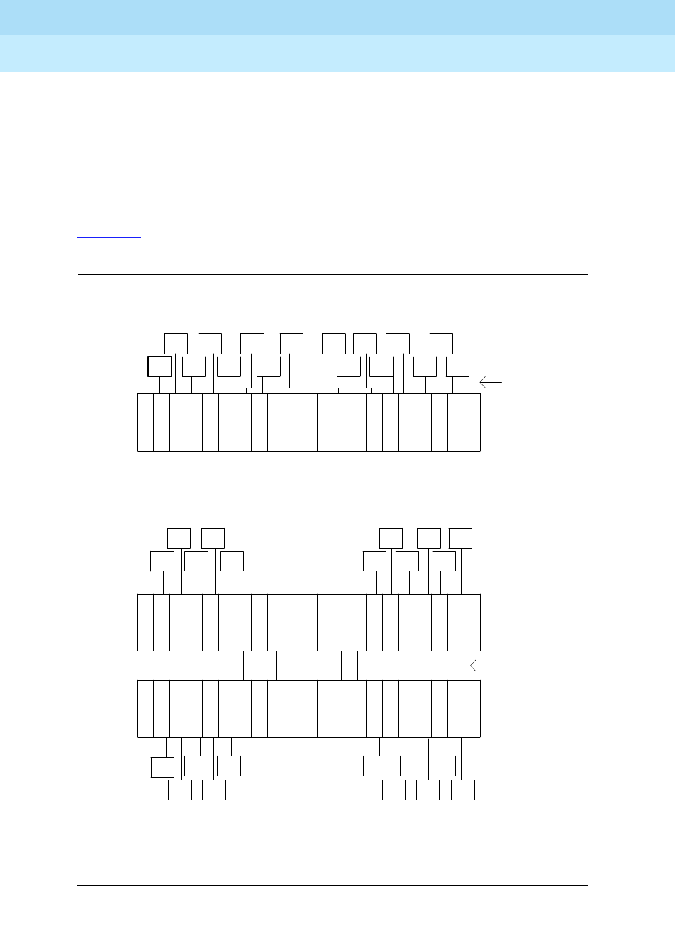
DEFINITY Enterprise Communications Server Release 6
Maintenance for R6r Volumes 1 & 2
555-230-126 Issue 2
January 1998
Maintenance Architecture
Page 1-11Port Network Connectivity (PNC)
1
■TDM and PKT busses, and bus terminations
There are 16 data busses in the SN. Each SNI has a slot dependent data
bus on which it transmits data and has 16 inputs, one for each SN SNI slot,
including its own. The data busses are terminated by 4 AHF105 paddle
boards that mount on the backside of the backplane slots 2 and 20.
■Power distribution and control leads
Figure 1-5 shows two examples of CSS configurations. Illustrations of the switch
node carrier hardware appear in Chapter 2.
Figure 1-5. Center Stage Switch Configurations (Simplex Examples)
EI
EPN EI
EI
EPN
EPN
EI
EI EI EI
EI EI EI
EI
EPN
EPN EPN EPN
EPN EPN EPN
EPN
Inter-switch
node
fibers
1
carrier
node
Switch * * *
1 2 3 4 5 6 7 8 9 10 11 12 13 14 15 16 17 18 20 21 Slot number 19
S
N
I
S
N
I
S
N
I
S
N
I
S
N
I
S
N
I
S
N
I
S
N
I
S
N
I
S
N
I
S
N
I
S
N
I
S
N
I
S
N
I
S
N
I
S
N
I
S
N
C
S
N
C
S
N
C
S
N
C
E
E
2
1 2 3 4 5 6 7 8 9 10 11 12 13 14 15 16 17 18 20 21
carrier
node
Switch
Slot number 19
* *
S
N
I
S
N
I
S
N
I
S
N
I
S
N
I
S
N
I
S
N
I
S
N
I
S
N
I
S
N
I
S
N
I
S
N
I
S
N
I
S
N
I
S
N
I
S
N
I
CSS with two switch nodes
EI
EPN
EI EI
EPN EPN
PPN
EI
EI
EPN EI
EI
EPN EPN
EPN
EI
EI EI
EI
EPN
EPN EPN
* * *
C
N
S
C
N
S
I
N
S
I
N
S
I
N
S
I
N
S
I
N
S
I
N
S
I
N
S
I
N
S
I
N
S
I
N
S
I
N
S
I
N
S
I
N
S
I
N
S
I
N
S
I
N
S
19 Slot number
Fiber
links
not
used
Switch
node
carrier
21
EI
EPN
EI
EPN
EI
EPN
EI EI EI
EI
EPN EPN
EPN EPN EPN
EI
EI
EI
EPN EPN
EPN
EI
5 4 3 20 18 17 16 15 14 13 12 11 10 9 8 7 6 2 1
CSS with one switch node
EI
EPN
EI EI
EPN EPN
PPN
EI
EI
EPN
* The PPN EI or a DS1C circuit pack may reside in this slot
** A DS1C circuit pack may reside in this slot

DEFINITY Enterprise Communications Server Release 6
Maintenance for R6r Volumes 1 & 2
555-230-126 Issue 2
January 1998
Maintenance Architecture
Page 1-12SPE Duplication
1
SPE Duplication
The Switch Processing Element (SPE) consists of the following circuit packs.
These circuit packs reside on the A carrier (control carrier) of the PPN in all
systems, except for the UN330B which is found only in high and critical reliability
systems. In high and critical reliability systems, the PPN B carrier duplicates
exactly the configuration of the A carrier, making two identical SPE complexes.
This duplication allows the system to recover from many faults, and enables
troubleshooting and repairing of SPE components without interrupting service.
The Tone-Clock circuit pack also resides on the control carrier, and is also
duplicated. However, it is not considered a part of the SPE. Although the
SPE-Select switches control Tone-Clock selection, its duplication strategy differs
from that of the SPE. See the ‘‘TDM-CLK (TDM Bus Clock)’’ and ‘‘TONE-BD
(Tone-Clock Circuit Pack)’’ sections in Chapter 9, ‘‘Maintenance Object Repair
Procedures’’ for details.
Duplicated SPEs employ an active/standby strategy. At any one time, one SPE, A
or B, is designated active and controls the switch services network. The other
SPE, designated standby, is not required for switch service but remains ready to
become active and resume control of service should a service-affecting failure
occur in the active SPE. This action is termed an SPE interchange. It is important
that the standby SPE be kept as available as possible to allow for a rapid
interchange.
Table 1-1. SPE Circuit Packs and Maintenance Objects
Apparatus
Code Circuit Pack Name Associated
Maintenance Objects
TN1648 System Access and
Maintenance SYSAM
UN330B Duplication Interface DUPINT,
DUP-CHL
UN331B Processor PROCR
TN1650B Memory MEM-BD
TN1655 Packet PKT-INT
UN332 Mass Storage System/
Network Control (MSSNET) H-ADAPTR,
SW-CTL
TN1657 Disk Drive DISK
TN1656 Tape Drive TAPE
STBY-SPE
STO-DATA

DEFINITY Enterprise Communications Server Release 6
Maintenance for R6r Volumes 1 & 2
555-230-126 Issue 2
January 1998
Maintenance Architecture
Page 1-13SPE Duplication
1
Standby SPE Availability
The STBY-SPE maintenance object is responsible for testing of the standby SPE
so that any faults that would prevent it from being available for service can be
isolated and repaired. Various factors affect the availability of the standby SPE:
■The condition of the individual hardware components of the standby SPE,
including circuit packs, power supplies, cables and other supporting
components.
Loss of power in an SPE due to power supply or power delivery
components is discussed under the condition SPE-Down. If a circuit pack
in the standby SPE that is critical to call service has failed, the standby will
not be able to become active. Maintenance testing of the standby SPE
allows isolation and repair of component problems so that the standby
can be made available again.
■Standby memory content
Each write operation in active memory is shadowed to the corresponding
location in the standby SPE’s memory. The standby memory should be in
agreement with the active in order to support an interchange that will
preserve call, feature and translation information. Maintenance software
tracking the STBY-SPE MO aims to keep the two memories in agreement.
■Standby State-of-Health (SOH)
The Duplication Interface circuit packs maintain a state-of-health value
which reflects the availability of the standby SPE. If the Standby SPE’s
state-of-health level is too poor, it cannot automatically be interchanged
into (made active).
■Standby SPE-Down
If the standby SPE is completely dead and held reset by its SYSAM (in
SPE-Down), or the standby SPE has no power, it is unavailable for service.
■System Time-of-Day
If the Time-of-Day clock of the standby SPE is substantially out of synch
with the active, interchanges could be more disruptive to service than
desirable.
System software running on both active and standby SPEs attempts to ensure
that the standby SPE is kept fully available in terms of the above factors. The
health of both the active and standby is tracked as a State-of-Health (SOH)
value.
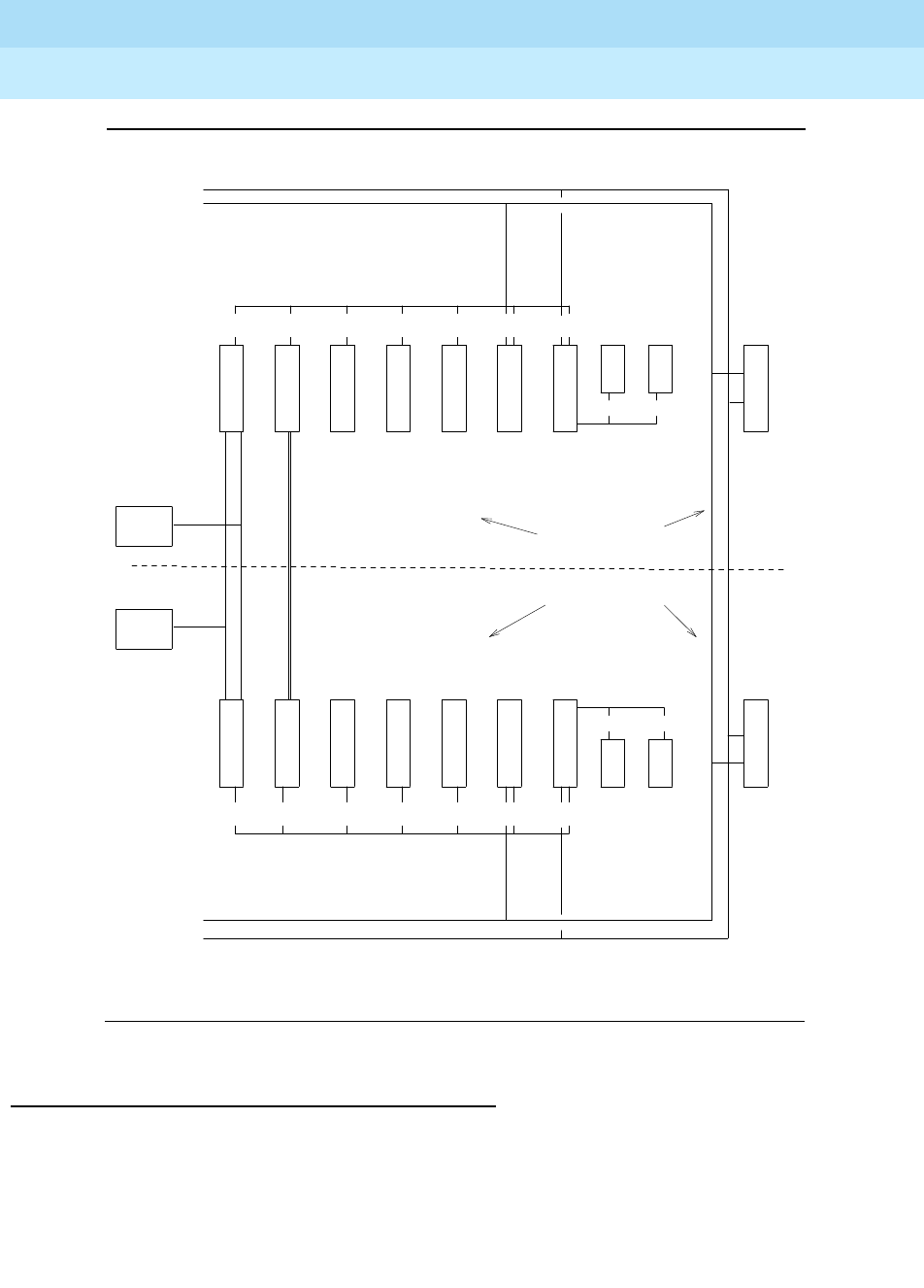
DEFINITY Enterprise Communications Server Release 6
Maintenance for R6r Volumes 1 & 2
555-230-126 Issue 2
January 1998
Maintenance Architecture
Page 1-14SPE Duplication
1
Figure 1-6. Duplicated SPEs — Hardware Configuration
Standby SPE State of Health
The Duplication Interface circuit packs on each of the two SPEs keep track of the
State of Health (SOH) of each of the two SPEs. This circuitry ensures that, at any
time, unless the SPE-select switches are locked:
■If the two SPEs have the same SOH, the current active SPE remains
active.
Active
Maintenance
Interface
SPE-Down
Interface
S
Y
S
A
M
S
Y
S
A
M
P
R
O
C
R
P
R
O
C
R
M
E
M
O
R
Y
M
E
M
O
R
Y
M
E
M
O
R
Y
M
E
M
O
R
Y
P
K
T
I
N
T
T
N
C
L
K
T
N
C
L
K
P
K
T
I
N
T
M
S
S
N
E
T
M
S
S
N
E
T
D
I
S
K
D
I
S
K
T
A
P
E
T
A
P
E
TDM Bus
TDM Bus
LAN Bus
LAN Bus
G3-MT
G3-MT
B Processor Carrier
A Processor Carrier
Processor Multiplexed Bus
Processor Multiplexed Bus
SCSI Bus
SCSI Bus
Duplication
Cable
TN1656
TN1648 UN332
TN1655
TN1650B TN1650B
TN1650B TN1650B
UN331B
UN331B
UN330B
UN330B
TN1657
. . . . . . . . . . . . . . . . . . . . . . . . . . . . . . . . . . . . . . . . . . . . . . . . . . . . . . . . . . . . . . . . . . . . . . . . . . . . . . . . . . . . . . . . . . . . . . . . . . . . .
.
.
.
.
.
.
.
.
.
.
.
.
.
.
.
.
.
.
.
.
.
.
.
.
.
.
.
.
.
.
.
.
.
.
.
.
.
.
.
. . . . . . . . . . . . . . . . . . . . . . . . . . . . . . . . . . . . . . . . . . . . . . . . . . . . . . . . . . . . . . . . . . . . . . . . . . . . . . . . . . . . . . . . . . . . . . . . . . . . . .
.
.
.
.
.
.
.
.
.
.
.
.
.
.
.
.
.
.
.
.
.
.
.
.
.
.
.
.
.
.
.
.
.
.
.
.
.
.
.
.
S P E B
S P E A
TN1648 UN332TN1655
TN1657 TN1656
D
U
P
I
N
T
D
U
P
I
N
T

DEFINITY Enterprise Communications Server Release 6
Maintenance for R6r Volumes 1 & 2
555-230-126 Issue 2
January 1998
Maintenance Architecture
Page 1-15SPE Duplication
1
■If the two SPEs have different SOH, the SPE with the better SOH becomes
or remains the active SPE.
These descriptions apply to SOH levels on the standby SPE. Four possible levels
of SPE SOH are supported and maintained by system hardware and software.
Standby SPE Maintenance Architecture
The maintenance strategy for the standby SPE is based on several independent
components.
■Maintenance of handshake communication so that software on the active
SPE can control maintenance of the standby SPE and its components.
■Controlling memory shadowing and performing the standby memory
refresh operation.
■Activities, independent of handshake communication and memory
shadowing, used to allow tracking of the standby SPE’s condition. This
includes reading of hardware status to determine the actual state of
standby SPE.
functional The standby SPE is fully healthy with up-to-date
memory content identical to active SPE memory
content. An interchange into this SPE will cause minimal
service disruption.
not refreshed The standby SPE’s hardware and operational software
are fully healthy but the standby memory content is not
currently identical to active SPE memory content.
Typically either memory shadowing is off or a memory
refresh operation is in progress to bring the memories’
contents into agreement. Interchange into an SPE of
this health level will lead to calls dropping and a service
outage of several minutes.
partially-functional One of the following conditions is in effect:
— A failure of a critical standby SPE component has
occurred.
— The standby SPE has been busied out.
— The SPE is in recent interchange mode (see
‘‘STBY-SPE (Standby SPE Maintenance)’’ in
Chapter 9, ‘‘Maintenance Object Repair
Procedures’’).
non-functional This is the worst and most seriously disabled state of a
standby SPE. The SPE has lost either power or basic
sanity; the standby processor and its software are
unable to cycle. Such an SPE cannot be made active
by an interchange.
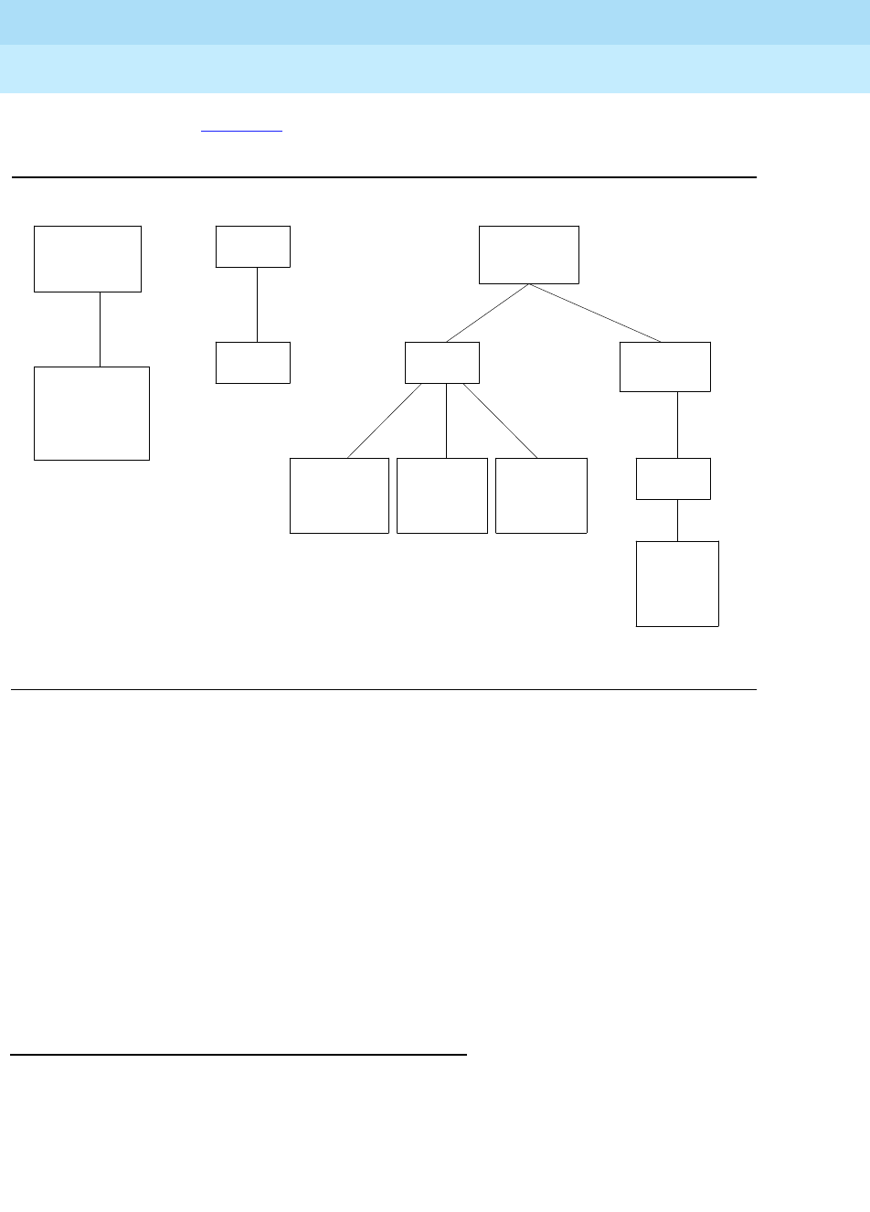
DEFINITY Enterprise Communications Server Release 6
Maintenance for R6r Volumes 1 & 2
555-230-126 Issue 2
January 1998
Maintenance Architecture
Page 1-16SPE Duplication
1
As shown in Figure 1-7, all maintenance capabilities for the standby SPE are built
upon these three strategies.
Figure 1-7. Components of Standby Maintenance
Standby SPE maintenance software is designed to attempt to self-correct
problems. If a problem occurs, this software automatically tries to address the
problem, bring the standby SPE back to a state of availability and clear all alarms
which might have been raised. Typically, if a standby SPE problem has not
cleared, it is of a hardware nature and some type of hardware component
maintenance or replacement action is indicated. Once such corrections have
been made, the system software will automatically bring the standby SPE back to
full availability. There is no management terminal command to stimulate refresh
of standby SPE memory; system software automatically accomplishes this itself
when conditions are appropriate. The same is true of efforts to turn on shadowing
where no explicit user interface command to turn on/off shadowing is available
(note that busyout/release, below, can be used to indirectly accomplish this).
Standby Maintenance Monitor Software
The Standby Maintenance Monitor (SMM) is a software package that is
always
running on key components of the standby SPE to verify its competence. SMM
tests individual standby SPE components and reports back to the active SPE, by
the handshake message, any failures of individual tests. Failure reports trigger
enhanced maintenance attention to standby SPE component problems by active
Standby SPE
Hardware Status
Reading
Maintain
Handshake
Communication
Maintain
Standby SOH,
Shadowing,
Lock
Status
Memory
Shadowing
Memory
Refresh
G3-MT
Access to
Standby SPE
Components
Error/Alarm
Logging
for Standby
Components
Handshake
Comm. Up
Time of day
clocks
in synch
Handshake
Comm.Down
Stby SPE
down/lock
G3-MT
Access to
SPE-Down
Interface

DEFINITY Enterprise Communications Server Release 6
Maintenance for R6r Volumes 1 & 2
555-230-126 Issue 2
January 1998
Maintenance Architecture
Page 1-17SPE Duplication
1
SPE software. SMM also ensures that when handshake communication has been
down for an extended period, the standby SPE will transition into the SPE-down
state.
Handshake Communication
Every 30 seconds, the active SPE sends a handshake request message to SMM
and waits for SMM to respond with a handshake response message. This
message transmission occurs across the Duplication Interface circuit packs and
their interconnecting cable. As long as SMM responds to these regular
handshake request messages, handshake communication is considered
up
as
reported on the status spe screen.
The physical path of handshake communication is illustrated below. Hardware
problems at any point in this route could interfere with handshake
communication. If the standby SPE fails to respond to four successive
handshake requests, handshake communication is considered down. A major
alarm is logged against STBY-SPE with error type 1 logged. The status spe
screen will indicate that handshake is down. It is then no longer possible to
communicate with the standby SPE. Maintenance testing of the standby by the
active SPE (or by command) is discontinued, and the error and alarm logs
become outdated for standby components.
Handshake communication failure is a severe and rare condition. It is due to
either a failure of Duplication Interface hardware or a catastrophic failure of the
standby SPE. As long as the active SPE is not locked by the switches, software
attempts every 30 seconds, to re-establish handshake communication.
When the SPEs are locked with the switches, handshake communication is
physically impossible, but no alarm is raised. When the standby is busied out,
handshake communication should remain up, but in any case, only the busyout
WARNING alarm will be raised.
Whenever the active SPE has undergone a restart (levels 1-5), handshake is
technically considered down during and just after the restart. After a level 1 (hot)
restart, if there are no standby SPE problems, handshake communication should
be restored within 30 seconds. After active-SPE restarts of levels 2 and up,
handshake should be restored within 3 minutes of G3-MT re-enabling.
The active SPE keeps hardware configuration and vintage data about the
components of the standby SPE. This data can be accessed with list
configuration control. Whenever handshake is down, this data may be out of
date. Whenever handshake has been down and is restored, the active SPE
requests standby SPE software to transmit the current version of this data. The
data is then stored in active SPE memory.
Failure to use the lock-and-power- down method for standby circuit pack
replacement can lead to incorrect standby component hardware configuration
and vintage data.

DEFINITY Enterprise Communications Server Release 6
Maintenance for R6r Volumes 1 & 2
555-230-126 Issue 2
January 1998
Maintenance Architecture
Page 1-18SPE Duplication
1
Figure 1-8. Handshake Communication Path
Maintenance of Standby Components
When handshake communication is up, maintenance for individual components
of the standby SPE is the same as that for the active (except in some details for
PKT-INT). The same commands are used to test standby and active circuit
packs, and the error and alarm logs maintained on the active side record data for
both.
If a major on-board alarm is raised against a standby SYSAM, Processor,
Memory, MSSNET, or Packet Interface board, the standby SPE’s SOH is lowered
to
partially-functional
. Once that board’s problem is fixed and the alarm cleared,
system software automatically raises the standby SPE’s SOH to
not-refreshed
or
functional
, depending on whether its memory is up to date.
Standby component faults can also affect memory shadowing. Certain faults can
have negative effects on system operation if memory shadowing is left on. When
these components get major alarms, memory shadowing is automatically kept off
by system software. These are referred to as
shadowing relevant
components.
Roughly, these include the hardware that provide shadowing or the hardware
into which shadowed writes occur.
Table 1-2 below shows the effect often major on-board alarms against standby
components on standby SOH and on memory shadowing. Note that off-board
. . . . . . . . . . .
. . . . . . . . . . .
P
R
O
C
R
SMM
software
SMM: Standby Maintenance Monitor
Request
Response
MAP: Maintenance Action Process
Duplication
Interface Cable
D
U
P
I
N
T
Standby
SPE
Active
SPE
DUP
Driver
P
R
O
C
R
MAP
software
D
U
P
I
N
T

DEFINITY Enterprise Communications Server Release 6
Maintenance for R6r Volumes 1 & 2
555-230-126 Issue 2
January 1998
Maintenance Architecture
Page 1-19SPE Duplication
1
alarms, minor alarms and warning alarms have no effect on memory shadowing
or on the SOH of the standby SPE.
When handshake communication is down, but the standby SPE is not in
SPE-down mode (SOH is not
nonfunctional
), autonomous testing of standby SPE
components by the SMM occurs on the standby SPE. If a component fails a test
while handshake is down,
its red LED is lit and the standby SOH is lowered to
partially-functional.
A standby SPE component is considered to be testable if it can be tested with
the usual maintenance commands from a management terminal connected to an
ACTIVE connector on the SPE. In this condition, full maintenance software for it is
running in the active SPE and the error/alarm data for it is up to date. Table 1-3
gives testability requirements for the various SPE components.
Table 1-2. Effects of Major Alarms on Shadowing and Standby SOH
Alarmed
Component SOH Effect Shadowing Effect
PROCR partially functional no effect
MEM-BRD partially functional shadowing kept off
SW-CTL partially functional shadowing kept off
SYSAM partially functional no effect
PKT-INT partially functional shadowing kept off
DUPINT no effect shadowing kept off
DUP-CHL no effect shadowing kept off
HOST-ADAPTER no effect no effect
DISK no effect no effect
TAPE no effect no effect

DEFINITY Enterprise Communications Server Release 6
Maintenance for R6r Volumes 1 & 2
555-230-126 Issue 2
January 1998
Maintenance Architecture
Page 1-20SPE Duplication
1
Locking the Active SPE
Duplication Interface hardware supports the ability to lock the active SPE in
active mode by means of the SPE-Select switches. The procedure for safely
doing this is described in Chapter 5, ‘‘Responding to Alarms and Errors’’, and in
‘‘STBY-SPE (Standby SPE Maintenance)’’ in Chapter 9, ‘‘Maintenance Object
Repair Procedures’’. In locked mode, the system operates as if it is simplex:
■The standby SPE is inaccessible to the active SPE and active G3-MT
login.
■No SPE-interchange is possible.
■Handshake is down and memory shadowing is off.
The locked state is intended for temporary use to prevent interchanges during
maintenance sessions. No alarm is raised when the switches are locked.
However, alarms against SPE-SELE are raised later if the switches are left out of
the AUTO position for an extended length of time.
Memory Shadowing
Memory shadowing is used to keep the standby SPE’s memory content
up-to-date relative to the active SPE’s memory. Memory shadowing is turned on
automatically when the standby SPE has booted up and completed its own
memory testing. Each write operation in active memory is replicated in the
corresponding location in standby memory.
Table 1-3. Testability Requirements for Standby Components
Component Required Condition
PROCR handshake up
MEM-BD handshake up
SW-CTL handshake up
SYSAM handshake up
PKT-INT handshake up and Stby Refreshed
DUPINT handshake up
DUP-CHL handshake up
HOST-ADAPTER handshake up
DISK handshake up and Stby Refreshed
TAPE handshake up and Stby Refreshed

DEFINITY Enterprise Communications Server Release 6
Maintenance for R6r Volumes 1 & 2
555-230-126 Issue 2
January 1998
Maintenance Architecture
Page 1-21SPE Duplication
1
When shadowing into the standby SPE has been off (as when the system first
comes up), system software checks to see if it is safe to restore shadowing.
Handshake communication must be up. Then software verifies (with Test #920)
that the SPEs have identical hardware configurations. If this passes and there are
no shadow-relevant component failures, system software turns on shadowing
again.
Once shadowing is turned on, it is necessary to refresh the contents of standby
memory to bring it into full agreement with the active’s by copying every word of
active SPE memory to the standby. This takes approximately 5 minutes, though
traffic load can increase the duration. When completed, the standby SPE is said
to be "refreshed". status spe or the
Standby SPE Status Query Test (#855)
in the
STBY-SPE test sequence can be used to check the REFRESH status of the
standby. Unless the standby SPE is refreshed, interchange into it can disrupt
service for several minutes. Otherwise, interchanges are minimally disruptive. A
standby SPE exiting lock mode or just released from busyout must undergo this
full re-initialization.
System software tracks the operation and raises a major alarm when refresh
failure occurs. If shadowing stays on, system software automatically tries to
refresh again 5 minutes later.
Generally, memory shadowing should always remain on. But there are conditions
when the system legitimately operates with shadowing off:
■The standby SPE is undergoing any restart.
■The active SPE is undergoing a restart level of 2 or greater.
■The active SPE is locked.
■The standby SPE is busied out.
In any other situation, it is an error condition for shadowing to be off. The first 2
situations are transitory and shadowing should automatically be restored within
10 minutes. If shadowing has been on for several minutes, it is an error condition
for the standby not to be refreshed.
Initialization: Bringing the Standby SPE Up
When the standby SPE has been out of service or is first coming up, SPE
software executes the following steps:
1. Establishes handshake communication.
2. When SMM answers handshake, raises the standby SPE’s SOH to
not
refreshed
if it has no critical component alarms, or
partially functional
there are critical component alarms.
3. Tests for component mismatch (test number 920).
4. If there is no mismatch, and no major alarms against shadow-relevant
components, and if SMM permits, turns on memory shadowing

DEFINITY Enterprise Communications Server Release 6
Maintenance for R6r Volumes 1 & 2
555-230-126 Issue 2
January 1998
Maintenance Architecture
Page 1-22Power Interruptions
1
5. If memory shadowing is successfully turned on, initiates the process of
overall memory refresh
6. When refresh completes, if there are no critical component major alarms,
raises the standby SPE’s SOH to level
functional
Standby SPE initialization is a lower priority than initializing the active SPE and is
therefore “paced” to lower CPU consumption. The above steps are carried out at
10 second intervals. During system initialization, the above sequence begins
about 2 minutes after the terminal login prompt becomes available. Normally, the
standby SPE should be fully initialized about 5 minutes after the availability of the
login prompt. You can follow the execution of this sequence by repeatedly
entering the command “status spe.”
Should a step of this initialization sequence fail, system software retries that step
at 30 second intervals until it succeeds. It does not proceed to the next step until
the current one has succeeded. The failed condition is alarmed.
A procedure for bringing up the standby SPE after being in the SPE-down or
locked modes is described at the end of Chapter 4, ‘‘Initialization and Recovery’’.
Power Interruptions
System cabinets and their associated power supplies can be powered by
110/208 volts AC either directly or from an Uninterruptible Power Supply (UPS)
system. Alternatively, the cabinets and their power supplies may be powered by
a -48 VDC battery power plant, which requires DC-to-DC conversion power units
in the system.
If power is interrupted to a DC-powered cabinet or an AC-powered cabinet
without optional backup batteries, the effect depends upon the decay time of the
power distribution unit. If the interruption period is shorter than the decay time,
there is no effect on service, though some -48V circuits may experience some
impact. If the decay time is exceeded for a PPN, all service is dropped,
emergency transfer is invoked and the system must reboot when power is
restored. If the decay time is exceeded for an EPN, all service to that Port
network is dropped and the EPN must be reset when power is restored. If the
EPN contains a Switch Node carrier, all service to Port Networks connected to
that Switch Node is dropped.
Single-carrier cabinets, which can be used for EPNs, also have no battery
backup. If power is interrupted for more than 0.25 seconds, all service is
dropped, and emergency transfer is invoked for the EPN.
In the above cases, the cabinet losing power is unable to log any alarms.
However, in the case of an EPN going down while the PPN remains up, alarms
associated with the EPN will be reported by the system.

DEFINITY Enterprise Communications Server Release 6
Maintenance for R6r Volumes 1 & 2
555-230-126 Issue 2
January 1998
Maintenance Architecture
Page 1-23Power Interruptions
1
Nominal Power Holdover
AC-powered multicarrier cabinets are equipped with an internal battery,
powered by its own charger, that provides a short term holdover to protect the
system against brief power interruptions. This feature, known as the Nominal
Power Holdover, is optional on cabinets supplied by a UPS and required on all
other AC-powered cabinets. The battery is controlled in such a manner that it
automatically provides power to the cabinet if the AC service fails. The duration
of the holdover varies according to the type of carrier and whether or not the
system has a duplicated SPE. See Table 1-4 for duration times:
Effects of Power Interruptions
Power holdover is controlled by software in the above manner in order to allow
the system to sustain multiple brief power interruptions without exhausting the
batteries before they have time to recharge. After power is restored, the batteries
are recharged by a circuit that monitors current and time. If the batteries take
more than 30 hours to recharge, a minor alarm is raised, indicating that the
batteries must be replaced or the charger replaced.
The 397 Battery Charger Circuit immediately detects loss of AC power and raises
a warning alarm against AC-POWER that is not reported to INADS. Certain
maintenance objects such as external DS1 timing will report major alarms in this
situation. When power is restored, the AC-POWER alarm is resolved.
PPN Cabinet with Power Holdover
When power is interrupted to a PPN cabinet, the effects depend upon the
duration of the outage. Battery power is supplied to the whole cabinet for 10
seconds. If power is restored during that period, service is not affected. If the
interruption exceeds the cabinet holdover period, but is restored before the
control carrier holdover expires, all service is dropped and emergency transfer is
invoked. The SPE is kept up allowing for a speedy restoration of service since a
reboot is not required. All non-SPE circuit packs must be reinserted, taking about
a minute, depending on the size of the system. If the interruption exceeds the
control carrier holdover, all service is dropped and the system must reboot when
Table 1-4. Nominal Power Holdover
Cabinet Type Control Carrier Entire Cabinet
PPN, duplicated SPE 5 minutes 10 seconds
PPN, simplex SPE 10 minutes 10 seconds
EPN 10 minutes 15 seconds

DEFINITY Enterprise Communications Server Release 6
Maintenance for R6r Volumes 1 & 2
555-230-126 Issue 2
January 1998
Maintenance Architecture
Page 1-24Protocols
1
power is restored, taking up to 15 minutes, depending on the size of the system.
Human intervention may be required if central office equipment has been busied
out.
EPN Cabinet with Power Holdover
When power is interrupted to an EPN MCC for less than 15 seconds, no service
effect results. If the interruption exceeds 15 seconds, only the control carrier is
kept up. Circuit packs on other carriers are powered down. Only calls and other
services maintained by circuit packs on the control carrier are maintained. For
this reason, critical services and those that require a long time to restore (for
example, Announcement circuit packs) should be located on control carriers. All
service to Port Networks connected to a Switch Node in the EPN is lost. When
power is restored, all affected EPNs are reset by system software (see ‘‘EXP-PN
(Expansion Port Network)’’ in Chapter 9, ‘‘Maintenance Object Repair
Procedures’’). As with the PPN, a warning alarm is raised against AC-POWER.
External Alarm Leads
Each cabinet provides two leads for one major and one minor alarm contact
closure that can be connected to external equipment. These are located on the
SYSAM and Maintenance circuit packs. If the switch is under warranty or a
maintenance agreement, EXT-DEV alarms are generated by the equipment
connected to these leads and reported to INADS. These may be used to report
failures of UPSs or battery reserves powering the switch. They are also
commonly used to monitor adjuncts such as AUDIX.
Protocols
This section describes the protocols handled by the system and the points where
these protocols change. Figure 1-9 is a pictorial guide through data-
transmission state changes. Figure 1-9 illustrates the flow of data from DTE
equipment, like a terminal or host, through DCE equipment, like a modem or data
module, into a communications port on the system. The data flow is shown by
solid lines. Below these lines are the protocols used at particular points in the
data stream.
Not shown in the Figure 1-9 is the treatment of D-channels in ISDN-PRI and
ISDN-BRI transmissions. PRI and BRI D-channels transport information elements
that contain call-signaling and caller information. These elements conform to
ISDN level-3 protocol. In the case of BRI, the elements are created by the
terminal or data module; for the PRI, the elements are created by the system,
which inserts them into the D-channel at the DS1 port.
For ISDN transmissions, therefore, BRI terminals and data modules, and DS1
ports insert, interpret, and strip both layer-2 DCE information and layer-3
elements. Also, the DS1 port passes layer-3 elements to the system for
processing.

DEFINITY Enterprise Communications Server Release 6
Maintenance for R6r Volumes 1 & 2
555-230-126 Issue 2
January 1998
Maintenance Architecture
Page 1-25Protocols
1
Layers
The Open System Interconnect (OSI) model for data communications contains
seven layers, each with a specific function. Communications to and through the
system concern themselves only with layers 1 and 2 of the model.
Layer 1, or the
physical layer,
covers the physical interface between devices and
the rules by which bits are passed. Among the physical layer protocols are
RS-232, RS-449, X.21, DCP, DS1, and others.
Layer 2, or the
data-link layer
, refers to code created and interpreted by the DCE.
The originating equipment can send blocks of data with the necessary codes for
synchronization, error control, or flow control. With these codes, the destination
equipment checks the physical-link reliability, corrects any transmission errors,
and maintains the link. When a transmission reaches the destination equipment,
it strips any layer-2 information the originating equipment may have inserted. The
destination equipment only passes to the destination DTE equipment the
information sent by the originating DTE equipment. The originating DTE
equipment can also add layer-2 code to be analyzed by the destination DTE
equipment. The DCE equipment treats this layer as data and passes it along to
the destination DTE equipment as it would any other binary bits.
Layers 3 to 7 (and the DTE-created layer 2) are embedded in the transmission
stream and are meaningful only at the destination DTE equipment. Therefore,
they are shown in the figure as ‘‘user-defined,’’ with no state changes until the
transmission stream reaches its destination.
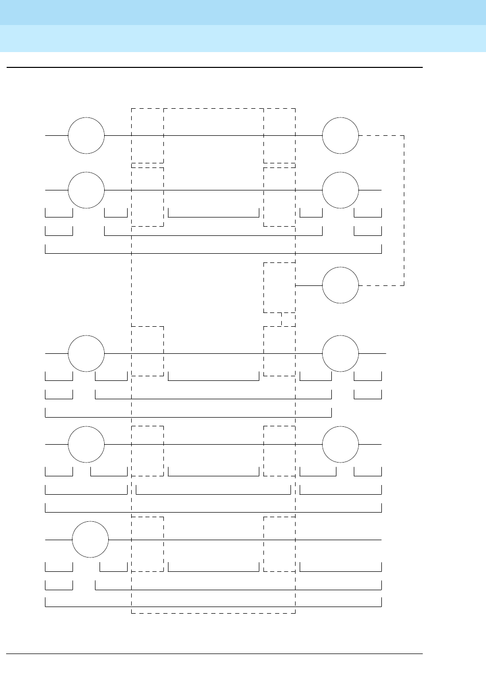
DEFINITY Enterprise Communications Server Release 6
Maintenance for R6r Volumes 1 & 2
555-230-126 Issue 2
January 1998
Maintenance Architecture
Page 1-26Protocols
1
Figure 1-9. Data Transmission States
DCE
ORIGINATING DCE
DESTINATION SYSTEM
RS232C RS232CRAW BITSDCP DCP 1
DTE
2 DMIASCII ASCII
3-7 USER DEFINED
D
I
G
I
T
A
L
P
O
R
T
D
I
G
I
T
A
L
P
O
R
T
D
I
G
I
T
A
L
P
O
R
T
D
I
G
I
T
A
L
P
O
R
T
DATA
MODULE
DATA
MODULE
DATA
MODULE
DATA
MODULE
DTE
DTE
DATA
MODULE DS1
PORT
1
D
I
G
I
T
A
L
P
O
R
T
RAW BITS
RS232C DS1 FORMATDCP
DMIASCII 2
P
O
R
T
D
S
1
DTE
T
R
U
N
K
P
O
R
T
A
N
A
L
O
G
ADU ADUDTE E
I
A
P
O
R
T
E
I
A
P
O
R
T
DTE
DMIASYNCH ASCII ASYNCH ASCII 2
3-7 USER DEFINED
RS232C RS232CADU PROT ADU PROT1 RAW BITS
3-7 USER DEFINED
VOICE GRADE DATAASCII ASCII 2
ANALOG ANALOG1 PCMRS232C RS232C
P
O
R
T
A
N
A
L
O
G
L
I
N
E
A
N
A
L
O
G
P
O
R
T
DTE
DTE
MODEM
POOLING
CABLE
MODEM
MODEM
MODEM
PCM
3-7 USER DEFINED

DEFINITY Enterprise Communications Server Release 6
Maintenance for R6r Volumes 1 & 2
555-230-126 Issue 2
January 1998
Maintenance Architecture
Page 1-27Protocols
1
Usage
The following is a list of the protocols when data is transmitted to and through the
system. The list is organized by protocol layers. Refer to Figure 1-9.
Layer-1 Protocols
Layer-1 protocols are used between the terminal or host DTE and the DCE, used
between the DCE equipment and the system port, and used inside the system.
The following layer-1 protocols are used between the DTE equipment and the
DCE equipment. DCE equipment can be data modules, modems, or Data
Service Units (DSUs). A DSU is a device that transmits digital data to a particular
digital endpoint over the public network without processing the data through any
intervening private network switches.
■
RS-232
— A common physical interface used to connect DTE to DCE.
This protocol is typically used for communicating up to 19.2 kbps
■
RS-449
— Designed to overcome the RS-232 distance and speed
restrictions and lack of modem control
■
V.35
— A physical interface used to connect DTE to a DCE. This protocol
is typically used for transmissions at 56 or 64 kbps
The following protocols are used at layer 1 to govern communication between the
DCE equipment and the port. These protocols consist of codes inserted at the
originating DCE and stripped at the port. The DS1 protocol can be inserted at the
originating, outgoing trunk port and stripped at the destination port.
■
Digital Communications Protocol (DCP)
— A standard for a 3-channel
link. This protocol sends digitized voice and digital data in frames at 160
kbps. The channel structure consists of two information (I) channels and
one signaling (S) channel. Each I-channel provides 64 kbps of voice
and/or data communication and the S-channel provides 8 kbps of
signaling communication between the system and DTE equipment. DCP is
similar to ISDN-BRI
■
Basic Rate Interface (BRI)
— An ISDN standard for a 3-channel link,
consisting of two 64-kbps bearer (B) channels and one 16-kbps signaling
(D) channel. For the implementation of this standard, see
DEFINITY
Communications System and System 75 and System 85 ISDN BRI
Reference
, 555-025-103
■
Primary Rate Interface (PRI)
— An ISDN standard that sends digitized
voice and digital data in T1 frames at 1.544-Mbps or, for countries outside
the United States, in E1 frames at 2.048-Mbps. Layer 1 (physical), layer 2
(link), and layer 3 (network) ISDN PRI protocols are defined in
AT&T
System 75 and 85
—
DS1/DMI/ISDN-PRI
—
Reference Manual
,
555-025-101. At 1.544 Mbps, each frame consists of 24 64-kbps channels
plus 8 kbps for framing. This represents 23 B-channels plus 1 D-channel.

DEFINITY Enterprise Communications Server Release 6
Maintenance for R6r Volumes 1 & 2
555-230-126 Issue 2
January 1998
Maintenance Architecture
Page 1-28Protocols
1
The maximum user rate is 64 kbps for voice and data. The maximum
distances are based on T1 limitations. At 2.048 Mbps, each E1 frame
consists of 32 64-kbps channels
■
Analog
— A modulated voice-frequency carrier signal
■
ADU Proprietary
— A signal generated by an ADU. The signal is for
communication over limited distances and can be understood only by a
destination ADU or destination system port with a built-in ADU
■
Digital Signal Level 1 (DS1)
— A protocol defining the line coding,
signaling, and framing used on a 24-channel line. Many types of trunk
protocols (for example, PRI and 24th-channel signaling) use DS1 protocol
at layer 1
■
European Conference of Postal and Telecommunications rate 1 (CEPT1)
— A protocol defining the line coding, signaling, and framing used on a
32-channel line. Countries outside the United States use CEPT1 protocol
Inside the system, data transmission appears in one of two forms:
1. Raw digital data, where the physical layer protocols, like DCP, are
stripped at the incoming port and reinserted at the outgoing port.
2. Pulse Code Modulation (PCM)-encoded analog signals (analog
transmission by a modem), the signal having been digitized by an
analog-to-digital coder/decoder (CODEC) at the incoming port.
Layer-2 Protocols
Layer-2 protocols are given below:
■
8-bit character code
—
Between the DTE equipment and the DCE
equipment. Depending on the type of equipment used, the code can be
any proprietary code set.
■
Digital multiplexed interface
proprietary — Family of protocols between
the originating DCE and the destination DCE for digital transmission. See
DEFINITY Communications System and System 75 and System 85
DS1/DMI/ISDN PRI Reference
, 555-025-101; and
Digital Multiplexed
Interface [DMI] Technical Specification,
555-025-204
■
Voice-grade data
— Between the originating DCE and the destination
DCE for analog transmission
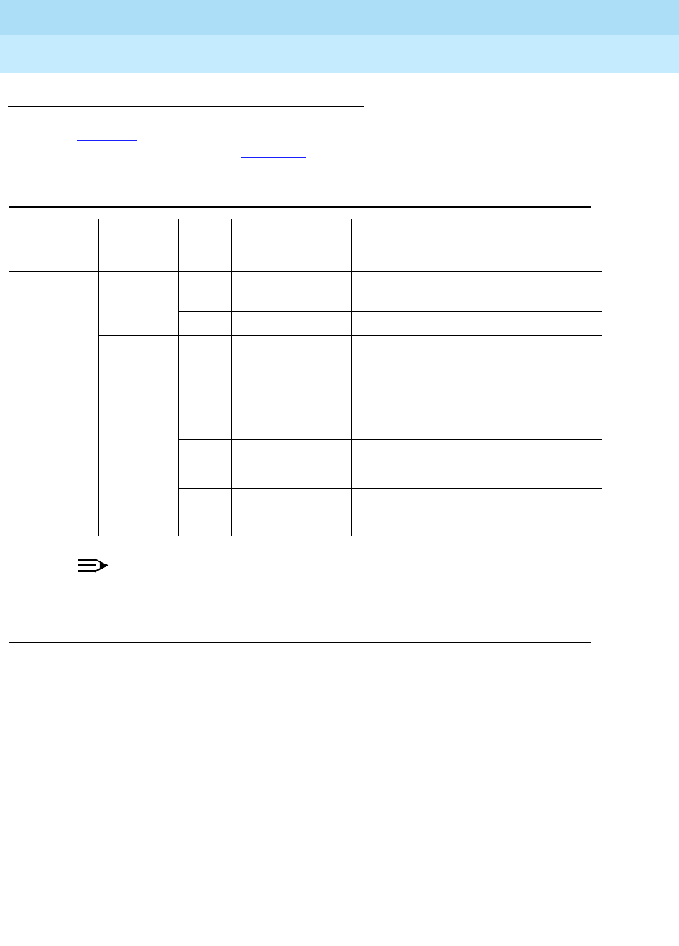
DEFINITY Enterprise Communications Server Release 6
Maintenance for R6r Volumes 1 & 2
555-230-126 Issue 2
January 1998
Maintenance Architecture
Page 1-29Protocols
1
Protocol States
Table 1-5 summarizes the protocols used at various points in the data
transmission stream. See Figure 1-9.
NOTE:
OSI means Open Systems Interconnect
PCM means Pulse Code Modulated
DMI means Digital Multiplexed Interface
Table 1-5. Protocol States for Data Communication
Transmiss-
ion Type
Incoming
DTE to
DCE OSI
Layer Protocols DTE to
DCE DCE to System
Port Inside System
Analog Modem 1 RS-232, RS-449,
or V.35 analog PCM
2 8- or 10-bit code voice-grade data voice-grade data
ADU 1 RS-232 ADU proprietary raw bits
2 asynchronous
8-bit code asynchronous
8-bit code DMI
Digital Data
Module 1 RS-232, RS-449,
or V.35 DCP or BRI raw bits
2 8-bit code DMI DMI
Digital
Signal
Level 1
(DS1)
1 any DS1 PCM or raw bits
2 8-bit code DMI or voice-
grade data DMI or voice- grade
data

DEFINITY Enterprise Communications Server Release 6
Maintenance for R6r Volumes 1 & 2
555-230-126 Issue 2
January 1998
Maintenance Architecture
Page 1-30Protocols
1
Both the physical-layer protocol and the Digital Multiplexed Interface (DMI) mode
used in the connection are dependent upon the type of 8-bit code used at layer 2
between the DTE equipment and DCE equipment, as listed in Table 1-6 and
Table 1-7.
Connectivity Rules
Figure 1-9 implies the following connectivity rules:
■Only the DS1 port and the analog trunk port are trunking facilities (all other
ports are line ports). For communication over these facilities, the
destination DCE equipment can be a hemisphere away from the system,
and the signal can traverse any number of intervening switching systems
before reaching the destination equipment.
■Data originating at any type of digital device, whether DCP or BRI, can exit
the system at any type of digital port — BRI, digital-line, PRI, DS1, and
others; as long as the call destination is equipped with a data module
using the same DMI mode used at the call origin. This is because once the
data enters the system through a digital port, its representation is uniform
(raw bits at layer 1, and DMI at level 2), regardless of where it originated.
Table 1-6. Physical-Layer Protocol Versus Character Code
Protocol Code
RS-232 Asynchronous 8-bit ASCII, and synchronous
RS-449 Asynchronous 8-bit ASCII, and synchronous
V.35 Synchronous
Table 1-7. Digital Multiplexed Interface (DMI) Mode Versus
Character Code
DMI Mode Code
0 Synchronous (64 kbps)
1 Synchronous (56 kbps)
2 Asynchronous 8-bit ASCII (up to 19.2 kbps), and synchronous
3 Asynchronous 8-bit ASCII, and private proprietary

DEFINITY Enterprise Communications Server Release 6
Maintenance for R6r Volumes 1 & 2
555-230-126 Issue 2
January 1998
Maintenance Architecture
Page 1-31Protocols
1
■Although data entering the system through an EIA port has not been
processed through a data module, the port itself has a built-in data
module. Inside the system, port data is identical to digital line data. Data
entering the system at a DCP line port can exit at an EIA port. Conversely,
data entering the system at an EIA port can exit at any DCP line port. The
destination data module must be set for Mode-2 DMI communication.
■Voice-grade data can be carried over a DS1 facility as long as the
destination equipment is a modem compatible with the originating modem
■If a mismatch exists between the types of signals used by the endpoints in
a connection (for example, the equipment at one end is an analog
modem, and the equipment at the other end is a digital data module), a
modem-pool member must be inserted in the circuit. When the endpoints
are on different switches, it is recommended that the modem-pool
member be put on the origination or destination system. A modem-pool
member is always inserted automatically for calls to off-premises sites via
analog or voice-grade trunking. For internal calls, however, the systems
are capable of automatically inserting a modem-pool member.
■Data cannot be carried over analog facilities unless inside the system it is
represented as a Pulse Code Modulation (PCM)-encoded analog signal.
To do this for data originating at a digital terminal, the signal enters the
system at a digital port and exits the system at a digital port. The signal
then reenters the system through a modem-pool connection (data-module
to modem to analog-port) and exits the system again at an analog port.
■Although DS1 is commonly called a trunk speed, here it names the
protocol used at layer 1 for digital trunks. Some trunks use different
signaling methods but use DS1 protocol at layer 1 (for example, PRI and
24th-channel signaling trunks).
Disconnect Supervision
Disconnect supervision means the CO has the ability to release a trunk when the
party at the CO disconnects, and the system is able to recognize the release
signal. In general, a CO in the United States provides disconnect supervision for
incoming calls but not for outgoing calls. Many other countries do not provide
disconnect supervision on either incoming or outgoing calls.
The system must provide the assurance that at least one party on the call can
control the dropping of the call. This avoids locking up circuits on a call where no
party is able to send a disconnect signal to the system. Internal operations must
check to be sure one party can provide disconnect supervision. An incoming
trunk that does not provide disconnect supervision is not allowed to terminate to
an outgoing trunk that does not provide disconnect supervision.
In a DCS environment, an incoming trunk without disconnect supervision can
terminate to an outgoing DCS trunk connecting two nodes. The incoming trunk is
restricted from being transferred to a party without disconnect supervision on the
terminating node.

DEFINITY Enterprise Communications Server Release 6
Maintenance for R6r Volumes 1 & 2
555-230-126 Issue 2
January 1998
Maintenance Architecture
Page 1-32Protocols
1
This is because, through messaging, the terminating node knows the originating
node cannot provide disconnect supervision. This messaging is not possible with
non-DCS tie trunks, and the direct call is denied.
Some two-wire loop start trunks outside the United States provide busy tone
disconnect in place of line signals. For these trunks, an adjunct can be attached
to the trunk to listen for busy or other disconnect tone. When a tone is detected,
the adjunct sends line signals for disconnect to the system.
Administration is provided for each trunk group to indicate whether it provides
disconnect supervision for incoming calls and for outgoing calls.
Transfer on Ringing
A station or attendant may conference in a ringing station or transfer a party to a
ringing station. When a station conferences in a ringing station and then drops
the call, the ringing station is treated like a party without disconnect supervision.
However, when a station transfers a party to a ringing station, the ringing station
party is treated like a party with disconnect supervision. Two timers (Attendant
Return Call Timer and Wait Answer Supervision Timer) are provided to ensure the
call is not locked to a ringing station.
Conference, Transfer, and Call-Forwarding
Denial
If a station or attendant attempts to connect parties without disconnect
supervision together, the following is possible:
■
Digital Station or Local Attendant Transfer
: if a digital station attempts to
transfer the two parties together, the call appearance lamp flutters,
indicating a denial. If transferring to a DCS trunk, the denial may drop the
call since the transfer is allowed and the other system is queried for
disconnect supervision.
■
Analog Station Transfer
: if an analog station attempts to transfer two
parties together by going on-hook, the analog station is no longer on the
call and the transfer cannot be denied.
■
Centralized Attendant Service (CAS) Attendant Transfer
: if a CAS attempts
to transfer two parties together by pressing the release key, the release
link trunk is released and the branch attempts a transfer by going on-hook
■
Station Conference/Dropout
: if a station conferences all parties, the
conference is allowed since the station has disconnect supervision. When
the station is dropped from the call, the call is dropped since the other
parties do not have disconnect supervision.
■
Station Call Forwarding
: if a station is call forwarded off-premise to a trunk
without disconnect supervision, the calling party without disconnect
supervision is routed to the attendant
Table 1-8 lists the various protocols, with applications and maximum limitations.

DEFINITY Enterprise Communications Server Release 6
Maintenance for R6r Volumes 1 & 2
555-230-126 Issue 2
January 1998
Maintenance Architecture
Page 1-33Protocols
1
Table 1-8. Protocols Used in DEFINITY
Protocol Applications Maximum
Data Rate Maximum Distance
DCP Digital switch to data
endpoints 64 kbps 5000 feet (1524 m) for data
3000 feet (915 m) for voice
RS-232 System to administration
terminal. Data module to
host computer
Data module to printer
Data module for
downloading and
high-speed data transfer
EIA interface
(Data line to ADU)
19.2 kbps
64 kbps
64 kbps
19.2 kbps
9.6 kbps
4.8 kbps
2.4 kbps
1.2 kbps
0.3 kbps
50 feet (15.2 m)
17 feet (5.9 m)
17 feet (5.9 m)
2000 feet (610 m)
5000 feet (1524 m)
7000 feet (2130 m)
12,000 feet (3654 m)
20,000 feet (6100 m)
40,000 feet (12200 m)
RS-449 Processor Interface to
Processor Interface 19.2 kbps
9.6 kbps
4.8 kbps
2.4 kbps
200 feet (61 m)
400 feet (122 m)
800 feet (244 m)
1600 feet (488 m)
SSI 715 BCS-2 to Processor
Interface
500 series printers to
Processor Interface
56 kbps 5000 feet (1524 m)
BISYNC Processor Interface line
controller to host
computer for terminal
emulation (9.6 kbps)
2.4 kbps
4.8 kbps
9.6 kbps
BX.25 Communication interface
to MSA, DCS, ISDN, or
AUDIX
9.6 kbps
SDCPI Data module to Processor
Interface 64 kbps 17 feet (5.9 m)
RS-366 Host computer to ACU
Data module to ACU 64 kbps 50 feet (15.2 m)
17 feet (5.9 m)
V.35 Data module to data
endpoints 56 kbps 50 feet (15.2 m)
Continued on next page
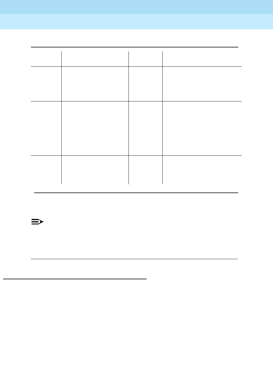
DEFINITY Enterprise Communications Server Release 6
Maintenance for R6r Volumes 1 & 2
555-230-126 Issue 2
January 1998
Maintenance Architecture
Page 1-34Protocols
1
NOTE:
ADU means Asynchronous Data Unit
BCS means Business Communications System
MSA means Message Servicing Adjunct
ACU means Automatic Call Unit
Transmission Characteristics
The system transmission characteristics comply with the American National
Standards Institute/Electronic Industries Association (ANSI/EIA) standard
RS-464A (SP-1378A). The following tables list some general switch transmission
characteristics.
Category
AData modules to terminals
or cluster controller
Data module in ASCII
emulation mode
64 kbps
9.6 kbps
500 feet (152 m)
ISDN-BRI Communication interface
to ISDN-BRI S/T
ISDN-BRI U
64 kbps
160 kbps
655 feet (199.3 m) to network
interface or repeater
1310 feet (399.3 m) system to
system
18,000 feet (5486.4 m) from
system to network interface,
and then ~2000 feet to phone
ISDN-PRI Communication interface
to ISDN-PRI 64 kbps 655 feet (199.3 m) to network
interface or repeater
1310 feet (399.3 m) system to
system
Table 1-8. Protocols Used in DEFINITY — Continued
Protocol Applications Maximum
Data Rate Maximum Distance
Continued on next page
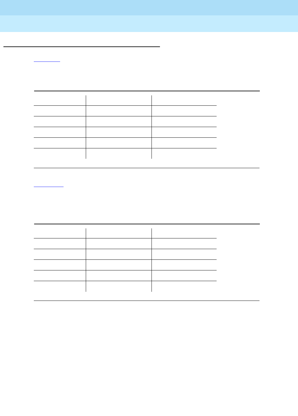
DEFINITY Enterprise Communications Server Release 6
Maintenance for R6r Volumes 1 & 2
555-230-126 Issue 2
January 1998
Maintenance Architecture
Page 1-35Protocols
1
Frequency Response
Table 1-9 lists the analog-to-analog frequency response for station-to-station or
station-to-CO trunk, relative to loss at 1 kHz for the United States.
Table 1-10 lists the analog-to-digital frequency response of the system for station
or CO-trunk-to-digital interface (DS0), relative to loss at 1 kHz for the United
States.
Table 1-9. Analog-to-Analog Frequency Response
Frequency (Hz) Maximum Loss (dB) Minimum Loss (dB)
60 —20
200 5 0
300 to 3000 1 -0.5
3200 1.5 -0.5
3400 3 0
Table 1-10. Analog-to-Digital Frequency Response
Frequency (Hz) Maximum Loss (dB) Minimum Loss (dB)
60 — 20
200 3 0
300 to 3000 0.5 -0.25
3200 0.75 -0.25
3400 1.5 0

DEFINITY Enterprise Communications Server Release 6
Maintenance for R6r Volumes 1 & 2
555-230-126 Issue 2
January 1998
Maintenance Architecture
Page 1-36Protocols
1
Insertion Loss for Port-to-Port; Analog or Digital
Table 1-11 lists the insertion loss in the system for different connection types for
the United States. Table 1-12 shows the overload and cross-talk characteristics.
Intermodulation Distortion
Table 1-13 lists the intermodulation distortion in the system for analog-to-analog
and analog-to-digital, up to 9.6 kbps data
Table 1-11. Insertion Loss for the United States
Typical Connections Nominal Loss
(dB) at 1 kHz
On-premises to on-premises station 6
On-premises to off-premises station 3
Off-premises to off-premises station 0
On-premises station to 4-wire trunk 3
Off-premises station to 4-wire trunk 2
Station-to-trunk 0
Trunk-to-trunk 0
Table 1-12. Overload and Crosstalk
Overload level +3 dBm0
Crosstalk loss >70 dB
Table 1-13. Intermodulation Distortion
Four-Tone Method Distortion
Second-order tone products >46 dB
Third-order tone products >56 dB

DEFINITY Enterprise Communications Server Release 6
Maintenance for R6r Volumes 1 & 2
555-230-126 Issue 2
January 1998
Maintenance Architecture
Page 1-37Protocols
1
Quantization Distortion Loss
Table 1-14 lists the quantization distortion loss in the system for analog port to
analog port.
Table 1-15 lists the quantization distortion loss in the system for analog port to
digital port and digital port to analog port.
Terminating Impedance: 600 Ohms nominal
Trunk balance impedance (selectable): 600 Ohms nominal or complex Z [350 Ohms + (1
k Ohms in parallel with 0.215uF)]
Impulse Noise
On 95% or more of all connections, the impulse noise is 0 count (hits) in five
minutes at +55 dBrnC (decibels above reference noise with C-filter) during the
busy hour.
Table 1-14. Quantization Distortion Loss
Analog Port-to-Analog Port
Signal Level Distortion Loss
0 to -30 dBm0 >33 dB
-40 dBm0 >27 dB
-45 dBm0 >22 dB
Table 1-15. Quantization Distortion Loss
Analog Port-to-Digital Port or
Digital Port-to-Analog Port
Signal Level Distortion Loss
0 to -30 dBm0 >35 dB
-40 dBm0 >29 dB
-45 dBm0 >25 dB

DEFINITY Enterprise Communications Server Release 6
Maintenance for R6r Volumes 1 & 2
555-230-126 Issue 2
January 1998
Maintenance Architecture
Page 1-38Service Codes
1
ERL and SFRL Talking State
Echo-Return Loss (ERL) and Single-Frequency Return Loss (SFRL) performance
is usually dominated by termination and/or loop input impedances. The system
provides an acceptable level of echo performance if the ERL and SFRL are met.
Peak Noise Level
■Analog to analog — 20 dBrnC (decibels above reference noise with
C-filter)
■Analog to digital — 19 dBrnC
■Digital to analog — 13 dBrnC
Echo Path Delay
■Analog port to analog port — < 3 ms
■Digital interface port to digital interface port — < 2 ms
Service Codes
Service codes (for the United States only) are issued by the Federal
Communications Commission (FCC) to equipment manufacturers and
registrants. These codes denote the type of registered terminal equipment and
the protective characteristics of the premises wiring of the terminal equipment
ports.
Private line service codes are as follows:
■7.0Y — Totally protected private communications (microwave) systems
■7.0Z — Partially protected private communications (microwave) systems
■8.0X — Port for ancillary equipment
■9.0F — Fully protected terminal equipment
■9.0P — Partially protected terminal equipment
■9.0N — Unprotected terminal equipment
Station-to-station ERL should meet or exceed 18 dB SFRL
should meet or exceed 12 dB
Station to 4-wire trunk connection ERL should meet or exceed 24 dB SFRL
should meet or exceed 14 dB
Station to 2-wire trunk connection ERL should meet or exceed 18 dB SFRL
should meet or exceed 12 dB
4-wire to 4-wire trunk connection ERL should meet or exceed 27 dB SFRL
should meet or exceed 20 dB

DEFINITY Enterprise Communications Server Release 6
Maintenance for R6r Volumes 1 & 2
555-230-126 Issue 2
January 1998
Maintenance Architecture
Page 1-39Facility Interface Codes
1
■9.0Y — Totally protected terminal equipment
The product line service code is 9.0F indicating it is terminal equipment with fully
protected premises wire at the private line ports.
Facility Interface Codes
A Facility Interface Code (FIC) is a five-character code (United States only) that
provides the technical information needed to order a specific port circuit pack for
analog private lines, digital lines, MTS lines, and WATS lines.
Table 1-16 through Table 1-18 list the FICs. Included are service order codes,
Ringer Equivalency Numbers (RENs), and types of network jacks that connect a
line to a rear panel connector on a carrier.
Table 1-16. Analog Private Line and Trunk Port Circuit Packs
Circuit Pack FIC Service
Order Code Network
Jack
TN742 and TN747B Off-Premises
Station Port, and TN746B Off-Premises
Station Port or On-Premises Station port
0L13C 9.0F RJ21X
TN760/B/C/D Tie Trunk TL31M 9.0F RJ2GX
Table 1-17. Digital Trunk Port Circuit Packs
Circuit Pack FIC Service
Order Code Network
Jack
TN1654 and TN574 DS1 Converter; TN722B
DS1 Tie trunk; and TN767 and TN464 DS1
Interface
04DU9B,C 6.0P RJ48C
and
RJ48M
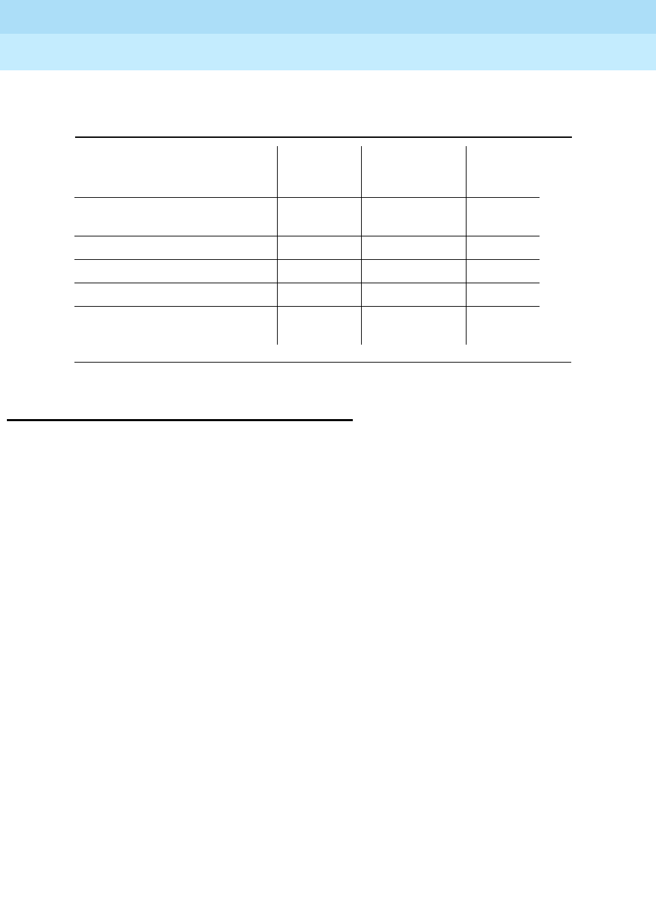
DEFINITY Enterprise Communications Server Release 6
Maintenance for R6r Volumes 1 & 2
555-230-126 Issue 2
January 1998
Maintenance Architecture
Page 1-40Multimedia Interface (MMI)
1
Multimedia Interface (MMI)
The Multimedia Interface handles the following protocols:
■International Telecommunications Union (ITU) H.221 — Includes H.230,
H.242, H.231, and H.243 protocol
■American National Standards Institute (ANSI) H.221 — Includes H.230,
H.242, H.231, and H.243 protocol
■BONDING (Bandwidth On Demand INoperability Group) Mode 1
■ESM HLP HDLC Rate Adaptation
The Vistium Personal Conferencing System is supported either through the
8510T BRI terminal or directly through the Vistium TMBRI PC board.
Using the World Class Core (WCC) BRI interface, most desktop multimedia
applications are supported through a personal computer’s BRI interface.
Table 1-18. MTS and WATS Port Circuit Packs
Circuit Pack FIC
Ringer
Equivalency
Number (REN) Network
Jack
TN742 and TN746B Analog Line 02LS2 None RJ21 and
RJ11C
TN747B Central Office Trunk 02GS2 1.0A RJ21X
TN753 DID Trunk 02RV2-T 0,0B RJ21X
TN790 Processor 02LS2 1.0A RJ21X
TN1648 System Access and
Maintenance 02LS2 0.5A RJ21X

Hardware Configurations
Page 2-1Multi-Carrier Cabinet
2
DEFINITY Enterprise Communications Server Release 6
Maintenance for R6r Volumes 1 & 2
555-230-126 Issue 2
January 1998
2
2Hardware Configurations
The DEFINITY System supports a variety of configurations consisting of a PPN
and up to 21 EPNs. In addition, the system may use a Center Stage Switch (CSS)
consisting of one or two Switch Nodes. This chapter describes the PPN and EPN
cabinets, and the configuration of carriers and circuit packs within these
cabinets.
Multi-Carrier Cabinet
The Multi-Carrier Cabinet (J58890A) accommodates from one to five circuit pack
carriers, and is always used for the PPN. EPNs may use either multicarrier
cabinets or single-carrier cabinets.
The power unit in the bottom of the MCC cabinet supplies AC voltage or DC
voltage from an external source to the power supply in each carrier. The AC
powered cabinet optionally contains a battery charger and backup batteries to
provide temporary power to the cabinet if the external source fails. The backup
unit is optional for systems powered from an Uninterruptible Power Supply (UPS).
The fan unit in the middle of the cabinet cools the carriers. AC-powered cabinets
have two 120V AC receptacles in the back for use as an AC power source. These
can be used to power the G3-MT.
Each cabinet must be connected to one of the following dedicated power
sources:
■120V AC 60 Hz at 50A from a National Electrical Manufacturing
Association (NEMA) 5-50R power outlet or equivalent
■Single phase 240V AC, or three phase 208V AC, 60 Hz at 30A from a
NEMA L 14-30R power outlet or equivalent
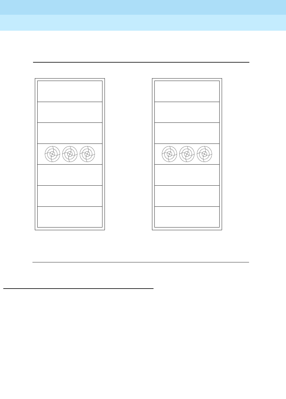
DEFINITY Enterprise Communications Server Release 6
Maintenance for R6r Volumes 1 & 2
555-230-126 Issue 2
January 1998
Hardware Configurations
Page 2-2Multi-Carrier Cabinet
2
■-48V DC battery plant
■Global MCC uses 50-60 Hz at 200-240 VAC power source
Figure 2-1. Multicarrier Cabinet (J58890A) Configurations
Processor Port Network Cabinet
The PPN cabinet, pictured above, is the primary cabinet in all G3r systems. It
contains the Switch Processing Element (SPE) that controls the system and one
Port Network that is interconnected by the daisy-chained TDM/LAN bus. If the
system has a CSS, the PPN cabinet also contains a switch node. The individual
carriers are described in following sections.
The A position always contains a PPN Control Carrier (J58890AP), also known as
the Processor Carrier, which holds the SPE circuit packs. If the system has a
duplicated SPE, the B position holds a second PPN Control Carrier. At least one,
and up to four, Port Carriers (J58890BB) can be located in the other four carrier
positions, depending on traffic needs and whether the system uses those
positions for other types of carriers. In general, Port Carriers are added in the
sequence, B-C-D-E, unless those positions are used otherwise, as follows.
J58890AP
J58890BB
or
Port
Carrier Carrier
PPN Control
Duplicated
Carrier
PPN Control
J58890AP
J58890SA
or
Duplicated
Switch
Node
Carrier
Port
Carrier
J58890BB
Power
Distribution
Unit (G Carrier)
Port
Carrier
J58890BB
J58890SA
or
Switch
Node
Carrier
Port
Carrier
J58890BB
Processor Port Network
J58890BB
J58890BB
J58890BB
Power
Distribution
Unit (G Carrier)
or
Duplicated
Switch
Node
Carrier
Port
Carrier
or
Switch
Node
Carrier
Port
Carrier
Port
Carrier
Expansion
Control
Carrier
Port
Carrier
Expansion Port Network
J58890SA
J58890SA
J58890AF
J58890BB
D Carrier
A Carrier
B Carrier
C Carrier
Fan Unit
E Carrier

DEFINITY Enterprise Communications Server Release 6
Maintenance for R6r Volumes 1 & 2
555-230-126 Issue 2
January 1998
Hardware Configurations
Page 2-3Carriers in Multi-Carrier Cabinets
2
If the system has a Center Stage Switch, the E position holds a Switch Node
Carrier. In a CSS system with duplicated PNC, the D position holds a Switch
Node Carrier that duplicates the one in E position. In large systems requiring a
CSS with two Switch Nodes, the second SN is located in an EPN cabinet, for both
simplex and duplicated systems. Systems that have added a CSS configuration
after the original installation may have their first SN in an EPN cabinet.
Expansion Port Network Cabinets
When used for an EPN, the multicarrier cabinet supports one Port Network with a
daisy-chained TDM/LAN bus, or, optionally, two separate PNs if the cabinet does
not contain a Switch Node. A cabinet with two PNs has two separate TDM/LAN
bus daisy-chains. One TDM/LAN bus between carriers in positions A, B and C
supports the first PN, and another TDM/LAN bus between positions D and E
supports the second PN. Figure 2-1 shows locations of carriers in EPN cabinets.
Each EPN cabinet contains one Expansion Control Carrier (J58890AF) located in
the A position. In cabinets with one PN, up to four Port Carriers are added as
needed in the sequence B-C-D-E, unless the D or E positions are used for a
Switch Node. Cabinets with two PNs use optional Port Carriers in the B position,
and then the C position for the first PN (above the fans). The second PN, (below
the fans), is configured with the first Port Carrier in the E position and an optional
second Port Carrier in D position.
In large systems with a CSS that requires two Switch Nodes, the second SN is
located in an EPN cabinet (this is usually cabinet number 2, PN number 2). This
EPN may not be remoted by a DS1CONV complex. An EPN with an SN has a
Switch Node Carrier in E position. In systems with duplicated PNC, (Critical
Reliability option), the D position holds another Switch Node Carrier that
duplicates the one in E position.
Carriers in Multi-Carrier Cabinets
PPN Control Carrier (J58890AP)
The PPN Control Carrier contains dedicated slots used for circuit packs that
compose the switch processing element (SPE). It does not contain port circuit
pack slots. This carrier always resides in position A of the PPN cabinet. In a
system with a duplicated SPE, a second PPN Control Carrier resides in the B
position of the PPN cabinet.

DEFINITY Enterprise Communications Server Release 6
Maintenance for R6r Volumes 1 & 2
555-230-126 Issue 2
January 1998
Hardware Configurations
Page 2-4Carriers in Multi-Carrier Cabinets
2
Table 2-1 describes the function of each slot in the PPN Control Carrier.
Table 2-1. PPN Control Carrier Circuit Pack Slots
Slot Name Circuit Pack Code Notes
POWER UNIT
(right side) Power Unit (+5V) 649A Required for DC-powered systems. TRI
PLS OUTPUT DC-Powered cabinets
SYS ACCESS/
MAINTENANCE System Access and
Maintenance TN1648 Required
DUP INTFC Duplication Interface UN330B Required for systems with duplicated
SPE
PROCR RISC Processor UN331B Required
TEST INTFC Used by field support to connect
diagnostic equipment
MEMORY 1 to 4 32 Mbyte Memory TN1650B Two required, up to four optional,
Release 5 requires 3
PACKET INTFC 1
to 3 Packet Interface TN1655 One required, two slots reserved for
future use; with duplicated SPE, both
carriers must use same slot
TONE-CLOCK Tone-Clock TN780
TN2182 Required; TN780 required for interface
to external Stratum 3 Clock
MSS/ NET CON Mass Storage System/
Network Control UN332 Required
DISK DRIVE Disk Drive TN1657 Required
TAPE DRIVE Tape Drive TN1656 Required

DEFINITY Enterprise Communications Server Release 6
Maintenance for R6r Volumes 1 & 2
555-230-126 Issue 2
January 1998
Hardware Configurations
Page 2-5Carriers in Multi-Carrier Cabinets
2
Port Carrier (J58890BB)
Table 2-2 describes the function of each carrier slot.
Table 2-2. Port Carrier Circuit Pack Slots
Error Code Circuit Pack Test
Result Description/ Recommendation
POWER UNIT
(right side) Power Unit
(+5V) 649A Required for DC-powered systems. TRI
PLS OUTPUT DC-Powered
POWER
UNIT/
SERVICE
Power Unit,
Neon TN755B This position is addressed as “00” in
commands and displays. It does not
provide tip and ring to the wall field. The
following circuit packs are optional,
depending on system features. One
TN771D is required in all PPNs, and one
in each EPN of Critical Reliability systems.
Call Classifier TN744
Integrated
Announcement TN750
Speech
Synthesizer TN725B,
TN433,
TN457
Tone Detector TN748,
TN420B
Maintenance/
Test TN771D
TONE-
CLOCK 1 Tone-clock TN768
TN2182 Required as follows:
EPN with duplicated PNC: B carrier EPN
cabinet with two PNs: D carrier
E carrier of an EPN cabinet with two PNs
and duplicated PNC; the Tone-clock slot
is located with Port Slot #2. If the carrier
does not contain a Tone-Clock board, any
port board may be installed in this slot.
EXPN INTFC
2Expansion
Interface TN570 Optional, depending on system’s
connectivity and duplication
configuration; if not used for an EI board,
this slot can accept any common port
board.
3 If the system’s connectivity and
duplication configuration require a
second EI on a port carrier, it resides in
this slot; otherwise, this slot accepts any
common port board.
4 to 20 Port Boards Any common port board.
Continued on next page

DEFINITY Enterprise Communications Server Release 6
Maintenance for R6r Volumes 1 & 2
555-230-126 Issue 2
January 1998
Hardware Configurations
Page 2-6Carriers in Multi-Carrier Cabinets
2
Expansion Control Carrier (J58890AF)
The Expansion Control Carrier is located in position A of each EPN. Table 2-3
describes the function of each carrier slot.
Table 2-3. Expansion Control Carrier Slots
Slot Name Circuit Pack Code Notes
POWER UNIT
(left side) Power Unit (+5V)
631DA1 Required for
AC-powered systems
644A1 Required for
DC-powered systems
or empty
MAINTENANCE Maintenance TN775B Required
TONE-CLOCK Tone-Clock TN2182 Required
EXPN INTFC Expansion
Interface TN570 Required
2 to 19 Port Boards Any common port
board. Slot 2 may
house a second EI if
the configuration
requires one.
POWER UNIT/
18, 19 Power Unit, Neon TN755B Required for certain
features; otherwise will
accept any common
port board.
POWER UNIT
(right side) Power Unit
(-48V/-5V) 631DB1 Required for
AC-powered systems
645B1 Required for
DC-powered systems
649A TRI PLS OUTPUT for
Release 5 DC-Powered
cabinets

DEFINITY Enterprise Communications Server Release 6
Maintenance for R6r Volumes 1 & 2
555-230-126 Issue 2
January 1998
Hardware Configurations
Page 2-7Carriers in Multi-Carrier Cabinets
2
Switch Node Carrier (J58890SA)
Switch Node carriers house the components of a Center Stage Switch (CSS). The
first switch node is located in carrier E of the PPN. If duplicated in a Critical
Reliability configuration, its duplicate is located in carrier D of the PPN. The
second switch node is located in carrier E of a non-remoted EPN. If duplicated in
a Critical Reliability configuration, its duplicate is located in carrier D of the same
EPN.
Table 2-4. Switch Node Carrier Circuit Pack Slots
Slot Name Circuit
Pack Code Notes
POWER UNIT
(right side) Power Unit
(+5V) 649A Required for DC-powered systems
EXPN INTFC
DS1 CONV/ 1 DS1
Converter TN574 Provides fiber connectivity from DS1 facilities
to a remote EPN; this slot used in conjunction
with an SNI in one of slots 2 to 9.
Expansion
Interface TN570 Used for an EI board only in the PPN cabinet
in a system with duplicated PNC (Critical
Reliability); used in conjunction with adjacent
SNI
2 to 9, 13 to 20 Switch
Node
Interface
TN573 SNIs are added sequentially as needed
beginning with slot 2. If a second switch node
is needed, (for more than 16 EPNs), up to 5
SNIs (those in slots 7, 8, 9, 13 and 14) are
connected to corresponding SNIs in the other
SN.
SWITCH
NODE
CLOCK / 10
Switch
Node Clock TN572 Required
SWITCH
NODE
CLOCK / 12
Switch
Node Clock TN572 Used in High Reliability option only
(duplicated SPE, simplex PNC)
DS1 CONV/ 21 DS1CONV TN574 Used as above in conjunction with an SNI in
one of slots 13 to 20
Continued on next page

DEFINITY Enterprise Communications Server Release 6
Maintenance for R6r Volumes 1 & 2
555-230-126 Issue 2
January 1998
Hardware Configurations
Page 2-8PNC Cabling — Fiber Hardware
2
PNC Cabling — Fiber Hardware
The term “fiber” is used to refer to all the hardware needed for the three basic
types of connections used to form multi-PN systems. Fiber administration
specifies the endpoints to be connected, optional DS1 CONV locations, and
parameters for DS1 Facility Line encoding and equalization. The 3 connection
types are:
1. EI-to-EI or EI-to-SNI Intercabinet hardware
2. EI-to-SNI or EI-to-EI intracabinet hardware
3. EI-DS1CONV or SNI-DS1CONV hardware
EI-to-EI or EI-to-SNI Intercabinet Fiber Optic
Cables
EI-to-EI or EI-to-SNI intercabinet connections are implemented by installing a
lightwave transceiver on the I/O connector plate for each of the administered
fiber endpoints. Each lightwave transceiver has a receive and a transmit
connector for a 62.5 micron or 50 micron fiber connection. Standard fibers are
available in various lengths up to 150 feet (46 m) for single-mode fiber and up to
200 feet (61 m) for multi-mode fiber. These fibers are used to connect lightwave
transceivers to each other when they are close enough together, or to optical
cross-connect facilities for greater distances.
The lightwave transceivers are powered from I/O connector plate leads attached
to TN570 Expansion Interface circuit pack or a TN573 Switch Node Interface
circuit pack. The transceivers include loop-around capabilities to support fiber
fault isolation. Either of two different 9823-type multi-mode transceivers may be
used, depending upon the length of the fiber (table below), or the 300A single
mode fiber transceiver. The transceivers at each end of a given fiber should
match. Figure 2-2 illustrates the interconnection of fiber optic hardware.
Part
Number Maximum Fiber Length Fiber Mode
9823A 4900 feet (1494 m) Multi-mode
9823B 25,000 feet (7620 m) Multi-mode
300A 22 miles (35.4 km) Single mode
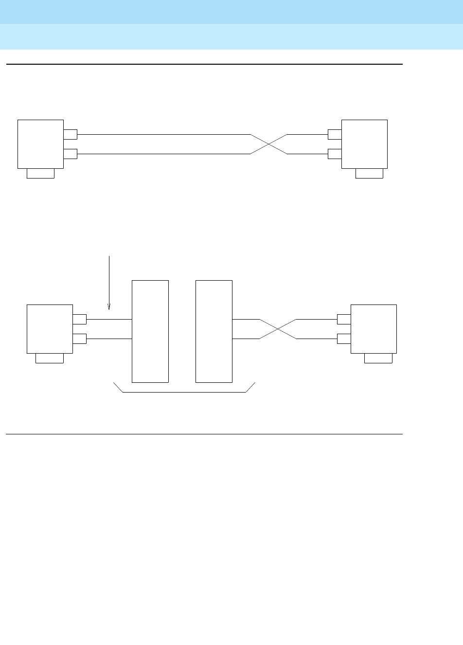
DEFINITY Enterprise Communications Server Release 6
Maintenance for R6r Volumes 1 & 2
555-230-126 Issue 2
January 1998
Hardware Configurations
Page 2-9PNC Cabling — Fiber Hardware
2
Figure 2-2. Fiber Link Connection Hardware
To I/O
Connector
Plate
9823-Type
Lightwave
Transceiver
9823-Type
Lightwave
Transceiver
TX
RX
TX
RX
To I/O
Connector
Plate
FL2P-P-xx
Fiber-Optic
Cables
FL2P-P-xx
Fiber-Optic
Cables
FL2P-P-xx
Fiber-Optic
Cables
To I/O
Connector
Plate
TX
RX
TX
RX
9823-Type
Lightwave
Transceiver
9823-Type
Lightwave
Transceiver
To I/O
Connector
Plate
100A
LIU
Optical Cross-Connect Facility
100A
LIU

DEFINITY Enterprise Communications Server Release 6
Maintenance for R6r Volumes 1 & 2
555-230-126 Issue 2
January 1998
Hardware Configurations
Page 2-10PNC Cabling — Fiber Hardware
2
EI-to-SNI or EI-to-EI Intracabinet Metallic
Cabling
Metallic cable may be substituted for optical cable for “fiber” connections
between EIs or between an EI and an SNI in the same MCC cabinet. The same
I/O plate connectors are used. The metallic cables should not be used for
intercabinet connections, since doing so violates system ground integrity. The
metallic cable comes in two lengths.
DS1 CONV Cabling
Digital services (DS1) can be used to connect PNs that are up to 100 miles (161
km) apart when fiber optic cabling is not practical. Multi-mode (fiber-connected
PNs must be less than 25,000 feet (7620 m) and less than 22 miles (35.4 km) for
single- mode fiber from the PPN.) A TN574 or TN1654 DS1 Converter (DS1
CONV) circuit pack serves as the interface between the network and an EI or SNI
on the switch. DS1 cabling on a carrier consists of a Y-cable that connects a DS1
CONV to an EI or SNI and to the network. The following cables may be used,
depending upon where the DS1 CONV and the EI or SNI are located:
Part No. Length Intended use
H600-278,G1 13 inches (33
cm) From an EI in slot 1 of a switch node carrier to an
SNI in the same half of the carrier (usually the
adjacent slot)
H600-278,G2 66 inches
(168 cm) From an EI to an SNI in the same cabinet, but in a
different carrier or different half of a carrier
Connection Type Length
Comcode
Number
TN574
Comcode
Number
TN1654
On same half carrier 1 foot (30.48 cm) 846448637 847245750
On different half
carriers in same
cabinet
5.5 feet (1.68 m) 846448645 847245768
Between two
adjacent cabinets 1 foot (30.48 cm),
used with two
9823As, and 1
20-foot (6.1 m) fiber
optic cable
846448652, and
one 846885259
bracket
847245776 with
one 846885259
bracket

DEFINITY Enterprise Communications Server Release 6
Maintenance for R6r Volumes 1 & 2
555-230-126 Issue 2
January 1998
Hardware Configurations
Page 2-11PNC Cabling — Fiber Hardware
2
The DS1 CONV to EI/SNI cable is a shielded metallic Y-cable held in place at the
EI/SNI port connector by a 4B retainer and at the DS1 CONV port connector by a
4C retainer. The cable end with one 25-pair amphenol connector attaches to the
I/O Plate connector for the EI or SNI. The end with two 25-pair amphenol
connectors attaches to the DS1 CONV I/O Plate connector.
The 13-inch cable 846448652 or 847245776 connects the DS1 CONV to a
fiber-optic cable, enabling the DS1 CONV to connect to an EI or SNI at a greater
distance. The cable end with one 25-pair amphenol connector attaches to a
lightwave transceiver using the 846885259 bracket. The end with two 25-pair
amphenol connectors attaches to the DS1 CONV I/O Plate connector. The other
end of the fiber-optic cable connects to a lightwave transceiver attached to the
I/O plate connector of the EI or SNI.
An H600-348 cable connects the DS1 CONV cable to a Channel Service Unit
(CSU), which connects to a wall field. (Alternatively, connection is sometimes
made directly from the Y-cable to the wall field. See the pinout for the 50-pin
connector at the end of the Fiber Fault Isolation Procedure in Chapter 5,
‘‘Responding to Alarms and Errors’’.) This cable provides from one to four DS1
connections. One end of the H600-348 cable is plugged into the 50-pin
amphenol piggy-back connector on the 8464486xx cable connected to the
DS1CONV port connector. The other end of the H600-348 cable has four 15-pin
sub-miniature D-type connectors that plug into the CSU. A pinout of this cable
appears the end of the Fiber Fault Isolation Procedure in Chapter 5. H600-348
cables come in the following lengths:
Group No. Length Group No. Length
G1 25 feet (7.62 m) G5 125 feet (38.1 m)
G2 50 feet (15.24 m) G6 200 feet (60.96 m)
G3 75 feet (22.86 m) G7 400 feet (121.9 m)
G4 100 feet (30. 48 m) G8 650 feet (198 m)
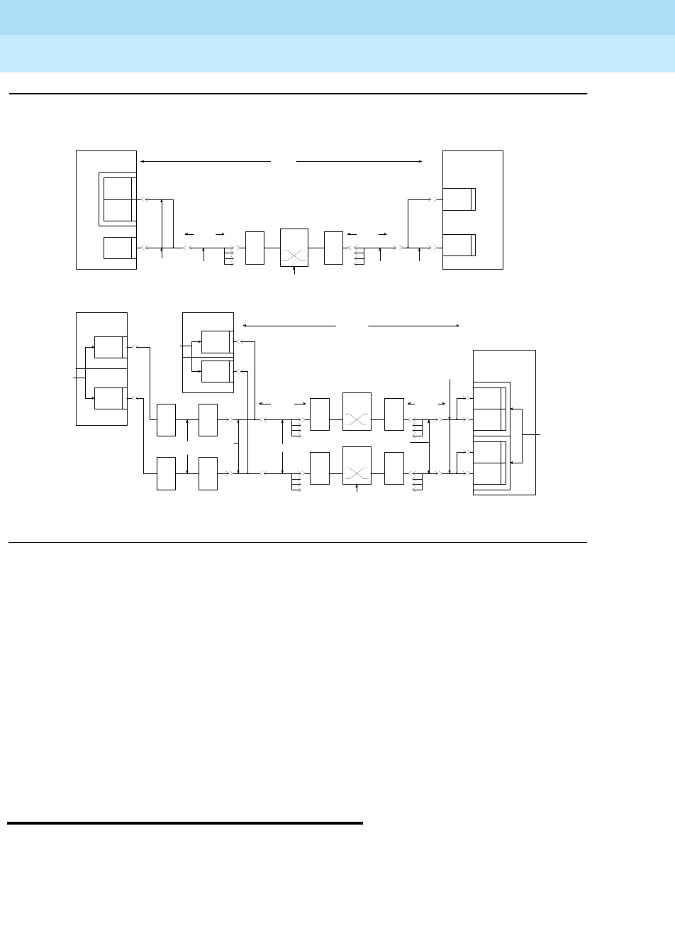
DEFINITY Enterprise Communications Server Release 6
Maintenance for R6r Volumes 1 & 2
555-230-126 Issue 2
January 1998
Hardware Configurations
Page 2-12Circuit Packs
2
Figure 2-3. Typical DS1 CONV Connections to Remote EPNs
1. Place duplicate pairs in different carriers.
2. When removing two or more, the maximum cable distance between any
two remoted end points is 100 miles (161 km). For example, if the EPN is
75 miles (121 km) from the PPN, then EPN 2 can only be 25 miles (40.2
km) from the PPN.
3. 846447637 is used within a carrier for a TN574, for TN1654 within a carrier
use a 847245750.
846448645 is used within a cabinet between carriers for a TN574, for
TN1654 within a cabinet between carriers use a 847245768.
Circuit Packs
The following tables list all circuit packs supported by DEFINITY Systems. For
information concerning vintages and current versions, see
Reference Guide for
Circuit Pack Vintages and Change Notices
which is published periodically as a
special edition of the
Lucent Technical Monthly
.
CIRCUIT
PACK
TN574
G3r
CABINET
CIRCUIT
PACK
TN570
DS1C
G3r
CABINET
CIRCUIT
PACK
TN573
FULLY DUPLICATED
CIRCUIT
PACK
TN573
PPN
EPN
CIRCUIT
PACK
TN574
G3r
CABINET
9823A 9823A
846448637
OR
846448645
H600-348,G-()
FL2P-XX
846448652
H600-348,G()
CONNECT
CROSS
FIELD
CONNECT
CROSS
FIELD
CSU CSU
H600-348,G-()
CIRCUIT
PACK
TN574
G3r
CABINET
CIRCUIT
PACK
TN570
EPN
FOR DIRECT CROSS CONNECT -
SEE TEXT
100 MILES
(SEE NOTE 2)
650 FEET
MAX
CIRCUIT
PACK
TN573
CIRCUIT
PACK
TN574
CSU CSU
9823A 9823A
CONNECT
CROSS
FIELD
CSU CSU
SEE NOTE 1
SEE NOTE 1
H600-348,G()
CIRCUIT
PACK
TN574
CIRCUIT
PACK
TN570
CIRCUIT
PACK
TN574
CIRCUIT
PACK
TN570
G3r
CABINET
EPN
SEE NOTE 1
100 MILES
(SEE NOTE 2)
FOR DIRECT CROSS CONNECT -
SEE TEXT
650 FEET
846448637
(SEE NOTE 3)
846448637
(SEE NOTE 3)
650 FEET 650 FEET

DEFINITY Enterprise Communications Server Release 6
Maintenance for R6r Volumes 1 & 2
555-230-126 Issue 2
January 1998
Hardware Configurations
Page 2-13Circuit Packs
2
Table 2-5. Circuit packs and modules
supported by DEFINITY
Apparatus
Code Name Type
631DA1 AC Power Unit Power
631DB1 AC Power Unit Power
644A1 DC Power Unit Power
645B1 DC Power Unit Power
649A DC Power Unit Power
676B DC Power Supply Power
982LS Current Limiter Power
CFY1B Current Limiter Power
CPP1 Memory Expansion Control
ED-1E546
(TN2169)
(TN2170)
(TN566)
(TN567)
DEFINITY AUDIX R3 System Port Assembly
ED-1E546
(TN2208)
(TN2170)
Call Visor ASAI over the DEFINITY (LAN) Gateway R1 Port Assembly
J58890MAP
(TN800) CallVisor over the DEFINITY LAN Gateway R2 Port Assembly
TN417 Auxiliary Trunk Port
TN419B Tone-Clock Control
TN420B/C Tone Detector Service
TN429 Direct Inward/Outward Dialing (DIOD) Trunk Port
TN433 Speech Synthesizer Service
TN436B Direct Inward Dialing Trunk Port
TN437 Tie Trunk Port
TN438B Central Office Trunk Port
TN439 Tie Trunk Port
TN447 Central Office Trunk Port
TN457 Speech Synthesizer Service
TN458 Tie Trunk Port
Continued on next page

DEFINITY Enterprise Communications Server Release 6
Maintenance for R6r Volumes 1 & 2
555-230-126 Issue 2
January 1998
Hardware Configurations
Page 2-14Circuit Packs
2
TN459B Direct Inward Dialing Trunk Port
TN464C/D/E/F DS1 Interface - T1, 24 Channel - E1, 32 Channel Port
TN465/B/C Central Office Trunk Port
TN467 Analog Line Port
TN468B Analog Line Port
TN479 Analog Line Port
TN497 Tie Trunk Port
TN553 Packet Data Line Port
TN556/B ISDN-BRI 4-Wire S/T-NT Line (A-Law) Port
TN570/B/C Expansion Interface Port
TN572 Switch Node Clock Control
TN573/B Switch Node Interface Control
TN574 DS1 Converter - T1, 24 Channel Port
TN577 Packet Gateway Port
TN722B DS1 Tie Trunk Port
TN725B Speech Synthesizer Service
TN726/B Data Line Port
TN735 MET Line Port
TN742 Analog Line Port
TN744/B Call Classifier Service
TN744/C/D Call Classifier - Detector Service
TN746/B Analog Line Port
TN747B Central Office Trunk Port
TN748/B/C/D Tone Detector Service
TN750/B/C Announcement Service
TN753 Direct Inward Dialing Trunk Port
TN754/B Digital Line 4-Wire DCP Port
TN755B Neon Power Unit Power
TN756 Tone Detector Service
Table 2-5. Circuit packs and modules
supported by DEFINITY — Continued
Apparatus
Code Name Type
Continued on next page

DEFINITY Enterprise Communications Server Release 6
Maintenance for R6r Volumes 1 & 2
555-230-126 Issue 2
January 1998
Hardware Configurations
Page 2-15Circuit Packs
2
TN758 Pooled Modem Port
TN760B/C/D Tie Trunk Port
TN762B Hybrid Line Port
TN763B/C/D Auxiliary Trunk Port
TN765 Processor Interface Control
TN767B/C/D/E DS1 Interface - T1, 24 Channel Port
TN768 Tone-Clock Control
TN769 Analog Line Port
TN771D Maintenance/Test Service
TN772 Duplication Interface Control
TN773 Processor Control
TN775/B Maintenance Service
TN776 Expansion Interface Port
TN777/B Network Control Control
TN778 Packet Control Control
TN780 Tone-Clock Control
TN786 Processor Control
TN786B Processor Control
TN787F/G Multimedia Interface Service
TN788B Multimedia Voice Conditioner Service
TN789 Radio Controller Control
TN790 Processor Control
TN793 Analog Line, 24-Port, 2-Wire Port
TN796B Processor Control
TNPRI/BRI PRI to BRI Converter Port
TN1648 System Access/Maintenance Control
TN1650B Memory Control
TN1654 DS1 Converter - T1, 24 Channel/E1, 32 Channel Port
TN1655 Packet Interface Control
Table 2-5. Circuit packs and modules
supported by DEFINITY — Continued
Apparatus
Code Name Type
Continued on next page

DEFINITY Enterprise Communications Server Release 6
Maintenance for R6r Volumes 1 & 2
555-230-126 Issue 2
January 1998
Hardware Configurations
Page 2-16Circuit Packs
2
TN1656 Tape Drive Control
TN1657 Disk Drive Control
TN2135 Analog Line Port
TN2136 Digital Line 2-Wire DCP Port
TN2138 Central Office Trunk Port
TN2139 Direct Inward Dialing Trunk Port
TN2140/B Tie Trunk Port
TN2144 Analog Line Port
TN2146 Direct Inward Dialing Trunk Port
TN2147/C Central Office Trunk Port
TN2149 Analog Line Port
TN2180 Analog Line Port
TN2181 Digital Line 2-Wire DCP Port
TN2182/B Tone-Clock -Tone Detector and Call Classifier Control
TN2183 Analog Line Port
TN2184 DIOD Trunk Port
TN2198 ISDN-BRI 2-Wire U Interface Port
TN2199 Central Office Trunk Port
TN2202 Ring Generator Power
TN2224 Digital Line, 24-Port, 2-Wire DCP Port
UN330B Duplication Interface Control
UN331B Processor Control
UN332 Mass Storage/Network Control Control
WP-90510 AC Power Supply (Compact Single-Carrier Cabinet) Power
WP-91153 AC Power Supply (Single-Carrier Cabinet) Power
Table 2-5. Circuit packs and modules
supported by DEFINITY — Continued
Apparatus
Code Name Type
Continued on next page

DEFINITY Enterprise Communications Server Release 6
Maintenance for R6r Volumes 1 & 2
555-230-126 Issue 2
January 1998
Hardware Configurations
Page 2-17Duplication: Reliability Options
2
Duplication: Reliability Options
Standard Reliability Option
On Standard Reliability systems, the 512-time-slot TDM bus is divided into two
duplicate 256-time-slot buses, A and B. Call traffic is shared between the two
buses. The first 5 time slots on each bus are reserved for the control channel,
which is active on only one of the two buses at a time. Likewise, the next 17 time
slots are reserved for carrying system tones. The tone times slot are not
necessarily on the same bus (A or B) as the control channel. If any failure takes
place that affects the ability of the active control or tone time slots to function, the
other bus becomes active for those time slots.
High Reliability Option
High Reliability systems duplicate components that are critical to the viability of
the system as a whole to prevent a single failure from dropping all service:
■PPN control carrier and carrier power units (OLSs)
■All SPE circuit packs: Processor, Memory, MSSNET, Disk, Tape, SYSAM,
Duplication Interface, and carrier power units (OLSs)
■PPN Tone Clock circuit pack (EPN Tone-Clocks are not duplicated)
■TDM buses (described above)
In addition to the above, the following are duplicated in Center Stage Switch
(CSS) configurations:
■The PPN to CSS fiber link (consisting of the PPN Expansion Interface
circuit packs, the Switch Node Interface circuit packs that connect to the
PPN EIs, and cabling from the PPN EI to the CSS)
■Switch Node Clocks (SNCs) (two; on each Switch Node carrier)
The duplicated SPEs operate in active/standby fashion. Interchanges of the SPE
and of PPN Tone-Clocks operate independently unless induced by use of the
SPE-select switches. The 2 SNCs on each Switch Node carrier also operate in an
active/standby manner.
The duplicated fiber link between the PPN EIs and the CSS (the cable may
actually be metallic) do not use an active/standby strategy. Instead, both links
simultaneously carry active call traffic and control connectivity in an equally
distributed load-sharing manner. If a component fails one of these fiber links, all
connectivity over it on it is torn down, resulting in some dropped calls and control
and application links. Links and subsequent call service is immediately
re-established over the other EI fiber link.

DEFINITY Enterprise Communications Server Release 6
Maintenance for R6r Volumes 1 & 2
555-230-126 Issue 2
January 1998
Hardware Configurations
Page 2-18Duplication: Reliability Options
2
Critical Reliability Option
Critical Reliability systems include all of the features of the High Reliability option
described above. Additionally, the duplicate components of Port Network
Connectivity (PNC) and other components critical to the viability of each EPN.
■Switch Node carriers and carrier power supplies (OLSs)
■Switch Node Interface (SNI) circuit packs
■Switch Node Clock (SNC) circuit packs (one on each duplicated Switch
Node carrier)
■PPN and EPN Tone-Clock circuit packs
■PPN and EPN Expansion Interface circuit packs
■Each EPN contains a TN771D Maintenance/Test circuit pack
■Inter-PN cabling
■DS1 Converter Complexes (circuit packs, cabling and DS1 facilities used
to connect remote EPNs)
The entire PNC (whether direct connect or CSS connected) is duplicated as a
whole, forming two identical sets which each function as a whole (A-PNC and
B-PNC). The 2 PNCs operate in an active/standby manner with all inter-PN calls
set up on both PNCs so that the active can assume control without disruption of
service. Operation of PNC duplication is described under PNC-DUP in Chapter
9, ‘‘Maintenance Object Repair Procedures’’.
The Tone-Clocks in each EPN operate in an active/standby manner
independently from other duplication strategies.

Management Terminal
Page 3-1Terminals Supported
3
DEFINITY Enterprise Communications Server Release 6
Maintenance for R6r Volumes 1 & 2
555-230-126 Issue 2
January 1998
3
3Management Terminal
The management terminal is used to enter commands and monitor operations
through the maintenance user interface. Chapter 8, ‘‘Maintenance Commands’’
describes the commands available to the maintenance user.
Terminals Supported
Refer to
DEFINITY Enterprise Communications Server Release 5 Installation and
Test for Multi-Carrier Cabinets
, and the user manual on your terminal model for
setup instructions.
Multiple Access
Release 6r allows multiple users to perform maintenance and administration at
the same time:
■This system has a security feature to allow the customer to define their
own logins and passwords and to specify a set of commands for each
login. It allows up to 11 customer and 4 services logins. Each login name
can be customized.
■Login Security Violation Notification Following a Security Violation and
Login Kill after “N” Attempts features notifies a referral point, and disables
a login ID (Customer or Lucent Services logins) following a security
violation (a user defined security violation threshold). The Login Kill after
“N” Attempts feature will not disable the last remaining inads type login.
Lucent Services logins require a Lucent init level login ID to re-enable
logins that have been disabled by a security violation or the command
disable login.

DEFINITY Enterprise Communications Server Release 6
Maintenance for R6r Volumes 1 & 2
555-230-126 Issue 2
January 1998
Management Terminal
Page 3-2Switch-Based Bulletin Board
3
■
Logoff Notification (Release 5)
alerts system administrators, during log
off from the system administration and maintenance interface, of possible
system maintenance problems. This notification also alerts the system
administrators that features that present a significant security risk are
enabled. A message displays on the system administration/maintenance
interface during logoff if a security risk feature is enabled. Additionally, the
user can be required to acknowledge the notification before the logoff is
completed.
■The system is delivered to the customer with one “super-user” login and
password defined. The customer is required to administer any additional
login and passwords. The super-user login has full customer permissions
and can customize any login that they create. Login permissions are set
by the super-user to allow or block any object that can affect the health of
the switch. Up to 40 administration or maintenance objects (commands)
can be blocked for a specified login.
■Two maintenance logins are reserved for the SYSAM-RMT and
SYSAM-LCL ports on the TN1648 SYSAM circuit pack located on PPN
control carriers. SYSAM-RMT is a dial-up remote access port reserved for
use by INADS. SYSAM-LCL is accessed by RS232 connectors on the
TN1648. Two other maintenance users can log in by dial-up System
Access Ports (SAPs) or by connecting directly to EPN Maintenance circuit
packs.
■Up to 5 maintenance and 5 administration commands can run
concurrently. Some commands that use the same resources as others
experience contention and cannot be run at the same time. For more
information on contention, see ‘‘Contention Between Simultaneous
Commands’’ in Chapter 8, ‘‘Maintenance Commands’’.
Switch-Based Bulletin Board
This feature allows a System Access Terminal (SAT) user to leave messages in
the system in order to communicate with other system users.
NOTE:
This feature does not substitute for any existing procedures for escalating
problems. It is only an aid to the existing process.
Description
The bulletin board service provides an easy interface for the customer and
Lucent to leave messages on the system.
The bulletin board feature makes it easy for the customer to communicate with
Lucent (and vise versa). For example, when a new load is installed on a switch in
the customer's system, Lucent is able to leave the customer messages that
describe any new functions. It also allow Lucent to keep you informed on the
progress of trouble items. In addition, you can use this feature to provide

DEFINITY Enterprise Communications Server Release 6
Maintenance for R6r Volumes 1 & 2
555-230-126 Issue 2
January 1998
Management Terminal
Page 3-3Switch-Based Bulletin Board
3
additional information concerning problems that have already been escalated by
the normal procedure.
Accessing the Bulletin Board
Any user with the appropriate permissions can log into the system and have
access to the bulletin board. Users that have “Maintain System” or “Administer
Features” permissions can enter, change, display, print, or schedule to print a
message. Users that have “Display Admin” and “Maintain Data” permission can
display the bulletin board. Any user who has “Display” permission can display,
print, and schedule to print the contents of the bulletin board.
When a user logs on to the system they are notified of any messages on the
bulletin board. The notification message indicates the last time the bulletin board
was updated, if any “High-Priority” message exist, and if the bulletin board is
80% or more full. If a “High-Priority” message exists, the command prompt will
change to the following message:
■High-Priority Bulletin Board Messages Entered:
After the next command is entered, the default command prompt returns to the
screen.
User Considerations
■Only one user at a time may edit a message on the bulletin board.
■The user must have the proper permissions to access the bulletin board.
■You, the user must maintain the information stored on the bulletin board. It
is your responsibility to delete old messages. If the bulletin board is full
any new messages overwrite old messages.
System Considerations
■The Bulletin Board feature provides up to 3 pages of text for each
message. Each page is limited to 20 lines of text and 40 characters per
line. The first 10 lines of text on page 1 are reserved for Lucent Service’s
High-Priority messages.
System Bulletin Board Commands
The system commands “change bulletin board”, “display bulletin board,” and
existing commands in the user interface are provided for use in the Switch Based
Bulletin Board.
To edit or enter a message on the Switch Based Bulletin Board you must:
1. Log into the system with “Maintain System or Administer Features”
Permissions.
2. Enter the command change bulletin-board.

DEFINITY Enterprise Communications Server Release 6
Maintenance for R6r Volumes 1 & 2
555-230-126 Issue 2
January 1998
Management Terminal
Page 3-4Switch-Based Bulletin Board
3
3. Follow system prompts.
To display messages on the Switch Based Bulletin Board you must:
1. Log into the system with “Maintain System”, “Display Admin,” or “Maint
Data” permissions.
2. Enter the command display bulletin board.
3. Follow system prompts.
Editing a Switch-Based Bulletin Board Message
As stated before, a message may contain up to three pages of information with
the first 10 lines on page 1 reserved for Lucent Service’s
High-Priority
messages
(the “INIT”, “INADS”, and “craft” logins can edit the first 10 lines on page one).
Pages 2 and 3 will allow up to 20 lines of 40 characters of text. Each line has a
date field to show when the line is modified.
The control keys used to edit existing feature forms must be used to edit a
message in the Switch Based Bulletin Board. The following characters are
allowed for use in the text field:
■Uppercase/Lowercase letters, spaces, numerals, and !@#$%^&*()_
-+=[]{};’”<>./?.
NOTE:
Tab characters are not allowed. The existing command line interface will
cause the cursor to move to the next field if a Tab character is entered.
If a user changes any lines which cause 2 or more consecutive blank lines the
bulletin board is automatically reorganized (upon submittal). Two or more blank
lines are changed to a single blank line. A blank line is at the top of a form is also
deleted. This prevent holes in the bulletin board screens as old entries are
deleted.
To save a message entered into the bulletin board text field, you must execute
the save translation command.
The following screen, is an example of bulletin board messages between Lucent
and a customer that is having trouble with trunk group translations:

DEFINITY Enterprise Communications Server Release 6
Maintenance for R6r Volumes 1 & 2
555-230-126 Issue 2
January 1998
Management Terminal
Page 3-5Switch-Based Bulletin Board Message Notification
3
Switch-Based Bulletin Board Message
Notification
When a user logs on to the system they are notified of any messages on the
bulletin board. The notification message indicates the last time the bulletin board
was updated, if any “High-Priority” message exist and if the bulletin board is 80%
or more full. If a “High-Priority” message exists, the command prompt changes to
the following message:
High-Priority Bulletin Board Messages Entered:
After the next command is entered, the default command prompt returns to the
screen.
To Log In
To log in to the switch:
1. Enter your login name and password on the login and password screen.
If your password has expired you see the message:
Your password has expired, enter a new one.
The password aging screen (Screen 3-1) is displayed when a user logs in.
If the user’s password is expired, the user is prompted to enter a new
password. If your password is within 7 days of the expiration date you see:
display bulletin-board Page 1 of 3
Messages (* indicates high-priority) Date
* Lucent is in the process of 02/02/95
* investigating your trunk lockup problem. 02/02/95
* The Bulletin Board will be updated as 02/02/95
* information is found. 02/02/95
* We have identified the problem. 02/02/95
* The trunk you added does not provide 02/02/95
* disconnect supervision, however your trunk 02/02/95
* group was administered as such. 02/02/95
* Please call for details. 02/02/95
*
We recently added a new trunk group (14) 02/03/95
and have had trunk group members locking up. 02/03/95
We see the error - Thanks for checking. 02/03/95
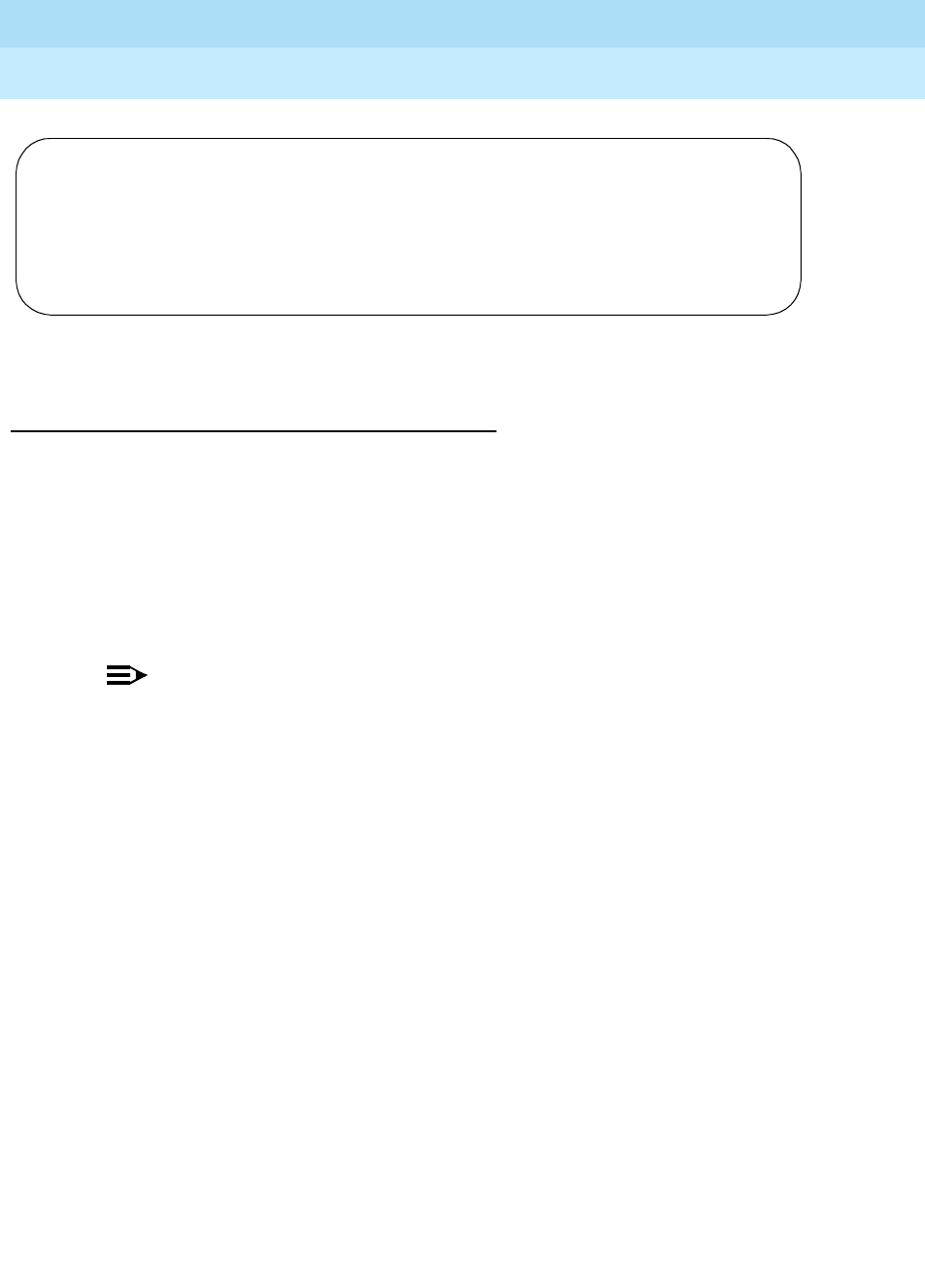
DEFINITY Enterprise Communications Server Release 6
Maintenance for R6r Volumes 1 & 2
555-230-126 Issue 2
January 1998
Management Terminal
Page 3-6Switch-Based Bulletin Board Message Notification
3
Screen 3-1. Password Aging Screen
Forced Password Aging and Administrable
Logins for G3V3 and Later Releases
G3V3 and later releases provide enhanced login/password security by adding a
security feature that allows users to define their own logins/passwords and to
specify a set of commands for each login. The system allows up to 11 customer
logins. Each login name can be customized and must be made up of from 3 to 6
alphabetic/numeric characters, or a combination of both. A password must be
from 4 to 11 characters in length and contain at least 1 alphabetic and 1 numeric
symbol. Password aging is an optional feature that the super-user administering
the logins can activate.
NOTE:
If several “users” are logging in and out at the same time, a user may see
the message “Transient command conflict detected; please try later”. After
the “users” have completed logging in or out, the System Access Terminal
is available for use, try executing the command again.
The password for each login can be aged starting with the date the password
was created, or changed, and continuing for a specified number of days (1 to
99). The user is notified at the login prompt, 7 days before the password
expiration date, that his/her password is about to expire. When the password
expires the user is required to enter a new password into the system before
logging in. If a login is added or removed, the “Security Measurement” reports
are not updated until the next hourly poll, or a clear measurements
security-violations command is entered. Once a non-super-user has changed
his/her password, the user must wait 24 hours to change the password again.
V4 security is enhanced by providing a logoff notification screen to a system
administrator when he/she logs off while either the facility test call or remote
access features are still administered. The administrator can be required to
acknowledge the notification before completing the logoff process. Logoff
notification is administered on the Login Administration screen.
The system is delivered to the customer with one customer “super-user”
login/password defined. The customer is required to administer additional
login/passwords as needed. The super-user login has full customer permissions
and can customize any login that he/she creates.
Login: telmgr
Password:
Your Password has expired, enter a new one.
Reenter Current Password:
Old Password:
New Password:
Reenter New Password:

DEFINITY Enterprise Communications Server Release 6
Maintenance for R6r Volumes 1 & 2
555-230-126 Issue 2
January 1998
Management Terminal
Page 3-7Switch-Based Bulletin Board Message Notification
3
Login permissions for a specified login can be set by the super-user to block any
object that may compromise switch security. Up to 40 administration or
maintenance objects commands can be blocked for a specified login in. When
an object (administrative or maintenance command) is entered in the blocked
object list on the Command Permissions Categories Restricted Object List form,
the associated administrative or maintenance actions cannot be performed by
the specified login.
There are 3 command categories. Each of the 3 command categories has a
group of command subcategories listed under them, and each command
subcategory has a list of command objects that the commands acts on. See
Table 3-1 and Table 3-2 for a list of objects. A super-user can set a users
permissions to restrict or block access to any command in these categories. The
3 categories are:
■Common Commands
— Display Admin. and Maint. Data
— System Measurements
■Administration Commands
— Administer Stations
— Administer Trunks
— Additional Restrictions
— Administer Features
— Administer Permissions
■Maintenance Commands
— Maintain Stations
— Maintain Trunks
— Maintain Systems
— Maintain Switch Circuit Packs
— Maintain Process Circuit Packs
These categories are displayed on the Command Permissions Categories form.
To Log In
To log in to the switch:
1. Enter your login name and password on the login and password screen
(Screen 3-2).
If your password has expired you see the message:
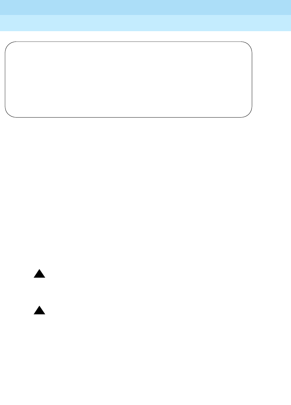
DEFINITY Enterprise Communications Server Release 6
Maintenance for R6r Volumes 1 & 2
555-230-126 Issue 2
January 1998
Management Terminal
Page 3-8Switch-Based Bulletin Board Message Notification
3
Screen 3-2. Password Expiration Screen
The Password Expiration screen is displayed when you log in. If your password is
expired you are prompted to enter a new password. If your password is within 7
days of the expiration date you see:
WARNING: Your password will expire in X days
To Logoff
To logoff, enter logoff at the command prompt.
If facility test call notification or remote access notification are enabled for your
login (see Adding Customer Logins and Assigning Initial Passwords, below), you
receive a logoff screen. If either the facility test call or remote access
acknowledgments are required, you need to respond to the Proceed with
Logoff? prompt on the logoff screen. The response is defaulted to n; you will
need to enter y to override the default.
!CAUTION:
To leave the facility test call administered after you logoff poses a
significant security risk.
!CAUTION:
To Leave Remote Access feature administered after logging off poses a
significant security risk if you are using the feature in conjunction with the
Facility Test Call feature.
Login: telmgr
Password:
Your Password has expired, enter a new one.
Reenter Current Password:
New Password:
Reenter New Password:

DEFINITY Enterprise Communications Server Release 6
Maintenance for R6r Volumes 1 & 2
555-230-126 Issue 2
January 1998
Management Terminal
Page 3-9Switch-Based Bulletin Board Message Notification
3
Screen 3-3. Logoff Screen
To Display a Login
To display a specified login:
1. Enter the command display login [login name] and press the Enter key.
The system displays the requested login’s:
■Name
■Login type
■Service level
■Access to INADS Port value (V4)
■Password aging cycle length
■Facility test call notification and acknowledgment
■Remote access notification and acknowledgment
To List Logins
To list all of the system logins and the status of each login:
2. Enter the command list logins.
The system displays the following information for all current logins:
■Name
■Service level
■Status (active, inactive, disabled, svn-disabled, void)
■Password aging cycle length
The system displays only those logins with the same, or lower, service
level as the requestor.
To Remove a Login
To remove a login from the system:
1. Enter the command remove login [login name].
Facility Test Call Administered
Remote Access Administered
Proceed with Logoff? [n]

DEFINITY Enterprise Communications Server Release 6
Maintenance for R6r Volumes 1 & 2
555-230-126 Issue 2
January 1998
Management Terminal
Page 3-10Switch-Based Bulletin Board Message Notification
3
The system displays the Login Administration form.
2. Press the Enter key to remove the login, or press Cancel to exit the remove
login procedure without making a change.
To Test a Login
1. Enter your login name at the login prompt.
Screen 3-4. Login Prompt Form
After the user enters the correct login name and password and the login is
administered correctly, the system displays the command line interface.
Administering Customer Logins and Forced
Password Aging
Adding Customer Logins and Assigning Initial
Password
To add a customer login you must be a super-user, have administrative
permissions, and:
1. Enter the add login [name] command to access the Login Administration
form.
2. Enter your super-user password in the Password of Login Making Change
field on the Login Administration form.
The 3- to 6-character login name (characters 0-9, a-z, A-Z) entered with
the add login [name] command is displayed in the Login’s Name field.
3. Enter customer in the Login Type field. The system default for the
Login Type field is customer. The maximum number of customer logins
of all types is 11.
4. Enter super-user or non-super-user in the Service Level field. Default is
non-super-user.
■“super-user” gives access to the add, change, display, list, and
remove commands for all customer logins and passwords. The
super-user can administer any mix of super-user/non-super-user
logins up to a total of ten additional system logins.
■“non-super-user” permissions are limited by restrictions specified
by the super-user when administering the non-super-user login. A
non-super-user can change his/her password with permission set
Login: telmgr
Password:vvvvvvvvcf

DEFINITY Enterprise Communications Server Release 6
Maintenance for R6r Volumes 1 & 2
555-230-126 Issue 2
January 1998
Management Terminal
Page 3-11Switch-Based Bulletin Board Message Notification
3
by the super-user, however once a password has been changed
the non-super-user must wait 24 hours before changing the
password again. A non-super-user cannot change other user
passwords, login characteristics, or permissions.
5. Enter y in the Disable Following a Security Violation field to
disable a login following a login security threshold violation. This field is a
dynamic field and only appears on the Login Administration form when the
SVN Login Violation Notification feature is enabled. The system default for
the Disable Following a Security Violation field is y.
6. Enter y in the Access to INADS Port? field to allow access to the
remote administration port. This field only displays if Acct. has first
enabled customer super-user access to the INADS Remote Administration
Port. Default is n. This step is valid for V4 and higher systems only.
7. Enter a password for the new login in the Login’s Password field. A
password must be from 4 to 11 characters in length and contain at least 1
alphabetic and 1 numeric symbol. Valid characters include numbers,
and!&*?;’^(),.:- (the system will not echo the password to the screen as
you type).
8. Re-enter the password in the Login’s Password field. The system will not
echo the password to the screen as you type.
9. Enter the number of days (1 to 99) from the current day, that you want the
password to expire, in the Password Aging Cycle Length field. If a you
enter a blank in this field, password aging does not apply to the login.
10. Decide whether or not to leave the default of yes (“y”) in the Facility
Test Call Notification? field. If you retain the default, the user
receives notification at logoff that the facility test call feature access code
is administered. If you do not want the notification to appear, set the field
to n.
!CAUTION:
Leaving The facility Test Call administered after logging off poses a
significant security risk.
11. Decide whether or not to leave the default of yes (“y”) in the Facility Test
Call Notification Acknowledgment Required field. If you retain the default,
the user is required to acknowledge that they wish to logoff while Facility
Test Call is still administered. If you do not want to force the user to
acknowledge, set the field to n. This field appears only if the Facility
Test Call Notification field is set to y.
12. Decide whether or not to leave the default of yes (“y”) in the Remote
Access Notification? field. If you retain the default, the user receives
notification at logoff that remote access is still administered. If you do not
want the notification to appear, set the field to n.

DEFINITY Enterprise Communications Server Release 6
Maintenance for R6r Volumes 1 & 2
555-230-126 Issue 2
January 1998
Management Terminal
Page 3-12Switch-Based Bulletin Board Message Notification
3
!CAUTION:
To Leave Remote Access feature administered after logging off
poses a significant security risk if you are using the feature in
conjunction with the Facility Test Call feature.
13. Decide whether or not to leave the default of yes (“y”) in the Remote
Access Acknowledgment Required? field. If you retain the default,
the user is required to acknowledge that they wish to logoff while remote
access is still administered. If you do not want to force the user to
acknowledge, set the field to n. This field appears only if the Facility
Test Call Notification field is set to y.
Screen 3-5. Login Administration
Changing a Login’s Attributes
To change a customer login’s attributes you must be a super-user, have
administrative permissions (specifically, the Administration Permission
field must be set to y for the super-user), and:
1. Enter the change login [name] command to access the Login
Administration form.
2. Enter your super-user password in the Password of Login Making
Change field on the Login Administration form.
The 3- to 6-character login name (characters 0-9, a-z, A-Z) entered with
the change login [name] command is displayed in the Login’s Name
field.
3. Enter customer in the Login Type field.
4. Enter super-user or non-super-user in the Service Level field.
LOGIN ADMINISTRATION
Password of Login Making Change:
LOGIN BEING ADMINISTERED
Login’s Name:xxxxxxx
Login Type:
Service Level:
Disable Following a Security Violation?
Access to INADS Port?
LOGIN’S PASSWORD INFORMATION
Login’s Password:
Reenter Login’s Password:
Password Aging Cycle Length:
LOGOFF NOTIFICATION
Facility Test Call Notification? y Acknowledgment Required? y
Remote Access Notification? y Acknowledgment Required? y

DEFINITY Enterprise Communications Server Release 6
Maintenance for R6r Volumes 1 & 2
555-230-126 Issue 2
January 1998
Management Terminal
Page 3-13Switch-Based Bulletin Board Message Notification
3
NOTE:
You cannot change your own service level.
5. To disable a login following a login security threshold violation, enter y in
the Disable Following a Security Violation field. This field is a
dynamic field and only appears on the Login Administration form when the
SVN Login Violation Notification feature is enabled.
6. To allow access to the remote administration port, enter y in the Access
to INADS Port? field. This field only displays if Lucent has first enabled
customer super-user access to the INADS Remote Administration Port.
7. Enter a password for the new login in the Login’s Password field. A
password must be from 4 to 11 characters in length and contain at least 1
alphabetic and 1 numeric symbol. Valid characters include numbers,
and!&*?;’^(),.:- (the system will not echo the password to the screen as
you type).
8. Re-enter the password in the Login’s Password field. The system will not
echo the password to the screen as you type.
9. Enter the number of days (1 to 99) from the current day, when you wish the
password to expire, in the Password Aging Cycle Length field. If a
blank is entered in this field, password aging does not apply to the login.
Administering Login Command Permissions
To administer command permissions, log in as super-user and:
1. Access the Command Permissions Categories form by entering the
command change permissions login [login name]. When the Command
Permission Categories form is displayed for a login, the default
permissions for that “login type” are shown on the form. The super-user
administering the login can change a y to n for each subcategory field on
the form.
2. Select a category for the login and enter y in each field where permission
to perform a administrative or maintenance action is needed. The
command object you select must be within the permissions for the login
type you are administering.
If the Maintenance option is set to y on the Customer Options form, the
super-user can enter y in the Maintain Switch Circuit Packs? or
Maintain Process Circuit Packs fields.
3. A super-user with full super-user permissions (super-user administering
the login cannot have the Additional Restrictions field set to y for
his/her own login) can restrict additional administrative or maintenance
actions for a specified login by entering y in the Additional
Restrictions field on the Command Permission Categories form. Enter
the additional restrictions for a login in the Restricted object list

DEFINITY Enterprise Communications Server Release 6
Maintenance for R6r Volumes 1 & 2
555-230-126 Issue 2
January 1998
Management Terminal
Page 3-14Switch-Based Bulletin Board Message Notification
3
fields on the Command Permission Categories Restricted Object List form.
You can enter up to 40 command names (object names) to block actions
associated with a command category for a specified login.
.
Screen 3-6. Command Permission Categories (Page 1 of 3)
Screen 3-7. Command Permissions Categories (Page 2 of 3)
Page 1 of 3
COMMAND PERMISSION CATEGORIES
Login Name: Sup3ru
COMMON COMMANDS
Display Admin. and Maint. Data? y
System Measurements? _
ADMINISTRATION COMMANDS
Administer Stations? y Administer Features? y
Administer Trunks? y Administer Permissions? y
Additional Restrictions? n
MAINTENANCE COMMANDS
Maintain Stations? n Maintain Switch Circuit Packs? n
Maintain Trunks? n Maintain Process Circuit Packs? n
Maintain Systems? n
Page 2 of 3
COMMAND PERMISSION CATEGORIES
RESTRICTED OBJECT LIST
_______________________ ______________________
_______________________ ______________________
_______________________ ______________________
_______________________ ______________________
_______________________ ______________________
_______________________ ______________________
_______________________ ______________________
_______________________ ______________________
_______________________ ______________________
_______________________ ______________________

DEFINITY Enterprise Communications Server Release 6
Maintenance for R6r Volumes 1 & 2
555-230-126 Issue 2
January 1998
Management Terminal
Page 3-15Switch-Based Bulletin Board Message Notification
3
Screen 3-8. Command Permissions Categories (Page 3 of 3)
Table 3-1. Command Permissions Form Entries — Display Administration and
Maintenance
Object Action
Change Display List Monitor Remove Status Tes
t
aar analysis X X
aar digit-conversion X X
aar route-chosen X
abbreviated-dialing 7103A-buttons X
abbreviated-dialing enhanced X
abbreviated-dialing group X X
abbreviated-dialing personal X X
abbreviated-dialing system X
aca-parameters X
access-endpoint X X X X
adjunct-names X
adjunt-controlled-agents X
administered-connection X X X
agent-loginID X X
alarms X X
alias-station X
alphanumeric-dial-table X
alternate-frl X
Continued on next page
Page 3 of 3
COMMAND PERMISSION CATEGORIES
RESTRICTED OBJECT LIST
_______________________ ______________________
_______________________ ______________________
_______________________ ______________________
_______________________ ______________________
_______________________ ______________________
_______________________ ______________________
_______________________ ______________________
_______________________ ______________________
_______________________ ______________________
_______________________ ______________________

DEFINITY Enterprise Communications Server Release 6
Maintenance for R6r Volumes 1 & 2
555-230-126 Issue 2
January 1998
Management Terminal
Page 3-16Switch-Based Bulletin Board Message Notification
3
analog -testcall X
announcements X
ars analysis X X
ars analysis X
ars digit-conversion X
ars digit-conversion X
ars route-chosen X
ars-toll X
attendant X X
bcms agent X
bcms lignites X
bcms split X
bcms trunk X
bcms vdn X
board X
bri-port X
bridged-extensions X
bulletin-board X
button-location-aca X
cabinet X X
call-forwarding X
call-screening X
capacity X
card-mem1XX
cdr-link XX
circuit-packs X
communication-interface hop-channels X X
communication-interface links X
communication-interface
proc-channels XX
configuration all X
Table 3-1. Command Permissions Form Entries — Display Administration and
Maintenance — Continued
Object Action
Change Display List Monitor Remove Status Tes
t
Continued on next page

DEFINITY Enterprise Communications Server Release 6
Maintenance for R6r Volumes 1 & 2
555-230-126 Issue 2
January 1998
Management Terminal
Page 3-17Switch-Based Bulletin Board Message Notification
3
configuration board X
configuration carrier X
configuration control X
configuration network X
configuration software X
configuration station X
configuration trunk X
console-parameters X
cor X X
cos X
coverage answer-group X X
coverage groups X
coverage path X X
customer-alarm X
data-module X X X X
dappling X
digit-absorption X
display-format X X
do-not-disturb group X
do-not-disturb station X
ds1 X X
dsp-msg-auto-wakeup X
dsp-msg-call-identifier X
dsp-msg-date-time X
dsp-msg-lwc X
dsp-msg-mct X
dsp-msg-miscellaneous X
dsp-msg-property-mgmt X
dsp-msg-softkey-label X
dsp-msg-tod-routing X
Table 3-1. Command Permissions Form Entries — Display Administration and
Maintenance — Continued
Object Action
Change Display List Monitor Remove Status Tes
t
Continued on next page
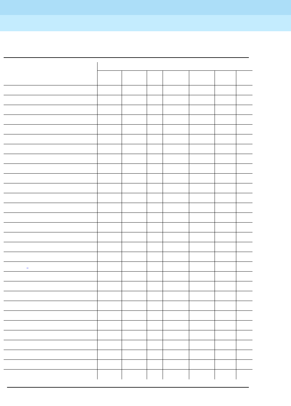
DEFINITY Enterprise Communications Server Release 6
Maintenance for R6r Volumes 1 & 2
555-230-126 Issue 2
January 1998
Management Terminal
Page 3-18Switch-Based Bulletin Board Message Notification
3
emergency X
enp-number-plan X
environment X
errors X
events X
external-device-alarm X
extension-type X
external-device-alarming X
feature-access-code X
fiber-link2XX
groups-of-extensions X
hardware-group XX
health X
history X
hunt-group X X
inads-link X
integrated-annc-boards X X
intercom-group X X
interface1XX
intra-switch-cdr X X
isdn cpn-prefix X
isdn network-facilities X
isdn-testcall X
isdn tsc-gateway X
ixc-codes X
journal-printer X
led X
link XX
listed-directory-numbers X
login X
Table 3-1. Command Permissions Form Entries — Display Administration and
Maintenance — Continued
Object Action
Change Display List Monitor Remove Status Tes
t
Continued on next page
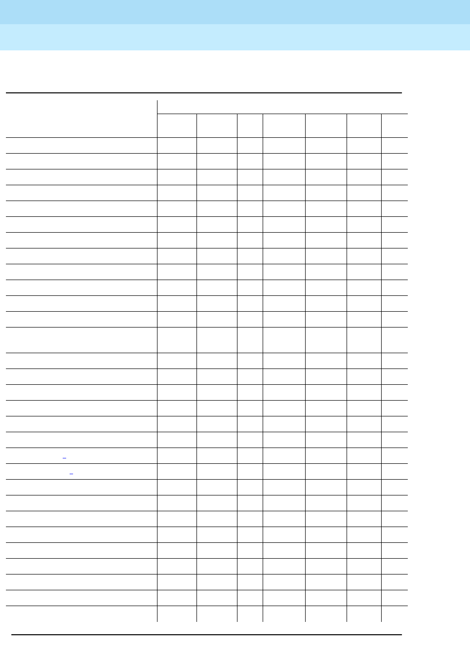
DEFINITY Enterprise Communications Server Release 6
Maintenance for R6r Volumes 1 & 2
555-230-126 Issue 2
January 1998
Management Terminal
Page 3-19Switch-Based Bulletin Board Message Notification
3
login3 X
login-ids X
maintenance X
marked-port X
mct-group-extensions X
mct-history X
meas-selection coverage X
meas-selection principal X
meas-selection route-pattern X
meas-selection trunk-group X
meas-selection wideband-trunk-grp X
measurements security-violations detail X
measurements security-violations
summary X
memory X
MO X
modem-pool X X X
multi-frequency signaling X
network-control X
node-routing X X
packet-control1XX
packet-interface2X
paging code-calling-ids X X
paging-loudspeaker X
password X
periodic-scheduled X
permissions X
personal-CO-line X X
pgate X X
pickup-group X X
pkt X
Table 3-1. Command Permissions Form Entries — Display Administration and
Maintenance — Continued
Object Action
Change Display List Monitor Remove Status Tes
t
Continued on next page

DEFINITY Enterprise Communications Server Release 6
Maintenance for R6r Volumes 1 & 2
555-230-126 Issue 2
January 1998
Management Terminal
Page 3-20Switch-Based Bulletin Board Message Notification
3
pms X
pms-down X
pms-link X
pms-log X
pnc X
port X X
port-network2X
pri-endpoint X X X X
processor X
remote-call-coverage X
report-scheduler X X X
rhnpa X
route-pattern X X
routing-table X X
scr X
second-digit X
security-violations X
set-data X
signaling-group X X X X
sit-treatment X
site-data X
skill X
sp-link XX
spe X
stargate-port X
station X X X
svn-button-location X
switch-node2X
synchronization X X X
sys-link X X
Table 3-1. Command Permissions Form Entries — Display Administration and
Maintenance — Continued
Object Action
Change Display List Monitor Remove Status Tes
t
Continued on next page

DEFINITY Enterprise Communications Server Release 6
Maintenance for R6r Volumes 1 & 2
555-230-126 Issue 2
January 1998
Management Terminal
Page 3-21Switch-Based Bulletin Board Message Notification
3
system X
system 1st-cabinet X
system 2nd-cabinet X
system 3rd-cabinet X
system all-cabinets X
system conn X
system customer-options X
system features X
system-maintenance X
system-parameters cdr X
system-parameters country-options X
system-parameters duplication2X
system-parameters hospitality X
system-parameters security X
tdm X
term-ext-group X X
terminal-parameters 603/302B1 X
terminal-parameters 8400 X
test-schedule X X
time X
time-of-day X
toll X
toll all X
toll restricted-call X
toll-list X
toll unrestricted-call X
tone-clock X
trunk XXX
trunk-group X X X
trunk-group-history X
Table 3-1. Command Permissions Form Entries — Display Administration and
Maintenance — Continued
Object Action
Change Display List Monitor Remove Status Tes
t
Continued on next page

DEFINITY Enterprise Communications Server Release 6
Maintenance for R6r Volumes 1 & 2
555-230-126 Issue 2
January 1998
Management Terminal
Page 3-22Switch-Based Bulletin Board Message Notification
3
1. Intel only.
2. MIPS only.
3. Must be super-user.
trunk-group-members X
tsc-administered X
tti X
udp X X
unstaffed-agents X
usage button-type hunt-ns X
usage button-type trunk-ns X
usage button-type night-service X
usage-extensions X
usage-hunt X
vdn X X X
vector X X
wakeup incomplete X
wakeup requests X
wakeup station X
wakeup-log X
Table 3-2. Command Permissions Form Entries — Administer Permissions
Object Action
Add Change Display Enable Remove
login X X X X X
permissions X
Table 3-1. Command Permissions Form Entries — Display Administration and
Maintenance — Continued
Object Action
Change Display List Monitor Remove Status Tes
t
Continued on next page

DEFINITY Enterprise Communications Server Release 6
Maintenance for R6r Volumes 1 & 2
555-230-126 Issue 2
January 1998
Management Terminal
Page 3-23Switch-Based Bulletin Board Message Notification
3
Table 3-3. Command Permissions Form Entries — Administer Stations
Object Action
Add Change Duplicate Remove
abbreviated-dialing 7103A-buttons X X X
abbreviated-dialing enhanced X X X
abbreviated-dialing group X X X
abbreviated-dialing personal X X
abbreviated-dialing system X X X
alias-station X
attendant X X X
console-parameters
data-module X X X X
routing-table X X X
station X X X X
terminal-parameters 603/302B1 X
terminal-parameters 8400 X
vdn X X X
vector X
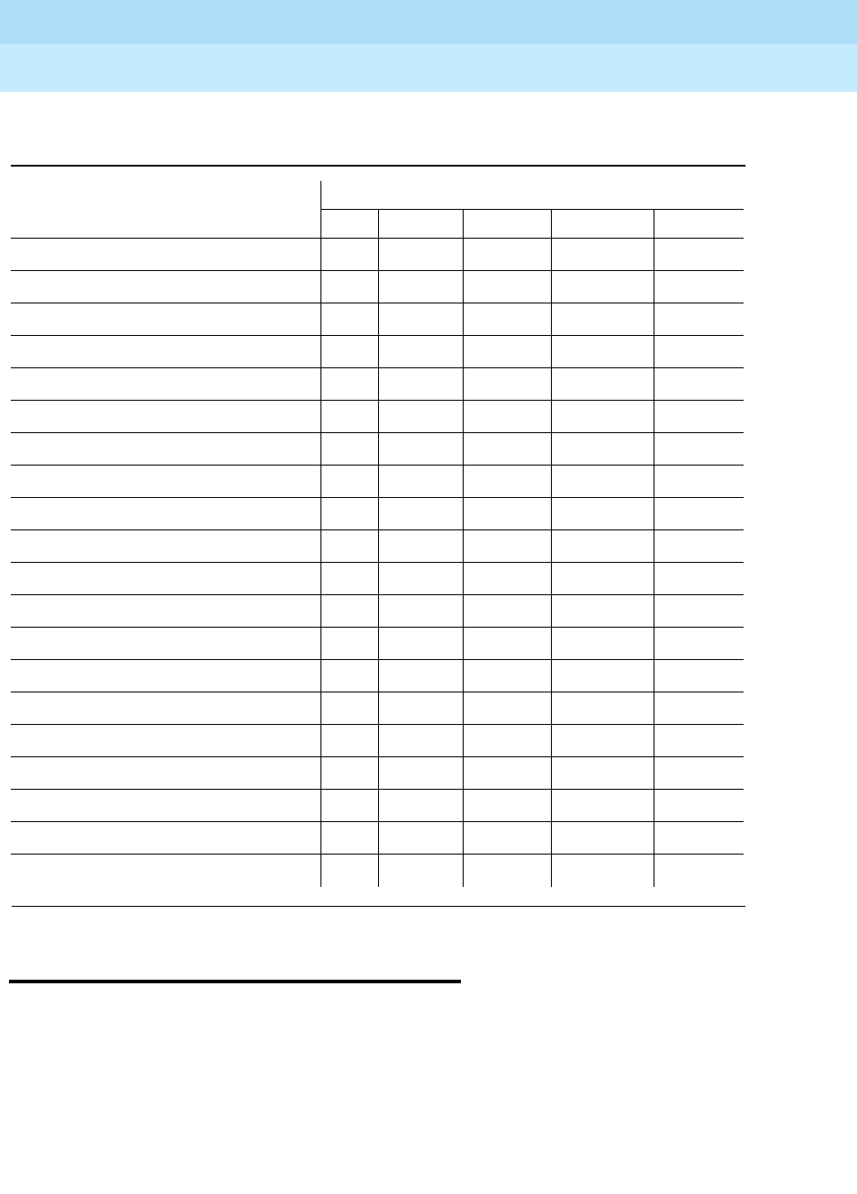
DEFINITY Enterprise Communications Server Release 6
Maintenance for R6r Volumes 1 & 2
555-230-126 Issue 2
January 1998
Management Terminal
Page 3-24Connecting the MT
3
Connecting the MT
The management terminal can be connected to the system in the following ways:
■SYSAM-LCL Port
The management terminal can be connected directly to the SYSAM-LCL
port of the TN1648 System Access and Maintenance (SYSAM) circuit
pack in the PPN control carrier (or SPE). Two RS-232 connectors are
located on the rear panel of the PPN control carrier beneath the label
TERMINAL. To access the maintenance user interface running on the
Table 3-4. Command Permissions Form Entries — Administer Trunks
Object Action
Add Change Display Duplicate Remove
aar analysis X
aar digit-conversion X
access-endpoint X X X X
announcements X
ars analysis X
ars digit-conversion X
ars toll X
digit-absorption X
meas-selection route-pattern X
meas-selection trunk-group X
meas-selection wideband-trunk-grp X
modem-pool X X X
personal-CO-line X X X
pri-endpoint X X X X
remote-access X X
rhnpa X
route-pattern X
time-of-day X
toll X
trunk-group X X X

DEFINITY Enterprise Communications Server Release 6
Maintenance for R6r Volumes 1 & 2
555-230-126 Issue 2
January 1998
Management Terminal
Page 3-25Connecting the MT
3
active SPE, connect an M25B (EIA) cord to the connector labeled ACTIVE.
Connect the other end to the connector on the 715 BCS labeled P2(DCE).
On most other terminals, use the connector labeled MAIN PORT. A null
modem is not required for these ports. More information on setting up the
715 BCS is given in following sections of this chapter.
On systems with duplicated SPEs, there are two PPN control carrier and
two identical sets of connectors. Either connector labeled ACTIVE can be
used, regardless of which SPE is active. The STANDBY connectors are
described below.
■SYSAM-RMT Port (RAP)
One login can access the system by dialing in to the SYSAM-RMT port
with a modem operating at either 1.2 or 2.4 kbps. This port is reserved for
INADS (Initialization and Administration System) access.
Logging In When The SPE Is In SPE Down Mode
If the system is in SPE down mode when the RAP Terminal displays login, enter
INADS as the RAP login/name. Use the first INADS type password as your RAP
password.
NOTE:
You must identify the first INADS login before the system is in SPE
down mode. The first INADS type login may be identified by entering
the list login command and noting the first INADS login listed.
■System Ports
Terminals can log in via system ports (also known as system access ports
or SAPs) if the system is so equipped. The connection is made by dialing
in to a to a data port located on a data line circuit pack that is
administered as a system port. This type of port is identified by the entry
Type: system port on the data module form. These ports operate at
9.6 kbps. For more information on system ports, see ‘‘PDATA-PT (Packet
Data Line Port)’’ in Chapter 9, ‘‘Maintenance Object Repair Procedures’’
and
DEFINITY Enterprise Communication Server Release 6 Administration
and Feature Description
.
■EPN Maintenance Circuit Pack
Terminals can log in to the system by directly connecting to the TN775
Maintenance circuit pack in each Expansion Port Network. Connect an
M25B (EIA) cord to the RS-232 connector labeled TERM on the rear panel
of the expansion control carrier. This connection operates at a slower
speed because it communicates over system control links shared with call
processing messages. The bit rate is limited to about 1 kbps. This type of
connection is useful for performing maintenance on a remotely located
EPN.

DEFINITY Enterprise Communications Server Release 6
Maintenance for R6r Volumes 1 & 2
555-230-126 Issue 2
January 1998
Management Terminal
Page 3-26Logging On
3
■Standby SPE Connection
With duplicated SPEs, there are two SYSAM connectors on each PPN
control carrier (A and B). Either carrier’s connectors may be used. Either
ACTIVE connector always access the active SPE regardless of which
carrier is active. Either STANDBY connector accesses the standby SPE
through the SPE-Down interface. This interface is available when the SPEs
are locked by the SPE-Select switches on a system with duplicated SPEs.
Otherwise the STANDBY connection is inactive. (On a simplex SPE, this
interface is accessed when the SPE is down through the ACTIVE
connector). Separate terminals may be connected to the two connectors,
or one terminal may be switched back and forth between connections.
The unused connectors should be capped.
The SPE-down interface can only be accessed by SYSAM-LCL or SYSAM-RMT
connections. This interface is described in
Initialization and Recovery
.
Serial Printer Connection
For serial printer operation, connect the printer to the connector on the back of
the 715 BCS terminal labeled P1(DCE). A null modem is not required. Set the
printer for 9600 baud, 7 data bits and 1 stop bit. These are the default settings for
the 715 BCS. If necessary, terminal settings for serial printer operations can be
changed from the Communication Options sub-menu of the Setup menu.
Parallel Printer Connection
For parallel printer operation, connect the printer to the connector labeled with
the printer icon. To enable parallel printer operation, use the following series of
keystrokes.
1. Cntl + F1 to access the Setup menu
2. F4 to select the User Preferences sub-menu
3. Down arrow to the Parallel Port field
4. F4 to enable the option
5. F1, F5, F1 to return to Setup, save selections, and exit
Logging On
To log in to the system:
1. Connect and power up the MT; the screen displays login:
2. Enter your login name, and press the Return key. The screen displays
password:
3. Enter your password, and press the Return key.

DEFINITY Enterprise Communications Server Release 6
Maintenance for R6r Volumes 1 & 2
555-230-126 Issue 2
January 1998
Management Terminal
Page 3-27Logging On
3
For security reasons, the password is not displayed as you type it. The
system verifies that a valid login and password name were entered. If an
invalid login or password name was entered, the screen displays login
incorrect:
In this case you must repeat the procedure. If your password has expired
or is within 7 days of the expiration day, you see a error message:
Your Password has expired; enter a new one
Old Password:
New Password:
WARNING: your password will expire in xx days
If the system recognizes the login and password name, the screen
displays the software version number followed by the prompt:
Terminal Type (Enter 513, 4410, 4425, or VT220):
[513]
4. Depending on your terminal type, enter one of the following:
5. You can deactivate INADS alarm origination whenever you log in as craft.
After you supply the terminal type information requested, the system will
display the following if alarm origination is activated on the Maintenance
System-Parameters screen:
Suppress Alarm Origination: [y]
The default answer is yes. If you do NOT wish to suppress alarm
origination, enter no. Any other entry will default to yes. The test
inads-link command will work regardless of whether you have overridden
INADS alarm origination.
6. The screen will display:
enter command:
The system is now ready to execute maintenance commands. Press the
HELP key to display a list of all valid entries.
If you have a High-Priority Bulletin Board Message, the command line
prompt will include the following notification to all users who are logged in:
-High-Priority Bulletin Board Messages Entered:
Terminal Type Entry
513 BCT 513 (default)
715 BCS 513 (default)
4410 Data Terminal 4410
4425 Data Terminal 4425
DEC VT220 VT220

DEFINITY Enterprise Communications Server Release 6
Maintenance for R6r Volumes 1 & 2
555-230-126 Issue 2
January 1998
Management Terminal
Page 3-28Logging Off
3
Logging Off
The terminal should be logged off whenever it is not in use to avoid accidental or
malicious entries that could corrupt translations or disrupt operations. This also
re-enables INADS alarm origination so that alarms will not go unreported.
To log off, simply enter logoff at the command prompt. The screen should then
display:
login:
If no entry is made for 30 minutes during a craft login, the system automatically
times out and terminates the login. At that time, any unresolved alarms that have
not been reported to INADS will be reported. If you are logged in at more than
one G3-MT terminal, the system waits until the last terminal times out or logs off
before reporting such alarms to INADS.
Logoff Notification
alerts system administrators of enabled features that present
a significant security risk. The user may be required to acknowledge the
notification before the logoff is completed

Initialization and Recovery
Page 4-1
4
DEFINITY Enterprise Communications Server Release 6
Maintenance for R6r Volumes 1 & 2
555-230-126 Issue 2
January 1998
4
4Initialization and Recovery
When the system is powered up, or when it experiences a catastrophic fault that
interrupts its basic functions, it undergoes a reboot. In addition to reboot, there
are several less severe resets available for the system to recover from less
disrupting errors. The technician can also initiate these resets with a command.
!CAUTION:
System resets can have wide-ranging disruptive effects. Unless you are
familiar with resetting the system, follow normal escalation procedures
before attempting a demand reset.
If a reset fails to recover normal system operation, the firmware that controls reset
will escalate to the next higher level, up to reboot if necessary. A failure to reboot
results in SPE-down mode, which is described in later in this chapter.
This chapter describes the causes, effects, and duration of each reset level. In a
system with duplicated SPE, the standby SPE can undergo a reset without
disrupting service since the active SPE remains in control. These resets can also
be requested with the corresponding reset standby-spe
level
commands. All
standby resets turn off memory shadowing, leaving the standby SPE temporarily
unavailable for service. Refresh of the standby typically takes several minutes.
When resets occur, including interchanges, an error is logged against the
maintenance object “SYSTEM.” The error code gives information about the cause
of the reset. Information about the reset is also logged in the initcauses log. See
display initcauses in Chapter 8, ‘‘Maintenance Commands’’.
The EPNs can also undergo individual resets. These are described in ‘‘EXP-INTF
(Expansion Interface Circuit Pack)’’ and ‘‘EXP-PN (Expansion Port Network)’’ in
Chapter 9, ‘‘Maintenance Object Repair Procedures’’. PNC interchanges are

DEFINITY Enterprise Communications Server Release 6
Maintenance for R6r Volumes 1 & 2
555-230-126 Issue 2
January 1998
Initialization and Recovery
Page 4-2Multiple Offer Categories
4
described under PNC-DUP in Chapter 9, and under reset pnc interchange in
Chapter 8, ‘‘Maintenance Commands’’.
Multiple Offer Categories
When the system is initially powered up, or when it experiences a catastrophic
fault that interrupts its basic functions, the system either initializes or reboots.
Initialization
Upon initialization, no forms (not even Customer Options) are available until the
Offer Category is set. (The remote INADS channel is available.) To set the
customer options, do the following:
1. Enter change system-parameters offer-options (init and inads logins
only) and the following form displays:
Field descriptions
2. After these two fields are filled and you press Enter, the system displays:
WARNING: Activating Offer Category may set unchangeable
limits.
This is to let you know that the Offer Category along with the model
determine the system capacities (limits) and allowable hardware.
3. Press the Submit key to submit the form.
4. Use the save translations command to make the changes permanent.
Offer category Type either A or B.
Activate offer? Type y if the entry for Offer category is correct and press Tab.
Type n if there is an error in the Offer category field and press
Tab. Re-enter the correct Offer Category.
change system-parameters offer-options
OFFER OPTIONS FORM
Offer Category: _
Activate Offer? _
WARNING: Need to save translations and reboot to make the change permanent.

DEFINITY Enterprise Communications Server Release 6
Maintenance for R6r Volumes 1 & 2
555-230-126 Issue 2
January 1998
Initialization and Recovery
Page 4-3Hot Restart
4
!CAUTION:
To avoid potential loss of servce, ensure that your system’s
translations are protected by saving them to the PCM/CIA card.
Hot Restart
This reset occurs only on a duplicated SPE during a
planned
SPE interchange.
Reset Level 1 (Warm Restart)
Duration Up to 1.5 minutes
Causes reset system interchange command
(use of the contention-override or health-override options
causes a reset level 1 or higher)
SPE interchange requested by scheduled maintenance
Effects Call service is unaffected.
Yellow LEDs light on new active SPE and go out on the new
standby.
Memory shadowing is turned off.
Remote access port (SYSAM-RMT) login is dropped.
Duration Up to 10 seconds, typically 2 seconds
Causes reset system 1 command
Spontaneous SPE interchange (those caused by hardware
faults)
Software faults that are non-service affecting
Abort of planned SPE interchange
Hardware bus errors
TN1655 Packet Interface faults

DEFINITY Enterprise Communications Server Release 6
Maintenance for R6r Volumes 1 & 2
555-230-126 Issue 2
January 1998
Initialization and Recovery
Page 4-4Reset Level 1 (Warm Restart)
4
Effects Stable calls are preserved.
System links, and stable feature and service state data are
preserved.
Error and alarm logs are preserved, but all alarms are resolved
except for STBY-SPE and busyouts.
Transient calls (not yet connected), and some user stimuli, are
dropped.
New calls are not processed during the reset.
G3-MT logins, including remote access and system port logins,
are dropped.
If the reset resulted from a spontaneous SPE interchange,
memory shadowing is turned off, and the standby SPE will not
be available for service until memory is refreshed (several
minutes).
Application links such as those to AUDIX and CDR are
dropped and reestablished in under 2 1/2 minutes. (BX.25 links
are not dropped, and CDR data is buffered during the outage.)
MSS activity is aborted.
Translation data is preserved, but if translation changes were in
progress, the reset is escalated to Reset Level 3 (Cold-1).
If core dump is enabled for this reset level, reset is delayed
until the core dump is complete.

DEFINITY Enterprise Communications Server Release 6
Maintenance for R6r Volumes 1 & 2
555-230-126 Issue 2
January 1998
Initialization and Recovery
Page 4-5Reset Level 2 (Cold-2 Restart)
4
Reset Level 2 (Cold-2 Restart)
Duration Up to 3.75 minutes
Causes reset system 2 command
Escalation from reset level 1
An attempted reset level 1 during a PNC interchange
TDM-bus clock recovery on the PPN
Spontaneous interchange into an unrefreshed standby SPE
Effects All system and application links are dropped.
All calls are dropped.
Non-translation feature data, such as Automatic Wakeup calls,
are lost and must be reentered.
All G3-MT logins, including remote access and system port
logins, are dropped.
Initialization firmware runs diagnostics and displays results on
the G3-MT screen.
SPE memory shadowing is turned off, leaving the standby SPE
unavailable for service for several minutes.
All hardware components, except PNC components, are reset,
including the EPNs. All standby Expansion Interfaces, and the
active EI in the PPN are reset. SNIs, SNCs, DS1Cs and active
EIs in the EPNs are not reset.
If the PNC is duplicated, a global refresh of the standby PNC is
performed after the reset.
All busied out maintenance objects are released and must be
rebusied, if so desired.
Circuit packs are reinitialized, (translations are verified by
comparison to physical board locations).
If core dump is enabled for this reset level, reset is delayed
until the core dump is complete.
Error and alarm logs are preserved, but all alarms are resolved
except for STBY-SPE and busyouts.

DEFINITY Enterprise Communications Server Release 6
Maintenance for R6r Volumes 1 & 2
555-230-126 Issue 2
January 1998
Initialization and Recovery
Page 4-6Reset Level 3 (Cold-1 Restart)
4
Reset Level 3 (Cold-1 Restart)
Reset Level 4 (Reboot)
Duration Up to 6.5 minutes
Causes reset system 3 command
Escalation from reset level 2
Translation loading fault
Spontaneous interchange into an unrefreshed standby SPE
Effects Actions and effects are the same as for reset level 2, plus the
following:
Emergency transfer is invoked.
Translations are reloaded from disk or tape.
If core dump is enabled for this reset level, reset is delayed
until the core dump is complete.
Translations entered by users since the last save translation
was executed by command or by scheduled maintenance are
lost.
Duration Typically 8 to 11 minutes
Causes reset system 4 command
Escalation from reset level 3
Power up
Recovery attempt from SPE-down mode (requested by reboot
command, or automatically every 20 minutes)
Spontaneous interchange into an unrefreshed standby SPE
Effects System software (boot image) is reloaded, and all processes
are reinitialized
The disk, if present and healthy, is the default device from
which the software is loaded. Otherwise, the reload is taken
from tape
Before reboot, the system attempts to save the alarm and error
logs to the disk on the active SPE
After reboot, error and alarm logs are restored from the SPE
that is active coming out of the reboot. (Note that this means
that some error and alarm information may be lost if the last
save before the reboot save does not succeed or if an SPE
interchange takes place)

DEFINITY Enterprise Communications Server Release 6
Maintenance for R6r Volumes 1 & 2
555-230-126 Issue 2
January 1998
Initialization and Recovery
Page 4-7Reset Level 5 (Extended Reboot)
4
Reset Level 5 (Extended Reboot)
Initialization Diagnostics
For each reset level, the system performs a series of diagnostic tests on
components of the SPE to confirm that the system can be brought into service.
The management terminal displays the result of each test as it occurs. If a reboot
fails, and the system cannot bring itself up, SPE-down mode is invoked. A
description of this mode, with troubleshooting procedures available to it, appears
in the following section.
Table 4-1 shows the diagnostic tests run during initializations. Level 1, 2 and 3
resets 4 perform the first 11 tests (through the Timer Test). Reboots complete all
tests in the table except the last one. Only extended reboots execute the Memory
Board Couple Test.
If a test fails, make the indicated repair. If more than one repair is indicated,
perform them in the order shown until the problem is resolved. Follow procedures
described in ‘‘Replacing SPE Circuit Packs’’ in Chapter 5, ‘‘Responding to
Alarms and Errors’’.
Other effects are the same as those in reset level 3, except that
more extensive diagnostics are performed.
If reboot fails, SPE-down mode is invoked.
If a core dump is enabled for this reset level via the set vector
command, the reboot is delayed until the core dump has
completed.
Duration Up to 25 minutes
Causes reset system 5 command
This reset is invoked only by command
Effects Effects are the same as for a level 4 reboot except that more
extensive diagnostics are performed.
This reset is used to diagnose SPE component failures not
detected by level 4 reboot tests.

DEFINITY Enterprise Communications Server Release 6
Maintenance for R6r Volumes 1 & 2
555-230-126 Issue 2
January 1998
Initialization and Recovery
Page 4-8Initialization Diagnostics
4
Table 4-1. Initialization Diagnostics for All Reset Levels
Test Description/Recommendation
Internal Register Test Replace processor.
Loop Data Test Replace processor. Replace memory 1. Reseat
all circuit packs in the processor carrier except
SYSAM. The carrier may be defective. Follow
normal escalation procedures.
Duart Test Replace the processor board. Failure of this test
will not prevent the system from running, but the
processor is probably faulty.
Rom Checksum Test Replace the processor.
Control Status Test Replace the processor.
Dcache Test Replace the processor. Failure of this test may
not prevent the system from running, but
degradation of service is probable.
Icache test Replace the processor. Failure of this test may
not prevent the system from running, but
degradation of service is probable.
Write Buffer Test Replace the processor. Replace the memory 1.
Bus Test Replace processor. Replace memory 1. Reseat
all circuit packs in the processor carrier except
SYSAM. The carrier may be defective. Follow
normal escalation procedures.
Parity Test Replace the processor. Replace the SYSAM.
Timer Test Replace the processor.
Bus Config Test Replace processor.
Mem Config Test Check memory boards for correct TN number
and positioning on the carrier. Reseat memory
boards.
Memory Functional Test Replace memory boards one at a time until test
passes.
Memory Board Stuck Bit
Test Replace memory board.
Memory Board EDC Test Replace memory board.
Continued on next page

DEFINITY Enterprise Communications Server Release 6
Maintenance for R6r Volumes 1 & 2
555-230-126 Issue 2
January 1998
Initialization and Recovery
Page 4-9SPE-Down Command Interface
4
SPE-Down Command Interface
A limited command interface called the SPE-down interface can be used to
communicate with low level firmware when system software is unavailable for
executing the usual maintenance commands. This is useful in three situations.
■The SPE is down in a system without duplicated SPEs
■The standby SPE is down in a system with duplicated SPEs
■One SPE is locked standby in a system with duplicated SPEs
Memory Board Burst Test Replace memory board Replace processor
board The carrier may be defective. Follow
normal escalation procedures.
Sysam Test Replace the SYSAM board.
Vm Test Replace the processor.
Exception Test Replace the processor.
MSS Test Replace the MSSNET board. Replace the
processor.
Sanity Timer Test Replace the SYSAM board.
Dupint Test Replace the DUPINT board.
Disk Test Replace the disk drive.
Loading Disk Reformat disk. Replace the MSSNET board.
Ram Data Checksum Test Reboot from whichever device (tape or disk) was
not
used for the failed reboot. Replace memory.
Ram Text Checksum Test Reboot from whichever device (tape or disk) was
not
used for the failed reboot. Replace memory.
Tape Test Replace the tape cartridge. Replace the tape
drive. Replace the MSSNET board.
Pktint Reset Test Replace the packet interface board.
Mem Board Couple Test
(Extended reboot only) Replace the indicated memory board.
Table 4-1. Initialization Diagnostics for All Reset Levels — Continued
Test Description/Recommendation
Continued on next page

DEFINITY Enterprise Communications Server Release 6
Maintenance for R6r Volumes 1 & 2
555-230-126 Issue 2
January 1998
Initialization and Recovery
Page 4-10SPE-Down Command Interface
4
SPE-Down Mode
Severe problems with components of the SPE may render a non-duplicated
system incapable of call processing and other normal operations. When this
happens, the system enters SPE-down mode and software is no longer in control.
If the SPE is duplicated, this situation only occurs when
both
SPEs have fatal
faults. Otherwise, if one SPE goes down, an interchange will occur and the
system will run on the newly active SPE.
SPE Locked Standby or Standby SPE-Down
The SPE-down interface can be useful when repairing a standby SPE on a
duplicated system. For example, if handshake communication is down, this is the
only way to communicate with the standby SPE. Or, if a circuit pack on the
standby has been replaced, this interface allows you to test both that circuit pack
and the rest of the standby SPE before unlocking.
When the standby SPE on a duplicated system is down, or locked by means of
the SPE-Select switches, it is no longer in communication with the active side,
and the system is functionally unduplicated. In this state, the normal
Maintenance User Interface is unavailable to the standby SPE. You can use the
SPE-down interface to test the standby SPE and verify its health before rebooting
or unlocking. A test of all SPE boards takes only a short time and ensures that all
problems have been fixed and the SPE is ready to return to service.
Bringing Up the SPE-Down Interface
When SPE-down mode is in effect, the red LED will be lit on the Processor circuit
pack and the system will present the following message:
An alarm-notification call already in progress will preempt input from the terminal.
When the call is completed or dropped, the system displays the results of the call
and a welcome message with one of the following prompts, indicating which SPE
is currently connected to the terminal.
*********** SPE DOWN MODE *************
SPE_A_DOWN> If SPE-A was active when the system went
down
SPE_B_DOWN> If SPE-B was active when the system went
down
SPE_DOWN> If the SPE is unduplicated

DEFINITY Enterprise Communications Server Release 6
Maintenance for R6r Volumes 1 & 2
555-230-126 Issue 2
January 1998
Initialization and Recovery
Page 4-11SPE-Down Command Interface
4
You can now enter SPE-down interface commands as described in ‘‘Using the
SPE-Down Interface’’. If the prompt does not appear, check the connections
between the terminal and the control carrier. Make sure the cable is connected to
the connector labeled
ACTIVE
. If possible, try a different cable and/or terminal. If
the prompt is still not present, replace the SYSAM circuit pack. If the SPE remains
down with no prompt, follow normal escalation procedures.
To return the standby SPE to service, see the following section on ‘‘Bringing the
SPE Back into Service’’.
SPE Locked Standby or Standby SPE-Down
To bring up the SPE-down interface on a functioning duplicated system, connect
the terminal to the STANDBY terminal connector on the rear panel of either
processor carrier. Assuming all cabling is intact, either connector will access the
SPE which is standby. If the standby SPE is down, the message and prompt
shown above are displayed. To enter SPE-locked-standby mode, carefully, and
one at a time
, move the SPE-Select switches to the position indicating the carrier
of the currently active SPE. For example, if the SPE in carrier A is active, move the
switches to position A. When the SPE is locked, SPE interchanges are prevented,
memory shadowing is turned off, handshake is down, and maintenance activities
normally controlled by software on the active SPE cease. The following message
is printed, (in this example, A is locked standby):
One of the following prompts will appear, indicating which SPE is locked
standby
and whether the SPE is down.
SPE_A_LOCKED>
SPE_B_LOCKED>
SPE_A_DOWN_LOCKED>
SPE_B_DOWN_LOCKED>
You can now enter the commands described in ‘‘Using the SPE-Down Interface’’.
If the prompt fails to appear, check your connections. Try connecting to the
connector labeled STANDBY on the other PPN control carrier (A or B). If
possible, try using a different cable and/or terminal. If the above actions do not
produce a prompt, replace the SYSAM circuit pack on the standby SPE. If the
prompt is still not present, follow normal escalation procedures.
If an SPE was down and the SPE-Select switches are set to lock, the
down-and-locked-standby mode
replaces
the SPE-down mode. Normally, when
the standby SPE is up and cycling, the yellow LED on the Processor circuit pack
flashes on and off. If the SPE is locked standby
and
a terminal is connected to
the STANDBY connector, the Processor LED remains unlit.
*********SPE A locked standby************

DEFINITY Enterprise Communications Server Release 6
Maintenance for R6r Volumes 1 & 2
555-230-126 Issue 2
January 1998
Initialization and Recovery
Page 4-12SPE-Down Command Interface
4
To return the standby SPE to service, see the following section on ‘‘Bringing the
SPE Back into Service’’.
NOTE:
The physical connection of the terminal to the STANDBY connector while
the SPE is locked standby with the SPE-Select switches prevents the
Standby Maintenance Monitor (SMM) from running. Any reboot command
to the standby while it is in the locked state will abort.
Using the SPE-Down Interface
When one of the above prompts appear, you may enter Spe-down interface
commands. These are executed by the Low-level Maintenance Monitor (LMM),
which is firmware resident on the processor board for controlling initialization and
recovery actions, and processor and memory diagnostics.
Communications with the terminal are handled by the SYSAM board. If a remote
access port (SYSAM-RMT) call is received while in this mode, it will preempt
access by the local MT, and this message will be displayed:
When the call is completed or dropped, the prompt will return. Note that the
SPE-down interface to an SPE that is locked standby is never available to the
remote access port, because the standby SPE is isolated from the active SYSAM
circuit pack.
A limited set of commands is available to the SPE-down interface, as follows.
Local Terminal session overridden by remote access
KEYBOARD LOCKED, WAIT FOR SYSAM OR LOGIN PROMPT

DEFINITY Enterprise Communications Server Release 6
Maintenance for R6r Volumes 1 & 2
555-230-126 Issue 2
January 1998
Initialization and Recovery
Page 4-13SPE-Down Command Interface
4
The following qualifier can be used with the test commands:
Enter
only
the characters which appear in bold type. For instance, to test all
memory boards ten times, enter t ma 10 Entering t results in testing all boards
once. You can abort the execution of a command by pressing ESC 3 times.
Test Commands
After a command is entered, various test result messages are printed on the
terminal, indicating whether each test passes, fails or aborts. If any components
fail, refer to the Maintenance Object documentation that applies. Additional
information for interpreting these results can be found in the ‘‘Troubleshooting a
Table 4-2. SPE-Down Interface Commands
Keyboard Entry Command
?Help
rReboot
sSecondary reboot
ddisplay alarms
t al or tTest all standby SPE circuit packs
t sy Test SYSAM circuit pack
t pr Test Processor circuit pack
t m1 Test Memory circuit pack 1
t m2 Test Memory circuit pack 2
t m3 Test Memory circuit pack 3
t m4 Test Memory circuit pack 4
t ma Test all Memory circuit packs
t du Test DUPINT circuit pack
t ms Test MSSNET circuit pack
t p1 Test PKTINT circuit pack 1
t p2 Test PKTINT circuit pack 2
t p3 Test PKTINT circuit pack 3
t pa Test all PKTINT circuit packs
1 to 99 Number of repetitions (default is 1)

DEFINITY Enterprise Communications Server Release 6
Maintenance for R6r Volumes 1 & 2
555-230-126 Issue 2
January 1998
Initialization and Recovery
Page 4-14SPE-Down Command Interface
4
Duplicated SPE’’ and ‘‘Testing the Standby SPE’’ sections in Chapter 5,
‘‘Responding to Alarms and Errors’’. Note that the test memory command
performs exhaustive tests and can be very time-consuming.
When testing is complete, the system readies itself for another command and the
prompt appears. If testing does not complete within 20 minutes, the following
message is displayed:
LMM did not finish test in time.
This is a serious error indicating that the processor, bus, and/or LMM are not
working properly. Normally you will see initial test result output within a few
seconds. If not, you can abort the test request by pressing ESC 3 times, and the
command prompt will be returned.
If the SPE-down mode is entered or re-entered as a result of the test request, the
screen displays:
Can’t continue - test aborted.
Again, this is a serious error, but at least the processor is able to handle
SPE-down reporting. Likely fault locations are memory board number 1,
processor board, or processor/memory bus.
Display Alarms Command
The display alarms command asks for the alarms that caused the SPE to go
down. It is valid only in the SPE-down or down-and-locked-standby mode. If d is
entered while the SPE is in one of the down modes, the following header is
displayed:
DISPLAY ALARMS:
Physical
Name
Logical
Name
On
Board?
Alternate
Name
Alarm
Type
Date
Alarmed
Date
Resolved

DEFINITY Enterprise Communications Server Release 6
Maintenance for R6r Volumes 1 & 2
555-230-126 Issue 2
January 1998
Initialization and Recovery
Page 4-15SPE-Down Command Interface
4
The header is followed by one and only one of the following lines (except that
more than one Memory circuit pack failure may be displayed):
Note that the display is designed to approximate an alarm display from software
maintenance, but is not populated with certain information, represented by
dashed out fields. Only the first failed component detected is displayed.
In the absence of any other information about the cause of the failure, replace the
indicated component using the procedures described in Replacing SPE Circuit
Packs. After all tests pass, return the standby SPE to service, with procedures
described in the following section on ‘‘Bringing the SPE Back into Service’’.
BOOT_ERROR indicates that the LMM was not able to either load, start, or keep
the SPE running following a reboot request. SPE_SAN indicates that SYSAM
detected enough sanity timeouts to exceed the threshold.
Reboot Commands
After all SPE-down interface tests have passed, an SPE can be brought back up
by using the reboot commands. The reboot command, r starts a reboot using the
boot image loaded on the disk device. The secondary reboot command, s, starts
a reboot using the boot image loaded on the tape device. The latter is useful if
the boot image on the disk is corrupted, the disk device is faulty, or a different
software load is desired. A reboot can be interrupted by pressing ESC 3 times.
As noted earlier, if an SPE is locked in the standby mode, the reboot commands
cannot be entered and will abort.
--- PROCR y ----- MAJOR ----- -----
----- MEM_BD_0 y ----- MAJOR ----- -----
----- MEM_BD_1 y ----- MAJOR ----- -----
----- MEM_BD_2 y ----- MAJOR ----- -----
----- MEM_BD_3 y ----- MAJOR ----- -----
----- MSS_NET y ----- MAJOR ----- -----
----- TAPE y ----- MAJOR ----- -----
----- DISK y ----- MAJOR ----- -----
----- NO_TAPE y ----- MAJOR ----- -----
----- BOOT_ERROR ----- MAJOR ----- -----
----- SPE_SAN ----- MAJOR ----- -----

DEFINITY Enterprise Communications Server Release 6
Maintenance for R6r Volumes 1 & 2
555-230-126 Issue 2
January 1998
Initialization and Recovery
Page 4-16SPE-Down Command Interface
4
Bringing the SPE Back into Service
!WARNING:
In a system with duplicated SPEs, a spontaneous SPE interchange may
occur if the active SPE is not in good health and either
— an unlocked SPE completes its reboot and handshake is
reestablished
— a locked SPE in which the Standby Maintenance Monitor (SMM) is
running is unlocked
!WARNING:
Use the status spe command to determine the health of the active SPE and
whether an interchange will occur.
Once all tests pass using the SPE-down interface, the SPE should be competent
to return to service. There are however certain problems which will not show up in
testing that may prevent this. Follow the appropriate procedure below to bring
the SPE back up.
Simplex SPE
After the reboot command is entered, a series of diagnostics is run on the SPE.
Results are displayed as they occur, as described in preceding sections. If all
tests pass, the boot image is loaded and control is given to the operating system.
If you cannot get the SPE to reboot after replacing the components that failed
SPE-down interface tests, follow normal escalation procedures.
Duplicated SPE
The physical connection of the terminal to the STANDBY connector, while the
SPE is locked standby with the SPE-Select switches, prevents the Standby
Maintenance Monitor (SMM) from running. Thus, any reboot command to the
standby while in this state will abort. To reboot an SPE that is locked standby and
has a terminal connected to it, simply move the SPE-SELECT switches to the
AUTO position one at a time. This will automatically cause the standby SPE to
reboot and its progress is displayed on the terminal. Moving the switches back to
the locked position will cause the reboot to abort.
To reboot the standby SPE and have it remain locked standby following the
reboot, use the following procedure:
1. Start the reboot by moving the SPE-Select switches one at a time to the
AUTO position.

DEFINITY Enterprise Communications Server Release 6
Maintenance for R6r Volumes 1 & 2
555-230-126 Issue 2
January 1998
Initialization and Recovery
Page 4-17SPE-Down Command Interface
4
2. As soon as initialization diagnostics begin to appear on the screen,
disconnect the MT cable from the STANDBY connector on the control
carrier.
3. Return the SPE-SELECT switches to their previous locked position.
When the standby is back up and cycling, the yellow LED on the Processor
circuit pack will begin flashing. It is then safe to unlock the SPE-Select switches if
they were relocked. At this point, the system should re-establish handshake
communication, turn on memory shadowing (assuming the standby is not busied
out), and perform a refresh of the standby SPE’s memory. These steps can be
monitored by using the status spe command at a terminal connected to the
ACTIVE terminal connector. When these steps have been completed, the
standby SPE should have a “functional” state of health and be fully in service.
If all tests pass, but the SPE does not return to service, there may still be
problems on the standby which escaped detection by SPE-down testing. In this
case, use the following steps, which describe a means of sequentially replacing
circuit packs that are the most likely source of the problem.
1. First determine if memory shadowing is disabling handshake. With the
standby locked, busyout the standby SPE; this prevents shadowing from
turning on.
2. Bring up the standby as described above (unlock, unplug the STANDBY
terminal and relock). If the yellow LED on the Processor fails to flash,
follow normal escalation procedures. After the yellow LED begins flashing,
unlock and monitor the recovery progress by repeatedly entering status
spe on a terminal connected to the
active
SPE. If handshake is not
established after 2 minutes, memory shadowing is not the problem.
Proceed to step 4.
3. Release the standby and follow the progress of the refresh with status
spe. If the refresh succeeds, the system should be fully functional. If the
onset of shadowing or refresh coincides with handshake failure, replace
the following circuit pack one at a time in the order shown and repeat this
procedure from step 1 each time. (Use lock-and-power-down and
DUP-CHL instructions).
a. Standby DUPINT
b. Standby PKT-INT
c. Standby MSSNET
d. Active DUPINT
If the problem persists, follow normal escalation procedures.
4. If handshake has not come up after 2 minutes, replace each of the
following circuit packs one at a time, in the order shown, and repeat this
procedure from step 1 each time:
a. Standby PKT-INT
b. Standby DUPINT

DEFINITY Enterprise Communications Server Release 6
Maintenance for R6r Volumes 1 & 2
555-230-126 Issue 2
January 1998
Initialization and Recovery
Page 4-18SPE-Down Command Interface
4
c. Standby SYSAM
d. Standby PROCESSOR
e. Standby MSSNET
f. Standby MEMORY number 1
g. Standby MEMORY number 2
If the problem persists, follow normal escalation procedures.

Responding to Alarms and Errors
Page 5-1Safety Precautions
5
DEFINITY Enterprise Communications Server Release 6
Maintenance for R6r Volumes 1 & 2
555-230-126 Issue 2
January 1998
5
5Responding to Alarms and Errors
Safety Precautions
By observing the prescribed safety precautions when working on the system,
you can avoid unnecessary disruption of service and damage to the equipment.
The items on this list should be a regular part of your routine.
!WARNING:
Failure to comply with these procedures can have catastrophic effects on
system service and hardware. Read the explanations following the list to
ensure a complete understanding of these necessary procedures.
■Whenever touching any component inside the cabinet, ground yourself by
means of the wrist strap attached to the cabinet, and avoid sources of
static electricity.
■When logging on with the terminal, be aware that INADS alarm notification
is normally disabled. Log off the terminal when leaving the system.
■Think carefully before moving SPE-SELECT switches. Always set them one
at a time to the letter of the PPN control carrier that is
currently active
(unless a procedure specifically tells you to do otherwise).
■Never “hot plug” an SPE circuit pack, except for the tape and disk drives
on a simplex SPE. Lock and power down the PPN control carrier first.
■Do
not
power down switch node or port carriers to replace a board.
■Handle fiber optic cables with care. Bending, piercing, or cutting the
cable can sever communications between major subsystems.
■When disconnecting fiber optic cables, grasp of both the lightwave
transceiver and the cable connector.

DEFINITY Enterprise Communications Server Release 6
Maintenance for R6r Volumes 1 & 2
555-230-126 Issue 2
January 1998
Responding to Alarms and Errors
Page 5-2DEFINITY AUDIX System Power Procedures
5
■Before powering down a cabinet or carrier that contains DEFINITY AUDIX
circuit packs (TN566), first power down the AUDIX unit to avoid damaging
the AUDIX software. Instructions for powering down this unit are in the
‘‘DEFINITY AUDIX System Power Procedures’’ below, on the circuit pack,
and in DEFINITY AUDIX documentation.
■When you are finished working on a cabinet, replace and secure all
panels and covers to avoid disseminating electromagnetic interference.
DEFINITY AUDIX System Power
Procedures
Manually Power Down AUDIX System
A yellow caution sticker on the system’s power unit notifies technicians to shut
down the DEFINITY AUDIX System prior to powering down the system.
1. Using a pointed object, such as a paper clip or pen (do not use a pencil),
press the Boot/shutdown button. The button is located at the top right
portion of the front panel.
2. Hold the boot/Shutdown button in until the LCD display flashes the
message MSHUT.
3. Release the Boot/Shutdown button.
NOTE:
The DEFINITY AUDIX System takes about five minutes to shut down.
The “heartbeat” indication on the display continues to flash.
Manually Power Up AUDIX System
1. Using a pointed object such as a paper clip or a pen (do not use a pencil),
press the Boot/Shutdown button.
2. Hold the boot/Shutdown button in until the display indicates the message,
BTEST, steady on.
3. Release the Boot/Shutdown button. the DEFINITY AUDIX system takes
approximately 5 minutes to power up.
■The display has the following sequence of steady on messages:
—OSINIT
—OS
—AINIT
—ADX
■The DEFINITY AUDIX System is now powered up. When the system
is in the active state, the display indicates ADX, and the red LED is
off.

DEFINITY Enterprise Communications Server Release 6
Maintenance for R6r Volumes 1 & 2
555-230-126 Issue 2
January 1998
Responding to Alarms and Errors
Page 5-3Electrostatic Discharge
5
NOTE:
When powering up, the DEFINITY ADUXI System automatically
reboots. This sequence may show an MD or MJ ADX alarm in the
display until the system how powered up. When the system has
completed its power up sequence, the display reads: ADX.
Electrostatic Discharge
Whenever a circuit pack is inserted or removed, the grounding wrist strap
attached to the cabinet must be used to avoid damage or disruption from ESD.
Use of the wrist strap is also required whenever touching any components inside
the switch cabinet, including the SPE-SELECT and EMERGENCY TRANSFER
switches. While such actions may not cause a problem in a highly controlled
environment, disruption to the system could result when conditions are not ideal,
(for example, when the air is very dry).
If you
must
proceed when a wrist strap is not available, grab the outside panel of
the cabinet with one hand
before
touching any components, and keep your extra
hand grounded throughout the procedure.
Handle a circuit pack only by the faceplate, latch, or top and bottom edges. Do
not touch board components, leads or connector pins. Keep circuit packs away
from plastic and other synthetic materials such as polyester clothing. Do not set a
circuit pack on a non-conductive surface such as paper. Use the anti-static bag,
if available.
Never hand a circuit pack to another person unless that person is also using a
wrist ground strap.
The body collects potentially damaging amounts of static electricity from many
ordinary activities. The smallest amount of ESD that can be felt is far above that
which can damage a sensitive component or disrupt service!
Figure 5-1 shows the location of the grounding jack.

DEFINITY Enterprise Communications Server Release 6
Maintenance for R6r Volumes 1 & 2
555-230-126 Issue 2
January 1998
Responding to Alarms and Errors
Page 5-4Suppress Alarm Origination [y]
5
Figure 5-1. Multi-Carrier Cabinet ESD Grounding Wrist Strap Jack
Suppress Alarm Origination [y]
When logged in as “craft,” no alarms are reported to INADS. After logging off,
INADS automatically reactivates, and any unresolved alarms are reported to
INADS.
Also, when logged in as “craft,” an automatic logoff of the terminal occurs after
30 minutes of non-use. At that time, any unresolved alarms are reported to
INADS. If you are logged in as “craft” at 2 different terminals, the logoff occurs
when the second terminal remains unused for 30 minutes.
NOTE:
The test inads-link command functions even if INADS Alarm Origination is
overridden.
ESD
JACK

DEFINITY Enterprise Communications Server Release 6
Maintenance for R6r Volumes 1 & 2
555-230-126 Issue 2
January 1998
Responding to Alarms and Errors
Page 5-5Reseating and Replacing Circuit Packs
5
Reseating and Replacing Circuit Packs
Most repair procedures involve replacing faulted circuit packs. In some cases,
problems are resolved by reseating the existing circuit pack. Reseat a circuit
pack
only
when explicitly instructed to do so by the documented procedures.
Reseating is discouraged since it can put a faulty component back into service
without addressing the cause, resulting in additional and unnecessary
dispatches. After reseating a circuit pack, make sure the problem is really fixed
by thorough testing and observing the component in operation.
When a port board is removed from the backplane, no alarm is logged for about
11 minutes to allow for maintenance activity to proceed. After that, a minor
on-board alarm is logged. If the port board is not administered, no alarm is
logged.
!WARNING:
This procedure can be destructive, resulting in a total or partial service
outage.
!WARNING:
Proceed only after consulting and understanding the applicable service
documentation for the component.
!WARNING:
Observe all Safety Precautions described above.
!WARNING:
If the yellow LED on the circuit pack to be removed is lit, the circuit pack is
active and services using it will be interrupted.
!WARNING:
Follow special procedures for the circuit packs listed below.

DEFINITY Enterprise Communications Server Release 6
Maintenance for R6r Volumes 1 & 2
555-230-126 Issue 2
January 1998
Responding to Alarms and Errors
Page 5-6Replacing a BIU or Rectifier
5
Special Procedures
The following circuit packs require special procedures.
For components of the SPE, see “Replacing SPE Circuit Packs”.
■UN331B Processor (SPE)
■TN1650B Memory (SPE)
■TN1655 Packet Interface (SPE)
■TN1648 SYSAM (SPE)
■UN332 MSSNET (SPE)
■TN1657 Disk (SPE)
■TN1656 Tape (SPE)
■TN768/780 Tone/Clock
■UN330B Duplication Interface
■TN750 Expansion Interface
■TN573 Switch Node Interface
■TN572 Switch Node Clock
■DS1 CONV
Replacing a BIU or Rectifier
To remove a Battery Interface Unit (BIU) or rectifier first attach a grounding strap
from the cabinet to your bare wrist then follow the steps listed below:
1. Unlock the latch pin.
2. Pull down on the locking lever until the BUI or rectifier moves forward and
disconnects from its socket.
3. Pull the BIU or rectifier out just enough to break contact with the
backplane connector. Use steady even force to avoid disturbing the
backplane.
4. Carefully slide the BIU or rectifier out of slot.
To install a BIU or rectifier first attach a grounding strap from the cabinet to your
bare wrist than follow the steps listed below:
1. Insert the back edge of the BIU or rectifier making sure that it is
horizontally aligned. Slide the unit in to the slot until it engages the
backplane. Use extreme care in seating the backplane connectors.
2. Lift the locking lever until the latch pin engages.
3. Verify that the unit is seated correctly by observing the operation of the
LED’s.

DEFINITY Enterprise Communications Server Release 6
Maintenance for R6r Volumes 1 & 2
555-230-126 Issue 2
January 1998
Responding to Alarms and Errors
Page 5-7Replacing SPE Circuit Packs
5
Replacing SPE Circuit Packs
All circuit packs on the processor carrier of the PPN except for the Tone/Clock
board are components of the SPE. In addition to the customary MO
documentation, there are additional diagnostic techniques for these boards
described in the following section,
Troubleshooting a Duplicated SPE
, and in the
section
SPE-down Interface
. Instructions for replacing the Tone/Clock circuit
pack can be found in the TDM-CLK MO documentation.
!WARNING:
DO NOT “HOT PLUG” AN SPE BOARD. Before removing any SPE circuit
pack you must power down the carrier in which it resides, (except in the
case of a tape or disk drive in a simplex SPE). Powering down the
processor carrier is destructive on a simplex system, causing a total service
outage. Be sure you have consulted the appropriate documentation for the
component you are replacing. Be sure you are familiar with the precautions
at the beginning of this chapter.
Simplex SPE
This procedure is destructive, resulting in a total service outage except for lines
administered with Emergency Transfer. The processor
must
be powered down to
avoid hardware damage. Arrange to perform this procedure when a service
outage will have the least impact on the customer.
1. Attach the grounding strap to your wrist.
2. Remove power to the processor carrier, (carrier A), by unplugging the
power cords located on the front of the power units located at
both
ends of
the carrier.
3. Remove or reseat the circuit pack using the procedure described
previously in
Reseating and Replacing Circuit Packs
.
4. Restore power to the carrier by plugging both power cords back in.
5. Monitor the system reboot by observing the LEDs and G3-MT output.
These indicators are described in
Initialization and Recovery
.
6. Test the replaced component(s) using the appropriate MO
documentation.
7. If the same problem persists, reinstall the original circuit pack to avoid
confusing further troubleshooting.

DEFINITY Enterprise Communications Server Release 6
Maintenance for R6r Volumes 1 & 2
555-230-126 Issue 2
January 1998
Responding to Alarms and Errors
Page 5-8Replacing SPE Circuit Packs
5
Replacing Circuit Packs on a Duplicated SPE:
Lock-and-Power-Down
By following the lock-and-power-down procedure, components of a duplicated
SPE can usually be replaced with no disruption of service.
!WARNING:
In a system with duplicated SPEs, a spontaneous SPE interchange may
occur if the active SPE is not in good health and either an unlocked SPE
completes its reboot and handshake is reestablished, or a locked SPE in
which the Standby Maintenance Monitor (SMM) is running is unlocked.
!WARNING:
Use the status spe command to determine the health of the active SPE and
whether an interchange will occur.
1. Enter status spe
to verify that the component to be replaced is on the
standby SPE. If it is, go to step 2.
If the component is on the active SPE, initiate a planned SPE interchange
by entering reset system interchange. If the interchange fails, there may
be faults on the standby SPE preventing the interchange. You must either
repair the fault on the standby SPE first, or force an interchange by using
reset system interchange health-override.
!WARNING:
Forcing an interchange may disrupt service. Arrange to do so at a
time suitable for the customer.
2. Enter status port-network 1 to check the health of the PPN Tone/Clocks.
The Tone/Clock in the same carrier as the active SPE should have a
service state of “in.” If not, repair it using “TDM-CLK” before proceeding.
3. Lock the active SPE.
After grounding yourself, move the SPE-SELECT switches on both
DUPINT boards, 1 at a time, to the carrier designation of the active SPE.
For example, if the A carrier SPE is currently active, move the switches to
position “A.”
4. Enter status port-network 1 to verify that the active Tone/Clock is in the
same carrier as the active SPE.
If not, repeat the command until this condition is met. If the active
Tone/Clock has not migrated to the active carrier after 1 minute, there is a
Tone/Clock problem. The Tone/Clock problem must be fixed first to avoid
service disruption. See “TDM-CLK” maintenance object.

DEFINITY Enterprise Communications Server Release 6
Maintenance for R6r Volumes 1 & 2
555-230-126 Issue 2
January 1998
Responding to Alarms and Errors
Page 5-9Replacing SPE Circuit Packs
5
5. Power down the standby processor carrier by:
a. Remove the power plug from the left side of the carrier first.
b. Remove the second power plug from the right side of the carrier.
6. Remove the failed circuit pack and replace it with a new one of the same
type.
7. Power up the standby processor carrier by:
a. Insert the power plug in the right side of the carrier first.
b. After inserting the first power plug in the right insert the second
power plug in the left side of the carrier.
The red and green LEDs will light indicating restoration of power and
testing of the boards. These LEDs will go out as tests pass.
8. This step is optional. Use a terminal and the SPE-down interface to test the
standby SPE as follows.
If a terminal is connected to the STANDBY connector on the back of either
PPN control carrier, the power-up reboot of the standby aborts and the
SPE-Down interface can then be used to enter commands to the LMM
firmware. Use t al, or the SPE-Down interface test command for the
replaced component, to confirm that the problem is fixed. Repair any
failures reported.
When testing is finished, move the SPE-Select switches to the AUTO
position
one at a time
. This unlocks the standby and begin a reboot which
can be monitored from the terminal.
9. Verify that the standby is up.
Regular flashing of the yellow LED on the Processor board indicates that
the standby SPE is up and cycling. If the yellow LED is not flashing after
five minutes, test the standby SPE as described in the above step. Relock
the SPE standby, attach a terminal to the STANDBY connector on the back
of either PPN control carrier and execute the SPE-down interface tests. All
tests must pass before unlocking.
10. If the standby SPE is still locked, unlock it by returning both SPE-Select
switches to the AUTO position
one at a time
.
11. Enter status spe to confirm that handshake is up. This should occur within
2 minutes. When it is, enter the test long clear command for the replaced
component. If an alarm does not clear, consult the appropriate MO.
12. Verify that the standby SPE is brought into service.
Enter status spe. The standby SPE is fully operational when handshake is
up, shadowing is on, and memory is refreshed. It can take up to 10
minutes after unlocking for the standby to be brought fully into service.
13. If the standby SPE does not fully return to service, consult ‘‘STBY-SPE
(Standby SPE Maintenance)’’.

DEFINITY Enterprise Communications Server Release 6
Maintenance for R6r Volumes 1 & 2
555-230-126 Issue 2
January 1998
Responding to Alarms and Errors
Page 5-10Troubleshooting a Duplicated SPE
5
Troubleshooting a Duplicated SPE
The section on maintenance object ‘‘STBY-SPE (Standby SPE Maintenance)’’
contains procedures for troubleshooting specific problems such as handshake
failure, memory shadowing failure, and poor state of health. The following
procedures describe a method for determining the cause of a spontaneous SPE
interchange and resolving any related problems.
If a spontaneous SPE interchange has occurred, assume that a serious fault has
occurred on the SPE that is currently the standby. The following symptoms
indicate that a spontaneous SPE interchange has taken place:
■A MINOR alarm with error type 103 is logged against STBY-SPE.
■An interchange entry is recorded in the initcauses log.
■The system is put into
recent interchange mode
, which prevents further
SPE interchanges from taking place.
The presence of recent interchange mode is displayed on the status spe
screen. The system is released from this mode, and the minor alarm is cleared,
after 1 hour, or upon the execution of test spe-standby long, regardless of
whether all tests pass.
There are three possible causes of a spontaneous interchange:
■Major hardware failure
■Failed recovery that has been software escalated
■Switching both SPE-SELECT switches to the standby carrier (not a
recommended procedure)
In the last case, the interchange is not fault-driven, and no specific repair action
is required. To determine whether this is the case, enter display initcauses. If
the interchange was initiated by the SPE-SELECT switches, the Cause field will
appear as in the following example.
If the interchange was fault-driven, there are two ways of finding the cause.
1. Using alarm and error logs in conjunction with the timestamp described
above. After a spontaneous SPE interchange has occurred, the Alarm Log
retains a record of any MAJOR ON-BOARD alarm against an SPE
component that took place before the interchange. This record is retained
for three hours and may indicate the cause of the interchange when
testing is not possible or conclusive. Other information in the Error Log
may also be helpful.
2. Testing the standby SPE when the logs do not identify the problem.
Cause Action Escalated Carrier Time
SPE-SELECT switch 1 no 1B 11/27 14:53

DEFINITY Enterprise Communications Server Release 6
Maintenance for R6r Volumes 1 & 2
555-230-126 Issue 2
January 1998
Responding to Alarms and Errors
Page 5-11Troubleshooting a Duplicated SPE
5
Start by determining the time of the interchange. Then, examine the alarm and
error logs as described in the following section. If that does not identify the
problem, proceed to the next section, which describes a sequence of tests of the
standby SPE.
Determining the Time of a Spontaneous
Interchange
There are 2 ways to tell at what time a spontaneous interchange has taken place:
■STBY-SPE Error 103
This error is logged with a minor alarm whenever a spontaneous
interchange takes place. The time recorded for the
first occurrence
of the
error is the approximate time of interchange. The error is logged against
the carrier of the SPE that was active before the interchange. This should
now be the standby SPE, assuming no further interchanges have taken
place.
■Display initcauses
The display initcauses command displays a record of all system resets.
In the following example, a spontaneous interchange
into
the B carrier
SPE took place at 2:53 P.M. The standby SPE (B) transitioned into active
mode with a WARM restart, (reset level 1).
Cause Action Escalated Carrier Time
Interchange 1 no 1B 11/27 14:53

DEFINITY Enterprise Communications Server Release 6
Maintenance for R6r Volumes 1 & 2
555-230-126 Issue 2
January 1998
Responding to Alarms and Errors
Page 5-12Troubleshooting a Duplicated SPE
5
Examining the Alarm and Error Logs
The system may have had time to log alarms or errors against the fault the
caused the interchange. Proceed through the steps summarized in the following
flowchart. Examine only major alarms with a timestamp near the time of
interchange, and whose carrier designation is the current standby SPE (the SPE
interchanged out of). Include any resolved alarms meeting this description.
Figure 5-2. Determining the Cause of an SPE Interchange
Use the SYSTEM error table following this
chart to determine which SPE component
is implicated.
This indicates a serious processor/memory
bus problem. Busyout or, preferably, lock
the standby SPE to prevent an
interchange, and escalate the problem.
Consult MO documentation for PKT-INT.
Is there a Major alarm against
the standby SW-CTL?
no
no
no
no
no
no
no
no
Consult MO documentation for TAPE.
Consult the MO documentation for the
indicated component.
yes
yes
yes
yes
Replace the standby
MSSNET circuit pack.
yes
yes
Consult CARR-POW in
Chapter 9.
yes
yes
If handshake is down (check status spe),
replace the alarmed standby circuit pack
If handshake is up, execute a
test long clear of the alarmed
component and consult documentation
for that MO in Chapter 9.
Proceed to the next flowchart, Testing
the Standby SPE
Is there a TAPE error 3585 with aux code 408?
Is there a PKT-INT error 100?
Is there an error 150 against any SPE component?
Is there a SYSTEM error 6002, 6003,
6102, or 6103?
Enter display errors and look for unalarmed
errors for SPE components, CARR-POW
and SYSTEM. Is there a SYSTEM
error 6001 or 6101.
Enter display alarms for categories SPE
and environ. Are there any major
alarms against CARR-POW?
Are there major alarms against other
SPE components?
All relevant alarms must be timestamped at or near the time of interchange.

DEFINITY Enterprise Communications Server Release 6
Maintenance for R6r Volumes 1 & 2
555-230-126 Issue 2
January 1998
Responding to Alarms and Errors
Page 5-13Troubleshooting a Duplicated SPE
5
Auxiliary Data for SYSTEM Errors 6002, 6003,
6102, and 6103
The following table shows which components are indicted by the auxiliary error
codes found by using the preceding flowchart. Once you have identified the
faulted component, consult the section for that MO.
AUX Data Implicated Maintenance Object
16384 PROCR
16385 MEM-BD
4137 PKT-INT
16391 SW-CTL
16386 SYSAM
16389 DUPINT
16392 HOST-ADAPTER
16397 TAPE
16398 DISK

DEFINITY Enterprise Communications Server Release 6
Maintenance for R6r Volumes 1 & 2
555-230-126 Issue 2
January 1998
Responding to Alarms and Errors
Page 5-14Troubleshooting a Duplicated SPE
5
Testing the Standby SPE
The system may not have had time to log errors against the failed component
that caused the spontaneous interchange. If you have progressed through the
preceding flowchart without determining the cause of interchange, test the
standby for faults by proceeding through the following steps.
Figure 5-3. Testing the Standby SPE
Consult MO documentation for SW-CTL.
Enter \f(HBtest spe-standby long\fH and wait
for all tests to execute.
Do all tests except for STBY-SPE test 855 pass?
Busyout the standby SPE and enter \f(HBtest dup long\fH.
Do all DUPINT and DUP-CHL tests pass?
When call service needs allow for a
possible disruption, release the standby
SPE and wait for it to refresh (\f(HBstatus spe\fH).
Enter \f(HBreset system interchange\fH. Did the
planned interchange succeed?
Busyout the standby SPE and enter \f(HBtest dupint long\fH.
Do all tests pass?
Do all tests pass?
Do all tests pass?
Run the long test sequence on the active SW-CTL.
Enter \f(HBtest stored data long\fH.
yes
yes
yes
yes
yes
yes
yes
yes
Have you completed the steps in the
preceding flowchart?
no
no
no
no
no
no
no
Follow normal esclation procedures.
Enter \f(HBstatus spe\fH. Is the standby SPE
fully refreshed with handshake up? Troubleshoot using MO documentation
for STBY-SPE.
Consult MO documentation for the
component whose test failed.
Consult MO documentation for the
component whose test failed.
Consult MO documentation for
DUPINT or DUP-CHL.
Consult the following discussion of
planned interchange failure.
Consult MO documentation for DUPINT.

DEFINITY Enterprise Communications Server Release 6
Maintenance for R6r Volumes 1 & 2
555-230-126 Issue 2
January 1998
Responding to Alarms and Errors
Page 5-15Executing a Planned SPE Interchange
5
Executing a Planned SPE Interchange
Planned SPE interchanges are initiated on demand by the reset system
interchange command, or automatically by scheduled daily maintenance. The
latter is administered with the system-parameters maintenance screen. A
planned interchange normally has no perceivable effect on service. All active
calls, transient calls, system links and stimuli, and data transmission are
preserved. The SYSAM-RMT port (also called the Remote Access Port) is
dropped, necessitating a re-login. The duration of the interchange is
approximately one minute.
!CAUTION:
Switching the SPE-select switches to the standby carrier causes a
spontaneous interchange, not a planned one. This can disrupt service and
is not a recommended procedure.
Prerequisites
Several conditions must be met to guarantee a non-disruptive interchange. If
these are not met the system will not execute the interchange. All of these
conditions, listed below, are expected to be met during normal operation.
■The SPE must not be locked by the SPE-SELECT switches.
■The standby SPE must be fully in service.
That is, handshake is up, shadowing is on, memory is refreshed, and
standby SPE state-of-health is “functional”. ‘‘STBY-SPE (Standby SPE
Maintenance)’’ describes how to correct a failure of any of these.
■There can be no minor alarms against the standby’s PKT-INT or SYSAM
circuit packs.
■There can be no ongoing disk or tape operations on either active or
standby MSS components.
Wait until all such operations, such as translation saves or backup
restores, are complete before requesting an interchange.
SPE Interchange Failures
If the above conditions are not met, or if any intermediate steps taken by the
system in executing the interchange fail, the interchange is prevented. Usually,
failure of a planned interchange has no effect on service.
If the interchange fails after the packet interface links have migrated, the system
will require a reset level 1 (warm restart) to restore the links. In such a case, no
calls are dropped, and new call service resumes within 5 seconds. However, it is
probable that there is a severe system problem which predates the attempted
interchange.
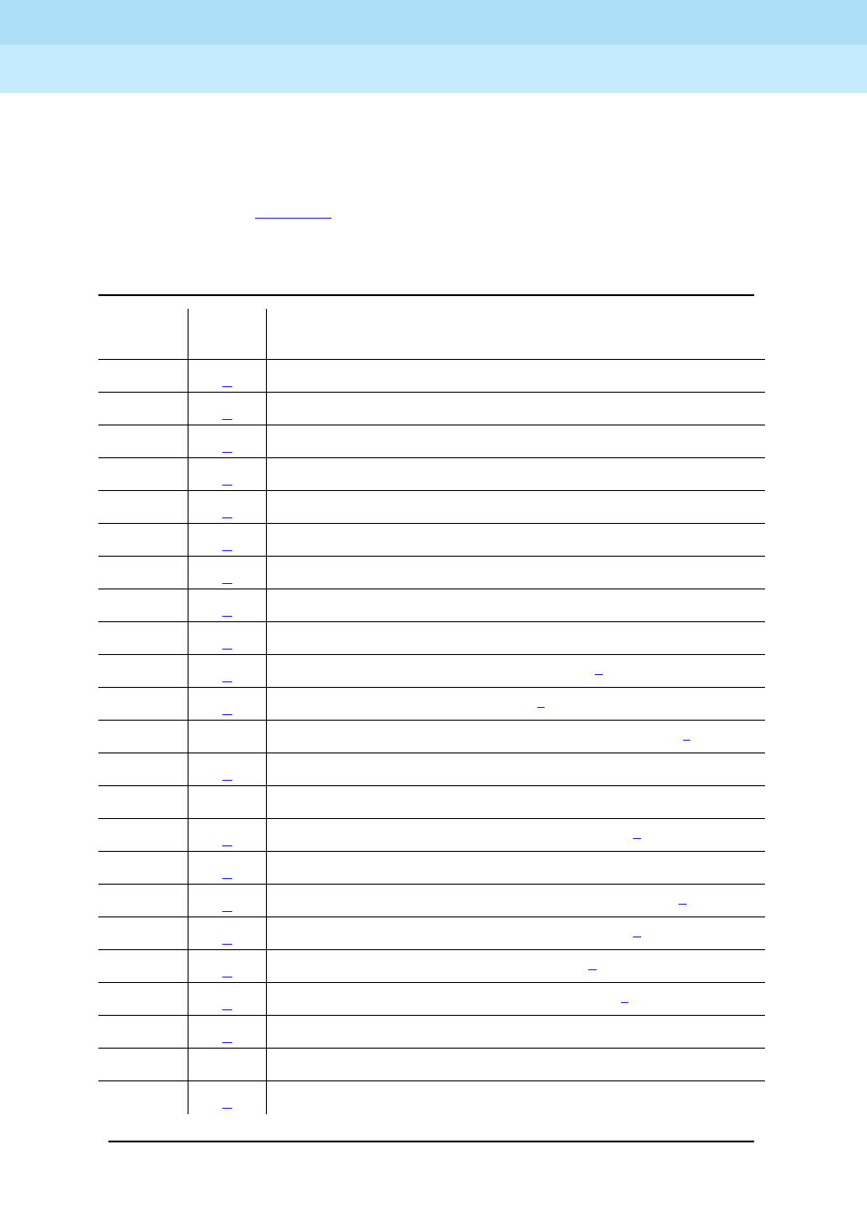
DEFINITY Enterprise Communications Server Release 6
Maintenance for R6r Volumes 1 & 2
555-230-126 Issue 2
January 1998
Responding to Alarms and Errors
Page 5-16Executing a Planned SPE Interchange
5
If the SPE is locked by means of the SPE-SELECT switches, error 607, auxiliary
data 1153, is logged against SYSTEM. If the switches are not locked and the
interchange fails, an unalarmed error 605 is logged against SYSTEM. The
auxiliary code associated with this error indicates which aspect of the
interchange failed. Table 5-1 explains the meaning of the auxiliary codes and
what corrective action to take.
Table 5-1. SYSTEM Error 605 Planned Interchange Failure
Aux
Data See
Note Explanation
1352 1Standby SOH “non-functional”
1353 1Standby SOH not “functional”
1355 1Handshake Communication with Standby SPE is down
1356 1Memory Shadowing not enabled
1357 1Standby memory not refreshed
1358 2Mass Storage System was in use
1359 3PKT-INT link migration failed
1360 1Interchange failed1
1361 4SW-CTL failure
1369 7Could not suspend G3-MT connectivity1
1370 4Could not freeze active SW-CTL1
1371 5 Internal Error associated with processor interrupts1
1372 6Minor alarm on standby SYSAM or PKT-INT
1395 SPE Duplication not administered
1396 3PKT-INT Link Migration failure in Begin Step1
1397 3PKT-INT Link Migration denied, (peer test in progress)
1398 3PKT-INT Link Migration failure in Completion Step1
1399 3PKT-INT Link Migration failure in Finish Step1
1400 4Could Not Idle SW-CTL dual port RAM1
1401 4Could Not Refresh SW-CTL dual port RAM1
1402 5Internal Error (could not get duplication status)
1403 5 Unable to inhibit Standby Maintenance Monitor
1404 5Failure to determine Standby SPE alarm status
Continued on next page

DEFINITY Enterprise Communications Server Release 6
Maintenance for R6r Volumes 1 & 2
555-230-126 Issue 2
January 1998
Responding to Alarms and Errors
Page 5-17Executing a Planned SPE Interchange
5
Notes for SYSTEM Error 605 AUX Data:
1. Follow repair instructions in ‘‘STBY-SPE (Standby SPE Maintenance)’’ for
the particular standby SPE problem. After fixing that problem, try the
interchange again.
2. Mass Storage System is in use. Check Disk and Tape LEDs for activity.
Wait until all MSS activity completes, then try the interchange again. If the
problem persists, check for alarms and errors against MSS components
and follow repair procedures in Chapter 9, ‘‘Maintenance Object Repair
Procedures’’.
3. Test the PKT-INT on both carriers with the long test sequence. Follow
procedures for ‘‘PKT-INT (Packet Interface Circuit Pack)’’ in Chapter 9,
‘‘Maintenance Object Repair Procedures’’. Once
all
tests of both PKT-INTs
pass, try the interchange again.
4. Consult SW-CTL service documentation. Test SW-CTL on both carriers
with the long test sequence. Follow repair instructions for any failures.
Once
all
tests of both SW-CTLs pass, try the interchange again.
5. Make sure the standby SPE is refreshed Then try the interchange again.
6. Examine alarm log to determine which of PKT-INT or SYSAM circuit packs
has a minor alarm against it. Consult service documentation of whichever
is alarm to clear
7. Check for errors/alarms against active SPE’s SYSAM. If you find any,
consult SYSAM service documentation. If you find none, and if all tests of
the SYSAM long sequence pass, try the interchange again.
8. Run test duplication-interface long and follow instructions for any test
that does not pass.
1. A WARM restart is required.
1406 3Active SPE’s PKT-INT in held-reset state
1418 8Active Duplication Interface circuit pack is in a bad state
and needs to be reset.
2500 5Internal Software failure1 (sometimes)
Table 5-1. SYSTEM Error 605 Planned Interchange Failure — Continued
Aux
Data See
Note Explanation
Continued on next page

DEFINITY Enterprise Communications Server Release 6
Maintenance for R6r Volumes 1 & 2
555-230-126 Issue 2
January 1998
Responding to Alarms and Errors
Page 5-18Fiber Fault Isolation Procedure
5
Fiber Fault Isolation Procedure
Use the following procedure to isolate faults on a fiber-link. When troubleshooting
a system with duplicated Port Network Connectivity (PNC), first busyout
pnc-standby before busying out a standby Fiber-Link (FIBER-LK), Expansion
Interface (EXP-INTF), Switch Node Interface (SNI) or DS1 Converter (DS1C). At
the end of this section is a description of the loopback tests run and a pinout of
the cable used to connect the DS1 C to DS1 facilities.
■A busyout of any of these components on a simplex PNC is destructive.
■Be sure to release all busied out components after completing the tests.
Steps:
1. Enter display alarms with category pnc.
Are there any on-board alarms? If so, replace the circuit pack(s).
2. Enter display errors for category pnc.
Check for any of the following errors:
If
one or more
of the above errors are present go to step 3.
If
none
of the above errors are present, look for SNI-PEER errors.
■If there is one SNI circuit pack with many different SNI-PEER error
types, replace the indicated SNI circuit pack
■If there are many SNI-PEER errors of the same error type, replace
the indicted SNI circuit pack using the following table.
Maintenance
Object Error
Type
FIBER-LK Any
SNI-BD 513
EXP-INTF 257
769
770
1281
1537
3073
3074
3075
3076
3585
3841
3842

DEFINITY Enterprise Communications Server Release 6
Maintenance for R6r Volumes 1 & 2
555-230-126 Issue 2
January 1998
Responding to Alarms and Errors
Page 5-19Fiber Fault Isolation Procedure
5
■After replacing an SNI circuit pack, clear alarms by executing test
board UUCSSlong clear for all alarmed EXP-INTF circuit packs.
Wait 5 minutes for any SNI-BD or SNI-PEER alarms to clear. (You
can speed this process with clear firmware counters [a-pnc |
b-pnc] for the PNC that was repaired).
■Exit this procedure.
3. Enter list fiber-link to get the physical location of the fiber-link endpoints.
If a DS1 CONV is administered to the fiber-link (DS1 CONV is “y”), use the
display fiber-link command to get the physical location of the DS1 CONV
circuit packs on the fiber-link.
4. Execute busyout fiber-link FP followed by test fiber-link FP long.
If any tests in the sequence fail
, proceed with step 5.
If all of the tests pass
, clear alarms by executing test board UUCSS long
clear for all alarmed EXP-INTF circuit packs. Wait 5 minutes for any
SNI-BD, SNI-PEER, FIBER-LK, or DS1C-BD alarms to clear. You can
speed this process with clear firmware counters [a-pnc | b-pnc] for the
PNC that was repaired. You are finished with this procedure.
Error Type SNI slot
12
257 3
513 4
769 5
1025 6
1281 7
1537 8
1793 9
2049 13
2305 14
2561 15
2817 16
3073 17
3329 18
3585 19
3841 20
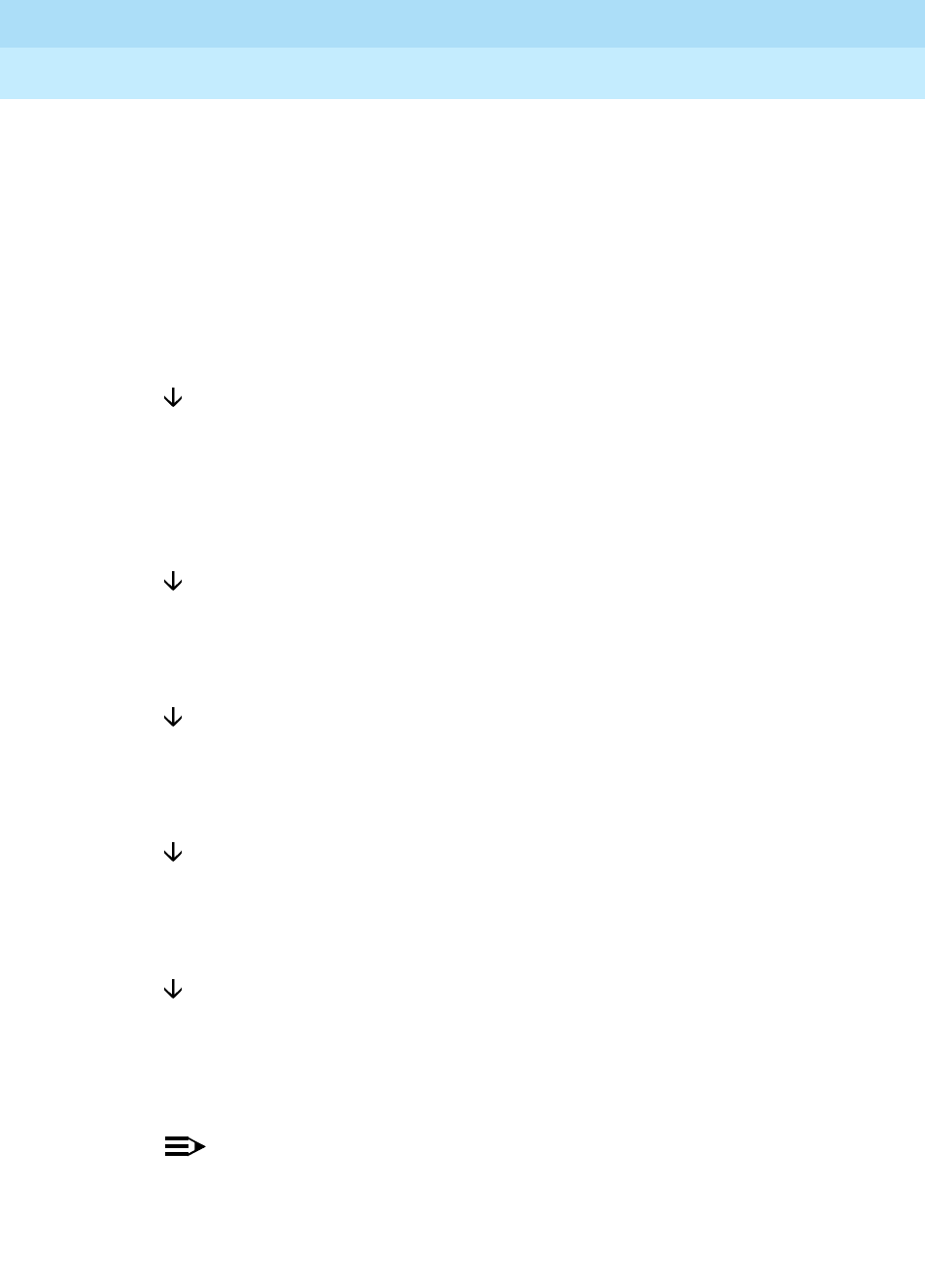
DEFINITY Enterprise Communications Server Release 6
Maintenance for R6r Volumes 1 & 2
555-230-126 Issue 2
January 1998
Responding to Alarms and Errors
Page 5-20Fiber Fault Isolation Procedure
5
5. For each endpoint of the fiber-link, follow this flowchart:
Busyout and test board UUCSS long and record all test failures. When
looking at test results, consult the explanations and illustrations of the
tests, which appear at the end of this procedure.
Is Board Not Assigned displayed for an EXP-INTF in an EPN? If yes,
test maintenance
long to release an EXP-INTF that may be held reset by an EPN
Maintenance circuit pack.
If No
Did EXP-INTF test 242 fail? If yes, replace the EXP-INTF circuit pack and
the lightwave transceiver (if present) and go back to step 4. (EXP-INTF
test 242 runs an on-board looparound if no lightwave transceiver is
connected to the EXP-INTF.)
If No
Did SNI test 757 fail? If yes, replace the SNI circuit pack and go back to
step 4 of this procedure.
If No
Did SNI test 756 fail? If yes, replace the SNI circuit pack and the lightwave
transceiver (if present) and go back to step 4.
If No
Did EXP-INTF test 240 fail? If yes, replace the EXP-INTF circuit pack and
go back to step 4.
If No
Did tests 238 (EXP-INTF) or 989 (SNI) fail? If yes, replace the lightwave
transceivers and fiber-optic cable, or metallic cable, and go back to step
4. The faulted component can be further isolated by using the Manual
Loopback Procedure described at the end of this procedure.
NOTE:
If a fiber out of frame condition exists and lightwave transceivers are
used, check that both lightwave transceivers are of the same type,
(9823a or 9823b). If they are not both the same, replace one of the
lightwave transceivers so that they match. (9823A is used for

DEFINITY Enterprise Communications Server Release 6
Maintenance for R6r Volumes 1 & 2
555-230-126 Issue 2
January 1998
Responding to Alarms and Errors
Page 5-21Fiber Fault Isolation Procedure
5
distances up to 4900 feet (1493 m) and 9823B is used for distances
up to 25,000 feet (7620 m)).
If No
Is a DS1 CONV administered on the fiber-link? If no, follow normal
escalation procedures.
If Yes
Is there an SNI-BD 513 alarmed error (display errors for category pnc)?
If yes, replace cabling between the SNI circuit pack and the DS1C circuit
pack. If the alarm persists, replace the DS1C and the SNI circuit packs.
Go back to step 4.
If No
If the connected circuit pack is an EXP-INTF, did test 238 fail? If yes,
replace cabling between the EXP-INTF circuit pack and the DS1C circuit
pack. If test 238 continues to fail, replace the DS1C and the EXP-INTF
circuit packs.
Go back to step 4.
If No
Busyout and test board UUCSS long for both DS1C circuit packs and
note all test failures and aborts.
Did the test return Board not inserted for the near-end circuit pack
(nearest the SPE), or for the far-end circuit pack in a simplex PNC? If so,
replace the cabling between the DS1C circuit pack and the SNI or
EXP-INTF circuit pack.
Wait 1 minute and retest.
If the board is still not inserted, replace the DS1C circuit pack and the
EXP-INTF or SNI connected to it.
Go back to step 4.
If No
Check to see if any of the CSU devices are looped back. Busyout and
test ds1-facility UUCSS external-loop for each DS1 facility.

DEFINITY Enterprise Communications Server Release 6
Maintenance for R6r Volumes 1 & 2
555-230-126 Issue 2
January 1998
Responding to Alarms and Errors
Page 5-22Fiber Fault Isolation Procedure
5
The tests should fail.
If any test passes, the facility is looped back, and the loopback should be
removed. If the DS1C Complex has only one DS1 facility, this test cannot
be executed at the far-end circuit pack (farthest from the SPE).
Did test 788 pass and test 789 fail? If yes, replace the DS1C and lightwave
transceiver (if present) at the other end of the DS1C complex. (See Figure
5-4 and Figure 5-5.)
Go back to step 4.
If No
Did test 788 fail or abort and test 789 fail or abort? If yes, execute test
ds1-facility UUCSS long command for each administered and equipped
DS1 facility.
If No
Did test 797 fail?
If yes, run the test ds1-facility UUCSS external-loopback command for
each administered and equipped DS1 facility.
This test requires manually altering the external connections of the DS1
facility. Place the loopbacks at as many points as your CSU capabilities
will allow (see Figure 5-5).
■If test 799 fails at LB1, problem is with DS1C #1, CSU #1, or the
connections in between.
■If test 799 passes at LB1 and fails at LB2, the problem is with CSU
#1.
■If test 799 passes at LB1 and at LB2, the problem is with the DS1
facility, CSU #2, connections to CSU #2, or DS1C #2.
SNI/EI Manual Loop Back Procedure
Use this procedure to isolate a fault in the cables or lightwave transceivers of
SNI/EI links. (Do not use this procedure on a connection with a DS1C as an
endpoint.) By performing the loopback at both endpoints and, if applicable, at
the cross-connect field, the failure point can be identified. If both endpoints pass,
but the link remains inactive (with the boards not busied out), the fault should lie
in the cabling in between. If the test passes at a transceiver, but fails at the
cross-connect field, the cable or connectors in between are at fault.

DEFINITY Enterprise Communications Server Release 6
Maintenance for R6r Volumes 1 & 2
555-230-126 Issue 2
January 1998
Responding to Alarms and Errors
Page 5-23Fiber Fault Isolation Procedure
5
A short optical fiber jumper with connectors is required for this procedure. If the
link uses metallic cable, the metallic connector must be removed from the back
of the carrier, and a lightwave transceiver connected in its place.
1. Note the condition of the yellow LED on the circuit pack.
2. Busyout the circuit pack.
3. Disconnect the transmit and receive fiber pair from the lightwave
transceiver on the back of the circuit pack. Note which is the transmit fiber
and which is the receive fiber for proper re-connection at the end of this
procedure.
4. Connect the transmit and receive jacks of the lightwave transceiver with
the jumper cable.
NOTE:
Make sure that the total length of the fiber jumper cable does not
exceed the maximum length recommended for the fiber link
connections between cabinets. Otherwise, test results may be
influenced by violation of connectivity guidelines.
5. At the front of the cabinet, observe the yellow LED on the looped back
circuit pack.
■If the yellow LED flashes once per second, the circuit pack or
transceiver should be replaced.
■If the yellow LED flashes five times per second, the circuit pack or
its lightwave transceiver may need replacement. This condition
may also be due to a faulty system clock on the port network (for an
EI) or the switch node carrier (for an SNI).
■If the yellow LED was flashing before starting this procedure, and it
is now either solid on or solid off, this circuit pack and its lightwave
transceiver are functioning properly.
6. Replace the faulty component(s) and reconnect the original cables in their
correct positions. Be sure to use a lightwave transceiver that matches the
one at the opposite end.
7. Release the circuit pack.
Loopback Tests Run for Fiber Fault Isolation
Procedure
Figure 5-5 shows the loopbacks performed on the SNI circuit pack for test 756
and test 757. Test 756 reports the result of the off-board loopback; test 757
reports the result of the on-board loopback. Test 756 and test 757 can run
individually or as part of the test board UUCSS long command for an SNI circuit
pack.
Test 242 can be run as part of the test board UUCSS long command for an
Expansion Interface circuit pack. Besides testing on-board components, this test
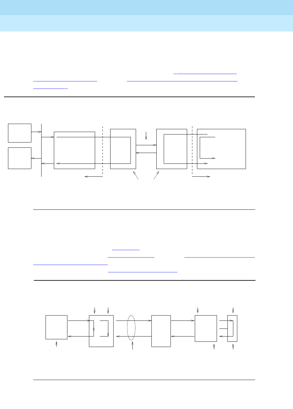
DEFINITY Enterprise Communications Server Release 6
Maintenance for R6r Volumes 1 & 2
555-230-126 Issue 2
January 1998
Responding to Alarms and Errors
Page 5-24Fiber Fault Isolation Procedure
5
is helpful for isolating problems between a circuit pack and the lightwave
transceiver. The loopback shown in this diagram shows only part what test 242
does. If no lightwave transceiver is connected to the Expansion Interface circuit
pack, an on-board loopback is performed on the Expansion Interface circuit
pack. For more information about test 242, see the ‘‘EXP-INTF (Expansion
Interface Circuit Pack)’’ section in Chapter 9, ‘‘Maintenance Object Repair
Procedures’’.
Figure 5-4. Fiber Fault Isolation Tests
If DS1Cs exist on the fiber link (check with list fiber-link), then additional
DS1CONV loopback tests can be run to further isolate the problem. The
loopback tests are shown in Figure 5-5. For more information about loopback
tests 788 and 789, see the ‘‘DS1 CONV-BD’’ section in Chapter 9, ‘‘Maintenance
Object Repair Procedures’’. For more information about DS1 facility loopback
tests 797 and 799, see the ‘‘DS1-FAC (DS1 Facility)’’ section.
Figure 5-5. DS1 CONV Loopbacks
Tone
Clock
Tone
Detector
Test
#242
fiber-optic
cable
TDM BUS back skin
of cabinet
lightwave
transceivers
TN753
Switch
Node
Interface
Test
#757
Test
#756
TN570
Expansion
Interface
back skin
of cabinet
Test #989 (framing)Test #238 (framing)
Tests 788, 780, 797,
and 799 start here:
. . . . .
.
.
.
.
.
.
.
.
.
. . . . .
Test 797 loops at internal
interface for the DS1 facility
Test 789
loops here
Test 788
loops here
lightwave
transceiver
DS1 Facility
CSU 2 DS1C
2
CSU 1
DS1C
1
Test 799
LB 1 Test 799
LB 2

DEFINITY Enterprise Communications Server Release 6
Maintenance for R6r Volumes 1 & 2
555-230-126 Issue 2
January 1998
Responding to Alarms and Errors
Page 5-25Fiber Fault Isolation Procedure
5
Table 5-2 shows the pin assignments for the cable used to connect the TN574
DS1 CONV circuit pack to DS1 facilities.
Table 5-2. DS1 Interface Cable Connectors
Lead Desig.
50-Pin
Connector
Pin
15-Pin
Connector
Color Pin Color
Plug 04
Facility D Line In LID 38 W-BL 11 W-BL
Facility D Line In LID* 13 BL-W 03 BL-W
Facility D Line Out LOD 39 W-O 09 W-O
Facility D Line Out LOD* 14 O-W 01 O-W
Plug 03
Facility C Line In LIC 41 W-G 11 W-G
Facility C Line In LIC* 16 G-W 03 G-W
Facility C Line Out LOC 42 W-BR 09 W-BR
Facility C Line Out LOC* 17 BR-W 01 BR-W
Plug 02
Facility B Line In LIB 44 W-S 11 W-S
Facility B Line In LIB* 19 S-W 03 S-W
Facility B Line Out LOB 45 R-BL 09 R-BL
Facility B Line Out LOB* 20 BL-R 01 BL-R
Plug 01
Facility A Line In LIA 47 R-O 11 R-O
Facility A Line In LIA* 22 O-R 03 O-R
Facility A Line Out LOA 48 R-G 09 R-G
Facility A Line Out LOA* 23 G-R 01 G-R
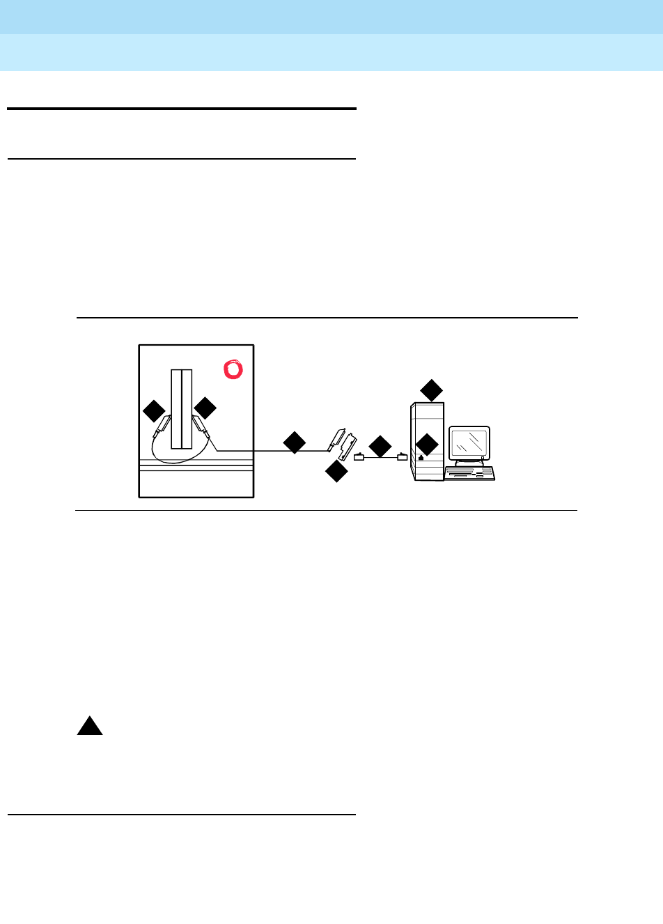
DEFINITY Enterprise Communications Server Release 6
Maintenance for R6r Volumes 1 & 2
555-230-126 Issue 2
January 1998
Responding to Alarms and Errors
Page 5-26Multimedia Call Handling (MMCH)
5
Multimedia Call Handling (MMCH)
Enhancements
Expansion Services Module
The Expansion Services Module (ESM) provides T.120 data sharing capability on
a MMCH multipoint H.320 video conference. Each conference participant must
have endpoints administered and a personal computer with the H.320 video
application installed. The DEFINITY ECS must have the expansion service
module installed.
Figure 5-6. Typical ESM connections
Figure Notes
!CAUTION:
The TN2207 circuit pack is the only pack allowing connection of an ESM to
the DEFINITY ECS switch.
Troubleshooting
Before troubleshooting any problems associated with the DEFINITY MMCH,
always be sure that the endpoint is operating correctly (audio, video, and data)
by making point-to-point test calls. If possible, make the test calls over the
1. Port B Y-cable connector to a TN787
Multimedia Interface (MMI) circuit pack
2. Port A Y-cable connector to a TN2207 PRI
circuit pack
3. 25-pair Y-cable
4. 356A adapter
5. D8W cord connected to 356A
adapter port 1
6. Expansion Service Module (ESM)
7. Port B on compatible primary rate
interface (PRI) card
cydf012 RPY 100697
12
4
5
3
6
7

DEFINITY Enterprise Communications Server Release 6
Maintenance for R6r Volumes 1 & 2
555-230-126 Issue 2
January 1998
Responding to Alarms and Errors
Page 5-27Multimedia Call Handling (MMCH)
5
network to test the connectivity and routing of network calls from the endpoint.
This eliminates problems such as disconnected audio or video cables and
network troubles.
64 Kbps Calls Terminate but Far End Receives
56 Kbps Indication
Description
Some 2x64 Kbps conferences on the DEFINITY MMCH do not establish because
of framing, audio, or video problems.
For calls that are routed in the network through a Lucent Technologies/LEC
interface, the originating equipment may launch a 64 Kbps call attempt, and the
far end receives either a 56 Kbps or 64 Kbps indication. If the far end receives a
64 Kbps indication, the call may have used 56 Kbps facilities. If so, the call may
exhibit any of the following conditions:
■No handshaking in one direction or both (call disconnects after timeouts)
■Call connects, but audio or video is corrupted (audio noise or no video)
■Call succeeds without disruption (this is the least likely since one endpoint
must be aware that the call is really 56 Kbps to connect)
If any of the above conditions occur, then 64 Kbps calls from the site are
blocked.
Solution
Administer the conference for connection at 56 Kbps.
Calls Terminate with No Audio
Description
To support endpoints that do not support Multipoint Command Conference
(MCC), the DEFINITY MMCH changes its capability set and initiates a capability
set exchange with the endpoint when the Selected Communications Mode (SCM)
changes. If the endpoint does not follow the SCM audio mode, the MCU may
include the endpoint as a secondary (audio only) endpoint. If the endpoint sends
an unknown or unsupported audio mode, then the TN788B decoder port mutes
the endpoint from the conference. The user may hear the conference but may not
be heard by other parties in the conference.
Solution
1. Use the Status Conference x form and check the Audio Mode field for the
current operating mode of the conference.

DEFINITY Enterprise Communications Server Release 6
Maintenance for R6r Volumes 1 & 2
555-230-126 Issue 2
January 1998
Responding to Alarms and Errors
Page 5-28Multimedia Call Handling (MMCH)
5
2. Another indication of the audio modes is in the “Incoming Mode
Commands from Endpoint and Outgoing Commands from MMI” on page
3 of the Status Conference x Endpoint y form. Check the Audio fields
under the Mode Commands/Communication Modes section of the form.
Some Parties Cannot Be Heard by Others (Audio
Subsetting)
Description
Problems where varying subsets of the conference hear different things may
have problems with the various summing resources/groups that are in use.
Traditionally theses faults are caused by the SPE not cleaning up the
connections properly. Isolation and diagnosis should focus on the VC resources
in use by that conference.
Solution
1. Use the status conference command to list the VC resources in use by
this conference. Try a hot replacement of any VC boards in use, which
refreshes the VC translations and move all of the audio connections to
different VC ports.
2. If the problem still exists, try dropping the conference and then bringing
the conference back up again. Not only does this refresh VC translations,
but uses different timeslots as well.
3. If the problem still exists, suspect a hardware problem. If practical, wait for
the DEFINITY MMCH to be idle (no active conferences), and then check
the circuit packs for active (yellow) LEDs. If any of these are unexpected,
such as on a VC board, try replacing the board and then bringing the
conference up again.
Calls Terminate with No Video
Description
Generally, loss of video can be divided into 2 types. The first occurs when the
DEFINITY MMCH switches to the endpoint, but nobody sees them. The receivers
see either “black” video or a frozen image of the previous speaker depending on
the codec of the manufacturer. The type occurs when the DEFINITY MMCH does
not switch to an endpoint.
Solution
In the first type described above, wiring problems, power to the camera, or video
encoder circuit pack problems in the codec are typical causes.
In the second type, no video from an endpoint typically occurs because it is not a
valid video source. This can be checked by looking at page 1 of the Status
Conference x Endpoint y Vid form under the Capability section. In this section, a

DEFINITY Enterprise Communications Server Release 6
Maintenance for R6r Volumes 1 & 2
555-230-126 Issue 2
January 1998
Responding to Alarms and Errors
Page 5-29Multimedia Call Handling (MMCH)
5
“y” or “c” suggests that the endpoint has video. An “e” means ept has not
declared any video capability in cap set, “n” is audio only, and “blank” means
audio add-on.
Also check page 1 of the Status Conference x Endpoint y Vs form for indication of
the video state for the endpoint values.
Calls Terminate Correctly but Are Unstable
A number of conditions will lead to some or all endpoints having stability
problems during the course of a conference. A lack of stability from an endpoint
is noticeable by a lack of a video switching while the party is the only talker or
excessive disconnects from that endpoint.
Synchronization
Generally, the most common problem is a mismatch in synchronization sources
between the endpoint and the DEFINITY MMCH. This typically causes low-level
(Px64) handshake problems that can trigger the endpoint/MMCH to disconnect
the call. The MCCH’s timers are set to sufficiently high values so that, normally,
the endpoint will timeout and disconnect first. If installed in a customer network, it
is a good idea to perform an audit of the path synchronization is being supplied.
If there are different clock sources between endpoints and the DEFINITY MMCH,
some problems are sure to occur. The severity of these problems can range from
a handshake failure every few seconds to one per day. Depending on the type of
endpoint, this can cause the endpoint to disconnect or just freeze video until the
main problem is resolved.
Specifically, PictureTel System 4000 endpoints seem to be the most sensitive to
instability. The Lucent Technologies Vistium also disconnects fairly infrequently.
Last, the CLI Rembrandt II VP freezes video and waits for framing to be
recovered.
Network Configuration Concerns with Synchronization
When auditing a network for synchronization, avoid unnecessary hops. Thus, a
switch providing star-configuration synchronization is preferred over a
daisy-chain configuration. Additionally, if there are DEFINITY PBXs that have
EPNs, synchronization should be provided to sub nodes from the same port
network through which the PBX receives its synchronization. Passing
synchronization through the PBX Expansion Interface adds an unnecessary hop
to the path and creates another potential point of failure.
Expansion Interface Duplication
If a customer’s network uses PBX EPNs with duplicated Expansion Interfaces,
scheduled switching of the Expansion Interface links should be disabled on the
PBX via change system-parameters maintenance. When scheduled
maintenance runs and switches the links, there is a brief corruption of the data
path. If endpoints have active calls when the switch occurs, this corruption of the
data path causes Px64 handshake problems, which lead to the endpoints losing

DEFINITY Enterprise Communications Server Release 6
Maintenance for R6r Volumes 1 & 2
555-230-126 Issue 2
January 1998
Responding to Alarms and Errors
Page 5-30Multimedia Call Handling (MMCH)
5
video source status, and sometimes disconnecting as described above.
Disabling the EI switching is in the customer’s best interest to prevent the
disruption of the Px64 data stream. The customer will get the same level of alarm
indications and maintenance on the EI links, regardless of the status of
scheduled switching.
PRI D-Channel Backup
A somewhat unlikely source of call stability problems occur where the
translations for PRI D-channel Backup between two non-MCU switches were
incorrect. As an example, on switch A, DS1 1A10 was designated as the primary
source, and on switch B, the corresponding DS1 was designated as the
secondary source. When scheduled maintenance was run on the switch that had
an active standby D-channel, an audit disconnected some calls using the link.
The problem was corrected when the the D-channel primary/secondary
assignments matched.
Processor Duplication on the PBX
Do not enable the PI link switch on scheduled maintenance. This can cause link
stability problems on the Accunet Bandwidth Controller (ABC).
Voice-Activated Switching Problems
Voice-activated switching on the DEFINITY MMCH does not follow the loudest
talker. The MMCH queues all speaking parties and selects a new video
broadcaster (the second-oldest speaking party) when the oldest speaking party
has stopped talking. The new broadcaster will see the last speaker as its video.
The system can also “learn” about the noise coming from an endpoint to help
prevent false switches, adapting both to noise level and repetitive sounds such
as a fan. This adaptation occurs over approximately 10 seconds.
No Switching, Full Motion Video
If a room is excessively noisy, the DEFINITY MMCH may receive sufficient audio
signal to conclude that there is a speaker present. Use the Status Conference x
form to determine if the MMCH thinks an endpoint is talking. The MMCH sets the
Ts field to t for each endpoint if there is voice energy detected. This endpoint
may have to mute when nobody at the site is speaking to allow the conference to
proceed normally. Remind the customer that it may be necessary to mute if a
side conversation is going on in the background, just as one would do in an
audio conference. If the system does not switch broadcasters even after the
current broadcaster has muted, check the conference administration using the
display conference X command to ensure that the conference is in
voice-activated mode. Also verify that parties who were speaking are valid video
sources as described in the “Calls Terminate with No Video” section above.
The See-Me feature (MCV) can also cause VAS to “lock-up.” An endpoint can
activate MCV to force their site to become the broadcaster. If they do not disable
the feature when finished, the system remains in this mode indefinitely.

DEFINITY Enterprise Communications Server Release 6
Maintenance for R6r Volumes 1 & 2
555-230-126 Issue 2
January 1998
Responding to Alarms and Errors
Page 5-31Multimedia Call Handling (MMCH)
5
Beginning with Release 3.0, the status conference X command shows that MCV
is in effect by displaying av in the Video Status (Vs) column. Page 3 of the Status
Conference X Endpoint Y form also has a Broadcaster field that indicates MCV
is in effect with (SEE-ME) as the broadcaster. The same scenario can occur in a
CHAIR or UCC-controlled conference with a designated broadcaster. In this
situation the CHAIR/UCC has not released the designated broadcaster and
returned to VAS mode. If there is a UCC-designated broadcaster, status
conference X indicates a Video Status of u. Also, for UCC rollcall the return
video may appear to be stuck. Check the Video Status for an “R,” indicating
rollcall.
If none of the examples above appears to be the cause, and if the room was
quiet, all speakers are valid video sources, the conference is voice-activated,
and the speaker can be heard, then escalate the problem.
Video Never Switches to a Particular Party
Description
Verify that the endpoint is a valid video source as described in the “Calls
Terminate with No Video” section above. If it is, then the audio from the endpoint
may not have sufficient voice signal for the hardware to determine the parties at
the endpoint are speaking. Check the Talk field on page three of the Status
Conference X Endpoint Y form to see if the talking bit is y. Next, check the
audio by standing adjacent to the microphone and speaking at a normal level.
Solution
If the audio is not muffled:
1. Use the status conference command to determine which port on the
TN788B (VC board) is connected to this endpoint.
2. Check the VC (TN788B) board using the test board xxyy long command.
3. Drop the call.
4. Find another available port, then:
a. Busyout the port to which the endpoint was connected.
b. Make another call to the same conference. If the problem corrects
itself, then the previous port may be bad. If there are other VC
boards with sufficient available ports to replace calls on the current
VC, then pull the board that has the bad endpoint on it (the status
conference command displays the encoder port associated with
the call). The system will automatically reestablish the VC
connections without dropping the call. If this fixes the problem, then
replace the board, as it has at least one bad port. Reseating the
board may temporarily fix the problem due to the hard reset done to
the board.

DEFINITY Enterprise Communications Server Release 6
Maintenance for R6r Volumes 1 & 2
555-230-126 Issue 2
January 1998
Responding to Alarms and Errors
Page 5-32Multimedia Call Handling (MMCH)
5
Audio Echo
Echo in conference calls, particularly those with large delay characteristics, is
totally disruptive. When Voice Activated Switching is taken into account, the
effects are disastrous. Various arrangements of the microphone(s) and room
speaker(s) may be needed.
For some Lucent Technologies Vistium endpoints, if an external speaker is
attached or was attached when the system was last rebooted, this endpoint will
cause audio echo throughout the conference. First, isolate the offending
endpoint by asking each endpoint to mute, one at a time, until the echo
disappears.
If the input from an endpoint is located too close to the speakers of an endpoint,
then acoustic echo is created. The microphone must be moved away from the
speakers.
Normally, if any microphone in the room is moved relative to the speakers, that
site will cause echo until the echo canceller in the codec retrains itself, some will
require a manual reset. If a PictureTel keypad is configured with external
microphones connected to the keypad, then the internal microphone and
external microphone(s) “sing” to each other if the “ext mic” bat switch is set to
“int mic” on the back of the keypad. In this configuration, VAS locked on that site,
and the acoustic “singing” was inaudible.
Rate Adaptation
Because of a lack of a clear explanation in standards, sometimes endpoints do
not work well with each other and the DEFINITY MMCH. The MMCH will only
allow a conference to downgrade from 64kbps to 56 kbps operation on
conferences that have the Rate Adaptation flag set to y.
When a downgrade does occur, information on the Status Conference form
indicates the success or failure of the 64kbps-endpoints that are participants to
properly rate adapt to 56kbps. As a general indication that the conference has
rate adapted, the Conference Transfer Rate and Effective Transfer
Rate fields show initial and current transfer rates, respectively. For each 64-kbps
endpoint the column that indicates Rate Adapt shows an n if the endpoint did
not follow the procedures as specified by the H.221. If an endpoint shows y, it
did successfully rate adapt. If an endpoint shows c, it joined the conference at
56kbps.
Once the conference rate adapts, the endpoints that do not properly follow suit,
will become audio-only endpoints. A conference will not rate adapt from 56 kbps
back to 64 kbps until all endpoints disconnect from the conference and it idles.
The PictureTel 1000 Release 1.1C, PictureTel 6.01 software, and the Vistium 2.0
software successfully rate adapt with the MCU. External rate adaptation
techniques used by VTEL and CLI are known to cause problems with the
endpoint when used with this feature.

DEFINITY Enterprise Communications Server Release 6
Maintenance for R6r Volumes 1 & 2
555-230-126 Issue 2
January 1998
Responding to Alarms and Errors
Page 5-33Troubleshooting ISDN-PRI Problems
5
Endpoint or I-MUX in Loopback Mode
Some endpoints have a loopback enable feature. This makes DEFINITY MMCH
data loopback at the MMCH when a connection is in progress. The loopback can
be enabled prior to or during a connection.
The MMCH does not detect the loop and continues to VAS. In most scenarios,
the switch occurs, but within a few seconds, the broadcaster’s return video
becomes its own image. Once the broadcaster stops speaking, the system
“false” switches to an apparently random port that was not speaking.
Troubleshooting ISDN-PRI Problems
The following flow chart defines a layered approach when troubleshooting
ISDN-PRI problems. Since a problem at a lower layer affects upper layers, layers
are investigated from low to high. In the flowchart, the DS1 facility is layer 1, the
ISDN-PRI D-channel is layer 2, and the ISDN trunks are layer 3. Transient
problems are diagnosed on Page 2 of the flowchart. For problems with PRI
endpoints (wideband), see the following section.
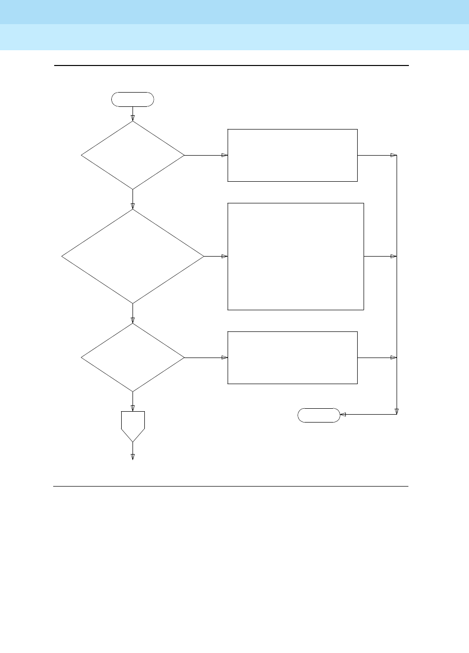
DEFINITY Enterprise Communications Server Release 6
Maintenance for R6r Volumes 1 & 2
555-230-126 Issue 2
January 1998
Responding to Alarms and Errors
Page 5-34Troubleshooting ISDN-PRI Problems
5
Figure 5-7. Troubleshooting ISDN-PRI (Page 1 of 2)
ARE THERE
ALARMS OR ERRORS
AGAINST UDS1-BD OR
DETERMINE PRESENT STATUS
OF DS-1 FACILITYVIA UDS1-BD
OR DS1-BD MO SECTION.
ARE THERE
ALARMS OR
ERRORS AGAINST
ISDN-LINK OR
ISDN-SGR
IF MULITPLE ALARMS EXIST,
INVESTIGATE IN FOLLOWING
ORDER:
ISDN-LINK
ISDN-SGR
FOLLOW REPAIR PROCEDURE
FOR APPROPRIATE MO
ARE THERE
ALARMS OR
ERRORS AGAINST
FOLLOW REPAIR
PROCEDURE FOR ISDN-TRK
TO
PAGE
2
NO
YES
START
YES
NO
YES
END
A
NO
DS1-BD
ISDN-TRK
FOLLOW REPAIR PROCEDURES
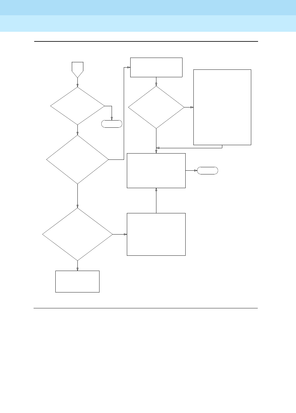
DEFINITY Enterprise Communications Server Release 6
Maintenance for R6r Volumes 1 & 2
555-230-126 Issue 2
January 1998
Responding to Alarms and Errors
Page 5-35Troubleshooting ISDN-PRI Problems
5
Figure 5-8. Troubleshooting ISDN-PRI (Page 2 of 2)
PAGE
YES
END
A
FROM
1
ARE
THERE
TRANSIENT
PROBLEMS MAKING
ISDN-PRI
ARE
THERE BIT
ERRORS OVER
HAS A
SYNCHRONIZATION
SOURCE BEEN
SYSTEM SWITCHING
IF PROBLEMS
STILL EXIST,
THEN ESCALATE
COMPARE INDICATED
FACILITY TO RECORD
OF PREVIOUS PROBLEMS
ARE BIT
ERRORS OCCURRING
MORE FREQUENTLY
THAN PREVIOUS
RECORD INDICATED
FACILITY AND, IF THIS
CONTINUES TO OCCUR,
CONTACT FACILITY OR
EXTERNAL EQUIPMENT
PROVIDER. THEN ESCALATE
THE TI FACILITY?
UNSTABLE?
AWAY FROM IT?
NO
YES
SEE UDS1-BD OR DS1-BD
MO FOR REPAIR PROCEDURES
IF SYNC PROBLEM IS DUE
TO SLIPS. OTHERWISE,
FOLLOW REPAIR
PERFORM AN IN-DEPTH
ANALYSIS OF T1
FACILITY INCLUDING:
TRANSMISSION FACILITY,
EXTERNAL EQUIPMENT
(DACS, CSUs, ETC.)
AND ANY OTHER
NOISE-PRODUCING
EQUIPMENT.
REFER TO AT&T PRACTICE
#855-351-101 ISSUE 8,
JANUARY 1987. THIS
DESCRIBES T1 CABLING TO
CSUs, ETC, IN DETAIL
YES
NO
NO
NO
YES
END
CALLS
SEE SYNC MO
HISTORY
PROCEDURES FOR
SYNC MO
USE LIST
MEASUREMENTS
COMMAND

DEFINITY Enterprise Communications Server Release 6
Maintenance for R6r Volumes 1 & 2
555-230-126 Issue 2
January 1998
Responding to Alarms and Errors
Page 5-36Troubleshooting ISDN-PRI Endpoints (Wideband)
5
Troubleshooting ISDN-PRI Endpoints
(Wideband)
The following flow chart defines a layered approach when troubleshooting PRI
endpoint problems. Because problems at lower layers affect upper layers, layers
are investigated from low to high. In this procedure, the DS1 facility is layer 1, the
TN1655 Packet Interface is layer 2, and the PRI endpoint ports are layer 3.
The troubleshooting procedure described here is limited to diagnosing faults
between the switch and the line-side PRI terminal adapter or ISDN-PRI endpoint
equipment. Problems encountered on the network-side of a wideband
connection or problems with end-to-end equipment compatibility are beyond the
scope of this section.

DEFINITY Enterprise Communications Server Release 6
Maintenance for R6r Volumes 1 & 2
555-230-126 Issue 2
January 1998
Responding to Alarms and Errors
Page 5-37Troubleshooting ISDN-PRI Endpoints (Wideband)
5
START
↓
Are there alarms or errors against any
of the following maintenance objects:
UDS1-BD PKT-INT SYS-LINK
ISDN-LNK ISDN-SGR PE-BCHL
YES
→
Resolve those alarms or errors in the order
listed at left by following procedures for the
appropriate maintenance object in Chapter
9.
↓ NO
Check out the status of the endpoint
equipment or Terminal Adaptor. Do
this at the endpoint, not at the G3-MT
on the switch. Does the adaptor or
endpoint indicate problems?
YES
→Follow repair procedures recommended by
the provider of the Terminal Adapter or
endpoint equipment.
↓ NO
Check administration at the endpoint
and on the switch (for example, port
boundary width). Are they
inconsistent?
YES
→Correct the administration so that both ends
match.
↓ NO
Does every call fail or are the failures
transient?
↓ Transient Failures
Always
Fails
→
Check the health of the application
equipment (for example, the video codec)
and that of the DEFINITY network. If constant
failures persist, follow normal escalation
procedures.
Use list measurements ds1 to check
for bit errors over the DS1 interface
between the switch and the terminal
adapter or endpoint equipment.
↓ No bit errors
Bit
Errors
→
Perform an in-depth analysis of the DS1
interface including premises distribution
wiring, endpoint equipment, and any other
possible source of noise. If the problem
cannot be isolated, follow normal escalation
procedures.
Check for alarms and errors against
SYNC. Has a synchronization source
been unstable? Has the system
switched synch sources?
YES
→Follow procedures described in SYNC in
Chapter 9.
↓ NO
Follow normal escalation
procedures.
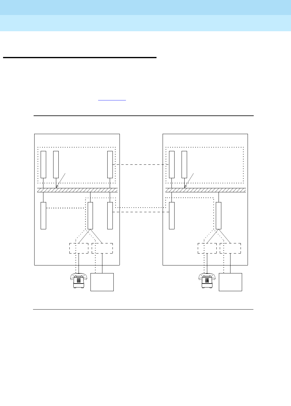
DEFINITY Enterprise Communications Server Release 6
Maintenance for R6r Volumes 1 & 2
555-230-126 Issue 2
January 1998
Responding to Alarms and Errors
Page 5-38Troubleshooting ISDN-BRI/ASAI Problems
5
Troubleshooting ISDN-BRI/ASAI
Problems
Troubleshooting ISDN-BRI/ASAI problems can be a complex and involved
procedure. The reason for this is that ISDN-BRI devices communicate with the
SPE over the Packet Bus, as opposed to the TDM Bus. Therefore, it is possible
for failures of other Packet Bus-related system components to cause problems
with ISDN-BRI devices. Figure 5-9 shows the connectivity of the Packet Bus as it
applies to ISDN-BRI signaling.
Figure 5-9. ISDN-BRI/Packet Bus Connectivity
Signaling Links
T
N
7
T
N
7
Testing/
Reconfig
T
N
7
7
Signaling
Links
EPN
Duplicated
PNC
Only
Packet Bus
BRI-PT ABRI-PT
ASAI-ADJ
T
N
5
0 1
5
0
5
5
6
T
N
7
ABRI-PT
T
N
Duplicated
PNC
Only
T
N
7
Packet Bus
Signaling
Links
BRI-PT
T
N
1
6
5
5Testing/
Reconfig
T
N
1
6
5
5
T
N
7
7
PPN
ASAI-ADJ
1
5
5
6
5
0
5
0

DEFINITY Enterprise Communications Server Release 6
Maintenance for R6r Volumes 1 & 2
555-230-126 Issue 2
January 1998
Responding to Alarms and Errors
Page 5-39Troubleshooting ISDN-BRI/ASAI Problems
5
The flowchart in Figure 5-10 describes the steps that should be taken to isolate
and resolve ISDN-BRI problems. The order in which you should examine the
maintenance objects is determined by looking at how wide-spread the failure is.
For example, since all ISDN-BRI devices communicate with the TN1655 Packet
Interface circuit pack, this MO should be examined early in the sequence. On the
other hand, a failure of a TN570 circuit pack may cause ISDN-BRI failure in an
EPN, but could not be the cause of a failure in the PPN.
NOTE:
If the flowchart query ‘‘Is the problem affecting MOs on multiple BRI-BD
circuit packs?’’ is reached, and the port network in question has only one
ISDN-BRI circuit pack, then assume that the answer is ‘‘Yes’’ and follow the
repair procedure for PKT-BUS.
When directed by the flow chart to refer to the Maintenance documentation for a
specific MO, keep in mind that the repair procedure for that MO may refer you to
another MO’s repair procedure. The flowchart tries to coordinate these activities
so that a logical flow is maintained if the ISDN-BRI problems are not resolved with
the first set of repair procedures.
These following status commands may also be useful when diagnosing
ISDN-BRI problems:
■status port-network
■status packet-interface
■status bri-port
■status station
■status data-module
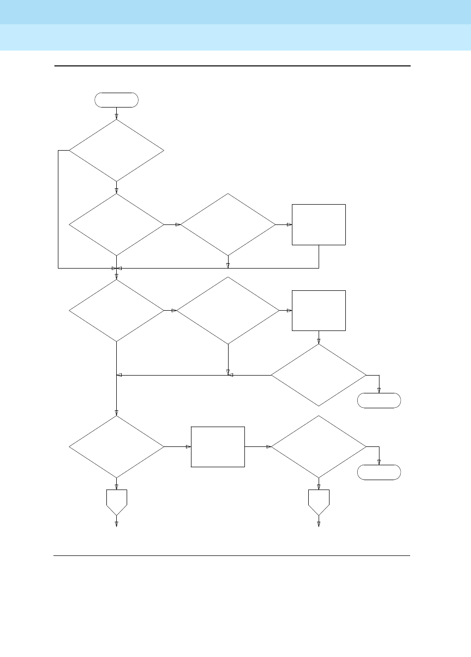
DEFINITY Enterprise Communications Server Release 6
Maintenance for R6r Volumes 1 & 2
555-230-126 Issue 2
January 1998
Responding to Alarms and Errors
Page 5-40Troubleshooting ISDN-BRI/ASAI Problems
5
Figure 5-10. Troubleshooting ISDN-BRI Problems (Page 1 of 2)
START
ARE THERE
ALARMS OR
ERRORS AGAINST
PKT-BUS
NO
YES
IS THIS A
CRITICAL RELIABILITY
SYSTEM?
NO
ARE THERE
ALARMS OR
ERRORS AGAINST
M/T-PKT
YES
IS THE
PROBLEM
ISOLATED TO
ARE THERE
ALARMS OR ERRORS
AGAINST EXP-INTF*
THE PPN
A
TO
PAGE
2
IS THE
ISDN-BRI
PROBLEM
RESOLVED
END
ARE THERE
ALARMS OR
ERRORS AGAINST
PKT-INT
IS THE
ISDN-BRI
PROBLEM
RESOLVED
NO
YES
YES
(DUPLICATED PNC)
NO
YES
NO
TO
PAGE
2
NO
B
FOLLOW THE
REPAIR
PROCEDURE
FOR PKT-INT
FOLLOW THE
REPAIR
PROCEDURE
FOLLOW THE
REPAIR
PROCEDURE
FOR M/T-PKT
YES
END
YES
YES
FOR EXP-INTF
NO
NO
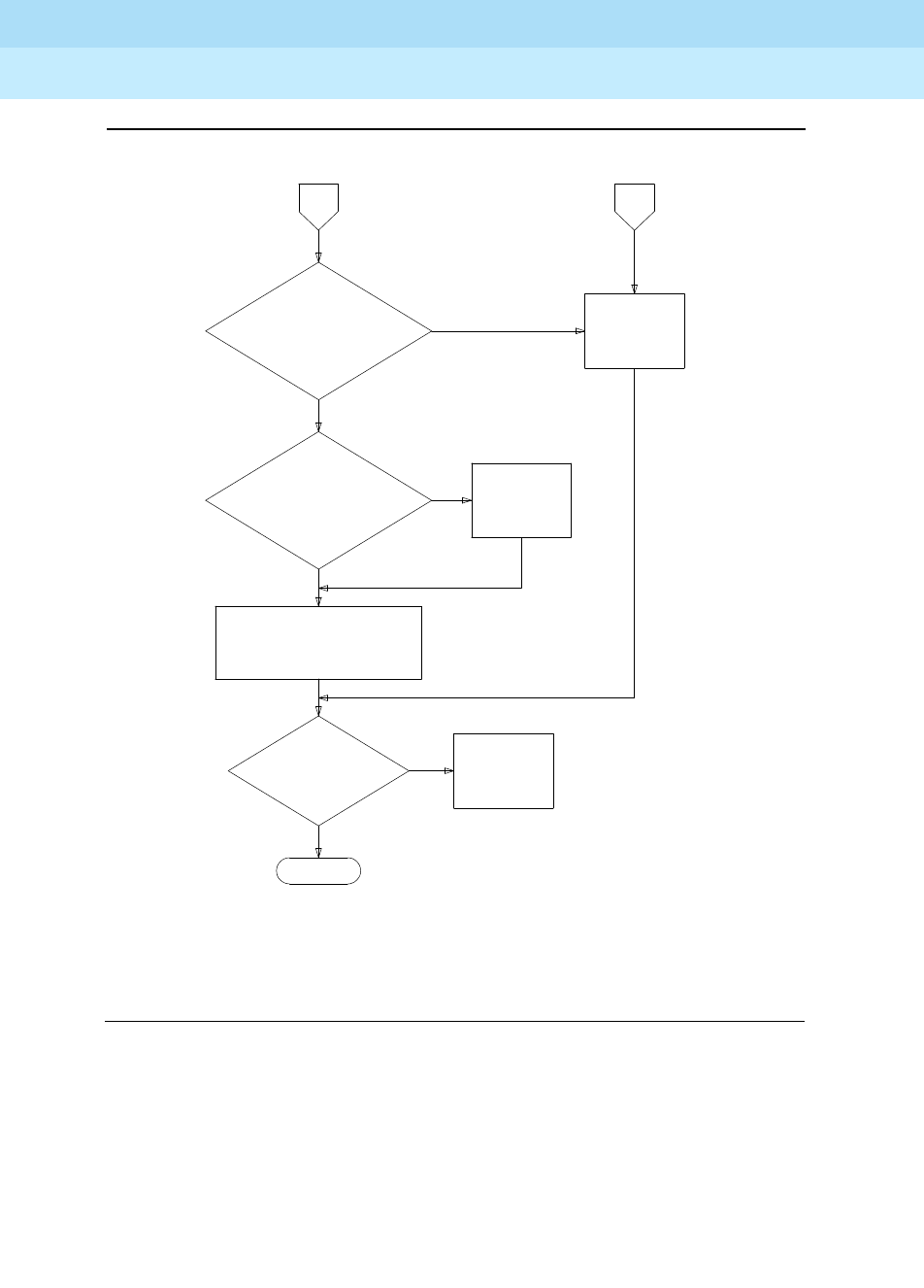
DEFINITY Enterprise Communications Server Release 6
Maintenance for R6r Volumes 1 & 2
555-230-126 Issue 2
January 1998
Responding to Alarms and Errors
Page 5-41Troubleshooting ISDN-BRI/ASAI Problems
5
Figure 5-11. Troubleshooting ISDN-BRI Problems (Page 2 of 2)
PAGE
NO
YES
END
FROM
1
IS THE
PROBLEM AFFECTING
MOs ON MULTIPLE
BRI-BD CIRCUIT
IS THE
PROBLEM AFFECTING
MULTIPLE MOs ON
THE SAME BRI-BD
CIRCUIT
A
NO
FOLLOW THE REPAIR
PROCEDURE FOR BRI-PORT,
BRI-DAT, ABRI-PORT, BRI-SET,
OR ASAI-ADJ, AS APPROPRIATE
IS
THE ISDN-BRI
PROBLEM
RESOLVED
FOLLOW THE
REPAIR
PROCEDURE
FOR BRI-BD
YES
FOLLOW THE
REPAIR
PROCEDURE
FOR PKT-BUS
PAGE
FROM
1
B
* THESE MOs WOULD BE BRI-PORT,
ABRI-PORT, BRI-DAT,
BRI-SET, OR ASAI-ADJ
PACKS *
PACKS *
ESCALATE
THE
PROBLEM
YES
NO

DEFINITY Enterprise Communications Server Release 6
Maintenance for R6r Volumes 1 & 2
555-230-126 Issue 2
January 1998
Responding to Alarms and Errors
Page 5-42Troubleshooting ISDN-PRI Test Call Problems
5
Troubleshooting ISDN-PRI Test Call
Problems
An ISDN-PRI test call is placed across an ISDN-PRI user-network interface to a
previously designated number in order to test ISDN capabilities of the switch, the
trunk and the far end. An ISDN-PRI test call is also a maintenance procedure
concerned with the identification and verification ISDN-PRI user-network
interface problems. The ISDN-PRI test call can access ISDN-PRI trunks only.
An ISDN-PRI test call can be placed only if the circuit translates to an ISDN-PRI
trunk. An ISDN-PRI test call can be originated via either the
synchronous
or the
asynchronous
method. Each method is described below.
NOTE:
Before attempting to make an ISDN-PRI test call to the public network (that
is, the network is the far-end), make sure that test call service is provisioned
by the network. The user must subscribe to Test Type 108 service and have
the correct far-end test call number administered on the trunk group form
for the call to be allowed.
Synchronous Method
One command is used in this method to start, stop and query an ISDN-PRI test
call. In the synchronous method, an outgoing ISDN-PRI test call may be part of
one of the following
long
test sequences entered at the terminal:
■test trunk grp/mbr long [repeat #]
■test port UUCSSpp long [repeat #]
■test board UUCSS long [repeat #]
The long qualifier must be entered in the above commands in order for the ISDN
test call to run. The repeat number (#) can be any number from 1 through 99
(default = 1).
The following information is displayed in response to the above commands:
■Port: The port address (UUCSSpp) is the port network number, carrier
designation, slot, and circuit of the maintenance object under test.
■Maintenance Name: The type of maintenance object tested.
■Test Number: The actual test that was run.
■Test Results: Indicates whether the test passes, fails, or aborts.
■Error Code: Additional information about the results of the test (See the
ISDN-TRK section of Chapter 9 for details.

DEFINITY Enterprise Communications Server Release 6
Maintenance for R6r Volumes 1 & 2
555-230-126 Issue 2
January 1998
Responding to Alarms and Errors
Page 5-43Troubleshooting ISDN-PRI Test Call Problems
5
Asynchronous Method
The asynchronous method requires a Maintenance/Test circuit pack to be
present in the system. In this method, 4 commands are used to start, stop, query,
and list an outgoing ISDN-PRI test call:
Before placing an outgoing ISDN-PRI test call, verify that the Feature Access
Code has been administered on the System Features Form, and that the Far End
Test Line Number and TestCall Bearer Capability Class (BCC) have been
administered on the Trunk Group Administration Form. Furthermore, if the
ISDN-PRI trunk is of the cbc (call by call) service type, then the Testcall Service
field on Trunk Group Administration Form must have been administered also.
To initiate an outgoing ISDN-PRI test call with the asynchronous method, issue
the start command listed above, which enables you to specify a specific the
trunk on which to originate the ISDN-PRI test call. An optional qualifier can be
used that specifies in minutes (1 to 120) the duration of the test call. If no duration
is specified, the default is either 8.4 or 9.6 seconds.
Screen 5-1 shows a typical response to the test isdn-testcall command:
Screen 5-1. Test ISDN-TestCall Response
The displayed fields have the following meanings:
Start: test isdn-testcall grp/mbr[minutes]
Stop: clear isdn-testcall grp/mbr
List: list isdn-testcall
Query: status isdn-testcall <grp>/<mbr>
Port The port address (UUCSSpp) is the port network number, carrier
designation, slot, and circuit of the maintenance object under test.
Maint. Name The type of maintenance object tested.
Test Number The actual test that was run.
Test
Results Indicates whether the test passes, fails, or aborts.
Error Code Additional information about the results of the test (See the ISDN-TRK
section in Chapter 9 for details).
test isdn-testcall
Port Maintenance Name Test Number Test Result Error Code
1B1501 ISDN-TRK 258 PASS

DEFINITY Enterprise Communications Server Release 6
Maintenance for R6r Volumes 1 & 2
555-230-126 Issue 2
January 1998
Responding to Alarms and Errors
Page 5-44Troubleshooting the Outgoing ISDN-Testcall Command
5
The functions of the clear, list, and status commands associated with the ISDN
Testcall are summarized below.
clear isdn-testcall: enables you to cancel an in-progress ISDN-PRI test call and
allow another test call to start.
list isdn-testcall: enables you to list all the ISDN-PRI trunks in use for an
ISDN-PRI test call in the system.
status isdn-testcall: enables you to check on the progress of an outgoing test
call. When an outgoing ISDN-PRI test call completes in a specific port network,
another ISDN-PRI trunk from the same port network is available for testing
(regardless of whether the status information has been displayed).
Troubleshooting the Outgoing
ISDN-Testcall Command
If the TestCall BCC field appears on the Trunk Group Administration Form, make
sure the TestCall BCC field indicates the correct BCC for the service provisioned
on the ISDN-PRI trunk. The TestCall BCC values are defined as follows:
If the ISDN-PRI trunk is of type cbc make sure the TestCall Service field on the
Trunk Group Administration Form indicates the correct service so that a network
facility message can be sent across the ISDN-PRI network.
If the outgoing ISDN-PRI test call keeps aborting, make sure that the far-end
device can handle DCP Mode 0 or DCP Mode 1.
NOTE:
Before attempting to make an ISDN-PRI test call to the public network (that
is, the network is the far-end), make sure that test call service is provisioned
by the network. The user must subscribe to Test Type 108 service and have
the correct far-end test call number administered on the trunk group form
for the call to be allowed.
0Voice
1Digital Communications Protocol Mode 1
2Mode 2 Asynchronous
3Mode 3 Circuit
4Digital Communications Protocol Mode 0 (that is
usually the default).

DEFINITY Enterprise Communications Server Release 6
Maintenance for R6r Volumes 1 & 2
555-230-126 Issue 2
January 1998
Responding to Alarms and Errors
Page 5-45Packet Bus Fault Isolation and Repair
5
Packet Bus Fault Isolation and Repair
The following procedures provide a means of isolating and correcting faults on
both the packet bus and the various maintenance objects that use the packet
bus. The packet bus is shared by all circuit packs that communicate on it, and a
fault on one of those can disrupt communications over the packet bus.
Furthermore, a circuit pack that does not use the packet bus can also cause
service disruptions by impinging on the backplane or otherwise modifying the
configuration of the bus. (this is discussed in more detail later). For these
reasons, isolating the cause of packet bus failure can be complicated. This
discussion provides a flowchart and descriptions of the tools and procedures
used to isolate and correct packet bus faults.
This discussion is organized into the following sections which provide
background information and troubleshooting procedures. The packet bus Fault
Isolation Flowchart is intended to be the normal starting point for isolating and
resolving packet bus problems. Before using it you should familiarize yourself
with packet bus maintenance by reading the introductory sections.
■‘‘Remote Maintenance versus On-Site Maintenance’’discusses the
strategy and the requirements for performing remote maintenance and
on-site maintenance for the packet bus.
■‘‘Tools for Packet Bus Fault Isolation and Correction’’ discusses the tools
that are needed to isolate and correct packet bus faults.
■‘‘What is the Packet Bus?’’ describes the packet bus, its use in G3r, and
the types of faults that can occur on the packet bus. A diagram shows the
physical and logical connections between circuit packs connected to the
packet bus.
■‘‘Circuit Packs That Use the Packet Bus’’ describes the various circuit
packs, ports, and endpoints that use the packet bus. The section
discusses how these maintenance objects interact, how a failure of one
maintenance object can affect another, and failure symptoms of these
maintenance objects.
■‘‘Maintenance of the Packet Bus’’ describes the strategy of maintenance
software for packet bus. Similarities and differences between the packet
bus and the TDM Bus are discussed. An overview of the Fault Isolation
and Correction Procedures is also presented.
■‘‘The Maintenance/Test Circuit Pack (TN771)’’ discusses the use of the
Maintenance/Test circuit pack in both packet bus fault isolation and other
switch maintenance. The standalone mode of the Maintenance/Test circuit
pack, which is used to perform on-site packet bus fault isolation and
correction, is discussed in detail.

DEFINITY Enterprise Communications Server Release 6
Maintenance for R6r Volumes 1 & 2
555-230-126 Issue 2
January 1998
Responding to Alarms and Errors
Page 5-46Packet Bus Fault Isolation and Repair
5
■‘‘Packet Bus Fault Isolation Flowchart’’ is the starting point for the
troubleshooting process. It is used to determine if a failure of service is
caused by the packet bus itself or by another maintenance object on the
packet bus.
■‘‘Correcting Packet Bus Faults’’ presents the procedures required to
correct either a problem with the packet bus itself or one that is caused by
a circuit pack connected to the Packet Bus.
Remote Maintenance versus On-Site
Maintenance
Most packet bus fault isolation and repair procedures require a technician to be
on-site. This is because a packet bus failures are caused by a hardware failure of
either the packet bus itself or a circuit pack that is connected to it. Initial
diagnoses can be made via use of the
packet bus Fault Isolation Flowchart
, but
the Maintenance/Test Standalone Mode Procedure and the packet bus Fault
Correction Procedure require that a technician be on-site. These procedures are
presented with this requirement in mind.
The flowchart refers to the repair procedures in Chapter 9, ‘‘Maintenance Object
Repair Procedures’’ for various maintenance objects. When a decision point is
reached, a remotely located technician can refer to the appropriate section and
attempt to resolve any fault conditions. Some procedures require on-site repair
action. Keep in mind that failure of a maintenance object appearing early in the
flowchart can cause alarms with maintenance objects that appear later in the
flowchart. Multiple dispatches can be prevented by remotely checking
subsequent stages on the flowchart and preparing the on-site technician for
replacement of several components if necessary.
The Maintenance/Test packet bus port described below provides status
information that is accessed with the status port-network P command and the
PKT-BUS test sequence. The Maintenance/Test circuit pack may or may not be
present at a customer site, depending on the configuration of the switch. If a
Maintenance/Test circuit pack is not present, one must be taken to the site for
diagnosing packet bus problems.
In a system with duplicated SPEs, an SPE interchange may resolve the packet
bus problem. This operation can be executed remotely, and is discussed in
Packet Bus Fault Correction Procedures
below.

DEFINITY Enterprise Communications Server Release 6
Maintenance for R6r Volumes 1 & 2
555-230-126 Issue 2
January 1998
Responding to Alarms and Errors
Page 5-47Packet Bus Fault Isolation and Repair
5
Tools for Packet Bus Fault Isolation and
Correction
The following tools may be required on-site to perform packet bus fault isolation
and correction.
■TN771D Maintenance/Test circuit pack for use in standalone mode, and
the connectors and cables necessary to install it (see the
Maintenance/Test Circuit Pack
section).
■A replacement for the TN771D Maintenance/Test circuit pack in the
system may be needed. See the
A Special Precaution Concerning the
TN771D
section.
■A backplane pin-replacement kit may be required (see
Packet Bus Fault
Correction
) If the kit is not available, replacement of a carrier may be
required.
What is the Packet Bus?
The packet bus is a set of 24 leads in the backplane of each Port Network.
Twenty of these leads are data leads, three are control leads, and one lead is a
spare. This distinction is important only for understanding why some circuit
packs are able to detect only certain faults; the distinction does not affect fault
isolation and repair. Each Port Network has its own packet bus and there is one
packet bus maintenance object (PKT-BUS) in each port network. The packet bus
is not duplicated as is the TDM Bus. There are however several spare leads on
the packet bus and, in Critical Reliability systems (duplicated PNC), these spare
leads are used to recover from some failures on the packet bus.
The packet bus carries various types of information:
■Signaling and data traffic destined for other port-networks and/or Center
Stage Switches. The TN570 Expansion Interface circuit pack provides
packet bus access for these connections.
■ISDN-BRI signaling information for ISDN-BRI stations, data modules and
ASAI adjunct connections. The TN556 ISDN-BRI circuit pack provides
packet bus access for these connections.
■X.25 signaling information and data traffic to support system adjunct
applications. The TN577 Packet Gateway circuit pack provides packet
bus access for these connections.
■ISDN-PRI signaling information carried in the D-channels of ISDN-PRI
facilities connected to the switch. The TN464F Universal DS1 circuit pack
provides packet bus access for these connections.
■System Port traffic to support various input/output devices such as dial-up
modems and printers, as well as system adjunct applications. The TN553
Packet Data circuit pack provides packet bus access for these
connections.

DEFINITY Enterprise Communications Server Release 6
Maintenance for R6r Volumes 1 & 2
555-230-126 Issue 2
January 1998
Responding to Alarms and Errors
Page 5-48Packet Bus Fault Isolation and Repair
5
The SPE interface to the packet bus is the TN1655 Packet Interface circuit pack.
When SPEs are duplicated, there is one TN1655 in each SPE. The TN771D
Maintenance/Test Circuit Pack (discussed in detail later) provides packet bus
maintenance testing and reconfiguration capabilities.
Packet Bus Faults
Two types of packet bus faults occur:
Shorts are far more common than opens, since they can be caused by incorrect
insertion of a circuit pack. It is possible for a circuit pack to be the cause of a
packet bus fault but still operate trouble-free itself. For example, the insertion of a
TDM-only circuit pack such as a TN754 Digital Line could bend the packet bus
pins on the backplane, but remain unaffected since it does not communicate
over the packet bus.
Packet bus faults do not necessarily cause service interruptions, but shorts on it
usually do. Depending on what leads are defective, the system may be able to
recover and continue to communicate. While this allows uninterrupted service, it
makes isolating the fault difficult. The Maintenance/Test circuit pack provides the
capability to detect, and, in some cases, correct packet bus faults.
Packet Bus Connectivity
Various circuit packs communicate on the packet bus (see the next section). For
more details, refer to Chapter 9, ‘‘Maintenance Object Repair Procedures’’ for the
following circuit packs:
■TN1655 Packet Interface: PKT-INTF
■TN570 Expansion Interface: EXP-INTF
■TN556 ISDN-BRI: BRI-BD, BRI-PORT, ABRI-PORT, BRI-SET, BRI-DAT,
ASAI-ADJ
■TN577 Packet Gateway: PGATE-BD, PGATE-PT
■TN553 Packet Data: PDATA-BD, PDATA-PT
■TN464F Universal DS1: UDS1-BD, ISDN-LNK
Shorts A short occurs when different leads on the packet bus become
electrically connected to each other. This can occur due to failures of
circuit packs, cables between carriers, TDM/LAN terminators, or
bent pins on the backplane. A fault occurring during normal
operation is usually caused by a circuit pack. A fault that occurs
while moving circuit packs or otherwise modifying the switch is
usually due to bent pins on the backplane.
Opens An open occurs when there is a break on the packet bus such that
the electrical path to the termination resistors is interrupted. Usually,
this break is caused by a failed TDM/LAN cable or terminator. A less
likely possibility is a failure in the backplane of a carrier.

DEFINITY Enterprise Communications Server Release 6
Maintenance for R6r Volumes 1 & 2
555-230-126 Issue 2
January 1998
Responding to Alarms and Errors
Page 5-49Packet Bus Fault Isolation and Repair
5
■TN771D Maintenance/Test: M/T-BD, M/T-DIG, M/T-PKT
Circuit Packs That Use the Packet Bus
This section describes the circuit packs that use the packet bus and the effects
of circuit pack and bus failures on each other.
Seven circuit packs can use the packet bus: The maintenance objects pertaining
to each circuit pack, (described further in Chapter 9), are listed in brackets.
■TN1655 Packet Interface [PKT-INTF] provides the SPE interface to the
packet bus (as the UN332 MSSNET does to the TDM Bus). All traffic on
the packet bus passes through the Packet Interface. The Packet Interface
can detect some control lead failures and many data lead failures via
parity errors on received data.
■TN570 Expansion Interface [EXP-INTF] connects the Port Networks
(PNs) in the system. (Only TN570s can be used in Release 5r). All Packet
traffic between PNs passes through a pair of TN570s (one in each port
network). The Expansion Interface can detect some control lead failures,
and many data lead failures via parity errors on received data.
■TN556, TN2198, and TN2208 ISDN-BRI circuit packs [BRI-BD,
BRI-PORT, ABRI-PORT, BRI-SET, BRI-DAT, ASAI-ADJ] carries signaling
information for ISDN-BRI station sets and data modules, as well as
signaling information and ASAI messages between the SPE and an ASAI
adjunct. The ISDN-BRI circuit pack has the same fault detection
capabilities as the TN570 Expansion Interface.
■TN577 Packet Gateway circuit pack [PGATE-BD, PGATE-PT] provides
X.25 connectivity to support external system adjuncts such as Audix®
and DCS. The packet bus carries both signaling and customer traffic. The
Packet Gateway circuit pack has the same fault detection capabilities as
the TN570 Expansion Interface.
■TN553 Packet Data circuit pack [PDATA-BD, PDATA-PT] connects via a
backplane cable to a TN726B Data Line circuit pack in an adjacent carrier
slot. Together, the two circuit packs perform a protocol conversion from
mode 3 packet bus traffic originating in the SPE to mode 2 TDM Bus traffic
destined for external system devices and adjuncts. This connectivity is
referred to as a
System Port
. System Ports support devices and adjuncts
such as the System Printer, the PMS Journal Printer, the PMS Wakeup Log
Printer, data terminals, remote administration terminals, and equipment to
support the Call Detail Recording (CDR) feature. System Ports are also
used for saving and restoring System Announcements. The packet bus
carries both signaling and data for the Packet Data circuit pack. The
Packet Data circuit pack has the same fault detection capabilities as the
TN570 Expansion Interface.

DEFINITY Enterprise Communications Server Release 6
Maintenance for R6r Volumes 1 & 2
555-230-126 Issue 2
January 1998
Responding to Alarms and Errors
Page 5-50Packet Bus Fault Isolation and Repair
5
■TN464F Universal DS1 circuit pack [UDS1-BD, ISDN-LNK] supports
ISDN-PRI communications over an attached DS1 facility. It transports of
D-channel signaling information over the packet bus, and B-channel data
over the TDM bus. The Universal DS1 circuit pack has the same fault
detection capabilities as the TN570 Expansion Interface.
■TN771D Maintenance/Test circuit pack [M/T-BD, M/T-DIG, M/T-PKT,
M/T-ANL] is the workhorse of packet bus maintenance. This circuit pack
can detect all packet bus failures for the Port Network in which it resides.
In Critical Reliability systems (duplicated PNC), this circuit pack enables
the reconfiguring of the packet bus around a small number of failed leads.
The TN771D circuit pack provides a standalone mode (one that does not
involve communication with the SPE), for inspecting the packet bus for
faults. Standalone mode is a critical tool for troubleshooting packet bus
faults.
NOTE:
All Maintenance/Test circuit packs must be of vintage TN771D or
later. This circuit pack is also used for ISDN-PRI trunk testing
(M/T-DIG) and ATMS trunk testing (M/T-ANL).
Effects of Circuit Pack Failures on the Packet Bus
Certain failures of any of the above circuit packs can disrupt traffic on the packet
bus Some failures cause packet bus failures with corresponding alarms, while
others cause service outages without alarming the packet bus, (although the
failed circuit pack should be alarmed).
Packet bus circuit pack failures affect the bus in the following ways:
■TN1655 Packet Interface. A failure of the Packet Interface typically
causes all Packet traffic in the system to fail. As a result,
— Expansion Port Networks and Center Stage Switches are disabled.
— ISDN-BRI sets are not able to make or receive calls.
— Communication with ASAI adjuncts fail
— X.25 communications with external adjuncts fail.
— System Ports are disabled.
— ISDN-PRI D-channel signaling is disabled.
If the failure is on the packet bus interface, the packet bus may be
alarmed as well.
In a system with duplicated SPEs, there is one TN1655 Packet Interface in
each SPE. If a Packet Interface failure in the active SPE causes a packet
bus disruption, an SPE interchange may restore service. In other cases,
replacement of the circuit pack may be required before service is
restored.

DEFINITY Enterprise Communications Server Release 6
Maintenance for R6r Volumes 1 & 2
555-230-126 Issue 2
January 1998
Responding to Alarms and Errors
Page 5-51Packet Bus Fault Isolation and Repair
5
■TN570 Expansion Interface. A failure of the Expansion Interface typically
causes all packet traffic in the connected EPN or Center Stage Switch to
fail. If the failure is on the packet bus interface, the packet bus may be
alarmed as well.
If an active Expansion Interface failure causes a packet bus disruption in a
Critical Reliability system (duplicated PNC), a PNC Interchange may
restore service. In other cases, replacement of the circuit pack may be
required before service is restored.
■TN556 ISDN-BRI Circuit Pack. A failure of the ISDN-BRI circuit pack
typically causes some or all ISDN-BRI sets and data modules and/or an
ASAI adjunct connected to the circuit pack to stop functioning. If the
failure is on the circuit pack’s packet bus interface, the packet bus may be
alarmed.
■TN577 Packet Gateway Circuit Pack. A failure of the Packet Gateway
circuit pack disrupts communications with the adjunct (for example,
Audix, DCS) connected to the far end of the X.25 link. If the failure is on the
circuit pack’s packet bus interface, the packet bus may be alarmed.
■TN553 Packet Data Circuit Pack. A failure of the Packet Data circuit pack
disrupts System Port traffic. If the failure is on the circuit pack’s packet bus
interface, the packet bus may also be alarmed. Applications that use
System Ports include:
— Saving and restoring announcements
— Call Detail Recording (CDR)
— Journal Printer for the Property Management System (PMS)
— Wakeup Log Printer for the Property Management System (PMS)
—System Printer
— Data Terminals
— Remote administration terminals
■TN464F Universal DS1 Circuit Pack. A failure of the Universal DS1
Circuit Pack disrupts ISDN-PRI signaling traffic carried on the D-channel.
The loss of that signaling may impact the pack’s 23 B-channels. If the
D-channel supports Non Facility Associated Signaling (NFAS), the
B-channels of up to 20 other DS1 circuit packs may also be affected. In
cases where all 24 channels of the circuit pack are B-channels, packet
bus related failures may not affect the B-channels, since only D-channel
signaling is carried on the packet bus. If the failure is on the circuit pack’s
packet bus interface, the packet bus may be alarmed as well.
■TN771D Maintenance/Test. A failure of the Maintenance/Test may cause
an incorrect indication of a packet bus failure or the inability to detect such
a failure. If the failure is on the packet bus interface, the packet bus may
be alarmed as well.

DEFINITY Enterprise Communications Server Release 6
Maintenance for R6r Volumes 1 & 2
555-230-126 Issue 2
January 1998
Responding to Alarms and Errors
Page 5-52Packet Bus Fault Isolation and Repair
5
Failure of any circuit pack’s bus interface may alarm the packet bus due to
shorting of the packet bus leads. This typically disrupts
all
packet bus traffic in
the affected PN. A failure of the packet bus in the PPN affects packet traffic in the
EPNs as well. Some packet bus failures do not affect all endpoints, so a packet
bus failure cannot be ruled out just because some packet service is still
available.
A circuit pack can fail in a manner such that it transmits bad data on the packet
bus. If the Packet Interface so fails, all Packet traffic is disrupted. Such a failure
on an Expansion Interface may disrupt all Packet traffic in that port network. If an
ISDN-BRI circuit pack fails such that it transmits bad data, all devices connected
to the circuit pack fail to function. This failure may also disrupt the entire packet
bus whenever the circuit pack tries to transmit data. Such a disruption may be
indicated by packet bus alarms that occur and go away, intermittent failures of
other packet circuit packs, and/or interference with other connected endpoints.
These failures are difficult to isolate because of their intermittent nature. In most
cases, the failed circuit pack is alarmed, and all connected endpoints on the
circuit pack are out of service until the circuit pack is replaced. These symptoms
help in isolating the fault.
Maintenance of the Packet Bus
The following topics are covered in this section:
■‘‘Packet Bus and TDM Bus: a Comparison’’
■‘‘Packet Bus Maintenance Software’’
■‘‘Fault Correction Procedures: Overview’’
Packet Bus and TDM Bus: a Comparison
The packet and TDM busses have several similarities and differences. There are
two physical TDM buses in each PN. One of the buses can fail without affecting
the other, but half of the call-carrying capacity is lost. There is
one
packet bus in
each PN. A failure of that bus can disrupt all packet traffic in that PN.
In critical reliability systems, the Maintenance/Test circuit pack provides packet
bus reconfiguration capabilities. This allows the packet bus to remain in service
with up to 3 lead failures. There is no corresponding facility on the TDM Bus.
Instead, the second physical TDM Bus continues to carry traffic until repairs are
completed.
System response varies according by type of bus failure and whether or not the
failure occurs in the PPN or an EPN. In an EPN, a catastrophic TDM Bus failure
(one that affects both TDM Buses) disables
all
traffic in the PN. A catastrophic
packet bus failure affects only packet traffic, so that TDM traffic is unaffected,
while all ISDN-BRI, ASAI, X.25, and ISDN-PRI signaling traffic is disrupted. The
significance of this distinction depends on the customer’s applications. A
customer whose primary application requires ASAI would consider the switch to
be out of service, while a customer with a large number of Digital/Analog/Hybrid
sets and a small number of ISDN-BRI sets would probably not consider the

DEFINITY Enterprise Communications Server Release 6
Maintenance for R6r Volumes 1 & 2
555-230-126 Issue 2
January 1998
Responding to Alarms and Errors
Page 5-53Packet Bus Fault Isolation and Repair
5
packet bus failure a catastrophic problem. The only way an EPN packet bus
failure can affect TDM traffic is via possible impact on system response time in a
large switch due to running of ISDN-BRI endpoint maintenance. This should
rarely happen because the packet bus maintenance software is able to prevent
this for most faults (see the next section).
If packet bus failure occurs in the PPN, the impact is much more widespread.
Because the PPN packet bus carries the signaling and control links for all EPNs,
PPN packet bus failure effectively removes all the EPNs from service, including
both TDM and packet busses. Packet bus traffic in the PPN is also disrupted.
!CAUTION:
Packet bus fault correction and fault isolation often involve circuit pack
removal, which is destructive to service. Minimize time devoted to
destructive procedures by the use of non-destructive ones where possible.
Packet Bus Maintenance Software
Packet bus maintenance software involves the usual set of maintenance object
error conditions, tests, and alarms. These are described in “PKT-BUS” in Chapter
9. Because a packet bus failure can cause all BRI/ASAI endpoints in the affected
Port Network, and all their associated ports and circuit packs, to report failures,
special care must be taken to ensure that the flood of error messages does not
overload the system and interfere with TDM Bus traffic.
When such a failure
occurs
, circuit pack maintenance is affected in the following manner:
■In-line errors for the following MOs which indicate possible packet bus
failures are logged but
not acted upon:
BRI-BD, PGATE-BD, PDATA-BD,
UDS1-BD.
■In-line errors for the following MOs which indicate possible packet bus
failures are
neither logged nor acted upon:
BRI-PORT, ABRI-PORT,
PGATE-PT, PDATA-PT, ISDN-LNK.
■All in-line errors for the following MOs are
neither logged nor acted upon:
BRI-SET, BRI-DAT, ASAI-ADJ.
■Circuit pack and port in-line errors that are not related to the packet bus,
or that indicate a circuit pack failure, are acted upon in the normal fashion.
■Periodic and scheduled background maintenance is not affected.
■Foreground maintenance (for example, commands executed from the
terminal) is not affected.
These interactions allow normal non-packet system traffic to continue unaffected,
and they reduce the number of entries into the Error/Alarm Logs. If the packet
bus failure is caused by a failed circuit pack, errors against the circuit pack
should appear in the Error/Alarm Logs as an aid for fault isolation. The above
strategy is implemented when:
■In-line errors indicate a possible packet bus failure reported by two or
more Packet circuit packs.

DEFINITY Enterprise Communications Server Release 6
Maintenance for R6r Volumes 1 & 2
555-230-126 Issue 2
January 1998
Responding to Alarms and Errors
Page 5-54Packet Bus Fault Isolation and Repair
5
■A packet bus Uncorrectable report is sent from the Maintenance/Test
packet bus port (M/T-PKT).
When such a failure occurs, a PKT-BUS error is logged. Refer to the PKT-BUS
section in Chapter 9 for more detailed information.
Fault Correction Procedures: Overview
This section gives an overview of the procedures used to isolate the cause of and
correct packet bus faults. Details are presented in following sections.
1. Procedure 1 attempts to determine if a circuit pack that interfaces to the
packet bus is the cause of the packet bus problem. This involves
examination of the Error and Alarm logs followed by the usual repair
actions.
2. If the packet bus problem persists, remove port circuit packs (those in
purple slots) to look for circuit packs that have failed and/or damaged the
packet bus pins.
3. If the packet bus problem persists, perform the same procedure for
control complex circuit packs.
4. If the problem persists, or if the packet bus faults are known to have open
leads, replace bus terminators and cables. If this does not resolve the
problem, reconfigure the carrier connectivity of the port network to attempt
to isolate a faulty carrier.
The Maintenance/Test Circuit Pack (TN771)
The TN771 Maintenance/Test circuit pack provides the following functions:
■Analog Trunk (ATMS) Testing
■Digital Port Loopback Testing
■ISDN-PRI Trunk Testing
■Packet Bus Testing
■Packet Bus Reconfiguration (Critical Reliability systems only)
The PPN always contains a TN771D. Critical Reliability systems have a TN771D
in each EPN. A TN771D is optional in EPNs of other configurations. The ISDN-PRI
Trunk Testing functions are discussed in the ‘‘ISDN-PLK (ISDN-PRI Signaling
Link Port)’’ section in Chapter 9, ‘‘Maintenance Object Repair Procedures’’.
The Digital Port Testing functions are discussed in the ‘‘DIG-LINE (Digital Line)’’,
"DAT-LINE (Data Line Port)", ‘‘PDMODULE (Processor Data Module) TDMODULE
(Trunk Data Module)’’, ‘‘TDMODULE (Trunk Data Module)’’, ‘‘PGATE-PT (Packet
Gateway Port)’’, ‘‘PDATA-PT (Packet Data Line Port)’’, and ‘‘MODEM-PT (Modem
Pool Port)’’, sections in Chapter 9, ‘‘Maintenance Object Repair Procedures’’.
The Analog Trunk Testing functions are discussed in the ‘‘TIE-TRK (Analog Tie
Trunk)’’, ‘‘DID-TRK (Direct Inward Dial Trunk)’’, ‘‘CO-TRK (Analog CO Trunk)’’,

DEFINITY Enterprise Communications Server Release 6
Maintenance for R6r Volumes 1 & 2
555-230-126 Issue 2
January 1998
Responding to Alarms and Errors
Page 5-55Packet Bus Fault Isolation and Repair
5
and ‘‘AUX-TRK (Auxiliary Trunk)’’, sections in Chapter 9, ‘‘Maintenance Object
Repair Procedures’’.
NOTE:
All Maintenance/Test circuit packs must be of TN771D vintage or later.
TN771D Packet Functions
The Maintenance/Test packet bus port (M/T-PKT) provides the packet bus
testing and reconfiguration capabilities. When the port is in service, it
continuously monitors the packet bus for faults and fault recoveries, and reports
results to PKT-BUS maintenance.
The yellow LED on the TN771D Maintenance/Test circuit pack provides a visual
indication of the state of the packet bus:
NOTE:
It takes 5 to 10 seconds for the LED to respond to a change in the state of
the packet bus.
During normal switch operation, the Maintenance/Test provides visual feedback
of the packet bus state. When in standalone mode (see the next section), these
visual indications are still present, but the packet bus is never reconfigured. The
yellow LED either blinks or is off.
Flashing Flashing of the yellow LED once per second indicates that there
are too many faults for the Maintenance/Test packet bus port to
recover by swapping leads.
The packet bus may be unusable
.
If the failures detected are open lead failures, the packet bus
may still be operating.
On steady The Maintenance/Test packet bus port has swapped leads on
the packet bus to correct a fault.
The packet bus is still
operating
. Or, one of the other ports on the Maintenance/Test
circuit pack is in use.
NOTE:
First busy out the Maintenance/Test circuit pack ports
used for other than packet bus testing before using the
Maintenance/Test circuit pack to help resolve packet bus
faults. This is done by entering busyout port UUCSS01,
busyout portUUCSSl02, and busyout port UUCSS03. Be
sure to release these ports when the process is
completed.
Off There is no packet bus fault present.

DEFINITY Enterprise Communications Server Release 6
Maintenance for R6r Volumes 1 & 2
555-230-126 Issue 2
January 1998
Responding to Alarms and Errors
Page 5-56Packet Bus Fault Isolation and Repair
5
TN771D in Standalone Mode
In TN771D standalone mode, a terminal is connected to the Maintenance/Test
circuit pack with an Amphenol connector on the back of the cabinet. This setup
allows direct inspection of the packet bus and identifies shorted or open leads.
This mode does not use the usual MT Maintenance User Interface and is thus
available even if switch is not in service. When in standalone mode, the TN771D
does not reconfigure the packet bus.
Required Hardware
■TN771D: Standard or High Reliability systems may not have a TN771D in
each EPN. (Use list configuration to determine if this is so.) When this is
the case, one must be taken to the site. See the following section, ‘‘Special
Precaution Concerning the TN771D’’.
■Terminal or PC with terminal-emulation software: The EIA-232 (RS-232)
port should be configured at 1200 baud, no parity, 8 data bits, and one
stop bit. This is
not
the same configuration as for the G3-MT. If a terminal
configured as a G3-MT is used, change the SPEED field from 9600 to
1200 on the terminal’s options setup menu. (This menu is accessed on
most terminals by pressing the CTRL and F1 keys together. On the 513
BCT, press SHIFT/F5 followed by TERMINAL SET UP). Remember to
restore the original settings before returning the G3-MT to service.
■355A EIA-232 Adapter (COMCODE 105 012 637).
■258B Six-Port Male Amphenol Adapter (COMCODE 103 923 025). A 258A
Adapter and an extension cable can also be used.
■D8W 8-wire modular cable of an appropriate length to connect the 258A
on the back of the cabinet to the 355A adapter. The relevant COMCODE is
determined by the length of the cable, as follows:
— 103 786 786 (7 feet)(2.1 m)
— 103 786 802 (14 feet)(4.3 m)
— 103 786 828 (25 feet)(7.6 m)
— 103 866 109 (50 feet)(15.2 m)
Slot Selection for Standalone Mode
When selecting a carrier slot to use for standalone mode in a port network that
does not already contain a TN771D, keep the following points in mind:
■A port circuit slot (indicated by a purple label) should be used. The
service slot (slot 0)
cannot
be used for standalone mode, although a
TN771D may normally be installed there.
■-5 volt power supply must be available in the carrier. (Refer to
‘‘CARR-POW’’ in Chapter 9, ‘‘Maintenance Object Repair Procedures’’ for
a description of carrier power supply units.)

DEFINITY Enterprise Communications Server Release 6
Maintenance for R6r Volumes 1 & 2
555-230-126 Issue 2
January 1998
Responding to Alarms and Errors
Page 5-57Packet Bus Fault Isolation and Repair
5
■A slot in the A carrier is preferable for EPNs if the above conditions are
met.
Entering and Exiting Standalone Mode
When in standalone mode, the red LED on the TN771D is lit This is normal and
serves as a reminder to remove the TN771 from standalone mode.
!CAUTION:
The TN771D in standalone must be the only TN771D in the port network. If
a TN771D is already in the port network, place that TN771D in standalone
mode. Do not insert a second TN771D. Otherwise, the system is not able to
detect the extra circuit pack and will behave unpredictably.
!CAUTION:
If the TN771D packet bus port has reconfigured the packet bus in a Critical
Reliability system (indicated by error type 2049 against PKT-BUS), placing
the Maintenance/Test in standalone mode causes a loss of service to the
packet bus. In this case, this procedure disrupts service.
For port networks with a TN771D already installed:
1. Ensure that Alarm Origination is suppressed either at login or via change
system-parameters maintenance.
2. Attach the 258A 6-Port Male Amphenol Adapter to the Amphenol
connector on the back of the carrier corresponding to the TN771D’s slot.
Connect one end of a D8W 8-wire modular cable to port 1 of the 258A.
Connect the other end of the cable to a 355A EIA-232 Adapter. Plug the
EIA-232 Adapter into the terminal to be used, and turn the terminal on.
3. Reseat the TN771D circuit pack.
NOTE:
On a Critical Reliability system, this causes a MINOR OFF-BOARD
alarm to be raised against PKT-BUS. This alarm is not resolved until
the TN771D’s packet bus port (M/T-PKT) is returned to service. To
ensure that PKT-BUS alarms have been cleared, it may be
necessary to restore the TN771D to normal mode.
For port networks without a TN771D installed:
1. Attach the 258A 6-Port Male Amphenol Adapter to the Amphenol
connector on the back of the carrier corresponding to the slot into which
the TN771D is to be inserted. Connect one end of a D8W 8-wire modular
cable to port 1 of the 258A. Connect the other end of the cable to a 355A
EIA-232 Adapter. Plug the EIA-232 Adapter into the terminal to be used,
and turn the terminal on.
DEFINITY Enterprise Communications Server Release 6
Maintenance for R6r Volumes 1 & 2
555-230-126 Issue 2
January 1998
Responding to Alarms and Errors
Page 5-58Packet Bus Fault Isolation and Repair
5
2. Insert the TN771D circuit pack into the slot. The system will not recognize
the presence of the circuit pack.
If the standalone mode is entered successfully, the following is displayed on the
connected terminal:
!CAUTION:
If the above display does not appear, check the wiring between the
terminal and the TN771D, and the terminal parameters settings. If these are
correct, the TN771D may be defective. In such a case, use the following
procedures to exit standalone mode and then test the Maintenance/Test
circuit pack. Refer to M/T-BD and M/T-PKT in
Chapter 9, ‘‘Maintenance
Object Repair Procedures’’
. If the TN771D fails while in standalone mode,
the message
TN771 circuit pack failed
is displayed, and no further
input is accepted on the terminal. The circuit pack must be replaced.
To exit standalone mode:
1. Remove the 258A Adapter from the Amphenol connector.
2. If the TN771D was installed for this procedure, remove it. Otherwise,
reseat the TN771D.
3. If change system-parameters maintenance was used to disable alarm
origination, re-enable it now.
Using Standalone Mode in Packet Bus Fault
Isolation and Correction
When the TN771D is in standalone mode, three commands are available:
ds Displays the current state of the packet bus leads.
dsa Toggles auto-report mode on and off. In auto-report mode, the
state of the packet bus leads are displayed and the terminal
beeps whenever a change occurs.
? Displays the available commands.
TN771 STANDALONE MODE
(Type “?” at the prompt for help)
Command:
DEFINITY Enterprise Communications Server Release 6
Maintenance for R6r Volumes 1 & 2
555-230-126 Issue 2
January 1998
Responding to Alarms and Errors
Page 5-59Packet Bus Fault Isolation and Repair
5
Below is an example of a standalone mode display. The symbols above the line
represent specific leads on the backplane. The bottom line indicates the
following:
NOTE:
This information is available only from the standalone mode. It is not
available from the MT or a remote login.
Figure 5-12 shows the location of the packet bus leads for a given slot as seen
from the front and back of the carrier.
OOpen lead
S Shorted lead
blank No fault
L L L L L L L L L L H H H H H H H H H H S S S L
P 0 1 2 3 4 5 6 7 8 P 0 1 2 3 4 5 6 7 8 S F B F
_______________________________________________
S S O
Command:
DEFINITY Enterprise Communications Server Release 6
Maintenance for R6r Volumes 1 & 2
555-230-126 Issue 2
January 1998
Responding to Alarms and Errors
Page 5-60Packet Bus Fault Isolation and Repair
5
Figure 5-12. Packet Bus Leads on the Backplane
. . . .
.
.
.
.
.
.
.
.
.
.
.
.
.
.
.
.
.
.
.
.
.
.
.
.
.
.
.
.
.
.
.
.
.
.
.
.
.
.
.
.
.
.
.
.
.
.
.
.
.
.
.
.
.
.
.
.
.
.
.
.
.
.
.
.
.
.
.
.
.
.
.
.
.
.
.
.
.
.
.
.
.
.
.
.
.
.
.
.
.
.
.
.
.
.
.
.
.
.
.
.
. . . .
. . . .
Front View
. . . .
. . . .
. . . .
Backplane
Separation GND
GND
L8
H0
SB
H2
H4
SF
H6
H7
H8
SS CLK
+5v
+5v
+5v
+5v
+5v
L5
LP
L2
L4
L1
+5v
L7
GND
LF
GND
GND
GND
L3
GND
L6
GND
HP
H1
GND
H3
GND
H5
L0
GND
GND
DEFINITY Enterprise Communications Server Release 6
Maintenance for R6r Volumes 1 & 2
555-230-126 Issue 2
January 1998
Responding to Alarms and Errors
Page 5-61Packet Bus Fault Isolation and Repair
5
Figure 5-13. Packet Bus Leads on the Backplane
+5v
LP
L2
L4
L7
L8
H0
SB
H2
H4
SF
H6
H7
H8
GND
SS CLK
GND
GND
+5v
+5v +5v
+5v
+5v
L5
L1
. . . .
.
.
.
.
.
.
.
.
.
.
.
.
.
.
.
.
.
.
.
.
.
.
.
.
.
.
.
.
.
.
.
.
.
.
.
.
.
.
.
.
.
.
.
.
.
.
.
.
.
.
.
.
.
.
.
.
.
.
.
.
.
.
.
.
.
.
.
.
.
.
.
.
.
.
.
.
.
.
.
.
.
.
.
.
.
.
.
.
.
.
.
.
.
.
.
.
.
.
.
.
GND
L3
GND
L6
GND
HP
H1
GND
H3
GND
H5
GND
LF
GND
GND
GND
. . . .
. . . .
Back View
. . . .
. . . .
. . . .
L0

DEFINITY Enterprise Communications Server Release 6
Maintenance for R6r Volumes 1 & 2
555-230-126 Issue 2
January 1998
Responding to Alarms and Errors
Page 5-62Packet Bus Fault Isolation and Repair
5
Special Precaution Concerning the TN771D
A TN771D Maintenance/Test circuit pack must be taken to the customer site if:
■The Maintenance/Test packet bus port indicates that a Packet Bus fault is
present by logging a Major or Minor alarm against PKT-BUS. A Major
alarm is indicated in the error log by Error Type 513; a Minor alarm is
indicated by Error Type 2049.
■Test #572 of the PKT-BUS test sequence is the only test that fails.
This precaution is taken because certain failures of the Maintenance/Test circuit
pack can appear as packet bus failures. To ensure that the problem is indeed
with the packet bus, proceed through the following steps:
1. If the TN771D Maintenance/Test circuit pack is replaced during this
process, enter the test pkt P long command to determine if the packet
bus faults have been resolved. If there are still packet bus problems,
correct them by using the procedures in the sections that follow.
2. If the Maintenance/Test circuit pack was
not
replaced, enter test pkt P.
Record the results (PASS/FAIL/ABORT) and error codes for Test #572.
3. Enter status port-network P. Record the information listed for PKT-BUS.
4. Busyout the Maintenance/Test circuit pack with busyout board UUCSS.
5. Replace the Maintenance/Test circuit pack with the new circuit pack.
6. Release the Maintenance/Test circuit pack with release board UUCSS.
7. Enter the test pkt P and status port-network P commands as described
in Steps 2 and 3.
8. If the data matches the previously recorded data, a packet bus problem
exists, and the original TN771D Maintenance/Test circuit pack is not
defective. Reinsert the original TN771D, and correct the packet bus
problem by using the procedures in the sections that follow.
9. If the data does
not
match the previously recorded data, the original
TN771D circuit pack is defective. If there are still indications of packet bus
problems, correct them by using the procedures in the following sections.
Packet Bus Fault Isolation Flowchart
The flowchart below shows the steps to be taken for isolating and resolving
packet bus problems. The order in which the maintenance objects should be
examined can be determined by assessing how wide-spread the failure is. For
example, since all ISDN-BRI devices communicate with the TN1655 Packet
Interface circuit pack, this MO should be examined early in the sequence. On the
other hand, a failure of a TN570 circuit pack in an EPN may cause ISDN-BRI
failure in the EPN, but not in the PPN.
Whenever the flowchart refers to MO documentation keep in mind that the repair
procedure for that MO may in turn refer to another MO’s repair procedure. The
flowchart tries to coordinate these procedures so that a logical flow is maintained

DEFINITY Enterprise Communications Server Release 6
Maintenance for R6r Volumes 1 & 2
555-230-126 Issue 2
January 1998
Responding to Alarms and Errors
Page 5-63Packet Bus Fault Isolation and Repair
5
if the packet bus problems are not resolved via the first set of repair procedures.
However, a packet bus failure can lead to a somewhat haphazard referencing of
various MO procedures that may result in taking steps that are repetitive or
unnecessary. If this occurs, return to the flowchart at the step that follows the
reference to Chapter 9, ‘‘Maintenance Object Repair Procedures’’, and continue
from there. The following status commands can also help diagnose packet bus
problems, especially when logged in remotely.
status port-network P status packet-interface
status pnc status bri-port
status station status data-module
status link status pms-link
status sp-link status cdr-link
status journal-link

DEFINITY Enterprise Communications Server Release 6
Maintenance for R6r Volumes 1 & 2
555-230-126 Issue 2
January 1998
Responding to Alarms and Errors
Page 5-64Packet Bus Fault Isolation and Repair
5
Figure 5-14. Troubleshooting Packet Bus Problems (Page 1 of 2)
Boldface letters in the flowchart refer to paragraphs in the explanatory section
that follows.
YES
YES
YES
YES
YES
YES
YES
YES
NO
NO
NO
NO
To
page
2
NO
NO
NO
NO
A
Are there
alarms or errors
TDM-CLK?
C
Is only
asinglePN
affected?
D
Are there
alarms or errors
against
PKT-INTF?
F
Are there
alarms or errors
against
EXP-INTF?
B
Are the
packet bus
problems
resolved?
Are the
packet bus
problems
resolved?
Are the
packet bus
problems
resolved?
Is packet
bus use
enabled?
Refer to
"maintenance related
system parameters
form" in chapter 5
Follow the repair
procedure for
TDM-CLK
Follow the repair
procedure for
PKT-INTF
Follow the repair
procedure for
EXP-INTF
E
Check each
port network
(PPN first)
A
START
END
END
END
fcdfpbp1 RPY 101397
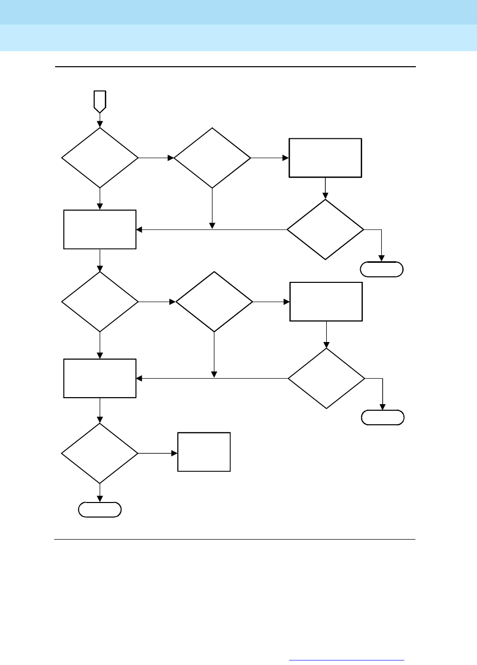
DEFINITY Enterprise Communications Server Release 6
Maintenance for R6r Volumes 1 & 2
555-230-126 Issue 2
January 1998
Responding to Alarms and Errors
Page 5-65Packet Bus Fault Isolation and Repair
5
Figure 5-15. Troubleshooting Packet Bus Problems (Page 2 of 2)
Boldface letters in the flowchart refer to paragraphs in the explanatory section
that follows.
Flowchart Notes
The following paragraphs refer by letter to corresponding entries in the
preceding flowchart. Individual errors and alarms are not detailed in the
flowchart. When referring to explanations of these in Chapter 9, ‘‘Maintenance
YES
YES
YES
YES
YES
YES
YES
NO
NO
NO
NO
From
page
1
NO
NO
NO
G
Is a
TN771 present
in this port
network?
J
Does the
TN771 indicate
packet bus
faults?
K
Is the
problem isolated
to a single
board?
H
Are there
alarms or errors
against
M/T-PKT?
Are the
packet bus
problems
resolved?
Are the
packet bus
problems
resolved?
Are the
packet bus
problems
resolved?
M
Follow the packet
bus fault isolation and
correction procedures
L
Follow the board,
port and/or endpoint
repair procedures
Follow the repair
procedure for
M/T-PKT
I
Place the TN771
in standalone mode
Escalate
the
problem
A
END
END
END
fcdfpbp2 RPY 101397

DEFINITY Enterprise Communications Server Release 6
Maintenance for R6r Volumes 1 & 2
555-230-126 Issue 2
January 1998
Responding to Alarms and Errors
Page 5-66Packet Bus Fault Isolation and Repair
5
Object Repair Procedures’’, any that do not refer explicitly to the TDM bus
(except TDM-CLK) should be considered a possible cause of packet bus
problems.
a. Problems with the system clock (TDM-CLK) can cause service disruptions
on the packet bus. All alarms active against TDM-CLK should be resolved
first, even if the explanation refers only to TDM bus. A packet bus problem
cannot cause a TDM-CLK problem, but a TDM-CLK problem can cause a
packet bus problem.
b. Throughout the flowchart, the question, ‘‘Are the packet bus problems
resolved?,’’ refers to the problems that led you to this chart, and can
involve several checks, such as:
■Are all packet bus alarms resolved?
■Are all packet circuit pack port and endpoint alarms resolved?
■Are all ISDN-BRI stations/data modules, ASAI adjuncts, System
Port supported adjuncts, Packet Gateway supported adjuncts, and
ISDN-PRI D-channel links in service?
■Does the Maintenance/Test packet bus port (in normal or
standalone mode) still indicate a packet bus fault?
c. If only a single PN is affected, the Packet Interface is probably not the
source of the problem. Nonetheless, if all of the ISDN-BRI, Packet
Gateway, Packet Data, and Universal DS1 circuit packs are located in a
single EPN, assume that the answer to this question is ‘‘No,’’ and check
the Packet Interface.
d. A packet problem that affects more than one port network is probably
caused by either a Packet Interface failure or a PPN packet bus failure.
The Packet Interface is checked before the packet bus.
e. Because the packet bus in each port network is physically separate, each
affected port network must be checked individually. The PPN should be
checked first since any EPN packet problems are usually resolved once a
PPN packet problem is resolved. After resolving the problem in one port
network, make sure that problems in other port networks have also been
resolved.
f. This step applies only when attempting to resolve an EPN packet bus
problem. When checking the Expansion Interfaces in an EPN, be sure to
check the corresponding one(s) in the PPN. (G3r supports only the TN570
Expansion Interface, not the earlier TN776 Port Network Interface).
g. If a TN771D is not present, one must be installed to accommodate the
standalone mode. See the above section on standalone mode.
h. If a TN771D is present, it can fail in such a way that it eventually disrupts
the packet bus or misinterprets a packet bus problem.
i. If work is being done on-site, follow the procedures described earlier in
this discussion on standalone mode. If work is not being done on-site, go
to the next step.

DEFINITY Enterprise Communications Server Release 6
Maintenance for R6r Volumes 1 & 2
555-230-126 Issue 2
January 1998
Responding to Alarms and Errors
Page 5-67Packet Bus Fault Isolation and Repair
5
j. The answer is yes if any of the following apply:
■The TN771D in standalone mode indicates any faulty leads.
■Test #572 in the PKT-BUS test sequence fails.
■The status port-network P display indicates that faulty leads are
present and the TN771D in the port network is known to be
functioning correctly.
k. If the non-functional endpoints are isolated to a single circuit pack, that
circuit pack is probably the cause of the problem.
l. Investigate errors and alarms in the following order:
1. Circuit pack-level
2. Ports
3. Endpoints
m. Follow the ‘‘Troubleshooting Procedures’’ outlined later in this discussion.
If the packet bus problem cannot be resolved with these procedures,
follow normal escalation procedures.
Correcting Packet Bus Faults
The Status Port-Network Command
Status port-network P displays include the service state, alarm status, and, if
the Maintenance/Test packet bus port is present, the number of faulty and open
leads for the packet bus in the specified port-network. This information can be
used to determine the urgency of the repair. In general, a service state of “out”
indicates extreme urgency, while a service state of “reconfig” indicates moderate
urgency.
NOTE:
Ultimately, the urgency of a repair is determined by the customer’s
requirements. A customer who uses ISDN-BRI for station sets, or who relies
heavily on packet bus supported system adjunct features like DCS, Audix,
or CDR, probably considers a packet bus failure critical. On the other hand,
a customer with little ISDN-BRI service and no adjunct features may
consider even an uncorrectable packet bus fault unimportant, and may
prefer to delay repairs due to their disruptive nature.
If background maintenance is running on the packet bus when the status
port-network command is issued, the data reported for the packet bus may be
inconsistent due to updating by the tests. If the data seems inconsistent, enter
the command again.

DEFINITY Enterprise Communications Server Release 6
Maintenance for R6r Volumes 1 & 2
555-230-126 Issue 2
January 1998
Responding to Alarms and Errors
Page 5-68Packet Bus Fault Isolation and Repair
5
If test results or the results of the status port-network command indicate that
there are 24 faults on the packet bus, the problem is probably caused by faulty
cables between carriers, or by defective or missing bus terminators. However,
before proceeding, make sure that the Maintenance/Test packet bus port is not
generating a false report by looking for an M/T-PKT error in the error log. Then
test the Maintenance/Test packet bus port with test port UUCSSpp. See
‘‘Special Precaution Concerning the TN771D’’ above if any problems are
suspected.
NOTE:
If the carrier into which a TN771D Maintenance/Test circuit pack is inserted
does not have a -5V power supply, the Maintenance/Test packet bus port
reports 24 open leads in response to status port-network, or Test #572 of
the PKT-BUS test sequence. Refer to CARR-POW maintenance in Chapter
9 to ensure that a -5 volt power supply is available.
Considerations for Duplicated Systems
Some packet bus-related components are duplicated in systems with one of the
duplication options:
■In High Reliability systems (duplicated SPE, simplex PNC), Packet
Interface circuit packs are duplicated with the SPEs, a Maintenance/Test
circuit pack is required in the PPN, and Maintenance/Test packet bus
reconfiguration is not enabled.
■In Critical Reliability Systems (duplicated SPE and PNC), the Packet
Interface circuit packs are duplicated, Maintenance/Test circuit packs are
required in all port networks, and packet bus reconfiguration by the
Maintenance/Test circuit packs is enabled.
If a packet bus problem is caused by a duplicated component, switching to the
standby component may alleviate the problem and isolate the faulty circuit pack.
Start by executing the commands in the following list when they apply.
■reset system interchange: If this command resolves the packet bus
problem, the problem is with the Packet Interface in the SPE which was
just switched to standby. Refer to ‘‘PKT-INT (Packet Interface Circuit
Pack)’’ in Chapter 9, ‘‘Maintenance Object Repair Procedures’’.
■reset pnc interchange: If this command resolves the packet bus
problem, the problem is with the EIs or the link on the PNC (a or b) that just
became the standby. Refer to ‘‘EXP-INTF (Expansion Interface Circuit
Pack)’’ in Chapter 9, ‘‘Maintenance Object Repair Procedures’’.
■set tone-clock: If this command resolves the packet bus problem, the
problem is with the Tone/Clock that just became the standby. Refer to
‘‘TDM-CLK (TDM Bus Clock)’’ in Chapter 9, ‘‘Maintenance Object Repair
Procedures’’ of this document.
Continue with the procedures in the next section.

DEFINITY Enterprise Communications Server Release 6
Maintenance for R6r Volumes 1 & 2
555-230-126 Issue 2
January 1998
Responding to Alarms and Errors
Page 5-69Packet Bus Fault Isolation and Repair
5
Troubleshooting Procedures
Packet bus faults are usually caused by a defective circuit pack connected to the
backplane, by bent pins on the backplane, or by defective cables or terminators
that make up the packet bus. The first two faults cause shorts, while the third fault
causes either shorts or opens.
There are four procedures for correcting packet bus faults. Which are used
depends on the nature of the fault. For example:
■If the Maintenance/Test packet bus port is activated, and if there is an
indication of open leads on the packet bus from status port-network or
Test #572, go directly to Procedure 4. Procedures 1 through 3 try to locate
faulty circuit packs or bent pins and these do not cause open faults.
■If there are both shorts and opens, start with Procedure 4, and return to
Procedure 1 if shorts persist after the open leads are fixed.
!CAUTION:
Packet bus fault isolation procedures involve removing circuit packs and
possibly disconnecting entire carriers These procedures are destructive.
Whenever possible, implement these procedures during hours of minimum
system use.
!CAUTION:
To replace the following circuit packs, follow instructions in the appropriate
sections: Tone-Clock (‘‘TONE-BD (Tone-Clock Circuit Pack)’’), Expansion
Interface (‘‘EXP-INTF (Expansion Interface Circuit Pack)’’), Packet Interface
(‘‘Replacing SPE Circuit Packs’’).
When the procedure asks whether the packet bus problem has been resolved,
the following conditions should all be met:
■All faulty leads reported by the TN771D standalone mode should no
longer be reported.
■All alarms against the packet bus and packet circuit packs have been
resolved.
■All ISDN-BRI stations and data modules and all relevant ASAI, System
Port, and Packet Gateway supported adjuncts are in service.

DEFINITY Enterprise Communications Server Release 6
Maintenance for R6r Volumes 1 & 2
555-230-126 Issue 2
January 1998
Responding to Alarms and Errors
Page 5-70Packet Bus Fault Isolation and Repair
5
Procedure 1
Procedure 1 determines whether any circuit packs that use the packet bus have
faults. For each circuit pack type in Table 5-3 proceed through the steps below.
Check the circuit pack in the order presented by the flowchart which appears
earlier in this discussion unless newly inserted circuit packs are involved. Newly
added boards are the most likely cause of a problem.
1. Display errors and display alarms for the circuit pack.
2. For any errors or alarms, follow the repair actions recommended in
Chapter 9, ‘‘Maintenance Object Repair Procedures’’.
3. After following the recommended repair actions,
whether they succeed or
fail
, determine if the packet bus fault is resolved. If so, you are finished.
4. If the packet bus fault is still present, apply this procedure to the next
circuit pack.
5. If there are no more circuit packs in the list, go to Procedure 2.
Procedure 2
Procedure 2 removes and reinserts
port
circuit packs (purple slots), and the
Expansion Interface one or several at a time. Use Procedure 2 for each port
circuit pack in the port network until the problem is resolved
or
all port circuit
packs have been tried.
NOTE:
The Expansion Interface circuit pack should be the last one checked since
removing it disconnects the EPN. To check an active Expansion Interface in
a system with duplicated PNC, use reset pnc interchange to make it the
standby. (Always check the status of the standby before executing an
interchange.)
Table 5-3. Packet Circuit Packs
Circuit Pack Name Circuit Pack Code Associated Maintenance Objects
ISDN-BRI TN556 BRI-BD, BRI-PORT, ABRI-PORT, BRI-SET,
BRI-DAT, ASAI-ADJ
Maintenance/Test TN771D M/T-BD, M/T-PKT
Packet Gateway TN577 PGATE-BD, PGATE-PT
Packet Data TN553 PDATA-BD, PDATA-PT
Universal DS1 TN464F UDS1-BD, ISDN-LNK
Packet Interface TN1655 PKT-INTF
Expansion Interface TN570 EXP-INTF

DEFINITY Enterprise Communications Server Release 6
Maintenance for R6r Volumes 1 & 2
555-230-126 Issue 2
January 1998
Responding to Alarms and Errors
Page 5-71Packet Bus Fault Isolation and Repair
5
NOTE:
The Tone/Clock circuit pack should be the next-to-last one checked. (The
TN771D must be reseated after the Tone/Clock is reinstalled.) Refer to
Procedure 3 for the TN768 or TN780 Tone/Clock circuit pack in a PPN with
duplicated SPEs.
If the packet bus problem is present when the circuit pack is inserted, but is
resolved when the circuit pack is removed, either the circuit pack or the
backplane pins in that slot caused the problem. If the backplane pins are intact,
replace the circuit pack. Keep in mind that there may be more than one failure
cause.
In Procedure 2, you may try one circuit pack at a time, or multiple circuit packs
simultaneously. The allowable level of service disruption should guide this
choice. If the entire port network can be disrupted, trying large groups of circuit
packs will save time. If traffic is heavy, trying 1 circuit pack at a time is slow but
will minimize outages.
If the TN771D Standalone mode does
not
indicate packet bus faults, perform
Procedure 2 for
only the port
circuit packs (purple slots) listed in Table 5-3 in
Procedure 1. In this case, you need not check for problems with the backplane
pins. It is sufficient to determine whether the problem is resolved by removing
circuit packs.
If you decide to remove multiple circuit packs, consider working with an entire
carrier at a time to more quickly and reliably determine which circuit packs are
not
the source of trouble. Any circuit packs, (packet or non-packet), that have
been recently inserted should be checked first. Packet circuit packs should be
checked before non-packet circuit packs.
1. Remove one or several circuit packs.
2. Determine if the packet bus fault is still present. If not, go to step 4.
3. If the packet bus fault is still present:
a. Determine if the backplane pins in the removed circuit pack’s slot
are bent using the output from the Maintenance/Test standalone
mode and the backplane illustrations which appear earlier in this
discussion.
b. If the backplane pins are bent:
Power down the carrier (see ‘‘Replacing a BIU or Rectifier’’),
straighten or replace the pins, reinsert the circuit pack and restore
power. Repeat Step 2 for the same circuit pack.
c. If the backplane pins are not bent:
Reinsert the circuit pack(s), and repeat this procedure for the next
set of circuit packs.

DEFINITY Enterprise Communications Server Release 6
Maintenance for R6r Volumes 1 & 2
555-230-126 Issue 2
January 1998
Responding to Alarms and Errors
Page 5-72Packet Bus Fault Isolation and Repair
5
4. If the packet bus fault is not present:
a. Reinsert circuit packs one at a time and repeat the following
substeps until all circuit packs have been reinserted.
b. Determine if the packet bus fault has returned.
c. If the packet bus fault has returned, the reinserted circuit pack is
defective. Replace the circuit pack and then continue.
d. If the packet bus fault does not return when all of the circuit packs
have been reinserted, you are finished.
Continue with Procedure 3 if all the port circuit packs have been checked, but
the packet bus fault is still not resolved.
Procedure 3
Procedure 3 removes and reinserts SPE and EPN control circuit packs one at a
time. In the PPN, the following SPE circuit packs either use the packet bus or are
connected to it in the backplane wiring:
■TN1655 Packet Interface
■TN768/TN780 Tone/Clock
■UN332 MSSNET
In the EPN, the following control circuit packs either use the packet bus for
communication or are connected to it in the backplane wiring:
■TN775 EPN Maintenance Board
■TN768/TN780 Tone/Clock
These are the only SPE and EPN control circuit packs that are likely to cause a
packet bus problem in a stable system. Perform this procedure on only these
circuit packs.
If the TN771D Standalone mode does
not
indicate packet bus faults, perform
Procedure 3 for
only
the Packet Interface and Tone/Clock circuit packs and do
not check for problems with the backplane pins. Determining if the problem is
resolved by removing circuit packs is sufficient.
For a system with simplex SPE:
1. Power down the control carrier. Refer to ‘‘Replacing SPE Circuit Packs’’.
2. Remove the suspect circuit pack.
3. Determine if the backplane pins in the removed circuit pack’s slot are
bent.
4. If the backplane pins are bent:
a. Straighten or replace the pins.

DEFINITY Enterprise Communications Server Release 6
Maintenance for R6r Volumes 1 & 2
555-230-126 Issue 2
January 1998
Responding to Alarms and Errors
Page 5-73Packet Bus Fault Isolation and Repair
5
b. Insert the same circuit pack.
5. If the backplane pins are not bent:
a. Replace the circuit pack (reinsert the old one if a replacement is not
available).
6. Turn the power back and allow the system to reboot. This may take up to
12 minutes. Log in at the terminal.
7. Determine if the packet bus fault is still present. If not, you are finished.
If the problem is still present,
a. If the old circuit pack was reinserted in Step 5, replace the circuit pack,
and repeat Procedure 3.
b. If the circuit pack was replaced in Step 5, repeat Procedure 3 for the next
SPE circuit pack.
If Procedure 3 fails to identify the cause of the problem, go to Procedure 4.
For a system with duplicated SPEs:
1. For SPE circuit packs, follow the ‘‘Replacing Circuit Packs on a Duplicated
SPE: Lock-and-Power-Down’’ procedure within the ‘‘Replacing SPE Circuit
Packs’’ section to remove and replace the circuit pack.
2. To remove an EPN Tone/Clock circuit pack, use set tone-clock if
necessary to make the suspect circuit pack the standby. (Always check
the status of the standby Tone/Clock with status port network before
executing an interchange.)
3. Determine if the backplane pins in the removed circuit pack’s slot are
bent.
4. If the pins are bent:
a. Power down the carrier if it is not already.
b. Straighten or replace the pins.
c. Insert the same circuit pack.
d. Restore power to the carrier.
5. If the backplane pins are not bent:
Insert or replace the circuit pack.
6. Determine if the packet bus fault is still present. If not you are finished.
7. If the packet bus fault is still present, do the following:
a. If the old circuit pack was reinserted in Step 5, replace the circuit
pack and repeat Procedure 3 starting at Step 2.
b. If the circuit pack was replaced with a new one, proceed with the
next step.

DEFINITY Enterprise Communications Server Release 6
Maintenance for R6r Volumes 1 & 2
555-230-126 Issue 2
January 1998
Responding to Alarms and Errors
Page 5-74Packet Bus Fault Isolation and Repair
5
8. Repeat this procedure for the other SPE or Tone/Clock. If both have
already been checked, go to the next step.
9. If all SPE and/or EPN control circuit packs have been checked and the
problem is not resolved, continue with Procedure 4.
Procedure 4
Procedure 4 is used when the preceding procedures fail or when open leads are
present. It is helpful in identifying multiple circuit pack faults and carrier hardware
faults. It attempts to isolate the failure to a particular set of carriers and checks
only the circuit packs in those carriers.
In Procedure 4, the TDM/LAN Cable Assemblies and TDM/LAN termination
resistor packs are replaced. If this action does not resolve the packet bus fault,
the carriers are reconfigured by moving the termination resistor packs on the
carrier backplanes in such a manner that certain carriers are disconnected from
the bus. To terminate the packet bus at the end of a particular carrier, unplug the
cable that connects the carrier to the next carrier and replace the cable with a
TDM/LAN terminator resistor pack (see Figure 5-16). When the length of the
packet bus is modified with this procedure, circuit packs that are essential to
system operation (and the TN771D Maintenance/Test in standalone mode) must
still be connected to the new ‘shortened’ packet and TDM busses.
!DANGER:
Power must be removed from the entire port network before any cables or
terminators are removed. Failure to do so can cause damage to circuit
packs and power supplies, and can be hazardous to the technician.
!DANGER:
Circuit packs in carriers that are not part of the shortened bus are not
inserted. As a result, these circuit packs are not alarmed Ignore alarm
status for these circuit packs for now All alarms should be resolved when
the cabinet is restored to its original configuration.
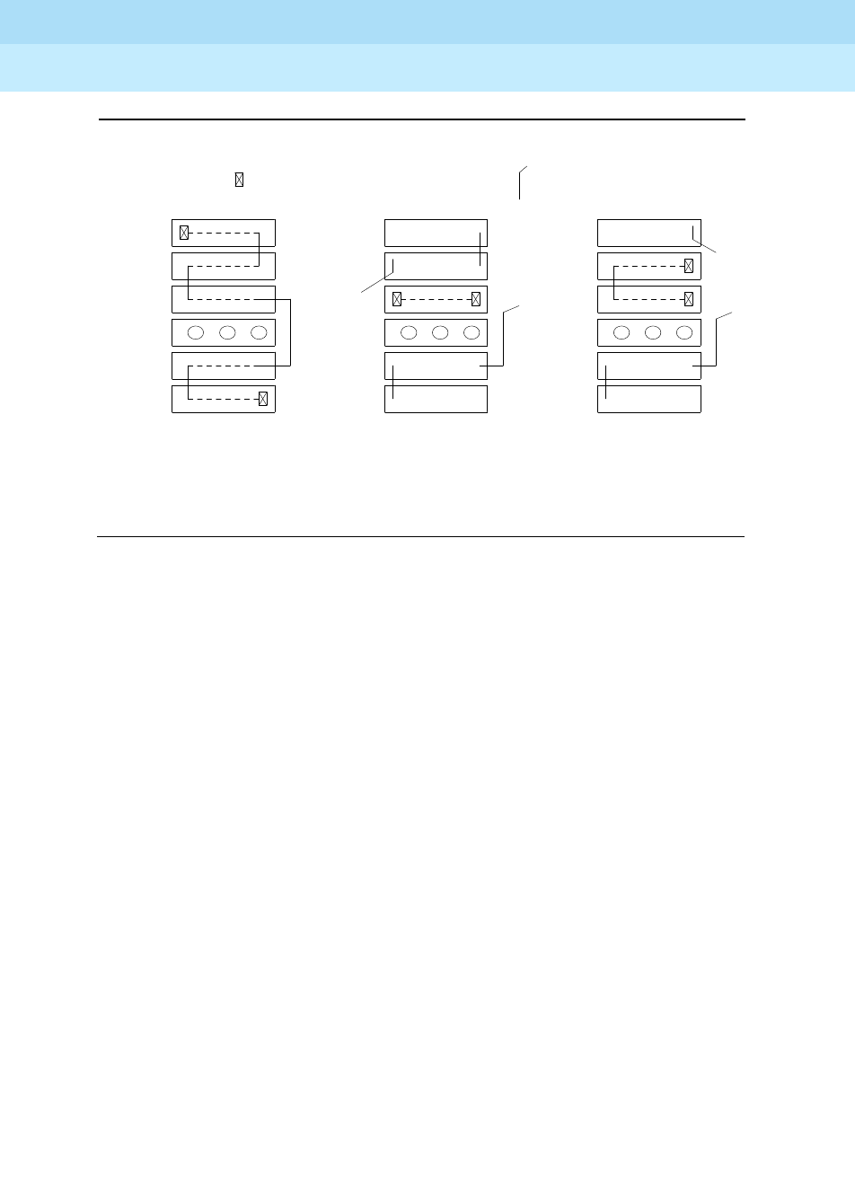
DEFINITY Enterprise Communications Server Release 6
Maintenance for R6r Volumes 1 & 2
555-230-126 Issue 2
January 1998
Responding to Alarms and Errors
Page 5-75Packet Bus Fault Isolation and Repair
5
Figure 5-16. Carrier Rewiring Example—Rear View of Multicarrier Cabinet
Procedure 4 consists of two parts. Part 1 attempts to clear the packet bus fault by
replacing all the bus cabling and terminators within a port-network. Part 2
attempts to isolate the fault to a particular carrier by extending the packet bus
from the control carrier to additional carriers one at a time.
Part 1:
1. Power down the port network.
2. Replace all of the TDM/LAN Cable Assemblies and both TDM/LAN
Terminators.
3. Restore power to the port network.
4. Determine if the packet bus fault is still present.
5. If the packet bus fault is resolved, the procedure is completed. Otherwise,
go to Part 2.
TDM/LAN Bus Cable TDM/LAN Bus Terminator
Normally
Configured
Cabinet
(All 5 Carriers
Used)
Bus Shortened
to Carrier A Only
(Control Carrier)
Shortened Bus
Extended to
Include
A and B
Carriers
Carrier D
Carrier E
Fans
Carrier A
Carrier B
Carrier C

DEFINITY Enterprise Communications Server Release 6
Maintenance for R6r Volumes 1 & 2
555-230-126 Issue 2
January 1998
Responding to Alarms and Errors
Page 5-76Packet Bus Fault Isolation and Repair
5
Processor Port Network:
1. Power down the cabinet and terminate the packet bus so that it extends
only from the carrier that contains the active SPE (A or B) to the carrier that
contains the Maintenance/Test circuit pack.
2. Power up the cabinet, allow the system to reboot, and determine if the
packet bus fault is still present. If not, proceed to the next step.
If there are shorts on the packet bus, perform Procedures 2 and/or 3 for
the circuit packs in the active SPE and carriers connected to it on the
shortened bus. (Procedure 2 is performed for port circuit packs, and
Procedure 3 is performed for SPE circuit packs.)
3. If the packet bus fault is not present, extend the packet bus to another
carrier, and repeat the procedure in the previous step. When the addition
of a carrier causes the fault to recur, and if there are shorts, perform
Procedure 2 and/or Procedure 3 for only the circuit packs in that carrier.
4. If the packet bus fault recurs when the packet bus is extended, and if
there are no shorts, or Procedures 2 and 3 do not resolve the problem, the
added carrier(s) that caused the problem to recur are defective and must
be replaced.
Expansion Port Networks:
1. Place the Maintenance/Test circuit pack into a carrier that contains the
active Expansion Interface circuit pack to permit isolation of the failure to
the smallest possible number of carriers.
2. Power down the cabinet and terminate the packet bus on the carrier with
the M/T and active EI.
3. Determine if the packet bus fault is still present If so, and if there are shorts
on the packet bus, perform Procedure 2 and/or Procedure 3 for only the
circuit packs in carriers connected to the ‘‘shortened’’ packet bus.
4. If the packet bus fault is not present, extend the packet bus to another
carrier, and repeat the procedure in the previous step. When a carrier that
causes the fault to recur is added, and if there are shorts, perform
Procedure 2 and/or Procedure 3 for only the circuit packs in that carrier.
5. If the packet bus fault recurs as the packet bus is extended, and if there
are no shorts, or Procedures 2 and 3) do not resolve the problem, the
added carrier(s) that caused the problem to recur are defective and must
be replaced.

Additional Maintenance Procedures
Page 6-1Software Updates
6
DEFINITY Enterprise Communications Server Release 6
Maintenance for R6r Volumes 1 & 2
555-230-126 Issue 2
January 1998
6
6Additional Maintenance Procedures
Software Updates
A software update is the complete replacement of the software load running on a
switch with a new version of software. Updates are used to provide new features
and improved services, and to repair bugs discovered in the field. Note that the
process is called a software update; the command used is upgrade software. A
description of this command appears in Chapter 8, ‘‘Maintenance Commands’’.
Software
field updates
are partial replacements of a software load normally used
for emergency bug fixes. Usually, a field update is transmitted electronically to
the system from a remote site, but a technician must be on site to apply the
update to backup tapes and insure that the system returns to normal operation.
This procedure should be guided by the remote facility applying the update.
Refer to
DEFINITY Enterprise Communications Server Release 5.4 Upgrades and
Additions for R5r
for specific upgrade information.
Software Version Number
Each software load is identified by a version number. The following are typical
software version numbers displayed when list configuration software-version
is entered:
SOFTWARE VERSION: DG3r01.06.1.00.0
SOFTWARE VERSION: G3r5.01.2.0.078
This identifier is also called the release number or the vintage number. Version
numbers are interpreted as follows:

DEFINITY Enterprise Communications Server Release 6
Maintenance for R6r Volumes 1 & 2
555-230-126 Issue 2
January 1998
Additional Maintenance Procedures
Page 6-2Software Updates
6
Release 5r loads:
The boot image field contains “m” (mips) for G3r systems.
The system expects any software upgrade to be going from a lower, or older
version number, to a higher, or newer version number. To install an older version
(for example, when backing out a failed upgrade), follow normal escalation
procedures to avoid putting the system into a corrupted state.
Each software version also has a compatibility index of the form:
Differences between old and new version numbers and compatibility indexes
can be used to determine what service effects can be expected from the update.
See the ‘‘Service Effects of a Software Update’’ section that follows.
Service Effects of a Software Update
Simplex SPE
The upgrade software command executes a system reboot similar to a reset
system 4. Emergency transfer is invoked and all calls drop. The MT login is
terminated and error logs are cleared. The service outage lasts for a period of up
to 15 minutes. Results of each step in the upgrade process and initialization
diagnostics are displayed on the terminal screen. Screen output is described in
Maintenance Commands
, upgrade software. Failure of initialization will produce
an SPE-down mode, described in
Initialization and Recovery
. Translations are
reloaded from the primary storage device and reformatted for the new software if
necessary.
Duplicated SPE
On a system with a duplicated SPE, a software update may be either
call-preserving
or
call-dropping
. The compatibility of the old and new versions
determines which type of update is performed. If the major fields of the
compatibility indexes of the two versions are equal, then a call-preserving update
is possible. The documentation accompanying the update tapes (Engineering
Design Information, or EDI, and the Release Letter) should confirm this. With rare
exceptions, this is the case when the Feature Version and Product ID numbers
match.
G3r5 m 01 2 0 078
Product Boot Major Minor Unscheduled Load
ID Image Release Release Release Number
81
Major Field Minor Field

DEFINITY Enterprise Communications Server Release 6
Maintenance for R6r Volumes 1 & 2
555-230-126 Issue 2
January 1998
Additional Maintenance Procedures
Page 6-3Software Updates
6
If these conditions are not met, The upgrade software call-override option must
be used, and the update will result in a system reset level 2 (cold-2 restart). An
additional option, preserve-calls, can be added to force the system to attempt to
preserve calls, but this must be used with care. If the incompatibility is great
enough, this option may cause the system to escalate to a reboot (reset system
4). It is recommended that you escalate any such software update.
Call-Preserving Update
During a call-preserving update, calls in which two or more parties are
connected and talking are preserved. The following types of calls are dropped:
wideband calls, held calls, dialing calls, and calls that are connected to
announcements, speech synthesizers, or tones. Administered connections are
dropped and automatically restored. Feature activation attempts are ignored. No
new calls are processed for a brief period. This period usually lasts less than 5
seconds but can last up to 1 minute depending on traffic load during the SPE
interchange. Conference calls that attempt a new connection are either ignored
or dropped.
Call-Dropping Update
During a call-dropping update, the effect will be similar to a cold-2 restart (reset
system 2). All calls and system links drop, and the MT login is terminated. The
service outage lasts up to 4 minutes.
Preparing for a Software Update
1. Notify users of anticipated service effects described in the preceding
section and arrange to do the update at a suitable time. Also advise
appropriate users of the following feature interactions:
■Administered connections are temporarily dropped.
■Leave Word Calling messages stored in the SPE are lost. Those
stored in a Message Server Adjunct or AUDIX system are saved.
■Some feature settings will be lost and must be restored afterward.
The effect is the same as a cold-2 restart. Features affected include
night service, trunk/hunt group control, and manual/clock-manual
override status on time of day routing. For example, hunt groups
and attendant are put into night service after the update.
■ACD queues will be lost. There is no mechanism to drain the
queues. CMS or BCMS can be used to monitor the queue lengths.
If it is important to empty all queues before the update, you must
coordinate with the customer to redirect traffic away from ACD
splits before the update. Changing vectors to temporarily route
calls to a disconnect announcement is one way to accomplish this.
ACD agents will need to log in again after the update and their
status lamps may be incorrect for about an hour (until periodic
background maintenance completes one cycle).

DEFINITY Enterprise Communications Server Release 6
Maintenance for R6r Volumes 1 & 2
555-230-126 Issue 2
January 1998
Additional Maintenance Procedures
Page 6-4Software Updates
6
■CMS links are dropped and restored, resulting in a loss of incoming
data during the upgrade. Data loss can be minimized by
performing the update soon after the end of a CMS measurement
interval.
■Wideband calls are dropped.
2. Some information which is stored in system memory will be lost and must
be manually recorded and then re-entered after the update:
■Record all busied out maintenance objects. Enter display errors
print, and select error type 18 on the menu. All busyouts will be lost
during the update and must be reentered afterward. Disabled
maintenance objects will likewise be re-enabled by the update.
■All measurement data stored in memory, including BCMS, is lost.
Print any desired reports before the update.
■Enter list report-scheduler. Reports that are currently printing or
queued will be lost. Wait until reports are finished printing or notify
the customer. Reports are printing if the Link State field displays up
on the status sp-link screen.
■Enter list wakeup print and list do-not-disturb stations print.
These feature settings will be lost and must be re-entered
afterwards.
3. Make sure that the system’s health and activity can support a successful
update:
■Enter status spe and verify that the state of health of the SPE is
functional
. This must hold true for active and standby SPEs when
duplicated.
■Enter display alarms and display errors. Resolve any active
alarms or errors against SPE components or the PPN Tone-Clock.
■Enter status logins and make sure that no other logins except
yours are active.
■Enter status health and look at the amount of load on the system. If
call processing is greater than 50 percent, an update is not
recommended due to increased customer impact.
■Disable TTI changes by the change system-parameters features.
■Enter change system-parameters maintenance and make sure
that scheduled daily maintenance will not be running during the
update. The Start Time field should be set to a time well after the
session will end. If scheduled daily maintenance is running and
needs to be shut off, set the Stop Time field to one minute after the
current time. Be sure to restore the original settings when finished.

DEFINITY Enterprise Communications Server Release 6
Maintenance for R6r Volumes 1 & 2
555-230-126 Issue 2
January 1998
Additional Maintenance Procedures
Page 6-5Software Updates
6
Restoring the System after an Update
During software updates, including call-preserving updates, several feature
settings are lost. These must be manually restored afterward.
■Re-enter all Maintenance Object busyouts.
■Re-enter wakeup calls and do-not-disturb stations.
■Restore attendant feature settings.
■Notify Administration and ACD users that the update is complete.
■Re-enable TTI changes by the change system-parameters features.
■On the change system-parameters maintenance form, restore Alarm
Origination, Save Translations, CPE Alarm Level and SPE Interchange
fields and Scheduled Daily Maintenance times to their original settings.
■Manually reset any speakerphones which derive power from the switch by
pressing the button on the voice terminal.
Backing Out of a Software Update
If fatal hardware errors or memory faults prevent the update from completing, the
system must be recovered and the update backed out. If the update command
has already been entered, follow normal escalation procedures. Backing out
after this point is hazardous and may leave the system in a corrupted state.
Software Update Procedure — Simplex SPE
After making the preparations described above, execute the following sequence
of steps, entering the commands shown in bold type. This part of the procedure
normally takes about 3 1/2 hours. Screen output for each command is described
in Chapter 8, ‘‘Maintenance Commands’’. If errors are encountered after entering
the
update software
command, follow normal escalation procedures. Avoid
touching the keyboard while the save or upgrade commands are running since
doing so may cause diagnostic messages to be lost.

DEFINITY Enterprise Communications Server Release 6
Maintenance for R6r Volumes 1 & 2
555-230-126 Issue 2
January 1998
Additional Maintenance Procedures
Page 6-6Software Updates
6
Table 6-1. Software Update—Simplex SPE
Step Time
(min) Remarks
change sys-par
maint 2 Note the current settings of the Save Translation and Alarm
Origination Activated fields and then set them to n. Set CPE
Alarm Activation Level to none. Make sure scheduled daily
maintenance is not set to run during the update.
save
announcements 40 These steps create a backup tape in case the update fails
and a backout is necessary. Saving announcements may be
skipped if display announcements shows no administered
announcements.
save translation 2
backup disk 10
Remove the
backup tape and
clean the tape
drive
5 This procedure is described under ‘‘TAPE’’ in Chapter 9,
‘‘Maintenance Object Repair Procedures’’.
Insert the tape
with the new
software
2 Wait for the tape to retension itself.
list config
software-version 5 Make sure the tape has the expected version number.
restore disk
install 10 This copies files from the new tape to disk. If you are
updating
from
a load earlier than 6.0, substitute for this step
the following sequence: copy announce tape, save
translation tape, then restore disk full.
The following step will result in the service effects described above.
upgrade software
to-version 10 Use the new software version number described above. The
system will reboot and then reload translations. Results of
each step in the upgrade process and initialization
diagnostics will be displayed on the terminal. A full
description of screen output appears in upgrade software
in Chapter 8, ‘‘Maintenance Commands’’.
NOTE:
Be careful not to touch the G3-MT keyboard while
waiting for the command to execute, or the result
messages may be lost.
Login on the G3-MT.
Continued on next page

DEFINITY Enterprise Communications Server Release 6
Maintenance for R6r Volumes 1 & 2
555-230-126 Issue 2
January 1998
Additional Maintenance Procedures
Page 6-7Software Updates
6
Software Update Procedure — Duplicated SPE
After making the preparations described above, execute the following sequence
of steps, entering the commands shown in bold type. This part of the procedure
normally takes about 3-1/2 hours. Screen output for each command is described
in Chapter 8, ‘‘Maintenance Commands’’. If errors are encountered after entering
the update software command, follow normal escalation procedures. Avoid
touching the keyboard while the save or upgrade commands are running since
doing so may cause diagnostic messages to be lost.
change sys-par
maint 2 Set the Save Translation, Alarm Origination Activated, CPE
Alarm Level, and Daily Scheduled Maintenance times to the
values that were in effect before starting this procedure.
save translation 2 This step stores the upgraded translations on disk.
backup disk 20 This step makes a backup copy of the new files. If a
coredump from before the upgrade is on disk, this can take
up to 50 minutes.
test stored-data 10 This step verifies that all MSS files are consistent. The next
run of scheduled maintenance will also do this.
list config soft
long 5 Verify that all files are correct.
backup disk 20 Make extra backup copies of the new files as needed. The
next run of scheduled maintenance will also do this.
set vector 8 1 Sets the coredump vector to take a coredump when the
system reboots.
Restore the system as described above.
Table 6-1. Software Update—Simplex SPE — Continued
Step Time
(min) Remarks
Continued on next page

DEFINITY Enterprise Communications Server Release 6
Maintenance for R6r Volumes 1 & 2
555-230-126 Issue 2
January 1998
Additional Maintenance Procedures
Page 6-8Software Updates
6
Table 6-2. Software Update—Duplicated SPE
Step Time
(min) Remarks
change sys-par maint 2 Note the current settings of the Save
Translation, SPE Interchange, and Alarm
Origination Activated fields and then set
them to n. Set CPE Alarm Activation Level
to none. Make sure scheduled daily
maintenance is not set to run during the
update.
save announcements 40 These steps create a backup tape in case
the update fails and a backout is
necessary. Saving announcements may
be skipped if display announcements
shows no administered announcements.
save translation 2
backup disk 10
Remove tapes and
clean tape drives. 5 This procedure is described under ‘‘TAPE’’
in Chapter 9, ‘‘Maintenance Object Repair
Procedures’’.
Insert the tapes
containing the new
software
2 Wait for the tape to retension itself.
list config
software-version long 5 Make sure the tapes have the expected
version number.
restore disk install
both 10 Copies new tape files to disk. If updating
from
a load earlier than 6.0, substitute for
this step the following sequence: copy
announce tape, save translation tape,
then restore disk full both.
Continued on next page
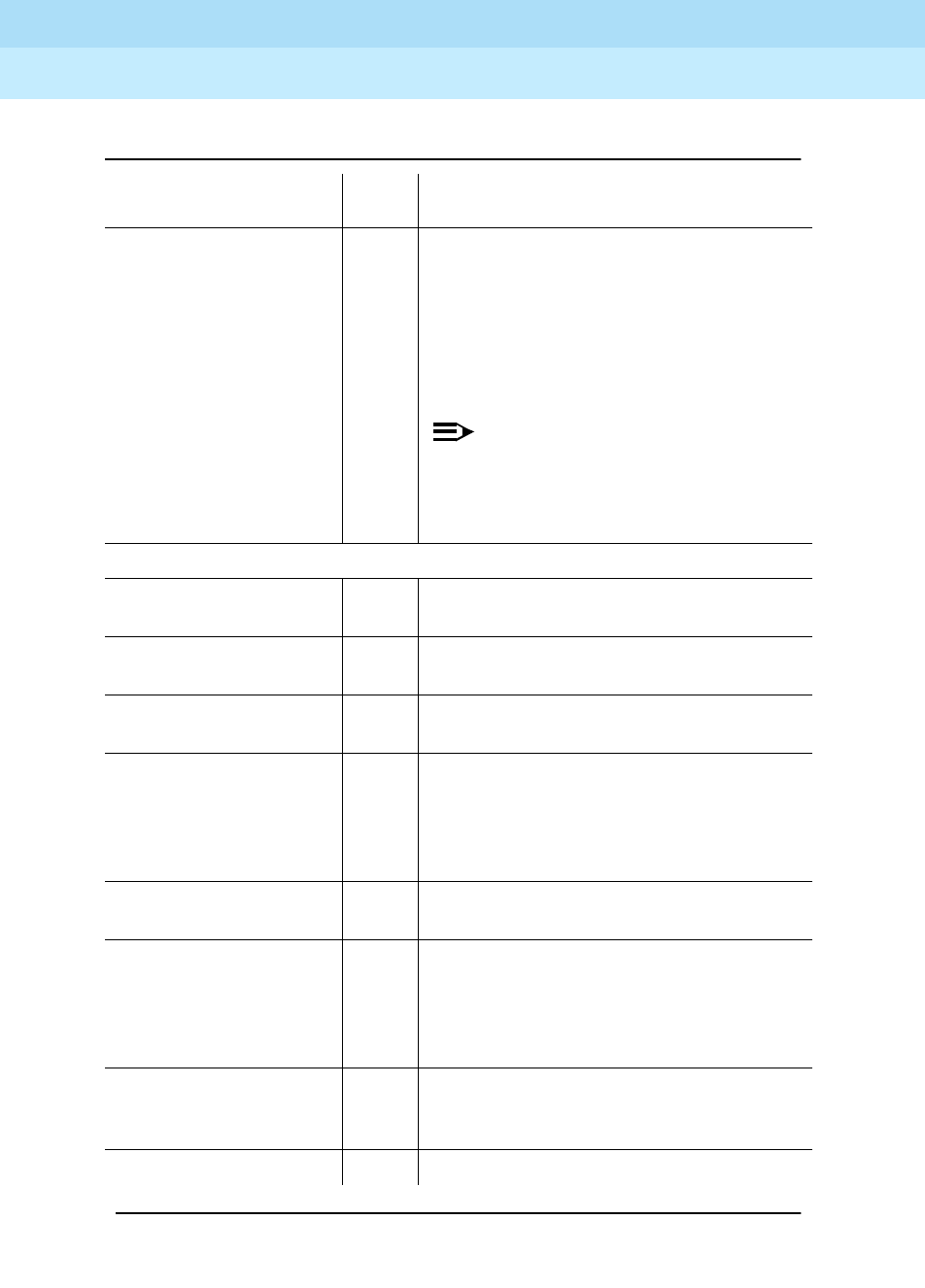
DEFINITY Enterprise Communications Server Release 6
Maintenance for R6r Volumes 1 & 2
555-230-126 Issue 2
January 1998
Additional Maintenance Procedures
Page 6-9Software Updates
6
The following step will
result in the service
effects described
above. upgrade
software to-version
10 Use the new software version number
described above. The system will reboot
the standby SPE, reload translations, and
then execute an SPE interchange. Results
of each step in the upgrade process and
initialization diagnostics will be displayed
on the terminal.
NOTE:
Be careful not to touch the G3-MT
keyboard while waiting for the
command to execute, or the result
messages may be lost.
Log in on the G3-MT.
status spe 5 Repeat this command until the states of
health of both SPEs are
functional
.
reset spe-standby 4 5 This step initiates a reboot of the standby
SPE with the new software load.
status spe 15 Repeat this command until the states of
health of both SPEs are
functional
.
change sys-par maint 2 Set the Save Translation, Alarm Origination
Activated, CPE Alarm Level, SPE
Interchange fields and Daily Scheduled
Maintenance times to the values that were
in effect before starting this procedure.
save translation both 2 This step stores the upgraded translations
on both disks.
backup disk 20 This step makes a backup copy of the new
files. The next run of scheduled
maintenance will also do this. If a
coredump from before the upgrade is on
disk, this can take up to 50 minutes.
test stored-data 10 This step verifies that all MSS files are
consistent. The next run of scheduled
maintenance will also do this.
list config soft long 5 Verify that all files are correct.
Table 6-2. Software Update—Duplicated SPE — Continued
Step Time
(min) Remarks
Continued on next page

DEFINITY Enterprise Communications Server Release 6
Maintenance for R6r Volumes 1 & 2
555-230-126 Issue 2
January 1998
Additional Maintenance Procedures
Page 6-10DS1 CPE Loopback Jack (T1 Only)
6
DS1 CPE Loopback Jack (T1 Only)
Using the DS1 CPE Loopback Jack (apparatus code 700A, comcode
107988867), a technician can test the DS1 span between the system and the
network interface point. The loopback jack is required when DC power appears
at the interface to the ICSU.
The loopback jack isolates the ICSU from the DC
power and properly loops the DC span power
.
NOTE:
The loopback jack operates with any vintage of TN767E (or later) or
TN464F (or later) DS1 circuit packs and with G3V3 EDI release 3 (or later)
software. The loopback jack operates with the 120A2 (or later) Integrated
Channel Service Unit (ICSU) only;
not
the 31xx series of Channel Service
Units or other external CSUs or earlier ICSUs.
Loopback Jack Installation
Configurations Using a Smart Jack
The preferred location of the loopback jack is at the interface to the Smart Jack.
This provides maximum coverage of CPE wiring when remote tests are run using
the loopback jack. If the Smart Jack is not accessible, install the loopback jack at
the extended demarcation point.
1. If there is no extended demarcation point, install the loopback jack directly
at the network interface point as shown in Figure 6-1.
2. If there is an extended demarcation point and the Smart Jack is not
accessible, install the loopback jack as shown in Figure 6-2.
3. If there is an extended demarcation point, but the Smart Jack is
accessible, install the loopback jack as shown in Figure 6-3.
backup disk 20 Make extra backup copies of the new files
as needed.
set vector f spe-maint 1 Sets the coredump vector to take a
coredump when the system reboots.
Restore the system as described above.
Table 6-2. Software Update—Duplicated SPE — Continued
Step Time
(min) Remarks
Continued on next page

DEFINITY Enterprise Communications Server Release 6
Maintenance for R6r Volumes 1 & 2
555-230-126 Issue 2
January 1998
Additional Maintenance Procedures
Page 6-11DS1 CPE Loopback Jack (T1 Only)
6
Configurations Without a Smart Jack
1. Install the loopback jack at the point where the cabling from the ICSU
plugs into the “dumb” block. If there is more than one “dumb” block,
choose the one that is closest to the Interface Termination feed or the fiber
MUX. This provides maximum coverage for loopback jack tests. Refer to
Figure 6-4 and Figure 6-5.
Installation
1. To install the loopback jack, simply disconnect the RJ-48 (8-wide)
connector (typically an H600-383 cable) at the appropriate interface point
and connect the loopback jack in series with the DS1 span. See Figure 6-1
through Figure 6-5.
2. Plug the H600-383 cable from the ICSU into the female connector on the
loopback jack.
3. Plug the male connector on the loopback jack cable into the network
interface point.
NOTE:
Do not remove the loopback jack after installation. This is not a test
tool and should always be available to remotely test a DS1 span.
Administration
1. At the management terminal, enter change ds1 <location>. The
“location” is the DS1 interface circuit pack for which the loopback jack
was installed.
2. Be sure the “near-end CSU type” is set to integrated.
3. On page 2 of the form, change the supply CPE loopback jack
power field to y.
NOTE:
Setting this field to y informs the technician that a loopback jack is
present on the facility. This allows a technician to determine that the
facility is available for remote testing.
4. Enter save translation to save the new information.
DS1 Span Test
This test should only be performed after the DS1 circuit pack and the 120A2 (or
later) ICSU have been successfully tested using appropriate maintenance
procedures. The DS1 span test consists of 2 sequential parts. Each part provides
a result indicating if there is a problem in the CPE wiring. CPE wiring may be
considered problem-free only if the results of both parts are successful.

DEFINITY Enterprise Communications Server Release 6
Maintenance for R6r Volumes 1 & 2
555-230-126 Issue 2
January 1998
Additional Maintenance Procedures
Page 6-12DS1 CPE Loopback Jack (T1 Only)
6
The first part of the span test powers-up the loopback jack and attempts to send
a simple code from the DS1 board, through the wiring and loopback jack, and
back to the DS1 board. Maintenance software waits about 10 seconds for the
loopback jack to loop, sends the indication of the test results to the management
terminal, and proceeds to the second part of the test.
The second part of the test sends the standard DS1 3-in-24 stress testing pattern
from the DS1 board, through the loopback jack, and back to a bit error detector
and counter on the DS1 board. The bit error rate counter may be examined at will
via the management terminal, and provides the results of the second part of the
test. The test remains in this state until it is terminated so that the CPE wiring may
be bit error rate tested for as long as desired.
1. Busy out the DS1 circuit pack by entering busyout board UUCCSS
(where UUCCSS is the cabinet, carrier, and slot number of the DS1
board).
2. At the management terminal, enter change ds1 <location> and verify the
near-end csu type is set to integrated.
3. Change to page 2 of the DS1 administration form and confirm that the TX
LBO field is 0dB. If not, record the current value and change it to 0dB for
testing. Press Enter to implement the changes or press Cancel to change
nothing.
4. Enter test ds1-loop <location> cpe-loopback-jack. This turns on simplex
power to the loopback jack and waits about 20 seconds for any active
DS1 facility alarms to clear. A “PASS” or “FAIL” displays on the terminal.
This is the first of the 2 results. A “FAIL” indicates a fault is present in the
wiring between the ICSU and the loopback jack. The loopback jack may
also be faulty. A “PASS” only indicates that the loopback jack looped
successfully, not that the test data contains no errors. If a “PASS” is
obtained, continue with the following steps.
NOTE:
The loss of signal (LOS) alarm (demand test #138) is not processed
during this test while the 3-in-24 pattern is active.
5. Enter clear meas ds1 loop <location> to clear the bit error count.
6. Enter clear meas ds1 log <location> to clear the performance
measurement counts.
7. Enter clear meas ds1 esf <location> to clear the ESF error count.
8. Enter list meas ds1 sum <location> to display the bit error count. Refer
to Table 6-3 for troubleshooting information.

DEFINITY Enterprise Communications Server Release 6
Maintenance for R6r Volumes 1 & 2
555-230-126 Issue 2
January 1998
Additional Maintenance Procedures
Page 6-13DS1 CPE Loopback Jack (T1 Only)
6
9. Repeat Steps 5 through 8 as desired to observe bit error rate
characteristics. Also, wait 1 to 10 minutes between Steps 5 through 7. One
minute without errors translates to better than a 1 in 10 to the eighth error
rate. Ten minutes without errors translates to better than a 1 in 10 to the
ninth error rate.
10. If the test runs for 1 minute with an error count of 0, confirm that the 3-in-24
pattern error detector is operating properly by entering test ds1-loop
<location> inject-single-bit-error. This causes the 3-in-24 pattern
generator on the DS1 circuit pack to inject a single-bit error into the
transmit pattern. A subsequent list meas ds1 summary <location>
command displays the bit error count. If a count greater than 1 is
displayed, replace the ICSU and retest. If the problem continues, replace
the DS1 circuit pack.
Table 6-3. DS1 Span Troubleshooting
Displayed Field Function Indication
Test:
cpe-loopback-jack Pattern 3-in-24 The loopback jack test is active.
Synchronized Y or N If “y” displays, the DS1 circuit pack has synchronized to
the looped 3-in-24 pattern and is accumulating a count of
the bit errors detected in the pattern until the test has
ended. If “n” displays, retry the test 5 times by ending the
test per Step 11 and re-starting the test per Step 4. If the
circuit pack never synchronizes, substantial bit errors in
the 3-in-24 pattern are likely. This could be intermittent
connections or a broken wire in a receive or transmit pair
in the CPE wiring.
Bit Error Count Cumulative
count of
detected errors
If there are no wiring problems, the counter remains at 0.
A count that pegs at 65535 or continues to increment by
several hundred to several thousand on each list meas
command execution indicates intermittent or corroded
connections, severe crosstalk, or impedance imbalances
between the two conductors of the receive pair or the
transmit pair. Wiring may need replacement.
Note that “ESF error events” counter and the ESF
performance counter summaries (“errored seconds”,
“bursty errored seconds”, and so forth) will also
increment. These counters are not used with the
loopback jack tests. However, they will increment if errors
are occurring. Counters should be cleared following the
test.

DEFINITY Enterprise Communications Server Release 6
Maintenance for R6r Volumes 1 & 2
555-230-126 Issue 2
January 1998
Additional Maintenance Procedures
Page 6-14DS1 CPE Loopback Jack (T1 Only)
6
11. Terminate the test by entering test ds1-loop <location> end
cpe-loopback-jack-test. Wait about 30 seconds for the DS1 to re-frame
on the incoming signal and clear DS1 facility alarms.
Loopback termination fails under the following conditions:
a. The span is still looped somewhere. This could be at the loopback
jack, at the ICSU, or somewhere in the network. This state is
indicated by a fail code of 1313. If the red LED on the loopback
jack is on, replace the ICSU. Re-run the test and verify that the
loopback test terminates properly. If not, replace the DS1 circuit
pack and repeat the test.
b. The DS1 cannot frame on the incoming span’s signal after the
loopback jack is powered down. This means that there is
something wrong with the receive signal into the loopback jack
from the “dumb” block or the Smart Jack. If the service provider
successfully looped and tested the span, up to the Smart Jack, this
condition isolates the problem to the wiring between the loopback
jack and the Smart Jack. Refer to “Loopback Jack Fault Isolation
Procedures” for information on how to proceed in this case. The
test cannot be successfully terminated until a good signal is
received. To properly terminate the test before a good receive
signal is available, enter reset board <location>.
12. Restore the “TX LBO” field to the original value recorded in Step 2.
13. Release the DS1 circuit pack using the release board UUCCSSpp
command.
14. Leave the loopback jack connected to the DS1 span.
Loopback Jack Fault Isolation Procedures
This section describes the possible DS1 configurations in which the loopback
jack may be used. These configurations are: when the DS1 provider includes a
Smart Jack, when no Smart Jack is provided at all, and when sites use fiber
multiplexers. These configurations are separated into “Configurations Using a
Smart Jack” and “Configurations Without a Smart Jack.”
Configurations Using a Smart Jack
The addition of the loopback jack and the presence of a Smart Jack divides the
DS1 span into 3 separate sections for fault isolation. These sections are shown in
Figure 6-1 through Figure 6-3 for the different span configurations. They are:
Section 1: Between the 120A2 (or later) ICSU and the loopback jack.
Section 2: Between the loopback jack and the Smart Jack (network interface
point).
Section 3: From the Smart Jack to the CO. It is necessary to contact the DS1
provider to run this test.

DEFINITY Enterprise Communications Server Release 6
Maintenance for R6r Volumes 1 & 2
555-230-126 Issue 2
January 1998
Additional Maintenance Procedures
Page 6-15DS1 CPE Loopback Jack (T1 Only)
6
A problem can exist in 1 or more of the 3 sections. The field technician is
responsible for finding and correcting problems in the first 2 sections. The DS1
service provider is responsible for finding and correcting problems in the third
section. Testing is divided into 3 steps.
■Test customer premises wiring (section 1 in the following 3 figures) from
the ICSU to the loopback jack as described in “DS1 Span Test.”
■Test the CO-to-network interface wiring (section 3 in Figure 6-1) using the
Smart Jack loopback (CO responsibility). Coordinate this test with the DS1
provider.
■Test the short length of customer premises wiring (section 2 in the
following 3 figures) between the loopback jack and the Smart Jack. This
can be done using a loopback that “overlaps” section 2 of the cable. Any
of the following loopbacks can do this:
a. The local ICSUs line loopback, which is typically activated, tested,
and then deactivated by the DS1 service provider at the CO end.
b. The local DS1 interface’s payload loopback, activated and tested
by the DS1 service provider at the CO end.
c. The far-end ICSU’s line loopback. This test is activated at the
management terminal by entering test ds1-loop <location>
far-csu-loopback-test-begin. The test is terminated by entering
test ds1-loop <location> end-loopback/span-test. Bit error
counts are examined as described in “DS1 Span Test.” This test
method is the least preferable because it covers wiring that is not in
the local portion of the span. This test only isolates problems to
section 2 wiring if there are no problems in the wiring between the
far-end CO and the far-end ICSU. Coordinate this test with the DS1
service provider.
If any of the above tests (a, b, or c) fail, a problem is indicated in section 2
as long as the tests for section 1 and section 3 pass. Since section 2
includes the network interface point, it is necessary to work with the
service provider to isolate the fault to the loopback jack cable, the “dumb”
block, or the Smart Jack.
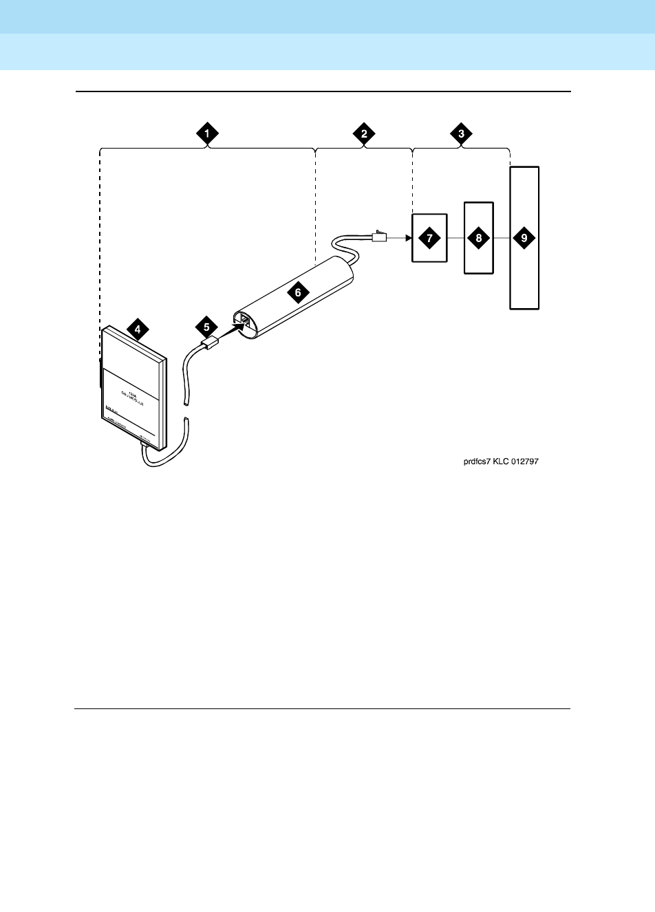
DEFINITY Enterprise Communications Server Release 6
Maintenance for R6r Volumes 1 & 2
555-230-126 Issue 2
January 1998
Additional Maintenance Procedures
Page 6-16DS1 CPE Loopback Jack (T1 Only)
6
Figure 6-1. Network Interface at Smart Jack
Figure Notes:
1. Span Section 1
2. Span Section 2
3. Span Section 3
4. 120A2 (or later) Integrated
Channel Service Unit (ICSU)
5. RJ-48 to Network Interface (Up to 1000
Feet) (305 m)
6. Loopback Jack
7. Network Interface Smart Jack
8. Interface Termination or Fiber MUX
9. Central Office
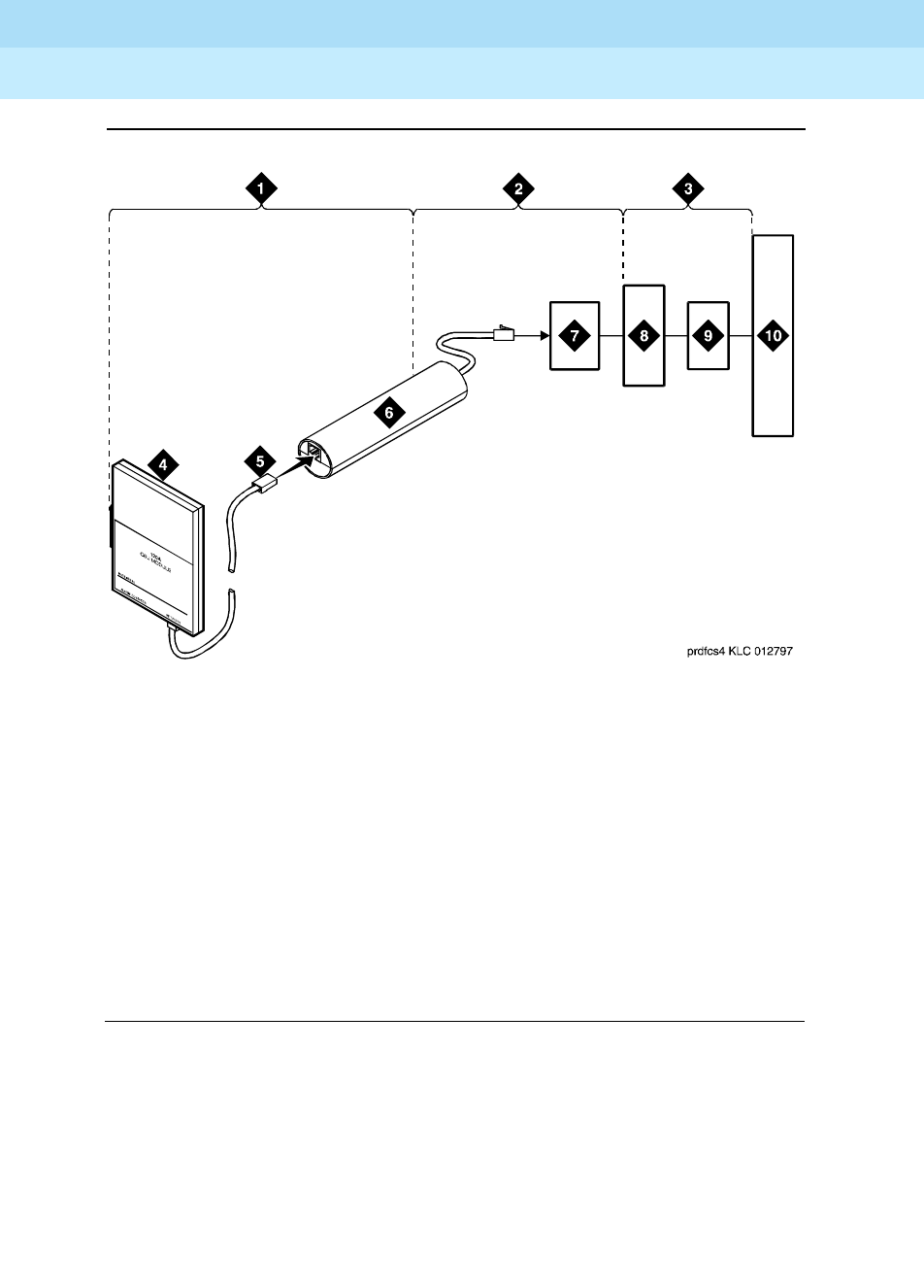
DEFINITY Enterprise Communications Server Release 6
Maintenance for R6r Volumes 1 & 2
555-230-126 Issue 2
January 1998
Additional Maintenance Procedures
Page 6-17DS1 CPE Loopback Jack (T1 Only)
6
Figure 6-2. Network Interface at Extended Demarcation Point (Smart Jack
Inaccessible)
Figure Notes:
1. Span Section 1
2. Span Section 2
3. Span Section 3
4. 120A2 (or later) Integrated
Channel Service Unit (ICSU)
5. RJ-48 to Network Interface
(Up to 1000 Feet) (305 m)
6. Loopback Jack
7. “Dumb” Block (Extended Demarcation)
8. Network Interface Smart Jack
9. Interface Termination or Fiber MUX
10. Central Office
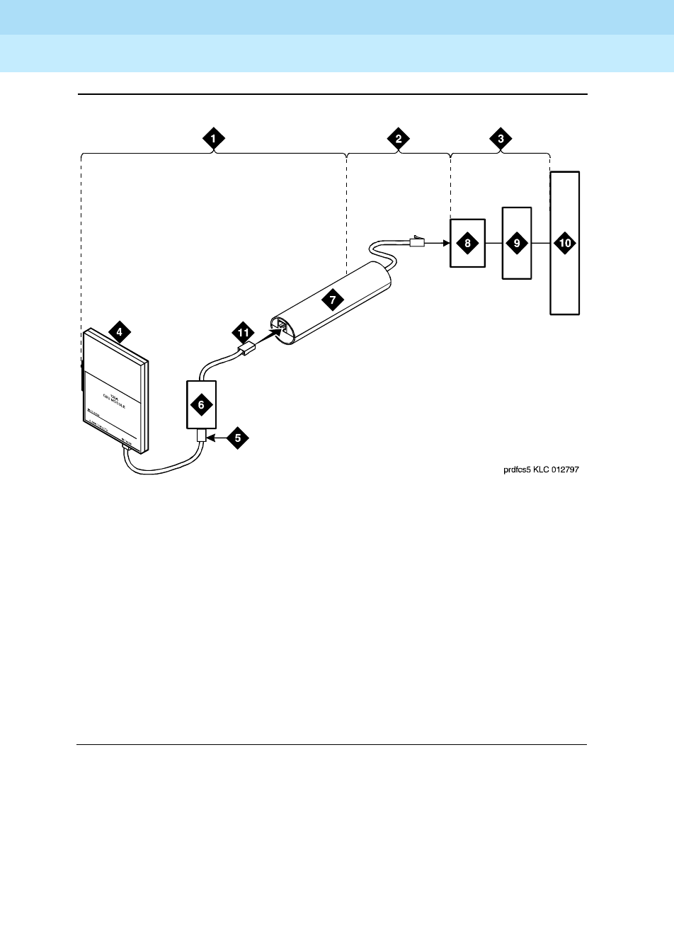
DEFINITY Enterprise Communications Server Release 6
Maintenance for R6r Volumes 1 & 2
555-230-126 Issue 2
January 1998
Additional Maintenance Procedures
Page 6-18DS1 CPE Loopback Jack (T1 Only)
6
Figure 6-3. Network Interface at Extended Demarcation Point (Smart Jack
Accessible)
Figure Notes:
1. Span Section 1
2. Span Section 2
3. Span Section 3
4. 120A2 (or later) Integrated
Channel Service Unit (ICSU)
5. RJ-48 to Network Interface
(Up to 1000 Feet) (305 m)
6. “Dumb” Block (Extended Demarcation)
7. Loopback Jack
8. Network Interface Smart Jack
9. Interface Termination or Fiber MUX
10. Central Office
11. “Dumb” Block to Smart Jack RJ-48
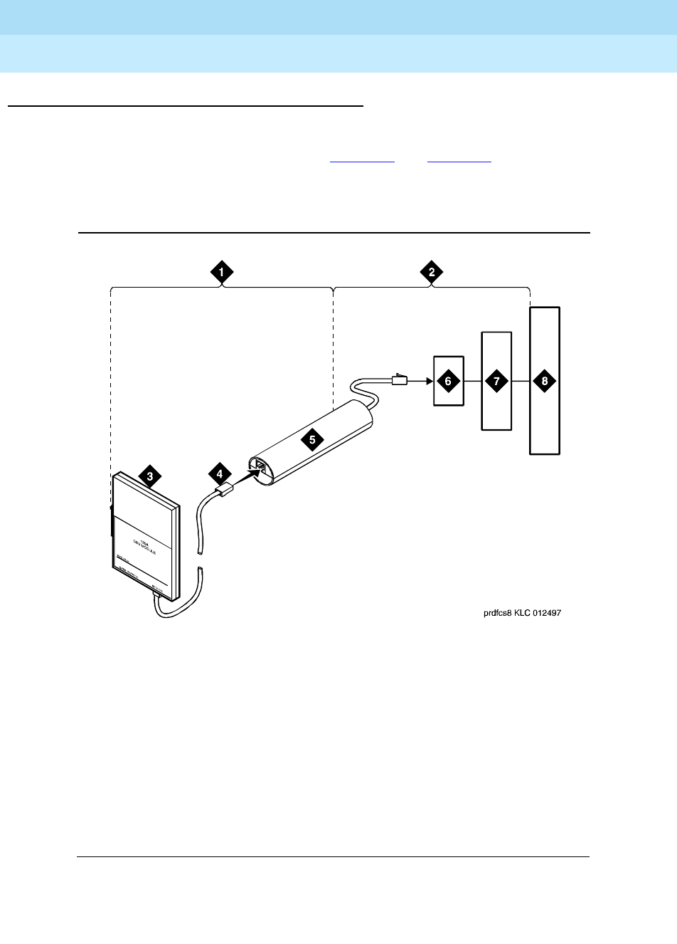
DEFINITY Enterprise Communications Server Release 6
Maintenance for R6r Volumes 1 & 2
555-230-126 Issue 2
January 1998
Additional Maintenance Procedures
Page 6-19DS1 CPE Loopback Jack (T1 Only)
6
Configurations Without a Smart Jack
When the loopback jack is added to a span that does not contain a Smart Jack,
the span is divided into 2 sections. See Figure 6-4 and Figure 6-5.
1. ICSU to the loopback jack.
2. Loopback jack to the Central Office (CO).
Figure 6-4. Network Interface at “Dumb” Block
Figure Notes:
1. Span Section 1
2. Span Section 2
3. 120A2 (or later) Integrated
Channel Service Unit (ICSU)
4. RJ-48 to Network Interface
(Up to 1000 Feet) (305 m)
5. Loopback Jack
6. “Dumb” Block (Demarcation Point)
7. Interface Termination or Fiber MUX
8. Central Office
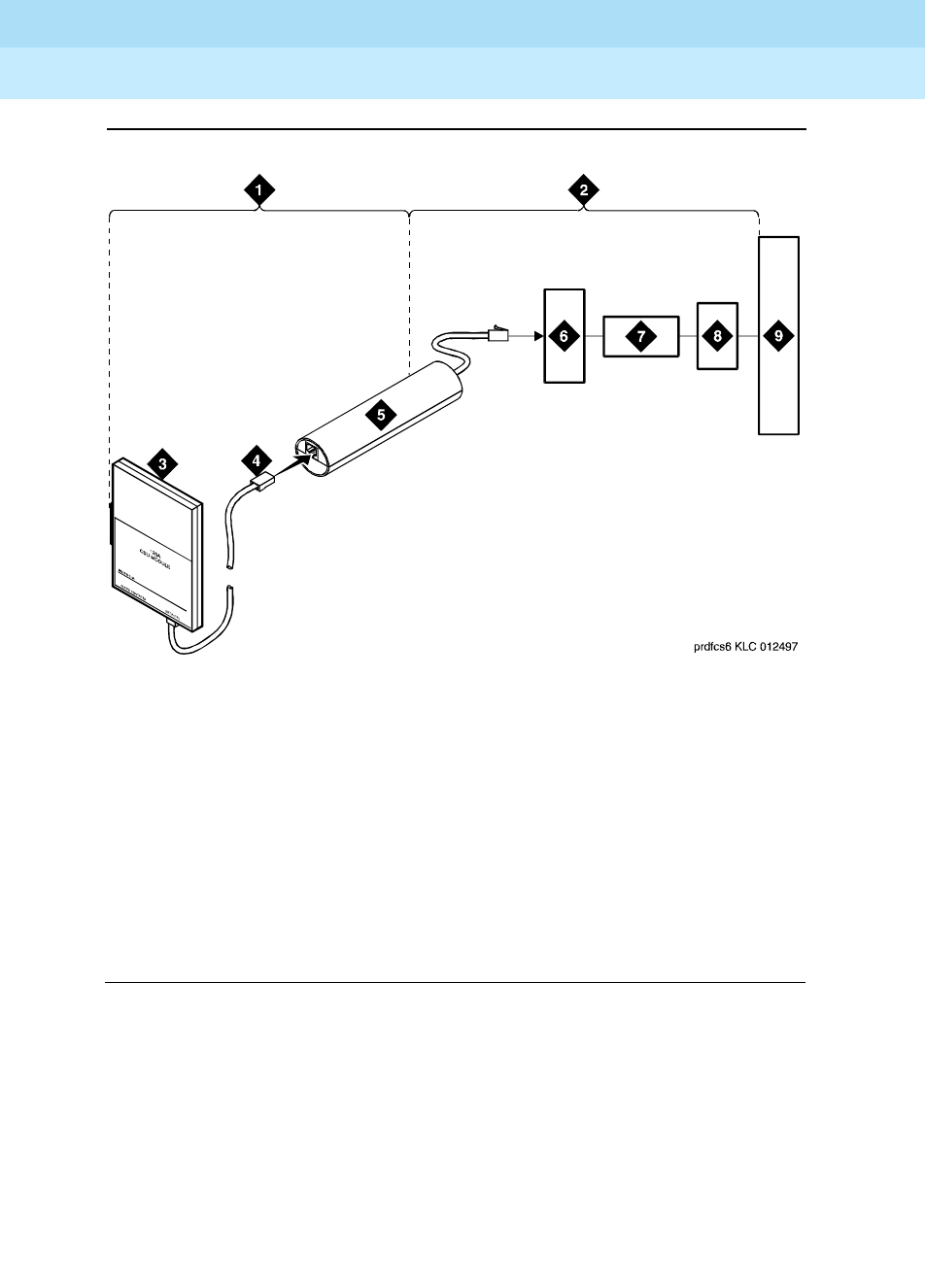
DEFINITY Enterprise Communications Server Release 6
Maintenance for R6r Volumes 1 & 2
555-230-126 Issue 2
January 1998
Additional Maintenance Procedures
Page 6-20DS1 CPE Loopback Jack (T1 Only)
6
Figure 6-5. Network Interface at “Dumb” Block with Repeater Line to Fiber
MUX
Section 2 includes the short cable from the loopback jack to the “dumb” block
demarcation point (part of the loopback jack). This is the only portion o f section
2 that is part of customer premises wiring but is not covered in the loopback
jack’s loopback path.
Figure Notes:
1. Span Section 1
2. Span Section 2
3. 120A2 (or later) Integrated
Channel Service Unit (ICSU)
4. RJ-48 to Network Interface
(Up to 1000 Feet) (305 m)
5. Loopback Jack
6. “Dumb” Block (Demarcation Point)
7. Repeater
8. Fiber MUX
9. Central Office

DEFINITY Enterprise Communications Server Release 6
Maintenance for R6r Volumes 1 & 2
555-230-126 Issue 2
January 1998
Additional Maintenance Procedures
Page 6-21DS1 CPE Loopback Jack (T1 Only)
6
A problem can exist in 1 or both of the 2 sections. The field technician is
responsible for finding and correcting problems in section 1 and the loopback
cable portion of section 2. The DS1 service provider is responsible for finding
and correcting problems in the majority of section 2. Testing is divided into 2
steps.
1. Test customer premises wiring (section 1 in Figure 6-4) from the ICSU to
the loopback jack as described in the “DS1 Span Test” section.
2. Test the loopback jack-to-”dumb” block and ”dumb” block-to-CO wiring
(section 2 in Figure 6-4). This can be done using a loopback that
“overlaps” the section of the span. Any of the following loopbacks can do
this:
a. The local ICSUs line loopback, which is typically activated, tested,
and then deactivated by the DS1 service provider at the CO end.
b. The local DS1 interface’s payload loopback, activated and tested
by the DS1 service provider at the CO end.
c. The far-end ICSU’s line loopback. This test is activated at the
management terminal by entering test ds1-loop <location>
far-csu-loopback-test-begin. The test is terminated by entering
test ds1-loop <location> end-loopback/span-test. Bit error
counts are examined as described in the “DS1 Span Test” section.
This test only isolates problems to section 2 wiring if there are no
problems in the wiring between the far-end CO and the far-end
ICSU. Coordinate this test with the DS1 service provider.
If any of the above tests (a, b, or c) fail, a problem is indicated in
section 2. This could mean bad loopback jack -to-”dumb” block
cabling, but is more likely to indicate a problem somewhere
between the “dumb” block and the CO. This is the responsibility of
the DS1 service provider. If the DS1 Span Test confirms that there
are no problems in section 1, the technician should proceed as
follows to avoid unnecessary dispatch.
■Identify and contact the DS1 service provider
■Inform the DS1 provider that loopback tests of the CPE
wiring to the “dumb” block (section 1) showed no problems
■If the far-end ICSU line loopback test failed, inform the DS1
provider
■Request that the DS1 provider perform a loopback test of
their portion of the section 2 wiring by sending someone out
to loop section 2 back to the CO at the “dumb” block.
If this test fails, the problem is in the service provider’s
wiring.
If the test passes, the problem is in the cable between the
loopback jack and the “dumb” block. Replace the loopback
jack.

DEFINITY Enterprise Communications Server Release 6
Maintenance for R6r Volumes 1 & 2
555-230-126 Issue 2
January 1998
Additional Maintenance Procedures
Page 6-22DS1 CPE Loopback Jack (T1 Only)
6
Configurations Using Fiber Multiplexers
Use the loopback jack when customer premises DS1 wiring connects to an
on-site fiber multiplexer (MUX) and allows wiring to the network interface point on
the MUX to be remotely tested. This requires that ICSUs be used on DS1 wiring
to the MUX.
Fiber MUXes can take the place of Interface termination feeds as shown in Figure
6-1 , Figure 6-2, Figure 6-3, and Figure 6-4. Test these spans using the same
procedures as metallic spans. Note the following points:
1. Fiber MUXes may have loopback capabilities that can be activated by the
service provider from the CO end. These may loop the signal back to the
CO or back to the DS1 board. If the MUX provides the equivalent of a line
loopback on the “problem” DS1 facility, this may be activated following a
successful loopback jack test and used to isolate problems to the wiring
between the loopback jack and the MUX.
2. Be aware that there are installations that use repeatered metallic lines
between the MUX and the “dumb” block. These lines require DC power for
the repeaters and this DC power is present at the “dumb” block interface
to the CPE equipment.
A loopback jack is required in this configuration to
properly isolate and terminate the DC power
.
To check for the presence of DC, make the following 4 measurements at the
network interface jack:
1. From Transmit Tip (T, Pin 5) to Receive Tip (T1, Pin 2)
2. From Transmit Ring (R, Pin 4) to Receive Ring (R1, Pin 4)
3. From Transmit Tip (T, Pin 5) to Transmit Ring (R, Pin 4)
4. From Receive Tip (T1, Pin 2) to Receive Ring (R1, Pin 4)
All measurements should read 0 (zero) volts DC. For pin numbers and pin
designations, refer to
Integrated Channel Service Unit (ICSU) Installation and
Operation
, 555-230-193.
Operating Charasteristics
If a TN464F or TN767E and a 120A2 were installed in a system running pre-G3V3
software and the software is later upgraded to G3V3 Release 3 or later, reseat
the DS1 circuit pack so that the ICSU administration fields will appear on the DS1
administration form.
DEFINITY Enterprise Communications Server Release 6
Maintenance for R6r Volumes 1 & 2
555-230-126 Issue 2
January 1998
Additional Maintenance Procedures
Page 6-23Facility Test Calls
6
Facility Test Calls
The Facility Test Calls feature allows you to use a voice terminal to make test
calls to specific trunks, time slots, tones, and tone receivers within the system.
The test call verifies that the accessed component is functioning properly. To use
this feature, it must be enabled on the Class of Restriction form, and you must
know the Facility Test Call Access Code. The code can be retrieved by entering
display feature-access-codes. It appears on page one of the screen output.
NOTE:
For the ISDN-PRI Test Call feature see ‘‘Troubleshooting ISDN-PRI Test Call
Problems’’ in Chapter 5, ‘‘Responding to Alarms and Errors’’.
NOTE:
The following test call descriptions are for voice terminal users:
Trunk Test Call
The trunk test call accesses specific Tie or CO trunks, including DS1 trunks. If the
trunk is busied out by maintenance, it will be temporarily released for the test call
and returned to busyout afterwards. Before making the test call, use list
configuration to determine the location of the trunk ports that you which to test.
DID trunks cannot be accessed.
To place a trunk test call:
1. Dial the FAC described above and listen for dial tone.
2. Dial the 7-digit port location UUCSSpp:
UU= Cabinet number (01 for PPN, 02 -- 44 for EPNs)
C = Carrier number (A=1, B=2, C=3, D=4, E=5)
SS = Slot number (01--20)
pp = Port circuit number (01--24)
The channels on a DS1 trunk are addressed by using the channel number
for the port number.
3. Listen for one of the following tones:
Dial tone or Silence The trunk is connected. Go to step 4.
Busy Tone The trunk is either busy processing a call or
is out of service. Check status trunk.

DEFINITY Enterprise Communications Server Release 6
Maintenance for R6r Volumes 1 & 2
555-230-126 Issue 2
January 1998
Additional Maintenance Procedures
Page 6-24Facility Test Calls
6
4. Place a call. If the call does not go through (no ringing is heard) check to
see if the circuit has been removed or if the trunk is a rotary trunk.
The dial tone heard is coming from the far-end. If the far end has been
disabled, you will not hear dial tone. However, depending on far-end
administration, you may still be able to dial digits. All digits dialed after the
port number are transmitted using end-to-end DTMF signaling. If the trunk
being tested is a rotary trunk, it is not possible to break dial tone.
DSO Loop-Around Test Call
The DS0 Loop Around feature provides a loop around connection for incoming
Non-ISDN DS1 trunk data calls. This feature is similar to the far end loop around
connection provided for the ISDN Test Call feature. This DS0 loop around is
provided primarily to allow a network service provider to perform facility testing at
the DS0 level before video teleconferencing terminals are installed at the PBX.
The feature is activated on a call-by-call basis by dialing a test call extension
specified on the second page of the System Parameters Maintenance form. No
special hardware is required. When the test call extension is received by the
PBX, a non inverting 64 kbps connection is set up on the PBX’s Time Division
Multiplexed bus. More than one loop around call can be active at the same time.
For calls routed over the public network using the ACCUNET Switched Digital
Service (SDS) or Software Defined Data Network (SDDN), the data transmission
rate is 56 Kbps since robbed bit signaling is used. For calls established over a
private network using common channel signaling, the full 64 kbps data rate is
available.
When the incoming trunk group is used only for data calls (SDS), the
Communications Type on the associated Trunk Group form should be set to
“data”. When the incoming trunk group is used for robbed bit alternate voice
and/or data (SDN/SDDN), the Communications Type on the Trunk Group form
should be set to “rbavd” (robbed bit alternate voice data). For private network
trunks using common channel signaling, the Communications Type on the
associated Trunk Group form can be set to “avd”.
Reorder tone The trunk requested is in a different port
network from your station, and inter-PN
resources are not available to access it.
Intercept Tone The port addressed is not a trunk, or it is a
DID trunk, or the trunk is not administered.
Confirmation Tone The port is a tone receiver. See the ‘‘DTMR
Test Call’’ section.

DEFINITY Enterprise Communications Server Release 6
Maintenance for R6r Volumes 1 & 2
555-230-126 Issue 2
January 1998
Additional Maintenance Procedures
Page 6-25Facility Test Calls
6
DTMR Test Call
This call accesses and tests the dual tone multifrequency receivers (DTMR-PTs)
located on TN420 and TN748 Tone Detector circuit packs. These tone receivers
are also known as touch tone receivers (TTRs). Before making the test call, use
list configuration to determine the location of the TN420 or TN748 that you
which to test.
To place a tone receiver test call:
1. Dial the FAC described in the introduction to this section and listen for dial
tone.
2. Dial the seven-digit port location UUCSSpp of one of the four DTMR ports
located on a Tone Detector circuit pack:
C = Carrier number (A=1, B=2, C=3, D=4, E=5)
SS = Slot number (00-20)
pp = Port circuit number (DTMR ports are numbered 01, 02, 05, and 06.
3. Listen for one of the following tones:
4. Dial the sequence 1234567890*#.
If the sequence is entered and received correctly, dial tone is returned
and another test call can be made. If the test fails, intercept tone is
returned. A failure may indicate a faulty DTMR port or circuit pack, a faulty
voice terminal, or an error in the entry of the sequence.
5. To test another DTMR, repeat steps 2 through 4.
6. To terminate the test call, hang up the station set used for testing.
TDM Bus Time Slot Test Call
The time slot test call connects the voice terminal to a specified time slot on the A
or B TDM Bus of a specified port network. To connect to any out-of-service time
slots, refer to the ‘‘Out-of-Service Time Slot Test Call’’ section.
To test a specific time slot on the TDM bus of a specific port network:
1. Dial the FAC described in the introduction to this section and listen for dial
tone.
Confirmation tone The DTMR is connected. Go to step 4.
Intercept tone The port entered is not a TTR, (if a trunk, see
above), or the board is not inserted.
Reorder tone The DTMR is in use, (call processing), the
board is busied out, or inter-PN resources are
unavailable for the call.
Dial tone The port is a trunk. See the preceding section.

DEFINITY Enterprise Communications Server Release 6
Maintenance for R6r Volumes 1 & 2
555-230-126 Issue 2
January 1998
Additional Maintenance Procedures
Page 6-26Facility Test Calls
6
2. Dial the 2-digit port network number followed by # and the 3-digit time slot
number listed in the following table.
3. Listen for one of the following tones:
TDM Bus Time Slots
When you address a tone-carrying time slot on the TDM bus (A or B) that is
currently carrying tones, you will be connected to that time slot and will hear the
tone.
Time slots 005-021 and 261-277 are reserved to carry the system’s dedicated
tones. Time slots 000-004 and 256-260 carry control information and are not
addressable. Time slots 254 and 510 are not addressable due to a hardware
constraint. At any given time, only one of the TDM busses (A or B) carries the
dedicated tones, with B being the default. Entering status port-network will
display which TDM bus is currently carrying the dedicated tones. The
corresponding time slots on the other bus are normally inactive and are used for
call service only as a last resort when all other non-control channel time slots on
both busses are busy. Bus A’s tone time slots are numbered 005-021; bus B’s
tone time slots are numbered 261-277.
Reorder tone The time slot is in use, the time slot is not
addressable, or inter-PN resources are not
available to make the call.
Confirmation tone The time slot is idle or out-of-service. The time
slot may be on the TDM bus (A or B) that is not
currently carrying tones, or it may be busied
out. The call is connected to the time slot so
that any noise may be heard.
System tone The time slot is carrying a system tone as listed
in the following table.

DEFINITY Enterprise Communications Server Release 6
Maintenance for R6r Volumes 1 & 2
555-230-126 Issue 2
January 1998
Additional Maintenance Procedures
Page 6-27Facility Test Calls
6
Table 6-4. TDM Bus Time Slot Numbers
TDM Bus A
time slot TDM Bus B
time slot Tone Heard
000 256 Reorder
001 257 Reorder
002 258 Reorder
003 259 Reorder
004 260 Reorder
005 261 Touch Tone 1 - 697Hz
006 262 Touch Tone 2 - 770 Hz
007 263 Touch Tone 3 - 852Hz
008 264 Touch Tone 4 - 941 Hz
009 265 Touch Tone 5 - 1209 Hz
010 266 Touch Tone 6 - 1336Hz
011 267 Touch Tone 7 - 1447 Hz
012 268 Touch Tone 8 - 1633 Hz
013 269 Dial Tone
014 270 Reorder Tone
015 271 Alert Tone
016 272 Busy Tone
017 273 Ringback Tone
018 274 Special Ringback Tone
019 275 2225 Hz Tone
020 276 Music
021 277 Tone on Hold
022-253 278-509 Confirmation (used for calls)
254 510 Reorder
255 511 Confirmation

DEFINITY Enterprise Communications Server Release 6
Maintenance for R6r Volumes 1 & 2
555-230-126 Issue 2
January 1998
Additional Maintenance Procedures
Page 6-28Facility Test Calls
6
Out-of-Service Time Slot Test Call
This call can be used to determine if there are any out-of-service time slots on the
TDM bus of a specified port network. If there are, you will be connected to one.
By listening to noise on the time slot and selectively removing circuit packs, you
may be able to isolate the source of interference.
To place the call:
1. Dial the FAC described above and listen for dial tone.
2. Dial the port network number followed by **** and listen for one of the
following tones:
3. Repeated test calls will alternate between out-of-service time slots on TDM
bus A and TDM bus B.
System Tone Test Call
This test connects the voice terminal to a specific system tone.
To place the call:
1. Dial the FAC described above.
2. Dial the port network number followed by * and the two-digit tone
identification number from the following table.
3. Listen for one of the following tones:
NOTE:
For a definition of Call Progress Tones see
DEFINITY
Communications System Generic 3 System Descriptions and
Specifications, 555-230-206,
Chapter 11.
Reorder tone There are no out-of-service time slots on the
specified port network.
Confirmation tone Connection is made to an out-of-service time
slot.
Intercept tone The number entered is not a valid tone number.
Reorder tone Inter-PN resources are not available.
System tone The specified tone will be heard if it is functioning.

DEFINITY Enterprise Communications Server Release 6
Maintenance for R6r Volumes 1 & 2
555-230-126 Issue 2
January 1998
Additional Maintenance Procedures
Page 6-29Facility Test Calls
6
Table 6-5. System Tone Identification Numbers
Number Description
00 Null tone
01 Dial tone
02 Reorder tone
03 Alert tone
04 Busy tone
05 Recall dial tone
06 Confirmation tone
07 Internal call waiting tone
08 Ringback tone
09 Special ringback tone
10 Dedicated ringback tone
11 Dedicated special ringback tone
12 Touch tone 1
13 Touch tone 2
14 Touch tone 3
15 Touch tone 4
16 Touch tone 5
17 Touch tone 6
18 Touch tone 7
19 Touch tone 8
20 Chime
21 350 Hz
22 440 Hz
23 480 Hz
24 620 Hz
25 2025 Hz
26 2225 Hz
27 Counter
Continued on next page

DEFINITY Enterprise Communications Server Release 6
Maintenance for R6r Volumes 1 & 2
555-230-126 Issue 2
January 1998
Additional Maintenance Procedures
Page 6-30Facility Test Calls
6
28 External call waiting
29 Priority call waiting
30 Busy verification
31 Executive override/intrusion tone
32 Incoming call identification
33 Dial zero
34 Attendant transfer
35 Test calls
36 Recall on don’t answer
37 Audible ring
38 Camp-on recall
39 Camp-on confirmation
40 Hold recall
41 Hold confirmation
42 Zip tone
43 2804 Hz
44 1004 Hz (-16db)
45 1004 Hz (0 db)
46 404 Hz
47 Transmission test sequence 105
48 Redirect tone
49 Voice signaling tone
50 Digital milliwatt
51 440 Hz + 480 Hz
52 Music
53 Transmission test sequence 100
54 Transmission test sequence 102
55 Laboratory test tone 1
Table 6-5. System Tone Identification Numbers — Continued
Number Description
Continued on next page

DEFINITY Enterprise Communications Server Release 6
Maintenance for R6r Volumes 1 & 2
555-230-126 Issue 2
January 1998
Additional Maintenance Procedures
Page 6-31Preventive Maintenance
6
Preventive Maintenance
The following preventive maintenance procedures should be followed when
visiting customer sites. The chart that follows shows a sample of the Preventive
Maintenance Log. Whenever you complete a preventive maintenance procedure,
be sure to fill in the information on the log form before you leave the customer’s
premises.
Air Filters
Air filters should be inspected annually. If a filter is dirty or clogged, first tap it on
the ground. If the filter is still dirty or clogged, then wash it with warm water and a
mild detergent. A vacuum cleaner can be used if one is available. If there is no
facility for washing or vacuuming the air filter, then replace the filter. Refer to
‘‘CABINET (Cabinet Sensors)’’ maintenance documentation for information on air
filters and fans.
56 Laboratory test tone 2
57 Disable echo supervision dial tone
58 7 seconds of answer tone
59 4 seconds of answer tone
60 Restore music (or silence)
61 Warning tone
62 Forced music tone
63 Zip tone (first of 2 sent)
64 Incoming call ID (first of 2 sent)
65 Tone on hold
66 CO dial tone
67 Repetitive confirmation tone
68 Conference/bridging tone
Table 6-5. System Tone Identification Numbers — Continued
Number Description
Continued on next page

DEFINITY Enterprise Communications Server Release 6
Maintenance for R6r Volumes 1 & 2
555-230-126 Issue 2
January 1998
Additional Maintenance Procedures
Page 6-32Preventive Maintenance
6
Tape Drive
The head and capstan on the tape drive of the SPE should be cleaned every
three months. Abrasive particles from worn tape and environmental debris can
cause loss of information and services. The procedure for cleaning the tape drive
is described in the section on TAPE in Chapter 9, ‘‘ABRI-PORT (ASAI ISDN-BRI
Port)’’.
Batteries
The backup batteries in the power distribution unit in the bottom of the cabinet
should be replaced every four years or whenever a POWER alarm that indicts the
condition of the batteries is logged. Systems with an uninterruptible power
supply (UPS) may not be equipped with backup batteries.
DEFINITY Enterprise Communications Server Release 6
Maintenance for R6r Volumes 1 & 2
555-230-126 Issue 2
January 1998
Additional Maintenance Procedures
Page 6-33Preventive Maintenance
6
Date equipment installed: ________________________
Post this form with the equipment.
1. Inspect annually; clean or replace
2. Clean every three months
3. Replace every 4 years
PREVENTIVE MAINTENANCE LOG
DEFINITY ECS
Air Filters1Scheduled
Date Date
Completed Completed
By Scheduled
Date Date
Completed Completed
By
Single-carrier cabinet
Multi-carrier cabinet
Tape Head/Capstan2Scheduled
Date Date
Completed Completed
By Scheduled
Date Date
Completed Completed
By
Battery Packs3Scheduled
Date Date
Completed Completed
By Scheduled
Date Date
Completed Completed
By
Single-carrier cabinet
Multi-carrier cabinet

DEFINITY Enterprise Communications Server Release 6
Maintenance for R6r Volumes 1 & 2
555-230-126 Issue 2
January 1998
Additional Maintenance Procedures
Page 6-34Analog Tie Trunk Back-to-Back Testing
6
Analog Tie Trunk Back-to-Back
Testing
The TN760 circuit pack can be configured for back-to-back testing (also known
as connectivity testing) by making translation and cross-connect changes. This
testing configuration allows for the connection of Tie Trunks back-to-back in the
same switch to verify the operation of Tie Trunk ports. The tests can be
performed in either the E&M or simplex modes. (Refer to
DEFINITY
Communications System Generic 1 and Generic 3 Installation and Test,
555-230-104, for instructions on how to make connections at the cross-connect
field).
E&M Mode Test Procedure
1. At the administration terminal, enter list configuration trunks to
determine which ports are assigned on the Tie Trunk circuit pack.
2. Enter display dialplan command to determine the Trunk Access Code
(TAC) format.
3. Enter display port xxx for all ports defined in Step 1. This displays the
trunk groups of which the ports are members. See Chapter 5,
‘‘Responding to Alarms and Errors’’ for details of how to remove and
replace port circuit packs.
4. Insert the circuit pack back into the slot.
5. Enter display trunk xxx p for each trunk group identified in Step 3. This
command displays the specified trunk group on the administration
terminal screen and prints a hard copy on the printer. Save this data for
later use.
6. Remove all members defined by these ports from the trunk group(s) using
the change trunk xxx command.
7. Remove the Tie Trunk circuit pack from the carrier slot.
8. Set the dip (option) switches for each of the two ports to be tested on the
Tie Trunk circuit pack to “E&M mode” and “unprotected.”
9. Enter add trunk n to add a new (test) trunk group. Then enter information
for the following fields:
Group Type tie
TAC Use trunk access code obtained from dial
plan
Trunk Type (in/out) wink/wink

DEFINITY Enterprise Communications Server Release 6
Maintenance for R6r Volumes 1 & 2
555-230-126 Issue 2
January 1998
Additional Maintenance Procedures
Page 6-35Analog Tie Trunk Back-to-Back Testing
6
10. Locate the Tie Trunk port terminal connections at the cross-connect field.
Consult the appropriate table below for either 110-type or 66-type
hardware.
11. At the cross-connect field, disconnect outside trunk facilities from the Tie
Trunk ports and mark the disconnected wires for reconnecting the Tie
Trunk ports to their normal configuration later. The D Impact Tool
(AT-8762) is required to perform this step.
12. Use jumper wires (DT 24M-Y/BL/R/G and DT 24P-W/BRN) and the D
Impact Tool to connect wiring between the two ports assigned in Step 9 at
the cross-connect field. For example, if the two ports on the Analog Tie
Trunk circuit pack are port 1 and 2, connect the wirings as shown below:
13. Check all wirings to verify good connections between the two test ports.
14. Place a call from one voice terminal to another voice terminal using the Tie
Trunk ports assigned. Dial TAC and extension. For example, if TAC of Tie
Trunk group is 110 and station number is 5012, then dial 110 5012. If the
call cannot be made, either one of these ports could be defective. There
are four ports on the TN760. Try different combinations to determine
defective ports.
15. If there is a defective port on the circuit pack, try to switch to an unused
port. If all ports are normally used, then replace the circuit pack.
16. Disconnect the jumpers between two ports. Then use administration
terminal and trunk printouts to restore all trunk group changes to normal
values.
Port Assign two of the ports from the tie trunk.
Mode E&M for both ports
Type Specify one port as t1 standard and other
port as t1 compatible.
Port 1
(t1 stan)
(E & M)
Port 2
(t1 comp)
(E & M)
T1 connected to T12
R1 “R12
T11 “ T2
R11 “ R2
E1 “ M2
M1 “ E2

DEFINITY Enterprise Communications Server Release 6
Maintenance for R6r Volumes 1 & 2
555-230-126 Issue 2
January 1998
Additional Maintenance Procedures
Page 6-36Analog Tie Trunk Back-to-Back Testing
6
Table 6-6. Carrier Lead Appearances MDF
110 Connecting
Block Terminals CO Trunk TN747 Tie Trunk TN760
1T1T1
2R1R1
3 T11
4R11
5E1
6M1
7T2T2
8R2R2
9 T12
10 R12
11 E2
12 M2
13 T3 T3
14 R3 R3
15 T13
16 R13
17 E3
18 M3
19 T4 T4
20 R4 R4
21 T14
22 R14
23 E4
24 M4
25 T5
26 R5
27
28
Continued on next page

DEFINITY Enterprise Communications Server Release 6
Maintenance for R6r Volumes 1 & 2
555-230-126 Issue 2
January 1998
Additional Maintenance Procedures
Page 6-37Analog Tie Trunk Back-to-Back Testing
6
Simplex Mode Test Procedure
1. Repeat Steps 1 through 7 of the E&M Mode Test Procedure.
2. Set the dip (option) switches for each of the two ports to be tested on the
Tie Trunk circuit pack to simplex mode.
29
30
31 T6
32 R6
32
33
34
36
37 T7
38 R7
39
40
41
42
43 T8
44 R8
45
46
47
48
49
50
Table 6-6. Carrier Lead Appearances MDF — Continued
110 Connecting
Block Terminals CO Trunk TN747 Tie Trunk TN760
Continued on next page

DEFINITY Enterprise Communications Server Release 6
Maintenance for R6r Volumes 1 & 2
555-230-126 Issue 2
January 1998
Additional Maintenance Procedures
Page 6-38Terminating Trunk Transmission Testing
6
3. Enter add trunk n to add a new (test) trunk group. Then enter information
for the following fields:
4. Locate the Tie Trunk port terminal connections at the cross-connect field.
Consult the appropriate table above for either 110-type or 66-type
hardware.
5. At the cross-connect field, disconnect outside trunk facilities from the
Analog Tie Trunk ports and mark the disconnected wires for later when the
Tie Trunk ports are placed back into normal operation. The D Impact Tool
(AT-8762) is required to perform this step.
6. Use jumper wires (DT 24M-Y/BL/R/G) and the D Impact Tool to connect
wiring between the two ports assigned in Step 4 at the cross-connect field.
For example, if the two ports on the Analog Tie Trunk circuit pack are ports
1 and 2, connect the wirings as shown below:
7. Repeat Steps 13 through 16 of the E & M Mode Test Procedure.
Terminating Trunk Transmission
Testing
The Terminating Trunk Transmission (TTT) (non-interactive) feature provides for
extension number access to three tone sequences that can be used for trunk
transmission testing from the far end of the trunks.
Group Type tie
TAC Use trunk access code obtained from dial
plan.
Trunk Type (in/out) wink/wink
Port Assign two of the ports from the tie trunk.
Mode simplex
Type type 5
Port 1 connected to Port 2
(type 5) (type 5)
(simplex) (simplex)
T1 connected to T12
R1 “R12
T11 “ T2
R11 “ R2

DEFINITY Enterprise Communications Server Release 6
Maintenance for R6r Volumes 1 & 2
555-230-126 Issue 2
January 1998
Additional Maintenance Procedures
Page 6-39Removing and Restoring Power
6
The three test types should have extension numbers assigned on the
Maintenance-Related System Parameters Form.
Test Type 100:___ Test Type 102:___ Test Type 105:___
Test Type 100 provides:
■5.5 seconds of 1004 Hz tone at 0dB
■Quiet until disconnect; disconnect is forced after one minute
Test Type 102 provides:
■9 seconds of 1004 Hz tone at 0dB
■1 second of quiet
■This cycle is repeated until disconnect; disconnect is forced after 24
hours.
Test Type 105 provides:
■9 seconds of 1004 Hz at -16dB
■1 second of quiet
■9 seconds of 404 Hz at -16dB
■1 second of quiet
■9 seconds of 2804 Hz at -16dB
■30 seconds of quiet
■1/2 second of Test Progress Tone (2225 Hz)
■Approximately five seconds of quiet
■Forced disconnect
Removing and Restoring Power
!CAUTION:
Error Log information is lost when the PPN cabinet is powered down. If this
information is to be saved, enter the reset system 4 command. The
command will take several minutes to complete, and will result in saving of
the Error Log to the MSS.
!CAUTION:
Before powering down a cabinet or carrier that contains DEFINITY AUDIX
circuit packs (TN566 and TN2169), you must first power down the AUDIX
unit to avoid damage to the AUDIX software Instructions for powering down
this unit appear on the circuit pack and in DEFINITY AUDIX documentation.

DEFINITY Enterprise Communications Server Release 6
Maintenance for R6r Volumes 1 & 2
555-230-126 Issue 2
January 1998
Additional Maintenance Procedures
Page 6-40Automatic Transmission Measurement System (ATMS)
6
!CAUTION:
If there is an alarm or problem suspected on the Tape or Disk Circuit packs
do not save translations or announcements to the affected device. If there is
an alarm or problem suspected with the Host Adapter circuit, do not save
data to either MSS device. Saving data under these circumstances can
destroy good copies of the file. If necessary, obtain a spare tape cartridge
to save data.
To remove power to the cabinet:
1. If the cabinet is the PPN, execute save translation and save
announcement unless a tape drive problem is active.
2. Set the Emergency Transfer switch(es) in the affected cabinet to ON. In
the PPN these are located on the SYSAM circuit pack(s). Set both in a
system with duplicated SPE. In an EPN the switch is located on the EPN
Maintenance circuit pack. This locks the system in the emergency transfer
mode until the trouble is cleared.
3. Depending on which type of cabinet you are powering down, do one of
the following:
■In an AC-Powered multi-carrier cabinet, set the circuit breaker to
OFF at the Power Distribution Unit.
■In a DC-Powered multi-carrier cabinet, turn off the DC Power
supply.
■In an AC-Powered single-carrier cabinet stack, turn off the power in
each affected carrier individually. The ON/OFF switch is located at
the back of the carrier behind the WP-91153 Power Unit.
■In a DC-Powered single-carrier cabinet stack, turn off the power in
each affected carrier individually. The ON/OFF switch is located at
the back of the carrier behind the 676B Power Unit.
4. Power is restored by reversing the action taken above.
When restoring power to a PPN, the system will reboot. When restoring
power to an EPN, the EPN will under go a restart. This process is
described under EXP-PN in Chapter 9, ‘‘ABRI-PORT (ASAI ISDN-BRI
Port)’’.
If a powered down carrier contains a 676B Power Unit, the 676B must
have been powered down for at least 10 seconds for the unit to restart.
Automatic Transmission
Measurement System (ATMS)
The ATMS performs transmission tests on analog trunks to determine whether
they are performing satisfactorily. The switch automatically originates test calls
from an Originating Test Line (OTL), over the trunks to be tested, to a Terminating

DEFINITY Enterprise Communications Server Release 6
Maintenance for R6r Volumes 1 & 2
555-230-126 Issue 2
January 1998
Additional Maintenance Procedures
Page 6-41Automatic Transmission Measurement System (ATMS)
6
Trunk Line (TTL) on the switch at the far end of the trunk. Several different
measurements of noise and attenuation are made and compared to administered
thresholds. Test measurements can be viewed in the form of detailed or
summary reports which are described below.
ATMS test calls can be initiated on demand from the management terminal, or
automatically by ATMS Trunk Test Schedules. For complete details on how to set
up ATMS Trunk Test Schedules, see Chapter 4 of
Generic 3 V2 Implementation,
555-230-653
. Demand tests are run with the test analog-testcall command
which is described below.
Trunk groups can be administered to respond in different ways when a trunk fails
to perform within the administered thresholds. Alarms and errors may be logged,
and the trunk can be automatically busied out. When a trunk fails an
unacceptable threshold twice, the system will busy it out if the trunk group is so
administered and doing so will not exceed an administered limit (25, 50, 75, or
100% of the members in the group). This limit is not applied to later busyouts
caused by other factors. Trunks can be manually returned to service by
changing the thresholds and running a demand test or by using the release
command.
ATMS Requirements
ATMS tests utilize the analog port (port number 01) on a TN771
Maintenance/Test circuit pack. Each PPN contains one TN771. Depending on
system configuration, each EPN may also contain one TN771. Multiple TN771s
allow up to 3 concurrent test calls.
AMTS tests are designed to operate on the types of trunks found in the US, and
the TN771 analog port is Mu-law companding only. The tests will not be useful in
all environments.
For ATMS tests to run, several administrative prerequisites must be met. The
following list shows the field entries necessary to enable testing.

DEFINITY Enterprise Communications Server Release 6
Maintenance for R6r Volumes 1 & 2
555-230-126 Issue 2
January 1998
Additional Maintenance Procedures
Page 6-42Automatic Transmission Measurement System (ATMS)
6
Running ATMS Tests
(Test Analog-Testcall Command)
ATMS test calls can be originated either on demand or according to the ATMS
Test Schedule. Test schedules are set up with test-schedule commands which
are described in
DEFINITY Enterprise Communications Server Release 5.4
Administration and Feature Description
.
Demand test calls are originated by the test analog-testcall command. You can
specify testing of an entire trunk group, an individual trunk, or all trunks on a
single circuit pack. Trunks can be addressed by either group/member numbers
or circuit pack/port locations. The type of test call, the number of the testing line
on the far-end switch and various other parameters must be administered on the
trunk group form before the command can execute.
Table 6-7. ATMS Administration
Form Field Entry/Remarks
System-parameters
customer options ATMS? y (You must logoff/login in order for
changes on this form to take effect.)
Station Extension At least one TN711 analog port must
be assigned.
Port Number UUCSS01 where UUCSS is the
location of any TN771
Port Type COR 105TL
The number of a COR that has
testing enabled (see next form)
Class of Restriction Facility Access Trunk Test y
Trunk Group Maintenance Tests?
ATMS Thresholds (page 4
of form)
y
This page is used to specify
performance thresholds, the type
and access number of the far-end
TTL, and system response to test
failures.
Hunt Group (Optional, for incoming test calls) If
the system has several TN771s, you
can use this form to make up a hunt
group of TTLs so that one extension
can be used for the whole pool.
ATMS Trunk Test
Schedule (Optional) To set up a test schedule,
see Chapter 4 of
Generic 3 V2
Implementation,
555-230-653
.

DEFINITY Enterprise Communications Server Release 6
Maintenance for R6r Volumes 1 & 2
555-230-126 Issue 2
January 1998
Additional Maintenance Procedures
Page 6-43Automatic Transmission Measurement System (ATMS)
6
Normally you should invoke only the full or supervision tests. The other options
are provided mainly for use in setting up an ATMS schedule. Which tests are run
depend on the type of TTL at the far end to which the test call is made. The
following table shows which tests are run for each type of TTL. Command syntax
is as follows:
test analog-testcal
trunkgroup#/| member#| port UUCSSpp | boardUUCSS
[full | supervision | no-selftest | no-return-loss | no-st-or-rl]
[repeat#][schedule]
Input Parameters
Different TTLs have different measurement capabilities and you will need the
following information about specific TTL types. This table does not include the
self-test nor does it distinguish between measurements for different test tone
levels.
trunk
addresses You can specify a single trunk or several trunks by using
trunk, port, or board addresses. These parameters are
described in the introduction to Chapter 8, ‘‘Maintenance
Commands’’. If you enter a trunk group number without a
member number, all members of the group are tested.
full This executes the most comprehensive test call available
using the administered test set type.
“Full“is the default.
supervision This test takes about 10 seconds and simply confirms the
presence of testing capability at the far end.
no-selftest This executes the full test, but skips self test sequences.
This saves about 20 seconds on the type 105 transmission
test and has no effect on type 100 and 102 transmission
tests.
no-return-loss This executes the full test, but skips return loss sequences.
This saves about 20 seconds on the type 105 transmission
test and has no effect on type 100 or 102 transmission tests.
no-st-or-rl This executes the full test, but skips the self test and the
return loss sequences. This saves about 40 seconds on the
type 105 transmission test and has no effect on type 100 or
102 transmission tests.
repeat # This specifies repeating the tests up to 99 times. The default
is a single run of the tests.
schedule This qualifier brings up a form for scheduling execution of
the test at a later time. This is not the same as setting up an
ATMS Test Schedule, which is described above.

DEFINITY Enterprise Communications Server Release 6
Maintenance for R6r Volumes 1 & 2
555-230-126 Issue 2
January 1998
Additional Maintenance Procedures
Page 6-44Automatic Transmission Measurement System (ATMS)
6
Test Call Results
If the test call successfully completes, and all trunks test within administered
thresholds for marginal and unacceptable performance, then a PASS result is
returned. If the test aborts or fails, an error code indicating the cause is returned.
The error codes are explained in the CO-TRK and TIE-TRK sections of Chapter 9,
‘‘ABRI-PORT (ASAI ISDN-BRI Port)’’. When the trunk is being used for call
1. Return Loss includes Singing Return Loss High Frequency, Singing Return Loss Low Frequency, and
Echo Return Loss.
Table 6-8. Measurement Capability by TTL Type
Terminating Test Line Type
Test
105 Type
with Return
Loss
105 Type
without
Return Loss
High-level/
Low-level
Tone Source 100 Type 102 Type
1004 Hz Loss
Far-End to Near-End xx xxx
1004 Hz Loss
Near-End to Far-End xx
404 Hz Loss Far-End
to Near-End xx x
404 Hz Loss
Near-End to Far-End xx
2804 Hz Loss
Far-End to Near-End xx x
2804 Hz Loss
Near-End to Far-End xx
C-Message Noise
Near-End xx xx
C-Message Noise
Far-End xx
C-Notched Noise
Near-End xx
C-Notched Noise
Far-End xx
Return Loss1
Near-End xx xx
Return Loss Far-End

DEFINITY Enterprise Communications Server Release 6
Maintenance for R6r Volumes 1 & 2
555-230-126 Issue 2
January 1998
Additional Maintenance Procedures
Page 6-45Automatic Transmission Measurement System (ATMS)
6
processing, the test aborts. When the trunk is already being tested by
maintenance software, the test is queued and run when the maintenance activity
finishes.
Measurement data gathered by analog testcalls can be retrieved with the list
testcalls command which is described below. Which measurements are made
and recorded depends on which type of test is specified and the capabilities of
the far-end TTL.
Screen 6-1 shows a typical result for test analog-testcall trunk 60
Screen 6-1. Test Results for test analog-testcall trunk 60
Output Fields
Port The physical location of the port supporting the trunk
being tested. The format is UUCSSpp where UU is the
cabinet number, C is the carrier letter, SS is the circuit
pack slot, and pp is the port circuit number.
Maintenance
Name The name of the maintenance object tested, TIE-TRK
or CO-TRK.
Alt. Name The trunk group number and member number of the
trunk being tested.
Test Number ATMS tests are numbered 844 through 848.
Result If the test call successfully completes, and all trunks
test within administered thresholds for marginal and
unacceptable performance, then a PASS result is
returned. If measurements fall outside the thresholds,
the test fails. The trunks group can be administered to
log errors and alarms, and to busy out the failed trunk.
If the test call cannot be completed, an ABORT is
returned.
test analog-testcall trunk 60 SPE B
TEST RESULTS
Port Maintenance Name Alt. Name Test No. Result Error Code
02B1901 TIE-TRK 060/001 845 PASS
02B1902 TIE-TRK 060/002 845 PASS
02B1903 TIE-TRK 060/003 845 PASS
02B1904 TIE-TRK 060/004 845 ABORT 1004
02B1905 TIE-TRK 060/005 845 PASS
02B1906 TIE-TRK 060/006 845 ABORT 1004

DEFINITY Enterprise Communications Server Release 6
Maintenance for R6r Volumes 1 & 2
555-230-126 Issue 2
January 1998
Additional Maintenance Procedures
Page 6-46Automatic Transmission Measurement System (ATMS)
6
ATMS Reports (List Testcall Command)
The list testcalls command produces detailed and summary reports of
measurements made by the Automatic Transmission Measurement System
(ATMS). Measurement reports contain data on trunk signal loss, noise, singing
return loss, and echo return loss, and are used to determine the quality of trunk
lines. The system maintains a database with the results of the last test for each
trunk. System resets clear all transmission test data, and ATMS measurements
are not backed up by the Mass Storage System.
ATMS parameters are administered on page 4 of the trunk group form. These
include thresholds for marginal and unacceptable performance. On the screen
display, measurements that exceed the marginal threshold are highlighted.
Measurements that are exceed the unacceptable level appear flashing,
indicating unusable trunks. Trunk groups can be administered to log errors and
alarms, and busyout the failed trunk in response to such results.
The detailed report lists measurements for each trunk group member. The
summary reports lists trunk groups as a whole. Which measurements are
displayed depends on what type of test, if any, was last run on the trunk, and the
capabilities of the TTL on the switch at the far end of the trunk. See the preceding
description of the test analog-testcall command. A blank line indicates that no
test data is available for that trunk or group.
The number of pages of each report is dependent upon the selection criteria and
the number of outgoing trunks in the system. About 10 measurements can be
listed on a page on the administration terminal, or about 50 measurements can
be listed on a printer. By default, reports list all measurements. Filtering can be
used to limit the output. For example, the report can be set up to print only failed
measurements.
The syntax of the command is as follows:
list testcalls detail | summary
[port UUCSSpp]
[grp group#] [to-grpgroup#]
[mem member#] [to-memmember#]
[resultresultID> | not-resultresultID]
[count#] [print | schedule]
Error Code This numerical code indicates the reason for a failure
or abort. The codes are explained in the CO-TRK and
TIE-TRK sections of Chapter 9, ‘‘ABRI-PORT (ASAI
ISDN-BRI Port)’’.

DEFINITY Enterprise Communications Server Release 6
Maintenance for R6r Volumes 1 & 2
555-230-126 Issue 2
January 1998
Additional Maintenance Procedures
Page 6-47Automatic Transmission Measurement System (ATMS)
6
Input Parameters - List Testcall Command
ATMS Summary Reports
The ATMS Summary Report summarizes, on a trunk group basis, the collective
results of the latest ATMS tests performed on each trunk group. By interacting
with the trunk group form, it highlights out-of-tolerance measurements. Marginal
trunks are highlighted, and unusable trunks blink, allowing you to quickly identify
out-of-tolerance or unusable trunks. Screen 6-2 shows a typical summary report.
detail This qualifier specifies a detailed report that shows each measurement
made for each trunk.
summary This qualifier specifies a report that shows totaled results of ATMS tests
for trunk groups as a whole.
grp # This qualifier specifies a report showing measurements for a specific
trunk group. When used with to-grp, this option specifies the starting
trunk group in a range.
to-grp This qualifier specifies a report showing measurements for all trunk
groups from 1 up to the trunk group number entered. When used with
grp, this is the ending trunk group in a range.
mem Used with grp, this qualifier specifies a report showing measurements for
a specific trunk group member. When used with to-mem, this is starting
trunk group member in a range.
to-mem Used with grp, this qualifier specifies display of measurements for all
trunk group members from 1 up to the specified trunk group member
entered. When used with mem, this is the ending trunk group member in
a range.
port This qualifier specifies display of measurements for the trunk assigned to
a specific port circuit.
result Only measurements that match the specified result are displayed. Result
IDs include pass, marg, fail, and numerical abort codes.
not-result Only measurement results that do not match the specified result are
displayed.
count number This qualifier limits the total number of records displayed.
print With this qualifier, the command executes immediately (if resources are
available) and sends output both to the screen and to a printer
connected to the terminal where the command was entered.
schedule With this qualifier, a scheduling form is displayed which allows you to
specify a start time for the command. The command is placed in the
queue and, when executed, sends the output to the system printer.

DEFINITY Enterprise Communications Server Release 6
Maintenance for R6r Volumes 1 & 2
555-230-126 Issue 2
January 1998
Additional Maintenance Procedures
Page 6-48Automatic Transmission Measurement System (ATMS)
6
Screen 6-2. Summary Report Screen
Output Fields - ATMS Summary Report
Trk Grp Num Results for each trunk group are listed by trunk group number.
Trunk group number Only outgoing or two-way analog trunks are
listed.
Num Of Trks The number of members in the trunk group.
Last Test Date The date of the oldest measurement in the trunk group.
Last Test Time The time of the oldest measurement in the trunk group.
Trunks Passed
Transm Test The number of trunks that have passed the trunk transmission
tests.
Trunks Failed
Marginal Threshld The number of trunks that performed outside the marginal
threshold, but not the unacceptable threshold, as defined on the
trunk group form.
Trunks Failed
Unaccept Threshld The number of trunks that performed outside the unacceptable
threshold, as defined on the trunk group form.
Trks In-Use The number of trunks that were in use at the time of testing. Abort
codes for trunk-in-use are 1000 and 1004.
Trks Not Test The number of trunks that were not tested due to error conditions
other than trunk-in-use. Abort codes are given in the detailed
report.
ATMS MEASUREMENT SUMMARY REPORT
Trunks Trunks Trunks
trk Num Last Last Passed Failed Failed Trks Trks Busied
Grp of Test Test Transm Marginal Unaccept In- Not Out
Num Trks Date Time Test Threshld Threshld Use Test Trunks
1 10 10/04/91 15:15 10 0 0 0 0 0
10 10 10/04/91 15:40 10 0 0 0 0 0
20 5 10/04/91 16:00 5 0 0 0 0 0
30 30 0 0 0 0 30 0
40 20 10/04/91 16:15 20 0 0 0 0 0
50 10 10/04/91 16:40 10 0 0 0 0 0
60 3 10/04/91 16:55 0 0 0 0 0 3
78 10 10/04/91 17:05 8 0 0 1 0 1
83 15 10.04/91 17:20 15 0 0 0 0 0
105 100 10/04/91 17:40 100 0 0 0 0 0
125 2 10/04/91 19:30 0 0 0 0 0 2
350 10 10/04/91 19:40 10 0 0 0 0 0
500 55 10/04/91 19:55 55 0 0 0 0 0
650 1 10/04/91 21:00 1 0 0 0 0 0

DEFINITY Enterprise Communications Server Release 6
Maintenance for R6r Volumes 1 & 2
555-230-126 Issue 2
January 1998
Additional Maintenance Procedures
Page 6-49Automatic Transmission Measurement System (ATMS)
6
ATMS Detail Report
This report is divided into two sections. The upper section lists the trunk group,
trunk type, trunk vendor, TTL type, and the user-defined threshold values
administered on page 4 of the trunk group form. The lower section lists the most
recent set of measurements for each member of the trunk group selected for the
report. Measurements that exceed the marginal threshold, but not the
unacceptable threshold, are highlighted. Measurements that exceed the
unacceptable threshold blink, identifying unusable trunks. When a marginal or
unacceptable measurement is located, scan the top section to find out how far
the measurement deviates from its defined threshold.
Output Fields - ATMS Detail Report
Measurements are made in both directions, near to far end, and far to near end.
For each measurement, there are 2 columns on the lower part of the report, “NE”
for near end, and “FE” for far end. These refer to the destination end for that
measurement.
Busied Out Trunks The number of trunks that were busied out in response to test
failures. These may be caused by hardware problems, incorrect
threshold values, and so on.
Group The trunk group number selected.
Type The trunk group type.
Vendor The vendor of this trunk group.
ATMS TRUNK MEASUREMENTS
Group: 78 Type: co Vendor: AT&T TTL Type: 105-w-rl
THRESHOLD VALUES
Loss dev at
1004Hz-loss 404Hz 2804Hz C-msg C-ntch SRL SRL
Min Max - + - + Noise Noise LO HI ERL
Marginal -2 21 9 9 9 9 55 74 0 0 0
Unacceptable -2 21 9 9 9 9 55 74 0 0 0
Trk Test Test Test -16dBm OdBm
Mem Date Time Rslt FE NE FE NE FE NE FE NE FE NE FE NE FE NE FE NE FE NE
1 10/04 14:25 pass 7 7 7 7 -2 -2 7 7 15 28 34 34 8 16 11 16 11 17
2 10/04 14:26 1920
3 10/04 14:27 1000
4 10/04 14:28 pass 7 7 7 7 -2 -2 7 7 15 29 38 34 8 16 11 15 11 16
5 10/04 14:29 pass 7 7 7 7 -2 -2 6 6 15 35 34 34 8 6 9 6 10 7
6 10/04 14:30 pass 7 7 7 7 -2 -2 6 6 15 26 34 34 8 16 9 13 10 16
7 10/04 14:31 pass 7 7 7 7 -2 -2 7 7 15 30 34 34 8 16 9 11 10 13
8 10/04 14:32 pass 6 6 6 6 -2 -2 6 6 15 25 34 34 10 17 11 16 12 17
9 10/04 14:33 pass 6 6 7 7 -1 -1 7 7 15 25 34 34 8 15 9 13 10 16
10 10/04 14:34 pass 6 6 7 6 -1 -1 7 7 15 36 34 35 8 6 9 6 10 7

DEFINITY Enterprise Communications Server Release 6
Maintenance for R6r Volumes 1 & 2
555-230-126 Issue 2
January 1998
Additional Maintenance Procedures
Page 6-50Automatic Transmission Measurement System (ATMS)
6
TTL Type The type of terminating test line on the switch at the far end of the trunk
to which the test call was made.
Threshold
Values The list of marginal and unacceptable threshold values for each type of
measurement. These are defined on the trunk group form.
Trk Mem The trunk member number.
Test Date The month and day this trunk was last tested.
Test Time The time of day this trunk was last tested.
Tst Rslt The results of the trunk transmission test as follows:
pass
The test call completed successfully and trunk performance was
satisfactory
marg
Trunk measurements exceeded the marginal threshold, but not the
unacceptable.
fail
Trunk measurements exceeded the unacceptable threshold.
xxxx
A numerical error code indicates the reason for an aborted test call. The
codes are explained in the CO-TRK and TIE-TRK sections of Chapter 9,
‘‘ABRI-PORT (ASAI ISDN-BRI Port)’’.
blank
A blank line indicates that no measurements have been made on this
trunk since the database was last initialized.
1004Hz-los
s Min Far-to-near and near-to-far measurements of 1004-Hz loss from low-level
tone.
1004Hz-los
s Max Far-to-near and near-to-far measurements of 1004-Hz loss at 0 dBm.
Loss dev
at 404Hz These low-frequency transmission tests measure maximum positive and
negative deviation of +9 and -9 dB from the 1004-Hz loss
measurements.
Loss dev
at 2804Hz These high frequency transmission tests measure maximum positive and
negative deviation of +9 and -9 dB from the 1004-Hz loss
measurements.
C-msg
Noise Maximum noise interference noise) terminating on a voice terminal within
the voice-band frequency range (500 to 2500 Hz). The measurement
ranges from 15 to 55 dBrnC (decibels above reference noise).
C-ntch
Noise Maximum signal-dependent noise interference on a line between 34 and
74 dBrnC.

DEFINITY Enterprise Communications Server Release 6
Maintenance for R6r Volumes 1 & 2
555-230-126 Issue 2
January 1998
Additional Maintenance Procedures
Page 6-51Automatic Transmission Measurement System (ATMS)
6
ATMS Measurement Analysis
ATMS compares the results of the test measurements with threshold values to
identify trunks that are out of tolerance or unusable. Once a defective circuit has
been pinpointed, a proper analysis must be made to determine the appropriate
action to take on the facility failures. Although there is no “right” procedure for
every situation, the following items will help in troubleshooting problems:
■If a circuit fails an ATMS transmission test, it does not necessarily mean
the trouble is in the facility itself. The problem could be caused by a faulty
test line, bad switch path, or a variety of other reasons.
■If a circuit fails a transmission test but successfully passes a supervision
test, some of the items mentioned above are probably not at fault, since
proper call routing and circuit continuity are required for successful of a
supervision test.
■If several circuits in the same group are failing, this could indicate the
failure of some common equipment (such as a carrier system, test line, or
cable) or erroneous information in the threshold tables.
■When a test call can be successfully made, but not completed, either the
OTL or TTL is probably defective. For this failure type, further ATMS
testing might be seriously impaired, but the system is not otherwise
affected.
■If a test call cannot be successfully made, the wrong number might have
been dialed, the far-end device might be busy, the far-end device is
defective, or there is a serious trunk failure obstructing the call.
SRL-LO Singing return loss from 0 to 40 dB between the sum of the circuit
(repeater) gains and the sum of the circuit losses. SRL-LO occurs most
often in the frequency range of 200 to 500 Hz.
SRL-HI Singing return loss from 0 to 40 dB between the sum of the circuit
(repeater) gains on a circuit and the sum of the circuit losses. SRL-HI
occurs most often in the frequency range of 2500 to 3200 Hz.
ERL Echo return loss from 0 to 40 dB between the level of signal strength
transmitted and the level of signal strength reflected. ERL occurs most
often in the frequency range of 500 to 2500 Hz

DEFINITY Enterprise Communications Server Release 6
Maintenance for R6r Volumes 1 & 2
555-230-126 Issue 2
January 1998
Additional Maintenance Procedures
Page 6-52Automatic Transmission Measurement System (ATMS)
6

LED Indicators
Page 7-1Terminal Alarm Notification
7
DEFINITY Enterprise Communications Server Release 6
Maintenance for R6r Volumes 1 & 2
555-230-126 Issue 2
January 1998
7
7LED Indicators
If a maintenance object in the system begins to fail some of the periodic tests,
the system automatically generates an alarm. This alarm indicates to
maintenance personnel that action is required to restore the system to a normal
condition. The system identifies three levels of alarms:
■Major Alarms — Failures that cause critical degradation of service and
require immediate attention.
■Minor Alarms — Failures that cause some degradation of service, but do
not render a crucial portion of the system inoperable. This condition
requires action, but its consequences are not immediate. Problems might
be impairing service to a few trunks or stations or interfering with one
feature across the entire system.
■Warning Alarms — Failures that cause no significant degradation of
service or failures in equipment external to the system. Warning alarms
are not reported to the attendant console or INADS.
Alarms are communicated to the system users and technicians by entries in the
Alarm Log and the lighting of LEDs located on the attendant console, on all
circuit packs in the switch cabinets, and, optionally, on customer-designated
voice terminals.
Terminal Alarm Notification
Terminal Alarm Notification is an optional feature which displays several types of
alarms on voice terminals with administered feature buttons or the attendant
console. A maximum of ten digital and/or hybrid voice terminals may be used.
When an alarm occurs, the green status LED associated with the assigned
button will be in a steady state. The lamp may be turned off by pressing the

DEFINITY Enterprise Communications Server Release 6
Maintenance for R6r Volumes 1 & 2
555-230-126 Issue 2
January 1998
LED Indicators
Page 7-2Attendant Console LEDs
7
button associated with the lighted alarm lamp. If the lamp is turned off, and the
alarm has not been resolved by the time maintenance reschedules testing, the
green status LED will resume its steady state. The following alarms are
displayed:
Attendant Console LEDs
The console has two red LEDs, labeled “ALM” and “ACK.” The ALM LED lights
steadily when there is a Major or Minor alarm at the switch cabinet. The ACK LED
lights steadily if the alarm has been successfully reported to INADS. If the system
is unable to report the alarm to INADS, the LED flashes; this signals the attendant
to call INADS and report the alarm.
ac-alarm Administered Connection Alarm: a locally administered
connection (ADM-CONN) has a Major, Minor, or Warning
alarm active.
pr-awu-alm Auto Wakeup Journal Printer Alarm: the automatic wakeup
journal printer has a Major, Minor, or Warning alarm active.
ds1-alarm DS1 Facility Alarm: a DS1-BD has an off-board Major, Minor,
or Warning alarm active.
trk-ac-alm Facility Access Alarm: The facility access trunk test feature
is activated.
major-alrm Major Alarm: The system has logged a Major Alarm.
mj/mn-alrm Major/Minor Alarm: The system has logged a Major or Minor
Alarm.
pr-pms-alm PMS Printer: The Property Management System printer has
a Major, Minor, or Warning alarm active.
rs-alert Reset-Alert: reset system 2 or 3 has been performed.
cdr1-alrm Call Detail Recording Alarm: The Primary CDR Link has a
Major, Minor, or Warning alarm active.
cdr2-alrm Call Detail Recording Alarm: The Secondary Link has a
Major, Minor, or Warning alarm active.
pr-sys-alm System Printer Alarm: The System Printer (SYS-PRNT) has a
Major, Minor, or Warning alarm active.
pms-alarm The Property Management System has a Major, Minor or
Warning alarm active.

DEFINITY Enterprise Communications Server Release 6
Maintenance for R6r Volumes 1 & 2
555-230-126 Issue 2
January 1998
LED Indicators
Page 7-3Circuit Pack LEDs
7
Circuit Pack LEDs
Each circuit pack typically has three LEDs on the front panel visible at the front of
the carrier, there are some exceptions to this (for example DS1CONV circuit
pack) that are covered later in this section. On most circuit packs, the LEDs
indicate the following when lit. Exceptions to these indications are explained in
subsequent sections.
LED Alarms without Alarm Log Entry or with
Error Type 1
Whenever the system or a part of the system is reset, all affected circuit packs
will briefly light their red and green LEDs as they are initialized. Upon power-up
of a newly installed system, several alarm indicators may remain lit until the
circuit packs are administered. These alarms should be ignored until
administration is completed.
During routine or demand testing of Mass Storage System components, the red,
green and yellow LEDs on the MSSNET, TAPE, and DISK circuit packs all light
temporarily. This is normal and does not indicate a problem.
After a circuit pack has been initialized, a lit red LED should be accompanied by
an alarm in the Alarm Log. A single fault can sometimes light alarm LEDs on
several circuit packs, as in the following examples.
■A TDM bus problem may cause several port circuit packs to display red
LEDS.
■An EPN Maintenance circuit pack can prevent an Expansion Interface
circuit pack from initializing.
■Extensive interactions in the Center Stage Switch can cause multiple
alarms from single faults in DS1C, SNI and SNC circuit packs and fiber
links.
■Tone/clock problems may cause other circuit packs to report alarms.
Red Alarm The system has detected a fault in this circuit pack.
The Alarm Log should contain an on-board alarm for
this circuit pack or one of the maintenance objects
associated with it. The red LED is also lit briefly when a
circuit pack is inserted or reset. If the circuit pack
passes its initialization tests, the LED is extinguished. If
a fault is detected, it remains lit.
Green Testing The system is currently running tests on this circuit
pack as part of background maintenance or demand
testing. This LED is also lit briefly during initialization
tests when a circuit pack is inserted or reset.
Yellow Busy The circuit pack is currently in use by the system.

DEFINITY Enterprise Communications Server Release 6
Maintenance for R6r Volumes 1 & 2
555-230-126 Issue 2
January 1998
LED Indicators
Page 7-4Expansion Interface Circuit Pack LEDs
7
■Misconnected optical fiber cables may cause several circuit packs to
alarm.
■Packet bus faults can cause several port circuit packs to display red
LEDs.
If a circuit pack has had at least five minutes to be initialized, and the red LED is
lit without an associated alarm in the Alarm Log, the circuit pack may not be in
communication with the system. This may also be the case when a circuit pack is
properly administered and present in its slot, but there is an error type 1 logged
against it. To determine if this is so, proceed as follows:
■Issue the list configuration board UUCSS command. If the system does
not detect the circuit pack, this command will return
identifier not assigned
or
no board.
If the documentation for the associated maintenance object gives no
special instructions for this situation, go to the next step.
■Check the Hardware Error Log for TONE-BD or TDM-BUS errors. Use the
test tdm and test tone-clock commands and use the appropriate
maintenance procedures to resolve any identified faults. If this does not
resolve the problem, go to the next step
■Reseat the suspect circuit pack.
!CAUTION:
This procedure can cause a partial or total service outage. Consult
thoroughly the documentation for the associated maintenance object
before proceeding. Observe the precautions and procedures
described above.
■Inspect the backplane connectors for bent pins.
■If the system seems to be functioning correctly, but the circuit pack in
question will not communicate with the system, replace the circuit pack.
Expansion Interface Circuit Pack LEDs
The Expansion Interface (EI) TN570 circuit pack has the standard red, green and
yellow LEDs. The red and green LEDs have the traditional meaning, where red
indicates an alarm condition, and green indicates testing in progress.

DEFINITY Enterprise Communications Server Release 6
Maintenance for R6r Volumes 1 & 2
555-230-126 Issue 2
January 1998
LED Indicators
Page 7-5Maintenance Circuit Pack LEDs
7
The yellow LED displays various flashing patterns to provide status information
useful in isolating faults in the fiber link and other components connected to the
fiber link. Table 7-1 illustrates the EI yellow LED states.
Maintenance Circuit Pack LEDs
TN1648 System Access-Maintenance (SYSAM) and TN775 EPN Maintenance
circuit packs have seven LEDs on their front panels. The top three LEDs are the
standard group of red, green and yellow, and indicate the status of the circuit
pack. The green LED on TN775s blinks faintly once per second, indicating
continual self-testing.
The second group of three LEDs, labeled “ALARMS”, reflect maintenance
conditions throughout the system, and indicate alarms reported against other
components, as described below. On systems with duplicated SPEs, disregard
the Major, Minor, and Warning alarm LEDs on the standby SYSAM circuit pack.
Table 7-1. Expansion Interface Yellow Led Flashing Codes
LED on LED off Condition
0.1 sec 0.1 sec Fiber Out-of-Frame. This state indicates a failure of test
#989. This may be caused by absence of the opposite
end EI or Switch Node Interface, a broken or missing
fiber, or a missing lightwave transceiver on either
endpoint.
0.5 sec 0.5 sec In Frame — No Neighbor. This state corresponds to a
failure of test # 237, usually due to a failure of this EI or
of the EI or SNI at the other end of the fiber.
2 sec 0.2 sec Expansion Interface Active. This is the normal state of
an active EI that is an archangel of an Expansion Port
Network.
solid on Expansion Interface Active. This is the normal state for
an active EI that is not an EPN archangel. These include
EPN EIs connected to other EPN EIs in Direct Connect
Configurations, and EIs located in the Processor Port
Network.
solid off Expansion Interface Standby. This is the normal state for
a standby EI in systems with a duplication option.

DEFINITY Enterprise Communications Server Release 6
Maintenance for R6r Volumes 1 & 2
555-230-126 Issue 2
January 1998
LED Indicators
Page 7-6Maintenance Circuit Pack LEDs
7
Only those on the active SYSAM are updated with the current system status. The
yellow LED that is third from the top indicates which SYSAM is active.
These LEDS are illustrated on the following page.
MAJOR (red) flashing Major Alarm against a component in
the same cabinet, (PPN for SYSAM,
and EPN for MAINT).
MAJOR (red) solid Major Alarm against a component in
another cabinet in the system.
MINOR (red) flashing Minor Alarm against a component in
the same cabinet.
MINOR (red) solid Minor Alarm against a component in
another cabinet.
WRNG (yellow) flashing Warning Alarm against a component
in the same cabinet.
WRNG (yellow) solid Warning Alarm against a component
in another cabinet.
ACK (green) on Acknowledged; alarm has been
reported to INADS.
EMERGENCY TRANSFER (red) on Emergency transfer has been
invoked. This occurs upon power-up
as well as during disabling failures.
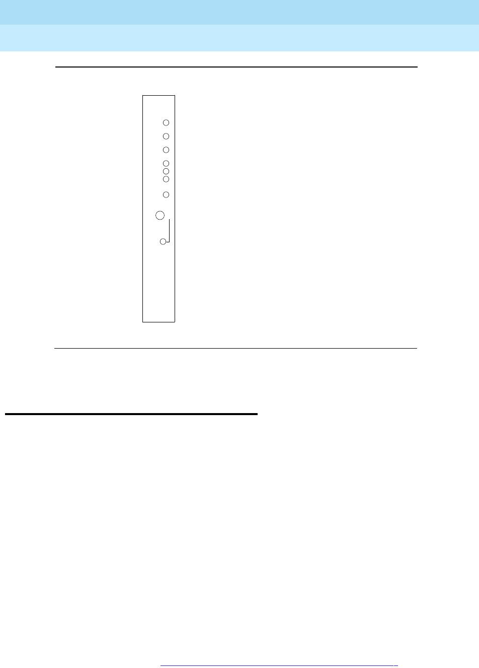
DEFINITY Enterprise Communications Server Release 6
Maintenance for R6r Volumes 1 & 2
555-230-126 Issue 2
January 1998
LED Indicators
Page 7-7Duplication Interface Circuit Pack LEDs
7
Figure 7-1. SYSAM and EPN Maintenance Circuit Pack LEDs
Duplication Interface Circuit Pack
LEDs
In systems with duplicated SPEs, (High Reliability and Critical Reliability), there
are two Duplication Interface UN330B circuit packs. One is located in carrier A
and one in carrier B of the PPN. Each circuit pack has four LEDs. The top three
have the traditional function of indicating the status of the pack.
The LED located at the bottom of the faceplate directly beneath the SPE Select
switch is labeled OVERRIDE. Under normal operating conditions, the SPE Select
switch is in the AUTO (center) position, and the OVERRIDE LED remains unlit.
This means that the system controls which SPE is active. System selection of the
active SPE can be manually overridden by moving the SPE Select switches from
the AUTO position to either the “A” position or the “B” position on both
Duplication Interface circuit packs. At this time, the red OVERRIDE LEDs on both
Duplication Interface circuit packs will light steadily to indicate that one SPE is
locked Active and the system is not duplicated. If both SPE Select switches are
not in the same position, the system software retains control of Active SPE
selection, and the OVERRIDE LED remains unlit. When control of the SPE
selection is returned to the system by returning the SPE Select switches on both
Duplication Interface circuit packs to the AUTO position, the OVERRIDE LED will
go dark. Forced SPE selection should be undertaken only after consulting the
appropriate sections in Chapter 9, ‘‘Maintenance Object Repair Procedures’’.
Alarm LED (red)
Test LED (green)
Busy LED (yellow)
Major alarm LED (red)
Minor alarm LED (red)
Warning alarm LED (yellow)
Acknowledgement LED (green)
Emergency Transfer control switch
ALARMS
MAJOR
MINOR
WRNG
ACK
EMERGENCY
TRANSFER
OFF ON
AUTO
Emergency transfer LED (red)
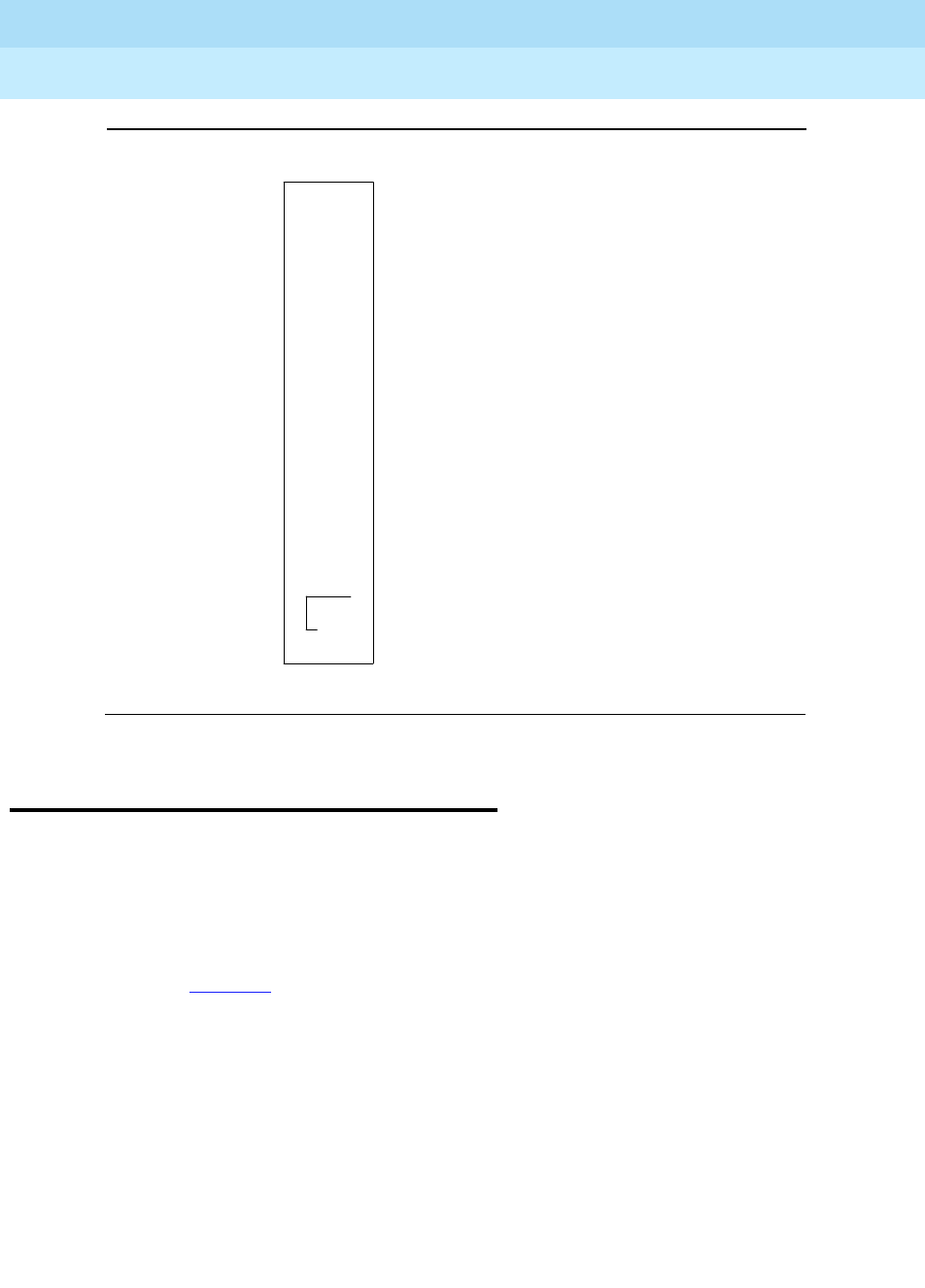
DEFINITY Enterprise Communications Server Release 6
Maintenance for R6r Volumes 1 & 2
555-230-126 Issue 2
January 1998
LED Indicators
Page 7-8Switch Node Interface LEDs
7
Figure 7-2. Duplication Interface Circuit Pack LEDs
Switch Node Interface LEDs
The Switch Node Interface (SNI) TN573 circuit pack has the standard red, green,
and yellow LEDs. The red and green LEDs have the traditional meaning, where
red indicates an alarm condition, and green indicates testing in progress.
The yellow LED displays various flashing patterns to provide status information
useful in isolating faults in the fiber link and other components connected to the
fiber link. Table 7-2 illustrates the SNI yellow LED states.
SPE-Select Switch
SPE-Select LED (Red)
Alarm LED (Red)
Test LED (Green)
Busy LED (Yellow)
O
O
O
SPE
AUTO
Override
B A
O
O

DEFINITY Enterprise Communications Server Release 6
Maintenance for R6r Volumes 1 & 2
555-230-126 Issue 2
January 1998
LED Indicators
Page 7-9DS1 CONV (TN574/TN1654) Circuit Pack LEDs
7
DS1 CONV (TN574/TN1654) Circuit
Pack LEDs
The TN574 and the TN1654 LEDs provide an indication of the state of the DS1
Converter and facilities, and are covered in the following sections of this
document.
TN574 Circuit Pack LEDs
Seven LEDs provide an indication of the state of the DS1 Converter (DS1 CONV)
TN574 circuit pack and the DS1 facilities. The top group has the standard red,
green and yellow LEDs. The red and green LEDs have the traditional meaning,
where red indicates an alarm condition, and green indicates testing in progress.
The four green LEDs on the bottom indicate the status of the DS1 facilities (see
following section).
Table 7-2. Switch Node Interface Yellow Led Flashing States
LED on LED off Condition
0.1 sec 0.1 sec Fiber Out-of-Frame. This state indicates a failure of test
#238, which may be caused by absence of the opposite
end EI or Switch Node Interface, a broken or missing
fiber, or a missing lightwave transceiver on either
endpoint.
0.5 sec 0.5 sec In Frame — No Neighbor. This state corresponds to a
failure of test # 237, usually due to a failure of this SNI,
or the EI or SNI at the opposite of the fiber. This
condition may also be due to a faulty Switch Node
Clock.
solid on SNI Active. This is the normal state for an active SNI.
solid off SNI Standby. This is the normal state for a standby SNI
in systems with a duplication option.

DEFINITY Enterprise Communications Server Release 6
Maintenance for R6r Volumes 1 & 2
555-230-126 Issue 2
January 1998
LED Indicators
Page 7-10DS1 CONV (TN574/TN1654) Circuit Pack LEDs
7
The yellow LED is used to indicate the state of the Fiber Interface, the Fiber
Channel, and the DS1 channel in the following manner and order of priority.
DS1 Facility LEDs
Below the three standard LEDs on the DS1C circuit pack are four green LEDs
used to indicate whether a receive signal is present for each of the four DS1
facilities. Figure 7-3 shows which facility (A, B, C, or D) corresponds to each LED.
If a green LED is off, there is a Loss of Signal condition on the DS1 facility
associated with that LED. The presence of a signal does not guarantee that the
signal is using the correct framing format or line coding; an Alarm Indication
Signal indicating that the opposite end of the DS1C complex is out of service
may be present.
Table 7-3. DS1C Yellow Led Flashing States
LED on LED off Condition
0.1 sec 0.1 sec Fiber Out-of-Frame or Fiber Loss of Signal
0.5 sec 0.5 sec In Frame, fiber channel down. The fiber channel
communicating between the DS1C and the other fiber
endpoint (EI or SNI) is down.
1 sec 1 sec In Frame, DS1 channel down. The channel between the
two DS1Cs in the DS1C complex is down.
2 sec 0.2 sec No response from SPE. The SPE is not acknowledging
messages from the DS1C or the communications link to
the SPR is down.
solid on DS1C active. This is the normal state for an active
DS1C.
solid off DS1C standby. This is the normal state for a standby
DS1C in Critical Reliability Systems (duplicated PNC).
DEFINITY Enterprise Communications Server Release 6
Maintenance for R6r Volumes 1 & 2
555-230-126 Issue 2
January 1998
LED Indicators
Page 7-11DS1 CONV (TN574/TN1654) Circuit Pack LEDs
7
Figure 7-3. TN574 DS1C Circuit Pack LEDs
TN1654 Circuit Pack LEDs
The TN1654 DS1CONV board has 11 LEDs on its faceplate. The top 3 system
standard LEDs indicate the state of the DS1CONV board. These LEDs are under
firmware control until the board has established a link to the SPE via the EI or SNI.
Once the link is established, software controls the 3 LEDs. If the link breaks, the
LEDs are again under firmware control.
The red and green LEDs have the traditional use: red means an alarm condition,
and green indicates that maintenance testing is in progress. The red and green
LEDs are also turned on during circuit pack initialization by firmware. When the
control link to the circuit pack is lost, firmware controls the red LED to indicate an
alarm condition.
The yellow LED under firmware control is used to indicate the state of the
physical Fiber Interface, the Fiber Channel (link to EI or SNI), the DS1 Control
Channel (link to opposite DS1CONV board), and the SPE communications link in
the following manner and order of priority. (The yellow LED remains on for longer
periods of time as the DS1CONV Complex becomes closer to being fully
operational.)
1. If the Fiber is Out of Frame or if a Fiber Loss of Signal condition exists, the
yellow LED will flicker at a 5 Hz rate (on for 100 mS, off for 100 mS).
ALARM LED (RED)
TEST LED (GREEN)
BUSY LED (YELLOW)
DS1 FACILITY A
DS1 FACILITY B
DS1 FACILITY C
DS1 FACILITY D

DEFINITY Enterprise Communications Server Release 6
Maintenance for R6r Volumes 1 & 2
555-230-126 Issue 2
January 1998
LED Indicators
Page 7-12DS1 CONV (TN574/TN1654) Circuit Pack LEDs
7
2. If the Fiber Channel is down (DS1 Converter circuit pack/fiber endpoint
communications), the yellow LED will flash at a 1 Hz rate (on for 500 ms,
off for 500 ms).
3. If the DS1 Control Channel is down between the two DS1CONVs in the
DS1CONV Complex, the yellow LED will pulse at a 0.5 Hz rate (on for 1
second, off for 1 second).
4. If the SPE communications link is down, the yellow LED will wink off every
2 seconds for 200 ms (2 seconds on, 200 ms off).
5. If all is well with the Fiber Interface and all communications channels, the
yellow LED will remain on continuously in a Standard Reliability and High
Reliability System configuration. In Critical Reliability systems (duplicated
PNC), an active DS1CONV circuit pack will have its yellow LED on
continuously, and a standby DS1CONV circuit pack will have its yellow
LED off. The LED will then be under software control.
The bottom four green LEDs on the TN574 DS1CONV board are under hardware
control. The four green LEDs indicate, for each DS1CONV facility, whether a
receive signal is present for the DS1 facility
The next four LEDs on the TN1654 DS1CONV board are labeled STATUS LEDs
and are for future use. These LEDs will not be lit.
The bottom four LEDs on the TN1654 board are labeled SPAN LEDs. These LEDs
are under firmware control. If the facility is not administered, then the LED is not
lit. The LED is lit amber if the facility is running alarm free. If the facility is
detecting either a red alarm (loss-of-signal or loss-of-frame), a yellow alarm
(remote frame alarm) or a blue alarm (AIS signal) then the LED is lit red. The
SPAN SELECT Switch on the TN1654 faceplate is for future use. Pushing the
switch will have no effect on the board. See Figure 7-4 for a view of the face plate
on the TN1654 DS1CONV circuit pack
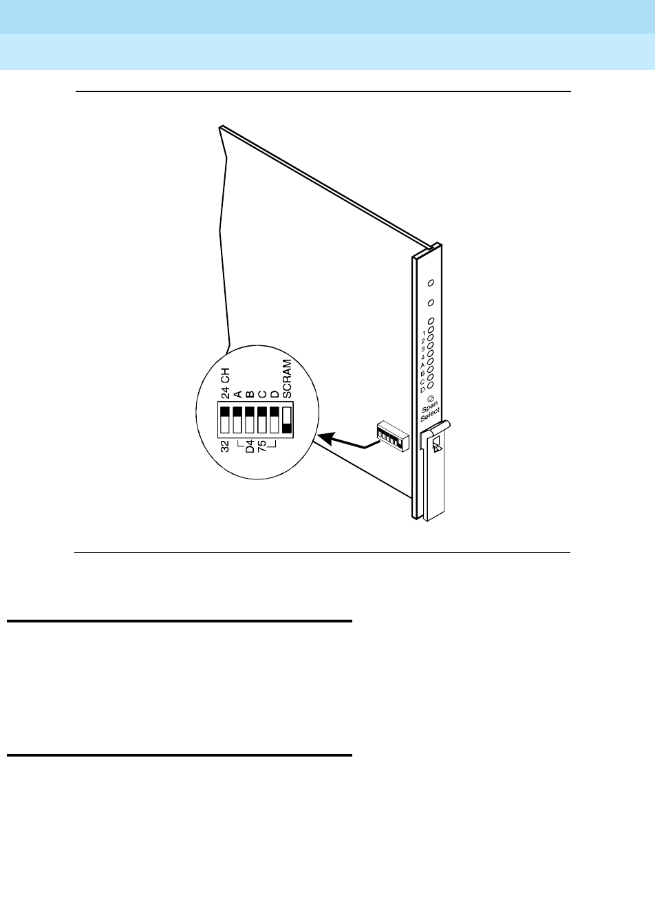
DEFINITY Enterprise Communications Server Release 6
Maintenance for R6r Volumes 1 & 2
555-230-126 Issue 2
January 1998
LED Indicators
Page 7-13Tone-Clock Circuit Pack LEDs
7
.
Figure 7-4. TN1654 DS1CONV Circuit Pack
Tone-Clock Circuit Pack LEDs
The Tone-Clock circuit packs have the standard red, green and yellow LEDs. The
red LED has the traditional meaning. The yellow and green LEDs flash in specific
patterns to indicate the status of the circuit pack. The standby status applies only
to systems with a duplication option.
Maintenance/Test Circuit Pack LEDs
The TN771D Maintenance/Test circuit pack has the standard red, green, and
yellow LEDs. The red and green LEDs have the traditional meaning, where red
indicates an alarm condition, and green indicates testing in progress.
The yellow LED can be off or on continuously or flashing, depending on the mode
of operation of the TN771D and whether or not it has detected errors. The yellow
LED is on steady when the TN771D’s analog test port or digital test ports are
being used to test trunks or line circuits. The yellow LED is also used to indicate
INSET
0015_0 RBP 052396

DEFINITY Enterprise Communications Server Release 6
Maintenance for R6r Volumes 1 & 2
555-230-126 Issue 2
January 1998
LED Indicators
Page 7-14LEDs on Standby Components
7
Packet Bus status. Table 7-4 illustrates the Maintenance/Test yellow LED states
as they apply to Packet Bus activity.
LEDs on Standby Components
In high reliability and critical reliability option systems, duplicated components
that are on standby will usually have their yellow LEDs unlit, with the following
exceptions.
■The Major, Minor and Warning alarm LEDs on the SYSAM circuit pack on
the standby SPE do not give reliable indications. Pay attention only to
those LEDs that are on the active SYSAM circuit pack.
■The yellow LED will blink on and off when the standby Processor circuit
pack is up and standby maintenance is running.
1. It takes 5 to 10 seconds for the yellow LED to respond to a change in the state of the
Packet Bus.
2. Because the yellow LED on the Maintenance/Test circuit pack can also be on steady
when the digital and analog test ports on the circuit pack are in use, exact
interpretation of the yellow LED may require that the technician busy out the analog
and digital test ports or examine the error and Alarm Logs for PKT-BUS errors and
alarms.
3. “Standalone” refers to the TN771D’s capability to operate autonomously as a
troubleshooting aid. A detailed description of the TN771D standalone mode is
provided in the ‘‘Packet Bus Fault Isolation and Repair’’ section of Chapter 5,
‘‘Responding to Alarms and Errors’’.
Table 7-4. TN771D Maintenance/Test Yellow LED States
LED State1TN771D Mode Condition
Solid off Normal The Maintenance/Test circuit pack
detects no Packet Bus faults.
Solid on2Normal The Maintenance/Test Packet Bus
port has successfully reconfigured
the Packet Bus around a fault.
Flashing (1 Hz) Normal The Maintenance/Test Packet Bus
port is unable to reconfigure the
Packet Bus around a fault.
Solid off Standalone3The Maintenance/Test detects no
Packet Bus faults.
Solid on Standalone This condition cannot normally
occur. The LED is always either off or
blinking in standalone mode.
Flashing (1 Hz) Standalone The Maintenance/Test Packet Bus
port detects a Packet Bus fault.

DEFINITY Enterprise Communications Server Release 6
Maintenance for R6r Volumes 1 & 2
555-230-126 Issue 2
January 1998
LED Indicators
Page 7-15LEDs on Standby Components
7
■In high reliability systems with a Center Stage Switch, (duplicated SPE,
simplex PNC), the standby Switch Node Clock’s yellow LED is off. In
critical reliability systems, the standby SNC is located on a separate
carrier and normally remains lit.
■Yellow LEDs on Power Units on standby carriers normally remain lit.
When LED indications are not clear, use the status pnc, status spe and
status pn commands to determine which components are active.

DEFINITY Enterprise Communications Server Release 6
Maintenance for R6r Volumes 1 & 2
555-230-126 Issue 2
January 1998
LED Indicators
Page 7-16LEDs on Standby Components
7

Maintenance Commands
Page 8-1Command Line Syntax
8
DEFINITY Enterprise Communications Server Release 6
Maintenance for R6r Volumes 1 & 2
555-230-126 Issue 2
January 1998
8
8Maintenance Commands
This chapter contains descriptions of commands available to the craft login.
Introductory sections explain the meaning of common input parameters, or
command line arguments, common output fields, and error codes for busyout,
release and reset commands.
!CAUTION:
This document is intended for Release 5 and later systems only. For
previous DEFINITY systems (G3V4 and earlier), refer to DEFINITY
Enterprise Communications Server Release 5 Maintenance for R5r,
555-230-105.
Command Line Syntax
Each command consists of an action word, an object upon which the action is
performed, and optional qualifiers that modify the execution of the command. In
some cases the choice of a qualifier may be required. The syntax of the
command appears under the heading at the beginning of each command
description. The syntax is interpreted as follows:
Command words can be abbreviated. A partially spelled word is recognized as
long as enough letters are entered to distinguish it from other valid entries.
Otherwise, the screen displays a selection of command words that match the
Command Object Optional Qualifiers
test station
extension
[short|long] [repeat number | clear] [schedule]
bold bold italic if a
variable, bold if
entered literally
bracketed; either/or choices are separated by a
vertical slash (|); bold italic if a variable, bold if
entered literally

DEFINITY Enterprise Communications Server Release 6
Maintenance for R6r Volumes 1 & 2
555-230-126 Issue 2
January 1998
Maintenance Commands
Page 8-2Common Input Parameters
8
abbreviation. For example, test alarms step short clear can be entered as t al
st sh c. Drop leading zeroes from numerical entries. For example, cabinet
number 03 can be entered as 3.
Pressing the HELP key displays all available commands. If an incomplete
command is entered, pressing HELP displays all valid qualifiers for the command.
NOTE:
When the successful execution of a command is prevented, an error
message that is usually self-explanatory displays. If the following message
appears, the software is most likely corrupt:
Error encountered; can’t complete request
In this case, follow normal escalation procedures.
Common Input Parameters
Characters in bold type are entered literally on the command line. Characters in
italic bold type are variables. SeeTable 8-1 for common test command
parameters and their explanations and for explanations of less common
parameters.
For example, display cabinet requires only the entry of
UU
: display cabinet 12.
Test port requires a location of the form
UUCSSpp
: test port 05c1506 to test
Table 8-1. Common Test Command Parameters
Parameter Range Meaning
UU 1-22 One or two-digit cabinet number For many commands
this defaults to cabinet 1, the PPN
CA-E Letter designation of a carrier. For many commands
relating to SPE or EPN control circuit packs, this
defaults to A, the control carrier. For PPNs with
duplicated SPEs, A or B is usually specified for SPE
MOs.
SS 1-21 One or two-digit number identifying a circuit pack slot
on a carrier For many commands relating to SPE or EPN
control circuit packs, this usually defaults to the only
possible slot number.
pp 1-24 One or two-digit number identifying an individual port
circuit on circuit pack The range of this variable differs
depending on the type of circuit pack.

DEFINITY Enterprise Communications Server Release 6
Maintenance for R6r Volumes 1 & 2
555-230-126 Issue 2
January 1998
Maintenance Commands
Page 8-3Common Input Parameters
8
port circuit 6 on the circuit pack in cabinet 5, carrier C, slot 6. The list and
display commands are useful in relating MO locations to information such as PN
number, extension, link numbers, and so forth. Table 8-2 contains information
about the less-common command parameters.
Table 8-2. Less-Common Test Command Parameters
Parameter Range Default Meaning
PN# One or two-digit port network number. EPN cabinets
may contain one or two port networks. Use list
cabinet to find which port networks are in each
cabinet.
print This command executes immediately (if resources
are available) and sends output both to the screen
and to a printer connected to the terminal where the
command was entered. This option is available for
display, list and status commands.
schedule A scheduling form is displayed which allows you to
specify a start time for the command. The command
is placed in the queue and, when executed, sends
the output to the system printer. The schedule
option is available for display, list and test
commands. When used with display alarms or
errors, a full report is generated. The usual selection
form for error and alarm reports is suppressed so
that it will not interfere with the command’s execution
when it is issued from the queue.
You can see what commands are currently queued
with the list command-queue command. A queued
command can be canceled with remove
command-queue job#. This option requires that the
system printer be administered on page 4 of the
Feature-Related System Parameters form.
group# 1-666 One to three-digit trunk group number; used to
address trunk maintenance objects.
group#/
member# 1-255 Group number followed by a slash and the one to
three-digit member number of an individual trunk;
used to address trunk maintenance objects.
Continued on next page
DEFINITY Enterprise Communications Server Release 6
Maintenance for R6r Volumes 1 & 2
555-230-126 Issue 2
January 1998
Maintenance Commands
Page 8-4Common Input Parameters
8
extension The extension number assigned to the port or other
maintenance object.
The number of digits in an extension is determined
by the system dial plan. The list and display
commands are useful in relating extension numbers,
maintenance objects, and other components.
repeat # 1-100 1 Used with test commands, the number of times a
test sequence is to be repeated. The word repeat, or
simply the letter r, followed by the number.
short
long Used with test commands, these qualifiers
determine either the long or short test sequence run
for this maintenance object. The test sequence run
varies for each maintenance object.
!CAUTION:
For some maintenance objects, the long
sequence is destructive, that is, disruptive to
call service.
The short sequence is always non-destructive.
clear Used with test commands, this specifies that the test
sequence is to be repeated until any active alarms
against the maintenance object is cleared by the
passing of tests or until any test in the sequence
fails.
If no such alarms are active, the sequence is run
once. The long clear combination effects a clearing
of all alarms against the maintenance object if no
errors are encountered. The short clear combination
clears only alarms pertinent to the tests in the short
sequence.
!CAUTION:
If all tests pass, the long clear combination
clears all error counters. If firmware counters
are cleared while actual problem exists,
customer service may degrade due to calls
being routed over faulty components.
Table 8-2. Less-Common Test Command Parameters — Continued
Parameter Range Default Meaning
Continued on next page

DEFINITY Enterprise Communications Server Release 6
Maintenance for R6r Volumes 1 & 2
555-230-126 Issue 2
January 1998
Maintenance Commands
Page 8-5Common Output Fields
8
Common Output Fields
■An indication that the command successfully completed or a
self-explanatory message giving a reason for a failure or abort.
■An input form for entering additional information required to complete the
command. These are described under each command that presents an
input form.
■A form listing one or more lines of results with error codes that indicate the
reason for a FAIL or ABORT result.
Many commands that use the last form display the fields listed in the table below.
Some return one line of output. Other commands that run either one test on
several objects or several different tests on one or more objects return several
lines of output. In this case, each line represents one test result.
The length of this variable differs for the various types of commands. A port
circuit requires a full length address such as 11C1502, which indicates circuit
number 2 on the circuit pack in cabinet 11, carrier C, slot 15. A control carrier
component such as a SYSAM circuit pack is designated simply as 01B,
indicating the SYSAM in carrier B of cabinet 1, the PPN cabinet.
Some MOs such as TDM-BUS are addressed by PN number. In this case, the
number is usually preceded by PN. For example, TDM bus A in port network 5 is
designated as PN 05A.
In critical reliability systems, Port Network Connectivity is duplicated as two
independent sets of PNC components. These are designated as A-PNC and
B-PNC.
Variable Range Meaning
UU 1-22 One or two-digit cabinet number
CA-E Letter designation of a circuit pack carrier
SS 1-21 One or two-digit number identifying a circuit pack slot on a carrier
pp 1-24 One or two-digit number identifying an individual port circuit on
circuit pack
Port The address or physical location of the MO. Usually this is
UUCSSpp.

DEFINITY Enterprise Communications Server Release 6
Maintenance for R6r Volumes 1 & 2
555-230-126 Issue 2
January 1998
Maintenance Commands
Page 8-6Common Output Fields
8
Maintenance Name The name of the MO as it appears in the alarm and
error logs.
Alt. Name The output screens of many commands list an
alternate name for certain MOs in addition to their port
address (physical location). The meaning of the name
depends upon the type of the object, as shown in the
following table.
Maintenance
Object Alternate Name Example
Station extension 84140
Trunk trunk group # / member #
(001-666) / (001-255) 45/3
Personal CO line P/ personal CO line group # (001-200) P/23
Test
No. The number of the test run on the MO as part of a test command.
Descriptions of each test and its related error codes appear under the
relevant MO. Other commands such as clear firmware-counters and
reset also report a test number.

DEFINITY Enterprise Communications Server Release 6
Maintenance for R6r Volumes 1 & 2
555-230-126 Issue 2
January 1998
Maintenance Commands
Page 8-7Contention Between Simultaneous Commands
8
Contention Between Simultaneous
Commands
The following limits apply to simultaneous maintenance and administration
activities:
■Up to 8 users can be logged into the system at the same time.
■Up to 5 maintenance commands can run concurrently.
Result One of the following results:
PASS: The command successfully completed. For a test command
this indicates that no errors were detected by the test.
ABORT: The command was prevented from completing. See Error
Code below.
FAIL: Indicates that a serious error was detected by the test. See Error
Code below.
NO BOARD: The system does not detect a circuit pack in the location
specified on the command line.
CONFLICT: Another user was testing this maintenance object.
EPN-DOWN: The EPN holding the MO is inaccessible. The Expansion
Archangel Link may be down.
DISABLED: The MO or test has been disabled by the Tier 3 disable
command.
NOT ASSIGNED: The location specified does not have a circuit pack
administered to it.
EXTRA BOARD: This result can appear for the Maintenance/Test, Call
Classifier, Tone Detector, Announcement, and Speech Synthesis
circuit packs. Each of these circuit packs has restrictions on how many
can be in the system or a port network:
Maintenance/Test circuit pack: 1 per port network
Tone Detector circuit pack: up to 50 per system
Call Classifier circuit pack: up to 25 per system
Speech Synthesis circuit pack: 40 per system
Announcement circuit pack: 1 per system
Remove the extra circuit pack(s).
Error
Code A number indicating the reason for a FAIL or ABORT result. For test
commands and other commands that return a test result, consult the
tables of test error codes under the relevant MO. For busyout, release
and reset commands, see ‘‘Common Abort and Fail Codes’’ and Test
Commands.

DEFINITY Enterprise Communications Server Release 6
Maintenance for R6r Volumes 1 & 2
555-230-126 Issue 2
January 1998
Maintenance Commands
Page 8-8Busyout and Release Commands
8
■Up to 3 maintenance commands issued from system access port (SAP) or
EPN Maintenance circuit pack logins can run concurrently. The other 2 are
reserved for the SYSAM and INADS ports.
■Up to 5 administration commands can run concurrently.
■In general, a maintenance object or other system entity can be acted upon
by only one command at a time. This restriction applies to such action
commands as:
—busyout
— change
—clear
— recycle
— release
—set
—test
■In general, only 1 SPE component can be acted upon at one time by
commands such as those just mentioned.
■When an action command is acting on a circuit pack, that circuit pack and
all maintenance objects located on it are unavailable for other commands.
■Display-only commands such as the following generally do not conflict
with any other commands.
—display
— status
—get
— monitor
■Certain system-wide actions such as reset system and upgrade
software cannot run concurrently with any other command.
■Most commands require the use of shared system resources in order to
execute. When required resources are already in use, the command will
abort. For example, save, restore, backup, and test disk commands all
require the use of the Mass Storage System (MSS). Only one such
command can run at one time.
Busyout and Release Commands
The busyout command places the object of the command in a maintenance
busy state. In this state, the object is removed from active service and is not
available for use by call processing. Services dependent on the busied out
component are dropped. If the component supports a link, the link is dropped.
No scheduled or periodic background tests are run on the object while it is
busied out. Demand maintenance tests can be run on the object, though some

DEFINITY Enterprise Communications Server Release 6
Maintenance for R6r Volumes 1 & 2
555-230-126 Issue 2
January 1998
Maintenance Commands
Page 8-9Busyout and Release Commands
8
tests require that the object be released to complete. A WARNING alarm with
error type 18 is logged against each busied out object. All busied out MOs can
be displayed by entering error type 18 in the Error Type field on the Hardware
Errors Report Form (see display errors). The matching release command
returns the maintenance object to service, providing the object is not otherwise
incapacitated.
On systems with duplicated SPE, busyouts are preserved across planned SPE
interchanges and level 1 system resets (Warm). System resets of level 2 or
higher release the busied out objects.
A variety of self-explanatory error messages may be displayed if the command
cannot be executed as entered. In addition to these there are a number of
numerical error codes which may be displayed in the Error Code field if the
command ABORTS or FAILS as indicated in the Result field. These are explained
in the
Common Abort and Fail Codes
section of this chapter.
The following screen display shows a typical result for busyout board 1c03
(analog line circuit pack in cabinet 1, carrier c, slot 7 with three administered
ports):
The following display shows a typical result for most maintenance objects. See
‘‘Common Output Fields’’ above for an explanation of the fields displayed.
busyout board 01C03
Command Results
Port Maintenance Name Alt. Name Result Error Code
01C03 ANL-BD PASS
01C0301 ANL-16-L 5409 PASS
01C0302 ANL-16-L 5416 PASS
01C0303 ANL-16-L 5421 PASS
01C0304 ANL-16-L 5422 PASS
01C0305 ANL-16-L 5411 PASS
Command successfully completed
busyout disk b
COMMAND RESULTS
Port Maintenance Name Alt. Name Result Error Code
01B DISK PASS
Command successfully completed

DEFINITY Enterprise Communications Server Release 6
Maintenance for R6r Volumes 1 & 2
555-230-126 Issue 2
January 1998
Maintenance Commands
Page 8-10Common Abort and Fail Codes
8
Common Abort and Fail Codes
Table 8-3 lists common error codes associated with abort and fail results for
busyout, release, test, and reset commands. In addition to these, many
maintenance objects have other unique error codes.
Table 8-3. Common Error Codes for Busyout, Release, Test,
and Reset Commands
Error
Code Command
Result Description/Recommendation
ABORT System resources are unavailable to run command.
1. Try the command again at 1-minute intervals up to 5 times.
0 ABORT Internal system error.
1. Retry the command at 1-minute intervals up to 5 times.
1005 ABORT A DS1 interface circuit pack could not be reset because it is
currently supplying the on-line synchronization reference.
1. Use the set sync command to designate a new DS1
interface circuit pack as the on-line reference, then try the
reset again.
1010 ABORT Attempt was made to busyout an object that was already busied
out.
1011 ABORT Attempt was made to release an object that was not first busied
out.
1015 ABORT A reset of this circuit pack requires that all maintenance objects
on it be in the out-of-service state.
1. Use the busyout board command to place all objects on the
circuit pack in the out-of-service state, and try the reset
again.
1026 ABORT The specified TDM bus cannot be busied out because the
control channel or system tones are being carried on it. You can
use the set tdm PC command to switch the control channel and
system tones to the other TDM bus.
1030 ABORT This command is not allowed on a circuit pack on the standby
SPE.
Continued on next page

DEFINITY Enterprise Communications Server Release 6
Maintenance for R6r Volumes 1 & 2
555-230-126 Issue 2
January 1998
Maintenance Commands
Page 8-11Common Abort and Fail Codes
8
1338 ABORT The system could not execute the command on a component on
the Standby SPE because an interchange was pending.
1. Refer to ‘‘STBY-SPE (Standby SPE Maintenance)’’ in Chapter
9.
2. Try the command again after the SPE interchange occurs.
1339 ABORT The system could not execute the command on a component on
the Standby SPE because an handshake communication was
down.
1. Refer to ‘‘STBY-SPE (Standby SPE Maintenance)’’ in Chapter
9.
2. Try the command again after the standby SPE is restored to
service. Use status spe to determine state of standby SPE.
1347 ABORT The system could not execute the command on a component on
the Standby SPE because memory refresh was not complete.
1. Refer to ‘‘STBY-SPE (Standby SPE Maintenance)’’ in Chapter
9.
2. Try the command again after the standby SPE is restored to
service. Use status spe to determine state of standby SPE.
1350 ABORT The system could not execute the command on a component on
the Standby SPE because memory shadowing was not enabled.
1. Refer to ‘‘STBY-SPE (Standby SPE Maintenance)’’ in Chapter
9.
2. Try the command again after the standby SPE is restored to
service. Use status spe to determine state of standby SPE.
2012
2500 ABORT Internal system error.
2100 ABORT System resources to run this command were unavailable.
1. Try the command again at 1-minute intervals up to 5 times.
Table 8-3. Common Error Codes for Busyout, Release, Test,
and Reset Commands — Continued
Error
Code Command
Result Description/Recommendation
Continued on next page

DEFINITY Enterprise Communications Server Release 6
Maintenance for R6r Volumes 1 & 2
555-230-126 Issue 2
January 1998
Maintenance Commands
Page 8-12Common Abort and Fail Codes
8
62524
62525
62526
ABORT Maintenance is currently active on the maximum number of
maintenance objects that the system can support. This condition
is commonly caused by the fact that the system contains a large
number of stations or trunks that have been administered, and
whose circuit packs are installed, but which are not physically
connected.
1. Resolve as many alarms as possible on the station and trunk
MOs, or busyout these MOs to prevent maintenance activity
on them. Then try the command again.
NO
BOARD The circuit pack is not physically installed.
EXTRA BD This result can appear for Maintenance/Test, Call Classifier, Tone
Detector, Announcement and Speech Synthesis circuit packs.
Each of these circuit packs has restrictions on how many can be
installed in the system or in a port network. The restrictions are as
follows:
TN771D Maintenance/Test: 1 /port network
TN748 Tone Detector: 50 /system
TN744 Call Classifier: 25 /system
Speech Synthesizer: 40 /system
TN750 Announcement: 1 /system
Remove any extra circuit packs.
1 FAIL For reset commands, the circuit pack was not successfully
halted.
2 FAIL For reset commands, the circuit pack was not successfully
restarted after being halted. For both results, replace the circuit
pack.
FAIL Refer to the applicable maintenance object in Chapter 9.
PASS The requested action successfully completed. If the command
was a reset, the circuit pack is now running and should be
tested.
Table 8-3. Common Error Codes for Busyout, Release, Test,
and Reset Commands — Continued
Error
Code Command
Result Description/Recommendation
Continued on next page

DEFINITY Enterprise Communications Server Release 6
Maintenance for R6r Volumes 1 & 2
555-230-126 Issue 2
January 1998
Maintenance Commands
Page 8-13Alarm and Error Categories
8
Alarm and Error Categories
The display alarms and display errors commands allow you to generate
reports for certain groups of maintenance objects. By entering a category from
the Table 8-4 into the Category field of the input form, you can restrict the report
to only those maintenance objects included in that category. The report can be
further narrowed down by using the other fields on the form.
Table 8-4 is a list of the categories showing which MOs are included. Table 8-5 is
sorted by MO and shows the categories containing each MO.
Table 8-4. Alarm and Error Categories
Category Maintenance Objects
adm-conn ADM-CONN
announce ANN-PT
ANN-BD
ANNOUNCE
bri/asai ASAI-ADJ
ASAI-BD
ASAI-PT
ASAI-RES
ABRI-PORT
BRI-BD
BRI-PORT
BRI-SET
LGATE-AJ
LGATE-BD
LGATE-PT
cdr CDR-LNK
data-mod BRI-DAT
DAT-LINE
DT-LN-BD
PDMODULE
TDMODULE
Continued on next page

DEFINITY Enterprise Communications Server Release 6
Maintenance for R6r Volumes 1 & 2
555-230-126 Issue 2
January 1998
Maintenance Commands
Page 8-14Alarm and Error Categories
8
detector DTMR-PT
DETR-BD
GPTD-PT
TONE-BD
dup-spe CARR-POW
DUPINT
MEM-BD
PROCR
SPE-SELEC
STBY-SPE
SW-CTL
TAPE
environ AC-POWER
CABINET
CARR-POW
DC-POWER
EMG-XFER
EXT-DEV
POWER
RING-GEN
exp-intf AC-POWER
CARR-POW
DC-POWER
DUPINT
EPN-SNTY
EXP-INTF
MAINT
SYNC
Table 8-4. Alarm and Error Categories — Continued
Category Maintenance Objects
Continued on next page

DEFINITY Enterprise Communications Server Release 6
Maintenance for R6r Volumes 1 & 2
555-230-126 Issue 2
January 1998
Maintenance Commands
Page 8-15Alarm and Error Categories
8
TDM-CLK
TONE-BD
ext-dev CUST-ALM
generatr STRAT-3
SYNC
TDM-CLK
TONE-PT
TONE-BD
inads-link INADS
infc EXP-INTF
ISDN-LNK
ISDN-SGRP
PGATE-BD
X25-PT
maint MAINT
mass-st DISK
H-ADAPTR
STO-DATA
TAPE
mbus DUPINT
MEM-BD
PROCR
SW-CTL
TAPE
memory MEM-BD
Table 8-4. Alarm and Error Categories — Continued
Category Maintenance Objects
Continued on next page

DEFINITY Enterprise Communications Server Release 6
Maintenance for R6r Volumes 1 & 2
555-230-126 Issue 2
January 1998
Maintenance Commands
Page 8-16Alarm and Error Categories
8
misc CONFIG
ERR-LOG
MIS
PROC-SAN
SYSTEM
TIME-DAY
mmi MMI-BD
MMI-LEV
MMI--PT
MMI-SYNC
mnt-test M/T-ANL
M/T-BD
M/T-DIG
M/T-PKT
modem MODEM-BD
MODEM-PT
mssnet H-ADAPTR
SW-CTL
netcon SW-CTL
pkt M/T-PKT
PKT-BUS
pms/jrnl JNL-PRNT
PMS-LINK
pnc DS1C-BD
DS1-FAC
EXP-INTF
FIBER-LK
PNC-DUP
Table 8-4. Alarm and Error Categories — Continued
Category Maintenance Objects
Continued on next page

DEFINITY Enterprise Communications Server Release 6
Maintenance for R6r Volumes 1 & 2
555-230-126 Issue 2
January 1998
Maintenance Commands
Page 8-17Alarm and Error Categories
8
SN-CONF
SNC-BD
SNC-LINK
SNC-REF
SNI-BD
SNI-PEER
pncmaint DS1C-BD
DS1-FAC
EXP-INTF
FIBER-LK
PNC-DUP
SN-CONF
SNC-BD
SNC-LINK
SNC-REF
SNI-BD
pnc-peer SNI-PEER
procr PROCR
quick-st ABRI-PT
ADXDP-PT
ANL-16-LINE
ANL-LINE
ANL-NE-LINE
ANN-PT
ANNOUNCE
ASAI-ADJ
AUDIX-PT
AUX-TRK
Table 8-4. Alarm and Error Categories — Continued
Category Maintenance Objects
Continued on next page

DEFINITY Enterprise Communications Server Release 6
Maintenance for R6r Volumes 1 & 2
555-230-126 Issue 2
January 1998
Maintenance Commands
Page 8-18Alarm and Error Categories
8
BRI-PT
BRI-SET
CDR-LINK
CLSFY-PT
CO-DS1
CO-TRK
CONFIG
DAT-LINE
DID-DS1
DID-TRK
DIG-LINE
DIOD-TRK
DISK
DS1-FAC
DS1C-BD
DTMR-PT
EPN-SANITY
EXP-INTF
EXP-PN
FIBER-LNK
GPTD-PT
HYB-LINE
ISDN-LNK
ISDN-TRK
JNL-PRNT
MAINT
MEM-BD
MET-LINE
Table 8-4. Alarm and Error Categories — Continued
Category Maintenance Objects
Continued on next page

DEFINITY Enterprise Communications Server Release 6
Maintenance for R6r Volumes 1 & 2
555-230-126 Issue 2
January 1998
Maintenance Commands
Page 8-19Alarm and Error Categories
8
MODEM-PT
OPS-LINE
PDATA-PT
PDMODULE
PGATE-PT
PKT-BUS
PKT-INT
PMS-LINK
PMS-PRNT
PNC-DUP
PRI-CDR
PROCR
S-SYN-PT
SEC-CDR
SN-CONF
SNC-BD
SNC-LNK
SNC-REF
SNI-BD
SNI-PEER
SW-CNTL
SYS-PRNT
SYSAM
SYSLINK
SYSTEM
TAPE
TDM-BUS
TDM-CLK
Table 8-4. Alarm and Error Categories — Continued
Category Maintenance Objects
Continued on next page

DEFINITY Enterprise Communications Server Release 6
Maintenance for R6r Volumes 1 & 2
555-230-126 Issue 2
January 1998
Maintenance Commands
Page 8-20Alarm and Error Categories
8
TDMODULE
TIE-DS1
TIE-TRK
TONE-BD
TTR-LEV
spe DISK
DUP-CHL
DUPINT
H-ADAPTR
MEM-BD
PKT-INT
PROCR
SPE-SELEC
STBY-SPE
STO-DATA
SW-CTL
SYSAM
SYSTEM
TAPE
s-syn S-SYN-BD
S-SYN-PT
stabd ABRI-PORT
ADXDP-BD
ADXDP-PT
ANL-16-LINE
ANL-BD
ANL-BD
ANL-LINE
Table 8-4. Alarm and Error Categories — Continued
Category Maintenance Objects
Continued on next page

DEFINITY Enterprise Communications Server Release 6
Maintenance for R6r Volumes 1 & 2
555-230-126 Issue 2
January 1998
Maintenance Commands
Page 8-21Alarm and Error Categories
8
ANL-NE-LINE
ASAI-ADJ
AUDIX-BD
AUDIX-PT
BRI-BD
BRI-PORT
BRI-SET
DIG-BD
DIG-LINE
HYB-BD
HYB-LINE
MET-BD
MET-LINE
stacrk ADXDP-PT
ANL-LINE
ANL-16-LINE
ANL-NE-LINE
AUDIX-PT
DIG-LINE
HYB-LINE
MET-LINE
OPS-LINE
stations ABRI-PORT
ADXDP-PT
ANL-16-LINE
ANL-LINE
ANL-NE-LINE
ASAI-ADJ
Table 8-4. Alarm and Error Categories — Continued
Category Maintenance Objects
Continued on next page

DEFINITY Enterprise Communications Server Release 6
Maintenance for R6r Volumes 1 & 2
555-230-126 Issue 2
January 1998
Maintenance Commands
Page 8-22Alarm and Error Categories
8
AUDIX-PT
BRI-PORT
BRI-SET
DIG-LINE
HYB-LINE
MET-LINE
OPS-LINE
sys-link SYS-LINK
sys-prnt SYS-PRNT
tape TAPE
tdm SW-CTL
TDM-BUS
tone CLSFY-BD
CLSFY-PT
DETR-BD
DTMR-PT
GPTD-PT
STRAT-3
SYNC
TDM-CLK
TONE-BD
TONE-PT
TTR-LEV
trkbd AUX-BD
AUX-TRK
CO-BD
CO-DS1
CO-TRK
Table 8-4. Alarm and Error Categories — Continued
Category Maintenance Objects
Continued on next page

DEFINITY Enterprise Communications Server Release 6
Maintenance for R6r Volumes 1 & 2
555-230-126 Issue 2
January 1998
Maintenance Commands
Page 8-23Alarm and Error Categories
8
DID-BD
DID-DS1
DID-TRK
DIOD-BD
DIOD-TRK
DS1-BD
ISDN-TRK
PE-BCHL
TIE-BD
TIE-DS1
TIE-TRK
UDS1-BD
WAE-PT
trkcrk AUX-TRK
CO-DS1
CO-TRK
DID-DS1
DID-TRK
DIOD-TRK
ISDN-LNK
ISDN-TRK
TIE-DS1
TIE-TRK
trunks CO-TRK
AUX-TRK
CO-DS1
DID-DS1
DID-TRK
Table 8-4. Alarm and Error Categories — Continued
Category Maintenance Objects
Continued on next page

DEFINITY Enterprise Communications Server Release 6
Maintenance for R6r Volumes 1 & 2
555-230-126 Issue 2
January 1998
Maintenance Commands
Page 8-24Alarm and Error Categories
8
DIOD-TRK
ISDN-LNK
ISDN-TRK
PE-BCHL
TIE-DS1
TIE-TRK
WAE-PORT
vc VC-BD
VC-DSPPT
VC-LEV
VC-SUMPT
wide-band PE-BCHL
WAE-PORT
Table 8-4. Alarm and Error Categories — Continued
Category Maintenance Objects
Continued on next page

DEFINITY Enterprise Communications Server Release 6
Maintenance for R6r Volumes 1 & 2
555-230-126 Issue 2
January 1998
Maintenance Commands
Page 8-25Alarm and Error Categories
8
Table 8-5. Alarm and Error Categories
(Sorted by MO)
Maintenance Object Categories
ABRI-PORT bri/asai
quick-st
stabd
stations
AC-POWER environ
exp-intf
ADM-CONN adm-conn
ADXCL-BD
ADXCL-PT
ADXCL-RS
ADXDP-BD quick-st
stabd
ADXDP-PT quick-st
stabd
ADXDP-RS
ANL-16-L quick-st
sta-bd
stacrk
stations
ANL-BD stabd
ANL-LINE quick-st
stabd
stacrk
stations
ANN-BD announce
ANN-PT announce
quick-st
ANNOUNCE quick-st
Continued on next page

DEFINITY Enterprise Communications Server Release 6
Maintenance for R6r Volumes 1 & 2
555-230-126 Issue 2
January 1998
Maintenance Commands
Page 8-26Alarm and Error Categories
8
announce
ASAI-ADJ bri/asai
quick-st
sta-bd
stations
AUDIX-BD quick-st
sta-bd
AUDIX-PT quick-st
stabd
stacrk
stations
AUDIX-RES
AUX-BD trkbd
AUX-TRK quick-st
trkbd
trkcrk
trunks
BRI-BD bri/asai
sta-bd
BRI-DAT data-mod
quick-st
BRI-PORT bri/asai
quick-st
stabd
stations
BRI-SET bri/asai
quick-st
stabd
Table 8-5. Alarm and Error Categories
(Sorted by MO) — Continued
Maintenance Object Categories
Continued on next page

DEFINITY Enterprise Communications Server Release 6
Maintenance for R6r Volumes 1 & 2
555-230-126 Issue 2
January 1998
Maintenance Commands
Page 8-27Alarm and Error Categories
8
stations
CABINET environ
CARR-POW environ
exp-intf
CDR-LNK cdr
quick-st
CLSFY-BD tone
CLSFY-PT tone
quick-st
CO-BD trkbd
CO-DS1 quick-st
trkbd
trkcrk
trunks
CO-TRK quick-st
trkbd
trkcrk
trunks
CONFIG misc
quick-st
CUST-ALM ext-dev
DAT-LINE data-mod
quick-st
DC-POWER environ
exp-intf
DETR-BD detector
tone
DID-BD trkbd
Table 8-5. Alarm and Error Categories
(Sorted by MO) — Continued
Maintenance Object Categories
Continued on next page

DEFINITY Enterprise Communications Server Release 6
Maintenance for R6r Volumes 1 & 2
555-230-126 Issue 2
January 1998
Maintenance Commands
Page 8-28Alarm and Error Categories
8
DID-DS1 quick-st
trkbd
trkcrk
trunks
DID-TRK quick-st
trkbd
trkcrk
trunks
DIG-BD sta-bd
DIG-LINE quick-st
stabd
stacrk
stations
DIOD-BD trkbd
DIOD-TRK quick-st
trkbd
trkcrk
trunks
DISK quick-st
mass-st
spe
DS1-BD trkbd
DS1-FAC pnc
pncmaint
quick-st
DS1C-BD pnc
pncmaint
quick-st
Table 8-5. Alarm and Error Categories
(Sorted by MO) — Continued
Maintenance Object Categories
Continued on next page

DEFINITY Enterprise Communications Server Release 6
Maintenance for R6r Volumes 1 & 2
555-230-126 Issue 2
January 1998
Maintenance Commands
Page 8-29Alarm and Error Categories
8
DT-LN-BD data-mod
DTMR-PT detector
tone
quick-st
DUP-CHL spe
DUPINT dup-spe
exp-intf
mbus
spe
EMG-XFER environ
EPN-SNTY exp-intf
quick-st
ERR-LOG misc
EXP-INTF exp-intf
infc
pnc
pncmaint
quick-st
EXP-PN quick-st
EXT-DEV environ
ext-dev
FIBER-LK pnc
pncmaint
quick-st
GPTD-PT detector
quick-st
tone
H-ADAPTR mass-st
Table 8-5. Alarm and Error Categories
(Sorted by MO) — Continued
Maintenance Object Categories
Continued on next page

DEFINITY Enterprise Communications Server Release 6
Maintenance for R6r Volumes 1 & 2
555-230-126 Issue 2
January 1998
Maintenance Commands
Page 8-30Alarm and Error Categories
8
mssnet
spe
HYB-BD stabd
HYB-LINE quick-st
stabd
stacrk
stations
INADS inads
ISDN-LNK infc
quick-st
trkcrk
trunks
ISDN-SGR infc
ISDN-TRK quick-st
trkbd
trkcrk
trunks
JNL-PRNT quick-st
MAINT exp-intf
maint
quick-st
MEM-BD dup-spe
mbus
memory
quick-st
spe
MET-BD stabd
MET-LINE quick-st
Table 8-5. Alarm and Error Categories
(Sorted by MO) — Continued
Maintenance Object Categories
Continued on next page

DEFINITY Enterprise Communications Server Release 6
Maintenance for R6r Volumes 1 & 2
555-230-126 Issue 2
January 1998
Maintenance Commands
Page 8-31Alarm and Error Categories
8
stabd
stacrk
stations
MIS misc
MODEM-BD modem
MODEM-PT modem
quick-st
M/T-ANL mnt-test
M/T-BD mnt-test
M/T-DIG mnt-test
M/T-PKT mnt-test
pkt
OPS-LINE quick-st
stacrk
stations
PDATA-BD
PDATA-PT quick-st
PDMODULE data-mod
quick-st
PE-BCHL trunkbd
trunks
wideband
PGATE-BD
PGATE-PT quick-st
PKT-BUS pkt
quick-st
PKT-INT quick-st
spe
Table 8-5. Alarm and Error Categories
(Sorted by MO) — Continued
Maintenance Object Categories
Continued on next page

DEFINITY Enterprise Communications Server Release 6
Maintenance for R6r Volumes 1 & 2
555-230-126 Issue 2
January 1998
Maintenance Commands
Page 8-32Alarm and Error Categories
8
PMS-LINK pms/jrnl
quick-st
PMS-PRNT quick-st
PNC-DUP pnc
pncmaint
quick-st
POWER-AC
POWER-DC
PRI-CDR quick-st
PROC-SAN misc
PROCR dup-spe
mbus
procr
quick-st
spe
RING-GEN environ
S-SYN-BD quick-st
S-SYN-PT quick-st
s-syn
SEC-CDR quick-st
SN-CONF pnc
pncmaint
quick-st
SNC-BD pnc
pncmaint
quick-st
SNC-LINK pnc
pncmaint
Table 8-5. Alarm and Error Categories
(Sorted by MO) — Continued
Maintenance Object Categories
Continued on next page

DEFINITY Enterprise Communications Server Release 6
Maintenance for R6r Volumes 1 & 2
555-230-126 Issue 2
January 1998
Maintenance Commands
Page 8-33Alarm and Error Categories
8
quick-st
SNC-REF pnc
pncmaint
quick-st
SNI-BD pnc
pncmaint
quick-st
SNI-PEER pnc
pnc-peer
quick-st
SPE-SELE dup-spe
spe
STBY-SPE dup-spe
spe
STO-DATA mass-st
spe
STRAT-3 generatr
tone
SVC-SLOT
SW-CTL dup-spe
mbus
mssnet
netcon
quick-st
spe
tdm
SYNC exp-intf
generatr
Table 8-5. Alarm and Error Categories
(Sorted by MO) — Continued
Maintenance Object Categories
Continued on next page

DEFINITY Enterprise Communications Server Release 6
Maintenance for R6r Volumes 1 & 2
555-230-126 Issue 2
January 1998
Maintenance Commands
Page 8-34Alarm and Error Categories
8
tone
SYS-LINK sys-link
SYS-PRNT quick-st
sys-prnt
SYSAM quick-st
spe
SYSTEM misc
quick-st
spe
TAPE dup-spe
mass-st
mbus
quick-st
spe
tape
TDM-BUS quick-st
tdm
TDM-CLK exp-intf
generatr
quick-st
tone
TDMODULE data-mos
quick-st
TIE-BD trkbd
TIE-DS1 quick-st
trkbd
trkcrk
trunks
Table 8-5. Alarm and Error Categories
(Sorted by MO) — Continued
Maintenance Object Categories
Continued on next page

DEFINITY Enterprise Communications Server Release 6
Maintenance for R6r Volumes 1 & 2
555-230-126 Issue 2
January 1998
Maintenance Commands
Page 8-35backup disk
8
backup disk
This command copies all information from the disk drive in the specified
processor carrier(s) to the tape system in the same carrier. This can take up to 40
minutes to complete.
TIE-TRK quick-st
trkbd
trkcrk
trunks
TIME-DAY misc
TONE-BD detector
exp-intf
generatr
quick-st
tone
TONE-PT generatr
tone
TSC-ADM
TTR-LEV quick-st
tone
UDS1-BD trkbd
WAE-PORT trunkbd
trunks
wideband
backup disk [spe-a | spe-b | active | standby | both | either] [incremental | full]
Table 8-5. Alarm and Error Categories
(Sorted by MO) — Continued
Maintenance Object Categories
Continued on next page

DEFINITY Enterprise Communications Server Release 6
Maintenance for R6r Volumes 1 & 2
555-230-126 Issue 2
January 1998
Maintenance Commands
Page 8-36backup disk
8
On a simplex SPE, the default is to perform an incremental backup of SPE-A. On
a duplex SPE, the default is to perform an incremental backup on both SPE-A
and SPE-B.
NOTE:
The backup command can take up to 10 minutes to complete. Avoid
pressing the ENTER key on the keyboard during this time, since doing so will
cause the result messages to be lost.
Parameters
Examples
backup disk
backup disk spe-b
backup disk active incremental
Output
spe-a Specifies a backup from the A processor carrier hard disk to the
A SPE tape.
spe-b This specifies a backup from the B processor carrier hard disk
to the B SPE tape.
active This specifies a backup of the active processor.
standby This specifies a backup of the standby processor.
both This specifies a backup of both processor carriers.
either Specifies a backup of both SPE carriers. If the standby is not
accessible, the command performs a backup of the active SPE.
incremental Causes all data marked “good” that has been changed since
the last backup to tape to be copied to the tape. That is, all files
that have a date newer than the date on the tape file.
full This causes all data to be copied from disk to tape regardless
of the dates and the state of the data (“good” or “bad”).
Processor Identifies the processor carrier that was backed up
(SPE-A, or SPE-B).
Command Completion
Status Results of the command, and the reason for any
failure are displayed.

DEFINITY Enterprise Communications Server Release 6
Maintenance for R6r Volumes 1 & 2
555-230-126 Issue 2
January 1998
Maintenance Commands
Page 8-37busyout cdr-link
8
For the following output example, assume that the command, backup disk is
entered on a duplex system.
busyout cdr-link
busyout cdr-link [primary | secondary]
The busyout cdr-link command puts a specified call detail recording link in a
maintenance busy state. When busied out, the link is dropped and must be
reestablished later when returned to service. See the description of status link
for more information on links.
Parameters
Examples
busyout cdr-link
busy cdr secondary
For more information see the following sections at the beginning of this chapter:
Busyout and Release Commands, Common Input Parameters, and Common
Output Fields.
busyout data-module
busyout data-module extension
This command puts the specified data module in a maintenance busy state,
whether or not it is installed. No call processing may be executed on the data
[primary | secondary] This qualifier is used to specify one of the two
possible links to CDR output devices. Primary is the
default.
backup disk
BACKUP DISK
Processor Command Completion Status
SPE-A Success
SPE-B Success
Command Successfully Completed

DEFINITY Enterprise Communications Server Release 6
Maintenance for R6r Volumes 1 & 2
555-230-126 Issue 2
January 1998
Maintenance Commands
Page 8-38busyout disk
8
modules or over the data channels. A list of all data-modules administered on the
system can be displayed with list data-module. This form gives the extension,
port, type and other data for each data-module. The following table gives the
maintenance object name for each type of data-module listed in the “Type” field
on the list data-module form.
busyout disk
busyout disk C
This command puts the hard disk drive of the Mass Storage System (MSS) into a
maintenance busy state. Placing the disk in a busyout state prevents read and
write access to the disk except when performed by demand maintenance
testing. This command and the release command abort if any other MSS
operation has already begun.
When the release command is issued, all alarms against the disk are
automatically resolved. If the host-adapter is busied out, it must be released
before the disk can be released. When the host-adapter becomes out-of-service
due to test or reset failures and becomes uninstalled, the disk also becomes
uninstalled, and all access by system software and maintenance tests and
commands is blocked.
The cabinet is always 1 and need not be entered. The carrier, a or b, must be
entered only on systems with duplicated SPEs.
busyout ds1-facility
busyout ds1-facility UUCSSf [override]
This command puts a specified DS1 facility of a DS1C Complex into a
maintenance busy state. Each DS1C complex uses from 1 to 4 DS1 facilities.
One of the facilities, called the packet facility, carries the control channel for all
facilities in the complex, all packet traffic, and some circuit connections. The
other facilities carry circuit connections only. Whenever the circuit pack resets,
the packet facility is set on the “a” facility. If system software detects a problem
Type Maintenance Object
adm-t BRI-SET
announcement DAT-LINE
dtdm DIG-LINE
pdm PDMODULE
system-port DAT-LINE
x.25 PGATE-PT

DEFINITY Enterprise Communications Server Release 6
Maintenance for R6r Volumes 1 & 2
555-230-126 Issue 2
January 1998
Maintenance Commands
Page 8-39busyout fiber-link
8
with this facility, it switches the packet and control traffic to another facility. The
busyout command is not allowed on the packet facility unless the override
qualifier is used. When the override is used, all packet and circuit traffic on the
packet facility is switched to one of the other 3 facilities; all traffic that was on the
destination facility before the switch is dropped. There is no way to tell which
facility is carrying the packet and control traffic without attempting to busy it out
.
If there is only 1 facility left in service on the circuit pack, it cannot be busied out.
In this case, the circuit pack must be busied.
!CAUTION:
Busying out a non-packet facility disrupts all traffic carried on that facility.
Use of the override command to busy the packet facility disrupts all traffic
on the facility to which the packet and control traffic is moved. Which facility
this is cannot be determined in advance.
On critical reliability systems (duplicated PNC) a facility on the active PNC
cannot be busied out. To busyout a facility on the standby PNC, the standby PNC
must first be busied out by busyout pnc.
busyout fiber-link
busyout fiber-link fiber# [a-pnc | b-pnc]
The busyout fiber-link command puts a specified fiber link into a maintenance
busy state. (See Busyout and Release Commands at the beginning of this
chapter). A fiber link is a connection carrying all circuit and packet traffic
between two port networks, two switch nodes, or a port network and a switch
node. A fiber link may contain a DS1 CONV complex used to provide
connectivity to a remote EPN.
!CAUTION:
On systems with simplex PNC, the busyout command is destructive. All
calls and application links carried on the busied out fiber link will be torn
down, and new calls will not be established over the link.
On systems with duplicated PNC, the command is allowed only on a fiber link on
the standby PNC, does not impact service, and requires that the standby PNC
be busied first.
For more information on fiber links, see FIBER-LNK in Chapter 9.

DEFINITY Enterprise Communications Server Release 6
Maintenance for R6r Volumes 1 & 2
555-230-126 Issue 2
January 1998
Maintenance Commands
Page 8-40busyout host-adapter
8
Parameters
If neither PNC is specified, the command defaults to a-pnc.
Examples
Duplex PNC: busyout fiber-link 01 b-pnc busyout fiber-link 03 (defaults to
a-pnc)
busyout host-adapter
busyout host-adapter C
The busyout host-adapter command puts the host-adapter circuit on the
MSSNET circuit pack into a maintenance busy state. When the host-adapter is
busied out, the tape and disk devices on the same carrier are also busied out,
and warning alarms with error type 526 are raised against DISK and TAPE. The
tape and disk do remain available for maintenance testing. This command will
abort if any other MSS operation has already begun.
When the host-adapter is out of service due to test failures, or uninstalled due to
a reset failure, the related tape and disk devices are also placed in the
uninstalled state. All access by system software, maintenance tests, and
commands, including reset, are blocked from execution.
fiber# The administered number assigned to the fiber link. (In a system with
duplicated PNC, this represents a fiber link pair.) List fiber-link
displays a list of all fiber links with their numbers, endpoints, and
other useful information.
a-pnc If PNC is duplicated, this identifier is used to distinguish between the
two fibers of a duplicated pair. For non duplicated PNC “a-pnc” is the
only valid qualifier.
b-pnc On a system with duplicated PNC, this identifier distinguishes
between the two fibers of a duplicated fiber pair. This identifier is
invalid on a system with simplex PNC.

DEFINITY Enterprise Communications Server Release 6
Maintenance for R6r Volumes 1 & 2
555-230-126 Issue 2
January 1998
Maintenance Commands
Page 8-41busyout journal-printer
8
Parameters
Examples
For more information see the following sections at the beginning of this chapter:
Busyout and Release Commands, Common Input Parameters, and Common
Output Fields.
busyout journal-printer
busyout journal-printer pms-log | wakeup-log
The busyout journal-printer command puts the link to the Property
Management System log or wakeup log printers in a maintenance busy state.
(See Busyout and Release Commands at the beginning of this chapter). When
busied out, the link is dropped and no data transfer can take place over it.
This command can be used to prevent unwanted interference between different
maintenance processes. Maintenance software may put a component that is part
of a link in a busy state, causing link set-up to fail, and resulting in attempts by
the system to reestablish the link. If a maintenance test requires that the
component be idle, frequent attempts at re-setup may delay the recovery of a
faulty component. Busying out the link will prevent re-setup attempts.
Parameters
Examples
busyout journal-printer pms-log
busyout journal-printer wakeup-log
For more information see the following sections at the beginning of this chapter:
Busyout and Release Commands, Common Input Parameters, and Common
Output Fields.
C The cabinet is always 1 and need not be entered. On systems with
duplicated SPEs only, carrier a or b must be entered.
Simplex: busyout host-adapter
Duplicated: busyout host-adapter b
pms-log Busies out the link to the Property Management System printer
wakeup-log Busies out the link to the Wakeup Log printer

DEFINITY Enterprise Communications Server Release 6
Maintenance for R6r Volumes 1 & 2
555-230-126 Issue 2
January 1998
Maintenance Commands
Page 8-42busyout link
8
busyout link
busyout link link#
The busyout link command puts a specified Packet Gateway link in a
maintenance busy state. (See Busyout and Release Commands at the
beginning of this chapter). A link may also be busied out with busyout port using
the address of the PGATE port that supports the link.
!CAUTION:
Busyout of a link drops all calls and packet traffic dependent on that link.
The application, adjunct, or switch connected to the link will be
inaccessible and the link will have to be reestablished later when returned
to service. See status link for more details on links.
Parameters
For more information see the following sections at the beginning of this chapter:
Busyout and Release Commands, Common Input Parameters, and Common
Output Fields.
busyout spe-standby
busyout spe-standby
The busyout spe-standby command lowers the Software State Of Health of the
standby Switch Processing Element (SPE) kept by the standby Duplication
Interface (DUPINT) board to the lowest possible level above non-functional. This
diminishes the chance that an interchange will occur, but does not guarantee
that an interchange will not occur. This command also turns off memory
shadowing. Periodic and scheduled testing
are not
turned off on busied out
objects, but warning alarms with error 18 are generated.
Busyout of the standby SPE is allowed if communication to the standby is down
(handshake failure), but the state of health may not be lowered. Use status spe
to determine the condition of the SPE after the busyout has been entered.
When a busyout of the standby SPE is performed, the software state of health of
the standby SPE is set to the lowest possible level and memory shadowing is
turned off. This is done to lessen the probability that the system will switch to the
standby SPE. However, in some cases a “spontaneous” (hard) interchange of the
SPEs may still occur.
Link# A number (1-16) assigned to the link on the
Communication-Interface Links form.

DEFINITY Enterprise Communications Server Release 6
Maintenance for R6r Volumes 1 & 2
555-230-126 Issue 2
January 1998
Maintenance Commands
Page 8-43busyout sp-link
8
This command can be used as a mechanism to turn off memory shadowing of
the standby SPE.
The busyout
will
execute even if the standby SPE state of health is less than
“functional”, memory shadowing is already off, or handshake communication
with the standby is down.
For more information see the following sections at the beginning of this chapter:
Busyout and Release Commands, Common Input Parameters, and Common
Output Fields.
busyout sp-link
busyout sp-link
The busyout sp-link command puts the system printer link into a maintenance
busy state. Placing the system printer link in a busyout state prevents access to
the system printer.
The system printer link is a link from the switch to an external printer. This link is
created by administering the system printer extension and setting up a call to the
system printer.
For more information, refer to the following sections: Busyout and Release
Commands, Common Input Parameters, and Common Output Fields.
busyout tape
busyout tape C
The busyout tape command puts the tape into a maintenance busy state.
Placing the tape in a busyout state prevents read and write access of the tape
except for that requested by demand maintenance testing. This command aborts
if the host adapter on the same carrier is already busied out.
When the host-adapter is busied out, only the demand maintenance busyout and
test commands are permitted on the attached tape in the same carrier. Reset,
release, scheduled and periodic testing and other system software access are
blocked. In this case, the host-adapter must first be released before the tape can
be released.
When the host-adapter is taken out-of-service due to maintenance test or reset
failures, the tape is also placed in the uninstalled state and all access by system
software, maintenance tests and commands, including reset, are blocked.

DEFINITY Enterprise Communications Server Release 6
Maintenance for R6r Volumes 1 & 2
555-230-126 Issue 2
January 1998
Maintenance Commands
Page 8-44busyout trunk
8
Parameters
Examples
Simplex: busyout tape
Duplicated: busyout tape a
For more information, refer to the following sections: Busyout and Release
Commands, Common Input Parameters, and Common Output Fields. This
command will abort if any other MSS operation has already begun.
busyout trunk
busyout trunk group# [/member#]
The busyout trunk command puts an entire trunk group or a single trunk group
member in a maintenance busy state whether it is installed or not. Entering only
the group number busies out all members in the group. (Although not
recommended, entering a group number and a slash (/) without a member
number busies out the member with the lowest-numbered port location.)
Examples
busyout trunk 78
busyout trunk 78/1
For more information see the following sections at the beginning of this chapter:
Busyout and Release Commands, Common Input Parameters, and Common
Output Fields.
cancel hardware-group
cancel hardware-group
In the course of executing test hardware-group, you may find it necessary to
halt the test temporarily or permanently. This can be accomplished with cancel
hardware-group. The canceled test hardware-group command may be
restarted where it left off with resume hardware-group, or another test
hardware-group test may be started. In addition to the cancel hardware-group
command, pressing CANCEL will cancel a hardware-group test executing in the
foreground.
C The cabinet is always 1 and need not be entered. On systems with
duplicated SPEs only, the carrier, a orb, must be entered.

DEFINITY Enterprise Communications Server Release 6
Maintenance for R6r Volumes 1 & 2
555-230-126 Issue 2
January 1998
Maintenance Commands
Page 8-45cancel hardware-group
8
The status of a canceled test hardware-group command will show up as
“canceled” on the “status hardware-group” screen.
When a hardware-group test is executing in the foreground with the
“continuously” option and CANCEL is pressed or the cancel hardware-group is
entered, then the hardware-group test is canceled and for security reasons, the
MT running the hardware-group test will be logged off. However, after logging
back on the system, you can still restart the canceled hardware-group test
command with resume hardware-group command.
Scheduled and Periodic Maintenance
When a test hardware-group is entered, all activity related to scheduled
background maintenance, periodic background maintenance, and data audits is
suspended for the duration of the execution of the test hardware-group
command. All activity related to scheduled background maintenance, periodic
background maintenance, and data audits will restart if the “test
hardware-group” command is canceled.
Status Hardware-Group
The state of a canceled test hardware-group command is displayed by the test
hardware-group command and the state shows up as canceled.
All Ports Option
When test hardware-group all-ports is canceled, the internally generated port
translations for ports that are otherwise untranslated are removed. If resume
hardware-group is then entered, only customer-administered ports will
subsequently be tested. resume does
not
reinstate the port translations that
were removed by the cancel.
Output
If a test hardware-group command started in the background is successfully
canceled with cancel hardware-group, this response is displayed:
Hardware-group command successfully canceled
If a test hardware-group command executing in the foreground is successfully
canceled with a cancel hardware-group command from another terminal, the
following response will be displayed on the terminal where the hardware-group
command was executing:
Hardware-group command aborted with cancel
command entered from another terminal

DEFINITY Enterprise Communications Server Release 6
Maintenance for R6r Volumes 1 & 2
555-230-126 Issue 2
January 1998
Maintenance Commands
Page 8-46change circuit packs
8
change circuit packs
change circuit-packs UU
This command allows the user to administratively add, change or remove circuit
packs that are to be inserted into port, expansion control, and switch node
carriers. It is used to configure the system when the circuit packs have not yet
been physically inserted. This command does
not
support displaying or
modifying the boards in the PPN control carrier.
Parameters
Output
An input form is displayed containing the following fields:
The following display shows a typical result when change circuit-packs 1 is
entered on a system with simplex SPE and a Center Stage Switch (cabinet 1 is
always 5-carrier).
UU The number of the cabinet containing the circuit packs to be modified.
Default is 1.
Cabinet The administered number of the cabinet (1-22).
Cabinet
Layout Type of cabinet.
Carrier Each page of this form reports the information for 1 carrier.
This field indicates the letter designation of the carrier
displayed on the current page.
Carrier
Type The function of the carrier: (port, processor, switch-node,
dup-switch-node, or not-used).
Slot The carrier slot numbers (00 - 21).
Code The TN or UN part number of the circuit pack. This number
identifies the circuit pack type to system software.
Sfx The letter suffix of the circuit pack, if applicable.
Name The name of the circuit pack. This field aids in entering the
circuit pack codes.

DEFINITY Enterprise Communications Server Release 6
Maintenance for R6r Volumes 1 & 2
555-230-126 Issue 2
January 1998
Maintenance Commands
Page 8-47change circuit packs
8
change circuit-packs 1 Page 1 of 5
CIRCUIT PACKS
Cabinet: 1 Carrier: A
Cabinet Layout: five-carrier Carrier Type: processor
*** PROCESSOR BOARDS NOT ADMINISTERABLE IN THIS SCREEN ***
change circuit-packs 1 Page 2 of 5
CIRCUIT PACKS
Cabinet: 1 Carrier: B
Cabinet Layout: five-carrier Carrier Type: not-used
Slot Code Sfx Name Slot Code Sfx Name
00: 11:
01: 12:
02: 13:
03: 14:
04: 15:
05: 16:
06: 17:
07: 18:
08: 19:
09: 20:
10: 21:
’#’ indicates circuit pack conflict.

DEFINITY Enterprise Communications Server Release 6
Maintenance for R6r Volumes 1 & 2
555-230-126 Issue 2
January 1998
Maintenance Commands
Page 8-48change circuit packs
8
change circuit-packs 1 Page 3 of 5
CIRCUIT PACKS
Cabinet: 1 Carrier: C
Cabinet Layout: five-carrier Carrier Type: port
Slot Code Sfx Name Slot Code Sfx Name
00: 11: TN754 DIGITAL LINE
01: TN748 C TONE DETECTOR 12: TN753 DID TRUNK
02: 13: TN742 ANALOG LINE
03: 14: TN760 C TIE TRUNK
04: TN771 C MAINTENANCE/TEST 15: TN747 B CO TRUNK
05: TN748 B TONE DETECTOR 16: TN742 ANALOG LINE
06: TN767 DS1 INTERFACE 17: TN556 BRI LINE
07: TN742 ANALOG LINE 18: TN742 ANALOG LINE
08: TN762 B HYBRID LINE 19:
09: TN742 ANALOG LINE 20: TN754 DIGITAL LINE
10:
’#’ indicates circuit pack conflict.
change circuit-packs 1 Page 4 of 5
CIRCUIT PACKS
Cabinet: 1 Carrier: D
Cabinet Layout: five-carrier Carrier Type: port
Slot Code Sfx Name Slot Code Sfx Name
00: 11:
01: 12: TN722 B DS1 TIE TRUNK
02: 13: TN760 C TIE TRUNK
03: TN750 B ANNOUNCEMENT 14:
04: 15: TN754 DIGITAL LINE
05: 16:
06: 17: TN742 ANALOG LINE
07: TN747 B CO TRUNK 18:
08: TN753 DID TRUNK 19:
09: TN742 ANALOG LINE 20:
10: 21:
’#’ indicates circuit pack conflict.

DEFINITY Enterprise Communications Server Release 6
Maintenance for R6r Volumes 1 & 2
555-230-126 Issue 2
January 1998
Maintenance Commands
Page 8-49change fiber-link
8
change fiber-link
change fiber-link fiber#
The change fiber-link command changes the translation data associated with
an existing fiber link. On critical reliability systems (duplicated PNC), each fiber
link is duplicated and exists as a pair. When PNC duplication is enabled, only the
fields on pages 2 and 3 (the DS1 CONV complex attributes) can be changed.
Translation data is not changed until the Enter key is pressed. Pressing CANCEL
any time before pressing Enter to enter the changes returns you to the command
line without changing any translation data.
When you enter a command that changes translation data, two checks are made:
■You must have permission to administer the feature.
■No other user may be executing a change, add, or remove fiber-link
command.
On a simplex PNC or fully operational duplex PNC, you must remove a fiber and
add it again to change the endpoint board locations.
change circuit-packs 1 Page 5 of 5
CIRCUIT PACKS
Cabinet: 1 Carrier: E
Cabinet Layout: five-carrier Carrier Type: switch-node
Slot Code Sfx Name Slot Code Sfx Name
11:
01: TN570 EXPANSION INTF 12:
02: TN573 SWITCH NODE INTF 13:
03: TN573 SWITCH NODE INTF 14:
04: 15:
05: 16:
06: 17:
07: 18:
08: 19: TN573 SWITCH NODE INTF
09: 20: TN573 SWITCH NODE INTF
10: TN572 SWITCH NODE CLOCK 21:
’#’ indicates circuit pack conflict.

DEFINITY Enterprise Communications Server Release 6
Maintenance for R6r Volumes 1 & 2
555-230-126 Issue 2
January 1998
Maintenance Commands
Page 8-50change fiber-link
8
Parameters
Examples
change fiber-link 21
Output
The following fields appear on Page 2 when a DS1 CONV complex is
administered on the fiber link. Only the DS1 CONV complex
attributes
are
administered here. The circuit pack itself is administered by change circuit
pack. Entries on Page 2 represent the A-PNC. If the PNC is duplicated, these
fields are repeated on Page 3 for the B-PNC. Page 3 fields are display-only, and
can be changed only by changing their counterpoints on Page 2.
number The administered number (1-27) associated with a fiber link or, on
a duplicated PNC, with a fiber link pair.
Fiber Link # This display-only field shows the identifying number of the
fiber link entered on the command line.
Board Location The physical address (cabinet-carrier-slot) of the circuit
packs comprising the two endpoints (ENDPOINT-1 and
ENDPOINT-2) of the fiber link.
Board Type This display-only field shows the type of circuit pack
administered at each endpoint (“ei” or “sni”).
DS1 Converter? y indicates that a DS1C Converter Complex is used on this
link to remotely locate a port network. If this is the case, a
second page displays for administration of the DS1C
Complex attributes.
Board Location This field under the heading DS1C-1 is used to define the
physical location of the converter board connected to
ENDPOINT-1. It is a data entry field consisting of the
board’s physical address by cabinet-carrier-slot. When the
location is entered, validation is performed to ensure that
the board has been administered and is of the correct type
(DS1 CONV).
DS1 Converter
Facilities The fields under this heading define attributes of the four
DS1 facilities (A, B, C, D) that can be connected to the
DS1 CONV.
Facility Installed? This specifies (y or n) whether the indicated facility has
been provided and installed. Facility A is required for the
DS1 CONV Complex.

DEFINITY Enterprise Communications Server Release 6
Maintenance for R6r Volumes 1 & 2
555-230-126 Issue 2
January 1998
Maintenance Commands
Page 8-51change fiber-link
8
The line equalization setting defaults to the median value of 3. This setting
remains in effect until changed by administration. Incorrect equalizer settings
may cause a higher error rate on the DS1 facility.
Passes Far-end
Clock? This specifies whether the DS1 CONV can use the timing
of the received signal as a clock source (as when passing
timing from a master PN to a slave PN. If the DS1 signal
does not come directly from the far-end DS1 CONV board
or the network, n should be entered. (For example, when
using a ‘combined’ facility in which the signal is converted
from digital to analog and back to digital.)
Digital Data
Compatible? This specifies whether the facility is suitable for
transmission of digital data. Facility A must be so and this
field cannot be changed. If Customer Premises Equipment
that alters digital data exists on this facility (for example, a
channel expansion multiplexer or a combined DS1 facility),
n should be entered. (Thus, a multiplexer cannot be
installed on facility A).
DS1C-1 Line
Compensation This specifies the type of line compensation or line
equalization for each facility of the DS1 CONV connected
to ENDPOINT-1. Valid entries are 1 to 5. Meanings of these
entries are shown in Table 8-6.
Table 8-6. DS1 Line Equalization Settings
Equalizer Setting
Distance to DSX-1 Interface (feet)
22 AWG ABAM and 24 AWG PDS 26 AWG PDS
1 1 to 133 0 to 90
2 133 to 266 90 to 180
3 266 to 399 180 to 270
4 399 to 533 270 to 360
5 533 to 655 360 to 450
DS1 CONV-2 Line
Compensation: Same as the above for ENDPOINT-2 of the DS1 CONV
Complex.

DEFINITY Enterprise Communications Server Release 6
Maintenance for R6r Volumes 1 & 2
555-230-126 Issue 2
January 1998
Maintenance Commands
Page 8-52change synchronization
8
The following display shows a typical result when change fiber-link 1 is entered
on a system with simplex PNC and Center Stage Switch.
change synchronization
change synchronization
Zero Code
Suppression: Specifies the line coding format for each facility. Valid
entries are: zcs and b8zs. There are 2 line coding
options supported by the DS1 Interfaces to meet
ones-density requirements in the data stream. Zero
Code Suppression (ZCS) line coding is the default and
is in place following an initialization until changed by
administration. Note that either line coding option may
be used on the DS1 Interface that carries the packet
time slots.
Framing Mode: Specifies the data framing format (esf or d4) used on
the facility. It is initialized to ESF. In this mode, an
automatic selection process is executed until either the
DS1 Interface is brought into frame, or an Options
CCMS message is received by the framing options
master. Once options are set by administration, they
remain fixed on the framing option master until the board
is again initialized, reset, or sent new options. The
framing option on the framing option slave Converter
Board can change to track the framing option master’s
option.
change fiber-link 1 Page 1 of 1
FIBER LINK ADMINISTRATION
Fiber Link #: 1
ENDPOINT-1 ENDPOINT-2
(A-PNC) (A-PNC)
Board Location: 01E01 Board Location: 01E02
Board Type: ei Board Type: sni
Is one endpoint remoted via DS1 Converter Complex? n

DEFINITY Enterprise Communications Server Release 6
Maintenance for R6r Volumes 1 & 2
555-230-126 Issue 2
January 1998
Maintenance Commands
Page 8-53change synchronization
8
This command sets the source and type of timing signals to be used by the
system.
The system uses a hierarchy of timing sources to synchronize data transmission
throughout the system. Stratum 3 Synchronization uses an external Stratum 3
Clock connected to a port network (usually the PPN) which has a TN780
Tone-Clock circuit pack. Stratum 4 Synchronization uses either external signals
received through a DS1 interface circuit pack or a master Tone-Clock within the
system. (Throughout this discussion, the term DS1 interface includes TN464
UDS1 circuit packs.)
A DS1 interface administered as a primary or secondary synchronization source
cannot be removed on the DS1 circuit pack form or the regular circuit pack form.
The synchronization must first be changed or removed.
Output
Stratum 4 Fields
Stratum 3 Fields
The following display shows a typical result when change synch is entered with
stratum 4 synchronization in use.
Stratum: This field specifies the stratum number, 3 or 4, of the
synchronization source used by the system. The stratum
number determines which other fields are displayed on the
screen form.
Primary: The location of the DS1 Interface circuit pack that provides
the preferred source of timing reference signals. A blank
indicates that no external timing source is used.
Secondary: The location of the DS1 Interface circuit pack that provides
the backup source of timing reference signals to be used if
the primary source fails. It must be in the same port network
as the primary source. A blank indicates that no backup
external timing source is used.
Location: The locations of all administered DS1 circuit packs in the
system.
Name: The user-defined name, if any, administered on the DS1
circuit pack form.
Slip: This field indicates whether there are any slip alarms logged
against the circuit pack.
Port Network: This display-only field gives the number of the port network
connected to the Stratum 3 clock (normally 1, the PPN).

DEFINITY Enterprise Communications Server Release 6
Maintenance for R6r Volumes 1 & 2
555-230-126 Issue 2
January 1998
Maintenance Commands
Page 8-54change system-parameters maintenance
8
The following display shows a typical result when change synch is entered with
stratum 3 synchronization in use.
change system-parameters
maintenance
change system-parameters maintenance
The maintenance-related system parameters form specifies and displays
scheduled maintenance operations and maintenance support functions.
This form activates and deactivates INADS alarm origination when performing
repairs. To deactivate alarm origination:
1. Make a note of the current entries in the Alarm Origination and CPE fields
so you can restore them when you are done.
2. Change the Alarm Origination to OSS Numbers field “neither.”
3. Change the CPE Alarm Activation Level field to “none.”
4. If daily scheduled maintenance must be prevented from starting during a
maintenance procedure, set the Start Time field to a time after the
session will end. If daily Scheduled Maintenance is already running and
needs to be shut off, set the Stop Time field to one minute after the
current time.
5. Press Enter and verify that the screen displays the message:
Command successfully completed
NOTE:
For earlier releases of system software, disable Cleared Alarm
Notification and Restart Notification before submitting the form.
NOTE:
When finished working on the switch be sure to return all fields to
their original settings.
change synchronization Page 1 of 1 SPE A
SYNCHRONIZATION PLAN
SYNCHRONIZATION SOURCE (DS1 circuit pack location)
Stratum: 3
Port Network: 1

DEFINITY Enterprise Communications Server Release 6
Maintenance for R6r Volumes 1 & 2
555-230-126 Issue 2
January 1998
Maintenance Commands
Page 8-55change system-parameters maintenance
8
Examples
change system-parameters maintenance
Output
An input form is displayed with the following fields. Defaults for data entry fields
are listed in parentheses.
Operations Support Parameters:
Product
Identification This is a 10-digit number starting with 1 that identifies the
switch to an Operations Support System (OSS), for example,
INADS.
First OSS
Telephone
Number
The first telephone number that the switch uses to report
alarms to, for example, INADS or Trouble Tracker. The
number must be obtained from the National Customer
Support Center (NCSC) or the TSC. # and * are not allowed
in the telephone number.
Abbrev Alarm
Report Enables the Abbreviated Alarm Report feature for the first
OSS. (yes)
Second OSS
Telephone
Number
The second telephone number that the switch uses to report
alarms to, for example, INADS or DEFINITY SNMP. The
number must be obtained from the National Customer
Support Center (NCSC) or the TSC. # and * are not allowed
in the telephone number.
Abbrev Alarm
Report Enables the Abbreviated Alarm Report feature for the
second OSS. (no)

DEFINITY Enterprise Communications Server Release 6
Maintenance for R6r Volumes 1 & 2
555-230-126 Issue 2
January 1998
Maintenance Commands
Page 8-56change system-parameters maintenance
8
Alarm
Origination to
OSS Numbers
Indicates one of four options for alarm origination (neither):
■If this field is set to “both,” all Major and Minor alarms
result in an automatic call to both OSS telephone
numbers. Both OSS telephone numbers must be
administered.
■If this field is set to “first-only,” all Major and Minor alarms
result in an automatic call to the first OSS number only.
The switch does not call the second OSS telephone
number even if the number is administered. The first
OSS telephone number must be administered
■If this field is set to “neither,” alarm origination does not
take place. Warning alarms are not reported to either
numbers.
■If this field is set to “second-as-backup,” all Major and
Minor alarms result in an automatic call to the first OSS
telephone number. If calling the first OSS telephone
number fails four attempts, the switch starts to call the
second OSS telephone number as a backup until calling
the first OSS telephone number becomes successful.
Both OSS telephone numbers must be administered.
Before Release 5, the name of this field is “Alarm Origination
Activated.” If Alarm Origination is deactivated, both Cleared
Alarm Notification and Restart Notification are disabled,
even though they may still be activated in the administration.
Cleared Alarm
Notification Enables the switch to originate a call to the OSS and send
an alarm resolution message whenever all previously
reported Major and Minor alarms are resolved. Alarm
Origination must be activated in order for Cleared Alarm
Notification to work. (no)
Restart
Notification Enables the switch to originate a call to the OSS and report
any system restarts caused by problems with the switch.
Suspension
Threshold The threshold for suspending Cleared Alarm Notification.
Some problems may cause alarms to be generated and
then resolved repeatedly. To detect these problems (by not
sending additional Cleared Alarm notifications to indicate a
problem- free system), the switch suspends Cleared Alarm
Notification when it has reported this administrable number
of Cleared Alarm notifications in a 24 hour period. A
suspended Cleared Alarm Notification is only enabled again
with a successfully completed “logoff” command, a system
reset, or when the threshold is changed. This field is
irrelevant if Cleared Alarm Notification or Alarm Origination is
disabled. The possible range of threshold values is between
1 and 15.

DEFINITY Enterprise Communications Server Release 6
Maintenance for R6r Volumes 1 & 2
555-230-126 Issue 2
January 1998
Maintenance Commands
Page 8-57change system-parameters maintenance
8
Scheduled Maintenance
A series of maintenance tests and operations runs automatically every day
according to the schedule and settings specified in Table 8-7
Test Remote
Access Port Specifies whether testing of the remote access port on the
SYSAM circuit pack is enabled. This field should be set to
"yes" whenever there is an INADS line connected to the
switch and there is a maintenance contract in effect so that
alarm origination capability is maintained.
If no equipment is connected to the remote access port, or if
a trunk for remote access and alarm origination is not
provided, running tests on the remote access port on the
SYSAM results in test failures. This causes unnecessary
maintenance alarms and allows potentially destructive tests
to be run. Setting this field to “no” prevents this.
CPE Alarm
Activation
Level
Indicates the minimum level (Major, Minor or Warning) at
which the Customer-Provided Equipment (CPE) alarm is
activated. If the level is ‘‘none,’’ the CPE does is not
activated for any alarm. (none)
NOTE:
The CPE alarm is always activated when the switch
goes into Emergency Transfer, regardless of the CPE
Alarm Activation Level setting.
Customer
Access to
INADS Port
Provides the capability to prohibit access to system
administration and maintenance interface, via the INADS
port when using customer login ID’s. This field can only be
activated Lucent through system-parameters maintenance
administration.(no)
Table 8-7. Schedules and Settings for Maintenance Tests
Start Time The hour and minute in 24-hour notation at which daily
scheduled maintenance will begin running.
Stop Time The hour and minute when scheduled daily maintenance will
stop running. If any daily maintenance operations are not
completed by this time, the system will note where in the
sequence it stopped and perform those operations during
the next scheduled daily maintenance.
Continued on next page

DEFINITY Enterprise Communications Server Release 6
Maintenance for R6r Volumes 1 & 2
555-230-126 Issue 2
January 1998
Maintenance Commands
Page 8-58change system-parameters maintenance
8
Daily
Maintenance This display-only field simply represents the series of tests
that are always run by maintenance software as part of daily
maintenance.
Save
Translation This field indicates on which days translation data in memory
will automatically be saved to the Mass Storage System disk
and/or tape devices during scheduled maintenance. The
save operation is first made to disk, followed by a disk
backup to tape. On systems with duplicated SPEs, translation
data is saved on both SPEs. Valid entries are daily, days of
the week, or no. "No" specifies that no automatic saves are to
be executed. (daily)
Control
Channel
Interchange
Each port network has a pair of TDM busses called A and B,
each of which has a set of time slots dedicated to use by the
control channel. At any one time, the control channel in each
PN is carried on only one of the two busses. This field
indicates on which days the control channel in each port
network will be switched from one of the paired TDM busses
to the other. Valid entries are daily, days of the week, or no.
"No" specifies that no interchange be executed. (no)
System
Clocks
Interchange
On High and Critical Reliability systems, this option causes a
Tone-Clock interchange in each port network with duplicated
Tone-Clock circuit packs. Each port network interchanges
into the standby Tone-Clock for 20 seconds and then back to
the Tone-Clock that was originally active. This field indicates
on which days the interchanges are to take place. Valid
entries are daily, days of the week, or no. "No" specifies that
interchanges be executed. (no)
The system performs a Tone-Clock interchange, making the
stand by Tone-Clock active. The newly active Tone-Clock
circuit pack is tested and, while active, provides system
clocks for the port network in which it resides. The system then
interchanges back to the originally active Tone-Clock circuit
pack.
SPE
Interchange On systems with duplicated SPEs, this field indicates on
which days an SPE interchange will be executed during
scheduled maintenance. Valid entries are daily, days of the
week, or no. "No" specifies no scheduled interchanges. (no)
Table 8-7. Schedules and Settings for Maintenance Tests — Continued
Continued on next page

DEFINITY Enterprise Communications Server Release 6
Maintenance for R6r Volumes 1 & 2
555-230-126 Issue 2
January 1998
Maintenance Commands
Page 8-59change system-parameters maintenance
8
Minimum
Threshold for
TTRs
When the number of touch tone receivers (TTRs) in service
falls below this number (4 to 200), a WARNING alarm is
raised against TTR-LEV (see TTR-LEV in Chapter 9,
‘‘ABRI-PORT (ASAI ISDN-BRI Port)’’). These are also known
as dual-tone multifrequency receivers (DTMRs). There are 4
TTRs on each TN748 Tone Detector circuit pack, and up to
50 TN748s in a system. To alarm the first occurrence of a TTR
being taken out of service, set this field to 4 times the number
of TN748s. If this number is set to more than three less than
the total number of TTRs, a port network with only one TN748
could lose all of its TTRs before this alarm is raised.
Minimum
Threshold for
CPTRs
When the number of call progress tone receivers in service
falls below this number (2 to 100), a WARNING alarm is
raised against TTR-LEV (see TTR-LEV in Chapter 9,
‘‘ABRI-PORT (ASAI ISDN-BRI Port)’’). These are also known
as general purpose tone detectors (GPTDs). There are 2
CPTRs on each TN748 Tone Detector circuit pack, and up to
50 TN748s in a system. To alarm the first occurrence of a
CPTR being taken out of service, set this field to 2 times the
number of TN748s. If this number is set to more than one less
than the total number of TTRs, a port network with only one
TN748 could lose all of its CPTRs before this alarm is raised.
Minimum
Threshold for
Call Classifier
Ports
When the number of call classifier ports (CLSFY-PTs) in
service falls below this number, a WARNING alarm is raised
against TTR-LEV (see TTR-LEV in Chapter 9). Valid entries
are 1 to 200. There are 8 ports on each TN744 Call Classifier
circuit pack, and up to 25 TN744s in a system. To alarm the
first occurrence of a CLSFY-PT being taken out of service, set
this field to 8 times the number of TN744s. If this number is
set to more than 7 less than the total number of CSLFY-PTs in
the system, a port network with only one TN744 could lose all
of its CLSFY-PTS before the alarm is raised. If there are no
TN744s in the system, leave this field blank.
Table 8-7. Schedules and Settings for Maintenance Tests — Continued
Continued on next page

DEFINITY Enterprise Communications Server Release 6
Maintenance for R6r Volumes 1 & 2
555-230-126 Issue 2
January 1998
Maintenance Commands
Page 8-60change system-parameters maintenance
8
Test Type
100, Test
Type 102,
Test Type 105
An extension assigned to receive tie-trunk calls from other
switches with test line origination capability. The system
responds by sending a sequence of test tones. Test Type
100 tests far end to near end loss and C-message by
sending:
■5.5 seconds of 1004 Hz tone at 0dB
■Quiet until disconnect; disconnect is forced after one
minute
Test Type 102 tests far end to near end loss by sending:
■9 seconds of 1004 Hz tone at 0dB
■1 second of quiet
■This cycle is repeated until disconnect; disconnect is
forced after 24 hours.
Test Type 105 tests 2-way loss, gain slope, and C-message
and C-notch noise by sending:
■nine seconds of 1004 Hz at -16dB
■one second of quiet
■nine seconds of 404 Hz at -16dB
■one second of quiet
■nine seconds of 2804 Hz at -16dB
■30 seconds of quiet
■one half second of Test Progress Tone (2225 Hz)
■approximately 5 seconds of quiet
■forced disconnect
ISDN-PRI Test
Call Extension The extension used by a far-end ISDN node to place a call to
the system to test the ISDN-PRI trunks between the far-end
and the system.
ISDN-BRI
Service SPID This field shows whether or not the link is associated with the
Service SPID. If the link is associated with the Service SPID,
the field contains a number from “0 to 99999” this number is
the test spid (See
SPID Facility Test
in
chapter 9
under
BRI-SET
MO) otherwise, this field is blank. Service SPID is a
feature used by the system technician to check building
wiring between the switch and the BRI endpoint.
Table 8-7. Schedules and Settings for Maintenance Tests — Continued
Continued on next page

DEFINITY Enterprise Communications Server Release 6
Maintenance for R6r Volumes 1 & 2
555-230-126 Issue 2
January 1998
Maintenance Commands
Page 8-61change system-parameters maintenance
8
DSO
Loop-Around
Test Call
Extension
The extension used by the network service provider to set up
a DSO loop around connection for testing non ISDN DS1
trunks
The DSO Loop-Around Test Call feature is used primarily for
testing DSO channels associated with non ISDN-PRI trunks.
The loop-around is activated by dialing the test extension
number. Multiple DSO Loop-Around connections can be set
up by placing multiple calls to the loop-around extension.
For more information see chapter 6 (Facility Test Calls).
Loss Plan Use only when extra loss is required to maintain quality of
transmission on conference calls. Leave this field blank if no
extra loss is required. If extra loss is required, enter digits as
shown below.
Number Of
Parties To Be
Conferenced Enter Digit
32
43
54
65
76
SPE
Optional
Boards:
These fields indicate whether a Disk circuit pack is present in
the system, and which Packet Interface slots are administered.
If a Packet Interface circuit pack is physically present, the
corresponding Packet Interface field is set to y when the
system boots, and no change to that field is allowed. If the
system is equipped with duplicated SPEs, a Packet Interface
field is set to y when either SPE carrier contains a Packet
Interface circuit pack in the corresponding position. If a Packet
Interface circuit pack is not present, then the value for the
Packet Interface field is read from translation data stored on
disk or tape. If the field is set to n, a Packet Interface circuit
pack may be administered by changing the corresponding
Packet Interface field to y.
Table 8-7. Schedules and Settings for Maintenance Tests — Continued
Continued on next page

DEFINITY Enterprise Communications Server Release 6
Maintenance for R6r Volumes 1 & 2
555-230-126 Issue 2
January 1998
Maintenance Commands
Page 8-62change system-parameters maintenance
8
The following display shows a typical result when change system-parameters
maintenance is entered.
change system-parameters maintenance Page 1 of 2
MAINTENANCE-RELATED SYSTEM PARAMETERS
OPERATIONS SUPPORT PARAMETERS
Product Identification: 1000000000
First OSS Telephone Number: 5551212 Abbrev Alarm Report? y
Second OSS Telephone Number: 5551213 Abbrev Alarm Report? n
Alarm Origination to OSS Numbers: both
Cleared Alarm Notification? y
Restart Notification? y
Test Remote Access Port? n
CPE Alarm Activation Level: none
Customer Access to INADS Port? n
Repeat Dial Interval (mins): 7
SCHEDULED MAINTENANCE
Start Time: 22: 00 Stop Time: 04: 00
Daily Maintenance: daily Save Translation: daily
Control Channel Interchange: no System Clocks Interchange: no
SPE Interchange: no
change system-parameters maintenance Page 2 of 2
MAINTENANCE-RELATED SYSTEM PARAMETERS
MAINTENANCE THRESHOLDS ( Before Notification )
Minimum Threshold for TTRs: 4 Minimum Threshold for CPTRs: 1
Minimum Threshold for Call Classifier Ports: _
TERMINATING TRUNK TRANSMISSION TEST (Extension)
Test Type 100: Test Type 102: Test Type 105:
ISDN MAINTENANCE
ISDN-PRI TEST CALL Extension: _____ ISDN BRI Service SPID: _____
DS1 MAINTENANCE
DSO Loop-Around Test Call Extension: _____
LOSS PLAN (Leave Blank if no Extra Loss is Required)
Minimum Number of Parties in a Conference Before Adding Extra Loss: _____
SPE OPTIONAL BOARDS
Disk? y Packet Intf1? y Packet Intf2? n Packet Intf3? n
DEFINITY Enterprise Communications Server Release 6
Maintenance for R6r Volumes 1 & 2
555-230-126 Issue 2
January 1998
Maintenance Commands
Page 8-63clear errors
8
clear errors
clear errors
The clear errors command moves all errors and resolved alarms to the cleared
errors list, thereby making room for new incoming error messages which might
otherwise be dropped. This command does not clear active alarms from the
alarm log. Cleared error entries are the first entries overwritten when additional
room is needed to log new entries. To retrieve cleared errors, use display errors
clear.
NOTE:
Use this command with care. Cleared data will be lost if the logs fill up.
clear firmware-counters
clear firmware-counters UUCSS | a-pnc | b-pnc
This command clears the firmware error counters on the specified circuit
packs(s). This command is valid only for SNI, SNC, and DS1C board locations.
When a- or b-pnc is specified, all such circuit packs in a single PNC can be
cleared at once. On a Critical Reliability systems (duplicated PNC), only circuit
packs on a standby PNC that is busied out can be cleared.
This command is useful for quickly clearing lingering alarms after a hardware
problem has been fixed. (Test clear commands do not clear alarms on SNI,
SNC, and DS1C circuit packs.)
!WARNING:
This command can mask actual hardware problems since firmware is
cleared and appears as if no problems were ever encountered.
Parameters
For more information see Common Output Fields at the beginning of this chapter.
clear pgate-port
clear pgate-port UUCSSpp
UUCSS The specified location must be occupied by an SNI, SNC or DS1C circuit
pack. All circuit packs on the standby PNC can be cleared at once by
specifying a- or b-pnc. To do so, the standby PNC must first be busied out.
DEFINITY Enterprise Communications Server Release 6
Maintenance for R6r Volumes 1 & 2
555-230-126 Issue 2
January 1998
Maintenance Commands
Page 8-64disable suspend-alm-orig
8
The clear pgate-port command clears the hardware error counters associated
with the specified packet gateway port by performing a reset. If the number of
the link assigned to the port is known, clear link accomplishes the same thing.
For more information see Common Input Parameters and Common Output Fields
at the beginning of this chapter.
disable suspend-alm-orig
This command disables one or more active Suspend Alarm Origination entries.
Synopsis
disable suspend-alm-orig (board location).
Examples
disable suspend-alm-orig 1C03
disable suspend-alm-orig 1E07
Description
This command disables one or more active Suspend Alarm Origination entries
from the Suspend Alarm Origination table. This command disables all entries
(boards and ports) matching the specified physical board location.
NOTE:
A port entry cannot be disabled with this command. Allowing for different
ways to disable one or more entries greatly increases the complexity of
updating and displaying the Suspend Alarm Origination table.
Defaults
None.
Parameter
Help Messages
N is the maximum number of cabinets in the switch:
board
location This parameter specifies the physical board location of the
hardware component that has been replaced or corrected. A
port location is not supported because of it complexities.

DEFINITY Enterprise Communications Server Release 6
Maintenance for R6r Volumes 1 & 2
555-230-126 Issue 2
January 1998
Maintenance Commands
Page 8-65display alarms
8
Enter board location:[cabinet(1-N)];
carrier(A-E);slot(0-20)
Output
The command returns one of the following messages:
1. If the board specifier is not valid:
Board invalid
2. If no entries can be disabled in the Suspend Alarm Origination table:
Entry not found; no entries disabled
Feature Interactions
None.
display alarms
This command will display an options form which allows the technician to choose
which alarms are to be displayed.
Synopsis
display alarms
[print | schedule]
Permissions
The following default logins may execute this command: system technician,
inads, cust, rcust, bcms, init, browse.
Examples
display alarms display alarms print display alarms schedule
Description
The display alarms command brings up a hardware alarm report. This screen
allows the technician various different options to select which alarms will be
displayed on the alarm report. There are no parameters entered on the command
line, parameters are selected on the hardware alarm report form instead.

DEFINITY Enterprise Communications Server Release 6
Maintenance for R6r Volumes 1 & 2
555-230-126 Issue 2
January 1998
Maintenance Commands
Page 8-66display alarms
8
An alarm can occur for any hardware object when it has been determined by the
maintenance subsystem that a problem definitely exists. The impact of the
problem is indicated by the alarm type:
Warning alarm—A problem which has been deemed important enough to log, or
may be external to the system, but not severe enough to cause a noticeable
degradation of service.
Minor alarm—A problem which could disable a local area of the system and so
noticeably degrade the system.
Major alarm—A problem which widely degrades the system and seriously
impairs service. This would cause a call to be placed to INADS.
A resolved alarm is a problem which has been corrected, and the alarmed
component of the system is functioning correctly again. The alarm will be
stamped with a resolved date and time, indicating that it is no longer a concern
(any errors associated with the alarms will also be considered resolved).
Defaults
All alarms will be displayed.
Parameters
Help Messages
If the technician presses HELP after entering “display alarms” the following
message will be displayed:
[’print’ or’schedule’]
print This will cause the report to be printed if a printer is linked to the
SAT.
schedule When the “schedule” option is specified, the command is
validated and then a scheduling form is displayed to allow the
technician to schedule execution of the command. The command
is then placed in the command queue and is executed at the
specified time. The information displayed by the command is sent
to the system printer instead of the screen. Refer to the Report
Scheduler and System Printer feature specification [4] for more
details.
There are no parameters entered on the command line,
parameters are selected on the hardware alarm report form
instead.

DEFINITY Enterprise Communications Server Release 6
Maintenance for R6r Volumes 1 & 2
555-230-126 Issue 2
January 1998
Maintenance Commands
Page 8-67display alarms
8
Error Messages
If during the execution of a command a resource problem occurs that requires
the user to restart the command, then the following message will be displayed:
Command resources busy; Press CANCEL to clear, and then resubmit
If all of the available maintenance resources are currently in use, then the
following message will be displayed:
All maintenance resources busy; try again later
From Input
After entering the command display alarms, the system technician will be
presented with an options form.
Alarm Types The type of alarm to be displayed is specified by placing a “y”
or “n” in the alarm type fields. The technician can choose a
combination of active alarms, major, minor, warning, or
resolved alarms.
Interval Display alarm records for the last (m)onth, last (h)our, last
(d)ay, last (w)eek, or (a)ll. The default is all.
From Display alarm records from the time specified by
mm/dd/hh/mm, where mm is the month, dd is the day, hh is
the hour and mm is the minute. If no “from” date is entered,
then no checking is done. This will give the user all the alarms
active since a month prior to the current time.
To Display alarm record to the time specified by mm/dd/hh/mm,
where mm is the month, dd is the day, hh is the hour and mm
is the minute. If no “to” date is entered, any alarm which is
active after the from date will be selected.

DEFINITY Enterprise Communications Server Release 6
Maintenance for R6r Volumes 1 & 2
555-230-126 Issue 2
January 1998
Maintenance Commands
Page 8-68display alarms
8
Equipment
Type The technician can choose between seven different
equipment types. If there is no input to any of these fields, the
system will default to all the equipment. The user can select
one of the following fields:
■Cabinet: This allows the technician to display all alarms
associated with a particular cabinet. Alarms for a cabinet
are referenced by a number ranging from 1 to 3 which is
assigned during cabinet administration.
■Port Network: This allows the technician to display all
alarms associated with a particular port network. Alarms
for a port network are referenced by a number ranging
from 1 to 3.
■Board Number: This allows the technician to choose all
alarms associated with a particular circuit pack for
display. Alarms for a (cabinet-carrier-slot). If the cabinet
number is omitted, the system will default to 1.
■Port: This allows the technician to choose all alarms
associated with a particular port on a circuit pack for
display. Alarms for a port circuit are referenced by port
location (cabinet-carrier-slot-circuit). If the cabinet
number is omitted, the system will default to 1.
■Category: Alarms for a particular equipment category.
■Extension: Alarms associated with an extension number.
■Trunk (group/member): The technician can choose to
view all alarms associated with a particular trunk group or
trunk group member. The group identifier should be
entered to view all alarms associated with a trunk group
XXX/___. The group identifier and member identifier
should both be entered to view all alarms associated with
a specific trunk group member XXX/XXX.
DEFINITY Enterprise Communications Server Release 6
Maintenance for R6r Volumes 1 & 2
555-230-126 Issue 2
January 1998
Maintenance Commands
Page 8-69display alarms
8
Field Help
Following are the help messages that the system technician will see upon
tabbing to the specified field and pressing the HELP key.
Active? n(o) y(es)
Resolved? n(o) y(es)
Major? n(o) y(es)
Minor? n(o) y(es)
Warning? n(o) y(es)
Interval: The interval field help is a list of objects. This list includes:
m(onth), h(our), d(ay), w(eek), a(ll).
From (month) “Enter month between 1-12
From (day) Enter day between 0-31
From (hour) Enter hour between 0-23
From (minute) Enter minute between 0-59
To (month) Enter month between 1-12
To (day) Enter day between 0-31
To (hour) Enter hour between 0-23
To (minute) Enter minute between 0-59
Cabinet: Enter cabinet number (1-3)
Port Network: Enter port network number (1-3)
Continued on next page
display alarms Page 1 of 1
ALARM REPORTS
The following options control which alarms will be displayed.
ALARM TYPES
Active? y_ Resolved? n_
Major? y_ Minor? y_ Warning? y_
REPORT PERIOD
Interval: m_ From: __/__/__:__ To: __/__/__:__
EQUIPMENT TYPE ( Choose only one, if any, of the following )
Cabinet: ____
Port Network: __
Board Number: _______
Port: ________
Category: ________
Extension: _____
Trunk ( group/member ): ___/___

DEFINITY Enterprise Communications Server Release 6
Maintenance for R6r Volumes 1 & 2
555-230-126 Issue 2
January 1998
Maintenance Commands
Page 8-70display alarms
8
Field Error Messages
Following are the error messages that display on the screen. The messages
display when the system technician tabs out of a field and the validation routines
are executed. In the following messages, an “x” represents the character that
was entered by the user.
Board Number: Enter 5 character board number;
cabinet(01-3):carrier(A-E):slot(00-20)
Port: Enter port number; [cabinet(1-3)]: carrier(A-E):
slot(0-20): circuit(01-31)
Category: The category field help is a list of objects. This list includes the
following:
adm-conn, announce, bri/asai, card-mem, cdr,
data-mod, detector, dup-spe, environ, exp-intf,
ext-dev, generatr, inads-link, infc, maint, mbus,
memory, misc, mnt-test, modem, netcon, pkt,
pkt-ctrl pms/jrnl, procr, quick-st s-syn, stabd,
stacrk, stations, sys-prnt, tape, tdm, tone,
trkbd, trkcrk, trunk, wideband.
For a table describing the category entries in greater detail, see the
display errors command.
Extension: Enter assigned extension
Trunk (group) Enter group number between 1-99
Trunk (member) Enter group member between 1-99, or blank
Body
Active? “x” is an invalid entry; please press HELP
Resolved? “x” is an invalid entry; please press HELP
Major? “x” is an invalid entry; please press HELP
Minor? “x” is an invalid entry; please press HELP
Warning? “x” is an invalid entry; please press HELP
Interval: “x” is an invalid entry; please press HELP
From (month) Entry must be all digits
From (day) Entry must be all digits
Continued on next page
Continued on next page

DEFINITY Enterprise Communications Server Release 6
Maintenance for R6r Volumes 1 & 2
555-230-126 Issue 2
January 1998
Maintenance Commands
Page 8-71display alarms
8
Output
After valid options are entered by the technician, an alarm report is displayed.
The data displayed on this form will be:
From (hour) Entry must be all digits
From (minute) Entry must be all digits
To (month) Entry must be all digits
To (day) Entry must be all digits
To (hour) Entry must be all digits
To (minute) Entry must be all digits
Cabinet: Entry invalid
Port Network: Entry invalid
Board Number: Board invalid
Port: Port invalid
Category: “xxxxxxxx” is an invalid entry; please
press HELP
Extension: Entry must be all digits
Trunk (group) Entry must be all digits
Trunk (member) Entry must be all digits
Port The location of the alarmed object. For installed circuit packs,
the location is displayed as cabinet-carrier-[slot]-[circuit].
For Port Network-related objects, the location is displayed as
PN UUB, where “UU” is the Port Network number and B is the
bus (A or B). For Fiber Link-related objects, the location is
displayed as x a-PNC where “x” is the Fiber Link number and
“a” is the PNC side (A or B). This is the same identifier as used
by the alarm log.
Maintenance
Name The logical name of the MO which has been alarmed.
On Brd Whether the fault detected is on the associated circuit pack, or
an off board element connected to the circuit pack.
Continued on next page

DEFINITY Enterprise Communications Server Release 6
Maintenance for R6r Volumes 1 & 2
555-230-126 Issue 2
January 1998
Maintenance Commands
Page 8-72display alarms
8
Alt Name The alternate means of identifying the MO. This field contains
the extension when the object is a station, and it contains
xxx/yyy when the object is a trunk, where xxx is the trunk
group number and yyy is the member number. It contains
P/xxx when the object is a private CO line, where xxx is the
private CO line group number.
Alarm Type MAJOR, MINOR, or WARNING. This is an indicator to the
seriousness of the alarm raised.
Service State RDY (ready for service), OUT (out of service), or IN (in
service). This is the current service state of the station and
trunk ports shown. If a blank is displayed in this field it means
that no service state is associated with the MO.
Ack? The columns under the “1” and “2” headings denote if the
alarm has been acknowledged by the first and second OSS
telephone numbers, respectively. A “y” in this field means that
the alarm has been acknowledged. An “n” means that the
alarm has not been acknowledged. A “c” means that the alarm
resolved and cleared and the alarm notification was
acknowledged. A blank means that there will be no attempt to
report the alarm.
Date
Alarmed Day, hour, and minute of alarm.
Date
Resolved Day, hour, and minute of resolution. For active alarms this field
is zero (0).

DEFINITY Enterprise Communications Server Release 6
Maintenance for R6r Volumes 1 & 2
555-230-126 Issue 2
January 1998
Maintenance Commands
Page 8-73display errors
8
For the following example, the ENTER key was pressed immediately after entering
the display alarms print command.
Feature Interactions
If the alarm origination is disabled by “change system-parameters maintenance,”
the Ack? field displays blanks no matter what the true acknowledge state is for
the alarm.
If “second-as-backup” is administered in the Alarm Origination to OSS
Numbers field, the column under the “2” heading will be blank for the alarms that
the switch has not attempted to send to the second OSS telephone number. For
the alarms that the switch has attempted to send to the second OSS telephone
number, the column will be “y,” “n,” or “c,” depending on the acknowledgment
status of the alarm. After calling the first OSS telephone number becomes
successful, for the alarms that the switch has attempted to send to OSSN2, the
column will be consistent with the column under the “1” heading.
display errors
display errors [high-resolution] [print | schedule]
The display errors command brings up an input form that allows you to select
which errors will be displayed on the hardware error report.
display alarms
ALARM REPORT
Port Maintenance On Alt Alarm Svc Ack? Date Date
Name Brd? Name Type State 1 2 Alarmed Resolved
02A TONE-BD y MAJOR y n 05/22/20:34 00/00/00:00
01C07 ANL-BD y MINOR n n 05/22/20:26 00/00/00:00
01C0702 ANL-LINE n 311 WARNING IN 05/22/20:26 00/00/00:00
01C0701 ANL-LINE n 1051 WARNING IN 05/22/20:26 00/00/00:00
01C0703 ANL-LINE n 1053 WARNING IN 05/22/20:26 00/00/00:00
01C1505 CO-TRK n 78/01 WARNING OUT 05/22/20:26 00/00/00:00
01C1505 CO-TRK n 78/01 WARNING OUT 05/22/20:26 00/00/00:00
02A0201 TONE-PT n WARNING 05/22/20:34 00/00/00:00
02A TDM-CLK n WARNING 05/23/13:43 00/00/00:00
PN 02B TDM-BUS n WARNING 05/23/14:53 00/00/00:00
Command successfully completed

DEFINITY Enterprise Communications Server Release 6
Maintenance for R6r Volumes 1 & 2
555-230-126 Issue 2
January 1998
Maintenance Commands
Page 8-74display errors
8
Errors can result from in-line firmware errors, periodic tests, failures detected
while executing a test command, software inconsistency, or a data audit
discrepancy. The Error Log is restricted in size. A new entry overwrites the oldest
unalarmed entry. The overwritten entry must be at least six minutes old, or the
new entry is dropped.
Help Messages
The following help message will be displayed when the first page of a multiple
page list of alarms/errors or after the Prev Page key is pressed:
Press CANCEL to abort or NEXT PAGE for next page
The following help message will be displayed after the Next Page key is pressed
and there are more pages of alarms/errors to be displayed:
Press CANCEL to abort, NEXT PAGE for next page, PREV PAGE for
previous page
The following help message will be displayed after the Next Page key is pressed
and there are no more alarms/errors to be displayed:
Press CANCEL to abort, NEXT PAGE to complete, PREV PAGE for
previous page
Actions
The following command will display the next page of alarms/errors or echo
“Command successfully completed” and exit if there a no more pages of
alarms/errors to display:
Next Page
The following command will display the previous page of alarms/errors and the
“press CANCEL to abort or NEXT PAGE for next page” help message:
Prev Page
The following display command will be cancelled and echo “Command aborted”
and exit.
Cancel
System Reboots and the Error and Alarm Logs
The system attempts to save the error and alarm logs to the disk on the
active
SPE when any of the following events take place:
— The save translation command is executed.
— Translations are saved as part of scheduled maintenance (as
administered on the maintenance-related system parameters form).

DEFINITY Enterprise Communications Server Release 6
Maintenance for R6r Volumes 1 & 2
555-230-126 Issue 2
January 1998
Maintenance Commands
Page 8-75display errors
8
— A demand or software-escalated system reboot takes place.
— The PPN is about to lose all power after having been on battery backup.
Conditions such as unavailability of the MSS can prevent this attempt from
succeeding.
Whenever the system reboots, the error log is restored from the disk on the SPE
that becomes active with the reboot. Since the logs are saved to the disk on the
SPE that was active before the reboot, the versions restored at reboot time may
not be current. This occurs when either:
— The attempt to save at reboot did not succeed.
— The SPE that is active coming out of the reboot is not the same one to
which the logs were last saved.
In such a case, the logs will not show the errors and alarms that have been
logged since the last time a save was made to the SPE that became active with
the reboot. When looking at errors that precede the last reboot, look for
indications preceding the reboot to determine whether the logs restored at
reboot are complete.
System resets less severe than a reboot rarely affect the error and alarm logs.
NOTE:
If there are SYSTEM errors in the Error Log, use display initcauses to
obtain additional information. Information that could not be logged during a
system reset may be found here.
Parameters
For more information see ‘‘Common Input Parameters’’ at the beginning of this
chapter.
Input Form
This form specifies which errors display on the report. When all selections have
been made, press ENTER. If no selections are made, or if the schedule option is
specified, all errors from the last day that are associated with active alarms
display (or print).
high-resolution This option specifies an error report with high resolution
time stamps for the first occurrence and last occurrence of
the error. The high resolution time stamp includes seconds
and a sequence count within a second. The sequence
count starts over for each second.

DEFINITY Enterprise Communications Server Release 6
Maintenance for R6r Volumes 1 & 2
555-230-126 Issue 2
January 1998
Maintenance Commands
Page 8-76display errors
8
Error Type The report can be restricted to specific error codes. This field
defaults to all errors.
Error List The report can be restricted to errors from one of three lists
described below: active-alarms, errors, or cleared-errors.
Default is active-alarms.
Interval Specifies error records for the last month, hour, day, week, or
all errors (m, h, d, w, a). The default is all.
From Specifies error records starting from the time specified by
mm/dd/hh/mm (month/day/hour/minute). If no “from” date is
entered, errors from the earliest record in the log are
displayed.
To Specifies all error records up to the time specified by
mm/dd/hh/mm. If no “to” date is entered, all errors up to the
current date are displayed.
Equipment
Type To limit the report to a specific group of components, enter
the location of a type of equipment in one of the following
fields. If no entry is made, errors for the entire system are
displayed.
■Cabinet: Enter the cabinet number (1-22).
■Port Network Number: 1-22
■Board Number: Enter the cabinet-carrier-slot address of
the circuit pack (for example, 11c04). If the cabinet
number i omitted, it defaults to 1.
■Port: Enter the cabinet-carrier-slot-circuit address of the
port (for example, 11c0408). If the cabinet number is
omitted, the system will default to 1.
■Category: errors for a particular equipment category. See
the list of alarm and error categories at the beginning of
this chapter. The HELP key displays a list of categories.
■Extension: Enter the extension number of a port.
■Trunk (group/member): Enter a trunk group number, or a
trunk group and member number separated by a slash
(for example, 78 or 78/1).

DEFINITY Enterprise Communications Server Release 6
Maintenance for R6r Volumes 1 & 2
555-230-126 Issue 2
January 1998
Maintenance Commands
Page 8-77display errors
8
Output
display errors Page 1 of 1
ERROR REPORT
The following options control which errors will be displayed.
ERROR TYPES
Error Type: ____ Error List: active-alarms
REPORT PERIOD
Interval: _ From: __/__/__:__ To: __/__/__:__
EQUIPMENT TYPE ( Choose only one, if any, of the following )
Cabinet: __
Port Network: __
Board Number: ____
Port: ______
Category: ________
Extension: _____
Trunk ( group/member ): __/__

DEFINITY Enterprise Communications Server Release 6
Maintenance for R6r Volumes 1 & 2
555-230-126 Issue 2
January 1998
Maintenance Commands
Page 8-78display errors
8
Error Log Report Standard Resolution
Port The physical location of the alarmed object. For circuit pack based
MOs, the location is cabinet-carrier-[slot]-[circuit]. For PN-based
objects, such as TDM-BUS, the location displays as 3PN xx, where xx
is the PN number. For Fiber Link-based objects, the location displays as
x a,b-PNC where x is the Fiber Link number and a- or b-pnc indicates
one of the PNC pair. (Always a-pnc on systems with simplex PNC.)
Maintenance
Name The abbreviated name of the MO that encountered the error.
Alt Name An alternate means of identifying the MO.
Error Type Numerical error code that identifies the type of problem. The meanings
of these codes are explained under the name of the MO in Chapter 9.
Aux Data Additional numerical information about the error type. Only the most
recent auxiliary data for each error type is displayed.
First Occur Month, day, hour, and minute (and second if the high-resolution
command line option is used) that the error was first recorded.
Seq Cnt Sequence Count. These numbers give the order in which the errors
were logged. Each sequence covers a period of one second. Sequence
numbers are assigned to the first and last occurrences of a given error
within the one second period given in the time stamp. There may be
gaps in the sequence numbers within a given second because the last
occurrence of an error may replace an existing entry and because
sequence numbers are also assigned to software events not shown in
the hardware error log. This information is displayed only if the
high-resolution option is specified on the command line.
Last Occur The month, day, hour, and minute (and second if the high-resolution
command line option is used) of the most recent error. If the system is
unable to retrieve the time of day when the error occurred, a “dummy”
date will be stamped in the log so as to distinguish it from reliable data.
It appears as “00/00/01:07”
Err Cnt The total number of times that the error type has occurred. The
maximum entry displayed is 999.
Err Rt Average hourly rate at which the error has occurred from the first
occurrence to the present. The maximum entry displayed is 999.
Rt/Hr An approximation of the rate at which this error occurred in the last hour.
The maximum entry displayed is 999.

DEFINITY Enterprise Communications Server Release 6
Maintenance for R6r Volumes 1 & 2
555-230-126 Issue 2
January 1998
Maintenance Commands
Page 8-79display errors
8
The following display shows a typical result when disp errors is entered with the
default input settings.
Al St Alarm Status - A character indicating the status of this MO in the error
and alarm logs. The allowed values are:
■a Active alarm entry
■r Resolved alarm entry
■c Resolved alarm entry as a result of the long “clear” option of
the test command.
■s Resolved alarm entry as a result of a software requested
(non-demand) system restart.
■t Resolved alarm entry as a result of a technician requested
system restart.
■n Not alarmed.
Ac A flag (yes or no) indicating whether or not the maintenance object is
still under active consideration by the maintenance subsystem.
display errors Page 1
HARDWARE ERROR REPORT - ACTIVE ALARMS
Port Mtce Alt Err Aux First Last Err Err Rt/ Al Ac
Name Name Type Data Occur Occur Cnt Rt Hr St
01C0702 ANL-LINE 311 257 01/31/09:20 01/31/20:26 255 999 255 a y
01C0701 ANL-LINE 1051 257 01/31/20:26 01/31/20:26 4 0 4 a y
01C0703 ANL-LINE 1053 257 01/31/20:26 01/31/20:26 4 0 4 a y
01A TDM-CLK 0 0 01/31/20:34 01/31/20:34 1 0 1 a n
01C1505 CO-TRK 078/001 3329 57408 01/31/20:26 01/31/20:27 5 300 5 a y
01C1505 CO-TRK 078/001 1537 01/31/20:26 01/31/20:28 5 150 5 a y
02A0201 TONE-PT 0 01/31/20:34 01/31/20:34 1 0 1 a y
PN 02B TDM-BUS 18 0 01/31/14:53 01/31/21:12 1 0 1 a n
1 A-PNC FIBER-LK 18 0 01/31/21:55 01/31/21:55 1 0 1 a y
Command successfully completed

DEFINITY Enterprise Communications Server Release 6
Maintenance for R6r Volumes 1 & 2
555-230-126 Issue 2
January 1998
Maintenance Commands
Page 8-80display events
8
Error Log Report High Resolution
The following display shows a typical result when display errors high-res is
entered with the default input settings.
display events
display events [print]
A vector event is the occurrence of something unexpected during a
vector-routed call due to resource exhaustion or faulty vector programming. (For
example, route-step failures are typically due to the programming of an invalid
extension.) These types of failures are not due to faulty hardware or system
software error and do not constitute incorrect feature operation. This command
allows you to diagnose and correct vectoring problems due to the
above-mentioned causes. See
DEFINITY Communications System Generic 3 Call
Vectoring and Expert Agent Selection (EAS) Guide
, 555-230-520, for information
on how to interpret this report.
Input Form
The following entry form is displayed to allow limiting the report to events of a
certain type or from a certain time period. Enter the desired parameters and
press ENTER.
Category “Vector” specifies the type of event report to display and is the
only valid entry.
display errors high-resolution Page 1
HIGH RESOLUTION HARDWARE ERROR REPORT - ACTIVE ALARMS
Port Mtce Alt Err Aux First Seq Last Seq Err Al
Name Name Type Data Occur Cnt Occur Cnt Cnt St
01C0702 ANL-LINE 311 257 01/31/09:20:21 1 01/31/20:26:05 1 255 a
01C0701 ANL-LINE 1051 257 01/31/20:26:18 1 01/31/20:26:18 7 4 a
01C0703 ANL-LINE 1053 257 01/31/20:26:18 2 01/31/20:26:18 8 4 a
01A TDM-CLK 0 0 01/31/20:34:35 1 01/31/20:34:35 1 1 a
01C1505 CO-TRK 078/001 3329 57408 01/31/20:26:07 1 01/31/20:27:28 1 5 a
01C1505 CO-TRK 078/001 1537 01/31/20:26:52 1 01/31/20:28:41 1 5 a
02A0201 TONE-PT 0 01/31/20:34:28 1 01/31/20:34:28 1 1 a
PN 02B TDM-BUS 18 0 01/31/14:53:03 1 01/31/21:12:22 1 1 a
1 A-PNC FIBER-LK 18 0 01/31/21:55:24 1 01/31/21:55:24 1 1 a
Command successfully completed

DEFINITY Enterprise Communications Server Release 6
Maintenance for R6r Volumes 1 & 2
555-230-126 Issue 2
January 1998
Maintenance Commands
Page 8-81display events
8
Output
See
DEFINITY Communications System Generic 3 Call Vectoring and Expert
Agent Selection (EAS) Guide
, 555-230-520, for more information on how to
interpret this report. In particular, the Event Data 2 field will be associated with
possible causes and repair strategies for the event.
Report
Period The fields in this section allow you to view only those vector
events that occurred within a specific time period. If these are
left blank, all vector events recorded are displayed.
Interval: This field specifies a display of all events within the last time
period of the type Enter the first letter of one of the following
selections:
a
ll,
m
onth,
d
ay,
h
our,
m
inute.
Start/Stop
Time The starting and ending times, in 24-hour notation, of the
interval to be reported.
Vector
Number The number of the vector (1-256) for which events will be
reported. If this field is left blank, events for all vectors will be
reported.
Event Type Specific types of vector events are associated with numbers
from 50000 to 50999. Entering one of these numbers will limit
the report to events of this type. If this field is left blank, events
for all types of vectors will be reported.
Event Type A number from 50000 to 50999 that identifies what type of
vector event occurred.
Event
Description A text string describing the event.
Event Data
1If in the format
number
/
number
such as “200/10”, this
indicates the vector number and step number associated
with the event. If in the format “Split
number”
such as “Split
2”, this indicates the split number.
Event Data
2Additional data concerning the event encoded as a hex
number.
First Occur The date and time when the vector event first occurred.
Last Occur The date and time when the vector event last occurred.
Evnt Cnt The total number of times, up to 255, that vector events of
this type have occurred.

DEFINITY Enterprise Communications Server Release 6
Maintenance for R6r Volumes 1 & 2
555-230-126 Issue 2
January 1998
Maintenance Commands
Page 8-82display fiber-link
8
The following example shows the input form for display events:
The following example shows a typical vector event report.
display fiber-link
display fiber-link fiber# [print | schedule]
The display fiber-link command displays the translation data associated with an
existing fiber link.
The output for this command is the same as that for change fiber-link.
display events Page 1 of 1 SPE B
EVENT REPORT
The following options control which events will be displayed.
EVENT CATEGORY
Category: vector
REPORT PERIOD
Interval: _a_ From: __/__/__:__ To: __/__/__:__
SEARCH OPTIONS
Vector Number: ___
Event Type: _____
display events Page 1 SPE B
EVENTS REPORT
Event Event Event Event First Last Evnt
Type Description Data 1 Data 2 Occur Occur Cnt
50020 Call not queued 256/5 B 09/28/13:43 09/28/13:43 1
50541 Not a messaging split Split 89 4C 09/28/13:43 09/28/13:43 1

DEFINITY Enterprise Communications Server Release 6
Maintenance for R6r Volumes 1 & 2
555-230-126 Issue 2
January 1998
Maintenance Commands
Page 8-83display initcauses
8
Parameters
display initcauses
display initcauses [print | schedule]
The display initcauses command displays a history of recovery steps taken by
the system.
This command displays information for restarts of the active
processor only
. Whenever the processor resets and the system is restarted,
whether initiated by a technician command or by system software, information
about the recovery is stored. If the reset is escalated, only the reset that
successfully completes is recorded. Information about the reset may also be
found in the Error Log. When a reset 4 (reboot) occurs, the Error Log is saved on
the Mass Storage System.
Records of the last 16 restarts are retained in the initcauses log in chronological
order. A power failure results in loss of all records in the initcauses log.
Output
The entire initcauses log, consisting of 16 resets, fills one screen.
fiber# The administered number (1 to 27) associated with a fiber link (or
fiber link pair in a duplicated PNC).
Cause This gives the reason for the system reset, as follows:
Agent Request: The restart was requested through the
Agent/GEMINI debugger interface (not available to craft login).
Craft Request: The reset was initiated using reset system. This
includes restarts requested through the SPE-Down interface.
Initialized: This represents a power-up, and is always the first
entry in the log unless more than 15 restarts have occurred since
the last power up.
Interchange: A spontaneous interchange was executed by the
system usually in response to a major hardware fault on the active
SPE.
Maintenance Reset: The SPE was reset by maintenance software
on the SYSAM circuit pack. This includes periodic resets initiated
by the SYSAM during SPE-Down mode.

DEFINITY Enterprise Communications Server Release 6
Maintenance for R6r Volumes 1 & 2
555-230-126 Issue 2
January 1998
Maintenance Commands
Page 8-84display initcauses
8
The following display shows a typical result when dis init is entered.
Cause mon: A restart was initiated from the system monitor (not
available to craft login).
Sanity Timer Reset: The sanity timer on the processor timed out
and reset the system. This usually indicates corrupted software.
Scheduled Interchange: An interchange was performed as part
of scheduled daily maintenance.
Software Request: System software detected problems and
executed a restart to recover.
SPE-Select Lead Change: On systems with duplicated SPEs, the
SPE select lead changed and reset the processor.
SPE-Select Switch: The SPE select switches on the DUPINT
circuit packs were manually set to lock the standby SPE active,
causing a spontaneous interchange. This is not a recommended
procedure.
Unknown: The restart could not be classified. The Error Log may
contain more information about the restart.
Upgrade Software: The indicated SPE was reset as part of the
execution of the upgrade software command. If this precedes a
Software Requested level 2 reset, both are probably associated
and indicate a non-call preserving upgrade took place.
Action The level of recovery performed by the system.
1 Reset system 1 (Warm)
2 Reset system 2 (Cold-2)
3 Reset system 3 (Cold-1)
4 Reset system 4 (Reboot)
5 Reset system 5 (Extended Reboot)
Planned SPE Interchange (requested by reset system command
or scheduled maintenance)
Escalated Whether the restart was escalated to a higher level than originally
attempted. The system’s software escalation strategy can perform
a higher level restart than the one initiated if problems prevent or
conditions interfere with normal execution.
Carrier The carrier (always A in a simplex system) on which the restart
took place. If an interchange took place, this indicates the carrier
of the newly active SPE that was switched into.
Time The month, day and time of the restart.

DEFINITY Enterprise Communications Server Release 6
Maintenance for R6r Volumes 1 & 2
555-230-126 Issue 2
January 1998
Maintenance Commands
Page 8-85display system-parameters maintenance
8
display system-parameters
maintenance
This command displays existing maintenance-related system parameters.
Synopsis
display system-parameters maintenance [high-resolution] [print | schedule]
Permissions
Logins with the following service levels may execute this command: craft, inads,
init, super-user, or logins with Maintain Switch Circuit Packs permissions
enabled.
Examples
display system-parameters maintenance
display system-parameters maintenance print
display system-parameters maintenance schedule
display initcauses
INITIALIZATION CAUSES
Cause Action Escalated Carrier Time
Initialized 4 no 1A 06/01 7:14
Scheduled Interchange i no 1B 06/02 2:00
Scheduled Interchange i no 1A 06/03 2:00
Scheduled Interchange i no 1B 06/04 2:00
Scheduled Interchange i no 1A 06/05 2:00
Scheduled Interchange i no 1B 06/06 2:00
Scheduled Interchange i no 1A 06/07 2:00
Scheduled Interchange i no 1B 06/08 2:00
Scheduled Interchange i no 1A 06/09 2:00
Scheduled Interchange i no 1B 06/10 2:00
Scheduled Interchange i no 1A 06/11 2:00
Interchange 1 no 1B 06/11 12:14
Craft Request i no 1A 06/11 15:40
Craft Request i no 1B 06/11 16:33
Scheduled Interchange i no 1A 06/12 2:00
Scheduled Interchange i no 1B 06/13 2:00
Command successfully completed

DEFINITY Enterprise Communications Server Release 6
Maintenance for R6r Volumes 1 & 2
555-230-126 Issue 2
January 1998
Maintenance Commands
Page 8-86display system-parameters maintenance
8
Description
The display system-parameters maintenance command displays the
translation data for maintenance related system parameters.
Parameters
For more information see ‘‘Common Input Parameters’’ at the beginning of this
chapter.
Help Messages
The following help message will be displayed when the system technician
presses the help key after entering the display system-parameters
maintenance command:
[‘Print’ or ‘schedule’]
Output
An input form is displayed with the following fields. Defaults for data entry fields
are listed in parentheses.
Print This option causes the report to be printed if a printer is linked
to the SAT.
Schedule When the schedule option is specified, the command is
validated and a schedule form is displayed to allow the
technician to schedule execution of the command at a
specified time. The information displayed by the command
will be sent to the system printer instead of the screen.
Product
Identificati
on
This is a 10-digit number starting with 1 that identifies the
switch to an Operations Support System (OSS), for example,
INADS.
First OSS
Telephone
Number
The first telephone number that the switch uses to report
alarms to, for example, INADS or Trouble Tracker. The
number must be obtained from the National Customer
Support Center (NCSC) or the TSC. # and * are not allowed
in the telephone number.
Abbrev
Alarm Report Enables the Abbreviated Alarm Report feature for the first
OSS. (yes)

DEFINITY Enterprise Communications Server Release 6
Maintenance for R6r Volumes 1 & 2
555-230-126 Issue 2
January 1998
Maintenance Commands
Page 8-87display system-parameters maintenance
8
Second OSS
Telephone
Number
The second telephone number that the switch uses to report
alarms to, for example, INADS or DEFINITY SNMP. The
number must be obtained from the National Customer
Support Center (NCSC) or the TSC. # and * are not allowed
in the telephone number.
Abbrev
Alarm Report Enables the Abbreviated Alarm Report feature for the
second OSS. (no)
Alarm
Origination
to OSS
Numbers
Indicates one of four options for alarm origination (neither):
■If “both,” all Major and Minor alarms result in an
automatic call to both OSS telephone numbers. Both
OSS telephone numbers must be administered.
■If “first-only,” all Major and Minor alarms result in an
automatic call to the first OSS number only. The switch
does not call the second OSS telephone number even if
the number is administered. The first OSS telephone
number must be administered
■If “neither,” alarm origination does not take place.
Warning alarms are not reported to either numbers.
■If “second-as-backup,” all Major and Minor alarms result
in an automatic call to the first OSS telephone number. If
calling the first OSS telephone number fails four
attempts, the switch starts to call the second OSS
telephone number as a backup until calling the first OSS
telephone number becomes successful. Both OSS
telephone numbers must be administered.
Before Release 5, the name of this field is “Alarm Origination
Activated.” If Alarm Origination is deactivated, both Cleared
Alarm Notification and Restart Notification are disabled, even
though they may still be activated in the administration.
Cleared
Alarm
Notification
Enables the switch to originate a call to the OSS and send an
alarm resolution message whenever all previously reported
Major and Minor alarms are resolved. Alarm Origination must
be activated in order for Cleared Alarm Notification to work.
(no)
Restart
Notification Enables the switch to originate a call to the OSS and report
any system restarts caused by problems with the switch.

DEFINITY Enterprise Communications Server Release 6
Maintenance for R6r Volumes 1 & 2
555-230-126 Issue 2
January 1998
Maintenance Commands
Page 8-88display system-parameters maintenance
8
Scheduled Maintenance
A series of maintenance tests and operations runs automatically every day
according to the schedule and settings specified in the following fields.
Suspension
Threshold The threshold for suspending Cleared Alarm Notification.
Some problems may cause alarms to be generated and then
resolved repeatedly. To detect these problems (by not
sending additional Cleared Alarm notifications to indicate a
problem- free system), the switch suspends Cleared Alarm
Notification when it has reported this administrable number
of Cleared Alarm notifications in a 24 hour period. A
suspended Cleared Alarm Notification is only enabled again
with a successfully completed “logoff” command, a system
reset, or when the threshold is changed. This field is
irrelevant if Cleared Alarm Notification or Alarm Origination is
disabled. The possible range of threshold values is between
1 and 15.
Test Remote
Access Port Specifies whether testing of the remote access port on the
SYSAM circuit pack is enabled. This field should be set to
“yes” whenever there is an INADS line connected to the
switch and there is a maintenance contract in effect so that
alarm origination capability is maintained.
CPE Alarm
Activation
Level
Indicates the minimum level (Major, Minor or Warning) at
which the Customer-Provided Equipment (CPE) alarm is
activated. If the level is “none,” the CPE does is not activated
for any alarm. (none)
NOTE:
The CPE alarm is always activated when the switch
goes into Emergency Transfer, regardless of the CPE
Alarm Activation Level setting.
Start Time The hour and minute in 24-hour notation at which daily
scheduled maintenance will begin running. (22:00)
Stop Time The hour and minute when scheduled daily maintenance
will stop running. If any daily maintenance operations are
not completed by this time, the system will note where in
the sequence it stopped and perform those operations
during the next scheduled daily maintenance.
Daily
Maintenance This display-only field simply represents the series of
tests that are always run by maintenance software as part
of daily maintenance.

DEFINITY Enterprise Communications Server Release 6
Maintenance for R6r Volumes 1 & 2
555-230-126 Issue 2
January 1998
Maintenance Commands
Page 8-89display system-parameters maintenance
8
Save
Translation This field indicates on which days translation data in
memory will automatically be saved to the Mass Storage
System disk and/or tape devices during scheduled
maintenance. The save operation is first made to disk,
followed by a disk backup to tape. On systems with
duplicated SPEs, translation data is saved on both SPEs.
Valid entries are daily, days of the week, or no. “No”
specifies that no automatic saves are to be executed.
(daily)
Control Channel
Interchange Each port network has a pair of TDM busses called A and
B, each of which has a set of time slots dedicated to use
by the control channel. At any one time, the control
channel in each PN is carried on only one of the two
busses. This field indicates on which days the control
channel in each port network will be switched from one of
the paired TDM busses to the other. Valid entries are
daily, days of the week, or no. “No” specifies that no
interchange be executed. (no)
System Clocks
Interchange On High and Critical Reliability systems, this option
causes a Tone-Clock interchange in each port network
with duplicated Tone-Clock circuit packs. Each port
network interchanges into the standby Tone-Clock for 20
seconds and then back to the Tone-Clock that was
originally active. This field indicates on which days the
interchanges are to take place. Valid entries are daily,
days of the week, or no.”No” specifies that interchanges
be executed. (no)
SPE Interchange On systems with duplicated SPEs, this field indicates on
which days an SPE interchange will be executed during
scheduled maintenance. Valid entries are daily, days of
the week, or no.”No” specifies no scheduled
interchanges. (no)
Minimum
Threshold for
TTRs
When the number of touch tone receivers (TTRs) in
service falls below this number (4 to 200), a WARNING
alarm is raised against TTR-LEV. These are also known as
dual-tone multifrequency receivers (DTMRs). There are 4
TTRs on each TN748 Tone Detector circuit pack, and up
to 50 TN748s in a system. To alarm the first occurrence of
a TTR being taken out of service, set this field to 4 times
the number of TN748s. If this number is set to more than 3
less than the total number of TTRs, a port network with
only one TN748 could lose all of its TTRs before this alarm
is raised.

DEFINITY Enterprise Communications Server Release 6
Maintenance for R6r Volumes 1 & 2
555-230-126 Issue 2
January 1998
Maintenance Commands
Page 8-90display system-parameters maintenance
8
Minimum
Threshold for
CPTRs
When the number of call progress tone receivers in
service falls below this number (2 to 100), a WARNING
alarm is raised against TTR-LEV (see TTR-LEV in Chapter
9, ‘‘ABRI-PORT (ASAI ISDN-BRI Port)’’). These are also
known as general purpose tone detectors (GPTDs). There
are 2 CPTRs on each TN748 Tone Detector circuit pack,
and up to 50 TN748s in a system. To alarm the first
occurrence of a CPTR being taken out of service, set this
field to 2 times the number of TN748s. If this number is
set to more than one less than the total number of TTRs, a
port network with only one TN748 could lose all of its
CPTRs before this alarm is raised.
Minimum
Threshold for
Call Classifier
Ports
When the number of call classifier ports (CLSFY-PTs) in
service falls below this number, a WARNING alarm is
raised against TTR-LEV. Valid entries are 1 to 200. There
are 8 ports on each TN744 Call Classifier circuit pack,
and up to 25 TN744s in a system. To alarm the first
occurrence of a CLSFY-PT being taken out of service, set
this field to 8 times the number of TN744s. If this number
is set to more than 7 less than the total number of
CSLFY-PTs in the system, a port network with only one
TN744 could lose all of its CLSFY-PTS before the alarm is
raised. If there are no TN744s in the system, leave this
field blank.
Test Type 100,
Test Type 102,
Test Type 105
An extension assigned to receive tie-trunk calls from
other switches with test line origination capability. The
system responds by sending a sequence of test tones.
Test Type 100 tests far-end to near-end loss and
C-message by sending:
■5.5 seconds of 1004 Hz tone at 0dB
■Quiet until disconnect; disconnect is forced after 1
minute
ISDN-PRI Test
Call Extension The extension used by a far-end ISDN node to place a
call to the system to test the ISDN-PRI trunks between the
far-end and the system.
ISDN-BRI
Service SPID This field shows whether or not the link is associated with
the Service SPID. If the link is associated with the Service
SPID, this field contains a “yes” and the extension field is
blank; otherwise, this field is blank. Service SPID is a
feature used by the system technician to check building
wiring between the switch and the BRI endpoint.

DEFINITY Enterprise Communications Server Release 6
Maintenance for R6r Volumes 1 & 2
555-230-126 Issue 2
January 1998
Maintenance Commands
Page 8-91display system-parameters maintenance
8
DSO Loop-Around
Test Call
Extension
This field contains the extension number for the test call
extension number. This test extension number will be
used to establish a loop-around connection on the
selected trunk.
The DSO Loop-Around Test Call feature is used primarily
for testing DSO channels associated with non-ISDN-PRI
trunks. The loop-around is activated by dialing the test
extension number. Multiple DSO Loop-Around
connections can be set up by placing multiple calls to the
loop-around extension.
DSO Loop-Around
Test Call
Extension
The DS0 Loop Around feature provides a loop around
connection for incoming non-ISDN DS1 trunk data calls.
This feature is similar to the far-end loop around
connection provided for the ISDN Test Call feature. This
DS0 loop around is provided primarily to allow a network
service provider to perform facility testing at the DS0 level
before video teleconferencing terminals are installed at
the PBX.
The feature is activated on a call-by-call basis by dialing
a test call extension specified on the second page of the
System Parameters Maintenance form. No special
hardware is required. When the test call extension is
received by the PBX, a non-inverting, 64 kbps connection
is set up on the PBX’s Time Division Multiplexed bus.
More than one loop around call can be active at the same
time.
More information follows.
DSO Loop-Around
Test Call
Extension
(cont’d.)
For calls routed over the public network using the
ACCUNET Switched Digital Service (SDS) or Software
Defined Data Network (SDDN), the data transmission rate
is 56 kbps, since robbed bit signaling is used. For calls
established over a private network using common
channel signaling, the full 64 kbps data rate is available.
When the incoming trunk group is used only for data calls
(SDS), the Communications Type on the associated Trunk
Group form should be set to “data.” When the incoming
trunk group is used for robbed bit alternate voice and/or
data (SDN/SDDN), the Communications Type on the
Trunk Group form should be set to “rbavd” (robbed bit
alternate voice data). For private network trunks using
common channel signaling, the Communications Type on
the associated Trunk Group form can be set to “avd.”
Loss Plan Use only when extra loss is required to maintain quality of
transmission on conference calls. Leave this field blank if
no extra loss is required. If extra loss is required, enter
digits as shown below.

DEFINITY Enterprise Communications Server Release 6
Maintenance for R6r Volumes 1 & 2
555-230-126 Issue 2
January 1998
Maintenance Commands
Page 8-92display system-parameters maintenance
8
No. Of Parties To
Be Conferenced Enter Digit
32
43
54
65
76
SPE Optional
Boards: These fields indicate whether a Disk circuit pack is
present in the system, and which Packet Interface slots
are administered. If a Packet Interface circuit pack is
physically present, the corresponding Packet Interface
field is set to y when the system boots, and no change to
that field is allowed. If the system is equipped with
duplicated SPEs, a Packet Interface field is set to y when
either SPE carrier contains a Packet Interface circuit pack
in the corresponding position. If a Packet Interface circuit
pack is not present, then the value for the Packet
Interface field is read from translation data stored on disk
or tape. If the field is set to n, a Packet Interface circuit
pack may be administered by changing the
corresponding Packet Interface field to y.

DEFINITY Enterprise Communications Server Release 6
Maintenance for R6r Volumes 1 & 2
555-230-126 Issue 2
January 1998
Maintenance Commands
Page 8-93display system-parameters maintenance
8
The following display shows a typical result when display system-parameters
maintenance is entered.
display system-parameters maintenance Page 1 of 2
MAINTENANCE-RELATED SYSTEM PARAMETERS
OPERATIONS SUPPORT PARAMETERS
Product Identification: 1000000000
First OSS Telephone Number: 5551212 Abbrev Alarm Report? y
Second OSS Telephone Number: 5551213 Abbrev Alarm Report? n
Alarm Origination to OSS Numbers: both
Cleared Alarm Notification? y
Restart Notification? y
Test Remote Access Port? n
CPE Alarm Activation Level: none
Packet Bus Activated? n
Customer Access to INADS Port? n
Repeat Dial Interval (mins): 7
SCHEDULED MAINTENANCE
Start Time: 22: 00 Stop Time: 04: 00
Daily Maintenance: daily Save Translation: daily
Control Channel Interchange: no System Clocks Interchange: no
SPE Interchange: no EXP-LINK Interchange: no
display system-parameters maintenance Page 2 of 2
MAINTENANCE-RELATED SYSTEM PARAMETERS
MAINTENANCE THRESHOLDS ( Before Notification )
Minimum Threshold for TTRs: 4 Minimum Threshold for CPTRs: 1
Minimum Threshold for Call Classifier Ports: _
TERMINATING TRUNK TRANSMISSION TEST (Extension)
Test Type 100: Test Type 102: Test Type 105:
ISDN MAINTENANCE
ISDN-PRI TEST CALL Extension: _____ ISDN BRI Service SPID: _____
DS1 MAINTENANCE
DSO Loop-Around Test Call Extension: 1001
LOSS PLAN (Leave Blank if no Extra Loss is Required)
Minimum Number of Parties in a Conference Before Adding Extra Loss: _____
SPE OPTIONAL BOARDS
Disk? y Packet Intf1? y Packet Intf2? n Packet Intf3? n

DEFINITY Enterprise Communications Server Release 6
Maintenance for R6r Volumes 1 & 2
555-230-126 Issue 2
January 1998
Maintenance Commands
Page 8-94display time
8
display time
display time [print | schedule]
This command displays the system date and time that is used by software
processes for scheduling and so on.
Output
enable administered-connection
enable administered-connection [adm-conn# | all
This command re-enables scheduled and periodic testing and in-line error
processing on a specified administered connection (AC) or all ACs. It is used
after previously disabling maintenance via the disable
administered-connection command. These commands can be useful in
isolating results of certain maintenance processes by preventing interference
from others.
Parameters
enable suspend-alm-orig
This command suspends Alarm Origination for alarms generated from a
specified hardware component over a time-out duration.
adm-conn# The number (1-128) of the administered connection as assigned
during administration.
all This qualifier causes all ACs in the system to be enabled.
display time
DATE AND TIME
DATE
Day of the Week: Sunday Month: January
Day of the Month: 1 Year: 1992
TIME
Hour: 6 Second: 20
Minute: 8

DEFINITY Enterprise Communications Server Release 6
Maintenance for R6r Volumes 1 & 2
555-230-126 Issue 2
January 1998
Maintenance Commands
Page 8-95enable suspend-alm-orig
8
Synopsis
enable suspend-alm-orig (board or port location) [off-board-only]
expires-in-hrs(1-72).
Examples
enable suspend-alm-orig 1C03 expires-in-hrs 3
enable suspend-alm-orig 1E0701 expires-in-hrs 72
enable suspend-alm-orig 1E07 off-board-only expires-in-hrs 24
Description
This command enables Suspend Alarm Origination for a board (which also
includes all ports and endpoints on the board) or for a port (which includes all
endpoints on the port), and either for both on- and off-board alarms or for
off-board alarms only. Many control circuit packs do not have a board location,
so this command cannot support all circuit packs.
On the command line, specify a time-out duration between one and 72 hours.
The “off-board-only” keyword is optional; if the keyword is not specified, the entry
suspends Alarm Origination for both on-and off-board alarms. Each enable
command becomes a new entry or replaces an existing entry in the Suspend
Alarm Origination table. A new entry that matches both the physical location and
off-only/on- and off-board specifications of an active entry replaces the active
entry in the Suspend Alarm Origination table.
This command may be useful for improving control over situations such as the
following:
■Improved control over customer requests. For example, to suspend
off-board DS1 alarms temporarily for customers that periodically
disconnect DS1 trunks for testing or other business related purposes.
■Improved control over external (non-Lucent) problems. For example, to
suspend off-board DS1 alarms before a customer resolves facility
problems (such as working with the vendor of a T1 trunk that has
developed an off-board condition).
■Improved control over internal (Lucent) problems that cannot be resolved
right away. For example, to suspend Alarm Origination for a bad circuit
pack detected late Friday night and personnel cannot be dispatched until
Monday.
NOTE:
Also see other Suspend Alarm Origination related commands, including
“disable suspend-alm-orig” and “list suspend-alm-orig”.

DEFINITY Enterprise Communications Server Release 6
Maintenance for R6r Volumes 1 & 2
555-230-126 Issue 2
January 1998
Maintenance Commands
Page 8-96enable synchronization-switch
8
Defaults
This command enables Suspend Alarm Origination for both on- and off-board
alarms if the “off-board-only” keyword is not specified.
Parameter
Help Messages
Enter board or port location,
[‘off-board-only’], expires-in-hrs(1-72)
Output
The command returns one of the following messages:
1. If the time-out duration is not between one and 72:
XX is an invalid identifier; please press HELP
2. If the port or board specifier is not valid:
Port/Board invalid
3. If the Suspend Alarm Origination table is full:
Table full; cannot enable a new entry
Feature Interactions
None.
enable synchronization-switch
enable synchronization-switch
board or port
location This parameter specifies the physical location of the
hardware component for suspending Alarm
Origination.
off-board-only This option enables Suspend Alarm Origination for
off-board alarms only.
expires-in-hrs This parameter specifies the time-out duration for a
Suspend Alarm Origination entry. Expired entries are
removed automatically.

DEFINITY Enterprise Communications Server Release 6
Maintenance for R6r Volumes 1 & 2
555-230-126 Issue 2
January 1998
Maintenance Commands
Page 8-97enable test-number
8
This command returns control of the selection of synchronization source to the
maintenance subsystem and tone-clock after being previously turned off by the
disable synch command. See “SYNCH” in Chapter 9 for details.
enable test-number
enable test-number test#
Examples
enable test-number 102
This command will re-enable a specified test that was previously turned off with
the disable test command. (The disable test command is not available to the
craft login.) While disabled a test cannot be run by background or demand
maintenance. Before enabling a test, ascertain why it was disabled, and inform
INADS that it has been turned back on.
Parameters
format card-mem
This command formats the active and standby processor Flash Read-Only
Memory.
Synopsis
format card-mem [translation] [announcements] [coredump]
Permissions
The following default logins may execute this command: browse, system
technician, cust, inads, init.
Examples
format card-mem translation
format card-mem announcements
format card-mem coredump
test# The number of the test to be re-enabled
Descriptions of each test appear under the relevant MO in Chapter 9.
See the Index for a numerical list of all demand maintenance tests.

DEFINITY Enterprise Communications Server Release 6
Maintenance for R6r Volumes 1 & 2
555-230-126 Issue 2
January 1998
Maintenance Commands
Page 8-98format card-mem
8
Description
The maintenance command, “format card-mem translation” will erase and format
the memory card for translations only. The maintenance command format
card-mem announcement will erase and format the memory card for
translations and announcements. The maintenance command format card-mem
coredump will erase and format the memory card for translations,
announcements and coredump.
Defaults
No defaults.
Parameters
Help Messages
If the system technician presses help after entering
displaymemory-configuration the following message will be displayed:
Error Messages
If the format memory [translation] [announcements] [coredump] maintenance
command is executed and errors occur, one of the following error messages will
be displayed:
— flash card to small for operation requested
— card is bad (reformat failed)
— card is write protected
— command cannot be executed due to command contention
— NETCON 12V programming power failure
print This parameter causes the information displayed by this command to
be sent to the printer attached to the terminal as well as to the screen.
schedule When the “schedule” option is specified, the command is validated and
then a scheduling form is displayed to allow the technician to schedule
execution of the command. The command is then placed in the
command queue and is executed at the specified time. The information
displayed by the command is sent to the system printer instead of the
screen. Refer to the Report Scheduler and System Printer feature
specification [1] for more details.

DEFINITY Enterprise Communications Server Release 6
Maintenance for R6r Volumes 1 & 2
555-230-126 Issue 2
January 1998
Maintenance Commands
Page 8-99get vector
8
Output
For the following output example the command format card-mem was entered.
.
Feature Interactions
None
get vector
get vector [long] [print]
This command displays the triggering conditions and the SPE associated with a
core dump of memory to the tape or disk device. The vector is a set of system
reset levels which will cause the contents of memory to be saved on tape. When
the core dump occurs, the vector settings are cleared. The vector is set with the
set vector command (not available to craft logins). If no core dump has taken
place since the vector was set, the settings are displayed. If a core dump has
taken place, the time and location of the core dump files is displayed.
NOTE:
When a system reset of a level that is set to trigger a core dump takes
place, the vector is cleared regardless of whether the core dump is
successful.
Enter ’translation’ or ’announcements’ or ’coredump’ or ’firmware’
’translation’ option includes translation only
’announcements’ option includes translation and announcments
’core-dump’ option includes translation, announcments, and code-dump
’firmware’ option includes translation, announcements, and firmware
Or press CANCEL to cancel the command
-------------------------------------------------------------------------------
Identifier command word(s) omitted; please press HELP PREV-FIELD to edit
-------------------------------------------------------------------------------
Command: format card-mem <Help>
Command:

DEFINITY Enterprise Communications Server Release 6
Maintenance for R6r Volumes 1 & 2
555-230-126 Issue 2
January 1998
Maintenance Commands
Page 8-100get vector
8
Parameters
long Specifies display of the timestamps for the core dump. If SPEs are
duplicated, timestamps are printed for both SPEs (or a message
stating why the timestamp cannot be printed is displayed).
Core
Dump
Vector
The conditions which are enabled to initiate a core dump to tape or
disk, as represented by a hexadecimal value. The hexadecimal
value represents a combination of four system reset levels: warm
restart (reset level 1), cold 2 restart (2), cold 1 restart (3), and reboot
(4). The table below shows which reset levels will initiate a core
dump for each value of the vector.
Vector Value Reset Levels Vector Value Reset Levels
0 none 8 4
1191, 4
22a2, 4
3 1, 2 b 1, 2, 4
43c3, 4
5 1, 3 d 1, 3, 4
62, 3e2, 3, 4
7 1, 2, 3 f 1, 2, 3, 4
Set
Vector
Command
Option
This indicates from which SPE the core dump is to be taken as specified
with the set vector command. This is always spe-active for simplex
systems. Additional options for systems with duplicated SPEs are
spe-standby and spe-smm. If the vector has been cleared or not set,
blanks are displayed.
Core
Dump
Time
For each SPE, the date and time at which the core dump took place, or on
of the following:
Blank: No core dump has been stored.
Cannot access: The system cannot currently access the core dump file.
(For example, a standby SPE may not be refreshed).
Non-duplicated SPE: This SPE does not exist (as in a simplex system).
Device busy: the MSS device on which the core dump is stored is busy with
another operation.

DEFINITY Enterprise Communications Server Release 6
Maintenance for R6r Volumes 1 & 2
555-230-126 Issue 2
January 1998
Maintenance Commands
Page 8-101list cabinet
8
The following display shows a typical result when get vic is entered and no core
dump has taken place.
The following display shows a typical result when get vec long is entered and a
core dump has taken place, clearing the vector.
list cabinet
list cabinet [print | schedule]
The list cabinet command displays the type, layout, room, floor, building,
operational carriers and port network number for each cabinet in the system. This
command is useful when the port network number is needed for another
command entry and only the cabinet number is known.
get vector
GET RESULTS
Core Dump Vector Set Vector Command Option
F spe-standby
Core Dump Time
SPE_A
SPE_B
Command successfully completed
get vector
GET RESULTS
Core Dump Vector Set Vector Command Option
F spe-standby
Core Dump Time
SPE_A JUN 5 14:31
SPE_B device busy
Command successfully completed

DEFINITY Enterprise Communications Server Release 6
Maintenance for R6r Volumes 1 & 2
555-230-126 Issue 2
January 1998
Maintenance Commands
Page 8-102list configuration
8
Output
The following display shows a typical result when list cabinet is entered on a
system with four port networks. In this example there are two port networks in
cabinet 2.
list configuration
list configuration hardware-group [print | schedule]
NOTE:
The list configuration software-version command is discussed
separately under its own heading.
Number The administered number of the cabinet.
Type The type of cabinet (PPN or EPN).
Layout The layout of the cabinet .
Room Room where cabinet is located, if administered on the
cabinet form.
Floor Floor where cabinet is located, if administered on the
cabinet form.
Building Building where cabinet is located, if administered on the
cabinet form.
A B C D E The letter designation of each carrier. For each carrier the
port network number is given (PN #). If the carrier is a switch
node this number is preceded by SN.
list cabinet Page 1 SPE A
CABINET REPORT
Number Type Layout Room Floor Building A B C D E
1 PPN 5-car PN 01 PN 01 PN 01 PN 01 SN 01
2 EPN 5-car PN 02 PN 02 PN 02 PN 05 PN 05
3 EPN 5-car PN 03 PN 03 PN 03 PN 03 PN 03
4 EPN stack PN 04 PN 04 PN 04 PN 04 PN 04
Command Successfully Completed

DEFINITY Enterprise Communications Server Release 6
Maintenance for R6r Volumes 1 & 2
555-230-126 Issue 2
January 1998
Maintenance Commands
Page 8-103list configuration
8
Hardware configuration reports list, for each circuit pack in the group specified,
the type, code, suffix, and vintage of the requested circuit packs as installed in
the switch, and all ports assigned to the circuit pack.
Parameters
Enter one of the following hardware groups.
■all—Specifies the display of all circuit packs administered and/or
physically inserted in port, switch node and control carriers on the entire
system.
■board
UUCSS
—Specifies the display of all assigned ports on the circuit
pack specified by cabinet, carrier and slot.
■carrier
c
—Specifies the display of all circuit packs and assigned ports on
a specified carrier.
■control—Specifies the display of all circuit packs located in the control
complex.
■ds1—Specifies the display of all the DS1 (TN722, TN767 and TN464)
circuit packs administered and/or physically inserted in port carriers on
the entire system.
■port-network pn#—Specifies the display of all circuit packs located in a
specified port network. List cabinet gives the port network number(s)
associated with a particular cabinet. Circuit packs on switch node carriers
are not displayed when the port-network qualifier is entered. To display
SN circuit packs, use the all, carrier or board qualifiers.
■stations—Specifies the display of all circuit packs that can be assigned
stations (including DS1 circuit packs for remote stations). All assigned
ports are displayed.
■trunks—Specifies the display of all circuit packs that can be used for
administering trunks. All assigned ports are displayed.
Examples
list configuration carrier 2c schedule
list configuration port-network 5
list configuration stations print
Output
Assigned Ports:
■Board Number—The functional name of the circuit pack
■Code—The TN or UN code and suffix of the circuit packs are displayed.

DEFINITY Enterprise Communications Server Release 6
Maintenance for R6r Volumes 1 & 2
555-230-126 Issue 2
January 1998
Maintenance Commands
Page 8-104list configuration
8
■Vintage 00000000-065535 KKKKKK—The vintage number of the circuit
pack.
■no board—The circuit pack is administered but not physically installed.
■conflict—The circuit pack administered to the slot differs from the circuit
pack that is physically installed.
■no link—The T1 link is down to a DS1 circuit pack.
Field definitions:
■Signaling—This field is displayed only when ”list configuration ds1”
option is selected. The contents of the field are the same as the signaling
mode administered for the ds1 circuit pack (via add/change ds1
command) or ”none” if the circuit pack is not administered.
■Name—This field is displayed only when “list configuration ds1” option is
selected. The contents of the field are the same as the name administered
for the ds1 circuit pack (by the add/change ds1 command) or “blank” if
the circuit pack is not administered.
■CSU MOD—This field is displayed only when “list configuration ds1”
option is selected. The field contains the identification number of the
Integrated CSU module present on the ds1 circuit pack (TN767E or later /
TN464F or later) or “none”. If the circuit pack is a TN464E or TN767D,
“unknown” will be displayed. If the circuit pack is a TN464D or TN767C or
earlier suffix DS1 board, then “n/a” will be displayed.
Assigned Ports
Each port on the circuit pack is represented by a position corresponding to its
circuit number in ascending order from left to right. The assigned ports are not
displayed for list configuration ds1. Two rows are required for circuit packs with
more then 8 ports. The position displays one of the following values depending
on its administered status:
■01-16—The circuit number of an assigned port.
■u—The port corresponding to this position exists but is unassigned.
■t—The port is not currently assigned and is supported by the Terminal
Translation Initialization feature. Ports in this state can be activated by the
TTI association sequence.
■mj—The port corresponding to this position is currently assigned as an
external device (mj) alarm port.
■mn—The port corresponding to this position is currently assigned as an
external device (mn) alarm port.
Each port on a TN556 ISDN-BRI circuit pack can have two BRI endpoints. BRI
ports are displayed once when assigned only one endpoint and twice when fully
configured with two endpoints.

DEFINITY Enterprise Communications Server Release 6
Maintenance for R6r Volumes 1 & 2
555-230-126 Issue 2
January 1998
Maintenance Commands
Page 8-105list configuration
8
The following display shows a typical result when list configuration all is
entered.
The following display shows a typical result when list configuration ds1 is
entered.
list configuration all Page 1
SYSTEM CONFIGURATION
Board Assigned Ports
Number Board Type Code Vintage u=unassigned t=tti
01C00 MAINTENANCE/TEST TN771C 000003 u 02 03 04
01C01 AUXILIARY TRUNK TN748C conflict u u u u
01C02 EXPANSION INTRFC no board
01C03 PGATE BOARD TN577 000003 u u u u
01C05 TONE DETECTOR TN748B 000002 01 02 03 u 05 06 07
01C06 DS1 INTERFACE TN767 000011 u u u u u u u
u u u u u u u
u u u u u u u
01C07 ANALOG LINE TN742 000010 u u u u u u u
01C08 HYBRID LINE TN762B 000004 u u u u u u u
01C09 ANALOG LINE TN742 000010 u u u u u u u
01C11 DIGITAL LINE TN754 000004 u u u u u u u
01C12 DID TRUNK TN753 000006 u u u u u u u
01C13 ANALOG LINE TN742 000010 u u u u u u u
01A14 SYS ACCESS-MAINT TN1648 000002 mj mn
01A15 Maintenance TN775B 000002 mj u
press CANCEL to quit -- press NEXT PAGE to continue
list configuration ds1
SYSTEM CONFIGURATION - DS1 Circuit Packs
Location Code Vintage Signaling Name CSU MOD
01B05 TN464F 000002 isdn-pri 120A1
01B06 TN464D 000002 isdn-pri n/a
01B10 TN767C 000003 none n/a
01B11 TN767E 000003 robbed-bit 120A1
01B12 TN767E conflict none <blank>
01C06 no board none <blank>
01C13 TN464E 000003 common-channel unknown
01C16 TN767D 000024 robbed-bit unkonwn
01C18 TN464F 000002 isdn-pri none

DEFINITY Enterprise Communications Server Release 6
Maintenance for R6r Volumes 1 & 2
555-230-126 Issue 2
January 1998
Maintenance Commands
Page 8-106list configuration software-version
8
list configuration software-version
list configuration software-version [memory-resident | long] [print |
schedule]
This command displays
■Software version numbers and compatibility indexes of the software load
modules stored in system memory (RAM) and on the Mass Storage
System devices (tape and disk).
■The dates and times when translation and announcement data were last
saved to the MSS.
■Information about any software update files that have been applied to the
system. See ‘‘Software Updates’’ in Chapter 6, ‘‘Additional Maintenance
Procedures’’ for an explanation of software versions and compatibility
indexes.
Parameters
Output
If the tape contains a core dump file, fields for tape data display coredump.
When a core dump is present, all other files on the device are marked invalid. If
the tape or disk files cannot be read at the time the command is entered, the
relevant fields display no tape or no disk. (This does not indicate that the
system does not recognize the presence of the device.)
Fields in the SPE-B column are blank for standard reliability systems. On high
and critical reliability systems, only fields for the active SPE are displayed unless
the long option is specified.
Tape and Disk Second Copy Fields
Many of the files on disk and tape are duplicated: a second copy of the file is
stored on the same device. The Second Copy fields indicate whether the two
copies are consistent using the following entries:
long Specifies display of data for both SPEs in a high or critical
reliability If not used, only data for the active SPE is
shown.
memory-resident Specifies display of RAM-resident files only. Fields for
tape and disk data will contain n/a
Good The second copy is considered usable. The time stamp and/or
vintage of the second copy matches the first, and its status bits
mark it as a good file.

DEFINITY Enterprise Communications Server Release 6
Maintenance for R6r Volumes 1 & 2
555-230-126 Issue 2
January 1998
Maintenance Commands
Page 8-107list configuration software-version
8
Update File Section
The top half of page 1 of the form displays information pertaining to software
field-update files (“patches”).
Software Verson Section
This section at the bottom of page 1 of the output form displays information
related to the current software-load module stored in memory and in the MSS.
Inconsistent The time stamp or vintage of the file is inconsistent with the first
copy, or the status bits mark it as a bad file. Follow normal
escalation procedures.
Inaccessible The second copy of the file could not be accessed. Media
failure is the most probable cause.
Creation
(GMT) Tape
and (GMT) Disk
When the update file was originally created, in
Greenwich Mean Time (GMT). Note that this is
not
the
time at which the update file was written to the MSS
device.
Old-Version
Tape and Disk The software version for which the update was created.
Old-Identifier
Tape and Disk Which previous update file this update file expected to
find stored in the MSS when it was applied.
New-Identifier
Tape and Disk Uniquely identifies the current update file.
Memory Resident Version number of the RAM-resident load module.
Tape Resident Version number of the tape-resident load module.
Tape Second Copy See Second Copy remarks above.
Disk Resident Version number of the disk-resident load module.
Disk Second Copy See Second Copy remarks above.
Update-identifier This uniquely identifies the update file, if any, that has
been applied to memory.

DEFINITY Enterprise Communications Server Release 6
Maintenance for R6r Volumes 1 & 2
555-230-126 Issue 2
January 1998
Maintenance Commands
Page 8-108list configuration software-version
8
Translation Date Section
This section at the top of page 2 displays information related to the translation
files as stored in memory and the MSS.
Update-state The status of the software field-update (“patch”) file:
none in memory
No software update has been applied to memory.
immediate partially applied
A software update failed in the process of being
applied. Check the validity of the update file that was
sent. Check also the hardware error log for tape errors,
and follow standard maintenance procedures.
all immediate applied deferred pending
A valid update file was received by the switch, and all
update files marked for immediate application were
applied. This message indicates that there are
additional files in the update file whose application has
been deferred until a system reset of a required level
takes place.
deferred partially applied
Application of the deferred files of a software update
was attempted and failed. Check the validity of the
update file that was sent. Check also the hardware error
log for tape errors, and follow standard maintenance
procedures.
entirely applied to memory
All files in a software update have been successfully
applied.
Memory
Resident Date and time marked on the tape or disk when translation
data was last read from the MSS into memory. This is
stored in SPE memory and is not modified by changes to
translation data. A save translation will update this date. If
“Date invalid” is displayed, the timestamp does not contain
the expected information.
Tape Resident The last date and time that translation data was saved to
tape. This date is read from tape and appears blank if the
tape is not installed.
Tape Second
Copy See Second Copy remarks above.

DEFINITY Enterprise Communications Server Release 6
Maintenance for R6r Volumes 1 & 2
555-230-126 Issue 2
January 1998
Maintenance Commands
Page 8-109list configuration software-version
8
System Configuration Section
This section of page 2 pertains to size of the memory configuration. All fields
should display large except when the tape indicates the presence of a
coredump.
Announcement Date Section
This section at the bottom of page 2 displays data pertaining to the recorded
announcement files.
Compatibility Index Section
This section on page 3 displays data pertaining to the compatibility index, which
is used to determine what types of software updates can be applied to a system
running this software load.
The following display shows a typical result when list configuration
software-version is entered on a simplex system. On a duplicated system the
Disk Resident The last date and time that translation data was saved to
disk. This date is read from disk and appears blank if the
disk is not installed.
Disk Second
Copy See Second Copy remarks above.
Tape Resident The last date and time that announcement data was saved to
tape. This date is read from the tape.
Tape Second
Copy The last date and time that announcement data was saved to
tape. This date is read from the second copy of the file on the
tape.
Disk Resident The last date and time that announcement data was saved to
disk. This date is read from disk and appears blank if the disk
is not installed.
Disk Second
Copy The last date and time that announcement data was saved to
disk. This date is read from the second copy of the file on the
disk.
Memory
Resident The compatibility index of the software version in memory.
Tape Resident The compatibility index of the software version on tape.
Disk Resident The compatibility index of the software version on disk.

DEFINITY Enterprise Communications Server Release 6
Maintenance for R6r Volumes 1 & 2
555-230-126 Issue 2
January 1998
Maintenance Commands
Page 8-110list configuration software-version
8
fields under SPE-B should display the same entries as the SPE-A fields if all files
are consistent.
list configuration software-version Page 1
SOFTWARE VERSIONS
SPE-A SPE-B
UPDATE FILE
Creation (GMT) Tape: none
(GMT) Disk: none
Old Version Tape: none
Disk: none
Old Identifier Tape: none
Disk: none
New Identifier Tape: none
Disk: none
SOFTWARE VERSION
Memory Resident: DG3r01.06.0.01.0
Tape Resident: DG3r01.06.0.01.0
Tape Second Copy: good
Disk Resident: DG3r01.06.0.01.0
Disk Second Copy: good
Update Identifier: none
Update State: none in memory
press CANCEL to quit -- press NEXT PAGE to continue
list configuration software-version Page 2
SOFTWARE VERSIONS
SPE-A SPE-B
TRANSLATION DATE
Memory Resident: 10:00 pm SAT APR 11, 1992
Tape Resident: 2:00 am SAT APR 11, 1992
Tape Second Copy: good
Disk Resident: 10:00 pm SAT APR 11, 1992
Disk Second Copy: good
SYSTEM CONFIGURATION
Memory Resident: large
Tape Resident: large
Disk Resident: large
ANNOUNCEMENT DATE
Tape Resident: 11:38 am FRI MAR 27, 1992
Tape Second Copy: 11:38 am FRI MAR 27, 1992
Disk Resident: 10:09 pm SAT APR 11, 1992
Disk Second Copy: 10:09 pm SAT APR 11, 1992

DEFINITY Enterprise Communications Server Release 6
Maintenance for R6r Volumes 1 & 2
555-230-126 Issue 2
January 1998
Maintenance Commands
Page 8-111list configuration software-version
8
The following display shows a typical result when list config soft mem is
entered on a system with duplicated SPE while the B carrier SPE is active.
SOFTWARE VERSIONS
SPE-A SPE-B
COMPATIBILITY INDEX
Memory Resident: 8.3
Tape Resident: 8.3
Disk Resident: 8.3
list configuration software-version memory-resident Page 1 SPE B
SOFTWARE VERSIONS
SPE_A SPE_B
UPDATE FILE
Creation (GMT) Tape: n/a
(GMT) Disk: n/a
Old Version Tape: n/a
Disk: n/a
Old Identifier Tape: n/a
Disk: n/a
New Identifier Tape: n/a
Disk: n/a
SOFTWARE VERSION
Memory Resident: DG3r01.06.1.00.0
Tape Resident: n/a
Tape Second Copy: n/a
Disk Resident: none
Disk Second Copy: n/a
Update Identifier: none
Update State: none in memory
press CANCEL to quit -- press NEXT PAGE to continue

DEFINITY Enterprise Communications Server Release 6
Maintenance for R6r Volumes 1 & 2
555-230-126 Issue 2
January 1998
Maintenance Commands
Page 8-112list disabled-MOs
8
list disabled-MOs
list disabled-MOs [print | schedule]
This command displays a list of the maintenance objects that have been
disabled with the disable MO, disable all, or disable MO-all command (not
available to craft logins). as well as whether or not the command has been run.
Use display disabled-tests for numbers of tests that have been disabled.
list configuration software-version memory-resident Page 2 SPE B
SOFTWARE VERSIONS
SPE_A SPE_B
TRANSLATION DATE
Memory Resident: 12:10 pm THU JUN 4, 1992
Tape Resident: n/a
Tape Second Copy: n/a
Disk Resident: n/a
Disk Second Copy: n/a
SYSTEM CONFIGURATION
Memory Resident: large
Tape Resident: n/a
Disk Resident: n/a
ANNOUNCEMENT DATE
Tape Resident: n/a
Tape Second Copy: none
Disk Resident: n/a
Disk Second Copy: none
press CANCEL to quit -- press NEXT PAGE to continue
list configuration software-version memory-resident Page 3 SPE B
SOFTWARE VERSIONS
SPE_A SPE_B
COMPATIBILITY INDEX
Memory Resident: 8.4
Tape Resident: n/a
Disk Resident: n/a
Command successfully completed

DEFINITY Enterprise Communications Server Release 6
Maintenance for R6r Volumes 1 & 2
555-230-126 Issue 2
January 1998
Maintenance Commands
Page 8-113list fiber-link
8
Output
The following display shows a typical result when list disabled-MOs is entered
and no MOs are currently disabled.
list fiber-link
list fiber-link [print | schedule]
This command displays a list of all fiber links in the system. The list is a summary
of data entered on the fiber link form (add, display, change, or remove
fiber-link).
Maintenance
Name Type of maintenance object(s) disabled. “ALL” is displayed
if all MOs are either enabled or disabled.
Location The physical location (cabinet-carrier-[slot-circuit]) of the
maintenance objects. Blank when “ALL” is displayed under
Maintenance Name.
Status Whether the MOs displayed are enabled or disabled.
list disabled-MOs
DISABLED MAINTENANCE OBJECT INFORMATION
Maintenance Name Location Status
ALL Enabled
Command successfully completed

DEFINITY Enterprise Communications Server Release 6
Maintenance for R6r Volumes 1 & 2
555-230-126 Issue 2
January 1998
Maintenance Commands
Page 8-114list history
8
Output
The following display shows a typical result when list fiber is entered on a
system with duplicated PNC and 5 EPNs, one of which is DS1C remoted.
list history
list history [print | schedule]
The list history command generates a log listing of the most recent
data-affecting administration and maintenance commands successfully
completed.
Administration data commands change translation data. Maintenance data
commands change state information. For example, change station would be
classed as a data command, whereas display station would not.
FIBER LINK # The administered number used to identify the fiber link (1 to 27).
TYPE The types of circuit packs that constitute endpoint 1 and
endpoint 2 of the fiber link. (ei or sni).
A-PNC LOC The physical locations (cabinet-carrier-slot number) of the
circuit packs that constitute the endpoints.
B-PNC LOC In a system with duplicated PNC, the physical location
(cabinet-carrier-slot number) of the circuit packs that constitute
the endpoints of the link in the B-PNC.
DS1 CONV Whether or not an endpoint of the link is remotely located by
means of a DS1C Converter Complex.
list fiber-link SPE A
FIBER LINK ADMINISTRATION
FIBER - - - ENDPOINT 1- - - - -ENDPOINT 1- - DS1
LINK # TYPE A-PNC B-PNC TYPE A-PNC B-PNC CONV
LOC LOC LOC LOC
1 ei 01E01 01D01 sni 01E02 01D02 n
2 ei 02A01 02B02 sni 02E02 02D02 n
3 ei 03A01 03B02 sni 01E20 01D20 n
4 ei 04A01 04B02 sni 02E02 02D20 n
5 ei 05A01 05B02 sni 02E03 02D03 y
6 sni 01E13 01D13 sni 02E13 02D13 n
7 sni 01E09 01D09 sni 02E09 02D09 n
8 sni 01E14 01D14 sni 02E14 02D14 n
9 ei 06A01 06B02 sni 01E03 01D03 n
Command Successfully Completed
DEFINITY Enterprise Communications Server Release 6
Maintenance for R6r Volumes 1 & 2
555-230-126 Issue 2
January 1998
Maintenance Commands
Page 8-115list history
8
All information in the transaction log is saved on tape as translation data when
the save translation command is performed (LIFO order). A system reset of
level 3 or higher (COLD 1 and reboots) saved translations and the transaction log
are read from tape. In this way, the translation data and the data in the
transaction log will remain compatible.
The translation log is written to tape as translation data when the save translation
command is executed.
Translation data is time stamped when saved on tape. This time stamp is noted
when translation is loaded from tape and included in all recent change history
reports.
When a user requests a recent change history report, there could be other users
concurrently issuing data commands and altering the contents of the transaction
log. Therefore, if the user pages the entire way through the report, the oldest
entries in the transaction log may have been overwritten by data commands
issued by these other users. Should this occur, the final entries of the report will
show the data commands which have been issued by these other users since
the recent change history report was originally requested.
Use of the maintenance command “set time” to alter the system clock could
make it look as if the recent change history report is not in true LIFO order.
A maximum of 250 commands are stored in the transaction log.
Output
NOTE:
The date listed in the header, refers to the last date on which a reset level 3
(COLD-1 restart) or greater took place.
This date is not updated
when
translation is saved manually by command, or automatically by scheduled
daily maintenance. Thus, it is usually
not
the date of the current translations.
.Date of Loaded Translation:
Date The date the command was issued. Format “mm/dd” where “mm” is
the month and “dd” is the day.
Time The time the command was issued. Format “hh:mm” where “hh” is
the hour and “mm” is the minute.
Port The port field indicates the port type to which the user was
connected when the command was issued.

DEFINITY Enterprise Communications Server Release 6
Maintenance for R6r Volumes 1 & 2
555-230-126 Issue 2
January 1998
Maintenance Commands
Page 8-116list history
8
Port Type List History
Display
EPN Maintenance Board Port MAINT
System Access Port SYS-PORT
Maintenance Board Port SYSAM-LCL
Remote Maintenance Board Port SYSAM-RMT
Login The login of the user performing the data command; for example
“craft.”
Actn The first word (verb) of the command, specifying the operation to
be performed. This field is truncated after four characters to allow
enough space for objects and qualifiers. Four characters is enough
to uniquely identify each action.
Object The second phrase of the command specifying the particular thing
being acted upon by the command.
NOTE:
Where the object is multiple words in length, only the first
word will be displayed in the object field. All succeeding
words will be treated as qualifiers. This field is truncated after
twelve characters to allow enough space for qualifiers. 12
characters is enough to uniquely identify each object.
Qualifier One or more qualifiers which specify the characteristics of the
action/object pair. This field is truncated after 31 characters to keep
information for a command on a single line.

DEFINITY Enterprise Communications Server Release 6
Maintenance for R6r Volumes 1 & 2
555-230-126 Issue 2
January 1998
Maintenance Commands
Page 8-117list isdn-testcall
8
The following display shows a typical result when list history is entered.
list isdn-testcall
list isdn-testcall [print | schedule]
The list isdn-testcall command displays the ISDN-PRI trunks that are currently
in use for outgoing ISDN test calls.
list history Page 1 SPE A
HISTORY
Date of Loaded Translation: 12:10pm Thu Jun 4, 1992
Date Time Port Login Actn Object Qualifier
6/05 14:55 SYSAM-LCL craft enab test-number 5
6/05 14:54 SYSAM-LCL craft set vector f
6/05 14:31 SYSAM-LCL craft rese system 1
6/05 14:29 SYSAM-LCL craft set vector f
6/05 14:27 SYSAM-LCL craf disa synchronizat
6/05 14:26 SYSAM-LCL craft enab synchronizat
6/05 14:20 SYSAM-LCL craft enab synchronizat
6/05 14:19 SYSAM-LCL craft disa synchronizat
6/05 14:19 SYSAM-LCL craft clea port 1c0308
6/05 14:19 SYSAM-LCL craft mark port 1c0308
6/05 14:18 SYSAM-LCL craft clea firmware-cou 3d21
6/05 14:18 SYSAM-LCL craft busy pnc-standby
6/05 14:16 SYSAM-LCL craft clea errors
6/05 14:08 SYSAM-LCL craft rel trunk 1
press CANCEL to quit -- press NEXT PAGE to continue

DEFINITY Enterprise Communications Server Release 6
Maintenance for R6r Volumes 1 & 2
555-230-126 Issue 2
January 1998
Maintenance Commands
Page 8-118list marked-ports
8
Output
The following display shows a typical result when list isdn-testcall is entered.
list marked-ports
list marked-ports [print | schedule]
The list marked-ports command displays all of the ports that have been marked
unusable with the mark port command.
B-Channel The trunk group number and member number of the trunk in
use.
Start Time Day of the month, hour and minute when the test call began.
Duration Expected duration, in minutes, of the test call.
M/T Port Cabinet, carrier, slot and circuit number of the port on the
Maintenance/Test circuit pack in use for the outgoing test call.
list isdn-testcall
ISDN-PRI TESTCALLS
B-Channel Start Time Duration M/T Port
078/001 25/14:36 120 1B1102
Command successfully completed

DEFINITY Enterprise Communications Server Release 6
Maintenance for R6r Volumes 1 & 2
555-230-126 Issue 2
January 1998
Maintenance Commands
Page 8-119list measurements ds1
8
Output
list measurements ds1
list measurements ds1 UUCSS [print | schedule]
list measurements ds1-log UUCSS [print | schedule]
list measurements ds1-fac UUCSSf [log | summary] [print | schedule]
The list measurements ds1 and list measurements ds1-log commands
provide performance measurements on a DS-1 link. The ds1 option provides a
summary report while the ds1-log option provides a detailed report.
The performance measurements of a DS-1 link indicate the quality of the DS-1
physical interface between the system and a far-end system.
The list measurements ds1-fac command provides link performance
measurements on a DS1 Converter facility.
The DS1 Converter Complex consists of two DS1Cs connected by one to four
DS1 facilities. This complex allows the distance between two port networks to
extend up to 100 miles, thereby extending the range of the optical fiber link within
limited bandwidth (96 channels). A DS1C Complex can be used in a direct
connectivity configuration or a Center Stage Switch configuration. The DS1
converters may be connected to an Expansion Interface(EI) or a Switch Node
Interface(SNI) via a metallic connection.
Port The physical location (cabinet-carrier-slot-port circuit) of the
marked port.
Board-Type The type of circuit pack with the marked port.
list marked-ports
MARKED-PORT INFORMATION
Port Board-Type
1C0101 DIG-BD
1C0102 DIG-BD
Command successfully completed

DEFINITY Enterprise Communications Server Release 6
Maintenance for R6r Volumes 1 & 2
555-230-126 Issue 2
January 1998
Maintenance Commands
Page 8-120list measurements ds1
8
Parameters
Examples
list measurements ds1 2a18
list measurements ds1-log 2e01a
list measurements ds1-facility summary 2e01d schedule
Output
The following field descriptions pertain to the summary reports accessed by list
measurements ds1 and list measurements ds1-facility summary.
UUCSS The location of a DS1 circuit pack.
UUCSS The location of a DS1 converter facility where
UUCSS
is the
location of the circuit pack and
f
is a letter (a-d) designating one
of the four DS1 facilities.
Counted Since: The start time and date when the associated measurement
counters were cleared, or when the DS1C circuit pack or
facility was administered.
Number of
Seconds Elapsed
Into Current
15-min
Interval:
The number of seconds from the beginning of the current
15-minute interval. This field has a value from 0 to 900.
Total of Valid
15-min
Intervals in
Past 24-hr
Period:
The total number of 15-minute intervals in the past 24-hour
period that contain valid data. This field has a value from 0
to 96.
Category The following four fields report data form the error
counters.
Errored Seconds The value of the errored seconds counter for the specified
15-minute interval. This field has a value from 0 to 900 or
N/A if the data for the 15-minute interval is invalid.
Bursty Err Secs The value of the bursty errored seconds counter for the
specified 15-minute interval. This field has a value from 0 to
900 or N/A if the data for the 15-minute interval is invalid.
Severely Err
Secs The value of the severely errored seconds counter for the
specified 15-minute interval. This field has a value from 0 to
900 or N/A if the data for the 15-minute interval is invalid.

DEFINITY Enterprise Communications Server Release 6
Maintenance for R6r Volumes 1 & 2
555-230-126 Issue 2
January 1998
Maintenance Commands
Page 8-121list measurements ds1
8
The following field descriptions pertain to the detailed reports accessed by the
list measurements ds1-log and list measurements ds1-facility log
commands.
Failed Seconds The value of the failed seconds counter for the specified
15-minute interval. This field has a value from 0 to 900 or
N/A if the data for the 15-minute interval is invalid.
Worst 15-Min
Interval The date(Date), end time(Time), and error count (Count;
from 0 to 900 in increments of four) of the 15-minute
interval in the previous 24-hour period that contains the
maximum value for each of the four error categories
(errored seconds, bursty errored seconds, severely
errored seconds, and failed seconds).
Total of 24-Hour
Count The sum of all valid 15-minute counts for the previous
24-hour period for each of the four error categories. This
field has a value from 0 to 65535.
Current
15-Minute
Interval
The error count for the current (incomplete) 15-minute
interval for each of the four error categories. This field has
a value from 0 to 899 or N/A if the data for the current
15-minute interval is invalid.
Counted
Since: The start time and date when the associated measurement
counters were cleared or the DS1C circuit pack was administered.
Date The date of the 15-minute interval.
Time The time of the 15-minute interval.
Errored
seconds The value of the errored seconds counter for the specified
15-minute interval. This field has a value from 0 to 900 or N/A if the
data for the 15-minute interval is invalid.
Bursty
err secs The value of the bursty errored seconds counter for the specified
15-minute interval. This field has a value from 0 to 900 or N/A if the
data for the 15-minute interval is invalid.
Valid
interval This field indicates whether the data for the specified 15-minute
interval is valid. Data is considered valid when a count for that
15-minute interval. If the field has a value of ‘‘y’’, the data for the
four error categories is valid; otherwise, the data is invalid. Data is
considered valid when a count for that 15-minute interval is
retrieved and none of the following invalid conditions occur. Data
is invalid if a system warm start or a system cold start occurred
during the interval, if the DS1C circuit pack was not inserted
during the interval, if the system time was changed during the
interval, or if the system was too busy to respond to a poll request
for the interval.

DEFINITY Enterprise Communications Server Release 6
Maintenance for R6r Volumes 1 & 2
555-230-126 Issue 2
January 1998
Maintenance Commands
Page 8-122list measurements ds1
8
The following output examples show all of the four different DS1 reports.
list measurements ds1 2a19 SPE A
Switch Name: Date: 1:25 pm THU APR 16, 1992
DS-1 Link Performance Measurements Summary Report
Counted Since: 1:20 pm THU APR 16, 1992
Number of Seconds Elapsed Into Current 15-min Interval: 323
Total of Valid 15-min Intervals in Past 24-hr Period: 0
Total of Current
Worst 15-Min Interval 24-hr 15-Min Int
Category Date Time Count Count Count
Errored Seconds 4/16 13:20 0 0 4
Bursty Err Secs 4/16 13:20 0 0 4
Severely Err Secs 4/16 13:20 0 0 0
Failed Seconds 4/16 13:20 0 0 0
Command successfully completed
list measurements ds1-facility summary 2e01a SPE A
Switch Name: Date: 1:26 pm THU APR 16, 1992
DS1C Link Performance Measurements Summary Report
Counted Since: 10:50 am THU APR 16, 1992
Number of Seconds Elapsed Into Current 15-min Interval: 375
Total of Valid 15-min Intervals in Past 24-hr Period: 10
Total of Current
Worst 15-Min Interval 24-hr 15-Min Int
Category Date Time Count Count Count
Errored Seconds 4/16 10:50 0 0 0
Bursty Err Secs 4/16 10:50 0 0 0
Severely Err Secs 4/16 10:50 0 0 0
Failed Seconds 4/16 10:50 0 0 0
Command successfully completed

DEFINITY Enterprise Communications Server Release 6
Maintenance for R6r Volumes 1 & 2
555-230-126 Issue 2
January 1998
Maintenance Commands
Page 8-123list pms-down
8
list pms-down
list pms-down [start-time][stop-time][print]
list measurements ds1-log 2a19 SPE A
Switch Name: Date: 1:26 pm THU APR 16, 1992
DS-1 Link Performance Measurements Detailed Log Report
Counted Since: 1:20 pm THU APR 16, 1992
ERRORED BURSTY SEVERELY FAILED VALID
DATE TIME SECOND ERR SECS ERR SECS SECONDS INTERVAL
4/16 13:05 0 0 0 0 y
4/16 13:20 0 0 0 0 y
Command successfully completed
list measurements ds1-facility log 2e01a SPE A
Switch Name: Date: 1:26 pm THU APR 16, 1992
DS1C Link Performance Measurements Detailed Log Report
Counted Since: 10:50 am THU APR 16, 1992
ERRORED BURSTY SEVERELY FAILED VALID
DATE TIME SECOND ERR SECS ERR SECS SECONDS INTERVAL
4/16 11:05 0 0 0 0 y
4/16 11:20 0 0 0 0 y
4/16 11:35 0 0 0 0 y
4/16 11:50 0 0 0 0 y
4/16 12:05 0 0 0 0 y
4/16 12:20 0 0 0 0 y
4/16 12:35 0 0 0 0 y
4/16 12:50 0 0 0 0 y
4/16 13:05 0 0 0 0 y
4/16 13:20 0 0 0 0 y
Command successfully completed

DEFINITY Enterprise Communications Server Release 6
Maintenance for R6r Volumes 1 & 2
555-230-126 Issue 2
January 1998
Maintenance Commands
Page 8-124list suspend-alm-orig
8
This command lists all events that have meaning to the Property Management
System (PMS) that have occurred while the link between the switch and the PMS
was down. For example, any room status codes entered by hotel housekeeping
staff during a time of PMS outage would be shown in this report.
Parameters
Output
The following example shows a typical result when list pms-down is entered.
list suspend-alm-orig
This command lists entries in the Suspend Alarm Origination table.
Synopsis
list suspend-alm-orig [print | schedule]
start-time The starting time in 24-hour notation from which events are to
be listed.
stop-time The time in 24-hour notation up to which events are to be
listed.
Extension The extension associated with the reported event.
Event The PMS event that was reported to the switch, but which could
not be sent to the PMS.
Reason The reason that the event could not be reported by the switch to
the PMS.
Time The time at which the event was reported.
list pms-down
PROPERTY MANAGEMENT SYSTEM ACTIVITY
Extension Event Reason Time
402 from room, code 1 PMS link out of service 7:00am
405 from stn, code 1 PMS link out of service 9:00am
411 check in, complete PMS link out of service 9:30am
411 PBX enabled MWL PMS link out of service 12:00am
450 from room, code 1 PMS reject 12:05am

DEFINITY Enterprise Communications Server Release 6
Maintenance for R6r Volumes 1 & 2
555-230-126 Issue 2
January 1998
Maintenance Commands
Page 8-125list suspend-alm-orig
8
Examples
list suspend-alm-orig
list suspend-alm-orig print
list suspend-alm-orig schedule
Description
This command lists active entries in the Suspend Alarm Origination table. Even
though this command only lists active entries, an entry that expires during the list
process still appears in the output. If the Suspend Alarm Origination table is
empty, the output would only contain the title and field headings.
Parameters
Help Messages
[‘print’ or ‘help’]
Output
Print This option causes the report to be printed if a printer is linked
to the SAT.
Schedule When the schedule option is specified, the command
validates and a schedule form displays to allow the
technician to schedule execution of the command at a
specified time. The information displayed by the command is
sent to the system printer instead of the screen.
list suspend-alm-orig
Suspend Alarm Origination Entries
Physical Board Expires At
01C03 off-only 06/11/15:06
01E0407 on-and-off 06/11/17:26
01E0406 on-and-off 06/12/45:34

DEFINITY Enterprise Communications Server Release 6
Maintenance for R6r Volumes 1 & 2
555-230-126 Issue 2
January 1998
Maintenance Commands
Page 8-126list sys-link
8
Feature Interactions
None.
list sys-link
list sys-link [print | schedule]
The list sys-link displays all of the system links. The location, link type and
channel number, link state, current path status, faulted path status, and last
recorded fault, if any, are displayed for each system link. See SYS-LINK in
Chapter 9, ‘‘ABRI-PORT (ASAI ISDN-BRI Port)’’ for details.
Output
Location The physical location of the far endpoint associated with the
system link (cabinet-carrier-slot-circuit).
Link
Type/Channel The type of system-link and the processor channel number
of the link (if there is one). System links include the following
(see MO SYS-LINK):
Expansion Archangel Links (EAL), Indirect Neighbor Links
(INL), Processor Gate Control links (PGC), PRI signaling
links (PRI), System Port links (SAP), Remote Neighbor links
(RNL), Local Neighbor links (LNL), X25 adjunct links.
Processor channel numbers range from 1 to 128.
State Whether the system link is “up” or “down.”
Current Path This field specifies the status of the current path. This field
displays “none” if the link is down or “present” if the current
path is functional.
Faulted Path This field shows whether the link has experienced a fault and
been switched to another path. “Present” indicates that the
link has been faulted at least once. “None” is displayed if the
link has not gone down. “Default” is displayed if the default
faulted path is being used.
Last Fault
Recorded The date and time that the most recent fault on the link took
place.

DEFINITY Enterprise Communications Server Release 6
Maintenance for R6r Volumes 1 & 2
555-230-126 Issue 2
January 1998
Maintenance Commands
Page 8-127mark port
8
The following display shows a typical result when list sys-link is entered on a
system with 5 PNs and PNC duplication.
mark port
mark port UUCSSpp
The mark port command will identify a port as unusable by normal call
processing. The port will be able to be tested, etc. but calls will not be attempted
through the port. The marking of a port is saved as part of translation. The port
can be restored to service by using the clear port command.
For more information see ‘‘Common Input Parameters’’ and ‘‘Common Output
Fields’’ at the beginning of this chapter.
monitor bcms
monitor bcms split split# | system system# | skill skill#
The monitor bcms command displays output for agents and splits summarizing
the Basic Call Management System (BCMS) condition. This on-line status report
is automatically updated every 30 seconds or on demand by pressing UPDATE.
The command is canceled by pressing CANCEL which results in termination of the
login. Three display options are available: split, system and skill.
list sys-link Page 1 SPE A
SYSTEM LINKS INFORMATION
Location Link Type/ State Current Faulted Last Fault
Channel Path Path Recorded
02A0101 EAL up present present 12/30/1991 14:18
02B0201 EAL up present none
03A0101 EAL up present present 12/30/1991 12:56
03B0201 EAL up present none
04A0101 EAL up present present 12/30/1991 14:18
04B0201 EAL up present none
05A0101 EAL up present present 12/30/1991 12:56
05B0201 EAL up present none
01E0201 LNL up present none
01D0201 LNL up present none
01E2001 RNL up present none
02E0201 RNL up present present 12/30/1991 14:18
02E0301 RNL up present present 12/30/1991 14:18
02E2001 RNL up present none
press CANCEL to quit -- press NEXT PAGE to continue

DEFINITY Enterprise Communications Server Release 6
Maintenance for R6r Volumes 1 & 2
555-230-126 Issue 2
January 1998
Maintenance Commands
Page 8-128monitor bcms
8
Parameters
Examples
monitor bcms split 1
monitor bcms system 1 5 7 8 9
monitor bcms system 1-15
split This specifies display of status information for one particular split
(ACD hunt group). The qualifier is followed by an ACD hunt group
number (split number) that identifies the split to the switch.
system This specifies display of split queue status as well as cumulative split
information for all splits measured by BCMS. The qualifier is followed
by ACD hunt group numbers (split numbers) separated by spaces
and/or split number ranges separated by a hyphen (“-”).
skill This specifies display of status information for one particular skill
group. The qualifier is followed by a skill number that identifies the
group.

DEFINITY Enterprise Communications Server Release 6
Maintenance for R6r Volumes 1 & 2
555-230-126 Issue 2
January 1998
Maintenance Commands
Page 8-129monitor bcms
8
Output for the System Option
Date The current date and time which is updated every 30 seconds
or when the UPDATE key is pressed.
SPLIT The name of the split being reported, if no name is
administered then the split extension is displayed in the form
“EXTxxxxx”. Splits are displayed in split number order. This
field is translation data.
CALLS WAIT The number of calls currently waiting in this split’s queue. If
any of these calls are Direct Agent Calls, the field will be
preceded by an asterisk. This field is real-time status data.
OLDEST CALL The amount of time that the oldest call has waited in queue.
This field is real-time status data.
AVG ANSW
SPEED The average time required for an answer in this split during the
current period, including time in queue and time ringing at the
agent’s voice terminal. Intraflow calls (those that overflow from
one ACD split to another split) will not have queue time from
previous splits included in the average. The calculation is
Total Answer Time/Total Automatic Call Distribution (ACD)
Calls. This is measurement data and includes only those calls
that have completed.
AVAIL AGENT The number of agents in this split currently available to receive
an Automatic Call Distribution (ACD) call from this split. This
field is real-time status data.
# ABAND The number of calls that have abandoned during the current
period. This field is measurement data.
AVG ABAND
TIME The average time abandoned calls waited in queue before
abandoning during the current period. The calculation is Total
Abandon Time/Total Calls Abandoned. This field is
measurement data and includes only those calls that have
completed (terminated).
# ACD The number of Automatic Call Distribution (ACD) calls handled
by this split during the current period. This includes calls that
intraflow into the split. This field is measurement data.
AVG TALK The average talk time for Automatic Call Distribution (ACD)
calls handled by this split during the current period. This does
not include ring time at the agents’ voice terminal. The
calculation is Total ACD Talk Time/Number of ACD Calls. This
field is measurement data and includes only those calls that
have completed (terminated).

DEFINITY Enterprise Communications Server Release 6
Maintenance for R6r Volumes 1 & 2
555-230-126 Issue 2
January 1998
Maintenance Commands
Page 8-130monitor bcms
8
The following display shows a typical result when monitor bcms system is
entered.
AVG AFTER
CALL The average After Call Work (ACW) time for Automatic Call
Distribution (ACD) calls handled by this split during the current
period. ACD calls with no ACW time are included in the
average. Time spent on direct incoming or outgoing calls while
in ACW will not be included in the average. The calculation is
(Total ACW Time - Total ACW Incoming Time - Total ACW
Outgoing Time)/Total ACD Calls. This field is measurement
data and includes only those calls that have completed
(terminated).
monitor bcms system Page 1 of 1
BCMS SYSTEM STATUS
Date: 14:02 THU OCT 17 1991
AVG AVG AVG
CALLS OLDEST ANSW AVAIL # ABAND # AVG AFTER
SPLIT WAIT CALL SPEED AGENT ABAND TIME ACD TALK CALL
Service 3 1:03 :45 0 3 :30 20 2:30 1:25
Sales 5 :33 :15 0 11 :45 36 1:32 :35

DEFINITY Enterprise Communications Server Release 6
Maintenance for R6r Volumes 1 & 2
555-230-126 Issue 2
January 1998
Maintenance Commands
Page 8-131monitor bcms
8
Output for the Split Option
Split: The number of the split requested. This field is translation
data.
Split Name: The name of the split requested. If no name exists the split
extension is displayed in the form “EXT xxxxx”. This field is
translation data.
Date: The current date and time which is updated every 30 seconds
or when the UPDATE key is pressed.
Calls
Waiting: The number of calls currently waiting in this split’s queue. If
any of these calls are Direct Agent Calls, the field will be
preceded by an asterisk. This field is real-time status data.
Oldest
Call: The time in minutes:seconds that the current oldest call has
waited in this split’s queue. This field is real-time status data.
Staffed: The number of agents currently logged into this split. This field
is real-time status data.
Avail The number of agents currently available to receive an
Automatic Call Distribution (ACD) call in this split. Agents are
in either the Auto-in or Manual-in work modes and are not
currently on a call. If the agent is on another split’s call or in
After Call Work (ACW) for another split, this agent is not
considered available and will not be recorded here. This field
is real-time status data.
ACD The number of agents in this split currently on an Automatic
Call Distribution (ACD) call for this split. This includes ACD
calls that are being handled by this split that arrive as
coverage from another split. This field also includes outbound
calls (Outgoing Call Manager) that are distributed through the
ACD. Note that if an agent puts an ACD call on hold, but does
not enter another state (for example, the agent does not enter
the AVAIL state), the agent will still be seen as in the ACD
state. This field is real-time status data.
ACW The number of agents in this split currently in After Call Work
(ACW) split. This field is real-time status data.
AUX The number of agents in this split currently in AUX work for this
split. If an agent is on another split’s call or in After Call Work
(ACW) for another split, this agent is not considered in AUX
work and will not be recorded here. This field is real-time
status data.
Extn The number of agents in this split currently on non-ACD
(Automatic Call Distribution) calls, either incoming or outgoing
directly to/from their extensions. If the agents are also in After
Call Work (ACW) or AUX they will be recorded as Extn rather
than ACW or AUX. This field is real-time status data.

DEFINITY Enterprise Communications Server Release 6
Maintenance for R6r Volumes 1 & 2
555-230-126 Issue 2
January 1998
Maintenance Commands
Page 8-132monitor bcms
8
The following display shows a typical result when mon bcms spl 1 is entered.
OtherSplit The number of agents in this split on another split’s call or in
After Call Work (ACW) for another split. Only used if agents
belong to multiple splits. This field is real-time status data.
AGENT The name of the agent associated with the extension. If no
name exists this field will be left blank. This field is translation
data.
EXT The agent’s extension. This field is translation data.
STATE The current state of the agent for this split. This possible states
are Avail, ACD, ACW, AUX, Extn In, Extn Out, OtherSplit, and
Unstaff. If an agent is staffed, the agent must also be in one of
the above states. This field is real-time status data.
TIME The clock time at which the agent entered the current state.
This field is real-time status data.
ACD CALLS The number of Automatic Call Distribution (ACD) calls
(inbound and outbound), that the agent has completed for this
split during the current period (half hour or hour). The
maximum number of calls is 255, and if this maximum is
exceeded, 255 is displayed. This field is measurement data.
EXTN IN
CALLS The number of non-ACD incoming calls that the agent has
received and completed during the current period. The
maximum number of calls displayed is 255. This field is
measurement data.
EXTN OUT
CALLS The number of outgoing non-ACD (Automatic Call Distribution)
calls that the agent has completed during the current period.
The maximum number displayed is 255. This field is
measurement data.
monitor bcms split 1 Page 1 of 1 SPE A
BCMS SPLIT (AGENT) STATUS
Split: 1
Split Name: hunt group 1 Date: 9:02 TUE OCT 22 1991
Calls Waiting: 0
Oldest Call: 0:00
0=Staffed 0=Avail 0=ACD 0=ACW 0=AUX 0=Extn 0=OtherSplit
AGENT EXT STATE TIME ACD EXTN IN EXTN OUT
CALLS CALLS CALLS

DEFINITY Enterprise Communications Server Release 6
Maintenance for R6r Volumes 1 & 2
555-230-126 Issue 2
January 1998
Maintenance Commands
Page 8-133monitor health
8
monitor health
monitor health
The monitor health command displays the same information as the status
health command and updates the display automatically every minute. The
command is terminated by pressing Cancel. When the command is canceled, the
management terminal login is dropped. See status health for a description of
the fields displayed.
monitor security violations
monitor security-violations [print]
The monitor security-violations command displays the following information
about failed attempts to access the system: the time of the violation, the login
entered, and the port accessed during the failed login attempt. For remote
access violations, the trunk group number, member, and extension are also
shown. A total of 16 entries are maintained for each type of access. The report is
automatically updated every 30 seconds until the command is canceled by
pressing CANCEL. Unlike some other monitor commands, canceling does not
cause the terminal to be logged off.
Output
Date The date of the security violation given as MM/DD.
Time The time of the logged security violation given as HH:MM.
Login The login ID that was entered as part of the violation attempt.

DEFINITY Enterprise Communications Server Release 6
Maintenance for R6r Volumes 1 & 2
555-230-126 Issue 2
January 1998
Maintenance Commands
Page 8-134monitor system
8
System Management Violations
Remote Access Violations
monitor system
This command with the view1 or view2 option displays one screen page of
output summarizing the overall condition of the system. With the connection
option, the command displays the real-time status for time slots and buses.
Additionally, there are other miscellaneous parameters displayed that show call
rates, intervals, etc.
Port
Type The type of port through which the login violation was attempted:
SYS-PORT
A dial-in connection to a system port.
MAINT
A physical connection to the G3-MT terminal connector on an
EPN maintenance circuit pack.
SYSAM-LCL
A physical connection to the ACTIVE terminal connector on the
SYSAM circuit pack in a PPN control carrier.
SYSAM-RMT
A connection to the Remote Access Port (RAP) on the SYSAM
circuit pack. This port is usually accessed by dialing in and is
reserved for use by INADS.
Ext The extension assigned to the data module that was used to
attempt the failed login. If a data module was not used (as in the
case of dedicated EIA connections, for example) the field is
blank.
TG No. The trunk group that carried the incoming remote access attempt
(remote access violations only).
Mbr The trunk group member number associated with the trunk from
which the remote access attempt terminated (remote access
violations only).
Ext The extension used to access the RAP (remote access violations
only).

DEFINITY Enterprise Communications Server Release 6
Maintenance for R6r Volumes 1 & 2
555-230-126 Issue 2
January 1998
Maintenance Commands
Page 8-135monitor system
8
Synopsis
monitor system [ view1 | view2 | conn [ pnn
pnn number 1 pnn number 2 pnn
number 3
] ]
Permissions
The following default logins may execute this command: system technician,
inads, cust, init, nms, browse.
Examples
monitor system view1
monitor system view2
monitor system conn
monitor system conn pnn 1 5 7
Description
The monitor system view1 and view2 commands display a page of output
summarizing the condition of the system. This on-line status report is
automatically updated until the command is canceled by pressing the CANCEL
key. Two display options are available: view1 and view2.
The current overall system status is available with either of the view options.
“View1” displays attendant, maintenance, and traffic status. Attendant and
maintenance status are updated every minute and traffic status is updated on an
hourly basis. When the command is canceled, the technician will be
automatically logged off for security reasons. The “view2” report contains
everything the “view1” report does, except the hunt group measurements are
omitted from the traffic status portion of the “view2” report. These forms contain
simplified high-level information from which a basic picture of the system’s health
can be drawn. The monitor system conn command displays output that shows
the status of connections in the connection manager process. Data is collected
frequently in the connection manager for certain key information items. It is from
this database that this report is drawn. This on-line status report is automatically
updated every minute (or by pressing the UPDATE key) until the command is
canceled by pressing the CANCEL key. Pressing the CANCEL keys forces a logout
of the current login id.
There is one option to the command line entry, monitor system conn. That
parameter is
pnn
. On the
gaz target
, there are only 3 possible pnns. On the
mips
target
, however, up to 22 pnn can be administered. The command line
parameter
pnn
is used to indicate which 3 pnns the user wishes to see.

DEFINITY Enterprise Communications Server Release 6
Maintenance for R6r Volumes 1 & 2
555-230-126 Issue 2
January 1998
Maintenance Commands
Page 8-136monitor system
8
Defaults
No defaults.
Parameters
Help Messages
If the system technician presses HELP after entering “monitor system”, the
following object command word choices will be displayed:
conn view1 view2
scr
If the system technician presses HELP after entering “monitor system conn” the
following message will be displayed:
Enter 3 port network numbers (xx-xx) [’pnn’ x x x]
Error Messages
If the pnn number entered is non numeric, not administered, or invalid in any
other way, one of following messages will be displayed:
Object command word omitted; please press HELP
“xx” is an invalid identifier; press RETURN to execute modified command
If during the execution of a command a resource problem occurs that requires
the user to restart the command, then the following message will be displayed:
Command resources busy; Press CANCEL to clear, and then resubmit
view1 This specifies a form that will include the attendant status, the
maintenance status, the last hour’s measurement of trunk
groups, hunt groups, and the attendant group, and finally, the
time of day.
view2 This specifies a form that will display a subset of the view1
form entries. This form will include all of the view1 form except
the last hour’s hunt group measurements.
conn This option will bring up the connection monitor output for key
information.
entering no
options Omitting the “pnn # # #” argument on the command line will
cause the default configuration of Pnn’s 1, 2 and 3 to be
displayed.
pnn # # # Entering “pnn # # #”, where “#” is replaced by a pnn number
from 1 to 3, will cause data for the specified pnns to be
displayed.

DEFINITY Enterprise Communications Server Release 6
Maintenance for R6r Volumes 1 & 2
555-230-126 Issue 2
January 1998
Maintenance Commands
Page 8-137monitor system
8
If all of the available maintenance resources are currently in use, then the
following message will be displayed:
All maintenance resources busy; try again later
Output
The following output fields are for the monitor system view1 and monitor
system view2 commands.
Console # A list of console numbers that are either activated or
deactivated.
Activated: The attendant console is in service. An attendant console is
considered activated if its handset/headset is plugged in, it is
not busied out, and the system is in day service and the
console is a day or day/night or principle console, or the
system is in night service and the console is a night or
day/night console.
Deactivated
:The attendant console is not in service. The attendant console
is considered deactivated if it does not meet the previous
activated conditions.
# of
alarms for
trunks
The total number of existing minor and major alarms on trunk
ports.
# of
alarms for
other
resources
The total number of existing minor and major alarms on all
maintainable objects in the system except trunks and stations.
First OSS
number has
been
informed?
Has all the alarm been reported and acknowledged by the first
OSS telephone number. If the “Alarm Origination” is not
enable or there are no active alarm, the field will be “n”.
Measurement
Hour The starting time of the period for which the measurement was
taken. For example, if the measurement hour is shown as
1800, it means the traffic status data displayed is for the time
period from 6 PM to 7 PM (The measurement is taken on an
hourly basis).
Grp no A number between 1 and the maximum trunk group number or
maximum hunt group number in the system.
Grp dir Group direction: incoming, outgoing or two way.
Calls qued Total calls that arrived and were placed in the queue for trunk
groups.
Calls aban Total calls that were abandoned by the caller.

DEFINITY Enterprise Communications Server Release 6
Maintenance for R6r Volumes 1 & 2
555-230-126 Issue 2
January 1998
Maintenance Commands
Page 8-138monitor system
8
For the following output example, the command monitor system view1 was
entered.
%Out blkg: The ratio of outgoing calls that are not carried (due to overload
conditions) on a trunk group to the outgoing calls offered.
% Time ATB: The percentage of time within the polling interval that all trunks
in the trunk group were unavailable for use.
Time of day The current time of day acquired from the system.
monitor system view1
ATTENDANT STATUS MAINTENANCE STATUS
Console no. # of alarms for trunks: 4
Activated: 1 2 3 4 5 6 # of alarms for stations: 2
# of alarms for other res: 1
Deactivated: 7 8 First OSS number has been informed? n
TRAFFIC STATUS
Measurement Hour: 1800
Trunk Group Measurement Hunt groups Measurement
(4 grps with highest %time ATB) (4 grps with highest # of qued calls)
Grp no: 78 Grp no: 16
Grp dir: Calls qued: 2
Calls qued: 1 Calls aban: 1
%Out blkg: Attendant Group Measurement
%Time ATB: Calls qued: 1 Calls aban: 0
16:06 WED MAR 6 1996
- press CANCEL to quit -

DEFINITY Enterprise Communications Server Release 6
Maintenance for R6r Volumes 1 & 2
555-230-126 Issue 2
January 1998
Maintenance Commands
Page 8-139monitor system
8
For the following output example, the command monitor system view2 was
entered.
Output
The following output fields are for the monitor system conn command.
Time Slot
Status There are 4 numbers associated with the time slot status for
each specified pnn; for each of the two buses (0 and 1)
there is a maintenance and a normal state. The first row is
the pnn, the second specifies the bus while the third
specifies the bus’s state while the last column represents
the number of idle counts. These fields represent real-time
status data.
Bus Status For the bus status fields, there are two numbers associated
with each of the two buses for each pnn. Shown are the pnn
number; the bus associated with it, i.e., 0 or 1; and the state
of the bus, i.e., “avail” or “unavail”. These fields represent
real-time status data.
Callrate The callrate field represents the call rate being experienced
currently on the switch. This is a counter which is bumped
each time a call attempt is made. This field represents
real-time status data.
monitor system view2
ATTENDANT STATUS MAINTENANCE STATUS
Console no. # of alarms for trunks: 4
Activated: 1 2 3 4 5 6 # of alarms for stations: 2
# of alarms for other res: 1
Deactivated: 7 8 First OSS number has been informed? n
TRAFFIC STATUS Measurement Hour: 1800
Trunk Group Measurement
(4 grps with highest %time ATB)
Grp no: 78
Grp dir:
Calls qued: 1
%Out blkg:
%Time ATB:
Attendant Group Measurement
Calls qued: 1 Calls aban: 0
16:08 WED MAR 6 1996
- press CANCEL to quit -

DEFINITY Enterprise Communications Server Release 6
Maintenance for R6r Volumes 1 & 2
555-230-126 Issue 2
January 1998
Maintenance Commands
Page 8-140monitor system
8
Interval This field is related to the above field in that it represents
the interval being applied with which the call rate is
applicable. It is normally set to a 36 second time period.
This field represents a constant status data.
Max_callrate This field represents the maximum call rate which has been
hit during the time since the last hour has passed. If, for
example, at 20 minutes past 12:00 this command is
executed, this field will represent the maximum call rate
obtained during the past 20 minutes. This field represents
real-time status data.
Next_hour This field will contain a value of 0 or 1 depending upon if the
measurements being taken are for this hour or the next. It is
related to the previous field in that the maximum call rate is
reflected for this hour. When this flag is set, then statistics
begin to accumulate for the next hour and shortly
thereafter, the maximum call rate will become zero and
accumulations will begin anew.
tot_ts_req This field holds the total time slots in use during the time
period elapsed since the top of the last hour. Data is
internally collected every 100 seconds. When the timer fires
and the data collection occurs, a check is made as to how
many time slots are currently in use. That’s where the total
comes from. There are three numbers displayed for this
field on the form; one for each of the pnns requested. This
field represents real-time status data.
ts_denied This field holds the total time slots requests that were
denied during the time period elapsed since the top of the
last hour. Data is internally collected every 100 seconds.
There are three numbers displayed for this field on the form;
one for each of the pnns requested. This field represents
real-time status data.
tot_fts_req This field represents the total fiber time slots that have been
requested. This field is incremented each time a fiber time
slots that have been allocated since the last top of the hour
measurements polling. There are three values shown on the
form; one for each of the requested pnns. This field
represents real-time status data.
ts_count This field indicates how many time slots are in use during
the last 100 second poling period. An internal timer causing
polling to occur every 100 seconds. The value in this field
represents the requests for time slots during that 100
second interim. There are three numbers displayed for this
field on the form; one for each of the pnns requested. This
field represents real-time status data.

DEFINITY Enterprise Communications Server Release 6
Maintenance for R6r Volumes 1 & 2
555-230-126 Issue 2
January 1998
Maintenance Commands
Page 8-141monitor system
8
ts_total This field gets it’s value from the time slots count field
discussed above every 100 seconds. It represents the total
number of time slots requested since the top of the last
hour and is real-time status data.
fts_count This field indicates how many fiber time slots are in use
during the last 100 second poling period. An internal timer
causing polling to occur every 100 seconds. The value in
this field represents the requests for fiber time slots during
that 100 second interim. There are three numbers
displayed for this field on the form; one for each of the pnns
requested. This field represents real-time status data.
fts_total This field indicates the total number of fiber time slots. This
field gets it’s value from the fiber time slots count field
discussed above every 100 seconds. It represents the total
number of fiber time slots requested since the top of the
last hour and is real-time status data.
Requests-TN748
TTRs The total number of touch tone receivers requested is
reflected in this field. It is a running count of currently active
requests. It is decremented when a tone receiver is freed
and incremented when they are requested. Note that this
field applies strictly to the TN748 board. This field
represents real-time status data.
Requests-TN748
CPTRs The total number of call progress tone receivers requested
is reflected in this field. It is a running count of currently
active requests. It is decremented when a call progress
tone receiver is freed and incremented when they are
requested. Note that this field applies strictly to the TN748
board. This field represents real-time status data.
Requests-TN744
CPTRs The total number of call progress tone receivers requested
is reflected in this field. It is a running count of currently
active requests. It is decremented when a call progress
tone receiver is freed and incremented when they are
requested. Note that this field applies strictly to the TN744
board. This field represents real-time status data.
Requests-TN744
TTRs The total number of touch tone receivers requested is
reflected in this field. It is a running count of currently active
requests. It is decremented when a tone receiver is freed
and incremented when they are requested. Note that this
field applies strictly to the TN744 board. This field
represents real-time status data.
Requests-TN744
MFC The total number of multi-frequency receivers requested is
reflected in this field. It is a running count of currently active
requests. It is decremented when a multi-frequency
receiver is freed and incremented when they are
requested. Note that this field applies strictly to the TN744
board. This field represents real-time status data.

DEFINITY Enterprise Communications Server Release 6
Maintenance for R6r Volumes 1 & 2
555-230-126 Issue 2
January 1998
Maintenance Commands
Page 8-142monitor traffic
8
The following display was produced by entering monitor system conn.
Feature Interactions
None.
monitor traffic
monitor traffic trunk-groups [group#]
monitor traffic hunt-groups
The monitor traffic command shows the current load on specified trunk and hunt
groups and the length of time that the oldest call in the group has been waiting.
Time Slot Status Bus Status
Pnn Bus State *Idle Count Pnn Bus State
10 0 Maint 0 10 0 Avail
10 1 Normal 233 10 1 Avail
10 0 Maint 0 22 0 Avail
10 1 Normal 233 22 1 Avail
22 0 Maint 0 1 0 Avail
22 1 Normal 233 1 1 Avail
22 0 Maint 0
22 1 Normal 233 *Callrate: 20
1 0 Maint 0 *Interval: 60
1 1 Normal 233 *Max_callrate:45
1 0 Maint 0 *Next_hour: 70
1 1 Normal 233
tot_ts_req :0F24 0000 3CE2 ts_count :0010 0920 0200 Requests-TN748 TTRs :0014
ts_denied :0E46 3CE2 0000 ts_total :0000 0090 0028 Requests-TN748 CPTRs:0041
tot_fts_req:0000 53D2 2231 fts_count:02E0 0910 0784 Requests-TN744 CPTRs:0082
fts_total:0320 0192 7048 Requests-TN744 TTRs :0082
Requests-TN744 MFCs :0082
Note: * Denotes Base 10, All Other Figures are in Base 16

DEFINITY Enterprise Communications Server Release 6
Maintenance for R6r Volumes 1 & 2
555-230-126 Issue 2
January 1998
Maintenance Commands
Page 8-143monitor traffic
8
Parameters
Output
trunk-groups The trunk group report displays the number of calls in the
queue waiting to be serviced for each trunk group. The total
number of members in the group and the number of members
active on calls are displayed for comparative analysis. Only
administered trunk groups up to a maximum of 60 are
displayed.
You can specify the starting trunk group. For example, if you
enter 5, trunk groups from group 5 up are displayed.
hunt-groups The hunt-group report is similar to the trunk-group report. In
addition to the information contained in the trunk-group report,
this report displays how long the oldest call in each group’s
queue has been waiting. The display is updated every minute.
refreshed. Fields are blank for unadministered hunt groups.
#Group number for the trunk or hunt group.
SThe size (number of members administered) of each trunk or hunt
group.
AThe number of members in a group that are active on a call. This does
not include members which have been busied out.
QThe length of the queue administered for a group.
WThe number of calls waiting in the group queue to be serviced.
LCIQ The longest call in queue (LCIQ) indicates the time in seconds the
oldest call in the hunt group queue has been waiting to be serviced.

DEFINITY Enterprise Communications Server Release 6
Maintenance for R6r Volumes 1 & 2
555-230-126 Issue 2
January 1998
Maintenance Commands
Page 8-144monitor trunk
8
The following display shows a typical result when mon tr hu is entered.
The following display shows a typical result when mon tr tr is entered.
monitor trunk
monitor trunk group# / member#
This command displays the same information as the status trunk command and
updates the data automatically every minute or on demand. To manually update
the display, press UPDATE (f6 on most terminals). Press CANCEL to cancel the
monitor traffic hunt-groups
HUNT GROUP STATUS 22:49 G3-MT DEC 31 1988
# S A Q W LCIQ # S A Q W LCIQ
1 15 10 10 0 20 17
2 18
3 19
4 20
5 21
6 22
7 23
8 24 10 5 0 0 10
9 25
10 26
11 27
12 28
13 29
14 30
15 31
16 32
(#: Group; S: Grp Size; A: Active Members; Q: Q Length; W: Calls Waiting)
(LCIQ: Longest Call In Queue in seconds
monitor traffic trunk-groups
TRUNK GROUP STATUS 22:49 G3-MT DEC 311988
# S A Q W # S A Q W # S A Q W # S A Q W
1 15 10 0 0
2 22 21 10 10
9 31 12 20 0
65 5 5 10 8
99 12 0 0 0
(#: Group; S: Grp Size; A: Active Members; Q: Q Length; W: Calls Waiting)

DEFINITY Enterprise Communications Server Release 6
Maintenance for R6r Volumes 1 & 2
555-230-126 Issue 2
January 1998
Maintenance Commands
Page 8-145recycle carrier
8
command. Unlike some monitor commands, the terminal login is not dropped
when you cancel the command.
recycle carrier
recycle carrier UUC
The recycle carrier command turns power off, then back on, on a specific carrier.
When a power unit is replaced in a carrier, this command must be entered to
restart the power on that carrier. The following carriers cannot be recycled:
■PPN Control Carrier (active or standby)
■Switch Node Carrier
■EPN Control Carrier
■Any carrier holding an active Tone-Clock or an active Expansion Interface
circuit pack
!CAUTION:
When a port carrier is recycled, all ports and adjuncts supported by circuit
packs on that carrier undergo a service outage.
!CAUTION:
Never recycle power to a carrier containing DEFINITY AUDIX
TN566/TN2169 circuit packs without first shutting down the AUDIX system.
Doing so can damage AUDIX software. Follow instructions on the
TN566/TN2169 faceplate (these also appear under ADXDP-PT in
Chapter
9, ‘‘ABRI-PORT (ASAI ISDN-BRI Port)’’
). On G3r V1 systems, the
TN566/TN2169 may appear as a TN746 with a vintage greater than 50.
For more information see Common Input Parameters and Common Output Fields
at the beginning of this chapter.
release commands
release board UUCSS
release maintenance-name [address]
Release commands release specified maintenance objects from the
maintenance busyout state and puts them back into service, assuming the health
of the component(s) permits. Hardware tests specific to the maintenance object
are performed to verify that it is functioning.
For each maintenance object, the release command is entered in the same
fashion as the associated busyout command, except that the word release is

DEFINITY Enterprise Communications Server Release 6
Maintenance for R6r Volumes 1 & 2
555-230-126 Issue 2
January 1998
Maintenance Commands
Page 8-146release commands
8
entered instead of busyout. See the description of the related busyout command
for details of command syntax.
If a release command is entered for an object that is not busied out, the
command will abort. Some release commands trigger recovery actions by the
system, such as the refresh of a standby PNC or SPE. See the description of the
related busyout command for details of command execution and interactions.
Parameters
Input parameters consist of specifying the location, if required, of the given
maintenance object. Use the same format as that used for the related busyout
command.
Examples
release board 01c11
release data-module 310
release tone-clock 2a
release ds1-fac 02e01a
release fiber-link 13
release standby-spe
Output
The identity of the maintenance object and the result of command execution is
displayed on a screen form similar to the related busyout screen. When the
command aborts or fails, an error code indicating the reason is displayed. See
Common Abort and Fail Codes at the beginning of this chapter.
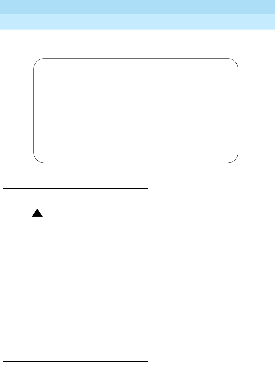
DEFINITY Enterprise Communications Server Release 6
Maintenance for R6r Volumes 1 & 2
555-230-126 Issue 2
January 1998
Maintenance Commands
Page 8-147reset board
8
The following display shows a typical result when release board 01c07 is
entered.
reset board
reset board UUCSS [repeat #]
!CAUTION:
This command can be service disrupting and may cause extraneous
alarms. Effects of a reset vary depending upon the type of object being
reset and upon whether the component is duplicated. Consult the section in
Chapter 9, ‘‘ABRI-PORT (ASAI ISDN-BRI Port)’’
on the relevant maintenance
object for details.
When a port circuit pack is specified, the reset board command performs a
software reset of every administered port on the circuit pack. All ports must be
busied out before the port circuit pack is reset.
On Critical Reliability systems (duplicated PNC), reset of an Expansion Interface,
Switch Node Interface, Switch Node Clock, or DS1 Converter circuit pack on the
active PNC is not permitted. Standby components must first be busied out before
entering the reset.
Cabinet number and repeat both default to 1. For more information see Common
Input Parameters and Common Output Fields at the beginning of this chapter.
reset disk
reset disk [C]
release board 01C07
COMMAND RESULTS
Port Maintenance Name Alt. Name Result Error Code
01C07 ANL-BD PASS
01C0701 ANL-LINE 5409 PASS
01C0702 ANL-LINE 5416 PASS
01C0703 ANL-LINE 5421 PASS
Command successfully completed

DEFINITY Enterprise Communications Server Release 6
Maintenance for R6r Volumes 1 & 2
555-230-126 Issue 2
January 1998
Maintenance Commands
Page 8-148reset fiber-link
8
This command resets the disk device, queries the device for ID, size and other
information, and initiates self-testing by the device. Upon successful completion,
all alarms on that disk are cleared and the device is returned to service.
The cabinet is always 1 and need not be entered. On systems with duplicated
SPEs only, carrier a or b must be entered.
Failure of the reset command places the disk in the uninstalled state. All system
access to the disk, including demand testing, is prevented except for demand
resets.
When the host-adapter is busied out, only the demand busyout and test
commands are permitted on the attached disk. Reset, release, scheduled and
periodic testing and other system software access are blocked. In this case, the
host-adapter must first be released before the disk can be released.
When the host-adapter is taken out of service due to test or reset failures, and
becomes uninstalled, the disk is also placed in the uninstalled state and all
access by system software, including resets, is blocked.
reset fiber-link
reset fiber-link fiber# [a-pnc | b-pnc]
!CAUTION:
The reset fiber-link command is destructive on standard and high reliability
systems (simplex PNC), and may cause an entire port network to be
removed from service.
This command resets the Expansion Interface and/or Switch Node Interface
circuit packs that are endpoints of a specified fiber link, dropping the link in the
process.
A fiber link must be busied out before being reset. To busyout a fiber on critical
reliability systems, the fiber must be on the standby PNC and the standby PNC
must first be busied out. See busyout fiber-link for associated interactions.
The list fiber-link command displays a list of fiber links and their locations.

DEFINITY Enterprise Communications Server Release 6
Maintenance for R6r Volumes 1 & 2
555-230-126 Issue 2
January 1998
Maintenance Commands
Page 8-149reset host-adapter
8
Parameters
Examples
Simplex PNC: reset fiber-link 1
Duplex PNC: reset fiber-link 1
reset host-adapter
reset host-adapter C
This command resets and initializes the host-adapter circuit on the MSSNET
circuit pack. Upon successful completion, the host-adapter is put into service
and all alarms active for that host-adapter circuit are cleared.
The cabinet is always 1 and need not be specified. Carrier a or b must be
specified only on systems with duplicated SPEs.
This command will abort if any other MSS operation has already begun.
Failure of this command will place the host-adapter in the uninstalled state,
preventing all maintenance testing, including demand testing, of the failed
host-adapter. The reset must pass to put the host-adapter back into service.
When the host-adapter is taken out of service due to failures of its tests, or fails a
reset and becomes uninstalled, the attached tape and disk are also placed in the
uninstalled state and all access by system software, maintenance tests and
commands including reset are blocked from execution.
reset maintenance
reset maintenance UUC
This command performs a reset on a specified maintenance circuit pack.
Specifying cabinet 1 resets the PPN SYSAM circuit pack on the selected carrier,
dropping any remote or local logins. Specifying cabinets 2 through 22 resets the
fiber# The administered number of the fiber link (1-27). On critical
reliability systems (duplicated PNC), this number designates a
fiber link pair; the following qualifier specifies which fiber in the
pair is to be reset.
a-pnc, b-pnc On critical reliability systems (duplicated PNC), this
distinguishes between the two fibers in a duplicated pair. On
systems with simplex PNC this is always a-pnc and need not be
specified.

DEFINITY Enterprise Communications Server Release 6
Maintenance for R6r Volumes 1 & 2
555-230-126 Issue 2
January 1998
Maintenance Commands
Page 8-150reset packet-interface
8
EPN maintenance circuit pack in the ‘a’ carrier of the specified cabinet, dropping
any local login to that circuit pack.
The cabinet number defaults to 1. The carrier must be specified only for PPNs
with duplicated SPEs.
reset packet-interface
reset packet-interface C [S]
!CAUTION:
Resetting a packet interface is disruptive under the following conditions:
■On all standard reliability systems (simplex SPE)
■When SPEs in a duplicated system are locked, or handshake is down, and
the active packet interface is reset.
■When the standby SPE in a duplicated system has a state of health lower
than the active, and the active packet interface is reset.
!CAUTION:
In the above cases, call service throughout the system is disrupted, the
terminal is logged off and all EPNs are unavailable during the reset interval.
A minor alarm is logged against the circuit pack to be reset. This lowers the
state of health of the associated SPE and may cause a spontaneous SPE
interchange in duplicated systems.
This command resets and initializes the packet interface circuit pack hardware
and firmware. The actual sequence of operation depends on the type and status
of the SPEs.
When an active packet interface is reset, its links are dropped and reassigned to
the remaining in-service packet interface circuit packs. These links are not
migrated back to the packet interface after the reset. A level 2 (Cold-2) or greater
system restart is required to redistribute the links equally among all active packet
interfaces, including the one that was reset.
Simplex SPE
For standard reliability systems the specified packet interface circuit pack is
simply reset. Failure of the reset can lead to the circuit pack being placed in the
out-of-service state. When a packet interface is out of service, scheduled,
periodic, error and demand testing of the circuit pack is prevented and it is not
used for links. The circuit pack returns to the in-service state upon passing the
reset. A level 2 (Cold-2) or greater system restart is then performed to distribute
the links equally among the available packet interface circuit packs.

DEFINITY Enterprise Communications Server Release 6
Maintenance for R6r Volumes 1 & 2
555-230-126 Issue 2
January 1998
Maintenance Commands
Page 8-151reset packet-interface
8
Duplicated SPE Standby Packet Interface
Reset of a packet interface on the standby SPE does not disrupt service and
results in a reset of all packet interfaces on the standby SPE. The following
conditions are necessary:
■Handshake communication is up.
■The SPE carriers are not locked with the SPE-Select switches.
The following sequence occurs:
1. Memory shadowing is turned off.
2. All standby packet interfaces are reset.
3. If the reset succeeds, shadowing is turned on, memory refresh initiated,
and the packet is put into the standby state.
4. If the reset fails, the circuit pack is put into the out-of-service state,
lowering the standby SPE’s state-of-health.
Duplicated SPE Active Packet Interface
Standby SPE available
When a packet interface on the active SPE of a duplicated system is specified, a
spontaneous SPE interchange is first performed by the system, assuming that:
■The SPE carriers are not locked with the SPE-Select switches.
■Handshake communication is up.
■The state of health of the standby SPE is not lower than that of the active.
If these conditions are met, the interchange places the active SPE into the
standby state, and then all standby packet interfaces are reset as in the above
case. Links are not disrupted, but due to the interchange transient calls are
dropped and the terminal is logged off.
Standby SPE Not Available
If any of the three conditions listed above are not met, an SPE interchange is
prevented and the active packet interface is reset, resulting in disruption of all
links associated with the circuit pack (see the Caution above). When the
interchange is prevented by lower state of health of the standby, the standby
packet interfaces are also reset according to the sequence listed above.
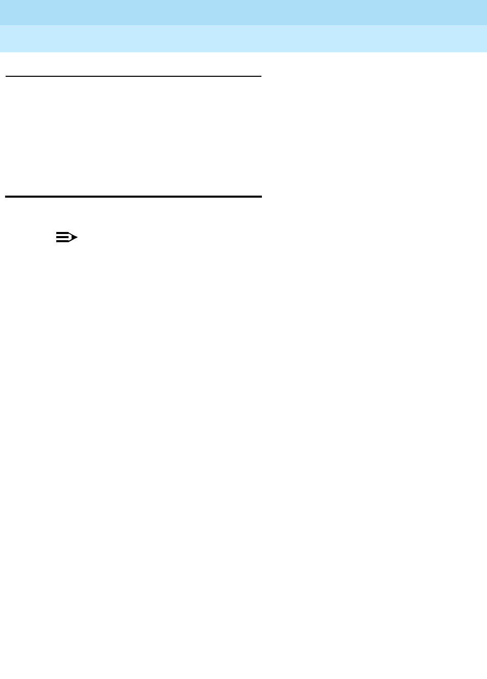
DEFINITY Enterprise Communications Server Release 6
Maintenance for R6r Volumes 1 & 2
555-230-126 Issue 2
January 1998
Maintenance Commands
Page 8-152reset interchange
8
Parameters
reset interchange
reset pnc interchange [override-and-lock]
NOTE:
This command does not work like other reset commands. Instead of
resetting or initializing hardware, a PNC interchange is executed. Before
entering this command, look at the states of health of the two PNCs with
status pnc.
This command executes a PNC interchange on a Critical Reliability system
(duplicated PNC). The standby PNC becomes active and assumes control of
active call processing, and the active goes to standby. If the health of the
standby PNC is the same as or better than that of the active, no service
disruption takes place; all stable calls and links are preserved. Some unstable
calls may drop.
Both demand and spontaneous PNC interchanges are prevented by the
following conditions:
■The standby PNC is busied out.
■The PNCs are locked by means of the set pnc lock or reset PNC
override-and-lock commands.
■For 5 minutes after a spontaneous PNC interchange, or for 30 seconds
after a demand interchange, an anti-thrashing mechanism prevents
subsequent interchanges unless the override-and-lock option is used.
■If the state of health of the standby PNC is worse than that of the active,
the command will abort unless the override-and-lock option is used.
■If the standby PNC has not completed a global refresh since it was last
initialized or released, the reset will abort unless the override-and -lock
option is used.
Note the following caution regarding the use of the override-and-lock option.
See status pnc for details of how to obtain and interpret the states of health and
other current information about the PNCs. For a more complete explanation of
PNC duplication and interchanges, see PNC-DUP in Chapter 9.
C, CS The cabinet is always 1 and need not be specified. Carrier a or b
must be specified only for duplicated SPEs. The slot number
(1-3) designates one of the dedicated PKT-INTFC slots on the
PPN control carrier and defaults to the lowest-numbered slot with
a packet interface installed in it.

DEFINITY Enterprise Communications Server Release 6
Maintenance for R6r Volumes 1 & 2
555-230-126 Issue 2
January 1998
Maintenance Commands
Page 8-153reset interchange
8
Parameters
Output
One of the following messages is displayed:
Command successfully completed
If the reset pnc interchange command is unsuccessful due to the state of health
of the standby Port Network Connectivity, operation of anti-thrashing, or the
following message will be displayed:
Interchange of pnc failed;
try again using the ’override-and-lock’ identifier
See the preceding caution regarding use of the override-and-lock option. If the
reset pnc interchange command is unsuccessful due to a busyout of the standby
PNC, the following message will be displayed:
Must release port network connectivity first
reset pnc interchange [override-and-lock]
NOTE:
This command does not work like other reset commands. Instead of
resetting or initializing hardware, a PNC interchange is executed. Before
entering this command, look at the states of health of the two PNCs with
status pnc.
This command executes a PNC interchange on a Critical Reliability system
(duplicated PNC). The standby PNC becomes active and assumes control of
active call processing, and the active goes to standby. If the health of the
standby PNC is the same as or better than that of the active, no service
disruption takes place; all stable calls and links are preserved. Some unstable
calls may drop.
interchange ”interchange” (without a preceding hyphen) must be
specified on the command line.
override-and-lock This option is also used to override the anti-thrashing
mechanism. Subsequent PNC interchanges are prevented,
regardless of changes in the states health of the PNCs.
Double call setup still takes place; each call is set up on
both PNCs. To unlock the PNCs, use set pnc unlock.
!CAUTION:
This option forces execution of the interchange
regardless of the state of health of the standby,
possibly disrupting service.

DEFINITY Enterprise Communications Server Release 6
Maintenance for R6r Volumes 1 & 2
555-230-126 Issue 2
January 1998
Maintenance Commands
Page 8-154reset interchange
8
Both demand and spontaneous PNC interchanges are prevented by the
following conditions:
■The standby PNC is busied out.
■The PNCs are locked by means of the set pnc lock or reset PNC
override-and-lock commands.
■For five minutes after a spontaneous PNC interchange, or for 30 seconds
after a demand interchange, an anti-thrashing mechanism prevents
subsequent interchanges unless the override-and-lock option is used.
■If the state of health of the standby PNC is worse than that of the active,
the command will abort unless the override-and-lock option is used.
■If the standby PNC has not completed a global refresh since it was last
initialized or released, the reset will abort unless the override-and -lock
option is used.
Note the following caution regarding the use of the override-and-lock option.
See status pnc for details of how to obtain and interpret the states of health and
other current information about the PNCs. For a more complete explanation of
PNC duplication and interchanges, see PNC-DUP in Chapter 9.
Parameters
interchange ”interchange” (without a preceding hyphen) must be
specified on the command line.
override-and-loc
kThis option is also used to override the anti-thrashing
mechanism. Subsequent PNC interchanges are prevented,
regardless of changes in the states health of the PNCs.
Double call setup still takes place; each call is set up on
both PNCs. To unlock the PNCs, use set pnc unlock.
!CAUTION:
This option forces execution of the interchange
regardless of the state of health of the standby,
possibly disrupting service.

DEFINITY Enterprise Communications Server Release 6
Maintenance for R6r Volumes 1 & 2
555-230-126 Issue 2
January 1998
Maintenance Commands
Page 8-155reset port-network
8
Output
One of the following messages is displayed:
Command successfully completed
If the reset pnc interchange command is unsuccessful due to the state of health
of the standby Port Network Connectivity, operation of anti-thrashing, or the
following message will be displayed:
Interchange of pnc failed;
try again using the ’override-and-lock’ identifier
See the preceding caution regarding use of the override-and-lock option. If the
reset pnc interchange command is unsuccessful due to a busyout of the standby
PNC, the following message will be displayed:
Must release port network connectivity first
reset port-network
reset port-network PN# level [1 | 2]
!CAUTION:
A reset of level 2 is destructive, causing all calls and application links on the
specified EPN to drop. EPN resets are described under EXP-PN in Chapter
9.
This command resets a specified port network to a specified level. This does not
cause an interchange on a system with duplicated PNC. The command will not
execute on the PPN, or on an EPN whose fiber link to the PPN or CSS is down.

DEFINITY Enterprise Communications Server Release 6
Maintenance for R6r Volumes 1 & 2
555-230-126 Issue 2
January 1998
Maintenance Commands
Page 8-156reset port-network
8
Parameters
Examples
reset port-network 10 level 2
Output
For more information, see ‘‘Common Output Fields’’ and ‘‘Common Abort and Fail
Codes’’ at the beginning of this chapter. The following display shows a typical
result when reset port-network 4 lev 1 is entered.
PN# Port network number
Use list cabinet to find the PN number(s) associated with a
given cabinet.
level 1 | 2 Reset level 1 (WARM restart) is used to restart an EPN that is
still fully or partially in service. All stable calls are preserved,
and full service is restored within 35 seconds.
Reset level 2 (COLD restart) results in reset, removal, and
reinsertion of all EPN circuit packs. It is used to recover an
EPN that has been taken out of service. Level 2 restarts should
take less than 2 minutes. All calls and application links with an
endpoint in the EPN are dropped. If two level 2 resets within an
hour fail to return the EPN to service, EPN Emergency Transfer
is invoked. (EPN Emergency Transfer will already be in effect if
the link to the EPN has been down for more than 1 minute).
Port The PN number of the reset EPN.
reset port-network 4 level 1
TEST RESULTS
Port Maintenance Name Alt. Name Test No. Result Error Code
04 EXP-PN 956 PASS
Command Successfully Completed

DEFINITY Enterprise Communications Server Release 6
Maintenance for R6r Volumes 1 & 2
555-230-126 Issue 2
January 1998
Maintenance Commands
Page 8-157reset spe-standby
8
reset spe-standby
reset spe-standby level# [tape]
This resets the standby SPE on a system with duplicated SPEs to a specified
level. The command is increasingly destructive as the reset level increases. On a
system with disk and tape devices, the reset is executed using the boot image
stored on disk unless a reset of level 4 (reboot) with the “tape” qualifier is
requested. During the reset, the standby SPE is taken out of service for several
minutes. Reset status can be monitored with the status spe command.
During a reset of any level, memory shadowing is turned off. After the reset
completes, memory shadowing is automatically restored and a memory refresh
of the standby takes place. The standby is not fully in service until the refresh is
complete. Reset spe-standby invokes initialization of the standby in the same
fashion as low level maintenance. The reset level requested will not be escalated
by software. The level requested will always be the level that is performed.
Any reset of the standby SPE turns off shadowing, leaving the standby SPE
unrefreshed. It may take several minutes before the standby is available for
service.
Parameters
Output
The message: Command successfully completed indicates that the reset
has been initiated. Execution and recovery can take several minutes.
level# This specifies the level of reset to be executed, from 1 to 5:
Tape Recovery
1 Warm Restart
2Cold-2
3Cold-1
4 Reboot
5 Extended Reboot
Tape Valid only for a reset of level 4, this specifies a reboot using the
boot image stored on tape instead of disk.

DEFINITY Enterprise Communications Server Release 6
Maintenance for R6r Volumes 1 & 2
555-230-126 Issue 2
January 1998
Maintenance Commands
Page 8-158reset system
8
reset system
reset system [level# | interchange] [disk | tape] [contention-override]
!CAUTION:
All system resets (except planned interchanges) are service affecting, with
higher levels being increasingly destructive. Some resets may take up to
one half hour to complete. Certain conditions may result in a higher reset
level than the one requested. Unless you are experienced with resetting a
system, follow normal escalation procedures.
NOTE:
reset system interchange, used to switch control of the system from an
active SPE to the standby, is discussed separately under its own heading.
This command resets a Switch Processing Element (SPE) at a specified level that
is increasingly disruptive as the reset level increases.
All system resets (except
reset system interchange) are disruptive and terminate the G3-MT login.
When the command is entered, the MSS devices are checked to see if they are
currently in use. If any command or maintenance process that accesses the MSS
is in progress, the reset is denied and a message is displayed. In this case, the
contention-override option is required to force the reset. This check prevents
aborting of a save translation or other MSS process.
If the vector bit is set to trigger a core dump for the specified reset level, a copy
of system memory is first written to the primary MSS device. The system then
clears the vector and proceeds with the request. If the vector is set for an active
SPE core dump for reset level 1 a reset level 2 will be performed to recover the
Packet Interface links. See the get vector command.
System software will generally not escalate a demand system reset to a higher
level. There are certain conditions that result in a higher level reset than that
requested. These include the following:
■The vector is set to trigger a core dump on the active SPE in the event of a
level 1 reset.
■A PNC interchange is already in progress.
■A change in translation administration is in progress.
Reset levels greater than 1 turn off shadowing in a duplicated system, and leave
the standby SPE in an unrefreshed condition for several minutes.
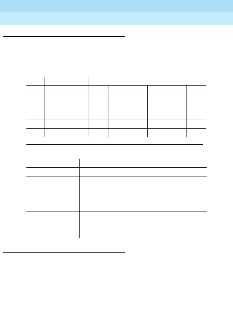
DEFINITY Enterprise Communications Server Release 6
Maintenance for R6r Volumes 1 & 2
555-230-126 Issue 2
January 1998
Maintenance Commands
Page 8-159reset system
8
Parameters
Examples
reset system 1
reset system 4 tape contention-override
Output
Once this command is entered, it may not be canceled. The screen will display
the results of various initialization tests. If the reset command is successful the
user will be logged off (except for reset system interchange). Several
Level Reset levels are numbered as shown in Table 8-8. The execution times
listed are approximations.
Table 8-8. Approximate Recovery Time for System Resets (min:sec)
Level Recovery 2,400 lines 5,000 lines 15,000 lines
Tape Disk Tape Disk Tape Disk
1 Warm Restart :10 :10 :10 :10 :10 :10
2 Cold-2 1:001:002:002:004:004:00
3 Cold-1 3:00 2:00 5:00 3:00 11:00 7:00
4 Reboot 12:00 4:00 15:00 6:30 23:00 11:00
5 Extended Reboot 15:00 7:00 18:00 10:00 25:00 15:00
Interchange See reset system interchange
Health-override See reset system interchange
Disk Valid only for reset level 4, this specifies use of the boot
image stored on disk for the reboot. Disk is the default
device.
Tape Valid only for reset level 4, this specifies use of the boot
image stored on tape for the reboot.
Contention-override Contention control aborts the reset system command if
any other command is currently running. The
contention-override option forces other processes to
abort, allowing the reset to proceed.

DEFINITY Enterprise Communications Server Release 6
Maintenance for R6r Volumes 1 & 2
555-230-126 Issue 2
January 1998
Maintenance Commands
Page 8-160reset system interchange
8
conditions may prevent a requested reset. If the reset fails and the message
displayed is not self-explanatory, use status spe to determine what caused the
failure.
reset system interchange
reset system interchange [health-override][contention-override]
!CAUTION:
Although this command is normally not disruptive, certain conditions may
escalate the interchange to a higher reset level.
This command is used to switch control from the currently active SPE to the
standby. This type of interchange is called a planned, soft, demand or requested
interchange. Interchanges caused by hardware faults or the SPE-Select
hardware switches are called spontaneous or hard interchanges. Planned
interchanges are discussed under:
— SPE Duplication in Chapter 1, ‘‘Maintenance Architecture’’
— Executing a Planned Interchange in Chapter 5, ‘‘Responding to Alarms
and Errors’’
— STBY-SPE in Chapter 9
This operation is not disruptive if the state of health of the standby SPE is
“functional.” If this condition is not met, system software will normally abort a
requested interchange. When this is the case, the health-override option can be
specified to try to force a
spontaneous
(hard) interchange.
!CAUTION:
Use of health-override may cause serious service disruption.
Once a planned interchange has been initiated, it cannot be aborted with the
CANCEL key. A reset system interchange command will abort for the following
reasons:
■If the standby SPE is down
■If the SPEs are locked by means of the SPE-Select switches
■If communication to the standby SPE is not possible (handshake is down)
■If shadowing to the standby SPE is not turned on
■If the standby SPE is not fully refreshed
■If the State-of-Health of the standby is not “functional”
■There is an SCD dual-port RAM failure
■If there is any Mass Storage System activity

DEFINITY Enterprise Communications Server Release 6
Maintenance for R6r Volumes 1 & 2
555-230-126 Issue 2
January 1998
Maintenance Commands
Page 8-161reset system interchange
8
■If Packet Interface link migration fails
■If a minor or major alarm is logged against the standby SPE’s SYSAM or
Packet Interface circuit packs
■If the standby SPE is busied out
The destructiveness of an interchange that fails depends on how far the
interchange proceeds before it fails. A non-destructive recovery should occur if
an interchange is aborted before link migration has started. If the interchange
fails after link migration has started, the system will perform a WARM restart to
recover.
The SPE-Select switches located on the Duplication Interface circuit packs
override any demand maintenance activities. If the SPEs are locked by means of
these hardware switches, an interchange cannot take place until the switches
are unlocked.
If a planned interchange aborts or fails, an error will be logged against SYSTEM,
signaling that the expected interchange has not occurred. In this case, the reset
may be escalated by software. This condition is described in Failure of Planned
Interchange in Chapter 5, ‘‘Responding to Alarms and Errors’’.
If reset system interchange override is specified while a PNC interchange is
occurring, a spontaneous (hard) SPE interchange will occur which results in a
Cold restart. After the restart, the active PNC will be the one that was being
switched into before the restart.
If a requested SPE interchange fails, an error conveying additional information
about the failure will be logged against the SYSTEM maintenance object.

DEFINITY Enterprise Communications Server Release 6
Maintenance for R6r Volumes 1 & 2
555-230-126 Issue 2
January 1998
Maintenance Commands
Page 8-162reset tape
8
Parameters
Output
Once this command is entered, it may not be canceled. The screen will display
the results of various initialization tests. Several conditions can prevent a
requested interchange. If the interchange fails and the message displayed is not
self-explanatory, use status spe to determine what caused the failure. Executing
a Planned SPE Interchange in Chapter 5, ‘‘Responding to Alarms and Errors’’
and STBY-SPE in Chapter 9 contain useful information for troubleshooting
interchange failures, The following display shows a typical result when reset sys
int is entered while a save operation is currently running.
reset tape
reset tape [C]
This command resets the tape circuit pack, queries the device for ID, size and
other information, initiates self testing of the device, and rewinds the tape. If
successful, all alarms active for the tape device are cleared and the device is put
back in service.
health-override If a planned (demand) interchange fails for any of the
previously listed reasons, this option can be specified to
try to force a switch to occur. This option causes the
active SPE’s state of health to be downgraded as much
as possible in order to allow a spontaneous (hard)
switch to occur. However, if the standby SPE’s state of
health is still not better than that of the active, or if the
SPEs are locked, the interchange will still not occur.
contention-override Due to contention control, reset system interchange
aborts if any other command is currently running. Use of
this option overrides contention control and forces the
command to execute regardless of whether other
commands are currently running.
reset system interchange SPE A
Unable to interchange due to MSS activity.

DEFINITY Enterprise Communications Server Release 6
Maintenance for R6r Volumes 1 & 2
555-230-126 Issue 2
January 1998
Maintenance Commands
Page 8-163restore announcements
8
This command will abort if any other MSS operation has already begun.
Failure of the reset command will place the tape in the uninstalled state,
preventing all maintenance testing including demand testing of the failed tape as
well as all system access to the failed tape except for this reset command.
When the host-adapter is busied out, only the busyout and test commands are
permitted on the tape in that carrier. Reset, release, scheduled and periodic
testing and other system software access are blocked. The host-adapter must be
released before the tape can be released.
When the host-adapter is taken out-of-service due to test failures, or fails a reset
and becomes uninstalled, the tape on the same carrier is also placed in the
uninstalled state. All access to that tape by system software, including
maintenance tests, resets and other commands are blocked from execution.
Parameters
Examples
For more information see ‘‘Common Output Fields’’ at the beginning of this
chapter.
restore announcements
restore announcements [disk | tape]
This command copies stored announcement data from the specified MSS device
to the announcement board. On a duplicated system, data is always copied from
the device on the active SPE.
NOTE:
The restore command can take up to 40 minutes to complete. Avoid
pressing the ENTER key on the keyboard during this time, since doing so
will cause the result messages to be lost.
The command is not executed if any of the following conditions is present:
■An announcement data module and a system port data module have not
been administered.
CThe cabinet is always 1 and need not be entered. Carrier a or b must be
specified only for systems with duplicated SPE.
Simplex SPE: reset tape
Duplicated SPE: reset tape a

DEFINITY Enterprise Communications Server Release 6
Maintenance for R6r Volumes 1 & 2
555-230-126 Issue 2
January 1998
Maintenance Commands
Page 8-164restore announcements
8
■The announcement data module port is out of service or already in use (for
example, performing an announcement playback).
■An integrated announcements session is in progress or the circuit pack is
currently being uploaded or downloaded. Announcements cannot be
save or restored after the restore announcements command has started.
Tape is specified and a tape cartridge is not in the tape drive.
■A system port is not available.
■The MSS is in use by either another user or by maintenance.
■An announcement file does not exist on the specified device, or is
corrupted.
In case of a failure of the restore command, you must make sure the
announcement file is completely copied to the announcement circuit pack. The
system will continually attempt to download the circuit pack at 10 minute intervals
until either a download is successful, announcements are recorded, or a
download is initiated from the terminal. In case of a hardware or firmware error,
an error will be logged, pointing to the source of trouble. Maintenance software
will invoke tests to diagnose and attempt to correct the problem. If maintenance
software fails to correct the problem, an alarm is raised.
If a system crash or spontaneous SPE interchange takes place, the restore
operation will fail, leaving the announcement circuit pack without a valid
announcement file. To remedy this, repeat the restore command on the newly
active SPE.
NOTE:
Until announcements are completely copied to the announcement circuit
pack, calls will not be connected to any announcements on the
announcement circuit pack.
When the announcement circuit pack is inserted or reset, an automatic download
of the announcement file is performed.

DEFINITY Enterprise Communications Server Release 6
Maintenance for R6r Volumes 1 & 2
555-230-126 Issue 2
January 1998
Maintenance Commands
Page 8-165restore disk
8
Parameters
Output
The following display shows a typical result when restore announcements is
entered.
restore disk
This command copies all information from the tape device in the specified SPE to
the disk device on the same carrier. Defaults are a full restore and, if the SPE is
duplicated, both SPEs.
disk This specifies copying the announcement data stored on the disk
device. Disk is the default device.
tape This specifies copying the announcement data stored on the tape
device.
Processor The SPE from whose MSS device the announcement data was
copied.
Command
Completion
Status
This field indicates the results of the command execution an
gives a self-explanatory reason for any failures.
Error Code A number indicating whether the announcement file was
successfully restored to the announcement board:
0 = The restore was successful.
1 = The restore failed.
restore disk [active | standby] [spe-a | spe-b] [both | either]
[incremental | full]
restore announcements Page 1 of 1 SPE A
RESTORE ANNOUNCEMENTS
Processor Command Completion Status Error Code
SPE-A Success 0

DEFINITY Enterprise Communications Server Release 6
Maintenance for R6r Volumes 1 & 2
555-230-126 Issue 2
January 1998
Maintenance Commands
Page 8-166restore disk
8
NOTE:
The restore command can take up to 1 hour to complete. Avoid pressing
the ENTER key on the keyboard during this time, since doing so will cause
the result messages to be lost.
Parameters
Examples
restore disk
restore disk active incremental
Output
The outcomes are displayed for each SPE.
spe-a This specifies a restore from the A carrier tape device to the A
carrier disk device.
spe-b This specifies a restore from the B carrier tape device to the B
carrier disk device.
active This specifies a restore on the active SPE.
standby This specifies a restore on the standby SPE.
both This specifies a restore on both SPEs. If the MSS on either SPE is
inaccessible, the restore will abort on both SPEs.
either This specifies a restore on both SPEs. If the standby SPE is
inaccessible, the active SPE only will be restored.
incremental This specifies that all data on tape marked “good” that has a date
newer than the date on the disk be copied to the disk from the
tape.
full This specifies that all data be copied to the disk regardless of the
dates and the status of the data (e.g., “good” or “bad”).
Processor This identifies the processor carrier that was backed up
(SPE-A or SPE-B).
Command
Completion
Status
This field displays one of various self-explanatory messages
indicating the success or failure of the command.

DEFINITY Enterprise Communications Server Release 6
Maintenance for R6r Volumes 1 & 2
555-230-126 Issue 2
January 1998
Maintenance Commands
Page 8-167resume hardware-group
8
The following display shows a typical result when restore disk is entered.
resume hardware-group
resume hardware-group
In the course of execution of a test hardware-group command, it may be
desirable to halt the test temporarily or permanently. This is accomplished by
either the cancel hardware-group command for a background test, or by
pressing Cancel for a foreground test. Resume hardware-group enables you to
restart the hardware group test at the point where it was canceled. This
capability is not available if another hardware group test has been started. The
status of a hardware group test can be obtained with status hardware-group.
When test hardware-group all-ports is canceled, the internally generated port
translations for previously untranslated ports are removed. If resume
hardware-group is then entered, only customer-administered ports will then be
tested. resume does
not
reinstate the port translations that were removed by
cancellation of the test.
Output
When a test that was executing in the background is resumed, a success
message is displayed. When a test that was executing in the foreground is
resumed, test results are displayed.
restore disk
RESTORE DISK
Processor Command Completion Status
SPE-A Success
SPE-B Success
Command Successfully Completed

DEFINITY Enterprise Communications Server Release 6
Maintenance for R6r Volumes 1 & 2
555-230-126 Issue 2
January 1998
Maintenance Commands
Page 8-168save announcements
8
save announcements
!CAUTION:
Do not execute save announcements if there is an unresolved problem
with the HOST-ADAPTR maintenance object. Save translations should not
be done to a tape or disk device with unresolved problems. Doing so may
destroy a good copy of the files.
!CAUTION:
The option to save announcements to only one SPE in a duplicated system
should be used with care since it causes two inconsistent versions to exist
in storage.
!CAUTION:
The save command can take up to 40 minutes to complete. Avoid pressing
ENTER
during this time since doing so will cause the result messages to be
lost.
The save announcements command copies announcement data from the
TN750B Integrated Announcement circuit pack to the Mass Storage System
(MSS). Default devices are the disk in a disk/tape system, and the devices in
both SPEs in a duplicated system. Other options are available as described
below.
Save announcements writes two identical copies of the announcement data to
each specified device. Each copy bears the same time-stamp, (the time at which
the first copy was written). Each copy is also marked with the state of the copy
(“good” or “bad”).
Execution of this command requires the presence of a TN750B circuit pack and
an administered announcement data module and associated system port.
The command is disallowed or aborts if:
■An announcement data module and system port data module are not
administered.
■The announcement data module port is out of service or already in use.
■No announcements are on the board.
■An integrated announcements session is in progress.
■The board is currently being uploaded or downloaded.
save announcements [active | standby | spe-a | spe-b | both | either]
[disk | tape]

DEFINITY Enterprise Communications Server Release 6
Maintenance for R6r Volumes 1 & 2
555-230-126 Issue 2
January 1998
Maintenance Commands
Page 8-169save announcements
8
■The tape drive is specified and no tape is in the tape drive or the tape is
write-protected.
■No system access port is available.
■The MSS is in use by another user or by maintenance.
■The specified device or SPE is not in service.
■The standby SPE is specified and shadowing is not enabled.
A user cannot record announcements while a save announcements command is
in progress. However, 15 channels are still available for announcement playback
(one is reserved for uploading and downloading).
When MSS devices on both SPEs in a duplicated system are specified, save
announcements will save data from the announcement board to the active and
standby devices in parallel. The status of each save operation is reported
separately. If one save operation fails, the save to the other device continues.
Thus, the data is not lost. In this case, announcement date is inconsistent
between the two devices. In case of a failure due to hardware faults or
spontaneous SPE interchange, the user must make the announcement files on
the two MSS devices consistent.
If a hardware failure occurs during a save announcements operation, software
will log a hardware error. Maintenance software will invoke tests to diagnose and
attempt to correct the problem. If corrective action fails, an alarm is raised
against the ANNOUNCE maintenance object. Follow procedures recommended
under ANNOUNCE in Chapter 9, ‘‘ABRI-PORT (ASAI ISDN-BRI Port)’’.
If a good copy of the announcement file is not available on the MSS, the restore
announcements command can not be executed until after a successful save
announcements is completed. The announcements on the board are still
accessible and usable.

DEFINITY Enterprise Communications Server Release 6
Maintenance for R6r Volumes 1 & 2
555-230-126 Issue 2
January 1998
Maintenance Commands
Page 8-170save announcements
8
Parameters
Examples
save announcements
save announcements active disk
save announcements standby tape
save announcements spe-a disk
active This option specifies writing to the specified device in the currently
active SPE.
standby This option specifies writing to the specified device in the standby
SPE.
spe-a This option specifies writing to the specified device in the SPE on
the A carrier.
spe-b This option specifies writing to the specified device in the SPE on
the B carrier.
both This option specifies writing to the specified device in each SPE
concurrently. A failure in accessing either device causes the entire
operation to fail and neither device is written to.
either This option specifies writing to the specified device in both SPEs
concurrently. If there is a failure in accessing one of the devices,
the announcement data will still be written to the other one.
disk This option specifies writing to the disk drive. Disk is the default
device.
tape This option specifies writing to the tape drive.

DEFINITY Enterprise Communications Server Release 6
Maintenance for R6r Volumes 1 & 2
555-230-126 Issue 2
January 1998
Maintenance Commands
Page 8-171save translation
8
Output
The following display shows a typical result when save announcements is
entered on a system with simplex SPE.
save translation
NOTE:
The save command can take up to 15 minutes to complete. Avoid pressing
the ENTER key on the keyboard during this time, since doing so will cause
the result messages to be lost.
All translation data is kept in volatile system memory during normal operation. In
the event of a power outage or certain system failures, data in memory is lost.
The save translation command allows the user to store on disk or tape the
translation data currently in memory. This operation can be executed as part of
scheduled background maintenance or on demand. The defaults are to save to
disk and, on a system with duplicated SPEs, to both SPEs.
Processor The SPE(s) to which announcement data was written (SPE-A or
SPE-B).
Command
Completion
Status
The result of command execution, with a self-explanatory
message explaining any failure or abort.
Error Code Each device holds two copies of the announcements file. This
field indicates whether both copies on the device were
successfully stored:
2 = Both copies of the file were saved.
1 = One copy was saved and one failed.
0 = Neither copy was saved.
save translation [active | standby | spe-a | spe-b | both | either]
[disk | tape]
save announcements Page 1 of 1 SPE A
SAVE ANNOUNCEMENTS
Processor Command Completion Status Error Code
SPE-A Success 2

DEFINITY Enterprise Communications Server Release 6
Maintenance for R6r Volumes 1 & 2
555-230-126 Issue 2
January 1998
Maintenance Commands
Page 8-172save translation
8
!CAUTION:
Save translation should not be executed if there is an unresolved problem
with the HOST-ADAPTR maintenance object. Save translations should not
be done to a TAPE or DISK device with unresolved problems. Doing so may
destroy a good copy of the files.
!CAUTION:
On systems with duplicated SPEs, the capability to save translation to only
one SPE should be used with extreme caution since it results in the two
SPEs having inconsistent translation data in storage.
The save translation cannot be executed if translation data is being changed by
an administration command.
Parameters
Examples
save translation disk
save translation either tape
Output
Results are displayed for each SPE.
spe-a This specifies saving translation data to the MSS device on the SPE
in carrier A only.
spe-b This specifies saving translation data to the MSS device on the SPE
in carrier B only.
active This specifies saving translation data on the active SPE only.
standby This specifies saving translation data on the standby SPE only.
both This specifies saving translation data on both SPEs concurrently (the
default). The command will fail if the specified device on either SPE
is inaccessible, and neither device will be saved to.
either This specifies saving translation data on both SPEs. If the standby is
inaccessible, the save will still be done on the active SPE.
disk This specifies saving translation data to the disk drive. Disk is the
default device.
tape This specifies saving translation data to the tape drive.
Processor This identifies the SPE to which translation data was saved
(SPE-A or SPE-B).

DEFINITY Enterprise Communications Server Release 6
Maintenance for R6r Volumes 1 & 2
555-230-126 Issue 2
January 1998
Maintenance Commands
Page 8-173set options
8
The following display shows a typical result of entering save translation on a
duplex system.
set options
This command allows the user to administer whether certain alarms are reported
to INADS or whether they are downgraded to a minor alarm, warning alarm, or no
alarm.
Synopsis
set options
Permissions
The following default logins may execute this command: inads, init.
Examples
set options
Command
Completion
Status
One of the following results is displayed:
Success
Disk device is out of service
Tape device is out of service
save translation
SAVE TRANSLATION
Processor Command Completion Status
SPE-A Success
SPE-A Success
Command Successfully Completed

DEFINITY Enterprise Communications Server Release 6
Maintenance for R6r Volumes 1 & 2
555-230-126 Issue 2
January 1998
Maintenance Commands
Page 8-174set options
8
Description
This special command enables the technician (that is, remote user with INADS
permission) to select which types of maintenance categories report alarms
automatically and which types require the customer to call in. Judicious use of
this command can reduce the number of ineffective alarms to the TSC. For the
set options command to be effective, the default settings specified in this
section should always be used. These settings are not intended to be changed
on a per-system basis. Special circumstances (for example, special studies) may
require temporary changes under the guidance of Tiers 3 and 4.
NOTE: Alarms can’t be upgraded.
Defaults
Initially, the alarm reporting options for On-board Trunk Alarms (Alarm Group 1),
both Major and Minor, are set to “yes” (y); all others are set to “warning” (w). All
trunk groups are associated with alarm severity group 1 by default.
Parameters
None.
Help Messages
If the user presses HELP after entering set options, the following message is
displayed:
Entry is not required
Error Messages
If the command entered is in conflict with another currently executing command,
then a message is displayed showing the login id of the conflicting user and the
conflicting command. The message is as follows:
’login id’:’command’ has a command conflict
If during the execution of a command a resource problem occurs that requires
the user to restart the command, then the following message is displayed:
Command resources busy;
Press CANCEL to clear, and then resubmit
If all of the available maintenance resources are currently in use, then the
following message is displayed:
All maintenance resources busy; try again later

DEFINITY Enterprise Communications Server Release 6
Maintenance for R6r Volumes 1 & 2
555-230-126 Issue 2
January 1998
Maintenance Commands
Page 8-175set options
8
Form Input
After entering the command set options, the user is presented with the following
form.
NOTE:
The remaining Trunk Group information is shown on the next 6 pages and is
not documented in this Manual.
On the first page of the Alarm Reporting Options Form, the user selects the alarm
severity options for station alarms, the four trunk alarm severity groups, the
adjunct alarms, off-board DS1 alarms, off board PGATE-PT alarms, and other
off-board alarms. On the second page, known as the Alarm Reporting Options
Form, the user assigns an alarm severity group to each trunk group. This feature
set options Page 1 of 8
ALARM REPORTING OPTIONS
Major Minor
On-board Station Alarms: w w
Off-board Station Alarms: w w
On-board Trunk Alarms (Alarm Group 1): y y
Off-board Trunk Alarms (Alarm Group 1): w w
On-board Trunk Alarms (Alarm Group 2): w w
Off-board Trunk Alarms (Alarm Group 2): w w
On-board Trunk Alarms (Alarm Group 3): w w
Off-board Trunk Alarms (Alarm Group 3): w w
On-board Trunk Alarms (Alarm Group 4): w w
Off-board Trunk Alarms (Alarm Group 4): w w
On-board Adjunct Alarms: w w
Off-board Adjunct Alarms: w w
Off-board DS1 Alarms: w w
Off-board PGATE-PT Alarms: w w
Off-board Alarms (Other): w w
set options Page 2 of 8
TRUNK GROUP ALARM OPTIONS
(Alarm Group)
01: 1 11: 1 21: 1 31: 1 41: 1 51: 1 61: 1 71: 1 81: 1 91: 1
02: 1 12: 1 22: 1 32: 1 42: 1 52: 1 62: 1 72: 1 82: 1 92: 1
03: 1 13: 1 23: 1 33: 1 43: 1 53: 1 63: 1 73: 1 83: 1 93: 1
04: 1 14: 1 24: 1 34: 1 44: 1 54: 1 64: 1 74: 1 84: 1 94: 1
05: 1 15: 1 25: 1 35: 1 45: 1 55: 1 65: 1 75: 1 85: 1 95: 1
06: 1 16: 1 26: 1 36: 1 46: 1 56: 1 66: 1 76: 1 86: 1 96: 1
07: 1 17: 1 27: 1 37: 1 47: 1 57: 1 67: 1 77: 1 87: 1 97: 1
08: 1 18: 1 28: 1 38: 1 48: 1 58: 1 68: 1 78: 1 88: 1 98: 1
09: 1 19: 1 29: 1 39: 1 49: 1 59: 1 69: 1 79: 1 89: 1 99: 1
10: 1 20: 1 30: 1 40: 1 50: 1 60: 1 70: 1 80: 1 90: 1 100: 1

DEFINITY Enterprise Communications Server Release 6
Maintenance for R6r Volumes 1 & 2
555-230-126 Issue 2
January 1998
Maintenance Commands
Page 8-176set options
8
enables the technician to reduce the level of alarms reported for on-board or
off-board trouble conditions.
The following alarm options are available:
■Minor
Alarms are raised as maintenance testing discovers them but the severity
of the alarm is downgraded to a minor. Alarmed resources that would
have normally been taken out of service are still taken out of service. LEDs
on the port board and maintenance board follow the normal Minor alarm
LED strategy and there is a call to the receiving OSS.
■Warning
Alarms are raised as maintenance testing discovers them, but the severity
of the alarm is downgraded to a warning. The advantage to the technician
here is that the Alarm Log can still be used to pinpoint trunk or station
problems reported by the customer. Alarmed resources that would
normally have been taken out-of-service are still taken out-of-service.
Alarm LEDs light on the port circuit pack and Maintenance circuit pack as
before, but no attendant LEDs or stations reporting alarms are affected.
There is no call to INADS.
■Report
This option treats the alarms in the same way as the warning category with
one exception: alarms are reported to INADS using a special WARNING
category. When an alarm of this type is received, INADS logs the
occurrence and either creates a trouble ticket or closes it immediately.
The retry strategy for a call of this type is similar to normal Major or Minor
alarm reports. However, the acknowledgment LED on the attendant
console or alarm reporting station does not reflect the status of the call.
■Yes
Alarms are raised in the normal manner. There is no filtering of alarm data.
■No
Alarms raised on a trunk, station, or adjunct in this category are dropped.
Error information is provided as before, but there is no trace of an alarm.
There is no LED activity and no call to INADS. Because resources are
taken out-of-service without any record, this option is recommended only
when other options do not provide the desired result.
The alarm options can be administered only on a system-wide basis for the
following alarm categories:
■Major on-board station alarms
■Minor on-board station alarms
■Major off-board station alarms
■Minor off-board station alarms

DEFINITY Enterprise Communications Server Release 6
Maintenance for R6r Volumes 1 & 2
555-230-126 Issue 2
January 1998
Maintenance Commands
Page 8-177set options
8
Four alarm severity groups are provided for trunk alarms. You can administer the
alarm options for the categories listed below in each alarm severity group.
However, in G1, the alarm options can be administered only on a system-wide
basis for the following categories:
■Major on-board trunk alarms
■Minor on-board trunk alarms
■Major off-board trunk alarms
■Minor off-board trunk alarms
For Adjuncts, an alarm severity option is assigned to each of the following
categories:
■Major on-board adjunct alarms
■Major off-board adjunct alarms
■Minor on-board adjunct alarms
■Minor off-board adjunct alarms
You can also administer the options on a system-wide basis for Minor off-board
DS1 Interface circuit pack alarms.
Alarm reporting options information in the Alarm Reporting Options Form is
considered translation data and, thus, is preserved through all levels of restart.
This feature affects the alarming of the MOs listed below. Neither the trunk nor
the station category applies to alarms raised on the common portion of the circuit
pack.
In all cases, if the option associated with the alarm type is set to “n,” the alarm
report is dropped. All error information about the alarm is intact, but there is no
record of an alarm and no LEDs light on the port circuit pack, the Maintenance
circuit pack, the attendant console, or alarm reporting station to indicate a
problem.
If the option is set to “warning” or “report,” port circuit pack LEDs and LEDs on
the Maintenance circuit pack are affected the same as normal warning alarms.
The default parameters are as follows:
■Downgrade all station, trunk (except on-board trunk alarms), and Minor
DS1-BD alarms to warning alarms.
■On-board Major and Minor trunk alarms, should continue to raise alarms
and report to INADS.

DEFINITY Enterprise Communications Server Release 6
Maintenance for R6r Volumes 1 & 2
555-230-126 Issue 2
January 1998
Maintenance Commands
Page 8-178set options
8
Station MOs Affected By This Command
NOTE:
Although alarms on these MOs may appear as warnings, the alarms should
be investigated with user-reported problems.
■Analog Lines (ANL-LINE, ANL-NE-L, ANL-16-L)
■Digital Lines (DIG-LINE)
■Hybrid Lines (HYB-LINE)
■MET Lines (MET-LINE)
■ISDN-BRI Lines (BRI-PORT, BRI-SET)
Trunk maintenance is characterized by an escalation of a Minor alarm to a Major
alarm if more than 75 percent of the members of the trunk group are alarmed. If
the option for the trunk category is set to “warning,” “minor,” “report,” or “no,” this
no longer happens. Maintenance removes an individual trunk member
out-of-service according to the normal criteria used for Major and Minor alarms.
Trunk MOs Affected By This Command:
NOTE:
Although alarms on these MOs may appear as warnings, the alarms should
be investigated with user-reported problems.
■Auxiliary Trunks (AUX-TRK)
■Central Office Trunks (CO-TRK)
■Direct Inward Dialing Trunks (DID-TRK)
■Direct Inward and Outward Dial Trunks (DIOD-TRK)[G1.2SE only]
■DS1 Central Office Trunks (CO-DS1)
■DS1 Direct Inward Dialing Trunks (DID-DS1)
■DS1 Tie Trunks (TIE-DS1)
■ISDN Trunks (ISDN-TRK)
■Tie Trunks (TIE-TRK)
Circuit Pack MOs Affected By This Command
NOTE:
Although alarms on these MOs may appear as warnings, the alarms should
be investigated with user-reported problems.

DEFINITY Enterprise Communications Server Release 6
Maintenance for R6r Volumes 1 & 2
555-230-126 Issue 2
January 1998
Maintenance Commands
Page 8-179set options
8
NOTE:
Trunks that are not members of Trunk Groups, (e.g. PCOLs) are
downgraded according to the alarm severity of group one.
■DS1 Interface Circuit Pack (DS1-BD)
Adjunct-Related MOs Affected by this Command
NOTE:
Although alarms on these MOs may appear as warnings, the alarms should
be investigated with user-reported problems.
■ASAI Adjunct (ASAI-ADJ)
■Lucent Adjunct Port (ATT-PORT)
■Ethernet ASAI Port (LGATE-PT)
■Ethernet ASAI Adjunct (LGATE-AJ)
■Ethernet Lucent Port (ATTE-PT)
■Ethernet Lucent Adjunct (ATTE_AJ)
■ISDN-BRI Ports connected to Adjuncts (ABRI-PORT)
Although adjuncts are administered as stations, the administration of alarm
severity for the station alarm group does not affect the alarm severity levels of the
adjuncts. Similarly, the administration of alarm severity for the adjunct alarm
group does not affect the alarm severity levels for other types of stations.
PGATE-PT and associated Link MOs Affected by
this Command
NOTE:
Although alarms on these MOs may appear as warnings, the alarms should
be investigated with user-related problems.
■
See
Packet Gateway Port (PGATE-PT)
for other Link associated MOs
affected by this Command
NOTE:
Although alarms on these MOs may appear as warnings, the alarms should
be investigated with user-related problems.
■EPN Maintenance Circuit Pack (MAINT)
■Expansion Interface (EXP-INTF)
■ISDN-PRI Signaling Group (ISN-SGR)
■Journal Printer (JNL-PRNT)

DEFINITY Enterprise Communications Server Release 6
Maintenance for R6r Volumes 1 & 2
555-230-126 Issue 2
January 1998
Maintenance Commands
Page 8-180set options
8
■PMS Link (PMS-LINK)
■PMS log printer (PMS-LOG)
■Primary CDR Link (PRI-CDR)
■Secondary CDR Link (SEC-CDR)
■SPE Select Switches (SPE-SELEC)
■Synchronization (SYNC)
■Packet Gateway Port (PGATE-PT)
■System Printer (SYS-PRNT)
■TDM Clock (TDM-CLK)
■Tone Generator Circuit Pack (TONE-BD)
Field Help
Since all fields on the first page may have the same values, then pressing HELP in
any field on the first page presents the following field help message:
m(inor) n(o) r(eport) w(arning) y(es)
The following is a description of the values:
All fields on page 2 may have the same values. Pressing HELP in any field on
page 2 gives the following field help message:
Enter alarm group number: 1 to 4
The alarm group number is a way of distinguishing four different groups of
alarms. These alarm groups allow the user to specify that alarms in different
groups are handled differently from those in other groups.
Field Error Messages
All of the fields on the first page allow the same values. Only one error message
is printed for all first page fields. If the value is not one of the listed characters
(m,n,r,w,or y) then the following message is displayed:
m(inor) Downgrade the major alarm to a minor alarm and report the alarm
to INADS.
n(o) Do not log the alarm or report it to INADS.
r(eport) Downgrade the alarm to a warning and report the warning to
INADS.
w(arning) Downgrade the alarm to a warning, log it but do not report the
alarm to INADS.
y(es) Log and report the alarm to INADS.

DEFINITY Enterprise Communications Server Release 6
Maintenance for R6r Volumes 1 & 2
555-230-126 Issue 2
January 1998
Maintenance Commands
Page 8-181set pnc
8
“X” is an invalid entry; please press HELP key
All of the fields on page 2 allow the same values. If the value in one of these fields
is not numeric, the following message is displayed:
Entry must be all digits
All of the fields on pages page 2 allow the same values. If the value in one of
these fields is a digit other than 1, 2, 3, or 4, the following message is displayed:
Entry out of range
Output
After the user has entered in the changes to the options and pressed SUBMIT,
the following message appears at the bottom of the screen:
Command successfully completed
Feature Interactions
None.
set pnc
set pnc lock | unlock
On Critical Reliability systems (duplicated PNC), set pnc lock locks the active
port network connectivity in the active state. PNC interchanges will be prevented
and the active port network connectivity will remain active regardless of its state
of health. Duplicate call setup will still take place, though the standby is not
available for service. This condition can also be initiated by the reset pnc
interchange override-and-lock command. You can tell if the PNC is locked by
looking at the Software Locked? field on the status pnc screen. (The
Interchange Disabled? field refers to the antithrashing mechanism.)
Set pnc unlock releases the lock and enables subsequent interchanges to take
place.
If the health of the active pnc has degraded to worse than that of the standby
pnc, unlocking the active port network connectivity can cause an immediate PNC
interchange This condition can be foreseen by use of status pnc.
System restarts remove a PNC lock.
!CAUTION:
If the active PNC experiences problems while in the locked state, service
disruptions may occur that would ordinarily be avoided by PNC
interchange.

DEFINITY Enterprise Communications Server Release 6
Maintenance for R6r Volumes 1 & 2
555-230-126 Issue 2
January 1998
Maintenance Commands
Page 8-182set signaling-group
8
Parameters
set signaling-group
set signaling-group group#
The set signaling-group command sets the secondary D-Channel in the
specified signaling group to be the primary D-Channel. The primary D-Channel
becomes the secondary D-Channel. A signaling group is a collection of
B-channels signaled for by a designated single D-channel or set of D-channels
over an ISDN-PRI link.
Parameters
set snc
set snc UUCSS [override]
This command sets which switch node clock (SNC) circuit pack in a given switch
node carrier is active.
NOTE:
This command is valid only on a High Reliability system with a Center Stage
Switch (duplicated SPE, simplex PNC). In this configuration, SNCs are
duplicated on each switch node carrier.
Parameters
set synchronization
set synchronization UUC [SS]
lock PNC interchanges will be prevented, and the active port network
connectivity will be locked on-line.
unlock Releases the PNC lock.
group# The signaling group identifier is an administered number assigned
to each signaling group.
override This qualifier will force execution of the set command regardless of
the health of the standby SNC circuit pack.

DEFINITY Enterprise Communications Server Release 6
Maintenance for R6r Volumes 1 & 2
555-230-126 Issue 2
January 1998
Maintenance Commands
Page 8-183set tdm
8
This command sets a specific DS1 trunk or tone-clock circuit pack as the
reference source for system synchronization signals. It is permitted only after
synchronization has been disabled with disable synch. Any administered DS1
trunk or
active
tone-clock may be entered with the set command. The DS1 or
tone-clock will remain the synchronization reference until either the set command
specifies another circuit pack, or enable synchronization is entered.
After an enable synchronization, the administered primary or secondary
synchronization source will become the synchronization reference. If no primary
or secondary source is administered, an active tone-clock will be used as the
synchronization reference.
See SYNCH in Chapter 9, ‘‘ABRI-PORT (ASAI ISDN-BRI Port)’’ for details.
Parameters
set tdm
set tdm port-network PN# bus a | b [override]
This command determines which of the paired TDM buses (A or B) on a port
network will carry the control channel and dedicated tone time slots. Each port
network has a 512 time-slot TDM bus configured as two separate 256 time-slot
buses. This division allows for duplication of control channels and time slots
dedicated for use by system tones. On power-up, the control channel is carried
on the A bus, and the tone time slots are carried on the B bus. Execution of this
command puts both the control channel and the tone time slots on the specified
bus.
Under extremely heavy traffic load, tone time slots on the bus that is not currently
carrying the tones may be used for call processing. Use of the override
command under these conditions will cause calls to be dropped.
See TDM-BUS in Chapter 9 for details.
UUCSS The location of the DS1 Interface or Tone-Clock circuit pack
selected to provide the reference timing signals for system
synchronization. The location of a DS1 trunk is entered as UUCSS.
The location of a tone-clock, which must be active, is entered as
UUC. UU represents the cabinet number, C the carrier letter, and SS
the slot number.

DEFINITY Enterprise Communications Server Release 6
Maintenance for R6r Volumes 1 & 2
555-230-126 Issue 2
January 1998
Maintenance Commands
Page 8-184set time
8
Parameters
Examples
set tdm port-network 2 bus a
set time
set time
This command brings up a form showing the current day, date, month, year and
time kept by the system clock. These entries can be edited to update the system
time. The second field is set to zero whenever the time on the clock is altered. If
no new entries are made, system time remains unchanged.
Input Form
An input form with the following fields is displayed. The current time, or default
time will be displayed in the fields.
PN# The Port Network number of the TDM bus to be set. List cabinet
displays port network numbers for a given cabinet.
bus One of the paired TDM buses, a or b.
override This option forces the setting of a bus which is out of service or a
bus whose dedicated tone time slots are in use by call
processing.
!CAUTION:
Use of this option disrupts service.
Day of the Week: Valid entries are Monday through Sunday.
Day of the Month: 1-31 are valid entries. A check for leap year is also
made.
Month: January through December.
Year: The year must be saved as translation data and
passed to the kernel whenever kernel memory is
corrupted (system reboot or cold I restart), or the
data is changed.
Hour: 0-23 are valid entries.
Minute: 0-59 are valid entries.
Second: This field is reset automatically and cannot be
altered.

DEFINITY Enterprise Communications Server Release 6
Maintenance for R6r Volumes 1 & 2
555-230-126 Issue 2
January 1998
Maintenance Commands
Page 8-185set tone-clock
8
set tone-clock
set tone-clock UUC [override]
On port networks with duplicated Tone-Clocks, this command is used to select
which of the two Tone-Clock circuit packs is to be active.
In EPNs, the A-carrier Tone Clock is the
preferred
Tone-Clock. It is always active
unless a failure, maintenance testing, or use of this set command has caused an
interchange to the B-carrier Tone-Clock. If you have used this command during a
maintenance session, set the EPN Tone-Clock back to the A carrier when you are
finished, assuming it is healthy. Tone-Clock interchanges executed by
scheduled daily maintenance cause the standby to become active for 20
seconds and then interchange back to whichever Tone-Clock was originally
active.
Cabinet number defaults to 1.
Parameters
Examples
set tone-clock 01c override
set tone-clock a
override This qualifier forces execution of the set command regardless of
the health of the Tone-Clock circuit pack.
!CAUTION:
Use of this option is destructive to an entire port network for
EPNs and for the entire system for PPN Tone-Clocks.
set time Page 1 of 1
DATE AND TIME
DATE
Day of the Week: _________ Month: _________
Day of the Month: __ Year: ____
TIME
Hour: __ Second:
Minute: __
DEFINITY Enterprise Communications Server Release 6
Maintenance for R6r Volumes 1 & 2
555-230-126 Issue 2
January 1998
Maintenance Commands
Page 8-186set vector
8
set vector
set vector reset-level# [spe-standby | spe-active | spe-maint | spe-smm]
The set vector command specifies the reset levels which will activate a core
dump. When a designated reset occurs, a current copy of the system’s memory
is stored on the disk device, allowing the information to be examined later for
troubleshooting purposes.
To force an immediate core dump, set the appropriate bit using this command
and then execute reset system of the corresponding level,
but
be aware of
possible disruption as a result of the reset.
!CAUTION:
Note that level 1 (WARM) resets may result in a more destructive level 2
(COLD2) reset for certain settings of the vector.
!CAUTION:
Service is disrupted whenever an active SPE is performing a core dump.
Execution
The following actions are taken in response to the vector settings listed below
when a designated reset takes place. In all cases after a core dump has been
performed, the vector will be cleared.
Simplex SPE
When a system restart occurs on a system with simplex (SPE) with the
corresponding vector bit set, the core dump is written to the primary MSS device.
Once the core dump is written, the vector is cleared and the restart is performed.
When a WARM restart (reset system 1) is performed and the vector is set for
WARM restarts, a COLDII is executed after the WARM restart in order to recover
the packet interface circuit pack. Packet interface recovery is necessary due to
delays of writing the core dump.

DEFINITY Enterprise Communications Server Release 6
Maintenance for R6r Volumes 1 & 2
555-230-126 Issue 2
January 1998
Maintenance Commands
Page 8-187set vector
8
Duplicated SPE Options
Feature Interactions
In a simplex SPE system, service will be disrupted while a core dump is being
written to the primary Mass Storage System device. In addition, service will
continue to be disrupted until the software is restarted at an appropriate level.
These “disruption” times will vary depending upon the particular switch
configuration.
If a core dump file already exists, a subsequent core dump will overwrite it.
If the disk is not accessible, a core dump cannot be executed.
A core dump file can overwrite other files on tape. Caution must be exercised
when generating a core dump on tape.
The vector will be cleared when a system restart of the proper level is performed
regardless of whether the core is actually dumped.
If handshake is down in a duplicated system, while spe-active, spe-standby, or
spe-maint is set, the active vector will be set, but the standby vector will retain its
former value. This could lead to different vectors on the active and standby SPEs.
Set vector should be reentered after handshake is back up. (Setting spe-smm
spe-active The active SPE will perform a core dump. When a WARM restart
(reset system 1) is performed and the vector is set for WARM
restarts, a COLDII is executed after the WARM restart in order to
recover the packet interface circuit pack. This packet interface
recovery is necessary due to the delays of writing the core dump
spe-standby The standby SPE will perform a core dump after its memory has
been refreshed. When a WARM restart (reset system 1) is
performed and the vector is set for WARM restarts, a COLDII is
executed after the WARM restart in order to recover the packet
interface circuit pack. This packet interface recovery is
necessary due to the delays of refreshing the standby processor.
spe-maint The standby SPE will perform a core dump without refreshing its
memory first. This option is the default on a duplicated system.
spe-smm The standby SPE will perform a core dump. This allows a dump
of the Standby Maintenance Monitor (SMM) when the standby
SPE is experiencing problems. If an interchange occurs after the
standby (spe-smm) SPE vector has been set, a core dump will
not be performed on either the new active SPE or the new
standby SPE regardless of the level of restart that occurs.
However, if another interchange occurs making the new active
SPE the standby SPE once again, a core dump on the standby
SPE will occur if the standby restarts at the appropriate level.

DEFINITY Enterprise Communications Server Release 6
Maintenance for R6r Volumes 1 & 2
555-230-126 Issue 2
January 1998
Maintenance Commands
Page 8-188set vector
8
while handshake is down returns an error message.) If handshake is up, the
selected vector (active or standby) will be set and the other cleared.
If an interchange occurs after the spe-smm vector has been set, a subsequent
restart will not trigger a core dump. However, if
another
interchange occurs, a
core dump on the standby SPE will take place in response to a reset of the
appropriate level on the standby.
Parameters
condition A hexadecimal value representing the combination of reset levels
(1= warm restart, 2= cold-2 restart, 3=cold-1 restart, and 4=reboot)
that are enabled to initiate a core dump, as illustrated in the following
table.
Vector
Value Reset
Levels Vector
Value Reset
Levels
0 none 8 4
1191, 4
22a2, 4
3 1, 2 b 1, 2, 4
43c3, 4
5 1, 3 d 1, 3, 4
6 2, 3 e 2, 3, 4
7 1, 2, 3 f 1, 2, 3, 4
spe-standby This is the default for duplicated systems. If a restart of a
designated level occurs on the active SPE and the
corresponding vector bit is set, a core dump will be taken on the
standby SPE after the standby SPE has performed a refresh of
memory.
spe-active On duplicated systems, a restart on the active SPE will cause a
core dump to be taken on the active SPE.
!CAUTION:
A core dump performed with the spe-active option causes
a service disruption.
spe-maint On a duplicated system, if a restart of a designated level occurs
on the active SPE, a core dump will be taken on the standby
SPE without a refresh of its memory first.

DEFINITY Enterprise Communications Server Release 6
Maintenance for R6r Volumes 1 & 2
555-230-126 Issue 2
January 1998
Maintenance Commands
Page 8-189status access-endpoint
8
status access-endpoint
status access-endpoint extension [print]
This command displays the operational of a non-signaling port on a DS1
interface or on an analog tie trunk circuit pack.
Output
The following display shows a typical result when status access-endpoint 2300
is entered.
status administered-connection
status administered-connection adm-conn# [print]
spe-smm On a duplicated system, if a restart of a designated level occurs
on the standby SPE, a core dump will be taken on the standby
SPE. This can be useful to debug Standby Maintenance Monitor
(SMM) problems.
Extension The extension number of the specified port.
Port The physical location (cabinet-carrier-slot-circuit) of the
port.
Communication
Type The type of communication supported by the channel:
56k-data, 64k-data, or voice-band-data.
Service State The operational status of the access-endpoint channel:
in-service/idle, out-of-service, maintenance-busy or
disconnected.
Connected
Ports The location of any facility/endpoint to which this
access-endpoint is connected.
status access-endpoint 2300 SPE A
ACCESS END-POINT STATUS
Extension: 2300
Port: 02B0905
Communication Type: 56k-data
Service State: disconnected
Connected Ports:

DEFINITY Enterprise Communications Server Release 6
Maintenance for R6r Volumes 1 & 2
555-230-126 Issue 2
January 1998
Maintenance Commands
Page 8-190status administered-connection
8
This commands displays the operational status of an administered connection.
To view administrative information for administered connections, use list
administered-connection and display administered-connection.
Parameters
Output
adm-conn# The number (1-128) of the administered connection as
assigned during administration.
Connection
Number: The number assigned to the administered connection.
Enabled? Whether the administered connection is enabled.
Originator: The extension of the access or data endpoint that originates the
connection.
Destination: The destination address used to route the administered connection.
Connection
State: The current status of the administered connection as follows:
connected = A connection between the originating and destination
endpoints is currently active.
restored = The connection has been restored. The session may or may
not have been preserved.
failed = The connection failed due to either an administrative error such
as a wrong number or a service-blocking condition such as barring of
outgoing calls.
Recovering from such a failure requires manual intervention. No further
attempt is made by the system to re-establish the administered connection
until the change administered- connection command is executed. If the
failure was caused by a transient condition, you may be able to
re-establish the connection by first disabling and then enabling the
connection via the “Enable?” field on the change administered
connection form. (The enable admin and disable admin
commands
affect only maintenance processes).

DEFINITY Enterprise Communications Server Release 6
Maintenance for R6r Volumes 1 & 2
555-230-126 Issue 2
January 1998
Maintenance Commands
Page 8-191status administered-connection
8
Connection
State:
(cont’d.)
The cause of the failure is reported as an ISDN cause value that is
recorded in the error log. Refer to the Hardware Error Log Table for
ADM-CONN in Chapter 9 to identify failure causes.
waiting to retry = The system is waiting between attempts to restore
the connection. The amount of time between attempts to restore is
administered on the administered connections form. Check the contents of
the Failure Cause field for information about why the administered
connection failed.
attempting to connect/attempting to restore = These are
transitional states during which an attempt is made to connect or restore
the administered connection. If an administered connection remains in this
state for longer than 1 minute, disable and then re-enable the connection.
If the problem still persists, or if the administered connection has retried a
number of times with administered connection origination
attempt timed out reported in the Failure Cause field, then make sure
that the originating data module is connected and the destination access
endpoint is not out-of-service.
not scheduled = The administered connection is enabled but is not
scheduled to be active at the current time.
Failure
Cause: This field displays a self-explanatory message indicating the reason for a
current state of attempting to connect, attempting to restore,
or failed. If the administered connection should be active but is not
connected, then this field shows the most recent reason for failure. See
also the above description of "Connection State: failed."
Number of
Retries: The number of consecutive failed attempts to establish the connection.
Auto
Restorable? When an administered connection fails, the system can automatically
attempt to restore the connection. This field indicates whether this
capability is activated on the administered connections administration
form.

DEFINITY Enterprise Communications Server Release 6
Maintenance for R6r Volumes 1 & 2
555-230-126 Issue 2
January 1998
Maintenance Commands
Page 8-192status attendant
8
The following display shows a typical result when status administered-conn 3 is
entered. In this example, destination is another switch, and the destination
number consists of a trunk access code (512) and extension (26001).
status attendant
status attendant console# [print]
The status attendant command displays the operational state of the specified
attendant console. This information can help in trouble diagnosis and in locating
facilities to which the attendant console is connected.
status bri-port
status bri-port UUCSSpp [print]
The status bri-port command displays the service state, maintenance state and
layer 1 state of an ISDN-BRI port. Also displayed on this form is information on
the point-to-point signaling links carried over the port. For more information, see
BRI-PORT in Chapter 9, ‘‘ABRI-PORT (ASAI ISDN-BRI Port)’’.
Output
An extra section describing how to interpret the results of this command follows
the screen display.
Port The location of the ISDN-BRI port.
Service
State Whether the ISDN-BRI port is ‘‘in-service’’ or ‘‘out-of-service.’’
Maintenance
Busy? Whether maintenance testing is currently being performed on
the port.
status administered-connection 3 page 1 of 1
ADMINISTERED-CONNECTION STATUS
Connection Number: 3
Enabled? y
Originator: 71001
Destination: 51226001
Connection State: connected
Failure Cause:
Number of Retries:
Auto Restorable? y

DEFINITY Enterprise Communications Server Release 6
Maintenance for R6r Volumes 1 & 2
555-230-126 Issue 2
January 1998
Maintenance Commands
Page 8-193status bri-port
8
Layer 1
State The operational state of the physical connection (Layer 1) of the
ISDN link carried over the port:
activated = Layer 1 frames are being passed between the
port and BRI endpoints.
pend-activation = The port is in service, the layer 1
interface device is turned on and layer 1 frames are being sent
from the port, but the BRI endpoints are not responding.
deactivated = The layer 1 interface device on the BRI has
been turned off due to the port being out of service.
TEI Value The Terminal Endpoint Identifier (TEI) is a layer 2 addressing
parameter used by the switch to exchange information with BRI
endpoints over the point-to-point signaling link. The TEI is a
number from 1 to 127.
Layer2
State The operational state of the point-to-point signaling link (Layer
2):
assigned = The link is currently in the AWAIT_EST (Await
Establish) state at layer 2. If the BRI endpoint supports TEI
allocation procedures, those procedures have been
successfully executed and a TEI has been assigned to the
endpoint by the switch.
established = The link is in the MF_EST_NORM (Multi-Frame
Established Normal) state at layer 2. The switch has
successfully started the link and is now capable of exchanging
layer 3 frames with the endpoint. If the endpoint does not
support SPID initialization procedures, the voice extension of
the endpoint associated with the link is also displayed. This is
the normal state for a link in a point-to-point wiring configuration.
L3-established = The link is in the MF_EST_NORM state at
layer 2 and SPID initialization procedures have been
successfully completed. The voice extension of the endpoint
associated with the link is also displayed. This is the normal
state for a link in a multi-point wiring configuration.
hyperactive = Traffic on this link has exceeded the threshold
and the link has been suspended.
Endpt
Extension The extension of the voice/data endpoint associated with the
link. This field is blank if the link is not in the established or
L3-established state.
Endpt SPID The SPID (Service Profile Identifier) administered for the
voice/data endpoint. This field is blank if the link is not in the
established or L3-established state.

DEFINITY Enterprise Communications Server Release 6
Maintenance for R6r Volumes 1 & 2
555-230-126 Issue 2
January 1998
Maintenance Commands
Page 8-194status bri-port
8
The following display shows a typical result when status bri-port is entered.
Service
SPID? If the link is associated with the Service SPID this field displays
yes and the Endpoint Extension field is blank. Otherwise this
field is blank. Service SPID is a feature used by service
technicians to check building wiring between the switch and the
BRI endpoint.
Table 8-9. Interpreting BRI-Port Status Reports
Error
Type Aux
Data Associated
Test Alarm
Level On/Off
Board Test to Clear Value
ASAI,
BRI 0-126 Assigned blank blank This is a transitory state for BRI
endpoints and ASAI adjuncts. The
switch is attempting to establish the link.
1. Check the endpoint and wiring by
following the SPID Facility Test
Procedure described in the BRI-SET
section of Chapter 9.
2. Repeat status bri-port to determine
that the Layer 2 state of the
signaling link is either
L3-Established (for ASAI
adjuncts and BRI endpoints
supporting MIM initialization) or
Established (for fixed TEI BRI
endpoints and automatic TEI BRI
endpoints not supporting MIM
initialization). If it is not, follow
normal escalation procedures. (A
MIM or management information
message is a level-3 message that
conveys management and
maintenance information between a
communications system and a BRI
terminal.)
Continued on next page

DEFINITY Enterprise Communications Server Release 6
Maintenance for R6r Volumes 1 & 2
555-230-126 Issue 2
January 1998
Maintenance Commands
Page 8-195status bri-port
8
ASAI 0-63 Established blank blank This is a transitory state for ASAI
adjuncts. ASAI signaling is connected at
Layer 2 but the Layer 3 Restart
procedure has not been completed
between switch and adjunct.
1. Check the adjunct by following the
recommended repair procedures
of the manufacturer.
2. Repeat status bri-port and
determine whether the L2 state of
the signaling link is L3-Established.
If it is not, follow normal escalation
procedures.
BRI 0-126 Established ext# blank This is the normal state for non-MIM
initializing, fixed, and automatic TEI BRI
endpoints.
BRI,
ASAI 64-126 Established blank blank This is a transitory state for automatic
TEI BRI endpoints that support MIM
initialization.
1. Verify that SPID administration on
the switch and the endpoint are
consistent. Repeat status bri-port
to determine whether the Layer 2
state of the signaling link is
L3-Established.
2. Try replacing the endpoint. Repeat
status bri-port to determine
whether the Layer 2 state of the
signaling link is L3-Established.
If it is not, follow normal escalation
procedures.
BRI 64-126 L3-Established ext# blank This is the normal state for automatic TEI
BRI endpoints that support MIM
initialization.
BRI,
ASAI 64-126 L3-Established blank yes A demand SPID Facility Test is in
progress on the port, and the link is not
currently associated with a BRI
endpoint. See SPID Facility Test
Procedures described in the BRI-SET
section of Chapter 9, ‘‘ABRI-PORT (ASAI
ISDN-BRI Port)’’.
Table 8-9. Interpreting BRI-Port Status Reports — Continued
Error
Type Aux
Data Associated
Test Alarm
Level On/Off
Board Test to Clear Value
Continued on next page

DEFINITY Enterprise Communications Server Release 6
Maintenance for R6r Volumes 1 & 2
555-230-126 Issue 2
January 1998
Maintenance Commands
Page 8-196status bri-port
8
BRI 64-126 L3-Established ext# yes A demand SPID Facility Test is in
progress on the port, and the link is
associated with an endpoint on the port.
See SPID Facility Test Procedures
described in the BRI-SET section of
Chapter 9.
BRI 0-126 L3-Established blank blank An invalid SPID is assigned to link.
1. Change the SPID value in the BRI
endpoint to match the SPID
administered to the BRI endpoint on
the port. Repeat status bri-port to
determine whether the Layer 2 state
of the signaling link is
L3-Established. If it is not, follow
normal escalation procedures.
BRI 0-126 L3-Assigned ext# blank This is a transitory state for BRI
endpoints that support MIM initialization.
1. Wait 5 seconds and repeat the
command. If the state has not
changed, continue with Step 2.
2. Make sure SPID administration on
the switch and endpoint are
consistent. Repeat status bri-port
to determine whether the Layer 2
state of the signaling link is
L3-Established. If it is not, go to
Step 3.
3. Try replacing the endpoint. Repeat
status bri-port to determine
whether the Layer 2 state of the
signaling link is L3-Established.
If it is not, follow normal escalation
procedures.
Table 8-9. Interpreting BRI-Port Status Reports — Continued
Error
Type Aux
Data Associated
Test Alarm
Level On/Off
Board Test to Clear Value
Continued on next page

DEFINITY Enterprise Communications Server Release 6
Maintenance for R6r Volumes 1 & 2
555-230-126 Issue 2
January 1998
Maintenance Commands
Page 8-197status bri-port
8
BRI 0-126 L3-Assigned ext# yes This is a transitory state for BRI
endpoints that support MIM initialization
when a SPID Facility Test has been
used to initialize the station.
1. Wait 5 seconds and repeat the
command. If the state has not
changed continue with Step 2.
2. Make sure SPID administration on
the switch and endpoints are
consistent. Repeat status bri-port
to determine whether the Layer 2
state of the signaling link is
L3-Established. If it is not, go to
Step 3.
3. Try replacing the endpoint. Repeat
status bri-port to determine
whether the Layer 2 state of the
signaling link is L3-Established.
If it is not, follow normal escalation
procedures.
ASAI
BRI 0-126 Hyperactive ignore ignore Link has sent too many messages per
unit time. Signaling has been
suspended. After 60 seconds, the
system attempts to put the link into
service. If a link remains in this state
while there is no activity at the BRI
endpoint, take the following steps:
1. Make sure SPID administration on
the switch and endpoints are
consistent. Repeat status bri-port
to determine whether the Layer 2
state of the signaling link is
L3-Established. If it is not, go to
Step 2.
2. Try replacing the endpoint. Repeat
status bri-port to determine
whether the Layer 2 state of the
signaling link is L3-Established.
If it is not, follow normal escalation
procedures.
Table 8-9. Interpreting BRI-Port Status Reports — Continued
Error
Type Aux
Data Associated
Test Alarm
Level On/Off
Board Test to Clear Value
Continued on next page

DEFINITY Enterprise Communications Server Release 6
Maintenance for R6r Volumes 1 & 2
555-230-126 Issue 2
January 1998
Maintenance Commands
Page 8-198status bri-port
8
Interpreting Results of BRI-Port Status Reports
Table 8-9 will help to interpret results of the status bri-port command. Find the
combination of output field values contained in your report and follow the
recommendations for the type of endpoint connected to the portStatus Cabinet
status cabinet UU [print]
This command displays the operational status and attributes of the specified
cabinet. The output screen displays configuration information for each carrier,
connectivity and alarm information for each port network or switch node, and the
emergency transfer status of the cabinet.
The cabinet number defaults to 1.
ASAI 0-126 L3-Restarting ext# The switch has sent a Restart message
to the adjunct but has not yet received a
Restart Acknowledgment message
from the adjunct.
ASAI 0-126 L3-Restarted ext# After receiving a Restart
Acknowledgment message, the switch
has sent a Heartbeat message to the
adjunct and is waiting for a response.
ASAI 0-126 L3-Established ext# This is the normal state for ASAI adjunct.
Table 8-9. Interpreting BRI-Port Status Reports — Continued
Error
Type Aux
Data Associated
Test Alarm
Level On/Off
Board Test to Clear Value
Continued on next page
status bri-port 1c1701 Page 1 of 1 SPE A
STATUS BRI-PORT
Port: 01C1701
Service State: in-service
Maintenance Busy?: no
Layer 1 State: activated
TEI Value Layer2 State Endpt Extension Endpt SPID Service SPID?
Link1 64 13-established 1010 1010
Link2
Link3

DEFINITY Enterprise Communications Server Release 6
Maintenance for R6r Volumes 1 & 2
555-230-126 Issue 2
January 1998
Maintenance Commands
Page 8-199status bri-port
8
Output
Carrier Location The cabinet number and carrier letter of each carrier in the
cabinet.
PN/SN Number The Port Network number (1-22) or Switch Node number (1 or 2)
of the indicated carrier.
Carrier Type The type of the indicated carrier: processor, port,
expansion-control, switch-node, dup-sw-node or not-used.
Cabinet Type One of the following types:
MCC Multicarrier cabinet
SCC Single carrier cabinet
S75XE System 75 (pre-R1V4) single carrier XE cabinet
blank The cabinet type could not be determined.
PN/SN Each Port Network and Switch Node located in the cabinet is
identified by its PN number or its SN number and PNC
designation (A or B).
Connectivity
Status
For PNs connectivity status refers to the availability of the
Expansion Archangel Link (EAL) and Indirect Neighbor Link (INL)
to the carrier for both active and standby PNCs (if duplicated).
Possible values are:
upEAL and INL are both available.
downEAL and INL are both unavailable.
near-endThe EAL is available and the INL is unavailable.
far-endThe INL is available and the EAL is unavailable.
blankIn the standby column, this means PNC is not
duplicated.
For SNs connectivity status indicates circuit pack insertion on the
Switch Node as follows:
upAt least one switch node interface circuit pack in the
Switch Node is inserted.
downThere are no switch node interface circuit packs
inserted on the Switch Node.
blankIn the active column, this indicates that the Switch Node
carrier is currently the standby in a critical reliability system.
In the standby column, this indicates that the Switch Node
carrier is currently active (whether or not PNC is duplicated).

DEFINITY Enterprise Communications Server Release 6
Maintenance for R6r Volumes 1 & 2
555-230-126 Issue 2
January 1998
Maintenance Commands
Page 8-200status bri-port
8
The following display shows a typical result when status cabinet 1is entered.
Emergency
Transfer The location of the circuit pack containing the emergency transfer
select switch (EPN maintenance or SYSAM). In PPN cabinets with
duplicated SPEs, there are two such circuit packs. In this case, if
the standby Emergency Transfer Select switch is changed while
handshake is down, switch setting displayed will be incorrect
until handshake comes back up.
Select
Switch The current setting of the emergency transfer switch:
on Emergency transfer has been manually activated.
off Emergency transfer is being manually prevented.
auto+ The cabinet is controlling emergency transfer and it is
currently activated.
auto- The cabinet is controlling emergency transfer it is not
currently activated.
unavail The current setting of the emergency transfer switch
is not available.
PN/SN Each Port Network and Switch Node located in the cabinet is
identified by its PN number or its SN number and PNC
designation (A or B).
Mj, Mn, Wn The number of major, minor and warning alarms currently logged
against the Port Network or Switch Node.
status cabinet 1
CABINET CONFIGURATION STATUS CABINET CONNECTIVITY STATUS
Carrier PN/SN Carrier Cabinet PN/SN Connectivity Status
Location Number Type Type Active Standby
01A PN 1 processor MCC PN 1 up up
01B PN 1 processor SN 1 B-PNC up
01C PN 1 port SN 1 A-PNC up
01D SN 1 dup-sw-node
01E SN 1 switch-node
CABINET EMERGENCY TRANSFER CABINET ALARM STATUS
Emergency Select PN/SN Mj Mn Wn
Transfer Switch PN 1 0 2 1
01A off SN 1 B-PNC 0 0 0
01B off SN 1 A-PNC 0 0 0

DEFINITY Enterprise Communications Server Release 6
Maintenance for R6r Volumes 1 & 2
555-230-126 Issue 2
January 1998
Maintenance Commands
Page 8-201status cdr-link
8
status cdr-link
status cdr-link [print]
The status cdr-link command displays the status of the call detail recording
(CDR) links. If a link is down, the report includes the number of times the switch
has tried to re-establish the link.
The CDR link is the physical link that the SPE uses to send call detail records to
an output device such as a Call Detail Recording Utility (CDRU). CDR links use
System Ports which are described in the PDATA-PT section of Chapter 9. A
system may have up to two CDR links, a primary and a secondary. See PRI-CDR
in Chapter 9.
Output
The following information is displayed for both the Primary and Secondary CDR
links, whether or not both are used.
The following is an example of the fields contained on the output form.
Link State The operational status of the link as follows:
up The link is established and is capable of supporting the
application. This is the normal operational state.
down The link is physically down.
extension not administered An extension number for
the output device has not been assigned on the CDR system
parameters form.
Number of
Retries The number of times the switch has tried to set up the link.
Maintenance
Busy Whether the link is busied out for testing.
status cdr-link SPE A
CDR LINK STATUS
Primary Secondary
Links state: up extension not administered
Maintenance Busy? no

DEFINITY Enterprise Communications Server Release 6
Maintenance for R6r Volumes 1 & 2
555-230-126 Issue 2
January 1998
Maintenance Commands
Page 8-202status cleared-alarm-notif
8
status cleared-alarm-notif
This command returns the status of Cleared Alarm Notification.
Synopsis
status cleared-alarm-notif [1 | 2]
Examples
status cleared-alarm-notif
status cleared-alarm-notif 1
status cleared alarm-notif 2
Description
This command is intended to be used by Expert System to detect a chronic
alarming condition. If this command returns Feature is suspended, Expert
System can then identify an open trouble ticket as a chronic problem for special
considerations.
Defaults
The test defaults to return the status of Cleared Alarm Notification of the first OSS
telephone number.
Parameter
Help Messages
[‘1’ or ‘2’]
1This option returns the status of Cleared Alarm Notification of the first OSS
telephone number.
2This option returns the status of Cleared Alarm Notification of the second
OSS telephone number.

DEFINITY Enterprise Communications Server Release 6
Maintenance for R6r Volumes 1 & 2
555-230-126 Issue 2
January 1998
Maintenance Commands
Page 8-203status conference
8
Output
The command returns one of the following messages:
1. If Cleared Alarm Notification is enabled and has not been suspended:
Feature is enabled
2. If Cleared Alarm Notification is disabled:
Feature is disabled
3. If Cleared Alarm Notification is enabled and has been suspended:
Feature is suspended
Feature Interactions
None.
status conference
This command is a troubleshooting aid to help identify problems with a
multimedia conference and can help solve more complex problems.
Synopsis
The first screen appears when status conference is entered and at least 1 valid
conference is found.
Permissions
The following default logins may execute this command: system technician,
inads, init.
Examples
status conference
status conference 2 print
status conference [all \ conference-ID] [print \ schedule]
status conference [all \ conference-ID] [endpoint \ endpoint id]
(see ‘‘Field Descriptions (status conference endpoint)’’ on page 8-218)

DEFINITY Enterprise Communications Server Release 6
Maintenance for R6r Volumes 1 & 2
555-230-126 Issue 2
January 1998
Maintenance Commands
Page 8-204status conference
8
Description
Use the status conference command to solve the following multimedia
problems:
1. A user unable to join or remain joined to a conference.
2. A conference having poor video quality due to it being downgraded
because of the automatic algorithms - audio AUTO mode and the Px64
video picture specifications.
3. A user not receiving full service, such as being an audio-only endpoint (no
video).
4. An audio add-on user unable to join or remain joined to a conference.
5. A conferee not being seen by other users due to interworking problems.
6. A user not able to participate in the Muiltpoint Communications Service
conference.
7. A continuous conference not switching endpoints in or out of quadrants.
Defaults
The default for the conference-ID is all (all stored data).
Parameters
Feature Interactions
None.
Output
Depending on the command entered, it is possible to have many records
display. Active conferences display first (in order of conference-ID), followed by
completed conferences (most recently completed first). There is no data or
information about conferences not yet begun.
The data for each conference displays in 2 parts: the first screen describes the
status of the conference and indicates the modes and levels of the conference. It
also shows certain endpoint information such as which endpoints are in use and
which endpoint caused the conference operating mode to change. This screen
status conference Displays all stored conference data.
status conference 2 print Displays data on conference 2 (current or last
completed), and sends it to the SAT printer.
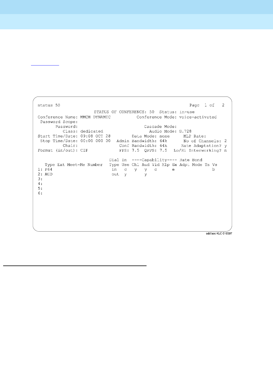
DEFINITY Enterprise Communications Server Release 6
Maintenance for R6r Volumes 1 & 2
555-230-126 Issue 2
January 1998
Maintenance Commands
Page 8-205status conference
8
is similar to the administration screens. The remainder of the screens display
endpoint level data (up to 8 endpoints per screen), displaying the ports and drop
reasons.
Screen 8-1 shows page 1 of a typical administration screen. The first screen
appears when status conference is entered and at least 1 valid conference is
found.
Screen 8-1. status conference: page 1 of 2
Field Descriptions (status conference, page 1)
status The current status of the conference - active, in-use, complete
conference
name Always set as MMCH DYNAMIC
conference
mode Always set as voice-activated
password Not Applicable
password
scope Not Applicable
cascade mode Conference cascade mode - blank
audio mode The current operating audio mode - G.711-A, G.711-mu, G.728.
G.722

DEFINITY Enterprise Communications Server Release 6
Maintenance for R6r Volumes 1 & 2
555-230-126 Issue 2
January 1998
Maintenance Commands
Page 8-206status conference
8
class The type of conference - dedicated
data mode Data mode capability for this conference - none, any-mlp, ww-pcs
MLP rate MLP Data Rate for this conference - blank.
start
time/date Conference start time in 24-hour notation with month and day.
stop
time/date End of conference in 24-hour notation with month and day. It is the
actual end time if Status is complete; otherwise it is blank.
admin
bandwidth The channel bandwidth as administered on the Conference Record
form - 64k.
no of
channels The number of channels (transfer rate) required for each Px64 endpoint
- 2.
Chair Identifies the current chair token holder. This field is always blank.
conf
bandwidth The current operating channel conference bandwidth. This can be
different from the administered bandwidth because of Rate Adaptation.
Rate
adaptation Does this conference support Rate Adaptation? - n, y.
Format
(in/out) For single-screen conference, the video format of the conference, CIF,
QCIF, QCIF/CIF, H.CTS, H.CTX+, and SG4. For conferences
other than H.261, the input and output formats are always symmetric
and the mode is the same for input and output. These display as
H.CTX, H.CTX+, and SG4. For H.261 mode non-continuous presence
conferences, the format is always symmetric and displays as CIF and
QCIF. The same is true for the non-presentation, continuous presence
conference in single-screen. For presentation mode H.261 single
screen continuous presence capable conferences, the input and
output formats may be symmetric QCIF/CIF (displayed as CIF) or
asymmetric QCIF/CIF, depending on if the format is administered as
upgradeable. For quad-screen conferences, the format is QCIF/CIF to
reflect the input of QCIF from all participants and output of CIF to all
participants. For presentation mode quad-screen conference, the
format is also QCIF/CIF to reflect the input/output of all participants
except the presenter. In quad-screen mode, the input from the
presenter is always CIF.
FPS The CIF frame rate (frames per second) - ‘-‘, 30, 15, 10, 7.5. FPS
indicates the rate that an endpoint is capable of receiving frames. Note
that there is no indication of the maximum transmit frame rate nor the
current frame rate that the MCU can detect. The frame rate changes as
a function of the amount of motion in the input image.

DEFINITY Enterprise Communications Server Release 6
Maintenance for R6r Volumes 1 & 2
555-230-126 Issue 2
January 1998
Maintenance Commands
Page 8-207status conference
8
QFPS The ACIF frame rate (frames per second) - ‘ - ‘, 30, 15, 10, 7.5. QFPS
indicates the rate that an endpoint is capable of generating/receiving
frames.
For quad-screen VAS conferences, QFPS reflects the highest common
QCIF frame rate of all endpoints and the rate of the video mixer board,
which may be lower than the rest of the participants. Note that QCIF
calculation takes into account the highest common CIF frame rate
declared by all conference participants, since QCIF rate cannot be
greater than that of the highest common CIF rate.
For quad-screen presentation conferences, QFPS reflects the highest
common QCIF frame rate of all participants and the rate of the video
mixer board. Note that the QFPS cannot be greater than the CIF frame
rate announced by the presenter.
QFPS field is blank for proprietary modes.
lo/hi
interworking Does this conference support Low Speed/High Speed Interworking? -
This field will always have a value of n.
Type The type of conferee, either Audio/Video (P64), Audio Add-on (AUD),
Cascade Link (CAS), BONDing Call (BOND), BONDing Cascade Link
(BCAS), UCC Controller (UCC), or Dedicated Access (DA). BONDing
calls use up to 12 channels to form a single multimedia pipe.
Ext Endpoint extension chosen at administration. This field is blank.
Meet-me
number The Meet-Me Number administered for the Meet-Me Extension. This
field is blank.
Dial Type Indicates whether dial-in or dial-out is used to join the endpoint to the
conference - in, out. The value in is for dial-in, and out is for dial-out.

DEFINITY Enterprise Communications Server Release 6
Maintenance for R6r Volumes 1 & 2
555-230-126 Issue 2
January 1998
Maintenance Commands
Page 8-208status conference
8
In Use Is the endpoint currently participating in the conference or in process of
connecting to the conference? - y, c, e, f, n, blank.
y means that the endpoint is in use and is fully connected on all media
in an active conference.
c means that the endpoint is in use and is fully connected, however the
endpoint has changed the conference audio or video capability or has
changed the rate of the conference because of rate adaptation. This
condition requires analysis of this endpoint’s capabilities and mode
fields to identify which capability was reduced.
e means that the endpoint is in use but the endpoint had capability
problems. The endpoint does not have one of the required capabilities
(Vid, Bhl, MLP) to be a full participant. For MLP capabilities, see the
“T120” field. This condition requires analysis of this endpoint’s
capabilities and mode field to identify the missing capability.
f means that the endpoint is in use but is not connected to all media.
This indicates that the endpoint has declared all the required
capabilities (channel/video/ audio/data) but is not fully connected to all
conference media at this time. This endpoint may be in the process of
connecting, has failed to connect, or is not a valid video source. This
condition requires analysis of this endpoint’s capabilities and mode
fields to identify the problem.
n means that the endpoint was connected in a conference but has/was
disconnected or attempted to connect to a conference but was
unsuccessful.
blank means the field is blank until the first call is made from/to the
endpoint.
Chl Data on the quantify and quality of channels (transfer rate)? - y, e, n,
blank
y the endpoint has the required number of channels.
e means that the endpoint has not declared support for the correct
number of channels and cannot participate fully in the conference.
n means that the endpoint has declared the correct number of
channels, but all the channels have not yet joined the conference, due
to either a network or endpoint problem.
blank Audio add-on endpoints always have the Chl field set to blank.

DEFINITY Enterprise Communications Server Release 6
Maintenance for R6r Volumes 1 & 2
555-230-126 Issue 2
January 1998
Maintenance Commands
Page 8-209status conference
8
Aud Does it have the required audio capability? - y, c, e, blank
y the endpoint has the required audio capability. Audio add-on
endpoint always have the Aud field set to y once the endpoint has
joined the conference.
c this endpoint is PCM only and it changed the video quality of the
conference by changing the operating audio from G.728 to G.711. If
the administered audio mode is auto and the administered bandwidth
is 112 kbps (56 k/channel) or 128 kbps (64 k/channel), the system
starts out with the highest common audio of G.728. When the
administered bandwidth is greater than 128 kbps, the system starts out
with the highest common bandwidth of 7 kHz.
e A PCM-only endpoint that did not have the capability of supporting
the administered audio mode of G.728 (such as a data conference), or
G. 278/G.711 endpoint that did not have the capability of supporting
the administered audio mode of 7 kHz. Such endpoints operate with
PCM audio and interwork with the current operating audio mode.
blank the field is blank until the first call is made from/to the endpoint.
Vid Does it have the required video capability and is receiving video? - y, c,
e, n, blank
y the endpoint has the required video capability and should be
receiving video if the Chl, Aud, and Dat fields are y.
c means it downgraded the conference’s video quality - either from CIF
to ACIF or by decreasing the frame rate. The conference video mode is
set by default to CIF and if a QCIF-only endpoint joins the conference,
then the entire conference is made to operate in QCIF, with the video
clarity downgraded. Also, the conference frame rate is initially set to the
highest frame rate that can then be reduced by any endpoint. If the
conference video mode is not administered with upgrade capability,
then if the video parameters for a conference have been
“downgraded,” they are not “upgraded” until all endpoints disconnect
from the conference.
e means that the endpoint has not declared any video capability in its
cap-set.
n means audio only, not receiving video, possibly due to an audio or
data problem.
blank Audio add-on endpoint always have the Vid field set to blank.
Mlp The state of the Control Link to the ESM (T.120 stack terminator), the
endpoint MLP data capability, and the state of the data connection in
the T.120 stack. This field value is always blank, indicating that the
Data Mode for the conference is none, and therefore, the data does not
apply, or the endpoint has never joined the conference.

DEFINITY Enterprise Communications Server Release 6
Maintenance for R6r Volumes 1 & 2
555-230-126 Issue 2
January 1998
Maintenance Commands
Page 8-210status conference
8
Gx Does it have the Still Frame Graphics capability? - y, e, blank
y This endpoint has this capability.
e This endpoint did not declare this capability. The conference retains
the still frame graphics capability when a non-compliant endpoint joins
the conference.
blank This endpoint has never joined the conference.
Rate Adpt Rate adaptation/Interworking indicator - 5, 6, y, c, e, n, blank. Values
of 5 and 6 apply only to Low Speed/High Speed Interworking. All other
values apply only to Rate Adaptation.
5 A 56-kbps (Low Speed) endpoint has joined a High Speed (128 kbps
or above) conference. This endpoint is connected with audio only
capability but is not a valid video source and destination.
6 A 64-kbps (Low Speed) endpoint has joined a High Speed (128 kbps
or above) conference. This endpoint is connected with audio only
capability but is not a valid video source and destination.
y This endpoint has joined the conference at the administered rate of
64 kbps, but because rate adaptation to 56 kbps was triggered by
another endpoint, this endpoint has successfully rate adapted to 56
kbps.
c The administered bandwidth of the conference is 64 kbps and this
endpoint has joined the conference at 56 kbps. The first 56 kbps
endpoint that joins 64 kbps rate adaptable conference triggers rate
adaptation (see Join Time below).
n A 64-kbps conference was triggered to rate adapt to 56 kbps by
some other endpoint. This endpoint joined the conference at the
bandwidth of 64 kbps, but encountered problems in rate adapting
down to 56 kbps. This endpoint may have the audio and may be
receiving video, but is not a valid video source.
blank Rate adaptation was never triggered by any endpoint, and if this
endpoint is in use and connected, then it has joined the conference at
the administered bandwidth.
Bond Mode BONDing Mode - blank. This field is blank for calls that are not related
to bonding.

DEFINITY Enterprise Communications Server Release 6
Maintenance for R6r Volumes 1 & 2
555-230-126 Issue 2
January 1998
Maintenance Commands
Page 8-211status conference
8
Ts Indication of the talking state of the endpoint - t, m, M, S, blank.
t At the time the command was invoked, voice energy (talking) was
detected from the endpoint.
m At the time the command was invoked, the endpoint indicated to the
MCU that it was muted. It is possible that an endpoint may mute, but
not send any indication to the MCU. In this situation the MCU does not
display a mute indication.
M At the time the command was invoked, the endpoint’s audio was
muted via UDD/CRCS Agent interface. M displays when both the
endpoint and the UCC/CRCS Agent have muted the endpoint audio.
S At the time the command was invoked, the endpoint’s audio was
muted because of solo-audio state set by UCC/CRCS Agent. While in
solo-audio state, new endpoints joining the conference are
automatically muted.
blank At the time the command was invoked voice energy (talking)
was not being detected from the endpoint.
Vs Indication of the MCU video state for this endpoint - a, b, B, c, i, r, R, s,
S, u, U, v, blank.
For quad-screen conferences an * is affixed before the value of Vs to
indicate that an endpoint is currently part of the mixed image. A # may
be affixed before the value of Vs to indicate that an endpoint was fixed
to be in the mixed image (via administration or UCC/CRCS Agent), but
instead, a Fill video is shown in its place. This occurs when the video
of an endpoint that is fixed in a quadrant cannot be used as a video
source because the endpoint is currently not joined to the conference,
has suppressed its video, or has invalid video to be the video source.
Notice that at most four endpoints have an * or # affixed before the Vs
field value.
For quad-screen conference in VAS mode, the mixed image is
broadcast to all endpoints. For quad-screen conference in presentation
mode, the mixed image is return video to the presenter.

DEFINITY Enterprise Communications Server Release 6
Maintenance for R6r Volumes 1 & 2
555-230-126 Issue 2
January 1998
Maintenance Commands
Page 8-212status conference
8
Vs
(cont’d.)
a This value applies only to quad-screen conferences. *a indicates that
an endpoint is part of the current mixed image and is fixed in one of the
quadrants via administration. A value of *a indicates that the endpoint
is fixed in a quadrant but is not currently connected (Fill image
displays).
b For full-screen conference it indicates that at the time the command
was invoked, this endpoint’s video was being broadcast to other sites.
This conference was in VAS, broadcast, or presentation mode. For
quad-screen VAS conference it is prefixed with an asterisk (*) and
indicates that this endpoint’s video is part of the mixed image because
of VAS. For quad-screen presentation conferences, b (without an
asterisk) identifies the presenter as the broadcaster.
B At the time the command was invoked the endpoint’s video was
being broadcast to other sites because of the UCC roll call feature.
UCC roll call feature can only be performed in full-screen mode.
c At the time the command was invoked this endpoint’s video was
being broadcast to other sites. The conference was in chair mode and
the broadcaster was designated by the chair. Chair features can only
be performed in full-screen mode.
i At the time the command was invoked the endpoint was not a valid
video source. For continuous presence conference, if this endpoint is
fixed in a particular quadrant, an asterisk (#) is affixed before i.
r For full-screen conferences, at the time the command was invoked
the endpoint’s video was the return video to the broadcaster. For
continuous presence conference in presentation mode, *r represents a
VAS quadrant that is part of the mixed image.
R At the time the command was invoked, the endpoint’s video was the
return video to the broadcaster because of the UCC browse feature.
UCC Browse feature can only be performed in full-screen mode.
s At the time the command was invoked this endpoint’s video was
suppressed at the request of the endpoint. For continuous presence
conference with fixed quadrant participants, if this endpoint is fixed in a
particular quadrant a # is affixed before s.

DEFINITY Enterprise Communications Server Release 6
Maintenance for R6r Volumes 1 & 2
555-230-126 Issue 2
January 1998
Maintenance Commands
Page 8-213status conference
8
Vs
(cont’d)
S At the time the command was invoked this endpoint’s video was
suppressed via UCC/CRCS Agent interface. For continuous presence
conference with fixed quadrant participants, if this endpoint is fixed in a
particular quadrant, # is affixed before S. S displays when both the
endpoint and the UCC/CRCS Agent have suppressed the endpoint
video.
u For full-screen conferences, at the time the command was invoked
this endpoint’s video was being broadcast to other sites. The
conference was in VAS mode and the broadcaster was designated by
the UCC/CRSCS Agent interface. For quad-screen conferences, it
indicates that UCC/CRCS Agent designated this endpoint as fixed in a
quadrant. An asterisk (*) is affixed before u if the endpoint is currently
part of the quad image, and # is affixed if the endpoint is not currently
joined.
U Applies only to quad-screen conference and indicates that
UCC/CRCS Agent designated a quadrant as VAS. An asterisk (*) is
affixed before U to indicate that this endpoint is part of the current quad
image.
v At the time the command was invoked this endpoint’s video was
being broadcast to other sites. The conference was in VAS mode but
the endpoint has asked to be a broadcaster via “See-Me” request and
was granted a MCV (Multipoint Command Visualize) token. The See-Me
feature is only performed in full-screen mode.
blank At the time of the request the endpoint’s video was not
broadcast, return, video, or part of the mixed-image, but it is a valid
video source.

DEFINITY Enterprise Communications Server Release 6
Maintenance for R6r Volumes 1 & 2
555-230-126 Issue 2
January 1998
Maintenance Commands
Page 8-214status conference
8
Screen 8-2. status conference: page 2 of 2
Field Descriptions (status conference, page 2)
Sum Grp The VD audio Level 1 (L1) and Level 2 (L2) summer group parts for
each assigned group (1-4). Summer parts are assigned only for
conferences with over 6 participants. When a conference operates at an
audio mode of 7 kHz (administered audio mode is 7 kHz, or auto with
the bandwidth greater than 128 kbps), the system allocates “primary”
and “secondary” L1 and L2 summer parts. These primary and
secondary parts are allocated as adjacent port slots on the same board.
Status conference only displays the primary summer ports. The
secondary summer ports are always one slot higher than the displayed
primary summer port.
Join Time Time (in 24-hour notation) when the channel joined the conference.
Drop Time Time (in 24-hour notation) when the channel disconnected. If the first
channel has a drop time, then it means that the endpoint is not in use. If
there is a drop time without a join time, it means that the call
disconnected without being joined to the conference.
status conference page 2 of 2
STATUS OF CONFERENCE:
Sum Grp: Group1 Group2 Group3 Group 4
L1:
L2:
Join Drop Drop AC --------Ports--------- Sum
Ext Time Time Reason Num Trunk Video Aud/Esm Grp Software
1:
2:
3:
4:
5:
6:

DEFINITY Enterprise Communications Server Release 6
Maintenance for R6r Volumes 1 & 2
555-230-126 Issue 2
January 1998
Maintenance Commands
Page 8-215status conference
8
Drop Reason The reason for the channel’s disconnect:
2-pri This drop reason occurs when an administration error causes a
mismatch in primary-secondary designation for a cascade link. This
mismatch shows that both MCUs are administered as primaries (see
“Cascading” for a description of primary-secondary compatibility).
2-sec This drop reason occurs when an administration error causes a
mismatch in primary-secondary designation for a cascade link. This
mismatch shows that both MCUs are administered as secondaries (see
“Cascading” for a description of primary-secondary compatibility).
Agent The reservation agent has caused the call to disconnect (for
example, the agent has changed a connected dial-out destination
number).
Bandwidth mismatch between a call and the conference it attempted
to join. For example, a 56-kbps call attempted to join a 64-kbps
conference that does not allow rate adaptation.
BondHshake BONDing handshake drop reason can be caused due to
the following reasons: information channel parameter not supported or
invalid, parameter negotiation terminated out of sequence, timer
expired because of the secondary channels did not establish, or
BONDing framing was not detected for one of the other channels.
Busy This dial-out drop reason occurs when the MCU detects that the
conferee’s terminal equipment is busy. This drop reason is detected by
an ISDN cause value (for example h0). See “Dial-out” for a description
of CPTR usage.
Chair disconnected the endpoint, using either Chair Command
Disconnect (CCD) or Chair Command Kill (CCK) signals.
Conf End The conference was ended due to reaching stop time for a
reserved conference or due to an active conference being converted to
file.

DEFINITY Enterprise Communications Server Release 6
Maintenance for R6r Volumes 1 & 2
555-230-126 Issue 2
January 1998
Maintenance Commands
Page 8-216status conference
8
Drop Reason
(cont’d)
Endpoint Clearing received from DS1 - the disconnect came from the
endpoint. The endpoint notified the MCU that it intended to disconnect.
Far-end Clearing received from DS1 - the disconnect came from either
the network or the endpoint.
Handshake Either framing was never found (the endpoint could not
complete initialization - problems finding Frame Alignment Signal (FAS),
Multi Frame Alignment (MFA) and getting a corrected coded cap-set) or
framing was lost for some time (over 40 seconds) and the endpoint was
disconnected.
IDtimeout The MCU has not received response to the UIN/password
Query from the H.320 user after three attempts. Each attempt has a
system administered timeout period.
Internal MCU has a problem allocating trunk resources necessary to
route the dial-out call for the specified dial-numbers. This problem can
be associated with routing pattern or trunk associated translation (for
example, TAC specified in the dial-out number or routing pattern points
to a trunk group without members), or it can indicate a lack of trunk
resources (for example, all trunk members are maintenance busy or all
in-service members are busy on a call).
Network Clearing received from DS1 - the disconnect came from the
network. The endpoint that had the disconnect notification capability
disconnected without notifying the MCU.
Not-MCU The dial-out destination number(s) of the “CAS” extension has
terminated to a number that is not a dial-in cascade MCU extension.
No-ring This dial-out drop reason occurs when the call has been up
for 30 seconds and no ringing is detected.
Reorder This dial-out drop reason occurs when the MCU detects that
there are no available trunks in the network to place the call. This drop
reason is detected by MCU CPTR resources. See “Dial-out” for a
description of CPTR usage.

DEFINITY Enterprise Communications Server Release 6
Maintenance for R6r Volumes 1 & 2
555-230-126 Issue 2
January 1998
Maintenance Commands
Page 8-217status conference
8
Drop Reason
(cont’d)
Pre-AnsDrop The call disconnected before answer by an endpoint.
The cause of the disconnect may be the network, an endpoint, or a
terminal adapter. This drop reason is different from ‘No-answer,’ which
indicates that a 60-second timeout occurred while alerting. In this case,
the call drops before the 60-second timer has expired. Some busy
endpoints connected through terminal adapters display this behavior.
Resource MCU could not provide resources (VC or MMI) when the call
arrived or lost the resources during the call. This could be due to them
being Out of Service, busied out by craft, or being used by system
maintenance. This drop reason could also occur if the DS1/MMI cable is
disconnected. If there was a resource problem when the call arrived, it
would get reorder (fast busy) and not get disconnected by the MCU.
Password Either the user entered the wrong password or the audio
add-on user did not enter it within the specified time period. Note that
the audio add-on user gets one attempt to enter a correct password and
inter-digit timing for each digit (that is, about 10 seconds between
digits).
System An MCU restart (level 2) disconnected all calls.
UIN-Inv The user entered an invalid User Identification Number.
Unknown The system could not determine the cause of the disconnect.
Wrong-num This dial-out drop reason occurs when the MCU detects
the wrong destination number was dialed. This drop reason is detected
by MCU CPTR resources SDN cause value. See “Dial-out” for details.
UCC controller intentionally disconnected the endpoint.
AC Num Administered Connection Number - from 1 to 128. AC number can be
used to further diagnose a problem by combining status conference
information with the status administered connection command and
data stored in the error and alarm logs.
Ports Trunk The data endpoint that the channel is using.
Ports Video The MMI port for the channel.
Ports Aud If the endpoint type is not “UCC,” the VC audio encoder port (which is
always paired to a decoder port) for the channel (only the first channel).
Because only one audio encoder port is allocated per endpoint, it
appears together with the ESM data port in the endpoint’s channel 1
port slot position of the Port Aud/ESM column. For “UCC” endpoint
type, the channel 1 port slot position displays the allocated Call
Classifier resource.
Ports ESM The Expansion Service Module MMI data port. This field is always blank.
Sum Grp Endpoint’s assigned summer group number. The summer group port
assignments are on screen 1.
software For Lucent Technologies use only.

DEFINITY Enterprise Communications Server Release 6
Maintenance for R6r Volumes 1 & 2
555-230-126 Issue 2
January 1998
Maintenance Commands
Page 8-218status conference
8
Field Descriptions (status conference endpoint)
status conference
x
endpoint
y
The first screen appears when status conference
x
endpoint
y
is entered and
the specified conference is found. Data relevant for each endpoint displays in 6
pages. If the endpoint-ID of all is used, all possible endpoints associated with
the specified conference display.
Page 1 - Status Conference Endpoint
Screen 8-3. Page 1 of 6: status conference x endpoint y
Endpoint Endpoint-ID is a slot number associated with the endpoint entered on
the conference forms.
Product Product identification number obtained from the endpoint.
Manufacturer/
Country Manufacturer identification number and manufacturer’s country code
obtained from the endpoint.
Terminal Name This field is always blank.
Sum Grp Summer group number to which this endpoint belongs and the VC
Audio Level (L1) and Level 2 (L2) summer ports for this group. These
fields have an entry only for conferences with over 6 participants.
Dial Out #1
Dial Out #2 Blank
Blank
status conference endpoint page 1 of 6
STATUS OF CONFERENCE ___ ENDPOINT: __ Status: ________
Ext: _____ Type: ____ Manufacturer/Country: ____/____ Product: _____
Terminal Name: _______________ Data Mode: _________ MLP Rate: ____
Admin Bandwidth: ____ Rate Adaptation: _
Conf Bandwidth: ____ Lo/Hi Interworking: _
Meet-Me Number: ____________________ Dial Out #1: _______________________
Sum Grp: _ L1: ______ L2: ______ #2: _______________________
Quadrature: ______ ________
ENDPOINT STATES/CAPABILITIES/MODES
In Enh ----Capability---- Rate Bond
Use BAS Chl Aud Vid Mlp Gx Adpt Mode Ts Vs
- - - - - - - - - - -
Help line
enter command:

DEFINITY Enterprise Communications Server Release 6
Maintenance for R6r Volumes 1 & 2
555-230-126 Issue 2
January 1998
Maintenance Commands
Page 8-219status conference
8
In Use Is the endpoint currently participating in the conference or in process
of connecting to the conference? - y, c, e, f, n, blank.
y means that the endpoint is in use and is fully connected on all
media in an active conference.
c means that the endpoint is in use and is fully connected, however
the endpoint has changed the conference audio or video capability
or has changed the rate of the conference because of rate
adaptation. This condition requires analysis of this endpoint’s
capabilities and mode fields to identify which capability was reduced.
e means that the endpoint is in use but the endpoint had capability
problems. The endpoint does not have one of the required
capabilities (Vid, Bhl, MLP) to be a full participant. For MLP
capabilities, see the “T120” field. This condition requires analysis of
this endpoint’s capabilities and mode field to identify the missing
capability.
f means that the endpoint is in use but is not connected to all media.
This indicates that the endpoint has declared all the required
capabilities (channel/video/ audio/data) but is not fully connected to
all conference media at this time. This endpoint may be in the
process of connecting, has failed to connect, or is not a valid video
source. This condition requires analysis of this endpoint’s capabilities
and mode fields to identify the problem.
n means that the endpoint was connected in a conference but
has/was disconnected or attempted to connect to a conference but
was unsuccessful.
blank means the field is blank until the first call is made from/to the
endpoint.
Enh BAS EnhancedBasic Service Flag - n, y
y means that the endpoint supports the enhanced BAS
commands/caps;
n means that the endpoint only supports the basic BAS
commands/caps.
Chl Data on the quantify and quality of channels (transfer rate)? - y, e, n,
blank
y the endpoint has the required number of channels.
e means that the endpoint has not declared support for the correct
number of channels and cannot participate fully in the conference.
n means that the endpoint has declared the correct number of
channels, but all the channels have not yet joined the conference,
due to either a network or endpoint problem.
blank Audio add-on endpoints always have the Chl field set to
blank.

DEFINITY Enterprise Communications Server Release 6
Maintenance for R6r Volumes 1 & 2
555-230-126 Issue 2
January 1998
Maintenance Commands
Page 8-220status conference
8
Aud Does it have the required audio capability? - y, c, e, blank
y the endpoint has the required audio capability. Audio add-on
endpoint always have the Aud field set to y once the endpoint has
joined the conference.
c this endpoint is PCM only and it changed the video quality of the
conference by changing the operating audio from G.728 to G.711. If
the administered audio mode is auto and the administered bandwidth
is 112 kbps (56 k/channel) or 128 kbps (64 k/channel), the system
starts out with the highest common audio of G.728. When the
administered bandwidth is greater than 128 kbps, the system starts
out with the highest common bandwidth of 7 kHz.
e A PCM-only endpoint that did not have the capability of supporting
the administered audio mode of G.728 (such as a data conference),
or G. 278/G.711 endpoint that did not have the capability of
supporting the administered audio mode of 7 kHz. Such endpoints
operate with PCM audio and interwork with the current operating
audio mode.
blank the field is blank until the first call is made from/to the
endpoint.
Vid Does it have the required video capability and is receiving video? - y,
c, e, n, blank
y the endpoint has the required video capability and should be
receiving video if the Chl, Aud, and Dat fields are y.
c means it downgraded the conference’s video quality - either from
CIF to ACIF or by decreasing the frame rate. The conference video
mode is set by default to CIF and if a QCIF-only endpoint joins the
conference, then the entire conference is made to operate in QCIF,
with the video clarity downgraded. Also, the conference frame rate is
initially set to the highest frame rate that can then be reduced by any
endpoint. If the conference video mode is not administered with
upgrade capability, then if the video parameters for a conference
have been “downgraded,” they are not “upgraded” until all endpoints
disconnect from the conference.
e means that the endpoint has not declared any video capability in its
cap-set.
n means audio only, not receiving video, possibly due to an audio or
data problem.
blank Audio add-on endpoint always have the Vid field set to
blank.
Mlp The state of the Control Link to the ESM (T.120 stack terminator), the
endpoint MLP data capability, and the state of the data connection in
the T.120 stack. This field value is always blank, indicating that the
Data Mode for the conference is none, and therefore, the data does
not apply, or the endpoint has never joined the conference.

DEFINITY Enterprise Communications Server Release 6
Maintenance for R6r Volumes 1 & 2
555-230-126 Issue 2
January 1998
Maintenance Commands
Page 8-221status conference
8
Gx Does it have the Still Frame Graphics capability? - y, e, blank
y This endpoint has this capability.
e This endpoint did not declare this capability. The conference
retains the still frame graphics capability when a non-compliant
endpoint joins the conference.
blank This endpoint has never joined the conference.
Rate Adpt Rate adaptation/Interworking indicator - 5, 6, y, c, e, n, blank.
Values of 5 and 6 apply only to Low Speed/High Speed Interworking.
All other values apply only to Rate Adaptation.
5 A 56-kbps (Low Speed) endpoint has joined a High Speed (128
kbps or above) conference. This endpoint is connected with audio
only capability but is not a valid video source and destination.
6 A 64-kbps (Low Speed) endpoint has joined a High Speed (128
kbps or above) conference. This endpoint is connected with audio
only capability but is not a valid video source and destination.
y This endpoint has joined the conference at the administered rate of
64 kbps, but because rate adaptation to 56 kbps was triggered by
another endpoint, this endpoint has successfully rate adapted to 56
kbps.
c The administered bandwidth of the conference is 64 kbps and this
endpoint has joined the conference at 56 kbps. The first 56 kbps
endpoint that joins 64 kbps rate adaptable conference triggers rate
adaptation (see Join Time below).
n A 64-kbps conference was triggered to rate adapt to 56 kbps by
some other endpoint. This endpoint joined the conference at the
bandwidth of 64 kbps, but encountered problems in rate adapting
down to 56 kbps. This endpoint may have the audio and may be
receiving video, but is not a valid video source.
blank Rate adaptation was never triggered by any endpoint, and if
this endpoint is in use and connected, then it has joined the
conference at the administered bandwidth.
Bond Mode BONDing Mode - blank. This field is blank for calls that are not related
to bonding.

DEFINITY Enterprise Communications Server Release 6
Maintenance for R6r Volumes 1 & 2
555-230-126 Issue 2
January 1998
Maintenance Commands
Page 8-222status conference
8
Ts Indication of the talking state of the endpoint - t, m, M, S, blank.
t At the time the command was invoked, voice energy (talking) was
detected from the endpoint.
m At the time the command was invoked, the endpoint indicated to
the MCU that it was muted. It is possible that an endpoint may mute,
but not send any indication to the MCU. In this situation the MCU
does not display a mute indication.
M At the time the command was invoked, the endpoint’s audio was
muted via UDD/CRCS Agent interface. M displays when both the
endpoint and the UCC/CRCS Agent have muted the endpoint audio.
S At the time the command was invoked, the endpoint’s audio was
muted because of solo-audio state set by UCC/CRCS Agent. While in
solo-audio state, new endpoints joining the conference are
automatically muted.
blank At the time the command was invoked voice energy (talking)
was not being detected from the endpoint.

DEFINITY Enterprise Communications Server Release 6
Maintenance for R6r Volumes 1 & 2
555-230-126 Issue 2
January 1998
Maintenance Commands
Page 8-223status conference
8
Vs Indication of the MCU video state for this endpoint - a, b, B, c, i, r, R,
s, S, u, U, v, blank.
For quad-screen conferences an * is affixed before the value of Vs to
indicate that an endpoint is currently part of the mixed image. A #
may be affixed before the value of Vs to indicate that an endpoint was
fixed to be in the mixed image (via administration or UCC/CRCS
Agent), but instead, a Fill video is shown in its place. This occurs
when the video of an endpoint that is fixed in a quadrant cannot be
used as a video source because the endpoint is currently not joined
to the conference, has suppressed its video, or has invalid video to
be the video source. Notice that at most four endpoints have an * or
# affixed before the Vs field value.
For quad-screen conference in VAS mode, the mixed image is
broadcast to all endpoints. For quad-screen conference in
presentation mode, the mixed image is return video to the presenter.
a This value applies only to quad-screen conferences. *a indicates
that an endpoint is part of the current mixed image and is fixed in one
of the quadrants via administration. A value of *a indicates that the
endpoint is fixed in a quadrant but is not currently connected (Fill
image displays).
b For full-screen conference it indicates that at the time the command
was invoked, this endpoint’s video was being broadcast to other
sites. This conference was in VAS, broadcast, or presentation mode.
For quad-screen VAS conference it is prefixed with an asterisk (*) and
indicates that this endpoint’s video is part of the mixed image
because of VAS. For quad-screen presentation conferences, b
(without an asterisk) identifies the presenter as the broadcaster.
B At the time the command was invoked the endpoint’s video was
being broadcast to other sites because of the UCC roll call feature.
UCC roll call feature can only be performed in full-screen mode.
c At the time the command was invoked this endpoint’s video was
being broadcast to other sites. The conference was in chair mode
and the broadcaster was designated by the chair. Chair features can
only be performed in full-screen mode.

DEFINITY Enterprise Communications Server Release 6
Maintenance for R6r Volumes 1 & 2
555-230-126 Issue 2
January 1998
Maintenance Commands
Page 8-224status conference
8
Page 2 - Endpoint Channel Information
This section only describes the fields that are specific to the endpoint-level
command output.
Vs
(cont’d.)
i At the time the command was invoked the endpoint was not a valid
video source. For continuous presence conference, if this endpoint is
fixed in a particular quadrant, an asterisk (#) is affixed before i.
r For full-screen conferences, at the time the command was invoked
the endpoint’s video was the return video to the broadcaster. For
continuous presence conference in presentation mode, *r represents
a VAS quadrant that is part of the mixed image.
R At the time the command was invoked, the endpoint’s video was
the return video to the broadcaster because of the UCC browse
feature. UCC Browse feature can only be performed in full-screen
mode.
s At the time the command was invoked this endpoint’s video was
suppressed at the request of the endpoint. For continuous presence
conference with fixed quadrant participants, if this endpoint is fixed in
a particular quadrant a # is affixed before s.
S At the time the command was invoked this endpoint’s video was
suppressed via UCC/CRCS Agent interface. For continuous
presence conference with fixed quadrant participants, if this endpoint
is fixed in a particular quadrant, # is affixed before S. S displays when
both the endpoint and the UCC/CRCS Agent have suppressed the
endpoint video.
u For full-screen conferences, at the time the command was invoked
this endpoint’s video was being broadcast to other sites. The
conference was in VAS mode and the broadcaster was designated
by the UCC/CRSCS Agent interface. For quad-screen conferences, it
indicates that UCC/CRCS Agent designated this endpoint as fixed in
a quadrant. An asterisk (*) is affixed before u if the endpoint is
currently part of the quad image, and # is affixed if the endpoint is not
currently joined.
U Applies only to quad-screen conference and indicates that
UCC/CRCS Agent designated a quadrant as VAS. An asterisk (*) is
affixed before U to indicate that this endpoint is part of the current
quad image.
v At the time the command was invoked this endpoint’s video was
being broadcast to other sites. The conference was in VAS mode but
the endpoint has asked to be a broadcaster via “See-Me” request
and was granted a MCV (Multipoint Command Visualize) token. The
See-Me feature is only performed in full-screen mode.
blank At the time of the request the endpoint’s video was not
broadcast, return, video, or part of the mixed-image, but it is a valid
video source.

DEFINITY Enterprise Communications Server Release 6
Maintenance for R6r Volumes 1 & 2
555-230-126 Issue 2
January 1998
Maintenance Commands
Page 8-225status conference
8
Screen 8-4. Page 2 of 6: status conference x endpoint y
Join Time Time (in 24-hour notation) when the channel joined the conference.
Drop Time Time (in 24-hour notation) when the channel disconnected. If the first
channel has a drop time, then it means that the endpoint is not in use.
If there is a drop time without a join time, it means that the call
disconnected without being joined to the conference.
status conference endpoint page 2 of 6
ENDPOINT CHANNEL INFORMATION
Chan. Join Drop ----Drop---- AC ------------Ports---------- Fr
No. Time Time Reason Code Num Trunk Video Aud/ESM BONDng Err Software
1: _____ _____ _________ __ ___ ______ ______ ______ ______ ___ ________
2: _____ _____ _________ __ ___ ______ ______ ______ ______ ___ ________
3: _____ _____ _________ __ ___ ______ ______ ______ ___ ________
4: _____ _____ _________ __ ___ ______ ______ ______ ___ ________
5: _____ _____ _________ __ ___ ______ ______ ______ ___ ________
6: _____ _____ _________ __ ___ ______ ______ ______ ___ ________
7: _____ _____ _________ __ ___ ______ ______ ______ ___ ________
8: _____ _____ _________ __ ___ ______ ______ ______ ___ ________
9: _____ _____ _________ __ ___ ______ ______ ______ ___ ________
10: _____ _____ _________ __ ___ ______ ______ ______ ___ ________
11: _____ _____ _________ __ ___ ______ ______ ______ ___ ________
12: _____ _____ _________ __ ___ ______ ______ ______ ___ ________
Help line
enter command:

DEFINITY Enterprise Communications Server Release 6
Maintenance for R6r Volumes 1 & 2
555-230-126 Issue 2
January 1998
Maintenance Commands
Page 8-226status conference
8
Drop Reason The reason for the channel’s disconnect:
2-pri This drop reason occurs when an administration error causes
a mismatch in primary-secondary designation for a cascade link. This
mismatch shows that both MCUs are administered as primaries (see
“Cascading” for a description of primary-secondary compatibility).
2-sec This drop reason occurs when an administration error causes
a mismatch in primary-secondary designation for a cascade link. This
mismatch shows that both MCUs are administered as secondaries
(see “Cascading” for a description of primary-secondary
compatibility).
Agent The reservation agent has caused the call to disconnect (for
example, the agent has changed a connected dial-out destination
number).
Bandwidth mismatch between a call and the conference it
attempted to join. For example, a 56-kbps call attempted to join a
64-kbps conference that does not allow rate adaptation.
BondHshake BONDing handshake drop reason can be caused due
to the following reasons: information channel parameter not
supported or invalid, parameter negotiation terminated out of
sequence, timer expired because of the secondary channels did not
establish, or BONDing framing was not detected for one of the other
channels.
Busy This dial-out drop reason occurs when the MCU detects that
the conferee’s terminal equipment is busy. This drop reason is
detected by an ISDN cause value (for example h0). See “Dial-out” for
a description of CPTR usage.
Chair disconnected the endpoint, using either Chair Command
Disconnect (CCD) or Chair Command Kill (CCK) signals.
Conf End The conference was ended due to reaching stop time for
a reserved conference or due to an active conference being
converted to file.

DEFINITY Enterprise Communications Server Release 6
Maintenance for R6r Volumes 1 & 2
555-230-126 Issue 2
January 1998
Maintenance Commands
Page 8-227status conference
8
Drop Reason
(cont’d)
Endpoint Clearing received from DS1 - the disconnect came from
the endpoint. The endpoint notified the MCU that it intended to
disconnect.
Far-end Clearing received from DS1 - the disconnect came from
either the network or the endpoint.
Handshake Either framing was never found (the endpoint could not
complete initialization - problems finding Frame Alignment Signal
(FAS), Multi Frame Alignment (MFA) and getting a corrected coded
cap-set) or framing was lost for some time (over 40 seconds) and the
endpoint was disconnected.
IDtimeout The MCU has not received response to the
UIN/password Query from the H.320 user after three attempts. Each
attempt has a system administered timeout period.
Internal MCU has a problem allocating trunk resources necessary
to route the dial-out call for the specified dial-numbers. This problem
can be associated with routing pattern or trunk associated translation
(for example, TAC specified in the dial-out number or routing pattern
points to a trunk group without members), or it can indicate a lack of
trunk resources (for example, all trunk members are maintenance
busy or all in-service members are busy on a call).
Network Clearing received from DS1 - the disconnect came from the
network. The endpoint that had the disconnect notification capability
disconnected without notifying the MCU.
Not-MCU The dial-out destination number(s) of the “CAS” extension
has terminated to a number that is not a dial-in cascade MCU
extension.
No-ring This dial-out drop reason occurs when the call has been up
for 30 seconds and no ringing is detected.
Reorder This dial-out drop reason occurs when the MCU detects
that there are no available trunks in the network to place the call. This
drop reason is detected by MCU CPTR resources. See “Dial-out” for
a description of CPTR usage.

DEFINITY Enterprise Communications Server Release 6
Maintenance for R6r Volumes 1 & 2
555-230-126 Issue 2
January 1998
Maintenance Commands
Page 8-228status conference
8
Drop Reason
(cont’d)
Pre-AnsDrop The call disconnected before answer by an endpoint.
The cause of the disconnect may be the network, an endpoint, or a
terminal adapter. This drop reason is different from ‘No-answer,’
which indicates that a 60-second timeout occurred while alerting. In
this case, the call drops before the 60-second timer has expired.
Some busy endpoints connected through terminal adapters display
this behavior.
Resource MCU could not provide resources (VC or MMI) when the
call arrived or lost the resources during the call. This could be due to
them being Out of Service, busied out by craft, or being used by
system maintenance. This drop reason could also occur if the
DS1/MMI cable is disconnected. If there was a resource problem
when the call arrived, it would get reorder (fast busy) and not get
disconnected by the MCU.
Password Either the user entered the wrong password or the audio
add-on user did not enter it within the specified time period. Note that
the audio add-on user gets one attempt to enter a correct password
and inter-digit timing for each digit (that is, about 10 seconds
between digits).
System An MCU restart (level 2) disconnected all calls.
UIN-Inv The user entered an invalid User Identification Number.
Unknown The system could not determine the cause of the
disconnect.
Wrong-num This dial-out drop reason occurs when the MCU detects
the wrong destination number was dialed. This drop reason is
detected by MCU CPTR resources SDN cause value. See “Dial-out”
for details.
UCC controller intentionally disconnected the endpoint.
Drop Code A detail code complementing the Drop Reason (see above).
Additional bonding related information may be obtained from
supplementary BONDing Drop Codes described above.
AC Num Administered Connection Number - from 1 to 128. AC number can be
used to further diagnose a problem by combining status conference
information with the status administered connection command and
data stored in the error and alarm logs.
Ports Trunk The data endpoint that the channel is using.
Ports Video The MMI port for the channel.

DEFINITY Enterprise Communications Server Release 6
Maintenance for R6r Volumes 1 & 2
555-230-126 Issue 2
January 1998
Maintenance Commands
Page 8-229status conference
8
Page 3 - Conference Information
This section only describes the fields that are specific to the endpoint-level
command output.
Screen 8-5. Page 3 of 6: status conference x endpoint y
Conference Info. This information applies mostly to full-screen conferences. The
Broadcaster field also applies to quad-screen presentation mode
conferences.
Ports Aud If the endpoint type is not “UCC,” the VC audio encoder port (which is
always paired to a decoder port) for the channel (only the first
channel). Because only one audio encoder port is allocated per
endpoint, it appears together with the ESM data port in the endpoint’s
channel 1 port slot position of the Port Aud/ESM column. For “UCC”
endpoint type, the channel 1 port slot position displays the allocated
Call Classifier resource.
Ports ESM The Expansion Service Module MMI data port. This field is always
blank.
Ports BONDng The MMI port used for BONDing for the channel.
Fr Err Frame error counter. A circular hex counter (0-FF) to indicate the
occurrence of framing errors.
status conference endpoint page 3 of 6
CONFERENCE INFO: Broadcaster: xx (See-Me)
Return Vid: xx
---------- MODE COMMANDS/COMMUNICATION MODES ------| EPT MISC | ------- FAW --
CMD STAT CONF EPT-IN EPT-OUT |------ I O | CH1 CH2
----- ---- ------------ ------------- -------------| AIM: y n | --- ---
XRATE: y 384 384 384 | VIS y n | A-OUT: y n
AUDIO: n G728 neutral G728 | MIS: n | A-IN: y n
56/64: y derestrict derestrict derestrict | MCV: n | M-FRM: y n
VIDEO: n H.261 H.261 H.261 |-------------| MFA: y n
MLP: y MLP-off MLP-off MLP-off | TALK: y 05 | MFN: y n
H-MLP: y H-MLP-off H-MLP-off H-MLP-off | VFCV: y 01 | FAS: y n
LSD: y LSD-off LSD-off LSD-off | BCTK: n 02 |MCUFAL: 00 00
HSD: y HSD-off HSD-off HSD-off | RTTK: y 01 | FEFAL: 00 00
CRYPT: y encrypt-off encrypt-off encrypt-off | BCLS: n |
S/M: y N-comp-6B-H0 N-comp-6B-H0 N-comp-6B-H0 | RTLS: n |
| HYPR: n 00 |
|DMUTE: n 00 |
|H.261: n 00 |
| VFMT: n 00 |
Help line
enter command:

DEFINITY Enterprise Communications Server Release 6
Maintenance for R6r Volumes 1 & 2
555-230-126 Issue 2
January 1998
Maintenance Commands
Page 8-230status conference
8
Mode Commands/Communication Modes. This is a collection of both incoming
and outgoing bandwidth allocations for the multiplex. The Incoming data is the
rate at which the MCU thinks the endpoint is communicating based on the
Bit-rate Allocation Signal (BAS) codes received from the endpoint/codec and the
capabilities the MCU has declared. The Outgoing data is the rate from the MCU
toward the endpoint. The following are column definitions for this section of page
3.
Broadcaster Indicates the endpoint number that is the current broadcaster. The
Broadcaster can be qualified with the following keywords:
1. Broadcast - indicates a broadcast mode broadcaster.
2. Chair - indicates that the broadcaster was designated by the
chair.
3. See-Me - indicates that the broadcaster is a result of MCV
request from an endpoint.
4. Presenter - indicates a presentation mode broadcaster.
5. Rollcall - indicates that the broadcaster was designated by
the UCC via the Rollcall feature.
6. UCC - indicates that the broadcaster was designated by the UCC.
7. VAS - indicates a Voice Activated Switching broadcaster.
Next
Broadcaster Indicates the endpoint number that is selected to be the next
broadcaster.
Return Vid Indicates the endpoint number that is the current return video. The
return video can be qualified with the following keywords:
1. blank - indicates that the return video is the previous broadcaster
forced to be return video because of VAS, action by Chair, action
by UCC, or endpoint MCV request. The broadcaster qualifier
identifies which action forced this endpoint to become return
video.
2. Autoscan - indicates auto scan return video. This is true only
when conference mode is broadcast with auto scan.
3. Browse - indicates that the return video was designated by the
UCC via the Browse feature.
4. VAS - indicates a Voice Activated Switching return video.
Next Return
Vid Indicates the endpoint number that is selected to be the next return
video.
CONF The desired conference operating mode. This may be different from
the endpoint in (EPT-IN) or endpoint out (EPT-OUT) modes.
CMD labels for the various types of mode commands

DEFINITY Enterprise Communications Server Release 6
Maintenance for R6r Volumes 1 & 2
555-230-126 Issue 2
January 1998
Maintenance Commands
Page 8-231status conference
8
The following are field definitions for the Mode Commands/Communication
Modes section of Page 3.
STAT indicates if the conference and the incoming modes are compatible.
A value of y indicates mode compatibility; a value of n indicates that
the modes are not compatible.
EPT-IN defines the communication modes coming in from an endpoint.
EPT-OUT defines the communication modes sent out to an endpoint based on
the number of channels connected and the capabilities of the
endpoint.
XRATE One of the supported rates in Table 8-10:
Table 8-10. Supported Transfer Rates
XRATE Bandwidth of the Call
2x64 2B (2x56 or 2x64)
128 112kbps or 128kbps
196 168kbps or 196kbps
256 224kbps or 256kbps
320 280kbps or 320kbps
384 336kbps or 384kbps
512 512kbps
768 768kbps
1472 1472kbps
1536 1536kbps‘
1920 1920kbps
Continued on next page
XRATE
(cont’d.)
XRATE may be 64 when the endpoint is just dialing in, or in the event
of problems. It implies that only one B channel is being used.

DEFINITY Enterprise Communications Server Release 6
Maintenance for R6r Volumes 1 & 2
555-230-126 Issue 2
January 1998
Maintenance Commands
Page 8-232status conference
8
AUDIO Audio rate (kbps bandwidth) of the conference and the endpoint
must be the same but not necessarily their mode. When the audio
rate of the conference and the endpoint are different the endpoint’s
audio will interwork but the endpoint’s video will be invalid. MCU may
or may not send video to such an endpoint.
Table 8-11 summarizes expected endpoint audio mode with different
configurations of transfer rate, facility bandwidth, conference mode,
and whether or not all endpoints support the highest common audio
mode (HC audio) when the administered mode is auto. The highest
common conference mode is dependent on the administered
bandwidth. A ‘-’ in the table indicates ‘does not apply.’
Table 8-11. Audio Mode Configurations
Admin Mode
(HC Audio)
All
Support
HC Audio Xfer
Rate Facility
BW Conf Mode Expected Endpoint Mode
auto (G.728) yes <=128k - G.728 G.728
auto (G.728) no <=128k 64k G.711-A-56k G.711-A-56k B.711-Mu-56k
auto (G.728) no <=128k 56k G.711-A-48k G.711-A-48k G.711-MU-48k
auto (G.722) - >128k 64k G.722-56k G.722-56k G.711-A-56k G.711-Mu-56k
auto (G.722) - >128k 56k G.722-48k G.722-48k G.711-A-48k G.711-Mu-48k
G.728 - - G.728 G.728
G.711 - - 64k G.711-A-56k G.711-A-56k G.711-Mu-56k
G.711 - - 56k G.711-A-48k G.711-A-48k G.711-Mu-48k
G.722 - - 64k G.722-56k G.722-56k G.711-A-56k G.711-mu-56k
G.722 - - 56k G.722-48k G.722-48k G.711-A-48k G.711-Mu-48k
Continued on next page
AUDIO
(cont’d.)
Other possible AUDIO mode values include neutral (neutralized
I-channel) and Au-off, Frm (no audio signal) which never match
conference mode and are not supported by MCU.

DEFINITY Enterprise Communications Server Release 6
Maintenance for R6r Volumes 1 & 2
555-230-126 Issue 2
January 1998
Maintenance Commands
Page 8-233status conference
8
Endpoint Miscellaneous (EPT MISC) Information. EPT MISC contains
miscellaneous states and counters for an endpoint. The flags can be a value of y
or n. The counters start with initial value of 0x00, they increment to 0xff, and then
56/64 The 65/64 field is derestrict when operating at per-channel
speeds of 64kbps, 128kbps, 192kbps, 256kbps, 320kbps, 384kbps,
512kbps, 768 kbps, 1472kbps, 1536kbps, or 1920kbps; it is
restrict when operating at 56kbps, 112kbps, 168kbps, 224kbps,
280kbps, 336kbps, 448kbps, and 672kbps.
Note that if the conference is configured for Nx56kbs operation, the
endpoint may signal either via capabilities or modes that is operating
at the proper rate. In such a case, even when we receive
derestrict command which does not match the conference
communication mode of restrict, if the capability indicates
restrict (MISC capability has restrict displayed on Page 4) the
STAT 56/64 is set to y to indicate 56/64 compatibility between the
conference and the endpoint.
VIDEO The Video mode: H.261 (recommended), H.CTX (proprietary),
H.CTX+ (proprietary), or SG4 (proprietary) indicate that video is on in
the direction indicated; video-off when the video is off.
MLP Multi Layer Protocol data mode. When Data Mode is administered as
any-mlp or ww-pcs, the MLP mode should be var-MLP. Other
values will affect video status.
The MLP mode should be MLP-off when Data Mode is administered
as none. Again, other values in this mode will affect video status.
H_MLP The High Speed MLP mode. The HMLP mode should be H-MLP-off.
Other values in this mode will affect video status.
LSD Low Speed Data mode. The LSD mode should be LSD-off. Other
values in this mode will affect video status.
HSD High Speed Data mode. The HSD mode should be HSD-off. Other
values in this mode will affect video status.
CRYPT Encryption mode. The CRYPT mode should be encrypt-off. Other
values in this mode will affect video status.
S/M Single/Multi channel interoperability mode. 6B-H0-comp indicates
that the sender is interoperating multiple channels and a single
channel (for example, 6B and H0). Not-comp-6B-H0 indicates that
the sender is not interoperating between 6B and H0. Normally this
value is Not-comp-6B-H0. Other values in this mode will affect video
status.

DEFINITY Enterprise Communications Server Release 6
Maintenance for R6r Volumes 1 & 2
555-230-126 Issue 2
January 1998
Maintenance Commands
Page 8-234status conference
8
wrap around to 0x01. AIM and VIS are BAS commands which can be sent as
input (I) to MCU from an endpoint or as output (O) from MCU to an endpoint.
AIM Audio Indicate Muted. Value of y on input (I) indicates that this
endpoint has muted its audio. MCU will not VAS to an endpoint
displaying mute indicate. Value of n on input indicates that this
endpoint has not muted (only if endpoint audio mode is turned on).
Value of y on output (O) indicates that all other endpoints in the
conference have muted their audio (have sent AIM to MCU). MCU in
turn tells this endpoint (by sending it AIM) that there is no audio
output from MCU. A value of n on output indicates that there is an
audio path open across the bridge.
VIS Video Indicate Suppressed. Value of y on input (I) indicates that this
endpoint has suppressed its video (indicated video is muted). Value
of y on output (O) indicates that the MCU is not sending video to this
endpoint because there is no video broadcaster (broadcaster has not
joined or broadcaster’s video is not valid).
MIS Multipoint Indicate Secondary-status. This command is only sent as
output (O) to an endpoint. A value of n indicates that the endpoint is
viewed as capable of being a valid source (although not necessarily
at this moment). A value of n is the correct state to be in for video. A
value of y indicates that MIS was sent to an endpoint and that this
endpoint is viewed as a secondary endpoint. The endpoint is
included in the audio portion of the conference but not the video
portion. Video will not be sent.
MCV Multipoint Command Visualize. This command is only sent as input (I)
from an endpoint. A value of y indicates that an endpoint has
requested to become a broadcaster. This is used during Still Frame
Graphics and to force “presentation” mode.
TALK A value of y indicates that the VC board is detecting voice energy
from the endpoint. The TALK counter indicates the number of times a
start/stop was detected.
VRCV Value of y indicates if the endpoint is receiving video (MMCH is
sending video to the endpoint). The VRCV counter indicates the
number of times video was sent/not sent to this endpoint.
BCTK Applies to single screen and quad-screen presentation mode
conferences. A value of y indicates that the endpoint is the video
broadcast source. The BCTK counter indicates the number of times
this endpoint was the video broadcast source.
RTTK Applies only to single screen conferences. A value of y indicates that
the endpoint is the return video source. The RTTK counter indicates
the number of times this endpoint was the return video source.
BCLS Applies to single screen and quad-screen presentation mode
conferences. A value of y indicates that the endpoint is watching the
video of the broadcast source.

DEFINITY Enterprise Communications Server Release 6
Maintenance for R6r Volumes 1 & 2
555-230-126 Issue 2
January 1998
Maintenance Commands
Page 8-235status conference
8
Frame Alignment Word (FAW) Information. The FAW section of page 3
provides the channel Frame Alignment Word information for the communication
paths labeled CHL 1 and 2. For 2B calls, both CHL 1 and 2 are used. For
1-channel calls (112,bps, 128kbps, 168kbps, 196kbps, 224kbps, 256kbps,
280kbps, 320kbps, 336kbps, 384kbps, 768kbps, 1472kbps, 1536kbps, and
1920kbps) only CHL 1 is used. A-OUT, A-IN, M-FRM, MFA, and MFN are flags
with values of y or n.
RTLS Applies only to single screen conferences. A value of y indicates that
the endpoint is watching the video of the return source.
HYPR A value of y indicates hyperactivity from an endpoint (MCU isolated
endpoint from the MCU conference due to “thrashing” behavior) and
affects endpoint’s status as a video source (for 5 seconds of
hyperactivity timer). The HYPR counter indicates the number of times
this endpoint was hyperactive.
DMUTE A value of y indicates that the decoder was muted by the VC board or
the software in the MCU. VC board mutes the decoder when it loses
MMI or endpoint framing is lost, when it receives an invalid audio
code word, and when endpoint is hyperactive. The only time that the
MCU software mutes the decoder of an endpoint is to mute all
endpoints, other than the broadcaster, when a mode of a conference
is “broadcastw/scan” (broadcast with auto scan). The DMUTE
counter indicates the number of times this endpoint’s decoder was
muted by the VC board.
VFMT The video format applicable only to quad-screen conferences. This
field always has a value of n, indicating QCIF format.
H.261 A value of y indicates video framing loss. The H.261 counter
indicates the number of times the framing was lost.
A-OUT MCU has endpoint framing.
A-IN Endpoint has MCU framing
M-FRM Multichannel frame alignment is present (alignment of both channels
in 2B).
MFA Multiframe alignment word is present (required in 2B call).
MFN Multiframe numbering is present (required in 2B call).
FAS Frame Alignment Signal (FAS) channel number (1 or 2). This number
should match the column header.
MCUFAL MCU Frame Alignment Loss (MCUFAL). A counter of the number of
times the MCU indicates to the endpoint that it has lost endpoint FAW
or multichannel synchronization (M-FRM). The MCU a-bit toggles
when the MCU gains or loses endpoint multichannel synchronization.
This counter starts with an initial value of 0x00, increments to 0xff,
then wraps around to 0x01. The MCUFAL count is also shown in the
Fr Err field on Page 2

DEFINITY Enterprise Communications Server Release 6
Maintenance for R6r Volumes 1 & 2
555-230-126 Issue 2
January 1998
Maintenance Commands
Page 8-236status conference
8
Page 4 - Endpoint Capability Information
This section only describes the fields that are specific to the endpoint-level
command output.
Screen 8-6. Page 4 of 6: status conference x endpoint y
FEFAL Far End Frame Alignment Loss (FEFAL). A counter of the number of
changes the MCU detects in the endpoint’s a-bit (A-OUT). The
endpoint a-bit toggles when an endpoint gains or loses MCU framing.
This counter starts with an initial value of 0x00, increments to 0xff,
then wraps around to 0x01.
status conference endpoint page 4 of 6
ENDPOINT CAPABILITY INFORMATION
--------------------------------------------------------------------------------
VID | vfmt: QCIF cfps: 30 H.CTX SG4 imp
| da_sfg qfps: 7.5 H.CTX+ SG4_sfg
-----|--------------------------------------------------------------------------
MISC | derestrict S/M mbe dcomp cic
-----|--------------------------------------------------------------------------
XR | 64 64x2 64x3 64x4 64x5 64x6 384 384x2 384x3 384x4 384x5
| 128 192 256 320 512 768 1152 1472 1536 1920
-----|--------------------------------------------------------------------------
AUD | ntrl 711m 711a g728 g722_64 g722_48
-----|--------------------------------------------------------------------------
LSD | var 300 1200 4800 6400 8000 9600 14.4k 16k 24k 32k 40k 48k 56k 62.4k 64k
-----|--------------------------------------------------------------------------
HSD | var 64k 128k 192k 256k 320k 348k 512k 768k 1152k 1536k
-----|--------------------------------------------------------------------------
MLP | var 4k 6.4k 14.4k 16k 22.4k 24k 30.4k 32k 38.4k 40k 46.4k 62.4k
-----|--------------------------------------------------------------------------
HMLP | var 62.4k 68k 128k 192k 256k 320k 384k
--------------------------------------------------------------------------------

DEFINITY Enterprise Communications Server Release 6
Maintenance for R6r Volumes 1 & 2
555-230-126 Issue 2
January 1998
Maintenance Commands
Page 8-237status conference
8
Endpoint Capability Information. Fields on this page will only be displayed if an
endpoint declares the specific capability. For example, if an endpoint does not
declare the VID H.CTX capability, the H.CTX field will not be displayed.
VID Provides information about the type of video and frame rate the
endpoint supports.
vfmt - does not display if the endpoint has no video capability. All
values are blank if there is an active call or this is an audio-only
endpoint. Otherwise, values for this field include:
■FCIF for full CIF
■QCIF for quarter CIF. Support of CIF implies support of QCIF. In
general, for larger screens, CIF displays sharper resolution video,
which ZCIF is blocked, but may run at higher frame rates and less
clear. The differences are less observable on very small displays.
■cfps and qfps are the maximum frame rate (frames/second) at
which the endpoint can receive video for CIF and QCIF operating
modes. CIF frame rate values are 30fps, 15fps, 10fps, and 7.4fps.
If the endpoint does not support CIF (that is, the vfmt field is
QCIF), the cfps value should be blank.
■da_sfg indicates support for H.261 Still Frame Graphics
transfers.
■H.CTX, H.CTX+ and SG4 are proprietary video format
capabilities.
■SG4_sfg indicates support for SG4 Still Frame Graphics
MISC The restrict field is 1 way for an endpoint to indicate that it is
operating at 56 kbps per channel, the other way is the 56/64
command mode with a value of restrict. An endpoint on a 56 kbps
conference must send one or both of the 2 indications that they are
operating at 56 kbps before they become a video source in a 56 kbps
conference. If they signal either way that they are operating at 56
kbps in a 64 kbps or 384 kbps conference, they are an audio-only
source, but the MCU continues to send Selected Communication
Mode (SCM) toward them when possible.
A MISC capability of derestrict and a 56/64 command of
derestrict together indicate that an endpoint is operating at 64
kbps. If either is restrict, the conference operates at 56 kbps.
Other field values include:
■dcomp indicates support for WorldWorx PCS data compliance.
■mbe indicates support for Multi Byte Extension. MBE capability is
used for the exchange of passwords, terminal names, and other
special capabilities, such as, support of WorldWorx PCS specific
features.
■cic (Chair Indicate Capability) indicates chair control capability.

DEFINITY Enterprise Communications Server Release 6
Maintenance for R6r Volumes 1 & 2
555-230-126 Issue 2
January 1998
Maintenance Commands
Page 8-238status conference
8
Page 5 - Endpoint Call Status Information
This page summarizes such call-related status as per-channel join counts,
join/drop time, drop reason, drop code, and auxiliary bonding drop code. In
addition, it contains a drop code and software fields from the previous call. The
data on the page is always retained. The Endpoint Call Status Information section
groups together all call-related fields. The only new field in this section is Join
Count; all other fields are described in Screen 8-3 and Screen 8-4.
XR Transfer rate capabilities are statement about the speeds at which
the endpoint can operate over the current connection and operate a
Px64 Multiplex.
For a 384 kbps (H0) call, the endpoint sends its capabilities to
indicate 384 kbps support, which displays as 384. On a 336 kbps
call, the endpoint must signal 384 kbps support. If an endpoint does
not indicate support for 384 kbps on a 384/336 kbps conference, the
MCU provides Audio Only Communications Mode (ACOM). For a 2B
conference, the MCU sets the rate to 2x64, expecting the endpoints
to do likewise (64x2 is displayed; if this is not displayed, there is no
64x2 capability). Endpoints may occasionally take 2x64 (or the
current channel rate: 384, 768, 1472, 1536) out of their capability.
This is Mode 0 forcing and is part of normal procedures. The MCU
will provide AOCM if the endpoint does not signal support matching
the configuration of the conference.
AUD The audio fields are statements of the audio protocols that the
endpoint supports. 711m and 711a are PCM (G.711) and support Mu
and A-law, respectively, and at least one is required of endpoints.
The g728 field indicates whether G.728 is supported (LB_CELP). This
value depends upon the type of the endpoint and how that endpoint
is currently configured. The g722_48 field indicates endpoint support
for G.722 (7 kHz) at both 48 kbps and 56 kbps. Therefore, g722_48
indicates that the endpoint supports G.722 audio at both rates. The
g722_64 field indicates endpoint support for G.722 at 64 kbps in an
unframed (not supported by the MCU) mode.
LSD The LSD fields indicate the capabilities for Low Speed Data
conferencing.
HSD The HSD fields indicate the capabilities for High speed Data
conferencing.
MLP The MLP fields indicate the capabilities for Multi Layer Protocol Data
capabilities.
HMLP The HMLP fields indicate the conference’s capability for High Speed
MLP data conferencing.

DEFINITY Enterprise Communications Server Release 6
Maintenance for R6r Volumes 1 & 2
555-230-126 Issue 2
January 1998
Maintenance Commands
Page 8-239status conference
8
Screen 8-7. Page 5 of 6: status conference x endpoint y
Page 6 - Administered Connections
This page summarizes information on the administered connections associated
with this endpoint. This data can only be viewed while the conference is active.
Join Count This field displays a count of the number of times this endpoint joined
this conference during this conference session. This counter starts
with an initial value of 0, can increment to 64, and wraps around back
to 1.
status conference endpoint page 5 of 6
ENDPOINT CALL STATUS INFORMATION
Join Join Drop -------------- Drop -------- --- Previous -----
Chan Count Time Time Reason Code BondCode DropCode Software
1: __ _____ _____ __________ __ __ __ ________
2: __ _____ _____ __________ __ __ __ ________
3: __ _____ _____ __________ __ __ __ ________
4: __ _____ _____ __________ __ __ __ ________
5: __ _____ _____ __________ __ __ __ ________
6: __ _____ _____ __________ __ __ __ ________
7: __ _____ _____ __________ __ __ __ ________
8: __ _____ _____ __________ __ __ __ ________
9: __ _____ _____ __________ __ __ __ ________
10: __ _____ _____ __________ __ __ __ ________
11: __ _____ _____ __________ __ __ __ ________
12: __ _____ _____ __________ __ __ __ ________

DEFINITY Enterprise Communications Server Release 6
Maintenance for R6r Volumes 1 & 2
555-230-126 Issue 2
January 1998
Maintenance Commands
Page 8-240status conference
8
Screen 8-8. Page 6 of 6: status conference x endpoint y
Dial-out
number The actual numbers that are dialed out by the administered
connections for each channel in the call. Note that the dial Out #1 and
#2 on page 1 of the forms display the DCP endpoint number. This is
particularly useful with bonding dial-out calls.
status conference endpoint page 6 of 6
ADMINISTERED CONNECTIONS INFORMATION
AC Retry Failure
Chan Num Dial-out Number Connection State Count Cause
1: ___ _____________________ _____________________ __ __
2: ___ _____________________ _____________________ __ __
3: ___ _____________________ _____________________ __ __
4: ___ _____________________ _____________________ __ __
5: ___ _____________________ _____________________ __ __
6: ___ _____________________ _____________________ __ __
7: ___ _____________________ _____________________ __ __
8: ___ _____________________ _____________________ __ __
9: ___ _____________________ _____________________ __ __
10: ___ _____________________ _____________________ __ __
11: ___ _____________________ _____________________ __ __
12: ___ _____________________ _____________________ __ __

DEFINITY Enterprise Communications Server Release 6
Maintenance for R6r Volumes 1 & 2
555-230-126 Issue 2
January 1998
Maintenance Commands
Page 8-241status conference
8
Connection
State Indicates the current call state of the AC. The following are connection
states associated with dial-out ACs:
■enabled - is transient in nature and indicates that an AC is about
to enter the attempting to connect state.
■disabled - this may mean one of three things:
— The AC has reached an administered retry threshold, and all
retries are stopped. Verify this by checking the Error Log and
checking whether an error type of 9 is logged against the AC.
— The AC was in a connected state and the far end disconnected.
— The initial channel call has not yet connected. No dial out call
attempt is made for the additional channel(s) until the initial
channel has reached a connected state.
■not scheduled - is transient in nature and indicates that an AC is
about to enter the “attempting to connect” state.
■waiting to retry - means that the AC is inactive (sleeping)
and waiting for the retry timer to expire. Once the timer expires, the
AC sends a dial out call and enters the “attempting to connect”
state. ACs in this state indicate that the dial out call has failed at
least once.
■attempting to connect - means that the AC is active on a call,
but the call has not yet connected.
■connected - means that the call associated with the AC has been
answered and join cut-thru to the conference.
Retry Count This field indicates how many retries have been attempted for this AC
during this join attempt. This field does not clear when the AC
connects. However, it clears when a new join attempt is made via a
Redial feature. Note that this is different from the Join Count which
counts the number of times the channel joined the conference during
this conference session.
Failure Cause This field shows an ISDN or CPTR cause value (values lower than 0x7f)
recorded when the last dial out call was dropped. Values above 0x7f
are generated internally. Table 8-12 lists all possible failure cause
values displayed by this field and its associated description. The
Failure Cause value is logged in the Error Log and can be
displayed via the display errors command. (Err Type is normally
displayed as a decimal.)

DEFINITY Enterprise Communications Server Release 6
Maintenance for R6r Volumes 1 & 2
555-230-126 Issue 2
January 1998
Maintenance Commands
Page 8-242status conference
8
Table 8-12. Status AC - Failure Cause Values
Failure Cause
(hexadecimal) Description
0x00 (0t0) N/A
0x01 (0t1) Incorrect destination address
0x02 (0t2) Reason unknown
0x06 (0t6) Reason unknown
0x10 (0t16) Normal call clearing
0x11 (0t17) Endpoint not available
0x12 (0t18) ISDN timer expired
0x15 (0t21) Reason unknown
0x12 (0t22) Destination address changed
0x1C (0t28) Bad destination or access denied
0x1D (0t29) Access denied
0x1F (0t31) Reason unknown
0x22 (0t34) Trunks unavailable
0x26 (0t38) Temporary or facility failure
0x29 (0t41) Temporary or facility failure
0x2A (0t42) Resources unavailable
0x2C (0t44) Resources unavailable
0x32 (0t50) Access denied
0x34 (0t52) Access denied
0x36 (0t54) Access denied
0x3A (0t58) Resources unavailable
0x41 (0t65) Required capability not implemented
0x42 (0t66) Required capability not implemented
0x45 (0t69) Required capability not implemented
0x51 (0t81) ISDN protocol error
0x52 (0t82) Required capability not implemented
0x58 (0t88) Incorrect destination number
0x60 (0t96) ISDN protocol error
0x61 (0t97) ISDN protocol error
0x62 (0t98) ISDN protocol error
Continued on next page

DEFINITY Enterprise Communications Server Release 6
Maintenance for R6r Volumes 1 & 2
555-230-126 Issue 2
January 1998
Maintenance Commands
Page 8-243status data-module
8
status data-module
status data-module extension [print]
This command displays internal software states of a specified data-module port.
It is useful for diagnosis and locating facilities to which the data module is
connected.
0x64 (0t100) ISDN protocol error
0x66 (0t102) ISDN timer expired
0x7f (0t127) Reason unknown
0xC2 (0t194) Ring no answer
0xC8 (0t200) Hi and dry - no feedback detected
0xC9 (0t201) Cascade link administered wrong
0xCA (0t202) CPTR not available to detect failure
Table 8-12. Status AC - Failure Cause Values — Continued
Failure Cause
(hexadecimal) Description
Continued on next page

DEFINITY Enterprise Communications Server Release 6
Maintenance for R6r Volumes 1 & 2
555-230-126 Issue 2
January 1998
Maintenance Commands
Page 8-244status data-module
8
Output
If the specified port is administered as a system port, the following fields will be
displayed at the bottom of the screen. See PDATA-PT in Chapter 9 for more
information.
Data
Ext/Sta Ext
for Stn DM
The data module’s extension number. For DTDMs, the
connected station extension is shown instead.
Port/Channel
Number The location of the port connected to the data module. For
data channels, the channel number is shown instead.
Service
State The operational state of the data-module:
in-service/idle The data module is connected but not
in use.
in-service/active The data module is connected and in
use.
out-of-service The data module has been removed from
service.
CF Destination
Ext The call-forwarding destination, if any, of the port.
Maintenance
Busy Whether the port is busied out for testing.
Connected Ports Locations of ports to which the data module is currently
connected.
Associated
PDATA Port The location of a port on a TN553 Packet Data Line
circuit pack to which this data-module port is
connected.
Service State The operational state of the associated PDATA port.
Maintenance
Busy Whether the PDATA port is busied out for testing.

DEFINITY Enterprise Communications Server Release 6
Maintenance for R6r Volumes 1 & 2
555-230-126 Issue 2
January 1998
Maintenance Commands
Page 8-245status hardware-group
8
The following display shows a typical result when status data-module 301 is
entered.
The following display shows a typical result when status data-module 5451 is
entered and extension 5451 is a system port.
status hardware-group
status hardware-group [print]
Summary information on the active or last hardware group tests will be displayed.
This display includes the number and percentage of maintenance objects tested,
the percentage of tests passed/failed/aborted, the time elapsed since initiating
the hardware group test, the specific hardware group test command (see test
hardware-group command) initiated, and the state (active/canceled/complete) of
the hardware-group test.
status data-module 301
DATA MODULE STATUS
Data Ext/Stn Ext for Stn DM: 301 Service State: out-of-service
Port/Channel Number: 01C1103 Maintenance Busy? no
CF Destination Ext:
Connected Ports:
status data-module 5451
DATA MODULE STATUS
Data Ext/Stn Ext for Stn DM: 5451 Service State: in-service/active
Port/Channel Number: 01D0601 Maintenance Busy? no
CF Destination Ext:
Connected Ports: 04B0402
Associated PDATA Port: 01D0501
Service State: in-service/active
Maintenance Busy? no

DEFINITY Enterprise Communications Server Release 6
Maintenance for R6r Volumes 1 & 2
555-230-126 Issue 2
January 1998
Maintenance Commands
Page 8-246status hardware-group
8
Output
Hardware
Group
Command
State:
The state of a hardware-group command: active: testing is in progress;
canceled: testing has been canceled; complete the command has
completed and there is no testing going on.
Number of
MOs Tested: The number of MOs in the specified group (refer to test
hardware-group command) that have had been tested by the current
hardware-group command. This includes all MOs that were either
actually tested or were aborted due to resource contention.
Total
Number of
MOs to be
Tested:
The total number of MOs in the group that was specified in the "test
hardware-group" command.
Percent
Complete: A ratio of the number of MOs completed and the total number of MOs
to test in the command.
Elapsed
Test Time: The duration of the hardware-group test. If a test was canceled and
then restarted this time excludes the cancel period. If the
hardware-group command has finished it will indicate the length of
time it took to complete the command. The time is displayed in the
HH:MM:SS format where HH is hours, MM is minutes, and SS is
seconds.
Repetition
Number The number of iterations that have been completed corresponding to
the ‘repeat’ or the ‘continuously’ option.
Percentage
of Tests
Passed:
The percentage of tests that passed.
Percentage
of Tests
Failed:
The percentage of tests that failed.
Percentage
of Tests
Aborted:
The percentage of tests that were aborted.
Command: The hardware-group action object and qualifiers that were entered.
Test
sequence: This will display either short or long.
Test
repetition: This will display either continuously or the keyword repeat along with
the repeat value entered.
Output
options: This will display the selections that were chosen on the input form:
auto-page, background, or failures.
Hardware
options: This will display the selections that were chosen on the input form,
(all-ports or SPE-interchange).

DEFINITY Enterprise Communications Server Release 6
Maintenance for R6r Volumes 1 & 2
555-230-126 Issue 2
January 1998
Maintenance Commands
Page 8-247status health
8
The following display shows a typical result when status hardware-group is
entered.
status health
status health [print]
The status health command displays a summary of current conditions throughout
the system that are critical to service. Monitor health displays the same screen
and updates it automatically.
Parameters
Output
print Sends output to a printer connected to the terminal and to the screen
Major Number of major alarms logged up to 2000
Minor Number of minor alarms logged up to 2000
Warning Number of warning alarms logged up to 2000
Trunks Number of busied-out trunks
Stations Number of busied-out stations
Others Number of busied-out maintenance objects, excluding trunks and
stations
status hardware-group page 1 of 1
HARDWARE GROUP STATUS
Hardware Group Command State: active
Number of MOs Tested: 11070
Total Number of MOs to be Tested: 12300
Percent Complete: 90%
Elapsed Test Time (hr:min:sec): 4:15:30
Repetition Number: 1
Percentage of Tests Passed: 82%
Percentage of Tests Failed: 11%
Percentage of Tests Aborted: 7%
ENTERED HARDWARE GROUP Command
Command: test hardware-group system
Test sequence: short
Test repetition: repeat 3
Output Options: failures
Hardware Options: SPE-interchange

DEFINITY Enterprise Communications Server Release 6
Maintenance for R6r Volumes 1 & 2
555-230-126 Issue 2
January 1998
Maintenance Commands
Page 8-248status health
8
Static Percentage of CPU time currently dedicated to high priority items such
as the operating system, rounded to the nearest whole number
SM Percentage of CPU time currently dedicated to system management or
periodic and scheduled maintenance, rounded to the nearest whole
number
If a large amount of periodic or scheduled maintenance testing is being
performed, this number can be high without affecting service.
CP Percentage of CPU time currently dedicated to call processing, rounded
to the nearest whole number
Call processing has priority over system management and will draw
occupancy from the SM or IDLE categories.
Idle Percentage of CPU time currently idle and available for use, rounded to
the nearest whole number
Active SPE Always A for a simplex SPE, otherwise:
A or BThe currently active SPE
lockedThe SPE is locked by the SPE-Select switches on the
Duplication Interface circuit packs.
autoThe switches are set to allow the system control of active SPE
selection.
Active PNC Always A for a simplex PNC, otherwise:
A-PNC The currently active PNC or B-PNC
lockedThe PNC is locked via the set pnc command.
autoThe system is controlling selection of the active PNC.
Duplicated? Whether the SPE and PNC are duplicated
SPE Power Current source of power to the PPN
commercialThe SPE is currently powered by the normal external
power source.
backupThe SPE is currently powered by the backup batteries. This
is usually due to a failure of the external power source.

DEFINITY Enterprise Communications Server Release 6
Maintenance for R6r Volumes 1 & 2
555-230-126 Issue 2
January 1998
Maintenance Commands
Page 8-249status health
8
Time Source The current source of timing signals used for system synchronization
For systems with a Stratum 3 clock:
externalNormal operating condition
internalAnother source besides the Stratum 3 clock, such as a
Tone-Clock circuit pack, is providing the master timing signal.
For systems with Stratum 4 timing:
primaryThe primary administered timing source
secondaryThe secondary administered timing source
localAnother source besides the administered ones, such as a
Tone-Clock circuit pack, is providing the master timing signal.
# Logins Number of current users
Cab Cabinet number
Cabinet numbers can be related to port network numbers with the list
cabinet command.
Emerg Trans The current setting of the switches on the SYSAM and EPN Maintenance
circuit packs that control Emergency Transfer
See EMG-XFER in Chapter 9. For a PPN cabinet with duplicated SPEs,
settings for both SYSAM circuit packs are displayed; auto is then
abbreviated to a, and off to of. If the Emergency Transfer switch
setting on a standby SYSAM is changed while handshake is down, this
field will display the prior value until handshake is restored.
auto - Emergency Transfer is under system control and is not
currently activated (normal operating state).
auto + Emergency Transfer is under system control and is in effect.
on Emergency Transfer has been manually activated. This setting
should only be in effect during an emergency.
offEmergency Transfer is manually prevented from occurring. This
setting should only be in effect when a technician is on site.
n.a.The setting of the switch in this EPN is not available to the
switch. The Expansion Archangel Link may be down.
Mj, Mn, Wn Number of Major, Minor or Warning alarms associated with the cabinet
An asterisk indicates that the number exceeds 99.

DEFINITY Enterprise Communications Server Release 6
Maintenance for R6r Volumes 1 & 2
555-230-126 Issue 2
January 1998
Maintenance Commands
Page 8-250status isdn-testcall
8
The following display shows a typical result when status health is entered on a
system with 3 cabinets.
Feature Interactions
In a High or Critical Reliability System, if the standby SPE Emergency Transfer
Select Switch is changed and the handshake is down, the displayed Emerg
Trans field will be incorrect until the handshake comes up again.
status isdn-testcall
status isdn-testcall group# / member# [print]
Examples
status isdn-testcall 78/1 print
PNC Current Port Network Connectivity (PNC) status for each of the port
networks in the cabinet
When multiple port networks exist within a cabinet, Carriers A, B, and C
are listed first and separated from Carriers D and E by a slash (e.g.
up/up).
up Both the Expansion Archangel Link (EAL) and the Indirect
Neighbor Link (INL, if applicable) are available.
dn Both EAL and INL (if applicable) are not available.
ne (Near End) The EAL is available but the INL is not available.
fe (Far End) The INL is available but the EAL is not available.
up/up When two port networks share a cabinet, the port network in
carriers A, B, and C is listed first and separated from the one in
carriers D and E by a slash.
Time of Day Current system time
status health
SPE: A/Auto B/functional OCC: ST: 9% Cp: 25% Sm: 10% Idl:66%
PNC: A-PNC/Auto B-PNC/functional ALARM:Maj: 0 Min: 2 Wrn: 9
Pwr: Comm Sync:local Logins:4 BUSYOUTS:Trk: 0 Stn: 0 Oth: 0
Cab EmTr Mj Mn Wn PNC Cab EmTr Mj Mn PNC Cab EmTr Mj Mn Wn PNC
1 off 0| 7| 0 up
2 off 0| 0| 4 up
3 nia 0| 2| 0 up -Press CANCEL to
quit - 9:33 THU APR 16 :1993

DEFINITY Enterprise Communications Server Release 6
Maintenance for R6r Volumes 1 & 2
555-230-126 Issue 2
January 1998
Maintenance Commands
Page 8-251status isdn-testcall
8
This command displays the progress of an outgoing ISDN-PRI test call on the
trunk specified. The tested ISDN-PRI B-channel port number, bit error rate,
number of bits transmitted, block error rate, number of blocks transmitted, start
time, duration specified, duration of test call and reason of termination are
displayed on the status form.
If the bit error rate or block error rate is greater than zero, the ISDN-PRI trunk
“may” be in a troubled state. Based on the statistical information displayed on the
terminal, it can be decided to take the ISDN trunk out of service. This is
subjective data because the ISDN trunk may be used for data or voice. If the
trunk is used for data and the rates are high, the trunk should be taken out of
service. If the trunk is used for voice, the trunk may not have to be taken out of
service. High rates may also be due to some type of power hit on the line.
Output
Port This field specifies the physical address of the ISDN-PRI
B-channel.
Bit Error
Rate The measured bit error count according to the comparison of
the sent and received bit pattern. The number is displayed in
scientific notation.
Number of
Bits The number of bits generated. The number is displayed in
scientific notation.
Block
error Rate The measured block error count according to the comparison
of the sent and received bit pattern. The number is displayed
in scientific notation.
Number of
Blocks The number of blocks generated. The number is displayed in
scientific notation.
Start Time The time the test call started (dd/hh:mm).
Duration
Specified The duration specified in minutes for how long the test call
should run. Valid durations are 1-120 (minutes) or blank (to
indicate the default amount of minutes was used to run the
test).
Duration
of Test The duration specified in minutes for how long the test call has
been running. A blank indicates that the default amount of time
was used to run the test.

DEFINITY Enterprise Communications Server Release 6
Maintenance for R6r Volumes 1 & 2
555-230-126 Issue 2
January 1998
Maintenance Commands
Page 8-252status journal-link
8
The following display shows a typical result when status isdn-t 80/1 is entered.
status journal-link
status journal-link wakeup-log | pms-log [print]
This command displays the operational status of a wakeup-log or a pms-log
printer link. If the link is down, the number of times the switch has tried to
re-establish the link will be shown.
A journal printer is used to document automatic wake-up events, emergency
access to attendant events and, if the Property Management System is not
functional, housekeeping events. When the system includes two printers, one is
for the housekeeping events and the other is used for automatic wake-up events
and emergency access events.
Reason of
Termination The reason of termination indicates why the test call has
terminated. Valid reasons of termination are "finished,"
"canceled," "overflow," "no bits," "transmission," "internal fail,"
"data corrupt," and "in progress." A termination reason of
"finished" means the test finished in the specified time. A
termination reason of "canceled" means the test call has been
canceled with the "clear isdn-testcall" command. A reason of
"overflow" denotes that the bits transmitted have overflowed
buffer allocation. A reason of "no bits" means that no bits have
been received because the ISDN-PRI test call circuit
connection is bad. A reason of "transmission" means there has
been a data transmission interruption, probably caused from a
power hit. A termination reason of "internal fail" specifies that
there is an internal error on the Maintenance/Test circuit pack.
A reason of "in progress" means the test is still running and a
reason of "data corrupt" is used for any other error condition.
status isdn-testcall 80/1 Page 1 of 1 SPE A
ISDN TESTCALL STATUS
Bit Number Block Number Duration Reason
Error Of Error Of Start Duration Of Of
Port Rate Bits Rate Blocks Time Specified Test Termination
1B1401 0EE0 4EE7 0EE0 6EE2 25/12:36 120 100 in progress

DEFINITY Enterprise Communications Server Release 6
Maintenance for R6r Volumes 1 & 2
555-230-126 Issue 2
January 1998
Maintenance Commands
Page 8-253status link
8
Parameters
Examples
status journal-link wakeup-log
status journal-link pms-log print
Output
The following display shows a typical result when status journal-link
wakeup-log is entered.
status link
status link link# [print]
wakeup-log The printer that handles automatic wakeup events, emergency
access events and scheduled reports.
pms-log The printer that handles housekeeping events while the PMS is
down.
print This qualifier sends output to a printer connected to the terminal and
to the screen.
Link State The operational status of the link as follows:
up The link is established and is capable of supporting the
application. This is the normal operational state.
down The link is physically down.
extension not administered An extension number for the
printer administered has not been assigned on the hospitality
system parameters.
Maintenance
Busy Whether there is any maintenance testing being performed upon
the link.
status journal-link wakeup-log SPE A
JOURNAL LINK STATUS
Link State: down
Number of retries: 1
Maintenance Busy? no

DEFINITY Enterprise Communications Server Release 6
Maintenance for R6r Volumes 1 & 2
555-230-126 Issue 2
January 1998
Maintenance Commands
Page 8-254status link
8
The status link command displays the operational status associated with a
specified X.25 link. If you know the physical Packet Gateway port number, but
not the link number, use status pgate-port to access the same information.
Adjunct Applications supported over X.25 connections include:
■AUDIX
■Calling Party Billing Number (CPN/BN or ISDN Gateway)
■CMS
■DCS
■Gateway Channels for DCS over ISDN-PRI
■Message Server
For details regarding these adjuncts and their administration, see
DEFINITY
Enterprise Communications Server Release 5 Administration and Feature
Description
.
The following terms are used in the descriptions of the output fields:
Link A synchronous connection between the switch and an adjunct or
another switch. The link consists of three protocol levels described
below. The entire link is identified by a link number (1-16) which is
specified on the change communications-interface links form.
Level 1 The physical connection between a local port on a PGATE board and the
corresponding hardware at the other end (for example, a PI board on a
G3i, an SCP board on AUDIX, or a PGATE board on another G3r). There
may be several Level 1 components between these two endpoints (for
example, modems, DS1 facilities, cables, and so forth.).
Level 2 The logical protocol that allows data communication between these two
endpoints. BX.25 specifies that this be the LAPB (Link Access Protocol
on the B-channel) protocol. Frames are sent at Level 2. Establishment of
the protocol requires one end to send a SABM (Set Asynchronous
Balanced Mode) frame and the other to respond with a UA (User
Acknowledgment) frame. Both sides send SABMs until they receive a
UA, at which time Level 2 is up and the Link Status field indicates
“restarting”. Restarting should be a temporary condition, since the link is
unusable until Level 3 comes up. Level 3 should come up quickly after
the establishment of Level 2.
Level 3 The logical protocol that allows multiplexing of many channels onto one
Level 2 link. BX.25 specifies the X.25 data phase protocol. Packets are
sent at Level 3 and are included in Level 2 frames. This protocol is
established after Level 2 when one end sends a Restart packet and the
other end replies with a Restart Confirm packet. The Link Status field
indicates "connected" when Level 3 is up.

DEFINITY Enterprise Communications Server Release 6
Maintenance for R6r Volumes 1 & 2
555-230-126 Issue 2
January 1998
Maintenance Commands
Page 8-255status link
8
Parameters
Output
Processor
channel One of the 128 channels that connect the SPE to ports communicating
with adjuncts or other switches over the BX.25 links. A single link may
utilize up to 64 processor channels. The link number (1-16), the Level 3
processor channel number (1-128), and the name of the associated
adjunct (dcs, audix, and so on) using the channel are administered on
the communication-interface processor-channel form which can be
accessed with display and change commands.
Hop channel Used in DCS, a hop channel allows a remote switch to communicate with
another switch (or an adjunct) through an intermediary switch (called the
tandem switch). The hop channel connects a channel on one link to a
different channel on another link to form an extended connection that
allows the joined endpoints to function as if they were directly
connected. In this way each machine in the DCS network can have
processor channel connections to every other machine without requiring
a direct link with every other machine.
link# The number (1-16) used to identify a specific link.
Data
Extension The extension of the packet gateway port.
Port
Location The physical location of the packet gateway port
(cabinet-carrier-slot-circuit).
Service
State One of the following service states is displayed:
in-service/idle The circuit pack has been inserted by
system software and the port has initialized properly, but
Level 3 protocol is not established.
in-service/active The circuit pack has been inserted by
system software, the port has initialized properly, and Level 3
protocol is established.
out-of-service Either the port is busied out or the circuit
pack is absent.
Maintenance
Busy? Whether or not the Packet Gateway port is busied out for
maintenance testing.
Connected
to The port that connects to the link. The port can be specified
by destination digits or by an extension number entered in the
Connected To field on the Change
Communication-Interface Link form.

DEFINITY Enterprise Communications Server Release 6
Maintenance for R6r Volumes 1 & 2
555-230-126 Issue 2
January 1998
Maintenance Commands
Page 8-256status link
8
AC This field is displayed when the extension displayed in the
Connected to field is part of an administered connection.
The following information is given:
■Administered connection number
■Status of the administered connection: Connected,
Disconnected, or Disabled
■Extension type: Orig for an originating extension and
Dest for a destination extension
The status command searches for the first occurrence of the
Connected Data Module as an originator or destination of an
AC. If the same AC is administered twice (with different
numbers), the lower numbered one is disabled and the
higher numbered one is enabled. In such a case, the
command will find the lower one and display it as not
connected even though the link may be up on the higher one.
Link Number The link number (1-16) specified on the command line.
Link Id A descriptive string assigned by the user. This is ordinarily
the name of the application or adjunct connected to the link.
Link Status One of the following states is displayed:
connected A Level 3 connection with the other end is
established.
disconnected A Level 2 connection with the other end is
not established.
restarting A Level 2 connection with the other end is
established and the Level 3 connection is being attempted.
Active
Channels The number of logical channels active on this link.
Service
State The service state of the PDM listed in the Connected to
field: in-service/active, in-service/idle, or
out-of-service.

DEFINITY Enterprise Communications Server Release 6
Maintenance for R6r Volumes 1 & 2
555-230-126 Issue 2
January 1998
Maintenance Commands
Page 8-257status link
8
The following fields represent values of counters read from the Packet Gateway
circuit pack. These counters are not initialized when the circuit pack is inserted.
To get reliable values for these, use clear link and wait about 15 minutes.
CRC Check
(receive) The number of frames received with a bad Cyclic Redundancy Check.
Excessive errors of this type indicate noise on the link, which is usually
caused by a Level 1 problem. If this is the case, try testing and replacing
the various Level 1 components in the connection or the circuit pack at
the far end of the link. Look also at the error counters for the far-end
circuit pack. If the near-end CRC Check or Invalid Frame counters are
increasing, the far-end should report an increasing number of
retransmitted frames. If this is the case, the problem probably lies in the
connecting facilities.
Invalid Frame
(receive) The number of frame errors received from the far end of the link.
Diagnostics for this counter are the same as those for "CRC Check
(receive)" described above.
Information
Frame
(retransmit)
The number of Level two information frames that have been retransmitted
due to errors or missing messages. A high value in this field usually
means noise is being introduced on the link, causing the data within the
information to be changed; therefore, when the cyclic redundancy check
(CRC) is performed by the receiver it will not agree with the CRC sent
with the message. Excessive errors of this type indicate noise, usually
caused by a Level 1 problem. Try testing and replacing, if necessary,
both the various Level 1 components in the connection and the circuit
pack. Look also at the error counters on the far-end circuit pack. If the
CRC check or Invalid Frame counters are increasing on the far-end, the
near-end should report an increasing number of retransmitted frames. If
this is the case, then the problem probably lies in the connecting
facilities.
Level 2 link
reset
(receive)
This value indicates the number of times the Level 2 protocol has been
reset by the far end. A non-zero value indicates one of the following:
■Noise is being introduced on the link and a reset has been
requested. See ‘‘Information Frame (retransmit).’’
■If this counter increases without the link coming up, and the near
end’s transmitted resets are increasing also, there may be a one-way
connection (incoming only).
■If the near end’s resets transmitted count is not increasing, the near
end may not be accepting the reset request. Busyout and release the
link.
■Translations are not correct. One side must act as a DTE and the
other as a DCE. Try changing the administration of the near end to
the opposite of its current definition on the X.25 data module form.

DEFINITY Enterprise Communications Server Release 6
Maintenance for R6r Volumes 1 & 2
555-230-126 Issue 2
January 1998
Maintenance Commands
Page 8-258status link
8
Level 2 link
reset
(transmit)
The number of times the Level 2 protocol has been reset by the near end.
A non-zero value may indicate any of the following:
■Noise is being introduced on the link, causing a reset. (See "Invalid
Frame (receive)" above.
■The link has been taken down by the near end, resulting in the far
end continuously sending SABMs while waiting for the near end to
reply
■The far end has faulty translations, causing it to fail to respond to the
I-frames received.
■The connections to the far end are faulty.
Level 3
restart
packet
(receive)
The number of "Level 3 link reset" messages received by the switch.
These packets are received when the connected application decides to
reset and restart the communication channel. This counter is meaningful
only if there are no Level 2 problems. If Level 2 is functioning correctly,
non-zero values may indicate a malfunctioning adjunct, or slow packet
transmission at the switch end causing the adjunct’s timers to expire.
Level 3
restart
packet
(transmit)
The number of "Level 3 link reset" messages transmitted by the switch.
These are transmitted when the switch decides to reset and restart the
communication channel. This counter is meaningful only if there are no
Level 2 problems. If Level 2 is functioning correctly, non-zero values may
indicate that the adjunct is not responding to the messages in time,
causing the timers on the switch to expire.

DEFINITY Enterprise Communications Server Release 6
Maintenance for R6r Volumes 1 & 2
555-230-126 Issue 2
January 1998
Maintenance Commands
Page 8-259status link
8
PROCESSOR/HOP
CHANNEL
STATUS
For each channel, the type of the channel (p for processor, h for hop), the
channel number (1-128), and the channel’s status is given as follows:
+ For hop channels, this indicates that connectivity is established
through this switch.
For processor channels, this indicates that the session level protocol
(which uses Level 3) is established, and application messages can
be transferred. Level 3 must be up for this to occur.
For the DCS gateway application
, a + does not mean that end-to-end
communication is established. The local SPE does not interpret
gateway data as it does data from other applications. Instead the
data is retransmitted over a TSC (temporary signaling connection)
carried on a PRI D-channel. Such a processor channel can be up
regardless of the status of the corresponding TSC. Messages
received by the gateway application for a TSC that is not established
are silently dropped.
— The SPE could not establish a connection to the specified channel
on the PGATE circuit pack. This is always the case when link Level
3 is not up. If Level 3 is up, check for errors on PGATE-BD,
PGATE-PT, or other related maintenance objects (SYSLINK,
PKT-INT or PKT-BUS). SYSLINK procedures should indicate
whether there are any other objects to check. Note that a hop
channel is associated with two links; “-” is displayed unless Level
3 is up on both links.
More information follows.

DEFINITY Enterprise Communications Server Release 6
Maintenance for R6r Volumes 1 & 2
555-230-126 Issue 2
January 1998
Maintenance Commands
Page 8-260status link
8
The following display shows a typical result when status link 1 is entered.
PROCESSOR/HOP
CHANNEL
STATUS
(cont’d.)
* On a processor channel, Level 3 is established but the session Level
protocol is not. This will be the case immediately after Level 3 is
established on the link. The channel should come up (“+”) within 30
seconds. (This status is not valid for a hop channel).
If Level 3 is established on a link, and other channels on the link are up,
down channels may indicate:
■Port translations (local and remote port numbers) do not match. (For
each end, the local port specification must match the opposite end’s
remote port specification).
■Distant components of the channel’s logical connectivity may be
faulty. The down channel may hop to another channel at the far-end
switch, or at another, more distant, switch. If the link to which the
channel is hopped is down (at the far-end switch) the channel will not
come up. All links on the path between the two ultimate endpoints
must be up for the channel to come up. Therefore, this condition
could come and go because of actions taking place on a distant
machine.
If all sessions on the link are down, the following may be indicated:
■Either or both of the two problems mentioned above may be present
for each processor channel on the link.
■If all of the processor channels terminate on the same machine, (they
are not hopped elsewhere), there may be problems with the far-end
machine’s software. First busyout and release the link. If that fails,
restart the far end’s software.
status link 1 Page 1 of 1
LINK/PGATE PORT STATUS
Data Extension: 4011 Link Number: 1
Port Location: 01C0301 Link Id: audixA
Service State: in-service/active Link Status: in-service
Maintenance Busy? n Active Channels: 0
Connected To: 12C0308 PDMODULE Service State: in-service/active
AC: 1 Connected/Orig
ERROR COUNTERS
CRC Check (receive): 0
Invalid Frame (receive): 0 Information Frame (retransmit): 0
Level 2 link reset (receive): 0 Level 2 link reset (transmit): 0
Level 3 restart packet (receive): 0 Level 3 restart packet (transmit):0
PROCESSOR/HOP CHANNEL STATUS
P001+ H005+ H001+

DEFINITY Enterprise Communications Server Release 6
Maintenance for R6r Volumes 1 & 2
555-230-126 Issue 2
January 1998
Maintenance Commands
Page 8-261status logins
8
status logins
status logins [print]
This command will display information about all of the users that are currently
logged into the system. This information will contain their login names, location of
physical access, and their currently executing command.
The screen does not automatically update, and is a reflection of the system at the
time the request was made. Users may have logged off, or on, or the command
may have finished executing while the information is being displayed. These
updates will not be reflected until the next execution of the command.
The command will take a snapshot of the commands that the users on the system
are currently executing. Because of timing, the command could be terminated by
the time this command finishes displaying the list (i.e. the active command may
not be accurate).
status packet-interface
status packet-interface [print]
The status packet-interface command displays the status of all packet-interface
circuit packs in the system along with link information. The service state is
displayed for both active and standby packet-interface circuit packs. Link status
information including total, active and failed links are displayed for active
packet-interface circuit packs only.
If there are no standby packet interface circuit packs, or if the standby is
inaccessible (due to handshake failure, incomplete memory refresh, or locking of
the SPEs) the standby packet-interface circuit packs will be in the uninstalled
state.
When a packet-interface circuit pack is out-of-service or uninstalled, it is not used
to establish and maintain links. When the circuit pack returns to in-service status,
new links are again assigned to it.
For simplex SPE systems, information for only the A carrier packet-interface is
displayed. For duplicated SPE systems, if the standby is inaccessible because of
handshake failure or locking of carriers, the standby packet-interface circuit
packs will be in the uninstalled state.

DEFINITY Enterprise Communications Server Release 6
Maintenance for R6r Volumes 1 & 2
555-230-126 Issue 2
January 1998
Maintenance Commands
Page 8-262status periodic-scheduled
8
Output
Separate columns identify each packet interface circuit pack slot. Service state is
displayed for both active and standby packet-interface circuit packs. Dashes in
output fields for the standby SPE indicate that link information is not applicable to
standby packet-interface circuit packs.
The following display shows a typical result when status packet-interface is
entered.
status periodic-scheduled
status periodic-scheduled [print]
Location The packet-interface cabinet, carrier and circuit pack position
number.
Service
State One of the following states is displayed: "in-service",
"out-of-service" or "uninstalled". The "standby" state is used in
place of "in-service" for standby packet-interface circuit packs.
Total links The total number of links.
Active
links The number of links that are in use.
Failed
links The number of links that failed to be established. These links
are in a recovery state and not active. The failures can arise
from problems in the packet-interface, EI or center stage
hardware. The number of failed links is the number of total
links minus the number of active links.
status packet-interface
PACKET INTERFACE STATUS
Location: 01A1 01A2 01A3
Service State: in-service uninstalled uninstalled
Total Links: 32 - -
Active Links: 32 - -
Failed Links: 0 - -
Location: 01B1 01B2 01B3
Service State: standby uninstalled uninstalled
Total Links: - - -
Active Links: - - -
Failed Links: - - -

DEFINITY Enterprise Communications Server Release 6
Maintenance for R6r Volumes 1 & 2
555-230-126 Issue 2
January 1998
Maintenance Commands
Page 8-263status periodic-scheduled
8
The status periodic-scheduled command displays summary information on
currently active and recently completed background testing. Periodic tests are
run every hour, and scheduled tests are run daily. Starting and stopping times,
and other parameters for daily scheduled testing are administered on the
change system parameters maintenance form.
Output
The following display shows a typical result when status periodic-scheduled is
entered.
Percentage
Complete The ratio of the number of maintenance objects tested to
the total number of maintenance objects tested during a
cycle. For periodic tests, the ratio is for the current cycle, if
active; or for the last completed cycle if not. For scheduled
tests, the ratio is for the last completed cycle.
System
Critical System critical resources are those whose health affects
the entire system such as the processor. These are always
tested first.
Shared
Resource Shared resources are those that are used by many users,
such as trunks. These are tested after system critical
resources.
Single User Single User resources are those whose health affects only
one user, such as voice stations.
Pre-
SCHEDULED
MAINTENANCE
The system can be administered to perform interchanges
of duplicated components and backup of data to disk
before daily scheduled maintenance begins. This is
pre-scheduled maintenance and is administered on the
change system-parameters maintenance form.

DEFINITY Enterprise Communications Server Release 6
Maintenance for R6r Volumes 1 & 2
555-230-126 Issue 2
January 1998
Maintenance Commands
Page 8-264status pgate-port
8
status pgate-port
status pgate UUCSSpp [print]
The status pgate-port command displays the operational status of a a specified
Packet Gateway port. Such ports support the connection of X.25 adjunct
applications to the system. If the technician knows the X.25 link number
associated with the connection, but not the port number, then the “status link”
command may be used to access exactly the same information.
Adjunct Applications supported over X.25 connections include:
■AUDIX
■Calling Party Billing Number (CPN/BN or ISDN Gateway)
■CMS
■DCS
■Gateway Channels for DCS over ISDN-PRI
■Message Server
See
DEFINITY Communications System Generic 3 V2 Implementation,
555-230-653, for details. Status information provided by the command is
restricted to the switch hardware and extends no further than the Packet
Gateway circuit pack port.
status periodic-scheduled
MO Current Current Previous Cycle Rate of
Type Cycle % Cycle Duration Completed
Complete Active? (hr:min:sec Cycles
PERIODIC System Critical 80% y 00:00:48 1.0/hr
MAINTENANCE Shared Resource 100% n 00:00:43 1.0/hr
Single User 100% n 00:00:48 1.0/hr
Total 00:01:57
Start Time of Current or Previous Cycle: 11/19/13:34:36
Pre-SCHEDULED MAINTENANCE n 00:08:15
SCHEDULED System Critical 100% n 00:02:15 1.0/day
MAINTENANCE Shared Resource 100% n 00:03:16 1.0/day
Single User 100% n 00:20:05 1.0/day
Total 00:25:36
Start Time of Current or Previous Cycle: 11/18/22:00

DEFINITY Enterprise Communications Server Release 6
Maintenance for R6r Volumes 1 & 2
555-230-126 Issue 2
January 1998
Maintenance Commands
Page 8-265status pms-link
8
The screen output for this command is the same as that for the status link
command.
status pms-link
status pms-link [print]
The status pms-link command displays the status of the property management
system interface link. If the link is up, whether or not a data base swap is taking
place between the switch and PMS, will be shown. If the link is down, the number
of times the switch has tried to set up the link will be shown.
A property management system (PMS) is a stand alone computer system which
can be integrated with the switch to enhance the service capability for a
hotel/motel.
Output
The following display shows a typical result when status pms-link is entered.
status pnc
status pnc [print]
The status pnc command displays a summary of conditions on the active and
standby Port Network Connectivities. If the PNC is not duplicated, the screen
displays blanks in the PNC-B and other duplication-related fields.
Physical
Link State Up, down, or extension not administered will be displayed.
The PMS link is considered administered only if an extension
is given in the system hospitality form.
Protocol
State
Maintenance
Busy Whether there is any maintenance testing being performed
upon the link.
status pms-link
PMS LINK STATUS
Physical Link State: extension not administered
Protocol State:
Maintenance Busy?

DEFINITY Enterprise Communications Server Release 6
Maintenance for R6r Volumes 1 & 2
555-230-126 Issue 2
January 1998
Maintenance Commands
Page 8-266status pnc
8
Output
Most fields on this screen display blanks when the PNC is not duplicated.
In a duplicated system, each PNC has a separate entry for the following fields,
representing conditions for only that particular PNC.
Duplicated? Whether or not the system has a duplicated PNC (Critical
Reliability option).
Software
Locked? On a system with duplicated PNC, whether the PNCs are
locked by means of the set pnc lock or reset pnc
override-and-lock commands. When this field displays “yes”,
spontaneous or demand PNC interchanges are not possible. To
enable interchanges, use the set pnc unlock command.
Standby
Busied? On a system with duplicated PNC, whether or not the standby
PNC is busied out with the busy pnc command. Interchanges
are prevented when the standby is busied out.
Direct
Connect? Whether the system uses direct-connect connectivity or a
center stage switch.
Standby
Refreshed? On a duplicated system, this field indicates whether the
standby PNC has completed a global refresh of duplicated call
setup after being released from a busyout, or after a system
reset.
NOTE:
This field does not indicate if a partial unrefresh has taken
place in response to a problem on the standby. Only a
“functional” state of health on the standby (all zeros in the
state of health vector) guarantees that the standby’s call
setup matches completely that of the active.
Interchange
Disabled? This field displays “yes” when the anti-thrashing mechanism is
in effect, preventing PNC interchanges. This is the case for 5
minutes after a spontaneous PNC interchange, and for 30
seconds after a demand interchange. The reset pnc
interchange override-and-lock command overrides
antithrashing. This field does not indicate whether a PNC
interchange is currently prevented by a software lock, by
insufficient state of health of the standby, or by busyout of the
standby.
Mode This field displays "active" or "standby", depending on whether or
not that PNC controls active call processing.

DEFINITY Enterprise Communications Server Release 6
Maintenance for R6r Volumes 1 & 2
555-230-126 Issue 2
January 1998
Maintenance Commands
Page 8-267status pnc
8
State of
Health On a system with duplicated PNC, the state of health of each
PNC. For the standby PNC, service effects mentioned below are
those that would occur if that PNC were to become active via an
interchange.
Functional: the indicated PNC has no service disrupting alarms
against it. The state of health vector is all zeros, and call setup on
the standby PNC matches that of the active.
Partially functional: the health of the PNC is less than perfect. The
source and severity of the problem is indicated by the state of
health vector (Inter-PN and Inter-SN Indexes). Whenever the
standby’s state of health is partially functional, duplicated call
setup on the standby probably does not match that on the active.
Not functional: Expansion Archangel Links to all EPNs are down
on this PNC. No service is possible to any EPNs via this PNC.
Inter PN
Index,
Inter SN
Index
The Inter-PN and Inter-SN Indexes form the state of health vector,
which is used to track and compare the states of health of both
PNCs. The fields making up the indexes are two digit numbers
separated by periods (.), with each field representing a different
class of faults. The fault class fields are arranged in order of
decreasing importance from left to right. In other words, each
field in the index supersedes the following fields in determining
which PNC is healthiest. The Inter-PN Index contains five fields
(XX.XX.XX.XX.XX), and the Inter-SN Index has two (XX.XX). The
Inter-PN Index reports faults in connectivity between port
networks and supersedes the Inter-SN Index, which reports faults
in connectivity between switch nodes. (The Inter-SN Index is only
meaningful for systems with a center stage switch having 2
switch nodes, each of which is duplicated).
The meaning of each fault class field is given in Table 8-13
below. A zero entry indicates that there are no such faults
reported. Higher numbers indicate increasing number of faults.
All zeros indicates perfect state of health. Unless the PNCs are
locked, the active PNC’s state of health should always be equal
to or better than the standby’s. (Otherwise, the system would
perform a spontaneous interchange.)
After a PNC-related alarm is cleared, the system performs a
partial refresh of the standby PNC. The corresponding fault class
field is not updated to reflect the improved state of health until the
refresh is done. The state of health indexes will not agree with the
current alarm status during this period.

DEFINITY Enterprise Communications Server Release 6
Maintenance for R6r Volumes 1 & 2
555-230-126 Issue 2
January 1998
Maintenance Commands
Page 8-268status pnc
8
Table 8-13. Fault Class Field Descriptions
Fault Class Priority Description MOs
FC_EAL 1 Number of PNs with EALs down EXP-PN
FC_INL 2 Number of PNs with LINL, RINL, or EI-SNI
neighbor link faults EXP-PN
SN-CONF
FC_HW 3 Number of PNs affected by hardware faults in
a link having an EI as an endpoint (Endpoints
can be determined with list fiber-link.)
EXP-INTF
SN-CONF
FIBER-LK
SNI-BD
DS1C-BD
FC_PER 4 Number of PNs affected by SNI peer link faults
for SNIs connected to EIs SNI-PEER
FC_DS1 5 Number of PNs affected by DS1C facility faults DS1FAC
FC_SNIL 6 Number of inter-switch-node fibers affected by
peer or neighbor link faults SNI-PEER
FC_SNIHW 7 Number of inter-switch-node fibers affected by
hardware faults SN-CONF
SNI-BD
FIBER-LK
Major Alarms,
Minor Alarms,
Warning Alarms
The number of major, minor, or warning alarms logged
against DS1C-BD, SNI-BD, SNC-BD, EXP-INTF, FIBER-LK,
DS1C-FAC, SNC-LINK, SN-CONF, SNC-REF, SYNCH, and
SNI-PEER on the indicated PNC.
Switch Node
Locations The locations of all Switch Nodes comprising the indicated
PNC.

DEFINITY Enterprise Communications Server Release 6
Maintenance for R6r Volumes 1 & 2
555-230-126 Issue 2
January 1998
Maintenance Commands
Page 8-269status port-network
8
The following display shows a typical result when status pnc is entered on a
system with a single switch node CSS and duplicated PNC.
status port-network
status port-network [PN#] [print]
This command displays the operational status and attributes of the user
specified Port Network and several of its key components, including expansion
interface circuit pack(s), TDM busses, tone-clock circuit packs, and the packet
bus.
Blank will be displayed for tdm bus, tone-clock and packet bus fields if the link to
the EPN is down or if that information is otherwise unavailable.
Port network number defaults to 1.
If the Expansion Archangel Link to the specified Port Network is not available,
tdm bus, tone clock, and packet bus fields will be blank.
status pnc
PORT NETWORK CONNECTIVITY
Duplicated? yes
Software Locked? no
Standby Busied? no
Direct Connect? no
Standby Refreshed? yes
Interchange Disabled? no
A-PNC B-PNC
Mode: active Mode: standby
State of Health: functional State of Health: functional
Inter PN Index: 00.00.00.00.00 Inter PN Index: 00.00.00.00.00
Inter SN Index: 00.00 Inter SN Index: 00.00
Major Alarms: 0 Major Alarms: 0
Minor Alarms: 0 Minor Alarms: 0
Warning Alarms: 0 Warning Alarms: 0
SN Locations: 01E SN Locations: 01D

DEFINITY Enterprise Communications Server Release 6
Maintenance for R6r Volumes 1 & 2
555-230-126 Issue 2
January 1998
Maintenance Commands
Page 8-270status port-network
8
Output
PN The Port Network number associated with the Port Network for which
status is being displayed.
Major
Alarms The number of major alarms logged against the Port Network that is
being displayed.
Minor
Alarms The number of minor alarms logged against the Port Network that is
being displayed.
Warning
Alarms The number of warning alarms logged against the Port Network that is
being displayed.
Carrier
Locs The cabinet and carrier locations of each carrier in the Port Network.
PNC Status Active (and Standby if PNC is duplicated) Port Network Connectivity
(PNC) status for the specified port network is displayed. The PNC Status
of a port network is determined by the availability of the Expansion
Archangel Link (EAL) and Indirect Neighbor Link (INL) to the port
network. A status of "up" denotes that the EAL and INL are both available.
A status of "down" is displayed when the EAL and INL are both
unavailable. When the EAL is available, but the INL is unavailable, a
status of "near-end" is displayed. A status of "far-end" is displayed when
the INL is available and the EAL is unavailable. When the EAL is
unavailable (far-end), tone clock, tdm bus, and packet bus information
will be blank.
FIBER-LINK This field displays the fiber-link number associated with all fiber links
having an Expansion Interface circuit pack endpoint residing in the
specified Port Network. The fiber connectivity side will also be displayed
(i.e. "A-PNC" or "B-PNC").
Endpoints The physical position of each Expansion Interface board that is an
endpoint for a fiber link in the specified Port Network is displayed as
“UUcSS.” “UU” represents the cabinet number, “c” represents the
carrier, and “SS” represents the slot position. The simplex PNC
configuration will display only one Expansion Interface pair, while the
duplex PNC configuration will display two Expansion Interface pairs
separated by a hyphen (-). If blanks are displayed it means the endpoints
could not be retrieved by software.
Mode The mode is the current role of the link. A mode of "active" means the link
is providing normal circuit and control functions for the Port Network. A
mode of "standby" means the link is part of a duplicated system and is
ready to perform its functions but is not active. If blanks are displayed it
means that PNC is not duplicated, or the mode could not be retrieved
from software.
TDM Bus The TDM bus identifier associated with the Port Network is displayed.
The TDM bus ("a" or "b") specifies which half of the TDM bus is being
displayed.

DEFINITY Enterprise Communications Server Release 6
Maintenance for R6r Volumes 1 & 2
555-230-126 Issue 2
January 1998
Maintenance Commands
Page 8-271status port-network
8
Service
State The operational state of the TDM bus. A TDM bus service state of "in"
means the bus is in normal operation. A TDM bus service state of "out"
means the bus has failed certain maintenance tests and has been taken
out of service, or the maintenance object has been demand busied out.
Control
Channel This field shows whether the TDM bus has the control channel on it
(“y”/”n”). Only one TDM bus of a TDM bus pair on each Port Network can
have the control channel on it at a given time. If the system does not
contain an EPN, blanks appear in this field.
Dedicated
Tones This field shows whether the TDM bus has the system tones on it
(“y”/”n”). Only one TDM bus of a TDM bus pair can have system tones on
it at a given time. If the system does not contain an EPN, blanks appear
in this field.
TONE/CLOCK The location of the tone-clock circuit packs in the specified Port Network.
The location is represented using the cabinet and carrier where the
tone-clock resides (e.g. 1a, 1b, 2a, 2b, etc.).
Service
State This field represents the operational state of the tone-clock circuit pack.
A service state of "in" means the tone-clock has been installed and is in
normal operation. A service state of "out" means that the tone-clock is out
of service and has failed certain maintenance tests.
System
Clock This field shows which tone-clock circuit pack supplies the system clock
for that port network by displaying the mode of the tone-clock. An
“active” mode means that the tone-clock supplies the system clock. Only
one tone-clock in each Port Network can have a mode of “active” at any
given time. A “standby” mode means the tone-clock is part of a
duplicated clock system and is ready to supply the system clock, but is
not currently “active.” A “down” mode means the tone-clock is not
operational.
System
Tones This field shows which tone-clock circuit pack supplies the system tones
for that port network by displaying the mode of the tone-clock. An
“active” mode means that the tone-clock supplies the system tones. Only
one tone-clock in each Port Network can have a mode of “active” at any
given time. A “standby” mode means the tone-clock is part of a
duplicated clock system and is ready to supply system tones, but is not
currently “active.” A “down” mode means the tone-clock is not
operational.
PKT This field contains the Packet Bus identifier, which is the same as the Port
Network number.

DEFINITY Enterprise Communications Server Release 6
Maintenance for R6r Volumes 1 & 2
555-230-126 Issue 2
January 1998
Maintenance Commands
Page 8-272status port-network
8
Service
State This field represents the operational state of the packet bus. A service
state of “in” means the packet bus has been installed and is in normal
operation. A service state of “out” means that the packet bus is out of
service and has failed certain maintenance tests, or the maintenance
object has been demand busied out. A service state of “reconfig” means
that the Maintenance/Test circuit pack has swapped one or more signal
leads because of lead faults detected during testing (Duplex System
Only). A service state of “open lds” means the Maintenance/Test circuit
pack query was run and open bus leads were found. A service state of
Blanks in this field means the system does not have the Packet Bus
feature optioned.
Major
Alarms Whether major alarms are logged against the packet bus that is being
displayed ("y" or "n").
Minor
Alarms Whether minor alarms are logged against the packet bus that is being
displayed ("y" or "n").
Bus Faults This field indicates the number of faulty bus leads, where a fault is
defined as either shorted to another lead or stuck at some value. This
field may take on any integer value between 0 and 24. The field contains
a blank if the Maintenance/Test circuit pack is not present or has been
taken out of service.
Open Bus
Leads This field indicates the number of bus leads that have an open circuit
between the Maintenance/Test circuit pack and bus terminator. This
information is determined by testing performed on the bus leads; bus
leads test open as a result of physical damage to the backplane or the
backplane’s connectors, or because a bus terminator is missing. This
field may contain integer values between 0 and 24. This field contains a
blank if the Maintenance/Test circuit pack is not present or has been
taken out of service.

DEFINITY Enterprise Communications Server Release 6
Maintenance for R6r Volumes 1 & 2
555-230-126 Issue 2
January 1998
Maintenance Commands
Page 8-273status processor-channel
8
The following display shows a typical result when status port-network 2 is
entered.
status processor-channel
status processor-channel channel# [print]
The status processor-channel command displays the status of the specified
processor channel and the values of its various counters. A processor channel is
one of 128 logical channels associated with an SCI link. Each processor channel
terminates in the switch processing element with a session.
status port-network 2
PORT NETWORK STATUS
Major Minor Warning Carrier PNC Status FIBER-
PN Alarms Alarms Alarms Locs Active Standby LINK Endpoints Mode
2 1 4 2 02A up up 2 A-PNC 02A01-01E03 active
02B 2 B-PNC 02B01-01D03 standby
02C
02D
TDM Service Control Dedicated TONE/ Service System System
Bus State Channel Tones CLOCK State Clock Tones
A In y n 02A In Active Active
B In n y 02B Out Standby Standby
Service Major Minor Bus Open Bus
PKT State Alarms Alarms Faults Leads
2 out n n 0 0

DEFINITY Enterprise Communications Server Release 6
Maintenance for R6r Volumes 1 & 2
555-230-126 Issue 2
January 1998
Maintenance Commands
Page 8-274status signaling-group
8
Parameters
Output
The following display shows a typical result when status processor-channels 1
is entered.
status signaling-group
status signaling-group group# [print]
This command displays the service state, type, port location, and of the primary
and secondary D-Channels within an ISDN-PRI signaling group. A signaling
group is a set of B-channels signaled for by a designated single D-channel or
combination of D-channels.
channel number The processor channel number (1-128).
Channel Number The processor channel number 1-128.
Channel Status The state that the channel is in: 1-16. The following
describes the various channel states:
Reset Count The number of times that the reset has been issued for
this channel.
Message Buffer
Number The number of message buffers currently allocated for
communications on this channel.
Link Number The physical BX.25 interface link, 1-16, associated with
the channel.
Retransmission
Count The number of times that message retransmission has
occurred.
status processor-channels 1
PROCESSOR CHANNEL STATUS
Channel Number: 1
Channel Status: 11: Administered but not connected
Reset Count: 0
Message Buffer Number: 0
Link Number: 3
Retransmission Count: 0

DEFINITY Enterprise Communications Server Release 6
Maintenance for R6r Volumes 1 & 2
555-230-126 Issue 2
January 1998
Maintenance Commands
Page 8-275status signaling-group
8
Parameters
Output
The following information is given for both primary and secondary D-channels, if
any.
group# An administered number associated with each signaling group.
Group ID: An administered number from 1 to 666 that identifies the signaling
group.
Type: See “ISDN-SGR (ISDN-PRI Signaling Group)” in Chapter 9 for
more information about group types.
facility All members are carried on a single DS-1 associated
facility. Facility-associated signaling groups support only
simplex D-channel configuration.
non-facility Members can include trunks on several different
associated DS-1 facilities. The DS-1 facility is identified
signaling across the ISDN-PRI using an explicit facility
identifier. A single D-channel on one of the facilities is used to
signal for all members. In a duplex configuration, a second
D-channel is assigned to act as a backup in case the primary
signaling channel fails.
Group
State: The operational state of D-channel providing signaling for the
group: in-service or out-of-service. In duplex
configurations, this field displays in-service if either D-channel
is functioning.
Link: The number of the link carrying the D-channel.
Port: The location of the port carrying the D-channel.

DEFINITY Enterprise Communications Server Release 6
Maintenance for R6r Volumes 1 & 2
555-230-126 Issue 2
January 1998
Maintenance Commands
Page 8-276status signaling-group
8
The following display shows a typical result when status signaling-group 1 is
entered.
Level 3
State: The operational state of the primary and secondary D-channels:
in-service The D-channel is functioning.
standby the link is established but the D-channel is not
currently being used for layer 3 signaling.
wait This is a transitional state in the process of progressing to
the in-service state. The switch has sent an ISDN SERVICE
message requesting establishment of layer 3 communications,
and is awaiting a SERVICE ACKNOWLEDGE message from the
far end to put the D-channel into service.
maintenance busy The D-channel is no longer in the
multiple-frame-established state at layer 2. When an active
D-channel in a duplex signaling group fails, it is placed into this
state and an interchange to the standby D-channel takes place.
When layer 3 signaling is re-established over the new
D-channel, the failed D-channel is moved from this state to
out-of-service and restarted. If the link is successfully
re-established, it is put into the standby state.
manual-out-of-service The link carrying the D-channel has
been busied-out by command.
out-of-service The D-channel is down.
no-link A link has not been administered for this D-channel on
the signaling-group form.
status signaling-group 1 Page 1 of 1 SPE A
STATUS SIGNALING-GROUP
Group ID: 1
Type: facility associated signaling
Group State: in-service
Primary D-Channel
Link: 1 Port: 01C1924 Level 3 State: in-service
Secondary D-Channel
Link: Port: Level 3 State:

DEFINITY Enterprise Communications Server Release 6
Maintenance for R6r Volumes 1 & 2
555-230-126 Issue 2
January 1998
Maintenance Commands
Page 8-277status spe
8
status spe
status spe [print]
The status spe command displays a page of output summarizing the condition of
the active and standby (if the system is duplicated) SPE(s) in the system. If the
SPEs are not duplicated, the fields in the standby SPE column will be blank.
Output
Duplicated? This field specifies whether the system is a duplex SPE system ("yes" or
"no").
SPE
Selected: If the system is a duplex SPE system, this field displays which SPE is
locked active by the position of the duplication interface circuit pack
Select-switches. If "spe a locked active" is displayed, then the SPE in
cabinet 1 and carrier A has been locked active (both duplication
interface circuit pack switches are switched left). If "spe b locked active"
is displayed, then the SPE in cabinet 1 and carrier B has been locked
active (both duplication interface circuit pack switches are switched
right). If "auto" is displayed, it means the switches are in any other
combination of positions besides both left or both right. If blanks are
displayed, the system is not a duplex SPE system (there are no
duplication interface boards).
Standby
Busied? This field specifies whether the standby SPE is busied out ("yes" or "no").
Blanks are displayed if the system is not a duplex SPE system.
Standby
Refreshed? This field specifies whether the standby SPE’s memory has been
completely refreshed ("yes" or "no"). Blanks are displayed if the system is
not a duplex SPE system.
Standby
Shadowing: This field specifies whether the standby SPE’s memory is currently being
updated when changes are made to the active SPE’s memory ("on" or
"off"). Blanks are displayed if the system is not a duplex SPE system.
Standby
Handshake: This field specifies whether the software running on the standby SPE’s
duplication interface board is communicating to the software on the
active SPE’s duplication interface board ("up" or "down"). Blanks are
displayed if the system is not a duplex SPE system.

DEFINITY Enterprise Communications Server Release 6
Maintenance for R6r Volumes 1 & 2
555-230-126 Issue 2
January 1998
Maintenance Commands
Page 8-278status spe
8
Recent
Spontaneous
Interchange?
This field specifies whether a spontaneous interchange has occurred
within the last hour. If this field displays “yes,” a spontaneous
interchanges has occurred within the last hour. If the field displays “no” a
spontaneous interchange has not occurred within the last hour, or a
technician has purposely reset this field in the software. Immediately
following a spontaneous interchange, the field is set to “yes.” While the
field displays “yes,” the health of the standby SPE can never be better
than “partially functional,” and an interchange can not occur unless the
health of the active SPE drops below “partially functional.” Recent
interchange mode can be cleared by either test spe-standby long or
busyout spe-standby. This condition clears automatically one hour after
the interchange occurred.
This field will be blank in a simplex SPE system.
Mode: The mode is the current role of the SPE. "active" indicates that this SPE
is controlling the network and providing services for the system.
standby indicates that this SPE is part of a duplicated system and is not
currently active. Blanks indicate that the system has a simplex SPE.
Select
Switch: This field shows the position of the SPE Select-switch on the duplication
interface circuit pack. The Select-switch can be in three different
positions. A position of "spe a" means the switch is switched left. A
position of "spe b" means the switch is switched right. A position of "auto"
means the switch is in the center position. "unavail" means the
duplication interface circuit pack has been removed (the board has been
unseated). Blanks mean that the system is not duplicated and there is no
Select-switch due to there being no duplication interface boards.
Major
Alarms: The number of major alarms logged against the SPE are displayed in this
field. Blanks in the standby fields mean that the system is not duplicated
and a standby SPE does not exist. The category spe may be entered on
the display alarms or display errors forms to view all alarms or errors
logged against SPE maintenance objects.
Minor
Alarms: The number of minor alarms logged against the SPE are displayed in this
field. Blanks in the standby side mean that the system is not duplicated
and a standby SPE does not exist. The category spe may be entered on
the display alarms or display errors forms to view all alarms or errors
logged against SPE maintenance objects.
Warning
Alarms: The number of warning alarms logged against the SPE are displayed in
this field. Blanks in the standby side mean that the system is not
duplicated and a standby SPE does not exist. The category spe may be
entered on the display alarms or display errors forms to view all alarms
or errors logged against SPE maintenance objects.

DEFINITY Enterprise Communications Server Release 6
Maintenance for R6r Volumes 1 & 2
555-230-126 Issue 2
January 1998
Maintenance Commands
Page 8-279status spe
8
State of
Health: On a duplicated SPE system, these fields each display one of the
following states of health for each SPE: "functional," "partially functional,"
"not refreshed," or "not functional". If the system has a simplex SPE, the
state of health fields for both the active and the standby SPEs will display
nothing. A health of "functional" means that the SPE has no service
disrupting alarms. A health of "partially functional" means that the health
of the SPE has been degraded (possibly service disrupting). A health of
"not functional" means that the associated SPE is not cycling at all (no
service). A health of "not refreshed" means that the standby SPE’s
memory has not been refreshed with the active SPE’s memory, but it is
otherwise healthy and cycling correctly.
Tape State: This field represents the operational state of the tape device. A service
state of "in-service" means the tape has been installed and is in normal
operation. A service state of "out-of-service" means that the tape is out of
service and has failed certain maintenance tests. A state of
"maintenance-busy" means the tape is busied out. Blanks mean the tape
device is not installed or the system has a simplex SPE.
Disk
Present? If a disk device resides on the SPE this field will display "yes," otherwise,
the field will display "no." A blank in the SPE-B side indicates the system
has a simplex SPE.
Disk State: This field represents the operational state of the disk device. A service
state of "in-service" means the disk has been installed and is in normal
operation. A service state of "out-of-service" means that the disk is out of
service and has failed certain maintenance tests. A state of
"maintenance-busy" means the disk is busied out. Blanks are displayed
on the SPE-B side when the system is not duplicated.

DEFINITY Enterprise Communications Server Release 6
Maintenance for R6r Volumes 1 & 2
555-230-126 Issue 2
January 1998
Maintenance Commands
Page 8-280status sp-link
8
The following display shows a typical result when status spe is entered on a
duplicated system
.
status sp-link
status sp-link [print]
This command displays a summary of the operational state of the system printer
link.
status spe page 1 of 1
PROCESSOR COMPLEX
Duplicated? yes
SPE Selected: auto
Standby Busied? no
Standby Refreshed? yes
Standby Shadowing: on
Standby Handshake: up
Recent Spontaneous Interchange? no
SPE-A SPE-B
Mode: active Mode: standby
Select Switch: auto Select Switch: auto
Major Alarms: 0 Major Alarms: 0
Minor Alarms: 0 Minor Alarms: 0
Warning Alarms: 0 Warning Alarms: 0
State of Health: functional State of Health: functional
Tape State: in-service Tape State: in-service
Disk Present? yes Disk Present? yes
Disk State: in-service Disk State: in-service

DEFINITY Enterprise Communications Server Release 6
Maintenance for R6r Volumes 1 & 2
555-230-126 Issue 2
January 1998
Maintenance Commands
Page 8-281status station
8
Output
The following display shows a typical result when status sp-link is entered.
status station
status station extension [print]
The status station command displays internal software state information for
diagnosis. This command can help locate facilities to which the station is
communicating.
Output
Link State: The operational state of the link:
up A call is currently set up to the system printer.
down The link is administered but a call is not currently set up
to the printer.
extension not administered An extension has not
been administered for the system printer on the
features-related system parameters form.
Number of
Retries: The number of times the switch has tried to establish the link
since a request to set it up has been received. This field is
displayed only when the link is down. The maximum value
displayed is 999.
Maintenance
Busy? Whether maintenance testing is being performed on the
system printer link. A blank is displayed if the system printer
link is not administered.
Type The type of equipment administered for the extension.
Extension The extension number specified on the command line.
Port The location of the port assigned to the station.
status sp-link SPE A
SYSTEM PRINTER LINK STATUS
Link State: down
Number of Retries: 0
Maintenance Busy? no

DEFINITY Enterprise Communications Server Release 6
Maintenance for R6r Volumes 1 & 2
555-230-126 Issue 2
January 1998
Maintenance Commands
Page 8-282status station
8
Call Park Whether the station has a call parked.
Ring Cut Off
Activated Whether ring cut-off is activated.
CF
Destination
Ext
The extension of the call forwarding destination.
Message
Waiting The location of any active messages for the station:
AUDIX, PMS or AP-SPE. The field is blank if no
messages are waiting.
Connected
Ports Locations of ports currently connected to the station.
Agent Logged
In Numbers of hunt groups that the agent is currently
logged into. A maximum of three groups is displayed.
On ACD Call? Whether the agent is currently on an ACD call.
Work Mode Work mode of each hunt group that an agent is logged
into.
Service State The service stat of the station: in-service/on-hook,
in-service/off-hook, out-of-service, or disconnected.
Maintenance
Busy? Whether maintenance is currently testing the object.
SAC Activated Whether send-all-calls is activated.
User Cntrl
Restr Which, if any, restrictions are placed on the individual
terminal:
total The station cannot originate or receive calls.
stat-stat The station cannot originate or receive calls
to other stations.
outward The station cannot originate calls to the public
network.
terminate The station cannot receive calls.
none
Group Cntrl
Restr Whether the station is restricted as part of a restricted
group. Values are the same as for the above field, User
Cntrl Restr.
AWU Call at If an automatic wakeup call is scheduled, this field
displays the time scheduled for the call.
DND Status of the do not disturb feature.
Room Status Whether a room is occupied, vacant, or a non-guest
room.

DEFINITY Enterprise Communications Server Release 6
Maintenance for R6r Volumes 1 & 2
555-230-126 Issue 2
January 1998
Maintenance Commands
Page 8-283status switch-node
8
The following display shows a typical result when status station 1002 is entered.
status switch-node
status switch-node SN# [print]
This command displays the operational status and attributes of the user
specified switch node. The operational status of the active and standby switch
node Clock(SNC) circuit packs for the switch node are displayed along with any
alarms logged against the specified switch node.
Parameters
Output
A line of information is displayed for each switch node carrier.
SN number Normally switch node 1 is located in the PPN cabinet, and switch
node 2, if present, is located in the nearest EPN cabinet. The
switch node number defaults to 1.
Switch Node The switch node number, 1 or 2. If the PNC is duplicated, the A
and B PNCs are each reported separately.
status station 1002
GENERAL STATUS
Type: 7405D Service State: in-service/on-hook
Extension: 1002 Maintenance Busy? no
Port: 01C0702 SAC Activated? no
Call Parked? no User Cntrl Restr: none
Ring Cut Off Act? no Group Cntrl Restr: none
CF Destination Ext:
Message Waiting:
Connected Ports:
ACD STATUS HOSPITALITY STATUS
Agent Logged In Work Mode AWU Call At:
DND: not activated
Room Status: non-guest room
On ACD Call? no

DEFINITY Enterprise Communications Server Release 6
Maintenance for R6r Volumes 1 & 2
555-230-126 Issue 2
January 1998
Maintenance Commands
Page 8-284status switch-node
8
The following display shows a typical result when status switch-node is entered.
Location The physical position of the switch node carrier represented as
"UUc". Where "UU" represents the cabinet number and "c"
represents the carrier. The simplex PNC configuration will
display only one switch node location, while the duplex PNC
configuration will display the active and standby switch node
locations.
Mode The mode is the current role of the switch node carrier. A mode
of "active" means the SN is providing normal circuit and control
functions for PNC. A mode of "standby" means the SN is ready
to become active, but is currently not active. If blanks are
displayed it means that PNC is not duplicated.
Major
Alarms The number of major alarms logged against the switch node
carrier that is being displayed.
Minor
Alarms The number of minor alarms logged against the switch node
carrier that is being displayed.
Warning
Alarms The number of warning alarms logged against the switch node
carrier that is being displayed.
Active SNC
Location The physical position of the active switch node Clock circuit
pack, per administration, represented as "UUcSS." "UU"
represents the cabinet number, "c" represents the carrier, and
"SS" represents the slot position. If an SNC is administered but
not inserted, "no board" will be displayed.
Standby
SNC
Location
The physical position of the standby switch node Clock circuit
pack, per administration, represented as "UUcSS." "UU"
represents the cabinet number, "c" represents the carrier, and
"SS" represents the slot position. Blanks will be displayed if
there is no standby switch node Clock for a given switch node.
If an SNC is administered but not inserted, "no board" will be
displayed.
status switch-node 1 page 1 of 1
switch node STATUS
Major Minor Warning Active SNC Standby SNC
Switch Node Location Mode Alarms Alarms Alarms Location Location
1 A-PNC 01E active 0 0 0 01E10 01E12
1 B-PNC 01D standby 0 1 2 01D10 01D12

DEFINITY Enterprise Communications Server Release 6
Maintenance for R6r Volumes 1 & 2
555-230-126 Issue 2
January 1998
Maintenance Commands
Page 8-285status sys-link
8
status sys-link
status sys-link UUCSSpp [ channel channel# ] [print]
The status sys-link command displays status data for a specified system link. The
report includes the type and operational state of the link, the associated
processor channel, if any, active alarms and path status, and a list of all
hardware components making up the link’s path. If in addition to the current path
a faulted path exists, the components making up the faulted path are displayed
on page 2 of the report.
Parameters
Examples
status sys-link 1e0201
status sys-link 1c17 channel 2
Output
UUCSSpp The link is specified by giving the location of the port associated with
the link.
channel# If the link is an X.25 link (to an adjunct or another switch), you must
specify a processor channel number (1-128) associated with the link.
Location The location of the port associated with the system link
(cabinet-carrier-slot-circuit).
Type/Chan The type of system-link and the channel number of the link (for
X.25 links) as follows:
EALExpansion Archangel Link
INLIndirect Neighbor Link (Center Stage Switch)
PGCPacket Gateway Call-Control Link
PRIISDN-PRI signaling Link
SAPSystem Access Port Link
X25X.25 Link to an adjunct or DCS
Alarms The highest level of alarm currently logged against the
components making up the link.
Current
Path The operational status of the current path:
noneThe link is down.
presentThe current path displayed below is valid.

DEFINITY Enterprise Communications Server Release 6
Maintenance for R6r Volumes 1 & 2
555-230-126 Issue 2
January 1998
Maintenance Commands
Page 8-286status sys-link
8
The following display shows a typical result when status sys-link 2a0101 is
entered. In the following case, the link encountered a fault and recovered by
switching to a different inter-switch-node fiber.
Faulted
Path The status of the faulted path, if any:
presentThe path of the link has been faulted at least once.
noneThere is no record of the link having gone down.
defaultThe default faulted path is being used.
Last Fault The date and time at which the most recent fault occurred.
State Whether the system link is "up" or "down."
Current
Hardware
Path
The location, maintenance name, and alarm information for
each hardware component making up the current path of the
link. The path begins at the Packet Interface in the SPE and
terminates at the circuit path that terminates the other end of the
link.
Faulted
Hardware
Path
If the link encounters a fault, the system will reroute it if possible
over an alternate route. If this has taken place, the faulted path
is displayed on page 2 of the report. The location, maintenance
name, and alarm information for each hardware component
making up the most recent faulted path is shown.
status sys-link 2a0101 Page 1 of 2 SPE A
Location: 02A0101 Type/Chan: EAL Alarms: none
Current Path: present Faulted Path: present Last Fault: 12/30/1991 14:18
State: up
Current Hardware Path
Maintenance Maintenance
Location Name Alarms Location Name Alarms
01A1 PKT-INT none
PN 01 PKT-BUS none
01E01 EXP-INTF none
1 A-PNC FIBER-LK none
01E02 SNI-BD none
01E09 SNI-BD none
7 A-PNC FIBER-LK none
02E09 SNI-BD none
02E02 SNI-BD none
2 A-PNC FIBER-LK none
02A01 EXP-INTF none

DEFINITY Enterprise Communications Server Release 6
Maintenance for R6r Volumes 1 & 2
555-230-126 Issue 2
January 1998
Maintenance Commands
Page 8-287status trunk
8
status trunk
status trunk group# [/ member#] [print]
The status trunk command displays information about the operational status of a
single trunk or of all members of a trunk group. You can also use it to locate
facilities with which the trunk is communicating.
The monitor trunk command displays the same information and updates the
screen automatically every minute or on demand.
Parameters
group#/member# If you enter a trunk group number without a member number,
then information for all members of that group is displayed as
shown in the second screen shown below. If you enter a trunk
group and a member number separated by a slash (/), then
information for only that member, including some additional
fields, is displayed as shown in the first screen shown below. If
you enter a group number followed by only a slash (/), then the
system defaults to member number 1 and displays the member
report.
status sys-link 2a0101 Page 2 of 2 SPE A
Location: 02A0101 Type/Chan: EAL Alarms: none
Current Path: present Faulted Path: present Last Fault: 12/30/1991 14:18
State: up
Faulted Hardware Path
Maintenance Maintenance
Location Name Alarms Location Name Alarms
01A1 PKT-INT none
PN 01 PKT-BUS none
01E01 EXP-INTF none
1 A-PNC FIBER-LK none
01E02 SNI-BD none
01E13 SNI-BD none
6 A-PNC FIBER-LK none
02E13 SNI-BD none
02E02 SNI-BD none
2 A-PNC FIBER-LK none
02A01 EXP-INTF none

DEFINITY Enterprise Communications Server Release 6
Maintenance for R6r Volumes 1 & 2
555-230-126 Issue 2
January 1998
Maintenance Commands
Page 8-288status trunk
8
Examples
status trunk 78
status trunk 80/2 print
Output
The following display shows a typical result when status trunk 20/1 is entered.
Trunk
Group/Member Group and member numbers of specified trunks.
Port The location of the port associated with the trunk.
Signaling
Group ID For ISDN trunks, the number of the signaling group to which the
trunk group belongs. For other trunk types, the field is blank.
Connected
Ports Locations of ports currently connected to the trunk.
Service
State One of the following states is displayed: in-service/active,
in-service/idle, out-of-service, out-of-service-NE (Near End),
out-of-service-FE (Far End), maint-NE/active, maint-FE/active,
maint-NE/idle, maint-FE/idle, pending-in-service, pending-maint,
or disconnected. NE (Near End) and FE (Far End) refer to which
end of the trunk has placed the facility in its current state.
Explanations of these service states for each type of trunk appear
in the maintenance object descriptions in Chapter 9, ‘‘ABRI-PORT
(ASAI ISDN-BRI Port)’’.
Maintenance
Busy Whether maintenance testing is currently being performed upon
the trunk.
CA-TSC State The status of the call-associated temporary signaling connection,
if any. A TSC is a temporary connection set up to pass call
information over ISDN-PRI signaling links.
status trunk 20/1
TRUNK STATUS
Trunk Group/Member: 020/001 Service State: in-service/idle
Port: 01D0801 Maintenance Busy? no
Signaling Group ID: 1 CA-TSC State: none
Connected Ports:

DEFINITY Enterprise Communications Server Release 6
Maintenance for R6r Volumes 1 & 2
555-230-126 Issue 2
January 1998
Maintenance Commands
Page 8-289status tsc-administered
8
The following display shows a typical result when status trunk 1 is entered for a
trunk group with two members.
status tsc-administered
status tsc-administered signaling-group# [ /tsc-index] [print]
This command displays the operational status of temporary signaling
connections (TSCs) administered for a specified signaling group.
Examples
status tsc-administered 1
status tsc-administered 1/2 print
Parameters
Output
signaling-group# An administered number associated with each signaling group.
tsc-index A number associated with each TSC in a signaling group.
TSC Index The administered TSC index (1-759).
TSC State A state of "inactive" means that the administered TSC is not
functioning (i.e. D-Channel out-of-service, or disabled, etc.). A state
of "active" indicates that the administered TSC is up and user
information can be exchanged end-to-end. A state of
"pending-inactive" shows that the TSC is being released. A state of
"pending-active" means that the TSC is about to come up.
status trunk 1
TRUNK GROUP STATUS
Member Port Service State Mtce Busy Connectd Ports
01/01 01A0101 in-service/idle no 01A0501 02B0607
01/02 04A0702 in-service/idle no 04C0604

DEFINITY Enterprise Communications Server Release 6
Maintenance for R6r Volumes 1 & 2
555-230-126 Issue 2
January 1998
Maintenance Commands
Page 8-290status tti
8
following display shows a typical result when status tsc-administered 1/1 is
entered.
status tti
status tti [print]
This command displays the operational status of the Terminal Translation
Initialization (TTI) background maintenance task. The TTI Background
maintenance task is activated by enabling the TTI feature on the
system-parameters features administration form. See
DEFINITY Communications
System Generic 3 V2 Implementation,
555-230-653.
Establish This field pertains to the switch responsible for the origination of the
administered TSC. A state of "as-needed" shows that the TSC is
established on an as needed basis. A state of "permanent" shows
that the TSC is permanently established.
Enabled “Y” indicates that the administered TSCs have been enabled.
Congested A congested state indicates that the network cannot handle the
receipt of USER INFORMATION messages for the administered
TSC. "Yes" indicates that the administered TSC is congested. "No"
indicates that the administered TSC is not congested. "Clear"
indicates that TSC was congested during its active period and the
congestion has been cleared.
status tsc-administered 1/1
ADMINISTERED NON-CALL-ASSOCIATED TSC STATUS
TSC TSC
Index State Establish Enabled Congested
1 inactive as-needed yes no

DEFINITY Enterprise Communications Server Release 6
Maintenance for R6r Volumes 1 & 2
555-230-126 Issue 2
January 1998
Maintenance Commands
Page 8-291status tti
8
Output
TTI
Background
Task State:
One of the following:
generating TTI ports
removing TTI ports
suspended
not active
completed - all ports translated
The last execution of the background task completed normally.
completed - some ports not trans
The task completed due to resource exhaustion with some ports left
untranslated.
TTI State: offThe TTI feature is not enabled.
voice, dataThe type of TTI ports that are being generated or removed
# of Boards
Completed: Number of TTI-supported circuit packs that have been processed by the
background maintenance task.
A “completed” circuit pack has either had all its unadministered ports
translated as TTI ports or its TTI ports have been removed and are now
unadministered ports.
# of Boards
Left to
Process:
Number of TTI-supported circuit packs that have not yet been processed
by the background maintenance task.
Percent
Complete: A ratio of the of number of circuit packs completed to the total number.
Elapsed
Time Since
Task
Started:
Elapsed time in hours:minutes:seconds since the TTI background task
was started.
This field is blank if the task is not active. If the task is completed or
suspended, this field displays the elapsed time up to when the job
finished or was suspended.

DEFINITY Enterprise Communications Server Release 6
Maintenance for R6r Volumes 1 & 2
555-230-126 Issue 2
January 1998
Maintenance Commands
Page 8-292test alarms
8
The following display shows a typical result when status tti is entered.
test alarms
This command tests the hardware associated with selected alarms
Synopsis
test alarms
auto-page failures step [short | long][repeat number | clear]
Permissions
The following default logins may execute this command: system technician,
inads, init, nms.
Examples
test alarms
test alarms step failures
test alarms long clear auto-page
test alarms long failures
Description
This command allows the technician to automatically test all of the hardware that
is associated with the active alarms in the alarm log. This command provides a
query form to help the user narrow the selection of alarmed objects. Once the
form is filled out, the user presses ENTER and the hardware associated with the
selected alarm log entries is tested. The results will be displayed in standard test
output and status information will be displayed on the message line as the
command progresses.
Several alarms may be logged against a single maintenance object, each alarm
representing a different problem. Even if there are multiple entries in the alarm
status tti
TTI STATUS
TTI Background Task State: completed - all ports translated
TTI State: voice
# of Boards Completed: 30
# of Boards Left to Process: 0
Percent Complete: 100
Elapsed Time since Task Started: 0 :0 :1

DEFINITY Enterprise Communications Server Release 6
Maintenance for R6r Volumes 1 & 2
555-230-126 Issue 2
January 1998
Maintenance Commands
Page 8-293test alarms
8
log for a single object, the test alarms command will only test each physical
object once.
Defaults
The default options for this command are: short, repeat of 1.
Parameters
auto-page This option provides the ability to continue testing and
displaying test results, by providing a new screen every time
the SAT screen is filled with test results. The screen does not
scroll to accommodate new results; instead a new screen is
provided after the current screen fills up.
If the auto-page option is not specified, the SAT screen will not
be refreshed once it is filled with test results and testing will
stop until the user enters the "PAGE" key to continue or the
"CANCEL" key to halt the testing.
failures This requests that only the failures be displayed on the screen.
All passes will not be displayed on the output screen.
Hardware failures as well as aborts, conflicts and EPN-down
failures will be displayed.
step This option will allow the user to step to the next or previous
alarm and not have the current alarm tested. When this option
is specified, the user is presented with the alarm information
and prompted for a keypress. The user may enter CANCEL to
abort the command, ENTER to test the currently displayed
alarm, NEXT ALARM (function key) to move to the next alarm,
PREV ALARM (function key) to move to the previous alarm
without testing the currently displayed alarm. If this option is
given, then the NEXT ALARM (function key) or PREV ALARM
(function key) may be pressed at any time during the
command (even during test results). If the NEXT ALARM or
PREV ALARM is pressed during a test, the test is aborted,
testing of the current alarm stops, and the next alarm or
previous alarm is displayed. If the first alarms is displayed, and
the PREV ALARM is pressed, then the last alarm is displayed.
Also, if the last alarm is currently displayed, and the NEXT
ALARM is requested, then the first alarm will be shown.
NOTE:
When this option is given the only way to terminate this
command is to press CANCEL.
short This will cause the command to execute a series of
nondestructive diagnostic tests.

DEFINITY Enterprise Communications Server Release 6
Maintenance for R6r Volumes 1 & 2
555-230-126 Issue 2
January 1998
Maintenance Commands
Page 8-294test alarms
8
Help Messages
If the technician presses HELP after entering “test alarms” the following message
will be displayed:
Enter [’auto-page’], [’failures’], [’step’],
[’short’ or ’long’], [’repeat’ (1-100) or ’clear’]
long This will execute a more comprehensive and longer version of
the diagnostic tests. This may involve both destructive and
nondestructive tests.
repeat number The "number" specifies how many times each test in the
sequence is to be repeated. "Number" may be any integer
between 1 and 100.
clear This option causes the test sequence (short or long) to repeat
until the alarm is cleared or a single test in the sequence fails.
The long clear option forces a clear of all alarms if no errors are
encountered during testing. The short clear option only clears
alarms pertinent to tests in the short sequence.
!WARNING:
Executing a clear with short option, may not clear all
alarms even if all tests pass.
!WARNING:
Since the "clear long" options clear all counters if tests
pass, it is possible for firmware counters to be cleared
even when a problem exists. In some cases customer
service might degrade since calls may be routed over
defective equipment.

DEFINITY Enterprise Communications Server Release 6
Maintenance for R6r Volumes 1 & 2
555-230-126 Issue 2
January 1998
Maintenance Commands
Page 8-295test alarms
8
Error Messages
If the command entered is in conflict with another currently executing command,
then a message will be displayed showing the login id of the conflicting user and
the conflicting command. The message is as follows:
’login id’:’command’ has a command conflict
If during the execution of a command a resource problem occurs that requires
the user to restart the command, then the following message will be displayed:
Command resources busy;
Press CANCEL to clear, and then resubmit
If all of the available maintenance resources are currently in use, then the
following message will be displayed:
All maintenance resources busy; try again later
Query From Input
After entering the command test alarms, the system technician will be presented
with an options form for alarm selection.
Alarm
Types The type of alarm to be tested is specified by placing a ’y’ or ’n’ in
the alarm type fields. The technician can choose a combination of
active alarms: major, minor, and/or warning.
Interval Test alarms for records for the last hour (h), last day (d), last week
(w) or all (a). The default is all.
From Test alarm associated with records from the time specified by
mm/dd/hh/mm, where mm month, dd is the day, hh is the hour and
mm is the minute. If no “from” date is entered, then no checking is
done. This will give the user all the alarms active since a month prior
to the current time.
To Test alarms associated with records to the time specified by
mm/dd/hh/mm, where mm is the month, dd is the day, hh is the hour
and mm is the minute. If no "to" date is entered, any alarm which is
active after the from date will be selected.

DEFINITY Enterprise Communications Server Release 6
Maintenance for R6r Volumes 1 & 2
555-230-126 Issue 2
January 1998
Maintenance Commands
Page 8-296test alarms
8
Equipment
Type The technician can choose between five different equipment types.
If there is no input to any of these fields, the system will default to all
the equipment. The user can select one of the following fields:
■Cabinet: This allows the technician to test all alarms associated
with a particular cabinet. Alarms for a cabinet are referenced by
a number ranging from 1 to 3 which is assigned during cabinet
administration.
■Port Network: This allows the technician to test all alarms
associated with a particular port network. Alarms for a port
network are referenced by a number ranging from 1 to 3.
■Board Number: This allows the technician to choose all alarms
associated with a particular circuit pack for testing. Alarms for a
circuit pack are referenced by circuit pack location
(cabinet-carrier-slot). If the cabinet number is omitted, the
system will default to 1.
■Port: This allows the technician to choose all alarms associated
with a particular port on a circuit pack for testing. Alarms for a
port circuit are referenced by port location
(cabinet-carrier-slot-circuit). If the cabinet number is omitted,
the system will default to 1.
■Category: Alarms for a particular equipment category.
■Extension: Alarms associated with an extension number.
■Trunk (group/member): The technician can choose to test all
alarms associated with a particular trunk group or trunk group
member. The group identifier should be entered to test all
alarms associated with a trunk group (XX/__). The group
identifier and member identifier should both be entered to test
all alarms associated with a specific trunk group member
(XX/XX).

DEFINITY Enterprise Communications Server Release 6
Maintenance for R6r Volumes 1 & 2
555-230-126 Issue 2
January 1998
Maintenance Commands
Page 8-297test alarms
8
Field Help
Following are the help messages that the system technician will see upon
tabbing to the specified field and pressing the HELP key.
Major? "n(o) y(es)"
Minor? "n(o) y(es)"
Warning? "n(o) y(es)"
Interval: "m(onth), h(our), d(ay), w(eek), a(ll)"
From month "Enter month between 1-12"
From (day) "Enter day between 0-31"
From (hour) "Enter hour between 0-23"
From
(minute) "Enter minute between 0-59"
To (month) "Enter month between 1-12"
To (day) "Enter day between 0-31"
To (hour) "Enter hour between 0-23"
To (minute) "Enter minute between 0-59"
Cabinet: "Enter cabinet number (1-3)"
Port
Network: "Enter port network number (1-3)"
test alarms repeat 1
HARDWARE TEST ALARM QUERY
The following options control which alarms will be tested.
ALARM TYPES
Major? y_ Minor? y_ Warning? y_
REPORT PERIOD
Interval: m_ From: __/__/__:__ To: __/__/__:__
EQUIPMENT TYPE ( Choose only one, if any, of the following )
Cabinet: __
Port Network: __
Board Number: ____
Port: ______
Category: ________
Extension: _____
Trunk ( group/member ): __/__

DEFINITY Enterprise Communications Server Release 6
Maintenance for R6r Volumes 1 & 2
555-230-126 Issue 2
January 1998
Maintenance Commands
Page 8-298test alarms
8
Field Error Messages
Following are the error messages that will be displayed on the screen. The
messages are displayed when the system technician tabs out of a field and the
validation routines are executed. In the following messages, an “x” represents
the character that was entered by the user.
Board
Number: "Enter 4 character board number;
[cabinet(1-3)]:carrier(A-E):slot(0-21)"
Port: "Enter port number;
[cabinet(1-3)]:carrier(A-E):slot(0-21):circuit(1-24)"
Category: “adm-conn, announce, bri/asai, card-mem, cdr, data-mod,
detector, dup-spe, environ, ext-intf, ext-dev, generatr,
inads-link, infc, maint, mbus, memory, misc, mnt-test, modem,
netcon, pkt, pkt_ctrl, quick-st, pms/jrnl, procr, s-syn, stabd,
stacrk, stations, sys-prnt, tape, tdm, tone, trkbd, trkcrk, trunks
and wideband” (For a table describing the category entries in
greater detail, see the “display errors” command.)
Extension: "Enter assigned extension, or blank"
Trunk
(group) "Enter group number between 1-99"
Trunk
(member) "Enter group member between 1-99, or blank"
Major? ""x" is an invalid entry; please press HELP"
Minor? ""x" is an invalid entry; please press HELP"
Warning? ""x" is an invalid entry; please press HELP"
Interval: ""x" is an invalid entry; please press HELP key"
From (month) "Entry must be all digits"
From (day) "Entry must be all digits"
"Day invalid"
From (hour) "Entry must be all digits"
"Hour invalid"
From
(minute)
"Entry must be all digits"
"Minute invalid"
To (month) "Entry must be all digits"
To (day) "Entry must be all digits"
"Day invalid"

DEFINITY Enterprise Communications Server Release 6
Maintenance for R6r Volumes 1 & 2
555-230-126 Issue 2
January 1998
Maintenance Commands
Page 8-299test alarms
8
Output
The responses, with normal output, will be displayed on a test-by-test basis with
one line of data displayed for each test result. With the failures option only the
tests that have failed will be displayed.
The following output fields are for the ALARM ENTRY section:
To (hour) "Entry must be all digits"
"Hour invalid"
To (minute) "Entry must be all digits"
"Minute invalid"
Cabinet: "Invalid entry"
Port
Network:
"Port Network invalid"
Board
Number:
"Invalid entry"
Port: "Port invalid"
Category: “xxxxxxxx” is an invalid entry; please press
HELP”
Extension: "Entry must be all digits"
"Extension not assigned"
Trunk
(group)
"Entry must be all digits"
"Group not assigned, or group assigned but with
no member"
Trunk
(member)
"Entry must be all digits"
"Number invalid""
"Group member not assigned"
"Trunk or trunk group invalid"
Port The location of the alarmed object (cabinet-carrier-slot-circuit).
This is the same identifier as used by the alarm log.
Maintenance
Name The logical name of the maintenance object which has been
alarmed.
On Board Whether the fault detected is on the associated circuit pack, or
an off board element connected to the circuit pack.
Alt Name Terminal extension numbers or trunk group numbers.

DEFINITY Enterprise Communications Server Release 6
Maintenance for R6r Volumes 1 & 2
555-230-126 Issue 2
January 1998
Maintenance Commands
Page 8-300test alarms
8
The following fields are displayed for the test results:
When errors are encountered preparing a particular object to be tested (not
inserted, contention, etc.) the an error message will be displayed. This error
message will be displayed in the TEST RESULTS data.
For the following output example, assume that only one alarm was in the alarm
log and it is on the board in cabinet 1, carrier c, slot 7. The command that was
Alarm Type Major, Minor, or Warning. This is an indicator to the seriousness
of the alarm raised.
Service
State RDY (ready for service), OUT (out of service), or IN (in service).
This is the current service state of the station and trunk ports
shown.
Ack The columns under the “1” and “2” headings denote if the alarm
has been acknowledged by the first and second OSS
telephone numbers, respectively.
Date Alarmed Day, hour, and minute of alarm.
Alarm Count This field contains the count of the current alarm entry verses
the total number of alarms to be tested.
Port The port address (cabinet-carrier-slot-circuit) of the maintenance
object that is being tested.
Maintenance
Name The type of maintenance object that is being tested.
Alt. Name The alternate means of identifying the maintenance object. This
field contains the extension when the object is a station, and it
contains xxx/yyy when the object is a trunk, where xxx is the trunk
group number and yyy is the member number. It contains P/xxx
when the object is a private CO line, where xxx is the private CO
line group number.
Test No The actual test that is being executed.
Result An indicator as to whether the test failed, passed, aborted or no
hardware was available (no board). If this field has conflict, this
means that another user was testing this hardware. If this field
has epn-down it means that the epn is inaccessible at this time.
Error Code A numerical description of why the test failed or was aborted.

DEFINITY Enterprise Communications Server Release 6
Maintenance for R6r Volumes 1 & 2
555-230-126 Issue 2
January 1998
Maintenance Commands
Page 8-301test analog-testcall
8
entered was “test alarms” and the query form was left empty by just pressing
ENTER.
Feature Interactions
With the enhancement of multiple maintenance users, there may be a possibility
of two users attempting to test the same physical hardware (e.g. one via the test
alarms command and another through the test board command). If this
command should attempt to test a board that is currently being tested by another
user, a error message is displayed.
test analog-testcall
The test analog-testcall command causes the Automatic Transmission
Measurement System (ATMS) to originate a test calls over analog trunks. ATMS
collects performance measurements on the test call and compares them to
administered thresholds. Detail and summary reports of these measurements are
generated with the list testcalls command.
You can specify testing of an entire trunk group or an individual trunk using either
group/member addresses or port and circuit pack location. The type of test call,
the number of the testing line on the far-end switch and various other parameters
must be administered on the trunk group form before the command can execute.
test analog-testcall trunk group# / member# | port UUCSSpp | board UUCSS
[full | supervision | no-selftest | no-return-loss | no-st-or-rl]
[repeat #] [schedule]
test alarms Page 1
ALARM ENTRY
Port Maintenance On Alt Alarm Svc Ack? Date Alarm
Name Brd? Name Type State 1 2 Alarmed Count
01C03 UDS1-BD n WARNING 03/06/16:48 1/4
TEST RESULTS
Port Maintenance Name Alt. Name Test No. Result Error Code
01C03 UDS1-BD 138 NO BOARD
01C03 UDS1-BD 139 NO BOARD
01C03 UDS1-BD 140 NO BOARD
01C03 UDS1-BD 141 NO BOARD
01C03 UDS1-BD 142 NO BOARD
01C03 UDS1-BD 143 NO BOARD
01C03 UDS1-BD 144 NO BOARD
01C03 UDS1-BD 145 NO BOARD
01C03 UDS1-BD 146 NO BOARD
Testing completed for this object.

DEFINITY Enterprise Communications Server Release 6
Maintenance for R6r Volumes 1 & 2
555-230-126 Issue 2
January 1998
Maintenance Commands
Page 8-302test board
8
ATMS, the operation of this command, and the measurement reports are
described in Automatic Transmission Measurement System (ATMS) in Chapter 6,
‘‘Additional Maintenance Procedures’’.
test board
test board UUCSS [short | long] [repeat # | clear] [schedule]
The test board command will validate that the board exists at the specified
location. Based on the logical type (e.g., Analog, Digital, Hybrid, etc.) of board a
series of tests will be executed. Each individual test will exercise diagnostics on
the board and then return results of the test along with any possible error codes.
Destructive long tests on a Switch Node Interface (SNI) board are not allowed
unless the board has been busied out.
For more information see Common Input Parameters and Common Output Fields
at the beginning of this chapter.
The following display shows a typical result when test board 1D07 is entered
and slot 1D07 hods a Digital Line circuit pack with 7 ports administered.
test board 1d07 short SPE B
TEST RESULTS
Port Maintenance Name Alt. Name Test No. Result Error Code
01D07 DIG-BD 52 PASS
01D0701 DIG-LINE 5401 16 PASS
01D0701 DIG-LINE 5401 17 PASS
01D0702 PDMODULE 5460 17 PASS
01D0703 PDMODULE 5461 17 ABORT 5
01D0704 PDMODULE 5444 17 ABORT 5
01D0705 DIG-LINE 16 ABORT 1392
01D0705 DIG-LINE 17 ABORT 1392
01D0706 DIG-LINE Attd2 16 PASS
01D0706 DIG-LINE Attd2 17 PASS
01D0707 DIG-LINE Attd1 16 PASS
01D0707 DIG-LINE Attd1 17 PASS
Command Successfully Completed

DEFINITY Enterprise Communications Server Release 6
Maintenance for R6r Volumes 1 & 2
555-230-126 Issue 2
January 1998
Maintenance Commands
Page 8-303test cdr-link
8
test cdr-link
The test cdr-link command validates that a call detail recording link has been
administered and established.
Parameters
For more information see ‘‘Common Input Parameters’’ and ‘‘Common Output
Fields’’ at the beginning of this chapter.
test customer-alarm
test customer-alarm UUC [short | long] [repeat # | clear] [schedule]
The test customer-alarm command performs hardware diagnostic tests on the
leads of the SYSAM or EPN Maintenance circuit pack in a specified cabinet.
These leads are connected to customer equipment and provide a means of
alerting the system administrator and INADS when that equipment fails. The
alarm is activated when a relay on the connected equipment is closed for 1
minute.
The cabinet default is 1. The carrier needs be specified only for PPNs with
duplicated SPEs.
test data-module
test data-module extension [short | long] [repeat # | clear] [schedule]
The test data-module command performs hardware diagnostic tests on a data
module or a data channel. Test results are determined by the interface to the
digital switch-data line port, digital line port, or network control data channel.
test disk
test disk [C] [short | long] [repeat # | clear] [schedule]
test cdr-link primary | secondary
[short | long] [repeat number | clear] [schedule]
[primary | secondary] A system may have up to two CDR links: a primary that
is normally used and a secondary that serves as a
backup in case the primary fails. This qualifier specifies
which link to test. Primary is the default.

DEFINITY Enterprise Communications Server Release 6
Maintenance for R6r Volumes 1 & 2
555-230-126 Issue 2
January 1998
Maintenance Commands
Page 8-304test ds1-facility
8
The test disk command performs a series of tests on the disk circuit pack and
the disk media itself. The cabinet is always 1 and need not be entered. Carrier a
or b must be specified only for duplicated SPEs. This command will abort if any
other MSS operation has already begun.
Failure of the disk test may result in the disk being taken out of service. In this
state, access to the disk by all system software except maintenance is blocked.
When the host-adapter is taken out of service due to test or reset failures and
becomes uninstalled, the disk is also placed in the uninstalled state and all
access by system software, maintenance tests, commands (including resets) is
blocked.
test ds1-facility
test ds1-facility UUCSSf [short | long | external loopback] [repeat #]
[schedule]
The test ds1-facility command performs a series of tests on the specified
facility. Each individual test will exercise diagnostics on the facility and then
return results of the test along with any possible error codes. The long test is
destructive and is not allowed unless the facility has been busied out.
Parameters
Examples
test ds1-facility 04a01d
test ds1-facility 03a01a sh c
test ds1-loop
test ds1-loop - For TN464F or TN767E or later suffix DS1 Interface circuit packs.
This command is used for loopback and one-way span testing of the DS1 span.
UUCSSf A DS1 facility is specified by the location of the DS1 Converter circuit
pack and a letter from a to d corresponding to the four facilities
connected to the circuit pack.
external
loopback This specifies a destructive test that sends a test pattern to an
external device and returns it for comparison to the original.
Configure the external device to loop back the signal. See “DS1-FAC
(DS1 Facility)” and “DS1C-BD (DS1 Converter)” in Chapter 9.

DEFINITY Enterprise Communications Server Release 6
Maintenance for R6r Volumes 1 & 2
555-230-126 Issue 2
January 1998
Maintenance Commands
Page 8-305test ds1-loop
8
Synopsis
test ds1-loop location [cpe-loopback-jack-test-begin [number-of-bits
bit-pattern] | far-csu-loopback-test-begin | one-way-span-test-begin |
end-loopback/span-test | inject-single-bit-error | ds1/csu-loopback-tests]
Permissions
Logins with the following service levels may execute this command: system
technician, inads, init, super-user, or logins with Maintain Switch Circuit Packs
permissions enabled.
Examples
test ds1-loop 01c08
test ds1-loop 1-3c03 cpe-loopback-jack
test ds1-loop 1-3c03 cpe
test ds1-loop 10c03 end
test ds1-loop 02d12 fa
test ds1-loop 02d12 inj
Description
The test ds1-loop command will validate that the board exists at the specified
location, that the board is a TN464F or TN767E or later suffix DS1 Interface
board. Based on the command parameter, a long-duration loopback/span test or
series of short-duration loopback tests will be executed.
Long-duration loopback tests execute for an extended period of time until the
system technician terminates it. Short-duration loopback tests return the result of
the test to the screen when finished executing. The list measurements ds1
summary command should be used to monitor the status of a long-duration
loopback/span test.
Defaults
The default for the command is ds1/csu-loopback-tests.

DEFINITY Enterprise Communications Server Release 6
Maintenance for R6r Volumes 1 & 2
555-230-126 Issue 2
January 1998
Maintenance Commands
Page 8-306test ds1-loop
8
Parameters
Help Messages
If the system technician presses HELP after entering “test ds1-loop” the following
message will be displayed:
Enter DS1 board location,
1. The test will abort if the busyout command has not been set
location A [location] represents the physical position of the
board to be tested. For Standard cabinets a location is
entered as [UUcSS] where “UU” represents the
cabinet number, “c” represents the carrier, and “SS”
represents the slot position. A single digit cabinet
(1-3) are entered with or without a leading zero (0).
cpe-loopback-jack-test-begin1For TN464F or TN767E or later suffix DS1 boards, this
causes a long-duration loopback test to be setup
through the Customer Premises Equipment (CPE)
Loopback Jack. The command allows you to specify a
loop-up code for the CPE loopback jack if it differs
from the default of 0x47F. Specify the number of bits in
the loop-up code as well as the actual bit-pattern (in
hexadecimal).
far-csu-loopback-test-begin1For TN464F or TN767E or later suffix DS1 boards, this
causes a long-duration loopback test to be setup
through the far-end Channel Service Unit (CSU).
one-way-span-test-begin1For TN464F or TN767E or later suffix DS1 boards, this
begins execution of a long-duration one-way span
test.
end-loopback/span-test For TN464F or TN767E or later suffix DS1 boards, this
parameter terminates long-duration one-way span and
loopback testing.
inject-single-bit-error For TN464F or TN767E or later suffix DS1 boards, this
parameter causes a single bit error to be sent within
an active framed 3-in-24 test pattern used in
long-duration loopback and span testing.
ds1/csu-loopback-tests For TN464F or TN767E or later suffix DS1 boards, this
parameter executes the following loopback tests: DS1
Board LoopBack, CSU Module Equipment LoopBack,
and CSU Module Repeater LoopBack. These tests are
performed sequentially for a short duration each, and
individual PASS/FAIL/ABORT test results are reported
following each test.

DEFINITY Enterprise Communications Server Release 6
Maintenance for R6r Volumes 1 & 2
555-230-126 Issue 2
January 1998
Maintenance Commands
Page 8-307test ds1-loop
8
[’cpe-loopback-jack-test-begin [number-of-bits bit-pattern]’ or
’far-csu-loopback-test-begin’ or’one-way-span-test-begin’ or
’end-loopback/span-test’ or’inject-single-bit-error’ or
’ds1/csu-loopback-tests’]
Error Messages
If the format for the board location is incorrect, the following error message will
be displayed:
Port/Board invalid
If the EPN in which the specified board resides is not available, the following
message will be displayed:
EPN is not available
If the specified board is not inserted in the system, the following message will be
displayed:
Board not inserted
If the command entered is in conflict with another currently executing command,
then a message will be displayed showing the login id of the conflicting user and
the conflicting command. The message is as follows:
’login id’:’command’ has a command conflict
If during the execution of a command a resource problem occurs that requires
the user to restart the command, then the following message will be displayed:
Command resources busy; Press CANCEL to clear, and then resubmit
If all of the available maintenance resources are currently in use, then the
following message will be displayed:
All maintenance resources busy; try again later
If the test ds1-loop command is executed and the “G3 Version” field on the
“system-parameters customer-options” form is not V3 or later, then the following
message will be displayed:
G3 Version must be V3 or later
If the test ds1-loop command is executed on a circuit pack other than TN464F or
TN767E or later DS1 board, then the following message will be displayed:
Command valid for TN464F or TN767E or
later release DS1 circuit packs
If the [inject-single-bit-error] parameter is selected, but no CPE Loopback Jack,
far-end CSU, or one-way span test is active on the DS1 circuit pack, then the
following message will be displayed:
Parameter valid only if a loopback/span test is active on the DS1

DEFINITY Enterprise Communications Server Release 6
Maintenance for R6r Volumes 1 & 2
555-230-126 Issue 2
January 1998
Maintenance Commands
Page 8-308test duplication-interface
8
Output
The responses will be displayed on a test-by-test basis with one line of data
displayed for each test result.
For the following output example, assume that the board in cabinet 1, carrier c,
slot 7 is a TN767E DS1 board. The command that was entered was test ds1-loop
1c07.
Feature Interactions
Loopback or span tests will not be allowed on DS1 boards unless the board has
been busied out.
Only one of the CPE Loopback Jack, far-end CSU, one-way span, or DS1/CSU
loopback tests may be active at any given time on a DS1 span.
test duplication-interface
test duplication-interface [short | long] [repeat # | clear] [schedule]
Port The port address (cabinet-carrier-slot-circuit) of the
maintenance object that is being tested.
Maintenance
Name The type of maintenance object that is being tested.
Alt. Name The alternate means of identifying the maintenance object.
Test No The actual test that is being executed.
Result The result of the individual test - PASS, ABORT, FAIL, NO
BOARD, DISABLED, EXTRA BD.
Error Code A system-generated number that tells why the release failed
or aborted. A detailed list of the codes according to “Test No.”
is provided for each MO.
test ds1-loop 01C07 ds1/csu-loopback-tests
TEST RESULTS
Port Maintenance Name Alt. Name Test No. Result Error Code
01C07 DS1-BD 1209 PASS
01C07 DS1-BD 1210 PASS
01C07 DS1-BD 1211 PASS
Command Successfully Completed

DEFINITY Enterprise Communications Server Release 6
Maintenance for R6r Volumes 1 & 2
555-230-126 Issue 2
January 1998
Maintenance Commands
Page 8-309test duplication-interface
8
The test duplication-interface command performs hardware diagnostic tests on
the system’s dupint circuit packs and interconnecting cable (DUPINT and
DUP-CHL maintenance objects). Testing is under control of the active SPE. See
descriptions of these maintenance objects in Chapter 9 for more details.
The DUP-CHL maintenance object is associated with both active and standby
DUPINT boards and the interconnecting cable. The DUPINT maintenance object
is associated with the active dupint board. There are five tests for the DUPINT
maintenance object and an additional eight tests for the DUP-CHL maintenance
object.
When testing the active and standby dupint circuit packs and the interconnection
cable for an active SPE carrier, duplication channel components are only tested
in one direction. By performing an SPE interchange, the duplication channel
components can be tested in the other direction for complete testing. Further
testing of the standby dupint board can also be done through the SPE-down
Command Interface with carriers locked. This interface can be used for general
testing of the standby SPE when the SPE handshake is not functioning.
The duplication-interface test is invalid for an SPE simplex system. For SPE
duplex systems, the presence of both DUPINT boards is assumed. In duplex
SPE systems, any DUPINT communication failures will give FAIL or ABORT
results on the output screen.
Loss of handshake between active and standby SPEs prevents testing of
standby SPE components unless the SPE-down interface is used.
The long test sequence is destructive and requires that busyout spe-standby
be executed first.
Output
Port The physical address of the maintenance object that is being
tested. For DUPINT the address is the cabinet (1) and carrier (A
or B) of the active SPE. For DUP-CHL, the address is the cabinet
and carrier of the standby SPE.
Maintenance
Name The type of maintenance object that is being tested.
Alt. Name Not applicable.
Test No. The number of the test being executed.
Result An indicator as to whether the test failed, passed or was
aborted.
Error Code A numerical description of why the test failed or was aborted.

DEFINITY Enterprise Communications Server Release 6
Maintenance for R6r Volumes 1 & 2
555-230-126 Issue 2
January 1998
Maintenance Commands
Page 8-310test eda-external-device-alrm
8
The following display shows a typical result when test duplication-interface is
entered and A is the active carrier of a duplicated SPE system.
test eda-external-device-alrm
test eda-external-device-alrm all | physical location [repeat number | clear][
schedule]
This test will perform hardware diagnostic tests on an individual
external-device-alarm port or on all external-device-alarm ports.
The test eda-external-device-alrm command performs a hardware diagnostic
test on all administered external device alarms if all is entered. If an administered
external device alarm port is entered, the test external-device-alarm command
performs a hardware diagnostic test on that port. The test PASSES if the external
device is not reporting an external device alarm and FAILS if the external device
is reporting an external device alarm. If the technician specifies the port it must
be administered as an external device alarm port on a maintenance board or on
an analog line port carrier board.
Defaults
The default for this command is a repeat of 1.
test duplication-interface
TEST RESULTS
Port Maintenance Name Alt. Name Test No. Result Error Code
01B DUPINT 979 PASS
01A DUP-CHL 980 PASS
01A DUP-CHL 874 PASS
01A DUP-CHL 875 PASS
01A DUP-CHL 876 PASS
Command Successfully Completed

DEFINITY Enterprise Communications Server Release 6
Maintenance for R6r Volumes 1 & 2
555-230-126 Issue 2
January 1998
Maintenance Commands
Page 8-311test eda-external-device-alrm
8
Parameters
physical location In addition to entering the word “physical” the system
technician must specify the physical location. For an
administered external device alarm analog line port, a
“physical location” represents the physical position of the port
to be tested and is entered as UUcSSpp where “UU”
represents the cabinet number (1-MAX_CABS), “c”
represents the carrier, “SS” represents the slot position, and
“pp” represents the circuit.
Since the “maintenance board” alarm connections connect to
control carrier boards that are in unnumbered slots, the
standard port format cannot be used to designate these alarm
connections. The special ports UUmajor and UUminor are
used designate the major or minor maintenance board alarm
connection for cabinet UU.
NOTE:
The major/minor designation specifies the pair of wires,
not the alarm level associated with the connection (
i.e
.
the "major" port can be administered as a major, minor
or warning alarm and the "minor" port can be
administered as a major, minor or warning alarm).
The “all” location is used to test all administered external
device alarm ports on analog line boards and maintenance
boards.
repeat number The “number” specifies how many times the “test physical
location” is to be repeated. “Number” may be any integer
between 1 and 100.
clear This option causes the test sequence (short or long) to repeat
until the alarm (if one exists against the MO) is cleared or a
single test in the sequence fails. If no alarms are registered
against the maintenance object then the test sequence will be
exercised only once.
schedule When the “schedule” option is specified, the command is
validated and then a scheduling form is displayed to allow the
technician to schedule execution of the command. The
command is then placed in the command queue and is
executed at the specified time. The information displayed by
the command is sent to the system printer instead of the
screen. Refer to the Report Scheduler and System Printer
feature specifications [1] for more details.

DEFINITY Enterprise Communications Server Release 6
Maintenance for R6r Volumes 1 & 2
555-230-126 Issue 2
January 1998
Maintenance Commands
Page 8-312test eda-external-device-alrm
8
Examples
test eda-external-device-alrm all
test eda-external-device-alrm all schedule
test eda-external-device-alrm physical 1major r 10
test eda-external-device-alrm physical 2c1101 c
Output
For the following output example the command that was entered was test
external-device-alarm all:
The responses will be displayed on a test-by-test basis with one line of data
displayed for each test result.
Field definitions:
Port The port address (cabinet-carrier-slot-circuit) of the
maintenance object that is being tested.
Maintenance
Name The type of maintenance object that is being tested.
test eda-external-device-alrm all
TEST RESULTS
Port Maintenance Name Alt. Name Test No. Result Error Code
03major EXT-DEV CMS1 120 PASS
03A2102 EXT_DEV CMS2 120 FAIL
01major EXT-DEV UPS1 120 PASS
01minor EXT-DEV UPS1 120 PASS
01c1201 EXT-DEV UPS1 120 PASS
03A2101 EXT_DEV CC temp 120 PASS
01c1202 EXT-DEV Audix1 120 PASS
03minor EXT-DEV Audix2 120 FAIL
04major EXT-DEV unknown 120 FAIL
Command successfully completed

DEFINITY Enterprise Communications Server Release 6
Maintenance for R6r Volumes 1 & 2
555-230-126 Issue 2
January 1998
Maintenance Commands
Page 8-313test environment
8
test environment
test environment UU [short | long] [repeat # | clear] [schedule]
The test environment command performs hardware diagnostic tests of the
environment monitoring and control, and emergency transfer functions of a
specified cabinet. This command tests both PPN and EPN cabinets. Circuit
packs involved are the SYSAM (PPN) EPN Maintenance, and tone/clock (for the
ring generator test.
!CAUTION:
The long test recycles power on all port circuit pack carriers and is
destructive. It does not recycle power on active or standby PPN or EPN
control carriers or switch node carriers. When a port carrier is recycled, all
service and links to ports on the carrier are dropped. If a carrier containing
an active EI or tone-clock is recycled, all service to that cabinet will be
disrupted.
There are nine Maintenance Objects involved in this test:
Note that although the CUST-ALARM maintenance object is part of the
environment functionality, it is not actually tested using the ‘test maintenance’
command. See ‘test customer-alarm’ for details on testing this particular MO.
Output
The following display shows a typical result when test environment 1 is entered
in order to test the PPN cabinet.
Alt. Name The alternate means of identifying the MO. This is an
administered more descriptive name of the external device alarm
Test No The actual test that is being executed.
Result The result of the individual test -PASS, ABORT, FAIL,NO BOARD,
DISABLED, EXTRA BD.
Error Code A system-generated number that tells why the release failed or
aborted. A detailed list of the codes according to “Test No.” is
provided for each MO.
EMG-XFER POWER RING-GEN
AC-POWER DC-POWER CUST-ALARM
CARR-POW CABINET EXT-DEV

DEFINITY Enterprise Communications Server Release 6
Maintenance for R6r Volumes 1 & 2
555-230-126 Issue 2
January 1998
Maintenance Commands
Page 8-314test fiber-link
8
The following display shows a typical result when test environment 2 is entered
and cabinet 2 is a single carrier cabinet.
test fiber-link
The test fiber-link command validates that the optical fiber connection between
switch node interfaces (SNI) and expansion interfaces (EI), or a combination
thereof, are administered. If the fiber link is administered, a series of hardware
diagnostic tests are performed on the specified fiber link. The test results along
with any possible error codes are displayed on the MT. The long test sequence
test fiber-link# [a-pnc | b-pnc] [short | long]
[repeat # | clear] [schedule]
test environment 1
TEST RESULTS
Port Maintenance Name Alt. Name Test No. Result Error Code
01 POWER 5 PASS
01 AC-POWER 78 PASS
01E CARR-POW 127 PASS
01D CARR-POW 127 PASS
01A CARR-POW 127 PASS
01B CARR-POW 127 PASS
01C CARR-POW 127 PASS
01 EMG-XFER 124 PASS
01 CABINET 122 PASS
01 EXT-DEV 120 PASS
01 RING-GEN 117 PASS
01 RING-GEN 118 PASS
Command Successfully Completed
test environment 2
TEST RESULTS
Port Maintenance Name Alt. Name Test No. Result Error Code
04 DC-POWER 79 PASS
04 EMG-XFER 124 PASS
04 EXT-DEV 120 PASS
04 RING-GEN 117 PASS
04 RING-GEN 118 PASS
Command Successfully Completed

DEFINITY Enterprise Communications Server Release 6
Maintenance for R6r Volumes 1 & 2
555-230-126 Issue 2
January 1998
Maintenance Commands
Page 8-315test fiber-link
8
includes destructive tests. All destructive tests abort unless the fiber link is first
busied out. The short test sequence is non-destructive and can be performed
regardless of whether the fiber link is busied out.
A fiber link is a connection between port networks (PNs), switch nodes (SNs), or
between a PN and the Center Stage Switch (CSS). This connection is comprised
of a bi-directional optical fiber connection (optionally extended via a DS1
Converter Complex), with each end terminated on either an Expansion Interface
(EI) or a Switch Node Interface (SNI). Fiber links provide the medium for circuit
and packet connections between PNs and for communication between the SPE
and Expansion PNs (EPNs) for the CSS.
The long sequence includes destructive tests and requires that the fiber link be
busied out first. When a fiber is busied out, all calls over that fiber are dropped.
clear firmware-counters clears the firmware counters of specified SNI, SNC or
DS1C circuit packs, or of an the entire PNC (A or B).
Parameters
Examples
Simplex PNC:
test fiber-link 1 l schedule
test fiber-link 10 sh r 25 sch
Duplicated PNC:
test fiber-link 1 a-pnc schedule
test fiber-link 03 b-pnc sh r 3
Output
The following display shows a typical result when test fiber-link 1 b-pnc is
entered.
link# The number associated with a fiber link or fiber link pair (on
duplicated PNCs). List fiber-link displays the location of
endpoints for each fiber link.
a-pnc | b-pnc On Critical Reliability systems (duplicated PNC) this identifier is
used to distinguish between the two fibers of a duplicated fiber
pair.
Port On Critical Reliability systems (duplicated PNC) there are two
fibers associated with every fiber link number. A-PNC and B-PNC
distinguish one from the other.

DEFINITY Enterprise Communications Server Release 6
Maintenance for R6r Volumes 1 & 2
555-230-126 Issue 2
January 1998
Maintenance Commands
Page 8-316test hardware-group
8
test hardware-group
This command runs a series of demand maintenance tests on all hardware in a
specified group: a carrier, cabinet, port network, PNC (A or B), SPE, circuit pack
or the entire system. The tests executed vary depending on the options chosen
and types of hardware in the group. Some tests are run concurrently to speed
execution, so test results for several maintenance objects may be intermixed.
A hardware-group command running in the foreground can be aborted by
pressing Cancel or by entering cancel hardware-group at another terminal. The
cancel command must be used for a test running in the background. You can
restart a canceled hardware-group test at the point it left off by entering resume
hardware-group. Hardware group tests started with the all-ports or
spe-interchange options can be resumed, but they will not always test every port
that originally would have been tested.
Feature Interactions
test hardware-group [system | carrier UUC | cabinet UU | port-network PN# |
pnc a-pnc | b-pnc | board UUCSS | spe]
[print | schedule]
Test
hardware-group Only one "test hardware-group" command can be active at any
given time.
test fiber-link 1 b-pnc SPE B
TEST RESULTS
Port Maintenance Name Alt. Name Test No. Result Error Code
1 B-PNC FIBER-LK 777 PASS
1 B-PNC FIBER-LK 759 PASS
1 B-PNC FIBER-LK 989 PASS
1 B-PNC FIBER-LK 237 PASS
1 B-PNC FIBER-LK 238 PASS
Command Successfully Completed

DEFINITY Enterprise Communications Server Release 6
Maintenance for R6r Volumes 1 & 2
555-230-126 Issue 2
January 1998
Maintenance Commands
Page 8-317test hardware-group
8
TTI If the test hardware-group command is issued with the
all-ports option while the TTI background task is active, some
unadministered ports may not be tested. In addition, active
alarms on line ports may be cleared by this task. The status tti
command may be used to determine the state of the TTI
background task.
Add Station If the add station command is entered for an untranslated port
at the same time as it is being tested by the test
hardware-group command with the all-ports option, the
request to add station will fail and the following message will
be displayed:
Object in use; please try later
Trunk
Administration If an attempt is made to add an unadministered trunk port to a
trunk group at the same time as it is being tested because of
the test hardware-group command with the all-ports option,
the request will fail and the following message will be
displayed:
Object in use; please try later
Save Translation If the test hardware-group command is issued with the
all-ports option when a translation save operation is active,
some unadministered ports may not be tested. All other
hardware will be tested normally.
Hardware
Alarms When a hardware error is detected by the test hardware-group
command the hardware goes through the standard escalation
strategy. Alarms will be raised on hardware that manifest hard
errors. This alarming strategy is the same, regardless of
whether the ports are translated or not.
System
Interaction The performance of test hardware-group is affected by call
processing traffic, administration activity, choice of the short or
long option, whether the all-ports option was chosen, whether
the spe-interchange option was chosen, and other demand
maintenance activity.
Scheduled and
Periodic
Maintenance
When a test hardware-group command is entered, all activity
related to scheduled background maintenance, periodic
background maintenance, and data audits is suspended for
the duration of the execution of the test hardware-group
command. When a test hardware-group command is canceled
or when the test hardware-group command completes, all
suspended periodic, scheduled, and data audits background
maintenance activity will be restarted where it left off.
Demand Testing
of SPE
Components
When a test hardware-group command is entered with the
SPE-interchange option, demand tests of SPE components
may abort while the interchange is in progress.

DEFINITY Enterprise Communications Server Release 6
Maintenance for R6r Volumes 1 & 2
555-230-126 Issue 2
January 1998
Maintenance Commands
Page 8-318test hardware-group
8
Parameters
All maintenance objects included in the specified hardware group are tested,
including all circuit packs and ports. When a cabinet or larger entity is specified,
environmental MOs are tested (see test environment).
Examples
test hardware-group system
test hardware-group port-network 11
test hardware-group pnc a-pnc
test hardware-group board 01c07
test hardware-group spe
Form Input
When you enter the command, an input form is displayed upon which you can
specify certain options.

DEFINITY Enterprise Communications Server Release 6
Maintenance for R6r Volumes 1 & 2
555-230-126 Issue 2
January 1998
Maintenance Commands
Page 8-319test hardware-group
8
Test
sequence Specify the short or long test sequence. The long sequence is
more comprehensive and is not destructive.
Test
Repetition Specify repeat to enter a number of times that the entire test
sequence is to be repeated. Specify continuously to cause the
test sequence to be repeated until the command is canceled.
count When the previous field is set to repeat, specify the number of
repetitions here.
Auto-page? Specifying y causes a whole new screen to be displayed
automatically whenever the screen fills up with results. This
option is incompatible with the background option. If you do not
specify the auto-page option, once the screen fills with results,
testing will stop until you press Page or Cancel. Specifying print
on the command line automatically engages auto-page.
Background? Specifying y causes the tests to run in the background, freeing
up the terminal for other tasks. Error results are logged in the
error log but not displayed on the screen. This option is
incompatible with the auto-page and "continuously" options.
Failures? Specifying y causes only failure results to be displayed on the
screen.
All-ports? Specifying y causes testing of all customer-translated line and
trunk ports and, for the following circuit packs, untranslated
ports as well:
TN# Description TN# Description
TN413 Digital Line [G3r V2] TN753 Direct-Inward-Dial Trunk
TN417 Auxiliary Trunk [G3r V2] TN754 Digital Line
TN429 DIOD Trunk [G3r V2] TN754 Digital Line
TN436 DID Trunk [G3r V2] TN760C Tie Trunk
TN437 Tie Trunk [G3r V2] TN762 Hybrid Line
TN438 Central Office Trunk [G3r V2] TN762B Data Line
TN439 Tie Trunk [G3r V2] TN763C Auxiliary Trunk
TN447 Central Office Trunk [G3r V2] TN769 Analog Line with Message Waiting
TN458 Tie Trunk [G3r V2] TN784 Digital Line
TN459 DID Trunk [G3r V2] TN785 16 Port Analog Line
TN465 Central Office Trunk [G3r V2] TN2135 Italian 16 Port Analog Line [G3r V2]
TN467 8 port Analog line [G3r V2] TN2136 Digital Line [G3r V2]
TN468 16 port Analog line [G3r V2] TN2138 Central Office Trunk [G3r V2]

DEFINITY Enterprise Communications Server Release 6
Maintenance for R6r Volumes 1 & 2
555-230-126 Issue 2
January 1998
Maintenance Commands
Page 8-320test hardware-group
8
Output
When the test is run in the foreground, test results are displayed in the normal
format. In addition, the message line displays a running count of the number of
maintenance objects already tested, the total number included in the tests,
percent completed and repetition count.
The following display shows a typical result when test hardware-group system
is entered.
TN479 16 port Analog line [G3r V2] TN2139 Direct Inward Dialing Trunk [G3r V2]
TN497 Tie Trunk [G3r V2] TN2140 Tie Trunk [G3r V2]
TN556 ISDN BRI Line TN2144 Analog Line [G3r V2]
TN735 MET Line TN2146 Direct Inward Dialing Trunk [G3r V2]
TN742 8 port Analog Line TN2147 Central Office Trunk [G3r V2]
TN746 16 port Analog line TN2149 Analog Line [G3r V2]
TN747B Central Office Trunk TN2180 16 port Analog line [G3r V2]
SPE-interchange? Specifying y causes the system to perform a planned
SPE interchange so that both SPEs can be fully tested.
TN# Description TN# Description
test hardware-group system Page 1 of 1
TEST HARDWARE-GROUP SELECTIONS
Select the desired options for the specified test.
Test sequence: short
Test repetition: repeat_____ count: 1
Output OPTIONS: HARDWARE OPTIONS:
Auto-page? n All-ports? n
Background? n SPE-interchange? n
Failures? n

DEFINITY Enterprise Communications Server Release 6
Maintenance for R6r Volumes 1 & 2
555-230-126 Issue 2
January 1998
Maintenance Commands
Page 8-321test host-adapter
8
test host-adapter
test host-adapter [C] [short | long] [repeat # | clear] [schedule]
The test host-adapter command performs a series of tests on the host-adapter
portion of the specified MSSNET circuit pack. This command will abort if any
other MSS operation has already begun.
Failure of the host-adapter test may result in disabling access to the host-adapter
by all system software except maintenance. Such a failure of the host-adapter
also denies access to the related tape and disk until the host-adapter is fully in
service.
The cabinet is always 1 and need not be entered. Carrier a or b must be
specified only for systems with duplicated SPEs.
test inads-link
This command will perform hardware diagnostic tests from the inads port that is
accessible through the maintenance board to an OSS telephone number.
Synopsis
test inads-link [1 | 2]
test hardware-group system
TEST RESULTS
Port Maintenance Name Alt. Name Test No. Result Error Code
01C07 ANL-BD 51 PASS
01C07 ANL-BD 52 PASS
01C0703 ANL-LINE 5444 35 PASS
01C0702 ANL-LINE 5447 35 PASS
01C0703 ANL-LINE 5444 48 PASS
01C0701 ANL-LINE 5401 35 FAIL 1000
01C0702 ANL-LINE 5447 48 PASS
01C0703 ANL-LINE 5444 36 PASS
01C0702 ANL-LINE 5447 36 PASS
01C0701 ANL-LINE 5401 48 FAIL 1000
01C0701 ANL-LINE 5401 36 PASS
Testing system, 68 of 342 (19%) MOs tested for repetition 1

DEFINITY Enterprise Communications Server Release 6
Maintenance for R6r Volumes 1 & 2
555-230-126 Issue 2
January 1998
Maintenance Commands
Page 8-322test inads-link
8
Permissions
The following default logins may execute this command: system technician,
inads, init, nms.
Examples
test inads-link
test inads-link 1
test inads-link 2
Description
The test inads-link command attempts to make a call over the inads port on the
maintenance board to verify the INADS alarm notification process. By default, the
link to the first OSS telephone number is tested. If there is an alarm pending to be
reported or the call is in progress or up, then the test will be aborted. If the alarm
origination to the OSS telephone number to be tested is disabled, the test
generates an informative error and the test continues. The test will wait 2 minutes
before executing to allow the remote maintenance technician to logoff freeing the
line. The line must be free so the system can place a call to INADS. A local SAT
user entering the test inads-link command need not log off for the system to
place a call to INADS, but the2 minute delay still exists.
Once the call is answered by INADS, the system will send a message with a test
alarm type. INADS acknowledges receipt of the message and creates a trouble
ticket. The trouble ticket will be closed immediately and have a “INADS LINK
TEST” message entered in the description field. If an alarm is raised while the
test call is up, the system will not send an alarm message over the existing link.
The normal retry mechanism will be followed, which means an attempt to make a
call to INADS to report the error will take place 7 minutes later. An INADS trouble
ticket will be created only if the connection is successfully established, and a
message is sent to the system acknowledging that INADS received the system
message.
The “Maintain Process Circuit Packs” field must be set to yes on the inads and
technician permission forms. This will provide permissions to execute the test
inads-link command. The field can be changed by executing a change
permission login command.
There will be no alarms raised on the system as a result of the “test inads-link”
command. Attendant alarm and acknowledgment lamp states will not be
changed as a result of the command. The test will not be run during periodic or
scheduled maintenance.

DEFINITY Enterprise Communications Server Release 6
Maintenance for R6r Volumes 1 & 2
555-230-126 Issue 2
January 1998
Maintenance Commands
Page 8-323test inads-link
8
Defaults
The test will default to test the link to the first OSS telephone number.
Parameter
Help Messages
If the system technician presses HELP after entering test inads-link the following
message will be displayed:
[‘1’ or ‘2’]
Or press CANCEL to cancel the command
If the command entered is in conflict with another currently executing command,
then a message will be displayed showing the login id of the conflicting user and
the conflicting command. The message is as follows:
’login id’:’command’ has a command conflict
If during the execution of a command a resource problem occurs that requires
the user to restart the command, then the following message will be displayed:
Command resources busy;
Press CANCEL to clear, and then resubmit
If all of the available maintenance resources are currently in use, then the
following message will be displayed:
All maintenance resources busy; try again later
Output
If the test passed then the following message will be displayed:
Command successfully completed
If the test failed, because the link was up or because there was an active alarm
that the switch needs to report or there was a problem with the call, the following
message will be displayed:
Command failed
NOTE:
An entry is made in the error log describing why the inads-link test failed.
1This option will cause testing of the link to the first OSS telephone
number.
2This option will cause testing of the link to the second OSS telephone
number.

DEFINITY Enterprise Communications Server Release 6
Maintenance for R6r Volumes 1 & 2
555-230-126 Issue 2
January 1998
Maintenance Commands
Page 8-324test isdn-testcall
8
Feature Interactions
None
test isdn-testcall
test isdn-testcall group#/member# [minutes #] [schedule]
The test isdn-testcall command starts an outgoing ISDN-PRI test call using the
asynchronous method.
Only 1 ISDN trunk in each port network can be tested at one time. The maximum
number of asynchronous outgoing test calls that can be run simultaneously
depends on the number of Maintenance/Test circuit packs in the system.
For more information, see Test #258 under “ISDN-TRK (DS1 ISDN Trunk)” in
Chapter 9.
Parameters
For more information, see ‘‘Common Input Parameters’’ at the beginning of this
chapter.
Examples
test isdn-testcall 78/2 minutes 10
Output
test journal-printer
test journal-printer pms-log | wakeup-log
[short | long] [repeat number| clear] [schedule]
group#/member# Specify the trunk over which to originate the test call.
minutes # Specify the duration of the test call in minutes from 1 to
120. The duration defaults to 8.4 or 9.6 seconds.
Result PASS - The test call was successfully initiated.
ABORT - Resources were not available (for example, a B-channel
or Maintenance/Test circuit pack).
FAIL - An outgoing test call could not be initiated.

DEFINITY Enterprise Communications Server Release 6
Maintenance for R6r Volumes 1 & 2
555-230-126 Issue 2
January 1998
Maintenance Commands
Page 8-325test led
8
The test journal-printer command performs hardware diagnostics on the link
between the switch and a specified journal printer link to either the PMS-log
printer or the wakeup-log printer.
Parameters
One of the 2 journal printers must be specified:
Output
Background maintenance activity on a link can interfere with testing and
recovery of a particular component of the link. For example, as part of a test,
maintenance software may busy out a component of the link, causing the link to
drop. The system may then perform frequent attempts to re-establish the link.
This can delay recovery of the component, since it must be idle for certain tests
to take place. Busying out the link will prevent the system from these attempts to
set up the link. Remember that a busyout will tear down a link if it is not already
down.
test led
test led [all | cabinet UU | port-network PN# | switch-node SN# | a-pnc |
b-pnc] [repeat #]
This command verifies that a specified cabinet, port network, PNC or switch
node is recognized by the system. It is also useful for identifying a port network,
cabinet, or PNC (A or B).
When test led is entered, the red, green and yellow circuit pack LEDs are turned
on until all administered carriers in the specified group have been lit for 2
seconds. They are then turned off in the same order in which they came on. The
cycle can be repeated a number of times with the repeat option. Once all of the
repeat cycles are completed, all affected LEDs are restored to reflect their
current status.
pms-log This specifies the link to the Property Management System
printer, whose maintenance name is PMS-PRNT.
wakeup-log This specifies the wakeup-log printer, whose maintenance
name is JNL-PRNT.
Maintenance
Name PMS-PRNT designates the PMS-log printer. JNL-PRNT
designates the wakeup-log printer.

DEFINITY Enterprise Communications Server Release 6
Maintenance for R6r Volumes 1 & 2
555-230-126 Issue 2
January 1998
Maintenance Commands
Page 8-326test link
8
test link
test link link [short | long] [repeat | clear] [schedule]
This command verifies that the specified link is administered and performs a
series of tests on the link.
Parameters
Output
The following display shows a typical result when test link 1 long is entered.
test maintenance
test maintenance [C] [short | long] [repeat # | clear] [schedule]
The test maintenance command performs hardware diagnostic tests on a the
SYSAM (PPN) and EPN Maintenance circuit packs.
Port Each link is identified by a number (1-16) assigned on the
Communication-Interface Links form. Display
communication-interface links shows the location and
identification of each link.
Port The location of the port on a Packet Gateway circuit pack associated
with the link being tested.
test link 1 long SPE B
TEST RESULTS
Port Maintenance Name Alt. Name Test No. Result Error Code
01C2001 PGATE-PT 5464 610 ABORT 1000
01C2001 PGATE-PT 5464 611 ABORT 1000
01C2001 PGATE-PT 5464 599 ABORT 1005
01C2001 PGATE-PT 5464 613 PASS
01C2001 PGATE-PT 5464 614 ABORT 1
01C2001 PGATE-PT 5464 976 FAIL 2
01C2001 PGATE-PT 5464 977 FAIL
Command Successfully Completed

DEFINITY Enterprise Communications Server Release 6
Maintenance for R6r Volumes 1 & 2
555-230-126 Issue 2
January 1998
Maintenance Commands
Page 8-327test maintenance
8
On the SYSAM, this command tests system maintenance, ACTIVE and STANDBY
terminal ports, and the SYSAM refresh, dual port RAM, system reset and sanity
timer functions. On the SYSAM, the long test sequence resets the circuit pack,
terminating any local or remote SYSAM logins. To see if the last 2 tests pass, you
must log in again. The Outpulse Relay Test and the Analog Loop Around Test are
not run on the standby SYSAM in a duplicated SPE.
On EPN Maintenance circuit packs, the MT interface, EI link, reset and sanity
functions are tested. The long test resets the EPN Maintenance circuit pack,
causing a local EPN Maintenance login to drop.
The cabinet number defaults to 1. Carrier a or b must be specified only for PPN
cabinets with duplicated SPEs.
Output
The following display shows a typical result when test maintenance a is entered.
The following display shows a typical result when test maintenance 2 is entered.
test maintenance
TEST RESULTS
Port Maintenance Name Alt. Name Test No. Result Error Code
01A SYSAM 911 PASS
01A SYSAM 913 PASS
01A SYSAM 915 PASS
Command Successfully Completed
test maintenance 2
TEST RESULTS
Port Maintenance Name Alt. Name Test No. Result Error Code
02A MAINT 106 PASS
02A MAINT 229 PASS
02A MAINT 303 PASS
02A MAINT 854 PASS
02A MAINT 337 PASS
Command Successfully Completed

DEFINITY Enterprise Communications Server Release 6
Maintenance for R6r Volumes 1 & 2
555-230-126 Issue 2
January 1998
Maintenance Commands
Page 8-328test mass-storage
8
test mass-storage
test mass-storage [C] [short | long] [repeat | clear] [schedule]
This command performs tests on each of the 3 components of the Mass Storage
System (MSS): the host adapter circuit on the MSSNET circuit pack, the tape
circuit pack and the disk circuit pack. Each of the 3 objects is tested using the
same sequence used when individual components are tested separately.
This command aborts if any other mass-storage operation has already begun.
Failure of the host-adapter test may result in the disabling of periodic and
scheduled testing of the failed host-adapter and the related tape and disk.
Failure of a tape or disk test may result in the disabling of periodic and
scheduled testing of the component.
The cabinet is always 1 and need not be entered. Carrier a or b must be
specified only for systems with duplicated SPEs.
The following display shows a typical result when test mass-storage a is
entered.
test memory
test memory CSS [short | long] [repeat # | clear] [schedule]
This command performs hardware diagnostic tests on any or all Memory circuit
packs in the specified carrier. All tests in both sequences are non-destructive.
test mass-storage
TEST RESULTS
Port Maintenance Name Alt. Name Test No. Result Error Code
01A H-ADAPTR 822 PASS
01A H-ADAPTR 823 PASS
01A H-ADAPTR 824 PASS
01A H-ADAPTR 825 PASS
01A TAPE 809 PASS
01A TAPE 812 PASS
01A TAPE 813 PASS
01A TAPE 814 PASS
01A TAPE 815 PASS
01A DISK 809 PASS
01A DISK 812 PASS
01A DISK 813 PASS
01A DISK 814 PASS
01A DISK 815 PASS
Command Successfully Completed

DEFINITY Enterprise Communications Server Release 6
Maintenance for R6r Volumes 1 & 2
555-230-126 Issue 2
January 1998
Maintenance Commands
Page 8-329test mssnet
8
The short test takes about 2 minutes to complete. The long test on a single circuit
pack takes about 2.5 minutes. The long test takes an additional 2 minutes on
circuit pack 1 for the Checksum Test.
Parameters
Output
NOT ASSIGNED indicates that the specified slot is not administered.
test mssnet
test mssnet C [short | long][repeat |clear][schedule]
The test mssnet command runs a series of diagnostic tests on the MSSNET
circuit pack. Tests are run on both maintenance objects located on the MSSNET
circuit pack: host-adapter (H-ADAPTR) and switch control (SW-CTL).
Parameters
Output
The following display shows a typical result when test mssnet 1a is entered.
CSS The cabinet is always 1 and need not be specified. Carrier a or b must
be specified only for duplicated SPEs. You can specify one of the
Memory circuit pack slots (1-4) on the PPN control carrier. If the slot is
not specified, all memory circuit packs are tested.
CThe cabinet is always 1 and need not be entered. The carrier, a or b,
must be specified in a duplicated SPE system.
clear The clear option does not provide a useful function for this command.
MSSNET is used only as a command object to run tests of the MSSNET
circuit pack. Failures of circuits on the MSSNET board cause alarms
against H-ADAPTR and SW-CTL. Individual demand tests of those
maintenance objects should be used to clear associated alarms.

DEFINITY Enterprise Communications Server Release 6
Maintenance for R6r Volumes 1 & 2
555-230-126 Issue 2
January 1998
Maintenance Commands
Page 8-330test packet-interface
8
test packet-interface
test packet-interface [CSS] [short | long] [repeat # |clear] [schedule]
This command performs hardware diagnostic tests on any or all of the packet
interface circuit packs in a specified carrier. Tests performed include local
memory checksum tests, loop-around tests, and checks of failure counters.
The Maintenance Loop-Around Test (#886) is included in the test sequences of
active
packet-interface circuit packs only. The Active-Standby Peer Link Test
(#888) is included in the test sequences of the
standby
packet-interface circuit
packs only.
If the packet-interface circuit pack is in the “out-of-service” or “uninstalled”
states, no demand tests as well as scheduled, periodic and error tests will run.
See also reset packet-interface and status packet-interface.
Parameters
test processor
test processor [C] [short | long] [repeat # | clear] [schedule]
The test processor command performs hardware diagnostic tests on a specified
processor circuit pack.
CSS The cabinet is always 1 and need not be entered. The carrier, a or b, must
be entered only for duplicated SPEs. Slot number ranges from 1 to 3,
corresponding to the dedicated PKT-INTFC slots on the control carrier. If
omitted, all Packet Interface circuit packs on the specified carrier are
tested.
test mssnet 1a SPE A
TEST RESULTS
Port Maintenance Name Alt. Name Test No. Result Error Code
01A H-ADAPTR 822 PASS
01A H-ADAPTR 823 PASS
01A H-ADAPTR 824 PASS
01A H-ADAPTR 825 PASS
01A SW-CTL 92 PASS
Command Successfully Completed

DEFINITY Enterprise Communications Server Release 6
Maintenance for R6r Volumes 1 & 2
555-230-126 Issue 2
January 1998
Maintenance Commands
Page 8-331test signaling-group
8
test signaling-group
test signaling-group group#[short | long] [repeat# | clear][schedule]
The test signaling-group validates the administration of a signaling group and
runs a series of diagnostic tests on it.
An ISDN-PRI signaling group is a set of B-channels whose signaling messages
are carried together on a designated D-channel or set of D-channels.
Parameters
test spe-standby
test spe-standby [short | long] [repeat # | clear][schedule]
This command is valid only on systems with duplicated SPE. The test
spe-standby command performs hardware diagnostic tests on each component
of the standby Switch Processing Element (SPE). This command is also used
with the long option to remove a standby from recent interchange mode. The
sequence begins with testing of the STBY-SPE maintenance object to determine
the availability of the standby SPE. The following tests are run on STBY-SPE:
1. Standby SPE status query
2. Standby SPE handshake test
3. Standby SPE time of day comparison (standby in synch with active)
4. Standby SPE configuration matchup test
The last test is run only in the long sequence. After the above sequence, tests of
each component on the standby SPE are run.
Testing the standby SPE does not affects the availability of the standby SPE for
service only in that execution of the long sequence takes the standby out of
recent interchange mode.
group# An administered number associated with each signaling group.

DEFINITY Enterprise Communications Server Release 6
Maintenance for R6r Volumes 1 & 2
555-230-126 Issue 2
January 1998
Maintenance Commands
Page 8-332test spe-standby
8
Output
The following display shows a typical result when test spe-standby is entered.
test spe-standby Page 1 SPE B
TEST RESULTS
Port Maintenance Name Alt. Name Test No. Result Error Code
01A STBY-SPE 855 PASS
01A STBY-SPE 919 PASS
01A STBY-SPE 858 PASS
01A DISK 809 PASS
01A DISK 812 PASS
01A DISK 813 PASS
01A DISK 814 PASS
01A DISK 815 PASS
01A TAPE 809 PASS
01A TAPE 812 PASS
01A TAPE 813 PASS
01A TAPE 814 PASS
01A TAPE 815 PASS
01A H-ADAPTR 822 PASS
01A H-ADAPTR 823 PASS
press CANCEL to quit -- press NEXT PAGE to continue
test spe-standby Page 2 SPE B
TEST RESULTS
Port Maintenance Name Alt. Name Test No. Result Error Code
01A H-ADAPTR 824 PASS
01A H-ADAPTR 825 PASS
01A PROCR 896 PASS
01A PROCR 897 PASS
01A PROCR 899 PASS
01A PROCR 900 PASS
01A SYSAM 911 PASS
01A SYSAM 913 PASS
01A SYSAM 912 PASS
01A SYSAM 915 PASS
01A2 MEM-BD 906 PASS
01A2 MEM-BD 907 PASS
01A2 MEM-BD 908 PASS
01A1 MEM-BD 906 PASS
01A1 MEM-BD 907 PASS
press CANCEL to quit -- press NEXT PAGE to continue

DEFINITY Enterprise Communications Server Release 6
Maintenance for R6r Volumes 1 & 2
555-230-126 Issue 2
January 1998
Maintenance Commands
Page 8-333test stored-data
8
test stored-data
test stored-data [short | long] [repeat # | clear] [schedule]
The test stored-data command performs a set of consistency checks of the boot
images and translation data on tape and disk. In particular, software vintage
numbers and translation time stamps are compared.
The short test sequence includes only inter-device tests. These include a
tape-to-tape, disk-to-disk and two tape-to-disk tests for SPE duplex systems with
tape and disk devices on both carriers. The long test sequence includes up to
four intra-device consistency checks, one for each device. Another check of the
system boot source is included in the long sequence.
For SPE simplex systems, only one tape-to-disk inter-device test and two
intra-device consistency checks along with the boot source check are run. The
other tests simply do not appear in the short or long test sequences.
The lack of the optional disks does not affect which tests are run. For both SPE
simplex systems and SPE duplex systems, aborts are returned for those tests
which require a disk.
This command will abort if any other MSS operation has already begun.
If translations have been saved to disk since the last time the disk was backed
up to tape (a normal situation during work sessions), tests executed by this
command will fail.
test switch-control
test switch-control [C] [short | long] [repeat # | clear] [schedule]
test spe-standby PAGE 3 SPE B
TEST RESULTS
Port Maintenance Name Alt. Name Test No. Result Error Code
01A1 MEM-BD 908 PASS
01A SW-CTL 92 PASS
01A1 PKT-INT 887 PASS
01A1 PKT-INT 888 PASS
Command Successfully Completed

DEFINITY Enterprise Communications Server Release 6
Maintenance for R6r Volumes 1 & 2
555-230-126 Issue 2
January 1998
Maintenance Commands
Page 8-334test synchronization
8
The test switch-control command performs hardware diagnostic tests of the
PPN Archangel, or SW-CTL circuit, on a specified MSSNET circuit pack. The PPN
Archangel is responsible for transmitting messages back and forth between the
SPE and the port circuit packs. For the short test of the active PPN Archangel, a
loop-around test and a Control Channel test are performed. For the short test of
the standby PPN Archangel, only the loop-around test is performed.
The long test includes a reset. When applied to the active PPN Archangel, this
momentarily prevents call origination from stations or trunks connected to ports
in the PPN. It is non-destructive for existing calls.
Parameters
test synchronization
test synchronization [short | long] [repeat # | clear] [schedule]
The test synchronization command checks the timing synchronization source
and updates circuit packs with the correct synchronization parameters. The
tone-clocks, DS1s, and EIs are sent down-link messages to place them in the
correct synchronization configuration given the current on-line synchronization
reference.
The synchronization subsystem provides error-free digital communication
between the switch and other PBXs, COs, or customer premises equipment. The
subsystem is made up of the TDM bus clock, DS1 trunk circuit packs, and
maintenance and administration software resident in the SPE.
Parameters
test sys-link
test sys-link UUCSSpp [channel # ] [current | faulted]
[short | long][repeat # | clear] [schedule]
CThe cabinet is always 1 and need not be entered. Carrier a or b must
be specified only for systems with duplicated SPEs.
long This will execute a more comprehensive and longer version of the
diagnostic tests. When applied to the active PPN Archangel, this
momentarily prevents call origination from stations or trunks
connected to ports in the PPN. It is non-destructive for existing calls.
long Both long and short sequences run Test #417. If Stratum 3 synchronization
is administered, an additional non-destructive test (#649) is run by the
long sequence.

DEFINITY Enterprise Communications Server Release 6
Maintenance for R6r Volumes 1 & 2
555-230-126 Issue 2
January 1998
Maintenance Commands
Page 8-335test sys-link
8
The test sys-link command will validate the existence of the specified link and
run diagnostic tests on the hardware path that comprises the system link. If the
“current” or “faulted” option is specified, tests are run on all hardware objects
that comprise the specified link. If “current” or “faulted” is not specified, only the
end-to-end sys-link connection will be tested.
The hardware path that comprises a system link consists of up to 21 hardware
components that affect the behavior of the link. The number of components of a
given system link hardware path depends on the system configuration and type
of system link. The following links are examples of system links: Expansion
Archangel Links (EAL), Indirect Neighbor Links (INL), Processor Gate Control
links (PGC), PRI signaling links (PRI), System Access Port links (SAP), X.25
adjunct links (X25).
Parameters
Examples
test sys-link 2e0201 current l schedule
test sys-link 2e0201 faulted r 10
test sys-link 1c1701 channel 3 r 10
Output
The following display shows a typical result when test sys-link 1e0201 current is
entered.
UUCSSpp The location of the port associated with the system link.
channel
number The processor channel (1 to 128) associated with an X.25 adjunct
link to be tested.
current This specifies testing of the current hardware path of the system
link.
faulted This specifies testing of the hardware path of the system link as it
was constituted when a fault last caused the link to go down. For
more information, see ‘‘Common Input Parameters’’ at the
beginning of this chapter.

DEFINITY Enterprise Communications Server Release 6
Maintenance for R6r Volumes 1 & 2
555-230-126 Issue 2
January 1998
Maintenance Commands
Page 8-336test tape
8
test tape
test tape [C] [short | long] [repeat # | clear] [schedule]
The test tape command performs a series of tests on the tape circuit pack and
tape cartridge. The standard cartridge used for backups of the disk is
compatible with this test. The tape cartridge is rewound and a specific portion of
the tape is used for test reads and writes. Tapes used for core dumps have an
incompatible file system and should not be used for this test.
The cabinet is always 1 and need not be entered. Carrier a or b must be
specified only for systems with duplicated SPEs.
This command aborts if any other MSS operation has already begun.
Failure of the tape test may result in the tape being placed in an out-of-service
state. In this state, access to the tape by all system software except maintenance
is blocked.
When the host-adapter is taken out of service due to failures of its tests, or fails a
reset and becomes uninstalled, the tape is also placed in the uninstalled state
and all access by system software, maintenance tests and commands including
reset are blocked from execution.
Tapes used for core dumps have an incompatible file systems and cannot be
tested by this command.
test sys-link 1e0201 current Page 1 SPE A
TEST RESULTS
Port Maintenance Name Alt. Name Test No. Result Error Code
01E0201 SYS-LINK LNL 985 PASS
01A1 PKT-INT 886 PASS
01A1 PKT-INT 887 PASS
PN 01 PKT-BUS 572 PASS
PN 01 PKT-BUS 573 PASS
01E01 EXP-INTF 237 PASS
01E01 EXP-INTF 238 PASS
01E01 EXP-INTF 240 PASS
01E01 EXP-INTF 241 PASS
01E01 EXP-INTF 589 PASS
01E01 EXP-INTF 316 PASS
1 A-PNC FIBER-LK 777 PASS
1 A-PNC FIBER-LK 759 PASS
1 A-PNC FIBER-LK 237 PASS
1 A-PNC FIBER-LK 238 PASS
press CANCEL to quit -- press NEXT PAGE to continue

DEFINITY Enterprise Communications Server Release 6
Maintenance for R6r Volumes 1 & 2
555-230-126 Issue 2
January 1998
Maintenance Commands
Page 8-337test tdm
8
test tdm
test tdm port-network PN# [short | long] [repeat # | clear] [schedule]
The test tdm command performs hardware diagnostic tests on the time slots of
the specified TDM bus. Both halves (“a” and “b”) of the TDM bus are tested.
test tone-clock
test tone-clock UUC [short | long] [repeat # | clear] [schedule]
The test tone/clock command performs hardware diagnostic tests on the 3
maintenance objects on a specified tone/clock circuit pack: TONE-BD,
TONE-GEN, TDM-CLK.
test trunk
test trunk group# [/ member#] [short | long] [repeat # | clear] [schedule]
The test trunk command performs hardware diagnostic tests on an entire trunk
group or an individual trunk group member, depending on the options entered.
test tsc-administered
test tsc-administered signaling-group# / tsc-index [repeat#] [schedule]
The test tsc-administered command runs diagnostic tests on any type of
administered Temporary Signaling Connections (TSCs) on a signaling group. A
switched services request to run the TSC heartbeat test is also performed.
upgrade software
Simplex:
upgrade software to-version [version-override] [save-translation |
no-translation]
Duplex:
upgrade software to-version [call-override] [no-interchange]
[version-override] [preserve-calls | no-calls] [save-translation |
no-translation]

DEFINITY Enterprise Communications Server Release 6
Maintenance for R6r Volumes 1 & 2
555-230-126 Issue 2
January 1998
Maintenance Commands
Page 8-338upgrade software
8
This command is a single user command; that only status commands may be
executed while this command is running; all other commands will be blocked.
Parameters
Simplex: In a simplex system this command will result in translation being saved
to the primary device, followed by a reboot of the processor with loading
of the new software and translation data, and any field updates from the
primary MSS device. When completed, service is restored.
Duplex: In a duplicated SPE system, the upgrade software command will save
translation, reboot the standby SPE with new software from its primary
MSS device, load translations, apply any field updates, initiate an
interchange of the SPE’s, and begin providing service to the system.
Normally the interchange of the SPEs will result in minimal service
disruption. In cases where the new software load is incompatible with
the existing load, the system may perform a service-disrupting reboot.
to-version This qualifier identifies the software version. This qualifier is
checked against the data on the MSS device to verify that the
correct software version is being loaded and that the
software version is the same or newer that the version in
memory.
no-interchange This option is only available in duplicated systems and
provides the technician the ability to reboot the standby
processor with the software on the standby primary MSS
device, apply any field-updates and yet have the standby
SPE remain the standby.
The duplex default is to interchange the processors, upon a
successful boot of the standby SPE.
call-override This option is only available in duplicated systems and allows
the command to continue, even if the command will result in
a reset level 2 of the processor. Normally, the command
would print an error message if it was able to determine if the
reset was necessary. This reset would cause all calls in the
system to be dropped.
version-override This option allows the command to continue if the version
specified is older than the version in memory. This would
normally result in the command aborting because the
upgrade is not moving to a newer version of the software. If
the version-override option is used and the version on the
primary MSS device is older than the current version in
memory then the save translation step will be skipped.

DEFINITY Enterprise Communications Server Release 6
Maintenance for R6r Volumes 1 & 2
555-230-126 Issue 2
January 1998
Maintenance Commands
Page 8-339upgrade software
8
Examples
Duplex
upgrade software DG3v02.03.0.01.0
upgrade software DG3v02.03.0.01.0 no-interchange no-translation
upgrade software DG3v02.03.0.01.0 call-override version-override
Input
Due to the complexity of this command and the options available, the system will
display the following screen and ask for input (ENTER or CANCEL) from the user to
either proceed with the command or to cancel the request.
The following display shows a typical result when upgrade software
DGv01.02.1.13.0 is entered on a system with simplex SPE:
save-translation This option will override the internal system and save
translation. The switch will not save translation if the version in
memory is newer than the version to be booted. With this
option the translation will be saved regardless of the software
version.
no-translation This option will cause the system not to save translation.
When the upgrade is from an older to a newer release, the
system will save translation, even if the translation is
incompatible between the two particular releases. There may
be rare occasions when there may be this incompatibility and
therefore this option will keep the translation from being
saved on the new version.
preserve-calls The system may automatically not preserve calls because of
the compatibility index, which signals a potential memory
mismatch across the processors. Compatibility index major
numbers must be identical, and the minor must either be
identical or greater going forward for the upgrade to
automatically be call preserving. This option will override the
software determination of call preservation, and force the
memory from the active to be sent to standby processor in an
attempt to preserve calls. This option should be used with
care, because attempting to preserve calls when the internal
memory layout is not compatible will result in processor
escalation to an eventual reboot.

DEFINITY Enterprise Communications Server Release 6
Maintenance for R6r Volumes 1 & 2
555-230-126 Issue 2
January 1998
Maintenance Commands
Page 8-340upgrade software
8
The following display shows a typical result when upgrade software
DG3v01.02.1.13.0 is entered on a system with duplicated SPE.
If the user presses ENTER, then the command will proceed. If, however, the user
presses the CANCEL key then the command will be terminated.
Output
NOTE:
After initiating an upgrade software, do not touch the keyboard while
waiting for the command to execute. Entering a carriage return will cause
the progress and diagnostic messages to be lost. If the upgrade is
successful, Command successfully completed is
not
displayed.
Instead, the terminal is logged off the system and must be logged in again.
upgrade software DG3v01.02.1.13.0
This upgrade software command will result in the following actions:
From software version: DG3v01.02.1.13.0
To software version: DG3v01.03.4.13.0
Save CURRENT translation to MSS? yes
Press ENTER to continue or CANCEL to abort the command
upgrade software DG3v01.02.1.13.0
This upgrade software command will result in the following actions:
From software version: DG3v01.02.1.13.0
To software version: DG3v01.03.4.13.0
From compatibility index: 2.2
To compatibility index: 2.2
Save CURRENT translation to both active and standby MSS? yes
Attempt to preserve calls across interchange? yes
Press ENTER to continue or CANCEL to abort the command

DEFINITY Enterprise Communications Server Release 6
Maintenance for R6r Volumes 1 & 2
555-230-126 Issue 2
January 1998
Maintenance Commands
Page 8-341upgrade software
8
As the command progresses, results of each step are displayed with
corresponding error codes. The entire process takes about 10 minutes. While the
system is saving translations the following progress message is displayed and
updated every 10 seconds:
Maximum remaining translation save time: 03 mins 20 secs
A success or failure result is displayed. If the following message appears, system
software is corrupted; follow normal escalation procedures.
Error encountered; can’t complete request
Simplex SPE
The following display shows a typical result when upgrade software is executed
on a system with a simplex SPE.
Upgrade Step Each step in the upgrade execution is displayed after it occurs:
1. disable maintenance: This step prevents periodic
maintenance from interfering with the upgrade (similar to
the disable all command).
2. save translation: Saves a copy of the current translation to
the primary MSS device
3. reboot processor: Reboots the processor, causing a
temporary service outage.
4. If the upgrade is successful, Command successfully
completed is
not
displayed. Instead, the terminal is
logged off the system and must be logged in again.
Results This displays whether the step was successful or not. Possible
values are: PASS, FAIL, or SKIPPED. SKIPPED only occurs for
the save translation step when the current version is newer than
the version on the primary MSS device, causing this step to be
bypassed.
Error Code If a step fails, this field displays a code indicating the reason.
See the following table.
upgrade software
UPGRADE RESULTS
Upgrade Step Results Error Code
disable maintenance PASS
save translation PASS
reboot processor PASS
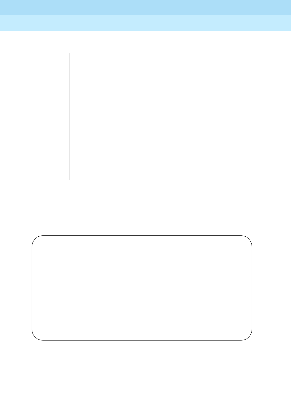
DEFINITY Enterprise Communications Server Release 6
Maintenance for R6r Volumes 1 & 2
555-230-126 Issue 2
January 1998
Maintenance Commands
Page 8-342upgrade software
8
Duplicated SPE
The following display shows a typical result when upgrade software is entered
on a system with duplicated SPE.
Upgrade Step Error
Code Description
Disable maintenance 6 Internal software error
Save translation 6 Internal software error
7 Storage device currently in use
8 Tape/disk access failure
9 Internal translation data is corrupted
10 Storage device has corrupted translation
2000 The save was not completed in the allotted time
6 Internal software error
Reboot processor 11 Could not load the boot image from the storage device
12 Could not reboot the processor
upgrade software
UPGRADE RESULTS
Upgrade Step Results Error Code
disable maintenance PASS
save translation PASS
busyout standby processor PASS
translation load and reboot standby PASS
change memory shadow bounds PASS
release standby processor PASS
refresh standby memory PASS
request an SPE interchange PASS

DEFINITY Enterprise Communications Server Release 6
Maintenance for R6r Volumes 1 & 2
555-230-126 Issue 2
January 1998
Maintenance Commands
Page 8-343upgrade software
8
Upgrade Step Each step in the upgrade execution is displayed after it occurs:
1. disable maintenance: This prevents periodic maintenance from
interfering with the upgrade (similar to the disable all command).
2. save translation: save a copy of the current translation to the primary
MSS device
3. busyout standby processor: This busies out the standby SPE,
preventing spontaneous interchanges while the new software load is
booted on the standby processor. This also turns off memory
shadowing from active memory to the standby.
4. translation load and reboot standby: This causes the standby
processor to load the boot image and translation on its primary
device. The SPE remains standby, and starts running the Standby
Maintenance Monitor (SMM).
5. change memory shadow bounds: This adjusts the range of memory
transmitted from the active to the standby SPE to include only the
information pertaining to active calls so as to preserve stable calls
across the interchange.
6. release standby processor: This releases the standby SPE from
busyout, allowing resumption of handshake and memory shadowing,
with transfer of active call status to the standby.
7. refresh standby memory: The system waits for refresh to complete
and reports the result.
8. request an SPE interchange: An interchange is executed into the
standby SPE with the new load. If this step succeeds, the terminal is
logged off. Otherwise, a failure code is returned.
9. If the upgrade is successful, Command successfully completed
is
not
displayed. Instead, the terminal is logged off the system and
must be logged in again.
Results Result of the execution of the corresponding step: PASS, FAIL, or
SKIPPED. SKIPPED occurs only for the save translation step when the
current version is newer than the version on the primary MSS device.
Error Code If a step fails, this field displays a code indicating the reason according
to Table 8-14:

DEFINITY Enterprise Communications Server Release 6
Maintenance for R6r Volumes 1 & 2
555-230-126 Issue 2
January 1998
Maintenance Commands
Page 8-344upgrade software
8
Table 8-14. Upgrade Software Error Codes—Duplicated SPE
Upgrade Step Error
Code Description
disable
maintenance 6 Internal software error
save translation 6 Internal software error
7 Storage device currently in use
8 Tape/disk access failure
9 Internal translation data is corrupted
10 Storage device has corrupted translation
2000 The save was not completed in the allotted time
busyout standby
processor 6 Internal software error
2010 Standby is already busied out
translation load
and reboot
standby
1 Could not create software processes on the standby
2 Not all processes on the standby were able to start
3 Standby LMM detected hardware failures on processor
complex
4 Software update file on standby corrupted
5 Translation on standby was not able to load correctly
6 Internal software error
2000 The load and reboot was not completed in the allotted
time, or communication with the standby was corrupted
2500 Internal software error with standby communication
change memory
shadow bounds 6 Internal software error
2500 Internal software error with standby communication
release standby
processor 6 Internal software error
2011 Standby processor was not busied out.
refresh standby
memory 6 Internal software error
2000 The refresh of the standby was not completed in the
allotted time
Continued on next page
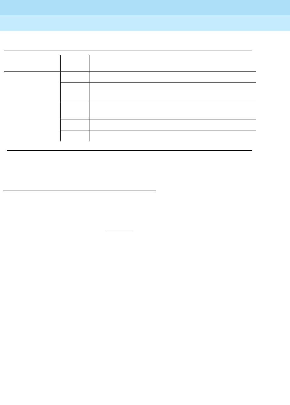
DEFINITY Enterprise Communications Server Release 6
Maintenance for R6r Volumes 1 & 2
555-230-126 Issue 2
January 1998
Maintenance Commands
Page 8-345upgrade software
8
Feature Interactions
System Restarts
An upgrade causes in a system restart. For a complete description of effects,
see “Software Updates” in Chapter 6.
Error and Alarm Log
Error and alarm logs are cleared.
Busyouts
Maintenance objects that have been busied out by command are released
during the reboot or interchange. If the upgrade command is canceled, all
busyouts are preserved.
Multi-User Contention
While the upgrade command is executing, all other administration and
maintenance commands except status reports are blocked.
Periodic and Scheduled Maintenance
Periodic and scheduled maintenance are suspended while the upgrade
command is processing.
request an SPE
interchange 6 Internal software error
2000 The load and reboot was not completed in the allotted
time, or communication with the standby was corrupted
2300 Communication failure with standby resulted in
interchange failure
2360 LMM attempt to interchange processors failed
2500 Internal software error with standby communication
Table 8-14. Upgrade Software Error Codes—Duplicated SPE — Continued
Upgrade Step Error
Code Description
Continued on next page

DEFINITY Enterprise Communications Server Release 6
Maintenance for R6r Volumes 1 & 2
555-230-126 Issue 2
January 1998
Maintenance Commands
Page 8-346upgrade software
8
Command History Log
Unlike other commands, the upgrade software command is logged into the
history log
before
it completes, prior to the save translation step. A record of the
upgrade is saved on the new active SPE.
Alarm Origination
To prevent reporting of alarms generated by the upgrade, alarm origination is
suspended during the execution of the command. After a successful interchange
on a system with duplicated SPE, alarm origination remains suspended for
approximately 5 minutes, or until the newly active SPE is ready to begin normal
maintenance.
Enable All
All previously disabled maintenance objects are re-enabled following the
upgrade. If the command is canceled, disables are preserved.
Parameters
Output
The following display shows a typical result when busyout ds1-facility 2e1a is
entered.
UUCSSf The location of a DS1 Converter facility. F represents a letter (a-d)
used to identify the separate DS1 facilities connected to the DS1
Converter.
override This option must be used to busyout the facility on a DS1 Converter
that is carrying the packet traffic and control messages. See the
caution note above.
Port The DS1 facility as described above in UUCSSf.
busyout ds1-facility 02e01a
COMMAND RESULTS
Port Maintenance Name Alt. Name Result Error Code
02E01A DS1-FAC PASS
Command successfully completed

DEFINITY Enterprise Communications Server Release 6
Maintenance for R6r Volumes 1 & 2
555-230-126 Issue 2
January 1998
Maintenance Commands
Page 8-347upgrade software
8
For more information see the following sections at the beginning of this chapter:
‘‘Busyout and Release Commands’’ and ‘‘Common Output Fields’’.

DEFINITY Enterprise Communications Server Release 6
Maintenance for R6r Volumes 1 & 2
555-230-126 Issue 2
January 1998
Maintenance Commands
Page 8-348upgrade software
8

Maintenance Object Repair Procedures
Page 9-1Escalation Procedures
9
DEFINITY Enterprise Communications Server Release 6
Maintenance for R6r Volumes 1 & 2
555-230-126 Issue 2
January 1998
9
9Maintenance Object Repair
Procedures
This document is intended for Release 5 and later systems only. For previous
DEFINITY systems (G3V4 and earlier), refer to
DEFINITY Enterprise
Communications Server Release 5.4 Maintenance for R5r
.
For maintenance Objects and Maintenance Commands for the DEFINITY
Wireless Business System (DWBS), refer to the appropriate maintenance
documentation that accompanies the DWBS.
Escalation Procedures
This document is not intended to solve all levels of trouble. When the limits of
these procedures have been reached and the problem has not been resolved, it
is the technician’s responsibility to escalate to a higher level of technical support.
Escalation should conform to the procedures in the
Technical and Administration
Plan
.

DEFINITY Enterprise Communications Server Release 6
Maintenance for R6r Volumes 1 & 2
555-230-126 Issue 2
January 1998
Maintenance Object Repair Procedures
Page 9-2ABRI-PORT (ASAI ISDN-BRI Port)
9
ABRI-PORT (ASAI ISDN-BRI Port)
Refer to BRI-PORT (ISDN-BRI Port) information for repair procedures.
1. The alarm level for ABRI ports may be administered using the set options command. The
alarm level can be set independently for off-board and on-board alarms to WARNING,
MINOR, or MAJOR for all ABRI ports in the system.
2. UU is the universal cabinet number (1 for PPN, 2 - 44 for EPNs). C is the carrier designation
(A, B, C, D, or E). SS is the number of the slot in which the circuit pack resides (01 to 21).
pp is the two digit port number (01, 02, ...).
MO Name (in
Alarm Log) Alarm Level Initial Command to Run Full Name of MO
ABRI-PORT 1MAJ/MIN/WRN test port UUCSSpp l 2ASAI ISDN-BRI Port

DEFINITY Enterprise Communications Server Release 6
Maintenance for R6r Volumes 1 & 2
555-230-126 Issue 2
January 1998
Maintenance Object Repair Procedures
Page 9-3AC-POWER
9
AC-POWER
AC Power for AC-Powered Systems
DEFINITY systems support two different cabinet types: Multi-Carrier Cabinets
and Single-Carrier Cabinets. Single-Carrier Cabinets are used only for EPNs.
Both cabinet types may be powered by either AC or DC power source.
Environmental maintenance differs according to cabinet type and power supply.
!CAUTION:
Before powering down a cabinet or carrier that contains DEFINITY AUDIX
circuit packs (TN566), first power down the AUDIX unit to avoid damaging
the AUDIX software. Instructions for powering down this unit are in the
‘‘DEFINITY AUDIX System Power Procedures’’ in Chapter 5, ‘‘Responding
to Alarms and Errors’’, on the circuit pack, and in DEFINITY AUDIX
documentation.
Single-Carrier Cabinet Power Systems
Each Single-Carrier Cabinet has one power supply that distributes DC power
and AC ringing voltage to the circuit pack slots in the cabinet.
AC Power Supply (WP-91153)
In an AC-powered cabinet, a single, plug-in, multi-output AC power supply is in
the power supply slot. A power cord, with a three-prong plug on one end and an
appliance connector on the other end, connects the supply to a dedicated AC
power source. The inputs to the power supply can be (depending on list version):
■120 VAC, 60 Hz, 15 Amp to 20 Amp; three wires in the power cord: one
hot wire, one neutral wire, and one ground wire
■220 VAC or 240 VAC, 50 Hz, 10 Amp; three wires in the power cord: one
hot wire, one neutral wire, and one ground wire
The AC power supply produces the following DC outputs: +5 VDC, -5 VDC,
-48 VDC, +12 VDC, and a battery-charging voltage. The DC outputs distribute
power on the cabinet backplane to the circuit pack slots.
1. UU is the universal cabinet number (1 for PPN, 2 - 44 for EPNs).
MO Name (in
Alarm Log) Alarm Level Initial Command to Run Full Name of MO
AC-POWER WARNING test environment UU1AC Power

DEFINITY Enterprise Communications Server Release 6
Maintenance for R6r Volumes 1 & 2
555-230-126 Issue 2
January 1998
Maintenance Object Repair Procedures
Page 9-4AC-POWER
9
The AC power supply also produces AC ringing voltage. The AC ringing voltage
output value and frequency depend on the country of use. The power supply has
a circuit breaker and EMI filtering.
Nominal Power Holdover
Multi-Carrier Cabinets
Two types of battery holdover are available:
■The small battery assembly provides short-term battery holdover. If AC
power fails, 48 VDC batteries power the system for 10 seconds in a PPN
cabinet, for 15 seconds in an EPN cabinet, and for 10 minutes in the
control carrier in a standard reliability system. The batteries also provide
system power for five minutes in the control carrier in high and critical
reliability systems, and for 10 minutes in the expansion control carrier in
the "A" position of an EPN cabinet (Release 5r only).
■Some AC-powered Multi-Carrier Cabinets contain three 48V batteries and
a battery charger (397C) to provide backup power in case power is
interrupted. The holdover times are identical to those above.
Single-Carrier Cabinets
A holdover circuit in the power supply allows a system to operate normally during
AC power interruptions. When AC input power fails, reserve batteries supply
power to the memory and processor circuit packs and fans for two minutes. All
port circuit packs are inactive during this time. The power supply contains a
battery charger to charge the holdover batteries.
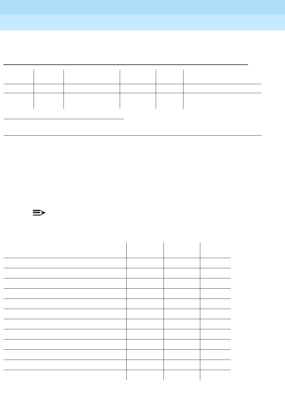
DEFINITY Enterprise Communications Server Release 6
Maintenance for R6r Volumes 1 & 2
555-230-126 Issue 2
January 1998
Maintenance Object Repair Procedures
Page 9-5AC-POWER
9
Error Log Entries and Test to Clear Values
System Technician-Demanded Tests:
Descriptions and Error Codes
Always investigate tests in the order shown in the table below. By clearing error
codes associated with the
Battery and Battery Charger Query Test
, for example,
you may also clear errors from other tests in the testing sequence. Refer to the
appropriate sections of this chapter for descriptions of each test.
NOTE:
The following tests apply to J58890CE, J58890CF, and J58890CH.
1. Run the Short Test Sequence first. If all tests pass, run the Long Test Sequence. Refer to the appropriate
test description and follow the recommended procedures.
Table 9-1. AC Power Error Log Entries
Error
Type Aux
Data Associated Test Alarm
Level On/Off
Board Test to Clear Value
010 Any Any Any test environment UU sh r 1
513 Any AC Power Query
Test (#78) WARNING OFF test environment UU sh r 1
Order of Investigation Short Test
Sequence Long Test
Sequence D/ND1
Battery & Battery Charger Query Test (#5) X X ND
AC Power Query Test (#78) X X ND
Power Unit Query Test (carrier E) (#127) X X ND
Power Unit Query Test (carrier D) (#127) X X ND
Power Unit Query Test (carrier A) (#127) X X ND
Power Unit Query Test (carrier B) (#127) X X ND
Power Unit Query Test (carrier C) (#127) X X ND
Emergency Transfer Query Test (#124) X X ND
Cabinet Temperature Query Test (#122) X X ND
External Alarm Lead Query Test (#120) X X ND
Analog Ring Generator Initialization Test (#117) X X ND
Analog Ring Generator Query Test (#118) X X ND
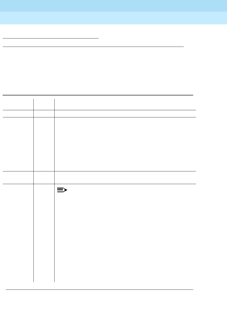
DEFINITY Enterprise Communications Server Release 6
Maintenance for R6r Volumes 1 & 2
555-230-126 Issue 2
January 1998
Maintenance Object Repair Procedures
Page 9-6AC-POWER
9
AC Power Query Test (#78)
This test queries the SYSAM in the PPN or the EPN maintenance circuit pack in
an EPN Multi-Carrier Cabinet system for the status of AC power to the cabinet.
1. D = Destructive; ND = Nondestructive
Table 9-2. TEST #78 Power Query Test
Error Code Test
Result Description/Recommendation
1000 ABORT System resources required to run test are not available (a)
100
2000 ABORT Response to the test request was not received within the allowable time
period (a)
1. If the test continues to ABORT with error code 2000, check for
system powering problems with the A carrier (PPN or EPN).
Resolve all AC-POWER and CARR-POW alarms. Then, repeat the
test.
2. If the test continues to ABORT with a 2000 error code, check for
and resolve all SYSAM errors in a PPN or MAINT errors (EPN
maintenance circuit pack) in an EPN. Then, repeat the test.
2029 2319
2320 2500 ABORT Internal system error
1FAIL
NOTE:
For a J58890CE, skip to step 2.
1. Procedures for a Global MCC (J58890CH):
a. For a nominal holdover system if there is no AC power at the
wall outlet, have a qualified electrician restore power to the
outlet. Power should range from 170 to 264 VAC.
b. If there is AC power at the wall outlet, then there could be a
problem with the RM0850 Rectifiers, BU3200A Battery Interface
Unit (BIU), or battery. Resolve all alarms logged against the
POWER maintenance object, and rerun the test. If the test still
fails, the BIU may be defective. Check the BIU. If the BOD
alarm LED is on, replace the BIU.
If the BOD LED is off and the BOK LED is on, then the SYSAM or
the EPN maintenance circuit pack may be incorrectly reporting
the problem. Resolve all alarms against these MOs and rerun
the test.
Continued on next page
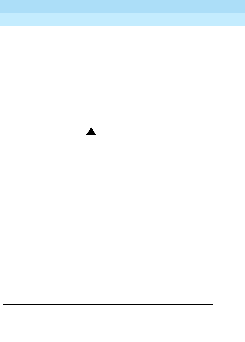
DEFINITY Enterprise Communications Server Release 6
Maintenance for R6r Volumes 1 & 2
555-230-126 Issue 2
January 1998
Maintenance Object Repair Procedures
Page 9-7AC-POWER
9
Notes:
a. Retry the command at 1-minute intervals a maximum of 5 times.
1
(Continued) FAIL 2. Procedures for a J58890CE:
The cabinet is currently without AC power.
1. Check for AC at the wall outlet (99-127 VAC, or 200 - 250 VAC).
a. If there is no AC power at the wall outlet, then the problem is not
with the system itself. Power must be restored to the wall outlet.
b. If there is AC power at the wall outlet, then there could be a
problem with the Battery or Battery chargers. Resolve all alarms
logged against POWER (Battery & Battery Charger), and rerun
the test. If the test still fails, the fuse F5 may have opened.
!WARNING:
Turn off the 397C Battery Charger before inserting or
removing Fuse F5.
Replace fuse F5 and rerun the test. If the test still fails, then the
SYSAM or the EPN Maintenance circuit pack may be incorrectly
reporting the problem. Resolve all alarms against these MOs, and
rerun the test. There are failures that can occur on the SYSAM and
EPN Maintenance circuit pack that
will not
be detected by their
respective maintenance, but which will cause many, if not all,
environment tests to fail. If more than two environment tests are
failing, the suspect circuit pack, depending on the system
configuration, should be replaced and the test rerun.
100 FAIL The cabinet is currently without AC power, and AC power maintenance
is in the middle of timing the NPH interval.
1. Follow the repair steps for error code 1.
PASS The SYSAM in the PPN or the EPN MAINT (maintenance) circuit pack in
an EPN has reported that the cabinet has AC power. If there is no AC
power at the wall outlet, then look for and resolve all alarms against the
appropriate MO listed.
Table 9-2. TEST #78 Power Query Test — Continued
Error Code Test
Result Description/Recommendation
Continued on next page

DEFINITY Enterprise Communications Server Release 6
Maintenance for R6r Volumes 1 & 2
555-230-126 Issue 2
January 1998
Maintenance Object Repair Procedures
Page 9-8AC-POWER
9
AC-POWER for DC-Powered Systems
NOTE:
In a DC-powered Multi-Carrier Cabinet, the AC-POWER maintenance
object exists, but serves no functional purpose. Because the system cannot
determine the type of power used, the AC-POWER test should always pass
or abort. The maintenance strategy for power components in DC cabinets
is described in the ‘‘CARR-POW’’ section.
DEFINITY supports two different cabinet types: Multi-Carrier Cabinets and
Single-Carrier Cabinets. Single-Carrier Cabinets are used only for EPNs. Both
cabinet types may be powered by either AC or DC power source. Environmental
maintenance differs according to cabinet type and external power supply.
1. UU is the universal cabinet number (1 for PPN, 2 - 44 for EPNs).
MO Name (in
Alarm Log) Alarm
Level Initial Command to Run Full Name of MO
AC-POWER WARNING test environment UU1AC Power
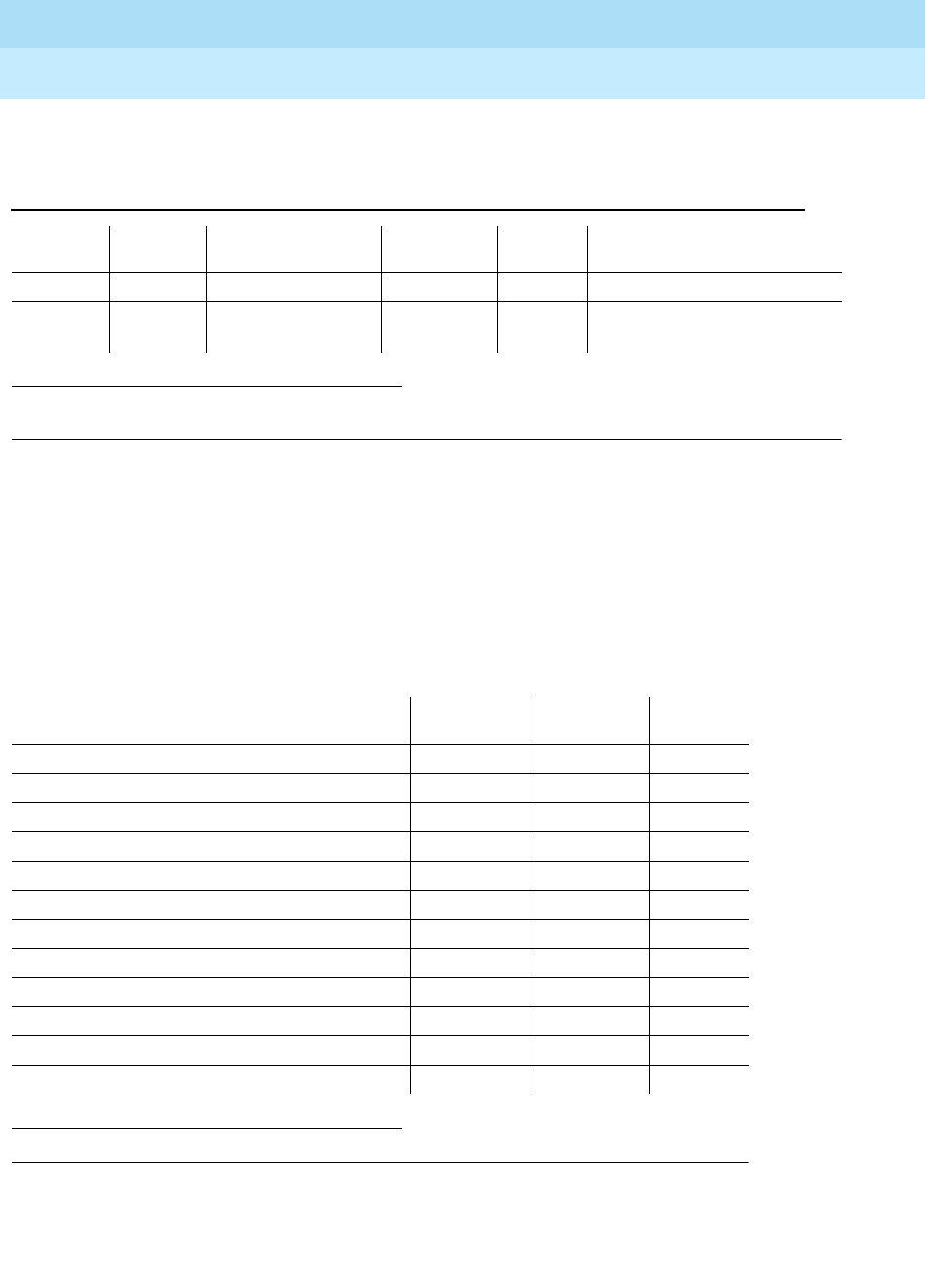
DEFINITY Enterprise Communications Server Release 6
Maintenance for R6r Volumes 1 & 2
555-230-126 Issue 2
January 1998
Maintenance Object Repair Procedures
Page 9-9AC-POWER
9
Error Log Entries and Test to Clear Values
System Technician-Demanded Tests:
Descriptions and Error Codes
Always investigate tests in the order presented in the table below. By clearing
error codes associated with the
AC Power Query Test
, for example, you may also
clear errors generated from other tests in the testing sequence. Refer to the
appropriate sections of this chapter for descriptions of each test.
1. Run the Short Test Sequence first. If all tests pass, run the Long Test Sequence. Refer to the appropriate
test description and follow the recommended procedures.
1. D = Destructive; ND = Nondestructive
Table 9-3. AC Power Error Log Entries
Error
Type Aux
Data Associated Test Alarm
Level On/Off
Board Test to Clear Value
010 Any Any Any test environment UU sh r 1
513 Any AC Power Query
Test (#78) WARNING OFF test environment UU sh r 1
Order of Investigation Short Test
Sequence Long Test
Sequence D/ND1
Battery & Battery Charger Query Test (#5) X X ND
AC Power Query Test (#78) X X ND
Power Unit Query Test (carrier E) (#127) X X ND
Power Unit Query Test (carrier D) (#127) X X ND
Power Unit Query Test (carrier A) (#127) X X ND
Power Unit Query Test (carrier B) (#127) X X ND
Power Unit Query Test (carrier C) (#127) X X ND
Emergency Transfer Query Test (#124) X X ND
Cabinet Temperature Query Test (#122) X X ND
External Alarm Lead Query Test (#120) X X ND
Analog Ring Generator Initialization Test (#117) X X ND
Analog Ring Generator Query Test (#118) X X ND

DEFINITY Enterprise Communications Server Release 6
Maintenance for R6r Volumes 1 & 2
555-230-126 Issue 2
January 1998
Maintenance Object Repair Procedures
Page 9-10AC-POWER
9
AC Power Query Test (#78)
This test is not valid for DC-powered cabinets and should always abort or pass.
Notes:
a. Retry the command at 1-minute intervals a maximum of 5 times.
Table 9-4. TEST #78 Power Query Test
Error
Code Test
Result Description/Recommendation
1000 ABORT System resources required to run test are not available
100
2000 ABORT Response to the test request was not received within the allowable time
period
2029
2319
2320
2500
ABORT Internal system error (a).
Any FAIL The SYSAM in a PPN or the EPN Maintenance circuit pack in an EPN is
incorrectly reporting an AC power problem. If this test fails, there is a
problem with the SYSAM OR EPN Maintenance circuit pack. Replace the
suspect circuit pack and run the test again. (b)
PASS Since this test is invalid for DC-powered cabinets, this result simply
indicates that the SYSAM or EPN Maintenance circuit pack is handling this
test properly
Continued on next page

DEFINITY Enterprise Communications Server Release 6
Maintenance for R6r Volumes 1 & 2
555-230-126 Issue 2
January 1998
Maintenance Object Repair Procedures
Page 9-11ADM-CONN (Administered Connection)
9
ADM-CONN (Administered
Connection)
An administered connection provides an end-to-end connection between two
access endpoints or data modules on either the same or different switches. The
connection is automatically established when it is administered and scheduled to
be active.
An error is logged whenever an administered connection fails or cannot be
established. Failures to establish a connection generate an error whether they
occur on an initial try, a retry, a fast retry, a redial or an auto-restoration. A failed
connection generates an error whether or not the connection is subsequently
reestablished by fast retry, redial, or auto restoration.
An alarm is logged when an administered connection cannot be established
either initially or after failure of a connection. Both the alarm level (none to major)
and a failure threshold can be administered for each administered connection.
An alarm is raised when either of the following occurs:
■The number of consecutive failed attempts to establish a connection
reaches the administered threshold.
■Software determines that failure to establish a connection is due to a
mistake in administration. See Table 9-5.
Error Log Entries and Test to Clear Values
1. Where N is an administered connection number indicated in the PORT field of the Alarm or Error Log.
MO Name (in
Alarm Log) Alarm Level Initial Command to Run Full Name of MO
ADM-CONN MAJOR, MINOR,
or WARNING status administered-connection N 1Administered Connection
Table 9-5. Administered Connection Error Log Entries
Error Type Aux
Data Associated
Test Alarm
Level On/Off
Board Test to Clear
Value
0, or 29 Any None Any OFF None
1, or 28 (a,b) Any None Any OFF None
2 (c) Any None Any OFF None
6,21,31, or 127(d) Any None Any OFF None
Continued on next page
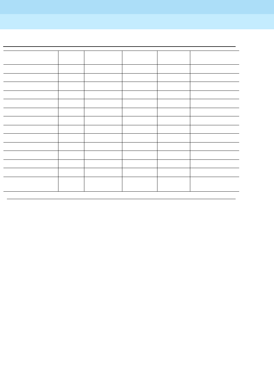
DEFINITY Enterprise Communications Server Release 6
Maintenance for R6r Volumes 1 & 2
555-230-126 Issue 2
January 1998
Maintenance Object Repair Procedures
Page 9-12ADM-CONN (Administered Connection)
9
For all ADM-CONN errors:
All of the above errors have no specific test associated with them and, except for
errors 17 and 127, are valid only for administered connections established over
ISDN-PRI facilities. Error 127 is valid for administered connections established
over non-ISDN facilities or between two endpoints on the same switch.
Notes:
a. These errors are typically associated with administration problems and
are not expected to be of a temporary nature. The administered
connection is not retried and the failure is alarmed immediately. The alarm
threshold specified by the customer is ignored.
b. The address of the destination endpoint is: an unassigned number (1),
has an invalid number format (28), or is restricted from terminating calls
due to Class of Restriction (‘‘Access Denied’’). Verify that the destination
address is correct and that the destination endpoint is administered. The
destination endpoint is not administered on the switch where this error is
logged.
c. A request has been made to use a transit network or common carrier that
cannot be accessed. Check the routing pattern used by this administered
connection and verify that the inter-exchange carrier specified is correct.
16 (a) Any None Any OFF None
17 (e) Any None Any OFF None
18, or 102 (f) Any None Any OFF None
22 (a,g) Any None Any OFF None
34,42,44, or 58 (h) Any None Any OFF None
38, or 41 (i) Any None Any OFF None
43, or 81 Any None Any OFF None
50 (a) Any None Any OFF None
52 (a) Any None Any OFF None
54 Any None Any OFF None
65,66, or 69 (a) Any None Any OFF None
82 Any None Any OFF None
88 (a) Any None Any OFF None
91,95,96,97,98,99,1
00, or 111 Any None Any OFF None
Table 9-5. Administered Connection Error Log Entries — Continued
Error Type Aux
Data Associated
Test Alarm
Level On/Off
Board Test to Clear
Value
Continued on next page

DEFINITY Enterprise Communications Server Release 6
Maintenance for R6r Volumes 1 & 2
555-230-126 Issue 2
January 1998
Maintenance Object Repair Procedures
Page 9-13ADM-CONN (Administered Connection)
9
d. The exact failure cause is unknown or has been mapped to one of these
values. If this is not a temporary condition, try reversing the direction of the
Administered Connection (originate the administered connection from the
destination switch). This may yield another failure cause.
e. The destination endpoint is not available. Check the status of the
destination endpoint at the far-end switch. The status for the destination
endpoint will not be available on the switch where this error is logged. At
the far end, use status access-endpoint or status data-module to see
whether the endpoint is busy, out-of-service or otherwise unavailable.
f. This switch sent an ISDN message to another switch, which either did not
respond (18) or did not respond within the allotted time (102). This could
be due to link failure or congestion or outage at the other switch.
g. The address of the destination endpoint has changed. Change the
administered connection accordingly. The destination endpoint will not be
administered on the switch where this error is logged.
h. These errors indicate that a resource (for example, a circuit or bearer
capability) required by the administered connection is not presently
available.
i. A network failure (38) or temporary failure (41) has occurred. Error Log
entries for other MOs (for example, DS1-BD) may indicate a local problem.

DEFINITY Enterprise Communications Server Release 6
Maintenance for R6r Volumes 1 & 2
555-230-126 Issue 2
January 1998
Maintenance Object Repair Procedures
Page 9-14ADX8D-BD (AUDIX Circuit Pack)
9
ADX8D-BD (AUDIX Circuit Pack)
The ADX8D-BD maintenance object represents a TN566/TN2169 DEFINITY
AUDIX circuit pack (sometimes called Embedded AUDIX) operating in
digital-port (DP) mode. For circuit-pack-level problems, see ‘‘XXX-BD (Common
Port Circuit Pack)’’. Port-level problems are covered by ADX8D-PT.
DEFINITY AUDIX consists of two circuit packs that occupy 5 slots on a port
carrier. The tests described in this manual apply only to switch-side maintenance
which tests circuit pack components related to the TDM bus interface. The
AUDIX system has an extensive maintenance strategy that is described in
DEFINITY AUDIX System Maintenance
, 585-300-110.
1. UU is the universal cabinet number (1 for PPN, 2 - 44 for EPNs). C is the carrier
designation (A, B, C, D, or E). SS is the number of the slot in which the circuit pack
resides (01 to 21).
MO Name (in
Alarm Log) Alarm Level Initial Command to Run1Full Name of MO
ADX8D-BD MINOR or
WARNING test board UUCSS sh AUDIX Circuit Pack

DEFINITY Enterprise Communications Server Release 6
Maintenance for R6r Volumes 1 & 2
555-230-126 Issue 2
January 1998
Maintenance Object Repair Procedures
Page 9-15ADX8D-PT (AUDIX Digital Port)
9
ADX8D-PT (AUDIX Digital Port)
The ADX8D-PT maintenance object represents a port on a TN566/TN2169
DEFINITY AUDIX circuit pack (sometimes called Embedded AUDIX) operating in
digital-port (DP) mode. The maintenance strategy for ports on the TN566
operating in control-link mode is described in ADX16A-PT.
The tests described in this section apply only to switch-side maintenance which
tests circuit pack components related to the TDM bus interface. The AUDIX
system has an extensive maintenance strategy that is described in
DEFINITY
AUDIX System Maintenance
, 585-300-110.
AUDIX resides on a combined pair of circuit packs: the TN566 Multifunction
Board (MFB) and the TN2169 Alarm Board (ALB). Because of its size this
combination occupies 5 slots, but only 1 slot is functional as far as the switch is
concerned. The other 4 slots are seen by the switch as ‘‘AUDIX-reserved’’ slots
(or ADXDP-RS/ADX8D-RS.)
In DP mode the TN566 pack supports up to 8 voice ports, each with a primary
information channel and a secondary information channel. Ports are
administered in increments of two. When a call to a station with an AUDIX login is
not answered, AUDIX answers the call using one of the available voice ports.
Unlike other AUDIX systems, DEFINITY AUDIX is not an adjunct.
!CAUTION:
Never do any of the following without first shutting down AUDIX. Follow
instructions on the TN566/TN2169 faceplate:
■
Remove DEFINITY AUDIX circuit packs
■
Cycle power to a carrier containing DEFINITY AUDIX circuit packs
■
Remove power to a carrier containing DEFINITY AUDIX circuit packs
1. UU is the universal cabinet number (1 for PPN, 2 - 44 for EPNs). C is the carrier
designation (A, B, C, D, or E).
SS
is the number of the slot in which the circuit pack
resides (01 to 21).
pp
is the two digit port number (01, 02, ...).
MO Name (in
Alarm Log) Alarm
Level Initial Command to
Run1Full Name of MO
ADX8D-PT MINOR test port UUCSSpp l AUDIX Digital Port
ADX8D-PT WARNING test port UUCSSpp sh AUDIX Digital Port
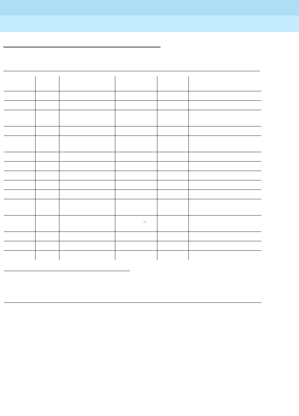
DEFINITY Enterprise Communications Server Release 6
Maintenance for R6r Volumes 1 & 2
555-230-126 Issue 2
January 1998
Maintenance Object Repair Procedures
Page 9-16ADX8D-PT (AUDIX Digital Port)
9
Error Log Entries and Test to Clear Values
Notes:
a. The user may experience a noisy port or link. This is an off-board problem
that is detected by the port circuit. If this problem exists, replace the
circuit pack (see caution at the beginning of this section). Once the
problem is resolved, the alarm is retired after a predetermined time.
b. At least 15 off-board problems have been detected with the link to the
voice port. When an error with the link is detected, an on-board counter is
incremented. Also see Note (a).
c. This is an internal type error that occurs when an audit request fails.
d. The port is busied-out by command. You can release the port via the
release port UUCSSpp command.
1. Run the Short Test Sequence first. If all tests pass, run the Long Test Sequence. Refer to the
appropriate test description and follow the recommended procedures.
2. Minor alarms on this MO may be downgraded to Warning alarms based on the values used in the
set options command.
Table 9-6. DEFINITY AUDIX Digital Port Error Log Entries
Error
Type Aux
Data Associated Test Alarm Level On/Off
Board Test to Clear Value
010 Any Any Any test port UUCSSpp sh r 1
1(a) 40987 None WARNING OFF
1(b) 1 to
20 None WARNING OFF
15(c) Any None
18(d) 0 busyout port
UUCSSpp WARNING OFF release port UUCSSpp
23(e) 0 None WARNING OFF
130(f) None WARNING ON test port UUCSSpp sh
257(g) 40971 None
513(h) Any None
1537(i) 40968 None WARNING OFF
1793 Voice & Ctrl. Local
Loop Test (#13) MIN/WRN2ON test port UUCSSpp l r 3
2049 NPE Crosstalk Test
(#9) MIN/WRN2ON test port UUCSSpp l r 3
2305(j) 40967 None
3840(k) 40965 None
3840(l) 41029 None

DEFINITY Enterprise Communications Server Release 6
Maintenance for R6r Volumes 1 & 2
555-230-126 Issue 2
January 1998
Maintenance Object Repair Procedures
Page 9-17ADX8D-PT (AUDIX Digital Port)
9
e. The circuit pack is administered but not physically installed. The alarm will
clear when a circuit pack is inserted.
f. The circuit pack has been removed or has been insane for more than
21-minutes. To clear the error, reinsert or replace the AUDIX circuit pack
(see pcaution at the beginning of this section).
g. Something is interfering with transmitting to the voice port. This is usually
an on-board problem and can be ignored if no user complaints are
received.
h. AUDIX is not available to the switch, possibly due to a busyout on the
AUDIX system. Check out the AUDIX system referring
DEFINITY AUDIX
System Maintenance
, 585-300-110, if necessary.
i. An in-line maintenance error has generated an off-board warning due to
some problem with the link to the voice port. This can be ignored if no user
complaints are received. If the problem persists, replace the circuit pack
(see precaution at the beginning of this section). Once the problem is
resolved, the alarm is retired after a certain period of time.
j. The link between the circuit pack and the voice port is successfully reset.
No craft action is necessary.
k. No voice ports are connected to the DEFINITY AUDIX circuit pack. No
maintenance action is required.
l. The message buffer in the circuit pack is full.
System Technician-Demanded Tests:
Descriptions and Error Codes
Always investigate tests in the order presented in the table below when you are
inspecting errors in the system. By clearing error codes associated with the
Voice and Control Channel Local Looparound Test
for example, you may also
clear errors generated from other tests in the testing sequence.
1. D = Destructive; ND = Nondestructive
Order of Investigation Short Test
Sequence Long Test
Sequence D/ND1
Voice and Control Channel Local Looparound
Test (#13) XND
NPE Crosstalk Test (#9) X ND

DEFINITY Enterprise Communications Server Release 6
Maintenance for R6r Volumes 1 & 2
555-230-126 Issue 2
January 1998
Maintenance Object Repair Procedures
Page 9-18ADX8D-PT (AUDIX Digital Port)
9
NO-OP Tests
The maintenance strategy for DEFINITY AUDIX emulates the one for DIG-LINE.
The tests listed below apply only to DIG-LINE and not to DEFINITY AUDIX. These
are referred to as
NO-OP
tests, and they always return PASS.
■Electronic Power Feed Test (#11)
■Station Lamp Updates Test (#16)
■Station (Digital) Audits Test (#17)
NPE Crosstalk Test (#9)
This test verifies that this port’s NPE channel talks on the selected time slot and
that it never crosses over to time slots reserved for other connections. If the NPE
is not working correctly, one-way and noisy connections may be observed. This
test is part of a port’s Long Test Sequence, and it takes about 20 to 30 seconds
to complete.
Crosstalk testing is performed on both the primary information channel (voice)
and on the secondary information channel (data) associated with each DEFINITY
AUDIX port. If this test fails on either channel, the voice port is taken
out-of-service.
Table 9-7. TEST #9 NPE Crosstalk Test
Error
Code Test
Result Description/Recommendation
1 ABORT During testing of the primary information channel, system resources may
not have been available. Also, the port may have been busy during the
test.
1. Check the port status. Use the display port UUCSSpp command to
determine the voice port extension of the port. Use the status station
command to determine the service state of the port. If the service state
indicates that the port is in use, you must wait until the port is idle.
When the port is idle, try (a).
2 ABORT System resources may not have been available, or the port may have been
busy during the test. Try (a).
1000 ABORT System resources required to run this test are not available. The port may
be in use. Use the display port UUCSSpp command to determine the
voice port extension of the port. Use the status station command to
determine the service state of the port. If the service state indicates that
the port is in use, you must wait until the port is idle before retesting. Try
(a).
1001 ABORT System resources required to run this test are not available. Try (a).
Continued on next page

DEFINITY Enterprise Communications Server Release 6
Maintenance for R6r Volumes 1 & 2
555-230-126 Issue 2
January 1998
Maintenance Object Repair Procedures
Page 9-19ADX8D-PT (AUDIX Digital Port)
9
Notes:
a. Retry the command at 1-minute intervals a maximum of 5 times.
Voice and Control Channel Local Loop Test (#13)
This test checks the information and control channels between the Switch
Processing Element (SPE) and the DEFINITY AUDIX port circuit. First, the
primary information (voice) channel loop back test is run.
1002 ABORT The system could not allocate time slots for the test. The system may be
under heavy traffic conditions, or it may have time slots out-of-service due
to TDM-BUS errors. Refer to TDM-BUS maintenance to diagnose any
active TDM-BUS errors.
1. If system has no TDM-BUS errors, and if it is not handling heavy traffic,
try (a).
1003 ABORT The system could not allocate a tone receiver for the test. The system may
be oversized for the number of Tone Detectors present, or some Tone
Detectors may be out-of-service.
1. Look for TTR-LEV errors in the Error Log. If present, refer to TTR-LEV.
2. Look for TONE-PT errors in the Error Log. If present, refer to TONE-PT.
Try (a).
1004 ABORT The port was put in use during the test. The test has been aborted. Use the
display port UUCSSpp command to determine the voice port extension of
the port. Use the status station command to determine the service state
of the port. If the port is in use, wait until the port is idle before testing.
1020 ABORT Test disabled by background testing. Use the status station command to
determine when the voice port is available for testing.
2000 ABORT Response to the test request was not received within the allowable time
period. Try (a).
1
2 FAIL The NPE of the tested port is transmitting in error. This causes noisy and
unreliable connections. Failure code 1 indicates that the Crosstalk test
failed on the primary channel. Failure code 2 indicates that the Crosstalk
test failed on the secondary channel.
1. Replace the circuit pack .
PASS The port is using its allocated time slots correctly.
1. To be sure that this is not an intermittent problem, repeat this test up to
a maximum of 10 times to make sure it continues to pass.
2. If complaints still exist, examine the connections.
Table 9-7. TEST #9 NPE Crosstalk Test — Continued
Error
Code Test
Result Description/Recommendation
Continued on next page

DEFINITY Enterprise Communications Server Release 6
Maintenance for R6r Volumes 1 & 2
555-230-126 Issue 2
January 1998
Maintenance Object Repair Procedures
Page 9-20ADX8D-PT (AUDIX Digital Port)
9
While the primary information channel is still looped around, the Control Channel
Looparound Test is performed. The Looparound Test for the secondary
information (data) channel is then performed. This test is the same as the primary
information channel loop around test.
Next, a Conference Test is implemented for the primary information channel. This
test is the same as Conference Test #6.
Only one value (Pass, Fail, or Abort) is generated as a result of the four tests run.
If any test fails or aborts, the sequence is stopped.
Table 9-8. TEST #13 Voice and Control Channel Local Loop Test
Error
Code Test
Result Description/Recommendation
ABORT Internal system error. Try (a) then (b).
1000 ABORT System resources required to run this test are not available. The port may
be in use. Use the display port UUCSSpp command to determine the
voice port extension of the port. Use the status station command to
determine the service state of the port. If the service state indicates that
the port is in use, you must wait until the port is idle before retesting. Try
(a).
1001 ABORT System resources required for this test are not available. Try (a).
1002 ABORT The system could not allocate time slots for the test. The system may be
under heavy traffic conditions, or may have time slots that are
out-of-service due to TDM-BUS errors. Refer to “TDM-BUS” to diagnose
TDM-BUS errors.
1. If the system has no TDM-BUS errors, and is not handling heavy
traffic, try (a).
1003 ABORT The system could not allocate a tone receiver for the test. The system may
be oversized for the number of Tone Detectors present, or some Tone
Detectors may be out-of-service.
1. Look for TTR-LEV errors in the Error Log. If present, refer to TTR-LEV
(TTR Level).
2. Look for TONE-PT errors in the Error Log. If present, refer to TONE-PT
(Tone Generator).
3. If neither condition exists, try (a).
1004 ABORT The port was put in use during the test. Use the display port UUCSSpp to
determine the voice port extension of the port. Use the status station
command to determine the service state of the port. If the service state
indicates that the port is in use, you must wait until the port is idle before
retesting. Try (a).
2000 ABORT Response to the test request was not received within the allowable time
period. Try (a).
2100 ABORT Could not allocate the necessary system resources to run this test. Try (a).
Continued on next page

DEFINITY Enterprise Communications Server Release 6
Maintenance for R6r Volumes 1 & 2
555-230-126 Issue 2
January 1998
Maintenance Object Repair Procedures
Page 9-21ADX8D-PT (AUDIX Digital Port)
9
7 FAIL Conference Test failed on the primary channel. Some users may not notice
a disruption in service. In extreme cases, the conferencing feature may
not work at all.
14 FAIL The primary voice channel is not transmitting properly. User impact may
range from no noticeable effect to loss of use of this port.
15 FAIL The control channel between the processor and DEFINITY AUDIX circuit
pack is not transmitting properly. User impact may range from no
noticeable effect to loss of use of this port. This failure could also be
disruptive to other users.
16 FAIL The secondary voice channel is not transmitting properly. User impact
may range from no noticeable effect to loss of use of this port.
None FAIL The test failed for reasons external to the DEFINITY AUDIX circuit pack.
1. Run circuit pack tests to check the Tone Generator circuit pack and
the Tone Detector circuit pack by using the test board UUCSS s
command.
2. Resolve any problems that are detected on the Tone Generator circuit
pack or Tone Detector circuit pack.
3. If the Tone Generator and Tone Detector circuit packs are functioning
properly, and if the test still fails, replace the DEFINITY AUDIX circuit
pack (see precaution at the beginning of this section).
PASS Voice and Control Channel Local Loop test passed. All channels are
transmitting properly.
1. To be sure that this is not an intermittent problem, repeat this test up
to 10 times and see if it continues to pass.
2. If complaints still exist, examine the connections.
Table 9-8. TEST #13 Voice and Control Channel Local Loop Test — Continued
Error
Code Test
Result Description/Recommendation
Continued on next page
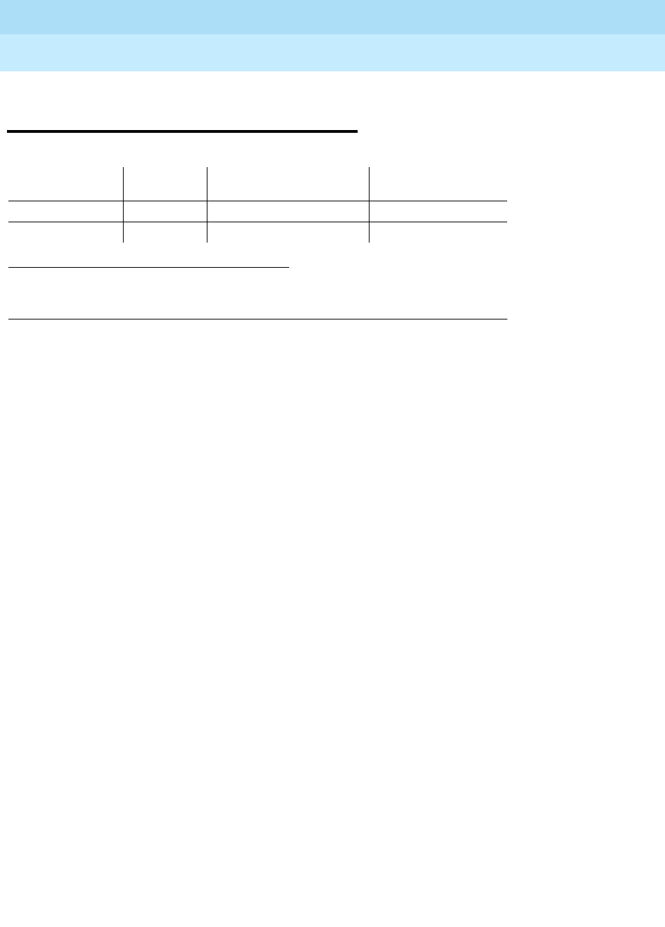
DEFINITY Enterprise Communications Server Release 6
Maintenance for R6r Volumes 1 & 2
555-230-126 Issue 2
January 1998
Maintenance Object Repair Procedures
Page 9-22ADX16D-B (16 Port AUDIX Circuit Pack)
9
ADX16D-B (16 Port AUDIX Circuit
Pack)
The ADX16D-BD maintenance object represents a TN566/TN2169 DEFINITY
AUDIX circuit pack combination operating in 16 port mode digital (DP). For
circuit-pack-level problems, see “XXX-BD (Common Port Circuit Pack)”.
Port-level maintenance is covered by ADX16D-PT.
DEFINITY AUDIX consists of 2 circuit packs that occupy 5 slots on a port carrier.
The tests described in this manual apply only to switch-side maintenance which
tests circuit pack components related to the TDM bus interface. The AUDIX
system has an extensive maintenance strategy of its own that is described in
DEFINITY AUDIX System Maintenance
, 585-300-110.
1. UU is the universal cabinet number (1 for PPN, 2 - 44 for EPNs). C is the carrier
designation (A, B, C, D, or E). SS is the number of the slot in which the circuit pack
resides (01 to 21).
MO Name (in
Alarm Log) Alarm
Level Initial Command to Run1Full Name of MO
ADX16D-B MINOR test board UUCSS sh AUDIX Circuit Pack
ADX16D-B WARNING test board UUCSS sh AUDIX Circuit Pack

DEFINITY Enterprise Communications Server Release 6
Maintenance for R6r Volumes 1 & 2
555-230-126 Issue 2
January 1998
Maintenance Object Repair Procedures
Page 9-23ADX16A-BD (AUDIX Circuit Pack)
9
ADX16A-BD (AUDIX Circuit Pack)
The ADX16A-BD maintenance object represents a TN566/TN2169 DEFINITY
AUDIX circuit pack combination operating in control-link (CL) mode. For
circuit-pack-level problems, see “XXX-BD (Common Port Circuit Pack)”.
Port-level maintenance is covered by ADX16A-PT.
DEFINITY AUDIX consists of 2 circuit packs that occupy 5 slots on a port carrier.
The tests described in this manual apply only to switch-side maintenance which
tests circuit pack components related to the TDM bus interface. The AUDIX
system has an extensive maintenance strategy that is described in
DEFINITY
AUDIX System Maintenance
, 585-300-110.
1. UU is the universal cabinet number (1 for PPN, 2 - 44 for EPNs). C is the carrier designation
(A, B, C, D, or E). SS is the number of the slot in which the circuit pack resides (01 to 21).
MO Name (in
Alarm Log) Alarm Level Initial Command to Run1Full Name of MO
ADXCL-BD or
\ADX16A-BD MINOR, or
WARNINGS test board UUCSS sh AUDIX Circuit Pack
DEFINITY Enterprise Communications Server Release 6
Maintenance for R6r Volumes 1 & 2
555-230-126 Issue 2
January 1998
Maintenance Object Repair Procedures
Page 9-24ADX16D-P (16-Port AUDIX Digital Port)
9
ADX16D-P (16-Port AUDIX Digital
Port)
!CAUTION:
Never do any of the following without first shutting down AUDIX. Follow the
instructions on the TN566/TN2169 faceplate:
■
Remove DEFINITY AUDIX circuit packs
■
Cycle power to a carrier containing DEFINITY AUDIX circuit packs
■
Remove power to a carrier or cabinet containing DEFINITY AUDIX circuit
pack.
The ADX16D-P maintenance object represents a port on a TN566/TN2169
DEFINITY AUDIX circuit pack operating in digital-port (DP) mode. The
maintenance strategy for ports on the TN566 operating in control-link mode is
described in ADX16A-PT.
The tests described in this section apply only to switch-side maintenance which
tests circuit pack components related to the TDM bus interface. The AUDIX
system has an extensive maintenance strategy that is described in
DEFINITY
AUDIX System Maintenance
, 585-300-110.
AUDIX resides on a combined pair of circuit packs: the TN566 Multifunction
Board (MFB) and the TN2169 Alarm Board (ALB). Because of its size this
combination occupies 5 slots, but only 1 slot is functional as far as the system is
concerned. The other 4 slots are seen by the switch as ‘‘AUDIX-reserved’’ slots
(or ADX16-RES/ADX16D-RS).
In 16 Port DP mode, the TN566 pack supports up to 16 voice ports, each with a
primary information channel and a secondary information channel. Ports are
administered in increments of two. When a call to a station with an AUDIX login is
not answered, AUDIX answers the call using one of the available voice ports.
Unlike other AUDIX systems, DEFINITY AUDIX is not an adjunct.
1. UU is the universal cabinet number (1 for PPN, 2-44 for EPNs). C is the carrier
designation (A, B, C, D, or E). SS is the number of the slot in which the circuit pack
resides (01 to 21). pp is the two digit port number (01, 02, ...).
MO Name (in
Alarm Log) Alarm Level Initial Command to Run1Full Name of MO
ADX16D-P MINOR or
WARNINGS test port UUCSSpp l AUDIX Digital Port
DEFINITY Enterprise Communications Server Release 6
Maintenance for R6r Volumes 1 & 2
555-230-126 Issue 2
January 1998
Maintenance Object Repair Procedures
Page 9-25ADX16D-P (16-Port AUDIX Digital Port)
9
Error Log Entries and Test to Clear Values
Notes:
a. The user may experience a noisy port or link. This is an off-board problem
that is detected by the port circuit. If this problem exists, replace the
circuit pack (see caution at the beginning of this section). Once the
problem is resolved, the alarm is retired after a predetermined time.
b. At least 15 off-board problems have been detected with the link to the
voice port. When an error with the link is detected, an on-board counter is
incremented. Also see Note a, above.
c. This is an internal type error that occurs when an audit request fails.
1. Run the Short Test Sequence first. If all tests pass, run the Long Test Sequence. Refer to the
appropriate test description and follow the recommended procedures.
2. Minor alarms may be downgraded to Warning alarms based on the values used in the set options
command.
Table 9-9. DEFINITY AUDIX Digital Port Error Log Entries
Error
Type Aux
Data Associated
Test Alarm
Level On/Off
Board Test to Clear Value
010 Any Any Any test port UUCSSpp sh r 1
1(a) 40987 None WARNING OFF
1(b) 1 to 20 None WARNING OFF
15(c) Any None
18(d) 0 busyout port
UUCSSpp WARNING OFF release port UUCSSpp
23(e) 0 None WARNING OFF
130(f) None WARNING ON test port UUCSSpp sh
257(g) 40971 None
513(h) Any None
1537(i) 40968 None WARNING OFF
1793 Voice and
Control Local
Loop TEST
(#13)
MIN/ WRN2ON test port UUCSSpp l r 3
2049 NPE Crosstalk
Test (#9) MIN/ WRN2ON test port UUCSSpp l r 3
2305(j) 40967 None
3840(k) 40965 None
3840(l) 41029 None

DEFINITY Enterprise Communications Server Release 6
Maintenance for R6r Volumes 1 & 2
555-230-126 Issue 2
January 1998
Maintenance Object Repair Procedures
Page 9-26ADX16D-P (16-Port AUDIX Digital Port)
9
d. The port is busied-out by command. Release the port with the release
port UUCSSpp command.
e. The circuit pack is administered but not physically installed. The alarm will
clear when a circuit pack is inserted.
f. The circuit pack has been removed or has been insane for more than
21-minutes. To clear the error, reseat or replace the AUDIX circuit pack
(see caution at the beginning of this section).
g. Something is interfering with transmitting to the voice port. This is usually
an on-board problem and can be ignored if no user complaints are
received.
h. AUDIX is not available to the switch, possibly due to a busyout on the
AUDIX system. Refer to
DEFINITY AUDIX System Maintenance
,
585-300-110, if necessary.
i. An in-line maintenance error has generated an off-board warning due to
some problem with the link to the voice port. This can be ignored if no user
complaints are received. If the problem persists, replace the circuit pack
(see caution at the beginning of this section). Once the problem is
resolved, the alarm is retired after a certain period of time.
j. The link between the circuit pack and the voice port is successfully reset.
No craft action is necessary.
k. No voice ports are connected to the DEFINITY AUDIX circuit pack. No
maintenance action is required.
l. The message buffer in the circuit pack is full.
System Technician-Demanded Tests:
Descriptions and Error Codes
Always investigate tests in the order presented in the table below. By clearing
error codes associated with the
Voice and Control Channel Local Looparound
Test
for example, you may also clear errors generated from other tests in the
testing sequence.
1. D = Destructive; ND = Nondestructive
Order of Investigation Short Test
Sequence Long Test
Sequence D/ND1
Voice and Control Channel Local Looparound Test (#13) X ND
NPE Crosstalk Test (#9) X ND

DEFINITY Enterprise Communications Server Release 6
Maintenance for R6r Volumes 1 & 2
555-230-126 Issue 2
January 1998
Maintenance Object Repair Procedures
Page 9-27ADX16D-P (16-Port AUDIX Digital Port)
9
NO-OP Tests
The maintenance strategy for DEFINITY AUDIX emulates the one for DIG-LINE.
The tests listed below apply only to DIG-LINE and not to DEFINITY AUDIX. These
tests always return PASS.
■Electronic Power Feed Test (#11)
■Station Lamp Updates Test (#16)
■Station (Digital) Audits Test (#17)
■Digital Terminal Remote Looparound Test (1201)
NPE Crosstalk Test (#9)
This test verifies that this port’s NPE channel talks on the selected time slot and
that it never crosses over to time slots reserved for other connections. If the NPE
is not working correctly, one-way and noisy connections may be observed. This
test is part of a port’s Long Test Sequence, and it takes about 20 to 30 seconds
to complete.
Crosstalk testing is performed on both the primary information channel (voice)
and on the secondary information channel (data) associated with each DEFINITY
AUDIX port. If this test fails on either channel, the voice port is taken
out-of-service.
Table 9-10. TEST #9 NPE Crosstalk Test
Error
Code Test
Result Description/Recommendation
1 ABORT During testing of the primary information channel, system resources may
not have been available. Also, the port may have been busy during the test.
1. Check the port status. Use the display port UUCSSpp command to
determine the voice port extension of the port. Use the status station
command to determine the service state of the port. If the port is in use,
it is unavailable for this test. Wait until the port is idle (a).
2 ABORT System resources may not have been available, or the port may have been
busy during the test.
1. Check if port is being used try (a)
1000 ABORT System resources required to run this test are not available. The port may
be in use. Use the display port UUCSSpp command to determine the
voice port extension of the port. Use the status station command to
determine the service state of the port. If the port is in use, it is unavailable
for certain tests. Refer to “Status” commands in Chapter 8, for a full
description of all possible states. Wait until the port is idle before testing.
1. If the port status is idle, try (a)
1001 ABORT System resources required to run this test are not available. Try (a)
Continued on next page

DEFINITY Enterprise Communications Server Release 6
Maintenance for R6r Volumes 1 & 2
555-230-126 Issue 2
January 1998
Maintenance Object Repair Procedures
Page 9-28ADX16D-P (16-Port AUDIX Digital Port)
9
Notes:
a. Retry the command at 1-minute intervals a maximum of 5 times.
1002 ABORT The system could not allocate time slots for the test. The system may be
under heavy traffic conditions, or it may have time slots out-of-service due
to TDM-BUS errors. Refer to “TDM-BUS” to diagnose TDM-BUS errors.
1. If system has no TDM-BUS errors, and if it is not handling heavy traffic,
try (a)
1003 ABORT The system could not allocate a tone receiver for the test. The system may
be oversized for the number of tone detectors present, or some tone
detectors may be out-of-service.
1. Look for TTR-LEV errors in the Error Log. If present, refer to “TTR LEV”.
2. Look for TONE-PT errors in the Error Log. If present, refer to
“TONE-PT”.
1004 ABORT The port was put in use during the test. The test has been aborted. Use the
display port UUCSSpp command to determine the voice port extension of
the port. Use the status station command to determine the service state of
the port. If the port is in use, it is unavailable for certain tests. Refer to
“Status” commands in Chapter 8, ‘‘Maintenance Commands’’ for
explanations of all possible states. Wait until the port is idle before testing.
1020 ABORT Test disabled via background testing. Use the status station command to
determine when the voice port is available for testing.
2000 ABORT Response to the test request was not received within the allowable time
period (a)
1
2 FAIL The NPE of the tested port was found to be transmitting in error. This
causes noisy and unreliable connections. Failure code 1 indicates that the
Crosstalk test failed on the primary channel. Failure code 2 indicates that
the Crosstalk test failed on the secondary channel.
1. Replace the circuit pack (see caution at the beginning of this section).
PASS The port is using its allocated time slots correctly.
1. To be sure that this is not an intermittent problem, repeat this test up to
a maximum of 10 times to make sure it continues to pass.
2. If complaints still exist, examine the connections.
Table 9-10. TEST #9 NPE Crosstalk Test — Continued
Error
Code Test
Result Description/Recommendation
Continued on next page

DEFINITY Enterprise Communications Server Release 6
Maintenance for R6r Volumes 1 & 2
555-230-126 Issue 2
January 1998
Maintenance Object Repair Procedures
Page 9-29ADX16D-P (16-Port AUDIX Digital Port)
9
Voice and Control Channel Local Loop Test (#13)
This test checks the information and control channels between the Switch
Processing Element (SPE) and the DEFINITY AUDIX port circuit. The SPE sends
a message to loop around both the information and control channels for the port.
First, the primary information (voice) channel loop back test is run.
While the primary information channel is still looped around, the Control Channel
Looparound Test is performed. The Looparound Test for the secondary
information (data) channel is then performed. This test is the same as the primary
information channel loop around test.
Next, a Conference Test is implemented for the primary information channel. This
test is the same as Conference Test #6.
Only one value (Pass, Fail, or Abort) is generated as a result of the four tests run.
If any test fails or aborts, the sequence is stopped.
Table 9-11. TEST #13 Voice and Control Channel Local Loop Test
Error
Code Test
Result Description/Recommendation
ABORT Internal system error (a).
1000 ABORT System resources required to run this test are not available. The port may be in
use. Use display port UUCSSpp command to determine the voice port
extension of the port. Use status station command to determine the service
state of the port. Wait until the port is idle before testing. Try (a).
1001 ABORT System resources required to run this test are not available. Try (a)
1002 ABORT The system could not allocate time slots for the test. The system may be under
heavy traffic conditions, or it may have time slots that are out-of-service due to
TDM-BUS errors. Refer to “TDM-BUS” to diagnose TDM-BUS errors.
1. If the system has no TDM-BUS errors and if it is not handling heavy traffic,
try (a).
1003 ABORT The system could not allocate a tone receiver for the test. The system may be
oversized for the number of tone detectors present, or some tone detectors
may be out-of-service.
1. Resolve any “TTR-LEV” errors.
2. Resolve any “TONE-PT” errors. Try (a)
1004 ABORT The port was put in use during the test. The test has been aborted. Use display
port UUCSSpp to determine the voice port extension of the port. Use status
station command to determine the service state of the port. If the port is in use,
wait until the port is idle before retesting.
2000 ABORT Response to the test request was not received within the allowable time period.
Try (a).
2100 ABORT Could not allocate the necessary system resources for this test. Try (a).
Continued on next page

DEFINITY Enterprise Communications Server Release 6
Maintenance for R6r Volumes 1 & 2
555-230-126 Issue 2
January 1998
Maintenance Object Repair Procedures
Page 9-30ADX16D-P (16-Port AUDIX Digital Port)
9
Notes:
a. Retry the command at 1-minute intervals a maximum of 5 times.
7 FAIL Conference Test failed on the primary channel. In some cases, users may not
notice a disruption in service. In extreme cases, the conferencing feature may
not work at all.
14 FAIL The primary voice channel is not transmitting properly. User impact may range
from no noticeable effect to loss of use of this port.
15 FAIL The control channel between the processor and AUDIX is not transmitting
properly. User impact may range from no noticeable effect to loss of use of this
port. This failure could also be disruptive to other users.
16 FAIL The secondary voice channel is not transmitting properly. User impact may
range from no noticeable effect to loss of use of this port.
None FAIL The test failed for reasons external to the AUDIX.
1. Run circuit pack tests to check the tone generator circuit pack and the tone
detector circuit pack using test board UUCSS s.
2. Resolve any problems detected on the tone generator circuit pack or tone
detector circuit pack.
3. If the tone generator and tone detector circuit packs are functioning
properly, and if the test still fails, replace the AUDIX (see caution at the
beginning of this section).
PASS Voice and Control Channel Local Loop test passed. All channels are
transmitting properly.
1. To be sure that this is not an intermittent problem, repeat this test up to 10
times and see if it continues to pass.
2. If complaints still exist, examine the connections.
Table 9-11. TEST #13 Voice and Control Channel Local Loop Test — Continued
Error
Code Test
Result Description/Recommendation
Continued on next page

DEFINITY Enterprise Communications Server Release 6
Maintenance for R6r Volumes 1 & 2
555-230-126 Issue 2
January 1998
Maintenance Object Repair Procedures
Page 9-31ADX16A-PT (AUDIX Analog Line/Control Link)
9
ADX16A-PT (AUDIX Analog
Line/Control Link)
!CAUTION:
Never do any of the following without first shutting down AUDIX. Follow the
instructions on the TN566/TN2169 faceplate:
■
Remove DEFINITY AUDIX circuit packs
■
Cycle power to a carrier containing DEFINITY AUDIX circuit packs
■
Remove power to a carrier containing DEFINITY AUDIX circuit packs
The ADX16A-PT maintenance object represents a port on a TN566/TN2169
DEFINITY AUDIX circuit pack that is operating in control-link (CL) mode. For
circuit-pack-level problems (ADX16A-BD or ANL-16-BD), see “XXX-BD
(Common Port Circuit Pack)”. For port-level problems with AUDIX operating in
digital-port mode, see ADXDP-PT/ADX8D-PT.
The tests described in this section apply only to switch-side maintenance which
tests circuit pack components related to the TDM bus interface. The AUDIX
system has an extensive maintenance strategy that is described in
DEFINITY
AUDIX System Maintenance
, 585-300-110.
AUDIX resides on a combined pair of circuit packs: the TN566 Multifunction
Board (MFB) and the TN2169 Alarm Board (ALB). Because of its size this
combination occupies 5 slots, but only 1 slot is functional as far as the switch is
concerned. The other 4 slots are seen by the switch as ‘‘AUDIX-reserved’’ slots.
In CL mode the TN566 pack supports up to 16 voice ports. When a call to a
station with an AUDIX login is not answered, AUDIX answers the call using one of
the available voice ports.
Unlike other AUDIX systems, DEFINITY AUDIX is not an adjunct.
1. UU is the universal cabinet number (1 for PPN, 2 - 44 for EPNs). C is the carrier designation (A, B,
C, D, or E). SS is the number of the slot in which the circuit pack resides (01 to 21). pp is the two
digit port number (01, 02, ...).
MO Name (in
Alarm Log) Alarm
Level Initial Command to
Run1Full Name of MO
ADXCL-PT or
ADX16A-PT MINOR test port UUCSSpp l AUDIX Analog Line/ Control Link
ADXCL-PT or
ADX16A-PT WARNING test port UUCSSpp sh AUDIX Analog Line/ Control Link
DEFINITY Enterprise Communications Server Release 6
Maintenance for R6r Volumes 1 & 2
555-230-126 Issue 2
January 1998
Maintenance Object Repair Procedures
Page 9-32ADX16A-PT (AUDIX Analog Line/Control Link)
9
Error Log Entries and Test to Clear Values
Notes:
a. This is an in-line error and can only be resolved over time. This indicates
that no terminal equipment was present when ringing was attempted.
Execute the short test port UUCSSpp command.
b. The circuit pack has been logically administered but not physically
installed. The alarm will be cleared when the circuit pack is installed.
c. The circuit pack has been removed or has been insane for more than
11-minutes. To clear the error, reseat or replace the circuit pack.
d. This is an in-line error and can only be resolved over time. This error
indicates that ringing voltage is absent. If only one analog circuit pack in
the system has this problem, then replace the circuit pack. If only analog
circuit packs on a particular carrier have this error, then the ringing
generator may not be connected to this carrier. If analog circuit packs on
many carriers have this error, check the ringing generator.
e. AUDIX is not available to the switch. Check the AUDIX system, referring to
DEFINITY AUDIX System Maintenance
, 585-300-110.
f. The TDM bus is out of service. See the “TDM-BUS” section.
1. Run the Short Test Sequence first. If all tests pass, run the Long Test Sequence. Refer to the
appropriate test description and follow the recommended procedures.
2. Minor alarms on this MO may be downgraded to Warning alarms based on the values used in the
set options command.
Table 9-12. DEFINITY AUDIX Analog Line/Control Link Error Log Entries
Error
Type Aux
Data Associated Test Alarm
Level On/Off
Board Test to Clear Value
010 Any Any Any test port UUCSSpp sh r 1
1 (a) 40977 None
18 0 busyout station
<
extension
>WRN ON release station <
extension
>
23 (b) 0 None WRN OFF
130 (c) None WRN ON test port UUCSSpp sh
257 (d) 40973 None
513 (e) Any None
1025 (f) Looparound
Test (#161) MIN/
WRN2ON test port UUCSSpp l r 2
1281 Conference Test
(#7) MIN/
WRN2ON test port UUCSSpp l r 2
1537 NPE Crosstalk
Test (#6) MIN/
WRN2ON test port UUCSSpp l r 2
DEFINITY Enterprise Communications Server Release 6
Maintenance for R6r Volumes 1 & 2
555-230-126 Issue 2
January 1998
Maintenance Object Repair Procedures
Page 9-33ADX16A-PT (AUDIX Analog Line/Control Link)
9
System Technician-Demanded Tests:
Descriptions and Error Codes
Always investigate tests in the order presented in the table below. By clearing
error codes associated with the
Looparound Test #161
for example, you may
also clear errors generated from other tests in the testing sequence.
NO-OP Tests
The maintenance strategy for DEFINITY AUDIX emulates the one for ANL-16-L.
The tests listed below apply only to ANL-16-L and not to DEFINITY AUDIX. These
tests always return PASS.
■Battery Feed Test (#35)
■Audits and Updates Test (#36)
■Station Present Test (#48)
Tests 36 and 48 ABORT when AUDIX is not running.
NPE Crosstalk Test (#6)
This test verifies that this port’s NPE channel talks on the selected time slot and
never crosses over to time slots reserved for other connections. If the NPE is not
working correctly, one-way and noisy connections may be observed. This test is
part of the long test sequence and takes about 25 seconds to complete.
1. D = Destructive; ND = Nondestructive
Order of Investigation Short Test
Sequence Long Test
Sequence D/ND1
Looparound Test (#161) X ND
Conference Test (#7) X ND
NPE Crosstalk Test (#6) X ND
Table 9-13. TEST #6 NPE Crosstalk Test
Error
Code Test
Result Description/ Recommendation
ABORT Could not allocate the necessary system resources to run this test.1
Continued on next page

DEFINITY Enterprise Communications Server Release 6
Maintenance for R6r Volumes 1 & 2
555-230-126 Issue 2
January 1998
Maintenance Object Repair Procedures
Page 9-34ADX16A-PT (AUDIX Analog Line/Control Link)
9
1000 ABORT System resources required to run this test are not available. The port may
be busy with a valid call. Use the display port UUCSSpp command to
determine the station extension. Use the status station command to
determine the service state of the port. If the port is in use, it is unavailable
for certain tests. Wait until the port is idle before testing.1
1001 ABORT Could not allocate the necessary system resources to run this test.1
1002 ABORT The system could not allocate time slots for the test. The system may be
under heavy traffic conditions or it may have time slots out-of-service due to
TDM-BUS errors. Refer to TDM-BUS Maintenance documentation to
diagnose any active TDM-BUS errors.
1. If system has no TDM-BUS errors and is not handling heavy traffic,
then 1.
1003 ABORT The system could not allocate a tone receiver for the test. The system may
be oversized for the number of tone detectors present or some tone
detectors may be out-of-service.
1. Resolve any “TTR-LEV” errors.
2. Resolve any “TONE-PT” errors.1
1004 ABORT The port was seized by a valid call during the test. The test has been
aborted. Use the display port UUCSSpp command to determine the
station extension. Use the status station command to determine the
service state of the port. If the port is in use, it is unavailable for certain
tests. Wait until the port is idle before testing.1
1005 ABORT This condition indicates that the test is not applicable when the analog port
is used in a combined modem pool. This error can be ignored.
1018 ABORT Test disabled via administration.
1. To enable the test for the particular analog station being tested, enter
the change station <extension> command and change the ‘‘Test?’’
field on the Station Form from ‘‘n’’ to ‘‘y.’’
2000 ABORT Response to the test request was not received within the allowable time
period.
2012 ABORT System could not respond to this request.
2100 ABORT Could not allocate the necessary system resources to run this test.1
Table 9-13. TEST #6 NPE Crosstalk Test — Continued
Error
Code Test
Result Description/ Recommendation
Continued on next page

DEFINITY Enterprise Communications Server Release 6
Maintenance for R6r Volumes 1 & 2
555-230-126 Issue 2
January 1998
Maintenance Object Repair Procedures
Page 9-35ADX16A-PT (AUDIX Analog Line/Control Link)
9
Conference Circuit Test (#7)
This test verifies that the NPE channel for the port being tested can correctly
perform the conferencing function.
1. Retry the command at 1-minute intervals a maximum of 5 times.
Any FAIL The NPE of the tested port was found to be transmitting in error. This
causes noisy and unreliable connections.
1. Replace the circuit pack.
PASS The port is correctly using its allocated time slots. User-reported troubles
on this port should be investigated by using other port tests, by examining
station wiring, or by examining the station.
Table 9-14. TEST #7 Conference Circuit Test
Error
Code Test
Result Description/Recommendation
ABORT Could not allocate the necessary system resources to run this test. (a)
1000 ABORT System resources required to run test are not available. The port may be busy
with a valid call. Use the display port UUCSSpp command to determine the
station extension. Use the status station command to determine the service
state of the port. If the port is in use, wait until it is idle before retesting.(a)
1004 ABORT The port was seized by a valid call during the test. The test has been aborted.
Use the display port UUCSSpp command to determine the station extension.
Use the status station command to determine the service state of the port. If
the port is in use, wait until it is idle before testing. Try (a).
1018 ABORT Test disabled by administration. This only applies to analog stations.
1. To enable the test for the analog station being tested, enter the change
station <extension> command and change the ‘‘Test?’’ field on the Station
Form from ‘‘n’’ to ‘‘y.’’
2000 ABORT Response to the test request was not received within the allowable time period.
Continued on next page
Table 9-13. TEST #6 NPE Crosstalk Test — Continued
Error
Code Test
Result Description/ Recommendation
Continued on next page

DEFINITY Enterprise Communications Server Release 6
Maintenance for R6r Volumes 1 & 2
555-230-126 Issue 2
January 1998
Maintenance Object Repair Procedures
Page 9-36ADX16A-PT (AUDIX Analog Line/Control Link)
9
Notes:
a. Retry the command at 1-minute intervals a maximum of 5 times.
Looparound Test (#161)
This test is designed to check the on-board transmission capabilities of the NPE
on the analog port.
2100 ABORT Could not allocate the necessary system resources for this test. Try (a).
Any FAIL The NPE of the tested port did not conference the tones correctly. This causes
noisy and unreliable connections.
1. Replace the circuit pack.
PASS The port can correctly conference multiple connections. User-reported troubles
on this port should be investigated by using other port tests and by examining
station, trunk, or external wiring.
Table 9-15. TEST #161 Looparound Test
Error
Code Test
Result Description/ Recommendation
ABORT Could not allocate the necessary system resources for this test. Try (a).
1000 ABORT System resources required to run this test are not available. The port may be
busy with a valid call. Use the display port UUCSSpp command to
determine the station extension. Use the status station command to
determine the service state of the port. If the port is in use, wait until it is idle
before testing.
1. If the port status is idle, try (a).
1002 ABORT The system could not allocate time slots for the test. The system may be
under heavy traffic conditions or it may have time slots out-of-service due to
TDM-BUS errors. Refer to “TDM-BUS” to diagnose TDM-BUS errors.
1. If system has no TDM-BUS errors and is not handling heavy traffic, try (a).
Continued on next page
Table 9-14. TEST #7 Conference Circuit Test — Continued
Error
Code Test
Result Description/Recommendation
Continued on next page

DEFINITY Enterprise Communications Server Release 6
Maintenance for R6r Volumes 1 & 2
555-230-126 Issue 2
January 1998
Maintenance Object Repair Procedures
Page 9-37ADX16A-PT (AUDIX Analog Line/Control Link)
9
Notes:
a. Retry the command at 1-minute intervals a maximum of 5 times.
1003 ABORT The system could not allocate a tone receiver for the test. The system may be
oversized for the number of tone detectors present or some tone detectors
may be out-of-service.
1. Resolve any “TTR-LEV” errors.
2. Resolve any “TONE-PT” errors.
3. If neither condition exists, try (a).
1004 ABORT The port was seized by a valid call during the test. The test has been aborted.
Use the display port UUCSSpp command to determine the station
extension. Use the status station command to determine the service state of
the port. If the port is in use, wait until the port is idle before testing. Try (a).
1018 ABORT Test disabled by administration. To enable the test for the particular analog
station, enter the change station <extension> command and change the
‘‘Test?’’ field on the Station Form from ‘‘n’’ to ‘‘y.’’
2000 ABORT Response to the test was not received within the allowable time period.
2100 ABORT Could not allocate the necessary system resources to run this test. Try (a).
FAIL The reflective Looparound Test failed. This causes noisy or unreliable
connections or other users calling this port may hear an echo.
1. Replace the circuit pack.
PASS The port is able to provide an analog transmission path to the station
equipment. User-reported troubles on this port should be investigated by
using other port tests, by examining station wiring, or by examining the
station.
Table 9-15. TEST #161 Looparound Test — Continued
Error
Code Test
Result Description/ Recommendation
Continued on next page

DEFINITY Enterprise Communications Server Release 6
Maintenance for R6r Volumes 1 & 2
555-230-126 Issue 2
January 1998
Maintenance Object Repair Procedures
Page 9-38ALARM-PT (ALARM PORT)
9
ALARM-PT (ALARM PORT)
The Alarm Port MO provides on-board maintenance for an analog line port that is
administered as an external device alarm port. Test are provided to verify the
analog line ports ability to detect an external device alarm. The external device
alarm (EXT-DEV) MO is used for the off-board external device alarm.
Error Log Entries and Test to Clear Values
Notes:
a. This is a software audit error that does not indicate any hardware
malfunction. Run Short Test Sequence and investigate errors.
1. UU is the universal cabinet number (1 for PPN, 2 -44 for EPNs). C is the carrier
designation (A, B, C, D, or E). SS is the number of the slot in which the circuit pack
resides (01 to 21). pp is the two digit port number (01, 02, ...).
1. Run the Short Test Sequence first. If all tests pass, run the Long Test Sequence. Refer to the
appropriate test description and follow the recommended procedures
MO Name (in
Alarm Log) Alarm
Level Initial Command to
Run1Full Name of MO
ALARM-PT MIN test port UUCSSpp l Alarm-Port
ALARM-PT WRN test port UUCSSpp sh Alarm-Port
Table 9-16. 8-Port Analog Line Error Log Entries
Error
Type Aux
Data Associated Test Alarm
Level On/Off
Board Test to Clear Value
010 Any Any Any test port UUCSSpp sh r 1
15 (a) Any Audits and
Updates Test
(#36)
18 0 busy-out station
extension
WARNIN
GOFF release station
extension
130 (b) None WARNIN
GON test port UUCSSpp sh
769 Battery Feed
Test (#35) MINIOR ON test port UUCSSpp sh r 2

DEFINITY Enterprise Communications Server Release 6
Maintenance for R6r Volumes 1 & 2
555-230-126 Issue 2
January 1998
Maintenance Object Repair Procedures
Page 9-39ALARM-PT (ALARM PORT)
9
b. Indicates that the circuit pack has been removed or has been insane for
more than 11-minutes. To clear the error, reseat or replace the circuit
pack.
System Technician-Demanded Tests:
Descriptions and Error Codes
Always investigate tests in the order presented in the table below. By clearing
error codes associated with the
Battery Feed Test
, for example, you may also
clear errors generated from other tests in the testing sequence.
Battery Feed Test (also called Port Diagnostic
Test) (#35)
The battery feed chip provides power to the telephone equipment, signaling,
rotary dial pulsing, transmission, and balance. This test checks the signaling and
switchhook capabilities of the battery feed chip by terminating the port, applying
battery, and trying to detect a current.
1. D = Destructive; ND = Nondestructive
Order of Investigation Short Test
Sequence Long Test
Sequence D/ND1
Battery Feed Test (#35) X X ND
Station Status and Translation Audits and Updates
Test (#36) XXND

DEFINITY Enterprise Communications Server Release 6
Maintenance for R6r Volumes 1 & 2
555-230-126 Issue 2
January 1998
Maintenance Object Repair Procedures
Page 9-40ALARM-PT (ALARM PORT)
9
Note:
a. Retry the command at 1-minute intervals a maximum of 5 times.
Station Status and Translation Audits and
Updates Test (#36)
For an analog line port that is administered as an external alarm, this test is
limited to updating the software with the switchhook state.
Table 9-17. TEST #35 Battery Feed Test
Error
Code Test
Result Description/Recommendation
ABORT Could not allocate the necessary system resources to run this test. Try (a).
1000 ABORT System resources required to run this test are not available. The port may be
reporting an external device alarm.
1. Enter test external-device-alarm port UUCSSpp to determine if the port
is reporting an EXT-DEV failure before retesting.
2. When the port has no EXT-DEV failure, try (a).
1004 ABORT The port received an EXT-DEV failure during the test. The test has been
aborted.
1. Enter test external-device-alarm port UUCSSpp to determine if the port
is reporting an EXT-DEV failure before retesting.
2. If the port has no EXT-DEV failure, try (a).
2000 ABORT Response to the test request was not received within the allowable time
period.
2100 ABORT Could not allocate the necessary system resources to run this test. Try (a).
FAIL The port’s battery feed chip is unable to supply sufficient power to sense the
external device alarm. This may occur when the test is performed at the same
time that the external device contact closure occurred.
1. Enter test external-device-alarm port UUCSSpp to determine if the port
is reporting an EXT-DEV failure before retesting. Wait until the port has no
EXT-DEV failure before retesting. Try (a).
PASS The port’s battery feed chip is able to provide power to the external device
alarm to detect contact closure.
Continued on next page

DEFINITY Enterprise Communications Server Release 6
Maintenance for R6r Volumes 1 & 2
555-230-126 Issue 2
January 1998
Maintenance Object Repair Procedures
Page 9-41ALARM-PT (ALARM PORT)
9
Note:
a. Retry the command at 1-minute intervals a maximum of 5 times.
Table 9-18. TEST #36 Station Status and Translation Audits and Updates
Error
Code Test
Result Description/Recommendation
ABORT Could not allocate the necessary system resources to run this test. Try (a).
1004 ABORT The port received an EXT-DEV failure during the test. The test has been
aborted.
1. Enter test external-device-alarm port UUCSSpp to determine if the
port is reporting an EXT-DEV failure before retesting.
2. If the port has no EXT-DEV failure, try (a).
1006 ABORT This port has been busied out by command.
1. Check Error Log for Error Type 18 (port busied out). If present, release
the port with the release port UUCSSpp command and run the test
again.
2000 ABORT Response to the test request was not received within the allowable time
period.
2100 ABORT Could not allocate the necessary system resources to run this test. Try (a).
1 FAIL This failure does not indicate a hardware problem. The switchhook audit
failed, this condition may occur when the audit is performed at the same
time that the terminal equipment goes off-hook.
1. Enter test external-device-alarm port UUCSSpp to determine if the
port is reporting an EXT-DEV failure before retesting. Wait until the port
has no EXT-DEV failure before retesting
2. If the port has no EXT-DEV failure, try (a).
7 FAIL The translation update failed. This does not indicate a hardware problem
but may be an internal software error.
PASS The software and the port processor have the same status.
Continued on next page

DEFINITY Enterprise Communications Server Release 6
Maintenance for R6r Volumes 1 & 2
555-230-126 Issue 2
January 1998
Maintenance Object Repair Procedures
Page 9-42ANL-16-L (16-Port Analog Line)
9
ANL-16-L (16-Port Analog Line)
The circuit packs listed below provide 16 analog line ports for single-line voice
terminals. The table indicates which circuit packs are equipped with lightning
protection (for off-premises (out-of -building) stations), and which ones support
the neon message waiting lamp feature.
No maintenance of the terminal connected to the 16-Port Neon Analog Line
circuit pack is performed, except to determine whether or not the terminal is
connected. Failures of the neon message waiting lamp power and the common
ringing application circuitry are reported as part of common port circuit pack
errors; see errors 1281 and 1793 in the “XXX-BD (Common Port Circuit Pack)”
section.
Ringing Caused by Maintenance Testing
Test #48 may cause some terminal equipment to ring briefly during daily
maintenance. If this ringing is disturbing the customer or the terminal equipment,
it should be disabled in the Tests field of the change station extension form. Be
aware that this action will also disable Tests #6, 7, 161 and 35.
1. UU is the universal cabinet number (1 for PPN, 2 -44 for EPNs). C is the carrier
designation (A, B, C, D, or E). SS is the number of the slot in which the circuit pack resides
(01 to 21). pp is the two digit port number (01, 02, ...).
MO Name (in
Alarm Log) Alarm Level Initial Command to
Run1Full Name of MO
ANL-16-L MIN test port UUCSSpp l 16-Port Analog Line
ANL-16-L WRN test port UUCSSpp sh 16-Port Analog Line
16-Port Analog Line Circuit Packs
Circuit
Pack Off-
Premises Neon
TN468B y
TN479
TN746 y
TN746B y y
TN2135 y
TN2144 y
TN2149 y
TN2180 y

DEFINITY Enterprise Communications Server Release 6
Maintenance for R6r Volumes 1 & 2
555-230-126 Issue 2
January 1998
Maintenance Object Repair Procedures
Page 9-43ANL-16-L (16-Port Analog Line)
9
Error Log Entries and Test to Clear Values
Notes:
a. These are in-line errors and can only be resolved over time.
■40960 indicates that too many simultaneous incoming ringing
attempts were made on this board. Only 4 ports on a board may
ring simultaneously. A 5th incoming call will cause an inline error
from the board.
1. Run the Short Test Sequence first. If all tests pass, run the Long Test Sequence. Refer to the
appropriate test description and follow the recommended procedures.
2. Minor alarms on this MO may be downgraded to Warning alarms based on the values used in the
set options command.
Table 9-19. 16-Port Analog Line Error Log Entries
Error
Type Aux
Data Associated
Test Alarm
Level On/Off
Board Test to Clear Value
010 Any Any Any test port UUCSSpp sh r 1
1(a) 40960
40975
40977
none
15(b) Any Audits and
Updates Test
(#36)
18 0 busy-out
station
extension
WRN ON release station
extension
130(c) None WRN ON test port UUCSSpp sh
257(d) 40973 none
513(e) Station
Present Test
(#48)
WRN OFF test port UUCSSpp sh r 2
769 Battery Feed
Test (#35) MIN/ WRN2ON test port UUCSSpp sh r 2
1025 Looparound
Test (#161) MIN/ WRN2ON test port UUCSSpp l r 2
1281 Conference
Test (#7) MIN/ WRN2ON test port UUCSSpp l r 2
1537 NPE
Crosstalk Test
(#6)
MIN/ WRN2ON test port UUCSSpp l r 2

DEFINITY Enterprise Communications Server Release 6
Maintenance for R6r Volumes 1 & 2
555-230-126 Issue 2
January 1998
Maintenance Object Repair Procedures
Page 9-44ANL-16-L (16-Port Analog Line)
9
■40975 indicates that the terminal equipment was on-hook when
ring-tip was detected during ringing. This usually indicates a failure
in the terminal equipment or the type of terminal has a low ringer
impedance. Call the terminal equipment and verify that the terminal
rings. If the terminal does not ring, then replace it. Otherwise, issue
the test port UUCSSpp command, and follow the procedure for
Test #48.
■40977 indicates that no terminal equipment was connected when
ringing was attempted. Run the short test via the test port
UUCSSpp command, and follow the procedure for the results of
Test #48.
b. This is a software audit error that does not indicate any hardware
malfunction. Run Short Test Sequence and investigate associated errors.
c. This error type indicates that the circuit pack has been removed or has
been insane for more than 11-minutes. To clear the error, reseat or replace
the circuit pack.
d. This is an in-line error and can only be resolved over time. This error
indicates that ringing voltage is absent. If only 1 analog circuit pack in the
system has this problem, then replace the circuit pack. If only analog
circuit packs on a particular carrier have this error, then the ringing
generator may not be connected to this carrier. If analog circuit packs on
many carriers have this error, then it is probably a problem with the ringing
generator.
e. Test #48 may cause some terminal equipment to ring briefly during daily
maintenance. If this disturbs the customer or the terminal equipment,
disable it by setting the Tests field on the change station extension form
to n. On some software releases, this will also disable Tests #6, 7, 161,
and 35.
System Technician-Demanded Tests:
Descriptions and Error Codes
Always investigate tests in the order presented in the table below when
inspecting errors in the system. By clearing error codes associated with the
Battery Feed Test,
for example, you may also clear errors generated from other
tests in the testing sequence.
Order of Investigation Short Test
Sequence Long Test
Sequence D/ND1
Battery Feed Test (#35) X X ND
Station Present Test (#48) X X ND
Looparound Test (#161) X ND

DEFINITY Enterprise Communications Server Release 6
Maintenance for R6r Volumes 1 & 2
555-230-126 Issue 2
January 1998
Maintenance Object Repair Procedures
Page 9-45ANL-16-L (16-Port Analog Line)
9
NPE Crosstalk Test (#6)
This test verifies that this port’s NPE channel talks on the selected time slot and
never crosses over to time slots reserved for other connections. If the NPE is not
working correctly, one-way and noisy connections may be observed. This test is
usually part of the long test sequence and takes about 20 to 30 seconds to
complete.
1. D = Destructive; ND = Nondestructive
Conference Test (#7) X ND
NPE Crosstalk Test (#6) X ND
Station Status and Translation Audits and Updates Test
(#36) XXND
Table 9-20. TEST #6 NPE Crosstalk Test
Error
Code Test
Result Description/Recommendation
ABORT Could not allocate the necessary system resources to run this test. Try (a).
1000 ABORT System resources required to run test are not available. The port may be
busy with a valid call. This result is also reported for the system’s
Music-On-Hold port when it is off-hook, which it usually is.
1. Enter display port UUCSSpp to determine the station’s extension.
Enter status station extension to determine the service state of the
port. If the port is in use, wait until the port is idle. Try (a).
1001 ABORT System resources required to run test are not available. This could be due
to a failure to seize the port. Try (a).
1002 ABORT The system could not allocate time slots for the test. The system may be
under heavy traffic conditions or have time slots out-of-service due to
TDM-BUS errors. Refer to “TDM-BUS” to diagnose any active TDM-BUS
errors.
1. If system has no TDM-BUS errors and is not handling heavy traffic, try
(a).
Continued on next page
Order of Investigation Short Test
Sequence Long Test
Sequence D/ND1

DEFINITY Enterprise Communications Server Release 6
Maintenance for R6r Volumes 1 & 2
555-230-126 Issue 2
January 1998
Maintenance Object Repair Procedures
Page 9-46ANL-16-L (16-Port Analog Line)
9
1003 ABORT The system could not allocate a tone receiver for the test. The system may
be oversized for the number of tone detectors present or some tone
detectors may be out-of-service.
1. Look for TTR-LEV errors in the Error Log. If present, refer to “TTR-LEV”.
2. Look for TONE-PT errors in the Error Log. If present, refer to
“TONE-PT”.
3. If neither condition exists, try (a).
1004 ABORT The port was seized by a valid call during the test. The test has been
aborted. Use the display port UUCSSpp command to determine the
station extension. Use the status station command to determine the
service state of the port. If the port is in use, wait until the port is idle before
testing. Try (a).
1005 ABORT The test was aborted due to a configuration problem. This test may not be
applicable, or it may be disruptive to terminal equipment other than a voice
terminal (for example, the modem pool member or Music On Hold).
1018 ABORT The test has been disabled by administration. The default for the “Test”
field on the “Station” form is “y”. Determine why this field has been set to “n”
on this station (this may be due to the ringing application test 48, that can
be customer or terminal disturbing).
1. To enable the test for a particular station being tested, enter change
station extension and set the “Test?” field on the station from “n” to
“y.”
2000 ABORT Response to the test request was not received within the allowable time
period.
2100 ABORT System resources required to run test are not available. This could be due
to a failure to seize the port. Try (a).
Any FAIL This test can fail due to on-board or off-board problems. Off-board
problems include EXP-PN and EXP-INTF faults, TDM-BUS faults, and faults
associated with the tone detectors/tone generators. Clear all off-board
problems before replacing the board. A TDM-BUS problem is usually the
result of a faulty board connected to the backplane, or bent pins on the
backplane.
1. Look for EXP-PN and/or EXP-INTF errors in the error log. If present,
refer to “EXP-PN” and “EXP-INTF”.
2. Look for TDM-BUS errors in the error log. If present, refer to
“TDM-BUS”.
3. Look for TONE-BD and/or TONE-PT errors in the error log. If present,
refer to “TONE-BD” and “TONE-PT”.
4. Test the board when the faults from Steps 1, 2, and 3 are cleared.
Replace the board only if the test fails.
Table 9-20. TEST #6 NPE Crosstalk Test — Continued
Error
Code Test
Result Description/Recommendation
Continued on next page

DEFINITY Enterprise Communications Server Release 6
Maintenance for R6r Volumes 1 & 2
555-230-126 Issue 2
January 1998
Maintenance Object Repair Procedures
Page 9-47ANL-16-L (16-Port Analog Line)
9
Notes:
a. Retry the command at 1-minute intervals a maximum of 5 times.
Conference Circuit Test (#7)
This test verifies that the NPE channel for the port being tested can correctly
perform the conferencing function.
PASS The port is correctly using its allocated time slots. User-reported troubles
on this port should be investigated by using other port tests, by examining
station wiring, or by examining the station.
0NO
BOARD The test could not relate the internal ID to the port (no board). This could be
due to incorrect translations, no board is inserted, an incorrect board is
inserted, or an insane board is inserted.
1. Check to ensure that the board translations are correct. Use the list
config command, and resolve any problems.
2. If the board was found to be correctly inserted in step 1, issue the
busyout board command.
3. Issue the reset board command.
4. Issue the release busy board command.
5. Issue the test board long command. This should re-establish the
linkage between the internal ID and the port. If this is not the case,
check to ensure that there is a valid board inserted.
Table 9-20. TEST #6 NPE Crosstalk Test — Continued
Error
Code Test
Result Description/Recommendation
Continued on next page

DEFINITY Enterprise Communications Server Release 6
Maintenance for R6r Volumes 1 & 2
555-230-126 Issue 2
January 1998
Maintenance Object Repair Procedures
Page 9-48ANL-16-L (16-Port Analog Line)
9
Table 9-21. TEST #7 Conference Circuit Test
Error
Code Test
Result Description/Recommendation
ABORT Could not allocate the necessary system resources to run this test. Try (a).
1000 ABORT System resources required to run this test are not available. The port may be
busy with a valid call. This result is also reported for the system’s
Music-On-Hold port when it is off-hook, which it usually is.
1. Enter display port UUCSSpp to determine the station’s extension.
Enter status station extension to determine the service state of the
port. If the port is in use, wait until the port is idle and try (a).
1004 ABORT The port was seized by a valid call during the test. The test has been
aborted. Use the display port UUCSSpp command to determine the station
extension. Use the status station command to determine the service state
of the port. If the port is in use, wait until the port is idle and try (a).
1005 ABORT The test was aborted due to a configuration problem. This test may not be
applicable, or it may be disruptive to terminal equipment other than a voice
terminal (for example, the modem pool member or Music On Hold).
1018 ABORT The test has been disabled via administration. The default for the “Test” field
on the “Station” form is “y”. Determine why this field has been set to “n” on
this station (this may be due to the ringing application test 48, which can be
customer or terminal disturbing).
1. To enable the test for the particular analog station being tested, enter
change station extension and set the “Test?” field on the station from
“n” to “y.”
2000 ABORT Response to the test request was not received within the allowable time
period.
2100 ABORT System resources required to run this test are not available.
1. Look for TONE-PT errors in the error log. If present, refer to “TONE-PT”.
2. If there are no TONE-PT errors in the error log, try (a).
Continued on next page

DEFINITY Enterprise Communications Server Release 6
Maintenance for R6r Volumes 1 & 2
555-230-126 Issue 2
January 1998
Maintenance Object Repair Procedures
Page 9-49ANL-16-L (16-Port Analog Line)
9
Notes:
a. Retry the command at 1-minute intervals a maximum of 5 times.
Battery Feed Test (also called Port Diagnostic
Test) (#35)
The battery feed chip provides power to the telephone equipment, signaling,
rotary dial pulsing, transmission, and balance. This test checks the signaling and
switchhook capabilities of the battery feed chip by terminating the port, applying
battery and detecting the resulting current.
For the TN746B, Test #35 does not actually run and instead always returns PASS.
Test #35 operates in the normal manner for TN746.
Any FAIL The NPE of the tested port did not conference the tones correctly. This will
cause noisy and unreliable connections.
1. Issue the display port and the status station commands to determine
if the station is idle. If the station is idle, issue the test port command for
this port.
2. If the test continues to fail, issue the busyout port and the release port
commands, and then retest.
3. If the test still fails, replace the board.
PASS The port can correctly conference multiple connections. User-reported
troubles on this port should be investigated by using other port tests and by
examining station, trunk, or external wiring.
0NO
BOARD The test could not relate the internal ID to the port (no board). This could be
due to incorrect translations, no board is inserted, an incorrect board is
inserted, or an insane board is inserted.
1. Check to ensure that the board translations are correct. Use the list
config command, and resolve any problems.
2. If the board was found to be correctly inserted in step 1, issue the
busyout board command.
3. Issue the reset board command.
4. Issue the release busy board command.
5. Issue the test board long command. This should re-establish the
linkage between the internal ID and the port. If this is not the case,
check to ensure that there is a valid board inserted.
Table 9-21. TEST #7 Conference Circuit Test — Continued
Error
Code Test
Result Description/Recommendation
Continued on next page

DEFINITY Enterprise Communications Server Release 6
Maintenance for R6r Volumes 1 & 2
555-230-126 Issue 2
January 1998
Maintenance Object Repair Procedures
Page 9-50ANL-16-L (16-Port Analog Line)
9
Table 9-22. TEST #35 Battery Feed Test
Error
Code Test
Result Description/Recommendation
ABORT Could not allocate the necessary system resources to run this test. Try (a).
1000 ABORT System resources required to run this test are not available. The port may be
busy with a valid call. This result is also reported for the system’s
Music-On-Hold port when it is off-hook, which it usually is.
1. Enter display port UUCSSpp to determine the station’s extension.
Enter status station extension to determine the service state of the
port. If the port is in use, wait until the port is idle and try (a).
1004 ABORT The port was seized by a valid call during the test. The test has been
aborted. Use the display port UUCSSpp command to determine the station
extension. Use the status station command to determine the service state
of the port. If the port is in use, wait until the port is idle and try (a).
1005 ABORT The test was aborted due to a configuration problem. This test may not be
applicable, or it may be disruptive to terminal equipment other than a voice
terminal (for example, the modem pool member or Music On Hold).
1018 ABORT The test has been disabled via administration. The default for the “Test” field
on the “Station” form is “y”. Determine why this field has been set to “n” on
this station (this may be due to the ringing application test 48, which can be
customer or terminal disturbing).
1. To enable the test for the particular analog station being tested, enter
change station extension and set the “Test?” field on the station to “y.”
1392 ABORT This port is currently a TTI port and the test will not execute on it.
1. Verify that the port is a TTI port using either the display port command
(the display shows that the port is a TTI port) or the list config
command (the display shows a t for the port).
2. If the port is
not
a TTI port, escalate the problem. If both commands
indicate that the port is a TTI port, the abort is correct for the test, and
no action is necessary.
2000 ABORT Response to the test request was not received within the allowable time
period.
2100 ABORT Could not allocate the necessary system resources to run this test. Try (a).
Continued on next page

DEFINITY Enterprise Communications Server Release 6
Maintenance for R6r Volumes 1 & 2
555-230-126 Issue 2
January 1998
Maintenance Object Repair Procedures
Page 9-51ANL-16-L (16-Port Analog Line)
9
Note:
a. Retry the command at 1-minute intervals a maximum of 5 times.
Station Status and Translation Audits and
Updates Test (#36)
This test updates the analog port’s message lamp state (if it has one) and
translations with information in the software.
FAIL The port’s battery feed chip is unable to supply sufficient power to the
terminal equipment. This could be a marginal test, and the terminal
equipment may be operating satisfactorily.
1. Try (a).
2. If the test continues to fail, determine whether the customer is
experiencing problems on this line. Replace the circuit pack only if the
customer is experiencing problems.
PASS The port’s battery feed chip is able to provide power to the station
equipment to detect on-/off-hook, but may not be able to supply power for
touch-tones. If touch-tones are inoperative on this station, then replace the
circuit pack because this port is inoperative. User-reported troubles on this
port should be investigated by using other port tests, by examining station
wiring, or by examining the station.
0NO
BOARD The test could not relate the internal ID to the port (no board). This could be
due to incorrect translations, no board is inserted, an incorrect board is
inserted, or an insane board is inserted.
1. Check to ensure that the board translations are correct. Use the list
config command, and resolve any problems.
2. If the board was found to be correctly inserted in step 1, issue the
busyout board command.
3. Issue the reset board command.
4. Issue the release busy board command.
5. Issue the test board long command. This should re-establish the
linkage between the internal ID and the port. If this is not the case,
check to ensure that there is a valid board inserted.
Table 9-22. TEST #35 Battery Feed Test — Continued
Error
Code Test
Result Description/Recommendation
Continued on next page

DEFINITY Enterprise Communications Server Release 6
Maintenance for R6r Volumes 1 & 2
555-230-126 Issue 2
January 1998
Maintenance Object Repair Procedures
Page 9-52ANL-16-L (16-Port Analog Line)
9
Table 9-23. Test #36 Station Status and Translation Audits and Updates
Error
Code Test
Result Description/ Recommendation
ABORT Could not allocate the necessary system resources to run this test. Try (a).
1004 ABORT The port was seized by a valid call during the test. The test has been
aborted. Use the display port UUCSSpp command to determine the
station extension. Use the status station command to determine the
service state of the port. If the port is in use, wait until port is idle (a).
1005 ABORT The test was aborted due to a configuration problem. This test may not be
applicable, or it may be disruptive to terminal equipment other than a voice
terminal (for example, the modem pool member or Music On Hold).
1006 ABORT This port has been busied out by command, or taken out-of-service by the
failure of the NPE Crosstalk Test.
1. Look in the error log for error type 18 (port busied out) for this port. If
this error is present, release the port with the release station
extension command, and run the test again.
2. Check the error log for error type 1025 (NPE crosstalk test failed) for
this port. If this error is present, investigate the errors associated with
the NPE Crosstalk Test 6.
3. Make sure that the terminal is connected and in service, and then
retest.
2000 ABORT Response to the test request was not received within the allowable time
period.
2100 ABORT Could not allocate the necessary system resources to run this test. Try (a).
1 FAIL This does not indicate a hardware problem. The switchhook audit failed.
The other updates were not performed because of this failure. This may
occur when the audit is performed at the same time the terminal equipment
goes off-hook. Use the status station command to determine when the
port is available (a).
5 FAIL This may be an internal software error. The message waiting lamp update
failed. The translation and ringer updates were not performed because of
this failure.
7 FAIL The translation update failed. There may be an internal software error. The
ringer update was not performed because of this failure.
Continued on next page

DEFINITY Enterprise Communications Server Release 6
Maintenance for R6r Volumes 1 & 2
555-230-126 Issue 2
January 1998
Maintenance Object Repair Procedures
Page 9-53ANL-16-L (16-Port Analog Line)
9
Note:
a. Retry the command at 1-minute intervals a maximum of 5 times.
Station Present Test (also called Ringing
Application Test) (#48)
This test applies momentary ringing voltage to the terminal equipment and
monitors resulting current flow to determine whether terminal equipment is
connected to the port. This test may cause some terminal equipment to ring
briefly during daily maintenance. If this ringing disturbs the customer or the
terminal equipment, you can disable it via the Tests field on the change station
form. However, on some software releases, Tests #6, 7, 161, and 35 are
disabled.
8 FAIL This does not indicate a hardware problem. There may be an internal
software error. The ringer update failed. Try (a).
PASS The software and the port processor have the same status. User-reported
troubles on this port should be investigated by using other port tests, by
examining station wiring, or by examining the station.
0NO
BOARD The test could not relate the internal ID to the port (no board). This could be
due to incorrect translations, no board is inserted, an incorrect board is
inserted, or an insane board is inserted.
1. Check to ensure the board translations are correct. Use the list config
command and resolve problems.
2. If the board was found to be correctly inserted in step 1, issue the
busyout board command.
3. Issue the reset board command.
4. Issue the release busy board command.
5. Issue the test board long command. This should re-establish the
linkage between the internal ID and the port. If this is not the case,
check to ensure that there is a valid board inserted.
Table 9-23. Test #36 Station Status and Translation Audits and Updates — Continued
Error
Code Test
Result Description/ Recommendation
Continued on next page

DEFINITY Enterprise Communications Server Release 6
Maintenance for R6r Volumes 1 & 2
555-230-126 Issue 2
January 1998
Maintenance Object Repair Procedures
Page 9-54ANL-16-L (16-Port Analog Line)
9
Table 9-24. TEST #48 Station Present Test
Error
Code Test
Result Description/Recommendation
ABORT Could not allocate the necessary system resources to run this test. Try (a)
1000 ABORT System resources required to run this test are not available. The port may
be busy with a valid call. Use the display port UUCSSpp command to
determine the station extension. Use the status station command to
determine the service state of the port. If the service state indicates that the
port is in use. Wait until the port is idle and try (a).
1004 ABORT The port was seized by a valid call during the test. The test has been
aborted. Use the display port UUCSSpp command to determine the
station extension. Use status station to determine the service state of the
port. If the service state indicates that the port is in use. Wait until the port is
idle and try (a).
1005 ABORT The test was aborted due to a configuration problem. This test may not be
applicable, or it may be disruptive to terminal equipment other than a voice
terminal (for example, the modem pool member or Music On Hold).
1008 ABORT Could not allocate a ringing circuit. Either all the ringing circuits are in use
or the ringing generator is defective or it is not wired correctly. Try (a).
1. If the test continues to abort, look for RING-GEN errors in the Error Log.
If an ABORT 1008 occurs for this test on other circuit packs as well,
then the ringing generator may be defective or is not wired correctly
(see errors for RING-GEN). If it does not occur on other ports, then all
four ring phases are in use.
1018 ABORT The test has been disabled by administration. The default for the “Test” field
on the “Station” form is “y”. Determine why this field has been set to “n” on
this station (this may be due to the brief ringing disturbance that this test
may cause).
1. To enable the test for the particular analog station being tested, enter
change station extension and set the ‘Test?’ field on the station to “y.”
2000 ABORT Response to the test request was not received within the allowable time
period.
2100 ABORT Could not allocate necessary system resources to run this test. Try (a).
Continued on next page

DEFINITY Enterprise Communications Server Release 6
Maintenance for R6r Volumes 1 & 2
555-230-126 Issue 2
January 1998
Maintenance Object Repair Procedures
Page 9-55ANL-16-L (16-Port Analog Line)
9
Notes:
a. Retry the command at 1-minute intervals a maximum of 5 times.
FAIL The terminal equipment is not connected to the circuit pack. Some terminal
equipment, such as modems, may fail even when connected properly.
1. Remotely test the equipment.
2. If the test fails again, look for RING-GEN errors in the error log. If
present, refer to “RING-GEN”.
3. Check all of the wiring between the station equipment and the switch.
Then, run the test again.
4. If the test still fails, the set may be defective. Check the set, and replace
it, if necessary.
5. Some terminal equipment could fail even when it is connected properly.
If this is the case, disable the test using the change station extension
command (enter “n” into the Test field). Note that this action also
disables tests 6, 7, 161, and 35 on this port.
PASS The station is connected properly to the switch. This test may also pass if no
terminal equipment is connected and the terminal is located very far from
the switch. User-reported troubles on this port should be investigated by
using other port tests, by examining station wiring, or by examining the
station.
0NO
BOARD The test could not relate the internal ID to the port (no board). This could be
due to incorrect translations, no board is inserted, an incorrect board is
inserted, or an insane board is inserted.
1. Check to ensure that the board translations are correct. Use the list
config command, and resolve any problems.
2. If the board was found to be correctly inserted in step 1, issue the
busyout board command.
3. Issue the reset board command.
4. Issue the release busy board command.
5. Issue the test board long command. This should re-establish the
linkage between the internal ID and the port. If this is not the case,
check to ensure that there is a valid board inserted.
Table 9-24. TEST #48 Station Present Test — Continued
Error
Code Test
Result Description/Recommendation
Continued on next page

DEFINITY Enterprise Communications Server Release 6
Maintenance for R6r Volumes 1 & 2
555-230-126 Issue 2
January 1998
Maintenance Object Repair Procedures
Page 9-56ANL-16-L (16-Port Analog Line)
9
Looparound Test (#161)
This test checks the on-board transmission capabilities of the NPE, the codec,
and the battery feed chip of the analog port. The test passes if the signal
measured by the tone detector is within acceptable limits.
Table 9-25. TEST #161 Looparound Test
Error
Code Test
Result Description/Recommendation
ABORT Could not allocate the necessary system resources to run this test. Try (a).
1000 ABORT System resources required to run this test are not available. The port may be
busy with a valid call. Use the display port UUCSSpp command to
determine the station extension. Use the status station command to
determine the service state of the port. If the port is in use, wait until the port
is idle and try (a).
1002 ABORT The system could not allocate time slots for the test. The system may be
under heavy traffic conditions or it may have time slots out-of-service due to
TDM-BUS errors. Refer to “TDM-BUS” to diagnose TDM-BUS errors.
1. If system has no TDM-BUS errors and is not handling heavy traffic, try
(a).
1003 ABORT The system could not allocate a tone receiver for the test. The system may
be oversized for the number of tone detectors present or some tone
detectors may be out-of-service.
1. Look for TTR-LEV errors in the Error Log. If present, refer to “TTR-LEV”.
2. Look for TONE-PT errors in the Error Log. If present, refer to “TONE-PT”.
3. If neither condition exists, try (a)
1004 ABORT The port was seized by a valid call during the test. The test has been
aborted. Use the display port UUCSSpp command to determine the station
extension. Use the status station command to determine the service state
of the port. If the port is in use, wait until the port is idle and try (a).
1005 ABORT This test is not run on ports administered as External Alert, Announcement
or combined modem pool ports. This error can be ignored.
1018 ABORT The test has been disabled by administration. The default for the “Test” field
on the “Station” form is “y”. Determine why this field has been set to “n” on
this station (this may be due to the ringing application test 48, which can be
customer or terminal disturbing).
1. To enable the test for the particular analog station being tested, enter
change station extension and set the “Test?” field on the station to “y.”
2000 ABORT Response to the test request was not received within the allowable time
period.
2100 ABORT Could not allocate the necessary system resources to run this test. This
could be due to a failure to seize the port. Try (a).
Continued on next page

DEFINITY Enterprise Communications Server Release 6
Maintenance for R6r Volumes 1 & 2
555-230-126 Issue 2
January 1998
Maintenance Object Repair Procedures
Page 9-57ANL-16-L (16-Port Analog Line)
9
Note:
a. Retry the command at 1-minute intervals a maximum of 5 times.
FAIL The reflective loop around test failed. This could cause noisy or unreliable
connections, or users calling this port may hear an echo. The problem can
also be off-board.
1. Since the test may be affected by a line seizure, repeat the test at
1-minute intervals for a maximum of 5 times.
2. Run circuit pack tests to check the tone generator circuit pack and the
tone detector circuit pack by using the test board UUCSS short
command.
3. Resolve any problems on the tone generator circuit pack or the tone
detector circuit pack.
4. If the tone generator and tone detector circuit packs are functioning
properly and the test still fails and a voice terminal is connected and
wired properly, replace the analog line circuit pack.
PASS The port is able to provide an analog transmission path to the station
equipment. User-reported troubles on this port should be investigated by
using other port tests, by examining station wiring, or by examining the
station.
0NO
BOARD The test could not relate the internal ID to the port (no board). This could be
due to incorrect translations, no board is inserted, an incorrect board is
inserted, or an insane board is inserted.
1. Check to ensure that the board translations are correct. Use the list
config command, and resolve any problems.
2. If the board was found to be correctly inserted in step 1, issue the
busyout board command.
3. Issue the reset board command.
4. Issue the release busy board command.
5. Issue the test board long command. This should re-establish the
linkage between the internal ID and the port. If this is not the case,
check to ensure that there is a valid board inserted.
Table 9-25. TEST #161 Looparound Test — Continued
Error
Code Test
Result Description/Recommendation
Continued on next page

DEFINITY Enterprise Communications Server Release 6
Maintenance for R6r Volumes 1 & 2
555-230-126 Issue 2
January 1998
Maintenance Object Repair Procedures
Page 9-58ANL-BD (Analog Line Circuit Pack)
9
ANL-BD (Analog Line Circuit Pack)
Refer to “XXX-BD (Common Port Circuit Pack)” for circuit pack level errors. See
also ANL-16-L (16-Port Neon Analog Line) maintenance information for related
line information.
1. UU is the universal cabinet number (1 for PPN, 2 - 44 for EPNs). C is the carrier designation (A, B, C,
D, or E). SS is the number of the slot in which the circuit pack resides (01 to 21).
MO Name (in
Alarm Log) Alarm
Level Initial Command to
Run1Full Name Of MO
ANL-BD MIN/WRN test board UUCSS sh 16-Port Neon Analog Line Circuit Pack
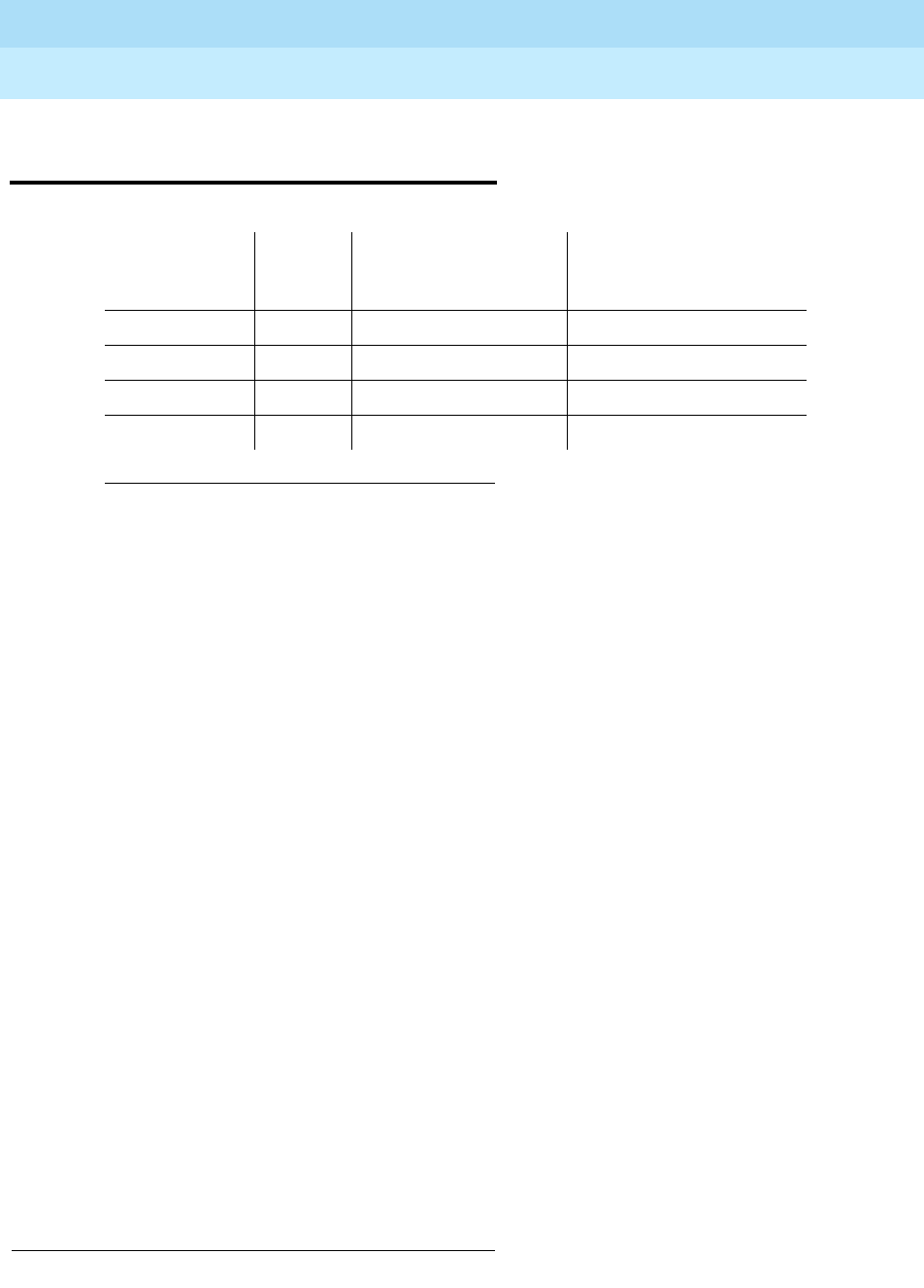
DEFINITY Enterprise Communications Server Release 6
Maintenance for R6r Volumes 1 & 2
555-230-126 Issue 2
January 1998
Maintenance Object Repair Procedures
Page 9-59ANL-LINE, ANL-NE-L (8-Port Analog Line)
9
ANL-LINE, ANL-NE-L (8-Port Analog
Line)
The 8-port Analog Line circuit packs,
each provide eight ports for single-line, on or off-premises analog endpoints
such as analog voice terminals, queue warning level lamps, recorded
announcements, dictation machines, PAGEPAC. paging equipment, external
alerting devices, modems, facsimile machines and AUDIX voice ports. Only the
TN769 supports a neon message waiting lamp. 1
Test #48 may cause some terminal equipment to ring briefly during daily
maintenance, which may disturb the customer or the terminal equipment. Test
#47 may cause a false alarm when the port is connected to certain off-premises
equipment, non-voice terminal equipment, or loop equipment. In either case, the
tests can be disabled by entering n in the ‘‘Tests’’ field on the change station
<extension> form. Be aware that this will disable Tests 6, 35, 47 and 48.
No maintenance of the terminal connected to the 8-Port Analog Line circuit pack
or 8-Port Neon Analog Line circuit pack is performed, except to determine
whether or not the terminal is connected. Failures of the common ringing
application circuitry and the neon message waiting lamp power (ANL-NE-L only)
are reported as errors 1281 and 1793 against XXX-BD (Common Port Circuit
Pack).
1. UU is the universal cabinet number (1 for PPN, 2 -44 for EPNs). C is the carrier
designation (A, B, C, D, or E). SS is the number of the slot in which the circuit pack
resides (01 to 21). pp is the two digit port number (01, 02, ...).
1. PAGEPAC is a registered trademark of Harris Corporation, Dracon Division
MO Name As
It Appears In
Alarm Log Alarm
Level
Initial System
Technician
Command To Run1Full Name of MO
ANL-LINE MIN test port UUCSSpp l 8-Port Analog Line
ANL-LINE WRN test port UUCSSpp sh 8-Port Analog Line
ANL-NE-L MIN test port UUCSSpp l 8-Port Neon Analog Line
ANL-NE-L WRN test port UUCSSpp sh 8-Port Neon Analog Line
TN712 TN467 [G3r V2] TN411 [G3rV2]
TN742 TN443 [G3r V2]
TN769 TN443 [G3r V2]

DEFINITY Enterprise Communications Server Release 6
Maintenance for R6r Volumes 1 & 2
555-230-126 Issue 2
January 1998
Maintenance Object Repair Procedures
Page 9-60ANL-LINE, ANL-NE-L (8-Port Analog Line)
9
Hardware Error Log Entries and Test to Clear
Values
Notes:
a. These are in-line errors that can only be resolved over time.
■40960 Indicates that too many simultaneous incoming ringing
attempts were made on this board. Only 4 ports on a board may
ring simultaneously. A 5th incoming call will cause an inline error
from the board.
■40975 indicates that the terminal equipment was on-hook when
ring-tip was detected during ringing. This usually indicates a failure
in the terminal equipment or the type of terminal has a low ringer
impedance. Call the terminal equipment and verify that the terminal
1. Run the Short Test Sequence first. If all tests pass, run the Long Test Sequence. Refer to the appropriate test
description and follow the recommended procedures.
2. Minor alarms on this MO may be downgraded to Warning alarms based on the values used in the set options
command.
8-Port Analog Line Error Log Entries
Error
Type Aux
Data Associated Test Alarm
Level On/Off
Board Test to Clear Value
010 Any Any Any test port UUCSSpp sh r 1
1 (a) 40960
40977
40975
None
15 (b) Any Audits and Updates
Test (#36)
18 0 busy-out station
extension
WARNING OFF release station
extension
130 (c) None WARNING ON test port UUCSSpp sh
257 (d) Station Present Test
(#48) WARNING OFF test port UUCSSpp sh r 3
513 Battery Feed Test (#35) MIN/WRN2ON test port UUCSSpp sh r 2
769 (e) Loop Around and
Conference Test (#47) test port UUCSSpp l r 3
1025 NPE Crosstalk Test (#6) MIN/WRN2ON test port UUCSSpp l r 3
1281 (f)
1793 (f)

DEFINITY Enterprise Communications Server Release 6
Maintenance for R6r Volumes 1 & 2
555-230-126 Issue 2
January 1998
Maintenance Object Repair Procedures
Page 9-61ANL-LINE, ANL-NE-L (8-Port Analog Line)
9
rings. If the terminal doesn’t ring, then replace it. Otherwise, issue
the test port UUCSSpp command, and follow the procedure for
Test #48.
■40977 indicates that no terminal equipment was connected when
ringing was attempted. Run the short test via the test port
UUCSSpp command, and follow the procedure for the results of
Test #48.
b. This is a software audit error that does not indicate any hardware
malfunction. Run Short Test Sequence and investigate errors (if any).
c. This error type indicates that the circuit pack has been removed or has
been insane for more than 11-minutes. To clear the error, reinsert or
replace the circuit pack.
d. Test #48 may cause some terminal equipment to ring briefly during daily
maintenance. If this ringing is disturbing the customer or the terminal
equipment, it should be disabled via the change station extension
command. However, on some releases of the software, this will disable
Tests #6, 47, and 35 as well as Test #48.
e. Test #47 may cause a false alarm when the port is connected to
off-premises equipment, some non-voice terminal equipment, and some
loop equipment. If this causes a false alarm, then disable the test by
changing the Tests field of the change station command to ‘‘no.’’
f. Refer to ‘‘XXX-BD (Common Port Circuit Pack)’’ Maintenance
documentation.
System Technician-Demanded Tests:
Descriptions and Error Codes
Always investigate tests in the order presented in the table below when
inspecting errors in the system. By clearing error codes associated with the
Battery Feed Test
, for example, you may also clear errors generated from other
tests in the testing sequence.
Order of Investigation Short Test
Sequence
Long
Test
Sequence D/ND1
Battery Feed Test (#35) X X ND
Station Present Test (#48) X X ND
NPE Crosstalk Test (#6) X ND
Loop Around and Conference Test (#47) X ND
Station Status and Translation Audits and
Updates Test (#36) XXND

DEFINITY Enterprise Communications Server Release 6
Maintenance for R6r Volumes 1 & 2
555-230-126 Issue 2
January 1998
Maintenance Object Repair Procedures
Page 9-62ANL-LINE, ANL-NE-L (8-Port Analog Line)
9
NPE Crosstalk Test (#6)
One or more Network Processing Elements (NPEs) reside on each circuit pack
with a TDM Bus interface. The NPE controls port connectivity and gain, and
provides conferencing functions on a per-port basis. The NPE Crosstalk Test
verifies that this port’s NPE channel talks on the selected time slot and never
crosses over to time slots reserved for other connections. If the NPE is not
working correctly, one-way and noisy connections may be observed. This test is
usually only part of a port’s Long Test Sequence and takes about 20 to 30
seconds to complete
1. D = Destructive; ND = Nondestructive
Table 9-26. TEST #6 NPE Crosstalk Test
Error
Code Test
Result Description/ Recommendation
1000 ABORT System resources required to run this test are not
available. The port may be busy with a valid call. This
result is also reported for the system’s Music-on-Hold
port when it is off-hook, which it usually is.
1. Enter display port UUCSSpp to determine the
station’s extension. Enter status station extension to
determine the service state of the port. If the port is
in use, it will be unavailable for certain tests. (Refer
to Chapter 8, ‘‘Maintenance Commands’’, for a
description of service states.) Wait until the port is
idle before retesting.
2. When the port is idle, retry the command at 1-minute
intervals up to 5 times.
3. If the test continues to abort, escalate the problem.
1001 ABORT Could not allocate the necessary system resources to
run this test.
1. Retry the command at 1-minute intervals a maximum
of 5 times.
2. If the test continues to abort, escalate the problem.
Continued on next page

DEFINITY Enterprise Communications Server Release 6
Maintenance for R6r Volumes 1 & 2
555-230-126 Issue 2
January 1998
Maintenance Object Repair Procedures
Page 9-63ANL-LINE, ANL-NE-L (8-Port Analog Line)
9
1002 ABORT The system could not allocate time slots for the test. The
system may be under heavy traffic conditions or it may
have time slots out-of-service due to TDM-BUS errors.
Refer to TDM-BUS (TDM Bus) Maintenance
documentation to diagnose any active TDM-BUS errors.
1. If system has no TDM-BUS errors and is not
handling heavy traffic, repeat test at 1-minute
intervals a maximum of 5 times.
2. If the test continues to abort, escalate the problem.
1003 ABORT The system could not allocate a tone receiver for the
test. The system may be oversized for the number of
Tone Detectors present or some Tone Detectors may be
out-of-service.
1. Look for TTR-LEV errors in the Error Log. If present,
refer to TTR-LEV (TTR Level) Maintenance
documentation.
2. Look for TONE-PT errors in the Error Log. If present,
refer to TONE-PT (Tone Generator) Maintenance
documentation.
3. If neither condition exists, retry the test at 1-minute
intervals a maximum of 5 times.
4. If the test continues to abort, escalate the problem.
1004 ABORT The port was seized by a valid call during the test. The
test has been aborted. Use the display port UUCSSpp
command to determine the station extension. Use the
status station command to determine the service state
of the port. If the service state indicates that the port is in
use, then the port is unavailable for certain tests. (Refer
to Chapter 8, ‘‘Maintenance Commands’’, for a
description of all possible states.) You must wait until the
port is idle before retesting.
1. Retry the command at 1-minute intervals a maximum
of 5 times.
2. If the test continues to abort and the port is not in
use, escalate the problem.
Table 9-26. TEST #6 NPE Crosstalk Test — Continued
Error
Code Test
Result Description/ Recommendation
Continued on next page

DEFINITY Enterprise Communications Server Release 6
Maintenance for R6r Volumes 1 & 2
555-230-126 Issue 2
January 1998
Maintenance Object Repair Procedures
Page 9-64ANL-LINE, ANL-NE-L (8-Port Analog Line)
9
1005 ABORT The test was aborted due to a configuration problem.
This code will result under either of the following
conditions:
1. This test may not be applicable, or it may be
disruptive to terminal equipment other than a voice
terminal (for example, the modem pool member or
music on hold).
2. The circuit pack is one of the following:
— TN742 vintages 13,14 and 15
— TN769 vintages 3,4 and 5
1018 ABORT Test disabled via administration. The default for the
'Test' field on the 'Station' form is 'y'; thus, you may want
to determine why this field has been set to 'n' on this
station (this may be due to the ringing application test
48, which can be customer or terminal disturbing).
1. To enable the test for a particular station, enter
change station extension and set the ‘Test?’ field
on the ‘Station Form’ to ‘y.’
1020 ABORT The test did not run due to a previously existing error on
the specific port or a more general circuit pack error.
1. Examine Error Log for existing errors against this
port or the circuit pack and attempt to diagnose the
previously existing error.
Table 9-26. TEST #6 NPE Crosstalk Test — Continued
Error
Code Test
Result Description/ Recommendation
Continued on next page

DEFINITY Enterprise Communications Server Release 6
Maintenance for R6r Volumes 1 & 2
555-230-126 Issue 2
January 1998
Maintenance Object Repair Procedures
Page 9-65ANL-LINE, ANL-NE-L (8-Port Analog Line)
9
2000 ABORT Response to the test request was not received within the
allowable time period.
2100 ABORT System resources required to run this test are not
available. Either a system allocation to get information
about the port or to put the port into a service state failed
or the attempt to put the port in connection with a tone
source failed (this could be a tone-clock problem). The
tone-clock and tone detectors could be having a
communication problem, for example, the companding
modes could be out of synchronization.
1. Retry the command at 1-minute intervals a maximum
of 5 times.
2. If the test continues to abort, escalate the problem.
Table 9-26. TEST #6 NPE Crosstalk Test — Continued
Error
Code Test
Result Description/ Recommendation
Continued on next page
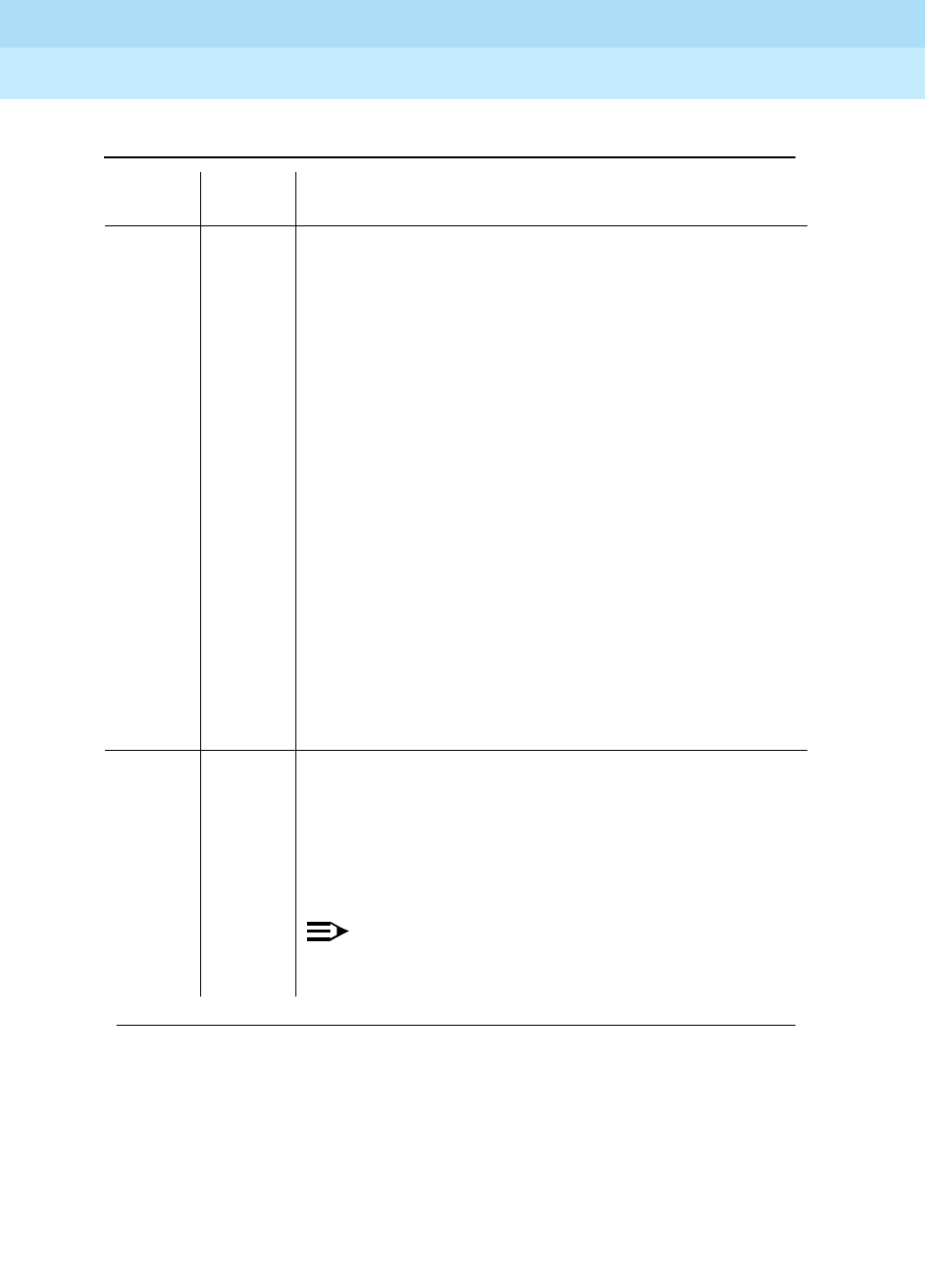
DEFINITY Enterprise Communications Server Release 6
Maintenance for R6r Volumes 1 & 2
555-230-126 Issue 2
January 1998
Maintenance Object Repair Procedures
Page 9-66ANL-LINE, ANL-NE-L (8-Port Analog Line)
9
Any FAIL This test can fail due to on-board or off-board problems.
Off-board problems of concern include EXP-PN and
EXP-INTF faults, TDM-BUS faults, and faults associated
with the tone detectors/tone generators. Clear all
off-board problems before replacing the board. Keep in
mind that a TDM-BUS problem is usually the result of a
faulty board connected to the backplane or bent pins on
the backplane.
1. Look for EXP-PN and/or EXP-INTF errors in the error
log. If present, refer to the EXP-PN Maintenance
documentation and the EXP-INTF Maintenance
documentation.
2. Look for TDM-BUS errors in the error log. If present,
refer to the TDM-BUS Maintenance documentation.
3. Look for TONE-BD and/or TONE-PT errors in the
error log. If present, refer to the TONE-BD
Maintenance documentation and the TONE-PT
Maintenance documentation.
4. Test the board when the faults from steps 1, 2, and 3
are cleared. Replace the board only if the test fails.
PASS The port is correctly using its allocated time slots.
User-reported troubles on this port should be
investigated by using other port tests, by examining
station wiring, by examining the station, and by ensuring
that the terminal is correctly translated as off-premises
or on-premises.
NOTE:
This test always passes for circuit packs TN712
prior to vintage 14 and TN742 prior to vintage 6.
Table 9-26. TEST #6 NPE Crosstalk Test — Continued
Error
Code Test
Result Description/ Recommendation
Continued on next page

DEFINITY Enterprise Communications Server Release 6
Maintenance for R6r Volumes 1 & 2
555-230-126 Issue 2
January 1998
Maintenance Object Repair Procedures
Page 9-67ANL-LINE, ANL-NE-L (8-Port Analog Line)
9
Battery Feed Test (also called Port Diagnostic
Test) (#35)
The battery feed chip provides power to the telephone equipment, signaling,
rotary dial pulsing, transmission, and balance. This test checks the signaling and
switchhook capabilities of the battery feed chip by terminating the port, applying
battery, and trying to detect a current.
0NO
BOARD The test could not relate the internal ID to the port (no
board). This could be due to incorrect translations, no
board is inserted, an incorrect board is inserted, or an
insane board is inserted.
1. Check to ensure that the board translations are
correct. Use the list config command, and resolve
any problems that are found.
2. If the board was found to be correctly inserted in
step 1, issue the busyout board command.
3. Issue the reset board command.
4. Issue the release busy board command.
5. Issue the test board long command. This should
re-establish the linkage between the internal ID and
the port. If this is not the case, dispatch to check to
ensure that there is a valid board inserted.
Table 9-27. TEST #35 Battery Feed Test Results
Error
Code Test
Result Description/ Recommendation
ABORT Could not allocate the necessary system resources to
run this test.
1. Retry the command at 1-minute intervals a maximum
of 5 times.
2. If the test continues to abort, escalate the problem.
Continued on next page
Table 9-26. TEST #6 NPE Crosstalk Test — Continued
Error
Code Test
Result Description/ Recommendation
Continued on next page

DEFINITY Enterprise Communications Server Release 6
Maintenance for R6r Volumes 1 & 2
555-230-126 Issue 2
January 1998
Maintenance Object Repair Procedures
Page 9-68ANL-LINE, ANL-NE-L (8-Port Analog Line)
9
1000 ABORT System resources required to run this test are not
available. The port may be busy with a valid call. This
result is also reported for the system’s Music-on-Hold
port when it is off-hook, which it usually is.
1. Enter display port UUCSSpp to determine the
station’s extension. Enter status station extension to
determine the service state of the port. If the port is
in use, it will be unavailable for certain tests. (Refer
to Chapter 8, ‘‘Maintenance Commands’’, for a
description of service states.) Wait until the port is
idle before retesting.
2. When the port is idle, retry the command at 1-minute
intervals up to 5 times.
3. If the test continues to abort, escalate the problem.
1004 ABORT System resources required to run this test are not
available. The port may be busy with a valid call. Use
the display port UUCSSpp command to determine the
station extension. Use the status station command to
determine the service state of the port. If the service
state indicates that the port is in use, then the port is
unavailable for certain tests. (Refer to Chapter 8,
‘‘Maintenance Commands’’, for a full description of all
possible states.) You must wait until the port is idle
before retesting.
1. Retry the command at 1-minute intervals a maximum
of 5 times.
2. If the test continues to abort and the port is not in
use, escalate the problem.
Table 9-27. TEST #35 Battery Feed Test Results — Continued
Error
Code Test
Result Description/ Recommendation
Continued on next page

DEFINITY Enterprise Communications Server Release 6
Maintenance for R6r Volumes 1 & 2
555-230-126 Issue 2
January 1998
Maintenance Object Repair Procedures
Page 9-69ANL-LINE, ANL-NE-L (8-Port Analog Line)
9
1005 ABORT The test was aborted due to a configuration problem.
This code will result under either of the following
conditions:
1. This test may not be applicable, or it may be
disruptive to terminal equipment other than a voice
terminal (for example, the modem pool member or
music on hold).
2. The circuit pack is one of the following:
— TN742 vintages 13,14 and 15
— TN769 vintages 3,4 and 5
1018 ABORT Test disabled via administration. The default for the
'Test' field on the 'Station' form is 'y'; thus, you may want
to determine why this field has been set to 'n' on this
station (this may be due to the ringing application test
48, which can be customer or terminal disturbing).
1. To enable the test for a particular station, enter
change station extension and set the ‘Test?’ field
on the ‘Station Form’ to ‘y.’
1392 ABORT This port is currently a TTI port and the test will not
execute on it.
1. Verify that the port is a TTI port using either the
display port command (the display shows that the
port is a TTI port) or the list config command (the
display shows a t for the port).
2. If either list config or display port indicate that the
port is
not
a TTI port, escalate the problem. If both
commands indicate that the port is a TTI port, the
abort is correct for the test, and no action is
necessary.
Table 9-27. TEST #35 Battery Feed Test Results — Continued
Error
Code Test
Result Description/ Recommendation
Continued on next page

DEFINITY Enterprise Communications Server Release 6
Maintenance for R6r Volumes 1 & 2
555-230-126 Issue 2
January 1998
Maintenance Object Repair Procedures
Page 9-70ANL-LINE, ANL-NE-L (8-Port Analog Line)
9
2000 ABORT Response to the test request was not received within the
allowable time period.
2100 ABORT System resources required to run this test are not
available. Either a system allocation to get information
about the port or to put the port into a service state failed
or the attempt to put the port in connection with a tone
source failed (this could be a tone-clock problem). The
tone-clock and tone detectors could be having a
communication problem, for example, the companding
modes could be out of synchronization.
1. Retry the command at 1-minute intervals a maximum
of 5 times.
2. If the test continues to abort, escalate the problem.
FAIL The port’s battery feed chip is unable to supply sufficient
power to the terminal equipment. This may occur when
the test is performed at the same time that the terminal
equipment goes off-hook.
1. Use status station to determine when the port is
available for testing. When the port becomes
available for testing, retry the command at 1-minute
intervals a minimum of five times.
2. If the test continues to fail, determine whether the
customer is experiencing problems on this line.
Replace the circuit pack only if the customer is
experiencing problems.
3. If the test continues to fail, escalate the problem.
Table 9-27. TEST #35 Battery Feed Test Results — Continued
Error
Code Test
Result Description/ Recommendation
Continued on next page
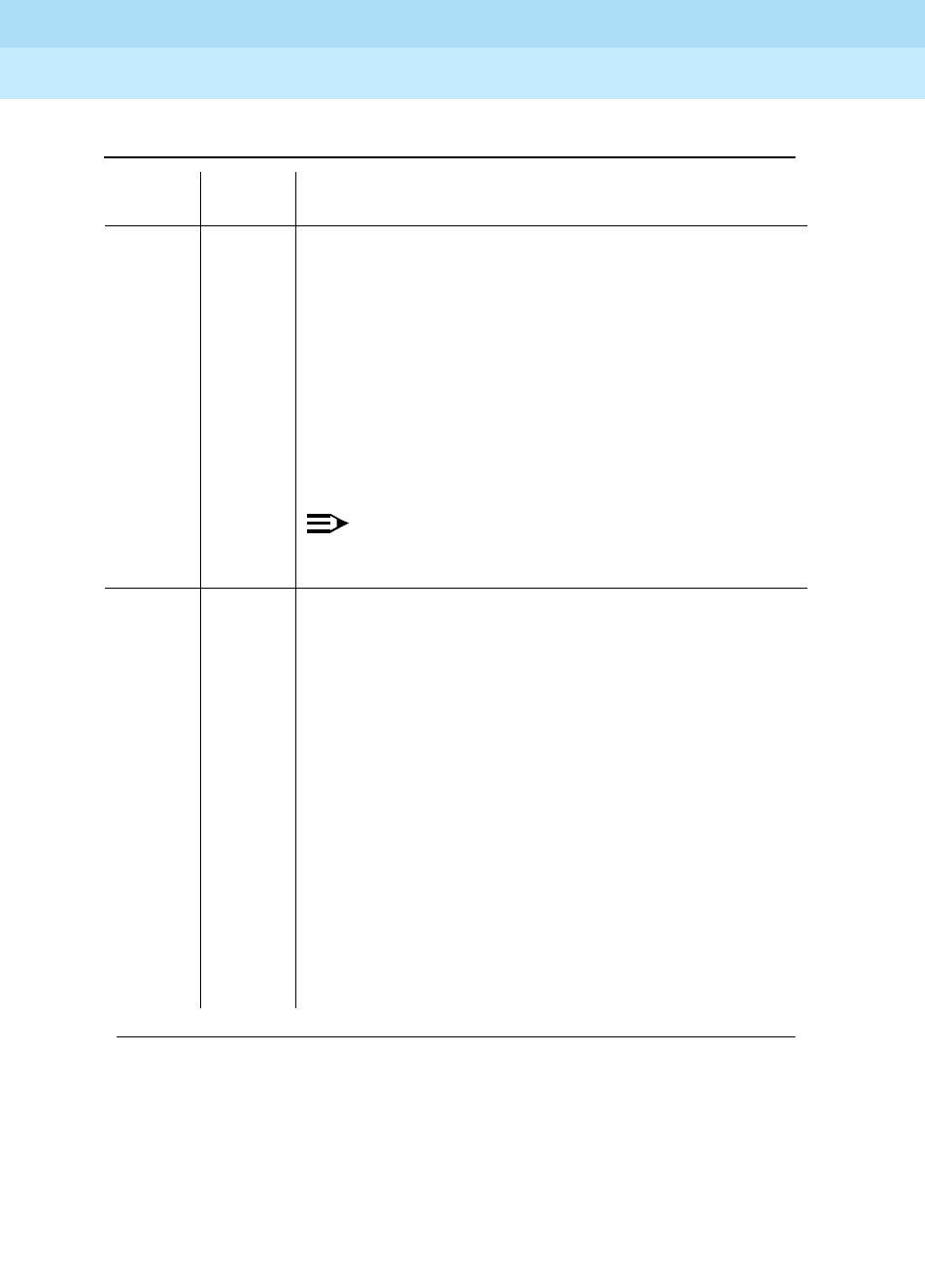
DEFINITY Enterprise Communications Server Release 6
Maintenance for R6r Volumes 1 & 2
555-230-126 Issue 2
January 1998
Maintenance Object Repair Procedures
Page 9-71ANL-LINE, ANL-NE-L (8-Port Analog Line)
9
PASS The port’s battery feed chip is able to provide power to
the station equipment to detect on-/off-hook. However,
the battery feed chip may still be unable to provide
power for touch-tones. If tones are heard when buttons
are pressed, then the battery feed chip is functioning
correctly; otherwise, replace the circuit pack because
this port is defective. User-reported troubles on this port
should be investigated by using other port tests, by
examining station wiring, by examining the station, and
by ensuring that the terminal is correctly translated as
off-premises or on-premises.
NOTE:
This test always passes for circuit packs TN712
prior to vintage 14 and TN742 prior to vintage 6.
0NO
BOARD The test could not relate the internal ID to the port (no
board). This could be due to incorrect translations, no
board is inserted, an incorrect board is inserted, or an
insane board is inserted.
1. Check to ensure that the board translations are
correct. Use the list config command, and resolve
any problems that are found.
2. If the board was found to be correctly inserted in
step 1, issue the busyout board command.
3. Issue the reset board command.
4. Issue the release busy board command.
5. Issue the test board long command. This should
re-establish the linkage between the internal ID and
the port. If this is not the case, dispatch to check to
ensure that there is a valid board inserted.
Table 9-27. TEST #35 Battery Feed Test Results — Continued
Error
Code Test
Result Description/ Recommendation
Continued on next page

DEFINITY Enterprise Communications Server Release 6
Maintenance for R6r Volumes 1 & 2
555-230-126 Issue 2
January 1998
Maintenance Object Repair Procedures
Page 9-72ANL-LINE, ANL-NE-L (8-Port Analog Line)
9
Station Status and Translation Audits and
Updates Test (#36)
This test updates the analog port’s message lamp state (if it has one) and
translations (such as station type, dial type, network connection) with information
kept in the software. The software is updated with the switchhook state reported
by the port processor. When the ringer is in the off state, this test also turns off
the station’s ringer to prevent constant ringing caused by defective hardware.
Table 9-28. TEST #36 Station Status and Translation Audits and Updates Test
Error
Code Test
Result Description/ Recommendation
ABORT Could not allocate the necessary system resources to
run this test.
1004 ABORT System resources required to run this test are not
available. The port may be busy with a valid call. Use
the display port UUCSSpp command to determine the
station extension. Use the status station command to
determine the service state of the port. If the service
state indicates that the port is in use, then the port is
unavailable for certain tests. (Refer to Chapter 8,
‘‘Maintenance Commands’’, for a full description of all
possible states.) You must wait until the port is idle
before retesting.
1. Retry the command at 1-minute intervals a maximum
of 5 times.
2. If the test continues to abort and the port is not in
use, escalate the problem.
1005 ABORT The test was aborted due to a configuration problem.
This code will result under either of the following
conditions:
1. This test may not be applicable, or it may be
disruptive to terminal equipment other than a voice
terminal (for example, the modem pool member or
music on hold).
2. The circuit pack is one of the following:
— TN742 vintages 13,14 and 15
— TN769 vintages 3,4 and 5
Continued on next page

DEFINITY Enterprise Communications Server Release 6
Maintenance for R6r Volumes 1 & 2
555-230-126 Issue 2
January 1998
Maintenance Object Repair Procedures
Page 9-73ANL-LINE, ANL-NE-L (8-Port Analog Line)
9
1006 ABORT This port has been busied out by command or taken
out-of-service by the failure of the NPE Crosstalk Test.
1. Look in the Error Log for Error Type 18 (port busied
out) for this port. If this error is present, then release
the port with the release station extension
command and run the test again.
2. Look in the Error Log for Error Type 1025 (NPE
Crosstalk Test failed) for this port. If this error is
present, then investigate the errors associated with
the NPE Crosstalk Test (#6) first.
3. Make sure that the terminal is connected and in
service, and then retest.
4. If the test continues to abort, escalate the problem.
2000 ABORT Response to the test request was not received within the
allowable time period.
2100 ABORT Could not allocate the necessary system resources to
run this test.
1. Retry the command at 1-minute intervals a maximum
of 5 times.
2. If the test continues to abort, escalate the problem.
1 FAIL This does not indicate a hardware problem. The
switchhook audit failed, and the other updates were not
performed because of this failure. This condition may
occur when the audit is performed at the same time that
the terminal equipment goes off-hook. Use the status
station command to determine when the port is
available for testing.
1. When the port becomes available for testing, retry
the command at 1-minute intervals a maximum of 5
times.
2. If the test continues to fail, escalate the problem.
Table 9-28. TEST #36 Station Status and Translation Audits and Updates Test —
Continued
Error
Code Test
Result Description/ Recommendation
Continued on next page
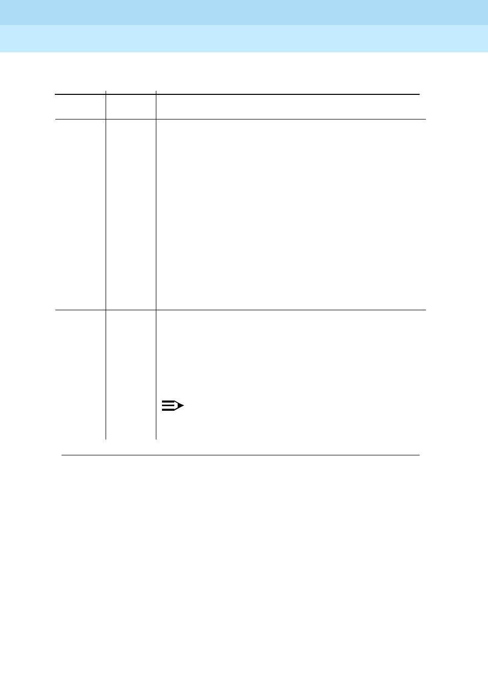
DEFINITY Enterprise Communications Server Release 6
Maintenance for R6r Volumes 1 & 2
555-230-126 Issue 2
January 1998
Maintenance Object Repair Procedures
Page 9-74ANL-LINE, ANL-NE-L (8-Port Analog Line)
9
5 FAIL This does not indicate a hardware problem but may
indicate an internal software error. The message waiting
lamp update failed. The translation and ringer updates
were not performed because of this failure.
7 FAIL The translation update failed. The ringer update was not
performed because of this failure. This does not indicate
a hardware problem but may be an internal software
error.
8 FAIL This does not indicate a hardware problem but may be
an internal software error. The ringer update failed.
1. Retry the command at 1-minute intervals a maximum
of 5 times.
2. If the test continues to fail, escalate the problem.
PASS The software and the port processor have the same
status. User-reported troubles on this port should be
investigated by using other port tests, by examining
station wiring, by examining the station, and by ensuring
that the terminal is correctly translated as off-premises
or on-premises.
NOTE:
This test always passes for circuit packs TN712
prior to vintage 14 and TN742 prior to vintage 6.
Table 9-28. TEST #36 Station Status and Translation Audits and Updates Test —
Continued
Error
Code Test
Result Description/ Recommendation
Continued on next page

DEFINITY Enterprise Communications Server Release 6
Maintenance for R6r Volumes 1 & 2
555-230-126 Issue 2
January 1998
Maintenance Object Repair Procedures
Page 9-75ANL-LINE, ANL-NE-L (8-Port Analog Line)
9
Loop Around and Conference Test (#47)
Each Analog Port consists of
■A Network Processing Element (NPE) for port connectivity and gain, and
conferencing functionality
■A codec which converts the digital signals of the TDM Bus to analog
signals
■A battery feed chip which provides power to the telephone set for
signaling, dial pulsing, transmission, and balance.
This test is designed to check the on-board transmission capabilities of the NPE,
the codec, and the battery feed chip of the Analog Port. A Tone Detector and a
Tone Generator talk and listen on the same pair of time slots as the Analog Port.
The Analog Port is then instructed to go into loop around mode (see Figure 9-1).
The test passes if the signal measured by the Tone Detector is within acceptable
limits.
0NO
BOARD The test could not relate the internal ID to the port (no
board). This could be due to incorrect translations, no
board is inserted, an incorrect board is inserted, or an
insane board is inserted.
1. Check to ensure that the board translations are
correct. Use the list config command, and resolve
any problems that are found.
2. If the board was found to be correctly inserted in
step 1, issue the busyout board command.
3. Issue the reset board command.
4. Issue the release busy board command.
5. Issue the test board long command. This should
re-establish the linkage between the internal ID and
the port. If this is not the case, dispatch to check to
ensure that there is a valid board inserted.
Table 9-28. TEST #36 Station Status and Translation Audits and Updates Test —
Continued
Error
Code Test
Result Description/ Recommendation
Continued on next page
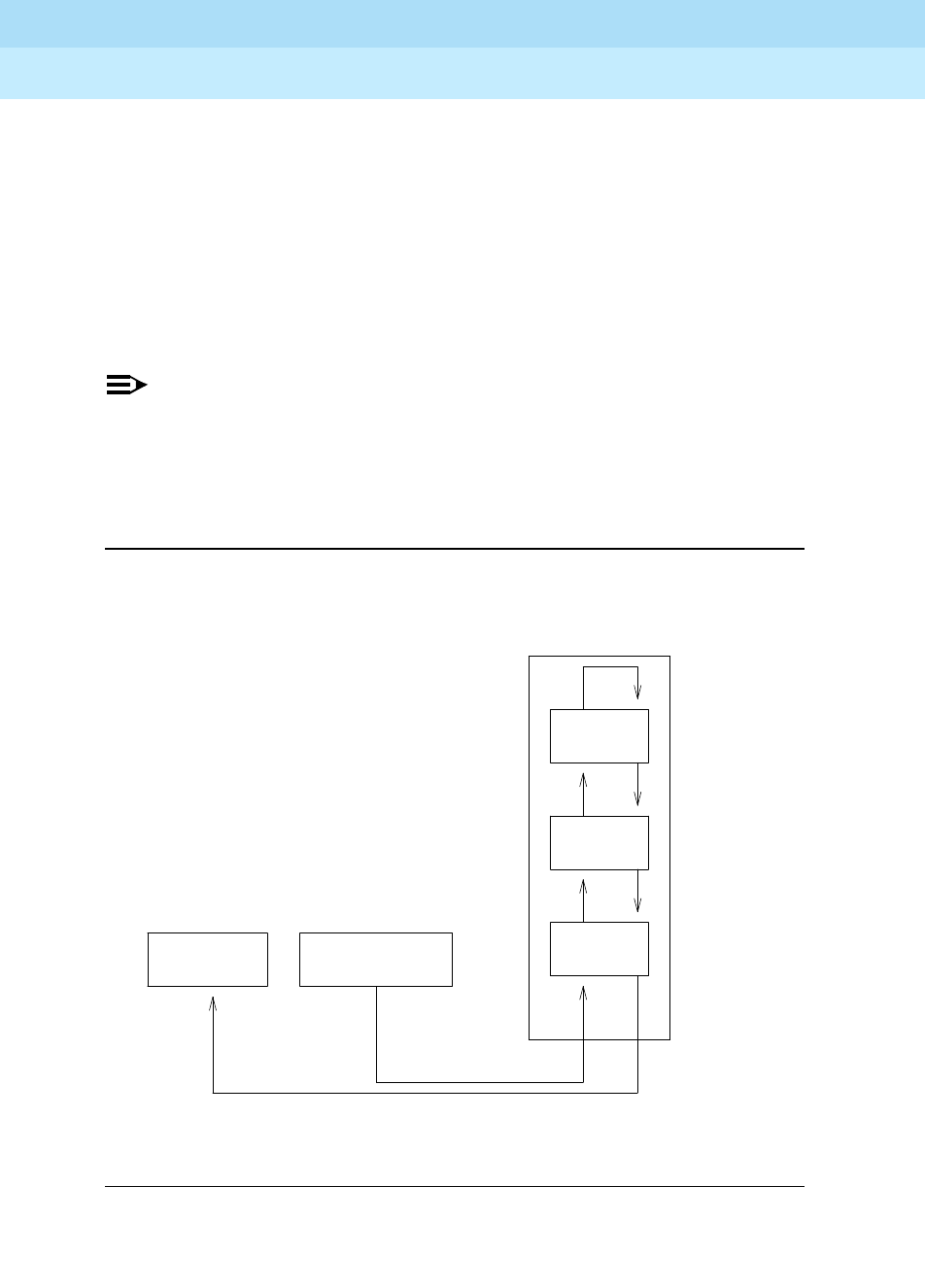
DEFINITY Enterprise Communications Server Release 6
Maintenance for R6r Volumes 1 & 2
555-230-126 Issue 2
January 1998
Maintenance Object Repair Procedures
Page 9-76ANL-LINE, ANL-NE-L (8-Port Analog Line)
9
The Conference Circuit Test verifies that the NPE channel for the port being
tested can correctly perform the conferencing function. Test #47 also tests the
operation of the port conference circuits in the NPE for three and four parties. In
addition, a test is run to measure noise. The NPE is instructed to listen to several
different tones and conference the tones together. The resulting signal is then
measured by a Tone Detector port. If the level of the tone is within a certain
range, the test passes.
The noise test is performed by filtering out the tone, and then measuring inherent
port noise.
NOTE:
This Loop Around Test is sensitive to the length of the loop, the equipment
in the loop, or the equipment terminating the loop, such as off-premises
stations. If this test is causing a false alarm, then disable the test by
changing the Tests field to ‘‘no’’ using the change station command for
this station.
Figure 9-1. Analog Loop Around and Conference Test
TDM BUS
BFC: Battery Feed Chip
NPE: Network Processing Element
Analog
Line
Port
BFC
CODEC
NPE Tone
Generator
Tone
Detector

DEFINITY Enterprise Communications Server Release 6
Maintenance for R6r Volumes 1 & 2
555-230-126 Issue 2
January 1998
Maintenance Object Repair Procedures
Page 9-77ANL-LINE, ANL-NE-L (8-Port Analog Line)
9
Table 9-29. TEST #47 Loop Around and Conference Test
Error
Code Test
Result Description/ Recommendation
ABORT Could not allocate the necessary system resources to
run this test.
1. Retry the command at 1-minute intervals a maximum
of 5 times.
2. If the test continues to abort, escalate the problem.
7 ABORT The port was seized by a user for a valid call.
1. Enter display port UUCSSpp to determine the
station’s extension. Enter status station extension
to determine the service state of the port. If the port
is in use, it will be unavailable for certain tests. Wait
until the port is idle before retesting.
2. If the port is idle, retry the command at 1-minute
intervals up to 5 times.
3. If the test continues to abort, escalate the problem.
1000 ABORT System resources required to run this test were not
available. The port may be busy with a valid call. (This
could be a Music-on-Hold port.)
1. Enter display port UUCSSpp to determine the
station’s extension. Enter status station extension
to determine the service state of the port. If the port
is in use, it will be unavailable for certain tests. Wait
until the port is idle before retesting.
2. If the port is idle, retry the command at 1-minute
intervals up to 5 times.
3. If the test continues to abort, escalate the problem.
1002 ABORT The system could not allocate time slots for the test. The
system may be under heavy traffic conditions or it may
have time slots out-of-service due to TDM-BUS errors.
Refer to TDM-BUS (TDM Bus) Maintenance
documentation to diagnose any active TDM-BUS errors.
1. If system has no TDM-BUS errors and is not
handling heavy traffic, repeat test at 1-minute
intervals a maximum of 5 times.
2. If the test continues to abort, escalate the problem.
Continued on next page

DEFINITY Enterprise Communications Server Release 6
Maintenance for R6r Volumes 1 & 2
555-230-126 Issue 2
January 1998
Maintenance Object Repair Procedures
Page 9-78ANL-LINE, ANL-NE-L (8-Port Analog Line)
9
1003 ABORT The system could not allocate a tone receiver for the
test. The system may be oversized for the number of
Tone Detectors present or some Tone Detectors may be
out-of-service.
1. Look for TTR-LEV errors in the Error Log. If present,
refer to TTR-LEV (TTR Level) Maintenance
documentation.
2. Look for TONE-PT errors in the Error Log. If present,
refer to TONE-PT (Tone Generator) Maintenance
documentation.
3. If neither condition exists, retry the test at 1-minute
intervals a maximum of 5 times.
4. If the test continues to abort, escalate the problem.
1004 ABORT The port has been seized for a valid call during the
conference or noise test.
1. If the circuit pack is a TN742 of vintage 10 or less,
this test is not valid. Otherwise, proceed with step 2.
2. When the port is available for testing, retry the
command at 1-minute intervals a maximum of 5
times.
3. If the test continues to abort and the port is not in
use, escalate the problem.
1005 ABORT The test was aborted due to a configuration problem.
This code will result under either of the following
conditions:
1. This test may not be applicable, or it may be
disruptive to terminal equipment other than a voice
terminal (for example, the modem pool member or
music on hold).
2. The circuit pack is one of the following:
— TN742 vintages 13,14 and 15
— TN769 vintages 3,4 and 5
Table 9-29. TEST #47 Loop Around and Conference Test — Continued
Error
Code Test
Result Description/ Recommendation
Continued on next page

DEFINITY Enterprise Communications Server Release 6
Maintenance for R6r Volumes 1 & 2
555-230-126 Issue 2
January 1998
Maintenance Object Repair Procedures
Page 9-79ANL-LINE, ANL-NE-L (8-Port Analog Line)
9
1018 ABORT Test disabled via administration. The default for the
’Test’ field on the ’Station’ form is ’y’; thus, you may want
to determine why this field has been set to ’n’ on this
station (this may be due to the ringing application test
48, which can be customer or terminal disturbing).
1. To enable the test for a particular station, enter
change station extension and set the ‘Test?’ field on
the ‘Station Form’ to ‘y.’
1392 ABORT This port is currently a TTI port and the test will not
execute on it.
1. Verify that the port is a TTI port using either the
display port command (the display shows that the
port is a TTI port) or the list config command (the
display shows a t for the port).
2. If either list config or display port indicate that the
port is
not
a TTI port, escalate the problem. If both
commands indicate that the port is a TTI port, the
abort is correct for the test, and no action is
necessary.
2000 ABORT Response to the test request was not received within the
allowable time period.
2100 ABORT System resources required to run this test are not
available. Either a system allocation to get information
about the port or to put the port into a service state failed
or the attempt to put the port in connection with a tone
source failed (this could be a tone-clock problem). The
tone-clock and tone detectors could be having a
communication problem, for example, the companding
modes could be out of synchronization.
1. Retry the command at 1-minute intervals a maximum
of 5 times.
2. If the test continues to abort, escalate the problem.
7 FAIL The conference test or the noise test failed. This could
cause noisy or unreliable connections, or users calling
this port may hear an echo. The problem can also be
off-board, as described below.
Table 9-29. TEST #47 Loop Around and Conference Test — Continued
Error
Code Test
Result Description/ Recommendation
Continued on next page

DEFINITY Enterprise Communications Server Release 6
Maintenance for R6r Volumes 1 & 2
555-230-126 Issue 2
January 1998
Maintenance Object Repair Procedures
Page 9-80ANL-LINE, ANL-NE-L (8-Port Analog Line)
9
13 The reflective loop around with gain set to low and the
600-ohm balance failed. This will cause noisy or
unreliable connections.
14 The reflective loop around test (with the gain set to high,
using RC balance) failed. This could cause noisy or
unreliable connections. The problem can also be
off-board, as described below.
15 The nonreflective loop around test failed. This could
cause noisy or unreliable connections, or users calling
this port may hear an echo. The problem can also be
off-board, as described below.
More information continues on the next page.
Table 9-29. TEST #47 Loop Around and Conference Test — Continued
Error
Code Test
Result Description/ Recommendation
Continued on next page
DEFINITY Enterprise Communications Server Release 6
Maintenance for R6r Volumes 1 & 2
555-230-126 Issue 2
January 1998
Maintenance Object Repair Procedures
Page 9-81ANL-LINE, ANL-NE-L (8-Port Analog Line)
9
7
13
14
15
(cont’d.)
FAIL
(cont’d.)
1. Disconnect the terminal equipment from the circuit
pack at the cross-connect and run the test again.
2. If the test fails again, replace the circuit pack and
reconnect the terminal equipment. If the test passes
the second time, then the test results were affected
by the terminal equipment connected to the port; in
this case, ignore the results of this test if all other
tests pass or abort and the station is operating
properly. Failure of test 47 does not cause an alarm.
If there are failures of other tests, then investigate
those errors. User reported troubles with this port
should be investigated by using other port tests, by
examining station wiring, and by examining the
station to ensure that it is correctly translated as
off-premises or on-premises.
NOTE:
If the loop around and conference circuit test fails
for all ports on a circuit pack, a -5 volt power
problem is indicated. If a TN736 or TN752 power
unit circuit pack is present, either the 631DB AC
power unit or the 676B DC power unit may be
defective. (The 631DB power unit is used in a
medium cabinet powered by an AC source. The
645B power unit is used in a medium cabinet
powered by a DC power source.) The system may
contain a TN736 or TN752 power unit circuit pack
or a 631DB AC power unit, but not both types of
power units. To investigate problems with a 631DB
AC power unit, refer to the ‘‘CARR-POW’’
Maintenance documentation. To investigate
problems with a 645B DC power unit, refer to the
‘‘CARR-POW’’ Maintenance documentation. If a
red LED on TN736 or TN752 power unit circuit
pack is on, replace the pack. If the test fails on
more than 1 port, check for errors on the TONE-BD
or the TONE-PT. If errors, take appropriate
actions. When the tone errors are cleared, rerun
the test.
Table 9-29. TEST #47 Loop Around and Conference Test — Continued
Error
Code Test
Result Description/ Recommendation
Continued on next page
DEFINITY Enterprise Communications Server Release 6
Maintenance for R6r Volumes 1 & 2
555-230-126 Issue 2
January 1998
Maintenance Object Repair Procedures
Page 9-82ANL-LINE, ANL-NE-L (8-Port Analog Line)
9
Station Present Test (also called Ringing
Application Test) (#48)
This test provides a burst of ringing current to the terminal equipment and
detects that current flows. This test is to ascertain whether or not terminal
equipment is connected to the port.
This test may cause some terminal equipment to ring briefly during daily
maintenance. If this ringing is disturbing the customer or the terminal equipment,
it should be disabled using the Tests field of the station administration screen.
PASS The port is able to provide an analog transmission path
to the station equipment. User-reported troubles on this
port should be investigated by using other port tests, by
examining station wiring, by examining the station, and
by ensuring that the terminal is correctly translated as
off-premises or on-premises.
NOTE:
This test always passes for circuit packs TN712
prior to vintage 14 and TN742 prior to vintage 6.
0NO
BOARD The test could not relate the internal ID to the port (no
board). This could be due to incorrect translations, no
board is inserted, an incorrect board is inserted, or an
insane board is inserted.
1. Check to ensure that the board translations are
correct. Use the list config command, and resolve
any problems that are found.
2. If the board was found to be correctly inserted in
step 1, issue the busyout board command.
3. Issue the reset board command.
4. Issue the release busy board command.
5. Issue the test board long command. This should
re-establish the linkage between the internal ID and
the port. If this is not the case, dispatch to check to
ensure that there is a valid board inserted.
Table 9-29. TEST #47 Loop Around and Conference Test — Continued
Error
Code Test
Result Description/ Recommendation
Continued on next page

DEFINITY Enterprise Communications Server Release 6
Maintenance for R6r Volumes 1 & 2
555-230-126 Issue 2
January 1998
Maintenance Object Repair Procedures
Page 9-83ANL-LINE, ANL-NE-L (8-Port Analog Line)
9
However, on some releases of the software, this action will disable Tests #6, 47,
and 35 as well as Test #48.
Table 9-30. TEST #48 Station Present Test
Error
Code Test
Result Description/ Recommendation
ABORT Could not allocate the necessary system resources to
run this test.
1. Retry the command at 1-minute intervals a maximum
of 5 times.
2. If the test continues to abort, escalate the problem.
1000 ABORT System resources required to run this test were not
available. The port may be busy with a valid call.
Use the display port UUCSSpp to determine the
station’s extension. Enter status station extension to
determine the service state of the port. If the port is in
use, it will be unavailable for certain tests. Wait until the
port is idle before retesting.
1. If the port is idle, retry the command at 1-minute
intervals up to 5 times.
2. Check for phone left off-hook or for wiring problems.
3. If the test continues to abort, escalate the problem.
1004 ABORT System resources required to run this test are not
available. The port may be busy with a valid call. Use
the display port UUCSSpp command to determine the
station extension. Use the status station command to
determine the service state of the port. If the service
state indicates that the port is in use, then the port is
unavailable for certain tests. (Refer to Chapter 8,
‘‘Maintenance Commands’’, for a full description of all
possible states.) You must wait until the port is idle
before retesting.
1. Retry the command at 1-minute intervals a maximum
of 5 times.
2. If the test continues to abort and the port is not in
use, escalate the problem.
Continued on next page

DEFINITY Enterprise Communications Server Release 6
Maintenance for R6r Volumes 1 & 2
555-230-126 Issue 2
January 1998
Maintenance Object Repair Procedures
Page 9-84ANL-LINE, ANL-NE-L (8-Port Analog Line)
9
1005 ABORT The test was aborted due to a configuration problem.
This code will result under either of the following
conditions:
1. This test may not be applicable, or it may be
disruptive to terminal equipment other than a voice
terminal (for example, the modem pool member or
music on hold).
2. The circuit pack is one of the following:
— TN742 vintages 13,14 and 15
— TN769 vintages 3,4 and 5
1008 ABORT Could not allocate a ringing circuit for one of the
following reasons: (1) all the ringing circuits are in use,
or (2) the ringing generator is defective, or (3) it is not
wired correctly.
1. Retry the command at 1-minute intervals a maximum
of 5 times.
2. If the test continues to abort, look for RING-GEN
errors in the Error Log. If an ABORT 1008 occurs for
Test #48 on other circuit packs as well, then the
ringing generator may be defective or not wired
correctly. If it does not occur on other ports, then
that circuit pack is currently using all four ringing
phases.
1018 ABORT The test was disabled via administration. The default for
the 'Test' field on the 'Station' form is 'y'; thus, you may
want to determine why this field has been set to 'n' on
this station (this may be due to the ringing application
test 48, which can be customer or terminal disturbing).
1. To enable the test for a particular station, enter
change station extension and set the ‘Test?’ field on
the ‘Station Form’ to ‘y.’
Table 9-30. TEST #48 Station Present Test — Continued
Error
Code Test
Result Description/ Recommendation
Continued on next page

DEFINITY Enterprise Communications Server Release 6
Maintenance for R6r Volumes 1 & 2
555-230-126 Issue 2
January 1998
Maintenance Object Repair Procedures
Page 9-85ANL-LINE, ANL-NE-L (8-Port Analog Line)
9
2000 ABORT Response to the test request was not received within the
allowable time period.
2100 ABORT System resources required to run this test are not
available. Either a system allocation to get information
about the port or to put the port into a service state failed
or the attempt to put the port in connection with a tone
source failed (this could be a tone-clock problem). The
tone-clock and tone detectors could be having a
communication problem, for example, the companding
modes could be out of synchronization.
1. Retry the command at 1-minute intervals a maximum
of 5 times.
2. If the test continues to abort, escalate the problem.
FAIL The terminal equipment is not connected to the circuit
pack or the ringing generator may have failed.
1. Remotely test the equipment.
2. If the test fails again, look for RING-GEN errors in the
error log. If present, refer to the RING-GEN (analog
ring generator) Maintenance documentation.
3. Check all of the wiring between the station
equipment and the switch. Then, run the test again.
4. If the test still fails, the set may be defective. Check
the set, and replace it, if necessary.
5. Some terminal equipment (such as a modem) could
fail even when it is connected properly. If this is the
case, disable the test using the change station
extension command (enter ’n’ into the ’Test’ field).
Note that this action also disables tests 6, 7, 161,
and 35 on this port.
PASS The station is connected properly to the switch. This test
may also pass if no terminal equipment is connected
and the terminal is located very far from the switch.
User-reported troubles on this port should be
investigated by using other port tests, by examining
station wiring, or by examining the station.
Table 9-30. TEST #48 Station Present Test — Continued
Error
Code Test
Result Description/ Recommendation
Continued on next page

DEFINITY Enterprise Communications Server Release 6
Maintenance for R6r Volumes 1 & 2
555-230-126 Issue 2
January 1998
Maintenance Object Repair Procedures
Page 9-86ANL-LINE, ANL-NE-L (8-Port Analog Line)
9
0NO
BOARD The test could not relate the internal ID to the port (no
board). This could be due to incorrect translations, no
board is inserted, an incorrect board is inserted, or an
insane board is inserted.
1. Check to ensure that the board translations are
correct. Use the list config command, and resolve
any problems that are found.
2. If the board was found to be correctly inserted in
step 1, issue the busyout board command.
3. Issue the reset board command.
4. Issue the release busy board command.
5. Issue the test board long command. This should
re-establish the linkage between the internal ID and
the port. If this is not the case, dispatch to check to
ensure that there is a valid board inserted.
Table 9-30. TEST #48 Station Present Test — Continued
Error
Code Test
Result Description/ Recommendation
Continued on next page
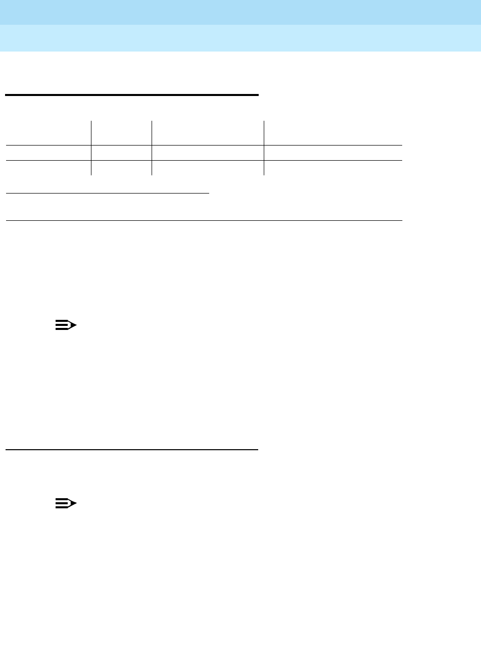
DEFINITY Enterprise Communications Server Release 6
Maintenance for R6r Volumes 1 & 2
555-230-126 Issue 2
January 1998
Maintenance Object Repair Procedures
Page 9-87ANN-BD (Announcement Circuit Pack)
9
ANN-BD (Announcement Circuit
Pack)
The TN750 contains 16 announcement ports each of which can play any
recorded announcement. The circuit pack also has one data line circuit port (port
17) for uploading and downloading announcement files to and from the system’s
disk and tape devices. For errors associated with port 17, refer to DAT-LINE. For
errors associated with ports 1-16 refer to ANN-PT.
NOTE:
TN750C is required if the system has multiple announcement boards. To
use multiple announcement boards, you must have V4 or later software,
and at least one TN750C (up to ten are allowed). Only one TN750A/B may
be present in the system when a TN750C is used. The announcements
from a TN750A/B can be saved and restored to a TN750C — but once the
announcements are recorded onto a TN750C, they are not backward
compatible with the TN750A/B.
Essential Service Information
You should have an understanding of the following principles before attempting
work on the TN750/B Announcement circuit pack.
NOTE:
The TN750C Announcement circuit pack has on-board non-volatile storage
and does not need to be saved to disk.
■The announcement circuit pack retains all integrated announcements
as
long as the circuit pack has power
. Announcements are preserved
through a software reset (reset board command), but they are lost when
the circuit pack is unseated. (Unseating is generally not recommended
unless replacement is necessary.)
1. UU is the universal cabinet number (1 for PPN, 2 - 44 for EPNs). C is the carrier designation (A,
B, C, D, or E). SS is the number of the slot in which the circuit pack resides (01 to 21).
MO Name (in
Alarm Log) Alarm
Level Initial Command to
Run1Full Name of MO
ANN-BD MINOR test board UUCSS l Announcement Circuit Pack
ANN-BD WARNING test board UUCSS l Announcement Circuit Pack

DEFINITY Enterprise Communications Server Release 6
Maintenance for R6r Volumes 1 & 2
555-230-126 Issue 2
January 1998
Maintenance Object Repair Procedures
Page 9-88ANN-BD (Announcement Circuit Pack)
9
■Whenever new announcements are recorded on the circuit pack, save
them on disk as soon as possible to ensure that they will not be lost due to
a disruption. Periodic saves to tape provide further backup if the disk files
are lost or corrupted. This is also accomplished when the entire disk is
backed up.
NOTE:
Unlike translations, announcements are never saved automatically
by the system. so you must do it manually.
■The save announcements command replaces the announcement files on
disk or tape with those in Announcement circuit pack speech memory.
Take care not to inadvertently destroy a valid file on tape or disk with this
command.
■The restore announcements command replaces announcement circuit
pack speech memory with announcement files on the disk or tape. Take
care not to inadvertently destroy valid announcements on the circuit pack
by restoring from a device that does not contain a current announcement
file.
■Whenever the announcement circuit pack is replaced, you must re-record
announcements or restore them from disk or tape. Otherwise, the circuit
pack will be unavailable to call processing service.
■If the circuit pack’s speech memory is corrupted, announcements should
not
be saved (for example, when the Announcement Checksum Test
(#209) fails or announcements sound corrupted when played back). This
can ruin a good announcement file on disk or tape, and potentially cause
errors and alarms on any circuit pack to which the saved file is
downloaded. If, however, the customer does not have a valid
announcement file on tape or disk, You may wish to save announcements
in an effort to try to retain those which are not corrupted.
Announcement Session
DEFINITY Enterprise Communications Server Release 5.4 Administration and
Feature Description.
The recording, playing back, and deleting of
announcements is called an announcement session. The station used must have
a class of service (COS) that includes console permissions.
1. To enter an announcement session, go off-hook on the station and enter
the announcement Feature Access Code (FAC) administered on the
Feature Access Codes form.
2. You should now hear dial tone. Enter the extension of the announcement
to be recorded, deleted, or played back.
3. You should again hear dial tone. To record an announcement, press 1,
record after the tone, and hang up when finished.

DEFINITY Enterprise Communications Server Release 6
Maintenance for R6r Volumes 1 & 2
555-230-126 Issue 2
January 1998
Maintenance Object Repair Procedures
Page 9-89ANN-BD (Announcement Circuit Pack)
9
4. To play back an announcement, press 2. Announcements can also be
played back by simply calling the announcement extension associated
with them.
5. To delete an announcement, press 3, and confirmation tone will be given if
the delete was successful.
Saving and Restoring Announcements
Integrated announcements on the announcement circuit pack can be uploaded
to the system tape or disk with the save announcements command. Likewise,
integrated announcements can be downloaded to the announcement circuit
pack with the restore announcements command. Both commands require a
free system port, an announcement data module administered on the
announcement circuit pack and, if saving to tape, a non-write protected tape
cartridge in the tape drive. Typical announcement uploads or downloads take 30
to 45 minutes, depending on system traffic.
The system automatically attempts to download to the announcement circuit
pack 5 minutes after it is inserted. This automatic download procedure may be
aborted or preempted by any of the following:
■An announcement is recorded within 10 minutes of circuit pack insertion.
■An announcement download is invoked sooner with the restore
announcements command.
■An announcement data module is not administered or is busy.
■A system access port is not available.
■There is no tape is in the system when saving to tape.
■The tape or disk does not have a valid announcement file.
NOTE:
If the announcement file becomes corrupted, the only solution is to
re-record all announcements.
!WARNING:
All alarms are upgraded to MAJOR when the BASE Tone Generator is set to
12. (France).

DEFINITY Enterprise Communications Server Release 6
Maintenance for R6r Volumes 1 & 2
555-230-126 Issue 2
January 1998
Maintenance Object Repair Procedures
Page 9-90ANN-BD (Announcement Circuit Pack)
9
Error Log Entries and Test to Clear Values
Table 9-31. Announcement Circuit Pack Error Log Entries
Error
Type Aux
Data Associated Test Alarm Level On/Off
Board Test to Clear Value
010 Any Any Any test board UUCSS sh r 1
1(a) 0 Circuit pack
removed or
SAKI Test (#53)
MINOR ON
2(n) None
14(b) 1-128 Announcement
Checksum Test
(#209)
18 0 busy-out board
UUCSS WARNING OFF release board UUCSS
23(c) 0 None WARNING OFF
125(d) None MINOR ON
217(m) 0 None WARNING OFF
257 65535 Control Channel
Test (#52) MINOR ON test board UUCSS l r 20
257(e) Any None
267(m) 0 None WARNING OFF
513(f) Any None
1025(g) 4363 NPE Audit Test
(#50) test board UUCSS l
1281(h) 17699 None
1538(i) Any None MINOR ON
1793 Angel-SP
Handshake Test
(#208)
MINOR ON test board UUCSS l r 3
17680 In-line Error
2049(j)(
k) Clock Match
Inquiry Test
(#212)
MINOR ON test board UUCSS sh r 3
17674 In-line Error
2305 140AY
Looparound
Test (#210)
MINOR ON test board UUCSS sh r 3
2561 Super Frame
Match Inquiry
Test (#211)
MINOR ON test board UUCSS sh r 3
Continued on next page
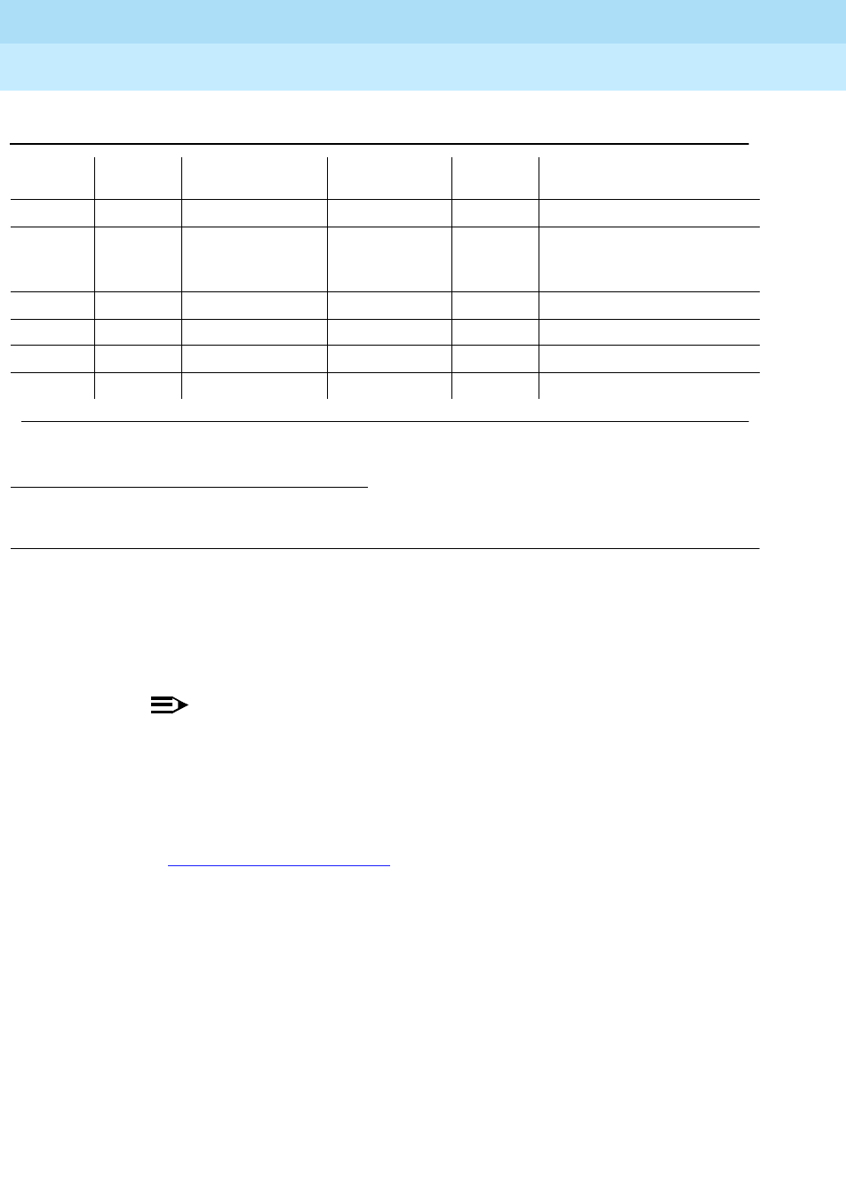
DEFINITY Enterprise Communications Server Release 6
Maintenance for R6r Volumes 1 & 2
555-230-126 Issue 2
January 1998
Maintenance Object Repair Procedures
Page 9-91ANN-BD (Announcement Circuit Pack)
9
Notes:
a. Error Type 1This error indicates the circuit pack totally stopped
functioning or it was physically removed from the system.
NOTE:
The alarm is logged about 11-minutes after the circuit pack has
been removed or when the SAKI Test (#53) fails.
If the circuit pack is not in the system, insert a circuit pack (in the same
slot as the error indicates) to resolve this error. If the circuit pack is in the
system and the red LED is on, refer to
Red LED without Associated Alarm
in Chapter 7, ‘‘LED Indicators’’.
b. Error Type 14This error is logged whenever the Announcement
Checksum Test (#209) fails. The Aux Data indicates the identifying
number of the first defective announcement found. This number
corresponds to the announcement numbers on the announcement
administration form. The extension associated with the announcement can
be determined with the display announcement command. This error
always appears in conjunction with Error Type 2817. Follow the
procedures for Error Type 2817 to troubleshoot Error Type 14.
c. Error Type 23The circuit pack has been logically administered but not
physically installed. The alarm will be cleared when the circuit pack is
installed.
1. Run the Short Test Sequence first. If all tests pass, run the Long Test Sequence. Refer to the
appropriate test description and follow the recommended procedures.
17676 In-line Error
2817(j) Announcement
Checksum Test
(#209)
MINOR ON test board UUCSS sh r 3
17682 In-line Error
17699(j) In-line Error
3840(l) Any None
3999 (o) Any None
Table 9-31. Announcement Circuit Pack Error Log Entries — Continued
Error
Type Aux
Data Associated Test Alarm Level On/Off
Board Test to Clear Value
Continued on next page

DEFINITY Enterprise Communications Server Release 6
Maintenance for R6r Volumes 1 & 2
555-230-126 Issue 2
January 1998
Maintenance Object Repair Procedures
Page 9-92ANN-BD (Announcement Circuit Pack)
9
d. Error Type 125A wrong circuit pack is inserted in the slot where this
circuit pack is logically administered. To resolve this problem, either
remove the wrong circuit pack and insert the logically administered circuit
pack OR use the change circuit-pack command to readminister this slot
to match the circuit pack inserted.
e. Error Type 257This error indicates transient communication problems
with this circuit pack. This error is not service-affecting and no action is
required.
f. Error Type 513This error, when reported with Aux Data in the range of
4352 to 4358, indicates the circuit pack has reported a hardware failure on
the circuit pack. The circuit pack should be replaced.
!WARNING:
Replacing the circuit pack will result in loss of integrated
announcements. See Essential Service Information above.
g. Error Type 1025This error is not service-affecting and no action is
required.
h. Error Type 1281The Speech Processor (SP) found one or more faulty
memory locations in the speech main memory (SMM). Whenever this error
is logged, error 2817 will also be logged (Note j), causing maintenance to
run the Announcement Checksum Test (#209) to determine if the bad
memory location is used by an announcement.
i. Error Type 1538The hyperactive circuit pack is out-of-service and may
exhibit one or more of the following symptoms:
1. The tests run on the ports of this circuit pack are returning with a
NO-BOARD.
2. A busy-out/release of the circuit pack has no affect on test results.
3. A list configuration command shows that the circuit pack and
ports are properly installed.
The system will try to restore the circuit pack within 15 minutes. If the error
recurs after 15 minutes, then replace the circuit pack.
j. Error Type 2049 and 2817These errors or logged in conjunction with
Error Type 1281, Aux Data 17699 (Note h). Since that error means that a
defective speech memory location was found, the announcement
checksum error is also logged, causing the Announcement Checksum
Test (#209) to run. This test determines whether the defective memory
location has corrupted any recorded announcements. If the Checksum
Test passes, the faulty memory location is not currently being used; the
Speech Processor will then mark the location as faulty to prevent future
announcements from using it.

DEFINITY Enterprise Communications Server Release 6
Maintenance for R6r Volumes 1 & 2
555-230-126 Issue 2
January 1998
Maintenance Object Repair Procedures
Page 9-93ANN-BD (Announcement Circuit Pack)
9
NOTE:
As memory locations are marked faulty, the amount of available
memory decreases, lowering the amount of announcement time
available on the circuit pack.
k. A transient error that does not cause an alarm can occasionally occur
during a SPE, TDM BUS, or Tone Clock interchange. Error Type 2049It
is possible for a marginal Tone-Clock circuit pack to cause this error
against the ANN-BD without alarming the TONE-BD. If this error occurs
again, replacing the Tone-Clock circuit pack may clear up this error. See
the FAIL case in the Clock Match Inquiry Test (#212).
l. Error Type 3840This error is not service-affecting and no action is
required.
m. Error Type 217 and 267Indicate that there is more than one TN750
Announcement circuit pack inserted in the system. Remove the alarmed
circuit pack.
n. Error Type 2Check the Class of Restriction (COR) administered for the
Data Line extension assigned to the TN750 for uploading and
downloading announcements. The extension can be found by using list
data-module.
o. Error Type 3999Indicates that the circuit pack sent a large number of
control channel messages to the switch within a short period of time. If
error type 1538 is also present, then the circuit pack was taken
out-of-service due to hyperactivity. If error type 1538 is not present, then
the circuit pack has not been taken out-of-service, but it has generated
50% of the messages necessary to be considered hyperactive. This may
be completely normal during heavy traffic periods. However, if this error
type is logged when the circuit pack is being lightly used, it may indicate a
problem with the circuit pack or the equipment attached to it.
System Technician-Demanded Tests:
Descriptions and Error Codes
Always investigate tests in the order presented in the table below when
inspecting errors in the system. By clearing error codes associated with the
Control Channel Looparound Test
, for example, you may also clear errors
generated from other tests in the testing sequence.
Order of Investigation Short Test
Sequence Long Test
Sequence D/ND1
Control Channel Looparound Test (#52)2X ND
Angel-Speech Processor (SP) Handshake X ND
Test (#208)
Clock Match Inquiry (#212) X X ND
Super Frame Match Inquiry (#211) X X ND

DEFINITY Enterprise Communications Server Release 6
Maintenance for R6r Volumes 1 & 2
555-230-126 Issue 2
January 1998
Maintenance Object Repair Procedures
Page 9-94ANN-BD (Announcement Circuit Pack)
9
Angel-Speech Processor Handshake Test (#208)
This test checks the integrity of the communication link between the two
processors on the Announcement circuit pack.
!CAUTION:
Failure of this test indicates that the Speech Processor is insane and results
in the loss of all integrated announcements on the circuit pack.
1. D = Destructive; ND = Nondestructive
2. For results of these tests, see the “XXX-BD (Common Port Circuit Pack)” section.
140AY Looparound Test (#210) X X ND
Announcement Checksum Test (#209) X X ND
Network Processor Element (NPE) Audit
Test (#50)2XND
SAKI Test (#53)2XD
Table 9-32. TEST #208 Angel-Speech Processor (SP) Handshake Test
Error
Code Test
Result Description/ Recommendation
2000 ABORT Response to the test request was not received within the allowable time
period. If Error Type 1538 is present in the Error Log, follow the
maintenance strategy recommended for this Error Type.
2100 ABORT Could not allocate the necessary system resources to run this test.
ABORT Internal system error. Try (a).
Continued on next page
Order of Investigation Short Test
Sequence Long Test
Sequence D/ND1
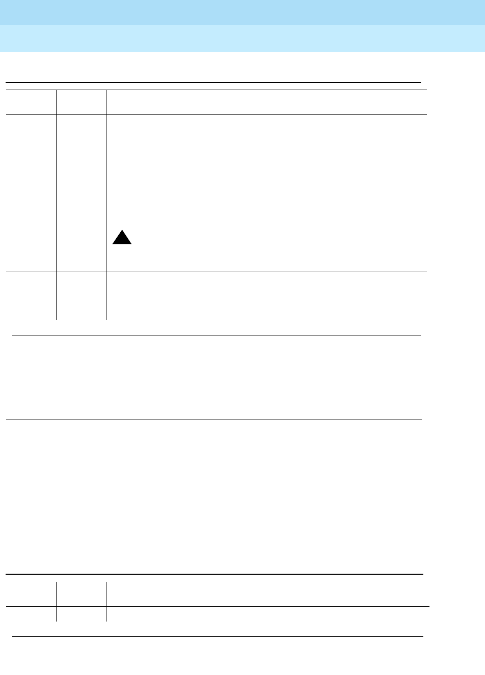
DEFINITY Enterprise Communications Server Release 6
Maintenance for R6r Volumes 1 & 2
555-230-126 Issue 2
January 1998
Maintenance Object Repair Procedures
Page 9-95ANN-BD (Announcement Circuit Pack)
9
Note:
a. Retry the command at 1-minute intervals a maximum of 5 times.
Announcement Checksum Test (#209)
In this test, the Speech Processor calculates a global checksum covering the
entire announcements file and compares it to a stored one. If the comparison of
any announcement’s checksum fails, then the total number of defective
announcements found is reported. The test failure is associated with an error
type 14 in the Error Log. The aux data gives the identifying number of the first
defective announcement found. This number and the extension assigned to the
announcement are listed on the display announcement command.
FAIL The circuit pack cannot be used. Announcement speech memory is cleared
when this test fails. When the problem has been resolved, announcements
must be re-recorded or downloaded to the circuit pack. Refer to
Essential
Service Information
earlier.
1. Reset the circuit pack by the reset board UUCSS command and then
run this test again. If the test continues to fail, replace the circuit pack.
2. If there are recurring alarms on this circuit pack caused by this test
failing, replace the circuit pack
even if step 1 works.
!CAUTION:
Replacing the circuit pack will result in loss of integrated
announcements. See Essential Service Information.
PASS The communications link between the two processors on the announcement
circuit pack is functioning properly. User-reported troubles on this circuit
pack should be investigated using other circuit pack and port tests. Refer to
“ANN-PT” for a description of the port tests.
Table 9-33. TEST #209 Announcement Checksum Test
Error
Code Test
Result Description/ Recommendation
1023 ABORT There are no announcements currently recorded on the circuit pack.
Continued on next page
Table 9-32. TEST #208 Angel-Speech Processor (SP) Handshake Test — Continued
Error
Code Test
Result Description/ Recommendation
Continued on next page

DEFINITY Enterprise Communications Server Release 6
Maintenance for R6r Volumes 1 & 2
555-230-126 Issue 2
January 1998
Maintenance Object Repair Procedures
Page 9-96ANN-BD (Announcement Circuit Pack)
9
1024 ABORT This abort code indicates any of the following:
■An announcement upload or download is in progress.
■An announcement upload or download was requested while the test
was running.
■A recording session was in progress.
■A recording session was initiated in while this test was running.
If an announcement upload or download is in progress, status data-module
extension should show that the announcement data port (17) is connected
to a data line port that is part of a system port, and the tape or disk should
be active. (To determine the extension of the announcement data module,
use the list data-module command.) See also
Locked Announcement
Circuit Pack
at the end of this table.
1. Wait until the cause of the abort finishes and run the test again. Upload
or download can take up to 45 minutes to complete. A recording
session is finished as soon as the station that was making the recording
is placed on-hook.
2. If the test continues to abort, and a recording session or
upload/download is not in progress, escalate the problem.
2000 ABORT Response to the test request was not received within the allowable time
period. If Error Type 1538 is present in the Error Log, follow the maintenance
strategy recommended for this Error Type.
2100 ABORT Could not allocate the necessary system resources to run test.
ABORT Internal system error. Try (a).
Table 9-33. TEST #209 Announcement Checksum Test — Continued
Error
Code Test
Result Description/ Recommendation
Continued on next page
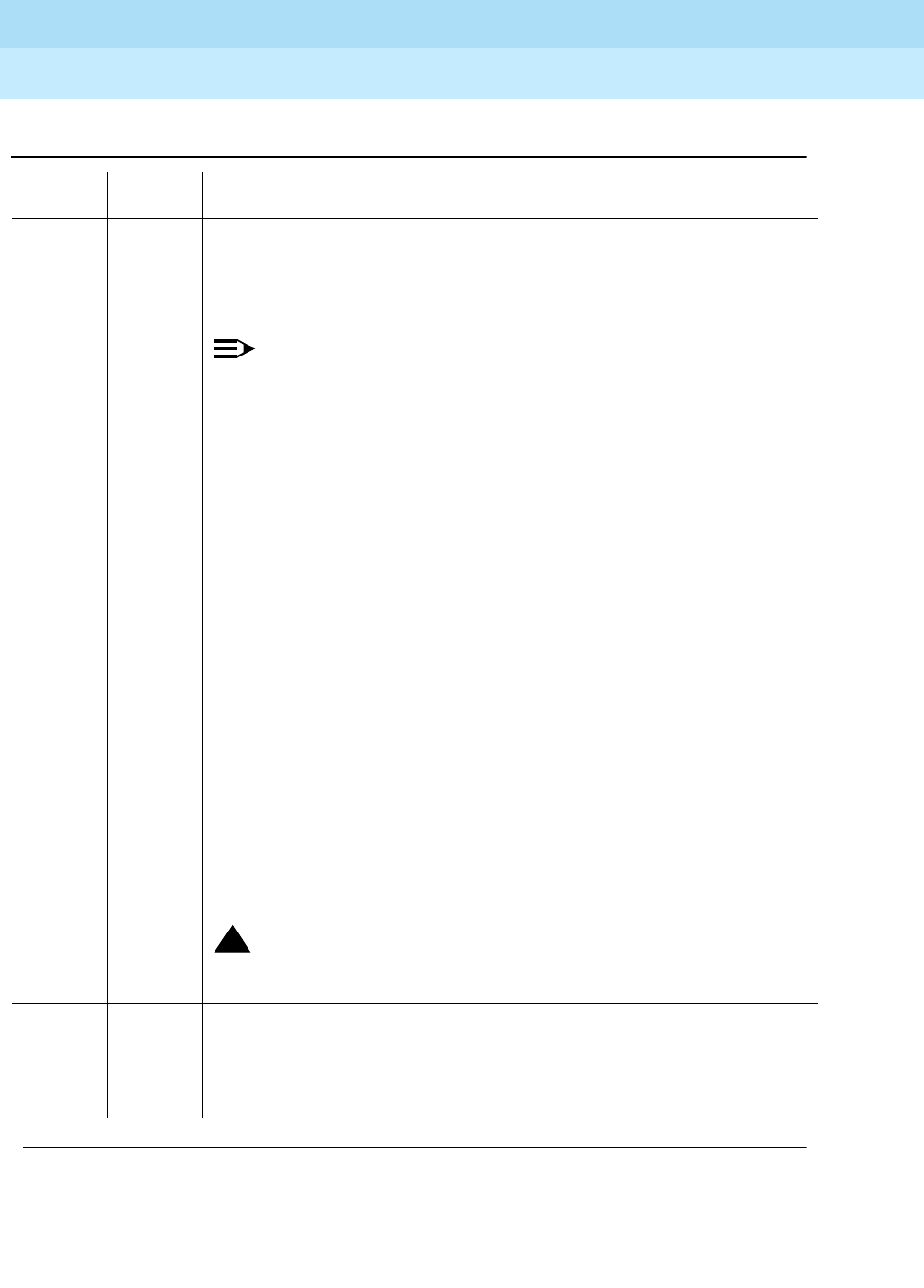
DEFINITY Enterprise Communications Server Release 6
Maintenance for R6r Volumes 1 & 2
555-230-126 Issue 2
January 1998
Maintenance Object Repair Procedures
Page 9-97ANN-BD (Announcement Circuit Pack)
9
0-256 FAIL The error code for this result gives the total number of defective
announcements found in speech memory.
When TEST #209 fails with error code 0, the global checksum failed on the
board, but no individual checksum failed.
NOTE:
Since announcements are stored digitally, it is possible for the
announcement checksum test to fail and still have all announcements
sound uncorrupted. When an individual announcement fails the
checksum test, always listen to the announcement before taking any
action. If the announcement sounds corrupted, then re-record it or
delete it. An announcement can be played back by dialing the
extension associated with the announcement number. Use the
display announcement command to find identifying numbers and
extensions of announcements.
1. Check the aux data for error type 14 in the Error Log to determine the
number of the first defective announcement encountered. Play back the
announcement and re-record or delete it if it sounds corrupted. If the
FAIL code for this test was greater than 1, there is more than one
corrupted announcement. To get the numbers of the others, you must
re-record or delete the first one and then rerun this test.
2. If, after deleting and re-recording all defective announcements, the
checksum test still fails, then reset the circuit pack using the reset
board UUCSS command and run this test again.
3. If the test continues to fail, reseat the circuit pack and restore
announcements (this can take up to 40 minutes). Any announcements
recorded since the last save announcements will be lost, and must be
re-recorded. Then run this test again.
4. If the test continues to fail, replace the circuit pack.
!CAUTION:
Replacing the circuit pack will result in loss of integrated
announcements. See Essential Service Information.
PASS All recorded announcements checksum correctly, indicating that the
speech main memory is functioning properly. User-reported troubles on this
circuit pack should be investigated using other circuit pack and port tests.
Refer to ANN-PT (Announcement Port) Maintenance documentation for a
description of the port tests.
Table 9-33. TEST #209 Announcement Checksum Test — Continued
Error
Code Test
Result Description/ Recommendation
Continued on next page

DEFINITY Enterprise Communications Server Release 6
Maintenance for R6r Volumes 1 & 2
555-230-126 Issue 2
January 1998
Maintenance Object Repair Procedures
Page 9-98ANN-BD (Announcement Circuit Pack)
9
Note:
a. Retry the command at 1-minute intervals a maximum of 5 times.
Locked Announcement Circuit Pack
The announcement circuit pack can exhibit a rare “locked” condition that renders
two of its ports unusable by software. One of these ports is the record port, thus
preventing any recording of announcements or execution of the save/restore
announcements commands. Software does not have any way of detecting this
condition and will attempt to use the ports.
When the circuit pack is in this state, the following symptoms is observed:
■When attempting to record an announcement, you will hear the proper
record tone, but the announcement will not record. This will not be
apparent until an attempt is made to play the announcement back.
■Performing a test board long will yield the following abort codes:
— Test #206 aborts on ports 1 and 9 with code 1024.
— Test #205 aborts on ports 1 and 9 with code 2000.
— Tests #209 and #210 abort with code 1024.
■The save/restore announcements commands will time out with: Error
encountered, can’t complete request
The announcement circuit pack lock-up can be cleared remotely by performing a
soft reset to the circuit pack with the following sequence of commands:
1. busy-out board UUCSS (this command will drop all calls to the
Announcement circuit pack)
2. reset board UUCSS
3. release board UUCSS
140AY Looparound Test (#210)
This test checks the integrity of the record channel on the Announcement circuit
pack (announcement port 1). The main function of the 140AY device is to accept
Pulse Code Modulation (PCM)/Adaptive Differential Pulse Code Modulation
(ADPCM) samples and compress/expand the samples using ADPCM. This test
connects a tone generator to one port (announcement port 1, the recording port),
and a tone detector to another port (announcement port 9). A tone is generated
by the tone generator on the first port and looped through the 140AY device to
the second port. The tone detector then responds with a tone present/absent
message. The 140AY Looparound Test is repeated at three different speech
compression rates.

DEFINITY Enterprise Communications Server Release 6
Maintenance for R6r Volumes 1 & 2
555-230-126 Issue 2
January 1998
Maintenance Object Repair Procedures
Page 9-99ANN-BD (Announcement Circuit Pack)
9
Since this test involves sending a tone through two different ports, the Playback
Speech Memory Array (PSMA) Test (#206) [see “ANN-PT” for a description of
this test] is run on the two ports first to make sure that they are working properly.
Table 9-34. TEST #210 140AY Looparound Test
Error
Code Test
Result Description/Recommendation
1-3 ABORT Response to the test request was not received within the allowable time
period. The error code indicates at which speech compression rate the test
aborted (1 being the first rate tested, 3 being the last). Try (a).
10 ABORT The Playback Speech Memory Array (PSMA) Test (#206) failed on
Announcement Port 1.
90 ABORT The Playback Speech Memory Array (PSMA) Test (#206) failed on
Announcement Port 9.
1. Refer to “ANN-PT”, Test #206.
1000 ABORT System resources required to run this test are not available. This test needs
Announcement Ports 1 and 9 to run. One of the ports may be in use on a
valid call. If Ports 1 and 9 are not in use, try (a).
1002 ABORT The system could not allocate time slots for the test. The system may be
under heavy traffic conditions or it may have time slots out-of-service due to
TDM-BUS errors. Refer to “TDM-BUS” to diagnose TDM-BUS errors.
1. If system has no TDM-BUS errors and is not handling heavy traffic, try
(a)
1003 ABORT The system could not allocate a tone receiver for the test. The system may
be oversized for the number of tone detectors present or some tone
detectors may be out-of-service.
1. Resolve any “TTR-LEV” errors.
2. Resolve any “TONE-PT” errors.
3. If neither condition exists, try (a).
1007 ABORT The announcement circuit pack thinks that Port 1 or Port 9 is busy.
1024 ABORT Announcement circuit pack blocked the test because an announcement
download is in progress. If a download is in progress, a status data-module
announcement data extension command should show that the
announcement data port is connected to a data line port that is part of a
system access port, and the tape drive should be active (to determine the
extension of the announcement data module, use the list data-module
command). See also
Locked Announcement Circuit Pack
at the end of the
table for Test #209.
1. Wait until download is finished (up to 45 minutes), and then run the test
again.
2000 ABORT Response to the test request was not received within the allowable time
period. If Error Type 1538 is present in the Error Log, follow the maintenance
strategy recommended for this error type.
Continued on next page
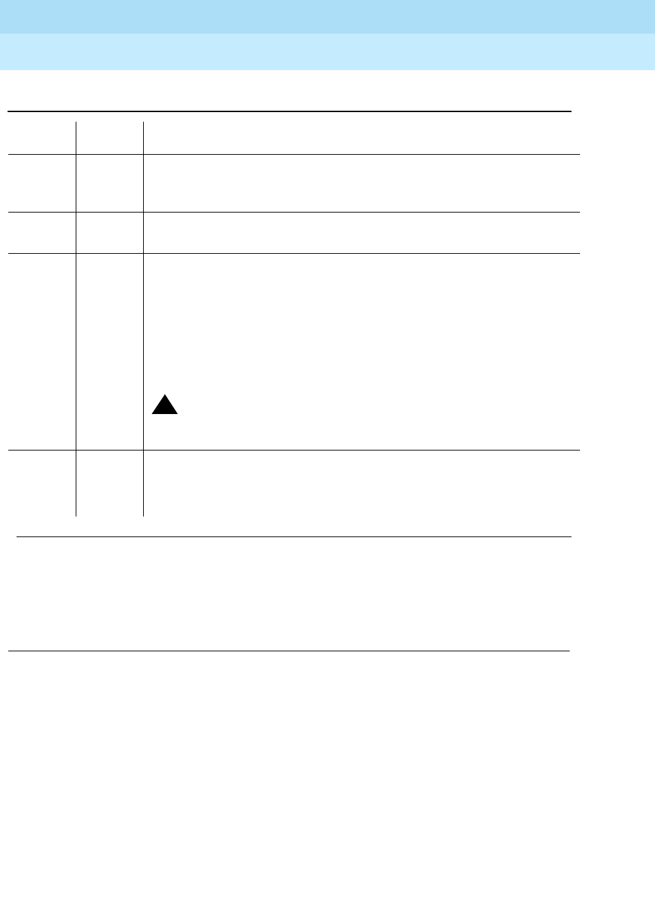
DEFINITY Enterprise Communications Server Release 6
Maintenance for R6r Volumes 1 & 2
555-230-126 Issue 2
January 1998
Maintenance Object Repair Procedures
Page 9-100ANN-BD (Announcement Circuit Pack)
9
Note:
a. Retry the command at 1-minute intervals a maximum of 5 times.
Super Frame Match Inquiry Test (#211)
The super frame is a means by which the Speech Processor (SP) synchronizes
with the 140AY device on the announcement circuit pack. If the super frame is
not synchronized, the SP will not be able to properly process record/playback
requests. Both the SP and the hardware generate a super frame pulse. When
these two pulses are out of synch, the SP sets a flag to indicate the mismatch.
When this test is run, the state of this flag is returned.
2007 ABORT The Announcement circuit pack thinks that Port 1 or Port 9 is busy. Try (a).
1. If the test continues to abort, follow the Announcement Port
maintenance procedures for Ports 1 and 9.
2100 ABORT Could not allocate the necessary system resources to run this test.
ABORT Internal system error. Try (a).
1-3 FAIL Test failed. The error code indicates at which speech compression rate the
test actually failed (1 being the first rate tested, 3 being the last).
1. Reset the circuit pack usingthe reset board UUCSS command and
then run this test again. If the test continues to fail, replace the circuit
pack.
2. If there are recurring alarms on this circuit pack caused by this test
failing, replace the circuit pack even if step 1 works.
!CAUTION:
Replacing the circuit pack will result in loss of integrated
announcements. See Essential Service Information.
PASS The record channel on the announcement circuit pack is functioning
properly. User-reported troubles on this circuit pack should be investigated
using other circuit pack and port tests. Refer to “ANN-PT” for a description
of the port tests.
Table 9-34. TEST #210 140AY Looparound Test — Continued
Error
Code Test
Result Description/Recommendation
Continued on next page
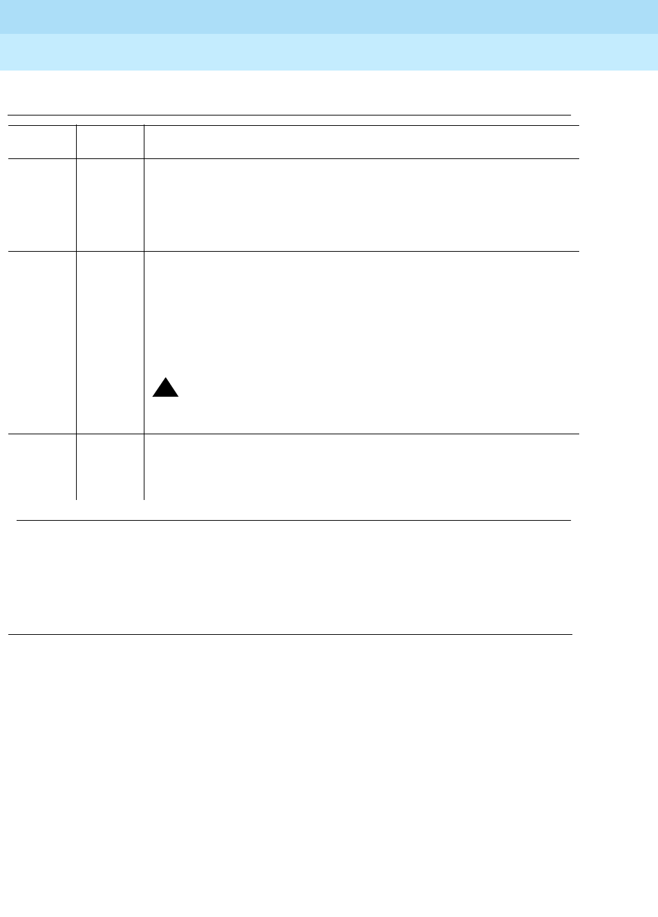
DEFINITY Enterprise Communications Server Release 6
Maintenance for R6r Volumes 1 & 2
555-230-126 Issue 2
January 1998
Maintenance Object Repair Procedures
Page 9-101ANN-BD (Announcement Circuit Pack)
9
Note:
a. Retry the command at 1-minute intervals a maximum of 5 times.
Clock Match Inquiry Test (#212)
This test determines the state of the clock-generating circuitry on the
Announcement circuit pack. This circuitry is used to synchronize the
announcement board with the TDM clock carried on the PN’s backplane.
Table 9-35. TEST #211 Super Frame Match Inquiry
Error
Code Test
Result Description/ Recommendation
2000 ABORT Response to the test request was not received within the allowable time
period. If Error Type 1538 is present in the Error Log, follow the
maintenance strategy recommended for this Error Type.
2100 ABORT Could not allocate the necessary system resources to run this test.
ABORT Internal system error. Try (a).
FAIL Test failed. Announcement playbacks should sound corrupted.
1. Reset the circuit pack via the reset board UUCSS command and then
run this test again. If the test continues to fail, replace the circuit pack
(see Warning).
2. If there are recurring alarms on this circuit pack caused by this test
failing, replace the circuit pack even if step 1 works.
!WARNING:
Replacing the circuit pack will result in loss of integrated
announcements. See Essential Service Information.
PASS The speech processor can properly process record/playback requests.
User-reported troubles on this circuit pack should be investigated using
other circuit pack and port tests. Refer to “ANN-PT” for a description of the
port tests.
Continued on next page
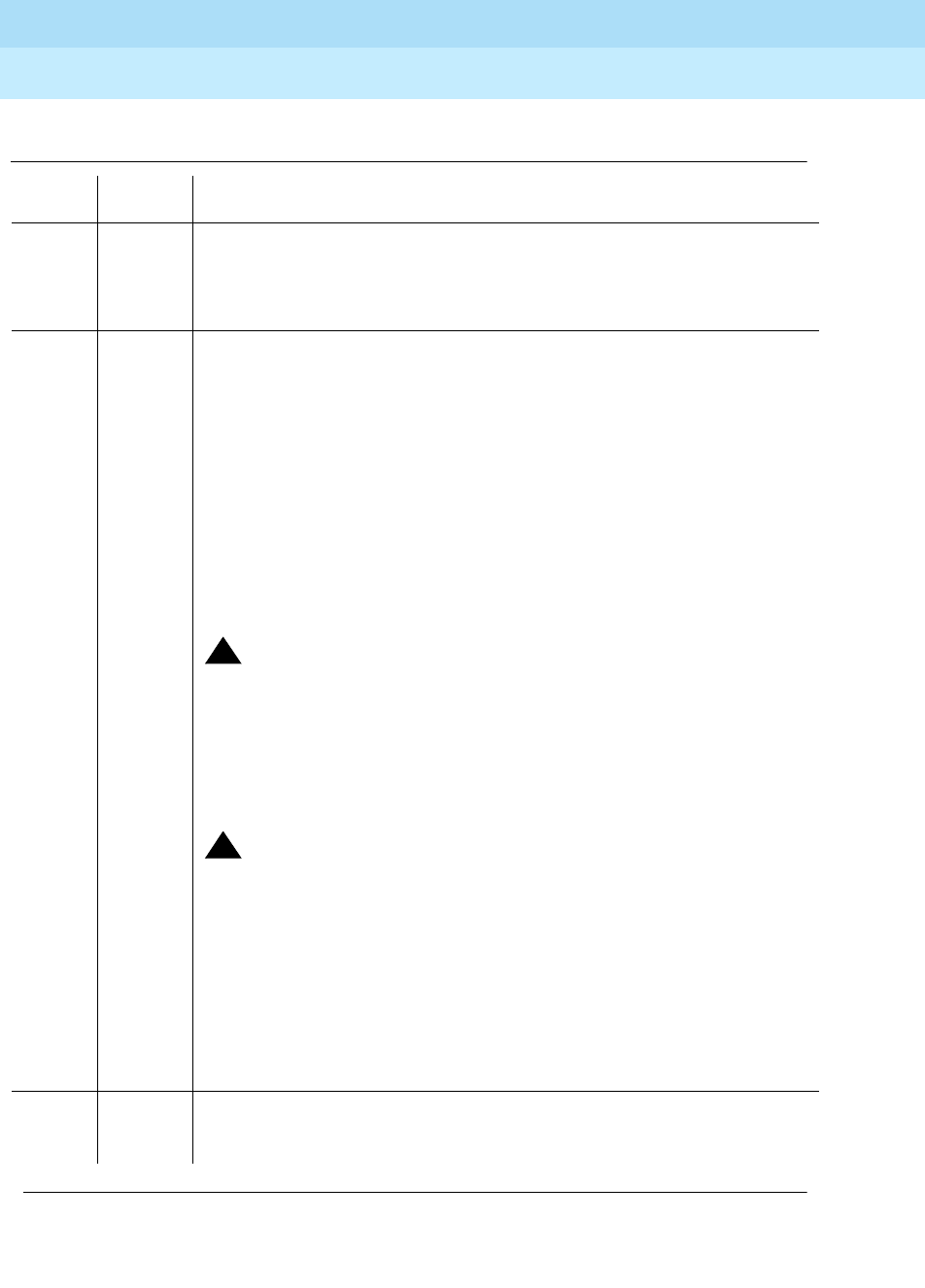
DEFINITY Enterprise Communications Server Release 6
Maintenance for R6r Volumes 1 & 2
555-230-126 Issue 2
January 1998
Maintenance Object Repair Procedures
Page 9-102ANN-BD (Announcement Circuit Pack)
9
Table 9-36. TEST #212 Clock Match Inquiry Test
Error
Code Test
Result Description/ Recommendation
2000 ABORT Response to the test was not received within the allowable time period. If
Error Type 1538 is present in the Error Log, follow the procedure for that error.
2100 ABORT Could not allocate the necessary system resources to run this test.
ABORT Internal system error. Try (a).
FAIL The ANN-BD may be defective or the active tone-clock circuit pack in the
same PN may be bad. Announcements recorded or played back while the
clock circuitry is not functioning properly sound distorted.
1. Reset the Announcement circuit pack via the reset board UUCSS
command and then run this test again. If the test continues to fail,
proceed to Step 2 or 3, whichever applies.
2. If this PN has duplicated Tone-Clocks: Determine the Active TONE-BD in
this PN via the status port-network 1 command. Make the Standby
Tone-Clock circuit pack active via the set tone-clock UUC command.
Rerun the test. If the test passes, then replace the now Standby
Tone-Clock circuit pack. If the test continues to fail, replace the ANN-BD
circuit pack.
!CAUTION:
Replacing the announcement circuit pack results in loss of integrated
announcements. See Essential Service Information. See “TONE-BD” for
Tone-Clock replacement instructions.
3. If the PN has a single tone-clock: Replace the ANN-BD. Rerun the test. If
the test continues to fail, replace the Tone-Clock circuit pack located in
the same PN as the ANN-BD.
!CAUTION:
Replacing the PPN Tone-Clock circuit pack in a Standard Reliability
system (simplex SPE) will cause COLD 2 reset (service outage).
Replacing a simplex EPN Tone-Clock will cause an EPN reset with
service outage to that EPN. See How to Replace a Tone-Clock Circuit
Pack in the “TONE-BD” section of this chapter. Replacing the ANN-BD
will result in loss of integrated announcements. See Essential Service
Information.
4. If failures of this test continue to raise alarms, replace the circuit pack
even if the previous steps were successful.
PASS Announcement playbacks must have clear sound quality. Investigate
user-reported troubles on this circuit pack using the other circuit pack and
port tests. Refer to “ANN-PT” for descriptions of the port tests.
Continued on next page

DEFINITY Enterprise Communications Server Release 6
Maintenance for R6r Volumes 1 & 2
555-230-126 Issue 2
January 1998
Maintenance Object Repair Procedures
Page 9-103ANN-BD (Announcement Circuit Pack)
9
Note:
a. Retry the command at 1-minute intervals a maximum of 5 times.

DEFINITY Enterprise Communications Server Release 6
Maintenance for R6r Volumes 1 & 2
555-230-126 Issue 2
January 1998
Maintenance Object Repair Procedures
Page 9-104ANN-PT (Announcement Port)
9
ANN-PT (Announcement Port)
There are 16 announcement ports on the announcement circuit pack. Each port
can play any integrated announcement, independently of the other ports. In
addition to the 16 ports, the announcement circuit pack also has one data line
circuit port (Port 17). The data line circuit port is used for uploading/downloading
the announcement memory to/from the system tape or disk devices. If there are
any errors associated with Port 17, refer to DAT-LINE maintenance information. If
there are any errors associated with the circuit pack, refer to “ANN-BD”
maintenance information.
Essential Service Information
There are a number of important basic principles that should be understood
before undertaking work on the announcement circuit pack. These are described
in
Essential Service Information
at the beginning of the “ANN-BD“ section of this
chapter.
Although announcement port 5 and data line circuit port 17 on the
announcement circuit pack are logically two separate ports, they are physically
the same port. Therefore, if one of the ports is in use, the other one will be busy.
Also, if announcement port 5 is out-of-service, the data line circuit port will be
taken out-of-service. However, if the data line circuit port is out-of-service, the
announcement port will remain in-service.
1. UU is the universal cabinet number (1 for PPN, 2 - 44 for EPNs), C is the carrier
designation (A, B, C, D, or E), and SS is the number of the slot in which the circuit
pack resides (01 to 21). pp is the two digit port number (01, 02, ...).
MO Name (in
Alarm Log) Alarm
Level Initial Command to Run1Full Name of MO
ANN-PT MINOR test port UUCSSpp l Announcement Port
ANN-PT WARNING test port UUCSSpp l Announcement Port

DEFINITY Enterprise Communications Server Release 6
Maintenance for R6r Volumes 1 & 2
555-230-126 Issue 2
January 1998
Maintenance Object Repair Procedures
Page 9-105ANN-PT (Announcement Port)
9
Error Log Entries and Test to Clear Values
Notes:
a. This error type indicates that the circuit pack has been removed or has
been insane for more than 11-minutes. To clear the error, reinsert or
replace the circuit pack.
b. This error is logged and the port is alarmed when an alarm is raised on the
announcement circuit pack because of a faulty condition with a common
circuit pack resource. Any one of the following alarmed errors on the
announcement circuit pack causes this error to be logged against the
Announcement Port: 1793, 2049, 2305, 2561. Follow the ‘‘ANN-BD
(Announcement Circuit Pack)’’ to resolve these alarms. When the
corresponding circuit pack alarm is cleared, this alarm will clear.
1. Run the Short Test Sequence first. If all tests pass, run the Long Test Sequence. Refer to the appropriate
test description and follow the recommended procedures.
Table 9-37. Announcement Port Error Log Entries
Error
Type Aux
Data Associated Test Alarm Level On/Off
Board Test to Clear Value
010 Any Any Any test port UUCSSpp sh r 1
1 Playback Speech
Memory Array
(PSMA) Test (#206)
MINOR ON test port UUCSSpp sh r 3
18 0 The port was busied
out. WARNING OFF release port UUCSSpp
130(a) None WARNING ON test port UUCSSpp sh
257 Channel
Administration
Memory Array
(CAMA) Test (#205)
MINOR ON test port UUCSSpp l r 3
17667 In-line error
513 140AY Channel
Sanity Inquiry Test
(#222)
MINOR ON test port UUCSSpp sh r 3
17684 In-line error
769(b) None
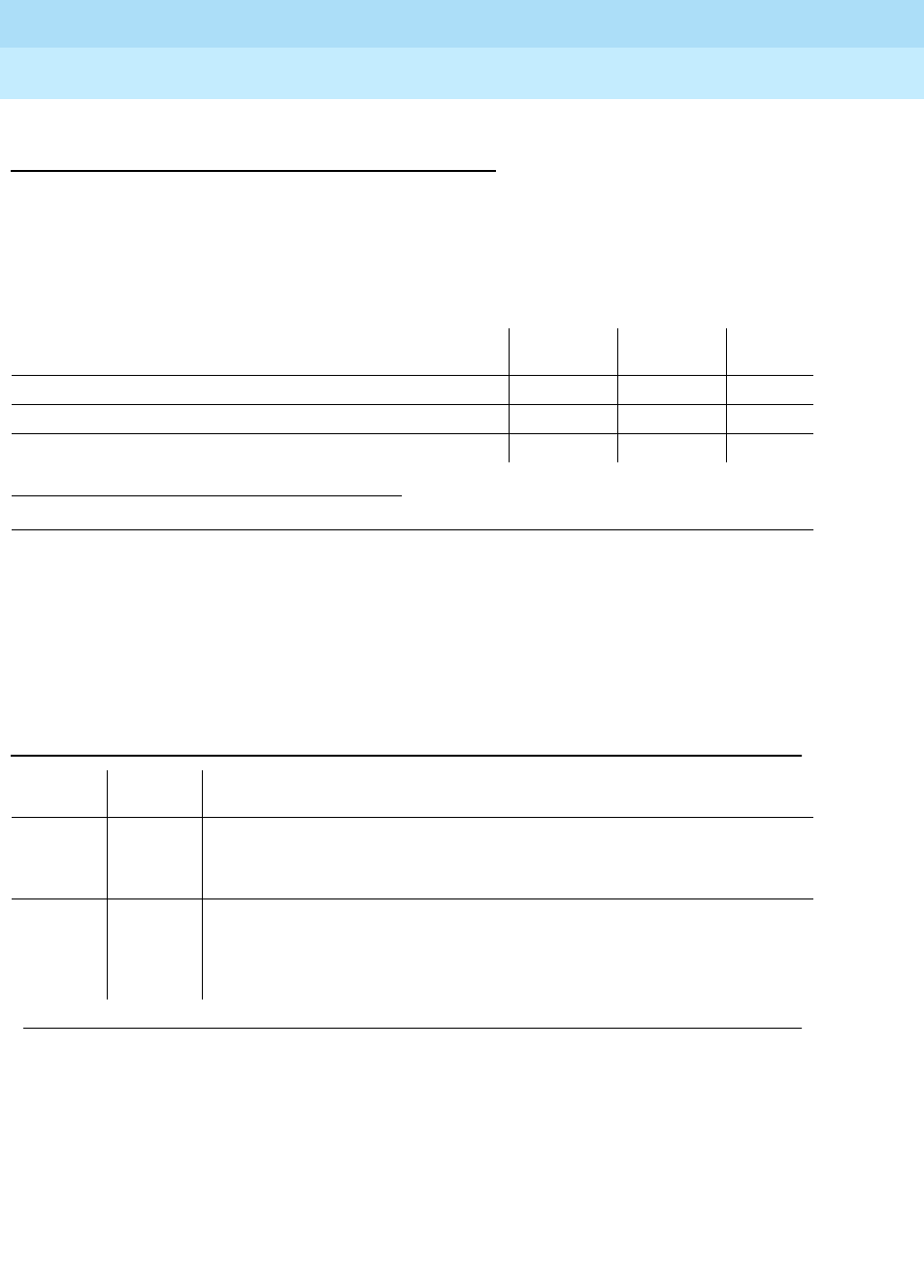
DEFINITY Enterprise Communications Server Release 6
Maintenance for R6r Volumes 1 & 2
555-230-126 Issue 2
January 1998
Maintenance Object Repair Procedures
Page 9-106ANN-PT (Announcement Port)
9
System Technician-Demanded Tests:
Descriptions and Error Codes
Always investigate tests in the order presented in the table below. By clearing
error codes associated with the
Channel Administration Memory Array (CAMA)
Test,
for example, you may also clear errors generated from other tests in the
testing sequence.
Channel Administration Memory Array (CAMA)
Test (#205)
This test is a memory device that stores information used to control the 140AY
device. The Angel asynchronously feeds the CAMA with the control information.
1. D = Destructive; ND = Nondestructive
Order of Investigation Short Test
Sequence Long Test
Sequence D/ND1
Channel Administration Memory Array (CAMA) Test (#205) X ND
Playback Speech Memory Array (PSMA) Test (#206) X X ND
140AY Channel Sanity Inquiry Test (#222) X X ND
Table 9-38. TEST #205 Channel Administration Memory Array (CAMA) Test
Error
Code Test
Result Description/Recommendation
1000 ABORT System resources required to run test are not available. The port may be in
use on a valid call.
1. If the circuit pack is not in use, try (a).
2000 ABORT Response to the test request was not received within the allowable time
period. See
Announcement Board Locked Condition
at the end of this
section.
2100 ABORT Could not allocate the necessary system resources to run this test.
Continued on next page
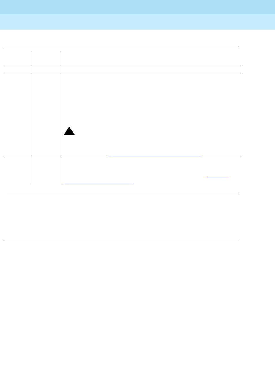
DEFINITY Enterprise Communications Server Release 6
Maintenance for R6r Volumes 1 & 2
555-230-126 Issue 2
January 1998
Maintenance Object Repair Procedures
Page 9-107ANN-PT (Announcement Port)
9
Notes:
a. Retry the command at 1-minute intervals a maximum of 5 times.
Playback Speech Memory Array (PSMA) Test
(#206)
The PSMA test checks the integrity of a playback channel’s interface to the
speech memory and the TDM Bus.
This test is very important.
It is the only test
that actually checks an announcement port’s ability to play back an
announcement on the TDM Bus. If the test fails, the tone detector returns the
number of bytes that did not match the expected sequence. The larger the
number, the more severe the problem is with that port. If this test fails,
announcements played over this port sound corrupted.
ABORT Internal system error, Try (a).
FAIL Test failed. Announcements played back on this port may sound corrupted.
1. Reset the circuit pack using the reset board UUCSS command and
then run this test again. If the test continues to fail, replace the circuit
pack.
2. If there are recurring alarms on this port caused by this test failing,
replace the circuit pack even if Step 1 works.
!CAUTION:
Replacing the circuit pack results in loss of integrated
announcements. Refer to Essential Service Information at the
beginning of ‘‘ANN-BD (Announcement Circuit Pack)’’ in this chapter.
PASS This test verifies that the Angel processor can properly set up this port for
playbacks. User-reported troubles on this circuit pack should be
investigated using other port and circuit pack tests. (Refer to ‘‘ANN-BD
(Announcement Circuit Pack)’’ for a description of the circuit pack tests.)
Table 9-38. TEST #205 Channel Administration Memory Array (CAMA) Test
Error
Code Test
Result Description/Recommendation
Continued on next page

DEFINITY Enterprise Communications Server Release 6
Maintenance for R6r Volumes 1 & 2
555-230-126 Issue 2
January 1998
Maintenance Object Repair Procedures
Page 9-108ANN-PT (Announcement Port)
9
Table 9-39. TEST #206 Playback Speech Memory Array (PSMA) Test
Error
Code Test
Result Description/Recommendation
1000 ABORT System resources required to run this test are not available. The port may
be in use on a valid call. When the port is not in use, try (a.
1002 ABORT The system could not allocate time slots for the test. The system may be
under heavy traffic conditions or it may have time slots out-of-service due to
TDM-BUS errors. Refer to “TDM-BUS” to diagnose TDM-BUS errors.
1. If system has no TDM-BUS errors and is not handling heavy traffic, try
(a).
1003 ABORT The system could not allocate a tone receiver for the test. The system may
be oversized for the number of tone detectors present or some tone
detectors may be out-of-service.
1. Look for TTR-LEV errors in the Error Log. If present, refer to “TTR-LEV”.
2. Look for TONE-PT errors in the Error Log. If present, refer to “TONE-PT”
.
3. If neither condition exists, try (a).
1024 ABORT Announcement circuit pack blocked the test because an announcement
download is in progress. If an announcement download is in progress, a
status data-module announcement data extension command shows that
the announcement data port is connected to a system access port, and the
tape drive should be active. (To determine the extension of the
announcement data module, use the list data-module command.) See
Announcement Board Locked Condition
at the end of this section.
1. Wait until download is finished (maximum of 45 minutes), and then run
the test again.
2000 ABORT Response to the test request was not received within the allowable time
period.
2100 ABORT Could not allocate the necessary system resources to run this test.
ABORT Internal system error. Try (a).
Continued on next page
DEFINITY Enterprise Communications Server Release 6
Maintenance for R6r Volumes 1 & 2
555-230-126 Issue 2
January 1998
Maintenance Object Repair Procedures
Page 9-109ANN-PT (Announcement Port)
9
Notes:
a. Retry the command at 1-minute intervals a maximum of 5 times.
140AY Channel Sanity Inquiry Test (#222)
The Angel keeps a sanity status bit for each of the 16 channels on the 140AY
device. This test queries the Angel to determine the status for a particular
channel. If a channel is insane, that implies that announcements cannot be
played back on that channel.
1 to 254 FAIL Test failed. The error code indicates the number of byte count errors found
by the Tone Detector.
1. Reset the circuit pack via the reset board UUCSS command and then
run this test again. If the test continues to fail, replace the circuit pack.
2. If there are recurring alarms on this port caused by this test failing,
replace the circuit pack even if Step 1 works.
!CAUTION:
Replacing the circuit pack results in loss of integrated
announcements. Refer to Essential Service Information at the
beginning of ‘‘ANN-BD (Announcement Circuit Pack)’’ in this chapter.
255 FAIL Test failed. The announcement port and the tone detector never
synchronized. Check for active GPTD-PT errors, and refer to “GPTD-PT
(General Purpose Tone Detector Port)” to diagnose them first.
1. If there are no active GPTD-PT errors, reset the circuit pack using the
reset board UUCSS command and then run this test again. If the test
continues to fail, replace the circuit pack.
2. If there are recurring alarms on this port caused by this test failing,
replace the circuit pack even if Step 1 works. See Caution, above.
PASS This port can cleanly play announcements. User-reported troubles on this
pack should be investigated using other port and circuit pack tests. Refer to
‘‘ANN-BD (Announcement Circuit Pack)’’ for a description of the circuit pack
tests.
Table 9-39. TEST #206 Playback Speech Memory Array (PSMA) Test — Continued
Error
Code Test
Result Description/Recommendation
Continued on next page

DEFINITY Enterprise Communications Server Release 6
Maintenance for R6r Volumes 1 & 2
555-230-126 Issue 2
January 1998
Maintenance Object Repair Procedures
Page 9-110ANN-PT (Announcement Port)
9
Announcement Board Locked Condition
a. The announcement circuit pack can exhibit a condition that does not allow
recording.
If the circuit pack gets locked into this state (this is an extremely rare
condition), two of the announcement ports on the circuit pack (one of
which is the record port) will be unusable by software. Also, save/restore
announcements will not work since the record port looks busy to the
circuit pack. Note that software does not have any way of knowing this
and will attempt to use the ports.
If the circuit pack is locked into this state, the following symptoms will be
observed:
1. When attempting to record an announcement, users will hear the
proper record tone, but the announcement will not record (they will
not know it until the announcement is played back).
2. Performing a test board long when the circuit pack is in this state
will yield the following abort codes:
■Ports 1 AND 9 abort Test 206 with code 1024.
■Ports 1 AND 9 abort Test 205 with code 2000.
Table 9-40. TEST #161 Looparound Test
Error
Code Test
Result Description/ Recommendation
2000 ABORT Response to the test request was not received within the allowable time
period.
2100 ABORT Could not allocate the necessary system resources to run this test.
ABORT Internal system error
1. Retry the command at 1-minute intervals a maximum of 5 times.
FAIL Test failed. Announcements cannot be played back over this port.
1. Reset the circuit pack via the reset board UUCSS command and then
run this test again. If the test continues to fail, replace the circuit pack
(see Warning).
2. If there are recurring alarms on this port caused by this test failing,
replace the circuit pack even if Step 1 works.
!CAUTION:
Replacing the circuit pack will result in loss of integrated
announcements. Refer to Essential Service Information at the
beginning of “ANN-BD” in this chapter.
PASS Announcements can be played back over this port. User-reported troubles
on this pack should be investigated using other port and circuit pack tests.
Refer to the ‘‘ANN-BD (Announcement Circuit Pack)’’ for a description of the
circuit pack tests.

DEFINITY Enterprise Communications Server Release 6
Maintenance for R6r Volumes 1 & 2
555-230-126 Issue 2
January 1998
Maintenance Object Repair Procedures
Page 9-111ANN-PT (Announcement Port)
9
■Board level Tests 209 and 210 abort with code 1024.
3. The save/restore announcements command will time out with:
Error encountered, can’t complete request
The Announcement circuit pack lock-up can be cleared remotely by
performing a soft reset to the circuit pack:
■busy-out board UUCSS (this command will drop all calls in
progress on the Announcement circuit pack).
■Reset circuit pack using the reset board UUCSS command.
■Release board using the release board UUCSS command.

DEFINITY Enterprise Communications Server Release 6
Maintenance for R6r Volumes 1 & 2
555-230-126 Issue 2
January 1998
Maintenance Object Repair Procedures
Page 9-112ANNOUNCE
9
ANNOUNCE
The ANNOUNCE maintenance object logs an error in the hardware error log
when either of the following occurs:
■A save announcement or restore announcement command does not
complete successfully.
■The system fails to restore announcements from tape or disk at boot time.
Hardware Error Log Entries
Notes:
a. Error occurred while saving announcements. See Table 9-42 for an
explanation of aux data and recommended repair actions.
b. Error occurred while saving announcements to the standby SPE. (See the
table in the next section for an explanation of aux data and recommended
repair actions.)
c. User pressed the CANCEL key while announcement was being saved by
the active SPE.
d. User pressed the CANCEL key while announcement was being saved by
the standby SPE.
e. Error occurred while restoring announcements. See Table 9-42 for an
explanation of aux data and recommended repair actions.
f. The PORT field for this error displays which SPE was active when the error
occurred.
MO Name (in
Alarm Log) Alarm
Level Initial Command to Run Full Name of MO
ANNOUNCE none none ANNOUNCEMENT
Table 9-41. ANNOUNCE Error Log Entries
Error Type Aux Data Associated Test Alarm
Level On/Off
Board Test to Clear
Value
1(a)(f) any None
257(b)(f) any None
513(c)(f) 0 None
769(d)(f) 0 None
1025(e)(f) any None

DEFINITY Enterprise Communications Server Release 6
Maintenance for R6r Volumes 1 & 2
555-230-126 Issue 2
January 1998
Maintenance Object Repair Procedures
Page 9-113ANNOUNCE
9
ANNOUNCE Error Code Aux Data
Table 9-42. ANNOUNCE Aux Data and Repair Actions
Aux
Data Description/Recommendation
30001
through
30054
Disk/Tape errors Check and resolve errors and alarms
32001 Internal system error
Check other ANNOUNCE errors and take corrective action. If there are no other
ANNOUNCE errors:
1. Retry the command at 3 minute intervals a maximum of 3 times.
2. Try the save/restore announcement command.
32002 Announcement circuit pack in use.
1. Retry the command at 2-minute intervals a maximum of 3 times.
2. Try the save/restore announcement command.
32003 Announcement port in use.
1. Wait for all Announcement ports to become available.
2. Enter the save/restore announcement command.
32004 No announcements on board. There are no announcements recorded on the
announcement circuit pack. The save announcement command is not allowed to
prevent the destroying of the announcement file on tape.
32005 Integrated announcement board not present. The announcement circuit pack is not
inserted, or it is defective.
1. Enter the list config command to check for the presence of the board in the
system.
2. If the Announcement circuit pack is present, use the test board UUCSS command
to check the status of the Announcement circuit pack.
32006 Announcement data module not available.
1. Use the status data-module command to check the status of the announcement
data module.
32007 Announcement data module out of service.
1. Use the status data-module command to check the status of the announcement
data module.
32008 Announcement data being saved or loaded.
1. Retry the command at two-minute intervals a maximum of three times.
2. If the save/restore announcement command fails, escalate the problem.
Continued on next page

DEFINITY Enterprise Communications Server Release 6
Maintenance for R6r Volumes 1 & 2
555-230-126 Issue 2
January 1998
Maintenance Object Repair Procedures
Page 9-114ANNOUNCE
9
32009 No system port is available (none are administered, or all are busy). A system port is
required to save or restore announcements.
1. Use add data-module to administer a System Port if none is administered.
2. If system ports are administered, use the status data-module command to check
the status of all system ports. At least one system port should be in the
in-service/idle state.
32010
32013 System port not administered or unavailable. A system port is required to save or
restore announcements.)
1. Use add data-module to administer a system port if none is administered.
2. If system ports are administered, use the status data-module command to check
the status of all system ports. At least one system port should be in the
in-service/idle state.
32012 Required announcement data module not administered.
1. Add an announcement data module and repeat the command.
Table 9-42. ANNOUNCE Aux Data and Repair Actions — Continued
Aux
Data Description/Recommendation
Continued on next page
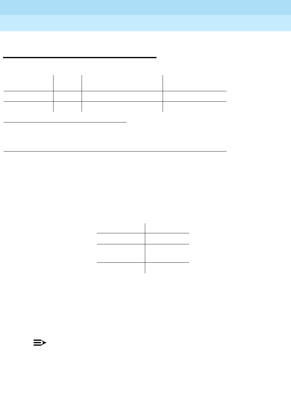
DEFINITY Enterprise Communications Server Release 6
Maintenance for R6r Volumes 1 & 2
555-230-126 Issue 2
January 1998
Maintenance Object Repair Procedures
Page 9-115ASAI-BD (Multi-Application Platform Board)
9
ASAI-BD (Multi-Application Platform
Board)
Maintenance testing of the common circuit pack is handled by on-board
firmware and SPE-controlled tests. Maintenance software queries the firmware
for error and alarm information, status, and test results. Firmware automatically
reports error conditions that result in SPE-controlled testing.
For MAPD board insertion, the switch makes an additional board query if any of
the following circuit packs are inserted:
For any of the above initial board uplinks, the switch queries the board for
administration data, as well as reporting the switch software release and the
system type.
For the native mode, the response to the board query downlink messages
consists of several CCMS uplink messages that identify the true board code,
vintage, suffix, emulation type, and number of reserved slots needed.
NOTE:
Refer to LAN-BD Maintenance documentation for circuit pack level errors.
See also ASAI-PT/ASAI-EPT (BRI Line) maintenance documentation for
related line information. See the following exceptions listed below:
■Hyperactivity: currently, the common circuit pack is considered
"hyperactive" if the Service Dispatcher receives 200 uplink
messages from the circuit pack in a 10-second period. Since
MAPD has 32 ports, the hyperactivity limit increases to 500 uplink
1. Where UU is the universal cabinet number (1 for PPN and 2-44 for EPN); C is the carrier
designation (for example, A, B, C, D, or E); SS is the address of the slot in the carrier
where the circuit pack is located (for example, 01, 02, ..., and so forth); and pp is the
two digit port number (01, 02, 03, ...).
MO Name (in
Alarm Log) Alarm
Level Initial Command to Run 1Full Name of MO
ASAI-BD MIN test board UUCSS pp ASAI-BD
ASAI-BD WRN test board UUCSS pp ASAI-BD
Circuit Pack Vintage
TN754 49
TN556 49,
80 or greater
TN800 any

DEFINITY Enterprise Communications Server Release 6
Maintenance for R6r Volumes 1 & 2
555-230-126 Issue 2
January 1998
Maintenance Object Repair Procedures
Page 9-116ASAI-BD (Multi-Application Platform Board)
9
messages per 10 seconds. The switch issues an alarm when the
limit reaches 400; when it reaches 500 up-link messages in 10
seconds, the board is taken out of service.
■LED use: the LED Control Message 038x requests the Angel to
drive the red, yellow, and green LEDs on the face plate of a typical
port board on or off. On the MAPD, only the red LED is controlled
by this message. Yellow and green change requests received from
the switch by the MAPD drive LCD behavior rather than LED
behavior. The DEFINITY switch continues to send the same LED
control messages to the MAPD that the DEFINITY switch currently
sends to all other port boards. The MAPD handles proper
interpretation of these messages. You should note that the PC on
the MAPD and the switch itself control the LEDs and the LCD on the
MAPD.
■Port Administration: in Administration Without Hardware (AWOH),
the switch allows administration of up to 8 ports in any of the first 12
ports. If the port type later reported by the board does not match
the existing type, the switch assumes it to be a MAPD board with a
different configuration and rejects the board.
NOTE:
Refer to the LAN-BD documentation for circuit pack level
errors. For related information, see ASAI-PT and ASAI-EPT
maintenance documentation.
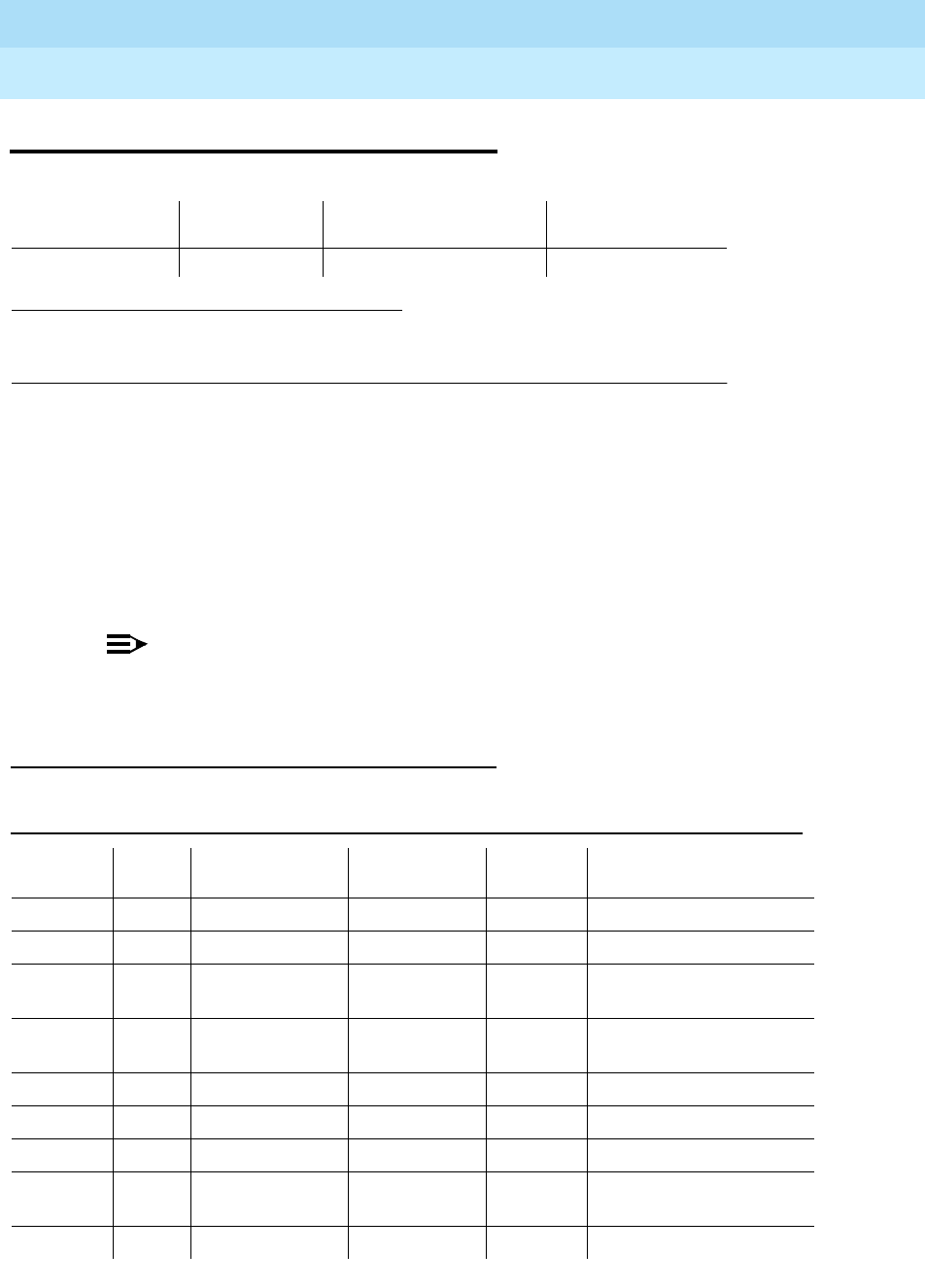
DEFINITY Enterprise Communications Server Release 6
Maintenance for R6r Volumes 1 & 2
555-230-126 Issue 2
January 1998
Maintenance Object Repair Procedures
Page 9-117ASAI-EPT
9
ASAI-EPT
The maintenance strategy for this endpoint MO is built on maintenance facilities
offered in the Lucent ISDN-BRI protocol and in the ASAI adjuncts. Currently there
are no facilities in the protocol that provide for maintenance of set data features.
The TN800 is a PC-based platform that allows interaction of multiple applications
with DEFINITY at any time. DEFINITY Release 5 software (Native mode) supports
emulation of three types of port MOs on this board. The type of ports to be
emulated is defined by the applications running on the TN800.
NOTE:
If the TN800 is emulating BRI, the software/firmware supports a maximum
of 12 ports, but only 8 of the 12 ports can be administered at any one time.
Error Log Entries and Test to Clear Values
1. The alarm level for ASAI adjuncts is administered using the set options command. The
alarm level can be set independently for off-board and on-board alarms to WARNING,
MINOR, or MAJOR for all ASAI adjuncts in the system.
MO Name (in
Alarm Log) Alarm Level Initial Command to Run Full Name of MO
ASAI-EPT MAJOR1test station extension ASAI-Adjunct
Table 9-43. ASAI-EPT Error Log Entries
Error
Type Aux
Data Associated Test Alarm Level
ASAI-EPT On/ Off
Board Test to Clear Value
010 Any Any Any test ASAI-ADJ
2 (a) 2-102 None
257 (b) Any BRI Layer 3
Query MAJ/WNG2OFF test station ext r 2
test data-module ext r 2
351 (c) 0 none WARNING OFF busyout and release
station
513 (d) 0 None
769 (e) 0 None MAJOR OFF
2561 (f) 0 None
2562-
2566 (g) 0 None
2567 (h) 0 None
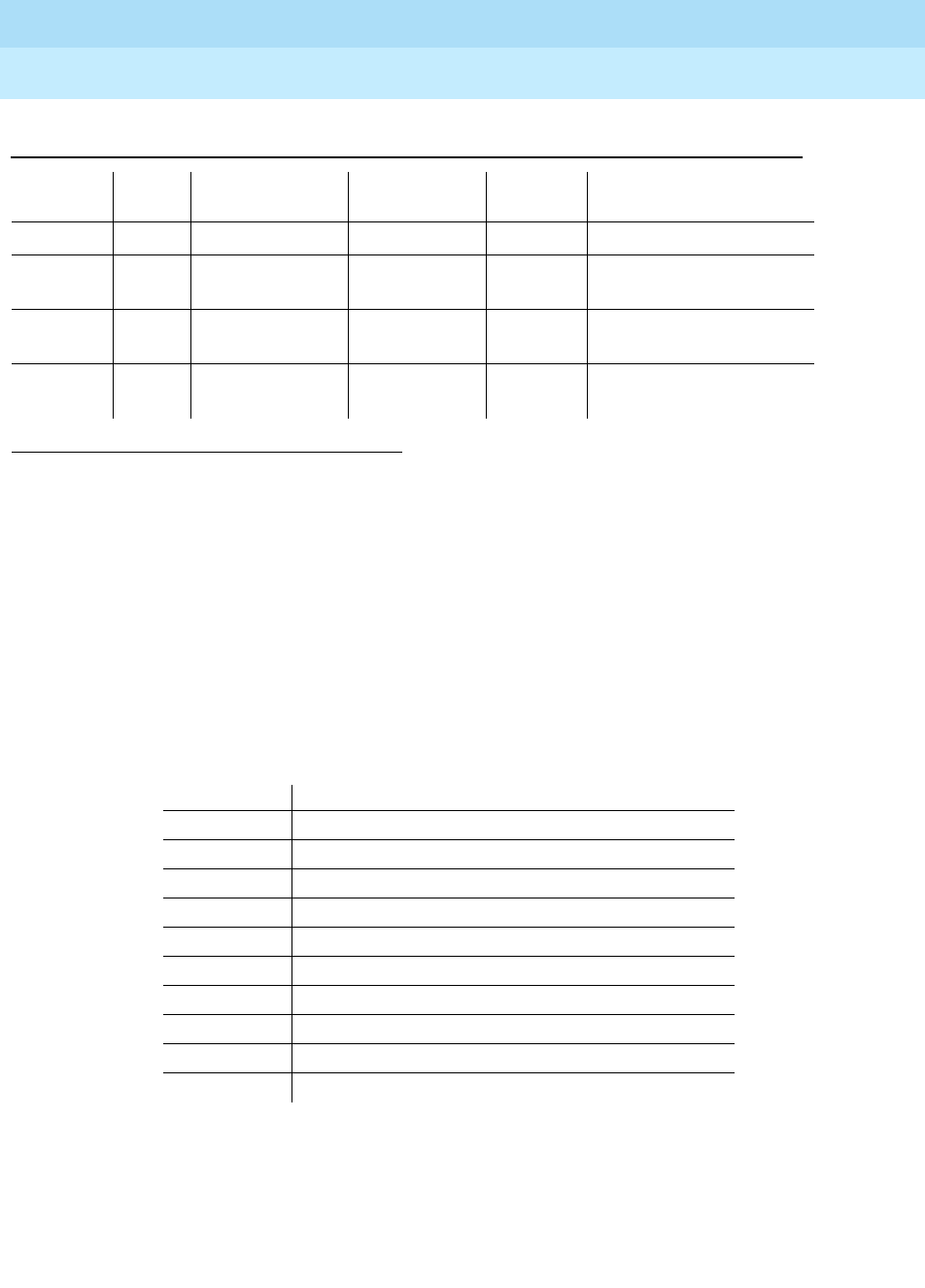
DEFINITY Enterprise Communications Server Release 6
Maintenance for R6r Volumes 1 & 2
555-230-126 Issue 2
January 1998
Maintenance Object Repair Procedures
Page 9-118ASAI-EPT
9
Notes:
a. Errors of this type indicate violations of the ISDN-BRI signaling protocol.
Timers associated with certain Layer 3 messages have expired before a
required response was received. In the following table, the aux data
column indicates which timer has just expired. For more information, refer
to the Lucent ISDN-BRI Specification.
The switch sent a message to an endpoint that did not respond in the
allotted time. This may be due to failure of the point-to-point signaling link
or because of a problem in the ASAI adjunct. To repair:
■Execute the test station extension command and perform the
associated repair procedures for those tests.
1. Run the Short Test Sequence first. If all tests pass, run the Long Test Sequence. Refer to the
appropriate test description and follow the recommended procedures.
2. Major alarms on this MO may be downgraded to Warning alarms based on the value used in the set
options command.
2568 (i) 0 None
3329 (j) Any Signaling Link
Status (626) MAJ/WNG†OFF
3584-
3839 (k) 0, 1 None
3841 (l)
4095 0 None
Aux Data Timer Type
2 First T303 (SETUP timer)
3 Second T303 (SETUP timer)
4 T305 (DISConnect timer)
5 First T308 (RELease timer)
6 Second T308 (RELease timer)
10 T316 (RESTart timer)
12 T309 (Layer 2 Failure timer)
16 TM100 (Management Information Message timer 1)
17 TM200 (Management Information Message timer 2)
102 TASAI (ASAI Routing Timer)
Table 9-43. ASAI-EPT Error Log Entries — Continued
Error
Type Aux
Data Associated Test Alarm Level
ASAI-EPT On/ Off
Board Test to Clear Value

DEFINITY Enterprise Communications Server Release 6
Maintenance for R6r Volumes 1 & 2
555-230-126 Issue 2
January 1998
Maintenance Object Repair Procedures
Page 9-119ASAI-EPT
9
b. An endpoint is not responding to the service state query message sent to
the adjunct or to the endpoint. This error causes an alarm to be raised.
The alarm is retired when the switch receives a response to the service
state query to the endpoint or to the adjunct.
When this error occurs for an ASAI adjunct, the Aux Data field indicates
the state of the ASAI link and whether an invalid response or no response
was received to the query from the switch, as shown in the following table:
See ‘‘status bri-port’’ in Chapter 8, ‘‘Maintenance Commands’’ for an
explanation of the ASAI link states.
For ASAI or Lucent adjuncts, the switch queries the adjunct every two
minutes. The Layer 3 Query Test is not executed for ASAI or Lucent
adjuncts through a command issued from the management terminal.
While alarmed for this error, the switch takes the associated port
out-of-service for five seconds every 15 minutes. This action attempts to
stimulate recovery actions to be taken by the adjunct.
When this error occurs for an ASAI or Lucent adjunct, the service
technician should:
1. Execute the test station extension command and perform the
associated repair procedures for those tests.
2. Check the health of the adjunct by following the recommended
repair procedures of the manufacturer of the adjunct if the
preceding step does not resolve the problem.
c. This error and associated warning alarm are logged against an ASAI
endpoint when the adjunct has asked the switch to suspend maintenance
on the ASAI endpoint. Busying out and releasing the ASAI station clears
this alarm.
d. This error occurs when the endpoint sends more messages than the
switch can handle. The switch suspends the reception of messages from
the endpoint for a short period of time. There is no repair procedure for
this error. If the condition persists, replace the endpoint.
e. This error occurs when the signaling link associated with the ASAI
endpoint has too much link-establishment related traffic. This occurs if the
signaling link is alternating between assigned and established states. If
this problem persists, replace the endpoint.
Aux Data ASAI Link State Error
102 13-restarting No response to RESTART message
104 13-restarting Invalid response to RESTART message
152 13-restarted No response to Layer 3 query
154 13-restarted Invalid response to Layer 3 query
202 13-established No response to Layer 3 query
204 13-established Invalid response to Layer 3 query

DEFINITY Enterprise Communications Server Release 6
Maintenance for R6r Volumes 1 & 2
555-230-126 Issue 2
January 1998
Maintenance Object Repair Procedures
Page 9-120ASAI-EPT
9
f. This error occurs when the ASAI-EPT message is not transmitted because
the PKT-CTRL (packet control circuit pack) transmit buffers are
exhausted. Frequent or persistent occurrence of these events may
indicate a hardware problem or traffic overload on the PKT-CTRL, the
signaling link, or the ASAI adjunct. Resolve the problem by following the
repair procedures for the PKT-CTRL. If these attempts fail, re-engineering
the traffic on the PKT-CTRL, signaling link, or adjunct may be necessary.
g. The ASAI message is not transmitted because the transmit buffer for the
ASAI link is full, causing the link to be flow-controlled. Frequent or
persistent occurrence of these events may indicate a hardware problem
or traffic overload on the PKT-CTRL, the signaling link, or the ASAI
adjunct. Resolve the problem by following the repair procedures issued
by the manufacturer of the adjunct. If these attempts fail, re-engineering of
the traffic on the PKT-CTRL, signaling link, or adjunct may be necessary.
h. This version of ASAI is not supported. Check the software version that is
running on the ASAI adjunct.
i. The adjunct identification is invalid. Check the vendor ID or software
running on the ASAI adjunct.
j. This occurs when the point-to-point signaling link to the endpoint goes
down, except when the link goes down because either a system
technician has busied out the PKT-CTRL or the PKT-BUS, or they have
failed. This error raises an alarm against the endpoint or adjunct. Execute
the test station extension short command and note the results of the
Signaling Link Status Test (#626). If this test fails, follow the repair
procedure for Test #626. The alarm is retired when the signaling link is
re-established to the endpoint or adjunct.
k. The switch software logs certain ASAI cause values. The cause value is
determined from the following formulas:
— If the error type is greater than 3712, then the ASAI cause value is
equal to the error type minus 3712. The switch sent this value to the
adjunct.
— If the error type is less than 3712, then the ASAI cause value is
equal to the error type minus 3584. The switch sent this value to the
adjunct.
Table 9-44 contains a description of the various ASAI cause values and
recommended system technician actions associated with the cause value.
The ISDN-BRI Specification (801-802-100) contains further information. In
addition, the Aux Data field of the Error Log entry contains additional
diagnostic information.
l. The switch software logs certain ASAI cause values. The cause value is
determined from the following formula:
— If the error type is greater than 3968, then the ASAI cause value is
equal to the error type minus 3968. The switch sent this value to the
endpoint.

DEFINITY Enterprise Communications Server Release 6
Maintenance for R6r Volumes 1 & 2
555-230-126 Issue 2
January 1998
Maintenance Object Repair Procedures
Page 9-121ASAI-EPT
9
— If the error type is less than 3968, then the ASAI cause code is
equal to the error type minus 3840. The switch sent this value to the
endpoint.
Table 9-44. ASAI Cause Values
Code Explanation Recommendation
0 Unrecognized
ASAI Protocol
Operation.
Requested ASAI protocol is not implemented by switch or adjunct. Aux
data field of error log entry contains protocol identifier for unrecognized
operation.
1. Consult switch and adjunct documentation to determine which set of
operations is supported by switch and the adjunct. Adjunct
administration turning off operations not implemented by the switch
may resolve the problem.
34 No circuit or
channel
available
A resource on the switch is unavailable for a call. For BRI endpoints, this
cause value is not logged. For ASAI, this condition means that there are
no available trunks for an outgoing call request.
1. Verify that the adjunct is administered to support the trunk
capabilities of the switch.
2. Investigate trunk group status by issuing the status trunk command
from the SAT or by requesting trunk group query(ies) from the
adjunct.
3. Perform trunk diagnostic procedures outlined in this manual.
40 Resources not
available. No available internal resources to service switch or adjunct request.
Exceeds system transaction capacity for adjunct or switch.
1. May require re-engineering of adjunct services.
50 Requested
facility not
subscribed
Requested facility is implemented, but not administered. Potential
administration problem with endpoint or adjunct.
For BRI endpoints:
1. Verify the switch administration of endpoint using either the display
station or display data-module commands.
2. If Step 1 does not resolve the problem, refer to the endpoint’s service
manual and verify administration on the endpoint.
For ASAI adjuncts:
1. Display the Customer Optional Features Form (administration
screen) on the switch to determine which ASAI capabilities are
turned on in the switch.
2. Verify that the adjunct is administered to support the identical
capabilities as the switch. If there is a mismatch in the administered
capabilities, then readminister the switch and/or the adjunct to
establish a consistent set of desired capabilities on both the switch
and the adjunct.
Continued on next page

DEFINITY Enterprise Communications Server Release 6
Maintenance for R6r Volumes 1 & 2
555-230-126 Issue 2
January 1998
Maintenance Object Repair Procedures
Page 9-122ASAI-EPT
9
58 Bearer
capability not
presently
available
Requested bearer capability is implemented, but not administered. No
B-channel administered. See code 50 above.
63 Service or
option not
available
Requested ASAI capability or resource is not available on the switch or
adjunct. More than one adjunct may be contending for the same switch
resource. Potential administration mismatch between the resource
domains administered on the switch and those administered on the
adjunct.
1. Verify that no overlapping administration of switch resources (for
example, requesting notifications on a single domain by multiple
adjuncts attempting to control a single call) exists across all adjuncts
connected to the switch. If overlaps exist, then re-administer the
adjuncts to ensure that each adjunct is associated with a unique set
of switch resources.
65 Bearer service
not
implemented
Requested service not implemented in switch or endpoint.
69 Requested
facility not
implemented
Requested service not supported in switch or endpoint.
1. Consult switch and endpoint documentation to determine service
support.
79 Service or
option not
implemented
Requested service or option (or combination of selected options) is not
supported (implemented) in switch or the adjunct.
1. Consult switch and adjunct documentation to determine ASAI
service and options supported by both switch and adjunct.
Re-administration of the switch-administered capabilities (see
Customer Optional Feature Form) or those of the adjunct may be
necessary to correct the problem.
81 Invalid CRV An invalid CRV was sent by the adjunct.
1. This may indicate a CRV inconsistency between the switch and the
adjunct. See the CallVisor protocol reference manual.
87 Internal switch
audit There is an inconsistency in switch data records.
1. There is no action needed, since the switch has corrected the data
inconsistency.
Table 9-44. ASAI Cause Values — Continued
Code Explanation Recommendation
Continued on next page

DEFINITY Enterprise Communications Server Release 6
Maintenance for R6r Volumes 1 & 2
555-230-126 Issue 2
January 1998
Maintenance Object Repair Procedures
Page 9-123ASAI-EPT
9
System Technician-Demanded Tests:
Descriptions and Error Codes
When inspecting errors in the system, always investigate errors associated with
the circuit pack and port first. Clearing these error codes first may also clear
errors generated against the endpoint. When all circuit pack and port errors have
been cleared, but errors still exist against the endpoint, investigate errors in the
table below. By clearing error codes associated with the Signaling Link Status
Test, for example, you may also clear errors generated from other tests in the
testing sequence.
BRI Layer 3 Query Test (#629)
This test is not used by the ASAI-ADJ maintenance object. For information about
this test, see BRI-SET in the maintenance documentation.
Signaling Link Status Test (#626)
This test determines the current status of the signaling link. This test passes if the
link is "bound" to an endpoint and fails if the link is "not bound."
The definition of the term "bound" for a link depends upon the type of endpoint
and may depend on the successful completion of procedures at both Layers 2
and 3 of the protocol. The definition of "bound" for ASAI type of endpoint is:
■ASAI adjuncts and BRI endpoints not administered for MIM initialization
(point-to-point):
For endpoints of this type, the signaling link is "bound" when the link is
connected at Layer 2 (L2 established).
1. D = Destructive; ND = Nondestructive
Order of Investigation Short Test
Sequence Long Test
Sequence D/ND1
Signaling Link Status Test (#626) X X ND

DEFINITY Enterprise Communications Server Release 6
Maintenance for R6r Volumes 1 & 2
555-230-126 Issue 2
January 1998
Maintenance Object Repair Procedures
Page 9-124ASAI-EPT
9
Table 9-45. TEST #626 Signaling Link Status Test
Error
Code Test
Result Description/ Recommendation
1139 ABORT The Packet Bus in the port network is out-of-service.
1. Follow the repair procedures for the Packet Bus.
2. After completing Step 1, execute the test port long UUCSSpp
command and review the results of the BRI Port Local LAN Looparound
Test to verify the repair.
1141 ABORT The PKT-CTRL is out-of-service.
1. Refer to PKT-CTRL maintenance documentation.
1144 ABORT The PPN Packet Bus is out-of-service.
1. Follow the repair procedures for the Packet Bus in the PPN.
2. Execute the test port long UUCSSpp command and review the results
of the BRI Port Local LAN Looparound Test to verify the repair.
2012 ABORT Internal system error
2100 ABORT Could not allocate the necessary system resources to run this test.
1. Retry the command at 1-minute intervals a maximum of 5 times.
1113 FAIL The signaling link is not "bound" to the adjunct. For ASAI adjuncts this error
indicates that the link is disconnected at Layer 2. Since the signaling link
associated with the endpoint has been identified by administration, the link
is only "unbound" from the endpoint when it is disconnected.
1. Execute the status bri-port UUCSSpp command and refer to the
associated procedures for this command contained in “BRI-PORT”.
PASS The signaling link is connected at Layer 2 and "bound" to the ASAI adjunct.
Continued on next page

DEFINITY Enterprise Communications Server Release 6
Maintenance for R6r Volumes 1 & 2
555-230-126 Issue 2
January 1998
Maintenance Object Repair Procedures
Page 9-125ASAI-PT
9
ASAI-PT
Unless otherwise stated, all maintenance actions contained in this section apply
to ASAI-PT and ISDN-BRI ports connected to ASAI adjuncts. This port type is
administered as an ASAI-BD on the TN800 circuit pack.
The TN800 circuit pack is a PC-based platform that allows interaction of multiple
applications with DEFINITY at any time. DEFINITY Release 5 software (Native
mode) will support emulation of three types of port MOs on this board. The type
of ports to be emulated are defined by the applications running on the TN800.
The TN800 can support a maximum of 32 ports (time slots) at a time.
The TN800 connects to the switch through a single slot in the backplane,
however its width is not limited to one slot. The number of slots occupied by the
TN800 is supplied by the board during its insertion. The TN800 in Release 5 is 3
slots wide. The blank (reserve) slots are to the left of the functional slot.
In non-native mode the TN800 is recognized as TN556, TN2181, TN754, or
TN746 based on the switch software and the application running on the TN800.
In non-native mode only one type of port MOs will run at any time, and the port
type depends on the application running on the TN800. If the TN800 fails
diagnostics in non-native mode, the system’s alarm and error logs would show a
failure for the board type the TN800 is emulating.
1. Where UU is the universal cabinet number (1 for PPN and 2-44 for EPN); C is the carrier
designation (for example, A, B, C, D, or E); SS is the address of the slot in the carrier where
the circuit pack is located (for example, 01, 02, ..., and so forth); and pp is the two digit port
number (01, 02, 03, ...).
2. The alarm level for ASAI adjunct ports may be administered using the set options
command. The alarm level can be set independently for off-board and on-board alarms to
WARNING, MINOR, or MAJOR for all ASAI adjunct ports in the system.
3. All alarming for an ASAI adjunct and off-board alarming for an ASAI port is disabled if the
ASAI adjunct asks the switch to suspend maintenance. When this occurs, an error and a
WARNING alarm is logged against the ASAI adjunct. Check the Hardware Error and Alarm
Logs to see if the adjunct has disabled alarming.
MO Name (in
Alarm Log Alarm Level Initial Command to
Run1Full Name of MO
ASAI-PT MAJOR2,3 test port UUCSSpp l ASAI ISDN BRI Port
ASAI-PT WARNING test port UUCSSpp l ASAI ISDN BRI Port

DEFINITY Enterprise Communications Server Release 6
Maintenance for R6r Volumes 1 & 2
555-230-126 Issue 2
January 1998
Maintenance Object Repair Procedures
Page 9-126ASAI-PT
9
Error Log Entries and Test to Clear Values
Notes:
a. This error occurs when the Level 1 Status Inquiry fails or when the BRI
circuit pack detects that Level 1 has been deactivated on the port. The
aux data field contains one of the following values:
Refer to the repair procedures for Test #621.
b. The circuit pack is having problems transmitting data to the Packet Bus,
thus affecting the conveyance of signalling information over D-channel.
This error occurs when the Packet Bus transmit FIFO buffer overflows. This
condition probably indicates a hardware problem as well. The ASAI-PORT
alarm level is MAJOR with aux data 0. Use troubleshooting procedures for
both on-board hardware problems and potential off-board Packet Bus
problems.
1. Run the Short Test Sequence first. If all tests pass, run the Long Test Sequence. Refer to the
appropriate test description and follow the recommended procedures.
2. Major and Minor alarms may be downgraded to warning alarms based on the value used in the set
options command.
Table 9-46. ASAI-PT Port Error Log Entries
Error
Type Aux
Data Associated Test Alarm Level
ASAI-PORT On/Off
Board Test to Clear Value
010 Any Any Any test port UUCSSpp sh r 1
1 (a) (a) Level 1 Status
Inquiry (#621) MAJ2OFF test port UUCSSpp sh r 2
513 (b) 0 none (b) ON
1537 (c) 46210 CRC Error
Counter (#623) MAJ2OFF
3841 (d) 46208 None
3844 (e) 46223 None
3845 (f) None
3846 (g) TEI None
Continued on next page
Blank This indicates that the Level 1 Status Inquiry failed.
32773 This is a message from the ASAI-Line circuit pack
indicating Level 1 has been deactivated.

DEFINITY Enterprise Communications Server Release 6
Maintenance for R6r Volumes 1 & 2
555-230-126 Issue 2
January 1998
Maintenance Object Repair Procedures
Page 9-127ASAI-PT
9
c. The port received an invalid frame over the D-channel. When the Cyclical
Redundancy Check (CRC) errors exceed 5 within 15 minutes, the port is
taken out of service for 5 seconds. If 5 more CRC errors are received
within 15 minutes of the first set of 5 errors, the port is taken out of service
for one minute. If 5 more CRC errors are received within 15 minutes of the
last 5, the port is taken out of service for 15 minutes.
This error is most likely due to a problem with the wiring to the set or
adjunct, interference on the wiring due to a noise source, or no termination
(an open circuit). It usually does not indicate a problem with the circuit
pack.
■Check the wiring to the endpoints or the adjunct.
■If the problem persists, replace the endpoints or adjuncts.
d. This error occurs when a Layer 1 Transmission error is detected for the
port. Run the Long Test Sequence and note the results of the Layer 1
Transmission Error Counter Test (#624).
e. This error occurs when the circuit pack detects an overflow of its receive
buffers. Run the Long Test Sequence and note the results of the Receive
FIFO Overflow Counter Test (#625).
f. This error occurs when the BRI Port Local LAN Looparound Test (#618)
fails. Run the Long Test Sequence and note the results of Test (#618).
g. The Terminal Endpoint Identifier (TEI) administered for the ASAI endpoint
most likely does not match the TEI administered in the ASAI adjunct.
Check the switch administration of the TEI against that of the adjunct, and
make sure that both are using the same TEI.
System Technician-Demanded Tests:
Descriptions and Error Codes
Always investigate tests in the order presented in the following tables when
inspecting errors in the system. For example, by clearing error codes associated
with the NPE Crosstalk Test, you may also clear errors generated from other tests
in the testing sequence.
Order of Investigation Short Test
Sequence Long Test
Sequence D/ND1
ASAI Port Local LAN Looparound Test (#618) X D
Level 1 Status Inquiry Test (#621) X X ND
CRC Error Counter Test (#623) X ND
Layer 1 Transmission Error Counter Test (#624) X ND
Receive FIFO Overflow Error Counter Test (#625) X ND
Clear Error Counters (#270) X X ND
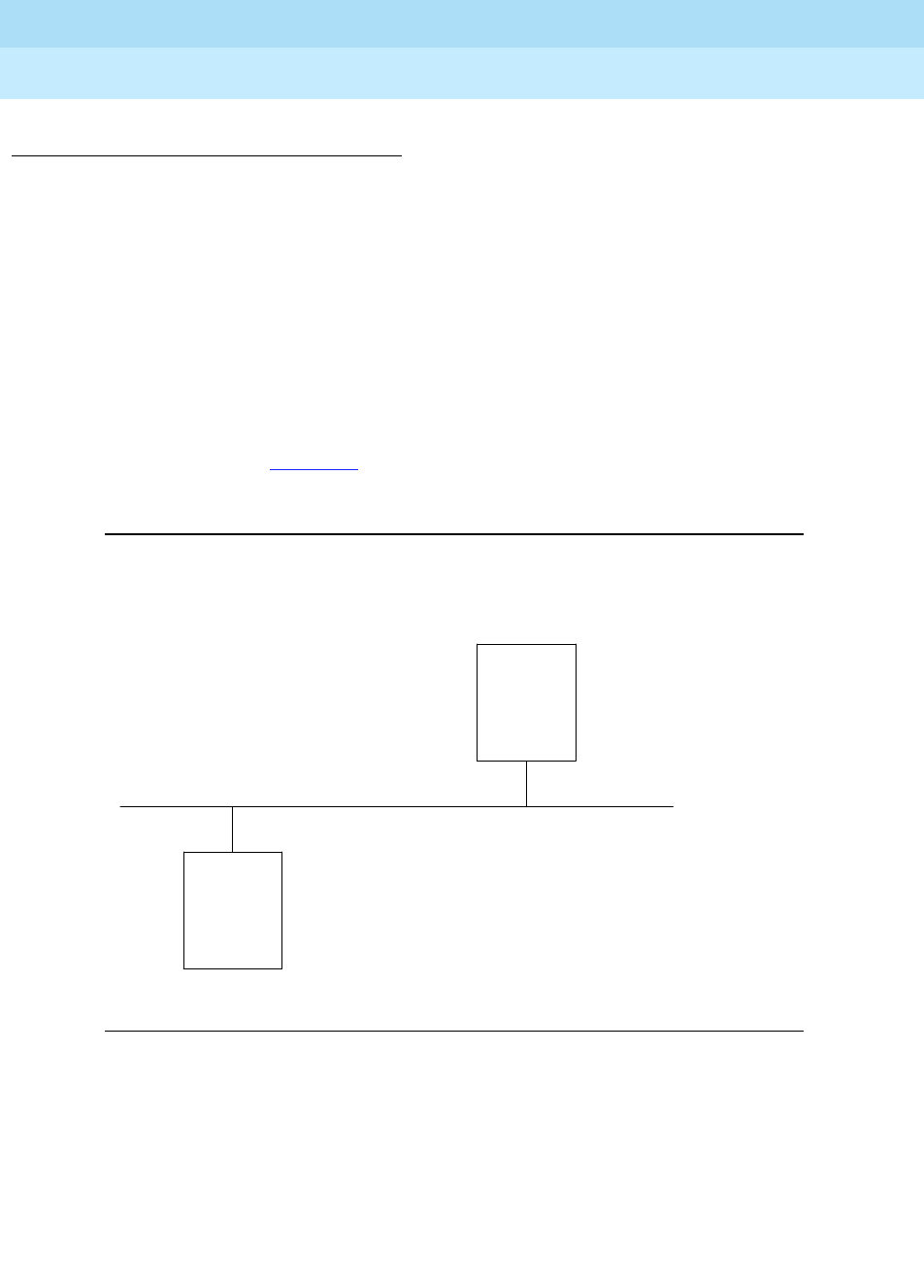
DEFINITY Enterprise Communications Server Release 6
Maintenance for R6r Volumes 1 & 2
555-230-126 Issue 2
January 1998
Maintenance Object Repair Procedures
Page 9-128ASAI-PT
9
BRI Port Local LAN Looparound Test (#618)
This test is destructive.
This test verifies the connectivity of a BRI port across the LAN Bus and executes
only if the port is out-of-service. The test aborts if calls associated with the port
are in-progress. Failures of this test indicate either on-board faults associated
with the ASAI-PT hardware on the circuit pack or problems with the LAN Bus,
which is used to form connectivity between the switch and the ASAI-PT.
The dotted lines in Figure 9-2 show how a Looparound Test is performed across
the Packet Bus for the D-channel.
Figure 9-2. BRI Port Local LAN Looparound Path
1. D = Destructive; ND = Nondestructive
BRI LINE
CIRCUIT
PACK
PACKET
INTERFACE
PACKET BUS
.
.
.
.
. . . . . . . . . . . . . . . . . . . . . . .
.
.
.
.
.
.
. . . . . . . . . . . . . . . . . . . . . .
.
.
.
.
.
. . . .

DEFINITY Enterprise Communications Server Release 6
Maintenance for R6r Volumes 1 & 2
555-230-126 Issue 2
January 1998
Maintenance Object Repair Procedures
Page 9-129ASAI-PT
9
Table 9-47. TEST #618 BRI Port Local LAN Looparound
Error
Code Test
Result Description/Recommendation
1015 ABORT The port is not in the out-of-service state.
1. Display the Port Status form using the status bri-port UUCSSpp
command to determine which stations or adjuncts are on this port.
2. Use the extension shown on this form in the status station command to
determine if the station or adjunct is in use.
3. If the port is in use, wait until it is idle, and use the busyout port
UUCSSpp command to place it in the out-of-service state and repeat
this test.
!WARNING:
Since the "busyout" command is destructive, using this command
prior to the port being idle causes all transactions associated with the
ASAI on the port to be torn down. Note that third party calls
established by an ASAI adjunct remain connected even though the
port is taken out-of-service.
1139 ABORT The Packet Bus in the port network is out-of-service.
1. Follow the repair procedures for the Packet Bus.
2. After completing Step 1, execute the test port long UUCSSpp
command and review the results of the BRI Port Local LAN Looparound
Test to verify the repair.
1141 ABORT The PKT-CTRL is out-of-service.
1. Follow the repair procedures for the PKT-CTRL.
2. Issue the test port long UUCSSpp command and review the results of
the BRI Port Local LAN Looparound Test to verify the repair.
1144 ABORT The PPN Packet Bus is out-of-service.
1. Follow the repair procedures for the Packet Bus.
2. Issue the test port long UUCSSpp command and review the results of
the BRI Port Local LAN Looparound Test to verify the repair.
2012 ABORT Internal system error
2100 ABORT Could not allocate the necessary system resources to run this test.
1. Retry the command at 1-minute intervals a maximum of 5 times.
Continued on next page

DEFINITY Enterprise Communications Server Release 6
Maintenance for R6r Volumes 1 & 2
555-230-126 Issue 2
January 1998
Maintenance Object Repair Procedures
Page 9-130ASAI-PT
9
Level 1 Status Inquiry Test (#621)
This test determines the state of the transmission facility of a BRI port at the
Level 1 (L1) or physical layer. L1 can be in one of two possible states: Activated
or Deactivated.
The Activated state is the correct state for an ISDN-BRI port. In this state the
Level 1 interface can communicate with the BRI endpoint or ASAI adjunct
administered on this port. This test passes if the state of L1 is activated. This test
also passes if software has taken this port out of service.
The Deactivated state indicates a problem with the ASAI circuit pack. When in
this state, the Level 1 interface is idle and is not trying to communicate with the
BRI endpoints or adjunct. When an ASAI port is placed in the out-of-service
state, Level 1 is also put into the deactivated state. This could be due either to
the system detecting a fault with the port or in response to a busyout port
UUCSSpp request.
FAIL The Looparound test has failed.
1. If the test fails repeatedly, attempt to reset the circuit pack if the other
ports on the board are not in use. Reset the circuit pack by issuing the
busyout board UUCSS and the reset board UUCSS commands.
2. If the test fails again, execute test pkt P on the management terminal. If
this fails, follow the failure procedures the in PKT-BUS section.
3. If the tests executed in Step 2 pass, the problem is local to the BRI
board. Replace the circuit pack.
PASS The BRI Port Local LAN Looparound test has passed.
Table 9-47. TEST #618 BRI Port Local LAN Looparound — Continued
Error
Code Test
Result Description/Recommendation
Continued on next page

DEFINITY Enterprise Communications Server Release 6
Maintenance for R6r Volumes 1 & 2
555-230-126 Issue 2
January 1998
Maintenance Object Repair Procedures
Page 9-131ASAI-PT
9
Table 9-48. TEST #621 Level 1 Status Inquiry
Error
Code Test
Result Description/Recommendation
1187 ABORT The board, port, or station may have been busied-out by a technician.
1. Look in the Error Log for Error Type 18 (port busied out) for this port and
ASAI-BD (board busied out). If this error type is present for ASAI-PT
only, then release the port using the release port pp command and run
the test again. If the error is present for both ASAI-BD and ASAI-PT,
then release the board with the release port UUCSS command and run
the test again.
NOTE:
When you release a port, you release all ports associated with it. If
certain ports still need to be busied out, use the release port
UUCSSpp command to busy them out.
2. Make sure the terminal is connected.
3. Retry the command at 1-minute intervals a maximum of 5 times.
2000 ABORT Response was not received from the circuit pack within the allowable time
period.
1. If the test aborts repeatedly a maximum of 5 times, reset the circuit pack
using the busyout board UUCSS and reset board UUCSS commands.
2. If the test aborts again, replace the circuit pack.
2012 ABORT Internal system error
2100 ABORT Could not allocate the necessary system resources to run this test.
1. Retry the command at 1-minute intervals a maximum of 5 times.
3 FAIL Received a status of Level 1 Deactivated; the port is out-of-service.
1. Issue the status bri-port UUCSSpp command to verify that the service
state of the port is out-of-service. If the port is not out-of-service,
proceed to Step 2.
2. If the port has been placed out-of-service using the busyout port
UUCSSpp command, try releasing the port by executing the release
port UUCSSpp command. Then issue the test port long UUCSSpp
command, and review the results of Level 1 Status Inquiry test. If this
test is still failing, proceed to Step 3.
3. After executing the test port long UUCSSpp command, review the
results of all the tests. Follow the repair procedures for any tests that fail.
Verify repair of the problem by executing the test port UUCSSpp
command and by determining that the Level 1 Status test passes.
PASS This test indicates that Level 1 is activated, or that software has taken the
port out of service.
Continued on next page

DEFINITY Enterprise Communications Server Release 6
Maintenance for R6r Volumes 1 & 2
555-230-126 Issue 2
January 1998
Maintenance Object Repair Procedures
Page 9-132ASAI-PT
9
Layer 1 Transmission Error Counter Test (#624)
This test reads and clears the BRI port’s Layer 1 Transmission error counter
maintained on the ASAI circuit pack. This counter is incremented by the circuit
pack when it detects a Layer 1 transmission problem. The test passes if the value
of the counter is 0 (that is, the error is cleared). If the counter is not zero, the test
fails, and the value of the counter is displayed in the Error Code field.
This error is most likely due to a problem with the wiring or adjunct (verify that the
wiring meets the configuration rules defined in
DEFINITY Communications
System Generic 1 and Generic 3i Wiring
, 555-204-111). It does not indicate a
problem with the TN800 circuit pack. This test is useful for verifying the repair of
the problem
Table 9-49. TEST #624 Layer 1 Transmission Error Counter Test
Error
Code Test
Result Description/Recommendation
2000 ABORT Response was not received from the circuit pack within the allowable time
period.
1. If the test aborts repeatedly a maximum of 5 times, reset the circuit
pack using the busyout board UUCSS and reset board UUCSS
commands.
2. If the test aborts again, replace the circuit pack.
2012 ABORT Internal system error
2100 ABORT Could not allocate necessary system resources to run test.
1. Retry the command at 1-minute intervals a maximum of 5 times.
Any FAIL The TN800 circuit pack is still detecting errors of this type. The Error Code
field contains the value of this counter.
1. Retry the command at 1-minute intervals a maximum of 5 times.
2. If the test continues to fail, review the results of other tests in the Long
Test Sequence. Note the results of the Level 1 Status Inquiry test.
Follow the repair procedures for any of the executed tests if they fail.
Otherwise, go to the next step.
3. Replace the circuit pack.
PASS The Layer 1 Transmission error counter was read correctly and has a value
of 0.
Continued on next page

DEFINITY Enterprise Communications Server Release 6
Maintenance for R6r Volumes 1 & 2
555-230-126 Issue 2
January 1998
Maintenance Object Repair Procedures
Page 9-133ASAI-PT
9
Receive FIFO Error Counter Test (#625)
This test reads and clears the BRI port’s Receive FIFO error counter maintained
on the TN800 circuit pack. This counter is incremented by the circuit pack when
it detects an overflow of its receive buffers. The test passes if the value of the
counter is 0 (that is, the error is cleared). If the counter is not zero, the test fails,
and the value of the counter is displayed in the Error Code field.
This error can occur if signaling frames are being received from a Packet Bus at
a rate sufficient to overflow the receive buffers on the circuit pack for a port or if
hardware fault is causing the receive buffers not to be emptied properly. This test
is useful for verifying the repair of the problem.
.
Table 9-50. TEST #625 Receive FIFO Error Counter Test
Error
Code Test
Result Description/Recommendation
2000 ABORT Response was not received from the circuit pack within the allowable time
period.
1. If the test aborts repeatedly a maximum of 5 times, reset the circuit
pack via the busyout board UUCSS and reset board UUCSS
commands.
2. If the test aborts again, replace the circuit pack.
2012 ABORT Internal system error
2100 ABORT Could not allocate necessary system resources to run test.
1. Retry the command at 1-minute intervals a maximum of 5 times.
Any FAIL The TN800 circuit pack is still detecting errors of this type. The Error Code
field contains the value of this counter.
1. Retry the command at 1-minute intervals a maximum of 5 times.
2. If the test continues to fail, review the results of other tests in the Long
Test Sequence. Note the results of the Level 1 Status Inquiry test.
Follow repair procedures for any of the tests that fail. Otherwise, go to
the next step.
3. If the tests for the endpoints or adjunct pass and the Layer 1
Transmission Error Counter Test continues to fail, check the wiring to
the endpoints or adjunct.
PASS The Layer 1 Transmission error counter was read correctly and has a value
of 0.
Continued on next page

DEFINITY Enterprise Communications Server Release 6
Maintenance for R6r Volumes 1 & 2
555-230-126 Issue 2
January 1998
Maintenance Object Repair Procedures
Page 9-134ASAI-PT
9
Clear Error Counters Test (#270)
There are various error counters associated with each ASAI-PT. This test clears
those counters and triggers the auditing of Layer 3 reinitialization. This test is
used only to send messages to the ASAI-PT and, therefore, should neither abort
nor fail. ASAI uses a fixed TEI value of 1.
Table 9-51. TEST #270 Clear Error Counters
Error
Code Test
Result Description/Recommendation
Any ABORT This test should never abort.
Any FAIL This test should never fail.
1. Retry the command at 1-minute intervals a maximum of 5 times.
PASS The message to clear the error counters of the ASAI-PT has been sent.
Continued on next page

DEFINITY Enterprise Communications Server Release 6
Maintenance for R6r Volumes 1 & 2
555-230-126 Issue 2
January 1998
Maintenance Object Repair Procedures
Page 9-135ASAI-RES/E-DIG-RES (TN800 reserve slot)
9
ASAI-RES/E-DIG-RES (TN800 reserve
slot)
There are no tests associated with these MOs. Both the test board and busy out
board commands abort when either is attempted on a reserved slot. An error
message indicates the slot is associated with the circuit pack that the TN800 is
emulating, but the requested operation is not valid.
The TN800 MAPD (Multi-Application Platform for DEFINITY) circuit pack
connects to the switch through a single slot in the backplane. The number of
slots occupied by the MAPD pack is supplied by the board when inserted. The
TN800 in R5EM is 3 slots wide. The TN800 requires 2 reserve slots to its left. The
reserve (blank) slots are to left of the functional slot and are place holders on the
switch, and do not have any interaction with the switch.
Each instance of these MOs represents a reserve slot associated with respective
circuit pack mode in which the MAPD is working.
MO Name (in
Alarm Log) Alarm
Level Initial Command to
Run Full Name of MO
ASAI-RES NONE NONE TN800 ASAI reserve slot
E-DIG-RES NONE NONE TN800 DIG reserve slot

DEFINITY Enterprise Communications Server Release 6
Maintenance for R6r Volumes 1 & 2
555-230-126 Issue 2
January 1998
Maintenance Object Repair Procedures
Page 9-136AUDIX-BD (AUDIX Circuit Pack)
9
AUDIX-BD (AUDIX Circuit Pack)
The AUDIX-BD maintenance object represents a TN566/TN2169 DEFINITY
AUDIX circuit pack combination. For circuit-pack-level problems, see “XXX-BD
(Common Port Circuit Pack)”.
DEFINITY AUDIX consists of a combination of 2 circuit packs that occupy 5 slots
on a port carrier. The tests described in this manual apply only to switch-side
maintenance which tests circuit pack components related to the TDM bus
interface. The AUDIX system has an extensive maintenance strategy that is
described in
DEFINITY AUDIX System Maintenance
, 585-300-110.
1.
UU
is the universal cabinet number (1 for PPN, 2 - 44 for EPNs).
C
is the carrier designation
(A, B, C, D, or E).
SS
is the number of the slot in which the circuit pack resides (01 to 21).
MO Name (in
Alarm Log) Alarm
Level Initial Command to Run1Full Name of MO
AUDIX-BD MINOR test board UUCSS sh AUDIX Circuit Pack
AUDIX-BD WARNING test board UUCSS sh AUDIX Circuit Pack

DEFINITY Enterprise Communications Server Release 6
Maintenance for R6r Volumes 1 & 2
555-230-126 Issue 2
January 1998
Maintenance Object Repair Procedures
Page 9-137AUDIX-PT (AUDIX Port)
9
AUDIX-PT (AUDIX Port)
The AUDIX-PT maintenance object represents a port on a TN566/TN2169
DEFINITY AUDIX circuit pack operating in digital-port (DP) mode. For
circuit-pack-level problems (AUDIX-BD), see “XXX-BD (Common Port Circuit
Pack)”.
The maintenance strategy for ports on the TN566 operating in control-link mode
is described in ADX16A-PT.
1.
UU
is the universal cabinet number (1 for PPN, 2 - 44 for EPNs).
C
is the carrier
designation (A, B, C, D, or E).
SS
is the number of the slot in which the circuit pack
resides (01 to 21).
pp
is the two digit port number (01, 02, ...).
MO Name (in
Alarm Log) Alarm
Level Initial Command to Run1Full Name of
MO
AUDIX-PT MINOR test port UUCSSpp l AUDIX Port
AUDIX-PT WARNING test port UUCSSpp sh AUDIX Port
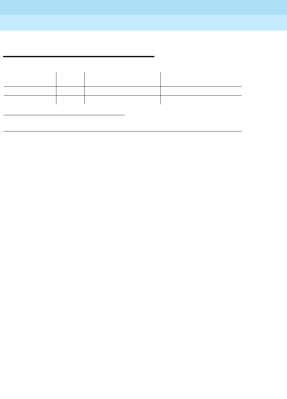
DEFINITY Enterprise Communications Server Release 6
Maintenance for R6r Volumes 1 & 2
555-230-126 Issue 2
January 1998
Maintenance Object Repair Procedures
Page 9-138AUX-BD (Auxiliary Trunk Circuit Pack)
9
AUX-BD (Auxiliary Trunk Circuit
Pack)
Refer to “XXX-BD (Common Port Circuit Pack)” maintenance information for
circuit pack level errors. See also AUX-TRK (Auxiliary Trunk) Maintenance
documentation for related trunk information.
1.
UU
is the universal cabinet number (1 for PPN, 2 - 44 for EPNs).
C
is the carrier designation (A,
B, C, D, or E).
SS
is the number of the slot in which the circuit pack resides (01 to 21).
MO Name (in
Alarm Log) Alarm
Level Initial Command to Run1Full Name of MO
AUX-BD MIN test board UUCSS sh Auxiliary Trunk Circuit Pack
AUX-BD WRN test board UUCSS sh Auxiliary Trunk Circuit Pack

DEFINITY Enterprise Communications Server Release 6
Maintenance for R6r Volumes 1 & 2
555-230-126 Issue 2
January 1998
Maintenance Object Repair Procedures
Page 9-139AUX-TRK (Auxiliary Trunk)
9
AUX-TRK (Auxiliary Trunk)
The TN763B/C/D and TN417 Auxiliary Trunk circuit packs are used to provide
ports for the following features: Music-On-Hold, loudspeaker paging (voice and
coded chimes), dictation, automated wake-up with AUDICHRON.
Recorder/Announcer, and recorded announcements. TN763C circuit packs
support Mu-law companding. TN417 circuit packs support A-law companding.
TN763D can support either companding mode and defaults to mu-law on
initialization. Companding modes are administered on the country-options
system-parameters screen. See
DEFINITY Enterprise Communications Server
Release 5.4 Administration and Feature Description
.
Music-On-Hold is administered via the Feature-Related System Parameters
Form. Loudspeaker paging can be administered via the change paging
loudspeaker or add trunk-group [Customer-Provided Equipment (CPE)]
commands. The change paging loudspeaker command is used for
system-provided paging; the add trunk group command is used for access to
otherwise-provided (CPE) paging. The translation for code chiming is
administered by the change paging code-calling-ids command. Recorded
announcement and dictation are administered by the add trunk-group (CPE)
command. Automatic wake-up is administered by the change
system-parameters hospitality command and uses all four ports on a TN763B
Auxiliary Trunk circuit pack.
Music-On-Hold provides audible feedback to a held, parked, or otherwise
split-away party indicating that the call is still connected. The feedback can be
customer-provided music, a recorded message, or other audible indication.
Since the Music-On-Hold port is always busy, some of its port tests always abort.
The Loudspeaker Paging feature provides voice and/or code calling chime
paging. If multiple paging zones are provided at a customer’s premises, the
Loudspeaker Paging feature gives a user the option of paging to a particular
1.
UU
is the universal cabinet number (1 for PPN, 2 - 44 for EPNs).
C
is the carrier
designation (A, B, C, D, or E).
SS
is the number of the slot in which the circuit pack
resides (01 to 21).
pp
is the two digit port number (01, 02, ...).
2. A Major alarm on a trunk indicates that alarms on these trunks are not downgraded by
the set options command and that at least 75 % of the trunks in this trunk group are
alarmed.
MO Name (in
Alarm Log) Alarm Level Initial Command to Run1Full Name of
MO
AUX-TRK MAJOR2test port UUCSSpp l Auxiliary Trunk
AUX-TRK MINOR test port UUCSSpp l Auxiliary Trunk
AUX-TRK WARNING test port UUCSSpp sh Auxiliary Trunk

DEFINITY Enterprise Communications Server Release 6
Maintenance for R6r Volumes 1 & 2
555-230-126 Issue 2
January 1998
Maintenance Object Repair Procedures
Page 9-140AUX-TRK (Auxiliary Trunk)
9
zone or to all zones. If a zone is being used for one type of page, it may not be
used at that time for the other one.
An Auxiliary Trunk circuit pack contains four ports and uses DTMF signaling. A
different hardware interface between the switch and the auxiliary equipment is
used for the four types of signaling that the auxiliary trunk circuit pack supports.
The interface used for the DEFINITY System loudspeaker paging consists of the
following three pairs:
■The Tip-Ring (T-R) pair used for voice transmission.
■The S (S-S1) pair that carries answer supervision and/or make busy
information.
■The SZ (SZ-SZ1) pair that provides the external equipment with a seizure
indication.
The interface used for recorded announcement, dictation, and other loudspeaker
paging consists of the following two pairs:
■The Tip-Ring (T-R) pair used for voice transmission.
■The S (S-S1) pair that carries answer supervision and/or make busy
information.
The interface used for Music-On-Hold consists of one pair:
■The Tip-Ring (T-R) pair used for voice transmission.
The interface, used for automatic wake-up using an Audichron
recorder/announcer unit, consists of the following two pairs:
■The Tip-Ring (T-R) pair used for voice transmission.
■The S (S-S1) pair that carries the synchronization signal.
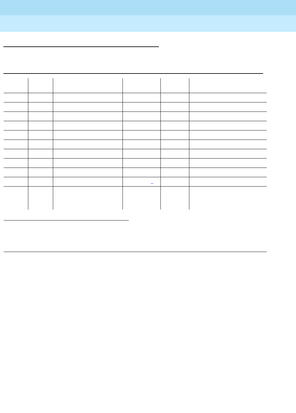
DEFINITY Enterprise Communications Server Release 6
Maintenance for R6r Volumes 1 & 2
555-230-126 Issue 2
January 1998
Maintenance Object Repair Procedures
Page 9-141AUX-TRK (Auxiliary Trunk)
9
Error Log Entries and Test to Clear Values
Notes:
a. Error Type 1 with Aux Data 57481 indicates a port fault. Use an empty port
if one is available until the circuit pack can be replaced.
b. Error Type 1 or 769 with Aux Data 57482 indicates a fault on signaling
lead, which is an off-board error. This error should only occur with
loudspeaker paging. If the trunk is being used for another application,
check that the administration is correct. Otherwise, check the wiring to the
external equipment connected to the Auxiliary Trunk and check the
external equipment.
c. This is a software audit error that does not indicate any hardware
malfunction. Run Short Test Sequence and investigate associated errors.
d. Indicates the circuit pack has been removed or has been insane for more
than 11-minutes. To clear the error, reseat or replace the circuit pack.
1. Run the Short Test Sequence first. If all tests pass, run the Long Test Sequence. Refer to the
appropriate test description and follow the recommended procedures.
2. Major or Minor alarms may be downgraded to Warning alarms based on the values used in the set
options command.
Table 9-52. Auxiliary Trunk Error Log Entries
Error
Type Aux
Data Associated Test Alarm
Level On/Off
Board Test to Clear Value
010 Any Any Any test port UUCSSpp sh r 1
1(a) 57481 None
1(b) 57782
15(c) Any Audit Update Test (#36)
18 0 busyout port UUCSSpp WARNING OFF release port UUCSSpp
130(d) None WARNING ON test trunk <grp>/<mbr> sh
769(b) 57482 None
257 Hybrid/Conference MIN/WRN2ON test port UUCSSpp l r 3
Circuit Test (#33)
513 NPE Crosstalk Test (#6) MIN/WRN2ON test port UUCSSpp l r 3
1025 Diagnostic Test—
Auxiliary Trunk Test
(#114)
WARNING ON test port UUCSSpp sh r 3
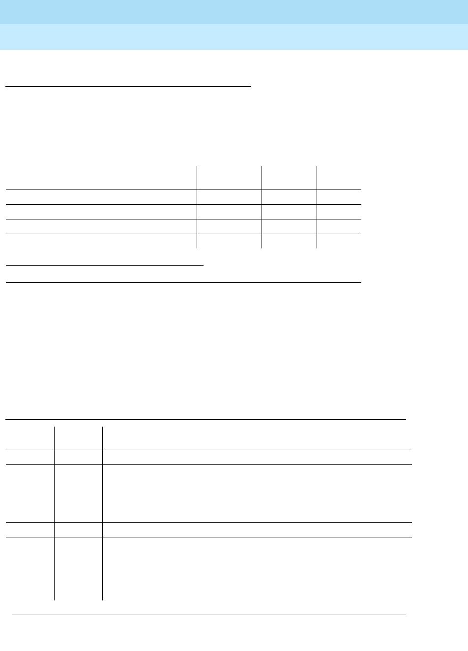
DEFINITY Enterprise Communications Server Release 6
Maintenance for R6r Volumes 1 & 2
555-230-126 Issue 2
January 1998
Maintenance Object Repair Procedures
Page 9-142AUX-TRK (Auxiliary Trunk)
9
System Technician-Demanded Tests:
Descriptions and Error Codes
Always investigate tests in the order presented in the table below when
inspecting errors in the system. By clearing error codes associated with the
Looparound and Conference Test,
for example, you may also clear errors
generated from other tests in the testing sequence.
NPE Crosstalk Test (#6)
The NPE Crosstalk Test verifies that this port’s NPE channel talks on the selected
time slot and never crosses over to time slots reserved for other connections. If
the NPE is not working correctly, one-way and noisy connections may be
observed. This test is part of a port’s Long Test Sequence and takes about 20 to
30 seconds to complete.
1. D = Destructive; ND = Nondestructive
Order of Investigation Short Test
Sequence Long Test
Sequence D/ND1
Looparound and Conference Test (#33) X ND
NPE Crosstalk Test (#6) X ND
Diagnostic Test (#114) X X ND
Audit Update Test (#36) X X ND
Table 9-53. TEST #6 NPE Crosstalk Test
Error
Code Test
Result Description/Recommendation
ABORT Could not allocate the necessary system resources to run this test. Try (a).
1000 ABORT System resources required to run test are not available. The port may be
busy with a valid call. Use the display port UUCSSpp command to
determine the trunk group/member number of the port. Use the status
trunk command to determine the service state of the port. If the port is in
use, wait until the port is idle, then try (a).
1001 ABORT Could not allocate the necessary system resources to run this test. Try (a).
1002 ABORT The system could not allocate time slots for the test. The system may be
under heavy traffic conditions or it may have time slots out-of-service due to
TDM-BUS errors. Refer to “TDM-BUS” to diagnose TDM-BUS errors.
1. If system has no TDM-BUS errors and is not handling heavy traffic, try
(a).
Continued on next page

DEFINITY Enterprise Communications Server Release 6
Maintenance for R6r Volumes 1 & 2
555-230-126 Issue 2
January 1998
Maintenance Object Repair Procedures
Page 9-143AUX-TRK (Auxiliary Trunk)
9
Notes:
a. Retry the command at 1-minute intervals a maximum of 5 times.
1003 ABORT The system could not allocate a tone receiver for the test. The system may
be oversized for the number of Tone Detectors present or some Tone
Detectors may be out-of-service.
1. Look for TTR-LEV errors in the Error Log. If present, refer to “TTR-LEV”.
2. Look for TONE-PT errors in the Error Log. If present, refer to “TONE-PT.
3. If neither condition exists, try (a).
1004 ABORT The port was seized by a valid call during the test. The test has been
aborted. Use the display port UUCSSpp command to determine the trunk
group/member number of the port. Use the status trunk command to
determine the service state of the port. If the port is in use, wait until the port
is idle. When idle, try (a).
2000 ABORT Response to the test request was not received within the allowable time
period. Try (a).
2020 ABORT The test did not run due to a previously existing error on the specific port or
a more general circuit pack error.
1. Examine Error Log for existing errors against this port or the circuit pack
and attempt to diagnose the previously existing error.
2100 ABORT Could not allocate the necessary system resources to run this test. Try (a).
Any FAIL The Network Processing Element (NPE) of the tested port was found to be
transmitting in error. This will cause noisy and unreliable connections. This
problem may be caused by defective tone detectors.
1. Test all tone-clock circuit packs, and resolve any errors on these circuit
packs before any action is taken on the auxiliary trunk circuit pack.
Then, repeat the test.
2. If the test fails again, replace the auxiliary trunk circuit pack.
PASS The port is correctly using its allocated time slots. User-reported troubles on
this port should be investigated using other port tests and examining
station, trunk, or external wiring.
Table 9-53. TEST #6 NPE Crosstalk Test — Continued
Error
Code Test
Result Description/Recommendation
Continued on next page

DEFINITY Enterprise Communications Server Release 6
Maintenance for R6r Volumes 1 & 2
555-230-126 Issue 2
January 1998
Maintenance Object Repair Procedures
Page 9-144AUX-TRK (Auxiliary Trunk)
9
Looparound and Conference Test (#33)
This test checks the reflective loop around and conference capabilities of an
auxiliary trunk port circuit. The test uses 404-Hz, 1004-Hz, and 2804-Hz tones.
Each tone is separately transmitted through the loop and checked. All of these
tests are performed on-board.
Table 9-54. TEST #33 Looparound and Conference Test
Error
Code Test
Result Description/Recommendation
ABORT Could not allocate the necessary system resources to run this test. Try (a).
1000 ABORT System resources required to run this test are not available. The port may
be busy with a valid call. Use the display port UUCSSpp command to
determine the trunk group/member number of the port. Use the status
trunk command to determine the service state of the port. If the port is in
use, wait until the port is idle and try (a).
1004 ABORT The port was seized by a valid call during the test. The test has been
aborted. Use the display port UUCSSpp command to determine the trunk
group/member number of the port. Use the status trunk command to
determine the service state of the port. If the port is in use, wait until the port
is idle and try (a).
2100 ABORT Could not allocate the necessary system resources to run this test. Try (a).
7 FAIL The conference capabilities of the port failed.
1. If no service problems exist on the port, continue to use the port until
the circuit pack can be replaced.
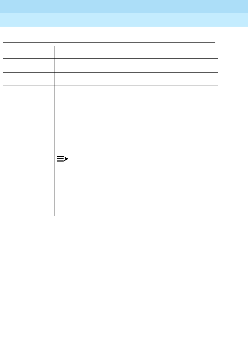
DEFINITY Enterprise Communications Server Release 6
Maintenance for R6r Volumes 1 & 2
555-230-126 Issue 2
January 1998
Maintenance Object Repair Procedures
Page 9-145AUX-TRK (Auxiliary Trunk)
9
Åudit Update Test (#36)
This test will send updates of the auxiliary trunk port translation for all ports on the
Auxiliary Trunk circuit pack that have been translated. The update is
non-disruptive and guards against possible corruption of translation data
contained on the circuit pack. No response message is expected from the circuit
pack once it receives translation updates. The port translation data includes:
■Trunk type
■DTMF time slot
■Termination R/RC
■Gain, high/low
■End-to-end signaling, tone, and pause duration
129 FAIL The reflective 404-Hz tone test failed, no transmission was detected to or
from the port. The problem may be off-board.
131 FAIL The reflective 1004-Hz tone test failed. No transmission was detected to or
from the port. The problem may be off-board.
133 FAIL The reflective 2804-Hz tone test failed. No transmission was detected to or
from the port. The problem may be off-board.
1. To make sure the problem is on-board, disconnect the port from the
auxiliary equipment and retry test.
2. If the test fails, replace the circuit pack. Otherwise, if the test passed
after disconnecting the port from the auxiliary equipment, the problem
is off-board. Check the wiring and connections to the auxiliary
equipment and retry the test after reconnecting the port to the auxiliary
equipment. If the test fails, check the auxiliary equipment. See the
preceding procedure for a failure with Error Code 7.
NOTE:
If the Looparound and Conference Test fails for all ports on a circuit
pack, a -5 volt power problem is indicated. If a TN736 or TN752
power unit circuit pack is present, the 631DB AC power unit or the
676B power unit may be defective. The system may contain either a
TN736 or a TN752 power unit circuit pack OR a 631DB power unit,
but not both types of power units.
To investigate power problems,
refer to “CARR-POW”.
PASS Looparound and Conference Test is successful. This port is functioning
properly.
Table 9-54. TEST #33 Looparound and Conference Test — Continued
Error
Code Test
Result Description/Recommendation

DEFINITY Enterprise Communications Server Release 6
Maintenance for R6r Volumes 1 & 2
555-230-126 Issue 2
January 1998
Maintenance Object Repair Procedures
Page 9-146AUX-TRK (Auxiliary Trunk)
9
■Trunk state, idle/active/unavailable
■Companding mode (A-law or mu-law) [G3r V2
Notes:
a. Retry the command at 1-minute intervals a maximum of 5 times.
Diagnostic Test—Auxiliary Trunk Test (#114)
The system software sends a message to the on-board microprocessor to
operate a relay in the port circuit. If ground is detected, the test passes.
Table 9-55. TEST #36 Audit Update Test
Error
Code Test
Result Description/Recommendation
ABORT Could not allocate the necessary system resources to run this test. Try (a).
1006 ABORT Port is in out-of-service state as a result of being busied out. This audit
cannot be run.
1. Retry the command once the port is in service (Release port UUCSSpp
command has been run).
2100 ABORT Could not allocate the necessary system resources to run this test.
FAIL Internal system error. Try (a).
PASS This test passed. Translation information was successfully updated on the
circuit pack.
Continued on next page

DEFINITY Enterprise Communications Server Release 6
Maintenance for R6r Volumes 1 & 2
555-230-126 Issue 2
January 1998
Maintenance Object Repair Procedures
Page 9-147AUX-TRK (Auxiliary Trunk)
9
Notes:
a. Retry the command at 1-minute intervals a maximum of 5 times.
Table 9-56. TEST #114 Diagnostic Test—Auxiliary Trunk Test
Error
Code Test
Result Description/Recommendation
ABORT Could not allocate the necessary system resources to run this test. Try (a).
1000 ABORT System resources required to run this test are not available. The port may be
busy with a valid call. Use the display port UUCSSpp command to
determine the trunk group/member number of the port. Use the status trunk
command to determine the service state of the port. If the port is in use, wait
until the port is idle and try (a).
1004 ABORT The port was seized by a valid call during the test. The test has been
aborted. Use the display port UUCSSpp command to determine the trunk
group/member number of the port. Use the status trunk command to
determine the service state of the port. If the port is in use, wait until the port
is idle and try (a).
2100 ABORT Could not allocate the necessary system resources to run this test. Try (a).
FAIL This test failed to detect ground.
1. Try the test once more.
2. If the test fails again, replace the circuit pack.
PASS This test passed. Ground was detected.
Continued on next page

DEFINITY Enterprise Communications Server Release 6
Maintenance for R6r Volumes 1 & 2
555-230-126 Issue 2
January 1998
Maintenance Object Repair Procedures
Page 9-148BRI-BD/LGATE-BD (ISDN-BRI Line Circuit Pack)
9
BRI-BD/LGATE-BD (ISDN-BRI Line
Circuit Pack)
!CAUTION:
A detailed flowchart for isolating and resolving Packet Bus faults is included
in Chapter 9, ‘‘Maintenance Object Repair Procedures’’, ‘‘Packet Bus Fault
Isolation and Correction.’’ This flowchart, along with the other information
presented in the chapter, can help in resolving problems that involve more
than a single station or circuit pack. Whenever the repair procedures for
this Maintenance Object refer to Packet Bus and/or Packet Control
maintenance, be sure to reference Chapter 9, ‘‘Maintenance Object Repair
Procedures’’, ‘‘Packet Bus Fault Isolation and Correction’’ in addition to the
relevant MO documentation.
This section relates to the TN556 ISDN BRI, TN2198 ISDN BRIU, TN2208
Ethernet, (LGATE)-Ethernet Multi-Function (MFB) boards.
The TN2208 LGATE MFB provides DEFINITY with the interface to Adjunct-Switch
Application Interface (ASAI) and Lucent adjuncts (for example, CONVERSANT®
Voice System). This circuit pack contains 12 ports for line circuit interface
(although only 8 are usable by the switch), each of which operates with 2
B-Channels and 1 D-Channel as specified in the Lucent ISDN-BRI Specification.
In this context, the term “ISDN-BRI port” is used to refer to ports on the TN2208
MFB circuit pack which are connected to ASAI or Lucent adjuncts. The TN2208
1. UU is the universal cabinet number (1 for PPN, 2 -44 for EPNs). C is the carrier
designation (A, B, C, D, or E). SS is the number of the slot in which the circuit pack
resides (01 to 21). pp is the two digit port number (01, 02, ...).
MO Name in
Alarm Log Alarm Level
Initial
Command to
Run1Full Name of
MO
BRI-BD MAJOR test board
UUCSS l ISDN-BRI Line
Circuit Pack
BRI-BD MINOR test board
UUCSS l ISDN-BRI Line
Circuit Pack
BRI-BD WARNING test board
UUCSS sh ISDN-BRI Line
Circuit Pack
LGATE-BD MAJOR test board
UUCSS l DEFINITY Lan
Gateway
LGATE-BD MINOR test board
UUCSS l DEFINITY Lan
Gateway
LGATE-BD WARNING -
(See Caution) test board
UUCSS sh DEFINITY Lan
Gateway

DEFINITY Enterprise Communications Server Release 6
Maintenance for R6r Volumes 1 & 2
555-230-126 Issue 2
January 1998
Maintenance Object Repair Procedures
Page 9-149BRI-BD/LGATE-BD (ISDN-BRI Line Circuit Pack)
9
LGATE MFB is handled by the switch software as if it is an ISDN BRI compatible
board and all maintenance actions referring to ASAI and Lucent adjunct Links in
this section apply.
The TN556, TN2198, and TN2208 ISDN-BRI Lines are packet port circuit packs
that provides access to ISDN-BRI endpoints. The ISDN-BRI Line circuit packs
supports 12 ports, each of which provides access to ISDN stations. Voice and
circuit-switched data from the ISDN stations are carried on the Time Division
Multiplex (TDM) Bus. Signaling is carried over the Packet Bus.
LEDS
The ISDN-BRI Line circuit pack performs extensive initialization tests and lights
both the red and green LEDS during the initialization testing. See Chapter 7,
‘‘LED Indicators’’, for more details on circuit pack status LEDs.
Hardware Error Log Entries and Test to Clear
Values
Table 9-57. BRI-BD Error Log Entries
Error
Type Aux
Data Associated Test Alarm
Level On/Off
Board Test to Clear Value
010 Any Any Any test board UUCSS sh r 1
1(a) Any None MINOR ON
18(b) 0 busyout board
UUCSS WARNING OFF release board UUCSS
23(c) 0 None WARNING OFF
257(d) 65535 Control Channel
Loop Test (#52) MINOR ON test board UUCSS r 20
513(e) 4352 to
4357
769(f) 4358
1025(g) 4363 NPE Audit Test
(#50)
1293 to
1294 (h) 46088 to
46096 SAKI Sanity Test
(#534) MINOR ON See footnote (h)
1537
to
1538 (i)
46082 MINOR ON
Continued on next page
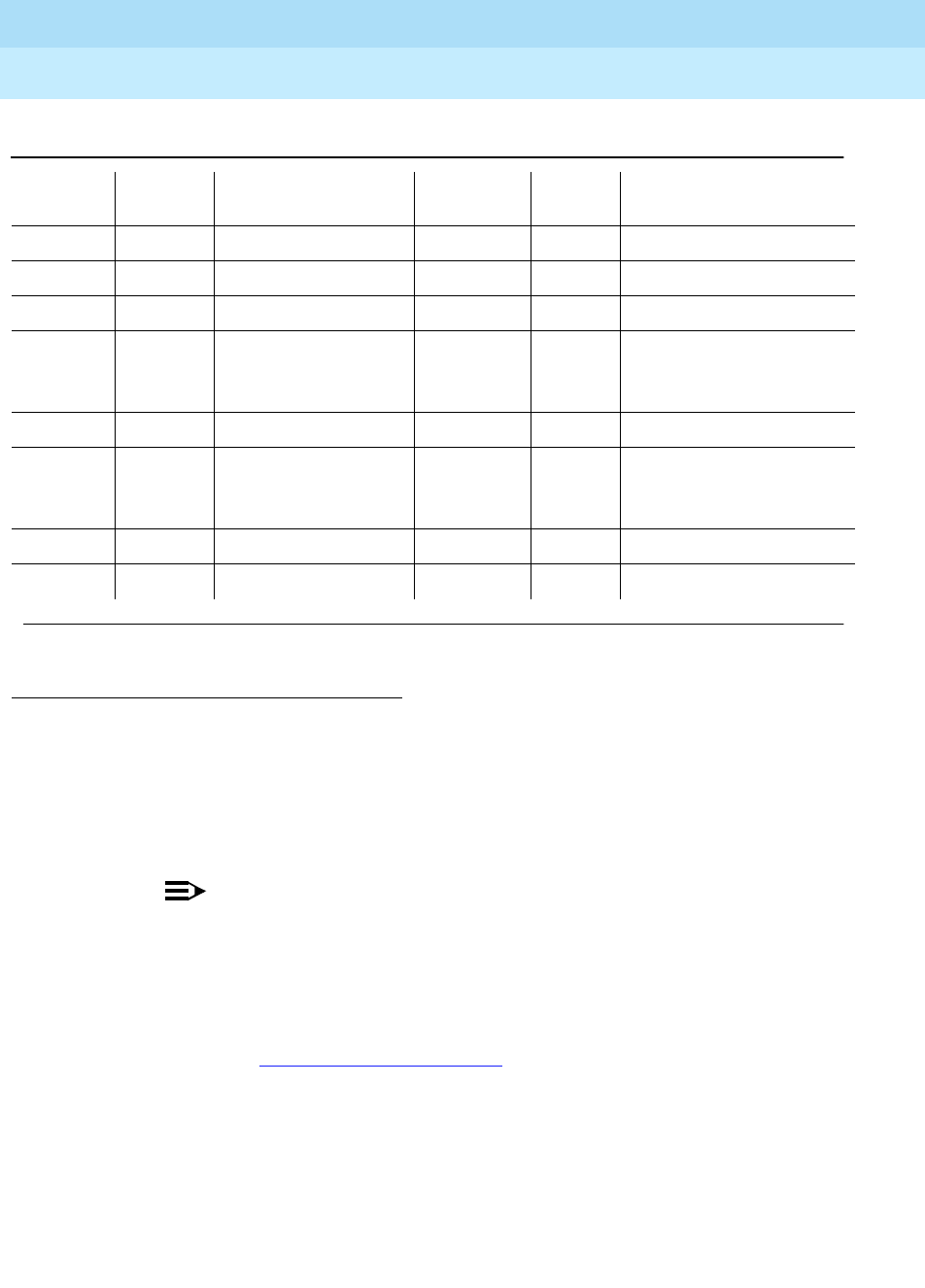
DEFINITY Enterprise Communications Server Release 6
Maintenance for R6r Volumes 1 & 2
555-230-126 Issue 2
January 1998
Maintenance Object Repair Procedures
Page 9-150BRI-BD/LGATE-BD (ISDN-BRI Line Circuit Pack)
9
Notes:
a. This error indicates the circuit pack totally stopped functioning or it was
physically removed from the system.
NOTE:
The alarm is logged approximately 11 minutes after the circuit pack
has been removed and/or SAKI Sanity Test (#53) fails.
If the circuit pack is not in the system, insert a circuit pack (in the same
slot as the error indicates) to resolve this error. Or, if the circuit pack is in
the system and the red LED is on, then follow the instructions for ‘‘Red
(alarm)’’ in Chapter 7, ‘‘LED Indicators’’.
b. This circuit pack has been busied out via the busyout board UUCSS
command.
c. Port(s) has(have) been administered on this circuit pack but the circuit
pack is not physically present.
d. This error indicates transient communication problems between the switch
and this circuit pack. Execute the test board UUCSS command and refer
to the repair procedures for the Control Channel Loop Around Test (#52).
1. Run the Short Test Sequence first. If all tests pass, run the Long Test Sequence. Refer to the
appropriate test description and follow the recommended procedures.
1793 (j) 46080 MINOR ON
1794 (j) 46094 MINOR ON
1795 (j) 46085 MINOR ON
2306 (j) LANBIC Receive
Parity Error Counter
Test (#595)
3330 (k) 46083 MINOR OFF
3840 (l) 4096
to
4101
3843 (m) 46097
3999 (n) Any None
Table 9-57. BRI-BD Error Log Entries — Continued
Error
Type Aux
Data Associated Test Alarm
Level On/Off
Board Test to Clear Value
Continued on next page

DEFINITY Enterprise Communications Server Release 6
Maintenance for R6r Volumes 1 & 2
555-230-126 Issue 2
January 1998
Maintenance Object Repair Procedures
Page 9-151BRI-BD/LGATE-BD (ISDN-BRI Line Circuit Pack)
9
e. An on-board hardware failure has been detected by the circuit pack.
The reported aux data values correspond to the following detected errors:
Reset the circuit pack by executing the busyout board UUCSS and reset
board UUCSS commands. When it is reset, the circuit pack executes a
set of tests to detect the presence of any of the above faults. The
detection of one of these errors during initialization causes the circuit pack
to lock-up and appear insane to the system. See the repair procedure in
footnote (a) for error type 1.
f. This error is reported by the circuit pack when it detects a program logic
error. While no action is required, this error may lead to errors of other
types being reported against this circuit pack.
g. This error is reported by the circuit pack when it cannot update NPE
memory and read it back. This error type can be ignored, but may lead to
errors of other types being reported against this circuit pack.
h. A critical hardware failure has been detected on the circuit pack. Reset
the circuit pack via the busyout board UUCSS and reset board UUCSS
commands. If the Circuit Pack Restart Test (#594) passes, then the
on-board circuitry is healthy. Retire the alarm via the test board UUCSS
long clear command. If the Circuit Pack Restart Test (#594) fails, replace
the circuit pack.
The reported error types correspond to the following detected errors:
4352 External RAM error
4353 Internal RAM error
4355 ROM Checksum error
4357 Instruction set error
1293 On-board auxiliary
processor insane
1294 Internal memory
access error

DEFINITY Enterprise Communications Server Release 6
Maintenance for R6r Volumes 1 & 2
555-230-126 Issue 2
January 1998
Maintenance Object Repair Procedures
Page 9-152BRI-BD/LGATE-BD (ISDN-BRI Line Circuit Pack)
9
i. These error types are reported when the following errors are detected:
j. These errors indicate that the circuit pack is having problems transmitting
data to the Packet Bus.
k. A critical failure has been detected in the Packet Bus interface of the
circuit pack. This failure may be due to either a Packet Bus fault or an
on-board fault. If the Packet Bus is alarmed, refer to the ‘‘PKT-BUS (Packet
Bus)’’ section and the Packet Bus Fault Isolation and Recovery section of
1537 Frame overrun at Packet Bus interface. This condition may
be caused by an on-board fault or by faulty data received
on one of the circuit pack’s external ports. If any of the ports
on this circuit pack are alarmed, refer to the repair
procedures for those maintenance objects.
1538 Circuit packet is hyperactive; that is, it is flooding the switch
with messages sent over the control channel. The circuit
pack is taken out-of-service when a threshold number of
these errors is reported to the switch. Clear the alarm via the
following commands: busyout board UUCSS, reset board
UUCSS, test board UUCSS long clear, release board
UUCSS. If the error recurs within 10 minutes, then replace
the circuit pack.
1793 Parity errors are detected when transmitting data to the
Packet Bus.
1794 Overflow of Packet Bus transmit buffers has occurred.
1795 Circuit pack cannot find end of frame when transmitting to
Packet Bus. Clear the alarm via the following commands:
busyout board UUCSS, reset board UUCSS, test board
UUCSS long clear, release board UUCSS. If the error
recurs within 10 minutes, then replace the circuit pack.
2306 This error occurs when the circuit pack detects an error in a
received frame from the packet bus. These errors are most
likely caused by a packet bus problem, but may be due to a
circuit pack fault.An invalid Link Access Procedure Data
(LAPD) frame error occurs if the frame contains a bad
Cyclical Redundancy Checking (CRC), is greater than the
maximum length, or violates the link level protocol.When bus
parity errors are reported, the LANBIC Receive Parity Error
Counter Test (#595) should be performed to determine if the
condition had cleared. Refer to the ‘‘PKT-BUS (Packet Bus)’’
Maintenance documentation to determine if the problem is
isolated to this circuit pack or if the problem is caused by
Packet Bus faults.

DEFINITY Enterprise Communications Server Release 6
Maintenance for R6r Volumes 1 & 2
555-230-126 Issue 2
January 1998
Maintenance Object Repair Procedures
Page 9-153BRI-BD/LGATE-BD (ISDN-BRI Line Circuit Pack)
9
the Maintenance documentation for recommended repair procedures.
The probability of this error being related to Packet bus problems
increases with the number of ISDN-BRI circuit packs displaying this error.
If the Packet Bus is not alarmed, reset the circuit pack via the busyout
board UUCSS and reset board UUCSS commands. If the Circuit Pack
Restart Test (#594) passes, then the on-board circuitry is healthy. Retire
the alarm via the test board UUCSS long clear command. If the Circuit
Pack Restart Test (#594) fails, replace the circuit pack. If the problem
persists after complying with the above instructions, then follow normal
escalation procedures.
l. These errors are not service-affecting. No action is required. These errors
are reported by the circuit pack when it receives a bad control channel
message from the switch. The auxiliary data identifies the following error
events:
m. This error is not service-affecting. No action is required.
n. This error indicates that the circuit pack sent a large number of control
channel messages to the switch in a short period of time.
4096 Bad major heading
4097 Bad port number
4098 Bad data
4099 Bad sub-qualifier
4100 State inconsistency
4101 Inconsistent downlink message
3843 Bad translation RAM detected, but call continues by using
another translation location.
3999 If error type 1538 is also present, then the circuit pack was
taken out-of-service due to hyperactivity.
If error type 1538 was not present, then the circuit pack has
not been taken out-of-service, but has generated 50% of the
messages necessary to be considered hyperactive. This
may be normal during heavy traffic periods. If traffic is light it
may indicate a problem with the circuit pack or the
equipment attached to it.

DEFINITY Enterprise Communications Server Release 6
Maintenance for R6r Volumes 1 & 2
555-230-126 Issue 2
January 1998
Maintenance Object Repair Procedures
Page 9-154BRI-BD/LGATE-BD (ISDN-BRI Line Circuit Pack)
9
System Technician-Demanded Tests:
Descriptions and Error Codes
Always investigate tests in the order presented in the following tables when
inspecting errors in the system. By clearing error codes associated with the
Control Channel Loop Around Test,
for example, you may also clear errors
generated from other tests in the testing sequence.
NPE Audit Test (#50)
Refer to the repair procedure described in the XXX-BD (Common Port Circuit
Pack) Maintenance documentation as NPE Audit Test (#50).
Control Channel Loop Around Test (#52)
Refer to the repair procedure described in the XXX-BD (Common Port Circuit
Pack) Maintenance documentation as Control Channel Loop Around Test (#52).
SAKI Sanity Test (#53)
Refer to the repair procedure described in the XXX-BD (Common Port Circuit
Pack) Maintenance documentation as SAKI Sanity Test (#53).
LANBIC Receive Parity Error Counter Test (#595)
This test is destructive.
The test reads and clears the LANBIC Receive Parity Error Counter on the circuit
pack. This counter is incremented by the circuit pack when it detects a parity
error in data received from the Packet Bus.
These errors may be indicative of a circuit pack problem, Packet Bus problem, or
a problem with another circuit pack on the bus. This test is useful for verifying the
repair of the problem.
1. D = Destructive; ND = Nondestructive
Order of Investigation
Short
Test
Sequence
Long
Test
Sequence D/ND1
Control Channel Loop-Around Test (#52) X X ND
NPE Audit Test (#50) X ND
LANBIC Receive Parity Error Counter Test (#595) X ND

DEFINITY Enterprise Communications Server Release 6
Maintenance for R6r Volumes 1 & 2
555-230-126 Issue 2
January 1998
Maintenance Object Repair Procedures
Page 9-155BRI-BD/LGATE-BD (ISDN-BRI Line Circuit Pack)
9
Table 9-58. TEST #595 LANBIC Receive Parity Error
Counter Test
Error
Code Test
Result Description/ Recommendation
2000 ABORT Response to the test was not received from the circuit
pack within the allowable time period.
1. If the test aborts repeatedly a maximum of five times,
reset the circuit pack via the busyout board UUCSS
and reset board UUCSS commands.
2. If the test aborts again, replace the circuit pack.
2100 ABORT Could not allocate the necessary system resources to
run this test.
2012 ABORT Internal System Error.
1. Retry the command at one-minute intervals a
maximum of five times.
2. If the test continues to fail, escalate the problem.
Continued on next page

DEFINITY Enterprise Communications Server Release 6
Maintenance for R6r Volumes 1 & 2
555-230-126 Issue 2
January 1998
Maintenance Object Repair Procedures
Page 9-156BRI-BD/LGATE-BD (ISDN-BRI Line Circuit Pack)
9
1-10 FAIL The circuit pack is still detecting errors of this type. The
error code indicates the value of the on-board error
counter.
1. Retry the command at one-minute intervals a
maximum of five times.
2. If the test continues to fail, verify the validity of the
Packet Bus. Run the Packet Bus maintenance test
with the test pkt P long command. If any Packet
Bus tests fail, refer to the ‘‘PKT-BUS (Packet Bus)’’
Maintenance documentation for recommended
repair procedures.
3. If the Packet Bus test passes, check the validity of
the circuit pack. Execute a test that involves data
transmission onto the Packet Bus. For example, the
BRI may use the connectivity tests of the port-level
maintenance object (BRI-PORT) by executing the
test port UUCSSpp command. Refer to the repair
procedures for the executed test if it fails. Otherwise,
proceed to the next step.
4. Other circuit packs on the Packet Bus may be the
cause of the parity error. Use the display errors
command to check the Error Log for other circuit
packs that are alarmed. If any alarms are present for
the other circuit packs, retire those alarms also.
Then, rerun the LANBIC Receive Parity Error
Counter Test (#595) on this circuit pack.
PASS No errors detected by circuit pack.
Table 9-58. TEST #595 LANBIC Receive Parity Error
Counter Test — Continued
Error
Code Test
Result Description/ Recommendation
Continued on next page

DEFINITY Enterprise Communications Server Release 6
Maintenance for R6r Volumes 1 & 2
555-230-126 Issue 2
January 1998
Maintenance Object Repair Procedures
Page 9-157BRI-DAT (ISDN-BRI Data Module)
9
BRI-DAT (ISDN-BRI Data Module)
Refer to the BRI-SET (ISDN-BRI Set) section of this chapter.
1. The alarm level for ASAI or Lucent adjuncts may be administered using the set options command.
The alarm level can be set independently for Off-Board and On-Board alarms to WARNING, MINOR,
or MAJOR for all ASAI adjuncts in the system.
MO Name (in
Alarm Log) Alarm Level Initial Command
to Run Full Name of MO
BRI-DAT WARNING1test data-module ISDN-BRI Stand-alone Data Module
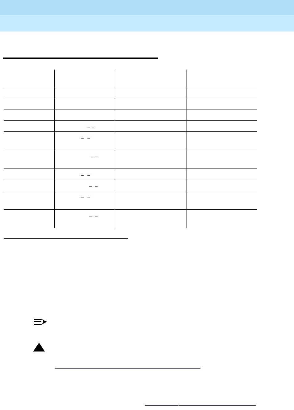
DEFINITY Enterprise Communications Server Release 6
Maintenance for R6r Volumes 1 & 2
555-230-126 Issue 2
January 1998
Maintenance Object Repair Procedures
Page 9-158BRI-PORT (ISDN-BRI Port), ABRI-PORT (ASAI ISDN-BRI Port)]
9
BRI-PORT (ISDN-BRI Port),
ABRI-PORT (ASAI ISDN-BRI Port)]
NOTE:
Some of the information in this section is reserved for future use.
!CAUTION:
A detailed flowchart for isolating and resolving Packet Bus faults is included
in Chapter 9, ‘‘Maintenance Object Repair Procedures’’, ‘‘Packet Bus Fault
Isolation and Correction.’’ This flowchart, along with the other information
presented in the chapter, can help in resolving problems that involve more
than a single station or circuit pack. Whenever the repair procedures for
this Maintenance Object refer to Packet Bus and/or Packet Control
maintenance, be sure to reference Chapter 9, ‘‘Maintenance Object Repair
1. UU is the universal cabinet number (1 for PPN, 2 -44 for EPNs). C is the carrier designation (A, B,
C, D, or E). SS is the number of the slot in which the circuit pack resides (01 to 21). pp is the two
digit port number (01, 02, ...).
2. The alarm level for ASAI and Lucent adjunct ports may be administered using the set options
command. The alarm level can be set independently for Off-Board and On-Board alarms to
WARNING, MINOR, or MAJOR for all ASAI and Lucent adjunct ports in the system.
3. All alarming for an ASAI and Lucent adjunct and OFF-BOARD alarming for an ASAI or Lucent port
is disabled if the ASAI or Lucent adjunct asks the switch to suspend maintenance. When this
occurs, an error and a WARNING alarm is logged against the ASAI or Lucent adjunct. The
Hardware Error and Alarm Logs should be checked to see if the adjunct has disabled alarming.
MO Name (in
Alarm Log) Alarm Level InitialCommand to
Run1Full Name of MO
BRI-PORT MINOR test port PCSSpp l ISDN-BRI Port
BRI-PORT WARNING test port PCSSpp sh ISDN-BRI Port
ABRI-PORT MAJOR2,3test port PCSSpp l ASAI ISDN-BRI Port
ABRI-PORT WARNING2,3test port PCSSpp l ASAI ISDN-BRI Port
ATT-PORT MAJOR 2, 3test port PCSSpp l Lucent Adjunct
ISDN-BRI Port
ATT-PORT WARNING 2, 3test port PCSSpp l Lucent Adjunct
ISDN-BRI Port
LGATE-PT MAJOR 2, 3test port PCSSpp l Ethernet ASAI Port
LGATE-PT WARNING 2, 3test port PCSSpp l Ethernet ASAI Port
ATTE-PT MAJOR 2, 3test port PCSSpp l Ethernet Lucent
Adjunct Port
ATTE-PT WARNING 2, 3test port PCSSpp l Ethernet Lucent
Adjunct Port

DEFINITY Enterprise Communications Server Release 6
Maintenance for R6r Volumes 1 & 2
555-230-126 Issue 2
January 1998
Maintenance Object Repair Procedures
Page 9-159BRI-PORT (ISDN-BRI Port), ABRI-PORT (ASAI ISDN-BRI Port)]
9
Procedures’’, ‘‘Packet Bus Fault Isolation and Correction’’ in addition to the
relevant MO documentation.
!WARNING:
If a significant Packet Bus failure occurs, errors and alarms may not be
logged as expected for
BRI-PORT/ABRI-POR/ATT-PORT/LGATE-PT/ATTE-PT. Conditions under
which this occurs are detailed in the ‘‘Maintenance of the Packet Bus’’
section of Chapter 9, ‘‘Maintenance Object Repair Procedures’’, ‘‘Packet
Bus Fault Isolation and Correction.’’
The TN2208 LGATE MFB provides DEFINITY with the interface to Adjunct-Switch
Application Interface (ASAI) and Lucent adjuncts (for example, CONVERSANT®.
Voice System). The circuit pack contains 12 ports of line circuit interface
(although only 8 are usable by the switch), each of which operates with two
B-channels (referred to as B1 and B2 throughout this section) and one D-channel
as specified in the Lucent ISDN-BRI Specification. In this context, the term
‘‘ISDN-BRI port’’ is used to refer collectively to ports on the TN2208 circuit pack
which are connected to ASAI or Lucent adjuncts.
The TN556 and TN2198 ISDN-BRI Line circuit packs provide DEFINITY with the
interface to ISDN-BRI end points, Adjunct-Switch Application Interface (ASAI)
and Lucent adjuncts (for example, CONVERSANT®. Voice System). The circuit
packs contain 12 ports of line circuit interface, each of which operates with two
B-channels (referred to as B1 and B2 throughout this section) and one D-channel
as specified in the Lucent ISDN-BRI Specification. In this context, the term
‘‘ISDN-BRI port’’ is used to refer collectively to ports on the TN556 an TN2198
circuit packs which are connected to either BRI endpoints, ASAI or Lucent
adjuncts.
For BRI endpoints, each B-channel may support voice or circuit-switched data
and may be circuit-switched simultaneously. The B-channels are not used on
ports connected to ASAI or Lucent adjuncts. The D-channel is used for
conveying signaling between the switch and a BRI endpoint(s), ASAI or Lucent
adjunct. Each ISDN-BRI D-channel is connected to the switch processor and the
ISDN-BRI port through the Packet Control circuit pack and the Packet Bus.
ISDN-BRI endpoints are available in various configurations. All endpoints require
the D-channel to convey signaling information to the switch. Only one B-channel
is required for a voice-only set or a stand-alone data module (BRI-DAT). A voice
and data-capable set requires both B-channels (one for voice and one for data).
Therefore, each TN556 or TN2198 port can support either two voice-only sets,
two stand-alone data modules (BRI-DAT), or one voice and data-capable set.
Only a single ASAI or Lucent adjunct may be connected to an ISDN-BRI port.
Multiple adjuncts per line are not supported.
Figure 9-3 illustrates the physical connection (solid line) between an ISDN-BRI
Port and its associated ISDN-BRI set(s). Each physical connection allows for two

DEFINITY Enterprise Communications Server Release 6
Maintenance for R6r Volumes 1 & 2
555-230-126 Issue 2
January 1998
Maintenance Object Repair Procedures
Page 9-160BRI-PORT (ISDN-BRI Port), ABRI-PORT (ASAI ISDN-BRI Port)]
9
B-channels and one D-channel. Each ISDN-BRI circuit pack can support up to
12 of these
physical
connections to different voice and voice/data sets or ASAI or
Lucent adjuncts. On a TN2198 each ISDN-BRI circuit pack can support up to 12
physical
connections to a NT1 which in turn connects to 2 terminals.
This section covers the maintenance documentation for ISDN-BRI ports. Some of
the results of maintenance testing of ISDN-BRI ports may be affected by the
health of the ISDN-BRI Line circuit pack (BRI-BD), BRI endpoint (BRI-SET), or
ASAI adjunct (ASAI-ADJ/LGATE-AJ/LGATE-AJ) or Lucent adjunct
(ATT-ADJ/ATTE-AJ). These interactions should be kept in mind when
investigating the cause of ISDN-BRI port problems. For more information on the
circuit pack and endpoints, refer to the BRI-BD (ISDN-BRI Line Circuit Pack)
Maintenance documentation, the BRI-SET (ISDN-BRI Endpoint) Maintenance
documentation, and ASAI-ADJ (Adjunct-Switch Application Interface)
Maintenance documentation, ATT-ADJ (Lucent Adjunct) Maintenance
documentation, LGATE-AJ (Ethernet Adjunct-Switch Application Interface)
Maintenance documentation, ATTE-AJ (Ethernet Lucent Adjunct) Maintenance
documentation.
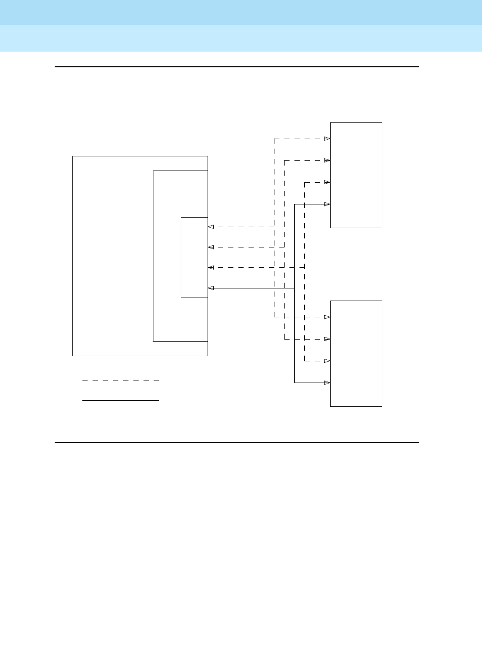
DEFINITY Enterprise Communications Server Release 6
Maintenance for R6r Volumes 1 & 2
555-230-126 Issue 2
January 1998
Maintenance Object Repair Procedures
Page 9-161BRI-PORT (ISDN-BRI Port), ABRI-PORT (ASAI ISDN-BRI Port)]
9
Figure 9-3. ISDN-BRI Port Interactions
VOICE
TERMINAL
DEFINITY
COMMUNICATIONS
SYSTEM
CIRCUIT
PACK
P
O
R
T
VOICE
TERMINAL
BRI LINE OR DATA
OR DATA
D-CHANNEL
B-CHANNEL
B-CHANNEL
LOGICAL CONNECTION
PHYSICAL CONNECTION

DEFINITY Enterprise Communications Server Release 6
Maintenance for R6r Volumes 1 & 2
555-230-126 Issue 2
January 1998
Maintenance Object Repair Procedures
Page 9-162BRI-PORT (ISDN-BRI Port), ABRI-PORT (ASAI ISDN-BRI Port)]
9
Hardware Error Log Entries and Test to Clear
Values
Table 9-59. ISDN-BRI Port Error Log Entries
Error
Type Aux
Data Associated Test
Alarm
Level
BRI-PORT
Alarm
Level
ABRI-POR
T
ATT-PORT
LGATE-PT
ATTE-PT On/Off
Board Test to Clear
Value
010 Any Any Any Any test port
PCSSpp sh r 1
1(a) (a) Level 1 Status
Inquiry (#621) WRN MAJ/MIN/W
RN2OFF test port
PCSSpp sh r 2
18 busyout port
PCSSpp WRN OFF release port
PCSSpp
130(b) WRN ON test port PCSS
sh
257(c) (c) EPF Inquiry (#622) WRN MAJ/MIN/
WRN2OFF test port
PCSSpp sh r 1
513(d) (d)
46222 none (d) (d) ON
769(e) 0 none WRN MAJ OFF
1281(f) NPE Crosstalk
(#617) MIN/WRN2ON test port
PCSSpp l r 2
1537(g) 46210 CRC Error Counter
(#623) WRN MAJ/MIN/
WRN2OFF
1793(h) BRI Port Local
TDM Loop
Around (#619)
MIN/WRN2ON test port
PCSSpp l r 2
3841(i) 46208 None
3842(j) 0 None
3843(k) 0 None
3844(l) 46223 None
Continued on next page
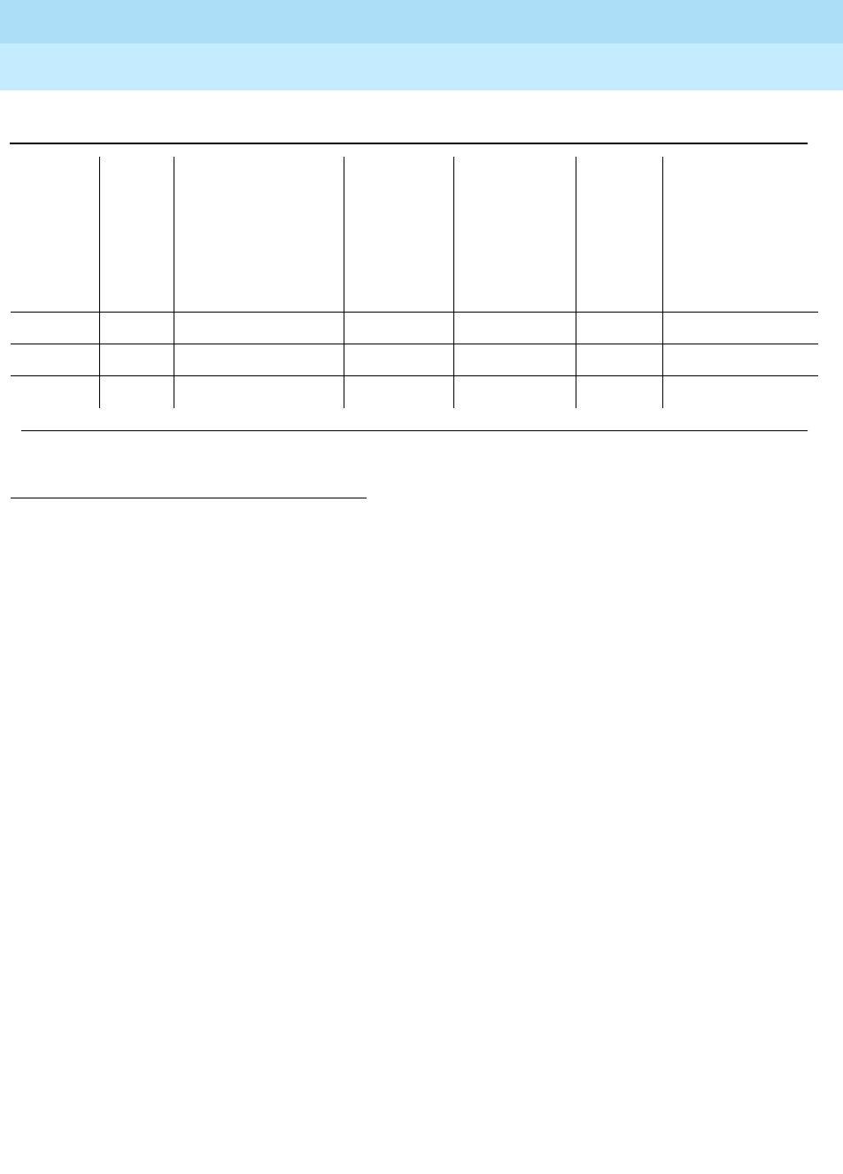
DEFINITY Enterprise Communications Server Release 6
Maintenance for R6r Volumes 1 & 2
555-230-126 Issue 2
January 1998
Maintenance Object Repair Procedures
Page 9-163BRI-PORT (ISDN-BRI Port), ABRI-PORT (ASAI ISDN-BRI Port)]
9
Notes:
a. This error occurs when the Level 1 Status Inquiry fails or when the BRI
circuit pack detects that Level 1 has been deactivated on the port. The
aux data field contains one of the following values:
■blank - this indicates that the Level 1 Status Inquiry failed.
■32773 - this is a message from the BRI-LINE circuit pack indicating
Level 1 has been deactivated.
Refer to the repair procedures for Test #621.
b. This error type indicates that the circuit pack has been removed or has
been insane for more than 11 minutes. To clear the error, replace or
reinsert the circuit pack.
c. This error occurs when the EPF Status Inquiry fails due to an overcurrent
condition or when the BRI-LINE circuit pack detects that the EPF is in an
over current condition. The aux data field contains one of the following
values:
■blank - this indicates that the EPF Status Inquiry failed due to an
overcurrent condition.
■40988 - this indicates that the BRI-LINE circuit pack has detected
an overcurrent condition and has turned the EPF off.
Execute the Short Test Sequence and see the repair procedures for Test
#622.
1. Run the Short Test Sequence first. If all tests pass, run the Long Test Sequence. Refer to the appropriate test
description and follow the recommended procedures.
2. Major and Minor alarms on this MO may be downgraded to Warning alarms based on the value
used in the set options command.
3845(m) None
3846(n) TEI None
3847(o) 0 None
Table 9-59. ISDN-BRI Port Error Log Entries — Continued
Error
Type Aux
Data Associated Test
Alarm
Level
BRI-PORT
Alarm
Level
ABRI-POR
T
ATT-PORT
LGATE-PT
ATTE-PT On/Off
Board Test to Clear
Value
Continued on next page

DEFINITY Enterprise Communications Server Release 6
Maintenance for R6r Volumes 1 & 2
555-230-126 Issue 2
January 1998
Maintenance Object Repair Procedures
Page 9-164BRI-PORT (ISDN-BRI Port), ABRI-PORT (ASAI ISDN-BRI Port)]
9
d. This error indicates that the circuit pack is having problems transmitting
data to the Packet Bus, thus affecting the conveyance of signaling
information over the D-channel. With Aux Data 46222, this error occurs
when the Packet Bus transmit buffers overflow. This condition probably
indicates a hardware problem. The BRI-PORT Alarm Level for the error
with Aux Data 46222 is ‘‘MIN/WRN,’’ and the
ABRI-PORT/ATT-PORT/LGATE-PT/ATTE-PT Alarm Level is
‘‘MAJ/MIN/WNR.’’ With Aux Data 0, this error occurs whenever the Packet
Bus transmit FIFO buffers overflow. This condition can be caused by an
on-board hardware problem as well as by problems on the Packet Bus
that disrupt the BRI circuit pack’s ability to transmit data onto the Packet
Bus. Use troubleshooting procedures for both on-board hardware
problems and potential off-board Packet Bus problems. See the
‘‘PKT-BUS (Packet Bus)’’ MO section in this chapter as well as Chapter 9,
‘‘Maintenance Object Repair Procedures’’, ‘‘Packet Bus Fault Isolation and
Correction’’ for more details on Packet Bus troubleshooting procedures.
The BRI-PORT Alarm Level for the error with Aux Data 0 is ‘‘MINOR,’’ and
the ABRI-PORT/ATT-PORT/LGATE-PT/ATTE-PT Alarm Level is ‘‘MAJOR.’’
e. This error occurs when the NPE Crosstalk Test (#617) fails. Run the Long
Test Sequence and pay particular attention to the results of Test #617.
f. This error occurs when broadcast signaling links associated with this port
have too much link establishment related traffic. This could occur if an
endpoint on this port is sending link establishment traffic on a port level
broadcast link or if there are Level 1 problems on the port. Check the error
logs for Level 1 errors. If Level 1 problems exist, follow the repair
procedures listed for test #621. Software will suspend activity to this port
for 75 minutes when the port is alarmed due to this error (note that service
suspension does not occur if the port is an
ABRI-PORT/LGATE-PT/ATTE-PT/ATT-PORT). If this problem persists,
replace the endpoint or endpoints associated with this port. If replacing
the endpoints does not fix the problem, follow normal escalation
procedures.
g. This error occurs when the port receives an invalid frame over the
D-channel. When CRC errors exceed five within 15 minutes, the port is
taken out of service for five seconds. If five more CRC errors are received
within 15 minutes of the first set of five errors, the port is taken out of
service for one minute. If five more CRC errors are received within 15
minutes of the last five, the port is taken out of service for 15 minutes.
This error is most likely due to a problem with the wiring to the set or
adjunct, interference on the wiring due to a noise source, or no termination
(an open circuit). It usually does not indicate a problem with the circuit
pack.
■Check the wiring to the endpoints or the adjunct.
■If the problem persists, replace the endpoints or adjuncts, or
escalate the problem.
h. This error occurs when the BRI Port Local TDM Loop Around

DEFINITY Enterprise Communications Server Release 6
Maintenance for R6r Volumes 1 & 2
555-230-126 Issue 2
January 1998
Maintenance Object Repair Procedures
Page 9-165BRI-PORT (ISDN-BRI Port), ABRI-PORT (ASAI ISDN-BRI Port)]
9
Test (#619) fails. Run the Long Test Sequence and pay particular attention
to the results of Test #619.
There are no Test to Clear Values for the following error types. The error
types are simply provided as additional data that may prove useful while
troubleshooting.
i. This error occurs when a Layer 1 Transmission error is detected for the
port. Run the Long Test Sequence and pay particular attention to the
results of the Layer 1 Transmission Error Counter Test (#624).
j. A BRI port supports up to three Terminal Endpoint Identifiers (TEIs). This
error occurs when the switch receives a request for a fourth TEI on a port.
Check the number of endpoints administered for this port.
k. This error occurs when an SPID initialization request is made from an
endpoint and the switch determines that the SPID value is invalid or is a
duplicate of another SPID that is already initialized at Layer 3 on the port.
Check the administration of the endpoints.
l. This error occurs when the circuit pack detects an overflow of its receive
buffers. Run the Long Test Sequence and pay particular attention to the
results of the Receive First In First Out (FIFO) Overflow Error Counter Test
(#625).
m. This error occurs when the BRI Port Local LAN Loop Around Test (#618)
fails. Run the Long Test Sequence and pay particular attention to the
results of Test #618.
n. This error most likely occurs when the Terminal Endpoint Identifier (TEI)
administered for the ASAI or Lucent endpoint does not match the TEI
administered in the ASAI or Lucent adjunct. Check the switch
administration of the TEI against that of the adjunct and make sure that
both are using the same TEI.
o. Indicates that sets on the port do not support Layer 3 initialization. Consult
the Service Set documentation.

DEFINITY Enterprise Communications Server Release 6
Maintenance for R6r Volumes 1 & 2
555-230-126 Issue 2
January 1998
Maintenance Object Repair Procedures
Page 9-166BRI-PORT (ISDN-BRI Port), ABRI-PORT (ASAI ISDN-BRI Port)]
9
System Technician-Demanded Tests:
Descriptions and Error Codes
Always investigate tests in the order presented in the following tables when
inspecting errors in the system. By clearing error codes associated with the
NPE
Crosstalk Test
, for example, you may also clear errors generated from other tests
in the testing sequence.
NOTE:
The NPE Crosstalk Test and the BRI Port Local TDM Loop Around Test are
not executed for ABRI-PORT/ATT-PORT/LGATE-PT/ATTE-PT.
NPE Crosstalk Test (#617)
This test is destructive.
One or more NPEs reside on each circuit pack with a TDM Bus interface. The
NPE controls port connectivity and gain, and provides conferencing functions on
a per port basis. The NPE Crosstalk Test verifies that this port’s NPE channel
talks on the selected time slot and never crosses over to time slots reserved for
other connections. If the NPE is not working correctly, one-way and noisy
connections may be observed. This test is part of a port’s Long Test Sequence
1. D = Destructive; ND = Nondestructive
Order of Investigation
Short
Test
Sequence Long Test
Sequence D/ND1
NPE Crosstalk Test (#617) X D
BRI Port Local LAN Loop Around Test
(#618) XD
BRI Port Local TDM Loop Around Test
(#619) XD
Electronic Power Feed Restoral Test
(#620) XXND
Level 1 Status Inquiry Test (#621) X X ND
Electronic Power Feed Inquiry Test (#622) X X ND
CRC Error Counter Test (#623) X ND
Layer 1 Transmission Error Counter Test
(#624) XND
Receive FIFO Overflow Error Counter Test
(#625) XND
Clear Error Counters (#270) X X ND

DEFINITY Enterprise Communications Server Release 6
Maintenance for R6r Volumes 1 & 2
555-230-126 Issue 2
January 1998
Maintenance Object Repair Procedures
Page 9-167BRI-PORT (ISDN-BRI Port), ABRI-PORT (ASAI ISDN-BRI Port)]
9
and takes approximately 20 to 30 seconds to complete. Crosstalk testing is
performed on both B-channels (B1 and B2) associated with a BRI port. If this test
fails on either channel, any endpoints connected to the port are taken
out-of-service.
This test is not executed for ABRI-PORT/ATT-PORT/LGATE-PT/ATTE-PT because
the B-channels associated with the port are not used by ASAI or Lucent adjuncts
Table 9-60. TEST #617 NPE Crosstalk Test
Error
Code Test
Result Description/ Recommendation
1000 ABORT System resources required to run this test are not
available. The port may be busy with a valid call. Use
the display port PCSSpp command to determine the
station extension or trunk group/member number of the
port. Use the status bri-port PCSSpp command to
determine the service state of the port. If the service
state indicates that the port is in use, then the port is
unavailable for certain tests. (Refer to the ‘‘Status
Commands’’ section in Chapter 8, ‘‘Maintenance
Commands’’, for a full description of all possible states.)
Wait until the port is idle before retesting.
1. If the port status is idle, then retry the command at
one-minute intervals a maximum of five times.
2. If the test continues to abort, escalate the problem.
1004 ABORT The port has been seized by a user for a valid call. Use
the status station command for the station associated
with this port and determine when the port is available
for testing.
1. Retry the command at one-minute intervals a
maximum of five times.
2. If the test continues to abort and the port is not in
use, escalate the problem.
1005 ABORT This test is not valid for this type of translation. Ports
administered as “ASAI” or “ADJK” can not run this test,
because the B channels associated with the port are not
used by ASAI or Lucent Adjunct Links. This is a normal
condition.
Continued on next page

DEFINITY Enterprise Communications Server Release 6
Maintenance for R6r Volumes 1 & 2
555-230-126 Issue 2
January 1998
Maintenance Object Repair Procedures
Page 9-168BRI-PORT (ISDN-BRI Port), ABRI-PORT (ASAI ISDN-BRI Port)]
9
BRI Port Local LAN Loop Around Test (#618)
This test is destructive.
This test, which verifies the connectivity of a BRI port across the LAN Bus,
executes only if the port is out-of-service. The test aborts if calls associated with
the port are in-progress. Failures of this test indicate either on-board faults
associated with the BRI-PORT hardware on the circuit pack, or problems with the
LAN Bus, which is used to form connectivity between the switch and the
BRI-PORT.
The dotted lines in Figure 9-4 show how a Loop Around Test is performed across
the Packet Bus for the D-channel.
2012 ABORT Internal System Error.
2100 ABORT Could not allocate the necessary resources to run this
test.
1. Retry the command at 1-minute intervals a maximum
of 5 times.
1
2FAIL The NPE of the tested port was found to be transmitting
in error. This causes noisy and unreliable connections.
Error code 1 indicates that the NPE Crosstalk Test failed
on Channel B1. Error code 2 indicates that the NPE
Crosstalk Test failed on Channel B1.
1. Replace the circuit pack.
PASS The port is correctly using its allocated time slots.
1. To be sure that this is not an intermittent problem,
repeat this test a maximum of 10 times to make sure
it continues to pass.
2. If complaints still exist, examine the station,
connections, and wiring.
Table 9-60. TEST #617 NPE Crosstalk Test — Continued
Error
Code Test
Result Description/ Recommendation
Continued on next page
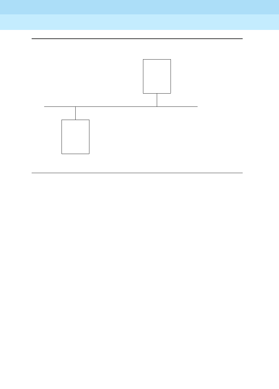
DEFINITY Enterprise Communications Server Release 6
Maintenance for R6r Volumes 1 & 2
555-230-126 Issue 2
January 1998
Maintenance Object Repair Procedures
Page 9-169BRI-PORT (ISDN-BRI Port), ABRI-PORT (ASAI ISDN-BRI Port)]
9
Figure 9-4. Path of the BRI Port Local LAN Loop Around
BRI LINE
CIRCUIT
PACK
PACKET
INTERFACE
PACKET BUS
.
.
.
.
. . . . . . . . . . . . . . . . . . . . . . .
.
.
.
.
.
.
. . . . . . . . . . . . . . . . . . . . . .
.
.
.
.
.
. . . .

DEFINITY Enterprise Communications Server Release 6
Maintenance for R6r Volumes 1 & 2
555-230-126 Issue 2
January 1998
Maintenance Object Repair Procedures
Page 9-170BRI-PORT (ISDN-BRI Port), ABRI-PORT (ASAI ISDN-BRI Port)]
9
Table 9-61. Test #618 BRI Port Local LAN Loop Around
Error
Code Test
Result Description/ Recommendation
1015 ABORT The port is not in the out-of-service state.
1. Display the BRI Port Status form via the status
bri-port PCSSpp command to determine which
stations or adjuncts are on this port.
2. Use the extension shown on this form in the status
station command to determine if the station or
adjunct is in use.
3. If it is in use, wait until it is idle, and then busyout the
port (using the busyout port PCSSpp command) to
place it in the out-of-service state and repeat this
test.
!WARNING:
Since the ‘‘busyout’’ command is destructive,
execution of this command prior to the port being
idle causes all calls associated with BRI endpoints
and all transactions associated with ASAI or
Lucent adjuncts on the port to be torn down. Note
that third party calls established by an ASAI or
Lucent adjunct remain connected even though the
port is taken out-of-service.
1139 ABORT The Packet Bus in the port network is out-of-service.
1. Follow the repair procedures for the Packet Bus.
2. After completing Step 1, execute the test port long
PCSSpp command, and review the results of the
BRI Port Local LAN Loop Around Test to verify the
repair.
1141 ABORT The PKT-CTRL is out-of-service.
1. Follow the repair procedures for the PKT-CTRL.
2. After completing Step 1, execute the test port long
PCSSpp command, and review the results of the
BRI Port Local LAN Loop Around Test to verify the
repair.
Continued on next page

DEFINITY Enterprise Communications Server Release 6
Maintenance for R6r Volumes 1 & 2
555-230-126 Issue 2
January 1998
Maintenance Object Repair Procedures
Page 9-171BRI-PORT (ISDN-BRI Port), ABRI-PORT (ASAI ISDN-BRI Port)]
9
BRI Port Local TDM Loop Around Test (#619)
This test is destructive.
This test verifies the connectivity of a BRI port across the TDM Bus. It aborts if
calls associated with the port are in progress. Failure of this test indicates an
on-board fault associated with the port hardware on the circuit pack.
This Loop Around Test runs a series of individual tests on the two B-channels (B1
and B2) associated with the port. It is a collection of the following:
1144 ABORT The PPN Packet Bus is out-of-service.
1. Follow the repair procedures for the Packet Bus.
2. After completing Step 1, execute the test port long
PCSSpp command, and review the results of the
BRI Port Local LAN Loop Around Test to verify the
repair.
2012 ABORT Internal System Error.
2100 ABORT Could not allocate the necessary system resources to
run this test.
1. Retry the command at one-minute intervals a
maximum of five times.
2. If the test continues to abort, escalate the problem.
FAIL The Loop Around Test has failed.
1. If the test fails repeatedly, attempt to reset the circuit
pack if the other ports on the board are not in use.
Reset the circuit pack by issuing the busyout board
PCSS and the reset board PCSS commands.
2. If the test fails again, execute test port-network
<pn#>
. If this fails, follow failure procedures in
‘‘PKT-BUS (Packet Bus)’’ section.
3. If tests executed in Step 2 pass, the problem is local
to the BRI board. Replace the circuit pack.
PASS The BRI Port Local LAN Loop Around Test has passed.
Table 9-61. Test #618 BRI Port Local LAN Loop Around — Continued
Error
Code Test
Result Description/ Recommendation
Continued on next page
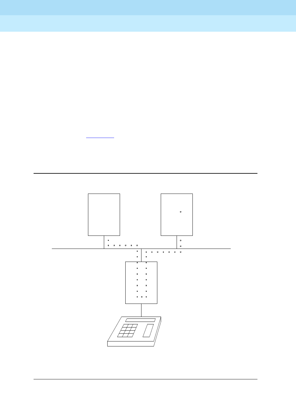
DEFINITY Enterprise Communications Server Release 6
Maintenance for R6r Volumes 1 & 2
555-230-126 Issue 2
January 1998
Maintenance Object Repair Procedures
Page 9-172BRI-PORT (ISDN-BRI Port), ABRI-PORT (ASAI ISDN-BRI Port)]
9
■A Loop Around Test across the TDM Bus for B1.
■A Conference Circuit Test for B1.
■A Loop Around Test across the TDM Bus for B2.
■A Conference Circuit Test for B2.
The tests are run in the above order. If one fails, the remaining tests in the
sequence are not executed. An error code is returned at that point.
This test is not executed for ABRI-PORT/ATT-PORT/LGATE-PT/ATTE-PT because
the B-channels associated with the port are not used by ASAI or Lucent adjuncts.
The dotted lines in Figure 9-5 show how a Loop Around Test is performed for the
B-channels. The figure shows a terminal connected to a BRI line board using a
TN556. If a TN2198 is used the terminal would be connected to a NT1, and the
NT1 to the BRI board.
Figure 9-5. Path of the BRI Port Local TDM Loop Around
Tone
Generator
Tone
Detector
BRI Line
Board
TDM Bus

DEFINITY Enterprise Communications Server Release 6
Maintenance for R6r Volumes 1 & 2
555-230-126 Issue 2
January 1998
Maintenance Object Repair Procedures
Page 9-173BRI-PORT (ISDN-BRI Port), ABRI-PORT (ASAI ISDN-BRI Port)]
9
Table 9-62. BRI Port Local TDM Loop Around
Error
Code Test
Result Description/ Recommendation
1000 ABORT The system resources required to run this test are not
available. The port may be busy with a valid call. Use
the display port PCSSpp command to determine the
station extension or trunk group/member number of the
port. Use the status bri-port PCSSpp command to
determine the service state of the port. If the service
state indicates that the port is in use, then the port is
unavailable for certain tests. (Refer to the ‘‘Status
Commands’’ section in Chapter 8, ‘‘Maintenance
Commands’’, for a full description of all possible states.)
Wait until the port is idle before retesting.
1. If the port is idle, then retry the command at
one-minute intervals a maximum of five times.
2. If the test continues to abort, escalate the problem.
1002 ABORT The system could not allocate time slots for the test. The
system may be under heavy traffic conditions or it may
have time slots out-of-service due to TDM-BUS errors.
Refer to TDM-BUS (TDM Bus) Maintenance
documentation to diagnose any active TDM Bus errors.
1. If the system has no TDM-BUS errors and is not
handling heavy traffic, repeat test at one-minute
intervals a maximum of five times.
2. If the test continues to abort, escalate the problem.
1003 ABORT The system could not allocate a tone receiver for the
test. The system may be oversized for the number of
Tone Detectors present or some Tone Detectors may be
out-of-service.
1. Look for TTR-LEV errors in the Error Log. If present,
refer to TTR-LEV (TTR Level) Maintenance
documentation.
2. Look for TONE-PT errors in the Error Log. If present,
refer to TONE-PT (Tone Generator) Maintenance
documentation.
3. If neither condition exists, retry the test at one-minute
intervals a maximum of five times.
4. If the test continues to abort, escalate the problem.
Continued on next page

DEFINITY Enterprise Communications Server Release 6
Maintenance for R6r Volumes 1 & 2
555-230-126 Issue 2
January 1998
Maintenance Object Repair Procedures
Page 9-174BRI-PORT (ISDN-BRI Port), ABRI-PORT (ASAI ISDN-BRI Port)]
9
1004 ABORT The port has been seized by a user for a valid call. Use
the status station command for the station associated
with this port and determine when the port is available
for testing.
1. Retry the command at one-minute intervals a
maximum of five times.
2. If the test continues to abort and the port is not in
use, escalate the problem.
1005 ABORT This test is not valid for this type of translation. Ports
administered as “ASAI” or “ADJK” can not run this test,
because the B channels associated with the port are not
used by ASAI or Lucent Adjunct Links. This is a normal
condition.
2000 ABORT Response to the test was not received from the
BRI-LINE circuit pack within the allowable time period.
1. If this result occurs repeatedly, attempt to reset the
circuit pack if the other ports are not in use. Reset
the circuit pack by issuing the busyout board PCSS
and the reset board PCSS commands.
2. If this result occurs again, replace the circuit pack.
2012 ABORT Internal System Error.
2100 ABORT Could not allocate the necessary resources to run this
test.
1. Retry the command at one-minute intervals a
maximum of five times.
2. If the test continues to abort, escalate the problem.
2103 ABORT The system could not make the conference connection
for the test.
1. Retry the command at one-minute intervals a
maximum of five times.
2. If the test continues to abort, escalate the problem.
Table 9-62. BRI Port Local TDM Loop Around — Continued
Error
Code Test
Result Description/ Recommendation
Continued on next page

DEFINITY Enterprise Communications Server Release 6
Maintenance for R6r Volumes 1 & 2
555-230-126 Issue 2
January 1998
Maintenance Object Repair Procedures
Page 9-175BRI-PORT (ISDN-BRI Port), ABRI-PORT (ASAI ISDN-BRI Port)]
9
Electronic Power Feed Restoral Test (#620)
This test attempts to restore the Electronic Power Feed (EPF) on an ISDN-BRI
port twice. In this test, the processor requests that the EPF be turned on for a
given port. An attempt is made to turn on the power unit to the station or adjunct.
If no current is being drawn by a station, this probably indicates that the station is
not connected. No current being drawn by an adjunct is the normal condition. If
an overcurrent condition is sensed (that is, too much current is being drawn), this
condition may indicate a short in the wiring to the endpoint or adjunct.
Depending on what condition is sensed, a message is returned stating that either
the EPF was turned on successfully with no problems or that an overcurrent
condition is sensed. This response is reported by the Electronic Power Feed
Inquiry (#622), which follows in the testing sequence. EPF Restoral is attempted
again by this test five seconds later. This test always passes for the TN2198
because it has no EPF. This test will always abort when run on the TN2208.
1
2FAIL As stated previously, this test runs a TDM Loop Around
Test on each B-channel. This indicates that the loop
around failed on one of the channels. Error Code 1
indicates that the TDM Loop Around Test failed on B1.
Error Code 2 indicates that the TDM Loop Around Test
failed on B2.
7
8FAIL As stated previously, this test runs a Conference Circuit
Test on each B-channel. A failure here indicates that one
of these conference tests failed; Error Code 7 means
that the test failed on B1; Error Code 8 means that the
test failed on B2.
1. If the test fails repeatedly, attempt to reset the circuit
pack if the other ports on the circuit pack are not in
use. Reset the circuit pack by issuing the busyout
board PCSS and the reset board PCSS
commands.
2. If the test fails again, replace the circuit pack.
PASS The BRI Port Local TDM Loop Around Test has passed.
Table 9-62. BRI Port Local TDM Loop Around — Continued
Error
Code Test
Result Description/ Recommendation
Continued on next page

DEFINITY Enterprise Communications Server Release 6
Maintenance for R6r Volumes 1 & 2
555-230-126 Issue 2
January 1998
Maintenance Object Repair Procedures
Page 9-176BRI-PORT (ISDN-BRI Port), ABRI-PORT (ASAI ISDN-BRI Port)]
9
Level 1 Status Inquiry Test (#621)
This test determines the state of the transmission facility of a BRI port at the
physical layer (that is, Level 1). Level 1 can be in one of three possible states:
Activated, Pending Activation, or Deactivated.
The Activated state is the correct state for an ISDN-BRI port. In this state the
Level 1 interface can communicate with the BRI endpoint or ASAI or Lucent
adjunct administered on this port. This test passes if the state of Level 1 (L1) is
Activated. This test also passes if software has taken this port out of service. See
the description of the Level 1 ‘‘Deactivated State’’ below for more details.
The Pending Activation state indicates a problem with the endpoints or adjunct,
the wiring to the sets or adjunct, or the BRI-LINE circuit pack. When in this state,
the Level 1 interface is either not receiving any L1 framing from the endpoint or
adjunct (Endpoint Idle), or it is communicating with the endpoint or adjunct but
cannot transition to the Activated state (Endpoint Active).
Table 9-63. TEST #620 Electronic Power Feed Restoral
Error
Code Test
Result Description/ Recommendation
1005 ABORT This test is not valid for this port type. The TN2208 does
not have an electronic power feed, and the test will
abort.
2012 ABORT Internal System Error.
1. Retry the command at one-minute intervals a
maximum of five times.
2. If the test continues to abort, escalate the problem.
PASS The EPF Test passed. The message to turn on the power
feed to the station or the adjunct was successfully sent
to the port.
1. Although this test should not return a fail result, after
running this test, the Error Log should be checked
for any entries with error type 257 to examine the
real results of this test.
2. An error type of 257 in the Error Log indicates some
problem with the power to the station or the adjunct.
Check for a short in the wiring, a damaged jack, a
defective voice terminal or adjunct, or an incorrect
type of terminal.
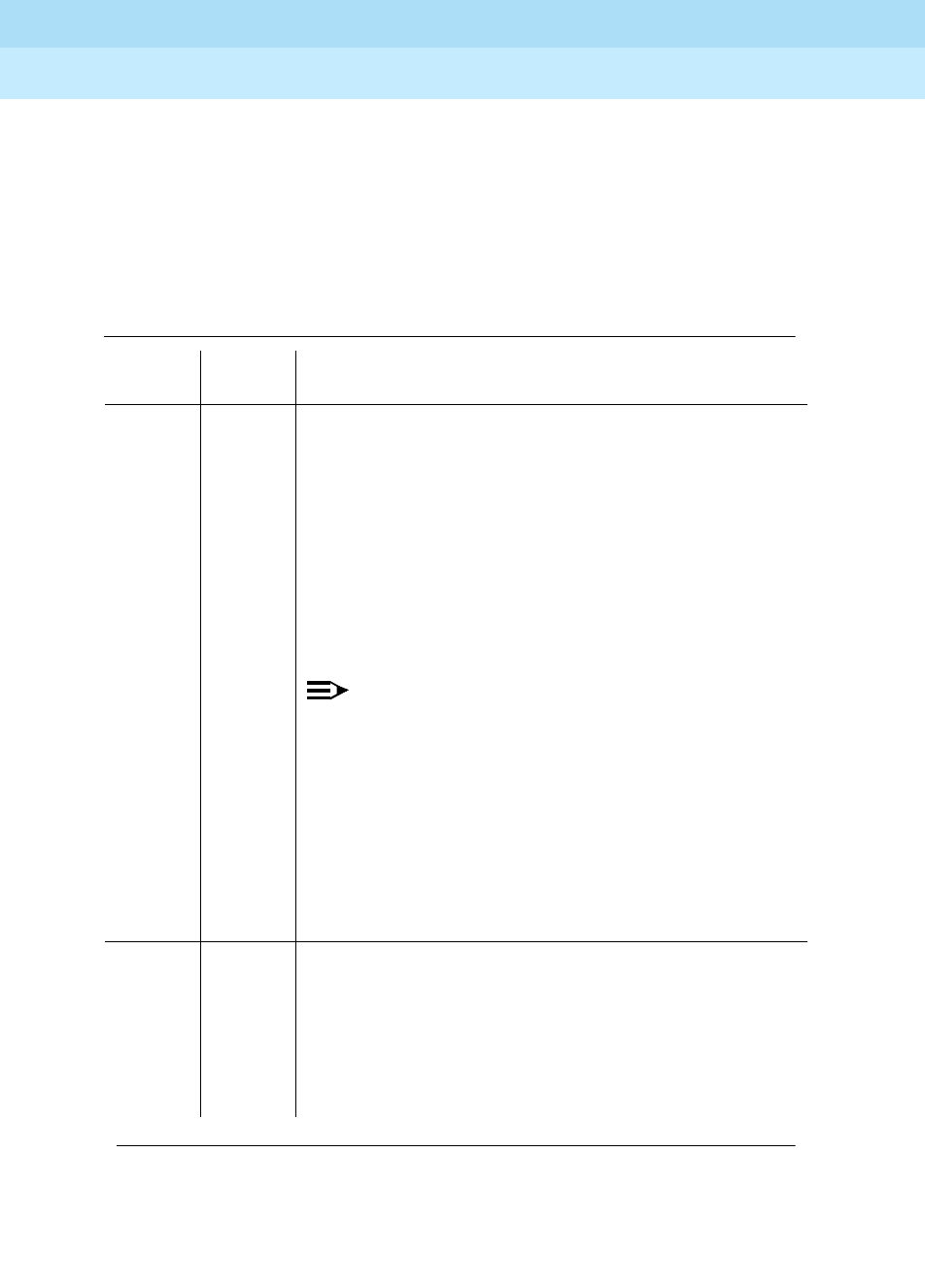
DEFINITY Enterprise Communications Server Release 6
Maintenance for R6r Volumes 1 & 2
555-230-126 Issue 2
January 1998
Maintenance Object Repair Procedures
Page 9-177BRI-PORT (ISDN-BRI Port), ABRI-PORT (ASAI ISDN-BRI Port)]
9
The Deactivated state indicates a problem with the BRI-LINE circuit pack. When
in this state, the Level 1 interface is idle and is not trying to communicate with the
BRI endpoints or adjunct. When an ISDN-BRI port is placed in the out-of-service
state, Level 1 is also put into the Deactivated state.Thiscouldbedue either to the
system detecting a fault with the port or to a busyout port PCSSpp request This
could be due either to the system detecting a fault with the port or to a busyout
port PCSSpp request
Table 9-64. TEST #621 Level 1 Status Inquiry
Error
Code Test
Result Description/ Recommendation
1187 ABORT The board, port or station may have been busied out by
a technician.
1. Look in the Error Log for Error Type 18 (port busied
out) for this port and BRI-BD (board busied out). If
this error type is present for BRI-PORT only, then
release the port via the release port pp command
and run the test again. If the error is present for both
BRI-BD and BRI-PORT, then release the board via
the release port PCSS command and run the test
again.
NOTE:
When you release a port, you release all ports
associated with it. If certain ports still need to be
busied out, use the release port PCSSpp
command to busy them out.
2. Make sure the terminal is connected.
3. Retry the command at one-minute intervals a
maximum of five times.
4. If the test continues to abort, escalate the problem.
2000 ABORT Response to the test was not received from the circuit
pack within the allowable time period.
1. If the test aborts repeatedly a maximum of five times,
reset the circuit pack via the busyout board PCSS
and reset board PCSS commands.
2. If the test aborts again, replace the circuit pack.
Continued on next page

DEFINITY Enterprise Communications Server Release 6
Maintenance for R6r Volumes 1 & 2
555-230-126 Issue 2
January 1998
Maintenance Object Repair Procedures
Page 9-178BRI-PORT (ISDN-BRI Port), ABRI-PORT (ASAI ISDN-BRI Port)]
9
2012 ABORT Internal System Error.
2100 ABORT Could not allocate the necessary system resources to
run this test.
1. Retry the command at one-minute intervals a
maximum of five times.
2. If the test continues to fail, escalate the problem.
Table 9-64. TEST #621 Level 1 Status Inquiry — Continued
Error
Code Test
Result Description/ Recommendation
Continued on next page
DEFINITY Enterprise Communications Server Release 6
Maintenance for R6r Volumes 1 & 2
555-230-126 Issue 2
January 1998
Maintenance Object Repair Procedures
Page 9-179BRI-PORT (ISDN-BRI Port), ABRI-PORT (ASAI ISDN-BRI Port)]
9
1 FAIL Received a status of Level 1 Pending
Activation-Endpoint Idle which indicates a problem with
the BRI endpoint or ASAI or Lucent adjunct, the wiring to
the endpoint or adjunct, or the ISDN-BRI port.
For the TN2198, received a status of Level 1 Pending
Activation. U interface down, which indicates a problem
with a connection between the switch and the NT1.
NOTE:
An NT1 is a 2-to-4 wire converter that is used to
connect 4-wire Lucent terminals to a 2-wire
TN2198 circuit pack. The NT1 also has status
lamps to determine the health of the unit.
1. For the TN556, verify that an end point is connected
to the port. If an endpoint is connected to the port
then proceed to step 2. For the TN2198 verify that
the connections are good between the switch and
the NT1. Verify that the NT1 has power.
2. As necessary, check and repair the wiring between
the circuit pack and the endpoint or adjunct. If a
TN2198 is used the set must have been plugged in
for at least 15 seconds before it will stabilize.
Execute the test port PCSSpp command, and
review the results of the Level 1 Status Inquiry Test
to verify the repair. If this test is still failing, proceed
to Step 3.
3. For BRI endpoints, replace the BRI endpoint(s)
connected to the port or the NT1 if a TN2198 is
used. For ASAI or Lucent adjuncts, follow the
recommended repair procedures of the
manufacturer for link communication problems. For
the NT1, follow the manufacturers repair
procedures. Then execute the test port PCSSpp
command and review the results of the Level 1
Status Inquiry Test to verify repair. If this test is still
failing, proceed to Step 4.
4. Escalate the problem to the next tier.
Table 9-64. TEST #621 Level 1 Status Inquiry — Continued
Error
Code Test
Result Description/ Recommendation
Continued on next page

DEFINITY Enterprise Communications Server Release 6
Maintenance for R6r Volumes 1 & 2
555-230-126 Issue 2
January 1998
Maintenance Object Repair Procedures
Page 9-180BRI-PORT (ISDN-BRI Port), ABRI-PORT (ASAI ISDN-BRI Port)]
9
2 FAIL For the TN556 or TN2208, received a status of Level 1
Pending Activation-Endpoint Active which indicates a
problem with the BRI endpoint or ASAI or Lucent
adjunct, the wiring to the endpoint or adjunct, or the
ISDN-BRI port.
For the TN2198, received a status of Level 1 Pending
Activation. U interface up S/T interface down, which
indicates a problem with the NT1 or the wiring between
the NT1 and the BRI endpoint (S/T interface).
1. As necessary, check and repair the wiring between
the circuit pack and the endpoint or adjunct.
Execute the test port PCSSpp command, and
review the results of the Level 1 Status Inquiry test to
verify the repair. If this test is still failing, proceed to
Step 2.
2. For BRI endpoints, try replacing the BRI endpoint(s)
connected to the port. For ASAI or Lucent adjuncts,
follow the recommended repair procedures of the
manufacturer for link communication problems. For
the NT1, follow the recommended repair procedures
of the manufacturer. Then execute the test port
PCSSpp command, and review the results of the
Level 1 Status Inquiry test to verify repair. If this test
is still failing, proceed to Step 3.
3. Escalate the problem to the next tier.
Table 9-64. TEST #621 Level 1 Status Inquiry — Continued
Error
Code Test
Result Description/ Recommendation
Continued on next page

DEFINITY Enterprise Communications Server Release 6
Maintenance for R6r Volumes 1 & 2
555-230-126 Issue 2
January 1998
Maintenance Object Repair Procedures
Page 9-181BRI-PORT (ISDN-BRI Port), ABRI-PORT (ASAI ISDN-BRI Port)]
9
3 FAIL Received a status of Level 1 Deactivated; the port is
out-of-service.
1. Issue the status bri-port PCSSpp command to
verify that the service state of the port is
out-of-service. If the service state of the port is not
out-of-service, escalate the problem to the next tier.
Otherwise, proceed to Step 2.
2. If the port has been placed out-of-service via the
busyout port PCSSpp command, try releasing the
port by executing the release port PCSSpp
command. Then issue the test port long PCSSpp
command, and review the results of Level 1 Status
Inquiry test. If this test is still failing, proceed to Step
3.
3. After executing the test port long PCSSpp
command, review the results of all the tests. Follow
the repair procedures for any tests that fail. Verify
repair of the problem by executing the test port
PCSSpp command and by determining that the
Level 1 Status test passes. If the test continues to fail
for this reason, proceed to Step 4.
4. Escalate the problem to the next tier.
4 FAIL For the TN2198 only:
Received a status of Level 1 Pending Activation, the NT1
has a loss of power indicating a problem with the NT1.
1. For the NT1 follow the manufacturers recommended
repair procedures.
2. Execute the test port PCSSpp command, and
review the results of the Level 1 Status Inquiry test to
verify the repair. If the test is still failing proceed to
Step 3.
3. Escalate the problem to the next tier.
PASS This test indicates that Level 1 is activated, or that
software has taken the port out of service.
Table 9-64. TEST #621 Level 1 Status Inquiry — Continued
Error
Code Test
Result Description/ Recommendation
Continued on next page

DEFINITY Enterprise Communications Server Release 6
Maintenance for R6r Volumes 1 & 2
555-230-126 Issue 2
January 1998
Maintenance Object Repair Procedures
Page 9-182BRI-PORT (ISDN-BRI Port), ABRI-PORT (ASAI ISDN-BRI Port)]
9
Electronic Power Feed Inquiry (#622)
This test queries the BRI-LINE circuit pack for the status of the Electronic Power
Feed (EPF) supplied to a BRI endpoint or an ASAI or Lucent adjunct. If the EPF is
on and no overcurrent condition exists, this test passes. All other states are not
normal and indicate a problem with the endpoint or adjunct, the wiring to the
endpoint or adjunct, or the BRI-LINE circuit pack. This test is not run on the
TN2208 circuit pack or the TN2198 and will always return a pass for the TN2198.
The TN2208 has no power feeds.
Table 9-65. TEST #622 Electronic Power Feed Inquiry
Error
Code Test
Result Description/ Recommendation
1005 ABORT This test is not valid for this port type. Ports on the
TN2208 can not run this test because this board does
not have an electronic power feed.
2000 ABORT Response to the test was not received from the circuit
pack within the allowable time period.
1. If the test aborts repeatedly a maximum of five times,
reset the circuit pack via the busyout board PCSS
and reset board PCSS commands.
2. If the test aborts again, replace the circuit pack.
2012 ABORT Internal System Error.
2100 ABORT Could not allocate the necessary system resources to
run this test.
1. Retry the command at one-minute intervals a
maximum of five times.
2. If the test continues to abort, escalate the problem.
Continued on next page

DEFINITY Enterprise Communications Server Release 6
Maintenance for R6r Volumes 1 & 2
555-230-126 Issue 2
January 1998
Maintenance Object Repair Procedures
Page 9-183BRI-PORT (ISDN-BRI Port), ABRI-PORT (ASAI ISDN-BRI Port)]
9
Layer 1 Transmission Error Counter Test (#624)
This test reads and clears the BRI port’s Layer 1 Transmission error counter
maintained on the BRI-LINE circuit pack. This counter is incremented by the
circuit pack when it detects a Layer 1 transmission problem. The test passes if
the value of the counter is 0 (that is, the error is cleared). If the counter is not
zero, the test fails, and the value of the counter is displayed in the Error Code
field.
This error is most likely due to a problem with the wiring or the endpoint or
adjunct (verify that the wiring meets the configuration rules defined in
DEFINITY
Communications System Generic 1 and Generic 3i Wiring
, 555-204-111. It does
not indicate a problem with the ISDN-BRI circuit pack. This test is useful for
verifying the repair of the problem.
1 FAIL The BRI-LINE circuit pack reports that it has detected an
overcurrent condition and has turned off the EPF.
1. As necessary, check and repair the wiring between
the circuit pack and the endpoint or adjunct. Check
the endpoints and replace one or both sets if the
sets are drawing too much current. Execute the test
port PCSSpp command and review the results of
the EPF Inquiry Test to verify the repair. If this test is
still failing, proceed to Step 2.
2. Execute the test port PCSSpp command, and
review the results of the Level 1 Status Inquiry Test.
If this test is also failing, then follow the repair
procedure for the Level 1 Status Inquiry Test.
Otherwise, escalate this problem to the next tier.
PASS The Electronic Power Feed Inquiry Test reports that the
EPF is on.
Table 9-65. TEST #622 Electronic Power Feed Inquiry — Continued
Error
Code Test
Result Description/ Recommendation
Continued on next page

DEFINITY Enterprise Communications Server Release 6
Maintenance for R6r Volumes 1 & 2
555-230-126 Issue 2
January 1998
Maintenance Object Repair Procedures
Page 9-184BRI-PORT (ISDN-BRI Port), ABRI-PORT (ASAI ISDN-BRI Port)]
9
Table 9-66. TEST #624 Layer 1 Transmission Error
Counter Test
Error
Code Test
Result Description/ Recommendation
2000 ABORT Response to the test was not received from the circuit
pack within the allowable time period.
1. If the test aborts repeatedly a maximum of five times,
reset the circuit pack via the busyout board PCSS
and reset board PCSS commands.
2. If the test aborts again, replace the circuit pack.
2012 ABORT Internal System Error.
2100 ABORT Could not allocate necessary system resources to run
test.
1. Retry the command at one-minute intervals a
maximum of five times.
2. If the test continues to fail, escalate the problem.
value FAIL The BRI-LINE circuit pack is still detecting errors of this
type. The Error Code field contains the value of this
counter.
1. Retry the command at one-minute intervals a
maximum of five times.
2. If the test continues to fail, review the results of other
tests in the Long Test Sequence. Pay particular
attention to the results of the Level 1 Status Inquiry
test. Follow repair procedures for any of the
executed tests if they fail. Otherwise, go to the next
step.
3. If the tests for the endpoints or adjunct pass and the
Layer 1 Transmission Error Counter Test continues
to fail, check the wiring to the endpoints or adjunct. If
the wiring appears to be fine, escalate the problem.
PASS The Layer 1 Transmission error counter was read
correctly and has a value of 0.
Continued on next page

DEFINITY Enterprise Communications Server Release 6
Maintenance for R6r Volumes 1 & 2
555-230-126 Issue 2
January 1998
Maintenance Object Repair Procedures
Page 9-185BRI-PORT (ISDN-BRI Port), ABRI-PORT (ASAI ISDN-BRI Port)]
9
Receive FIFO Overflow Error Counter Test (#625)
This test reads and clears the BRI port’s Receive FIFO Overflow error counter
maintained on the BRI-LINE circuit pack. This counter is incremented by the
circuit pack when it detects an overflow of its receive buffers. The test passes if
the value of the counter is 0 (that is, the error is cleared). If the counter is
non-zero, the test fails, and the value of the counter is displayed in the Error
Code field.
This error can occur if signaling frames are being received from the Packet Bus
at a rate sufficient to overflow the receive buffers on the circuit pack for a port OR
if a hardware fault is causing the receive buffers not to be emptied properly by
the circuit pack. This test is useful for verifying the repair of the problem.
Table 9-67. TEST #625 Receive FIFO Overflow Error
Counter Test
Error
Code Test
Result Description/ Recommendation
2000 ABORT Response to the test was not received from the circuit
pack within the allowable time period.
1. If the test aborts repeatedly a maximum of five times,
reset the circuit pack via the busyout board PCSS
and reset board PCSS commands.
2. If the test aborts again, replace the circuit pack.
2012 ABORT Internal System Error.
2100 ABORT Could not allocate the necessary system resources to
run this test.
1. Retry the command at one-minute intervals a
maximum of five times.
2. If the test continues to fail, escalate the problem.
Continued on next page

DEFINITY Enterprise Communications Server Release 6
Maintenance for R6r Volumes 1 & 2
555-230-126 Issue 2
January 1998
Maintenance Object Repair Procedures
Page 9-186BRI-PORT (ISDN-BRI Port), ABRI-PORT (ASAI ISDN-BRI Port)]
9
Clear Error Counters Test (#270)
This test is not an actual test in the strict sense of the word. There are various
error counters associated with each
BRI-PORT/ABRI-PORT/ATT-PORT/LGATE-PT/ATTE-PT. This test clears those
counters and triggers the auditing of Terminal Endpoint Identifier (TEI) values
and layer 3 reinitialization. This test is used only to send messages to the
BRI-PORT/ABRI-PORT/ATT-PORT/LGATE-PT/ATTE-PT and, therefore, should
neither abort nor fail
value FAIL The BRI-LINE circuit pack is still detecting errors of this
type. The Error Code field contains the value of this
counter.
1. Retry the command at one-minute intervals a
maximum of five times.
2. If the test continues to fail, run the Long Test
Sequence and pay particular attention to the Loop
Around Tests (#618 and #619). See the repair
procedures for the executed test if it fails. Otherwise,
go to the next step.
3. Replace the circuit pack.
PASS The Receive FIFO Overflow error counter was read
correctly and has a value of 0.
Table 9-67. TEST #625 Receive FIFO Overflow Error
Counter Test — Continued
Error
Code Test
Result Description/ Recommendation
Continued on next page

DEFINITY Enterprise Communications Server Release 6
Maintenance for R6r Volumes 1 & 2
555-230-126 Issue 2
January 1998
Maintenance Object Repair Procedures
Page 9-187BRI-PORT (ISDN-BRI Port), ABRI-PORT (ASAI ISDN-BRI Port)]
9
Table 9-68. TEST #270 Clear Error Counters
Error
Code Test
Result Description/ Recommendation
Any ABORT This test should never abort.
Any FAIL This test should never fail.
1. Retry the command at one-minute intervals a
maximum of five times.
2. If the test continues to fail, escalate the problem.
PASS The message to clear the error counters of the
BRI-Port/ABRI-Port/ATT-PORT/LGATE-PT/ATTE-PT has
been sent.
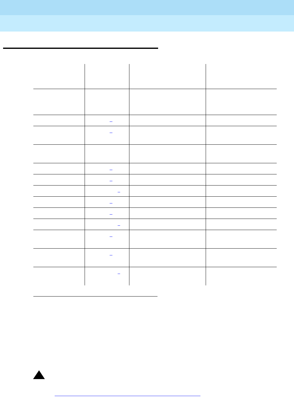
DEFINITY Enterprise Communications Server Release 6
Maintenance for R6r Volumes 1 & 2
555-230-126 Issue 2
January 1998
Maintenance Object Repair Procedures
Page 9-188BRI-SET, ASAI-ADJ, BRI-DAT
9
BRI-SET, ASAI-ADJ, BRI-DAT
!CAUTION:
A detailed flowchart for isolating and resolving Packet Bus faults is included
in Chapter 9, ‘‘Maintenance Object Repair Procedures’’, ‘‘Packet Bus Fault
Isolation and Correction.’’ This flowchart, along with the other information
1. UU is the universal cabinet number (1 for PPN, 2 -44 for EPNs). C is the carrier designation (A,
B, C, D, or E). SS is the number of the slot in which the circuit pack resides (01 to 21). pp is the
two digit port number (01, 02, ...).
2. The alarm level for ASAI and Lucent adjuncts may be administered using the set options
command. The alarm level can be set independently for Off-Board and On-Board alarms to
WARNING, MINOR, or MAJOR for all ASAI and Lucent adjuncts in the system.
3. Alarming for an ASAI and Lucent adjuncts is disabled if the adjunct asks the switch to suspend
maintenance. When this occurs, an error and a WARNING alarm are logged against the
endpoint. Busying out and releasing the ASAI station or ADJLK station will clear the alarm.
MO Name As
It Appears in
Alarm Log Alarm Level
Initial System
Technician Command to
Run1Full Name of MO
BRI-SET
BRI-DAT WARNING2test station extension l,
test data-module
extension
ISDN-BRI Set
ASAI-ADJ MAJOR2) test station extension ASAI-Adjunct
ASAI-ADJ MAJOR2test data-module
extension ASAI-Adjunct
ASAI-ADJ WARNING3test data-module
extension ASAI-Adjunct
ATT-ADJ MAJOR2test station extension Lucent-Adjunct
ATT-ADJ MAJOR2test station extension Lucent-Adjunct
ATT-ADJ WARNING3test station extension Lucent-Adjunct
LGATE-AJ MAJOR2test station extension Ethernet ASAI-Adjunct
LGATE-AJ MAJOR2test station extension Ethernet ASAI-Adjunct
LGATE-AJ WARNING3test station extension Ethernet ASAI-Adjunct
ATTE-AJ MAJOR2test station extension Ethernet
Lucent-Adjunct
ATTE-AJ MAJOR2test station extension Ethernet
Lucent-Adjunct
ATTE-AJ WARNING3test station extension Ethernet
Lucent-Adjunct

DEFINITY Enterprise Communications Server Release 6
Maintenance for R6r Volumes 1 & 2
555-230-126 Issue 2
January 1998
Maintenance Object Repair Procedures
Page 9-189BRI-SET, ASAI-ADJ, BRI-DAT
9
presented in the chapter, can help in resolving problems that involve more
than a single station or circuit pack. Whenever the repair procedures for
this Maintenance Object refer to Packet Bus and/or Packet Control
maintenance, be sure to reference Chapter 9, ‘‘Maintenance Object Repair
Procedures’’, ‘‘Packet Bus Fault Isolation and Correction’’ in addition to the
relevant MO documentation.
!WARNING:
If a significant Packet Bus failure occurs, errors and alarms may not be
logged as expected for
BRI-SET/BRI-DAT/ASAI-ADJ/ATT-ADJ/LGATE-AJ/ATTE-AJ. Conditions
under which this occurs are detailed in the ‘‘Maintenance of the Packet
Bus’’ section of Chapter 9, ‘‘Maintenance Object Repair Procedures’’,
‘‘Packet Bus Fault Isolation and Correction.’’
The TN2208 ESAI MFB provides DEFINITY with an Ethernet interface to
Adjunct-Switch Application Interface (ASAI) and Lucent adjuncts (for example,
CONVERSANT® Voice System). This circuit pack contains 8 ports of line circuit
interface, each of which operates with two B-channels (referred to as B1 and B2
throughout this section) and one D-channel as specified in the Lucent ISDN-BRI
Specification. In this context, the term ‘‘ISDN-BRI port’’ is used to refer
collectively to ports on the TN2208 MFB circuit pack which is connected to ASAI
or Lucent adjuncts. The TN2208 ESAI MFB is handled by switch software as it is
an ISDN BRI compatible board and all maintenance actions referring to ASAI and
Lucent Adjunct Links in this section apply.
In G3iV1.1-286 and G3iV2-386, two types of ISDN-BRI endpoints may be
connected to ISDN-BRI (ISDN Basic Rate Interface Line) TN556 and TN2198
circuit packs: ISDN-BRI station endpoints, ASAI (Adjunct-Switch Application
Interface) and Lucent adjuncts (for example CONVERSANT® Voice System).
These circuit packs contain 12 ports of line circuit interfaces, each of which
operates at 192 kilobits per second (kbps) with two B-channels and one
D-channel as specified in the Lucent ISDN-BRI specification (PUB 801-802-100).
For BRI endpoints, each B-channel may support voice or circuit-switched data
and may be circuit-switched simultaneously. The B-channels are not used by
ASAI or Lucent adjuncts. The D-channel is used for conveying signaling between
the switch and a BRI endpoint(s) or ASAI or Lucent adjuncts. Each ISDN-BRI
D-channel is connected to the switch processor and the ISDN-BRI port through
the PKT-CTRL (Packet Control) and the PKT-BUS (Packet Bus).
ISDN-BRI endpoints come in a number of configurations. All endpoints require
the D-channel to convey signaling information to the switch. A voice-only set
requires only one B-channel. A voice and data-capable set requires both
B-channels (one for voice and one for data). Therefore, each TN556 port can
support either two voice-only sets or one voice and data-capable set. Only a
single ASAI or Lucent adjunct may be connected to an ISDN-BRI port. Multiple
adjuncts per line are not supported.
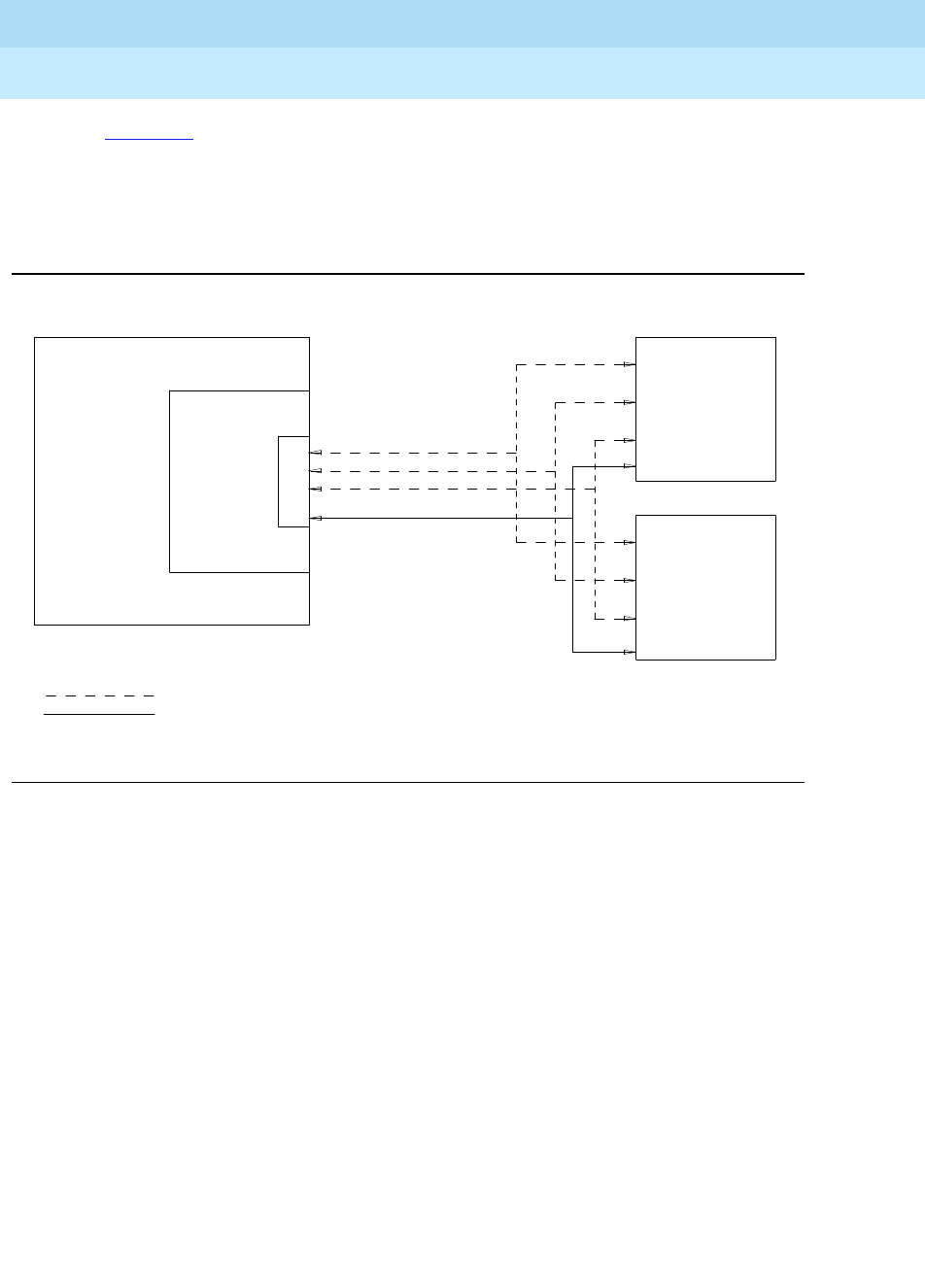
DEFINITY Enterprise Communications Server Release 6
Maintenance for R6r Volumes 1 & 2
555-230-126 Issue 2
January 1998
Maintenance Object Repair Procedures
Page 9-190BRI-SET, ASAI-ADJ, BRI-DAT
9
Figure 9-6 illustrates the physical connection (solid line) between an ISDN-BRI
Circuit Pack and a voice or voice/data set. Each physical connection allows for
two B-channels, as stated above, plus one D-channel. Each ISDN-BRI circuit
pack can support up to 12 of these PHYSICAL connections to different voice and
voice/data sets or ASAI and Lucent adjuncts.
Figure 9-6. ISDN-BRI Set Interactions
This section contains the ISDN-BRI Set, ASAI Adjunct and Lucent Adjunct
Maintenance documentation. Some of the results of maintenance testing of the
ISDN-BRI Set or the ASAI and Lucent Adjunct may be affected by the health of
the ISDN-BRI circuit pack and Port. These interactions should be kept in mind
when investigating the cause of ISDN-BRI Set problems.
BRI Line
Circuit Pack
P
O
R
T
D-Channel
B-Channel
B-Channel
PHYSICAL CONNECTION
VOICE
or DATA
SET
Logical Connection
VOICE
or DATA
SET
PBX
Physical Connection

DEFINITY Enterprise Communications Server Release 6
Maintenance for R6r Volumes 1 & 2
555-230-126 Issue 2
January 1998
Maintenance Object Repair Procedures
Page 9-191BRI-SET, ASAI-ADJ, BRI-DAT
9
Hardware Error Log Entries and Test to Clear
Values
Table 9-69. BRI-SET/ASAI-ADJ Error Log Entries
Error
Type Aux
Data Associated Test
Alarm
Level
BBRI-SET
Alarm
Level
ASAI-ADJ
ASAI-ADJ
ATT-ADJ
LGATE-AJ
ATTE-AJ On/Off
Board Test to Clear
Value
010 Any Any Any Any test BRI-SET or
ASAI-ADJ
ATT-ADJ
ESIA-ADJ
EATT_ADJ
2(a) 2-10
2None
18 0 busyout station
ext WARNING MAJOR/
WARNING2OFF release station
<ext>
130(b) WRN ON test port PCSS sh
257(c) Any BRI Layer 3
Query (#629) WARNING MAJOR/
WARNING2OFF test station ext r 2
test data-module
ext r 2
351(d) 0 None WARNING OFF busyout and
release station
513(e) 0 None
769(f) 0 None WARNING MAJOR OFF
2561
(g) 0None
2562-
2566(h) 0None
2567
(o) 0None
2568
(p) 0None
Continued on next page

DEFINITY Enterprise Communications Server Release 6
Maintenance for R6r Volumes 1 & 2
555-230-126 Issue 2
January 1998
Maintenance Object Repair Procedures
Page 9-192BRI-SET, ASAI-ADJ, BRI-DAT
9
Notes:
a. Errors of this type indicate violations of the ISDN-BRI signaling protocol;
timers associated with certain Layer 3 messages have expired before a
required response was received. In the following table, the aux data field
indicates which timer has just expired. (For more information, refer to the
Lucent ISDN-BRI Specification.
1. Run the Short Test Sequence first. If all tests pass, run the Long Test Sequence. Refer to the appropriate test
description and follow the recommended procedures.
2. Major alarms on this MO may be downgraded to Warning alarms based on the value used in the
set options command.
2817(i) 0 XID Test (#628) WARNING MAJOR/
WARNING2OFF test station ext r 2
test data-module
ext r 2
3073(j) 0 BRI Remote
Loop Back
(#627)
WARNING OFF test station ext l r 2
test data-module
ext l r 2
3329
(k) Any Signaling Link
Status
(626)
WARNING MAJOR/
WARNING2OFF
3584 0,1 None
3585-
3839(i) 0None
3840-
4095
(m)
(n)
0None
Table 9-69. BRI-SET/ASAI-ADJ Error Log Entries — Continued
Error
Type Aux
Data Associated Test
Alarm
Level
BBRI-SET
Alarm
Level
ASAI-ADJ
ASAI-ADJ
ATT-ADJ
LGATE-AJ
ATTE-AJ On/Off
Board Test to Clear
Value
Continued on next page

DEFINITY Enterprise Communications Server Release 6
Maintenance for R6r Volumes 1 & 2
555-230-126 Issue 2
January 1998
Maintenance Object Repair Procedures
Page 9-193BRI-SET, ASAI-ADJ, BRI-DAT
9
)
The switch sent a message to the endpoint which did not respond in the
allotted time. This can happen occasionally due to failure of the
point-to-point signaling link or because of a problem in the BRI endpoint or
ASAI adjunct or Lucent adjunct. Execute the test station extension sh
command and pay particular attention to the results of the BRI Layer 3
Query Test (#629). If this test fails, follow the repair procedure for Test
#629.
b. This error type indicates that the circuit pack has been removed or has
been insane for more than 11 minutes. To clear the error, replace or
reinsert the circuit pack.
c. This error occurs when the endpoint does not respond to the service state
query message sent to the adjunct or the endpoint. This error causes an
alarm to be raised. The alarm is retired when the switch receives a
response to the service state query to the endpoint or the adjunct.
For BRI endpoints, the Aux Data field for this error contains ‘‘0.’’ When it
occurs, execute the test station extension sh command and pay
particular attention to the results of the BRI Layer 3 Query Test (#629). If
this test fails, follow the repair procedure for Test #629.
Aux Data Timer Type
2 First T303 (SETUP timer)
3 Second T303 (SETUP timer)
4 T305 (DISConnect timer)
5 First T308 (RELease timer)
6 Second T308 (RELease timer)
10 T316 (RESTart timer)
12 T309 (Layer 2 Failure timer)
16 TM100 (Management Information
Message timer 1)
17 TM200 (Management Information
Message timer 2)
102 TASAI (ASAI Routing Timer)

DEFINITY Enterprise Communications Server Release 6
Maintenance for R6r Volumes 1 & 2
555-230-126 Issue 2
January 1998
Maintenance Object Repair Procedures
Page 9-194BRI-SET, ASAI-ADJ, BRI-DAT
9
When this error occurs for an ASAI or Lucent adjunct, the Aux Data field
indicates the state of the ASAI link or Lucent link and whether an invalid
response or no response was received to the query from the switch, as
shown in the following table:
(See "Status BRI-Port" in Chapter 8, ‘‘Maintenance Commands’’, for an
explanation of the ASAI link states.)
For ASAI or Lucent adjuncts, the switch automatically queries the adjunct
every two minutes (and therefore the Layer 3 Query Test is not executed
for ASAI or Lucent adjuncts via a command issued from the G3MT
terminal). While alarmed for this error, the switch momentarily (for five
seconds) takes the associated port out-of-service every 15 minutes. This
action is taken in an attempt to stimulate recovery actions to be taken by
the adjunct.
When this error occurs for an ASAI or Lucent adjunct, the service
technician should:
1. Execute the test station extension command and pay particular
attention to any tests which fail and perform the associated repair
procedures for those tests.
2. Check the health of the adjunct by following the recommended
repair procedures of the manufacturer of the adjunct if the
preceding step does not resolve the problem.
3. The alarm condition persists and, if the above steps do not resolve
the problem, follow normal escalation procedures.
d. This error and associated WARNING alarm are logged against an ASAI or
Lucent endpoint when the adjunct has asked the switch to suspend
Maintenance on the ASAI or Lucent endpoint. Busying out and releasing
the ASAI station or ADJLK station will clear this alarm.
e. This error occurs when the endpoint sends more messages than the
switch can handle. The switch suspends the reception of messages from
the endpoint for a short period of time. There is no repair procedure for
this error. If the condition persists, replace the endpoint.
Aux
Data ASAI Link State Error
102 13-restarting No response to RESTART message
104 13-restarting Invalid response to RESTART message
152 13-restarted No response to Layer 3 query
154 13-restarted Invalid response to Layer 3 query
202 13-established No response to Layer 3 query
204 13-established Invalid response to Layer 3 query

DEFINITY Enterprise Communications Server Release 6
Maintenance for R6r Volumes 1 & 2
555-230-126 Issue 2
January 1998
Maintenance Object Repair Procedures
Page 9-195BRI-SET, ASAI-ADJ, BRI-DAT
9
f. This error occurs when the signaling link associated with a BRI endpoint
has too much link establishment related traffic. This could occur if the
signaling link is bouncing between assigned and established states.
Software will suspend activity to this endpoint for 75 minutes when the
endpoint is alarmed due to this problem (note that service suspension
does not occur if the endpoint is an ASAI or Lucent adjunct). If this
problem persists, replace the endpoint. If replacing the endpoint does not
fix the problem, follow normal escalation procedures.
g. This error occurs when the ASAI-ADJ or ATT-ADJ or LGATE-AJ or
ATTE-AJ message is not transmitted because the PKT-CTRL (Packet
Control Circuit Pack) transmit buffers are exhausted. Frequent or
persistent occurrence of these events may indicate a hardware problem
or traffic overload on the PKT-CTRL, the signaling link, or the ASAI or
Lucent adjunct. Attempt to resolve the problem by following the repair
procedures for the PKT-CTRL. If these attempts fail, the problem should
be escalated because re-engineering of the traffic on the PKT-CTRL,
signaling link, or adjunct may be necessary.
h. This error occurs when the ASAI message is not transmitted because the
transmit buffer for the ASAI link is full, causing the link to be flow
controlled. Frequent or persistent occurrence of these events may
indicate a hardware problem or traffic overload on the PKT-CTRL, the
signaling link, or the ASAI or Lucent adjunct. Attempt to resolve the
problem by following the repair procedures issued by the manufacturer of
the adjunct. If these attempts fail, the problem should be escalated
because re-engineering of the traffic on the PKT-CTRL, signaling link, or
adjunct may be necessary.
i. This error indicates a problem with Layer 2 over the D-channel between
the switch and the endpoint. When this error occurs, an alarm is raised
against the station or adjunct. Execute the test station extension short
command and pay particular attention to the results of the BRI XID Test
(#628). If this test fails, follow the repair procedure for Test #628.
j. This error indicates a problem with the B-channel connection between the
switch and the endpoint. When this error occurs, a warning alarm is raised
against the endpoint. Execute the test station
<extension>
long
command and pay particular attention to the results of the BRI Remote
Loop Back Test (#627). If this test fails, follow the repair procedure for Test
#627.
k. This error occurs whenever the point-to-point signaling link to the endpoint
goes down (except when it goes down because either the PKT-CTRL or
the PKT-BUS has failed or has been busied out by system technician).
When this error occurs, an alarm is raised against the endpoint or adjunct.
Execute the test station
<extension>
short command and pay particular
attention to the results of the Signaling Link Status Test (#626). If this test
fails, follow the repair procedure for Test #626. The alarm is retired when
the signaling link is reestablished to the endpoint or adjunct.
l. Certain ASAI protocol-specific cause codes are logged by switch
software. The cause code can be determined from the following formula:

DEFINITY Enterprise Communications Server Release 6
Maintenance for R6r Volumes 1 & 2
555-230-126 Issue 2
January 1998
Maintenance Object Repair Procedures
Page 9-196BRI-SET, ASAI-ADJ, BRI-DAT
9
If the error type is greater than 3712, then the ASAI cause code is equal to
the error type minus 3712. This code was sent to the adjunct by the
switch.
If the error type is less than 3712, then the ASAI cause code is equal to the
error type minus 3584. This code was sent to the switch by the adjunct.
A description of the various ASAI cause values is contained in the Table
9-70. This table also contains recommended system technician actions
associated with the cause value. Further information can also be found in
the Lucent ASAI Specification (288-500-03). In addition, the Aux Data field
of the Error Log entry contains additional diagnostic information additional
diagnostic.
Table 9-70. ASAI CAUSE VALUES
Error
Code Test Result Description/ Recommendation
0 Unrecognized
ASAIProtocol
Operation
Requested ASAI protocol operation is not
implemented by the switch or adjunct. Aux
Data field of Error Log entry contains
protocol identifier for unrecognized
operation.
1. Consult switch and adjunct
documentation to determine which set
of operations is supported by the switch
and the adjunct. Adjunct administration
turning off operations not implemented
by the switch may resolve the problem.
2. If Step 1 does not resolve the problem,
escalate to the next tier.
40 Resources not
available No available internal resources to service
switch or adjunct request. System
transaction capacity for adjunct or switch is
exceeded.
1. Re-engineering of adjunct services my
be required. If problem persists,
escalate problem to the next tier.
Continued on next page

DEFINITY Enterprise Communications Server Release 6
Maintenance for R6r Volumes 1 & 2
555-230-126 Issue 2
January 1998
Maintenance Object Repair Procedures
Page 9-197BRI-SET, ASAI-ADJ, BRI-DAT
9
63 SERVICE OR
OPTION NOT
AVAILABLE
Requested ASAI capability or resource is
not available on the switch or adjunct. More
than one adjunct may be contending for the
same switch resources. Potential
administration mismatch between the
resource domains administered on the
switch and those administered on the
adjunct.
1. Verify that no overlapping administration
of switch resources (e.g., requesting
notifications on a single domain by
multiple adjuncts or multiple adjuncts
attempting to control a single call) exists
across all adjuncts connected to the
switch. If overlaps exist, then
readminister the adjuncts to guarantee
that each adjunct is associated with a
unique set of switch resources.
2. If Step 1 does not resolve the problem,
escalate to the next tier.
79 SERVICE OR
OPTION NOT
IMPLEMENTED
Requested service or option (or
combination of selected options) is not
supported (implemented) in switch or the
adjunct.
1. Consult switch and adjunct
documentation to determine ASAI
service and options supported by both
switch and adjunct. Readministration of
the switch-administered capabilities
(see Customer Optional Feature Form)
or those of the adjunct may be
necessary to correct the problem.
2. If Step 1 does not provide the set of
desired services due to deficient
implementation, escalate the problem to
the next tier.
Table 9-70. ASAI CAUSE VALUES — Continued
Error
Code Test Result Description/ Recommendation
Continued on next page

DEFINITY Enterprise Communications Server Release 6
Maintenance for R6r Volumes 1 & 2
555-230-126 Issue 2
January 1998
Maintenance Object Repair Procedures
Page 9-198BRI-SET, ASAI-ADJ, BRI-DAT
9
m. Certain ISDN-BRI cause codes are logged by switch software. The cause
code can be determined from the following formula:
If the error type is greater than 3968, then the ISDN-BRI cause code is
equal to the error type minus 3968. This code was sent to the endpoint by
the switch.
If the error type is less than 3968, then the ISDN-BRI cause code is equal
to the error type minus 3840. This code was sent to the switch by the
endpoint.
A description of the various ISDN-BRI cause values is contained in Table
9-71. This table also contains recommended system technician actions
associated with the cause value. Further information can also be found in
the Lucent ISDN-BRI Specification (801-802-100). In addition, the Aux
Data field of the Error Log entry contains additional diagnostic information.
n. Error 3847 indicates that sets on the port do not support level 3
initialization. Consult the Set Service documentation
o. For the Error 2567 indicates that the version of ASAI is not supported,
check version of the software running on the ASAI or Lucent adjunct.
87 Internal switch
audit There is an inconsistency in switch data
records.
1. There is no action needed since the
switch has corrected the data
inconsistency.
2. If a number of these errors continue to
occur, then escalate to next tier.
Table 9-70. ASAI CAUSE VALUES — Continued
Error
Code Test Result Description/ Recommendation
Continued on next page

DEFINITY Enterprise Communications Server Release 6
Maintenance for R6r Volumes 1 & 2
555-230-126 Issue 2
January 1998
Maintenance Object Repair Procedures
Page 9-199BRI-SET, ASAI-ADJ, BRI-DAT
9
Table 9-71. ISDN-BRI CAUSE VALUES
Error
Code Test Result Description/ Recommendation
1 Requested channel is in use by another station
on the BRI-PORT. (Not applicable for ASAI or
Lucent adjuncts.)
For BRI endpoints:
1. Try to originate a call to or from this port.
2. If the error persists, busy out and release
the port.
3. If the problem still persists, replace stations
on the port.
4. If the problem still persists, escalate to the
next tier.
34 No circuit or
channel
available
A resource on the switch is unavailable for a
call. For BRI endpoints: This cause value is not
logged. For ASAI or Lucent Adjuncts: This
condition means that there are no available
trunks for an outgoing call request.
1. Verify that the adjunct is administered to
support the trunk capabilities of the switch.
2. Investigate trunk group status by issuing
status trunk commands from the SAT or by
requesting a trunk group query or queries
from the adjunct.
3. Perform trunk diagnostic procedures
outlined in this manual.
4. If step 3 does not resolve the problem,
escalate to the next tier.
42 Switch
Equipment
Congestion
Switch takes control to limit received traffic. For
BRI endpoints: This cause value is not logged.
For ASAI or Lucent Adjuncts:
1. See CallVisor protocol reference manual.
2. If step 1 does not resolve the problem,
escalate to the next tier.
Continued on next page

DEFINITY Enterprise Communications Server Release 6
Maintenance for R6r Volumes 1 & 2
555-230-126 Issue 2
January 1998
Maintenance Object Repair Procedures
Page 9-200BRI-SET, ASAI-ADJ, BRI-DAT
9
50 Requested
Facility Not
Subscribed
Requested facility is implemented, but not
administered. Potential administration problem
with endpoint or adjunct. For BRI endpoints:
1. Verify the switch administration of endpoint
using either the display station or display
data-module commands.
2. If Step 1 does not resolve the problem, refer
to the endpoint’s service manual and verify
administration on the endpoint.
3. If Step 2 does not resolve the problem,
escalate to the next tier.
For ASAI adjuncts:
1. Display the Customer Optional Features
Form (administration screen) on the switch
to determine which ASAI capabilities are
turned on in the switch.
2. Verify that the adjunct is administered to
support the identical capabilities as the
switch. If there is a mismatch in the
administered capabilities, then readminister
the switch and/or the adjunct to establish a
consistent set of desired capabilities on
both the switch and the adjunct.
3. If Step 2 does not resolve the problem,
escalate to the next tier.
For Lucent adjuncts:
1. Display the Customer Optional Features
Form (administration screen) on the switch
to determine if the Lucent adjunct is set
enabled on in the switch.
2. If error type 2567 or 2568, verify the Lucent
adjunct version, and readminister if
needed.
3. If step 2 does not fix the problem, escalate
to the next tier of support
Table 9-71. ISDN-BRI CAUSE VALUES — Continued
Error
Code Test Result Description/ Recommendation
Continued on next page

DEFINITY Enterprise Communications Server Release 6
Maintenance for R6r Volumes 1 & 2
555-230-126 Issue 2
January 1998
Maintenance Object Repair Procedures
Page 9-201BRI-SET, ASAI-ADJ, BRI-DAT
9
p. For Error 2568 indicates that the adjunct id is invalid, check the vender id
or software running on the Lucent adjunct
System Technician-Demanded Tests:
Descriptions and Error Codes
When inspecting errors in the system and deciding which ones to address,
always investigate errors associated with the circuit pack and port first. Clearing
these error codes first may also clear errors generated against the endpoint.
When all circuit pack and port errors have been cleared, and errors still exist
against the endpoint, always investigate errors in the order they are presented in
58 Bearer
Capability Not
Presently
Available
Requested bearer capability is implemented,
but not administered. No B-channel
administered. See recommendation 50 above.
65 Bearer Service
Not
Implemented
Requested service not implemented in switch
or endpoint.
69 Requested
Facility Not
Implemented
Requested service not supported in switch or
endpoint.
1. Consult switch and endpoint
documentation to determine service
support.
2. If Step 1 does not resolve the problem,
escalate to the next tier.
81 Invalid CRV An invalid CRV was sent by the adjunct.
1. This may indicate a CRV inconsistency
between the switch and the adjunct. See
the CallVisor protocol reference manual.
2. If step 1 does not resolve the problem,
escalate to the next tier.
Table 9-71. ISDN-BRI CAUSE VALUES — Continued
Error
Code Test Result Description/ Recommendation
Continued on next page
DEFINITY Enterprise Communications Server Release 6
Maintenance for R6r Volumes 1 & 2
555-230-126 Issue 2
January 1998
Maintenance Object Repair Procedures
Page 9-202BRI-SET, ASAI-ADJ, BRI-DAT
9
the table below. By clearing error codes associated with the
Signaling Link
Status Test,
for example, you may also clear errors generated from other tests in
the testing sequence.
Note:
a. Will execute the test port long PCSSpp command, and review the results
of the BRI Port Local LAN Loop Around Test to verify the repair.
Signaling Link Status Test (#626)
This test determines the current status of the signaling link. This test passes if the
link is ‘‘bound’’ to an endpoint and fails if the link is ‘‘not bound.’’
The definition of the term ‘‘bound’’ for a link depends upon the type of endpoint
and may depend on the successful completion of procedures at both Layers 2
and 3 of the protocol. The definition of ‘‘bound’’ for each type of endpoint is as
follows:
■BRI endpoints administered for MIM (management information
messages) initialization (multipoint):
NOTE:
An MIM is a level 3 message that conveys management and
maintenance information between a communications system and a
BRI terminal.
For endpoints of this type, the signaling link is ‘‘bound’’ when the link is
connected at Layer 2 and the link has been associated with an endpoint,
[that is, the endpoint has completed SPID initialization (L3 established)].
1. D = Destructive; ND = Nondestructive
Order of Investigation
Short
Test
Sequence Long Test
Sequence D/ND1
Signaling Link Status Test (#626) X X ND
BRI XID Test (#628) X X ND
BRI Layer 3 Query (#629) X(a) X(a) ND
BRI Remote Loop Back (#627) X(a) ND
BRI Set Audits (#630) X(a) X(a) ND
BRI Vendor ID Test (#631) X(a) ND
BRI Model/Vintage ID Test (#632) X(a) ND

DEFINITY Enterprise Communications Server Release 6
Maintenance for R6r Volumes 1 & 2
555-230-126 Issue 2
January 1998
Maintenance Object Repair Procedures
Page 9-203BRI-SET, ASAI-ADJ, BRI-DAT
9
■ASAI adjuncts and BRI endpoints not administered for MIM
initialization (point-to-point):
For endpoints of this type, the signaling link is ‘‘bound’’ when the link is
connected at Layer 2 (L2 established).
For all endpoint types, a signaling link becomes ‘‘unbound’’ when it is
disconnected at Layer 2. For BRI endpoints supporting MIM initialization, a
signaling link may also become ‘‘unbound’’ if a subsequent attempt to perform
SPID initialization on a ‘‘bound’’ link fails, (that is, wrong SPID is entered into the
endpoint by the user)
Table 9-72. TEST #626 Signaling Link Status Test
Error
Code Test
Result Description/ Recommendation
1139 ABORT The Packet Bus in the port network is out-of-service.
1. Follow the repair procedures for the Packet Bus.
2. After completing Step 1, execute the test port long
PCSSpp command, and review the results of the
BRI Port Local LAN Loop Around Test to verify the
repair.
1141 ABORT The PKT-CTRL is out-of-service.
1. Refer to PKT-CTRL (Packet Control Circuit Pack)
Maintenance documentation.
2. If Step 1 does not resolve the problem, escalate to
the next tier.
1144 ABORT The PPN Packet Bus is out-of-service.
1. Follow the repair procedures for the Packet Bus in
the PPN.
2. After completing Step 1, execute the test port long
PCSSpp command, and review the results of the
BRI Port Local LAN Loop Around Test to verify the
repair.
Continued on next page

DEFINITY Enterprise Communications Server Release 6
Maintenance for R6r Volumes 1 & 2
555-230-126 Issue 2
January 1998
Maintenance Object Repair Procedures
Page 9-204BRI-SET, ASAI-ADJ, BRI-DAT
9
1187 ABORT The circuit pack, port or station may have been busied
out by a technician.
1. Look in the Error Log for Error Type 18 (busied out )
for BRI-BD, BRI-PORT, or BRI-SET.
a. If this error type is present for BRI-SET only, then
release the station via the release station
b. If this error type is present for BRI-PORT and
BRI-SET, then release the port via the release
port PCSSpp command and run the test again.
c. If the error is present for BRI-BD, BRI-PORT, and
BRI-SET, then release the circuit pack via the
release port PCSSpp command and run the test
again. If the error is present for BRI-SET only,
then release the circuit pack via the release port
PPCSS command and run the test again. If the
error is present for both BRI-BD and BRI-PORT,
then release the circuit pack via the release
board PPCSS command and run the test again.
NOTE:
When you release the circuit pack, you release all
ports associated with it. If certain ports still need to
be busied out, use the release port PCSSpp
command to busy them out.
2. Make sure the terminal is connected.
3. Retry the command at one-minute intervals a
maximum of five times.
4. If the test continues to abort, escalate the problem.
2012 ABORT Internal System Error.
2100 ABORT Could not allocate the necessary system resources to
run this test.
1. Retry the command at one-minute intervals a
maximum of five times.
2. If the test continues to abort, escalate the problem.
Table 9-72. TEST #626 Signaling Link Status Test — Continued
Error
Code Test
Result Description/ Recommendation
Continued on next page

DEFINITY Enterprise Communications Server Release 6
Maintenance for R6r Volumes 1 & 2
555-230-126 Issue 2
January 1998
Maintenance Object Repair Procedures
Page 9-205BRI-SET, ASAI-ADJ, BRI-DAT
9
BRI Remote Loop Back Test (#627)
This test checks the integrity of a circuit switched B-channel connection between
the switch and the endpoint.
In this test, the endpoint is put in the ‘‘maintenance busy’’ state to prevent the
switch from issuing calls to the endpoint during the test. An application message
containing a loop back activate request for the appropriate B-channel is sent to
the endpoint. The endpoint responds with a loop back activated response.
Maintenance then sends data to the endpoint over the B-channel under test.
Since the B-channel is looped back at the endpoint, maintenance should receive
the data that it sent. If no data is detected, the test fails. An application message
containing a loop back deactivate request is then sent to the endpoint to
terminate the remote loop back test. The endpoint responds with an MIM
message containing a loop back deactivate response. Maintenance then
releases the endpoint so that it is available to terminate calls.
1113 FAIL The signaling link is not ‘‘bound’’ to the adjunct or
endpoint. For BRI endpoints supporting MIM
initialization, this error indicates that the endpoint has
not been bound to a signaling link (that is, SPID
initialization has not been completed). Since the
signaling link associated with the endpoint is not
identified until SPID initialization completes, this error
does not imply that the signaling link is connected or
disconnected at Layer 2 nor does it provide the status of
TEI assignment for the endpoint. For ASAI adjuncts and
BRI endpoints not supporting MIM initialization, this error
indicates that the link is disconnected at Layer 2. Since
the signaling link associated with the endpoint has been
identified via administration, the link is only ‘‘unbound’’
from the endpoint when it is disconnected.
1. Execute the status bri-port PCSSpp command and
refer to the associated procedures for this command
contained in the BRI-PORT (ISDN-BRI Port)
Maintenance documentation.
PASS The signaling link is connected at Layer 2 and ‘‘bound’’
to the BRI endpoint or ASAI adjunct.
Table 9-72. TEST #626 Signaling Link Status Test — Continued
Error
Code Test
Result Description/ Recommendation
Continued on next page

DEFINITY Enterprise Communications Server Release 6
Maintenance for R6r Volumes 1 & 2
555-230-126 Issue 2
January 1998
Maintenance Object Repair Procedures
Page 9-206BRI-SET, ASAI-ADJ, BRI-DAT
9
This test is not executed for ASAI adjuncts because adjuncts do not support
MIMs upon which this test is based.
Table 9-73. TEST #627 BRI Remote Loop Back
Error
Code Test
Result Description/ Recommendation
1000 ABORT Could not seize the endpoint or B-channels for test.
1. Retry the command at one-minute intervals a
maximum of five times.
2. If the test continues to abort, escalate the problem.
1005 ABORT The endpoint’s MIMs Supported field is administered to
‘‘no.’’
1. Use the change station extension command to
change parameter only if the endpoint
documentation reflects support for ISDN-BRI
Management and Maintenance Procedures.
1113 ABORT The signaling link between the switch and the endpoint
is down.
1. Use the test port PCSSpp long command to clear
any errors which prevent establishment of the
signaling link.
2. Examine the results of the Signaling Link Status Test
(#626) which is run as part of this command. If this
test aborts or fails, follow the repair procedure for
Test #626.
3. If the XID Test #628 continues to abort, escalate the
problem.
1139 ABORT The Packet Bus in the port network is out-of-service.
1. Follow the repair procedures for the Packet Bus.
2. After completing Step 1, execute the test port long
PCSSpp command, and review the results of the
BRI Port Local LAN Loop Around Test to verify the
repair.
1141 ABORT The PKT-CTRL is out-of-service.
1. Refer to PKT-CTRL (Packet Control Circuit Pack)
Maintenance documentation.
2. If Step 1 does not resolve the problem, escalate to
the next tier.
Continued on next page
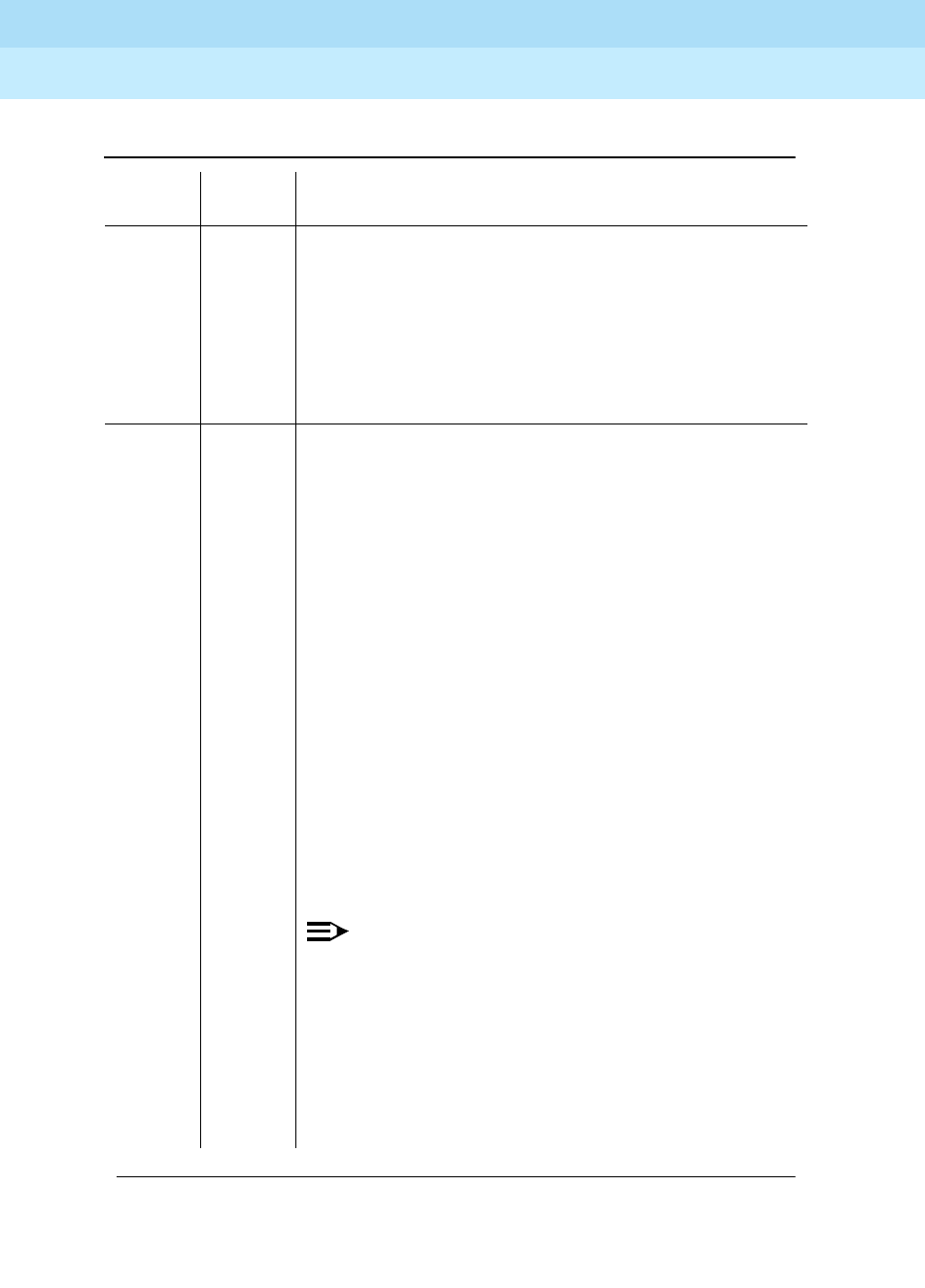
DEFINITY Enterprise Communications Server Release 6
Maintenance for R6r Volumes 1 & 2
555-230-126 Issue 2
January 1998
Maintenance Object Repair Procedures
Page 9-207BRI-SET, ASAI-ADJ, BRI-DAT
9
1144 ABORT The PPN Packet Bus is out-of-service.
1. Follow the repair procedures for the Packet Bus in
the PPN.
2. After completing Step 1, execute the test port long
PCSSpp command, and review the results of the
BRI Port Local LAN Loop Around Test to verify the
repair.
1187 ABORT The circuit pack, port or station may have been busied
out by a technician.
1. Look in the Error Log for Error Type 18 (busied out )
for BRI-BD, BRI-PORT, or BRI-SET.
a. If this error type is present for BRI-SET only, then
release the station via the release station
b. If this error type is present for BRI-PORT and
BRI-SET, then release the port via release port
PCSSpp command and run the test again.
c. If the error is present for BRI-BD, BRI-PORT, and
BRI-SET, then release the circuit pack via the
release port PCSSpp command and run the test
again. If the error is present for both BRI-BD and
BRI-PORT, then release the circuit pack via the
release board PPCSS command and run the test
again. If the error is present for BRI-SET only,
then release the circuit pack via the release port
PPCSS command and run the test again.
NOTE:
When you release the circuit pack, you release all
ports associated with it. If certain ports still need to
be busied out, use the release port PCSSpp
command to busy them out.
2. Make sure the terminal is connected.
3. Retry the command at one-minute intervals a
maximum of five times.
Table 9-73. TEST #627 BRI Remote Loop Back — Continued
Error
Code Test
Result Description/ Recommendation
Continued on next page

DEFINITY Enterprise Communications Server Release 6
Maintenance for R6r Volumes 1 & 2
555-230-126 Issue 2
January 1998
Maintenance Object Repair Procedures
Page 9-208BRI-SET, ASAI-ADJ, BRI-DAT
9
BRI XID Test (#628)
This test checks the D-channel connection between the SPE and the endpoint or
adjunct.
In this test, a D-channel XID frame is sent to the endpoint or adjunct over the
point-to-point signaling link. The test passes if the endpoint or adjunct responds
with a Layer 2 XID-RESPONSE frame
This test must be administered to not run in the station administration form for
ports on a TN2208.
2012 ABORT Internal System Error.
1. Retry the command at one-minute intervals a
maximum of five times.
2. If the test continues to abort, escalate the problem.
2068 ABORT The endpoint has rejected the switch sent application
message. This indicates that the endpoint does not
support the ISDN-BRI Management and Maintenance
Procedure for Loop Back Testing.
1. Use the change station extension command and
change the
MIMs Supported
field to n.
2069 ABORT The endpoint has returned an error response to the
application message sent by the switch.
2100 ABORT Could not allocate the necessary system resources to
run this test.
1. Retry the command at one-minute intervals a
maximum of five times.
2. If the test continues to abort, escalate the problem.
Table 9-73. TEST #627 BRI Remote Loop Back — Continued
Error
Code Test
Result Description/ Recommendation
Continued on next page
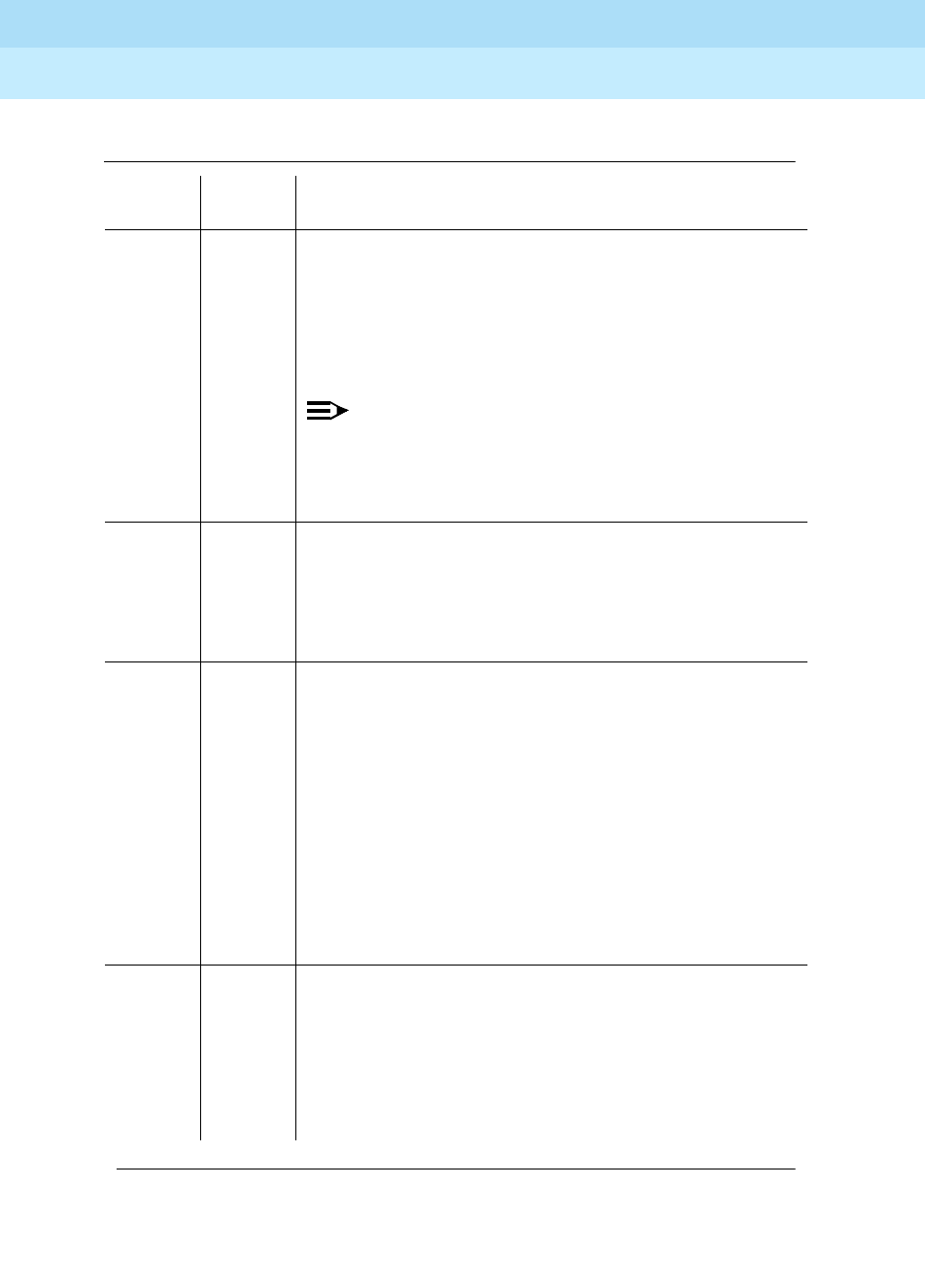
DEFINITY Enterprise Communications Server Release 6
Maintenance for R6r Volumes 1 & 2
555-230-126 Issue 2
January 1998
Maintenance Object Repair Procedures
Page 9-209BRI-SET, ASAI-ADJ, BRI-DAT
9
Table 9-74. TEST #628 BRI XID
Error
Code Test
Result Description/ Recommendation
1000 ABORT The BRI-SET, ASAI-ADJ, ATT-ADJ, LGATE-AJ, ATTE-AJ
is busy. The test cannot be executed at this time:
1. Pause momentarily (30 seconds) and re-execute at
this time.
2. If this problem persists, escalate this problem.
NOTE:
A BRI-PORT can also be busy. When using this for
BRI-PORT/ABRI-PORT tests, the words ‘‘BRI-SET,
ASAI-ADJ, ATT-ADJ,’’ can be changed to
‘‘BRI-PORT, ABRI-PORT, ATT-ADJ.’’
1005 ABORT The endpoint is not administered to support XID Testing.
1. If the endpoint documentation reflects support XID
testing, use the change station extension
command to change the
XID Testing?
field on the
form to y.
1113 ABORT The signaling link between the switch and the endpoint
is down.
1. Use the test port PCSSpp long command to clear
any errors which prevent establishment of the
signaling link.
2. Examine the results of the Signaling Link Status Test
(#626) which is run as part of this command. If this
test aborts or fails, follow the repair procedure for
Test #626.
3. If the XID Test #628 continues to abort, escalate the
problem.
1139 ABORT The Packet Bus in the port network is out-of-service.
1. Follow the repair procedures for the Packet Bus.
2. After completing Step 1, execute the test port long
PCSSpp command, and review the results of the
BRI Port Local LAN Loop Around Test to verify the
repair.
Continued on next page

DEFINITY Enterprise Communications Server Release 6
Maintenance for R6r Volumes 1 & 2
555-230-126 Issue 2
January 1998
Maintenance Object Repair Procedures
Page 9-210BRI-SET, ASAI-ADJ, BRI-DAT
9
1141 ABORT The PKT-CTRL is out-of-service.
1. Refer to PKT-CTRL (Packet Control Circuit Pack)
Maintenance documentation.
2. If Step 1 does not resolve the problem, escalate to
the next tier.
1144 ABORT The PPN Packet Bus is out-of-service.
1. Follow the repair procedures for the Packet Bus in
the PPN.
2. After completing Step 1, execute the test port long
PCSSpp command, and review the results of the
BRI Port Local LAN Loop Around Test to verify the
repair.
Table 9-74. TEST #628 BRI XID — Continued
Error
Code Test
Result Description/ Recommendation
Continued on next page
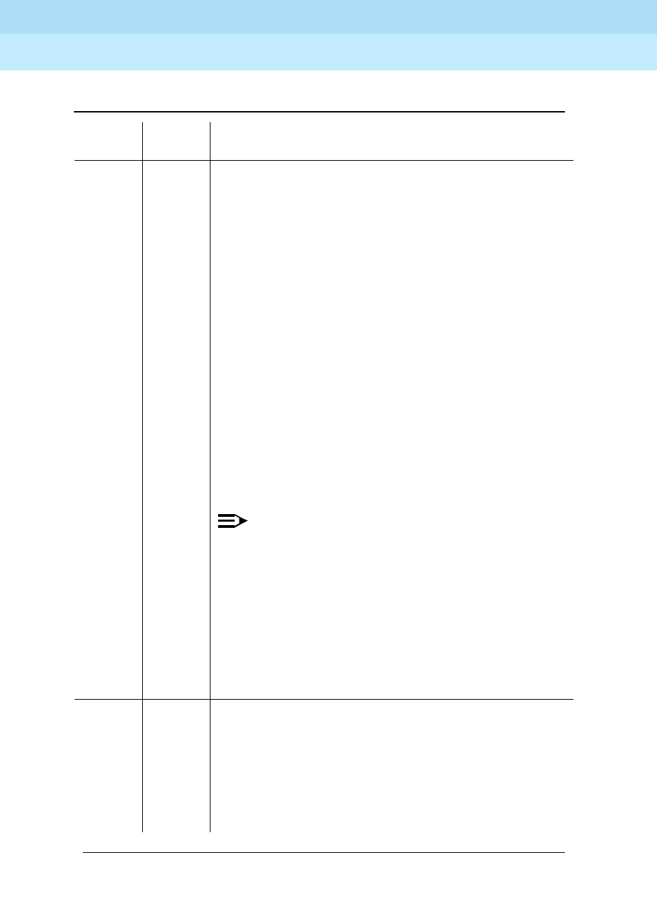
DEFINITY Enterprise Communications Server Release 6
Maintenance for R6r Volumes 1 & 2
555-230-126 Issue 2
January 1998
Maintenance Object Repair Procedures
Page 9-211BRI-SET, ASAI-ADJ, BRI-DAT
9
1187 ABORT The circuit pack, port or station may have been busied
out by a technician.
1. Look in the Error Log for Error Type 18 (busied out )
for BRI-BD, BRI-PORT, or BRI-SET.
a. If this error type is present for BRI-SET only, then
release the station via the release station
b. If this error type is present for BRI-PORT and
BRI-SET, then release the port via release port
PCSSpp command and run the test again.
c. If the error is present for BRI-BD, BRI-PORT, and
BRI-SET, then release the circuit pack via the
release port PCSSpp command and run the test
again. If the error is present for BRI-SET only,
then release the circuit pack via the release port
PCSSpp command and run the test again. If the
error is present for both BRI-BD and BRI-PORT,
then release the circuit pack via the release
board PPCSS command and run the test again.
NOTE:
When you release the circuit pack, you release all
ports associated with it. If certain ports still need to
be busied out, use the release port PCSSpp
command to busy them out.
2. Make sure the terminal is connected.
3. Retry the command at one-minute intervals a
maximum of five times.
4. If the test continues to abort, escalate the problem.
2012 ABORT Internal System Error.
2100 ABORT Could not allocate the necessary system resources to
run this test.
1. Retry the command at one-minute intervals a
maximum of five times.
2. If the test continues to abort, escalate the problem.
Table 9-74. TEST #628 BRI XID — Continued
Error
Code Test
Result Description/ Recommendation
Continued on next page

DEFINITY Enterprise Communications Server Release 6
Maintenance for R6r Volumes 1 & 2
555-230-126 Issue 2
January 1998
Maintenance Object Repair Procedures
Page 9-212BRI-SET, ASAI-ADJ, BRI-DAT
9
BRI Layer 3 Query Test (#629)
This test is used to check the application layer communications between the
switch and the endpoint or adjunct.
For BRI endpoints, an application message containing the appropriate endpoint
service state is sent by the switch to the endpoint. The endpoint responds with an
acknowledgment to the application message.
For ASAI and Lucent adjuncts, this test is not executed from the administration
terminal. Rather, a query message is automatically sent by the switch every two
minutes. Failure of the switch to receive a response to a query from the adjunct is
logged in the Hardware Error Log
2000 FAIL The XID-RESPONSE message was not received from
the endpoint.
1. Consult the endpoint documentation to determine if
the Layer 2 XID and XID-RESPONSE messages are
supported. If the documentation reflects no support
for these messages, change XID Testing? field to
‘‘no’’ using the change station extension
command.
2. If the endpoint supports these Layer 2 messages
and the test continues to fail, assume the endpoint is
defective and replace it.
3. If the test continues to fail, escalate the problem.
PASS The switch can successfully pass messages over the
D-channel to the BRI endpoint.
Table 9-74. TEST #628 BRI XID — Continued
Error
Code Test
Result Description/ Recommendation
Continued on next page

DEFINITY Enterprise Communications Server Release 6
Maintenance for R6r Volumes 1 & 2
555-230-126 Issue 2
January 1998
Maintenance Object Repair Procedures
Page 9-213BRI-SET, ASAI-ADJ, BRI-DAT
9
Table 9-75. TEST #629 BRI Layer 3 Query
Error
Code Test
Result Description/ Recommendation
1005 ABORT The endpoint’s MIMs Supported? field is administered to
‘‘no.’’
1. Use the change station extension command to
change the parameter only if the endpoint
documentation reflects support for ISDN-BRI
Management and Maintenance Procedures.
1113 ABORT The signaling link between the switch and the endpoint
or adjunct is down.
1. Use the test port PCSSpp long command to clear
any errors which prevent establishment of the
signaling link.
2. Examine the results of Test #626, which is executed
with the command. If this test aborts or fails, follow
the repair procedure for the Signaling Link Status
Test.
3. Escalate problem if BRI Layer 3 Query Test
continues to abort.
1139 ABORT The Packet Bus in the port network is out-of-service.
1. Follow the repair procedures for the Packet Bus.
2. After completing Step 1, execute the test port long
PCSSpp command, and review the results of the
BRI Port Local LAN Loop Around Test to verify the
repair.
1141 ABORT The PKT-CTRL is out-of-service.
1. Consult the repair procedure for PKT-CTRL (Packet
Control Circuit Pack) Maintenance documentation.
2. If Step 1 does not resolve the problem, escalate to
the next tier.
Continued on next page

DEFINITY Enterprise Communications Server Release 6
Maintenance for R6r Volumes 1 & 2
555-230-126 Issue 2
January 1998
Maintenance Object Repair Procedures
Page 9-214BRI-SET, ASAI-ADJ, BRI-DAT
9
1144 ABORT The PPN Packet Bus is out-of-service.
1. Follow the repair procedures for the Packet Bus in
the PPN.
2. After completing Step 1, execute the test port long
PCSSpp command, and review the results of the
BRI Port Local LAN Loop Around Test to verify the
repair.
1187 ABORT The circuit pack, port or station may have been busied
out by a technician.
1. Look in the Error Log for Error Type 18 (busied out )
for BRI-BD, BRI-PORT, or BRI-SET.
a. If this error type is present for BRI-SET only, then
release the station via the release station
b. If this error type is present for BRI-PORT and
BRI-SET, then release the port via the release
port PCSSpp command and run the test again.
c. If the error is present for BRI-BD, BRI-PORT, and
BRI-SET, then release the circuit pack via the
release port PCSSpp command and run the test
again. If the error is present for BRI-SET only,
then release the circuit pack via the release port
PPCSS command and run the test again. If the
error is present for both BRI-BD and BRI-PORT,
then release the circuit pack via the release
board PPCSS command and run the test again.
NOTE:
When you release the circuit pack, you release all
ports associated with it. If certain ports still need to
be busied out, use the release port PCSSpp
command to busy them out.
2. Make sure the terminal is connected.
3. Retry the command at one-minute intervals a
maximum of five times.
4. If the test continues to abort, escalate the problem.
Table 9-75. TEST #629 BRI Layer 3 Query — Continued
Error
Code Test
Result Description/ Recommendation
Continued on next page

DEFINITY Enterprise Communications Server Release 6
Maintenance for R6r Volumes 1 & 2
555-230-126 Issue 2
January 1998
Maintenance Object Repair Procedures
Page 9-215BRI-SET, ASAI-ADJ, BRI-DAT
9
2012 ABORT Internal System Error.
2100 ABORT Could not allocate the necessary system resources to
run this test.
1. Retry the command at one-minute intervals a
maximum of five times.
2. If the test continues to abort, escalate the problem.
2068 ABORT The endpoint has rejected the switch sent application
message. This indicates that the endpoint does not
support the ISDN-BRI Management and Maintenance
Procedure for Endpoint Service Messages.
1. Use the change station extension command and
change the MIMs Supported? field to ‘‘no.’’
2069 ABORT The endpoint has returned an error response to the
switch sent application message.
1. Retry the command at one-minute intervals a
maximum of five times.
2. If the test continues to abort, escalate the problem.
2000 FAIL No response is received from the endpoint or the
adjunct. For BRI endpoints:
1. Consult the endpoint documentation to determine if
ISDN-BRI Management and Maintenance
Procedures are supported. If not supported, use the
change station extension command to change the
‘‘MIMs Supported?’’ field to ‘‘no.’’ Use the busyout
station extension and release station extension
commands to busyout and release the endpoint to
resolve any endpoint alarms resulting from failure of
this test.
2. If the endpoint supports these procedures and the
test continues to fail, assume the endpoint is
defective and replace it.
PASS The endpoint has successfully responded to the
switch’s application message.
Table 9-75. TEST #629 BRI Layer 3 Query — Continued
Error
Code Test
Result Description/ Recommendation
Continued on next page

DEFINITY Enterprise Communications Server Release 6
Maintenance for R6r Volumes 1 & 2
555-230-126 Issue 2
January 1998
Maintenance Object Repair Procedures
Page 9-216BRI-SET, ASAI-ADJ, BRI-DAT
9
BRI Set Audits Test (#630)
This is a series of two tests which are classified as audits. The switch sends
messages to the BRI endpoint to perform the following tests:
■Ringer Audit - This audit insures that both the switch and the endpoint
agree as to the current state of the endpoint’s ringer.
■Lamps Audit - This audit insures that both the switch and the endpoint
agree as to the current state of the endpoint’s lamps.
■Call Activity Audit - This audit insures that the state of calls is consistent
between the switch and the endpoint.
This test is not executed for ASAI or Lucent adjunct because adjuncts do not
employ ringers or lamps, or establish calls on the B-channels associated with the
BRI interface
Table 9-76. TEST #630 BRI Set Audits
Error
Code Test
Result Description/ Recommendation
1113 ABORT The signaling link between the switch and the endpoint
is down.
1. Use the test port PCSSpp long command to clear
any errors which prevent establishment of the
signaling link.
2. Examine the results of the Signaling Link Status Test
(#626) which is run as part of this command. If this
test aborts or fails, follow the repair procedure for
Test #626.
3. If the BRI Set Audits test continues to abort, escalate
the problem.
1139 ABORT The Packet Bus in the port network is out-of-service.
1. Follow the repair procedures for the Packet Bus.
2. After completing Step 1, execute the test port long
PCSSpp command, and review the results of the
BRI Port Local LAN Loop Around Test to verify the
repair.
Continued on next page

DEFINITY Enterprise Communications Server Release 6
Maintenance for R6r Volumes 1 & 2
555-230-126 Issue 2
January 1998
Maintenance Object Repair Procedures
Page 9-217BRI-SET, ASAI-ADJ, BRI-DAT
9
1141 ABORT The PKT-CTRL is out-of-service.
1. Refer to PKT-CTRL (Packet Control Circuit Pack)
Maintenance documentation.
2. If Step 1 does not resolve the problem, escalate to
the next tier.
1144 ABORT The PPN Packet Bus is out-of-service.
1. Follow the repair procedures for the Packet Bus in
the PPN.
2. After completing Step 1, execute the test port long
PCSSpp command, and review the results of the
BRI Port Local LAN Loop Around Test to verify the
repair.
Table 9-76. TEST #630 BRI Set Audits — Continued
Error
Code Test
Result Description/ Recommendation
Continued on next page
DEFINITY Enterprise Communications Server Release 6
Maintenance for R6r Volumes 1 & 2
555-230-126 Issue 2
January 1998
Maintenance Object Repair Procedures
Page 9-218BRI-SET, ASAI-ADJ, BRI-DAT
9
1187 ABORT The circuit pack, port or station may have been busied
out by a technician.
1. Look in the Error Log for Error Type 18 (busied out )
for BRI-BD, BRI-PORT, or BRI-SET.
a. If this error type is present for BRI-SET only, then
release the station via the release station
b. If this error type is present for BRI-PORT and
BRI-SET, then release the port via the release
port PCSSpp command and run the test again.
c. If the error is present for BRI-BD, BRI-PORT, and
BRI-SET, then release the circuit pack via the
release port PCSSpp command and run the test
again. If the error is present for both BRI-BD and
BRI-PORT, then release the circuit pack via the
release board PPCSS command and run the test
again.
NOTE:
When you release the circuit pack, you release all
ports associated with it. If certain ports still need to
be busied out, use the release port PCSSpp
command to busy them out.
2. Make sure the terminal is connected.
3. Retry the command at one-minute intervals a
maximum of five times.
4. If the test continues to abort, escalate the problem.
2012 ABORT Internal System Error.
2100 ABORT Could not allocate the necessary system resources to
run this test.
1. Retry the command at one-minute intervals a
maximum of five times.
2. If the test continues to abort, escalate the problem.
PASS The switch has successfully executed the BRI station
audits.
Table 9-76. TEST #630 BRI Set Audits — Continued
Error
Code Test
Result Description/ Recommendation
Continued on next page

DEFINITY Enterprise Communications Server Release 6
Maintenance for R6r Volumes 1 & 2
555-230-126 Issue 2
January 1998
Maintenance Object Repair Procedures
Page 9-219BRI-SET, ASAI-ADJ, BRI-DAT
9
SPID Facility Test
This test is used to verify the wiring and operation of the signaling link between
the switch and a endpoint or adjunct on a BRI interface. This test is not
executed from the administration terminal, but rather is executed by using a
BRI test set equipped with a display. The test set may replace the BRI set,
ASAI or Lucent adjunct under test by plugging it into the same jack or by
bridging it onto the wiring at some point between the switch and the endpoint (or
adjunct), thereby creating a pseudo-BRI multipoint configuration.
When plugged into the port in this manner, the test set establishes a signaling
link connection with the switch and attempts to complete SPID initialization by
using the Service SPID administered for the system (see the System
Maintenance Administration Form). If the test set displays the correct
administered port address for the endpoint or adjunct under test, the test passes
(see Service SPID Display, which follows). If after one-minute nothing is
displayed on the test set, the test fails.
SPID Facility Test
Test
Result Description / Recommendation
FAIL No response is received from the endpoint.
1. Check the physical wiring between the switch and the
endpoint or adjunct.
2. If test continues to fail, escalate to the next tier.

DEFINITY Enterprise Communications Server Release 6
Maintenance for R6r Volumes 1 & 2
555-230-126 Issue 2
January 1998
Maintenance Object Repair Procedures
Page 9-220BRI-SET, ASAI-ADJ, BRI-DAT
9
The abbreviations used in (Service SPID Display) have the following meanings:
FAIL Display does not match administered port address for the
endpoint or adjunct.
1. Change station administration for endpoint or adjunct to
match displayed port address.
2. If test continues to fail, escalate the problem.
PASS Display matches administered port address for the endpoint or
adjunct.
For BRI endpoints:
1. Verify that the SPID values administered in the switch and
the endpoint are consistent.
2. If the SPID values are correct, replace the endpoint.
3. If test continues to fail, escalate the problem.
For ASAI adjuncts:
1. Verify that the TEI values administered in the switch and the
adjunct are consistent.
2. If the TEI values are correct, consult the recommended
repair procedures of the manufacturer for the adjunct.
3. If test continues to fail, escalate the problem.
UU Universal Cabinet number
(1 for PPN, 2 - 44 for EPN)
C Carrier (A,B,C, ...)
SS Slot (01, 02, ...)
pp port (01-12)
ext extension one and two (one through 99999)
SPID service order profile identifier
SPID Facility Test
Test
Result Description / Recommendation

DEFINITY Enterprise Communications Server Release 6
Maintenance for R6r Volumes 1 & 2
555-230-126 Issue 2
January 1998
Maintenance Object Repair Procedures
Page 9-221BRI-SET, ASAI-ADJ, BRI-DAT
9
Table 9-77. Service SPID Display
Restricted Service
starting display
column 8 142531
UUCSSpp - ext1 - SPID111111 - ext2 - SPID222222
starting display
column 8 142531
UUCSSpp * ext1 * SPID111111 - ext2 - SPID222222
Bound to Second
Endpoint
Translation starting
display column
8 142531
UUCSSpp - ext1 - SPID111111 * ext2 * SPID222222
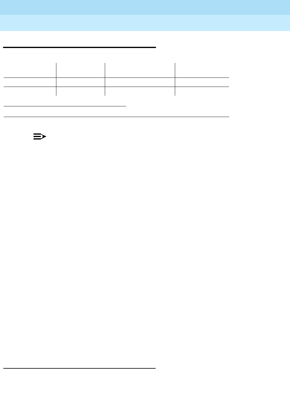
DEFINITY Enterprise Communications Server Release 6
Maintenance for R6r Volumes 1 & 2
555-230-126 Issue 2
January 1998
Maintenance Object Repair Procedures
Page 9-222CABINET (Cabinet Sensors)
9
CABINET (Cabinet Sensors)
NOTE:
The CABINET maintenance object is valid only for multi-carrier cabinets.
For information about environmental maintenance on single-carrier
cabinets, refer to DC-POWER.
The cabinet sensors monitor cabinet temperature and fan rotation. Variable-
speed fans are used extensively in DEFINITY Systems.
The SYSAM circuit pack in the PPN cabinet and the EPN Maintenance circuit
pack in a multi-carrier EPN cabinet monitor a temperature sensor (S1) at the top
of the cabinet and generate a major alarm if the exit air temperature exceeds 65
degrees Celsius (149 degrees Fahrenheit). Another temperature sensor in the
top of the cabinet (S2) also monitors exit air temperature. If it exceeds 70
degrees Celsius (158 degrees Fahrenheit), the power distribution unit turns off all
cabinet power and invokes emergency transfer. Other sensors monitor fan
performance.
The repair procedures that follow rely on your ability to distinguish between high
and low fan speeds by the sound of the fans. Experience will allow you to
distinguish between the high and low pitches generated by high and low speeds.
A thermometer is also required for some of the procedures that follow.
In making replacements, observe the following rules:
■New fan assemblies accept
only
variable-speed fans.
■Old fan assemblies accept either variable-speed or nonvariable-speed
fans.
■Replace a fan assembly (carrier)
only
with a fan assembly of the same
type (new for new, old for old).
Variable-Speed Fans
A variable-speed fan is identified by the following features:
■A fan and air filter assembly with product code ED-67077-30, Group 4 or
greater, labeled on the front of the carrier
1. UU is the universal cabinet number (1 for PPN, 2 -44 for EPNs).
MO Name (in
Alarm Log) Alarm Level Initial Command to
Run1Full Name of MO
CABINET MAJOR test environment UU Cabinet Sensors
CABINET MINOR test environment UU Cabinet Sensors

DEFINITY Enterprise Communications Server Release 6
Maintenance for R6r Volumes 1 & 2
555-230-126 Issue 2
January 1998
Maintenance Object Repair Procedures
Page 9-223CABINET (Cabinet Sensors)
9
■A five-pin white connector mounted next to each fan on the fan assembly
cover plate for speed control and alarm circuitry
■A two-pin black -48 V power connector to each fan
■A power filter (ED-1E554-30, G1 or G2) located in a metal box mounted
behind the fans on the right-hand cable trough as you face the rear of the
cabinet
■The AHD1 circuit pack and the two S4 sensors used with older fan
assemblies are
not
present.
Alarm leads from each fan are tied together into a single lead that registers a
minor alarm against CABINET whenever a fan’s speed drops below a preset limit
or fails altogether.
NOTE:
The front fans may run at a different speed than the rear fans since they are
controlled by different sensors.
Replacing Variable-Speed Fans
This procedure applies to replacement of a variable-speed fan (KS-23912, L3) in
a new type fan assembly (ED-67707-30, G4 or greater). Do
not
use a
nonvariable-speed fan in this assembly.
1. If replacing a fan in the front of the cabinet, remove the white plastic fan
assembly cover by pulling it outward. There is no cover on the rear fans;
they are accessible simply by opening the rear cabinet doors.
2.
Connect the grounding wrist strap to yourself and the cabinet.
The fan
alarm circuit can be damaged by ESD.
3. Disconnect the white 5-pin connector on the fan assembly.
4. Loosen and remove the retaining screw nearest the power connector on
the defective fan.
5. Disconnect the 2-pin black power plug on the fan.
6. Loosen and remove the other retaining screw on the fan.
7. Remove the fan from the fan assembly.
8. Position the new fan and insert the screw that is opposite the power
connector.
9. Connect the 2-pin black power plug on the fan.
10. Connect the white 5-pin connector on the fan assembly. Insert and tighten
the retaining screws.
11. Replace the front fan cover, if removed.

DEFINITY Enterprise Communications Server Release 6
Maintenance for R6r Volumes 1 & 2
555-230-126 Issue 2
January 1998
Maintenance Object Repair Procedures
Page 9-224CABINET (Cabinet Sensors)
9
Replacing the Fan Power Filter
The fan power filter (ED-1E554-30) is a metal box located behind the fans on the
right-hand cable trough as you face the rear of the cabinet. It is not present with
nonvariable-speed fan assemblies.
!CAUTION:
The fan power filter can be replaced without powering down the cabinet. To
avoid damage, you must use the following steps in the order shown. Note
that the J2F/P2F connectors on the power filter must not be connected
whenever connecting or disconnecting the J2/P2 connectors on the fan
assembly.
1. Access the power filter through the rear cabinet doors.
2.
Connect the grounding wrist strap to yourself and the cabinet.
The fan
alarm circuit can be damaged by ESD.
!CAUTION:
Failure to disconnect the J2F connector on the filter before the J2
connector on the fan assembly can damage the fan alarm circuits.
3. Disconnect cabinet local cable connector J2F from the P2F connector on
top of the power filter.
4. Disconnect cable connector J2 from the P2 connector on the fan
assembly.
5. Loosen the power filter mounting screws using a 5/16” nut driver and
remove the filter.
!CAUTION:
Failure to connect the J2 connector on the fan assembly can
damage the fan alarm circuits.
6. Connect the J2 cable connector of the replacement power filter to the P2
connector on the fan assembly.
7. Mount the new power filter on the screws and tighten.
8. Connect cabinet local cable connector J2F to the P2F connector on the
top of the power filter.
9. The fans should start rotating after a 4 second delay.

DEFINITY Enterprise Communications Server Release 6
Maintenance for R6r Volumes 1 & 2
555-230-126 Issue 2
January 1998
Maintenance Object Repair Procedures
Page 9-225CABINET (Cabinet Sensors)
9
Replacing the Top Temperature Sensor
The top temperature sensors are located at the top rear of the cabinet in some
cabinets. On these cabinets, the tape shelf is located on the rear door, at the
bottom.
1. From the rear of the cabinet, remove the screws holding the top
temperature sensor.
2. Replace the sensor with a new one using the screws removed above.
3. Route the cable along the path of the existing sensor cable.
4. Unplug the cable on the defective sensor and replace with the plug on the
new sensor.
5. Remove the old sensor from the cabinet.
Error Log Entries and Test to Clear Values
System Technician-Demanded Tests:
Descriptions and Error Codes
Always investigate tests in the order presented in the table below. By clearing
error codes associated with one test, you may also clear errors generated from
later tests in the sequence.
Table 9-78. Cabinet Sensors Error Log Entries
Error
Type Aux
Data Associated Test Alarm
Level On/Off
Board Test to Clear Value
0 0 Any Any Any test environment
UU
1 0 or 1 Cabinet Temperature
Query (#122) MINOR ON test environment
UU
s r 3
257 0 or 1 Cabinet Temperature
Query (#122) MAJOR ON test environment
UU
s r 3
Order of Investigation Short Test
Sequence Long Test
Sequence D/ND*
Battery & Battery Charger Query Test (#5)1XXND
AC Power Query Test (#78)2XXND
OLS Query Test (carrier E) (#127)3XXND
OLS Query Test (carrier D) (#127)3XXND
OLS Query Test (carrier A) (#127)3XXND
OLS Query Test (carrier B) (#127)3XXND
OLS Query Test (carrier C) (#127)3XXND
Emergency Transfer Query Test (#124)4XXND

DEFINITY Enterprise Communications Server Release 6
Maintenance for R6r Volumes 1 & 2
555-230-126 Issue 2
January 1998
Maintenance Object Repair Procedures
Page 9-226CABINET (Cabinet Sensors)
9
Cabinet Temperature Query Test (#122)
This test queries the SYSAM in a PPN or the EPN Maintenance circuit pack in an
EPN for the status of the temperature and fan sensors in the cabinet.
1. See the POWER section in this chapter.
2. See the AC-POWER section in this chapter.
3. See the CARR-POW section in this chapter.
4. See the EMG-XFER section in this chapter.
5. See the EXT-DEV section in this chapter.
6. See the RING-GEN section in this chapter.
Cabinet Temperature Query Test (#122) X X ND
External Alarm Lead Query Test (#120)5XXND
Analog Ring Generator Initial Test (#117)6XXND
Analog Ring Generator Query Test (#118)6XXND
Table 9-79. TEST #122 Cabinet Temperature Query Test
Error
Code Test
Result Description/ Recommendation
1000 ABORT System resources required to run test are not available.
1. Try (a).
2000 ABORT Response to the test request was not received within the allowable time
period.
1. Try (a).
2. If the test continues to abort with error code 2000, check for power
problems with the A carrier (PPN or EPN). Look for and resolve all
AC-POWER and CARR-POW alarms in a multi-carrier cabinet or
DC-POWER alarms in a single-carrier cabinet. Repeat the test.
3. If the test continues to abort with error code 2000, check for and
resolve all SYSAM errors in a PPN or MAINT errors in an EPN.
Repeat the test.
Continued on next page
Order of Investigation Short Test
Sequence Long Test
Sequence D/ND*

DEFINITY Enterprise Communications Server Release 6
Maintenance for R6r Volumes 1 & 2
555-230-126 Issue 2
January 1998
Maintenance Object Repair Procedures
Page 9-227CABINET (Cabinet Sensors)
9
Notes:
2029
2319 2500 ABORT Internal system error
1. Try (a).
1FAIL VARIABLE-SPEED FAN ASSEMBLIES: One or more fans have
stopped.
If none of the fans are running:
1. Resolve all alarms against “CARR-POW”.
2. Verify that 48 VDC is available to the fan power filter at the J2F local
cable connector. The voltage range is -42.5 V to -52.5 V. There
should be 48 VDC between the following pin pairs: 2/3, 8/9, 10/11. If
-48 VDC is not present, replace the CFY1B current limiter card.
3. If there is 48 VDC at the power filter input, verify that there is 48 VDC
at the power filter output using the following procedure exactly to
avoid damage to the fan alarm circuit. Note that the J2F/P2F
connectors on the power filter must be disconnected whenever
connecting or disconnecting the J2/P2 connectors on the fan
assembly.
First
disconnect connector J2F from P2F on the top of the
filter.
Then
disconnect J2 from P2 on the fan assembly. Reconnect
J2F to P2F on the filter. There should be 48 VDC between the
following pin pairs on the J2 connector: 2/3, 8/9, 10/11. If not,
replace the fan power filter using the procedure described
previously.
Be sure to disconnect the J2F/P2F connector again
before reconnecting the J2/P2.
If 48 VDC is present, the fans should
have power. Make sure all power connectors are sound and making
good contact.
Be sure to disconnect the J2F/P2F connector again
before reconnecting the J2/P2.
1
Continued
FAIL
Continued
If some of the fans are running and some are not:
1. Replace the defective fans. If all fans can then be started, wait 5
minutes and rerun the test. If the test fails again, proceed to the next
step below.
If all fans are running and the test fails with error code 1:
One or more fans may have a defective alarm circuit.
2. Remove all 6 white 5-pin connectors on the front and back of the fan
assembly. This will cause all fans to run at high speed and the alarm
to be cleared. If the alarm does not clear, the SYSAM (in a PPN) or
EPN Maintenance circuit pack is incorrectly reporting the problem.
Check for and resolve all errors against SYSAM or MAINT, and then
rerun the test.
3. One at a time, replace the 5-pin connectors and check to see if the
alarm recurs. Replace each fan whose reconnection causes a
recurrence of the alarm.
Table 9-79. TEST #122 Cabinet Temperature Query Test — Continued
Error
Code Test
Result Description/ Recommendation
Continued on next page

DEFINITY Enterprise Communications Server Release 6
Maintenance for R6r Volumes 1 & 2
555-230-126 Issue 2
January 1998
Maintenance Object Repair Procedures
Page 9-228CABINET (Cabinet Sensors)
9
a. Retry the command at 1-minute intervals a maximum of 5 times.

DEFINITY Enterprise Communications Server Release 6
Maintenance for R6r Volumes 1 & 2
555-230-126 Issue 2
January 1998
Maintenance Object Repair Procedures
Page 9-229CARR-POW
9
CARR-POW
Carrier Power Supply
DEFINITY systems support two different cabinet types: multi-carrier and
single-carrier. Single-carrier cabinets are used only for EPNs. Both cabinet types
may be powered by either AC or DC external power source. Environmental
maintenance differs according to cabinet type and external power supply.
!CAUTION:
Before powering down a cabinet or carrier that contains DEFINITY AUDIX
circuit packs (TN566), first power down the AUDIX unit to avoid damaging
the AUDIX software. Instructions for powering down this unit are in the
‘‘DEFINITY AUDIX System Power Procedures’’ in Chapter 5, ‘‘Responding
to Alarms and Errors’’, on the circuit pack, and in DEFINITY AUDIX
documentation.
The CARR-POW maintenance object represents the pair of power supplies that
supply +5V, -48V and -5 VDC power to each carrier in a multi-carrier cabinet. In
AC-powered cabinets, these are called Off Line Switches (OLS); in DC-powered
cabinets, they are DC/DC converters.
Cycling Power Supplies
When a port carrier power supply problem is reported by hardware, the system
can cycle the power supplies in that carrier. When a carrier is cycled, the power
supplies are turned off for 2 seconds and then turned back on. The system
cannot cycle the power supplies on any of the following types carriers even if
they are duplicated:
— PPN control carrier
— Expansion control carrier
— Switch node carrier
— Single-carrier cabinet
1.
UU
is the universal cabinet number (1 for PPN, 2-44 for EPNs),
C
is the carrier designation (A,
B, C, D, or E). Cycle the carrier indicated by the PORT field in the alarm log.
MO Name (in
Alarm Log) Alarm Level Initial Command to
Run1Full Name of MO
CARR-POW MAJOR Cycle carrier
UUC
Carrier Port Power Supply
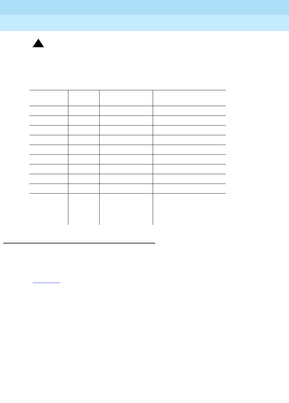
DEFINITY Enterprise Communications Server Release 6
Maintenance for R6r Volumes 1 & 2
555-230-126 Issue 2
January 1998
Maintenance Object Repair Procedures
Page 9-230CARR-POW
9
!WARNING:
When port carrier power is cycled, all service dependent upon circuit packs
in that carrier are disrupted.
AC-Powered Cabinets
AC Power Distribution Unit and Battery Charger
(J58890CE-2)
Figure 9-7 shows an AC Power Distribution Unit (List 9 or List 10). This unit sits at
the bottom of some Multi-Carrier Cabinets.
Carrier Port Power Supplies—Multi-Carrier Cabinets
Code System
Power Output (VDC) Location
631DA AC +5 Left side
631DB AC -48/-5 Right side
644A DC +5 Left side
645B DC -48/-5 Right Side
TN755B 165 Slots 17 and 18
631WA/AR AC +5 Left side
631WB/BR AC -48 Right side
TN736 AC -5 Used with 631
TN752 AC 165/-5 WA/WB or AR/AB
649A AC -48 at 10 Amps
+5 VDC and -5
VDC at 6 Amps
Right side on control
and port carriers. Left
and right side on
switch node carriers.
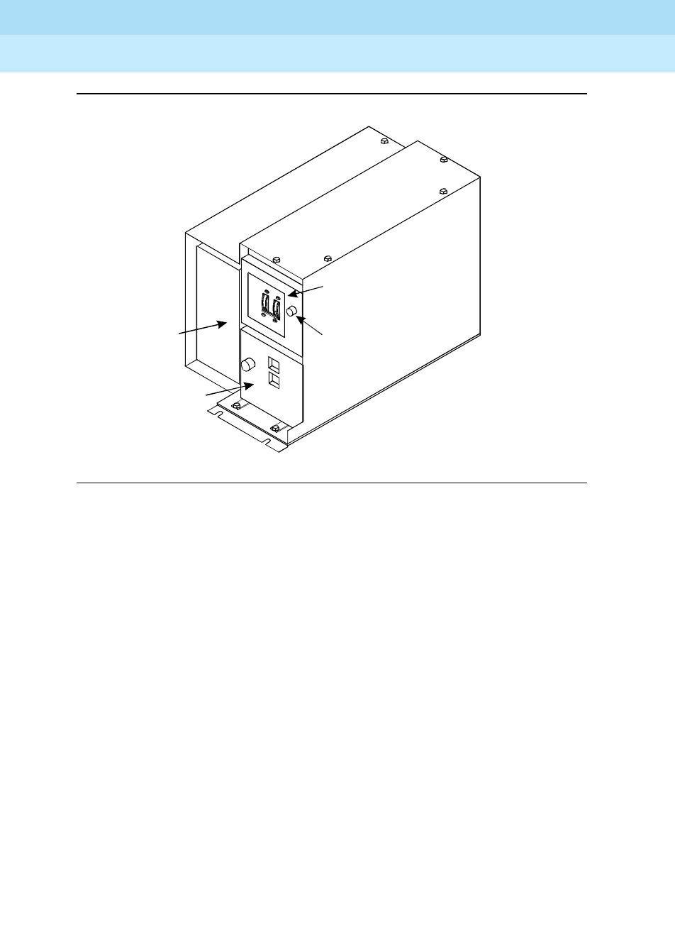
DEFINITY Enterprise Communications Server Release 6
Maintenance for R6r Volumes 1 & 2
555-230-126 Issue 2
January 1998
Maintenance Object Repair Procedures
Page 9-231CARR-POW
9
Figure 9-7. AC Power Distribution Unit (J58890CE-2) — Front
The AC Power Distribution Unit contains the following components:
■Circuit breaker
■Electromagnetic Interference (EMI) filter
■Ring generator
■AC input fuse
■20 Amp fuses
■Signal connector
■-48 VDC fan power
j58890ce RBP 031996
Circuit
Breakers
Ring
Generator
631DB
Power Unit Ring Generator
Fuse
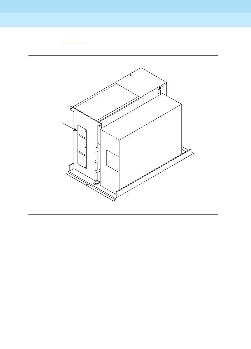
DEFINITY Enterprise Communications Server Release 6
Maintenance for R6r Volumes 1 & 2
555-230-126 Issue 2
January 1998
Maintenance Object Repair Procedures
Page 9-232CARR-POW
9
The optional battery charger (List 11) sits at the bottom of some Multi-Carrier
Cabinets. See Figure 9-8.
Figure 9-8. Battery Charger (Optional Part of J58890CE-2) — Front
The charger is used only without an Uninterruptible Power Supply (UPS). The
charger contains:
■Three 48 VDC batteries for backup power to the cabinet
■A DC power relay to automatically switch the batteries into the power
circuit if a main power failure is detected
Batteries
Battery
Charger
battchar RBP 031996
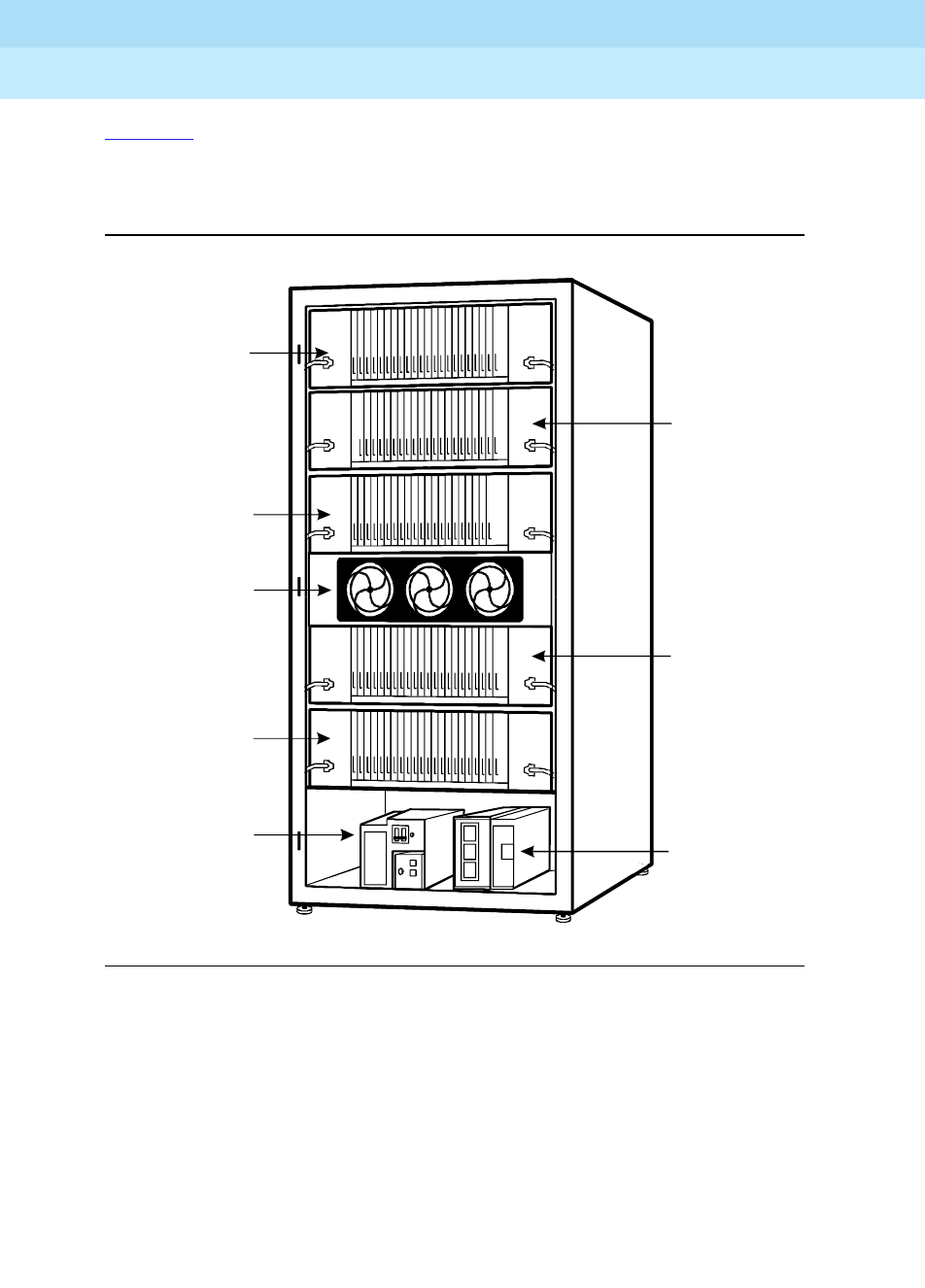
DEFINITY Enterprise Communications Server Release 6
Maintenance for R6r Volumes 1 & 2
555-230-126 Issue 2
January 1998
Maintenance Object Repair Procedures
Page 9-233CARR-POW
9
Figure 9-9 shows AC power distribution in some Multi-Carrier Cabinets. The DC
power distribution cables are on both sides of the cabinet. These cables supply
power to each of the carriers. The optional battery charger is at the right side of
the power distribution unit.
Figure 9-9. AC Power Distribution in Multi-Carrier Cabinets
Power Backup
If AC power fails, three 48 VDC batteries power the system for 10 seconds in a
PPN cabinet, for 15 seconds in an EPN cabinet, and for 10 minutes in the control
carrier in a standard reliability system. The batteries also supply system power
for five minutes in the control carrier in high and critical reliability systems, and for
10 minutes in the expansion control carrier in the "A" position of an EPN cabinet
(Release 5r only).
3
2
"C" Position
Carrier
"B" Position
Carrier
"A" Position
Carrier
"D" Position
Carrier
Battery
Charger
(Optional)
"E" Position
Carrier
"F" Position
Fan Unit
Power
Distribution
Unit
mcc4_g3 RBP 041696
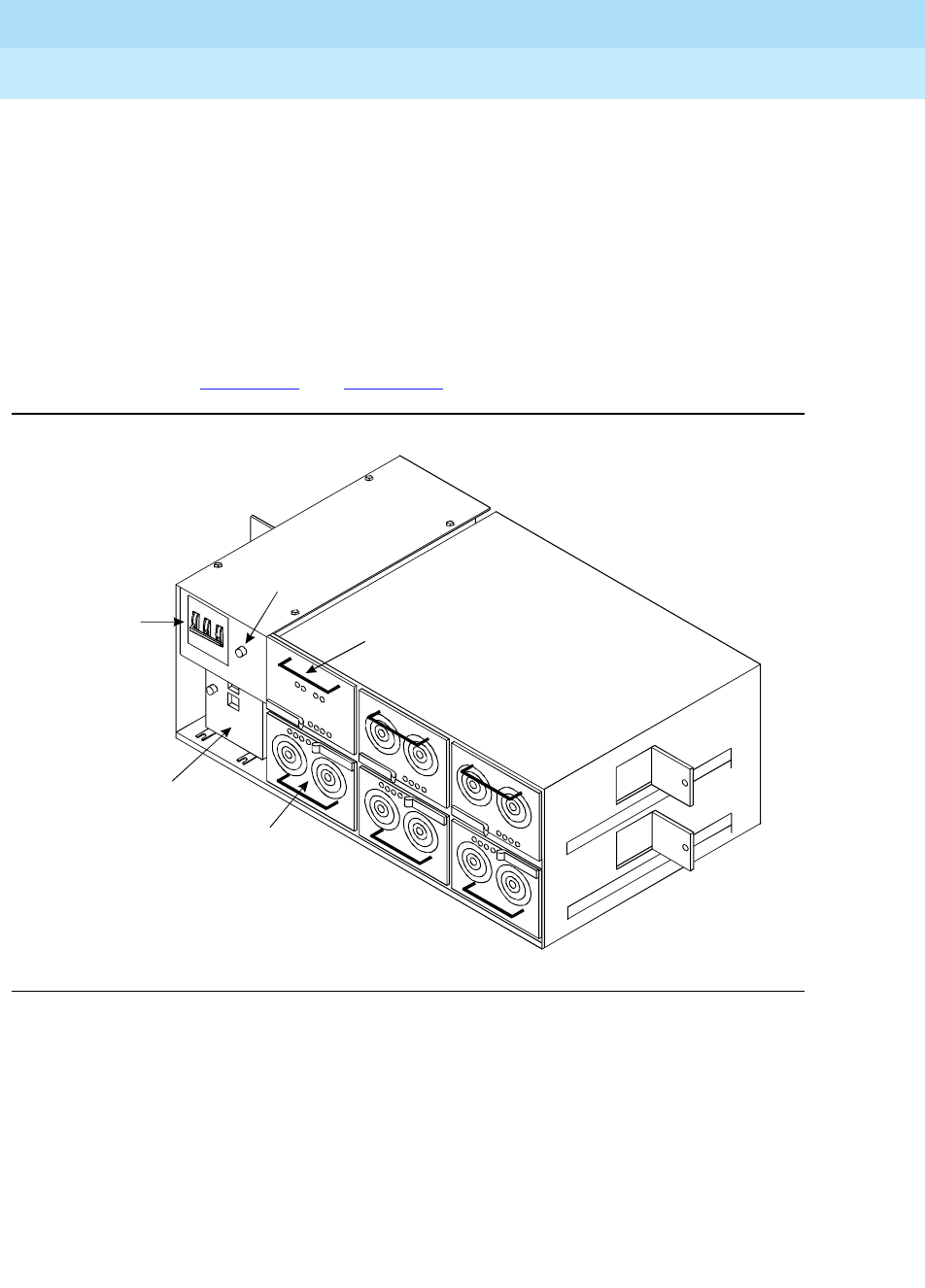
DEFINITY Enterprise Communications Server Release 6
Maintenance for R6r Volumes 1 & 2
555-230-126 Issue 2
January 1998
Maintenance Object Repair Procedures
Page 9-234CARR-POW
9
Uninterruptible Power Supply
An external UPS provides a longer backup time than holdover batteries and can
replace the batteries and battery charger. The unit connects from the AC power
source to a cabinet’s AC power cord. If AC power fails, the unit supplies its own
AC power to the cabinet.
J58890CH-1
In AC powered cabinets, the power distribution unit (J58890CH-1), distributes
170 to 264 VAC from a wall outlet to a set of BU3200A Battery Interface Units
(BIU). See Figure 9-10 and Figure 9-11.
Figure 9-10. AC Power Distribution Unit (J58890CH-1) — Front
Circuit
Breakers
Rectifier
Modules
Ring
Generator
Ring Generator
Fuse
Battery
Interface
Unit
j58890ch RBP 071596
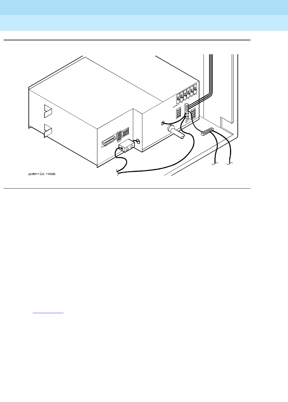
DEFINITY Enterprise Communications Server Release 6
Maintenance for R6r Volumes 1 & 2
555-230-126 Issue 2
January 1998
Maintenance Object Repair Procedures
Page 9-235CARR-POW
9
Figure 9-11. Power Distribution Unit (J58890CH-1)
Power Backup
The small battery is at the center rear of the Multi-Carrier Cabinet. This eight Amp
Hour (AH) battery is fused for short circuit protection and is charged by the
J58890CH-1. The batteries also contain a thermal sensor that changes the
charging voltage depending on battery temperature.
The small batteries provide short-term battery holdover. If AC power fails, 48
VDC batteries power the system for 10 seconds in a PPN cabinet, for 15 seconds
in an EPN cabinet, and for 10 minutes in the control carrier in a standard
reliability system. The batteries also provide system power for five minutes in the
control carrier in high and critical reliability systems, and for 10 minutes in the
expansion control carrier in the "A" position of an EPN cabinet (Release 5r only).
Figure 9-12 shows the small battery assembly.
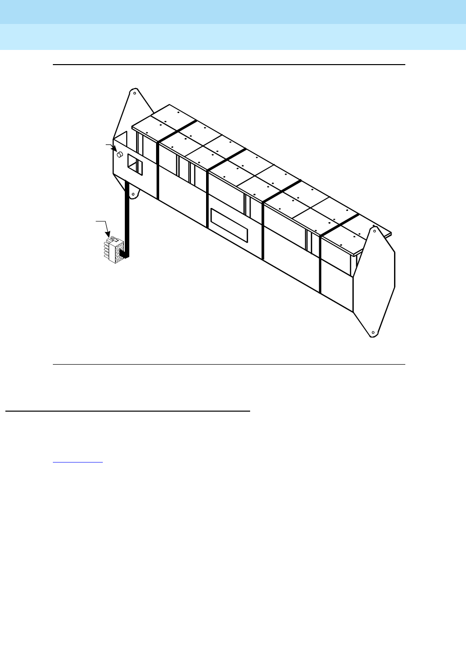
DEFINITY Enterprise Communications Server Release 6
Maintenance for R6r Volumes 1 & 2
555-230-126 Issue 2
January 1998
Maintenance Object Repair Procedures
Page 9-236CARR-POW
9
Figure 9-12. Small Battery Assembly
DC-Powered Cabinets
DC Power Distribution Unit (J58890CF-2)
Figure 9-13 shows a power distribution unit in some DC-powered Multi-Carrier
Cabinets. The unit sits at the bottom of the cabinet and contains the ring
generator, 20 Amp circuit breakers, terminal blocks, and system fan power.
0064_0 RBP 071596
Fuse
Battery
Connector
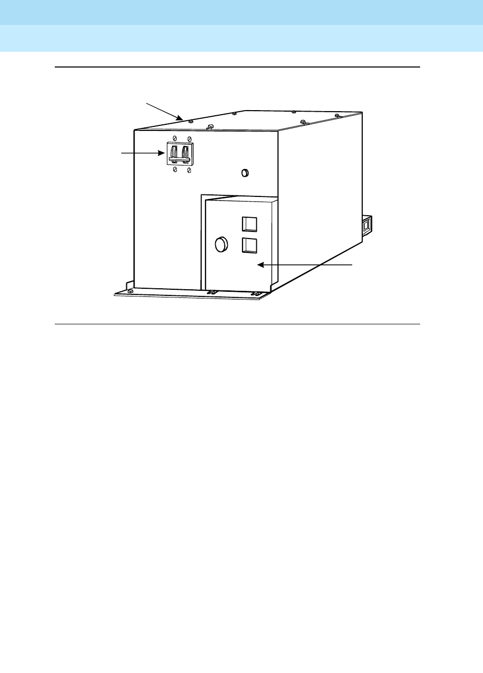
DEFINITY Enterprise Communications Server Release 6
Maintenance for R6r Volumes 1 & 2
555-230-126 Issue 2
January 1998
Maintenance Object Repair Procedures
Page 9-237CARR-POW
9
Figure 9-13. DC Power Distribution Unit (J58890CF-2) — Front
Some carriers may contain two power supplies, the 644A and the 645B, which
together supply the required voltages to the carrier. Other carriers may contain
one 649A power supply located on the right side of the carrier. In these systems,
an additional 649A is located on the right of the optional switch node carriers.
Loss of the 645B Carrier Port Power Supply in the active PPN control carrier
causes the management terminal login to drop. In a system with duplicated SPEs
CARR-POW alarms do not cause an interchange, but loss of power to PROC,
MEM-BD, SW-CTL, SYSAM, and PKT-INT maintenance objects (powered from
the left side of the active control carrier) reduces the SPE state of health, possibly
causing an interchange. Loss of power on the right side of the active control
carrier causes the HOST-ADAPTER, DISK, and TAPE maintenance objects to fail,
these failures do not cause an SPE interchange.
4
2
Circuit
Breakers
DC Power
Distribution
Unit
Ring
Generator
Terminal
Block
mcc_dc_1 PDH 062696
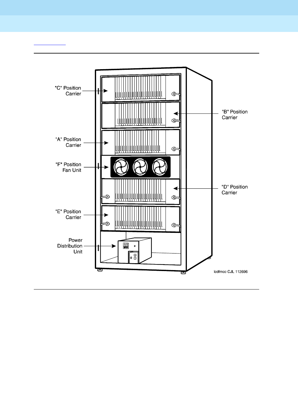
DEFINITY Enterprise Communications Server Release 6
Maintenance for R6r Volumes 1 & 2
555-230-126 Issue 2
January 1998
Maintenance Object Repair Procedures
Page 9-239CARR-POW
9
The table below shows which carriers are protected by each circuit breaker on
the J58890CF-1. The ring generator is protected by a fuse located next to the
main circuit breaker on the front of the unit.
The atable below shows which carriers are protected by each circuit breaker on
the J58890CH-1. The ring generator is protected by a fuse located next to the
main circuit breaker on the front of the unit.
Neon Lamp Power
The system can also support neon message waiting lamps on analog
telephones. Any carrier containing a TN769 Neon Analog Line circuit packs must
also be supplied with 150 Volts from a TN755B power supply circuit pack. See
the table above for other supported neon power circuit packs.
Circuit
Breaker Associated Carriers
CB1 Carrier A, both sides
CB2 Carrier B, both sides
CB3 Carrier C, both sides
CB4 Carrier D, both sides
CB5 Carrier E, both sides
CB6 Level F (Fans) and Level G (Ring Generator)
Circuit
Breaker Associated Carriers
CB1 Carrier A, both sides
CB2 Carrier B, both sides
CB3 Carrier C, both sides
CB4 Carrier D, both sides
CB5 Carrier E, both sides
CB6 Level F (Fans) and Level G (Ring Generator)
DEFINITY Enterprise Communications Server Release 6
Maintenance for R6r Volumes 1 & 2
555-230-126 Issue 2
January 1998
Maintenance Object Repair Procedures
Page 9-240CARR-POW
9
Error Log Entries and Test to Clear Values
!WARNING:
The OLS Recycle Test (#126) is destructive. For more information, refer to
the description of this test.
System Technician-Demanded Tests:
Descriptions and Error Codes
Always investigate tests in the order presented in the table below. By clearing
error codes associated with the
Battery & Battery Charger Query Test
, for
example, you may also clear errors generated from other tests in the testing
sequence.
1. Run the OLS Query Test (#127) first using the test environment UUr 2 command. Then, if a
carrier must be recycled to clear the CARR-POW alarm, use the recycle carrier UUC command
to run the OLS Recycle Test (#126). The OLS Recycle Test (#126) is not included in either the long
or short test sequences.
Table 9-80. Carrier Port Power Supply Error Log Entries
Error
Type Aux
Data Associated Test Alarm
Level On/Off
Board Test to Clear Value
110 or 1 OLS Query Test (#127) MAJOR ON test environment
UU
r 2
recycle carrier
UUC
Order of Investigation Short Test
Sequence Long Test
Sequence D/ND1
Battery & Battery Charger Query Test (#5) (a) X X ND
AC Power Query Test (#78) (b) X X ND
OLS Query Test (carrier E) (#127) X X ND
OLS Query Test (carrier D) (#127) X X ND
OLS Query Test (carrier A) (#127) X X ND
OLS Query Test (carrier B) (#127) X X ND
OLS Query Test (carrier C) (#127) X X ND
OLS Recycle Carrier Test (#126) D
Emergency Transfer Query Test (#124) (c) X X ND
Cabinet Temperature Query Test (#122) (d) X X ND
External Alarm Lead Query Test (#120) (e) X X ND
Analog Ring Generator Initialization Test (#117) (f) X X ND
Analog Ring Generator Query Test (#118) (f) X X ND

DEFINITY Enterprise Communications Server Release 6
Maintenance for R6r Volumes 1 & 2
555-230-126 Issue 2
January 1998
Maintenance Object Repair Procedures
Page 9-241CARR-POW
9
Notes:
a. Refer to “POWER” section for a description of this test.
b. Refer to “AC-POWER” section for a description of this test.
c. Refer to “EMG-XFER” section for a description of this test.
d. Refer to “CABINET” section for a description of this test.
e. Refer to “EXT-DEV” section for a description of this test.
f. Refer to “RING-GEN” section for a description of this test.
OLS Recycle Test (#126)
This test is destructive.
This test removes power from the specified carrier and causes all circuit packs in
the recycled carrier to be removed and inserted. These actions cause all calls
originating or terminating on circuit packs in this carrier to be dropped. The pair
of OLSs in the specified carrier is recycled. Both OLSs in the carrier are turned
off for 2 seconds and then back on again. After the OLSs have been turned back
on, the test queries the SYSAM in a PPN or the EPN Maintenance circuit pack in
an EPN for the status of the pair of OLSs in the specified carrier. If both OLSs are
on and functioning, then the test passes. If both OLSs are not on and functioning,
the test fails, and BOTH OLSs are turned off.
1. D = Destructive; ND = Nondestructive

DEFINITY Enterprise Communications Server Release 6
Maintenance for R6r Volumes 1 & 2
555-230-126 Issue 2
January 1998
Maintenance Object Repair Procedures
Page 9-242CARR-POW
9
Notes:
a. Retry the command at 1-minute intervals a maximum of 5 times.
Table 9-81. TEST #126 OLS Recycle Test
Error
Code Test
Result Description/ Recommendation
1000 ABORT System resources required for this test are not available.
1. Try (a).
1366 ABORT Indicates that the active Tone/Clock for the EPN is in requested carrier.
1. If duplicated Tone/Clock boards exist, issue the set tone-clock
command to switch Tone/Clocks, otherwise the power cannot be
cycled.
2. If the switch succeeds, rerun the test.
1367 ABORT Indicates that the active Expansion Interface link for the EPN is in requested
carrier.
1. If duplicated EIs exist, issue the reset pnc interchange command to
switch EIs, otherwise the power cannot be cycled.
2. If the switch succeeds, rerun the test.
2000 ABORT Response to the test request was not received within the allowable time
period.
1. Try (a).
2029
2319
2320
2500
ABORT Internal system error
1. Try (a).
FAIL There is a problem with one or both OLSs on the cycled carrier.
1. Since the OLS Recycle Test failed, both OLSs in the cycled carrier
should have been powered off by the system software. Both OLSs
should be showing a red status LED, instead of a yellow one. Since the
OLS Query Test is a subset of the OLS Recycle Test, the OLS Query
Test (#127) should also fail. Run the OLS Query Test by using the test
environment UU command where UU is the appropriate cabinet
number.
2. If test #127 fails, follow the repair procedures described for Test #127.
PASS Both OLSs in the recycled carrier were found to be healthy by the SYSAM in
a PPN or the EPN Maintenance circuit pack in an EPN after the OLSs were
powered down and back up. If the status LEDs on both OLSs are not
showing yellow, then the SYSAM or the EPN MAINT (Maintenance) circuit
pack may have incorrectly reported the state of the OLSs. Resolve any
alarms on these MOs.
Continued on next page

DEFINITY Enterprise Communications Server Release 6
Maintenance for R6r Volumes 1 & 2
555-230-126 Issue 2
January 1998
Maintenance Object Repair Procedures
Page 9-243CARR-POW
9
Off-Line Switcher (OLS) Query Test (#127)
This test queries the SYSAM in a PPN or the EPN Maintenance circuit pack in an
EPN for the status of the pair of OLSs in the specified carrier. If both OLSs are on
and functioning, then the test passes. If both are not on and functioning, it fails.
Table 9-82. TEST #127 OLS Query Test
Error
Code Test
Result Description/ Recommendation
1000 ABORT System resources required for this test are not available.
1. Try (a).
2000 ABORT Response to the test request was not received within the allowable time
period.
1. Try (a).
2. If the test continues to ABORT with error code 2000, check for system
powering problems with the A carrier (PPN or EPN). Resolve all
AC-POWER and CARR-POW alarms in a multi-carrier cabinet system or
DC-POWER alarms in a single-carrier cabinet system. Then, repeat the
test.
3. If the test continues to ABORT with a 2000 error code, resolve all
SYSAM errors in the PPN or MAINT (EPN Maintenance circuit pack)
errors in an EPN. Then, repeat the test.
2029
2500 ABORT Internal system error
1. Try (a).
FAIL AC POWERED SYSTEMS
There is a problem with one or both OLSs on the tested carrier.
1. For each OLS that has all status LEDs OFF, check the AC input to the
OLS at the OLS outlet. If there is no AC, then check the appropriate
fuses for the affected OLS. Replace open fuses. If the fuses open again
or AC does not show up at the OLS outlet, then there is probably a
power wiring problem in the cabinet.
2. At this point, AC should be present at the OLS outlet. Use the recycle
carrier UUC command (where
UUC
is the appropriate cabinet and
carrier) in an attempt to bring back the OLSs for this carrier. If the test
passes, the trouble is cleared. If the test does not pass, one OLS or
both, in the tested carrier is defective. If only one OLS is defective, then
the status LEDs on the healthy OLS will light green for a moment. When
the recycle test determines that both OLSs are defective, the software
will turn off power to both the good and defective OLSs. This will cause
the status LED(s) on the good OLS to light red.
3. Unplug both OLSs, and wait approximately 1-minute to allow the OLSs
to cool down. Plug in the OLSs. If either OLS is operating properly (the
status LEDs show green), then replace the defective OLS(s). See OLS
Replacement Procedures in this section.
Continued on next page

DEFINITY Enterprise Communications Server Release 6
Maintenance for R6r Volumes 1 & 2
555-230-126 Issue 2
January 1998
Maintenance Object Repair Procedures
Page 9-244CARR-POW
9
FAIL
(cont’d.)
4. If the replaced OLS(s) still do not operate properly, then a circuit pack
or a defective telephone connected to a circuit pack in the affected
carrier could be causing an electrical load which is preventing the OLS
from operating properly. Unseat all the circuit packs in the carrier, and
reissue the recycle carrier command.
a. If the recycle passes, then the OLSs are healthy, and the problem is
with one of the circuit packs. Reinsert the circuit packs one at a time.
If the status LED shows red after reinserting a circuit pack, then
replace the defective circuit pack. If the status LED still shows red,
then remove the amphenol connector on the back of the slot
containing this circuit pack and reissue the recycle carrier
command. If the status LED shows green, then the problem is with
one of the telephones or the wiring to one of the telephones on this
slot.
b. If either OLS still shows a red status LED, then check for bent pins
and cable placement in the affected carrier. There are failures that
can occur on the SYSAM and EPN Maintenance circuit pack that
will
not
be detected by their respective maintenance, but which will
cause many, if not all, environment tests to fail. If many environment
tests are failing, the suspect circuit pack, depending on the system
configuration, should be replaced and the test rerun.
FAIL DC POWERED SYSTEMS
There is a problem with one or both port carrier power supplies on the tested
carrier.
1. For each port carrier power supply that has all status LEDs OFF, check
the DC input to the port carrier power supply at the port carrier power
supply outlet. If there is no DC, then check the appropriate circuit
breakers for the affected port carrier power supply. If the circuit breaker
has tripped, reset the circuit breaker. If the circuit breaker trips again or
DC is not present at the port carrier power supply outlet, then there is
probably a power wiring problem in the cabinet.
2. At this point, DC should be present at the port carrier power supply
outlet. Use the recycle carrier UUC command (where
UUC
is the
appropriate cabinet and carrier) in an attempt to bring back the port
carrier power supplies for this carrier. If the test passes, the trouble is
cleared. If the test does not pass, one port carrier power supply, or
both, in the tested carrier is defective. If only one port carrier power
supply is defective, then the status LEDs on the healthy port carrier
power supply will light green for a moment. When the recycle test
determines that both port carrier power supplies are defective, the
software will turn off power to both the good and defective port carrier
power supplies. This will cause the status LED(s) on the good port
carrier power supply to light red.
Table 9-82. TEST #127 OLS Query Test — Continued
Error
Code Test
Result Description/ Recommendation
Continued on next page

DEFINITY Enterprise Communications Server Release 6
Maintenance for R6r Volumes 1 & 2
555-230-126 Issue 2
January 1998
Maintenance Object Repair Procedures
Page 9-245CARR-POW
9
Notes:
FAIL
(cont’d.)
3. Unplug both port carrier power supplies, and wait approximately
1-minute to allow the power supplies to cool down. Plug in the power
supplies. If either power supply is operating properly (the status LEDs
show green), then replace the defective power supply(s). See "Port
Carrier Power Supply Replacement Procedures" above.
4. If the replaced port carrier power supply(s) still do not operate properly,
then a circuit pack or a defective telephone connected to a circuit pack
in the affected carrier could be causing an electrical load which is
preventing the power supply from operating properly. Unseat all the
circuit packs in the carrier, and reissue the recycle carrier command.
a. If the recycle passes, then the port carrier power supplies are
healthy, and the problem is with one of the circuit packs. Reinsert the
circuit packs one at a time. If the status LED shows red after
reinserting a circuit pack, then replace the defective circuit pack. If
the status LED still shows red, then remove the amphenol connector
on the back of the slot containing this circuit pack and reissue the
recycle carrier command. If the status LED shows green, then the
problem is with one of the telephones or the wiring to one of the
telephones on this slot.
b. If either port carrier power supply still shows a red status LED, then
check for bent pins and cable placement in the affected carrier.
There are failures that can occur on the SYSAM and EPN
Maintenance circuit pack that
will not
be detected by their respective
maintenance, but which will cause many, if not all, environment tests
to fail. If many environment tests are failing, the suspect circuit pack,
depending on the system configuration, should be replaced and the
test rerun.
PASS AC POWERED SYSTEMS
Both OLSs in the tested carrier were found to be healthy by the SYSAM in a
PPN or the EPN Maintenance circuit pack in an EPN. If the status LEDs on
both OLSs are not showing green, then the SYSAM or the EPN MAINT circuit
pack may have incorrectly reported the state of the OLSs. Resolve any
alarms on these MOs.
DC POWERED SYSTEMS
Both port carrier power supplies in the tested carrier were found to be
healthy by the SYSAM in a PPN or the EPN Maintenance circuit pack in an
EPN. If the status LEDs on both port carrier power supplies are not showing
green, then the SYSAM or EPN MAINT circuit pack may have incorrectly
reported the state of the port carrier power supplies. Resolve any alarms on
these MOs.
Table 9-82. TEST #127 OLS Query Test — Continued
Error
Code Test
Result Description/ Recommendation
Continued on next page

DEFINITY Enterprise Communications Server Release 6
Maintenance for R6r Volumes 1 & 2
555-230-126 Issue 2
January 1998
Maintenance Object Repair Procedures
Page 9-246CARR-POW
9
a. Retry the command at 1-minute intervals a maximum of 5 times.

DEFINITY Enterprise Communications Server Release 6
Maintenance for R6r Volumes 1 & 2
555-230-126 Issue 2
January 1998
Maintenance Object Repair Procedures
Page 9-247CDR-LNK (Call Detail Recording Link)
9
CDR-LNK (Call Detail Recording
Link)
Refer to the PRI-CDR/SEC-CDR (Primary and Secondary CDR Links) section for
Call Detail Recording Link problems.
MO Name (in
Alarm Log) Alarm
Level Initial Command to Run Full Name
of MO
CDR-LINK MINOR test cdr [primary/secondary] l CDR Link
CDR-LINK WARNING test cdr [primary/secondary] CDR Link

DEFINITY Enterprise Communications Server Release 6
Maintenance for R6r Volumes 1 & 2
555-230-126 Issue 2
January 1998
Maintenance Object Repair Procedures
Page 9-248CLSFY-BD (Call Classifier Circuit Pack)
9
CLSFY-BD (Call Classifier Circuit
Pack)
Refer to “XXX-BD (Common Port Circuit Pack)” for circuit pack level errors. See
also “Call Classifier Port (CLSFY-PT)” for related port information.
1. 4UU is the universal cabinet number (1 for PPN, 2 -44 for EPNs). C is the carrier
designation (A, B, C, D, or E). SS is the number of the slot in which the circuit pack resides
(01 to 21).
MO Name (in
Alarm Log) Alarm
Level Initial Command to
Run1Full Name of MO
CLSFY-BD MIN test board UUCSS sh Call Classifier Circuit Pack
CLSFY-BD WRN test board UUCSS sh Call Classifier Circuit Pack
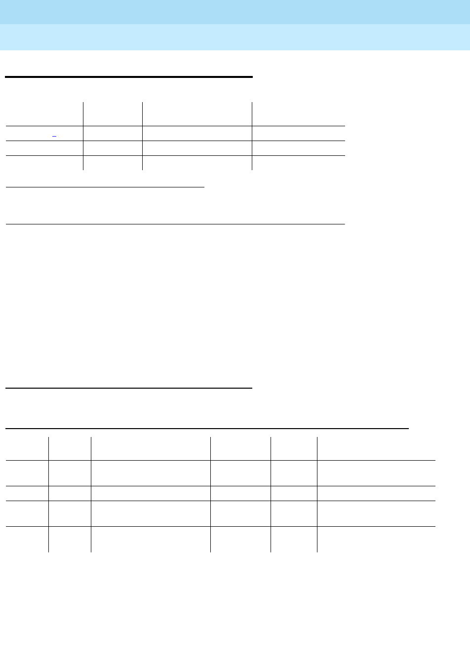
DEFINITY Enterprise Communications Server Release 6
Maintenance for R6r Volumes 1 & 2
555-230-126 Issue 2
January 1998
Maintenance Object Repair Procedures
Page 9-249CLSFY-PT (Call Classifier Port)
9
CLSFY-PT (Call Classifier Port)
The TN744 Call Classifier is a service circuit pack that provides specialized tone
detection capabilities to support the Outbound Call Management (OCM) and
Inbound Call Management (ICM) features. The TN744 supports both A-law and
Mu-law companding.
The TN744 has eight ports (CLSFY-PTs), each capable of supporting call
classification, touch-tone reception and MFC-tone generation and detection. The
CLSFY-PT maintenance object implements a set of tests designed to ensure
proper operation of the Call Classifier.
Error Log Entries and Test to Clear Values
Notes:
a. There are two possible alarm levels for this error type: MAJOR and
MINOR. A major alarm is raised if the total number of call classifier ports
currently in-service is less than or equal to 1/2 of the administered
1. UU is the universal cabinet number (1 for PPN, 2 -44 for EPNs). C is the carrier
designation (A, B, C, D, or E). SS is the number of the slot in which the circuit pack
resides (01 to 21). pp is the two digit port number (01, 02, ...).
MO Name (in
Alarm Log) Alarm
Level Initial Command to
Run1Full Name of MO
CLSFY-PT1MAJOR test port UUCSSpp sh Call Classifier Port
CLSFY-PT MINOR test port UUCSSpp sh Call Classifier Port
CLSFY-PT WARNING test port UUCSSpp sh Call Classifier Port
Table 9-83. Call Classifier Port (CLSFY-PT) Error Log Entries
Error
Type Aux
Data Associated Test Alarm
Level On/Off
Board Test to Clear Value
1 any Tone Detector
Audit/Update Test (#43) MAJOR/
MINOR(a) ON test port UUCSSpp r 2
18 busyout port WARNING OFF release port UUCSSpp
257(b) 17666 Tone Detection Audit
Update Test (#43) MAJOR/
MINOR(a) ON test port UUCSSpp r 3
513(c) any Tone Detection
Verification Test (#42) MAJOR/
MINOR(a) ON test port UUCSSpp r 3

DEFINITY Enterprise Communications Server Release 6
Maintenance for R6r Volumes 1 & 2
555-230-126 Issue 2
January 1998
Maintenance Object Repair Procedures
Page 9-250CLSFY-PT (Call Classifier Port)
9
threshold number. Otherwise, a minor alarm is raised. In either case, run
the short test sequence on the alarmed port and follow the error code
procedures for the individual tests.
The in-service threshold number for alarming call classifier ports is
administered using the change system-parameters maintenance
command. For details, refer to Chapter 8, ‘‘Maintenance Commands’’.
b. The CLSFY-PT lost its translation. Testing the CLSFY-PT is sufficient to
reload its translation. If testing the call classifier port does not clear the
error, then the call classifier circuit pack containing the defective call
classifier port should be replaced.
c. This error indicates the call classifier port is having problems detecting
call classification tones or detecting and generating R2-MFC tones This is
usually accompanied by failures of some incoming or outgoing calls. If
this error type is persistently logged, then replace the call classifier circuit
pack containing the defective CLSFY-PT.
System Technician-Demanded Tests:
Descriptions and Error Codes
Always investigate tests in the order presented in the following tables. By
clearing error codes associated with the
Tone Detection Verification Test
, for
example, you may also clear errors generated from other tests in the testing
sequence.
Tone Detection Verification Test (#42)
This test checks the operation of the TN744 in touch-tone receiver, call classifier
and R2-MFC modes. It verifies the circuit pack’s ability to detect DTMF, ring
back, busy reorder and modem answer tones and to generate and detect
forward and backward MFC tones.
1. D = Destructive; ND = Nondestructive
Order of Investigation Short Test
Sequence Long Test
Sequence D/ND1
Tone Detection Verification Test(#42) X X ND
Tone Detection Audit/Update Test(#43) X X ND

DEFINITY Enterprise Communications Server Release 6
Maintenance for R6r Volumes 1 & 2
555-230-126 Issue 2
January 1998
Maintenance Object Repair Procedures
Page 9-251CLSFY-PT (Call Classifier Port)
9
Table 9-84. TEST #42 Tone Detection Verification Test
Error
Code Test
Result Description/ Recommendation
none ABORT The system was not able to allocate all the resources needed for this test
OR there was an internal system error.
1 ABORT The system could not allocate all the resources needed to test the tones.
1001 ABORT The system was unable to put the call classifier port in the appropriate
mode to test it.
1002 ABORT The system could not allocate time slots for the test connection. This
situation could occur when the system is heavily loaded. If the system is not
heavily loaded, then test the TDM-BUS via the test tdm command. Refer to
TDM-BUS for details.
1. Try (a).
1003 ABORT The system could not allocate a Tone-Clock for the test connection. This
may be caused by a heavy load on the system or by a faulted Tone-Clock.
1. Check to see if there are any alarms against the Tone-Clock in the port
network where the test aborted. If so refer to the recommended
procedures for TONE-BD or TONE-PT.
2. If a new Tone-Clock has been inserted, allow about 1-minute for
maintenance to run on the newly inserted circuit pack.
3. Try (a).
2000 ABORT Call classifier circuit pack’s response to the test request was not received
within the allowable time period.
1. Try (a).
2006 ABORT Indicates that the active Tone-Clock circuit pack or a Tone Detector circuit
pack may not be functioning properly.
1. Test the
active
Tone-Clock circuit pack in the port network with the test
tone-clock UUC command and refer to the TONE-BD section for
failures.
2. Try (a).
2100 ABORT Could not allocate the necessary system resources to run this test.
1. Try (a).
1-3 FAIL DTMF digits were not detected correctly. This may or may not impact
reception of R2-MFC calls.
1. Run the short test sequence via the test port UUCSSpp sh r 1
command.
2. If the problem persists, the system is still operating properly but
capacity will be reduced. To restore performance to normal, replace
the call classifier circuit pack containing the defective CLSFY-PT (Call
Classifier Port).
Continued on next page

DEFINITY Enterprise Communications Server Release 6
Maintenance for R6r Volumes 1 & 2
555-230-126 Issue 2
January 1998
Maintenance Object Repair Procedures
Page 9-252CLSFY-PT (Call Classifier Port)
9
Notes:
a. Retry the command at 1-minute intervals a maximum of 5 times.
Tone Detector Audit/Update Test (#43)
This test performs a sanity audit on the CLSFY-PT (Call Classifier Port).
102 FAIL 2225 Hz Modem Answer Tone was not detected correctly. This will impact
call-classification operation.
1. Run the short test sequence via the test port UUCSSpp sh r 1
command.
2. If the problem persists, the system can still operate properly but
capacity will be reduced. In order to restore performance to normal,
replace the call classifier circuit pack containing the defective port.
130 FAIL Forward or backward R2-MFC signals were not correctly generated or
detected. This will impact R2-MFC calls.
1. Run the short test sequence via the test port UUCSSpp sh r 1
command.
2. If the problem persists, the system can still operate properly but
capacity will be reduced. In order to restore performance to normal,
replace the call classifier circuit pack containing the defective port.
PASS Tone detection verification is successful. The call classifier port is able to
detect and generate all necessary tones.
Table 9-85. TEST #43 Tone Detector Audit/Update Test
Error
Code Test
Result Description/ Recommendation
none ABORT The system was not able to allocate the resources for this test.
1. Try (a).
2000 ABORT Response to the test request was not received within the allowable time
period.
2100 ABORT Could not allocate the necessary system resources to run this test.
1. Try (a).
Continued on next page
Table 9-84. TEST #42 Tone Detection Verification Test — Continued
Error
Code Test
Result Description/ Recommendation
Continued on next page

DEFINITY Enterprise Communications Server Release 6
Maintenance for R6r Volumes 1 & 2
555-230-126 Issue 2
January 1998
Maintenance Object Repair Procedures
Page 9-253CLSFY-PT (Call Classifier Port)
9
Notes:
a. Retry the command at 1-minute intervals a maximum of 5 times.
FAIL Hardware audit failed.
1. Run the short test sequence via the test port UUCSSpp sh r 1
command.
2. If the problem persists, the system is still operating properly but system
capacity will be reduced. In order to restore system performance to
normal, replace the call classifier circuit pack (CLSFY-BD) containing
the defective call classifier port.
PASS The call classifier port has passed the sanity inquiry.
Table 9-85. TEST #43 Tone Detector Audit/Update Test — Continued
Error
Code Test
Result Description/ Recommendation
Continued on next page

DEFINITY Enterprise Communications Server Release 6
Maintenance for R6r Volumes 1 & 2
555-230-126 Issue 2
January 1998
Maintenance Object Repair Procedures
Page 9-254CO-BD (Central Office Trunk Circuit Pack)
9
CO-BD (Central Office Trunk Circuit
Pack)
Refer to “XXX-BD (Common Port Circuit Pack)” for circuit pack level errors. See
also “CO-TRK (CO Trunk)” for related trunk information.
1. UU is the universal cabinet number (1 for PPN, 2 -44 for EPNs). C is the carrier designation (A,
B, C, D, or E). SS is the number of the slot in which the circuit pack resides (01 to 21).
MO Name (in
Alarm Log) Alarm
Level Initial Command to
Run1Full Name of MO
CO-BD MIN test board UUCSS sh Central Office Trunk Circuit Pack
CO-BD WRN test board UUCSS sh Central Office Trunk Circuit Pack
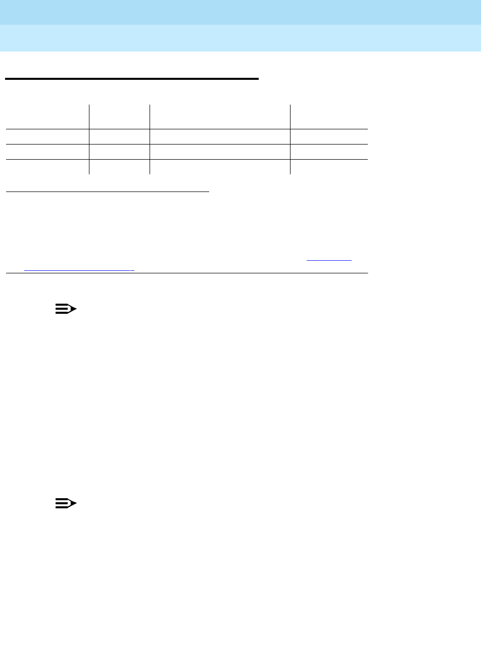
DEFINITY Enterprise Communications Server Release 6
Maintenance for R6r Volumes 1 & 2
555-230-126 Issue 2
January 1998
Maintenance Object Repair Procedures
Page 9-255CO-DS1 (DS1 CO Trunk)
9
CO-DS1 (DS1 CO Trunk)
NOTE:
Many trunk problems are caused by incorrect settings of parameters on the
trunk group administration form. Settings must be compatible with the local
environment and with parameter settings on the far-end. Refer to
DEFINITY
Enterprise Communications Server Release 5.4 Administrationa nd Feature
Description
, for information on how to administer trunks. The Application
Notes section of that book shows the correct settings for administrable
timers and other parameters on a country-by-country basis.
A DS1 CO (central office) trunk provides a link for digitized voice or data
communications between the system and a central office switch. There are two
types of DS1 interfaces:
■24 DS0 channels on a 1.544 Mbps link
■31 DS0 channels + 1 framing channel on a 2.048 Mbps link
NOTE:
32-channel mode is supported only on TN464 circuit packs and on G3r V2
systems.
The DS1-CO maintenance object monitors and maintains a CO trunk port on
either a TN767 DS1 Interface circuit pack or a TN464 UDS1 Interface circuit
pack. Throughout this discussion, the term DS1 circuit pack applies to both. See
‘‘DS1-BD (DS1 Interface Circuit Pack)’’ and ‘‘UDS1-BD (UDS1 Interface Circuit
Pack)’’ in this chapter for more information about these circuit packs. The DS1
circuit pack supports low level CO trunk signaling interfaces for both
ground-start and loop-start trunks. This maintenance strategy covers the in-line
errors log, initialization tests, periodic tests, scheduled tests, demand tests, and
alarm resolution.
1. UU is the universal cabinet number (1 for PPN, 2 -44 for EPNs). C is the carrier
designation (A, B, C, D, or E). SS is the number of the slot in which the circuit pack
resides (01 to 21). pp is the two digit port number (01, 02, ...).
2. A Major alarm on a trunk indicates that alarms on these trunks are not downgraded by
the set options command and that at least 75 percent of the trunks in this trunk group
are alarmed. For more information on the set options command, see Chapter 8,
‘‘Maintenance Commands’’.
MO Name (in
Alarm Log) Alarm
Level Initial Command to Run1Full Name of
MO
CO-DS1 MAJOR2test trunk
group# member#
l DS1 CO Trunk
CO-DS1 MINOR test trunk
group# member#
l DS1 CO Trunk
CO-DS1 WARNING test trunk
group# member#
DS1 CO Trunk

DEFINITY Enterprise Communications Server Release 6
Maintenance for R6r Volumes 1 & 2
555-230-126 Issue 2
January 1998
Maintenance Object Repair Procedures
Page 9-256CO-DS1 (DS1 CO Trunk)
9
Three trunk service states are specified by DS1 CO trunk maintenance:
Error Log Entries and Test to Clear Values
out-of-service The trunk is in a deactivated state and
cannot be used for either incoming or
outgoing calls.
in-service The trunk is in an activated state and can
be used for both incoming and outgoing
calls.
disconnect (ready-for-service) The trunk is in an activated state but can
only be used for an incoming call.
Table 9-86. DS1 CO Trunk Error Log Entries
Error
Type Aux
Data Associated Test Alarm
Level On/Off
Board Test to Clear Value
010 Any Any Any test trunk <grp>/<mbr>
1(a) 57408
1(a) 57487
15(b) Any Port Audit and
Update Test (#36)
18(c) 0 busyout trunk
<grp>/<mbr> WARNING OFF release trunk <grp>/<mbr>
130(d) None WARNING ON test trunk <grp>/<mbr>
257(e) 57392 DS1 CO Dial Tone
Seizure Test (#314) MIN/MAJ2OFF
513(f) 57393 DS1 CO Dial Tone
Seizure Test (#314) MIN/MAJ2OFF
769(g) 57484
1025 DS1 CO Dial Tone
Seizure Test (#314) MIN/
WRN3OFF test trunk <grp>/<mbr> r 2
1281 Conference Circuit
Test (#7) MIN/
WRN3ON test trunk <grp>/<mbr> l r 4
1537 NPE Crosstalk Test
(#6) MIN/
WRN3ON test trunk <grp>/<mbr> l r 3
1793(h) test board UUCSS l
2562(i)) 16665
2817(j) 52992
3840(k) Port Audit and
Update Test (#36)

DEFINITY Enterprise Communications Server Release 6
Maintenance for R6r Volumes 1 & 2
555-230-126 Issue 2
January 1998
Maintenance Object Repair Procedures
Page 9-257CO-DS1 (DS1 CO Trunk)
9
Notes:
a. Error Type 1—Aux Data 57408—No tip ground is detected on an
outgoing call.
Aux Data 57487—PBX could not get "loop close" signal.
The DS1 Interface circuit pack detected a hardware fault. These errors will
cause the Dial Tone Test (#314) to run and are only considered a problem
if the Dial Tone Test fails (in which case Error Type 1025 will also show
up). In this case, the trunk may be put in the ready-for-service state
(shown as "disconnected" by the status command), which allows only
incoming calls. Run the Dial Tone Test (#314) and follow the procedures.
b. Error Type 15—This is a software audit error that does not indicate any
hardware malfunction. Run Short Test Sequence and investigate
associated errors (if any).
c. Error Type 18—System Technician has busied out the trunk to the
out-of-service state. No calls can be made on this trunk except the Facility
Access Test Call. For details on this feature, refer to "Facility Test Calls"
section in Chapter 6, ‘‘Additional Maintenance Procedures’’.
d. Error Type 130—This error type indicates that the circuit pack has been
removed or has been insane for more than 11-minutes. To clear the error,
reinsert or replace the circuit pack.
e. Error Type 257—The DS1 Interface circuit pack detects a hardware fault.
Aux Data 57392 indicates no external release on PBX disconnect.
f. Error Type 513—The DS1 Interface circuit pack detects a hardware fault.
Aux Data 57393 indicates belated external release on PBX disconnect.
g. Error Type 769—The DS1 Interface circuit pack detects a hardware fault.
The Aux Data field contains the following error type:—57484, fault is
detected on tip/ring.
h. Error Type 1793—DS1 Interface circuit pack is out-of-service. Look for
DS1-BD errors in the Hardware Error Log if the port is on a TN767 DS1
board. Look for UDS1-BD errors in the Hardware Error Log if the port is on
a TN464 UDS1 board. Refer to the DS1-BD or UDS1-BD (DS1 Trunk
Circuit Pack) Maintenance documentation for details
1. Run the Short Test Sequence first. If all tests pass, run the Long Test Sequence. Refer to the
appropriate test description and follow the recommended procedures.
2. This alarm will only be raised when the System-Parameter Country form has the Base Tone
Generator field set to 4 (Italy). This alarm will be a MINOR alarm unless 75% or more trunks in this
trunk group are out of service, then the alarm will be upgraded to a MAJOR alarm.
3. Major alarms MO may be downgraded to Warning alarms based on the value used in the set
options command.

DEFINITY Enterprise Communications Server Release 6
Maintenance for R6r Volumes 1 & 2
555-230-126 Issue 2
January 1998
Maintenance Object Repair Procedures
Page 9-258CO-DS1 (DS1 CO Trunk)
9
i. Error Type 2562—Retry Failure error. This error is logged only. It is not a
hardware failure and hence does not start any testing or generate any
alarms. This error comes from call processing and is generated when a
second attempt (retry) to seize an outgoing trunk fails.
j. Error Type 2817—Glare error. This error is logged only. It is not a
hardware failure and hence does not start any testing or generate any
alarms. This error is the result of a simultaneous seizure of a two-way trunk
from both the near-end and the far-end. Attempt to place the call again. If
the error persists, execute the Dial Tone Seizure Test (#314) and follow
those procedures.
k. Error Type 3840—Port Audit and Update Test (#36) failed due to an
internal system error. Enter the status trunk command to verify the status
of the trunk. If the trunk is out-of-service, then enter the release trunk
command to put it back into in-service. Retry the test command.
System Technician-Demanded Tests:
Descriptions and Error Codes
Always investigate tests in the order they are presented in the table below when
inspecting errors in the system. By clearing error codes associated with the
NPE
Crosstalk Test,
for example, you may also clear errors generated from other tests
in the testing sequence.
NPE Crosstalk Test (#6)
The NPE Crosstalk Test verifies that this port’s NPE channel talks on the selected
time slot and never crosses over to time slots reserved for other connections. If
the NPE is not working correctly, one-way and noisy connections may be
observed. This test is usually only part of a port’s Long Test Sequence and takes
about 20 to 30 seconds to complete.
1. D = Destructive; ND = Nondestructive
Order of Investigation Short Test
Sequence Long Test
Sequence D/ND1
NPE Crosstalk Test (#6) X ND
Conference Circuit Test (#7) X ND
DS1 CO Trunk Seizure Test (#314) X X ND
Port Audit and Update Test (#36) X X ND

DEFINITY Enterprise Communications Server Release 6
Maintenance for R6r Volumes 1 & 2
555-230-126 Issue 2
January 1998
Maintenance Object Repair Procedures
Page 9-259CO-DS1 (DS1 CO Trunk)
9
Table 9-87. TEST #6 NPE Crosstalk Test
Error
Code Test
Result Description/ Recommendation
ABORT System resources required for this test are not available.
1. Try (a).
1000 ABORT System resources required to run this test were not available. The port may
be busy with a valid call. Use the display port UUCSSpp command to
determine the trunk group/member number of the port. Use the status
trunk command to determine the service state of the port. If the port is in
use, wait until the port is idle before testing.
1. If the port status is active but the port is not in use (no calls), check the
error log for error type 1025 (see the error log table for a description of
this error and required actions). The port may be locked up.
2. If the port status is idle, try (a).
1001 ABORT System resources required for this test are not available.
1. Try (a).
1002 ABORT The system could not allocate time slots for the test. The system may be
under heavy traffic conditions or it may have time slots out-of-service due to
TDM-BUS errors. The status health command can be used to determine if
the system is experiencing heavy traffic. Refer to “TDM-BUS” to diagnose
any active TDM-BUS errors.
1. If system has no TDM-BUS errors and is not handling heavy traffic, try
(a).
1003 ABORT The system could not allocate a tone receiver for the test. The system may
be oversized for the number of Tone Detectors present or some tone
detectors may be out-of-service. The list measurements tone-receiver
command will display information on the system’s tone receivers.
1. Look for TTR-LEV errors in the Error Log. If present, refer to “TTR-LEV”.
2. Look for TONE-PT errors in the Error Log. If present, refer to “TONE-PT”.
3. If neither condition exists, try (a).
1004 ABORT The port was seized by a user for a valid call. Use the display port
UUCSSpp command to determine the trunk group/member number of the
port. Use the status trunk command to determine the service state of the
port. If the port is in use, wait until the port is idle before testing.
1. If the port status is idle, try (a).
1020 ABORT The test did not run due to a previously existing error on the specific port or
a more general circuit pack error.
1. Examine Error Log for existing errors against this port or the circuit pack
and attempt to diagnose the already existing error.
Continued on next page
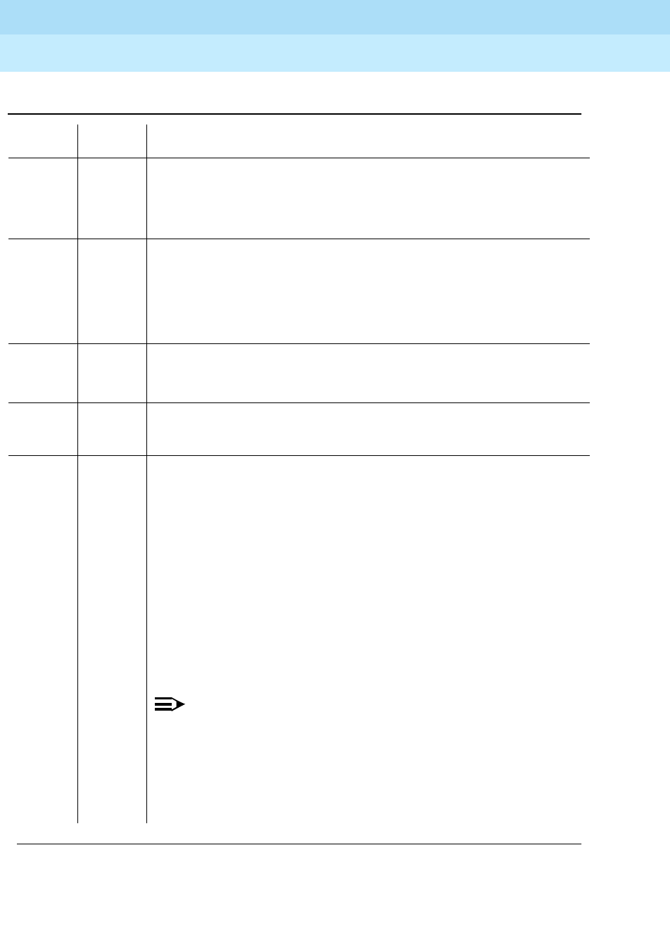
DEFINITY Enterprise Communications Server Release 6
Maintenance for R6r Volumes 1 & 2
555-230-126 Issue 2
January 1998
Maintenance Object Repair Procedures
Page 9-260CO-DS1 (DS1 CO Trunk)
9
Notes:
2000 ABORT Response to the test request was not received within the allowable time
period.
2100 ABORT System resources required for this test are not available.
1. Try (a).
2053 ABORT At least one of the following errors was found on the DS1 circuit pack: loss
of signal (1281), blue alarm (1793), red alarm (2049), yellow alarm (2305),
or hyperactivity (1537).
1. Look for the above error types in the Hardware Error Log and follow the
procedures given in the appropriate DS1-BD or UDS1-BD maintenance
documentation for the listed error types.
FAIL The NPE of the tested port was found to be transmitting in error. This will
cause noisy and unreliable connections.
1. Replace the circuit pack.
PASS The port is correctly using its allocated time slots. User-reported troubles on
this port should be investigated using other port tests and examining
station, trunk, or external wiring.
0NO
BOARD The test could not relate the internal ID to the port (no board). This could be
due to incorrect translations, no board is inserted, an incorrect board is
inserted, an insane board is inserted, or the board is hyperactive.
1. Check to ensure that the board translations are correct. Use the list
config command, and resolve any problems that are found.
2. If the board was found to be correctly inserted in step 1, issue the
busyout board command.
3. Issue the reset board command.
4. Issue the release busy board command.
5. Issue the test board long command. This should re-establish the
linkage between the internal ID and the port. If this is not the case,
dispatch to check to ensure that there is a valid board inserted.
NOTE:
Hyperactivity causes some special problems with the sequence
suggested above. If the ports are translated after issuing the list
config command but the ’Vintage’ field reports that there is no board
(when there really is a board), then the busyout board and the
release busy board commands will not work (even though the reset
board command will work). The software will put the hyperactive
board back in service after the hyperactivity clears.
Table 9-87. TEST #6 NPE Crosstalk Test — Continued
Error
Code Test
Result Description/ Recommendation
Continued on next page

DEFINITY Enterprise Communications Server Release 6
Maintenance for R6r Volumes 1 & 2
555-230-126 Issue 2
January 1998
Maintenance Object Repair Procedures
Page 9-261CO-DS1 (DS1 CO Trunk)
9
a. Retry the command at 1-minute intervals a maximum of 5 times.
Conference Circuit Test (#7)
The Conference Circuit Test verifies that the NPE channel for the port being
tested can correctly perform the conferencing function. The NPE is instructed to
listen to several different tones and conference the tones together. The resulting
signal is then measured by a tone detector port. If the level of the tone is within a
certain range, the test passes.
Table 9-88. TEST #7 Conference Circuit Test
Error
Code Test
Result Description/ Recommendation
ABORT System resources required for this test are not available.
1. Try (a).
1000 ABORT The test was aborted. System resources required to run this test were not
available. The port may be busy with a valid call. Use the display port
UUCSSpp command to determine the trunk group/member number of the
port. Use the status trunk command to determine the service state of the
port. If the port is in use, wait until the port is idle before testing.
1. If the port status is active but the port is not in use (no calls), check the
error log for error type 1025 (see the error log table for a description of
this error and required actions). The port may be locked up.
2. If the port status is idle, try (a).
1002 ABORT The system could not allocate time slots for the test. The system may be
under heavy traffic conditions, or it may have time slots out of service due to
TDM-BUS errors. Refer to “ TDM-BUS” to diagnose TDM-BUS errors.
1. If the system has no TDM-BUS errors and is not handling heavy traffic
and the port status is idle, try (a).
1003 ABORT The system could not allocate a tone receiver for the test. The system may
be oversized for the number of tone detectors present or some of the tone
detectors may be out of service. Issue the list measurements
tone-receiver command to display basic information about the system's
tone receivers.
1. Look for TTR-LEV errors in the error log. If present, refer to “ TTR-LEV”.
2. Look for TONE-PT errors in the error log. If present, refer to “ TONE-PT”.
3. If neither condition exists, try (a).
1004 ABORT The port has been seized by a user for a valid call. Use the status station
or status trunk command to determine when the port is available for
testing.
1. Try (a).
Continued on next page

DEFINITY Enterprise Communications Server Release 6
Maintenance for R6r Volumes 1 & 2
555-230-126 Issue 2
January 1998
Maintenance Object Repair Procedures
Page 9-262CO-DS1 (DS1 CO Trunk)
9
1018 ABORT The test was disabled via translation. You may want to determine why the
test has been disabled before you enable it.
1. Verify that the ’Maintenance Test’ field on the ’Trunk Administration’
screen is set to 'n.’ To enable the test, change the trunk administration
and enter 'y' into the 'Maintenance Test' field.
2. Repeat the test.
1020 ABORT The test did not run due to a previously existing error on the specific port or
a more general circuit pack error.
1. Examine Error Log for existing errors against this port or the circuit pack
and attempt to diagnose the previously existing error.
2000 ABORT Response to the test request was not received within the allowable time
period.
2100 ABORT System resources required for this test are not available.
1. Try (a).
2053 ABORT At least one of the following errors was found on the DS1 circuit pack: loss of
signal (1281), blue alarm (1793), red alarm (2049), yellow alarm (2305), or
hyperactivity (1537).
Look for the above error types in the Hardware Error Log and follow the
procedures given in the appropriate DS1-BD or UDS1-BD maintenance
documentation for the listed error types.
Table 9-88. TEST #7 Conference Circuit Test — Continued
Error
Code Test
Result Description/ Recommendation
Continued on next page
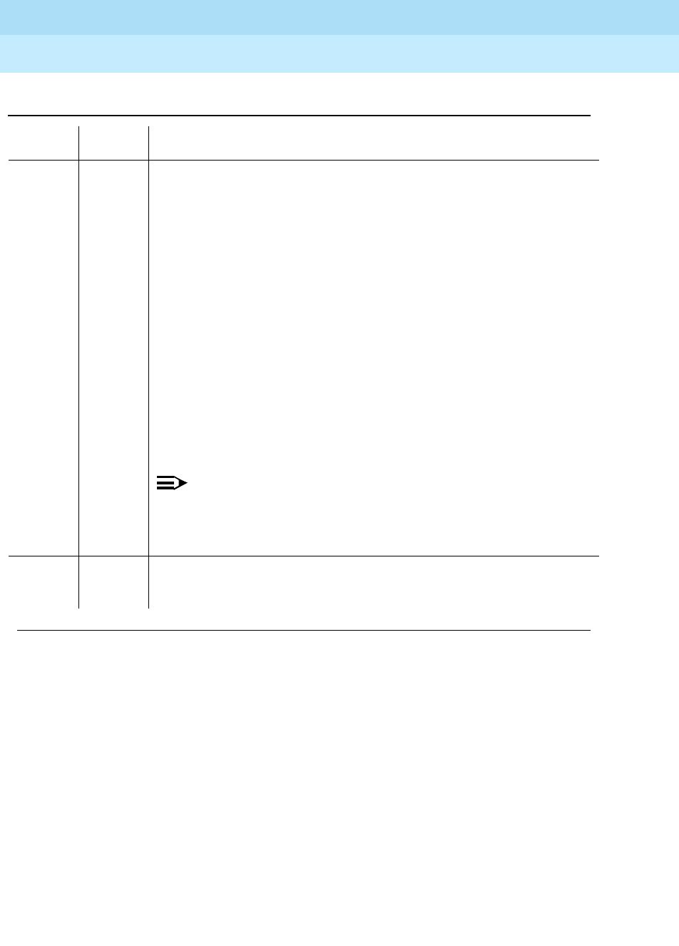
DEFINITY Enterprise Communications Server Release 6
Maintenance for R6r Volumes 1 & 2
555-230-126 Issue 2
January 1998
Maintenance Object Repair Procedures
Page 9-263CO-DS1 (DS1 CO Trunk)
9
FAIL The NPE of the tested port did not conference the tones correctly. This will
cause noisy and unreliable connections.
1. Enter the list configuration board UUCSS command. If the circuit
pack is a TN767B vintage 8 or 9, replace the circuit pack with a TN767C
V3 or later. The error log may have error type 1281 entries.
2. Test all administered trunks on the board. If one fails, this could be an
off-board problem (such as an incoming seizure or an off-hook port
seizure during the test). Retest the board.
3. If all of the ports fail, check the CARR-POW.
4. If several ports fail, check the error log for TONE-BD or TONE-PT errors.
If there are such errors, take the appropriate action. When the TONE
errors have cleared, rerun the test.
5. If the retry passes and troubles have been reported, coordinate
isolation with the CO. Make sure that the switch, the CO, and any NTCE
equipment (the CSU’s) have the correct administration.
6. Replace the circuit pack.
NOTE:
If the conference circuit test fails for all ports on a circuit pack, a -5
volt power problem is indicated. To investigate problems with a
power unit, refer to “CARR-POW”. If a red LED on a TN736 or TN752
power unit circuit pack is on, replace the pack.
PASS The port can correctly conference multiple connections. User-reported
troubles on this port should be investigated by using other port tests and by
examining station, trunk, or external wiring.
Table 9-88. TEST #7 Conference Circuit Test — Continued
Error
Code Test
Result Description/ Recommendation
Continued on next page
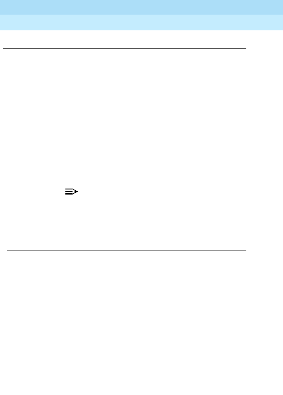
DEFINITY Enterprise Communications Server Release 6
Maintenance for R6r Volumes 1 & 2
555-230-126 Issue 2
January 1998
Maintenance Object Repair Procedures
Page 9-264CO-DS1 (DS1 CO Trunk)
9
Notes:
a. Retry the command at 1-minute intervals a maximum of 5 times.
Port Audit and Update Test (#36)
This test sends port level translation data from switch processor to the DS1
Interface circuit pack to assure that the trunk’s translation is correct. Translation
updates include the following data: trunk type (in/out), dial type, timing
parameters, and signaling bits enabled. The port audit operation verifies the
consistency of the current state of trunk.
0NO
BOARD The test could not relate the internal ID to the port (no board).
This result could be due to incorrect translations, no board is inserted, an
incorrect board is inserted, an insane board is inserted, or the board is
hyperactive.
1. Check to ensure that the board translations are correct. Use the list
config command, and resolve any problems that are found.
2. If the board was found to be correctly inserted in step 1, issue the
busyout board command.
3. Issue the reset board command.
4. Issue the release busy board command.
5. Issue the test board long command.
This should re-establish the linkage between the internal ID and the port. If
this is not the case, dispatch to check to ensure that there is a valid board
inserted.
NOTE:
Hyperactivity causes some special problems with the sequence
suggested above.If the ports are translated after issuing the list
config command but the ’Vintage’ field reports that there is no board
(when there really is a board), then the busyout board and the
release busy board commands will not work (even though the reset
board command will work). The software will put the hyperactive
board back in service after the hyperactivity clears.
Table 9-88. TEST #7 Conference Circuit Test — Continued
Error
Code Test
Result Description/ Recommendation
Continued on next page

DEFINITY Enterprise Communications Server Release 6
Maintenance for R6r Volumes 1 & 2
555-230-126 Issue 2
January 1998
Maintenance Object Repair Procedures
Page 9-265CO-DS1 (DS1 CO Trunk)
9
Table 9-89. TEST #36 Port Audit and Update Test
Error
Code Test
Result Description/ Recommendation
ABORT Internal system error
1. Try (a).
1000 ABORT System resources required to run this test were not available. The port may be
busy with a valid call. Issue display port UUCSSpp to determine the trunk
group/member number of the port. Use the status trunk command to
determine the service state of the port. If the port is in use, wait until the port is
idle before testing.
1. If the port status is active but the port is not in use (no calls), check the
error log for error type 1025. The port may be locked up.
2. If the port status is idle, try (a).
1006 ABORT The DS1 CO trunk is out of service.
1. Use status trunk to verify that the trunk is out of service.
2. If the trunk is out of service, determine why.
3. If it is OK to put the trunk back in service, issue the release trunk
command to put the trunk back in service, and then retry the test.
2000 ABORT Response to the test was not received within the allowable time period.
2100 ABORT Could not allocate the necessary system resources to run this test.
FAIL Test failed due to internal system error.
1. Try (a).
PASS Trunk translation has been updated successfully. The current trunk states kept
in the DS1 Interface circuit pack and switch software are consistent. If the trunk
is busied out, the test will not run but will return PASS. To verify that the trunk is
in-service:
1. Enter status trunk to verify that the trunk is in-service. If the trunk is
in-service, no further action is necessary. If the trunk is out-of-service.
2. Enter release trunk to put the trunk back into in-service.
3. Retry the test command.
Continued on next page

DEFINITY Enterprise Communications Server Release 6
Maintenance for R6r Volumes 1 & 2
555-230-126 Issue 2
January 1998
Maintenance Object Repair Procedures
Page 9-266CO-DS1 (DS1 CO Trunk)
9
Notes:
a. Retry the command at 1-minute intervals a maximum of 5 times.
DS1 CO Dial Tone Seizure Test (#314)
DS1 CO Dial Tone Seizure Test checks the trunk’s signaling capability provided
by the DS1 Interface circuit pack. The maintenance software initiates the test by
sending a "seizure" message to the DS1 Interface circuit pack and expects an
"active" reply from the DS1 interface circuit pack. If the "active" message is
received, then the test passes. If no message is received and the timer expires,
the test is aborted. If the DS1 Interface circuit pack sends a "reorder" message
back to maintenance software, then the test fails.
This test cannot be run on a trunk in any of the following conditions:
a. The trunk direction is administered as an incoming only trunk.
b. The trunk has been seized by a normal trunk call.
c. The trunk is administered with maintenance test disabled.
0NO
BOARD The test could not relate the internal ID to the port. This result could be due to
incorrect translations, no board inserted, an incorrect board inserted, an
insane board inserted, or the board is hyperactive.
1. Check to ensure that the board translations are correct. Use the list config
command, and resolve any problems that are found.
2. Issue the busyout board command.
3. Issue the reset board command.
4. Issue the release busy board command.
5. Issue the test board long command.
This should re-establish the linkage between the internal ID and the port. If not,
to check that there is a valid board inserted.
Hyperactivity causes some special problems with the sequence suggested
above. If the ports are translated after issuing the list config command but the
’Vintage’ field reports that there is no board (when there really is a board), then
the busyout board and the release busy board commands do not work (even
though the reset board command does work). The software puts the
hyperactive board back in service after the hyperactivity clears.
Table 9-89. TEST #36 Port Audit and Update Test — Continued
Error
Code Test
Result Description/ Recommendation
Continued on next page

DEFINITY Enterprise Communications Server Release 6
Maintenance for R6r Volumes 1 & 2
555-230-126 Issue 2
January 1998
Maintenance Object Repair Procedures
Page 9-267CO-DS1 (DS1 CO Trunk)
9
Table 9-90. TEST #314 DS1 CO Dial Tone Seizure Test
Error
Code Test
Result Description/ Recommendation
ABORT Internal system error
1. Try (a).
1000 ABORT The test was aborted because system resources required to run this test
were not available. The port may be busy with a valid call. Use the display
port UUCSSpp command to determine the trunk group/member number of
the port. Use the status trunk command to determine the service state of
the port. If the port is in use, wait until the port is idle before testing.
1. If the port status is active but the port is not in use (no calls), check the
error log for error type 1025. The port may be locked up.
2. If the port status is idle, try (a).
1004 ABORT The test was aborted because the port was seized by a user for a valid call.
Use the display port UUCSSpp command to determine the trunk
group/member number of the port. Use the status trunk command to
determine the service state of the port. If the port is in use, wait until the
port is idle before testing.
1. If the port status is idle, try (a).
1005 ABORT Test failed due to incompatible configuration administered in trunk group
form.
1. Look at the trunk group administration form and see whether the trunk
is incoming only, port 24 on a DS1 Interface with common control
channel signaling, or an automatic CO type such as FX. Under any of
these conditions this is a normal abort.
1018 ABORT Test is disabled via translation. You may want to determine why the test has
been disabled before you enable it.
1. Verify that the ’Maintenance Test’ field on the ’Trunk Group’ form is set
to ’n’. To enable the test, issue the change trunk-group x command (x
equals the number of the trunk group to be tested). Then, change the
entry in the ’Maintenance Test’ field on the form to ’y’.
2. Repeat the test.
1040 ABORT The test was aborted because this port may be an access endpoint.
1. Verify that this port is an access endpoint by issuing the display port
command.
2. If the port has been administered as an access endpoint, then this is a
normal abort.
1020 ABORT The DS1 Interface circuit pack is out-of-service.
1. Look for DS1-BD/UDS1-BD errors in the Hardware Error Log. If
present, refer to the appropriate DS1-BD/UDS1-BD (DS1/UDS1 Trunk
Circuit Pack).
2. Retry the command.
Continued on next page

DEFINITY Enterprise Communications Server Release 6
Maintenance for R6r Volumes 1 & 2
555-230-126 Issue 2
January 1998
Maintenance Object Repair Procedures
Page 9-268CO-DS1 (DS1 CO Trunk)
9
2012 ABORT The test was aborted due to an internal system error.
1. Try (a).
2100 ABORT Could not allocate the necessary system resources for this test.
1. Try (a).
2000 FAIL Response to the seizure message was not received within the allowable
time period.
1. Enter the list configuration board UUCSS command. If the circuit
pack is a TN767B vintage 8 or 9, a failure of test 314 causes a
subsequent failure of test 7 due to a firmware bug. Eventually, the
board and all of its ports will be taken out of service and extraneous
on-board alarms will be generated. Replace the circuit pack with a
TN767C V3 or later.
2. Verify that the ’Trunk Type’ field on the ’Trunk Administration’ screen
matches the trunk type administered on far-end switch.
3. Look for DS1-BD or UDS1-BD errors in the hardware error log. If
present, refer to the DS1-BD (DS1 trunk circuit pack) maintenance
documentation or to the UDS1-BD (UDS1 trunk circuit pack)
maintenance documentation.
4. Try (a).
2053 FAIL At least one of the following errors was found on the DS1 circuit pack: loss
of signal (1281), blue alarm (1793), red alarm (2049), yellow alarm (2305),
or hyperactivity (1537).
1. Look for these error types in the hardware error log and then follow the
procedures given in the maintenance documentation that is
appropriate for the error type that was found.
FAIL The trunk cannot be seized for an outgoing call. This could cause in-line
failures to be reported against the trunk (no answer would report error type
257 with auxiliary data 57487 in the error log).
1. Verify the Trunk Type field on the trunk administration screen form
matches the trunk type administered on far end switch.
2. Look for DS1-BD/UDS1-BD errors in Error Log. If present, refer to
DS1-BD/UDS1-BD (DS1/UDS1 Trunk Circuit Pack).
3. Try (a).
PASS The trunk can be seized for an outgoing call.
Table 9-90. TEST #314 DS1 CO Dial Tone Seizure Test — Continued
Error
Code Test
Result Description/ Recommendation
Continued on next page

DEFINITY Enterprise Communications Server Release 6
Maintenance for R6r Volumes 1 & 2
555-230-126 Issue 2
January 1998
Maintenance Object Repair Procedures
Page 9-269CO-DS1 (DS1 CO Trunk)
9
Notes:
a. Retry the command at 1-minute intervals a maximum of 5 times.
0NO
BOARD The test could not relate the internal ID to the port (no board).
This could be due to incorrect translations, no board is inserted, an
incorrect board is inserted, an insane board is inserted, or the board is
hyperactive.
1. Check to ensure that the board translations are correct. Use the list
config command, and resolve any problems that are found.
2. Issue the busyout board command.
3. Issue the reset board command.
4. Issue the release busy board command.
5. Issue the test board long command. This should re-establish the
linkage between the internal ID and the port. If this is not the case,
dispatch to check to ensure that there is a valid board inserted.
Hyperactivity causes some special problems with the sequence suggested
above. If the ports are translated after issuing the list config command but
the ’Vintage’ field reports that there is no board (when there really is a
board), then the busyout board and the release busy board commands
will not work (even though the reset board command will work). The
software will put the hyperactive board back in service after the
hyperactivity clears.
Table 9-90. TEST #314 DS1 CO Dial Tone Seizure Test — Continued
Error
Code Test
Result Description/ Recommendation
Continued on next page
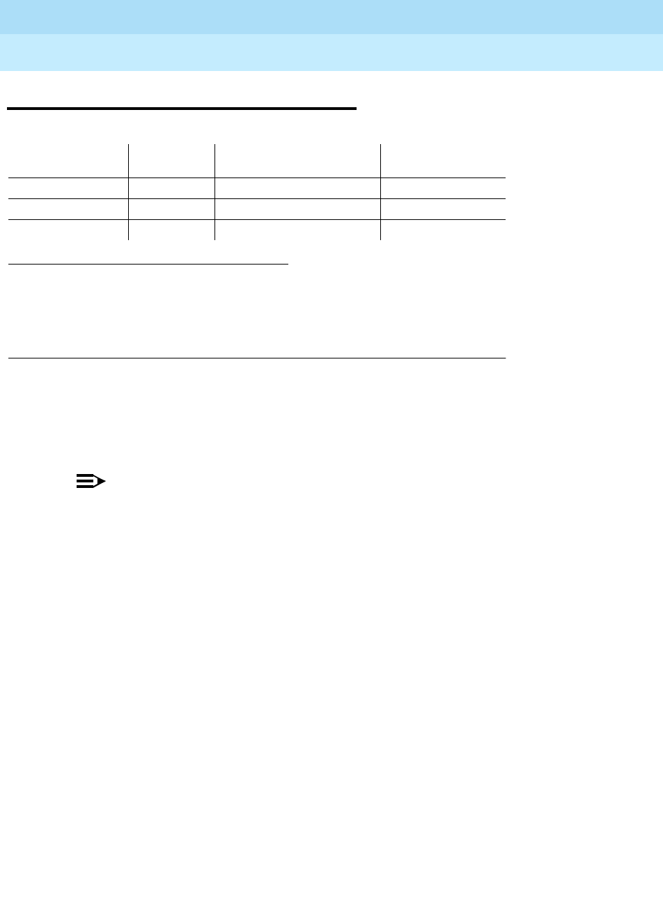
DEFINITY Enterprise Communications Server Release 6
Maintenance for R6r Volumes 1 & 2
555-230-126 Issue 2
January 1998
Maintenance Object Repair Procedures
Page 9-270CO-TRK (Analog CO Trunk)
9
CO-TRK (Analog CO Trunk)
If ATMS testing is enabled, check the error log for ATMS errors 3840 and 3841. If
the error log indicates that measurements exceeded acceptable thresholds, and
no other trouble is found with test trunk, run the ATMS test call with test
analog-testcall port UUCSSpp full.
NOTE:
Many trunk problems are caused by incorrect settings of parameters on the
trunk group administration form. Settings must be compatible with the local
environment and with parameter settings on the far-end. Refer to
DEFINITY
Enterprise Communications Server Release 5.4 Administration and Feature
Description
. The Application Notes section of that book shows the correct
settings for administrable timers and other parameters on a country-by-
country basis.
Analog CO trunks are 2-wire analog lines to the CO which support both incoming
and outgoing calls. CO trunk circuit packs have eight ports, each of which
provides an interface between the 2-wire CO line and the 4-wire TDM bus. The
system supports the following CO trunk circuit packs:
The following sequences show the interactions between the switch and the CO
during call setup for both loop-start and ground-start trunks.
1. UU is the universal cabinet number (1 for PPN, 2 -44 for EPNs). C is the carrier
designation (A, B, C, D, or E). SS is the number of the slot in which the circuit pack
resides (01 to 21). pp is the two digit port number (01, 02, ...).
2. A MAJOR alarm on a trunk indicates that alarms on these trunks are not downgraded
by the set options command and that at least 75% of the trunks in this trunk group
are alarmed.
MO Name (in
Alarm Log) Alarm
Level Initial Command to Run1Full Name of MO
CO-TRK MAJOR2test port UUCSSpp l Analog CO Trunk
CO-TRK MINOR test port UUCSSpp l Analog CO Trunk
CO-TRK WARNING test port UUCSSpp l Analog CO Trunk
TN438 TN2138
TN447 TN2147
TN465 TN2148
TN747

DEFINITY Enterprise Communications Server Release 6
Maintenance for R6r Volumes 1 & 2
555-230-126 Issue 2
January 1998
Maintenance Object Repair Procedures
Page 9-271CO-TRK (Analog CO Trunk)
9
Loop Start Operation
Idle State: Tip = ground, Ring = CO Battery Outgoing Call:
1. PBX Off-Hook (Seize Message): Closes the Tip-Ring Loop
CO Response: DC loop current + Dial tone
2. PBX On-Hook (Drop Message): Open Tip-Ring loop, no loop current
CO Response: CO goes to idle state (see Note)
Incoming Call:
1. CO Applies Ringing Voltage
PBX Response: Detect ringing current
2. PBX Off-Hook (Answer Message): Close loop
CO Response: Trip ringing, provide loop current
3. PBX On-Hook (Drop Message): Open Tip-Ring loop, no loop current
CO Response: CO goes to idle state (see Note)
NOTE:
CO does not normally provide an On-Hook (Disconnect) signal.
Exceptions to this rule include Netherlands loop start and UK
loop-calling guarded-clearing.
Ground Start Operation
Idle state: Tip = open, Ring = CO Battery Outgoing Call:
1. PBX Off-Hook (Seize Message): Places ground on Ring
CO Response: Places ground on Tip
PBX Response: Close the loop
CO Response: Provide loop current
PBX response: Dial out digits
2. PBX On-Hook first (Drop Message): Open the Tip-Ring Loop, no loop
current
CO Response: Open circuit on Tip
3. CO On-Hook first (Disconnect): Open circuit on Tip, no loop current
PBX Response: Open Tip-Ring loop

DEFINITY Enterprise Communications Server Release 6
Maintenance for R6r Volumes 1 & 2
555-230-126 Issue 2
January 1998
Maintenance Object Repair Procedures
Page 9-272CO-TRK (Analog CO Trunk)
9
Incoming Call:
1. CO Off-Hook (Seizure): CO applies ground on Tip and applies ringing
voltage
PBX Response: Make trunk busy for outgoing calls
2. CO Ringing: CO applies ringing voltage
PBX Response: Detect ringing, ring destination
3. PBX Off-Hook (Answer Message): Close loop
CO Response: Trip ringing, provide loop current
4. PBX On-Hook first (Drop Message): Open the Tip-Ring Loop, no loop
current
CO Response: Open circuit on Tip
5. CO On-Hook first (Disconnect): Open circuit on Tip, no loop current
Error Log Entries and Test to Clear Values
Table 9-91. CO Trunk Error Log Entries
Error
Type Aux Data Associated Test Alarm
Level On/Off
Board Test to Clear Value
010 Any Any Any test port
UUCSSpp
sh r 1
1 (a) 57347 None
15 (b) any Port Audit Update
Test (#36)
18 0 busyout trunk WARNING OFF release trunk
grp#/mbr#
130(c) None WARNING ON test port
UUCSSpp
sh r 2
257 (a) 50176 None
513 (a) 57364 None MAJ/MIN/
WRN2ON
769 (a) 57392 None MAJ/MIN/
WRN2OFF
1025 (e) Any Demand Diagnostic
Test (#3) MAJ/MIN/
WRN2OFF test port
UUCSSpp
sh r 2
1281 (e) Any Demand Diagnostic
Test (#3) MAJ/MIN/
WRN2ON test port
UUCSSpp
sh r 3
1537 Dial Tone Test (#0) MAJ/MIN/
WRN2OFF test port
UUCSSpp
l r 2
Continued on next page
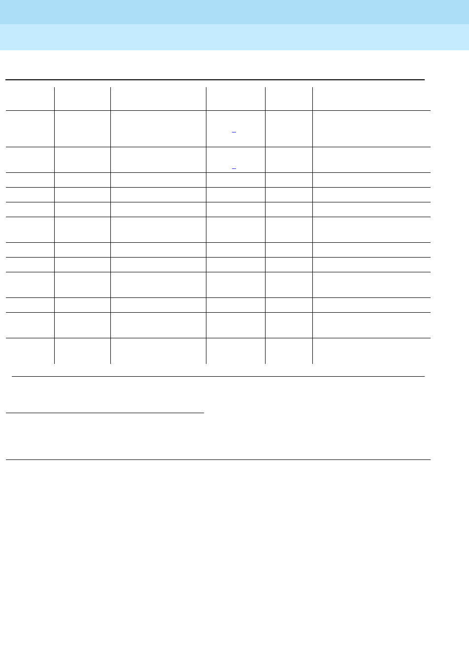
DEFINITY Enterprise Communications Server Release 6
Maintenance for R6r Volumes 1 & 2
555-230-126 Issue 2
January 1998
Maintenance Object Repair Procedures
Page 9-273CO-TRK (Analog CO Trunk)
9
Notes:
a. These are in-line errors that have no specific test associated with them.
Refer to the following table for an explanation and appropriate action.
b. This is a software audit error that does not indicate any hardware
malfunction. Run Short Test Sequence and investigate associated errors.
c. This error type indicates that the circuit pack has been removed or has
been insane for at least 11-minutes. To clear the error, reinsert or replace
the circuit pack.
d. Aux data 57345 — Single polarity ringing current
Aux data 57376 — No loop current on incoming call
Aux data 57408 — No tip ground detected on outgoing call
1. Run the Short Test Sequence first. If all tests pass, run the Long Test Sequence. Refer to the appropriate
test description and follow the recommended procedures.
2. Major alarms may be downgraded to Warning alarms based on the value used in the set options
command.
1793 Looparound and
Conference Test
(#33
MAJ/MIN/
WRN2ON test port
UUCSSpp
l r 3
2049 NPE Cross Talk Test
(#6) MAJ/MIN/
WRN2ON test port
UUCSSpp
l r 3
2561 (d) 57345 None
2817 (a) 57360 None
2817 (a) 57393 None
2817 (d) 57484 Dial Tone Test(#0) MAJ/MIN/
WRN OFF test port
UUCSSpp
l r 1
3073 (d) 57376 None
3329 (d) 57408 None
3329 (d) 57484 Dial Tone Test(#0) MAJ/MIN/
WRN OFF test port
UUCSSpp
l r 1
3585 (d) 57424 None
3840 (f) 8000 Transmission Tests
(ATMS)(#844-848) OFF test analog-testcall
3841 (f) Transmission Tests
(ATMS)(#844-848) MINOR OFF test analog-testcall
Table 9-91. CO Trunk Error Log Entries — Continued
Error
Type Aux Data Associated Test Alarm
Level On/Off
Board Test to Clear Value
Continued on next page

DEFINITY Enterprise Communications Server Release 6
Maintenance for R6r Volumes 1 & 2
555-230-126 Issue 2
January 1998
Maintenance Object Repair Procedures
Page 9-274CO-TRK (Analog CO Trunk)
9
Aux data 57424 — No loop current on outgoing call
Aux data 57484 — No dial tone on outgoing call
These errors will cause the Dial Tone Test (#0) to run and are only
considered a problem if the Dial Tone Test fails (in which case Error Type
1537 will also show up). In this case, the trunk may be put in
"Ready-for-Service" state (shown as "disconnected" by status command),
which allows only incoming calls. Run the Dial Tone Test (#0) and follow its
outlined procedures.
If error count associated with this error type is very high (i.e., 255) and if
Alarm Status on the Hardware Error Report is "n" (not alarmed), then the
existence of this error type indicates that, despite the fact that many in-line
error messages have been received, all Call Seizure Tests have passed.
Problems at the CO may cause this condition rather than problems with
the PBX.
e. These errors will be logged for all versions of the CO-TRK/CO-BD.
However, no MINOR alarms will be generated for Central Office Trunks
[TN747B] with vintages V8 or greater. Any failures received by this test will
still be logged as Error type 1025/1281.
Check for the use of MFT/Range extenders. If there are extenders present,
and there are no other complaints or maintenance errors against this
trunk, then there is a good chance that Test #3 failed due to excessive
loop current and may be ignored.
f. Error 3840 indicates that test calls made by the Automatic Transmission
Measurement System (ATMS) returned measurements in the
unacceptable range. Error 3841 indicates measurements were in the
marginal range. Use list testcall detail to examine the specific
transmission parameters which are out of spec, and investigate the trunk
for that kind of noise. If the noise is acceptable, then the AMTS thresholds
administered on page 4 of the trunk group form should be changed.
Table 9-92. CO Trunk Errors with No Tests
Error
Type Aux
Data Error Description and Repair Action
1 57347 Port error. Ringing without ground. This error is detected on an incoming
call on a ground-start CO trunk. The CO trunk circuit pack has not detected
a Tip ground before ringing current is detected. This may indicate that the
ground detector is not working. However, the call will be accepted. Busyout
the affected port, and run a long test. Observe the test results. If any tests
fail, refer to the description of the tests and the associated error codes.
Release the port. If users continue to report troubles, check for other errors
and make test calls to determine whether the problem should be referred to
the CO.
Continued on next page

DEFINITY Enterprise Communications Server Release 6
Maintenance for R6r Volumes 1 & 2
555-230-126 Issue 2
January 1998
Maintenance Object Repair Procedures
Page 9-275CO-TRK (Analog CO Trunk)
9
257 50176 Battery reversal detected. This is usually caused by the CO (often seen with
step-by-step and cross-bar offices in connection with outgoing calls). This is
detected if the direction of the loop current changes from normal to reverse
for at least 40 msec. Could occur if the trunk was just installed and for some
reason the Tip and Ring wires were reversed at the PBX. If battery reversals
occur during dialing, wrong numbers may result. Refer problem to CO. Ask
them to remove the battery reversal option.
513 57364 Ground detector stuck active. After several occurrences, an on-board minor
alarm is generated. Run the short test sequence. If test aborts with Error
Code 1000, disconnect Tip and Ring and repeat short test. If test still aborts,
replace circuit pack. If test passes, refer problem to CO. If any other error
code is received, pursue that problem.
769 57392 CO not releasing after call is dropped from PBX end (TN747B), or the loop is
not open after a disconnect (TN765). After several occurrences, an
off-board (TN747B) or on-board (TN465) warning alarm is generated. Refer
problem to CO.
2561 57345 Single polarity ringing current. This error results from abnormal ringing
current, but does not prevent the incoming call from being accepted. One
cause could be that the reverse current detector associated with the port is
failing. (Will not be detected by any tests.) Another cause could be that
normal current is not detected. In this case, neither incoming nor outgoing
calls can be completed, and the dial tone test will also fail. The last cause
could be that certain types of noise are present on the CO line during the
silent period of ringing. First check for other errors. If the count for this error
is very high (255), and all tests pass, then either the reverse current detector
is defective or the CO line is noisy. If the CO line is suspect, make Tip and
Ring observations. If the line is determined to be noisy, refer the problem to
the CO. If the reverse current detector is defective, ignore this error.
2817 57360 Ground but no ringing. This error occurs on an incoming call on a
ground-start trunk. If ringing is not detected within 5 seconds of the Tip
being grounded, the call is still accepted. If the CO is of the No. 5ESS.
switch type, ringing delays of more than 5 seconds during heavy traffic are
fairly common. Check for other errors.
2817 57393 On the TN465, the loop is opening too slowly after a disconnect. This error
indicates an on-board problem, although the trunk may be functional.
Check for other errors.
3073 57376 No loop current on incoming call. The incoming destination has already
answered and no loop current has been detected. If this is a hard fault, the
dial tone test and all outgoing calls should also fail. Check for other errors.
Table 9-92. CO Trunk Errors with No Tests — Continued
Error
Type Aux
Data Error Description and Repair Action
Continued on next page

DEFINITY Enterprise Communications Server Release 6
Maintenance for R6r Volumes 1 & 2
555-230-126 Issue 2
January 1998
Maintenance Object Repair Procedures
Page 9-276CO-TRK (Analog CO Trunk)
9
System Technician-Demanded Tests:
Descriptions and Error Codes
Always investigate tests in the order they are presented in the table below when
inspecting errors in the system. By clearing error codes associated with the
NPE
Crosstalk Test,
for example, you may also clear errors generated from other tests
in the testing sequence.
1. D = Destructive; ND = Nondestructive
3329 57408 Trunk error. No Tip ground detected on outgoing call. This error occurs
when an attempt is made to seize a ground-start CO trunk for an outgoing
call and Tip ground is not detected or the caller hangs up before Tip ground
is detected.
1. Busyout the affected port, and run a long test. Observe the test results.
If any tests fail, refer to the description of the tests and the associated
error codes. Release the port.
2. If users continue to report troubles, check for other errors and make test
calls to determine whether the problem should be referred to the CO.
Busyout the affected port, and run a long test. If Dial Tone Test #0
passes, ignore this error. Release the port.
3585 57424 No loop current on outgoing call. This error occurs on attempt to seize a
loop or ground-start trunk for an outgoing call. An error occurs if loop
current is not detected or the caller hangs up before it is detected. Busyout
the affected port, and run a long test. If CO Demand Diagnostic Test #3
passes and this error keeps occurring, refer problems to CO. Release the
port.
Order of Investigation Short Test
Sequence Long Test
Sequence D/ND1
NPE Crosstalk Test (#6) X ND
Dial Tone Test (#0) X ND
CO Demand Diagnostic Test (#3) (a) X X ND
Looparound and Conference Test (#33) X ND
Audit Update Test (#36) X X ND
Transmission Test - ATMS (#844-848) (b) (b) ND
Table 9-92. CO Trunk Errors with No Tests — Continued
Error
Type Aux
Data Error Description and Repair Action
Continued on next page

DEFINITY Enterprise Communications Server Release 6
Maintenance for R6r Volumes 1 & 2
555-230-126 Issue 2
January 1998
Maintenance Object Repair Procedures
Page 9-277CO-TRK (Analog CO Trunk)
9
Notes:
a. A demand test of Diagnostic Test (#3) will always return a PASS indication
for CO-TRK/CO-BD [TN747B] version 8 or greater. However, any errors
produced as a result of this test will be logged and produce no alarms.
If errors logged by test #3 are the only complaints against this trunk, then
the system technician should check if MFT/Range Extenders are being
used. If extenders are present, then there is a good chance that there is
excessive loop current, which will cause Test #3 to log errors.
However, all else being normal, these errors should not affect the
customer.
b. The ATMS tests are not part of either test sequence. They are run either on
demand with test analog-testcall or by the ATMS schedule.
Dial Tone Test (#0)
This test attempts to seize a port and checks for the return of a dial tone.
Table 9-93. TEST #0 Dial Tone Test
Error
Code Test
Result Description/ Recommendation
ABORT Could not allocate system resources to run this test.
1. Try (a).
1000 ABORT System resources required to run this test are not available. The port may be
busy with a valid call. Use the command display port UUCSSpp to
determine the trunk group/member number of the port. Use the status
trunk command to determine the service state of the port. If the service
state indicates that the port is in use, then the port is unavailable for certain
tests. You must wait until the port is idle before retesting.
1. Try (a).
1001 ABORT System resources required to run this test were not available. This could be
due to a failure to seize the port.
1. Try (a).
1002 ABORT The system could not allocate time slots for the test. The system may be
under heavy traffic conditions or it may have time slots out-of-service due to
TDM-BUS errors. Refer to “TDM-BUS” to diagnose TDM-BUS errors.
1. If the system has no TDM-BUS errors and is not handling heavy traffic,
try (a).
Continued on next page
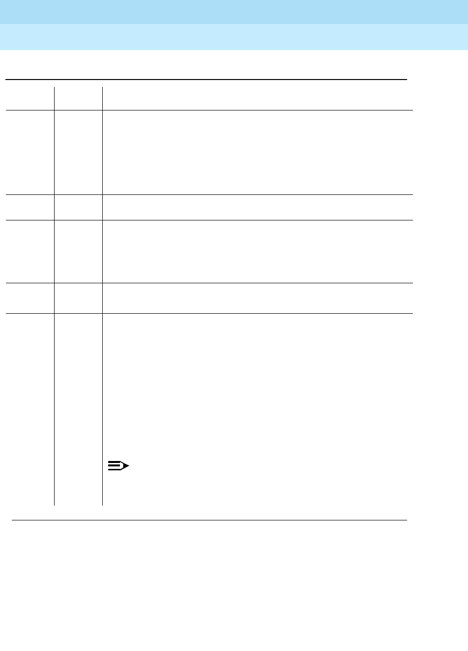
DEFINITY Enterprise Communications Server Release 6
Maintenance for R6r Volumes 1 & 2
555-230-126 Issue 2
January 1998
Maintenance Object Repair Procedures
Page 9-278CO-TRK (Analog CO Trunk)
9
1004 ABORT The port was seized by a user for a valid call. Use the display port
UUCSSpp command to determine the trunk group/member number of the
port. Use the status trunk command to determine the service state of the
port. If the service state indicates that the port is in use, then the port is
unavailable for certain tests. You must wait until the port is idle before
retesting.
1. If the port status is idle, try (a).
1005 ABORT Trunk has been administered as incoming-only; dial tone can only be
obtained on outgoing trunks. This is a normal condition.
1018 ABORT Test has been disabled via administration.
1. Verify that the "Maintenance Tests?" field on the Trunk Group Form is set
to "n." To enable the test, issue the change trunk-group x command
where "x" equals the number of the trunk group to be tested. Then
change the entry in the "Maintenance Tests?" field on the form to "y."
2000 ABORT Response to the test was not received within the allowable time period.
1. Try (a).
FAIL Trunk was seized, but dial tone could not be detected.
1. Test all administered outgoing ports on the board. Failure of 1 indicates
a problem toward the CO.
2. If all fail, see note below.
3. Check for errors on the TONE-BD or TONE-PT. Clear any errors found,
and repeat the test.
4. If the error has still not cleared, refer the problem to the CO.
5. If no service problems exist on the port, continue to use the port until the
circuit pack can be replaced (as a last resort). Perform a trunk test call
to see if the trunk is operable.
NOTE:
If the dial tone test fails for all ports on a circuit pack, a -5 volt power
problem is indicated. To investigate problems with a power unit, refer
to “CARR-POW”.
Table 9-93. TEST #0 Dial Tone Test — Continued
Error
Code Test
Result Description/ Recommendation
Continued on next page

DEFINITY Enterprise Communications Server Release 6
Maintenance for R6r Volumes 1 & 2
555-230-126 Issue 2
January 1998
Maintenance Object Repair Procedures
Page 9-279CO-TRK (Analog CO Trunk)
9
Notes:
a. Retry the command at 1-minute intervals a maximum of 5 times.
CO Demand Diagnostic Test (#3)
For ground start trunks, port circuit pack relays are operated and checks are
made to see if the port can detect and apply ground on the Tip lead. This test
also verifies that there is no external ground on the Ring lead. In the absence of
other failures, the circuit pack should be replaced only if this test fails with the CO
line disconnected.
2002 FAIL Seizure portion of test failed due to hardware problem. Fault is usually
caused by a disconnected trunk.
1. If the CO Demand Diagnostic Test (#3) also failed, display the
Hardware Error Log. If the CO Demand Diagnostic Test failed because
it could not detect ground (indicated by Error Type 1281 in the
Hardware Error Log) AND Error Type 3329 or 3585 appears in the
Hardware Error Log (with the same last occurred time as Error Type
1281 and 1537), replace the circuit pack.
2. Check trunk wiring to ensure good connection; repeat test if wiring
correction made.
3. Locate another identical CO trunk and swap its wiring with one under
test. Repeat test on both trunks and determine if problem follows trunk
or remains at original port. If problem follows trunk, refer problem to CO.
If problem remains at port, replace circuit pack and repeat test.
1009 PASS Detected tone was not pure dial tone. No action required.
PASS Trunk was seized, and dial tone was detected. User-reported troubles on
this port should be investigated by using other port tests and by examining
trunk or external wiring.
0NO
BOARD The test could not relate the internal ID to the port.
1. Check to ensure that the board translations are correct. Translate the
board, if necessary.
2. Issue the busyout board command.
3. Issue the reset board command.
4. Issue the release busy board command.
5. Issue the test board command. This should re-establish the linkage
between the internal ID and the port.
Table 9-93. TEST #0 Dial Tone Test — Continued
Error
Code Test
Result Description/ Recommendation
Continued on next page

DEFINITY Enterprise Communications Server Release 6
Maintenance for R6r Volumes 1 & 2
555-230-126 Issue 2
January 1998
Maintenance Object Repair Procedures
Page 9-280CO-TRK (Analog CO Trunk)
9
For the TN2147, this test also checks the on-board programmable transmission
circuits that allow the circuit pack to support transmission characteristics of
several different countries.
Table 9-94. TEST #3 CO Demand Diagnostic Test
Error
Code Test
Result Description/ Recommendation
ABORT Could not allocate system resources to run this test.
1. Try (a).
1000 ABORT System resources required to run this test are not available. The port may be
busy with a valid call. Use the display port UUCSSpp command to determine
the trunk group/member number of the port. Use the status trunk command to
determine the service state of the port. If the service state indicates that the
port is in use, then the port is unavailable for certain tests. You must wait until
the port is idle before retesting.
1. If the port status is idle, try (a).
1004 ABORT The port was seized by a user for a valid call. Use the display port UUCSSpp
command to determine the trunk group/member number of the port. Use the
status trunk command to determine the service state of the port. If the service
state indicates that the port is in use, then the port is unavailable for certain
tests. You must wait until the port is idle before retesting.
1. If the port status is idle, try (a).
1005 ABORT Test inapplicable to present configuration. This is a normal condition.
1018 ABORT Test has been disabled via administration.
1. For this test to run, the Maintenance Tests? field on the trunk group
form must be set to n. The form is accessed with the change trunk-group
grp# command.
2000 ABORT Response to the test was not received within the allowable time period.
1. Try (a).
Continued on next page
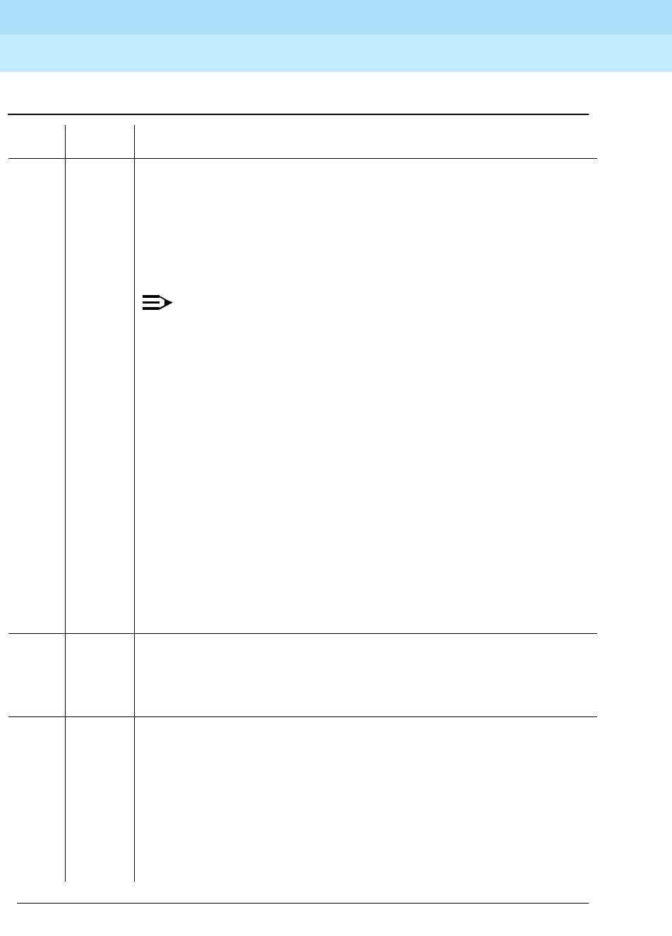
DEFINITY Enterprise Communications Server Release 6
Maintenance for R6r Volumes 1 & 2
555-230-126 Issue 2
January 1998
Maintenance Object Repair Procedures
Page 9-281CO-TRK (Analog CO Trunk)
9
FAIL Failure to detect ground or faulty ground detected on Ring lead. Display the
hardware errors for this trunk, to determine if the fault was on- or-off board.
Look for Error Type 1025 or 1281 (if both appear in the Hardware Error Log,
pick the most recent error). Error Type 1025 indicates a faulty ground detected
on Ring lead (an off-board fault) and Error Type 1281 indicates failure to detect
(internally generated) ground (an on-board fault).
Faulty ground detected on Ring lead (Error Type 1025):
NOTE:
On TN747B vintage 8 and greater circuit packs, an incoming seizure
during this test may cause it to fail with an off-board fault.
1. Repeat test. If test passes, ignore the original failure. If test aborts, follow
the recommended procedures.
2. Repeat test with CO line removed.
3. If test fails, replace the circuit pack.
4. If test passes, refer problem to CO.
Failure to detect ground (Error Type 1281):
1. Run the long test sequence. If the CO Demand Diagnostic Test fails, the
Dial Tone Test (#0) fails with Error Code 2002, AND Error Type 3329 or
3585 appears in the Hardware Error Log (with the same last occurred time
as Error Type 1281 and 1537), replace the circuit pack.
2. Repeat test with CO line removed.
3. If test fails, replace the circuit pack.
4. If test passes, the CO may be drawing too much current. Refer problem to
CO.
PASS This test verifies that the port is able to apply ground for outgoing calls and
detect ground for incoming calls; however, it does not provide information on
whether a CO line is actually connected. User-reported troubles on this port
should be investigated by using other port tests and by examining trunk or
external wiring.
0NO
BOARD The test could not relate the internal ID to the port (no board).
1. Check to ensure that the board translations are correct. Translate the
board, if necessary.
2. Issue the busyout board command.
3. Issue the reset board command.
4. Issue the release busy board command.
5. Issue the test board command. This should re-establish the linkage
between the internal ID and the port.
Table 9-94. TEST #3 CO Demand Diagnostic Test — Continued
Error
Code Test
Result Description/ Recommendation
Continued on next page

DEFINITY Enterprise Communications Server Release 6
Maintenance for R6r Volumes 1 & 2
555-230-126 Issue 2
January 1998
Maintenance Object Repair Procedures
Page 9-282CO-TRK (Analog CO Trunk)
9
Notes:
a. Retry the command at 1-minute intervals a maximum of 5 times.
NPE Crosstalk Test (#6)
The NPE Crosstalk Test verifies that this port’s NPE channel talks on the selected
time slot and never crosses over to time slots reserved for other connections. If
the NPE is not working correctly, one way and noisy connections may be
observed. This test is usually only part of a port’s long test sequence and takes
approximately 20 to 30 seconds to complete.
Table 9-95. TEST #6 NPE Crosstalk Test
Error
Code Test
Result Description/ Recommendation
ABORT Could not allocate the necessary system resources to run this test.
1. Try (a).
1000 ABORT The port was seized by a user for a valid call. Use the display port
UUCSSpp command to determine the trunk group/member number of the
port. Use the status trunk command to determine the service state of the
port. If the port is in use, wait until the port is idle before testing.
1. If the port status is active but the port is not in use (no calls), check the
error log for error type 1025 (see the error log table for a description of
this error and required actions). The port may be locked up. Check the
CO wiring, check for excessive loop current, and check the trunk
translations. (If the trunk is translated incorrectly, this test will abort.)
2. If the port status is idle, busyout and release the trunk, and try (a).
3. If the test still aborts, replace the circuit pack.
1001 ABORT Could not allocate the necessary system resources to run this test.
1. Try (a).
1002 ABORT The system could not allocate time slots for the test. The system may be
under heavy traffic conditions or it may have time slots out-of-service due to
TDM-BUS errors. Refer to TDM-BUS (TDM-Bus) Maintenance
documentation to diagnose any active TDM-BUS errors.
1. If system has no TDM-BUS errors and is not handling heavy traffic, try
(a).
Continued on next page

DEFINITY Enterprise Communications Server Release 6
Maintenance for R6r Volumes 1 & 2
555-230-126 Issue 2
January 1998
Maintenance Object Repair Procedures
Page 9-283CO-TRK (Analog CO Trunk)
9
Notes:
a. Retry the command at 1-minute intervals a maximum of 5 times.
1003 ABORT The system could not allocate a tone receiver for the test. The system may
be oversized for the number of tone detectors present or some tone
detectors may be out-of-service.
1. Look for TTR-LEV errors in the Error Log. If present, refer to TTR-LEV.
2. Look for TONE-PT errors in the Error Log. If present, refer to TONE-PT.
3. If neither condition exists, try (a).
1004 ABORT The port was seized by a valid call during the test. The test has been
aborted. Use the display port UUCSSpp command to determine the trunk
group/member number of the port. Use the status trunk command to
determine the service state of the port. If the port is in use, wait until the port
is idle before testing.
2000 ABORT Response to the test request was not received within the allowable time
period.
2100 ABORT Could not allocate the necessary system resources to run this test.
1. Try (a).
Any FAIL The NPE of the tested port was found to be transmitting in error. This will
cause noisy and unreliable connections.
1. Replace the circuit pack.
PASS The port is correctly using its allocated time slots. User-reported troubles on
this port should be investigated by using other port tests and by examining
trunk or external wiring.
0NO
BOARD The test could not relate the internal ID to the port (no board).
1. Check to ensure that the board translations are correct. Translate the
board, if necessary.
2. Issue the busyout board command.
3. Issue the reset board command.
4. Issue the release busy board command.
5. Issue the test board command. This should re-establish the linkage
between the internal ID and the port.
Table 9-95. TEST #6 NPE Crosstalk Test — Continued
Error
Code Test
Result Description/ Recommendation
Continued on next page

DEFINITY Enterprise Communications Server Release 6
Maintenance for R6r Volumes 1 & 2
555-230-126 Issue 2
January 1998
Maintenance Object Repair Procedures
Page 9-284CO-TRK (Analog CO Trunk)
9
Looparound and Conference Circuit Test (#33)
This test checks the reflective loop around and conference capabilities of a CO
port circuit. The test uses 404-Hz, 1004-Hz, and 2804-Hz tones. Each tone is
transmitted separately through the loop and checked.
Table 9-96. TEST #33 Looparound and Conference
Circuit Test
Error
Code Test
Result Description/ Recommendation
ABORT Could not allocate the necessary system resources to run this test.
7 ABORT Conference Circuit Test aborted.
129 ABORT The 404-Hz reflective loop around test aborted. Response to the test
request was not received within the allowable time period.
131 The 1004-Hz reflective loop around test aborted. Response to the test
request was not received within the allowable time period.
133 The 2804-Hz reflective loop around test aborted. Response to the test
request was not received within the allowable time period.
1. Try (a).
1000 ABORT System resources required to run this test are not available. The port may
be busy with a valid call. Use the display port UUCSSpp command to
determine the trunk group/member number of the port. Use the status
trunk command to determine the service state of the port. If the port is in
use, wait until the port is idle before testing.
1. If the port status is active but the port is not in use (no calls), check the
error log for error type 769 (see the error log table for a description of
this error and required actions). The port may be locked up.
2. If the port status is idle, try (a).
1002 ABORT The system could not allocate time slots for the test. The system may be
under heavy traffic conditions or it may have time slots out-of-service due to
TDM-BUS errors. Refer to “TDM-BUS” to diagnose TDM-BUS errors.
1. If system has no TDM-BUS errors and is not handling heavy traffic, try
(a).
1003 ABORT The system could not allocate a tone receiver for the test. The system may
be oversized force.
1. Look for TTR-LEV errors in the Error Log. If present, refer to TTR-LEV.
2. Look for TONE-PT errors in the Error Log. If present, refer to TONE-PT.
3. If neither condition exists, try (a)
Continued on next page

DEFINITY Enterprise Communications Server Release 6
Maintenance for R6r Volumes 1 & 2
555-230-126 Issue 2
January 1998
Maintenance Object Repair Procedures
Page 9-285CO-TRK (Analog CO Trunk)
9
1004 ABORT System resources required to run this test are not available. The port may
be busy with a valid call. Use the display port UUCSSpp command to
determine the trunk group/member number of the port. Use the status
trunk command to determine the service state of the port. If the port is in
use, wait until the port is idle before testing.
1. If the port status is idle, try (a).
1018 ABORT The test was disabled via administration. Verify that the ’Maintenance Test’
field on the ’Trunk Group’ form is set to ’n’. To enable the test, issue the
’change trunk-group x’ command (x equals the number of the trunk group to
be tested). Then, change the entry in the ’Maintenance Test’ field on the
form to ’y’.
1. Try (a).
2000 ABORT Response to the test was not received within the allowable time period.
1. Try (a).
2100 ABORT Could not allocate the necessary system resources to run this test.
1. Try (a).
7 FAIL The conference capabilities of the port failed (Error Code 7).
129 The reflective 404-Hz Tone Test failed. No transmission was detected to or
from the port (Error Code 129).
131 The reflective 1004-Hz Tone Test failed. No transmission was detected to or
from the port (Error Code 131).
133 The reflective 2804-Hz Tone Test failed. No transmission was detected to or
from the port (Error Code 133).
FAULT ISOLATION: Proceed as follows unless power or tone problems are
suspected (see notes on the next page).
1. To make sure the problem is on-board, disconnect the port from the CO
and retry the test. Coordinate this with the CO, or do it after busy hours;
otherwise, the CO may put the connection out of service.
2. If the retry fails, replace the circuit pack.
3. If the retry passes and no troubles have been reported, disable the test.
If the retry passes and troubles have been reported, refer the problem
to the CO.
Table 9-96. TEST #33 Looparound and Conference
Circuit Test — Continued
Error
Code Test
Result Description/ Recommendation
Continued on next page

DEFINITY Enterprise Communications Server Release 6
Maintenance for R6r Volumes 1 & 2
555-230-126 Issue 2
January 1998
Maintenance Object Repair Procedures
Page 9-286CO-TRK (Analog CO Trunk)
9
Notes:
a. Retry the command at 1-minute intervals a maximum of 5 times.
Port Audit Update Test (#36)
This test will send updates of the CO port translation for all ports on the circuit
pack which have been translated. The update is non-disruptive and guards
against possible corruption of translation data contained on the circuit pack. No
response message is expected from the circuit pack once it receives translation
updates. The port translation data includes: ground or loop start trunk, tone or
rotary dialing trunk, rotary dialing inter-digit timing, network balance R/RC, and
disconnect timing.
7,
129,
131, or
133
FAIL NOTE:
If the loop around and conference circuit test fails for all ports on a
circuit pack, a -5 volt power problem is indicated. To investigate
problems with a power unit, refer to “CARR-POW”. If a red LED on
TN736 or TN752 power unit circuit pack is on, replace the pack. If the
test fails on more than 1 port, check for errors on the TONE-BD or the
TONE-PT. If errors, take appropriate actions. When the tone errors
are cleared, rerun the test. If the test fails again, see FAULT
ISOLATION above.
PASS CO Trunk Looparound and Conference Test is successful. User-reported
troubles on this port should be investigated by using other port tests and by
examining trunk or external wiring.
0NO
BOARD The test could not relate the internal ID to the port (no board).
1. Check to ensure that the board translations are correct. Translate the
board, if necessary.
2. Issue the busyout board command.
3. Issue the reset board command.
4. Issue the release busy board command.
5. Issue the test board command. This should re-establish the linkage
between the internal ID and the port.
Table 9-96. TEST #33 Looparound and Conference
Circuit Test — Continued
Error
Code Test
Result Description/ Recommendation
Continued on next page

DEFINITY Enterprise Communications Server Release 6
Maintenance for R6r Volumes 1 & 2
555-230-126 Issue 2
January 1998
Maintenance Object Repair Procedures
Page 9-287CO-TRK (Analog CO Trunk)
9
Notes:
a. Retry the command at 1-minute intervals a maximum of 5 times.
Table 9-97. TEST #36 Port Audit Update Test
Error
Code Test
Result Description/ Recommendation
ABORT Could not allocate the necessary system resources to run this test.
1. Try (a).
1006 ABORT The port has been placed out of service, perhaps by craft busyout. Use the
display port UUCSSpp command to determine the trunk group/member
number of the port. Use the status trunk command to determine the service
state of the port. If the service state indicates that the port is in use, wait until
the port is idle before testing.
1. If the port status is idle, try (a).
2100 ABORT System resources required to run this test were not available.
1. If the port status is idle, try (a).
FAIL Internal system error
2. Try (a).
PASS This test passed. Translation information was successfully updated on the
circuit pack. User-reported troubles on this port should be investigated by
using other port tests and by examining trunk or external wiring. If the trunk is
busied out, the test will not run, but will return PASS. To verify that the trunk is
in-service:
1. Enter status trunk to verify that the trunk is in-service. If the trunk is
in-service, no further action is necessary. If the trunk is out-of-service,
continue to Step 2.
2. Enter release trunk command to put trunk back into in-service.
3. Retry the test command.
0NO
BOARD The test could not relate the internal ID to the port (no board).
1. Check to ensure that the board translations are correct. Translate the
board, if necessary.
2. Issue the busyout board command.
3. Issue the reset board command.
4. Issue the release busy board command.
5. Issue the test board command. This should re-establish the linkage
between the internal ID and the port.
Continued on next page

DEFINITY Enterprise Communications Server Release 6
Maintenance for R6r Volumes 1 & 2
555-230-126 Issue 2
January 1998
Maintenance Object Repair Procedures
Page 9-288CO-TRK (Analog CO Trunk)
9
Transmission Test (#844-848)
This test is non-destructive.
NOTE:
Tests #844-848 are not supported on a International switch.
These tests are run by the Automatic Transmission Measurement System
(ATMS). They are not part of the long or short trunk test sequences. Instead, they
are run on demand with the test analog-testcall command or as part of ATMS
scheduled testing. For more information, see
Automatic Transmission
Measurement System
in Chapter 6, ‘‘Additional Maintenance Procedures’’.
The test call is run from an analog port on a TN771 Maintenance/Test circuit
pack. It attempts to seize a port and make a call to a terminating test line (TTL) on
the trunk’s far end. Transmission performance measurements are made and
compared to administered thresholds. Errors are generated when results fall
outside of "marginal" or "unacceptable" thresholds. Detail and summary
measurement reports are obtainable via the list testcalls command.
Table 9-98. TEST #844-848 Transmission Test
Error
Code Test
Result Description/ Recommendation
1000 ABORT System resources required to run this test are not available. The port may be
busy with a valid call. Use display port UUCSSpp to determine the trunk
group/member number of the port. Use the "status trunk" command to
determine the service state of the port. If the port is in use, wait until the port
is idle before testing.
1. If the port status is idle, then try (a).
1001 ABORT Could not allocate the necessary system resources to run this test.
1. Try (a).
1002 ABORT The system could not allocate timeslots for the test. The system may be
under heavy traffic conditions or it may have timeslots out of service due to
TDM bus errors. Refer to “TDM Bus” to diagnose TDM bus errors.
1. If system has no TDM bus errors and is not handling heavy traffic, try
(a).
1004 ABORT The port has been seized by a user for a valid call. Use status trunk to
determine when the port is available for testing.
2. Try (a).
1005 ABORT Trunk has been administered as incoming-only; transmission tests can only
be run on outgoing trunks.
Continued on next page

DEFINITY Enterprise Communications Server Release 6
Maintenance for R6r Volumes 1 & 2
555-230-126 Issue 2
January 1998
Maintenance Object Repair Procedures
Page 9-289CO-TRK (Analog CO Trunk)
9
1115 ABORT The near end test line on the TN771 circuit pack could not be allocated.
1. Verify that the TN771 circuit pack is in service and that port 1 is
administered and in service with the status port command.
2. Try (a).
1900 ABORT The test completion message was not received from the TN771 circuit pack.
1. Test the TN771 circuit packs.
1901 ABORT This error occurs when the TN771 circuit pack uplinks a message that is not
the proper response for this test. The anticipated uplink messages are
seize, ring or answer.
1. Verify that the Trunk is administered properly.
1905 ABORT Intercept tone detected from far end.
1. Get the test line data from theand verify it with the far end. Dial the test
number manually to see if the TTL is reached. If it is not, then either the
number is wrong, or the far end is administered incorrectly.
1906 ABORT Reorder tone detected from far end.
1. See actions for error code 1905.
1907 ABORT Other unexpected tone detected from far end.
1. See actions for error code 1905.
1913 ABORT Audible Ring detected from far end.
1. See actions for error code 1905.
1914 ABORT Unidentified interrupted tone detected from far end.
1. See actions for error code 1905
1915 ABORT Busy tone detected from far end.
1. Since the test line at the far end was busy. Try the test again.
2. If the test continues to abort, the problem is with the far end system.
1918 ABORT Test progress tone not removed from far end (type 105 test line only).
1. The problem is with the far end system; a technician at the far end
should test the test line (TN771 or ADFTC).
1919 ABORT Unexpected far end release
1. The problem is with the far end system; a technician at the far end
should test the test line (TN771 or ADFTC).
1920 ABORT No response from far end.
1. The problem is with the far end system; a technician at the far end
should test the test line (TN771 or ADFTC).
Table 9-98. TEST #844-848 Transmission Test — Continued
Error
Code Test
Result Description/ Recommendation
Continued on next page

DEFINITY Enterprise Communications Server Release 6
Maintenance for R6r Volumes 1 & 2
555-230-126 Issue 2
January 1998
Maintenance Object Repair Procedures
Page 9-290CO-TRK (Analog CO Trunk)
9
1921 ABORT No data returned from far end.
1. The problem is with the far end system; a technician at the far end
should test the test line (TN771 or ADFTC).
1922 ABORT Steady, unidentifiable tone from far end
1. See actions for error code 1905.
1923 ABORT Broadband energy detected from far end (such as voice or announcement).
1. See actions for error code 1905.
1924 ABORT No test tone from far end
1. See actions for error code 1905.
1938 ABORT Near-end self test failed.
1. Test the TN771 circuit packs.
1939 ABORT Loss self check at 0dBm at 1004 Hz failed.
1. Test the TN771 circuit packs.
1940 ABORT Far end noise self check failed.
1. The problem is with the far end system; a technician at the far end
should test the test line (TN771 or ADFTC).
1941 ABORT High frequency singing return loss self check failed.
1. Test the TN771 circuit packs.
1942 ABORT Echo return loss self check failed.
1. Test the TN771 circuit packs.
1943 ABORT Singing return loss self check failed.
1. Test the TN771 circuit packs.
1944 ABORT Loss self check at -16 dBm at 1004 Hz failed.
1. Test the TN771 circuit packs
1945 ABORT Loss self check at -16 dBm at 404 Hz failed.
1. Test the TN771 circuit packs.
1946 ABORT Loss self check at -16 dBm at 2804 Hz failed.
1. Test the TN771 circuit packs.
1947 ABORT Noise with tone self check failed.
1. Test the TN771 circuit packs.
2000 ABORT The test timed out while waiting for a response from the TN771 circuit pack.
1. Try (a).
Table 9-98. TEST #844-848 Transmission Test — Continued
Error
Code Test
Result Description/ Recommendation
Continued on next page

DEFINITY Enterprise Communications Server Release 6
Maintenance for R6r Volumes 1 & 2
555-230-126 Issue 2
January 1998
Maintenance Object Repair Procedures
Page 9-291CO-TRK (Analog CO Trunk)
9
Notes:
a. Retry the command at 1-minute intervals a maximum of 5 times.
2012 ABORT An internal software error occurred.
1. Try (a).
2053 ABORT The test call could not be established, but no information on why is
available.
1. Try (a).
2056 ABORT An error occurred while trying to obtain results from the TN771 circuit pack.
1. Test the TN771 circuit packs.
FAIL Measured transmission performance was in the unacceptable range as
administered on the trunk group form. Retrieve a measurement report via
the list testcalls command. Make sure that ATMS thresholds are set
properly on page 4 of the trunk group form. Besides the facility, test failures
can be caused by faulty test lines or switch paths. If the measurements
point to a facility problem, report the results to the trunk vendor.
8000 FAIL Measured transmission performance was in the marginal range as
administered on the trunk group form. This generally means that the trunk is
usable but has an undesirable amount of noise or loss. If the user does not
report unacceptable effects, it may not be necessary to take any action.
Retrieve a measurement report via the list testcalls command. Make sure
that ATMS thresholds are set properly on page 4 of the trunk group form.
Table 9-98. TEST #844-848 Transmission Test — Continued
Error
Code Test
Result Description/ Recommendation
Continued on next page

DEFINITY Enterprise Communications Server Release 6
Maintenance for R6r Volumes 1 & 2
555-230-126 Issue 2
January 1998
Maintenance Object Repair Procedures
Page 9-292CONFIG (System Configuration)
9
CONFIG (System Configuration)
The System Configuration maintenance object (MO) oversees logical insertion
and removal of circuit packs in the system. When Switch Control detects that a
circuit pack is present in a port slot, it informs System Configuration and System
Configuration queries the circuit pack to determine the type and vintage of the
circuit pack. Similarly, when Switch Control detects that a circuit pack has been
removed from a port slot, it informs System Configuration.
There are no alarms or tests for System Configuration, but three types of errors
are logged to the Hardware Error Log.
Error Log Entries and Test to Clear Values
Notes:
a. This error indicates that a port circuit pack in the system did not respond
to a circuit pack type inquiry. Follow the procedures outlined in (b) to
determine if there is an error.
b. This error indicates that less than 25% of Trunk Group is available.
c. This error indicates that a port circuit pack in the system did not respond
to a vintage inquiry.
As a result of either of these errors, a port circuit pack may be physically
inserted in a port slot, but the system may not recognize its existence. The
Aux Data field specifies the circuit pack’s port-network number as
indicated in the following table.
1. This error should not occur. It indicates that an attempt was made by software to raise an alarm
against CONFIG without first logging a CONFIG error.
MO Name (in
Alarm Log) Alarm
Level Initial Command to Run Full Name of MO
CONFIG none none System Configuration
Table 9-99. System Configuration Error Log Entries
Error
Type Aux
Data Associated Test Alarm
Level On/Off
Board Test to Clear Value
010 none none N/A none
1-119 (a) 0-21 none
257(b) none MAJOR
1001-111
9 (c) 0-21 none

DEFINITY Enterprise Communications Server Release 6
Maintenance for R6r Volumes 1 & 2
555-230-126 Issue 2
January 1998
Maintenance Object Repair Procedures
Page 9-293CONFIG (System Configuration)
9
The Error Type field specifies the carrier and slot location of the circuit pack that
caused the error as indicated in Table 9-100. If the Error Type field is greater
than 1000, subtract 1000 from the Error Type field before consulting the table.
If more than one CONFIG error is logged with an Aux Data of 1 at the same time,
investigate any EXP-INTF (Expansion Interface) errors before proceeding. Once
the port circuit pack location has been determined from Table 9-100, use the list
configuration all command to determine if the circuit pack is inserted. If not,
insert the pack. If the circuit pack has already been inserted but the error
persists, replace the circuit pack
Converting Aux Data to Port-Network Number
Aux Data Port-Network Number
01
12
23
34
45
56
67
78
89
910
10 11
11 12
12 13
13 14
14 15
15 16
16 17
17 18
18 19
19 20
20 21
21 22

DEFINITY Enterprise Communications Server Release 6
Maintenance for R6r Volumes 1 & 2
555-230-126 Issue 2
January 1998
Maintenance Object Repair Procedures
Page 9-294CONFIG (System Configuration)
9
Table 9-100. Converting Error Types To Carrier Locations
Error Type Carrier Location
1a)
2E01
3E02
4E03
5E04
6E05
7E06
8E07
9E08
10 E09
11 E10
12 E11
13 E12
14 E13
15 E14
16 E15
17 E16
18 E17
19 E18
20 E19
21 E20
22 E00 (d)
23 a)
24 a)
25 (a)
26 (a)
27 A00 (e)
28 A01 (b)
29 A02
30 A03
31 A04
32 (a)
33 (a)
34 D01
35 D02
Continued on next page

DEFINITY Enterprise Communications Server Release 6
Maintenance for R6r Volumes 1 & 2
555-230-126 Issue 2
January 1998
Maintenance Object Repair Procedures
Page 9-295CONFIG (System Configuration)
9
36 D03
37 D04
38 D05
39 D06
40 D07
41 D08
42 D09
43 D10
44 D11
45 D12
46 D13
47 D14
48 D15
49 D16
50 D17
51 D18
52 D19
53 D20
54 D00 (d)
55 (a)
56 A05
57 A06
58 A07
59 A08
60 A09
61 A10 (c)
62 A11
63 A12
64 (a)
65 (a)
66 B01
67 B02
68 B03
69 B04
70 B05
Table 9-100. Converting Error Types To Carrier Locations — Continued
Error Type Carrier Location
Continued on next page

DEFINITY Enterprise Communications Server Release 6
Maintenance for R6r Volumes 1 & 2
555-230-126 Issue 2
January 1998
Maintenance Object Repair Procedures
Page 9-296CONFIG (System Configuration)
9
71 B06
72 B07
73 B08
74 B09
75 B10
76 B11
77 B12
78 B13
79 B14
80 B15
81 B16
82 B17
83 B18
84 B19
85 B20
86 B00 (d)
87 (a)
88 A13
89 A14
90 A15
91 A16
92 A17
93 A18
94 A19
95 A20
96 (a)
97 (a)
98 C01
99 C02
100 C03
101 C04
102 C05
103 C06
104 C07
105 C08
Table 9-100. Converting Error Types To Carrier Locations — Continued
Error Type Carrier Location
Continued on next page

DEFINITY Enterprise Communications Server Release 6
Maintenance for R6r Volumes 1 & 2
555-230-126 Issue 2
January 1998
Maintenance Object Repair Procedures
Page 9-297CONFIG (System Configuration)
9
Notes:
a. These error types do not represent physical port circuit pack slots and are
not logged against CONFIG.
b. If this error type occurs in the PPN, it refers to the A-Carrier Tone
Generator circuit pack. If it occurs in any EPN, it refers to the circuit pack
in slot A01.
c. If this error type occurs in the PPN, it refers to the B-Carrier Tone
Generator circuit pack. If it occurs in any EPN, it refers to the circuit pack
in slot A10.
d. Slots B00, C00, D00, and E00 refer to the
Service Slots
in the B, C, D, And
E carriers.
e. In EPN A-Carriers, slot A00 is the Tone Generator slot.
106 C09
107 C10
108 C11
109 C12
110 C13
111 C14
112 C15
113 C16
114 C17
115 C18
116 C19
117 C20
118 C00 (d)
119 (a)
Table 9-100. Converting Error Types To Carrier Locations — Continued
Error Type Carrier Location
Continued on next page

DEFINITY Enterprise Communications Server Release 6
Maintenance for R6r Volumes 1 & 2
555-230-126 Issue 2
January 1998
Maintenance Object Repair Procedures
Page 9-298CUST-ALM (Customer-Provided Alarming Device)
9
CUST-ALM (Customer-Provided
Alarming Device)
The system provides customers a way to connect their own alarm indication
device to a switch. The CUST-ALM maintenance object represents this
customer-provided alarming device (CPAD).
The customer administers the level of alarm for which the CPAD will be activated
via the change system-parameter maintenance form (CPE Alarm Activation
Level field). The customer sets this field to: none, warning, minor, or major
depending on the level of alarm at which the CPAD should be activated. When
an alarm occurs of at least the level to which the CPAD is administered, the
CPAD in the PPN and the EPN will be activated. The CPAD will also be activated
within a cabinet whenever Emergency Transfer is invoked within that cabinet.
The CPAD is connected to the SYSAM in the PPN (in a duplicated SPE system,
the CPAD is connected to both SYSAMs), and to the EPN Maintenance circuit
pack in the EPN. The CUST-ALM maintenance object is not maintained by the
system, and will not generate any alarms. If a problem is suspected with the
CPAD, it may be tested using the test customer-alarm command, which will
activate the device by closing the relay on either the SYSAM or the EPN
Maintenance circuit pack (whichever is specified) for 1-minute. In a duplicated
SPE system the CPAD on the PPN is connected to the SYSAM on both carrier A
and carrier B, and the test customer-alarm command will close the relay on the
active SYSAM. The repeat parameter may be used to close the relay for a longer
length of time where the number of the repeat is the number of minutes for which
the device will be activated (5 minutes is the suggested repeat value).
System Technician-Demanded Tests:
Descriptions and Error Codes
The test customer-alarm UUC command is provided to allow a technician to
check that the customer-provided alarming device is correctly installed and
functional. It is recommended that this test be run at least once after both the
switch and the customer alarm have been installed.
1. where UUC is an appropriate cabinet number and carrier (duplicated SPE system only,
that is, can be 1a or 1b).
MO Name (in
Alarm Log) Alarm
Level Initial Command to Run1Full Name of MO
CUST-ALM none test customer-alarm UUC Customer-Provided
Alarming Device

DEFINITY Enterprise Communications Server Release 6
Maintenance for R6r Volumes 1 & 2
555-230-126 Issue 2
January 1998
Maintenance Object Repair Procedures
Page 9-299CUST-ALM (Customer-Provided Alarming Device)
9
Customer-Provided Alarming Device Test (#115)
The Customer-Provided Alarming Device (CPAD) Test closes the relay that
activates the CPAD for 1-minute only within the port network specified. If it takes
longer than 1-minute to check that the CPAD has been activated, the Repeat
field on the test customer-alarm UUC command can be used to close the relay
for up to 99 minutes. Note that when the repeat option is used, the results for Test
#115 come back immediately and, for each test that passed, the CPAD is kept on
for that many minutes. The CPAD does not go off after 1-minute and then come
back on. Instead, the CPAD is kept on continuously for the entire time. If the
CPAD is being activated and deactivated in a flickering fashion, there is a
problem with either the CPAD, or the SYSAM, or the EPN Maintenance circuit
pack.
Notes:
a. Retry the command at 1-minute intervals a maximum of 5 times.
Table 9-101. TEST #115 Customer-Provided Alarming Device Test
Error
Code Test
Result Description/ Recommendation
Any ABORT Internal system error
2. Try (a).
PASS The switch software successfully sent the request to the SYSAM or EPN
Maintenance circuit pack to turn on the CPAD. The CPAD must be
physically inspected to verify that it is working. If the CPAD is working but
the customer has complained that the CPAD did not indicate a system
alarm when it occurred, then check the administered alarm level for turning
on the CPAD. This is on the display system-parameter maintenance form.
Compare this level with the customer’s specifications. If the level does not
match the customer’s specifications, change it using the change
system-parameter maintenance form. If Test #115 passes, and the CPAD
is not being activated, check the connection of the CPAD to the SYSAM or
EPN Maintenance circuit pack. If the CPAD can be activated but cannot be
deactivated, first check to make sure Emergency Transfer is not activated in
the affected port network via the status port-network command.
Emergency Transfer can be forced to manual OFF via the Emergency
Transfer switch on the SYSAM or EPN Maintenance circuit pack. If
Emergency Transfer is OFF and the CPAD still cannot be deactivated,
check the administered levels for the CPAD via the display
system-parameter maintenance form and compare against the alarm
levels currently present in the system (display alarms command).
Continued on next page
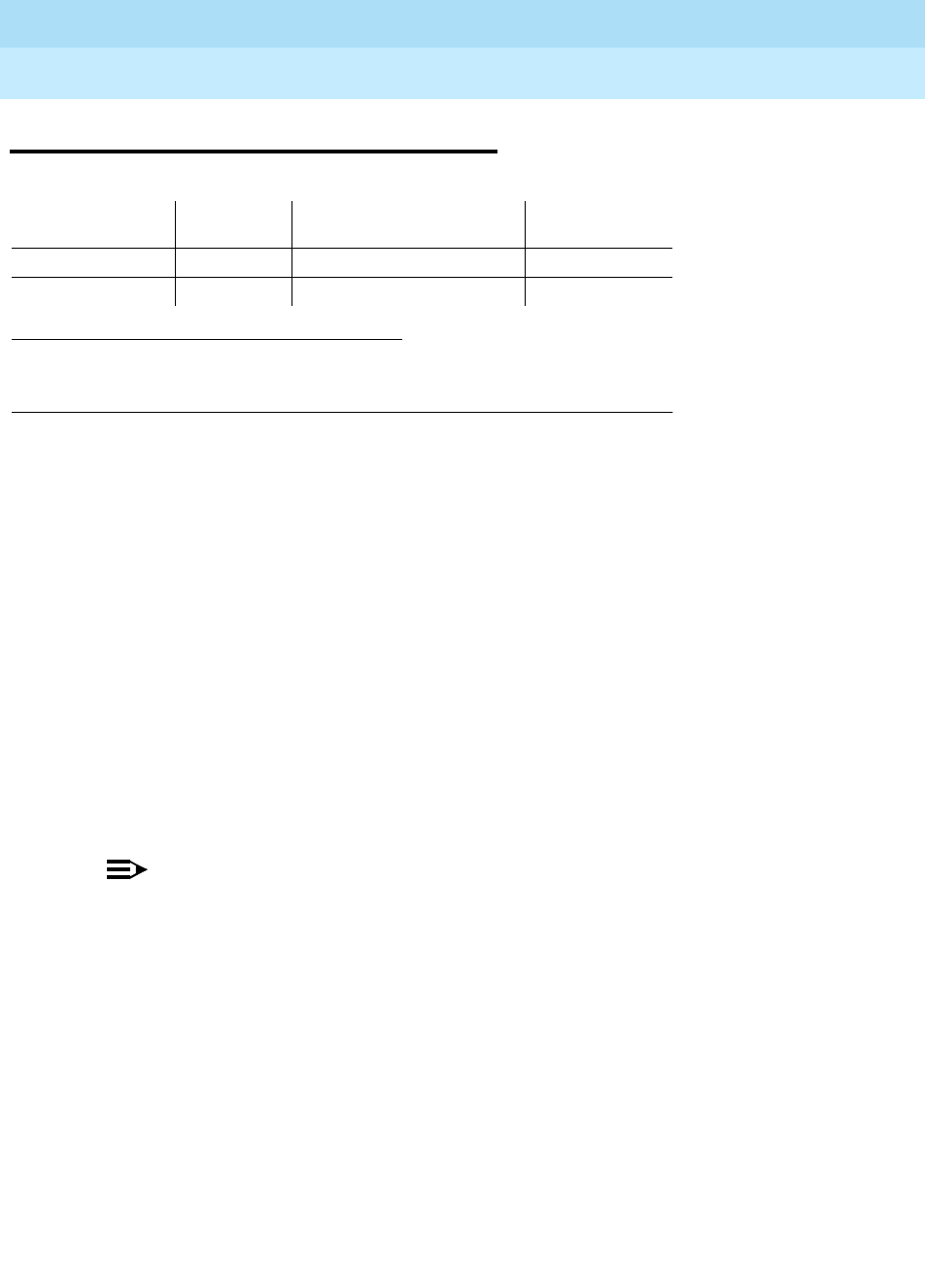
DEFINITY Enterprise Communications Server Release 6
Maintenance for R6r Volumes 1 & 2
555-230-126 Issue 2
January 1998
Maintenance Object Repair Procedures
Page 9-299DAT-LINE (Data Line Port)
9
9
DAT-LINE (Data Line Port)
The TN726 Data Line circuit pack has 8 ports, each of which supports an RS-232
interface to asynchronous Customer Premises Equipment (CPE). Each of these
ports and the equipment connected to it constitute a data line. For DT-LN-BD
(Data Line Circuit Pack) errors, refer to "XXX-BD (Common Port Circuit Pack)".
Check circuit pack-level errors first since the usability of the ports depend on the
health of the circuit pack.
Data line ports are administered at the terminal with the add data-module
command. The data module type is
data-line
. The list data-module command
will list all administered data modules in the system. See “PDATA-PT” for details
on how data lines are used as system ports.
The TN750 Announcement circuit pack also has one data line-type port on it.
This data line port is used for saving and restoring announcements. For a
description of this feature and repair instructions for the TN750, refer to
“ANN-BD”.
NOTE:
If the tests for the data line port in question pass, and user-reported
complaints persist, there is probably an external problem. Test the
asynchronous data unit (ADU), following the procedures outlined in
User
Manual Z3A Asynchronous Data Unit
, 555-401-701. If the ADU appears to
be working properly, check the external wiring, and then check the
customer equipment.
1. UU is the universal cabinet number (1 for PPN, 2 -44 for EPNs). C is the carrier
designation (A, B, C, D, or E). SS is the number of the slot in which the circuit pack
resides (01 to 21). pp is the two digit port number (01, 02, ...).
MO Name (in
Alarm Log) Alarm
Level Initial Command to Run1Full Name of
MO
DAT-LINE MINOR test port UUCSSpp l Data Line Port
DAT-LINE WARNING test port UUCSSpp l Data Line Port

DEFINITY Enterprise Communications Server Release 6
Maintenance for R6r Volumes 1 & 2
555-230-126 Issue 2
January 1998
Maintenance Object Repair Procedures
Page 9-300DAT-LINE (Data Line Port)
9
Error Log Entries and Test to Clear Values
Notes:
a. This is a software audit error that does not indicate any hardware
malfunction. Run the Short Test Sequence and investigate errors.
b. Indicates the circuit pack has been removed or has been insane for more
than 11-minutes. To clear the error, reseat or replace the circuit pack.
c. Error type 769 indicates that the data line circuit pack found an error in the
transmit/receive circuitry of an administered data line when the circuit
pack was inserted. Perform the following:
1. Enter busyout board UUCSS for the circuit pack on which the port
resides.
2. Enter reset board UUCSS. Check the Error Log to determine if
Error Type 769 is logged again for DAT-LINE. Make sure that the
Active Alarms Only field is set to n.
If error type 769 reappears, replace the data line circuit pack. If
Error Type 769 does not reappear, proceed to Step 3.
3. Enter release board UUCSS.
1. Run the Short Test Sequence first. If all tests pass, run the Long Test Sequence. Refer to the appropriate
test description and follow the recommended procedures.
Table 9-102. Data Line Port Error Log Entries
Error
Type Aux
Data Associated Test Alarm
Level On/Off
Board Test to Clear Value
010 Any Any Any test port UUCSSpp sh r 1
1 Digital Looparound
Test (#171) MINOR ON test port UUCSSpp s r 2
15(a) Any Audit Update Test
(#36)
18 0 Busyout port
UUCSSpp WARNING OFF rel port UUCSSpp
130 (b) None WARNING ON test port UUCSSpp sh
257 Conference Circuit
Test (#7) MINOR ON test port UUCSSpp l r 2
513 NPE Crosstalk Test
(#6) MINOR ON test port UUCSSpp l r 2
769(c) 40983 None
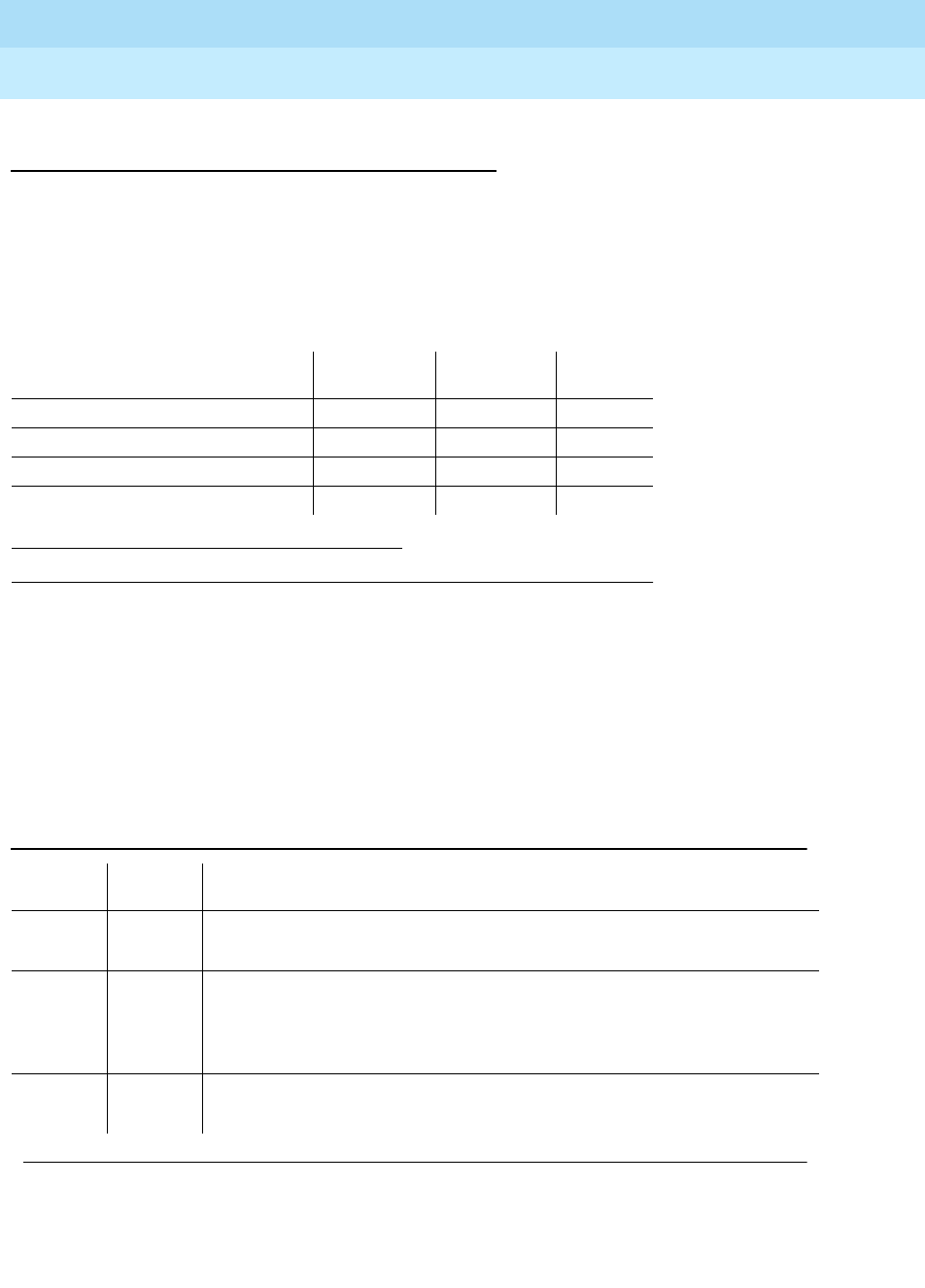
DEFINITY Enterprise Communications Server Release 6
Maintenance for R6r Volumes 1 & 2
555-230-126 Issue 2
January 1998
Maintenance Object Repair Procedures
Page 9-301DAT-LINE (Data Line Port)
9
System Technician-Demanded Tests:
Descriptions and Error Codes
Always investigate tests in the order presented in the table below. By clearing
error codes associated with the
Digital Looparound Test,
for example, you may
also clear errors generated from other tests in the testing sequence. For
example, you may also clear errors generated from other tests in the testing
sequence.
NPE Crosstalk Test (#6)
The NPE Crosstalk Test verifies that this port’s NPE channel talks on the selected
time slot and never crosses over to time slots reserved for other connections. If
the NPE is not working correctly, one-way and noisy connections may be
observed. This test is usually part of a port’s long test sequence and takes about
20 to 30 seconds to complete.
1. D = Destructive; ND = Nondestructive
Order of Investigation Short Test
Sequence Long Test
Sequence D/ND1
Digital Looparound Test (#171) X X ND
NPE Crosstalk Test (#6) X ND
Conference Circuit Test (#7) X ND
Audit Update Test (#36) X X ND
Table 9-103. TEST #6 NPE Crosstalk Test
Error
Code Test
Result Description/ Recommendation
ABORT Could not allocate the necessary system resources to run this test.
1. Try (a).
1000 ABORT System resources required to run test are not available. The port may be in
use on a valid call. Use status data-module to determine when the port is
available for testing.
1. Try (a).
1001 ABORT Could not allocate the necessary system resources to run this test.
1. Try (a).
Continued on next page

DEFINITY Enterprise Communications Server Release 6
Maintenance for R6r Volumes 1 & 2
555-230-126 Issue 2
January 1998
Maintenance Object Repair Procedures
Page 9-302DAT-LINE (Data Line Port)
9
Notes:
a. Retry the command at 1-minute intervals a maximum of 5 times.
1002 ABORT The system could not allocate time slots for the test. The system may be
under heavy traffic conditions or it may have time slots out-of-service due to
TDM-BUS errors. Refer to “TDM-BUS” to diagnose TDM-BUS errors.
1. If system has no TDM-BUS errors and is not handling heavy traffic, try
(a).
1003 ABORT The system could not allocate a tone receiver for the test. The system may
be oversized for the number of tone detectors present or some tone
detectors may be out-of-service.
1. Look for TTR-LEV errors in the Error Log. If present, refer to “TTR-LEV”.
2. Look for TONE-PT errors in the Error Log. If present, refer to “TONE-PT”.
3. If neither condition exists, try (a).
1004 ABORT The port has been seized by a user for a valid call. Use status data-module
to determine when the port is available for testing.
1. Try (a).
1020 ABORT An existing error type 769 on this port prevented the test from running.
1. Follow the procedure following the Error Log Table for error type 769.
2000 ABORT Response to the test request was not received within the allowable time
period.
2100 ABORT Could not allocate the necessary system resources to run this test.
1. Try (a).
Any FAIL The NPE of the tested port was found to be transmitting in error. This will
cause noisy and unreliable connections.
1. Replace the circuit pack.
PASS The port is correctly using its allocated time slots. Investigate user-reported
troubles on this port using other port tests and examining the ADU, external
wiring, and customer equipment.
Table 9-103. TEST #6 NPE Crosstalk Test — Continued
Error
Code Test
Result Description/ Recommendation
Continued on next page

DEFINITY Enterprise Communications Server Release 6
Maintenance for R6r Volumes 1 & 2
555-230-126 Issue 2
January 1998
Maintenance Object Repair Procedures
Page 9-303DAT-LINE (Data Line Port)
9
Conference Circuit Test (#7)
The Conference Circuit Test verifies that the NPE channel for the port being
tested can correctly perform the conferencing function. The NPE is instructed to
listen to several different tones and conference the tones together. The resulting
signal is then measured by a tone detector port. If the level of the tone is within a
certain range, the test passes.
Notes:
a. Retry the command at 1-minute intervals a maximum of 5 times.
Table 9-104. TEST #7 Conference Circuit Test
Error
Code Test
Result Description/ Recommendation
ABORT Could not allocate the necessary system resources to run this test.
1. Try (a).
1000 ABORT System resources required to run this test are not available. The port may be
in use on a valid call. Use status data-module to determine when the port is
available for testing.
1004 ABORT The port has been seized by a user for a valid call. Use status data-module
to determine when the port is available for testing.
1. Try (a).
1020 ABORT An existing error type 769 on this port prevented the test from running.
1. Follow the procedure following the Error Log Table for error type 769.
2000 ABORT Response to the test request was not received within the allowable time
period.
2100 ABORT Could not allocate the necessary system resources to run this test.
1. Try (a).
Any FAIL The conference circuit test failed (possible off-board problem).
1. Busyout and release the port (data line), and then retest.
2. Replace the circuit pack if the test continues to fail.
PASS The port can correctly conference multiple connections. Investigate
user-reported troubles on this port using other port tests and examining the
ADU, external wiring, and customer equipment.
Continued on next page

DEFINITY Enterprise Communications Server Release 6
Maintenance for R6r Volumes 1 & 2
555-230-126 Issue 2
January 1998
Maintenance Object Repair Procedures
Page 9-304DAT-LINE (Data Line Port)
9
Audit Update Test (#36)
This audit verifies that the hardware state of the data line is consistent with the
system translations. The audit queries the port for the switchhook state, the
software state is updated according to the returned value. Also, the audit data
line options down to the port.
Digital Looparound Test (#171)
The Digital Looparound Test checks the data line port’s ability to transmit and
receive data on the TDM Bus. Data is sent through an available
Maintenance/Test digital port over the TDM Bus, internally looped through the
data line port back onto the TDM Bus, and received again by the same
Maintenance/Test digital port.
Note that only one of the two digital ports on a Maintenance/Test circuit pack is
used for this test, and that port must be the first such port; such as port 02. If
port 02 is in use, out-of-service, or not present, the test aborts. This test may fail if
the Maintenance/Test digital port used by the test is not functioning properly. If
there are any M/T-DIG errors in the Error Log, refer to the “M/T-BD” to clear them
first. This test will pass regardless of any customer equipment that might be
connected to the port, as long as the port is not in use by the equipment.
Table 9-105. TEST #36 Audit Update Test
Error
Code Test
Result Description/ Recommendation
1006 ABORT An existing error type 769 on this port prevented the test from running.
1. Follow the procedure following the Error Log Table for error type 769.
2000 ABORT Response to the test request was not received within the allowable time
period.
2100 ABORT Could not allocate the necessary system resources to run this test.
ABORT Internal system error
7 FAIL Internal system error
1. Try the command again at 1-minute intervals up to 5 times.
PASS The hardware port state is consistent with the software state. Investigate
user-reported troubles on this port using other port tests and examining the
ADU, external wiring, and customer equipment.

DEFINITY Enterprise Communications Server Release 6
Maintenance for R6r Volumes 1 & 2
555-230-126 Issue 2
January 1998
Maintenance Object Repair Procedures
Page 9-305DAT-LINE (Data Line Port)
9
Table 9-106. TEST #171 Digital Looparound Test
Error
Code Test
Result Description/ Recommendation
ABORT Internal system error
1. Try (a).
1000 ABORT System resources required to run test are not available. The port may be in
use on a valid call. Use status data-module to determine when the port is
available for testing.
1. Try (a).
1020 ABORT An existing error type 769 on this port prevented the test from running.
1. Follow the procedure following the Error Log Table for error type 769.
1042 ABORT Port under test is a TTI port and has only default translations with no
assigned extension. The executed test requires an assigned extension
associated with the port being tested. Therefore, this test cannot
successfully execute.
1. If there is a need to execute the test on this particular port then the
tester must insure that the port is fully translated such that the port has
an assigned extension.
1180 ABORT There is no Maintenance/Test circuit pack digital port available to carry out
the test.
1. Check to see if the Maintenance/Test digital ports are present. (Enter
list config command; ports 02 and 03 should show).
2. If the digital ports (02 and 03) on the Maintenance/ Test circuit pack are
not present, refer to “M/T-BD”.
3. If the digital ports are present, try (a).
1181 ABORT No time-slots available to connect digital ports for the test.
1. Try (a).
1182 ABORT Internal system error. Failed to connect the digital ports with time-slots.
1. Try (a).
1340 ABORT No Maintenance/Test digital port is currently available to perform this test.
1. Use list config to determine whether any Maintenance/Test digital ports
(ports 02 and 03 on the Maintenance/Test circuit pack) are present in
the system. At least one Maintenance/Test circuit pack must be present
in the PPN of a Release 5r system. There should be at least two such
ports present. If the ports are present, proceed to step 2. Otherwise,
determine why no ports appear in the list config display. Refer to
“M/T-DIG” and “M/T-BD”.
2. Look for M/T-DIG errors in the Error Log. If present, refer to “M/T-DIG”.
3. If the ports are present and no errors are logged against them, try (a).
4. If the test continues to abort, replace the Maintenance/Test circuit pack.
Continued on next page

DEFINITY Enterprise Communications Server Release 6
Maintenance for R6r Volumes 1 & 2
555-230-126 Issue 2
January 1998
Maintenance Object Repair Procedures
Page 9-306DAT-LINE (Data Line Port)
9
1392 ABORT This port is currently a TTI port and the test will not execute on it.
1. Verify that the port is a TTI port using either the display port command
(the display shows that the port is a TTI port) or the list config
command (the display shows a "t" for the port).
2. If either list config or display port indicate that the port is not a TTI
port, escalate the problem. If both commands indicate that the port is a
TTI port, the abort is correct for the test, and no action is necessary.
2004 ABORT Off hook was not received from the data line device.
1. Busyout the digital port being tested on the data line circuit pack. Try
(a).
2. If the test still aborts, replace the circuit pack.
2005 ABORT The handshake between the Maintenance/Test circuit pack digital port and
the data line port failed.
1. Look for M/T-DIG errors in the Error Log. If present, refer to “M/T-DIG”.
2. Try (a).
3. If the test still aborts, replace the data line circuit pack.
2312 ABORT Test did not complete, did not receive loop back data.
1. Look for M/T-DIG errors in the Error Log. If present, refer to “M/T-BD”.
2. Retry the test, if still aborts, replace the Data Line circuit pack.
2313 ABORT Failed to receive a response from the Maintenance/Test digital port.
1. Look for M/T-DIG errors in the Error Log. If present, refer to “M/T-BD”.
2. Try (a).
3. If the test continues to abort, replace the Maintenance/Test circuit pack.
2314 ABORT Data line port did not respond to downlinked message.
1. Busyout the digital port being tested on the data line circuit pack. Retry
the command at 1-minute intervals a maximum of 5 times.
2. If the test still aborts, replace the circuit pack.
Table 9-106. TEST #171 Digital Looparound Test — Continued
Error
Code Test
Result Description/ Recommendation
Continued on next page

DEFINITY Enterprise Communications Server Release 6
Maintenance for R6r Volumes 1 & 2
555-230-126 Issue 2
January 1998
Maintenance Object Repair Procedures
Page 9-307DAT-LINE (Data Line Port)
9
Notes:
a. Retry the command at 1-minute intervals a maximum of 5 times.
2500 ABORT Internal system error.
1. Try (a).
FAIL The test failed because the data received did not match the data sent. This
would indicate that there is a fault somewhere in the transmit/receive path to
the TDM Bus, which will probably result in data corruption over this port. This
test may fail if the Maintenance/Test digital port used by the test is not
functioning properly.
1. Look for M/T-DIG errors in the Error Log. If present, refer to “M/T-BD”.
2. Repeat Test #171.
3. If the test fails again, replace the data line circuit pack.
PASS The port can correctly transmit/receive data. Investigate user-reported
troubles on this port using other port tests and examining the ADU, external
wiring, and customer equipment.
Table 9-106. TEST #171 Digital Looparound Test — Continued
Error
Code Test
Result Description/ Recommendation
Continued on next page

DEFINITY Enterprise Communications Server Release 6
Maintenance for R6r Volumes 1 & 2
555-230-126 Issue 2
January 1998
Maintenance Object Repair Procedures
Page 9-308DC-POWER (Single Carrier Cabinet Environment)
9
DC-POWER (Single Carrier Cabinet
Environment)
DEFINITY Generic 3r systems support two different cabinet types: multicarrier
and single carrier. Single carrier cabinets are used only for EPNs. Both cabinet
types may be powered by either AC or DC external power source. Environmental
maintenance differs according to cabinet type and external power supply. Refer
to the following table to determine which maintenance object documentation to
use for environmental maintenance.
1. UU is the universal cabinet number indicated in the PORT field of the alarm log.
MO Name As
It Appears in
Alarm Log Alarm
Level
Initial System
Technician
Command to Run1Full Name of MO
DC-POWER MAJOR test environment UU Single Carrier Cabinet Environment
Cabinet Type Power
Source Environmental Maintenance Objects
Single carrier (EPN) AC or DC DC-POWER (all environmental
maintenance)
Multicarrier AC AC-POWER for AC-powered systems
(external power source)
POWER for AC-powered systems
(battery backup)
CARR-POW
(carrier port power supply)
CABINET
(temperature and fan sensors)
Multicarrier DC CARR-POW
(carrier port power supply)
CABINET
(temperature and fan sensors)

DEFINITY Enterprise Communications Server Release 6
Maintenance for R6r Volumes 1 & 2
555-230-126 Issue 2
January 1998
Maintenance Object Repair Procedures
Page 9-309DC-POWER (Single Carrier Cabinet Environment)
9
The DC-POWER maintenance object represents all environmental maintenance
for single-carrier cabinets, whether the external power supply is AC or DC. This
includes the external power supply and all Carrier Port Power Supplies in a port
network composed of a single-carrier cabinet stack. The Carrier Port Power
Supplies provide +5/-5/-48V DC to the circuit packs on the carrier. The following
power supplies are used:
Each power unit has one yellow LED. A lit LED signifies normal operation. An unlit
LED signifies a loss of external power to the cabinet, or a fault in the power unit.
When hardware detects a problem with any of these components, it reports the
information to the system software through a single lead. System software does
not differentiate between different environmental failures. Since several
environmental elements of single-carrier cabinets are logged against the
DC-POWER maintenance object, it is possible to have a DC-POWER alarm while
there is still power to the system.
If a Carrier Port Power Supply is physically removed from a carrier in a
single-carrier cabinet, there will not be a DC-POWER alarm. DC-POWER
maintenance cannot distinguish between removal of the power supply and the
physical absence of the cabinet.
There is a nominal power holdover of .25 second in an EPN single carrier
cabinet.
WP-91153 Accepts AC power input
676B Accepts DC power input

DEFINITY Enterprise Communications Server Release 6
Maintenance for R6r Volumes 1 & 2
555-230-126 Issue 2
January 1998
Maintenance Object Repair Procedures
Page 9-310DC-POWER (Single Carrier Cabinet Environment)
9
Hardware Error Log Entries and Test to Clear
Values
System Technician-Demanded Tests:
Descriptions and Error Codes
Always investigate tests in the order presented in the following table when
inspecting errors in the system. By clearing error codes associated with the
Single Carrier Cabinet Power Query Test
, for example, you may also clear errors
generated from other tests in the testing sequence. Test description(s) and
recommended maintenance procedures follow for all errors that can occur
during system technician-demanded testing.
Notes:
a. Refer to EMG-XFER (Emergency Transfer) Maintenance documentation
for a description of this test.
1. UU is the universal cabinet number indicated in the PORT field of the Alarm Log.
2. Run the Short Test Sequence first. If all tests pass, run the Long Test Sequence. Refer to the
appropriate test description and follow the recommended procedures.
1. D = Destructive; ND = Nondestructive
Single Carrier Cabinet Power Error Log Entries
Error
Type Aux
Data Associated Test Alarm
Level On/Off
Board Test to Clear Value1
020 Any Any Any test environment UU
513 0 or 1 Single Carrier Cabinet
Power Query (#79) MAJOR ON test environment UU r 2
Order of Investigation
Short
Test
Sequence Long Test
Sequence D/ND1
Single Carrier Cabinet Power Query Test
(#79) XXND
Emergency Transfer Query Test (#124) (a) X X ND
External Alarm Lead Query Test (#120) (b) X X ND
Analog Ring Generator Initialization Test
(#117) (c) XXND
Analog Ring Generator Query Test (#118)
(c) XXND

DEFINITY Enterprise Communications Server Release 6
Maintenance for R6r Volumes 1 & 2
555-230-126 Issue 2
January 1998
Maintenance Object Repair Procedures
Page 9-311DC-POWER (Single Carrier Cabinet Environment)
9
b. Refer to EXT-DEV (External Alarm Lead) Maintenance documentation for a
description of this test.
c. Refer to RING-GEN (Analog Ring Generator) Maintenance documentation
for a description of this test.
Single Carrier Cabinet Power Query Test (#79)
This test queries the EPN Maintenance circuit pack (in an EPN) about the status
of the power in a single carrier cabinet system. This test can only detect power
problems in carriers in the Port Network for which the Carrier Port Power Supply
is physically present.
Table 9-107. TEST #79 Single Carrier Cabinet Power Query Test
Error
Code Test
Result Description/ Recommendation
1000 ABORT System resources required to run this test are not
available.
1. Retry the command at 1-minute intervals a maximum
of 5 times.
2. If the test continues to abort, escalate the problem.
2000 ABORT Response to the test request was not received within the
allowable time period.
1. Retry the command at 1-minute intervals a maximum
of 5 time.
2. If the test continues to ABORT with a 2000 error
code, check for and resolve all MAINT (EPN
Maintenance circuit pack) errors. Then, repeat the
test.
3. If the test continues to ABORT with a 2000 error
code, then escalate the problem.
2029
2319
2320
2500
ABORT Internal System Error
1. Retry the command at 1-minute intervals a maximum
of 5 times.
2. If the test continues to abort, escalate the problem.
Continued on next page

DEFINITY Enterprise Communications Server Release 6
Maintenance for R6r Volumes 1 & 2
555-230-126 Issue 2
January 1998
Maintenance Object Repair Procedures
Page 9-312DC-POWER (Single Carrier Cabinet Environment)
9
1 FAIL There is currently a problem with the environment of the
power system.
1. The power supply to any one of the carriers may
have been lost.
a. Verify, and if necessary restore, AC power at the
wall outlet for each carrier.
b. Rerun the test. If the test still fails, proceed to
Step 2.
2. One of the WP-91153 or 676-B power units for one of
the carriers could be defective.
a. If a WP-91153 or 676-B power unit does not have
its yellow status LED on, then replace the power
unit (procedure in Chapter 5, ‘‘Responding to
Alarms and Errors’’).
b. Rerun the test. If the test still fails, proceed with
Step 3.
3. The MAINT (EPN Maintenance Circuit Pack) could
be incorrectly reporting this error. Resolve all alarms
on these MOs, and rerun the test. There are failures
that can occur on the EPN Maintenance circuit pack
that
will not
be detected by their respective
maintenance, but which will cause many, if not all,
environment tests to fail. If more than two
environment tests are failing, the suspect circuit
pack, depending on the system configuration,
should be replaced and the test rerun. If the test still
fails, follow normal escalation procedures.
PASS The MAINT (EPN Maintenance Circuit Pack) has
reported no problem with the power.
Table 9-107. TEST #79 Single Carrier Cabinet Power Query Test —
Continued
Error
Code Test
Result Description/ Recommendation
Continued on next page

DEFINITY Enterprise Communications Server Release 6
Maintenance for R6r Volumes 1 & 2
555-230-126 Issue 2
January 1998
Maintenance Object Repair Procedures
Page 9-313DETR-BD (Tone Detector Circuit)
9
DETR-BD (Tone Detector Circuit)
For proper tone detection, the companding mode administered for the system
must match that of the DETR-BD circuit pack. The companding mode is
administered on the system-parameters country-options form. Refer to
DEFINITY
Enterprise Communications Server Release 5.4 Administration and Feature
Description
.
For all DETR-BD (Tone Detector Circuit Pack) errors, refer to "XXX-BD (Common
Port Circuit Pack)".
1. UU is the universal cabinet number (1 for PPN, 2 -44 for EPNs). C is the carrier designation (A,
B, C, D, or E). SS is the number of the slot in which the circuit pack resides (01 to 21).
MO Name (in
Alarm Log) Alarm
Level Initial Command to
Run1Full Name of MO
DETR-BD MINOR test board UUCSS Tone Detector Circuit Pack
DETR-BD WARNING test board UUCSS Tone Detector Circuit Pack

DEFINITY Enterprise Communications Server Release 6
Maintenance for R6r Volumes 1 & 2
555-230-126 Issue 2
January 1998
Maintenance Object Repair Procedures
Page 9-314DID-BD (Direct Inward Dial Trunk Circuit Pack)
9
DID-BD (Direct Inward Dial Trunk
Circuit Pack)
Refer to "XXX-BD (Common Port Circuit Pack)" for circuit pack level errors. See
also “DID-TRK” (DID Trunk) for related trunk information.
1. UU is the universal cabinet number (1 for PPN, 2 -44 for EPNs). C is the carrier
designation (A, B, C, D, or E). SS is the number of the slot in which the circuit pack
resides (01 to 21). pp is the two digit port number (01, 02, ...).
MO Name (in
Alarm Log) Alarm
Level Initial Command to
Run1Full Name of MO
DID-BD MIN test board UUCSS sh Direct Inward Dial Trunk
Circuit Pack
DID-BD WRN test board UUCSS sh Direct Inward Dial Trunk
Circuit Pack

DEFINITY Enterprise Communications Server Release 6
Maintenance for R6r Volumes 1 & 2
555-230-126 Issue 2
January 1998
Maintenance Object Repair Procedures
Page 9-315DID-DS1 (Direct Inward Dial Trunk)
9
DID-DS1 (Direct Inward Dial Trunk)
The DID-DS1 trunk provides a digital Direct Inward Dial (DID) trunk from a CO
switch to the system through a DS1 link. A 24-channel DS1 link can support up to
24 DID-DS1 trunk calls simultaneously. A 32-channel link can support up to 30. A
DID-DS1 trunk can be used for digitized voice and data communications with
appropriate DS1 signaling mode (for example, common channel signaling). The
TN767 and TN464 series circuit packs support wink-start and immediate-start
trunks and call processing signaling. See ‘‘DS1-BD (DS1 Interface Circuit Pack)’’
and "UDS1-BD (UDS1 Interface Circuit Pack)" for more information. Throughout
this section, the term DS1 applies to both the DS1 or UDS1 circuit packs.
Information included in this section covers the in-line errors log, initialization
tests, periodic tests, scheduled tests, system technician demand tests, and
alarms escalation and elimination. Two trunk service states are specified in the
DID-DS1 trunk maintenance:
If the DS1 circuit pack is out-of-service, then all trunks on the DS1 Interface
circuit pack are put into the out-of-service state and a Warning alarm is raised.
1. A Major alarm on a trunk indicates that alarms on these trunks are not downgraded by the set
options command and that at least 75 percent of the trunks in this trunk group are alarmed. For
more information on the set options command.
MO Name (in
Alarm Log) Alarm Level Initial Command to Run Full Name of MO
DID-DS1 MAJOR1test trunk
grp
/
mbr
l Direct Inward Dial Trunk
DID-DS1 MINOR test trunk
grp
/
mbr
l Direct Inward Dial Trunk
DID-DS1 WARNING test trunk
grp
/
mbr
Direct Inward Dial Trunk
out-of-service The trunk is in a deactivated state and cannot be used
for incoming calls.
in-service The trunk is in an activated state and can be used for
incoming calls.

DEFINITY Enterprise Communications Server Release 6
Maintenance for R6r Volumes 1 & 2
555-230-126 Issue 2
January 1998
Maintenance Object Repair Procedures
Page 9-316DID-DS1 (Direct Inward Dial Trunk)
9
Error Log Entries and Test to Clear Values
Notes:
a. Error Type 1—DS1 Interface circuit pack detects a hardware error on the
DS1 DID trunk. The Aux Data field indicates the following:
1. Run the Short Test Sequence first. If all tests pass, run the Long Test Sequence. Refer to the
appropriate test description and follow the recommended procedures.
2. This alarm will only be raised when the System-Parameter Country form has the Base Tone Generator
field set to 4 (Italy). This alarm will be a MINOR alarm unless 75% or more trunks in this trunk group
are out of service, then the alarm will be upgraded to a MAJOR alarm.
3. Major alarms may be downgraded to Warning alarms based on the value used in the set options
command.
DID-DS1 Trunk Error Log Entries
Error
Type Aux
Data Associated Test Alarm
Level On/Off
Board Test to Clear Value
010 Any Any Any test trunk
grp#/mbr#
1(a) Any
15(b) Any Port Audit and
Update Test (#36)
18(c) WARNING OFF release trunk
grp#/mbr#
130(d) None WARNING ON test trunk
grp#/mbr#
257(e) 57474
57473
513(f) 57392 MIN/MAJ2
769(g) 57393 MIN/MAJ2
1281 Conference Circuit
Test (#7) MIN/
WRN3ON test trunk
grp#/mbr#
l r 4
1537 NPE Crosstalk
Test (#6) MIN/
WRN3ON test trunk
grp#/mbr#
l r 3
1793(h) test board
UUCSS
l
2305(i) 50944 None MIN/MAJ2OFF
3840(j) Port Audit and
Update Test (#36)

DEFINITY Enterprise Communications Server Release 6
Maintenance for R6r Volumes 1 & 2
555-230-126 Issue 2
January 1998
Maintenance Object Repair Procedures
Page 9-317DID-DS1 (Direct Inward Dial Trunk)
9
Maintenance does not start any testing or generate any alarms in
response to these errors.
b. Error Type 15—This is a software audit error that does not indicate any
hardware malfunction. Run Short Test Sequence and investigate errors (if
any).
c. Error Type 18—The trunk has been taken out of service by a demand
busyout. No calls can be made on this trunk.
d. Error Type 130—This error type indicates that the circuit pack has been
removed or has been insane for more than 11 minutes. To clear the error,
reinsert or replace the circuit pack.
e. Error Type 257—DS1 Interface circuit pack detects a hardware error on
the DS1 DID trunk. The Aux Data field indicate the source of the error:
f. Error Type 513—DS1 Interface circuit pack detects a hardware error on
the DS1 DID trunk. Aux Data 57392 indicates no external release on PBX
disconnect.
g. Error Type 769—DS1 Interface circuit pack detects a hardware error on
the DS1 DID trunk. Aux Data 57393 indicates belated external release on
PBX disconnect.
h. Error Type 1793—DS1 Interface circuit pack is out-of-service. Look for
DS1-BD/UDS1-BD errors in Hardware Error Log. Refer to the appropriate
“DS1-BD/UDS1-BD” information for details.
i. Error Type 2305—This error indicates that a signaling change was
detected by the PBX trunk circuit pack which is inconsistent with the
present state of the trunk.
j. Error Type 3840—Port Audit and Update Test (#36) failed due to an
internal system error. Enter status trunk command to verify the status of
the trunk. If the trunk is out-of-service, then enter the release trunk
command to put it back to in-service. Retry the test command.
57476 On-hook before wink
57477 On-hook before ready to receive digits
57485 Wink too short for valid signal
57474 Rotary dial rate above 12 pulses per second
57473 Rotary dial rate below 8 pulses per second

DEFINITY Enterprise Communications Server Release 6
Maintenance for R6r Volumes 1 & 2
555-230-126 Issue 2
January 1998
Maintenance Object Repair Procedures
Page 9-318DID-DS1 (Direct Inward Dial Trunk)
9
System Technician-Demanded Tests:
Descriptions and Error Codes
Always investigate tests in the order they are presented in the table below. By
clearing error codes associated with the
NPE Crosstalk Test,
for example, you
may also clear errors generated from other tests in the testing sequence.
NPE Crosstalk Test (#6)
The NPE Crosstalk Test verifies that this port’s NPE channel talks on the selected
time slot and never crosses over to time slots reserved for other connections. If
the NPE is not working correctly, one-way and noisy connections may be
observed. This test is usually only part of a port’s Long Test Sequence and takes
about 20 to 30 seconds to complete.
1. D = Destructive; ND = Nondestructive
Order of Investigation Short Test
Sequence Long Test
Sequence D/ND1
NPE Crosstalk Test (#6) X ND
Conference Circuit Test (#7) X ND
Port Audit and Update Test (#36) X X ND
Table 9-108. TEST #6 NPE Crosstalk Test
Error
Code Test
Result Description/ Recommendation
ABORT System resources required for this test are not available.
1. Try (a).
1000 ABORT System resources required for this test are not available.
The port may be busy with a valid call. Use display port UUCSSpp to
determine the trunk group/ member number of the port. Use the status
trunk command to determine the service state of the port. If the port is
in use, wait until the port is idle before testing.
1. If the port status is active but the port is not in use (no calls), check
the error log for error type 1025. The port may be locked up.
2. If the port status is idle, try (a).
Continued on next page

DEFINITY Enterprise Communications Server Release 6
Maintenance for R6r Volumes 1 & 2
555-230-126 Issue 2
January 1998
Maintenance Object Repair Procedures
Page 9-319DID-DS1 (Direct Inward Dial Trunk)
9
1001 ABORT System resources required for this test are not available.
1. Try (a).
1002 ABORT The system could not allocate time slots for the test. The system may
be under heavy traffic conditions or it may have time slots out-of-
service due to TDM BUS error. Use status health to determine if the
system is experiencing heavy traffic. Refer to “TDM-BUS”.
1. If the system has no TDM-BUS errors and is not handling heavy
traffic, try (a).
1003 ABORT The system could not allocate a tone receiver for the test. The system
may be oversized for the number of tone detectors present or some
tone detectors may be out-of-service. Use list measurements
tone-receiver to display information on the tone receivers.
1. Resolve any “TTR-LEV” errors.
2. Resolve any “TONE-PT” errors.
3. If neither condition exists, try (a).
1004 ABORT The port was seized by a user for a valid call. Use display port
UUCSSpp to determine the trunk group/member number of the port.
Use status trunk to determine the service state of the port. If the port is
in use, wait until the port is idle before testing.
1. If the port status is idle, try (a).
1020 ABORT The test did not run due to a previously existing error on the specific
port or a more general circuit pack error.
1. Examine Error Log for existing errors against this port or circuit
pack and attempt to diagnose the previously existing error.
2000 ABORT Response to the test was not received within the allowable time period.
2100 ABORT System resources required for this test are not available.
2. Try (a).
2053 ABORT At least one of the following errors is found on the DS1 circuit pack:
1281—Loss of signal, 1793—Blue Alarm, 2049—Red Alarm, 2305—
Yellow Alarm, or 1537—Hyperactivity
Resolve any of the above error types. See “DS1-BD” or “UDS1-BD”.
Table 9-108. TEST #6 NPE Crosstalk Test — Continued
Error
Code Test
Result Description/ Recommendation
Continued on next page

DEFINITY Enterprise Communications Server Release 6
Maintenance for R6r Volumes 1 & 2
555-230-126 Issue 2
January 1998
Maintenance Object Repair Procedures
Page 9-320DID-DS1 (Direct Inward Dial Trunk)
9
Notes:
a. Retry the command at 1-minute intervals a maximum of 5 times.
Conference Circuit Test (#7)
The Conference Circuit Test verifies that the NPE channel for the port being
tested can correctly perform the conferencing function. The NPE is instructed to
listen to several different tones and conference the tones together.
ANY FAIL This can be due to off-board problems, including EXP-PN and
EXP-INTF faults, TDM-BUS faults, and tone detectors/tone generators.
Clear all off-board problems before replacing the board. A TDM-BUS
problem is usually a faulty board or bent pins on the backplane.
1. Resolve any “EXP-PN”, “EXP-INTF”, “TDM-BUS”, “TONE-BD”, and
“TONE-PT” errors in the error log.
2. Retest when errors are cleared. Replace the board if the test fails.
PASS The port is correctly using its allocated time slots. Investigate
user-reported troubles on this port using other port tests and by
examining station, trunk, or external wiring.
0NO
BOARD The test could not relate the internal ID to the port. This could be due to
incorrect translations, no board is inserted, an incorrect board is
inserted, or an insane board is inserted.
1. Check to ensure that the board translations are correct. Use lIst
config and resolve any problems that are found.
2. Issue the busyout board command. Issue the reset board
command. Issue the release busy board command.
3. Issue the test board long command. This should re-establish the
link between the internal ID and the port. If not, check to see that
there is a valid board inserted.
Table 9-108. TEST #6 NPE Crosstalk Test — Continued
Error
Code Test
Result Description/ Recommendation
Continued on next page

DEFINITY Enterprise Communications Server Release 6
Maintenance for R6r Volumes 1 & 2
555-230-126 Issue 2
January 1998
Maintenance Object Repair Procedures
Page 9-321DID-DS1 (Direct Inward Dial Trunk)
9
Table 9-109. TEST #7 Conference Circuit Test
Error
Code Test
Result Description/ Recommendation
ABORT Could not allocate the necessary system resources for this test.
1. Try (a).
1000 ABORT System resources required for this test were not available. The port
may be busy with a valid call. Use display port UUCSSpp to
determine the trunk group/member number of the port. Use status
trunk to determine the service state of the port. If the port is in use,
wait until the port is idle before testing.
1. If the port status is active but the port is not in use (no calls), check
the error log for error type 1025. The port may be locked up.
2. If the port status is idle, try (a).
1002 ABORT The system could not allocate time slots for the test. The system may
be under heavy traffic conditions, or it may have time slots out of
service due to TDM-BUS errors. Refer to “TDM-BUS”.
1. If the system has no TDM-BUS errors and is not handling heavy
traffic and the port status is idle, try (a).
1003 ABORT The system could not allocate a tone receiver for the test. The system
may be oversized for the number of tone detectors present or some of
the tone detectors may be out of service. Use list measurements
tone-receiver to display information about the tone receivers.
1. Resolve any “TTR-LEV” errors in the error log.
2. Resolve any “TONE-PT” errors in the error log.
3. If neither condition exists, try (a).
1004 ABORT The port was seized by a user for a valid call. Use display port
UUCSSpp to determine the trunk group/member number of the port.
Issue the status trunk command to determine the service state of the
port. If the port is in use, wait until the port is idle before testing.
1. If the port status is idle, try (a).
1018 ABORT The test was disabled via translation. Determine why the test has been
disabled before you enable it.
1. Verify that the Maintenance Test field on the Trunk Administration
screen is set to “n”. To enable the test, change the trunk
administration and enter “y” into the Maintenance Test field.
2. Repeat the test.
Continued on next page

DEFINITY Enterprise Communications Server Release 6
Maintenance for R6r Volumes 1 & 2
555-230-126 Issue 2
January 1998
Maintenance Object Repair Procedures
Page 9-322DID-DS1 (Direct Inward Dial Trunk)
9
1020 ABORT The test did not run due to a previously existing error on the specific
port or a more general circuit pack error.
1. Examine Error Log for existing errors against this port or the circuit
pack and attempt to diagnose the previously existing error.
2000 ABORT Response to the test was not received within the allowable time period.
2100 ABORT Could not allocate the necessary system resources to run this test.
1. Try (a).
2053 ABORT At least one of the following errors is found on the DS1 circuit pack:
■1281—Loss of signal
■1793—Blue Alarm
■2049—Red Alarm
■2305—Yellow Alarm
■1537—Hyperactivity
Look for the above error types in the Error Log. Refer to “DS1-BD” or
“UDS1-BD” for the listed error types.
FAIL The NPE of the tested port did not conference the tones correctly. This
can cause noisy and unreliable connections.
1. Enter list configuration board UUCSS. The circuit pack must be a
TN767C V3 or later. The error log may have error type 1281.
2. Test all administered trunks on the board. If one fails, this could be
an off-board problem (such as an incoming seizure or an off-hook
port seizure during the test). Retest the board.
3. If all of the ports fail, a -5 volt power problem is indicated. Check
“CARR-POW”.
4. If several ports fail, resolve any “TONE-BD” or “TONE-PT” errors
and rerun the test.
5. If the retry passes and troubles are reported, coordinate isolation
with the CO. Make sure that the switch, the CO, and any NTCE
equipment (the CSUs) have the correct administration.
6. Replace the circuit pack.
Table 9-109. TEST #7 Conference Circuit Test — Continued
Error
Code Test
Result Description/ Recommendation
Continued on next page

DEFINITY Enterprise Communications Server Release 6
Maintenance for R6r Volumes 1 & 2
555-230-126 Issue 2
January 1998
Maintenance Object Repair Procedures
Page 9-323DID-DS1 (Direct Inward Dial Trunk)
9
Notes:
a. Retry the command at 1-minute intervals a maximum of 5 times.
Port Audit and Update Test (#36)
This test sends port level translation data from the switch processor to the DS1
Interface circuit pack to assure that the trunk’s translation is correct. The port
audit operation verifies the consistency of the current state of the trunk as kept in
the DS1 Interface circuit pack and in the switch software.
PASS The port can correctly conference multiple connections. Investigate
user-reported troubles on this port using other port tests and by
examining station, trunk, or external wiring.
0NO
BOARD The test could not relate the internal ID to the port. This could be due to
incorrect translations, no board is inserted, an incorrect board is
inserted, or an insane board is inserted.
1. Check to ensure that the board translations are correct. Use the
lIst config command and resolve any problems that are found.
2. If the board was found to be correctly inserted in step 1, issue the
busyout board command.
3. Issue the reset board command.
4. Issue the release busy board command.
5. Issue the test board long command. This should re-establish the
link between the internal ID and the port. If not, check to see that
there is a valid board inserted.
Table 9-110. TEST #36 Port Audit and Update Test
Error
Code Test
Result Description/ Recommendation
ABORT Internal system error
1. Try (a).
Continued on next page
Table 9-109. TEST #7 Conference Circuit Test — Continued
Error
Code Test
Result Description/ Recommendation
Continued on next page

DEFINITY Enterprise Communications Server Release 6
Maintenance for R6r Volumes 1 & 2
555-230-126 Issue 2
January 1998
Maintenance Object Repair Procedures
Page 9-324DID-DS1 (Direct Inward Dial Trunk)
9
1000 ABORT The port may be busy with a valid call. Issue display port UUCSSpp to
determine the trunk group/member number of the port. Use the status trunk
command to determine the service state of the port. If the port is in use, wait
until the port is idle before testing.
1. If the port status is active but the port is not in use (no calls), check the
error log for error type 1025. The port may be locked up.
2. If the port status is idle, try (a).
1006 ABORT The test was aborted because the trunk is out of service.
1. Use status trunk to verify that the trunk is out of service.
2. If the trunk is out of service, determine why.
3. To put the trunk back in service, issue the release trunk command. Retry
the test.
2000 ABORT Response to the test was not received in the allowable time period.
2100 ABORT Could not allocate resources to run this test.
1. Try (a).
FAIL Test failed due to internal system error.
1. Try (a).
PASS Trunk translation has been updated successfully. The current trunk states kept
in the DS1 Interface circuit pack and switch software are consistent. If the
trunk is busied out, the test will not run but will return PASS. To verify that the
trunk is in-service:
1. Enter status trunk to verify that the trunk is in-service. If the trunk is
in-service, no further action is necessary. If the trunk is out-of-service.
2. Enter release trunk to put the trunk back into in-service.
3. Retry the test command.
Table 9-110. TEST #36 Port Audit and Update Test — Continued
Error
Code Test
Result Description/ Recommendation
Continued on next page

DEFINITY Enterprise Communications Server Release 6
Maintenance for R6r Volumes 1 & 2
555-230-126 Issue 2
January 1998
Maintenance Object Repair Procedures
Page 9-325DID-DS1 (Direct Inward Dial Trunk)
9
Notes:
a. Retry the command at 1-minute intervals a maximum of 5 times.
0NO
BOARD The test could not relate the internal ID to the port (no board). This could be
due to incorrect translations, no board is inserted, an incorrect board is
inserted, or an insane board is inserted.
1. Check to ensure that the board translations are correct. Use the list
config command, and resolve any problems that are found.
2. If the board was found to be correctly inserted in step 1, issue the
busyout board command.
3. Issue the reset board command.
4. Issue the release busy board command.
5. Issue the test board long command. This should re-establish the linkage
between the internal ID and the port. If this is not the case, check to see
that there is a valid board inserted.
Table 9-110. TEST #36 Port Audit and Update Test — Continued
Error
Code Test
Result Description/ Recommendation
Continued on next page
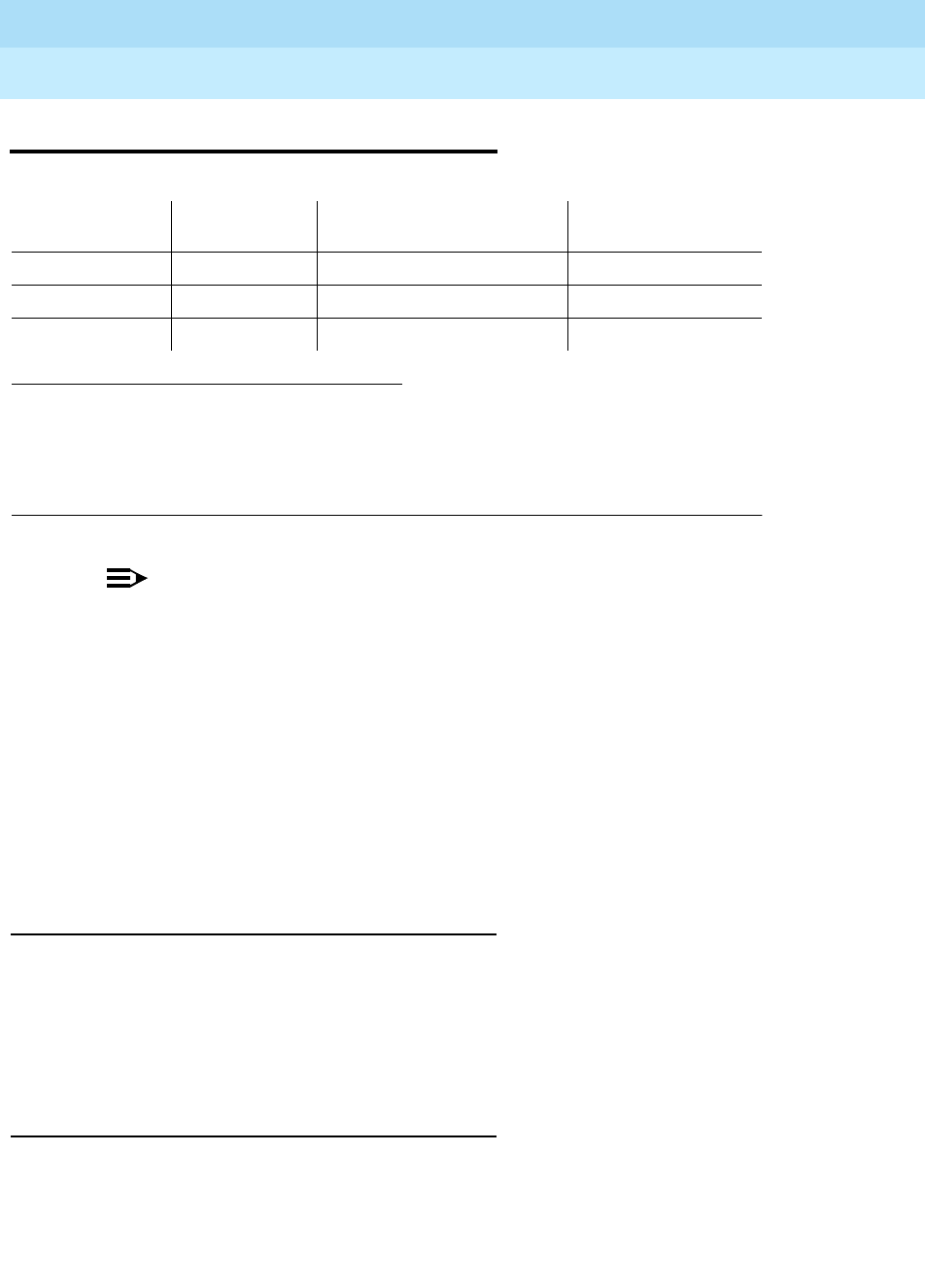
DEFINITY Enterprise Communications Server Release 6
Maintenance for R6r Volumes 1 & 2
555-230-126 Issue 2
January 1998
Maintenance Object Repair Procedures
Page 9-326DID-TRK (Direct Inward Dial Trunk)
9
DID-TRK (Direct Inward Dial Trunk)
NOTE:
Many trunk problems are caused by incorrect settings of parameters on the
trunk group administration form. Settings must be compatible with the local
environment and with parameter settings on the far-end. Refer to
DEFINITY.
Enterprise Communications Server Release 5.4 Administration and Feature
Description
, for information on how to administer trunks. The Application
Notes section of that book shows the correct settings for administrable
timers and other parameters on a country-by-country basis.
Direct Inward Dial trunks connect the switch to the CO, and allow outside parties
to call directly to an extension in the system. DID trunk circuit packs support
eight incoming-only ports. Each port provides an interface between the 2-wire
analog CO line and the 4-wire TDM bus on the switch.
DID Trunk Operation
The DID port receives three to five digits from the CO that are used to directly
connect an outside caller to the called station without assistance from an
attendant. For each call, the CO switch signals the system by opening and
closing individual DID loops (one of the eight ports), causing the starting or
stopping of loop current.
DID Trunk Testing
The system uses four tests of on-board circuitry to diagnose the health of the
trunk. These are described in the following sections. Additionally, in-line testing
which can generate errors, is performed while a call is in progress. See the Error
Log table for a description of these errors. These errors may be reproduced by
placing a call on the trunk and checking the Hardware Error Log.
1. UU is the universal cabinet number (1 for PPN, 2 -44 for EPNs). C is the carrier designation
(A, B, C, D, or E). SS is the number of the slot in which the circuit pack resides (01 to 21). pp
is the two digit port number (01, 02, ...).
2. A MAJOR alarm on a trunk indicates that alarms on these trunks are not downgraded by the
set options command and that at least 75 percent of the trunks in this trunk group are
alarmed.
MO Name (in
Alarm Log) Alarm Level Initial Command to Run1Full Name of MO
DID-TRK MAJOR2test port
UUCSSpp
l DID Trunk
DID-TRK MINOR test port
UUCSSpp
l DID Trunk
DID-TRK WARNING None DID Trunk

DEFINITY Enterprise Communications Server Release 6
Maintenance for R6r Volumes 1 & 2
555-230-126 Issue 2
January 1998
Maintenance Object Repair Procedures
Page 9-327DID-TRK (Direct Inward Dial Trunk)
9
Problems detected during signaling may be caused by off-board faults in the CO
switch or connections for which a Warning alarm is raised.
Before a maintenance test can be run on a port, the port must be idle. If an
incoming call seizes a port that is being tested, the test will abort and the
incoming call will proceed.
For transmission and signaling standard specification, refer to
Digital PBX
Standards
, RS4648.
Ports Out-of-Service without Errors or Alarms
A common trouble on DID trunks that produces no errors or alarms occurs when
the CO busies out (disconnects) the port. This situation occurs when the CO
thinks there are problems with the DID port. In this case, no incoming calls will be
possible through this port. This may result in complaints from outside callers
trying unsuccessfully to call in. This problem can be diagnosed by listing
measurements on lightly used trunks. If a particular port is detected as not in use,
a call to the CO will be necessary to get the connection back in service.
Error Log Entries and Test to Clear Values
Table 9-111. DID Trunk Error Log Entries
Error
Type Aux
Data Associated Test Alarm
Level On/Off
Board Test to Clear Value
010 Any Any Any test port
UUCSSpp
sh r 1
1(a) Any None WRN OFF
1(b) 57476 None WRN OFF
1(c) 57477 None WRN OFF
1(d) 57483 None WRN OFF
15(e) Any Port Audit Update
(#36)
18 0 busyout trunk
grp/mbr
WRN OFF release trunk
grp/mbr
130(f) None WRN ON test trunk
grp/mbr
257(g) 57472 None WRN OFF
257(h) 57473 None WRN OFF
257(i) 57474 None WRN OFF
257(j) 57475 None WRN OFF
513(k) 57392 None MIN/ WRN2OFF
510(l) 57393 None
Continued on next page

DEFINITY Enterprise Communications Server Release 6
Maintenance for R6r Volumes 1 & 2
555-230-126 Issue 2
January 1998
Maintenance Object Repair Procedures
Page 9-328DID-TRK (Direct Inward Dial Trunk)
9
Notes:
See also the preceding section on trunk problems without errors or alarms.
a. This condition occurs when the tone detector times out waiting for digits.
Change wink/immediate-start parameter to wink/immediate-start and
rotary/tone-dial parameters.
1. Verify trunk administered wink/immediate-start parameter.
2. Test trunk using BUTT set.
3. Refer problem to CO.
b. Rotary dial before wink — This condition occurs when the CO starts
dialing before the PBX sends wink on a wink-start trunk.
1. Verify trunk administered wink/immediate-start parameter.
2. Refer problem to CO.
c. Rotary dial too early — This condition occurs when the CO starts dialing
too soon after seizure on an immediate-start trunk.
1. Verify trunk administered wink/immediate-start parameter.
2. Refer problem to CO.
d. Rotary dial pulse during wink — This condition occurs when the CO
sends rotary dial digits too soon after seizure on a wink-start trunk.
1. Verify trunk administered wink/immediate-start parameter.
1. Run the Short Test Sequence first. If all tests pass, run the Long Test Sequence. Refer to the
appropriate test description and follow the recommended procedures.
2. Major alarms may be downgraded to Warning alarms based on the value used in the set options
command.
769 Any Port Diagnostic
(#35) MIN/ WRN2ON test port
UUCSSpp
r 3
1025 Looparound and
Conference (#33) MIN/ WRN2ON test port
UUCSSpp
l r 3
1281 NPE Crosstalk (#6) MIN/ WRN2ON test port
UUCSSpp
l r 3
1537 Any Port Diagnostic
(#35) MAJ/ MIN/
WRN2OFF test port
UUCSSpp
r 3
1793(m) 57489 None None
Table 9-111. DID Trunk Error Log Entries — Continued
Error
Type Aux
Data Associated Test Alarm
Level On/Off
Board Test to Clear Value
Continued on next page

DEFINITY Enterprise Communications Server Release 6
Maintenance for R6r Volumes 1 & 2
555-230-126 Issue 2
January 1998
Maintenance Object Repair Procedures
Page 9-329DID-TRK (Direct Inward Dial Trunk)
9
2. Refer problem to CO.
e. This is a software audit error that does not indicate any hardware
malfunction. Run Short Test Sequence and investigate associated errors
(if any).
f. This error type indicates that the circuit pack has been removed or has
been insane for more than 11 minutes. To clear the error, reinsert or
replace the circuit pack.
g. Rotary dial pulse on-hook longer than 105 msec — Break between rotary
pulses is too long.
1. Test trunk by performing an incoming test call.
2. Refer problem to CO.
h. Rotary dial rate below 8 pulses/sec — More than 135 msec between two
successive breaks.
1. Verify trunk administered interdigit-timing parameters.
2. Refer problem to CO.
i. Rotary dial rate above 12 pulses/sec — Less than 75 msec between two
successive breaks.
1. Verify trunk administered interdigit-timing parameters.
2. Refer problem to CO.
j. Digit detection — CO is starting new rotary dial digit within 150 msec of
previous digit.
1. Verify trunk administered interdigit timing parameters.
2. Refer problem to CO.
k. Loop current active — CO not releasing trunk after PBX disconnect.
Occurs when the PBX end drops first and the CO does not release the
trunk within 4 minutes.
1. Verify the interface to the network with a hand telephone set. If calls
are placed correctly, then refer problem to the CO.
2. If unable to place calls or this equipment is not available, check the
status on port using the status trunk command. If active but not
connected, disconnect bridging clips at the network interface.
Check status on the trunk. If trunk went idle, then replace clips. If
trunk is still active but unable to place calls, refer problem to the
CO.
l. Late CO trunk release — This event only occurs after the occurrence of
Error Type 513. The CO released the trunk 4 minutes after the PBX
dropped the call. This event decrements the severity (error count) of Error
Type 513, or may mean the problem related to Error Type 513 has been
fixed.
Verify that Error Type 513 does not occur again. Refer to Error 513.

DEFINITY Enterprise Communications Server Release 6
Maintenance for R6r Volumes 1 & 2
555-230-126 Issue 2
January 1998
Maintenance Object Repair Procedures
Page 9-330DID-TRK (Direct Inward Dial Trunk)
9
m. Incomplete Dial timer expired. This error only applies to the TN459 and
indicates a problem with incoming dialing stream. Refer the problem to
the CO.
System Technician-Demanded Tests:
Descriptions and Error Codes
Always investigate tests in the order presented in the table below. By clearing
error codes associated with the
NPE Crosstalk Test
for example, you may also
clear errors generated from subsequent tests in the testing sequence..
NPE Crosstalk Test (#6)
The NPE Crosstalk Test verifies that this port’s NPE channel talks on the selected
time slot on the TDM bus and never crosses over to time slots reserved for other
connections. If the NPE is not working correctly, one-way and noisy connections
may be observed. This test is usually only part of a port’s Long Test Sequence
and takes about 20 to 30 seconds to complete.
1. D = Destructive; ND = Nondestructive
Order of Investigation Short Test
Sequence Long Test
Sequence D/ND1
NPE Crosstalk Test (#6) X ND
Port Diagnostic Test (#35) X X ND
Looparound and Conference Circuit Test (#33) X ND
Port Audit Update Test (#36) X X ND
Table 9-112. TEST #6 NPE Crosstalk Test
Error
Code Test
Result Description/ Recommendation
ABORT Could not allocate the necessary system resources for this test. This could be
due to a failure to seize the port.
1. Try (a).
Continued on next page

DEFINITY Enterprise Communications Server Release 6
Maintenance for R6r Volumes 1 & 2
555-230-126 Issue 2
January 1998
Maintenance Object Repair Procedures
Page 9-331DID-TRK (Direct Inward Dial Trunk)
9
1000 ABORT System resources required to run this test are not available. The port may be
busy with a valid call. Enter display port UUCSSpp to determine the station
extension, attendant number, or trunk group/member number of the port. Enter
status station, status attendant, or status trunk to determine the service
state of the port. If the port is in use, wait until the port is idle before testing.
Attendants are always in use (off-hook) if the handset is plugged in and the
port is not busied out.
1. If the port status is active but the port is not in use (no calls), check the
Error Log for Error Type 513. The port may be locked up.
2. If the port status is idle, try (a).
1001 ABORT Could not allocate the necessary system resources to run this test.
1. Try (a).
1002 ABORT The system could not allocate time slots for the test. The system may be under
heavy traffic conditions or it may have time slots out-of- service due to
TDM-BUS errors. Refer to “TDM-BUS”.
1. If system has no TDM-BUS errors and is not handling heavy traffic, try (a).
1003 ABORT The system could not allocate a tone receiver for the test. The system may be
oversized for the number of Tone Detectors present or some Tone Detectors
may be out-of-service.
1. Resolve any “TTR-LEV” errors.
2. Resolve any “TONE-PT” errors”.
3. If neither condition exists, try (a).
1004 ABORT The port was seized by a valid call during the test. Enter display port
UUCSSpp to determine the station extension, attendant number, or trunk
group/member number of the port. Enyer status station, status attendant, or
status trunk to determine the service state of the port. If the the port is in use,
wait until the port is idle before testing. Attendants are always in use (off-hook)
if the handset is plugged in and the port is not busied out.
1. Try (a).
2000 ABORT Response to the test was not received within the allowable time period.
2100 ABORT Could not allocate the necessary system resources for this test. This could be
due to a failure to seize the port.
1. Try (a).
Table 9-112. TEST #6 NPE Crosstalk Test — Continued
Error
Code Test
Result Description/ Recommendation
Continued on next page

DEFINITY Enterprise Communications Server Release 6
Maintenance for R6r Volumes 1 & 2
555-230-126 Issue 2
January 1998
Maintenance Object Repair Procedures
Page 9-332DID-TRK (Direct Inward Dial Trunk)
9
Notes:
a. Retry the command at 1-minute intervals a maximum of 5 times.
Looparound and Conference Circuit Test (#33)
This test checks the reflective and non-reflective loop around and conference
capabilities of a DID port circuit. The test that uses 404-Hz, 1004-Hz, and
2804-Hz tones is an on-board test only. Each tone is separately transmitted to
and from the port (loop around within the port) and verified.
This test may fail due to noise induced by adjacent electric power lines.
Customers having this problem should resolve it with their local power company.
To temporarily alleviate the alarm caused by the failure of this test, the test may
be disabled from trunk administration Test field. (This also disables the port
diagnostic test.)
Any FAIL This test can fail due to off-board problems, including EXP-PN and EXP-INTF
faults, TDM-BUS faults, and tone detectors/tone generators. Clear all off-board
problems before replacing the board. A TDM-BUS problem is usually a faulty
board or bent pins on the backplane.
1. Resolve any “EXP-PN”, “EXP-INTF”, “TDM-BUS”, “TONE-BD”, and
“TONE-PT” errors in the error log.
2. Retest the board. Replace the board if the test fails.
PASS The port is correctly using its allocated time slots. User-reported troubles on
this port should be investigated using other port tests and by examining
station, trunk, or external wiring.
0NO
BOARD The test could not relate the internal ID to the port (no board).
1. Check to ensure that the board translations are correct. Translate the
board, if necessary.
2. Issue the busyout board command.
3. Issue the reset board command.
4. Issue the release busy board command.
5. Issue the test board command. This should re-establish the linkage
between the internal ID and the port.
Table 9-112. TEST #6 NPE Crosstalk Test — Continued
Error
Code Test
Result Description/ Recommendation
Continued on next page

DEFINITY Enterprise Communications Server Release 6
Maintenance for R6r Volumes 1 & 2
555-230-126 Issue 2
January 1998
Maintenance Object Repair Procedures
Page 9-333DID-TRK (Direct Inward Dial Trunk)
9
Table 9-113. TEST #33 Looparound and Conference Circuit Test
Error
Code Test
Result Description/ Recommendation
ABORT Could not allocate the necessary system resources to run this test. This could
be due to a failure to seize the port.
1. Try (a).
1000 ABORT System resources required to run this test are not available. The port may be
busy with a valid call. Enter display port UUCSSpp to determine the station
extension, attendant number, or trunk group/member number of the port. Use
status station, status attendant, or status trunk to determine the service
state of the port. If the port is in use, wait until the port is idle before testing.
Attendants are always in use (off-hook) if the handset is plugged in and the
port is not busied out.
1. If the port status is active but the port is not in use (no calls), check the
Error Log for Error Type 513. The port may be locked up.
2. If the port status is idle, try (a).
1004 ABORT The port was seized by a valid call during the test. Enter display port
UUCSSpp to determine the station extension, attendant number, or trunk
group/member number of the port. Use status station, status attendant, or
status trunk to determine the service state of the port. If the port is in use, wait
until the port is idle before testing. Attendants are always in use (off-hook), if
the handset is plugged in and the port is not busied out.
1. Try (a).
1018 ABORT Test disabled via administration. Verify that the ‘‘Maintenance Tests?’’ field on
the Trunk Group Form is set to "n". To enable the test, issue the change
trunk-group x command where ‘‘x’’ equals the number of the trunk group to be
tested. Then change the entry in the ‘‘Maintenance Tests?’’ field on the form to
‘‘y.’’
2000 ABORT Response to the test was not received within the allowable time period.
1. Try (a).
2100 ABORT System resources required to run this test are not available. This may be due to
the port being seized.
1. This abort code is usually associated with tone-clock (TONE-BD,
TONE-PT, and TDM-CLK) resources. Clear any tone errors in the error log.
2. Try (a).
Continued on next page
DEFINITY Enterprise Communications Server Release 6
Maintenance for R6r Volumes 1 & 2
555-230-126 Issue 2
January 1998
Maintenance Object Repair Procedures
Page 9-334DID-TRK (Direct Inward Dial Trunk)
9
3 FAIL The nonreflective 1004 Hz tone test of the port failed. An echo was detected
from the port. Poor quality transmission was detected to or from the port. The
problem may be off-board.
7 The conference capabilities of the port failed. Poor quality transmission was
detected to or from the port. The problem may be off-board.
129 The reflective 404-Hz tone test failed. Poor quality transmission was detected
to or from the port. The problem may be off-board.
131 The reflective 1004-Hz tone test failed. Poor quality transmission was detected
to or from the port. The problem may be off-board.
133 The reflective 2804-Hz tone test failed. Poor quality transmission was detected
to or from the port. The problem may be off-board.
!CAUTION:
The port may still be operational, or the fault may be off-board
(connections or CO). Off-board problems include incoming seizures or
off-hook port seizures during the test and, perhaps, noise induced by
adjacent electric power lines. The test may be disabled from trunk
administration ’Test’ field. This turns off all testing for that trunk group
except for tests 6 and 36.
3
7
129
131
133
(cont’
d.)
FAIL
(cont’d.)
Proceed as follows unless power or tone problems are suspected (see note
below).
1. To see if the problem is on-board, disconnect the port from the far-end and
retry the test. Coordinate this with the CO, or do it after busy hours.
2. If the retry fails, replace the circuit pack.
3. If the retry passes and no troubles have been reported, disable the test in
the trunk group administration. If the retry passes and troubles are
reported, coordinate isolation with the CO.
NOTE:
If the loop around and conference circuit test fails for all ports on a
circuit pack, a -5 volt power problem is indicated. A power unit may be
defective. Refer to “CARR-POW”. If the test fails on more than 1 port,
check for errors on the TONE-BD or the TONE-PT. Rerun the test.
PASS DID Trunk Looparound and Conference Test is successful. This port is
functioning properly.
1. If users are reporting troubles, examine loop connections to the port and
refer problem to the CO.
Table 9-113. TEST #33 Looparound and Conference Circuit Test — Continued
Error
Code Test
Result Description/ Recommendation
Continued on next page

DEFINITY Enterprise Communications Server Release 6
Maintenance for R6r Volumes 1 & 2
555-230-126 Issue 2
January 1998
Maintenance Object Repair Procedures
Page 9-335DID-TRK (Direct Inward Dial Trunk)
9
Notes:
a. Retry the command at 1-minute intervals a maximum of 5 times.
Port Diagnostic Test (#35)
This test checks a port’s battery feed circuitry for on-/off-hook detection, battery
shutdown, and battery reversal (wink) capabilities.
0NO
BOARD The test could not relate the internal ID to the port (no board).
1. Check to ensure that the board translations are correct.
2. Issue the busyout board command.
3. Issue the reset board command.
4. Issue the release busy board command.
5. Issue the test board command. This should establish the link between the
internal ID and the port.
Table 9-114. TEST #35 Port Diagnostic Test
Error
Code Test
Result Description/ Recommendation
ABORT System resources required to run this test were not available.
1. Try (a).
1000 ABORT System resources required to run this test were not available. The port may be
busy with a valid call. Enter display port UUCSSpp to determine the trunk
group/member number of the port. Use the status trunk command to
determine the service state of the port. If the port is in use, wait until the port is
idle before testing.
1. If the port status is active but the port is not in use (no calls), check the
error log for error type 513. The port may be locked up.
2. If the port status is idle, busyout and release the trunk, and try (a).
3. If the test continues to abort, check for wiring errors toward the CO which
may cause the trunk to lock up.
4. If the wiring is good and the test continues to abort, replace the TN753.
Continued on next page
Table 9-113. TEST #33 Looparound and Conference Circuit Test — Continued
Error
Code Test
Result Description/ Recommendation
Continued on next page

DEFINITY Enterprise Communications Server Release 6
Maintenance for R6r Volumes 1 & 2
555-230-126 Issue 2
January 1998
Maintenance Object Repair Procedures
Page 9-336DID-TRK (Direct Inward Dial Trunk)
9
1004 ABORT The port was seized by a valid call during the test. The test has been aborted.
Enter display port UUCSSpp to determine the station extension, attendant
number, or trunk group/member number of the port. Use the status station,
status attendant, or status trunk command to determine the service state of
the port. If the port is in use, wait until the port is idle before testing. Attendants
are always in use (off-hook) if the handset is plugged in and the port is not
busied out.
1. Try (a).
1018 ABORT Test has been disabled by trunk group administration. Verify that the
‘‘Maintenance Tests?’’ field on the Trunk Group Form is set to "n". To enable the
test, issue the change trunk-group x command where ‘‘x’’ equals the number
of the trunk group to be tested. Then change the entry in the ‘‘Maintenance
Tests?’’ field on the form to ‘‘y.’’
2000 ABORT Response to the test was not received within the allowable time period.
2100 ABORT Could not allocate the necessary system resources to run this test.
1. Try (a).
61446 FAIL Battery feed test failed. A loop current fault was detected. This is most probably
an incoming CO-line problem. This failure code is only reported by the TN2139
Italian DID circuit pack.
1. Check the incoming CO-line for loop current. If none is detected refer the
problem to the CO.
2. If the CO-line checks out OK, the failure must be on the DID port. Replace
the circuit pack.
61456 FAIL Battery feed test failed. An on-board problem was detected. This port is
out-of-service.
1. Replace circuit pack.
61472 FAIL Battery feed test failed. A problem with the incoming CO-line was detected.
1. Check the incoming CO-line for proper operation. If warranted, refer the
problem to the CO.
2. If the CO-line is not at fault, the failure must be on the DID port. Replace the
circuit pack.
PASS Current flow was detected for this port.
1. User-reported troubles on this port should be investigated using other port
tests and by examining connections.
2. Refer problem to the CO.
Table 9-114. TEST #35 Port Diagnostic Test — Continued
Error
Code Test
Result Description/ Recommendation
Continued on next page

DEFINITY Enterprise Communications Server Release 6
Maintenance for R6r Volumes 1 & 2
555-230-126 Issue 2
January 1998
Maintenance Object Repair Procedures
Page 9-337DID-TRK (Direct Inward Dial Trunk)
9
Notes:
a. Retry the command at 1-minute intervals a maximum of 5 times.
Port Audit Update Test (#36)
This test sends updates of the DID port translation for all ports on the circuit pack
that have been translated. The update is non-disruptive and guards against
possible corruption of translation data contained on the circuit pack. No
response message is expected from the circuit pack once it receives translation
updates. The port translation data includes:
■Wink or immediate start trunk
■Dial tone or rotary dialing trunk
■Rotary dialing inter-digit timing
■Network balance R/RC
■Disconnect timing
0NO
BOARD The test could not relate the internal ID to the port (no board).
1. Check to ensure that the board translations are correct. Translate the
board, if necessary.
2. Issue the busyout board command.
3. Issue the reset board command.
4. Issue the release busy board command.
5. Issue the test board command. This should re-establish the linkage
between the internal ID and the port.
Table 9-115. TEST #36 Port Audit Update Test
Error
Code Test
Result Description/ Recommendation
ABORT Could not allocate the necessary system resources to run this test.
1. Try (a).
Continued on next page
Table 9-114. TEST #35 Port Diagnostic Test — Continued
Error
Code Test
Result Description/ Recommendation
Continued on next page

DEFINITY Enterprise Communications Server Release 6
Maintenance for R6r Volumes 1 & 2
555-230-126 Issue 2
January 1998
Maintenance Object Repair Procedures
Page 9-338DID-TRK (Direct Inward Dial Trunk)
9
Notes:
a. Retry the command at 1-minute intervals a maximum of 5 times.
1006 ABORT The port was placed out of service, perhaps by craft busyout. Use display
port UUCSSpp to determine the trunk group/member number of the port.
Use status trunk to determine the service state of the port. If the port is out
of service, wait until the port is in service and idle before testing.
1. If the port status is in service and idle, then try (a).
2100 ABORT Could not allocate the necessary system resources to run the test.
1. Try (a).
FAIL Internal system error
1. Try (a).
PASS This test passed. Translation information was successfully updated on the
circuit pack.
1. If signaling troubles are reported (Error Types 1, 257, or 513 in Error
Log table), verify translation information for this port.
2. Refer problem to the CO.
0NO
BOARD The test could not relate the internal ID to the port .
1. Check to ensure that the board translations are correct. Translate the
board, if necessary.
2. Issue the busyout board command.
3. Issue the reset board command.
4. Issue the release busy board command.
5. Issue the test board command. This should re-establish the linkage
between the internal ID and the port.
Table 9-115. TEST #36 Port Audit Update Test — Continued
Error
Code Test
Result Description/ Recommendation
Continued on next page

DEFINITY Enterprise Communications Server Release 6
Maintenance for R6r Volumes 1 & 2
555-230-126 Issue 2
January 1998
Maintenance Object Repair Procedures
Page 9-339DIG-BD (Digital Line Circuit Pack)
9
DIG-BD (Digital Line Circuit Pack)
Refer to "XXX-BD (Common Port Circuit Pack)" for circuit pack level errors. See
also “DIG-LINE” for related line information.
1. UU is the universal cabinet number (1 for PPN, 2 -44 for EPNs). C is the carrier designation (A, B,
C, D, or E). SS is the number of the slot in which the circuit pack resides (01 to 21).
MO Name (in
Alarm Log) Alarm Level Initial Command to Run1Full Name of MO
DIG-BD MIN test board UUCSS sh Digital Line Circuit Pack
DIG-BD WRN test board UUCSS sh Digital Line Circuit Pack

DEFINITY Enterprise Communications Server Release 6
Maintenance for R6r Volumes 1 & 2
555-230-126 Issue 2
January 1998
Maintenance Object Repair Procedures
Page 9-340DIG-LINE (Digital Line)
9
DIG-LINE (Digital Line)
DIG-LINE maintenance monitors and tests ports on digital line circuit packs and
the hardware connected to those ports for lines administered as a digital station.
These include stations with just a digital voice terminal and stations with a digital
voice terminal and a linked data module. Stand-alone data modules, and data
adaptors in stand-alone mode, are covered by the PDMODULE and TDMODULE
maintenance objects. Circuit pack-level maintenance is covered by “DIG-BD”
whose strategy is described in the "XXX-BD (Common Port Circuit Pack)" section.
Only the TN754B or TN2136 should be used in out-of-building applications. For
important information pertaining to protection required for out-of-building digital
voice terminals, see
DEFINITY Enterprise Communications Server Release 5.4
Installation and Test for Multi-Carrier Cabinets
.
Only 2-wire Italtel Digital Telephone Models 1 and 2 (IDT1/2) or DAs can directly
connect to a TN2136. Lucent DCP (4-wire) digital voice terminals and data
modules can connect to these circuit packs via Italtel’s 2/4-wire adapter. DAs
can operate in either of two modes which are covered by different MOs:
Digital line maintenance interacts with digital line circuit pack (DIG-BD)
maintenance, and results of DIG-LINE testing can be affected by the health of
the digital line circuit pack. Keep this in mind when investigating digital line
problems.
There are instances where the service state of a station is mentioned. It is helpful
to understand what is meant by the different service states that may exist. The
different service states which apply to digital line station are explained as follows:
1. UU is the universal cabinet number (1 for PPN, 2 -44 for EPNs). C is the carrier designation
(A, B, C, D, or E). SS is the number of the slot in which the circuit pack resides (01 to 21).
pp is the two digit port number (01, 02, ...).
MO Name (in
Alarm Log) Alarm Level Initial Command to Run1Full Name of MO
DIG-LINE MINOR test port
UUCSSpp
l Digital Line
DIG-LINE WARNING test port
UUCSSpp
sh Digital Line
DA Mode Administered as: Endpoint MO
Stand-alone PDM Data endpoint only PDMODULE
Linked DTDM IDT1/2 and optional data terminal DIG-LINE

DEFINITY Enterprise Communications Server Release 6
Maintenance for R6r Volumes 1 & 2
555-230-126 Issue 2
January 1998
Maintenance Object Repair Procedures
Page 9-341DIG-LINE (Digital Line)
9
Downloading of Terminal Parameters
Programmable Terminals
The following information is presented to help you understand how maintenance
software interacts with terminal parameter downloading.
Terminal Types:
a. 84xx multibutton digital voice terminals (8403D01A, 8410B, 8410D02A,
8434D01A) with optional expansion module.
b. 603A1 and 603D1 Callmaster terminals for telemarketing applications.
c. 302B1 and 302C1 attendant console.
Circuit Packs:
1. 8400x, 302B1 Terminals
a. TN754 (4-wire, mu-law)
Minimum usable vintage for 8410D and 8434D terminals - V11
b. TN413 (4-wire, A-law)
c. TN754B (4-wire, A-law/mu-law selectable)
d. TN2177 (2-wire, 16-port, A-law/mu-law selectable)
e. TN2181 (2-wire, 16-port, A-law/mu-law selectable)
f. TN2224 (2-wire, 24-port, A-law/mu-law selectable)
2. 603A1/D1 Terminals
a. TN754 (4-wire, mu-law),
b. TN413 (4-wire, A-law)
c. TN754B (4-wire, A-law/mu-law selectable)
Out-of-Service The port, and thus the station, have been removed from service.
Busyout puts the port in the out-of-service state.
Ready-for-
Service The port on the circuit pack has been put into service, but the
voice terminal has not yet established signaling communications
with the port.
In-Service The voice terminal has established signaling communications
with the port, and the system is ready to process calls to and
from that station. A terminal in the ready-for-service state will
progress to the in-service state if it is functioning normally. It can
also be forced into the in-service state by going off-hook.
DEFINITY Enterprise Communications Server Release 6
Maintenance for R6r Volumes 1 & 2
555-230-126 Issue 2
January 1998
Maintenance Object Repair Procedures
Page 9-342DIG-LINE (Digital Line)
9
Downloadable Terminal Parameters
The following parameters are downloaded to programmable terminals:
Nonvolatile Memory
Nonvolatile memory stores downloadable parameters in programmable
terminals. Once the terminal is downloaded, it is not be necessary to download it
again, even if power is removed from the terminal. If nonvolatile memory fails with
power still present, the terminal reverts to its default factory settings except for its
A-law/mu-law companding settings which are stored in RAM. If power is
removed after the nonvolatile memory fails, the terminal reverts to its factory
default settings.
NOTE:
The mu-law companding mode is assigned as a default setting at the
factory. For the United States, a programmable terminal can place calls
even though it has not been downloaded from the system.
Download Actions
There are several different scenarios which causes a terminal to be downloaded.
These can occur as part of background maintenance activity or on demand from
the System Access Terminal or from a station.
For the background actions described below, the terminal downloads
automatically if a download retry flag for the terminal is set in software. This flag is
set at the time translation is loaded at boot time, when translation which affects
the parameters of a terminal is changed as part of system administration actions,
and when a port is inserted in software as a result of board insertion or translation
change.
Table 9-116. Parameters Downloadable to Programmable Terminals
Parameter Scope Terminal
International Flags (A-law/mu-law, Display Mode, DLI Voltage
level) System level 84xx, 603x,
302B1
Primary Levels
(Transmission & Sidetone) System level 84xx, 603x,
302B1
Adjunct Levels
(Transmission & Sidetone) System level 84xx
Handset Expander Option System level 84xx
Administrable Options (Speakerphone & Mute Button) Per-terminal 84xx
Administrable Softkeys Per-terminal,
System level 8410D, 8434D

DEFINITY Enterprise Communications Server Release 6
Maintenance for R6r Volumes 1 & 2
555-230-126 Issue 2
January 1998
Maintenance Object Repair Procedures
Page 9-343DIG-LINE (Digital Line)
9
Automatic Download Actions
1. System Reboot/Restart
A global download action is started when periodic maintenance tests start
after a system reboot/restart regardless of whether the parameters have
been downloaded previously.
2. Periodic Tests
If the download flag is still set when periodic tests are run on a terminal, a
download action will occur. This operation is required in case a terminal
could not be downloaded previously because it was off-hook at the time
the system first booted or because the terminal was off-hook at the time
translation associated with downloadable parameters was changed.
Note that it may take more than an hour for periodic tests to reach the
terminal that needs to be downloaded.
3. Terminal Administration
A downloadable terminal is automatically downloaded when translation
changes associated with downloadable parameters are made as part of
system administration. As shown in the previous table, these changes can
be for a specified terminal or may be system-wide. If the change is for
system-level parameter, a background global update request is made to
download all programmable terminals.
This global update may take more than an hour for a system with several
thousand programmable terminals.
4. Port Insertion
Whenever maintenance software initiates a request to place a port into
service, a terminal download action is started on that terminal if that
terminal is programmable. This port insertion action occurs under the
following circumstances:
a. A digital line circuit pack that is physically inserted into the system
has ports currently administered for programmable terminals.
If more than 20 port insertion requests are received within a few
seconds, a global download request is started up as a background
task. This action updates all programmable terminals instead of just
those being inserted. This is done to avoid system overload for
situations where there is massive board insertion. This could occur
when connectivity to an EPN is reestablished after that EPN was
down.
b. A station port is added to the system by a "add station" or "change
station" command.
c. A TTI port is activated.

DEFINITY Enterprise Communications Server Release 6
Maintenance for R6r Volumes 1 & 2
555-230-126 Issue 2
January 1998
Maintenance Object Repair Procedures
Page 9-344DIG-LINE (Digital Line)
9
5. Audits
As part of periodic maintenance, the hardware status audit test queries
programmable terminals to determine which levels and/or options are
being used. If the reported values are not equal to the administered
values, the system will initiate a terminal download action. This audit does
NOT check the parameters used for softkeys.
6. Activation of TTI
A terminal is downloaded automatically when it is activated using the
Terminal Translation Initialization feature. Therefore, no special user
actions are required for TTI.
NOTE:
Plugging the station cord into a terminal does not automatically
cause the terminal to be downloaded. If this terminal has factory
defaults or if the terminal has been previously downloaded with
parameters different than those desired, use one of the demand
download actions described below to download the terminal.
Demand Download Actions
1. Busyout/Release Command
A maintenance demand busyout/release request for a station will cause
the terminal to be downloaded regardless of its previous download status.
2. Feature Access Code
A Refresh Terminal Parameters Feature Access Code can be used to
request a terminal download action. When this code is followed by a "#",
the programmable parameters for the current terminal are downloaded
when the terminal goes on hook. When this code is followed by an
extension, the programmable parameters for the specified station are
downloaded.
This Refresh Terminal Parameters Feature Access Code is assigned on
the second page of the "feature-access-codes" screen.
A confirmation is returned if the download request is accepted. A busy
tone is returned if the request is made from a different station when the
target station is off-hook.
The first three green call appearance LEDs on the 84xx 603x terminal will
be turned on for three seconds if the station was successfully downloaded
as a result of an entry of a Refresh Terminal Parameters Facility Access
Code. This is not true for the 302B1 terminal.
There is no visible display on a station for the other background or
demand download actions. As described below, the "status station" and
"status attendant" screens can be used to check the download status of a
specified terminal.
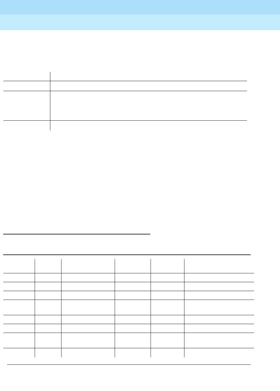
DEFINITY Enterprise Communications Server Release 6
Maintenance for R6r Volumes 1 & 2
555-230-126 Issue 2
January 1998
Maintenance Object Repair Procedures
Page 9-345DIG-LINE (Digital Line)
9
Status of Parameter Downloads
The "status station" and "status attendant" screens display the current download
status of individual 84xx, 603, and 301B1 terminals in the Download Status field.
The possible download states are:
Possible reasons for terminal being not downloaded include:
— Terminal is off-hook.
— Terminal detected a bad checksum.
— Terminal detected a bad or missing EEPROM (refer to hardware error log).
— Terminal is busy programming data from a previous PROGRAM message.
— Terminal is in the Programming Disabled state.
— Terminal is in the Local Program Options Mode.
— Terminal is disconnected or out of service (use status station command).
Error Log Entries and Test to Clear Values
Status Terminal Download State
Complete Terminal successfully downloaded sometime in the past.
Pending System waiting to download the terminal. This may require the execution of a
background periodic test which could take more than an hour. A demand
download as described above may also be used to initiate an immediate
download.
Not Applicable Not a programmable terminal.
Table 9-117. Digital Line Error Log Entries
Error
Type Aux
Data Associated Test Alarm
Level On/Off
Board Test to Clear Value
010 Any Any Any test port
UUCSSpp
sh r 1
1 (a) 40987 None WARNING OFF
1 (b) 1 to 20 None WARNING OFF
18 (c) 0 busyout port
UUCSSpp
WARNING OFF rel port
UUCSSpp
130 (d) None WARNING ON test port
UUCSSpp
sh
257 (e) 40971 None
513 0 Station (Digital)
Audits Test (#17) WARNING(
o) OFF test port
UUCSSpp
sh r 6
767 (f) 40964 None WARNING OFF
Continued on next page
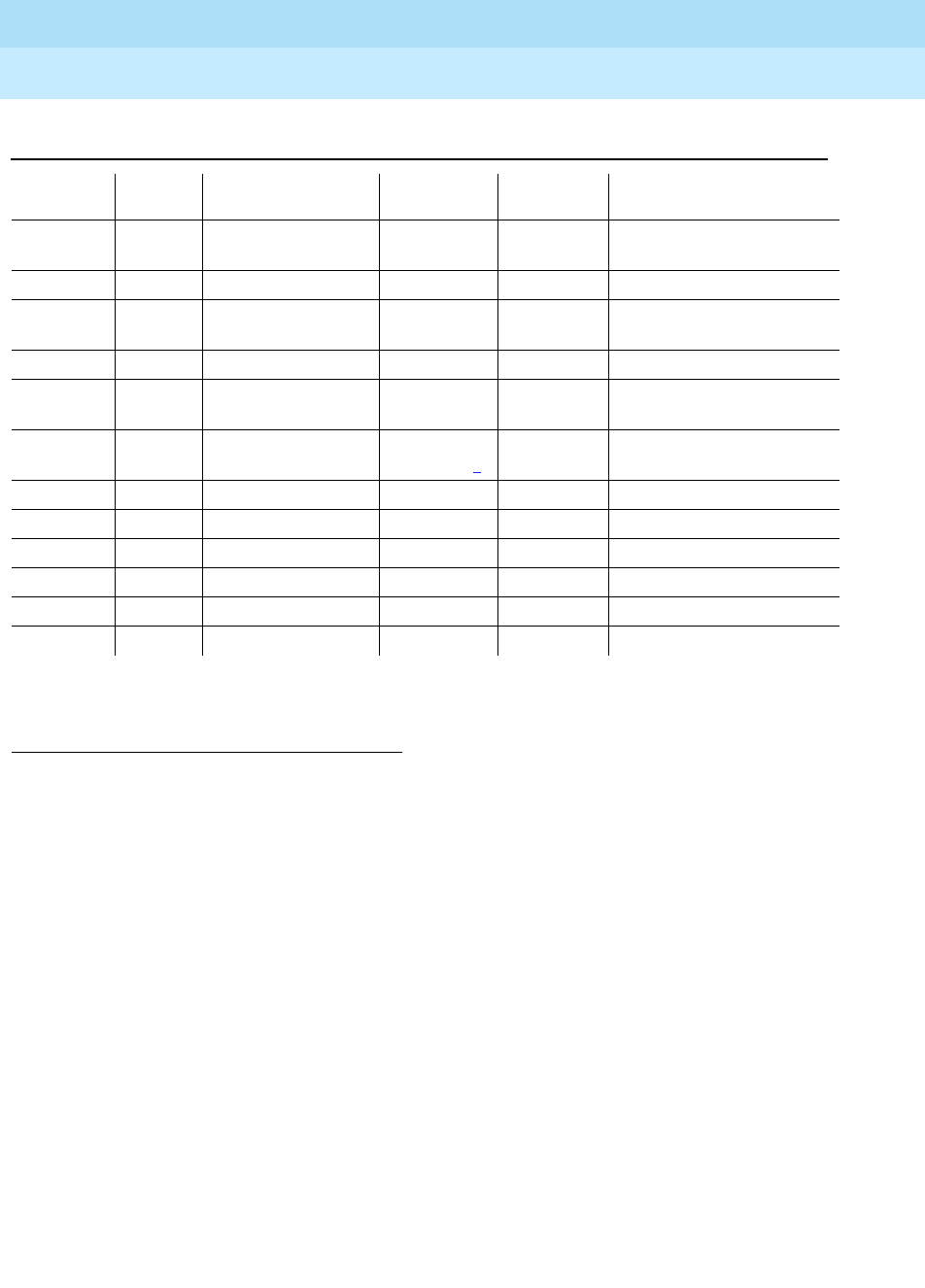
DEFINITY Enterprise Communications Server Release 6
Maintenance for R6r Volumes 1 & 2
555-230-126 Issue 2
January 1998
Maintenance Object Repair Procedures
Page 9-346DIG-LINE (Digital Line)
9
Notes:
a. Could experience a noisy port or link. This is an off-board problem
detected by the port circuit. Check for defective wiring, a defective voice
terminal, or move voice terminal closer to the switch (in terms of feet of
wire from the jack to the switch). If the problem still exists, replace the
circuit pack. Once the problem has been resolved, the alarm will be
retired after a predetermined amount of time.
b. This Error Type and Aux Data will occur when at least 15 off-board
problems have been detected with the link to the terminal. When an error
with the link is detected, an on-board counter is incremented.
The user could experience a noisy port or link. This is an off-board
problem detected by the port circuit. Check for defective wiring, a
defective voice terminal, or move voice terminal closer to the switch (in
terms of feet of wire from the jack to the switch). If the problem still exists,
replace the circuit pack. Once the problem has been resolved, the alarm
will be retired after a predetermined amount of time.
1. Run the Short Test Sequence first. If all tests pass, run the Long Test Sequence. Refer to the appropriate
test description and follow the recommended procedures.
2. Major alarms may be downgraded to Warning alarms based on the value used in the set options
command.
769 (g) 40963
40988 None WARNING OFF
1026(o) NONE WARNING OFF
1281 Any Station (Digital)
Audits Test (#17) WARNING OFF test port
UUCSSpp
sh r 4
1537 (h) 40968 None WARNING OFF
1793 Voice & Ctrl. Local
Loop Test (#13) MINOR/
WARNING2ON test port
UUCSSpp
l r 3
2049 NPE Crosstalk Test
(#9) MINOR/
WARNING2ON test port
UUCSSpp
l r 3
2304 (n) None
2305 (i) 32770 None
2305 (h) 40967 None
3840 (k) 40965 None
3840 (l) 40989 None
3841 (m) 41029 None
Table 9-117. Digital Line Error Log Entries — Continued
Error
Type Aux
Data Associated Test Alarm
Level On/Off
Board Test to Clear Value
Continued on next page

DEFINITY Enterprise Communications Server Release 6
Maintenance for R6r Volumes 1 & 2
555-230-126 Issue 2
January 1998
Maintenance Object Repair Procedures
Page 9-347DIG-LINE (Digital Line)
9
c. This error type is logged when the port in question is busied out by
maintenance personnel. Make sure port is released from busyout via the
release port UUCSS pp/PCSSpp command.
d. This error type indicates that the circuit pack has been removed or has
been insane for more than 21 minutes. To clear the error, reinsert or
replace the circuit pack.
e. Problems transmitting to the voice terminal. This problem can be caused
by defective wiring. Defective wiring can cause varying degrees of
problems on different types of sets. Sets such as the 7410 appear to be
more susceptible to wiring problems than other sets. This is usually an
on-board problem and can be ignored if no user complaints are received.
f. This is an in-line event that produces this error type when a favorable
response is received from running the Digital Line Electronic Power Feed
Test (#11). No craft action is necessary. This alarm will be resolved with
the passing of time.
g. With Aux Data 40963, this error type is a result of an unfavorable response
to the Electronic Power Feed/ Positive Temperature Coefficient Test (#11).
With Aux Data 40988, this error type indicates that the EPF/PTC circuit has
been turned off due to an overcurrent condition.
For TN754 vintage 13 or earlier and TN413, the EPF circuit senses an
overcurrent condition at the voice terminal. Check for a short in the wiring,
a damaged jack, an incorrect type of voice terminal, or a defective voice
terminal.
For TN754 vintage 14 or later, TN754B and TN2136, the PTC will open if
there is a short on the power line for 1/2 second or longer. The voice
terminal is probably not operating properly. Unplug the voice terminal for
30 seconds and then plug it back in. If the voice terminal still does not
operate, then check for a short in the wiring, a damaged jack, an incorrect
type of voice terminal, or a defective voice terminal.
Once the problem has been resolved, it may take up to 1 hour for the
alarm to clear due to ‘‘leaky bucket’’ strategy. If the problem cannot be
resolved by one of the steps above, then replace the circuit pack.
h. An in-line maintenance error has generated an off-board warning due to
some problem with the link to the voice terminal. This can be ignored if no
user complaints are received. Otherwise, make sure the voice terminal is
connected, check for defective wiring, check for a defective voice
terminal, and move voice terminal to a jack that is closer to the switch (in
terms of feet of wiring between the jack and the switch). If the problem still
exists, replace the circuit pack. Once the problem has been resolved, the
alarm will be retired after a predetermined amount of time.
i. This indicates that the station went off-hook while it was in the
ready-for-service state. Use the status station command to determine the
state of the station. The off-hook should have moved the station to
ready-for-service. No craft action is necessary.
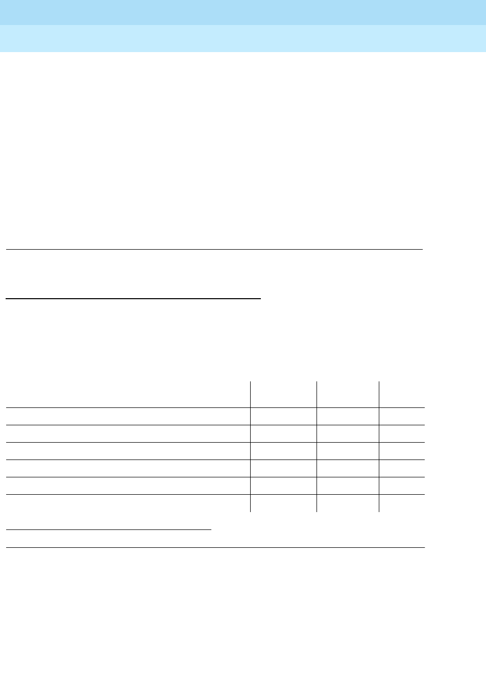
DEFINITY Enterprise Communications Server Release 6
Maintenance for R6r Volumes 1 & 2
555-230-126 Issue 2
January 1998
Maintenance Object Repair Procedures
Page 9-348DIG-LINE (Digital Line)
9
j. This is the code that is generated when the link between the circuit pack
and the voice terminal is successfully reset. No craft action is necessary.
k. No terminal is connected to the Digital Line board. No maintenance action
is required.
l. An uplink message has been logged indicating that the Electric Power
Feed (EPF) is on with no load on it. No action is necessary.
m. The circuit pack’s message buffer is full. This may be caused by having
many display phones with heavy traffic connected to the circuit pack. No
action is necessary.
n. Internal system error. No action is necessary.
o. There is a problem with the voice terminal EEPROM. When the voice
terminal is repaired the alarm will be resolved with the passing of time.
System Technician-Demanded Tests:
Descriptions and Error Codes
Always investigate tests in the order presented in the table below. By clearing
error codes associated with the
Voice and Control Channel Local Looparound
Test,
for example, you may also clear errors generated from other tests in the
testing sequence.
Digital Terminal Remote Looparound Test
(#1201)
This test checks the connection between the SPE and the digital terminal and the
ability of the terminal and the associated port to send and receive data. This test
is based on procedure 622 to isolate digital terminal problems.
1. D = Destructive; ND = Nondestructive
Order of Investigation Short Test
Sequence Long Test
Sequence D/ND1
Digital Terminal Remote Looparound Test (#1201) X D
Voice and Control Channel Local Looparound Test (#13) X ND
Digital Line NPE Crosstalk Test (#9) X ND
Digital Line Electronic Power Feed Test (#11) X ND
DIG-LINE Station Lamp Updates Test (#16) X X ND
Station (Digital) Audits Test (#17) X X ND

DEFINITY Enterprise Communications Server Release 6
Maintenance for R6r Volumes 1 & 2
555-230-126 Issue 2
January 1998
Maintenance Object Repair Procedures
Page 9-349DIG-LINE (Digital Line)
9
A request is presented to the terminal to go into loopback mode. Data is sent to
the terminal and when received back, checked for consistency. This test is run
as a part of the "test long" procedure. It is not included in any error recovery
strategy and generates no Error Log entries or alarms. To begin the test,
Maintenance will ask call processing to make the associated endpoint and port “
Maintenance Busy”. This test succeeds if the endpoint is "idle". If the reserve
request fails then the test aborts. If the request succeeds then the SPE sends a
message to loop around both information channels for the digital terminal. First
the primary information (voice, Information Channel 1 or I1) channel loopback
test is run. The test is performed by sending a digital count from the Tone/Clock
circuit pack on the primary information channel time slot and receiving the same
digital count with a general purpose tone detector.
If the primary information channel test is successful, the loop around test for the
secondary information (data, Information Channel 2 or I2) channel is then
performed. This test is the same as the primary information channel loop around
test and is performed only if a DTDM is administered. This is also the case for a
linked DA.
Only one value (Pass. Fail, or Abort) is generated as a result of the two tests run.
If any test fails aborts, the sequence is stopped. Upon completion of this test the
associated endpoint and port are moved back into the previous service state.
Table 9-118. TEST #1201 Digital Terminal Remote Looparound Test
Error
Code Test
Result Description/ Recommendation
ABORT Internal system error
1. Try (a).
1000 ABORT System resources required to run this test are not available. The port may be
busy with a valid call. Use the display portUUCSSpp/PCSSpp command to
determine the station extension or attendant number of the port. Use status
station or status attendant to determine the service state of the port. If the
port is in use, wait until the port is idle before testing. Attendants are always in
use (off-hook) if the handset is plugged in and the port is not busied out.
1. If the port status is idle, then try (a).
1001 ABORT System resources required to run this test are not available.
1. If the port status is idle, then try (a).
1002 ABORT The system could not allocate time slots for the test. The system may be under
heavy traffic conditions or it may have time slots out-of-service due to
TDM-BUS errors. Refer to “TDM-BUS”.
1. If the system has no TDM-BUS errors and is not handling heavy traffic, try
(a).
Continued on next page

DEFINITY Enterprise Communications Server Release 6
Maintenance for R6r Volumes 1 & 2
555-230-126 Issue 2
January 1998
Maintenance Object Repair Procedures
Page 9-350DIG-LINE (Digital Line)
9
1003 ABORT The system could not allocate a tone receiver for the test. The system may be
oversized for the number of Tone Detectors present or some Tone Detectors
may be out of service.
1. Resolve any “TTR-LEV” errors in the Error Log.
2. Resolve any “TONE-PT” errors in the Error Log.
3. If neither condition exist, try (a).
1004 ABORT The port was seized by a valid call during the test. The test has been aborted.
Enter display port UUCSSpp to determine the station extension or attendant
number of the port. Use status station or status attendant to determine the
service state of the port. If the port is in use, wait until the port is idle before
resetting. Attendants are always in use (off-hook) if the handset is plugged in
and the port is not busied out.
1. tTy (a).
1005 ABORT The installed circuit pack does not support this operation.
2000 ABORT Response to the test was not received within the allowable time period.
1. Try (a).
2100 ABORT System resources required to run this test are not available.
1. Make sure terminal is connected and repeat test.
2. If test fails replace terminal and repeat test.
3. Try (a).
14 FAIL The primary channel is not operating properly. User impact may range from
noticing nothing to not being able to use the port. Check the results of "Voice
and Control Channel Local Loop Test (#13). If that test fails, suspect the Digital
Line circuit pack. If that test passes then replace the terminal. If both tests fail,
and component replacement does not change the results, then:
1. Run circuit pack tests to check the tone generator circuit pack and the
Tone Detector circuit pack using test board UUCSS .
2. Resolve any problems that are detected on the Tone Generator circuit
pack or Tone Detector circuit pack.
1015 ABORT The system will not allow this test to be run because the station is/has not been
busied out. Busy out the station with the /E3busyout station/E1 command.
Table 9-118. TEST #1201 Digital Terminal Remote Looparound Test — Continued
Error
Code Test
Result Description/ Recommendation
Continued on next page

DEFINITY Enterprise Communications Server Release 6
Maintenance for R6r Volumes 1 & 2
555-230-126 Issue 2
January 1998
Maintenance Object Repair Procedures
Page 9-351DIG-LINE (Digital Line)
9
Notes:
a. Retry the command at 1-minute intervals a maximum of 5 times.
Digital Line NPE Crosstalk Test (#9)
The NPE Crosstalk Test verifies that this port’s NPE channel talks on the selected
time slot and never crosses over to time slots reserved for other connections. If
the NPE is not working correctly, one-way and noisy connections may be
observed. This test is part of a port’s Long Test Sequence and takes about 20 to
30 seconds to complete.
16 FAIL The secondary channel is not operating properly. User impact may range from
noticing nothing to not being able to use this terminal. Check the results of
"Voice and Control Channel Local Loop Test (#13). If that test fails, suspect the
Digital Line circuit pack. If that test passes then replace the terminal. If both
test fail, and component replacement does not change the results, then:
1. Run circuit pack tests to check the tone generator circuit pack and the
Tone Detector circuit pack using test board UUCSS .
2. Resolve any problems that are detected on the Tone Generator circuit
pack or Tone Detector circuit pack.
PASS Voice and Control Channel Local Loop test passed. All channels are
transmitting properly.
1. To be sure that this is not an intermittent problem, repeat this test up to a
maximum of ten times to make sure it continues to pass.
2. If complaints persist (noisy connections for voice. corrupted data transfer
for data), examine the station, connections, and wiring.
Table 9-118. TEST #1201 Digital Terminal Remote Looparound Test — Continued
Error
Code Test
Result Description/ Recommendation
Continued on next page
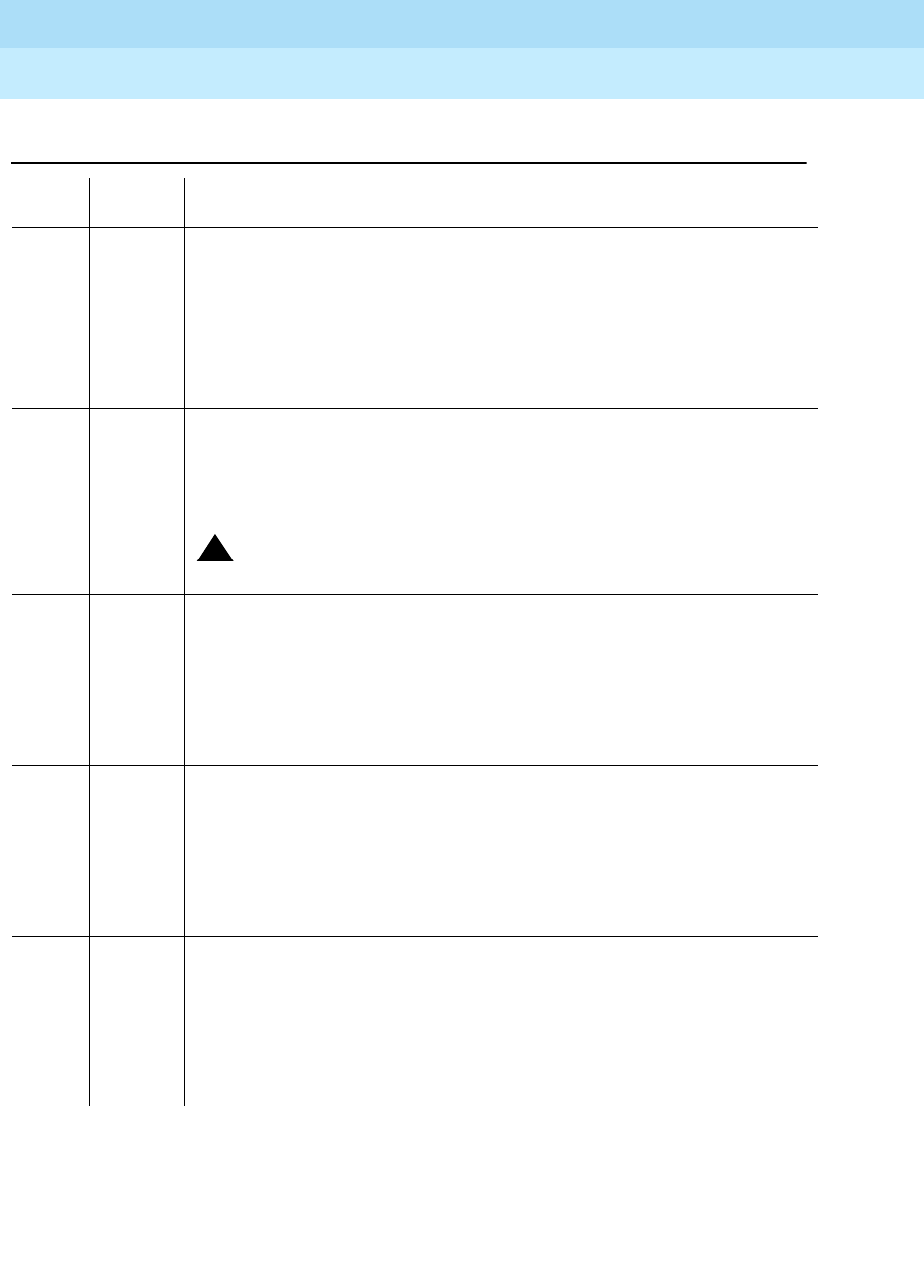
DEFINITY Enterprise Communications Server Release 6
Maintenance for R6r Volumes 1 & 2
555-230-126 Issue 2
January 1998
Maintenance Object Repair Procedures
Page 9-352DIG-LINE (Digital Line)
9
88
Table 9-119. TEST #9 Digital Line NPE Crosstalk Test
Error
Code Test
Result Description/ Recommendation
1 ABORT During testing of the primary information channel, system resources were not
available. Also, the port may have been busy during the test.
1. Check the port status. Enter display port UUCSSpp to determine the
station extension of the port. Use status station to determine the service
state of the port. If the port is in use, wait until the port is idle before
testing.
2. If the port status is idle, try (a).
2 ABORT During testing of DTDM, system resources may not have been available. Also,
the port may have been busy during the test.
1. Check if port is being used. If possible, disconnect by toggling disconnect
button on DTDM. Retry command after 1 minute.
!WARNING:
This action will drop the call in progress.
1000 ABORT System resources required to run this test are not available. The port may be
busy with a valid call. Enter display port UUCSSpp to determine the station
extension or attendant number of the port. Use status station or status
attendant to determine the service state of the port. If the port is in use, wait
until the port is idle before testing. Attendants are always in use (off-hook) if the
handset is plugged in and the port is not busied out.
1. If the port status is idle, try (a).
1001 ABORT System resources required to run this test are not available.
1. Try (a).
1002 ABORT The system could not allocate time slots for the test. The system may be under
heavy traffic conditions or it may have time slots out-of-service due to
TDM-BUS errors. Refer to “TDM-BUS”.
1. If system has no TDM-BUS errors and is not handling heavy traffic. Try (a).
1003 ABORT The system could not allocate a tone receiver for the test. The system may be
oversized for the number of Tone Detectors present or some Tone Detectors
may be out-of-service.
1. Resolve any “TTR-LEV” errors in the Error Log.
2. Resolve any “TONE-PT” errors in the Error Log.
3. If neither condition exists, try (a).
Continued on next page

DEFINITY Enterprise Communications Server Release 6
Maintenance for R6r Volumes 1 & 2
555-230-126 Issue 2
January 1998
Maintenance Object Repair Procedures
Page 9-353DIG-LINE (Digital Line)
9
Notes:
a. Retry the command at 1-minute intervals a maximum of 5 times.
Digital Line Electronic Power Feed/Positive
Temperature Coefficient/PPF Test(#11)
For TN413, and TN754 vintage 13 or earlier, this is an Electronic Power Feed
(EPF) restoral test. In this test, the processor requests that the EPF be turned on
for a given port, and an attempt is made to turn on the power supply to the
station. If no current is drawn, the station is probably not connected. If an
overcurrent condition is sensed, there may be a short in the loop. A message is
returned reporting that either the EPF was successfully turned on, or that an
overcurrent condition was sensed. This test is repeated again 5 seconds later.
For TN754 vintage 14 or later, TN754B and TN2136 this is a Positive Temperature
Coefficient (PTC) restoral test. In this test, the processor requests that the PTC be
1004 ABORT The port was seized by a valid call during the test. The test has been aborted.
Enter display port UUCSSpp to determine the station extension or attendant
number of the port. Use status station or status attendant to determine the
service state of the port. If the port is in use, wait until the port is idle before
testing. Attendants are always in use (off-hook) if the handset is plugged in
and the port is not busied out.
1020 ABORT Test disabled via background testing. Use status station command to
determine when station is available for testing.
2000 ABORT Response to the test request was not received within the allowable time
period.
1. Try (a).
1
2FAIL The Network Processing Element (NPE) of the tested port was found to be
transmitting in error. This will cause noisy and unreliable connections. Failure
code 1 indicates that the Crosstalk test failed on the primary channel. Failure
code 2 indicates that the Crosstalk test failed on the secondary channel.
1. Replace circuit pack.
PASS The port is correctly using its allocated time slots.
1. To be sure that this is not an intermittent problem, repeat this test up to a
maximum of 10 times to make sure it continues to pass.
2. If complaints persist, examine the station, connections, and wiring.
Table 9-119. TEST #9 Digital Line NPE Crosstalk Test — Continued
Error
Code Test
Result Description/ Recommendation
Continued on next page

DEFINITY Enterprise Communications Server Release 6
Maintenance for R6r Volumes 1 & 2
555-230-126 Issue 2
January 1998
Maintenance Object Repair Procedures
Page 9-354DIG-LINE (Digital Line)
9
turned on for a given port, and an attempt is made to turn on the power supply to
the station. If an overcurrent condition is sensed, there is probably a short on the
power line that causing the PTC to open and disconnect the voice terminal. Since
the PTC does not have self-restoral capability, the voice terminal must be
manually unplugged for 30 seconds and then plugged back in to restore the
PTC. A message is returned reporting that either the PTC was successfully
turned on successfully with no problem or an overcurrent condition was sensed.
This test is repeated again 5 seconds later.
TN2181 and TN2224 boards carry a Protected Power Feed (PPF) relays, one for
each port. Therefore this will be a Protected Power Feed restoral test. The test
procedure and its response is same as that of EPF. One of differences between
EFP and PPF is that, if the port goes into a overcurrent state, PPF does not report
this change of state because it is a transient state which will not last more than
50ms. If the over current persists the power will be shut off automatically and an
EPF_off_overcurrent message is sent uplink.
Table 9-120. TEST #11 Digital Line Electronic Power Feed Test
Error
Code Test
Result Description/ Recommendation
ABORT Internal system error
1. Try (a).
1000 ABORT System resources required to run this test are not available. The port may be
busy with a valid call. Enter display port UUCSSpp to determine the station
extension or attendant number of the port. Use status station or status
attendant to determine the service state of the port. If the port is in use, wait
until the port is idle before testing. Attendants are always in use (off-hook) if the
handset is plugged in and the port is not busied out.
1. If the port status is idle, then try (a).
FAIL Internal system error
1. Try (a).
Continued on next page

DEFINITY Enterprise Communications Server Release 6
Maintenance for R6r Volumes 1 & 2
555-230-126 Issue 2
January 1998
Maintenance Object Repair Procedures
Page 9-355DIG-LINE (Digital Line)
9
Notes:
a. Retry the command at 1-minute intervals a maximum of 5 times.
Voice and Control Channel Local Loop Test (#13)
These tests check the information and control channels between the Switch
Processing Element (SPE) and the Digital Line port circuit. The SPE sends a
message to loop around both the information and control channels for the port.
First, the primary information (voice) channel loop back test is run. The test is
performed by sending a digital count from the Tone-Clock circuit pack on the
primary information channel time slot and receiving the same digital count with a
general purpose Tone Detector.
While the primary information channel is still looped around, the Control Channel
Looparound Test is performed. This test consists of sending four different
transparent patterns to the on-board microprocessor, receiving them back, and
comparing them.
The Looparound Test for the secondary information (data) channel is then
performed. This test is the same as the primary information channel loop around
test and is performed only if a DTDM is administered.
A Conference Test is done next for the primary information channel. This test is
the same as Conference Test #6. Only one value (Pass, Fail, or Abort) is
generated as a result of four tests run. If any test fails or aborts, the sequence is
stopped.
PASS Electronic Power Feed Test passed. The message to turn on the power to the
station was successfully sent to the port.
1. Although this test will never actually return a FAIL result except for the
Internal system error described above, it will log an error indicating the
real results of the test. Check the Error Log for any entries with Error Types
767 or 769 after the test completes.
2. If Error Type 767 appears in the Error Log, this indicates that the test
sensed no problems with the power to the station. To verify that the station
is powered up correctly, run a self-test on the station and check that all the
feature buttons are operating.
3. If Error Type 769 appears in the Error Log, this indicates some problem
with the power to the station. Check for a short in the wiring, a damaged
jack, a defective voice terminal, or an incorrect type of terminal.
Table 9-120. TEST #11 Digital Line Electronic Power Feed Test — Continued
Error
Code Test
Result Description/ Recommendation
Continued on next page

DEFINITY Enterprise Communications Server Release 6
Maintenance for R6r Volumes 1 & 2
555-230-126 Issue 2
January 1998
Maintenance Object Repair Procedures
Page 9-356DIG-LINE (Digital Line)
9
Table 9-121. TEST #13 Voice and Control Channel Local Loop Test
Error
Code Test
Result Description/ Recommendation
ABORT Internal system error
1. Try (a).
1000 ABORT System resources required to run this test are not available. The port may be
busy with a valid call. Use display port UUCSSpp to determine the station
extension or attendant number of the port. Use status station or status
attendant to determine the service state of the port. If the port is in use, wait
until the port is idle before testing. Attendants are always in use (off-hook) if the
handset is plugged in and the port is not busied out.
1. If the port status is idle, try (a).
1001 ABORT System resources required for this test are not available.
1. Retry the command at 1-minute intervals a maximum of 5 times.
1002 ABORT The system could not allocate time slots for the test. The system may be under
heavy traffic conditions or it may have time slots out-of-service due to
TDM-BUS errors. Refer to “TDM-BUS”.
1. If system has no TDM-BUS errors and is not handling heavy traffic, repeat
test at 1-minute intervals a maximum of 5 times.
1003 ABORT The system could not allocate a tone receiver for the test. The system may be
oversized for the number of Tone Detectors present or some Tone Detectors
may be out-of-service.
1. Resolve any “TTR-LEV” errors in the Error Log.
2. Resolve any “TONE-PT” errors in the Error Log.
3. If neither condition exists, retry the command at 1-minute intervals a
maximum of 5 times.
1004 ABORT The port was seized by a valid call during the test. The test has been aborted.
Use display port UUCSSpp to determine the station extension or attendant
number of the port. Use status station or status attendant to determine the
service state of the port. If the port is in use, wait until the port is idle before
testing. Attendants are always in use (off-hook) if the handset is plugged in and
the port is not busied out.
1. Retry the command at 1-minute intervals a maximum of 5 times.
2000 ABORT Response to the test was not received within the allowable time period.
1. Retry the command at 1-minute intervals a maximum of 5 times.
2100 ABORT Could not allocate the necessary system resources to run this test.
1. Rerun the test at 1-minute intervals a maximum of 5 times.
Continued on next page

DEFINITY Enterprise Communications Server Release 6
Maintenance for R6r Volumes 1 & 2
555-230-126 Issue 2
January 1998
Maintenance Object Repair Procedures
Page 9-357DIG-LINE (Digital Line)
9
Notes:
a. Retry the command at 1-minute intervals a maximum of 5 times.
DIG-LINE Station Lamp Updates Test (#16)
This test lights all lamps on the terminal as specified. The lamp updates will run
only if the station is in-service. The status of the station is checked and the lamp
updates are blocked from taking place if the station is not in the in-service state.
This test does not affect the status of the Message Waiting lamp.
7 FAIL Conference Test failed on primary channel. In some cases, users may not
notice disruption in service. In extreme cases, conferencing feature may not
work at all.
14 FAIL The primary voice channel is not transmitting properly. User impact may range
from noticing nothing to not being able to use this port.
15 FAIL The control channel between the processor and digital circuit pack is not
transmitting properly. User impact may range from noticing nothing to not
being able to use the port. Could also be disruptive to other users.
16 FAIL The secondary voice channel is not transmitting properly. User impact may
range from noticing nothing to not being able to use this port.
1. Run circuit pack tests to check the Tone Generator circuit pack and the
Tone Detector circuit pack using test board UUCSS.
2. Resolve any problems that are detected on the Tone Generator circuit
pack or Tone Detector circuit pack.
3. If the Tone Generator and Tone Detector circuit packs are functioning
properly, and the test still fails, replace the Digital Line circuit pack.
PASS Voice and Control Channel Local Loop test passed. All channels are
transmitting properly.
1. To be sure that this is not an intermittent problem, repeat this test up to a
maximum of 10 times to make sure it continues to pass.
2. If complaints persist (noisy connections for voice, corrupted data for data
transfer), examine the station, connections, and wiring.
Table 9-121. TEST #13 Voice and Control Channel Local Loop Test — Continued
Error
Code Test
Result Description/ Recommendation
Continued on next page

DEFINITY Enterprise Communications Server Release 6
Maintenance for R6r Volumes 1 & 2
555-230-126 Issue 2
January 1998
Maintenance Object Repair Procedures
Page 9-358DIG-LINE (Digital Line)
9
Table 9-122. TEST #16 DIG-LINE Station Lamp Updates Test
Error
Code Test
Result Description/ Recommendation
ABORT Internal system error
1. Retry the command at 1-minute intervals a maximum of 5 times.
1 ABORT This port may have been busied out by system technician.
1. Look in the Error Log for Error Type 18 (port busied out) for this port. If this
error type is present, then release the port via the release station
<extension> command and run the test again.
2. Make sure that the terminal is connected.
3. Retry the command at 1-minute intervals a maximum of 5 times.
3 ABORT Station may be in ready-for-service or out-of-service state.
1. Use status station command to verify state of station.
2. Make sure the terminal is connected.
3. Retry the command at 1-minute intervals a maximum of 5 times.
1000 ABORT System resources required to run this test are not available. The port may be
busy with a valid call. Use display port UUCSSpp to determine the station
extension or attendant number of the port. Use status station or status
attendant to determine the service state of the port. If the port is in use, wait
until the port is idle before testing. Attendants are always in use (off-hook) if the
handset is plugged in and the port is not busied out.
1. If the port status is idle, then retry the command at 1-minute intervals a
maximum of 5 times.
1392 ABORT This port is currently a TTI port and the test will not execute on it.
1. Verify that the port is a TTI port using either the display port command
(the display shows that the port is a TTI port) or the list config command
(the display shows a “t” for the port).
2. If either list config or display port indicates that the port is
not
a TTI port,
escalate the problem. If both commands indicate that the port is a TTI port,
the abort is correct, and no action is necessary.
FAIL Internal system error
1. Retry the command at 1-minute intervals a maximum of 5 times.
PASS The message to light all of the station lamps was sent successfully to the port.
1. Observe the station lamps being lit when running the test. If all lamps do
not light, the other Digital Line test results may indicate related problems
that do not allow the lamps to light.
2. Investigate by using other Digital Line port tests, and by examining the
station, wiring, and connections.
Continued on next page

DEFINITY Enterprise Communications Server Release 6
Maintenance for R6r Volumes 1 & 2
555-230-126 Issue 2
January 1998
Maintenance Object Repair Procedures
Page 9-359DIG-LINE (Digital Line)
9
Digital Station Audits Test (#17)
This is a series of six tests that are classified as audits. The SPE sends messages
to the on-board microprocessor to perform the following tests. These audits run
only if the station is in-service.
■Switchhook Inquiry Test — This is an update of the SPE records
according to the circuit pack’s records. This inquiry is sent all the way to
the voice terminal.
■Bad Scan Inquiry Test — A message is sent uplink which contains a
count that is generated due to certain events relating to the link conditions.
This can be an indication of communications problems between the
Processor and Digital Port circuit pack.
■EPF/PTC Inquiry Test — For a TN413 or a TN754 vintage 13 or earlier, the
status of the Electronic Power Feed (EPF) is sent uplink. Possible
conditions are: EPF-on-ok, EPF-off, and EPF-no-load. For TN754 vintage
14 or later, TN754B or TN2136, TN2181, TN2224, the status of the PTC is
sent uplink. Possible conditions are: PTC-on-ok, PTC-off, and PTC-no-
load.
■ID Request Test — A request is made to the station for its status. The
station sends its configuration information and health information back.
This information is checked and a pass/fail result is provided.
■Ringer Update Test — This updates the digital telephone ringer state
according to the processor records.
■DTMF Administration Update Test — This is a message to the digital
station to refresh the default value that causes the station to send touch-
tones only in the primary information channel. This value is set initially
when the station is put in-service and every time the station’s state
changes from other states to in-service.
Table 9-123. TEST #17 Station (Digital) Audits Test
Error
Code Test
Result Description/ Recommendation
1 ABORT Switchhook audit timed out.
2 ABORT ID request fails, health bit returned from voice terminal is bad.
1. Make sure voice terminal is connected and repeat test.
2. If test fails, replace voice terminal and repeat test.
Continued on next page

DEFINITY Enterprise Communications Server Release 6
Maintenance for R6r Volumes 1 & 2
555-230-126 Issue 2
January 1998
Maintenance Object Repair Procedures
Page 9-360DIG-LINE (Digital Line)
9
3 ABORT The EPF/PTC has detected an overcurrent condition.
1. For a TN754 vintage 13 or earlier Digital Line circuit pack, use test
UUCSSpp long. If Test #11 passes, then the EPF/PTC condition was
cleared. Rerun the Short Test Sequence. If Test #11 does not pass, follow
the repair procedures described for Test #11.
2. Look for Error Type 769 logged against DIG-LINE and follow the
procedures in the associated footnote. If any additional problems are
found, rerun the test.
4 ABORT Internal system error
1. Resolve any outstanding circuit pack maintenance problems.
2. Retry the command at 1-minute intervals a maximum of 5 times.
5 ABORT Ringer update aborted due to station being in ready-for-service or
out-of-service state.
6 ABORT This port may have been busied out by system technician.
1. Look in the Error Log for Error Type 18 (port busied out) for this port. If this
error is present, the release the port via release station
2. Make sure that the terminal is connected.
3. Retry the command at 1-minute intervals a maximum of 5 times.
1000 ABORT System resources required for this test are not available.
1392 ABORT This port is currently a TTI port and the test will not execute on it.
1. Verify that the port is a TTI port using either the display port command
(the display shows that the port is a TTI port) or the list config command
(the display shows a “t” for the port).
2. If either list config or display port indicate that the port is
not
a TTI port,
escalate the problem. If both commands indicate that the port is a TTI port,
the abort is correct, and no action is necessary.
2000 ABORT Response to the test was not received in the allowable time period.
FAIL Internal system error
1. Retry the command at 1-minute intervals a maximum of 5 times.
PASS Station Audits passed. This Digital Port circuit pack is functioning properly.
1. If complaints persist, investigate by using other port tests, and by
examining the station, wiring, and connections.
Table 9-123. TEST #17 Station (Digital) Audits Test — Continued
Error
Code Test
Result Description/ Recommendation
Continued on next page

DEFINITY Enterprise Communications Server Release 6
Maintenance for R6r Volumes 1 & 2
555-230-126 Issue 2
January 1998
Maintenance Object Repair Procedures
Page 9-361DIOD-BD (DIOD Trunk Circuit Pack)
9
DIOD-BD (DIOD Trunk Circuit Pack)
Refer to the "XXX-BD (Common Port Circuit Pack)") section at the end of this
chapter.
1.
UU
is the universal cabinet number (1 for PPN, 2 -44 for EPNs).
C
is the carrier designation
(A, B, C, D, or E).
SS
is the number of the slot in which the circuit pack resides (01 to 21).
pp
is the two digit port number (01, 02, ...).
MO Name (in
Alarm Log) Alarm Level Initial Command to Run1Full Name of MO
DIOD-BD MINOR test port
UUCSSpp
s DIOD Circuit Pack
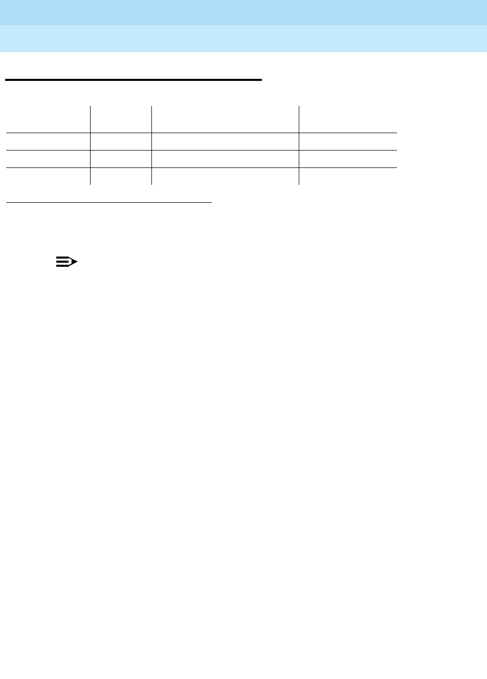
DEFINITY Enterprise Communications Server Release 6
Maintenance for R6r Volumes 1 & 2
555-230-126 Issue 2
January 1998
Maintenance Object Repair Procedures
Page 9-362DIOD-DS1 (DS1 DIOD Trunk)
9
DIOD-DS1 (DS1 DIOD Trunk)
NOTE:
Many trunk problems are caused by incorrect settings of parameters on the
trunk group administration form. Settings must be compatible with the local
environment and with parameter settings on the far-end. Refer to
DEFINITY
Enterprise Communications Server Release 5.4 Administration and Feature
Description
, for information on how to administer trunks. The Application
Notes section of that book shows the correct settings for administrable
timers and other parameters on a country-by-country basis.
A DS1 DIOD trunk provides a link for digitized voice or data communications
between the system and a central office switch. There are two types of DS1
interfaces:
■24 DS0 channels on a 1.544 Mbps link
■31 DS0 channels + 1 framing channel on a 2.048 Mbps link
■32-channel mode is supported only on TN464 circuit packs and on G3r V2
systems.
The DS1-DIOD maintenance object monitors and maintains a DIOD trunk port on
a TN464 UDS1 Interface circuit pack. See "UDS1-BD (UDS1 Interface Circuit
Pack)" in this chapter for more information about this circuit pack. The DS1 circuit
pack supports low level CO trunk signaling interfaces for both ground-start and
loop-start trunks. This maintenance strategy covers the in-line errors log,
initialization tests, periodic tests, scheduled tests, demand tests, and alarm
resolution and escalation.
Three trunk service states are specified by DS1 DIOD trunk maintenance:
1. A Major alarm on a trunk indicates that alarms on these trunks are not downgraded by the
set options command and that at least 75 percent of the trunks in this trunk group are
alarmed. For more information on the set options command.
MO Name (in
Alarm Log) Alarm
Level Initial Command to Run Full Name of MO
DIOD-DS1 MAJOR1test trunk
group# member#
l DS1 DIOD Trunk
DIOD-DS1 MINOR test trunk
group# member#
l DS1 DIOD Trunk
DIOD-DS1 WARNING test trunk
group# member#
DS1 DIOD Trunk
out-of-service The trunk is in a deactivated state and cannot be used
for either incoming or outgoing calls.
in-service The trunk is in an activated state and can be used for
both incoming and outgoing calls.

DEFINITY Enterprise Communications Server Release 6
Maintenance for R6r Volumes 1 & 2
555-230-126 Issue 2
January 1998
Maintenance Object Repair Procedures
Page 9-363DIOD-DS1 (DS1 DIOD Trunk)
9
Error Log Entries and Test to Clear Values
disconnect
(ready-for-service) The trunk is in an activated state but can only be used for
an incoming call.
DS1 DIOD Trunk Error Log Entries
Error
Type Aux
Data Associated Test Alarm
Level On/Off
Board Test to Clear Value
010 Any Any Any test trunk <grp>/<mbr>
1(a) 57408
1(a) 57487
57476
57477
57485
15(b) Any Port Audit and
Update Test (#36)
18(c) 0 busyout trunk
<grp>/<mbr> WARNING OFF release trunk
<grp>/<mbr>
130(d) None WARNING ON test trunk <grp>/<mbr>
257(e) 57392 DS1 CO Dial Tone
Seizure Test (#314) MIN/MAJ2OFF
513(f) 57393 DS1 CO Dial Tone
Seizure Test (#314) MIN/MAJ2OFF
769(g) 57484
1025(h) 51200
1025 DS1 CO Dial Tone
Seizure Test (#314) MIN/
WRN3OFF test trunk <grp>/<mbr>
r 2
1281 Conference Circuit
Test (#7) MIN/
WRN3ON test trunk <grp>/<mbr>
l r 4
1537 NPE Crosstalk Test
(#6) MIN/
WRN3ON test trunk <grp>/<mbr>
l r 3
1793(i) test board UUCSS l
2049(j) 57473
57474
57475
2305(k) 50944
2562(l) 16665
2817(m) 52992
3840(n) Port Audit and
Update Test (#36)

DEFINITY Enterprise Communications Server Release 6
Maintenance for R6r Volumes 1 & 2
555-230-126 Issue 2
January 1998
Maintenance Object Repair Procedures
Page 9-364DIOD-DS1 (DS1 DIOD Trunk)
9
Notes:
a. Error Type 1—Aux Data 57408—No tip ground is detected on an
outgoing call.
Aux Data 57476—Rotary Dial before Wink.
Aux Data 57477—Rotary Dial pulse too early.
Aux Data 57485—Wink too short for a valid signal.
Aux Data 57487—PBX could not get ‘‘loop close’’ signal.
The DS1 Interface circuit pack detected a hardware fault. These errors will
cause the Dial Tone Test (#314) to run and are only considered a problem
if the Dial Tone Test fails (in which case Error Type 1025 will also show
up). In this case, the trunk may be put in the ready-for-service state
(shown as ‘‘disconnected’’ by the status command), which allows only
incoming calls. Run the Dial Tone Test (#314) and follow the procedures.
b. Error Type 15—This is a software audit error that does not indicate any
hardware malfunction. Run Short Test Sequence and investigate
associated errors (if any).
c. Error Type 18—System Technician has busied out the trunk to the
out-of-service state. No calls can be made on this trunk except the Facility
Access Test Call. For details on this feature, refer to ‘‘Facility Test Calls’’
section in Chapter 6.
d. Error Type 130—This error type indicates that the circuit pack has been
removed or has been insane for more than 11 minutes. To clear the error,
reinsert or replace the circuit pack.
e. Error Type 257—The DS1 Interface circuit pack detects a hardware fault.
Aux Data 57392 indicates no external release on PBX disconnect.
f. Error Type 513—The DS1 Interface circuit pack detects a hardware fault.
Aux Data 57393 indicates belated external release on PBX disconnect.
g. Error Type 769—The DS1 Interface circuit pack detects a hardware fault.
The Aux Data field contains the following error type:—57484, fault is
detected on tip/ring.
h. The DS1Interface circuit pack detects a hardware fault, and the Aux Data
field contains the following error type: 51200, port is unavailable. Run the
Dial Tone Test (#314) and follow procedures.
1. Run the Short Test Sequence first. If all tests pass, run the Long Test Sequence. Refer to the
appropriate test description and follow the recommended procedures.
2. This alarm is only raised when the System-Parameter Country form has the Base Tone Generator
field set to 4 (Italy). This alarm will be a MINOR alarm unless 75% or more trunks in this trunk group
are out of service, then the alarm will be upgraded to a MAJOR alarm.
3. Major alarms may be downgraded to Warning alarms based on the value used in the set options
command.

DEFINITY Enterprise Communications Server Release 6
Maintenance for R6r Volumes 1 & 2
555-230-126 Issue 2
January 1998
Maintenance Object Repair Procedures
Page 9-365DIOD-DS1 (DS1 DIOD Trunk)
9
i. Error Type 1793—DS1 Interface circuit pack is out-of-service. Look for
UDS1-BD errors in the Hardware Error Log if the port is on a TN464 UDS1
board. Refer to "UDS1-BD (UDS1 Interface Circuit Pack)" (DS1 Trunk
Circuit Pack) for details
j. Error Type 2049—With the following Aux Data:
Aux Data 57473—Rotary dial rate below 8 pulses per second.
Aux Data 57474—Rotary dial rate above 12 pulses per second.
Aux Data 57475—Rotary Dial interdigit time is too short.
The DS1 interface circuit pack detects a hardware error on the DS1 DIOD
trunk. The trunk can not communicate with the far-end because it is
unable to interpret digits sent from the far-end switch. Check with the
far-end switch or Operating Company for proper trunk connection.
k. Error Type 2305—Recorder message, trunk could not be seized (Aux Data
50944). Run Test #314 and follow the outlined procedures.
l. Error Type 2562—Retry Failure error. This error is logged only. It is not a
hardware failure and hence does not start any testing or generate any
alarms. This error comes from call processing and is generated when a
second attempt (retry) to seize an outgoing trunk fails.
m. Error Type 2817—Glare error. This error is logged only. It is not a
hardware failure and hence does not start any testing or generate any
alarms. This error is the result of a simultaneous seizure of a two-way trunk
from both the near-end and the far-end. Attempt to place the call again. If
the error persists, execute the Dial Tone Seizure Test (#314) and follow
those procedures.
n. Error Type 3840—Port Audit and Update Test (#36) failed due to an
internal system error. Enter the status trunk command to verify the status
of the trunk. If the trunk is out-of-service, then enter the release trunk
command to put it back into in-service. Retry the test command.
System Technician-Demanded Tests:
Descriptions and Error Codes
Always investigate tests in the order they are presented in the table below. By
clearing error codes associated with the
NPE Crosstalk Test,
for example, you
may also clear errors generated from other tests in the testing sequence.
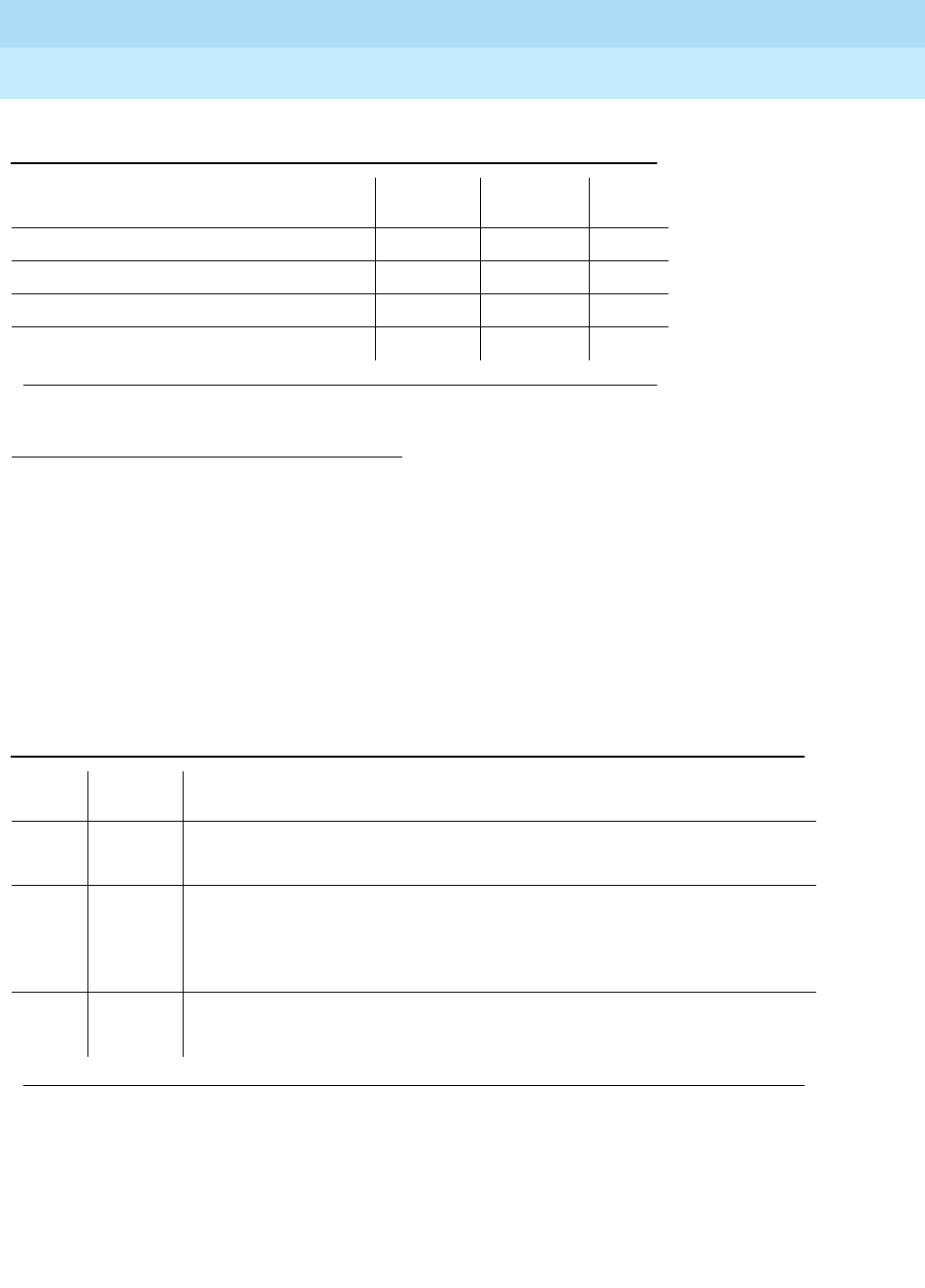
DEFINITY Enterprise Communications Server Release 6
Maintenance for R6r Volumes 1 & 2
555-230-126 Issue 2
January 1998
Maintenance Object Repair Procedures
Page 9-366DIOD-DS1 (DS1 DIOD Trunk)
9
NPE Crosstalk Test (#6)
The NPE Crosstalk Test verifies that this port’s NPE channel talks on the selected
time slot and never crosses over to time slots reserved for other connections. If
the NPE is not working correctly, one-way and noisy connections may be
observed. This test is usually only part of a port’s Long Test Sequence and takes
about 20 to 30 seconds to complete.
1. D = Destructive, ND = Non-destructive
Table 9-124. System Technician-Demanded Tests: DS1-BD
Order of Investigation Short Test
Sequence Long Test
Sequence D/ND1
NPE Crosstalk Test (#6) X ND
Conference Circuit Test (#7) X ND
DS1 Dial Tone Test (#314) X X ND
Port Audit and Update Test (#36) X X ND
Continued on next page
Table 9-125. TEST #6 NPE Crosstalk Test
Error
Code Test
Result Description/ Recommendation
ABORT System resources required for this test are not available.
1. Retry the command at 1-minute intervals a maximum of 5 times.
1000 ABORT System resources required to run this test are not available. The port may be in
use on a valid call. Use the status station or status trunk command to
determine when the port is available for testing.
1. Retry the command at 1-minute intervals a maximum of 5 times.
1001 ABORT System resources required for this test are not available.
1. Retry the command at 1-minute intervals a maximum of 5 times.
Continued on next page

DEFINITY Enterprise Communications Server Release 6
Maintenance for R6r Volumes 1 & 2
555-230-126 Issue 2
January 1998
Maintenance Object Repair Procedures
Page 9-367DIOD-DS1 (DS1 DIOD Trunk)
9
1002 ABORT The system could not allocate time slots for the test. The system may be under
heavy traffic conditions or it may have time slots out-of-service due to
TDM-BUS errors. The status health command can be used to determine if the
system is experiencing heavy traffic. Refer to the TDM-BUS (TDM Bus)
Maintenance documentation to diagnose any active TDM-BUS errors.
1. If system has no TDM-BUS errors and is not handling heavy traffic, repeat
test at 1-minute intervals a maximum of 5 times.
1003 ABORT The system could not allocate a tone receiver for the test. The system may be
oversized for the number of Tone Detectors present or some tone detectors
may be out-of-service. The list measurements tone-receiver command will
display information on the system’s tone receivers.
1. Resolve any “TTR-LEV” errors in the Error Log.
2. Resolve any “TONE-PT” errors in the Error Log.
3. If neither condition exists, retry the test at 1-minute intervals a maximum of
5 times.
1004 ABORT The port has been seized by a user for a valid call. Use the status trunk
command to determine when the port is available for testing.
1. Retry the command at 1-minute intervals a maximum of 5 times.
1020 ABORT The test did not run due to a previously existing error on the specific port or a
more general circuit pack error.
1. Examine Error Log for existing errors against this port or the circuit pack
and attempt to diagnose the already existing error.
2000 ABORT Response to the test request was not received within the allowable time
period.
2100 ABORT System resources required for this test are not available.
1. Retry the command at 1-minute intervals a maximum of 5 times.
2053 ABORT At least one of the following errors is found on the DS1 circuit pack:
■1281—Loss of signal
■1793—Blue Alarm
■2049—Red Alarm
■2305—Yellow Alarm
■1537—Hyperactivity
Look for the above error types in the Hardware Error Log and follow the
procedures given in the appropriate DS1-BD or UDS1-BD maintenance
documentation for the listed error types.
Table 9-125. TEST #6 NPE Crosstalk Test — Continued
Error
Code Test
Result Description/ Recommendation
Continued on next page

DEFINITY Enterprise Communications Server Release 6
Maintenance for R6r Volumes 1 & 2
555-230-126 Issue 2
January 1998
Maintenance Object Repair Procedures
Page 9-368DIOD-DS1 (DS1 DIOD Trunk)
9
Conference Circuit Test (#7)
The Conference Circuit Test verifies that the NPE channel for the port being
tested can correctly perform the conferencing function. The NPE is instructed to
listen to several different tones and conference the tones together. The resulting
signal is then measured by a tone detector port. If the level of the tone is within a
certain range, the test passes.
FAIL The NPE of the tested port was found to be transmitting in error. This will cause
noisy and unreliable connections.
1. Replace the circuit pack.
PASS The port is correctly using its allocated time slots. User-reported troubles on
this port should be investigated using other port tests and examining station,
trunk, or external wiring.
Table 9-126. TEST #7 Conference Circuit Test
Error
Code Test
Result Description/ Recommendation
ABORT System resources required for this test are not available.
1. Retry the command at 1-minute intervals a maximum of 5 times.
1000 ABORT System resources required to run this test are not available. The port may be in
use on a valid call. Use the status station or status trunk command to
determine when the port is available for testing.
1004 ABORT The port has been seized by a user for a valid call. Use the status station or
status trunk command to determine when the port is available for testing.
1. Retry the command at 1-minute intervals a maximum of 5 times.
1018 ABORT Test disabled via administration. This only applies to analog stations.
1. To enable test, set the Test field on the station administration screen for the
particular analog station being tested to ‘‘y.’’ Use the change station
extension command.
Continued on next page
Table 9-125. TEST #6 NPE Crosstalk Test — Continued
Error
Code Test
Result Description/ Recommendation
Continued on next page

DEFINITY Enterprise Communications Server Release 6
Maintenance for R6r Volumes 1 & 2
555-230-126 Issue 2
January 1998
Maintenance Object Repair Procedures
Page 9-369DIOD-DS1 (DS1 DIOD Trunk)
9
Port Audit and Update Test (#36)
This test sends port level translation data from switch processor to the DS1
Interface circuit pack to assure that the trunk’s translation is correct. Translation
updates include the following data: trunk type (in/out), dial type, timing
parameters, and signaling bits enabled. The port audit operation verifies the
consistency of the current state of trunk kept in the DS1 Interface circuit pack
and in the switch software.
1020 ABORT The test did not run due to a previously existing error on the specific port or a
more general circuit pack error.
1. Examine Error Log for existing errors against this port or the circuit pack
and attempt to diagnose the previously existing error.
2000 ABORT Response to the test request was not received within the allowable time period.
2100 ABORT System resources required for this test are not available.
1. Retry the command at 1-minute intervals a maximum of 5 times.
2053 ABORT At least one of the following errors is found on the DS1 circuit pack:
■1281—Loss of signal
■1793—Blue Alarm
■2049—Red Alarm
■2305—Yellow Alarm
■1537—Hyperactivity
Look for the above error types in the Hardware Error Log and follow the
procedures given in the appropriate DS1-BD or UDS1-BD maintenance
documentation for the listed error types.
FAIL The NPE of the tested port did not conference the tones correctly. This will
cause noisy and unreliable connections.
1. Replace the circuit pack.
PASS The port can correctly conference multiple connections. User-reported
troubles on this port should be investigated by using other port tests and by
examining station, trunk, or external wiring.
Table 9-126. TEST #7 Conference Circuit Test — Continued
Error
Code Test
Result Description/ Recommendation
Continued on next page

DEFINITY Enterprise Communications Server Release 6
Maintenance for R6r Volumes 1 & 2
555-230-126 Issue 2
January 1998
Maintenance Object Repair Procedures
Page 9-370DIOD-DS1 (DS1 DIOD Trunk)
9
DS1 CO Dial Tone Seizure Test (#314)
DS1 CO Dial Tone Seizure Test checks the trunk’s signaling capability provided
by the DS1 Interface circuit pack. The maintenance software initiates the test by
sending a ‘‘seizure’’ message to the DS1 Interface circuit pack and expects an
‘‘active’’ reply from the DS1 interface circuit pack. If the ‘‘active’’ message is
received, then the test passes. If no message is received and the timer expires,
the test is aborted. If the DS1 Interface circuit pack sends a ‘‘reorder’’ message
back to maintenance software, then the test fails.
This test cannot be run on a trunk in any of the following conditions:
a. The trunk direction is administered as an incoming only trunk.
b. The trunk has been seized by a normal trunk call.
c. The trunk is administered with maintenance test disabled.
Table 9-127. TEST #36 Port Audit and Update Test
Error
Code Test
Result Description/ Recommendation
ABORT Internal system error
1. Retry the command at 1-minute intervals a maximum of 5 times.
2000 ABORT Response to the test request was not received within the allowable time
period.
2100 ABORT Could not allocate the necessary system resources to run this test.
FAIL Test failed due to internal system error.
1. Retry the command at 1-minute intervals a maximum of 5 times.
PASS Trunk translation has been updated successfully. The current trunk states kept
in the DS1 Interface circuit pack and switch software are consistent. If the
trunk is busied out, the test will not run but will return PASS. To verify that the
trunk is in-service:
1. Enter the status trunk command to verify that the trunk is in-service. If the
trunk is in-service, no further action is necessary. If the trunk is
out-of-service, continue to step 2.
2. Enter the release trunk command to put the trunk back into in-service.
3. Retry the test command.
Continued on next page

DEFINITY Enterprise Communications Server Release 6
Maintenance for R6r Volumes 1 & 2
555-230-126 Issue 2
January 1998
Maintenance Object Repair Procedures
Page 9-371DIOD-DS1 (DS1 DIOD Trunk)
9
Table 9-128. TEST #314 DS1 CO Dial Tone Seizure Test
Error
Code Test
Result Description/ Recommendation
ABORT Internal system error
1. Retry the command at 1-minute intervals a maximum of 5 times.
1000 ABORT System resources required to run this test are not available. The port may be
in use on a valid call. Use the status trunk command to determine when the
port is available for testing.
1004 ABORT The port has been seized by a user for a valid call. Use the status trunk
command to determine when the port is available for testing.
1. Retry the command at 1-minute intervals a maximum of 5 times.
1005 ABORT Test failed due to incompatible configuration administered in trunk group
form.
1. Look at the trunk group administration form and see if the trunk is
incoming only, port 24 on a DS1 Interface with common control channel
signaling, or an automatic CO type such as FX. Under any of these
conditions this is a normal abort.
1018 ABORT Test has been disabled via administration.
1. Verify that the ‘‘Maintenance Tests’’ field on the Trunk Group Form is set
to ‘‘n.’’ To enable the test, issue the change trunk-group x command
where ‘‘x’’ equals the number of the trunk group to be tested. Then
change the entry in the ‘‘Maintenance Tests’’ field on the form to ‘‘y.’’
2. Repeat the test.
1020 ABORT The DS1 Interface circuit pack is out-of-service.
1. Look for UDS1-BD errors in the Hardware Error Log. If present, refer to
"UDS1-BD (UDS1 Interface Circuit Pack)" (DS1/UDS1 Trunk Circuit
Pack).
2. Retry the command.
2000 ABORT Response to the test request was not received within the allowable time
period.
2100 ABORT Could not allocate the necessary system resources to run this test.
1. Retry the command at 1-minute intervals for a maximum of 5 times.
Continued on next page

DEFINITY Enterprise Communications Server Release 6
Maintenance for R6r Volumes 1 & 2
555-230-126 Issue 2
January 1998
Maintenance Object Repair Procedures
Page 9-372DIOD-DS1 (DS1 DIOD Trunk)
9
2053 ABORT At least one of the following errors is found on the DS1 circuit pack:
■1281—Loss of signal
■1793—Blue Alarm
■2049—Red Alarm
■2305—Yellow Alarm
■1537—Hyperactivity
Look for the above error types in the Hardware Error Log and follow the
procedures given in the appropriate DS1-BD or UDS1-BD maintenance
documentation for the listed error types.
FAIL The trunk cannot be seized for an outgoing call.
1. Verify that the Trunk Type field on the trunk administration screen form
matches the trunk type administered on far end switch.
2. Look for UDS1-BD errors in Hardware Error Log. If present, refer to the
UDS1-BD (DS1/UDS1 Trunk Circuit Pack) Maintenance documentation.
3. Retry the test at 1-minute intervals for a maximum of 5 times.
PASS The trunk can be seized for an outgoing call.
Table 9-128. TEST #314 DS1 CO Dial Tone Seizure Test — Continued
Error
Code Test
Result Description/ Recommendation
Continued on next page
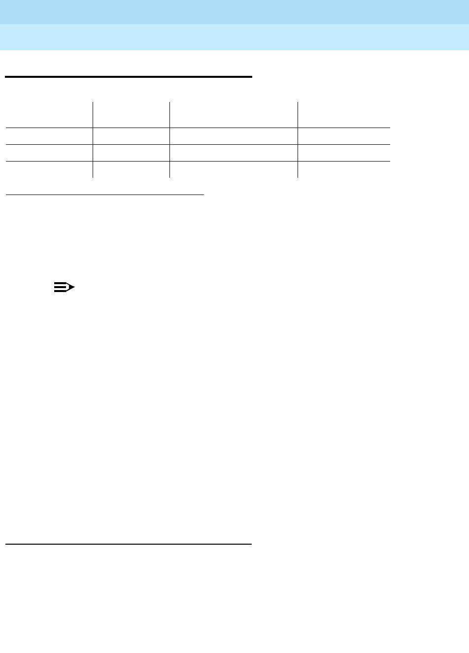
DEFINITY Enterprise Communications Server Release 6
Maintenance for R6r Volumes 1 & 2
555-230-126 Issue 2
January 1998
Maintenance Object Repair Procedures
Page 9-373DIOD-TRK (DIOD Trunk)
9
DIOD-TRK (DIOD Trunk)
NOTE:
Many trunk problems are caused by incorrect settings of parameters on the
trunk group administration form. Settings must be compatible with the local
environment and with parameter settings on the far-end. Refer to DEFINITY
Communications System Generic 3 V2 Implementation, 555-230-653 for
information on how to administer trunks. The Application Notes section of
that book shows the correct settings for administrable timers and other
parameters on a country-by-country basis.
Direct inward and outward dial (DIOD) trunks are 2-wire analog lines to the CO
which support the following services:
■Both incoming and outgoing CO calls
■DID trunk
■DID trunk and 1-way outgoing DIOD
TN429 DIOD trunk circuit packs provide eight ports for loop-start CO trunks and
serve as an interface between the 2-wire analog CO line and the 4-wire TDM bus
on the switch.
Loop Start Operation
Idle State: Tip = ground, Ring = CO Battery
Outgoing Call
1. PBX Off-Hook (Seize Message): Closes the Tip-Ring Loop CO Response:
DC loop current + Dial tone
1.
UU
is the universal cabinet number (1 for PPN, 2 -44 for EPNs).
C
is the carrier designation (A,
B, C, D, or E).
SS
is the number of the slot in which the circuit pack resides (01 to 21).
pp
is
the two digit port number (01, 02, ...).
2. A MAJOR alarm on a trunk indicates that alarms on these trunks are not downgraded by the
set options command and that at least 75 percent of the trunks in this trunk group are
alarmed.
MO Name (in
Alarm Log) Alarm Level Initial Command to Run1Full Name of MO
DIOD-TRK MAJOR2test port
UUCSSpp
l DIOD Trunk
DIOD-TRK MINOR test port
UUCSSpp
l DIOD Trunk
DIOD-TRK WARNING test port
UUCSSpp
l DIOD Trunk

DEFINITY Enterprise Communications Server Release 6
Maintenance for R6r Volumes 1 & 2
555-230-126 Issue 2
January 1998
Maintenance Object Repair Procedures
Page 9-374DIOD-TRK (DIOD Trunk)
9
2. PBX On-Hook (Drop Message): Open Tip-Ring loop, no loop current CO
Response: CO goes to idle state (see Note)
Incoming Call
1. CO Applies Ringing Voltage PBX Response: Detect ringing current
2. PBX Off-Hook (Answer Message): Close loop CO Response: Trip ringing,
provide loop current
3. PBX On-Hook (Drop Message): Open Tip-Ring loop, no loop current CO
Response: CO goes to idle state (see Note)
Direct Inward Dialing (DID)
1. CO Applies Ringing Voltage
PBX Response: Detect ringing current and close loop
CO Response: Send DTMF digits
PBX Response: Acknowledge of Number dialed and open loop
2. PBX Off-Hook (Answer Message): Close loop CO Response: Trip ringing,
provide loop current
3. PBX On-Hook (Drop Message): Open Tip-Ring loop, no loop current CO
Response: CO goes to idle state (see Note)
NOTE:
CO does not normally provide an On-Hook (Disconnect) signal.
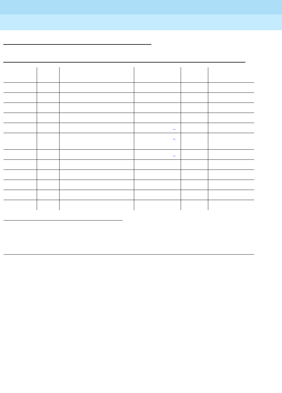
DEFINITY Enterprise Communications Server Release 6
Maintenance for R6r Volumes 1 & 2
555-230-126 Issue 2
January 1998
Maintenance Object Repair Procedures
Page 9-375DIOD-TRK (DIOD Trunk)
9
Error Log Entries and Test to Clear Values
Notes:
a. These are in-line errors that have no specific test associated with them.
Refer to the following table for an explanation and appropriate action.
b. This is a software audit error and does not indicate any hardware
malfunction. Run the Short Test Sequence and investigate associated
errors.
c. Aux data 57376—No loop current on incoming call
Aux data 57424—No loop current on outgoing call
These errors cause the Dial Tone Test (#0) to run and are only considered
a problem if the Dial Tone Test fails (in which case Error Type 1537 also
appears). In this case, the trunk may be put in ‘‘Ready-for-Service’’ state
(shown as ‘‘disconnected’’ by status command), which allows only
incoming calls. Run the Dial Tone Test (#0) and follow its procedures.
1. Run the Short Test Sequence first. If all tests pass, run the Long Test Sequence. Refer to the
appropriate test description and follow the recommended procedures.
2. Major alarms on this MO may be downgraded to Warning alarms based on the value used in the set
options command. If the Minor alarm is not downgraded by the set-options values, the Minor alarm is
upgraded to a Major alarm if 75 percent of the trunks in this trunk group are alarmed.
Table 9-129. DIOD Trunk Error Log Entries
Error Type Aux
Data Associated Test Alarm Level On/Off
Board Test to Clear
Value
010 Any Any Any test port sh
15 (b) any Port Audit Update Test (#36)
18 0 Busyout trunk
grp/mbr
WARNING release trunk
769 (a) 57392 None MAJ/MIN/WRN2ON
1537 Dial Tone Test (#0) MAJ/MIN/WRN2ON test port long r 2
1793 Looparound and
Conference Test (#33) MAJ/MIN/WRN2ON test port long r 3
2049 NPE Cross Talk Test (#6) MAJ/MIN/WRN2ON test port long r 3
2561 (a,d) 57345 None
2817 (a,e) 57393 None
3073 (a,c) 57376 None
3073 (a,c) 57424 None
3585 (a,c) 57424 None

DEFINITY Enterprise Communications Server Release 6
Maintenance for R6r Volumes 1 & 2
555-230-126 Issue 2
January 1998
Maintenance Object Repair Procedures
Page 9-376DIOD-TRK (DIOD Trunk)
9
d. Single polarity ringing current—This error results from abnormal ringing
current, but does not prevent the incoming call from being accepted. This
error code is logged for information purposes only and does not cause
additional testing to occur.
e. Late CO Trunk release—This indicates that the CO releases the trunk at
least four minutes after the PBX dropped the call. This error code is only
logged as an informational event and causes no other testing to occur.
Table 9-130. DIOD Trunk Errors without Associated Tests
Error
Type Aux
Data Description and Recommendation
769 57392 CO not releasing after call is dropped from PBX end (TN747B), or the loop is
not open after a disconnect (TN765). After several occurrences, an off-board
(TN747B) or on-board (TN465) warning alarm is generated. Refer problem to
CO.
2561 57345 Single polarity ringing current. This error results from abnormal ringing current,
but does not prevent the incoming call from being accepted. One cause could
be that the reverse current detector associated with the port is failing. (Will not
be detected by any tests.) The other cause could be that normal current is not
detected. In this case, neither incoming nor outgoing calls can be completed,
and the dial tone test also fails. Check for other errors.
2817 57393 CO released the trunk at least four minutes after the PBX dropped the call.
This error code is log only and causes no other testing to occur. No alarm is
generated. Check for other errors.
3073 57376 No loop current on incoming call. The incoming destination has already
answered and no loop current has been detected. If this is a hard fault, the
dial tone test and all outgoing calls should also fail. Check for other errors.
3585 57424 No loop current on outgoing call. This error occurs on attempt to seize a loop
or ground-start trunk for an outgoing call. An error occurs if loop current is not
detected or the caller hangs up before it is detected. Busyout the affected
port, and run a Long test. If Dial Tone Test #0 passes, ignore this error.
Release the port.
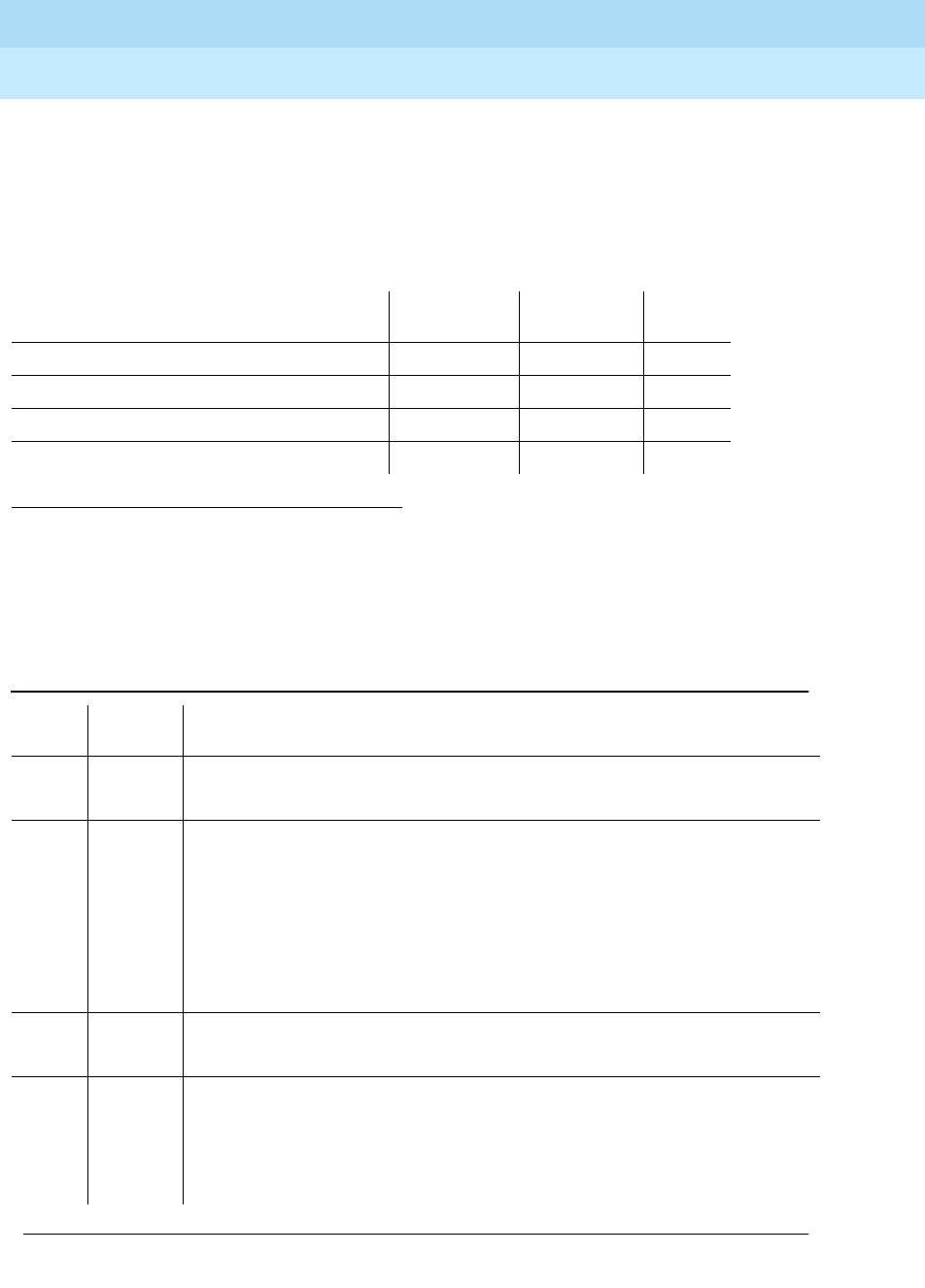
DEFINITY Enterprise Communications Server Release 6
Maintenance for R6r Volumes 1 & 2
555-230-126 Issue 2
January 1998
Maintenance Object Repair Procedures
Page 9-377DIOD-TRK (DIOD Trunk)
9
System Technician-Demanded Tests:
Descriptions and Error Codes
Always investigate tests in the order they are presented in the table below. By
clearing error codes associated with the
NPE Crosstalk Test,
for example, you
may also clear errors generated from other tests in the testing sequence.
Dial Tone Test (#0)
This test attempts to seize a port and checks for the return of a dial tone.
1. D = Destructive; ND = Nondestructive
Order of Investigation Short Test
Sequence Long Test
Sequence D/ND1
NPE Crosstalk Test (#6) X ND
Dial Tone Test (#0) X ND
Looparound and Conference Test (#33) X ND
Audit Update Test (#36) X X ND
Table 9-131. TEST #0 Dial Tone Test
Error
Code Test
Result Description/ Recommendation
ABORT Could not allocate system resources to run this test.
1. Retry the command at 1-minute intervals a maximum of 5 times.
1000 ABORT System resources required to run this test are not available. The port may be
busy with a valid call. Use the command display port UUCSSpp to determine
the trunk group/member number of the port. Use the status trunk command to
determine the service state of the port. If the service state indicates that the
port is in use, then the port is unavailable for certain tests. You must wait until
the port is idle before retesting.
1. If the port status is idle, then retry the command at 1-minute intervals a
maximum of 5 times.
1001 ABORT Could not allocate the necessary system resources to run this test.
1. Retry the command at 1-minute intervals a maximum of 5 times.
1002 ABORT The system could not allocate time slots for the test. The system may be under
heavy traffic conditions or it may have time slots out-of-service due to
TDM-BUS errors. Refer to “TDM-BUS”.
1. If the system has no TDM-BUS errors and is not handling heavy traffic,
repeat test at 1-minute intervals a maximum of 5 times.
Continued on next page

DEFINITY Enterprise Communications Server Release 6
Maintenance for R6r Volumes 1 & 2
555-230-126 Issue 2
January 1998
Maintenance Object Repair Procedures
Page 9-378DIOD-TRK (DIOD Trunk)
9
NPE Crosstalk Test (#6)
The NPE Crosstalk Test verifies that this port’s NPE channel talks on the selected
time slot and never crosses over to time slots reserved for other connections. If
the NPE is not working correctly, one way and noisy connections may be
observed. This test is usually only part of a port’s long test sequence and takes
approximately 20 to 30 seconds to complete.
1004 ABORT The port has been seized by a user for a valid call. Use the status trunk
command to determine when the port is available for testing.
1. Retry the command at 1-minute intervals a maximum of 5 times.
1018 ABORT Test has been disabled via administration.
1. The Maintenance Tests? field must be set to y on the trunk group form
for this test to run. This form is accessed with the change trunk-group
grp# command.
1005 ABORT Trunk has been administered as incoming-only; or DID trunk group type; dial
tone can only be obtained on outgoing trunks. This is a normal condition.
2000 ABORT Response to the test was not received within the allowable time period.
1. Retry the command at 1-minute intervals a maximum of five times.
FAIL Trunk was seized, but dial tone could not be detected.
1. Check for errors on TONE-BD or TONE-PT. Clear any errors and repeat
test.
2. If error has still not cleared, refer problem to CO.
2002 FAIL Seizure portion of test failed due to hardware problem. Fault is usually caused
by a disconnected trunk.
1. Check trunk wiring to ensure good connection; repeat test if wiring
correction made.
2. Locate another identical CO trunk and swap its wiring with one under test.
Repeat test on both trunks and determine if problem follows trunk or
remains at original port. If problem follows trunk, refer problem to CO. If
problem remains at port, replace circuit pack and repeat test.
1009 PASS Detected tone was not pure dial tone. No action required.
PASS Trunk was seized, and dial tone was detected. User-reported troubles on this
port should be investigated by using other port tests and by examining trunk or
external wiring.
Table 9-131. TEST #0 Dial Tone Test — Continued
Error
Code Test
Result Description/ Recommendation
Continued on next page

DEFINITY Enterprise Communications Server Release 6
Maintenance for R6r Volumes 1 & 2
555-230-126 Issue 2
January 1998
Maintenance Object Repair Procedures
Page 9-379DIOD-TRK (DIOD Trunk)
9
Table 9-132. TEST #6 NPE Crosstalk Test
Error
Code Test
Result Description/ Recommendation
ABORT Could not allocate the necessary system resources to run this test.
1. Retry the command at 1-minute intervals a maximum of 5 times.
1000 ABORT System resources required to run this test are not available. The port may be
busy with a valid call. Enter display port UUCSSpp to determine the trunk
group/member number of the port. Use the status trunk command to
determine the service state of the port. If the port is in use, wait until the port is
idle before testing.
1. If the port status is idle, then retry the command at 1-minute intervals a
maximum of 5 times.
1001 ABORT Could not allocate the necessary system resources to run this test.
1. Retry the command at 1-minute intervals a maximum of 5 times.
1002 ABORT The system could not allocate time slots for the test. The system may be under
heavy traffic conditions or it may have time slots out-of-service due to
TDM-BUS errors. Refer to “TDM-BUS”.
1. If system has no TDM-BUS errors and is not handling heavy traffic, repeat
test at 1-minute intervals a maximum of 5 times.
1003 ABORT The system could not allocate a tone receiver for the test. The system may be
oversized for the number of tone detectors present or some tone detectors may
be out-of-service.
1. Resolve any “TTR-LEV” errors in the Error Log.
2. Resolve any “TONE-PT” errors in the Error Log.
3. If neither condition exists, retry the test at 1-minute intervals a maximum of
5 times.
1004 ABORT The port was seized by a valid call during the test. The test has been aborted.
Enter display port UUCSSpp to determine the trunk group/member number of
the port. Use the status trunk command to determine the service state of the
port. If the port is in use, wait until the port is idle before retesting.
2000 ABORT Response to the test was not received within the allowable time period.
2100 ABORT Could not allocate the necessary system resources to run this test.
1. Retry the command at 1-minute intervals a maximum of 5 times.
Any FAIL The NPE of the tested port was found to be transmitting in error. This causes
noisy and unreliable connections.
1. Replace the circuit pack.
PASS The port is correctly using its allocated time slots. User-reported troubles on
this port should be investigated by using other port tests and by examining
trunk or external wiring.
Continued on next page

DEFINITY Enterprise Communications Server Release 6
Maintenance for R6r Volumes 1 & 2
555-230-126 Issue 2
January 1998
Maintenance Object Repair Procedures
Page 9-380DIOD-TRK (DIOD Trunk)
9
Looparound and Conference Circuit Test (#33)
This test checks the reflective loop and conference abilities of a CO port circuit.
The test uses 404 Hz, 1004 Hz, and 2804 Hz tones. Each tone is transmitted
separately through the loop and checked.
Table 9-133. TEST #33 Looparound and Conference Circuit Test
Error
Code Test
Result Description/ Recommendation
ABORT Could not allocate system resources to run this test.
7 ABORT Conference Circuit Test aborted.
1000 ABORT System resources required to run this test are not available. The port may be
busy with a valid call. Enter display port UUCSSpp to determine the trunk
group/member number of the port. Use the status trunk command to
determine the service state of the port. If the port is unavailable, wait until the
port is idle before testing.
1. If the port status is idle, then retry the command at 1-minute intervals a
maximum of 5 times.
1004 ABORT The port has been seized by a user for a valid call. Use the status trunk
command to determine when the port is available for testing.
1. Retry the command at 1-minute intervals a maximum of 5 times.
2100 ABORT Could not allocate the necessary system resources to run this test.
1. Retry the command at 1-minute intervals a maximum of five times.
7 FAIL 1. Check for errors on TONE-BD or TONE-PT.
2. If the Reflective Looparound Test fails for all ports on a circuit pack, a -5
volt power problem is indicated. If a TN736 or TN752 power unit circuit
pack is present, check the circuit pack for a red LED. If the red LED is on,
then replace the appropriate power unit circuit pack. If neither the TN736
nor the TN752 power unit circuit pack is present, then the OLS631DB AC
power unit may be defective. The system may contain a TN736 or TN752
power unit circuit pack
or
an OLS631DB AC power unit,
but not both
.
Refer to “CARR-POW”.
3. Rerun the test.
4. If the test fails again, replace the circuit pack.
PASS CO Trunk Looparound and Conference Test is successful. User-reported
troubles on this port should be investigated by using other port tests and by
examining trunk or external wiring.
Continued on next page

DEFINITY Enterprise Communications Server Release 6
Maintenance for R6r Volumes 1 & 2
555-230-126 Issue 2
January 1998
Maintenance Object Repair Procedures
Page 9-381DIOD-TRK (DIOD Trunk)
9
Port Audit Update Test (#36)
This test sends updates of the CO port translation for all ports on the circuit pack
which have been translated. The update is non-disruptive and guards against
possible corruption of translation data contained on the circuit pack. No
response message is expected from the circuit pack once it receives translation
updates. The port translation data includes: ground or loop start trunk, tone or
rotary dialing trunk, rotary dialing inter-digit timing, network balance R/RC, and
disconnect timing.
Table 9-134. TEST #36 Port Audit Update Test
Error
Code Test
Result Description/ Recommendation
ABORT Could not allocate the necessary system resources to run this test.
1. Retry the command at 1-minute intervals a maximum of 5 times.
2100 ABORT Could not allocate the necessary system resources to run the test.
FAIL Internal system error.
1. Retry the command at 1-minute intervals a maximum of 5 times.
PASS This test passed. Translation information was successfully updated on the
circuit pack. User-reported troubles on this port should be investigated by
using other port tests and by examining trunk or external wiring. If the trunk is
busied out, the test does not run, but returns PASS. To verify that the trunk is
in-service:
1. Enter status-command to verify that the trunk is in-service. If the trunk is
in-service, no further action is necessary. If the trunk is out-of-service,
continue to Step 2.
2. Enter release-trunk command to put trunk back into in-service.
3. Retry the test command.
Continued on next page

DEFINITY Enterprise Communications Server Release 6
Maintenance for R6r Volumes 1 & 2
555-230-126 Issue 2
January 1998
Maintenance Object Repair Procedures
Page 9-382DISK (MSS Disk Circuit Pack)
9
DISK (MSS Disk Circuit Pack)
The TN1657 Disk circuit pack is part of the Generic 3r Mass Storage System
(MSS). The MSS provides non-volatile storage for system software, translation
data, announcement data and program update data. As shown in Figure 9-15,
the MSS consists of a Host Adapter circuit on the UN332 MSS-Network Control
circuit pack (MSSNET), a Small Computer System Interface (SCSI) bus, a
TN1656 Tape circuit pack and the TN1657 Disk Drive circuit pack. The Disk
Drive acts as the primary storage device and the Tape Drive serves as a backup
device.
The system is usually booted from the bootimage stored on disk. The save
translation and save announcements commands save to disk the
memory-resident translation data and TN750-resident announcement data,
respectively. The backup disk command copies data from the disk to the tape
for backup storage. The restore disk command copies data from the tape back
to disk. All MSS components reside in the SPE, or PPN control carrier (carrier A
for a simplex SPE, carriers A and B for a duplicated SPE).
The Disk Drive circuit pack contains SCSI bus terminators, an industry standard
SCSI-based Disk Drive, and interface circuitry to the private bus to control the
LEDs, detect the presence of the circuit pack, and identify the vintage of the
hardware.
A -48V to +12V converter circuit on the Tape circuit pack provides power for both
the Tape Drive and the Disk Drive. The presence of +12V on these circuit packs
is monitored separately by maintenance software so that a failure of the +12V
converter on the Tape circuit pack can be identified or ruled out as the source of
the problem when the Disk Drive loses +12V power.
The Host Adapter Circuit, Tape circuit pack, and Disk circuit pack are treated as
separate, but related, maintenance objects (H-ADAPTER,TAPE, and DISK).
Since the Disk circuit pack is controlled by SCSI commands which are generated
by the Host Adapter, problems with the Host Adapter can prevent
communications with the Disk. Whenever the Host Adapter is taken out of service
by the busy-out host-adapter command, or due to failure of a critical Host
Adapter test, the Tape and Disk maintenance objects are also placed in a
maintenance busyout state.
1. In a system with a simplex SPE, the carrier does not have to be specified. In a system
configured with duplicated SPEs, the carrier (a or b) must be specified.
MO Name (in
Alarm Log) Alarm Level Initial Command to Run1Full Name of MO
DISK WARNING test disk a|b long MSS Disk Circuit Pack
DISK MINOR test disk a|b long MSS Disk Circuit Pack
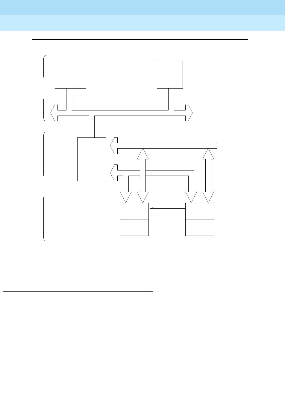
DEFINITY Enterprise Communications Server Release 6
Maintenance for R6r Volumes 1 & 2
555-230-126 Issue 2
January 1998
Maintenance Object Repair Procedures
Page 9-383DISK (MSS Disk Circuit Pack)
9
Figure 9-15. Mass Storage System Interactions
General Troubleshooting Information
Keep the following points in mind when troubleshooting disk problems.
1.
Do not save translations or announcements on the disk if unresolved Disk
Drive or Host Adapter problems are present.
If there is something wrong with the MSS, any attempt to save translations
or announcements could destroy a good copy of the files on disk.
2. When multiple error conditions are present, check for Host Adapter and
Tape errors first.
Maintenance software cannot always distinguish between errors caused
by the Disk Drive, and errors caused by the Host Adapter or Tape Drive.
Switch System
Processor Memory
SPE
System Bus
SCSI BUS
MSSNET
CIRCUIT HOST
PACK ADAPTER
(UN332) Private Bus
Mass
Storage
System
+ 12 V
DISK DISK TAPE TAPE
CIRCUIT DRIVE DRIVE CIRCUIT
PACK PACK
(TN1657) DISK TAPE (TN1656)

DEFINITY Enterprise Communications Server Release 6
Maintenance for R6r Volumes 1 & 2
555-230-126 Issue 2
January 1998
Maintenance Object Repair Procedures
Page 9-384DISK (MSS Disk Circuit Pack)
9
3. In a system with duplex SPEs, the tests run on the standby Disk circuit
pack are identical to those run on the active Disk circuit pack. The
DUPINT circuit pack handles communications between the active and
standby SPEs for the control channel and memory shadowing. Therefore,
problems with the DUPINT circuit pack may affect maintenance testing of
the standby Disk circuit pack.
4. The
disk data will likely be destroyed
if:
a. Power is removed from the Disk circuit pack while its yellow LED is
on.
b. The Disk circuit pack is removed while its yellow LED is on.
5.
Tape data may be destroyed
if the Disk circuit pack is removed while the
yellow LED on the Tape Drive is on.
Replacing the Disk Circuit Pack
■If the SPE is not duplicated:
1. Issue the busyout host-adapter command.
The Host Adapter should be "busied out" to prevent other
applications from trying to access the disk or tape.
2. Replace the Disk circuit pack.
3. Issue the reset host-adapter command.
This allows the disk to "spin up."
4. Issue the release host-adapter command.
5. Issue the status spe command and verify that the disk is now in
service.
6. Issue the restore disk command to copy the boot image files,
translation files, announcement files, and program update files from
the tape to the disk. This may take up to an hour to complete.
7. Issue the test stored-data command to verify that the files on all
storage devices are consistent.
■If the SPE is duplicated:
1. To replace the Disk circuit pack on a system equipped with
duplicated SPEs, use the lock-and power-down procedure
described in
Replacing SPE Circuit Packs
in Chapter 5.
2. After the standby SPE is powered up and fully refreshed, enter the
restore disk command to copy the bootimage files, translation
files, announcement files, and program update files from the tape to
the disk.
3. Test the standby Disk using the test disk long command.
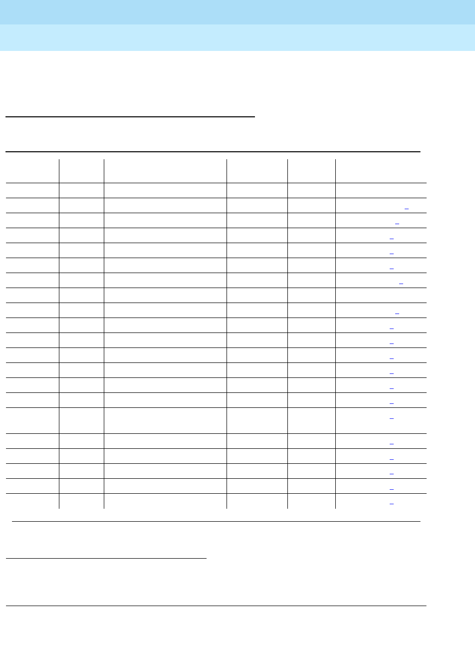
DEFINITY Enterprise Communications Server Release 6
Maintenance for R6r Volumes 1 & 2
555-230-126 Issue 2
January 1998
Maintenance Object Repair Procedures
Page 9-385DISK (MSS Disk Circuit Pack)
9
4. Verify that the files on all storage devices are consistent by issuing
the test stored-data command.
Error Log Entries and Test to Clear Values
The
Service State
field in the Alarm Log refers to the accessibility of the device.
IN (in service) means that users can access the device and all maintenance tests
1. In a system with simplex SPE, the carrier need not be specified. With duplicated SPEs, carrier a or b
must be specified.
2. If error type 1 with aux data of 123 is present, this field will indicate the cause of the out-of-service
condition. See the
MSS Error Actions
table at the end of the section on TAPE
Table 9-135. DISK Error Log Entries
Error
Type Aux
Data Associated Test Alarm
Level On/Off
Board Test to Clear Value
1 (a) any Disk Reset (#809) MINOR OFF reset disk a|b1
18 (b) 0 Busyout Disk (#817) WARNING OFF release disk a|b1
250 (c) 0 Reset Disk (#894) WARNING OFF reset disk a|b1
257 (d) any Disk Looparound (#814) WARNING OFF test disk a|b1 sh r 2
258 (e) any Disk Looparound (#814) WARNING OFF test disk a|b1 sh r 2
513 (f) any Disk Diagnostics (#813) MINOR ON test disk a|b1 sh r 2
526 (g) 0 Busyout Host-adapter WARNING OFF rel host-ad a|b1
528 (h) 0 WARNING OFF
529 (i) 0 WARNING OFF reset disk a|b1
769 (j) any Disk Looparound (#814) MINOR ON test disk a|b1 sh r 2
1025 (k) any Disk Write-Read (#810) MINOR OFF test disk a|b1 l r 2
1281 (l) any Disk Diagnostics (#813) MINOR ON test disk a|b1 sh r 2
1793 (m) any Disk Looparound (#814) MINOR OFF test disk a|b1 sh r 2
2049 (n) any Disk Looparound (#814) MINOR OFF test disk a|b1 sh r 2
2305 (o) any Disk Status (#815) MINOR ON test disk a|b1 sh r 1
2306 (p) 5504 Disk Frmwr Counters
(#812) MINOR ON test disk a|b1 sh
2561 (q) any Disk Write-Read (#810) MINOR OFF test disk a|b1 l r 2
2817 (r) any Disk Status (#815) WARNING ON test disk a|b1 sh r 2
3073 (s) any In-line MINOR ON test disk a|b1 l r 2
3329 (t) any Disk Audit (#811) MINOR OFF test disk a|b1 sh r 2
3841 (u) 2Miscellaneous MINOR OFF test disk a|b1 l r 1
Continued on next page

DEFINITY Enterprise Communications Server Release 6
Maintenance for R6r Volumes 1 & 2
555-230-126 Issue 2
January 1998
Maintenance Object Repair Procedures
Page 9-386DISK (MSS Disk Circuit Pack)
9
run. MTC (maintenance busy) means that the device is busied out; users cannot
access it, but all demand maintenance tests run. OUT (out of service) means that
users cannot access the device, but background and demand testing may run.
Notes:
a. Error type 1 means that the device is out of service as a result of
maintenance tests detecting a critical failure of the disk drive.
b. Error type 18 means that the disk was busied out on demand from the
System Access Terminal.
c. Error type 250 means that the Reset Test (#809 or #894) failed.
d. Error type 257 means that the device could not be accessed.
e. Error type 258 means an attempt was made to remove a disk that was
physically present or failure during remove occurred.
f. Error type 513 means that on-board disk drive diagnostics tests requested
by the Disk Diagnostic Test (#813) failed.
g. Error type 526 means that the Host Adapter was busied out. This also
causes the disk to be busied out.
h. Error type 528 means that there was a failure to insert the disk at system
initialization time. This is a software problem.
i. Error type 529 means that there was a failure to put the disk in service or to
take it out of service. Execute the reset disk command and then execute
the status spe command to verify that the disk is in service. If the disk is
not in the expected state, first clear any other alarms against other MSS
components and then execute the reset disk command.
j. Error type 769 means that the disk Loop-around Test (#814) failed.
k. Error type 1025 means that a disk medium error was detected when the
disk was read or written. The Disk circuit pack should be replaced if this
error continues to be reported.
l. Error type 1281 indicates that a hardware failure condition was detected
by the Firmware Error Counters Read and Clear Test (#812). See the
MSS
Error Actions
table at the end of the section on TAPE.
m. Error type 1793 is an in-line error from the disk control software that
indicates there was a problem with the SCSI Bus Access Failure or
Memory Access Failure between the Host Adapter and the Disk Drive. See
the
MSS Error Actions
table at the end of the section on TAPE.
n. Error type 2049 indicates that a bad command was sent to the disk drive.
This may be caused by a software error or a hardware failure. Execute the
test disk long command and fix any failures associated with those tests.
Error type 2305 means that the system is equipped with more than 2
memory circuit packs and the disk is either not large enough or has not
been configured correctly to support the larger memory size.

DEFINITY Enterprise Communications Server Release 6
Maintenance for R6r Volumes 1 & 2
555-230-126 Issue 2
January 1998
Maintenance Object Repair Procedures
Page 9-387DISK (MSS Disk Circuit Pack)
9
1. If the value in the Auxiliary Data field is 5513, the vintage of the
TN1657 Disk circuit pack is less than V4. This may be verified by
executing the list configuration control command.
2. If the value in the Auxiliary Data field is 5514, the disk capacity is
adequate but the file system on the disk has not been configured
for the large coredump file required when greater than 2 memory
circuit packs are used.
o. Error Type 2305 indicates a mismatch between memory size and disk size
AUX Data 5513 indicates the system is equipped with 3 memory circuit
packs but the capacity of the disk is not large enough for the coredump
file.
AUX Data 5514 indicates the system is equipped with 3 memory circuit
packs but the disk has not been configured for a large coredump file. The
tape and disk should have been configured for the larger memory size as
part of the procedures for installing 3 memory circuit packs as described
in the Installation Manual.
p. Error type 2306 means that a block has been reassigned on the disk or an
attempt to reassign a block has failed. The Minor alarm may clear after
executing the Status test (#815) but the data block will remain reassigned
as a result of a medium error. The disk drive should be replaced if this
Error Type is generated more than 3 times within an hour.
q. Error type 2561 indicates that the Data Write-Read Test (#810) failed.
r. Error 2817 indicates that the Disk Status Test (#815) detected a fault. See
the
MSS Error Actions
table at the end of the section on TAPE.
s. Error type 3073 indicates in-line errors reported by the disk control
software. See the
MSS Error Actions
table at the end of the section on
TAPE.
t. Error type 3329 indicates that the Disk Audit Test (#811) detected a
corrupted directory file. This is a serious failure of the disk so the disk
should be restored from tape.
u. Error type 3841 is used to record miscellaneous data when an
out-of-service condition occurs. See the
MSS Error Actions
table at the
end of the section on TAPE.
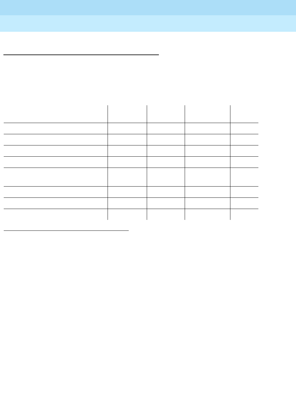
DEFINITY Enterprise Communications Server Release 6
Maintenance for R6r Volumes 1 & 2
555-230-126 Issue 2
January 1998
Maintenance Object Repair Procedures
Page 9-388DISK (MSS Disk Circuit Pack)
9
System Technician-Demanded Tests:
Descriptions and Error Codes
Always investigate tests in the order presented in the table below when
inspecting errors in the system. By clearing error codes associated with the
Disk
Reset Test
, for example, you may also clear errors generated from other tests in
the testing sequence.
Disk Reset Test (#809 and #894)
The Disk Reset Test consists of the following steps controlled by firmware on the
Host Adapter Circuit (located on the MSSNET circuit pack):
■Disk Drive reset: A SCSI BUS DEVICE RESET message is transmitted to
the Disk circuit pack to reset it.
■Presence test: A SCSI INQUIRY command is sent to the Disk Drive to
attempt to query it. If the Disk Drive is present, it will return information
about the device type, whether or not its medium is removable,
compatibility with established standards, vendor and product IDs, and
other miscellaneous information.
■Start unit: This starts the disk drive spinning.
■Capacity test: A SCSI READ CAPACITY command is sent to the Disk
Drive. It returns with the logical block address and the block length of the
last logical block on the medium. This is necessary to restore the
information lost after the reset and verify that the device can be accessed.
A SCSI READ DATA BUFFERS command is sent to the Disk Drive. This
returns the size of the controller memory data buffers.
1. D = Destructive; ND = Nondestructive
Order of Investigation Short Test
Sequence Long Test
Sequence Reset Board
Sequence D/ND1
Disk Reset Test (#809) X X ND
Disk Diagnostic Test (#813) X X ND
Disk Looparound Test (#814) X X ND
Disk Status Test (#815) X X ND
Disk Firmware Error Counters
Read and Clear Test (#812) XX ND
Disk Write-Read Test (#810) X ND
Disk Audit Test (#811) X ND
Disk Reset Test (#894) X ND

DEFINITY Enterprise Communications Server Release 6
Maintenance for R6r Volumes 1 & 2
555-230-126 Issue 2
January 1998
Maintenance Object Repair Procedures
Page 9-389DISK (MSS Disk Circuit Pack)
9
A SCSI READ DEFECT DATA command is sent to the Disk Drive. This
returns the addresses of bad blocks on the disk that must be mapped
around.
■Device Diagnostic Tests: A SCSI SEND DIAGNOSTICS command is sent
to the Disk Drive to initiate a set of device-dependent self-tests that run as
a unit. Failures can be for multiple reasons and the return code that
indicates the cause of failure is vendor unique. A failure condition reports
as single failure type since the only repair action is to replace the Disk
Drive circuit pack
Table 9-136. TEST #809 Disk Reset Test
Error
Code Test
Result Description/ Recommendation
526 ABORT The Host Adapter has been busied out.
1. Issue the release host-adapter command.
1316 ABORT Could not get access to the MSS. Other application software may be using it or
background maintenance tests may be running.
1. Retry the command at 1-minute intervals a maximum of 5 times.
2. If the test continues to abort, verify that the daily translation-save operation
is not in progress (use display system-parameters maintenance to
display the time for scheduled maintenance and the "y/n" option for saving
translation daily).
1335 ABORT Could not run the test on the Standby SPE—Duplication not administered.
1. Refer to “STBY-SPE”.
2. Administer standby present.
1338 ABORT Could not run the test on the Standby SPE—Interchange pending.
1. Refer to “STBY-SPE”.
2. After interchange occurs, run test on new active SPE.
1339 ABORT Could not run the test on the Standby SPE—Handshake down.
1. Refer to “STBY-SPE”.
2. When the standby is restored to service (use status spe to determine
state of standby) retry the command.
1347 ABORT Could not run the test on the Standby SPE—Refresh not complete.
1. When the standby is restored to service (use status spe to determine
state of standby) retry the command.
1350 ABORT Could not run the test on the Standby SPE—Shadowing not enabled.
1. When the standby is restored to service (use status spe to determine
state of standby) retry the command.
Continued on next page

DEFINITY Enterprise Communications Server Release 6
Maintenance for R6r Volumes 1 & 2
555-230-126 Issue 2
January 1998
Maintenance Object Repair Procedures
Page 9-390DISK (MSS Disk Circuit Pack)
9
2000 ABORT Response to the test was not received within the allowable time period.
1. Retry the command at 1-minute intervals a maximum of 5 times.
2500 ABORT Could not run the test on the Standby SPE—Internal software error.
1. Retry the command at 1-minute intervals a maximum of 5 times.
5102 ABORT Could not allocate the Mass Storage System to run test
1. Retry the command at 1-minute intervals a maximum of 5 times.
2. If the test continues to abort, verify that the daily translation-save operation
is not in progress (use the display system-parameters maintenance
command to display the time for scheduled maintenance and the "y/n"
option for saving translation daily).
NO
BOARD The disk has been placed in the "uninstalled" state.
1. Verify that the disk drive is fully inserted and powered up.
2. Attempt a demand reset of the disk.
5513 FAIL The system contains 3 memory boards but the capacity of the disk is not large
enough for the coredump file.
1. Issue the list configuration control command and check if the carrier is
equipped with 3 memory boards and the vintage of the TN1657 Disk
circuit pack is less than Vintage 4.
2. Replace the Disk circuit pack with one of Vintage 4 or greater, issue the
reset disk command, and perform the restore disk command. The
restore operation may take up to 1 hour to complete.
5514 FAIL The system contains 3 memory boards but the disk has not been configured
for a large coredump file. The tape and disk should have been configured for
the larger memory size as part of the procedures for installing 3 memory circuit
packs.
1. Issue the configure tape 3-mem command to ensure that the file system
on the tape is configured for the large core dump file. This command
cannot execute if the tape is already configured.
2. Issue the restore disk command. This step may take up to 1 hour for a
complete restore.
3. Execute the test disk command to clear the alarm.
Table 9-136. TEST #809 Disk Reset Test — Continued
Error
Code Test
Result Description/ Recommendation
Continued on next page

DEFINITY Enterprise Communications Server Release 6
Maintenance for R6r Volumes 1 & 2
555-230-126 Issue 2
January 1998
Maintenance Object Repair Procedures
Page 9-391DISK (MSS Disk Circuit Pack)
9
Disk Write-Read Test (#810)
The Disk Write-Read Test verifies that data can be written to the disk and read
back successfully. This test consists of the following steps:
1. Maintenance software in the SPE issues a request to the Host Adapter for
a transfer of data between SPE memory and a specified block on the disk.
The Host Adapter firmware issues a SCSI WRITE command to the Disk
Drive which results in a transfer of data between the SPE memory and the
disk.
2. Maintenance software in the SPE issues a request to the Host Adapter to
run a checksum on the data previously written to the disk. The Host
Adapter reads the data off the disk and computes a checksum which is
returned to the SPE maintenance software.
3. Maintenance software compares the value of the checksum from the Host
Adapter with the checksum it previously calculated on the data it stored
on the disk.
Multiple failure conditions can occur during this test since it uses both the
software and hardware functions used during normal operations
1. See the MSS Error Actions Table at the end of the TAPE section.
Any
Other1FAIL The disk configuration information shows the disk is missing or the disk LED
test failed.
1. Retry the command for a maximum of 5 retries.
2. If the command continues to fail, replace the Disk circuit pack, issue the
reset disk command and perform the restore disk command. This will
take up to 1 hour for a complete restore.
3. Replace the MSSNET circuit pack.
PASS The Disk status test passed successfully. Look at the results of other tests to
see if it is operating correctly.
Table 9-136. TEST #809 Disk Reset Test — Continued
Error
Code Test
Result Description/ Recommendation
Continued on next page

DEFINITY Enterprise Communications Server Release 6
Maintenance for R6r Volumes 1 & 2
555-230-126 Issue 2
January 1998
Maintenance Object Repair Procedures
Page 9-392DISK (MSS Disk Circuit Pack)
9
Table 9-137. TEST #810 Disk Write-Read Test
Error
Code Test
Result Description/ Recommendation
1301
1302 ABORT Could not run the test—internal MSS error
1. Retry the command.
1304 ABORT Could not allocate the Mass Storage System to run this test. Other application
software may be using it or background maintenance tests may be running.
1. Retry the command at 1-minute intervals for a maximum of 5 retries.
2. If the test continues to abort, verify that the daily translation-save operation
is not in progress (Use the display system-parameters maintenance
command to display the start time for scheduled maintenance and the
"y/n" option for saving translation daily).
1316 ABORT Could not get access to the Mass Storage System. Other application software
may be using it or background maintenance tests may be running.
1. Retry the command at 1-minute intervals a maximum of 5 times.
2. If the test continues to abort, verify that the daily translation-save operation
is not in progress (issue the display system-parameters maintenance
command to display the time for scheduled maintenance and the "y/n"
option for saving translation daily).
1335 ABORT Could not run the test on the Standby SPE—Duplication not administered.
1. Refer to “STBY-SPE”.
2. Administer standby present.
1338 ABORT Could not run the test on the Standby SPE—Interchange pending.
1. Refer to “STBY-SPE”.
2. After interchange occurs, run test on new active SPE.
1339 ABORT Could not run the test on the Standby SPE—Handshake down.
1. Refer to “STBY-SPE”.
2. When the standby is restored to service (use status spe to determine
state of standby) retry the command.
1347 ABORT Could not run the test on the Standby SPE—Refresh not complete.
1. When the standby is restored to service (use status spe to determine
state of standby) retry the command.
1350 ABORT Could not run the test on the Standby SPE—Shadowing not enabled.
1. When the standby is restored to service (use status spe to determine
state of standby) retry the command.
2000 ABORT Response to the test was not received within the allowable time period.
1. Retry the command at 1-minute intervals a maximum of 5 retries.
Continued on next page

DEFINITY Enterprise Communications Server Release 6
Maintenance for R6r Volumes 1 & 2
555-230-126 Issue 2
January 1998
Maintenance Object Repair Procedures
Page 9-393DISK (MSS Disk Circuit Pack)
9
Disk Audit Test (#811)
The Disk Audit Test verifies the following Disk Medium conditions.
■The directory can be read.
■There are no "dirty" files. What is meant by "dirty" is that the data in the file
may not be complete or the directory entry was never updated after the
data was written to the device
1. See the MSS Error Actions Table at the end of the TAPE section.
2500 ABORT Could not run the test on the Standby SPE—Internal software error.
1. Retry the command at 1-minute intervals a maximum of 5 times.
5102 ABORT Could not allocate the Mass Storage System to run this test
1. Retry the command at 1-minute intervals a maximum of 5 times.
2. If the test continues to abort, verify that the daily translation-save operation
is not in progress (issue the display system-parameters maintenance
command to display the time for scheduled maintenance and the "y/n"
option for saving translation daily).
NO
BOARD The disk has been placed in the "uninstalled" state.
1. Verify that the disk drive is fully inserted and powered up.
2. Attempt a demand reset of the disk.
1FAIL The disk could not be accessed, the checksum on the data written did not
match the checksum in memory or the data read did not match the data
written.
1. Retry the command for a maximum of 5 retries.
2. If the command continues to fail, replace the Disk circuit pack, issue the
reset disk command and perform the restore disk command. This will
take up to 1 hour for a complete restore.
3. If the test continues to fail, replace the MSSNET circuit pack.
PASS The Disk write read test executed successfully. Look at the results of other
tests to see if it is operating correctly.
Table 9-137. TEST #810 Disk Write-Read Test — Continued
Error
Code Test
Result Description/ Recommendation
Continued on next page

DEFINITY Enterprise Communications Server Release 6
Maintenance for R6r Volumes 1 & 2
555-230-126 Issue 2
January 1998
Maintenance Object Repair Procedures
Page 9-394DISK (MSS Disk Circuit Pack)
9
Table 9-138. TEST #811 Disk Audit Test
Error
Code Test
Result Description/ Recommendation
1316 ABORT Could not get access to the Mass Storage System. Other software may be
using it or background maintenance tests may be running.
1. Retry the command at 1-minute intervals a maximum of 5 times.
2. If the test continues to abort, verify that the daily translation-save operation
is not in progress (issue the display system-parameters maintenance
command to display the time for scheduled maintenance and the "y/n"
option for saving translation daily).
1335 ABORT Could not run the test on the Standby SPE—Duplication not administered.
1. Refer to “STBY-SPE”.
2. Administer standby present.
1338 ABORT Could not run the test on the Standby SPE—Interchange pending.
1. Refer to “STBY-SPE”.
2. After interchange occurs, run test on new active SPE.
1339 ABORT Could not run the test on the Standby SPE—Handshake down.
1. Refer to “STBY-SPE”.
2. When the standby is restored to service (use status spe to determine
state of standby) retry the command.
1347 ABORT Could not run the test on the Standby SPE—Refresh not complete.
1. When the standby is restored to service (use status spe to determine
state of standby) retry the command.
1350 ABORT Could not run the test on the Standby SPE—Shadowing not enabled.
1. When the standby is restored to service (use status spe to determine
state of standby) retry the command.
2000 ABORT Response to the test was not received within the allowable time period.
1. Retry the command at 1-minute intervals a maximum of 5 times.
2500 ABORT Could not run the test on the Standby SPE—Internal software error.
1. Retry the command at 1-minute intervals a maximum of 5 times.
5102 ABORT Could not allocate the Mass Storage System to run this test
1. Retry the command at 1-minute intervals for a maximum of 5 retries.
2. If the test continues to abort, verify that the daily translation-save operation
is not in progress (issue the display system-parameters maintenance
command to display the time for scheduled maintenance and the "y/n"
option for saving translation daily).
Continued on next page

DEFINITY Enterprise Communications Server Release 6
Maintenance for R6r Volumes 1 & 2
555-230-126 Issue 2
January 1998
Maintenance Object Repair Procedures
Page 9-395DISK (MSS Disk Circuit Pack)
9
Disk Firmware Error Counters Read and Clear
Test (#812)
The Host Adapter firmware is constantly running background tests on each of its
devices. When an error is detected by one of these background tests, the
appropriate counter in the host adapter dual port RAM is incremented. The Disk
Firmware Error Counters Read and Clear Test requests that the firmware return
these errors to the software and clear the area in dual port RAM. If any counter is
non-zero, the software then increments the appropriate software counter. The 16
errors reported by the firmware are:
■Unexpected interrupt from the SCSI Bus Interface Controller Chip (SBICC)
■SBICC timed out during SCSI command
■Error interrupt from the Direct Memory Access Controller (DMAC)
■DMAC timeout without issuing interrupt
■Disk self-test failed
■Disk external looparound test failed
■Command failed with bad sense key
■Disk could not be accessed
■Flaw detected in disk medium
1. See the MSS Error Actions Table at the end of the TAPE section.
NO
BOARD The disk has been placed in the "uninstalled" state.
1. Verify that the disk drive is fully inserted and powered up.
2. Attempt a demand reset of the disk.
1FAIL The audit of the disk directory failed.
1. Perform a restore disk full command. This will take up to 1 hour for a
complete restore (G3V3 full disk restore + or - 30 minutes).
2. If the test continues to fail, replace the Disk circuit pack, issue the reset
disk command and perform the restore disk command.
3. If the test continues to fail, replace the MSSNET circuit pack.
PASS The disk directory audit passed successfully. Look at the results of other tests
to see if it is operating correctly.
Table 9-138. TEST #811 Disk Audit Test — Continued
Error
Code Test
Result Description/ Recommendation
Continued on next page

DEFINITY Enterprise Communications Server Release 6
Maintenance for R6r Volumes 1 & 2
555-230-126 Issue 2
January 1998
Maintenance Object Repair Procedures
Page 9-396DISK (MSS Disk Circuit Pack)
9
■Unrecoverable hardware error on disk
■Invalid parameter in SCSI command
■Media removed or device reset
■Disk is write protected
■Disk reached end of medium
■Block reassigned on disk
■Block reassignment on disk failed
Table 9-139. TEST #812 Disk Firmware Error
Counters Read and Clear Test
Error
Code Test
Result Description/ Recommendation
1305 ABORT Could not read firmware error counters.
1. Retry the command at 1-minute intervals a maximum of 5 times.
1306 ABORT Could not read configuration area for defect information.
1. Retry the command at 1-minute intervals a maximum of 5 times.
1316 ABORT Could not get access to the Mass Storage System. Other software may be
using it or background maintenance tests may be running.
1. Retry the command at 1-minute intervals a maximum of 5 times.
2. If the test continues to abort, verify that the daily translation-save operation
is not in progress (issue the display system-parameters maintenance
command to display the time for scheduled maintenance and the "y/n"
option for saving translation daily).
1335 ABORT Could not run the test on the Standby SPE—Duplication not administered.
1. Refer to “STBY-SPE”.
2. Administer standby present.
1338 ABORT Could not run the test on the Standby SPE—Interchange pending.
1. Refer to the documentation for STBY-SPE maintenance.
2. After interchange occurs, run test on new active SPE.
1339 ABORT Could not run the test on the Standby SPE—Handshake down.
1. Refer to “STBY-SPE”.
2. When the standby is restored to service (use status spe to determine state
of standby) retry the command.
1347 ABORT Could not run the test on the Standby SPE—Refresh not complete.
1. When the standby is restored to service (use status spe to determine state
of standby) retry the command.
Continued on next page

DEFINITY Enterprise Communications Server Release 6
Maintenance for R6r Volumes 1 & 2
555-230-126 Issue 2
January 1998
Maintenance Object Repair Procedures
Page 9-397DISK (MSS Disk Circuit Pack)
9
Disk Diagnostic Test (#813)
The Disk Diagnostic test causes the Host Adapter to send a SCSI send
diagnostics command to the DISK Drive circuit pack. This initiates a set of
device-dependent self-tests that are run as a unit. Failures can be for multiple
1. See the MSS Error Actions Table at the end of the TAPE section.
1350 ABORT Could not run the test on the Standby SPE—Shadowing not enabled.
1. When the standby is restored to service (use status spe to determine state
of standby) retry the command.
2000 ABORT Response to the test request was not received within the allowable time period.
1. Retry the command at 1-minute intervals a maximum of 5 times.
2500 ABORT Could not run the test on the Standby SPE—Internal software error.
1. Retry the command at 1-minute intervals a maximum of 5 times.
5102 ABORT Could not allocate the Mass Storage System to run this test
1. Retry the command at 1-minute intervals a maximum of 5 times.
2. If the test continues to abort, verify that the daily translation-save operation
is not in progress (issue the display system-parameters maintenance
command to display the time for scheduled maintenance and the "y/n"
option for saving translation daily).
NO
BOARD The disk has been placed in the "uninstalled" state.
1. Verify that the disk drive is fully inserted and powered up.
2. Attempt a demand reset of the disk.
1FAIL At least one of the firmware error counters was non-zero.
1. Retry the command at 1-minute intervals a maximum of 5 times.
2. If the test continues to fail, replace the Disk circuit pack, issue the reset
disk command and perform the restore disk command. This will take up
to 1 hour for a complete restore.
3. If the test continues to fail, replace the MSSNET circuit pack.
PASS All of the firmware error counters were zero. Look at the results of other tests to
see if it is operating correctly.
Table 9-139. TEST #812 Disk Firmware Error
Counters Read and Clear Test — Continued
Error
Code Test
Result Description/ Recommendation
Continued on next page

DEFINITY Enterprise Communications Server Release 6
Maintenance for R6r Volumes 1 & 2
555-230-126 Issue 2
January 1998
Maintenance Object Repair Procedures
Page 9-398DISK (MSS Disk Circuit Pack)
9
reasons. The return code which indicates the cause of failure is vendor unique. A
failure condition will be reported as single failure type since the only repair action
is to replace the Disk Drive circuit pack
Table 9-140. TEST #813 Disk Diagnostic Test
Error
Code Test
Result Description/ Recommendation
1316 ABORT Could not get access to the Mass Storage System. Other application software
may be using it or background maintenance tests may be running.
1. Retry the command at 1-minute intervals a maximum of 5 times.
2. If the test continues to abort, verify that the daily translation-save operation
is not in progress (issue the display system-parameters maintenance
command to display the time for scheduled maintenance and the "y/n"
option for saving translation daily).
1335 ABORT Could not run the test on the Standby SPE—Duplication not administered.
1. Refer to “STBY-SPE”.
2. Administer standby present.
1338 ABORT Could not run the test on the Standby SPE—Interchange pending.
1. Refer to the documentation for STBY-SPE maintenance.
2. After interchange occurs, run test on new active SPE.
1339 ABORT Could not run the test on the Standby SPE—Handshake down.
1. Refer to the documentation for STBY-SPE maintenance.
2. When the standby is restored to service (use status spe to determine state
of standby) retry the command.
1347 ABORT Could not run the test on the Standby SPE—Refresh not complete.
1. When the standby is restored to service (use status spe to determine state
of standby) retry the command.
1350 ABORT Could not run the test on the Standby SPE—Shadowing not enabled.
1. When the standby is restored to service (use status spe to determine state
of standby) retry the command.
2000 ABORT Response to the test was not received within the allowable time period.
1. Retry the command at 1-minute intervals a maximum of 5 times.
2500 ABORT Could not run the test on the Standby SPE—Internal software error.
1. Retry the command at 1-minute intervals a maximum of 5 times.
Continued on next page

DEFINITY Enterprise Communications Server Release 6
Maintenance for R6r Volumes 1 & 2
555-230-126 Issue 2
January 1998
Maintenance Object Repair Procedures
Page 9-399DISK (MSS Disk Circuit Pack)
9
Disk Loop-Around Tests (#814)
This test extends the Host Adapter Loop-Around test to send data from the Host
Adapter to buffers on the Disk Drive circuit pack and back to the Host Adapter. It
may detect errors related to the Host Adapter, SCSI bus, and the Disk Drive
circuit pack. It is intended to functionally test the Disk Drive circuit pack to the
extent possible without actually writing data to the disk.
This test consists of two sets of tests:
■Disk Internal Loop-Around
Data is generated in the RAM of the Host Adapter and transferred to its
SCSI Data Memory. A SCSI WRITE DATA BUFFERS command is sent to
the Disk Drive circuit pack which causes the Disk Drive circuit pack to
copy the data to its buffers. A SCSI READ DATA BUFFERS command is
then sent by the Host Adapter to the Disk Drive circuit pack which causes
the Disk Drive circuit pack to transfer the data from its buffers back to the
1. See the MSS Error Actions Table at the end of the TAPE section.
5102 ABORT Could not allocate the Mass Storage System to run this test
1. Retry the command at 1-minute intervals a maximum of 5 times.
2. If the test continues to abort, verify that the daily translation-save operation
is not in progress (issue the display system-parameters maintenance
command to display the time for scheduled maintenance and the "y/n"
option for saving translation daily).
NO
BOARD The disk has been placed in the "uninstalled" state.
1. Verify that the disk drive is fully inserted and powered up.
2. Attempt a demand reset of the disk.
1FAIL A Disk diagnostic test failed.
1. Retry the command a maximum of 5 times.
2. If the command continues to fail, replace the Disk circuit pack, issue the
reset disk command and perform the restore disk command. This will
take up to 1 hour for a complete restore.
3. If the test continues to fail, replace the MSSNET circuit pack.
PASS The Disk passed all diagnostic tests. Look at the results of other tests to see if it
is operating correctly.
Table 9-140. TEST #813 Disk Diagnostic Test — Continued
Error
Code Test
Result Description/ Recommendation
Continued on next page

DEFINITY Enterprise Communications Server Release 6
Maintenance for R6r Volumes 1 & 2
555-230-126 Issue 2
January 1998
Maintenance Object Repair Procedures
Page 9-400DISK (MSS Disk Circuit Pack)
9
Host Adapter’s SCSI Data Memory. The Host Adapter then copies the
data back to its private RAM where it compares it with the original test
data.
■Disk External Loop-Around
This test is similar to the Internal Loop-around test except that the data
originates in the Host Adapter’s Dual Port RAM and it is transferred to and
from the SCSI Data Memory using SPE system bus accesses. Only a small
amount of data is sent to the Disk Drive circuit pack in order to keep
system bus access to a minimum.
Table 9-141. TEST #814 Disk Loop-Around Test
Error
Code Test
Result Description/ Recommendation
1316 ABORT Could not get access to the Mass Storage System. Other application
software may be using it or background maintenance tests may be running.
1. Retry the command at 1-minute intervals a maximum of 5 times.
2. If the test continues to abort, verify that the daily translation-save
operation is not in progress (issue the display system-parameters
maintenance command to display the time for scheduled maintenance
and the "y/n" option for saving translation daily).
1335 ABORT Could not run the test on the Standby SPE—Duplication not administered.
1. Refer to the documentation for STBY-SPE maintenance.
2. Administer standby present.
1338 ABORT Could not run the test on the Standby SPE—Interchange pending.
1. Refer to the documentation for STBY-SPE maintenance.
2. After interchange occurs, run test on new active SPE.
1339 ABORT Could not run the test on the Standby SPE—Handshake down.
1. Refer to the documentation for STBY-SPE maintenance.
2. When the standby is restored to service (use status spe to determine
state of standby) retry the command.
1347 ABORT Could not run the test on the Standby SPE—Refresh not complete.
1. When the standby is restored to service (use status spe to determine
state of standby) retry the command.
1350 ABORT Could not run the test on the Standby SPE—Shadowing not enabled.
1. When the standby is restored to service (use status spe to determine
state of standby) retry the command.
2000 ABORT Response to the test request was not received within the allowable time
period.
1. Retry the command at 1-minute intervals a maximum of 5 times.
Continued on next page

DEFINITY Enterprise Communications Server Release 6
Maintenance for R6r Volumes 1 & 2
555-230-126 Issue 2
January 1998
Maintenance Object Repair Procedures
Page 9-401DISK (MSS Disk Circuit Pack)
9
Disk Status Test (#815)
The Disk Status Test verifies the following:
■The Host Adapter knows about the existence of the Disk Drive.
■The LEDs on the faceplate can be turned on and off correctly. This verifies
only that the LED control and status logic is operating correctly. LED
operation may also be tested visually with test led.
■The presence of +5V and +12V
1. See the MSS Error Actions Table at the end of the TAPE section.
2500 ABORT Could not run the test on the Standby SPE—Internal software error.
1. Retry the command at 1-minute intervals a maximum of 5 times.
5102 ABORT Could not allocate the Mass Storage System to run this test
1. Retry the command at 1-minute intervals a maximum of 5 times.
2. If the test continues to abort, verify that the daily translation-save
operation is not in progress (issue the display system-parameters
maintenance command to display the time for scheduled maintenance
and the "y/n" option for saving translation daily).
NO
BOARD The disk has been placed in the "uninstalled" state.
1. Verify that the disk drive is fully inserted and powered up.
2. Attempt a demand reset of the disk.
1FAIL The Disk loop-around test failed.
1. Retry the command a maximum of 5 times.
2. If the command continues to fail, replace the Disk circuit pack, issue the
reset disk command and perform the restore disk command. This will
take up to 1 hour for a complete restore.
3. If the test continues to fail, replace the MSSNET circuit pack.
PASS The Disk loop-around test passed. Look at the results of other tests to see if it
is operating correctly.
Table 9-141. TEST #814 Disk Loop-Around Test — Continued
Error
Code Test
Result Description/ Recommendation
Continued on next page

DEFINITY Enterprise Communications Server Release 6
Maintenance for R6r Volumes 1 & 2
555-230-126 Issue 2
January 1998
Maintenance Object Repair Procedures
Page 9-402DISK (MSS Disk Circuit Pack)
9
Table 9-142. TEST #815 Disk Status Test
Error
Code Test
Result Description/ Recommendation
1306
1307
1308
ABORT Internal software error between maintenance software and MSS driver.
1. Retry the command at 1-minute intervals a maximum of 5 times.
1316 ABORT Could not get access to the Mass Storage System. Other application software
may be using it or background maintenance tests may be running.
1. Retry the command at 1-minute intervals a maximum of 5 times.
2. If the test continues to abort, verify that the daily translation-save operation
is not in progress (issue the display system-parameters maintenance
command to display the time for scheduled maintenance and the "y/n"
option for saving translation daily).
1335 ABORT Could not run the test on the Standby SPE—Duplication not administered.
1. Refer to the documentation for STBY-SPE maintenance.
2. Administer standby present.
1338 ABORT Could not run the test on the Standby SPE—Interchange pending.
1. Refer to the documentation for STBY-SPE maintenance.
2. After interchange occurs, run test on new active SPE.
1339 ABORT Could not run the test on the Standby SPE—Handshake down.
1. Refer to the documentation for STBY-SPE maintenance.
2. When the standby is restored to service (use status spe to determine state
of standby) retry the command.
1347 ABORT Could not run the test on the Standby SPE—Refresh not complete.
1. When the standby is restored to service (use status spe to determine state
of standby) retry the command.
1350 ABORT Could not run the test on the Standby SPE—Shadowing not enabled.
1. When the standby is restored to service (use status spe to determine state
of standby) retry the command.
2000 ABORT Response to the test request was not received within the allowable time period.
1. Retry the command at 1-minute intervals a maximum of 5 times.
2500 ABORT Could not run the test on the Standby SPE—Internal software error.
1. Retry the command at 1-minute intervals for a maximum of 5 retries.
Continued on next page

DEFINITY Enterprise Communications Server Release 6
Maintenance for R6r Volumes 1 & 2
555-230-126 Issue 2
January 1998
Maintenance Object Repair Procedures
Page 9-403DISK (MSS Disk Circuit Pack)
9
5102 ABORT Could not allocate the Mass Storage System to run this test
1. Retry the command at 1-minute intervals a maximum of 5 times.
2. If the test continues to abort, verify that the daily translation-save operation
is not in progress (issue the display system-parameters maintenance
command to display the time for scheduled maintenance and the "y/n"
option for saving translation daily).
NO
BOARD The disk has been placed in the "uninstalled" state.
1. Verify that the disk drive is fully inserted and powered up.
2. Attempt a demand reset of the disk.
5513 FAIL The system is equipped with 3 memory circuit packs but the capacity of the
disk is not large enough for the coredump file.
1. Use list configuration control and verify that the control carrier is
equipped with 3 memory boards. Also check the vintage of the TN1657
Disk Drive circuit pack.
2. Replace the Disk Drive circuit pack with Vintage 4 or greater, issue the
reset disk command, and perform the restore disk command. The restore
operation may take up to 1 hour to complete.
5514 FAIL The system is equipped with 3 memory circuit packs but the disk has not been
configured for a large coredump file. The tape and disk should be configured
for the larger memory size as part of the procedures for installing 3 memory
circuit packs.
1. Use configure tape 3-mem to ensure that the file system on the tape has
been configured for the large core dump file. This command will not
execute if the tape has already been configured.
2. Use restore disk. This step may take up to 1 hour for a complete restore.
3. Execute the test disk R command to clear the alarm.
Any
Other1FAIL The disk configuration information shows the disk is missing or the disk LED test
failed.
1. Retry the command a maximum of 5 times.
2. If the command continues to fail, replace the Disk Drive circuit pack, issue
the reset disk command and perform the restore disk command. This will
take up to 1 hour for a complete restore.
3. If the test continues to fail, replace the MSSNET circuit pack.
PASS The Disk status test passed successfully. Look at the results of other tests to
see if it is operating correctly.
Table 9-142. TEST #815 Disk Status Test — Continued
Error
Code Test
Result Description/ Recommendation
Continued on next page

DEFINITY Enterprise Communications Server Release 6
Maintenance for R6r Volumes 1 & 2
555-230-126 Issue 2
January 1998
Maintenance Object Repair Procedures
Page 9-404DISK (MSS Disk Circuit Pack)
9
Disk Reset Test (#894)
The Disk Reset Test is executed when the reset disk command is entered at the
terminal. The test results for Test 894 are the same as those for Test 809. The
only difference between Test 809, which is run as part of the test sequence for
the test disk command, and Test 894 which is run in response to the reset disk
command is that all disk alarms are resolved when Test 894 passes while only
some disk alarms may be resolved when Test 809 passes.
Refer to the results for Test #809 for the appropriate repair procedures.
1. See the MSS Error Actions Table at the end of the TAPE section.

DEFINITY Enterprise Communications Server Release 6
Maintenance for R6r Volumes 1 & 2
555-230-126 Issue 2
January 1998
Maintenance Object Repair Procedures
Page 9-405DLY-MTCE (MO-DAILY)
9
DLY-MTCE (MO-DAILY)
The DLY-MTCE maintenance object monitors daily translation saves. If a
translation save times out or fails to run, an error is logged against this
maintenance object. If the save fails three times in a row, a MINOR alarm is
raised; if the save fails for seven consecutive attempts, a MAJOR alarm is raised.
MO Name (in
Alarm Log) Alarm
Level Initial Command to Run Full Name of MO
DLY-MTCE MINOR NONE DLY-MTCE
DLY-MTCE MAJOR NONE DLY-MTCE

DEFINITY Enterprise Communications Server Release 6
Maintenance for R6r Volumes 1 & 2
555-230-126 Issue 2
January 1998
Maintenance Object Repair Procedures
Page 9-406DS1-BD (DS1 Interface Circuit Pack)
9
DS1-BD (DS1 Interface Circuit Pack)
The DS1 Interface circuit pack provides an interface to an external DS1 facility
and supports 24 DS0 channels carried on a 1.544 Mbps DS1 link. These DS0
channels can be administered as either trunks to other switches or lines to
off-premises stations. The TN464C and later suffix Universal DS1 Interface also
supports a 32-channel interface on a 2.048Mbps link. The functions and
maintenance strategy for the TN464 circuit packs are covered under a separate
maintenance object, UDS1-BD.
DS1-BD maintenance logs in-line errors reported by the DS1 Interface circuit
pack, runs tests for error diagnosis and recovery, and raises and clears alarms.
The following table shows the capabilities of each DS1 circuit pack. The TN722
and TN722B are not supported on G3r V1 or later systems.
ISDN-PRI Trunk signaling (for example, Q.921, Q.931) requires a TN464D and is
handled by system software. The TN464 is covered in the "UDS1-BD (UDS1
Interface Circuit Pack)" section of Chapter 9.
Each trunk and line have their own maintenance strategies. However, they all
depend on the health of the DS1 Interface circuit pack. Refer to the following
sections for details: TIE-DS1, CO-DS1, DID-DS1, OPS-LINE, ISDN-TRK, and
ISDN-PLK. Signaling over the DS1 link must be synchronized between the
transmitting and receiving ends to ensure error-free communication. Refer to
"SYNC (Synchronization)" for details.
1. UU is the universal cabinet number (1 for PPN, 2 - 44 for EPNs). C is the carrier designation (A, B,
C, D, or E). SS is the number of the slot in which the circuit pack resides (01 to 21).
MO Name (in
Alarm Log) Alarm Level Initial Command to
Run1Full Name of MO
DS1-BD MAJOR test board UUCSS sh DS1 Interface Circuit Pack
DS1-BD MINOR test board UUCSS l DS1 Interface Circuit Pack
DS1-BD WARNING test board UUCSS sh DS1 Interface Circuit Pack
Circuit Pack
Code 24
Channel 32
Channel Tie Trunk
Signaling CO Trunk
Signaling
DID
Trunk
Signaling OPS Line
Signaling
TN722/B x x
TN767/B/C/D/E x x x x x
TN464C/D/E/F x x x x x x
(24-chl only)

DEFINITY Enterprise Communications Server Release 6
Maintenance for R6r Volumes 1 & 2
555-230-126 Issue 2
January 1998
Maintenance Object Repair Procedures
Page 9-407DS1-BD (DS1 Interface Circuit Pack)
9
The TN767E circuit pack combined with Lucent’s new 120A1 CSU Module forms
an Enhanced Integrated CSU. The new 120A1 CSU Module, when combined
with the functionality provided by the TN767E hardware and firmware, and new
switch software, provides functionality equivalent to an external stand-alone
Lucent ESF T1 CSU. The 120A1 CSU Module connects to the TN767E circuit
pack on the I/O connector panel on the back of the port carrier. The new CSU
Module, thus becomes an integrated part of the DEFINITY. system. Throughout
the document, the term 120A1 will mean a 120A1 or later suffix CSU Module.
The Enhanced Integrated CSU is for use in the United States of America with
1.544 Mbps DS1 service. For further details on the 120A1 CSU Module see
DEFINITY. Communications System Generic 1, Generic 2, and Generic 3 V1 and
V2 - Integrated CSU Module Installation and Operation, 555-230-193.
The TN767E and 120A1 CSU Module support on-demand loopback tests that
assist in the detection of faults between the TN767E circuit pack and the CSU
Module, between the Integrated CSU and the optional Customer Premises
Loopback Jack, or between the Integrated CSU and remote CSU. These
loopback tests are explained in detail later in this DS1-BD section, but Figure
9-16 gives a high level overview of the loopback points.
The following list of acronym definitions are for Figure 9-16:
■PLB = Payload Loopback
■BLB = Board Loopback
■ELB = Equipment Loopback
■LLB = Line Loopback
■RLB = Repeater Loopback
■CLJ = Loopback Jack Loopback
■R-LLB = Remote Line Loopback
■SMRT = Smart Jack
■LPBK = Loopback
For more information about DS1 interfaces, see the
DEFINITY Communications
System DS1/CEPT1/ISDN-PRI Reference
, 555-025-107.
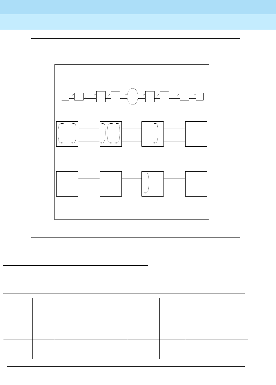
DEFINITY Enterprise Communications Server Release 6
Maintenance for R6r Volumes 1 & 2
555-230-126 Issue 2
January 1998
Maintenance Object Repair Procedures
Page 9-408DS1-BD (DS1 Interface Circuit Pack)
9
Figure 9-16. High Level Overview Of Loopback Points
Error Log Entries and Test to Clear Values
Table 9-143. DS1 Interface Circuit Pack Maintenance Error Log Entries
Error
Type Aux
Data Associated Test Alarm
Level On/Off
Board Test to Clear Value
010 Any Any Any test board UUCSS
1 (a) 0 Circuit pack removed or
SAKI Test (#53) MIN/WRN‡ON
18 (b) 0 busy-out board UUCSS WARNING OFF release board UUCSS
23 (c) 0 WARNING OFF add ds1 UUCSS
Continued on next page
CPE
LPBK
JACK
NET
SMRT
JACK
CSU
MOD
NET
SMRT
JACK
CPE
LPBK
JACK
DS1
BRD
CSU
MOD
DS1
BRD
NET-
WORK
CSU module to CSU module
Remote end
NETWORK ENVIRONMENT
Local end
NETWORK
SMRT
JACK
BLB
R-LLB
CPE
LPBK
JACK
DS1
BOARD
Remote end loop backs (* CSU or External CSU)
NETWORK
SMRT
JACK
CSU*
MOD
CSU
MOD
CLJ-LB LLB RLB ELB
PLB
CPE
LPBK
JACK
DS1
BOARD
Local end loop backs

DEFINITY Enterprise Communications Server Release 6
Maintenance for R6r Volumes 1 & 2
555-230-126 Issue 2
January 1998
Maintenance Object Repair Procedures
Page 9-409DS1-BD (DS1 Interface Circuit Pack)
9
12 5(d) None MINOR ON
257 65535 Control Channel Loop Test
(#52) MINOR ON test board UUCSS l r 20
257 (e) Any None
513 (f) Any MINOR ON
769 (g) 4358
1025 (e) 4363 NPE Audit Test (#50)
1281 Any Loss of Signal Alarm Inquiry
Test (#138) MIN/WRN†OFF test board UUCSS
1300 (h) Any Loss Of Signal Alarm Inquiry
Test (#138) WARNING OFF test board UUCSS
1301 (i) Any Loss Of Signal Alarm Inquiry
Test (#138) WARNING OFF test board UUCSS
1302 (j) Any Loss Of Signal Alarm Inquiry
Test (#138) MIN/WRN†OFF test board UUCSS
1303 (k) Any Loss Of Signal Alarm Inquiry
Test (#138) MIN/WRN†ON test board UUCSS
1310 (l) Any Board Loopback Test
(#1209) MINOR ON test ds1-loop UUCSS
ds1/csu-loopback-tests
1311 (m) Any Equipment Loopback Test
(#1210) MIN/WRN†OFF test ds1-loop UUCSS
ds1/csu-loopback-test
1312 (n) Any Repeater Loopback Test
(#1211) MIN/WRN†OFF test ds1-loop UUCSS
ds1/csu-loopback-tests
1313 (o) Any CPE Loopback Jack Test
(#1212) MIN/WRN†OFF test ds1-loop UUCSS
end-loopback/span-test
1314 (p) Any Far CSU Loopback Test
(#1213) MIN/WRN†OFF test ds1-loop UUCSS
end-loopback/span-test
1320 Any Loss of Signal Alarm Inquiry
Test (#138) MIN/WRN†OFF test board UUCSS
1321 Any Loss of Signal Alarm Inquiry
Test (#138) MIN/WRN†OFF test board UUCSS
1322 Any Loss of Signal Alarm Inquiry
Test (#138) MINOR ON test board UUCSS
1323 Any Loss of Signal Alarm Inquiry
Test (#138) MIN/WRN†OFF test board UUCSS
Table 9-143. DS1 Interface Circuit Pack Maintenance Error Log Entries — Continued
Error
Type Aux
Data Associated Test Alarm
Level On/Off
Board Test to Clear Value
Continued on next page

DEFINITY Enterprise Communications Server Release 6
Maintenance for R6r Volumes 1 & 2
555-230-126 Issue 2
January 1998
Maintenance Object Repair Procedures
Page 9-410DS1-BD (DS1 Interface Circuit Pack)
9
1. Run the Short Test Sequence first. If all tests pass, run the Long Test Sequence. Refer to the
appropriate test description and follow the recommended procedures.
1324 Any Loss of Signal Alarm Inquiry
Test (#138) WARNING OFF test board UUCSS
1538 (q) Any MINOR ON
1793 Any Blue Alarm Inquiry Test
(#139) MAJ/MIN/
WRN ** OFF test board UUCSS
1794 Any Blue Alarm Inquiry Test
(#139) MAJ/MIN/
WRN ** OFF test board UUCSS
1795 Any Blue Alarm Inquiry Test
(#139) MAJ/MIN/
WRN ** OFF test board UUCSS
2049 Any Red Alarm Inquiry Test
(#140) MIN/WRN†OFF test board UUCSS
2305 Any Yellow Alarm Inquiry Test
(#141) MINOR OFF test board UUCSS
2306 Any Yellow Alarm Inquiry Test
(#141) MINOR OFF test board UUCSS
2561 Any Major Alarm Inquiry Test
(#142) MIN/WRN†OFF test board UUCSS
2817 Minor Alarm Inquiry Test
(#143) MIN/WRN†OFF test board UUCSS
3073 to
3160 (r) Any Slip Alarm Inquiry Test
(#144) MIN/WRN†OFF test board UUCSS r 6
3329 to
3345 (s) Any Misframe Alarm Inquiry Test
(#145) MIN/WRN†OFF test board UUCSS r 6
3840(t) Any None
3900(u) Any CPE Loopback Jack Test
(#1212)
3901(v) Any Far CSU Loopback Test
(#1213)
3902(w) Any One-Way Span Test (#1214)
3999 (x) Any None
Table 9-143. DS1 Interface Circuit Pack Maintenance Error Log Entries — Continued
Error
Type Aux
Data Associated Test Alarm
Level On/Off
Board Test to Clear Value
Continued on next page

DEFINITY Enterprise Communications Server Release 6
Maintenance for R6r Volumes 1 & 2
555-230-126 Issue 2
January 1998
Maintenance Object Repair Procedures
Page 9-411DS1-BD (DS1 Interface Circuit Pack)
9
Notes:
a. This error indicates that the circuit pack has stopped functioning or is not
completely administered. The alarm is logged about 15 minutes after the
circuit pack has been removed or 11 minutes after the SAKI Test (#53)
fails.
To be completely administered, a DS1 circuit pack must meet all 3 of the
following conditions:
1. Have an entry in the circuit plan via the change circuit pack
command
2. Be administered via the add ds1 UUCSS command
3. Be physically inserted in the appropriate slot
If the circuit pack has an entry in the circuit plan and either of the other two
conditions are
not
met, a MINOR alarm is logged. To resolve the error
either
1. Make sure all conditions for administration are met and that a
functioning DS1 circuit pack is inserted in the correct slot.
2. Completely remove the DS1-BD from the system using the following
steps:
a. Remove any administered DS1 trunks or access endpoints
associated with the circuit pack from their trunk groups.
b. Execute the remove ds1 UUCSS and change circuit pack
UUCSS commands.
If all the administration conditions are met for this circuit pack and the red
LED is still on, follow the instructions for
LED Alarms with Error Type 1
in
Chapter 7.
b. The DS1 Interface circuit pack has been busied out by a busy-out board
UUCSS command.
c. The DS1-BD circuit pack is not completely administered. A completely
administered DS1-BD circuit pack should have an entry in the circuit plan
via the change circuit pack command, should have been administered
via the add ds1 UUCSS command, and should have been inserted into
the appropriate port slot.
d. The circuit pack in the slot does not match the type administered to that
position. Either replace the circuit pack with one of the type administered,
or use change circuit-pack to readminister the slot. This error may also
indicate that the 24/32-channel selection on the DS1 administration form
does not match the configuration of the circuit pack.
e. This error is associated with the Common Port Circuit Pack Maintenance
Test. Refer to "XXX-BD (Common Port Circuit Pack)" for details.
f. The DS1 Interface circuit pack has detected a transient hardware problem
(for example, external RAM failure, internal RAM failure, internal ROM
failure, or instruction set failure). This error will disappear when no faults

DEFINITY Enterprise Communications Server Release 6
Maintenance for R6r Volumes 1 & 2
555-230-126 Issue 2
January 1998
Maintenance Object Repair Procedures
Page 9-412DS1-BD (DS1 Interface Circuit Pack)
9
are detected for 30 minutes. The value in the Aux Data field indicates the
type of hardware problem. However, when this error is reported with Aux
Data in the range of 4352 to 4358, it indicates the circuit pack has
reported a hardware failure such that the circuit pack should be replaced.
g. The DS1 Interface circuit pack has detected a transient hardware logic
error (for example, program logic inconsistency). This error will disappear
when no faults are detected for 100 minutes. The value in Aux Data field
indicates the type of hardware problem.
h. CSU Module missing. The Near-End CSU Type field on the add ds1
form has been administered as integrated but the 120A1 CSU Module
is not physically connected (or is improperly connected) to the TN767E
board on the back of the port carrier.
If using the 120A1 CSU Module, plug (or replug) the CSU Module into the
TN767E circuit pack’s connector on the I/O connector panel on back of
the carrier. Otherwise, change the Near-End CSU Type field using the
change ds1 form to other.
If this error remains after plugging the CSU Module into the board’s
connector, there could be a problem with the I/O connector panel.
i. CSU Module not expected. The 120A1 CSU Module is physically
connected to the TN767E board on the back of the port carrier but the
Near-End CSU Type field on the add ds1 form has not been
administered as integrated.
If the 120A1 CSU Module is to be used, use the change ds1 command to
change the Near-End CSU Type field to integrated. Otherwise,
physically remove the 120A1 CSU Module from the back of the port
carrier.
j. DS1 configuration error. Attempting to use the 120A1 CSU Module with a
TN767E circuit pack that is configured for 32-channel (2.048 Mbps)
operation. The CSU Module only works with a DS1 board configured for
24-channel (1.544 Mbps) operation in the United States of America.
k. DS1 circuit pack suffix incorrect for CSU Module. The Near-End CSU
Type field on the add ds1 form has been administered as integrated
but the DS1 circuit pack is not a TN767E or later suffix DS1 board.
If the 120A1 CSU Module is to be used, remove the circuit pack and
replace it with a TN767E or later suffix board. Otherwise, use the change
ds1 command to change the Near-End CSU Type field to other
.
l. BLB failure. This error occurs when the DS1 Board Loopback (BLB)
demand test fails. Repeat the test using the following commands:
busyout board UUCSS, test ds1-loop UUCSS ds1/csu-loopback-tests,
release board UUCSS. If the BLB test continues to fail, then the TN767E
circuit pack needs to be replaced.
m. ELB failure. This error occurs when the Integrated CSU (I-CSU) Module
Equipment Loopback (ELB) test fails. This test is executed by the I-CSU
during I-CSU power-up/reset (i.e., TN767E board physically inserted and

DEFINITY Enterprise Communications Server Release 6
Maintenance for R6r Volumes 1 & 2
555-230-126 Issue 2
January 1998
Maintenance Object Repair Procedures
Page 9-413DS1-BD (DS1 Interface Circuit Pack)
9
120A1 CSU Module already installed) or when the 120A1 CSU Module is
plugged on to an already initialized DS1 board. The ELB test is also
executed as part of the command test ds1-loop UUCSS
ds1/csu-loopback-tests.
Attempt to clear the alarm via the following commands: busyout board
UUCSS, test ds1-loop UUCSS ds1/csu-loopback-tests, and release
board UUCSS. If the ELB test continues to fail, then either the TN767E
board, the CSU Module, or the I/O cable between the backplane and the
CSU module (or any combination thereof) has failed. Attempt to isolate
where the failure is occurring by re-executing the test by replacing one
piece of hardware at a time.
n. RLB failure. This error occurs when the Integrated CSU (I-CSU) Module
Repeater Loopback (RLB) test fails. This test is executed by the I-CSU
during I-CSU power-up/reset (i.e., TN767E board physically inserted and
120A1 CSU Module already installed) or when the 120A1 CSU Module is
plugged on to an already initialized DS1 board. The RLB test is also
executed as part of the command test ds1-loop UUCSS
ds1/csu-loopback-tests.
Attempt to clear the alarm via the following commands: busyout board
UUCSS, test ds1-loop UUCSS ds1/csu-loopback-tests, and release
board UUCSS. If the RLB test continues to fail, then the CSU Module
needs to be replaced.
o. CPE Loopback Jack deactivation error. This error occurs when the
TN767E circuit pack could not deactivate a CPE Loopback Jack
loopback.
Attempt to clear the alarm via the following commands: busyout board
UUCSS, test ds1-loop UUCSS end-loopback/span-test, and release
board UUCSS. If the attempt to deactivate the CPE Loopback Jack
loopback continues to fail, other steps must be taken to deactivate the
loopback.
p. Far CSU Loopback deactivation error. This error occurs when the TN767E
circuit pack could not deactivate a far-end CSU loopback on
power-up/reset or upon software request.
Attempt to clear the alarm via the following commands:
busyout board
UUCSS
,
test ds1-loop UUCSS end-loopback/span-test
,
release board
UUCSS
. If the attempt to deactivate the Far CSU loopback continues to
fail, then escalate the problem.
q. The hyperactive circuit pack is out-of-service and may exhibit one or more
of the following symptoms:
1. The common circuit pack level tests such as Test #51 and/or Test
#220 are aborting with error code 2000.
2. The tests run on the ports of this circuit pack are returning NO
BOARD.
3. A busy-out/release of the circuit pack has no affect on test results.

DEFINITY Enterprise Communications Server Release 6
Maintenance for R6r Volumes 1 & 2
555-230-126 Issue 2
January 1998
Maintenance Object Repair Procedures
Page 9-414DS1-BD (DS1 Interface Circuit Pack)
9
4. A list configuration command shows that the circuit pack and
ports are properly installed.
The circuit pack is isolated from the system and all trunks of this circuit
pack are placed into the out-of-service state. The system will try to restore
the circuit pack within 15 minutes. When no faults are detected for 15
minutes, the DS1 Interface circuit pack is restored to normal operation. All
trunks of the DS1 Interface circuit pack are then returned to the in-service
state. If the error recurs after 15 minutes, then replace the circuit pack.
r. For later releases of G3V4 and beyond, only error 3073 will show that this
board is receiving Slips and the AUX data shows the last Slip count that
was reported.
s. For later releases of G3V4 and beyond, only error 3329 will show that this
board is receiving misframes and the AUX data shows the last misframe
count that was reported.
t. This error is not service-affecting and can be ignored.
u. Error 3900 is used to give status information on a CPE Loopback Jack
Test. The value in the Aux Data field indicates the status of the loopback
test.
v. Error 3901 is used to give status information on a Far CSU Loopback Test.
The value in the Aux Data field indicates the status of the loopback test.
w. Error 3902 is used to give status information on a One-Way Span Test. The
value in the Aux Data field indicates the status of the span test.
x. Error type 3999 indicates that the circuit pack sent a large number of
control channel messages to the switch within a short period of time. If
error type 1538 is also present, then the circuit pack was taken
out-of-service due to hyperactivity. If error type 1538 is not present, then
1
—
Test is currently running.
2
—
Test failed because loopback could not be activated.
3
—
Test failed because test pattern could not be detected.
4
—
Test has been terminated.
1
—
Test is currently running.
2
—
Test failed because loopback could not be activated.
3
—
Test failed because test pattern could not be detected.
4
—
Test has been terminated.
1
—
Test is currently running.
2
—
Test has failed because test could not be activated.
3 — Test pattern was not received from the far end.
4
—
Test has been terminated.

DEFINITY Enterprise Communications Server Release 6
Maintenance for R6r Volumes 1 & 2
555-230-126 Issue 2
January 1998
Maintenance Object Repair Procedures
Page 9-415DS1-BD (DS1 Interface Circuit Pack)
9
the circuit pack has not been taken out-of-service, but it has generated
50% of the messages necessary to be considered hyperactive. This may
be completely normal during heavy traffic periods. However, if this error
type is logged when the circuit pack is being lightly used, it may indicate a
problem with the circuit pack or the equipment attached to it.
System Technician-Demanded Tests:
Descriptions and Error Codes
Always investigate tests in the order they are presented in Table 9-144. By
clearing error codes associated with the
NPE Connection Audit Test,
for
example, you may also clear errors generated from other tests in the testing
sequence
Table 9-144. System Technician-Demanded Tests: DS1-BD
Order of Investigation Short Test
Sequence Long Test
Sequence
Reset
Board
Sequence
test
ds1-loop
Command D/ND1
NPE Connection Audit Test (#50) X ND
Control Channel Loop Test (#52) X ND
Loss of Signal Alarm Inquiry Test
(#138) XX ND
Blue Alarm Inquiry Test (#139) X X ND
Red Alarm Inquiry Test (#140) X X ND
Yellow Alarm Inquiry Test (#141) X X ND
Major Alarm Inquiry Test (#142) X X ND
Minor Alarm Inquiry Test (#143) X X ND
Slip Alarm Inquiry Test (#144) X X ND
Misframe Alarm Inquiry Test (#145) X X ND
Translation Update Test (#146) X X ND
ICSU Status LEDs Test (#1227) X X ND
SAKI Sanity Test (#53) X D
Internal Looparound Test (#135) X D
DS1/CSU Loopback Tests X D
DS1 Board Loopback Test (#1209) X D
Continued on next page
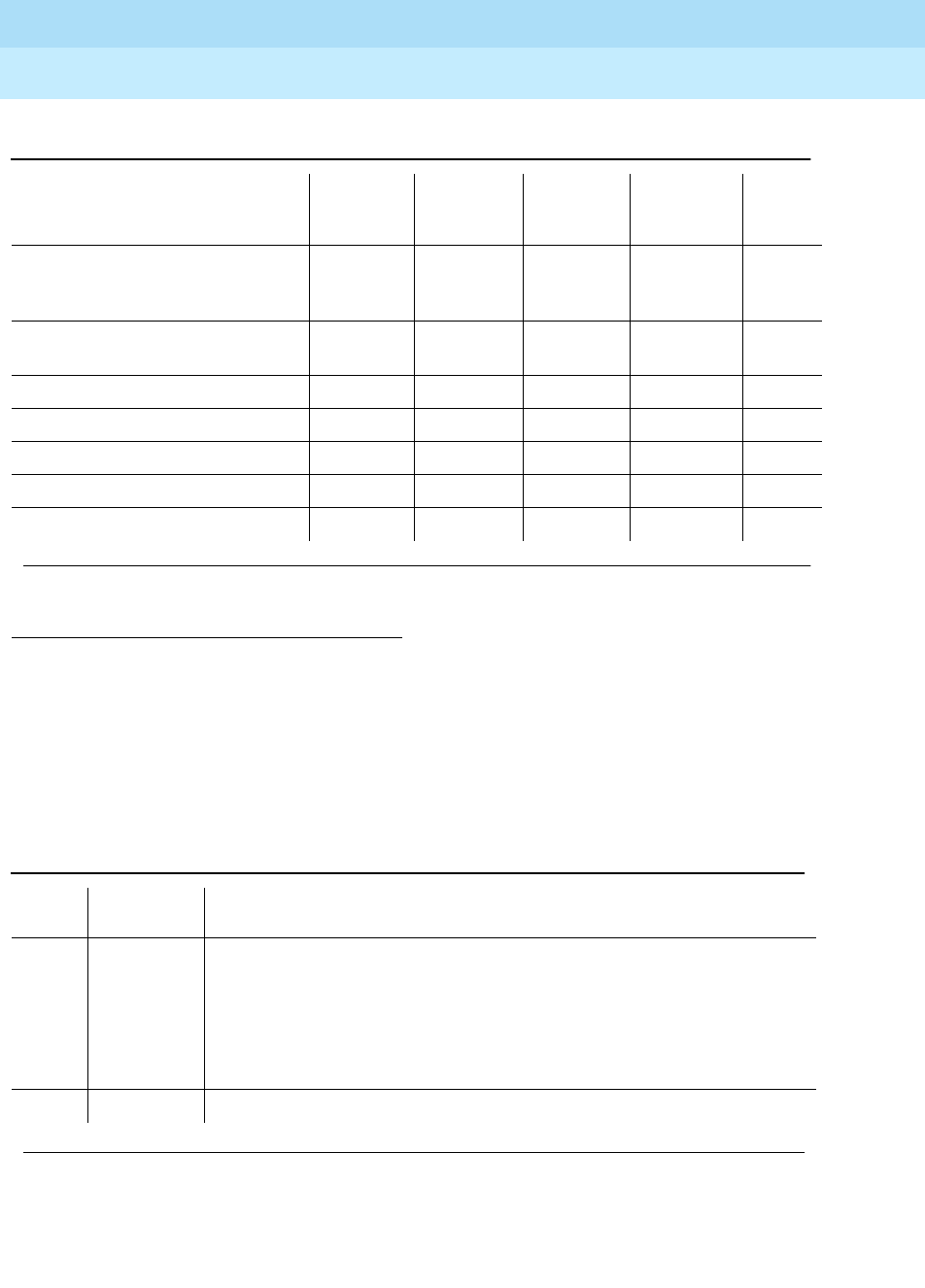
DEFINITY Enterprise Communications Server Release 6
Maintenance for R6r Volumes 1 & 2
555-230-126 Issue 2
January 1998
Maintenance Object Repair Procedures
Page 9-416DS1-BD (DS1 Interface Circuit Pack)
9
NPE Connection Audit Test (#50):
The system sends a message to the on-board microprocessor to update the
network connectivity translation for all the Network Processing Elements (NPEs)
on the circuit pack.
1. D = Destructive, ND = Non-destructive
CSU Equipment Loopback Test
(#1210) XD
CSU Repeater Loopback Test
(#1211) XD
CPE Loopback Jack Test (#1212) X D
Far CSU Loopback Test (#1213) X D
One-Way Span Test (#1214) X D
Inject Single Bit Error (#1215) X D
End Loopback/Span Test (#1216) X D
Table 9-145. TEST #50 NPE Connection Audit Test
Error
Code Test Result Description/ Recommendation
None
2100 ABORT System resources required for this test are not available.
1019 ABORT Test already in progress.
FAIL Internal system error
1. Retry the command at 1-minute intervals a maximum of 5 times.
PASS The circuit pack’s NPEs have been updated with their translation.
Continued on next page
Table 9-144. System Technician-Demanded Tests: DS1-BD — Continued
Order of Investigation Short Test
Sequence Long Test
Sequence
Reset
Board
Sequence
test
ds1-loop
Command D/ND1
Continued on next page

DEFINITY Enterprise Communications Server Release 6
Maintenance for R6r Volumes 1 & 2
555-230-126 Issue 2
January 1998
Maintenance Object Repair Procedures
Page 9-417DS1-BD (DS1 Interface Circuit Pack)
9
Control Channel Looparound Test (#52)
This test queries the circuit pack for its circuit pack code and vintage and verifies
its records.
0 NO BOARD The test could not relate the internal ID to the port (no board).
This could be due to incorrect translations, no board is inserted, an
incorrect board is inserted, or an insane board is inserted.
1. Check to ensure that the board translations are correct. Use the add
ds1 UUCSS command to administer the DS1 interface if it is not
already administered.
2. If board was already administered correctly, check the error log to
determine if the board is hyperactive. If this is the case, the board is
shut down. Reseating the board will re-initialize the board.
3. Issue the busyout board command.
4. Issue the reset board command.
5. Issue the release busy board command.
6. Issue the test board long command.
This should re-establish the linkage between the internal ID and the port.
Table 9-146. TEST #52 Control Channel Looparound Test
Error
Code Test Result Description/ Recommendation
None
2100 ABORT System resources required for this test are not available.
1. Retry the command at 1-minute intervals a maximum of 5 times.
Continued on next page
Table 9-145. TEST #50 NPE Connection Audit Test — Continued
Error
Code Test Result Description/ Recommendation
Continued on next page
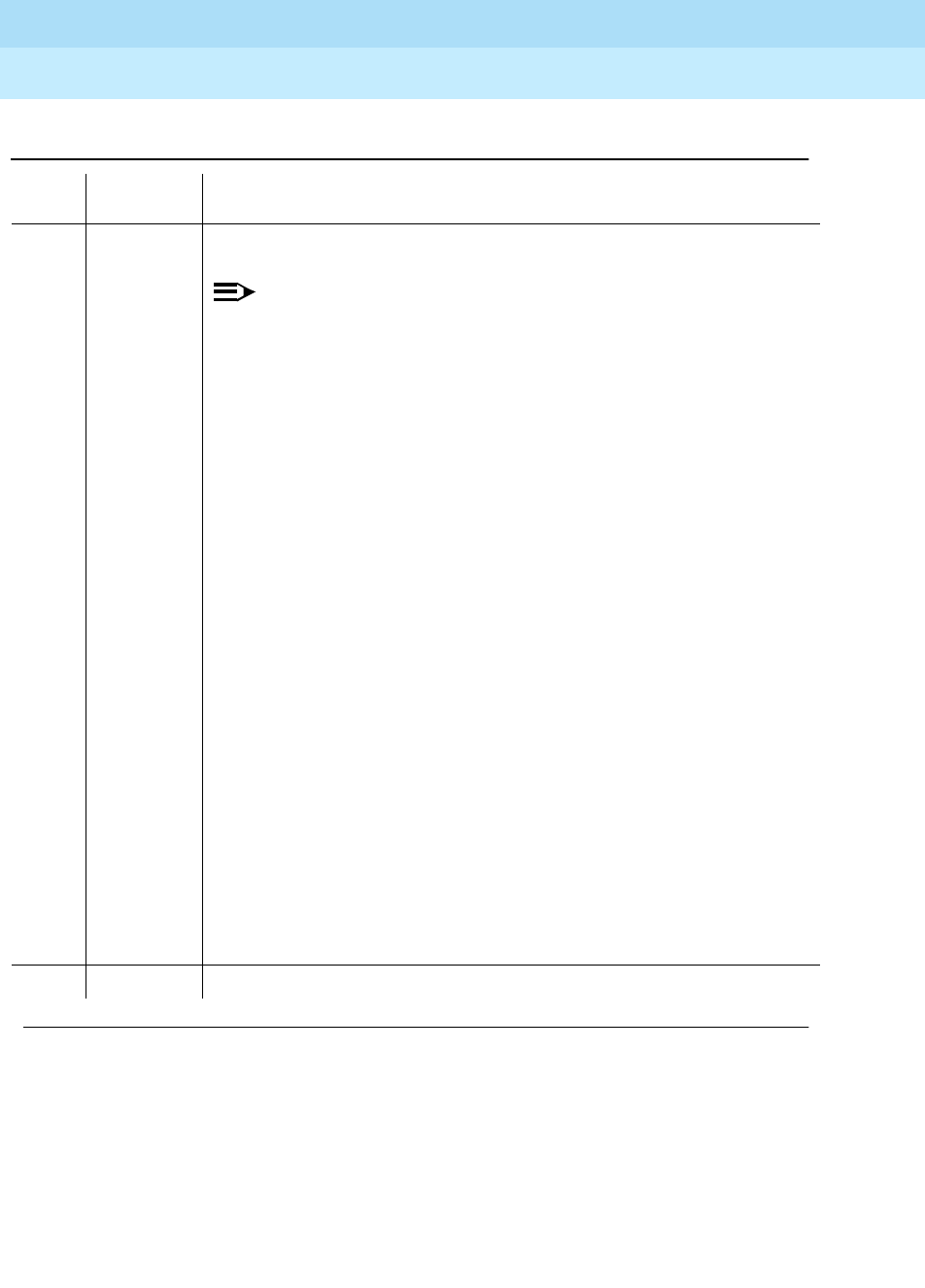
DEFINITY Enterprise Communications Server Release 6
Maintenance for R6r Volumes 1 & 2
555-230-126 Issue 2
January 1998
Maintenance Object Repair Procedures
Page 9-418DS1-BD (DS1 Interface Circuit Pack)
9
FAIL The test failed because the circuit pack did not return the circuit pack code
or vintage.
NOTE:
Error type 1538 in the error log indicates hyperactivity. The
hyperactive circuit pack is out of service and one or more of the
following symptoms may be exhibited.
1. The DS1-BD tests (such as Test 138 and Test 139) are aborting with
error code 2000.
2. The tests run on the ports of this circuit pack are returning a no board
result.
3. A busyout or a release command has no affect on the test result.
4. A list config command shows that the circuit pack and the ports are
properly installed.
When hyperactivity occurs, the circuit pack is isolated from the system, and
all of the trunks for this circuit pack are placed into the out of service state.
The system will try to restore the circuit pack within 15 minutes. When no
faults are detected for 15 minutes, the DS1 interface circuit pack is restored
to normal operation. All of the trunks for the DS1 interface circuit pack are
then returned to the in service state. Hyperactivity is often caused by the
associated facility. In such a case, faults (such as slips, misframes, or blue
alarms) would be entered in the error log. In addition, many hardware errors
would be logged against the associated trunk circuits. If the facility is OK
and the error occurs again after 15 minutes, replace the circuit pack.
1. Retry the command for a maximum of 5 times.
2. If the problem continues, check for hyperactivity. Resolve the problem,
as appropriate.
3. If there is no longer hyperactivity, retry the command for a maximum of 5
times.
4. If the test continues to fail, replace the circuit pack.
PASS Communication with this circuit pack is successful.
Table 9-146. TEST #52 Control Channel Looparound Test — Continued
Error
Code Test Result Description/ Recommendation
Continued on next page

DEFINITY Enterprise Communications Server Release 6
Maintenance for R6r Volumes 1 & 2
555-230-126 Issue 2
January 1998
Maintenance Object Repair Procedures
Page 9-419DS1-BD (DS1 Interface Circuit Pack)
9
SAKI Sanity Test (#53)
This test is destructive. This test resets the circuit pack.
0 NO BOARD The test could not relate the internal ID to the port (no board).
This could be due to incorrect translations, no board is inserted, an incorrect
board is inserted, or an insane board is inserted.
1. Check to ensure that the board translations are correct. Use the add
ds1 UUCSS command to administer the DS1 interface if it is not already
administered.
2. If board was already administered correctly, check the error log to
determine if the board is hyperactive. If this is the case, the board is shut
down. Reseating the board will re-initialize the board.
3. If the board was found to be correctly inserted in step 1, issue the
busyout board command.
4. Issue the reset board command.
5. Issue the release busy board command.
6. Issue the test board long command.
This should re-establish the linkage between the internal ID and the port.
Table 9-147. TEST #53 SAKI Sanity Test
Error
Code Test Result Description/ Recommendation
None ABORT System resources required for this test are not available.
1. Retry the command at 1-minute intervals a maximum of 5 times.
1005 ABORT Wrong circuit pack configuration to run this test. This error applies only to
DS1 Interface circuit packs. It means the DS1 Interface circuit pack is
providing timing for the system and, therefore, it cannot be reset without
major system disruptions.
1. If the circuit pack needs to be reset, then set synchronization to another
DS1 Interface circuit pack or to the Tone-Clock circuit pack and try
again. Refer to "SYNC (Synchronization)".
Continued on next page
Table 9-146. TEST #52 Control Channel Looparound Test — Continued
Error
Code Test Result Description/ Recommendation
Continued on next page

DEFINITY Enterprise Communications Server Release 6
Maintenance for R6r Volumes 1 & 2
555-230-126 Issue 2
January 1998
Maintenance Object Repair Procedures
Page 9-420DS1-BD (DS1 Interface Circuit Pack)
9
Internal Looparound Test (#135)
This test is destructive.
The Internal Looparound Test is run by looping the transmitted DS1 bit stream
back into the DS1’s board receiver. The loop occurs just before the DS1 facility
1015 ABORT Port is not out-of-service.
1. Busyout the circuit pack.
2. Execute the command again.
2100 ABORT System resources required for this test are not available.
1. Retry the command at 1-minute intervals a maximum of 5 times.
1 FAIL The circuit pack failed to reset.
2 FAIL The circuit pack failed to restart.
1. Execute the command again.
2. If the problem persists, replace the circuit pack.
PASS The circuit pack initializes correctly.
1. Run the Short Test Sequence.
0 NO BOARD The test could not relate the internal ID to the port (no board).
This could be due to incorrect translations, no board is inserted, an
incorrect board is inserted, or an insane board is inserted.
1. Check to ensure that the board translations are correct. Use the add
ds1 UUCSS command to administer the DS1 interface if it is not already
administered.
2. If board was already administered correctly, check the error log to
determine if the board is hyperactive. If this is the case, the board is
shut down. Reseating the board will re-initialize the board.
3. If the board was found to be correctly inserted in step 1, issue the
busyout board command.
4. Issue the reset board command.
5. Issue the release busy board command.
6. Issue the test board long command.
This should re-establish the linkage between the internal ID and the port.
Table 9-147. TEST #53 SAKI Sanity Test — Continued
Error
Code Test Result Description/ Recommendation
Continued on next page

DEFINITY Enterprise Communications Server Release 6
Maintenance for R6r Volumes 1 & 2
555-230-126 Issue 2
January 1998
Maintenance Object Repair Procedures
Page 9-421DS1-BD (DS1 Interface Circuit Pack)
9
interface. The test is highly destructive and can only be initiated by a system
technician-demanded reset board UUCSS command.
All trunks on the DS1 Interface circuit pack must be busied out via the system
technician busy-out board command before running the Internal Looparound
Test. When the Internal Looparound Test is initiated, maintenance software
sends appropriate messages to the DS1 Interface circuit pack to start the test.
The test uses the Tone Generator and Tone Detector to exercise a bit pattern
consistency test for all ports. If the transmitted and received bit patterns on a
trunk are different, the test fails.
When the test is complete, the maintenance software sends a stop loop around
message to the DS1 Interface circuit pack to put the circuit pack back into the
normal operation mode. All trunks of the DS1 Interface circuit pack are restored
to the in-service state after the release board command is entered
Table 9-148. TEST #135 Internal Looparound Test
Error
Code Test
Result Description/ Recommendation
2012 ABORT Internal system error
1. Retry the command at 1-minute intervals a maximum of 5 times.
1002 ABORT The system could not allocate time slots for the test. The system may be
under heavy traffic conditions or it may have time slots out-of-service due to
TDM-BUS errors. Refer to “TDM-BUS” to diagnose TDM-BUS errors.
1. If system has no TDM-BUS errors and is not handling heavy traffic, repeat
test at 1-minute intervals a maximum of 5 times.
1003 ABORT The system could not allocate a tone receiver for the test. The system may be
oversized for the number of Tone Detectors present or some Tone Detectors
may be out-of-service.
1. Resolve any “TTR-LEV” errors in the Error Log.
2. Resolve any “TONE-PT” errors in the Error Log.
3. If neither condition exists, retry the test at 1-minute intervals a maximum
of 5 times.
1004 ABORT Received an incoming call on a port of the DS1 circuit pack during the test.
1. Enter the busy-out board UUCSS command to put all trunks of DS1
Interface circuit pack to out-of-service state.
2. Retry the command at 1-minute intervals a maximum of 5 times.
1015 ABORT Ports on DS1 Interface circuit pack have not been busied out.
1. Enter the busy-out board UUCSS command to put all trunks of the DS1
Interface circuit pack into out-of-service state.
2. Retry the command.
Continued on next page
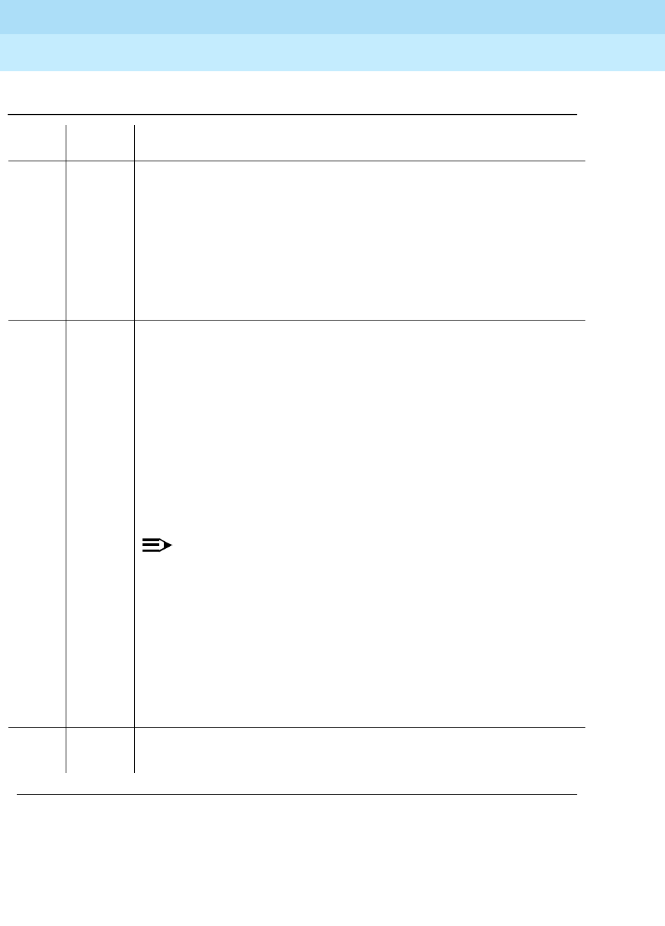
DEFINITY Enterprise Communications Server Release 6
Maintenance for R6r Volumes 1 & 2
555-230-126 Issue 2
January 1998
Maintenance Object Repair Procedures
Page 9-422DS1-BD (DS1 Interface Circuit Pack)
9
1039 ABORT The DS1 Interface circuit pack is providing timing for the system. Therefore, it
cannot be reset without major system disruption.
1. If the DS1 Interface circuit pack needs to be tested, set the
synchronization reference to another DS1 Interface circuit pack or to the
Tone-Clock circuit pack via the following command sequence:
■Issue the disable synchronization-switch command.
■Next, issue the set synchronization UUCSS command.
■Lastly, issue the enable synchronization-switch command.
2000 ABORT The test was aborted. Response to the test was not received within the
allowable time period. This may be due to hyperactivity. Error type 1538 in the
error log indicates hyperactivity. The hyperactive circuit pack is out of service
and one or more of the following symptoms may be exhibited.
1. The DS1-BD tests (such as Test 139 and Test 140) are aborting with error
code 2000.
2. The tests run on the ports of this circuit pack are returning a no board
result.
3. A busyout or a release command has no affect on the test results.
4. A list config command shows that the circuit pack and the ports are
properly installed.
NOTE:
When hyperactivity occurs, the circuit pack is isolated from the system,
and all of the trunks for this circuit pack are placed into the out of
service state. The system will try to restore the circuit pack within 15
minutes. When no faults are detected for 15 minutes, the DS1 interface
circuit pack is restored to normal operation. All of the trunks for the DS1
interface circuit pack are then returned to the in service state.
Hyperactivity is often caused by the associated facility. In such a case,
faults (such as slips, misframes, or blue alarms) would be entered in
the error log. In addition, many hardware errors would be logged
against the associated trunk circuits. If the facility is OK and the error
occurs again after 15 minutes, replace the circuit pack.
2100 ABORT Could not allocate the necessary system resources to run this test.
1. Retry the command at 1-minute intervals for a maximum of 5 times.
Table 9-148. TEST #135 Internal Looparound Test — Continued
Error
Code Test
Result Description/ Recommendation
Continued on next page

DEFINITY Enterprise Communications Server Release 6
Maintenance for R6r Volumes 1 & 2
555-230-126 Issue 2
January 1998
Maintenance Object Repair Procedures
Page 9-423DS1-BD (DS1 Interface Circuit Pack)
9
Loss of Signal Alarm Inquiry Test (#138)
This test verifies the synchronization status and continuity of the DS1 link. The
Loss of Signal alarm indicates that the DS1 Interface circuit pack is unable to
derive the synchronization clock from the DS1 facility. When the DS1 Interface
FAIL DS1 Interface circuit pack failed in the Internal Looparound Test.
1. Retry the command at 1-minute intervals a maximum of 5 times.
2. If the DS1 Interface circuit pack is TN767, enter the list measurement
ds1-log UUCSS command to read the error seconds measurement.
Otherwise, skip this step.
3. Verify that both endpoints of the DS1 link are administered using the
same signaling mode, framing mode, and line coding.
4. Check the physical connectivity of DS1 Interface circuit packs and cable.
5. If all of the above are OK, replace the local DS1 Interface circuit pack and
repeat the test.
6. Contact T1 Network Service to diagnose remote DS1 endpoint.
PASS All administered trunks of DS1 Interface circuit pack pass the Internal
Looparound Test. The bit pattern consistency test is executed successfully
over the path that covers a DS1 port, cable, and the external NCTE device.
0NO
BOARD The test could not relate the internal ID to the port (no board).
This could be due to incorrect translations, no board is inserted, an incorrect
board is inserted, or an insane board is inserted.
1. Check to ensure that the board translations are correct. Use the add ds1
UUCSS command to administer the DS1 interface if it is not already
administered.
2. If board was already administered correctly, check the error log to
determine if the board is hyperactive. If this is the case, the board is shut
down. Reseating the board will re-initialize the board.
3. If the board was found to be correctly inserted in step 1, issue the
busyout board command.
4. Issue the reset board command.
5. Issue the release busy board command.
6. Issue the test board long command.
This should re-establish the linkage between the internal ID and the port.
Table 9-148. TEST #135 Internal Looparound Test — Continued
Error
Code Test
Result Description/ Recommendation
Continued on next page

DEFINITY Enterprise Communications Server Release 6
Maintenance for R6r Volumes 1 & 2
555-230-126 Issue 2
January 1998
Maintenance Object Repair Procedures
Page 9-424DS1-BD (DS1 Interface Circuit Pack)
9
circuit pack detects a Loss of Signal alarm, it stops providing the synchronization
clock for the system if it is administered as a timing source and transmits a
Yellow alarm to the remote DS1 endpoint.
When the Loss of Signal alarm is confirmed, the maintenance software places all
trunks or ports of the DS1 Interface circuit pack into the out-of-service state. The
inquiry test will run every 10 minutes until the loss of signal has been restored.
The DS1 Interface circuit pack raises a Loss of Signal alarm after the signal has
been lost for about 1second. It will not retire the alarm until the signal has
returned for about 10 seconds.
This test is also used to maintain the new 120A CSU Module. This Module, when
combined with the functionality provided by the TN767E circuit pack, provides
functionality equivalent to an external standalone ESF T1 CSU.
If a TN767E circuit pack detects certain ICSU hardware errors, it will notify
maintenance. When the maintenance subsystem receives notification of the
I-CSU error, it will execute this Loss of Signal Inquiry test. The test, in addition to
querying for a Loss Of Signal alarm condition, will also query the TN767E board
to confirm the I-CSU error. A Minor or Warning alarm will be raised depending on
the severity of the ICSU error. The trunks on the board may be taken out of
service if the ICSU error is deemed serious.
If a Loss Of Signal alarm and an ICSU error co-exist, the Loss Of Signal alarm
condition will take priority and the board and all trunks on the board will be put in
the out-of-service state. Errors will be logged, however, for both.
When the maintenance subsystem receives notification that the ICSU hardware
error condition no longer exists, maintenance will restore the board and all trunks
to their previous service state if the alarm can be cleared (no other ICSU errors or
Loss Of Signal alarm exist)
Table 9-149. TEST #138 Loss of Signal Alarm Inquiry Test
Error
Code Test
Result Description/ Recommendation
ABORT Internal system error
2100 ABORT Could not allocate the necessary system resources to run this test.
1. Retry the command at 1-minute intervals a maximum of 5 times.
Continued on next page

DEFINITY Enterprise Communications Server Release 6
Maintenance for R6r Volumes 1 & 2
555-230-126 Issue 2
January 1998
Maintenance Object Repair Procedures
Page 9-425DS1-BD (DS1 Interface Circuit Pack)
9
2000 ABORT Response to the test was not received within the allowable time period. This
may be due to hyperactivity. Error type 1538 in the error log indicates
hyperactivity. The hyperactive circuit pack is out of service and one or more of
the following symptoms may be exhibited.
1. The DS1-BD tests (such as test 138 and test 139) are aborting with error
code 2000.
2. The tests run on the ports of this circuit pack are returning a no board
result.
3. A busyout or a release command has no affect on the test results.
4. A list config command shows that the circuit pack and the ports are
properly installed.
NOTE:
When hyperactivity occurs, the circuit pack is isolated from the system,
and all of the trunks for this circuit pack are placed into the out of
service state. The system will try to restore the circuit pack within 15
minutes. When no faults are detected for 15 minutes, the DS1 interface
circuit pack is restored to normal operation. All of the trunks for the DS1
interface circuit pack are then returned to the in service state.
Hyperactivity is often caused by the associated facility. In such a case,
faults (such as slips, misframes, or blue alarms) would be entered in the
error log. In addition, many hardware errors would be logged against
the associated trunk circuits. If the facility is OK and the error occurs
again after 15 minutes, replace the circuit pack.
FAIL DS1 Interface circuit pack detects a Loss of Signal alarm. The physical link is
broken or the remote DS1 endpoint is down. All trunks or ports of this DS1
interface circuit pack are out-of-service. If the DS1 Interface circuit pack is
designated as the supplier of the system synchronization source, then the
system synchronization maintenance will adopt a source elsewhere. Refer to
"SYNC (Synchronization)" section for details.
1. If the DS1 Interface circuit pack connects to a T1 facility, call the vendor
of the T1 carrier to diagnose the remote DS1 endpoint. If the DS1
Interface circuit pack connects directly to a switch, call the system
technician of the remote switch to diagnose the DS1 endpoint.
2. Check the physical connection of the DS1 Interface circuit pack and the
cable. If a 120A1 CSU Module is physically connected to a TN767E board
on the back of the port carrier, check the physical connection of the CSU
Module and make sure the Network Interface cable is plugged into the
CSU Module’s NETWORK jack.
Table 9-149. TEST #138 Loss of Signal Alarm Inquiry Test — Continued
Error
Code Test
Result Description/ Recommendation
Continued on next page

DEFINITY Enterprise Communications Server Release 6
Maintenance for R6r Volumes 1 & 2
555-230-126 Issue 2
January 1998
Maintenance Object Repair Procedures
Page 9-426DS1-BD (DS1 Interface Circuit Pack)
9
1300 FAIL The CSU Module is missing. The
Near-End CSU Type
field on the
add ds1
form has been administered as
integrated
but the 120A1 CSU Module is not
physically connected to the TN767E board on the back of the port carrier.
1. If using the 120A1 CSU Module, plug the CSU Module into the TN767E
circuit pack’s connector on the I/O connector panel on back of the carrier.
Otherwise, change the
Near-End CSU Type
field using the
change ds1
form to
other
.
2. Run the test again.
1301 FAIL The 120A1 CSU Module is physically connected to the TN767E board on the
back of the port carrier but the
Near-End CSU Type
field on the
add ds1
form
has not been administered as
integrated
.
1. If the 120A1 CSU Module is to be used, use the
change ds1
command to
change the
Near-End CSU Type
field to
integrated
. Otherwise, physically
remove the 120A1 CSU Module from the back of the port carrier.
2. Run the test again.
1302 FAIL Attempting to use the 120A1 CSU Module with a TN767E circuit pack that is
configured for 32-channel (2.048 Mbps) operation. The CSU Module only
works with a DS1 board configured for 24-channel (1.544 Mbps) operation in
the United States of America.
1. If the 120A1 CSU Module is to be used, physically remove the TN767E
circuit pack and reconfigure for 24-channel (1.544 Mbps) operation.
2. Reinsert the circuit pack and run the test again.
1303 FAIL The DS1 circuit pack Suffix is incorrect for CSU Module administration. The
Near-End CSU Type
field on the
add ds1
form has been administered as
integrated
but the DS1 circuit pack is not a TN767E or later suffix DS1 board.
1. If the CSU Module is to be used, and the
Near-End CSU
Type field is set
to
integrated
, to allow for CSU module administration, remove the circuit
pack and replace it with a TN767E or later suffix board. Otherwise use the
change ds1
command to change the
Near-End CSU Type
field to
other
.
1310 FAIL The DS1 Board Loopback (BLB) demand test (#1209) failed.
1. Repeat the test using the
test ds1-loop UUCSS ds1/csu-loopback-tests
command.
2. If the BLB test continues to fail, then replace the TN767E circuit pack.
3. Run this test again.
Table 9-149. TEST #138 Loss of Signal Alarm Inquiry Test — Continued
Error
Code Test
Result Description/ Recommendation
Continued on next page

DEFINITY Enterprise Communications Server Release 6
Maintenance for R6r Volumes 1 & 2
555-230-126 Issue 2
January 1998
Maintenance Object Repair Procedures
Page 9-427DS1-BD (DS1 Interface Circuit Pack)
9
1311 FAIL The Integrated CSU (I-CSU) Module Equipment Loopback (ELB) test (#1210)
failed. This test is executed by the ICSU during ICSU power-up/reset (TN767E
board physically inserted and 120A CSU Module already installed) or when
the 120A CSU Module is plugged on to an already initialized DS1 board. The
ELB test is also executed as part of the command test ds1-loop UUCSS
ds1/csu-loopback-tests.
1. Execute test ds1-loop UUCSS ds1/csu-loopback-tests.
2. If the ELB test continues to fail, then either the TN767E board, the CSU
Module, or the I/O cable between the backplane and the CSU module (or
any combination thereof) has failed. Attempt to isolate the problem to one
of these areas. Begin by replacing the CSU Module and running the
t
est
ds1-loop UUCSS ds1/csu-loopback-tests command again.
3. If the ELB test continues to fail, then replace the TN767E board and run
test ds1-loop UUCSS ds1/csu-loopback-tests again.
4. If the ELB test continues to fail, the problem could be in the I/O cable
between the backplane and the CSU module.
1312 FAIL The Integrated CSU (I-CSU) Module Repeater Loopback (RLB) test (#1211)
failed. This test is executed by the ICSU during ICSU power-up/reset (TN767E
board physically inserted and 120A CSU Module already installed) or when
the 120A1 CSU Module is plugged on to an already initialized DS1 board. The
RLB test is also executed as part of the command
t
est ds1-loop UUCSS
ds1/csu-loopback-tests.
1. Execute test ds1-loop UUCSS ds1/csu-loopback-tests.
2. If the RLB test continues to fail, then replace the CSU Module.
3. Run this test again.
1313 FAIL The TN767E circuit pack could not deactivate a CPE Loopback Jack
loopback.
1. Execute
t
est ds1-loop UUCSS end-loopback/span-test.
2. If the attempt to deactivate the CPE Loopback Jack is not successful,
check the cabling and investigate the problem at the CPE Loopback
Jack.
3. Run the test again.
1314 FAIL The TN767E circuit pack could not deactivate a far-end CSU loopback.
1. Execute test ds1-loop UUCSS end-loopback/span-test.
Table 9-149. TEST #138 Loss of Signal Alarm Inquiry Test — Continued
Error
Code Test
Result Description/ Recommendation
Continued on next page

DEFINITY Enterprise Communications Server Release 6
Maintenance for R6r Volumes 1 & 2
555-230-126 Issue 2
January 1998
Maintenance Object Repair Procedures
Page 9-428DS1-BD (DS1 Interface Circuit Pack)
9
1320 FAIL A 120A1 CSU module hardware failure or an ICSU serial interface audit failure
was detected by the TN767E DS1 circuit pack.
1. Replace the CSU module, and then run the test again.
2. If the test continues to fail with this error code, replace the TN767E and
run the test again.
3. If the test continues to fail with this error code, the problem could be in the
I/O cable between the backplane and the CSU module.
1321 FAIL DTE LOS (loss of signal) was detected between the TN767E DS1 board and
the 120A1 CSU Module. Either the TN767E board, the 120A1 CSU Module, or
the I/O cable between the backplane and the CSU module (or any
combination thereof) has failed. Attempt to isolate the problem to one of these
areas.
1. Replace the CSU Module and run the test again.
2. If the test continues to fail with this error code, then replace the TN767E
board and run the test again.
3. If the test continues to fail with this error code, the problem could be in the
I/O cable between the backplane and the CSU module.
1322 FAIL No 5 volts power detected from the TN767E circuit pack to the 120A1 CSU
Module. Problem probably due to an open fuse on the DS1 board or a faulty
ICSU. NOTE
Do not swap DS1 boards as this may open the fuse on the new
board
.
1. Remove the TN767E from the system and reinsert.
2. Run the test again once the board has finished its reset.
3. If the test continues to fail with this error code, then replace the CSU
Module and run the test again.
4. If the test continues to fail with this error code, then replace the TN767E
board and run the test again.
5. If the test continues to fail with this error code, the problem could be in the
I/O cable between the backplane and the CSU module.
1323 FAIL A service affecting CSU Module audit failure was detected by the TN767E
DS1 circuit pack. All administered ports on the DS1 circuit pack are affected
and maintenance software will place the ports into the out-of-service state.
1. Replace the 120A1 CSU Module.
1324 FAIL A non-service affecting CSU Module audit failure was detected by the TN767E
DS1 circuit pack. No ports should be affected. No immediate action is
required. These errors indicate that the CSU Module hardware may have a
problem, and that it should be replaced when practical to avoid further
deterioration.
Table 9-149. TEST #138 Loss of Signal Alarm Inquiry Test — Continued
Error
Code Test
Result Description/ Recommendation
Continued on next page

DEFINITY Enterprise Communications Server Release 6
Maintenance for R6r Volumes 1 & 2
555-230-126 Issue 2
January 1998
Maintenance Object Repair Procedures
Page 9-429DS1-BD (DS1 Interface Circuit Pack)
9
Blue Alarm Inquiry Test (#139)
The Blue Alarm is a signal sent by the remote DS1 endpoint when it is
out-of-service. The Blue Alarm Inquiry Test checks the blue alarm status of the
remote DS1 endpoint.
When the DS1 Interface circuit pack detects a Blue Alarm signal from the remote
DS1 endpoint, the circuit pack will transmit a Yellow alarm to the remote DS1
endpoint and send a BLUE ALARM message to the maintenance software. When
the Blue alarm is confirmed, the maintenance software places all trunks of the
DS1 Interface circuit pack into the out-of-service state. The inquiry test will be run
every 10 minutes until the Blue alarm is cleared.
The DS1 Interface circuit pack takes 2 seconds to recognize and report a Blue
alarm and 16 seconds to recognize and report the resolution of a Blue alarm.
When the Blue alarm is cleared, the DS1 Interface circuit pack stops transmitting
the Yellow alarm and places the trunks back into the service state before the Blue
alarm occurs.
PASS DS1 signal is present and the physical link is healthy. In addition, no
Integrated CSU errors are detected.
0NO
BOARD The test could not relate the internal ID to the port (no board).
This could be due to incorrect translations, no board is inserted, an incorrect
board is inserted, or an insane board is inserted.
1. Check to ensure that the board translations are correct. Use the add ds1
UUCSS command to administer the DS1 interface if it is not already
administered.
2. If board was already administered correctly, check the error log to
determine if the board is hyperactive. If this is the case, the board is shut
down. Reseating the board will re-initialize the board.
3. If the board was found to be correctly inserted in step 1, issue the
busyout board command.
4. Issue the reset board command.
5. Issue the release busy board command.
6. Issue the test board long command.
This should re-establish the link between the internal ID and the port.
Table 9-149. TEST #138 Loss of Signal Alarm Inquiry Test — Continued
Error
Code Test
Result Description/ Recommendation
Continued on next page

DEFINITY Enterprise Communications Server Release 6
Maintenance for R6r Volumes 1 & 2
555-230-126 Issue 2
January 1998
Maintenance Object Repair Procedures
Page 9-430DS1-BD (DS1 Interface Circuit Pack)
9
Line Loopback Alarm
The Line Loopback (LLB) is used by the remote DS1 endpoint to put the ICSU or
DS1 into a loopback mode. When the ICSU or DS1 Board is in the LLB mode, the
arriving bit pattern is regenerated and sent back. Line Loopback (LLB) Alarm is
activated when the in-band activate LLB bit pattern has been arriving
continuously for 5 seconds on the DS1 line. LLB is deactivated when the in-band
deactivate LLB bit pattern has been arriving continuously for 5 seconds on the
DS1 line.
Since LLB is a maintenance condition rendering all DS0 channels unavailable for
signaling or bearer traffic, maintenance software treats this the same as a Blue
Alarm.
Payload Loopback Alarm
The Payload Loopback (PLB) is used by the remote DS1 endpoint to put the
switch DS1 into a loopback mode. PLB Alarm is activated when a network
protocol activate bit pattern arrives over the 4-Kbps ESF data link on the DS1
line. PLB is deactivated when a network protocol deactivate bit pattern arrives
over the 4-Kbps ESF data link on the DS1 line.
Since PLB is a maintenance condition rendering all DS0 channels unavailable for
signaling or bearer traffic, maintenance software treats this the same as a Blue
Alarm
Table 9-150. TEST #139 Blue Alarm Inquiry Test
Error
Code Test
Result Description/ Recommendation
ABORT Internal system error
2100 ABORT Could not allocate the necessary system resources to run this test.
1. Retry the command at 1-minute intervals a maximum of 5 times.
Continued on next page
DEFINITY Enterprise Communications Server Release 6
Maintenance for R6r Volumes 1 & 2
555-230-126 Issue 2
January 1998
Maintenance Object Repair Procedures
Page 9-431DS1-BD (DS1 Interface Circuit Pack)
9
2000 ABORT Response to the test was not received within the allowable time period. This
may be due to hyperactivity. Error type 1538 in the error log indicates
hyperactivity. The hyperactive circuit pack is out of service and one or more of
the following symptoms may be exhibited.
1. The DS1-BD tests (such as test 138 and test 139) are aborting with error
code 2000.
2. The tests run on the ports of this circuit pack are returning a no board
result.
3. A busyout or a release command has no affect on the test results.
4. A list config command shows that the circuit pack and the ports are
properly installed.
NOTE:
When hyperactivity occurs, the circuit pack is isolated from the system,
and all of the trunks for this circuit pack are placed into the out of service
state. The system will try to restore the circuit pack within 15 minutes.
When no faults are detected for 15 minutes, the DS1 interface circuit
pack is restored to normal operation. All of the trunks for the DS1
interface circuit pack are then returned to the in service state.
Hyperactivity is often caused by the associated facility. In such a case,
faults (such as slips, misframes, or blue alarms) would be entered in the
error log. In addition, many hardware errors would be logged against the
associated trunk circuits. If the facility is OK and the error occurs again
after 15 minutes, replace the circuit pack.
FAIL The remote DS1 endpoint is out-of-service.
1. If the DS1 interface circuit pack connects to a T1 facility, call the vendor of
the T1 carrier to diagnose the remote endpoint.
2. If the DS1 interface circuit pack connects directly to a switch, call the
system technician of the remote switch to diagnose the DS1 endpoint.
1794 FAIL The DS1 Interface circuit pack detects a Line Loopback Alarm (LLB).
1. If the DS1 interface circuit pack connects to a T1 facility, call the vendor of
the T1 carrier to diagnose the remote DS1 endpoint.
2. If the DS1 interface circuit pack connects directly to a switch, call the
system technician of the remote switch to diagnose the DS1 endpoint.
3. If the DS1 interface circuit pack connects directly to a line-side terminating
device (for example, a PRI terminal adapter), call the vendor of the
terminating device to diagnose the equipment.
Table 9-150. TEST #139 Blue Alarm Inquiry Test — Continued
Error
Code Test
Result Description/ Recommendation
Continued on next page

DEFINITY Enterprise Communications Server Release 6
Maintenance for R6r Volumes 1 & 2
555-230-126 Issue 2
January 1998
Maintenance Object Repair Procedures
Page 9-432DS1-BD (DS1 Interface Circuit Pack)
9
Red Alarm Inquiry Test (#140)
DS1 Interface circuit pack raises a Red alarm when the framing pattern of the
incoming DS1 bit stream has been lost. The Red Alarm Inquiry Test checks the
framing status of a DS1 Interface circuit pack. DS1 Interface circuit pack takes 3
seconds to recognize and report a Red alarm and 10 seconds to recognize and
report the resolution of a Red alarm.
When the DS1 Interface circuit pack detects a Red alarm, the circuit pack will
transmit a Yellow alarm to the remote DS1 endpoint and send a RED ALARM
message to the maintenance software. After the Red alarm is confirmed, the
maintenance software places all trunks of the circuit pack into the out-of-service
state. The inquiry test will be run every 10 minutes until the Red alarm is cleared.
1795 FAIL The DS1 Interface circuit pack detects a Payload Loopback Alarm (PLB). If the
DS1 Interface circuit pack connects to a leased T1 facility, call the vendor of
the T1 carrier to diagnose the remote DS1 endpoint. If the DS1 Interface circuit
pack connects directly to another DS1 board, call the system technician of the
remote switch to diagnose the DS1 endpoint.
PASS Remote DS1 endpoint is in-service. Neither a Blue alarm nor a Line Loopback
alarm nor a Payload Loopback alarm is detected in the DS1 Interface circuit
pack.
0NO
BOARD The test could not relate the internal ID to the port (no board).
This could be due to incorrect translations, no board is inserted, an incorrect
board is inserted, or an insane board is inserted.
1. Check to ensure that the board translations are correct. Use the add ds1
UUCSS command to administer the DS1 interface if it is not already
administered.
2. If board was already administered correctly, check the error log to
determine if the board is hyperactive. If this is the case, the board is shut
down. Reseating the board will re-initialize the board.
3. If the board was found to be correctly inserted in step 1, issue the busyout
board command.
4. Issue the reset board command.
5. Issue the release busy board command.
6. Issue the test board long command.
This should re-establish the link between the internal ID and the port.
Table 9-150. TEST #139 Blue Alarm Inquiry Test — Continued
Error
Code Test
Result Description/ Recommendation
Continued on next page

DEFINITY Enterprise Communications Server Release 6
Maintenance for R6r Volumes 1 & 2
555-230-126 Issue 2
January 1998
Maintenance Object Repair Procedures
Page 9-433DS1-BD (DS1 Interface Circuit Pack)
9
When the Red alarm is cleared, the DS1 Interface circuit pack will stop
transmitting the Yellow alarm to the remote DS1 endpoint. The maintenance
software restores all trunks of the DS1 Interface circuit pack to the service state
before the Red alarm occurs.
Loss of Multiframe Alarm: If the DS1 Interface circuit pack is administered using
DMI-BOS signaling, the DS1 Interface circuit pack raises a Loss of Multiframe
Alarm (LMA) when it cannot interpret the incoming signaling bits to synchronize
to the multiframe pattern received in the 24th channel. Once DS1 Interface circuit
pack detects an LMA, the circuit pack will transmit a Remote Multiframe Alarm
(RMA) to the remote DS1 endpoint. Maintenance software handles both Red
alarm and LMA alarm(s) using the same mechanism.
Table 9-151. TEST #140 Red Alarm Inquiry Test
Error
Code Test
Result Description/ Recommendation
ABORT Internal system error
2100 ABORT Could not allocate the necessary system resources to run this test.
1. Retry the command at 1-minute intervals a maximum of 5 times.
2000 ABORT Response to the test was not received within the allowable time period. This
may be due to hyperactivity. Error type 1538 in the error log indicates
hyperactivity. The hyperactive circuit pack is out of service and one or more of
the following symptoms may be exhibited.
1. The DS1-BD tests (such as test 138 and test 139) are aborting with error
code 2000.
2. The tests run on the ports of this circuit pack are returning a no board
result.
3. A busyout or a release command has no affect on the test results.
4. A list config command shows that the circuit pack and the ports are
properly installed.
NOTE:
When hyperactivity occurs, the circuit pack is isolated from the system,
and all of the trunks for this circuit pack are placed into the out of service
state. The system will try to restore the circuit pack within 15 minutes.
When no faults are detected for 15 minutes, the DS1 interface circuit
pack is restored to normal operation. All of the trunks for the DS1
interface circuit pack are then returned to the in service state.
Hyperactivity is often caused by the associated facility. In such a case,
faults (such as slips, misframes, or blue alarms) would be entered in the
error log. In addition, many hardware errors would be logged against the
associated trunk circuits. If the facility is OK and the error occurs again
after 15 minutes, replace the circuit pack.
Continued on next page

DEFINITY Enterprise Communications Server Release 6
Maintenance for R6r Volumes 1 & 2
555-230-126 Issue 2
January 1998
Maintenance Object Repair Procedures
Page 9-434DS1-BD (DS1 Interface Circuit Pack)
9
FAIL The DS1 Interface circuit pack detects a Red alarm. An out-of-frame condition
occurs on the DS1 Interface circuit pack. DS1 Interface circuit pack will
transmit a Yellow alarm to the remote DS1 endpoint until the Red alarm is
retired.
1. Verify that both endpoints of the DS1 link are administered using the same
signaling mode, framing mode, and line coding. Likewise, verify that any
intermediate CSU’s are administered correctly.
2. If the DS1 interface circuit pack connects to a T1 facility, call the vendor of
the T1 carrier to diagnose the remote DS1 endpoint. If the DS1 interface
circuit pack connects directly to a switch, call the system technician of the
remote switch to diagnose the DS1 endpoint.
3. Check the physical connectivity of the DS1 pack and of the cable.
4. Replace the local DS1 interface circuit pack, and repeat the test.
1 FAIL The DS1 interface circuit pack detected a loss of multiframe alarm (LMA). An
out of frame condition occurred on the DS1 interface circuit pack. The DS1
interface circuit pack will transmit a remote multiframe alarm (RMA) to the
remote DS1 endpoint until the LMA is retired.
1. Verify that both endpoints of the DS1 link are administered using the same
signaling mode, framing mode, and line coding. Likewise, verify that any
intermediate CSU’s are administered correctly.
2. If the DS1 interface circuit pack connects to a T1 facility, call the vendor of
the T1 carrier to diagnose the remote DS1 endpoint. If the DS1 interface
circuit pack connects directly to a switch, call the system technician of the
remote switch to diagnose the DS1 endpoint.
3. Check the physical connectivity of the DS1 pack and of the cable.
4. Replace the local DS1 interface circuit pack, and repeat the test.
PASS No Red alarm is detected on DS1 Interface circuit pack.
Table 9-151. TEST #140 Red Alarm Inquiry Test — Continued
Error
Code Test
Result Description/ Recommendation
Continued on next page

DEFINITY Enterprise Communications Server Release 6
Maintenance for R6r Volumes 1 & 2
555-230-126 Issue 2
January 1998
Maintenance Object Repair Procedures
Page 9-435DS1-BD (DS1 Interface Circuit Pack)
9
Yellow Alarm Inquiry Test (#141)
Receiving a Yellow alarm from remote DS1 endpoint indicates that the remote
DS1 endpoint has an out-of-frame condition. The Yellow Alarm Inquiry Test is
used to determine whether the remote DS1 endpoint is transmitting a Yellow
alarm. The DS1 Interface circuit pack takes 500 msec to recognize and report a
Yellow alarm and 500 msec to recognize and report that a Yellow alarm condition
is cleared.
When the DS1 Interface circuit pack detects a Yellow alarm from the remote DS1
endpoint, it will send a YELLOW-ALARM uplink message to the maintenance
software. After the maintenance software receives the YELLOW-ALARM
message, the Yellow Alarm Inquiry Test is run to confirm the Yellow alarm. Once
the Yellow alarm is confirmed, the maintenance software places all trunks on the
circuit pack into the out-of-service state. The Inquiry Test will be run every 10
minutes until the Yellow alarm is cleared.
When the Yellow alarm is cleared, the maintenance software restores all trunks
on the DS1 Interface circuit pack back to their previous service state before the
Yellow alarm is raised.
0NO
BOARD The test could not relate the internal ID to the port (no board).
This could be due to incorrect translations, no board is inserted, an incorrect
board is inserted, or an insane board is inserted.
1. Check to ensure that the board translations are correct. Use the add ds1
UUCSS command to administer the DS1 interface if it is not already
administered.
2. If board was already administered correctly, check the error log to
determine if the board is hyperactive. If this is the case, the board is shut
down. Reseating the board will re-initialize the board.
3. If the board was found to be correctly inserted in step 1, issue the busyout
board command.
4. Issue the reset board command.
5. Issue the release busy board command.
6. Issue the test board long command.
This should re-establish the linkage between the internal ID and the port.
Table 9-151. TEST #140 Red Alarm Inquiry Test — Continued
Error
Code Test
Result Description/ Recommendation
Continued on next page
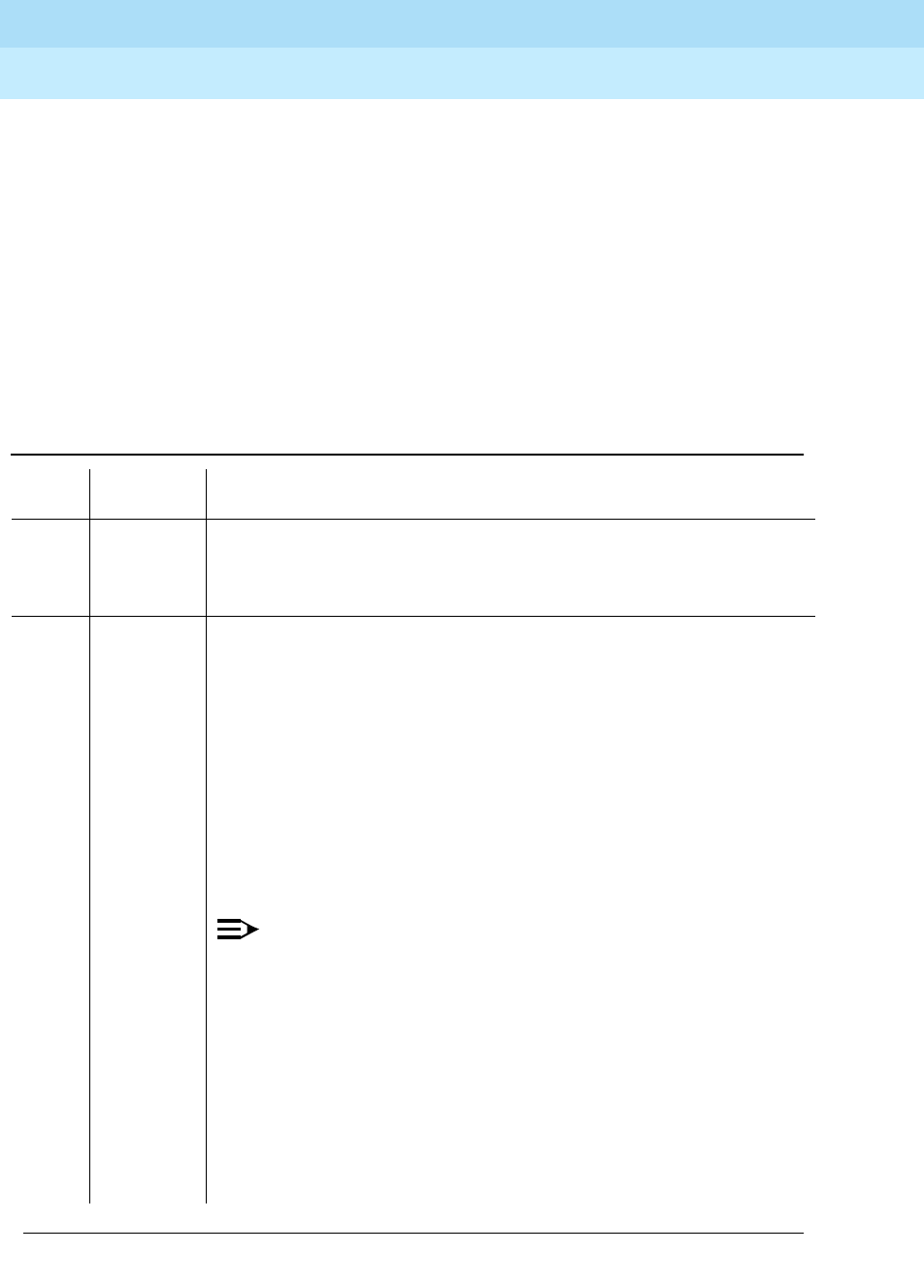
DEFINITY Enterprise Communications Server Release 6
Maintenance for R6r Volumes 1 & 2
555-230-126 Issue 2
January 1998
Maintenance Object Repair Procedures
Page 9-436DS1-BD (DS1 Interface Circuit Pack)
9
This Yellow Alarm corresponds to the yellow F2 state documented in CCITT
recommendation I.431.
Remote Multiframe Alarm: Remote Multiframe Alarm (RMA) indicates that the
remote DS1 endpoint is in a Loss of Multiframe Alarm condition while the DS1
Interface circuit pack is administered using the DMI-BOS common channel
signaling. The RMA is handled as a Yellow alarm.
Yellow F5 State Alarm: For 32-channel E1 operation with CRC4 on, the F5 fault
state is defined as a fault in the user-network interface, specifically in the
direction from the user (PBX) to the network. Refer to CCITT recommendation
I.431
Table 9-152. TEST #141 Yellow Alarm Inquiry Test
Error
Code Test Result Description/ Recommendation
ABORT Internal system error
2100 ABORT Could not allocate the necessary system resources to run this test.
1. Retry the command at 1-minute intervals a maximum of 5 times.
2000 ABORT Response to the test was not received within the allowable time period. This
may be due to hyperactivity. Error type 1538 in the error log indicates
hyperactivity. The hyperactive circuit pack is out of service and one or more
of the following symptoms may appear.
1. The DS1-BD tests (such as test 138 and test 139) are aborting with
error code 2000.
2. The tests run on the ports of this circuit pack are returning a no board
result.
3. A busyout or a release command has no affect on the test results.
4. A list config command shows that the circuit pack and the ports are
properly installed.
NOTE:
When hyperactivity occurs, the circuit pack is isolated from the
system, and all of the trunks for this circuit pack are placed into the
out of service state. The system will try to restore the circuit pack
within 15 minutes. When no faults are detected for 15 minutes, the
DS1 interface circuit pack is restored to normal operation. All of the
trunks for the DS1 interface circuit pack are then returned to the in
service state. Hyperactivity is often caused by the associated facility.
In such a case, faults (such as slips, misframes, or blue alarms)
would be entered in the error log. In addition, many hardware errors
would be logged against the associated trunk circuits. If the facility is
OK and the error occurs again after 15 minutes, replace the circuit
pack.
Continued on next page

DEFINITY Enterprise Communications Server Release 6
Maintenance for R6r Volumes 1 & 2
555-230-126 Issue 2
January 1998
Maintenance Object Repair Procedures
Page 9-437DS1-BD (DS1 Interface Circuit Pack)
9
FAIL The DS1 interface circuit pack detected a yellow alarm sent by the remote
DS1 endpoint. An out of frame condition occurred at the DS1 endpoint.
1 FAIL The DS1 Interface circuit pack detects a Remote Multiframe Alarm sent by
the remote DS1 endpoint. An out-of-frame condition occurs on the remote
DS1 endpoint.
2 FAIL The DS1 Interface circuit pack is reporting a yellow F5 State alarm. There is
a fault in the user-network interface from the user (PBX) to the network.
1. Verify that both endpoints of the DS1 link are administered using the
same signaling mode, framing mode, and line coding. Likewise, verify
that any intermediate CSUs are administered correctly.
2. If the DS1 interface circuit pack connects to a T1 facility, call the vendor
of the T1 carrier to diagnose the remote DS1 endpoint. If the DS1
interface circuit pack connects directly to a switch, call the system
technician of the remote switch to diagnose the DS1 endpoint.
3. Check the physical connectivity of the DS1 pack and of the cable.
4. Replace the local DS1 interface circuit pack, and repeat the test.
PASS No Yellow alarm nor Remote Multiframe Alarm nor F5 State Alarm is
received from the remote DS1 endpoint.
0 NO BOARD The test could not relate the internal ID to the port (no board).
This could be due to incorrect translations, no board is inserted, an
incorrect board is inserted, or an insane board is inserted.
1. Check to ensure that the board translations are correct. Use the add
ds1 UUCSS command to administer the DS1 interface if it is not
already administered.
2. If board was already administered correctly, check the error log to
determine if the board is hyperactive. If this is the case, the board is
shut down. Reseating the board will re-initialize the board.
3. If the board was found to be correctly inserted in step 1, issue the
busyout board command.
4. Issue the reset board command.
5. Issue the release busy board command.
6. Issue the test board long command.
This should re-establish the linkage between the internal ID and the port.
Table 9-152. TEST #141 Yellow Alarm Inquiry Test — Continued
Error
Code Test Result Description/ Recommendation
Continued on next page

DEFINITY Enterprise Communications Server Release 6
Maintenance for R6r Volumes 1 & 2
555-230-126 Issue 2
January 1998
Maintenance Object Repair Procedures
Page 9-438DS1-BD (DS1 Interface Circuit Pack)
9
Major Alarm Inquiry Test (#142)
The Major alarm raised by a DS1 Interface circuit pack indicates that the average
bit error rate on the DS1 facility is greater than 1/1000. The Major Alarm Inquiry
Test is used to determine that the received DS1 bit error rate is greater than
1/1000. When D4 framing mode is selected, the DS1 Interface circuit pack takes
16 seconds to recognize and report a Major alarm and 16 seconds to recognize
and report that a Major alarm condition is cleared. If ESF framing mode is
selected, the DS1 Interface circuit pack takes 10 seconds to recognize and
report a Major alarm and 10 seconds to recognize and report that a Major alarm
condition is cleared.
When the DS1 Interface circuit pack detects a Major alarm, it will send a
MAJOR-ALARM message to the maintenance software. After the maintenance
software receives a MAJOR-ALARM message, the Major Alarm Inquiry Test is
initiated to confirm the Major alarm on the DS1 Interface circuit pack. The Inquiry
Test will be run every 10 minutes until the Major alarm is cleared. The
maintenance software places all trunks on the circuit pack in the out-of-service
state if the Major alarm persists for more than 20 minutes.
When the Major alarm is cleared, the maintenance software restores all trunks on
the circuit pack to their previous service state before a Major alarm occurs.
Table 9-153. TEST #142 Major Alarm Inquiry Test
Error
Code Test
Result Description/ Recommendation
ABORT Internal system error
2100 ABORT Could not allocate the necessary system resources to run this test.
1. Retry the command at 1-minute intervals a maximum of 5 times.
Continued on next page
DEFINITY Enterprise Communications Server Release 6
Maintenance for R6r Volumes 1 & 2
555-230-126 Issue 2
January 1998
Maintenance Object Repair Procedures
Page 9-439DS1-BD (DS1 Interface Circuit Pack)
9
2000 ABORT Response to the test was not received within the allowable time period. This
may be due to hyperactivity. Error type 1538 in the error log indicates
hyperactivity. The hyperactive circuit pack is out of service and one or more of
the following symptoms may be exhibited.
1. The DS1-BD tests (such as test 138 and test 139) are aborting with error
code 2000.
2. The tests run on the ports of this circuit pack are returning a no board
result.
3. A busyout or a release command has no affect on the test results.
4. A list config command shows that the circuit pack and the ports are
properly installed.
NOTE:
When hyperactivity occurs, the circuit pack is isolated from the system,
and all of the trunks for this circuit pack are placed into the out of service
state. The system will try to restore the circuit pack within 15 minutes.
When no faults are detected for 15 minutes, the DS1 interface circuit
pack is restored to normal operation. All of the trunks for the DS1
interface circuit pack are then returned to the in service state.
Hyperactivity is often caused by the associated facility. In such a case,
faults (such as slips, misframes, or blue alarms) would be entered in the
error log. In addition, many hardware errors would be logged against
the associated trunk circuits. If the facility is OK and the error occurs
again after 15 minutes, replace the circuit pack.
FAIL The DS1 Interface circuit pack detects a Major alarm. The DS1 bit error rate is
greater than 1/1000.
1. The performance of DS1 link between DS1 Interface circuit pack and
remote DS1 endpoint is very poor. If the DS1 Interface circuit pack is
TN767, enter list measurement ds1-log UUCSS command to read the
error seconds measurement.
2. Verify that both endpoints of the DS1 link are administered using the same
signaling mode, framing mode, and line coding.
3. If the DS1 interface circuit pack connects to a T1 facility, call the vendor of
the T1 carrier to diagnose the remote DS1 endpoint. If the DS1 interface
circuit pack connects directly to a switch, call the system technician of the
remote switch to diagnose the DS1 endpoint.
4. Check the physical connectivity of the DS1 pack and of the cable.
5. Replace the local DS1 interface circuit pack, and repeat the test.
PASS No Major alarm is detected in DS1 Interface circuit pack.
Table 9-153. TEST #142 Major Alarm Inquiry Test — Continued
Error
Code Test
Result Description/ Recommendation
Continued on next page

DEFINITY Enterprise Communications Server Release 6
Maintenance for R6r Volumes 1 & 2
555-230-126 Issue 2
January 1998
Maintenance Object Repair Procedures
Page 9-440DS1-BD (DS1 Interface Circuit Pack)
9
Minor Alarm Inquiry Test (#143)
The Minor alarm raised by a DS1 Interface circuit pack indicates that the average
bit error rate on the DS1 facility is greater than 1/1,000,000, but less than 1/1000.
The Minor Alarm Inquiry Test is used to determine that the received DS1 bit error
rate is greater than 1/1,000,000 and less than 1/1000. When D4 framing mode is
selected, the DS1 Interface circuit pack takes 41 minutes to recognize and report
a Minor alarm and 41 minutes to recognize and report that a Minor alarm
condition is cleared. If ESF framing mode is selected, the DS1 Interface circuit
pack takes 10 minutes to recognize and report a Minor alarm and 10 minutes to
recognize and report that a Minor alarm condition is cleared.
When the DS1 Interface circuit pack detects a Minor alarm condition, it will send
a MINOR-ALARM message to the maintenance software. After the maintenance
software receives a MINOR-ALARM message, the Minor Alarm Inquiry Test is
initiated to confirm the Minor alarm. All trunks on the circuit pack are kept in the
in-service state after the Minor alarm is confirmed. The Minor Alarm Inquiry Test
is run every 10 minutes until the Minor alarm is cleared.
0NO
BOARD The test could not relate the internal ID to the port (no board).
This could be due to incorrect translations, no board is inserted, an incorrect
board is inserted, or an insane board is inserted.
1. Check to ensure that the board translations are correct. Use the add ds1
UUCSS command to administer the DS1 interface if it is not already
administered.
2. If board was already administered correctly, check the error log to
determine if the board is hyperactive. If this is the case, the board is shut
down. Reseating the board will re-initialize the board.
3. If the board was found to be correctly inserted in step 1, issue the busyout
board command.
4. Issue the reset board command.
5. Issue the release busy board command.
6. Issue the test board long command.
This should re-establish the link between the internal ID and the port.
Table 9-153. TEST #142 Major Alarm Inquiry Test — Continued
Error
Code Test
Result Description/ Recommendation
Continued on next page
DEFINITY Enterprise Communications Server Release 6
Maintenance for R6r Volumes 1 & 2
555-230-126 Issue 2
January 1998
Maintenance Object Repair Procedures
Page 9-441DS1-BD (DS1 Interface Circuit Pack)
9
Table 9-154. TEST #143 Minor Alarm Inquiry Test
Error
Code Test Result Description/ Recommendation
ABORT Internal system error
2100 ABORT Could not allocate the necessary system resources to run this test.
1. Retry the command at 1-minute intervals a maximum of 5 times.
2000 ABORT Response to the test was not received within the allowable time period. This
may be due to hyperactivity. Error type 1538 in the error log indicates
hyperactivity. The hyperactive circuit pack is out of service and one or more
of the following symptoms may be exhibited.
1. The DS1-BD tests (such as test 138 and test 139) are aborting with error
code 2000.
2. The tests run on the ports of this circuit pack are returning a no board
result.
3. A busyout or a release command has no affect on the test results.
4. A list config command shows that the circuit pack and the ports are
properly installed.
NOTE:
When hyperactivity occurs, the circuit pack is isolated from the
system, and all of the trunks for this circuit pack are placed into the out
of service state. The system will try to restore the circuit pack within 15
minutes. When no faults are detected for 15 minutes, the DS1 interface
circuit pack is restored to normal operation. All of the trunks for the
DS1 interface circuit pack are then returned to the in service state.
Hyperactivity is often caused by the associated facility. In such a case,
faults (such as slips, misframes, or blue alarms) would be entered in
the error log. In addition, many hardware errors would be logged
against the associated trunk circuits. If the facility is OK and the error
occurs again after 15 minutes, replace the circuit pack.
Continued on next page

DEFINITY Enterprise Communications Server Release 6
Maintenance for R6r Volumes 1 & 2
555-230-126 Issue 2
January 1998
Maintenance Object Repair Procedures
Page 9-442DS1-BD (DS1 Interface Circuit Pack)
9
Slip Alarm Inquiry Test (144)
Slips occur when transmitter and receiver are not running at precisely the same
clock rate. The DS1 Interface circuit pack can detect both positive and negative
slips on the DS1 facility. The Slip Alarm Inquiry Test is used to acquire the total
number of slips occurred on a DS1 link.
FAIL The DS1 Interface circuit pack detects a Minor alarm. The DS1 bit error rate
is greater than 1/1,000,000 and less than 1/1000.
1. The performance of DS1 link between DS1 Interface circuit pack and
remote DS1 endpoint is poor. If DS1 Interface circuit pack is TN767,
enter list measurement ds1-log UUCSS command to read the error
seconds measurement.
2. Verify that both endpoints of the DS1 link are administered using the
same signaling mode, framing mode, and line coding.
3. If the DS1 interface circuit pack connects to a T1 facility, call the vendor
of the T1 carrier to diagnose the remote DS1 endpoint. If the
DS1interface circuit pack connects directly to a switch, call the system
technician of the remote switch to diagnose the DS1 endpoint.
4. Check the physical connection of the DS1 pack and of the cable.
5. Replace the local DS1 interface circuit pack, and repeat the test.
PASS No Minor alarm is detected in DS1 Interface circuit pack.
0 NO BOARD The test could not relate the internal ID to the port (no board).
This could be due to incorrect translations, no board is inserted, an incorrect
board is inserted, or an insane board is inserted.
1. Check to ensure that the board translations are correct. Use the add ds1
UUCSS command to administer the DS1 interface if it is not already
administered.
2. If board was already administered correctly, check the error log to
determine if the board is hyperactive. If this is the case, the board is shut
down. Reseating the board will re-initialize the board.
3. If the board was found to be correctly inserted in step 1, issue the
busyout board command.
4. Issue the reset board command.
5. Issue the release busy board command.
6. Issue the test board long command.
This should re-establish the link between the internal ID and the port.
Table 9-154. TEST #143 Minor Alarm Inquiry Test — Continued
Error
Code Test Result Description/ Recommendation
Continued on next page
DEFINITY Enterprise Communications Server Release 6
Maintenance for R6r Volumes 1 & 2
555-230-126 Issue 2
January 1998
Maintenance Object Repair Procedures
Page 9-443DS1-BD (DS1 Interface Circuit Pack)
9
When the DS1 Interface circuit pack detects a slip condition, the circuit pack will
increase the on-board slip counter by 1. A SLIP-COUNT message is
spontaneously sent to the system software after the counter reaches a threshold
(for example, 88). When the maintenance software receives the SLIP-COUNT
message, the Slip Alarm Inquiry Test is initiated to query the slip counters on DS1
Interface circuit pack and total the slip counts in the maintenance software.
If the count of slips is over the threshold, a Minor alarm is raised against the DS1
Interface circuit pack. All trunks of the DS1 Interface circuit pack are still in the
in-service state. If the DS1 Interface circuit pack is used to supply the system
synchronization source, the MINOR alarm will initiate a synchronization source
switch. See “TDM-BUS” and "SYNC (Synchronization)" for details.
Table 9-155. TEST #144 Slip Alarm Inquiry Test
Error
Code Test Result Description/ Recommendation
ABORT Internal system error
2100 ABORT Could not allocate the necessary system resources to run this test.
1. Retry the command at 1-minute intervals a maximum of 5 times.
2000 ABORT Response to the test was not received within the allowable time period. This
may be due to hyperactivity. Error type 1538 in the error log indicates
hyperactivity. The hyperactive circuit pack is out of service and one or more
of the following symptoms may be exhibited.
1. The DS1-BD tests (such as test 138 and test 139) are aborting with error
code 2000.
2. The tests run on the ports of this circuit pack are returning a no board
result.
3. A busyout or a release command has no affect on the test results.
4. A list config command shows that the circuit pack and the ports are
properly installed.
NOTE:
When hyperactivity occurs, the circuit pack is isolated from the
system, and all of the trunks for this circuit pack are placed into the
out of service state. The system will try to restore the circuit pack
within 15 minutes. When no faults are detected for 15 minutes, the
DS1 interface circuit pack is restored to normal operation. All of the
trunks for the DS1 interface circuit pack are then returned to the in
service state. Hyperactivity is often caused by the associated facility.
In such a case, faults (such as slips, misframes, or blue alarms) would
be entered in the error log. In addition, many hardware errors would
be logged against the associated trunk circuits. If the facility is OK
and the error occurs again after 15 minutes, replace the circuit pack.
Continued on next page

DEFINITY Enterprise Communications Server Release 6
Maintenance for R6r Volumes 1 & 2
555-230-126 Issue 2
January 1998
Maintenance Object Repair Procedures
Page 9-444DS1-BD (DS1 Interface Circuit Pack)
9
1 to 88 FAIL The DS1 interface circuit pack detected a slip alarm. The error code equals
the number of slips detected by the DS1 interface circuit pack since the last
slip alarm inquiry test.
1. Retry the command at 1-minute intervals a maximum of 5 times.
2. If the DS1 interface circuit pack is a TN767, enter the list measurement
ds1-log UUCSS command to read the error seconds measurement.
3. Verify that both endpoints and all intermediate equipment of the DS1 link
are administered using the same signaling mode, framing mode, and
line coding.
4. If the DS1 interface circuit pack connects to a T1 facility, call the vendor
of the T1 carrier to diagnose the remote DS1 endpoint. If the DS1
interface circuit pack connects directly to a switch, call the system
technician of the remote switch to diagnose the DS1 endpoint.
5. Check the active alarm and error logs for recent alarms and errors
against the synchronization (SYNC). Follow the suggested repair
procedure for these errors.
6. Check the physical connectivity of the DS1 pack and of the cable.
7. Replace the local DS1 interface circuit pack and repeat the test.
PASS No Slip alarm is detected on the DS1 Interface circuit pack.
0 NO BOARD The test could not relate the internal ID to the port (no board).
This could be due to incorrect translations, no board is inserted, an incorrect
board is inserted, or an insane board is inserted.
1. Check to ensure that the board translations are correct. Use the add
ds1 UUCSS command to administer the DS1 interface if it is not already
administered.
2. If board was already administered correctly, check the error log to
determine if the board is hyperactive. If this is the case, the board is
shut down. Reseating the board will re-initialize the board.
3. If the board was found to be correctly inserted in step 1, issue the
busyout board command.
4. Issue the reset board command.
5. Issue the release busy board command.
6. Issue the test board long command.
This should re-establish the link between the internal ID and the port.
Table 9-155. TEST #144 Slip Alarm Inquiry Test — Continued
Error
Code Test Result Description/ Recommendation
Continued on next page

DEFINITY Enterprise Communications Server Release 6
Maintenance for R6r Volumes 1 & 2
555-230-126 Issue 2
January 1998
Maintenance Object Repair Procedures
Page 9-445DS1-BD (DS1 Interface Circuit Pack)
9
Misframe Alarm Inquiry Test (#145)
Misframe Alarm indicates that framing bits observed on a DS1 Interface circuit
pack are in error. Misframe Alarm Inquiry Test queries the total number of
misframes that occurred on a DS1 Interface circuit pack since the last inquiry.
When the DS1 Interface circuit pack detects a misframe error, it will increase its
misframe counter by 1. If the counter reaches the threshold, a
MISFRAME-COUNT message is automatically sent to the switch maintenance
software. After the maintenance software receives the MISFRAME-COUNT
message, the Misframe Alarm Inquiry Test is initiated to collect the misframe
counts from the DS1 Interface circuit pack.
When the threshold of misframes is reached, if the DS1 Interface circuit pack is
supplying the system synchronization source, then a switching synchronization
source message is sent to the TDM Bus Clock. See TDM-BUS (TDM Bus)
Maintenance documentation for details. A Minor alarm against the DS1 Interface
circuit pack is raised, but all trunks of the DS1 Interface circuit pack are still in the
in-service state.
Table 9-156. TEST #145 Misframe Alarm Inquiry Test
Error
Code Test Result Description/ Recommendation
ABORT Internal system error
2100 ABORT Could not allocate the necessary system resources to run this test.
1. Retry the command at 1-minute intervals a maximum of 5 times.
Continued on next page
DEFINITY Enterprise Communications Server Release 6
Maintenance for R6r Volumes 1 & 2
555-230-126 Issue 2
January 1998
Maintenance Object Repair Procedures
Page 9-446DS1-BD (DS1 Interface Circuit Pack)
9
2000 ABORT Response to the test was not received within the allowable time period. This
may be due to hyperactivity. Error type 1538 in the error log indicates
hyperactivity. The hyperactive circuit pack is out of service and one or more
of the following symptoms may appear.
1. The DS1-BD tests (such as test 138 and test 139) are aborting with error
code 2000.
2. The tests run on the ports of this circuit pack are returning a no board
result.
3. A busyout or a release command has no affect on the test results.
4. A list config command shows that the circuit pack and the ports are
properly installed.
NOTE:
When hyperactivity occurs, the circuit pack is isolated from the
system, and all of the trunks for this circuit pack are placed into the
out of service state. The system will try to restore the circuit pack
within 15 minutes. When no faults are detected for 15 minutes, the
DS1 interface circuit pack is restored to normal operation. All of the
trunks for the DS1 interface circuit pack are then returned to the in
service state. Hyperactivity is often caused by the associated facility.
In such a case, faults (such as slips, misframes, or blue alarms) would
be entered in the error log. In addition, many hardware errors would
be logged against the associated trunk circuits. If the facility is OK
and the error occurs again after 15 minutes, replace the circuit pack.
Table 9-156. TEST #145 Misframe Alarm Inquiry Test — Continued
Error
Code Test Result Description/ Recommendation
Continued on next page

DEFINITY Enterprise Communications Server Release 6
Maintenance for R6r Volumes 1 & 2
555-230-126 Issue 2
January 1998
Maintenance Object Repair Procedures
Page 9-447DS1-BD (DS1 Interface Circuit Pack)
9
ANY FAIL The test failed because the DS1 interface circuit pack detected errors in the
received framing bits pattern. The error code equals the number of
misframes detected by the DS1 interface circuit pack since the last misframe
alarm inquiry test. Major bit and minor bit error rate (error types 2561 and
2817) error logs often accompany misframe alarms. Clearing the cause of
these error logs may clear the misframes which are occurring.
1. Retry the command at 1-minute intervals a maximum of 5 times.
2. If the DS1 interface circuit pack is a TN767, enter the list measurement
ds1-log UUCSS command to read the error seconds measurement.
3. Verify that both endpoints and all intermediate equipment of the DS1 link
are administered using the same signaling mode, framing mode, and
line coding.
4. If the DS1 interface circuit pack connects to a T1 facility, call the vendor
of the T1 carrier to diagnose the remote DS1 endpoint. If the DS1
interface circuit pack connects directly to a switch, call the system
technician of the remote switch to diagnose the DS1 endpoint.
5. Check the active alarm and error logs for recent alarms and errors
against the synchronization (SYNC). Follow the suggested repair
procedure for these errors.
6. Check the physical connection of the DS1 pack and of the cable.
7. Replace the local DS1 interface circuit pack, and repeat the test.
PASS No Misframe alarm is detected on the DS1 Interface circuit pack.
0 NO BOARD The test could not relate the internal ID to the port (no board).
This could be due to incorrect translations, no board is inserted, an incorrect
board is inserted, or an insane board is inserted.
1. Check to ensure that the board translations are correct. Use the add
ds1 UUCSS command to administer the DS1 interface if it is not already
administered.
2. If board was already administered correctly, check the error log to
determine if the board is hyperactive. If this is the case, the board is shut
down. Reseating the board will re-initialize the board.
3. If the board was found to be correctly inserted in step 1, issue the
busyout board command.
4. Issue the reset board command.
5. Issue the release busy board command.
6. Issue the test board long command.
This should re-establish the link between the internal ID and the port.
Table 9-156. TEST #145 Misframe Alarm Inquiry Test — Continued
Error
Code Test Result Description/ Recommendation
Continued on next page

DEFINITY Enterprise Communications Server Release 6
Maintenance for R6r Volumes 1 & 2
555-230-126 Issue 2
January 1998
Maintenance Object Repair Procedures
Page 9-448DS1-BD (DS1 Interface Circuit Pack)
9
Translation Update Test (#146)
The Translation Update Test sends the circuit-pack-level information specified by
System Administration to the DS1 Interface circuit pack. Translation includes the
following data administered for a DS1 Interface circuit pack (see output of
display ds1 UUCSS command): DS1 Link Length between two DS1 endpoints,
Synchronization Source Control, All Zero Suppression, Framing Mode, Signaling
Mode, Time Slot Number of 697-Hz Tone, Time Slot Number of 700-Hz Tone, etc.
If a TN767E or later DS1 circuit pack is combined with a 120A CSU Module to
form and Integrated CSU Module, this test will also send the administration for
this Integrated CSU to the circuit pack to assure the board’s translations are
correct. The administration of the CSU Module is done using the DS1 circuit pack
administration form. Translation for the CSU Module includes the following data:
Transmit LBO, Receive ALBO, Supply CPE Loopback Jack Power?, and so forth.
Table 9-157. TEST #146 Translation Update Test
Error
Code Test Result Description/ Recommendation
ABORT Internal system error
1. Retry the command at 1-minute intervals a maximum of 5 times.
FAIL Internal system software error.
1. Enter the display ds1 UUCSS command to verify the DS1 Interface
circuit pack translation.
PASS Translation data has been downloaded to the DS1 Interface circuit pack
successfully.
Continued on next page

DEFINITY Enterprise Communications Server Release 6
Maintenance for R6r Volumes 1 & 2
555-230-126 Issue 2
January 1998
Maintenance Object Repair Procedures
Page 9-449DS1-BD (DS1 Interface Circuit Pack)
9
DS1 Board Loopback Test (#1209)
This test is destructive.
The DS1 Board Loopback (BLB) Test causes a loopback at the TN767E DS1
board edge and tests DS1 board internal circuitry.
The test is destructive and can only be initiated by a system technician
demanded
t
est ds1-loop UUCSS ds1/csu-loopback-tests command.
All trunks or ports on the DS1 Interface circuit pack must be busied out via the
system technician busyout board command before running the BLB Test.
When the BLB Test is initiated, maintenance software sends an appropriate
message to the TN767E DS1 Interface circuit pack to start the test. The board will
set up the BLB loopback, transmit a test pattern, and verify that the pattern is
received unaltered through the loopback. If the transmitted and received pattern
is different, the test fails.
When the test is complete, all trunks or ports on the TN767E DS1 Interface circuit
pack are restored to the in-service state after the release board command is
entered
0 NO BOARD The test could not relate the internal ID to the port (no board).
This could be due to incorrect translations, no board is inserted, an incorrect
board is inserted, or an insane board is inserted.
1. Check to ensure that the board translations are correct. Use the add ds1
UUCSS command to administer the DS1 interface if it is not already
administered.
2. If board was already administered correctly, check the error log to
determine if the board is hyperactive. If this is the case, the board is shut
down. Reseating the board will re-initialize the board.
3. If the board was found to be correctly inserted in step 1, issue the
busyout board command.
4. Issue the reset board command.
5. Issue the release busy board command.
6. Issue the test board long command.
This should re-establish the link between the internal ID and the port.
Table 9-157. TEST #146 Translation Update Test — Continued
Error
Code Test Result Description/ Recommendation
Continued on next page

DEFINITY Enterprise Communications Server Release 6
Maintenance for R6r Volumes 1 & 2
555-230-126 Issue 2
January 1998
Maintenance Object Repair Procedures
Page 9-450DS1-BD (DS1 Interface Circuit Pack)
9
Table 9-158. TEST #1209 DS1 Board Loopback Test
Error
Code Test
Result Description/ Recommendation
ABORT Internal system error
1. Retry
t
est ds1-loop UUCSS ds1/csu-loopback-tests at 1-minute intervals
a maximum of 5 times.
1005 ABORT DS1 Board Loopback Test cannot be executed in the current configuration. To
run this Test, the TN767E or later suffix DS1 must be administered for
24-channel operation. The "Bit Rate" field on the DS1 circuit pack administration
form must be set to "1.544" for 24-channel operation.
1015 ABORT Ports on the DS1 Interface circuit pack have not been busied out to
out-of-service.
1. Enter busyout board UUCSS to put all trunks or ports of the DS1 Interface
circuit pack into the out-of-service state.
2. Retry the command.
1039 ABORT The DS1 Interface circuit pack is providing timing for the system. Executing this
test could cause major system disruption.
If the DS1 Interface circuit pack needs to be tested, set the synchronization
reference to another DS1 Interface circuit pack or to the Tone-Clock circuit
pack via the following command sequence:
1. Issue the disable synchronization-switch command.
2. Next, issue the set synchronization UUCSS command.
3. Lastly, issue the enable synchronization-switch command.
1950 ABORT Another loopback/span test is already executing on the DS1 board or the board
is in a network requested loopback mode (Line loopback or Payload loopback).
The hardware error log will indicate whether a Customer Loopback Jack Test,
Far CSU Loopback Test, or the One-Way Span Test is executing or if the board
is in line loopback or payload loopback mode. Only one long-duration
loopback/span test can be active at a given time. Thus, if a loopback/span test
is already active, that test must be terminated via the
test ds1-loop UUCSS
end-loopback/span-test
command in order to execute this test.
ABORT Internal system error
2100 ABORT Could not allocate the necessary system resources to run this test.
1. Retry the command at 1-minute intervals for a maximum of 5 times.
Continued on next page
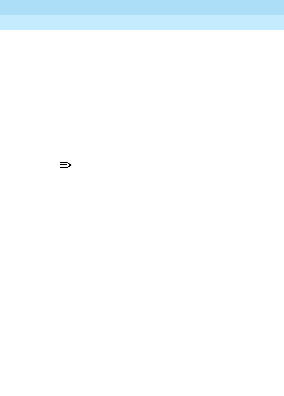
DEFINITY Enterprise Communications Server Release 6
Maintenance for R6r Volumes 1 & 2
555-230-126 Issue 2
January 1998
Maintenance Object Repair Procedures
Page 9-451DS1-BD (DS1 Interface Circuit Pack)
9
2000 ABORT Response to the test was not received within the allowable time period. This
may be due to hyperactivity. Error type 1538 in the error log indicates
hyperactivity. The hyperactive circuit pack is out of service and one or more of
the following symptoms may be exhibited.
1. The DS1-BD tests (such as test 138 and test 139) are aborting with error
code 2000.
2. The tests run on the ports of this circuit pack are returning a no board
result.
3. A busyout or a release command has no affect on the test results.
4. A list config command shows that the circuit pack and the ports are
properly installed.
NOTE:
When hyperactivity occurs, the circuit pack is isolated from the system,
and all of the trunks for this circuit pack are placed into the out of service
state. The system will try to restore the circuit pack within 15 minutes.
When no faults are detected for 15 minutes, the DS1 interface circuit
pack is restored to normal operation. All of the trunks for the DS1
interface circuit pack are then returned to the in service state.
Hyperactivity is often caused by the associated facility. In such a case,
faults (such as slips, misframes, or blue alarms) would be entered in the
error log. In addition, many hardware errors would be logged against the
associated trunk circuits. If the facility is OK and the error occurs again
after 15 minutes, replace the circuit pack.
FAIL DS1 Interface circuit pack failed the DS1 Board Loopback Test.
1. Retry test ds1-loop UUCSS ds1/csu-loopback-tests.
2. If the BLB test continues to fail, then replace the DS1 circuit pack.
PASS The BLB test executed successfully. The test pattern was transmitted and
received successfully up to the TN767E DS1 board edge.
Table 9-158. TEST #1209 DS1 Board Loopback Test — Continued
Error
Code Test
Result Description/ Recommendation
Continued on next page

DEFINITY Enterprise Communications Server Release 6
Maintenance for R6r Volumes 1 & 2
555-230-126 Issue 2
January 1998
Maintenance Object Repair Procedures
Page 9-452DS1-BD (DS1 Interface Circuit Pack)
9
CSU Equipment Loopback Test (#1210)
This test is destructive.
The CSU Equipment Loopback (ELB) Test causes a loopback at the near-edge
of the local 120A CSU Module and tests the connection from the TN767E DS1
board to the CSU Module (DS1 board edge interconnecting cable, and CSU
Module edge). This test will only be performed if the 120A CSU Module is
present, administered, and connected to a 1.544Mbps TN767E DS1 circuit pack
on the back of the port carrier.
The test is destructive and can only be initiated by a system technician
demanded test ds1-loop UUCSS ds1/csu-loopback-tests command.
All trunks or ports on the DS1 Interface circuit pack must be busied out via the
system technician busyout board command before running the ELB Test.
When the ELB Test is initiated, maintenance software sends an appropriate
message to the TN767E DS1 Interface circuit pack to start the test. The board
sets up the ELB loopback, transmit a test pattern, and verify that the pattern is
received unaltered through the loopback. If the transmitted and received pattern
is different, the test fails.
0NO
BOARD The test could not relate the internal ID to the port (no board).
This could be due to incorrect translations, no board is inserted, an incorrect
board is inserted, or an insane board is inserted.
1. Check to ensure that the board translations are correct. Use the add ds1
UUCSS command to administer the DS1 interface if it is not already
administered.
2. If board was already administered correctly, check the error log to
determine if the board is hyperactive. If this is the case, the board is shut
down. Reseating the board will re-initialize the board.
3. If the board was found to be correctly inserted in step 1, issue the busyout
board command.
4. Issue the reset board command.
5. Issue the release busy board command.
6. Issue the test board long command.
This should re-establish the link between the internal ID and the port.
Table 9-158. TEST #1209 DS1 Board Loopback Test — Continued
Error
Code Test
Result Description/ Recommendation
Continued on next page

DEFINITY Enterprise Communications Server Release 6
Maintenance for R6r Volumes 1 & 2
555-230-126 Issue 2
January 1998
Maintenance Object Repair Procedures
Page 9-453DS1-BD (DS1 Interface Circuit Pack)
9
In addition, the DS1 circuit pack hardware applies a DC current while the test is
running in order to detect any broken wires which may not be detected by the
loopback pattern.
When the test is complete, all trunks or ports on the TN767E DS1 Interface circuit
pack are restored to the in-service state after the release board command is
entered.
Table 9-159. TEST #1210 CSU Equipment Loopback Test
Error
Code Test
Result Description/ Recommendation
ABORT Internal system error
1. Retry
t
est ds1-loop UUCSS ds1/csu-loopback-tests at 1-minute intervals
a maximum of 5 times.
1005 ABORT CSU Equipment Loopback Test cannot be executed in the current
configuration. To run this test, the
Near-End CSU Type
field on the DS1 circuit
pack administration form must be set to
integrated
and the "Bit Rate" field must
be set to "1.544" (24-channel operation).
1. Use the change ds1 UUCSS command to set the
Near-End CSU Type
field
on the DS1 circuit pack administration form to
integrated
, and/or change
the "Bit Rate" field to "1.544" if the board is to be used in the 24-channel
configuration.
2. Retry test ds1-loop UUCSS ds1/csu-loopback-tests.
1015 ABORT Ports on the DS1 Interface circuit pack have not been busied out to
out-of-service.
1. Enter the busyout board UUCSS command to put all trunks or ports of the
DS1 Interface circuit pack into the out-of-service state.
2. Retry the command.
1039 ABORT The DS1 Interface circuit pack is providing timing for the system. Executing this
test could cause major system disruption.
If the DS1 Interface circuit pack needs to be tested, set the synchronization
reference to another DS1 Interface circuit pack or to the Tone-Clock circuit pack
via the following command sequence:
1. Issue the disable synchronization-switch command.
2. Next, issue the set synchronization UUCSS command.
3. Lastly, issue the enable synchronization-switch command.
Continued on next page
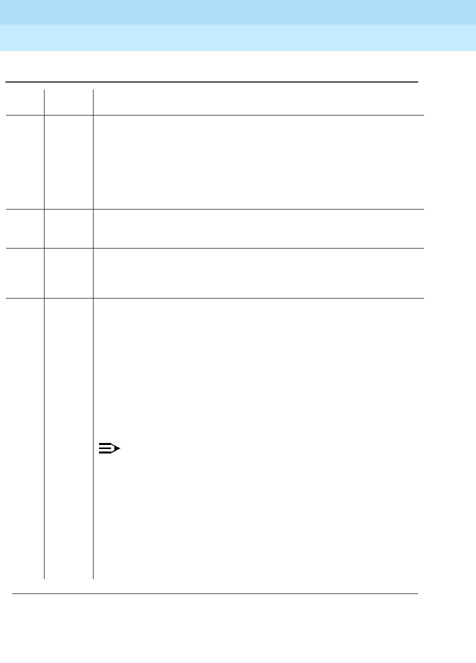
DEFINITY Enterprise Communications Server Release 6
Maintenance for R6r Volumes 1 & 2
555-230-126 Issue 2
January 1998
Maintenance Object Repair Procedures
Page 9-454DS1-BD (DS1 Interface Circuit Pack)
9
1950 ABORT Another loopback/span test is already executing on the DS1 board or the board
is in a network requested loopback mode (Line loopback or Payload loopback).
The hardware error log will indicate whether a Customer Loopback Jack Test,
Far CSU Loopback Test, or the One-Way Span Test is executing or if the board
is in line loopback or payload loopback mode. Only one long-duration
loopback/span test can be active at a given time. Thus, if a loopback/span test
is already active, that test must be terminated via the test ds1-loop UUCSS
end-loopback/span-test command in order to execute this test.
1951 ABORT The CSU Equipment Loopback Test could not be executed because the 120A
CSU Module was not physically installed. Physically connect the 120A CSU
Module to the TN767E board on the back of the port carrier.
ABORT Internal system error
2100 ABORT Could not allocate the necessary system resources to run this test.
1. Retry the command at 1-minute intervals a maximum of 5 times.
2000 ABORT Response to the test was not received within the allowable time period. This
may be due to hyperactivity. Error type 1538 in the error log indicates
hyperactivity. The hyperactive circuit pack is out of service and one or more of
the following symptoms may be exhibited.
1. The DS1-BD tests (such as test 138 and test 139) are aborting with error
code 2000.
2. The tests run on the ports of this circuit pack are returning a no board result.
3. A busyout or a release command has no affect on the test results.
4. A list config command shows that the circuit pack and the ports are
properly installed.
NOTE:
When hyperactivity occurs, the circuit pack is isolated from the system,
and all of the trunks for this circuit pack are placed into the out of service
state. The system will try to restore the circuit pack within 15 minutes.
When no faults are detected for 15 minutes, the DS1 interface circuit
pack is restored to normal operation. All of the trunks for the DS1
interface circuit pack are then returned to the in service state.
Hyperactivity is often caused by the associated facility. In such a case,
faults (such as slips, misframes, or blue alarms) would be entered in the
error log. In addition, many hardware errors would be logged against the
associated trunk circuits. If the facility is OK and the error occurs again
after 15 minutes, replace the circuit pack.
Table 9-159. TEST #1210 CSU Equipment Loopback Test — Continued
Error
Code Test
Result Description/ Recommendation
Continued on next page

DEFINITY Enterprise Communications Server Release 6
Maintenance for R6r Volumes 1 & 2
555-230-126 Issue 2
January 1998
Maintenance Object Repair Procedures
Page 9-455DS1-BD (DS1 Interface Circuit Pack)
9
CSU Repeater Loopback Test (#1211)
This test is destructive.
The CSU Repeater Loopback (RLB) Test causes a loopback at the far-edge of
the local 120A CSU Module and tests the connection from the TN767E DS1
board to and including the CSU Module circuitry. This test will only be performed
FAIL DS1 Interface circuit pack failed the CSU Equipment Loopback Test.
1. Retry test ds1-loop UUCSS ds1/csu-loopback-tests.
2. If the ELB test continues to fail, then either the TN767E board, the CSU
Module, or the I/O cable between the backplane and the CSU module (or
any combination thereof) has failed. Attempt to isolate the problem to one of
these areas. Replace the CSU Module and running test ds1-loop UUCSS
ds1/csu-loopback-tests again.
3. If the ELB test continues to fail, then replace the TN767E board and run test
ds1-loop UUCSS ds1/csu-loopback-tests again.
4. If the ELB test continues to fail, the problem could be in the I/O cable
between the backplane and the CSU module.
PASS The ELB test executed successfully. The test pattern was transmitted and
received successfully over the connection from the TN767E DS1 board to the
near-edge of the 120A1 CSU Module.
0NO
BOARD The test could not relate the internal ID to the port (no board).
This could be due to incorrect translations, no board is inserted, an incorrect
board is inserted, or an insane board is inserted.
1. Check to ensure that the board translations are correct. Use the add ds1
UUCSS command to administer the DS1 interface if it is not already
administered.
2. If board was already administered correctly, check the error log to
determine if the board is hyperactive. If this is the case, the board is shut
down. Reseating the board will re-initialize the board.
3. If the board was found to be correctly inserted in step 1, issue the busyout
board command.
4. Issue the reset board command.
5. Issue the release busy board command.
6. Issue the test board long command.
This should re-establish the link between the internal ID and the port.
Table 9-159. TEST #1210 CSU Equipment Loopback Test — Continued
Error
Code Test
Result Description/ Recommendation
Continued on next page

DEFINITY Enterprise Communications Server Release 6
Maintenance for R6r Volumes 1 & 2
555-230-126 Issue 2
January 1998
Maintenance Object Repair Procedures
Page 9-456DS1-BD (DS1 Interface Circuit Pack)
9
if the 120A CSU Module is present, administered, and connected to a 1.544
Mbps TN767E DS1 circuit pack on the back of the port carrier.
The test is destructive and can only be initiated by a system technician
demanded test ds1-loop UUCSS ds1/csu-loopback-tests command.
All trunks or ports on the DS1 Interface circuit pack must be busied out via the
system technician busyout board command before running the RLB Test.
When the RLB Test is initiated, maintenance software sends an appropriate
message to the TN767E DS1 Interface circuit pack to start the test. The board will
set up the RLB loopback, transmit a test pattern, and verify that the pattern is
received unaltered through the loopback. If the transmitted and received pattern
is different, the test fails.
In addition, the DS1 circuit pack hardware applies a DC current while the test is
running in order to detect any broken wires which may not be detected by the
loopback pattern.
When the test is complete, all trunks or ports on the TN767E DS1 Interface circuit
pack are restored to the in-service state after the release board command is
entered
Table 9-160. TEST #1211 CSU Repeater Loopback Test
Error
Code Test
Result Description/ Recommendation
ABORT Internal system error
1. Retry test ds1-loop UUCSS ds1/csu-loopback-tests at 1-minute
intervals a maximum of 5 times.
1005 ABORT CSU Repeater Loopback Test cannot be executed in the current
configuration. To run this test, the
Near-End CSU Type
field on the DS1circuit
pack administration form must be set to
integrated
and the "Bit Rate" field on
the DS1 circuit pack administration form must be set to "1.544" (24-channel
configuration).
1. Use the change ds1 UUCSS command to set the
Near-End CSU Type
field on the DS1 circuit pack administration form to
integrated
, and/or
change the "Bit Rate" field to "1.544" if the board is to be used in
24-channel configuration.
2. Retry test ds1-loop UUCSS ds1/csu-loopback-tests.
Continued on next page

DEFINITY Enterprise Communications Server Release 6
Maintenance for R6r Volumes 1 & 2
555-230-126 Issue 2
January 1998
Maintenance Object Repair Procedures
Page 9-457DS1-BD (DS1 Interface Circuit Pack)
9
1015 ABORT Ports on the DS1 Interface circuit pack have not been busied out to
out-of-service.
1. Enter the busyout board UUCSS command to put all trunks or ports of
the DS1 Interface circuit pack into the out-of-service state.
2. Retry the command.
1039 ABORT The DS1 Interface circuit pack is providing timing for the system. Executing
this test could cause major system disruption.
If the DS1 Interface circuit pack needs to be tested, set the synchronization
reference to another DS1 Interface circuit pack or to the Tone-Clock circuit
pack via the following command sequence:
1. Issue the disable synchronization-switch command.
2. Next, issue the set synchronization UUCSS command.
3. Lastly, issue the enable synchronization-switch command.
1950 ABORT Another loopback/span test is already executing on the DS1 board or the
board is in a network requested loopback mode (Line loopback or Payload
loopback). The hardware error log indicates whether a Customer Loopback
Jack Test, Far CSU Loopback Test, or the One-Way Span Test is executing or
if the board is in line loopback or payload loopback mode. Only one
long-duration loopback/span test can be active at a given time. Thus, if a
loopback/span test is already active, that test must be terminated via the test
ds1-loop UUCSS end-loopback/span-test command in order to execute this
test.
1951 ABORT The CSU Repeater Loopback Test could not be executed because the 120A
CSU Module was not physically installed. Physically connect the 120A1 CSU
Module to the TN767E board on the back of the port carrier.
Table 9-160. TEST #1211 CSU Repeater Loopback Test — Continued
Error
Code Test
Result Description/ Recommendation
Continued on next page
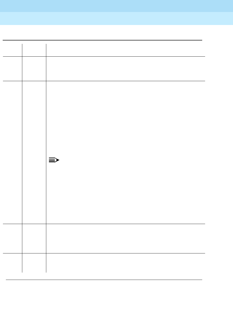
DEFINITY Enterprise Communications Server Release 6
Maintenance for R6r Volumes 1 & 2
555-230-126 Issue 2
January 1998
Maintenance Object Repair Procedures
Page 9-458DS1-BD (DS1 Interface Circuit Pack)
9
ABORT Internal system error
2100 ABORT Could not allocate the necessary system resources to run this test.
1. Retry the command at 1-minute intervals a maximum of 5 times.
2000 ABORT Response to the test was not received within the allowable time period. This
may be due to hyperactivity. Error type 1538 in the error log indicates
hyperactivity. The hyperactive circuit pack is out of service and one or more of
the following symptoms may be exhibited.
1. The DS1-BD tests (such as test 138 and test 139) are aborting with error
code 2000.
2. The tests run on the ports of this circuit pack are returning a no board
result.
3. A busyout or a release command has no affect on the test results.
4. A list config command shows that the circuit pack and the ports are
properly installed.
NOTE:
When hyperactivity occurs, the circuit pack is isolated from the system,
and all of the trunks for this circuit pack are placed into the out of
service state. The system will try to restore the circuit pack within 15
minutes. When no faults are detected for 15 minutes, the DS1 interface
circuit pack is restored to normal operation. All of the trunks for the DS1
interface circuit pack are then returned to the in service state.
Hyperactivity is often caused by the associated facility. In such a case,
faults (such as slips, misframes, or blue alarms) would be entered in the
error log. In addition, many hardware errors would be logged against
the associated trunk circuits. If the facility is OK and the error occurs
again after 15 minutes, replace the circuit pack.
FAIL DS1 Interface circuit pack failed the CSU Repeater Loopback Test.
1. Retry test ds1-loop UUCSS ds1/csu-loopback-tests.
2. If the RLB test continues to fail, and the CSU Equipment Loopback Test
(#1210) passed, then replace the CSU Module.
PASS The RLB test executed successfully. The test pattern was transmitted and
received successfully over the connection from the TN767E DS1 board to the
far-edge of the 120A1 CSU Module.
Table 9-160. TEST #1211 CSU Repeater Loopback Test — Continued
Error
Code Test
Result Description/ Recommendation
Continued on next page

DEFINITY Enterprise Communications Server Release 6
Maintenance for R6r Volumes 1 & 2
555-230-126 Issue 2
January 1998
Maintenance Object Repair Procedures
Page 9-459DS1-BD (DS1 Interface Circuit Pack)
9
CPE Loopback Jack Test (#1212)
This test is destructive.
The CPE Loopback Jack (CLJ-LB) Test causes a loopback at the CPE Loopback
Jack and tests the building wiring connection between the TN767E DS1 board
and the CPE Loopback Jack.
The test is highly destructive and can only be initiated by a system technician
demanded test ds1-loop UUCSS cpe-loopback-jack-test-begin
[number-of-bits bit-pattern] command. The System technician has the choice
of entering a loopback activation code on the command line or using the default
code (0x47F).
All trunks or ports on the DS1 Interface circuit pack must be busied out via the
system technician busyout board command before running the CPE Loopback
Jack Test.
The CPE Loopback Jack Test has the TN767E DS1 Interface circuit pack transmit
a loopback activation code to the CPE Loopback Jack, waits up to 10 seconds
for return of the code to verify the loopback has been established, transmits a
framed 3-in-24 test pattern, begins counting bit errors in the received test
0NO
BOARD The test could not relate the internal ID to the port (no board).
This could be due to incorrect translations, no board is inserted, an incorrect
board is inserted, or an insane board is inserted.
1. Check to ensure that the board translations are correct. Use the add ds1
UUCSS command to administer the DS1 interface if it is not already
administered.
2. If board was already administered correctly, check the error log to
determine if the board is hyperactive. If this is the case, the board is shut
down. Reseating the board will re-initialize the board.
3. If the board was found to be correctly inserted in step 1, issue the
busyout board command.
4. Issue the reset board command.
5. Issue the release busy board command.
6. Issue the test board long command.
This should re-establish the link between the internal ID and the port.
Table 9-160. TEST #1211 CSU Repeater Loopback Test — Continued
Error
Code Test
Result Description/ Recommendation
Continued on next page

DEFINITY Enterprise Communications Server Release 6
Maintenance for R6r Volumes 1 & 2
555-230-126 Issue 2
January 1998
Maintenance Object Repair Procedures
Page 9-460DS1-BD (DS1 Interface Circuit Pack)
9
pattern, and returns a PASS result to indicate that the pattern was successfully
sent. If the loopback is not established within the 10 seconds, the test returns
FAIL.
The status of the CPE Loopback Jack test will be available in the hardware error
log via error type 3900. Several distinct aux values will be used to give the user
information of the status of the test.
The
list measurements ds1 summary
command will display the length of time the
test has been running (
Test Duration
field) and number of bit errors detected
(
Loopback/Span Test Bit-Error Count
field). If the test pattern is being passed
through the loopback cleanly, the number of bit errors should be very low. The
command will also display the type of loopback/span test executing (
Test
field),
the type of pattern generated for the loopback/span test (
Pattern
field), and
whether the pattern (
3-in-24 Pattern
) is synchronized (
Synchronized Field
).
To terminate the test, enter test ds1-loop UUCSS end-loopback/span-test
command or the release board. Using the release board command restores all
trunks or ports on the TN767E DS1 Interface circuit pack to the in-service state.
Table 9-161. TEST #1212 CPE Loopback Jack Test
Error
Code Test
Result Description/ Recommendation
ABORT Internal system error
1. Retry test ds1-loop UUCSS cpe-loopback-jack-test-begin at 1-minute
intervals a maximum of 5 times.
1005 ABORT CPE Loopback Jack Test cannot be executed in the current configuration. To
run this Test, the TN767E or later suffix DS1 must be administered for
24-channel operation. The "Bit Rate" field on the DS1 circuit pack administration
form must be set to "1.544" for 24-channel operation.
1015 ABORT Ports on the DS1 Interface circuit pack have not been busied out to
out-of-service.
1. Enter the busyout board UUCSS command to put all trunks or ports of the
DS1 Interface circuit pack into the out-of-service state.
2. Retry the command.
Continued on next page

DEFINITY Enterprise Communications Server Release 6
Maintenance for R6r Volumes 1 & 2
555-230-126 Issue 2
January 1998
Maintenance Object Repair Procedures
Page 9-461DS1-BD (DS1 Interface Circuit Pack)
9
1039 ABORT The DS1 Interface circuit pack is providing timing for the system. Executing this
test could cause major system disruption.
If the DS1 Interface circuit pack needs to be tested, set the synchronization
reference to another DS1 Interface circuit pack or to the Tone-Clock circuit
pack via the following command sequence:
1. Issue the disable synchronization-switch command.
2. Next, issue the set synchronization UUCSS command.
3. Lastly, issue the enable synchronization-switch command.
1950 ABORT Another loopback/span test is already executing on the DS1 board or the board
is in a network requested loopback mode (Line loopback or Payload loopback).
The hardware error log will indicate whether a Customer Loopback Jack Test,
Far CSU Loopback Test, or the One-Way Span Test is executing or if the board
is in line loopback or payload loopback mode. Only one long-duration
loopback/span test can be active at a given time. Thus, if a loopback/span test
is already active, that test must be terminated via the
test ds1-loop UUCSS
end-loopback/span-test
command in order to execute this test.
ABORT Internal system error
2100 ABORT Could not allocate the necessary system resources to run this test.
1. Retry the command at 1-minute intervals for a maximum of 5 times.
Table 9-161. TEST #1212 CPE Loopback Jack Test — Continued
Error
Code Test
Result Description/ Recommendation
Continued on next page
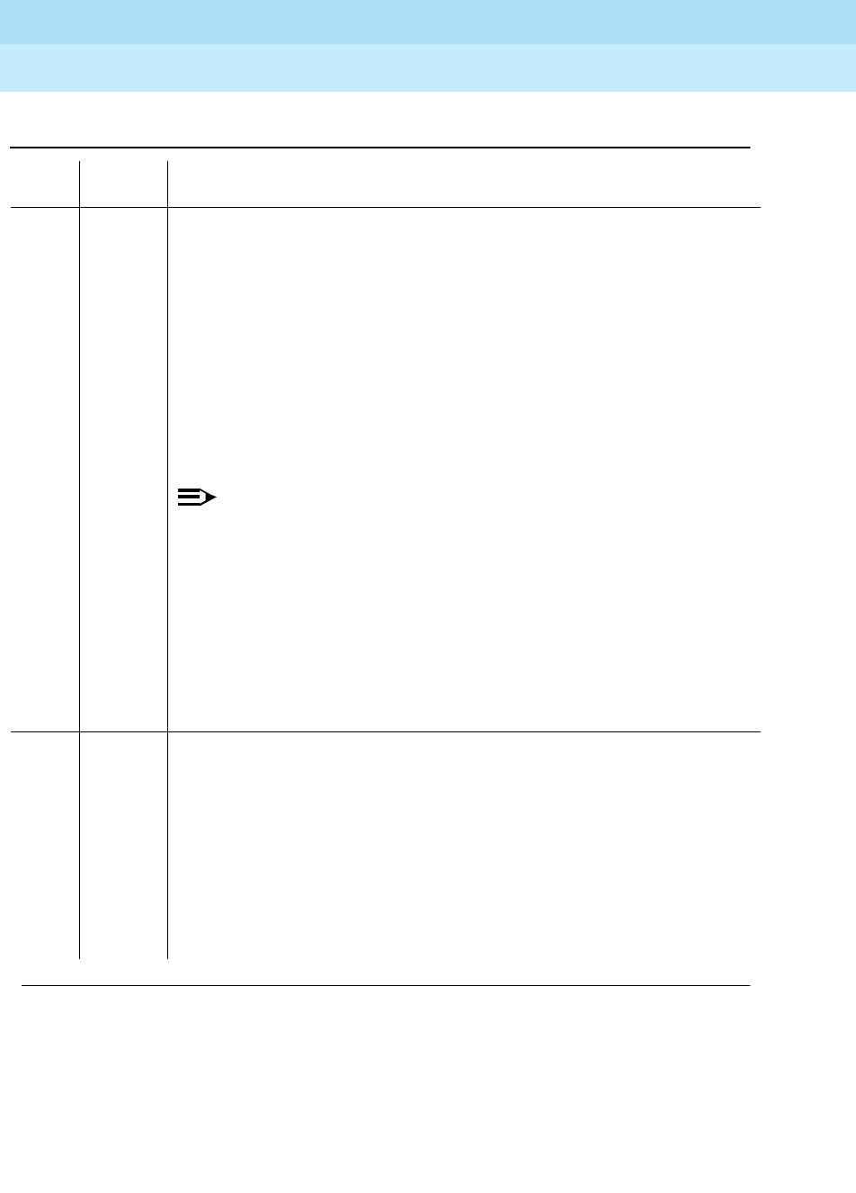
DEFINITY Enterprise Communications Server Release 6
Maintenance for R6r Volumes 1 & 2
555-230-126 Issue 2
January 1998
Maintenance Object Repair Procedures
Page 9-462DS1-BD (DS1 Interface Circuit Pack)
9
2000 ABORT Response to the test was not received within the allowable time period. This
may be due to hyperactivity. Error type 1538 in the error log indicates
hyperactivity. The hyperactive circuit pack is out of service and one or more of
the following symptoms may be exhibited.
1. The DS1-BD tests (such as test 138 and test 139) are aborting with error
code 2000.
2. The tests run on the ports of this circuit pack are returning a no board
result.
3. A busyout or a release command has no affect on the test results.
4. A list config command shows that the circuit pack and the ports are
properly installed.
NOTE:
When hyperactivity occurs, the circuit pack is isolated from the system,
and all of the trunks for this circuit pack are placed into the out of service
state. The system will try to restore the circuit pack within 15 minutes.
When no faults are detected for 15 minutes, the DS1 interface circuit
pack is restored to normal operation. All of the trunks for the DS1
interface circuit pack are then returned to the in service state.
Hyperactivity is often caused by the associated facility. In such a case,
faults (such as slips, misframes, or blue alarms) would be entered in the
error log. In addition, many hardware errors would be logged against the
associated trunk circuits. If the facility is OK and the error occurs again
after 15 minutes, replace the circuit pack.
2 FAIL The CLJ-LB test failed because it was not set up properly. The DS1 interface
pack could not successfully put the CPE loopback jack into loopback mode.
1. Rerun the test ds1-loop UUCSS cpe-loopback-jack-test-begin
command.
2. If the test continues to fail, the problem could be with the TN767E board,
the CPE loopback jack equipment, or somewhere between. Run the test
ds1-loop UUCSS ds1/csu-loopback-tests command to determine if the
loopback tests that are closer to the TN767E board are successful. If any of
these tests fail, follow the maintenance strategy that is associated with the
test that fails.
Table 9-161. TEST #1212 CPE Loopback Jack Test — Continued
Error
Code Test
Result Description/ Recommendation
Continued on next page

DEFINITY Enterprise Communications Server Release 6
Maintenance for R6r Volumes 1 & 2
555-230-126 Issue 2
January 1998
Maintenance Object Repair Procedures
Page 9-463DS1-BD (DS1 Interface Circuit Pack)
9
Far CSU Loopback Test (#1213)
This test is destructive.
The Far CSU Loopback (R-LLB) Test causes a loopback at the far-end CSU and
tests all circuitry and facilities from the local TN767E DS1 board to the far-end
CSU.
3 FAIL The CPE Loopback Jack Test was not set up properly. The framed 3-in-24 test
pattern, generated by the DS1 Interface circuit pack and looped back through
the CPE Loopback Jack, could not be detected properly by the DS1 circuit
pack.
1. Retry
t
est ds1-loop UUCSS cpe-loopback-jack-test-begin.
2. If the CPE Loopback test continues to fail, the problem could be with the
TN767E board, the CPE Loopback Jack equipment, or somewhere in
between. Run test ds1-loop UUCSS ds1/csu-loopback-tests to see if the
loopback tests closer to the TN767E board are successful. If any of those
loopback tests fail, follow the maintenance strategy associated with those
loopbacks.
PASS The CPE Loopback Jack test has successfully began executing. The test will
continue to run until the system technician enters the
t
est ds1-loop UUCSS
end-loopback/span-test command or the release board UUCSS command.
0NO
BOARD The test could not relate the internal ID to the port (no board).
This could be due to incorrect translations, no board is inserted, an incorrect
board is inserted, or an insane board is inserted.
1. Check to ensure that the board translations are correct. Use the add ds1
UUCSS command to administer the DS1 interface if it is not already
administered.
2. If board was already administered correctly, check the error log to
determine if the board is hyperactive. If this is the case, the board is shut
down. Reseating the board will re-initialize the board.
3. If the board was found to be correctly inserted in step 1, issue the busyout
board command.
4. Issue the reset board command.
5. Issue the release busy board command.
6. Issue the test board long command.
This should re-establish the link between the internal ID and the port.
Table 9-161. TEST #1212 CPE Loopback Jack Test — Continued
Error
Code Test
Result Description/ Recommendation
Continued on next page

DEFINITY Enterprise Communications Server Release 6
Maintenance for R6r Volumes 1 & 2
555-230-126 Issue 2
January 1998
Maintenance Object Repair Procedures
Page 9-464DS1-BD (DS1 Interface Circuit Pack)
9
The test is destructive and can only be initiated by a system technician
demanded test ds1-loop UUCSS far-csu-loopback-test-begin command.
All trunks or ports on the DS1 Interface circuit pack must be busied out via the
system technician busyout board command before running the Far CSU
Loopback Test.
If the far-end CSU is not a 120A CSU Module, and the DS1 is administered for
ami-zcs line coding, one’s density protection must be disabled on the CSU
during the test due to the large number of zero’s in the 3-in-24 test pattern.
The Far CSU Loopback Test has the TN767E DS1 Interface circuit pack transmit
a loopback activation code to the remote CSU, waits up to 15 seconds for return
of the code to verify the loopback has been established, transmits a framed
3-in-24 test pattern, begins counting bit errors in the received test pattern, and
returns a PASS result. If the loopback is not established within the 15 seconds,
the test fails.
The status of the Far CSU Loopback test will be available in the hardware error
log via error type 3901. Several distinct aux values will be used to give the user
information of the status of the test.
The
list measurements ds1 summary
command will display the length of time the
test has been running (
Test Duration
field) and number of bit errors detected
(
Loopback/Span Test Bit-Error Count
field). If the test pattern is being passed
through the loopback cleanly, the number of bit errors should be very low. The
command will also display the type of loopback/span test executing (
Test
field),
the type of pattern generated for the loopback/span test (
Pattern
field), and
whether the pattern (
i.e.
3-in-24 Pattern
) is synchronized (
Synchronized
field).
To terminate the test, enter
t
est ds1-loop UUCSS end-loopback/span-test or
the release board command. Using the release board command will restore all
trunks or ports on the TN767E DS1 Interface circuit pack to the in-service state.
Table 9-162. TEST #1213 Far CSU Loopback Test
Error
Code Test
Result Description/ Recommendation
ABORT Internal system error
1. Retry
t
est ds1-loop UUCSS far-csu-loopback-test-begin at 1-minute
intervals a maximum of 5 times.
1005 ABORT Far CSU Loopback Test cannot be executed in the current configuration. To run
this, the TN767E or later suffix DS1 must be administered for 24-channel
operation. The "Bit Rate" field on the DS1 circuit pack administration form must
be set to "1.544" for 24-channel operation.
Continued on next page

DEFINITY Enterprise Communications Server Release 6
Maintenance for R6r Volumes 1 & 2
555-230-126 Issue 2
January 1998
Maintenance Object Repair Procedures
Page 9-465DS1-BD (DS1 Interface Circuit Pack)
9
1015 ABORT Ports on the DS1 Interface circuit pack have not been busied out to
out-of-service.
1. Enter the busyout board UUCSS command to put all trunks or ports of the
DS1 Interface circuit pack into the out-of-service state.
2. Retry the command.
1039 ABORT The DS1 Interface circuit pack is providing timing for the system. Executing this
test could cause major system disruption.
If the DS1 Interface circuit pack needs to be tested, set the synchronization
reference to another DS1 Interface circuit pack or to the Tone-Clock circuit
pack via the following command sequence:
1. Issue the disable synchronization-switch command.
2. Next, issue the set synchronization UUCSS command.
3. Lastly, issue the enable synchronization-switch command.
1950 ABORT Another loopback/span test is already executing on the DS1 board or the board
is in a network requested loopback mode (Line loopback or Payload loopback).
The hardware error log will indicate whether a Customer Loopback Jack Test,
Far CSU Loopback Test, or the One-Way Span Test is executing or if the board
is in line loopback or payload loopback mode. Only one long-duration
loopback/span test can be active at a given time. Thus, if a loopback/span test
is already active, that test must be terminated via the
test ds1-loop UUCSS
end-loopback/span-test
command in order to execute this test.
ABORT Internal system error
2100 ABORT Could not allocate the necessary system resources to run this test.
1. Retry the command at 1-minute intervals for a maximum of 5 times.
Table 9-162. TEST #1213 Far CSU Loopback Test — Continued
Error
Code Test
Result Description/ Recommendation
Continued on next page
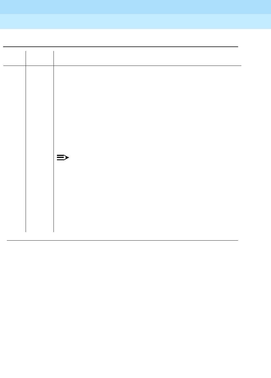
DEFINITY Enterprise Communications Server Release 6
Maintenance for R6r Volumes 1 & 2
555-230-126 Issue 2
January 1998
Maintenance Object Repair Procedures
Page 9-466DS1-BD (DS1 Interface Circuit Pack)
9
2000 ABORT Response to the test was not received within the allowable time period. This
may be due to hyperactivity. Error type 1538 in the error log indicates
hyperactivity. The hyperactive circuit pack is out of service and one or more of
the following symptoms may be exhibited.
1. The DS1-BD tests (such as test 138 and test 139) are aborting with error
code 2000.
2. The tests run on the ports of this circuit pack are returning a no board
result.
3. A busyout or a release command has no affect on the test results.
4. A list config command shows that the circuit pack and the ports are
properly installed.
NOTE:
When hyperactivity occurs, the circuit pack is isolated from the system,
and all of the trunks for this circuit pack are placed into the out of service
state. The system will try to restore the circuit pack within 15 minutes.
When no faults are detected for 15 minutes, the DS1 interface circuit
pack is restored to normal operation. All of the trunks for the DS1
interface circuit pack are then returned to the in service state.
Hyperactivity is often caused by the associated facility. In such a case,
faults (such as slips, misframes, or blue alarms) would be entered in the
error log. In addition, many hardware errors would be logged against the
associated trunk circuits. If the facility is OK and the error occurs again
after 15 minutes, replace the circuit pack.
Table 9-162. TEST #1213 Far CSU Loopback Test — Continued
Error
Code Test
Result Description/ Recommendation
Continued on next page

DEFINITY Enterprise Communications Server Release 6
Maintenance for R6r Volumes 1 & 2
555-230-126 Issue 2
January 1998
Maintenance Object Repair Procedures
Page 9-467DS1-BD (DS1 Interface Circuit Pack)
9
One-Way Span Test (#1214)
This test is destructive.
2 FAIL The far CSU Loopback Test was not set up properly. The DS1 Interface circuit
pack could not put the far-end CSU into loopback mode.
3 FAIL The far CSU Loopback Test was not set up properly. The framed 3-in-24 test
pattern, generated by the DS1 Interface circuit pack and looped back through
the far-end CSU, could not be detected by the DS1 circuit pack.
1. Retry
t
est ds1-loop UUCSS far-csu-loopback-test-begin.
2. If the Far CSU Loopback test continues to fail with this error code, the
problem could be with the TN767E board, the far-end CSU equipment, or
somewhere in between. Run test ds1-loop UUCSS
cpe-loopback-jack-test-begin to see if the CPE Loopback Jack test which
is closer to the TN767E board is successful. (If a CPE Loopback Jack
device is not being used, then run test ds1-loop UUCSS
ds1/csu-loopback-tests to see if these even closer loopback tests
succeed). If the closer loopback test fails, follow the maintenance strategy
associated with that loopback
PASS The Far CSU Loopback test has successfully began executing. The test will
continue to run until the system technician enters test ds1-loop UUCSS
end-loopback/span-test or the release board UUCSS.
0NO
BOARD The test could not relate the internal ID to the port (no board).
This could be due to incorrect translations, no board is inserted, an incorrect
board is inserted, or an insane board is inserted.
1. Check to ensure that the board translations are correct. Use the add ds1
UUCSS command to administer the DS1 interface if it is not already
administered.
2. If board was already administered correctly, check the error log to
determine if the board is hyperactive. If this is the case, the board is shut
down. Reseating the board will re-initialize the board.
3. If the board was found to be correctly inserted in step 1, issue the busyout
board command.
4. Issue the reset board command.
5. Issue the release busy board command.
6. Issue the test board long command.
This should re-establish the link between the internal ID and the port.
Table 9-162. TEST #1213 Far CSU Loopback Test — Continued
Error
Code Test
Result Description/ Recommendation
Continued on next page

DEFINITY Enterprise Communications Server Release 6
Maintenance for R6r Volumes 1 & 2
555-230-126 Issue 2
January 1998
Maintenance Object Repair Procedures
Page 9-468DS1-BD (DS1 Interface Circuit Pack)
9
The One-Way Span Test allows one-way span testing to and from remote test
equipment or another DEFINITY communications system. This will test all
circuitry and facilities from the local TN767E DS1 board to the remote test
equipment or other DEFINITY communications system.
The test is destructive and can only be initiated by a system technician
demanded
test ds1-loop UUCSS one-way-span-test-begin
command.
All trunks or ports on the DS1 Interface circuit pack must be busied out via the
system technician busyout board command before running the One-Way Span
Test.
The One-Way Span Test has the TN767E DS1 Interface circuit pack transmit a
framed 3-in-24 test pattern and attempt to receive and verify the pattern. If the
TN767E board receives a framed 3-in-24 test pattern sent from another DEFINITY
G3V3 or test equipment at the far-end of the DS1, it will begin counting bit errors
within the received pattern.
The status of the One-Way Span test will be available in the hardware error log
via error type 3902. Several distinct aux values will be used to give the user
information of the status of the test.
The
list measurements ds1 summary
command will display the length of time the
test has been running (
Test Duration
field) and number of bit errors detected
(
Loopback/Span Test Bit-Error Count
field). If the test pattern is being sent
cleanly over the span from the far-end, the number of bit errors should be very
low. The
Test Duration
field will show
0
until the test pattern is received from the
far-end. Upon receiving the test pattern, the board will begin calculating the test
duration and number of bit errors. The command will also display the type of
loopback/span test executing (
Test
field), the type of pattern generated for the
loopback/span test (
Pattern
field), and whether the pattern (
i.e.
3-in-24 Pattern
) is
synchronized (
Synchronized
field).
To terminate the test, enter the
test ds1-loop UUCSS end-loopback/span-test
command or the release board command. Using the release board command
will restore all trunks or ports on the TN767E DS1 Interface circuit pack to the
in-service state.
Table 9-163. TEST #1214 One-Way Span Test
Error
Code Test
Result Description/ Recommendation
ABORT Internal system error
1. Retry the test ds1-loop UUCSS one-way-span-test-begin command at
1-minute intervals a maximum of 5 times.
Continued on next page

DEFINITY Enterprise Communications Server Release 6
Maintenance for R6r Volumes 1 & 2
555-230-126 Issue 2
January 1998
Maintenance Object Repair Procedures
Page 9-469DS1-BD (DS1 Interface Circuit Pack)
9
1005 ABORT One-Way Span Test cannot be executed in the current configuration. To run
this, the TN767E or later suffix DS1 must be administered for 24-channel
operation. The "Bit Rate" field on the DS1 circuit pack administration form must
be set to "1.544" for 24-channel operation.
1015 ABORT Ports on the DS1 Interface circuit pack have not been busied out to
out-of-service.
1. Enter the busyout board UUCSS command to put all trunks or ports of the
DS1 Interface circuit pack into the out-of-service state.
2. Retry the command.
1039 ABORT The DS1 Interface circuit pack is providing timing for the system. Executing
this test could cause major system disruption.
If the DS1 Interface circuit pack needs to be tested, set the synchronization
reference to another DS1 Interface circuit pack or to the Tone-Clock circuit
pack via the following command sequence:
1. Issue the disable synchronization-switch command.
2. Next, issue the set synchronization UUCSS command.
3. Lastly, issue the enable synchronization-switch command.
1950 ABORT Another loopback/span test is already executing on the DS1 board or the
board is in a network requested loopback mode (Line loopback or Payload
loopback). The hardware error log will indicate whether a Customer Loopback
Jack Test, Far CSU Loopback Test, or the One-Way Span Test is executing or
if the board is in line loopback or payload loopback mode. Only one
long-duration loopback/span test can be active at a given time. Thus, if a
loopback/span test is already active, that test must be terminated via the test
ds1-loop UUCSS end-loopback/span-test command in order to execute this
test.
ABORT Internal system error
2100 ABORT Could not allocate the necessary system resources to run this test.
1. Retry the command at 1-minute intervals for a maximum of 5 times.
Table 9-163. TEST #1214 One-Way Span Test — Continued
Error
Code Test
Result Description/ Recommendation
Continued on next page
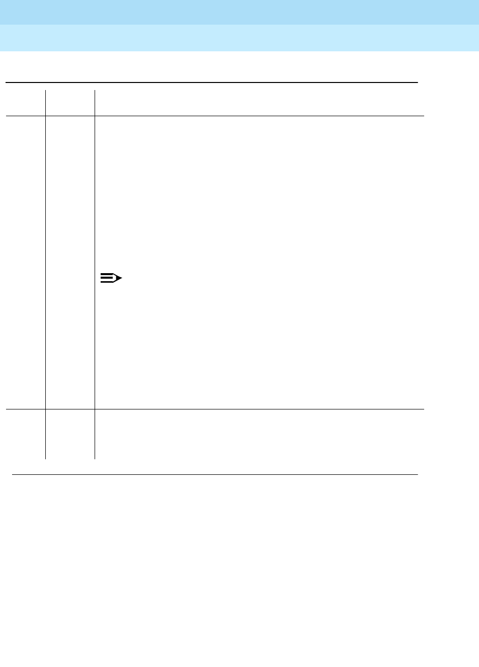
DEFINITY Enterprise Communications Server Release 6
Maintenance for R6r Volumes 1 & 2
555-230-126 Issue 2
January 1998
Maintenance Object Repair Procedures
Page 9-470DS1-BD (DS1 Interface Circuit Pack)
9
2000 ABORT Response to the test was not received within the allowable time period. This
may be due to hyperactivity. Error type 1538 in the error log indicates
hyperactivity. The hyperactive circuit pack is out of service and one or more of
the following symptoms may be exhibited.
1. The DS1-BD tests (such as test 138 and test 139) are aborting with error
code 2000.
2. The tests run on the ports of this circuit pack are returning a no board
result.
3. A busyout or a release command has no affect on the test results.
4. A list config command shows that the circuit pack and the ports are
properly installed.
NOTE:
When hyperactivity occurs, the circuit pack is isolated from the system,
and all of the trunks for this circuit pack are placed into the out of service
state. The system will try to restore the circuit pack within 15 minutes.
When no faults are detected for 15 minutes, the DS1 interface circuit
pack is restored to normal operation. All of the trunks for the DS1
interface circuit pack are then returned to the in service state.
Hyperactivity is often caused by the associated facility. In such a case,
faults (such as slips, misframes, or blue alarms) would be entered in the
error log. In addition, many hardware errors would be logged against
the associated trunk circuits. If the facility is OK and the error occurs
again after 15 minutes, replace the circuit pack.
PASS The One-Way Span test has successfully began transmitting a framed 3-in-24
test pattern. The test will continue to run until the system technician enters the
test ds1-loop UUCSS end-loopback/span-test
command or the
release board
UUCSS
command.
Table 9-163. TEST #1214 One-Way Span Test — Continued
Error
Code Test
Result Description/ Recommendation
Continued on next page

DEFINITY Enterprise Communications Server Release 6
Maintenance for R6r Volumes 1 & 2
555-230-126 Issue 2
January 1998
Maintenance Object Repair Procedures
Page 9-471DS1-BD (DS1 Interface Circuit Pack)
9
Inject Single Bit Error Test (#1215)
This test is destructive.
The Inject Single Bit Error Test will cause a single bit error to be sent within an
active framed 3-in-24 test pattern.
The test is highly destructive and can only be initiated by a system technician
demanded
test ds1-loop UUCSS inject-single-bit-error
command. An attempt to
use this command will be rejected if none of the three long-duration DS1
loopback/span tests (CPE Loopback Jack Test, Far CSU Loopback Test,
One-Way Span Test) are active on a TN767E circuit pack.
All trunks or ports on the DS1 Interface circuit pack must be busied out via the
system technician busyout board command before running the Inject Single Bit
Error Test.
The
list measurements ds1 summary
command displays the number of bit errors
detected (
Loopback/Span Test Bit-Error Count
field). Injecting this single bit error
should increment the bit error count of the loopback/span test by one.
0NO
BOARD The test could not relate the internal ID to the port (no board).
This could be due to incorrect translations, no board is inserted, an incorrect
board is inserted, or an insane board is inserted.
1. Check to ensure that the board translations are correct. Use the add ds1
UUCSS command to administer the DS1 interface if it is not already
administered.
2. If board was already administered correctly, check the error log to
determine if the board is hyperactive. If this is the case, the board is shut
down. Reseating the board will re-initialize the board.
3. If the board was found to be correctly inserted in step 1, issue the busyout
board command.
4. Issue the reset board command.
5. Issue the release busy board command.
6. Issue the test board long command.
This should re-establish the link between the internal ID and the port.
Table 9-163. TEST #1214 One-Way Span Test — Continued
Error
Code Test
Result Description/ Recommendation
Continued on next page
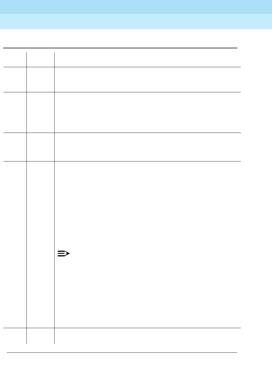
DEFINITY Enterprise Communications Server Release 6
Maintenance for R6r Volumes 1 & 2
555-230-126 Issue 2
January 1998
Maintenance Object Repair Procedures
Page 9-472DS1-BD (DS1 Interface Circuit Pack)
9
Table 9-164. TEST #1215 Inject Single Bit Error Test
Error
Code Test
Result Description/ Recommendation
ABORT Internal system error
1. Retry the
test ds1-loop UUCSS inject-single-bit-error
command at
1-minute intervals a maximum of 5 times.
1015 ABORT Ports on the DS1 Interface circuit pack have not been busied out to
out-of-service.
1. Enter the busyout board UUCSS command to put all trunks or ports of the
DS1 Interface circuit pack into the out-of-service state.
2. Retry the command.
ABORT Internal system error
2100 ABORT Could not allocate the necessary system resources to run this test.
1. Retry the command at 1-minute intervals for a maximum of 5 times.
2000 ABORT Response to the test was not received within the allowable time period. This
may be due to hyperactivity. Error type 1538 in the error log indicates
hyperactivity. The hyperactive circuit pack is out of service and one or more of
the following symptoms may be exhibited.
1. The DS1-BD tests (such as test 138 and test 139) are aborting with error
code 2000.
2. The tests run on the ports of this circuit pack are returning a no board
result.
3. A busyout or a release command has no affect on the test results.
4. A list config command shows that the circuit pack and the ports are
properly installed.
NOTE:
When hyperactivity occurs, the circuit pack is isolated from the system,
and all of the trunks for this circuit pack are placed into the out of
service state. The system will try to restore the circuit pack within 15
minutes. When no faults are detected for 15 minutes, the DS1 interface
circuit pack is restored to normal operation. All of the trunks for the DS1
interface circuit pack are then returned to the in service state.
Hyperactivity is often caused by the associated facility. In such a case,
faults (such as slips, misframes, or blue alarms) would be entered in the
error log. In addition, many hardware errors would be logged against
the associated trunk circuits. If the facility is OK and the error occurs
again after 15 minutes, replace the circuit pack.
PASS A single bit error has been successfully injected into an active framed 3-in-24
test pattern.
Continued on next page

DEFINITY Enterprise Communications Server Release 6
Maintenance for R6r Volumes 1 & 2
555-230-126 Issue 2
January 1998
Maintenance Object Repair Procedures
Page 9-473DS1-BD (DS1 Interface Circuit Pack)
9
End Loopback/Span Test (#1216)
This test is destructive.
The End Loopback/Span Test will terminate an active loopback or span test on a
TN767E DS1 circuit pack. Bit error counting against the received test pattern
stream is terminated and sending of the framed 3-in-24 test pattern is halted. If
either the CPE Loopback Jack or the far-end CSU is looped, the appropriate
loopback deactivate code is sent. If the loopback could not be deactivated, then
the test will FAIL and a MINOR alarm will be noted in the alarm log until the
loopback is cleared.
The test is highly destructive and can only be initiated by a system technician
demanded
test ds1-loop UUCSS end-loopback/span-test
command. Since only
one of these three different long-duration loopback/span tests can be active at a
time, the TN767E circuit pack knows which loopback/span test to terminate.
All trunks or ports on the DS1 Interface circuit pack must be busied out via the
system technician busyout board command before running this End
Loopback/Span Test.
0NO
BOARD The test could not relate the internal ID to the port (no board).
This could be due to incorrect translations, no board is inserted, an incorrect
board is inserted, or an insane board is inserted.
1. Check to ensure that the board translations are correct. Use the add ds1
UUCSS command to administer the DS1 interface if it is not already
administered.
2. If board was already administered correctly, check the error log to
determine if the board is hyperactive. If this is the case, the board is shut
down. Reseating the board will re-initialize the board.
3. If the board was found to be correctly inserted in step 1, issue the
busyout board command.
4. Issue the reset board command.
5. Issue the release busy board command.
6. Issue the test board long command.
This should re-establish the link between the internal ID and the port.
Table 9-164. TEST #1215 Inject Single Bit Error Test — Continued
Error
Code Test
Result Description/ Recommendation
Continued on next page

DEFINITY Enterprise Communications Server Release 6
Maintenance for R6r Volumes 1 & 2
555-230-126 Issue 2
January 1998
Maintenance Object Repair Procedures
Page 9-474DS1-BD (DS1 Interface Circuit Pack)
9
The
list measurements ds1 summary
command will display the length of time the
test ran (
Test Duration
field) and number of bit errors detected (
Loopback/Span
Test Bit-Error Count
field).
To restore the trunks or ports on the TN767E DS1 Interface circuit pack to the
in-service state, execute the release board command.
Table 9-165. TEST #1216 End Loopback/Span Test
Error
Code Test
Result Description/ Recommendation
ABORT Internal system error
1. Retry the
test ds1-loop UUCSS end-loopback/span-test
command at
1-minute intervals a maximum of 5 times.
1005 ABORT End Loopback/Span Test cannot be executed in the current configuration. To
run this, the TN767E or later suffix DS1 must be administered for 24-channel
operation. The "Bit Rate" field on the DS1 circuit pack administration form must
be set to "1.544" for 24-channel operation.
1015 ABORT Ports on the DS1 Interface circuit pack have not been busied out to
out-of-service.
1. Enter the busyout board UUCSS command to put all trunks or ports of the
DS1 Interface circuit pack into the out-of-service state.
2. Retry the command.
ABORT Internal system error
2100 ABORT Could not allocate the necessary system resources to run this test.
1. Retry the command at 1-minute intervals for a maximum of 5 times.
Continued on next page
DEFINITY Enterprise Communications Server Release 6
Maintenance for R6r Volumes 1 & 2
555-230-126 Issue 2
January 1998
Maintenance Object Repair Procedures
Page 9-475DS1-BD (DS1 Interface Circuit Pack)
9
2000 ABORT Response to the test was not received within the allowable time period. This
may be due to hyperactivity. Error type 1538 in the error log indicates
hyperactivity. The hyperactive circuit pack is out of service and one or more of
the following symptoms may be exhibited.
1. The DS1-BD tests (such as test 138 and test 139) are aborting with error
code 2000.
2. The tests run on the ports of this circuit pack are returning a no board
result.
3. A busyout or a release command has no affect on the test results.
4. A list config command shows that the circuit pack and the ports are
properly installed.
NOTE:
When hyperactivity occurs, the circuit pack is isolated from the system,
and all of the trunks for this circuit pack are placed into the out of
service state. The system will try to restore the circuit pack within 15
minutes. When no faults are detected for 15 minutes, the DS1 interface
circuit pack is restored to normal operation. All of the trunks for the DS1
interface circuit pack are then returned to the in service state.
Hyperactivity is often caused by the associated facility. In such a case,
faults (such as slips, misframes, or blue alarms) would be entered in the
error log. In addition, many hardware errors would be logged against
the associated trunk circuits. If the facility is OK and the error occurs
again after 15 minutes, replace the circuit pack.
1313 FAIL The TN767E DS1 circuit pack could not deactivate the loopback through the
Customer Loopback Jack.
1. Retry the
test ds1-loop UUCSS end-loopback/span-test
command at
1-minute intervals for a maximum of 5 times.
1314 FAIL The TN767E DS1 circuit pack could not deactivate the loopback through the
far-end CSU.
1. Make sure that the far-end DS1 is installed if the far-end CSU is a 120A
CSU Module.
2. Retry the
test ds1-loop UUCSS end-loopback/span-test
command at
1-minute intervals for a maximum of 5 times.
PASS The active long-duration loopback or span test on the TN767E circuit pack
was successfully terminated.
Table 9-165. TEST #1216 End Loopback/Span Test — Continued
Error
Code Test
Result Description/ Recommendation
Continued on next page

DEFINITY Enterprise Communications Server Release 6
Maintenance for R6r Volumes 1 & 2
555-230-126 Issue 2
January 1998
Maintenance Object Repair Procedures
Page 9-476DS1-BD (DS1 Interface Circuit Pack)
9
ICSU Status LEDs Test (#1227)
The TN767E DS1 circuit pack has four status LEDs on the faceplate in addition to
the three standard faceplate LEDs. These four status LEDs are associated with
the 120A1 Channel Service Unit (CSU) Module that can be connected to the
TN767E board via the I/O connector panel on the back of the port carrier.
This test is a visual test. It will light the four status LEDs red for 5 seconds, then
light them green for 5 seconds, then light them yellow for 5 seconds, then turn
the LEDs off and returns control of the status LEDs to the circuit pack.
This test will only be executed on TN767E or later suffix DS1 circuit packs
administered for 24-channel operation (1.544 bit rate).
If the 1201 CSU Module is not installed, the status LEDs are always off and this
test aborts.
0NO
BOARD The test could not relate the internal ID to the port (no board).
This could be due to incorrect translations, no board is inserted, an incorrect
board is inserted, or an insane board is inserted.
1. Check to ensure that the board translations are correct. Use the add ds1
UUCSS command to administer the DS1 interface if it is not already
administered.
2. If board was already administered correctly, check the error log to
determine if the board is hyperactive. If this is the case, the board is shut
down. Reseating the board will re-initialize the board.
3. If the board was found to be correctly inserted in step 1, issue the
busyout board command.
4. Issue the reset board command.
5. Issue the release busy board command.
6. Issue the test board long command.
This should re-establish the link between the internal ID and the port.
Table 9-165. TEST #1216 End Loopback/Span Test — Continued
Error
Code Test
Result Description/ Recommendation
Continued on next page

DEFINITY Enterprise Communications Server Release 6
Maintenance for R6r Volumes 1 & 2
555-230-126 Issue 2
January 1998
Maintenance Object Repair Procedures
Page 9-477DS1-BD (DS1 Interface Circuit Pack)
9
Table 9-166. TEST #1227 ICSU Status LEDs Test
Error
Code Test
Result Description/ Recommendation
ABORT Internal system error
1. Retry the command at 1-minute intervals a maximum of 5 times.
1005 ABORT The ICSU Status LEDs test can not be executed for the current configuration.
The test applies only to TN767E or later DS1 circuit packs administered for
24-channel operation (1.544 bit rate).
1. If the circuit pack is a TN767E or later suffix DS1 circuit pack, then retry the
command.
1951 ABORT The ICSU Status LEDs Test can not be executed because a 120A1 or later suffix
CSU Module is not physically installed. If using a 120A1 CSU Module,
physically connect it to the TN767E board on the back of the port carrier
otherwise, ignore this abort.
2100 ABORT Could not allocate the necessary system resources to run this test.
1. Retry the command at 1-minute intervals for a maximum of 5 times.
2500 ABORT Internal system error.
1. Retry the command.
PASS The ICSU Status LEDs test executed successfully. A PASS result, however,
does not necessarily mean that the status LEDs behaved properly. It only
means that the software successfully attempted to light the status LEDs. This is
a visual test. The service technician must visually exam the behavior of the
LEDs while the test is running. The LEDs are functioning properly if the four
status LEDs are lit red for 5 seconds, then lit green for 5 seconds, then lit yellow
for 5 seconds. If the LEDs behave differently, the board should be replaced at
the customer’s convenience.
Continued on next page

DEFINITY Enterprise Communications Server Release 6
Maintenance for R6r Volumes 1 & 2
555-230-126 Issue 2
January 1998
Maintenance Object Repair Procedures
Page 9-478DS1-BD (DS1 Interface Circuit Pack)
9
0NO
BOARD The test could not relate the internal ID to the port (no board).
This could be due to incorrect translations, no board is inserted, an incorrect
board is inserted, or an insane board is inserted.
1. Check to ensure that the board translations are correct. Use the add ds1
UUCSS command to administer the DS1 interface if it is not already
administered.
2. If board was already administered correctly, check the error log to
determine if the board is hyperactive. If this is the case, the board is shut
down. Reseating the board will re-initialize the board.
3. If the board was found to be correctly inserted in step 1, issue the busyout
board command.
4. Issue the reset board command.
5. Issue the release busy board command.
6. Issue the test board long command.
This should re-establish the linkage between the internal ID and the port.
Table 9-166. TEST #1227 ICSU Status LEDs Test — Continued
Error
Code Test
Result Description/ Recommendation
Continued on next page

DEFINITY Enterprise Communications Server Release 6
Maintenance for R6r Volumes 1 & 2
555-230-126 Issue 2
January 1998
Maintenance Object Repair Procedures
Page 9-479DS1-FAC (DS1 Facility)
9
DS1-FAC (DS1 Facility)
The DS1-FAC is a part of the DS1 Converter (DS1 CONV) Complex. The DS1
CONV Complex consists of two TN574 DS1 CONV circuit packs or two TN1654
DS1 CONV circuit packs connected by one to four DS1 facilities. The
maintenance object name for the DS1 CONV circuit pack is DS1C-BD, and the
maintenance object name for the connected DS1 facilities is DS1-FAC.
The TN1654 DS1 Converter Circuit pack is a redesign of the TN574 DS1
Converter board. The TN1654 provides functionality equivalent to the TN574 but
also adds a 32-Channel E1 interface for international support as well as
circuit-switched wideband connections (NxDS0).
The TN1654 DS1 CONV circuit pack is not compatible with the TN574 DS1
CONV board or the Y-cable used to interface to the TN574 DS1 CONV. A
TN573B or later suffix SNI board must also be used when connecting to the
TN1654 DS1 CONV board. See section DS1C-BD for information on both DS1
CONV circuit packs.
The DS1 CONV Complex is a part of the Port Network Connectivity (PNC). The
DS1 CONV Complex is used to extend the range of the 32 Mbps fiber links that
connect EPNs to either the PPN or the Center Stage Switch, allowing EPNs to be
located at remote sites.
The DS1 CONV circuit pack contains on-board firmware that detects DS1 facility
alarms and errors, communicates status to maintenance software, and runs tests
in the background or on demand from maintenance software. The overall
maintenance software strategy includes demand tests, recovery strategies, error
logging and alarm logging, and periodic audits.
Every error condition reported by the firmware is associated with the background
tests that the firmware runs autonomously. Demand tests that are executed by
the maintenance software do not have any functionality that would effect any
additional error manipulation by the firmware. However, the Failure Audit test
1. UU is the universal cabinet number (1 for PPN, 2-44 for EPNs). C is the carrier designation (A,
B, C, D, or E). SS is the number of the slot in which the circuit pack resides (01 to 21). f is the
DS1 facility (a, b, c, or d). See Chapter 7, or the DS1C-BD section, for identification of DS1
facility LEDs.
MO Name (in
Alarm Log) Alarm Level Initial Command to Run1Full Name of MO
DS1-FAC MAJOR test board UUCSS sh r 1 DS1 Facility
DS1-FAC MINOR test board UUCSS sh r 1 DS1 Facility
DS1-FAC WARNING test board UUCSS sh r 1 DS1 Facility
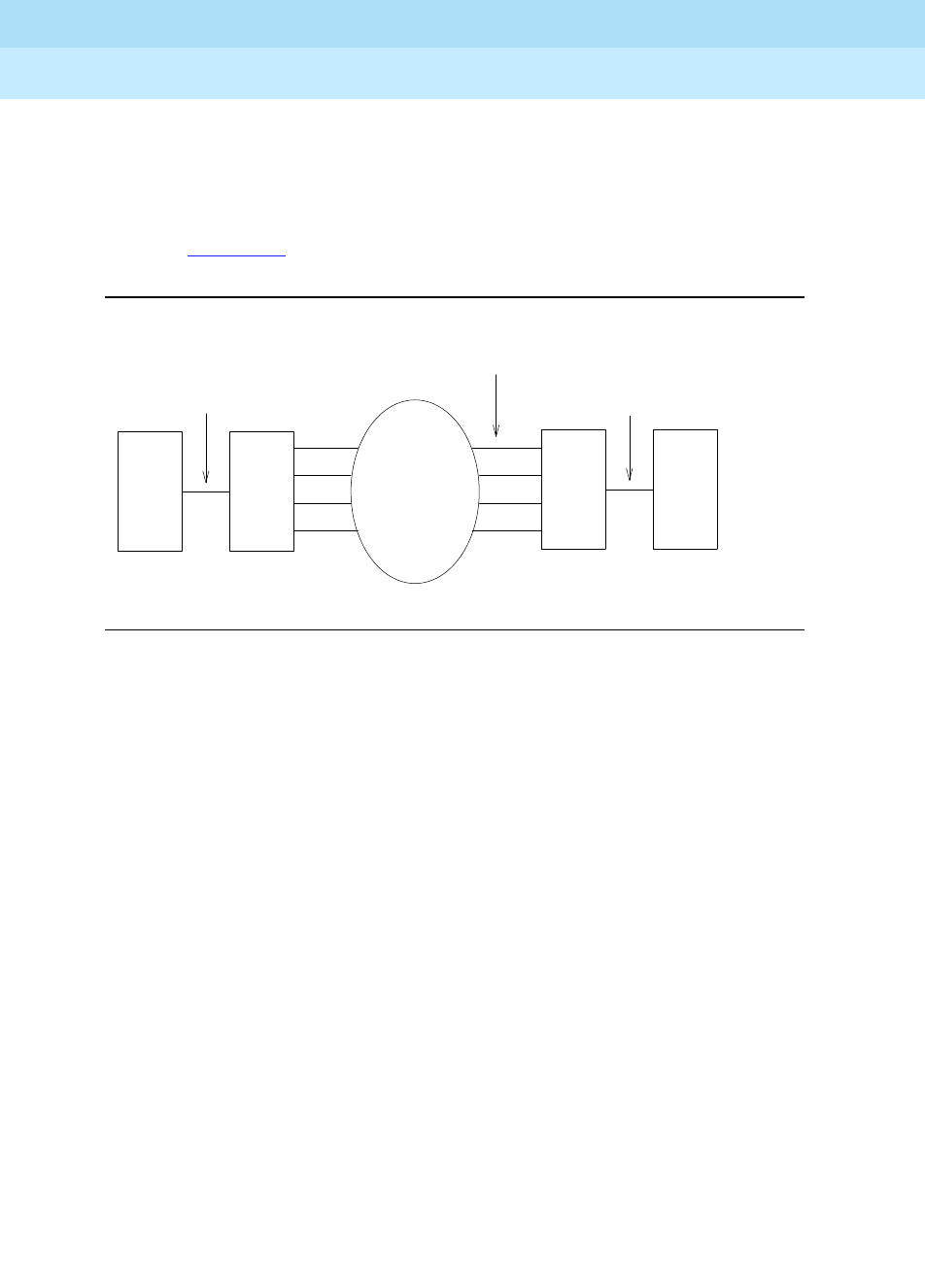
DEFINITY Enterprise Communications Server Release 6
Maintenance for R6r Volumes 1 & 2
555-230-126 Issue 2
January 1998
Maintenance Object Repair Procedures
Page 9-480DS1-FAC (DS1 Facility)
9
#949 effects auditing of the software error log by forcing the firmware to report
the pending errors again.
DS1 CONV circuit packs are connected to the Expansion Interface (EI) circuit
packs (TN570) and the Switch Node Interface (SNI) circuit packs (TN573) as
shown in Figure 9-17.
Figure 9-17. DS1 CONV Complex and the DS1 Facilities
The DS1 CONV Complex can replace fiber links between two EIs and fiber links
between an EPN EI and an SNI. Fiber links between two SNIs and fiber links
between the Processor Port Network (PPN) and the Center Stage Switch (CSS)
cannot be replaced by a DS1 CONV Complex.
On the TN574 DS1 CONV circuit pack, one of the four DS1 facilities is used as
the primary facility (or packet facility), and it is the only facility that can carry
packet traffic besides providing circuit connections. The primary facility has 22
channels available for circuit and packet connections. Other facilities each have
24 channels available for circuit connections. On the TN574 primary facility,
channels 1and 24 are not available for packet or for circuit connections. Channel
1 is used for excess packets traffic to prevent packet overflow that might result
from zero code substitutions. Channel 24 is the DS1 Control Channel that carries
control link data between the two DS1 CONV circuit packs.
The primary facility on the TN1654 DS1 CONV circuit pack is restricted to facility
A or facility B. The TN1654 provides fixed packet bandwidth of 192 Kbps while
the TN574 provides packet bandwidth of up to 1408 Kbps with a dynamic
allocation mechanism that could change packet/circuit use of individual
channels. The first three 64 Kbps channels on the primary facility of the TN1654
are reserved as the packet channels. The DS1 Control Channel will be Channel
24 in T1 mode and Channel 31 in E1 mode. In T1 format the TN1654 provides 24
circuit channels for use on non-primary facilities and 20 circuit channels on the
primary facility. E1 format provides 31 circuit channels for use on non-primary
facilities and 27 circuit channels on the primary facility.
Metallic or Fiber Connection
DS1CONV
DS1 Facilities
Network
EI or
SNI
EI
DS1CONV
Metallic or Fiber Connection

DEFINITY Enterprise Communications Server Release 6
Maintenance for R6r Volumes 1 & 2
555-230-126 Issue 2
January 1998
Maintenance Object Repair Procedures
Page 9-481DS1-FAC (DS1 Facility)
9
When there are alarms on the packet facility, DS1 CONV circuit pack firmware
changes the mapping of the DS1 channels to move the packet traffic to another
facility. On TN574 DS1 CONV boards, the packet traffic will be moved to another
‘‘Digital Data Compatible’’ facility (as indicated on the fiber link administration
screen). On TN1654 DS1 CONV boards, the packet traffic will be moved to either
facility A or B if available. This mapping is done to keep the packet service
operational at all times as the system control links are carried on these packet
connections. When packet traffic is moved to another facility, circuit connections
on the new facility are torn down and circuit connections on the old (faulty) facility
are re-mapped to the new packet facility.
After firmware initialization, facility A, the first facility, is chosen as the default
primary facility for both DS1 CONV boards.
The TN574 DS1 CONV has seven LEDs which provide an indication of the state
of the DS1 CONV circuit pack and the DS1 facilities. There is a yellow, a green,
and a red LED under software and/or firmware control. There are four Green
LEDs under hardware control that indicate, for each DS1 facility, whether a
receive signal is present for the DS1 facility. From top to bottom these green
LEDs correspond to DS1 facilities A, B, C, and D respectively. If one of the four
green LED is on, it indicates a signal is present, but it does not imply that the
signal is using the correct framing format (ESF or D4) or line coding (ZCS or
B8ZS). See section DS1C-BD for the description of the red, the green, and the
yellow LEDs on the DS1 CONV circuit pack.
The TN1654 DS1 CONV board has eleven LEDs on its faceplate. The top three
system standard LEDs (yellow, green and red) are used to provide an indication
of the state of the DS1 CONV board. The bottom four LEDs on the TN1654 board
are labeled SPAN LEDs. These LEDs are under firmware control. If the facility is
not administered, then the LED is not lit. The LED is lit amber if the facility is
running alarm free. If the facility is detecting either a red alarm (loss-of-signal or
loss-of-frame), a yellow alarm (remote frame alarm) or a blue alarm (AIS signal)
then the LED is lit red. See section DS1C-BD for a complete description off all the
LEDs.
The TN1654 DS1 CONV circuit pack supports the Wideband Switching feature.
The TN574 DS1 CONV does not.
DS1 Facility Busyout
Busying out a maintenance object allows service to be disconnected gracefully.
Busyout puts the object out-of-service until the repair procedures are completed.
DS1 facilities are busied out via the busyout ds1-facility command. When an
attempt is made to busyout the packet facility (or primary facility), system will
print a warning message indicating that the override option must be used to
busyout the packet facility. Busying out the packet facility will result in moving the
packet traffic to another facility and disconnecting circuit connections on that
new facility.

DEFINITY Enterprise Communications Server Release 6
Maintenance for R6r Volumes 1 & 2
555-230-126 Issue 2
January 1998
Maintenance Object Repair Procedures
Page 9-482DS1-FAC (DS1 Facility)
9
The system will not allow the last packet DS1 facility to be busied out. In this
case, the DS1 CONV circuit pack must be busied out instead.
When the busyout ds1-facility command is executed, software communicates
with both DS1 CONV circuit packs in the DS1 CONV Complex. If the board at
which the facility is being busied out is not accessible, then the abort code 2100
will be returned, if the board at the other end of the DS1 CONV Complex is not
accessible, then the abort code 105 will be returned.
DS1 Facility Administration
DS1 facility administration is a part of the fiber link administration. DS1 options
are set on the second page of the fiber link administration screen. In Critical
Reliability systems, the third page of the fiber link administration screen contains
the DS1 facility options for the B side of the PNC.
DS1 facility administration is explained in the following sections. Descriptions
given here do not provide complete coverage of fiber link administration. See the
DEFINITY ECS Release 5 Implementation Manual (555-230-302).
Replacing a DS1 Facility
Disconnecting a DS1 facility is service disrupting except on Critical Reliability
Systems since they have PNC duplication.
On a Standard Reliability or High Reliability System (no PNC Duplication):
This procedure is destructive.
1. Busyout the DS1 facility via the busyout ds1-facility command.
2. Replace the DS1 facility.
3. Release the DS1 facility via the release ds1-facility command.
On a Critical Reliability System (PNC Duplication):
This procedure is non-destructive.
1. If the DS1 facility to be replaced is on the active PNC (its yellow LED will
be on solid), first do a PNC demand interchange via the reset pnc
interchange command. (The status pnc command can also be used to
determine the active PNC.)
2. When the DS1 facility to be replaced is on the standby PNC (if the DS1
facility was originally on the standby PNC or after the PNC interchange
has finished), busyout the DS1 facility via the busyout ds1-facility
command.
3. Replace the DS1 facility.
4. Release the DS1 facility via the release ds1-facility command.

DEFINITY Enterprise Communications Server Release 6
Maintenance for R6r Volumes 1 & 2
555-230-126 Issue 2
January 1998
Maintenance Object Repair Procedures
Page 9-483DS1-FAC (DS1 Facility)
9
Installing a DS1 Facility
Installing a DS1 facility is done in the following sequence:
1. Connect the facility.
2. Check the fiber link number via the list fibers command. Administer the
DS1 facility via the change fiber-link command. Change the Facility
Installed field from "no" to "yes" for the facility that is being installed.
3. Busyout the DS1 CONV circuit pack via the busyout board command.
4. Run the DS1 Facilities Connectivity test #790 via the test board UUCSS
long command to make sure that the facilities are connected correctly.
5. Release the DS1 CONV circuit pack via the release board command.
Removing a DS1 Facility
Removing a DS1 facility is service disrupting in any system configuration
(because the DS1 facility administration is similar on both sides of the PNC on
Critical Reliability Systems).
This procedure is destructive.
1. Busyout the DS1 facility via the busyout ds1-facility command.
2. Check the fiber link number via the list fibers command. De-administer
the DS1 facility via the change fiber-link command. Change the Facility
Installed field from "yes" to "no" for the facility that is being removed.
3. Disconnect the DS1 facility (or facilities in Critical Reliability System
configuration).
DS1 Interface Options
The following DS1 Interface options must be set with fiber link administration. To
set the values, check the number of the fiber link via the list fibers command.
Execute the change fiber-link command and set the following fields:
Facility Installed
This field determines if the DS1 facility is installed. The field is set to
yes
if the
facility is installed.
For TN574 DS1 CONV boards, facility A must be installed before the others.
Facilities B, C and D can then be installed in any order desired since the primary
facility can reside on any of the four facilities.
For TN1654 DS1 CONV boards, facility A must be installed first, then B, then C or
D. This is required since the primary facility can only reside on facilities A or B.

DEFINITY Enterprise Communications Server Release 6
Maintenance for R6r Volumes 1 & 2
555-230-126 Issue 2
January 1998
Maintenance Object Repair Procedures
Page 9-484DS1-FAC (DS1 Facility)
9
Passes Far-end Clock
This field determines if the DS1 facility can be used as a clock reference for the
receive fiber signal. The field is set to
yes
unless the DS1 facility cannot be used
as clock reference signal.
This field appears on the fiber-link form only for TN574 DS1 CONV circuit packs.
On the TN1654 DS1 CONV board, none of the facilities can be used as a clock
reference for the receive fiber signal thus administration of this field is not
applicable.
DS1 facilities cannot be used as system synchronization sources.
Digital Data Compatible
This field determines if the DS1 facility is suitable for carrying packet traffic. The
field is set to
yes
unless the DS1 facility is not digital data compatible.
This field appears on the fiber-link form only for TN574 DS1 CONV circuit packs.
The TN574 circuit pack allows any of the four facilities to be used as the primary
facility which carries the packet traffic. The TN1654 DS1 CONV board, however,
allows packet traffic only on facilities A and B. Thus there is no need to
administer this information as it is already predetermined.
Bit Rate
This field is used to select domestic T1 operation or international E1 operation for
all facilities in the TN1654 DS1 CONV Complex. The field is set to
1.544
Mbps for
T1 operation and
2.048
Mbps for E1 operation.
This field appears on the fiber-link form only for TN1654 DS1 CONV circuit packs.
NOTE:
The TN1654 DS1 CONV circuit pack is also field configurable for T1 or E1
operation. All four DS1 facilities are configured to either T1 or E1 as a group
via an option switch located on the component side of the circuit pack. An
error will be logged and an alarm will be raised if there is a T1/E1
inconsistency between the administered bit rate and the board option
switch setting.
Idle Code
This field is used to set the idle code for all facilities on the TN1654 DS1 CONV
board. This field can accept any combination of ones (1) and zeros (0) with the
exception that the second left-most digit must be set to one (1) at all times.
This field appears on the fiber-link form only for TN1654 DS1 CONV circuit packs.

DEFINITY Enterprise Communications Server Release 6
Maintenance for R6r Volumes 1 & 2
555-230-126 Issue 2
January 1998
Maintenance Object Repair Procedures
Page 9-485DS1-FAC (DS1 Facility)
9
CRC
This field determines if CRC is enabled for all facilities on the TN1654 circuit
pack. The field is set to
yes
if a cyclic redundancy check (CRC) is to be
performed on transmissions that the board receives.
CRC is applicable only to E1 operation. Thus, this field appears on the fiber-link
form only for TN1654 DS1 CONV circuit packs whose bit rate is administered to
2.048 Mbps.
DS1 CONV-1 and DS1 CONV-2 Line Compensation
The DS1 facility line signal is pre-equalized at the transmitter on the DS1 CONV
circuit pack so that DS1 line pulses have correct amplitude and shape when they
reach the Network Interface (see Figure 9-18). The amount of equalization
necessary is determined by the distance to the Network Interface and also by the
type of wiring used to connect to the Network Interface. If the equalization is not
set to the correct value, potentially high error rates (errored seconds) will be
observed on the DS1 facility. Equalization values are determined as follows:
Line compensation is applicable only to T1 operation, thus these fields will not
appear on the fiber-link form if the TN1654 DS1 CONV is administered for a bit
rate of 2.048 Mbps.
Line Coding
This field is used to administer the line coding for the DS1 facility. For the TN574
board and the TN1654 board in T1 mode, the field may be set to
ami-zcs
or
b8zs
.
If the TN1654 board is set for E1 operation, the line coding may be set to either
ami-basic
or
hdb3
. The line coding must be the same at each end of the DS1
CONV Complex.
Framing Mode
Either
esf
or
d4
framing mode can be selected for the DS1 facility. The same
framing mode must be used at each end of the DS1 CONV Complex
Equalizer
Setting
Distance to Network Interface (feet)
Cable type 22 AWG ABAM &
24 AWG PDS Cable type 26 AWG PDS
1 1 to 133 0 to 90
2 133 to 266 90 to 180
3 266 to 399 180 to 270
4 399 to 533 270 to 360
5 533 to 655 360 to 450

DEFINITY Enterprise Communications Server Release 6
Maintenance for R6r Volumes 1 & 2
555-230-126 Issue 2
January 1998
Maintenance Object Repair Procedures
Page 9-486DS1-FAC (DS1 Facility)
9
For TN574 DS1 CONV boards, the framing mode field is administrable.
For TN1654 DS1 CONV boards, this field is display only. It can not be
administered. The TN1654 has option switches located on the component side of
the circuit pack. If T1 operation is selected via the first switch, four additional
switches are used to select the framing mode for each facility. Each facility can
be set to either D4 or ESF framing. The framing mode field will display what the
switch is set to for the DS1 facility.
Framing Mode is applicable only to T1 operation, thus this field will not appear on
the fiber-link form if the TN1654 DS1 CONV is administered for a bit rate of 2.048
Mbps.
Line Termination
This field displays the line termination for the DS1 facility on the TN1654 DS1
Converter circuit pack. This field is display only. It can not be administered. The
TN1654 has option switches located on the component side of the circuit pack. If
E1 operation is selected via the first switch, four additional switches are used to
select the line termination for each facility. Each facility can be set to either CEPT
75 ohm coaxial or 120 ohm CEPT twisted pair. This line termination field will
display what the switch is set to for the DS1 facility.
Line Termination is applicable only to E1 operation, thus this field will not appear
on the fiber-link form if the TN1654 DS1 CONV is administered for a bit rate of
1.544 Mbps
Facility Circuit ID
These fields are used to specify a unique alpha-numeric name up to 40
characters long for each DS1 facility. This field will be displayed for each facility
whose
Facility Installed?
field is set to
yes
.

DEFINITY Enterprise Communications Server Release 6
Maintenance for R6r Volumes 1 & 2
555-230-126 Issue 2
January 1998
Maintenance Object Repair Procedures
Page 9-487DS1-FAC (DS1 Facility)
9
DS1 Converter Performance Measurements
Report
The DS1 Converter Performance Measurements provide link performance
measurements for the DS1 facilities.
When no facility alarms exist on the DS1 facility, events that indicate a
degradation in the performance of the DS1 facility are monitored and recorded.
These events will generate appropriate alarms when performance of the DS1
facility has degraded below acceptable levels. These measurements include
errored seconds, bursty seconds, severely errored seconds, and failed seconds.
There are two DS1 Converter Performance Measurements Sub-reports. The first
sub-report, DS1 Converter Performance Measurements Summary Report,
provides information on the worst 15 minute interval of data, the total for 24 hours
of data and the current 15 minute counter for each of the above mentioned
counters.
The second sub-report, DS1 Converter Performance Measurements Detailed
Report displays a detailed log for the last 96 15-minute intervals for each of the
above mentioned counters.
The DS1 Converter Performance Measurements Summary Report can be
accessed with list measurements ds1-facility summary UUCSSf
[print/schedule]. A more detailed version of the report is accessed with list
measurements ds1-facility log UUCSSf [print/schedule].
The user can reset all hardware and software measurement counters for a given
facility with clear measurements ds1-facility UUCSSf. The
Counted Since
time
is also reset and the
Number of Valid Intervals
count is set to zero.
The reports are printed on the screen or, by using the
print
option, on a printer
attached to the terminal.
Clearing Firmware Errors
DS1 CONV error reports are generated by firmware autonomously, they are not
associated with system technician demanded tests. Therefore, test board clear
command does not affect the error status known by the DS1 CONV firmware. To
clear all the on-board firmware-detected errors unconditionally, execute the
clear firmware-counters command.
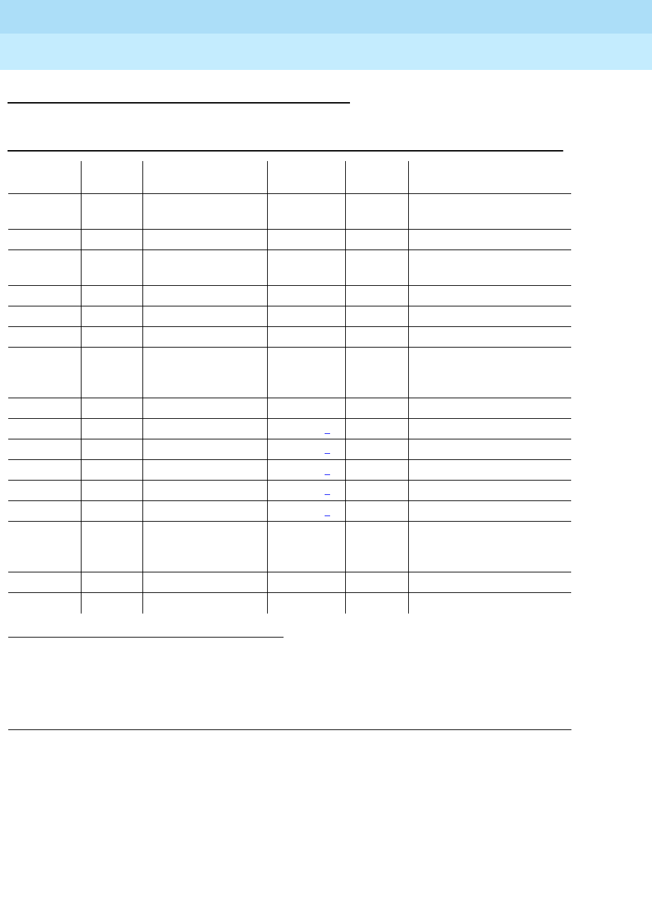
DEFINITY Enterprise Communications Server Release 6
Maintenance for R6r Volumes 1 & 2
555-230-126 Issue 2
January 1998
Maintenance Object Repair Procedures
Page 9-488DS1-FAC (DS1 Facility)
9
Error Log Entries and Test to Clear Values
Notes:
When problems persist, resetting the DS1 CONV circuit pack via the reset board
command may temporarily resolve the error condition and restore service until
further assistance is provided.
a. A major failure occurred on the DS1 interface hardware on the DS1 CONV
circuit pack associated with this DS1 facility. Replace the DS1 CONV
circuit pack.
1. Run the Short Test Sequence first. If all tests pass, run the Long Test Sequence. Refer to the
appropriate test description and follow the recommended procedures.
2. These failures are logged as a WARNING alarm when the error is first reported. The alarm severity
is raised to a MAJOR in 15 minutes if the problem persists.
3. This failure is logged as a WARNING alarm when the error is first reported. The alarm severity is
raised to a MINOR in 15 minutes if the problem persists.
Table 9-167. DS1 Facility Error Log Entries
Error
Type Aux
Data Associated Test Alarm
Level On/Off
Board Test to Clear Value
010 Any Any Any test ds1-facility UUCSSf
sh r 1
1(a) Failure Audit #949 MAJOR ON test board UUCSS sh r 1
18(b) 0 busyout
ds1-facility UUCSSf WARNING OFF release ds1-facility
UUCSS
257(c) Failure Audit #949 MINOR ON test board UUCSS sh r 1
513(d) 1 Failure Audit #949 MINOR OFF test board UUCSS sh r 1
513(d) 2 Failure Audit #949 MINOR OFF test board UUCSS sh r 1
856(e) DS1 Facility Query
for Slips/Misframes
#972
MINOR OFF none
1025(f) Failure Audit #949 MAJOR2OFF test board UUCSS sh r 1
1281(g) None Failure Audit #949 MAJOR2OFF test board UUCSS sh r 1
1281(g) 1 Failure Audit #949 MAJOR2OFF test board UUCSS sh r 1
1281(g) 2 Failure Audit #949 MAJOR2OFF test board UUCSS sh r 1
1537(h) Failure Audit #949 MAJOR2OFF test board UUCSS sh r 1
1793(i) Failure Audit #949 MAJOR2OFF test board UUCSS sh r 1
2065(j) DS1 Facility Query
for Slips/Misframes
#972
MINOR OFF none
2305(k) Failure Audit #949 MAJOR OFF test board UUCSS sh r 1
2561(l) Failure Audit #949 MINOR3OFF test board UUCSS sh r 1

DEFINITY Enterprise Communications Server Release 6
Maintenance for R6r Volumes 1 & 2
555-230-126 Issue 2
January 1998
Maintenance Object Repair Procedures
Page 9-489DS1-FAC (DS1 Facility)
9
b. This error indicates that the DS1 facility has been busied out via the
busyout ds1-facility command. To resolve this error, release the DS1
facility via the release ds1-facility command.
c. A minor failure occurred on the DS1 interface hardware on the DS1 CONV
circuit pack associated with this DS1 facility. Replace the DS1 CONV
circuit pack.
d. DS1 CONV circuit packs in this DS1 CONV Complex do not match in their
framing formats or line coding formats.
Aux Data 1
indicates that the framing formats (ESF or D4) do not match.
For TN574 DS1 CONV boards, the framing mode is administered on the
fiber-link form. The TN1654 DS1 CONV has option switches located on the
component side of the circuit pack. If T1 operation is selected via the first
switch, four additional switches are used to select the framing mode for
each facility. The Framing Mode field on the fiber-link form is display-only
for the TN1654 boards. It displays what the switch is set to for the DS1
facility. It can not be administered.
Aux Data 2
indicates that the line coding formats do not match. Line
Coding is an administrable value on the fiber-link form. The line coding
options are
ami-zcs
or
b8zs
for TN574 boards and TN1654 boards in T1
mode. For TN1654 boards in E1 mode, the line coding options are
ami-basic
or
hdb3
.
This error should clear in 15 minutes.
1. Verify that DS1 facility and the network is using the same line
coding (ami-zcs, b8zs, ami-basic, hdb3) and framing mode (ESF,
D4). Use list fibers and display fiber-link commands to check the
values for this DS1 facility. Contact T1 Network Service to check the
modes used by the network.
If the framing mode format differs on boards in a TN1654 DS1
CONV Complex, the DS1 CONV board that has its option switch set
incorrectly will have to be physically removed from the system in
order to set the facility framing mode switch properly.
2. If the problem persists, reset both DS1 CONV circuit packs via the
reset board command.
3. If the problem still persists, replace this DS1 CONV circuit pack.
4. If the problem still persists, replace the DS1 CONV circuit pack at
the other end of the DS1 CONV Complex.
e. More than 88 negative and/or positive slip errors occurred. This error will
clear when there are no slips for 1 hour.
1. Enter display errors and follow the associated repair procedures
for any SYNC, TDM-CLK, and SNC-BD errors.
2. Verify that the DS1 facility and the network are using the same Line
Coding. For TN574 boards and TN1654 boards in T1 mode, also
verify that the Framing Mode used is the same. Use list fibers and

DEFINITY Enterprise Communications Server Release 6
Maintenance for R6r Volumes 1 & 2
555-230-126 Issue 2
January 1998
Maintenance Object Repair Procedures
Page 9-490DS1-FAC (DS1 Facility)
9
display fiber-link commands to check the values for this DS1
facility. Contact T1 Network Service to check the modes used by
the network. See the above sections, “Line Coding” and “Framing
Mode” for details on how these options apply to the TN574 and
TN1654 DS1 CONV boards.
3. For TN574 boards and TN1654 boards in T1 mode, check line
equalization settings as described in the above section, ‘‘DS1
CONV-1 and DS1 CONV-2 Line Compensation.’’
4. Enter display errors and follow the associated repair procedures
for any EXP-INTF, and SNI-BD errors for the Fiber Endpoints. Enter
display errors and follow the associated repair procedures for any
FIBER-LK errors for this fiber link.
5. If the problem still persists, replace this DS1 CONV circuit pack.
6. If the problem still persists, replace the DS1 CONV circuit pack at
the other end of the DS1 CONV Complex.
f. Loss of Frame Alignment (LFA) Alarm, the RED alarm: This alarm indicates
that the DS1 interface associated with the DS1 facility cannot frame up on
the received data.
For the following repair procedure, refer to Figure 9-18 and the diagrams
in the related test descriptions.
1. If the network is used instead of private T1 lines, check that the DS1
facility and the network are using the same line coding. For TN574
boards and TN1654 boards in T1 mode, also verify that the Framing
Mode used is the same. For TN1654 boards, verify that the two
boards in the DS1 CONV Complex are using the same bit rate. Use
list fibers and display fiber-link commands to check the values
for this DS1 facility. Contact T1 Network Service to verify the modes
set for the network. See the above sections, “Line Coding”,
“Framing Mode” and “Bit Rate” for details on how these options
apply to the TN574 and TN1654 DS1 CONV boards
2. Run the Near-end External Loopback test #799 via the test
ds1-facility UUCSSf external-loopback command by setting up a
loopback at CPE side of CSU towards DS1 CONV circuit pack
shown as loopback point LB 1 in the test description diagram. If the
test fails, replace connectors and the cables between CSU and the
DS1 CONV circuit pack.
3. If the test passes, run the Near-end External Loopback test #799
via the test ds1-facility UUCSSf external-loopback command by
setting up a loopback at DS1 facility side of CSU towards the DS1
CONV circuit pack shown as loopback point LB 2 in the test
description diagram. If the test fails, replace the CSU.
4. If the test #799 passes, run the Far-end Internal Loopback test
#797 via the test ds1-facility UUCSSf long command. If the test
#797 passes, go to step 6. If the test fails, then run the Near-end

DEFINITY Enterprise Communications Server Release 6
Maintenance for R6r Volumes 1 & 2
555-230-126 Issue 2
January 1998
Maintenance Object Repair Procedures
Page 9-491DS1-FAC (DS1 Facility)
9
External Loopback test #799 via the test ds1-facility UUCSSf
external-loopback command at the other end of the DS1 CONV
Complex, and repeat steps 2 and 3 for the other end-point.
If the system is not configured as a Critical Reliability System and if
there is only one DS1 facility, then the test #799 can only be
executed at the end which is closer to the SPE relative to the DS1
CONV circuit pack at the end of the DS1 CONV Complex. If the test
cannot be executed for this reason, then replace the cables,
connectors and the CSU at the other end of the DS1 CONV
Complex.
5. If the problem could not be isolated by the near-end external
loopback tests, then the fault should be between CSU A and CSU
B. Contact T1 Network Service to resolve the problem(*).
6. If the problem still persists, check for excessive slips and
synchronization problems. Enter display errors and follow the
associated repair procedures for any SYNC, TDM-CLK, or SNC-BD
errors. For TN574 boards and TN1654 boards in T1 mode, check
line equalization settings as described in the above section,
DS1
CONV-1 and DS1 CONV-2 Line Compensation
.
7. Enter display errors and follow the associated repair procedures
for any EXP-INTF, and SNI-BD errors for the Fiber Endpoints. Enter
display errors and follow the associated repair procedures for any
FIBER-LK errors for this fiber link.
8. If the problem still persists, replace this DS1 CONV circuit pack.
9. If the problem still persists, replace the DS1 CONV circuit pack at
the other end of the DS1 CONV Complex.
If D4 framing mode is used, an in-band alarm signal (RFA) will be
transmitted that will corrupt the transmit data on this facility.
g.
Aux Data None
This entry in the DS1 Facility Error Log will only occur prior
to release V5. The DS1 CONV circuit pack’s neighbor (the DS1 CONV
circuit pack at the other end of the DS1 CONV complex) is unable to frame
up on the signal being sent to it by this DS1 CONV circuit pack on this DS1
facility. The far-end facility will be in LFA state. To isolate faults for this
case, follow the repair procedure for error type 1025 for the other end of
the DS1 facility. Note that references to the near-end and far-end are
reversed, for example, the neighbor is now the near-end. If D4 framing is
used, received data will be corrupted as well as transmitted data.
Aux Data 1
indicates that the facility is detecting a Remote Frame Alarm
(RFA), also known as the YELLOW alarm, being sent by the remote DS1
endpoint. This Yellow alarm corresponds to the yellow F2 state
documented in CCITT Recommendation I.431. If D4 framing is used,
received data will be corrupted in addition to transmitted data.

DEFINITY Enterprise Communications Server Release 6
Maintenance for R6r Volumes 1 & 2
555-230-126 Issue 2
January 1998
Maintenance Object Repair Procedures
Page 9-492DS1-FAC (DS1 Facility)
9
Aux Data 2
indicates that the facility is detecting a yellow F5 state alarm.
This error only applies to TN1654 DS1 CONV boards in 32-channel E1
operation with CRC enabled via the fiber-link form. The F5 fault state is
defined as a fault in the user-network interface, specifically in the direction
from the user (PBX) to the network. Refer to CCITT recommendation I.431.
The far-end facility will be in LFA state. To isolate faults for this case, follow
the same repair procedure as in error type #1025 (Loss of Frame
Alignment) for the other end of the DS1 facility.
h. Alarm Indication Signal (AIS), the BLUE alarm. This alarm indicates that
the far end of the facility is out of service. This means that the other end of
the DS1 facility is undergoing maintenance testing or has a LOS condition
and the CSU is providing a Keep Alive signal. If the Keep Alive signal is
not supplied by the CSU, a LOS condition will exist on the facility instead
of the AIS. If a LOS condition exists on the facility, the green LED on the
TN574 DS1 CONV circuit pack that is associated with the facility will be
off; if an AIS condition exists on the facility, the green LED that is
associated with the facility that has the AIS will be on. For TN1654 DS1
CONV boards, the LED associated with the facility will be lit red if either
the LOS or AIS conditions exist.
To isolate faults for this case, follow the same repair procedure as in error
type #1793 (Loss of Signal) for the other end of this DS1 facility.
An RFA alarm indication (YELLOW alarm) is transmitted in response to this
BLUE alarm. If D4 framing is used, transmitted data is corrupted.
i. Loss of Signal (LOS) alarm. This alarm indicates that no signal is present
at the DS1 interface associated with the facility. On TN574 DS1 CONV
boards, the green LED that is associated with the facility will be off. For
TN1654 DS1 CONV boards, the LED that is associated with the facility will
be lit red. If the LED behavior differs, replace the DS1 CONV circuit pack.
Fault isolation for this problem may be different depending on the
capabilities of the CSU device that is being used. Typically, CSUs
provides an LED that is useful for fault isolation (see Figure 9-19). This is
the "16 Zeros" LED. This LED is momentarily lit when a string of 16
consecutive zeros is detected in the DS1 signal from the DS1 CONV.
Zeros on a DS1 link are represented by an absence of a pulse. Thus, an
active 16 Zeros LED indicates a LOS alarm from the DS1 CONV.
For the following repair procedure, refer to Figure 9-18 and the diagrams
in the related test descriptions.
1. If the DS1 facility side LOS indication on CSU A is off (inactive),
check for a problem between the DS1 CONV A circuit pack and the
CPE side of CSU A. Connectors, cables, and the CSU may need to
be replaced.
2. If the DS1 facility side LOS indication on CSU A is on (active),
check for a problem between the CSU A and the CSU B. Contact
T1 Network Service to resolve the problem. 1

DEFINITY Enterprise Communications Server Release 6
Maintenance for R6r Volumes 1 & 2
555-230-126 Issue 2
January 1998
Maintenance Object Repair Procedures
Page 9-493DS1-FAC (DS1 Facility)
9
3. If the CPE side LOS indication on CSU B is on (active), check for a
problem between the CPE side of CSU B and the DS1 CONV B
circuit pack. Connectors, cables, and the CSU B may need to be
replaced.
4. If the CSU A and the CSU B do not provide visual CPE side and
DS1 facility side LOS indications, follow the repair procedure that is
given for error type #1025 (Loss of Frame Alignment). Apply the
procedure first to the DS1 CONV B side instead of the DS1 CONV A
where the error is reported (external loopback test is not expected
to pass if we execute it at this end as long as we have the LOS
indication).
Repair procedure for error type #1025 (Loss of Frame Alignment)
includes execution of Near-end External Loopback test #799. If the
system is not configured as a Critical Reliability System and if there
is only one DS1 facility, then the test #799 can only be executed at
the end which is closer to the SPE relative to the DS1 CONV circuit
pack at the end of the DS1 CONV Complex. If the test cannot be
executed for that reason, then still make the external loopback as if
the test was going to be executed, but instead of executing the test,
check the green LED at the face plate of the DS1 CONV B that is
associated with this DS1 facility. If the green LED is off, then
replace the connectors, cables, and the CSU B.
5. If the problem still persists, replace the DS1 CONV circuit pack at
the other end of the DS1 CONV Complex.
6. If the problem still persists, replace this DS1 CONV circuit pack.
If D4 framing is used, an in-band alarm signal (RFA) is transmitted that
corrupts transmit data in response to this alarm.
j. More than 17 misframe errors occurred. This error will clear when there
are no misframes for 1 hour.
1. Enter display errors and follow the associated repair procedures
for any SYNC, TDM-CLK, or SNC-BD errors.
2. Verify that the DS1 facility and the network are using the same Line
Coding. For TN574 boards and TN1654 boards in T1 mode, also
verify that the Framing Mode used is the same. Use list fibers and
display fiber-link commands to check the values for this DS1
facility. Contact T1 Network Service to check the modes used by
1. ;DS1 facility may be a private line or it may be connected to the Network. Network
Interface (NI) point is where the customer’s maintenance responsibility ends and the DS1
facility vendor’s maintenance responsibility begins. This point ideally is the T, R, T1, and
R1 terminals on the rear of the CSU to which the wires of the DS1 facility vendor’s DS1
facility is attached. If the NI does not occur at this point, then any cabling between the
CSU terminals and the NI is also considered to be part of the CPE. This cable typically
runs between the DS1 facility terminals of the CSU and a cross-connect field where the
DS1 facility vendor has terminated the DS1 facility. Maintenance responsibility for this
portion of the DS1 facility resides with the customer unless other arrangements are made.

DEFINITY Enterprise Communications Server Release 6
Maintenance for R6r Volumes 1 & 2
555-230-126 Issue 2
January 1998
Maintenance Object Repair Procedures
Page 9-494DS1-FAC (DS1 Facility)
9
the network. See the above sections, “Line Coding” and “Framing
Mode” for details on how these options apply to the TN574 and
TN1654 DS1 CONV boards.
3. For TN574 boards and TN1654 boards in T1 mode, check line
equalization settings as described in the above section
DS1
CONV-1 and DS1 CONV-2 Line Compensation
.
4. Enter display errors and follow the associated repair procedures
for any EXP-INTF, and SNI-BD errors for the Fiber Endpoints. Enter
display errors and follow the associated repair procedures for any
FIBER-LK errors for this fiber link.
5. If the problem still persists, replace this DS1 CONV circuit pack.
6. If the problem still persists, replace the DS1 CONV circuit pack at
the other end of the DS1 CONV Complex.
k. Facility Packet Channel Loopback Error. This error indicates that the DS1
CONV primary facility which carries the packet timeslots and DS1 control
channel is looped to itself. This error applies only to facilities A and B on
TN1654 DS1 CONV boards. If both facilities A and B are being used and
firmware detects a loopback condition an attempt will be made to switch
the primary facility to the other facility. If the other facility is looped, down
or not being used, the EPN will be down until this loopback is removed.
1. Check the loopback LEDs on both CSU A and CSU B as shown in
Figure 9-18 to see if a CSU is in a loopback mode. Also check to
see if the CSUs have been manually hard-wired into a loopback
mode. Remove detected loopbacks.
2. If the CSUs are not in loopback mode, reset both DS1 CONV
boards via the reset board command.
l. Facility Jitter Alarm. This alarm indicates excessive receive jitter on the
DS1 facility. This error only applies to TN1654 DS1 CONV boards. The
problem is external to the DS1 CONV board. It could be caused by bad
wiring, a bad device (CSU or repeater) or a bad signal coming in at the
Network Interface.
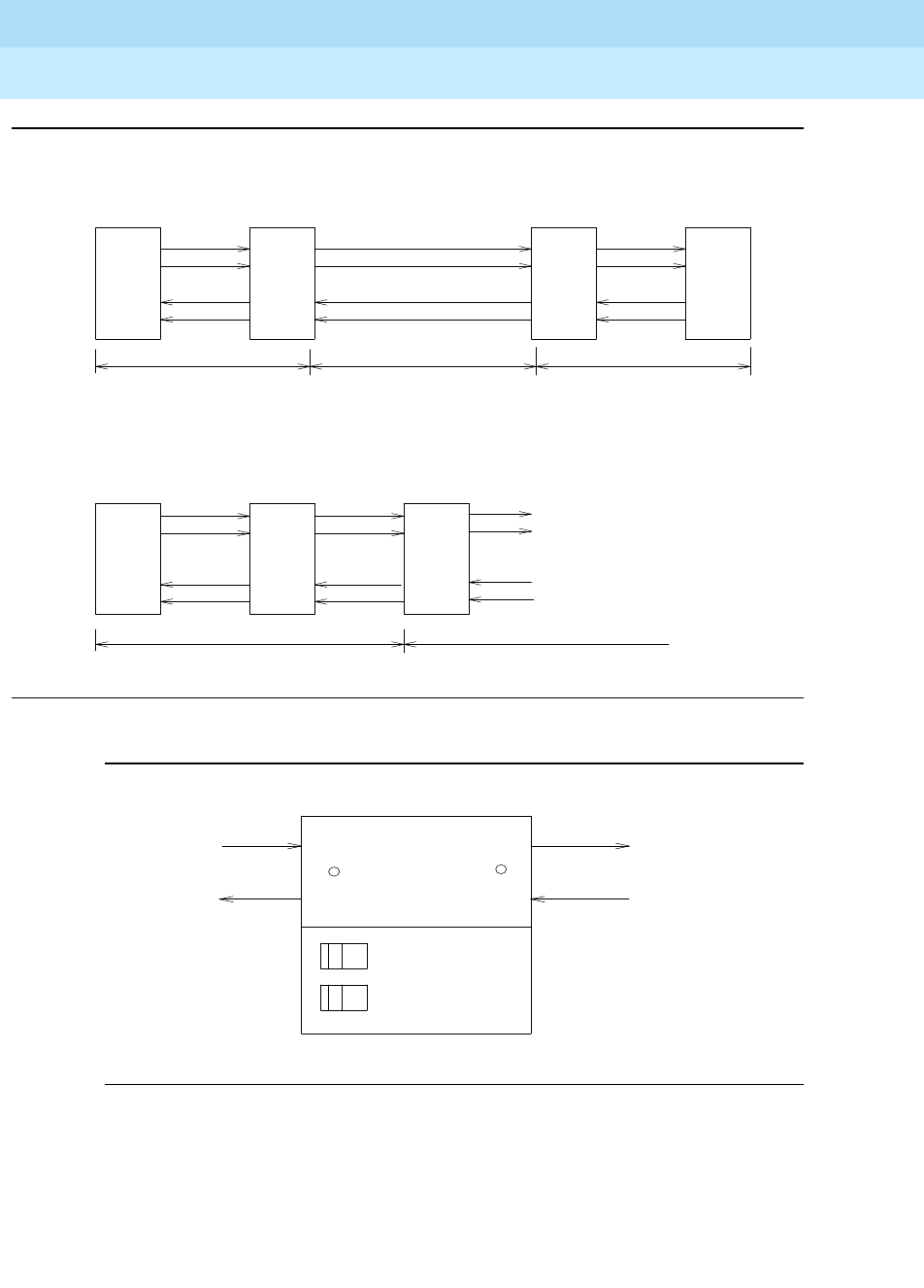
DEFINITY Enterprise Communications Server Release 6
Maintenance for R6r Volumes 1 & 2
555-230-126 Issue 2
January 1998
Maintenance Object Repair Procedures
Page 9-495DS1-FAC (DS1 Facility)
9
Figure 9-18. DS1 Facility Connections
Figure 9-19. Typical CSU Maintenance Capabilities
DS1CONV
B
CPE CPE
CSU
ACSU
BA
DS1CONV
Network/DS1 Facility
Network Interface at CSU
Network Interface at Cross Connect Field
T
R
T1
R1
T
R
T1
R1
CPE Network/DS1 Facility
Cross
Connect
Field
DS1CONV
R1
T1
R
T
CSU
CPE Loopback
Switch
Self Test
Switch
Signal In
Signal In
DS1 Facility Side
CSU
CPE Side
LOS LED
DS1 Facility
Side LOS
LED
Signal Out
Signal Out
CPE Side

DEFINITY Enterprise Communications Server Release 6
Maintenance for R6r Volumes 1 & 2
555-230-126 Issue 2
January 1998
Maintenance Object Repair Procedures
Page 9-496DS1-FAC (DS1 Facility)
9
System Technician-Demanded Tests:
Descriptions And Error Codes
Always investigate tests in the order presented in the table below. By clearing
error codes associated with the
Failure Audit
for example, you may also clear
errors generated from other tests in the testing sequence. The
Failure Audit
test
is executed via the test board command.
Far-End Internal Loopback Test (#797)
This test is destructive.
This test starts at the DS1 CONV circuit pack whose equipment location was
entered and traverses over the specified facility and loops at the internal facility
interface on the other DS1 CONV circuit pack in the DS1 CONV Complex. See
diagram below.
Every part of this test is executed under firmware control and the result is sent
back to the maintenance software. The test is executed by sending digital data
through every DS1 channel on this facility. For TN574 DS1 Converter facilities,
test patterns are sent through all DS1 channels. For TN1654 DS1 Converter
facilities, test patterns are sent through one DS1 channel.
If there is only one DS1 facility available, the system will not allow that last facility
to be busied out. In that case, the DS1 CONV circuit pack must be busied out
before executing this test.
On a Standard Reliability and High Reliability System (no PNC duplication), if
there is only one DS1 facility available, then this test can only be executed at the
end-point which is closer to the SPE relative to the neighbor DS1 CONV circuit
pack because of its impacts on the system control links. For TN574 DS1 CONV
boards, the completion of the test will be delayed in this configuration to wait for
the recovery of the system control links. On a Critical Reliability System (PNC
Duplication), or when there are multiple DS1 facilities, the test can be executed
at any DS1 CONV circuit pack.
1. D = Destructive; ND = Nondestructive
Order of Investigation Short Test
Sequence
Long
Test
Sequence External
Loopback Reset
Sequence D/ND1
Failure Audit (#949) ND
DS1 Interface Options Audit (#798) X X ND
Far-End Internal Loopback Test
(#797) XD
Near-end External Loopback Test
(#799) XD
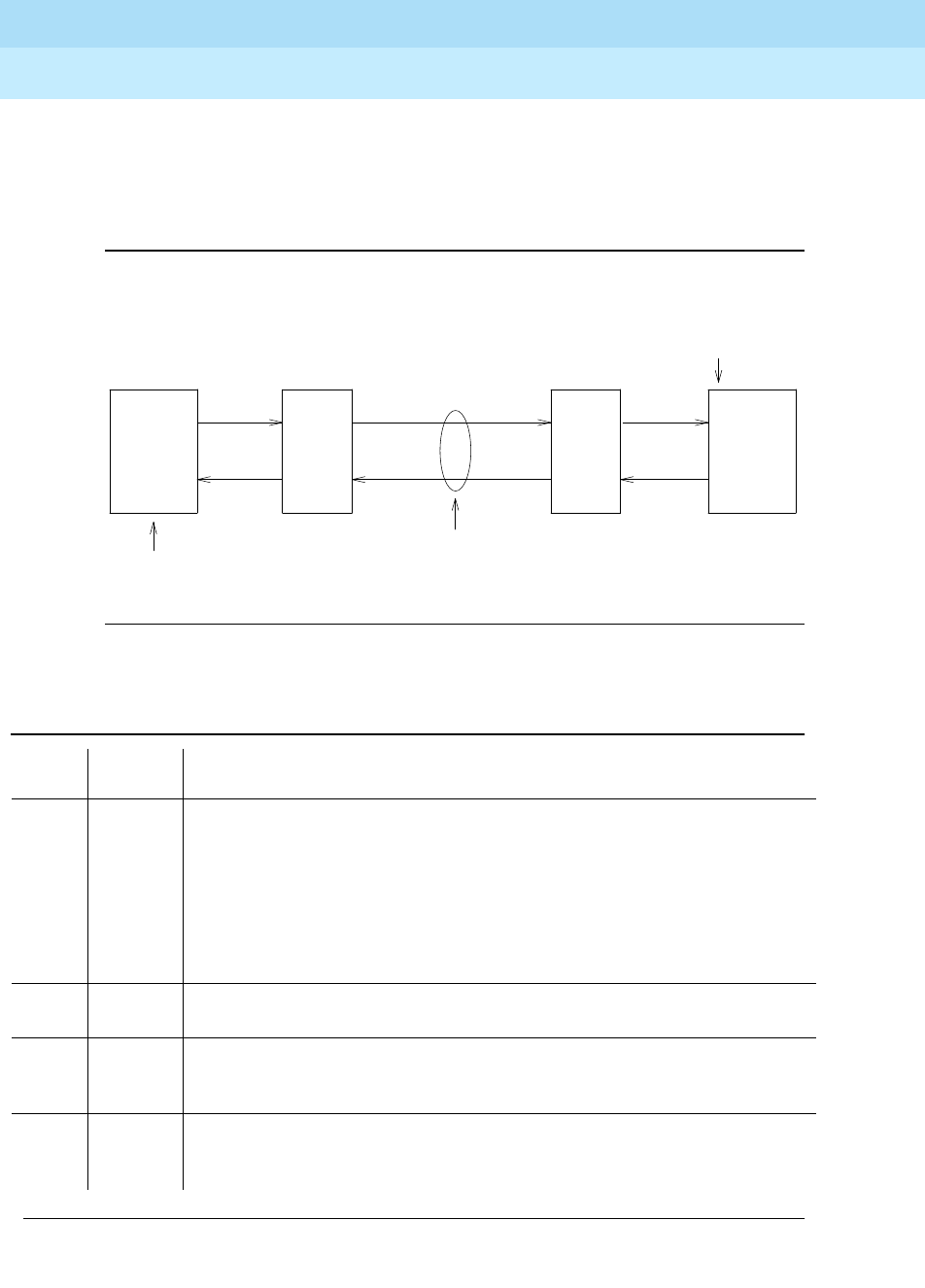
DEFINITY Enterprise Communications Server Release 6
Maintenance for R6r Volumes 1 & 2
555-230-126 Issue 2
January 1998
Maintenance Object Repair Procedures
Page 9-497DS1-FAC (DS1 Facility)
9
If the test passes on a TN1654 DS1 facility, the
round trip delay time
will be
displayed in milliseconds in the
Error Code
field. The round trip delay time is
defined as the length of time in milliseconds it takes for the firmware to receive
the test pattern after it has been sent.
Figure 9-20. Far-End Internal Loopback Test (#797)
Table 9-168. TEST #797 Far-End Internal Loopback Test
Error
Code Test
Result Description/ Recommendation
2000 ABORT Timed out while waiting for a response from the circuit pack.
2100 ABORT Could not allocate the necessary system resources to run this test.
2300 ABORT The downlink message necessary to run this test could not be sent.
2301 ABORT The timer could not be set before sending the downlink message necessary to
run this test.
1. Retry the command at 1-minute intervals a maximum of 3 times.
2316 ABORT Fiber link is not administered. Administer the DS1 CONV fiber link via the add
fiber-link command.
2321 ABORT DS1 facility is not busied out. Busyout the DS1 facility via the busyout
ds1-facility command. If there is only one DS1 facility, then busyout the DS1
CONV circuit pack via the busyout board command.
2332 ABORT Test is not allowed to execute at the far end with this system configuration
when there is only one DS1 facility available. Execute the test at the other end
of the DS1 CONV Complex.
Continued on next page
DS1 Facility
DS1CONV
A
. . .
.
.
.
.
.
.
.
.
.
.
.
. . .
Loop at internal interface
for the DS1 facility
DS1CONV
B
CSU
B
Test starts here
CSU
A

DEFINITY Enterprise Communications Server Release 6
Maintenance for R6r Volumes 1 & 2
555-230-126 Issue 2
January 1998
Maintenance Object Repair Procedures
Page 9-498DS1-FAC (DS1 Facility)
9
DS1 Interface Options Audit Test (#798)
This test is non-destructive.
This test sends the administered DS1 Interface options to the DS1 CONV circuit
pack. Options are sent to both DS1 CONV circuit packs at the same time to
prevent any transitional mismatch of options.
2500 ABORT Internal system error
1. Retry the command at 1-minute intervals a maximum of 3 times.
FAIL Far-End Internal loopback failed. A problem exists between DS1 CONV A and
the internal interface for DS1 facility on the DS1 CONV B (see diagram above).
1. If the test is executed as a part of an error analysis, then return back to the
related section.
2. Enter display errors and follow the associated repair procedures for any
on-board DS1 CONV-BD errors on this DS1 CONV circuit pack and the
DS1 CONV circuit pack at the other end of the DS1 CONV Complex.
3. If the network is used instead of private T1 lines, verify that the DS1 facility
and the network are using the same Line Coding. For TN574 boards and
TN1654 boards in T1 mode, also verify that the Framing Mode used is the
same. Use list fibers and display fiber-link commands to check the
values for this DS1 facility. Contact T1 Network Service to check the
modes used by the network. See the above sections, “Line Coding” and
“Framing Mode” for details on how these options apply to the TN574 and
TN1654 DS1 CONV boards.
4. Isolate the problem by running the Near-end External Loopback test #799
via the test ds1-facility UUCSSf external-loopback command, first at
this end and then at the other end of the DS1 CONV Complex. Setup
loopbacks at different points as shown in the description diagram for test
#799, and follow repair procedures described for test #799.
5. If the problem could not be found by near-end external loopback tests,
then the fault should be between the CSU A and the CSU B. Contact T1
Network Service to resolve the problem, also see the repair procedures for
error type #1025 (Loss of Frame Alignment).
Any PASS Transmission through the path of the loopback is successful. TN1654 DS1
facilities will display the round trip delay time in milliseconds in the Error Code
field. The round trip delay time is defined as the length of time in milliseconds it
takes for the firmware to receive the test pattern after it has been sent.
Table 9-168. TEST #797 Far-End Internal Loopback Test — Continued
Error
Code Test
Result Description/ Recommendation
Continued on next page

DEFINITY Enterprise Communications Server Release 6
Maintenance for R6r Volumes 1 & 2
555-230-126 Issue 2
January 1998
Maintenance Object Repair Procedures
Page 9-499DS1-FAC (DS1 Facility)
9
The following DS1 facility options are sent to the TN574 DS1 CONV circuit pack:
Framing Mode, Line Coding and DS1 CONV-1 and DS1 CONV-2 Line
Compensation.
The following DS1 facility options are sent to the TN1654 DS1 CONV circuit pack:
Line Coding and DS1 CONV-1 and DS1 CONV-2 Line Compensation (T1 only).
These option fields are given in the fiber link administration screen.
Near-end External Loopback Test (#799)
This test is destructive
This test starts at the DS1 CONV circuit pack whose equipment location was
entered and traverses over the specified facility and loops back at the manually
hard-wired external loopback device. Depending on the type of physical
connectivity of the DS1 facility, special tools, cables or connectors may be
required to make the hard-wired loopbacks.
To isolate a problem, set the loopback first at the loopback point LB 1, and then
at the loopback point LB 2, see Figure 9-21 and
Figure 9-18.
Place the
loopbacks at as many points as your CSU capabilities will allow. Hard-wired
loopbacks at the far end are not desirable, because the equalization level
adjustments may cause problems.
Table 9-169. TEST #798 DS1 Interface Options Audit
Error
Code Test
Result Description/ Recommendation
105 ABORT The neighbor DS1 CONV circuit pack at the other end of the DS1 CONV
Complex is not accessible.
2100 ABORT Could not allocate the necessary system resources to run this test.
2000 ABORT Timed out while waiting for a response from the circuit pack.
2300 ABORT The downlink message necessary to run this test could not be sent.
2301 ABORT The timer could not be set before sending the downlink message necessary to
run this test.
1. Retry the command at 1-minute intervals a maximum of 3 times.
2316 ABORT Fiber link is not administered. Administer the DS1 CONV fiber link via the add
fiber-link command.
2500 ABORT Internal system error
1. Retry the command at 1-minute intervals a maximum of 3 times.
PASS The DS1 Interface options are sent to the circuit pack.
Continued on next page
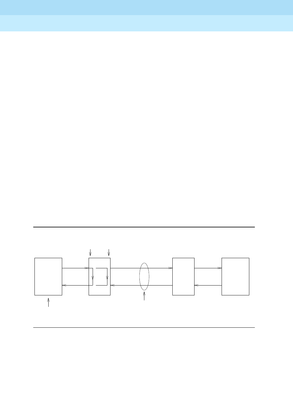
DEFINITY Enterprise Communications Server Release 6
Maintenance for R6r Volumes 1 & 2
555-230-126 Issue 2
January 1998
Maintenance Object Repair Procedures
Page 9-500DS1-FAC (DS1 Facility)
9
Every part of this test is executed under firmware control and the result is sent
back to the maintenance software. The test is executed by sending digital data
through every DS1 channel on this DS1 facility.
This test is executed via the test ds1-facility UUCSSf external-loopback
command. It is not part of the Long Test Sequence because it requires
modifications to the physical connectivity of the DS1 facility.
If there is only one DS1 facility available, system will not allow the last facility to
be busied out. In that case, the DS1 CONV circuit pack must be busied out
before executing this test.
On a Standard Reliability and High Reliability System (no PNC duplication), if
there is only one DS1 facility available, then this test can only be executed at the
end-point which is closer to the SPE relative to the neighbor DS1 CONV circuit
pack because of its impacts on the system control links. On a Critical Reliability
System (PNC Duplication), or when there are multiple DS1 facilities, the test can
be executed at any DS1 CONV circuit pack.
If the test passes on a TN1654 DS1 facility, the
round trip delay time
will be
displayed in milliseconds in the
Error Code
field. The round trip delay time is
defined as the length of time in milliseconds it takes for the firmware to receive
the test pattern after it has been sent. This measurement is taken on the last DS1
channel tested.
Figure 9-21. Loopback Points for Test #799
LB 2LB 1
DS1 Facility
DS1CONV
A
CSU A
Test starts here
CSU B
DS1CONV
B

DEFINITY Enterprise Communications Server Release 6
Maintenance for R6r Volumes 1 & 2
555-230-126 Issue 2
January 1998
Maintenance Object Repair Procedures
Page 9-501DS1-FAC (DS1 Facility)
9
Table 9-170. TEST #799 Near-end External Loopback Test
Error
Code Test
Result Description/ Recommendation
2100 ABORT Could not allocate the necessary system resources to run this test.
2000 ABORT Timed out while waiting for a response from the circuit pack.
2300 ABORT The downlink message necessary to run this test could not be sent.
2301 ABORT The timer could not be set before sending the downlink message necessary to
run this test.
1. Retry the command at 1-minute intervals a maximum of 3 times.
2316 ABORT Fiber link is not administered. Administer the DS1 CONV fiber link via the add
fiber-link command.
2321 ABORT DS1 facility is not busied out. Busyout the DS1 facility via the busyout
ds1-facility command. If there is only one DS1 facility, then busyout the DS1
CONV circuit pack via the busyout board command.
2332 ABORT Test is not allowed to execute at the far end with this system configuration
when there is only one DS1 facility available. Check the green LED at the face
plate of the DS1 CONV circuit pack. The green LED should be on if the loop is
complete.
2500 ABORT Internal system error
1. Retry the command at 1-minute intervals a maximum of 3 times.
FAIL Near-end external loopback failed. A problem exists in the path of the
loopback.
1. If the test is executed as a part of an error analysis, then return back to the
related section.
2. Enter display errors and follow the associated repair procedures for any
on-board DS1C-BD errors.
3. If the loopback point is LB 1, replace connectors and cables between the
DS1 CONV A and the CSU A. If the loopback point is LB 2, replace CSU A.
Also see the repair procedure for error type #1025 (Loss of Frame
Alignment).
4. If the test still fails, replace DS1 CONV A circuit pack.
Any PASS Transmission through the path of the loopback is successful. TN1654 DS1
facilities will display the round trip delay time in milliseconds in the Error Code
field. The round trip delay time is defined as the length of time in milliseconds it
takes for the firmware to receive the test pattern after it has been sent. This
measurement is taken on the last DS1 channel tested.
Continued on next page

DEFINITY Enterprise Communications Server Release 6
Maintenance for R6r Volumes 1 & 2
555-230-126 Issue 2
January 1998
Maintenance Object Repair Procedures
Page 9-502DS1-FAC (DS1 Facility)
9
Failure Audit (#949)
This test is non-destructive.
This test queries the DS1 CONV circuit pack for any existing circuit pack or
facility failures and any unacknowledged cleared failure messages. Upon
receiving the query request, DS1 CONV firmware sends failure reports to the
maintenance software for every error in its failure database.
This test operates on both maintenance objects DS1C-BD and DS1-FAC. Error
counts of both MOs (DS1C-BD and DS1-FAC) that are displayed in the error log
will be incremented when this test is executed. This test is executed via the test
board command. The test is also executed internally by the maintenance
software when an alarm is resolved
Table 9-171. TEST #949 Failure Audit
Error
Code Test
Result Description/ Recommendation
2100 ABORT Could not allocate the necessary system resources to run this test.
2000 ABORT Timed out while waiting for a response from the circuit pack.
2300 ABORT The downlink message necessary to run this test could not be sent.
2301 ABORT The timer could not be set before sending the downlink message necessary to
run this test.
1. Retry the command at 1-minute intervals a maximum of 3 times.
2316 ABORT Fiber link is not administered. Administer the DS1 CONV fiber link via the add
fiber-link command.
2500 ABORT Internal system error
1. Retry the command at 1-minute intervals a maximum of 3 times.
FAIL The DS1 CONV circuit pack reported failures or retransmitted a cleared failure
message.
1. Enter display errors and follow the associated repair procedures for any
DS1C-BD and DS1-FAC errors.
PASS The DS1 CONV circuit pack has no failures.
Continued on next page

DEFINITY Enterprise Communications Server Release 6
Maintenance for R6r Volumes 1 & 2
555-230-126 Issue 2
January 1998
Maintenance Object Repair Procedures
Page 9-503DS1 CONV-BD
9
DS1 CONV-BD
DS1 Converter (Also called DS1 CONV)
The DS1 CONV Complex is part of the Port Network Connectivity (PNC)
consisting of two TN574 DS1 Converter or two TN1654 DS1 Converter circuit
packs connected by one to four DS1 facilities. It is used to extend the range of
the 32 Mbps fiber links that connect EPNs to either the PPN or the Center Stage
Switch, allowing EPNs to be located at remote sites.
The TN1654 DS1 Converter Circuit pack is a redesign of the TN574 DS1
Converter board. The TN1654 provides functionality equivalent to the TN574 but
also adds a 32-Channel E1 interface for international support as well as
circuit-switched wideband connections (NxDS0). The TN1654 is supported
beginning with DEFINITY Release 5r.
Every error condition reported by the firmware is associated with background
tests that the firmware runs autonomously. Demand tests that are executed by
the maintenance software do not cause any new error generation by the
firmware. However, the Failure Audit test #949 effects auditing of the software
error log by forcing the firmware to report the pending errors again.
Maintenance of the DS1 facilities themselves is covered under the “DS1-FAC”
maintenance object.
The DS1 CONV Complex can extend a fiber link between two EIs or between an
EPN EI and an SNI. Fiber links between two SNIs or between the Processor Port
Network (PPN) and the Center Stage Switch (CSS) cannot be extended.
The TN1654 board is not compatible with the TN574 board. A DS1 CONV
Complex may consist of two TN574 boards or two TN1654 boards but a TN574
cannot be combined with a TN1654 in the same complex. A system with multiple
1. UU is the universal cabinet number (1 for PPN, 2-44 for EPNs). C is the carrier designation
(A, B, C, D, or E). SS is the number of the slot in which the circuit pack resides (01 to 21).
MO Name (in
Alarm Log) Alarm Level Initial Command to Run1Full Name of MO
DS1 CONV-BD MAJOR test board UUCSS sh r 1 DS1 CONV Circuit
Pack
DS1 CONV-BD MINOR test board UUCSS sh r 1 DS1 CONV Circuit
Pack
DS1 CONV-BD WARNING test board UUCSS sh r 1 DS1 CONV Circuit
Pack

DEFINITY Enterprise Communications Server Release 6
Maintenance for R6r Volumes 1 & 2
555-230-126 Issue 2
January 1998
Maintenance Object Repair Procedures
Page 9-504DS1 CONV-BD
9
DS1 CONV-remoted EPNs may contain DS1 CONV Complexes of both types,
TN1654 board-pairs and TN574 board-pairs. Critical reliability configurations
with a pair of DS1 CONV Complexes serving an EPN require identical board
pairs and facilities. For example, a TN574 Complex and a TN1654 Complex may
not be used together to serve the same EPN in a critical reliability configuration.
DS1 CONV circuit packs connect to TN570 Expansion Interface (EI) circuit packs
and TN573 Switch Node Interface (SNI) circuit packs via metallic cables as
shown in Figure 9-22. A fiber link cable can be used instead of the metallic cable
if it is necessary to locate the DS1 CONV far from the connected EI or SNI circuit
pack, for example, in an adjacent cabinet.
The DS1 CONV circuit pack can be placed in any regular slot in a PN carrier.
However, the DS1 CONV circuit pack can only be placed in slots 1 and 21 in a
Switch Node (SN) carrier. The DS1 CONV circuit pack is not connected to the
TDM bus or the SN backplane. Communication to the circuit pack is done
through the connected EI or the SNI circuit packs. Therefore, there is
considerable interaction between the DS1 CONVs and the connected EIs and
the SNIs. A special "Y" cable connects the DS1 CONV circuit pack to the Fiber
Endpoint and to the facilities.
NOTE:
The two DS1 CONV boards, TN1654 and TN574, use unique “Y” cables
that are incompatible with each other.
The TN573 SNI circuit pack is incompatible with the TN1654 board. A TN573B or
later suffix SNI board must be used when connecting to a TN1654 board. The
TN573B SNI board is fully backward compatible with the TN573 board and can
be connected to either TN1654 or TN574 boards.
NOTE:
A TN573B or later suffix board must be used when connecting a SNI board
to a TN1654 board. Error 125 will be logged and an on-board minor alarm
will be generated against the SNI board if it is incompatible with the
TN1654 circuit pack.
Figure 9-23 and Figure 9-24 show DS1 CONV connections in a direct connect
PNC configuration and between the CSS and an EPN in a Critical Reliability
System configuration (duplicated PNC).
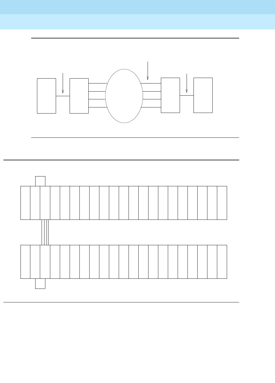
DEFINITY Enterprise Communications Server Release 6
Maintenance for R6r Volumes 1 & 2
555-230-126 Issue 2
January 1998
Maintenance Object Repair Procedures
Page 9-505DS1 CONV-BD
9
Figure 9-22. DS1 CONV connection to EIs and SNIs
Figure 9-23. DS1 CONV Complex in Direct Connect PNC
Metallic or Fiber Connection
DS1CONV
DS1 Facilities
Network
EI or
SNI
EI
DS1CONV
Metallic or Fiber Connection
DS1 Facilities
I
E
D
S
1
C
O
N
V
D
S
1
C
O
N
V
I
E
Metallic or Fiber Connection
Remote EPN
PPN
Metallic or Fiber Connection
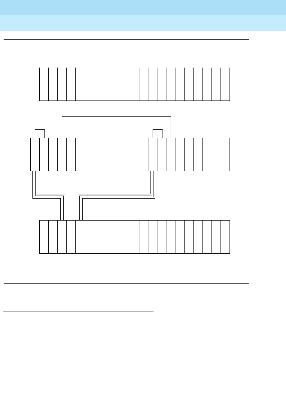
DEFINITY Enterprise Communications Server Release 6
Maintenance for R6r Volumes 1 & 2
555-230-126 Issue 2
January 1998
Maintenance Object Repair Procedures
Page 9-506DS1 CONV-BD
9
Figure 9-24. DS1 CONV Complex in Duplicated PNC with 1 SN
DS1 CONV Administration and Board Insertion
Board insertion is the detection of a circuit pack by the system. The DS1 CONV
circuit pack will not be inserted unless the circuit pack type, TN574 or TN1654, is
entered into the associated field in circuit pack administration screen. The Fiber
Endpoint (the EI or the SNI) must also be inserted and be operational for the DS1
CONV circuit pack to function.
Fiber link administration must be completed before the DS1 CONV maintenance
can be operational. Fiber links are administered via the add fiber-link command.
Fiber Endpoints, DS1 CONV circuit pack locations and DS1 facility options are
entered as a part of the fiber link administration.
Metallic
or Fiber
Connection
Fiber Link
E
I
E
I
PPN
. . .
I
N
S
D
S
1
C
O
N
V
. . . I
S
N
I
S
N
I
S
N
D
S
1
C
O
N
V
E
I
Metallic or Fiber Connection
EPN
DS1 Facilities
DS1 Facilities
SN B-PNC SN A-PNC
D
S
1
C
O
N
V
E
I
D
S
1
C
O
N
V
Metallic
or Fiber
Connection
Fiber Link

DEFINITY Enterprise Communications Server Release 6
Maintenance for R6r Volumes 1 & 2
555-230-126 Issue 2
January 1998
Maintenance Object Repair Procedures
Page 9-507DS1 CONV-BD
9
Administration steps for a Standard Reliability and High Reliability System (no
PNC Duplication) are as follows:
1. Administer carriers via the add/change cabinet command
2. Administer circuit packs via the change circuit-pack command
3. Administer connectivity and the facility options of the DS1 CONV Complex
via the add/change fiber-link command
Administration steps for a Critical Reliability System (PNC duplication) are as
follows:
1. Enable PNC duplication feature using change system-parameter
customer-option command
2. Administer carriers via the add/change cabinet command
3. Administer circuit packs via the change circuit-pack command
4. Administer connectivity and the DS1 facility options of each DS1 CONV
Complex via the add/change fiber-link command
5. Turn on PNC duplication via the change system-parameter duplication
command
TN1654 Board Configuration Switch Settings
The TN1654 DS1 CONV circuit pack is field configurable for T1 or E1 operation
so that a single board serves worldwide application. All four DS1 facilities are
configured to either T1 or E1 as a group via an option switch located on the
component side of the circuit pack. If T1 operation is selected, four additional
switches are used to select the framing mode for each facility. Each facility can
be set to either D4 or ESF framing. If E1 operation is selected, the same four
switches are used to select the E1 facility line termination impedance. The E1 line
termination impedance for each facility can be set to either 120Ω for twisted-pair
or 75Ω for coaxial wiring.
T1 or E1 operation must also be administered for the TN1654 DS1 CONV board
on the fiber-link form via the Bit Rate field. An error will be logged and an alarm
will be raised if there is a T1/E1 inconsistency between the administered bit rate
and the board option switch setting.
The T1 facility framing mode and the E1 facility line termination impedance are
defined by the option switch settings only. Administration of these values is not
allowed. The fiber-link form will display the selected option switch settings for
each facility.
DS1 CONV LEDs
The TN574 board has seven LEDs on its faceplate. The TN1654 board has
eleven LEDs on its faceplate. The top three system standard LEDs are used to
provide an indication of the state of the DS1 CONV board. These LEDs are under

DEFINITY Enterprise Communications Server Release 6
Maintenance for R6r Volumes 1 & 2
555-230-126 Issue 2
January 1998
Maintenance Object Repair Procedures
Page 9-508DS1 CONV-BD
9
firmware control until the board has established a link to the SPE via the EI or SNI.
Once the link is established, software controls the three LEDs. If the link breaks,
the LEDs are again under firmware control.
The red and green LEDs have the traditional use where red means an alarm
condition and green indicates that maintenance testing is in progress. The red
and green LED is also turned on during circuit pack initialization by firmware.
When the control link to the circuit pack is lost, firmware controls the red LED to
indicate an alarm condition.
The yellow LED under firmware control is used to indicate the state of the
physical Fiber Interface, the Fiber Channel (link to EI or SNI), the DS1 Control
Channel (link to opposite DS1 CONV board) and the SPE communications link in
the following manner and order of priority. (The yellow LED remains on for longer
periods of time as the DS1 CONV Complex becomes closer to being fully
operational.)
1. If the Fiber is Out of Frame or if a Fiber Loss of Signal condition exists, the
yellow LED will flicker at a 5 Hz rate (on for 100 mS, off for 100 mS).
2. If the Fiber Channel is down (DS1 Converter circuit pack/fiber endpoint
communications), the yellow LED will flash at a 1 Hz rate (on for 500 mS,
off for 500 mS).
3. If the DS1 Control Channel is down between the two DS1 CONVs in the
DS1 CONV Complex, the yellow LED will pulse at a 1/2 Hz rate (on for 1
second, off for 1 second).
4. If the SPE communications link is down, the yellow LED will wink off every
2 seconds for 200 ms (2 seconds on, 200 mS off).
5. If all is well with the Fiber Interface and all communications channels, the
yellow LED will remain on continuously in a Standard Reliability and High
Reliability System configuration. In Critical Reliability systems (duplicated
PNC), an active DS1 CONV circuit pack will have its yellow LED on
continuously, and a standby DS1 CONV circuit pack will have its yellow
LED off. The LED will then be under software control.
The bottom four green LEDs on the TN574 DS1 CONV board are under hardware
control. The four green LEDs indicate, for each DS1 CONV facility, whether a
receive signal is present for the DS1 facility
The next four LEDs on the TN1654 DS1 CONV board are labeled STATUS LEDs
and are for future use. These LEDs will not be lit.
The bottom four LEDs on the TN1654 board are labeled SPAN LEDs. These LEDs
are under firmware control. If the facility is not administered, then the LED is not
lit. The LED is lit amber if the facility is running alarm free. If the facility is
detecting either a red alarm (loss-of-signal or loss-of-frame), a yellow alarm
(remote frame alarm) or a blue alarm (AIS signal) then the LED is lit red. The
SPAN SELECT Switch on the TN1654 faceplate is for future use. Pushing the
switch will have no affect on the board.
DEFINITY Enterprise Communications Server Release 6
Maintenance for R6r Volumes 1 & 2
555-230-126 Issue 2
January 1998
Maintenance Object Repair Procedures
Page 9-509DS1 CONV-BD
9
Clear Firmware-Counters Command
DS1 CONV firmware generates error reports autonomously. This takes place
independently of technician-demanded tests. Therefore, the test board UUCSS
clear command will not affect the error status reported by firmware. The clear
firmware-counters command will clear all on-board firmware-detected
errors unconditionally.
The clear firmware-counters UUCSS command sends a downlink message to
the DS1 CONV circuit packs, causing them to clear out their firmware error
counters and failure databases. Once the firmware failure database is cleared,
the failure audit test (#949) will pass. If problems still exist, the firmware will
increment its error counters and the failure audit test will begin failing again.
This command should not be used as a replacement for the repair procedures
associated with the hardware error log entries. This command may be useful if a
problem has been fixed and off-board alarms associated with the problem are
still active.
Downtime required when upgrading to TN1654
DS1 CONV Circuit Packs
!WARNING:
Upgrading from TN574 DS1 CONV circuit packs to TN1654 DS1 CONV
circuit packs will require down time for the affected EPN.
The TN1654 DS1 Converter circuit pack is not compatible with the TN573 SNI
circuit pack, the TN574 DS1 CONV board, the Y-cable used to connect to the
TN574 DS1 CONV board or pre-G3V5 software. All DS1 CONV boards and
Y-cables must be upgraded. If the EPN is remoted via a Center-Stage Switch, the
connected SNI must also be upgraded. A TN573B or later suffix SNI board must
be used when connecting to a TN1654 DS1 CONV board.
The fiber-link administration for the TN574 DS1 CONV Complex must be
removed via the remove fiber-link command. The change circuit-pack form must
be updated to reflect that TN1654 boards are now being used. The TN1654 DS1
CONV Complex can then be administered via the add fiber-link command.
Replacing a DS1 CONV Circuit Pack with the
same type DS1 CONV circuit pack—Simplex
PNC
!WARNING:
Do not power down a Switch Node carrier to replace a circuit pack.

DEFINITY Enterprise Communications Server Release 6
Maintenance for R6r Volumes 1 & 2
555-230-126 Issue 2
January 1998
Maintenance Object Repair Procedures
Page 9-510DS1 CONV-BD
9
!WARNING:
Replacing a Switch Node Interface, Switch Node Clock, Expansion
Interface or DS1 Converter circuit pack on a simplex system disrupts
service. The service effect can range from outage of a single EPN to outage
of the entire system.
!WARNING:
A DS1 Converter Complex must consist of two TN574 boards or two
TN1654 boards. A TN574 cannot be combined with a TN1654 in the same
DS1 CONV Complex.
Replacing a DS1 CONV Circuit Pack with the
same type DS1 CONV circuit pack—Duplicated
PNC
!WARNING:
On a system with duplicated PNC, synchronization may be provided over a
combination of active and standby components. This condition is indicated
by an OFF-BOARD WARNING alarm against TDM-CLK with error type
2305. Repairs to standby PNC in this state may disrupt service. Otherwise,
if the active PNC is functional, replacement of a standby component will not
disrupt service.
Steps Comments
Enter busyout board UUCSS UUCSS represents the cabinet-carrier-slot
address of the circuit pack to be replaced. A
G3-MT logged in at the EPN Maintenance
circuit pack will remain active in spite of the
busyout.
Replace the circuit pack with the same
DS1 CONV board type.
Wait for the circuit pack to reset Red and green LEDs will light and then go
out.
Enter release board UUCSS CAUTION:
Do not busyout any Expansion
Interface circuit pack after this point.
Enter test alarms long clear for category
exp-intf.
Wait 5 minutes for SNI-BD, FIBER-LK
AND DS1C-BD alarms to clear, or enter
clear firmware counters a-pnc
DEFINITY Enterprise Communications Server Release 6
Maintenance for R6r Volumes 1 & 2
555-230-126 Issue 2
January 1998
Maintenance Object Repair Procedures
Page 9-511DS1 CONV-BD
9
.
!WARNING:
Do not power down a Switch Node carrier to replace a circuit pack.
!WARNING:
Replacing a Switch Node Interface, Switch Node Clock, Expansion
Interface or DS1 Converter circuit pack on a simplex system disrupts
service. The service effect can range from outage of a single EPN to outage
of the entire system.
!WARNING:
A DS1 Converter Complex must consist of two TN574 boards or two
TN1654 boards. A TN574 cannot be combined with a TN1654 in the same
DS1 CONV Complex.
!WARNING:
The two DS1 CONV boards, TN1654 and TN574, use unique “Y” cables that
are incompatible with each other.
Steps Comments
Enter status pnc Verify that the component to be replaced is
on the standby PNC.
Enter busyout pnc
Enter busyout board UUCSS UUCSS represents the cabinet-carrier-slot
address of the circuit pack to be replaced.
Replace the circuit pack with the same
DS1 CONV board type.
Enter release board UUCSS CAUTION:
Do not busyout any Expansion
Interface circuit pack after this point.
Enter test alarms long clear for
category exp-intf
Wait 5 minutes for SNI-BD, SNI-PEER,
FIBER-LK, and DS1C-BD alarms to clear,
or enter clear firmware counters
<a-pnc or b-pnc>
Use the letter designation of the pnc which
holds the replaced component (the standby
pnc).
Enter status pnc If either PNC state-of-health is not
"functional", consult the PNC-DUP section of
the Maintenance Manual.
Enter release pnc

DEFINITY Enterprise Communications Server Release 6
Maintenance for R6r Volumes 1 & 2
555-230-126 Issue 2
January 1998
Maintenance Object Repair Procedures
Page 9-512DS1 CONV-BD
9
!WARNING:
A TN573B or later suffix board must be used when connecting a SNI board
to a TN1654 DS1 Converter board.
Steps Comments
Enter list fiber-link Determine the fiber-link number associated
with the two TN574 circuit packs to be
upgraded.
Enter busyout fiber-link <fiber #> fiber # represents the fiber-link number
associated with the TN574 DS1 CONV
Complex that is being upgraded to a TN1654
DS1 CONV Complex.
Enter remove fiber-link <fiber #>
Remove the TN574 DS1 CONV circuit
packs from the system.
Replace the TN574 Y-cables with
appropriate TN1654 Y-cables.
Replace the removed TN574 DS1 CONV
circuit packs with TN1654 DS1 CONV
circuit packs. Prior to installing the
TN1654 boards, review the prior
section,
TN1654 Board Configuration
Switch Settings
.
If a TN1654 DS1 CONV board is
connected to an SNI board, upgrade the
SNI to a TN573B or greater.
Wait for the circuit packs to reset Red and green LEDs will light and then go out.
Enter change circuit-packs <cabinet
#>. Update the form to show that
TN1654 boards are now being used
instead of TN574 boards. Also update
the connected SNI, if applicable, to
suffix B.
cabinet # represents the cabinet associated
with a DS1 CONV board. The appropriate
change circuit-packs
form needs to be
updated for both DS1 CONV boards. Also, if
needed, re-add translations for connected EI
boards.
Enter add fiber-link <fiber #> to re-add
the fiber-link using TN1654 DS1 CONV
circuit packs. See the
Definity Enterprise
Communications Server, Release 5,
Implementation Manual
, 555-230-302,
for details on TN1654 administration.
fiber # represents the fiber-link number
associated with the TN574 DS1 CONV
Complex that is being upgraded to a TN1654
DS1 CONV Complex
Enter test alarms long clear for
category exp-intf.
DEFINITY Enterprise Communications Server Release 6
Maintenance for R6r Volumes 1 & 2
555-230-126 Issue 2
January 1998
Maintenance Object Repair Procedures
Page 9-513DS1 CONV-BD
9
Upgrading TN574 DS1 CONV Circuit Packs in a
fiber-link to TN1654s—Duplicated PNC
!WARNING:
Do not power down a Switch Node carrier to replace a circuit pack.
!WARNING:
In duplicated PNC configurations, one DS1 CONV complex in the fiber-link
serves as the active and the second DS1 CONV complex serves as the
standby. Each DS1 Converter Complex consists of two TN574 boards or
two TN1654 boards. A TN574 cannot be combined with a TN1654 in the
same DS1 CONV Complex. It is also required that all four DS1 CONV
boards and interconnecting facilities that serve an EPN be of the same
type. Note, however, that TN574 and TN1654 boards can coexist within the
same system, they just cannot be in the same fiber-link.
!WARNING:
The two DS1 CONV boards, TN1654 and TN574, use unique “Y” cables that
are incompatible with each other.
!WARNING:
A TN573B or later suffix board must be used when connecting a SNI board
to a TN1654 DS1 Converter board.
Wait 5 minutes for SNI-BD, FIBER-LK
AND DS1C-BD alarms to clear, or enter
clear firmware-counters a-pnc
Table 9-172. Upgrading TN574 DS1 CONV Circuit Packs in a fiber-link to
TN1654s—Duplicated PNC
Steps Comments
Enter status pnc Verify that the A-PNC is active. If the
B-PNC is active, enter the reset pnc
interchange command to cause the
A-PNC to go active.
Continued on next page
Steps Comments

DEFINITY Enterprise Communications Server Release 6
Maintenance for R6r Volumes 1 & 2
555-230-126 Issue 2
January 1998
Maintenance Object Repair Procedures
Page 9-514DS1 CONV-BD
9
Enter busyout pnc-standby Fiber link can not be removed if PNC
duplication is operational. Must busyout
the standby PNC first.
Enter change system-parameters
duplication. Change the Enable
Operation of PNC Duplication? field
to n.
Disable PNC duplication.
Enter list fiber-link Determine the fiber-link number that the
four TN574 circuit packs to be upgraded
are associated with.
Enter busyout fiber-link <fiber #> fiber # represents the fiber-link number
associated with the TN574 DS1 CONV
Complexes that are being upgraded to
TN1654 DS1 CONV Complexes.
Enter remove fiber-link <fiber #>
Remove the four TN574 DS1 CONV circuit
packs from the system.
Replace the TN574 Y-cables with
appropriate TN1654 Y-cables.
Replace the removed TN574 DS1 CONV
circuit packs with TN1654 DS1 CONV circuit
packs. Prior to installing the TN1654 boards,
review the prior section,
TN1654 Board
Configuration Switch Settings
.
If a TN1654 DS1 CONV board is connected
to an SNI board, upgrade the SNI to a
TN573B or greater.
Wait for the circuit packs to reset Red and green LEDs will light and then go
out.
Enter change circuit-packs <cabinet #>.
Update the form to show that TN1654
boards are now being used instead of
TN574 boards. Also update the connected
SNI, if applicable, to suffix B.
cabinet # represents the cabinet
associated with a DS1 CONV board. The
appropriate
change circuit-packs
form
needs to be updated for all four DS1
CONV boards. Also, if needed, re-add
translations for connected EI boards.
Table 9-172. Upgrading TN574 DS1 CONV Circuit Packs in a fiber-link to
TN1654s—Duplicated PNC — Continued
Steps Comments
Continued on next page

DEFINITY Enterprise Communications Server Release 6
Maintenance for R6r Volumes 1 & 2
555-230-126 Issue 2
January 1998
Maintenance Object Repair Procedures
Page 9-515DS1 CONV-BD
9
Error Log Entries and Test to Clear Values
Enter change system-parameters
duplication. Change the Enable
Operation of PNC Duplication? field
to y.
Enable PNC duplication.
Enter add fiber-link <fiber #> to re-add the
fiber-link using TN1654 DS1 CONV circuit
packs. See the
Definity Enterprise
Communications Server, Release 5,
Implementation Manual
, 555-230-302, for
details on TN1654 administration.
fiber # represents the fiber-link number
associated with the TN574 DS1 CONV
Complexes that are being upgraded to
TN1654 DS1 CONV Complexes.
Enter test alarms long clear for category
exp-intf.
Wait 5 minutes for SNI-BD, SNI-PEER,
FIBER-LK and DS1C-BD alarms to clear, or
enter clear-firmware counters <a-pnc or
b-pnc>
Enter status pnc If either PNC State of Health is not
"functional", consult the PNC-DUP section
of the Maintenance Manual.
Table 9-173. DS1 CONV Board Error Log Entries
Error
Type Aux
Data Associated Test Alarm
Level On/Off
Board Test to Clear Value
010 Any Any Any test board UUCSS sh r 1
1(a) Failure Audit Test
#949 MAJOR ON/OFF test board UUCSS sh r 1
18(b) 0 busyout board
UCSS WNG OFF release board UCSS
125(c) 3 None MINOR ON
218(d) any None MAJOR ON
Continued on next page
Table 9-172. Upgrading TN574 DS1 CONV Circuit Packs in a fiber-link to
TN1654s—Duplicated PNC — Continued
Steps Comments
Continued on next page

DEFINITY Enterprise Communications Server Release 6
Maintenance for R6r Volumes 1 & 2
555-230-126 Issue 2
January 1998
Maintenance Object Repair Procedures
Page 9-516DS1 CONV-BD
9
1. Run the Short Test Sequence first. If all tests pass, run the Long Test Sequence. Refer to the
appropriate test description and follow the recommended procedures.
257(e) Failure Audit Test
#949 MINOR ON test board UUCSS sh r 1
513(f) 1 Failure Audit Test
#949 MAJOR ON test board UUCSS sh r 1
513(g) 2 Failure Audit Test
#949 MAJOR ON test board UUCSS sh r 1
513(h) 3 Failure Audit Test
#949 MAJOR ON test board UUCSS sh r 1
513(i) 4 Failure Audit Test
#949 MAJOR ON test board UUCSS sh r 1
513(j) 5 Failure Audit Test
#949 MAJOR ON test board UUCSS sh r 1
769(k) 1 Failure Audit Test
#949 MINOR ON/OFF test board UUCSS sh r 1
769(l) 2 Failure Audit Test
#949 MINOR ON/OFF test board UUCSS sh r 1
769(m) 3 Failure Audit Test
#949 MINOR ON/OFF test board UUCSS sh r 1
769(n) 5 Failure Audit Test
#949 MINOR ON/OFF test board UUCSS sh r 1
769(o) 6 Failure Audit Test
#949 MINOR ON test board UUCSS sh r 1
769(p) 7 Failure Audit Test
#949 MINOR ON test board UUCSS sh r 1
1281(q) Failure Audit Test
#949 MINOR OFF test board UUCSS sh r 1
1537(r) Failure Audit Test
#949 MAJOR OFF test board UUCSS sh r 1
1793(s) Failure Audit Test
#949 MAJOR OFF test board UUCSS sh r 1
2049(t) Failure Audit Test
#949 MAJOR OFF test board UUCSS sh r 1
3329(u) Failure Audit Test
#949 WNG OFF test board UUCSS sh r 1
Table 9-173. DS1 CONV Board Error Log Entries — Continued
Error
Type Aux
Data Associated Test Alarm
Level On/Off
Board Test to Clear Value
Continued on next page

DEFINITY Enterprise Communications Server Release 6
Maintenance for R6r Volumes 1 & 2
555-230-126 Issue 2
January 1998
Maintenance Object Repair Procedures
Page 9-517DS1 CONV-BD
9
Notes:
When problems persist, resetting the DS1 CONV circuit pack via the reset board
command may temporarily resolve the error condition and restore service until
further assistance is provided.
a. If the alarm is on board, then a major hardware error has occurred in a
common part of the circuit pack, not circuit or packet specific. Replace
the DS1 CONV circuit pack.
If the alarm is off board, then either a major hardware error has occurred in
a common part of the circuit pack, or a good clock signal cannot be
recovered from the synchronization source. The synchronization source
can be the fiber link or any one of the DS1 facilities.
1. Enter display errors and follow the associated repair procedures
for any SYNC, TDM-CLK, and SNC-BD errors.
2. Enter display errors and follow the associated repair procedures
for any FIBER-LK and DS1-FAC errors.
3. If the problem persists, replace the DS1 CONV circuit pack.
b. This error indicates that the DS1 CONV circuit pack has been busied out
via the busyout board command. To resolve this error, release the DS1
CONV circuit pack via the release board command.
c. The 24/32-channel option switch setting on the TN1654 circuit pack does
not match the administered Bit Rate on the fiber-link form. If the on-board
switch setting is wrong, the circuit pack must be physically removed to
change the setting of the board option switch. If the administered bit rate
is wrong, use the change fiber-link command to correct it.
d. The DS1 CONV board is physically installed in a slot different than its
administered slot. Remove the DS1 CONV board and install it in its
administered slot or execute the remove fiber-link command followed by
the add fiber-link command to re-add the fiber-link setting the DS1 CONV
board’s administered location to the physically installed slot.
e. A minor hardware error has occurred in a common part of the circuit pack,
not circuit or packet specific. Replace the DS1 CONV circuit pack.
f. A major hardware problem has occurred that affects only circuit data
being received from the DS1 CONV circuit pack. Replace the DS1 CONV
circuit pack.
g. A major hardware problem has occurred that affects only circuit data
being transmitted from the DS1 CONV circuit pack. Replace the DS1
CONV circuit pack.
h. A major hardware problem has occurred that affects only packet data
being received from the DS1 CONV circuit pack. Replace the DS1 CONV
circuit pack.

DEFINITY Enterprise Communications Server Release 6
Maintenance for R6r Volumes 1 & 2
555-230-126 Issue 2
January 1998
Maintenance Object Repair Procedures
Page 9-518DS1 CONV-BD
9
i. A major hardware problem has occurred that affects only packet data
being transmitted from the DS1 CONV circuit pack. Replace the DS1
CONV circuit pack.
j. A major lightwave transceiver transmit error occurred that affects data
transmitted from the fiber link to the DS1 facility. Replace the DS1 CONV
circuit pack.
k.
This error only applies to TN574 DS1 CONV circuit packs
.
If the alarm is on board, then a minor hardware problem has occurred that
affects only circuit data being received from the DS1 CONV circuit pack.
Replace the DS1 CONV circuit pack.
If the alarm is off board, then either a minor hardware problem has
occurred that affects only circuit data being received into the DS1 CONV
circuit pack or a good clock signal cannot be recovered from one of the
DS1 facilities.
1. Enter display errors and follow the associated repair procedures
for any SYNC, TDM-CLK, and SNC-BD errors.
2. Enter display errors and follow the associated repair procedures
for any DS1-FAC errors.
3. If the problem persists, replace the DS1 CONV circuit pack.
l. This error only applies to TN574 DS1 CONV circuit packs.
If the alarm is on board, then a minor hardware problem has occurred that
affects only circuit data being transmitted from the DS1 CONV circuit
pack. Replace the DS1 CONV circuit pack.
If the alarm is off board, then either a minor hardware problem has
occurred that affects only circuit data being transmitted from the DS1
CONV circuit pack or a good clock signal cannot be recovered from the
fiber channel.
1. Enter display errors and follow the associated repair procedures
for any SYNC, TDM-CLK, and SNC-BD errors.
2. Enter display errors and follow the associated repair procedures
for any EXP-INTF, SNI-BD, and FIBER-LK errors.
3. If the problem persists, replace the DS1 CONV circuit pack.
m.
This error only applies to TN574 DS1 CONV circuit packs
.
If the alarm is on board, then a minor hardware problem has occurred that
affects only packet data being received from the DS1 CONV circuit pack.
Replace the DS1 CONV circuit pack.
If the alarm is off board, then either a minor hardware problem has
occurred that affects only packet data being received from the DS1 CONV
circuit pack or corrupted packets are being received from the packet
facility.

DEFINITY Enterprise Communications Server Release 6
Maintenance for R6r Volumes 1 & 2
555-230-126 Issue 2
January 1998
Maintenance Object Repair Procedures
Page 9-519DS1 CONV-BD
9
1. Enter display errors and follow the associated repair procedures
for any EXP-INTF, SNI-BD, and DS1-FAC errors.
2. If the problem persists enter display errors and follow the
associated repair procedures for any SYNC, TDM-CLK, and
SNC-BD errors.
3. If the problem still persists, replace the DS1 CONV circuit pack.
n. If the alarm is on board, then a minor FOI transmit error occurred that
affects data transmitted from the fiber link to the DS1 facility. Replace the
DS1 CONV circuit pack.
If the alarm is off board, then either a minor FOI transmit error occurred
that affects data transmitted from the fiber link to the DS1 facility. or
corrupted packets are being received from the packet facility.
1. Enter display errors and follow the associated repair procedures
for any EXP-INTF, SNI-BD, and DS1-FAC errors.
2. If the problem persists enter display errors and follow the
associated repair procedures for any SYNC, TDM-CLK, and
SNC-BD errors.
3. If the problem still persists, replace the DS1 CONV circuit pack.
o. A minor FOI receive error occurred that affects data received from the
DS1 facility and transmitted to the fiber link. Replace the DS1 CONV circuit
pack.
p. A minor on-board hardware failure exists on the processor/control
hardware on the DS1 CONV circuit pack. Replace the DS1 CONV circuit
pack.
q. For TN574 DS1 CONV boards, this error indicates that the facility masks or
the clock reference masks do not match between the two DS1 CONV
circuit packs in the DS1 CONV Complex.
For TN1654 DS1 CONV boards, this error indicates that the facility masks
do not match between the two DS1 CONV circuit packs in the DS1 CONV
Complex.
Alarm should clear in 15 minutes.
1. If the problem persists, reset both DS1 CONV circuit packs in the
DS1 CONV Complex via the reset board command.
2. If the problem persists, replace this DS1 CONV circuit pack.
3. If the problem persists, replace the DS1 CONV circuit pack at the
other end of the DS1 CONV Complex.
r. The two TN574 DS1 CONV circuit packs in the DS1 CONV complex do not
have the same firmware vintage. The TN574 DS1 CONV with the older
vintage should be replaced. This error does not apply to TN1654 boards.

DEFINITY Enterprise Communications Server Release 6
Maintenance for R6r Volumes 1 & 2
555-230-126 Issue 2
January 1998
Maintenance Object Repair Procedures
Page 9-520DS1 CONV-BD
9
s. Fiber Loss of Frame Alignment (LFA) alarm occurred at the other end of
the DS1 CONV Complex. The DS1 CONV circuit pack at the other end of
the DS1 CONV Complex cannot frame up on the signal coming into the
circuit pack from the fiber. (The neighbor DS1 CONV circuit pack
detected the LFA and relayed this information to this DS1 CONV circuit
pack via the DS1 Control Channel.) The yellow LED will flicker at a 5 Hz
rate (on for 100 mS, off for 100 mS).
1. Execute the list fibers command to determine the Fiber Endpoint
that is connected to the DS1 CONV circuit pack. Enter display
errors and follow the associated repair procedures for any
EXP-INTF, and SNI-BD errors for the Fiber Endpoints. Enter display
errors and follow the associated repair procedures for any
FIBER-LK errors for this fiber link.
2. If the problem still persists, check for excessive slips and
synchronization problems. Enter display errors and follow the
associated repair procedures for any SYNC, TDM-CLK, and
SNC-BD errors.
3. If the problem still persists, run the Far-end DS1 CONV Circuit Pack
Loopback test #788 on this DS1 CONV circuit pack via the test
board UUCSS long command. This test will indicate if the neighbor
DS1 CONV circuit pack hardware is functioning. If this test fails,
replace the DS1 CONV circuit pack at the other end of the DS1
CONV Complex.
4. If the problem still persists, run the Far-end Fiber Optic Terminator
(lightwave transceiver) Loopback test #789 on this DS1 CONV
circuit pack via the test board UUCSS long command. If this test
fails, replace the lightwave transceiver that is connected to the
neighbor DS1 CONV circuit pack at the other end of the DS1 CONV
Complex. (If the neighbor board is connected to the Fiber Endpoint
via metallic cable, then this test will abort.)
5. If the problem still persists, replace connectors and the cable
between the neighbor DS1 CONV circuit pack and the Fiber
Endpoint at the other end of the DS1 CONV Complex. The cable
may be a fiber or a metallic cable.
t. Fiber Loss of Signal (LOS) alarm occurred at the other end of the DS1
CONV Complex. The DS1 CONV circuit pack at the other end of the DS1
CONV Complex does not detect a signal coming into the circuit pack from
the fiber. (The neighbor DS1 CONV circuit pack detected the LOS and
relayed this information to this DS1 CONV circuit pack via the DS1
Channel.) The yellow LED will flicker at a 5 Hz rate (on for 100 mS, off for
100 mS).
1. Execute the list fibers command to determine the Fiber Endpoints
that are connected to both ends of this DS1 CONV Complex. Enter
display errors and follow the associated repair procedures for any
EXP-INTF, and SNI-BD errors for the Fiber Endpoints that are

DEFINITY Enterprise Communications Server Release 6
Maintenance for R6r Volumes 1 & 2
555-230-126 Issue 2
January 1998
Maintenance Object Repair Procedures
Page 9-521DS1 CONV-BD
9
administered on this fiber link, and Enter display errors and follow
the associated repair procedures for any FIBER-LK errors for this
fiber link.
2. If the problem still persists, run the Far-end DS1 CONV Circuit Pack
Loopback test #788 on this DS1 CONV circuit pack via the test
board UUCSS long command. This test will show if the neighbor
DS1 CONV circuit pack hardware is functioning. If this test fails,
replace the DS1 CONV circuit pack at the other end of the DS1
CONV Complex.
3. If the problem still persists, run the Far-end Fiber Optic Terminator
(lightwave transceiver) Loopback test #789 on this DS1 CONV
circuit pack via the test board UUCSS long command. If this test
fails, replace the lightwave transceiver that is connected to the
neighbor DS1 CONV circuit pack. (If the neighbor board is
connected to the Fiber Endpoint via metallic cable, then this test
will abort.)
4. If the problem persists, replace connectors and the cable between
the neighbor DS1 CONV circuit pack and the Fiber Endpoint at the
other end of the DS1 CONV Complex. The cable may be fiber or
metallic.
u. This error indicates that excessive slips have occurred on the fiber link
between the DS1 CONV board and the Fiber Endpoint. See MO SYNC for
diagnosing slip problems.
System Technician-Demanded Tests:
Descriptions And Error Codes
Always investigate tests in the order presented in the table below. By clearing
error codes associated with the
Failure Audit
for example, you may also clear
errors generated from other tests in the testing sequence. Tests 788 and 789 are
executed by the TN574 DS1 Converter circuit pack only.
Order of Investigation Short Test
Sequence Long Test
Sequence Reset Board
Sequence D/ND1
Failure Audit (#949) X X ND
DS1 Facilities Connectivity Test (#790) X D
Far-end DS1 CONV Circuit Pack Loopback
Test (#788) (Executed by TN574 only) XD
Far-end Lightwave Transceiver Loopback
Test (#789) (Executed by TN574 only) XD
Board Options Audit (#795) X X ND
Reset Test (#787) X D
DEFINITY Enterprise Communications Server Release 6
Maintenance for R6r Volumes 1 & 2
555-230-126 Issue 2
January 1998
Maintenance Object Repair Procedures
Page 9-522DS1 CONV-BD
9
NOTE:
Test #984 is not an actual demand maintenance test. This test number is
used to report results of the clear firmware-counters command. Refer to
the table for Test #949 to interpret ABORT codes for Test #984.
Reset Test (#787)
This test is destructive.
DS1 CONV circuit pack is reset via the reset board command. When the circuit
pack is reset, firmware executes a series of diagnostic tests on the circuit pack.
The results of these tests are queried from the board when the board is inserted
after completion of the reset sequence. If any one of the diagnostic test fails, the
error log will have an entry of error type 1 for this circuit pack location, and the
alarm log will have an entry of ON-BOARD MAJOR alarm.
The reset sequence will take about one minute to complete.
1. D = Destructive; ND = Nondestructive
Table 9-174. TEST #787 Reset Board
Error
Code Test
Result Description/ Recommendation
2100 ABORT Could not allocate the necessary system resources to run this test.
2300 ABORT The downlink message necessary to run this test could not be sent.
2301 ABORT The timer could not be set before sending the downlink message necessary to
run this test.
1. Retry the command at 1-minute intervals a maximum of 3 times.
2316 ABORT Fiber link is not administered. Administer the DS1 CONV fiber link via the add
fiber-link command.
2321 ABORT DS1 CONV circuit pack is not busied out. Busyout the DS1 CONV circuit pack
via the busyout board command.
2500 ABORT Internal system error
1. Retry the command at 1-minute intervals a maximum of 3 times.
PASS Reset sequence was executed successfully. This test result does not indicate if
the firmware diagnostic tests have passed. Display error log via the display
errors command to see if any one of the diagnostic firmware test have failed,
this will be indicated by an entry of error type 1 for this circuit pack location, and
the alarm log will have an entry of ON-BOARD MAJOR alarm, display the alarm
log via the display alarms command.
Continued on next page

DEFINITY Enterprise Communications Server Release 6
Maintenance for R6r Volumes 1 & 2
555-230-126 Issue 2
January 1998
Maintenance Object Repair Procedures
Page 9-523DS1 CONV-BD
9
Far-end DS1 Converter Circuit Pack Loopback
Test (#788)
This test is destructive.
This test is executed by the TN574 DS1 Converter circuit pack only. Test #790
covers this testing for the TN1654 DS1 Converter.
This test starts at the DS1 CONV circuit pack whose equipment location was
entered and loops all fiber timeslots at the far edge Fiber Optic Interface of the
DS1 CONV circuit pack at the other end of the DS1 CONV Complex. See
diagram below.
Every part of this test is executed under firmware control and the result is sent
back to the maintenance software. Test is executed by sending digital data
through every administered DS1 facility channel. Two different test patterns are
used, these are hexadecimal values 55 and AA.
On a Standard Reliability and High Reliability System (no PNC duplication), this
test can only be executed at the end-point which is closer to the SPE relative to
the neighbor DS1 CONV circuit pack because of its impacts on the system
control links, also the completion of the test will be delayed in this configuration to
wait for the recovery of the system control links. On a Critical Reliability System
(PNC Duplication), test can be executed at any DS1 CONV circuit pack.
0NO
BOARD The system software found no board.
1. Reset the board.
2. Remotely retry the command.
Table 9-174. TEST #787 Reset Board — Continued
Error
Code Test
Result Description/ Recommendation
Continued on next page

DEFINITY Enterprise Communications Server Release 6
Maintenance for R6r Volumes 1 & 2
555-230-126 Issue 2
January 1998
Maintenance Object Repair Procedures
Page 9-524DS1 CONV-BD
9
Figure 9-25. Far-end DS1 CONV Loopback Test (#788)
Table 9-175. TEST #788 Far-end DS1 Converter Board
Loopback Test
Error
Code Test
Result Description/ Recommendation
2000 ABORT Timed out while waiting for a response from the circuit pack.
2100 ABORT Could not allocate the necessary system resources to run this test.
2300 ABORT The downlink message necessary to run this test could not be sent to the
selected DS1C board.
2301 ABORT The timer could not be set before sending the downlink message necessary to
run this test.
1. Retry the command at 1-minute intervals a maximum of 3 times.
2316 ABORT Fiber link is not administered. Administer the DS1 CONV fiber link via the add
fiber-link command.
2321 ABORT DS1 CONV circuit pack is not busied out. Busyout the DS1 CONV circuit pack
via the busyout board command.
2332 ABORT The test was aborted because it cannot be run at the far-end with this system
configuration (PNC simplex) when there is only one DS1-FAC available (the link
would be lost and no test results would be seen at the SPE). Run the test at the
other end of the DS1C complex.
2500 ABORT Internal system error
1. Retry the command at 1-minute intervals a maximum of 3 times.
Continued on next page
Metallic or Fiber Connection
Metallic or Fiber Connection
Loops here
DS1CONVDS1CONV
B
Network
A
Test starts here
or
SNI
EI or
SNI
EI

DEFINITY Enterprise Communications Server Release 6
Maintenance for R6r Volumes 1 & 2
555-230-126 Issue 2
January 1998
Maintenance Object Repair Procedures
Page 9-525DS1 CONV-BD
9
Far-end Lightwave Transceiver Loopback Test
(#789)
This test is destructive.
This test is executed by the TN574 DS1 Converter circuit pack only. Test #790
covers this testing for the TN1654 DS1 Converter.
This test starts at the DS1 CONV circuit pack whose equipment location was
entered and loops at the Fiber Optic Terminator (lightwave transceiver) that is
connected to the DS1 CONV circuit pack at the other end of the DS1 CONV
Complex. See diagram below.
FAIL Far-end DS1 CONV loopback failed. A problem exists between the DS1 CONV
A and the DS1 CONV B (see diagram above).
1. If there are facilities that are not digital data compatible, then busyout
those facilities via the busyout ds1-facility command.
2. If the test is executed as a part of an error analysis, then return back to the
related section.
3. Enter display errors and follow the associated repair procedures for any
on-board DS1C-BD errors on this DS1 CONV circuit pack and the DS1
CONV circuit pack at the other end of the DS1 CONV Complex. Enter
display errors and follow the associated repair procedures for any
DS1-FAC errors on the DS1 facilities.
4. Check the DS1 Converter Measurements Report to see if there are facilities
with excessive errors, execute command list measurements ds1-facility
summary. If there are facilities with excessive errors, execute Far-end
Internal Loopback test #797 on those facilities, and follow repair
procedures described for the test.
5. If the test still fails, replace the DS1 CONV circuit pack at the other end of
the DS1 CONV Complex.
6. If the test still fails, replace this DS1 CONV circuit pack.
PASS Transmission through the path of the loopback is successful.
0NO
BOARD The system software found no board.
1. Reset the board.
2. Remotely retry the command.
Table 9-175. TEST #788 Far-end DS1 Converter Board
Loopback Test — Continued
Error
Code Test
Result Description/ Recommendation
Continued on next page
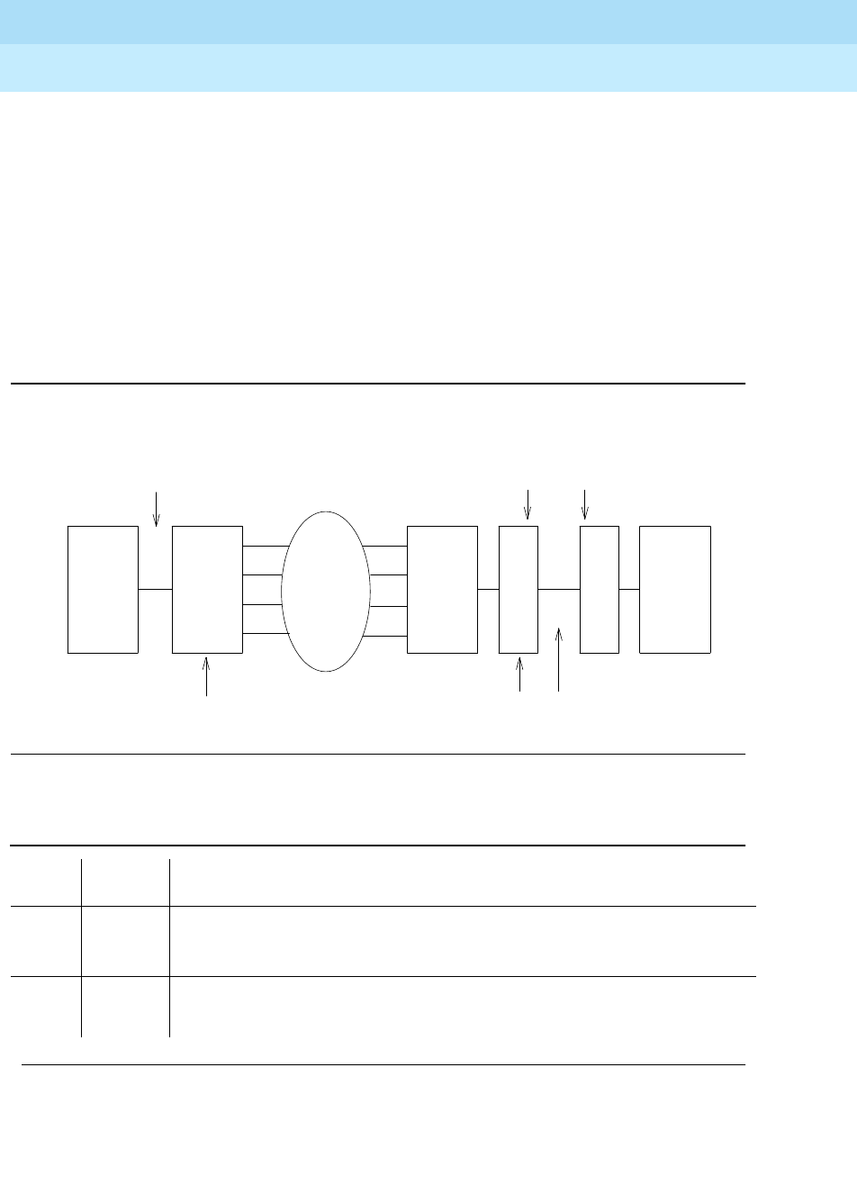
DEFINITY Enterprise Communications Server Release 6
Maintenance for R6r Volumes 1 & 2
555-230-126 Issue 2
January 1998
Maintenance Object Repair Procedures
Page 9-526DS1 CONV-BD
9
Every part of this test is executed under firmware control and the result is sent
back to the maintenance software. Test is executed by sending digital data
through every DS1 facility channel. Two different test patterns are used, these
are hexadecimal values 55 and AA.
On a Standard and High Reliability System (no PNC duplication), this test can
only be executed at the end-point which is closer to the SPE relative to the
neighbor DS1 CONV circuit pack because of its impacts on the system control
links, also the completion of the test will be delayed in this configuration to wait
for the recovery of the system control links. On a Critical Reliability System (PNC
Duplication), test can be executed at any DS1 CONV circuit pack.
Figure 9-26. Far-end Lightwave Transceiver Loopback Test
Table 9-176. TEST #789 Far-end FOT (Lightwave Transceiver) Loopback Test
Error
Code Test
Result Description/ Recommendation
1410 ABORT The test aborted because no lightwave transceiver is present. The neighbor
DS1 CONV circuit pack and the fiber endpoint are connected via metallic
cable. This abort may be ignored.
2000 ABORT Timed out while waiting for a response from the circuit pack.
2100 ABORT Could not allocate the necessary system resources to run this test.
Continued on next page
lightwave
transceiver
SNI
B
DS1CONVDS1CONV
Test starts here
A
EI Network
Loops here
Metallic or Fiber Connection
Fiber Connection

DEFINITY Enterprise Communications Server Release 6
Maintenance for R6r Volumes 1 & 2
555-230-126 Issue 2
January 1998
Maintenance Object Repair Procedures
Page 9-527DS1 CONV-BD
9
2300 ABORT The downlink message necessary to run this test could not be sent.
2301 ABORT The timer could not be set before sending the downlink message necessary to
run this test.
1. Retry the command at 1-minute intervals a maximum of 3 times.
2316 ABORT Fiber link is not administered. Administer the DS1 CONV fiber link via the add
fiber-link command.
2321 ABORT DS1 CONV circuit pack is not busied out. Busyout the DS1 CONV circuit pack
via the busyout board command.
2332 ABORT The test was aborted because it cannot be run at the far-end with this system
configuration (PNC simplex) when there is only one DS1-FAC available (the
link would be lost and no test results would be seen at the SPE). Run the test at
the other end of the DS1C complex.
2500 ABORT Internal system error
1. Retry the command at 1-minute intervals a maximum of 3 times.
FAIL Far-end lightwave transceiver loopback failed. A problem exists between the
DS1 CONV A and the lightwave transceiver connected to the DS1 CONV B
(see diagram above).
1. If there are facilities that are not digital data compatible, then busyout
those facilities via the busyout ds1-facility command.
2. If the test is executed as a part of an error analysis, then return back to the
related section.
3. Enter display errors and follow the associated repair procedures for any
on-board DS1 CONV-BD errors on this DS1 CONV circuit pack and the
DS1 CONV circuit pack at the other end of the DS1 CONV Complex. Enter
display errors and follow the associated repair procedures for any
DS1-FAC errors on the DS1 facilities.
4. Check the DS1 Converter Measurements Report to see if there are
facilities with excessive errors, execute command list measurements
ds1-facility summary. If there are facilities with excessive errors, execute
Far-end Internal Loopback test #797 on those facilities, and follow repair
procedures described for the test.
5. If the test still fails, replace the lightwave transceiver device that is
connected to the DS1 CONV circuit pack at the other end of the DS1
CONV Complex.
6. If the test still fails, replace the DS1 CONV circuit pack at the other end of
the DS1 CONV Complex.
7. If the test still fails, replace this DS1 CONV circuit pack.
PASS Transmission through the path of the loopback is successful.
Table 9-176. TEST #789 Far-end FOT (Lightwave Transceiver) Loopback Test —
Continued
Error
Code Test
Result Description/ Recommendation
Continued on next page

DEFINITY Enterprise Communications Server Release 6
Maintenance for R6r Volumes 1 & 2
555-230-126 Issue 2
January 1998
Maintenance Object Repair Procedures
Page 9-528DS1 CONV-BD
9
DS1 Facilities Connectivity Test (#790)
This test is destructive.
The DS1 facilities connectivity test will check the correct connectivity of the DS1
facilities at opposite ends of the DS1 CONV Complex. Every part of this test is
executed under firmware control and the result is sent back to the maintenance
software.
For TN574 DS1 Converter circuit packs, this test is executed by sending digital
data through each timeslot of every DS1 facility channel. Two different test
patterns are used, these are hexadecimal values 55 and AA.
For TN1654 DS1 Converter circuit packs, this test has been enhanced to provide
error codes that point to the exact fault. Rather than simply reporting a failure of
the connectivity test, the TN1654 test specifically identifies the two DS1 facilities
that are cross-connected at the near and far ends of the DS1 converter complex.
In addition, a fault code will indicate the condition of not being able to loop-up
the far-end as required to run the test due to the packet DS1 facility being down.
The TN1654 connectivity test sends digital data through only one timeslot.
Instead of looping back the facility to itself, the TN1654 version of the test
loops-up the other three facilities. If the test pattern comes back, the firmware
fails the test due to an incorrect connection between DS1 facilities. It should be
noted that this test will pass and give no indication of problems if the non-packet
facilities are down.
On a Standard and High Reliability System (no PNC duplication), this test can
only be executed at the end-point which is closer to the SPE relative to the
neighbor DS1 CONV circuit pack because of its impacts on the system control
links. In addition, for TN574 DS1 CONV boards, the completion of the test will be
delayed in this configuration to wait for the recovery of the system control links.
On a Critical Reliability System (PNC Duplication), test can be executed at any
DS1 CONV circuit pack.
0NO
BOARD The system software found no board.
1. Reset the board.
2. Remotely retry the command.
Table 9-176. TEST #789 Far-end FOT (Lightwave Transceiver) Loopback Test —
Continued
Error
Code Test
Result Description/ Recommendation
Continued on next page

DEFINITY Enterprise Communications Server Release 6
Maintenance for R6r Volumes 1 & 2
555-230-126 Issue 2
January 1998
Maintenance Object Repair Procedures
Page 9-529DS1 CONV-BD
9
Table 9-177. TEST #790 DS1 Facilities Connectivity Loopback Test
Error
Code Test
Result Description/ Recommendation
2000 ABORT Timed out while waiting for a response from the circuit pack.
2100 ABORT Could not allocate the necessary system resources to run this test.
2300 ABORT The downlink message necessary to run this test could not be sent.
2301 ABORT The timer could not be set before sending the downlink message necessary to
run this test.
1. Retry the command at 1-minute intervals a maximum of 3 times.
2316 ABORT Fiber link is not administered. Administer the DS1 CONV fiber link via the add
fiber-link command.
2321 ABORT DS1 CONV circuit pack is not busied out. Busyout the DS1 CONV circuit pack
via the busyout board command.
2332 ABORT The test was aborted because it cannot be run at the far-end with this system
configuration (PNC simplex) when there is only one DS1-FAC available (the link
would be lost and no test results would be seen at the SPE). Run the test at the
other end of the DS1C complex.
2500 ABORT Internal system error
1. Retry the command at 1-minute intervals a maximum of 3 times.
Continued on next page

DEFINITY Enterprise Communications Server Release 6
Maintenance for R6r Volumes 1 & 2
555-230-126 Issue 2
January 1998
Maintenance Object Repair Procedures
Page 9-530DS1 CONV-BD
9
FAIL TN574 DS1 facilities connectivity loopback test failed.
1 FAIL TN1654 Near-end DS1 facility A is connected to far-end DS1 facility B.
2 FAIL TN1654 Near-end DS1 facility A is connected to far-end DS1 facility C.
3 FAIL TN1654 Near-end DS1 facility A is connected to far-end DS1 facility D.
10 FAIL TN1654 Near-end DS1 facility B is connected to far-end DS1 facility A.
12 FAIL TN1654 Near-end DS1 facility B is connected to far-end DS1 facility C.
13 FAIL TN1654 Near-end DS1 facility B is connected to far-end DS1 facility D.
20 FAIL TN1654 Near-end DS1 facility C is connected to far-end DS1 facility A.
21 FAIL TN1654 Near-end DS1 facility C is connected to far-end DS1 facility B.
23 FAIL TN1654 Near-end DS1 facility C is connected to far-end DS1 facility D.
30 FAIL TN1654 Near-end DS1 facility D is connected to far-end DS1 facility A.
31 FAIL TN1654 Near-end DS1 facility D is connected to far-end DS1 facility B.
32 FAIL TN1654 Near-end DS1 facility D is connected to far-end DS1 facility C.
55 FAIL TN1654 DS1 CONV packet facility is down and can’t send loop-up message to
the far-end.
1. Enter display errors and follow the associated repair procedures for any
DS1-FAC errors on the DS1 facilities at both ends of the DS1 CONV
Complex. If an alarm exists on a DS1 facility, then this test will fail.
2. Check the DS1 connections, both circuit packs should have their DS1
facilities connected identically.
3. Check the DS1 Converter Measurements Report to see if there are facilities
with excessive errors, execute command list measurements ds1-facility
summary. If there are facilities with excessive errors, execute Far-end
Internal Loopback test #797 via the test ds1-facility UUCSSf long
command on those facilities, and follow repair procedures described for
the test.
4. Both circuit packs may not have the same translation information. Run the
Board Options Audit test #795 via the test board UUCSS short command
for both circuit packs in the DS1 CONV Complex to send the options, and
check the results of this audit test. This test will not pass until the audit test
problems are resolved.
PASS DS1 facility connections are correct.
0NO
BOARD The system software found no board.
1. Reset the board.
2. Remotely retry the command.
Table 9-177. TEST #790 DS1 Facilities Connectivity Loopback Test — Continued
Error
Code Test
Result Description/ Recommendation
Continued on next page

DEFINITY Enterprise Communications Server Release 6
Maintenance for R6r Volumes 1 & 2
555-230-126 Issue 2
January 1998
Maintenance Object Repair Procedures
Page 9-531DS1 CONV-BD
9
Board Options Audit (#795)
This test is non-destructive.
This test sends the administered circuit pack options to the DS1 CONV circuit
pack. Options are sent to both DS1 CONV circuit packs at the same time to
prevent any transitional mismatch of options.
The following data is sent to the TN574 DS1 CONV circuit pack: system reliability
configuration, master and slave end-points for framing (this is determined by the
relative position of the circuit pack to the SPE), the facility mask (if each facility is
installed), clock reference mask (whether each facility can be used as a clock
reference source and whether the board is being used as a Network Timing
Source), packet compatible mask (whether each facility is packet compatible)
and facility information for line coding, framing mode, and line compensation.
The following data is sent to the TN1654 DS1 CONV circuit pack: system
reliability configuration, master and slave end-points for framing (this is
determined by the relative position of the circuit pack to the SPE), the facility
mask (whether each facility is installed), idle code, CRC enabled/disabled flag
(sent in E1 mode only) and facility information for line coding and line
compensation (sent in T1 mode only).
Table 9-178. TEST #795 Board Options Audit
Error
Code Test
Result Description/ Recommendation
105 ABORT The neighbor DS1 CONV circuit pack at the other end of the DS1 CONV
Complex is not accessible (only applies to TN574 boards with vintage less
than 7).
1. Retry the command at 1-minute intervals a maximum of 3 times.
2. The link to the other end of the DS1 CONV Complex may be down. Enter
display errors and follow the associated repair procedures for any
DS1C-BD and DS1-FAC errors.
2000 ABORT Timed out while waiting for a response from the circuit pack.
2100 ABORT Could not allocate the necessary system resources to run this test.
2300 ABORT The downlink message necessary to run this test could not be sent.
2301 ABORT The timer could not be set before sending the downlink message necessary to
run this test.
1. Retry the command at 1-minute intervals a maximum of 3 times.
Continued on next page
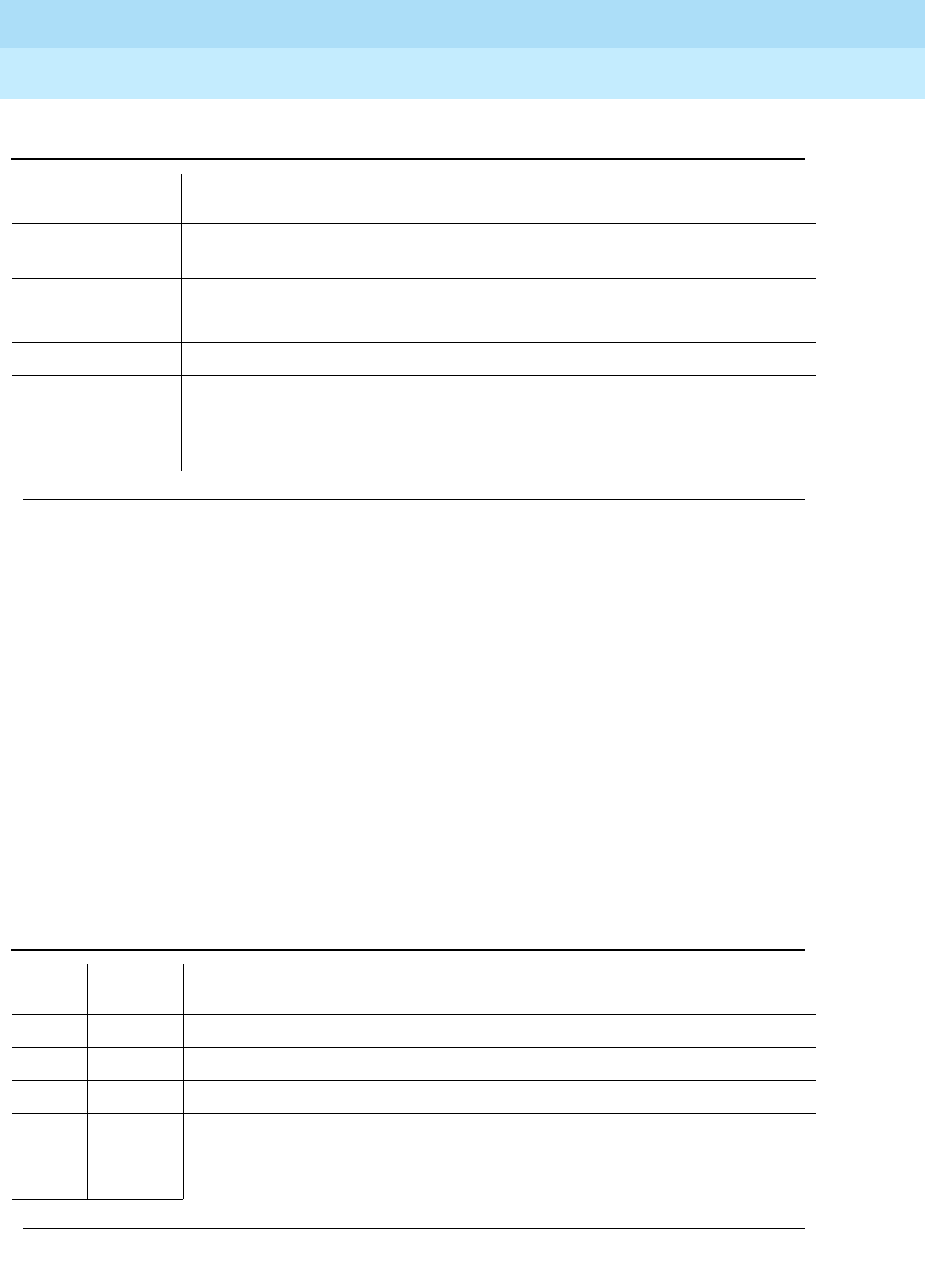
DEFINITY Enterprise Communications Server Release 6
Maintenance for R6r Volumes 1 & 2
555-230-126 Issue 2
January 1998
Maintenance Object Repair Procedures
Page 9-532DS1 CONV-BD
9
Failure Audit (#949)
This test is non-destructive.
This test queries the DS1 CONV circuit pack for any existing circuit pack or
facility failures and any unacknowledged cleared failure messages for auditing
purposes. Upon receiving the query request, DS1 CONV firmware sends failure
reports to the maintenance software for every error in its failure database.
This test operates on both maintenance objects DS1C-BD and DS1-FAC. Error
counts of both maintenance objects (DS1C-BD and DS1-FAC) that are displayed
in the error log will be incremented when this test is executed. This test is also
executed internally by the maintenance software when an alarm is resolved
2316 ABORT Fiber link is not administered. Administer the DS1 CONV fiber link via the add
fiber-link command.
2500 ABORT Internal system error
1. Retry the command at 1-minute intervals a maximum of 3 times.
PASS The options are sent to the circuit pack.
0NO
BOARD The system software found no board.
1. Reset the board.
2. Remotely retry the command.
Table 9-179. TEST #949 Failure Audit
Error
Code Test
Result Description/ Recommendation
2000 ABORT Timed out while waiting for a response from the circuit pack.
2100 ABORT Could not allocate the necessary system resources to run this test.
2300 ABORT The downlink message necessary to run this test could not be sent.
2301 ABORT The timer could not be set before sending the downlink message necessary to
run this test.
1. Retry the command at 1-minute intervals a maximum of 3 times.
Continued on next page
Table 9-178. TEST #795 Board Options Audit — Continued
Error
Code Test
Result Description/ Recommendation
Continued on next page

DEFINITY Enterprise Communications Server Release 6
Maintenance for R6r Volumes 1 & 2
555-230-126 Issue 2
January 1998
Maintenance Object Repair Procedures
Page 9-533DS1 CONV-BD
9
2316 ABORT Fiber link is not administered. Administer the DS1 CONV fiber link via the add
fiber-link command.
2500 ABORT Internal system error
1. Retry the command at 1-minute intervals a maximum of 3 times.
FAIL The DS1 CONV circuit pack reported failures or retransmitted a cleared failure
message.
1. Enter display errors and follow the associated repair procedures for any
DS1C-BD and DS1-FAC errors.
PASS The DS1 CONV circuit pack has no failures.
0NO
BOARD The system software found no board.
1. Reset the board.
2. Remotely retry the command.
Table 9-179. TEST #949 Failure Audit — Continued
Error
Code Test
Result Description/ Recommendation
Continued on next page

DEFINITY Enterprise Communications Server Release 6
Maintenance for R6r Volumes 1 & 2
555-230-126 Issue 2
January 1998
Maintenance Object Repair Procedures
Page 9-534DT-LN-BD (Data Line Circuit Pack)
9
DT-LN-BD (Data Line Circuit Pack)
Refer to "XXX-BD (Common Port Circuit Pack)" for circuit pack level errors. See
also DAT-LINE (Data Line Circuit Port) for related line information.
1. UU is the universal cabinet number (1 for PPN, 2 -44 for EPNs). C is the carrier
designation (A, B, C, D, or E). SS is the number of the slot in which the circuit pack
resides (01 to 21).
MO Name (In
Alarm Log Alarm
Level Initial Command to
Run1Full Name of MO
DT-LN-BD MIN test board UUCSS sh Data Line Circuit Pack
DT-LN-BD WRN test board UUCSS sh Data Line Circuit Pack

DEFINITY Enterprise Communications Server Release 6
Maintenance for R6r Volumes 1 & 2
555-230-126 Issue 2
January 1998
Maintenance Object Repair Procedures
Page 9-535DTMR-PT (Dual Tone Multi-Frequency Receiver Port)
9
DTMR-PT (Dual Tone
Multi-Frequency Receiver Port)
Dual Tone Multi-Frequency Receiver Ports (DTMR), also known as Touch-Tone
Receivers (TTR), reside on the following circuit packs:
■TN748 (mu-law companding)
■TN420 (A-law companding) [G3r V2]
There are four Dual Tone Multi-Frequency Receiver (DTMR-PT) ports and two
General Purpose Tone Detector (GPTD-PT) ports on each Tone Detector circuit
pack. The DTMR port is used to detect touch-tone digits that are placed on the
Time Division Multiplex (TDM) bus. Examples of touch-tone digits are digits 0
through 9, digit #, and digit *. The ability of the DTMR port to detect touch-tone
digits is essential for maintenance of other circuit packs (for example,
Tone-Clock circuit pack) and in placing a station-to-station call. Calls originating
from a hybrid station
do not
require a DTMR port.
The DTMR-PT maintenance object implements a set of tests to ensure that
detection of touch tone digits by the DTMR port is functioning properly. For all
Tone Detector circuit pack level errors (DETR-BD), refer to the "XXX-BD
(Common Port Circuit Pack)".
1. UU is the universal cabinet number (1 for PPN, 2 -44 for EPNs). C is the carrier designation (A, B,
C, D, or E). SS is the number of the slot in which the circuit pack resides (01 to 21). pp is the two
digit port number (01, 02, ...).
MO Name (in
Alarm Log) Alarm
Level Initial Command to Run1Full Name of MO
DTMR-PT MAJOR test port UUCSSpp sh Dual Tone Multi-Frequency
Receiver Port (TTR)
DTMR-PT MINOR test port UUCSSpp sh Dual Tone Multi-Frequency
Receiver Port (TTR)
DTMR-PT WARNING release port UUCSSpp Dual Tone Multi-Frequency
Receiver Port (TTR)
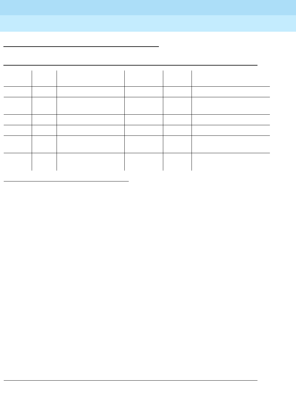
DEFINITY Enterprise Communications Server Release 6
Maintenance for R6r Volumes 1 & 2
555-230-126 Issue 2
January 1998
Maintenance Object Repair Procedures
Page 9-536DTMR-PT (Dual Tone Multi-Frequency Receiver Port)
9
Error Log Entries and Test to Clear Values
Notes:
a. There are two possible alarm levels for this error: Major alarm and Minor
alarm. A Major alarm is raised if the total number of DTMR ports currently
in service is less than or equal to 1/2 of the administered threshold
number. Otherwise, a Minor alarm is raised. In either case, run the Short
Test Sequence against the DTMR port and follow the error code
procedures for the individual tests.
The threshold number of DTMR ports for service is administered using the
change system-parameters maintenance command.
b. The DTMR port lost its translation. Testing the DTMR port is sufficient to
reload its translation. If testing the DTMR port does not clear the error,
then the Tone Detector circuit pack containing the defective DTMR port
should be replaced.
c. This error indicates the DTMR port is having problems detecting
touch-tone digits. If this error is being constantly logged, then the Tone
Detector circuit pack containing the defective DTMR port should be
replaced.
d. This error type indicates that the circuit pack has been removed or has
been insane for at least 11 minutes. To clear the error, reinsert or replace
the circuit pack.
1. Run the Short Test Sequence first. If all tests pass, run the Long Test Sequence. Refer to the appropriate
test description and follow the recommended procedures.
Table 9-180. Dual Tone Multi-Frequency Receiver Port (TTR) Error Log Entries
Error
Type Aux
Data Associated Test Alarm
Level On/Off
Board Test to Clear Value
010 Any Any Any test port UUCSSpp sh r 1
1 17664 Tone Detector Audit/
Update Test (#43) MAJOR/
MINOR(a) ON test port UUCSSpp r 2
18 0 busyout port UUCSSpp WARNING ON release port UUCSSpp
130 (d) None WARNING ON test port
UUCSSpp
sh r 2
257 (b) 17666 Tone Detector Audit/
Update Test (#43 MAJOR/
MINOR(a) ON test port UUCSSpp r 3
513 (c) Any Tone Detection
Verification Test (#42 MAJOR/
MINOR(a) ON test port UUCSSpp r 3

DEFINITY Enterprise Communications Server Release 6
Maintenance for R6r Volumes 1 & 2
555-230-126 Issue 2
January 1998
Maintenance Object Repair Procedures
Page 9-537DTMR-PT (Dual Tone Multi-Frequency Receiver Port)
9
System Technician-Demanded Tests:
Descriptions and Error Codes
Always investigate tests in the order presented in the table below. By clearing
error codes associated with the
Tone Detection Verification Test,
for example,
you may also clear errors generated from other tests in the testing sequence.
Tone Detection Verification Test (#42)
This test checks the touch-tone digits detection capability of the DTMR port.
1. D = Destructive; ND = Nondestructive
Order of Investigation Short Test
Sequence Long Test
Sequence D/ND1
Tone Detection Verification Test (#42) X X ND
Tone Detector Audit/Update Test (#43) X X ND
Table 9-181. TEST #42 Tone Detection Verification Test
Error
Code Test
Result Description/ Recommendation
ABORT The system was not able to allocate all the resources needed for this test or
there was an Internal system error.
1 ABORT The system could not allocate all the resources needed to test the DTMR port.
1001 ABORT The system was unable to put the DTMR port in the appropriate mode to test it.
1002 ABORT The system could not allocate time slots for the test connection. This could
happen when the system is heavily loaded. If the system is not heavily loaded,
then test the TDM Bus via the test tdm [a|b] command. Refer to the TDM-BUS
(TDM Bus) Maintenance documentation for details.
1. Retry the command at 1-minute intervals a maximum of 5 times.
1003 ABORT The system could not allocate a Tone Generator for the test connection. This
may be caused by a heavy load on the system or by a faulted Tone-Clock.
1. Check to see if there are any alarms against the Tone-Clock in the port
network where the test aborted. If so refer to the recommended
procedures for TONE-BD or TONE-PT.
2. If a new Tone-Clock has been inserted, allow about 1 minute for
maintenance to run on the newly inserted circuit pack.
3. Retry the command at 1-minute intervals a maximum of 5 times.
Continued on next page

DEFINITY Enterprise Communications Server Release 6
Maintenance for R6r Volumes 1 & 2
555-230-126 Issue 2
January 1998
Maintenance Object Repair Procedures
Page 9-538DTMR-PT (Dual Tone Multi-Frequency Receiver Port)
9
Tone Detector Audit/Update Test (#43)
The DTMR port is refreshed with all time slot information and sanity audit is
performed on the DTMR port.
2000 ABORT Response to the test was not received within the allowable time period.
1. Retry the command at 1-minute intervals a maximum of 5 times.
2100 ABORT Could not allocate the necessary system resources to run this test
1. Retry the command at one-minute intervals a maximum of five times.
2006 ABORT DTMF detection failed. Make sure that the companding mode administered for
the system matches that of the Tone Detector: mu-law for TN748, A-law for
TN420.
1-3 FAIL DTMF digits were not correctly detected.
1. Run the Short Test Sequence: test port UUCSSpp sh r 1.
2. If the problem persists, the system is still operating properly but system
capacity will be reduced. In order to restore the system performance to
normal, replace the Tone Detector circuit pack containing the defective
DTMR port.
PASS The DTMR port is able to detect all the touch-tone digits.
Table 9-182. TEST #43 Tone Detector Audit/Update Test
Error
Code Test
Result Description/ Recommendation
None ABORT The system was not able to allocate all the resources needed for this test.
1. Wait 1 minute and try again.
2000 ABORT Response to the test request was not received within the allowable time
period.
2100 ABORT Could not allocate the necessary system resources to run this test.
1. Retry the command at 1-minute intervals for a maximum of 5 times.
Table 9-181. TEST #42 Tone Detection Verification Test — Continued
Error
Code Test
Result Description/ Recommendation
Continued on next page
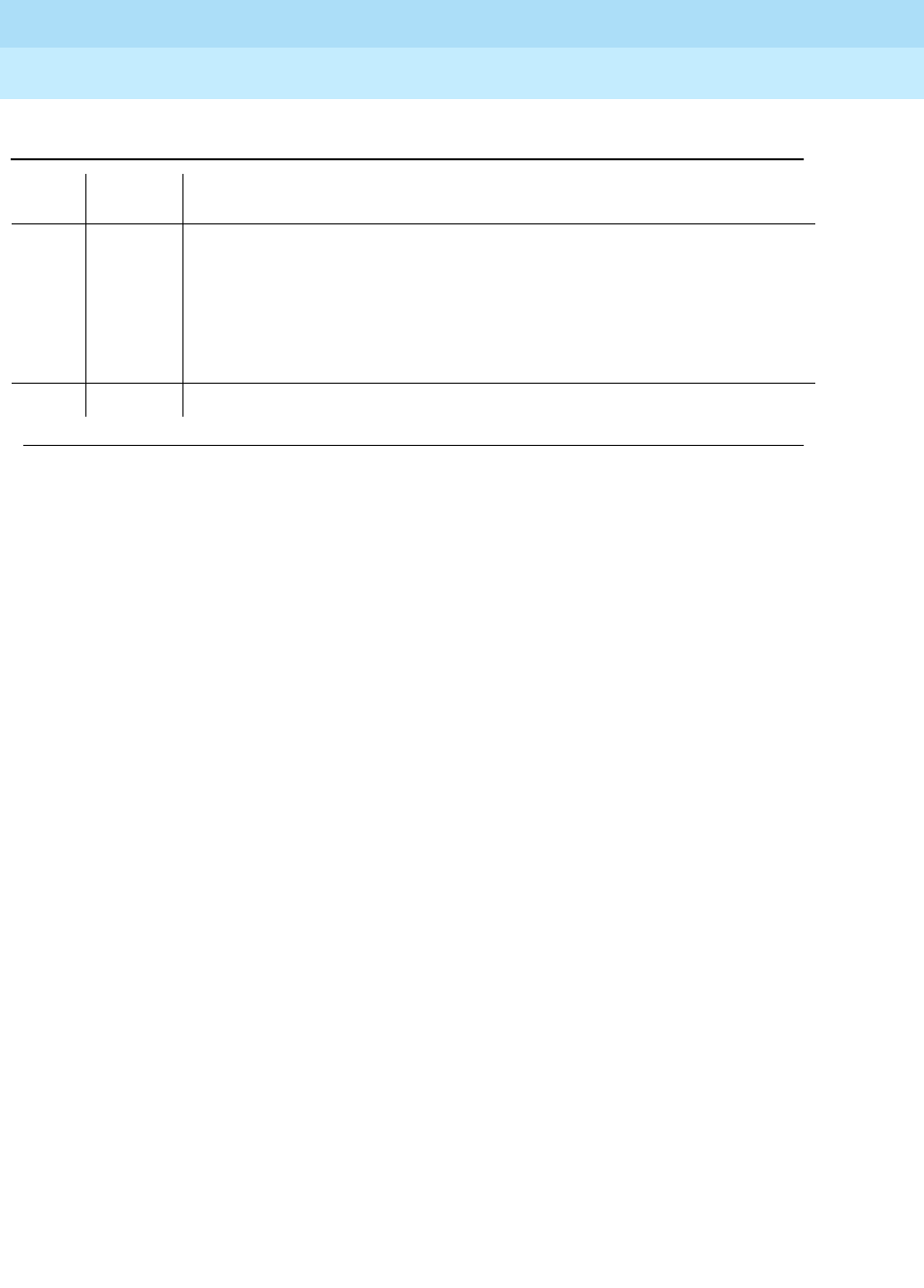
DEFINITY Enterprise Communications Server Release 6
Maintenance for R6r Volumes 1 & 2
555-230-126 Issue 2
January 1998
Maintenance Object Repair Procedures
Page 9-539DTMR-PT (Dual Tone Multi-Frequency Receiver Port)
9
FAIL Hardware audit failed.
1. Run the Short Test Sequence: test port UUCSSpp sh r 1.
2. If the problem persists, the system is still operating properly but system
capacity will be reduced. In order to restore the system performance to
normal, replace the Tone Detector circuit pack containing the defective
DTMR port.
PASS The DTMR port has been successfully refreshed with its translation.
Continued on next page
Table 9-182. TEST #43 Tone Detector Audit/Update Test — Continued
Error
Code Test
Result Description/ Recommendation

DEFINITY Enterprise Communications Server Release 6
Maintenance for R6r Volumes 1 & 2
555-230-126 Issue 2
January 1998
Maintenance Object Repair Procedures
Page 9-540DUP-CHL (Duplication Interface)
9
DUP-CHL (Duplication Interface)
The Duplication Channel (DUP-CHL) maintenance object tests both UN330B
Duplication Interface circuit packs and the interconnecting cable. These tests, as
a group, test end-to-end functionality. That is to say, software on the standby and
the active as well as both duplication circuit packs and their cabling must be
operational to some degree for these tests to PASS or FAIL. Otherwise, they will
ABORT. Tests that fail are recorded in the error and alarm log as errors/alarms
against the standby SPE. No errors/alarms are recorded against the active SPE
for this maintenance object.
Duplication Interface Functions
The Duplication Interface is comprised of two UN330B circuit packs, one in each
of the duplicate SPE carriers, connected by a single Duplication Interface cable.
The circuit packs and cable provide the following functions to support SPE
duplication.
■Memory Shadowing
Every write to memory made by the active SPE is also written into the
standby SPE memory. Only those memory writes to addresses that lie
within certain address boundaries, as defined by memory bounds
registers on the Duplication Interface circuit packs, and other qualified
writes are shadowed.
■SPE Communication
Software running on the active SPE communicates with software on the
standby SPE by sending and receiving information via the two way,
general purpose mailbox mechanism provided by the circuit packs.
■Manual SPE Locking
The Duplication Interface Circuit packs monitor the relative
states-of-health of the two SPEs, and control selection of active/standby
status for them.
■SPE Selection
The SPE-Select switches on the Duplication Interface circuit packs can be
used to lock the active SPE and prevent interchanges. See STBY-SPE for
instructions.
MO Name (in Alarm
Log) Alarm
Level Initial Command to Run Full Name of MO
DUP-CHL MAJOR test duplication-interface l c Duplication-Interface
DUP-CHL MINOR test duplication-interface l c Duplication-Interface

DEFINITY Enterprise Communications Server Release 6
Maintenance for R6r Volumes 1 & 2
555-230-126 Issue 2
January 1998
Maintenance Object Repair Procedures
Page 9-541DUP-CHL (Duplication Interface)
9
Three Maintenance Objects are involved in the maintenance of the Duplication
Interface circuit packs and their cabling: DUPINT, DUP-CHL, and SPE-SELE.
DUPINT runs tests that check the operation of the active Duplication Interface
circuit pack. DUP-CHL tests overall functionality of the circuit packs. This utilizes
both circuit packs, their cabling, and communication with the standby software.
SPE-SELE monitors the position of the select switches located on the front of the
Duplication Interface circuit packs.
Testing is directional from the active Duplication Interface circuit pack to the
standby Duplication Interface circuit pack. If an interchange has occurred with
alarms raised against DUPINT or DUP-CHL, testing cannot resolve or clear these
alarms because they are against the wrong circuit packs in the active to standby
directional configuration. An interchange is needed to allow testing to resolve or
clear these directional alarms.
DUP-CHL Tests
Eight tests run under this MO. Four of these (Status Register Comparison, SMM
Channel, Remote SPE Error, and Memory Shadowing) are run at system
initialization, during short and long demand testing, and during periodic and
scheduled testing. Three other tests (Remote Loop-Around, State-of-Health, and
Memory Shadowing Disable) are run only at initialization time (reset system 2 or
higher) and during long demand testing. The FIFO Full destructive test is run only
as a long demand test.
For long demand testing use test duplication-interface long clear. The clear
option is needed to clear alarms for error types that don’t have an associated
test. Since these tests require the turning on and off of memory shadowing, you
must enter the command busyout spe before the long sequence can be run.
Busying out the SPE turns off memory shadowing but handshake communication
continues between the SPEs. After testing of DUP-CHL is complete, release spe
must be entered before memory shadowing is turned on and refresh completes.
Memory shadowing is not turned back on if DUPINT, DUP-CHL or other MAJOR
alarms pertinent to memory shadowing are not retired. See Chapter 1 and
STBY-SPE for details.
test dup and test dup long run DUPINT
and
DUP-CHL tests. This is the only
command that runs short and long test sequences for these maintenance
objects.
Replacement procedures for the standby Duplication Interface circuit pack, the
active Duplication Interface circuit pack, and the interconnecting cable appear at
the end of this section (DUP-CHL). These procedures are designed to prevent
disruption of customer service (except when the active Duplication Interface
circuit pack must be replaced due to shadowing failure). Each procedure also
describes testing after replacement to verify duplication operation when either
SPE carrier is active. Test failures in a procedure may direct you to another
maintenance object for repairs.

DEFINITY Enterprise Communications Server Release 6
Maintenance for R6r Volumes 1 & 2
555-230-126 Issue 2
January 1998
Maintenance Object Repair Procedures
Page 9-542DUP-CHL (Duplication Interface)
9
Administration
No add or remove commands are associated with the Duplication Interface
circuit packs.
In-line Errors
If standby SPE software detects problems with the standby Duplication Interface
circuit pack, it will report these via the handshake to the active. The report will
indicate one of the following:
— An error in reading or writing one or more of the registers on the circuit
pack
— A problem with local loop around test
— A problem with the HFAIL bit being set
The last error is a bit set by the Duplication Interface circuit pack’s hardware
indicating a possible problem with the multiplexing of address and data during
memory shadowing. No tests can retire these alarms reported by standby
software. If the software stops reporting the errors, the alarms will be retired in
about 15 minutes.
Other types of in-line errors are catastrophic ones resulting from FIFO overflow or
Remote SPE Error interrupts. If these errors cause an alarm, shadowing will be
turned off until the alarm is resolved. Alarms from these errors and the other
in-line errors can be resolved by executing test duplication-interface long clear
with no tests failing.
MAJOR vs. MINOR Alarms
DUP-CHL may have MAJOR or MINOR alarms. MAJOR alarms cause memory
shadowing to be turned off. MINOR Alarms do not. DUP-CHL alarms do not lower
the Standby State of Health and do not cause an SPE interchange.
Tests run by DUP-CHL are directional in nature: they are run by the active SPE on
the standby SPE. Failures of these tests are logged against the standby
Duplication Interface circuit pack. Consequently, should an interchange occur,
alarms logged against DUP-CHL associated with the formerly standby, now
active SPE can not be resolved. An interchange is required to allow testing to
resolve or clear these directional alarms.
MO Interactions
test duplication-interface runs DUPINT and DUP-CHL non-destructive tests.
test duplication-interface long clear runs DUPINT and DUP-CHL destructive
and non-destructive tests, and requires that the standby SPE be busied out.
Busying out the standby SPE turns off memory shadowing and lowers the health
of the standby to
partially-functional
. This prevents an SPE interchange.

DEFINITY Enterprise Communications Server Release 6
Maintenance for R6r Volumes 1 & 2
555-230-126 Issue 2
January 1998
Maintenance Object Repair Procedures
Page 9-543DUP-CHL (Duplication Interface)
9
Once all DUPINT, DUP-CHL and any other alarms pertinent to shadowing are
retired, a release of the standby will allow shadowing to be turned back on and
refresh to complete. See STBY-SPE for more details.
DUP-CHL tests can also fail because shadowing is prevented by of a fault with
MO: PKT-INT or MEM-BD. Use the command status spe to observe the
presence of active alarms and display the alarm log to determine if alarms exist
against these related maintenance objects that could cause memory shadowing
to fail. MAJOR alarms from these other maintenance objects that cause memory
shadowing failures must be resolved before attempting to resolve DUP-CHL
alarms. A memory shadowing failure that is caused by another maintenance
object such as PKT-INT can also cause a DUP-CHL alarm due to a test failure or
in-line errors. Executing the test duplication-interface long clear command
after repairing the underlying cause of the memory shadowing failure can also
resolve a DUP-CHL alarm.
Error Log Entries and Test to Clear Values
Table 9-183. Duplication Channel Error Log Entries
Error
Type Aux
Data Associated Test Alarm
Level1On/Off
Board Test to Clear Value
02Any Any Any
001 State-of-Health (#873) MINOR ON test dupl l
257 Memory Shadow
Disable Interrupt test
(#872)
MINOR ON test dupl l
513 any SMM Channel test
(#874) MINOR ON test dupl l
769 Remote Error Interrupt
test (#875) MAJOR ON test dupl l
1025 Memory Shadowing test
(#876) MAJOR ON test dupl l
1281(a) none MAJOR ON test dupl l c
1537(b) none MINOR ON test dupl l c
1793(c) none MAJOR ON test dupl l c
2049 Remote Loop-Around
test (#869) MAJOR ON test dupl l
2305 FIFO Full Interrupt test
(#871) MINOR ON test dupl l
2561 any Status Register
Comparison test (#871) MAJOR ON test dupl l
2817(d) any none MAJOR OFF test dupl l c
Continued on next page

DEFINITY Enterprise Communications Server Release 6
Maintenance for R6r Volumes 1 & 2
555-230-126 Issue 2
January 1998
Maintenance Object Repair Procedures
Page 9-544DUP-CHL (Duplication Interface)
9
Notes:
a. Reported by software on the standby via the handshake mechanism. This
error indicates that software on the standby has seen the HFAIL bit
become set on the standby Duplication Interface circuit pack. The setting
of the HFAIL bit is an indication that an error in the multiplexing of the
address and data by the Duplication Interface circuit packs has occurred.
Three reports of this bit being set will result in a MAJOR alarm that can
only be cleared over time (i.e. within 15 minutes of the final report) or by
using test duplication interface long clear. Recommendation for repair
(only if an alarm is raised): Replace Duplication Interface components
starting with the standby Duplication Interface circuit pack. Use SPE
Duplication Channel Component Replacement procedures at the end of
this DUP-CHL section.
b. Reported by the software on the standby via the handshake. This error
indicates that the software on the standby failed tests with one or more of
the registers located on the standby Duplication Interface circuit pack.
The following Error Types are used to specify the register tests that failed:
Three reports of this error will result in a MINOR alarm that can only be
cleared over time (i.e. within 15 minutes of the final report) or by using test
duplication interface long clear. Follow the repair procedures listed in
note a above.
c. Reported by the software on the standby the handshake mechanism. This
error indicates that the software on the standby failed the Local
Loop-Around test on the standby Duplication Interface circuit pack. Three
reports of this error will result in a MAJOR alarm that can only be cleared
over time (within 15 minutes of the final report) or by using test
duplication interface long clear. Follow the repair procedures listed in
note a above.
d. Catastrophic in-line error failure.
■Aux Data 1: Remote SPE shadowing bus error
Possible false alarms can be caused by pulling a standby SPE
circuit pack (other than TAPE or DISK) while carrier power is on.
Use the following repair procedure for this off circuit pack alarm.
1. DUP-CHL alarms can be resolved only when the alarmed Duplication Interface circuit pack is in the
standby SPE carrier.
2. Run the Short Test Sequence first. If all tests pass, run the Long Test Sequence. Refer to the
appropriate test description and follow the recommended procedures.
1 Control Register Test
2 Shadowing Bounds Register Test
4 Type/Suffix/Vintage Register Test
3, 5, 6, 7 Additive combinations of the above

DEFINITY Enterprise Communications Server Release 6
Maintenance for R6r Volumes 1 & 2
555-230-126 Issue 2
January 1998
Maintenance Object Repair Procedures
Page 9-545DUP-CHL (Duplication Interface)
9
1. Use the display alarms command and select Category spe.
If any maintenance objects other than DUPINT or DUP-CHL
have MAJOR alarms, fix these problems. Problems causing
MAJOR alarms for MEM-BD, PKT-INT, SYSAM, H-ADAPTR,
and SW-CTL, should be repaired first.
2. Execute the test duplication-interface long clear
command to clear this alarm. If any DUPINT or DUP-CHL
test fails or aborts, use the repair strategy for that test.
3. If no DUPINT nor DUP-CHL tests failed, the DUPINT and
DUP-CHL alarms are resolved or cleared in this active to
standby direction so release the standby SPE from the
busyout condition using the release spe-standby command
and wait (about 10 minutes) for the standby SPE to be
refreshed as observed with the status spe command.
4. If the standby SPE is refreshed, and fully functional, with no
DUPINT or DUP-CHL alarms in the other active to standby
direction, this procedure is finished.
5. If the standby SPE is refreshed, and fully functional, with
DUPINT or DUP-CHL alarms in the other active to standby
direction, use the reset system interchange command. Go
to step 8.
6. If the standby SPE is not refreshed, and fully functional, with
DUPINT or DUP-CHL alarms in the other active to standby
direction, arrange a time with the customer to interchange
the SPE carriers because this interchange will disrupt
service. If the standby SPE is not cycling as indicated by the
flashing yellow LED on the standby Processor circuit pack,
use the lock-and-power-down procedure described in
Chapter 5 to power down and power up the standby SPE. If
the standby SPE is still not cycling, escalate the problem.
7. Hard switch into the standby SPE by moving both SPE Select
switches to the position that selects the standby SPE as
active.
8. After the interchange, use the busyout spe-standby
command. If the SPE Select switches are not in the auto
position, move the switches to the auto position. Use the test
duplication-interface long clear command to resolve the
DUPINT and DUP-CHL alarms. If any DUPINT or DUP-CHL
test fails, use the repair strategy for that test.
9. If no DUPINT nor DUP-CHL tests fail, the DUPINT and
DUP-CHL alarms are resolved or cleared in both directions
so release the standby SPE from the busyout condition using
the release spe-standby command and wait (about 10
minutes) for the standby SPE to be refreshed as observed
with the status spe command.

DEFINITY Enterprise Communications Server Release 6
Maintenance for R6r Volumes 1 & 2
555-230-126 Issue 2
January 1998
Maintenance Object Repair Procedures
Page 9-546DUP-CHL (Duplication Interface)
9
■Aux Data 3: Remote Duplication Interface circuit pack FIFO
overflow
Execute the test duplication-interface long clear command to
resolve this alarm. If any DUPINT or DUP-CHL test fails, use the
repair strategy for that test.
System Technician-Demanded Tests:
Descriptions and Error Codes
Always investigate tests in the order presented in the table below. By clearing
error codes associated with the
SMM Channel test
for example, you may also
clear errors generated from other tests in the testing sequence.
Remote Loop-Around Test (#869)
This test is destructive.
This test writes a word to a memory address on the active SPE that is inverted
and is looped back by the standby Duplication Interface circuit.
1. D = Destructive; ND = Nondestructive
Order of Investigation Short Test
Sequence Long Test
Sequence Reset Board
Sequence D/ND1
Status Register Comparison Test (#980) X X ND
Remote Loop-Around Test (#869) X D
Dup Mailbox Test (#874) X X ND
Remote Error Interrupt Test (#875) X X ND
Memory Shadowing Test (#876) X X ND
State-of-Health Test (#873) X D
Memory Shadowing Disable Test (#872) X D
FIFO Full Interrupt Test (#871) X D

DEFINITY Enterprise Communications Server Release 6
Maintenance for R6r Volumes 1 & 2
555-230-126 Issue 2
January 1998
Maintenance Object Repair Procedures
Page 9-547DUP-CHL (Duplication Interface)
9
Table 9-184. TEST #869 Remote Loop-Around Test
Error
Code Test
Result Description/ Recommendation
1321 ABORT The faceplate switches on the Duplication Interface circuit packs are not set to
auto.
1. If the switches are locked because you are using a replacement
procedure, continue with this procedure to the step that directs you to
unlock the active SPE by moving both switches to auto. The next step
using the test duplication-interface long clear should not abort with this
error code.
2. If the switches are locked and a replacement procedure is not being used,
start with step 6 of the SPE Duplication Channel Component Replacement
procedure for the standby
3. Duplication Interface Circuit pack at the end of this DUP-CHL section to
avoid an undesired interchange when unlocking the active SPE. If this
same abort is received with both switches in auto, Replace Duplication
Interface components starting with the standby Duplication Interface
circuit pack. Use SPE Duplication Channel Component Replacement
procedures at the end of this DUP-CHL section. In addition to looking for
failures, also check for the absence of this 1321 abort code when testing
after the procedure directs setting the switches to auto after a component
replacement.
1405 ABORT This test did not run because the Duplication Channel was busy.
1. Retry the command at 1-minute intervals a maximum of 5 times.
1411 ABORT This test did not run because the standby Duplication Interface circuit pack
cannot be detected as being plugged in by the software.
1. If this abort continues to occur, the standby SPE may not have initialized
properly. Use the lock-and-power-down procedure described in Chapter 5
to power down and power up the standby SPE, but don’t replace any
circuit packs.
2500 ABORT Internal system error
1. Retry the command at 1-minute intervals a maximum of 5 times.
FAIL The Remote Loop-Around Test has failed to loop a data word from the active to
the standby and back to the active Duplication Interface circuit pack.
1. The standby SPE may not have initialized properly. Use the
lock-and-power-down procedure described in Chapter 5 to power down
and power up the standby SPE, but don’t replace any circuit packs.
2. Replace Duplication Interface components starting with the standby
Duplication Interface circuit pack. Use SPE Duplication Channel
Component Replacement procedures at the end of this DUP-CHL section.
Continued on next page

DEFINITY Enterprise Communications Server Release 6
Maintenance for R6r Volumes 1 & 2
555-230-126 Issue 2
January 1998
Maintenance Object Repair Procedures
Page 9-548DUP-CHL (Duplication Interface)
9
FIFO Full Interrupt Test (#871)
This test is destructive.
This test effectively checks the correct operation of the FIFO located on the
standby Duplication Interface circuit pack.
55 FAIL The attempt to turn off memory shadowing in this DUPINT circuit pack could
not be verified in the DUPINT hardware status register.
1. Replace Duplication Interface components starting with the standby
Duplication Interface circuit pack. Use SPE Duplication Channel
Component Replacement procedures at the end of this DUP-CHL section.
PASS A data word was successfully looped around from the active to the standby
and back to the active Duplication Interface circuit pack.
Table 9-185. TEST #871 FIFO Full Interrupt Test
Error
Code Test
Result Description/ Recommendation
1321 ABORT The faceplate switches on the Duplication Interface circuit packs are not set to
auto.
1. If the switches are locked because you are using a replacement
procedure, continue with this procedure to the step that directs you to
unlock the active SPE by moving both switches to auto. The next step
using the test duplication-interface long clear should not abort with this
error code.
2. If the switches are locked and a replacement procedure is not being used,
start with step 6 of the SPE Duplication Channel Component Replacement
procedure for the standby Duplication Interface Circuit pack at the end of
this DUP-CHL section to avoid an undesired interchange when unlocking
the active SPE.
3. If this same abort is received with both switches in auto, Replace
Duplication Interface components starting with the standby Duplication
Interface circuit pack. Use SPE Duplication Channel Component
Replacement procedures at the end of this DUP-CHL section. In addition
to looking for failures, also check for the absence of this 1321 abort code
when testing after the procedure directs setting the switches to auto after
a component replacement.
Continued on next page
Table 9-184. TEST #869 Remote Loop-Around Test — Continued
Error
Code Test
Result Description/ Recommendation
Continued on next page

DEFINITY Enterprise Communications Server Release 6
Maintenance for R6r Volumes 1 & 2
555-230-126 Issue 2
January 1998
Maintenance Object Repair Procedures
Page 9-549DUP-CHL (Duplication Interface)
9
1325 ABORT Memory shadowing is inhibited from the standby SPE.
1. Shadowing may not be turned on yet, so wait 5 minutes and run the test
again.
2. Rerun the test; if the same 1325 abort occurs again, use the display
alarms command and select Category spe. If any maintenance objects
other than DUPINT or DUP-CHL have MAJOR alarms, fix these problems.
Problems causing MAJOR alarms for MEM-BD, PKT-INT, SYSAM,
H-ADAPTR, and SW-CTL should be repaired first.
3. Rerun the test; if the same 1325 abort occurs again, look for other DUPINT
or DUP-CHL test failures by using the busyout spe-standby if not already
busied out and the test duplication-interface long clear commands. Fix
these problems according to the service documentation for these packs.
4. If this 1325 abort continues to occur, the standby SPE may not have
initialized properly. Use the lock-and-power-down procedure described in
Chapter 5 to power down and power up the standby SPE, but don’t
replace any circuit packs.
1411 ABORT This test did not run because the standby Duplication Interface circuit pack
cannot be detected as being plugged in by the software.
1. If this abort continues to occur, the standby SPE may not have initialized
properly. Use the lock-and-power-down procedure described in Chapter 5
to power down and power up the standby SPE, but don’t replace any
circuit packs.
1418 ABORT The HFAIL bit being set in the active Duplication Interface circuit pack
prevented this test from running.
1. Run this long demand test sequence and verify that test #870 passes or
follow the repair strategy for test #870 until it passes.
2000 ABORT This test did not run because communication with the standby timed out while
waiting for a reply to a maintenance message.
1. Retry the command at 1-minute intervals a maximum of 5 times.
2. If this abort continues to occur, the standby SPE may not have initialized
properly. Use the lock-and-power-down procedure described in Chapter 5
to power down and power up the standby SPE, but do not replace any
circuit packs.
Table 9-185. TEST #871 FIFO Full Interrupt Test — Continued
Error
Code Test
Result Description/ Recommendation
Continued on next page

DEFINITY Enterprise Communications Server Release 6
Maintenance for R6r Volumes 1 & 2
555-230-126 Issue 2
January 1998
Maintenance Object Repair Procedures
Page 9-550DUP-CHL (Duplication Interface)
9
Memory Shadowing Disable Test (#872)
This test is destructive.
This test verifies the correct operation of the interrupt that indicate when
shadowing has been turned off (disallowed) by the standby Processor
2334 ABORT The hardware mailbox in the standby Duplication Interface circuit pack is not
ready to receive messages.
1. Retry the command at 1-minute intervals a maximum of 5 times.
2. If this abort continues to occur, the standby SPE may not have initialized
properly. Use the lock-and-power-down procedure described in Chapter 5
to power down and power up the standby SPE, but don’t replace any
circuit packs.
2500 ABORT Internal system error
1. Retry the command at 1-minute intervals a maximum of 5 times.
FAIL The expected interrupt was not received from the standby Duplication
Interface circuit pack when the FIFO was filled to overflowing with test data.
1. Replace Duplication Interface components starting with the standby
Duplication Interface circuit pack. Use SPE Duplication Channel
Component Replacement procedures at the end of this DUP-CHL section.
53 FAIL The Duplication Interface circuit pack FIFO flow control flag was not set during
this FIFO Full Interrupt Test.
1. Replace Duplication Interface components starting with the standby
Duplication Interface circuit pack. Use SPE Duplication Channel
Component Replacement procedures at the end of this DUP-CHL section.
54 FAIL The attempt to turn on memory shadowing in this DUPINT circuit pack could
not be verified in the DUPINT hardware status register.
1. Replace Duplication Interface components starting with the standby
Duplication Interface circuit pack. Use SPE Duplication Channel
Component Replacement procedures at the end of this DUP-CHL section.
PASS The FIFO full interrupt was received from the standby Duplication Interface
circuit pack when the FIFO was filled to overflowing with test data.
Table 9-185. TEST #871 FIFO Full Interrupt Test — Continued
Error
Code Test
Result Description/ Recommendation
Continued on next page

DEFINITY Enterprise Communications Server Release 6
Maintenance for R6r Volumes 1 & 2
555-230-126 Issue 2
January 1998
Maintenance Object Repair Procedures
Page 9-551DUP-CHL (Duplication Interface)
9
Table 9-186. Test #872 Memory Shadowing Disable Test
Error
Code Test
Result Description/ Recommendation
1321 ABORT The faceplate switches on the Duplication Interface circuit packs are not set to
auto.
1. If the switches are locked because you are using a replacement
procedure, continue with this procedure to the step that directs you to
unlock the active SPE by moving both switches to auto. The next step
using the test duplication-interface long clear should not abort with this
error code.
2. If the switches are locked and a replacement procedure is not being used,
start with step 6 of the SPE Duplication Channel Component Replacement
procedure for the standby Duplication Interface Circuit pack at the end of
this DUP-CHL section to avoid an undesired interchange when unlocking
the active SPE.
3. If this same abort is received with both switches in auto, Replace
Duplication Interface components starting with the standby Duplication
Interface circuit pack. Use SPE Duplication Channel Component
Replacement procedures at the end of this DUP-CHL section. In addition to
looking for failures, also check for the absence of this 1321 abort code
when testing after the procedure directs setting the switches to auto after a
component replacement.
1322 ABORT Memory shadowing is off, but not inhibited by the standby SPE.
1. Shadowing may not be turned on yet, so use release spe-standby if the
standby is busied out, wait 5 minutes and run the test again. If the long
duplication-interface demand test was being used, investigate any failure
or abort from test #872 because this test is expected to turn on shadowing.
2. Rerun the test; if the same 1322 abort occurs again, use the display
alarms command and select Category spe. If any maintenance objects
other than DUPINT or DUP-CHL have MAJOR alarms, fix these problems.
Problems causing MAJOR alarms for MEM-BD, PKT-INT, SYSAM,
H-ADAPTR, and SW-CTL should be repaired first.
3. Rerun the test; if the same 1322 abort occurs again, look for other DUPINT
or DUP-CHL test failures by using the busyout spe-standby if not already
busied out and the test duplication-interface long clear commands. Fix
these problems according to the service documentation for these packs.
4. If this abort continues to occur, the standby SPE may not have initialized
properly. Use the lock-and-power-down procedure described in Chapter 5
to power down and power up the standby SPE, but don’t replace any circuit
packs.
Continued on next page

DEFINITY Enterprise Communications Server Release 6
Maintenance for R6r Volumes 1 & 2
555-230-126 Issue 2
January 1998
Maintenance Object Repair Procedures
Page 9-552DUP-CHL (Duplication Interface)
9
1325 ABORT Memory shadowing is inhibited from the standby SPE.
1. Shadowing may not be turned on yet, so wait 5 minutes and run the test
again.
2. Rerun the test; if the same 1325 abort occurs again, use the display
alarms command and select Category spe. If any maintenance objects
other than DUPINT or DUP-CHL have MAJOR alarms, fix these problems.
Problems causing MAJOR alarms for MEM-BD, PKT-INT, SYSAM,
H-ADAPTR, and SW-CTL should be repaired first.
3. Rerun the test; if the same 1325 abort occurs again, look for other DUPINT
or DUP-CHL test failures by using the busyout spe-standby if not already
busied out and the test duplication-interface long clear commands. Fix
these problems according to the service documentation for these packs.
4. If this 1325 abort continues to occur, the standby SPE may not have
initialized properly. Use the lock-and-power-down procedure described in
Chapter 5 to power down and power up the standby SPE, but don’t replace
any circuit packs.
1405 ABORT This test did not run because the Duplication Channel was busy.
1. Retry the command at 1-minute intervals a maximum of 5 times.
1411 ABORT This test did not run because the standby Duplication Interface circuit pack
cannot be detected as being plugged in by the software.
1. If this abort continues to occur, the standby SPE may not have initialized
properly. Use the lock-and-power-down procedure described in Chapter 5
to power down and power up the standby SPE, but don’t replace any circuit
packs.
2000 ABORT This test did not run because communication with the standby timed out while
waiting for a reply to a maintenance message instructing it to disallow memory
shadowing.
1. Retry the command at 1-minute intervals a maximum of 5 times.
2. If this abort continues to occur, the standby SPE may not have initialized
properly. Use the lock-and-power-down procedure described in Chapter 5
to power down and power up the standby SPE, but don’t replace any circuit
packs.
2334 ABORT The hardware mailbox in the standby Duplication Interface circuit pack is not
ready to receive messages.
1. Retry the command at 1-minute intervals a maximum of 5 times.
2. If this abort continues to occur, the standby SPE may not have initialized
properly. Use the lock-and-power-down procedure described in Chapter 5.
to power down and power up the standby SPE, but don’t replace any circuit
packs.
Table 9-186. Test #872 Memory Shadowing Disable Test — Continued
Error
Code Test
Result Description/ Recommendation
Continued on next page

DEFINITY Enterprise Communications Server Release 6
Maintenance for R6r Volumes 1 & 2
555-230-126 Issue 2
January 1998
Maintenance Object Repair Procedures
Page 9-553DUP-CHL (Duplication Interface)
9
State-of-Health (#873)
This test is destructive.
This test verifies the correct operation of the State-of-Health interrupt
2500 ABORT Internal system error
1. Retry the command at 1-minute intervals a maximum of 5 times.
FAIL The expected interrupt that indicates shadowing has been turned off in the
standby SPE was not received after this test had instructed the standby SPE to
turn off shadowing.
1. Replace Duplication Interface components starting with the standby
Duplication Interface circuit pack. Use SPE Duplication Channel
Component Replacement procedures at the end of this DUP-CHL section.
54 FAIL The attempt to turn on memory shadowing in this DUPINT circuit pack could not
be verified in the DUPINT hardware status register.
1. Replace Duplication Interface components starting with the standby
Duplication Interface circuit pack. Use SPE Duplication Channel
Component Replacement procedures at the end of this DUP-CHL section.
PASS The interrupt that indicates shadowing has been turned off in the standby SPE
was received after this test had instructed the standby SPE to turn off
shadowing.
Table 9-186. Test #872 Memory Shadowing Disable Test — Continued
Error
Code Test
Result Description/ Recommendation
Continued on next page

DEFINITY Enterprise Communications Server Release 6
Maintenance for R6r Volumes 1 & 2
555-230-126 Issue 2
January 1998
Maintenance Object Repair Procedures
Page 9-554DUP-CHL (Duplication Interface)
9
Table 9-187. TEST #873 State-Of-Health Test
Error
Code Test
Result Description/ Recommendation
1321 ABORT The faceplate switches on the Duplication Interface circuit packs are not set to
auto.
1. If the switches are locked because you are using a replacement
procedure, continue with this procedure to the step that directs you to
unlock the active SPE by moving both switches to auto. The next step
using the test duplication-interface long clear should not abort with this
error code.
2. If the switches are locked and a replacement procedure is not being used,
start with step 6 of the SPE Duplication Channel Component Replacement
procedure for the standby Duplication Interface Circuit pack at the end of
this DUP-CHL section to avoid an undesired interchange when unlocking
the active SPE.
3. If this same abort is received with both switches in auto, replace
Duplication Interface components starting with the standby Duplication
Interface circuit pack. Use SPE Duplication Channel Component
Replacement procedures at the end of this section. In addition to looking
for failures, also check for the absence of this 1321 abort code when
testing after the procedure directs setting the switches to auto after a
component replacement.
1405 ABORT This test did not run because the Duplication Channel was busy.
1. Retry the command at 1-minute intervals a maximum of 5 times.
1411 ABORT This test did not run because the standby Duplication Interface circuit pack
cannot be detected as being plugged in by the software.
1. If this abort continues to occur, the standby SPE may not have initialized
properly. Use the lock-and-power-down procedure described in Chapter 5
to power down and power up the standby SPE, but don’t replace any
circuit packs.
1420 ABORT The state-of-health of the active SPE is partially functional.
1. Use the display alarms command selecting the SPE category to
determine which alarms have caused the active SPE to have a lower
state-of-health. Problems causing MAJOR alarms for MEM-BD, PKT-INT,
SYSAM, H-ADAPTR, and SW-CTL should be repaired first.
2. If this abort continues to occur, the standby SPE may not have initialized
properly. Use the lock-and-power-down procedure described in Chapter 5
to power down and power up the standby SPE, but don’t replace any
circuit packs. Try this test again.
Continued on next page

DEFINITY Enterprise Communications Server Release 6
Maintenance for R6r Volumes 1 & 2
555-230-126 Issue 2
January 1998
Maintenance Object Repair Procedures
Page 9-555DUP-CHL (Duplication Interface)
9
Duplication Channel Test (#874)
This test verifies the correct transmission of a message sent from the active SPE
to the standby SPE via the Duplication Interface circuit pack mailbox
2000 FAIL This test did not run because communication with the standby timed out while
waiting for a reply to a maintenance message instructing it to lower it’s
state-of-health.
1. Replace Duplication Interface components starting with the standby
Duplication Interface circuit pack. Use SPE Duplication Channel
Component Replacement procedures at the end of this section.
2334 ABORT The hardware mailbox in the standby Duplication Interface circuit pack is not
ready to receive messages.
1. Retry the command at 1-minute intervals a maximum of 5 times.
2. If this abort continues to occur, the standby SPE may not have initialized
properly. Use the lock-and-power-down procedure described in Chapter 5
to power down and power up the standby SPE, but do not replace any
circuit packs.
2500 ABORT Internal system error
1. Retry the command at 1-minute intervals a maximum of 5 times.
FAIL The standby state-of-health was lowered but no interrupt was received after the
test had instructed the standby SPE to lower its state of health.
1. Replace Duplication Interface components starting with the standby
Duplication Interface circuit pack. Use SPE Duplication Channel
Component Replacement procedures at the end of this DUP-CHL section.
PASS The test successfully received the lowered state-of-health interrupt from the
standby Duplication Interface circuit pack.
Table 9-187. TEST #873 State-Of-Health Test — Continued
Error
Code Test
Result Description/ Recommendation
Continued on next page

DEFINITY Enterprise Communications Server Release 6
Maintenance for R6r Volumes 1 & 2
555-230-126 Issue 2
January 1998
Maintenance Object Repair Procedures
Page 9-556DUP-CHL (Duplication Interface)
9
Table 9-188. TEST #874 Duplication Channel Test
Error
Code Test
Result Description/ Recommendation
1321 ABORT The faceplate switches on the Duplication Interface circuit packs are not set to
auto.
1. If the switches are locked because you are using a replacement
procedure, continue with this procedure to the step that directs you to
unlock the active SPE by moving both switches to auto. The next step
using the test duplication-interface long clear should not abort with this
error code.
2. If the switches are locked and a replacement procedure is not being used,
start with step 6 of the SPE Duplication Channel Component Replacement
procedure for the standby Duplication Interface Circuit pack at the end of
this DUP-CHL section to avoid an undesired interchange when unlocking
the active SPE.
3. If this same abort is received with both switches in auto, Replace
Duplication Interface components starting with the standby Duplication
Interface circuit pack. Use SPE Duplication Channel Component
Replacement procedures at the end of this DUP-CHL section. In addition to
looking for failures, also check for the absence of this 1321 abort code
when testing after the procedure directs setting the switches to auto after a
component replacement.
1411 ABORT This test did not run because the standby Duplication Interface circuit pack
cannot be detected as being plugged in by the software.
1. If this abort continues to occur, the standby SPE may not have initialized
properly. Use the lock-and-power-down procedure described in Chapter 5
to power down and power up the standby SPE, but don’t replace any
circuit packs.
2000 ABORT This test did not run because communication with the standby timed out while
waiting for a reply to a maintenance message.
1. Retry the command at 1-minute intervals a maximum of 5 times.
2. If this abort continues to occur, the standby SPE may not have initialized
properly. Use the lock-and-power-down procedure described in Chapter 5
to power down and power up the standby SPE, but do not replace any
circuit packs.
2500 ABORT Internal system error
1. Retry the command at 1-minute intervals a maximum of 5 times.
FAIL The standby software did not return the test message sent from the active SPE
to the standby SPE via the Duplication Interface circuit pack mailbox.
1. Replace Duplication Interface components starting with the standby
Duplication Interface circuit pack. Use SPE Duplication Channel
Component Replacement procedures at the end of this DUP-CHL section.
Continued on next page

DEFINITY Enterprise Communications Server Release 6
Maintenance for R6r Volumes 1 & 2
555-230-126 Issue 2
January 1998
Maintenance Object Repair Procedures
Page 9-557DUP-CHL (Duplication Interface)
9
Remote SPE Error Interrupt Test (#875)
This test is used to check for the correct operation of the Remote SPE Error
interrupt
2334 FAIL The hardware mailbox in the standby Duplication Interface circuit pack is not
ready to receive messages.
1. Retry the command at 1-minute intervals a maximum of 5 times.
2. If this failure continues to occur, the standby SPE may not have initialized
properly. Use the lock-and-power-down procedure described in Chapter 5
to power down and power up the standby SPE, but do not replace any
circuit packs.
3. Replace Duplication Interface components starting with the standby
Duplication Interface circuit pack. Use SPE Duplication Channel
Component Replacement procedures at the end of this section.
PASS The standby software returned the test message sent from the active SPE to the
standby SPE via the Duplication Interface circuit pack mailbox.
Table 9-188. TEST #874 Duplication Channel Test — Continued
Error
Code Test
Result Description/ Recommendation
Continued on next page

DEFINITY Enterprise Communications Server Release 6
Maintenance for R6r Volumes 1 & 2
555-230-126 Issue 2
January 1998
Maintenance Object Repair Procedures
Page 9-558DUP-CHL (Duplication Interface)
9
Table 9-189. TEST #875 Remote SPE Error Interrupt Test
Error
Code Test
Result Description/ Recommendation
1321 ABORT The faceplate switches on the Duplication Interface circuit packs are not set to
auto.
1. If the switches are locked because you are using a replacement
procedure, continue with this procedure to the step that directs you to
unlock the active SPE by moving both switches to auto. The next step
using the test duplication-interface long clear should not abort with this
error code.
2. If the switches are locked and a replacement procedure is not being used,
start with step 6 of the SPE Duplication Channel Component Replacement
procedure for the standby Duplication Interface Circuit pack at the end of
this DUP-CHL section to avoid an undesired interchange when unlocking
the active SPE.
3. If this same abort is received with both switches in auto, Replace
Duplication Interface components starting with the standby Duplication
Interface circuit pack. Use SPE Duplication Channel Component
Replacement procedures at the end of this DUP-CHL section. In addition
to looking for failures, also check for the absence of this 1321 abort code
when testing after the procedure directs setting the switches to auto after
a component replacement.
1322 ABORT Memory shadowing is off, but not inhibited by the standby SPE.
1. Shadowing may not be turned on yet, so use release spe-standby if the
standby is busied out, wait 5 minutes and run the test again. If the long
duplication-interface demand test was being used, investigate any failure
or abort from test #872 because this test is expected to turn on
shadowing.
2. Rerun the test; if the same 1322 abort occurs again, use the display
alarms command and select Category spe. If any maintenance objects
other than DUPINT or DUP-CHL have MAJOR alarms, fix these problems.
Problems causing MAJOR alarms for MEM-BD, PKT-INT, SYSAM,
H-ADAPTR, and SW-CTL should be repaired first.
3. Rerun the test; if the same 1322 abort occurs again, look for other DUPINT
or DUP-CHL test failures by using the busyout spe-standby if not already
busied out and the test duplication-interface long clear commands. Fix
these problems according to the service documentation for these packs.
4. If this abort continues to occur, the standby SPE may not have initialized
properly. Use the lock-and-power-down procedure described in Chapter
5 to power down and power up the standby SPE, but don’t replace any
circuit packs.
Continued on next page

DEFINITY Enterprise Communications Server Release 6
Maintenance for R6r Volumes 1 & 2
555-230-126 Issue 2
January 1998
Maintenance Object Repair Procedures
Page 9-559DUP-CHL (Duplication Interface)
9
1325 ABORT Memory shadowing is inhibited from the standby SPE.
1. Shadowing may not be turned on yet, so wait 5 minutes and run the test
again.
2. Rerun the test; if the same 1325 abort occurs again, use the display
alarms command and select Category spe. If any maintenance objects
other than DUPINT or DUP-CHL have MAJOR alarms, fix these problems.
Problems causing MAJOR alarms for MEM-BD, PKT-INT, SYSAM,
H-ADAPTR, and SW-CTL should be repaired first.
3. Rerun the test; if the same 1325 abort occurs again, look for other DUPINT
or DUP-CHL test failures by using the busyout spe-standby if not already
busied out and the test duplication-interface long clear commands. Fix
these problems according to the service documentation for these packs.
4. If this 1325 abort continues to occur, the standby SPE may not have
initialized properly. Use the lock-and-power-down procedure described in
Chapter 5 to power down and power up the standby SPE, but don’t
replace any circuit packs.
1411 ABORT This test did not run because the standby Duplication Interface circuit pack
cannot be detected as being plugged in by the software.
1. If this abort continues to occur, the standby SPE may not have initialized
properly. Use the lock-and-power-down procedure described in Chapter
5 to power down and power up the standby SPE, but don’t replace any
circuit packs.
2000 ABORT This test did not run because communication with the standby timed out while
waiting for a reply to a maintenance message.
1. Retry the command at 1-minute intervals a maximum of 5 times.
2. If this abort continues to occur, the standby SPE may not have initialized
properly. Use the lock-and-power-down procedure described in Chapter
5 to power down and power up the standby SPE, but do not replace any
circuit packs.
2334 ABORT The hardware mailbox in the standby Duplication Interface circuit pack is not
ready to receive messages.
1. Retry the command at 1-minute intervals a maximum of 5 times.
2. If this abort continues to occur, the standby SPE may not have initialized
properly. Use the lock-and-power-down procedure described in Chapter
5 to power down and power up the standby SPE, but don’t replace any
circuit packs.
2500 ABORT Internal system error
1. Retry the command at 1-minute intervals a maximum of 5 times.
Table 9-189. TEST #875 Remote SPE Error Interrupt Test — Continued
Error
Code Test
Result Description/ Recommendation
Continued on next page

DEFINITY Enterprise Communications Server Release 6
Maintenance for R6r Volumes 1 & 2
555-230-126 Issue 2
January 1998
Maintenance Object Repair Procedures
Page 9-560DUP-CHL (Duplication Interface)
9
Memory Shadowing Test (#876)
This test checks to see if memory writes in the active SPE that occur within
shadowed address space, can be successfully shadowed into the standby SPEs
memory
FAIL This test attempted to shadow a word with bad parity from the active SPE into
the standby SPE memory, but the expected remote SPE error interrupt from
detecting this bad parity word was not received in the active SPE.
1. Replace Duplication Interface components starting with the standby
Duplication Interface circuit pack. Use SPE Duplication Channel
Component Replacement procedures at the end of this DUP-CHL section.
54 FAIL The attempt to turn on memory shadowing in this DUPINT circuit pack could
not be verified in the DUPINT hardware status register.
1. Replace Duplication Interface components starting with the standby
Duplication Interface circuit pack. Use SPE Duplication Channel
Component Replacement procedures at the end of this DUP-CHL section.
PASS The test successfully created an Remote SPE Error interrupt.
Table 9-189. TEST #875 Remote SPE Error Interrupt Test — Continued
Error
Code Test
Result Description/ Recommendation
Continued on next page

DEFINITY Enterprise Communications Server Release 6
Maintenance for R6r Volumes 1 & 2
555-230-126 Issue 2
January 1998
Maintenance Object Repair Procedures
Page 9-561DUP-CHL (Duplication Interface)
9
Table 9-190. TEST #876 Memory Shadowing Test
Error
Code Test
Result Description/ Recommendation
1321 ABORT The faceplate switches on the Duplication Interface circuit packs are not set to
auto.
1. If the switches are locked because you are using a replacement procedure,
continue with this procedure to the step that directs you to unlock the active
SPE by moving both switches to auto. The next step using the test
duplication-interface long clear should not abort with this error code.
2. If the switches are locked and a replacement procedure is not being used,
start with step 6 of the SPE Duplication Channel Component Replacement
procedure for the standby Duplication Interface Circuit pack at the end of
this DUP-CHL section to avoid an undesired interchange when unlocking
the active SPE.
3. If this same abort is received with both switches in auto, Replace
Duplication Interface components starting with the standby Duplication
Interface circuit pack. Use SPE Duplication Channel Component
Replacement procedures at the end of this DUP-CHL section. In addition to
looking for failures, also check for the absence of this 1321 abort code
when testing after the procedure directs setting the switches to auto after a
component replacement.
1322 ABORT Memory shadowing is off, but not inhibited by the standby SPE.
1. Shadowing may not be turned on yet, so use release spe-standby if the
standby is busied out, wait 5 minutes and run the test again. If the long
duplication-interface demand test was being used, investigate any failure or
abort from test #872 because this test is expected to turn on shadowing.
2. Rerun the test; if the same 1322 abort occurs again, use the display alarms
command and select Category spe. If any maintenance objects other than
DUPINT or DUP-CHL have MAJOR alarms, fix these problems. Problems
causing MAJOR alarms for MEM-BD, PKT-INT, SYSAM, H-ADAPTR, and
SW-CTL should be repaired first.
3. Rerun the test; if the same 1322 abort occurs again, look for other DUPINT
or DUP-CHL test failures by using the busyout spe-standby if not already
busied out and the test duplication-interface long clear commands. Fix
these problems according to the service documentation for these packs.
4. If this abort continues to occur, the standby SPE may not have initialized
properly. Use the lock-and-power-down procedure described in Chapter 5
to power down and power up the standby SPE, but do not replace any
circuit packs.
Continued on next page

DEFINITY Enterprise Communications Server Release 6
Maintenance for R6r Volumes 1 & 2
555-230-126 Issue 2
January 1998
Maintenance Object Repair Procedures
Page 9-562DUP-CHL (Duplication Interface)
9
1325 ABORT Memory shadowing is inhibited from the standby SPE.
1. Shadowing may not be turned on yet, so wait 5 minutes and run the test
again.
2. Rerun the test; if the same 1325 abort occurs again, use the display alarms
command and select Category spe. If any maintenance objects other than
DUPINT or DUP-CHL have MAJOR alarms, fix these problems. Problems
causing MAJOR alarms for MEM-BD, PKT-INT, SYSAM, H-ADAPTR, and
SW-CTL should be repaired first.
3. Rerun the test; if the same 1325 abort occurs again, look for other DUPINT
or DUP-CHL test failures by using the busyout spe-standby if not already
busied out and the test duplication-interface long clear commands. Fix
these problems according to the service documentation for these packs.
4. If this 1325 abort continues to occur, the standby SPE may not have
initialized properly. Use the lock-and-power-down procedure described in
Chapter 5 to power down and power up the standby SPE, but do not
replace any circuit packs.
1411 ABORT This test did not run because the standby Duplication Interface circuit pack
cannot be detected as being plugged in by the software.
1. If this abort continues to occur, the standby SPE may not have initialized
properly. Use the lock-and-power-down procedure described in Chapter 5
to power down and power up the standby SPE, but don’t replace any circuit
packs.
2000 ABORT This test did not run because communication with the standby timed out while
waiting for a reply to a maintenance message.
1. Retry the command at 1-minute intervals a maximum of 5 times.
2. If this abort continues to occur, the standby SPE may not have initialized
properly. Use the lock-and-power-down procedure described in Chapter 5
to power down and power up the standby SPE, but do not replace any
circuit packs.
2500 ABORT Internal system error
1. Retry the command at 1-minute intervals a maximum of 5 times.
FAIL Test data retrieved from the standby SPE memory didn’t match test data written
into the active SPE memory and shadowed to the standby SPE memory.
1. Replace Duplication Interface components starting with the standby
Duplication Interface circuit pack. Use SPE Duplication Channel
Component Replacement procedures at the end of this section.
Table 9-190. TEST #876 Memory Shadowing Test — Continued
Error
Code Test
Result Description/ Recommendation
Continued on next page

DEFINITY Enterprise Communications Server Release 6
Maintenance for R6r Volumes 1 & 2
555-230-126 Issue 2
January 1998
Maintenance Object Repair Procedures
Page 9-563DUP-CHL (Duplication Interface)
9
Status Register Comparison Test (#980)
The Status Register Comparison Test compares active Duplication Interface
circuit pack remote status with standby Duplication Interface circuit pack local
status.
54 FAIL The attempt to turn on memory shadowing in this DUPINT circuit pack could not
be verified in the DUPINT hardware status register.
1. Replace Duplication Interface components starting with the standby
Duplication Interface circuit pack. Use SPE Duplication Channel
Component Replacement procedures at the end of this DUP-CHL section.
PASS The test was able to successfully shadow, within shadowed address space,
writes in the active SPE into the standby SPE memory.
Table 9-191. TEST #980 Status Register Comparison Test
Error
Code Test
Result Description/ Recommendation
1321 ABORT The faceplate switches on the Duplication Interface circuit packs are not set to
auto.
1. If the switches are locked because you are using a replacement procedure,
continue with this procedure to the step that directs you to unlock the active
SPE by moving both switches to auto. The next step using the test
duplication-interface long clear should not abort with this error code.
2. If the switches are locked and a replacement procedure is not being used,
start with step 6 of the SPE Duplication Channel Component Replacement
procedure for the standby Duplication Interface Circuit pack at the end of
this DUP-CHL section to avoid an undesired interchange when unlocking
the active SPE.
3. If this same abort is received with both switches in auto, Replace
Duplication Interface components starting with the standby Duplication
Interface circuit pack. Use SPE Duplication Channel Component
Replacement procedures at the end of this DUP-CHL section. In addition to
looking for failures, also check for the absence of this 1321 abort code
when testing after the procedure directs setting the switches to auto after a
component replacement.
Continued on next page
Table 9-190. TEST #876 Memory Shadowing Test — Continued
Error
Code Test
Result Description/ Recommendation
Continued on next page

DEFINITY Enterprise Communications Server Release 6
Maintenance for R6r Volumes 1 & 2
555-230-126 Issue 2
January 1998
Maintenance Object Repair Procedures
Page 9-564DUP-CHL (Duplication Interface)
9
1411 ABORT This test did not run because the standby Duplication Interface circuit pack
cannot be detected as being plugged in by the software.
1. If this abort continues to occur, the standby SPE may not have initialized
properly. Use the lock-and-power-down procedure described in Chapter 5
to power down and power up the standby SPE, but do not replace any
circuit packs.
2000 ABORT This test did not run because communication with the standby timed out while
waiting for a reply to a maintenance message requesting the standby status.
1. Retry the command at 1-minute intervals a maximum of 5 times.
2. If this abort continues to occur, the standby SPE may not have initialized
properly. Use the lock-and-power-down procedure described in Chapter 5
to power down and power up the standby SPE, but do not replace any
circuit packs.
2334 ABORT The hardware mailbox in the standby Duplication Interface circuit pack is not
ready to receive messages.
1. Retry the command at 1-minute intervals a maximum of 5 times.
2. If this abort continues to occur, the standby SPE may not have initialized
properly. Use the lock-and-power-down procedure described in Chapter 5
to power down and power up the standby SPE, but do not replace any
circuit packs.
2500 ABORT Internal system error
1. Retry the command at 1-minute intervals a maximum of 5 times.
Any FAIL The remote status in the active did not match the local status in the standby
Duplication Interface circuit pack, or the remote status in the standby did not
match the local status in the active Duplication Interface circuit pack.
1. Replace Duplication Interface components starting with the standby
Duplication Interface circuit pack. Use SPE Duplication Channel
Component Replacement procedures at the end of this section.
PASS The comparison of remote with local status matched in both directions for the
pair of Duplication Interface circuit packs.
Table 9-191. TEST #980 Status Register Comparison Test — Continued
Error
Code Test
Result Description/ Recommendation
Continued on next page

DEFINITY Enterprise Communications Server Release 6
Maintenance for R6r Volumes 1 & 2
555-230-126 Issue 2
January 1998
Maintenance Object Repair Procedures
Page 9-565DUP-CHL (Duplication Interface)
9
Replacing Duplication Channel Components
The SPE Duplication Channel consists of a Duplication Interface circuit pack
(DUPINT) in the active SPE, a DUPINT in the standby SPE, and an
interconnecting cable. The following sections contain step-by-step procedures
for replacing each of these components. DUPINT replacement must be done on
the standby SPE to prevent loss of service.
If replacement of standby DUPINT circuit pack does not repair the Duplication
Channel, replace the DUPINT circuit pack on the active SPE. If replacement of
both of these circuit packs does not repair the Duplication Channel, replace the
interconnecting cable.
Replacing the STANDBY Duplication Interface
(DUPINT) Circuit Pack
This procedure is used after a test duplication-interface long displays a failure
for at least one of the tests that indict the standby DUPINT. The procedure to
interchange the active DUPINT to the standby mode also uses this procedure.
1. Use the busyout spe-standby command to lower the standby State of
Health to partially functional to prevent an unwanted interchange during
replacement and testing of the standby DUPINT.
2. Manually lock the active SPE. by moving the SPE select switches located
on the front of the DUPINT circuit packs to positions where they are both
selecting the current active SPE.
3. Whenever locking the SPE,
always
verify that the active PPN Tone/Clock is
in the active SPE carrier
before
doing any repair activity on the standby
SPE carrier such as powering down. Enter status port-network 1 to
check which clock is active. Remove power from the standby SPE carrier
by pulling the power cords located on both sides of the carrier.
Power
must be removed from the standby carrier in order for the replacement
DUPINT to initialize properly.
4. Set the SPE-select switch on the new DUPINT circuit pack to the same
position as the circuit pack you are going to replace. Then remove and
replace the defective circuit pack.
!CAUTION:
The new standby DUPINT must have its SPE Select switch set to lock
the currently active carrier. The switch should be in the same
position as the removed circuit pack.
5. Apply power to the standby SPE carrier.

DEFINITY Enterprise Communications Server Release 6
Maintenance for R6r Volumes 1 & 2
555-230-126 Issue 2
January 1998
Maintenance Object Repair Procedures
Page 9-566DUP-CHL (Duplication Interface)
9
6. Verify that the standby is up. Regular flashing of the yellow LED on the
Processor circuit pack indicates that the standby SPE is up and cycling. If
the yellow LED is not flashing after 5 minutes test the standby SPE by
using the lock-and-power-down procedure described in Chapter 5.
7. With the standby SPE still busied out to prevent an interchange, unlock the
active SPE by moving the SPE Select Switches back to the Auto position.
8. Use the status spe command to verify that handshake is up. Wait up to 10
minutes for handshake to come up.
9. If status spe shows MAJOR alarms, enter the display alarms command
for category spe. Resolve alarms for maintenance objects other than
STBY-SPE, DUPINT and DUP-CHL first.
10. Execute the test duplication-interface long clear command to resolve
the DUPINT and DUP-CHL alarms. If any test aborts, but none fail, run this
test again at 1-minute intervals up to a maximum of 5 times, until all tests
pass.
■If no DUPINT or DUP-CHL tests failed, the DUPINT and DUP-CHL
alarms are resolved or cleared in this active to standby direction.
Continue with step 11.
■If any DUPINT or DUP-CHL tests failed, and the standby DUPINT
has been replaced, but the active DUPINT pack has
not
been
replaced, replace the active DUPINT using the procedure in the
following section.
■If any DUPINT or DUP-CHL tests failed, and
both
DUPINTs have
been replaced, but the DUPINT interconnecting cable has not been
replaced, replace the DUPINT interconnecting cable using the
replacement procedure for the DUPINT interconnecting cable.
■If any DUPINT or DUP-CHL tests failed, and both DUPINT circuit
packs and the interconnecting cable have been replaced, escalate
the problem.
11. Release the standby SPE from the busyout using the release
spe-standby command and wait about 10 minutes for the standby SPE to
be refreshed. If the standby SPE fails to refresh, as observed with status
spe, follow normal escalation procedures.
12. If the SPE Standby State-of-Health is functional as observed with status
spe, enter the reset system interchange command. With this SPE now
active, execute busyout spe-standby and use test duplication-interface
long clear to test the Duplication Channel in the other direction.
■If all tests pass, continue with step 13.
■If any test fails, and the currently
standby
DUPINT circuit pack has
not already been replaced, replace it now by starting at the
beginning of this procedure. This circuit pack has passed tests
while on the active carrier, but is still the most likely circuit pack to
be faulted, especially if DUP-CHL tests are failing.

DEFINITY Enterprise Communications Server Release 6
Maintenance for R6r Volumes 1 & 2
555-230-126 Issue 2
January 1998
Maintenance Object Repair Procedures
Page 9-567DUP-CHL (Duplication Interface)
9
■If any test fails, and the currently
active
DUPINT circuit pack has
not already been replaced, replace it now by starting at the
beginning of the replacement procedure for the
active
DUPINT.
This circuit pack has passed tests while on the standby carrier, but
failed when on the active carrier, especially if DUPINT tests are
failing.
■If any test fails, and
both
DUPINTs have been replaced, replace the
DUPINT interconnecting cable by using the procedure on the
following pages.
13. Execute the release spe-standby command and wait for memory
shadowing and standby refreshed to occur as verified with the status spe
command.
■If the standby is refreshed within 10 minutes, this replacement
procedure is successfully finished.
■If the standby is not refreshed within 10 minutes, continue with step
14.
14. Use the status spe command. If the status shows MAJOR alarms, use the
display alarms command with the spe category selection. Resolve
alarms for maintenance objects other than DUPINT and DUP-CHL.
■If the standby is refreshed within 10 minutes, and the DUPINT and
DUP-CHL alarms are resolved, this replacement procedure is
successfully finished.
■If the DUPINT and DUP-CHL alarms are not resolved, and the
standby DUPINT has been replaced, but the
active
DUPINT has
not
been replaced, replace the active DUPINT using the procedure in
the following section.
■If the DUPINT and DUP-CHL alarms are not resolved, and both
DUPINTs have been replaced, but the DUPINT interconnecting
cable has
not
been replaced during this repair activity, replace the
DUPINT interconnecting cable using the procedure for
interconnecting cable.
Replacing the ACTIVE Duplication Interface
(DUPINT) Circuit Pack
This procedure is used after a test duplication-interface (long) displays a
failure for at least one of the tests that indict the active DUPINT, or when
replacement of the active DUPINT is otherwise recommended. The active SPE
must be interchanged to the standby mode before replacing this DUPINT to
minimize disruption of customer service. Replacement of the DUPINT in the
standby SPE carrier is described in the previous section.
1. If the status spe command displays Standby Busied? yes, release
the standby SPE by using the release spe-standby command. If the
System was recently interchanged, or if the standby SPE was busied out

DEFINITY Enterprise Communications Server Release 6
Maintenance for R6r Volumes 1 & 2
555-230-126 Issue 2
January 1998
Maintenance Object Repair Procedures
Page 9-568DUP-CHL (Duplication Interface)
9
and released, or if some other recent maintenance was performed on the
standby SPE, it may take up to 10 minutes for the standby SPE to be
refreshed. Use status spe to determine if State of Health:
functional for the Mode: standby side is displayed.
■If handshake is down, continue with step 5.
■If the Standby State of Health is other than functional, continue with
step 2.
■If the Standby State of Health is functional, enter the command
reset system interchange.
—
If the SPE interchange occurred,
replace the standby
DUPINT using the replacement procedure for the standby
DUPINT.
—
If the SPE interchange did not occur
continue with step 2.
2. If there are no major alarms against MEM-BD, PKT-INT, SYSAM,
H-ADAPTR, or SW-CTL, continue with step 5 in this procedure.
3. If MAJOR alarms cannot be resolved for MEM-BD, PKT-INT, SYSAM,
H-ADAPTR, or SW-CTL using their associated maintenance procedures,
escalate the problem. These MAJOR alarms must be resolved before
continuing with DUPINT and DUP-CHL Maintenance.
4. If any MAJOR alarms were resolved for MEM-BD, PKT-INT, SYSAM,
H-ADAPTR, or SW-CTL using their associated maintenance procedures,
test DUPINT and DUP-CHL again: use busyout spe-standby followed by
test duplication-interface long clear and see if any tests fail. Enter
release spe-standby.
■If any test fails, continue with step 5 in this procedure.
■If all tests pass, wait up to 10 minutes and enter status spe to
determine whether Standby Refreshed? yes and State of
Health: functional are displayed for the standby SPE.
If the above are not displayed,
go to Step 5 of this procedure.
If the above are displayed,
enter the command reset system
interchange.
■If this interchange was not successful, continue with step 5
in this procedure.
■If this interchange was successful, use the busyout
spe-standby command followed by the test
duplication-interface long clear command and see if any
tests fail. Execute release spe-standby.
If all tests pass,
the duplication channel has been
successfully tested in both directions and this procedure is
finished.
If any test fails
, replace the standby DUPINT using the
previous replacement procedure for the standby DUPINT.

DEFINITY Enterprise Communications Server Release 6
Maintenance for R6r Volumes 1 & 2
555-230-126 Issue 2
January 1998
Maintenance Object Repair Procedures
Page 9-569DUP-CHL (Duplication Interface)
9
5. Use the status spe command to determine if Standby Refreshed?
yes for Mode: standby is displayed.
■
If the standby is refreshed,
a hard switch will not affect customer
service. Continue with step 6.
■
If the standby is not refreshed,
you will need to execute a hard
switch that
will
affect customer service (by at least dropping current
calls). Notify the customer and establish a time to perform this
disruptive maintenance.
6. Hard switch into the standby SPE by moving both SPE Select switches to
the position that selects the standby SPE as active.
■If the interchange was successful, replace the standby DUPINT
using the replacement procedure for the standby DUPINT.
Replacing the Duplication Interface
Interconnecting Cable
This procedure is used after replacing both DUPINT circuit packs has failed to
resolve the duplication channel failure.
1. Use the busyout spe-standby command to lower the standby State of
Health to partially functional to prevent an unwanted interchange during
the Duplication Interconnecting cable replacement and testing.
2. Manually lock the active SPE. This is done by moving the SPE select
switches located on the front of the DUPINTs to positions where they are
both selecting the current active SPE.
3. Whenever locking the SPE,
always
verify that the active PPN Tone/Clock is
in the active SPE carrier
before
doing any repair activity on the standby
SPE carrier such as powering down. Enter status port-network 1 to
check which clock is active. Remove power from the standby SPE carrier
by pulling the power cords located on both sides of the carrier. Power
must be removed from the standby carrier. If power is not removed
from the standby SPE carrier before the interconnecting cable is
disconnected, an interchange to the standby SPE will occur, causing
disruption of customer service.
4. Examine the cable and associated connectors for obvious problems.
Check for broken or bent pins, and repair or replace before installing the
new cable.
!CAUTION:
This cable interconnects the powered down standby and the active
carriers. Use extreme caution. Shorting pins can cause the active
SPE to fail. Consider replacing this cable during periods of light
traffic or, ideally, when both carriers are powered down (system out
of service).

DEFINITY Enterprise Communications Server Release 6
Maintenance for R6r Volumes 1 & 2
555-230-126 Issue 2
January 1998
Maintenance Object Repair Procedures
Page 9-570DUP-CHL (Duplication Interface)
9
Replace the cable observing proper connector location and orientation.
5. Apply power to the standby SPE carrier.
6. Verify that the standby is up. Regular flashing of the yellow LED on the
Processor circuit pack indicates that the standby SPE is up and cycling. If
the yellow LED is not flashing after 5 minutes test the standby SPE by
using the lock-and-power-down procedure described in Chapter 5.
7. With the standby SPE still busied out to prevent an interchange, unlock the
active SPE by moving the SPE Select Switches back to the Auto position.
8. Use the status spe command to verify that handshake is up. Wait up to 10
minutes for handshake to come up.
9. If the status shows MAJOR alarms, use the display alarms command for
category spe. Resolve alarms for maintenance objects other than DUPINT
and DUP-CHL first.
10. Execute the test duplication-interface long clear command to resolve
the DUPINT and DUP-CHL alarms. If any tests abort, but no tests fail, run
the test again at 1-minute intervals up to a maximum of 5 times with the
goal of observing all tests passing.
■If no DUPINT nor DUP-CHL tests fail, the DUPINT and DUP-CHL
alarms are resolved or cleared in this active to standby direction.
Continue with step 11.
■You should by now have replaced both DUPINT circuit packs and
the interconnecting cable.
11. Release the standby SPE from the busyout condition using the release
spe-standby command and wait (about 10 minutes) for the standby SPE
to be refreshed as observed with the status spe command.

DEFINITY Enterprise Communications Server Release 6
Maintenance for R6r Volumes 1 & 2
555-230-126 Issue 2
January 1998
Maintenance Object Repair Procedures
Page 9-571DUP-CHL (Duplication Interface)
9
12. If the SPE Standby State-of-Health is functional as observed with the
status spe command, use the reset system interchange command. With
the other SPE now active, execute the busyout spe-standby command
and use the test duplication-interface long clear command to test the
Duplication Channel in the other direction, resolving any outstanding
alarms against DUPINT and DUP-CHL.
■If these tests pass, continue with step 13.
13. Execute the release spe-standby command and wait for memory
shadowing and standby refreshed to complete as verified with the status
spe command.
■If the standby is not refreshed within 10 minutes, continue with step
14.
■If the standby is refreshed within 10 minutes, this replacement
procedure is successfully finished.
14. Use the status spe command. If the status shows MAJOR alarms, use the
display alarms command with the spe category selection. Resolve
alarms for maintenance objects other than DUPINT and DUP-CHL.
■If the standby is not refreshed within 10 minutes, or the DUPINT and
DUP-CHL alarms are not resolved, escalate the problem.
■If the standby is refreshed within 10 minutes, and the DUPINT and
DUP-CHL alarms are resolved, this replacement procedure is
successfully finished.

DEFINITY Enterprise Communications Server Release 6
Maintenance for R6r Volumes 1 & 2
555-230-126 Issue 2
January 1998
Maintenance Object Repair Procedures
Page 9-572DUPINT (Duplication Interface Circuit Pack)
9
DUPINT (Duplication Interface Circuit
Pack)
The Duplication Interface (DUPINT) maintenance object tests the active UN330B
Duplication Interface circuit pack. Tests that fail are recorded in the error and
alarm log as errors/alarms against the active Duplication Interface circuit pack.
No errors/alarms are recorded against the standby Duplication Interface circuit
pack by this maintenance object.
Three Maintenance Objects are utilized in the maintenance of the Duplication
Interface circuit pack and their cabling. These are DUPINT, DUP-CHL, and
SPE-SELE. The first of these, DUPINT, is composed of tests that check the
operation of the active Duplication Interface circuit pack. The second
maintenance object, DUP-CHL, test overall functionality of the circuit pack. This
requires both circuit pack, their cabling, and communication with the standby
software. The third and final MO is SPE-SELE. SPE-SELE monitors the position of
the select switches located on the front of the Duplication Interface circuit pack.
Testing is directional from the active Duplication Interface circuit pack to the
standby Duplication Interface circuit pack. If an interchange has occurred with
alarms raised against DUPINT or DUP-CHL, testing cannot resolve or clear these
alarms because they are against the wrong circuit pack in the active to standby
directional configuration. An interchange is needed to allow testing to resolve or
clear these directional alarms.
Duplication Interface Maintenance Operation
There are six tests that comprise DUPINT. The not-destructive Active DUPINT
HFAIL test is run as scheduled, periodic and demand short. The Active DUPINT
Reset test is the destructive version of the HFAIL test and is only run at
initialization time and on demand long. They are not run as part of periodic or
scheduled maintenance. Test failures or in-line errors for this maintenance object
are logged against the active Duplication Interface circuit pack.
The five destructive tests run by DUPINT are only run during initialization (reset
system 2 or worse) and on demand with the command line of test
duplication-interface long. The clear option is needed to clear alarms for error
types that don’t have an associated test when all of the tests pass or abort. Since
these tests require the turning on and off of memory shadowing, you must enter
the command busyout spe before the long sequence may be run. The busying
out of the SPE turns off memory shadowing but handshaking continues between
MO Name (in
Alarm Log) Alarm
Level Initial Command to Run Full Name of MO
DUPINT MAJOR test duplication-interface l c Duplication Interface circuit pack
DUPINT MINOR test duplication-interface l c Duplication Interface circuit pack

DEFINITY Enterprise Communications Server Release 6
Maintenance for R6r Volumes 1 & 2
555-230-126 Issue 2
January 1998
Maintenance Object Repair Procedures
Page 9-573DUPINT (Duplication Interface Circuit Pack)
9
the active and standby SPEs. After testing of DUPINT is complete, the command
release spe must be entered before memory shadowing is allowed to be turned
on and memory refresh to complete. Memory shadowing is not turned back on if
DUPINT, DUP-CHL or other MAJOR alarms pertinent to memory shadowing are
not retired. See STBY-SPE for more details as to how the turning on/off of
shadowing is controlled.
The test duplication-interface and test duplication-interface long commands
run DUPINT and DUP-CHL tests. This is the only command that can run short
and long test sequences for these maintenance objects.
Replacement procedures are provided for the standby Duplication Interface
circuit pack, the active Duplication Interface circuit pack, and the
interconnecting cable. These procedures are designed to prevent disruption of
customer service except when the active Duplication Interface circuit pack must
be replaced because of a failure that prevents memory shadowing. Each
procedure also describes testing after replacement to verify duplication
operation when SPE carrier A is active and when SPE carrier B is active. Test
failures in a procedure can direct you to another procedure for the replacement
and testing of a related component.
Administration
No add or remove commands are associated with the Duplication Interface
circuit pack.
In-line Errors
The Local FIFO Full Failure and DUPINT Driver Failure error types can raise
alarms when in-line errors are received. There are no tests that can retire these
reported alarms. The command line option of test duplication-interface long
clear with the long test sequence and the clear option is needed to clear alarms
for these in-line errors. The in-line error types are cleared by this command only if
no tests fail.
MAJOR vs. MINOR Alarms
DUPINT may have MAJOR or MINOR alarms. Whenever a MAJOR alarm is
raised, memory shadowing to the standby is turned off. A MINOR alarm does not
turn off shadowing. Neither type of alarm causes an SPE interchange.
Maintenance Object Interactions
The command test duplication-interface runs both DUPINT and DUP-CHL
non-destructive tests. The command test duplication-interface long runs both
DUPINT and DUP-CHL destructive and non-destructive tests. The second
command can only be run if the standby SPE is busied out. This busy out of the
standby SPE turns off memory shadowing, and lowers the health of the standby
to partially-functional; thereby preventing a possible interchange between the

DEFINITY Enterprise Communications Server Release 6
Maintenance for R6r Volumes 1 & 2
555-230-126 Issue 2
January 1998
Maintenance Object Repair Procedures
Page 9-574DUPINT (Duplication Interface Circuit Pack)
9
active and standby SPE carriers. Then, if all DUPINT and DUP-CHL alarms are
retired, a release of the standby SPE will allow memory shadowing to be turned
back on (if no further alarms pertinent to memory shadowing are present) and
refresh to complete. See STBY-SPE for more details as to how the turning on/off
of shadowing is controlled.
Error Log Entries and Test to Clear Values
Notes:
a. Indicates either a failure during a reset of the Duplication Interface circuit
pack, or a report that either or both of the HFAIL and STDONE bits are in
the wrong state. These errors cause a MINOR alarm that does not affect
memory shadowing. The Aux Data indicates which error occurred.
1. DUPINT alarms can be resolved only when the alarmed Duplication Interface circuit pack is in the
active SPE carrier.
Table 9-192. Duplication Interface Circuit Pack Error Log Entries
Error
Type Aux
Data Associated Test Alarm
Level1On/Off
Board Test to Clear
Value
0 0 Any Any Any
1 Control Register test (#865) MAJOR ON test dupl l
257 Any Mailbox Loop-around test (#866) MAJOR ON test dupl l
513 Any Local Loop-around test (#867) MAJOR ON test dupl l
769 Any Memory Shadowing Bounds Test
(#868) MAJOR ON test dupl l
2049 (a) Any Active DUPINT Reset Test (#870)
Active DUPINT STDONE/ HFAIL
Check Test (#979)
MINOR ON test dupl l
3073 (b) 2 None MINOR ON test dupl l c
3329 (c) Any None MAJOR ON test dupl l c
Aux
Data Cause of Error
None The active DUPINT Reset Test failed because the reset was
unsuccessful.
1 The STDONE bit is in the wrong state.
2 The HFAIL bit is in the wrong state.
3 The STDONE and HFAIL bits are both in the wrong state.
51 The Active DUPINT Reset Test failed because the HFAIL bit stayed set
after reset.

DEFINITY Enterprise Communications Server Release 6
Maintenance for R6r Volumes 1 & 2
555-230-126 Issue 2
January 1998
Maintenance Object Repair Procedures
Page 9-575DUPINT (Duplication Interface Circuit Pack)
9
b. A local DUPINT FIFO overflow condition has been reported. If this alarm
cannot be cleared by replacing the active Duplication Interface circuit
pack, escalate the problem.
c. In-line errors have been reported from the DUPINT driver. If this alarm
cannot be cleared by replacing the active Duplication Interface circuit
pack, escalate the problem.
System Technician-Demanded Tests:
Descriptions and Error Codes
Always investigate tests in the order presented in the table below. By clearing
error codes associated with the
Control Register Test
for example, you may also
clear errors generated from other tests in the testing sequence.
Tests listed as
destructive
are so designated because they require shadowing to
be turned off. For testing to resolve DUPINT alarms, the alarmed circuit pack
must be on the Active SPE carrier.
52 The Active DUPINT Reset Test failed because the state of health could
not be restored after the reset.
55 The Active DUPINT Reset Test failed because shadowing could not be
turned off after the board was successfully reset.
Aux
Data Cause of Error
23 DUPINT driver suicide
24 DUPINT driver loss of interrupt path
27 DUPINT driver no handshake path for processes
28 DUPINT driver no handshake path for drivers
29 DUPINT driver no control path
30 DUPINT driver main receive failed
Order of Investigation Short Test
Sequence Long Test
Sequence D/ND1
Active DUPINT HFAIL Check Test (#979) X X ND
Active DUPINT Reset Test (#870) X D
Control Register Test (#865) X ND
Continued on next page
Aux
Data Cause of Error

DEFINITY Enterprise Communications Server Release 6
Maintenance for R6r Volumes 1 & 2
555-230-126 Issue 2
January 1998
Maintenance Object Repair Procedures
Page 9-576DUPINT (Duplication Interface Circuit Pack)
9
Control Register Test (#865)
This test checks the operation of the control register located on the Duplication
Interface circuit pack.
Mailbox Loop-around Test (#866)
This test is destructive.
This test checks the functionality of the mailbox mechanism provided by the
Duplication Interface circuit pack
1. D = Destructive, ND = Non-destructive
Mailbox Loop-around Test (#866) X D
Local Loop-around Test (#867) X D
Memory Shadow Bounds Test (#868) X D
Table 9-193. Test #865 Control Register Test
Error
Code Test
Result Description/ Recommendation
1418 ABORT The HFAIL bit and/or the STDONE bit is in the wrong state. The active
Duplication Interface circuit pack needs to be reset.
1. Run the test duplication-interface long command and follow instructions
for the Active DUPINT Reset Test (#870).
2. If test #870 passes and this test still aborts, escalate the problem.
2500 ABORT Internal system error
1. Retry the command at 1-minute intervals a maximum of 5 times.
FAIL The Control Register test bit was not set in the Status Register and the
Type/Suffix/Vintage Register after this bit was written into the Control Register.
1. Replace Duplication Interface components starting with the active
Duplication Interface circuit pack. Use SPE Duplication Channel
Component Replacement procedures at the end of this section.
PASS The Control Register test bit was set in the Status Register and the
Type/Suffix/Vintage Register after this bit was written into the Control Register.
Order of Investigation Short Test
Sequence Long Test
Sequence D/ND1
Continued on next page

DEFINITY Enterprise Communications Server Release 6
Maintenance for R6r Volumes 1 & 2
555-230-126 Issue 2
January 1998
Maintenance Object Repair Procedures
Page 9-577DUPINT (Duplication Interface Circuit Pack)
9
Local Loop-around Test (#867)
This test is destructive.
This test checks the ability of the active Duplication Interface circuit pack to
shadow writes that are within the shadowed address boundaries
Table 9-194. TEST #866 Mailbox Loop-around Test
Error
Code Test
Result Description/ Recommendation
1405 ABORT This test did not run because the Duplication Channel was busy.
1. Retry the command at 1-minute intervals a maximum of 5 times.
1418 ABORT The HFAIL bit and/or the STDONE bit is in the wrong state. The active
Duplication Interface circuit pack needs to be reset.
1. Run the test duplication-interface long command and follow instructions
for the Active DUPINT Reset Test (#870).
2. If test #870 passes and this test still aborts, escalate the problem.
2500 ABORT Internal system error
1. Retry the command at 1-minute intervals a maximum of 5 times.
FAIL The test message written into the active Duplication Interface circuit pack
mailbox did not cause an interrupt to notify the software to retrieve it from the
receive mailbox; or if retrieved, the looped back message did not match the
message written into the mailbox.
1. Replace Duplication Interface components starting with the active
Duplication Interface circuit pack. Use SPE Duplication Channel
Component Replacement procedures at the end of the DUP-CHL section.
55 FAIL The attempt to turn off memory shadowing in this Duplication Interface circuit
pack could not be verified in the Duplication Interface circuit pack hardware
status register.
1. Replace Duplication Interface components starting with the active
Duplication Interface circuit pack. Use SPE Duplication Channel
Component Replacement procedures at the end of the DUP-CHL section.
PASS The test message written into the active Duplication Interface circuit pack
mailbox successfully caused an interrupt to notify the software to retrieve it
from the receive mailbox and the retrieved looped back message matched the
message written into the mailbox.
Continued on next page

DEFINITY Enterprise Communications Server Release 6
Maintenance for R6r Volumes 1 & 2
555-230-126 Issue 2
January 1998
Maintenance Object Repair Procedures
Page 9-578DUPINT (Duplication Interface Circuit Pack)
9
Table 9-195. TEST #867 Local Loop-around Test
Error
Code Test
Result Description/ Recommendation
1321 ABORT The faceplate switches on the Duplication Interface circuit packs are not set to
auto.
1. If the switches are locked because you are using a replacement
procedure, continue with this procedure to the step that directs you to
unlock the active SPE by moving both switches to auto. The next step
using the test duplication-interface long clear should not abort with this
error code.
2. If the switches are locked and a replacement procedure is not being used,
start with step 6 of the SPE Duplication Channel Component Replacement
procedure for the standby Duplication Interface Circuit pack at the end of
the DUP-CHL section to avoid an undesired interchange when unlocking
the active SPE.
3. If this same abort is received with both switches in auto, Replace
Duplication Interface components starting with the standby Duplication
Interface circuit pack. Use SPE Duplication Channel Component
Replacement procedures at the end of the DUP-CHL section. In addition to
looking for failures, also check for the absence of this 1321 abort code
when testing after the procedure directs setting the switches to auto after
a component replacement.
1405 ABORT This test did not run because the Duplication Channel was busy.
1. Retry the command at 1-minute intervals a maximum of 5 times.
1418 ABORT The HFAIL bit and/or the STDONE bit is in the wrong state. The active
Duplication Interface circuit pack needs to be reset.
1. Run the test duplication-interface long command and follow instructions
for the Active DUPINT Reset Test (#870).
2. If test #870 passes and this test still aborts, escalate the problem.
2500 ABORT Internal system error
1. Retry the command at 1-minute intervals a maximum of 5 times.
FAIL The retrieved test data word that was looped around in the active Duplication
Interface circuit pack did not match the inversion of the written test data word.
1. Replace Duplication Interface components starting with the active
Duplication Interface circuit pack. Use SPE Duplication Channel
Component Replacement procedures at the end of the DUP-CHL section.
55 FAIL The attempt to turn off memory shadowing in this Duplication Interface circuit
pack could not be verified in the hardware status register.
1. Replace Duplication Interface components starting with the active
Duplication Interface circuit pack. Use SPE Duplication Channel
Component Replacement procedures at the end of the DUP-CHL section.
Continued on next page

DEFINITY Enterprise Communications Server Release 6
Maintenance for R6r Volumes 1 & 2
555-230-126 Issue 2
January 1998
Maintenance Object Repair Procedures
Page 9-579DUPINT (Duplication Interface Circuit Pack)
9
Memory Shadowing Bounds Test (#868)
This test is destructive.
This test is used to check the memory shadowing bounds register located on the
Duplication Interface circuit pack
PASS The retrieved test data word that was looped around in the active Duplication
Interface circuit pack matched the inversion of the written test data word.
Table 9-196. TEST #868 Memory Shadowing Bounds Test
Error
Code Test
Result Description/ Recommendation
1321 ABORT The faceplate switches on the Duplication Interface circuit packs are not set to
auto.
1. If the switches are locked because you are using a replacement procedure,
continue with this procedure to the step that directs you to unlock the active
SPE by moving both switches to auto. The next step using the test
duplication-interface long clear should not abort with this error code.
2. If the switches are locked and a replacement procedure is not being used,
start with step 6 of the SPE Duplication Channel Component Replacement
procedure for the standby Duplication Interface Circuit pack at the end of
the DUP-CHL section to avoid an undesired interchange when unlocking
the active SPE.
3. If this same abort is received with both switches in auto, Replace
Duplication Interface components starting with the standby Duplication
Interface circuit pack. Use SPE Duplication Channel Component
Replacement procedures at the end of the DUP-CHL section. In addition to
looking for failures, also check for the absence of this 1321 abort code
when testing after the procedure directs setting the switches to auto after a
component replacement.
1405 ABORT This test did not run because the Duplication Channel was busy.
1. Retry the command at 1-minute intervals a maximum of 5 times.
Continued on next page
Table 9-195. TEST #867 Local Loop-around Test — Continued
Error
Code Test
Result Description/ Recommendation
Continued on next page

DEFINITY Enterprise Communications Server Release 6
Maintenance for R6r Volumes 1 & 2
555-230-126 Issue 2
January 1998
Maintenance Object Repair Procedures
Page 9-580DUPINT (Duplication Interface Circuit Pack)
9
Active DUPINT Reset Test (#870)
This test is destructive.
This test checks the HFAIL bit in the active Duplication Interface circuit pack and
attempts to reset the circuit pack if the HFAIL bit is set. The state-of-health of the
standby SPE must be
partially functional
for this test to run.
1418 ABORT The HFAIL bit and/or the STDONE bit is in the wrong state. The active
Duplication Interface circuit pack needs to be reset.
1. Run the test duplication-interface long command and follow instructions
for the Active DUPINT Reset Test (#870).
2. If test #870 passes and this test still aborts, escalate the problem.
2500 ABORT Internal system error
1. Retry the command at 1-minute intervals a maximum of 5 times.
FAIL The looped around test word within the shadowing bounds did not match the
inversion of the written test word or the looped around test word outside the
shadowing bounds matched the inversion of the written test word. The test
words are looped within the active Duplication Interface circuit pack.
1. Replace Duplication Interface components starting with the active
Duplication Interface circuit pack. Use SPE Duplication Channel
Component Replacement procedures at the end of the DUP-CHL section.
55 FAIL The attempt to turn off memory shadowing in this Duplication Interface circuit
pack could not be verified in the hardware status register.
1. Replace Duplication Interface components starting with the active
Duplication Interface circuit pack. Use SPE Duplication Channel
Component Replacement procedures at the end of the DUP-CHL section.
PASS The looped around test word within the shadowing bounds matched the
inversion of the written test word and the retrieved test word outside the
shadowing bounds did not match the inversion of the written test word. The test
words are looped within the active Duplication Interface circuit pack.
Table 9-196. TEST #868 Memory Shadowing Bounds Test — Continued
Error
Code Test
Result Description/ Recommendation
Continued on next page

DEFINITY Enterprise Communications Server Release 6
Maintenance for R6r Volumes 1 & 2
555-230-126 Issue 2
January 1998
Maintenance Object Repair Procedures
Page 9-581DUPINT (Duplication Interface Circuit Pack)
9
Table 9-197. Test #870 Active DUPINT Reset Test
Error
Code Test
Result Description/ Recommendation
1419 ABORT A standby state-of-health of
functional
or
not refreshed
prevented the test from
running.
1. Manually lock the active SPE by moving the SPE-select switches located on
the front of the DUPINT circuit pack to positions where they are both
selecting the currently active SPE.
2. Rerun the test.
3. If the test passes, then unlock the active SPE by moving both SPE select
switches to the Auto position and rerun the test duplication-interface long
command.
4. If the test fails or aborts, replace the active DUPINT circuit pack. Use
procedures described in
Replacing Duplication Channel Components
in
the DUP-CHL section.
1321
2500 ABORT Internal system error
1. Retry the command at 1-minute intervals a maximum of 5 times.
FAIL The Active Duplication Interface circuit pack hardware did not initialize.
1. Replace Duplication Interface components starting with the active
Duplication Interface circuit pack. Use SPE Duplication Channel
Component Replacement procedures at the end of the DUP-CHL section.
51 FAIL After the active Duplication Interface circuit pack reset attempt, the HFAIL was
still set.
1. Replace Duplication Interface components starting with the active
Duplication Interface circuit pack. Use SPE Duplication Channel
Component Replacement procedures at the end of the DUP-CHL section.
52 FAIL After the active Duplication Interface circuit pack was reset, an attempt to set
the software state-of-health to its value that existed before running this reset test
failed.
1. Replace Duplication Interface components starting with the active
Duplication Interface circuit pack. Use SPE Duplication Channel
Component Replacement procedures at the end of the DUP-CHL section.
55 FAIL The attempt to turn off memory shadowing in this Duplication Interface circuit
pack could not be verified in the Duplication Interface hardware status register.
1. Replace Duplication Interface components starting with the active
Duplication Interface circuit pack. Use SPE Duplication Channel
Component Replacement procedures at the end of the DUP-CHL section.
PASS The Active Duplication Interface circuit pack HFAIL bit was not set, or the HFAIL
bit was set and successfully cleared by this test.
Continued on next page

DEFINITY Enterprise Communications Server Release 6
Maintenance for R6r Volumes 1 & 2
555-230-126 Issue 2
January 1998
Maintenance Object Repair Procedures
Page 9-582DUPINT (Duplication Interface Circuit Pack)
9
Active DUPINT HFAIL/STDONE Check Test
(#979)
This test checks the HFAIL and STDONE bits on the active Duplication Interface
circuit pack. This test is used only for periodic or scheduled testing
Table 9-198. Test #979 Active DUPINT HFAIL/STDONE Check Test
Error
Code Test
Result Description/ Recommendation
2500 ABORT Internal system error
1. Retry the command at 1-minute intervals a maximum of 5 times.
1 FAIL The STDONE bit on the active Duplication Interface circuit pack is in the wrong
state.
2 FAIL The STDONE bit on the active Duplication Interface circuit pack is in the wrong
state.
3 FAIL The STDONE and HFAIL bits on the active Duplication Interface circuit pack
are in the wrong state.
1. Run the test duplication-interface long command and follow instructions
for the Active DUPINT Reset Test (#870).
PASS The STDONE and HFAIL bits on the active Duplication Interface circuit pack
are in the correct state.
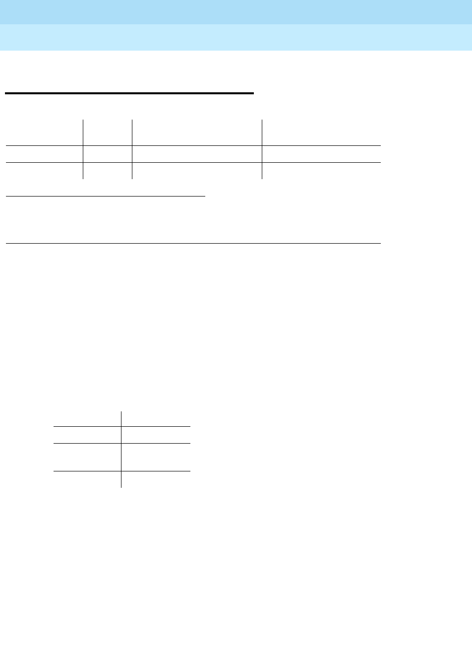
DEFINITY Enterprise Communications Server Release 6
Maintenance for R6r Volumes 1 & 2
555-230-126 Issue 2
January 1998
Maintenance Object Repair Procedures
Page 9-583E-DIG-BD (Multi Application Platform Board)
9
9
E-DIG-BD (Multi Application
Platform Board)
The maintenance strategy for DIG800-BD is the same as the one described for
MO-COMBD (MO-XXX-BD). Maintenance testing of the common circuit pack is
handled by on-board firmware and SPE controlled tests. Maintenance software
queries the firmware for error and alarm information, status, and test results. The
firmware automatically reports error conditions that will result in SPE-controlled
testing.
Board Insertion
The switch makes an additional board query if any of the following circuit packs
are inserted:
For any of the above initial board up-links, the switch sends queries requesting
additional data from the board for administration purposes, while also telling the
board the switch software release and the system type.
For the native mode, the response to the board query downlink messages
consists of several CCMS uplink messages that identify the true board code,
vintage, suffix, emulation type, and the number of reserved slots it needs.
1. Where UU is the universal cabinet number (1 for PPN and 2-44 for EPN); C is the carrier
designation (for example, A, B, C, D, or E); SS is the address of the slot in the carrier where
the circuit pack is located (for example, 01, 02, ...); and pp is the two digit port number (01,
02, 03, ...).
MO Name (in
Alarm Log) Alarm
Level Initial Command to Run1Full Name of MO
DIG800-BD MIN test board UUCSS sh MO800DIG-BD
DIG800-BD WRN test board UUCSS sh MO800DIG-BD
Circuit Pack Vintage
TN754 49
TN556 49,
80 or greater
TN800 any

DEFINITY Enterprise Communications Server Release 6
Maintenance for R6r Volumes 1 & 2
555-230-126 Issue 2
January 1998
Maintenance Object Repair Procedures
Page 9-584E-DIG-BD (Multi Application Platform Board)
9
Hyperactivity
The common circuit pack is considered "hyperactive" if the service dispatcher
receives 200 up-link messages from the circuit pack in a 10-second period.
Since MAPD has 32 ports, the hyperactivity limit is increased to 500 up-link
messages per 10seconds. An alarm is issued and the board taken out of service
when the limit reaches 400 or when it hits 500 up-link messages in 10 seconds.
LED Use
The LED Control message 038x requests the Angel to drive the Red, Yellow, and
Green LEDs on the face plate of typical port board on or off. On the MAPD, only
the Red LED is controlled by this message. Yellow and Green change requests
received from the switch by the MAPD drive LCD behavior rather than LED
behavior. The switch continues to send the same LED control messages to the
MAPD that it currently sends to all other port boards. The MAPD will handle
proper interpretation of these messages. You should note that the PC on the
MAPD, as well as the switch itself, can control the LEDs and the LCD on the
MAPD.
Port Administration
In administration without hardware, the switch allows administration of up to 32
MAPD ports of any port type. If the port type later reported by the board does not
match the existing type, the switch assumes the board is a MAPD board with a
different configuration and rejects the board. MAPD_DCP_STA and MAPD_
ASAI_STA are the only two types of terminals are allowed on a MAPD board.
Therefore, while administering ports on MAPD using add station form, it will
allow only the terminals mentioned above.
NOTE:
Refer to XXX-BD (Common Port Circuit Pack) maintenance documentation
for circuit pack level errors. See also DIG-LINE maintenance
documentation for related line information.

DEFINITY Enterprise Communications Server Release 6
Maintenance for R6r Volumes 1 & 2
555-230-126 Issue 2
January 1998
Maintenance Object Repair Procedures
Page 9-585E-DIG-RES (TN800 reserve slot)
9
E-DIG-RES (TN800 reserve slot)
See ASAI-RES.

DEFINITY Enterprise Communications Server Release 6
Maintenance for R6r Volumes 1 & 2
555-230-126 Issue 2
January 1998
Maintenance Object Repair Procedures
Page 9-586E-DIG-STA (Emulated Digital Line)
9
E-DIG-STA (Emulated Digital Line)
There are 4 tests in the Emulated Digital Line station maintenance test sequence
and only one test path in the test sequence. Once the test sequence is started,
all tests in the test sequence are executed.
E-DIG-ST maintenance monitors and tests ports on the TN800 MAPD circuit pack
and the hardware connected to those ports for lines administered as a digital
station. These include stations with an emulated digital voice terminal and
stations with an emulated digital voice terminal and a linked data module.
Stand-alone data modules and data adaptors in stand-alone mode are not
supported by the TN800 circuit pack. Circuit pack maintenance is covered by
E-DIG-BD.
Hardware Error Log Entries and
Test to Clear Values
1. Where UU is the universal cabinet number (1 for PPN and 2-44 for EPN); C is the carrier
designation (for example, A, B, C, D, or E); SS is the address of the slot in the carrier
where the circuit pack is located (for example, 01, 02, ...); and pp is the two digit port
number (01, 02, 03, ...).
MO Name (in
Alarm Log) Alarm Level Initial Command to
Run1 (a) (b) Full Name of MO
E-DIG-STA MINOR test port UUCSSpp l Emulated Digital St.
E-DIG-STA WARNING test port UUCSSpp sh Emulated Digital St.
Table 9-199. Digital Line Error Log Entries
Error
Type Aux
Data Associated Test Alarm
Level On/Off
Board Test to Clear Value
010 Any Any Any test port UUCSSpp sh r 1
18 (a) 0 busyout port UUCSSpp WNG OFF rel port UUCSSpp
130 (b) None WNG ON test port UUCSSpp sh
1793 (c) Voice and Control Local
Loop Test (#13) MIN/
WNG2ON test port UUCSSpp l r 3
2049 (d) NPE Crosstalk Test (#9) MIN/
WNG2ON test port UUCSSpp l r 3
2305 (e) 32770 None
Continued on next page

DEFINITY Enterprise Communications Server Release 6
Maintenance for R6r Volumes 1 & 2
555-230-126 Issue 2
January 1998
Maintenance Object Repair Procedures
Page 9-587E-DIG-STA (Emulated Digital Line)
9
Notes:
a. Maintenance personnel has busied out the port in question. Make sure
that the port is released from busyout by using the release port
UUCSSpp command.
b. The circuit pack has been removed or has been insane for more than 21
minutes. To clear the error, reinsert or replace the circuit pack.
c. The local loop test failed. Each failure increments the counter by 1 when
the local loop test fails. The counter is decremented when the loop test
passes. When the counter reaches a threshold of 3, an on-board MINOR
alarm is raised. This is the code that is generated when the link between
the circuit pack and the voice terminal is successfully reset. No technician
action is necessary.
d. The NPE Cross talk test failed. The counter is incremented by 1 when the
NPE Cross talk test fails. The counter is decremented by 1 when the NPE
Cross talk test passes. When the counter reaches a threshold of 3, an
on-board MINOR alarm is raised and the board is taken out of service.
e. The station went off-hook while it was in the ready-for-service state. Use
the status station command to determine the state of the station. The
off-hook should have moved the station to ready-for-service. No
technician action is necessary.
f. No terminal is connected to the Digital Line board. No maintenance action
is required.
g. The circuit pack’s message buffer is full. This may be caused by having
many display phones with heavy traffic connected to the circuit pack. No
action is necessary.
1. Run the Short Test Sequence first. If all tests pass, run the Long Test Sequence. Refer to the appropriate
test description and follow the recommended procedures.
2. Major alarms may be downgraded to Warning alarms based on the value used in the set options
command.
3840 (f) 40965 None
3841 (g) 41029 None
2304 (h) None
Table 9-199. Digital Line Error Log Entries — Continued
Error
Type Aux
Data Associated Test Alarm
Level On/Off
Board Test to Clear Value
Continued on next page

DEFINITY Enterprise Communications Server Release 6
Maintenance for R6r Volumes 1 & 2
555-230-126 Issue 2
January 1998
Maintenance Object Repair Procedures
Page 9-588E-DIG-STA (Emulated Digital Line)
9
h. Internal system error; no action is necessary. The error counters 1, 2, 3, 4,
5, 6, 10, 11, 12, 13, 14, 15, and 16 do not have any significance for this
MO.
System Technician-Demanded Tests:
Descriptions and Error Codes
Always investigate tests in the order presented in the table below when
inspecting errors in the system. By clearing error codes associated with the
Voice and Control Channel Local Loop Around Test, for example, you may also
clear errors generated from other tests in the testing sequence.
Digital Line NPE Crosstalk Test (#9)
One or more Network Processing Elements (NPEs) reside on each circuit pack
with a TDM Bus interface. The NPE controls port connectivity and gain and
provides conferencing functions on a per-port basis. The NPE Crosstalk Test
verifies that this port’s NPE channel talks on the selected time slot and never
crosses over to time slots reserved for other connections. If the NPE is not
working correctly, one-way and noisy connections may be observed. This test is
part of a port’s Long Test Sequence and takes about 20 to 30 seconds to
complete. Crosstalk testing occurs on both the primary information channel
(voice) and the secondary information channel (data) associated with each
digital station port. If this test fails on either channel, the station and the DTDM
are taken out-of-service.
1. D = Destructive; ND = Nondestructive
Order of Investigation Short Test
Sequence Long Test
Sequence D/ND1
Voice and Control Channel Local Loop Around Test (#13) X D
NPE Crosstalk Test (#9) X ND
Station Lamp Updates Test (#16) X ND
DEFINITY Enterprise Communications Server Release 6
Maintenance for R6r Volumes 1 & 2
555-230-126 Issue 2
January 1998
Maintenance Object Repair Procedures
Page 9-589E-DIG-STA (Emulated Digital Line)
9
Table 9-200. TEST #9 Digital Line NPE Crosstalk Test
Error
Code Test
Result Description/Recommendation
1 ABORT During testing of the primary information channel, system resources may
not have been available or the port was busy during the test.
1. Check the port status. Use the display port UUCSSpp command to
determine the station extension of the port. Use the status station
command to determine the service state of the port. If the service state
indicates that the port is in use, then the port is unavailable for this test.
You will have to wait until the port is idle.
2. If the port status is idle, then retry the command at 1-minute intervals a
maximum of 5 times.
2 ABORT During testing of DTDM, system resources may not have been available or
he port was busy during the test.
1. Check if port is being used. If possible, disconnect by toggling the
disconnect button on DTDM. Retry the command after 1 minute.
!CAUTION:
This action drops the call in progress.
1000 ABORT System resources required to run this test are not available. The port may
be busy with a valid call. Use display port UUCSSpp to determine the
station extension or attendant number of the port. Use status station or
status attendant to determine the service state of the port. If the service
state indicates that the port is in use, then the port is unavailable for certain
tests. You must wait until the port is idle before retesting. Attendants are
always in use (off-hook) if the handset is plugged in and the port is not
busied out.
1. If the port status is idle, then retry the command at 1-minute intervals a
maximum of 5 times.
1001 ABORT System resources required to run this test are not available.
1. Retry the command at 1-minute intervals a maximum of 5 times.
1002 ABORT The system could not allocate time slots for the test. The system is under
heavy traffic conditions or has time slots out-of-service due to TDM-BUS
errors. Refer to TDM-BUS to diagnose any active TDM-BUS errors.
1. If system has no TDM-BUS errors and is not handling heavy traffic,
repeat test at 1-minute intervals a maximum of 5 times.
Continued on next page

DEFINITY Enterprise Communications Server Release 6
Maintenance for R6r Volumes 1 & 2
555-230-126 Issue 2
January 1998
Maintenance Object Repair Procedures
Page 9-590E-DIG-STA (Emulated Digital Line)
9
1003 ABORT The system could not allocate a tone receiver for the test. The system is
oversized for the number of Tone Detectors present, or some Tone
Detectors are out-of-service.
1. Look for TTR-LEV errors in the Error Log. If present, refer to TTR
documentation.
2. Look for TONE-PT errors in the Error Log. If present, refer to TONE-PT
documentation.
3. If neither condition exists, retry the command at 1-minute intervals a
maximum of 5 times.
1004 ABORT The port was seized by a valid call during the test.
1. Use display port UUCSSpp to determine the station extension or
attendant number of the port.
2. Use status station or status attendant to determine the service state
of the port.
3. If the service state indicates that the port is in use, then the port is
unavailable for certain tests. Wait until the port is idle before retesting.
Attendants are always in use (off-hook) if the handset is plugged in and
the port is not busied out.
1020 ABORT Test disabled by background testing. Use the status station command to
determine when the station is available for testing.
2000 ABORT Response to the test request was not received within the allowable time
period.
1. Retry the command at 1-minute intervals a maximum of 5 times.
1
2FAIL The Network Processing Element (NPE) of the tested port is transmitting in
error. This causes noisy and unreliable connections.
Failure code 1 indicates that the Crosstalk test failed on the primary
channel.
Failure code 2 indicates that the Crosstalk test failed on the secondary
channel.
1. Replace the circuit pack.
PASS The port is correctly using its allocated time slots.
1. To ensure that this is not an intermittent problem, repeat this test a
maximum of 10 times.
2. If complaints persist, examine the station, connections, and wiring.
Table 9-200. TEST #9 Digital Line NPE Crosstalk Test — Continued
Error
Code Test
Result Description/Recommendation
Continued on next page

DEFINITY Enterprise Communications Server Release 6
Maintenance for R6r Volumes 1 & 2
555-230-126 Issue 2
January 1998
Maintenance Object Repair Procedures
Page 9-591E-DIG-STA (Emulated Digital Line)
9
Voice and Control Channel Local Loop Test (#13)
These tests check the information and control channels between the Switch
Processing Element (SPE) and the Digital Line port circuit. The SPE sends a
message to loop around both the information and control channels for the port.
First, the primary information (voice) channel loopback test sends a digital count
from the Tone-Clock circuit pack on the primary information channel time slot and
receives the same digital count with a general purpose tone detector.
While the primary information channel is still looped around, the Control Channel
Loop Around Test sends four different transparent patterns to the on-board
microprocessor, receives them back, and compares them.
The Loop Around Test for the secondary information (data) channel is the same
as the primary information channel loop around test and is performed only if a
DTDM is administered.
Next, a Conference Test checks the primary information channel. This test is the
same as Conference Test #6.
The four tests will generate only one resulting value (Pass, Fail, or Abort). If any
test fails or aborts, the test sequence stops.
Table 9-201. TEST #13 Voice and Control Channel
Local Loop Test
Error
Code Test
Result Description/ Recommendation
ABORT Internal system error
1. Retry the command at 1-minute intervals a maximum of 5 times.
1000 ABORT System resources required to run this test are not available. The port may
be busy with a valid call. Use display port UUCSSpp to determine the
station extension or attendant number of the port. Use status station or
status attendant to determine the service state of the port. If the service
state indicates that the port is in use, then the port is unavailable for
certain tests. Wait until the port is idle before retesting. Attendants are
always in use (off-hook) if the handset is plugged in and the port is not
busied out.
1. If the port status is idle, then retry the command at 1-minute intervals a
maximum of 5 times.
1001 ABORT System resources required to run this test are not available.
1. Retry the command at 1-minute intervals a maximum of 5 times.
Continued on next page

DEFINITY Enterprise Communications Server Release 6
Maintenance for R6r Volumes 1 & 2
555-230-126 Issue 2
January 1998
Maintenance Object Repair Procedures
Page 9-592E-DIG-STA (Emulated Digital Line)
9
1002 ABORT The system could not allocate time slots for the test. The system is under
heavy traffic conditions or it has time slots out-of-service due to TDM-BUS
errors. Refer to TDM-BUS to diagnose any active TDM-BUS errors.
1. If system has no TDM-BUS errors and is not handling heavy traffic,
repeat test at 1-minute intervals a maximum of 5 times.
1003 ABORT The system could not allocate a tone receiver for the test. The system is
oversized for the number of Tone Detectors present, or some Tone
Detectors are out-of-service.
1. Look for TTR-LEV errors in the Error Log. If present, refer to TTR-LEV
documentation.
2. Look for TONE-PT errors in the Error Log. If present, refer to TONE-PT
documentation.
3. If neither condition exists, retry the command at 1-minute intervals a
maximum of 5 times.
1004 ABORT The port was seized by a valid call during the test. The test has been
aborted. Use the display port UUCSSpp command to determine the
station extension or attendant number of the port. Use status station or
status attendant to determine the service state of the port. If the service
state indicates that the port is in use, then the port is unavailable for
certain tests. Wait until the port is idle before retesting. Attendants are
always in use (off-hook) if the handset is plugged in and the port is not
busied out.
1. Retry the command at 1-minute intervals a maximum of 5 times.
2. If the test continues to abort and the port is not in use, escalate the
problem.
2000 ABORT Response to the test request was not received within the allowable time
period.
2100 ABORT Could not allocate the necessary system resources to run this test.
1. Rerun the test at 1-minute intervals a maximum of 5 times.
Table 9-201. TEST #13 Voice and Control Channel
Local Loop Test — Continued
Error
Code Test
Result Description/ Recommendation
Continued on next page

DEFINITY Enterprise Communications Server Release 6
Maintenance for R6r Volumes 1 & 2
555-230-126 Issue 2
January 1998
Maintenance Object Repair Procedures
Page 9-593E-DIG-STA (Emulated Digital Line)
9
7 FAIL Conference Test failed on primary channel. In some cases, users may not
notice disruption in service. In extreme cases, conferencing feature may
not work at all.
14 FAIL The primary voice channel is not transmitting properly. User impact may
range from noticing nothing to not being able to use this port.
15 FAIL The control channel between the processor and digital circuit pack is not
transmitting properly. User impact may range from noticing nothing to not
being able to use the port. This could disrupt other users.
16 FAIL The secondary voice channel is not transmitting properly. User impact
may range from noticing nothing to not being able to use this port.
1. Run circuit pack tests to check the Tone Generator circuit pack and
the Tone Detector circuit pack using the test board UUCSSpp
command.
2. Resolve any problems that are detected on the Tone Generator circuit
pack or Tone Detector circuit pack.
3. If the Tone Generator and Tone Detector circuit packs are functioning
properly and the test still fails, replace the Digital Line circuit pack.
PASS The test passed, and all channels are transmitting properly.
1. To ensure that this is not an intermittent problem, repeat this test up to
10 times.
2. If noisy connections for voice or corrupted data for data transfer
persist, examine the station, connections, and wiring.
Table 9-201. TEST #13 Voice and Control Channel
Local Loop Test — Continued
Error
Code Test
Result Description/ Recommendation
Continued on next page

DEFINITY Enterprise Communications Server Release 6
Maintenance for R6r Volumes 1 & 2
555-230-126 Issue 2
January 1998
Maintenance Object Repair Procedures
Page 9-594E-DIG-STA (Emulated Digital Line)
9
Station Lamp Updates Test (#16)
This test lights all lamps on the terminal as specified. The lamp updates will run
only if the station is in-service. The status of the station is checked and the lamp
updates are blocked from taking place if the station is not in the in-service state.
This test does not affect the status of the Message Waiting lamp.
Table 9-202. TEST #16 DIG-LINE Station Lamp Updates Test
Error
Code Test
Result Description/ Recommendation
ABORT Internal system error
1. Retry the command at 1-minute intervals a maximum of 5 times.
1 ABORT System technician may have busied out the port.
1. Look in the Error Log for Error Type 18 (port busied out) for this port. If
this error type is present, then release the port with the release station
<extension> command and run the test again.
2. Make sure that the terminal is connected.
3. Retry the command at 1-minute intervals a maximum of 5 times.
3 ABORT Station may be in ready-for-service or out-of-service state.
1. Use the status station command to verify state of station.
2. Make sure the terminal is connected.
3. Retry the command at 1-minute intervals a maximum of 5 times.
1000 ABORT System resources required to run this test are not available. The port is busy
with a valid call. Use display port UUCSSpp to determine the station
extension or attendant number of the port. Use status station or status
attendant to determine the service state of the port. If the service state
indicates that the port is in use, then the port is unavailable for certain tests.
Wait until the port is idle before retesting. Attendants are always in use
(off-hook) if the handset is plugged in and the port is not busied out.
1. If the port status is idle, then retry the command at 1-minute intervals a
maximum of 5 times.
1392 ABORT This is currently a TTI port, and the test cannot execute on it.
1. Verify that the port is a TTI port using either the display port command
(the display shows that the port is a TTI port) or the list config
command (the display shows a t for the port).
2. If either list config or display port indicates that the port is
not
a TTI
port, escalate the problem. If both commands indicate that the port is a
TTI port, the abort is correct, and no action is necessary.
FAIL Internal system error.
1. Retry the command at 1-minute intervals a maximum of 5 times.
Continued on next page

DEFINITY Enterprise Communications Server Release 6
Maintenance for R6r Volumes 1 & 2
555-230-126 Issue 2
January 1998
Maintenance Object Repair Procedures
Page 9-595E-DIG-STA (Emulated Digital Line)
9
PASS The message to light all of the station lamps was sent successfully to the
port.
1. Observe the station lamps being lit when running the test. If all lamps do
not light successfully, the other Digital Line test results may indicate
related problems that will not allow the lamps to light.
2. Investigate by using other Digital Line port tests and by examining the
station, wiring, and connections.
Table 9-202. TEST #16 DIG-LINE Station Lamp Updates Test — Continued
Error
Code Test
Result Description/ Recommendation
Continued on next page

DEFINITY Enterprise Communications Server Release 6
Maintenance for R6r Volumes 1 & 2
555-230-126 Issue 2
January 1998
Maintenance Object Repair Procedures
Page 9-596EMG-XFER (Emergency Transfer)
9
EMG-XFER (Emergency Transfer)
The Emergency Transfer maintenance object monitors the position of the
Emergency Transfer switch(es) on the SYSAM circuit pack(s) in a PPN and the
EPN Maintenance circuit packs in an EPN. It does not monitor whether or not the
system is actually in Emergency Transfer.
Emergency Transfer (ET) provides the ability to connect designated analog
phones to CO trunks when the switch cannot provide minimal phone service.
Each cabinet (PPN and EPNs) has its own ET capability, and there is one
EMG-XFER maintenance object for each cabinet or stack of single-carrier
cabinets.
ET is controlled either automatically by the system, or manually, depending on
the setting of the ET switches as described below.
Emergency Transfer Switches: EPNs and Simplex
SPE
In a simplex SPE PPN cabinet, or in an EPN cabinet, if the ET switch is in the ‘‘on’’
position, ET is manually invoked and the system has no control of ET. This will
generate a major alarm. In a simplex SPE PPN cabinet or in an EPN cabinet, if the
ET switch is in the ‘‘off’’ position, ET cannot be invoked even if the system
requests it. This will generate a warning alarm. Unless a technician is currently
working on the cabinet, the switches should be left in the auto position, giving
control of ET to the system.
Emergency Transfer Switches: Duplicated SPEs
On a system with duplicated SPE, the switches on both SYSAMs must be in the
manual ‘‘on’’ position to manually invoke ET, generating a major alarm. If the
switch on either SYSAM is in the manual ‘‘off’’ position, ET cannot be invoked,
generating a warning alarm. Other settings give control to the system.
1. UU is the universal cabinet number as listed in the PORT field of the Alarm or Error Log.
MO Name (in
Alarm Log) Alarm Level Initial Command to Run1Full Name of MO
EMG-XFER MAJOR test environment UU Emergency Transfer
EMG-XFER WARNING test environment UU Emergency Transfer

DEFINITY Enterprise Communications Server Release 6
Maintenance for R6r Volumes 1 & 2
555-230-126 Issue 2
January 1998
Maintenance Object Repair Procedures
Page 9-597EMG-XFER (Emergency Transfer)
9
Emergency Transfer Status
The status cabinet UU command shows the location of the ET switches and the
current status of ET in the designated cabinet as follows:
Error Log Entries and Test to Clear Values
1. Run the Short Test Sequence first. If all tests pass, run the Long Test Sequence. Refer to the
appropriate test description and follow the recommended procedures.
on ET is manually invoked.
off ET is manually prevented.
auto+ ET is invoked and under system control.
auto- ET is not in effect and is under system control, (normal
operating state).
unavailable The switch setting(s) is not available.
Emergency Transfer Error Log Entries
Error
Type Aux
Data Associated Test Alarm
Level On/Off
Board Test to Clear Value
010 Any Any Any test environment UU
1 0 Emergency Transfer
Query (#124) MAJOR ON test environment UU r 3
257 0 Emergency Transfer
Query (#124) WARNING ON test environment UU r 3

DEFINITY Enterprise Communications Server Release 6
Maintenance for R6r Volumes 1 & 2
555-230-126 Issue 2
January 1998
Maintenance Object Repair Procedures
Page 9-598EMG-XFER (Emergency Transfer)
9
System Technician-Demanded Tests:
Descriptions and Error Codes (Multi-Carrier)
Always investigate tests in the order presented in the table below. By clearing
error codes associated with the
Battery & Battery Charger Query Test,
for
example, you may also clear errors generated from other tests in the testing
sequence.
Notes:
a. Refer to POWER section for a description of this test.
b. Refer to AC-POWER section for a description of this test.
c. Refer to CARR-POW section for a description of this test.
d. Refer to CABINET section for a description of this test.
e. Refer to EXT-DEV section for a description of this test.
f. Refer to RING-GEN section for a description of this test. These tests will
only show up in the test sequence if there is a TN768 or TN780 Tone/Clock
circuit pack in the port network being tested.
1. D = Destructive; ND = Nondestructive
Multi-Carrier System
Order of Investigation Short Test
Sequence Long Test
Sequence D/ND1
Battery & Battery Charger Query Test (#5) (a) X X ND
AC Power Query Test (#78) (b) X X ND
OLS Query Test (Carrier E) (#127) (c) X X ND
OLS Query Test (Carrier D) (#127) (c) X X ND
OLS Query Test (Carrier A) (#127) (c) X X ND
OLS Query Test (Carrier B) (#127) (c) X X ND
OLS Query Test (Carrier C) (#127) (c) X X ND
Emergency Transfer Query Test (#124) X X ND
Cabinet Sensors Query Test (#122) (d) X X ND
External Alarm Lead Query Test (#120) (e) X X ND
Analog Ring Generator Initialization Test
Analog Ring Generator Initialization Test (#117) (f) X X ND
Analog Ring Generator Query Test (#118) (f) X X ND

DEFINITY Enterprise Communications Server Release 6
Maintenance for R6r Volumes 1 & 2
555-230-126 Issue 2
January 1998
Maintenance Object Repair Procedures
Page 9-599EMG-XFER (Emergency Transfer)
9
System Technician-Demanded Tests:
Descriptions and Error Codes (Single-Carrier)
Always investigate tests in the order presented in the following table. By clearing
error codes associated with the
Battery & Battery Charger Query Test,
for
example, you may also clear errors generated from other tests in the testing
sequence. For example, you may also clear errors generated from other tests in
the testing sequence.
Notes:
a. Refer to “DC-POWER” for a description of this test.
b. Refer to “EXT-DEV” for a description of this test.
c. Refer to “RING-GEN” for a description of this test.
NOTE:
These tests only show up in the test sequence if there is a TN768
Tone-Clock Board in the port network being tested.
Emergency Transfer Query Test (#124)
The Emergency Transfer Query Test queries the hardware for the state of the
Emergency Transfer switch (or switches in a duplicated SPE system) and reports
the result. If the position of the switch in a single SPE cabinet or EPN cabinet, or
switches in a duplicated SPE cabinet, is such that the system software can
control Emergency Transfer (auto), then the test passes. If the position of the
switch or switches is such that the system software cannot control Emergency
Transfer (manual ‘‘on’’ or manual ‘‘off’’), then the test fails. In the PPN the SYSAM
controls Emergency Transfer, and in the EPN, the EPN Maintenance circuit pack
controls Emergency Transfer
1. D = Destructive; ND = Nondestructive
Single-Carrier System
Order of Investigation Short Test
Sequence Long Test
Sequence D/ND1
Power Query Test (#79) (a) X X ND
Emergency Transfer Query Test (#124) X X ND
External Alarm Lead Query Test (#120) (b) X X ND
Analog Ring Generator Initialization Test (#117) (c) X X ND
Analog Ring Generator Query Test (#118) (c) X X ND

DEFINITY Enterprise Communications Server Release 6
Maintenance for R6r Volumes 1 & 2
555-230-126 Issue 2
January 1998
Maintenance Object Repair Procedures
Page 9-600EMG-XFER (Emergency Transfer)
9
Notes:
Table 9-203. TEST #124 Emergency Transfer Query Test
Error
Code Test
Result Description/ Recommendation
1000 ABORT System resources required to run this test are not available.
1. Try (a).
2000 ABORT Response to the test was not received within the allowable time period.
1. Try (a).
2. If the test continues to ABORT with error code 2000, check for system
powering problems with the A carrier (PPN or EPN). Resolve all
“AC-POWER” and “CARR-POW” alarms in a multi-carrier cabinet system or
“DC-POWER” alarms in a single-carrier cabinet system. Then, repeat the
test.
3. If the test continues to ABORT with a 2000 error code, resolve all SYSAM
errors in a PPN, or MAINT (EPN Maintenance circuit pack) errors in an EPN.
Then, repeat the test.
2029
2319
2320
2500
ABORT Internal system error
1. Try (a).
17
18
20
33
65
289
FAIL Emergency Transfer is manually turned OFF via the Emergency Transfer switch.
1. Place the switch (or switches in a PPN with duplicated SPE) in the AUTO
position.
34
290 FAIL Emergency Transfer is manually turned ON via the Emergency Transfer switch.
1. Place the switch (or switches in a PPN with duplicated SPE) in the AUTO
position.
PASS System software has control of Emergency Transfer within this cabinet. If
Emergency Transfer is currently invoked (the emergency transfer LED is on),
the cause could be a major alarm. The following list shows the error types that
can cause Emergency Transfer. If any of these errors appear in the log, then
refer to the appropriate section and resolve those problems first. Maintenance
Object TAPE SW-CTL SW-CTL TONE-BD TONE-BD Error Type 3585 1 2 1 2305
Aux Data 408 0 0 If none of the above errors appear in the log, then check the
Emergency Transfer hardware. On an EPN, if Emergency Transfer is invoked
while call processing is permitted, verify that the current limiter card (982LS) is
in the correct slot on the backplane. If the current limiter card is not in the
correct slot, move it to the correct location and rerun Test #124.
Continued on next page

DEFINITY Enterprise Communications Server Release 6
Maintenance for R6r Volumes 1 & 2
555-230-126 Issue 2
January 1998
Maintenance Object Repair Procedures
Page 9-601EMG-XFER (Emergency Transfer)
9
a. Retry the command at 1-minute intervals a maximum of 5 times.

DEFINITY Enterprise Communications Server Release 6
Maintenance for R6r Volumes 1 & 2
555-230-126 Issue 2
January 1998
Maintenance Object Repair Procedures
Page 9-602EPN-SNTY (EPN Sanity Audit)
9
EPN-SNTY (EPN Sanity Audit)
The EPN Sanity Audit feature enhances the system’s ability to recover from failure
conditions that disable an entire EPN. In such situations, not only is the affected
EPN unable to provide service to the system, but the system itself has not
detected the condition. The EPN Sanity Audit feature recognizes an EPN as
unable to provide service when the software cannot receive control messages
from EPN circuit packs. When such a failure is detected by the EPN Sanity Audit,
a sequence of recovery actions is triggered to restore the EPN to service.
For a Standard Reliability system (simplex SPE), the recovery sequence is:
1. TDM Bus Switch
2. EPN WARM Reset
3. EPN COLD Reset
For a high or critical reliability system (duplicated SPE), the recovery sequence
is:
1. TDM Bus Switch
2. Tone/Clock Switch within the EPN
3. PNC Interchange
4. EPN WARM Reset
5. EPN COLD Reset
The EPN Sanity Audit feature activates only when all existing maintenance
operations have failed to detect the EPN problem. The EPN Sanity Audit serves
as a safety net for the EPN.
NOTE:
It is not clear why certain types of EPN problems activate this feature. Thus,
error log entries related to these problems do not specify which hardware
to replace. The error log entries only indicate that some drastic recovery
action occurred due to an unknown problem. However, clues as to the root
cause of the EPN outage may be present in the Error Logs and the Alarm
Logs of the following MOs: Switch Control (SW-CTL), TDM Bus (TDM-BUS),
Expansion Interface (EXP-INTF), TDM Bus Clock (TDM-CLK), EXP-PN, and
PNC-DUP. You should refer to these maintenance sections during trouble
shooting operations.
MO Name (in
Alarm Log) Alarm Level Initial Command to Run Full Name of MO
EPN-SNTY None None EPN Sanity Audit
DEFINITY Enterprise Communications Server Release 6
Maintenance for R6r Volumes 1 & 2
555-230-126 Issue 2
January 1998
Maintenance Object Repair Procedures
Page 9-603EPN-SNTY (EPN Sanity Audit)
9
Error Log Entries and Test to Clear Values
Notes:
a. Error 8801 occurs whenever the EPN is unable to send up-link control
messages and the control channel of the TDM Bus in the EPN has been
switched as part of the recovery procedure.
b. Error 8803 occurs each time whenever the EPN is unable to send up-link
control messages and the EPN Tone-Clock has been switched as part of
the recovery procedure.
c. Error 9901 occurs whenever the EPN is unable to send up-link control
messages, but recovers after the control channels of the TDM Bus in the
EPN are switched.
d. Error 9902 occurs whenever the EPN is unable to send up-link control
messages, but recovers after the active Tone-Clock in the EPN is
switched.
e. Error 9903 occurs whenever the EPN is unable to send up-link control
messages, but recovers after a PNC interchange has taken place.
f. Error 9904 occurs whenever the EPN is unable to send up-link control
messages, but recovers after an EPN WARM reset.
g. Error 9905 occurs whenever the EPN is unable to send up-link control
messages, but recovers after an EPN COLD reset.
1. Run the Short Test Sequence first. If all tests pass, run the Long Test Sequence. Refer to the
appropriate test description and follow the recommended procedures.
Table 9-204. EPN-SNTY Error Log Entries
Error
Type Aux
Data Associated Test Alarm
Level On/Off
Board Test to Clear Value
010 Any None
8801 (a) Any None
8803 (b) Any None
9901 (c) Any None
9902 (d) Any None
9903 (e) Any None
9904 (f) Any None
9905 (g) Any None

DEFINITY Enterprise Communications Server Release 6
Maintenance for R6r Volumes 1 & 2
555-230-126 Issue 2
January 1998
Maintenance Object Repair Procedures
Page 9-604ERR-LOG (Error Log)
9
ERR-LOG (Error Log)
The ERR-LOG maintenance object (MO) is responsible for the sanity of the Alarm
Log, the Hardware Error Log, and the Software Error Log. If an inconsistency is
detected in any one of these logs, all logs will be re-initialized and a hardware
error will be logged against ERR-LOG indicating the time of inconsistency. There
are no tests and no alarms for the Error Log MO. This MO exists solely for the
purpose of allowing errors to be logged against it.
Hardware Error Log Entries
Notes:
a. Indicates that an inconsistency was detected in either the Alarm Log, the
Hardware Error Log, or the Software Error Log. The system attempts to
recover the logs but, depending on the extent of the corruption, some or
all entries in the logs may be lost. Any alarms that were active at the time
of this error have been cleared. There is no associated test for this error.
The Aux Data value indicates when the inconsistency was found:
MO Name (in
Alarm Log) Alarm Level Initial Command to Run Full Name of MO
ERR-LOG none none Error Log
Error
Type Aux Data Associated Test Alarm
Level On/Off
Board Test to Clear Value
510 (a) Any none none none none
0 During a periodic audit of the Error Log
1 After an extended reboot
2 After a reboot
4 After a Level-3 System Reset (COLD_1)
8 After a Level-2 System Reset (COLD_2)
16 After a Level-1 System Reset (Warm Start)
100 After an internal software audit
2500 After a single-process (MDM) restart
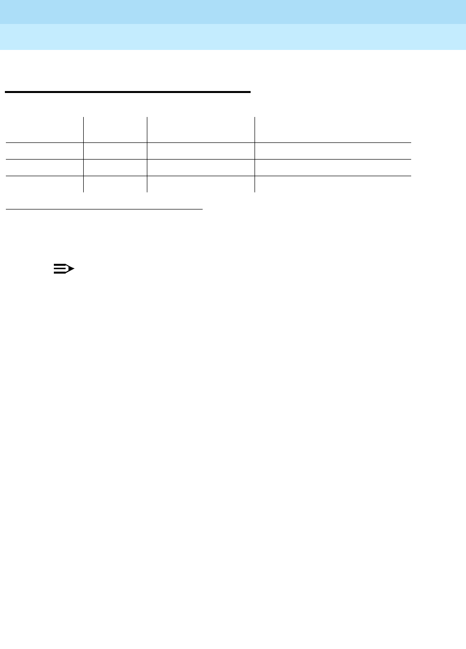
DEFINITY Enterprise Communications Server Release 6
Maintenance for R6r Volumes 1 & 2
555-230-126 Issue 2
January 1998
Maintenance Object Repair Procedures
Page 9-605ETR-PT (Enhanced Tone Receiver Port)
9
ETR-PT (Enhanced Tone Receiver
Port)
NOTE:
Replacing the tone/clock circuit pack requires a special procedure which is
described in "TONE-BD (Tone-Clock Circuit Pack)". That section also
describes the LED display for this board.
The TN2182 is a combined Tone Generator/Tone Detector board. It provides 8
Enhanced Tone receiver (ETR) ports. Each of these ports provides the functions
previously found individually on DTMR-PTs, GPTD-PTs and CLAS-PTs ports.
Thus each port on the TN2182 may be used for any tone detection function that
was previously done by TN748, TN420 or TN744 Tone detection boards.
The TN2182 provides Mu-law or A-law tone detection capability.
Since the TN2182 also provides Tone/Clock function only one (or two if your
system is duplicated) TN2182 circuit packs may be present in a port network.
Thus if more tone detection resources are needed, the additional resources must
be provided by TN748, TN420 or TN744 circuit packs.
1. UU is the universal cabinet number (1 for PPN, 2 - 44 for EPNs). C is the carrier designation (A, B,
C, D, or E). SS is the number of the slot in which the circuit pack resides (01 to 21). pp is the two
digit port number (01, 02, ...).
MO Name (in
Alarm Log) Alarm Level Initial Command to
Run1Full Name of MO
ETR-PT MAJOR test port PCSSpp sh Enhanced Tone Receiver Port
ETR-PT MINOR test port PCSSpp sh Enhanced Tone Receiver Port
ETR-PT WARNING test port PCSSpp sh Enhanced Tone Receiver Port

DEFINITY Enterprise Communications Server Release 6
Maintenance for R6r Volumes 1 & 2
555-230-126 Issue 2
January 1998
Maintenance Object Repair Procedures
Page 9-606ETR-PT (Enhanced Tone Receiver Port)
9
Error Log Entries and Test to Clear Values
Notes:
a. There are two possible alarm levels for this error type: major alarm and
minor alarm. These alarm levels are dependent on the administered
thresholds for TTR, CPTR and CCTR. Each ETR port is capable of
operating an any of these.
A major alarm is raised if the total number of ports capable of TTR, CPTR
or CCTR detection currently in-service is less than or equal to 1/2 of the
administered TTR, CPTR or CCTR threshold number.
Otherwise, a minor alarm is raised. In either case, run the short test
sequence against the port (ETR-PT) and follow the error code procedures
for the individual tests.
The threshold number of ports for service is administered using the
change system-parameters maintenance command.
b. The ETR-PT lost its translation. Testing the ETR-PT is sufficient to reload
its translation. If testing the ETR port does not clear the error, then the
circuit pack containing the defective ETR port should be replaced at a
time when it is convenient to remove a clock board from the system.
Follow the procedures described in "TONE-BD (Tone-Clock Circuit Pack)"
for replacing a tone/clock circuit pack.
c. This error indicates the (ETR-PT) Enhanced Tone Receiver is having
problems detecting touch tones, call progress or MFC tones. If this error
type is persistently logged, then the circuit pack containing the defective
ETR-PT should be replaced at a time it is convenient to remove a clock
board from the board from the system. Follow the procedures described
in the "TONE-BD (Tone-Clock Circuit Pack)" section for replacing a
tone/clock circuit pack.
Error
Type Aux
Data Associated Test Alarm
Level On/Off
Board Test to Clear Value
1 any Tone Detector Audit/Update
Test (#43) MAJOR/
MINOR(a) ON test port UUCSSpp r 2
18 busyout port WARNING OFF release port UUCSSpp
257(b) 17666 Tone Detection Audit
Update Test (#43 MAJOR/
MINOR(a) ON test port UUCSSpp r 3
513(c) any Tone Detection Verification
Test (#42) MAJOR/
MINOR(a) ON test port UUCSSpp r 3
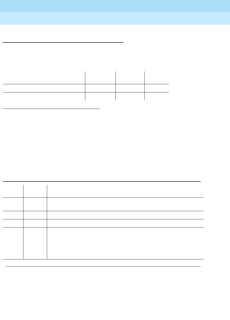
DEFINITY Enterprise Communications Server Release 6
Maintenance for R6r Volumes 1 & 2
555-230-126 Issue 2
January 1998
Maintenance Object Repair Procedures
Page 9-607ETR-PT (Enhanced Tone Receiver Port)
9
System Technician-Demanded Tests:
Descriptions and Error Codes
Always investigate tests in the order presented in the following table. By clearing
error codes associated with the
Tone Detection Verification Test
, for example,
you may also clear errors generated from other tests in the testing sequence.
Tone Detection Verification Test (#42)
This test checks out a single ETR port in the touch-tone receiver mode MFC tone
detection/generation mode and general purpose tone detection mode. During
the first portion of the test, the touch-tone receiver mode is tested. Then general
purpose call progress and maintenance tones are tested and lastly MFC tones
are tested
1. D = Destructive; ND = Nondestructive
Order of Investigation Short Test
Sequence Long Test
Sequence D/ND1
Tone Detection Verification Test(#42) X X ND
Tone Detection Audit/Update Test(#43) X X ND
Table 9-205. TEST #42 Tone Detection Verification Test
Error
Code Test
Result Description/ Recommendation
none ABORT The system was not able to allocate all the resources needed for this test OR
there was an Internal system error.
1 ABORT The system could not allocate all the resources needed to test the tones.
1001 ABORT The system was unable to put the ETR-PT in the appropriate mode to test it.
1002 ABORT The system could not allocate time slots for the test connection. This situation
could occur when the system is heavily loaded. If the system is not heavily
loaded, then test the TDM-BUS via the test tdm command. Refer to
“TDM-BUS” for details.
1. Try (a).
Continued on next page

DEFINITY Enterprise Communications Server Release 6
Maintenance for R6r Volumes 1 & 2
555-230-126 Issue 2
January 1998
Maintenance Object Repair Procedures
Page 9-608ETR-PT (Enhanced Tone Receiver Port)
9
1003 ABORT The system could not allocate a Tone-Clock for the test connection. This may
be caused by a heavy load on the system or by a faulted Tone-Clock.
1. Check to see if there are any alarms against the Tone-Clock in the port
network where the test aborted. If so refer to the recommended
procedures for TONE-BD or TONE-PT.
2. If a new Tone-Clock has been inserted, allow about 1 minute for
maintenance to run on the newly inserted circuit pack.
3. Try (a).
2000 ABORT Circuit Pack’s response to the test request was not received within the
allowable time period.
1. Try (a).
2006 ABORT This abort code indicates that the active Tone-Clock circuit pack or a Tone
Detector circuit pack may not be functioning properly.
1. Test the
active
Tone-Clock circuit pack in the port network with the test
tone-clock UUC command and refer to "TONE-BD (Tone-Clock Circuit
Pack)" for failures.
2. Try (a).
2100 ABORT Could not allocate the necessary system resources to run this test.
3. Try (a).
1-122 FAIL DTMF digits were not detected correctly.
1. Run the short test sequence via the test port UUCSSpp sh r 1 command.
2. If the problem persists, the system is still operating properly but capacity
is reduced. To restore performance to normal, replace the circuit pack
containing the defective “ETR-PT”.
102 FAIL 2225 Hz Modem Answer Tone was not detected correctly. This will impact
call-classification operation.
1. Run the short test sequence via the test port UUCSSpp sh r 1 command.
2. If the problem persists, the system can still operate properly but capacity
will be reduced. In order to restore performance to normal, replace the
circuit pack containing the defective port. Follow the procedures
described in the TONE-BD section for replacing a tone/clock circuit pack.
Table 9-205. TEST #42 Tone Detection Verification Test — Continued
Error
Code Test
Result Description/ Recommendation
Continued on next page
DEFINITY Enterprise Communications Server Release 6
Maintenance for R6r Volumes 1 & 2
555-230-126 Issue 2
January 1998
Maintenance Object Repair Procedures
Page 9-609ETR-PT (Enhanced Tone Receiver Port)
9
Notes:
a. Retry the command at 1-minute intervals a maximum of 5 times.
Tone Detector Audit/Update Test (#43)
A Digital Signal Processor sanity audit is performed on the ETR-PT.
130 FAIL Forward or Backward MFC signals were not correctly generated or detected.
This will impact MFC calls.
1. Run the short test sequence via test port UUCSSpp sh r 1.
2. If the problem persists, the system can still operate properly but capacity
will be reduced. In order to restore performance to normal, replace the
TN2182 circuit pack containing the defective ETR-PT. Follow the
procedures described in the TONE-BD section for replacing a tone/clock
circuit pack.
PASS Tone Detection Verification is successful. The ETR Port is able to
detect/generate all necessary tones.
Table 9-206. TEST #43 Tone Detector Audit/Update Test
Error
Code Test Result Description/ Recommendation
none ABORT The system could not allocate all the resources needed for this test.
1. Try (a).
2000 ABORT Response to the test request was not received within the allowable time
period.
Continued on next page
Table 9-205. TEST #42 Tone Detection Verification Test — Continued
Error
Code Test
Result Description/ Recommendation
Continued on next page
DEFINITY Enterprise Communications Server Release 6
Maintenance for R6r Volumes 1 & 2
555-230-126 Issue 2
January 1998
Maintenance Object Repair Procedures
Page 9-610ETR-PT (Enhanced Tone Receiver Port)
9
Notes:
a. Retry the command at 1-minute intervals a maximum of 5 times.
2100 ABORT Could not allocate the necessary system resources to run this test.
2. Try (a).
FAIL Hardware audit failed.
1. Run the short test sequence via test port UUCSSpp sh r 1.
2. If the problem persists, the system is still operating properly but system
capacity will be reduced. In order to restore system performance to
normal, replace the circuit pack containing the defective ETR-PT. Follow
the procedures described in the TONE-BD section for replacing a
tone/clock circuit pack.
PASS The ETR Port has passed the sanity inquiry.
Table 9-206. TEST #43 Tone Detector Audit/Update Test — Continued
Error
Code Test Result Description/ Recommendation
Continued on next page

DEFINITY Enterprise Communications Server Release 6
Maintenance for R6r Volumes 1 & 2
555-230-126 Issue 2
January 1998
Maintenance Object Repair Procedures
Page 9-611EXP-INTF (Expansion Interface Circuit Pack)
9
EXP-INTF (Expansion Interface
Circuit Pack)
Following this introductory description of the Expansion Interface (EI) circuit pack
are sections on the following topics:
■EI In-Service Mechanism
■EI LED s
■EI and Tone-Clock Interactions
■How to Replace an EI Circuit Pack
■EI Manual Loopback Procedure
The TN570 (EI) Circuit Pack provides a TDM and Packet bus to fiber interface for
the communication of signaling information, circuit switched connections and
packet switch connections between endpoints residing in separate port
networks. EI Circuit Packs are located in the Processor Port Network (PPN) or in
Expansion Port Networks (EPN s) and are connected via optical fiber links. An EI
can be connected to:
■Another EI (direct connect configuration)
■A DS1 Converter in a DS1 CONV Complex used to remote an EPN
■A Switch Node Interface (center stage switch configuration)
In a Center Stage Switch configuration with duplicated Port Network
Connectivity, the PPN Expansion Interface circuit pack may be located in the
Switch Node Carrier (see Figure 9-30). In these cases, the Expansion Interface
circuit pack and Switch Node Interface circuit pack may be connected via a
metallic cable instead of an optical fiber link. In diagnosing problems with an
Expansion Interface circuit pack that may be related to fiber link problems, the
metallic cable should be treated in the same manner as the optical fiber in
regards to testing and replacement.
A PPN-EPN connection can be extended via a DS1 CONV Complex. (See Figure
9-31). When discussing problems that may be related to fiber link problems, the
1.
UU
is the universal cabinet number (1 for PPN, 2 - 44 for EPNs).
C
is the carrier designation (A,
B, C, D, or E).
SS
is the number of the slot in which the circuit pack resides (01 to 21).
MO Name (in
Alarm Log) Alarm
Level Initial Command to
Run1Full Name of MO
EXP-INTF MAJOR test board UUCSS s Expansion Interface Circuit Pack
EXP-INTF MINOR test board UUCSS s Expansion Interface Circuit Pack
EXP-INTF WARNING test board UUCSS s Expansion Interface Circuit Pack
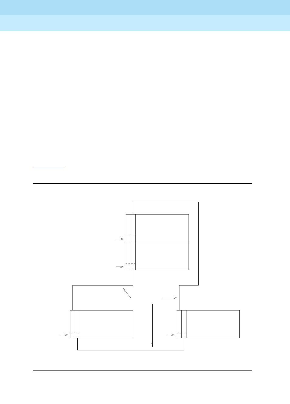
DEFINITY Enterprise Communications Server Release 6
Maintenance for R6r Volumes 1 & 2
555-230-126 Issue 2
January 1998
Maintenance Object Repair Procedures
Page 9-612EXP-INTF (Expansion Interface Circuit Pack)
9
DS1 CONV will be considered part of the fiber link. If diagnosis of the problem
points to the fiber connectivity, and a DS1 CONV circuit pack is part of this
connectivity, problems with the DS1 CONV circuit pack should be investigated
(See DS1 CONV-BD Maintenance documentation). The DS1 CONV circuit pack
enters into diagnostics for the Expansion Interface circuit pack via such tests as
the Neighbor Query Test (#237), the Fiber Out-of-frame Test (#238), the Two-way
Transmission Test ( #241), and the Packet Transmission Test (#589).
In critical reliability systems, the fiber link connections are duplicated as part of
Port Network Connectivity (PNC) duplication. In high reliability systems with a
Center Stage Switch and simplex Port Network Connectivity, a single point of
failure between the PPN and the Center Stage Switch is eliminated by duplicating
PPN EIs, the SNI s to which they connect in the Center Stage Switch, and the
fiber or metallic connections between them. These two connections normally
share the call processing load. In the event of the failure of one of these
connections, the load can be shifted to the operational link.
Figure 9-27 shows the location of the EI circuit packs in a typical simplex PNC,
direct connect configuration.
Figure 9-27. Direct Connect Configuration with Simplex PNC
Slot #
Slot #
Slot # Slot #
2
2
2 1 2 1
CABINET 2 CABINET 3
CARRIER A CARRIER A
CABINET 1
CABINET 1
EPN
EPN
E
E
E E E E
I
FIBER LINKS
I
I I I I
PORT CARRIER
PORT CARRIER
PPN
PPN
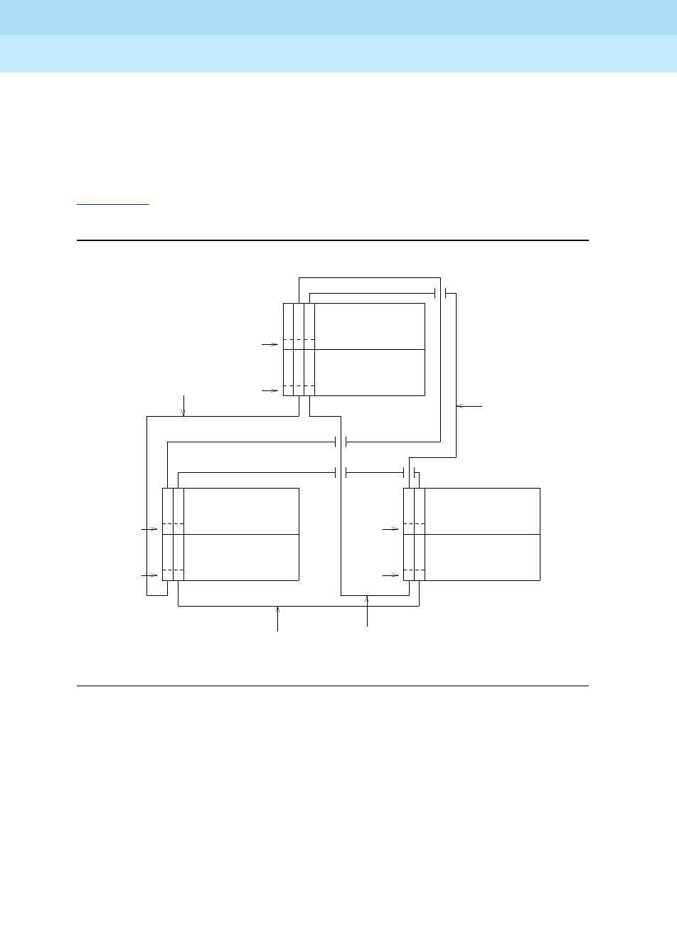
DEFINITY Enterprise Communications Server Release 6
Maintenance for R6r Volumes 1 & 2
555-230-126 Issue 2
January 1998
Maintenance Object Repair Procedures
Page 9-613EXP-INTF (Expansion Interface Circuit Pack)
9
Each Port Network in direct connect configurations must be connected to each
other port network via a fiber link. Each EPN has one EI that functions as an
archangel. This EI must be connected, via fiber, to an EI located in the PPN. If an
EI is functioning as an archangel (bus master), its yellow led will be flashing at a
rate of 2 seconds on and 200 ms off.
Figure 9-28 shows the location of EI circuit packs in a typical duplicated PNC,
direct connect configuration.
Figure 9-28. Direct Connect Configuration with Duplicated PNC
In a duplicated PNC there is an A-side PNC and a B-side PNC. All EIs in this
diagram are labeled with an A or a B to designate which PNC they are a part of.
Note that the PNC designation (A or B) does not relate directly to carrier location.
Again, only one of the EIs in an EPN can function as an archangel (TDM Bus
Master). The EI that is on the active PNC and that is connected to the PPN is the
only one that can function in this mode. In normal operation, its yellow LED
should be blinking at a rate of 2 seconds on and 200 ms. off.
PPN
CAB 1
CARRIER D
CARRIER C
EPN
CAB 2
CARRIER B
CARRIER A
EPN
CAB 3
CARRIER B
CARRIER A
FIBER 1 (A)
FIBER 1 (B)
FIBER 2 (A)
FIBER 2 (B)
FIBER 3 (B)
FIBER 3 (A)
E E
E E
E E
E E
E E
E E
I I
I I
3 2
3 2
Slot #
Slot #
Slot #
2 1
2 1
2 1
2 1
Slot #
Slot #
Slot #
I I
I I
I I
I I
(A) (A)
(A) (A) (A) (A)
(B) (B) (B) (B)
(B) (B)
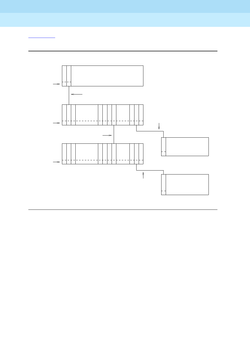
DEFINITY Enterprise Communications Server Release 6
Maintenance for R6r Volumes 1 & 2
555-230-126 Issue 2
January 1998
Maintenance Object Repair Procedures
Page 9-614EXP-INTF (Expansion Interface Circuit Pack)
9
Figure 9-29 shows the location of EIs in a typical center stage switch
configuration with simplex PNC.
Figure 9-29. Center Stage Switch Configuration with Simplex PNC
In a simplex stage switch configuration, only one EI is needed in each port
network. Notice that there is no direct connection between the EPNs, rather all
inter-EPN connections are made through the stage switch. Each SNI in the switch
node carriers can be connected to an EPN through an EI circuit pack.
METALLIC
FIBER
Slot #
Slot #
Slot #
C
20 19 13 12 10 3 2
C C
CN N N N N N
N N N N N N N
NS S S S S S
S S S S S S S
S
CAB 3
I
1
1
I
E
E
CARRIER A
CARRIER A
CAB 2
EPN
EPN
I I I I
I I I I I
I
20 19 13 12 10 3
CARRIER C
CABINET 1
PPN
2
CAB 2
SN #2
CARRIER E
CARRIER E
CAB 1
SN #1
2 1
FIBER
FIBER
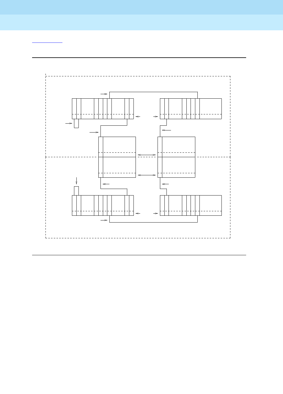
DEFINITY Enterprise Communications Server Release 6
Maintenance for R6r Volumes 1 & 2
555-230-126 Issue 2
January 1998
Maintenance Object Repair Procedures
Page 9-615EXP-INTF (Expansion Interface Circuit Pack)
9
Figure 9-30 shows the location of EIs in a typical two Switch Node Center Stage
Switch configuration with duplicated PNC.
Figure 9-30. Center Stage Switch Configuration with Duplicated PNC
In a duplicated center stage switch configuration, two EIs are needed in each
port network. One is located on the A-side PNC and the second one is located on
the B-side PNC. Note that PNC designation (A or B) does not relate directly to
carrier location. The EI that is on the active PNC will be the one that is acting as
the archangel (TDM Bus Master) for the EPN. This is the EI that should have its
yellow led blinking at a rate of 2 seconds on and 200 ms. off. The standby PNC EI
should have its yellow led off. The PPN EI circuit packs are located in the first slot
of the switch node carriers, although they may be located in port carriers.
FIBER
FIBER
A-PNC
FIBER
FIBER FIBER
21
21
10
1 1
1 2 10 13
13 1 2 10 12
N N N
N N N N
I I I I I
II
II I
C C
C C
CARRIER D
SN #1
SN #1
CAB 1
CAB 1
CARRIER D
Slot #
Slot #
EPN EPN
CAB 2
CAB 2
CARRIER B CARRIER B
CARRIER A CARRIER A
CAB 3
CAB 3
Slot #
Slot #
SN #2
SN #2
CAB 2
CAB 2
CARRIER E CARRIER E
E
E
E
E
E
E
I
I I
I I
I
S S S S S S S
S S S
S S S S
N N N N N N N
1
2
2
2 10 13
13 2 1
20
20
B-PNC
METALLIC
METALLIC
CABLE
CABLE
FIBER
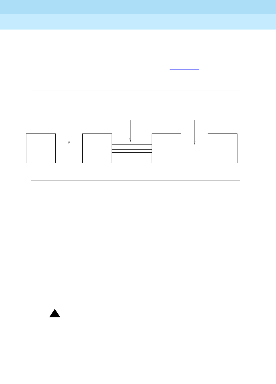
DEFINITY Enterprise Communications Server Release 6
Maintenance for R6r Volumes 1 & 2
555-230-126 Issue 2
January 1998
Maintenance Object Repair Procedures
Page 9-616EXP-INTF (Expansion Interface Circuit Pack)
9
An EPN (and thus, the EIs contained in that EPN) can be remoted via a DS1
converter complex. This requires that the associated fiber link which provides
connectivity to the remoted EPN, be administered with a DS1 converter complex.
The DS1 converter complex consists of two TN574 DS1 converter (DS1 CONV)
circuit packs connected by from 1 to 4 DS1 facilities. Figure 9-31 shows where
the DS1 converter complex fits into an EI to SNI, or EI to EI fiber link. For more
information, refer to the DS1 CONV circuit pack Maintenance documentation.
Figure 9-31. Fiber Link with DS1 Converter Complex
EI In-Service Mechanism
In order for phone calls to be routed through a given EPN, the EI that is part of the
connectivity to that EPN must be put into service. In order for an EI to be put into
service, the following criteria must be met:
1. The EI must be recognized by software (inserted). Use the list config
carrier command to determine if the board is recognized by software.
2. The EI must have a fiber link administered to it. Use the list fiber-link
command to determine if this Expansion Interface circuit pack has a fiber
administered to it.
3. The EI must have established a LAPD link to its neighbor (the circuit pack
on the "other end" of the fiber link). This neighbor can be another EI or an
SNI (Switch Node Interface).
!CAUTION:
If requirements 1 and 2, above, have been met, and the yellow LED s
are flashing in a manner that appears to confirm that the Expansion
Interface circuit pack has established a LAPD link to its neighbor, the
circuit pack still may not be "in-service". The requirement is that it
must have the CORRECT neighbor on the other end of the fiber.
Care must be taken when connecting the fibers to the back of the
carriers so that fibers are connected to the correct circuit packs. In a
Center Stage Switch configuration, run the "configuration audit" test
against the Switch Node Interface circuit pack that is the neighbor of
METALLIC CABLE or METALLIC CABLE or
EI EI (TN570)
(TN570)
or
SNI
(TN573)
DS1C DS1C
(TN574) (TN574)
OPTICAL FIBER OPTICAL FIBER 1 to 4 DS1 FACILITIES

DEFINITY Enterprise Communications Server Release 6
Maintenance for R6r Volumes 1 & 2
555-230-126 Issue 2
January 1998
Maintenance Object Repair Procedures
Page 9-617EXP-INTF (Expansion Interface Circuit Pack)
9
the Expansion Interface circuit pack in question (see SNI-BD
Maintenance Documentation for more details).
Once an EI has been put into service, if any of the above listed "in-service"
criteria becomes untrue, the EI will be taken out of service and service to that
port network will not be available.
In a system that is configured with PNC duplication active, taking an EI out of
service that is on the active PNC will, if all other things on the active and standby
PNC are equal (i.e. both PNCs are equally healthy, the standby PNC is not
busied out, the PNC is not locked by software), result in a PNC interchange.
Expansion Interface LEDs
The Expansion Interface circuit pack has the standard red, green, and yellow
LEDs. The red and green LEDs have the traditional use, where red means some
alarm condition and green indicates maintenance testing in progress. The yellow
LED is used to provide useful visual status information. The state of the yellow
LED is very important when executing the Expansion Interface Manual Loop
Back Procedure. The possible yellow LED states are shown in the following table.
Upon power-up, the red and green LEDs will come on and off. The yellow LED
will go to its appropriate state.
To determine which PNC, and therefore, which EI(s) in a port network, is active
and which is standby, the status port-network and status PNC commands can
be used. Alternately, visual inspection will show that the active EI circuit packs
will have their yellow LED on solid (for an inter-EPN EI in a direct connect system)
or blink a pattern of 2 seconds on and 200 ms off. The standby PNC EI circuit
packs will have their yellow LED s off. See the following table for the possible EI
yellow LED states.
Notes:
a. This flashing state corresponds to error codes 769 and 770 from the
Hardware Error Log and indicates a failure of Test #238. These error
codes will usually be accompanied by error code 1281 (no Expansion
Interface or Switch Node Interface detected on opposite end of fiber). This
Table 9-207. Expansion Interface Circuit Pack Yellow LED Flashing States
Condition LED On LED Off
Fiber Out-of-Frame (a) 0.1 second 0.1 second
In frame-No Neighbor (b) 0.5 second 0.5 second
Expansion Interface Active (c) 2 second 0.2 second
Expansion Interface Active (d) solid on never off
Expansion Interface Standby (e) never on solid off

DEFINITY Enterprise Communications Server Release 6
Maintenance for R6r Volumes 1 & 2
555-230-126 Issue 2
January 1998
Maintenance Object Repair Procedures
Page 9-618EXP-INTF (Expansion Interface Circuit Pack)
9
condition may be caused by the absence of the neighbor Expansion
Interface or Switch Node Interface circuit pack, a broken or missing fiber,
or a missing lightwave transceiver on either endpoint (Expansion Interface
or Switch Node Interface circuit pack).
b. This flashing state corresponds to error code 1281 from the Hardware
Error Log and indicates a failure of Test #237. This condition is usually due
to the failure of this Expansion Interface circuit pack or a failed Expansion
Interface or Switch Node Interface circuit pack neighbor.
c. This is the normal state for an Active EPN Expansion Interface circuit pack
that is also the bus master (Expansion Archangel) in the EPN.
d. This is the normal state for an Active Expansion Interface circuit pack that
is not the bus master (Expansion Archangel) for an EPN. This applies only
in the Direct Connect Configuration where the Expansion Interface circuit
pack in an EPN is connected via a fiber link to an Expansion Interface
circuit pack in the other EPN. This state also applies for an active
Expansion Interface circuit pack located in the PPN.
e. This is the normal state for a Standby Expansion Interface circuit pack in
both the PPN and EPNs.
NOTE:
In an EPN the TN775 EPN Maintenance (MAINT) circuit pack will monitor
the sanity of the Expansion Interface circuit pack. If the Expansion Interface
circuit pack should cycle between sane and insane several times, the
Maintenance circuit pack will hold the Expansion Interface circuit pack
reset. If a new Expansion Interface circuit pack is installed in the EPN, and
the red LED remains lit, the EPN Maintenance circuit pack should be
removed because it may be holding the new Expansion Interface circuit
pack reset. This condition could present itself if there is a link problem to
the EPN, and the EPN experiences several EPN restarts. The Maintenance
circuit pack may be reinstalled after the Expansion Interface circuit pack
has been physically inserted and the Expansion Interface circuit pack’s red
LED has gone off.
The link between two Active Expansion Interface circuit packs or between an
Active Expansion Interface circuit pack and an Active Switch Node Interface
circuit pack is involved in synchronization. The Expansion Interface circuit pack
will report slip errors if synchronization is not operating properly. When
diagnosing synchronization problems, the Expansion Interface circuit packs
should be examined as a possible cause.
EI and Tone-Clock Interactions
The viability of the EI fiber link depends upon the system clock that is provided
by the active Tone-Clock circuit pack on each network (see "TDM-CLK" and
"TONE-BD" in Chapter 9). Each Expansion Interface circuit pack transmits over
the fiber at a rate derived from the system clock on its network. If the Active

DEFINITY Enterprise Communications Server Release 6
Maintenance for R6r Volumes 1 & 2
555-230-126 Issue 2
January 1998
Maintenance Object Repair Procedures
Page 9-619EXP-INTF (Expansion Interface Circuit Pack)
9
Tone-Clock is defective in such a way that the frequency of system clock it
produces is out of the specified range (‘‘out of spec’’), an Expansion Interface
fiber link might go down. This affects an Expansion Archangel Link (EAL), a
Remote Neighbor Link (RNL), and/or a Local Neighbor Link (LNL), even though
the Expansion Interface circuit packs are healthy. When the PNC is duplicated,
both fiber links could go down if there is a defective Active Tone-Clock. Whether
or not a fiber link goes down, depends on certain characteristics of the
Expansion Interface circuit packs. An Expansion Interface circuit pack should not
be replaced if the fiber link on which it resides goes down because of a defective
Active Tone-Clock circuit pack. The defective Tone-Clock circuit pack should be
replaced instead. The Expansion Interface circuit packs are more sensitive to a
defective system clock than the rest of the components of the system. Therefore,
testing of the Tone-Clock circuit pack might not reveal a problem.
The symptoms of the problem in which an invalid system clock causes an
Expansion Link to go down are as follows:
■If the Tone-Clock in the PPN, or in an EPN that provides the current on-line
synchronization reference (see status synchronization), is providing an
invalid system clock:
Any Expansion Interface or SNI circuit pack has a Fiber Out-of-Frame
condition or a No Neighbor condition.
An Expansion Interface circuit pack yellow LED will blink quickly when a
Fiber Out-of-Frame condition exists (0.1 seconds on, 0.1 seconds off) and
Test #238 will fail on the Expansion Interface circuit pack that is
out-of-frame.
An SNI circuit pack with a Fiber Out-of-Frame condition will blink its yellow
LED quickly (0.1 seconds on, 0.1 seconds off) and Test #989 will fail on
the SNI circuit pack that is out-of-frame.
An Expansion Interface circuit pack yellow LED will blink slowly when a No
Neighbor condition exists (0.5 seconds on, 0.5 seconds off) and Test
#237 will fail on this Expansion Interface circuit pack, but Test #238 will
pass.
An SNI circuit pack with a no neighbor condition will blink its yellow LED
slowly (0.5 seconds on, 0.5 seconds off) and Test #759 will fail on this SNI
circuit pack, but Test #989 will pass.
■If a Tone-Clock in an EPN that does not provide the current on-line
synchronization reference (see status synchronization) is providing an
invalid system clock:
In a direct connect configuration
, the PPN Expansion Interface circuit
pack yellow LED will blink quickly (Fiber Out-of-Frame condition - 0.1
seconds on, 0.1 seconds off).
Test #238 will fail on this Expansion Interface circuit pack.
In a CSS configuration
, the SNI connected to the EPN Expansion Interface
circuit pack will blink its yellow LED quickly (Fiber Out-of-Frame condition
- 0.1 seconds on, 0.1 seconds off).

DEFINITY Enterprise Communications Server Release 6
Maintenance for R6r Volumes 1 & 2
555-230-126 Issue 2
January 1998
Maintenance Object Repair Procedures
Page 9-620EXP-INTF (Expansion Interface Circuit Pack)
9
The EPN Expansion Interface circuit pack yellow LED will blink slowly
(In-frame, No Neighbor condition - 0.5 seconds on, 0.5 seconds off).
If the EPN is in-service, Test #237 will fail on this Expansion Interface
circuit pack, but Test #238 will pass.
These symptoms can also be the result of other problems (for example, one half
of the fiber being unable to transmit data). If the system exhibits these symptoms,
execute the following procedure:
1. Verify that the EPN stays down for at least 1 minute.
If the EAL comes back in service after a short time, without switching the
Active Tone-Clock, the problem was probably that the on-line
synchronization source became invalid (See SYNC Maintenance
documentation for more information).
However, if the EAL (s) have not come back into service after a minute, the
synchronization source is not the cause of the problem. Proceed to Step 2.
2. Check for errors via the display errors command with the Category field
set to ‘‘tone’’ and the Active alarms field set to ‘‘n.’’ Some of the alarms on
EPN objects might have been resolved if the EPN went down. Refer to the
appropriate MO Maintenance documentation for descriptions of any of the
errors occurring at about the same time as the EXP-PN errors, SYS-LINK
errors against EAL s, RNLs, or LNLs, or FIBER-LK (769, 1025, or 1281)
errors. Resolve any active alarms. Also, if Error Type 18 was logged
against the SYNC MO when the EPN went down, the problem was
probably that the synchronization on-line reference became invalid. Since
reference switching was disabled, the Tone-Clock did not switch from the
invalid reference. Therefore, the Tone-Clock circuit pack put out a system
clock that was ‘‘out of spec.’’ Issue the enable synchronization-switch
command. If the EPN is down, reseat the Tone-Clock circuit packs on the
EPN. This action should restore the EPN to service.
Execute Steps 3 and 4 in the order most convenient to you and least
destructive to the customer.
3. Check to see if the fiber optic cable is transmitting properly via the
following procedure on one of the out-of-service links, or use the "Fiber
Fault Isolation Procedure"
in Chapter 5.
a. Carefully record the symptoms (yellow LED pattern and test failing)
that were occurring on the PPN Expansion Interface circuit pack
and the EPN Expansion Interface circuit pack or the connected
Switch Node Interface circuit pack in the case of a Center Stage
system. Clearly indicate which symptoms are occurring on which
Expansion Interface/Switch Node Interface circuit pack.
!CAUTION:
Before proceeding, note which is the current transmit fiber
and which is the current receive fiber for proper reconnection.

DEFINITY Enterprise Communications Server Release 6
Maintenance for R6r Volumes 1 & 2
555-230-126 Issue 2
January 1998
Maintenance Object Repair Procedures
Page 9-621EXP-INTF (Expansion Interface Circuit Pack)
9
b. Disconnect the transmit and receive fiber pair from the lightwave
transceiver on the back of one of the Expansion Interface circuit
pack slots that is exhibiting symptoms.
c. Connect what was formerly the transmit fiber to the receive jack.
d. Connect what was formerly the receive fiber to the transmit jack.
e. Perform Steps b, c, and d on the opposite end of the fiber and the
lightwave transceiver on the back of the connected Expansion
Interface or Switch Node Interface circuit pack slot.
f. If the symptoms which were formerly occurring on the Expansion
Interface circuit pack that was exhibiting these symptoms are now
occurring on the connected Expansion Interface or Switch Node
Interface circuit pack and vice versa, the fiber is defective and
should be replaced.
4. Determine if the problem is due to a defective Active Tone-Clock circuit
pack. Refer to the preceding list of symptoms to decide which network
contains the suspect Active Tone-Clock.
!CAUTION:
If you remove the EPN Expansion Interface circuit pack that is active
or that was active when the EPN was last in-service, the Tone-Clock
lead will revert to the default value which will cause the Tone-Clock
circuit pack located in the A carrier to become the Active
Tone-Clock. This characteristic can be deceiving. Replacing or
reseating the Active EPN Expansion Interface circuit pack might
restore the link(s) temporarily. However, if the Tone-Clock circuit
pack located in the B carrier was really the source of the problem
and not the Expansion Interface circuit pack, then the link(s) will go
down again the next time a Tone-Clock switch to the Tone-Clock in
the B carrier is attempted (probably when the scheduled Tone-Clock
switch occurs).
!CAUTION:
If, after all the links are restored, you suspect the problem
might have been due to a defective Tone-Clock circuit pack,
switch to this Tone-Clock at an appropriate time. If the
Tone-Clock circuit pack was the cause of the problem and the
same Expansion Interface circuit packs are in place, the same
link(s) will go down again.
a. On a system in which the network containing the suspect
Tone-Clock circuit pack has duplicated Tone-Clock circuit packs
and the network is in-service:

DEFINITY Enterprise Communications Server Release 6
Maintenance for R6r Volumes 1 & 2
555-230-126 Issue 2
January 1998
Maintenance Object Repair Procedures
Page 9-622EXP-INTF (Expansion Interface Circuit Pack)
9
Switch to the Standby Tone-Clock on this network. If the suspect
Tone-Clock circuit pack is defective, link(s) should be restored at
this point. Switching back to the defective Tone-Clock should make
the same link(s) go out-of-service. Such a Tone-Clock is defective
and should be replaced as soon as possible. If switching
Tone-Clocks does not bring up the EPN, then this Tone-Clock is not
the source of the problem. Make sure to switch back to the original
Tone-Clock.
!CAUTION:
If the defective Tone-Clock circuit pack is left as the Standby
Tone-Clock, then a scheduled Tone-Clock switch will cause
the same link(s) go out-of-service again.
b. On a system in which the EPN containing the suspect Tone-Clock
circuit pack is out-of-service:
Replace the Active Tone-Clock circuit pack on this network. In a
network with duplicated Tone-Clock circuit packs, the Active
Tone-Clock will be the Tone-Clock circuit pack whose yellow LED is
flashing: if both are flashing, it is the one that is blinking slower. If
the link(s) comes up after replacing this Tone-Clock circuit pack,
then this Tone-Clock circuit pack should be replaced as soon as
possible.
!CAUTION:
If the defective Tone-Clock circuit pack is left as the Standby
Tone-Clock, then a scheduled Tone-Clock switch will cause
the same EPN to go out-of-service again.
If replacing the Active Tone-Clock did not bring up the link(s), then
this Tone-Clock circuit pack is not the source of the problem.
c. On a Standard Reliability system in which the PPN contains the
suspect Tone-Clock circuit pack:
Replace the PPN Tone-Clock circuit pack at a time when bringing
down the system is most convenient to the customer.
!CAUTION:
Replacing the PPN Tone-Clock circuit pack will stop call
processing on that network and also bring down stable calls.
This action will eventually cause a Reset System 2(Cold_2
restart).
If replacing the Tone-Clock circuit pack restores the link(s), then the
Tone-Clock circuit pack is defective and should be replaced.
Otherwise, the problem is not with the PPN Tone-Clock circuit pack.

DEFINITY Enterprise Communications Server Release 6
Maintenance for R6r Volumes 1 & 2
555-230-126 Issue 2
January 1998
Maintenance Object Repair Procedures
Page 9-623EXP-INTF (Expansion Interface Circuit Pack)
9
Replacing an EI Circuit Pack—Simplex PNC
!WARNING:
Do not power down a Switch Node carrier to replace a circuit pack.
!WARNING:
Replacing a Switch Node Interface, Switch Node Clock, Expansion
Interface or DS1 Converter circuit pack on a simplex system disrupts
service. The service effect can range from outage of a single EPN to outage
of the entire system.
If the red LED remains lit, see the Note under ‘‘Expansion Interface LEDs’’ above.
Replacing an EI Circuit Pack— Duplicated PNC
!WARNING:
On a system with duplicated PNC, synchronization may be provided over a
combination of active and standby components. This condition is indicated
by an OFF-BOARD WARNING alarm against TDM-CLK with error type
2305. Repairs to standby PNC in this state may disrupt service. Otherwise,
1. Enter busyout board UUCSS UUCSS represents the
cabinet-carrier-slot address of the
circuit pack to be replaced.
2. Replace the circuit pack
3. Wait for the circuit pack to reset Red and green LEDs will light and then
go out.
4. Enter release board UUCSS CAUTION:
Do not busyout any
Expansion Interface circuit pack after
this point.
5. Enter test alarms long clear
for category exp-intf
6. Wait 5 minutes for SNI-BD,
FIBER-LK AND DS1 CONV-BD
alarms to clear, or enter clear
firmware counters a-pnc

DEFINITY Enterprise Communications Server Release 6
Maintenance for R6r Volumes 1 & 2
555-230-126 Issue 2
January 1998
Maintenance Object Repair Procedures
Page 9-624EXP-INTF (Expansion Interface Circuit Pack)
9
if the active PNC is functional, replacement of a standby component will not
disrupt service.
If the red LED remains lit, see the Note under ‘‘Expansion Interface LEDs’’ above.
1. Enter status pnc Verify that the component to be replaced is
on the standby PNC.
2. Enter busyout pnc
3. Enter busyout board UUCSS UUCSS represents the cabinet-carrier-slot
address of the circuit pack to be replaced.
4. Replace the circuit pack
5. Enter release board UUCSS CAUTION:
Do not busyout any Expansion
Interface circuit pack after this point.
6. Enter test alarms long clear
for category exp-intf
7. Wait 5 minutes for SNI-BD,
SNI-PEER, FIBER-LK, and DS1
CONV alarms to clear, or enter
clear firmware counters
<a-pnc or b-pnc>
Use the letter designation of the pnc which
holds the replaced component (the
standby pnc).
8. Enter status pnc If either PNC state-of-health is not
"functional", consult the "PNC-DUP (PNC
Duplication)" section.
9. Enter release pnc

DEFINITY Enterprise Communications Server Release 6
Maintenance for R6r Volumes 1 & 2
555-230-126 Issue 2
January 1998
Maintenance Object Repair Procedures
Page 9-625EXP-INTF (Expansion Interface Circuit Pack)
9
Expansion Interface Manual Loop Back Procedure
This procedure is to be used when an Expansion Interface circuit pack cannot be
tested by software. This is usually when the Expansion Interface circuit pack is in
the EPN and the EPN is down. When the connection to the Expansion Interface
circuit pack is via fiber, a short length of optical fiber is required for this
procedure. If a metallic cable is used in the connection, the metallic connector
must be removed from the back of the carrier, and a lightwave transceiver
connected in its place. The short length of optical fiber can then be used.
If this procedure is run on both endpoints of a fiber link (Expansion Interface
circuit packs or Switch Node Interface circuit packs), and both check out fine,
then the failure is most likely in the fiber itself, assuming neither endpoint circuit
pack is busied out and the link remains inactive.
1. Busyout the circuit pack (Expansion Interface or Switch Node Interface)
using the busyout board UUCSS command.
2. Disconnect the transmit and receive fiber pair from the lightwave
transceiver on the back of the circuit pack (Expansion Interface or Switch
Node Interface) slot.
Note which is the transmit fiber and which is the
receive fiber for proper re-connection at the end of this procedure. The
fiber connected to the transmit side of the lightwave transceiver on one
Expansion Interface circuit pack should be connected to the receive side
of the lightwave transceiver on the circuit pack on the opposite end of the
fiber.
3. Using a fiber jumper cable, interconnect the transmit and receive jacks of
the lightwave transceiver as shown in Figure 9-32.
NOTE:
Make sure that the total length of the fiber jumper cable does not
exceed the maximum length recommended for the fiber link
connections between cabinets. Using cable lengths not within
connectivity guidelines can adversely affect test results.
4. Go to the front of the cabinet and inspect the yellow LED.
■If the yellow LED flashes on at a rate of once per second, the
(Expansion Interface or Switch Node Interface) circuit pack or
transceiver should be replaced.
■If the yellow LED flashes on at a rate of five times per second, the
circuit pack (Expansion Interface or Switch Node Interface) or the
lightwave transceiver may need replacement. This condition may
also be due to a faulty system clock on the network containing this
Expansion Interface circuit pack.
■If the yellow LED is not blinking, this circuit pack (Expansion
Interface or Switch Node Interface), and the lightwave transceiver
are functioning properly.
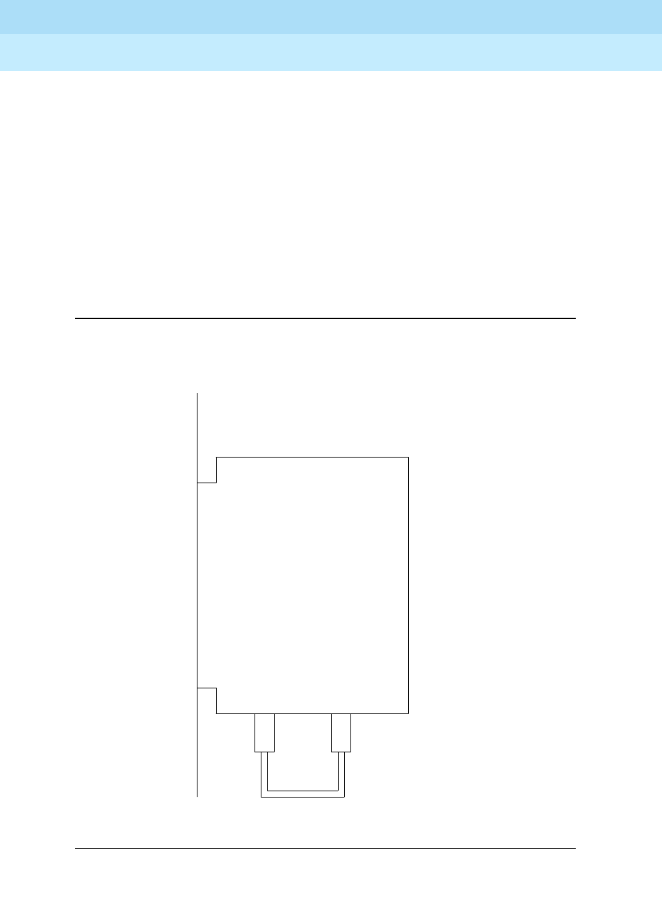
DEFINITY Enterprise Communications Server Release 6
Maintenance for R6r Volumes 1 & 2
555-230-126 Issue 2
January 1998
Maintenance Object Repair Procedures
Page 9-626EXP-INTF (Expansion Interface Circuit Pack)
9
5. Replace faulty components and reconnect the original fiber. Be sure to
reconnect the fibers properly as noted in Step 3. If there is a problem with
the port network after re-connecting the fiber, and the port network is
connected to a Center Stage Switch, run the Configuration Audit via the
test board command on the Switch Node Interface circuit pack to which
the intervening fiber is connected. See the SNI-BD section for instructions
on interpreting results.
command on the Switch Node Interface circuit pack to which the
intervening fiber is connected. See the SNI-BD section for instructions on
interpreting results.
6. Release Expansion Interface circuit pack or Switch Node Interface circuit
pack with the release board UUCSS command.
Figure 9-32. Interconnection of Lightwave Transceiver Transmit/Receive
Jacks
Tx Rx
Transceiver
Lightwave
Back Skin of Cabinet

DEFINITY Enterprise Communications Server Release 6
Maintenance for R6r Volumes 1 & 2
555-230-126 Issue 2
January 1998
Maintenance Object Repair Procedures
Page 9-627EXP-INTF (Expansion Interface Circuit Pack)
9
Error Log Entries and Test to Clear Values
Table 9-208. EXP-INTF Error Log Entries
Error
Type Aux
Data1Associated Test Alarm
Level On/Off
Board Test to Clear Value
020 Any Any Any test board UUCSS
1 Any Expansion Interface Local
TDM Looparound Test (#240) MAJ ON test board UUCSS r 2
2 Expansion Interface Local
TDM Looparound Test (#240) MAJ ON test board UUCSS r 2
18(a) 0 busyout board UUCSS WRN OFF release board UUCSS
23(b) 0 None WRN OFF
125(c) None MIN ON
131(d) None MIN ON
257(e) Any None MIN OFF
513(f) 5-7 None MAJ ON
769(g) 113 Expansion Interface FOOF
Query Test (#238) WRN OFF test board UUCSS r 1
770 Expansion Interface FOOF
Query Test (#238) WRN OFF test board UUCSS r 1
1025 Any Expansion Interface Control
Channel Test (#316) MAJ ON test board UUCSS r 1
1281(h) Expansion Interface Neighbor
Query Test (#237) MIN OFF test board UUCSS r 1
1537 Expansion Interface 2-way
Transmission Test (#241) MAJ OFF test board UUCSS r 4
1538(i) None MIN ON
1793 Expansion Interface
Lightwave Transceiver
Looparound Test (#242)
MAJ ON test board UUCSS l r
3
2305(j) 118 None WRN OFF
2306(j) 3 None WRN OFF
112
2561(k) Any None MIN ON
2817(l) Any None MIN ON
3073(m) Any Expansion Interface Packet
Interface Test(#589) MAJ OFF test board UUCSS r 3
Continued on next page
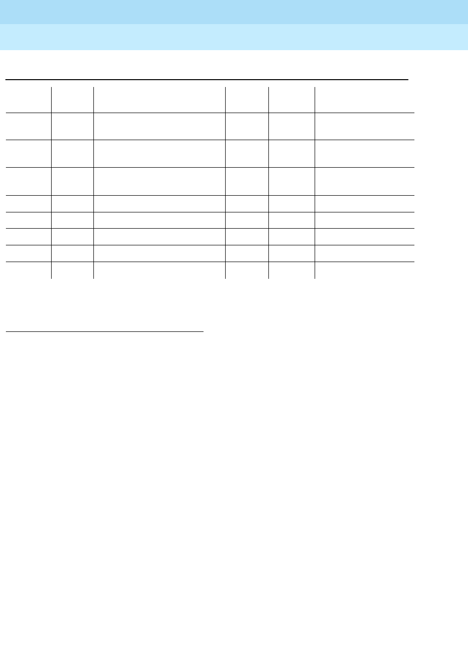
DEFINITY Enterprise Communications Server Release 6
Maintenance for R6r Volumes 1 & 2
555-230-126 Issue 2
January 1998
Maintenance Object Repair Procedures
Page 9-628EXP-INTF (Expansion Interface Circuit Pack)
9
Notes:
a. This error indicates that the Expansion Interface circuit pack has been
busied out via the busyout board UCSS command. To resolve this error,
release the Expansion Interface circuit pack via the release board UCSS
command.
b. Expansion Interface circuit pack has been administered on the Circuit
Pack form, but has not been physically inserted into the system. Insert the
circuit pack.
c. A wrong circuit pack is located in the slot where this circuit pack is
logically administered. To resolve this problem, either remove the wrong
circuit pack and insert the logically administered circuit pack OR use the
change circuit-pack command to readminister this slot to match the
circuit pack that is physically inserted in this slot (if a fiber is administered
to this circuit pack the fiber must be removed via administration before the
circuit pack can be removed from administration).
1. Aux Data 32767 for any error log entry indicates that an alarmed EI was busied out and then
released. When this occurs, existing service affecting alarms must be preserved. As is typical, when
the EI is released all alarms are resolved. Therefore the alarm and error logs must be repopulated
with the alarms present at time of busy out. This error code is an indication that existing aux data and
error log time stamps are no longer valid because they were lost when the alarms were resolved
upon release of the circuit pack.
2. Run the Short Test Sequence first. If all tests pass, run the Long Test Sequence. Refer to the
appropriate test description and follow the recommended procedures.
3074(n) 2 Expansion Interface Packet
Interface Test(#589) MAJ OFF test board UUCSS r 3
3075(n) 1 Expansion Interface Packet
Interface Test(#589) MAJ OFF test board UUCSS r 3
3076 Expansion Interface Packet
Interface Test(#589) MAJ OFF test board UUCSS r 3
3330(o) Any None WRN ON
3585(p) 0 None WRN OFF
3841(q) Any None MIN OFF (s)
3842(r) Any None MIN OFF (s)
10001(t) 0 None
Table 9-208. EXP-INTF Error Log Entries — Continued
Error
Type Aux
Data1Associated Test Alarm
Level On/Off
Board Test to Clear Value
Continued on next page

DEFINITY Enterprise Communications Server Release 6
Maintenance for R6r Volumes 1 & 2
555-230-126 Issue 2
January 1998
Maintenance Object Repair Procedures
Page 9-629EXP-INTF (Expansion Interface Circuit Pack)
9
d. This alarm is raised after an Expansion Interface circuit pack has been
removed from a slot for 5 minutes. The alarm will be resolved when the
Expansion Interface circuit pack is physically inserted into this slot and
becomes recognized by software.
Another way to resolve or prevent this alarm is to use the change circuit
pack command to remove the Expansion Interface circuit pack
administrative entry for this slot after the Expansion Interface circuit pack
has been removed from the slot.
It is also possible that the EI could be held in reset by the EPN
Maintenance Board (MAINT) and is not inserted in the system. Try issuing
the test maint P long command on the maintenance board in the same
port network.
e. Error Type 257 indicates that this Expansion Interface circuit pack is
detecting incorrect data on the incoming fiber bit stream. The data is
originating at the connected circuit pack (DS1 CONV circuit pack,
Expansion Interface circuit pack, or Switch Node Interface circuit pack).
1. Enter display errors and save a copy of the error log for use in later
steps. Intervening repair procedures are likely to alter the contents
of the error log and this information may be needed in later steps.
2. Perform the "Fiber Fault Isolation Procedure" described in Chapter
5.
3. If errors are still present or if this error occurs intermittently, replace
the Expansion Interface circuit packs, Switch Node Interface circuit
packs, DS1 CONV circuit packs, or the transceivers on this link.
4. These errors could result from a bad timing reference on the
network or switch node which contains the DS1 CONV circuit pack,
the Expansion Interface circuit pack or Switch Node Interface
circuit pack on the opposite end of the fiber. Refer to the error log
that was saved in step 1 and follow the associated repair
procedure for EXP-INTF error 2305 to resolve this error. If there are
any TONE-BD, TDM-CLK, or SYNC errors, resolve these errors as
well.
f. Error Type 513 with Aux Data 5-7 indicates an ON BOARD hardware
failure of the circuit packs RAM or ROM.
1. Replace the Expansion Interface circuit pack.
g. Besides running the test sequence and following procedures outlined for
test #238, perform the "Fiber Fault Isolation Procedure" described in
Chapter 5.
h. Error type 1281 means that the link to the neighbor circuit pack is broken
or that the fibers have been connected incorrectly. Enter test board
UUCSS and follow repair procedures for the tests.
i. Error Type 1538 indicates a hyperactive Expansion Interface circuit pack
that is generating an abnormal amount of control messages to the
Processor. When this error was generated, the Expansion Interface was

DEFINITY Enterprise Communications Server Release 6
Maintenance for R6r Volumes 1 & 2
555-230-126 Issue 2
January 1998
Maintenance Object Repair Procedures
Page 9-630EXP-INTF (Expansion Interface Circuit Pack)
9
automatically reset by the system. If this system does not have duplicated
Port Network Connectivity, service to the EPN will have been disrupted. If
this system does have duplicated Port Network Connectivity, the system
should have switched to the Standby Port Network Connectivity.
1. Enter the reset board UUCSS command for this Expansion
Interface circuit pack.
2. If error 1538 is detected again, replace the Expansion Interface
circuit pack.
j. Error Type 2305 with aux data 118 indicates that the Expansion Interface
circuit pack has detected slips on the incoming fiber data stream. That is,
an EPN and the PPN in a Direct Connect configuration, or a Port Network
and a Switch Node in a Center Stage Switch configuration, are not
synchronized.
1. Enter display errors and follow the repair procedures for
non-slip
errors against any SYNC (see ‘‘Approach to Troubleshooting’’ in
SYNC section), TDM-CLK, TONE-BD, DS1 CONV-BD, EXP-INTF,
SNC-BD, and SNI-BD. Non-slip errors are those
not
listed below:
2. For slip errors, refer to the SYNC section.
Error type 2306 indicates on-board failures related to system timing and
synchronization. Perform the "Fiber Fault Isolation Procedure" described in
Chapter 5.
k. Error Type 2561 indicates an on-board failure of Expansion Interface
circuitry related to handling packet data from the fiber interface and from
the Packet bus interface.
1. If this error has generated a minor alarm, the Expansion Interface
circuit pack should be replaced.
l. Error type 2817 indicates an on-board failure of Expansion Interface
circuitry related to transmission of data to the fiber interface.
1. If this error has generated a minor alarm, the Expansion Interface
circuit pack or transceiver should be replaced.
Circuit Pack Name Error Log
Name Error Log
Entry for Slips
DS1 Interface DS1-BD 3073 to 3160
Expansion Interface EXP-INTF 2305
Switch Node Interface SNI-BD 1537
Tone-Clock TDM-CLK 1025
UDS1 Interface UDS1-BD 3073 to 3160
DS1 CONV Circuit
Pack DS1 CONV-BD 3329

DEFINITY Enterprise Communications Server Release 6
Maintenance for R6r Volumes 1 & 2
555-230-126 Issue 2
January 1998
Maintenance Object Repair Procedures
Page 9-631EXP-INTF (Expansion Interface Circuit Pack)
9
m. Perform the following steps for error type 3073:
1. Execute the display errors command and resolve any errors on the
following: PKT-BUS, PKTINT, PDATA-BD, PGATE-BD, BRI-BD,
BRI-PT, BRI-SET/ASAI, UDS1-BD.
2. Enter the test board UUCSS r3 command for this circuit pack. If
this error continues to appear, replace the EI circuit pack.
n. Error types 3074 and 3075 indicate failures of the Expansion Interface
Circuit Pack Packet Path Test. This packet path test exercises circuitry on
the Expansion Interface circuit pack, the neighbor Expansion Interface or
Switch Node Interface circuit pack, and any intervening DS1 CONV circuit
packs (if the EPN is remoted).
1. Certain packet bus faults can cause these errors without the EI
being defective. Check to see of PKT-BUS errors are also present.
If they are, use the PKT-BUS section of this chapter and
Packet Bus
Fault Isolation and Repair
in Chapter 6 to diagnose the problem.
2. If error type 3075 is present without error type 3074, replace the
Expansion Interface circuit pack.
3. If error type 3074 exists with or without 3075, run test board
UUCSS on the EI and follow the repair procedures for any test that
does not pass.
4. If PKT-BUS errors are not present, and replacing the Expansion
Interface does not resolve the problem, there is still the possibility
of a packet bus fault. See
Packet Bus Fault Isolation and Repair
in
Chapter 6.
o. Error type 3330 indicates a failure of a diagnostic component on the
Expansion Interface circuit pack. The failed component will not impair
service, but it may leave the Expansion Interface circuit pack in a state
where the Expansion Interface circuit pack cannot detect errors.
1. Replace the Expansion Interface circuit pack at a time when it is
most convenient for the customer (this may cause service outages).
p. Error type 3585 indicates that the Expansion Interface circuit pack
experienced a series of very short out of frame conditions within several
minutes. This may indicate transmission difficulties over the fiber link. If
this condition ceases, the warning alarm should be resolved within 15
minutes.
1. Enter display errors and follow the associated repair procedures
for any SNC-BD, TDM-BUS, TDM-CLK or SYNC errors.
2. Perform the "Fiber Fault Isolation Procedure"
described in Chapter
5.

DEFINITY Enterprise Communications Server Release 6
Maintenance for R6r Volumes 1 & 2
555-230-126 Issue 2
January 1998
Maintenance Object Repair Procedures
Page 9-632EXP-INTF (Expansion Interface Circuit Pack)
9
3. If the alarm is not resolved within the next 15 minutes, replace the
lightwave transceiver on the Expansion Interface circuit pack
reporting the problem and on the connected Expansion Interface
circuit pack, Switch Node Interface circuit pack, or DS1 CONV
circuit pack.
4. If the alarm is not resolved within the next 15 minutes, replace the
Expansion Interface circuit pack reporting the alarm.
5. If the alarm is not resolved within the next 15 minutes, replace the
connected Expansion Interface circuit pack, Switch Node Interface
circuit pack or DS1 CONV circuit pack.
q. Error Type 3841 indicates the EI has reported a loss of lock with the
backplane system clock.
r. Error Type 3842 indicates that the test that queries the EI for the state of
the lock to the system clock has failed. This means that a loss of lock
condition is present.
s. The counter associated with Error Types 3841 and 3842 is cleared when
the query for the state of the clock-to-system-clock passes. Once the
alarm is raised, this test is run every five minutes. However, the test is not
part of any sequence that can be run on demand. See Note "p" above for
repair procedure.
t. Error type 10001 is a report that the Expansion Interface circuit pack
dropped one control message to the EPN. This condition may have been
observed as a call that did not complete correctly. No system technician
action is required.
System Technician-Demanded Tests:
Descriptions and Error Codes
Always investigate tests in the order presented in Table 9-209 below. By clearing
error codes associated with the
Expansion Interface Reset Test,
for example, you
may also clear errors generated from other tests in the testing sequence.
Table 9-209. System Technician-Demanded Tests: DS1-BD
Order of Investigation Short Test
Sequence Long Test
Sequence Reset Board
Seuqence D/ND1
Expansion Interface Reset Test (#336) X D
Expansion Interface Fiber Out-of-Frame
Query Test (#238) XX ND
Expansion Interface Lightwave Transceiver
Looparound Test (#242) XD
Continued on next page

DEFINITY Enterprise Communications Server Release 6
Maintenance for R6r Volumes 1 & 2
555-230-126 Issue 2
January 1998
Maintenance Object Repair Procedures
Page 9-633EXP-INTF (Expansion Interface Circuit Pack)
9
When testing Expansion Interface circuit packs to investigate problems, tests
should always be run on both circuit packs on the associated fiber link, whether
the circuit packs are both Expansion Interface circuit packs, or one is a Switch
Node Interface circuit pack. This will provide a better indication of where a
problem is located.
When testing of the EI is not possible, (for example, when the EPN is down), see
the
EI Manual Loopback Procedure
above.
Expansion Interface Neighbor Query Test (#237)
This test is non-destructive.
The Expansion Interface Neighbor Query Test is a request to an Expansion
Interface circuit pack to determine if it has established communication with its
neighbor Expansion Interface or Switch Node Interface circuit pack.
1. D = Destructive, ND = Non-destructive
Expansion Interface Control Channel Test
(#316) XX ND
Expansion Interface Neighbor Query Test
(#237) XX ND
Expansion Interface Local Looparound Test
(#240) XX ND
Expansion Interface 2-way Transmission
Test (#241) XX ND
Expansion Interface Packet Interface Test
(#589) XX ND
Table 9-209. System Technician-Demanded Tests: DS1-BD — Continued
Order of Investigation Short Test
Sequence Long Test
Sequence Reset Board
Seuqence D/ND1
Continued on next page

DEFINITY Enterprise Communications Server Release 6
Maintenance for R6r Volumes 1 & 2
555-230-126 Issue 2
January 1998
Maintenance Object Repair Procedures
Page 9-634EXP-INTF (Expansion Interface Circuit Pack)
9
Table 9-210. TEST #237 Expansion Interface Neighbor
Query Test
Error
Code Test
Result Description/ Recommendation
1033 ABORT The Expansion Interface circuit pack does not have a fiber link administered to
it. There is not sufficient data to run test.
1. Issue the list fiber-link command to verify that there is no fiber link
administered to this circuit pack.
2. If there is no fiber administered to this circuit pack, but there should be add
the correct fiber using the add fiber-link command.
3. Retry the command.
2000 ABORT Response to the test was not received within the allowable time period.
1. Try (a).
2031 ABORT The attempt to send the message to the Expansion Interface circuit pack,
asking it who it’s neighbor is, was not successful.
1. Try (a).
2100 ABORT System resources required to run this test are not available. Someone may be
doing something on this Port Network Interface.
1. Try (a).
2500 ABORT Internal system error
1. Try (a).
1033 FAIL The EI circuit pack under test cannot make contact with its neighbor EI or
Switch Node Interface circuit pack.
1. Perform the "Fiber Fault Isolation Procedure" in Chapter 5.
2027 FAIL The EI circuit pack has contact with the neighboring EI or Switch Node
Interface circuit pack, but it is the incorrect EI or Switch Node Interface circuit
pack.
1. Enter list fiber-links and verify that all fiber link cables are installed as they
are administered.
2. Repeat the command.
PASS The EI circuit pack has successfully established a link with the neighbor EI or
Switch Node Interface circuit pack.
1. If the status port-network command still indicates that this link is down, it
is possible that one or both of the EI and/or Switch Node Interface circuit
packs have been busied out.
2. If the link still does not come up, reset one or both EI and/or Switch Node
Interface circuit packs on the link.
Continued on next page

DEFINITY Enterprise Communications Server Release 6
Maintenance for R6r Volumes 1 & 2
555-230-126 Issue 2
January 1998
Maintenance Object Repair Procedures
Page 9-635EXP-INTF (Expansion Interface Circuit Pack)
9
Notes:
a. Retry the command at 1-minute intervals a maximum of 3 times.
Expansion Interface Fiber Out-of-Frame (FOOF)
Query Test (#238)
This test is non-destructive.
This test is a request to an Expansion Interface circuit pack to determine if it is
currently detecting the framing sequence on the incoming fiber data stream. If it
cannot detect this framing signal, the Expansion Interface circuit pack will not be
able to establish a link with the neighbor Expansion Interface or Switch Node
Interface circuit pack.
0NO
BOARD No board was detected by the test.
1. Check the error log for wrong board (error 125) or no board (error 131).
Resolve either of these issues, if applicable.
2. Check that the board is properly translated and inserted. If so, check for
hyperactivity (error 1538). If hyperactive, use the reset board UUCSS
command.
3. Run the test again. If it fails, the ID chip on board may be bad. Replace the
board and retest.
Table 9-210. TEST #237 Expansion Interface Neighbor
Query Test — Continued
Error
Code Test
Result Description/ Recommendation
Continued on next page

DEFINITY Enterprise Communications Server Release 6
Maintenance for R6r Volumes 1 & 2
555-230-126 Issue 2
January 1998
Maintenance Object Repair Procedures
Page 9-636EXP-INTF (Expansion Interface Circuit Pack)
9
Table 9-211. TEST #238 Expansion Interface Fiber Out-of-Frame
Query Test
Error
Code Test
Result Description/ Recommendation
1033 ABORT The EI circuit pack does not have a fiber link administered to it. There is not
sufficient data to run test.
1. Issue the list fiber-link command to verify that there is no fiber link
administered to this circuit pack.
2. If there is no fiber administered to this circuit pack, but there should be add
the correct fiber using the add fiber-link command.
3. Retry the command.
2000 ABORT Response to the test was not received within the allowable time period.
1. Try (a).
2100 ABORT System resources required to run this test are not available.
1. Try (a).
2500 ABORT Internal system error
1. Try (a).
FAIL Expansion Interface circuit pack could not detect framing sequence.
1. If the Expansion Interface circuit pack that is failing Test #238 is in the EPN,
and the red LEDs are ON on a large number of circuit packs, then reseat
any Tone-Clock circuit packs in the EPN.
2. Perform the "Fiber Fault Isolation Procedure" in Chapter 5.
3. Enter display errors and follow the associated repair procedures for any
SNC-BD, TDM-BUS, TDM-CLK, or SYNC errors.
PASS The Expansion Interface circuit pack has detected the valid framing signal on
the fiber.
1. Refer to errors from other Expansion Interface circuit pack, Switch Node
Interface tests, or DS1 CONV tests (if present) if the link is still not
functioning.
0NO
BOARD No board was detected by the test.
1. Check the error log for wrong board (error 125) or no board (error 131).
Resolve either of these issues, if applicable.
2. Check that the board is properly translated and inserted. If so, check for
hyperactivity (error 1538). If hyperactive, use the reset board UUCSS
command.
3. Run the test again. If it fails, the ID chip on board may be bad. Replace the
board and retest.
Continued on next page

DEFINITY Enterprise Communications Server Release 6
Maintenance for R6r Volumes 1 & 2
555-230-126 Issue 2
January 1998
Maintenance Object Repair Procedures
Page 9-637EXP-INTF (Expansion Interface Circuit Pack)
9
Notes:
a. Retry the command at 1-minute intervals a maximum of 3 times.
Expansion Interface Local Looparound (#240)
This test is non-destructive.
The EI local looparound is similar to the Lightwave Transceiver looparound
described in test #242. A test tone is received by the EI being tested, but is not
transmitted out to the fiber interface before being looped back. The loopback is
internal to the circuit pack. Thus, this test does not interfere with the normal fiber
data stream.
Table 9-212. TEST #240 Expansion Interface Local Looparound
Error
Code Test
Result Description/ Recommendation
1 ABORT Could not allocate time slot on TDM Bus A. Loopback passed on TDM Bus B.
2 ABORT Could not allocate time slot on TDM Bus B. Loopback passed on TDM Bus A.
1. If there is no reason to doubt that the EI circuit pack can transfer data to or
from a TDM Bus, then since the test passed on one bus, assume that the
test will pass on the other bus.
2. If this test continues to abort with the same error, rerun test at 1-minute
intervals a maximum of 3 times.
3. If the test still does not pass on the other TDM Bus, follow the procedure
for abort error code 3.
3 ABORT The system could not allocate time slots for the test on either TDM Bus. The
system may be under heavy traffic conditions or it may have time slots
out-of-service due to TDM-BUS errors. Enter display errors and follow
associated repair procedures for TDM-BUS errors.
1. If system has no TDM-BUS errors and is not handling heavy traffic, try (a).
1003 ABORT The system could not allocate a tone receiver for the test. The system may be
oversized for the number of tone detectors present or some tone detectors
may be out of service.
1. Enter display errors and follow associated repair procedures for TTR-LEV
errors in the error log. Even if there are not TTR-LEV errors, there may not
be a tone detector available on the network that contains the circuit pack
being tested. Verify that there is at least one tone detector on the network.
If not, this test always aborts for this EI circuit pack. This does not harm the
system.
2. Resolve any “TONE-PT” errors in the error log.
3. If neither condition exists, try (a).
Continued on next page

DEFINITY Enterprise Communications Server Release 6
Maintenance for R6r Volumes 1 & 2
555-230-126 Issue 2
January 1998
Maintenance Object Repair Procedures
Page 9-638EXP-INTF (Expansion Interface Circuit Pack)
9
1031 ABORT A query of the EI circuit pack aborted. The purpose of this query was to see if
the EI circuit pack could detect the framing signal.
1. If Test #238 aborted, follow the procedure associated with this abort code.
2. If Test #238 did not abort, rerun Test #240 at 1-minute intervals a
maximum of 3 times.
1032 ABORT The EI cannot detect the framing signal and cannot run the test.
1. Refer to the errors for test #238 to determine why the EI circuit pack is out
of frame.
1033 ABORT The EI circuit pack does not have a fiber link administered to it. There is not
sufficient data to run test.
1. Issue the list fiber-link command to verify that there is no fiber link
administered to this circuit pack.
2. If there is no fiber administered to this circuit pack, but there should be
add the correct fiber using the add fiber-link command.
3. Retry the command.
1394 ABORT The EI circuit pack is out of service and the test cannot be run. This condition
is due to a change in the EI circuit pack’s ability to communicate with the EI or
Switch Node Interface circuit pack on the other end of the fiber.
1. Run Test #237 and check the Error Log for EXP-INTF error type 1281. If
error type 1281 is present or if Test #237 does not pass, refer to repair
procedures for Test #237.
1395 ABORT This test cannot be run on an EI circuit pack if it is part of the B-side PNC and
Duplicated PNC is not enabled.
1. If this test needs to run on this EI circuit pack, enable PNC with the
change system-parameters duplication command.
2. Prevent the system from doing a PNC interchange by executing the set
PNC lock command.
3. Repeat this test.
2000 ABORT Response to the test was not received within the allowable time period.
1. Try (a).
2100 ABORT Could not allocate the necessary system resources to run this test.
1. Try (a).
2500 ABORT Internal system error
1. Try (a).
Table 9-212. TEST #240 Expansion Interface Local Looparound — Continued
Error
Code Test
Result Description/ Recommendation
Continued on next page

DEFINITY Enterprise Communications Server Release 6
Maintenance for R6r Volumes 1 & 2
555-230-126 Issue 2
January 1998
Maintenance Object Repair Procedures
Page 9-639EXP-INTF (Expansion Interface Circuit Pack)
9
Notes:
a. Retry the command at 1-minute intervals a maximum of 3 times.
1 FAIL Loopback on TDM Bus A failed. Loopback on TDM Bus B passed.
2 FAIL Loopback on TDM Bus B failed. Loopback on TDM Bus A passed.
3 FAIL Loopback on both TDM Buses failed.
12 FAIL Loopback on TDM Bus B failed. Loopback on TDM Bus A aborted because
the system could not allocate time slots.
21 FAIL Loopback on TDM Bus A failed. Loopback on TDM Bus B aborted because
the system could not allocate time slots.
None FAIL The test tone was not detected correctly after being looped through the EI
circuit pack.
1. If error type 2305 has been logged against the EI circuit pack in the last 5
minutes, this test could have failed due to the associated slips. If so, first
resolve the 2305 error, and then repeat test.
2. Run the tests for the Active Tone-Clock on the PN that contains the
indicted EI circuit pack to verify that dial-tone is supplied.
3. If the tone-clock is healthy, repeat the short test on the EI board.
4. If this test continues to fail, replace the EI circuit pack.
PASS Test tone was correctly detected after internal EI loopback on both TDM
Busses.
1. Refer to other EI circuit pack tests if the links between this EI circuit pack
and the EI or Switch Node Interface circuit pack on the other end of the
fiber is not functioning correctly.
0NO
BOARD No board was detected by the test.
1. Check the error log for wrong board (error 125) or no board (error 131).
Resolve either of these issues, if applicable.
2. Check that the board is properly translated and inserted. If so, check for
hyperactivity (error 1538). If hyperactive, use the reset board UUCSS
command.
3. Run the test again. If it fails, the ID chip on board may be bad. Replace the
board and retest.
Table 9-212. TEST #240 Expansion Interface Local Looparound — Continued
Error
Code Test
Result Description/ Recommendation
Continued on next page
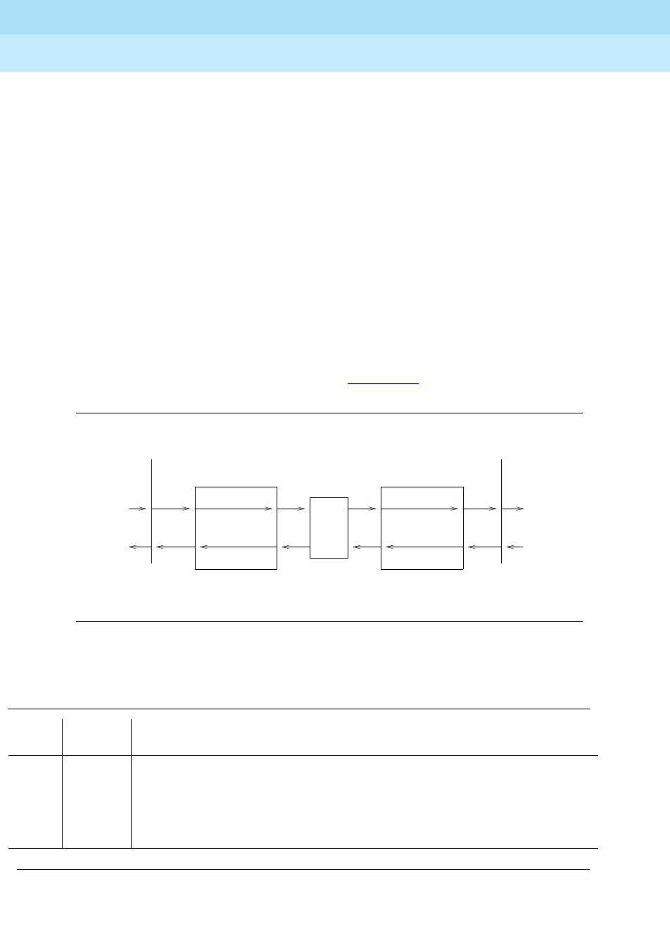
DEFINITY Enterprise Communications Server Release 6
Maintenance for R6r Volumes 1 & 2
555-230-126 Issue 2
January 1998
Maintenance Object Repair Procedures
Page 9-640EXP-INTF (Expansion Interface Circuit Pack)
9
Expansion Interface 2-way Transmission Test
(#241)
This test is non-destructive.
The EI 2-way transmission test is a basic connectivity test between two PNs. The
test first sends dialtone from the cabinet of the EI circuit pack under test through
the Center Stage Switch, through the DS1 CONV circuit packs, and through
another EI circuit pack to a tone detector in the other cabinet. The connections
are then reversed and the tone is passed in the opposite direction. If the system
is equipped with a Center Stage Switch, and this test either fails or aborts with
the above connection, a second PN is chosen (if one is available and the EI
circuit pack is In-Service) and the same test is run on this new connection. This
helps in the isolation of the fault. Since two EI circuit packs are involved in the
connection, either one of them could be at fault and this repeated test can help
determine which is actually at fault.
The path used in this test is represented in Figure 9-33.
Figure 9-33. Two-Way Circuit Switch Transmission Test
Table 9-213. TEST #241 Expansion Interface 2-way Transmission Test
Error
Code Test
Result Description/ Recommendation
1002 ABORT The system could not allocate time slots for the test. The system may be under
heavy traffic conditions or it may have time slots out of service due to TDM-BUS
errors. Enter display errors and follow associated repair procedures for
TDM-BUS errors.
1. If system has no TDM-BUS errors and is not handling heavy traffic, try (a).
Continued on next page
Clock
Clock
Tone
Tone
Tone
Tone
TDM BUS (PN Y) TDM BUS (PN X)
CSS
(Optional)
EXP-INTF EXP-INTF
Detector
Detector
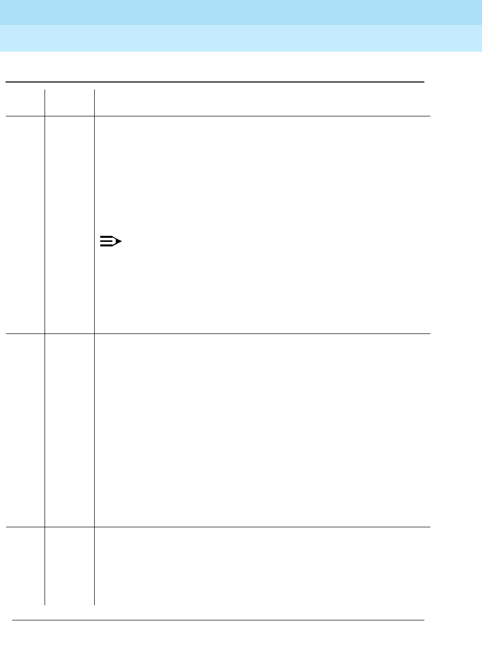
DEFINITY Enterprise Communications Server Release 6
Maintenance for R6r Volumes 1 & 2
555-230-126 Issue 2
January 1998
Maintenance Object Repair Procedures
Page 9-641EXP-INTF (Expansion Interface Circuit Pack)
9
1003 ABORT The system could not allocate a tone receiver for the test. The system may be
oversized for the number of tone detectors present or some tone detectors may
be out of service.
1. Enter display errors and follow associated repair procedures for TTR-LEV
errors in the error log. Even if there are not TTR-LEV errors, there may not be
a tone detector available on the network that contains the circuit pack being
tested. Verify that there is at least one tone detector on this network. If not,
this test will always abort for this EI circuit pack. This will not harm the
system in any way.
NOTE:
DEFINITY Systems require that Tone Detector circuit packs (TN768) must
be of vintage "B" or newer. If older Tone Detector circuit packs are
installed in the system, this test well always abort with this abort code.
2. Enter display errors and follow associated repair procedures for TONE-PT
errors.
3. If neither condition exists, try (a).
1033 ABORT The test cannot run because either the EI board does not have a fiber link
administered to it and there is not sufficient data to run the test, or there were no
other PNs administered that had its EI board In-Service.
1. Check fiber administration to insure that there is a fiber link administered to
this Expansion Interface circuit pack.
2. If there is a fiber administered to this EI circuit pack, then some change in
the status of the ability of the EI circuit pack in the other PNs to
communicate with the EI or Switch Node Interface circuit pack on the other
end of its fiber has occurred.
3. Test #237 and check for EXP-INTF circuit pack error type 1281 in the Error
Log for the EI circuit packs in these other PNs. If error type 1281 is present
and/or Test #237 does not pass, refer to repair procedures for Test #237.
4. If Test #237 passes, reseat the EI circuit pack. This is not destructive since
the circuit pack cannot be serving as the Expansion Archangel if it is not in
service.
1394 ABORT The Expansion Interface circuit pack is out of service and the test cannot be run.
This condition is due to a change in the EI circuit pack’s ability to communicate
with the EI or Switch Node Interface circuit pack on the other end of the fiber.
1. Run Test #237 and check the Error Log for EXP-INTF error type 1281. If
error type 1281 is present or if Test #237 does not pass, refer to repair
procedures for Test #237.
Table 9-213. TEST #241 Expansion Interface 2-way Transmission Test — Continued
Error
Code Test
Result Description/ Recommendation
Continued on next page

DEFINITY Enterprise Communications Server Release 6
Maintenance for R6r Volumes 1 & 2
555-230-126 Issue 2
January 1998
Maintenance Object Repair Procedures
Page 9-642EXP-INTF (Expansion Interface Circuit Pack)
9
1395 ABORT This test cannot be run on an EI circuit pack if it is part of the B-side PNC and
Duplicated PNC is not enabled.
1. If this test needs to run on this EI circuit pack, enable PNC with the change
system-parameters duplication command.
2. Prevent the system from doing a PNC interchange by executing the set
PNC lock command.
3. Repeat this test.
1413 ABORT This test requires the use of a Tone/Clock circuit pack in each of the port
networks used in this test. This abort code indicates that there are none of these
circuit packs located in one of the PNs.
1. Make sure that there is a Tone/Clock circuit pack located in the PN in which
the Expansion Interface circuit pack under test is located.
2. In Direct Connect configurations, make sure that there is a Tone/Clock
circuit pack located in the PN where the neighbor Expansion Interface
circuit pack is located.
3. In Center Stage Switch configurations, make sure that there is at least one
other PN, besides the PN where the EI circuit pack under test resides, that
contains a Tone/Clock circuit pack.
1414 ABORT This test requires the use of an active Tone/Clock circuit pack in each of the port
networks used in this test that does not have a MAJOR or MINOR alarm logged
against it. This abort code indicates that the active Tone/Clock circuit pack in
one of the port networks being used for the test has a MAJOR or MINOR alarm
logged against it.
1. Enter display alarms and follow associated repair procedures to resolve all
TONE-BD and TONE-PT alarms.
2000 ABORT Response to the test request was not received within the allowable time period.
1. Try (a).
2100 ABORT System resources required to run this test are not available.
1. Try (a).
2500 ABORT Internal system error
1. Try (a).
FAIL The test tone was not detected correctly in either direction.
1. Run the test for the Active Tone-Clocks on the Port Networks for which the
Expansion Interface circuit pack under test provides a link. This will
determine if the dial tone is being supplied.
2. Perform the "Fiber Fault Isolation Procedure" in Chapter 5.
Table 9-213. TEST #241 Expansion Interface 2-way Transmission Test — Continued
Error
Code Test
Result Description/ Recommendation
Continued on next page

DEFINITY Enterprise Communications Server Release 6
Maintenance for R6r Volumes 1 & 2
555-230-126 Issue 2
January 1998
Maintenance Object Repair Procedures
Page 9-643EXP-INTF (Expansion Interface Circuit Pack)
9
Notes:
a. Retry the command at 1-minute intervals a maximum of 3 times.
Expansion Interface Lightwave Transceiver
Looparound Test (#242)
This test is destructive.
1 or 2 FAIL The test tone was detected correctly in one direction, but not the opposite
direction.
1. Test for the Active Tone-Clocks on the PNs for which the defective EI board
provides a link. This determines if the dial tone is supplied.
2. Perform the "Fiber Fault Isolation Procedure" in Chapter 5.
Center Stage: These failure codes are possible on a Center Stage Switch
configuration only when there is just one other PN available for looping back the
test tone.
1. Perform the Procedure for Isolating Faults on a Fiber Link in Chapter 5.
3 or 4 FAIL The failure codes only apply to a system equipped with a Center Stage Switch.
They indicate that the test aborted or failed for the first connection from the EI
board under test to another EPN, and that the test tone was detected correctly
in one direction, but not the opposite direction when the connection was
between the EI board under test and a different EPN than was used in the first
connection.
1. Run the test for the Active Tone-Clocks on the PNs for which the defective
EI board provides a link. This determines if the dial tone is being supplied.
2. Perform the Procedure for Isolating Faults on a Fiber Link in Chapter 5.
PASS The tone was successfully transmitted in both directions. Both EI boards, Switch
Node Interface boards, DS1 CONV circuit packs, and their lightwave
transceivers are functioning properly.
0NO
BOARD No board was detected by the test.
1. Check the error log for wrong board (error 125) or no board (error 131).
Resolve either of these issues, if applicable.
2. Check that the board is properly translated and inserted. If so, check for
hyperactivity (error 1538). If hyperactive, use the reset board UUCSS
command.
3. Run the test again. If it fails, the ID chip on board may be bad. Replace the
board and retest.
Table 9-213. TEST #241 Expansion Interface 2-way Transmission Test — Continued
Error
Code Test
Result Description/ Recommendation
Continued on next page

DEFINITY Enterprise Communications Server Release 6
Maintenance for R6r Volumes 1 & 2
555-230-126 Issue 2
January 1998
Maintenance Object Repair Procedures
Page 9-644EXP-INTF (Expansion Interface Circuit Pack)
9
This test is destructive and requires that the Expansion Interface circuit pack first
be busied out. If the system has a duplicated Port Network Connectivity, this test
cannot be run on an Expansion Interface circuit pack that resides on the current
active PNC due to restrictions that prohibit the busying-out of certain
components that are part of the active PNC. If this test is run on an Expansion
Interface circuit pack that is part of the Standby PNC, this test is not destructive
and no service outages will take place.
In a system without duplicated Port Network Connectivity, where this Expansion
Interface circuit pack supports a PPN to EPN link, this test will disrupt service to
one EPN (Direct Connect) or all EPN s (Center Stage). If the Expansion Interface
circuit pack is part of an EPN to EPN link in a Direct Connect system, service
between the two EPN s will be disrupted.
This is a two part connectivity test. In the first part of the test, a digital count is
transmitted from the cabinet of the Expansion Interface circuit pack under test,
through the Expansion Interface circuit pack under test, out to its lightwave
transceiver. The connection then loops back into the lightwave transceiver
through the same Expansion Interface circuit pack again and into the originating
cabinet. If the test tone is detected by a tone detector, the first part of the test
passes. The path used for this part of the test is represented in Figure 9-34.
In the second part of the test, a data packet is sent from the TN1655 Packet
Interface circuit pack to the Expansion Interface circuit pack under test, the
packet is looped back through the lightwave transceiver and is sent back to the
Packet Interface circuit pack. If the Packet Interface circuit pack receives the
same packet it transmitted, the second part of the test passes. If the entire test
has passed, the Expansion Interface circuit pack, its backplane wiring and the
electrical portion of the lightwave transceiver are healthy.
The path used for this test if the Expansion Interface is located in the PPN is
represented in Figure 9-35. The path used for this test if the Expansion Interface
is located in an EPN is represented in Figure 9-36.
When the Expansion Interface circuit pack under test is in an EPN, the data
packet must also pass through the Active Expansion Interface circuit packs and
the Active DS1 CONV circuit packs (and the Active Switch Node Interface circuit
pack(s) in a Center Stage Switch system) of the Active PNC link connecting the
EPN to the PPN.
This test requires the Expansion Interface circuit pack to ignore incoming data
from its neighbor Expansion Interface circuit pack or Switch Node Interface
circuit pack. Thus this test will disturb any inter-port network connections that
currently exist over the link provided by the Expansion Interface under test and
its neighbor and disrupt signaling between the two circuit packs.
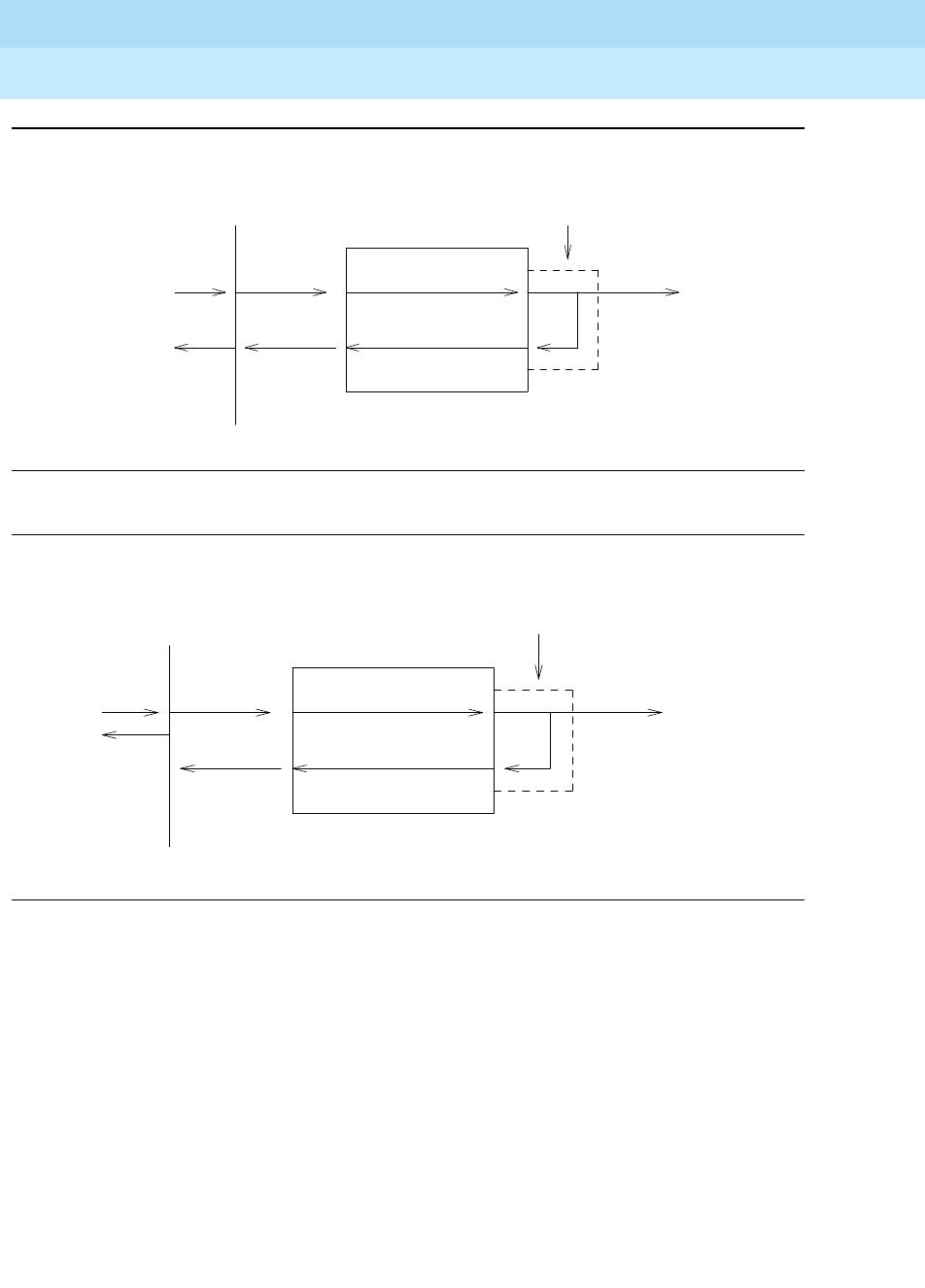
DEFINITY Enterprise Communications Server Release 6
Maintenance for R6r Volumes 1 & 2
555-230-126 Issue 2
January 1998
Maintenance Object Repair Procedures
Page 9-645EXP-INTF (Expansion Interface Circuit Pack)
9
Figure 9-34. TDM BUS Lightwave Transceiver Looparound
Figure 9-35. Packet BUS Lightwave Transceiver Looparound—PPN only
lightwave
To CSS or
Neighbor EI
TDMBUS (PN X)
Tone
Tone
Clock
Detector
EXP_INTF
transceiver
lightwave
To CSS or
Neighbor EI
Packet
Interface
TDMBUS (PN X)
EXP_INTF
transceiver
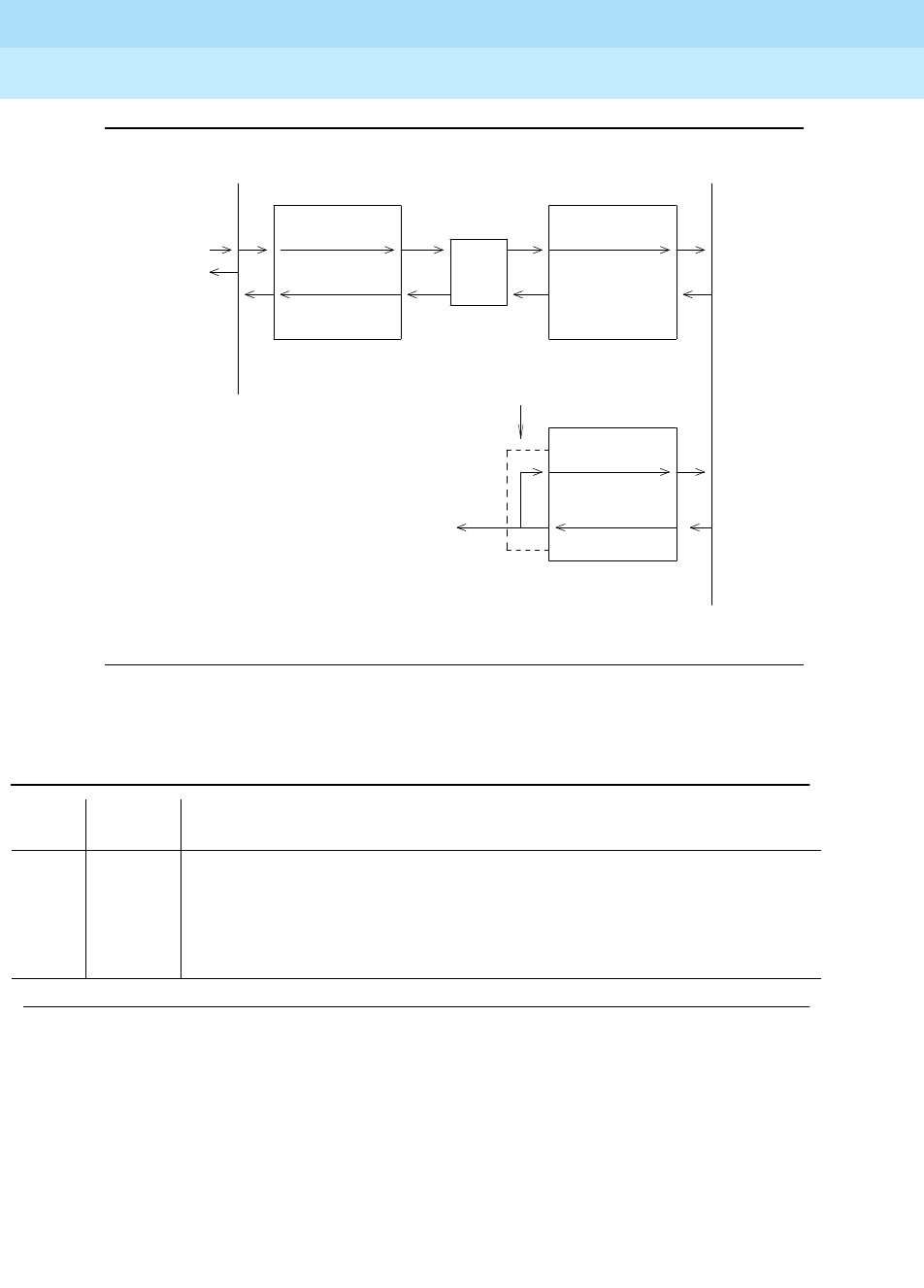
DEFINITY Enterprise Communications Server Release 6
Maintenance for R6r Volumes 1 & 2
555-230-126 Issue 2
January 1998
Maintenance Object Repair Procedures
Page 9-646EXP-INTF (Expansion Interface Circuit Pack)
9
Figure 9-36. Packet BUS Lightwave Transceiver Looparound—EPN only
Table 9-214. TEST #242 Expansion Interface Lightwave Transceiver Looparound
Error
Code Test
Result Description/ Recommendation
1002 ABORT The system could not allocate timeslots for the test. The system may be under
heavy traffic conditions or it may have timeslots out of service due to TDM-BUS
errors. Enter display errors and follow associated repair procedures for
“TDM-BUS”.
1. If system has no TDM-BUS errors and is not handling heavy traffic, try (a).
Continued on next page
Interface
Packet
EXP_INTF
Neighbor EI
To CSS or
lightwave
transceiver
(Optional)
CSS
EXP_INTF EXP_INTF

DEFINITY Enterprise Communications Server Release 6
Maintenance for R6r Volumes 1 & 2
555-230-126 Issue 2
January 1998
Maintenance Object Repair Procedures
Page 9-647EXP-INTF (Expansion Interface Circuit Pack)
9
1003 ABORT The system could not allocate a tone receiver for the test. The system may be
oversized for the number of Tone Detectors present or some Tone Detectors
may be out of service.
1. Enter display errors and follow associated repair procedures for TTR-LEV.
Even if there are no TTR-LEV errors, there may not be a Tone Detector
available on the network that contains the circuit pack being tested. Verify
that there is at least one Tone Detector on this network. If there is not at
least one Tone Detector, this test will always abort for this EI board. This will
not harm the system.
2. Enter display errors and follow associated repair procedures for TONE-PT.
3. If neither condition exists, try (a).
1015 ABORT The system will not allow this test to be run because the EI circuit pack has not
been busied out.
1. Busyout the Expansion Interface circuit pack. Then, repeat the test board
UUCSS long command.
1031 ABORT If the Expansion Interface circuit pack is in an EPN and is on the active PNC,
and is not part of an EPN to EPN link, this test CANNOT be executed. If the
lightwave transceiver looparound is activated, it is impossible to deactivate it.
1. If PNC Duplication is enabled, attempt to make the Standby PNC active via
the "reset pnc interchange" command.
2. If the PNC Interchange is successful, the lightwave transceiver looparound
test may now be executed on the original Expansion Interface circuit pack.
1033 ABORT The test cannot run because the EI circuit pack does not have a fiber link
administered to it and there is not sufficient data to run the test.
1. Issue the list fiber-link command to verify that there is no fiber link
administered to this circuit pack.
2. If there is no fiber administered to this circuit pack, but there should be add
the correct fiber using the add fiber-link command.
3. Retry the command.
1139 ABORT The packet bus in the EPN where this EI board is located has a major alarm
against it. This test needs to use the alarmed PN’s packet bus.
1. Enter display alarms and display errors and follow associated repair
procedures for PKT-BUS to resolve the alarm.
2. Retry the command.
1141 ABORT The Packet Interface circuit pack is out of service.
1. Refer to “PKT-INTF”.
Table 9-214. TEST #242 Expansion Interface Lightwave Transceiver Looparound — Continued
Error
Code Test
Result Description/ Recommendation
Continued on next page

DEFINITY Enterprise Communications Server Release 6
Maintenance for R6r Volumes 1 & 2
555-230-126 Issue 2
January 1998
Maintenance Object Repair Procedures
Page 9-648EXP-INTF (Expansion Interface Circuit Pack)
9
1144 ABORT The packet bus in the PPN has a major alarm against it. This test needs to use
the alarmed PPN packet bus.
1. Enter display alarms and display errors and follow associated repair
procedures for PKT-BUS to resolve the alarm.
2. Retry the command.
1394 ABORT The EI board is out of service and the test cannot be run. This condition is due
to a change in the EI board’s ability to communicate with the EI or Switch Node
Interface circuit pack on the other end of the fiber.
1. Run Test #237 and check the Error Log for EXP-INTF error type 1281. If
error type 1281 is present or if Test #237 does not pass, refer to repair
procedures for Test #237.
1395 ABORT This test cannot be run on an EI circuit pack if it is part of the B-side PNC and
Duplicated PNC is not enabled.
1. If this test needs to run on this EI circuit pack, enable PNC with the change
system-parameters duplication command.
2. Prevent the system from doing a PNC interchange by executing the set
PNC lock command.
3. Repeat this test.
1407 ABORT This test cannot be run on an EI board that is on the active PNC because it
cannot be busied out. This error code indicates that PNC duplication is
enabled.
1. Attempt to perform a PNC interchange via the reset pnc interchange
command.
2. If the PNC interchange is successful, busy out the original Expansion
Interface circuit pack via the busyout board UUCSS command where
UUCSS is the address of the original EI board.
3. Retry the command.
2000 ABORT 1. Try (a).
2. Response to the test was not received in the allowable time period.
2060 ABORT The link on the packet bus being used to perform the test has failed.
1. Try (a).
2. If the test continue to abort, enter display errors and follow the associated
repair procedures for PKTINT errors.
2100 ABORT Could not allocate the necessary system resources to run this test.
1. Try (a).
Table 9-214. TEST #242 Expansion Interface Lightwave Transceiver Looparound — Continued
Error
Code Test
Result Description/ Recommendation
Continued on next page

DEFINITY Enterprise Communications Server Release 6
Maintenance for R6r Volumes 1 & 2
555-230-126 Issue 2
January 1998
Maintenance Object Repair Procedures
Page 9-649EXP-INTF (Expansion Interface Circuit Pack)
9
2500 ABORT Internal system error
1. Try (a).
1 FAIL The test did not detect the test tone through the looparound connection.
NOTE:
The packet portion of this test was not run since the circuit portion failed.
1. Test the Active Tone-Clock on the PN that contains the defective EI circuit
pack to verify that dial tone is being supplied.
2. If the Tone-Clock is healthy, issue the test board UUCSS long on the EI
circuit pack.
3. If this test continues to fail, replace the EI circuit pack or transceiver. Then
reissue the test board UUCSS long on the new EI circuit pack.
2 FAIL The test tone was transmitted and detected correctly, but the correct data
packet was not detected by the TN1655 Packet Interface circuit pack.
1. Test the TN1655 Packet Interface circuit pack to verify that it is functioning
properly. If any tests fail, investigate those tests and repair the Packet
Interface circuit pack.
2. If the Packet Interface circuit pack checks out OK, enter display errors
and display alarms and follow the associated repair procedures for
SNI-BD and FIBER-LK alarms or errors (Center Stage Switch only) and for
DS1 CONV-BD alarms or errors (if so equipped).
3. Issue the test board UUCSS long command on the EI board.
4. If test #242 continues to fail, replace the EI board. Then issue the test
board UUCSS long command on the new EI board.
5. If test #242 continues to fail, replace the lightwave transceiver, reset the
circuit pack and issue the test board UUCSS long command on the EIn
circuit pack.
Table 9-214. TEST #242 Expansion Interface Lightwave Transceiver Looparound — Continued
Error
Code Test
Result Description/ Recommendation
Continued on next page

DEFINITY Enterprise Communications Server Release 6
Maintenance for R6r Volumes 1 & 2
555-230-126 Issue 2
January 1998
Maintenance Object Repair Procedures
Page 9-650EXP-INTF (Expansion Interface Circuit Pack)
9
Notes:
a. Retry the command at 1-minute intervals a maximum of 3 times.
PASS When this (#242) test and the EI Local Looparound Test #240 pass, this
indicates that the EI board is functioning properly, but it does not verify that the
optical portion of the lightwave transceiver is functioning.
1. Issue the test board UUCSS command on the EI board on both ends of
fiber. If this test passes from both sides, but other tests fail, such as #241,
this condition indicates either a faulty lightwave transceiver or the fiber itself
has failed. To determine if either a lightwave transceiver or the fiber itself
has failed, execute the EI Manual Loopback procedure described in a
previous section.
NOTE:
Test #242 can only be run from both EI s if they are the standby pair and
the active pair is working properly.
2. If this EI board is failing other tests, execute the EI Manual Loopback Test.
3. If problems still exist after the EI Manual Loopback Procedure indicates
both EI boards and both lightwave transceivers are healthy, manually
check out the building fiber. Verify that each optical fiber connects to a
transmitter at one end and a receiver at the other.
0NO
BOARD No board was detected by the test.
1. Check the error log for wrong board (error 125) or no board (error 131).
Resolve either of these issues, if applicable.
2. Check that the board is properly translated and inserted. If so, check for
hyperactivity (error 1538). If hyperactive, use the reset board UUCSS
command.
3. Run the test again. If it fails, the ID chip on board may be bad. Replace the
board and retest.
Table 9-214. TEST #242 Expansion Interface Lightwave Transceiver Looparound — Continued
Error
Code Test
Result Description/ Recommendation
Continued on next page

DEFINITY Enterprise Communications Server Release 6
Maintenance for R6r Volumes 1 & 2
555-230-126 Issue 2
January 1998
Maintenance Object Repair Procedures
Page 9-651EXP-INTF (Expansion Interface Circuit Pack)
9
Expansion Interface Control Channel Test (#316)
This test is non-destructive.
If an Expansion Interface circuit pack is a standby Expansion Interface circuit
pack (yellow LED off) or if the Expansion Interface is active in the PPN (yellow
LED on), this test queries the Expansion Interface circuit pack for its circuit pack
type and vintage information. If the Expansion Interface circuit pack is an active
Expansion Interface circuit pack in the EPN (yellow LED on long off short) the
Expansion Interface Control Channel test checks to see if the Expansion
Interface circuit pack can communicate with other circuit packs in the EPN using
the EPN TDM bus.
Table 9-215. TEST #316 Expansion Interface
Control Channel Test
Error
Code Test
Result Description/ Recommendation
2000 ABORT Response to the test request was not received within the allowable time period.
1. Try (a).
2100 ABORT Could not allocate the necessary system resources to run this test.
1. Try (a).
2500 ABORT Internal system error
1. Try (a).
Continued on next page

DEFINITY Enterprise Communications Server Release 6
Maintenance for R6r Volumes 1 & 2
555-230-126 Issue 2
January 1998
Maintenance Object Repair Procedures
Page 9-652EXP-INTF (Expansion Interface Circuit Pack)
9
Notes:
a. Retry the command at 1-minute intervals a maximum of 3 times.
Expansion Interface Reset Test (#336)
This test is destructive.
This test is potentially very destructive and requires the Expansion Interface
circuit pack to be busied out prior to execution of this test.
FAIL The EI circuit pack responded incorrectly or if it is the EPN active EI circuit
pack, it could not talk to EPN circuit packs.
1. If the active EI circuit pack in the EPN is failing and duplicated Port Network
Connectivity is enabled, attempt to switch to the standby PNC using the
reset PNC interchange command.
2. Repeat the short test sequence.
3. If test continues to fail, reset the EI circuit pack via the reset board UUCSS
command.
4. If the EI circuit pack in the EPN is failing, enter display errors and display
alarms and follow the associated repair procedures for TDM-CLK,
TONE-BD, or SYNC alarms and/or errors and repeat the Short Test
Sequence.
5. If test continues to fail, replace the circuit pack or transceiver.
PASS The EI circuit pack did respond correctly to test. Communication from software
to the EI circuit pack is functioning.
1. Refer to other EI circuit pack tests if the link is not functioning correctly.
0NO
BOARD No board was detected by the test.
1. Check the error log for wrong board (error 125) or no board (error 131).
Resolve either of these issues.
2. Check that the board is properly translated and inserted. If so, check for
hyperactivity (error 1538). If hyperactive, use the reset board UUCSS
command.
3. Run the test again. If it fails, the ID chip on board may be bad. Replace the
board and retest.
Table 9-215. TEST #316 Expansion Interface
Control Channel Test — Continued
Error
Code Test
Result Description/ Recommendation
Continued on next page

DEFINITY Enterprise Communications Server Release 6
Maintenance for R6r Volumes 1 & 2
555-230-126 Issue 2
January 1998
Maintenance Object Repair Procedures
Page 9-653EXP-INTF (Expansion Interface Circuit Pack)
9
The Expansion Interface Reset test, which is not part of either the Short or the
Long test sequences test is executed via the reset board UUCSS command
where UUCSS is the address of the Expansion Interface circuit pack to be reset.
If the system does not have Duplicated Port Network Connectivity, and is a Direct
Connect system, and one of the Expansion Interface circuit packs must be reset,
the action of busying out the desired Expansion Interface circuit pack will deny
calls to the EPN until the Expansion Interface circuit pack is released from the
busyout state. If the Expansion Interface circuit pack is part of a PPN to EPN link,
new connections to the EPN will be denied. If the Expansion Interface circuit
pack is part of an EPN to EPN link, calls between the two EPN s will be denied.
In a non-duplicated PNC system with a Center Stage Switch, if the Expansion
Interface circuit pack in the EPN is busied out, new service to that EPN only will
be denied. However, if the Expansion Interface circuit pack is located in the PPN,
new service to all EPN s will be denied until the Expansion Interface circuit pack
is released from the busyout state.
If the system does not have duplicated PNC, the reset of any EI is allowed, but it
will result in the resetting of all EPN boards and loss of service to the EPN (s) for
a few minutes.
If the system does have duplicated PNC, and the Expansion Interface circuit
pack to be reset is part of the Active PNC, the system will not allow the busyout
and the system technician will be required to interchange the PNCs via the reset
PNC interchange command. After executing the PNC interchange, it will be
possible to busyout and then reset the original Expansion Interface circuit pack.
If the EPN Maintenance (MAINT) circuit pack determines that the Expansion
Interface (EXP-INTF) circuit pack is cycling between sane and insane several
times within several minutes, MAINT may inhibit operation of the EXP-INTF by
holding the Expansion Interface circuit pack in a reset state. This condition may
result in an unsuccessful reset of the Expansion Interface circuit pack.
If the reset command returns ‘‘EPN is unavailable,’’ execute the following steps:
1. Use the change circuit-pack P command, where P is the port network
number of the EPN.
2. For the Expansion Interface circuit pack you wish to reset, add an entry to
the Circuit Pack form for the TN570 Expansion Interface circuit pack. Be
sure to enter the appropriate carrier and slot.
3. Enter the form.
4. Issue the busyout board UUCSS command.
5. Repeat the reset board command

DEFINITY Enterprise Communications Server Release 6
Maintenance for R6r Volumes 1 & 2
555-230-126 Issue 2
January 1998
Maintenance Object Repair Procedures
Page 9-654EXP-INTF (Expansion Interface Circuit Pack)
9
Table 9-216. TEST #336 Expansion Interface Reset Test
Error
Code Test
Result Description/ Recommendation
4 ABORT Could not reset the EPN Expansion Interface circuit pack over the optical fiber
since the neighbor Expansion Interface circuit pack or Switch Node Interface
circuit pack is not recognized by software (inserted).
1. Insert neighbor Expansion Interface circuit pack or Switch Node Interface
circuit pack and perform reset again.
1015 ABORT The system will not allow this test to be run because the EI circuit pack has not
been busied out.
Busyout the EI circuit pack. Repeat the reset board UUCSS command.
2000 ABORT Response to the test request was not received within the allowable time period.
2100 ABORT Could not allocate the necessary system resources to run this test.
1. Try (a).
2500 ABORT Internal system error
1. Try (a).
1 FAIL The Expansion Interface did not successfully reset.
1. If the EI circuit pack is in the EPN, the EPN Maintenance Board may be
holding the EI circuit pack reset. Attempt to rectify this condition by
executing the test maint P long command on the maintenance board in
the same EPN.
2. If Step #1 was not successful in releasing the Expansion Interface circuit
pack, temporarily remove the EPN maintenance circuit pack.
3. Repeat the reset board UUCSS command.
4. If reset continues to fail, replace circuit pack.
5. Insert EPN maintenance circuit pack if it was removed.
2 FAIL The Expansion Interface circuit pack was successfully reset, but it did not begin
running after the reset.
1. If the Expansion Interface circuit pack is in the EPN, temporarily remove the
EPN maintenance circuit pack.
2. Repeat the reset board UUCSS command.
3. Reinsert the EPN maintenance circuit pack if it was removed.
Continued on next page

DEFINITY Enterprise Communications Server Release 6
Maintenance for R6r Volumes 1 & 2
555-230-126 Issue 2
January 1998
Maintenance Object Repair Procedures
Page 9-655EXP-INTF (Expansion Interface Circuit Pack)
9
3 FAIL The reset over the optical fiber failed.
1. Execute the test board UUCSS command on the PPN neighbor EI circuit
pack located on the opposite end of the fiber from this EI circuit pack. If
Test #238 does not pass, follow the maintenance procedure associated
with this test result. Then perform the reset again.
2. If the EI circuit pack is in the EPN, temporarily remove the EPN
Maintenance circuit pack.
3. Repeat the reset board UUCSS command.
4. Reinsert EPN Maintenance circuit pack if it was removed.
5. Follow the procedure described in the EI and Tone-Clock interactions
section if the symptoms match those described there.
6. Check the Error Log for the EPN Tone-Clock errors that were resolved when
the EPN went down. These errors may have been resolved BECAUSE the
EPN went down. When there is no Tone-Clock generating the system clock
on an EPN, then an Expansion Interface (EI) circuit pack can only be reset
once. All subsequent reset attempts fail. It is also possible that the system
itself may have already tried to reset the EI circuit pack. Refer to
“TONE-BD” for maintenance strategy for Tone-Clock problems.
7. If the reset still fails, execute the Manual Loop Back Procedure on the
opposite PPN EI circuit pack. This procedure is described in the section
preceding the " Error Log Entries and Test to Clear Values" table for this
MO. If the EI circuit pack and the lightwave transceiver are healthy, the
problem is the EI circuit pack and its lightwave transceiver on the EPN end
of the fiber or the fiber itself. Test the EPN EI circuit pack with the manual
loop back procedure and investigate the test results.
PASS The EI was successfully reset. Remove the Expansion Interface circuit pack
from the busyout state by using the release board UUCSS command.
1. Execute test board UUCSS short command. Refer to errors for each test.
0NO
BOARD No board was detected by the test.
1. Check the error log for wrong board (error 125) or no board (error 131).
Resolve either of these issues, if applicable.
2. Check that the board is properly translated and inserted. If so, check for
hyperactivity (error 1538). If hyperactive, use the reset board UUCSS
command.
3. Run the test again. If it fails, the ID chip on board may be bad. Replace the
board and retest.
Table 9-216. TEST #336 Expansion Interface Reset Test — Continued
Error
Code Test
Result Description/ Recommendation
Continued on next page
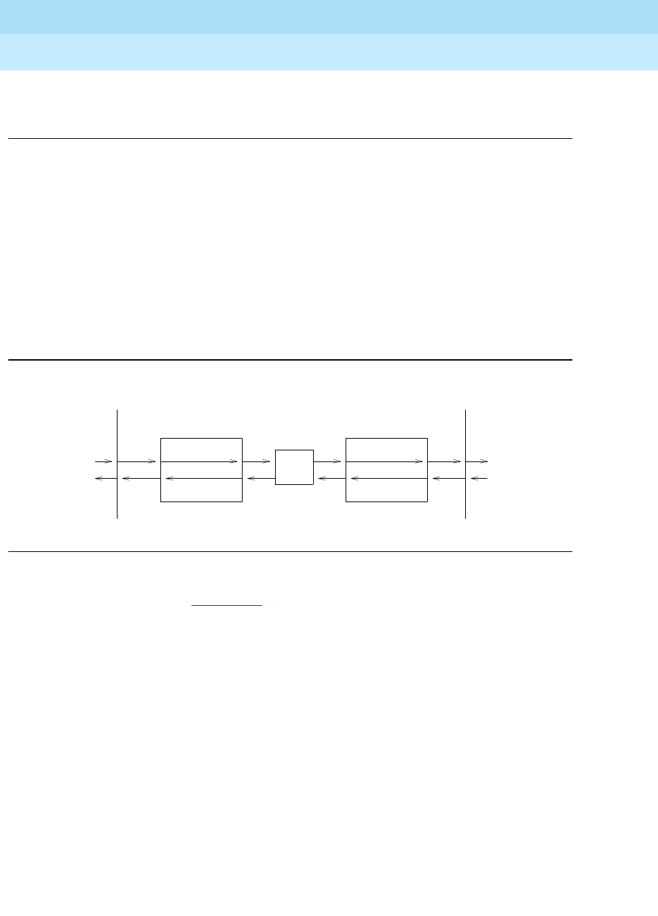
DEFINITY Enterprise Communications Server Release 6
Maintenance for R6r Volumes 1 & 2
555-230-126 Issue 2
January 1998
Maintenance Object Repair Procedures
Page 9-656EXP-INTF (Expansion Interface Circuit Pack)
9
Notes:
a. Retry the command at 1-minute intervals a maximum of 3 times.
Expansion Interface Packet Interface Test (#589)
This test is non-destructive.
This test will attempt to send a data packet from the TN1655 Packet Interface
circuit pack through any intervening Expansion Interface circuit packs and/or
Switch Node Interface circuit packs and through the Expansion Interface circuit
pack to be tested. The path the data packet takes is dependent on the location of
the Expansion Interface circuit pack to be tested and whether the system has
duplicate Port Network Connectivity. The following diagrams and short
discussion of each describe the different paths the test uses.
Figure 9-37. Expansion Interface Packet Interface Test—Packet Endpoint Loop
The path shown in Figure 9-37 is used when testing an EPN EI that is on the
active PNC.
(Optional)
CSS
EXP-INTF EXP-INTF
Packet Bus (PPN) Packet Bus (PN X)
PKT-
INT
LAPD
ENDPT
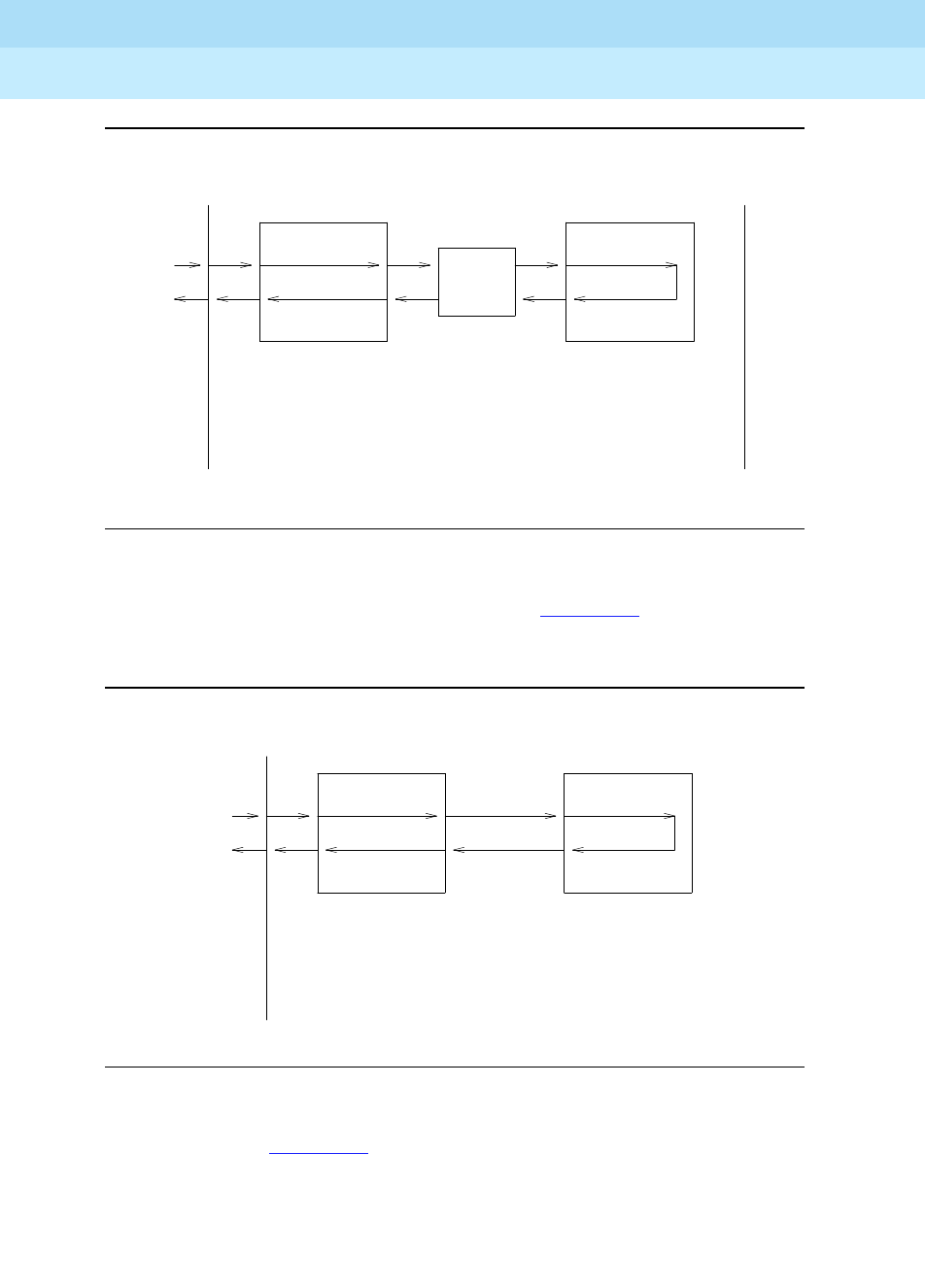
DEFINITY Enterprise Communications Server Release 6
Maintenance for R6r Volumes 1 & 2
555-230-126 Issue 2
January 1998
Maintenance Object Repair Procedures
Page 9-657EXP-INTF (Expansion Interface Circuit Pack)
9
Figure 9-38. Expansion Interface Packet Interface Test—PPN to EPN loop
In a Center Stage configuration the path shown in Figure 9-38 is used when
testing an EPN EI that is on the standby PNC. In a Direct Connect configuration,
this path is used on any PPN EI or on an EPN EI that is on the standby PNC.
Figure 9-39. Expansion Interface Packet Interface Test—PPN to CSS Loop
The path shown in Figure 9-39 is used when running the test on a PPN EI in a
Center Stage configuration.
(optional)
PKT-
INT
EXP-INTF EXP-INTF
Packet Bus (PPN) Packet Bus (PN X)
CSS
INTERFACE
SWITCH NODE
EXP-INTF
Packet Bus (PPN)
PKT-
INT
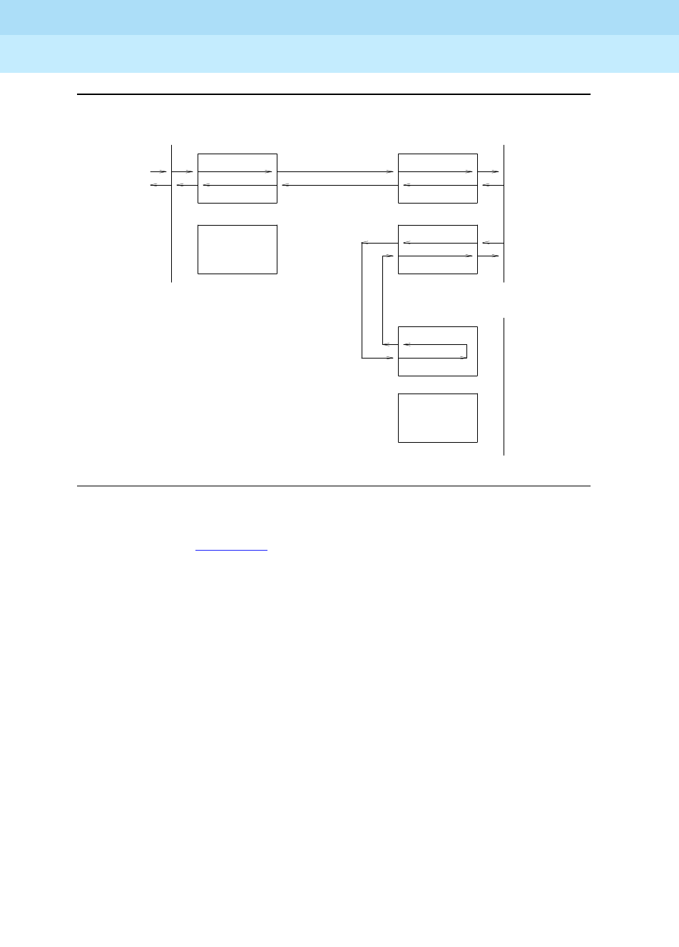
DEFINITY Enterprise Communications Server Release 6
Maintenance for R6r Volumes 1 & 2
555-230-126 Issue 2
January 1998
Maintenance Object Repair Procedures
Page 9-658EXP-INTF (Expansion Interface Circuit Pack)
9
Figure 9-40. Expansion Interface Packet Interface Test-EPN to EPN link
The path shown in Figure 9-40 is used when the EI under test is one that provides
connectivity between the two EPN s in a Direct Connect configuration.
INT
PKT
EXP-INTF
EXP-INTF EXP-INTF
EXP-INTF
EXP-INTF
EXP-INTF
Packet Bus ( PPN ) Packet Bus ( PN X )
Packet Bus ( PN Y )

DEFINITY Enterprise Communications Server Release 6
Maintenance for R6r Volumes 1 & 2
555-230-126 Issue 2
January 1998
Maintenance Object Repair Procedures
Page 9-659EXP-INTF (Expansion Interface Circuit Pack)
9
Table 9-217. TEST #589 Expansion Interface Packet
Interface Test
Error
Code Test
Result Description/ Recommendation
1033 ABORT The test cannot run because the Expansion Interface circuit pack does not
have a fiber link administered to it and there is not sufficient data to run the test
or because Expansion Interface circuit packs on other port networks needed
for this test are out of service.
1. Execute the list fiber-link command and determine if the Expansion
Interface circuit pack under test is an endpoint of one of the administered
fiber links. If it is one of the administered endpoints of a fiber link, proceed
to Step 2. If it is not an administered endpoint, then this is considered to be
a spare board and the test should not be attempted on this Expansion
Interface circuit pack.
2. Follow procedures for applicable configuration:
DIRECT CONNECT:
1. Issue the list config command for the cabinet and carrier where the
neighbor EI circuit pack is located. If the results reveal that the board is not
recognized by software, the board is out of service because of this
condition. Perform the following steps:
a. If this test is being executed on an Expansion Interface circuit pack
located in the PPN, enter display errors and follow the associated
repair procedures for EXP-PN errors for the port network where the
neighbor Expansion Interface circuit pack is located. Re-execute this
test.
b. If this test continues to abort with this abort code reset the DS1 CONV
circuit pack (if so equipped) or the neighbor Expansion Interface circuit
pack. This will not be destructive since the circuit pack cannot be
serving as the Expansion Archangel if it is not in service.
2. Run Test #237 and check for EXP-INTF circuit pack error type 1281 in the
Error Log. If error type 1281 is present and/or Test #237 does not pass,
refer to repair procedures for Test #237.
Continued on next page

DEFINITY Enterprise Communications Server Release 6
Maintenance for R6r Volumes 1 & 2
555-230-126 Issue 2
January 1998
Maintenance Object Repair Procedures
Page 9-660EXP-INTF (Expansion Interface Circuit Pack)
9
1033
(cont’d.)
ABORT
(cont’d.)
3. If Test #237 passes, reseat the Expansion Interface circuit pack. This will
not be destructive since the circuit pack cannot be serving as the
Expansion Archangel if it is not in service.
4. Repeat test #237.
CENTER STAGE:
If the Expansion Interface circuit pack under test is located in the PPN:
None of the Expansion Interface circuit packs located in the EPNs (on the same
PNC side) are in service (for EPN EIs see the next case).
1. Issue the list fiber-link command and determine if any of the Expansion
Interface circuit packs located in the EPNs are administered as endpoints
of a fiber link. If none of them are then ignore the results of this test.
2. Issue the list conf command for the cabinets and carriers where the
Expansion Interface circuit packs are located in all other EPNs. If the
results returned indicated that the circuit packs are not recognized by
software, they are out of service for this reason.
3. Issue the display errors command and follow the associated repair
procedures for EXP-PN errors. Re-execute this test.
4. If the test continues to abort with this error code reseat the Expansion
Interface circuit packs (or DS1 CONV circuit pack if so equipped) on the
EPNs. This will not be destructive since the circuit pack cannot be serving
as the Expansion Archangel if it is not in service.
1033
(cont’d.)
ABORT
(cont’d.)
5. Run Test #237 on each of the EPN Expansion Interface circuit packs and
check for EXP-INTF circuit pack error type 1281 in the error log. If error
type is present and/or Test #237 does not pass, refer to repair procedures
for Test #237.
6. Repeat this test.
If the Expansion Interface circuit pack under test is located in the EPN:
The Expansion Interface circuit located in the PPN is out of service.
1. Run Test #237 on each of the EPN Expansion Interface circuit packs and
check for EXP-INTF circuit pack error type 1281 in the error log. If error
type is present and/or Test #237 does not pass, refer to repair procedures
for Test #237.
2. Repeat this test.
Table 9-217. TEST #589 Expansion Interface Packet
Interface Test — Continued
Error
Code Test
Result Description/ Recommendation
Continued on next page

DEFINITY Enterprise Communications Server Release 6
Maintenance for R6r Volumes 1 & 2
555-230-126 Issue 2
January 1998
Maintenance Object Repair Procedures
Page 9-661EXP-INTF (Expansion Interface Circuit Pack)
9
1139 ABORT The Packet Bus in the Expansion Port Network where this Expansion Interface
circuit pack is located has a major alarm against it. This test needs to use the
alarmed port network’s Packet Bus.
1. Enter display alarms and follow the associated repair procedures for
PKT-BUS alarms.
2. Retry the command.
1141 ABORT The Packet Interface circuit pack is out of service.
1. Refer to PKT-INTF (Packet Interface circuit pack) Maintenance
documentation for the recommended repair procedure.
1144 ABORT The Packet Bus in the PPN has a major alarm against it. This test needs to use
the alarmed PPN Packet Bus.
1. Enter display alarms and follow the associated repair procedures for
PKT-BUS alarms.
2. Retry the command.
1394 ABORT The Expansion Interface circuit pack is out of service and the test cannot be
run. This condition is due to a change in the Expansion Interface circuit pack’s
ability to communicate with the Expansion Interface or Switch Node Interface
circuit pack on the other end of the fiber.
1. Run Test #237 and check the Error Log for EXP-INTF error type 1281. If
error type 1281 is present or if Test #237 does not pass, refer to the repair
procedures for Test #237.
2. If Test #237 passes, rest the Expansion Interface pack. Note that this will
not be destructive to the port network that the Expansion Interface circuit
pack is located in because it will not be serving as the expansion
archangel if it is not in service.
3. Repeat this test.
1395 ABORT This test cannot be run on an Expansion Interface circuit pack if it is part of the
B-side Port Network Connectivity and Duplicated Port Network Connectivity is
not enabled.
1. If this test needs to run on this Expansion Interface circuit pack, enable Port
Network Connectivity with the change system-parameters duplication
command.
2. Prevent the system from doing a PNC interchange by executing the set
PNC lock command.
3. Repeat this test.
Table 9-217. TEST #589 Expansion Interface Packet
Interface Test — Continued
Error
Code Test
Result Description/ Recommendation
Continued on next page

DEFINITY Enterprise Communications Server Release 6
Maintenance for R6r Volumes 1 & 2
555-230-126 Issue 2
January 1998
Maintenance Object Repair Procedures
Page 9-662EXP-INTF (Expansion Interface Circuit Pack)
9
1421 ABORT This abort code appears only when the Expansion Interface circuit pack
addressed in the test command is one that terminates a fiber link between two
EPNs in a direct connect system. It indicates that the test failed, but that this
test was run on the EPN EI board that is: a) In the same EPN as the board under
test b) On the active PNC (if duplicated) c) Terminates the fiber from the PPN
The EI tested is probably not at fault.
1. Enter display alarms and follow the EXP-INTF repair procedures for any
alarms against the EPN EI that is:
a. In the same EPN as the board just tested
b. On the active PNC
c. Terminates the fiber link from the PPN
2. If there are no alarms logged against that EI, run test #589 on it and follow
procedures for this test.
3. Try this command again.
1422 ABORT This abort code is valid and will only appear when the EI circuit pack under test
is one which is located in an EPN in a system that is configured with a Center
Stage Switch. It means that the test failed, but that this test was then run on the
PPN EI on the same PNC as the EI under test and that test failed. This means
that the EI originally tested is probably not at fault.
1. Resolve any alarms that are logged against the PPN EI that is on the same
PNC as the EI under test.
2. If there are no alarms logged against the PPN EI, run Test #589 against the
PPN EI and follow procedures for this test.
3. Try this command again.
2000 ABORT Response to the test request was not received within the allowable time period.
1. Retry the command at 1-minute intervals for a maximum of 3 retries.
2060 ABORT The link on the Packet Bus being used to perform the test has failed.
1. Try (a).
2. If the test continue to abort, enter display errors and follow the associated
repair procedures for PKT-INT.
2100 ABORT Could not allocate the necessary system resources to run this test.
1. Try (a).
2500 ABORT Internal system error
1. Try (a).
Table 9-217. TEST #589 Expansion Interface Packet
Interface Test — Continued
Error
Code Test
Result Description/ Recommendation
Continued on next page

DEFINITY Enterprise Communications Server Release 6
Maintenance for R6r Volumes 1 & 2
555-230-126 Issue 2
January 1998
Maintenance Object Repair Procedures
Page 9-663EXP-INTF (Expansion Interface Circuit Pack)
9
Notes:
a. Retry the command at 1-minute intervals a maximum of 5 times.
Expansion Interface Test (#244)
This test is potentially very destructive and requires the Expansion Interface
circuit pack to be busied out prior to execution of this test.
ANY FAIL The transmitted data packet was not received correctly by the Packet Interface
circuit pack. The failure may be in the EI under test, the DS1 CONV circuit
packs, or the intervening Center Stage components.
1. Test the Packet Interface circuit pack with the test packet- interface 1CS
command where C is the SPE carrier in a duplicated processor, and S is
the slot number the Packet Interface is located in. If the Packet Interface
circuit pack fails any tests, refer to “PKT-INTF”.
2. If the EI under test is located in an EPN in a high reliability system (2
PPN-to-CSS fibers in a simplex PNC), run the short test sequence on both
of the PPN EI boards and follow procedures for test #589.
3. Enter display errors and follow the associated repair procedures to
resolve all PKT-BUS errors.
4. Perform the "Fiber Fault Isolation Procedure" in Chapter 5.
PASS Although this test has passed, there may be related problems on other EI s
used in connectivity to and from this EI. Software may have conducted tests on
these other components and determined that this board was functioning
properly and any problems were probably due to a problem with some other
connectivity component. Check the error and alarm logs for problems with
other EI circuit packs and resolve these errors.
1. Refer to other EI board tests if the link is not functioning correctly.
0NO
BOARD No board was detected by the test.
1. Check the error log for wrong board (error 125) or no board (error 131).
Resolve either of these issues, if applicable.
2. Check that the board is properly translated and inserted. If so, check for
hyperactivity (error 1538). If hyperactive, use the reset board UUCSS
command.
3. Run the test again. If it fails, the ID chip on board may be bad. Replace the
board and retest.
Table 9-217. TEST #589 Expansion Interface Packet
Interface Test — Continued
Error
Code Test
Result Description/ Recommendation
Continued on next page

DEFINITY Enterprise Communications Server Release 6
Maintenance for R6r Volumes 1 & 2
555-230-126 Issue 2
January 1998
Maintenance Object Repair Procedures
Page 9-664EXP-INTF (Expansion Interface Circuit Pack)
9
The Expansion Interface Test, which is not a part of either the Short or the Long
Test Sequences, is executed via the reset board PCSS command where PCSS
is the address of the Expansion Interface circuit pack to be reset.
If the system only has one working Expansion Interface (EI) link between a pair of
port networks and one of the EI circuit packs must be reset, the action of busying
out the desired Expansion Interface circuit pack WILL DISRUPT SERVICE TO
THE EPN until the circuit pack is released from the busyout state. If the circuit
pack is part of a PPN to EPN link, the EPN WILL BE WITHOUT SERVICE. If the
circuit pack is part of an EPN to EPN link CALLS BETWEEN THE TWO EPNs WILL
BE DENIED.
If the system has working duplicate EI links, and the EI circuit pack to be reset is
part of the active EI link, the system does not allow the busyout and instructs
system technician to switch EI links via the set expansion-link PCSS command
where PCSS is the address of either Standby Expansion Interface circuit pack on
the Standby link. After executing the EI link switch, it is possible to busyout and
then reset the original EI circuit pack.
However, if the EPN Maintenance (MAINT) circuit pack determines that the
Expansion Interface (EXP-INTF) circuit pack is cycling between sane and insane
several times within several minutes, MAINT may inhibit operation of the
EXP-INTF by holding the EI circuit pack in a reset state. This condition may result
in an unsuccessful reset of the EI circuit pack.
If the reset command returns with "EPN is unavailable," execute the following:
1. Use the change circuit-pack P command where P is the port network
number of the EPN.
2. For the EI circuit pack you wish to reset, add an entry to the Circuit Pack
form for the TN776 Expansion Interface circuit pack. Be sure to enter the
appropriate carrier and slot (that is, A01 or B02).
3. Submit the form.
4. Repeat the reset board command.

DEFINITY Enterprise Communications Server Release 6
Maintenance for R6r Volumes 1 & 2
555-230-126 Issue 2
January 1998
Maintenance Object Repair Procedures
Page 9-665EXP-INTF (Expansion Interface Circuit Pack)
9
Table 9-218. TEST #224 Expansion Interface Test
Error
Code Test
Result Description/ Recommendation
ABORT Internal system error.
1. Try (a).
4 ABORT Could not reset EPN Expansion Interface circuit pack over optical fiber since
PPN Expansion Interface circuit pack on opposite end of fiber is not inserted.
1. Insert opposite EI circuit pack and perform reset again.
1015 ABORT The system does not allow this test to be run because the EI circuit pack has
not been busied out.
1. Busyout the Expansion Interface circuit pack. Repeat the reset board
PCSS command.
2000 ABORT Response to the test request was not received within the allowable time period.
2100 ABORT System resources required to run this test are not available.
1. Try (a).
9999 ABORT EI circuit pack reset successfully. Could not perform initialization test results
query because link to EPN is not up.
1. Execute release board PCSS. Wait one minute. Issue the display error
command. If you see Error Type 2049 logged against this EI circuit pack,
then the EI Test has failed with an error code equal to the aux data of this
entry. Otherwise, the initialization tests have passed.
12000 ABORT EI circuit pack reset successfully. Response to the initialization test results
query was not received within the allowable time period.
12100 ABORT EI circuit pack reset successfully. System resources required to run
initialization test are not available.
1. Try (a).
12026 ABORT EI circuit pack reset successfully. It responded with an unknown reply to the
query for the results of its initialization tests.
1. Try (a).
2. If the test continues to abort, replace the circuit pack or transceiver.
Continued on next page

DEFINITY Enterprise Communications Server Release 6
Maintenance for R6r Volumes 1 & 2
555-230-126 Issue 2
January 1998
Maintenance Object Repair Procedures
Page 9-666EXP-INTF (Expansion Interface Circuit Pack)
9
1 FAIL The EI did not successfully reset.
1. If the EI circuit pack is in the EPN, the EPN Maintenance Board may be
holding the EI circuit pack reset. Attempt to rectify this condition by
executing the test maint P long command on the maintenance board in
the same EPN.
2. If Step #1 was not successful in releasing the EI circuit pack, temporarily
remove the EPN maintenance circuit pack.
3. Repeat the reset board PCSS command.
4. If reset continues to fail, replace circuit pack.
5. Insert EPN maintenance circuit pack if it was removed.
2 FAIL The EI circuit pack was successfully reset, but it did not begin running after the
reset.
1. If the EI circuit pack is in the EPN, temporarily remove the EPN
maintenance circuit pack.
2. Repeat the reset board PCSS command.
3. Re-insert the EPN maintenance circuit pack if it was removed.
3 FAIL The reset over the optical fiber failed.
1. Execute the test board PCSS command on the PPN neighbor EI circuit
pack located on the opposite end of the fiber from this EI circuit pack. If
Test #238 does not pass, follow the maintenance procedure associated
with this test result. Then perform the reset again.
2. If the EI circuit pack is in the EPN, temporarily remove the EPN
Maintenance circuit pack.
3. Repeat the reset board PCSS command.
4. Reinsert EPN Maintenance circuit pack if it was removed.
5. Follow the procedure described in the "Relationship Between Expansion
Interface and Tone-Clock Circuit Packs" section if the symptoms match
those described there.
6. Check the Hardware Error Log for the EPN Tone-Clock errors that were
resolved about when the EPN went down. These EPN Tone-Clock errors
may have been resolved BECAUSE the EPN went down. When there is no
Tone-Clock generating the system clock on an EPN, then an EI circuit pack
can only be reset once. All subsequent reset attempts fail. It is also
possible that the system itself may have already tried to reset the EI circuit
pack. Refer to the TONE-BD (Tone-Clock) Maintenance documentation for
recommended maintenance strategy for Tone-Clock problems.
Table 9-218. TEST #224 Expansion Interface Test — Continued
Error
Code Test
Result Description/ Recommendation
Continued on next page

DEFINITY Enterprise Communications Server Release 6
Maintenance for R6r Volumes 1 & 2
555-230-126 Issue 2
January 1998
Maintenance Object Repair Procedures
Page 9-667EXP-INTF (Expansion Interface Circuit Pack)
9
7. If the reset still fails, execute the Manual Loop Back Procedure on the
opposite PPN EI circuit pack. This procedure is described in the section
preceding the "Hardware Error Log Entries and Test to Clear Values" table
for this MO. If the EI circuit pack and the lightwave transceiver are healthy,
the problem must lie with the EI circuit pack and its lightwave transceiver
on the EPN end of the fiber or with the fiber itself. Test the EPN EI circuit
pack with the manual loop back procedure and investigate the test results.
5001 FAIL Initialization failure: Expansion Interface circuit pack reset successfully and
restarted execution. But the Expansion Interface circuit pack could not
synchronize itself during the self-test phase of the hardware initialization.
1. Issue the reset board PCSS command. If the circuit pack is on the Active
link, this procedure can be very destructive. If a test board PCSS shows
all the tests passing, and there is no Standby link to which you can switch,
perform this reset at a time when service is least disrupted by losing use of
the EPN.
2. If the reset fails with the same error code, execute the test tone-clock PC
command where P is the network that contains this Expansion Interface
circuit pack and C is the carrier that contains the Active Tone-Clock on
network P. Also look for SYNC and TONE-BD errors. Resolve any SYNC
and TONE-BD errors by following the Maintenance documentation for
these MOs. Then reissue the reset board PCSS command.
3. If the Expansion Interface circuit pack still fails to reset with the same error
code, replace the Expansion Interface circuit pack.
5002 FAIL Initialization failure: EI circuit pack reset successfully and restarted
execution. But the EI circuit pack has determined that a lightwave transceiver
was not attached to the backplane connector when the EI circuit pack was last
reset. If this system does not have duplicate EI links, all users in the EPN will be
without service until this problem is resolved. If this system does have
duplicate links, the backup EI link is unavailable until this problem is resolved.
1. Attach lightwave transceiver to 25-pair backplane connector in slot
belonging to Expansion Interface circuit pack.
2. Reset the circuit pack again.
3. If the reset fails with an error code other than 5002, refer to the appropriate
maintenance section.
4. If the reset fails again with Error Code 5002, replace the lightwave
transceiver, reset the circuit pack, and execute the reset board PCSS
command again.
5. If the reset fails again with Error Code 5002, the new lightwave transceiver
may be defective, or the EI circuit pack may need to be replaced.
Table 9-218. TEST #224 Expansion Interface Test — Continued
Error
Code Test
Result Description/ Recommendation
Continued on next page

DEFINITY Enterprise Communications Server Release 6
Maintenance for R6r Volumes 1 & 2
555-230-126 Issue 2
January 1998
Maintenance Object Repair Procedures
Page 9-668EXP-INTF (Expansion Interface Circuit Pack)
9
Notes:
a. Retry the command at 1-minute intervals a maximum of 5 times.
5016
5017
5018
5019
5032
5033
5048
5064
5080
5096
5112
FAIL Initialization failure: EI circuit pack reset successfully and restarted
execution. But the EI circuit pack detected communication errors during the
self-test phase of the hardware initialization. The nature of the failure may
prevent the EI circuit pack from communicating with its neighbor EI circuit pack
on the opposite end of the fiber. The fault itself may be either on the EI circuit
pack or on the lightwave transceiver.
1. If all other tests on this EI circuit pack are passing and no other errors have
been logged against this circuit pack, replacement of the lightwave
transceiver or the circuit pack are recommended, but not critical.
2. If all other tests on this EI circuit pack are not passing or other errors have
been logged against this circuit pack, replace the lightwave transceiver
and/or the EI circuit pack.
PASS The EI was successfully reset, and it did restart execution. Also, it passed all its
initialization tests and detected a lightwave transceiver. Remove the EI circuit
pack from the busyout state by using the release board PCSS command.
1. Execute test board PCSS short command. Refer to errors for each test.
0NO
BOARD No board was detected by the test.
1. Check the error log for wrong board (error 125) or no board (error 131).
Resolve either of these issues.
2. Check that the board is properly translated and inserted. If so, check for
hyperactivity (error 1538). If hyperactive, use the reset board UUCSS
command.
3. Run the test again. If it fails, the ID chip on board may be bad. Replace the
board and retest.
Table 9-218. TEST #224 Expansion Interface Test — Continued
Error
Code Test
Result Description/ Recommendation
Continued on next page

DEFINITY Enterprise Communications Server Release 6
Maintenance for R6r Volumes 1 & 2
555-230-126 Issue 2
January 1998
Maintenance Object Repair Procedures
Page 9-669EXP-PN (Expansion Port Network)
9
EXP-PN (Expansion Port Network)
The EXP-PN maintenance object is responsible for overall maintenance of an
Expansion Port Network. The focus of EPN maintenance is on the Expansion
Interface circuit pack that is acting as the Expansion Archangel in an EPN.
EXP-INTF covers maintenance of the Expansion Interface circuit pack itself, while
EXP-PN covers a much broader area of activities and problems on an EPN. The
alarming strategy for EXP-PN is fairly simple, and does not make use of any
failure analysis routine for spawning maintenance actions. EXP-PN alarming is
based on the availability of an EPN for service, and the EPN’s response to
various recovery actions.
When investigating alarms logged against an EPN, problems involving the
Expansion Interface circuit pack acting as the Expansion Archangel, and
problems that may involve loss of communication between the EPN and the SPE
should be investigated. This could ultimately include fiber links (FIBER-LK), DS1
CONV circuit packs (DS1 CONV-BD), Switch Node Interface circuit packs
(SNI-BD) and Switch Node Configurations (SN-CONF).
EPN Restarts
While not an exhaustive discussion of EPN recovery actions, this section
describes at a high level the causes and effects of EPN restarts so that such
events recorded in the Error Log can be understood.
EPN Warm Restarts
EPN Warm Restart (EPN Reset Level 1) is generally performed on an EPN when
the recovery of that EPN can be accomplished in less than 30 seconds. When
possible, Warm Restart minimizes the work required to reinitialize an EPN, and
reduces the impact of an EPN failure by avoiding the longer and highly
destructive EPN Cold Restart. The primary cause of EPN restarts is failure of the
link from the SPE to the EPN due to a hardware fault in the link’s path. For most
hardware failures, this link, and thus the EPN, cannot be recovered until the failed
hardware is replaced. However, several failures modes exist for which hardware
redundancy allows the link to be recovered quickly. For instance, in a duplex
SPE system, a Packet Interface circuit pack failure causes an SPE interchange,
1. Investigate errors against EXP-PN and EXP-INTF.
MO Name (in
Alarm Log) Alarm
Level Initial Command to Run1Full Name of MO
EXP-PN MAJOR display errors1Expansion Port Network

DEFINITY Enterprise Communications Server Release 6
Maintenance for R6r Volumes 1 & 2
555-230-126 Issue 2
January 1998
Maintenance Object Repair Procedures
Page 9-670EXP-PN (Expansion Port Network)
9
which will allow the link to be recovered quickly over the newly active Packet
Interface. Or, on a Center Stage Switch, a link carried on one of the multiple
fibers interconnecting the switch nodes may be rerouted over an alternate fiber.
If the EAL is recovered quickly, the EPN Warm Restart returns the EPN to service
with minimal effects on user service. If the EAL cannot be recovered quickly, the
EPN is taken out-of-service and an EPN Reset Level 2 (EPN Cold Restart) is
required to return it to service.
EPN Cold Restarts
If the PPN to EPN link has failed and has not been recovered within 30 seconds,
the EPN is taken out of service and can be brought back into service only with an
EPN Reset Level 2 (EPN Cold Restart). Effects of an EPN Cold Restart include a
reset of all circuit packs in the EPN, and the disconnection of all calls to or from
the EPN. Calls with both endpoints within the EPN are dropped upon recovery.
EPN Restart Escalation
EPN restarts follow an escalation strategy controlled by maintenance software.
Whenever a request for an EPN Reset Level 1 (EPN Warm Restart) is made,
software checks to see if the restart should be escalated to an EPN Reset Level 2
(EPN Cold Restart). If any of the following are true, the restart is escalated:
■At least two level 1 restarts have occurred and less than two hours has
elapsed since the last occurrence.
■Current EPN conditions do not allow a level 1 restart, such as when the
EPN is out-of-service.
■Less than three minutes has elapsed since the last EPN Cold Restart,
indicating that the EPN is unstable.
If two EPN Cold Restarts have been executed in less than an hour and the link is
functional, but the EPN has not recovered to an in-service state, a MAJOR alarm
is raised against EXP-PN, and the EPN is put into Emergency Transfer by system
software. (Software can invoke EPN Emergency Transfer only when the link to the
EPN is up. If the link is down, the hardware automatically invokes Emergency
Transfer 1 minute after it detects a link failure).
Connectivity Alarming
When an EPN is out of service, a MAJOR EXP-PN alarm is raised against that
EPN. An EPN can only be alarmed if it is out of service
and
the fiber link between
the PPN and EPN is up. If the fiber link from the PPN to the Center Stage Switch is
down (by removing it from administration, for example), all EPN s are lost but not
alarmed, since they are not the cause of the problem. If, however, connectivity is
restored and the EPN fails to recover, The EPN will be alarmed.

DEFINITY Enterprise Communications Server Release 6
Maintenance for R6r Volumes 1 & 2
555-230-126 Issue 2
January 1998
Maintenance Object Repair Procedures
Page 9-671EXP-PN (Expansion Port Network)
9
Error Log Entries and Test to Clear Values
Notes:
a. This is an informational entry only, indicating that an EPN Reset Level 1
(EPN Warm Restart) has been executed on this EPN.
b. This is an informational entry only, indicating that an EPN Reset Level 2
(EPN Cold Restart) has been executed on this EPN. This does not include
restarts done at system initialization time.
c. Indicates that an EPN is not in-service when it is expected to be. The value
specified in the port field of the error log, is the PN number of the affected
PN. When this condition occurs, examine all system link errors and
EXP-INTF errors to aid in resolving the alarm (examples of system link
errors are errors logged against PKT-INTF, EXP-INTF, SNI-BD, FIBER-LK,
and PKT-BUS). Also check that all fiber connectivity matches that which
has been administered for the system. This alarm and error is resolved
and removed from the logs only when the EPN comes back into service, or
after fiber administration is changed to remove a fiber such that there is
not connectivity from the PPN to this EPN.
d. This alarm is raised when EPN maintenance has attempted to execute a
Cold Restart recovery action two times, and both restarts failed. This will
cause the EPN to be placed in Emergency Transfer. Examine all EXP-INTF
errors which, when cleared, may aid in resolving this alarm. Also check for
any SNI-BD, SNI-PEER, FIBR-LK, SN-CONF, or DS1 CONV-BD errors that
may indicate a communication problem between the processor and the
EPN. Make sure that the physical fiber connectivity matches that of system
administration.
Expansion Port Network (EXP-PN) Error Log Entries
Error Type Aux Data Associated Test Alarm
Level On/Off
Board Test to Clear Value
1(a) 0 None None
257(b) 0 None None
513(c) 0 None MAJOR OFF
769(d) 0 None MAJOR OFF

DEFINITY Enterprise Communications Server Release 6
Maintenance for R6r Volumes 1 & 2
555-230-126 Issue 2
January 1998
Maintenance Object Repair Procedures
Page 9-672EXP-PN (Expansion Port Network)
9
System Technician-Demanded Tests:
Descriptions And Error Codes
EXP-PN does not support demand testing. A demand reset can be executed to
perform a demand reset on an EPN by using the reset port-network P level [1 |
2] command. Where P is the port network number and 1 or 2 specifies the reset
level.
EPN Cold Restart (#955)
EPN Cold Restart, or EPN Reset Level 2, using the command reset port-network
P level 2 is used as a recovery mechanism for an EPN that has been taken
out-of-service. It is executed as a result of EPN recovery escalation when a Warm
Restart is not possible, or as a result of a system technician demanded EPN
restart. Once an EPN has gone out-of-service, an EPN Cold Restart is required to
bring it back into service.
is used as a recovery mechanism for an EPN that has been taken out-of-service.
It is executed as a result of EPN recovery escalation when a Warm Restart is not
possible, or as a result of a system technician demanded EPN restart. Once an
EPN has gone out-of-service, an EPN Cold Restart is required to bring it back
into service.
This is the most severe of the EPN restarts. Users of an EPN that experiences a
Cold Restart will experience a service outage. For the first 30 seconds after the
occurrence of an event that requires a restart, all stable calls will be preserved
(although new calls will be denied). All calls terminating in the EPN are then
dropped, and EPN users will not be able to place new phone calls during the
restart. All EPN hardware will also be re-initialized during this restart. The restart
will take no longer than 2 minutes with service being restored much quicker in a
typical restart situation.
Table 9-219. TEST #955 EPN Cold Restart
Error
Code Test
Result Description/ Recommendation
2100 ABORT Could not allocate the necessary system resources to execute this reset.
1. Try (a).
1386 ABORT The system link to this EPN is unavailable and cannot be used. This reset
cannot be executed without the link being operational.
1. Refer to “System Link” and resolve the link problem.
2000 ABORT Response to a request made in the internal portion of this reset procedure was
not received within the allowable time period.
1. Try (a).
Continued on next page

DEFINITY Enterprise Communications Server Release 6
Maintenance for R6r Volumes 1 & 2
555-230-126 Issue 2
January 1998
Maintenance Object Repair Procedures
Page 9-673EXP-PN (Expansion Port Network)
9
Notes:
a. Retry the command at 1-minute intervals a maximum of 3 times.
EPN Warm Restart (#956)
The EPN Warm Restart, or EPN Reset Level 1, using the command reset
port-network P level 1 is used to restart an EPN that has not been taken
out-of-service. It is the least severe of the EPN restart levels and is used in an
attempt to preserve the state of the system as much as possible, thereby
reducing user impact to a minimum. This restart will be attempted on a EPN if it
still in-service, or as a result of a system technician demanded EPN Warm
Restart.
During an EPN Warm Restart, all calls will be preserved including voice, data,
and packet calls. One an event has occurred that requires a warm restart,
service will be fully restored within 35 seconds.
2500 ABORT Internal system error
1. Try (a).
FAIL Internal system error
1. Try (a).
PASS The EPN Cold Restart procedure completed successfully.
Table 9-220. TEST #956 EPN Warm Restart
Error
Code Test
Result Description/ Recommendation
2100 ABORT Could not allocate the necessary system resources to execute this reset.
1. Retry the command at 1-minute intervals for a maximum of 3 times.
1386 ABORT The system link to this EPN is unavailable and cannot be used. This reset
cannot be executed without the link being operational.
1. Refer to “System Link” and resolve the link problem.
Continued on next page
Table 9-219. TEST #955 EPN Cold Restart — Continued
Error
Code Test
Result Description/ Recommendation
Continued on next page

DEFINITY Enterprise Communications Server Release 6
Maintenance for R6r Volumes 1 & 2
555-230-126 Issue 2
January 1998
Maintenance Object Repair Procedures
Page 9-674EXP-PN (Expansion Port Network)
9
1387 ABORT This EPN is not in a state where it is possible to perform a Warm Restart on the
EPN. It is necessary to perform an EPN Cold Restart (EPN Reset Level 2)
because of one of the following reasons:
■The EPN is in an out-of-service state.
■Insufficient time has elapsed since the last EPN Cold Restart was
performed on this EPN.
2000 ABORT Response to a request made in the internal portion of this reset procedure was
not received within the allowable time period.
1. Retry the command at 1-minute intervals for a maximum of 3 times.
2500 ABORT Internal system error
1. Retry the reset command at 1-minute intervals for a maximum of 3 times.
FAIL Internal system error
1. Retry the reset command at 1-minute intervals for a maximum of 3 times.
PASS The EPN Warm Restart procedure completed successfully.
Table 9-220. TEST #956 EPN Warm Restart — Continued
Error
Code Test
Result Description/ Recommendation
Continued on next page
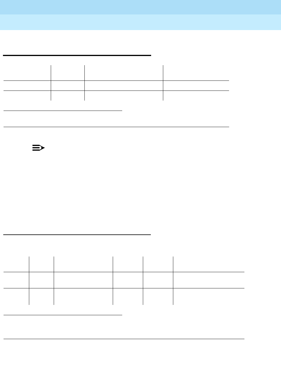
DEFINITY Enterprise Communications Server Release 6
Maintenance for R6r Volumes 1 & 2
555-230-126 Issue 2
January 1998
Maintenance Object Repair Procedures
Page 9-675EXT-DEV ADMIN? N (External Device Alarm)
9
EXT-DEV ADMIN? N (External Device
Alarm)
NOTE:
Use this MO when the
External Device Alarm Admin?
field on the
change
system-parameters customer-options
form is set to (n).
Release 5r SYSAM and EPN Maintenance circuit packs each have two sets of
alarm leads that can connect to external devices such as Uninterruptible Power
Supplies (UPS) or adjuncts such as AUDIX. Certain conditions on the external
device close the contacts on the alarm leads to notify the switch, which in turn,
originates an EXT-DEV alarm. One set of leads generates a major alarm; the
other set generates a minor alarm.
Error Log Entries and Test to Clear Values
1. where UU is an appropriate cabinet number determined via the PORT field from the Alarm
or Error Log.
1. Run the Short Test Sequence first. If all tests pass, run the Long Test Sequence. Refer to the
appropriate test description and follow the recommended procedures.
2. One port generates a MAJOR alarm; the other port generates a MINOR alarm.
MO Name (in
Alarm Log) Alarm
Level Initial Command to Run1Full Name of MO
EXT-DEV MAJOR test environment UU External Device Alarm
EXT-DEV MINOR test environment UU External Device Alarm
Error
Type Aux
Data Associated Test Alarm
Level On/Off
Board Test to Clear Value
010 Any Any Any test environment UU r 2 or
6
1 or 5 Any External Device
Alarm Test (#120) MAJOR
MINOR2OFF test environment UU r 2 or
6
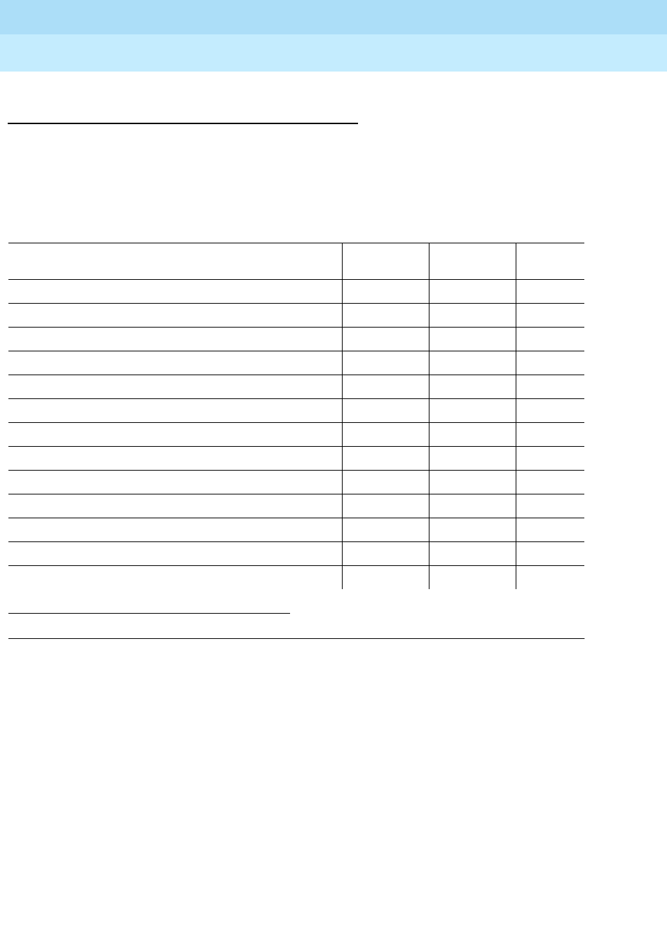
DEFINITY Enterprise Communications Server Release 6
Maintenance for R6r Volumes 1 & 2
555-230-126 Issue 2
January 1998
Maintenance Object Repair Procedures
Page 9-676EXT-DEV ADMIN? N (External Device Alarm)
9
System Technician-Demanded Tests:
Descriptions and Error Codes
Always investigate tests in the order presented in the table below. By clearing
error codes associated with the
Battery & Battery Charger Query Test,
you may
also clear errors generated from other tests in the testing sequence.
Notes:
a. Refer to POWER section for a description of this test.
b. Refer to AC-POWER section for a description of this test.
c. Refer to CARR-POW section for a description of this test.
d. Refer to EMG-XFER section for a description of this test.
e. Refer to CABINET section for a description of this test.
f. Refer to RING-GEN section for a description of this test.
1. D = Destructive; ND = Nondestructive
Multicarrier Cabinet Tests
Order of Investigation Short Test
Sequence Long Test
Sequence D/ND1
Battery & Battery Charger Query Test (#5) (a) X X ND
AC Power Query Test (#78) (b) X X ND
OLS Query Test (Carrier E) (#127) (c) X X ND
OLS Query Test (Carrier D) (#127) (c) X X ND
OLS Query Test (Carrier A) (#127) (c) X X ND
OLS Query Test (Carrier B) (#127) (c) X X ND
OLS Query Test (Carrier C) (#127) (c) X X ND
Emergency Transfer Query Test (#124) (d) X X ND
Cabinet Sensors Query Test (#122) (e) X X ND
External Device Alarm Test (MAJOR port) (#120) X X ND
External Device Alarm Test (MINOR port) (#120) X X ND
Analog Ring Generator Initialization Test (#117) (f) X X ND
Analog Ring Generator Query Test (#118) (f) X X ND
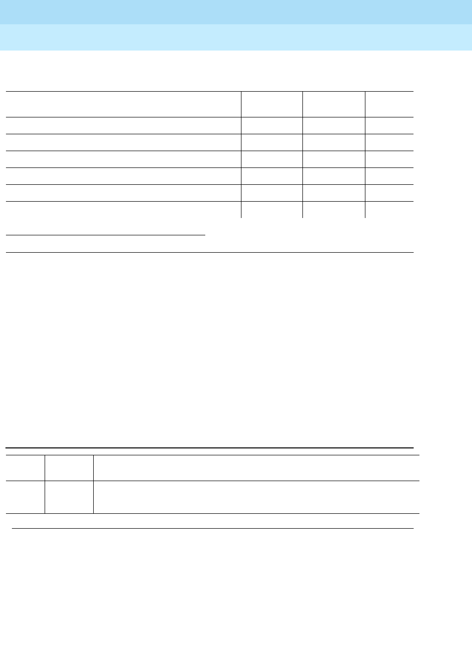
DEFINITY Enterprise Communications Server Release 6
Maintenance for R6r Volumes 1 & 2
555-230-126 Issue 2
January 1998
Maintenance Object Repair Procedures
Page 9-677EXT-DEV ADMIN? N (External Device Alarm)
9
Notes:
a. Refer to DC-POWER section for a description of this test.
b. Refer to EMG-XFER section for a description of this test.
c. Refer to RING-GEN section for a description of this test.
External Device Alarm Test (#120)
The External Device Alarm Test requests the state of the external device alarm
leads from the SYSAM in a PPN and from the EPN Maintenance circuit pack in an
EPN, and reports the results. The test has no effect on the external device itself.
1. D = Destructive; ND = Nondestructive
Single Carrier Cabinet Tests
Order of Investigation Short Test
Sequence Long Test
Sequence D/ND1
SCC Power Query Test (#79) (a) X X ND
Emergency Transfer Query Test (#124) (b) X X ND
External Device Alarm Test (MAJOR port) (#120) X X ND
External Device Alarm Test (MINOR port) (#120) X X ND
Analog Ring Generator Initialization Test (#117) (c) X X ND
Analog Ring Generator Query Test (#118) (c) X X ND
Table 9-221. TEST #120 External Device Alarm Test
Error
Code Test
Result Description/ Recommendation
1000 ABORT System resources required to run this test are not available.
1. Try (a).
Continued on next page

DEFINITY Enterprise Communications Server Release 6
Maintenance for R6r Volumes 1 & 2
555-230-126 Issue 2
January 1998
Maintenance Object Repair Procedures
Page 9-678EXT-DEV ADMIN? N (External Device Alarm)
9
Notes:
a. Retry the command at 1-minute intervals a maximum of 5 times.
2000 ABORT Response to the test was not received within the allowable time period.
1. Try (a).
2. If the test continues to ABORT with error code 2000, check for system
powering problems with the A carrier (PPN or EPN). Resolve all
AC-POWER and CARR-POW alarms. Repeat the test.
3. If the test continues to ABORT with a 2000 error code, check for and
resolve all SYSAM errors in a PPN or MAINT (EPN Maintenance circuit
pack) errors in an EPN. Then, repeat the test.
2029
2319
2320
2500
ABORT Internal system error
1. Try (a).
ANY FAIL The External Device Alarm has been activated by the external device.
1. Clear the major alarm on the external device, and rerun the test.
2. If the test still fails, then disconnect the External Device Alarm Leads from
the Maintenance circuit pack and rerun the test.
3. If the test still fails, then there is a problem with the Maintenance circuit
pack that is reporting the alarm. This circuit pack should be replaced.
There are failures that can occur on the SYSAM and EPN Maintenance
circuit pack that
will not
be detected by their respective maintenance, but
which will cause many environment tests to fail. If many environment tests
are failing, the suspect circuit pack should be replaced and the test rerun.
PASS If there is a problem with the external device, but the SYSAM or EPN
Maintenance circuit pack connected to the device reports no alarm, then the
External Device may not be properly reporting the problems or the External
Device may not be properly connected to the External Device Alarm Leads.
Table 9-221. TEST #120 External Device Alarm Test — Continued
Error
Code Test
Result Description/ Recommendation
Continued on next page
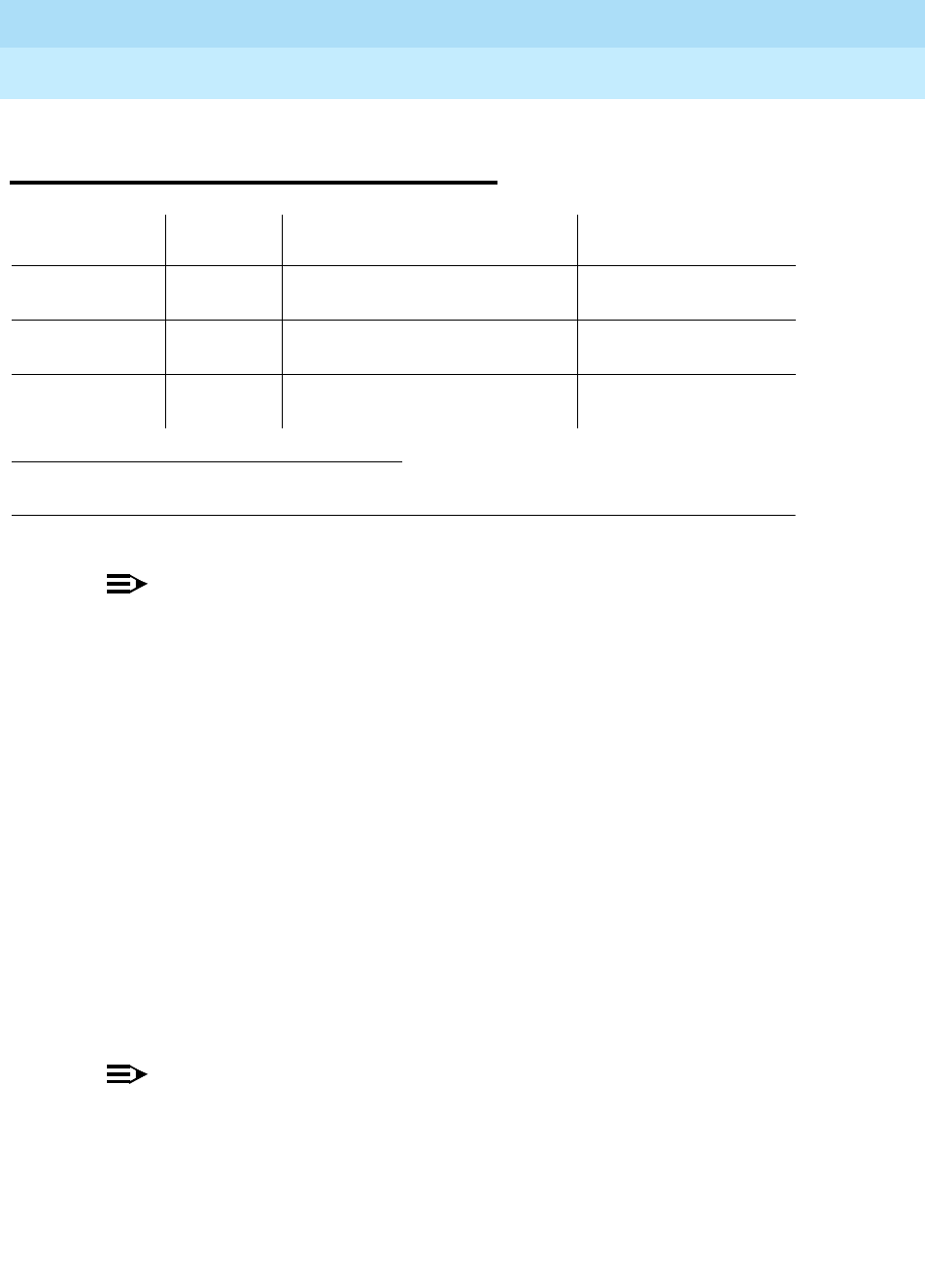
DEFINITY Enterprise Communications Server Release 6
Maintenance for R6r Volumes 1 & 2
555-230-126 Issue 2
January 1998
Maintenance Object Repair Procedures
Page 9-679EXT-DEV ADMIN? Y (External Device Alarm)
9
EXT-DEV ADMIN? Y (External
Device Alarm)
NOTE:
Use this MO when the
External Device Alarm Admin?
field on the
change
system-parameters customer-options
form is set to (y). You must have
INADS or INIT login permission to administer EXT-DEV Alarm.
Generic 3r SYSAM and EPN Maintenance circuit packs each have two alarm
ports which can be connected to external devices such as Uninterruptible Power
Supplies (UPS) or adjuncts such as AUDIX.
Certain conditions on the external device close the contacts on the alarm leads
to notify the switch which in turn originates an EXT-DEV alarm. One set of leads
generates a major alarm; the other set generates a minor alarm.
The special locations UUmajor and UUminor are used to designate the major or
minor maintenance board alarm connection for cabinet UU. The major/minor
designation specifies the port, not the alarm level associated with the
connection;
for example,
the “major” port can be administered as a major, minor,
or warning alarm, and the “minor” port can be administered as a major, minor, or
warning alarm. In addition Analog line ports can also be administered as external
device alarms.
NOTE:
An unadministered maintenance board external device alarm port, that is
sensing a contact closure will have an entry in the Error Log and in the
Alarm Log. INADS will not receive warning alarms.
1. where UU is an appropriate cabinet number determined via the PORT field from the Alarm or Error
Log.
MO Name (in
Alarm Log) Alarm
Level Initial Command to Run 1Full Name of MO
EXT-DEV MAJOR test eda-external-device-alrm
physical location External Device Alarm
EXT-DEV MINOR test eda-external-device-alrm
physical location External Device Alarm
EXT-DEV WARNING test eda-external-device-alrm
physical location External Device Alarm
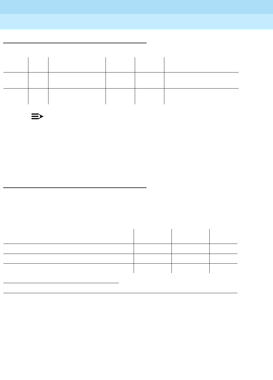
DEFINITY Enterprise Communications Server Release 6
Maintenance for R6r Volumes 1 & 2
555-230-126 Issue 2
January 1998
Maintenance Object Repair Procedures
Page 9-680EXT-DEV ADMIN? Y (External Device Alarm)
9
Error Log Entries and Test to Clear Values
NOTE:
The loss of -48 volt power prevents detection of an external device alarm.
AC-POWER, CARR-POW, and DC-POWER alarms could indicate the loss
of the external device alarm -48 volt power source. ALARM-PT alarms may
also indicate a loss of power. When analog line ports are administered as
analog line external device alarms loss of -48 volts prevents detection of an
external device alarm.
System Technician-Demanded Tests:
Descriptions and Error Codes
Always investigate tests in the order presented in the table below when
inspecting errors in the system. By clearing error codes associated with the
Battery & Battery Charger Query Test,
you may also clear errors generated from
other tests in the testing sequence.
External Device Alarm Test (#120)
The External Device Alarm Test requests the state of the External Device Alarm
from a Maintenance circuit pack and reports the results. The test has no effect on
the external device itself
1. D = Destructive; ND = Nondestructive
Error
Type Aux
Data Associated Test Alarm
Level On/Off
Board Test to Clear Value
0 0 Any Any Any test eda-external-device-alrm
physical location r 2 or 6
1 or 5 Any External Device
Alarm Test (#120) Any OFF test eda-external-device-alrm
physical location r 2 or 6
Order of Investigation Short Test
Sequence Long Test
Sequence D/ND1
External Device Alarm Test (MAJOR port) (#120) X X ND
External Device Alarm Test (MINOR port) (#120) X X ND
External Device Alarm Test (WARNING port) (#120) X X ND

DEFINITY Enterprise Communications Server Release 6
Maintenance for R6r Volumes 1 & 2
555-230-126 Issue 2
January 1998
Maintenance Object Repair Procedures
Page 9-681EXT-DEV ADMIN? Y (External Device Alarm)
9
Notes:
a. Retry the command at 1-minute intervals a maximum of 5 times.
Table 9-222. TEST #120 External Device Alarm Test
Error
Code Test
Result Description/ Recommendation
1000 ABORT System resources required to run this test are not available.
1. Try (a).
1035 ABORT The EPN containing this equipment is not available.
Resolve all EPN problems with this cabinet.
2000 ABORT Response to the test request was not received within the allowable time period.
1. Try (a).
2. (Maintenance Board) If the test continues to ABORT with error code 2000,
check for system powering problems with the A carrier. Resolve all
AC-POWER and CARR-POW alarms in a multi-carrier cabinet or
DC-POWER alarms in a single-carrier cabinet. Then, repeat the test.
3. (Maintenance Board) If the test continues to ABORT with a 2000 error
code, resolve all maintenance circuit pack errors. Then, repeat the test.
2029
2100
2319
2320
2500
ABORT Internal system error
1. Try (a).
ANY FAIL The External Device Alarm has been activated by the external device.
1. Clear the major alarm on the external device, and rerun the test.
2. If the test still fails, then disconnect the External Device Alarm Leads from
the Maintenance circuit pack and rerun the test.
3. If the test still fails, then there is a problem with the analog external device
alarm port or the Maintenance circuit pack that is reporting the alarm. This
circuit pack should be replaced. There are failures that can occur on the
Maintenance circuit pack that
will not
be detected by their respective
maintenance, but which will cause many environment tests to fail. If many
environment tests are failing, the suspect circuit pack should be replaced
and the test rerun.
PASS If there is a problem with the external device, but the administered analog line
external device alarm, or the administered Maintenance circuit pack connected
to the device reports no alarm, then the External Device may not be properly
reporting the problems or the External Device may not be properly connected
to the External Device Alarm Leads.
Continued on next page

DEFINITY Enterprise Communications Server Release 6
Maintenance for R6r Volumes 1 & 2
555-230-126 Issue 2
January 1998
Maintenance Object Repair Procedures
Page 9-682FIBER-LK (Fiber Link)
9
FIBER-LK (Fiber Link)
A fiber link consists of the endpoint boards that are connected via the optical
fiber, the lightwave transceivers or metallic connections on the endpoint boards,
and, if administered, the DS1 Converter (DS1 CONV) complex that exists
between the two fiber endpoints. The fiber endpoints are Expansion Interface (EI)
circuit packs and/or Switch Node Interface (SNI) circuit packs.
Three types of fiber links exist in G3r systems:
Fiber link errors and alarms are generated only on fibers that have at least one
SNI endpoint. Fiber errors for fibers that have EI s as both endpoints are
detected by the EI circuit pack, thus generating off-board EXP-INTF errors and
alarms. Fiber errors and alarms on EI-SNI fiber links generate FIBER-LK and/or
off-board EXP-INTF errors and alarms.
Fiber links are administered via add fiber-link F or add fiber-link next, where F
is the fiber-link number. The 2 endpoints of the fiber are administered (EI and EI,
EI and SNI, or SNI and SNI). In duplicated PNC configurations, both the a-pnc
fiber-link and the b-pnc fiber-link are administered to the same fiber link number.
The fiber links are designated by F P, where F is the fiber-link number and P is
the pnc, a-pnc or b-pnc. In addition, a DS1 converter complex may be
administered on the fiber link. In duplicated PNC configuration, the a-pnc and
b-pnc DS1 converter complexes are administered to the same fiber-link number.
DS1 facilities and parameters can be modified via change fiber-link F P.
An individual fiber link can be displayed with the display fiber-link F command.
All fiber links can be listed via the list fiber-link command.
1. F is the fiber link number; pnc is ‘‘a-pnc’’ or ‘‘b-pnc’’ (always ‘‘a-pnc’’ in simplex
systems).
MO Name (in
Alarm Log) Alarm Level Initial Command to Run1Full Name of
MO
FIBER-LK MAJOR test fiber
F pnc
s Fiber Link
FIBER-LK MINOR test fiber
F pnc
s Fiber Link
FIBER-LK WARNING test fiber
F pnc
s Fiber Link
EI-EI fiber This type of fiber is an EI to EI connection and is only used in
direct connect port network connectivity (PNC).
EI-SNI fiber This type of fiber is an EI to SNI connection and is only used
in Center Stage Switch (CSS) PNC.
SNI-SNI fiber This type of fiber is an SNI to SNI connection and is only
used in CSS PNC when two switch node carriers are
connected in a two or three switch node configuration.

DEFINITY Enterprise Communications Server Release 6
Maintenance for R6r Volumes 1 & 2
555-230-126 Issue 2
January 1998
Maintenance Object Repair Procedures
Page 9-683FIBER-LK (Fiber Link)
9
The following terms are used in the error descriptions:
LEDs for Circuit Packs on a Fiber Link
The yellow LEDs on the three types of boards, SNI (TN573), EI (TN570), and DS1
Converter (TN574 or TN1654), that may be a part of the fiber link can help in
diagnosing problems with the fiber link. The yellow LED states are as follows. The
flashing LED patterns take precedence over the active or standby LED patterns.
If both endpoints of a fiber link (EI and/or SNI) are flashing with a fiber out of
frame pattern, a fast yellow LED pattern (0.1 second on and 0.1 second off),
check the lightwave transceivers (if present). Both lightwave transceivers on the
fiber link must be of the same type. The 9823a shortwave transceiver and the
9823b longwave transceiver must never be combined on the same fiber link
because a fiber out of frame condition will exist. The 9823a lightwave transceiver
should be used for distances up to 4900 feet and the 9823b lightwave
transceiver should be used for distances up to 25,000 feet.
1. The fiber is in frame, but no communication exists to the
neighbor
Control Path The path between the two fiber endpoints that is necessary
for the two endpoint circuit packs to communicate.
Circuit Path The path between the two fiber endpoints that is necessary
for circuit switched phone calls to work.
Neighbor The circuit pack on the other end of the fiber.
Out of Frame A circuit pack reports fiber out of frame if it cannot detect
valid data coming from the fiber.
Packet Path The path between the two fiber endpoints that is necessary
for packet switched messages to be sent between the two
fiber endpoints.
Table 9-223. Switch Node Interface Yellow LED Flashing Codes
Condition LED on LED off
Fiber out of Frame 0.1 second 0.1 second
In frame, No Neighbor10.5 second 0.5 second
SNI active Solid on Never off
SNI standby Never on Solid off
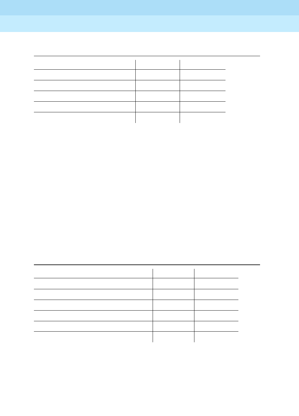
DEFINITY Enterprise Communications Server Release 6
Maintenance for R6r Volumes 1 & 2
555-230-126 Issue 2
January 1998
Maintenance Object Repair Procedures
Page 9-684FIBER-LK (Fiber Link)
9
Notes:
a. The fiber is in frame, but no communication exists to the neighbor.
b. This is the normal state for an active EPN EI circuit pack that is also the
bus master (expansion archangel) in the EPN.
c. This is the normal state for an active EI circuit pack that is not the bus
master (expansion archangel) for an EPN. This applies only in the direct
connect configuration where the EI circuit pack in an EPN connects via a
fiber link to an EI circuit pack in the other EPN. This state also applies for
an active EI circuit pack located in the PPN.
d. This is the normal state for a standby expansion Interface circuit pack in
both the PPN and EPNs.
For more details about how the Expansion Interface circuit pack error codes
relate to the LED states, see the EXP-INTF section.
Notes:
a. A Fiber is out of frame or a fiber loss of signal condition exists.
b. DS1 CONV/fiber endpoint communication is down.
c. The DS1 channel is down between the two DS1 CONVs in the DS1
converter complex.
Table 9-224. Expansion Interface Circuit Pack Yellow LED Flashing Codes
Condition LED on LED off
Fiber Out-of-Frame 0.1 second 0.1 second
(a) In frame-No Neighbor 0.5 second 0.5 second
(b) Expansion Interface Active 2 second 0.2 second
(c) Expansion Interface Active Solid on Never off
(d) Expansion Interface Standby Never on Solid off
Table 9-225. DS1 CONV Yellow LED Flashing Codes
Condition LED on LED off
(a) Fiber out of Frame 0.1 second 0.1 second
(b) In frame, fiber channel is down 0.5 second 0.5 second
(c) In frame, DS1 channel down 1 second 1 second
(d) DS1 CONV no response from SPE 2 second 0.2 second
DS1 CONV active Solid on Never off
DS1 CONV standby Never on Solid off
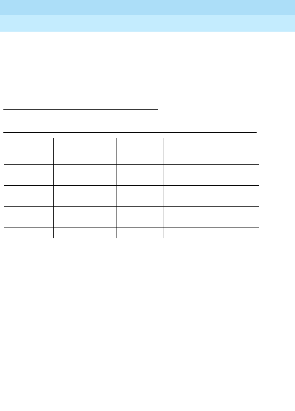
DEFINITY Enterprise Communications Server Release 6
Maintenance for R6r Volumes 1 & 2
555-230-126 Issue 2
January 1998
Maintenance Object Repair Procedures
Page 9-685FIBER-LK (Fiber Link)
9
d. The SPE is not acknowledging messages from the DS1 CONV circuit pack
or the DS1 CONV circuit pack does not have a processor route. This
pattern indicates a probable software problem.
In addition to the traditional red, green, and yellow LEDs, the DS1 CONV circuit
pack has four green LEDs that indicate whether a receive signal is present for
each DS1 facility.
Error Log Entries and Test to Clear Values
Notes:
a. The failure audit test (#777) should be run to confirm whether the error still
exists.
b. This error indicates problem with the control path to the neighbor.
c. This error indicates that the fiber link has been busied out via the busyout
fiber F P command. To resolve this error, release the fiber link via the
release fiber F P command.
d. This error indicates problem with the circuit path to the neighbor.
e. This error indicates problem with the packet path to the neighbor.
f. This error indicates problem with the control path from the neighbor.
g. This error indicates problem with the circuit path from the neighbor.
h. This error indicates problem with the packet path from the neighbor.
1. Run the Short Test Sequence first. If all tests pass, run the Long Test Sequence. Refer to the
appropriate test description and follow the recommended procedures.
Table 9-226. Fiber Link Error Log Entries
Error
Type Aux
Data Associated Test Alarm Level On/Off
Board Test to Clear Value
010 Any Any Any test fiber-link F P r 1
1 (b) any failure audit (#777) (a) WAR/MIN/MAJ OFF test fiber-link F P r 1
18 (c) 0 busyout fiber F P WARNING OFF release fiber F P
257 (d) any failure audit (#777) (a) WAR/MIN/MAJ OFF test fiber-link F P r 1
513 (e) any failure audit (#777) (a) WAR/MIN/MAJ OFF test fiber-link F P r 1
76 9(f) any failure audit (#777) (a) WAR/MIN/MAJ OFF test fiber-link F P r 1
1025 (g) any failure audit (#777) (a) WAR/MIN/MAJ OFF test fiber-link F P r 1
1281 (h) any failure audit (#777) (a) WAR/MIN/MAJ OFF test fiber-link F P r 1

DEFINITY Enterprise Communications Server Release 6
Maintenance for R6r Volumes 1 & 2
555-230-126 Issue 2
January 1998
Maintenance Object Repair Procedures
Page 9-686FIBER-LK (Fiber Link)
9
For note b and notes d through h, perform the following steps:
1. Perform the Fiber Fault Isolation Procedure described in Chapter 5.
2. Enter display errors and if any of the slip errors listed below exist, follow
the associated repair procedures in the SYNC section for slip errors.
System Technician-Demanded Tests:
Descriptions and Error Codes
Always investigate tests in the order presented in the table below when
inspecting errors in the system. By clearing error codes associated with one test,
you may also clear errors generated by other tests later in the sequence.
1. D = Destructive; ND = Nondestructive
Table 9-227. Error Log Entries for Slip Errors
Circuit Pack Name Error Log Name Error Log Entry for Slips
DS1 Interface DS1-BD 3073 to 3160
Expansion Interface EXP-INTF 2305
Switch Node Interface SNI-BD 1537
Tone-Clock TDM-CLK 1025
UDS1 Interface UDS1-BD 3073 to 3160
Table 9-228. Tests Run for an EI-to-EI Fiber Link
Order of Investigation Short Test
Sequence Long Test
Sequence Reset Fiber
Sequence D/ND1
EI Out-of-Frame Query Test(#238) X X ND
EI Neighbor Query Test(#237) X X ND
Fiber Link Reset Test(#768) X D
Table 9-229. Tests Run for an EI-to-SNI Fiber Link
Order of Investigation Short Test
Sequence Long Test
Sequence Reset Fiber
Sequence D/ND1
EI Out-of-Frame Query Test(#238) X X ND
EI Neighbor Query Test(#237) X X ND
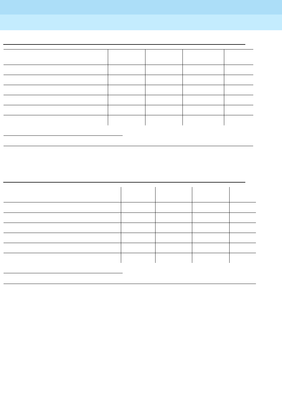
DEFINITY Enterprise Communications Server Release 6
Maintenance for R6r Volumes 1 & 2
555-230-126 Issue 2
January 1998
Maintenance Object Repair Procedures
Page 9-687FIBER-LK (Fiber Link)
9
Expansion Interface Neighbor Query Test (#237)
This test is non-destructive.
The Expansion Interface Neighbor Query Test is a request to an EI circuit pack to
determine if it has established communication with the EI or Switch Node
Interface circuit pack on the opposite end of the fiber.
For EI-EI fiber links, this test is run on both EI circuit pack endpoints of the fiber
link.
1. D = Destructive; ND = Nondestructive
1. D = Destructive; ND = Nondestructive
Configuration Audit(#759) X X ND
Failure Audit(#777) X X ND
Fiber Out of Frame Query(#989) X X ND
Destructive Facility Test(#757) X D
Off-Board Destructive Facility Test(#756) X D
Fiber Link Reset Test(#768) X D
Table 9-230. Tests Run for an SNI-to-SNI Fiber Link
Order of Investigation Short Test
Sequence Long Test
Sequence Reset Fiber
Sequence D/ND1
Configuration Audit(#759) X X ND
Failure Audit(#777) X X ND
Fiber Out of Frame Query(#989) X X ND
Destructive Facility Test(#757) X D
Off-Board Destructive Facility Test (#756) X D
Fiber Link Reset Test(#768) X D
Table 9-229. Tests Run for an EI-to-SNI Fiber Link
Order of Investigation Short Test
Sequence Long Test
Sequence Reset Fiber
Sequence D/ND1

DEFINITY Enterprise Communications Server Release 6
Maintenance for R6r Volumes 1 & 2
555-230-126 Issue 2
January 1998
Maintenance Object Repair Procedures
Page 9-688FIBER-LK (Fiber Link)
9
Table 9-231. TEST #237 Expansion Interface Neighbor Query Test
Error
Code Test
Result Description/ Recommendation
1033 ABORT The EI circuit pack does not have a fiber link administered to it. There is not
sufficient data to run test. Since the test fiber-link command was run, the
expansion interface should be administered on a fiber link, therefore this must
be a software problem.
2000 ABORT Response to the test request was not received within the allowable time
period.
1. Run the test board UUCSS test separately for each EI endpoint on this
fiber link and follow the procedures for this test in the EXP-INTF section.
2031 ABORT The attempt to send the message to the Expansion Interface circuit pack,
asking it who it’s neighbor is, was not successful.
1. Run the test board UUCSS test separately for each Expansion Interface
endpoint on this fiber link and follow the procedures for this test in the
EXP-INTF section.
2100 ABORT System resources required to run this test are not available.
1. Run the test board UUCSS test separately for each Expansion Interface
endpoint on this fiber link and follow the procedures in the EXP-INTF
section.
2500 ABORT Internal system error
1. Run the test board UUCSS test separately for each Expansion Interface
endpoint on this fiber link and follow the procedures in the EXP-INTF
section.
1033 FAIL The Expansion Interface circuit pack under test cannot make contact with
opposite end Expansion Interface or Switch Node Interface circuit pack.
1. Run the test board UUCSS test separately for each Expansion Interface
endpoint on this fiber link and follow the procedures in the EXP-INTF
section.
2027 FAIL The Expansion Interface circuit pack has contact with the opposite Expansion
Interface or Switch Node Interface circuit pack, but it is the incorrect
Expansion Interface or Switch Node Interface circuit pack.
1. Run the test board UUCSS test separately for each Expansion Interface
endpoint on this fiber link and follow the procedures in the EXP-INTF
section.
Continued on next page

DEFINITY Enterprise Communications Server Release 6
Maintenance for R6r Volumes 1 & 2
555-230-126 Issue 2
January 1998
Maintenance Object Repair Procedures
Page 9-689FIBER-LK (Fiber Link)
9
Expansion Interface Fiber Out-of-Frame (FOOF)
Query Test (#238)
This test is non-destructive.
This test is a request to an EI circuit pack to determine if it is currently detecting
the framing sequence on the incoming fiber data stream. If it cannot detect this
framing signal, the EI circuit pack will not be able to establish a link with the
opposite EI or Switch Node Interface circuit pack.
For EI-EI fiber links, this test is run on both EI circuit pack endpoints of the fiber
link.
PASS The EI circuit pack(s) have successfully established a link with the opposite
Expansion Interface or Switch Node Interface circuit pack.
1. If the status port-network command still indicates that this link is down, it
is possible that one or both of the EI and/or Switch Node Interface circuit
packs have been busied out.
2. If the link still does not come up, reset one or both EI and/or Switch Node
Interface circuit packs on the link.
Table 9-231. TEST #237 Expansion Interface Neighbor Query Test — Continued
Error
Code Test
Result Description/ Recommendation
Continued on next page

DEFINITY Enterprise Communications Server Release 6
Maintenance for R6r Volumes 1 & 2
555-230-126 Issue 2
January 1998
Maintenance Object Repair Procedures
Page 9-690FIBER-LK (Fiber Link)
9
SNI Off-Board Destructive Facility Test (#756)
This test is destructive.
The SNI runs a destructive looparound of the off-board and on-board
looparounds. This test returns the result of the off-board looparound, while test
757 returns the result of the on-board looparound. For SNI-SNI fiber links, this
test is run on both SNI circuit pack endpoints of the fiber link.
Table 9-232. TEST #238 Expansion Interface Fiber Out-of-Frame
Query Test
Error
Code Test
Result Description/ Recommendation
1033 ABORT The Expansion Interface circuit pack does not have a fiber link administered to
it. There is not sufficient data to run test. Since the test fiber-link command
was run, the expansion interface should be administered on a fiber link,
therefore this must be a software problem.
2000 ABORT Response to the test request was not received within the allowable time period.
1. Run the test board UUCSS test separately for each Expansion Interface
endpoint on this fiber link and follow the procedures in the EXP-INTF
section.
2100 ABORT System resources required to run this test are not available.
1. Run the test board UUCSS test separately for each Expansion Interface
endpoint on this fiber link and follow the procedures in the EXP-INTF
section.
2500 ABORT Internal system error
1. Run the test board UUCSS test separately for each Expansion Interface
endpoint on this fiber link and follow the procedures in the EXP-INTF
section.
FAIL Expansion Interface circuit pack could not detect framing sequence.
1. Run the test board UUCSS test separately for each Expansion Interface
endpoint on this fiber link and follow the procedures in the EXP-INTF
section.
PASS The Expansion Interface circuit pack(s) have detected the valid framing signal
on the fiber.
1. Refer to errors from other EI circuit packs, Switch Node Interface tests, or
DS1 Converter tests (if present) if the link is still not functioning.
Continued on next page

DEFINITY Enterprise Communications Server Release 6
Maintenance for R6r Volumes 1 & 2
555-230-126 Issue 2
January 1998
Maintenance Object Repair Procedures
Page 9-691FIBER-LK (Fiber Link)
9
Table 9-233. TEST #756 SNI Off-Board Destructive Facility Test
Error
Code Test
Result Description/ Recommendation
1015 ABORT The system will not allow this test to be run because the fiber link has not been
busied out. Busy out the fiber link with busyout fiber-link F P. Repeat the test
fiber-link F P long command.
2100 ABORT Could not allocate the necessary system resources to run this test.
1. Retry the command at 1-minute intervals a maximum of 3 times.
2300 ABORT The downlink message necessary to run this test could not be sent.
1. Retry the command at 1-minute intervals a maximum of 3 times.
2301 ABORT The software timer could not be set before sending the downlink message
necessary to run this test.
1. Retry the command at 1-minute intervals a maximum of 3 times.
2304 ABORT SNI circuit pack responded that it is not able to run the test requested by
software.
1. Retry the command at 1-minute intervals a maximum of 3 times.
2306 ABORT An SNI circuit pack on the fiber link is not responding to test requests sent by
software.
1. Run the test led switch-node for the switch node(s) that the SNI (s) reside
in to verify whether the LED s on the board(s) light. Follow the steps below
for the SNI (s) from step 1 that had no LED s light.
2. If the LED s on the other boards in the carrier light, but the LED s on this
board do not light, run test 760 via test board UUCSS l for the active SNC
in this carrier. Wait 5 minutes and then try step 1 one more time. If the LED s
on this board still do not light, replace this board. Replacing an SNI may be
service interrupting. Refer to the SNI-BD section for the procedure for
replacing an SNI.
3. If none of the LED s light for the boards in the same carrier as this board, fix
any problems associated with the connectivity of this carrier to the SPE. Use
list fiber-link to determine the fiber connections to this carrier. Check the
LED s on all SNI s and EI s and fix any fiber problems. Enter display errors
and follow the associated repair procedures for any EXP-INTF error entries
associated with the PPN. Also, follow the associated repair procedures for
any SYNC, SNI-BD, SNC-BD, FIBER-LK, or SNI-PEER error entries.
Continued on next page

DEFINITY Enterprise Communications Server Release 6
Maintenance for R6r Volumes 1 & 2
555-230-126 Issue 2
January 1998
Maintenance Object Repair Procedures
Page 9-692FIBER-LK (Fiber Link)
9
1415 ABORT The lightwave transceiver is not present for endpoint 1 of the fiber link (list
fiber-link can be used to display fiber link endpoints).
1. If a lightwave transceiver is not supposed to be present, do nothing. For
example, an SNI connected to a DS1 CONV circuit pack or an SNI with a
metallic connection does not have a lightwave transceiver. This test can
only be run when a lightwave transceiver exists.
2. Otherwise, continue with the following steps.
3. Check the lightwave transceiver connections.
4. Replace the lightwave transceiver. If a fiber out of frame condition exists
and lightwave transceivers are used, check that the lightwave transceivers
are of the same type (both are 9823a or both are 9823b). If they are not the
same type, replace one of the lightwave transceivers.
5. Replace the SNI circuit pack.
1416 ABORT The lightwave transceiver is not present for endpoint 2 of the fiber link (list
fiber-link can be used to display fiber link endpoints).
1. If a lightwave transceiver is not supposed to be present, do nothing. For
example, an SNI connected to a DS1 CONV circuit pack or an SNI with a
metallic connection does not have a lightwave transceiver. This test can
only be run when a lightwave transceiver exists.
2. Check the lightwave transceiver connections.
3. Replace the lightwave transceiver. If a fiber out of frame condition exists
and lightwave transceivers are used, check that the lightwave transceivers
are of the same type (both are 9823a or both are 9823b). If they are not the
same type, replace one of the lightwave transceivers.
4. Replace the SNI circuit pack.
127 FAIL The data is not correctly looped around on endpoint 1 of the fiber link (list
fiber-link can be used to display fiber link endpoints).
1. Check the lightwave transceiver.
2. Replace the lightwave transceiver. If a fiber out of frame condition exists
and lightwave transceivers are used, check that the lightwave transceivers
are of the same type (both are 9823a or both are 9823b). If they are not the
same type, replace one of the lightwave transceivers.
3. Replace the SNI circuit pack.
Table 9-233. TEST #756 SNI Off-Board Destructive Facility Test — Continued
Error
Code Test
Result Description/ Recommendation
Continued on next page
DEFINITY Enterprise Communications Server Release 6
Maintenance for R6r Volumes 1 & 2
555-230-126 Issue 2
January 1998
Maintenance Object Repair Procedures
Page 9-693FIBER-LK (Fiber Link)
9
SNI Destructive Facility Test (#757)
This test is destructive.
The SNI runs a destructive looparound of the off-board and on-board
looparounds. This test returns the result of the on-board looparound, while test
756 returns the result of the off-board looparound.
For SNI-SNI fiber links, this test is run on both SNI circuit pack endpoints of the
fiber link.
227 FAIL The data is not correctly looped around on endpoint 2 of the fiber link (list
fiber-link can be used to display fiber link endpoints).
1. Check the lightwave transceiver.
2. Replace the lightwave transceiver. If a fiber out of frame condition exists
and lightwave transceivers are used, check that the lightwave transceivers
are of the same type (both are 9823a or both are 9823b). If they are not the
same type, replace one of the lightwave transceivers.
3. Replace the SNI circuit pack.
PASS No problems associated with this test are detected on the SNI (s).
Table 9-234. TEST #757 SNI Destructive Facility Test
Error
Code Test
Result Description/ Recommendation
1015 ABORT The system will not allow this test to be run because the fiber link has not been
busied out. Busy out the fiber link with busyout fiber-link F P. Repeat the test
fiber-link F P long command.
2100 ABORT Could not allocate the necessary system resources to run this test.
1. Retry the command at 1-minute intervals a maximum of 3 times.
2300 ABORT The downlink message necessary to run this test could not be sent.
1. Retry the command at 1-minute intervals a maximum of 3 times.
Continued on next page
Table 9-233. TEST #756 SNI Off-Board Destructive Facility Test — Continued
Error
Code Test
Result Description/ Recommendation
Continued on next page

DEFINITY Enterprise Communications Server Release 6
Maintenance for R6r Volumes 1 & 2
555-230-126 Issue 2
January 1998
Maintenance Object Repair Procedures
Page 9-694FIBER-LK (Fiber Link)
9
Configuration Audit (#759)
This test is non-destructive.
This test is run via the test board short or test board long command for SNI
circuit packs or via test fiber-link for fiber links with SNI endpoint(s).
2301 ABORT The software timer could not be set before sending the downlink message
necessary to run this test.
1. Retry the command at 1-minute intervals a maximum of 3 times.
2304 ABORT SNI circuit pack responded that it is not able to run the test requested by
software.
1. Retry the command at 1-minute intervals a maximum of 3 times.
2306 ABORT An SNI circuit pack on the fiber link is not responding to test requests sent by
software.
1. Run the test led switch-node for the switch node(s) that the SNI (s) reside
in to verify whether the LEDs on the board(s) light. Follow the steps below
for the SNI(s) that had no LEDs light.
2. If the LEDs on the other boards in the carrier light, but the LEDs on this
board do not light, run test 760 via test board UUCSS l for the active SNC
in this carrier. Wait 5 minutes and then try step 1 one more time. If the LEDs
on this board still do not light, replace this board. Replacing an SNI may be
service interrupting. Refer to the SNI-BD section for the procedure for
replacing an SNI.
3. If no LEDs light for the boards in the same carrier as this board, fix any
problems associated with the connectivity of this carrier to the SPE. Use
list fiber-link to determine the fiber connections to this carrier. Check the
LEDs on all SNIs and EIs and fix any fiber problems. Enter display errors
and follow the associated repair procedures for any EXP-INTF error entries
associated with the PPN. Also, follow the associated repair procedures for
any SYNC, SNI-BD, SNC-BD, FIBER-LK, or SNI-PEER error entries.
127 FAIL The data is not correctly looped around on endpoint 1 of the fiber link (list
fiber-link can be used to display fiber link endpoints).
1. Replace the SNI circuit pack.
227 FAIL The data is not correctly looped around on endpoint 2 of the fiber link (list
fiber-link can be used to display fiber link endpoints).
1. Replace the SNI circuit pack.
PASS No problems associated with this test are detected on the SNI(s).
Table 9-234. TEST #757 SNI Destructive Facility Test — Continued
Error
Code Test
Result Description/ Recommendation
Continued on next page

DEFINITY Enterprise Communications Server Release 6
Maintenance for R6r Volumes 1 & 2
555-230-126 Issue 2
January 1998
Maintenance Object Repair Procedures
Page 9-695FIBER-LK (Fiber Link)
9
This test queries the SNI for SNC s in the same switch node carrier, SNI peers,
DS1 CONV s, and EI or SNI neighbors that the SNI can communicate with and
compares this data to the administered data.
Failures of this test cause entries in the error and alarm logs against Switch Node
Configuration (SN-CONF) with the board location of the SNI.
This test is unable to detect the case where an SNI is connected to the same type
of board (EI or SNI) as administered but located in a different cabinet but the
same carrier and same slot as the administered fiber endpoint. The administered
fiber endpoint can be viewed with the list fiber-link command. This test can only
detect if the fiber endpoint connected to the SNI is in a different carrier, slot
location than the administered fiber endpoint.
If the SNI is connected to the same type of fiber endpoint as the administered
fiber endpoint, but the location is the same as administered except for the
cabinet, all phone calls will not work correctly; some phone calls will not go
through and some phone calls will ring the wrong phone.
The test led command can be used in this case to check connectivity.
1. First, run the test led port-network command on each administered port
network and verify that the LEDs on the correct port network are lit.
2. If not, check that the fiber connections to the port network are consistent
with the administered fibers (list fiber-link) that does not light the LEDs as
expected.
3. Then run the test led switch-node command on each administered switch
node carrier and verify that the LEDs on the correct switch node carrier
are lit.
4. If not, check the connectivity to the switch node carrier that does not light
the LEDs as expected.
Table 9-235. TEST #759 Configuration Audit
Error
Code Test
Result Description/ Recommendation
2100 ABORT Could not allocate the necessary system resources to run this test for endpoint
1 of the fiber link (list fiber-link can be used to display fiber link endpoints). If
this fiber link has two SNI endpoints, run the test board UUCSS test separately
for each SNI and follow the repair procedures in section SNI-BD. Otherwise:
1. Retry the command at 1-minute intervals a maximum of 3 times.
Continued on next page

DEFINITY Enterprise Communications Server Release 6
Maintenance for R6r Volumes 1 & 2
555-230-126 Issue 2
January 1998
Maintenance Object Repair Procedures
Page 9-696FIBER-LK (Fiber Link)
9
2300 ABORT The downlink message necessary to run this test could not be sent. If this fiber
link has two SNI endpoints, run the test board UUCSS test separately for each
SNI and follow the repair procedures in section SNI-BD (list fiber-link can be
used to display fiber link endpoints). Otherwise:
1. Retry the command at 1-minute intervals a maximum of 3 times.
2301 ABORT The software timer could not be set before sending the downlink message
necessary to run this test. If this fiber link has two SNI endpoints, run the test
board UUCSS test separately for each SNI and follow the repair procedures in
section SNI-BD (list fiber-link can be used to display fiber link endpoints).
Otherwise:
1. Retry the command at 1-minute intervals a maximum of 3 times.
2306 ABORT An SNI circuit pack on the fiber link is not responding to test requests sent by
software.
1. Run the test led switch-node for the switch node(s) that the SNI(s) reside
in to verify whether the LEDs on the board(s) light. Follow the steps below
for the SNI(s) that had no LEDs light.
2. If the LEDs on the other boards in the carrier light, but the LEDs on this
board do not light, run test 760 via test board UUCSS l for the active SNC
in this carrier. Wait 5 minutes and then try step 1 one more time. If the LEDs
on this board still do not light, replace this board. Replacing an SNI may be
service interrupting. Refer to the SNI-BD section for the procedure for
replacing an SNI.
3. If none of the LEDs light for the boards in the same carrier as this board, fix
any problems associated with the connectivity of this carrier to the SPE.
Use list fiber-link to determine the fiber connections to this carrier. Check
the LEDs on all SNI s and EI s and fix any fiber problems. Enter display
errors and follow the associated repair procedures for any EXP-INTF error
entries associated with the PPN. Also, follow the associated repair
procedures for any SYNC, SNI-BD, SNC-BD, FIBER-LK, or SNI-PEER error
entries.
2500 ABORT Internal system error If this fiber link has two SNI endpoints, run the test board
UUCSS test separately for each SNI and follow the repair procedures in section
SNI-BD (list fiber-link can be used to display fiber link endpoints). Otherwise:
1. Retry the command at 1-minute intervals a maximum of 3 times.
Table 9-235. TEST #759 Configuration Audit — Continued
Error
Code Test
Result Description/ Recommendation
Continued on next page

DEFINITY Enterprise Communications Server Release 6
Maintenance for R6r Volumes 1 & 2
555-230-126 Issue 2
January 1998
Maintenance Object Repair Procedures
Page 9-697FIBER-LK (Fiber Link)
9
102 FAIL The SNI circuit pack (endpoint 1) cannot communicate with the equipped SNI
in slot 2 (list fiber-link can be used to display fiber link endpoints).
1. Perform the Fiber Fault Isolation Procedure described in Chapter 5. This
will resolve multiple SNI-PEER errors.
2. If the SNI being tested has SNI-PEER error type 1, replace the SNI being
tested. Replacing an SNI may be service interrupting. Refer to the SNI-BD
section for the procedure for replacing an SNI. To view SNI-PEER errors,
use the display errors command with category PNC-PEER. Retry the
command.
3. If the SNI being tested still has SNI-PEER error type 1, replace the SNI in
slot 2.
103 FAIL The SNI circuit pack (endpoint 1) cannot communicate with the equipped SNI
in slot 3 (list fiber-link can be used to display fiber link endpoints).
1. Perform the Fiber Fault Isolation Procedure described in Chapter 5. This
will resolve multiple SNI-PEER errors.
2. If the SNI being tested has SNI-PEER error type 257, replace the SNI being
tested. Replacing an SNI may be service interrupting. Refer to the SNI-BD
section for the procedure for replacing an SNI. To view SNI-PEER errors,
use the display errors command with category PNC-PEER. Retry the
command.
3. If the SNI being tested still has SNI-PEER error type 257, replace the SNI in
slot 3.
104 FAIL The SNI circuit pack (endpoint 1) cannot communicate with the equipped SNI
in slot 4 (use list fiber-link to display fiber link endpoints).
1. Perform the Fiber Fault Isolation Procedure described in Chapter 5. This
resolves multiple SNI-PEER errors.
2. If the SNI being tested has SNI-PEER error type 513, replace the SNI being
tested. Replacing an SNI may be service interrupting. Refer to the SNI-BD
section for the procedure for replacing an SNI. To view SNI-PEER errors,
use the display errors command with category PNC-PEER. Retry the
command.
3. If the SNI being tested has SNI-PEER error type 513, replace the SNI in slot
4.
Table 9-235. TEST #759 Configuration Audit — Continued
Error
Code Test
Result Description/ Recommendation
Continued on next page

DEFINITY Enterprise Communications Server Release 6
Maintenance for R6r Volumes 1 & 2
555-230-126 Issue 2
January 1998
Maintenance Object Repair Procedures
Page 9-698FIBER-LK (Fiber Link)
9
105 FAIL The SNI circuit pack (endpoint 1) cannot communicate with the equipped SNI
in slot 5 (list fiber-link can be used to display fiber link endpoints).
1. Perform the Fiber Fault Isolation Procedure described in Chapter 5. This
will resolve multiple SNI-PEER errors.
2. If the SNI being tested has SNI-PEER error type 769, replace the SNI being
tested. Replacing an SNI may be service interrupting. Refer to the SNI-BD
section for the procedure for replacing an SNI. To view SNI-PEER errors,
use the display errors command with category PNC-PEER. Retry the
command.
3. If the SNI being tested has SNI-PEER error type 769, replace the SNI in slot
5.
106 FAIL The SNI circuit pack (endpoint 1) cannot communicate with the equipped SNI
in slot 6 (list fiber-link can be used to display fiber link endpoints).
1. Perform the Fiber Fault Isolation Procedure described in Chapter 5. This
will resolve multiple SNI-PEER errors.
2. If the SNI being tested has SNI-PEER error type 1025, replace the SNI
being tested. Replacing an SNI may be service interrupting. Refer to the
SNI-BD section for the procedure for replacing an SNI. To view SNI-PEER
errors, use the display errors command with category PNC-PEER. Retry
the command.
3. If the SNI being tested still has SNI-PEER error type 1025, replace the SNI
in slot 6.
107 FAIL The SNI circuit pack (endpoint 1) cannot communicate with the equipped SNI
in slot 7 (list fiber-link can be used to display fiber link endpoints).
1. Perform the Fiber Fault Isolation Procedure described in Chapter 5. This
will resolve multiple SNI-PEER errors.
2. If the SNI being tested has SNI-PEER error type 1281, replace the SNI
being tested. Replacing an SNI may be service interrupting. Refer to the
SNI-BD section for the procedure for replacing an SNI. To view SNI-PEER
errors, use the display errors command with category PNC-PEER. Retry
the command.
3. If the SNI being tested still has SNI-PEER error type 1281, replace the SNI
in slot 7.
Table 9-235. TEST #759 Configuration Audit — Continued
Error
Code Test
Result Description/ Recommendation
Continued on next page

DEFINITY Enterprise Communications Server Release 6
Maintenance for R6r Volumes 1 & 2
555-230-126 Issue 2
January 1998
Maintenance Object Repair Procedures
Page 9-699FIBER-LK (Fiber Link)
9
108 FAIL The SNI circuit pack (endpoint 1) cannot communicate with the equipped SNI
in slot 8 (list fiber-link can be used to display fiber link endpoints).
1. Perform the Fiber Fault Isolation Procedure described in Chapter 5. This
will resolve multiple SNI-PEER errors.
2. If the SNI being tested has SNI-PEER error type 1537, replace the SNI
being tested. Replacing an SNI may be service interrupting. Refer to the
SNI-BD section for the procedure for replacing an SNI. To view SNI-PEER
errors, use the display errors command with category PNC-PEER. Retry
the command.
3. If the SNI being tested still has SNI-PEER error type 1537, replace the SNI
in slot 8.
109 FAIL The SNI circuit pack (endpoint 1) cannot communicate with the equipped SNI
in slot 9 (list fiber-link can be used to display fiber link endpoints).
1. Perform the Fiber Fault Isolation Procedure described in Chapter 5. This
will resolve multiple SNI-PEER errors.
2. If the SNI being tested has SNI-PEER error type 1793, replace the SNI
being tested. Replacing an SNI may be service interrupting. Refer to the
SNI-BD section for the procedure for replacing an SNI. To view SNI-PEER
errors, use the display errors command with category PNC-PEER. Retry
the command.
3. If the SNI being tested still has SNI-PEER error type 1793, replace the SNI
in slot 9.
112 FAIL The SNI circuit pack (endpoint 1) cannot communicate with the active SNC (list
fiber-link can be used to display fiber link endpoints).
1. Check the error log for other SNI circuit packs in the same carrier with a
257 SNI-BD error. Use display errors with category PNC to view SNI-BD
errors. If other SNI circuit packs in the same switch node carrier have error
257, then replace the active SNC in this switch node carrier. Replacing an
SNC may be service interrupting. Refer to the SNC-BD section for the
procedure for replacing an SNC.
2. Replace this SNI.
3. Replace the active SNC in the same switch node carrier.
Table 9-235. TEST #759 Configuration Audit — Continued
Error
Code Test
Result Description/ Recommendation
Continued on next page

DEFINITY Enterprise Communications Server Release 6
Maintenance for R6r Volumes 1 & 2
555-230-126 Issue 2
January 1998
Maintenance Object Repair Procedures
Page 9-700FIBER-LK (Fiber Link)
9
113 FAIL The SNI circuit pack (endpoint 1) cannot communicate with the equipped SNI
in slot 13 (list fiber-link can be used to display fiber link endpoints).
1. Perform the Fiber Fault Isolation Procedure described in Chapter 5. This
will resolve multiple SNI-PEER errors.
2. If the SNI being tested has SNI-PEER error type 2049, replace the SNI
being tested. Replacing an SNI may be service interrupting. Refer to the
SNI-BD section for the procedure for replacing an SNI. To view SNI-PEER
errors, use the display errors command with category PNC-PEER. Retry
the command.
3. If the SNI being tested still has SNI-PEER error type 2049, replace the SNI
in slot 13.
114 FAIL The SNI circuit pack (endpoint 1) cannot communicate with the equipped SNI
in slot 14 (list fiber-link can be used to display fiber link endpoints).
1. Perform the Fiber Fault Isolation Procedure described in Chapter 5. This
will resolve multiple SNI-PEER errors.
2. If the SNI being tested has SNI-PEER error type 2305, replace the SNI
being tested. Replacing an SNI may be service interrupting. Refer to the
SNI-BD section for the procedure for replacing an SNI. To view SNI-PEER
errors, use the display errors command with category PNC-PEER. Retry
the command.
3. If the SNI being tested still has SNI-PEER error type 2305, replace the SNI
in slot 14.
115 FAIL The SNI circuit pack (endpoint 1) cannot communicate with the equipped SNI
in slot 15 (list fiber-link can be used to display fiber link endpoints).
1. Perform the Fiber Fault Isolation Procedure described in Chapter 5. This
will resolve multiple SNI-PEER errors.
2. If the SNI being tested has SNI-PEER error type 2561, replace the SNI
being tested. Replacing an SNI may be service interrupting. Refer to the
SNI-BD section for the procedure for replacing an SNI. To view SNI-PEER
errors, use the display errors command with category PNC-PEER. Retry
the command.
3. If the SNI being tested still has SNI-PEER error type 2561, replace the SNI
in slot 15.
Table 9-235. TEST #759 Configuration Audit — Continued
Error
Code Test
Result Description/ Recommendation
Continued on next page

DEFINITY Enterprise Communications Server Release 6
Maintenance for R6r Volumes 1 & 2
555-230-126 Issue 2
January 1998
Maintenance Object Repair Procedures
Page 9-701FIBER-LK (Fiber Link)
9
116 FAIL The SNI circuit pack (endpoint 1) cannot communicate with the equipped SNI
in slot 16 (list fiber-link can be used to display fiber link endpoints).
1. Perform the Fiber Fault Isolation Procedure described in Chapter 5. This
will resolve multiple SNI-PEER errors.
2. If the SNI being tested has SNI-PEER error type 2817, replace the SNI
being tested. Replacing an SNI may be service interrupting. Refer to the
SNI-BD section for the procedure for replacing an SNI. To view SNI-PEER
errors, use the display errors command with category PNC-PEER. Retry
the command.
3. If the SNI being tested still has SNI-PEER error type 2817, replace the SNI
in slot 16.
117 FAIL The SNI circuit pack (endpoint 1) cannot communicate with the equipped SNI
in slot 17 (list fiber-link can be used to display fiber link endpoints).
1. Perform the Fiber Fault Isolation Procedure described in Chapter 5. This
will resolve multiple SNI-PEER errors.
2. If the SNI being tested has SNI-PEER error type 3073, replace the SNI
being tested. Replacing an SNI may be service interrupting. Refer to the
SNI-BD section for the procedure for replacing an SNI. To view SNI-PEER
errors, use the display errors command with category PNC-PEER. Retry
the command.
3. If the SNI being tested still has SNI-PEER error type 3073, replace the SNI
in slot 17.
118 FAIL The SNI circuit pack (endpoint 1) cannot communicate with the equipped SNI
in slot 18 (list fiber-link can be used to display fiber link endpoints).
1. Perform the Fiber Fault Isolation Procedure described in Chapter 5. This
will resolve multiple SNI-PEER errors.
2. If the SNI being tested has SNI-PEER error type 3329, replace the SNI
being tested. Replacing an SNI may be service interrupting. Refer to the
SNI-BD section for the procedure for replacing an SNI. To view SNI-PEER
errors, use the display errors command with category PNC-PEER. Retry
the command.
3. If the SNI being tested still has SNI-PEER error type 3329, replace the SNI
in slot 18.
Table 9-235. TEST #759 Configuration Audit — Continued
Error
Code Test
Result Description/ Recommendation
Continued on next page

DEFINITY Enterprise Communications Server Release 6
Maintenance for R6r Volumes 1 & 2
555-230-126 Issue 2
January 1998
Maintenance Object Repair Procedures
Page 9-702FIBER-LK (Fiber Link)
9
119 FAIL The SNI circuit pack (endpoint 1) cannot communicate with the equipped SNI
in slot 19 (list fiber-link can be used to display fiber link endpoints).
1. Perform the Fiber Fault Isolation Procedure described in Chapter 5. This
will resolve multiple SNI-PEER errors.
2. If the SNI being tested has SNI-PEER error type 3585, replace the SNI
being tested. Replacing an SNI may be service interrupting. Refer to the
SNI-BD section for the procedure for replacing an SNI. To view SNI-PEER
errors, use the display errors command with category PNC-PEER. Retry
the command.
3. If the SNI being tested still has SNI-PEER error type 3585, replace the SNI
in slot 19.
120 FAIL The SNI circuit pack (endpoint 1) cannot communicate with the equipped SNI
in slot 20 (list fiber-link can be used to display fiber link endpoints).
1. Perform the Fiber Fault Isolation Procedure described in Chapter 5. This
will resolve multiple SNI-PEER errors.
2. If the SNI being tested has SNI-PEER error type 3841, replace the SNI
being tested. Replacing an SNI may be service interrupting. Refer to the
SNI-BD section for the procedure for replacing an SNI. To view SNI-PEER
errors, use the display errors command with category PNC-PEER. Retry
the command.
3. If the SNI being tested still has SNI-PEER error type 3841, replace the SNI
in slot 20.
133 FAIL No neighbor link is administered, but the SNI (endpoint 1) has an EI neighbor
(list fiber-link can be used to display fiber link endpoints).
1. Administer the SNI on a fiber link to the EI neighbor it is connected to via
the add fiber-link next command. Or remove both fiber endpoints (i.e., this
SNI and its EI neighbor) and remove the fiber endpoints from circuit pack
administration via change circuit-pack.
134 FAIL No neighbor link is administered, but the SNI (endpoint 1) has an SNI neighbor
(list fiber-link can be used to display fiber link endpoints).
1. Administer the SNI on a fiber link to the SNI neighbor it is connected to via
the add fiber-link next command. Or remove both fiber endpoints (i.e., this
SNI and its SNI neighbor) and remove the fiber endpoints from circuit pack
administration via change circuit-pack.
Table 9-235. TEST #759 Configuration Audit — Continued
Error
Code Test
Result Description/ Recommendation
Continued on next page

DEFINITY Enterprise Communications Server Release 6
Maintenance for R6r Volumes 1 & 2
555-230-126 Issue 2
January 1998
Maintenance Object Repair Procedures
Page 9-703FIBER-LK (Fiber Link)
9
135 FAIL The SNI circuit pack (endpoint 1) cannot communicate with its neighbor (list
fiber-link can be used to display fiber link endpoints). The SNI has an
administered neighbor, but cannot communicate with its neighbor.
1. Check if the administered neighbor is inserted. If not, insert the neighbor
circuit pack.
2. Perform the
Fiber Fault Isolation Procedure
described in Chapter 5.
136 FAIL The endpoint 1 SNI’s administered neighbor does not match the physical
neighbor connected (list fiber-link can be used to display fiber link endpoints).
The type of neighbor administered is an SNI and the type of neighbor
physically connected is an EI. Enter list fiber-link and verify that the fiber optic
cable and metallic cable connections are installed as administered.
137 FAIL The endpoint 1 SNI’s administered neighbor does not match the physical
neighbor connected (list fiber-link can be used to display fiber link endpoints).
The type of neighbor administered is an EI and the type of neighbor physically
connected is an SNI. Enter list fiber-link and verify that the fiber optic cable
and metallic cable connections are installed as administered.
138 FAIL The physical neighbor location of endpoint 1 SNI does not match administered
neighbor location (list fiber-link can be used to display fiber link endpoints).
The carrier and slot of the administered neighbor do not match the carrier and
slot of the physical neighbor. Enter list fiber-link and verify that the fiber optic
cable and metallic cable connections are installed as administered. If the
problem does not seem to be caused by a physical connection problem or an
administration problem, replace the neighbor circuit pack. It is possible for the
neighbor circuit pack to have a hardware problem that causes it to report a
wrong angel address (physical carrier/slot address) to software.
139 FAIL The endpoint 1 SNI is administered to be connected to a DS1 CONV but is not
physically connected to a DS1 CONV (list fiber-link can be used to display
fiber link endpoints). If a DS1 CONV is not supposed to be connected to this
SNI, change administration to remove the DS1 converter complex from the fiber
link associated with this SNI by:
1. Check for the fiber that this SNI is an endpoint of by checking list fiber-link
2. Remove fiber-link for the fiber that this SNI is an endpoint of.
3. Add the fiber back via add fiber-link and this time do not administer the
DS1 converter complex. If a DS1 CONV should be connected to this SNI,
enter list fiber-link and verify that the fiber optic cable and/or metallic
cable connections are installed as administered.
Table 9-235. TEST #759 Configuration Audit — Continued
Error
Code Test
Result Description/ Recommendation
Continued on next page

DEFINITY Enterprise Communications Server Release 6
Maintenance for R6r Volumes 1 & 2
555-230-126 Issue 2
January 1998
Maintenance Object Repair Procedures
Page 9-704FIBER-LK (Fiber Link)
9
140 FAIL The endpoint 1 SNI is physically connected to a DS1 CONV but is not
administered to be connected to a DS1 CONV (list fiber-link can be used to
display fiber link endpoints). Either add the DS1 converter complex to the fiber
that this SNI is associated with by:
1. Check for the fiber that this SNI is an endpoint of by checking list
fiber-link.
2. Remove fiber-link for the fiber that this SNI is an endpoint of.
3. Add the fiber back via add fiber-link and this time administer the DS1
converter complex also. Or, remove the DS1 CONV connection and
connect the SNI directly to its administered fiber endpoint by entering list
fiber-link and verifying that the fiber optic cable and metallic cable
connections are installed as administered.
202 FAIL The SNI circuit pack (endpoint 2) cannot communicate with the equipped SNI
in slot 2 (list fiber-link can be used to display fiber link endpoints).
1. Perform the Fiber Fault Isolation Procedure described in Chapter 5. This
will resolve multiple SNI-PEER errors.
2. If the SNI being tested has SNI-PEER error type 1, replace the SNI being
tested. Replacing an SNI may be service interrupting. Refer to the SNI-BD
section for the procedure for replacing an SNI. To view SNI-PEER errors,
use the display errors command with category PNC-PEER. Retry the
command.
3. If the SNI being tested still has SNI-PEER error type 1, replace the SNI in
slot 2.
203 FAIL The SNI circuit pack (endpoint 2) cannot communicate with the equipped SNI
in slot 3 (list fiber-link can be used to display fiber link endpoints).
1. Perform the Fiber Fault Isolation Procedure described in Chapter 5. This
will resolve multiple SNI-PEER errors.
2. If the SNI being tested has SNI-PEER error type 257, replace the SNI being
tested. Replacing an SNI may be service interrupting. Refer to the SNI-BD
section for the procedure for replacing an SNI. To view SNI-PEER errors,
use the display errors command with category PNC-PEER. Retry the
command.
3. If the SNI being tested still has SNI-PEER error type 257, replace the SNI in
slot 3.
Table 9-235. TEST #759 Configuration Audit — Continued
Error
Code Test
Result Description/ Recommendation
Continued on next page

DEFINITY Enterprise Communications Server Release 6
Maintenance for R6r Volumes 1 & 2
555-230-126 Issue 2
January 1998
Maintenance Object Repair Procedures
Page 9-705FIBER-LK (Fiber Link)
9
204 FAIL The SNI circuit pack (endpoint 2) cannot communicate with the equipped SNI
in slot 4 (list fiber-link can be used to display fiber link endpoints).
1. Perform the Fiber Fault Isolation Procedure described in Chapter 5. This
will resolve multiple SNI-PEER errors.
2. If the SNI being tested has SNI-PEER error type 513, replace the SNI being
tested. Replacing an SNI may be service interrupting. Refer to the SNI-BD
section for the procedure for replacing an SNI. To view SNI-PEER errors,
use the display errors command with category PNC-PEER. Retry the
command.
3. If the SNI being tested still has SNI-PEER error type 513, replace the SNI in
slot 4.
205 FAIL The SNI circuit pack (endpoint 2) cannot communicate with the equipped SNI
in slot 5 (list fiber-link can be used to display fiber link endpoints).
1. Perform the Fiber Fault Isolation Procedure described in Chapter 5. This
will resolve multiple SNI-PEER errors.
2. If the SNI being tested has SNI-PEER error type 769, replace the SNI being
tested. Replacing an SNI may be service interrupting. Refer to the SNI-BD
section for the procedure for replacing an SNI. To view SNI-PEER errors,
use the display errors command with category PNC-PEER. Retry the
command.
3. If the SNI being tested still has SNI-PEER error type 769, replace the SNI in
slot 5.
206 FAIL The SNI circuit pack (endpoint 2) cannot communicate with the equipped SNI
in slot 6 (list fiber-link can be used to display fiber link endpoints).
1. Perform the Fiber Fault Isolation Procedure described in Chapter 5. This
will resolve multiple SNI-PEER errors.
2. If the SNI being tested has SNI-PEER error type 1025, replace the SNI
being tested. Replacing an SNI may be service interrupting. Refer to the
SNI-BD section for the procedure for replacing an SNI. To view SNI-PEER
errors, use the display errors command with category PNC-PEER. Retry
the command.
3. If the SNI being tested still has SNI-PEER error type 1025, replace the SNI
in slot 6.
Table 9-235. TEST #759 Configuration Audit — Continued
Error
Code Test
Result Description/ Recommendation
Continued on next page

DEFINITY Enterprise Communications Server Release 6
Maintenance for R6r Volumes 1 & 2
555-230-126 Issue 2
January 1998
Maintenance Object Repair Procedures
Page 9-706FIBER-LK (Fiber Link)
9
207 FAIL The SNI circuit pack (endpoint 2) cannot communicate with the equipped SNI
in slot 7 (list fiber-link can be used to display fiber link endpoints).
1. Perform the Fiber Fault Isolation Procedure described in Chapter 5. This
will resolve multiple SNI-PEER errors.
2. If the SNI being tested has SNI-PEER error type 1281, replace the SNI
being tested. Replacing an SNI may be service interrupting. Refer to the
SNI-BD section for the procedure for replacing an SNI. To view SNI-PEER
errors, use the display errors command with category PNC-PEER. Retry
the command.
3. If the SNI being tested still has SNI-PEER error type 1281, replace the SNI
in slot 7.
208 FAIL The SNI circuit pack (endpoint 2) cannot communicate with the equipped SNI
in slot 8 (list fiber-link can be used to display fiber link endpoints).
1. Perform the Fiber Fault Isolation Procedure described in Chapter 5. This
will resolve multiple SNI-PEER errors.
2. If the SNI being tested has SNI-PEER error type 1537, replace the SNI
being tested. Replacing an SNI may be service interrupting. Refer to the
SNI-BD section for the procedure for replacing an SNI. To view SNI-PEER
errors, use the display errors command with category PNC-PEER. Retry
the command.
3. If the SNI being tested still has SNI-PEER error type 1537, replace the SNI
in slot 8.
209 FAIL The SNI circuit pack (endpoint 2) cannot communicate with the equipped SNI
in slot 9 (list fiber-link can be used to display fiber link endpoints).
1. Perform the Fiber Fault Isolation Procedure described in Chapter 5. This
will resolve multiple SNI-PEER errors.
2. If the SNI being tested has SNI-PEER error type 1793, replace the SNI
being tested. Replacing an SNI may be service interrupting. Refer to the
SNI-BD section for the procedure for replacing an SNI. To view SNI-PEER
errors, use the display errors command with category PNC-PEER. Retry
the command.
3. If the SNI being tested still has SNI-PEER error type 1793, replace the SNI
in slot 9.
Table 9-235. TEST #759 Configuration Audit — Continued
Error
Code Test
Result Description/ Recommendation
Continued on next page

DEFINITY Enterprise Communications Server Release 6
Maintenance for R6r Volumes 1 & 2
555-230-126 Issue 2
January 1998
Maintenance Object Repair Procedures
Page 9-707FIBER-LK (Fiber Link)
9
212 FAIL The SNI circuit pack (endpoint 2) cannot communicate with the active SNC (list
fiber-link can be used to display fiber link endpoints).
1. Check the error log for other SNI circuit packs in the same carrier with a
257 SNI-BD error. Use display errors with category PNC to view SNI-BD
errors. If other SNI circuit packs in the same switch node carrier have error
257, then replace the active SNC in this switch node carrier. Replacing an
SNC may be service interrupting. Refer to the SNC-BD section for the
procedure for replacing an SNC.
2. Replace this SNI.
3. Replace the active SNC in the same switch node carrier.
213 FAIL The SNI circuit pack (endpoint 2) cannot communicate with the equipped SNI
in slot 13 (list fiber-link can be used to display fiber link endpoints).
1. Perform the Fiber Fault Isolation Procedure described in Chapter 5. This
will resolve multiple SNI-PEER errors.
2. If the SNI being tested has SNI-PEER error type 2049, replace the SNI
being tested. Replacing an SNI may be service interrupting. Refer to the
SNI-BD section for the procedure for replacing an SNI. To view SNI-PEER
errors, use the display errors command with category PNC-PEER. Retry
the command.
3. If the SNI being tested still has SNI-PEER error type 2049, replace the SNI
in slot 13.
214 FAIL The SNI circuit pack (endpoint 2) cannot communicate with the equipped SNI
in slot 14 (list fiber-link can be used to display fiber link endpoints).
1. Perform the Fiber Fault Isolation Procedure described in Chapter 5. This
will resolve multiple SNI-PEER errors.
2. If the SNI being tested has SNI-PEER error type 2305, replace the SNI
being tested. Replacing an SNI may be service interrupting. Refer to the
SNI-BD section for the procedure for replacing an SNI. To view SNI-PEER
errors, use the display errors command with category PNC-PEER. Retry
the command.
3. If the SNI being tested still has SNI-PEER error type 2305, replace the SNI
in slot 14.
Table 9-235. TEST #759 Configuration Audit — Continued
Error
Code Test
Result Description/ Recommendation
Continued on next page

DEFINITY Enterprise Communications Server Release 6
Maintenance for R6r Volumes 1 & 2
555-230-126 Issue 2
January 1998
Maintenance Object Repair Procedures
Page 9-708FIBER-LK (Fiber Link)
9
215 FAIL The SNI circuit pack (endpoint 2) cannot communicate with the equipped SNI
in slot 15 (list fiber-link can be used to display fiber link endpoints).
1. Perform the Fiber Fault Isolation Procedure described in Chapter 5. This
will resolve multiple SNI-PEER errors.
2. If the SNI being tested has SNI-PEER error type 2561, replace the SNI
being tested. Replacing an SNI may be service interrupting. Refer to the
SNI-BD section for the procedure for replacing an SNI. To view SNI-PEER
errors, use the display errors command with category PNC-PEER. Retry
the command.
3. If the SNI being tested still has SNI-PEER error type 2561, replace the SNI
in slot 15.
216 FAIL The SNI circuit pack (endpoint 2) cannot communicate with the equipped SNI
in slot 16 (list fiber-link can be used to display fiber link endpoints).
1. Perform the Fiber Fault Isolation Procedure described in Chapter 5. This
will resolve multiple SNI-PEER errors.
2. If the SNI being tested has SNI-PEER error type 2817, replace the SNI
being tested. Replacing an SNI may be service interrupting. Refer to the
SNI-BD section for the procedure for replacing an SNI. To view SNI-PEER
errors, use the display errors command with category PNC-PEER. Retry
the command.
3. If the SNI being tested still has SNI-PEER error type 2817, replace the SNI
in slot 16.
217 FAIL The SNI circuit pack (endpoint 2) cannot communicate with the equipped SNI
in slot 17 (list fiber-link can be used to display fiber link endpoints).
1. Perform the Fiber Fault Isolation Procedure described in Chapter 5. This
will resolve multiple SNI-PEER errors.
2. If the SNI being tested has SNI-PEER error type 3073, replace the SNI
being tested. Replacing an SNI may be service interrupting. Refer to the
SNI-BD section for the procedure for replacing an SNI. To view SNI-PEER
errors, use the display errors command with category PNC-PEER. Retry
the command.
3. If the SNI being tested still has SNI-PEER error type 3073, replace the SNI
in slot 17.
Table 9-235. TEST #759 Configuration Audit — Continued
Error
Code Test
Result Description/ Recommendation
Continued on next page

DEFINITY Enterprise Communications Server Release 6
Maintenance for R6r Volumes 1 & 2
555-230-126 Issue 2
January 1998
Maintenance Object Repair Procedures
Page 9-709FIBER-LK (Fiber Link)
9
218 FAIL The SNI circuit pack (endpoint 2) cannot communicate with the equipped SNI
in slot 18 (list fiber-link can be used to display fiber link endpoints).
1. Perform the Fiber Fault Isolation Procedure described in Chapter 5. This
will resolve multiple SNI-PEER errors.
2. If the SNI being tested has SNI-PEER error type 3329, replace the SNI
being tested. Replacing an SNI may be service interrupting. Refer to the
SNI-BD section for the procedure for replacing an SNI. To view SNI-PEER
errors, use the display errors command with category PNC-PEER. Retry
the command.
3. If the SNI being tested still has SNI-PEER error type 3329, replace the SNI
in slot 18.
219 FAIL The SNI circuit pack (endpoint 2) cannot communicate with the equipped SNI
in slot 19 (list fiber-link can be used to display fiber link endpoints).
1. Perform the Fiber Fault Isolation Procedure described in Chapter 5. This
will resolve multiple SNI-PEER errors.
2. If the SNI being tested has SNI-PEER error type 3585, replace the SNI
being tested. Replacing an SNI may be service interrupting. Refer to the
SNI-BD section for the procedure for replacing an SNI. To view SNI-PEER
errors, use the display errors command with category PNC-PEER. Retry
the command.
3. If the SNI being tested still has SNI-PEER error type 3585, replace the SNI
in slot 19.
220 FAIL The SNI circuit pack (endpoint 2) cannot communicate with the equipped SNI
in slot 20 (list fiber-link can be used to display fiber link endpoints).
1. Perform the Fiber Fault Isolation Procedure described in Chapter 5. This
will resolve multiple SNI-PEER errors.
2. If the SNI being tested has SNI-PEER error type 3841, replace the SNI
being tested. Replacing an SNI may be service interrupting. Refer to the
SNI-BD section for the procedure for replacing an SNI. To view SNI-PEER
errors, use the display errors command with category PNC-PEER. Retry
the command.
3. If the SNI being tested still has SNI-PEER error type 3841, replace the SNI
in slot 20.
233 FAIL No neighbor link is administered, but the SNI (endpoint 2) has an EI neighbor
(list fiber-link can be used to display fiber link endpoints).
1. Administer the SNI on a fiber link to the EI neighbor it is connected to via
the add fiber-link next command. Or remove both fiber endpoints (i.e., this
SNI and its EI neighbor) and remove the fiber endpoints from circuit pack
administration via change circuit-pack.
Table 9-235. TEST #759 Configuration Audit — Continued
Error
Code Test
Result Description/ Recommendation
Continued on next page

DEFINITY Enterprise Communications Server Release 6
Maintenance for R6r Volumes 1 & 2
555-230-126 Issue 2
January 1998
Maintenance Object Repair Procedures
Page 9-710FIBER-LK (Fiber Link)
9
234 FAIL No neighbor link is administered, but the SNI (endpoint 2) has an SNI neighbor
(list fiber-link can be used to display fiber link endpoints).
1. Administer the SNI on a fiber link to the SNI neighbor it is connected to via
the add fiber-link next command. Or remove both fiber endpoints (i.e., this
SNI and its SNI neighbor) and remove the fiber endpoints from circuit pack
administration via change circuit-pack.
235 FAIL The SNI circuit pack (endpoint 2) cannot communicate with its neighbor (list
fiber-link can be used to display fiber link endpoints). The SNI has an
administered neighbor, but cannot communicate with its neighbor.
1. Check if the administered neighbor is inserted. If not, insert the neighbor
circuit pack.
2. Perform the
Fiber Fault Isolation Procedure
described in Chapter 5.
236 FAIL The endpoint 2 SNI’s administered neighbor does not match the physical
neighbor connected (list fiber-link can be used to display fiber link endpoints).
The type of neighbor administered is an SNI and the type of neighbor
physically connected is an EI. Enter list fiber-link and verify that the fiber optic
cable and metallic cable connections are installed as administered.
237 FAIL The endpoint 2 SNI’s administered neighbor does not match the physical
neighbor connected (list fiber-link can be used to display fiber link endpoints).
The type of neighbor administered is an EI and the type of neighbor physically
connected is an SNI. Enter list fiber-link and verify that the fiber optic cable
and metallic cable connections are installed as administered.
238 FAIL The physical neighbor location of endpoint 2 SNI does not match administered
neighbor location (list fiber-link can be used to display fiber link endpoints).
The carrier and slot of the administered neighbor do not match the carrier and
slot of the physical neighbor. Enter list fiber-link and verify that the fiber optic
cable and metallic cable connections are installed as administered. If the
problem does not seem to be caused by a physical connection problem or an
administration problem, replace the neighbor circuit pack. It is possible for the
neighbor circuit pack to have a hardware problem that causes it to report a
wrong angel address (physical carrier/slot address) to software.
Table 9-235. TEST #759 Configuration Audit — Continued
Error
Code Test
Result Description/ Recommendation
Continued on next page

DEFINITY Enterprise Communications Server Release 6
Maintenance for R6r Volumes 1 & 2
555-230-126 Issue 2
January 1998
Maintenance Object Repair Procedures
Page 9-711FIBER-LK (Fiber Link)
9
Fiber Link Reset Test (#768)
This test is destructive.
This test resets both endpoints of the fiber link and is executed via the reset
fiber-link F P command. Any DS1 CONV circuit packs on the fiber link are not
reset. The reset fiber-link command should almost never be used. It may be
necessary to use it when the endpoint circuit packs enter a mode in which they
cannot communicate with software. When necessary, always reset fiber
endpoints with the command instead of reseating the endpoint circuit packs.
239 FAIL The endpoint 2 SNI is administered to be connected to a DS1 CONV but is not
physically connected to a DS1 CONV (list fiber-link can be used to display
fiber link endpoints). If a DS1 CONV is not supposed to be connected to this
SNI, change administration to remove the DS1 converter complex from the fiber
link associated with this SNI by:
1. Check for the fiber that this SNI is an endpoint of by checking list fiber-link
2. Remove fiber-link for the fiber that this SNI is an endpoint of.
3. Add the fiber back via add fiber-link and this time do not administer the
DS1 converter complex. If a DS1 CONV should be connected to this SNI,
enter list fiber-link and verify that the fiber optic cable and/or metallic
cable connections are installed as administered.
240 FAIL The endpoint 2 SNI is physically connected to a DS1 CONV but is not
administered to be connected to a DS1 CONV (list fiber-link can be used to
display fiber link endpoints). Either add the DS1 converter complex to the fiber
that this SNI is associated with by:
1. Check for the fiber that this SNI is an endpoint of by checking list
fiber-link.
2. Remove fiber-link for the fiber that this SNI is an endpoint of.
3. Add the fiber back via add fiber-link and this time administer the DS1
converter complex also. Or, remove the DS1 CONV connection and
connect the SNI directly to its administered fiber endpoint by entering list
fiber-link and verifying that the fiber optic cable and metallic cable
connections are installed as administered.
PASS The administered data and the circuit packs the SNI (s) can communicate with
match.
Table 9-235. TEST #759 Configuration Audit — Continued
Error
Code Test
Result Description/ Recommendation
Continued on next page

DEFINITY Enterprise Communications Server Release 6
Maintenance for R6r Volumes 1 & 2
555-230-126 Issue 2
January 1998
Maintenance Object Repair Procedures
Page 9-712FIBER-LK (Fiber Link)
9
For EI-EI fibers that connect an EPN to the PPN, the EI on the EPN is reset first
followed by the EI on the PPN. For EI-EI fiber links that connect two EPN s, one EI
is reset first followed by the other.
For an EI-SNI fiber link in which the EI is on the PPN, the SNI is reset first followed
by the EI.
For an EI-SNI fiber link in which the EI is on an EPN, the SNI is reset first followed
by the EI.
For an SNI-SNI fiber link, the SNI farthest from the PPN is reset first followed by
the SNI nearest to the PPN.
When an EI endpoint is reset, the Expansion Interface Reset Test (#336) is
executed. When an SNI endpoint is reset, the SNI Reset Test (#761) is executed.
These tests are described in the EXP-INTF and SNI-BD sections.
This test starts the other reset test mentioned above and returns PASS without
waiting for the results of the other reset test. For a better indication of how the
other reset tests are running, use the reset board UUCSS command on each
individual fiber link endpoint.
Failure Audit (#777)
This test is non-destructive.
This test queries the SNI (s) on the fiber link for any existing failures and any
unacknowledged cleared failure messages. Each failure generates an error and
alarm entry against SNI-BD, SNI-PEER, or FIBER-LK. An unacknowledged
cleared failure message is a message the SNI circuit pack sent to software
indicating a previous failure is now gone and the SNI circuit pack did not receive
Table 9-236. TEST #768 Fiber Link Reset Test
Error
Code Test
Result Description/ Recommendation
1703 ABORT Both fiber endpoints are in the hardware path for INLs to their respective switch
node carriers and, thus, cannot get a response from this test because the INLs
response should come on will go down as a result of the reset.
1. Reset the individual fiber-link endpoints via the reset board command.
2500 ABORT Internal system error
1. Retry the command at 1-minute intervals a maximum of 3 times.
PASS The reset of both fiber endpoints successfully completed.
Continued on next page

DEFINITY Enterprise Communications Server Release 6
Maintenance for R6r Volumes 1 & 2
555-230-126 Issue 2
January 1998
Maintenance Object Repair Procedures
Page 9-713FIBER-LK (Fiber Link)
9
a message from software indicating that the failure message was received by
software.
If no failures are detected by the SNI circuit pack, this test will pass.
If this test reports failures, the results screen for the test fiber-link command will
show FAIL with no FAIL code. The error log must then be displayed via display
errors with category PNC to view SNI-BD and FIBER-LK errors and display
errors with category PNC-PEER to view SNI-PEER errors.
For EI-EI fiber links, this test is not run. For EI-SNI fiber links, this test is run on the
SNI circuit pack endpoint of the fiber link. For SNI-SNI fiber links, this test is run
on both SNI circuit pack endpoints of the fiber link.
Table 9-237. TEST #777 Failure Audit
Error
Code Test
Result Description/ Recommendation
2100 ABORT Could not allocate the necessary system resources to run this test.
1. Retry the command at 1-minute intervals a maximum of 3 times.
2300 ABORT The downlink message necessary to run this test could not be sent.
1. Retry the command at 1-minute intervals a maximum of 3 times.
2301 ABORT The software timer could not be set before sending the downlink message
necessary to run this test.
1. Retry the command at 1-minute intervals a maximum of 3 times.
2302 ABORT The SNI circuit pack claims that it received a bad message from software.
1. Retry the command at 1-minute intervals a maximum of 3 times.
2303 ABORT The SNI circuit pack claims that the test requested by software is invalid.
1. Retry the command at 1-minute intervals a maximum of 3 times.
2304 ABORT SNI firmware is not able to run the test.
1. Retry the command at 1-minute intervals a maximum of 3 times.
Continued on next page

DEFINITY Enterprise Communications Server Release 6
Maintenance for R6r Volumes 1 & 2
555-230-126 Issue 2
January 1998
Maintenance Object Repair Procedures
Page 9-714FIBER-LK (Fiber Link)
9
2306 ABORT An SNI circuit pack on the fiber link is not responding to test requests sent by
software.
1. Run the test led switch-node for the switch node(s) that the SNI (s) reside
in to verify whether the LED s on the board(s) light. Follow the steps below
for the SNI (s) from step 1 that had no LED s light.
2. If the LED s on the other boards in the carrier light, but the LED s on this
board do not light, run test 760 via test board UUCSS l for the active SNC
in this carrier. Wait 5 minutes and then try step 1 one more time. If the LED
s on this board still do not light, replace this board. Replacing an SNI may
be service interrupting. Refer to the SNI-BD section for the procedure for
replacing an SNI.
3. If none of the LED s light for the boards in the same carrier as this board, fix
any problems associated with the connectivity of this carrier to the SPE.
Use list fiber-link to determine the fiber connections to this carrier. Check
the LED s on all SNI s and EI s and fix any fiber problems. Enter display
errors and follow the associated repair procedures for any EXP-INTF error
entries associated with the PPN. Also, follow the associated repair
procedures for any SYNC, SNI-BD, SNC-BD, FIBER-LK, or SNI-PEER error
entries.
FAIL The SNI circuit pack reported failures or retransmitted a cleared failure
message.
1. If this is the first time this test was run, run the test again. If there were any
previous failure messages that software did not acknowledge, this test will
FAIL even if the failure messages indicate a FAIL to PASS transition, i.e., a
problem has gone away. If this test is run twice and FAILs both times, then
at least one problem still exists.
2. Check the error and alarm logs (via display errors and display alarms) for
SNI-BD, SNI-PEER, and FIBER-LK entries. Fix any errors by referring to the
associated repair procedures.
3. If no SNI-BD, SNI-PEER, or FIBER-LK entries exist in the error and alarm
logs, retry the command.
PASS No problems are detected on the board.
Table 9-237. TEST #777 Failure Audit — Continued
Error
Code Test
Result Description/ Recommendation
Continued on next page

DEFINITY Enterprise Communications Server Release 6
Maintenance for R6r Volumes 1 & 2
555-230-126 Issue 2
January 1998
Maintenance Object Repair Procedures
Page 9-715FIBER-LK (Fiber Link)
9
SNI Fiber Out of Frame Query (#989)
This test is non-destructive.
The SNI circuit pack reports whether a fiber out of frame condition exists,
whether a loss of signal condition exists, and whether the lightwave transceiver is
present.
Table 9-238. TEST #989 SNI Fiber Out of Frame Query
Error
Code Test
Result Description/ Recommendation
1415 ABORT The lightwave transceiver is not present for endpoint 1 of the fiber link (list
fiber-link can be used to display fiber link endpoints).
1. If a lightwave transceiver is not supposed to be present, do nothing. For
example, an SNI connected to a DS1 CONV circuit pack or an SNI with a
metallic connection does not have a lightwave transceiver.
2. Otherwise, continue with the following steps.
3. Check the lightwave transceiver connections.
4. Replace the lightwave transceiver.
5. Replace the SNI circuit pack.
1416 ABORT The lightwave transceiver is not present for endpoint 2 of the fiber link (list
fiber-link can be used to display fiber link endpoints).
1. If a lightwave transceiver is not supposed to be present, do nothing. For
example, an SNI connected to a DS1 CONV circuit pack or an SNI with a
metallic connection does not have a lightwave transceiver.
2. Otherwise, continue with the following steps.
3. Check the lightwave transceiver connections.
4. Replace the lightwave transceiver.
5. Replace the SNI circuit pack.
2100 ABORT Could not allocate the necessary system resources to run this test.
1. Retry the command at 1-minute intervals a maximum of 3 times.
2300 ABORT The downlink message necessary to run this test could not be sent.
1. Retry the command at 1-minute intervals a maximum of 3 times.
2301 ABORT The software timer could not be set before sending the downlink message
necessary to run this test.
1. Retry the command at 1-minute intervals a maximum of 3 times.
2304 ABORT The SNI circuit pack responded that it is not able to run th etest requested by
software.
1. Retry the command at 1-minute intervals a maximum of 3 times.
Continued on next page

DEFINITY Enterprise Communications Server Release 6
Maintenance for R6r Volumes 1 & 2
555-230-126 Issue 2
January 1998
Maintenance Object Repair Procedures
Page 9-716FIBER-LK (Fiber Link)
9
2306 ABORT An SNI circuit pack on the fiber link is not responding to test requests sent by
software.
1. Run the test led switch-node for the switch node(s) that the SNI (s) reside
in to verify whether the LED s on the board(s) light. Follow the steps below
for the SNI (s) from step 1 that had no LED s light.
2. If the LED s on the other boards in the carrier light, but the LED s on this
board do not light, run test 760 via test board UUCSS l for the active SNC
in this carrier. Wait 5 minutes and then try step 1 one more time. If the LED s
on this board still do not light, replace this board. Replacing an SNI may be
service interrupting. Refer to the SNI-BD section for the procedure for
replacing an SNI.
3. If none of the LED s light for the boards in the same carrier as this board, fix
any problems associated with the connectivity of this carrier to the SPE.
Use list fiber-link to determine the fiber connections to this carrier. Check
the LED s on all SNI s and EI s and fix any fiber problems. Enter display
errors and follow the associated repair procedures for any EXP-INTF error
entries associated with the PPN. Also, follow the associated repair
procedures for any SYNC, SNI-BD, SNC-BD, FIBER-LK, or SNI-PEER error
entries.
2500 ABORT Internal system error
1. Retry the command at 1-minute intervals a maximum of 3 times.
141 FAIL The SNI circuit pack (endpoint 1 of the fiber-link) has a fiber out of frame
condition, but no loss of signal condition. Also, a lightwave transceiver is
connected to the SNI circuit pack.
1. Check that the connected circuit pack is physically installed. The
connected circuit pack is the other endpoint of the fiber-link if no DS1
CONV complex is administered (check via list fiber-link). Otherwise, if a
DS1 CONV complex is administered, the connected circuit pack is the DS1
CONV circuit pack connected to the SNI circuit pack.
2. Perform the Fiber Fault Isolation Procedure described in Chapter 5.
3. Replace this SNI circuit pack.
4. Replace the connected circuit pack.
Table 9-238. TEST #989 SNI Fiber Out of Frame Query — Continued
Error
Code Test
Result Description/ Recommendation
Continued on next page

DEFINITY Enterprise Communications Server Release 6
Maintenance for R6r Volumes 1 & 2
555-230-126 Issue 2
January 1998
Maintenance Object Repair Procedures
Page 9-717FIBER-LK (Fiber Link)
9
142 FAIL The SNI circuit pack (endpoint 1 of the fiber-link) has a fiber out of frame
condition, but no loss of signal condition. Also, no lightwave transceiver is
connected to the SNI circuit pack.
1. Check that the connected circuit pack is physically installed. The
connected circuit pack is the other endpoint of the fiber-link if no DS1
CONV complex is administered (check via list fiber-link). Otherwise, if a
DS1 CONV complex is administered, the connected circuit pack is the DS1
CONV circuit pack connected to the SNI circuit pack.
2. Perform the Fiber Fault Isolation Procedure described in Chapter 5.
3. Replace this SNI circuit pack.
4. Replace the connected circuit pack.
143 FAIL The SNI circuit pack (endpoint 1 of the fiber-link) has a loss of signal condition,
but no fiber out of frame condition. Also, a lightwave transceiver is connected to
the SNI circuit pack.
1. Check that the connected circuit pack is physically installed. The
connected circuit pack is the other endpoint of the fiber-link if no DS1
CONV complex is administered (check via list fiber-link). Otherwise, if a
DS1 CONV complex is administered, the connected circuit pack is the DS1
CONV circuit pack connected to the SNI circuit pack.
2. Perform the Fiber Fault Isolation Procedure described in Chapter 5.
3. Replace this SNI circuit pack.
4. Replace the connected circuit pack.
144 FAIL The SNI circuit pack (endpoint 1 of the fiber-link) has a loss of signal condition,
but no fiber out of frame condition. Also, no lightwave transceiver is connected
to the SNI circuit pack.
1. Check that the connected circuit pack is physically installed. The
connected circuit pack is the other endpoint of the fiber-link if no DS1
CONV complex is administered (check via list fiber-link). Otherwise, if a
DS1 CONV complex is administered, the connected circuit pack is the DS1
CONV circuit pack connected to the SNI circuit pack.
2. Perform the Fiber Fault Isolation Procedure described in Chapter 5.
3. Replace this SNI circuit pack.
4. Replace the connected circuit pack.
Table 9-238. TEST #989 SNI Fiber Out of Frame Query — Continued
Error
Code Test
Result Description/ Recommendation
Continued on next page

DEFINITY Enterprise Communications Server Release 6
Maintenance for R6r Volumes 1 & 2
555-230-126 Issue 2
January 1998
Maintenance Object Repair Procedures
Page 9-718FIBER-LK (Fiber Link)
9
145 FAIL The SNI circuit pack (endpoint 1 of the fiber-link) has a fiber out of frame
condition and a loss of signal condition. Also, a lightwave transceiver is
connected to the SNI circuit pack.
1. Check that the connected circuit pack is physically installed. The
connected circuit pack is the other endpoint of the fiber-link if no DS1
CONV complex is administered (check via list fiber-link). Otherwise, if a
DS1 CONV complex is administered, the connected circuit pack is the DS1
CONV circuit pack connected to the SNI circuit pack.
2. Perform the Fiber Fault Isolation Procedure described in Chapter 5.
3. Replace this SNI circuit pack.
4. Replace the connected circuit pack.
146 FAIL The SNI circuit pack (endpoint 1 of the fiber-link) has a fiber out of frame
condition, and a loss of signal condition. Also, no lightwave transceiver is
connected to the SNI circuit pack.
1. Check that the connected circuit pack is physically installed. The
connected circuit pack is the other endpoint of the fiber-link if no DS1
CONV complex is administered (check via list fiber-link). Otherwise, if a
DS1 CONV complex is administered, the connected circuit pack is the DS1
CONV circuit pack connected to the SNI circuit pack.
2. Perform the Fiber Fault Isolation Procedure described in Chapter 5.
3. Replace this SNI circuit pack.
4. Replace the connected circuit pack.
241 FAIL The SNI circuit pack (endpoint 2 of the fiber-link) has a fiber out of frame
condition, but no loss of signal condition. Also, a lightwave transceiver is
connected to the SNI circuit pack.
1. Check that the connected circuit pack is physically installed. The
connected circuit pack is the other endpoint of the fiber-link if no DS1
CONV complex is administered (check via list fiber-link). Otherwise, if a
DS1 CONV complex is administered, the connected circuit pack is the DS1
CONV circuit pack connected to the SNI circuit pack.
2. Perform the Fiber Fault Isolation Procedure described in Chapter 5.
3. Replace this SNI circuit pack.
4. Replace the connected circuit pack.
Table 9-238. TEST #989 SNI Fiber Out of Frame Query — Continued
Error
Code Test
Result Description/ Recommendation
Continued on next page

DEFINITY Enterprise Communications Server Release 6
Maintenance for R6r Volumes 1 & 2
555-230-126 Issue 2
January 1998
Maintenance Object Repair Procedures
Page 9-719FIBER-LK (Fiber Link)
9
242 FAIL The SNI circuit pack (endpoint 2 of the fiber-link) has a fiber out of frame
condition, but no loss of signal condition. Also, no lightwave transceiver is
connected to the SNI circuit pack.
1. Check that the connected circuit pack is physically installed. The
connected circuit pack is the other endpoint of the fiber-link if no DS1
CONV complex is administered (check via list fiber-link). Otherwise, if a
DS1 CONV complex is administered, the connected circuit pack is the DS1
CONV circuit pack connected to the SNI circuit pack.
2. Perform the Fiber Fault Isolation Procedure described in Chapter 5.
3. Replace this SNI circuit pack.
4. Replace the connected circuit pack.
243 FAIL The SNI circuit pack (endpoint 2 of the fiber-link) has a loss of signal condition,
but no fiber out of frame condition. Also, a lightwave transceiver is connected to
the SNI circuit pack.
1. Check that the connected circuit pack is physically installed. The
connected circuit pack is the other endpoint of the fiber-link if no DS1
CONV complex is administered (check via list fiber-link). Otherwise, if a
DS1 CONV complex is administered, the connected circuit pack is the DS1
CONV circuit pack connected to the SNI circuit pack.
2. Perform the Fiber Fault Isolation Procedure described in Chapter 5.
3. Replace this SNI circuit pack.
4. Replace the connected circuit pack.
244 FAIL The SNI circuit pack (endpoint 2 of the fiber-link) has a loss of signal condition,
but no fiber out of frame condition. Also, no lightwave transceiver is connected
to the SNI circuit pack.
1. Check that the connected circuit pack is physically installed. The
connected circuit pack is the other endpoint of the fiber-link if no DS1
CONV complex is administered (check via list fiber-link). Otherwise, if a
DS1 CONV complex is administered, the connected circuit pack is the DS1
CONV circuit pack connected to the SNI circuit pack.
2. Perform the Fiber Fault Isolation Procedure described in Chapter 5.
3. Replace this SNI circuit pack.
4. Replace the connected circuit pack.
Table 9-238. TEST #989 SNI Fiber Out of Frame Query — Continued
Error
Code Test
Result Description/ Recommendation
Continued on next page

DEFINITY Enterprise Communications Server Release 6
Maintenance for R6r Volumes 1 & 2
555-230-126 Issue 2
January 1998
Maintenance Object Repair Procedures
Page 9-720FIBER-LK (Fiber Link)
9
245 FAIL The SNI circuit pack (endpoint 2 of the fiber-link) has a fiber out of frame
condition and a loss of signal condition. Also, a lightwave transceiver is
connected to the SNI circuit pack.
1. Check that the connected circuit pack is physically installed. The
connected circuit pack is the other endpoint of the fiber-link if no DS1
CONV complex is administered (check via list fiber-link). Otherwise, if a
DS1 CONV complex is administered, the connected circuit pack is the DS1
CONV circuit pack connected to the SNI circuit pack.
2. Perform the Fiber Fault Isolation Procedure described in Chapter 5.
3. Replace this SNI circuit pack.
4. Replace the connected circuit pack.
246 FAIL The SNI circuit pack (endpoint 2 of the fiber-link) has a fiber out of frame
condition, and a loss of signal condition. Also, no lightwave transceiver is
connected to the SNI circuit pack.
1. Check that the connected circuit pack is physically installed. The
connected circuit pack is the other endpoint of the fiber-link if no DS1
CONV complex is administered (check via list fiber-link). Otherwise, if a
DS1 CONV complex is administered, the connected circuit pack is the DS1
CONV circuit pack connected to the SNI circuit pack.
2. Perform the Fiber Fault Isolation Procedure described in Chapter 5.
3. Replace this SNI circuit pack.
4. Replace the connected circuit pack.
PASS No problems associated with this test are detected on the SNI.
Table 9-238. TEST #989 SNI Fiber Out of Frame Query — Continued
Error
Code Test
Result Description/ Recommendation
Continued on next page

DEFINITY Enterprise Communications Server Release 6
Maintenance for R6r Volumes 1 & 2
555-230-126 Issue 2
January 1998
Maintenance Object Repair Procedures
Page 9-721GPTD-PT (General Purpose Tone Detector Port)
9
GPTD-PT (General Purpose Tone
Detector Port)
The General Purpose Tone Detector (GPTD) Ports, also known as Call Progress
Tone Receivers (CPTR ), reside on the following circuit packs:
■TN748 all suffixes (mu-law companding)
The GPTD port performs level measurements of test tones and to detect call
progress tones. Examples of call progress tones are dial tone, ring back, busy,
alert, confirmation, and recall dial. The abilities of the GPTD port to perform level
measurements of test tones and to detect call progress tones are essential for
maintenance of other circuit packs (for example, Tone-Clock).
The GPTD maintenance object defines a set of tests to ensure that the general
purpose tone detection capability of the GPTD port is functioning properly. For all
Tone Detector circuit pack level errors (DETR-BD), refer to "XXX-BD (Common
Port Circuit Pack)".
Error Log Entries and Test to Clear Values
1. UU is the universal cabinet number (1 for PPN, 2 -44 for EPN s). C is the carrier designation (A, B,
C, D, or E). SS is the number of the slot in which the circuit pack resides (01 to 21). pp is the two
digit port number (01, 02, ...).
MO Name (in
Alarm Log) Alarm
Level Initial Command to Run1Full Name of MO
GPTD-PT MAJOR test port UUCSSpp sh General Purpose Tone Detector Port
GPTD-PT MINOR test port UUCSSpp sh General Purpose Tone Detector Port
GPTD-PT WARNING release port UUCSSpp General Purpose Tone Detector Port
Table 9-239. General Purpose Tone Detector Port (CPTR) Error Log Entriess
Error
Type Aux
Data Associated Test Alarm
Level On/Off
Board Test to Clear Value
010 Any Any Any test port UUCSSpp sh r 1
1 17664 Tone Detector
Audit/ Update Test
(#43)
MAJOR/
MINOR (a) ON test port UUCSSpp r 2
18 0 busyout port
UUCSSpp WARNING ON release port UUCSSpp
Continued on next page

DEFINITY Enterprise Communications Server Release 6
Maintenance for R6r Volumes 1 & 2
555-230-126 Issue 2
January 1998
Maintenance Object Repair Procedures
Page 9-722GPTD-PT (General Purpose Tone Detector Port)
9
Notes:
a. A Major or a Minor alarm may be logged with this error. A Major alarm is
raised when the total number of GPTD ports currently in service is less
than or equal to 1/2 of the threshold number administered via the change
system-paramteres maintenance command. Otherwise a Minor alarm is
raised. In either case, run the Short Test Sequence on the alarmed GPTD
port and follow procedures for the individual test results.
b. The GPTD port lost its translation. Testing the GPTD port is sufficient to
reload its translation. If testing the GPTD port does not clear the error, then
replace the Tone Detector circuit pack containing the defective GPTD
port.
c. This error indicates the GPTD port is having problems detecting call
progress tones. If this error is logged constantly, replace the Tone
Detector circuit pack containing the defective GPTD port.
d. This error type indicates that the circuit pack has been removed or has
been insane for at least 11 minutes. To clear the error, reinsert or replace
the circuit pack.
1. Run the Short Test Sequence first. If all tests pass, run the Long Test Sequence. Refer to the appropriate
test description and follow the recommended procedures.
130 (d) None WARNING ON test port
UUCSSpp
sh r 2
257 (b) 17666 Tone Detector
Audit/ Update Test
(#43
MAJOR/
MINOR (a) ON test port UUCSSpp r 3
513 (c) Any Tone Detection
Verification Test
(#42
MAJOR/
MINOR (a) ON test port UUCSSpp r 3
Table 9-239. General Purpose Tone Detector Port (CPTR) Error Log Entriess — Continued
Error
Type Aux
Data Associated Test Alarm
Level On/Off
Board Test to Clear Value
Continued on next page
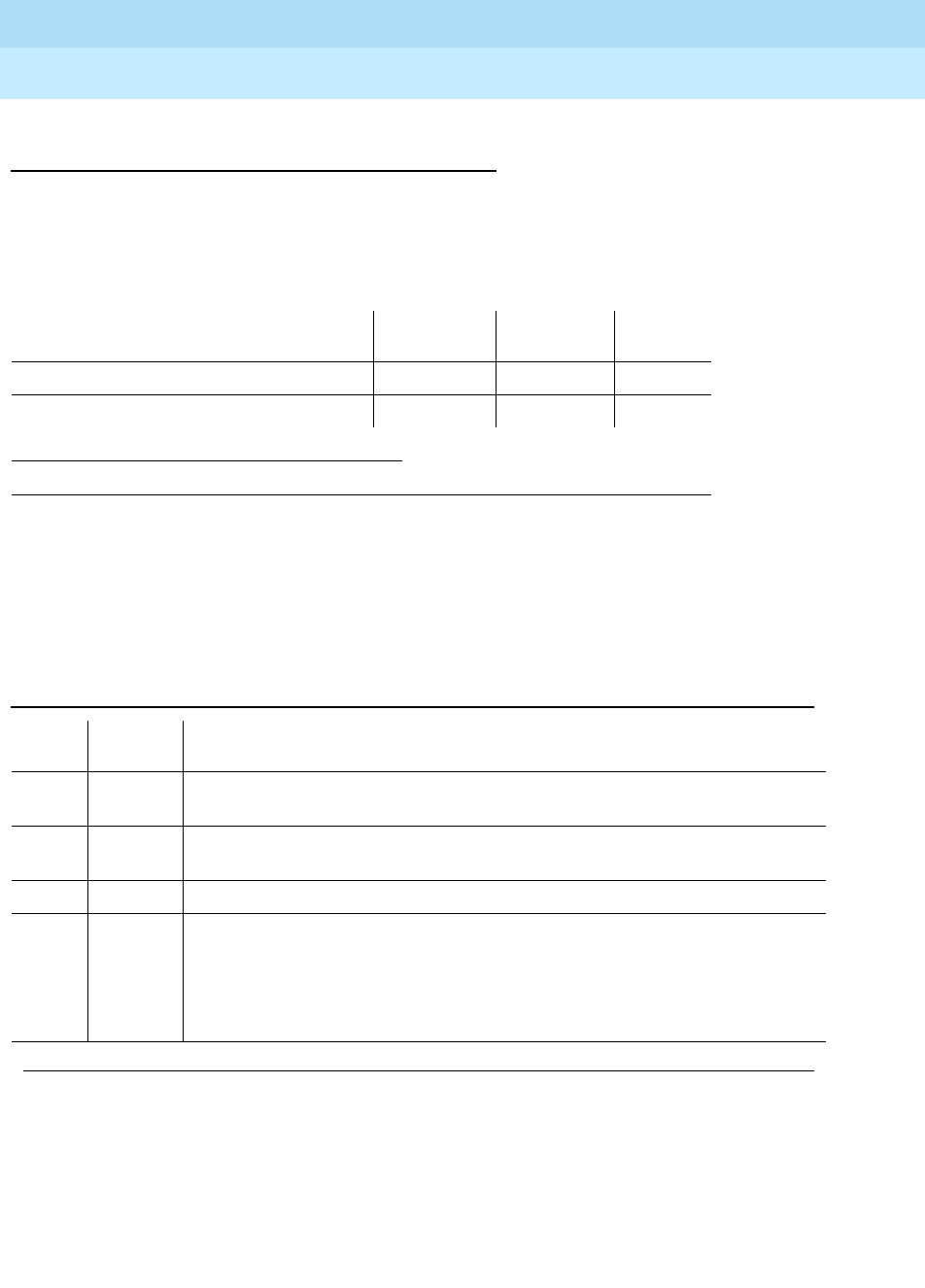
DEFINITY Enterprise Communications Server Release 6
Maintenance for R6r Volumes 1 & 2
555-230-126 Issue 2
January 1998
Maintenance Object Repair Procedures
Page 9-723GPTD-PT (General Purpose Tone Detector Port)
9
Technician-Demand Tests: Descriptions and
Error Codes
Always investigate tests in the order presented below when inspecting errors in
the system. By clearing error codes associated with the
Tone Detection
Verification Test,
for example, you may also clear errors generated from other
tests in the testing sequence.
Tone Detection Verification Test (#42)
This test verifies that the call progress tones detection and the tone level
measurement capabilities of the GPTD port are functioning properly.
1. D = Destructive; ND = Nondestructive
Order of Investigation Short Test
Sequence Long Test
Sequence D/ND1
Tone Detection Verification Test (#42) X X ND
Tone Detector Audit/Update Test (#43) X X ND
Table 9-240. TEST #42 Tone Detection Verification Test
Error
Code Test
Result Description/ Recommendation
ABORT The system was not able to allocate all the resources needed for this test or
there was an Internal system error.
1 ABORT The system could not allocate all the resources needed to test the call progress
tones.
1001 ABORT The system was unable to put the GPTD port in the appropriate mode to test it.
1002 ABORT The system could not allocate time slots for the test connection. This can
happen when the system is heavily loaded. If the system is not heavily loaded,
then test the TDM-BUS via the test tdm [1|2] command. Refer to “TDM-BUS” for
details.
1. Retry the command at 1-minute intervals a maximum of 5 times.
Continued on next page

DEFINITY Enterprise Communications Server Release 6
Maintenance for R6r Volumes 1 & 2
555-230-126 Issue 2
January 1998
Maintenance Object Repair Procedures
Page 9-724GPTD-PT (General Purpose Tone Detector Port)
9
1003 ABORT The system could not allocate a Tone-Clock for the test connection. This may be
caused by a heavy load on the system or by a faulted Tone-Clock.
1. Check to see if there are any alarms against the Tone-Clock in the port
network where the test aborted. If so refer to the recommended procedures
for TONE-BD or TONE-PT.
2. If a new Tone-Clock has been inserted, allow about 1 minute for
maintenance to run on the newly inserted circuit pack.
3. Retry the command at 1-minute intervals a maximum of 5 times.
2000 ABORT Response to the test request was not received within the allowable time period.
1. Retry the command at 1-minute intervals a maximum of 5 times.
2006 ABORT The active Tone-Clock circuit pack or a Tone Detector circuit pack may not be
functioning properly.
1. Test the
active
Tone-Clock circuit pack in the port network with the test
tone-clock UUC command and refer to the "TONE-BD (Tone-Clock Circuit
Pack)" section for failures.
2. Retry the command at 1-minute intervals up to 5 times.
2100 ABORT Could not allocate the necessary system resources to run this test.
Retry the command at 1-minute intervals a maximum of 5 times.
101-1
22 FAIL 1. Run the Short Test Sequence: test port UUCSSpp sh r 1.
2. If the problem persists, the system is still operating properly but system
capacity will be reduced. In order to restore the system performance to
normal, replace the tone detector circuit pack containing the defective
GPTD port.
1022 FAIL Tone detection for the system is administered as part of a wideband
configuration, and the tone detector is not a TN420C (the only circuit pack with
this capability). GPTD ports on other types of tone detector circuit packs are
taken out of service since they cannot provide the administered function.
1. Change the tone-detection mode administered on the system-parameters
country-options form (see
DEFINITY Enterprise Communications Server
Release 5.4 Administration and Feature Description)
or remove all
non-TN420C tone detector circuit packs from the system.
PASS Tone Detection Verification is successful. The GPTD port is able to detect all call
progress tones and perform level measurements of test tones.
Table 9-240. TEST #42 Tone Detection Verification Test — Continued
Error
Code Test
Result Description/ Recommendation
Continued on next page

DEFINITY Enterprise Communications Server Release 6
Maintenance for R6r Volumes 1 & 2
555-230-126 Issue 2
January 1998
Maintenance Object Repair Procedures
Page 9-725GPTD-PT (General Purpose Tone Detector Port)
9
Tone Detector Audit/Update Test (#43)
The GPTD port is refreshed with all time slot information and sanity audit is
performed on the GPTD port
Table 9-241. TEST #43 Tone Detector Audit/Update Test
Error
Code Test
Result Description/ Recommendation
ABORT The system was not able to allocate the resources needed for this test.
1. Wait 1 minute and try again.
2000 ABORT Response to the test request was not received within the allowable time
period.
2100 ABORT Could not allocate the necessary system resources to run this test.
1. Retry the command at 1-minute intervals a maximum of 5 times.
FAIL Hardware audit failed.
1. Run the Short Test Sequence: test port UUCSSpp short repeat 1.
2. If the problem persists, the system is still operating properly but system
capacity will be reduced. To restore the system performance to normal,
replace the Tone Detector circuit pack containing the defective GPTD
port.
PASS The GPTD port has been successfully refreshed with its translation.

DEFINITY Enterprise Communications Server Release 6
Maintenance for R6r Volumes 1 & 2
555-230-126 Issue 2
January 1998
Maintenance Object Repair Procedures
Page 9-726H-ADAPTR (MSS Host Adapter)
9
H-ADAPTR (MSS Host Adapter)
The Host Adapter circuit is located on the UN332 Mass Storage System/Network
Control circuit pack (MSSNET) and is part of the Mass Storage System (MSS)
which also contains the Switch Control (SW-CTL) circuit.. The MSS provides
non-volatile tape and disk storage for booting the PBX system and for saving
system translation data.
The Host Adapter circuit provides the interface between the Switch Processing
Element (SPE) system bus and the Small Computer System Interface (SCSI) bus.
The SCSI bus is an industry standard bus that connects a tape drive and disk
drive to the PBX.
Note that the red LED on the MSSNET board is shared by both the switch control
and host adapter circuits. A failure of either circuit will cause the LED to light. A
reset of the host adapter also causes this LED to light. A separate MO (SW-CTL)
and its associated tests are used for maintenance of the switch control circuit.
The tape and disk drives are treated as separate, but related, maintenance
objects (TAPE and DISK). Problems with the host adapter may affect the
operation of the tape and disk circuit packs.
When the host adapter is taken out of service because of a failure of a critical
host adapter test, or by use of the busyout command, the TAPE and DISK
maintenance objects are also placed in an out-of-service state.
In a system with duplicated SPEs, the tests run on the standby host adapter
circuit are identical to those run on the active host adapter circuit. The DUPINT
circuit pack handles communications between the active and standby SPEs for
both the control channel and memory shadowing. Therefore, problems with the
DUPINT circuit pack may affect maintenance tests of the standby host adapter
circuit pack.
Circuit Pack Replacement Procedures
If the MSSNET circuit pack needs to be replaced:
1. If the SPE is not duplicated:
1. In a system with a simplex SPE, the carrier need not be specified. In a system with duplicated
SPE s, carrier a or b must be specified.
MO Name (in
Alarm Log) Alarm Level Initial Command to Run1Full Name of MO
H-ADAPTR MINOR test host-adapter a|b long MSS Host Adapter
H-ADAPTR WARNING test host-adapter a|b long MSS Host Adapter
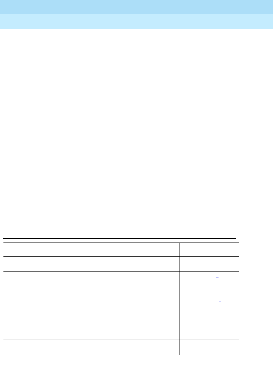
DEFINITY Enterprise Communications Server Release 6
Maintenance for R6r Volumes 1 & 2
555-230-126 Issue 2
January 1998
Maintenance Object Repair Procedures
Page 9-727H-ADAPTR (MSS Host Adapter)
9
2. Power down the SPE carrier by:
a. Remove the power plug from the left side of the carrier first.
b. Remove the second power plug from the right side of the carrier.
3. Replace the MSSNET circuit pack.
4. Power up the SPE carrier by:
a. Insert the power plug in the right side of the carrier first.
b. After inserting the first power plug in the right insert the second
power plug in the left side of the carrier.
5. Wait for the system to reboot.
c. Test the MSSNET circuit pack using the test mssnet long
command.
d. Verify that the tape and disk are in service by issuing the status
spe command.
6. If the SPE is duplicated:
a. Refer to "Replacing SPE Circuit Packs" in Chapter 5.
b. After the standby SPE is powered up and fully refreshed, test the
standby MSSNET circuit pack using the test mssnet long
command.
Error Log Entries and Test to Clear Values
Table 9-242. Host Adapter Error Log Entries
Error
Type Aux
Data1Associated Test Alarm
Level On/Off
Board Test to Clear Value
1(a) any Host Adapter
Hdwr Reset (#820) MINOR ON test host-ad a|b2 l
18 (b) 0 Busyout host-ad WARNING OFF rel host-ad a|b2
257(c) any Host Adapter Diag
(#823) WARNING ON test host-ad a|b2 l r 3
513(d) any Host Adapter Diag
(#823) MINOR ON test host-ad a|b2 l r 3
529(e) 0 Host Adapter Reset
(#893) WARNING ON reset host-ad a|b2
769(f) any Host Adapter
Looparound (#824) MINOR OFF test host-ad a|b2 sh r 2
1281(g) any Host Adapter Diag
(#823) MINOR OFF test host-ad a|b2 l r 2
Continued on next page
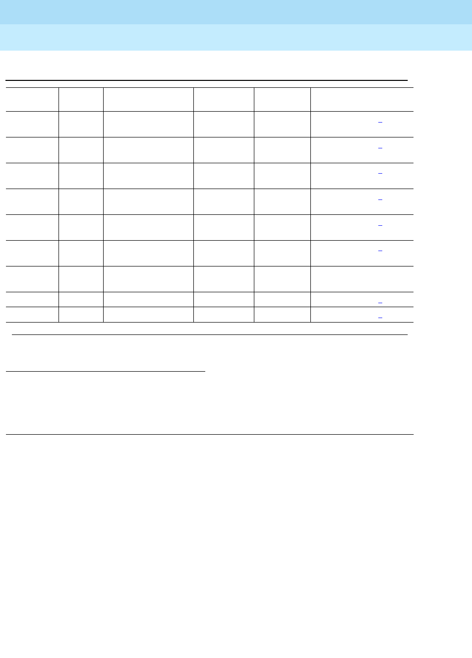
DEFINITY Enterprise Communications Server Release 6
Maintenance for R6r Volumes 1 & 2
555-230-126 Issue 2
January 1998
Maintenance Object Repair Procedures
Page 9-728H-ADAPTR (MSS Host Adapter)
9
The Service State field in the alarm log refers to the accessibility of the
device. IN (in service) means that users can access the device and all
maintenance tests will run. MTC (maintenance busy) means the device is busied
out; users cannot access it, but all maintenance tests will run. OUT (out of
service) means that users cannot access the device and background testing will
not run. Demand testing may or may not run depending on the severity of the
error.
Notes:
a. Indicates that the host adapter hardware is in a "held reset" state.
b. Indicates that the host adapter has been "busied out."
c. Indicates that non-critical host adapter diagnostics failed.
d. Indicates that critical host adapter diagnostics failed.
1. If error type 3585 with aux data of 5302 is present, this field will have the out of service cause data.
See the
MSS Error Actions
table at the end of the section on TAPE.
2. In a system with a simplex SPE, the carrier does not have to be specified. In a system with
duplicated SPE, the carrier (a or b) must be specified.
3. See the MSS Error Actions table at th end of the section on TAPE.
1793(h) any Host Adapter Diag
(#823) MINOR OFF test host-ad a|b2 l r 2
2049(i) any Host Adapter Diag
(#823) MINOR ON test host-ad a|b2 l r 2
2305(j) any Host Adapter Diag
(#823) MINOR ON test host-ad a|b2 l r 2
2561(k) any Host Adapter Diag
(#823) MINOR ON test host-ad a|b2 l r 2
2817(l) any Host Adapter
Hdwr Reset (#820) MINOR ON test host-ad a|b2 l 2
3073(m) any Host Adapter
Status (#825) WARNING OFF test host-ad a|b2 sh 2
3329(n) any Host Adapter
Hdwr Reset (#820) WARNING OFF test host-ad a|b l r 4
3585(o) any In line errors MINOR ON test host-ad a|b2 l r 2
3841(p) 3Miscellaneous WARNING OFF test host-ad a|b2 l r 1
Table 9-242. Host Adapter Error Log Entries — Continued
Error
Type Aux
Data1Associated Test Alarm
Level On/Off
Board Test to Clear Value
Continued on next page

DEFINITY Enterprise Communications Server Release 6
Maintenance for R6r Volumes 1 & 2
555-230-126 Issue 2
January 1998
Maintenance Object Repair Procedures
Page 9-729H-ADAPTR (MSS Host Adapter)
9
e. Indicates that the Host Adapter Reset (#820 or #893) failed or that the
hardware is in a "held reset" state.
f. Indicates that the Host Adapter Looparound Test (#824) failed.
g. Indicates that the host adapter detected a processor bus error.
h. Indicates that the host adapter could not access SCSI memory.
i. Indicates that the host adapter detected an illegal command or a
command was aborted.
j. Indicates that the host adapter detected an internal firmware or OS
software error.
k. Indicates that the host adapter detected an interrupt or exception.
l. Indicates that the host adapter detected a flash prom programming error.
m. Indicates that the Host Adapter Status Test (#825) detected an error in the
host adapter configuration status or in the LED status test. See the
MSS
Error Actions
table at the end of the section on TAPE.
n. Indicates internal host adapter software errors.
o. Indicates in-line errors reported by the host adapter firmware. See the
MSS Error Actions
table at the end of the section on TAPE.
p. This is used to record miscellaneous data when an out-of-service
condition occurs. See the
MSS Error Actions
table at the end of the section
on TAPE.
System Technician-Demanded Tests:
Descriptions and Error Codes
Always investigate tests in the order presented in the table below. By clearing
error codes associated with the
Host Adapter Diagnostic Test
, for example, you
may also clear errors generated from other tests in the testing sequence.
Table 9-243. System Technician-Demanded Tests: DS1-BD
Order of Investigation Short Test
Sequence Long Test
Sequence Reset Board
Sequence D/ND1
Host Adapter Reset Test (#820) X ND
Host Adapter Diagnostic Test (#823) X X ND
Host Adapter Looparound Test (#824) X X ND
Host Adapter Status Test (#825) X X ND
Continued on next page

DEFINITY Enterprise Communications Server Release 6
Maintenance for R6r Volumes 1 & 2
555-230-126 Issue 2
January 1998
Maintenance Object Repair Procedures
Page 9-730H-ADAPTR (MSS Host Adapter)
9
Host Adapter Reset Test (#820 and #893)
The Reset Test #820 resets the host adapter circuit on the MSSNET circuit pack
and runs an initialization test. The initialization test is similar to the Diagnostic
Test #823 with two exceptions: a test is run on the host adapter dual port RAM
during the reset test and a test involving system bus mastership is run during the
diagnostic test.
The reset test can be run in two ways: as a part of the long host adapter test
sequence (test host-adapter long) or as a result of the reset host adapter
command (reset host-adapter). Failure of the reset command causea the host
adapter to be placed in an internal "held reset" state. In this state the host
adapter will not run any background maintenance and will not respond to any
commands except a reset command. The only way to restore the host adapter to
service is for it to pass the reset command. Demand tests will not run until then.
If the reset test is requested as part of the long host adapter test sequence,
failure of the test causes the host adapter to be placed in a software
"out-of-service" state. From this state the host adapter can be restored to service
by either passing the long host adapter test sequence the proper number of
times or by passing the reset command. Refer to the Diagnostic Test #823 for a
more complete description of the test coverage.
1. D = Destructive, ND = Non-destructive
Host Adapter Firmware Error Counters X X ND
Read and Clear Test (#822)
Host Adapter Reset (#893) X ND
Table 9-243. System Technician-Demanded Tests: DS1-BD — Continued
Order of Investigation Short Test
Sequence Long Test
Sequence Reset Board
Sequence D/ND1
Continued on next page

DEFINITY Enterprise Communications Server Release 6
Maintenance for R6r Volumes 1 & 2
555-230-126 Issue 2
January 1998
Maintenance Object Repair Procedures
Page 9-731H-ADAPTR (MSS Host Adapter)
9
Table 9-244. TEST #820/#893 Host Adapter Reset Test
Error
Code Test
Result Description/ Recommendation
1316 ABORT Could not allocate the Mass Storage System to run this test. Other application
software may be using it or background maintenance tests may be running.
1. Retry the command at 1-minute intervals for a maximum of 5 retries.
2. If the test continues to abort, verify that the daily translation-save operation
is not in progress (issue the display system-parameters maintenance
command to display the time for scheduled maintenance and the "y/n"
option for saving translation daily).
1335 ABORT Could not run the test on the Standby SPE—Duplication not administered.
1. Refer to “STBY-SPE”.
2. Administer standby present.
1338 ABORT Could not run the test on the Standby SPE—Interchange pending.
1. Refer to “STBY-SPE”.
2. After interchange occurs, run test on new active SPE.
1339 ABORT Could not run the test on the Standby SPE—Handshake down.
1. Refer to “STBY-SPE”.
2. When the standby is restored to service (use status spe to determine
state of standby) retry the command.
1347 ABORT Could not run the test on the Standby SPE—Refresh not complete.
1. When the standby is restored to service (use status spe to determine
state of standby) retry the command.
1350 ABORT Could not run the test on the Standby SPE—Shadowing not enabled.
1. When the standby is restored to service (use status spe to determine
state of standby) retry the command.
2000 ABORT Response to the test request was not received within the allowable time period.
1. Retry the command at 1-minute intervals a maximum of 5 times.
2500 ABORT Could not run the test on the Standby SPE—Internal software error.
1. Retry the command at 1-minute intervals a maximum of 5 times.
5102 ABORT Could not allocate the Mass Storage System to run this test
1. Retry the command at 1-minute intervals a maximum of 5 times.
2. If the test continues to abort, verify that the daily translation-save operation
is not in progress (issue the display system-parameters maintenance
command to display the time for scheduled maintenance and the "y/n"
option for saving translation daily).
Continued on next page

DEFINITY Enterprise Communications Server Release 6
Maintenance for R6r Volumes 1 & 2
555-230-126 Issue 2
January 1998
Maintenance Object Repair Procedures
Page 9-732H-ADAPTR (MSS Host Adapter)
9
Host Adapter Read and Clear Firmware Error
Counters Test (#822)
The host adapter firmware constantly executes background testing of the host
adapter hardware. If any irregularities are detected, counters in dual port RAM
are incremented. The Read and Clear Firmware Error Counters test reads these
counters from the host adapter dual port RAM and increments the appropriate
software counters based on which ones are non-zero. The dual port RAM
counters are then cleared.
The firmware maintains sixteen counters that record the following errors:
■Unexpected interrupt from the SCSI Bus Interface Controller Chip
(SBICC).
■SBICC timed out during SCSI command.
■Direct Memory Access Controller (DMAC) generated error interrupt.
■DMAC timed out without interrupt.
■Universal Synchronous/Asynchronous Receiver/Transmitter (USART)
diagnostics failed.
■Host adapter LED test failed.
■Tape LED test failed.
1. See the MSS Error Actions table at th end of the section on TAPE.
NO
BOARD The host adapter has been placed in the "uninstalled" state.
1. Verify that the host adapter is fully inserted and powered up.
2. Attempt a demand reset of the host adapter.
1FAIL The host adapter could not be reset successfully.
1. Retry the command after 1 minute.
2. If the test fails, issue the reset host-adapter command.
3. If the command fails, replace the MSSNET circuit pack (see the circuit
pack replacement section above) and issue the test mssnet long
command.
PASS The host adapter was reset correctly. Check results of other tests to see if it is
operating correctly.
Table 9-244. TEST #820/#893 Host Adapter Reset Test — Continued
Error
Code Test
Result Description/ Recommendation
Continued on next page

DEFINITY Enterprise Communications Server Release 6
Maintenance for R6r Volumes 1 & 2
555-230-126 Issue 2
January 1998
Maintenance Object Repair Procedures
Page 9-733H-ADAPTR (MSS Host Adapter)
9
■Disk LED test failed.
■Processor bus dual port RAM test failed.
■Processor bus IO registers test failed.
■External host adapter loop around failed.
■Illegal SCSI target controller requested.
■Interrupt during processor bus access.
■Bus timeout during processor bus access.
■Parity error during processor bus access.
■Error Detection and Correction (EDC) error during processor bus access.
Table 9-245. TEST #822 Host Adapter Read and Clear Firmware
Error Counters Test
Error
Code Test
Result Description/ Recommendation
1311 ABORT Could not read the firmware error counters
1. Retry the command at 1-minute intervals a maximum of 5 retries.
1316 ABORT Could not allocate the Mass Storage System to run this test. Other application
software may be using it or background maintenance tests may be running.
1. Retry the command at 1-minute intervals for a maximum of 5 retries.
2. If the test continues to abort, verify that the daily translation-save operation
is not in progress (issue the display system-parameters maintenance
command to display the time for scheduled maintenance and the "y/n"
option for saving translation daily).
1335 ABORT Could not run the test on the Standby SPE—Duplication not administered.
1. Refer to “STBY-SPE”.
2. Administer standby present.
1338 ABORT Could not run the test on the Standby SPE—Interchange pending.
1. Refer to “STBY-SPE”.
2. After interchange occurs, run test on new active SPE.
1339 ABORT Could not run the test on the Standby SPE—Handshake down.
1. Refer to “STBY-SPE”.
2. When the standby is restored to service (use status spe to determine
state of standby) retry the command.
1347 ABORT Could not run the test on the Standby SPE—Refresh not complete.
1. When the standby is restored to service (use status spe to determine
state of standby) retry the command.
Continued on next page

DEFINITY Enterprise Communications Server Release 6
Maintenance for R6r Volumes 1 & 2
555-230-126 Issue 2
January 1998
Maintenance Object Repair Procedures
Page 9-734H-ADAPTR (MSS Host Adapter)
9
Host Adapter Diagnostic Test (#823)
The Host Adapter Diagnostic test runs a set of non-destructive diagnostic tests
for the Host Adapter. This includes tests requiring system bus mastership.
Specific tests include:
1. See the MSS Error Actions table at th end of the section on TAPE.
1350 ABORT Could not run the test on the Standby SPE—Shadowing not enabled.
1. When the standby is restored to service (use status spe to determine
state of standby) retry the command.
2000 ABORT Response to the test request was not received within the allowable time period.
1. Retry the command at 1-minute intervals a maximum of 5 retries.
2500 ABORT Could not run the test on the Standby SPE—Internal software error.
1. Retry the command at 1-minute intervals a maximum of 5 retries.
5102 ABORT Could not allocate the Mass Storage System to run this test
1. Retry the command at 1-minute intervals for a maximum of 5 retries.
2. If the test continues to abort, verify that the daily translation-save operation
is not in progress (issue the display system-parameters maintenance
command to display the time for scheduled maintenance and the "y/n"
option for saving translation daily).
NO
BOARD The host adapter has been placed in the "uninstalled" state.
1. Verify that the host adapter is fully inserted and powered up.
2. Attempt a demand reset of the host adapter.
1FAIL The Read and Clear Firmware Error Counters test detected a non-zero
firmware error counter.
1. Retry the command at 1-minute intervals a maximum of 5 retries.
2. If the command continues to fail, replace the MSSNET circuit pack (see
the circuit pack replacement section above) and issue the test mssnet
long command.
PASS The Read and Clear Firmware Error Counters test completed successfully
without detecting a non-zero firmware error counter. Look at the results of other
tests to see if it is operating correctly.
Table 9-245. TEST #822 Host Adapter Read and Clear Firmware
Error Counters Test — Continued
Error
Code Test
Result Description/ Recommendation
Continued on next page

DEFINITY Enterprise Communications Server Release 6
Maintenance for R6r Volumes 1 & 2
555-230-126 Issue 2
January 1998
Maintenance Object Repair Procedures
Page 9-735H-ADAPTR (MSS Host Adapter)
9
■Micro processor testing including exception processing
■Private RAM test
■EPROM and FLASHPROM checksum test
■SPE side Dual Port RAM test
■Control and status register test
■System memory access test
■SCSI bus access test
■SCSI memory access test
■Sanity timer test
■SCSI side Dual Port RAM test
A more complete test of the access to the disk and tape drives over the SCSI bus
is provided by the DISK and TAPE tests.
Table 9-246. TEST #823 Host Adapter Diagnostic Test
Error
Code Test
Result Description/ Recommendation
1316 ABORT Could not allocate the Mass Storage System to run this test. Other application
software may be using it or background maintenance tests may be running.
1. Retry the command at 1-minute intervals for a maximum of 5 retries.
2. If the test continues to abort, verify that the daily translation-save operation
is not in progress (issue the display system-parameters maintenance
command to display the time for scheduled maintenance and the "y/n"
option for saving translation daily).
1335 ABORT Could not run the test on the Standby SPE—Duplication not administered.
1. Refer to “STBY-SPE”.
2. Administer standby present.
1338 ABORT Could not run the test on the Standby SPE—Interchange pending.
1. Refer to “STBY-SPE”.
2. After interchange occurs, run test on new active SPE.
1339 ABORT Could not run the test on the Standby SPE—Handshake down.
1. Refer to “STBY-SPE”.
2. When the standby is restored to service (use status spe to determine state
of standby) retry the command.
Continued on next page

DEFINITY Enterprise Communications Server Release 6
Maintenance for R6r Volumes 1 & 2
555-230-126 Issue 2
January 1998
Maintenance Object Repair Procedures
Page 9-736H-ADAPTR (MSS Host Adapter)
9
Host Adapter Looparound Test (#824)
The Host Adapter Looparound test provides a partial functional test which
verifies that the host adapter can perform data transfer functions.
This test performs two subtests:
1. See the MSS Error Actions table at th end of the section on TAPE.
1347 ABORT Could not run the test on the Standby SPE—Refresh not complete.
1. When the standby is restored to service (use status spe to determine state
of standby) retry the command.
1350 ABORT Could not run the test on the Standby SPE—Shadowing not enabled.
1. When the standby is restored to service (use status spe to determine state
of standby) retry the command.
2000 ABORT Response to the test was not received within the allowable time period.
1. Retry the command at 1-minute intervals for a maximum of 5 retries.
2500 ABORT Could not run the test on the Standby SPE—Internal software error.
1. Retry the command at 1-minute intervals a maximum of 5 retries.
5102 ABORT Could not allocate the Mass Storage System to run this test
1. Retry the command at 1-minute intervals a maximum of 5 retries.
2. If the test continues to abort, verify that the daily translation-save operation
is not in progress (issue the display system-parameters maintenance
command to display the time for scheduled maintenance and the "y/n"
option for saving translation daily).
NO
BOARD The host adapter has been placed in the "uninstalled" state.
1. Verify that the host adapter is fully inserted and powered up.
2. Attempt a demand reset of the host adapter.
1FAIL The Host Adapter Diagnostic test could not be run successfully.
1. Replace the MSSNET circuit pack (see the circuit pack replacement
section above) and issue the test mssnet long command.
PASS The Host Adapter Diagnostic Test completed successfully. Look at the results
of other tests to see if it is operating correctly.
Table 9-246. TEST #823 Host Adapter Diagnostic Test — Continued
Error
Code Test
Result Description/ Recommendation
Continued on next page

DEFINITY Enterprise Communications Server Release 6
Maintenance for R6r Volumes 1 & 2
555-230-126 Issue 2
January 1998
Maintenance Object Repair Procedures
Page 9-737H-ADAPTR (MSS Host Adapter)
9
■Internal loop-around test
■External loop-around test
Note that this test is entirely contained in the host adapter and does not test
access to the system.
Table 9-247. TEST #824 Host Adapter Looparound Test
Error
Code Test
Result Description/ Recommendation
1316 ABORT Could not allocate the Mass Storage System to run this test. Other application
software may be using it or background maintenance tests may be running.
1. Retry the command at 1-minute intervals a maximum of 5 retries.
2. If the test continues to abort, verify that the daily translation-save operation
is not in progress (issue the display system-parameters maintenance
command to display the time for scheduled maintenance and the "y/n"
option for saving translation daily).
1335 ABORT Could not run the test on the Standby SPE—Duplication not administered.
1. Refer to “STBY-SPE”.
2. Administer standby present.
1338 ABORT Could not run the test on the Standby SPE—Interchange pending.
1. Refer to “STBY-SPE”.
2. After interchange occurs, run test on new active SPE. 3)
1339 ABORT Could not run the test on the Standby SPE—Handshake down.
1. Refer to “STBY-SPE”.
2. When the standby is restored to service (use status spe to determine state
of standby) retry the command.
1347 ABORT Could not run the test on the Standby SPE—Refresh not complete.
1. When the standby is restored to service (use status spe to determine state
of standby) retry the command.
1350 ABORT Could not run the test on the Standby SPE—Shadowing not enabled.
1. When the standby is restored to service (use status spe to determine state
of standby) retry the command.
2000 ABORT Response to the test was not received within the allowable time period.
1. Retry the command at 1-minute intervals a maximum of 5 retries.
2500 ABORT Could not run the test on the Standby SPE—Internal software error.
1. Retry the command at 1-minute intervals for a maximum of 5 retries.
Continued on next page

DEFINITY Enterprise Communications Server Release 6
Maintenance for R6r Volumes 1 & 2
555-230-126 Issue 2
January 1998
Maintenance Object Repair Procedures
Page 9-738H-ADAPTR (MSS Host Adapter)
9
Host Adapter Status Test (#825)
This test verifies the following host adapter circuit operations:
■The LED s on the MSSNET circuit pack can be turned on and off correctly.
Note that this only verifies that the control and status logic for the LED s is
operating correctly. The operation of the LED s may be tested visually by
using the test led command.
■The MSS configuration information is correct (the host adapter is not in the
"held reset" state).
1. See the MSS Error Actions table at th end of the section on TAPE.
5102 ABORT Could not allocate the Mass Storage System to run this test
1. Retry the command at 1-minute intervals a maximum of 5 retries.
2. If the test continues to abort, verify that the daily translation-save operation
is not in progress (issue the display system-parameters maintenance
command to display the time for scheduled maintenance and the "y/n"
option for saving translation daily).
NO
BOARD The host adapter has been placed in the "uninstalled" state.
1. Verify that the host adapter is fully inserted and powered up.
2. Attempt a demand reset of the host adapter.
1FAIL The host adapter loop around test could not be run successfully.
1. Replace the MSSNET circuit pack (see the circuit pack replacement
section above) and issue the test mssnet long command.
PASS The host adapter loop around Test completed successfully. Look at the results
of other tests to see if it is operating correctly.
Table 9-247. TEST #824 Host Adapter Looparound Test — Continued
Error
Code Test
Result Description/ Recommendation
Continued on next page

DEFINITY Enterprise Communications Server Release 6
Maintenance for R6r Volumes 1 & 2
555-230-126 Issue 2
January 1998
Maintenance Object Repair Procedures
Page 9-739H-ADAPTR (MSS Host Adapter)
9
Table 9-248. TEST #825 Host Adapter Status Test
Error
Code Test
Result Description/ Recommendation
1312
1313
1314
ABORT Internal software error between maintenance software and mss driver.
1. Retry the command at 1-minute intervals for a maximum of 5 retries.
1316 ABORT Could not allocate the Mass Storage System to run this test. Other application
software may be using it or background maintenance tests may be running.
1. Retry the command at 1-minute intervals for a maximum of 5 retries.
2. If the test continues to abort, verify that the daily translation-save operation
is not in progress (issue the display system-parameters maintenance
command to display the time for scheduled maintenance and the "y/n"
option for saving translation daily).
1335 ABORT Could not run the test on the Standby SPE—Duplication not administered.
1. Refer to “STBY-SPE”.
2. Administer standby present.
1338 ABORT Could not run the test on the Standby SPE—Interchange pending.
1. Refer to “STBY-SPE”.
2. After interchange occurs, run test on new active SPE.
1339 ABORT Could not run the test on the Standby SPE—Handshake down.
1. Refer to “STBY-SPE”.
2. When the standby is restored to service (use status spe to determine state
of standby) retry the command.
1347 ABORT Could not run the test on the Standby SPE—Refresh not complete.
1. When the standby is restored to service (use status spe to determine state
of standby) retry the command.
1350 ABORT Could not run the test on the Standby SPE—Shadowing not enabled.
1. When the standby is restored to service (use status spe to determine state
of standby) retry the command.
2000 ABORT Response to the test request was not received within the allowable time period.
1. Retry the command at 1-minute intervals for a maximum of 5 retries.
2500 ABORT Could not run the test on the Standby SPE—Internal software error
1. Retry the command at 1-minute intervals for a maximum of 5 retries.
Continued on next page

DEFINITY Enterprise Communications Server Release 6
Maintenance for R6r Volumes 1 & 2
555-230-126 Issue 2
January 1998
Maintenance Object Repair Procedures
Page 9-740H-ADAPTR (MSS Host Adapter)
9
Host Adapter Reset Test (#893)
The Host Adapter Reset Test #893 is run on demand in response to the reset
host-adapter command. This test resets the host adapter circuit on the MSSNET
circuit pack and runs an initialization test.
Failure of the reset command will cause the host adapter to be placed in an
internal "held reset" state. In this state the host adapter will not run any
background maintenance and will not respond to any commands except a reset
command. The only way to restore the host adapter to service is for it to pass the
reset command. Demand tests will not run until then.
The test results for Test 893 are the same as those for Test 820. Refer to the
information presented for Test 820 for the appropriate repair procedures.
1. See the MSS Error Actions table at th end of the section on TAPE.
5102 ABORT Could not allocate the Mass Storage System to run this test
1. Retry the command at 1-minute intervals for a maximum of 5 retries.
2. If the test continues to abort, verify that the daily translation-save operation
is not in progress (issue the display system-parameters maintenance
command to display the time for scheduled maintenance and the "y/n"
option for saving translation daily).
NO
BOARD The host adapter has been placed in the "uninstalled" state.
1. Verify that the host adapter is fully inserted and powered up.
2. Attempt a demand reset of the host adapter.
1FAIL The host adapter status test could not be run successfully.
1. Replace the MSSNET circuit pack (see the circuit pack replacement
section above) and issue the test mssnet long command.
PASS The host adapter status test completed successfully. Look at the results of other
tests to see if it is operating correctly.
Table 9-248. TEST #825 Host Adapter Status Test — Continued
Error
Code Test
Result Description/ Recommendation
Continued on next page
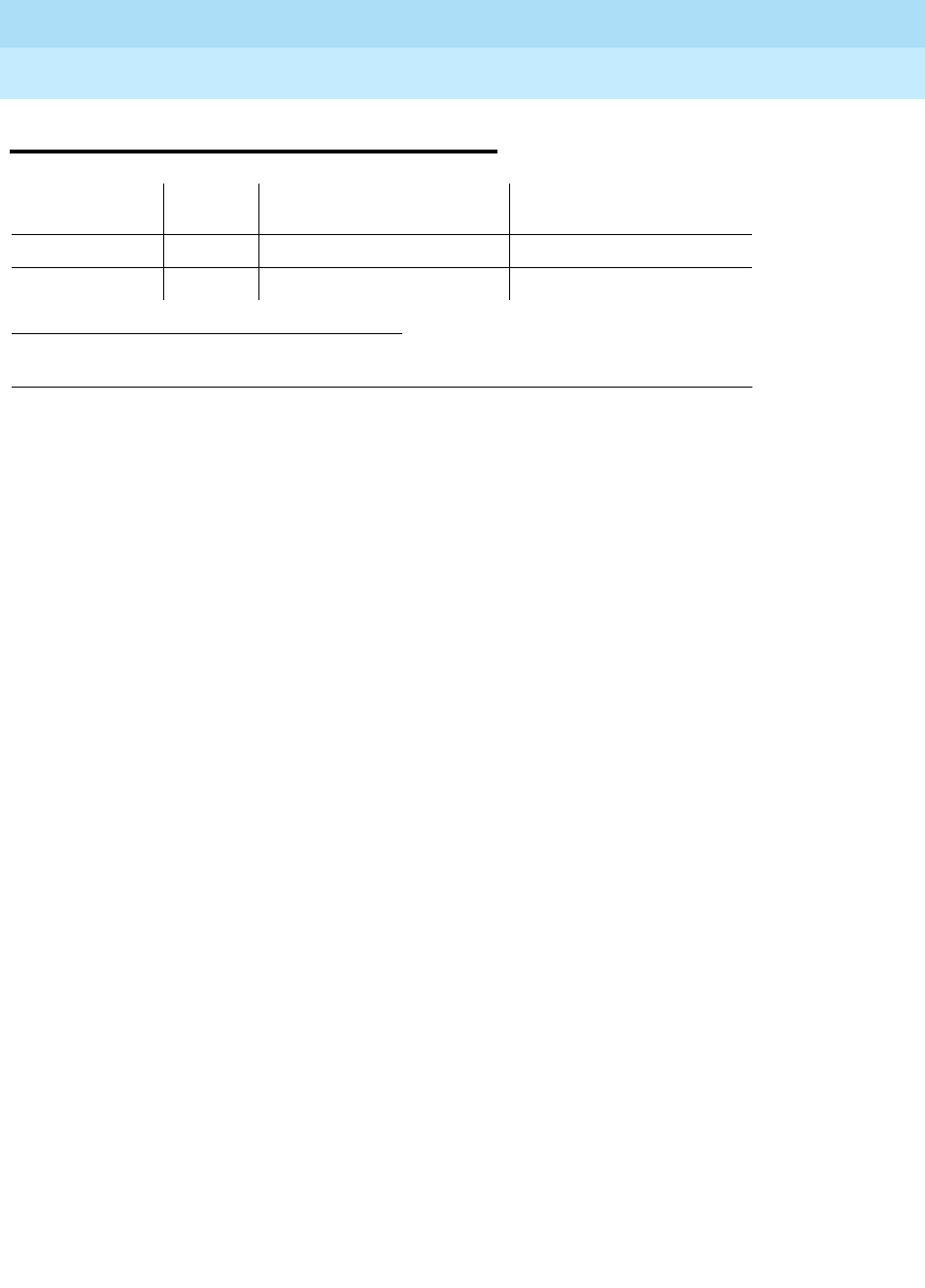
DEFINITY Enterprise Communications Server Release 6
Maintenance for R6r Volumes 1 & 2
555-230-126 Issue 2
January 1998
Maintenance Object Repair Procedures
Page 9-741HYB-BD (Hybrid Line Circuit Pack)
9
HYB-BD (Hybrid Line Circuit Pack)
Refer to XXX-BD (Common Port Circuit Pack) Maintenance documentation for
circuit pack level errors. See also HYB-LINE (Hybrid Line) Maintenance
documentation for related line information.
1. UU is the universal cabinet number (1 for PPN, 2 - 44 for EPN s). C is the carrier designation
(A, B, C, D, or E). SS is the number of the slot in which the circuit pack resides (01 to 21).
MO Name (in
Alarm Log) Alarm
Level Initial Command to Run1Full Name of MO
HYB-BD MIN test board UUCSS sh Hybrid Line Circuit Pack
HYB-BD WRN test board UUCSS sh Hybrid Line Circuit Pack

DEFINITY Enterprise Communications Server Release 6
Maintenance for R6r Volumes 1 & 2
555-230-126 Issue 2
January 1998
Maintenance Object Repair Procedures
Page 9-742HYB-LINE (Hybrid Line)
9
HYB-LINE (Hybrid Line)
Hybrid Line is another term for the Multi-Function Analog Telephone (MFAT). The
Hybrid Line set is also known as an SCS (Small Communications System).
The TN762B Hybrid Line circuit pack supports eight of these multifunction
analog telephone sets. The Hybrid Line sets use three pairs of wires: an analog
voice pair, a transmit/receive pair, and a power pair.
This section describes HYB-LINE (Hybrid Line) maintenance. HYB-LINE
maintenance is closely related to, and sometimes interacts with, HYB-BD (Hybrid
Line circuit pack) maintenance. This interaction should be kept in mind when
troubleshooting Hybrid Line problems.
This section occasionally refers to a station’s service state. These service states
are defined as follows:
Use status station to determine terminal service state. Status is reported as
either out-of-service, in-service, or disconnect. The latter is equivalent to the
ready-for-service state.
1. UU is the universal cabinet number (1 for PPN, 2 - 44 for EPN s). C is the carrier designation
(A, B, C, D, or E). SS is the number of the slot in which the circuit pack resides (01 to 21). pp
is the two digit port number (01, 02, ...).
MO Name (in
Alarm Log) Alarm Level Initial Command to Run1Full Name of MO
HYB-LINE Minor test port UUCSSpp l Hybrid Line
HYB-LINE Warning test port UUCSSpp l Hybrid Line
Out-of-Service The port, and thus the station, have been removed from
service. A busyout of a port will cause it to be
out-of-service.
Ready-for-Service The port on the circuit pack has been put into service,
but the voice terminal has not yet established signaling
communications with the port.
In-Service The voice terminal has established signaling
communications with the port, and the system is ready
to process calls to and from that station. A terminal in
the ready-for-service state will progress to the
in-service state if it is functioning normally, but it can
also be forced into the in-service state if it goes
off-hook.

DEFINITY Enterprise Communications Server Release 6
Maintenance for R6r Volumes 1 & 2
555-230-126 Issue 2
January 1998
Maintenance Object Repair Procedures
Page 9-743HYB-LINE (Hybrid Line)
9
Error Log Entries and Test to Clear Values
Notes:
a. The data link between the port and the terminal is not operational. (An
off-board problem was detected by port circuit). Verify that the Hybrid set
is connected and that the Electronic Power Feed (EPF) test passes. If data
transmission problems are experienced, check for defective wiring or a
defective voice terminal, or move terminal closer to the switch (reduce the
1. Run the Short Test Sequence first. If all tests pass, run the Long Test Sequence. Refer to the
appropriate test description and follow the recommended procedures.
2. Major or minor alarms may be downgraded to Warning alarms based on the value used in the set
options command.
Table 9-249. Hybrid Line Error Log Entries
Error
Type Aux
Data Associated Test Alarm
Level On/Off
Board Test to Clear Value
010 Any Any Any test port UUCSSpp sh r 1
1(a) 40987 None WARNING OFF
15(j) Any Hybrid Line Audits
Test(#161)
18(b) 0 busyout port
UUCSSpp WARNING OFF release port UUCSSpp
130(c) None WARNING ON test port UUCSSpp sh
257(d) 40988 None MIN/WRN OFF
513(e) 40965 Hybrid Line Audits
Test (#61) WARNING OFF test port UUCSSpp sh r 4
769(f) Remote Dig
Looparound Test
(#59)
WARNING OFF test port UUCSSpp sh r 3
1025 Hybrid & Conf.
Circuits Test (#57) MIN/WRN ON test port UUCSSpp l r 3
1281(f) Local Digital
Looparound Test
(#58)
WARNING ON test port UUCSSpp l r 3
1537(g) 40968 None WARNING OFF
1793 TDM NPE Crosstalk
Test (#6 MIN/WRN2ON test port UUCSSpp l r 3
2049(h) 32770 None
2049(i) 40967 None

DEFINITY Enterprise Communications Server Release 6
Maintenance for R6r Volumes 1 & 2
555-230-126 Issue 2
January 1998
Maintenance Object Repair Procedures
Page 9-744HYB-LINE (Hybrid Line)
9
length of the wiring between the terminal and the switch). If the problem
persists, replace the circuit pack. Once the problem has been resolved,
the alarm will be retired after a predetermined delay.
b. Error type 18 indicates the port is busied out. The port is released with
release port UUCSSpp.
c. The circuit pack has been removed or has been insane for more than 11
minutes. To clear the error, reinsert or replace the circuit pack.
d. The EPF has been turned off due to an overcurrent condition at the voice
terminal. Check for defective wiring or a damaged jack, and make sure
the voice terminal is a Hybrid set. Once the problem has been resolved,
the alarm will be retired after a predetermined delay.
e. The voice terminal has been disconnected or there is a problem in the
wiring to the terminal. Make sure that the voice terminal is connected or
check for defective wiring to the voice terminal.
f. Note that Error Types 769 and 1281 by themselves create Warning alarms
only, but if both are present, a Minor alarm will be logged.
g. The port has reported a problem with the data link to the voice terminal.
Ignore this error if there are no complaints about the voice terminal.
Otherwise, make sure the voice terminal is connected, check for defective
wiring, check for a defective voice terminal, and decrease the length of
the wiring between the voice terminal and the switch. If the problem
persists, replace the circuit pack.
h. The voice terminal went off-hook while in the disconnect state. Use the
status station command to determine the state of the terminal. The
off-hook should have moved the terminal to in-service. No repair action is
necessary.
i. The link between the circuit pack and the voice terminal has been
successfully reset. No repair action is necessary.
j. Error 15 indicates a software audit error that does not indicate any
hardware malfunction. Run the short test sequence and investigate any
errors.

DEFINITY Enterprise Communications Server Release 6
Maintenance for R6r Volumes 1 & 2
555-230-126 Issue 2
January 1998
Maintenance Object Repair Procedures
Page 9-745HYB-LINE (Hybrid Line)
9
System Technician-Demanded Tests:
Descriptions and Error Codes
Always investigate tests in the order presented in the table below. By clearing
error codes associated with the
Local Digital Looparound Test,
for example, you
may also clear errors generated from other tests in the testing sequence.
NPE Crosstalk Test (#6)
The NPE Crosstalk Test verifies that this port’s NPE channel talks on the selected
time slot and never crosses over to time slots reserved for other connections. If
the NPE is not working correctly, one-way and noisy connections may be
observed. This test is part of a port’s Long Test Sequence and takes about 20 to
30 seconds to complete.
1. D = Destructive, ND = Non-destructive
Table 9-250. System Technician-Demanded Tests: DS1-BD
Order of Investigation Short Test
Sequence Long Test
Sequence D/ND1
NPE Crosstalk Test (#6) X ND
Hybrid Electronic Power Feed Test (#56) X ND
Hybrid Circuit and Conference Circuit Test (#57) X ND
Local Digital Looparound Test (#58) X ND
Remote Digital Looparound Test (#59) X X ND
Station Lamp Update Test (#60) X X ND
Station Audits Test (#61) X X ND
Ringer Update Test (#62) X X ND
Continued on next page
Table 9-251. TEST #6 NPE Crosstalk Test
Error
Code Test
Result Description/ Recommendation
ABORT Could not allocate the necessary system resources to run this test.
1. Retry the command at 1-minute intervals a maximum of 5 times.
Continued on next page

DEFINITY Enterprise Communications Server Release 6
Maintenance for R6r Volumes 1 & 2
555-230-126 Issue 2
January 1998
Maintenance Object Repair Procedures
Page 9-746HYB-LINE (Hybrid Line)
9
1000 ABORT System resources required to run this test are not available. The port may be
busy with a valid call. Use the display port UUCSSpp command to determine
the station extension number of the port. Use the status station command to
determine the service state of the port. If the port is in use, wait until the port is
idle before testing.
1. If the port status is idle, then retry the command at 1-minute intervals a
maximum of 5 times.
1001 ABORT Could not allocate the necessary system resources to run this test. This could
be a failure to seize the port.
1. Retry the command at 1-minute intervals a maximum of 5 times.
1002 ABORT The system could not allocate time slots for the test. The system may be under
heavy traffic conditions or it may have time slots out-of-service due to TDM-BUS
errors. Refer to “TDM-BUS” to diagnose TDM-BUS errors.
1. If system has no TDM-BUS errors and is not handling heavy traffic, repeat
test at 1-minute intervals a maximum of 5 times.
1003 ABORT The system could not allocate a tone receiver for the test. The system may be
oversized for the number of Tone Detectors present or some Tone Detectors
may be out-of-service.
1. Resolve any “TTR-LEV” errors in the Error Log.
2. Resolve any “TONE-PT” errors in the Error Log.
3. If neither condition exists, retry the test at 1-minute intervals a maximum of 5
times.
1004 ABORT The port was seized by a valid call during the test. The test has been aborted.
Use the display port UUCSSpp command to determine the station extension
number of the port. Use the status station command to determine the service
state of the port. If the port is in use, wait until the port is idle before testing.
1. Retry the command at 1-minute intervals a maximum of 5 times.
1018 ABORT Test disabled via administration. This only applies to analog stations.
The default for this field is ‘y,’ so you may want to determine why it has been
turned off for this station.
1. To enable test, set the Test field on the station administration screen for the
particular analog station being tested to ‘y.’ Use the change station
<extension> command.
2000 ABORT Response to the test request was not received within the allowable time period.
1. Retry the command at 1-minute intervals a maximum of 5 times.
Table 9-251. TEST #6 NPE Crosstalk Test — Continued
Error
Code Test
Result Description/ Recommendation
Continued on next page

DEFINITY Enterprise Communications Server Release 6
Maintenance for R6r Volumes 1 & 2
555-230-126 Issue 2
January 1998
Maintenance Object Repair Procedures
Page 9-747HYB-LINE (Hybrid Line)
9
Hybrid Electronic Power Feed Test (#56)
In this test, the software requests that the EPF be turned on for a given port. Then
hardware attempts to turn on the power unit from the station. If no current is
drawn, the station is probably not connected. If an overcurrent condition is
2020 ABORT The test did not run due to an already existing error on the specific port or a
more general circuit pack error.
1. Examine Error Log for existing errors against this port or the circuit pack
and attempt to diagnose the already existing error.
2100 ABORT Could not allocate the necessary system resources to run this test. This could
be due to a failure to seize the port.
1. Retry the command at 1-minute intervals a maximum of 5 times.
Any FAIL This test can fail due to on-board or off-board problems. Off-board problems of
concern include EXP-PN and EXP-INTF faults, TDM-BUS faults, and faults
associated with the tone detectors/tone generators. Clear all off-board
problems before replacing the board. Keep in mind that a TDM-BUS problem is
usually the result of a faulty board connected to the backplane or bent pins on
the backplane.
1. Resolve any “EXP-PN” and “EXP-INTF” errors in the error log.
2. Resolve any “TDM-BUS” errors in the error log.
3. Retest the board when the faults from steps 1 and 2 are cleared.
PASS The port is correctly using its allocated time slots. User-reported troubles on this
port should be investigated using other port tests and by examining station,
trunk, or external wiring.
0NO
BOARD The test could not relate the internal ID to the port (no board). This could be due
to incorrect translations, no board is inserted, an incorrect board is inserted, or
an insane board is inserted.
1. Check to ensure that the board translations are correct. Use the list config
command, and resolve any problems that are found.
2. If the board was found to be correctly inserted in step 1, issue the busyout
board command.
3. Issue the reset board command.
4. Issue the release busy board command.
5. Issue the test board long command. This should re-establish the linkage
between the internal ID and the port. If this is not the case, dispatch to
check to ensure that there is a valid board inserted.
Table 9-251. TEST #6 NPE Crosstalk Test — Continued
Error
Code Test
Result Description/ Recommendation
Continued on next page

DEFINITY Enterprise Communications Server Release 6
Maintenance for R6r Volumes 1 & 2
555-230-126 Issue 2
January 1998
Maintenance Object Repair Procedures
Page 9-748HYB-LINE (Hybrid Line)
9
sensed (that is, too much current is being drawn), this may indicate a short in the
loop or a defective voice terminal. A message is returned stating that either the
EPF was turned on successfully, or that an overcurrent condition exists. This test
is repeated once more 5 seconds later. If either test is not successful, the test will
abort (see first ABORT entry in Table 9-252).
Table 9-252. TEST #56 Hybrid Electronic Power Feed Test
Error
Code Test
Result Description/ Recommendation
ABORT Internal system error
1. Retry the command at 1-minute intervals a maximum of 5 times.
1000 ABORT System resources required to run this test are not available. The port may be
busy with a valid call. Use the display port UUCSSpp command to determine
the station extension number of the port. Use the status station command to
determine the service state of the port. If the port is in use, wait until the port is
idle before testing.
1. If the port status is idle, then retry the command at 1-minute intervals a
maximum of 5 times.
FAIL Internal system error
1. Retry the command at 1-minute intervals a maximum of 5 times.
PASS Electronic Power Feed test passed. The message to turn on the power to the
station was successfully sent to the port.
1. Although this test will never actually return a FAIL result except for the
Internal system error described above, it will log an error if the
overcurrent case is detected by the hardware. Check the Error Log for any
entries with Error Type 257 when the test has completed.
2. If Error Type 257 does not appear in the Error Log within 10 seconds after
completion of this test, it is safe to assume that the test sensed no problems
with the power to the station. To verify that the station is powered up
correctly, run a self-test on the station, if available, and check that all the
feature buttons are operating.
3. If Error Type 257 appears in the Error Log, this indicates some problem with
the power to the station. Check for a short in the wiring, a damaged jack, a
defective voice terminal, or an incorrect type of terminal.
Continued on next page

DEFINITY Enterprise Communications Server Release 6
Maintenance for R6r Volumes 1 & 2
555-230-126 Issue 2
January 1998
Maintenance Object Repair Procedures
Page 9-749HYB-LINE (Hybrid Line)
9
Hybrid Circuit and Conference Circuit Test (#57)
This test checks two different port circuit functions. The Hybrid Circuit test
performs an analog reflective looparound measurement on the port’s hybrid
circuitry. The conference circuit test performs a conference test on the port’s
NPE.
For the
Hybrid Circuit Test
results to be valid, a voice terminal must be
connected to the port being tested. The test instructs the on-board
microprocessor to put the port in analog reflective looparound mode.
The
Conference Test
is performed only if the Hybrid Test passes. The
Conference Circuit Test verifies that the Network Processing Element (NPE) is
able to correctly conference several test tones together.
0NO
BOARD The test could not relate the internal ID to the port (no board). This could be due
to incorrect translations, no board is inserted, an incorrect board is inserted, or
an insane board is inserted.
1. Check to ensure that the board translations are correct. Use the list config
command, and resolve any problems that are found.
2. If the board was found to be correctly inserted in step 1, issue the busyout
board command.
3. Issue the reset board command.
4. Issue the release busy board command.
5. Issue the test board long command. This should re-establish the linkage
between the internal ID and the port. If this is not the case, dispatch to
check to ensure that there is a valid board inserted.
Table 9-253. TEST #57 Hybrid Circuit and Conference Circuit Test
Error
Code Test
Result Description/ Recommendation
ABORT Could not allocate the necessary system resources to run this test.
1. Retry the command at 1-minute intervals a maximum of 5 times.
Continued on next page
Table 9-252. TEST #56 Hybrid Electronic Power Feed Test — Continued
Error
Code Test
Result Description/ Recommendation
Continued on next page

DEFINITY Enterprise Communications Server Release 6
Maintenance for R6r Volumes 1 & 2
555-230-126 Issue 2
January 1998
Maintenance Object Repair Procedures
Page 9-750HYB-LINE (Hybrid Line)
9
1000 ABORT System resources required to run this test are not available. The port may be
busy with a valid call. Use the display port UUCSSpp command to determine
the station extension number of the port. Use the status station command to
determine the service state of the port. If the port is in use, wait until the port is
idle before testing.
1. If the port status is idle, then retry the command at 1-minute intervals a
maximum of 5 times.
1001 ABORT Could not allocate the necessary system resources to run this test. This could
be a failure to seize the port.
1. Retry the command at 1-minute intervals a maximum of 5 times.
1002 ABORT The system could not allocate time slots for the test. The system may be under
heavy traffic conditions or it may have time slots out-of-service due to TDM-BUS
errors. Refer to “TDM-BUS” to diagnose TDM-BUS errors.
1. If system has no TDM-BUS errors and is not handling heavy traffic, repeat
test at 1-minute intervals a maximum of 5 times.
1003 ABORT The system could not allocate a tone receiver for the test. The system may be
oversized for the number of Tone Detectors present or some Tone Detectors
may be out-of-service.
1. Look for TTR-LEV errors in the Error Log. If present, refer to TTR-LEV (TTR
Level).
2. Look for TONE-PT errors in the Error Log. If present, refer to TONE-PT
(Tone Generator).
3. If neither condition exists, retry the test at 1-minute intervals a maximum of
5 times.
1004 ABORT The port was seized by a valid call during the test. The test has been aborted.
Use the display port UUCSSpp command to determine the station extension
number of the port. Use the status station command to determine the service
state of the port. If the port is in use, wait until the port is idle before testing.
1. Retry the command at 1-minute intervals a maximum of 5 times.
1392 ABORT This port is currently a TTI port and the test will not execute on it.
1. Verify that the port is a TTI port using either the display port command (the
display shows that the port is a TTI port) or the list config command (the
display shows a t for the port).
2. If either list config or display port indicate that the port is
not
a TTI port,
escalate the problem. If both commands indicate that the port is a TTI port,
the abort is correct, and no action is necessary.
2000 ABORT Response to the test request was not received within the allowable time period.
1. Retry the command at 1-minute intervals a maximum of 5 times.
Table 9-253. TEST #57 Hybrid Circuit and Conference Circuit Test — Continued
Error
Code Test
Result Description/ Recommendation
Continued on next page

DEFINITY Enterprise Communications Server Release 6
Maintenance for R6r Volumes 1 & 2
555-230-126 Issue 2
January 1998
Maintenance Object Repair Procedures
Page 9-751HYB-LINE (Hybrid Line)
9
2012 ABORT Internal system error.
1. Retry the command at 1-minute intervals a maximum of 5 times.
2100 ABORT The system could not allocate a tone generator for the test.
1. Look for TONE-PT errors in the Error Log. If present, refer to TONE-PT
(Tone Generator) Maintenance documentation.
2. If no TONE-PT errors appear in the Error Log, retry the test at 1-minute
intervals a maximum of 5 times.
2103 ABORT The system could not make the conference connection for the test.
1. Retry the command at 1-minute intervals a maximum of 5 times.
7 FAIL Conference Test failed. User may be able to use conference circuit without
difficulty in some cases. In other extreme cases, conference calling will be
totally restricted.
The failure may be due to off-board circumstances, the most common of which
is an off-hook occurring during the test. Also, check the error logs against the
GPTD-BD, the TONE-BD, and the TONE-PT.
1. This error can be caused by a disconnected terminal. First, ensure that the
terminal is connected and the wiring is OK.
2. Then, issue the display port and the status station commands to
determine if the station is idle. If it is idle, issue the test port command for
this port.
3. If test continues to fail, issue the busyout port and the release port
commands, and then retest the port.
4. It is possible that the port may still be functional from a user’s point of view.
Table 9-253. TEST #57 Hybrid Circuit and Conference Circuit Test — Continued
Error
Code Test
Result Description/ Recommendation
Continued on next page

DEFINITY Enterprise Communications Server Release 6
Maintenance for R6r Volumes 1 & 2
555-230-126 Issue 2
January 1998
Maintenance Object Repair Procedures
Page 9-752HYB-LINE (Hybrid Line)
9
Hybrid Line Local Digital Looparound Test (#58)
This test checks the control channel between the Switch Processing Element
(SPE) and the port’s digital circuitry. The SPE sends transparent data to the
on-board microprocessor and compares the data echoed back. This test is
repeated three times.
57 FAIL Hybrid Circuit Test failed. This could result in noisy or bad connections.
1. This error can be caused by a disconnected terminal. First, ensure that the
terminal is connected and the wiring is OK.
2. Run circuit pack tests to check the Tone Generator circuit pack and the
Tone Detector circuit pack using the test board UUCSS short command.
3. Resolve any problems that are detected on the Tone Generator circuit pack
or Tone Detector circuit pack.
4. If the Tone Generator and Tone Detector circuit packs are functioning
properly, and the test still fails, replace the Hybrid Line circuit pack.
NOTE:
If the Hybrid Circuit and Conference Circuit Test fails for all ports on a
circuit pack, a -5 volt power problem is indicated. The AC power unit may
be defective. The system may contain a TN752 power unit circuit pack
OR a 631DB AC power unit,
but not both types of power units.
To
investigate problems with a power unit, refer to “CARR-POW”.
PASS Hybrid Circuit and Conference Circuit Test passed. The hybrid circuitry is
transmitting properly.
1. If complaints still exist, investigate by using other port tests, and by
examining the station, wiring, and connections.
0NO
BOARD The test could not relate the internal ID to the port (no board). This could be due
to incorrect translations, no board inserted, an incorrect board inserted, or an
insane board inserted.
1. Check that the board translations are correct. Use the list config
command, and resolve any problems.
2. If the board was found to be correctly inserted in step 1, issue the busyout
board command.
3. Issue the reset board command.
4. Issue the release busy board command.
5. Issue the test board long command. This should re-establish the linkage
between the internal ID and the port. If this is not the case, check that there
is a valid board inserted.
Table 9-253. TEST #57 Hybrid Circuit and Conference Circuit Test — Continued
Error
Code Test
Result Description/ Recommendation
Continued on next page

DEFINITY Enterprise Communications Server Release 6
Maintenance for R6r Volumes 1 & 2
555-230-126 Issue 2
January 1998
Maintenance Object Repair Procedures
Page 9-753HYB-LINE (Hybrid Line)
9
Table 9-254. TEST #58 Hybrid Line Local
Digital Looparound Test
Error
Code Test
Result Description/ Recommendation
ABORT Internal system error.
1. Retry the command at 1-minute intervals a maximum of 5 times.
1000 ABORT System resources required to run this test are not available. The port may be
busy with a valid call. Use the display port UUCSSpp command to determine
the station extension number of the port. Use the status station command to
determine the service state of the port. If the port is in use, wait until the port is
idle before testing.
1. If the port status is idle, then retry the command at 1-minute intervals a
maximum of 5 times.
1004 ABORT The port was seized by a valid call during the test. The test has been aborted.
Use the display port UUCSSpp command to determine the station extension
number of the port. Use the status station command to determine the service
state of the port. If the port is in use, wait until the port is idle before testing.
1. Retry the command at 1-minute intervals a maximum of 5 times.
2000 ABORT Response to the test was not received within the allowable time period.
1. Retry the command at 1-minute intervals a maximum of 5 times.
1,2,3 FAIL The control channel between the processor and the port is not transmitting
properly. This port is not operable.
1. Retry the test.
2. If the failure still occurs, issue the busyout and the release busy
commands, and then retest.
3. If the failure is occurring on more than one port on the board, suspect the
board.
4. If the failure is occurring on several boards in the same carrier, escalate the
problem.
5. If the failure appears to be isolated to one port, check all wiring to the set
and all set connections.
6. Replace the circuit pack as a last resort.
PASS Hybrid Line Local Digital Looparound Test passed. The control channel is
transmitting properly.
1. If complaints still exist, investigate by using other circuit pack tests, and by
examining the station, wiring, and connections.
Continued on next page

DEFINITY Enterprise Communications Server Release 6
Maintenance for R6r Volumes 1 & 2
555-230-126 Issue 2
January 1998
Maintenance Object Repair Procedures
Page 9-754HYB-LINE (Hybrid Line)
9
Hybrid Line Remote Digital Looparound Test
(#59)
This test checks the digital control pair from the port circuit to the terminal. The
on-board microprocessor sends a message to the terminal and checks for a
proper return message. This test is repeated three times, with two out of the three
attempts passing being sufficient for this test to pass. This test will run if the
station is in-service or out-of-service.
0NO
BOARD The test could not relate the internal ID to the port (no board). This could be
due to incorrect translations, no board is inserted, an incorrect board is
inserted, or an insane board is inserted.
1. Check to ensure that the board translations are correct. Use the list config
command, and resolve any problems that are found.
2. If the board was found to be correctly inserted in step 1, issue the busyout
board command.
3. Issue the reset board command.
4. Issue the release busy board command.
5. Issue the test board long command. This should re-establish the linkage
between the internal ID and the port. If this is not the case, dispatch to
check to ensure that there is a valid board inserted.
Table 9-255. TEST #59 Hybrid Line Remote Digital Looparound Test
Error
Code Test
Result Description/ Recommendation
ABORT Internal system error
1. Retry the command at 1-minute intervals a maximum of 5 times.
Continued on next page
Table 9-254. TEST #58 Hybrid Line Local
Digital Looparound Test — Continued
Error
Code Test
Result Description/ Recommendation
Continued on next page

DEFINITY Enterprise Communications Server Release 6
Maintenance for R6r Volumes 1 & 2
555-230-126 Issue 2
January 1998
Maintenance Object Repair Procedures
Page 9-755HYB-LINE (Hybrid Line)
9
1 ABORT A request for a remote station audit aborted even though all internal resources
were correctly allocated.
1. Look in the error log for error type 18 (port busied out) for this port. If this
error type is present, release the port via the release port UUCSSpp
command or the release station extension command, and then run the
test again.
2. Make sure that the terminal is connected.
3. Retry the command at 1-minute intervals for a maximum of 5 times.
1000 ABORT System resources required to run this test are not available. The port may be
busy with a valid call. Use the display port UUCSSpp command to determine
the station extension number of the port. Use the status station command to
determine the service state of the port. If the port is in use, wait until the port is
idle before testing.
1. If the port status is idle, then retry the command at 1-minute intervals a
maximum of 5 times.
2000 ABORT Response to the test request was not received within the allowable time period.
1. Retry the command at 1-minute intervals a maximum of 5 times.
1,2,3 FAIL No response was received within the allowable time period on one of the
transmissions to the terminal. This indicates a problem with the data link to the
voice terminal. This could be a sleeping set problem or it may be due to wiring
or an unplugged or defective set.
1. Check for errors in the error log, for example, error 1537.
2. Remotely issue the busyout and release busy commands, and run the
short test sequence on the port to check for other errors associated with
the port or terminal.
3. Check the wiring to the set if it appears that the terminal is not responding
to any tests; otherwise, replace the terminal and rerun the test.
4. If the test still fails, replace the circuit pack and reconnect the original
terminal.
PASS Hybrid Line Remote Digital Looparound Test passed. The hybrid circuit pack is
sending and receiving proper messages to and from the voice terminal.
1. If problems still exist, investigate using other circuit pack tests and by
examining the station, wiring, and connections.
Table 9-255. TEST #59 Hybrid Line Remote Digital Looparound Test — Continued
Error
Code Test
Result Description/ Recommendation
Continued on next page

DEFINITY Enterprise Communications Server Release 6
Maintenance for R6r Volumes 1 & 2
555-230-126 Issue 2
January 1998
Maintenance Object Repair Procedures
Page 9-756HYB-LINE (Hybrid Line)
9
Hybrid Line Lamp Updates Test (#60)
For this test, the software lights the lamps on the terminal based on the status
record contained in the processor. The lamp updates will run only if the station is
in-service.
0NO
BOARD The test could not relate the internal ID to the port (no board). This could be
due to incorrect translations, no board is inserted, an incorrect board is
inserted, or an insane board is inserted.
1. Check to ensure that the board translations are correct. Use the list config
command, and resolve any problems that are found.
2. If the board was found to be correctly inserted in step 1, issue the busyout
board command.
3. Issue the reset board command.
4. Issue the release busy board command.
5. Issue the test board long command. This should re-establish the linkage
between the internal ID and the port. If this is not the case, dispatch to
check to ensure that there is a valid board inserted.
Table 9-256. TEST #60 Hybrid Line Lamp Updates Test
Error
Code Test
Result Description/ Recommendation
1 ABORT A request for a remote station lamp update aborted even though all internal
resources were correctly allocated.
1. Look in the error log for error type 18 (port busied out) for this port. If this
error type is present, release the port via the release port UUCSSpp
command or the release station extension command, and then run the
test again.
2. Make sure that the terminal is connected.
3. Retry the command at 1-minute intervals for a maximum of 5 times.
2 ABORT Internal system error
1. Retry the command at 1-minute intervals a maximum of 5 times.
Continued on next page
Table 9-255. TEST #59 Hybrid Line Remote Digital Looparound Test — Continued
Error
Code Test
Result Description/ Recommendation
Continued on next page

DEFINITY Enterprise Communications Server Release 6
Maintenance for R6r Volumes 1 & 2
555-230-126 Issue 2
January 1998
Maintenance Object Repair Procedures
Page 9-757HYB-LINE (Hybrid Line)
9
3 ABORT The station is in a ready for service or an out of service state. This may be due
to wiring or an unplugged or defective set.
1. Make sure terminal is connected and the wiring is correct.
2. Retry the command at 1-minute intervals a maximum of 5 times.
1000 ABORT System resources required to run this test are not available. The port may be
busy with a valid call. Use the display port UUCSSpp command to determine
the station extension number of the port. Use the status station command to
determine the service state of the port. If the port is in use, wait until the port is
idle before testing.
1. If the port status is idle, then retry the command at 1-minute intervals a
maximum of 5 times.
1392 ABORT This port is currently a TTI port and the test will not execute on it.
1. Verify that the port is a TTI port using either the display port command (the
display shows that the port is a TTI port) or the list config command (the
display shows a t for the port).
2. If either list config or display port indicate that the port is
not
a TTI port,
escalate the problem. If both commands indicate that the port is a TTI port,
the abort is correct, and no action is necessary.
FAIL Internal system error
1. Retry the command at 1-minute intervals a maximum of 5 times.
PASS Hybrid Line Lamp Updates completed successfully
1. If complaints still exist, investigate by using other circuit pack tests, and by
examining the station, wiring, and connections.
0NO
BOARD The test could not relate the internal ID to the port (no board). This could be
due to incorrect translations, no board is inserted, an incorrect board is
inserted, or an insane board is inserted.
1. Check to ensure that the board translations are correct. Use the list config
command, and resolve any problems that are found.
2. If the board was found to be correctly inserted in step 1, issue the busyout
board command.
3. Issue the reset board command.
4. Issue the release busy board command.
5. Issue the test board long command. This should re-establish the linkage
between the internal ID and the port. If this is not the case, dispatch to
check to ensure that there is a valid board inserted.
Table 9-256. TEST #60 Hybrid Line Lamp Updates Test — Continued
Error
Code Test
Result Description/ Recommendation
Continued on next page

DEFINITY Enterprise Communications Server Release 6
Maintenance for R6r Volumes 1 & 2
555-230-126 Issue 2
January 1998
Maintenance Object Repair Procedures
Page 9-758HYB-LINE (Hybrid Line)
9
Hybrid Line Audits Test (#61)
This is a series of three tests that are classified as audits. These audits will abort
if attempted on an out-of-service station. The tests are as follows:
■Switchhook Audit—This is an update of the SPE records according to the
circuit packs’ records.
■Bad Scan Inquiry—A message is sent uplink that contains a count that is
generated due to certain events relating to the data link conditions. This is
an indication of data transmission problems between the Hybrid circuit
pack and the voice terminal.
■EPF Inquiry—The status of the Electronic Power Feed is sent uplink.
Possible conditions are: EPF-on-ok, EPF-off, EPF-no-load, and
EPF-on-overcurrent.
Table 9-257. TEST #61 Hybrid Line Audits Test
Error
Code Test
Result Description/ Recommendation
ABORT Internal system error
1 ABORT The test was aborted due to an internal system error during the switchhook
audit.
2 ABORT Internal system error occurred during bad scan inquiry audit.
1. Make sure that the station is not in an out of service state.
2. Retry the command at 1-minute intervals a maximum of 5 times.
3 ABORT This port may have been busied out by system technician.
1. Look in the Error Log for Error Type 18 (port busied out) for this port. If this
error type is present, release the port via the release station
<extension> command and run the test again.
2. Make sure that the terminal is connected.
3. Retry the command at 1-minute intervals a maximum of 5 times.
1000 ABORT System resources required to run this test are not available. The port may be
busy with a valid call. Use the display port UUCSSpp to determine the station
extension number of the port. Use the status station command to determine
the service state of the port. If the port is in use, wait until the port is idle before
testing.
1. If the port status is idle, then retry the command at 1-minute intervals a
maximum of 5 times.
Continued on next page

DEFINITY Enterprise Communications Server Release 6
Maintenance for R6r Volumes 1 & 2
555-230-126 Issue 2
January 1998
Maintenance Object Repair Procedures
Page 9-759HYB-LINE (Hybrid Line)
9
1004 ABORT The port was seized by a valid call during the test. The test has been aborted.
Use the display port UUCSSpp command to determine the station extension
number of the port. Use the status station command to determine the service
state of the port. If the port is in use, wait until the port is idle before testing.
1. Retry the command at 1-minute intervals a maximum of 5 times.
1392 ABORT This port is currently a TTI port and the test will not execute on it.
1. Verify that the port is a TTI port using either the display port command
(the display shows that the port is a TTI port) or the list config command
(the display shows a t for the port).
2. If either list config or display port indicate that the port is
not
a TTI port,
escalate the problem. If both commands indicate that the port is a TTI
port, the abort is correct, and no action is necessary.
2000 ABORT Response to the test request was not received within the allowable time
period.
FAIL Internal system error
1. Retry the command at 1-minute intervals a maximum of 5 times.
PASS Hybrid Line Audits Test passed.
1. Although this test will never actually return a FAIL result except for the
Internal system error described above, it is possible that it will enter
Error Types 257 or 513 into the Error Log. To determine if there are any
problems that don’t show up in the test result, look for these error types in
the Error Log.
2. If these errors appear in the Error Log, or if user complaints still exist,
investigate by using other circuit pack tests, and by examining the station,
wiring, and connections.
0NO
BOARD The test could not relate the internal ID to the port (no board). This could be
due to incorrect translations, no board is inserted, an incorrect board is
inserted, or an insane board is inserted.
1. Check to ensure that the board translations are correct. Use the list
config command, and resolve any problems that are found.
2. If the board was found to be correctly inserted in step 1, issue the
busyout board command.
3. Issue the reset board command.
4. Issue the release busy board command.
5. Issue the test board long command. This should re-establish the linkage
between the internal ID and the port. If this is not the case, dispatch to
check to ensure that there is a valid board inserted.
Table 9-257. TEST #61 Hybrid Line Audits Test — Continued
Error
Code Test
Result Description/ Recommendation
Continued on next page

DEFINITY Enterprise Communications Server Release 6
Maintenance for R6r Volumes 1 & 2
555-230-126 Issue 2
January 1998
Maintenance Object Repair Procedures
Page 9-760HYB-LINE (Hybrid Line)
9
Hybrid Line Ringer Update Test (#62)
In this update, a ‘‘ringer on’’ or a ‘‘ringer off’’ message is sent to the firmware to
start and stop the ringer on the set.
Table 9-258. TEST #62 Hybrid Line Ringer Update Test
Error
Code Test
Result Description/ Recommendation
3 ABORT This port may have been busied out by system technician.
1. Look in the Error Log for Error Type 18 (port busied out) for this port. If this
Error Type is present, release the port via the release station
<extension> command and run the test again.
2. Make sure that the terminal is connected.
3. Retry the command at 1-minute intervals a maximum of 5 times.
1000 ABORT System resources required to run this test are not available. The port may be
busy with a valid call. Use the display port UUCSSpp command to determine
the station extension number of the port. Use the status station command to
determine the service state of the port. If the port is in use, wait until the port is
idle before testing.
1. If the port status is idle, then retry the command at 1-minute intervals a
maximum of 5 times.
1392 ABORT This port is currently a TTI port and the test will not execute on it.
1. Verify that the port is a TTI port using either the display port command
(the display shows that the port is a TTI port) or the list config command
(the display shows a t for the port).
2. If either list config or display port indicate that the port is
not
a TTI port,
escalate the problem. If both commands indicate that the port is a TTI
port, the abort is correct, and no action is necessary.
FAIL Internal system error
1. Retry the command at 1-minute intervals a maximum of 5 times.
PASS Hybrid Station Ringer Update passed
1. If complaints still exist, investigate using other circuit pack tests on this
circuit pack, and by examining the terminal, wiring, and connections.
Continued on next page

DEFINITY Enterprise Communications Server Release 6
Maintenance for R6r Volumes 1 & 2
555-230-126 Issue 2
January 1998
Maintenance Object Repair Procedures
Page 9-761HYB-LINE (Hybrid Line)
9
0NO
BOARD The test could not relate the internal ID to the port (no board). This could be
due to incorrect translations, no board is inserted, an incorrect board is
inserted, or an insane board is inserted.
1. Check to ensure that the board translations are correct. Use the list
config command, and resolve any problems that are found.
2. If the board was found to be correctly inserted in step 1, issue the
busyout board command.
3. Issue the reset board command.
4. Issue the release busy board command.
5. Issue the test board long command. This should re-establish the linkage
between the internal ID and the port. If this is not the case, dispatch to
check to ensure that there is a valid board inserted.
Table 9-258. TEST #62 Hybrid Line Ringer Update Test — Continued
Error
Code Test
Result Description/ Recommendation
Continued on next page

DEFINITY Enterprise Communications Server Release 6
Maintenance for R6r Volumes 1 & 2
555-230-126 Issue 2
January 1998
Maintenance Object Repair Procedures
Page 9-762INADS (INADS Link)
9
INADS (INADS Link)
The INADS Link maintenance object (MO) represents the software and
communications link required by the switch to make a call to the Initialization and
Administration System (INADS). The purpose of the INADS Link MO is to check
the communications link between the system and INADS and verify that the alarm
notification process works correctly. An INADS technician can test the process
remotely to verify that alarms will be reported to INADS, or a system technician
may want to test the connection while on-site at installation time or during
subsequent service calls.
Although the INADS Link MO is never alarmed, the errors are logged. The errors
are only logged as a result of the test inads-link command being issued.
Error Log Entries and Test to Clear Values
The Hardware Error Log entries are described as part of the INADS Link Test
description below.
System Technician-Demanded Tests:
Descriptions and Error Codes
The test inads-link command is different from other test commands. This
command does not have a long or short option, and the test on the INADS Link
does not have an associated test number. When the test inads-link command is
issued, the user immediately sees either the ‘‘Command successfully
completed’’ or ‘‘Command failed’’ message.
INADS Link Test (No Test Number)
The INADS Link Test attempts to place a call to INADS (in the background) to
verify the communications link to INADS. When the test inads-link command is
entered, the user immediately sees either Command successfully
completed or Command failed. The “Command failed” message appears
when a previously run test inads-link command is in progress or the system has
active alarms which must be reported to INADS. The “Command successfully
completed” means the switch will start the attempt to call INADS in 2 minutes (the
test will still run even if Alarm Origination is disabled). The 2-minute delay allows
a remote INADS technician time enough to hang up the call and thus free up the
INADS line so that the switch can call INADS back. As error conditions are
encountered, errors are logged against INADS. Error codes 1 through 9 can be
logged if the test result was “Command successfully completed” and Error
Codes 10 and 11 can be logged if the test result was “Command failed.” An error
MO Name (in
Alarm Log) Alarm Level Initial Command to Run Full Name of MO
INADS none test inads-link INADS Link

DEFINITY Enterprise Communications Server Release 6
Maintenance for R6r Volumes 1 & 2
555-230-126 Issue 2
January 1998
Maintenance Object Repair Procedures
Page 9-763INADS (INADS Link)
9
is also logged against INADS if the call to INADS finally succeeds. The INADS
software (release 3.2 or later) recognizes this special ‘‘test inads’’ type of alarm
and will automatically open and then close a trouble ticket which indicates that
the reason for the trouble ticket is a test inads-link command. The trouble ticket
alarm will contain a ‘‘TESTING INADS LINK’’ description field.
After entering the command, it may take as long a 9 minutes for the switch to
place the call and for INADS to respond. The Error Log should be examined
using the category inads 10 minutes after successfully entering the command to
determine if the call was successful. Table 9-259 explains the error codes.
Table 9-259. INADS Link Test Error Log Entries
Error
Code Test
Result Description/ Recommendation
1 0 The call was successfully placed to INADS. No trouble found.
2 0 Informative error indicating that alarm origination was disabled at the
time of the test. The test will still run even if alarm origination is
disabled.
1. If Alarm Origination is desired, then enable this feature via the
Maintenance-Related System Parameters Form.
2. Repeat the test.
3 0 The INADS connection is currently in use.
1. Wait 10 minutes and retry this command.
4 0 INADS did not answer the alarm origination call.
1. Verify INADS is up and running.
2. Verify that the INADS phone number and switch product id are
correct via the Maintenance-Related System Parameters Form.
3. Enable alarm origination via the Maintenance-Related System
Parameters Form and test the SYSAM (System Access
Maintenance) by issuing the test maintenance a|b command. If
SYSAM Tests #916 and #917 do not pass, then refer to SYSAM
(System Access Maintenance) Maintenance documentation.
4. Retry the command.
5 0 No INADS phone number administered.
1. Administer the INADS phone number via the Maintenance-Related
System Parameters Form.
2. Retry the command.
Continued on next page

DEFINITY Enterprise Communications Server Release 6
Maintenance for R6r Volumes 1 & 2
555-230-126 Issue 2
January 1998
Maintenance Object Repair Procedures
Page 9-764INADS (INADS Link)
9
60 INADS did not send the acknowledgment message to the ‘‘test inads
alarm’’ message.
1. Verify that the INADS phone number and switch product id are
correct via the Maintenance-Related System Parameters Form.
2. Verify INADS is up and running.
3. Retry the command.
7 0 INADS sent a negative acknowledgment to the ‘‘TESTING INADS
LINK’’ message.
1. Verify that the product id on the switch and in the INADS database
are the same. Use the Maintenance-Related System Parameters
Form to determine the product id the switch has.
2. Rerun the test.
8 0 Internal system error; system received an invalid return code.
9 0 Internal system error
1. Try the command again at 1-minute intervals up to 5 times.
10 0 There is already a test inads-link command in progress.
1. Wait 10 minutes for the present command to finish.
2. Review the results of the present command by viewing the Error
Log and selecting the category ‘‘inads-link.’’
11 0 The switch is trying to report alarms to INADS. The test cannot be run
at this time.
1. Wait 10 minutes and retry the command.
Table 9-259. INADS Link Test Error Log Entries — Continued
Error
Code Test
Result Description/ Recommendation
Continued on next page
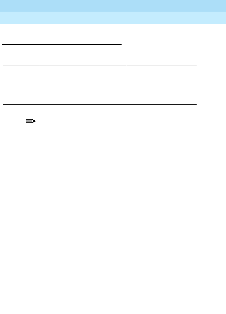
DEFINITY Enterprise Communications Server Release 6
Maintenance for R6r Volumes 1 & 2
555-230-126 Issue 2
January 1998
Maintenance Object Repair Procedures
Page 9-765ISDN-PLK (ISDN-PRI Signaling Link Port)
9
ISDN-PLK (ISDN-PRI Signaling Link
Port)
NOTE:
This MO was formerly known as "ISDN-LNK (ISDN-PRI Signaling Link Port)".
The ISDN-PRI interface uses out-of-band signaling (as opposed to robbed-bit,
in-band signaling) to transmit control messages between two endpoints. User
information channels carry digitized voice and digital data and are known as
bearer channels (B-channels). B-channels are assigned to DS1 ISDN trunks or
PRI endpoints. Call control signaling for the B-channels is combined and carried
over the separate ISDN-PRI Signaling Link Port D-channel.
The ISDN-PRI Signaling Link Port (ISDN-LNK) is a port on a TN464C/D UDS1
Interface circuit pack, which has a direct interface to the packet bus which
carries D-channel messages to the processor. The associated B-channels can
use ports on the same circuit pack or ports on other TN464C/Ds or TN767 DS1
Interface circuit packs. (The TN722 cannot be used for this application). The
B-channels are connected to the TDM Bus.
Two types of DS1 interfaces exist:
■24 DS0 channels on a 1.544 Mbps link
■31 DS0 channels + 1 framing channel on a 2.048 Mbps link
On 24-channel interfaces, the B-channels may use any of the first 23 ports. The
signaling link is assigned to the 24th port. On 32-channel interfaces, the DS1
ISDN Trunks (B-channels) may use any of ports 1 to 15 and 17 through 31. The
signaling link is assigned to the 16th port. The 32nd channel (port 0) is used for
framing. In NFAS configurations, the 24th or 16th ports on some of the DS1 circuit
packs may be used for B-channels. Refer to ISDN-SGR for further information.
A problem with the ISDN-LNK will have an effect on all of the associated
B-channels since without it no call control information can be conveyed to the
far-end switch or terminal adapter. Stable calls may remain operational, but no
new calls can be made. The ISDN-LNK in turn depends on the TN464C/D UDS1
Interface circuit pack it resides on and the packet bus which provides the link to
1. pp is
24
for 24-channel interfaces and
16
for 32-channel interfaces>
2. For additional related information, see "UDS1-BD (UDS1 Interface Circuit Pack)"
MO Name (in
Alarm Log) Alarm
Level Initial Command to Run1Full Name of MO
ISDN-LNK2MINOR test port
UUCSSpp
l ISDN-PRI Signaling Link Port
ISDN-LNK WARNING test port
UUCSSpp
sh ISDN-PRI Signaling Link Port
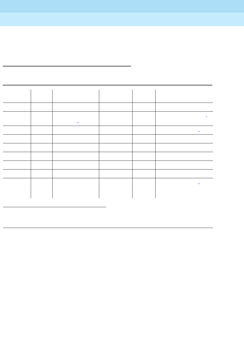
DEFINITY Enterprise Communications Server Release 6
Maintenance for R6r Volumes 1 & 2
555-230-126 Issue 2
January 1998
Maintenance Object Repair Procedures
Page 9-766ISDN-PLK (ISDN-PRI Signaling Link Port)
9
the processor. If there are problems with the ISDN-LNK, also investigate the
TN464C/D UDS1 Interface circuit pack (UDS1-BD) and the packet bus
(PKT-BUS).
Error Log Entries and Test to Clear Values
Notes:
a. The D-channel is demand busied out. No calls can be made over this
D-channel.
b. This error type indicates that the circuit pack has been removed or has
been insane for more than 11 minutes. To clear the error, reinsert or
replace the circuit pack.
c. Link error. This error occurs when the port receives an invalid frame over
the D-channel. This error normally indicates an off-board problem usually
related to transmission errors on the DS1 facility. Execute list
measurements ds1-log for the UDS1 TN464 circuit pack on which the
D-channel resides. If the UDS1 is reporting some errors, then the DS1
facility has experienced transmission problems which could have caused
the ISDN-LNK to report a Link Error.
1. Run the Short Test Sequence first. If all tests pass, run the Long Test Sequence. Refer to the
appropriate test description and follow the recommended procedures.
2. pp is 24 for 24-channel interfaces and 16 for 32-channel interfaces.
Table 9-260. ISDN-PRI Signaling Link Port Error Log Entries
Error
Type Aux
Data Associated Test Alarm Level On/Off
Board Test to Clear Value
010 Any Any Any test port
UUCSSpp
2
18 (a) 0 busyout port
UUCSSpp
2
WARNING OFF release port
UUCSSpp
2
130 (b) None WARNING ON test port
UUCSSpp
2
1537 (c) 46210 WARNING OFF
1793 (d) test board UUCSS l
3585 (e) 46222 MINOR ON
3841 (f) 46211
3842 (g) 46223
3843 (h) Signaling Port LAN
Loopback test
(#939)
test port
UUCSSpp
2
l

DEFINITY Enterprise Communications Server Release 6
Maintenance for R6r Volumes 1 & 2
555-230-126 Issue 2
January 1998
Maintenance Object Repair Procedures
Page 9-767ISDN-PLK (ISDN-PRI Signaling Link Port)
9
If the UDS1 is not reporting errors, execute the long test sequence for the
D-channel. Investigate any errors. If there are none, execute a long test
sequence for the UDS1 circuit pack (UDS1-BD). Investigate any errors.
If no errors could be found by testing, the Link Error is probably not
affecting service. However, if this Link Error continues to be logged, follow
normal escalation procedures.
d. UDS1 Interface circuit pack is out-of-service. Look for and resolve
UDS1-BD errors in the Hardware Error Log.
e. Transmit FIFO Overflow error. This error indicates that the circuit pack is
having problems transmitting data to the Packet Bus, thus affecting the
conveyance of signaling information over the D-channel. Specifically, this
error occurs when the Packet Bus transmit buffers overflow. This condition
probably indicates a hardware problem.
The actual alarming level will depend on the options chosen via the set
options command on the G3-MT terminal. ISDN-PRI Signaling Link Port
alarms are treated as Station alarms, and their default alarming option is to
downgrade all alarms to Warning. The value shown in the preceding table
indicates the normal, unfiltered case (option ‘‘y’’ on the set options form).
f. Bad DLCI error. This error occurs when a LAPD frame is received across
the DS1 facility which contains a DLCI which does not have a valid entry in
the on-board translation memory. This error normally indicates an
off-board problem usually related to a broken endpoint or a state
mismatch between a remote endpoint and the local call processing
software. Maintenance will not start any testing or generate any alarms in
response to this error.
g. Receive FIFO Overflow error. This error occurs when the circuit pack
detects an overflow of its receive buffers. If it occurs frequently, it may
indicate a LAPD parameter mismatch between the two end-points of a
packet switched connection. LAPD should be able to recover from this
problem, but it may degrade the performance of the LAN Bus.
Maintenance will not start any testing or generate any alarms in response
to this error.
h. This error occurs when the
Signaling Port LAN Loopback Test (#939)
fails.
Run the long test sequence and pay particular attention to the results of
Test #939.

DEFINITY Enterprise Communications Server Release 6
Maintenance for R6r Volumes 1 & 2
555-230-126 Issue 2
January 1998
Maintenance Object Repair Procedures
Page 9-768ISDN-PLK (ISDN-PRI Signaling Link Port)
9
System Technician-Demanded Tests:
Descriptions and Error Codes
The command to test the ISDN-LNK MO is test port UUCSSpp where pp is 24 for
24-channel interfaces and 16 for 32-channel interfaces.
Signaling Link Board Check (#643)
This test checks the health of the TN464C/D UDS1 Interface transporting the
ISDN-PRI Signaling Link Port
1. D = Destructive; ND = Nondestructive
Order of Investigation Short Test
Sequence Long Test
Sequence D/ND1
Signaling Port LAN Loopback Test (#939) X D
Signaling Link Board Check (#643) X X ND
Table 9-261. TEST #643 Signaling Link Board Check
Error
Code Test
Result Description/ Recommendation
ABORT Internal system error
1. Retry the command at 1-minute intervals for a maximum of 5 times.
1700 ABORT Rollabout video abort. The PRI terminal adapter associated with this D-channel
port is detached from the circuit pack. This is normal when the rollabout video
feature is enabled. To complete a test on this port:
1. Re-attach the disconnected PRI terminal adapter
2. Disable the rollabout video feature on this board by entering change ds1
UUCSS and set the ‘‘Alarm when PRI Endpoint Detached?’’ field to ‘‘y.’’
8 FAIL The UDS1 TN464C/D circuit pack is not in-service.
1. Check the Hardware Error Log for entries logged against UDS1-BD, and
consult “UDS1-BD” for repair procedures.
PASS The UDS1 Interface circuit pack transporting the ISDN-PRI Signaling Link Port
is in-service.
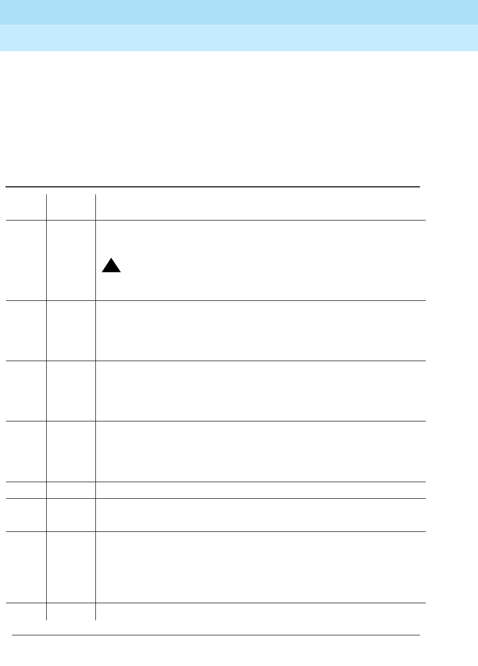
DEFINITY Enterprise Communications Server Release 6
Maintenance for R6r Volumes 1 & 2
555-230-126 Issue 2
January 1998
Maintenance Object Repair Procedures
Page 9-769ISDN-PLK (ISDN-PRI Signaling Link Port)
9
Signaling Port LAN Loopback Test (#939)
This test is destructive.
This test verifies the connectivity of an ISDN-PRI signaling port (D-channel)
across the LAN bus, also known as the packet bus. It will execute only if the port
is out-of-service. Failure of this test indicates a fault associated with the port
hardware on the circuit pack.
Table 9-262. TEST #939 Signaling Port LAN Loopback
Error
Code Test
Result Description/ Recommendation
1015 ABORT The port is not in the out-of-service state. Use the busyout port UUCSSpp
command to place it in the out-of-service state and repeat this test.
!CAUTION:
The busyout will prevent new call originations on all B-channels in the
signaling group until the port is released.
1139 ABORT The Packet Bus in this port network is out-of-service.
1. Follow repair procedures for the Packet Bus.
2. Enter test port UUCSSpp long command and check results of this test
(#939).
1141 ABORT The Packet Interface circuit pack is out-of-service.
1. Follow repair procedures for PKT-INT.
2. Enter test port UUCSSpp long command and check results of this test
(#939).
1144 ABORT The Packet Bus in the PPN is out-of-service.
1. Follow repair procedures for the Packet Bus.
2. Enter test port UUCSSpp long command and check results of this test
(#939).
2012 ABORT Internal system error.
2100 ABORT Could not allocate the necessary system resources to run this test.
1. Retry the command at 1-minute intervals a maximum of 5 times.
FAIL The Loopback Test has failed.
1. If the test fails repeatedly, attempt to reset the circuit pack when the other
ports on the board are not in use. Reset the circuit pack by entering
busyout board UUCSS and reset board UUCSS.
2. Repeat the test and, if it continues to fail, replace the circuit pack.
PASS Connectivity of the D-channel over the Packet Bus is operational.
Continued on next page

DEFINITY Enterprise Communications Server Release 6
Maintenance for R6r Volumes 1 & 2
555-230-126 Issue 2
January 1998
Maintenance Object Repair Procedures
Page 9-770ISDN-LNK (ISDN-PRI Signaling Link Port)
9
ISDN-LNK (ISDN-PRI Signaling Link
Port)
NOTE:
See the figures in the ‘‘ISDN-SGR (ISDN-PRI Signaling Group)’’ section of
this chapter for an illustration of the principles described below.
The ISDN-PRI interface uses out-of-band signaling (as opposed to robbed-bit,
in-band signaling) to transmit control messages between two endpoints. User
information channels carry digitized voice and digital data and are known as
bearer channels (B-channels). B-channels are assigned to DS1 ISDN trunks or
PRI endpoints. Call control signaling for the B-channels is combined and carried
over the separate ISDN-PRI Signaling Link Port D-channel.
The ISDN-PRI Signaling Link Port (ISDN-LNK) is a port on a TN464C/D UDS1
Interface circuit pack, which has a direct interface to the packet bus which
carries D-channel messages to the processor. The associated B-channels can
use ports on the same circuit pack or ports on other TN464C/Ds or TN767 DS1
Interface circuit packs. (The TN722 cannot be used for this application). The
B-channels are connected to the TDM Bus.
Two types of DS1 interfaces exist:
■24 DS0 channels on a 1.544 Mbps link
■31 DS0 channels + 1 framing channel on a 2.048 Mbps link
The 32-channel mode is supported only on TN464 series circuit packs
and on G3r V2 systems.
On 24-channel interfaces, the B-channels may use any of the first 23 ports. The
signaling link is assigned to the 24th port. On 32-channel interfaces, the DS1
ISDN Trunks (B-channels) may use any of ports 1 to 15 and 17 through 31. The
signaling link is assigned to the 16th port. The 32nd channel (port 0) is used for
framing. In NFAS configurations, the 24th or 16th ports on some of the DS1 circuit
packs may be used for B-channels. Refer to ISDN-SGR for further information.
1. pp is
24
for 24-channel interfaces and
16
for 32-channel interfaces
2. For additional related information, see ‘‘UDS1-BD (UDS1 Interface Circuit Pack)’’.
MO Name (in
Alarm Log) Alarm
Level Initial Command to
Run1Full Name of MO
ISDN-LNK2MINOR test port
UUCSSpp
l ISDN-PRI Signaling
Link Port
ISDN-LNK WARNING test port
UUCSSpp
sh ISDN-PRI Signaling
Link Port

DEFINITY Enterprise Communications Server Release 6
Maintenance for R6r Volumes 1 & 2
555-230-126 Issue 2
January 1998
Maintenance Object Repair Procedures
Page 9-771ISDN-LNK (ISDN-PRI Signaling Link Port)
9
A problem with the ISDN-LNK will have an effect on all of the associated
B-channels since without it no call control information can be conveyed to the
far-end switch or terminal adapter. Stable calls may remain operational, but no
new calls can be made. The ISDN-LNK in turn depends on the TN464C/D UDS1
Interface circuit pack it resides on and the packet bus which provides the link to
the processor. If there are problems with the ISDN-LNK, also investigate the
TN464C/D UDS1 Interface circuit pack (UDS1-BD) and the packet bus
(PKT-BUS).
Hardware Error Log Entries and Test to Clear
Values
Notes:
a. The D-channel is demand busied out. No calls can be made over this
D-channel.
b. This error type indicates that the circuit pack has been removed or has
been insane for more than 11 minutes. To clear the error, reinsert or
replace the circuit pack.
1. Run the Short Test Sequence first. If all tests pass, run the Long Test Sequence. Refer to the
appropriate test description and follow the recommended procedures.
2. pp is 24 for 24-channel interfaces and 16 for 32-channel interfaces.
ISDN-PRI Signaling Link Port Error Log Entries
Error
Type Aux
Data Associated Test Alarm
Level On/Off
Board Test to Clear Value
010 Any Any Any test port
UUCSSpp
2
18 (a) 0 busyout port
UUCSSpp
2
WARNING OFF release port
UUCSSpp
2
130 (b) None WARNING ON test port
UUCSSpp
2
1537 (c) 46210 WARNING OFF
1793 (d) test board UUCSS l
3585 (e) 46222 MINOR ON
3841 (f) 46211
3842 (g) 46223
3843 (h) Signaling Port
LAN Loopback
test (#939)
test port
UUCSSpp
2
l

DEFINITY Enterprise Communications Server Release 6
Maintenance for R6r Volumes 1 & 2
555-230-126 Issue 2
January 1998
Maintenance Object Repair Procedures
Page 9-772ISDN-LNK (ISDN-PRI Signaling Link Port)
9
c. Link error. This error occurs when the port receives an invalid frame over
the D-channel. This error normally indicates an off-board problem usually
related to transmission errors on the DS1 facility. Execute list
measurements ds1-log for the UDS1 TN464 circuit pack on which the
D-channel resides. If the UDS1 is reporting some errors, then the DS1
facility has experienced transmission problems which could have caused
the ISDN-LNK to report a Link Error.
If the UDS1 is not reporting errors, execute the long test sequence for the
D-channel. Investigate any errors. If there are none, execute a long test
sequence for the UDS1 circuit pack (UDS1-BD). Investigate any errors.
If no errors could be found by testing, the Link Error is probably not
affecting service. However, if this Link Error continues to be logged, follow
normal escalation procedures.
d. UDS1 Interface circuit pack is out-of-service. Look for and resolve
UDS1-BD errors in the Hardware Error Log.
e. Transmit FIFO Overflow error. This error indicates that the circuit pack is
having problems transmitting data to the Packet Bus, thus affecting the
conveyance of signaling information over the D-channel. Specifically, this
error occurs when the Packet Bus transmit buffers overflow. This condition
probably indicates a hardware problem.
The actual alarming level will depend on the options chosen via the set
options command on the G3-MT terminal. ISDN-PRI Signaling Link Port
alarms are treated as Station alarms, and their default alarming option is to
downgrade all alarms to Warning. The value shown in the preceding table
indicates the normal, unfiltered case (option ‘‘y’’ on the set options form).
f. Bad DLCI error. This error occurs when a LAPD frame is received across
the DS1 facility which contains a DLCI which does not have a valid entry in
the on-board translation memory. This error normally indicates an
off-board problem usually related to a broken endpoint or a state
mismatch between a remote endpoint and the local call processing
software. Maintenance will not start any testing or generate any alarms in
response to this error.
g. Receive FIFO Overflow error. This error occurs when the circuit pack
detects an overflow of its receive buffers. If it occurs frequently, it may
indicate a LAPD parameter mismatch between the two end-points of a
packet switched connection. LAPD should be able to recover from this
problem, but it may degrade the performance of the LAN Bus.
Maintenance will not start any testing or generate any alarms in response
to this error.
h. This error occurs when the
Signaling Port LAN Loopback Test (#939)
fails.
Run the long test sequence and pay particular attention to the results of
Test #939.

DEFINITY Enterprise Communications Server Release 6
Maintenance for R6r Volumes 1 & 2
555-230-126 Issue 2
January 1998
Maintenance Object Repair Procedures
Page 9-773ISDN-LNK (ISDN-PRI Signaling Link Port)
9
System Technician-Demanded Tests:
Descriptions and Error Codes
The command to test the ISDN-LNK MO is test port UUCSSpp where pp is 24 for
24-channel interfaces and 16 for 32-channel interfaces.
Signaling Link Board Check (#643)
This test checks the health of the TN464C/D UDS1 Interface transporting the
ISDN-PRI Signaling Link Port
1. D = Destructive; ND = Nondestructive
Order of Investigation Short Test
Sequence Long Test
Sequence D/ND1
Signaling Port LAN Loopback Test (#939) X D
Signaling Link Board Check (#643) X X ND
Table 0-1. TEST #643 Signaling Link Board Check
Error
Code Test
Result Description/ Recommendation
ABORT Internal System Error
1. Retry the command at 1-minute intervals for a
maximum of 5 times.
2. If the test continues to abort, escalate the problem.
1700 ABORT Rollabout video abort. The PRI terminal adapter
associated with this D-channel port is detached from the
circuit pack. This is normal when the rollabout video
feature is enabled. To complete a test on this port, do
one of the following:
1. Re-attach the disconnected PRI terminal adapter
2. Disable the rollabout video feature on this board by
entering change ds1 UUCSS and set the field
labeled ‘‘Alarm when PRI Endpoint Detached?’’ to
‘‘y.’’
8 FAIL The UDS1 TN464C/D circuit pack is not in-service.
1. Check the Hardware Error Log for entries logged
against UDS1-BD and consult the ‘‘UDS1-BD (UDS1
Interface Circuit Pack)’’ Maintenance documentation
for repair procedures.
DEFINITY Enterprise Communications Server Release 6
Maintenance for R6r Volumes 1 & 2
555-230-126 Issue 2
January 1998
Maintenance Object Repair Procedures
Page 9-774ISDN-LNK (ISDN-PRI Signaling Link Port)
9
Signaling Port LAN Loopback Test (#939)
This test is destructive.
This test verifies the connectivity of an ISDN-PRI signaling port (D-channel)
across the LAN bus, also known as the packet bus. It will execute only if the port
is out-of-service. Failure of this test indicates a fault associated with the port
hardware on the circuit pack.
Figure 9-41. Signaling Port LAN (Packet Bus) Loopback
PASS The UDS1 Interface circuit pack transporting the
ISDN-PRI Signaling Link Port is in-service.
Table 0-1. TEST #643 Signaling Link Board Check — Continued
Error
Code Test
Result Description/ Recommendation
Packet Bus
Packet
Interface
TN1655
UDS1
TN464

DEFINITY Enterprise Communications Server Release 6
Maintenance for R6r Volumes 1 & 2
555-230-126 Issue 2
January 1998
Maintenance Object Repair Procedures
Page 9-775ISDN-LNK (ISDN-PRI Signaling Link Port)
9
Table 0-2. TEST #939 Signaling Port LAN Loopback
Error
Code Test
Result Description/ Recommendation
1015 ABORT The port is not in the out-of-service state. Use the
busyout port UUCSSpp command to place it in the
out-of-service state and repeat this test.
!CAUTION:
The busyout will prevent new call originations on
all B-channels in the signaling group until the port
is released.
1139 ABORT The Packet Bus in this port network is out-of-service.
1. Follow repair procedures for the Packet Bus.
2. Enter test port UUCSSpp long command and
check results of this test (#939).
1141 ABORT The Packet Interface circuit pack is out-of-service.
1. Follow repair procedures for PKT-INT.
2. Enter test port UUCSSpp long command and
check results of this test (#939).
1144 ABORT The Packet Bus in the PPN is out-of-service.
1. Follow repair procedures for the Packet Bus.
2. Enter test port UUCSSpp long command and
check results of this test (#939).
2012 ABORT Internal system error.
2100 ABORT Could not allocate the necessary system resources to
run this test.
1. Retry the command at 1-minute intervals a maximum
of 5 times.
2. If the test continues to abort, escalate the problem.
FAIL The Loopback Test has failed.
1. If the test fails repeatedly, attempt to reset the circuit
pack when the other ports on the board are not in
use. Reset the circuit pack by entering busyout
board UUCSS and reset board UUCSS.
2. Repeat the test and, if it continues to fail, replace the
circuit pack.
Continued on next page

DEFINITY Enterprise Communications Server Release 6
Maintenance for R6r Volumes 1 & 2
555-230-126 Issue 2
January 1998
Maintenance Object Repair Procedures
Page 9-776ISDN-LNK (ISDN-PRI Signaling Link Port)
9
PASS Connectivity of the D-channel over the Packet Bus is
operational.
Table 0-2. TEST #939 Signaling Port LAN Loopback — Continued
Error
Code Test
Result Description/ Recommendation
Continued on next page
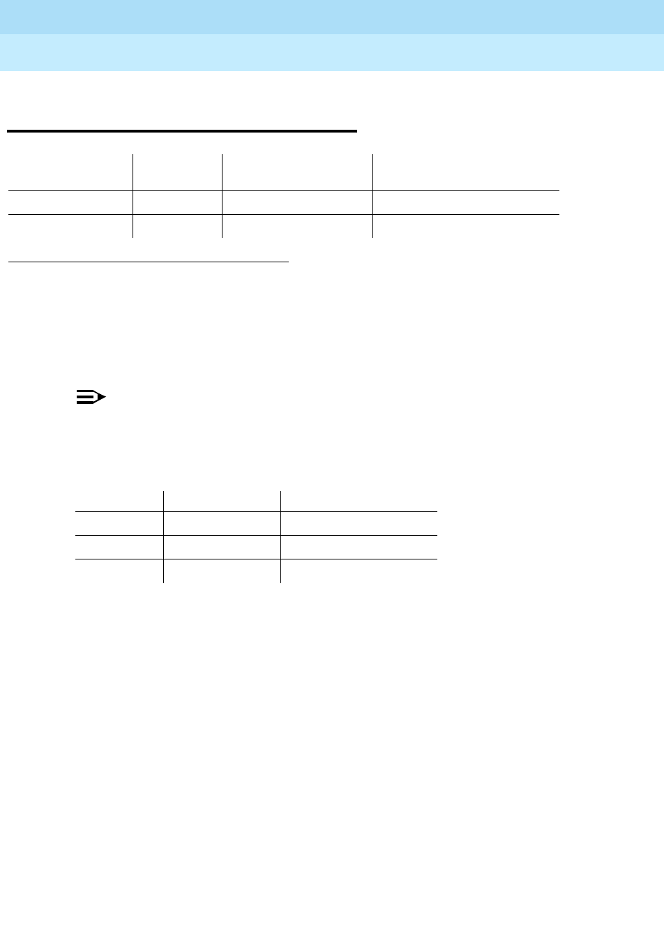
DEFINITY Enterprise Communications Server Release 6
Maintenance for R6r Volumes 1 & 2
555-230-126 Issue 2
January 1998
Maintenance Object Repair Procedures
Page 9-777ISDN-SGR (ISDN-PRI Signaling Group)
9
ISDN-SGR (ISDN-PRI Signaling
Group)
An ISDN-PRI Signaling Group is a collection of B-channels for which a given
ISDN-PRI Signaling Channel Port (D-channel) carries signaling information.
B-channels carry voice or data and can be assigned to DS1 ISDN trunks
(ISDN-TRK) or PRI endpoint ports (PE-BCHL).
NOTE:
Throughout this discussion the term B-channels refers to ISDN-TRKs or
PE-BCHLs, depending on the application under investigation.
The following circuit packs are supported in the implementation of ISDN-PRI.
The TN464C/D UDS1 Interface circuit pack, which has a direct interface to the
packet bus, is required for D-channel signaling. There are two types of DS1
interfaces:
■24 DS0 channels on a 1.544 Mbps link
■31 DS0 channels + 1 framing channel on a 2.048 Mbps link
The following discussion describes 24-channel interface signaling groups. The
32-channel interface works the same way, except that only port number 16 is
used for signaling instead of port number 24. Ports 1 through 15 and 17 through
31 are used for B-channels. The 32nd channel (port 0) is always used for
framing.
ISDN-PRI D-channel signaling can be combined with a group of B-channels in
three basic ways:
■Facility-associated signaling (FAS)
■Nonfacility-associated (NFAS) simplex signaling
1.
grp#
is the signaling group number (1-166); the test sequence can be either short or long.
MO Name (in
Alarm Log) Alarm Level Initial Command to
Run1Full Name of MO
ISDN-SGR MINOR test sig-group
grp#
ISDN-PRI Signaling Group
ISDN-SGR WARNING test sig-group
grp#
ISDN-PRI Signaling Group
Circuit Pack Channel Types Interface
TN464C/D B and D channels 24 or 32 channel
TN767 B channels 24 channel
TN464B B channels 32 channel (G3r V2 only)

DEFINITY Enterprise Communications Server Release 6
Maintenance for R6r Volumes 1 & 2
555-230-126 Issue 2
January 1998
Maintenance Object Repair Procedures
Page 9-778ISDN-SGR (ISDN-PRI Signaling Group)
9
■NFAS duplex signaling
In a FAS signaling group, the 24th port of the TN464C/D UDS1 Interface circuit
pack carries D-channel signaling for up to 23 B-channel ports on the same circuit
pack.
In an NFAS signaling group, the 24th port of one TN464C/D UDS1 Interface can
carry D-channel signaling for B-channels on several other DS1 circuit pack as
well, including TN767s and TN464Bs. The 24th port on the other circuit packs
can be used for B-channels. A D-channel in an NFAS group can signal for
B-channels on a total of 20 DS1 circuit packs.
NFAS duplex signaling provides increased reliability, which is highly desirable
since NFAS permits the D-channel to signal for many more B-channels. NFAS
Duplex allows the administration of a backup D-channel which remains in a
standby state until the active D-channel goes down. If the active D-Channel does
go down, the backup D-Channel takes over and provides signaling for all the
B-channels in the signaling group.
The operation of the entire ISDN-PRI signaling group depends on several other
entities: the ISDN-PRI signaling channel ports, the TN464C/D UDS1 Interface
circuit pack on which the D-channels reside and the system link that is carried
over the packet bus to the processor. When there are problems with the
ISDN-PRI signaling group, also investigate ISDN-LNK, UDS1-BD, SYS-LINK. and
PKT-BUS.
Error Log Entries and Test to Clear Values
Table 9-263. ISDN-PRI Signaling Group Error Log Entries
Error
Type Aux
Data Associated Test Alarm
Level On/Off
Board Test to Clear Value
010 Any Any test sig-group
grp#
1 (a) Any None
257 (b) Any None test sig-group
grp#
513 (c) Any None test sig-group
grp#
769 Any Primary Signaling Link
Hardware Check (#636) test sig-group
grp#
1025 Any Secondary Signaling Link
Hardware Check (#639) test sig-group
grp#
1793 (d) Any Layer 2 Status (Test #647) WARNING OFF test sig-group
grp#
2049 (e) Any Layer 2 Status (Test #647) WARNING OFF test sig-group
grp#
2305 (f) Any Remote Layer 3 Query
(Test #637) MINOR OFF test sig-group
grp#
Continued on next page

DEFINITY Enterprise Communications Server Release 6
Maintenance for R6r Volumes 1 & 2
555-230-126 Issue 2
January 1998
Maintenance Object Repair Procedures
Page 9-779ISDN-SGR (ISDN-PRI Signaling Group)
9
Notes:
a. This switch sent a message to the far-end switch or terminal adapter, and
the far-end did not respond in the allotted time. Possible causes include
link failure and congestion or outage at the far-end. The Aux Data field
contains Layer 3 protocol information used by internal counters.
If no other symptoms are not present, no action is required. If Layer 3
communication is down, there should be indications in the form of alarms
and errors for link components. Check out other errors against ISDN-SGR,
ISDN-TRK, and other hardware components on the link.
There is no test to clear these errors. The error counter is decremented by
1 every 15 minutes.
b. This error indicates that the primary signaling channel connection has
been lost for more than 90 seconds. If a secondary signaling channel
does not exist or is not in-service, the associated B-channels will be
placed in the ISDN Maintenance/Far-End state. The B-channels will not be
usable for outgoing calls, although incoming calls will still be accepted.
The switch will automatically attempt to recover the signaling link. Pay
particular attention to the results of Test #636 (Primary Signaling Link
Hardware Check) in the test sequence. When the link does recover, the
B-channels will be negotiated back to the In-Service state and their alarms
will be retired.
When this error occurs, the state of the Signaling Group is changed to
out-of-service (verify using the status sig-group command).
c. This error indicates that the secondary signaling channel connection has
been lost for more than 90 seconds. If the primary signaling channel is not
in-service, B-channels will be placed in the ISDN Maintenance/Far-End
state. The B-channels will not be usable for outgoing calls, although
incoming calls will still be accepted. The switch will automatically attempt
1. Run the Short Test Sequence first. If all tests pass, run the Long Test Sequence. Refer to the appropriate
test description and follow the recommended procedures.
3585 (g) Port
number None
3840 to
3928(h) Port
number None
Table 9-263. ISDN-PRI Signaling Group Error Log Entries — Continued
Error
Type Aux
Data Associated Test Alarm
Level On/Off
Board Test to Clear Value
Continued on next page

DEFINITY Enterprise Communications Server Release 6
Maintenance for R6r Volumes 1 & 2
555-230-126 Issue 2
January 1998
Maintenance Object Repair Procedures
Page 9-780ISDN-SGR (ISDN-PRI Signaling Group)
9
to recover the signaling link. Pay particular attention to the results of Test
#639 (Secondary Signaling Link Hardware Check) in the test sequence.
When the link does recover, the B-channels will be negotiated back to the
In-Service state and their alarms will be retired.
When this error occurs, the state of the Signaling Group is changed to
out-of-service (verify using the status sig-group command).
d. This error indicates a failure of the Layer 2 Query Test for the primary
signaling channel
e. This error indicates a failure of the Layer 2 Query Test for the secondary
signaling channel.
f. This error indicates a failure of Test #637, the Remote Layer 3 Query. A
specific message was sent to the far-end switch, and it did not respond
within the allotted time. Investigate elements of the ISDN PRI D-channel(s)
(ISDN-LNK) for both this switch and the Far-end switch. If Test #637 fails
twice in a row, the B-channels will be alarmed and made unavailable for
outgoing calls (although incoming calls will still be accepted). When Test
#637 succeeds and the Far-end switch starts responding properly, the
DS1 ISDN Trunk (B-channels) will be placed back into normal operation
and their alarms will be retired.
g. A SERV or SERV ACK ISDN D-channel message has been received by a
non-US-type interface (country option other than 1 on the DS1
administration form). However, these messages are used only for duplex
NFAS signaling which is supported only by country protocol 1.
Thus, there may be a mismatch in administration between the local and
far-end switches. Consult with the customer’s network provider to
determine whether the D-channel is set up correctly on the far-end switch.
h. These error types are used to report certain error messages received by
the ISDN-PRI Signaling Group for one of its associated B-channels. The
aux data field shows for which B-channel (port number) the message was
received.
The error code generated equals 3840+
x
, where
x
is a Cause Value
defined by the ISDN PRI Specification. Note that there is no Test to Clear
Value for these error types; selected ISDN cause values are placed in the
log when they are received, but no direct action or alarming is performed
solely in response to receiving them. They provide added data that may
prove useful when tracking down obscure networking and routing
problems. The following table provides more information:

DEFINITY Enterprise Communications Server Release 6
Maintenance for R6r Volumes 1 & 2
555-230-126 Issue 2
January 1998
Maintenance Object Repair Procedures
Page 9-781ISDN-SGR (ISDN-PRI Signaling Group)
9
Table 9-264. Descriptions and Recommendations for Error Types 3840-3928
Error
Code Description Recommendation
3842 A request has been made
to use a transit network or
common carrier that cannot
be accessed.
1. From the circuit pack and port number (in the Aux Data
field), determine the trunk group against which the error
was reported.
2. Check all routing patterns containing this trunk group for
validity of interexchange carriers requested (IXC field).
3846 The far-end switch has
indicated that the
B-channel (trunk) is not
acceptable for use in the
call for which it was
requested.
This could indicate an administration problem (for example,
the local switch and the far-end switch have different
B-channels administered), or could reflect the occurrence of
a normal race condition (for example, the local switch has
requested use of a B-channel which the far-end switch had
just reserved for use on another call).
1. From the circuit pack and port number (in the Aux Data
field), determine the trunk group against which the error
was reported.
2. Issue the status trunk command for the indicated trunk.
3) Refer to the ‘‘DS1 ISDN Trunk Service States’’ and
‘‘ISDN-PRI Trunk Service States’’ sections of ISDN-TRK
for recovery suggestions.
3858 Similar to Error Type 1. The
switch sent an ISDN
message to the far-end
switch or terminal adapter
which did not respond in
the allotted time.
Follow same recommendations as for Error Type 1.
3878 The far-end switch has
indicated that the network
is not functioning correctly
and that the condition may
last a relatively long period
of time (for example,
immediately re-attempting
the call may not be
successful).
1. From the circuit pack and port number (in the Aux Data
field, determine the trunk group against which the error
was reported.
2. Consult with the network provider to determine the
nature and expected duration of the out of service
condition.
3. Consider modifying all routing patterns containing this
trunk group, to route calls around the network which is
out of service.
Continued on next page

DEFINITY Enterprise Communications Server Release 6
Maintenance for R6r Volumes 1 & 2
555-230-126 Issue 2
January 1998
Maintenance Object Repair Procedures
Page 9-782ISDN-SGR (ISDN-PRI Signaling Group)
9
3890 A request to use a network
service (e.g., SDN) has
been denied.
Administration somewhere
on the network has
indicated that the
requested service has not
been subscribed to or
purchased for this trunk.
This could be a local administration problem only, or a
mismatch between the local administration and that of the
network provider.
1. From the circuit pack and port number (in the Aux Data
field), determine the trunk group against which the error
was reported.
2. Display the trunk group form: If the trunk group is
Call-by-Call (Service Type is ‘‘cbc’’), check all routing
pattern forms containing this trunk group to see if the
Service/Feature fields contain the correct network
services purchased for this trunk. If the trunk group is
not Call-by-Call, check that the Service Type field
contains the single network service purchased for this
trunk.
3. If local administration appears correct, consult with the
customer and/or the network provider to determine the
services that the customer has subscribed to for this
trunk group.
3892 Protocol detail; may offer a
clue if customer is having
ISDN calls denied with an
unexpected intercept tone.
If customer is complaining of unexpected intercept tones
when accessing ISDN trunks or PRI endpoints and no other
cause can be found, escalate the problem and provide the
next tier with this Error Log information.
3894 Protocol detail; may offer a
clue if customer is having
ISDN calls denied with an
unexpected intercept tone.
First, eliminate any transitory state mismatch problems by
issuing the test port UUCSSpp command for the trunk port
shown in the aux data field. Test #256 (Service State Audit)
is the important test in the sequence. If this passes
satisfactorily, yet the customer continues to complain of
unexpected intercept tones when accessing ISDN trunks or
PRI endpoints and no other cause can be found, escalate
the problem and provide the next tier with this Error Log
information.
3905 Protocol detail; may offer a
clue if customer is having
ISDN calls denied with an
unexpected intercept tone.
If customer is complaining of unexpected intercept tones
when accessing ISDN trunks or PRI endpoints and no other
cause can be found, escalate the problem and provide the
next tier with this Error Log information.
3906 Protocol detail; may offer a
clue if customer is having
ISDN calls denied with an
unexpected intercept tone.
If customer is complaining of unexpected intercept tones
when accessing ISDN trunks or PRI endpoints and no other
cause can be found, escalate to the problem and provide
the next tier with this Error Log information.
Table 9-264. Descriptions and Recommendations for Error Types 3840-3928 — Continued
Error
Code Description Recommendation
Continued on next page

DEFINITY Enterprise Communications Server Release 6
Maintenance for R6r Volumes 1 & 2
555-230-126 Issue 2
January 1998
Maintenance Object Repair Procedures
Page 9-783ISDN-SGR (ISDN-PRI Signaling Group)
9
System Technician-Demanded Tests:
Descriptions and Error Codes
Always investigate tests in the order presented in the table below when
inspecting errors in the system. By clearing error codes associated with the
Primary Signaling Link Hardware Check
, for example, you may also clear errors
generated from other tests in the testing sequence.
1. D = Destructive; ND = Nondestructive
3909 A request to use a network
service has been made,
but the network has
rejected the request
because the requested
service is not implemented.
Follow the recommendations listed above for error type
3890.
3928 A call was denied because
of a basic incompatibility
between the type of call
and either the facilities
selected by the routing
pattern or the called user
itself.
This error might be helpful as a clue if the customer
complains of receiving unexpected intercept tone after
accessing ISDN trunks or PRI endpoints. Determine the
trunk group from the circuit pack and port number (in the
aux data field) and then check the BCC fields of the
pertinent routing patterns. Also, investigate whether or not
the calling and called endpoints are compatible (for
example, some ISDN switches may not allow a voice station
to call a data extension).
Order of Investigation Short Test
Sequence Long Test
Sequence D/ND1
Primary Signaling Link Hardware Check (#636) X X ND
Secondary Signaling Link Hardware Check (#639) X X ND
Layer 2 Status Test (#647) X X ND
Remote Layer 3 Query Test (#637) X X ND
Table 9-264. Descriptions and Recommendations for Error Types 3840-3928 — Continued
Error
Code Description Recommendation
Continued on next page

DEFINITY Enterprise Communications Server Release 6
Maintenance for R6r Volumes 1 & 2
555-230-126 Issue 2
January 1998
Maintenance Object Repair Procedures
Page 9-784ISDN-SGR (ISDN-PRI Signaling Group)
9
Primary Signaling Link Hardware Check (#636)
The ISDN-PRI Signaling Group D-Channel port depends on the health of the
TN464C/D UDS1 Interface circuit pack on which it resides. This test will fail if
there are problems with either the ISDN-PRI Primary D-channel port or the UDS1
circuit pack. If there are problems with the ISDN-PRI Primary Signaling Channel
port (ISDN-LNK), also investigate the UDS1 circuit pack (UDS1-BD).
Remote Layer 3 Query (#637)
This test will query the far-end switch or terminal adapter to determine if the
signaling connection is functioning properly at Layer 3. It will select a B-channel
in the in-service or maintenance service state and send an ISDN Layer 3
SERVice message, which requires a response from the far end (similar to
performing Test #256 on an ISDN trunk. The test will not be performed if there are
no B-channels in an appropriate ISDN service state (as when none are
administered or they are all out of service).
NOTE:
The service state can be displayed by using the status trunk <trunk
group/trunk member> or status pri-endpoint command.
As is the case with Test #256 for an ISDN trunk, a PASS only indicates that a
message was composed and sent to the far-end switch or terminal adapter. The
ISDN PRI Specification allows up to 2 minutes for a response. Check the Error
Error
Code Test
Result Description/ Recommendation
ABORT Internal system error
1. Retry the command at 1-minute intervals a maximum of 5 times.
1700 ABORT Rollabout video abort. The PRI terminal adapter associated with the primary
D-channel port is detached from the circuit pack. This is a normal abort when
the rollabout video feature is enabled. To complete test on this port, either:
1. Re-attach the disconnected PRI terminal adapter, or
2. Disable the rollabout video feature on this board by entering change ds1
UUCSS and set field ‘‘Alarm when PRI Endpoint Detached?’’ to ‘‘y.’’
8 FAIL There is a problem with the UDS1 TN464C/D Circuit Pack or the ISDN-PRI
Signaling Channel (D-Channel). No ISDN trunk or PRI endpoint calls can be
made until the problem is resolved.
1. Consult the procedures for the UDS1 TN464C/D Circuit Pack (UDS1-BD)
and the ISDN-PRI Signaling Channel (ISDN-LNK).
PASS The basic physical connectivity of the primary D-channel is intact and
functional. One might try this test repeatedly to ensure the link is up and to
uncover any transitory problems.
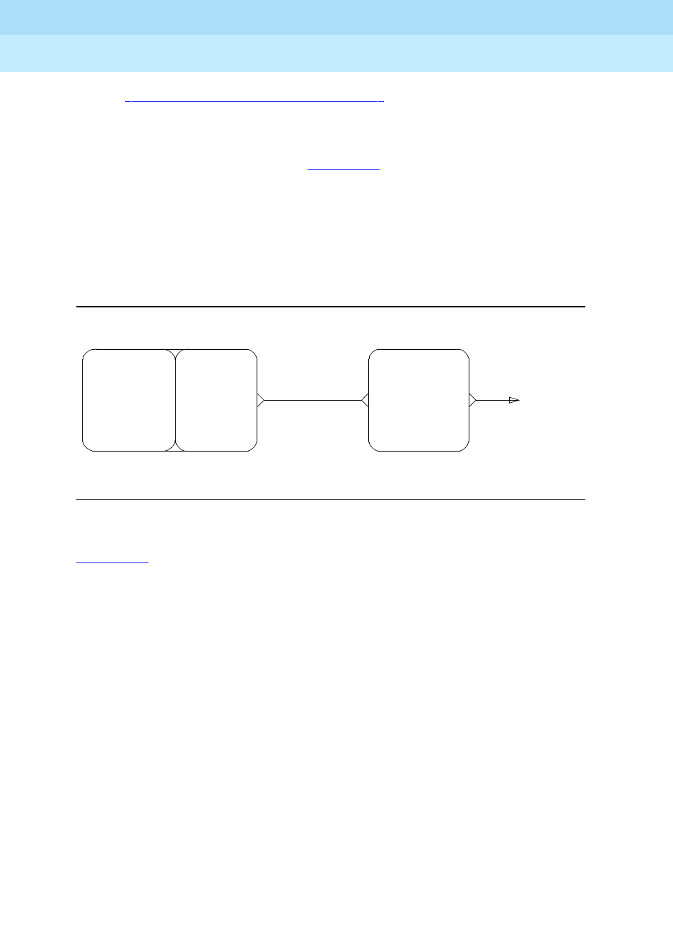
DEFINITY Enterprise Communications Server Release 6
Maintenance for R6r Volumes 1 & 2
555-230-126 Issue 2
January 1998
Maintenance Object Repair Procedures
Page 9-785ISDN-SGR (ISDN-PRI Signaling Group)
9
Log for ‘‘ISDN-SGR (ISDN-PRI Signaling Group)’’ errors of type 2305 for
evidence of a Remote Layer 3 Query failure.
Tests #639 and #636 check the health of the D-channels and DS1/UDS1
Interface Circuit Packs. As shown in Figure 9-42, this test goes one step further
by checking the communication path from the processor from the processor,
through the TDM/Packet Bus and DS1/UDS1 Interface circuit pack, and on to the
far-end switch or terminal adapter. A special ISDN message is sent to the far-end
switch or terminal adapter, which must respond within a specified amount of
time. This test is designed to ensure that the communication path between the
switch and the far-end is up and operational, and that the two endpoints can
properly exchange ISDN control messages.
Figure 9-42. Remote Layer 3 Query (Test #637)
Figure 9-42 illustrates a UDS1 Interface Circuit Pack located in the PPN. When
the UDS1 board is located in an EPN, there is additional Port Network
Connectivity hardware connecting the packet busses of the PPN and EPN.
Examples of such hardware are the Center Stage Switch and fiber-optic cables.
PKTINT
PACKET
BUS
UDS1
TN464C/D
TO FAR-END
(TN1655)
PROCESSOR
CIRCUIT
PACK CIRCUIT
PACK
PROCESSOR
(UN331)
INTERFACE

DEFINITY Enterprise Communications Server Release 6
Maintenance for R6r Volumes 1 & 2
555-230-126 Issue 2
January 1998
Maintenance Object Repair Procedures
Page 9-786ISDN-SGR (ISDN-PRI Signaling Group)
9
Secondary Signaling Link Hardware Check (#639)
The ISDN-PRI Signaling Group D-Channel port depends on the health of the
TN464C/D UDS1 Interface circuit pack on which it resides. This test will fail if
there are problems with either the ISDN-PRI Secondary D-channel port or the
UDS1 circuit pack. This test will abort if a Secondary D-channel is not
Table 9-265. TEST #637 Remote Layer 3 Query
Error
Code Test
Result Description/ Recommendation
1006 ABORT There are no associated B-channels in an ISDN ‘‘in-service’’ or ‘‘maintenance’’
service state. This is a NORMAL ABORT.
1. Administer or release an ISDN trunk or PRI endpoint before retrying the
test. For an ISDN trunk, use the status trunk group#/member# command
to verify the ISDN trunk state. For a PRI endpoint use status pri-endpoint
extension. Then, retry this test when at least one B-channel is in the
"in-service" or "maintenance" states.
1113 ABORT The signaling channel is down. Therefore, no messages can be sent to the
far-end switch or terminal adapter.
1. Examine the results of Tests #636 and #639 and follow recommendations
provided there.
2100 ABORT Could not allocate the necessary system resources to run this test.
1. Retry the command at 1-minute intervals a maximum of 5 times.
2500
or
none
ABORT Internal system error OR Administration Problem
1. Determine if any B-channels are administered. If there are none, then this
is a normal ABORT, since this test cannot run unless at least one
B-channel is administered. If at least one B-channels is administered,
there is an internal system error. Retry the command at 1-minute intervals
a maximum of 5 times.
FAIL Internal system error. See description of ABORT with error code 2500.
PASS A message was composed and sent to the far-end switch or terminal adapter.
The ISDN PRI specification allows up to 2 minutes for a reply. Check the Error
Log for ‘‘ISDN-SGR (ISDN-PRI Signaling Group)’’ for errors of type 2305 for
evidence of a Remote Layer 3 Query failure. If no new errors were logged
since this test was run, then this switch and the far-end switch or terminal
adapter can exchange call control messages. If there is still a problem with a
particular ISDN trunk or PRI endpoint, busyout the trunk and run the long test
sequence, paying particular attention to the results of Test #258 (ISDN Test
Call).
Continued on next page

DEFINITY Enterprise Communications Server Release 6
Maintenance for R6r Volumes 1 & 2
555-230-126 Issue 2
January 1998
Maintenance Object Repair Procedures
Page 9-787ISDN-SGR (ISDN-PRI Signaling Group)
9
administered for the signaling group. If there are problems with the ISDN-PRI
Secondary Signaling Channel port (ISDN-LNK), also investigate the UDS1 circuit
pack (UDS1-BD).
Layer 2 Status Test (#647)
The Layer 2 Status Test checks the layer 2 status of the ISDN-PRI Signaling
Channel (D-channel). This test will fail if there is a hardware failure or a facility
problem, or if the primary and secondary ISDN-PRI D-channels are not
administered correctly.
The Primary and Secondary Signaling Link Hardware tests (test 637 and 639)
and the Remote Layer 3 Query test (test 637) will detect most problems caused
by hardware failures or incorrect administration. However, the Layer 3 test (test
637) cannot detect end-to-end transmission problems with the Standby
D-channel since Layer 3 messages are not sent on the standby channel.
For G3r, the SYS-LINK Maintenance Object reports Layer 2 ISDN-PRI D-channel
problems and for G3i/s/vs, the PI-LINK Maintenance Object reports Layer 2
ISDN-PRI D-channel problems (if the D-channel is connected to the Processor
Interface circuit pack). However, for G3i, the PI-LINK Maintenance Object does
not monitor the Layer 2 status of the ISDN-PRI D-channel when the D-channel is
connected to the Packet Control circuit pack for the ISDN-PRI over PACCON
feature. The Layer 2 Query test is provided to detect D-Channel Layer 2 failures
Table 9-266. TEST #639 Secondary Signaling Link Hardware Check
Error
Code Test Result Description/ Recommendation
ABORT Internal system error
1. Retry the command at 1-minute intervals a maximum of 5 times.
1132 ABORT The Secondary D-Channel is not administered for this Signaling Group. This
is a NORMAL ABORT. Only a Primary D-Channel must be administered for a
Signaling Group.
8 FAIL There is a problem with the TN464C/D UDS1 Interface circuit pack or the
ISDN-PRI Secondary Signaling Channel (D-Channel). No ISDN trunk or PRI
endpoint calls can be made until the problem is resolved.
1. Consult the procedures for the UDS1 TN464C/D Circuit Pack
(UDS1-BD) and the ISDN-PRI Signaling Channel (ISDN-LNK).
PASS The basic physical connectivity of the Signaling Group’s Secondary
D-channel is intact and functional. Try this test repeatedly to ensure the link
is up and to uncover any transitory problems.
Continued on next page

DEFINITY Enterprise Communications Server Release 6
Maintenance for R6r Volumes 1 & 2
555-230-126 Issue 2
January 1998
Maintenance Object Repair Procedures
Page 9-788ISDN-SGR (ISDN-PRI Signaling Group)
9
and generate an associated Warning alarm independent of the hardware
configuration used for the D-channels.
Table 9-267. TEST #647 Layer 2 Status Query Test
Error
Code Test
Result Description/ Recommendation
1132 ABORT Internal system error:
The port location for the primary ISDN-PRI D-channel is not known. This
condition should not be possible since an administered DS1 circuit pack must
be specified when a Signaling Group is administered:
1. Retry the command at one minute intervals a maximum of five times.
1134 ABORT Internal system error:
The associated DS1 circuit pack is not administered. This condition should not
be possible since an administered DS1 circuit pack must be specified when a
Signaling Group is administered.
1. Retry the command at one minute intervals a maximum of three times.
2500 ABORT Internal system error:
1. Retry the command at one minute intervals a maximum of five times.
1 FAIL Layer 2 of the primary signaling channel is down:
1. Examine the results of the Primary Signaling Test (#636) and follow
recommendations provided there.
2. If test #636 passes, the Layer 2 Query test may still fail if the Signaling
Channel at the far end has not been administered correctly or if the
Signaling Channel has been busied out. Verify that the Primary Signaling
Channel (D-channel) at the far end has been administered correctly. Verify
that the DS1 port used for the Primary D-channel has not been busied out at
the far end.
2 FAIL Layer 2 of the secondary signaling channel is down.
1. Examine the results of Secondary Signaling Link Hardware Test (#639) and
follow recommendations provided there.
2. If tests #639 passes, the Layer 2 Query test may still fail if the Signaling
Channel at the far end has not been administered correctly or if the
Signaling Channel has been busied out. Verify that the Secondary Signaling
Channel (D-channel) at the far end has been administered correctly. Verify
that the DS1 port used for the Secondary D-channel has not been busied
out at the far end.
Continued on next page

DEFINITY Enterprise Communications Server Release 6
Maintenance for R6r Volumes 1 & 2
555-230-126 Issue 2
January 1998
Maintenance Object Repair Procedures
Page 9-789ISDN-SGR (ISDN-PRI Signaling Group)
9
3 FAIL Both the primary and secondary are down.
1. Examine the results of the Primary and SecondarySignaling Link Hardware
Tests (#636 and #639) and follow recommendations provided there.
2. If tests #636 and #639 pass, the Layer 2 Query test may still fail if the
Signaling Channel at the far end has not been administered correctly or if
the Signaling Channel has been busied out. Verify that the Primary and
Secondary Signaling Channel (D-channel) at the far end has been
administered correctly. Verify that the DS1 port used for the Primary and
Secondary D-channels has not been busied out at the far end.
PASS The Primary Signaling Channel is up and, if administered the Secondary
Channel is up.
Table 9-267. TEST #647 Layer 2 Status Query Test — Continued
Error
Code Test
Result Description/ Recommendation
Continued on next page
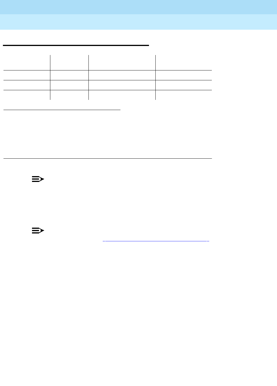
DEFINITY Enterprise Communications Server Release 6
Maintenance for R6r Volumes 1 & 2
555-230-126 Issue 2
January 1998
Maintenance Object Repair Procedures
Page 9-790ISDN-TRK (DS1 ISDN Trunk)
9
ISDN-TRK (DS1 ISDN Trunk)
NOTE:
Many trunk problems are caused by incorrect settings of parameters on the
trunk group administration form. Settings must be compatible with the local
environment and with parameter settings on the far-end. The Application
Notes section of that book shows the correct settings for administrable
timers and other parameters on a country-by-country basis.
NOTE:
See the figures in the ‘‘ISDN-SGR (ISDN-PRI Signaling Group)’’ section of
this chapter for an illustration of the principles described below. Throughout
this section, the general term DS1 circuit pack refers to TN464 and TN767
series circuit packs.
A DS1 ISDN trunk is a 64 Kbps bearer channel used to transmit digitized voice or
data traffic. These trunks, or B-channels, use a separate channel, the D-channel
for call-control signaling. This mode of operation is known as out-of-band
signaling, as opposed to in-band robbed-bit signaling, in which signaling is
carried in the same channel as the voice or data traffic. One D-channel, or ISDN
signaling link (ISDN-LNK), carries signaling messages for several B-channels,
forming an ISDN signaling group (ISDN-SGR).
A B-channel may be a port on either a TN464 series UDS1 circuit pack or a
TN767 series DS1 Interface circuit pack.
Two types of DS1 interfaces exist:
■24 DS0 channels on a 1.544 Mbps link
■31 DS0 channels + 1 framing channel on a 2.048 Mbps link
1. UU is the universal cabinet number (1 for PPN, 2 -44 for EPN s). C is the carrier
designation (A, B, C, D, or E). SS is the number of the slot in which the circuit pack
resides (01 to 21). pp is the two digit port number (01, 02, ...).
2. For additional repair information, see also DS1-BD for TN767 ports and UDS1-BD for
TN464C/D ports.
3. A MAJOR alarm on a trunk indicates that alarms on these trunks are not downgraded
by the set options command.
MO Name (in
Alarm Log) Alarm Level Initial Command to
Run1Full Name of MO
ISDN-TRK2MAJOR3test port UUCSSpp l DS1 ISDN Trunk
ISDN-TRK MINOR test port UUCSSpp l DS1 ISDN Trunk
ISDN-TRK WARNING test port UUCSSpp sh DS1 ISDN Trunk

DEFINITY Enterprise Communications Server Release 6
Maintenance for R6r Volumes 1 & 2
555-230-126 Issue 2
January 1998
Maintenance Object Repair Procedures
Page 9-791ISDN-TRK (DS1 ISDN Trunk)
9
On 24-channel interfaces, any of the first 23 ports on the DS1 circuit packs can
be a B-channel. On the TN464C/D UDS1 circuit pack, the 24th port may be used
as a B-channel or as a D-channel depending on the type of ISDN-PRI signaling
group (FAS or NFAS) implemented on the circuit pack. For more details, refer to
‘‘ISDN-SGR (ISDN-PRI Signaling Group)’’P in this chapter. On the TN767 DS1
circuit pack, all 24 ports are used as B-channels since D-channel signaling is not
supported on the TN767 circuit pack. The signaling for these B-channels is done
over a D-channel located on a UDS1 TN464C/D board.
On 32 channel interfaces, any of ports 1-15 and 17-31 on the DS1 interface
circuit pack can be a B-channel. The 16th port may be used as a B-channel or as
a D-channel depending on the type of ISDN-PRI signaling group (FAS or NFAS)
to which it belongs. For more details, refer to ‘‘ISDN-SGR (ISDN-PRI Signaling
Group)’’ and "DS1-BD (DS1 Interface Circuit Pack)" in this chapter.
For interfaces using country protocol 1 on the DS1 circuit pack administration
form (including US), the signaling protocol used for the maintenance of the
B-channel is defined by the Lucent ISDN-PRI specification. For interfaces using
country protocols other than 1, the signaling protocol used for the maintenance
of the B-channel is defined by the CCITT ISDN-PRI Specification.
There are five possible service states for a B-channel. the service state is
negotiated with the far-end switch, changes over time, and may have a far-end
and near-end components. The service state is initialized to
out-of-service/Far-End and an attempt is made to negotiate it to in-service.
The Lucent ISDN-PRI Specification defines the possible SERVICE STATES for a
B-channel. The service state is negotiated with the far-end switch, changes over
time, and may have a far-end or near-end component. The service state is
initialized to the Out-Of-Service/Far-End state and an attempt is made to
negotiate it to In-Service.
NOTE:
The service state of a particular DS1 ISDN Trunk B-channel can be
displayed by issuing the status trunk
trunk group/trunk member
system
technician command.
When a call is present, the specification defines the permissible call states as
well. There are tests in the short and long test sequences for DS1 ISDN Trunk
designed to audit these states and ensure agreement between both ends of the
PRI connection.
Alarming Based on Service States
A warning alarm is logged against a DS1 ISDN B-channel trunk when it is placed
in the Maintenance/Far-End or Out-Of-Service/Far-End states, during which the
trunk is unusable for outgoing calls. When a warning alarm is present, use status
trunk group#/member# command to determine the exact state. Other alarms
can be diagnosed by using the short and/or long test sequences. Note that an

DEFINITY Enterprise Communications Server Release 6
Maintenance for R6r Volumes 1 & 2
555-230-126 Issue 2
January 1998
Maintenance Object Repair Procedures
Page 9-792ISDN-TRK (DS1 ISDN Trunk)
9
ISDN B-channel trunk can be placed in a Far-End service state by either action
taken by the far-end switch or by failure of the far-end switch to respond. For
example, if the far-end does not respond to a Remote Layer 3 Query (Test #637
for ISDN-SGR), the associated DS1 ISDN trunk B-channels will be placed in the
Maintenance/Far-End service state.
As a port on a DS1 circuit pack (DS1-BD or UDS1-BD), and as part of a signaling
group dependent on a D-channel (ISDN-LNK) for signaling, operation of the
ISDN-TRK is dependent on the health of these other maintenance objects. The
ISDN D-channel in turn depends on the Packet Bus (PKT-BUS) for transmission
through the system. Keep this hierarchy of dependencies in mind when
diagnosing problems.
DS1 ISDN Trunk Service States
The status trunk command displays the following possible service states for
ISDN trunks. Table 9-268 gives recommended procedures for each state.
■In-Service (INS)
The B-channel is in its normal operating state.
■Out-of-Service/Far-End (OOS/FE)
A B-Channel is initialized to this state when administered. The switch
sends messages to the far-end to negotiate the B-channel into service. If
the far-end does not respond to the messages within a certain time period,
then the service state remains out-of-service and maintenance will
periodically resend the messages. The trunk is unusable for incoming and
outgoing calls.
■Out-of-Service/Near-End (OOS/NE)
This is the state of the trunk when the NPE Crosstalk Test fails or when the
trunk is busied out by system technician. In this state, the trunk is
unusable for incoming or outgoing calls. No messages are sent to the
far-end until the signaling link comes back into service or the trunk is
released by system technician.
■Maintenance/Far-End (MTC/FE)
This state is reached when the far-end does not respond to messages
sent over the signaling link for a particular trunk after a certain amount of
time. This state is different from OOS/FE since the signaling link must have
initially been up and the B-Channels in-service. The switch will periodically
send messages to the far-end to try to negotiate the trunk (B-channel) into
service. The trunk is unusable for outgoing calls but will service incoming
call requests from the far-end. Note that transitions into MTC/FE do not
drop stable calls. Therefore, if the service state changes from in-service to
MTC/FE, then stable calls are unaffected.
■Maintenance/Near-End (MTC/NE)

DEFINITY Enterprise Communications Server Release 6
Maintenance for R6r Volumes 1 & 2
555-230-126 Issue 2
January 1998
Maintenance Object Repair Procedures
Page 9-793ISDN-TRK (DS1 ISDN Trunk)
9
The trunk (B-channel) is in this state if the signaling channel (ISDN-LNK) is
busied out by system technician. The trunk (B-channel) is also temporarily
in this state if system technician has issued a test trunk
trunk group/trunk
member long
command. This command will execute the ISDN-PRI test
call. This test will change the state of the trunk member to MTC/NE for the
duration of the test unless a call request comes in from the far-end. In that
case, the test would abort. Note that transitions into MTC/NE do not drop
stable calls. In this state, the B-Channel is not usable for new incoming or
outgoing calls.
■Pending States
In addition to one of the above components, the service state may have a
pending
component, indicating that the switch is waiting for a reply from
the far-end. These service states remain in effect until either a response is
received or the allotted waiting time expires.
— Pending-in-Service
The near-end is waiting for a response from the far-end to a
B-channel maintenance message requesting that the B-channel be
transitioned to in-service.
— Pending-Maintenance
This state is supported only by systems using country protocol 1
(including US). The near-end is waiting for a response from the
far-end to a maintenance message requesting that the B-channel
be transitioned to the maintenance service state.
■Call Activity States
The in-service service state also has a call activity component.
—Active
A call is connected over the B-channel (for example,
in-service/active
).
—Idle
There is no call currently on the B-channel (for example,
in-service/idle
).

DEFINITY Enterprise Communications Server Release 6
Maintenance for R6r Volumes 1 & 2
555-230-126 Issue 2
January 1998
Maintenance Object Repair Procedures
Page 9-794ISDN-TRK (DS1 ISDN Trunk)
9
1. ISDN-TRK alarms; alarms against other objects may also be present.
Table 9-268. TEST #161 Looparound Test
Service State Alarm1Possible Cause Possible Solution
out-of-service/NE Warning Trunk is demand busied out. Enter release trunk grp#/mbr#.
Minor NPE Crosstalk Test (#6)
failed. Replace DS1/UDS1 circuit pack.
None DS1 or UDS1 circuit pack
lost its signal. Is the DS1/UDS1 circuit pack or
cable removed? Is the far-end
switch restarting? Check circuit
pack using procedures in
DS1-BD or UDS1-BD.
out-of-service/FE Warning Unadministered far-end Administer corresponding trunk
on far-end switch.
Warning The far-end trunk is busied
out. Check the status of the far-end
switch.
pending-in-service,
pending-maint None Maintenance message was
sent and the switch is
waiting up to 2 min. for a
reply from the far-end.
Wait 2 minutes and check
service state after the pending
state has cleared.
maint-NE None ISDN test call in progress
(test trunk long and test
isdn-testcall commands)
Wait several minutes for test to
finish and check status again.
None System link has been busied
out by command. Check link status. Release link
with release link link#.
maint-FE Warning Signaling channel has been
down for over 90 sec. Consult ISDN-SGRP and/or
ISDN-LNK. Far-end signaling
channel may be busied out, or
the far-end switch may currently
be restarting.
Warning Repeated failure of far end
to respond to messages. Maintenance software will
periodically try to resend
messages. You can speed the
process with test trunk
grp#/mbr# and/or test
signaling-gr #.
Warning The far-end trunk is being
tested. Check status of the far-end
switch. Wait for testing to finish.
in-service None Normal operating state
Continued on next page

DEFINITY Enterprise Communications Server Release 6
Maintenance for R6r Volumes 1 & 2
555-230-126 Issue 2
January 1998
Maintenance Object Repair Procedures
Page 9-795ISDN-TRK (DS1 ISDN Trunk)
9
Error Log Entries and Test to Clear Values
Notes:
a. These error types indicate a disagreement between this switch and the
switch at the other end of the trunk connection with regard to the ISDN call
state of the DS1 ISDN Trunk. This switch will automatically try to recover
by clearing the call, (that is, call will be torn down). You can use the status
trunk group#/member# command to determine the state of the trunk.
1. Run the Short Test Sequence first. If all tests pass, run the Long Test Sequence. Refer to the
appropriate test description and follow the recommended procedures.
2. Major or minor alarms may be downgraded to Warning alarms based on the value used in the set
options command.
Table 9-269. DS1 ISDN Trunk Error Log Entries
Error
Type Aux
Data Associated Test Alarm Level On/Off
Board Test to Clear Value
010 Any Any Any test port
UUCSSpp
1(a) Any None test port
UUCSSpp
15(b) Any Audit and Update
Test (#36)
18 0 busyout trunk
grp/mbr
release trunk
grp/mbr
129(c) None WARNING OFF test port
UUCSSpp
130(d) None WARNING ON test port
UUCSSpp
257(e) Any None test port
UUCSSpp
513(f) Any None WARNING OFF test port
UUCSSpp
769(e) Any None test port
UUCSSpp
1281 Any Conference Circuit
Test (#7) MAJ/MIN/WRN2ON test port
UUCSSpp
l r 4
1537 Any NPE Crosstalk Test
(#6) MAJ/MIN/WRN2ON test port
UUCSSpp
l r 3
1793(g) Any None test port
UUCSSpp
3073(h) Any Service State Audit
(#256) test port
UUCSSpp
3585(i) Any None none
3841(j) Any None WARNING OFF None

DEFINITY Enterprise Communications Server Release 6
Maintenance for R6r Volumes 1 & 2
555-230-126 Issue 2
January 1998
Maintenance Object Repair Procedures
Page 9-796ISDN-TRK (DS1 ISDN Trunk)
9
When running the Short Test Sequence of tests, pay close attention to the
results of the Call State Audit Test (#257).
b. Software audit error and does not indicate a hardware malfunction. Run
the Short Test Sequence and investigate associated errors.
c. The far-end switch changed its ISDN service state to either
out-of-service
or
maintenance
. This may be a temporary condition due to testing of that
trunk by the far-end, or a hardware problem with the trunk. Outgoing calls
will not be allowed over the trunk. To investigate the status of the trunk,
issue the status trunk group#/member# command.
d. This error type indicates that the circuit pack has been removed or has
been insane for more than 11 minutes. To clear the error, reinsert or
replace the circuit pack.
e. These error types indicate a disagreement between this switch and the
switch at the other end of the trunk connection with regard to the ISDN
service state of the DS1 ISDN Trunk. This switch will automatically try to
recover by performing a service state audit. You can use the status trunk
group#/member# command to determine the state of the trunk.
When running the Short Test Sequence, pay close attention to the results
of the Service State Audit Test (#256).
f. This trunk is not recognized by the far-end switch. Investigate the trunk
administration for both switches and make changes as necessary.
g. This error indicates a failure of the DS1/UDS1 Interface circuit pack. When
running the Short Test Sequence, the results of the Signaling Link State
Check Test (#255) are important.
h. Service State Audit attempt failed (see Test #256). The trunks will not be
usable for any outgoing calls (although incoming calls will be accepted)
until the test passes and the trunk state is changed to in-service (use
status trunk group#/member# to investigate trunk status).
i. Error Type 3585 appears when the switch receives an ISDN RESTART
message for an ISDN trunk. Calls are cleared with the RESTART message.
Therefore, this error type may be associated with a dropped call report
from a user.
The following Aux Data values for Error Type 3585 represent the trunk’s
ISDN call state at the time the unexpected request to restart the channel
was received from the remote switch. This information can be useful if
dropped calls (cutoffs) are reported by users of the ISDN-PRI trunks.
The meanings of Aux Data values are shown below; ignore any others.
Aux
Data Cause
0 A idle trunk receved a restart.

DEFINITY Enterprise Communications Server Release 6
Maintenance for R6r Volumes 1 & 2
555-230-126 Issue 2
January 1998
Maintenance Object Repair Procedures
Page 9-797ISDN-TRK (DS1 ISDN Trunk)
9
j. An ISDN trunk selected by the near-end has been rejected 10 times by the
far-end without a successful call. This may indicate a service state
mismatch between the near-end and far-end for this trunk that is effecting
the end user (that is, customer receives unexpected intercept tones when
accessing ISDN trunks). This may indicate that the ISDN trunk is not
administered on the far-end.
The Aux field contains the physical name of the ISDN trunk in decimal.
Then, verify that the far-end has this trunk administered.
The Warning alarm will be retired automatically whenever an outgoing or
incoming call that uses this trunk is answered by the called endpoint. If
problems persist, then busy-out the ISDN trunk to take it out of the hunt
group.
System Technician-Demanded Tests:
Descriptions and Error Codes
Always investigate tests in the order presented in the table below when
inspecting errors in the system. By clearing error codes associated with the
NPE
Crosstalk Test
, for example, you may also clear errors generated from other tests
in the testing sequence.
10 A call in a stable, talking state was cleared unexpectedly by the far-end
with an ISDN RESTART message. This state is called the "active" state.
4
7
8
260
263
A call that has not reached the active state, but has at least reached a
ringing state, was cleared unexpectedly by the far-end with an ISDN
RESTART message.
1
3
6
9
265
A call that has not yet reached a ringing state was cleared
unexpectedly by the far-end with an ISDN RESTART message.
11
12
19
531
267
268
A call that was in the process of clearing anyway has been cleared by
the far-end with an ISDN RESTART message. If this condition occurs
frequently, it may mean that the far-end is attempting to clear trunks
that it thinks are in a ‘‘hung’’ state. The RESTART message brings the
trunk to an idle condition.
Aux
Data Cause
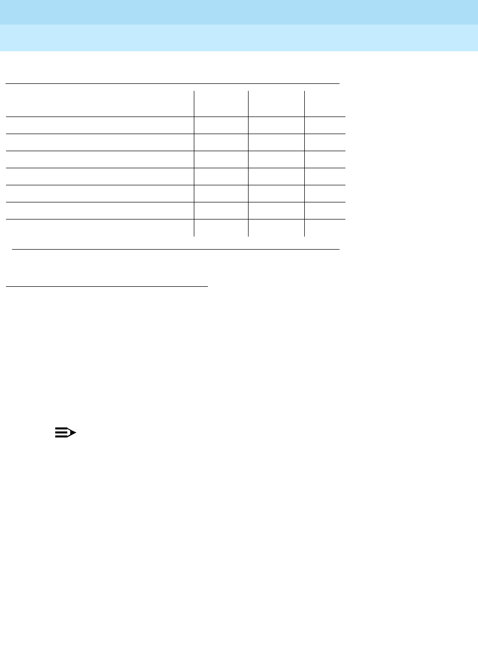
DEFINITY Enterprise Communications Server Release 6
Maintenance for R6r Volumes 1 & 2
555-230-126 Issue 2
January 1998
Maintenance Object Repair Procedures
Page 9-798ISDN-TRK (DS1 ISDN Trunk)
9
NPE Crosstalk Test (#6)
The NPE Crosstalk Test verifies that this port’s NPE channel talks on the selected
time slot and never crosses over to time slots reserved for other connections. If
the NPE is not working correctly, one-way and noisy connections may be
observed. This test is usually only part of a port’s long test sequence and takes
about 20 to 30 seconds to complete.
NOTE:
The TN464C/D UDS1 circuit pack has one SCOTCH-NPE chip instead of
several NPE chips.
1. D = Destructive, ND = Non-destructive
Table 9-270. System Technician-Demanded Tests: DS1-BD
Order of Investigation Short Test
Sequence Long Test
Sequence D/ND1
NPE Crosstalk Test (#6) X ND
Conference Circuit Test (#7) X ND
Audit and Update Test (#36) X X ND
Signaling Link State Check Test (#255) X X ND
Service State Audit Test (#256) X X ND
Call State Audit Test (#257) X X ND
ISDN Test Call Test (#258) X ND
Continued on next page

DEFINITY Enterprise Communications Server Release 6
Maintenance for R6r Volumes 1 & 2
555-230-126 Issue 2
January 1998
Maintenance Object Repair Procedures
Page 9-799ISDN-TRK (DS1 ISDN Trunk)
9
Table 9-271. TEST #6 NPE Crosstalk Test
Error
Code Test
Result Description/ Recommendation
ABORT Could not allocate the necessary system resources to run this test.
1. Retry the command at 1-minute intervals for a maximum of 5 times.
1000 ABORT System resources required to run this test are not available. The port may be in
use on a valid call. Use status station or status trunk commands to determine
when the port is available for testing.
1. Retry the command at 1-minute intervals for a maximum of 5 times.
1001 ABORT Could not allocate the necessary system resources to run this test.
1. Retry the command at 1-minute intervals for a maximum of 5 times.
1002 ABORT The system could not allocate time slots for the test. The system may be under
heavy traffic conditions or it may have time slots out-of-service due to TDM-Bus
errors. Refer to “TDM-Bus” to diagnose TDM-Bus errors.
1. If system has no TDM-Bus errors and is not handling heavy traffic, repeat
test at 1-minute intervals for a maximum of 5 times.
1003 ABORT The system could not allocate a tone receiver for the test. The system may be
oversized for the number of tone detectors present or some tone detectors may
be out-of-service.
1. Resolve any “TTR-LEV” errors in the Error Log.
2. Resolve any “TONE-PT” errors in the Error Log.
3. If neither condition exists, retry the test at 1-minute intervals for a maximum
of 5 times.
1004 ABORT The port has been seized by a user for a valid call. Use status station or
status trunk commands to determine when the port is available for testing.
1. Retry the command at 1-minute intervals for a maximum of 5 times.
1018 ABORT Maintenance is disable on this trunk.
1. Enable maintenance by entering ‘‘y’’ in the ‘‘Maintenance Tests?’’ field on
page 2 of the change trunk-group form.
1117 ABORT A service state audit message is outstanding.
1. Wait 2 minutes and then try again.
2000 ABORT Response to the test was not received within the allowable time period.
1. Retry the command at 1-minute intervals for a maximum of 5 times.
2020 ABORT The test did not run due to an already existing error on the specific port or a
more general circuit pack error.
1. Examine Error Log for existing errors against this port or the circuit pack
and attempt to diagnose the already existing error.
Continued on next page
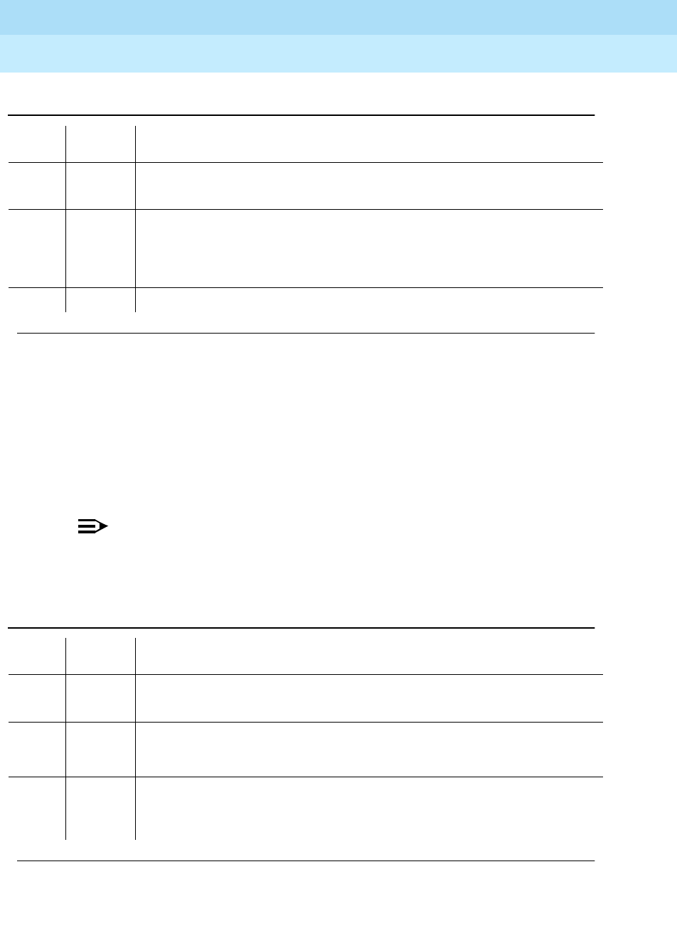
DEFINITY Enterprise Communications Server Release 6
Maintenance for R6r Volumes 1 & 2
555-230-126 Issue 2
January 1998
Maintenance Object Repair Procedures
Page 9-800ISDN-TRK (DS1 ISDN Trunk)
9
Conference Circuit Test (#7)
The Conference Circuit test verifies that the NPE channel for the port being
tested can correctly perform the conferencing function. The NPE is instructed to
listen to several different tones and conference the tones together. The resulting
signal is then measured by a tone detector port. If the level of the tone is within a
certain range, the test passes.
NOTE:
The TN464C/D UDS1 circuit pack has one SCOTCH-NPE chip instead of
several NPE chips.
2100 ABORT Could not allocate the necessary system resources to run this test.
1. Retry the command at 1-minute intervals for a maximum of 5 times.
Any FAIL The NPE of the tested port was found to be transmitting in error. This will cause
noisy and unreliable connections. The ISDN-TRK is moved to
out-of-service/near-end state.
1. Replace the circuit pack.
PASS The port is able to communicate over the TDM Bus.
Table 9-272. TEST #7 Conference Circuit Test
Error
Code Test
Result Description/ Recommendation
ABORT Could not allocate the necessary system resources to run this test.
1. Retry the command at 1-minute intervals for a maximum of 5 times.
1000 ABORT System resources required to run this test are not available. The port may be in
use on a valid call. Use status station or status trunk commands to determine
when the port is available for testing.
1004 ABORT The port has been seized by a user for a valid call. Use status station or status
trunk to determine when the port is available for testing.
1. Retry the command at 1-minute intervals for a maximum of 5 times.
Continued on next page
Table 9-271. TEST #6 NPE Crosstalk Test — Continued
Error
Code Test
Result Description/ Recommendation
Continued on next page

DEFINITY Enterprise Communications Server Release 6
Maintenance for R6r Volumes 1 & 2
555-230-126 Issue 2
January 1998
Maintenance Object Repair Procedures
Page 9-801ISDN-TRK (DS1 ISDN Trunk)
9
Audit and Update Test (#36)
This test sends port level translation data from switch processor to the DS1
interface circuit pack to assure that the trunk’s translation is correct. The port
audit operation verifies the consistency of the current state of trunk kept in the
DS1 interface circuit pack and in the switch software.
1018 ABORT Maintenance is disabled on this trunk.
1. Enable maintenance by entering ‘‘y’’ in the ‘‘Maintenance Tests?’’ field on
page 2 of the change trunk-group form.
1020 ABORT The test did not run due to an already existing error on the specific port or a
more general circuit pack error.
1. Examine Error Log for existing errors against this port or the circuit pack
and attempt to diagnose the already existing error.
2000 ABORT Response to the test request was not received within the allowable time period.
2100 ABORT Could not allocate the necessary system resources to run this test.
1. Retry the command at 1-minute intervals for a maximum of 5 times.
Any FAIL The NPE of the tested port did not conference the tones correctly. This will
cause noisy and unreliable connections.
1. Replace the circuit pack.
PASS The port can correctly conference multiple connections. User-reported troubles
on this port should be investigated using other port tests and examining station,
trunk, or external wiring.
Table 9-273. TEST #36 Audit and Update Test
Error
Code Test
Result Description/ Recommendation
1018 ABORT Maintenance is disabled on this trunk.
1. Enable maintenance by entering ‘‘y’’ in the ‘‘Maintenance Tests?’’ field on
page 2 of the change trunk-group form.
Continued on next page
Table 9-272. TEST #7 Conference Circuit Test — Continued
Error
Code Test
Result Description/ Recommendation
Continued on next page

DEFINITY Enterprise Communications Server Release 6
Maintenance for R6r Volumes 1 & 2
555-230-126 Issue 2
January 1998
Maintenance Object Repair Procedures
Page 9-802ISDN-TRK (DS1 ISDN Trunk)
9
Signaling Link State Check Test (#255)
The DS1 ISDN Trunk depends on the health of the appropriate TN464C/D UDS1
Interface circuit pack or TN767 DS1 interface circuit pack for proper operation. It
also depends on the ISDN-PRI D-channel (ISDN-LNK) trunk. This test checks the
status of those critical elements.
ABORT Internal system error
2000 ABORT Response to the test request was not received within the allowable time period.
2100 ABORT Could not allocate the necessary system resources to run this test.
FAIL Test failed due to internal system error.
1. Retry the command at 1-minute intervals for a maximum of 5 times.
PASS Trunk translation has been updated successfully. The current trunk states kept
in the DS1 interface circuit pack and switch software are consistent.
Table 9-274. TEST #255 Signaling Link State Check Test
Error
Code Test
Result Description/ Recommendation
None ABORT Internal system error
0 ABORT
1114 ABORT The signaling link is in a transitional state.
1. Retry the command at 1-minute intervals for a maximum of 5 times.
1018 ABORT Maintenance is disable on this trunk.
1. Enable maintenance by entering ‘‘y’’ in the ‘‘Maintenance Tests?’’ field on
page 2 of the change trunk-group form.
Continued on next page
Table 9-273. TEST #36 Audit and Update Test — Continued
Error
Code Test
Result Description/ Recommendation
Continued on next page

DEFINITY Enterprise Communications Server Release 6
Maintenance for R6r Volumes 1 & 2
555-230-126 Issue 2
January 1998
Maintenance Object Repair Procedures
Page 9-803ISDN-TRK (DS1 ISDN Trunk)
9
Service State Audit (#256)
As noted in the general description for DS1 ISDN Trunk, these trunks may be in
one of several service states. This test performs a Service State Audit with the
far-end switch.
For interfaces using country protocol 1 (including the US) the Service State Audit
executes in all trunk service states. A message is sent to the far-end switch to
ensure that both sides agree on the service state. A PASS for this test simply
means that the message has been successfully sent. Two minutes are allowed
for a reply. If no reply is received within that 2 minute window, the message is
sent out again. If that attempt fails, an error type 3073 will be logged and the
switch will attempt another Service State Audit every 15 minutes. If the trunk was
initially in-service, it is placed in the maintenance/far-end state. No outgoing calls
will be placed over this trunk, but incoming calls will be accepted. If an incoming
call is presented with the trunk in such a state, a Service State Audit is
immediately be attempted (the switch does not wait for the 15-minute cycle, but
tries to recover immediately).
For interfaces not using country protocol 1, the Service State Audit executes only
if the trunk is in the out-of-service/far-end state. A message is sent to the far-end
switch to attempt to bring the trunk back into the in-service state. A PASS for this
test simply means that the message has been successfully sent. Two minutes are
allowed for a reply. If no reply is received within that two minute window, the
message is sent out again. If again no response is received within two minutes,
the trunk remains in the out-of-service/far-end state. The switch will attempt
another Service State Audit after an hour has passed.
4 FAIL There is a problem with the signaling channel.
1. Consult the procedures for the ISDN-PRI Signaling Group (ISDN-SGRP).
Further information may also be obtained by consulting the procedures for
the ISDN-PRI Signaling Channel (ISDN-LNK).
8 FAIL There is a problem with the DS1 interface circuit pack.
1. Consult the procedures for the appropriate DS1 interface circuit pack
(DS1-BD or UDS1-BD).
PASS The signaling link hardware is OK.
Table 9-274. TEST #255 Signaling Link State Check Test — Continued
Error
Code Test
Result Description/ Recommendation
Continued on next page
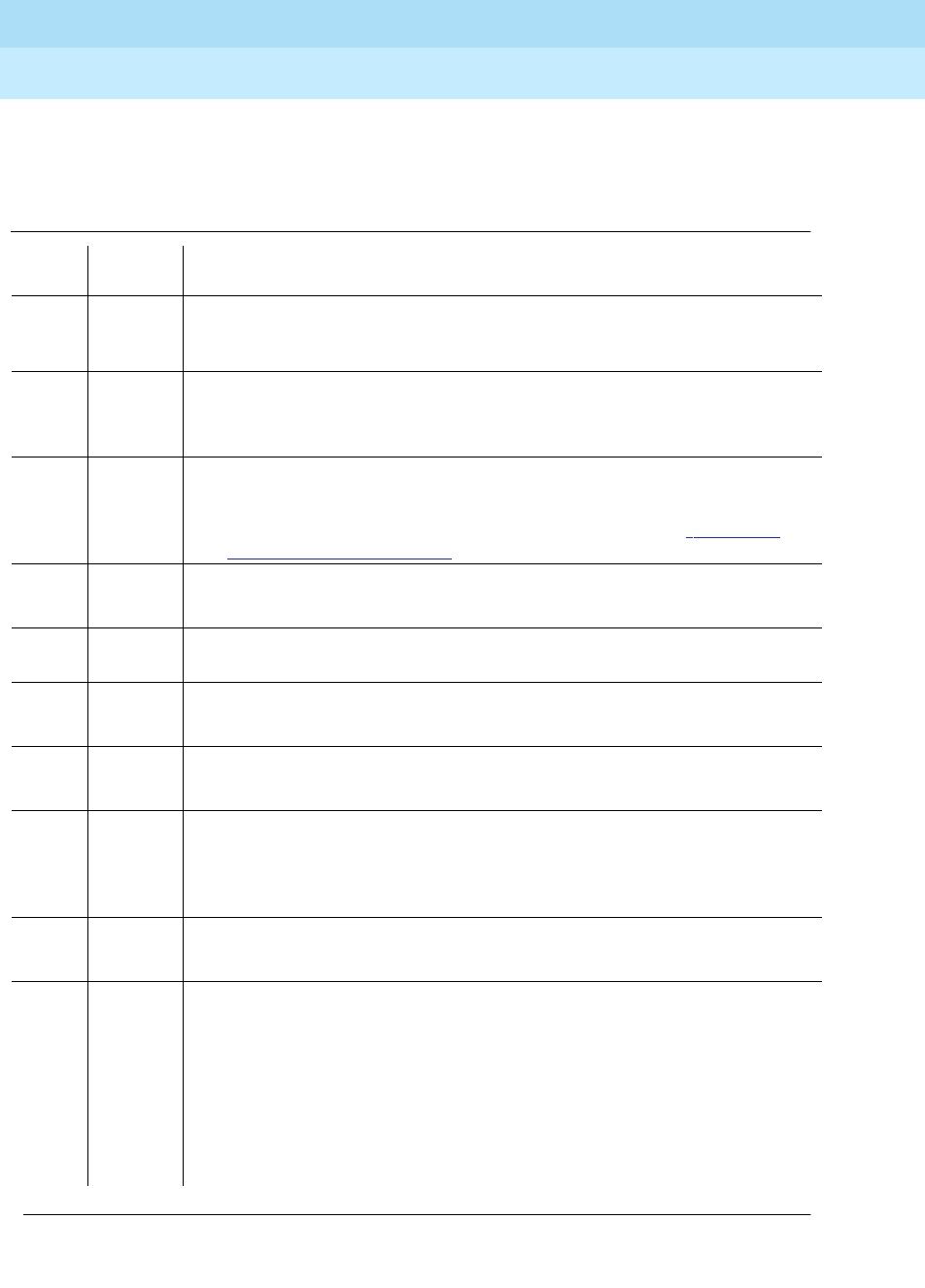
DEFINITY Enterprise Communications Server Release 6
Maintenance for R6r Volumes 1 & 2
555-230-126 Issue 2
January 1998
Maintenance Object Repair Procedures
Page 9-804ISDN-TRK (DS1 ISDN Trunk)
9
To investigate the service state of the DS1 ISDN Trunk, issue the status trunk
group#/member# command.
Table 9-275. TEST #256 Service State Audit Test
Error
Code Test
Result Description/ Recommendation
1000 ABORT Resources required to run this test were not available. The port may be on a
valid call or initializing. Use status station or status trunk to determine when
the trunk is available for testing. Check the results of Test #255.
1018 ABORT Maintenance is disable on this trunk.
1. Enable maintenance by entering ‘‘y’’ in the ‘‘Maintenance Tests?’’ field on
page 2 of the change trunk-group form.
1113 ABORT The signaling link has failed, so the system cannot send any messages on
behalf of this trunk.
1. Check the results of Test #255 and consult procedures for ‘‘ISDN-SGR
(ISDN-PRI Signaling Group)’’ in this chapter.
1114 ABORT The signaling link is in a transitional state.
1. Retry the command at 1-minute intervals for a maximum of 5 times.
1116 ABORT The trunk is not in the out-of-service/far-end state, which is required to run this
test on systems using a country protocol other than 1.
1117 ABORT A service state audit message is outstanding.
1. Wait 2 minutes and then try again.
2100 ABORT Could not allocate the necessary system resources to run this test.
1. Retry the command at 1-minute intervals for a maximum of 5 times.
1113 FAIL The signaling link has failed; the system cannot send any messages on behalf
of this trunk.
1. Consult procedures for ISDN-SGR (ISDN-PRI Signaling Group) and
ISDN-LNK (ISDN Signaling Link Port).
FAIL Internal system error
1. Retry the command at 1-minute intervals for a maximum of 5 times.
PASS Wait 4 minutes and then check the Error Log for any new errors of type 3073. If
there are none, then both sides of the ISDN connection agree on the service
state; the negotiation succeeded. If there is a new 3073 error, then the
negotiation failed (the far-end switch twice failed to respond within 2 minutes).
The switch will automatically retry every 15 minutes. If the trunk was initially
in-service, it is now placed in the maintenance/far-end state. Incoming calls will
be accepted, but no outgoing calls can be originated. If an incoming call is
presented, another Service State Audit will be immediately performed in an
attempt to put the DS1 ISDN Trunk in the proper state.
Continued on next page

DEFINITY Enterprise Communications Server Release 6
Maintenance for R6r Volumes 1 & 2
555-230-126 Issue 2
January 1998
Maintenance Object Repair Procedures
Page 9-805ISDN-TRK (DS1 ISDN Trunk)
9
Call State Audit Test (#257)
If a call is active on the trunk, the switches on both sides of the connection should
agree on the ISDN state of the call, as defined in the ISDN Protocol Specification.
This test audits internal call state data by querying the far-end switch as to the
ISDN state of the call. It can be helpful when trying to clear a hung call. If the
internal call state data on the near-end switch is different than that of the far-end
switch, then
the call will be torn down.
As with Test #256 (Service State Audit), a PASS simply means that an
appropriate message was composed and sent to the far-end switch. The ISDN
Specification allows up to 2 minutes for a reply. If a reply is not received within
the 2 minute window, a protocol time-out violation will be recorded in the error log
against the associated signaling channel (ISDN-LNK, error type 1).
Table 9-276. TEST #257 Call State Audit Test
Error
Code Test
Result Description/ Recommendation
1018 ABORT Maintenance is disable on this trunk.
1. Enable maintenance by entering ‘‘y’’ in the ‘‘Maintenance Tests?’’ field on
page 2 of the change trunk-group form.
1019 ABORT An audit is already in progress.
1. Wait 2 minutes and try again.
1113 ABORT The signaling link has failed, so the system cannot send any messages on
behalf of this trunk.
1. Check the results of Test #255 (Signaling Link State Check).
1114 ABORT The signaling link is in a transitional state.
1. Retry the command at 1-minute intervals for a maximum of 5 times.
1116 ABORT The trunk is in an out-of-service ISDN service state.
1. A call cannot be present if the trunk is in an ISDN out-of-service state, so a
call state audit would be inappropriate. No action necessary. (Use the
status trunk group#/member# command to investigate the ISDN state of
the trunk).
2100 ABORT Could not allocate the necessary system resources to run this test.
1. Retry the command at 1-minute intervals for a maximum of 5 times.
FAIL Internal system error
1. Retry the command at 1-minute intervals for a maximum of 5 times.
Continued on next page

DEFINITY Enterprise Communications Server Release 6
Maintenance for R6r Volumes 1 & 2
555-230-126 Issue 2
January 1998
Maintenance Object Repair Procedures
Page 9-806ISDN-TRK (DS1 ISDN Trunk)
9
ISDN Test Call Test (#258)
This test performs a far-end loop around to a far-end switch over an ISDN trunk.
The trunk’s service state must be in-service, maint-NE, or out-of-service/NE, and
no call can be active on the trunk. The test call can be initiated as part of a long
test sequence, or as an individual test, as described below. This test is valid only
for systems using country protocol 1 (including US), or when the far end has
loop-around capability.
A test call connection is established to a far-end switch over the ISDN trunk to be
tested. The digital port on a TN711D Maintenance/Test circuit pack generates a
test-pattern bit stream which is sent to the far-end switch and echoed back. The
received pattern is then compared to the sent pattern and checked for errors that
indicate a loss of integrity on the communications path.
If a test call is running when scheduled maintenance starts, the green LED is
turned off. To determine if a test call is still running, use the list isdn-testcall and
status isdn-testcall commands. A lit yellow LED on the Maintenance/Test circuit
pack also indicates that a test call is running.
PASS This switch sent a call state auditing message to the far-end switch to verify the
state of the call active on this trunk. If a call state mismatch is found, then the
call will be torn down within two minutes. If no call was active, then no message
was sent.
Table 9-276. TEST #257 Call State Audit Test — Continued
Error
Code Test
Result Description/ Recommendation
Continued on next page

DEFINITY Enterprise Communications Server Release 6
Maintenance for R6r Volumes 1 & 2
555-230-126 Issue 2
January 1998
Maintenance Object Repair Procedures
Page 9-807ISDN-TRK (DS1 ISDN Trunk)
9
Figure 9-43. Outgoing ISDN-PRI Test Call
Synchronous Test Calls
You can initiate a synchronous outgoing test call by entering one of the following
commands:
■test trunk group#/member# long [repeat #]
■test board UUCSS long [repeat #]
■test port UUCSSpp long [repeat #]
The above test sequences include a test-call for ISDN-PRI trunks. The duration of
the test call is 8.6 seconds for If unrestricted (B8ZS) B-channels and 9.4 seconds
for restricted (ZCS) B-channels. The test fails if the bit error rate retrieved from
the Maintenance/Test digital port is greater than 0. When this occurs, you will
need to perform further diagnostics, such as the test isdn-testcall command
described below.
Asynchronous Test Calls
You can start, query, and stop an outgoing test call by using the following
maintenance commands:
■test isdn-testcall group#/member# [minutes #]
This command initiates an outgoing ISDN-PRI test call for a maximum of
120 minutes. Default times are as above. Only one trunk per port network
can be tested at one time.
DS1 Facility
ISDN Trunk
(B-Channel)
UDS1
TN464
. . . . . . . . . . . . . . . . . . . . . . . . . . . . . . . . . . . . . . . . . . . . . . . . . . . . . . . .
.
.
.
.
.
.
.
.
.
.
.
.
.
.
.
.
.
.
.
.
.
.
.
.
.
.
.
.
.
.
.
.
.
.
.
.
.
.
.
.
.
.
.
.
. . . . . . . . . . . . . . . . . . . . . . . . . . . . . . . . . . . . . . . . . . . . . . . . . . . . . . . . .
.
.
.
.
.
.
.
.
.
.
.
.
.
.
.
.
.
.
.
.
.
.
.
.
.
.
.
.
.
.
.
.
.
.
.
.
.
.
.
.
.
.
.
.
.
M/T
TN771
G3r Switch originating test call
TDM Bus
Far-End Switch
with test call
terminating capability
. . . . . . . . . . . . . . . . . . . . . . . . . . . . .
.
.
.
.
.
.
.
.
.
.
.
.
.
. . . . . . . . . . . . . . . . . . . . . . . . . . . . . .
.
.
.
.
.
.
.
.
.
.
.
.
.
.
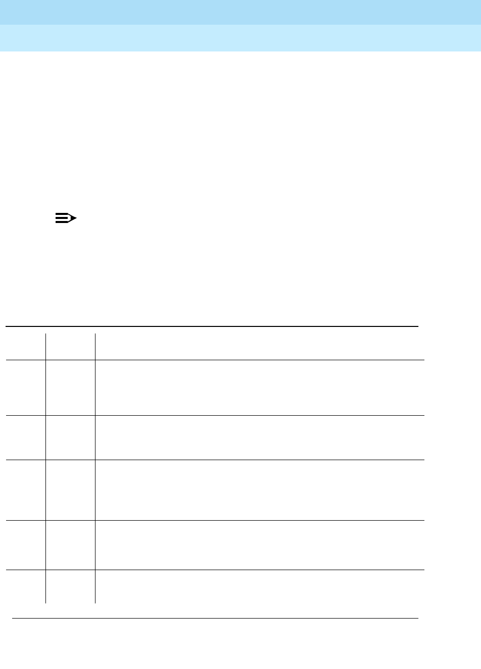
DEFINITY Enterprise Communications Server Release 6
Maintenance for R6r Volumes 1 & 2
555-230-126 Issue 2
January 1998
Maintenance Object Repair Procedures
Page 9-808ISDN-TRK (DS1 ISDN Trunk)
9
■status isdn-testcall group#/member#
This command displays the progress of the outgoing test call by reporting
bit and block error rates of the tested B-Channel.
■clear isdn-testcall group#/member#
This command terminates an outgoing test call already in progress.
Measurements already collected are not cleared until the next test call
begins.
A PASS of the asynchronous test indicates only that the test call was successfully
established. Use the status and list commands to get the results of the test.
NOTE:
Before attempting to make an ISDN-PRI test call to the public network (that
is, the network is the far-end), make sure that test call service is provisioned
by the network. The user must subscribe to Test Type 108 service and have
the correct far-end test call number administered on the trunk group form
for the call to be allowed.
Table 9-277. TEST #258 ISDN Test Call
Error
Code Test
Result Description/ Recommendation
4 ABORT There is a problem with the Signaling Channel.
1. Consult the procedures for the ISDN-PRI Signaling Group (ISDN-SGRP).
Further information may also be obtained by consulting the procedures for
the ISDN-PRI Signaling Channel (ISDN-LNK).
8 ABORT There is a problem with the DS1 interface circuit pack.
1. Consult the procedures for the appropriate DS1 interface circuit pack
(DS1-BD or UDS1-BD).
1004 ABORT B channel in use.
1. Determine if a call is active on this DS1 ISDN Trunk via the status trunk
group#/member# command.
2. When the service state indicates in-service/idle, retry the test.
1005 ABORT Bad Configuration (such as no Maintenance/Test circuit pack)
1. Make sure the Maintenance/Test Circuit Pack is inserted.
2. Repeat the test.
1018 ABORT Test call is disabled.
1. Enable Maintenance on the Trunk Group form.
Continued on next page

DEFINITY Enterprise Communications Server Release 6
Maintenance for R6r Volumes 1 & 2
555-230-126 Issue 2
January 1998
Maintenance Object Repair Procedures
Page 9-809ISDN-TRK (DS1 ISDN Trunk)
9
1019 ABORT Another Test call is in progress.
1. Issue the list isdn-testcall command to locate the test call.
2. Issue the status isdn-testcall command to find out the duration and start
time of the test call.
3. Issue the clear isdn-testcall command to stop the test call from running.
4. If time and duration indicate that the test call should have stopped, and
the clear isdn-testcall command does not work, refer to M/T-DIG
(Maintenance/Test Digital Port) for recommended maintenance strategy.
1020 ABORT There is a problem with the DS1 Interface Circuit Pack.
1. Refer to “DS1-BD or UDS1-BD”.
1024 ABORT (M/T-DIG) Maintenance/Test Digital Port in use.
1. Wait until yellow and green LED s are turned off on the M/T-BD
(Maintenance/Test circuit pack).
2. Retry test. If problem persists, refer to M/T-DIG (Maintenance/Test Digital
Port).
1113 ABORT The signaling link has failed. Therefore, the system cannot send any messages
on behalf of this trunk.
1. Check the results of Test #255 (Signaling Link State Check Test).
1116 ABORT The switch could not appropriately change the ISDN service state.
1. Determine if a call is active on this DS1 ISDN Trunk (use the status trunk
group#/member# command). If so, proceed as for Error Code 1119.
2. If not, check the Error and Alarm Logs for problems with this ISDN-TRK
(DS1 ISDN Trunk) MO.
1117 ABORT ISDN Service message is already outstanding.
1. Wait 2 minutes. Then try again.
1118 ABORT Far-end of ISDN trunk is not administered.
1. Check the administration of the far-end ISDN trunk.
2. Issue the status trunk group#/member# command.
3. Try the test again.
1119 ABORT The test call was aborted due to a normal call attempt on this trunk. NOTE: The
test call will only be performed if the trunk is idle.
1. Either wait for the normal call to terminate normally, or force it to be
dropped by using the busyout trunk trunk group/trunk member
command to busyout the DS1 ISDN Trunk. When the trunk is idle, retry the
test.
Table 9-277. TEST #258 ISDN Test Call — Continued
Error
Code Test
Result Description/ Recommendation
Continued on next page

DEFINITY Enterprise Communications Server Release 6
Maintenance for R6r Volumes 1 & 2
555-230-126 Issue 2
January 1998
Maintenance Object Repair Procedures
Page 9-810ISDN-TRK (DS1 ISDN Trunk)
9
1120 ABORT The DS1 ISDN Trunk is in the ISDN out-of-service/far-end state.
1. Try to change the service state via Test #256 (Service State Audit Test)
and then try this test again. Keep in mind that the trunk may be in the
out-of-service/far-end state due to problems at the far-end switch. If that is
the case, no remedial action can be taken at this end.
1122 ABORT There is no test line number for the far-end switch.
1. Check the Trunk Group Administration form.
1123 ABORT There is no Feature Access Code administration for this Facility Test.
1. Check the Dial Plan and Feature Administration forms.
2000
2012
None
ABORT Internal system error.
1. Retry the command at 1-minute intervals a maximum of 5 times.
2035 ABORT The call has timed out, perhaps because of a lack of system resources.
1. Wait 1 minute and try again.
2036
2037 ABORT Internal system error.
1. Follow recommendation for ABORT code 2012.
2038
2039 ABORT A problem occurred while trying to read the test data.
1. Wait 1 minute and then try again. If the test aborts again in the same
manner, there is a serious internal problem.
2040 ABORT Internal system error. Follow recommendations for ABORT code 2012.
2041 ABORT The call has timed out, perhaps because of a lack of system resources. Follow
recommendations for ABORT code 2035.
2066 ABORT Could not establish test call.
1. Retry the command at 1-minute intervals a maximum of 5 times.
2067 ABORT The call has timed out, perhaps because of a lack of system resources. Follow
recommendations for ABORT code 2035.
2074 ABORT Bit and Block Error query failed.
1. Retry the command at 1-minute intervals a maximum of 5 times.
2. If the test continues to abort, there may be a serious internal problem with
M/T-DIG (Maintenance/Test Digital Port). If this is the case, refer to the
M/T-DIG (Maintenance/Test Digital Port).
2075 ABORT Internal system error. Follow recommendations for ABORT code 2012.
2100 ABORT Could not allocate the necessary system resources to run this test.
1. Retry the command at 1-minute intervals a maximum of 5 times.
Table 9-277. TEST #258 ISDN Test Call — Continued
Error
Code Test
Result Description/ Recommendation
Continued on next page

DEFINITY Enterprise Communications Server Release 6
Maintenance for R6r Volumes 1 & 2
555-230-126 Issue 2
January 1998
Maintenance Object Repair Procedures
Page 9-811ISDN-TRK (DS1 ISDN Trunk)
9
2104 ABORT Call dropped or could not be originated.
1. Make sure service is provisioned by the network.
2. Check the administration of the far-end test line extension on the trunk
group administration form.
3. Check the administration of the Testcall BCC (Bearer Capability Class) on
the trunk group administration form.
4. Check the reason for termination with status isdn-testcall.
5. For further instructions see Troubleshooting ISDN Testcalls in Chapter 6.
6. Try the test again.
2201
2202
2203
2204
2205
ABORT Internal system error. Follow recommendations for ABORT code 2012.
2206 ABORT Could not allocate the necessary system resources to run this test. Follow
recommendations for ABORT code 2100.
2208 ABORT Internal system error. Follow recommendations for ABORT code 2012.
2209
2210 ABORT Could not allocate the necessary system resources to run this test. Follow
recommendations for ABORT code 2100.
2211 ABORT Internal system error. Follow recommendations for ABORT code 2012.
2212 ABORT Call terminated by unexpected disconnect.
1. Wait 1 minute and then try again.
2213 ABORT The call has timed-out, perhaps because of a lack of system resources. Follow
recommendations for ABORT code 2035.
2214 ABORT Call terminated by unexpected disconnect.
1. Wait 1 minute and then try again.
2215
2216
2217
2218
2219
ABORT Internal system error. Follow recommendations for ABORT code 2012.
2220 ABORT Call terminated prematurely.
1. Wait 1 minute and try again.
Table 9-277. TEST #258 ISDN Test Call — Continued
Error
Code Test
Result Description/ Recommendation
Continued on next page

DEFINITY Enterprise Communications Server Release 6
Maintenance for R6r Volumes 1 & 2
555-230-126 Issue 2
January 1998
Maintenance Object Repair Procedures
Page 9-812ISDN-TRK (DS1 ISDN Trunk)
9
2221
2222
2223
2224
2225
2226
ABORT Internal system error. Follow recommendations for ABORT code 2012.
2227 ABORT Could not allocate the necessary system resources to run this test. Follow
recommendations for ABORT code 2100.
2042 FAIL Comparison of data sent to data received indicates a loss of integrity on the
communications path.
1. Take the trunk out of service and check the quality of the DS1 connection,
including the transmission facility and any external equipment such as
DAC s, CSU s, etc. Use test isdn-testcall and status isdn-testcall
commands to get the bit and block error rates.
PASS The test pattern was sent and received properly. If the synchronous test call
was performed (long test sequence), this indicates that the communications
path is operating properly. If the test isdn-testcall command was used, PASS
indicates only that the test call was established. Use the status isdn-testcall
command to get the bit and block error rates detected by the test. If the bit
and block error rates are not acceptable, perform a complete analysis of the
DS1 facility including the transmission facility and any external equipment
such as DAC s, CSU s, etc.
Table 9-277. TEST #258 ISDN Test Call — Continued
Error
Code Test
Result Description/ Recommendation
Continued on next page

DEFINITY Enterprise Communications Server Release 6
Maintenance for R6r Volumes 1 & 2
555-230-126 Issue 2
January 1998
Maintenance Object Repair Procedures
Page 9-813JNL-PRNT (Journal Printer Link)
9
JNL-PRNT (Journal Printer Link)
The maintenance strategies for JNL-PRNT (Journal Printer Link) and PMS-PRNT
(PMS Printer Link) are the same. Refer to the "PMS-PRNT/JNL-PRNT (PMS Printer
Link)" section of this chapter.
MO Name (in
Alarm Log) Alarm Level Initial Command to Run Full Name of MO
JNL-PRNT MINOR test journal wakeup-log Journal Printer Link
JNL-PRNT WARNING test journal wakeup-log Journal Printer Link

DEFINITY Enterprise Communications Server Release 6
Maintenance for R6r Volumes 1 & 2
555-230-126 Issue 2
January 1998
Maintenance Object Repair Procedures
Page 9-814LGATE-AJ
9
LGATE-AJ
See BRI-SET
LGATE-BD
See BRI-BD
LGATE-PT
See BRI-PT

DEFINITY Enterprise Communications Server Release 6
Maintenance for R6r Volumes 1 & 2
555-230-126 Issue 2
January 1998
Maintenance Object Repair Procedures
Page 9-815LOG-SVN (Login Security Violation)
9
LOG-SVN (Login Security Violation)
The Security Violation Notification (SVN) feature provides notification when the
number of failed attempts to access the system administration/maintenance
interface meets or exceeds customer administered threshold parameters.
A major alarm is logged whenever a security violation is detected involving an
Lucent services login ID and that login ID has been disabled as a result of
detection of the security violation. The capability to disable a login ID following
detection of a security violation involving that login ID is administrable on a per
login ID basis.
Refer to the
DEFINITY Communications System Generic 3 V2 Implementation
,
555-230-653, Issue 1 for information on administration required for the Security
Violation Notification feature, and the option to disable a login ID following
detection of a security violation involving the affected login ID.
Error Log Entries and Test to Clear Values
General Information about log-svn error log entries:
a. The number (1 - 15), that appears in the error type field, corresponds to
the location of the login in the internal login data structure.
b. The
Alt Name
field on the alarm report indicates the login ID associated
with the security violation and major alarm.
c. These errors/alarms are associated with a number of failed attempts to
access the system management/maintenance interface using an Lucent
services login ID that meet or exceed the customer administered
threshold parameters. The associated alarm is immediately raised as a
major alarm.
1. Where <login ID> is the Lucent services login ID for which the security violation was detected. The
Alt Name field indicates the login ID associated with the security violation and the major alarm.
MO Name (in
Alarm Log) Alarm Level Initial Command to Run1Full Name of MO
LOG-SVN MAJOR enable login <login ID> Login Security Violation
Table 9-278. Security Violation Notification Error Log Entries
Error
Type Aux
Data Associated Test Alarm
Level On/Off
Board Test to Clear Value
1-15 None None Major OFF enable login <login ID>

DEFINITY Enterprise Communications Server Release 6
Maintenance for R6r Volumes 1 & 2
555-230-126 Issue 2
January 1998
Maintenance Object Repair Procedures
Page 9-816LOG-SVN (Login Security Violation)
9
d. The affected login ID will be disabled as a result of detection of the
security violation, unless it is the last enabled INADS type login on the
system. The provision to disable a login ID following detection of a security
violation involving that login ID is administerable on a login ID basis.
e. The enable login command is used to both enable a login that has been
disabled, and to retire any login security violation alarms associated with
the login ID.
f. Use of the enable login command to enable a login and/or retire alarms
must be executed using a login ID with greater service level hierarchy
permissions.
g. Access to the enable login command is controlled through the Administer
Permissions field on the Command Permission Categories form. This field
(Administer Permissions) must be set to "y" to access the enable login
command.
h. The
Port
alarm report field will set to the port where the final invalid login
attempt, involving the alarmed login ID, was detected. Valid port values for
G3i products include:
— MGR1 — Dedicated manager 1 or G3 management terminal
connection
— NET-n — Network controller dial up port
— INADS — INADS port
— EPN — EPN maintenance EIA port
— EIA — Other EIA port
Valid port value for G3r products include:
— SYSAM _LOC — Local administration port
— SYSAM _RMT — Remote administration port
— SYS_PORT — System Port
— MAINT — Maintenance port
i. The
Svc State
alarm report field will be set to OUT if the login ID is in the
disabled state as a result of detection of a security violation involving the
login ID. Once the login ID has been enabled, the field will be set to IN.
j. The source or reason of the failed login attempts should be identified and
the cause corrected prior to re-enabling a login ID and/or retiring any
alarms associated with the login ID. The cause may be something as
innocuous as the failure of Lucent services automatic login software, to
something as insidious as a hacker attempting to gain access to the
switch system management interface.
Prior to retiring an SVN alarm and enabling the associated login ID, the monitor
security-violations login command can be used to access information about
the invalid login attempts that caused the security violation. This information can

DEFINITY Enterprise Communications Server Release 6
Maintenance for R6r Volumes 1 & 2
555-230-126 Issue 2
January 1998
Maintenance Object Repair Procedures
Page 9-817LOG-SVN (Login Security Violation)
9
be useful in determining the source of the invalid attempts and analyzing why
they occurred.
The list logins command provides status information about logins on the system.
If a login has been disabled as a result of a security violation, the status will be
"
svn-disabled
."
Procedure to Retire SVN Alarm
To retire a SVN alarm:
1. Enter the command enable login <login ID>.
The login ID associated with that alarm is displayed in the
Alt Name
field of
the alarm report and the alarm is retired.

DEFINITY Enterprise Communications Server Release 6
Maintenance for R6r Volumes 1 & 2
555-230-126 Issue 2
January 1998
Maintenance Object Repair Procedures
Page 9-818MAINT (EPN Maintenance Circuit Pack)
9
MAINT (EPN Maintenance Circuit
Pack)
The TN775B EPN Maintenance circuit pack monitors and supports environmental
maintenance for EPN multicarrier or single-carrier cabinets. The EPN
Maintenance circuit pack provides switch software with a mechanism to activate
or deactivate Emergency Transfer in the EPN. Control by the system of
Emergency Transfer can be overridden by the Emergency Transfer Switch on the
faceplate of the circuit pack. The EPN Maintenance circuit pack invokes
Emergency Transfer when the EPN loses contact with the PPN or when the EPN
Maintenance circuit pack loses contact with all Expansion Interface circuit packs.
The EPN Maintenance circuit pack handles loss of AC power in the EPN
multicarrier cabinet by supplying battery power for 15 seconds to the EPN
cabinet and then an additional 10 minutes of power to just the control carrier in
the EPN. When power fails in a single-carrier EPN cabinet, no such power
holdover is available. In the event that an Expansion Interface circuit pack goes
insane and is reset six times within 15 minutes, the EPN Maintenance circuit pack
will hold the Expansion Links reset preventing the Expansion Interface circuit
pack from running.
The EPN Maintenance circuit pack has alarm LED s which indicate the presence
of Major, Minor, and Warning alarms. A flashing LED indicates the presence of
an alarm within the cabinet. A continuously lit LED indicates the presence of an
alarm elsewhere in the system.
A management terminal (G3-MT) can be directly connected to the TN775B EPN
Maintenance circuit pack. This link operates at 9600 baud, but system software
throttles the rate of data flow to the TN775B for display on the G3-MT to about
1200 baud. All system commands can be executed via the EPN G3-MT login.
However, due to the slow speed at which the EPN login operates, it is
recommended that it be used only for maintenance sessions and not for system
administration.
The PPN communicates with the EPN Maintenance circuit pack via the following
path; uplink messages from the EPN Maintenance circuit pack to the PPN take
exactly the reverse path. Messages flow from the UN331B Processor circuit pack
in the SPE to the TN1655 Packet Interface circuit pack, over the Lan Bus to the
Active PPN Expansion Interface circuit pack, across the fiber link to the Active
EPN Expansion Interface circuit pack, and over a serial link to the EPN
Maintenance circuit pack.
MO Name (in
Alarm Log) Alarm
Level Initial Command to
Run Full Name of MO
MAINT MINOR test maintenance sh EPN Maintenance Circuit Pack
MAINT MAJOR test maintenance l EPN Maintenance Circuit Pack

DEFINITY Enterprise Communications Server Release 6
Maintenance for R6r Volumes 1 & 2
555-230-126 Issue 2
January 1998
Maintenance Object Repair Procedures
Page 9-819MAINT (EPN Maintenance Circuit Pack)
9
The EPN Maintenance circuit pack must be physically inserted into the
dedicated slot marked Maintenance in the A carrier of the EPN. The serial links
from the EPN Maintenance circuit pack to the Expansion Interface circuit packs
are physically connected from this dedicated slot to slots 2A01 and 2B02 (2B02
is used only if there is duplicated Port Network Connectivity). The serial link from
slot 2A01 to the maintenance slot is hard-wired into the backplane of carrier A,
whereas the serial link from slot 2B02 to the maintenance slot is a ribbon cable
connecting the two slots. The serial link from the EPN Maintenance circuit pack to
the terminal is also a ribbon cable which plugs into a connector labeled TERM on
the back of carrier A.
The maintenance strategy for the EPN Maintenance circuit pack consists of
checking the integrity of the communications path to/from the EPN Maintenance
circuit pack, testing individual hardware components on the EPN Maintenance
circuit pack, and keeping the alarm LED s up-to-date. The individual hardware
components include the serial interfaces which handle the serial links connected
to the EPN Maintenance circuit pack. There are three serial interfaces, one for
each possible Expansion Interface circuit pack and one for the terminal.
Since the EPN Maintenance circuit pack supports environmental maintenance in
the EPN, trouble with the EPN Maintenance circuit pack can cause environmental
maintenance to falsely detect problems. In a multicarrier cabinet EPN, these
environmental MOs include: POWER (Battery & Battery Charger), CARR-POW
(Carrier Port Power Unit), AC-POWER (AC Power), CABINET (Cabinet Sensors),
EMG-XFER (Emergency Transfer), EXT-DEV (External Device Alarm), and
CUST-ALM (Customer-Provided Alarming Device). In a single carrier cabinet
EPN, these environmental MOs include DC-POWER (Single Carrier Cabinet
Power), EMG-XFER (Emergency Transfer), EXT-DEV (External Device Alarm),
and CUST-ALM (Customer-Provided Alarming Device).

DEFINITY Enterprise Communications Server Release 6
Maintenance for R6r Volumes 1 & 2
555-230-126 Issue 2
January 1998
Maintenance Object Repair Procedures
Page 9-820MAINT (EPN Maintenance Circuit Pack)
9
Error Log Entries and Test to Clear Values
Notes:
a. A value of 0 indicates that PNC-A (and therefore, the Expansion Interface
circuit pack located on PNC-A) was active when this error occurred. A
value of 1 indicates that PNC-B (and therefore, the Expansion Interface
circuit pack located on PNC-B) was active when this error occurred. To
clear this problem, make sure the Active PNC is the same as that
indicated by the Aux Value.
b. Multiple values can appear in the Aux Data field. There will be other errors
in the log if there is a real problem. Use these other errors to troubleshoot
the problem.
c. The serial link between the Expansion Interface circuit pack in the A
carrier and the EPN Maintenance circuit pack is defective.
1. Run the Short Test Sequence first. If all tests pass, run the Long Test Sequence. Refer to the
appropriate test description and follow the recommended procedures.
2. Major and Minor alarms may be downgraded to Warning alarms based on the value used in the
set options command.
Table 9-279. EPN Maintenance Circuit Pack Error Log Entries
Error
Type Aux
Data Associated Test Alarm
Level On/Off
Board Test to Clear Value
010 Any Any Any test maintenance sh r 1
1(a) 0
1 EPN Maintenance Circuit
Pack Reset Test (#306) MINOR ON test maintenance l
513(a) 0
1 MGR I Channel Loop
Test (#228) MINOR ON test maintenance sh r 3
769(b) Any Sanity Handshake Test
(#106)
1537(a) 0
1Sanity Maze Test (#303) MINOR ON test maintenance sh r 3
2561(a) 0
1 Sanity Handshake Test
(#106) MINOR ON test maintenance sh r 3
2817(a) 0(b)
1Serial Channel Loop
Test (#229) MINOR ON test maintenance sh r 3
3329(c) Any Serial Link Test (#337) MINOR/
WARNING2OFF test maintenance sh r 3
3585(d) Any Serial Link Test (#337) MINOR/
WARNING2OFF test maintenance sh r 3

DEFINITY Enterprise Communications Server Release 6
Maintenance for R6r Volumes 1 & 2
555-230-126 Issue 2
January 1998
Maintenance Object Repair Procedures
Page 9-821MAINT (EPN Maintenance Circuit Pack)
9
d. The serial link between the Expansion Interface circuit pack in the B
carrier and the EPN Maintenance circuit pack is defective.
System Technician-Demanded Tests:
Descriptions and Error Codes
Always investigate tests in the order presented in the table below when
inspecting errors in the system. By clearing error codes associated with the
Sanity Handshake Test,
for example, you may also clear errors generated from
other tests in the testing sequence.
Sanity Handshake Test (#106)
This test checks the EPN Maintenance circuit pack’s ability to respond to
queries. A message is sent to the EPN Maintenance circuit pack which then
sends a message back. If the response message is received, then the EPN
Maintenance circuit pack is queried for the EPN cabinet type (valid EPN cabinet
types are single carrier and multicarrier cabinets). The EPN Maintenance circuit
pack reads pins on the backplane of carrier A that identify the type of cabinet
and report this information. If a valid cabinet type is returned, then the test
passes.
1. D = Destructive, ND = Non-destructive
Order of Investigation Short Test
Sequence Long Test
Sequence D/ND1
Sanity Handshake Test (#106) X X ND
EPN Maintenance Circuit Pack Reset Test (#306) X D
Serial Channel Local Looparound Test (#229) X X ND
MGR I Channel Local Looparound Test (#228) X D
EPN Maintenance Circuit Pack Sanity Maze Test (#303) X X ND
EPN Maintenance Circuit Pack Serial Link Test (#337) X X ND

DEFINITY Enterprise Communications Server Release 6
Maintenance for R6r Volumes 1 & 2
555-230-126 Issue 2
January 1998
Maintenance Object Repair Procedures
Page 9-822MAINT (EPN Maintenance Circuit Pack)
9
Table 9-280. TEST #106 Sanity Handshake Test
Error
Code Test
Result Description/ Recommendation
ABORT Internal system error.
1000 ABORT System resources required for this test are not available.
2000 ABORT Response to cabinet query was not received in the allowable time period.
2033 ABORT Internal system error.
1. Retry the command at 1-minute intervals a maximum of five times.
2046 ABORT The EPN Maintenance circuit pack reported an invalid cabinet type. Not
knowing the cabinet type of the EPN will prevent all EPN environment
maintenance from running.
1. Retry the command.
2. If the test continues to abort with 2046, then either the EPN Maintenance
circuit pack is defective, or the EPN cabinet wiring is defective. First,
replace the EPN Maintenance circuit pack.
3. If the test continues to abort with 2046, then the EPN cabinet wiring is
defective in the A carrier and the EPN Maintenance circuit pack cannot
read the backplane pins to determine the cabinet type.
10601 ABORT Test disabled via software patch.
Continued on next page

DEFINITY Enterprise Communications Server Release 6
Maintenance for R6r Volumes 1 & 2
555-230-126 Issue 2
January 1998
Maintenance Object Repair Procedures
Page 9-823MAINT (EPN Maintenance Circuit Pack)
9
Management Terminal Channel Local
Loop-Around Test (#228)
This test is destructive.
This test checks TN775B on-board circuitry associated with the serial link for the
management terminal connection. This test will not cause the local terminal login
FAIL EPN Maintenance circuit pack did not respond to Sanity Handshake and the
test timed out.
1. Verify that the carrier A power units are good. If the -5 volt unit is
defective in the A carrier, then communication with the EPN Maintenance
circuit pack will not be possible.
2. If the -5 volt unit is good and this test continuously fails, background
maintenance will automatically escalate to an EPN Maintenance circuit
pack Reset (Test #306). Otherwise, manually invoke an EPN
Maintenance circuit pack Reset by issuing the test maintenance long
command and evaluating any generated error codes from Test #306. If
Test #306 passes, this test should also PASS. Use the following steps to
determine if the EPN Maintenance circuit pack, or the serial link to the
EPN Maintenance circuit pack, is defective:
Duplicated Port Network Connectivity:
1. Switch Port Network Connectivity by entering reset pnc interchange.
2. Run the Short Test Sequence against the EPN Maintenance circuit pack.
If Test #106 still fails, replace the EPN Maintenance circuit pack and
retest. Otherwise, follow the error routines for any errors that are logged
by this Short Test.
Simplex Port Network Connectivity:
1. Replace the EPN Maintenance circuit pack and invoke the Short Test
Sequence against it.
2. If error persists, replace the EPN Expansion Interface circuit pack, at a
time when the EPN can go down with minimal inconvenience.
3. If the error still persists, the problem is with the actual serial link in A
carrier backplane and not with the EPN Maintenance circuit pack.
PASS The communications path to and from the EPN Maintenance circuit pack is
sane, and the EPN Maintenance circuit pack can read and report the correct
EPN cabinet type. The EPN Maintenance circuit pack may still have
problems related to Tests #228, #229, #303, or #306.
Table 9-280. TEST #106 Sanity Handshake Test — Continued
Error
Code Test
Result Description/ Recommendation
Continued on next page

DEFINITY Enterprise Communications Server Release 6
Maintenance for R6r Volumes 1 & 2
555-230-126 Issue 2
January 1998
Maintenance Object Repair Procedures
Page 9-824MAINT (EPN Maintenance Circuit Pack)
9
to drop, but any data displayed on the terminal while the test is running will be
lost.
The EPN Maintenance circuit pack has 3 separate serial interfaces:
■One to the management terminal which is tested by Test #228
■One to the active EI circuit pack which is tested by Test #229
■One to the standby EI circuit pack which is tested by Test #229
Table 9-281. TEST #228 Management Terminal Channel Local Loop-Around Test
Error
Code Test
Result Description/ Recommendation
1000 ABORT System resources required for this test are not available.
2000 ABORT Response to the test was not received within the allowable time period.
2033 ABORT Internal system error.
1. Retry the command at 1-minute intervals a maximum of 5 times.
2034 ABORT Background EPN Maintenance circuit pack maintenance is running the MGR I
Channel Local Looparound Test.
1. Wait 30 seconds and retry the test a maximum of 5 times.
22801 ABORT Test disabled via software patch.
FAIL Test failed which means the EPN terminal is not usable.
1. Run the test three more times. Replace the EPN Maintenance circuit pack if
the test continues to fail.
PASS The serial interface circuitry on the EPN Maintenance circuit pack which controls
the EPN-connected terminal is functioning properly. If there are still troubles with
the EPN G3-MT terminal, the problem may be one of the following:
1. The EPN-connected terminal is not configured properly. The connection
between the terminal and the EPN Maintenance circuit pack must be set up
at 9600 baud.
2. The serial link from the back of carrier A to the EPN terminal may be
defective. The serial link consists of the connector on the back of carrier A
labeled TERM and the ribbon cable running to the terminal.
3. The terminal may be defective. Try another terminal.
4. Since this test is not 100 percent accurate, there may still be problems with
the EPN Maintenance circuit pack.
Continued on next page

DEFINITY Enterprise Communications Server Release 6
Maintenance for R6r Volumes 1 & 2
555-230-126 Issue 2
January 1998
Maintenance Object Repair Procedures
Page 9-825MAINT (EPN Maintenance Circuit Pack)
9
Serial Channel Local Looparound Test (#229)
This test checks TN775B on-board circuitry associated with the serial links to the
Expansion Interface circuit packs. A request is sent to the EPN Maintenance
circuit pack over the Active link via the Active Expansion Interface circuit pack
serial interface circuitry to test the serial interface circuitry of the standby
Expansion Interface circuit pack link. If a response is received, then by definition
the serial interface circuitry associated with the Active link is good.
The EPN Maintenance circuit pack has 3 separate serial interfaces:
■One to the management terminal which is tested by Test #228
■One to the active EI circuit pack which is tested by Test #229
■One to the standby EI circuit pack which is tested by Test #229
Table 9-282. TEST #229 Serial Channel Local Looparound Test
Error
Code Test
Result Description/ Recommendation
1000 ABORT System resources required to run this test are not available.
2000 ABORT Response to the test request was not received within the allowable time
period.
2033 ABORT Internal system error.
1. Retry the command at one-minute intervals a maximum of 5 times.
2034 ABORT Background EPN Maintenance circuit pack maintenance is running the Serial
Channel Local Looparound Test.
1. Wait 30 seconds, and retry the test a maximum of 5 times.
22901 ABORT Test disabled via software patch.
Continued on next page
DEFINITY Enterprise Communications Server Release 6
Maintenance for R6r Volumes 1 & 2
555-230-126 Issue 2
January 1998
Maintenance Object Repair Procedures
Page 9-826MAINT (EPN Maintenance Circuit Pack)
9
EPN Maintenance Circuit Pack Sanity Maze Test
(#303)
The EPN Maintenance circuit pack processor has direct access to special
registers in the EPN Maintenance circuit pack. These registers are tied to such
things as the Expansion Interface circuit pack reset leads and Carrier Port Power
Unit reset leads (which enable the EPN Maintenance circuit pack to recycle
carriers). To prevent an insane EPN Maintenance circuit pack from inadvertently
controlling these external devices, a special interface called the Sanity Maze is
provided that must first be navigated by the EPN Maintenance circuit pack
FAIL The on-board circuitry associated with the Standby serial link is defective.
Since the EPN Maintenance circuit pack reported this failure, the on-board
circuitry associated with the Active serial link is functional.
1. This test checks the circuitry on the EPN Maintenance circuit pack
associated with the Standby Expansion Interface link.
a. In a switch without duplicated Port Network Connectivity, current
service will not be affected because the circuitry failing is not being
used. Nevertheless, a Minor alarm will remain in the Alarm Log against
MAINT. Therefore, the EPN Maintenance circuit pack must be
replaced.
b. In a switch with duplicated Port Network Connectivity, service will not
be affected as long as you DO NOT INTERCHANGE THE PNCS;
otherwise, the connection to the EPN Maintenance circuit pack will be
lost. Losing the EPN Maintenance circuit pack connection will mean
loss of the connection to the terminal and EPN Environment
maintenance. The EPN Maintenance circuit pack must be replaced to
correct this problem.
PASS The on-board circuitry associated with both Expansion Interface circuit pack
serial links is good. If there is still a problem communicating with the EPN
Maintenance circuit pack, check the following:
1. The cable comprising the serial link (B carrier Expansion Interface circuit
pack to EPN Maintenance circuit pack only) may be defective.
2. The EPN Maintenance circuit pack may actually be defective.
NOTE:
This test may not be 100 percent accurate.
3. The Expansion Interface circuit pack on the Standby link may be
defective.
Table 9-282. TEST #229 Serial Channel Local Looparound Test — Continued
Error
Code Test
Result Description/ Recommendation
Continued on next page

DEFINITY Enterprise Communications Server Release 6
Maintenance for R6r Volumes 1 & 2
555-230-126 Issue 2
January 1998
Maintenance Object Repair Procedures
Page 9-827MAINT (EPN Maintenance Circuit Pack)
9
processor prior to any register access. There are two parts to the test. Part 1
involves navigating the Sanity Maze to toggle an unused lead. Part 2 attempts to
toggle an unused lead without first navigating the Sanity Maze. The Sanity Maze
test passes if Part 1 is successful and Part 2 fails.
Table 9-283. TEST #303 EPN Maintenance Circuit Pack Sanity Maze Test
Error
Code Test
Result Description/ Recommendation
1000 ABORT System resources required to run this test are not available.
2000 ABORT Response to the test was not received within the allowable time period.
2033 ABORT 1. Retry the command at one-minute intervals a maximum of 5 times.
FAIL The Sanity Maze of the EPN Maintenance circuit pack is defective.
1. Replace the EPN Maintenance circuit pack.
PASS The Sanity Maze is working properly, and the EPN Maintenance circuit pack
can access the unused register. If recycle carrier commands (for EPN
carriers) do not work, the following problems may still exist:
1. The Carrier Port Power Unit or wiring to the Carrier Port Power Unit may be
defective. Refer to CARR-POW (Carrier Port Power Unit) Maintenance
documentation.
2. Since this test only tests the EPN, there is a very small probability that the
EPN Maintenance circuit pack cannot access those registers that deal with
EPN devices. The EPN Maintenance circuit pack may need to be replaced.

DEFINITY Enterprise Communications Server Release 6
Maintenance for R6r Volumes 1 & 2
555-230-126 Issue 2
January 1998
Maintenance Object Repair Procedures
Page 9-828MAINT (EPN Maintenance Circuit Pack)
9
EPN Maintenance Circuit Pack Reset Test (#306)
This test is destructive.
The terminal connection will be dropped and, if the Emergency Transfer switch is
in the AUTO position, Emergency Transfer will be disabled for the duration of the
test.
The EPN Maintenance circuit pack is reset by the Active Expansion Interface
circuit pack. After the Expansion Interface circuit pack reports that the EPN
Maintenance circuit pack has reset, a handshake message is sent to the EPN
Maintenance circuit pack. If the EPN Maintenance circuit pack responds to the
handshake, the test passes. If not, it fails. If the test passes, the EPN-connected
terminal is brought back up, and Emergency Transfer is restored to its previous
state.
Table 9-284. TEST #306 EPN Maintenance Circuit Pack
Reset Test
Error
Code Test
Result Description/ Recommendation
1000 ABORT System resources required to run this test are not available.
1. Retry the command at one-minute intervals a maximum of 5 times.
1018 ABORT Test disabled via software patch.
2029 ABORT Internal system error.
1. Retry the command at one-minute intervals a maximum of 5 times.
2500 ABORT Internal system error.
1. Retry the command at one-minute intervals a maximum of 5 times.
1204 FAIL
1205 EI circuit pack could not reset the EPN Maintenance circuit pack. For
duplicated Port Network Connectivity:
1. The standby EI circuit pack may be defective and, thereby, preventing the
active EI circuit pack from resetting the EPN Maintenance circuit pack.
Unplug the standby EI circuit pack, and attempt to reset the EPN
Maintenance circuit pack using the test maint long command. If Test #306
passes, replace the standby EI circuit pack, and attempt the reset test
again. If Test #306 fails, then replace the Standby EPN EI circuit pack.
2. The active EI circuit pack may be defective and unable to reset the EPN
Maintenance circuit pack. Interchange the PNC by entering the reset pnc
interchange command. Now reset the EPN Maintenance circuit pack again
by using the test maintenance long command. If the test passes, the
problem is with the known standby EI circuit pack. Repeat Step 2 to
determine if the standby EI circuit pack should be replaced.
Continued on next page

DEFINITY Enterprise Communications Server Release 6
Maintenance for R6r Volumes 1 & 2
555-230-126 Issue 2
January 1998
Maintenance Object Repair Procedures
Page 9-829MAINT (EPN Maintenance Circuit Pack)
9
1205
(cont’d.)
3. Replace the EPN Maintenance circuit pack, and run the test again. If the
test passes, the problem is with the EPN Maintenance circuit pack.
Interchange the PNC by entering the reset pnc interchange command and
run the test again. The test should pass with both EI circuit packs being
active.
4. If the B carrier EI circuit pack is active, the ribbon cable connecting the
Expansion Interface circuit pack and the EPN Maintenance circuit pack
may be defective. Check the ribbon cable to make sure it is connected
properly and is not damaged.
For simplex Port Network Connectivity:
1. Replace the EPN Maintenance circuit pack, and run the test again. If it
passes, the problem is with the EPN Maintenance circuit pack.
2. If the test fails, replace the EI circuit pack. If the tests passes, the problem
is with the EI circuit pack.
3. If the test still fails, the problem is with the serial link wired into the
backplane of carrier A.
2005 FAIL EPN Maintenance Circuit Pack Reset passed, but the EPN Maintenance circuit
pack did not respond to subsequent handshake message. Retry this command
three more times. If it continues to fail, the EPN Maintenance circuit pack, the
active EI circuit pack, or the serial link is defective. To determine which is
defective, follow the appropriate procedures that follow.
Duplicated Port Network Connectivity:
1. Interchange PNCs by entering reset pnc interchange.
2. Run the Short Test Sequence against the EPN Maintenance circuit pack. If
Test #306 still fails, replace the EPN Maintenance circuit pack and retest.
Otherwise, follow the error routines for any errors that are logged by this
Short Test Sequence.
Simplex Port Network Connectivity:
1. Replace the EPN Maintenance circuit pack and invoke the Short Test
Sequence against it.
2. If the error persists, replace the EI circuit pack, at a time when the EPN can
go down with minimal inconvenience.
3. If the error still persists, the problem is with the actual serial link in A carrier
backplane and not with the EPN Maintenance circuit pack.
PASS The active EI circuit pack can reset the EPN Maintenance circuit pack. This
implies the EPN Maintenance circuit pack, the active EI circuit pack, and Active
serial link are sane. There could still be a problem with the standby EI circuit
pack and standby serial link in a Duplication Option system.
Table 9-284. TEST #306 EPN Maintenance Circuit Pack
Reset Test — Continued
Error
Code Test
Result Description/ Recommendation
Continued on next page

DEFINITY Enterprise Communications Server Release 6
Maintenance for R6r Volumes 1 & 2
555-230-126 Issue 2
January 1998
Maintenance Object Repair Procedures
Page 9-830MAINT (EPN Maintenance Circuit Pack)
9
EPN Maintenance Circuit Pack Serial Link Test
(#337)
This test is destructive.
This test checks the serial link from the standby EI circuit pack to the EPN
Maintenance circuit pack. If there is no standby link, or the standby link is down
at the time of the test, this test will abort.
NOTE:
The status of the link is changed to "down" when the standby EI circuit pack
begins initialization tests (for example, after being reset). The link status is
then updated at the conclusion of these tests.
Table 9-285. TEST #337 EPN Maintenance Circuit Pack Serial Link Test
Error
Code Test
Result Description/ Recommendation
1000 ABORT System resources required for this test are not available.
1. Retry the command at one-minute intervals a maximum of 5 times.
2029 ABORT
2500 Internal system error.
1. Retry the command at one-minute intervals a maximum of 5 times.
FAIL The serial link between the currently standby EI circuit pack and the EPN
Maintenance circuit pack is defective. If the standby EXP-INTF is on the A
carrier, then error type 3329 is logged. If the standby EXP-INTF is on the B
carrier, then error type 3585 is logged.
1.
If error type 3585 was logged,
check to see if the ICCA/ICCB cables
between carriers A and B are present and properly connected (ICCA to
ICCA, and ICCB to ICCB). The location of these connectors is shown in the
figures "Expansion Control Carrier (J58890AF)" in Chapter 2. Install or
reconnect the cables if necessary and rerun the test.
2. Replace the EPN Maintenance circuit pack.
3. Rerun the test. If the test continues to fail, replace the Standby EPN
Expansion Interface circuit pack.
4. Rerun the test. If the test continues to fail and the Standby link is on the B
carrier, then replace the ribbon cable that carries the serial link from
Expansion Interface circuit pack B to the EPN Maintenance circuit pack.
PASS The serial link from the Standby Expansion Links to the EPN Maintenance
circuit pack is working.
Continued on next page

DEFINITY Enterprise Communications Server Release 6
Maintenance for R6r Volumes 1 & 2
555-230-126 Issue 2
January 1998
Maintenance Object Repair Procedures
Page 9-831MEM-BD (32MB Memory Circuit Pack)
9
MEM-BD (32MB Memory Circuit
Pack)
The memory circuit packs contain the system software which is executed after it
is loaded from tape or disk. The processor and the memory circuit packs form
the most critical component for all system operation.
The processor must be able to access the memory for all system activity or the
system will go into SPE-down mode. In SPE-down mode, fatal memory errors
may show up as processor circuit pack errors.
Each memory circuit pack has 32 Mbytes of capacity. The SPE carrier(s) contain
four dedicated slots for Memory circuit packs. Depending on its size, the system
uses from two to four of these slots. Memory circuit packs must reside in
contiguous slots, starting Memory slot one.
Each Memory circuit pack contains its own error detection and correction (EDC)
circuit, parity checker and burst read function.
The EDC circuit operates by checking the contents of memory both as memory
locations are accessed by the Processor and periodically by a built-in
"scrubbing" function. The scrubbing function checks for errors through the entire
Memory circuit pack every 111 seconds. It flags and corrects single-bit errors
automatically and flags (but does not correct) multiple bit errors. If the EDC
circuit fails, the Memory circuit pack will not be able to detect and correct single
bit errors or detect and flag multiple bit errors. If a single or multiple bit error
occurs, the system may not continue to operate correctly.
1. UU is the cabinet number (always 1, not required). With simplex SPE, carrier designation is not
required. With duplicated SPEs, carrier a or b must be specified.
S
is the number of the circuit
pack slot (1 to 4 for Memory slots). If the slot number is
not
specified, all Memory circuit packs
in the specified carrier will be tested.
2. After a spontaneous SPE interchange has occurred, the Alarm Log retains for three hours a
record of any MAJOR ON-BOARD alarm against an SPE component that took place before the
interchange. If a spontaneous interchange has occurred (as indicated by STBY-SPE error type
103 or the display initcauses screen), and handshake is down, (check with status spe),
replace the alarmed circuit pack on the standby SPE. If handshake is up, execute a test long
clear of the alarmed circuit pack and follow recommended procedures.
MO Name (in
Alarm Log) Alarm
Level Initial Command to Run1Full Name of MO
MEM-BD MAJOR2test memory UUCS l 32M Memory Circuit Pack
MEM-BD MINOR test memory UUCS s 32M Memory Circuit Pack
MEM-BD WARNING 32M Memory Circuit Pack

DEFINITY Enterprise Communications Server Release 6
Maintenance for R6r Volumes 1 & 2
555-230-126 Issue 2
January 1998
Maintenance Object Repair Procedures
Page 9-832MEM-BD (32MB Memory Circuit Pack)
9
The Memory parity checker detects bad parity over the Processor Bus when any
Bus Master writes memory. It also generates parity (for checking by the
Processor) on Memory reads. If the parity checking logic fails, it will either
generate errors when it shouldn’t (a serious error condition that will probable
result in SPE Down) or miss errors when present (less serious).
The burst read circuit supports a special, block read mode used by the
Processor to quickly load program instructions into the Processor cache. Given a
single starting address over the Processor Bus, the Memory transfers four words
of data back to the Processor. This reduces the time it takes for the Processor to
get instructions. Problems in this circuit may be due to the Memory circuit pack
or Processor and will result in SPE Down.
If the PBX system is equipped with High Reliability or Critical Reliability option
(i.e. with duplicated SPEs), and if a failure of the active Memory circuit pack
causes a MAJOR on-board alarm, a SPE interchange will occur if the health of
the standby SPE permits the interchange.
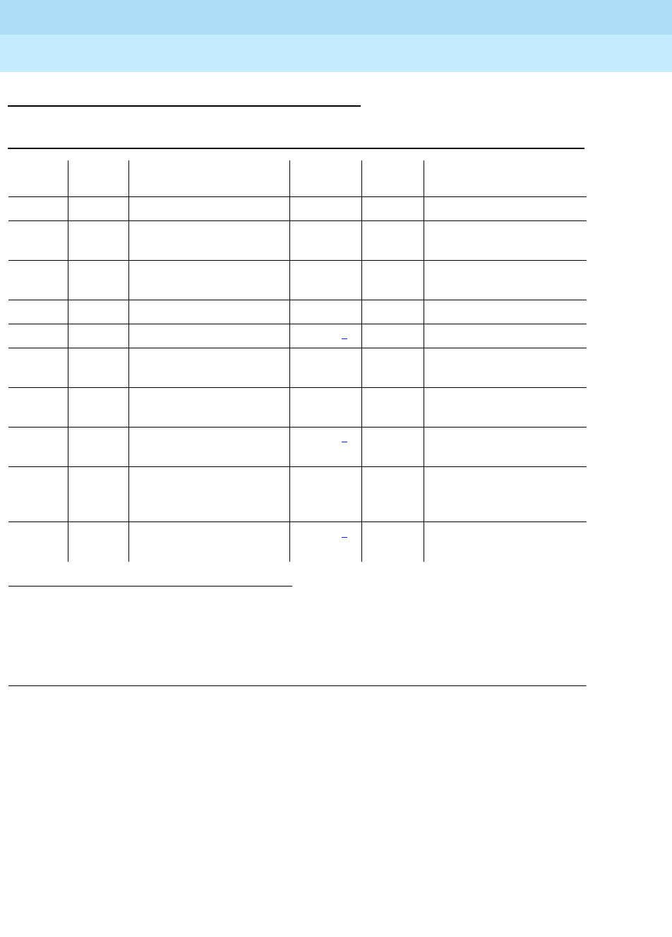
DEFINITY Enterprise Communications Server Release 6
Maintenance for R6r Volumes 1 & 2
555-230-126 Issue 2
January 1998
Maintenance Object Repair Procedures
Page 9-833MEM-BD (32MB Memory Circuit Pack)
9
Error Log Entries and Test to Clear Values
Notes:
a. This error (3) indicates that a software patch has been applied and either
the software patch is bad or was installed incorrectly.
1. Back out the software patch and run the test memory UUCS long
command to verify that the problem has been cleared.
2. If the PBX system is equipped with High Reliability or Critical
Reliability option (i.e. with duplicated SPEs), and this error occurs, a
SPE interchange will occur if the health of the standby SPE permits
the interchange.
b. This error (101) indicates that this Memory circuit pack is not required.
1. Run the Short Test Sequence first. If all tests pass, run the Long Test Sequence. Refer to the
appropriate test description and follow the recommended procedures.
2. If a spontaneous interchange has occurred (as indicated by STBY-SPE error type 103 or the
display initcauses screen), and handshake is down, (check with status spe), replace the alarmed
circuit pack on the standby SPE. If handshake is up, execute a test long clear of the alarmed
circuit pack and follow recommended procedures.
Table 9-286. MEM-BD Error Log Entries
Error
Type Aux
Data Associated Test Alarm
Level On/Off
Board Test to Clear Value
010 Any Any Any test memory UUCS sh r 1
1 Memory RAM Checksum
Test (#903) MAJOR OFF test memory UUCS l r 1
3(a) Memory RAM Checksum
Test (#903) MAJOR2OFF test memory UUCS l r 1
101(b) none WNG OFF
150(c) none MAJOR2ON test memory UUCS l c
257 Memory Parity Checker
Test (#906) MINOR ON test memory UUCS sh r 2
513 Any(d) Memory Single Bit Errors
(#902) MINOR ON test memory UUCS l r 10
769 Memory Multiple Bit
Errors (#902) MAJOR2ON test memory UUCS l r 2
1025 Memory Error
Detection/Correction
Test (#907)
MINOR ON test memory UUCS sh r 1
1281 Memory Burst Read Test
(#908) MAJOR2ON test memory UUCS sh r 1

DEFINITY Enterprise Communications Server Release 6
Maintenance for R6r Volumes 1 & 2
555-230-126 Issue 2
January 1998
Maintenance Object Repair Procedures
Page 9-834MEM-BD (32MB Memory Circuit Pack)
9
1. Remove the extra Memory circuit pack at the earliest convenience
to resolve this alarm. To replace the Memory circuit pack, use the
procedure described in
Replacing SPE Circuit Packs
in Chapter 5,
‘‘Responding to Alarms and Errors’’.
c. This error (150) indicates that a SPE interchange has occurred and that
the Memory circuit pack was the cause of the spontaneous interchange.
1. If other MEM-BD errors are present, investigate these errors.
2. If no other MEM-BD errors are present, run the test memory UUCS
long clear command and investigate any test failure.
d. The aux data indicates the number of single bit errors detected since the
last time the test was run.
System Technician-Demanded Tests:
Descriptions and Error Codes
Always investigate tests in the order presented in the table below. By clearing
error codes associated with the
Memory Single/Multiple Bit Error Audit
, for
example, you may also clear errors generated from other tests in the testing
sequence.
Memory Single/Multiple Bit Error Audit (#902)
This audit waits for the hardware scrubbing circuits in the Memory circuit packs
to make a complete pass through Memory and reports any single or multiple bit
errors that may have been found. If the test memory a|b long command is used,
this test executes once for each equipped Memory circuit pack
1. D = Destructive, ND = Non-destructive
Order of Investigation Short Test
Sequence Long Test
Sequence Reset Board
Sequence D/ND1
Single/Multiple Bit Error Audit (#902) X ND
Memory Burst Read Test (#908) X X ND
Memory Error Detection/Correction Test
(#907) XX ND
Memory RAM Checksum Test (#903) X ND
Memory Parity Checker Test (#906) X X ND

DEFINITY Enterprise Communications Server Release 6
Maintenance for R6r Volumes 1 & 2
555-230-126 Issue 2
January 1998
Maintenance Object Repair Procedures
Page 9-835MEM-BD (32MB Memory Circuit Pack)
9
Table 9-287. TEST #902 Memory Single/Multiple Bit Error Audit
Error
Code Test
Result Description/ Recommendation
100 ABORT The requested test did not complete within the allowable time period.
1. Retry the command.
1022
1335
2500
ABORT Internal system error.
1. Retry the command.
1338 ABORT The test is not allowed to run since a planned SPE interchange is in progress.
This may be caused by a planned interchange initiated automatically during 24
hour scheduled testing.
1. Wait 3 minutes and retry the command.
1339 ABORT The test could not run on the standby Memory circuit pack in the standby SPE
carrier because the standby SPE is unavailable.
1. Refer to the section on "STBY-SPE (Standby SPE Maintenance)"
procedures for information on why a standby SPE may be unavailable and
what repair actions should be taken. The status spe screen should
indicate that handshake is down. This may be caused by a variety of
reasons such as the SPE-SELECT switches on the DUPINT circuit packs
being set to the position of the active SPE, a failure of the DUPINT circuit
pack, or loss of power on the standby SPE. The
SPE Selected field
on the
status spe-standby screen will display
spe a
or
spe b
if both
SPE-SELECT switches are in the a or b positions, respectively.
2000 ABORT Response to the test request was not received within the allowable time period.
If the system is equipped with the High Reliability or Critical Reliability
Configuration and if the Memory circuit pack is on the standby SPE, this abort
code may indicate that the standby SPE is not responding to the handshake
message. If this is the case, the standby SPE maintenance software may take
up to two minutes to indicate that handshake communication with the standby
SPE is down. The ABORT code will then change to 1339 (handshake
communication down).
1. Retry the command at 1-minute intervals, a maximum of 3 times.
2315 ABORT The test was not run, because this is an extra Memory circuit pack. No testing
is allowed for extra Memory circuit packs.
2334 ABORT The hardware mailbox on the standby Duplication Interface board is not ready
to receive messages.
1. Retry the command at 1-minute intervals, a maximum of 5 times.
Continued on next page

DEFINITY Enterprise Communications Server Release 6
Maintenance for R6r Volumes 1 & 2
555-230-126 Issue 2
January 1998
Maintenance Object Repair Procedures
Page 9-836MEM-BD (32MB Memory Circuit Pack)
9
Memory RAM Checksum Test (#903)
This test computes the checksum of the system software text module. This test is
only run when the Memory circuit pack in slot one is being tested. If this test fails,
the RAM is corrupt. It does NOT indicate a hardware problem.
DO NOT REPLACE the Memory circuit pack when this is the only error or failing
test.
For systems equipped with the Standard Reliability configuration, do a system
restart (enter reset system 4) as soon as possible. For systems equipped with
the High Reliability or Critical Reliability configuration, perform the following steps
as soon as possible:
1. Busyout the standby SPE (enter busyout spe-standby).
2. Reboot the standby SPE (enter reset spe-standby 4).
3. Wait for the standby SPE to reboot (about 5 minutes).
4. Lock the standby SPE into active mode using the SPE-SELECT switches
on the DUPINT circuit packs. This will cause the new active SPE to
perform COLD reset and the new standby SPE will perform a reboot
FAIL The audit detected one or more single or multiple bit errors on the indicated
Memory circuit pack(s).
1. Retry the command.
2. If the test continues to fail, replace the affected Memory circuit pack.
3. If the test continues to fail after replacing the Memory circuit pack, replace
the Processor circuit pack. To replace the circuit packs, use the procedure
described in
Replacing SPE Circuit Packs
in Chapter 5.
PASS The Memory does not contain any single or multiple bit errors.
Table 9-287. TEST #902 Memory Single/Multiple Bit Error Audit — Continued
Error
Code Test
Result Description/ Recommendation
Continued on next page

DEFINITY Enterprise Communications Server Release 6
Maintenance for R6r Volumes 1 & 2
555-230-126 Issue 2
January 1998
Maintenance Object Repair Procedures
Page 9-837MEM-BD (32MB Memory Circuit Pack)
9
Table 9-288. TEST #903 RAM Checksum Test
Error
Code Test
Result Description/ Recommendation
100 ABORT The requested test did not complete within the allowable time period.
1. Retry the command.
1022
1335
2500
ABORT Internal system error.
1. Retry the command.
1338 ABORT The test is not allowed to run since a planned SPE interchange is in progress.
This may be caused by a planned interchange initiated automatically during 24
hour scheduled testing.
1. Wait 3 minutes and retry the command.
1339 ABORT The test could not run on the standby Memory circuit pack in the standby SPE
carrier because the standby SPE is unavailable.
1. Refer to the section on "STBY-SPE (Standby SPE Maintenance)" procedures
for information on why a standby SPE may be unavailable and what repair
actions should be taken. The status spe screen should indicate that
handshake is down. This may be caused by a variety of reasons such as
the SPE-SELECT switches on the DUPINT circuit packs being set to the
position of the active SPE, a failure of the DUPINT circuit pack, or loss of
power on the standby SPE. The
SPE Selected field
on the status
spe-standby screen will display
spe a
or
spe b
if both SPE-SELECT
switches are in the a or b positions, respectively.
2000 ABORT Response to the test request was not received within the allowable time period.
If the system is equipped with the High Reliability or Critical Reliability
Configuration and if the Memory circuit pack is on the standby SPE, this abort
code may indicate that the standby SPE is not responding to the handshake
message. If this is the case, the standby SPE maintenance software may take
up to two minutes to indicate that handshake communication with the standby
SPE is down. The ABORT code will then change to 1339 (handshake
communication down).
1. Retry the command at 1-minute intervals, a maximum of 3 times.
2315 ABORT The test was not run, because this is an extra Memory circuit pack. No testing is
allowed for extra Memory circuit packs.
2334 ABORT The hardware mailbox on the standby Duplication Interface board is not ready
to receive messages.
1. Retry the command at 1-minute intervals, a maximum of 5 times.
Continued on next page

DEFINITY Enterprise Communications Server Release 6
Maintenance for R6r Volumes 1 & 2
555-230-126 Issue 2
January 1998
Maintenance Object Repair Procedures
Page 9-838MEM-BD (32MB Memory Circuit Pack)
9
Memory Parity Checker Test (#906)
This test checks the operation of the Memory circuit pack parity generators and
checkers. If the test memory a|b command is used, this test executes once for
each equipped Memory circuit pack
FAIL The system may or may not continue to operate correctly. The system may fail at
some future date when some action requires access to the corrupted area of the
RAM. For systems equipped with the Standard Reliability configuration:
1. Restart the system with a reset system 4 and observe the startup memory
tests (refer to Chapter 4, ‘‘Initialization and Recovery’’, for a list of tests).
For systems equipped with the High Reliability or Critical Reliability
configuration:
1. Busyout the standby SPE (enter busyout spe-standby).
2. Reboot the standby SPE (enter reset spe-standby 4).
3. Wait for the standby SPE to reboot (about 5 minutes).
4. Lock the standby SPE into active mode using the SPE-SELECT switches on
the DUPINT circuit packs. This will cause the new active SPE to perform
COLD reset and the new standby SPE will perform a reboot.
PASS The RAM checksum is correct.
Table 9-289. TEST #906 Memory Parity Checker Test
Error
Code Test
Result Description/ Recommendation
100 ABORT The requested test did not complete within the allowable time period.
1. Retry the command.
1022
1335
2500
ABORT Internal system error.
1. Retry the command.
1338 ABORT The test is not allowed to run since a planned SPE interchange is in progress.
This may be caused by a planned interchange initiated automatically during 24
hour scheduled testing.
1. Wait 3 minutes and retry the command.
Continued on next page
Table 9-288. TEST #903 RAM Checksum Test — Continued
Error
Code Test
Result Description/ Recommendation
Continued on next page

DEFINITY Enterprise Communications Server Release 6
Maintenance for R6r Volumes 1 & 2
555-230-126 Issue 2
January 1998
Maintenance Object Repair Procedures
Page 9-839MEM-BD (32MB Memory Circuit Pack)
9
1339 ABORT The test could not run on the standby Memory circuit pack in the standby SPE
carrier because the standby SPE is unavailable.
1. Refer to the section on "STBY-SPE (Standby SPE Maintenance)"
procedures for information on why a standby SPE may be unavailable and
what repair actions should be taken. The status spe screen should
indicate that handshake is down. This may be caused by a variety of
reasons such as the SPE-SELECT switches on the DUPINT circuit packs
being set to the position of the active SPE, a failure of the DUPINT circuit
pack, or loss of power on the standby SPE. The
SPE Selected field
on the
status spe-standby screen will display
spe a
or
spe b
if both SPE-SELECT
switches are in the a or b positions, respectively.
2000 ABORT Response to the test request was not received within the allowable time period.
If the system is equipped with the High Reliability or Critical Reliability
Configuration and if the Memory circuit pack is on the standby SPE, this abort
code may indicate that the standby SPE is not responding to the handshake
message. If this is the case, the standby SPE maintenance software may take
up to two minutes to indicate that handshake communication with the standby
SPE is down. The ABORT code will then change to 1339 (handshake
communication down).
1. Retry the command at 1-minute intervals, a maximum of 3 times.
2315 ABORT The test was not run, because this is an extra Memory circuit pack. No testing is
allowed for extra Memory circuit packs.
2334 ABORT The hardware mailbox on the standby Duplication Interface board is not ready
to receive messages.
1. Retry the command at 1-minute intervals, a maximum of 5 times.
FAIL The Memory circuit pack cannot detect parity error conditions. If the test fails
on all equipped Memory circuit packs, the Processor may be at fault. Run the
tests described in the "PROCR (RISC Processor Circuit Pack)" section of this
manual.
1. Retry the command.
2. If the test continues to fail, replace the Memory circuit pack.
3. If the test continues to fail, replace the Processor circuit pack. To replace
the circuit packs, use the procedure described in
Replacing SPE Circuit
Packs
in Chapter 5.
PASS The Memory Parity Checker circuit is operating properly.
Table 9-289. TEST #906 Memory Parity Checker Test — Continued
Error
Code Test
Result Description/ Recommendation
Continued on next page

DEFINITY Enterprise Communications Server Release 6
Maintenance for R6r Volumes 1 & 2
555-230-126 Issue 2
January 1998
Maintenance Object Repair Procedures
Page 9-840MEM-BD (32MB Memory Circuit Pack)
9
Memory Error Detection/Correction Test (#907)
This test checks the error detection/correction circuitry on the Memory circuit
pack. It tests a few reserved memory locations to verify that single bit errors can
be corrected and multiple bit errors can be detected. If the test memory a|b
command is used, this test executes once for each equipped Memory circuit
pack
Table 9-290. TEST #907 Memory Error Detection/Correction Test
Error
Code Test
Result Description/ Recommendation
100 ABORT The test did not complete within the allowable time period.
1. Retry the command.
1022
1335
2500
ABORT Internal system error.
1. Retry the command.
1338 ABORT The test is not allowed to run since a planned SPE interchange is in progress.
This may be caused by a planned interchange initiated automatically during
24 hour scheduled testing.
1. Wait 3 minutes and retry the command.
1339 ABORT The test could not run on the standby Memory circuit pack in the standby SPE
carrier because the standby SPE is unavailable.
1. Refer to the section on "STBY-SPE (Standby SPE Maintenance)"
procedures for information on why a standby SPE may be unavailable and
what repair actions should be taken. The status spe screen should
indicate that handshake is down. This may be caused by a variety of
reasons such as the SPE-SELECT switches on the DUPINT circuit packs
being set to the position of the active SPE, a failure of the DUPINT circuit
pack, or loss of power on the standby SPE. The
SPE Selected field
on the
status spe-standby screen will display
spe a
or
spe b
if both
SPE-SELECT switches are in the a or b positions, respectively.
2000 ABORT Response to the test request was not received within the allowable time
period. If the system is equipped with the High Reliability or Critical Reliability
Configuration and if the Memory circuit pack is on the standby SPE, this abort
code may indicate that the standby SPE is not responding to the handshake
message. If this is the case, the standby SPE maintenance software may take
up to two minutes to indicate that handshake communication with the standby
SPE is down. The ABORT code will then change to 1339 (handshake
communication down).
1. Retry the command at 1-minute intervals, a maximum of 3 times.
2315 ABORT The test was not run, because this is an extra Memory circuit pack. No testing
is allowed for extra Memory circuit packs.
Continued on next page

DEFINITY Enterprise Communications Server Release 6
Maintenance for R6r Volumes 1 & 2
555-230-126 Issue 2
January 1998
Maintenance Object Repair Procedures
Page 9-841MEM-BD (32MB Memory Circuit Pack)
9
Memory Burst Read Test (#908)
This test verifies that the Memory Burst Read function works properly on both the
Memory and Processor circuit packs. If the test memory a|b command is used,
this test executes once for each equipped Memory circuit pack
2334 ABORT The hardware mailbox on the standby Duplication Interface board is not ready
to receive messages.
1. Retry the command at 1-minute intervals, a maximum of 5 times.
FAIL The Memory EDC circuitry is not working correctly. The system may not
continue to operate correctly if single or multiple bit errors occur in Memory at
a later time. If the test fails on all equipped Memory circuit packs, the
Processor may be at fault. Run the tests described in the Processor section of
this manual.
1. Replace the affected Memory circuit when convenient.
2. If the test continues to fail after replacing the Memory circuit pack, replace
the Processor circuit pack. To replace the circuit packs, use the
procedure described in
Replacing SPE Circuit Packs
in Chapter 5.
PASS The Memory EDC circuitry is working normally.
Table 9-291. TEST #908 Memory Burst Read Test
Error
Code Test
Result Description/ Recommendation
100 ABORT The requested test did not complete within the allowable time period.
1. Retry the command.
1022
1335
2500
ABORT Internal system error.
1. Retry the command.
1338 ABORT The test is not allowed to run since a planned SPE interchange is in progress.
This may be caused by a planned interchange initiated automatically during 24
hour scheduled testing.
1. Wait 3 minutes and retry the command.
Continued on next page
Table 9-290. TEST #907 Memory Error Detection/Correction Test — Continued
Error
Code Test
Result Description/ Recommendation
Continued on next page

DEFINITY Enterprise Communications Server Release 6
Maintenance for R6r Volumes 1 & 2
555-230-126 Issue 2
January 1998
Maintenance Object Repair Procedures
Page 9-842MEM-BD (32MB Memory Circuit Pack)
9
1339 ABORT The test could not run on the standby Memory circuit pack in the standby SPE
carrier because the standby SPE is unavailable.
1. Refer to the section on "STBY-SPE (Standby SPE Maintenance)"
procedures for information on why a standby SPE may be unavailable and
what repair actions should be taken. The status spe screen should
indicate that handshake is down. This may be caused by a variety of
reasons such as the SPE-SELECT switches on the DUPINT circuit packs
being set to the position of the active SPE, a failure of the DUPINT circuit
pack, or loss of power on the standby SPE. The
SPE Selected field
on the
status spe-standby screen will display
spe a
or
spe b
if both SPE-SELECT
switches are in the a or b positions, respectively.
2000 ABORT Response to the test request was not received within the allowable time period.
If the system is equipped with the High Reliability or Critical Reliability
Configuration and if the Memory circuit pack is on the standby SPE, this abort
code may indicate that the standby SPE is not responding to the handshake
message. If this is the case, the standby SPE maintenance software may take
up to two minutes to indicate that handshake communication with the standby
SPE is down. The ABORT code will then change to 1339 (handshake
communication down).
1. Retry the command at 1-minute intervals, a maximum of 3 times.
2315 ABORT The test was not run, because this is an extra Memory circuit pack. No testing is
allowed for extra Memory circuit packs.
2334 ABORT The hardware mailbox on the standby Duplication Interface board is not ready
to receive messages.
1. Retry the command at 1-minute intervals, a maximum of 5 times.
FAIL The Burst Read circuit is not functioning properly.
1. If the test fails on more than one Memory circuit pack, replace the
Processor and retry the test.
2. If the test fails only on one Memory circuit pack, replace the affected
Memory circuit pack.
3. If the test continues to fail only on the same Memory circuit pack, replace
the Processor. To replace the circuit packs, use the procedure described
in
Replacing SPE Circuit Packs
in Chapter 5.
PASS The Burst Read portion of the Memory and Processor circuit packs is operating
correctly.
Table 9-291. TEST #908 Memory Burst Read Test — Continued
Error
Code Test
Result Description/ Recommendation
Continued on next page

DEFINITY Enterprise Communications Server Release 6
Maintenance for R6r Volumes 1 & 2
555-230-126 Issue 2
January 1998
Maintenance Object Repair Procedures
Page 9-843MET-BD (MET Line Circuit Pack)
9
MET-BD (MET Line Circuit Pack)
Refer to XXX-BD (Common Port Circuit Pack) Maintenance documentation for
circuit pack level errors. See also MET-LINE (MET Line) Maintenance
documentation for related line information.
1.
UU
is the universal cabinet number (1 for PPN, 2 - 44 for EPNs).
C
is the carrier designation (A,
B, C, D, or E).
SS
is the number of the slot in which the circuit pack resides (01 to 21).
MO Name (in
Alarm Log) Alarm Level Initial Command to Run1Full Name of MO
MET-BD MINOR test board UUCSS sh MET Line Circuit Pack
MET-BD WARNING test board UUCSS sh MET Line Circuit Pack

DEFINITY Enterprise Communications Server Release 6
Maintenance for R6r Volumes 1 & 2
555-230-126 Issue 2
January 1998
Maintenance Object Repair Procedures
Page 9-844MET-LINE (MET Line)
9
MET-LINE (MET Line)
The TN735 MET Line circuit pack supports four of these sets as shown below.
Each MET set uses three pairs of wires: an analog voice pair, a transmit pair, and
a receive pair. Power is sent over the transmit and receive pairs. The MET Line
circuit pack supports all 10-, 20-, and 30-button sets.
This section describes MET-LINE (MET Line) maintenance. MET-LINE
maintenance is closely related to, and interacts with, MET-BD (MET Line circuit
pack) maintenance. This interaction should be kept in mind when
troubleshooting MET Line problems.
This section occasionally refers to a station’s
service states
. The service states
are defined as follows:
Use the status station command to determine terminal service state. Status is
reported as either out-of-service, in-service, or ‘‘disconnect,’’ which means the
station is in the ready-for-service state.
1. UU is the universal cabinet number (1 for PPN, 2 - 44 for EPNs). C is the carrier designation (A,
B, C, D, or E). SS is the number of the slot in which the circuit pack resides (01 to 21). pp is the
two digit port number (01, 02, ...).
MO Name (in
Alarm Log) Alarm Level Initial Command to Run1Full Name of MO
MET-LINE MINOR test port UUCSSpp l MET Line
MET-LINE WARNING test port UUCSSpp sh MET Line
Out-of-Service The port, and thus the station, have been removed from
service. A busyout of a port will cause it to be
out-of-service.
Ready-for-Service The port on the circuit pack has been put into service,
but the voice terminal has not yet established signaling
communications with the port.
In-Service The voice terminal has established signaling
communications with the port, and the system is ready
to process calls to and from that station. A terminal in
the ready-for-service state will progress to the
in-service state if it is functioning normally, but it can
also be forced into the in-service state if it goes
off-hook.

DEFINITY Enterprise Communications Server Release 6
Maintenance for R6r Volumes 1 & 2
555-230-126 Issue 2
January 1998
Maintenance Object Repair Procedures
Page 9-845MET-LINE (MET Line)
9
Error Log Entries and Test to Clear Values
Notes:
a. The data link between the port and the terminal is not operational, i.e., the
port circuitry has detected an off-board problem. Verify that the MET set is
connected and that the Electronic Power Feed (EPF) test passes. If data
transmission problems are experienced, check for defective wiring or a
defective voice terminal, or move terminal electrically closer to the switch
(i.e., reduce the length of the wiring between the terminal and the switch).
If the problem persists, replace the circuit pack. Once the problem is
resolved, the system retires the alarm after a predetermined time delay.
1. Run the Short Test Sequence first. If all tests pass, run the Long Test Sequence. Refer to the appropriate
test description and follow the recommended procedures.
2. Major or Minor alarms MO may be downgraded to Warning alarms based on the values used in the set
options command.
Table 9-292. MET Line Error Log Entries
Error
Type Aux
Data Associated Test Alarm
Level On/Off
Board Test to Clear Value
010 Any Any Any test port UUCSSpp sh r 1
1 (a) 40987 None
18 (b) 0 busyout port
UUCSSpp WARNING OFF release port UUCSSpp
130 (c) None WARNING ON test port UUCSSpp sh
257 (d) 40988 None MIN/WRN2OFF
513 (e) 40965 Hybrid Line Station
Audits Test (#61) WARNING OFF test port UUCSSpp sh r 4
769 Port Diagnostic Test
(#35) MIN/WRN2ON test port UUCSSpp l r 3
1025 Hybrid & Conf.
Circuits Test (#57) MIN/WRN2ON test port UUCSSpp l r 3
1537 (f) 40968 None MIN/WRN2OFF
1793 TDM NPE Crosstalk
Test (#6 MIN/WRN2ON test port UUCSSpp l r 3
2049 (g) 32770
2049 (h) 40967
3840 (i) 40989

DEFINITY Enterprise Communications Server Release 6
Maintenance for R6r Volumes 1 & 2
555-230-126 Issue 2
January 1998
Maintenance Object Repair Procedures
Page 9-846MET-LINE (MET Line)
9
b. Error type 18 is logged when maintenance personnel busyout the port.
maintenance personnel. The port is released from busyout via the release
port UUCSSpp command.
c. The circuit pack has been removed or has been insane for more than 11
minutes. To clear the error, reinsert or replace the circuit pack.
d. The EPF has been turned off due to an overcurrent condition at the voice
terminal. Check for defective wiring or a damaged jack, and verify that the
voice terminal is an MET set. Once the problem is resolved, the system
retires the alarm after a predetermined time delay.
e. The EPF inquiry audit has returned ‘‘epf-no-load’’ messages. This usually
indicates that the voice terminal has been disconnected or that there is a
defect in the wiring to the terminal. Check out both possibilities.
When the EPF inquiry audit subsequently receives an ‘‘epf-on-ok’’ or an
‘‘epf-off-ok’’ message, the system will take action to retire the alarm.
f. The port has reported a problem with the data link to the voice terminal.
Ignore this error if there are no complaints about the voice terminal.
Otherwise, make sure the voice terminal is connected, check for defective
wiring, check for a defective voice terminal, and decrease the length of
the wiring between the voice terminal and the switch. If the problem
persists, replace the circuit pack.
g. The voice terminal went off-hook while it was in the ready-for-service state.
Use the status system command to determine the state of the voice
terminal. The off-hook should have moved the station to in-service. No
repair action is necessary.
h. This code is generated when the link between the circuit pack and the
voice terminal is successfully reset. No repair action is necessary.
i. The hardware sent an uplink message indicating that the Electric Power
Feed (EPF) is not loaded, that is, it is not currently supplying power to a
voice terminal. No repair action is necessary.
System Technician-Demanded Tests:
Descriptions and Error Codes
Always investigate tests in the order presented in the table below when
inspecting errors in the system. By clearing error codes associated with the
Port
Diagnostic Test,
for example, you may also clear errors generated from other
tests in the testing sequence.
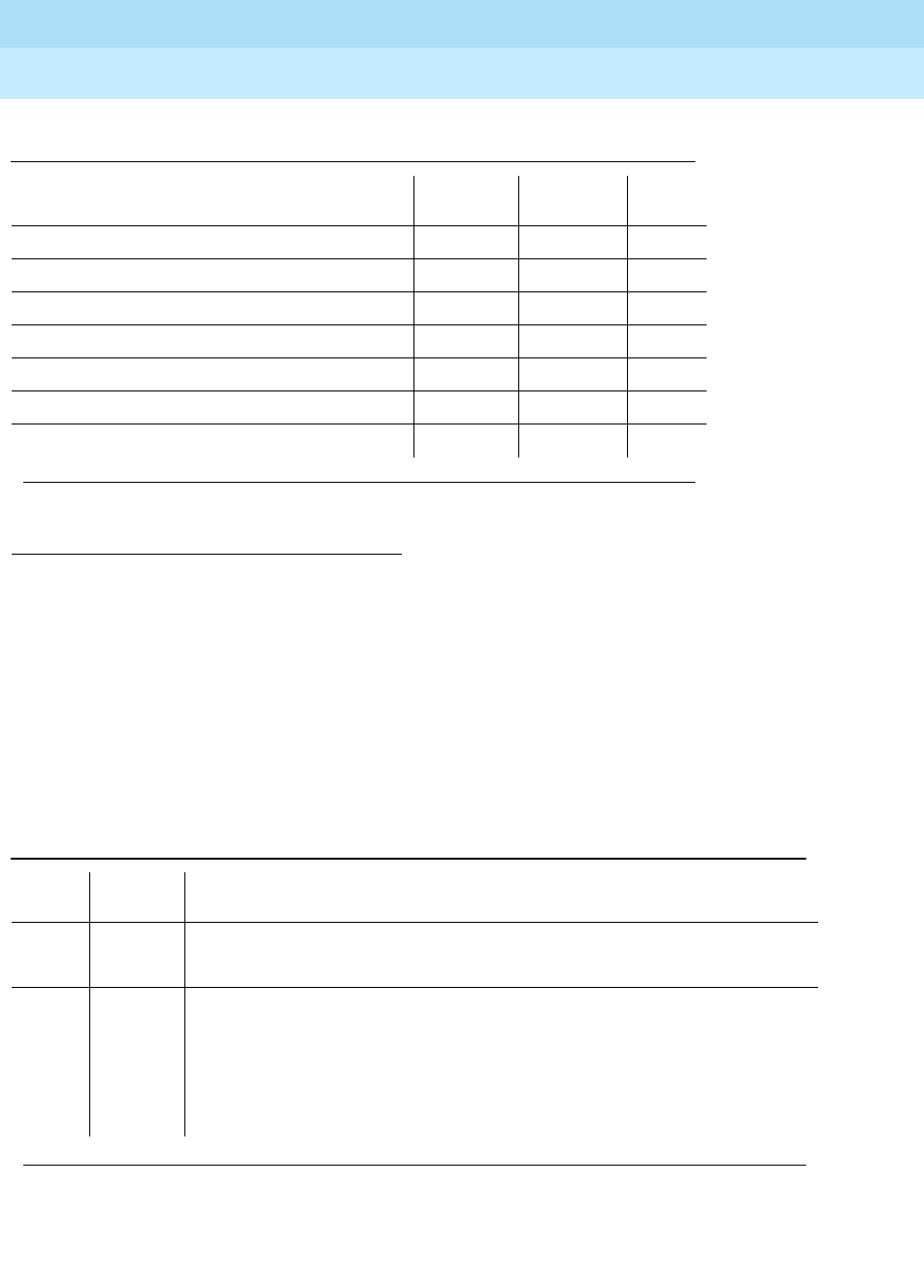
DEFINITY Enterprise Communications Server Release 6
Maintenance for R6r Volumes 1 & 2
555-230-126 Issue 2
January 1998
Maintenance Object Repair Procedures
Page 9-847MET-LINE (MET Line)
9
NPE Crosstalk Test (#6)
The NPE Crosstalk Test verifies that this port’s NPE channel talks on the selected
time slot and never crosses over to time slots reserved for other connections. If
the NPE is not working correctly, one-way and noisy connections may be
observed. This test is part of a port’s Long Test Sequence and takes about 20 to
30 seconds to complete.
1. D = Destructive, ND = Non-destructive
Table 9-293. System Technician-Demanded Tests: MET-LINE
Order of Investigation Short Test
Sequence Long Test
Sequence D/ND1
NPE Crosstalk Test (#6) X ND
Port Diagnostic Test (#35) X ND
MFAT Electronic Power Feed Test (#56) X ND
Hybrid Circuit and Conference Circuit Test (#57) X ND
Station Lamp Update Test (#60) X X ND
Station Audits Test (#61) X X ND
Ringer Update Test (#62) X X ND
Continued on next page
Table 9-294. TEST #6 NPE Crosstalk Test
Error
Code Test
Result Description/ Recommendation
ABORT Could not allocate the necessary system resources to run this test.
1. Retry the command at 1-minute intervals a maximum of 5 times.
1000 ABORT System resources required to run this test are not available. The port may be
busy with a valid call. Use the display port UUCSSpp command to determine
the station extension of the port. Use status station to determine the service
state of the port. If the port is in use, wait until the port is idle before testing.
1. If the port status is idle, then retry the command at 1-minute intervals a
maximum of 5 times.
Continued on next page

DEFINITY Enterprise Communications Server Release 6
Maintenance for R6r Volumes 1 & 2
555-230-126 Issue 2
January 1998
Maintenance Object Repair Procedures
Page 9-848MET-LINE (MET Line)
9
1001 ABORT System resources required to run this test are not available. This could be due
to a failure to seize the port.
1. Retry the command at 1-minute intervals a maximum of 5 times.
1002 ABORT The system could not allocate time slots for the test. The system may be under
heavy traffic conditions or it may have time slots out-of-service due to
TDM-BUS errors. Refer to “TDM-BUS” to diagnose TDM-BUS errors.
1. If system has no TDM-BUS errors and is not handling heavy traffic, repeat
test at 1-minute intervals a maximum of 5 times.
1003 ABORT The system could not allocate a tone receiver for the test. The system may be
oversized for the number of Tone Detectors present or some Tone Detectors
may be out-of-service.
1. Resolve any “TTR-LEV” errors in the Error Log.
2. Resolve any “TONE-PT” errors in the Error Log.
3. If neither condition exists, retry the test at 1-minute intervals a maximum of
5 times.
1004 ABORT The port was seized by a valid call during the test. The test has been aborted.
Use the display port UUCSSpp command to determine the station extension
of the port. Use the status station command to determine the service state of
the port. If the port is in use, wait until the port is idle before testing.
1. Retry the command at 1-minute intervals a maximum of 5 times.
1018 ABORT Test disabled via administration. This only applies to analog stations. The
default for this field is ‘y,’ so you may want to determine why it has been turned
off on this station.
1. To enable the test for the particular analog station being tested, enter the
change station extension command and change the 'Test' field on the
'Station' form from 'n' to 'y.'
2000 ABORT Response to the test request was not received within the allowable time
period.
1. Retry the command at 1-minute intervals a maximum of 5 times.
2020 ABORT The test did not run due to an already existing error on the specific port or a
more general circuit pack error.
1. Examine Error Log for existing errors against this port or the circuit pack
and attempt to diagnose the already existing error.
2100 ABORT System resources required to run this test are not available. This could be due
to a failure to seize the port.
1. Retry the command at 1-minute intervals a maximum of 5 times.
Table 9-294. TEST #6 NPE Crosstalk Test — Continued
Error
Code Test
Result Description/ Recommendation
Continued on next page

DEFINITY Enterprise Communications Server Release 6
Maintenance for R6r Volumes 1 & 2
555-230-126 Issue 2
January 1998
Maintenance Object Repair Procedures
Page 9-849MET-LINE (MET Line)
9
Port Diagnostic Test (#35)
This test checks a port’s battery feed circuitry. The battery feed circuitry is tested
for proper battery voltage by testing the switchhook state. In response to the test
message, the on-board firmware terminates the line and checks for switch-hook
presence. The termination is then removed, and a check is made for no
switch-hook presence. The MET set must be on-hook for the test to execute.
Any FAIL This test can fail due to on-board or off-board problems. Off-board problems
of concern include EXP-PN and EXP-INTF faults, TDM-BUS faults, and faults
associated with the tone detectors/tone generators. Clear all off-board
problems before replacing the board. Keep in mind that a TDM-BUS problem
is usually the result of a faulty board connected to the backplane or bent pins
on the backplane.
1. Look for EXP-PN and/or EXP-INTF errors in the error log. If present, refer to
“EXP-PN” and “EXP-INTF.”
2. Look for TDM-BUS errors in the error log. If present, refer to the TDM-BUS.
3. Look for TONE-BD and/or TONE-PT errors in the error log. If present, refer
to the TONE-BD and the TONE-PT.
4. Test the board when the faults from steps 1, 2, and 3 are cleared. Replace
the board only if the test fails.
PASS The port uses its allocated time slots correctly. Investigate user-reported
troubles on this port using other port tests and by examining station, trunk, or
external wiring.
0NO
BOARD The test could not relate the internal ID to the port (no board). This could be
due to incorrect translations, no board is inserted, an incorrect board is
inserted, or an insane board is inserted.
1. Check to ensure that the board translations are correct. Use the list
config command, and resolve any problems that are found.
2. If the board was found to be correctly inserted in step 1, issue the
busyout board command.
3. Issue the reset board command.
4. Issue the release busy board command.
5. Issue the test board long command. This should re-establish the linkage
between the internal ID and the port. If this is not the case, check to
ensure that there is a valid board inserted.
Table 9-294. TEST #6 NPE Crosstalk Test — Continued
Error
Code Test
Result Description/ Recommendation
Continued on next page
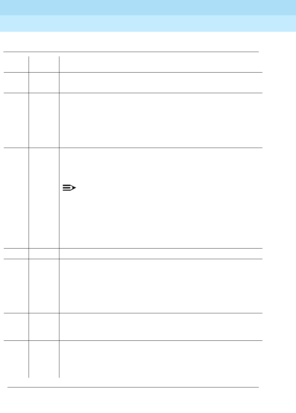
DEFINITY Enterprise Communications Server Release 6
Maintenance for R6r Volumes 1 & 2
555-230-126 Issue 2
January 1998
Maintenance Object Repair Procedures
Page 9-850MET-LINE (MET Line)
9
Table 9-295. TEST #35 Port Diagnostic Test
Error
Code Test
Result Description/ Recommendation
ABORT Internal system error.
1. Retry the command at 1-minute intervals a maximum of 5 times.
1000 ABORT System resources required to run this test are not available. The port may be
busy with a valid call. Use the display port UUCSSpp command to determine
the station extension of the port. Use the status station command to
determine the service state of the port. If the port is in use, wait until the port is
idle before testing.
1. If the port status is idle, then retry the command at 1-minute intervals a
maximum of 5 times.
1004 ABORT The port was seized by a valid call during the test. The test has been aborted.
Use the display port UUCSSpp command to determine the station extension
of the port. Use the status station command to determine the service state of
the port. If the port is in use, wait until the port is idle before testing.
NOTE:
The battery feed circuitry is tested for proper battery voltage by testing
the switchhook state. In response to the test message, the on-board
firmware terminates the line and checks for switch-hook presence. The
termination is then removed, and a check is made for no switch-hook
presence. The MET set must be on-hook for the test to execute.
1. If the port status is idle, then retry the command at 1-minute intervals a
maximum of 5 times.
1018 ABORT Test disabled via software patch.
2000 ABORT This port may have been busied out.
1. Look in the Error Log for Error Type 18 (port busied out) for this port. If this
error type is present, then release the port via the release station
<extension> command and run the test again.
2. Make sure that the terminal is connected.
3. Retry the command at 1-minute intervals a maximum of 5 times.
2100 ABORT Could not allocate the necessary system resources to run this test. This could
be due to a failure to seize the port.
1. Retry the command at 1-minute intervals a maximum of 5 times.
FAIL Battery Feed Test failed. This port is out-of-service.
1. Other ports on this circuit pack are not affected. Place user on a different
port, if available, until a replacement circuit pack can be obtained.
2. Replace circuit pack when available.
Continued on next page

DEFINITY Enterprise Communications Server Release 6
Maintenance for R6r Volumes 1 & 2
555-230-126 Issue 2
January 1998
Maintenance Object Repair Procedures
Page 9-851MET-LINE (MET Line)
9
MFAT Electronic Power Feed (#56)
The software requests that the EPF be turned on for a given port. The hardware
then attempts to turn on that port’s station power unit. If no current is drawn, the
station is probably not connected. If an overcurrent condition is sensed (too
much current is drawn), a short may exist in the loop, or the voice terminal may
be defective. The test results in a message indicating that either the EPF was
turned on successfully with no problems, or an overcurrent condition exists. This
test is repeated after a 5 second delay. If either test is not successful, the test
aborts. Although this test will never actually return a fail result (except for the
internal system error), an error type 257 entry will be made in the error log when
the test has completed if the overcurrent case is detected by the hardware.
PASS Battery Feed Test passed. Current flow is properly detected for this port.
1. If users are reporting problems, examine connections to the port.
0NO
BOARD The test could not relate the internal ID to the port (no board). This could be
due to incorrect translations, no board is inserted, an incorrect board is
inserted, or an insane board is inserted.
1. Check to ensure that the board translations are correct. Use the list config
command, and resolve any problems that are found.
2. If the board was found to be correctly inserted in step 1, issue the busyout
board command.
3. Issue the reset board command.
4. Issue the release busy board command.
5. Issue the test board long command. This should re-establish the linkage
between the internal ID and the port. If this is not the case, check to ensure
that there is a valid board inserted.
Table 9-296. TEST #56 MFAT Electronic Power Feed Test
Error
Code Test
Result Description/ Recommendation
ABORT The test was aborted due to an internal system error on a software request to
the board.
1. Retry the command at 1-minute intervals a maximum of 5 times.
Continued on next page
Table 9-295. TEST #35 Port Diagnostic Test — Continued
Error
Code Test
Result Description/ Recommendation
Continued on next page

DEFINITY Enterprise Communications Server Release 6
Maintenance for R6r Volumes 1 & 2
555-230-126 Issue 2
January 1998
Maintenance Object Repair Procedures
Page 9-852MET-LINE (MET Line)
9
1000 ABORT System resources required to run this test are not available. The port may be
busy with a valid call. Use the display port UUCSSpp command to determine
the station extension of the port. Use the status station command to determine
the service state of the port. If the port is in use, wait until the port is idle before
testing.
1. If the port status is idle, then retry the command at 1-minute intervals a
maximum of 5 times.
FAIL The test failed with an internal error while it was attempting to turn on the EPF.
1. Retry the command at 1-minute intervals a maximum of 5 times.
PASS Electronic Power Feed Test passed. The message to turn on the power to the
station was successfully sent to the port.
1. Although this test will never actually return a FAIL result except for the
Internal system error described above, it will log an error if the
overcurrent case is detected by the hardware. Check the Error Log for any
entries with Error Type 257 when the test has completed.
2. If Error Type 257 does not appear in the Error Log within 10 seconds after
completion of this test, it is safe to assume that the test sensed no
problems with the power to the station. You can verify that the station is
powered up correctly by executing a self-test on the station, and checking
that all the feature buttons are operating.
3. The appearance of Error Type 257 in the Error Log indicates a station
power problem. Check for a wiring short, a damaged jack, a defective
voice terminal, or an incorrect type of terminal.
0NO
BOARD The test could not relate the internal ID to the port (no board). This could be
due to incorrect translations, no board is inserted, an incorrect board is
inserted, or an insane board is inserted.
1. Check to ensure that the board translations are correct. Use the list config
command, and resolve any problems that are found.
2. If the board was found to be correctly inserted in step 1, issue the busyout
board command.
3. Issue the reset board command.
4. Issue the release busy board command.
5. Issue the test board long command. This should re-establish the linkage
between the internal ID and the port. If this is not the case, check to ensure
that there is a valid board inserted.
Table 9-296. TEST #56 MFAT Electronic Power Feed Test — Continued
Error
Code Test
Result Description/ Recommendation
Continued on next page

DEFINITY Enterprise Communications Server Release 6
Maintenance for R6r Volumes 1 & 2
555-230-126 Issue 2
January 1998
Maintenance Object Repair Procedures
Page 9-853MET-LINE (MET Line)
9
MET Circuit and Conference Circuit Test (#57)
This test checks two different port circuit functions. The Hybrid Circuit test
performs an analog reflective looparound measurement on the port’s hybrid
circuitry. The Conference Circuit test performs a conference test on the port’s
NPE.
For Hybrid Circuit Test results to be valid, a voice terminal must be connected to
the port being tested. The test instructs the on-board microprocessor to put the
port in analog reflective looparound mode. The Tone-Clock circuit pack supplies
a 1004-Hz tone to the port’s listen time slot and a General Purpose Tone Detector
(GPTD) measures the level of the reflected signal appearing on port’s talk time
slot.
The Conference Test is performed only if the Hybrid Circuit Test passes. The
Conference Circuit Test verifies that the Network Processing Element (NPE) is
able to correctly conference several test tones together. The test is executed in
two parts. The first half of the test verifies operation of the NPE’s first three
conference channels, and the second half verifies the NPE’s remaining four
conference channels. The test puts the NPE in loop-around mode and instructs it
to talk on a specified time slot while listening to a 1004-Hz tone using the
Conference Channels. A GPTD then measures the signal and noise levels of the
conferenced output and reports whether or not these fall within a specified
acceptable range.
Table 9-297. TEST #57 Hybrid Circuit and Conference Circuit Test
Error
Code Test
Result Description/ Recommendation
ABORT Could not allocate the necessary system resources to run this test.
1. Retry the command at 1-minute intervals a maximum of 5 times.
1000 ABORT System resources required to run this test are not available. The port may be busy
with a valid call. Use the display port UUCSSpp command to determine the
station extension of the port. Use the status station command to determine the
service state of the port. If the port is in use, wait until the port is idle before
retesting.
1. If the port status is idle, then retry the command at 1-minute intervals a
maximum of 5 times.
1001 ABORT System resources required to run this test were not available. This could be due
to a failure to seize the port.
1. Retry the command at 1-minute intervals a maximum of 5 times.
Continued on next page

DEFINITY Enterprise Communications Server Release 6
Maintenance for R6r Volumes 1 & 2
555-230-126 Issue 2
January 1998
Maintenance Object Repair Procedures
Page 9-854MET-LINE (MET Line)
9
1002 ABORT The system could not allocate time slots for the test. The system may be under
heavy traffic conditions or it may have time slots out-of-service due to TDM-BUS
errors. Refer to TDM-BUS (TDM Bus) Maintenance documentation to diagnose
any active TDM-BUS errors.
1. If system has no TDM-BUS errors and is not handling heavy traffic, repeat
test at 1-minute intervals a maximum of 5 times.
1003 ABORT The system could not allocate a tone receiver for the test. The system may be
oversized for the number of Tone Detectors present or some Tone Detectors may
be out-of-service.
1. Look for TTR-LEV errors in the Error Log. If present, refer to TTR-LEV (TTR
Level).
2. Look for TONE-PT errors in the Error Log. If present, refer to TONE-PT (Tone
Generator).
3. If neither condition exists, retry the test at 1-minute intervals a maximum of 5
times.
1004 ABORT The port was seized by a valid call during the test. The test has been aborted.
Use the display port UUCSSpp command to determine the station extension of
the port. Use the status station command to determine the service state of the
port. If the port is in use, wait until the port is idle before testing.
1. Retry the command at 1-minute intervals a maximum of 5 times.
2000 ABORT Response to the test request was not received within the allowable time period.
1. Retry the command at 1-minute intervals a maximum of 5 times.
2012 ABORT Internal system error.
2103 ABORT The system could not make the conference connection for the test.
1. Retry the command at 1-minute intervals a maximum of 5 times.
Table 9-297. TEST #57 Hybrid Circuit and Conference Circuit Test — Continued
Error
Code Test
Result Description/ Recommendation
Continued on next page
DEFINITY Enterprise Communications Server Release 6
Maintenance for R6r Volumes 1 & 2
555-230-126 Issue 2
January 1998
Maintenance Object Repair Procedures
Page 9-855MET-LINE (MET Line)
9
7 FAIL The conference circuit test failed. The conference circuit test is performed only if
the hybrid test passes. The conference circuit test verifies that the network
processing element (NPE) is able to correctly conference several test tones
together. The test is executed in two parts. The first half of the test verifies the
operation of the NPE’s first three conference channels, while the second half
verifies the NPE’s remaining four conference channels. The test puts the NPE in
loop around mode and instructs it to talk on a specified time slot while listening to
a 1004 Hz tone, using the conference channels. A GPTD then measures the
signal and noise levels of the conferenced output and reports whether or not
these are within an acceptable range. The failure may be due to off-board
circumstances, the most common of which is an off-hook occurring during the
test. It is possible that the port may still be functional from a user’s point of view.
Also, check the error logs against the GPTD-BD, the TONE-BD, and the
TONE-PT.
1. This error can be caused by a disconnected terminal. First, ensure that the
terminal is connected and the wiring is OK.
2. Then, issue the display port and the station status commands to determine
if the station is idle. If it is idle, issue the test port command for this port.
3. If test continues to fail, issue the busyout port and the release port
commands, and then retest the port.
57 FAIL Hybrid Circuit Test failed. This can result in noisy or bad connections.
1. Run circuit pack tests to check the Tone Generator circuit pack and the Tone
Detector circuit pack, using test board UUCSS short command.
2. Resolve any problems that are detected on the Tone Generator circuit pack
or Tone Detector circuit pack.
3. If the Tone Generator and Tone Detector circuit packs are functioning
properly, and the test still fails, replace the MET Line circuit pack.
NOTE:
If the Hybrid Circuit and Conference Circuit Test fails for all ports on a
circuit pack, a -5 volt power problem is indicated. To investigate problems
with a power unit, refer to “CARR-POW”.
Table 9-297. TEST #57 Hybrid Circuit and Conference Circuit Test — Continued
Error
Code Test
Result Description/ Recommendation
Continued on next page

DEFINITY Enterprise Communications Server Release 6
Maintenance for R6r Volumes 1 & 2
555-230-126 Issue 2
January 1998
Maintenance Object Repair Procedures
Page 9-856MET-LINE (MET Line)
9
MET Line Station Lamp Updates Test (#60)
For this test, the software lights the lamps on the terminal based on the status
record contained in the processor. The lamp updates run only if the station is
in-service.
PASS Hybrid Circuit and Conference Circuit Test passed. The hybrid circuitry is
transmitting properly.
1. If complaints persist, investigate by using other port tests, and by examining
the station, wiring, and connections.
0NO
BOARD The test could not relate the internal ID to the port (no board). This could be due
to incorrect translations, no board is inserted, an incorrect board is inserted, or an
insane board is inserted.
1. Check to ensure that the board translations are correct. Use the list config
command, and resolve any problems that are found.
2. If the board was found to be correctly inserted in step 1, issue the busyout
board command.
3. Issue the reset board command.
4. Issue the release busy board command.
5. Issue the test board long command. This should re-establish the linkage
between the internal ID and the port. If this is not the case, check to ensure
that there is a valid board inserted.
Table 9-298. TEST #60 MET Line Station Lamp Updates Test
Error
Code Test
Result Description/ Recommendation
1 ABORT This port may have been busied out.
1. Look in the Error Log for Error Type 18 (port busied out) for this port. If this
error type is present, then release the port via the release station
<extension> command and run the test again.
2. Make sure that the terminal is connected.
3. Retry the command at 1-minute intervals a maximum of 5 times.
Continued on next page
Table 9-297. TEST #57 Hybrid Circuit and Conference Circuit Test — Continued
Error
Code Test
Result Description/ Recommendation
Continued on next page

DEFINITY Enterprise Communications Server Release 6
Maintenance for R6r Volumes 1 & 2
555-230-126 Issue 2
January 1998
Maintenance Object Repair Procedures
Page 9-857MET-LINE (MET Line)
9
MET Line Station Audits Test (#61)
This is a series of three tests that are classified as audits. These audits will abort
if attempted on an out-of-service station. Although this test will never actually
return a fail result (except for the internal system error), it is possible that it will
2 ABORT Internal system error
1. Retry the command at 1-minute intervals a maximum of 5 times.
3 ABORT Station is in ready-for-service or out-of-service state. This may be due to wiring
or an unplugged or defective set.
1. Make sure terminal is connected and the wiring is correct.
2. Retry the command at 1-minute intervals a maximum of 5 times.
1000 ABORT System resources required to run this test are not available. The port may be
busy with a valid call. Use the display port UUCSSpp command to determine
the station extension of the port. Use the status station command to determine
the service state of the port. If the port is in use, wait until the port is idle before
testing.
1. If the port status is idle, then retry the command at 1-minute intervals a
maximum of 5 times.
FAIL Internal system error.
1. Retry the command at 1-minute intervals a maximum of 5 times.
PASS MET Line Station Lamp Updates completed successfully.
1. If complaints persist, investigate by using other circuit pack tests, and by
examining the station, wiring, and connections.
0NO
BOARD The test could not relate the internal ID to the port (no board). This could be
due to incorrect translations, no board is inserted, an incorrect board is
inserted, or an insane board is inserted.
1. Check to ensure that the board translations are correct. Use the list config
command, and resolve any problems that are found.
2. If the board was found to be correctly inserted in step 1, issue the busyout
board command.
3. Issue the reset board command.
4. Issue the release busy board command.
5. Issue the test board long command. This should re-establish the linkage
between the internal ID and the port. If this is not the case, check to ensure
that there is a valid board inserted.
Table 9-298. TEST #60 MET Line Station Lamp Updates Test — Continued
Error
Code Test
Result Description/ Recommendation
Continued on next page

DEFINITY Enterprise Communications Server Release 6
Maintenance for R6r Volumes 1 & 2
555-230-126 Issue 2
January 1998
Maintenance Object Repair Procedures
Page 9-858MET-LINE (MET Line)
9
enter error types 257 (over current) or 513 (open circuit) into the error log. To
determine if there are any problems that do not show up in the test result, look for
these error types in the error log. If these errors appear in the error log or if user
complaints still exist, investigate by using other circuit pack tests and by
examining the station, the wiring, and the connections. The tests are as follows:
Switchhook Audit This is an update of the SPE records according to the
circuit packs’ records.
Bad Scan Inquiry A message is sent uplink that contains a count that is
generated due to certain events relating to the link
conditions. This is an indication of data transmission
problems between the MET Line circuit pack and the
voice terminal.
EPF Inquiry The status of the Electronic Power Feed is sent uplink.
Possible conditions are: EPF-on-ok, EPF-off, EPF-no-load,
and EPF-on-overcurrent.
Table 9-299. TEST #61 MET Line Station Audits Test
Error
Code Test
Result Description/ Recommendation
ABORT Internal system error
1 ABORT The test was aborted due to an internal system error during the switchhook
audit.
2 The test was aborted due to an internal system error during the bad scan
inquiry.
3 The test was aborted due to an internal system error during the EPF audit
inquiry.
1. Make sure that the station is not in an out-of-service state.
2. Retry the command at 1-minute intervals for a maximum of 5 times.
1000 ABORT System resources required to run this test are not available. The port may be
busy with a valid call. Use the display port UUCSSpp command to determine
the station extension of the port. Use the status station command to
determine the service state of the port. If the port is in use, wait until the port is
idle before testing.
1. If the port status is idle, then retry the command at 1-minute intervals a
maximum of 5 times.
Continued on next page

DEFINITY Enterprise Communications Server Release 6
Maintenance for R6r Volumes 1 & 2
555-230-126 Issue 2
January 1998
Maintenance Object Repair Procedures
Page 9-859MET-LINE (MET Line)
9
MET Line Ringer Update Test (#62)
In this update, a ‘‘ringer on’’ or a ‘‘ringer off’’ message is sent to the firmware to
start and stop the ringer on the set.
1004 ABORT The port was seized by a valid call during the test. The test has been aborted.
Use the display port UUCSSpp command to determine the station extension
of the port. Use the status station command to determine the service state of
the port. If the port is in use, wait until the port is idle before testing.
1. Retry the command at 1-minute intervals a maximum of 5 times.
2000 ABORT Response to the test request was not received within the allowable time period.
1. Retry the command at 1-minute intervals a maximum of 5 times.
FAIL The test failed due to an internal system error.
1. Retry the command at 1-minute intervals a maximum of 5 times.
PASS Hybrid Line Station Audits passed.
1. Although this test will never actually return a FAIL result except for the
Internal system error described above, it is possible that it will enter Error
Types 257 or 513 into the Error Log. To determine if there are any
problems that don’t show up in the test result, look for these error types in
the Error Log.
2. If these errors appear in the Error Log, or if user complaints persist,
investigate by using other circuit pack tests, and by examining the station,
wiring, and connections.
0NO
BOARD The test could not relate the internal ID to the port (no board). This could be
due to incorrect translations, no board is inserted, an incorrect board is
inserted, or an insane board is inserted.
1. Check to ensure that the board translations are correct. Use the list config
command, and resolve any problems that are found.
2. If the board was found to be correctly inserted in step 1, issue the busyout
board command.
3. Issue the reset board command.
4. Issue the release busy board command.
5. Issue the test board long command. This should re-establish the linkage
between the internal ID and the port. If this is not the case, check to ensure
that there is a valid board inserted.
Table 9-299. TEST #61 MET Line Station Audits Test — Continued
Error
Code Test
Result Description/ Recommendation
Continued on next page

DEFINITY Enterprise Communications Server Release 6
Maintenance for R6r Volumes 1 & 2
555-230-126 Issue 2
January 1998
Maintenance Object Repair Procedures
Page 9-860MET-LINE (MET Line)
9
Table 9-300. TEST #62 MET Line Ringer Update Test
Error
Code Test
Result Description/ Recommendation
3 ABORT This port may have been busied out.
1. Look in the Error Log for Error Type 18 (port busied out) for this port. If
present, release the port via release station <extension> and run the
test again.
2. Make sure that the terminal is connected.
3. Retry the command at 1-minute intervals a maximum of 5 times.
1000 ABORT System resources required to run this test are not available. The port may be
busy with a valid call. Use display port UUCSSpp to determine the station
extension of the port. Use status station to determine the service state of the
port. If the port is in use, wait until the port is idle before testing.
1. If the port status is idle, retry the command at 1-minute intervals a
maximum of 5 times.
FAIL Internal system error
1. Retry the command at 1-minute intervals a maximum of 5 times.
PASS Hybrid Station Ringer Update passed.
1. If complaints persist, investigate using other circuit pack tests, and by
examining the terminal, wiring, and connections.
0NO
BOARD The test could not relate the internal ID to the port. This could be due to
incorrect translations, no board is inserted, an incorrect board is inserted, or
an insane board is inserted.
1. Check to ensure that the board translations are correct. Use the list
config command, and resolve any problems that are found.
2. Issue the busyout board command.
3. Issue the reset board command.
4. Issue the release busy board command.
5. Issue the test board long command. This should re-establish the
linkage between the internal ID and the port. If this is not the case, check
to ensure that there is a valid board inserted.
Continued on next page

DEFINITY Enterprise Communications Server Release 6
Maintenance for R6r Volumes 1 & 2
555-230-126 Issue 2
January 1998
Maintenance Object Repair Procedures
Page 9-861MIS (Management Information System)
9
9
MIS (Management Information
System)
The Management Information System (MIS)/Call Management System (CMS)
maintenance object is used only to monitor MIS busyouts during administration
of MIS translations. There are no hardware failures associated with this MO.
The MIS/CMS is an adjunct processor that collects Automatic Call Distribution
(ACD) data sent from the switch. In order to change MIS translations, a switch
administrator must first enter a busyout mis command at the G3-MT. When the
MIS is busied out, the switch will stop sending ACD data to the MIS, and a
Warning alarm will be raised.
When the switch administrator is finished, a release mis command should be
entered at the terminal. This will clear the Warning alarm and allow the switch to
send ACD data to the MIS.
Error Log Entries and Test to Clear Values
1. Run the Short Test Sequence first. If all tests pass, run the Long Test Sequence. Refer to the
appropriate test description and follow the recommended procedures.
2. When the busyout MIS command is issued, no data is sent to the MIS/CMS regardless of the
link state. To allow data to be sent to MIS/CMS, a release mis command must be issued from
the terminal.
MO Name (in
Alarm Log) Alarm
Level Initial Command to Run Full Name of MO
MIS WRN release mis Management Information System
Table 9-301. Management Information System Error Log Entries
Error
Type Aux
Data Associated Test Alarm Level On/Off
Board Test to Clear
Value
010 Any Any Any release mis
1820 busyout mis WARNING ON release mis

DEFINITY Enterprise Communications Server Release 6
Maintenance for R6r Volumes 1 & 2
555-230-126 Issue 2
January 1998
Maintenance Object Repair Procedures
Page 9-862MMI-BD
9
MMI-BD
Two circuit packs can be used for multimedia connections:
■‘‘TN787D (or later)’’
■‘‘TN2207/Expansion Services Module’’
TN787D (or later)
The Multimedia Interface Circuit Pack (TN787D or later and also called the
MMCH circuit pack) provides a number of H.221 protocol terminations for bit
streams received from the TDM bus. The Multimedia Interface demultiplexes the
H.221 bit stream (audio, video, data, control, and indication signals) and
transmits the bit streams onto the TDM bus so that the appropriate circuit packs
can process them.
The Multimedia Interface circuit pack is commonly referred to as the MMI pack
for H.221 protocol termination. There are 32 ports (also called resources) on the
circuit pack. See ‘‘MMI-PT’’ for maintenance of these resources.
The MMI circuit pack contains 4 digital signal processors that manage the 32
resources.
NOTE:
Refer to ‘‘Multimedia Call Handling (MMCH)’’ in Chapter 5, ‘‘Responding to
Alarms and Errors’’ for MMCH troubleshooting information.
1. Where UU is the universal cabinet number (1 for PPN and 2-44 for EPN); C is the carrier
designation (for example, A, B, C, D, or E); SS is the address of the slot in the carrier where the
circuit pack is located (for example, 01, 02, ...); and pp is the two digit port number (01, 02, 03, ...).
2. Refer to XXX-BD (Common Port Board).
MO Name (in
Alarm Log) Alarm
Level Initial Command to
Run1Full Name of MO
MMI-BD MAJOR test board UUCSS l r# Multimedia Interface Circuit Pack
MMI-BD MINOR test board UUCSS l r# Multimedia Interface Circuit Pack
MMI-BD2WARNING test board UUCSS s r# Multimedia Interface Circuit Pack
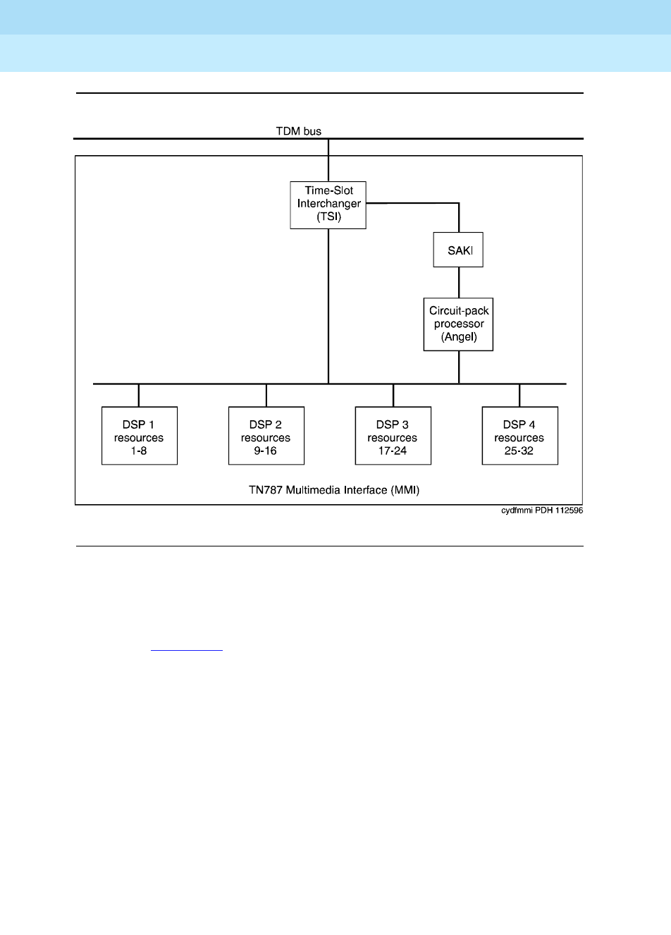
DEFINITY Enterprise Communications Server Release 6
Maintenance for R6r Volumes 1 & 2
555-230-126 Issue 2
January 1998
Maintenance Object Repair Procedures
Page 9-863MMI-BD
9
Figure 9-44. TN787 Multimedia Interface (MMI) Circuit Pack
TN2207/Expansion Services Module
The TN2207 circuit pack permits connecting an Expansion Services Module
(ESM). See Figure 9-45 for connectivity.
■Provides T.120 data sharing capability on a MMCH multipoint H.320 video
conference
■Each conference participant must have endpoints administered and a
personal computer with the H.320 video application installed.
■The DEFINITY ECS must have the expansion service module installed.
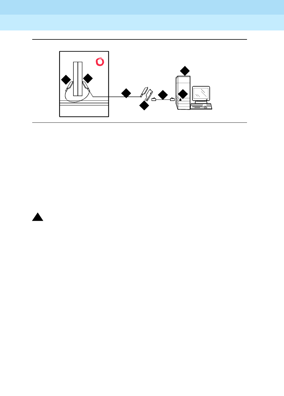
DEFINITY Enterprise Communications Server Release 6
Maintenance for R6r Volumes 1 & 2
555-230-126 Issue 2
January 1998
Maintenance Object Repair Procedures
Page 9-864MMI-BD
9
Figure 9-45. Typical ESM connections
Figure notes
!CAUTION:
The TN2207 circuit pack is the only pack allowing connection of an ESM to
the DEFINITY ECS switch.
1. Port B Y-cable connector to a TN787
Multimedia Interface (MMI) circuit pack
2. Port A Y-cable connector to a TN2207 PRI
circuit pack
3. 25-pair Y-cable
4. 356A adapter
5. D8W cord connected to 356A
adapter port 1
6. Expansion Service Module (ESM)
7. Port B on compatible primary rate
interface (PRI) card
cydf012 RPY 100697
12
4
5
3
6
7

DEFINITY Enterprise Communications Server Release 6
Maintenance for R6r Volumes 1 & 2
555-230-126 Issue 2
January 1998
Maintenance Object Repair Procedures
Page 9-865MMI-BD
9
Error Log Entries and Test to Clear Values
Notes:
a. The circuit pack stopped functioning or it was physically removed from the
system. The alarm logs approximately 11 minutes after the circuit pack
has been removed and/or the SAKI Sanity Test (#53) fails.
If the circuit pack is in the system and the red LED is on, follow the
instructions for a red alarm in ‘‘Circuit Pack LEDs’’ in Chapter 7, ‘‘LED
Indicators’’. Also, see “Handling Common Port Circuit Packs.”
b. This circuit pack has been busied out using the busyout board UUCSS
command.
c. There are more than four MMI circuit packs in the system. Remove the
circuit pack that generated the error in the error log by locating the slot
indicated by the error.
d. Indicates transient communication problems between the switch and this
circuit pack. Execute the test board UUCSS command and refer to the
repair procedures for the Control Channel Looparound Test (#52) in the
XXX-BD section.
1. Run the short test sequence first. If all tests pass, run the long test sequence. Refer to the appropriate
test description and follow the recommended procedures.
Table 9-302. MMI-BD Error Log Entries
Error
Type Aux
Data Associated Test Alarm
Level On/Off
Board Test to Clear Value
010 Any Any Any test board UUCSS sh r 1
1 (a) Any None MIN ON
18 (b) 0 Busyout board UUCSS WNG OFF release board UUCSS
217 (c) 0 None WNG ON
257 (d) 65535 Control Channel Loop Test
(#52) MIN ON test board UUCSS r 3
513 (e) 4352
to
4357
Uplink error from pack
769 (f) Any MMI Synchronization
Status Test #1123
1281 (g) Any Circuit Pack Restart Test
(#594) MAJ ON
1538 (h) Any Software detected error MIN ON
1793 (i) ANY TSI XTalk (#6) MIN ON test board UUCSS l r 3
2049 (j) Any TSI Loop (#1108) MAJ ON test board UUCSS l r 3

DEFINITY Enterprise Communications Server Release 6
Maintenance for R6r Volumes 1 & 2
555-230-126 Issue 2
January 1998
Maintenance Object Repair Procedures
Page 9-866MMI-BD
9
e. The circuit pack detected an Angel on-board hardware failure. The
reported aux data values correspond to the following detected errors:
4352 - External RAM error
4253 - Internal RAM error
4355 - ROM Checksum error
4357 - Instruction set error
Reset the circuit pack by using the busyout board UUCSS, reset board
UUCSS, and release board UUCSS commands. When reset, the circuit
pack executes a set of tests to detect the presence of any of the above
faults. The detection of one these errors during initialization causes the
circuit pack to lock up and appear insane to the system. See the repair
procedures in note b for Error Type 1.
f. This MMI circuit pack reported a loss of MMI synchronization. Refer to test
#1123 for repair procedures.
g. A failure of the time slot interchanger has been detected. Reset the circuit
pack using the busyout board UUCSS, reset board UUCSS, and
release board UUCSS commands. If the reset passes, then the on-board
circuitry is healthy. Retire the alarm using the test board UUCSS long
clear command followed by release board UUCSS.
h. The circuit pack is hyperactive; that is, it is flooding the switch with
messages sent over the control channel. The circuit pack is taken out of
service when a threshold number of these errors is reported to the switch.
Clear the alarm using the following commands: busyout board UUCSS,
reset board UUCSS, test board UUCSS long clear, release board
UUCSS. If the error recurs within 10 minutes, replace the circuit pack.
i. The TSI Cross Talk Test (#6) failed. See the description of this test and
follow the repair procedures.
j. The TSI Looparound Test (#1108) failed. See the description of this test
and follow the repair procedures.
System Technician-Demanded Tests:
Descriptions and Error Code
Always investigate tests in the order presented in Table 9-303 below when
inspecting errors in the system. By clearing error codes associated with the TSI
Crosstalk Test (#6), for example, you may also clear errors generated from other
tests in the testing sequence.

DEFINITY Enterprise Communications Server Release 6
Maintenance for R6r Volumes 1 & 2
555-230-126 Issue 2
January 1998
Maintenance Object Repair Procedures
Page 9-867MMI-BD
9
TSI Crosstalk Test (#6)
This test is non-destructive.
The Time Slot Interchanger (TSI) chip controls connectivity to the TDM bus. The
TSI Cross Talk Test verifies that this TSI talks on the selected TDM bus time slot
and never crosses over to time slots reserved for other connections. If the TSI is
not working correctly, one-way and noisy connections may occur. If the test
passes, then the TSI is able to communicate over the TDM bus. This test is part of
the circuit pack’s demand and scheduled long test sequence, and takes
approximately 20 to 30 seconds to complete.
1. D = Destructive, ND = Non-destructive
2. Refer to the repair procedure described in XXX-BD (Common Port Circuit Pack) for a description
of this test.
Table 9-303. System Technician-Demanded Tests: MMI-BD
Order of Investigation Short Test
Sequence Long Test
Sequence Reset Board
Sequence D/ND1
TSI Crosstalk (#6) X ND
TSI Looparound Test (#1108) X ND
MMI SYNC Status Test (#1123) X ND
MMI SYNC Status Test (#1122) X ND
Control Channel Looparound Test (#52)2XX ND
SAKI Sanity Test (#53)2XD
Continued on next page
Table 9-304. TEST #6 TSI Crosstalk Test
Error
Code Test
Result Description/Recommendation
ABORT Internal system error. This is an abnormal abort.
1. Retry the command at 1-minute intervals a maximum of 5 times.
1002 ABORT The system could not allocate time slots for the test, the traffic load on the
system is very high, or the time slots are out-of-service due to TDM-BUS errors.
Refer to “TDM-BUS” to diagnose any active TDM Bus errors.
1. If the system has no TDM-BUS errors and is not handling heavy traffic,
repeat the test at 1-minute intervals a maximum of 5 times.
Continued on next page

DEFINITY Enterprise Communications Server Release 6
Maintenance for R6r Volumes 1 & 2
555-230-126 Issue 2
January 1998
Maintenance Object Repair Procedures
Page 9-868MMI-BD
9
TSI Looparound Test (#1108)
This test is non-destructive.
During this test, the MMI’s Time Slot Interchanger (TSI) is listens to a TDM
timeslot. A digital count tone loops back in the TSI and onto another TDM timeslot
without passing through any resource hardware. A tone detector port verifies the
looped data. If the digital count is correct, then the test passes. The test is done
for both TDM buses. Failures indicate that the TSI is unreliable.
1003 ABORT The system could not allocate a tone detector for the test. The system is
oversized for the number of tone detectors present, or some tone detectors are
out-of-service.
1. Resolve any “TTR-LEV” errors in the Error Log.
2. Resolve any “TONE-PT” errors in the Error Log.
3. If neither condition exists, retry the test at 1-minute intervals a maximum of
5 times.
2000 ABORT Response to the test was not received from the MMI-BD circuit pack within the
allowable time period.
1. If this result occurs repeatedly, attempt to reset the circuit pack if the other
ports are not in use. Reset the circuit pack by issuing the busyout board
PCSS, reset board UUCSS, followed by the release board UUCSS
commands.
2. If this result occurs again, replace the circuit pack.
2012 ABORT Internal system error. This is an abnormal abort.
2100 ABORT Could not allocate the necessary resources to run this test. This is an abnormal
abort.
1. Retry the command at 1-minute intervals a maximum of 5 times.
FAIL The TSI was found to be transmitting in error. This causes noisy and unreliable
connections.
1. Replace the circuit pack.
PASS The TSI is correctly using its allocated time slots.
Table 9-304. TEST #6 TSI Crosstalk Test — Continued
Error
Code Test
Result Description/Recommendation
Continued on next page

DEFINITY Enterprise Communications Server Release 6
Maintenance for R6r Volumes 1 & 2
555-230-126 Issue 2
January 1998
Maintenance Object Repair Procedures
Page 9-869MMI-BD
9
MMI Synchronization Status Test (#1122 and
1123)
This test is non-destructive.
Table 9-305. TEST #1108 TSI Looparound Test
Error
Code Test
Result Description/Recommendation
ABORT Internal system error. This is an abnormal abort.
1. Retry the command at 1-minute intervals a maximum of 5 times.
1002 ABORT The system could not allocate time slots for the test. Either the traffic load on the
system is very high or time slots is out-of-service due to TDM-BUS errors. Refer
to “TDM-BUS” to diagnose any active TDM Bus errors.
1. If the system has no TDM-BUS errors and is not handling heavy traffic,
repeat the test at 1-minute intervals a maximum of 5 times.
1003 ABORT The system could not allocate a tone detector for the test. The system may be
oversized for the number of Tone Detectors present, or some Tone Detectors
may be out-of-service.
1. Resolve any “TTR-LEV” errors in the Error Log.
2. Resolve any “TONE-PT” errors in the Error Log.
3. If neither condition exists, retry the test at 1-minute intervals a maximum of
5 times.
2000 ABORT Response to the test was not received from the Tone Detector circuit pack
within the allowable time period.
1. If this result occurs repeatedly, attempt to reset the circuit pack (if the other
ports are not in use). Reset the circuit pack by issuing the busyout board
UUCSSpp and the reset board UUCSSpp commands followed by the
release board UUCSS command.
2. If this result occurs again, replace the circuit pack.
2012 ABORT Internal system error. This is an abnormal abort.
2100 ABORT Could not allocate the necessary resources to run this test. This is an abnormal
abort.
1. Retry the command at 1-minute intervals a maximum of 5 times.
FAIL The TSI was found to be transmitting in error, causing noisy and unreliable
connections.
1. Replace the circuit pack.
PASS The TSI is correctly using its allocated time slots.
Continued on next page

DEFINITY Enterprise Communications Server Release 6
Maintenance for R6r Volumes 1 & 2
555-230-126 Issue 2
January 1998
Maintenance Object Repair Procedures
Page 9-870MMI-BD
9
To support applications involving multiple MMI circuit packs, the appropriate
MMI circuit packs must be synchronized with one another. One such circuit pack
is designated as the master sync source, which provides the synchronization
signal onto the TDM bus. The other MMI circuit packs in the system listen to this
signal.
This test monitors this synchronization state. The test fails if the MMI circuit pack
is not in sync. The test passes with auxiliary code 1100 if the MMI circuit pack is
in sync and is providing the synchronization signal for the system. The test also
passes with an auxiliary code of 1101 if the MMI circuit pack is in sync and
listening to the sync signal. MMI circuit packs do not lose the synchronization
signal unless an MMI circuit pack is either pulled out of the system or reset by
using a technician command.
Test #1122 runs when the long option of the test board command is entered,
initiating the recovery of synchronization. Test #1123 runs when the short option
of the test board command is entered, giving the status of the synchronization.
You need not necessarily run the long option since synchronization signal
recovery should be taking place within software running in the background. Use
the long option only if synchronization is not established within 5 minutes of
investigating the problem.
Table 9-306. TEST #1122/1123 MMI Synchronization Status Test
Error
Code Test
Result Description/Recommendation
ABORT Internal system error. This is an abnormal abort.
1. Retry the command at 1-minute intervals a maximum of 5 times.
2000 ABORT A response to the test was not received from the MMI circuit pack within the
allowable time period.
1. If this result occurs repeatedly and the MMI circuit pack is idle, reset the
circuit pack using busyout board UUCSS, then reset board UUCSS,
followed by release board PCSS.
2. Rerun the test; if the same result occurs again, replace the MMI circuit
pack.
2012 ABORT Internal system error
2100 ABORT Could not allocate the necessary resources to run this test. This is an abnormal
abort.
1. Retry the command at 1-minute intervals a maximum of 5 times.
Continued on next page

DEFINITY Enterprise Communications Server Release 6
Maintenance for R6r Volumes 1 & 2
555-230-126 Issue 2
January 1998
Maintenance Object Repair Procedures
Page 9-871MMI-BD
9
Control Channel Looparound Test (#52)
Refer to the repair procedure described in the XXX-BD (Common Port Circuit
Pack) maintenance documentation as Control Channel Looparound Test (#52).
SAKI Sanity Test (#53)
Refer to the repair procedure described in the XXX-BD (Common Port Circuit
Pack) maintenance documentation as SAKI Sanity Test (#53).
FAIL The MMI circuit pack is out of MMI synchronization. Run the long option of the
test board command.
1. Wait up to 5 minutes, and then reset the circuit pack with these
commands: busyout board UUCSS, then reset board UUCSS, followed
by release board PCSS.
2. Rerun the test; if the same result occurs again, replace the circuit pack.
1100 PASS The MMI circuit pack is providing the synchronization correctly. This MMI
circuit pack is designated as the Master Sync source.
1101 PASS The MMI circuit pack is listening to the synchronization signal correctly.
Table 9-306. TEST #1122/1123 MMI Synchronization Status Test — Continued
Error
Code Test
Result Description/Recommendation
Continued on next page

DEFINITY Enterprise Communications Server Release 6
Maintenance for R6r Volumes 1 & 2
555-230-126 Issue 2
January 1998
Maintenance Object Repair Procedures
Page 9-872MMI-LEV (Multimedia Interface Resource Level)
9
MMI-LEV (Multimedia Interface
Resource Level)
The Multimedia Interface Resource Level MO monitors MMI efficiency by
tracking the number of MMI ports that are in-service, and then comparing that
number with the value entered in the MMIs field on the System-Parameters
Maintenance form. This MMIs field is located under the Minimum Maintenance
Threshold
section. The MMIs field contains the minimum number of MMI ports
needed for the Multimedia Call Handling (MMCH) feature to run efficiently and is
an administrable field. This field must contain a minimum threshold number for
MMI port capacity of between 0-128. The MMCH feature must be enabled on the
System-Parameters Customer-Options form before the MMIs field can be
changed to a number greater than zero. The algorithm for determining that a low
level of MMI resources exists uses the value entered in the MMIs field, and the
number of MMI ports that are in-service in the system.
Each MMI circuit pack contains a maximum of 32 ports. If the number of
in-service MMI ports falls below the minimum port capacity (value entered on the
System Parameters Maintenance form under the Minimum Maintenance
Threshold section
and
in the MMI field), a MMI-LEV error is logged. If this outage
continues for 15 minutes, a MAJOR alarm is raised.
Resolving MMI-LEV Errors/Alarms
MMI ports are a key part of the MMCH feature, and any loss in the number of
ports available for use degrades the MMCH customer-defined service level.
If a MMI circuit pack or port is busied out using the busyout board or busyout
port commands, these out-of-service ports are not included in the MMI level
calculation, thus allowing a technician to busy out a MMI circuit pack for
maintenance reasons without causing a MAJOR alarm to be raised. However, if
all of the ports on the MMI circuit pack are not made busy and the circuit pack is
removed, an alarm is raised.
NOTE:
When diagnosing a MMI-LEV problem, begin by resolving any alarms
raised against MMI-BD or MMI-PT maintenance objects. Clearing MMI-BD
or MMI-PT alarms may clear the MMI-LEV alarm.
The MMI circuit pack is maintained by the software like the Tone Detector circuit
pack, which can be removed and reinserted in any port board slot without
MO Name (in
Alarm Log) Alarm
Level Initial Command to Run Full Name of MO
MMI-LEV MAJOR See ‘‘Resolving MMI-LEV Errors/Alarms’’
(below) MMI-LEV

DEFINITY Enterprise Communications Server Release 6
Maintenance for R6r Volumes 1 & 2
555-230-126 Issue 2
January 1998
Maintenance Object Repair Procedures
Page 9-873MMI-LEV (Multimedia Interface Resource Level)
9
administration. Similarly, if a MMI circuit pack is removed from service logically
by failing the Archangel sanity scan test or is removed from service physically by
removing the circuit pack from the carrier, no error/alarm is raised against either
the MMI-BD or the MMI-PT maintenance objects. Therefore, if a MMI-LEV
error/alarm exists, yet no alarms have been raised against MMI-BD or MMI-PT
maintenance objects, a MMI circuit pack may have been removed from service
causing the MMI-LEV error/alarm. To resolve a MMI-LEV MAJOR alarm, restore
the number of MMI ports available for service to be equal to or greater than the
calculated port capacity.
To determine how many MMI circuit packs are needed for the MMCH feature:
1. Using the display system-parameters maintenance command, locate
the number listed in the Minimum Maintenance Thresholds (MMIs) field
and record this number.
2. Use the list configuration
command to verify the number of MMI ports.
3. Compare this number with the value listed in the MMIs field on the
System-Parameters Maintenance form (number listed in step 1 a minimum
thresholds number for MMI ports of between 0-128). Each MMI circuit
pack contains a maximum of 32 ports. If this number in the MMIs field is
less than or equal to 32, one MMI circuit pack is needed. If this number is
64, then two MMI circuit pack are needed.
4. Use the list configuration command to verify that the number of MMI
circuit packs listed agrees with the required minimum port capacity (from
step 1). If the number of MMI circuit packs listed in the step 2 differs from
the calculated number, restore the number of MMI circuit packs to the
correct value, in order to resolve the MMI-LEV alarm.
Error Log Entries and Test to Clear Values
To resolve this alarm, correct the out-of-service problem by following these procedures:
1. See “MMI-PT” and “MMI-BD” and resolve any associated alarms.
1. The number of MMI resources in the system that are in service has fallen below the calculated
minimum value. If the number of in-service MMI ports falls below the MMCH port capacity
(value entered in the Minimum Maintenance Thresholds for MMIs
field) on the
System-Parameters Maintenance form, a MMI-LEV error is logged. If this outage continues for
15 minutes, a MAJOR alarm is raised.
Table 9-307. MMI-LEV Error Log Entries
Error
Type Aux
Data Associated Test Alarm
Level On/ Off
Board Test to Clear Value
11Any None MAJOR OFF

DEFINITY Enterprise Communications Server Release 6
Maintenance for R6r Volumes 1 & 2
555-230-126 Issue 2
January 1998
Maintenance Object Repair Procedures
Page 9-874MMI-LEV (Multimedia Interface Resource Level)
9
2. If a MMI-LEV error/alarm exist and none has been raised against MMI-BD or
MMI-PT maintenance objects, an MMI circuit pack may have been removed from
service causing the MMI-LEV error/alarm. To resolve a MMI-LEV MAJOR alarm,
restore the number of MMI ports available for service to be equal to or more than
the calculated port capacity. See the ‘‘Resolving MMI-LEV Errors/Alarms’’ section
above for details.
3. If the error contines to alarm, escalate the problem.
System Technician-Demanded Tests:
Descriptions and Error Code
There are no System Technician-Demanded tests for MMI-LEV.
DEFINITY Enterprise Communications Server Release 6
Maintenance for R6r Volumes 1 & 2
555-230-126 Issue 2
January 1998
Maintenance Object Repair Procedures
Page 9-875MMI-PT
9
MMI-PT
NOTE:
Refer to Chapter 5, ‘‘Responding to Alarms and Errors’’ for MMCH
troubleshooting information.
The Multimedia Interface Circuit Pack provides a number of H.221 protocol
terminations for bit streams received from the TDM bus. The Multimedia Interface
demultiplexes the H.221 bit stream (audio, video, data, control, and indication
signals) and transmits the bit streams onto the TDM bus to be processed by the
appropriate circuit packs.
Each Multimedia Interface Circuit Pack contains 32 separately maintained
“ports,” more commonly referred to as "resources." MMI-PT represents one of
these 32 resources. At system boot or when the circuit pack is inserted, 32
resources are inserted into the system.
The MMI circuit pack contains 4 Digital Signal Processors (DSPs) which manage
the 32 resources. These resources are directly mapped to DSPs:
All 8 resources that the circuit pack controls may be placed out of service by the
failure of one of these DSPs.
1. Where UU is the universal cabinet number (1 for PPN and 2-44 for EPN); C is the carrier
designation (for example, A, B, C, D, or E); SS is the address of the slot in the carrier where the
circuit pack is located (for example, 01, 02, ...); and pp is the two digit port number (01, 02, 03, ...).
MO Name (in
Alarm Log) Alarm
Level Initial Command to Run1Full Name of MO
MMI-PT MAJOR test port UUCSSpp l r# Multimedia Interface Port
MMI-PT MINOR test port UUCSSpp l r# Multimedia Interface Port
MMI-PT WARNING test port UUCSSpp l r# Multimedia Interface Port
Resource Direct Map
1-8 DSP1
9-16 DSP2
17-24 DSP3
25-32 DSP4

DEFINITY Enterprise Communications Server Release 6
Maintenance for R6r Volumes 1 & 2
555-230-126 Issue 2
January 1998
Maintenance Object Repair Procedures
Page 9-876MMI-PT
9
Figure 9-46. TN787 MULTIMEDIA INTERFACE (MMI) CIRCUIT PACK
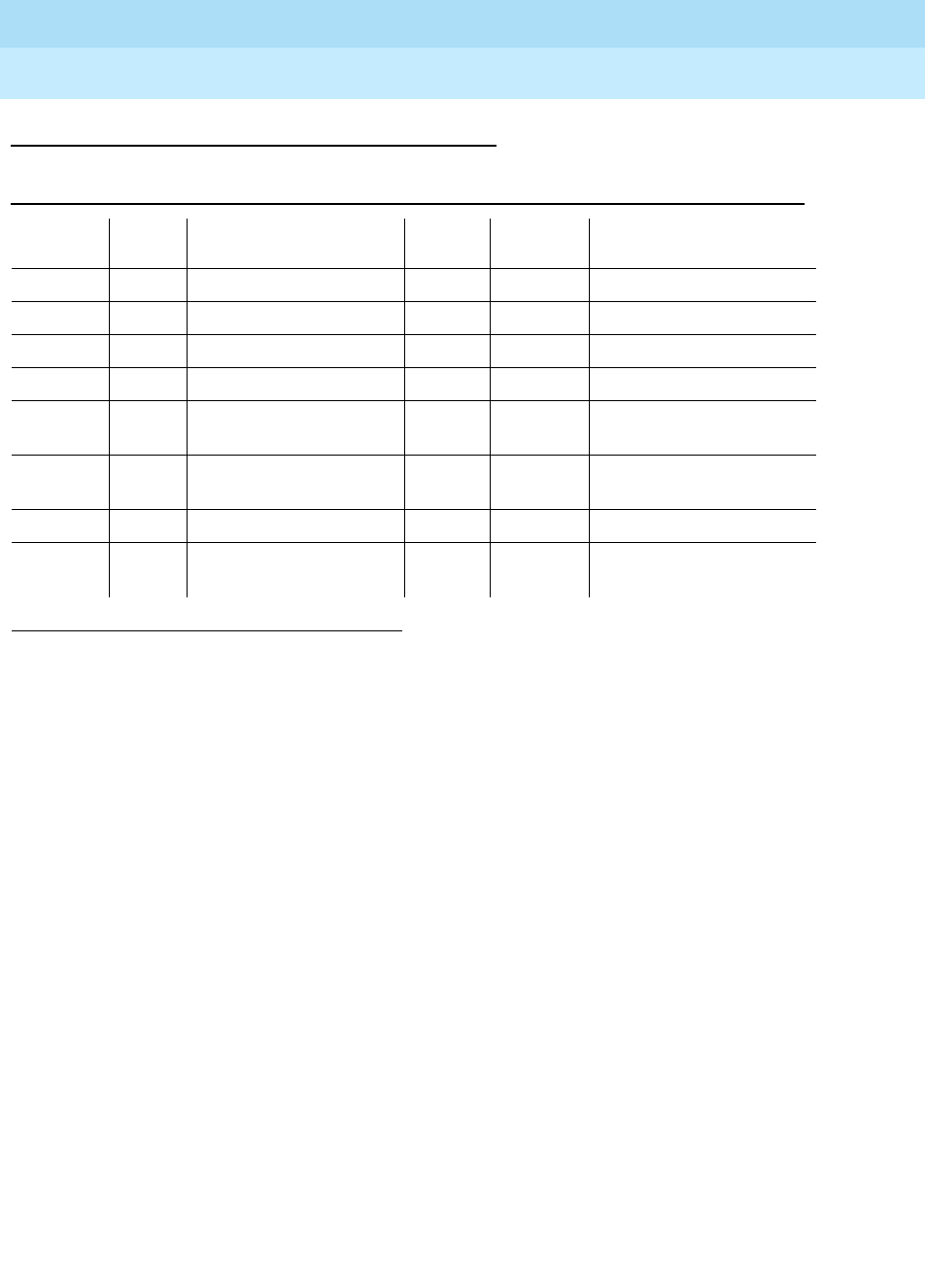
DEFINITY Enterprise Communications Server Release 6
Maintenance for R6r Volumes 1 & 2
555-230-126 Issue 2
January 1998
Maintenance Object Repair Procedures
Page 9-877MMI-PT
9
Error Log Entries and Test to Clear Values
Notes:
a. The customer endpoint connected on a conference sent too many
messages to the VSP-MCU in a specified amount of time. Check the
“status conference” forms to correlate which customer had the problem.
This is a customer endpoint problem and not a VSP-MCU problem.
b. This port has been busied out by the busyout port UUCSSpp command.
c. Indicates that the circuit pack has been removed or has been insane for
more than 11 minutes. To clear the error, replace or reseat the circuit
pack.
d. This error occurs if the MMI circuit pack detects a DSP Error. Maintenance
software will reset the DSP when this error is received. This error is logged
for all 8 resources connected to this particular DSP. If this DSP continues
to fail sanity, a Minor alarm is raised. Replace the circuit pack.
e. This error occurs when the Resource Looparound Test (#1111) fails. Run
the Long Test Sequence and note the results of Test #1111.
f. This error occurs if either the MMI or Voice Conditioner (VC) circuit packs
reports a loss of framing on the service channel between these two circuit
packs. When a customer endpoint establishes a call to the VSP-MCU, a
channel is established between the MMI resource and the VC port. If this
channel is detected to go down by either circuit pack, an uplink message
is sent. This error is then forwarded to maintenance for both circuit packs.
1. Run the short test sequence first. If all tests pass, run the Long Test Sequence. Refer to the
appropriate test description and follow the recommended procedures.
Table 9-308. MMI-PT Error Log Entries
Error
Type Aux
Data Associated Test Alarm
Level On/ Off
Board Test to Clear Value
010 Any Any Any test port UUCSSpp sh r 1
1 (a) Any Uplink error from pack
18 (b) 0 Busyout port PCSSpp WNG OFF release port UUCSSpp
130 (c) Any Software generated WNG ON
257 (d) Any None MAJ/
MIN ON
513 (e) Any Resource Loopback
Test (#1111) MIN ON test port UUCSSpp sh r 3
1025 (f) Any Uplink error from pack
3841 -
3844 (g) Any Uplink error from pack

DEFINITY Enterprise Communications Server Release 6
Maintenance for R6r Volumes 1 & 2
555-230-126 Issue 2
January 1998
Maintenance Object Repair Procedures
Page 9-878MMI-PT
9
Run the Long Test Sequence for this MMI resource, and if any of the tests
fail, follow the repair procedures for that test. If all tests pass, the cause of
the problem might be with the VC pack. See the “VC-DSPPT” repair
procedures.
g. These errors are not related to VSP-MCU. They could be caused by
network problems or from the customer endpoints. They are presented
here for logging purposes only.
System Technician-Demanded Tests:
Descriptions and Error Codes
Resource Looparound Test (#1111)
This test is destructive.
This test checks the connectivity of the resource within MMI circuit pack and out
to the TDM bus. The object is to test the circuitry that an H.221 bit stream comes
in contact with when that stream is demultiplexed, pre-processed, written to the
TDM bus and then reread (looped in the TSI), post-processed, multiplexed, and
then written back to the TDM bus for verification. The video, audio, and data
components of the bit stream are tested separately. If any one of these tests fails,
then the resource is taken out of service.
1. D = Destructive; ND = Nondestructive
Code Description
3841 CRC4 Error (Frame checksum error)
3842 Correctable BAS (Control msg single or double bit error, but
correctable)
3843 Uncorrectable BAS (Control msg bit error -three or more bit,
uncorrectable)
3844 Protocol Error (H.221 Protocol error from endpoint detected)
Order of Investigation Short Test
Sequence Long Test
Sequence D/ND1
Resource Looparound Test (#1111) X X D

DEFINITY Enterprise Communications Server Release 6
Maintenance for R6r Volumes 1 & 2
555-230-126 Issue 2
January 1998
Maintenance Object Repair Procedures
Page 9-879MMI-PT
9
Table 9-309. TEST #1111 Resource Looparound Test
Error
Code Test
Result Description/Recommendation
1000 ABORT System resources required to run this test are not available. The port may be
busy with a valid call.
1. Retry the command at 1-minute intervals a maximum of five times.
2. Use the status conference command to determine if there is an active
conference. If a call is active, the test cannot be run until the conference
call terminates.
1002 ABORT The system could not allocate time slots for the test. The traffic load on the
system may be very high or time slots may be out-of-service due to TDM-Bus
errors. Refer to “TDM-BUS” to diagnose any active TDM Bus errors.
1. If the system has no TDM-BUS errors and is not handling heavy traffic,
repeat the test at 1-minute intervals a maximum of five times.
1003 ABORT The system could not allocate a tone detector for the test. The system is
oversized for the number of tone detectors present or some tone detectors are
out-of-service.
1. Look for TTR-LEV errors in the Error Log. If present, refer to “TTR-LEV.”
2. Look for TONE-PT errors in the Error Log. If present, refer to “TONE-PT”.
3. If neither condition exists, retry the test at 1-minute intervals a maximum of
five times.
1004 ABORT The resource has been seized by a user for a valid call. Use the status
conference command to verify that there is a conference call active.
1. If there are no conference calls, retry the command at 1-minute intervals a
maximum of five times.
2000 ABORT Response to the test was not received from the Tone Detector circuit pack
within the allowable time period.
1. If this result occurs repeatedly, reset the circuit pack, if the other ports are
not in use. Reset the circuit pack by issuing the busyout board UUCSSpp
and the reset board UUCSSpp commands, followed by the release board
UUCSS command.
2. If this result occurs again, replace the circuit pack.
2012 ABORT Internal system error
2100 ABORT Could not allocate the necessary resources to run this test. Abnormal abort.
1. Retry the command at 1-minute intervals a maximum of 5 times.
Continued on next page

DEFINITY Enterprise Communications Server Release 6
Maintenance for R6r Volumes 1 & 2
555-230-126 Issue 2
January 1998
Maintenance Object Repair Procedures
Page 9-880MMI-PT
9
0, 1, 2 FAIL This resource cannot guarantee data integrity and is out-of-service. The
following error codes indicate failure of a particular media loop:
0 = video
1 = audio
2 = low-speed data
1. Replace the circuit pack
PASS The resource is functioning normally.
Table 9-309. TEST #1111 Resource Looparound Test — Continued
Error
Code Test
Result Description/Recommendation
Continued on next page
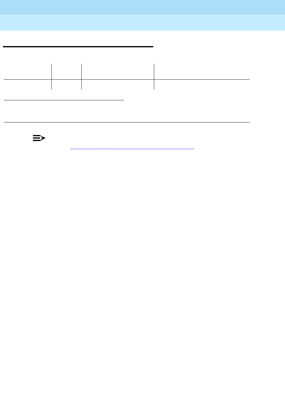
DEFINITY Enterprise Communications Server Release 6
Maintenance for R6r Volumes 1 & 2
555-230-126 Issue 2
January 1998
Maintenance Object Repair Procedures
Page 9-881MMI-SYNC
9
MMI-SYNC
NOTE:
Refer to Chapter 5, ‘‘Responding to Alarms and Errors’’ for MMCH
troubleshooting information.
Each Port Network (PN) must have a TN787D or later MMI circuit pack assigned
as the Multimedia Interface (MMI) master synchronization source for that PN. If
one or more MMI circuit pack is administered in a PN, one MMI circuit pack is
designated as the master synchronization source for all MMI circuit packs within
that PN.
The MMI circuit pack generates a synchronization signal and puts that signal on
the TDM bus. Other MMI packs or any other circuit pack within a PN can listen to
this signal and “synchronize up” to it. The first MMI circuit pack inserted in a PN
is normally designated as the master. As subsequent MMI packs are inserted,
they are instructed to listen and synchronize to the time-slot of the master MMI. In
the unlikely case of an MMI losing this reference, an uplink message is sent from
the MMI circuit pack that lost the signal to maintenance, which also clears the
“event” counter on this MMI with a downlink message. This forces the MMI circuit
pack to return the current state of the synchronization signal. If the signal is still
lost, then the recovery algorithm is entered. Note that during this time, the MMI
circuit pack synchronizes to its internal clock, and there should be no service
disruption. A loss of synchronization is usually the result of a circuit pack failure.
The maintenance strategy is to switch the master source away from the bad pack
to another healthy MMI circuit pack within the PN.
A synchronization switch takes place if half or more of the MMI circuit packs in a
PN report a loss of synchronization. For example, a PN with two MMIs reporting a
loss of sync source switches immediately, three and four MMIs switch if two
report the loss, and so forth. A healthy MMI circuit pack becomes the master
synchronization source providing the signal on a new timeslot. The other MMI
circuit packs within the PN are instructed to listen to this new signal, and the old
master stops providing the signal and now listens to the new master MMI. If an
MMI is physically removed from the system, then the remaining MMIs report the
loss of synchronization. The first MMI with no alarms present becomes the new
master of that PN. Once a synchronization switch has occurred, another switch is
1. Where UU is the universal cabinet number (1 for PPN and 2-44 for EPN); C is the carrier designation
(for example, A, B, C, D, or E); SS is the address of the slot in the carrier where the circuit pack is
located (for example, 01, 02, ...); and pp is the two digit port number (01, 02, 03, ...).
MO Name (in
Alarm Log) Alarm
Level Initial Command to Run1Full Name of MO
MMI-SYNC MINOR test board UUCSS l r# Multimedia Interface Circuit Pack

DEFINITY Enterprise Communications Server Release 6
Maintenance for R6r Volumes 1 & 2
555-230-126 Issue 2
January 1998
Maintenance Object Repair Procedures
Page 9-882MMI-SYNC
9
not allowed for 15 minutes to avoid hyperactive switching. If all the MMIs have
alarms, then no switch is made.
If the MMI circuit pack that provides synchronization is craft busied out, it will not
affect the PN synchronization. The signal is still provided by the busied-out pack.
There is no affect on synchronization if the technician issues a release of the
busied-out MMI. Synchronization is not affected by a warm start of the system
(reset system 1). For all other restarts (reboot through cold 2), MMI
synchronization recovers during board insertion.
Error Log Entries and Test to Clear Values
System Technician-Demanded Tests:
Descriptions and Error Codes
There are no system technician-demanded tests for MMI-SYNC.
1. An MMI synchronization switch was successful. Refer to MMI-BD errors for the reason for the
switch.
2. The requested MMI synchronization switch failed. Resolve all MMI-BD alarms.
Table 9-310. MMI-SYNC Error Log Entries
Error
Type Aux
Data Associated Test Alarm Level On/Off
Board Test to Clear Value
1 Any None See note
1
257 Any None MINOR OFF See note 2

DEFINITY Enterprise Communications Server Release 6
Maintenance for R6r Volumes 1 & 2
555-230-126 Issue 2
January 1998
Maintenance Object Repair Procedures
Page 9-883MODEM-BD (Modem Pool Circuit Pack)
9
MODEM-BD (Modem Pool Circuit
Pack)
Refer to XXX-BD (Common Port Circuit Pack) for circuit pack level errors. See
also MODEM-PT (Modem Pool Port) for related port information.
1.
UU
is the universal cabinet number (1 for PPN, 2 - 44 for EPNs).
C
is the carrier designation
(A, B, C, D, or E).
SS
is the number of the slot in which the circuit pack resides (01 to 21).
MO Name (in
Alarm Log) Alarm
Level Initial Command to Run1Full Name of MO
MODEM-BD MIN test board UUCSS sh Modem Pool Circuit Pack
MODEM-BD WRN test board UUCSS sh Modem Pool Circuit Pack

DEFINITY Enterprise Communications Server Release 6
Maintenance for R6r Volumes 1 & 2
555-230-126 Issue 2
January 1998
Maintenance Object Repair Procedures
Page 9-884MODEM-PT (Modem Pool Port)
9
MODEM-PT (Modem Pool Port)
The Modem Pool Port provides an interface for digital and analog data
communication devices or ports connected to the PBX. It may be thought of as a
PBX data communications ‘‘conversion resource’’ because it converts analog
modem signals typically used in the telephone network into digital signals that
are compatible with the internal PBX network and vice versa.
There may be a number of these conversion resources available in the PBX,
each assigned to an available Modem Pool Group. Only one conversion
resource is used per data connection. The PBX software usually adds the
conversion resource into a data connection if it determines that it is necessary for
the call. Typical connections that include Modem Pool conversion resources
include data calls from Analog Line or Central Office Trunk ports to any digital
port or Digital Line or Trunk ports to any analog port. An example of a Data
Module to Central Office Trunk connection using a Modem Pool conversion
resource is shown in Figure 9-47. In the case where a local data call originates
from an analog port normally used for voice service only and terminates on a
digital port, a Data Origination access code must be dialed before the extension
number for the Modem Pool conversion resource to be included in the
connection.
Each Modem Pool conversion resource contains two ports. One of these, an
analog port, is connected (via the PBX network) to the analog line or trunk port
that is the source of the modem signal. The second port is referred to as the
digital port and is connected (again through the PBX network) to the digital line or
trunk port associated with the Data Module in the connection. The analog modem
signals enter the analog port of the conversion resource in standard Pulse Code
Modulation (PCM) format, but are converted into Data Communications Protocol
(DCP) format before going to the digital line or trunk in the connection.
Integrated Modem Pools
There are two primary types of Modem Pool conversion resources available: an
Integrated Pooled Modem and a Combined Modem Pool. The integrated TN758
Pooled Modem circuit pack contains two independent 300 or 1200 baud
conversion resources. Each conversion resource contains two interfaces to the
PBX digital network: an analog port and a digital port. The analog port is
1.
UU
is the universal cabinet number (1 for PPN, 2 - 44 for EPNs).
C
is the carrier designation
(A, B, C, D, or E).
SS
is the number of the slot in which the circuit pack resides (01 to 21).
pp
is the two digit port number (01, 02, ...).
MO Name (in
Alarm Log) Alarm
Level Initial Command to Run1Full Name of MO
MODEM-PT MINOR test port UUCSSpp s Modem Pool Port
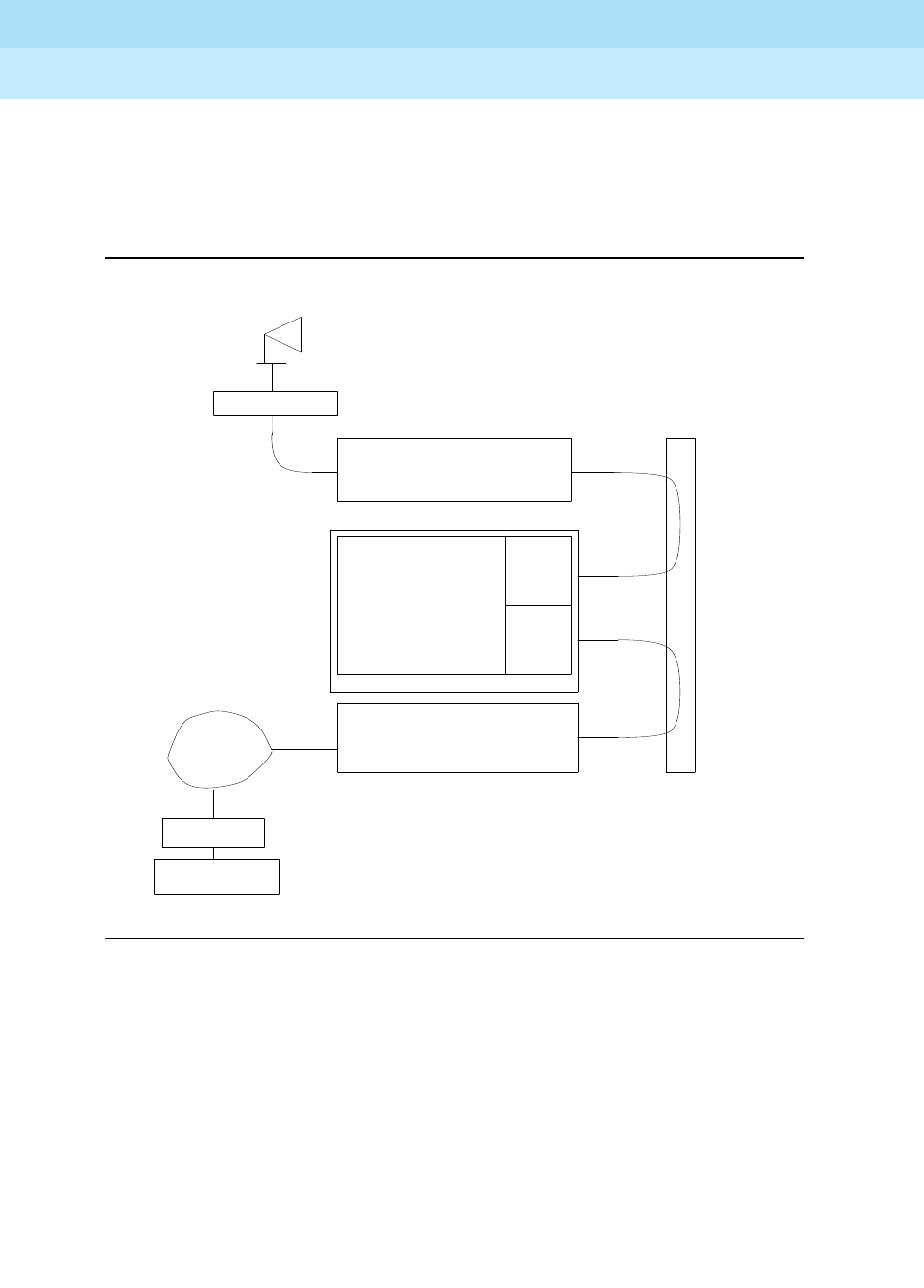
DEFINITY Enterprise Communications Server Release 6
Maintenance for R6r Volumes 1 & 2
555-230-126 Issue 2
January 1998
Maintenance Object Repair Procedures
Page 9-885MODEM-PT (Modem Pool Port)
9
connected through the PBX network to the analog line or trunk port containing
the analog modem signals. The digital port connects through the PBX network to
the digital line or trunk port in the call. The figure below shows a typical
end-to-end connection using a conversion resource on the integrated Pooled
Modem circuit pack.
Figure 9-47. Typical Modem Pool Switched Connection with Integrated
Pooled Modem
ANALOG
ANALOG
DCP
DCP
DCP
TIP/RING
PORT
DIGITAL
PORT
(TN758)
ANALOG
CONVERSION
POOLED MODEM
DATA MODULE
COMPUTER
HOST
MODEM
NETWORK
TELEPHONE
NETWORK
DIGITAL
PBX
(TN754)
LINE
DIGITAL
(TN747B)
TRUNK
CENTRAL OFFICE
RESOURCE
TERMINAL
PCM
PCM

DEFINITY Enterprise Communications Server Release 6
Maintenance for R6r Volumes 1 & 2
555-230-126 Issue 2
January 1998
Maintenance Object Repair Procedures
Page 9-886MODEM-PT (Modem Pool Port)
9
Combined Modem Pools
The Combined Modem Pool conversion resource is the second type available.
The function served by the Combined Modem Pool is similar to that of the
integrated Pooled Modem circuit pack, but the physical implementation is much
different. It has the advantage of supporting any speed the external modem can
support. The integrated Pooled Modem circuit pack can only support 300 or
1200 baud transmission rates. The Combined Modem Pool conversion resource
consists of a port on an Analog Line circuit pack, an external modem, a Data
Module, and a port on a TN754 Digital Line circuit pack. The tip and ring
interface of the Analog Line is connected to the modem, the RS-232C interface of
the modem connects to the Data Module, and the DCP interface on the Data
Module is connected to the Digital Line port.
The analog modem signals pass through the Analog Line port to the modem. The
modem converts these to RS-232C signals which are passed on to the Data
Module. The Data Module further converts the signals to the DCP protocol for the
Digital Line port which passes the signals on to the PBX network.

DEFINITY Enterprise Communications Server Release 6
Maintenance for R6r Volumes 1 & 2
555-230-126 Issue 2
January 1998
Maintenance Object Repair Procedures
Page 9-887MODEM-PT (Modem Pool Port)
9
Figure 9-48. Typical Modem Pool Switched Connection with Combined
Modem Pool
HOST
COMPUTER
DATA MODULE
TERMINAL
CENTRAL OFFICE
TRUNK
(TN747B)
DIGITAL
DIGITAL
LINE
DATA
MODULE
MODEM
ANALOG
LINE
RS-232
DCP
DCP
PCM
PCM
DCP
ANALOG
ANALOG
DCP
COMBINED MODEM POOL
DCP
Tip/Ring
(TN754)
LINE
(TN754)
PBX
DIGITAL
NETWORK
TELEPHONE
NETWORK
MODEM

DEFINITY Enterprise Communications Server Release 6
Maintenance for R6r Volumes 1 & 2
555-230-126 Issue 2
January 1998
Maintenance Object Repair Procedures
Page 9-888MODEM-PT (Modem Pool Port)
9
Troubleshooting Modem-Pool Symptoms
Certain customer-reported troubles may provide important information for
troubleshooting Modem Pool problems. For example, if the customer tries to
make a data call requiring a Modem Pool conversion resource, and the Modem
Pool and Data Module speeds or other options do not match, they may receive a
‘‘CHECK OPTIONS’’ error message on the terminal. In this case, check the
Modem Pool administration and Data Module option settings. If the Modem Pool
is a Combined type, check also the option settings on the external Modem and
Data Module, and cabling and connections between the Digital Line port, Data
Module, Analog Line port, and Modem.
Testing Modem-Pools
There are three types of commands that can be used to test Modem Pool
circuits: test port, test modem-pool #, and test board. The test port command
is generally the first test to run after the Error Log is evaluated and an entry is
found for a Modem Pool port. The test modem-pool # command runs the same
tests as the test port short command performed on a Modem Pool port.
However, the test modem-pool # command can automatically test all ports in
the Modem Pool group number specified in #. The test board command
performs the same tests as test port and test modem-pool # plus additional
tests for circuits common to the entire circuit pack. Refer to the "XXX-BD
(Common Port Circuit Pack)" section for information on additional tests performed
with test board (#50, #52, and #53).
If the Modem Pool port or group being tested with test modem-pool # contains
Combined Modem Pools, the ports on the associated Analog Line circuit pack
and the TN754 Digital Line circuit pack are tested as a group. Note, however,
that Combined Modem Pools are not tested with the tests described in this
section and the repair information related to Tests # 96, 97, 98, and 99 is not
applicable. The Analog port of the Combined Modem port is tested with Analog
port tests, and the Digital port of the Combined Modem port is tested with
TDMODULE/PDMODULE tests. Therefore, use the repair procedures outlined in
the ANL-LINE, ANL-16-L, ANL-NE-L, and TDMODULE/PDMODULE Maintenance
documentation when interpreting the results of the execution of the test
modem-pool # command on Combined Modem Pools.
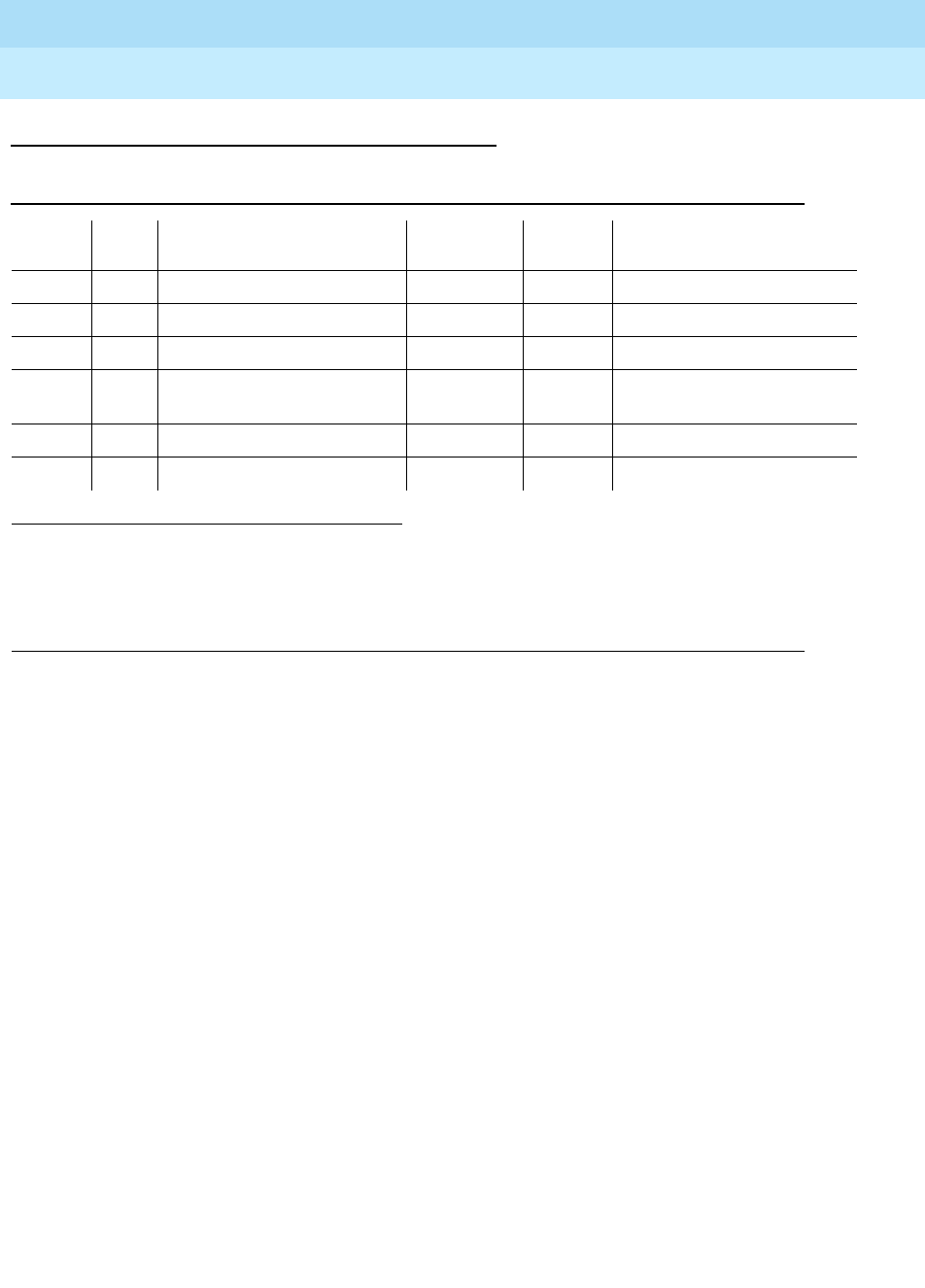
DEFINITY Enterprise Communications Server Release 6
Maintenance for R6r Volumes 1 & 2
555-230-126 Issue 2
January 1998
Maintenance Object Repair Procedures
Page 9-889MODEM-PT (Modem Pool Port)
9
Error Log Entries and Test to Clear Values
1. Run the Short Test Sequence first. If all tests pass, run the Long Test Sequence. Refer to the appropriate
test description and follow the recommended procedures.
2. This error type indicates that the circuit pack has been removed or has been insane for more than 21
minutes. To clear the error, reinsert or replace the circuit pack.
Table 9-311. Modem Pool Port Error Log Entries
Error
Type Aux
Data Associated Test Alarm
Level On/Off
Board Test to Clear Value
010 Any Any Any test port UUCSSpp sh r 1
18 0 busyout UUCSS WARNING OFF release port UUCSS
1302None WARNING ON test port UUCSSpp sh
257 Conversion Resource Loop
(#98) MINOR ON test port UUCSS s r 3
513 Modem Conference (#97) MINOR ON test port UUCSS l r 3
769 Modem NPE Crosstalk (#96) MINOR ON test port UUCSS l r 3
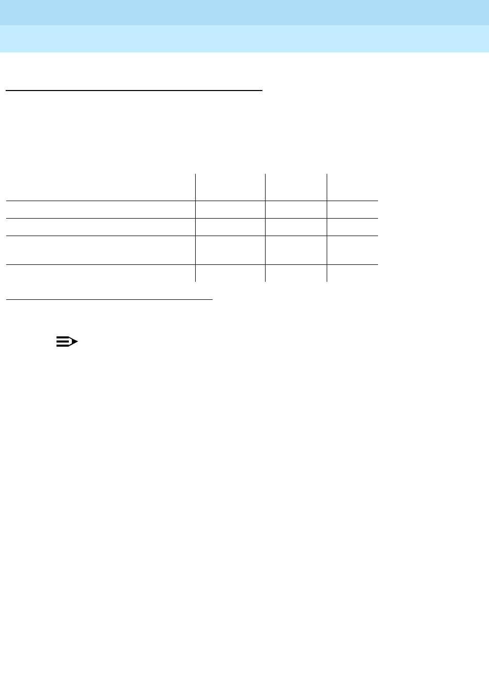
DEFINITY Enterprise Communications Server Release 6
Maintenance for R6r Volumes 1 & 2
555-230-126 Issue 2
January 1998
Maintenance Object Repair Procedures
Page 9-890MODEM-PT (Modem Pool Port)
9
System Technician-Demanded Tests:
Descriptions and Error Codes
Always investigate tests in the order presented in the table below when
inspecting errors in the system. By clearing error codes associated with the
Modem Pool Conference Test,
for example, you may also clear errors generated
from other tests in the testing sequence.
NOTE:
The tests in this section do not apply to Combined Modem Pool conversion
resources. The standard Digital Line and/or Analog Line port tests are run
on the ports associated with the Combined Modem Pool. Consult the test
descriptions for those maintenance objects when repairing Combined
Modem Pool arrangements.
1. D = Destructive, ND = Non-destructive
Order of Investigation Short Test
Sequence Long Test
Sequence D/ND1
Modem Pool NPE Crosstalk Test (#96) X D
Modem Pool Conference Test (#97) X D
Modem Pool Conversion Resource
Looparound Test (#98) XXND
Modem Pool Audits Test (#99) X X ND

DEFINITY Enterprise Communications Server Release 6
Maintenance for R6r Volumes 1 & 2
555-230-126 Issue 2
January 1998
Maintenance Object Repair Procedures
Page 9-891MODEM-PT (Modem Pool Port)
9
Modem Pool NPE Crosstalk Test (#96)
This test is destructive.
The Modem Pool Crosstalk Test verifies that the NPE is connected only to the
desired time slot and is not crosstalking on other time slots. This test operates
exactly like Test #6 for other types of port circuits but is performed twice in order
to test both NPEs in the Modem Pool Port
Table 9-312. TEST #96 Modem Pool NPE Crosstalk Test
Error
Code Test
Result Description/ Recommendation
ABORT System resources required for this test are not available.
1. Retry the command at 1-minute intervals a maximum of 5 times.
1000 ABORT System resources required for this test are not available. The port may be in use
on a valid call. Determine if the port is available for testing.
1. Retry the command at 1-minute intervals a maximum of 5 times.
1001 ABORT System resources required to run this test are not available.
1. Retry the command at 1-minute intervals a maximum of 5 times.
1002 ABORT The system could not allocate time slots for the test. The system may be under
heavy traffic conditions or it may have time slots out-of-service due to TDM-BUS
errors. Refer to “TDM-BUS” to diagnose any active TDM-BUS errors.
1. If the system has no TDM-BUS errors and is not handling heavy traffic,
repeat the test at 1-minute intervals a maximum of 5 times.
1003 ABORT The system could not allocate a tone receiver for the test. The system may be
oversized for the number of Tone Detectors present or some Tone Detectors
may be out-of-service.
1. Resolve any “TTR-LEV” errors in the Error Log.
2. Resolve any “TONE-PT” errors in the Error Log.
3. If neither condition exists, retry the test at 1-minute intervals a maximum of 5
times.
1004 ABORT The port has been seized by a user for a valid call. Determine whether the port
is available for testing.
1. Retry the command at 1-minute intervals a maximum of 5 times.
1020 ABORT The test did not run due to a previously existing error on the specific port or
because of a more general circuit pack error.
1. Examine the Error Log for existing errors against this port or the circuit pack,
and attempt to diagnose the previously existing errors.
2000 ABORT A response to the test was not received within the allowable time period.
1. Retry the command at 1-minute intervals a maximum of 5 times.
Continued on next page

DEFINITY Enterprise Communications Server Release 6
Maintenance for R6r Volumes 1 & 2
555-230-126 Issue 2
January 1998
Maintenance Object Repair Procedures
Page 9-892MODEM-PT (Modem Pool Port)
9
Modem Pool Conference Test (#97)
This test is destructive.
2100 ABORT System resources required for this test are not available.
1. Retry the command at 1-minute intervals a maximum of 5 times.
6000 ABORT System resources needed to complete the test could not be allocated for the
digital section of the Modem Pool conversion resource. Ordinarily, this means
the conversion resource or other hardware used during the test was in use.
1. Wait 1 minute and attempt the test again.
2. If the same error occurs, use the status port command to determine
whether the Modem Pool conversion resource is in use.
3. If the conversion resource is in use, and it is absolutely necessary to test it,
the call must be dropped by issuing a busyout port UUCSS command
against the conversion resource. Run the test again.
4. If the same error occurs while the conversion resource is idle, busyout both
Modem Pool conversion resources on the TN758 Pooled Modem circuit
pack containing the conversion resource under test.
5. If the test continues to fail or abort, replace the Pooled Modem circuit pack
and retest.
6001 ABORT System resources needed to complete the test could not be allocated for the
analog section of the Modem Pool conversion resource. Follow the test
procedures for the previous error code.
NONE FAIL The test failed. This error is internal to the Pooled Modem circuit pack and does
not involve external equipment or interfaces.
1. Busy-out both of the TN758 Pooled Modem conversion resources on the
circuit pack containing the failing conversion resource.
2. If the test continues to fail, replace the Pooled Modem circuit pack and
retest.
ANY FAIL The NPE of the tested port was found to be transmitting in error. This condition
will cause noisy and unreliable connections.
1. If the remaining ports are currently not in use (the yellow LED is off), reset
the circuit pack and repeat the test.
2. If the test fails again, replace the circuit pack.
PASS The port is correctly using its allocated time slots. Investigate user-reported
troubles on this port using other port tests and by examining station, trunk, or
external wiring.
Table 9-312. TEST #96 Modem Pool NPE Crosstalk Test — Continued
Error
Code Test
Result Description/ Recommendation
Continued on next page

DEFINITY Enterprise Communications Server Release 6
Maintenance for R6r Volumes 1 & 2
555-230-126 Issue 2
January 1998
Maintenance Object Repair Procedures
Page 9-893MODEM-PT (Modem Pool Port)
9
The Modem Pool Conference Test checks most of the switching and gain control
functions provided by the NPE circuit in the analog section of the conversion
resource. This test conferences a 1004-Hz tone through the NPE, looping it back
so that it can be verified with a Tone Detector circuit
Table 9-313. TEST #97 Modem Pool Conference Test
Error
Code Test
Result Description/ Recommendation
ABORT System resources required for this test are not available.
1000 ABORT System resources required to run this test are not available. The port may be in
use on a valid call. Determine whether the port is available for testing.
1002 ABORT The system could not allocate time slots for the test. The system may be under
heavy traffic conditions or it may have time slots out-of-service due to TDM-BUS
errors. Refer to TDM-BUS (TDM Bus) Maintenance documentation to diagnose
any active TDM Bus errors.
1. If the system has no TDM-BUS errors and is not handling heavy traffic,
repeat test at 1-minute intervals a maximum of 5 times.
1003 ABORT The system could not allocate a tone receiver for the test. The system may be
oversized for the number of Tone Detectors present or some Tone Detectors
may be out-of-service.
1. Resolve any “TTR-LEV” errors in the Error Log.
2. Resolve any “TONE-PT” errors in the Error Log.
3. If neither condition exists, retry the test at 1-minute intervals a maximum of 5
times.
1004 ABORT The port has been seized by a user for a valid call. Determine whether the port is
available for testing.
1. Retry the command at 1-minute intervals a maximum of 5 times.
1020 ABORT The test did not run due to a previously existing error on the specific port or
because of a more general circuit pack error.
1. Examine the Error Log for existing errors against this port or the circuit pack,
and attempt to diagnose previously existing errors.
2000 ABORT The response to the test was not received in the allowable time period.
2012 ABORT Internal system error.
2100 ABORT System resources required for this test are not available.
2103 ABORT The system could not make the conference connection for the test.
1. Retry the command at 1-minute intervals a maximum of 5 times.
Continued on next page

DEFINITY Enterprise Communications Server Release 6
Maintenance for R6r Volumes 1 & 2
555-230-126 Issue 2
January 1998
Maintenance Object Repair Procedures
Page 9-894MODEM-PT (Modem Pool Port)
9
4000 ABORT System resources needed to complete the test could not be allocated.
Ordinarily, this means the conversion resource or other hardware used during
the test was in use.
1. Wait 1 minute and attempt the test again.
2. If the same error occurs, use the status port command to determine
whether the Modem Pool conversion resource is in use.
3. If the conversion resource is in use, and it is absolutely necessary to test it,
the call must be dropped by issuing a busyout port UUCSS command
against the conversion resource. Run the test again.
4. If the same error occurs while the conversion resource is idle, busyout both
Modem Pool conversion resources on the TN758 Pooled Modem circuit
pack containing the conversion resource under test. Run the test again.
5. If the test continues to abort, replace the Pooled Modem circuit pack and
retest.
6551
5ABORT System resources required for this test are not available.
1. Retry the command at 1-minute intervals a maximum of 5 times.
2. Issue the test port long command on the port on which the test aborted. If
any test aborted or failed, follow recommended maintenance strategy for the
appropriate port type (for example, ANL-LINE, DIG-LINE).
None FAIL The test failed. This error is internal to the Pooled Modem circuit pack and does
not involve external equipment or interfaces.
1. Busy-out both of the TN758 Pooled Modem conversion resources on the
circuit pack containing the failing conversion resource.
2. If the test continues to fail, replace the Pooled Modem circuit pack and
retest.
Any FAIL The Network Processing Element (NPE) of the tested port did not conference the
tones correctly. This will cause noisy and unreliable connections.
1. If the remaining ports are currently not in use (the yellow LED is off), reset
the circuit pack and repeat the test.
2. If the test fails again, replace the circuit pack.
PASS The port can correctly conference multiple connections. User-reported troubles
on this port should be investigated using other port tests and by examining
station, trunk, or external wiring.
Table 9-313. TEST #97 Modem Pool Conference Test — Continued
Error
Code Test
Result Description/ Recommendation
Continued on next page
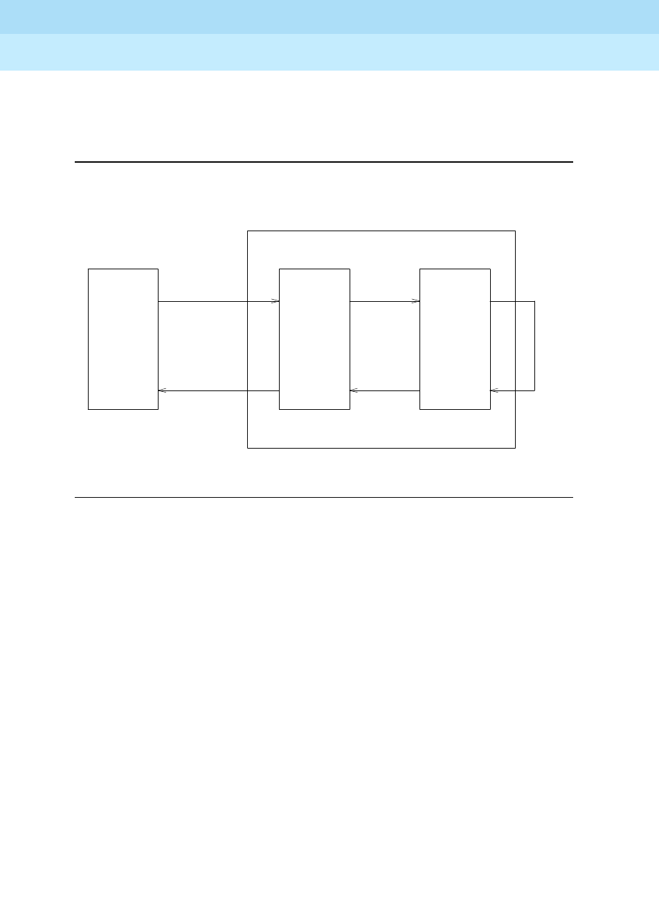
DEFINITY Enterprise Communications Server Release 6
Maintenance for R6r Volumes 1 & 2
555-230-126 Issue 2
January 1998
Maintenance Object Repair Procedures
Page 9-895MODEM-PT (Modem Pool Port)
9
Modem Pool Conversion Resource Loop-Around
Test (#98)
The Modem Pool Conversion Resource Looparound Test is set up as follows:
Figure 9-49. Modem Pool Conversion Resource Loop-Around
Test data patterns are transmitted from a Maintenance/Test Board digital port
over network time slot A through the digital port on the conversion resource,
looped around through the analog port via time slot C back to the
Maintenance/Test Board digital port circuit via time slot B where the patterns are
checked for accuracy. Finally, the test forces a disconnect by breaking the
connection between the Maintenance/Test Board digital port and the Modem
Pool Port (time slot A) and verifying that the Maintenance/Test Board digital port
and Modem Pool Port go on-hook within the proper time.This test attempts to
allocate a Maintenance/Test Board digital port, Modem Pool Port, and other
internal resources. If any of these allocation attempts fail, the test cannot be
completed and a specific abort error is reported.
TS-A
TS-C
ANALOG
PORTION
DIGITAL
PORTION
MAINTENANCE/
TEST BOARD
(TN771B)
DIGITAL
PORT
MODEM POOL CONVERSION RESOURCE
TN758 POOLED MODEM CIRCUIT PACK
TS-B

DEFINITY Enterprise Communications Server Release 6
Maintenance for R6r Volumes 1 & 2
555-230-126 Issue 2
January 1998
Maintenance Object Repair Procedures
Page 9-896MODEM-PT (Modem Pool Port)
9
Table 9-314. TEST #98 Modem Pool Conversion Resource
Looparound Test
Error
Code Test
Result Description/ Recommendation
1000 ABORT System resources needed to complete the test could not be allocated for the
digital section of the Modem Pool conversion resource. Ordinarily, this means
the conversion resource or other hardware used during the test was in use.
1. Wait 1 minute and attempt the test again.
2. If the conversion resource is in use, and it is absolutely necessary to test it,
the call will have to be dropped by issuing a busyout port UUCSSpp
command against the conversion resource. Run the test again. If the test
passes, release the port.
3. If the same error occurs while the conversion resource is idle, busy out both
Modem Pool conversion resources on the TN758 Pooled Modem circuit
pack containing the conversion resource under test. Rerun the test.
4. If the test continues to abort, replace the Pooled Modem circuit pack and
retest.
1180 ABORT A Maintenance/Test Board digital port could not be allocated for this test. This
error is more closely related to the digital port on the specific Maintenance/Test
Board circuit pack used for this test than the TN758 Pooled Modem circuit pack
itself. Therefore, any hardware testing or replacement activities will focus on the
Maintenance/Test Board circuit pack. Verify that the digital ports of the
Maintenance/Test Board are present if this error occurs.
1. Use the list config command to verify that both of the Maintenance/Test
Board digital ports are present. The display should show entries for both
port 02 and port 03.
2. If the digital ports (02 and 03) are not present, refer to the M/T-BD
Maintenance documentation.
3. If the digital ports are present, retry the command at 1 minute intervals a
maximum of 5 times.
1181 ABORT No time-slots available to connect digital ports for the test.
1. Retry the command at 1 minute intervals a maximum of 5 times.
1182 ABORT Internal system error. Failed to connect the digital ports with time-slots.
1. Retry the command at 1 minute intervals a maximum of 5 times.
Continued on next page

DEFINITY Enterprise Communications Server Release 6
Maintenance for R6r Volumes 1 & 2
555-230-126 Issue 2
January 1998
Maintenance Object Repair Procedures
Page 9-897MODEM-PT (Modem Pool Port)
9
1340 ABORT No Maintenance/Test digital port is currently available to perform this test.
1. Use list config to determine whether any Maintenance/Test digital ports
(ports 02 and 03 on the Maintenance/Test circuit pack) are present in the
system. Because at least one Maintenance/Test circuit pack must always be
present in the PPN of any G3r system, there should be at least two such
ports present. If the ports are present, proceed to step 2. Otherwise,
determine why no ports appear in the list config display.
2. If the ports are present and no errors are logged against them, retry the
command at 1 minute intervals a maximum of 5 times.
3. If the test continues to abort, replace the Maintenance/Test circuit pack.
2004 ABORT Off-Hook was not received from the Pooled Modem.
1. Busy-out the digital port being tested on the Pooled Modem circuit pack.
Retry the command at 1 minute intervals a maximum of 5 times.
2. If the test still aborts, replace the circuit pack.
2005 ABORT The Maintenance/Test Board digital port and the Pooled Modem Board digital
port failed to handshake.
1. Retry the command at 1 minute intervals a maximum of 5 times.
2. If the test still aborts, replace the Pooled Modem circuit pack.
2312 ABORT The Looparound Test did not complete, failed to receive loop-back data.
1. Retry the test, if still aborts, replace the Pooled Modem Board.
2313 ABORT The Maintenance/Test Board digital port allocated for this test did not respond to
downlinked message.
1. Retry the command at 1 minute intervals a maximum of 5 times.
2. If the test continues to abort, replace the MTB.
2314 ABORT The Modem Pool digital port did not respond to downlinked message. This error
is internal to the Modem Pool circuit pack and does not involve external
equipment or interfaces.
1. Busy-out the TN758 Pooled Modem conversion resources on the circuit
pack.
2. If the test continues to abort, replace the Pooled Modem circuit pack and
retest.
2500 ABORT Internal system error.
1. Retry the command at 1 minute intervals a maximum of 5 times.
Table 9-314. TEST #98 Modem Pool Conversion Resource
Looparound Test — Continued
Error
Code Test
Result Description/ Recommendation
Continued on next page

DEFINITY Enterprise Communications Server Release 6
Maintenance for R6r Volumes 1 & 2
555-230-126 Issue 2
January 1998
Maintenance Object Repair Procedures
Page 9-898MODEM-PT (Modem Pool Port)
9
Modem Pool Audit Test (#99)
This audit updates the Modem Pool conversion resource status contained in the
TN758 Pooled Modem circuit pack’s microprocessor. It does not actually test the
Pooled Modem circuit pack; therefore, there are no FAIL codes. The audit can
only be performed on idle conversion resources. If the conversion resource is in
use, the audit will abort
2323 ABORT The Maintenance Test circuit pack digital port allocated for this test did not
disconnect properly. This error is more closely related to the Maintenance Test
circuit pack digital port used for this test than the TN758 Pooled Modem circuit
pack itself. Therefore, any hardware testing or replacement activities will focus
on the Maintenance Test circuit pack.
1. Wait 1 minute and attempt the test again a maximum of 5 times.
2324 ABORT The digital portion of the tested Modem Pool port did not disconnect properly.
1. Wait 1 minute and attempt the test again.
2. If the test continues to abort, replace the Pooled Modem circuit pack and
retest.
2325 FAIL The Modem Pool port did not respond with an on-hook message when the
connection to the TN711 Maintenance/Test digital port was broken, indicating a
likely problem with the TN758 Pooled Modem circuit pack.
1. Busy-out both of the TN758 Pooled Modem conversion resources on the
circuit pack containing the failing conversion resource.
2. If the test continues to fail, replace the Pooled Modem circuit pack and
retest.
FAIL The Looparound Test failed, the loop-back data did not match the original data.
1. Repeat Test #98.
2. If the test fails again, replace the Pooled Modem circuit pack.
PASS The port can correctly transmit/receive data.
Table 9-314. TEST #98 Modem Pool Conversion Resource
Looparound Test — Continued
Error
Code Test
Result Description/ Recommendation
Continued on next page

DEFINITY Enterprise Communications Server Release 6
Maintenance for R6r Volumes 1 & 2
555-230-126 Issue 2
January 1998
Maintenance Object Repair Procedures
Page 9-899MODEM-PT (Modem Pool Port)
9
Table 9-315. TEST #99 Modem Pool Audit Test
Error
Code Test Result Description/ Recommendation
None ABORT The system was not able to allocate all the necessary resources to execute
this test. An ABORT simply indicates that the conversion resource was in use
when the audit was performed. No repair action is necessary unless the
conversion resource was known to be idle during the test (yellow in-use LED
was off) or was busied out before the test was run. In that case, a TN758
failure condition may exist and the following procedure should be used:
1. Busyout both of the TN758 Pooled Modem conversion resources on the
circuit pack containing the failing conversion resource.
2. If the test continues to abort, replace the Pooled Modem circuit pack and
retest.
Continued on next page
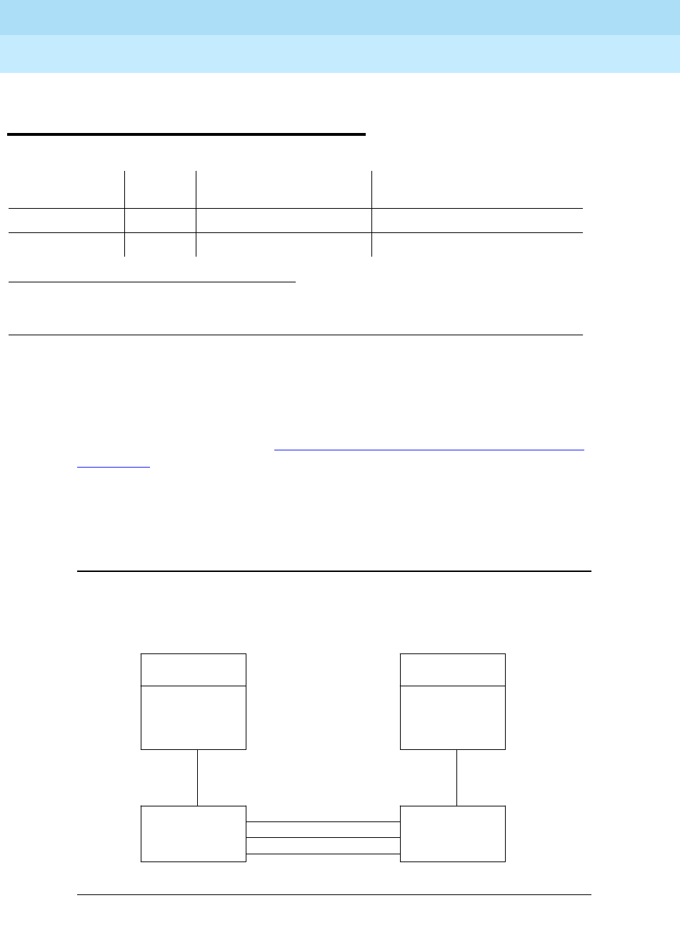
DEFINITY Enterprise Communications Server Release 6
Maintenance for R6r Volumes 1 & 2
555-230-126 Issue 2
January 1998
Maintenance Object Repair Procedures
Page 9-900M/T-ANL (Maintenance/Test Analog Port)
9
M/T-ANL (Maintenance/Test Analog
Port)
The Maintenance/Test Analog Port is port number 1 on the TN771
Maintenance/Test circuit pack. This port is used by the Automatic Transmission
Measurement System (ATMS) as an Originating Test Line (OTL) or Terminating
Test Line (TTL) for test calls over analog trunks. For more details, see ‘‘Automatic
Trunk Transmission System’’ in Chapter 6, ‘‘Additional Maintenance Procedures’’.
Figure 9-50 shows a typical ATMS configuration.
M/T-ANL maintenance ensures that the analog trunk’s testing function is
operating correctly. An alarm against M/T-ANL can reduce service, but it will not
block it. To accurately measure performance and health of analog trunks, the
TN771 should be replaced when a new circuit pack is available.
Figure 9-50. ATMS Tie Trunk Test Call
1.
UU
is the universal cabinet number (1 for PPN, 2 - 44 for EPNs).
C
is the carrier designation (A,
B, C, D, or E).
SS
is the number of the slot in which the circuit pack resides (01 to 21).
pp
is the
two digit port number (01, 02, ...).
MO Name (in
Alarm Log) Alarm
Level Initial Command to Run1Full Name of MO
M/T-ANL Minor test port UUCSSpp l Maintenance/Test Analog Port
M/T-ANL Warning release port UUCSSpp Maintenance/Test Analog Port
Tie
Trunk
Facilities
Originating
Test Line
(OTL)
TN771
TDM Bus
Terminating
Test Line
(TTL)
TN771
TDM Bu
s
PBX originating
the test call
PBX terminating
the test call
Tie Trunk
Circuit Pack
Tie Trunk
Circuit Pack
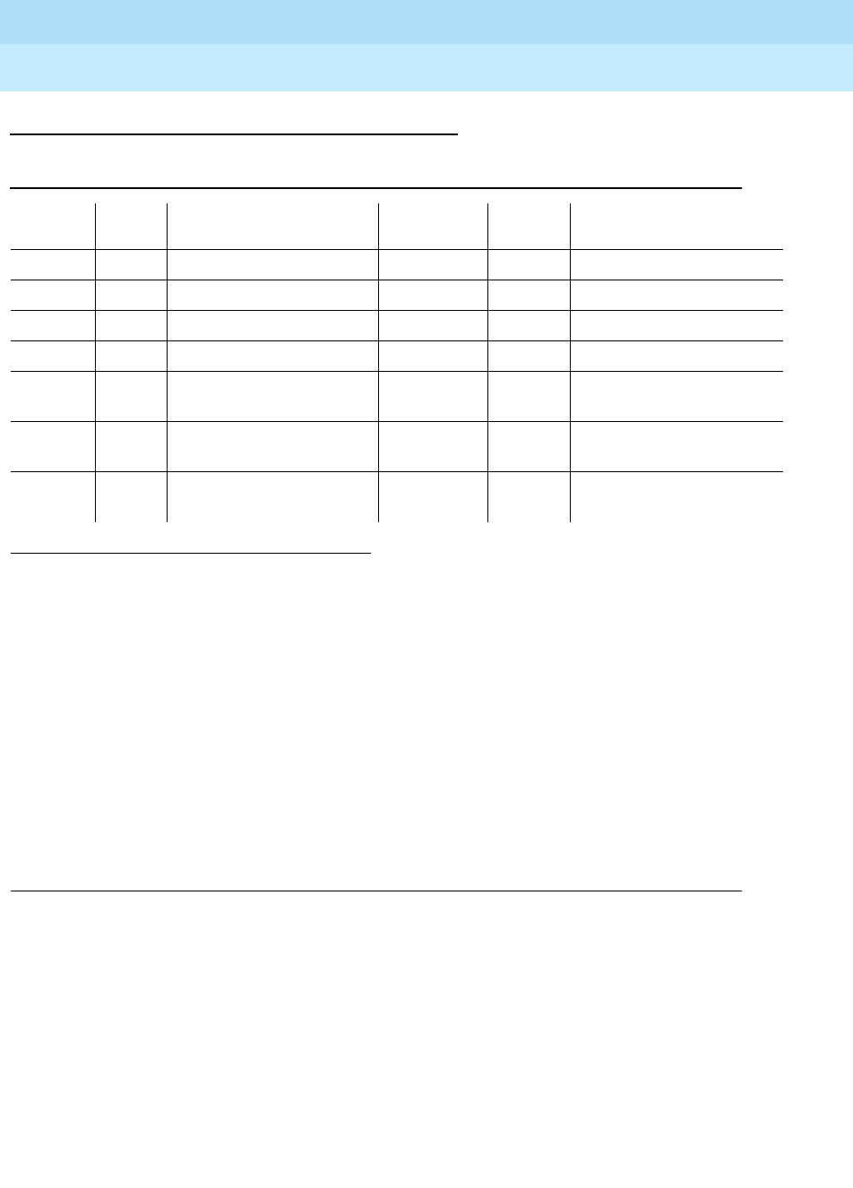
DEFINITY Enterprise Communications Server Release 6
Maintenance for R6r Volumes 1 & 2
555-230-126 Issue 2
January 1998
Maintenance Object Repair Procedures
Page 9-901M/T-ANL (Maintenance/Test Analog Port)
9
Error Log Entries and Test to Clear Values
Notes:
a. This error code appears in the Error Log only if the MTB circuit pack has
been removed since the Error Log was last cleared. Verify that the circuit
pack has been reinserted.
b. This error indicates a hardware failure on the Analog Port circuitry.
Replace the Maintenance/Test circuit pack if the alarm is not resolved by
the command above.
c. This error indicates that call processing records did not agree with
on-board records for the hook state (on-/off-hook) of the Maintenance/Test
Analog Port. This error is not service-affecting and no action is required.
1. Run the Short Test Sequence first. If all tests pass, run the Long Test Sequence. Refer to the appropriate
test description and follow the recommended procedures.
Table 9-316. M/T-ANL Error Log Entries
Error
Type Aux
Data Associated Test Alarm
Level On/Off
Board Test to Clear Value
01 (a) 0 Any Any Any test port UUCSSpp
1 (b) 41018 none MINOR ON test port UUCSSpp l r 3
18 0 busyout port UUCSSpp WARNING OFF release port UUCSSpp
257 Any NPE Crosstalk test (#9) MINOR ON test port UUCSSpp l r 3
513 Any Analog Port Sanity Test
(#963) MINOR ON test port UUCSS01 r 2
769 Any Analog Port Digital
Looparound Test (#13) MINOR ON test port UUCSSpp r 3
3840(c) Any Hook State Inquiry test
(#566)

DEFINITY Enterprise Communications Server Release 6
Maintenance for R6r Volumes 1 & 2
555-230-126 Issue 2
January 1998
Maintenance Object Repair Procedures
Page 9-902M/T-ANL (Maintenance/Test Analog Port)
9
System Technician-Demanded Tests:
Descriptions and Error Codes
Always investigate tests in the order presented in the following table when
inspecting errors in the system. By clearing error codes associated with the
Analog Port Sanity Test
, for example, you may also clear errors generated from
other tests in the testing sequence.
NPE Crosstalk Test (#9)
The NPE Crosstalk Test verifies that this port’s NPE channel talks on the selected
time slot and never crosses over to time slots reserved for other connections.
One or more Network Processing Elements (NPE) reside on each circuit pack
with a TDM Bus interface. The NPE controls port connectivity, gain, and provides
conferencing functions on a per port basis. If the NPE is not working correctly,
one way and/or noisy connections may be observed. This test is part of a port’s
long test sequence and takes approximately 10 to 20 seconds to complete
1. D = Destructive, ND = Non-destructive
Order of Investigation Short Test
Sequence Long Test
Sequence D/ND1
Analog Port Sanity Test (#963) X X ND
Digital Looparound Test (#13) X X ND
NPE Crosstalk Test (#9) X ND
Hook State Inquiry (#566) X X ND
Clear Error Counters (#270) X ND
Table 9-317. TEST #9 NPE Cross Talk Test
Error
Code Test
Result Description/ Recommendation
1000 ABORT System resources required to run this test are not available. The port may be in
use on a valid ATMS trunk test call.
1. Retry the command at 1-minute intervals a maximum of 3 times.
1001 ABORT System resources required to run this test are not available.
1. Retry the command at 1-minute intervals a maximum of 3 times.
Continued on next page

DEFINITY Enterprise Communications Server Release 6
Maintenance for R6r Volumes 1 & 2
555-230-126 Issue 2
January 1998
Maintenance Object Repair Procedures
Page 9-903M/T-ANL (Maintenance/Test Analog Port)
9
1002 ABORT The system could not allocate time slots for the test. The system may be under
heavy traffic conditions or it may have time slots out of service due to TDM-BUS
errors. Refer to TDM-BUS Maintenance documentation to diagnose any active
TDM-BUS errors. A system is considered under heavy traffic when the Call
Processing Occupancy is greater than 50% or when the System Management
and the Call Processing Occupancies together exceed 65%. To view the
system occupancy measurements enter the command status system health
on the system technician terminal.
1. If system has no TDM-BUS errors and is not handling heavy traffic, repeat
test at 1-minute intervals a maximum of 3 times.
1003 ABORT The system could not allocate a tone receiver for the test. The system may be
oversized for the number of tone detectors present or some tone detectors may
be out-of-service.
1. Resolve any “TTR-LEV” errors in the Error Log.
2. Resolve any “TONE-PT” errors in the Error Log.
3. If neither condition exists, retry the test at 1-minute intervals a maximum of
3 times.
1004 ABORT The port has been seized by a valid ATMS test call.
1. Retry the command at 1-minute intervals a maximum of 3 times.
2. If the test continues to abort and the port is not in use on a valid ATMS Test
Call, escalate the problem. To determine whether the port is in use by an
ATMS Test Call enter status station ext where ext is the assigned ATMS
station number.
2000 ABORT Response to the test request was not received within the allowable time period.
1. Retry the command at 1-minute intervals a maximum of 3 times.
2100 ABORT System resources required to run this test are not available.
1. Retry the command at 1-minute intervals a maximum of 3 times.
Any FAIL The NPE of the tested port was found to be transmitting in error. This will cause
noisy and unreliable connections.
1. If the remaining ports are currently not in use (yellow LED is off), try to reset
the circuit pack via the busyout board UUCSS, reset board UUCSS,
release board UUCSS command sequence. Then repeat the test.
2. If the test fails again, replace circuit pack.
PASS The port is correctly using its allocated time slots. User-reported troubles on
this port should be investigated by examining station, trunk, or external wiring.
Table 9-317. TEST #9 NPE Cross Talk Test — Continued
Error
Code Test
Result Description/ Recommendation
Continued on next page

DEFINITY Enterprise Communications Server Release 6
Maintenance for R6r Volumes 1 & 2
555-230-126 Issue 2
January 1998
Maintenance Object Repair Procedures
Page 9-904M/T-ANL (Maintenance/Test Analog Port)
9
Analog Port Digital Looparound Test (#13)
This test is a modification of the Voice and Control Channel Local Loop Test used
by Digital Station (DIG-LINE) maintenance. This test does not perform the control
channel and secondary information channel loop around tests as described for
DIG-LINE, as these data paths do not exist for the Maintenance/Test Analog Port.
The primary information channel is tested by first looping back the data channel
onto the TDM Bus, and then sending a digital count from the Tone-Clock circuit
pack and receiving the same digital count with a general purpose tone detector.
A conference test is done next for the primary information channel. This test is the
same as Conference Test (#6).
Only one value (Pass, Fail, or Abort) is generated as a result of the two tests. If
either fails or aborts, the sequence is stopped
Table 9-318. TEST #13 Analog Port Digital Looparound Test
Error
Code Test
Result Description/ Recommendation
ABORT Internal system error
1. Retry the command at 1-minute intervals a maximum of 3 times.
1000 ABORT The port is in use on a valid ATMS Test Call.
1. Retry the command at 1-minute intervals a maximum of 3 times.
2. If the test continues to abort and the port is not in use on a valid ATMS Test
Call, escalate the problem. To determine whether the port is in use by an
ATMS Test Call enter status station ext where ext is the assigned ATMS
station number.
1001 ABORT System resources required to run this test are not available.
1. Retry the command at 1-minute intervals a maximum of 3 times.
1002 ABORT The system could not allocate time slots for the test. The system may be under
heavy traffic conditions, or it may have time slots out-of-service due to
TDM-BUS errors. Refer to TDM-BUS Maintenance to diagnose any active
TDM-BUS errors. A system is considered under heavy traffic when the Call
Processing Occupancy is greater than 50% or when the System Management
and the Call Processing Occupancies together exceed 65%. To view the
system occupancy measurements enter the command status system health
on the system technician terminal.
1. If the system has no TDM-BUS errors and is not handling heavy traffic,
repeat the test at 1-minute intervals a maximum of 3 times.
Continued on next page

DEFINITY Enterprise Communications Server Release 6
Maintenance for R6r Volumes 1 & 2
555-230-126 Issue 2
January 1998
Maintenance Object Repair Procedures
Page 9-905M/T-ANL (Maintenance/Test Analog Port)
9
1003 ABORT The system could not allocate a tone receiver for the test. The system may be
oversized for the number of tone detectors present, or some tone detectors
may be out-of-service.
1. Look for TTR-LEV errors in the Error Log. If present, refer to TTR-LEV
Maintenance documentation.
2. Look for TONE-PT errors in the Error Log. If present, refer to TONE-PT
Maintenance documentation.
3. If neither condition exists, retry the command at 1-minute intervals a
maximum of 3 times.
1004 ABORT The port was seized by a valid ATMS Test Call.
1. Retry the command at 1 minute intervals a maximum of 3 times.
2. If the test continues to abort and the port is not in use on a valid ATMS Test
Call, escalate the problem. To determine whether the port is in use by an
ATMS Test Call enter status station ext where ext is the assigned ATMS
station number.
2000 ABORT Response to the test request was not received within the allowable time period.
1. Retry the command at 1 minute intervals a maximum of 3 times.
7 FAIL Conference test failed on the primary information channel.
1. Run the circuit pack tests to check the Tone/Clock (TONE-BD) circuit pack
and the Tone Detector circuit pack via the test board UUCSS command.
2. Resolve any problems that are detected on the Tone/Clock (TONE-BD)
circuit pack or Tone Detector circuit pack. See the section on Tone
Generator circuit pack.
3. If the Tone/Clock and Tone Detector circuit packs are functioning properly,
and the test still fails, replace the Maintenance/Test circuit pack.
14 FAIL The primary information channel is not transmitting properly. User may not
notice any interruption in service or may not be able to use this port.
1. Run the circuit pack tests to check the Tone Generator circuit pack and
the Tone Detector circuit pack using test board UUCSS.
2. Resolve any problems that are detected on the Tone Generator circuit
pack or Tone Detector circuit pack. See the section on Tone Generator
circuit pack.
3. If the Tone Generator and Tone Detector circuit packs are functioning
properly, and the test still fails, replace the Maintenance/Test Circuit Pack.
PASS The Maintenance/Test Analog Port analog trunk testing capability is operating
correctly.
Table 9-318. TEST #13 Analog Port Digital Looparound Test — Continued
Error
Code Test
Result Description/ Recommendation
Continued on next page

DEFINITY Enterprise Communications Server Release 6
Maintenance for R6r Volumes 1 & 2
555-230-126 Issue 2
January 1998
Maintenance Object Repair Procedures
Page 9-906M/T-ANL (Maintenance/Test Analog Port)
9
Clear Error Counters (#270)
The ports on the Maintenance/Test circuit pack continually run self-tests,
whenever the port is idle. The Angel uses a counter so that the Background
Maintenance Failure message is only sent uplink once (this keeps a failed
port/circuit pack from flooding the SPE with a string of messages). Many circuit
packs have counters in the Angel firmware. These counters are used so that
Control Channel Message Set (CCMS) messages are not continuously sent
uplink. Using this method, the message will be sent once, when the counter
reaches some preset threshold, and then not sent again until the counter is
cleared. This test is used to clear the counter, so that if the port continues to fail
during or after SPE-demanded testing, the Angel will send a message to indicate
that fact.
This test is only used to send a message to the Angel on the Maintenance/Test
Circuit Pack. Therefore, this test should never abort or fail.
Table 9-319. TEST #270 Clear Error Counters
Error
Code Test Result Description/ Recommendation
PASS The message to clear the Maintenance/Test circuit pack’s counter for
Background Maintenance Failures has been sent.
Continued on next page

DEFINITY Enterprise Communications Server Release 6
Maintenance for R6r Volumes 1 & 2
555-230-126 Issue 2
January 1998
Maintenance Object Repair Procedures
Page 9-907M/T-ANL (Maintenance/Test Analog Port)
9
Hook State Inquiry (#566)
This test ensures that the Maintenance/Test Analog Port maintenance software
and call processing agree on the on-/off-hook status of the Maintenance/Test
Analog Port.
Table 9-320. TEST #566 Hook State Inquiry
Error
Code Test Result Description/ Recommendation
1 ABORT Switch hook audit timed out. No response was received from the circuit pack
for information about the switch hook state.
1. Retry the command at 1-minute intervals a maximum of 3 times.
2. If the test continues to abort, replace the circuit pack and repeat the test.
2100 ABORT System resources required to run this test are not available.
1. Retry the command at 1-minute intervals a maximum of 3 times.
Any FAIL Internal system error
1. Retry the command at 1-minute intervals a maximum of 3 times.
2. If the test continues to fail reset the circuit pack via the busyout board
UUCSS, reset board UUCSS, release board UUCSS command
sequence.
3. Retry the command at 1-minute intervals a maximum of 3 times.
PASS Call processing and Maintenance/Test Analog Port maintenance software
agree on the Maintenance/Test Analog Port hook state.
Continued on next page

DEFINITY Enterprise Communications Server Release 6
Maintenance for R6r Volumes 1 & 2
555-230-126 Issue 2
January 1998
Maintenance Object Repair Procedures
Page 9-908M/T-ANL (Maintenance/Test Analog Port)
9
Analog Port Sanity Test (#963)
This test verifies that the port circuitry involved in the analog trunk testing on the
Maintenance/Test Analog Port is functioning properly.
This test will abort if an ATMS Test Call is in progress on the Maintenance/Test
Analog Port when the test is requested.
Table 9-321. TEST #963 Analog Port Sanity Test
Error
Code Test Result Description/ Recommendation
2000 ABORT Response to the test request was not received within the allowable time
period.
2100 ABORT System resources required to run this test are not available.
2500 ABORT An internal operation failed; the test could not be completed.
1. Retry the command at 1-minute intervals a maximum of 3 times.
50 FAIL The switch was unable to communicate with the port circuitry used for
analog trunk testing.
1. Reset the circuit pack via the busyout board UUCSS, reset board
UUCSS, release board UUCSS command sequence.
2. Test the port again via the test port UUCSS01 l command.
3. If the test fails again, replace the circuit pack.
PASS The Maintenance/Test Analog Port analog trunk testing capability is
operating correctly.
Continued on next page

DEFINITY Enterprise Communications Server Release 6
Maintenance for R6r Volumes 1 & 2
555-230-126 Issue 2
January 1998
Maintenance Object Repair Procedures
Page 9-909M/T-BD (Maintenance/Test Circuit Pack)
9
M/T-BD (Maintenance/Test Circuit
Pack)
The Maintenance/Test Circuit Pack supports Packet Bus fault detection and bus
reconfiguration for the port network in which it is installed. The circuit pack also
provides Analog Trunk testing, and data loopback testing of DCP Mode 2
endpoints and Digital (ISDN) Trunk Facilities via the TDM bus.
Port 1 of the Maintenance/Test board is the Analog Test port which provides the
Analog Trunk testing function for Automatic Transmission Measurement System
(ATMS). ATMS is a feature in which calls are made from a device called an
Originating Test Line (OTL) over a specific trunk to a device called a Terminating
Test Line (TTL). The OTL and TTL can then send tones over the trunk under test
and determine the quality of the connection. Ports 2 and 3 are the Digital ports
which provide the Digital (ISDN) Trunk testing functions. Port 4 is the Packet port
which provides the Packet Bus maintenance function.
Refer to XXX-BD (Common Port Circuit Pack) Maintenance documentation for
circuit pack level errors. See also M/T-ANA (Maintenance/Test Analog Test Port),
M/T-DIG (Maintenance/Test Digital Port) and M/T-PKT (Maintenance/Test Packet
Bus Port) Maintenance documentation for related analog test port digital port and
Packet Bus port information, respectively.
All ports except the Analog port (port 1) of the Maintenance/Test Board are
automatically administered when the circuit pack is inserted into the system and
they are removed when the circuit pack is unplugged from the system. The
Analog port however, is administered via the station screen with the type "105TL"
for an OTL or a TTL. This port remains administered even after the circuit pack is
physically removed from the system. Care should be taken to remove the OTL or
the TTL before unplugging the circuit pack.
1. UU is the universal cabinet number (1 for PPN, 2 - 44 for EPNs). C is the carrier designation (A,
B, C, D, or E). SS is the number of the slot in which the circuit pack resides (01 to 21).
MO Name As
It Appears in
Alarm Log Alarm
Level
Initial System
Technician Command
to Run1Full Name of MO
M/T-BD MIN test board UUCSS l Maintenance/Test Circuit Pack
M/T-BD WRN release board UUCSS Maintenance/Test Circuit Pack

DEFINITY Enterprise Communications Server Release 6
Maintenance for R6r Volumes 1 & 2
555-230-126 Issue 2
January 1998
Maintenance Object Repair Procedures
Page 9-910M/T-BD (Maintenance/Test Circuit Pack)
9
Hardware Error Log Entries and Test to Clear
Values
Notes:
a. This error indicates that the circuit pack has stopped functioning. Reset
the circuit pack via busyout board UUCSS, reset board UUCSS, and
release board UUCSS commands. If the SAKI Sanity Test (#53) passes,
then the on-board circuitry is healthy. If the SAKI Sanity Test (#53) fails,
replace the circuit pack.
b. The circuit pack has been busied out via the busyout board UUCSS
command. Execute release board UUCSS command.
1. Major or Minor alarms on this MO may have been downgraded to Warning alarms based on the values
used in the set options command.
2. Run the Short Test Sequence first. If all tests pass, run the Long Test Sequence. Refer to the appropriate
test description and follow the recommended procedures.
Maintenance/Test Board Error Log Entries
Error
Type Aux
Data Associated Test Alarm
Level1On/Off
Board Test to Clear Value
020 Any Any Any test port UUCSSpp sh r 1
1(a) 0 SAKI Sanity Test
(#53) MINOR ON See footnote a
18(b) 0 Busyout Board WARNING OFF release board UUCSS
36(c) 0
217(e) WARNING ON
257(d) 0 CC Loop Test (#52) MINOR ON test board UUCSS r3
267(e) WARNING ON
513(f) 4352
to
4357
769(g) 4358
1025(h) 4363 NPE Audit Test (#50) test board UUCSS l
1538(i) 0 MINOR ON
3840(j) 4096
to
4101
3999 (k) Any None

DEFINITY Enterprise Communications Server Release 6
Maintenance for R6r Volumes 1 & 2
555-230-126 Issue 2
January 1998
Maintenance Object Repair Procedures
Page 9-911M/T-BD (Maintenance/Test Circuit Pack)
9
c. A port processor on the circuit pack failed to initialize. Reset the circuit
pack via busyout board UUCSS, reset board UUCSS, and release
board UUCSS. if the problem does not go away, replace the circuit pack.
d. A Control Channel Protocol Error has occurred. This may be due to an
on-board hardware failure detected by the circuit pack. Reset the circuit
pack by executing busyout board UUCSS and reset board UUCSS
commands. If there is a problem, it will be detected during initialization
and will cause the circuit pack to lock up and appear insane to the
system.
e. An extra TN771D circuit pack has been inserted into the port network.
f. An on-board hardware failure has been detected by the circuit pack.
Reset the circuit pack via the busyout board UUCSS, reset board
UUCSS, and release board UUCSS commands. If SAKI Sanity Test (#53)
passes, the circuitry is healthy. If SAKI Sanity Test (#53) fails, replace the
circuit pack.
g. This error is reported by the circuit pack when it detects a program logic
error. While no action is required, this error may lead to errors of other
types being reported against this circuit pack.
h. This error is reported by the circuit pack when it cannot update NPE
memory and read it back. This error type can be ignored, but may lead to
errors of other types being reported against this circuit pack.
i. Excessive number of messages have been received from the
Maintenance/Test circuit pack. This may be due to a hardware problem on
the circuit pack. The switch will take the board out of service and
periodically put it back into service to see if the problem has disappeared.
If the problem persists, replace the circuit pack.
j. This error is not service affecting. No action is required. This error is
reported by the circuit pack when it receives a bad control channel
message from the switch.
k. Error type 3999 indicates that the circuit pack sent a large number of
control channel messages to the switch within a short period of time. If
error type 1538 is also present, then the circuit pack was taken
out-of-service due to hyperactivity. If error type 1538 is not present, then
the circuit pack has not been taken out-of-service, but it has generated
50% of the messages necessary to be considered hyperactive. This may
be completely normal during heavy traffic periods. However, if this error
type is logged when the circuit pack is being lightly used, it may indicate a
problem with the circuit pack or the equipment attached to it.
System Technician-Demanded Tests:
Descriptions and Error Codes
Always investigate tests in the order presented in the table below when
inspecting errors in the system. By clearing error codes associated with the

DEFINITY Enterprise Communications Server Release 6
Maintenance for R6r Volumes 1 & 2
555-230-126 Issue 2
January 1998
Maintenance Object Repair Procedures
Page 9-912M/T-BD (Maintenance/Test Circuit Pack)
9
Control Channel Loop Around Test
for example, you may also clear errors
generated from other tests in the testing sequence.
Repair procedures for the above tests are described in "XXX-BD (Common Port
Circuit Pack)" Maintenance documentation section.
1. D = Destructive, ND = Non-destructive
Order of Investigation
Short
Test
Sequence Long Test
Sequence D/ND1
Control Channel Loop-Around Test (#52) X X ND
NPE Audit Test (#50) X ND
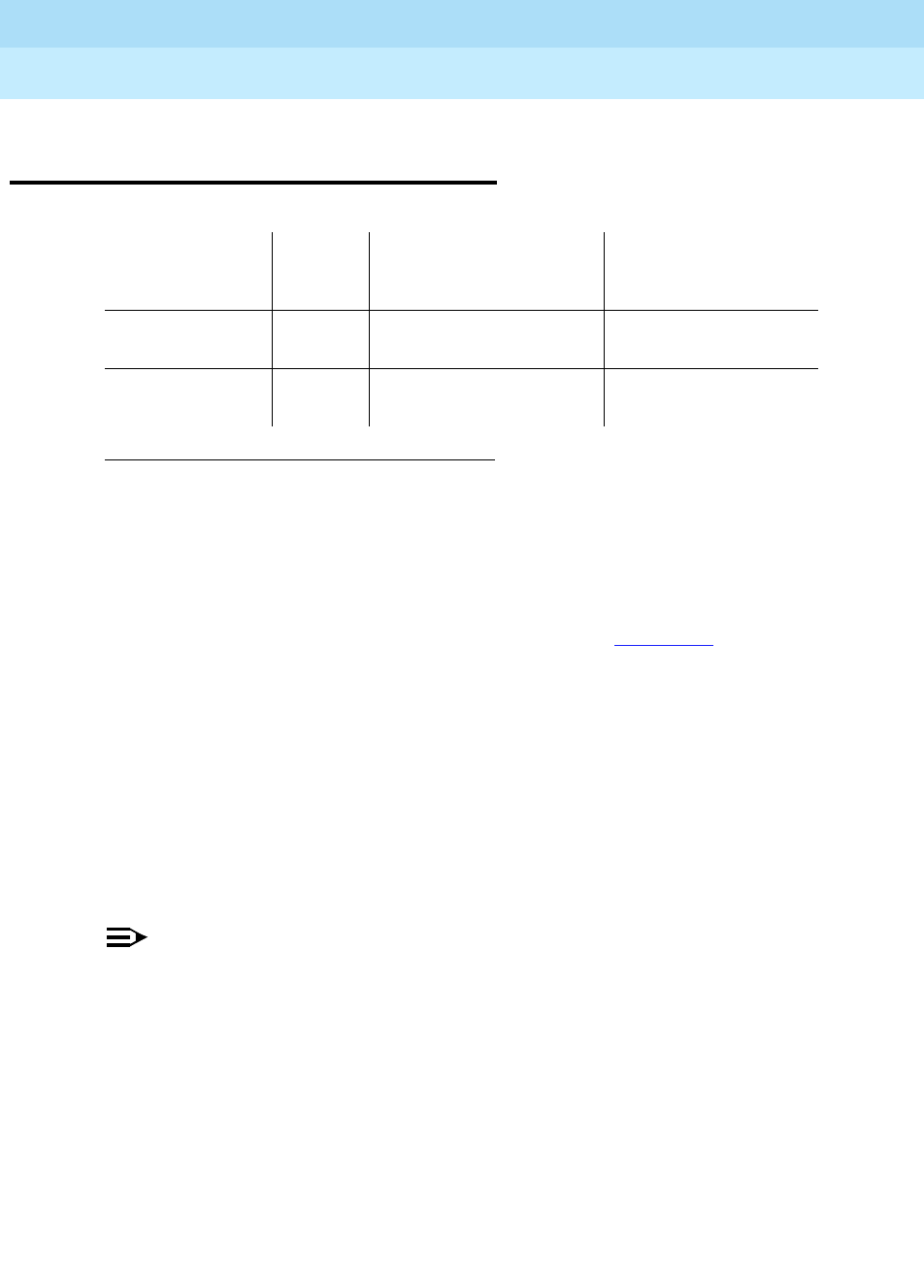
DEFINITY Enterprise Communications Server Release 6
Maintenance for R6r Volumes 1 & 2
555-230-126 Issue 2
January 1998
Maintenance Object Repair Procedures
Page 9-913M/T-DIG (Maintenance/Test Digital Port)
9
M/T-DIG (Maintenance/Test Digital
Port)
The Maintenance/Test Digital Port is a port on the TN771D circuit pack. Ports 2
and 3 are Digital Ports. The Maintenance/Test Digital Port provides the ability to
perform digital (i.e., ISDN-PRI) trunk testing via the TDM Bus. For an ISDN-PRI
test call, connections are set up in the system as shown in Figure 9-51.
When the Maintenance/Test Digital Port is participating in an ISDN-PRI test call,
the port sends a stream of pseudo-random data along the connected B-channel.
The far end loops back this data, and the Maintenance/Test Digital Port
compares the data to that which was sent. Errors are recorded on a bit and block
basis. Refer to ISDN-TRK (DS1 ISDN Trunk) Maintenance documentation for
more information on ISDN-PRI test calls.
The Maintenance/Test Digital Port maintenance ensures that the digital trunk
testing function is operating correctly. The Maintenance/Test Digital Port is
alarmed if maintenance determines that the digital port is operating incorrectly.
NOTE:
An alarm on the Maintenance/Test Digital Port reduces service, but does
not block it since the ISDN-TRK has other means to determine the health of
the ISDN-PRI trunk facility. However, to accurately measure the error
performance and to ensure accuracy of the health of the ISDN-PRI trunk,
the Maintenance/Test circuit pack should be replaced when a new circuit
pack is available.
1. UU is the universal cabinet number (1 for PPN, 2 - 44 for EPNs). C is the carrier
designation (A, B, C, D, or E). SS is the number of the slot in which the circuit pack
resides (01 to 21). pp is the two digit port number (01, 02, ...).
MO Name As It
Appears in
Alarm Log Alarm
Level
Initial System
Technician Command
to Run1Full Name of MO
M/T-DIG Minor test port UUCSSpp l Maintenance/Test
Digital Port
M/T-DIG Warning release port UUCSSpp Maintenance/Test
Digital Port
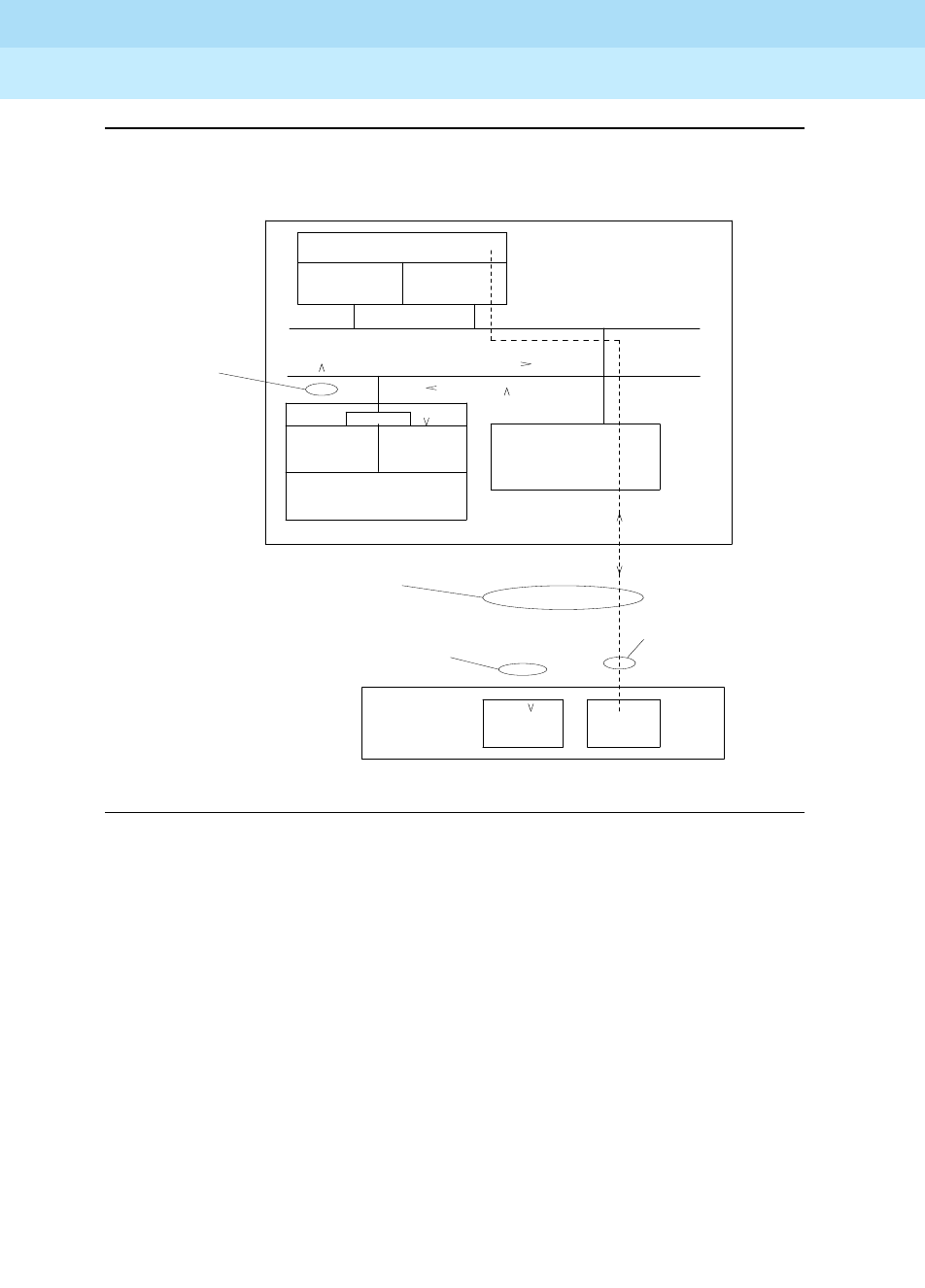
DEFINITY Enterprise Communications Server Release 6
Maintenance for R6r Volumes 1 & 2
555-230-126 Issue 2
January 1998
Maintenance Object Repair Procedures
Page 9-914M/T-DIG (Maintenance/Test Digital Port)
9
Figure 9-51. ISDN-PRI Outgoing Test Call
Looped-back data
stream pattern is
generated by digital
port 1 and checked
by digital port 2 on
the TN771
Digital
Port 1
.
.
.
. .
TN771
Maintenance/Test
SPE
UN332
MSSNET TN1655
PKT-INT
TDM
Bus
.
.
.
.
.
.
.
.
.
.
.
. . . . . . . . . . . . . . . . .
.
.
.
.
.
.
.
.
.
.
.
.
.
.
.
.
.
.
.
.
.
.
.
.
.
.
.
.
.
.
.
.
.
.
.
.
.
.
.
.
.
.
.
.
.
.
.
.
.
.
.
.
.
.
.
.
.
.
.
.
.
.
.
.
.
.
.
.
.
.
.
.
.
.
.
.
.
.
.
.
.
.
.
.
.
.
.
.
.
.
.
.
.
.
.
.
.
.
.
.
.
.
.
.
.
.
.
.
.
.
.
.
.
.
.
.
.
.
.
.
.
.
.
.
.
.
.
.
.
.
.
.
.
.
.
.
.
.
.
.
.
.
.
.
.
.
.
.
.
.
.
.
.
.
.
.
.
.
.
.
.
.
.
.
.
.
.
.
.
.
.
.
.
.
.
.
.
.
.
.
.
. . . . . . . . . . . . . . . . . . . . . . . . . . . . . . . . . . . . . . . . . . .
.
.
.
.
.
.
.
.
.
.
.
.
.
.
.
.
.
Control
. . . . . .
Loop-back
Circuitry
Far-End
Equipment
B-channel carries
looped-back test signal
D-Channel instructs
far end to connect
loop-back circuitry
across B-channel
signal
External DS1 Facility
PBX Equipment
TN464
DS1
Interface
Packet
Bus
Digital
Port 2

DEFINITY Enterprise Communications Server Release 6
Maintenance for R6r Volumes 1 & 2
555-230-126 Issue 2
January 1998
Maintenance Object Repair Procedures
Page 9-915M/T-DIG (Maintenance/Test Digital Port)
9
Hardware Error Log Entries and Test to Clear
Values
Notes:
a. This error indicates a hardware failure on the Digital Port circuitry. Replace
the Maintenance/Test circuit pack if the alarm is not resolved by the
command above.
b. The port has been busied out via the busy-out port UUCSSpp command.
c. This error indicates that Maintenance/Test Digital Port is talking on more
than just its assigned time slot. Replace the Maintenance/Test circuit
pack.
d. This error indicates that the Maintenance/Test Digital Port has failed its
self-test. Since the Digital Port Sanity Test runs only on port 2, but tests
both ports 2 and 3, both ports will be alarmed when the test fails. Note that
the command above indicates to test port 2, even if the error is logged
against port 3.
e. This error indicates that the Maintenance/Test Digital Port has been
unable to successfully loop data from a tone generator to a tone detector.
f. This error indicated that call processing records did not agree with
on-board records for the hook state (on-/off-hook) of the Maintenance/Test
Digital Port. This error is not service-affecting and no action is required.
1. Run the Short Test Sequence first. If all tests pass, run the Long Test Sequence. Refer to the appropriate
test description and follow the recommended procedures.
M/T-DIG Error Log Entries
Error
Type Aux
Data Associated Test Alarm
Level On/Off
Board Test to Clear Value
010 Any Any Any test port UUCSSpp
1 (a) 41018 none MINOR ON test port UUCSSpp l r 3
18 (b) 0 busy-out port UUCSSpp WARNING OFF release port UUCSSpp
257 (c) Any NPE Crosstalk Test (#9) MINOR ON test port UUCSSpp l r 3
513 (d) Any Digital Port Sanity Test
(#565) MINOR ON test port
UUCSS
02 r 2
769 (e) Any Digital Port Loop Around
Test (#13) MINOR ON test port UUCSSpp r 3
3840 (f) Any Hook State Inquiry test
(#566)
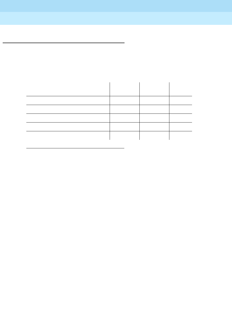
DEFINITY Enterprise Communications Server Release 6
Maintenance for R6r Volumes 1 & 2
555-230-126 Issue 2
January 1998
Maintenance Object Repair Procedures
Page 9-916M/T-DIG (Maintenance/Test Digital Port)
9
System Technician-Demanded Tests:
Descriptions and Error Codes
Always investigate tests in the order presented in the following table when
inspecting errors in the system. By clearing error codes associated with the
Digital Port Sanity Test
, for example, you may also clear errors generated from
other tests in the testing sequence.
NPE Crosstalk Test (#9)
This test is a modified version of the Digital Line NPE Crosstalk Test used by
DIG-LINE maintenance.
One or more Network Processing Elements (NPE) reside on each circuit pack
with a TDM Bus interface. The NPE controls port connectivity, gain, and provides
conferencing functions on a per port basis. The NPE Crosstalk Test verifies that
this port’s NPE channel talks on the selected time slot and never crosses over to
time slots reserved for other connections. If the NPE is not working correctly, one
way and/or noisy connections may be observed. This test is part of a port’s long
test sequence and takes approximately 10 to 20 seconds to complete. This test
is a modified version of the Digital Line NPE Crosstalk Test used by DIG-LINE
maintenance
1. D = Destructive, ND = Non-destructive
Order of Investigation Short Test
Sequence Long Test
Sequence D/ND1
Digital Port Sanity Test (#565) X X ND
Digital Port Loop Around Test (#13) X X ND
NPE Crosstalk Test (#9) X ND
Hook State Inquiry (#566) X X ND
Clear Error Counters (#270) X ND

DEFINITY Enterprise Communications Server Release 6
Maintenance for R6r Volumes 1 & 2
555-230-126 Issue 2
January 1998
Maintenance Object Repair Procedures
Page 9-917M/T-DIG (Maintenance/Test Digital Port)
9
Table 9-322. TEST #9 NPE Cross Talk Test
Error
Code Test
Result Description/ Recommendation
1000 ABORT System resources required to run this test are not
available. The port may be in use on a valid ISDN-PRI
test call. Use the list isdn-testcall command to
determine if the port is in use (if the port is listed in the
M/T Port column). If it is in use, either wait for the test call
to complete (as indicated in the Start Time and Duration
fields in the above display), or abort the test call with the
clear isdn-testcall grp/mem command, where
grp/mem is determined from the B-channel field of the
above display.
1. Retry the command at 1-minute intervals a maximum
of 5 times.
2. If the test continues to abort and the port is not in
use, escalate the problem.
1001 ABORT System resources required to run this test are not
available.
1. Retry the command at 1-minute intervals a maximum
of 5 times.
2. If the test continues to abort, escalate the problem.
1002 ABORT The system could not allocate time slots for the test. The
system may be under heavy traffic conditions or it may
have time slots out of service due to TDM-BUS errors.
Refer to TDM-BUS Maintenance documentation to
diagnose any active TDM-BUS errors.
1. If system has no TDM-BUS errors and is not
handling heavy traffic, repeat test at 1-minute
intervals a maximum of 5 times.
2. If the test continues to abort, escalate the problem.
Continued on next page

DEFINITY Enterprise Communications Server Release 6
Maintenance for R6r Volumes 1 & 2
555-230-126 Issue 2
January 1998
Maintenance Object Repair Procedures
Page 9-918M/T-DIG (Maintenance/Test Digital Port)
9
1003 ABORT The system could not allocate a tone receiver for the
test. The system may be oversized for the number of
tone detectors present or some tone detectors may be
out-of-service.
1. Look for TTR-LEV errors in the Error Log. If present,
refer to TTR-LEV Maintenance documentation.
2. Look for TONE-PT errors in the Error Log. If present,
refer to TONE-PT Maintenance documentation.
3. If neither condition exists, retry the test at 1-minute
intervals a maximum of 5 times.
4. If the test continues to abort, escalate the problem.
1004 ABORT The port has been seized by a valid ISDN-PRI test call.
Use the list isdn-testcall command to determine which
call is using the port (from the M/T Port column). Either
wait for the test call to complete (as indicated in the Start
Time and Duration fields of the above display), or abort
the test call with the clear isdn-testcall grp/mem
command, where grp/mem is determined form the
B-channel field of the above display.
1. Retry the command at 1-minute intervals a maximum
of 5 times.
2. If the test continues to abort and the port is not in
use, escalate the problem.
2000 ABORT Response to the test request was not received within the
allowable time period.
2100 ABORT System resources required to run this test are not
available.
1. Retry the command at 1-minute intervals a maximum
of 5 times.
2. If the test continues to abort, escalate the problem.
Table 9-322. TEST #9 NPE Cross Talk Test — Continued
Error
Code Test
Result Description/ Recommendation
Continued on next page

DEFINITY Enterprise Communications Server Release 6
Maintenance for R6r Volumes 1 & 2
555-230-126 Issue 2
January 1998
Maintenance Object Repair Procedures
Page 9-919M/T-DIG (Maintenance/Test Digital Port)
9
Digital Port Loop Around Test (#13)
This test is a modification of the Voice and Control Channel Local Loop Test used
by Digital Station (DIG-LINE) maintenance. This test does not perform the control
channel and secondary information channel loop around tests as described for
DIG-LINE, as these data paths do not exist for the Maintenance/Test Digital Port.
The primary information channel is tested by first looping back the data channel
onto the TDM Bus, and then sending a digital count from the Tone-Clock circuit
pack and receiving the same digital count with a general purpose tone detector.
A conference test is done next for the primary information channel. This test is the
same as Conference Test (#6).
Only one value (Pass, Fail, or Abort) is generated as a result of the two tests. If
either fails or aborts, the sequence is stopped
Any FAIL The NPE of the tested port was found to be transmitting
in error. This will cause noisy and unreliable
connections.
1. If the remaining ports are currently not in use (yellow
LED is off), try to reset the circuit pack. Then repeat
the test.
2. If the test fails again, replace circuit pack.
PASS The port is correctly using its allocated time slots.
User-reported troubles on this port should be
investigated using other port tests and by examining
station, trunk, or external wiring.
Table 9-322. TEST #9 NPE Cross Talk Test — Continued
Error
Code Test
Result Description/ Recommendation
Continued on next page

DEFINITY Enterprise Communications Server Release 6
Maintenance for R6r Volumes 1 & 2
555-230-126 Issue 2
January 1998
Maintenance Object Repair Procedures
Page 9-920M/T-DIG (Maintenance/Test Digital Port)
9
Table 9-323. TEST #13 Digital Port Loop Around Test
Error
Code Test
Result Description/ Recommendation
ABORT Internal System Error
1. Retry the command at 1-minute intervals a maximum
of 5 times.
2. If the test continues to abort, escalate the problem.
1000 ABORT The port is use on a valid ISDN-PRI Test Call. Use the
list isdn-testcall command to determine which call is
using the port (from the M/T Port column). Either wait for
the test call to complete (as indicated in the Start Time
and Duration fields in the above display), or abort the
test call with the clear isdn-testcall grp/mem
command, where grp/mem is determined from the
B-channel field of the above display.
1. Retry the command at 1-minute intervals a maximum
of 5 times.
2. If the test continues to abort and the port is not in
use, escalate the problem.
1001 ABORT System resources required to run this test are not
available.
1. Retry the command at 1-minute intervals a maximum
of 5 times.
2. If the test continues to abort, escalate the problem.
1002 ABORT The system could not allocate time slots for the test. The
system may be under heavy traffic conditions, or it may
have time slots out-of-service due to TDM-BUS errors.
Refer to TDM-BUS Maintenance to diagnose any active
TDM-BUS errors.
1. If the system has no TDM-BUS errors and is not
handling heavy traffic, repeat the test at 1-minute
intervals a maximum of 5 times.
2. If the test continues to abort, escalate the problem.
Continued on next page

DEFINITY Enterprise Communications Server Release 6
Maintenance for R6r Volumes 1 & 2
555-230-126 Issue 2
January 1998
Maintenance Object Repair Procedures
Page 9-921M/T-DIG (Maintenance/Test Digital Port)
9
1003 ABORT The system could not allocate a tone receiver for the
test. The system may be oversized for the number of
tone detectors present, or some tone detectors may be
out-of-service.
1. Look for TTR-LEV errors in the Error Log. If present,
refer to TTR-LEV Maintenance documentation.
2. Look for TONE-PT errors in the Error Log. If present,
refer to TONE-PT Maintenance documentation.
3. If neither condition exists, retry the command at
1-minute intervals a maximum of 5 times.
4. If the test continues to abort, escalate the problem.
1004 ABORT The port was seized by a valid ISDN-PRI Test Call. Use
the list isdn-testcall command to determine which call
is using the port (from the M/T Port column). Either wait
for the test call to complete (as indicated in the Start
Time and Duration fields of the above display), or abort
the test call with the clear isdn-testcall grp/mem
command, where grp/mem is determined from the
B-channel field of the above display.
1. Retry the command at 1-minute intervals a maximum
of 5 times.
2. If the test continues to abort and the port is not in
use, escalate the problem.
2000 ABORT Response to the test request was not received within the
allowable time period.
2100 ABORT System resources required to run this test are not
available.
1. Retry the test at 1-minute intervals a maximum of 5
times.
2. If the test continues to abort, escalate the problem.
Table 9-323. TEST #13 Digital Port Loop Around Test — Continued
Error
Code Test
Result Description/ Recommendation
Continued on next page

DEFINITY Enterprise Communications Server Release 6
Maintenance for R6r Volumes 1 & 2
555-230-126 Issue 2
January 1998
Maintenance Object Repair Procedures
Page 9-922M/T-DIG (Maintenance/Test Digital Port)
9
Clear Error Counters (#270)
This test is not an actual test in the strict sense of the word. Many circuit packs
have counters in the Angel firmware. These counters are used so that Control
Channel Message Set (CCMS) messages are not continuously sent uplink. Using
this method, the message will be sent once, when the counter reaches some
preset threshold, and then not sent again until the counter is cleared.
The ports on the Maintenance/Test circuit pack continually run self-tests,
whenever the port is idle. The Angel uses a counter so that the Background
Maintenance Failure message is only sent uplink once (this keeps a failed
port/circuit pack from flooding the SPE with a string of messages). This test is
7 FAIL Conference test failed on the primary information
channel. In most cases, the user may not notice a
disruption in service.
1. Run the circuit pack tests to check the Tone
Generator circuit pack and the Tone Detector circuit
pack via the test board UUCSS command.
2. Resolve any problems that are detected on the Tone
Generator circuit pack or Tone Detector circuit pack.
3. If the Tone Generator and Tone Detector circuit
packs are functioning properly, and the test still fails,
replace the Maintenance/Test circuit pack.
14 FAIL The primary information channel is not transmitting
properly. User impact may range from nothing to not
being able to use this port.
1. Run the circuit pack tests to check the Tone
Generator circuit pack and the Tone Detector circuit
pack using test board UUCSS.
2. Resolve any problems that are detected on the Tone
Generator circuit pack or Tone Detector circuit pack.
3. If the Tone Generator and Tone Detector circuit
packs are functioning properly, and the test still fails,
replace the Maintenance/Test Circuit Pack.
PASS The Maintenance/Test Digital Port digital trunk testing
capability is operating correctly.
Table 9-323. TEST #13 Digital Port Loop Around Test — Continued
Error
Code Test
Result Description/ Recommendation
Continued on next page

DEFINITY Enterprise Communications Server Release 6
Maintenance for R6r Volumes 1 & 2
555-230-126 Issue 2
January 1998
Maintenance Object Repair Procedures
Page 9-923M/T-DIG (Maintenance/Test Digital Port)
9
used to clear the counter, so that if the port continues to fail during or after
SPE-demanded testing, the Angel will send a message to indicate that fact.
This test is only used to send a message to the Angel on the Maintenance/Test
Circuit Pack. Therefore, this test should never abort or fail.
Digital Port Sanity Test (#565)
This test verifies that the port circuitry involved in the digital trunk testing on the
Maintenance/Test Digital Port is functioning properly. This circuitry is common to
both Maintenance/Test Digital Ports on the Maintenance/Test circuit pack.
Therefore, this test is only run for port 2. The test will abort when run on port 3, as
described in Table 9-325.
This test operates by connecting the two Maintenance/Test Digital Ports on the
TDM Bus so that they talk and listen to each other. Then four self-tests are
attempted: (a) sending data from port 2 to port 3 in asynchronous mode; (b)
sending data from port 3 to port 2 in asynchronous mode; (c) sending data from
port 2 to port 3 in synchronous mode; and (d) sending data from port 3 to port 2
in synchronous mode. The test passes if all four of these self-tests are
successful. The test will stop as soon as any one of these self-tests fails.
This test will abort if an ISDN Test Call is in progress on either Maintenance/Test
Digital Port when the test is requested, or if an ISDN Test Call is initiated while the
Digital Port Sanity Test is in progress
Table 9-324. TEST #270 Clear Error Counters
Error
Code Test
Result Description/ Recommendation
Any ABORT This test should never abort.
Any FAIL This test should never fail.
1. Retry the command at 1-minute intervals a
maximum of 5 times.
2. If the test continues to fail, escalate the problem.
PASS The message to clear the Maintenance/Test circuit
pack’s counter for Background Maintenance Failures
has been sent.
Continued on next page

DEFINITY Enterprise Communications Server Release 6
Maintenance for R6r Volumes 1 & 2
555-230-126 Issue 2
January 1998
Maintenance Object Repair Procedures
Page 9-924M/T-DIG (Maintenance/Test Digital Port)
9
Table 9-325. TEST #565 Digital Port Sanity Test
Error
Code Test
Result Description/ Recommendation
1000 ABORT One of the Maintenance/Test Digital Ports is busy with
background maintenance.
1. Either wait for the port to become idle, or busy-out
both Maintenance/Test Digital Ports on the
Maintenance/Test circuit pack via the busy-out port
UUCSS02 and busy-out port UUCSS03
commands, respectively.
2. Release the ports (if they were busied out) via the
release port UUCSS02 and release port UUCSS03
commands, respectively.
3. Retry the command at 1-minute intervals a maximum
of 5 times.
4. If the test continues to abort, escalate the problem.
1002 ABORT The system could not allocate time slots for the test. The
system may be under heavy traffic conditions, or it may
have time slots out-of-service due to TDM-BUS errors.
Refer to the TDM-BUS Maintenance documentation to
diagnose any active TDM Bus errors.
1. If the system has no TDM-BUS errors, and if not
handling heavy traffic, repeat the test at 1-minute
intervals a maximum of 5 times.
2. If the test continues to abort, escalate the problem.
Continued on next page

DEFINITY Enterprise Communications Server Release 6
Maintenance for R6r Volumes 1 & 2
555-230-126 Issue 2
January 1998
Maintenance Object Repair Procedures
Page 9-925M/T-DIG (Maintenance/Test Digital Port)
9
1004 ABORT The port was seized by a valid ISDN-PRI Test Call. Use
the list isdn-testcall command to determine which call
is using the port (from the M/T Port column). Either wait
for the test call to complete (as indicated in the Start
Time and Duration fields of the above display), or abort
the test call with the clear isdn-testcall grp/mem
command, where grp/mem is determined from the
B-channel field of the above display.
1019 ABORT An ISDN Test Call is in progress using this
Maintenance/Test circuit pack. The Maintenance/Test
circuit pack cannot perform a self-test on one of its
Digital Ports while an ISDN Test Call is using either of the
Digital Ports. Use the list isdn-testcall command to
determine which call is using the port (form the M/T Port
column). Either wait for the test call to complete (as
indicated in the Start Time and Duration fields of the
above display), or abort the test call with the clear
isdn-testcall grp/mem command, where grp/mem is
determined from the B-channel field of the above
display.
1. Retry the command at 1-minute intervals a maximum
of 5 times.
2. If the test continues to abort and the port is not in
use, escalate the problem.
1138 ABORT This test does not run on port 3 of the Maintenance/Test
circuit pack. This test will only run on port 2. Look at the
results of the Digital Port Sanity Test for port 2.
1. Run the command again for port 2 via the test port
UUCSS02 or test port UUCSS02 l command.
Table 9-325. TEST #565 Digital Port Sanity Test — Continued
Error
Code Test
Result Description/ Recommendation
Continued on next page

DEFINITY Enterprise Communications Server Release 6
Maintenance for R6r Volumes 1 & 2
555-230-126 Issue 2
January 1998
Maintenance Object Repair Procedures
Page 9-926M/T-DIG (Maintenance/Test Digital Port)
9
Hook State Inquiry (#566)
This test ensures that the Maintenance/Test Digital Port maintenance software
and call processing agree on the on-/off-hook status of the Maintenance/Test
Digital Port.
2000 ABORT Response to the test request was not received within the
allowable time period.
2100 ABORT System resources required to run this test are not
available.
2500 ABORT An internal operation failed; the test could not be
completed.
1. Retry the command at 1-minute intervals a maximum
of 5 times.
2. If the test continues to fail, escalate the problem.
50 FAIL The switch was unable to communicate with the port
circuitry used for digital trunk testing.
100 FAIL Data was not sent from port 2 to port 3 successfully in
asynchronous mode.
101 FAIL Data was not sent from port 3 to port 2 successfully in
asynchronous mode.
102 FAIL Data was not sent from port 2 to port 3 successfully in
synchronous mode.
103 FAIL Data was not sent from port 3 to port 2 successfully in
synchronous mode.
1. Reset the circuit pack via the busy-out board
UUCSS, reset board UUCSS, release board
UUCSS command sequence.
2. Test the port again via the test port UUCSS02 l
command.
3. If the test fails again, replace the circuit pack.
PASS The Maintenance/Test Digital Port digital trunk testing
capability is operating correctly.
Table 9-325. TEST #565 Digital Port Sanity Test — Continued
Error
Code Test
Result Description/ Recommendation
Continued on next page

DEFINITY Enterprise Communications Server Release 6
Maintenance for R6r Volumes 1 & 2
555-230-126 Issue 2
January 1998
Maintenance Object Repair Procedures
Page 9-927M/T-DIG (Maintenance/Test Digital Port)
9
Table 9-326. TEST #566 Hook State Inquiry
Error
Code Test
Result Description/ Recommendation
1 ABORT Switch hook audit timed out. No response was
received from the circuit pack for information about
the switch hook state.
1. Retry the command at 1-minute intervals a
maximum of 5 times.
2. If the test continues to abort, replace the circuit
pack and repeat the test.
3. If the test continues to abort, escalate the
problem.
2100 ABORT System resources required to run this test are not
available.
1. Retry the command at 1-minute intervals a
maximum of 5 times.
2. If the test continues to abort, escalate the
problem.
Any FAIL Internal System Error This test should never return a
failure.
1. Retry the command at 1-minute intervals a
maximum of 5 times.
2. If the test continues to fail reset the circuit pack via
the busy-out board UUCSS, reset board
UUCSS, release board UUCSS command
sequence.
3. Retry the command at 1-minute intervals a
maximum of 5 times.
4. If the test continues to fail, escalate the problem.
PASS Call processing and Maintenance/Test Digital Port
maintenance software agree on the Maintenance/Test
Digital Port hook state.
Continued on next page

DEFINITY Enterprise Communications Server Release 6
Maintenance for R6r Volumes 1 & 2
555-230-126 Issue 2
January 1998
Maintenance Object Repair Procedures
Page 9-928M/T-PKT (Maintenance/Test Packet Bus Port)
9
M/T-PKT (Maintenance/Test Packet
Bus Port)
The Maintenance/Test Packet Bus Port (M/T-PKT) is port number 4 on the TN771
Maintenance/Test circuit pack. The Packet Bus port provides the following
Packet Bus maintenance functions:
■Packet Bus fault detection
The ability to detect faults (e.g., shorts, open leads) on the Packet Bus
autonomously (i.e. without SPE involvement).
■Packet Bus reconfiguration
The ability to swap faulty leads with spare leads autonomously so that the
Packet Bus remains operational. This is accomplished by sending
messages to all Packet circuit packs [e.g., ISDN-BRI (TN556)] telling them
which spare leads to use on the Packet Bus.
M/T-PKT maintenance ensures that these maintenance functions are operating
correctly. The Maintenance/Test Packet Bus Port is alarmed if maintenance
determines that the port’s maintenance functions are operating incorrectly.
When M/T-PKT maintenance determines that the Packet Bus Port is defective,
the Packet Bus fault detection and Packet Bus reconfiguration functions provided
by the port will be turned off.
M/T-PKT maintenance interacts with Packet Bus maintenance. Therefore, there
may be alarms on the Packet Bus when there is a fault on the M/T-PKT. Refer to
PKT-BUS (Packet Bus) Maintenance documentation for further information.
1. UU is the universal cabinet number (1 for PPN, 2 - 44 for EPNs). C is the carrier designation
(A, B, C, D, or E). SS is the number of the slot in which the circuit pack resides (01 to 21). pp
is the two digit port number (01, 02, ...).
MO Name As
It Appears in
Alarm Log Alarm
Level
Initial System
Technician
Command to Run1Full Name of MO
M/T-PKT Minor test port UUCSSpp l Maintenance/Test Packet
Bus Port
M/T-PKT Warning release port
UUCSSpp Maintenance/Test Packet
Bus Port

DEFINITY Enterprise Communications Server Release 6
Maintenance for R6r Volumes 1 & 2
555-230-126 Issue 2
January 1998
Maintenance Object Repair Procedures
Page 9-929M/T-PKT (Maintenance/Test Packet Bus Port)
9
Hardware Error Log Entries and Test to Clear
Values
Notes:
a. This error indicates a hardware failure with the port circuitry which
provides the Packet Bus maintenance functions. Replace the
Maintenance/Test circuit pack if the alarm is not resolved by the test
command above.
b. The port has been busied out via the busyout port UUCSSpp command.
c. This error indicates that the Maintenance/Test Packet Bus Port has
reconfigured the Packet Bus by swapping a bad lead to a spare. Note that
this error is sent up whenever the Maintenance/Test Packet Bus Port is
initialized (since the Packet Bus Port reconfigures the Packet Bus to
whatever state it determines the Packet Bus is in). This will occur if the
circuit pack is inserted, if the system is restarted, or if the port is released
from a busyout state. Therefore, it is normal for this error to be present in
the error log.
If the M/T-PKT reconfigures the Packet Bus 6 times within 15 minutes, a
Minor alarm is raised indicating that either Packet Bus maintenance
functions are not operating correctly, or many changes are taking place
on the Packet Bus (circuit pack insertions or removals). If the system has
been in a stable state for more than 15 minutes, try the following
procedure:
1. Run the Short Test Sequence first. If all tests pass, run the Long Test Sequence. Refer to the
appropriate test description and follow the recommended procedures.
M/T-PKT Error Log Entries
Error
Type Aux
Data Associated Test Alarm Level On/Off
Board Test to Clear Value
010 Any Any Any test port UUCSSpp
1 (a) 41018 none MINOR ON test port UUCSSpp l r 3
18 (b) 0 busyout port
UUCSSpp WARNING OFF release port UUCSSpp
257 (c) Any none MINOR ON
513 (d) Any Packet Bus Port
Health Inquiry
Test (#567)
MINOR ON test port UUCSSpp r 3

DEFINITY Enterprise Communications Server Release 6
Maintenance for R6r Volumes 1 & 2
555-230-126 Issue 2
January 1998
Maintenance Object Repair Procedures
Page 9-930M/T-PKT (Maintenance/Test Packet Bus Port)
9
1. Reset the Maintenance/Test circuit pack from the G3-MT as follows:
■Enter the busyout board UUCSS command.
■Enter the reset board UUCSS command.
■Enter the release board UUCSS command.
2. Wait 15 minutes.
3. If the error recurs, replace the Maintenance/Test circuit pack.
When this alarm is active, the yellow LED will be in one of three states:
■An unlit yellow LED indicates no activity on the Maintenance/Test
circuit pack. You can replace the Maintenance/Test circuit pack.
■If there is an indication of an uncorrectable fault on the Packet Bus,
the yellow LED will be blinking at a rate of 1 Hz. It is OK to replace
the Maintenance/Test circuit pack. Ignore the Packet Bus error
indication, since the Maintenance/Test circuit pack has been
determined to be defective.
■If there is other activity on the Maintenance/Test circuit pack (i.e.
ISDN Test Call), or if there is an indication of a correctable fault on
the Packet Bus, the yellow LED will be on steady. If there is an ISDN
Test Call in progress, it must be halted via the clear isdn-testcall
grp/member command prior to replacing the circuit pack. Ignore
the Packet Bus error indication, since the Maintenance/Test circuit
pack has been determined to be defective.
d. This error indicates a failure of the Packet Bus Port Health Inquiry Test.
Either the Packet Bus Port has reported a self-test failure, or the SPE is
able to communicate with the Maintenance/Test Circuit Pack but not with
the Maintenance/Test Circuit Pack Packet Bus Port. Refer to the
description of the Packet Bus Port Health Inquiry Test, and follow the
instructions indicated for the failure code that matches the Aux Data field.
System Technician-Demanded Tests:
Descriptions and Error Codes
Always investigate tests in the order presented in the following table when
inspecting errors in the system.
1. D = Destructive, ND = Non-destructive
Order of Investigation Short Test
Sequence Long Test
Sequence D/ND1
Packet Bus Port Health Inquiry Test (#567) X X ND
Clear Error Counters (#270) X ND

DEFINITY Enterprise Communications Server Release 6
Maintenance for R6r Volumes 1 & 2
555-230-126 Issue 2
January 1998
Maintenance Object Repair Procedures
Page 9-931M/T-PKT (Maintenance/Test Packet Bus Port)
9
Clear Error Counters (#270)
This test is not an actual test in the strict sense of the word. Many circuit packs
have counters in the Angel firmware. The circuit pack’s Angel continuously runs
port self-tests on idle ports and keeps track of any errors it detects by
incrementing a firmware counter. When the counter value reaches some preset
threshold, the Angel sends a single CCMS (Control Channel Message Set) error
message uplink to the SPE. No more error messages of that type are sent uplink
until the SPE sends a downlink message to clear the counter. This strategy keeps
a failed port/circuit pack from flooding the SPE with a continuous string of
identical error messages). This test is used to clear the counter, so that if the port
continues to fail during or after SPE-demanded testing, the Angel will send a
message to indicate that fact.
This test is only used to send a downlink message to the Angel on the
Maintenance/Test circuit pack. Since the Angel normally provides no uplink
response to this message, this test should never abort or fail.
Packet Bus Port Health Inquiry Test (#567)
This test verifies that the Packet Bus fault detection maintenance function of the
M/T-PKT is functioning properly. This is done by having the M/T-PKT perform a
self-test. If this self-test passes, then the Packet Bus Port Health Inquiry Test
passes. If the self-test fails, or the SPE cannot communicate with the M/T-PKT,
then the test fails
Table 9-327. TEST #270 Clear Error Counters
Error
Code Test
Result Description/ Recommendation
Any ABORT This test should never abort.
Any FAIL This test should never fail.
1. Retry the command at 1-minute intervals a
maximum of 5 times.
2. If the test continues to fail, escalate the problem.
PASS The message to clear the Maintenance/Test circuit
pack’s counter for Background Maintenance Failures
has been sent.
Continued on next page

DEFINITY Enterprise Communications Server Release 6
Maintenance for R6r Volumes 1 & 2
555-230-126 Issue 2
January 1998
Maintenance Object Repair Procedures
Page 9-932M/T-PKT (Maintenance/Test Packet Bus Port)
9
Table 9-328. TEST #567 Consistency Test
Error
Code Test
Result Description/ Recommendation
2000 ABORT Response to the test request was not received within the
allowable time period.
2100 ABORT System resources necessary to run this test are not
available.
2500 ABORT An internal operation failed, and the test could not be
completed.
1. Retry the command at 1-minute intervals a maximum
of 5 times.
2. If the test continues to abort, escalate the problem.
2059 FAIL The M/T-PKT has reported a failure of the on-board
self-test.
2060 FAIL The M/T-PKT has reported an invalid state for the Packet
Bus.
2061 FAIL The SPE cannot communicate with the M/T-PKT, but is
able to communicate with the Maintenance/Test Circuit
Pack.
1. Retry the command.
2. If the test continues to fail, replace the
Maintenance/Test circuit pack and retry the
command.
3. If the test continues to fail, refer to PKT-BUS
Maintenance documentation to determine if the
M/T-PKT failure is being caused by a Packet Bus
fault.
PASS The M/T-PKT Packet Bus fault detection capability is
operating correctly.
Continued on next page
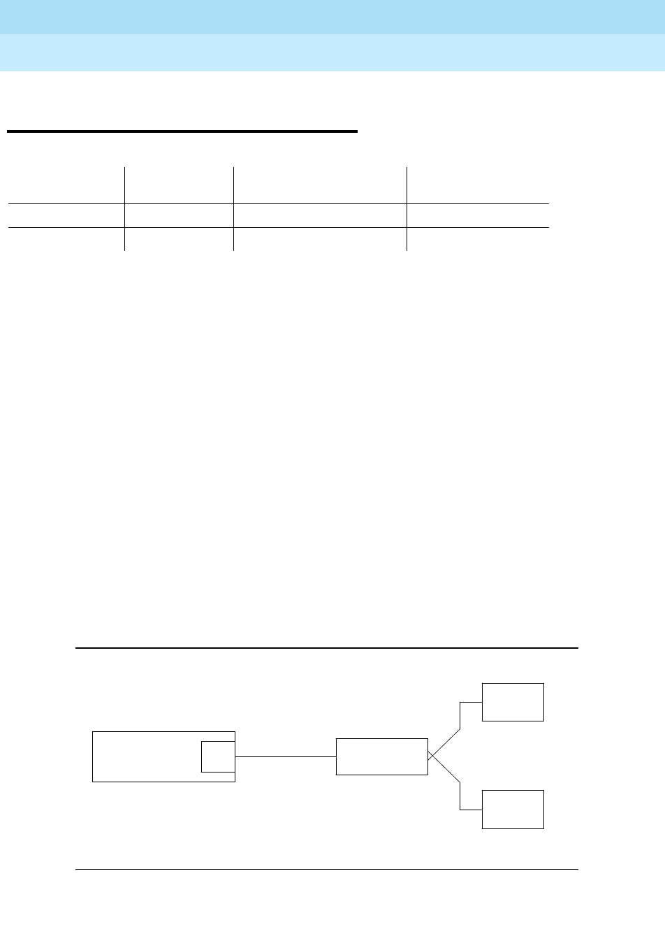
DEFINITY Enterprise Communications Server Release 6
Maintenance for R6r Volumes 1 & 2
555-230-126 Issue 2
January 1998
Maintenance Object Repair Procedures
Page 9-933OPS-LINE (DS1 Off Premises Station Line)
9
OPS-LINE (DS1 Off Premises Station
Line)
An analog Off-Premises Station (OPS) can be connected to the system through a
DS1 link. A TN767 DS1 Interface circuit pack or a TN464 UDS1 Interface circuit
pack can support up to 24 DS1 OPSs. Since the DS1 OPS is an analog telephone
set, a channel multiplexer is necessary as the remote DS1 endpoint that converts
the digital signal of a DS1 port to the OPS Line and vice versa.
The DS1 OPS Line Maintenance provides a strategy to maintain an OPS Line via
a trunk port of the TN767 DS1 Interface circuit pack or the TN464 UDS1 Interface
circuit pack. (Throughout this section, the term DS1 Interface can apply to either
of these circuit packs.) The strategy covers initialization tests, periodic tests,
scheduled tests, system technician-demanded tests, and alarm resolution and
escalation. Two service states are specified in a DS1 OPS Line maintenance.
They are:
out-of-service
, in which the line is in a deactivated state and cannot be
used for either incoming or outgoing calls; or
in-service
, in which the line is in an
activated state and can be used for both incoming and outgoing calls. If the DS1
Interface circuit pack is out-of-service, then all lines on the DS1 Interface circuit
pack are put into the out-of-service state, and a Warning alarm is raised.
For maintenance of the remote DS1 endpoint (for example, a Channel Division
Multiplexer or D4 Channel Bank), refer to the maintenance documentation from
its vendor for details.
Figure 9-52. DS1 OPS Line Interactions
MO Name (in
Alarm Log) Alarm Level Initial Command to Run Full Name of MO
OPS-LINE MINOR test station
extension
l DS1 OPS Line
OPS-LINE WARNING test station
extension
DS1 OPS Line
CHANNEL
MULTIPLEXER
ANALOG
STATION
DS1 LINK
ANALOG
STATION
DS1
System
DEFINITY
Communications
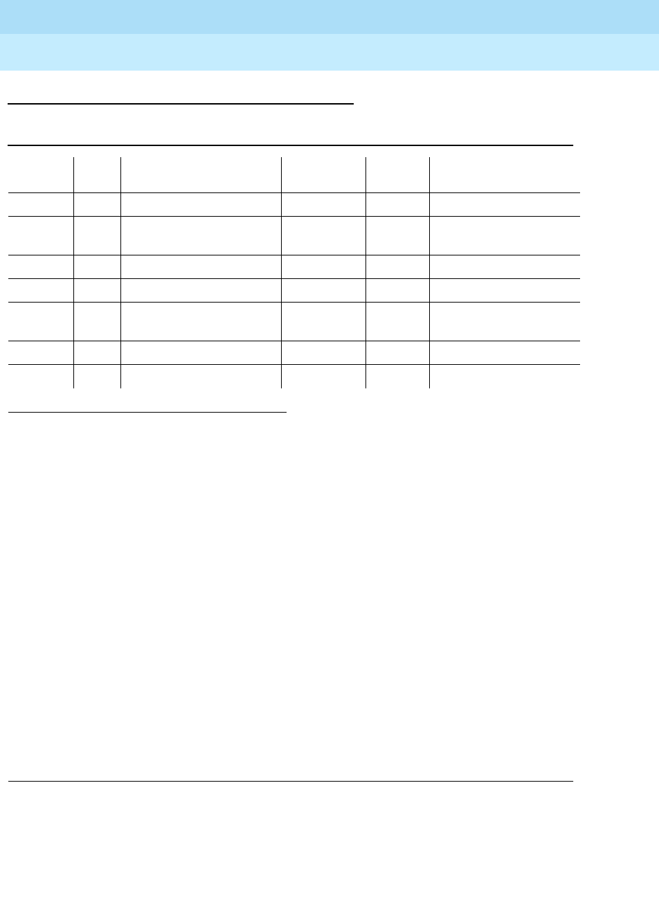
DEFINITY Enterprise Communications Server Release 6
Maintenance for R6r Volumes 1 & 2
555-230-126 Issue 2
January 1998
Maintenance Object Repair Procedures
Page 9-934OPS-LINE (DS1 Off Premises Station Line)
9
Error Log Entries and Test to Clear Values
Notes:
a. This is a software audit error that does not indicate any hardware
malfunction. Run the Short Test Sequence and investigate associated
errors (if any).
b. The DS1 OPS Line has been busied out by a busyout station <ext>
command. No calls can be made on this line.
c. This error type indicates that the circuit pack has been removed or has
been insane for more than 11 minutes. To clear the error, reinsert or
replace the circuit pack.
d. Error Type 1793 indicates a problem with the DS1 Interface circuit pack.
Since there is no error against the OPS-LINE port, no alarm is raised
against the OPS-LINE port. However, there should be errors logged
against the DS1 Interface circuit pack. Look for DS1-BD/UDS1-BD errors
in the Hardware Error Log and follow the appropriate procedures provided
in the DS1-BD/UDS1-BD (DS1/UDS1 Interface Circuit Pack) Maintenance
documentation.
1. Run the Short Test Sequence first. If all tests pass, run the Long Test Sequence. Refer to the
appropriate test description and follow the recommended procedures.
Table 9-329. DS1 OPS Maintenance Error Log Entries
Error
Type Aux
Data Associated Test Alarm
Level On/Off
Board Test to Clear Value
010 Any Any Any test station <ext>
15(a) Any Audit and Update Test
(#36)
18(b) 0 busyout station <ext> WARNING OFF release station <ext>
130(c) None WARNING ON test station <ext>
1281 Conference Circuit Test
(#7) MINOR ON test station <ext> l r 4
1537 NPE Crosstalk Test (#6) MINOR ON test station <ext> l r 3
1793(d) test board UUCSS l

DEFINITY Enterprise Communications Server Release 6
Maintenance for R6r Volumes 1 & 2
555-230-126 Issue 2
January 1998
Maintenance Object Repair Procedures
Page 9-935OPS-LINE (DS1 Off Premises Station Line)
9
System Technician-Demanded Tests:
Descriptions and Error Codes
Always investigate tests in the order presented in the table below when
inspecting errors in the system. By clearing error codes associated with the
NPE
Crosstalk Test,
for example, you may also clear errors generated from other tests
in the testing sequence.
1. D = Destructive; ND = Nondestructive
Order of Investigation Short Test
Sequence Long Test
Sequence D/ND1
NPE Crosstalk Test (#6) X ND
Conference Circuit Test (#7) X ND
DS1 OPS Switchhook Inquiry Test (#312) X X ND
Audit and Update Test (#36) X X ND

DEFINITY Enterprise Communications Server Release 6
Maintenance for R6r Volumes 1 & 2
555-230-126 Issue 2
January 1998
Maintenance Object Repair Procedures
Page 9-936OPS-LINE (DS1 Off Premises Station Line)
9
NPE Crosstalk Test (#6)
One or more Network Processing Elements (NPEs) reside on each circuit pack
with a TDM Bus interface. (The TN464 UDS1 circuit pack has one SCOTCH-NPE
chip instead of several NPE chips.) The NPE controls port connectivity and gain,
and provides conferencing functions on a per-port basis. The NPE Crosstalk Test
verifies that this port’s NPE channel talks on the selected time slot and never
crosses over to time slots reserved for other connections. If the NPE is not
working correctly, one-way and noisy connections may be observed. This test is
usually only part of a port’s Long Test Sequence and takes about 20 to 30
seconds to complete
Table 9-330. TEST #6 NPE Crosstalk Test
Error
Code Test
Result Description/ Recommendation
ABORT Could not allocate system resources to run this test or an internal system error
(software) occurred.
1. Retry the command at 1-minute intervals a maximum of 5 times.
1000 ABORT System resources required to run this test are not available. The port may be in
use on a valid call. Use status station or status trunk command to determine
when the port is available for testing.
1. Retry the command at 1-minute intervals a maximum of 5 times.
1001 ABORT Could not allocate the necessary system resources to run this test.
1. Retry the command at 1-minute intervals a maximum of 5 times.
1002 ABORT The system could not allocate time slots for the test. The system may be under
heavy traffic conditions or it may have time slots out-of-service due to
TDM-BUS errors. The status health command can be used to determine if the
system is experiencing heavy traffic. Refer to “TDM-BUS” to diagnose any
active TDM-BUS errors.
1. If system has no TDM-BUS errors and is not handling heavy traffic, repeat
test at 1-minute intervals a maximum of 5 times.
1003 ABORT The system could not allocate a tone receiver for the test. The system may be
oversized for the number of Tone Detectors present or some Tone Detectors
may be out-of-service. The list measurements tone-receiver command will
display information on the system’s tone receivers.
1. Look for TTR-LEV errors in the Error Log. If present, refer to TTR-LEV (TTR
Level) Maintenance documentation.
2. Look for TONE-PT errors in the Error Log. If present, refer to TONE-PT
(Tone Generator) Maintenance documentation.
3. If neither condition exists, retry the test at 1-minute intervals a maximum of
5 times.
Continued on next page

DEFINITY Enterprise Communications Server Release 6
Maintenance for R6r Volumes 1 & 2
555-230-126 Issue 2
January 1998
Maintenance Object Repair Procedures
Page 9-937OPS-LINE (DS1 Off Premises Station Line)
9
1004 ABORT The test was aborted because the port was seized by a user for a valid call.
Use status station command to determine the service state of the port. If the
service state indicates that the port is in use, then the port is unavailable for
certain tests. You must wait until the port is idle before retesting.
1. Retry the command at 1-minute intervals a maximum of 5 times.
1020 ABORT The test did not run due to an an already existing error on the specific port or
due to a more general error on the circuit pack.
1. Examine the error log for existing errors against this port or the circuit pack
and attempt to diagnose the already existing error. (Error code 1793
indicates a problem with the DS1 interface board, and any problems on
the associated DS1-BD or UDS1-BD should be resolved first.)
2000 ABORT Response to the test request was not received within the allowable time
period.
1. Retry the command at 1-minute intervals a maximum of 5 times.
2. If the test aborts with error code 2000 again, run short test sequence on
the associated DS1-BD or UDS1-BD. If tests 138 through 145 on the
associated DS1-BD or UDS1-BD are also aborting with error code 2000,
hyperactivity on the board or facility is indicated. In this case, the
hyperactivity problem should be dealt with first.
2100 ABORT System resources required for this test are not available.
1. Retry the command at 1-minute intervals a maximum of 5 times.
Any FAIL The test failed. This can be due to on-board or off-board problems. Off-board
problems of concern include EXP-PN and EXP-INTF faults, TDM-BUS faults,
and faults associated with the tone detectors/tone generators. Clear all
off-board problems before replacing the board. Keep in mind that a TDM-BUS
problem is usually the result of a faulty board connected to the backplane or
bent pins on the backplane.
1. Look for TONE-BD and/or TONE-PT errors in the error log. If present, refer
to TONE-BD and to TONE-PT.
2. Retest when the faults from step 1 are cleared.
Table 9-330. TEST #6 NPE Crosstalk Test — Continued
Error
Code Test
Result Description/ Recommendation
Continued on next page

DEFINITY Enterprise Communications Server Release 6
Maintenance for R6r Volumes 1 & 2
555-230-126 Issue 2
January 1998
Maintenance Object Repair Procedures
Page 9-938OPS-LINE (DS1 Off Premises Station Line)
9
PASS The port is correctly using its allocated time slots. User-reported troubles on
this port should be investigated using other port tests and by examining
station, trunk, or external wiring.
0NO
BOARD The test could not relate the internal ID to the port (no board). This could be
due to incorrect translations, no board is inserted, an incorrect board is
inserted, or an insane board is inserted.
1. Check to ensure that the board translations are correct. Use the list
config command, and resolve any problems that are found.
2. If the board was found to be correctly inserted in step 1, issue the
busyout board command.
3. Issue the reset board command.
4. Issue the release busy board command.
5. Issue the test board long command. This should re-establish the linkage
between the internal ID and the port. If this is not the case, dispatch to
check to ensure that there is a valid board inserted.
Table 9-330. TEST #6 NPE Crosstalk Test — Continued
Error
Code Test
Result Description/ Recommendation
Continued on next page

DEFINITY Enterprise Communications Server Release 6
Maintenance for R6r Volumes 1 & 2
555-230-126 Issue 2
January 1998
Maintenance Object Repair Procedures
Page 9-939OPS-LINE (DS1 Off Premises Station Line)
9
Conference Circuit Test (#7)
One or more Network Processing Elements (NPEs) reside on each circuit pack
with a TDM Bus interface. (The TN464 UDS1 circuit pack has one SCOTCH-NPE
chip instead of several NPE chips). The NPE controls port connectivity and gain,
and provides conferencing functions on a per-port basis. The Conference Circuit
Test verifies that the NPE channel for the port being tested can correctly perform
the conferencing function. The NPE is instructed to listen to several different
tones and conference the tones together. The resulting signal is then measured
by a Tone Detector port. If the level of the tone is within a certain range, the test
passes
Table 9-331. TEST #7 Conference Circuit Test
Error
Code Test
Result Description/ Recommendation
ABORT System resources required for this test are not available.
1. Retry the command at 1-minute intervals a maximum of 5 times.
1000 ABORT System resources required to run this test are not available. The port may be in
use on a valid call. Use the status station or status trunk command to
determine when the port is available for testing.
1002 ABORT The test was aborted because the system could not allocate time slots for the
test. The system might be under heavy traffic conditions, or it might have time
slots out of service due to TDM-BUS errors. (The status health command may
be used to determine whether the system is experiencing heavy traffic.) Refer
to TDM-BUS (TDM bus) to diagnose any active TDM-BUS errors.
1. If the system has no TDM-BUS errors, is not handling heavy traffic, and the
port status is idle, retry the command at 1-minute intervals for a maximum
of 5 times.
1003 ABORT The system could not allocate a tone receiver for the test. The system may be
oversized for the number of tone detectors present or some of the tone
detectors may be out of service. Issue the list measurements tone-receiver
command to display basic information about the system’s tone receivers.
1. Resolve any “TTR-LEV” errors in the error log.
2. Resolve any “TONE-PT” errors in the error log.
3. If neither condition exists, retry the test at 1-minute intervals for a
maximum of 5 times.
1004 ABORT The port has been seized by a user for a valid call. Use status station or
status trunk command to determine when the port is available for testing.
1. Retry the command at 1-minute intervals a maximum of 5 times.
Continued on next page

DEFINITY Enterprise Communications Server Release 6
Maintenance for R6r Volumes 1 & 2
555-230-126 Issue 2
January 1998
Maintenance Object Repair Procedures
Page 9-940OPS-LINE (DS1 Off Premises Station Line)
9
1018 ABORT The test was disabled via translation.
1. You may want to determine why the test has been disabled before you
enable it.
2. To enable the test for the particular analog station being tested, enter the
’change station extension’ command, and then change the ’Test’ field on
the ’Station’ form from ’n’ to ’y.’
1020 ABORT The test did not run due to an already existing error on the specific port or due
to a more general error on the circuit pack.
1. Examine the error log for existing errors against this port or the circuit pack
and attempt to diagnose the already existing error. (Error code 1793
indicates a problem with the DS1 interface board, and any problems on
the associated DS1-BD or UDS1-BD should be resolved first.)
2000 ABORT The test was aborted because response to the test was not received within the
allowable time period.
1. Retry the command at 1-minute intervals for a maximum of 5 times.
2. If the test aborts with error code 2000 again, run short test sequence on
the associated DS1-BD or UDS1-BD. If tests 138 through 145 on the
associated DS1-BD or UDS1-BD are also aborting with error code 2000,
hyperactivity on the board or facility is indicated. In this case, the
hyperactivity problem should be dealt with first.
2100 ABORT System resources required for this test are not available.
1. Retry the command at 1-minute intervals a maximum of 5 times.
Table 9-331. TEST #7 Conference Circuit Test — Continued
Error
Code Test
Result Description/ Recommendation
Continued on next page
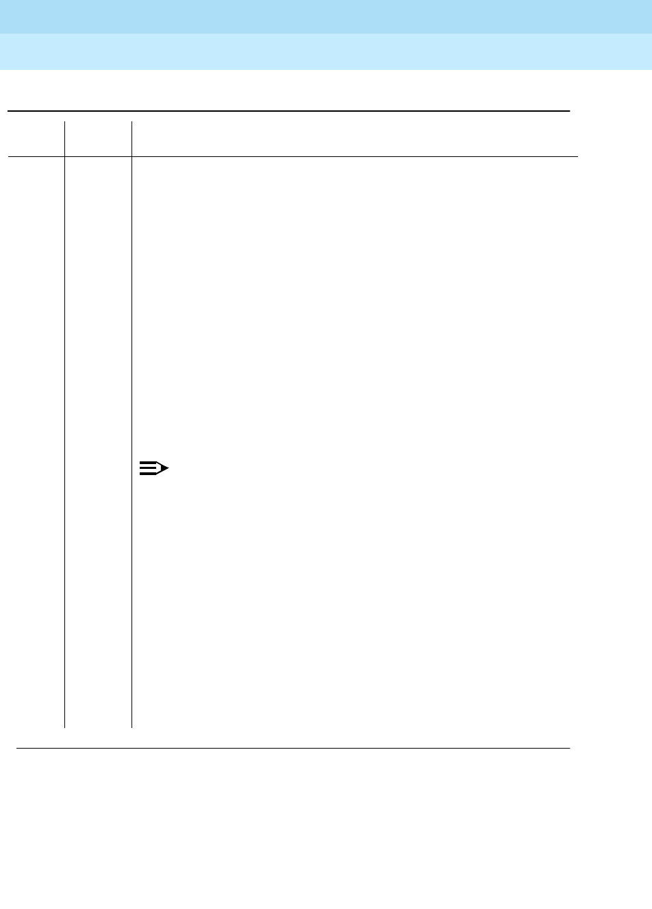
DEFINITY Enterprise Communications Server Release 6
Maintenance for R6r Volumes 1 & 2
555-230-126 Issue 2
January 1998
Maintenance Object Repair Procedures
Page 9-941OPS-LINE (DS1 Off Premises Station Line)
9
FAIL The NPE of the tested port did not conference the tones correctly. This can
cause noisy and unreliable connections.
1. Enter the list configuration board UUCSS command. If the circuit pack is
a TN767B vintage 8 or 9, replace the circuit pack with a TN767C V3 or
later. The error log may have error type 1281 entries.
2. Test all administered trunks on the board. If one fails, this could be an
off-board problem (such as an incoming seizure or an off-hook port
seizure during the test). Retest the board.
3. If all of the ports fail, check the CARR-POW (see note below).
4. If several ports fail, check the error log for TONE-BD or TONE-PT errors. If
there are such errors, take the appropriate action. When the TONE errors
have cleared, rerun the test.
5. If the retry passes and troubles have been reported, coordinate isolation
with the far-end PBX. Make sure that the near-end and far-end switches
and any NTCE equipment (the CSUs) have the correct administration.
6. Replace the circuit pack.
NOTE:
If the conference circuit test fails for all ports on a circuit pack, a
-5 volt power problem is indicated. If a TN736 or TN752 power
unit circuit pack is present, either the 631DB AC power unit or
the 676B DC power unit may be defective. (The 631DB power
unit is used in a medium cabinet powered by an AC source. The
645B power unit is used in a medium cabinet powered by a DC
power source.) The system may contain a TN736 or TN752
power unit or a 631DB AC power unit, but not both types of
power units. To investigate problems with a 631DB AC power
unit, refer to the CARR-POW (carrier port power unit for
AC-powered systems) Maintenance documentation. To
investigate problems with a 645B DC power unit, refer to the
CARR-POW (carrier port power unit for DC-powered systems)
Maintenance documentation. If a red LED on TN736 or TN752
power unit circuit pack is on, replace the pack.
Table 9-331. TEST #7 Conference Circuit Test — Continued
Error
Code Test
Result Description/ Recommendation
Continued on next page

DEFINITY Enterprise Communications Server Release 6
Maintenance for R6r Volumes 1 & 2
555-230-126 Issue 2
January 1998
Maintenance Object Repair Procedures
Page 9-942OPS-LINE (DS1 Off Premises Station Line)
9
PASS The port can correctly conference multiple connections. User-reported
troubles on this port should be investigated using other port tests and by
examining station, trunk, or external wiring.
0NO
BOARD The test could not relate the internal ID to the port (no board). This could be
due to incorrect translations, no board is inserted, an incorrect board is
inserted, or an insane board is inserted.
1. Check to ensure that the board translations are correct. Use the list
config command, and resolve any problems that are found.
2. If the board was found to be correctly inserted in step 1, issue the
busyout board command.
3. Issue the reset board command.
4. Issue the release busy board command.
5. Issue the test board long command. This should re-establish the linkage
between the internal ID and the port. If this is not the case, dispatch to
check to ensure that there is a valid board inserted.
Table 9-331. TEST #7 Conference Circuit Test — Continued
Error
Code Test
Result Description/ Recommendation
Continued on next page

DEFINITY Enterprise Communications Server Release 6
Maintenance for R6r Volumes 1 & 2
555-230-126 Issue 2
January 1998
Maintenance Object Repair Procedures
Page 9-943OPS-LINE (DS1 Off Premises Station Line)
9
Audit and Update Test (#36)
This test sends port level translation data from switch processor to the DS1
Interface circuit pack to assure that the trunk’s translation is correct. Translation
updates include the following data: line type, dial type, timing parameters, and
signaling bits enabled. The port audit operation verifies the consistency of the
current state of the trunk as kept in the DS1 Interface circuit pack and in the
switch software
Table 9-332. TEST #36 Audit and Update Test
Error
Code Test
Result Description/ Recommendation
ABORT Internal system error
1. Retry the command at 1-minute intervals a maximum of 5 times.
1000 ABORT The test was aborted because system resources required to run this test were
not available. The port may be busy with a valid call. Use the display port
UUCSSpp command to determine the station extension of the port. Use the
status station command to determine the service state of the port. If the
service state indicates that the port is in use, then the port is unavailable for
certain tests. You must wait until the port is idle before retesting.
1. If the port is idle, retry the command at 1-minute intervals a maximum of 5
times.
1006 ABORT The test was aborted because the station is out of service. This condition may
be accompanied by an error type 18 entry in the error log. You may want to
determine why the station was taken out of service. (When stations are taken
out of service by maintenance software, the problems that preceded that point
must be cleared.)
1. Use the status station command to check the service state of the port. If
the port is indeed out of service, enter the release station command to
bring the station back into service.
2. Retry the command at 1-minute intervals a maximum of 5 times.
2000 ABORT Response to the test request was not received within the allowable time period.
2100 ABORT Could not allocate the necessary system resources to run this test.
1. Retry the command at 1-minute intervals a maximum of 5 times.
7 or 8 FAIL Test failed due to internal system error. Do not replace port board.
■Error code 7: the failure occurred during station translation
download (to DS1 Interface circuit pack).
■Error code 8: the failure occurred during station ringer update.
1. Retry the command at 1-minute intervals a maximum of 5 times.
Continued on next page

DEFINITY Enterprise Communications Server Release 6
Maintenance for R6r Volumes 1 & 2
555-230-126 Issue 2
January 1998
Maintenance Object Repair Procedures
Page 9-944OPS-LINE (DS1 Off Premises Station Line)
9
PASS Trunk translation has been updated successfully. The current trunk states kept
in the DS1 Interface circuit pack and switch software are consistent. If the trunk
is busied out, the test will not run but will return PASS. To verify that the station
is in-service:
1. Enter the status station command to verify that the station is in-service. If
the station is in-service, no further action is necessary. If the station is
out-of-service, continue to step 2.
2. Enter the release station command to put the station back into in-service.
3. Retry the test command.
0NO
BOARD The test could not relate the internal ID to the port (no board). This could be
due to incorrect translations, no board is inserted, an incorrect board is
inserted, or an insane board is inserted.
1. Check to ensure that the board translations are correct. Use the list config
command, and resolve any problems that are found.
2. If the board was found to be correctly inserted in step 1, issue the busyout
board command.
3. Issue the reset board command.
4. Issue the release busy board command.
5. Issue the test board long command. This should re-establish the linkage
between the internal ID and the port. If this is not the case, dispatch to
check to ensure that there is a valid board inserted.
Table 9-332. TEST #36 Audit and Update Test — Continued
Error
Code Test
Result Description/ Recommendation
Continued on next page

DEFINITY Enterprise Communications Server Release 6
Maintenance for R6r Volumes 1 & 2
555-230-126 Issue 2
January 1998
Maintenance Object Repair Procedures
Page 9-945OPS-LINE (DS1 Off Premises Station Line)
9
DS1 OPS Switchhook Inquiry Test (#312)
This test initiates the Switchhook Audit Test. The test queries the switchhook state
of the Off-Premises-Station in switch software. If the state in switch software
disagrees with the state on the DS1 Interface circuit pack, then the state in the
switch software is updated to match the state on the DS1 Interface circuit pack
Table 9-333. TEST #312 DS1 OPS Switchhook Inquiry Test
Error
Code Test
Result Description/ Recommendation
ABORT Internal system error
1. Retry the command at 1-minute intervals a maximum of 5 times.
1004 ABORT The port has been seized by a user for a valid call. Use the status station
command to determine when the port is available for testing.
1. Retry the command at 1-minute intervals a maximum of 5 times.
1005 ABORT Test failed due to incompatible configuration administered in station
administration.
1. Using the display station command, verify that the station is not the 24th
port of the DS1 Interface circuit pack while common channel signaling is
specified. Use the display ds1 command to check the signaling type of
the DS1 circuit pack.
1006 ABORT The test was aborted because the station is out of service. This condition may
be accompanied by an error type 18 entry in the error log. You may want to
determine why the station was taken out of service. (When stations are taken
out of service by maintenance software, the problems that led up to that must
be cleared.)
1. Use the status station command to check the state of the port. If the port
is indeed out of service, enter the release station command to bring the
station back into service.
2. Retry the command at 1-minute intervals a maximum of 5 times.
1020 ABORT The DS1 Interface circuit pack is out-of-service.
1. Look for DS1-BD/UDS1-BD errors in Hardware Error Log. If present, refer
to the appropriate DS1-BD/UDS1-BD (DS1/UDS1 Interface Circuit Pack)
Maintenance documentation.
2. Retry the command.
Continued on next page

DEFINITY Enterprise Communications Server Release 6
Maintenance for R6r Volumes 1 & 2
555-230-126 Issue 2
January 1998
Maintenance Object Repair Procedures
Page 9-946OPS-LINE (DS1 Off Premises Station Line)
9
2000 ABORT The test was aborted because response to the test was not received within the
allowable time period.
1. Retry the command at 1-minute intervals for a maximum of 5 times.
2. If the test aborts with error code 2000 again, run short test sequence on
the associated DS1-BD or UDS1-BD. If tests 138 through 145 on the
associated DS1-BD or UDS1-BD are also aborting with error code 2000,
hyperactivity on the board or facility is indicated. In this case, the
hyperactivity problem should be dealt with first.
2012 ABORT The test was aborted due to a system error.
2100 ABORT Could not allocate the necessary system resources to run this test.
1. Retry the command at 1-minute intervals for a maximum of 5 times.
1 FAIL Internal system error.
1. Look for DS1-BD/UDS1-BD errors in the Hardware Error Log. If present,
refer to the appropriate DS1-BD/UDS1-BD (DS1/UDS1 Interface Circuit
Pack) Maintenance documentation.
2. If a channel multiplexer is used as the remote DS1 endpoint to which the
station connects, refer to the multiplexer vendor’s maintenance document
for diagnosis.
3. Retry the command at 1-minute intervals a maximum of 5 times.
PASS The station hook states in both switch software and DS1 Interface circuit pack
are consistent.
0
2012
NO
BOARD The test could not relate the internal ID to the port (no board). This could be
due to incorrect translations, no board is inserted, an incorrect board is
inserted, or an insane board is inserted.
1. Check to ensure that the board translations are correct. Use the list
config command, and resolve any problems that are found.
2. If the board was found to be correctly inserted in step 1, issue the
busyout board command.
3. Issue the reset board command.
4. Issue the release busy board command.
5. Issue the test board long command. This should re-establish the linkage
between the internal ID and the port. If this is not the case, dispatch to
check to ensure that there is a valid board inserted.
Table 9-333. TEST #312 DS1 OPS Switchhook Inquiry Test — Continued
Error
Code Test
Result Description/ Recommendation
Continued on next page

DEFINITY Enterprise Communications Server Release 6
Maintenance for R6r Volumes 1 & 2
555-230-126 Issue 2
January 1998
Maintenance Object Repair Procedures
Page 9-947PDATA-BD (Packet Data Line Circuit Pack)
9
PDATA-BD (Packet Data Line Circuit
Pack)
The TN553 Packet Data Line (PDATA-BD) circuit pack supports the connection
of twelve (12) asynchronous EIA RS-232C endpoints to the packet bus.
Functions of this circuit pack are described in the PDATA-PT section.
1. UU is the universal cabinet number (1 for PPN, 2 - 44 for EPNs). C is the carrier designation
(A, B, C, D, or E). SS is the number of the slot in which the circuit pack resides (01 to 21).
MO Name (in
Alarm Log) Alarm
Level Initial Command to
Run1Full Name of MO
PDATA-BD MINOR test board UUCSS PDATA Board Maintenance

DEFINITY Enterprise Communications Server Release 6
Maintenance for R6r Volumes 1 & 2
555-230-126 Issue 2
January 1998
Maintenance Object Repair Procedures
Page 9-948PDATA-BD (Packet Data Line Circuit Pack)
9
Error Log Entries and Test to Clear Values
Notes:
a. Error type 1 indicates the circuit pack has stopped functioning or has
been physically removed from the system. This error type does not apply
to ANN-BD, DETR-BD, S-SYN-BD, M/T-BD, or CLSFY-BD. The alarm is
logged approximately 11 minutes after removal of the circuit pack or
failure of the SAKI Sanity Test (#53).
Check for the physical presence of the circuit pack in the slot indicated by
the alarm. If the circuit pack is not present, insert one of the proper type. If
the circuit pack is present and its red LED is lit, see
LED Alarm Without
Alarm Log Entry
in Chapter 7, ‘‘LED Indicators’’.
1. Major or Minor alarms may have been downgraded to Warning alarms based on the values used in the
set options command.
2. Run the Short Test Sequence first. If all tests pass, run the Long Test Sequence. Refer to the appropriate
test description and follow the recommended procedures.
Table 9-334. PDATA Board Error Log Entries
Error Type Aux
Data Associated Test Alarm
Level1On/Off
Board Test to Clear Value
02Any Any Any test port UUCSSpp sh r 1
1(a) None MINOR ON
18(b) Busyout Board WARNING OFF release board UUCSS
257(c) CC Loop Test
(#52) MINOR ON test board UUCSS r3
513(d)
769(e)
1025(f) 4363 NPE Audit Test
(#50)
1293(g) 46088 to
46089 MINOR ON
1538(h) 46082 MINOR ON
1793(i) 46080 MINOR ON
2306(j) 46081
3330(k) 46083 MINOR ON
3840(l) 4096 to
4101
3843(m) 46097
3999(n) Any None

DEFINITY Enterprise Communications Server Release 6
Maintenance for R6r Volumes 1 & 2
555-230-126 Issue 2
January 1998
Maintenance Object Repair Procedures
Page 9-949PDATA-BD (Packet Data Line Circuit Pack)
9
b. The circuit pack has been busied out via the busyout board UUCSS
command.
c. This error indicates communication problems between the switch and this
circuit pack. Execute the test board UUCSS command and refer to the
repair procedures for Control Channel Loop-Around Test (#52).
d. An on-board hardware failure has been detected by the circuit pack.
Reset the circuit pack by executing busyout board UUCSS and reset
board UUCSS commands. If there is a problem, it will be detected during
initialization and will cause the circuit pack to lock up and appear insane
to the system. See the repair procedure in footnote (a).
e. This error is reported by the circuit pack when it detects a program logic
error. While no action is required, this error may lead to errors of other
types being reported against this circuit pack.
f. This error is reported by the circuit pack when it cannot update NPE
memory and read it back. This error type can be ignored, but may lead to
errors of other types being reported against this circuit pack.
g. A critical hardware failure (one or both of the data processors are insane)
has been detected on the circuit pack. Reset the circuit pack via the
busyout board UUCSS and reset board UUCSS commands. If the circuit
pack Restart Test (#594) passes, then the on-board circuitry is healthy.
Retire the alarm via the test board UUCSS long clear command. If the
circuit pack Restart Test (#594) fails, replace the circuit pack.
This error is also caused when the buffers on the board receive data faster
than they can transmit to the endpoints (Receive FIFO Overflow). Use the
above steps to repair the problem.
h. Circuit pack is hyperactive; i.e., it is flooding the switch with messages
sent over the control channel. The circuit pack is taken out-of-service
when a threshold number of these errors is reported to the switch. Clear
the alarm via the following commands: busyout board UUCSS, reset
board UUCSS, test board UUCSS long clear, release board UUCSS. if
the error recurs within 10 minutes, then replace the circuit pack.
i. This error indicates that parity errors are detected when transmitting data
to the Packet Bus. Reset the circuit pack via busyout board UUCSS and
reset board UUCSS commands. Also clear the alarm via test board
UUCSS long clear. If the error returns within 10 minutes, then replace the
circuit pack.
j. This error occurs when the circuit pack detects and error in a received
frame from the packet bus. These errors are most likely caused by a
packet bus problem, but may be due to a circuit pack fault.
Perform a LANHO Receive Parity Error Counter Test (#595) via test board
UUCSS l to determine if the condition has cleared. Also refer to PKT-BUS
Maintenance documentation to determine if the problem is isolated to this
circuit pack or if the problem is caused by Packet Bus faults.

DEFINITY Enterprise Communications Server Release 6
Maintenance for R6r Volumes 1 & 2
555-230-126 Issue 2
January 1998
Maintenance Object Repair Procedures
Page 9-950PDATA-BD (Packet Data Line Circuit Pack)
9
k. A critical failure has been detected in the Packet Bus interface of the
circuit pack. This failure may be due to an on-board fault or a Packet Bus
fault. If the Packet Bus is alarmed, refer to the PKT-BUS Maintenance
documentation for recommended repair procedures.
If the Packet Bus is not alarmed, reset the circuit pack via busyout board
UUCSS and reset board UUCSS commands. If the circuit pack Restart
Test (#594) passes, then the on board circuitry is healthy. Retire the alarm
via the test board UUCSS long clear command. If the circuit pack Restart
Test (#594) fails, replace the circuit pack.
l. This error is not service affecting. No action is required. This error is
reported by the circuit pack when it receives a bad control channel
message from the switch.
m. This error is not service-affecting. No action is required. A bad translation
RAM has been detected, but call continues by using another translation
RAM location.
n. Error type 3999 indicates that the circuit pack sent a large number of
control channel messages to the switch within a short period of time. If
error type 1538 is also present, then the circuit pack was taken
out-of-service due to hyperactivity. If error type 1538 is not present, then
the circuit pack has not been taken out-of-service, but it has generated
50% of the messages necessary to be considered hyperactive. This may
be completely normal during heavy traffic periods. However, if this error
type is logged when the circuit pack is being lightly used, it may indicate a
problem with the circuit pack or the equipment attached to it.System
Technician-Demanded Tests: Descriptions and Error Codes
Always investigate tests in the order presented in the table below. By clearing
error codes associated with the
Control Channel Looparound Test
for example,
you may also clear errors generated from other tests in the testing sequence.
Note:
a. For Control Channel Loop-Around Test (#52), and SAKI Sanity Test (#53)
refer to the respective repair procedures described in "XXX-BD (Common
Port Circuit Pack).”
1. D = Destructive; ND = Nondestructive
Order of Investigation Short Test
Sequence Long Test
Sequence D/ND1
Control Channel Loop-Around Test (#52) (a) X X ND
SAKI Sanity Test (#53) (a) X ND
LANHO Receive Parity Error Counter Test (#595) X D

DEFINITY Enterprise Communications Server Release 6
Maintenance for R6r Volumes 1 & 2
555-230-126 Issue 2
January 1998
Maintenance Object Repair Procedures
Page 9-951PDATA-BD (Packet Data Line Circuit Pack)
9
LANHO Receive Parity Error Counter Test (#595)
This test reads and clears the LANHO Receive Parity Error Counter on the circuit
pack. This counter is incremented by the circuit pack firmware each time it
detects a parity error in the data received from the Packet Bus.
These errors may be indicative of a circuit pack problem, Packet Bus problem, or
a problem with another circuit pack on the bus. This test is useful for verifying the
repair of the problem.
Table 9-335. Test #595 LANHO Receive Parity Error
Counter Test
Error
Code Test
Result Description/ Recommendation
2000 ABORT Response to the test was not received from the circuit pack within the allowable
time period.
1. If the test aborts repeatedly a maximum of 5 times, reset the circuit pack
via the busyout board UUCSS and reset board UUCSS commands.
2. If the test aborts again, replace the circuit pack.
2100 ABORT Could not allocate the necessary system resources to run this test.
2012 ABORT Internal system error.
1. Retry the command at 1-minute intervals a maximum of 5 times.
1-10 FAIL The circuit pack is still detecting errors of this type. The error code indicates the
value of the on-board error counter.
1. Retry the command at 1-minute intervals a maximum of 5 times.
2. If the test continues to fail, verify the validity of the Packet Bus. Run the
Packet Bus maintenance test with the test pkt port-network
port-network-number long command. If any Packet Bus tests fail, refer to
the Packet Bus Maintenance documentation for recommended repair
procedures.
3. If the Packet Bus test passes, check the validity of the circuit pack. Execute
a test that involves data transmission onto the Packet Bus. For example,
the PDATA Port Local Loop-Around Test (#602). This test can be run by
executing test port UUCSSpp command.
4. Other circuit packs on the Packet Bus may be the cause of the parity error.
Use the display alarms command to check the Error Log for other circuit
packs that are alarmed. If any alarms are present for other circuit packs,
retire those alarms also. Then, rerun the LANHO Receive Parity Error
Counter Test (#595) via test board UUCSS long on this circuit pack.
PASS No errors detected by the circuit pack.
Continued on next page

DEFINITY Enterprise Communications Server Release 6
Maintenance for R6r Volumes 1 & 2
555-230-126 Issue 2
January 1998
Maintenance Object Repair Procedures
Page 9-952PDATA-PT (Packet Data Line Port)
9
PDATA-PT (Packet Data Line Port)
System Ports and the PDATA Circuit Pack
The Packet Data Line Circuit (PDATA TN553) port board supports the connection
of asynchronous EIA RS-232C endpoints to the packet bus. Each PDATA circuit
pack has twelve (12) ports. PDATA ports are used solely to support the System
Ports feature. System ports provide a means for the SPE to communicate with
data applications via the TDM bus, something the SPE cannot otherwise do,
since it has no direct circuit-switched access to the TDM bus. Each system port
consists of a PDATA circuit pack port and a Data Line (TN726B) circuit pack port
which are cross-connected at the wall field. The PDATA side of the pair provides
an interface to the Packet Bus for Mode 3 packet data coming from the SPE via
the Packet Interface circuit pack. The PDATA converts the Mode 3 packet data
into EIA data which the Data Line circuit pack then converts to Mode 2 data and
places on the TDM bus. The data stream can then be directed to any external
application having an EIA interface by routing it through another Data Line port
(See the figure below.) System ports allow the following applications to
communicate with the SPE:
■Save/Restore of Announcement Circuit Pack Recorded Announcements
■Call Detail Recording (CDR)
■Journal Printer for the Property Management System (PMS)
■Wakeup Log Printer for the Property Management System (PMS)
■System Printer
■Data Terminals
■Remote G3-MT terminals
Although the paired PDATA and Data Line circuit packs used for system ports
may be located independently and in any port network, they are usually placed
in adjacent slots in the PPN.
1. UU is the universal cabinet number (1 for PPN, 2 - 44 for EPNs). C is the carrier designation (A,
B, C, D, or E). SS is the number of the slot in which the circuit pack resides (01 to 21). pp is the
two digit port number (01, 02, ...).
MO Name (in
Alarm Log) Alarm Level Initial Command to Run1Full Name of MO
PDATA-PT MINOR test port UUCSSpp PDATA Port
Maintenance
PDATA-PT WARNING release port UUCSSpp PDATA Port
Maintenance
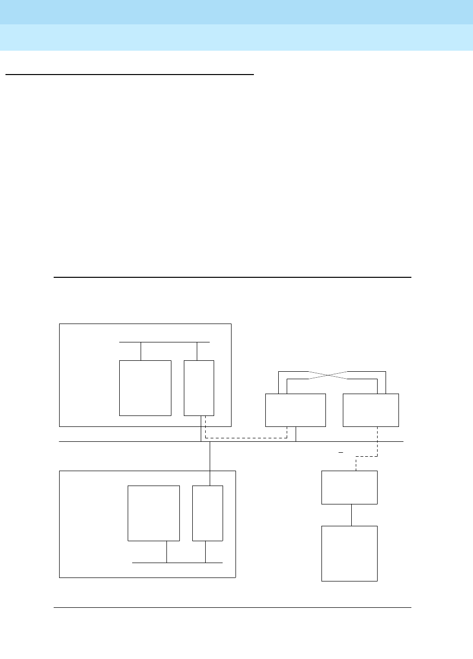
DEFINITY Enterprise Communications Server Release 6
Maintenance for R6r Volumes 1 & 2
555-230-126 Issue 2
January 1998
Maintenance Object Repair Procedures
Page 9-953PDATA-PT (Packet Data Line Port)
9
Data Applications and System Port Connectivity
As part of each data application, the SPE connects itself to the application
device through a system port. The application device may be an external
terminal, printer, or data-module, or it may be circuitry internal to the switch, as is
the case for the Announcement Circuit pack data-module used to save and
restore recorded announcements. The figure below is an example of a system
port connection using a second Data Line circuit pack (DAT-LN-BD) port to
provide dial-in access for a remote terminal.
A feature may not have a permanent connection to a system port. For example,
the announcement feature uses the system port when it is saving or restoring
announcement data to or from the Mass Storage System. The rest of the time it
does not use a system port. This makes troubleshooting these links more difficult,
since the symptoms may appear on one side of the link while the problem is on
the other. If the link is no longer up, there is no way to determine which system
port experienced the problem.
Figure 9-53. Typical System Port Connection
Printer,
CDR,
Data
Terminal,
or
Dial-up
G3-MT
M3
Packet Bus
PKT
INT
TN1655
Other SPE
Components
SPE Complex
Processor Bus
.
.
.
.
.
.
.
.
.
.
.
.
.
.
.
.
. .
.
.
.
.
.
.
.
.
.
.
.
.
.
.
Processor Bus
Other SPE
Components
SPE Complex
PKT
INT
TN1655
. . . . . . . . . . . . . . . . . . . . . . . . . . . . . . . . . . . . . . . . . . . . . . . . . . . . . . . . . . . . . . . . . . . . . . . . . . . . . . . . . . . . . . . . . . . . . . . . . . . . . . . . . . . . . . . . . . . . . . . . . . . . . .
TDM Bus
DAT-LINE
TN726B
DAT-LINE
TN726B
.
.
.
.
.
.
.
.
.
.
.
. .
.
.
.
.
.
.
.
.
PDATA
TN553
EIA
EIA
M2
(if duplicated)
Standby
Active

DEFINITY Enterprise Communications Server Release 6
Maintenance for R6r Volumes 1 & 2
555-230-126 Issue 2
January 1998
Maintenance Object Repair Procedures
Page 9-954PDATA-PT (Packet Data Line Port)
9
Testing the System Port Pool
This section describes a method for isolating a bad system port when its location
is not known. A pool of system ports is used to service the set of application
features listed above. The system supports a maximum of 10 system ports. Since
each Data Line Circuit pack provides 8 ports and each PDATA provides 12
ports, 2 Data Line Circuit packs and one PDATA Circuit pack are required if all
10 system ports are to be administered. If a link failed due to a faulty system port
and that port is not currently connected to the feature, you will need to test the
entire pool to isolate the bad system port. Follow these steps to isolate a bad port
or exonerate the pool of system ports.
1. Enter list data-module and record the extension for each system port.
Note: list data-module name option can be used to match on the name of
the system ports if they are all named similarly.
2. For each system-port enter display data-module ext to find the Data Line
(DAT-LINE) and PDATA ports administered. Each system port has a single
extension that applies to both the Data Line and PDATA port. For historical
reasons the PDATA is considered the associated port.
3. Check each port for alarms and errors using display alarms and display
errors.
4. Check for SYS-LINK error or alarms for SAP-type links using Display
alarms and errors.
5. Follow the repair procedures for any ports with errors.
Identifying Components of an Application Link
Use this procedure to locate the maintenance objects that make up a given
application link. You can then follow the repair procedures for each MO. In the
steps given below all the MOs in a link are located before any ports are tested.
Problems with the application adjunct links are reported in two ways:
■The data application experiences problems.
■Errors or alarms are logged against a port or extension.

DEFINITY Enterprise Communications Server Release 6
Maintenance for R6r Volumes 1 & 2
555-230-126 Issue 2
January 1998
Maintenance Object Repair Procedures
Page 9-955PDATA-PT (Packet Data Line Port)
9
Locating MOs When the Data Application Link
Fails
This sequence of steps should be used if the application is experiencing
problems and the health of the ports is unknown.
1. Using column three of the commands table below, find the command to
display the status of the application link. Enter the command to confirm the
health of the link. If the command requires a data-module extension, enter
list data-module to determine the extension.
2. If column two of the table below shows there is a link MO for the
application, enter display alarms and display errors. If there are alarms
or errors against the MO, follow the repair procedures for that MO.
3. Using column 4 of the table below, find the command to display the
extension of the application link. Enter the command and record the
extension.
4. Enter status data-module ext for the extension found in the previous step.
Record any connected ports.
5. If there are connected ports enter display port UUCSSpp and record the
extension for each port. The equipment type displayed should be SYSTEM
PORT DATA MODULE. Run status data-module ext for the connected
port. Record the associated PDATA port.
6. If there are no connected ports, follow the steps in
Testing the System Port
Pool
above to isolate or exonerate the system ports.
7. For each port, application extension, and connected Data Line and
PDATA ports, check the alarm and error logs for entries against these
ports. Follow the repair procedures for each port with problems.
8. Enter list sys-link and look for a SAP-type link with a port location that
matches the PDATA port. Check the alarm and error logs for entries
against the SYS-LINK. Follow repair procedures for SYS-LINK problems.
Locating MOs When Only a Problem Port Is
Known
A system port problem may originate in any of the following three components.
You may not know at first which is causing the problem.
■The application port
■The PDATA port
■The Data Line port

DEFINITY Enterprise Communications Server Release 6
Maintenance for R6r Volumes 1 & 2
555-230-126 Issue 2
January 1998
Maintenance Object Repair Procedures
Page 9-956PDATA-PT (Packet Data Line Port)
9
1. Enter display port UUCSSpp to find out what kind of port this is. Record
the extension and the identification field. The identification field likely
indicates a system-port or another type of data-module.
2.
If the port is a system port,
enter status data-module ext. Record the
Data Line or PDATA port. If there is a connected port do the following:
a. Record the location of the connected port.
b. Run display port UUCSSpp for the connected port and record the
identification and extension for the port.
c.
If the port is an announcement port,
skip this step. Otherwise,
determine whether the port’s extension is administered as an
application extension. Do this by executing each command in
column 4 of the table below, checking the extension administered
for that application against the port’s extension.
For each port and application located, check the alarm and error logs for
entries against these MOs. Follow repair procedures for MOs with log
entries. In situations where no connected ports were listed, test each
application link to ensure that more than one problem wasn’t involved.
3. If the port is not a system port, enter status data-module ext and record
the connected ports, if any are present.
4. Locate the application affected by entering each command in column 4 of
the table below and checking the administered extension. The extension
might be used as a remote G3-MT or data terminal.
5. If the status data-module display indicates no connected ports, follow the
steps in
Testing the System Port Pool
above to verify that the system ports
are working. If connected ports were displayed, enter display port
UUCSSpp using the connected port displayed. Record the associated
PDATA port.
6. For each port and application located, check the alarm and error logs for
entries against these MOs. Follow the repair procedures for MOs with log
entries. In situations where no connected ports were listed, test each
application link to ensure that more than one problem wasn’t involved.
7. Enter list sys-link and look for a SAP type link with a port location that
matches the PDATA port. Check the alarm and error logs for entries
against the SYS-LINK. Follow repair procedures for SYS-LINK problems.

DEFINITY Enterprise Communications Server Release 6
Maintenance for R6r Volumes 1 & 2
555-230-126 Issue 2
January 1998
Maintenance Object Repair Procedures
Page 9-957PDATA-PT (Packet Data Line Port)
9
System Port Wiring Scheme
If you find that you are having trouble with a PDATA port and you do not know
which extensions are being affected or which Data Line port is attached, enter
display port UUCSSpp with the PDATA port number to display the extension of
the System Port. With this extension you can run display data-module ext, which
will in turn identify the Data Line port. The PDATA and Data Line ports are wired
together in a manner similar to a null-modem. The figure below illustrates the
wiring scheme for the EIA ports. The subsequent table gives the full wiring
sequence for eight Data Line ports attached to eight PDATA ports.
Figure 9-54. System Port Wiring Scheme
Table 9-336. Data Application Commands
Application Name Application
MO Name
Command to
Display Link
Status Command to Locate the
Extension
Announcement Circuit
Pack Not Applicable Not Applicable display announcements
CDR CDR-LNK status cdr-link display sys-param cdr
Wakeup Log Print er for
the PMS Journal Printer
for the PMS
JRNL-LNK status journal-link
wakeup-log display
system-parameters
hospitality
System Printer SYS-PRNT status sp-link display
system-parameters
features
Data Terminals Not Applicable status data-module
ext list data-module
Remote G3-MT
terminals Not Applicable status data-module
ext list data-module
TXR
TXT
PXR
PXT
DAT-LINE
(TN726B)
Port
PXR
TXT
PDATA
(TN553)
Port
TXR
PXT
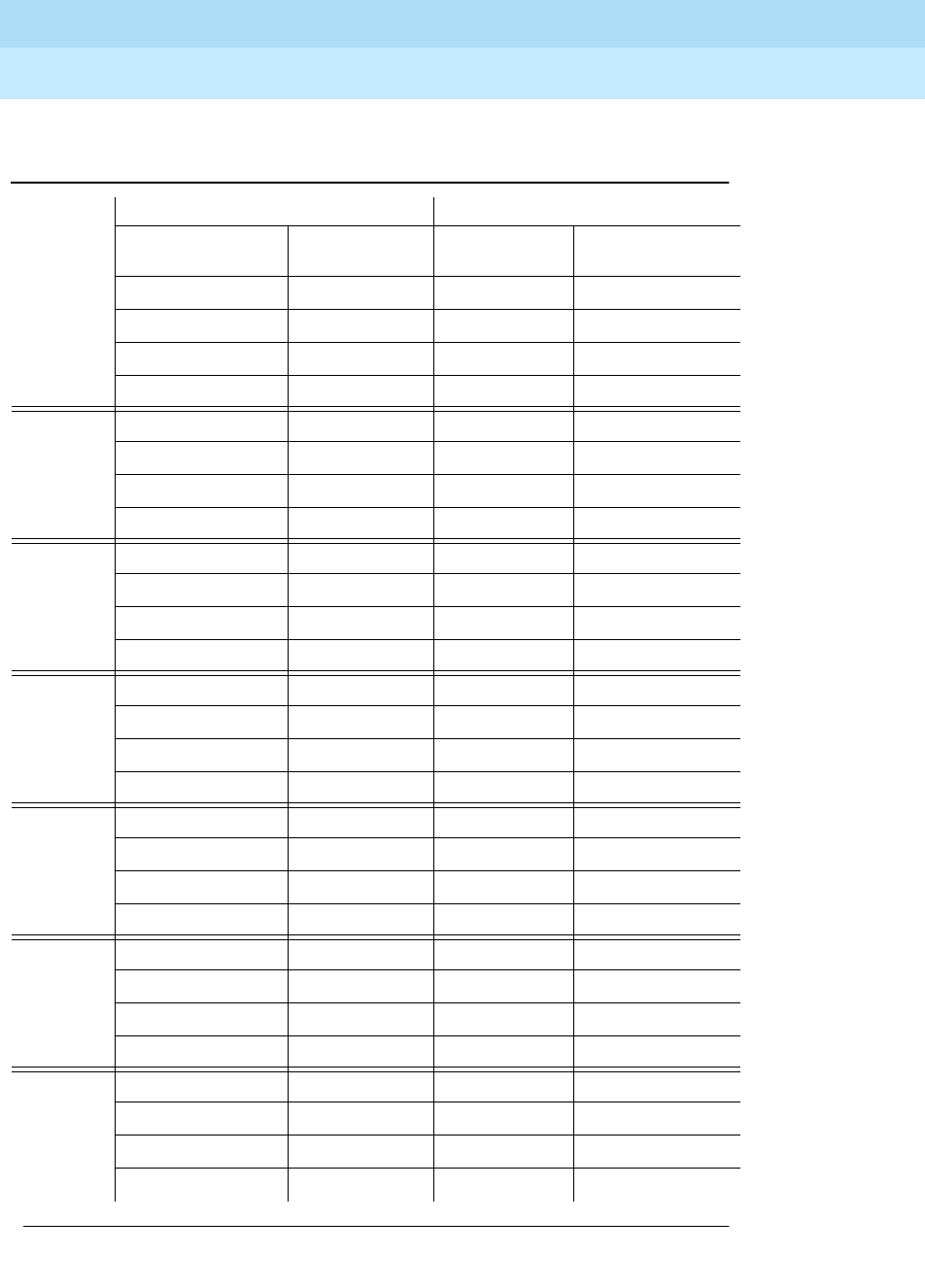
DEFINITY Enterprise Communications Server Release 6
Maintenance for R6r Volumes 1 & 2
555-230-126 Issue 2
January 1998
Maintenance Object Repair Procedures
Page 9-958PDATA-PT (Packet Data Line Port)
9
Table 9-337. Wiring Table for the System Ports Feature
(eight ports)
Port Data Line Port PDATA Port
Amphenol
Connector Pin # Carrier Lead
Appearance Carrier Lead
Appearance Amphenol
Connector Pin #
1 27 TXT1 PXT1 27
2 TXR1 PXR1 2
28 PXT1 TXT1 26
3PXR1TXR11
2 30 TXT2 PXT2 29
5 TXR2 PXR2 4
31 PXT2 TXT2 28
6PXR2TXR23
3 33 TXT3 PXT3 31
8 TXR3 PXR3 6
34 PXT3 TXT3 30
9PXR3TXR35
4 36 TXT4 PXT4 33
11 TXR4 PXR4 8
37 PXT4 TXT4 32
12 PXR4 TXR4 7
5 39 TXT5 PXT5 35
14 TXR5 PXR5 10
40 PXT5 TXT5 34
15 PXR5 TXR5 9
6 42 TXT6 PXT6 37
17 TXR6 PXR6 12
43 PXT6 TXT6 36
18 PXR6 TXR6 11
7 45 TXT7 PXT7 39
20 TXR7 PXR7 14
46 PXT7 TXT7 38
21 PXR7 TXR7 13
Continued on next page
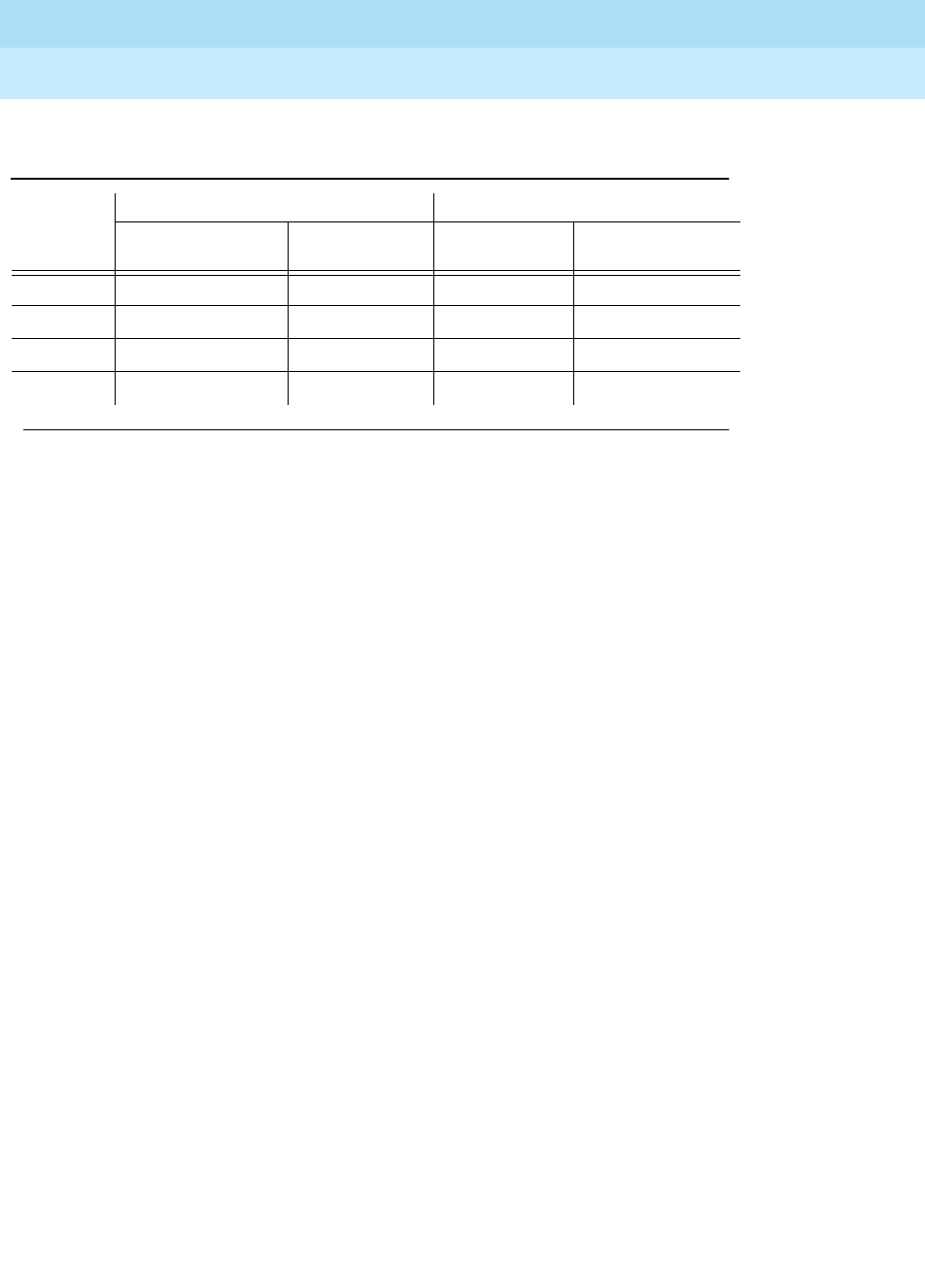
DEFINITY Enterprise Communications Server Release 6
Maintenance for R6r Volumes 1 & 2
555-230-126 Issue 2
January 1998
Maintenance Object Repair Procedures
Page 9-959PDATA-PT (Packet Data Line Port)
9
8 48 TXT8 PXT8 41
23 TXR8 PXR8 16
49 PXT8 TXT8 40
24 PXR8 TXR8 15
Table 9-337. Wiring Table for the System Ports Feature
(eight ports) — Continued
Port Data Line Port PDATA Port
Amphenol
Connector Pin # Carrier Lead
Appearance Carrier Lead
Appearance Amphenol
Connector Pin #
Continued on next page

DEFINITY Enterprise Communications Server Release 6
Maintenance for R6r Volumes 1 & 2
555-230-126 Issue 2
January 1998
Maintenance Object Repair Procedures
Page 9-960PDATA-PT (Packet Data Line Port)
9
Error Log Entries and Test to Clear Values
Notes:
a. This error occurs if the LAPD Connectivity test fails. If this test fails
repeatedly, a MINOR alarm is raised. This alarm indicates the failure to
establish a LAPD link with the port and to send and receive test data over
that port. See the repair procedure for LAPD Connectivity Test (#558).
b. This error type indicates that the circuit pack has been removed or has
been insane for more than 11 minutes. To clear the error, reinsert or
replace the circuit pack.
c. These three counters are incremented for errors which may or may not be
caused by the PDATA port itself. For example, the Invalid LAPD Frame
counter (error type 513) could exceed threshold due to a large number of
1. Major or Minor alarms on this MO may have been downgraded to Warning alarms based on the values
used in the set options command.
2. Run the Short Test Sequence first. If all tests pass, run the Long Test Sequence. Refer to the
appropriate test description and follow the recommended procedures.
Table 9-338. PDATA Port Error Log Entries
Error
Type Aux
Data Associated Test Alarm
Levell1On/Off
Board Test to Clear Value
02Any Any Any test port UUCSSpp sh r 1
1(a) LAPD Connectivity
Test (#558) MINOR ON test port UUCSSpp r 3
18 Busy Port WARNING OFF release port UUCSSpp
130(b) None WARNING ON test port UUCSSpp sh
257(c)
513(c)
779(c)
1025(d) Translation RAM
Update MINOR ON see footnote (c)
1281(e)
1793(f) Port Local
Loop-Around Test
(#602)
MINOR ON test port UUCSSpp
2049(g) System Port
Connectivity Test
(#603)
MINOR OFF test port UUCSSpp
3842*
3843*
3844*
37914 test port UUCSSpp sh l

DEFINITY Enterprise Communications Server Release 6
Maintenance for R6r Volumes 1 & 2
555-230-126 Issue 2
January 1998
Maintenance Object Repair Procedures
Page 9-961PDATA-PT (Packet Data Line Port)
9
"bad CRC" errors. The errors could be caused by packets arriving from the
"other end" which have a bad CRC, in which case the PDATA port is
behaving properly and should not be alarmed. On the other hand, the
error could be caused by faulty CRC-checking hardware on the PDATA
board, in which case the PDATA board should be alarmed.
Since these error counters do not necessarily indicate problems with the
PDATA port itself, no alarms are raised when the counters exceed
threshold. Instead, testing escalates to the LAPD Connectivity Test. If the
LAPD Connectivity test fails repeatedly, then the PDATA port is the source
of the problem and will be alarmed. More exhaustive tests can be run with
the reset board UUCSS command.
d. This error occurs if the switch has trouble in writing the translation data
into memory. A MINOR alarm is raised if this error occurs. This alarm
indicates the failure of either the Angel hardware or the RAM on the board.
If the Angel is the cause of the failure, similar alarms should be raised
against all other ports on the board. If the RAM is the cause of the failure,
then only the port is affected-other ports may function normally.
No associated test can retire this alarm. The repair procedure for this
alarm is as follows. First, reset the circuit pack (i.e. use
busyout board
UUCSS
and
reset board UUCSS
commands). If the circuit pack comes
back into service after the reset (the red LED on the circuit pack is off),
then execute the
test port UUCSSpp long clear
command to clear the
alarm. If the PDATA circuit pack fails to reset properly (i.e. the red LED on
the circuit pack is on.), replace the circuit pack.
Notice that the corresponding Translation RAM test always passes
because it issues a translation write command but does not wait around
for the failure up-link message from the board.
e. This error occurs when the receive FIFO RAM buffers on a circuit pack
overflow, i.e., the circuit pack receives data from the bus faster than it can
distribute the data to its endpoints. If this error occurs frequently, however,
it may indicate a LAPD parameter mismatch. LAPD should be able to
recover from this problem, but it may degrade the performance of the
Packet Bus. No alarm is raised for this error.
f. This error occurs if the PDATA Port Local Loop-Around test fails. If this test
fails, a MINOR alarm is raised. This alarm indicates the failure of the UART
device on the port. The circuit pack should be replaced if this alarm
cannot be cleared. See the repair procedure for PDATA Port Local
Loop-Around Test (#602) for more details.
g. This error occurs if the System Port Connectivity Test (#603) fails or if the
System Port connection fails in the call set-up procedure. This error is only
applicable to ports used as a System Port. If this test fails repeatedly, a
MINOR alarm is raised.
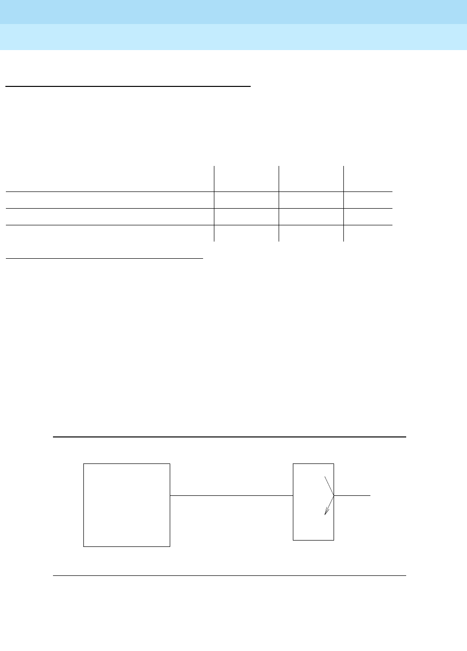
DEFINITY Enterprise Communications Server Release 6
Maintenance for R6r Volumes 1 & 2
555-230-126 Issue 2
January 1998
Maintenance Object Repair Procedures
Page 9-962PDATA-PT (Packet Data Line Port)
9
System Technician-Demanded Tests:
Descriptions and Error Codes
Always investigate tests in the order presented in the table below when
inspecting errors in the system. By clearing error codes associated with the
PDATA Port Local Loop-Around Test
for example, you may also clear errors
generated from other tests in the testing sequence.
LAPD Connectivity Test (#558)
This test is destructive.
This is a connectivity test which checks if a specific PDATA port is capable of
establishing a Level 2 LAPD link. The SPE will assign a LAPD bearer link between
the SPE Packet Bus interface (i.e. the Packet Interface, also called PKTINT,
TN1655) and the PDATA port. The SPE will send a test packet from the PKTINT to
the PDATA port and it will expect to receive a reply from the PDATA port. Failure
of this test may indicate an on-board fault associated with the port hardware on
the PDATA circuit pack.
Figure 9-55. Configuration for LAPD Connectivity Test
1. D = Destructive; ND = Nondestructive
Order of Investigation Short Test
Sequence Long Test
Sequence D/ND1
PDATA Port Local Loop-Around Test (#602) X X ND
LAPD Connectivity Test (#558) X X D
System Port Connectivity Test (#603) X X D
SPE
Packet Bus EIA
P
D
A
T
A
.
.
.
.
.
.
.
.
.
.
.
.
.
.
.
.
.
.
.
.
.
.
P
K
T
I
N
T

DEFINITY Enterprise Communications Server Release 6
Maintenance for R6r Volumes 1 & 2
555-230-126 Issue 2
January 1998
Maintenance Object Repair Procedures
Page 9-963PDATA-PT (Packet Data Line Port)
9
Table 9-339. TEST #558 LAPD Connectivity Test
Error
Code Test
Result Description/ Recommendation
1000 ABORT The port is in use for a call. Use status data-module extension command to
determine when the port is available for testing.
1. Retry the command when the port is idle. The port may be forced to the
idle state by executing busyout port UUCSSpp. This command is
destructive causing all calls and links associated with the port to be torn
down.
1137 ABORT The test link could not be created.
1. If the PDATA port is in an EPN, this is probably caused by Center Stage
maintenance interactions. The Center Stage includes the Switch Node
Interface (SNI), Expansion Interface (EI) and DS1C boards. Clear any
problems in these boards before continuing.
2. Retry at one minute intervals for a maximum of 3 times.
1139 ABORT The Packet Bus in this port network is out-of-service.
1. Retire the alarm associated with the Packet Bus. Please refer to the
maintenance section on the packet bus for details.
2. Retry the command when the alarm associated with the Packet Bus is
retired.
1141 ABORT The Packet Interface, PKTINT, Circuit Pack (TN1655) is out-of-service.
1. Refer to the repair procedures for the PKTINT circuit pack to put the circuit
pack back into service.
2. Retry the command when the alarm associated with the Packet Interface is
retired.
1144 ABORT The Packet Bus in the Port Processor Network (Network 1) is alarmed.
1. Retire the alarm associated with the Packet Bus in the Port Processor
Network. Please refer to the maintenance section on the packet bus for
details.
2. Retry the command when the alarm associated with the Packet Bus is
retired.
2012 ABORT Internal system error.
1. Retry the command at 1-minute intervals for a maximum of 3 times.
Continued on next page
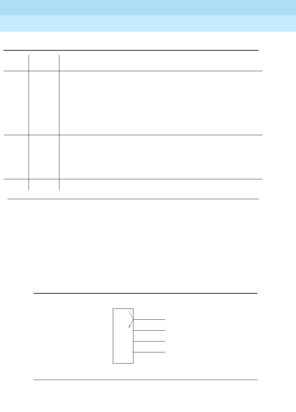
DEFINITY Enterprise Communications Server Release 6
Maintenance for R6r Volumes 1 & 2
555-230-126 Issue 2
January 1998
Maintenance Object Repair Procedures
Page 9-964PDATA-PT (Packet Data Line Port)
9
PDATA Port Local Loop-Around Test (#602)
This test is destructive.
This test verifies the per port circuitry on the PDATA circuit pack. This test is
executed by the PDATA circuit pack on command by the switch. The loop-back
is done internal to the circuit pack at point "A" in the figure. Failure of this test
indicates an on-board fault associated with the port hardware on the circuit pack.
Figure 9-56. Configuration for Port Local Loop-Around Test
1 FAIL Response to the test was not received for the PDATA circuit pack within the
allowable time period.
1. Retry the command at 1-minute intervals a maximum of 3 times.
2. reset board UUCSS if the other ports on the board are not in use (Yellow
LED is off or run status data-module extension).
3. Retry the command at 1-minute intervals a maximum of 3 times.
4. Replace the circuit pack.
2 FAIL The received test packet from the PDATA port is different than the test packet
transmitted to it.
1. If the test fails 3 times, reset board UUCSS if the other ports on the board
are not in use (yellow LED is off or run status data-module extension).
2. If the test continues to fail, replace the circuit pack.
PASS The PDATA port is able to terminate a LAPD link.
Table 9-339. TEST #558 LAPD Connectivity Test — Continued
Error
Code Test
Result Description/ Recommendation
Continued on next page
P
D
A
T
A
EIA
A

DEFINITY Enterprise Communications Server Release 6
Maintenance for R6r Volumes 1 & 2
555-230-126 Issue 2
January 1998
Maintenance Object Repair Procedures
Page 9-965PDATA-PT (Packet Data Line Port)
9
Table 9-340. TEST #602 PDATA Port Local Loop-Around Test
Error
Code Test
Result Description/ Recommendation
1000 ABORT The port is in use for a call. Use status data-module extension command to
determine when the port is available for testing.
1. Retry the command when the port is idle. The port can be made idle by
executing the busyout port UUCSSpp command. This command is
destructive causing all calls and links associated with the port to be torn
down.
1006 ABORT Port is out-of-service.
1. Run status data-module extension to check if the port is busied out. Run
release port UUCSS to free it, re-run the test.
2. Refer to the PKT-BUS maintenance section and fix any problems that are
related to the packet bus.
2000 ABORT Response to the test was not received for the PDATA circuit pack within the
allowable time period.
1. Retry the command at 1-minute intervals a maximum of 3 times.
2. reset board UUCSS if the other ports on the board are not in use (Yellow
LED is off or run the status data-module extension command).
3. Retry the command at 1-minute intervals a maximum of 3 times.
4. Replace the circuit pack.
2012 ABORT Internal system error.
1. Retry the command at 1-minute intervals a maximum of 3 times.
FAIL The PDATA circuit pack has detected a failure in the execution of the test.
1. If the test fails 3 times, reset board UUCSS if the other ports on the board
are not in use (Yellow LED is off or run the status data-module extension
command).
2. If the test fails again, replace the circuit pack.
PASS The PDATA on-board loop-around test for the port has passed verifying the
integrity of the per port circuitry.
Continued on next page

DEFINITY Enterprise Communications Server Release 6
Maintenance for R6r Volumes 1 & 2
555-230-126 Issue 2
January 1998
Maintenance Object Repair Procedures
Page 9-966PDATA-PT (Packet Data Line Port)
9
System Port Connectivity Test (#603)
This test is destructive.
This test verifies the capability to communicate between the PDATA and the Data
Line (TN 726B) ports of a System Port member. A System Port requires the
PDATA port and the Data Line port to be wired together. Failure of this test may
indicate faults with the wiring on PDATA port. Thus an off-board alarm is raised.
Since this test is applicable only to ports that are configured as a System Port,
the switch aborts the test if the port is not configured as a System Port.
The switch aborts this test if calls associated with the port are in progress. If the
ports are in use but tests must be run, the port can be busied out using the
busyout port UUCSSpp command. Release the port when the tests are done. If
a problem is fixed, the associated alarms will not be resolved until the port is
released.
Table 9-341. TEST #603 System Port Connectivity Test
Error
Code Test
Result Description/ Recommendation
11 ABORT The Data Line port could not be setup for this test.
2100 ABORT Could not allocate Data Line resources
1. Determine the Data Line port associated with the PDATA port.
2. Run test port UUCSSpp. If any of the Data Line port tests fail, resolve
these problems first.
3. If the problem persists, check the port admin and wiring
4. Verify that the Data Line port is not busied out (status data-module
extension) or not installed.
1000 ABORT The PDATA or Data Line port is in use for a call or maintenance tests are
already running on these ports.
1. Retry the command when the port is idle. The port may be forced to the idle
state by executing the busyout port UUCSSpp command. This command
is destructive causing all calls and links associated with the port to be torn
down.
1005 ABORT The configuration for this test is incorrect.
1. This is the expected test result for PDATA ports which have not been
administered as a System Port.
2. If the PDATA port is supposed to be configured as System Port, make the
necessary modifications on the port administration form change
data-module extension.
Continued on next page

DEFINITY Enterprise Communications Server Release 6
Maintenance for R6r Volumes 1 & 2
555-230-126 Issue 2
January 1998
Maintenance Object Repair Procedures
Page 9-967PDATA-PT (Packet Data Line Port)
9
1115 ABORT The PDATA port resources could not be allocated.
1. Run the busyout port UUCSSpp
2. Run the test again
3. Retry the command at 1-minute intervals for a maximum of 3 times.
4. Release the port when done.
2012 ABORT System Call Failed
2031 ABORT Uplink messages software failed.
2500 ABORT Internal system error.
1. Retry the command at 1-minute intervals for a maximum of 3 times.
7 FAIL Wiring does not match administration.
8 FAIL Invalid test message sequence.
10 FAIL Data Line port did not reset correctly.
11 FAIL PDATA port Data Terminal Ready (DTR) did not reset correctly.
12 FAIL PDATA port did not reset correctly.
2000 FAIL Test timed out, most probably the administered ports are not connected
correctly. For the above failure codes, use the following steps to correct the
problem.
1. Enter the commands list data-module and status data-module
extension on the G3-MT to find the corresponding Data Line port number
and PDATA port number. Check the wiring between the PDATA port and
the Data Line port. Look for loose connections, mis-wiring or broken wires.
2. Retry test a maximum of 2 times, no need to wait between tests.
3. If the test still fails, and the other ports on the circuit pack are not in use,
enter reset board UUCSS. (Use status data-module extension or LED
indicators to determine if other ports are idle).
4. Retry test a maximum of 2 times.
5. Replace the PDATA board.
6. Retry test a maximum of 2 times.
7. Replace the Data Line circuit pack.
8. Retry test a maximum of 2 times.
PASS The PDATA port and the Data Line port of the System Port feature are wired
together as administered.
Table 9-341. TEST #603 System Port Connectivity Test — Continued
Error
Code Test
Result Description/ Recommendation
Continued on next page
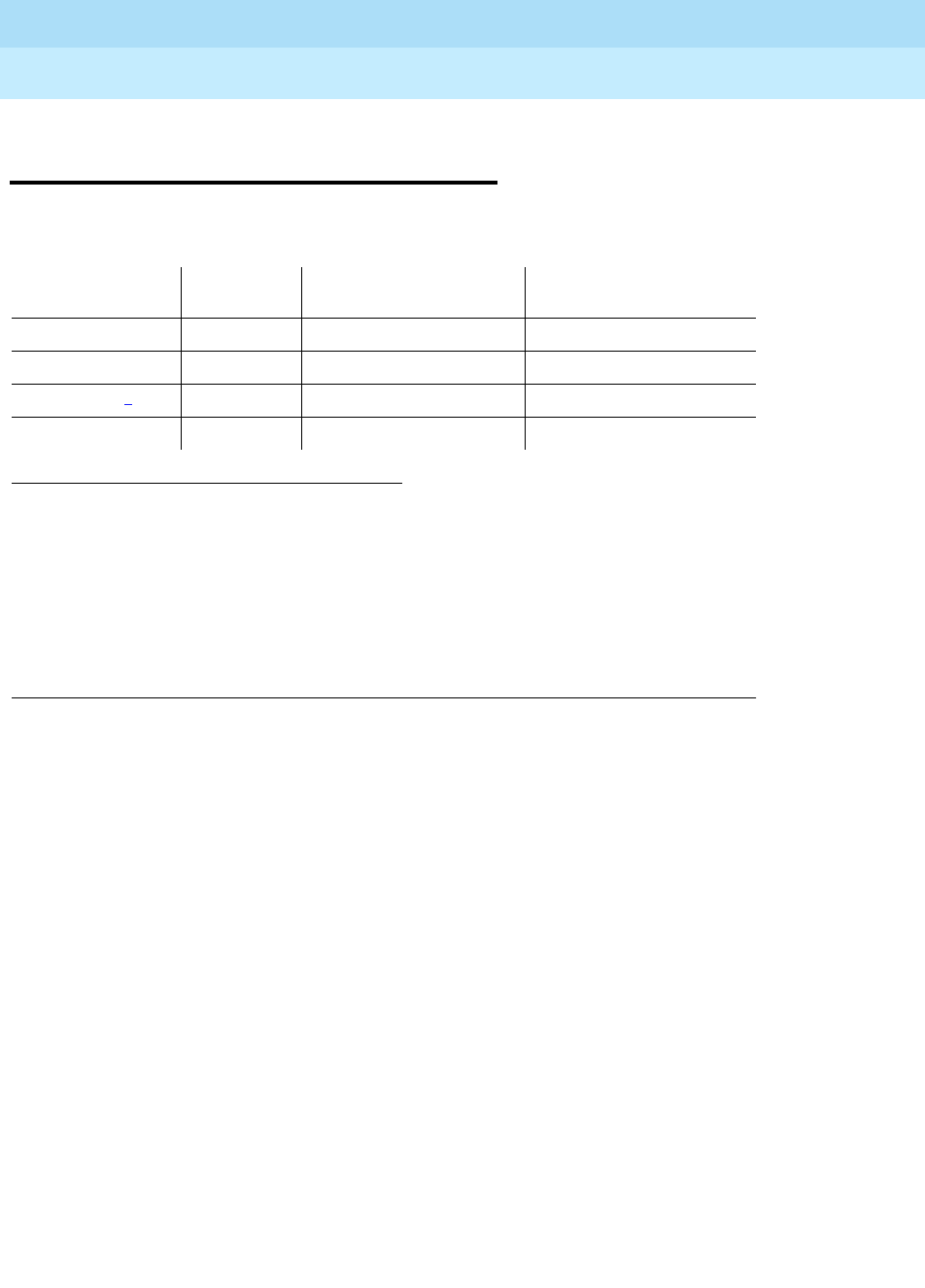
DEFINITY Enterprise Communications Server Release 6
Maintenance for R6r Volumes 1 & 2
555-230-126 Issue 2
January 1998
Maintenance Object Repair Procedures
Page 9-968PDMODULE (Processor Data Module) TDMODULE (Trunk Data Module)
9
PDMODULE (Processor Data Module)
TDMODULE (Trunk Data Module)
The PDMODULE and TDMODULE maintenance objects monitor and test Digital
Line circuit pack ports that are connected to Data Communications Equipment
(DCE) or Data Terminal Equipment (DTE). DCE include processor data modules
(MPDM) and Data Adaptors (DA). DTE include trunk data modules (DTE). These
stand-alone data modules provide interfaces between DCP ports on the Digital
Line circuit packs and data equipment such as terminals, host computers , and
data modems. (See the following list and figure.) Data modules are used for
dial-up and permanent circuit-switched data calls.
Digital Line circuit packs also connect to digital terminal data modules (DTDMs),
which work in conjunction with a voice terminal. Those configurations are
covered by the DIG-LINE maintenance object. Circuit pack-level maintenance is
covered by DIG-BD whose strategy is described in the "XXX-BD (Common Port
Circuit Pack).”
Digital line circuit packs include the TN754, TN754B, TN413, TN2136. See
DIG-LINE for more information on the characteristics of these circuit packs.
1. UU is the universal cabinet number (1 for PPN, 2 - 44 for EPNs). C is the carrier designation
(A, B, C, D, or E). SS is the number of the slot in which the circuit pack resides (01 to 21). pp
is the two digit port number (01, 02, ...).
2. Digital Terminal Data Modules (DTDM), and Data Adaptors (DA) in linked mode are
considered part of the Digital Line maintenance object. See the the DIG-LINE section for
maintenance of these devices. DAs in stand-alone mode are included in PDMODULE.
Some of the alarms that are logged due to PDMODULE and TDMODULE test failures may
be related to circuit pack problems reported during DIG-BD testing. Refer to
"XXX-BD (Common Port Circuit Pack)" for information on testing digital line circuit packs.
MO Name (in
Alarm Log) Alarm
Level Initial Command to
Run1Full Name of MO
PDMODULE2MINOR test port
UUCSSpp
l Processor Data Module
PDMODULE WARNING test port
UUCSSpp
s Processor Data Module
TDMODULE 2MINOR test port
UUCSSpp
l Trunk Data Module
TDMODULE WARNING test port
UUCSSpp
s Trunk Data Module
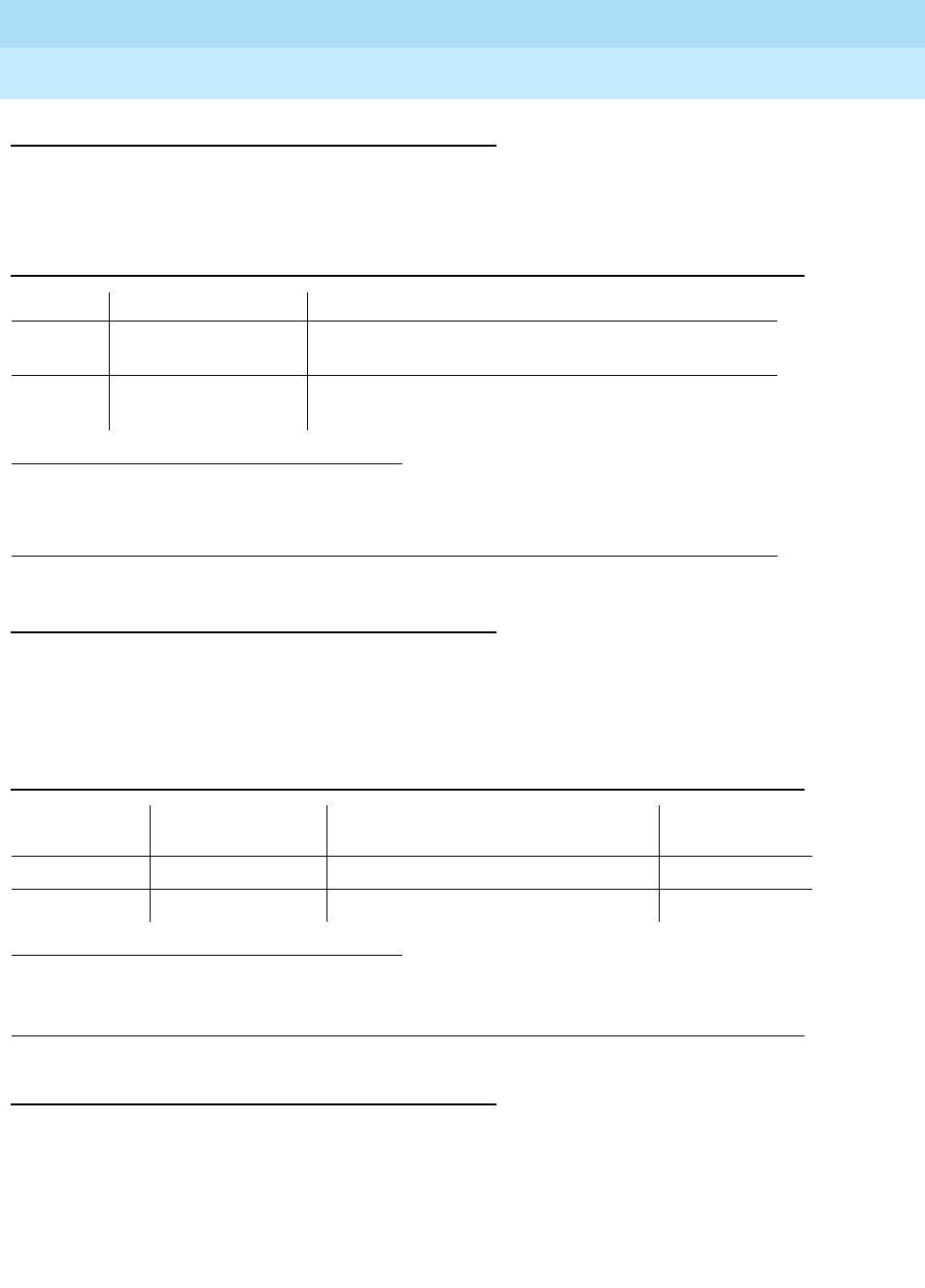
DEFINITY Enterprise Communications Server Release 6
Maintenance for R6r Volumes 1 & 2
555-230-126 Issue 2
January 1998
Maintenance Object Repair Procedures
Page 9-969PDMODULE (Processor Data Module) TDMODULE (Trunk Data Module)
9
Stand-Alone DCP Data Modules
There are two types of stand-alone DCP data modules:
Data Adapters
TN2136 circuit packs use IDCP signaling and a DAA2 Data Adaptor (DA) to
interface to DTE. DAs can operate in either of two modes which are covered by
different maintenance objects:
Configurations and Maintenance
In the following discussion, the general term data module refers to MPDMs,
MTDMs, and DAs. The PBX loop or digital link between a data module and the
Digital Line port supports two logical information channels and one signaling
channel. Data modules generally use the primary information channel for data
1. Early versions of these data modules were referred to as PDMs and TDMs, respectively. Later
models are designed to provide a variety of interfaces by using interchangeable modules and
are thus called modular data modules. Both types are supported by the tests described in this
section
1. IDT1/2: Italtel Digital Telephone, Model 1 or 2 (also known as Digital Telephones TD7210 and
TD7206).
Table 9-342. Stand-Alone DCP Data Modules
Type Name1Interfaces to:
MPDM Modular Processor
Data Module DTE (data terminals, host computers, printers, etc)
MTDM Modular Trunk Data
Module DCE (modems, data modules, etc)
Table 9-343. Data Adaptor Modes
DA Mode Administered as: Endpoint MaintenanceOb
ject
Stand-Alone PDM data endpoint only PDMODULE
Linked DTDM IDT1/21 and optional data terminal DIG-LINE

DEFINITY Enterprise Communications Server Release 6
Maintenance for R6r Volumes 1 & 2
555-230-126 Issue 2
January 1998
Maintenance Object Repair Procedures
Page 9-970PDMODULE (Processor Data Module) TDMODULE (Trunk Data Module)
9
communications and the signaling channel for dialing and call supervision. With
4-wire DCP, the secondary information channel can be used to support a second
data module on a shared port.
Besides being used for data calls between terminals, computers, and data
communications equipment, data modules also serve as interfaces to equipment
associated with system features such as System Administration, Station
Message Detailed Recording, Message Center Service, Automatic Call
Distribution, Distributed Communications System, and Audio Information
Exchange. Maintenance for data modules associated with these latter services
are covered by other maintenance objects such as PMS-PRNT, JNL-PRNT, and
PMS-LINK.
Maintenance of data modules is closely related to and interacts with Digital Line
circuit pack maintenance, and test results for data modules can be affected by
the health of the Digital Line circuit pack. Keep this interaction in mind when
investigating customer-reported problems with data modules.
Data modules provide a variety of option switches to allow the customer to select
data rates, parity, keyboard dialing, local, and remote loop back, etc. (The DAA2
Data Adaptor has an AT (Hayes) type interface that allows selection of the above
parameters as well as mode — linked or stand-alone.) An incorrect selection will
not necessarily cause errors, alarms or test failures, but it can result in service
disruption. Refer to the installation manual provided with the data module for
more information about those options.
This discussion occasionally refers to a station’s service state, which is defined
as follows:
Out-of-Service The port, and thus the data module, have been removed from
service. Causes for this include busyout of the port, removal of the
Digital Line circuit pack and failure of the NPE Crosstalk Test (#9).
Disconnected The port is administered but the associated digital link does not
respond. An administered port is put in a disconnected state after a
system reboot or circuit pack insertion. This state persists until a
link-reset-pass message is received from firmware on the circuit
pack.
In-Service When switch software receives a link-reset-pass message from the
port, the port is placed in service. If the link-reset-pass message is
missed, and an off-hook message is received while the port is in the
disconnected state, maintenance software will run an ID request test
and put the port into service upon receiving a correct response.
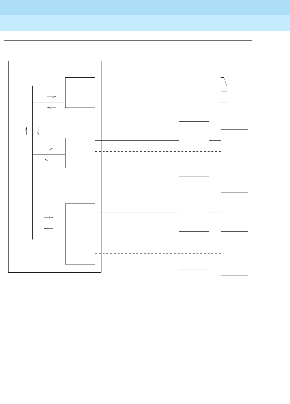
DEFINITY Enterprise Communications Server Release 6
Maintenance for R6r Volumes 1 & 2
555-230-126 Issue 2
January 1998
Maintenance Object Repair Procedures
Page 9-971PDMODULE (Processor Data Module) TDMODULE (Trunk Data Module)
9
Figure 9-57. Typical Data Module Configurations
Signaling
(Secondary Information
Channel unused)
Terminal
G3 PBX
..................
.................
Digital
Line
Circuit
Pack
TDM
BUS
. . . . . . . . . . . . . . . . . . . . . . . . . . . . . . . . . . . . . . . . . . . . . .
MPDM
or DA
in
stand-alone
mode
Primary Information Channel
Physical Connection
Digital
Line
Circuit
Pack
(Secondary Information
Channel unused)
Signaling
Physical Connection
Primary Information Channel
Host
Computer
with
DCE
Interface
MTDM
. . . . . . . . . . . . . . . . . . . . . . . . . . . . . . . . . . . . . . . . . . . . . .
. . . . . . . . . . . . . . . . . . . . . . . . . . . . . .
Physical Connection
Secondary
MTDM
Primary
MTDM
Host
Computer
with
DCE
Interface
Host
Computer
with
DCE
Interface
Primary Information Channel
Physical Connection
Signaling
Digital
Line
Circuit
Pack
Secondary Information Channel

DEFINITY Enterprise Communications Server Release 6
Maintenance for R6r Volumes 1 & 2
555-230-126 Issue 2
January 1998
Maintenance Object Repair Procedures
Page 9-972PDMODULE (Processor Data Module) TDMODULE (Trunk Data Module)
9
Error Log Entries and Test to Clear Values
Notes:
a. Error type 0 appears in the Error Log only if a Digital Line circuit pack that
has ports administered has been removed since the Error Log was last
cleared. Make sure that the circuit pack has been re-inserted.
b. Error type 1 with aux data 40987 indicates an off-board problem detected
by the port circuit, and may result in a noisy port or link. See note
n
for
recommendations.
Table 9-344. PDMODULE, TDMODULE Error Log Entries
Error Type Aux
Data Associated Test Alarm
Level On/Off
Board Test to Clear Value
0(a) 0 None
1(b,n) 40987 None WARNING OFF
1(c,n) 1 to 20 None WARNING OFF
15(d) Any None
18(e) 0 busyout port
UUCSSpp
WARNING OFF release port
UUCSSpp
257(f) 40971 None
513 0 Data Module Audits
(#17) WARNING OFF test port
UUCSSpp
sh r 6
769(g,n) 40988 None WARNING OFF
1281 Any Data Module Audits
(#17) WARNING OFF test port
UUCSSpp
sh r 4
1537(h,n) 40968 None WARNING OFF
1793 Information Channel
and Control Channel
Looparound (#13)
MINOR ON test port
UUCSSpp
l r 3
2049 NPE Crosstalk (#9) MINOR ON test port
UUCSSpp
l r 3
2304(i) None
2305(j) 32770 None
2305(k) 40967 None
2561(l) Any Data Module Internal
Looparound (#175) WARNING OFF test port
UUCSSpp
l r 5
2817 (m) Link GPP Loop (183)
Against Links MAJOR ON
3841 n) NONE
3841(o) None

DEFINITY Enterprise Communications Server Release 6
Maintenance for R6r Volumes 1 & 2
555-230-126 Issue 2
January 1998
Maintenance Object Repair Procedures
Page 9-973PDMODULE (Processor Data Module) TDMODULE (Trunk Data Module)
9
c. Error type 1 with aux data of 1 to 20 is logged when at least 15 off-board
problems have been detected with the link to the data module. Each error
detected increments an on-board counter. The aux data gives the value of
this counter divided by 15. The user could experience a noisy port or link.
See note ‘‘n’’ for recommendations.
d. Error type 15 is an internal that occurs when an audit request fails.
e. Error type 18 is logged when the port in question is demand busied out
Make sure that the port is released from busy out.
f. Error type 257 indicates problems with transmitting to the data module.
This is usually an on-board problem and can be ignored if no user
complaints are received. Otherwise, check for faulty wiring.
g. Error type 769 indicates that EPF has been turned off due to the
overcurrent condition at the data module. See the recommendations in
note
n
. This may also be caused by the the PTC being in the ‘‘tripped’’
position due to a short on the power line. You can correct this by removing
the short, unplugging the data module from the wall for about 30 seconds,
and plugging it back in.
h. Error type 1537 indicates that an in-line maintenance error has generated
an off-board warning due to some problem with the link to the data
module. This can be ignored if no user complaints are received.
Otherwise, see note
n
for recommendations.
i. Error type 2304 indicates an internal error. No action is necessary.
j. Error type 2305 with aux data 32770 indicates that the data equipment
went off-hook while the associated link was being initialized (in a
disconnected state). Use the status data-module command to determine
the state of the data module. The off-hook should have changed the
service state to in-service. No action is necessary.
k. Error type 2305 with aux data 40967 indicates that the link between the
circuit pack and the data module has been reset successfully. The link is
normally reset when the circuit pack associated with an administered port
is first plugged in (assuming that the data module is already in place and
connected to the associated port), when a port is first administered
(assuming the associated circuit pack is plugged in and that the data
module is connected to the associated port), or when a data module is
first connected to an administered port. No system technician action is
necessary.
l. Error type 3841 indicates that the downlink buffer on the circuit pack has
overflowed. No action is necessary.
m. A DCP endpoint may have been disconnected.
n. Make sure the data module is connected and operating properly. Check
for faulty wiring. If necessary, reduce the length of the cable between the
data module and the switch to 5000 ft for 24-gauge wire or 4000 ft for
24-gauge wire. Refer to
DEFINITY Communications System Generic 1 and
3 - Installation and Test
, 555-230-104.

DEFINITY Enterprise Communications Server Release 6
Maintenance for R6r Volumes 1 & 2
555-230-126 Issue 2
January 1998
Maintenance Object Repair Procedures
Page 9-974PDMODULE (Processor Data Module) TDMODULE (Trunk Data Module)
9
If the problem still exists, replace the circuit pack. Once the problem has
been resolved, the alarm will be retired in 60 minutes (90 min for error
1537). (These error counters use the leaky bucket mechanism.)
The DA module is not phantom-powered from the port. Thus when it is in
linked mode, its range is limited by the Italtel digital phone’s limit: 0.7 Km
(2300) ft on 26-gauge wire or 1.8 Km (5900) ft on 22-gauge (0.6 mm) wire.
If in stand-alone mode, it is limited by the maximum length of loop allowed
from the Digital Line Interface (DLI) component: up to 3.5 Km (2 miles) on
22-gauge (0.6 mm) wire.
System Technician-Demanded Tests:
Descriptions and Error Codes
Always investigate tests in the order presented in the table below. By clearing
error codes associated with the
Data Module Internal Looparound Test,
for
example, you may also clear errors generated from other tests in the testing
sequence.
NPE Crosstalk Test (#9)
The NPE Crosstalk Test verifies that this port’s NPE channel talks on the selected
time slot and never crosses over to time slots reserved for other connections. If
the NPE is not working correctly, one-way and noisy connections may be
observed. If a secondary data module is assigned, it is tested after the primary
data module. If either test fails, both data modules are taken out of service. This
test usually run only during the long test sequence and takes about 20 to 30
seconds to complete.
1. D = Destructive; ND = Nondestructive
Order of Investigation Short Test
Sequence Long Test
Sequence D/ND1
Data Module Internal Looparound Test (#175) X ND
Digital Port Board Network Processing Element Crosstalk
Test (#9) XND
Port Circuit Information Channel and Control Channel
Looparound Test (#13) XND
Data Module Audits Test (#17) X X ND

DEFINITY Enterprise Communications Server Release 6
Maintenance for R6r Volumes 1 & 2
555-230-126 Issue 2
January 1998
Maintenance Object Repair Procedures
Page 9-975PDMODULE (Processor Data Module) TDMODULE (Trunk Data Module)
9
Table 9-345. TEST #9 NPE Crosstalk Test
Error
Code Test
Result Description/ Recommendation
1000 ABORT System resources required to run this test are not available. The port may be
busy with a valid call. Use the display port UUCSSpp command to determine
the extension of the data module port. Use the status data-module command
to determine the service state of the port. If the port is in use, wait until the port
is idle before testing.
1. If the port status is idle, then retry the command at 1-minute intervals a
maximum of 5 times.
1001 ABORT System resources to run this test are not available.
1. Retry the command at 1-minute intervals a maximum of 5 times.
1002 ABORT The system could not allocate time slots for the test. The system may be under
heavy traffic conditions or it may have time slots out-of-service due to
TDM-BUS errors. Refer to “TDM-BUS” to diagnose TDM-BUS errors.
1. If system has no TDM-BUS errors and is not handling heavy traffic, repeat
test at 1-minute intervals a maximum of 5 times.
1003 ABORT The system could not allocate a tone receiver for the test. The system may be
oversized for the number of tone detectors present or some tone detectors
may be out-of-service.
1. Resolve any “TTR-LEV” errors in the Error Log.
2. Resolve any “TONE-PT” errors in the Error Log
3. If neither condition exists, retry the test at 1-minute intervals a maximum of
5 times.
1004 ABORT The port may be busy with a valid call. Use the display port UUCSSpp
command to determine the extension of the data module port. Use the status
data-module command to determine the service state of the port. If the port is
in use, wait until the port is idle before testing.
1. Retry the command at 1-minute intervals a maximum of 5 times.
1020 ABORT Test disabled via background testing. Use status data-module command to
determine when the data module is available for testing.
2000 ABORT Response to the test request was not received within the allowable time period.
1. Retry the command at 1-minute intervals a maximum of 5 times.
2020 ABORT The test did not run due to a previously existing error on the specific port or a
more general circuit pack error.
1. Examine Error Log for existing errors against this port or the circuit pack
and attempt to diagnose the previously existing error.
2100 ABORT Could not allocate the necessary system resources to run this test.
1. Retry the command at 1-minute intervals a maximum of 5 times.
Continued on next page

DEFINITY Enterprise Communications Server Release 6
Maintenance for R6r Volumes 1 & 2
555-230-126 Issue 2
January 1998
Maintenance Object Repair Procedures
Page 9-976PDMODULE (Processor Data Module) TDMODULE (Trunk Data Module)
9
Information and Control Channel Local Loop
Test (#13)
This is a set of four tests that check the operation of the information and control
channels used between the SPE and the Digital Line port circuit. This is an
Internal Looparound test only and does not check building wiring. See Test #175
for external loop around tests to the data module.
The SPE first sends a message to the on-board microprocessor to loop around
both the information and control channels for the port. Then, the primary
information channel loop back test is run. The test is performed by sending a
digital count from the Tone/Clock circuit pack on the primary channel time slot
and receiving the same digital count with a General Purpose Tone Detector. The
digital count looks like transparent data to the on-board microprocessor.
With the port still in loop-around mode, the S channel Looparound Test is
performed next. This test consists of sending four different transparent patterns
to the on-board microprocessor, receiving them back, and comparing them.
The third test is a Looparound Test for the secondary information channel. It is
performed only if a secondary data module is assigned to the port.
The fourth test is a Conference Test of the primary channel. This test is the same
as the Analog Line Conference Test #6.
Only one result is reported for the three tests run. If any test fails or aborts, the
sequence is stopped.
2500 ABORT Internal system error
1. Retry the command at 1-minute intervals a maximum of 5 times.
1,
2FAIL The NPE of the tested port was found to be transmitting in Error Log. This will
cause noisy and unreliable connections. Failure code 1 indicates that the
Crosstalk Test failed on the primary channel. Failure code 2 indicates that the
Crosstalk Test failed on the secondary channel.
1. Replace the circuit pack.
PASS The port is correctly using its allocated time slots.
1. To be sure that this is not an intermittent problem, repeat this test up to a
maximum of 10 times and verify that it continues to pass.
2. If complaints still exist, examine the data module, connections, and wiring.
Table 9-345. TEST #9 NPE Crosstalk Test — Continued
Error
Code Test
Result Description/ Recommendation
Continued on next page

DEFINITY Enterprise Communications Server Release 6
Maintenance for R6r Volumes 1 & 2
555-230-126 Issue 2
January 1998
Maintenance Object Repair Procedures
Page 9-977PDMODULE (Processor Data Module) TDMODULE (Trunk Data Module)
9
Table 9-346. TEST #13 Information and Control Channel
Local Loop Test
Error
Code Test
Result Description/ Recommendation
ABORT Internal system error
1. Retry the command at 1-minute intervals a maximum of 5 times.
1000 ABORT System resources required to run this test are not available. The port may be
busy with a valid call. Use the display port UUCSSpp command to determine
the data module extension. Then use status data module command with the
extension number to determine the service state of the data module. If the
service state indicates that the data module is in use, then the port is
unavailable for certain tests. You must wait until the port is idle before
retesting.
1. If the port status is idle, then retry the command at 1-minute intervals a
maximum of 5 times.
1001 ABORT System resources required to run this test are not available.
1. Retry the command at 1-minute intervals a maximum of 5 times.
1002 ABORT The system could not allocate time slots for the test. The system may be under
heavy traffic conditions or it may have time slots out-of-service due to
TDM-BUS errors. Refer to TDM-BUS Maintenance to diagnose any active
TDM-BUS errors.
1. If the system has no TDM-BUS errors and is not handling heavy traffic,
repeat the test at 1-minute intervals a maximum of 5 times.
1003 ABORT The system could not allocate a tone receiver for the test. The system may be
oversized for the number of tone detectors present or some tone detectors
may be out-of-service.
1. Look for TTR-LEV errors in the Error Log. If present, refer to TTR-LEV
Maintenance documentation.
2. Look for TONE-PT errors in the Error Log. If present, refer to TONE-PT
Maintenance documentation.
3. If neither condition exists, retry the command at 1-minute intervals for a
maximum of 5 retries.
1004 ABORT The port was seized by a valid call during the test. The test has been aborted.
Use the display port UUCSSpp command to determine the data module
extension. Then use status data module command with the extension number
to determine the service state of the data module. If the data module is in use,
wait until the port is idle before retesting.
2000 ABORT Response to the test request was not received within the allowable time
period.
1. Retry the command at 1-minute intervals a maximum of 5 times.
Continued on next page

DEFINITY Enterprise Communications Server Release 6
Maintenance for R6r Volumes 1 & 2
555-230-126 Issue 2
January 1998
Maintenance Object Repair Procedures
Page 9-978PDMODULE (Processor Data Module) TDMODULE (Trunk Data Module)
9
Data Module Audits Test (#17)
This is a series of six tests that are classified as hardware audits. The processor
sends messages to the on-board microprocessor to perform the following tests:
■Switchhook Inquiry — This is an update of the processor’s software
records based on the on-hook/off-hook status of the data module.
2100 ABORT System resources required for this test are not available.
1. Retry the command at 1-minute intervals a maximum of 5 times.
2500 ABORT Internal system error
1. Retry the command at 1-minute intervals a maximum of 5 times.
7 FAIL Conference test failed on the primary information channel. In some cases, user
may not notice disruption in service. In extreme cases, conferencing feature
may not work at all.
14 FAIL The primary information channel is not transmitting properly. User impact may
range from noticing nothing to not being able to use this port.
15 FAIL The control channel between the processor and Digital Line circuit pack is not
transmitting properly. This can cause a wide range of effects. The user may
notice nothing or the port may be totally unusable. This could also disrupt
other users.
1. Run circuit pack tests to check the Tone Generator and the Tone Detector
circuit packs using the test board UUCSS short command.
2. Resolve any problems that are detected on the Tone Generator circuit
pack or Tone Detector circuit pack.
3. If the Tone Generator and Tone Detector circuit packs are functioning
properly, and the test still fails, replace the Digital Line circuit pack.
16 FAIL The secondary information is not transmitting properly. This can cause a wide
range of effects. The user may notice nothing or the port may be totally
unusable.
1. To be sure that this is not an intermittent problem, repeat this test up to a
maximum of 10 times to make sure it continues to pass.
2. If complaints still exist (poor data transmission), examine the data module,
connections, and wiring.
PASS Information and Control Channel Local Loop Test passed. All channels are
transmitting properly
Table 9-346. TEST #13 Information and Control Channel
Local Loop Test — Continued
Error
Code Test
Result Description/ Recommendation
Continued on next page

DEFINITY Enterprise Communications Server Release 6
Maintenance for R6r Volumes 1 & 2
555-230-126 Issue 2
January 1998
Maintenance Object Repair Procedures
Page 9-979PDMODULE (Processor Data Module) TDMODULE (Trunk Data Module)
9
■Bad Scan Inquiry — A message is sent uplink that contains a count
generated by certain events relating to the digital loop’s (link) conditions.
This could be an indication of communication problems between the
processor and digital port board.
■EPF inquiry — The status of the Electronic Power Feed is sent uplink. EPF
is not used for data modules.
■ID Request — A request is made to the data module for its status. The
data module sends its configuration information and health information
back. This information is checked and a pass/fail result is provided.
■Ringer Update — This updates the data module’s ringer state according
to processor records.
■Translation Update — This is a message normally used with digital
stations to refresh the default value that causes the station to send touch
tones only in the primary information channel. This test is not used with
data modules.
Table 9-347. TEST #17 Data Module Audits Test
Error
Code Test
Result Description/ Recommendation
1 ABORT Switchhook audit timed out.
1. Verify the data module is connected to the PBX and repeat the test.
2. If the test aborts, replace the data module and repeat the test.
3. If the test continues to abort, replace the circuit pack and repeat the test.
2 ABORT ID request fails, health bit is defective, or no response from on-board
microprocessor.
1. Verify that the correct data module type (PDM versus TDM) is administered.
2. If the test aborts, replace the data module and repeat the test.
3. If the test aborts, replace the circuit pack and repeat the test.
3 ABORT No response from EPF audit.
4 ABORT Internal system error
1. Resolve any outstanding circuit pack maintenance problems.
2. Retry the command at 1-minute intervals a maximum of 5 times.
Continued on next page

DEFINITY Enterprise Communications Server Release 6
Maintenance for R6r Volumes 1 & 2
555-230-126 Issue 2
January 1998
Maintenance Object Repair Procedures
Page 9-980PDMODULE (Processor Data Module) TDMODULE (Trunk Data Module)
9
Data Module Internal Looparound Test (#175)
This test verifies that a data message can be sent from the PBX, through the
building wiring, through an internal loop-around path in the data module, and
back to the PBX. This path is illustrated below.
5 ABORT Ringer update aborted (data module not in the in-service state)
1. Verify that the data module is powered (power LED on).
2. Make sure data module is connected to the building wiring, check for faulty
wiring, check for faulty data module.
3. Retry the command at 1-minute intervals a maximum of 5 times.
4. Replace the Data Module and repeat the test.
5. If the test continues to abort, replace the Digital Line circuit pack and
repeat the test.
6 ABORT Data module translation update aborted.
1. Verify the data module is connected to the PBX.
2. Retry the command at 1-minute intervals a maximum of 5 times.
1000 ABORT System resources required to run this test are not available.
1. Retry the command at 1-minute intervals a maximum of 5 times.
1392 ABORT This port is currently a TTI port and the test will not execute on it.
1. Verify that the port is a TTI port using either the display port command (the
display shows that the port is a TTI port) or the list config command (the
display shows a t for the port).
2. If either list config or display port indicate that the port is
not
a TTI port,
escalate the problem. If both commands indicate that the port is a TTI port,
the abort is correct, and no action is necessary.
2000 ABORT Response to the test was not received within the allowable time period.
FAIL Internal system error
1. Retry the command at 1-minute intervals a maximum of 5 times.
PASS Data Module Audits passed. This digital port circuit pack is functioning
properly.
1. If complaints still exist, investigate by using other port tests, and by
examining the data module options, wiring, and connections.
Table 9-347. TEST #17 Data Module Audits Test — Continued
Error
Code Test
Result Description/ Recommendation
Continued on next page
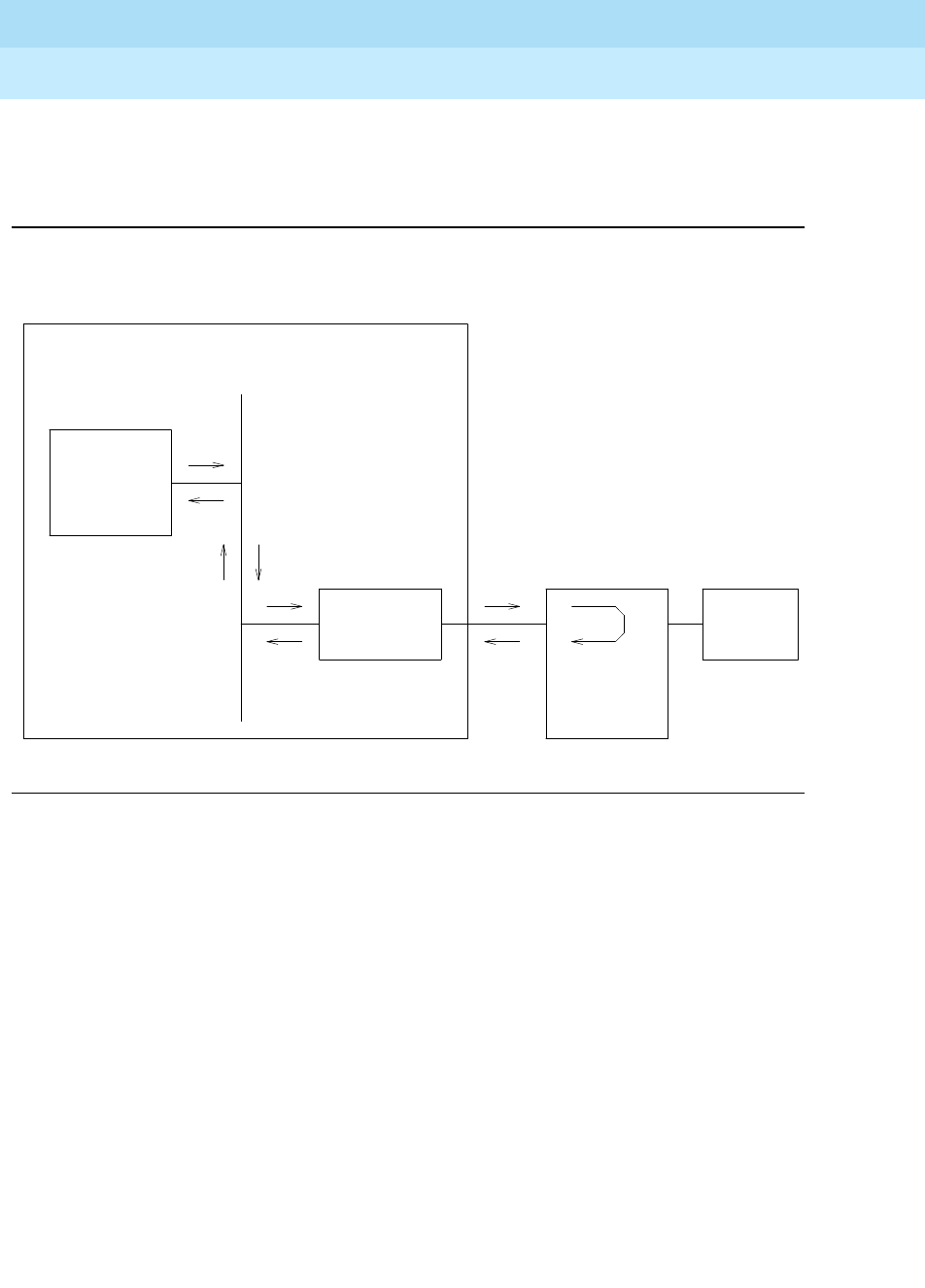
DEFINITY Enterprise Communications Server Release 6
Maintenance for R6r Volumes 1 & 2
555-230-126 Issue 2
January 1998
Maintenance Object Repair Procedures
Page 9-981PDMODULE (Processor Data Module) TDMODULE (Trunk Data Module)
9
For this test to run, the ‘‘Remote Loop-Around Test’’ field on the Data Module
administration form must be set to ‘‘y,’’ indicating that the data module endpoint
supports the test.
Figure 9-58. Internal Looparound Test
A signaling message is sent through the digital port circuit pack to the data
module, requesting it to enter loop-around mode. A test pattern is then sent from
the TN771 Maintenance/Test circuit pack, over the path illustrated above, and
back to the TN771 where it is checked for consistency.
The test aborts if any of the following local PBX resources are not available: a
digital port on the TN771 (there are two such digital ports, but only one may be
used at a time), two TDM time slots and an idle digital port connected to the data
module.
Digital Line
Circuit Pack Data
Equipment
Data Module
(MPDM, DA,
MTDM)
G3r PBX
TN771
Maintenance/
Test Circuit
Pack
TDM Bus

DEFINITY Enterprise Communications Server Release 6
Maintenance for R6r Volumes 1 & 2
555-230-126 Issue 2
January 1998
Maintenance Object Repair Procedures
Page 9-982PDMODULE (Processor Data Module) TDMODULE (Trunk Data Module)
9
Table 9-348. TEST #175 Data Module Internal LoopAround Test
Error
Code Test
Result Description/ Recommendation
1000 ABORT System resources required to run this test are not available. The port may be in
use on a valid call. Use status data-module to determine when the port is
available for testing.
1. Retry the command at 1-minute intervals a maximum of 5 times.
1005 ABORT Loop around testing is not enabled on the data module administration form.
1. Set ‘‘Loop-Around Test’’ field to ‘‘y’’ on the data module administration
form.
1042 ABORT The port under test is a TTI port and thus has only default translations and no
assigned extension. The test requires an extension assigned to the port being
tested.
1. If there is a need to execute the test on this particular port, then you must
fully administer the port so that is has an assigned extension.
1180 ABORT A Maintenance/Test Circuit pack digital port is not available to carry out the
test.
1. Check to see if the Maintenance/Test digital ports are present (use the list
config board command and look for ports 02 and 03).
2. If the digital ports (02 and 03) on the M/T-BD are not present, refer to the
"M/T-DIG (Maintenance/Test Digital Port)" section.
3. If the digital ports are present, try the command again at 1-minute intervals
up to 5 times.
1181 ABORT No time-slots available to connect digital ports for the test.
1. Try the command again at 1-minute intervals up to 5 times.
1182 ABORT Internal system error. Failed to connect the digital ports with time-slots.
1. Retry the command at 1-minute intervals a maximum of 5 times.
Continued on next page

DEFINITY Enterprise Communications Server Release 6
Maintenance for R6r Volumes 1 & 2
555-230-126 Issue 2
January 1998
Maintenance Object Repair Procedures
Page 9-983PDMODULE (Processor Data Module) TDMODULE (Trunk Data Module)
9
1340 ABORT No Maintenance/Test digital port is currently available to perform this test.
1. Use list config to determine whether any Maintenance/Test digital ports
(ports 02 and 03 on the Maintenance/Test circuit pack) are present in the
system. Because at least one Maintenance/Test circuit pack must always
be present in the PPN of any G3r system, there should be at least two such
ports present. If the ports are present, proceed to step 2. Otherwise,
determine why no ports appear in the list config display. Refer to
"M/T-DIG (Maintenance/Test Digital Port)" and M/T-BD maintenance
documentation.
2. Look for M/T-DIG errors in the Error Log. If present, refer to M/T-DIG
maintenance documentation.
3. If the ports are present and no errors are logged against them, retry the
command at 1-minute intervals a maximum of 5 times.
4. If the test continues to abort, replace the Maintenance/Test circuit pack.
1392 ABORT This port is currently a TTI port and the test will not execute on it.
1. Verify that the port is a TTI port using either the display port command (the
display shows that the port is a TTI port) or the list config command (the
display shows a "t" for the port).
2. If either list config or display port indicate that the port is not a TTI port,
escalate the problem. If both commands indicate that the port is a TTI port,
the abort is correct for the test, and no action is necessary.
2005 ABORT The handshake between the Maintenance/Test digital port and the Data
Module failed.
1. Look for M/T-DIG errors in the Error Log. If present, refer to "M/T-DIG
(Maintenance/Test Digital Port)" section.
2. If test still aborts on retry, check physical connection of data module under
test. Make sure the switches are on NORM, OFF (between REM_LP and
LOC_LP), 9600, and ASYN.
3. If the test still aborts, replace the Data Module.
2312 ABORT The Looparound Test did not complete, failed to receive loop-back data.
1. Check for M/T-DIG error in the Error Log. If present, refer to M/T-DIG
section.
2. Retry the test, if still aborts, replace the Data Module.
3. If the test aborts again, replace the Digital Line Circuit Pack.
Table 9-348. TEST #175 Data Module Internal LoopAround Test — Continued
Error
Code Test
Result Description/ Recommendation
Continued on next page

DEFINITY Enterprise Communications Server Release 6
Maintenance for R6r Volumes 1 & 2
555-230-126 Issue 2
January 1998
Maintenance Object Repair Procedures
Page 9-984PDMODULE (Processor Data Module) TDMODULE (Trunk Data Module)
9
2313 ABORT The Maintenance/Test digital port allocated for this test did not respond to
downlinked message.
1. Look for M/T-DIG errors in the Error Log. If present, refer to "M/T-DIG
(Maintenance/Test Digital Port)" section.
2. Retry the command at 1-minute intervals a maximum of 5 times.
3. If the test continues to abort, replace the MTB.
2314 ABORT Data Module did not respond to downlinked message.
1. Check the wiring of the Data Module under test.
2. Verify that the Data Module is powered (power LED on).
3. Make sure the switches are on NORM, OFF (between REM_LP and LOC_
LP), 9600, and ASYN.
4. If the test still aborts, replace the Date Module.
5. If the same abort code appears, replace the Digital Line Circuit Pack which
is connect to the Data Module.
2500 ABORT Internal system error
1. Retry the command at 1-minute intervals a maximum of 5 times.
FAIL Data received from remote loop back does not match data sent.
1. Check for faulty wiring.
2. Replace the data module and repeat the test.
3. If the test fails, replace the Digital Line circuit pack associated with the
data module and repeat the test.
PASS Data Module Looparound Test passed.
Table 9-348. TEST #175 Data Module Internal LoopAround Test — Continued
Error
Code Test
Result Description/ Recommendation
Continued on next page

DEFINITY Enterprise Communications Server Release 6
Maintenance for R6r Volumes 1 & 2
555-230-126 Issue 2
January 1998
Maintenance Object Repair Procedures
Page 9-985PE-BCHL (PRI Endpoint Port)
9
PE-BCHL (PRI Endpoint Port)
A PRI Endpoint provides ISDN-PRI (Primary Rate Interface) connections
application equipment or terminal adapters that terminate ISDN-PRI. The
equipment or terminal adapters are connected to the switch via the TN464C/D
UDS1 interface circuit pack. This maintenance object monitors the PRI endpoint
port hardware on the UDS1 circuit pack by logging hardware errors, running
tests for port initialization, and running periodic and scheduled maintenance and
demand tests.
Wideband Switching
Wideband switching supports end-to-end connectivity between customer
endpoints at data rates from 128 to 1536 kbps over T1 facilities and to 1984 kbps
over E1 facilities. DEFINITY switching capabilities are extended to support
wideband calls comprised of multiple DS0s that are switched end-to-end as a
single entity.
Wideband switching is designed for ISDN application equipment such as ISDN
video codecs, but can also interface to non-ISDN application equipment by
using PRI terminal adapters. In the same sense that a DEFINITY data module
acts as a DCP or BRI terminal adapter between endpoint data such as V.35 and
dialing interfaces such as RS-366 and a DCP interface, a PRI terminal adapter
acts as a wideband terminal adapter between endpoint data and dialing
interfaces and DEFINITY’s line-side ISDN PRI interface. Wideband switching
introduces PRI endpoints on DEFINITY line-side interfaces.
A PRI endpoint has a unique extension number and consists of one or more
contiguous B-channels on a line-side T1 or E1 ISDN PRI facility. Endpoints initiate
and receive calls via ISDN SETUP messages indicating the data rate and
specific B-Channels to be used, and communicate all other call status
information via standard ISDN messages. Any DEFINITY ISDN signaling set such
as Lucent, CCITT, or ECMA may be used for a line-side ISDN PRI facility.
Multiple PRI endpoints on one line-side facility are separate and distinct within
the facility. Non-overlapping contiguous sets of B-Channels are associated with
1. For additional repair information, see also UDS1-BD and
Troubleshooting Wideband
Problems
in Chapter 5, ‘‘Responding to Alarms and Errors’’.
MO Name (in
Alarm Log) Alarm
Level Initial Command to
Run1Full Name of MO
PE-BCHL1MINOR test port
UUCSSpp
l PRI Endpoint Port
PE-BCHL WARNING test port
UUCSSpp
sh PRI Endpoint Port

DEFINITY Enterprise Communications Server Release 6
Maintenance for R6r Volumes 1 & 2
555-230-126 Issue 2
January 1998
Maintenance Object Repair Procedures
Page 9-986PE-BCHL (PRI Endpoint Port)
9
each PRI endpoint, and the endpoint equipment is expected to initiate calls
within these boundaries. The endpoint application equipment must:
■Use standard ISDN-PRI signaling
■Adhere to the administered PRI endpoint boundaries when initiating calls
■Handle incoming calls appropriately, based on the originating PRI
endpoint
Signaling and B-Channel States
PRI ports use a separate channel called the D-channel for call control and
signaling messages. This is called out-of-band signaling. The D-channel
associated with the set of B-channels is an ISDN-PRI signaling link port
(ISDN-LNK). The signaling protocol used on the ISDN-PRI signaling link port
D-channel is defined by one of the four selectable ISDN-PRI Specifications:
Lucent, CCITT, ECMA, and ANSI.
The ISDN-PRI Specification defines the possible service states for a B-channel.
The service state is negotiated with the far-end terminal adapter, changes over
time, and can have a far-end and near-end components. The service state is
initialized to Out-Of-Service/Far-End, and an attempt is made to negotiate it to
In-Service. The service state of a particular PRI endpoint port B-channel can be
displayed with the status pri-endpoint extension command.
If a call is present, the Specification defines the permissible call statES as well.
There are tests in the short and long test sequences for the PRI endpoint port
designed to audit these states and ensure agreement between both ends of the
PRI wideband connection.
Alarming Based on Service States
A PRI endpoint port B-channel logs a warning alarm when it is placed in a
Maintenance/Far-End or Out-Of-Service/Far-End state. While in such a state, the
port is unusable for calls to the terminal adapter. However, the user can still use
the other remaining ports in the PRI endpoint to make calls to and from the
terminal adapter. When a warning alarm is raised, use the status pri-endpoint
extension command to determine the exact state of the port. Other alarms can be
diagnosed by using the short and long test sequences. Note that a PRI endpoint
port B-channel can be placed in a far-end service state by direct action by the
far-end terminal adapter or by inaction of the far-end terminal adapter. For
example, if it does not respond to a Remote Layer 3 Query (see Test #260 for
ISDN-LNK) the associated PRI endpoint port B-channels will be placed in the
Maintenance/Far-End service state.
A PRI endpoint port is a port on a UDS1 interface circuit pack and thus depends
on the health of the circuit pack for proper operation (see the following figure). A
problem on the associated ISDN-PRI Signaling Link Port D-channel (ISDN-LNK)
can also affect the PRI endpoint. The ISDN-PRI Signaling Link Port in turn
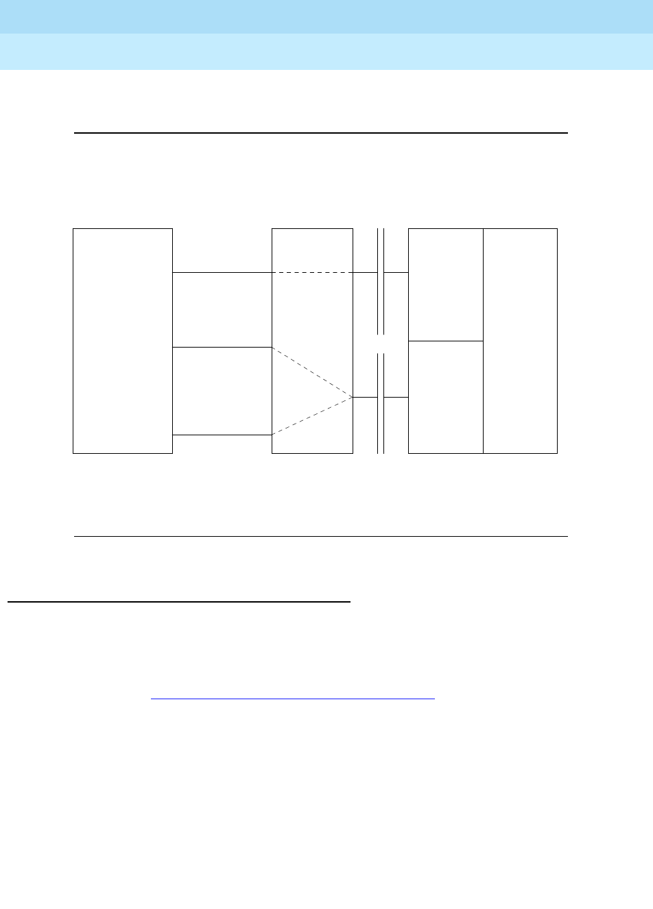
DEFINITY Enterprise Communications Server Release 6
Maintenance for R6r Volumes 1 & 2
555-230-126 Issue 2
January 1998
Maintenance Object Repair Procedures
Page 9-987PE-BCHL (PRI Endpoint Port)
9
depends on the SYS-LINK (System Link) to the Packet Interface. Keep this
hierarchy of dependencies in mind when diagnosing problems.
Figure 9-59. PRI Endpoint Port Interactions
PRI Endpoint Port Service States
The status pri-endpoint extension command displays the following possible
service states for PRI endpoint ports. The table that follows gives recommended
procedures for each state. The figure following that shows typical progressions
from one service state to another. Refer also to
Troubleshooting Wideband
Problems
in Chapter 5, ‘‘Responding to Alarms and Errors’’ for a layered
approach to addressing PRI endpoint problems.
■In-Service (INS)
The B-channel is in its normal operating state.
■Out-of-Service/Far-End (OOS/FE)
A B-Channel is initialized to this state when first administered. The switch
then sends messages to the far-end terminal adapter to negotiate the
B-channel into service. If the far-end terminal adapter does not respond to
the messages within a certain time period, the port remains out of service,
MSSNET
Circuit
Pack
(UN332)
Packet
Bus
TDM
Bus
PKTINT
Circuit
Pack
(TN1655)
Processor
(UN331)
UDS1
Interface
Circuit
Pack
(TN464C)
Terminal
Adapter
.
.
.
.
.
.
.
.
.
.
.
.
.
.
.
.
.
.
.
.
.
.
.
.
.
.
.
.
Signaling
(Port 24)
ISDN-LNK
PE-BCHL
PE-BCHL
Data
Data
(Port 1)
(Port 23)

DEFINITY Enterprise Communications Server Release 6
Maintenance for R6r Volumes 1 & 2
555-230-126 Issue 2
January 1998
Maintenance Object Repair Procedures
Page 9-988PE-BCHL (PRI Endpoint Port)
9
and maintenance will periodically resend the messages. The port is
unusable for incoming and outgoing calls, although other ports in the PRI
endpoint can still be used.
■Out-of-Service/Near-End (OOS/NE)
This is the state of the port when a hardware failure exists on the signaling
link, the NPE Crosstalk Test fails, or when the port is busied out by
command. In this state, the port is unusable for calls coming in to the
switch or going out to the terminal adapter, although other ports in the PRI
endpoint can still be used for incoming and outgoing calls. No messages
are sent to the far-end terminal adapter until the signaling link comes back
into service or the port is released by command.
■Maintenance/Far-End (MTC/FE)
This state is reached when the far-end terminal adapter does not respond
to messages sent over the signaling link for a particular port within a
certain amount of time. This state is different from OOS/FE since the
signaling link must have initially been up and the B-Channels in service.
The switch will periodically send messages to the far-end terminal adapter
to try to negotiate the port (B-channel) into service. The port is unusable
for outgoing calls to the terminal adapter but will service incoming call
requests from the far-end. Other ports of the PRI endpoint can still to place
outgoing calls to the terminal adapter. Transitions into MTC/FE do not drop
stable calls. If the service state changes from in-service to MTC/FE, stable
calls are unaffected.
■Maintenance/Near-End (MTC/NE)
The signaling link (SYS-LINK) is busied out by the busyout, test port l or
test pri-endpoint l commands. Transitions into MTC/NE do not drop
stable calls. The busyout link lnk-no command does not drop stable
wideband calls. In this state, the B-Channel is not usable for new incoming
calls to the switch or new outgoing calls to the terminal adapter.
■Pending States (PEND)
If the near-end is expecting a timed response from the far-end for a
request to change the service state of a port, a
pending
state is in effect.
For example, if the port is out-of-service/far-end and an in-service
message was sent to the far-end, then the service state of the port is
OOS/FE-PEND/INS meaning out-of-service/far-end, pending/in-service.
The service state will reflect this pending state until the far-end responds
or the timer expires.

DEFINITY Enterprise Communications Server Release 6
Maintenance for R6r Volumes 1 & 2
555-230-126 Issue 2
January 1998
Maintenance Object Repair Procedures
Page 9-989PE-BCHL (PRI Endpoint Port)
9
Table 9-349. PRI Endpoint Port Service States
Service
State1Alarm Possible Cause Possible Solution
OOS/NE
Warning Port has been busied out
by command. Enter release pri-endpoint extension.
Minor NPE Crosstalk Test (#6)
failed. Replace UDS1 circuit pack.
UDS1 circuit pack lost its
signal. Is the UDS1 circuit pack removed? Is the
UDS1 cable disconnected? Is the far-end
terminal restarting or experiencing
problems? Check circuit pack using
procedures UDS1-BD.
OOS/FE
Warning Far-end problems or
incompatibility Check administration and status of the
corresponding port on the terminal
adapter.
Warning The far-end port is busied
out. Check the status of the far-end terminal
adapter.
OOS/FE
PINS
Service message was
sent and the switch is
waiting up to 2 min. for a
reply from the far-end
terminal adapter.
Wait 2 min. and check service state after
the PINS state has cleared.
MTC/NE System link demand
busied out Check link status. Release with release
link link#.
MTC/FE Warning Signaling channel has
been down for over 90
sec.
Consult ISDN-SGRP, ISDN-LNK and/or
SYS-LINK. Far-end terminal adapter may
currently be restarting.
Warning Repeated failure of far
end to respond to
messages.
Maintenance software will periodically try
to resend messages. You can speed the
process with test port UUCSSpp (Test
#256).
Warning The far-end port is being
tested. Check status of the far-end terminal
adapter.
MTC/FE
PINS Service message was
sent and the switch is
waiting up to 2 min. for a
reply from the far-end
terminal adapter.
Wait 2 min. and check service state after
the PINS state has cleared.
Continued on next page

DEFINITY Enterprise Communications Server Release 6
Maintenance for R6r Volumes 1 & 2
555-230-126 Issue 2
January 1998
Maintenance Object Repair Procedures
Page 9-990PE-BCHL (PRI Endpoint Port)
9
1. OOS Out of Service
MTC Maintenance
FE Far-end
NE Near-end
PINS Pending in-service
INS Normal operating state.
ISDN wideband calls
being completed.
Table 9-349. PRI Endpoint Port Service States — Continued
Service
State1Alarm Possible Cause Possible Solution
Continued on next page
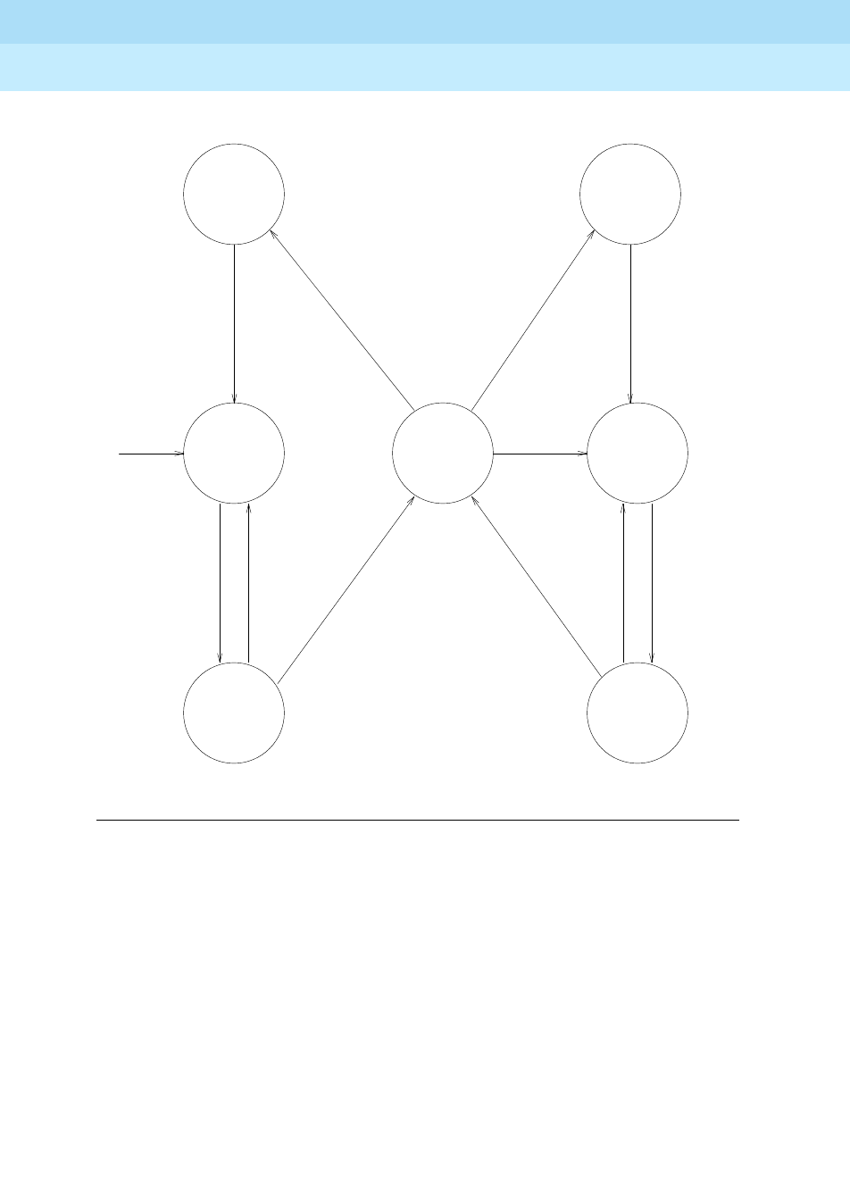
DEFINITY Enterprise Communications Server Release 6
Maintenance for R6r Volumes 1 & 2
555-230-126 Issue 2
January 1998
Maintenance Object Repair Procedures
Page 9-991PE-BCHL (PRI Endpoint Port)
9
Figure 9-60. Common Progressions in PRI Endpoint Service States
CRAFT BUSYOUT OF
SIGNALING LINK
"BUSYOUT LINK LINK-NO",
OR TRANSIENT STATE FOR
CRAFT-DEMANDED LONG
TEST OF THE PORT.
CRAFT RELEASE
OF SIGNALING LINK
IF D-CHANNEL
CONTROLLING THE
B-CHANNEL IS UP,
SEND A MESSAGE
REQUESTING
TRANSITION
TO IN-SERVICE
D-CHANNEL HAS BEEN
DOWN FOR AT LEAST
90 SECONDS.
FAILED TO
RECEIVE REPLY
FROM FAR END.
MTCE WILL
PERIODICALLY
TRY TO RESEND
THE MESSAGE
RECEIVED
ACKNOWLEDGEMENT
FROM THE FAR END
RECEIVED
ACKNOWLEDGEMENT
FROM THE FAR END
FAILED TO
RECEIVE REPLY
FROM FAR END.
MTCE WILL
PERIODICALLY
TRY TO RESEND
THE MESSAGE
ADMINISTER
B-CHANNEL AS
MEMBER OF A
PRI ENDPOINT
OUT-OF-
SERVICE
NEAR END
OUT-OF-
SERVICE
FAR END
OUT-OF-
SERVICE
FAR END
PENDING
IN-SERVICE
IN-SERVICE
MAINTENANCE
NEAR END
MAINTENANCE
FAR END
MAINTENANCE
FAR END
PENDING
IN-SERVICE
CRAFT RELEASE OF
A B-CHANNEL OR
NEAR-END LINK
PROBLEM (PI-LINK OR
SYS-LINK) CLEARS UP
IF D-CHANNEL
CONTROLLING THE
B-CHANNEL IS UP,
SEND A MESSAGE
REQUESTING
TRANSITION
TO IN-SERVICE
CRAFT BUSYOUT OF B-CHANNEL
BUSYOUT PORT/PRI-ENDPOINT,
LINK PROBLEM AT NEAR END
(PI-LINK OR SYS-LINK),
DS1 BOARD NOT INSERTED,
OR DS1 BOARD FAILURE.

DEFINITY Enterprise Communications Server Release 6
Maintenance for R6r Volumes 1 & 2
555-230-126 Issue 2
January 1998
Maintenance Object Repair Procedures
Page 9-992PE-BCHL (PRI Endpoint Port)
9
Error Log Entries and Test to Clear Values
Notes:
a. These error types indicate a disagreement between this switch and the
terminal adapter at the other end of the connection with regard to the
ISDN
call
state of the PRI endpoint port. This switch will automatically try to
recover by clearing the call (the call will be torn down). Use the status
pri-endpoint extension command to determine the state of the port.
When running the Short Test Sequence of tests, pay close attention to the
results of the Call State Audit Test (#257).
b. This is a software audit error that does not indicate any hardware
malfunction. Run the Short Test Sequence and investigate associated
errors.
1. Run the Short Test Sequence first. If all tests pass, run the Long Test Sequence. Refer to the appropriate test
description and follow the recommended procedures
Table 9-350. PRI endpoint port Error Log Entries
Error
Type Aux
Data Associated Test Alarm
Level On/Off
Board Test to Clear Value
010 Any Any Any test port
UUCSSpp
sh r 1
1(a) Any None test port
UUCSSpp
sh r 1
15(b) Any Audit and Update Test
(#36)
18(c) 0 busyout pri-endpoint
extension
busyout port
UUCSSpp
release pri-endpoint
extension
release port
UUCSSpp
129(d) None WARNING OFF test port
UUCSSpp
sh r 1
130(e) None WARNING ON test port
UUCSSpp
sh
257(f) Any None test port
UUCSSpp
sh r 1
513(g) Any None WARNING OFF test port
UUCSSpp
sh r 1
769(f) Any None test port
UUCSSpp
sh r 1
1281(h) Any Conference Circuit Test (#7 MINOR ON test port
UUCSSpp
l r 4
1537(i) Any NPE Crosstalk Test (#6) MINOR ON test port
UUCSSpp
l r 3
1793(j) Any None test port
UUCSSpp
sh r 1
3073(k) Any Service State Audit (#256) test port
UUCSSpp
sh r 2
3585(l) Any None None

DEFINITY Enterprise Communications Server Release 6
Maintenance for R6r Volumes 1 & 2
555-230-126 Issue 2
January 1998
Maintenance Object Repair Procedures
Page 9-993PE-BCHL (PRI Endpoint Port)
9
c. The PRI endpoint port has been busied out by busyout pri-endpoint
extension or busyout port UUCSSpp. No wideband calls can be made to
this port, although wideband calls can still be made to other ports within
this PRI endpoint if they are in service.
d. The far-end terminal adapter changed its ISDN
service
state to either
out-of-service or maintenance. This may be a temporary condition due to
testing of this port by the far-end terminal adapter
or
a hardware problem
with the port. Outgoing calls to the terminal adapter will not be allowed
over the port, although calls can still be made to other ports that are in
service within the same PRI endpoint. To investigate the status of the port,
enter status pri-endpoint extension.
e. This error type indicates that the circuit pack has been removed or has
been insane for more than 11 minutes. To clear the error, reinsert or
replace the circuit pack.
f. These error types indicate a disagreement between this switch and the
terminal adapter at the other end of the connection with regard to the
ISDN service state of the PRI endpoint port. The switch will automatically
try to recover by performing a service state audit. Use status
pri-endpoint extension to determine the state of the port.
When running the Short Test Sequence, pay close attention to the results
of the Service State Audit Test (#256).
g. This port is not recognized by the far-end terminal adapter. Investigate the
PRI endpoint administration for both the switch and the terminal adapter,
and make sure they agree.
h. The Conference Circuit Test (#7) failed on this port. See Test #7 for repair
procedures.
i. The NPE Crosstalk Test (#6) failed on this port. See Test #6 for repair
procedures.
j. This error indicates a failure of the UDS1 Interface circuit pack. The results
of the Signaling Link State Check Test (#255 in the short sequence) are
important.
k. Two Service State Audit attempts have failed (see Test #256). The port will
not be usable for any outgoing calls to the terminal adapter until the test
passes and the port state is changed to in-service. Incoming calls from
the terminal adapter
will
be accepted over this port, and other ports in the
PRI endpoint can still be used for both incoming and outgoing calls to and
from the terminal adapter.
l. Error Type 3585 appears when the switch receives an ISDN RESTART
message for an ISDN port that is not idle. Since calls are not typically
cleared with the RESTART message, this error type may be associated
with a dropped call report from a user.

DEFINITY Enterprise Communications Server Release 6
Maintenance for R6r Volumes 1 & 2
555-230-126 Issue 2
January 1998
Maintenance Object Repair Procedures
Page 9-994PE-BCHL (PRI Endpoint Port)
9
The following Aux Data values for Error Type 3585 represent the port’s
ISDN call state at the time the unexpected RESTART request was
received from the terminal adapter. This information can be useful if
dropped calls are being reported by users of the PRI endpoint. Aux values
that do not appear below can be ignored.
System Technician-Demanded Tests:
Descriptions and Error Codes
Always investigate tests in the order presented in the table below when
inspecting errors in the system. By clearing error codes associated with the
NPE
Crosstalk Test
, for example, you may also clear errors generated from other tests
in the testing sequence.
PE-BCHL Error 3585 Aux Data
Aux
Data Meaning
10 A call in a stable, talking state (the
active
state) was cleared unexpectedly by the far-end
terminal adapter with an ISDN RESTART message.
4
7
8
260
263
A call that has not reached the active state, but has at least reached a ringing state, was
cleared unexpectedly by the far-end terminal adapter with an ISDN RESTART message.
1
3
6
265
A call that has not yet reached a ringing state was cleared unexpectedly by the far-end
terminal adapter with an ISDN RESTART message.
11
12
19
531
267
268
A call that was already in the process of clearing has been cleared by the far-end
terminal adapter with an ISDN RESTART message. If this condition occurs frequently, it
may mean that the far-end terminal adapter is attempting to clear ports that it thinks are in
a ‘‘hung’’ state. The RESTART message puts the port in an idle condition.
Order of Investigation Short Test
Sequence Long Test
Sequence D/ND1
NPE Crosstalk Test (#6) X ND
Conference Circuit Test (#7) X ND
Audit and Update Test (#36) X X ND
Signaling Link State Check Test (#255) X X ND
Service State Audit Test (#256) X X ND
Call State Audit Test (#257) X X ND

DEFINITY Enterprise Communications Server Release 6
Maintenance for R6r Volumes 1 & 2
555-230-126 Issue 2
January 1998
Maintenance Object Repair Procedures
Page 9-995PE-BCHL (PRI Endpoint Port)
9
NPE Crosstalk Test (#6)
The NPE Crosstalk Test verifies that this port’s NPE channel talks on the selected
time slot and never crosses over to time slots reserved for other connections. If
the NPE is not working correctly, one-way and noisy connections may be
observed. This test is usually part of a port’s long test sequence and takes about
20 to 30 seconds to complete.
1. D = Destructive; ND = Nondestructive
Table 9-351. TEST #6 NPE Crosstalk Test
Error
Code Test
Result Description/ Recommendation
ABORT Could not allocate the necessary system resources to run this test.
1. Retry the command at 1-minute intervals for a maximum of 5 times.
1000 ABORT System resources required to run this test are not available. The port may be in
use on a valid call. Use status pri-endpoint extension commands to
determine when the port is available for testing.
1. Retry the command at 1-minute intervals for a maximum of 5 times.
1001 ABORT Could not allocate the necessary system resources to run this test.
1. Retry the command at 1-minute intervals for a maximum of 5 times.
1002 ABORT The system could not allocate time slots for the test. The system may be under
heavy traffic conditions or it may have time slots out-of-service due to
TDM-Bus errors. Use the status health command to determine if the system is
experiencing heavy traffic. Investigate and resolve any errors against
TDM-BUS.
1. If system has no TDM-Bus errors and is not handling heavy traffic, repeat
test at 1-minute intervals for a maximum of 5 times.
1003 ABORT The system could not allocate a tone receiver for the test. The system may be
oversized for the number of tone detectors present or some tone detectors
may be out-of-service. The list measurements tone-receiver command will
display information on the system’s tone receiver.
1. Resolve any errors against TTR-LEV.
2. Resolve any errors against TONE-PT.
3. If neither of the above exists, retry the test at 1-minute intervals for a
maximum of 5 times.
1004 ABORT The port has been seized by a user for a valid call. Use status pri-endpoint
extension to determine when the port is available for testing.
1. Retry the command at 1-minute intervals for a maximum of 5 times.
Continued on next page

DEFINITY Enterprise Communications Server Release 6
Maintenance for R6r Volumes 1 & 2
555-230-126 Issue 2
January 1998
Maintenance Object Repair Procedures
Page 9-996PE-BCHL (PRI Endpoint Port)
9
Conference Circuit Test (#7)
The Conference Circuit test verifies that the NPE channel for the port being
tested can correctly perform the conferencing function. The NPE is instructed to
listen to several different tones and conference the tones together. The resulting
signal is measured by a tone detector port. If the level of the tone is within a
certain range, the test passes.
1117 ABORT A service state audit message is outstanding.
1. Wait 2 minutes and then try again.
2000 ABORT Response to the test request was not received within the allowable time
period.
1. Retry the command at 1-minute intervals for a maximum of 5 times.
2020 ABORT The test did not run due to an existing error on the specific port or a more
general circuit pack error.
1. Examine the Error Log for existing errors against this port or the circuit
pack and follow recommended procedures.
2100 ABORT Could not allocate the necessary system resources to run this test.
1. Retry the command at 1-minute intervals for a maximum of 5 times.
Any FAIL The NPE of the tested port was found to be transmitting in error. This will cause
noisy and unreliable connections. The PE-BCHL is moved to
out-of-service/near-end state.
1. Replace the circuit pack.
PASS The port is able to communicate over the TDM Bus.
Table 9-352. TEST #7 Conference Circuit Test
Error
Code Test
Result Description/ Recommendation
ABORT Could not allocate the necessary system resources to run this test.
1. Retry the command at 1-minute intervals for a maximum of 5 times.
Continued on next page
Table 9-351. TEST #6 NPE Crosstalk Test — Continued
Error
Code Test
Result Description/ Recommendation
Continued on next page

DEFINITY Enterprise Communications Server Release 6
Maintenance for R6r Volumes 1 & 2
555-230-126 Issue 2
January 1998
Maintenance Object Repair Procedures
Page 9-997PE-BCHL (PRI Endpoint Port)
9
Audit and Update Test (#36)
This test sends port level translation data from switch processor to the UDS1
interface circuit pack to assure that the port’s translation is correct. The port audit
operation verifies the consistency of the current state of port kept in the UDS1
interface circuit pack and in the switch software.
1000 ABORT System resources required to run this test are not available. The port may be in
use on a valid call. Use status pri-endpoint extension commands to determine
when the port is available for testing.
1004 ABORT The port has been seized by a user for a valid call. Use status pri-endpoint
extension to determine when the port is available for testing.
1. Retry the command at 1-minute intervals for a maximum of 5 times.
1020 ABORT The test did not run due to an already existing error on the specific port or a
more general circuit pack error.
1. Examine Error Log for existing errors against this port or the circuit pack
and attempt to diagnose the already existing error.
2000 ABORT Response to the test request was not received within the allowable time period.
2100 ABORT Could not allocate the necessary system resources to run this test.
1. Retry the command at 1-minute intervals for a maximum of 5 times.
Any FAIL The NPE of the tested port did not conference the tones correctly. This will
cause noisy and unreliable connections.
1. Replace the circuit pack. Even though wideband calls do not use the
conferencing feature on the NPE, this failure indicates problems with the
circuit pack hardware.
PASS The port can correctly conference multiple connections. User-reported troubles
on this port should be investigated using other port tests and examining
terminal adapter or external wiring.
Table 9-352. TEST #7 Conference Circuit Test — Continued
Error
Code Test
Result Description/ Recommendation
Continued on next page

DEFINITY Enterprise Communications Server Release 6
Maintenance for R6r Volumes 1 & 2
555-230-126 Issue 2
January 1998
Maintenance Object Repair Procedures
Page 9-998PE-BCHL (PRI Endpoint Port)
9
Signaling Link State Check Test (#255)
As noted in the preceding general description, operation of the PRI endpoint port
depends on the health of the UDS1 interface circuit pack and System Link for
proper operation. This test checks the status of those critical elements.
Table 9-353. TEST #36 Audit and Update Test
Error
Code Test
Result Description/ Recommendation
ABORT Internal system error
2000 ABORT Response to the test was not received within the allowable time period.
2100 ABORT Could not allocate the necessary system resources to run this test.
FAIL Test failed due to internal system error.
1. Retry the command at 1-minute intervals for a maximum of 5 times.
PASS Port translation has been updated successfully. The current port states kept in
the UDS1 interface circuit pack and switch software are consistent. If the port is
busied out, the test will not run, but will return PASS. To verify that the port is
in-service:
1. Enter status pri-endpoint extension to verify that the port is in-service. If
the port is in-service, no further action is necessary. If the port is
out-of-service, continue to Step 2.
2. Enter release pri-endpoint extension or release port UUCSSpp command
to put port back into in-service.
3. Retry the test command.
Continued on next page
Table 9-354. TEST #255 Signaling Link State Check Test
Error
Code Test
Result Description/ Recommendation
ABORT Internal system error
1. Retry the command at 1-minute intervals for a maximum of 5 times.
Continued on next page

DEFINITY Enterprise Communications Server Release 6
Maintenance for R6r Volumes 1 & 2
555-230-126 Issue 2
January 1998
Maintenance Object Repair Procedures
Page 9-999PE-BCHL (PRI Endpoint Port)
9
Service State Audit (#256)
As noted in the general description for PRI endpoint port, these ports may be in
one of several service states as defined by the ISDN-PRI Specification. This test
performs a service state audit with the far-end terminal adapter to ensure both
sides agree on the service state.
A PASS for this test simply means that an audit message was successfully
composed and sent out to the far-end terminal adapter. The ISDN Specification
allows up to 2 minutes for a reply. If no reply is received within that 2 minute
window, this switch will automatically try once again. If that attempt fails, an error
will be logged (Error Type 3073) and the switch will then attempt recovery by
automatically retrying approximately every 15 minutes. If the port was initially in
the INS (in-service) state, it will now be placed in the MTC/FE (maintenance state,
far-end problem) state. Until a Service State Audit attempt is successful, no
outgoing calls will be placed over this port, but incoming calls will be accepted.
The service state of this port does not affect the service state of other ports in the
PRI endpoint. If an incoming call that uses this port is presented while in such a
state, a Service State Audit attempt will immediately be attempted (that is, the
switch will not wait for the 15-minute cycle, but will instead try to recover
immediately). To investigate the status of this PRI endpoint port, issue the status
pri-endpoint extension command.
1700 ABORT Rollabout video abort. The PRI terminal adapter associated with this PRI
endpoint extension is detached from the circuit pack. This is a normal abort
when the rollabout video feature is enabled.
1. Either reconnect the disconnected PRI terminal adapter or disable the
rollabout video feature on this circuit pack. To do the latter, enter change
ds1 UUCSS and set the field labeled ‘‘Alarm when PRI Endpoint
Detached?’’ to ‘‘y.’’
4 FAIL There is a problem with the Signaling Channel and/or with the System Link.
1. Consult procedures for the ISDN-GRP and SYS-LINK. See also ISDN-LNK
for useful information.
8 FAIL There is a problem with the UDS1 interface circuit pack.
1. Consult procedures for UDS1-BD.
PASS The signaling link hardware is OK.
Table 9-354. TEST #255 Signaling Link State Check Test — Continued
Error
Code Test
Result Description/ Recommendation
Continued on next page

DEFINITY Enterprise Communications Server Release 6
Maintenance for R6r Volumes 1 & 2
555-230-126 Issue 2
January 1998
Maintenance Object Repair Procedures
Page 9-1000PE-BCHL (PRI Endpoint Port)
9
Call State Audit Test (#257)
If a call is active on the port, the switches on both sides of the connection should
agree on the ISDN state of the call as defined in the ISDN Protocol Specification.
This test audits internal call state data by querying the far-end terminal adapter
as to the ISDN state of the call. It can be helpful when trying to clear a hung call.
If the internal call state data on the near-end switch is different than that of the
far-end terminal adapter, the call will be torn down.
Table 9-355. TEST #256 Service State Audit Test
Error
Code Test
Result Description/ Recommendation
1113 ABORT The signaling link has failed, so the system cannot send any messages on
behalf of this port.
1. Check the results of Test #255 (Signaling Link State Check).
1117 ABORT A service state audit message is outstanding.
1. Wait 2 minutes and then try again.
1700 ABORT Rollabout video abort. The PRI terminal adapter associated with this PRI
endpoint extension is detached from the circuit pack. This is a normal abort
when the rollabout video feature is enabled.
1. Either reconnect the disconnected PRI terminal adapter or disable the
rollabout video feature on this circuit pack. To do the latter, enter change
ds1 UUCSS and set the field labeled ‘‘Alarm when PRI Endpoint
Detached?’’ to ‘‘y.’’
2100 ABORT Could not allocate the necessary system resources to run this test.
1. Retry the command at 1-minute intervals for a maximum of 5 times.
FAIL Internal system error
1. Retry the command at 1-minute intervals for a maximum of 5 times.
PASS Wait 4 minutes and then check the Error Log for any new errors of type 3073. If
there are none, then both sides of the ISDN connection agree on the service
state; the negotiation succeeded. If there is a new 3073 error, then the
negotiation failed (the far-end terminal adapter twice failed to respond within the
mandatory 2-minute window). This switch will automatically retry approximately
every 15 minutes. If the port was initially in the INS (in-service) state, it will now
be placed in the MTC/FE (maintenance, far-end problem) state (refer to the
‘‘Service States’’ section which precedes the PE-BCHL ‘‘Hardware Error Log
Entries and Test to Clear Values’’ table); incoming calls will be accepted, but no
outgoing calls will be originated this port. If an incoming call is presented,
another Service State Audit will be immediately performed in an attempt to bring
the PRI endpoint port the proper state.
Continued on next page

DEFINITY Enterprise Communications Server Release 6
Maintenance for R6r Volumes 1 & 2
555-230-126 Issue 2
January 1998
Maintenance Object Repair Procedures
Page 9-1001PE-BCHL (PRI Endpoint Port)
9
As with Test #256 (Service State Audit), a PASS simply means that an
appropriate message was composed and sent to the far-end terminal adapter.
The ISDN Specification allows up to 2 minutes for a reply. If a reply is not
received within the 2 minute window, a protocol time-out violation will be
recorded in the error log against the associated signaling channel (ISDN-PRI
Signaling Link Port, which is listed in the Error Log as ISDN-LNK; the Error Type
is 1).
Table 9-356. TEST #257 Call State Audit Test
Error
Code Test
Result Description/ Recommendation
1019 ABORT An audit is already in progress.
1. Wait 2 minutes and try again.
1113 ABORT The signaling link has failed, so the system cannot send any messages on
behalf of this port.
1. Check the results of Test #255 (Signaling Link State Check).
1116 ABORT The port is in an out-of-service ISDN service state.
1. A call cannot be present if the port is in an ISDN out-of-service state, so a
call state audit would be inappropriate. No action necessary. (Use the
status pri-endpoint extension command to investigate the ISDN state of
the port).
1700 ABORT Rollabout video abort. The PRI terminal adapter associated with this PRI
endpoint extension is detached from the circuit pack. This is a normal abort
when the rollabout video feature is enabled.
1. Reconnect the disconnected PRI terminal adapter or disable the rollabout
video feature on this circuit pack. To do the latter, enter change ds1
UUCSS and set the field labeled ‘‘Alarm when PRI Endpoint Detached?’’
to ‘‘y.’’
2100 ABORT Could not allocate the necessary system resources to run this test.
1. Retry the command at 1-minute intervals for a maximum of 5 times.
FAIL Internal system error
1. Retry the command at 1-minute intervals for a maximum of 5 times.
PASS This switch sent a call state auditing message to the far-end terminal adapter
to verify the state of the call active on this port. If a call state mismatch is found,
then the call will be torn down within two minutes. If no call was active, then no
message was sent.
Continued on next page

DEFINITY Enterprise Communications Server Release 6
Maintenance for R6r Volumes 1 & 2
555-230-126 Issue 2
January 1998
Maintenance Object Repair Procedures
Page 9-1002PGATE-BD (Packet Gateway Circuit Pack)
9
PGATE-BD (Packet Gateway Circuit
Pack)
Packet Gateway Circuit Pack
The TN577 Packet Gateway is a packet port circuit pack that provides
connectivity between synchronous communication links and Packet Bus
endpoints.
A LAPD signaling link is established between the Packet Gateway and the SPE
for passing call control and other management information. Since one link serves
all the ports on the circuit pack, maintenance of the signaling link is part of the
Packet Gateway circuit pack maintenance.
Three external cabling arrangements allow port configurations supporting four
RS423 connectors. External ports on Packet Gateways running the X.25
application provide switch connectivity to BX.25 adjuncts : AUDIX, CMS, ISDN
Gateway, other PBXs in a DCS network, and 3B2 Message Server Adjuncts.
Packet Gateway Congestion Controls
Congestion controls are activated on Packet Gateway when the number of
buffers reach a specified threshold (high buffer mark). The switch releases its
congestion controls when the Packet Gateway reports that it has recovered from
congestion, i.e., its utilized buffer level has returned to normal levels.
A MINOR on-board alarm is raised if congestion persists on the affected Packet
Gateway for a 15 minute interval or is raised immediately if the congestion
controls fail to prevent all buffers from being exhausted. When congestion
abates, the MINOR alarm is not retired until the Packet Gateway is free of
congestion for 30 minutes.
1. UU is the universal cabinet number (1 for PPN, 2 - 44 for EPNs). C is the carrier designation (A, B, C,
D, or E). SS is the number of the slot in which the circuit pack resides (01 to 21).
MO Name (in
Alarm Log) Alarm
Level Initial Command to Run1Full Name of MO
PGATE-BD MINOR test board UUCSS long Packet Gateway Circuit Pack
PGATE-BD WARNING test board UUCSS short Packet Gateway Circuit Pack

DEFINITY Enterprise Communications Server Release 6
Maintenance for R6r Volumes 1 & 2
555-230-126 Issue 2
January 1998
Maintenance Object Repair Procedures
Page 9-1003PGATE-BD (Packet Gateway Circuit Pack)
9
Error Log Entries and Test to Clear Values
Table 9-357. PGATE-BD Error Log Entries
Error
Type Aux
Data Associated Test Alarm
Level On/Off
Board Test to Clear Value
1 (a) 0 MINOR ON
18 (b) WARNING OFF release board UUCSS
23 (c) 0 WARNING OFF add pgate UUCSS
257 65535 Control Channel
Loop Test (#52) MINOR ON test board UUCSS l r 20
257 (d)
513 (e) 4352 to
4357 MINOR ON
769 (f) 4358
1025(g) 4363 NPE Audit Test (#50)
1291 to
1296 (h) MINOR ON reset board UUCSS
1537(i) ANY MINOR ON
1793
1794
1795 (j)
MINOR ON
2049 (k) Packet Interface
Test (#598) MINOR ON test board UUCSS l r 3
2305
2306 (l)
2817
2819 (m) Congestion Query
Test (#600) MINOR ON test board UUCSS s r 3
3073 (n) Link Status Test
(#601) MINOR ON test board UUCSS s
3329 (o) MINOR ON reset board UUCSS
3568 (p)
3840 (q) 4096 to
4100
3841
3843 (r)
3842 (s)
3999 (t) Any None
Continued on next page

DEFINITY Enterprise Communications Server Release 6
Maintenance for R6r Volumes 1 & 2
555-230-126 Issue 2
January 1998
Maintenance Object Repair Procedures
Page 9-1004PGATE-BD (Packet Gateway Circuit Pack)
9
Notes:
a. This error indicates that the circuit pack has stopped functioning or was
physically removed from the system. Check too see whether the circuit
pack is present in the slot indicated by the error. If the circuit pack is
there, then reset it with reset board UUCSS. If the error persists, than
replace the circuit pack.
b. Packet Gateway circuit pack has been busied out by command.
c. Packet Gateway circuit pack has not been administered for the slot in
which it is inserted.
d. This error indicates transient communication problems between the switch
and this circuit pack. This error is not service affecting and can be ignored
unless repeated failure of the Control Channel Loop-Around Test indicates
a hardware failure of the circuit pack.
e. A hardware failure on the circuit pack has been detected and reported by
the circuit pack. These errors are detected by initialization or background
tests which run on the circuit pack. The detection of one of these errors
causes the circuit pack to "lock up" and appear insane to the system See
error type 1.
The reported aux data values correspond to the following detected errors:
f. This error is reported by the circuit pack when it detects a program logic
error. This error can be ignored, but may lead to errors of other types
being reported against this circuit pack.
g. This error is reported by the circuit pack when it cannot update NPE
memory and read it back. This error type can be ignored, but may lead to
errors of other types being reported against this circuit pack.
h. A critical hardware or firmware failure has been detected on the circuit
pack. The switch resets the circuit pack upon the report of one of these
errors. If three of these errors are received in 15 minutes, a MINOR alarm
is raised on the circuit pack. Try clearing the alarm by executing the reset
board UUCSS command. The circuit pack should be replaced if this
alarm cannot be resolved.
The reported error types correspond to the following detected errors:
4352: External RAM error
4353: Internal RAM error
4355: ROM Checksum error
4357: Instruction set error

DEFINITY Enterprise Communications Server Release 6
Maintenance for R6r Volumes 1 & 2
555-230-126 Issue 2
January 1998
Maintenance Object Repair Procedures
Page 9-1005PGATE-BD (Packet Gateway Circuit Pack)
9
i. The circuit pack is hyperactive (flooding the switch with messages sent
over the control channel) and is taken out of service when a threshold
number of these errors are reported to the switch. Reset the circuit pack
via the reset board UUCSS command to clear the alarm. If the error
happens again within 15 minutes, then replace the circuit pack.
j. These errors are detected and reported by the circuit pack when
transmitting frames to the packet bus. The switch raises a MINOR alarm
on the circuit pack when these errors are received by the switch at a
defined rate.
These errors are reported when the following errors are detected:
Reset the circuit pack via the reset board UUCSS command to clear the
alarm. If the error happens again within 15 minutes, then replace the
circuit pack.
k. This error is reported when the "Packet Interface Test" has failed. A
threshold number of these failures cause a MINOR alarm to be raised on
the circuit pack. If the alarm cannot be cleared, try resetting the circuit
pack to clear the problem. If the circuit pack reset is successful, execute
the "Packet Interface Test" several times again. Replace the circuit pack if
the "Packet Interface Test" continues to fail.
l. This error occurs when the circuit pack detects an error in a received
frame from the packet bus. These errors are most likely caused by a
packet bus problem, but may be due to a circuit pack fault.
These error types are reported when the following errors are detected:
1291: Contents of translation and application program memory
corrupted
1292: Internal hardware component failure
1293: On-board auxiliary processor insane
1294: Internal memory access error
1296: Call aborted due to bad translation RAM locations
1793: Parity errors are detected when transmitting frames to the packet
bus
1794: Overflow of packet bus transmit buffers has occurred
1795: Circuit pack cannot find end of frame when transmitting to packet
bus

DEFINITY Enterprise Communications Server Release 6
Maintenance for R6r Volumes 1 & 2
555-230-126 Issue 2
January 1998
Maintenance Object Repair Procedures
Page 9-1006PGATE-BD (Packet Gateway Circuit Pack)
9
An Invalid LAPD frame error occurs if the frame contains bad CRC, is
greater than the maximum length, or violates the link level protocol.
When invalid LAPD frame errors are reported, the ‘‘Invalid LAPD Frame
Error Counter Test’’ should be executed to determine if the condition has
cleared. When bus parity errors are reported, the ‘‘LANBIC Receive Parity
Error Counter Test’’ should be performed to determine if the condition has
cleared. Execution of the Packet Interface Test should be performed if this
problem persists to verify the integrity of the circuit pack. If the Packet
Interface Test passes, then the repair procedure for the packet bus should
be consulted.
m. These errors occur when the Packet Gateway reports that it is congested
or the ‘‘Congestion Query Test’’ fails. A Packet Gateway enters a
congested state when the number of utilized buffers on the board
exceeds a specified threshold.
The error types associated with congestion are defined as follows:
See description of ‘‘Congestion Query Test’’ for correct repair procedure
to follow.
n. This error is reported when the call control signaling link fails or when the
Link Status Test fails for an X.25 Packet Gateway circuit pack. The call
control signaling link is considered failed when it is disconnected at the
link level and cannot be reconnected quickly. If the link cannot be
reconnected quickly, a MINOR off-board alarm is raised against the circuit
pack. This failure may be due to circuit pack problems, packet bus
problems, or packet interface circuit pack problems.
o. A critical failure has been detected in the Packet Bus interface of the
circuit pack. The switch resets the circuit pack upon the report of one of
these errors. If two of these errors are received in 15 minutes, a MINOR
alarm is raised on the circuit pack. Try clearing the alarm by executing the
reset board UUCSS command. The circuit pack should be replaced if
this alarm cannot be resolved.
p. The circuit pack is hyperactive (flooding the switch with messages sent
over the control channel) and is taken out of service when a threshold
number of these errors are reported to the switch. It may exhibit one or
more of the following symptoms:
1. Tests run on the ports of this circuit pack return NO-BOARD.
2305: Invalid LAPD frame received
2306: Parity error detected on received frame
2817: Utilized buffers have exceeded high buffer mark
2819: All buffers exhausted

DEFINITY Enterprise Communications Server Release 6
Maintenance for R6r Volumes 1 & 2
555-230-126 Issue 2
January 1998
Maintenance Object Repair Procedures
Page 9-1007PGATE-BD (Packet Gateway Circuit Pack)
9
2. List configuration shows that the circuit pack and ports are
properly installed.
3. A busyout/release of the circuit pack brings the board back into
service.
4. Error type 3999 indicates that the circuit pack sent a large number
of control channel messages to the switch within a short period of
time. If error type 3586 is also present, then the circuit pack was
taken out-of-service due to hyperactivity. If error type 3586 is not
present, then the circuit pack has not been taken out-of-service, but
it has generated 50% of the messages necessary to be considered
hyperactive. This may be completely normal during heavy traffic
periods. However, if this error type is logged when the circuit pack
is being lightly used, it may indicate a problem with the circuit pack
or the equipment attached to it.
This condition should clear itself within 30 minutes. It is recommended that
the error be allowed to clear itself. If this error reoccurs within 15 minutes
of being cleared, replace the circuit pack. If the same error occurs on a
different circuit pack, follow normal escalation procedures.
The circuit pack can be manually brought back into service in the
following ways.
— Busyout and release the circuit pack.
— Busyout, reset and release the circuit pack.
q. These errors are not service-affecting and can be ignored.
These errors are reported by the circuit pack when it receives a bad
control channel message from the switch. The auxiliary data identifies the
following error events:
r. By themselves, these errors are not service-affecting and can be ignored.
They may cause other errors which are service-affecting to be reported.
The error type indicates the following:
4096: Bad major heading
4097: Bad port number
4098: Bad data
4099: Bad sub-qualifier
4100: State inconsistency
3841: Internal firmware error
3843: Bad translation RAM detected, but call continues by using
another translation location

DEFINITY Enterprise Communications Server Release 6
Maintenance for R6r Volumes 1 & 2
555-230-126 Issue 2
January 1998
Maintenance Object Repair Procedures
Page 9-1008PGATE-BD (Packet Gateway Circuit Pack)
9
When it begins to affect service, error type 3843 escalates to error type
1296.
s. This error is reported when the receive buffers for the packet interface
overflow. Frequent occurrence of this error may be indicative of a
congested circuit pack. See description of ‘‘Receive FIFO Overflow Error
Counter Test.’’
System Technician-Demanded Tests:
Descriptions and Error Codes
When inspecting errors in the system and deciding which ones to address,
always investigate errors in the order they are presented in the table below.
Circuit Pack Restart Test (#252)
This destructive test is used to reset the circuit pack. This test is not part of either
short or long demand test sequence and is executed only on detection of PPCPU
errors. The circuit pack is reset via the SAKI Sanity Test (#53).
Control Channel Loop-Around Test (#52)
This test queries the circuit pack for its circuit pack code and vintage and verifies
its records.
This test is non-destructive.
1. D = Destructive; ND = Nondestructive
Order of Investigation Short Test
Sequence Long Test
Sequence D/ND1
Control Channel Loop-Around Test #52 X X ND
Invalid LAPD Frame Error Counter Test #597 X ND
LANBIC Receive Parity Error Counter Test #595 X ND
Receive FIFO Overflow Error Counter Test #596 X ND
Packet Interface Test #598 X X ND
Congestion Query Test #600 X X ND
Link Status Test #601 X X ND

DEFINITY Enterprise Communications Server Release 6
Maintenance for R6r Volumes 1 & 2
555-230-126 Issue 2
January 1998
Maintenance Object Repair Procedures
Page 9-1009PGATE-BD (Packet Gateway Circuit Pack)
9
Table 9-358. TEST #52 Control Channel Loop-Around Test
Error
Code Test
Result Description/ Recommendation
None
2100 ABORT Could not allocate the necessary system resources to run this test.
1. Retry the command at 1-minute intervals for a maximum of 5 times.
FAIL The circuit pack failed to return the circuit pack code or vintage.
1. Retry the command a few times for a maximum of 5 times.
2. If the problem continues to fail, and if the circuit pack is one of the Port
circuit packs, reseat the circuit pack. Otherwise, if the circuit pack is one
of the Processor Complex circuit packs, see
Replacing SPE Circuit Packs
in Chapter 5, ‘‘Responding to Alarms and Errors’’ for how to pull out and
reinsert the circuit pack.
3. Retry the command a few times for a maximum of 5 times.
4. If the problem continues to fail, and if the circuit pack is one of the Port
Circuit Packs, replace the circuit pack. Otherwise, if the circuit pack is
one of the Processor Complex Circuit Packs, see
Replacing SPE Circuit
Packs
in Chapter 5, ‘‘Responding to Alarms and Errors’’ for how to
replace the circuit pack.
5. Retry the command a few times for a maximum of 5 times.
PASS Communication with this circuit pack is successful.

DEFINITY Enterprise Communications Server Release 6
Maintenance for R6r Volumes 1 & 2
555-230-126 Issue 2
January 1998
Maintenance Object Repair Procedures
Page 9-1010PGATE-BD (Packet Gateway Circuit Pack)
9
Circuit Pack Restart Test (#252)
This test is destructive.
This test is used to reset the circuit pack. This test is not part of either short or
long demand test sequence and is executed only on detection of PPCPU errors.
The circuit pack is reset via the SAKI Sanity Test (#53).
The SAKI Sanity Test resets the circuit pack. This test fails if the circuit pack does
not return to a sane state after being reset.
LANBIC Receive Parity Error Counter Test (#595)
The test reads and clears the LANBIC Receive Parity Error Counter on the Packet
Gateway circuit pack. This counter is incremented by the circuit pack when it
detects a parity error with a received frame from the packet bus.
Table 9-359. Test #252 Circuit Pack Restart Test
Error
Code Test
Result Description/ Recommendation
None ABORT Could not allocate the necessary system resources to run this test.
1. Retry the command at 1-minute intervals for a maximum of 5 times.
1015 ABORT Port is not out-of-service.
1. Busyout the circuit pack.
2. Execute command again.
2100 ABORT Could not allocate the necessary system resources to run this test.
1. Retry the command at 1-minute intervals for a maximum of 5 times.
1 FAIL The circuit pack failed to reset.
1. Execute command again.
2. If the problem persists, then pull out and reinsert the circuit pack.
3. If the problem persists, replace the circuit pack.
2 FAIL The circuit pack failed to restart.
1. Execute command again.
2. If the problem persists, then pull out and reinsert the circuit pack.
3. If the problem persists, replace the circuit pack.
PASS The circuit pack initializes correctly.
1. Run the short test sequence.
Continued on next page

DEFINITY Enterprise Communications Server Release 6
Maintenance for R6r Volumes 1 & 2
555-230-126 Issue 2
January 1998
Maintenance Object Repair Procedures
Page 9-1011PGATE-BD (Packet Gateway Circuit Pack)
9
These errors may be indicative of a circuit pack problem, packet bus problem, or
a problem with another circuit pack on the bus. This test is useful for verifying the
repair of the problem.
This test is non-destructive.
Receive FIFO Overflow Error Counter Test (#596)
The test reads and clears the Receive FIFO Overflow Error Counter on the Packet
Gateway circuit pack. This counter is incremented by the circuit pack when it
detects its packet bus receive buffers overflow.
These errors can occur occasionally due to the statistical sizing of the buffers.
Persistent occurrence of these errors may be indicative of a congested circuit
pack. Distribution of a portion of the traffic load on the circuit pack to other circuit
packs in the system may be necessary.
This test is non-destructive.
Table 9-360. TEST #595 LANBIC Receive Parity Error Counter Test
Error
Code Test
Result Description/ Recommendation
2000 ABORT Response to the test was not received from the circuit pack within the allowable
time period.
1. If the test fails repeatedly, attempt to reset the circuit pack.
2. If the test fails again, replace the circuit pack.
2100 ABORT Could not allocate the necessary system resources to run this test.
1. Retry the command at 1-minute intervals for a maximum of 5 times.
2500 ABORT Internal system error.
1. Retry the command at 1-minute intervals a maximum of 5 times.
1-10 FAIL The circuit pack is still detecting errors of this type. The error code indicates the
value of the on-board error counter.
1. Retry the command at 1-minute intervals a maximum of 5 times.
2. If the test continues to fail, execute the ‘‘Packet Interface Test.’’.
3. If ‘‘Packet Interface Test’’ passes, see repair procedures for Packet Bus.
PASS No errors detected by circuit pack.

DEFINITY Enterprise Communications Server Release 6
Maintenance for R6r Volumes 1 & 2
555-230-126 Issue 2
January 1998
Maintenance Object Repair Procedures
Page 9-1012PGATE-BD (Packet Gateway Circuit Pack)
9
Invalid LAPD Frame Error Counter Test (#597)
The test reads and clears the Invalid LAPD Frame Error Counter on the Packet
Gateway circuit pack. This counter is incremented by the circuit pack when it
receives an invalid LAPD frame on its packet interface. An invalid frame is
detected when a CRC error is detected on a received frame, an unrecognizable
frame is received, or a recognizable frame is received in an unexpected state.
These errors may be indicative of a circuit pack problem, packet bus problem, or
a problem with another circuit pack on the bus. This test is useful for verifying the
repair of the problem.
This test is non-destructive.
Table 9-361. TEST #596 Receive FIFO Overflow Error
Counter Test
Error
Code Test
Result Description/ Recommendation
2000 ABORT Response to the test was not received from the circuit pack within the allowable
time period.
1. If the test fails repeatedly, attempt to reset the circuit pack.
2. If the test fails again, replace the circuit pack.
2100 ABORT Could not allocate the necessary system resources to run this test.
1. Retry the command at 1-minute intervals a maximum of 5 times.
2500 ABORT Internal system error.
1. Retry the command at 1-minute intervals a maximum of 5 times.
1-10 FAIL The circuit pack is still detecting errors of this type. The error code indicates the
value of the on-board error counter.
1. Retry the command at 1-minute intervals a maximum of 5 times.
2. If the test continues to fail, perform the ‘‘Packet Interface Test.’’
3. If ‘‘Packet Interface Test’’ passes, see repair procedures for Packet Bus.
PASS No errors detected by circuit pack.
Continued on next page

DEFINITY Enterprise Communications Server Release 6
Maintenance for R6r Volumes 1 & 2
555-230-126 Issue 2
January 1998
Maintenance Object Repair Procedures
Page 9-1013PGATE-BD (Packet Gateway Circuit Pack)
9
Packet Interface Test (#598)
The test checks the packet bus interface circuitry on the Packet Gateway circuit
pack. Failure of this test is indicative of a faulty circuit pack.
This test is non-destructive.
Table 9-362. TEST #597 Invalid LAPD Frame Error
Counter Test
Error
Code Test
Result Description/ Recommendation
2000 ABORT Response to the test was not received from the circuit pack within the
allowable time period.
1. If the test fails repeatedly, attempt to reset the circuit pack.
2. If the test fails again, replace the circuit pack.
2100 ABORT Could not allocate the necessary system resources to run this test.
1. Retry the command at 1-minute intervals for a maximum of 5 times.
2500 ABORT Internal system error.
1. Retry the command at 1-minute intervals a maximum of 5 times.
1-10 FAIL The circuit pack is still detecting errors of this type. The error code indicates
the value of the on-board error counter.
1. Retry the command at 1-minute intervals a maximum of 5 times.
2. If the test continues to fail, execute the "Packet Interface Test".
3. If "Packet Interface Test" passes, see repair procedures for Packet Bus.
PASS No errors detected by circuit pack.
Continued on next page
Table 9-363. TEST #598 Packet Interface Test
Error
Code Test
Result Description/ Recommendation
2000 ABORT Response to the test was not received from the circuit pack withing the
allowable time period.
1. If the test fails repeatedly, attempt to reset the circuit pack.
2. If the test fails again, replace the circuit pack.
Continued on next page

DEFINITY Enterprise Communications Server Release 6
Maintenance for R6r Volumes 1 & 2
555-230-126 Issue 2
January 1998
Maintenance Object Repair Procedures
Page 9-1014PGATE-BD (Packet Gateway Circuit Pack)
9
Congestion Query Test (#600)
This test determines the state of congestion on the Packet Gateway circuit pack
based on the number of utilized buffers on the board. The test passes if the
Packet Gateway is operating normally, used buffers are at a normal level. This
test fails if the Packet Gateway is in a congested state, i.e., utilized buffers are
approaching exhaust or are exhausted.
The switch automatically throttles new calls to a congested Packet Gateway.
New outgoing calls are redirected to another Packet Gateway if available. New
incoming calls are denied. Normal call handling is resumed when the Packet
Gateway reports that it has recovered from congestion.
This test is non-destructive.
2012 ABORT Internal system error.
1. Retry the command at 1-minute intervals a maximum of 5 times.
2100 ABORT Could not allocate the necessary system resources to run this test.
1. Retry the command at 1-minute intervals for a maximum of 5 times.
FAIL Circuit pack has detected a failure of the Packet Interface Test.
1. Retry the command 5 times.
2. If the test continues to fail, reset the circuit pack.
3. If the test continues to fail, replace the circuit pack.
PASS The Packet Interface Test passes.
Table 9-364. TEST #600 Congestion Query Test
Error
Code Test
Result Description/ Recommendation
2000 ABORT Response to the test was not received from the circuit pack within the
allowable time period.
1. If the test fails repeatedly, attempt to reset the circuit pack.
2. If the test fails again, replace the circuit pack.
Continued on next page
Table 9-363. TEST #598 Packet Interface Test — Continued
Error
Code Test
Result Description/ Recommendation
Continued on next page

DEFINITY Enterprise Communications Server Release 6
Maintenance for R6r Volumes 1 & 2
555-230-126 Issue 2
January 1998
Maintenance Object Repair Procedures
Page 9-1015PGATE-BD (Packet Gateway Circuit Pack)
9
2012 ABORT Internal system error.
1. Retry the command at 1-minute intervals a maximum of 5 times.
2100 ABORT Could not allocate the necessary system resources to run this test.
1. Retry the command at 1-minute intervals for a maximum of 5 times.
1 FAIL The Packet Gateway is congested. Its buffer level is approaching exhaust.
1. Retry command 5 times at 1-minute intervals.
2. If command continues to fail, it may be necessary to shed load from the
affected Packet Gateway if congestion persists. Examine the Packet
Gateway port measurements to determine which ports are heavily utilized
and the processor occupancy of the circuit pack.
3. A low processor occupancy when Packet Gateway congested indicates a
failure of the circuit pack. Try resetting the circuit pack. If congestion
reoccurs, replace the circuit pack.
4. A high processor occupancy validates that the Packet Gateway is actually
congested due to traffic load. In the short term, congestion may be
relieved by selectively busying out ports on the Packet Gateway or by
busying out BRI endpoints assigned to the affected Packet Gateway. In
the long term, replacement of ports on the affected Packet Gateway by
new ports on existing other or new Packet Gateways or redistribution of
D-Channels to existing other or new Packet Gateways has to be
considered.
2 FAIL The Packet Gateway is congested. No buffers are available at the current time.
1. Retry command 5 times at 1-minute intervals.
2. If command continues to fail, it may be necessary to shed load from the
affected Packet Gateway if congestion persists. Examine the Packet
Gateway port measurements to determine which ports are heavily utilized
and the processor occupancy of the circuit pack.
3. A low processor occupancy when Packet Gateway congested indicates a
failure of the circuit pack. Try resetting the circuit pack. If congestion
reoccurs, replace the circuit pack.
4. A high processor occupancy validates that the Packet Gateway is actually
congested due to traffic load. In the short term, congestion may be
relieved by selectively busying out ports on the Packet Gateway or by
busying out BRI endpoints assigned to the affected Packet Gateway. In
the long term, replacement of ports on the affected Packet Gateway by
new ports on existing other or new Packet Gateways or redistribution of
D-Channels to existing other or new Packet Gateways has to be
considered.
3 FAIL The Packet Gateway circuit pack is operating normally and is not congested.
Table 9-364. TEST #600 Congestion Query Test — Continued
Error
Code Test
Result Description/ Recommendation
Continued on next page

DEFINITY Enterprise Communications Server Release 6
Maintenance for R6r Volumes 1 & 2
555-230-126 Issue 2
January 1998
Maintenance Object Repair Procedures
Page 9-1016PGATE-BD (Packet Gateway Circuit Pack)
9
Link Status Test (#601)
This test determines the state of the call control signaling link for X.25 Packet
Gateways.
This test determines if the signaling link is connected or disconnected. If the link
is connected, this test causes a test frame (called an XID frame) to be sent to the
Packet Gateway circuit pack over the signaling link. The test passes if the
signaling is connected and a test frame response is received by the switch. The
test fails if the signaling link is disconnected or no response if received from the
circuit pack.
This test is non-destructive.
PASS Hardware setting and attached cable type match Packet Gateway circuit pack
administration.
Table 9-365. TEST #601 Link Status Test
Error
Code Test
Result Description/ Recommendation
2012 ABORT Internal system error.
1. Retry the command at 1-minute intervals a maximum of 5 times.
2100 ABORT The necessary system resources to execute the test could not be allocated.
1. Retry the command at 1-minute intervals a maximum of 5 times.
2 FAIL The X.25 call control signaling link is disconnected.
1. Reexecute the test 5 times at 1-minute intervals.
2. If the test continues to fail, execute the ‘‘Packet Interface Test’’ to
determine if the problem is due to the circuit pack. If the test fails, see
repair procedures for Packet Interface Test.
3. If the Packet Interface Test passes, then see repair procedures for Packet
Control circuit pack and Packet Bus.
Continued on next page
Table 9-364. TEST #600 Congestion Query Test — Continued
Error
Code Test
Result Description/ Recommendation
Continued on next page

DEFINITY Enterprise Communications Server Release 6
Maintenance for R6r Volumes 1 & 2
555-230-126 Issue 2
January 1998
Maintenance Object Repair Procedures
Page 9-1017PGATE-BD (Packet Gateway Circuit Pack)
9
3 FAIL No response was received to transmitted test frame for Call control link.
1. Repeat the test 5 times.
2. If the test continues to fail for this reason, try resetting the circuit pack.
3. If test continues to fail for this reason, try replacing the circuit pack.
PASS The X.25 call control signaling link is connected and a correct response was
received by the switch to a test packet.
Table 9-365. TEST #601 Link Status Test — Continued
Error
Code Test
Result Description/ Recommendation
Continued on next page

DEFINITY Enterprise Communications Server Release 6
Maintenance for R6r Volumes 1 & 2
555-230-126 Issue 2
January 1998
Maintenance Object Repair Procedures
Page 9-1018PGATE-PT (Packet Gateway Port)
9
PGATE-PT (Packet Gateway Port)
The TN577 Packet Gateway circuit pack provides connectivity from the switch to
adjuncts or to other switches in a Distributed Communications System (DCS).
Ports on the TN577 perform statistical multiplexing of data connections based on
the X.25 data communication protocol standard. An X.25 Access Link must be
established between the Packet Gateway port and the adjunct or DCS switch
prior to the connection of any data sessions on the port. Such data connections
consist of X.25 packet-data streams which entering the Packet Gateway port and
are transported by Packet Gateway circuitry to the packet bus and then to other
endpoints on the bus. An X.25 Access Link is illustrated in the description of the
Link Status Test (#614).
Packet Gateway Applications
The following applications and adjuncts use packet gateway ports:
■AUDIX
■Call Management System (CMS)
■Distributed Calling System (DCS)
■ISDN Gateway Adjunct
■Message Server
Packet Gateway Configurations
X.25 links connect to the SPE via the packet bus and the TN1655 Packet
Interface circuit pack. In addition to the configurations shown, a long distance
modem can connect directly to one of the external ports on the Packet Gateway
circuit pack to connect to data networks including private lines, Dataphone II
networks, and Digital Data Service (DDS) networks. Disregard the references to
notes in the following figures.
1.
UU
is the universal cabinet number (1 for PPN, 2 - 44 for EPNs).
C
is the carrier designation (A, B,
C, D, or E).
SS
is the number of the slot in which the circuit pack resides (01 to 21).
pp
is the two
digit port number (01, 02, ...).
MO Name (in
Alarm Log) Alarm Level Initial Command to Run1Full Name of MO
PGATE-PT MAJOR test port UUCSSpp long X.25 Port Maintenance
PGATE-PT MINOR test port UUCSSpp long X.25 Port Maintenance
PGATE-PT WARNING test port UUCSSpp X.25 Port Maintenance

DEFINITY Enterprise Communications Server Release 6
Maintenance for R6r Volumes 1 & 2
555-230-126 Issue 2
January 1998
Maintenance Object Repair Procedures
Page 9-1019PGATE-PT (Packet Gateway Port)
9
Adjuncts can directly connect to one of the external ports on the Packet Gateway
circuit pack using a null modem or limited-distance modem. This is the preferred
method for connecting adjuncts located near the switch. Similar configurations
are used to connect to CMS, Message Server, and ISDN Gateway.
The RS-423 interface on the Packet Gateway circuit pack can be switched via
administered connection to any DCP Mode 2 digital endpoint on the switching
network. Similar configurations are used to connect to CMS, Message Server,
and ISDN Gateway. In this configuration, the BX.25 link is switched over the TDM
bus to a DS1 port and over a DS1 facility to another G3r switch. The Packet
Gateway can use only DMI Mode 1 on the TDM bus.
DCS systems that use ISDN-PRI signaling use a TN464 Universal DS1 circuit
pack and do not require a Packet Gateway.
Link-Associated Maintenance Objects
Each link is made up of a chain of several different maintenance objects. The list
sys-link and status sys-link commands can be used to identify the specific
components that make up a specific link. All X.25 links use the following MOs:
—PKT-INT
— The PPN PKT-BUS
— The PKT-BUS of the port network housing the packet gateway
—PGATE-BD
—PGATE-PT
Certain configurations may also use some of the following:
— TDM-BUS
—DS1-BD
— UDS1-BD
—TIE-DS1
— ISDN-LNK
— ISDN-TRK
When investigating link problems, first resolve any problems existing at higher
levels such as PKT-INT and PKT-BUS, and then proceed to problems at lower
levels such as ISDN-TRK.

DEFINITY Enterprise Communications Server Release 6
Maintenance for R6r Volumes 1 & 2
555-230-126 Issue 2
January 1998
Maintenance Object Repair Procedures
Page 9-1020PGATE-PT (Packet Gateway Port)
9
Identifying Maintenance Objects That Make Up a
Link
When the location of the port and the channel number of an X.25 link is known,
the status sys-link command can be used to identify all of the components in
the path traveled by the link. Refer to the SYS-LINK section in this chapter for
more guidance in troubleshooting links.
Service problems may be reported in several different ways. Generally a problem
will be associated with a local adjunct, an alarmed link that involves hop
channels, or an alarmed port or trunk. The following procedures show how to
locate components of a link starting with:
— The adjunct or DCS link name
— An associated hop channel number
— A port or trunk
Once the MOs making up the link are known, inspect the alarm and error logs or
run tests for each maintenance object located on a suspect link. These
procedures do not include isolating problems located on adjuncts or other
switches. The steps sometimes require logins on different switches or adjuncts.
In this discussion, the term machine refers to a switch or an adjunct.
The packet interface (PKT-INT), packet bus (PKT-BUS), and TDM-BUS are not
covered by these procedures because they are part of the fabric for the
connections. These components should be tested first if they are alarmed or
reporting errors.
Tracing a Link to a Given Adjunct or DCS Link
1. display adjunct-names
Locate and record the adjunct name that was reported and the
application type. If the problem is with DCS this step can be ignored. DCS
will probably be called DCS.
2. display communications-interface processor-channels
■Find the row with the application name found in the previous step.
The application name if it is listed will be in the identification field.
■Record the processor-channel number, application, interface link
and channel, adjunct name and machine ID. For the message
server adjunct there may be more than one processor link.
3. display communications-interface links
■Find the line that has the link found in the previous step.

DEFINITY Enterprise Communications Server Release 6
Maintenance for R6r Volumes 1 & 2
555-230-126 Issue 2
January 1998
Maintenance Object Repair Procedures
Page 9-1021PGATE-PT (Packet Gateway Port)
9
■Record the link, extension, destination number or TAC and the
identification field. The TAC may be combined with a remote
extension. Run display dialplan if there are questions as to valid
TAC numbers.
If the destination number is a local extension, then it is probably a
local data-module. This can be verified by running display
data-module ext.
4. display communications-interface hop-channels
Check if the link and processor channel found in the previous steps is
listed in this form. If it isn’t, then the major pieces of the link on this switch
have been located. If the link is connected to another link, copy down all
the information for that hop-channel. With the link and channel that are
connected repeat steps 2 - 4. This should be repeated until there are no
more links that are connected to any of the links uncovered to this point.
For each link that goes to another machine follow the next instructions in
the next section to obtain the MOs on the other machines. If the machine is
not a Generic 3, consult the repair procedures for that machine.
5. For each extension located run display data-module ext to find the port
and the board. The port and board should then be tested to find out if this
MO is having problems. The repair section for each MO should be
consulted to understand and fix the problem.
6. For each TAC located, run display trunk-group tac tac# to find the trunk
group. The alarm and error logs should be checked for entries against this
trunk group. Alternatively, the trunk group can be tested using test
trunk-group trunk number. Refer to the repair section for that trunk type if
problems are found.
Tracing a Link When a Hop-Channel Is Involved
This problem may be reported in several different ways. Typically a given
application on switch ‘‘A’’ in a DCS configuration is down. Using the steps in the
section following this one, you find that the application connects to switch ‘‘B’’
over channel ‘‘x.’’ This section shows how to continue the tracing procedure on
switch B. The extension on switch B that terminates the physical link may or may
not be known. If the number of the channel to B is not known, begin at the
second step.
1. display communications-interface hop-channels
Find the link that uses the known channel. Record the link/channel pairs
2. display communications-interface links
Look at the links found in the previous step. One of the links should point
back to the other switch or adjunct. Record the X.25 extension, destination
number and identification field for each link.

DEFINITY Enterprise Communications Server Release 6
Maintenance for R6r Volumes 1 & 2
555-230-126 Issue 2
January 1998
Maintenance Object Repair Procedures
Page 9-1022PGATE-PT (Packet Gateway Port)
9
If a destination number is specified, verify that it is a valid extension on the
other machine. If the other machine is a DEFINITY Generic 3, follow the
procedure in the section that follows this one. If not, refer to the
maintenance maintenance documentation for the other machine.
If the link or channel is not known, scan the identification field for the
known machine name that has link connectivity to this machine. For each
line of data that matches, record the entire line. For links with remote
destination numbers, remove the TAC and verify that the number is valid
on the other machine. For Generic 3 machines this can be done using the
procedure in the section following this one. If there are no matches, you
must go back to the other machine and find out the channel number or the
application that uses the channel before continuing.
3. display station extension
Record the port associated with the extension.
4. If the destination number field is not ‘‘external,’’ then the number is a valid
extension on another machine. The destination number can also be
combined with a TAC. Run list trunk-group to find if a TAC is prepended
to the destination number. Record the trunk-group if a TAC has been
prepended.
5. Check the alarm and error logs for each extension, trunk-group or link. If
alarms or errors are present follow the repair procedures for that MO.
6. If the link continues to another machine, Use the channel number,
application, and identification field to continue the trace there. Repeat this
procedure for Generic 3 machines.
Tracing a Link Given a Port or Trunk
1. display port UUCSSpp
a. Find out if the port connects to a data module or a trunk.
b. Record its extension or trunk group.
c. If it is a trunk group, run display trunk group#/member#. Record
the trunk access code (TAC) and go to the next step.
2. display communications-interface links
a. Find the link that has the extension, destination number or TAC
located in the previous step. The TAC may be combined with a
remote extension.
b. Record the link, X.25 port, destination # or TAC and identification
field.
If the administration was done according to the documentation
guidelines, the identification field may contain what application is
running. This will give you some idea as to what other problems
might be related and the priority for fixing this problem.

DEFINITY Enterprise Communications Server Release 6
Maintenance for R6r Volumes 1 & 2
555-230-126 Issue 2
January 1998
Maintenance Object Repair Procedures
Page 9-1023PGATE-PT (Packet Gateway Port)
9
If the destination number is a local extension, then it is probably a
local data-module. If the number is remote or the word "external",
look at the comment field for an indication of the data-module’s
extension or administered connection. More information on the
local extension can be obtained by running display data-module
extension.
3. display communications-interface processor-channels
a. Find the row with the link number found in the previous step.
b. Record the processor-channel number, application, interface link
and channel, adjunct name and machine ID. For the Message
Server Adjunct there can be more than one link.
4. display communications-interface hop-channels
a. Check if the link and processor channel found in the previous steps
is listed in this form. If it isn’t, then the major pieces of the link on
this switch have been located. If the link is connected to another
link, copy down all the information for that hop-channel. With the
link and channel that are connected, repeat steps 2 - 4. This should
be repeated until there are no more links that are connected to any
of the links of concern.
b. For each extension located run display data-module ext to find the
port and the board. The port and board should then be tested to
find out if this MO is having problems. The repair section for each
MO should be consulted to understand and fix the problem.
c. For each TAC located, run display trunk-group tac tac# to find out
the trunk group. The trunk group should then be tested using test
trunk-group E4trunk number. The repair section should be
consulted to understand and fix problems found for an MO.
X.25 Protocol Errors
All of the X.25 port errors are generated as part of error procedures specified by
the X.25 protocol. The reader is referred to the X.25 specification for more
detailed explanation of these errors and their implications. These errors are
logged as a result of errors detected by the far end and received by the port in
X.25 packets, and as a result of errors detected by the near end and sent by the
port in X.25 packets to the far end.
All of these errors are conveyed in three types of X.25 packets:
■Restart Request (Indication) Packets
■Reset Request (Indication) Packets
Restart packets cause reinitialization of the X.25 packet layer (Level 3) causing
all links to be reset which are associated with the X.25 link. These packets are
sent when the packet layer is first initialized or when certain errors are detected.

DEFINITY Enterprise Communications Server Release 6
Maintenance for R6r Volumes 1 & 2
555-230-126 Issue 2
January 1998
Maintenance Object Repair Procedures
Page 9-1024PGATE-PT (Packet Gateway Port)
9
Reset packets are sent to reinitialize a virtual circuit in the data transfer state
when specified errors are detected on the virtual circuit.
Errors are conveyed in the Cause and Diagnostic fields of these packets. The
Cause Field indicates the reason for the error and the Diagnostic Field provides a
further explanation of the error. Cause and diagnostic codes can be generated
by either a network (DCE) or a network user (DTE). Code values are segmented
such that those generated by a DTE or a DCE can be distinguished. Cause
codes are further segmented to distinguish between causes delivered to a DTE
which were generated by a private or public network. Essentially, a private
network utilizes the PDN cause code values by offsetting the PDN value by 128.
DEFINITY G3 assumes the role of a private network when generating the causes
whether its side of the interface is administered as a DTE or a DCE.
A port administration option allows logging of X.25 errors to be selectively turned
on or off for individual ports. A customer may choose to turn on error logging only
for important network interfaces and hosts in order to capture a complete error
history about these ports. For less critical interfaces, a customer may choose to
turn off error logging to prevent cluttering the system error log. In this case, error
logging can be turned on as needed to diagnose trouble reports with the
interface. Error logging is not turned on as the administrative default for this
option on X.25 Packet Gateway ports.
Error Log Entries and Test to Clear Value
Table 9-366. PGATE Port Error Log Entries
Error
Type Aux
Data Associated Test Alarm
Level On/Off
Board Test to Clear Value
010 Any Any Any test port UUCSSpp s
1 (a) 0 Packet Gateway Port
Local Loop-Around
(#610)
MINOR ON test port UUCSSpp l r 3
18 0 busy port UUCSSpp WARNING ON release port UUCSSpp
257 (b) 0
513 (c) 1, 2 Level 1 State Query
Test (#613) MINOR OFF test port UUCSSpp r 2
769 (d) 0 WARNING OFF (d)
1024
to
1289 (e)
0, 3,
35768,
35769
1537 (l) Any Session Status Query
Test (976) WARNING OFF
Continued on next page

DEFINITY Enterprise Communications Server Release 6
Maintenance for R6r Volumes 1 & 2
555-230-126 Issue 2
January 1998
Maintenance Object Repair Procedures
Page 9-1025PGATE-PT (Packet Gateway Port)
9
Notes:
a. This error occurs when the Packet Gateway Port Local Loop-Around Test
(#610) fails. Execute the test port UUCSSpp long command and see the
repair procedures for test #610.
b. This error occurs when a Packet Gateway port detects an overrun or an
underrun condition that may be indicative of a hardware problem on the
port. The Packet Gateway Port Local Loop-Around Test (#610) should be
executed via the test port UUCSSpp long command to determine if a
hardware problem exists. See the repair procedures for test #610.
c. This error occurs when the Level 1 State Query Test (#613) fails or when
the Packet Gateway port detects that the Clear To Send (aux data 1) or
Data Carrier Detect (aux data 2) lead is "low" in the RS423 cable
1. Run the Short Test Sequence first. If all tests pass, run the Long Test Sequence. Refer to the appropriate
test description and follow the recommended procedures.
1538 (l) 0 Session Status Query
Test (976) MINOR OFF
2049
to
2303 (f)
1-64
2305
to
2364 (g)
1,
129
2305
to
2364 (h)
57,
185
2305
to
2364 (i
35768
2560
to
2815 (j)
1-4156,
39865-
39924
2817 (k) Link Status Test
(#614) MINOR OFF test port UUCSSpp r 2
3585 0-1 Packet Gateway
Switched Port
Loop-Around Test
(#599)
MAJOR ON test port UUCSSpp l r 3
Table 9-366. PGATE Port Error Log Entries
Error
Type Aux
Data Associated Test Alarm
Level On/Off
Board Test to Clear Value
Continued on next page

DEFINITY Enterprise Communications Server Release 6
Maintenance for R6r Volumes 1 & 2
555-230-126 Issue 2
January 1998
Maintenance Object Repair Procedures
Page 9-1026PGATE-PT (Packet Gateway Port)
9
connected to the port. This problem can be caused by cabling, data set,
or transmission facility faults. For an RS423 connection, execute the test
port UUCSSpp long command and see the repair procedures for Packet
Gateway Port Remote Loop-Around Test #611.
If the port speed is administered as a switched port then the CTS will
always be high but the DCD will be low only if there are transmission
problems with the far-end. If this occurs, execute the test port UUCSSpp
long command and see the repair procedures for Packet Gateway
Switched Port Loop-Around Test #599.
d. This error occurs when the port receives an invalid frame. A frame is
invalid if it is greater than the maximum length, contains CRC errors, or
violates the link level protocol. If this error occurs repeatedly, an off-board
WARNING alarm is raised against the port. The Packet Gateway Port
Remote Loop-Around Test (#611) can be used to isolate the problem.
Before executing the test port UUCSSpp long command, refer to the
repair procedures for test #611 for special instructions regarding the
execution of this test. Once the repair has been verified as described in
the repair procedures for test #611, the alarm can be cleared by
executing the test port UUCSSpp long clear command.
e. These errors occur when an X.25 Restart packet is received or sent by the
switch due to a Local Procedure error or Network Congestion. Restarts are
sent to initialize the packet layer interface and cause all calls on the
interface to be cleared. A Local Procedure error usually indicates that one
side of the interface has detected a protocol procedural error. Network
Congestion normally indicates that the attached network is severely
overloaded and has taken a control measure which entails restarting the
X.25 interface. The value of the X.25 diagnostic code (0 to 255) contained
in each packet is used to offset the base (1024) to produce unique error
types. The auxiliary data value indicates the cause of the error and
whether the error was sent or received. The auxiliary data value is
encoded as follows:
f. These errors are reported for processor/hop channels and is consistent
with the 1984 CCITT X.25 Recommendation. This error is reported when
an X.25 reset packet is received due to an DTE Originated Error (i.e.,
cause value). The value of the diagnostic code (1 to 255) contained in
each packet is used to offset the base (2048) to produce unique error
types. Note the diagnostic code of "0" (No Additional Information) is not
logged as this is considered a normal resetting circumstance. Only
0 Local Procedure Error received.
3 Network Congestion received.
35768 Local Procedure Error sent.
35771 Network Congestion sent.

DEFINITY Enterprise Communications Server Release 6
Maintenance for R6r Volumes 1 & 2
555-230-126 Issue 2
January 1998
Maintenance Object Repair Procedures
Page 9-1027PGATE-PT (Packet Gateway Port)
9
nonzero diagnostics are logged in this case - indicating resetting due to a
detected error. The auxiliary data field of the log entry contains the
affected logical channel number.
g. These errors are reported only for PVCs and indicate loss of end-to-end
communication on the PVC. This error indicates that the PVC is "Out Of
Order" due to a network or remote DTE problem (e.g., the remote DTE is
unattached). These errors are consistent with the 1984 CCITT X.25
Recommendation. The logical channel number (1 to 64) associated with
the PVC is used to offset the the base (2304) to produce unique error
types. The auxiliary data field for errors of this type contain "1" when a
Public Network code has been received. The auxiliary data field contains
"129" if a Private Network cause code has been received.
h. These errors are reported only for PVCs and indicate loss of end-to-end
communication on the PVC. This error indicates that the PVC is "Network
Out Of Order" due to a network problem. These errors have error types
2305 through 2364 and are consistent with the 1984 CCITT X.25
Recommendation. The logical channel number (1 to 64) associated with
the PVC is used to offset the the base (2304) to produce unique error
types. The auxiliary data field for errors of this type contain "57" when a
Public Network code or "185" when a Private Network code has been
received.
i. These errors are only reported for PVCs and indicate the loss of
end-to-end communication on the PVC. This error indicates that no
response is received from the endpoint when the switch attempts to reset
a PVC. This error is reported to the switch by the Packet Gateway port
every 6 minutes if no response continues to be received. Errors of this
type normally indicate an administrative mismatch for the PVC between
the switch and the attached endpoint/network. These errors have error
types 2305 through 2364. These errors are consistent with the 1984 CCITT
X.25 Recommendation. The logical channel number (1 to 64) associated
with the PVC is used to offset the base (2304) to produce unique error
types. The auxiliary data field of the log entry contains "35768" for errors of
this type.
j. This error is reported when an X.25 Reset packet is received or sent due
to a Local Procedure Error (i.e., cause value 5 for Public Network or 133
for Private Network Causes). A Local Procedure error usually indicates
that one side of the interface has detected a protocol procedural error.
The value of the diagnostic code (0 to 255) contained in each packet is
used to offset the base (2560) to produce unique error types. The auxiliary
data field indicates whether the error was sent or received by the switch,

DEFINITY Enterprise Communications Server Release 6
Maintenance for R6r Volumes 1 & 2
555-230-126 Issue 2
January 1998
Maintenance Object Repair Procedures
Page 9-1028PGATE-PT (Packet Gateway Port)
9
which logical channel number was affected by the error, and whether a
Private or Public Network cause value was used. The auxiliary data value
is encoded as follows:
k. This error occurs when the Link Status Test (#614) fails. An X.25 Access
Link is considered failed if it is disconnected at the link level and cannot
be quickly reconnected. This failure is usually related to faults in the
external port cabling, data set, transmission facility, or due to a far-end
equipment failure. If the link fails, a MINOR off-board alarm is raised
against the port. Execute the test port UUCSSpp long command and see
the repair procedures for test #611.
l. These errors occur when at least one session associated with this port is
down. Error 1537 is posted when at least one but not all sessions are
down. Error 1538 is posted when all the sessions on the link associated
with this port are down, but the link itself is not down. The commands
status pgate-port or status link can be used to isolate the session(s) that
are down. Once the session information is available, appropriate actions
related to the session involved may be followed.
System Technician-Demanded Tests:
Descriptions and Error Codes
Always investigate tests in the order presented in the table below when
inspecting errors in the system. By clearing error codes associated with the
PDATA Port Local Loop-Around Test
for example, you may also clear errors
generated from other tests in the testing sequence.
1-64 The corresponding Public Network cause value is
received over the indicated logical channel number.
4097-4156 The corresponding Private Network cause value is
received over the indicated logical channel number.
The logical channel number (1-64) is offset by the
value 4096.
39865-39924 The corresponding Private Network cause value is
sent over the indicated logical channel number. The
logical channel number (1-64) is offset by the value
39864. The switch does not generate any Public
Network causes.
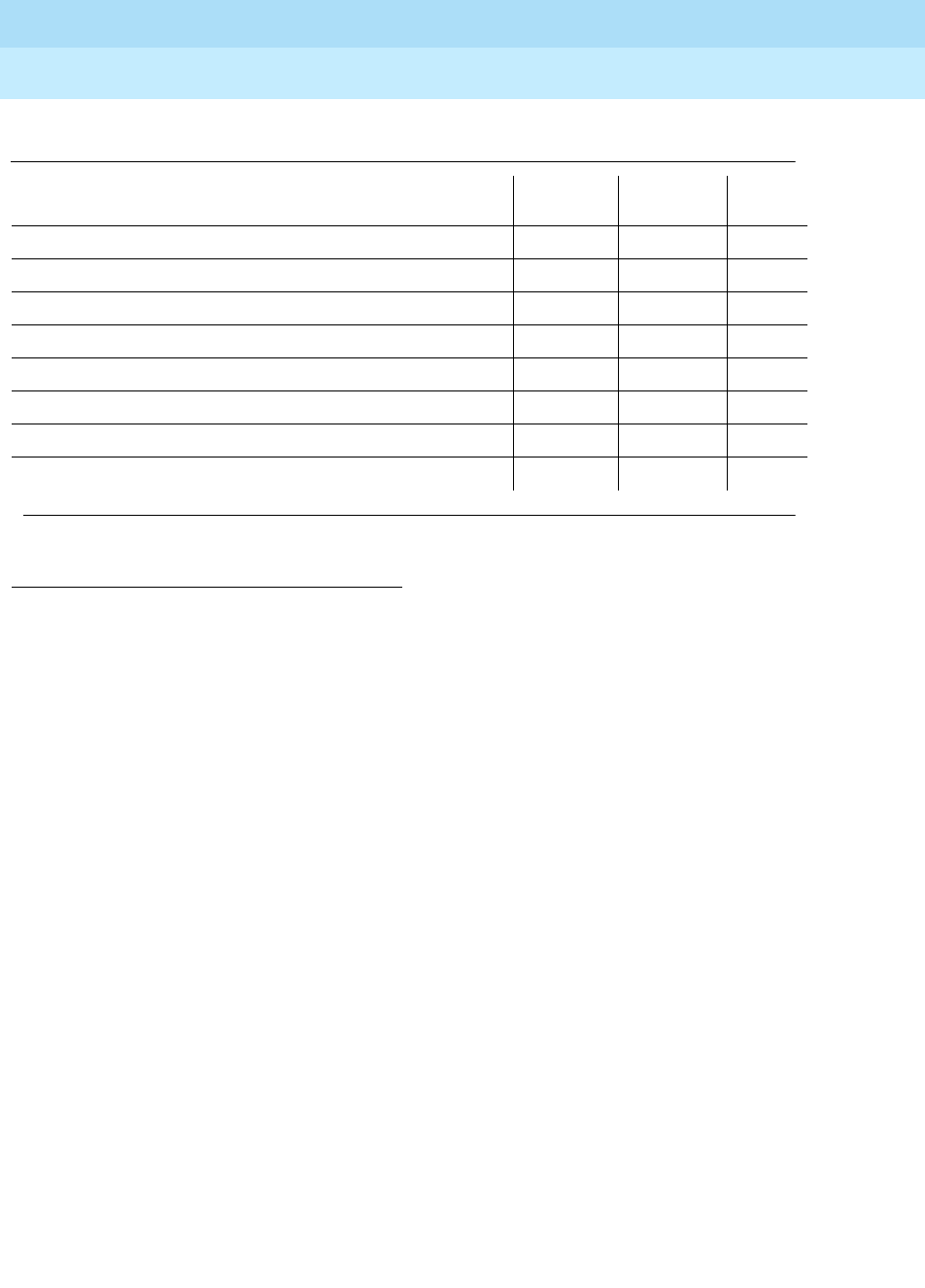
DEFINITY Enterprise Communications Server Release 6
Maintenance for R6r Volumes 1 & 2
555-230-126 Issue 2
January 1998
Maintenance Object Repair Procedures
Page 9-1029PGATE-PT (Packet Gateway Port)
9
Packet Gateway Switched Port Loop-Around Test
(#599)
This test is destructive.
This test verifies that the Packet Gateway port can send and receive data on the
TDM bus.
Failure of this test indicates a possible failure of the Packet Gateway circuit pack,
the TDM Bus, or the digital port on the Maintenance/Test circuit pack.
This test aborts when calls are in progress on the port, or if the signaling link the
port is connected to the port. This test also aborts when executed on a port
whose administered speed is other than ‘‘switched.
1. D = Destructive, ND = Non-destructive
Table 9-367. System Technician-Demanded Tests: PGATE-PT
Order of Investigation Short Test
Sequence Long Test
Sequence D/ND1
Packet Gateway Port Local Loop-Around Test (#610) X D
Packet Gateway Switched Port Loop-Around Test (#599) X D
Level 1 State Query Test (#613) X X ND
Link Status Test (#614) X X ND
Packet Gateway Port Remote Loop-Around Test (#611) X D
(Local Loopback, Digital and Remote Loopbacks)
Session Status Query Test (#976) X X ND
Session Restart Test (#977) X D
Continued on next page

DEFINITY Enterprise Communications Server Release 6
Maintenance for R6r Volumes 1 & 2
555-230-126 Issue 2
January 1998
Maintenance Object Repair Procedures
Page 9-1030PGATE-PT (Packet Gateway Port)
9
Packet Gateway Port Local Loop-Around Test
(#610)
This test is destructive.
This test verifies the functionality of a port circuit on the Packet Gateway circuit
pack. When the switch sends the test request, the Packet Gateway circuit pack
Table 9-368. TEST #599 Packet Gateway Switched Port
Loop-Around Test
Error
Code Test
Result Description/ Recommendation
1000 ABORT The port is in use for a call or the X.25 Access Link is connected. Execute
status packet-gateway-port UUCSSpp to determine when the port is
available for testing.
1. Retry the command when the port is idle. The port may be forced to the
idle state by executing a busyout port UUCSS command. The busyout
port command is destructive causing all calls and links associated with
the port to be torn down.
1005 ABORT The configuration for this test is incorrect.
1. Verify that the port under test is configured as a switched port. This error
code will result when the port under test is configured as an RS423.
2. If this is supposed to be a switched port and it is not administered that way
change the configuration using change data-module ext. The ‘‘baud’’
field should display ‘‘switched’’.
1340 ABORT The Maintenance Test Board digital port was not available.
1341 ABORT Allocation of timeslots failed.
1342 ABORT Connection of ports to timeslots failed.
2000 ABORT Uplink message not received before time limit.
2012 ABORT Internal system error.
1. Retry the command at 1-minute intervals a maximum of 3 times.
0 FAIL Received data test pattern does not match transmitted data test pattern.
1. Retry command at 1-minute intervals a maximum of 3 times.
2. If it still fails, eliminate that the problem is with PKT-BUS and M/T-DIG by
following the repair procedures for those MOs.
3. If they pass, replace the board. Deciding when to replace the board must
be balanced against traffic on the other ports.
PASS The circuitry of the port tested, and its connectivity across the packet bus, is
functioning properly.
Continued on next page
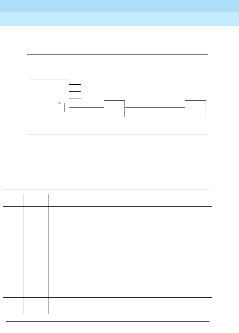
DEFINITY Enterprise Communications Server Release 6
Maintenance for R6r Volumes 1 & 2
555-230-126 Issue 2
January 1998
Maintenance Object Repair Procedures
Page 9-1031PGATE-PT (Packet Gateway Port)
9
automatically loops back the signal at the port as shown in the the figure below.
Failure of this test indicates the existence of a fault in the port hardware on the
circuit pack.
Figure 9-61. Packet Gateway Port Local Loop-Around Test
This test aborts if calls are using the port or if the X.25 Access Link associated
with the port is connected. To avoid this, first enter busyout data-module
extension or busyout port UUCSSpp or busyout link link#, which will cause all
calls and links using the port to be torn down.
Table 9-369. TEST #610 Packet Gateway Port Local Loop-Around Test
Error
Code Test
Result Description/ Recommendation
1000 ABORT The X.25 Access Link is connected or the port is in use for a call. Execute
status packet-gateway-port UUCSSpp to determine when the port is
available for testing.
1. Retry the command when the port is idle. The port may be forced to the
idle state by executing a busyout port UUCSSpp command. This
command is destructive causing all calls and links associated with the port
to be torn down.
2000 ABORT Response to the test was not received from the Packet Gateway circuit pack
within the allowable time period.
1. If this result occurs repeatedly, attempt to reset the circuit pack if the other
ports on the board are not in use (Yellow LED is off). Reset the circuit pack
by issuing the busyout board UUCSS and the reset board UUCSS
commands.
2. If this result occurs again, replace the circuit pack.
2012 ABORT Internal system error.
1. Retry the command at 1-minute intervals a maximum of 3 times.
Continued on next page
Data
Set
Data
Set
Port
TN566
Packet
Gateway
RS423 Transmission Facility

DEFINITY Enterprise Communications Server Release 6
Maintenance for R6r Volumes 1 & 2
555-230-126 Issue 2
January 1998
Maintenance Object Repair Procedures
Page 9-1032PGATE-PT (Packet Gateway Port)
9
Packet Gateway Port Remote Loop-around Test
(#611)
This test is destructive.
This test checks the integrity of cabling and devices external to the Packet
Gateway port hardware. Packet Gateway firmware executes this test on demand
by sending a test frame which is looped back to the Packet Gateway by a
loop-around that has been externally activated or installed at one of several
points in the external connectivity (see loopbacks A, B and C in the figure below).
The test passes when the sent and received test frames are identical. The test
fails if the sent and received test frames do not match, or if no test frame is
received prior to a time out.
If you suspect a problem in cabling or external devices, then repeat this test at
points that are progressively further from the PGATE port until either a failure
point is identified or the integrity of the entire path is verified. Certain site
configurations may require teamwork with those who maintain the off-site
transmission facilities.
FAIL The Packet Gateway circuit pack has detected a failure in the execution of the
test.
1. If the test fails repeatedly, attempt to reset the circuit pack if the other ports
on the board are not in use (Yellow LED is off). Reset the circuit pack by
issuing the busyout board UUCSS and the reset board UUCSS
commands.
2. If the test fails again, replace the circuit pack.
PASS The circuitry of the port tested is functioning properly.
Table 9-369. TEST #610 Packet Gateway Port Local Loop-Around Test — Continued
Error
Code Test
Result Description/ Recommendation
Continued on next page
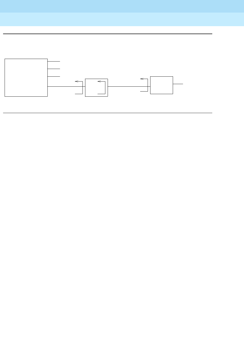
DEFINITY Enterprise Communications Server Release 6
Maintenance for R6r Volumes 1 & 2
555-230-126 Issue 2
January 1998
Maintenance Object Repair Procedures
Page 9-1033PGATE-PT (Packet Gateway Port)
9
Figure 9-62. Packet Gateway Port Remote Loop-Around Test
Manual activation of the loopback is required for this test. If available, the Local
Loopback (B in the above figure), Digital Loopback (C), and Remote Loopback
(D) capabilities of external data sets may be used in conjunction with this test for
fault isolation. Execution of this test with the data set in the Local Loopback mode
verifies the integrity of the external port cabling. Execution of this test with the
data set in the Digital Loopback mode verifies the integrity of the data set.
Execution of this test with the far-end data set in the Remote Loopback mode
verifies the integrity of the transmission facility.
For this test to run, the port or link must be busied out and the ‘‘Remote
Loopback’’ field on the data-module form must be set to ‘‘y.’’ This field should
only be set to ‘‘y’’ when the external loopback switch has been activated for the
test, and should be changed back to ‘‘n’’ when testing is completed and the
external loopback has been deactivated.
To test to an MPDM attached to a Packet Gateway port:
1. Enter busyout data-module extension or busyout port UUCSSpp or
busyout link link#.
2. Set the switch on the MPDM to local loopback.
3. Enter change data-module extension and set the ‘‘Remote Loop-Around
Test’’ field to ‘‘y.’’
4. Enter test data-module extension long or test port UUCSSpp long or
test link link# long.
5. When finished testing, enter change data-module extension and set the
‘‘Remote Loop-Around Test’’ field to ‘‘n.’’
6. Enter release data-module extension or release port UUCSSpp or
release link link#.
To test through an administered connection to an MPDM attached to an adjunct
(see ‘‘Packet Gateway Configurations’’ at the beginning of the PGATE-PT
section):
Far-end
Switch or
Adjunct
RS423
TN577
Packet
Gateway
Port
Data
Set
Data
Set
C
Transmission
Facility
A B
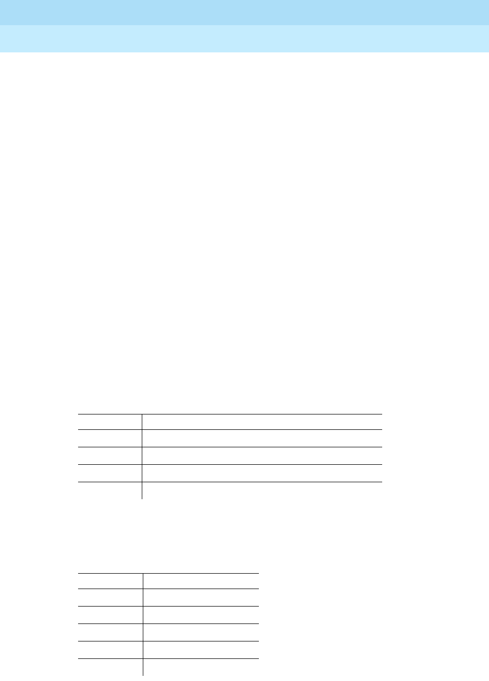
DEFINITY Enterprise Communications Server Release 6
Maintenance for R6r Volumes 1 & 2
555-230-126 Issue 2
January 1998
Maintenance Object Repair Procedures
Page 9-1034PGATE-PT (Packet Gateway Port)
9
1. Enter busyout data-module extension or busyout port UUCSSpp or
busyout link link#.
2. Enter change data-module extension and set the ‘‘Remote Loop-Around
Test’’ field to ‘‘y.’’
3. Set the switch on the MPDM to local loopback.
4. Enter disable administered-connection adm-conn#.
5. Attach a loopback plug to the MPDM and set the switch on the MPDM to
remote loopback.
6. Enter enable administered-connection adm-conn#.
7. When the administered connection becomes established at the MPDM,
set remote loopback to normal.
8. Enter test data-module extension long or test port UUCSSpp long or
test link link# long.
9. When finished testing, enter change data-module extension and set the
‘‘Remote Loop-Around Test’’ field to ‘‘n.’’
10. Enter release data-module extension or release port UUCSSpp or
release link link#.
If a loopback plug is not available, one can be made using a break-out box or
hand-made connector. To loop back an RS232 cable, tie the following pins
together:
To loop back an RS449 cable (often used to connect AUDIX to an IDI), connect
the following pins.
RS232 Cable Loopback
Pins to Join Pin Names
2-3 Transmit-data, Receive-data
4-5 Request-to-send, Clear-to-send
8-20 Carrier-detect, data-terminal-ready
15-17-24 Transmit-clock, Receive-clock, Transmit-clock
RS449 Cable Loopback
Pins to Join Pin Names
4-6 SD-A’, RD-A
5-8-17 ST-A, RS-A’, TT-A’
7-9 RS-A’’, CS-A
12-13 TR-A’, RR-A
22-24 SD-B’, RD-C

DEFINITY Enterprise Communications Server Release 6
Maintenance for R6r Volumes 1 & 2
555-230-126 Issue 2
January 1998
Maintenance Object Repair Procedures
Page 9-1035PGATE-PT (Packet Gateway Port)
9
23-26-35 ST-C, RT-C, TT-B’
25-27 RS-B’, CS-C
30-37 TR-B’, SC
Table 9-370. TEST #611 Packet Gateway Port Remote
Loop-Around Test
Error
Code Test
Result Description/ Recommendation
1000 ABORT The port is in use for an X.25 Access Link call or a call is connected. Execute
status packet-gateway-port UUCSSpp to determine when the port is
available for testing.
1. Retry the command when the port is idle. The port may be forced to the
idle state by executing a busyout port UUCSSpp command. This
command is destructive causing all calls and links associated with the
port to be torn down.
2. If the test fails again, replace the circuit pack.
1005 ABORT The configuration for this test is incorrect.
1. Verify that the external loopback has been installed or activated.
2. Enter change data-module extension and verify that the ‘‘Remote
Looparound Test’’ field displays ‘‘y’’.
3. Repeat the test.
4. When testing is complete, deactivate the external loopback and change
the ‘‘Remote Loop-Around Test’’ field back to ‘‘n.’’
5. If the test aborts with this code while the port administration is correctly
configured, escalate the problem.
2000 ABORT Response to the test was not received from the Packet Gateway circuit pack
within the allowable time period.
1. If this result occurs repeatedly, attempt to reset the circuit pack if the other
ports on the board are not in use (Yellow LED is off). Reset the circuit pack
by issuing the busyout board UUCSS and the reset board UUCSS
commands.
2. Consult the repair procedures for the Packet Gateway Local Loop-Around
test (#610).
2012 ABORT Internal system error.
1. Retry the command at 1-minute intervals a maximum of 3 times.
2100 ABORT The necessary system resources to execute the test could not be allocated.
1. Retry the command at 1-minute intervals a maximum of 5 times.
Continued on next page
RS449 Cable Loopback
Pins to Join Pin Names

DEFINITY Enterprise Communications Server Release 6
Maintenance for R6r Volumes 1 & 2
555-230-126 Issue 2
January 1998
Maintenance Object Repair Procedures
Page 9-1036PGATE-PT (Packet Gateway Port)
9
Level 1 State Inquiry Test (#613)
This test is non-destructive.
This test determines the state of the transmission facility at the physical layer
(Level 1). This test is executed by the Packet Gateway circuit pack for a port on a
command from the switch. The test passes when the current status of the Data
Carrier Detect (DCD) and Clear To Send (CTS) If either of these leads are low,
the test fails.
If the port speed is administered as a switched port then the CTS will always be
high but the DCD will be low only if there are transmission problems with the
FAIL The Packet Gateway circuit pack has detected a failure in the execution of the
test.
1. Verify that the Packet Gateway Local Loop-Around test (#610) passes.
Follow repair procedures for that test first if it fails.
2. Run test #611 for each external loopback position. If any test fails, then
take the action specified for that point:
a. Local Loopback (Loopback ‘‘B’’): Replace the external port cabling.
b. Digital Loopback (Loopback ‘‘C’’): Replace the data set.
c. Remote Loopback (Loopback ‘‘D’’): Investigate potential transmission
line problems. If necessary, escalate the problem to the party
responsible for maintaining the off-premise transmission network.
PASS Passing of this test for the following loopbacks indicates the integrity of the
following pieces of equipment:
1. Local Loopback (Loopback ‘‘B’’). Packet Gateway port hardware plus
cabling.
2. Digital Loopback (Loopback ‘‘C’’). Packet Gateway port hardware plus
cabling plus data set.
3. Remote Loopback (Loopback ‘‘D’’). Packet Gateway port hardware plus
cabling plus data set plus transmission line.
4. If all the above tests pass, place the port in-service (release port
UUCSSpp). Execute the status packet-gateway-port UUCSSpp
command and verify that the transmission-related error counters are not
increasing. Execute the ‘‘Link Status Test (#614)’’ via the test port
UUCSSpp command. Check out equipment at far-end if this test fails.
Table 9-370. TEST #611 Packet Gateway Port Remote
Loop-Around Test — Continued
Error
Code Test
Result Description/ Recommendation
Continued on next page

DEFINITY Enterprise Communications Server Release 6
Maintenance for R6r Volumes 1 & 2
555-230-126 Issue 2
January 1998
Maintenance Object Repair Procedures
Page 9-1037PGATE-PT (Packet Gateway Port)
9
far-end and the link had been up. If this occurs, execute the test port UUCSSpp
long command and consult the repair procedures beginning at Packet Gateway
Switched Port Loop-Around Test #599.
Table 9-371. TEST #613 Level 1 State Inquiry Test
Error
Code Test
Result Description/ Recommendation
2000 ABORT Response to the test was not received from the Packet Gateway circuit pack
X.25 port within the allowable time period.
1. If this result occurs repeatedly, attempt to reset the circuit pack if the other
ports on the board are not in use (Yellow LED is off). Reset the circuit pack
by performing the busyout board UUCSS and the reset board UUCSS
commands.
2. If this result occurs again, replace the circuit pack.
2012 ABORT Internal system error.
1. Retry the command at 1-minute intervals a maximum of 3 times.
2100 ABORT The necessary system resources to execute the test could not be allocated.
1. Retry the command at 1-minute intervals a maximum of 5 times.
1FAILThe Clear To Send lead is ‘‘low’’ indicating a problem with the data set or the
cable attached to the port.
1. Repeat the test.
2. If the test still fails, verify that the data set and the Packet Gateway port are
properly attached to the cable and the data set is powered on.
3. Place the data set in the ‘‘Local Loopback’’ mode. Consult the repair
procedures for the Packet Gateway Port Remote Loop-Around test (#611).
2 FAIL The Data Carrier Detect lead is ‘‘low’’ indicating a problem on the transmission
side of the data set.
1. Repeat the test.
2. If the test still fails, verify the integrity of the wiring on the transmission side
of the data set. Make sure that the data set is properly attached to the
transmission line.
3. If the local transmission wiring is intact, notify the authority responsible for
resolving off-premise transmission facility problems. The Packet Gateway
Port Remote Loop-Around Test (#611) may be useful in diagnosing this
problem.
PASS The Level 1 interface is healthy, both the DCD and CTS leads in the RS423
cable or TDM bus are ‘‘high.’’
Continued on next page

DEFINITY Enterprise Communications Server Release 6
Maintenance for R6r Volumes 1 & 2
555-230-126 Issue 2
January 1998
Maintenance Object Repair Procedures
Page 9-1038PGATE-PT (Packet Gateway Port)
9
Link Status Test (#614)
This test is non-destructive.
This test determines if the X.25 Access Link is connected or disconnected. The
switch determines the state of the X.25 Access Link by sending a query to the
Packet Gateway circuit pack. This test passes if the X.25 Access Link is
connected and fails if it is disconnected.
Figure 9-63. Packet Gateway Links
X.25
Access
Link
X.25
Call-Control
Link
. . . . . . . . . . . . . . . . . . . . . . .
Packet Bus
TN1655
PKT-INT
SPE
TN577
Packet
Gateway
G3r System Far-End
Switch

DEFINITY Enterprise Communications Server Release 6
Maintenance for R6r Volumes 1 & 2
555-230-126 Issue 2
January 1998
Maintenance Object Repair Procedures
Page 9-1039PGATE-PT (Packet Gateway Port)
9
Table 9-372. TEST #614 Link Status Test
Error
Code Test
Result Description/ Recommendation
1006 ABORT The port is out of service, either due to a hardware failure or the busyout port
UUCSSpp command.
1. Check if the port has been busied out. If the error log (display errors
command) contains error type 18 and the alarm log (display alarms
command) contains an active WARNING alarm for this port, the port has
been busied-out. This is a NORMAL abort.
2. If the port has not been busied-out and aborts with this result, execute the
Packet Gateway Port Local Loop-Around Test (#610) and the Level 1 State
Query Test (#613) via the test port UUCSSpp long command. Consult the
repair procedures for these tests.
1151 ABORT The X.25 Call Control Link has failed. It is not possible at the moment to send a
message to the Packet Gateway circuit pack to activate this test.
1. Execute the test board UUCSS command and see the repair procedures
for the X.25 Call Control Link Test (#601).
2. Repeat this test once the X.25 Call Control Link has been re-established,
i.e., test #601 passes.
2000 ABORT Response to the test was not received from the Packet Gateway circuit pack
within the allowable time period.
1. If this same result occurs repeatedly, begin by executing the tests as
detailed in the earlier section. Consult the individual repair procedures for
a specific test if problems are found.
2. If this result continues to occur, attempt to reset the circuit pack if the other
ports on the board are not in use (Yellow LED is off). Reset the circuit pack
by executing the busyout board UUCSS and reset board UUCSS
commands.
3. If this result occurs again, replace the circuit pack.
2012 ABORT Internal system error.
1. Retry the command at 1-minute intervals a maximum of 3 times.
2100 ABORT The necessary system resources to execute the test could not be allocated.
1. Retry the command at 1-minute intervals a maximum of 5 times.
FAIL Received data test pattern does not match transmitted data test pattern. Same
recommendation as for error code 2 above.
Continued on next page

DEFINITY Enterprise Communications Server Release 6
Maintenance for R6r Volumes 1 & 2
555-230-126 Issue 2
January 1998
Maintenance Object Repair Procedures
Page 9-1040PGATE-PT (Packet Gateway Port)
9
Session Status Query Test (#976)
This test is non-destructive.
This test determines the state of the sessions on the X.25 Access Link associated
with the Packet Gateway port.
This test determines if all the sessions associated with the channels using the
X.25 Access Link is up or down. This test passes if the all the sessions are up
and fails otherwise.
2 FAIL The X.25 Access Link is disconnected.
1. Execute the Packet Gateway Port Local Loop-Around Test (#610) and the
Level 1 State Query Test (#613) via the test port UUCSSpp long
command. Consult the repair procedures for these tests.
2. If all tests pass, check far-end switch equipment. Execute the Packet
Gateway Port Remote Loop-Around Test (#611) via the test port
UUCSSpp long command. Consult the repair procedures for this test.
3. If test #611 passes, see the repair procedures for the Packet Control
circuit pack and the Packet Bus.
PASS The X.25 Access Link is connected.
Table 9-373. TEST #976 Session Status Query Test
Error
Code Test
Result Description/ Recommendation
1124 ABORT The X.25 access link associated with this Packet Gateway Port is not enabled.
1. Check if the X.25 access link is enabled for this Packet Gateway Port. If the
‘‘enable’’ field on ‘‘display communication-interface link’’ form is ‘‘n’’ for the
link entry which contains the data module extension associated with the
Packet Gateway Port, then the X.25 access link is not enabled. Set the field
to ‘‘y’’ using change communication-interface link command and repeat
the test. This is a NORMAL abort.
2000 ABORT Response to the test was not received within the allowable time period.
1. Retry the command at 1-minute intervals a maximum of 5 times.
Continued on next page
Table 9-372. TEST #614 Link Status Test — Continued
Error
Code Test
Result Description/ Recommendation
Continued on next page
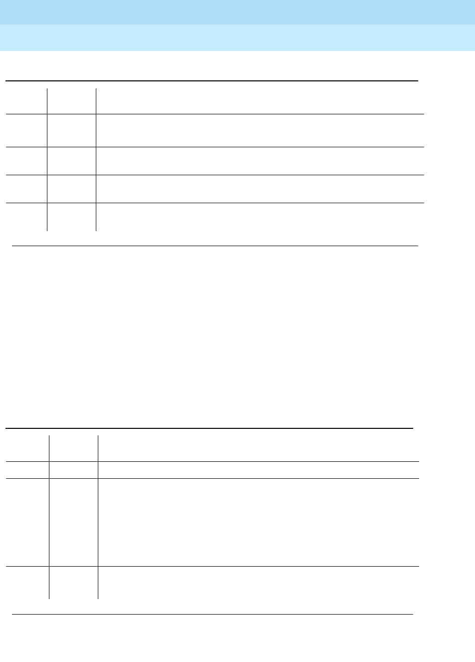
DEFINITY Enterprise Communications Server Release 6
Maintenance for R6r Volumes 1 & 2
555-230-126 Issue 2
January 1998
Maintenance Object Repair Procedures
Page 9-1041PGATE-PT (Packet Gateway Port)
9
Session Restart Test (#977)
This test is destructive.
This test destroys and attempts to restart all the sessions on the X.25 Access Link
associated with the Packet Gateway port.
The test attempts to restart all the sessions as long as there is at least one
session down on the link. This test aborts if the all the sessions are up.
2500 ABORT Internal system error.
1. Retry the command at 1-minute intervals a maximum of 3 times.
1 FAIL At least one (but not all) sessions on the X.25 access link associated with the
Packet Gateway Port are down. Same recommendation as for error type 1537.
2 FAIL All sessions on the X.25 access link associated with the Packet Gateway Port
are down. Same recommendation as for error type 1538.
PASS All sessions on the X.25 access link associated with the Packet Gateway Port
are up.
Table 9-374. TEST #977 Session Status Query Test
Error
Code Test
Result Description/ Recommendation
ABORT All sessions are up. This is a NORMAL abort.
1124 ABORT The X.25 access link associated with this Packet Gateway Port is not enabled.
1. Check if the X.25 access link is enabled for this Packet Gateway Port. If
the ‘‘enable’’ field on ‘‘display communication-interface link’’ form is ‘‘n’’
for the link entry which contains the data module extension associated
with the Packet Gateway Port, then the X.25 access link is not enabled.
Set the field to ‘‘y’’ using change communication-interface link
command and repeat the test. This is a NORMAL abort.
2000 ABORT Response to the test was not received within the allowable time period.
1. Retry the command at 1-minute intervals a maximum of 5 times.
Continued on next page
Table 9-373. TEST #976 Session Status Query Test — Continued
Error
Code Test
Result Description/ Recommendation
Continued on next page

DEFINITY Enterprise Communications Server Release 6
Maintenance for R6r Volumes 1 & 2
555-230-126 Issue 2
January 1998
Maintenance Object Repair Procedures
Page 9-1042PGATE-PT (Packet Gateway Port)
9
2500 ABORT Internal system error.
1. Retry the command at 1-minute intervals a maximum of 3 times.
FAIL The X.25 Access Link associated with the Packet Gateway Port is down.
Same recommendation as for test type 611.
PASS All sessions on the X.25 access link associated with the Packet Gateway Port
are restarted.
Table 9-374. TEST #977 Session Status Query Test — Continued
Error
Code Test
Result Description/ Recommendation
Continued on next page

DEFINITY Enterprise Communications Server Release 6
Maintenance for R6r Volumes 1 & 2
555-230-126 Issue 2
January 1998
Maintenance Object Repair Procedures
Page 9-1043PKT-BUS (Packet Bus)
9
PKT-BUS (Packet Bus)
The packet bus consists of a single bus, and one such bus appears in each
port-network. The packet bus in each port-network is physically independent
from those in other port-networks, so each port-network has a separate PKT-BUS
maintenance object. This bus supports the following types of connections:
■Logical control links between the SPE and all Expansion Port-Networks
(EPN)
■ISDN-BRI D-channel transport (signaling)
■ASAI D-channel transport (signaling)
■ISDN-PRI D-channel (signaling)
■X.25 system adjunct signaling and traffic
■System Access Ports
The TN1655 Packet Interface circuit pack provides the SPE interface to the
packet bus. Packet Bus testing depends on the TN771D Maintenance/Test
circuit pack, the TN1655 Packet Interface circuit pack, TN570 Expansion
Interface circuit pack, and the Packet port circuit packs (TN556 ISDN-BRI Line,
TN553 Packet Data Line, TN464 Universal DS1, and TN577 Packet Gateway).
Packet Bus tests may abort if some of these are not present in the system. The
tests may yield inconsistent results if any of this hardware is defective. The
individual test descriptions provide more information.
The interactions between the packet bus and the circuit packs that use the bus
are complex. Circuit pack failures can alarm the packet bus, while Packet Bus
faults can alarm or interrupt service to one or more circuit packs and their ports
and endpoints. The
Packet Bus Fault Isolation and Correction
section of Chapter
5, ‘‘Responding to Alarms and Errors’’ describes Packet Bus maintenance and
interactions circuit packs. That section should be referenced for all
troubleshooting and repairs. The
Bus Fault Isolation Flowchart
is the normal
starting point for experienced technicians. Technicians unfamiliar with the packet
bus and its implementation in Generic 3r should study the introductory material
before using the flowchart to diagnose and repair packet bus faults.
1. where P is the port-network number indicated in the PORT field from the Alarm or Error Log.
MO Name (in
Alarm Log) Alarm Level Initial Command to Run1Full Name of MO
PKT-BUS MAJOR test pkt P l r 21Packet Bus
PKT-BUS MINOR test pkt P l Packet Bus
PKT-BUS WARNING test pkt P l Packet Bus

DEFINITY Enterprise Communications Server Release 6
Maintenance for R6r Volumes 1 & 2
555-230-126 Issue 2
January 1998
Maintenance Object Repair Procedures
Page 9-1044PKT-BUS (Packet Bus)
9
This section on the PKT-BUS maintenance object is limited to a description of the
Error and Alarm Log entries and the test sequence for the packet bus. The
following list summarizes some of the important points to consider when working
with the packet bus.
■The Maintenance/Test circuit pack (TN771D) is a critical tool for isolating
packet bus faults. This circuit pack is present in each port-network of a
Critical Reliability system (duplicated SPE
and
PNC. In a Standard
Reliability system, the circuit pack may be included as a customer option.
If a TN771D is not present, (check with list config),
one must be taken to
the customer site
to allow for proper fault isolation.
Packet Bus Fault
Isolation and Correction
in Chapter 5, ‘‘Responding to Alarms and Errors’’
describes the packet bus testing facilities of the TN771D and when one
must be taken to the customer site.
■Certain catastrophic packet bus failures have an effect on maintenance
software activities relating to Packet circuit packs, ports, and endpoints:
— Packet circuit pack (BRI-BD, PGATE-BD, PDATA-BD, UDS1-BD)
in-line errors indicating possible Packet Bus failures are logged in
the error log, but are not acted upon.
— Port-level (BRI-PORT, ABRI-PORT, PGATE-PT, PDATA-PT) in-line
errors on Packet circuit packs which indicate possible Packet Bus
failures
are not logged or acted upon
.
— Circuit pack and port in-line errors that are not relevant to the
Packet Bus, or that indicate a circuit pack failure, are acted upon in
the normal fashion.
— Periodic and scheduled background maintenance are not affected.
— Foreground maintenance (for example, a test board command
executed at a terminal) is not affected.
The actions in the previous list serve to reduce the system load, which
could become excessive if many maintenance objects are affected by a
packet bus failure. However, such an excessive load should in no way
impede the isolation and the correction of the faults.
When the above actions are implemented, Error Type 3329 is logged
against PKT-BUS, and a Warning alarm is raised. Other Packet Bus errors
may raise more severe alarms, thereby overriding the Warning alarm.
■Since all packet traffic requires communication with the Packet Interface,
circuit pack in the SPE , a packet bus failure in the Processor Port-Network
(PPN) causes packet traffic in the Expansion Port-Networks (EPNs) to fail.
Due to this requirement, a PPN packet bus failure must be investigated
first whenever packet bus failures occur in multiple port-networks.

DEFINITY Enterprise Communications Server Release 6
Maintenance for R6r Volumes 1 & 2
555-230-126 Issue 2
January 1998
Maintenance Object Repair Procedures
Page 9-1045PKT-BUS (Packet Bus)
9
Hardware Error Log Entries and Test to Clear
Value
Notes:
a. Within the last minute, packet circuit packs have reported errors that
indicate a possible packet bus failure. The Aux Data value is 1 or 2,
indicating that only one or more than one Packet circuit pack
(respectively) have reported a possible packet bus failure.
b. The Maintenance/Test packet bus port (M/T-PKT) for this port-network has
determined that there are more packet bus faults than the port can
correct. The Aux Data value indicates the number of faulty leads.
c. Packet circuit packs have detected possible packet bus failures via in-line
error or via background test failure. Examine the Error and Alarm logs for
more specific PKT-BUS errors.
1. ON-BOARD indicates a problem with the packet bus itself.
2. Run the Short Test Sequence first. If all tests pass, run the Long Test Sequence. Refer to the appropriate
test description and follow the recommended procedures.
Table 9-375. PKT-BUS Error Log Entries
Error
Type Aux
Data Associated Test Alarm
Level On/Off
Board1Test to Clear Value
020 Any Any Any test pkt port-network
1 (a) 1-2 Packet Circuit Pack
Audit Test (#570) MAJOR ON test pkt port-network P l r 2
513 (b) 1-24 Maintenance/Test
Circuit Pack Query
Test (#572)
MAJOR ON test pkt port-network P l r 2
1793 (c) Any None
2049 (d) 1-3 Maintenance/Test
Circuit Pack Query
Test (#572)
MINOR ON test pkt port-network P l r 2
2305 (e) 1-24 Maintenance/Test
Circuit Pack Query
Test (#572)
test pkt port-network P l
3329 (f) 1-7 none WARNING ON test pkt port-network P l
3585 (g) Any none MINOR ON test pkt port-network P l
3841 (h) Any none MINOR OFF
Continued on next page

DEFINITY Enterprise Communications Server Release 6
Maintenance for R6r Volumes 1 & 2
555-230-126 Issue 2
January 1998
Maintenance Object Repair Procedures
Page 9-1046PKT-BUS (Packet Bus)
9
d. The Maintenance/Test packet bus port (M/T-PKT) has detected a Packet
Bus fault and taken corrective action by swapping to spare leads. This
error appears only in Critical Reliability systems (duplicated SPEs and
PNC). The Aux Data value indicates the number of faulty leads. If this is
the only active error against the packet bus,
the packet bus is still in
service
. Due to the disruptive nature of the packet bus Fault Isolation and
Correction procedures, repairs should be deferred until a time when the
least interruption in service will result. This should be determined by
consultation with the customer. However, do not delay repairs for too long,
since the switch will not be able to recover from another packet bus failure
until the existing one is resolved.
Packet Bus Fault Isolation and Correction
in Chapter 5, ‘‘Responding to Alarms and Errors’’ contains a sub-section,
A Special Precaution Concerning the TN771D
that describes how to
ensure that the TN771D is providing correct information. A new TN771D
may need to be taken to the customer site.
e. The Maintenance/Test packet bus port (M/T-PKT) has detected open
leads on the packet bus. The Aux Data value indicates the number of
open leads.
f. Packet circuit pack, port, and endpoint maintenance has been disabled
due to a packet bus failure. The Aux Data value indicates the cause:
Keep in mind that although only packet circuit packs can detect and
report packet bus problems, such problems can be caused by any circuit
pack.
g. Packet circuit pack, port, and endpoint maintenance has been disabled
due to more than one circuit pack reporting in-line errors. If this occurs
more than three times in 15 minutes a Minor alarm is raised against the
packet bus. This happens when maintenance is disabled due to errors
and is then re-enabled because no more errors are reported.
This error may still be present in the error log even though the Packet
Circuit Pack Audit Test (#573) indicates that only one circuit pack is
reporting a problem. This happens when more than one circuit pack has
reported errors in any one-minute interval since the packet bus fault
occurred.
Aux
Data Cause
1 In-line errors from packet circuit packs
2 Uncorrectable packet bus fault reported by the
Maintenance/Test packet bus port (M/T-PKT)
3 Both of the above
100
x
Packet-related circuit pack, port, and endpoint
maintenance in the EPN has been disabled due to a
packet bus failure in the PPN. The last digit has the same
meaning as the single digits listed above.

DEFINITY Enterprise Communications Server Release 6
Maintenance for R6r Volumes 1 & 2
555-230-126 Issue 2
January 1998
Maintenance Object Repair Procedures
Page 9-1047PKT-BUS (Packet Bus)
9
h. The Maintenance/Test packet bus port (M/T-PKT) for this port-network is
not in service. This alarm does not appear for EPNs in Standard or High
Reliability systems since a TN771 is not required there. The error indicates
one or more of the following:
■The packet bus port has been busied out (indicated by Error Type
18), and a Warning alarm is active against M/T-PKT in the same
port-network. Release the port by entering release port UUCSS04.
■The packet bus port has failed. Look for alarms against M/T-PKT,
and attempt to resolve these alarms.
■The Maintenance/Test circuit pack was not recognized by the
system at the last system restart. Replace the Maintenance/Test
circuit pack.
■There is no Maintenance/Test circuit pack in this port-network. One
must be installed.
The TN711 must be installed before other packet bus alarms can be
resolved. (Alarms against a given maintenance object are not resolved
until all alarm-generating conditions have been cleared).
System Technician-Demanded Tests:
Descriptions and Error Codes
Always investigate tests in the order presented in the following tables. By
clearing error codes associated with the
Packet Circuit Pack Audit Test,
for
example, you may also clear errors generated from other tests in the testing
sequence.
Maintenance/Test Circuit Pack Query Test (#572)
This test queries the Maintenance/Test packet bus port about the state of health
of the packet bus. If the Maintenance/Test circuit pack indicates that the packet
bus has faults, the test fails. The corresponding failure code describes the
severity, type, and number of faults. The test passes if the packet bus is
fault-free.
NOTE:
A Maintenance/Test circuit pack is usually not present in any EPN of a
system without duplicated PNC (Critical Reliability). Customers may
1. D = Destructive; ND = Nondestructive
Order of Investigation Short Test
Sequence Long Test
Sequence D/ND1
Packet Circuit Pack Audit Test (#573) X X ND
Maintenance/Test Circuit Pack Query Test (#572) X X ND

DEFINITY Enterprise Communications Server Release 6
Maintenance for R6r Volumes 1 & 2
555-230-126 Issue 2
January 1998
Maintenance Object Repair Procedures
Page 9-1048PKT-BUS (Packet Bus)
9
optionally install a Maintenance/Test circuit pack in order to make use of its
analog trunk and digital line test capabilities, and to enhance the system’s
analog trunk and digital line test capabilities, system’s ability to quickly
recognize a packet bus failure.
Table 9-376. Test #572 Maintenance/Test Circuit Pack
Query Test
Error
Code Test
Result Description/ Recommendation
1006 ABORT The packet bus port of the Maintenance/Test circuit pack is out of service.
1. Determine if the port is busied out. If so, release it with the release port
UUCSS04 command. Then retry the test command.
2. If there are alarms active against the packet bus port (MT-PKT), refer to
M/T-PKT Maintenance documentation to resolve them. Then retry the test
command.
1142 ABORT No Maintenance/Test circuit pack packet bus port is in service in this
port-network.
1. If this port-network is required by configuration guidelines to have a
Maintenance/Test circuit pack (i.e., it is either a PPN or else an EPN in a
system having both SPE and PNC duplication) either
a. the Maintenance/Test circuit pack for this port-network has failed, and
should be replaced,
b. the Maintenance/Test circuit pack has been busied out, and should be
released, or
c. there is no Maintenance/Test circuit pack in this port-network, and one
must be installed.
2. In an EPN of a system without both SPE and PNC duplication, the
Maintenance/Test packet bus Port is not required and may not be present.
If it is present, and is busied out, or has failed, release or replace the circuit
pack. If there is no Maintenance/Test circuit pack, ignore the results of this
test for this port-network.
2000 ABORT The test timed-out while waiting for an uplink CCMS response from the
Maintenance/Test packet bus port.
1. Re-enter the command at 1-minute intervals a maximum of 5 times.
2. If the test continues to abort, check for problems with the Maintenance/Test
packet bus port (look for M/T-PKT in the Error and Alarm Logs).
2059 ABORT The Maintenance/Test packet bus port has reported a hardware failure.
1. Refer to M/T-PKT Maintenance documentation to correct the problem.
2. Re-enter the test command.
Continued on next page
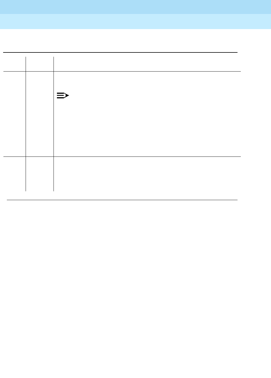
DEFINITY Enterprise Communications Server Release 6
Maintenance for R6r Volumes 1 & 2
555-230-126 Issue 2
January 1998
Maintenance Object Repair Procedures
Page 9-1049PKT-BUS (Packet Bus)
9
2077 ABORT The Maintenance/Test Circuit Pack Query located more than one
Maintenance/Test packet bus port in the port-network.
NOTE:
The software should not allow this to occur. This is an internal system
error. Escalate the problem, but also attempt the following work-around
steps.
1. Remove all Maintenance/Test circuit packs from the port-network.
2. Insert one Maintenance/Test circuit pack (there should not be more than
one in a port-network).
3. Re-enter the test command.
2100 ABORT Maintenance could not allocate all of the necessary system resources to
perform this test.
2500 ABORT An internal operation failed; the test could not be completed.
1. Re-enter the command at 1-minute intervals a maximum of 5 times.
Table 9-376. Test #572 Maintenance/Test Circuit Pack
Query Test — Continued
Error
Code Test
Result Description/ Recommendation
Continued on next page

DEFINITY Enterprise Communications Server Release 6
Maintenance for R6r Volumes 1 & 2
555-230-126 Issue 2
January 1998
Maintenance Object Repair Procedures
Page 9-1050PKT-BUS (Packet Bus)
9
Packet Circuit Pack Audit Test (#573)
This test determines whether Packet circuit packs have reported Packet
Bus-related in-line errors within the last minute. If so, the failure code indicates
whether one or more than one circuit pack has reported such failures.
If the test has failed within the last 5 minutes, there is a 15 second delay before
the result is returned. This prevents a repeated sequence of this test from always
reporting the same result. If the test passes and a FAIL has not occurred within
the last five minutes, a PASS is returned immediately.
FAIL The Maintenance/Test packet bus port has detected faults on the Packet Bus.
The error codes are interpreted as follows:
1
xxx
The Maintenance/Test packet bus port has reconfigured the packet bus around
the faulty leads. This action only occurs in Critical Reliability systems
(duplicated SPE and PNC).
2
xxx
The Maintenance/Test packet bus port is unable to correct all of the Packet Bus
faults it has detected.
x0
xx
None of the packet bus faults are open faults.
x1
xx
At least some of the packet bus faults are open faults. Look for error type 2305
in the Error Log. The Aux Data value indicates the number of open leads.
xxyy The last two digits of the error code indicate the total number of faulty packet
bus leads detected.
Examples:
Error Code 2003 FAIL: The Maintenance/Test packet bus port has
detected 3 faulty leads. None of them are opens. At least one was unable
to be corrected.
Error Code 1103 FAIL: The Maintenance/Test Packet Port has detected 3
faulty leads. At least one is an open. The Maintenance/Test circuit pack
was able to correct all of them by reconfiguring.
1. Refer to the
Packet Bus Fault Isolation Flowchart
in the
Packet Bus Fault
Isolation and Correction
section of Chapter 5, ‘‘Responding to Alarms and
Errors’’.
PASS No faults have been detected on the packet bus by the Maintenance/Test
circuit pack. This is an indication that the packet bus is operating correctly.
Table 9-376. Test #572 Maintenance/Test Circuit Pack
Query Test — Continued
Error
Code Test
Result Description/ Recommendation
Continued on next page

DEFINITY Enterprise Communications Server Release 6
Maintenance for R6r Volumes 1 & 2
555-230-126 Issue 2
January 1998
Maintenance Object Repair Procedures
Page 9-1051PKT-BUS (Packet Bus)
9
Table 9-377. Test #573 Packet Circuit Pack Audit Test
Error
Code Test
Result Description/ Recommendation
2500 ABORT An internal operation failed; the test could not be repeated.
1. Re-enter the command at one-minute intervals a maximum of five times.
1 FAIL One Packet circuit pack has reported packet bus-related in-line errors within
the last minute.
2 FAIL More than one Packet circuit pack has reported packet bus-related in-line
errors within the last minute.
PASS No Packet circuit packs have reported packet bus-related in-line errors within
the last minute. This indicates that the packet bus is healthy, or that a packet
bus fault is transient or is being caused by a faulty Packet circuit pack. If this
test passes, but there are other signs of a packet bus failure (for example,
logged errors or alarms, or other test failures) refer to the
Packet Bus Fault
Isolation Flowchart
in
Packet Bus Fault Isolation and Correction
in Chapter 5,
‘‘Responding to Alarms and Errors’’.

DEFINITY Enterprise Communications Server Release 6
Maintenance for R6r Volumes 1 & 2
555-230-126 Issue 2
January 1998
Maintenance Object Repair Procedures
Page 9-1052PKT-INT (Packet Interface Circuit Pack)
9
PKT-INT (Packet Interface Circuit
Pack)
The Packet Interface (PKT-INT) circuit pack (TN1655) serves as an interface
between the Switch Processing Element (SPE) and the Packet bus in the
Processor Port Network (see the figure in the following pages).
The PKT-INT supports links used for call setup of all ports located in Expansion
Port Networks (EPNs). Therefore, if the PBX system is equipped with the
Standard Reliability configuration (without duplicated SPEs), a failure of the
Packet Interface circuit pack will prevent call origination and tear-down from
telephones and trunks connected to EPNs. In addition to affecting telephone
service, a failure of the Packet Interface circuit pack will affect service provided
by the following circuit packs that connect to the Packet bus:
■TN464C Universal DS1 circuit pack — ISDN PRI service
■TN553 Packet Data Line circuit pack — System Port feature used for
connectivity to features such as Call Detail Recording and dial-up
administration.
■TN556 ISDN-BRI Line circuit pack — ISDN BRI service
■TN577 Packet Gateway circuit pack — BX.25 links used for services
requiring BX.25 links such as AUDIX and Distributed Communications
Systems
If the PBX system is equipped with the High Reliability or Critical Reliability option
(i.e. with duplicated SPEs), and if a failure of the Packet Interface circuit pack on
the active SPE causes a MAJOR alarm, a SPE interchange will occur if the state
of health of the standby SPE is high enough to permit an interchange. A MAJOR
alarm caused by a failure of a Packet Interface circuit pack on the standby SPE
will drop the state of health of the standby SPE which prevents any attempt to
interchange SPEs.
1. C is the carrier location (a or b), S is the position number of the Packet Interface circuit pack (1, 2,
or 3). The carrier location is required only for duplicated SPEs.
2. If a spontaneous interchange has occurred (as indicated by STBY-SPE error type 103 or the
display initcauses screen), and handshake is down, (check with status spe), replace the alarmed
circuit pack on the standby SPE. If handshake is up, execute a test long clear of the alarmed circuit
pack and follow recommended procedures.
MO Name (in
Alarm Log) Alarm
Level Initial Command to Run1Full Name of MO
PKT-INT MAJOR2reset packet-interface CS Packet Interface Circuit Pack
PKT-INT MINOR test packet-interface CS l Packet Interface Circuit Pack
PKT-INT WARNING test packet-interface CS l Packet Interface Circuit Pack

DEFINITY Enterprise Communications Server Release 6
Maintenance for R6r Volumes 1 & 2
555-230-126 Issue 2
January 1998
Maintenance Object Repair Procedures
Page 9-1053PKT-INT (Packet Interface Circuit Pack)
9
The links that pass through the Packet Interface circuit pack are identified as
application links and system links as follows:
1. Application links
a. EIA endpoints requiring connectivity to the SPE.
These links pass over the Packet bus, through the System Ports,
and over the TDM bus to provide connectivity from the SPE to
endpoints on the TDM bus (see figure below).
The following system features use application links of this type.
■Call Detail Recording (CDR)
■Dial-up administration
■Property Management System (PMS)
■Journal printer
■Wake-up log printer
■Announcement circuit pack upload/download of recorded
messages
b. BX.25 links supported by the Packet Gateway.
The following system features use application links of this type.
■Distributed Communication System (DCS)
■Audio Information Exchange (AUDIX)
■Messaging Service Adjunct (MSA)
■Call Management System (CMS)
■Outgoing Call Management (OCM)
■Adjunct Switch Application Interface (ASAI)
2. System links
■Expansion Archangel links (signaling links for call setup of
endpoints in an EPN)
■Center Stage Control Network (CSCN) links
■ISDN PRI D channel signaling links
■Packet Gateway call control links (signaling links to the Packet
Gateway circuit pack)
■ISDN BRI D channel broadcast and point-to-point signaling links
■Adjunct Switch Application Interface (ASAI) links
The PBX has been designed for a maximum of three Packet Interface circuit
packs but only one Packet Interface circuit pack is required for the current PBX
hardware configuration. The Packet Interface circuit pack will normally be
inserted in the first Packet Interface slot provided in the control carrier although it
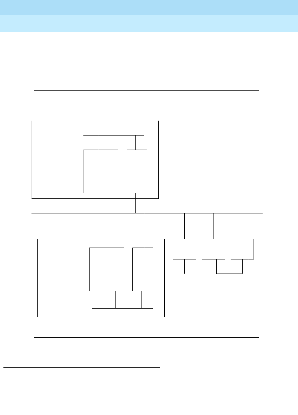
DEFINITY Enterprise Communications Server Release 6
Maintenance for R6r Volumes 1 & 2
555-230-126 Issue 2
January 1998
Maintenance Object Repair Procedures
Page 9-1054PKT-INT (Packet Interface Circuit Pack)
9
will operate in any one of the three slots provided. If more than one Packet
Interface circuit pack is inserted, an alarm will be generated. For a system
equipped with duplicated SPEs, the slot used for the Packet Interface circuit
pack on the standby SPE must be the same slot position as that used on the
active SPE or an alarm will be generated against the Packet Interface circuit
pack in the standby SPE.
Figure 9-64. Packet Interface Connectivity
Packet Interface Service Operations
The following sections provides more background information about Packet
Interface service operations.
.
.
.
.
.
.
.
.
.
.
.
TDM Bus
Packet Bus
SPE Complex
PKT
INT
TN1655
PKT
INT
TN1655
System
Ports
To EPN
Connectivity
.
.
.
.
.
.
.
.
.
.
.
DATA
LINE
BD
PDATA
BD
EXP
INTF
Optional
Duplicated
Processor Bus
Other SPE
Components
Other SPE
Components
SPE Complex
Processor Bus
. . . . . . . . . . . . . . . . . . . . . . . . . . . . . . . . . . . . . . . . . . . . . . . . . . . . . . . . . . . . . . . . . . . . . . . . . . . . . . . . . . . . . . . . . . . . . . . . . . . . . . . . . . . . . . . . . . . . . . . . . . . . . .

DEFINITY Enterprise Communications Server Release 6
Maintenance for R6r Volumes 1 & 2
555-230-126 Issue 2
January 1998
Maintenance Object Repair Procedures
Page 9-1055PKT-INT (Packet Interface Circuit Pack)
9
Administration
There are no add or remove commands associated with the Packet Interface
circuit packs. Instead, Packet Interface fields (
Packet Intf1, Packet Intf2, Packet
Intf3
) that appear under the SPE Optional Boards category on the second page
of the System Parameters Maintenance Form are provided to indicate whether
the Packet Interface circuit pack is administered.
If a Packet Interface circuit pack is physically present, the corresponding Packet
Interface field is set to ‘‘y’’ when the system boots, and no change to that field is
allowed. (If the system is equipped with duplicated SPEs, a Packet Interface field
is set to ‘‘y’’ when either SPE carrier contains a Packet Interface circuit pack in
the corresponding position.) If a Packet Interface circuit pack is not present, then
the value for the Packet Interface field is read from translation data stored on disk
or tape. If the field is set to ‘‘n,’’ a Packet Interface circuit pack may be
administered by changing the corresponding Packet Interface field to ‘‘y.’’
Packet Interface Circuit Pack Replacement
When replacing a Packet Interface circuit pack, follow the procedure used for
replacing any circuit pack in the SPE carrier. The SPE carrier must be powered
down before a Packet Interface circuit pack is removed or added and then the
SPE carrier must be powered back up after the circuit pack is inserted.
Packet Interface circuit packs should not be plugged in or removed from a
running system since configuration tables in software need to be updated at
system restart time. This is also true for Packet Interface circuit packs in the
standby SPE carrier when the system is equipped with duplicated SPEs. Refer to
Replacing SPE Circuit Packs
in Chapter 5, ‘‘Responding to Alarms and Errors’’
for more information on the procedures for replacing circuit packs in a standby
SPE carrier.
Demand Reset of a Packet Interface Board
A demand reset of a Packet Interface circuit pack on an active SPE via the entry
of a reset packet-interface command will be denied by system software if the
Packet Interface is in service (has not been placed in an out-of-service state by
background maintenance software). Otherwise, a reset of an in-service Packet
Interface circuit pack would cause severe service disruption including the loss of
all existing calls and dropped links to adjuncts such as AUDIX. The software that
controls Packet Interface maintenance puts a Packet Interface circuit pack in the
out-of-service state if that circuit pack has been reset three times within the last
15 minutes. as part of the automatic recovery action that is initiated when a
hardware fatal fault condition is detected.
A demand reset of a Packet Interface circuit pack on the standby SPE is not
disruptive and is allowed regardless of the service state of the associated
maintenance software. When a standby Packet Interface circuit pack is reset,
memory shadowing is turned off and then back on. A memory refresh is then
performed to update the state of the standby Packet Interface circuit pack and to

DEFINITY Enterprise Communications Server Release 6
Maintenance for R6r Volumes 1 & 2
555-230-126 Issue 2
January 1998
Maintenance Object Repair Procedures
Page 9-1056PKT-INT (Packet Interface Circuit Pack)
9
refresh the standby’s memory. It takes several minutes after a Packet Interface
circuit pack on the standby SPE is reset before memory refresh of the standby
SPE is complete. During that time, demand tests of the standby Packet Interface
circuit will abort.
Service States
Packet Interface maintenance software maintains a state variable that keeps
track of the in-service/out-of-service state of each Packet Interface circuit pack.
In a system equipped with a single SPE, if maintenance software detects that a
Packet Interface circuit pack has a ‘‘fatal fault’’, it will automatically attempt to
reset that circuit pack as quickly as possible. An extensive set of diagnostic tests
are run when the circuit pack is reset.
If the circuit pack diagnostic tests do not pass in a system without duplicated
SPEs, the failing Packet Interface circuit pack is placed in an out-of-service state.
All links handled by that circuit pack will go out of service. This is a disruptive
action since established calls associated with telephones connected to
Expansion Port Networks are dropped as a result of the EPNs being taken out of
service.
If the system is equipped with duplicated SPEs and if the standby SPE has an
acceptable state-of-health, an SPE interchange will occur instead of a reset of
the Packet Interface circuit pack. This is less disruptive than a reset since stable
calls are not disconnected.
A Packet Interface circuit pack will also be put in the ‘‘out-of-service’’ state if the
circuit pack has reported a fatal fault at system initialization time or if the circuit
pack has been reset by background maintenance three times within the last 15
minutes, whether or not the Reset test passes. The state of a Packet Interface
circuit pack can be determined by using the status packet-interface command.
Duplication Impact
The Packet Interface circuit pack is a single point of failure in a system that is not
equipped with duplicated SPEs. If this is not acceptable, customers have the
option of upgrading to a configuration with a duplicated SPE processor complex
as part of the High Reliability or Critical Reliability Configuration. the previous
figure shows the configuration with duplicated processors. The following
concepts apply only when the processors are duplicated.
■Configuration Mismatch
The number and position of Packet Interface circuit packs on the standby
SPE must match exactly the number and position of Packet Interface
circuit packs on the active SPE. If this is not the case, a MAJOR alarm is
raised against a missing Packet Interface circuit pack on the standby SPE
and a WARNING alarm is raised against extra Packet Interface circuit
packs on the standby SPE.

DEFINITY Enterprise Communications Server Release 6
Maintenance for R6r Volumes 1 & 2
555-230-126 Issue 2
January 1998
Maintenance Object Repair Procedures
Page 9-1057PKT-INT (Packet Interface Circuit Pack)
9
The system is provided with 3 slots for a maximum of 3 Packet Interface
circuit packs. Only one Packet Interface circuit pack is required. This
circuit pack is typically plugged into the first slot but it may be plugged
into any of three slots. A WARNING alarm will be raised if more than one
Packet Interface circuit pack is present in an SPE carrier.
The version of firmware on a standby Packet Interface circuit pack must
also match the version of firmware on the corresponding active Packet
Interface circuit pack. If this is not the case, the standby Packet Interface
circuit pack enters a fatal fault state and the standby Packet Interface
circuit pack maintenance software sets its corresponding
in-service/out-of-service state to out-of-service.
The configuration checks are only made if the active SPE can
communicate with the standby SPE. If the standby SPE is locked off-line
by setting the SPE-SELECT switches on the DUPINT circuit packs to the
position of the active SPE, the mismatch test is not run and therefore, the
mismatch is not detected.
■Packet Bus Connection
In a system equipped with duplicated SPEs, the Packet Interface circuit
packs in the Standby SPE can not access the Packet Bus to write data
except during the time of a planned SPE interchange and when the Peer
Link Test (#888) is run. Consequently, the Maintenance Looparound Test
(#886) that requires access to the Packet Bus is not run on Packet
Interface circuit packs on the Standby SPE.
■SPE Interchange
Severe Packet Interface circuit pack faults which cause system and
application links to go down will be detected within 1 second. A fatal fault
error message will be generated and the Packet Interface maintenance
software will attempt to run the Packet Interface Reset test. In systems
equipped with the High Reliability or Critical Reliability Configuration this
will result in a request for an SPE interchange instead of a reset of the
Packet Interface circuit pack since stable calls are preserved across an
SPE interchange.
■Clearing Alarms on Standby Packet Interface Circuit Packs
Alarms for Packet Interface circuit packs on the standby SPE are not
cleared automatically when handshake communication with the standby
SPE goes down. Handshake communication will go down when the
standby SPE is powered down (as part of the repair procedures) or when
the SPE-SELECT switches on the DUPINT circuit packs are set to the
position of the active SPE. Packet Interface alarms remain after an SPE
interchange. This means that memory shadowing will not turn on after an
SPE interchange if a Packet Interface circuit pack on the standby SPE had
a Major alarm before the interchange. If the Packet Interface circuit pack
is replaced, the alarm will still be present. A demand reset of the standby
PKT-INT is required to clear the alarm.

DEFINITY Enterprise Communications Server Release 6
Maintenance for R6r Volumes 1 & 2
555-230-126 Issue 2
January 1998
Maintenance Object Repair Procedures
Page 9-1058PKT-INT (Packet Interface Circuit Pack)
9
Maintenance Object Interactions
■Packet Bus Maintenance
The Packet Interface circuit pack physically interacts with the PKT-BUS
(Packet Bus). For certain types of Packet Interface circuit pack errors, it
may be difficult to isolate the fault to one of these two components. In
these cases, Packet Interface maintenance will forward the error report to
the Packet Bus maintenance, thus causing Packet Bus maintenance to
record a Packet Bus fault in the hardware error log and to run appropriate
Packet Bus tests.
■Packet Circuit Pack Maintenance
The operation of the Packet Interface circuit pack affects the operation
and maintenance of other circuit packs connected to the Packet bus. This
includes:
1. Expansion Interface circuit pack maintenance (EXP-INTF)
2. Packet Data Line as part of the System Port (PDATA-BD)
A System Port is used for connectivity to endpoints connected to
the TDM bus such as CDR and dial-up G3-MTs.
3. BRI applications (BRI-PT)
4. Packet Gateway applications (PGATE) for X.25 interfaces
5. Universal DS1 applications (UDS1) for ISDN/PRI applications
Some errors of Packet Circuit Packs may require examination of the
Packet Interface operating status. To obtain this information, examine the
Error and Alarm Logs for PKT-INT entries. Also issue the status
packet-interface command to determine the service state of the Packet
Interface circuit packs (e.g., in-service/out-of-service) and information
about the total number of Packet Interface links assigned to a Packet
Interface circuit pack. For a Packet Interface circuit pack in the standby
SPE in a system equipped with duplicated SPEs, a Packet Interface is
shown to be a ‘‘standby’’ mode if it is not out of service due to a failure
condition. The number of links for a standby Packet Interface is always
zero.
In general, if all links for a Packet Interface circuit pack on an Active SPE
are shown in the ‘‘Failed Links’’ category, there may be a fault on the
Packet Interface circuit pack or on the Packet Bus that caused all links to
go down. If only a small percentage of the links are shown as ‘‘Failed
Links,’’ then the Packet Interface circuit pack is probably not the source of
the problem. Examples of the source of individual link failures include the
failure of a BRI telephone set, a disconnect of the cord to a BRI set, and a
failure or removal of an Expansion Interface circuit pack in an Expansion
Port Network, The disconnect of a BRI set causes three link failures and
the removal of a EI board in an EPN causes one link failure. Refer to
Chapter 8, ‘‘Maintenance Commands’’, for more information on the status
packet-interface command.

DEFINITY Enterprise Communications Server Release 6
Maintenance for R6r Volumes 1 & 2
555-230-126 Issue 2
January 1998
Maintenance Object Repair Procedures
Page 9-1059PKT-INT (Packet Interface Circuit Pack)
9
For the case where not all links are in the ‘‘Failed Links’’ category, examine
the alarm log and error log for failures of the following circuit pack types
and follow the repair procedures for those circuit packs before
considering replacing the associated Packet Interface circuit pack:
■Expansion Interface circuit pack (EXP-INTF)
■Switch Node Interface circuit pack (SNI-BD)
■Switch Node Clock circuit pack (SNC-BD)
■Packet Data Line circuit packs and ports (PDATA-BD, PDATA-PT)
■ISDN-BRI Line circuit packs, ports, and stations (BRI-BD,
BRI-PORT, BRI-SET)
■Packet Gateway circuit packs and ports (PGATE-BD, PGATE-PT)
■Universal DS1 circuit packs and ports (UDS1-BD, TIE-DS1)
Error Log Entries and Test to Clear Values
Table 9-378. Packet Interface Error Log Entries
Error
Type Aux
Data Associated Test Alarm Level On/Off
Board Test to Clear Value
010 Any Any ON test packet-interface CS l r
2
1 (a) Any None MAJOR2ON reset packet-interface CS3
10 (b) 0 None
23 (c) 0 None MAJOR2OFF
23 (d) 0 None MINOR OFF
50 (e) 0 None
100 (f) 0 None
150 (g) 0 None MAJOR ON test packet-interface CN l c
200 (h) 0 None MAJOR2OFF
217 (j) 0 None WARNING OFF
257 (i) Any None MAJOR2ON reset packet-interface CS3
267 (j) 0 None WARNING OFF
513 (k) Any None MAJOR2ON reset packet-interface CS3
769 (l) Any Maintenance
Looparound Test
(#886)
MAJOR2ON test packet-interface CS s r
2
Continued on next page
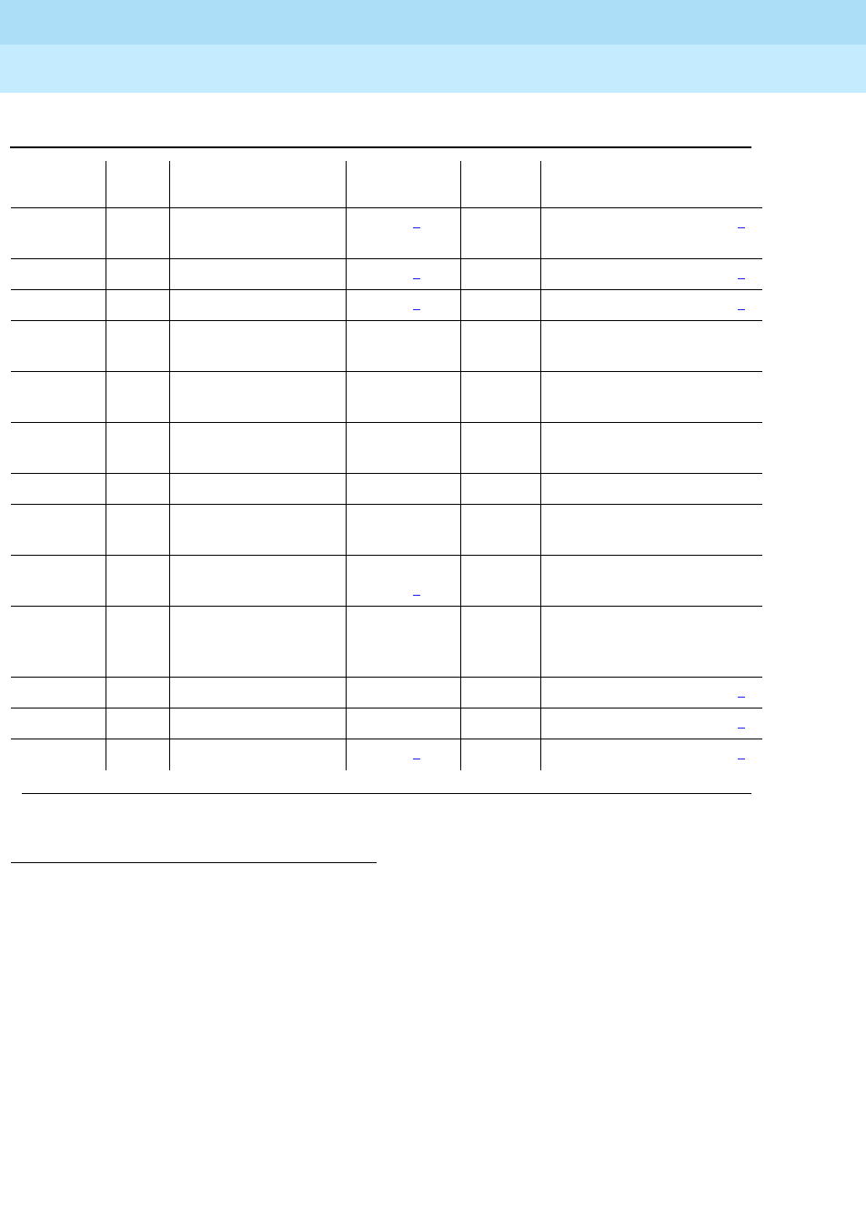
DEFINITY Enterprise Communications Server Release 6
Maintenance for R6r Volumes 1 & 2
555-230-126 Issue 2
January 1998
Maintenance Object Repair Procedures
Page 9-1060PKT-INT (Packet Interface Circuit Pack)
9
Notes:
a. Error 1 occurs when background maintenance software has reset the
Packet Interface circuit pack as a fault recovery action. It is used to keep
track of the number of times that the Packet Interface circuit pack is reset,
1. Indicates that an alarm was raised but an associated error was not entered into the hardware error
log due to a momentary overload condition caused by a burst of hardware or software error reports.
Run the long test sequence. Refer to the appropriate test descriptions for any failures and follow the
recommended procedures.
2. If a spontaneous interchange has occurred (as indicated by STBY-SPE error type 103 or the display
initcauses screen), and handshake is down, (check with status spe), replace the alarmed circuit
pack on the standby SPE. If handshake is up, execute a test long clear of the alarmed circuit pack
and follow recommended procedures.
3. A Packet Interface circuit pack on an active SPE can only be reset if it has been taken out of service
by background maintenance software. A Packet Interface circuit pack on a standby SPE can be
reset independent of its service state.
1025, (m) Any Private Looparound
Test (#885) MAJOR2ON reset packet-interface CS3
1026 Any None MAJOR2ON reset packet-interface CS3
1281 (n) Any None MAJOR2ON reset packet-interface CS3
1537 (o) Any Memory Checksum
Test (884) MINOR ON test packet-interface CS l r
2
1793 (p) Any Memory Checksum
Test (#884) MINOR ON test packet-interface CS l r
2
2049 (q) Any None WARNING ON test packet-interface CS r
25
2305 (r) Any None test packet-interface CS r 2
2561 (s) Any Active-Standby Peer
Link Test (#888) MINOR OFF test packet-interface CS s r
2
2817 (t) Any Read and Clear Test
(#887) MINOR/
MAJOR2ON test packet-interface CS s
3074,
3073,
3072 (u)
Any Maintenance
Looparound Test
(#886)
WARNING OFF test packet-interface CS s r
2
3329 (v) Any None WARNING OFF reset packet-interface CS3
3585 (w) Any None WARNING OFF reset packet-interface CS3
3841 (x) Any None MAJOR2OFF reset packet-interface CS3
Table 9-378. Packet Interface Error Log Entries — Continued
Error
Type Aux
Data Associated Test Alarm Level On/Off
Board Test to Clear Value
Continued on next page

DEFINITY Enterprise Communications Server Release 6
Maintenance for R6r Volumes 1 & 2
555-230-126 Issue 2
January 1998
Maintenance Object Repair Procedures
Page 9-1061PKT-INT (Packet Interface Circuit Pack)
9
independent of whether or not the Reset test passed. Once three of these
errors have occurred in the last 15 minutes, maintenance will place the
Packet Interface circuit pack into an out-of-service state, and a MAJOR
on-board alarm will be raised on the Packet Interface circuit pack.
1. Check to see if error codes 257, 513, 769, 1025, 1281, or 3841 are
present in the hardware error log. If one or more of those error
codes are present, refer to the information associated with those
errors for the appropriate repair procedures.
2. If no other Packet Interface errors appear in the error log, and if the
Packet Interface circuit pack is not in a held reset state as indicated
by the absence of a MAJOR alarm with a Service State of OUT, no
action should be taken. If a Packet Interface MAJOR alarm is
present and no other Packet Interface error codes are in the
hardware error log, execute a demand reset by entering reset
packet-interface CS and refer to the repair procedures for Test #
889.
b. Error 10 indicates that the Packet Interface maintenance software caused
an escalating system WARM restart as part of a recovery action for certain
Packet Interface circuit pack failures. A SYSTEM error type 10 should also
be present, indicating that a software initiated WARM restart occurred.
1. Check to see if error types 513, 1025, or 3074 are present in the
hardware error log. If they are present, refer to the repair
procedures for those errors for further action.
c. Error 23 along with an associated MAJOR alarm indicates that (a) Packet
Interface circuit pack translation data was loaded from the tape or disk at
boot time but the Packet Interface circuit pack was not detected to be
physically present or (b) a Packet Interface circuit pack is on the active
SPE but a corresponding Packet Interface circuit pack on the standby
SPE is missing.
1. If the Packet Interface circuit pack is physically present, replace the
circuit pack. The SPE must be rebooted to resolve the alarm.
2. Otherwise, insert the missing Packet Interface circuit pack into the
system or use the change system-parameters maintenance
command to change the entries for Packet Interface circuit packs
to match the circuit packs actually present. If a Packet Interface
circuit is added to the system, the SPE must be rebooted to resolve
the alarm.
d. Error 23 along with an associated MINOR alarm occurs when a user
logically administers a Packet Interface circuit pack using the change
system-parameters maintenance command when the Packet Interface
circuit pack is not physically present.
1. Use the display system-parameters maintenance command to
determine the number of Packet Interface circuit packs logically or
physically present.

DEFINITY Enterprise Communications Server Release 6
Maintenance for R6r Volumes 1 & 2
555-230-126 Issue 2
January 1998
Maintenance Object Repair Procedures
Page 9-1062PKT-INT (Packet Interface Circuit Pack)
9
2. Insert the missing Packet Interface circuit pack into the system or
use the change system-parameters maintenance command to
change the entries for Packet Interface circuit packs to match those
actually present.
e. Error 50 indicates that the SPE is sending more downlink messages than
the Packet Interface can keep up with. This is an in-line error not produced
by any test. When this error is reported, application software is slowed
down to allow the Packet Interface to process existing downlink
messages. If there is a hardware problem, the Packet Interface test will
normally cause other errors to be logged. In the rare case where there are
no other PKT-INT errors logged but error 50 occurs more than 10 times in
the last hour, follow normal escalation procedures.
f. Error 100 indicates that the SPE requested a reset of Packet Interface
circuit packs on the active SPE as part of a Packet Interface circuit pack
recovery action. In a High Reliability or Critical Reliability system, an SPE
interchange will occur instead of a Packet Interface circuit pack reset, if
the health of the standby SPE allows an interchange.
1. If no other PKT-INT errors except error code 1 are present, this
means that that the Packet Interface circuit pack was in a fatal fault
state at the time of system initialization or SPE interchange and it
was reset successfully. No other actions are required.
2. If PKT-INT error codes other than error code 1 are present, refer to
the repair procedures for those errors to correct the failure.
g. Error 150 indicates that a SPE interchange occurred and that the Packet
Interface circuit pack was the cause of the spontaneous interchange.
1. If other PKT-INT errors are present, investigate those errors.
2. If no other PKT-INT errors are present, run the test
packet-interface long clear command and investigate any
failures.
h. Error 200 indicates that memory shadowing was turned off in preparation
for resetting a Packet Interface circuit pack on the active SPE in a system
with the High Reliability or Critical Reliability Configuration. No action
should be taken based on this error code. Normally, when the state of
health of the standby SPE allows an SPE interchange, an SPE interchange
will be requested instead of a Packet Interface reset. However, if the state
of health of the standby SPE does not permit an SPE interchange, the
Packet Interface circuit pack on the active SPE will be reset. As part of that
reset action, memory shadowing is turned off so that the Packet Interface
circuit pack on the standby SPE will be refreshed after the active Packet
Interface circuit pack is reset.
i. Error 257 indicates that the circuit pack detected a fatal failure. This error
is a very serious and when it occurs, maintenance software immediately
escalates testing to the destructive reset test (#889).
1. If the Packet Interface circuit has a MAJOR alarm:

DEFINITY Enterprise Communications Server Release 6
Maintenance for R6r Volumes 1 & 2
555-230-126 Issue 2
January 1998
Maintenance Object Repair Procedures
Page 9-1063PKT-INT (Packet Interface Circuit Pack)
9
a. Reset the Packet Interface circuit pack using the reset
packet-interface CS command.
b. Refer to the repair procedures for the Packet Interface Reset
Test (#889).
2. If the Packet Interface circuit pack is not alarmed, no action is
required.
j. Errors 267 and 217 indicate that the number of Packet Interface circuit
packs detected as being physically present exceeds number of Packet
Interface circuit packs supported by the software configuration or, if the
SPEs are duplicated, that a Packet Interface circuit pack is detected as
being physically present on the standby SPE but the corresponding
Packet Interface circuit pack on the active SPE is not present.
1. If more than one Packet Interface circuit pack is inserted in the
active or standby SPE carrier, remove the extra circuit pack(s).
2. If the SPE is duplicated, visually check that the number and
location of Packet Interface circuit packs in the standby SPE carrier
match the number and location of Packet Interface circuit packs in
the active SPE carrier. If there is a mismatch, insert Packet Interface
circuit packs in the standby SPE to match the Packet Interface
circuit packs in the active SPE.
k. Error 513 is called Message Handshake failure. It indicates that a failure
with the message protocol between the SPE software and the Packet
Interface circuit pack was detected.
1. If the Packet Interface circuit has a MAJOR alarm:
a. Reset the Packet Interface circuit pack using the reset
packet-interface CS command.
b. Refer to the repair procedures for the
Packet Interface Reset
Test (#889)
.
2. If the Packet Interface circuit pack is not alarmed, no action is
required.
l. Error 769 indicates that there was a failure in the
Packet Looparound test
.
A maintenance looparound link cannot be established or the Packet
Interface circuit pack cannot send and receive data correctly as part of
the looparound test (Test #886). If the number of errors exceeds a defined
threshold, a Major alarm will be raised.
In a system equipped with duplicated SPEs, a failure of the Maintenance
Looparound test may have caused an SPE interchange which would result
in an alarm associated with error code 769 being reported against a
Packet Interface circuit pack that is currently on the standby SPE. If so, it
may be necessary to force the standby SPE to go active by using the
SPE-SELECT switches on the DUPINT circuit packs to run the
Maintenance Looparound test to make sure the problem is cleared.
For more information, refer to the repair procedures of Test #886.

DEFINITY Enterprise Communications Server Release 6
Maintenance for R6r Volumes 1 & 2
555-230-126 Issue 2
January 1998
Maintenance Object Repair Procedures
Page 9-1064PKT-INT (Packet Interface Circuit Pack)
9
m. Error 1025 indicates a failure of the private Level 3 looparound test (Test #
885).
1. If the Packet Interface circuit has a MAJOR alarm:
a. Reset the Packet Interface circuit pack using the reset
packet-interface CS command.
b. Refer to the repair procedures for the
Packet Interface Reset
Test (#889)
.
2. If the Packet Interface circuit pack is not alarmed, no action is
required.
n. Error 1281 indicates that the Packet Interface circuit pack has Translation
RAM failures. PKT-INT Translation RAM is used to convert the addresses
of a packet to the destination endpoint address.
1. If the Packet Interface circuit has a MAJOR alarm:
a. Reset the Packet Interface circuit pack using the reset
packet-interface CS command.
b. Refer to the repair procedures for the
Packet Interface Reset
Test (#889)
.
2. If the Packet Interface circuit pack is not alarmed, no action is
required.
o. Error 1537 indicates a Boot PROM memory failure. The Packet Interface
circuit pack may still be operational if no other errors are reported.
However the circuit pack may report a fatal fault during board initialization.
This may occur during a system recovery level more severe than a WARM
restart. For more information, refer to Test #884.
p. Error 1793 indicates a FLASH Memory test failure. The Packet Interface
circuit pack may still be operational if no other errors are reported.
However the circuit pack may report a fatal fault during board initialization.
This may occur during a system recovery level more severe than a WARM
restart. For more information, refer to the repair procedures of Test #884.
q. Error 2049 indicates a LAPD Received Buffer Overflow error. The Packet
Interface circuit pack Packet bus receive buffer overflowed. For more
information, refer to the repair procedures of Test #887.
r. Error 2305 indicates a Packet Bus Interface Detected Parity failure. The
Packet Interface circuit pack received packets with parity error from the
Packet bus.
1. Check for errors logged against the Packet bus and
Maintenance/Test circuit pack. Refer to the appropriate repair
procedures to clear those errors first.
2. Check all other circuit packs connected to the Packet bus in the
same cabinet. Packet Bus failures are likely to be caused by a
faulty circuit pack connected to the backplane or bent pins on the
back plane.

DEFINITY Enterprise Communications Server Release 6
Maintenance for R6r Volumes 1 & 2
555-230-126 Issue 2
January 1998
Maintenance Object Repair Procedures
Page 9-1065PKT-INT (Packet Interface Circuit Pack)
9
3. If steps 1 and 2 above do not clear the problem, execute the test
packet-interface command and follow repair procedures
described for Test #887.
s. Error 2561 indicates a Active-Standby Peer Link test failure indicating a
possible failure of the Packet Interface circuit pack on the active SPE or a
failure of the corresponding Packet Interface circuit pack on the standby
SPE. If the number of errors exceeds a defined threshold, a Minor alarm
will be raised. For more information, refer to the repair procedures of Test
#888.
t. Error 2817 indicates a Standby Packet Interface circuit pack Translation
RAM failure. A MINOR alarm is raised when there are 1 to 5 bad locations
and a MAJOR alarm is raised when there are 5 or more bad locations.
Execute the test packet-interface command and follow repair procedures
described for Test #887.
u. Errors 3074, 3073, and 3072 indicate PKT-INT Transmit Buffer Overflow,
which means that the number of transmit buffers required by software
exceeded the number available. A 3074 error is generated when the
PKINT sends an in-line hardware error to maintenance software indicating
transmit buffer overflow. As part of the background recovery action for this
error, maintenance software will automatically run the Maintenance
Looparound test (#886). If that test fails, maintenance software generates
error codes 3073 and 3072, and it requests a system WARM restart. If,
after the WARM restart, transmit buffer overflow errors continue to be
reported, maintenance software generates error code 100 and it resets
the PKT-INT. These errors may be the result of system overload due to a
problem with communication between the PKT-INT and the EPNs.
1. Check for errors logged against the Expansion Interface circuit
pack, the Switch Node Interface circuit pack, Packet Gateway
circuit pack, the Packet Data Line circuit packs associated with the
System Ports, BRI Line circuit packs and BRI endpoints, and the
Universal DS1 circuit packs supporting PRI service. Errors against
those components should be cleared first.
2. Enter the test packet-interface short command against the Packet
Interface circuit pack associated with the error. If the Maintenance
Looparound test (#886) test passes, the alarm will clear. If the test
fails, repeat the test 5 times. If it continues to fail, follow normal
escalation procedures.
v. Error 3329 indicates that the TDM clock has failed. The Tone Board should
have been alarmed (TONE-BD, TDM-CLK). Refer to TDM-CLK and/or
TONE-BD for further action. The Packet Interface circuit is taken out of
service when this failure occurs. Execute the reset packet-interface
command to bring the Packet Interface circuit back into service.
w. Error 3585 indicates that a Packet bus failure has been detected and that
the Packet bus is alarmed. Refer to the Packet Bus maintenance
documentation for further action.

DEFINITY Enterprise Communications Server Release 6
Maintenance for R6r Volumes 1 & 2
555-230-126 Issue 2
January 1998
Maintenance Object Repair Procedures
Page 9-1066PKT-INT (Packet Interface Circuit Pack)
9
x. Error 3841 indicates that the Packet Interface circuit pack has reported a
fatal fault failure condition that may be caused by a Packet Bus failure on
the Processor Port Network.
1. If error 3585 has also been reported, refer to the maintenance
documentation for PKT (Packet Bus) maintenance. After the Packet
Bus failure has been corrected, execute the reset packet-interface
command to bring the Packet Interface circuit back into service.
2. If error 3585 has not been reported, enter the reset
packet-interface command and follow the repair steps associated
with test #889.
System Technician-Demanded Tests:
Descriptions and Error Codes
Always investigate tests in the order presented in the table below. By clearing
error codes associated with the
Packet Interface Private Looparound
test for
example, you may also clear errors generated from other tests in the testing
sequence.
Notes:
a. This test is run only on a Packet Interface circuit pack on an active SPE.
b. This test is run only on a Packet Interface circuit pack on a standby SPE.
1. D = Destructive; ND = Nondestructive
Order of Investigation Short Test
Sequence Long Test
Sequence Reset Board
Sequence D/ND1
Packet Interface Reset Test (#889) X D
Packet Interface Private Looparound Tests
(#885) XND
Packet Interface Maintenance Looparound
Test (#886) (a) XX ND
Packet Interface Memory Checksum Test
(#884) XND
Packet Interface Error Counter Read and
Clear Test (#887) XX ND
Packet Interface Active-Standby Peer Link
Test (#888) (b) XX ND

DEFINITY Enterprise Communications Server Release 6
Maintenance for R6r Volumes 1 & 2
555-230-126 Issue 2
January 1998
Maintenance Object Repair Procedures
Page 9-1067PKT-INT (Packet Interface Circuit Pack)
9
Memory Checksum Test (#884)
This test involves sending a message to the Packet Interface circuit pack to run
private non-destructive memory checksum tests on the firmware text residing in
Boot PROM and FLASH memory. If the test fails during background testing, the
circuit pack will remain operational until a reset is executed on the circuit pack.
Then the initialization firmware will fail and will put the circuit pack in an
out-of-service state.
Table 9-379. TEST #884 Memory Checksum Test
Error
Code Test
Result Description/ Recommendation
1006
1137 ABORT Packet Interface circuit pack is in the out-of-service state so normal
maintenance tests will not run on that circuit pack.
1. Request a Packet Interface circuit pack reset using the reset
packet-interface CS command. Refer to the Packet Interface Reset Test
(#889) repair procedures for further action.
1334 ABORT The Packet Interface circuit pack command queue is full. This should be a
temporary condition caused by a high rate of commands being sent to a
Packet Interface circuit pack. Continued operation with a full command queue
will cause a system WARM restart that may escalate to more severe restart
levels.
1. Retry the command at 10-second intervals, a maximum of 5 times.
1338 ABORT The test is not allowed to run since a planned SPE interchange is in progress. A
planned interchange may be caused by 24 hour scheduled testing. During this
time the terminal will be held out of service but it should recover automatically
after three minutes.
1. Wait three minutes and retry the command.
1339 ABORT The test could not run on the standby Packet Interface circuit pack because the
standby SPE is unavailable.
1. Refer to the STBY-SPE maintenance documentation for information on why
a standby SPE may be unavailable and what repair actions should be
taken. The status spe screen should indicate that handshake is down. This
may be caused by a variety of reasons such as the setting the
SPE-SELECT switches on the DUPINT circuit packs to the position of the
active SPE, a failure of the DUPINT circuit pack, or loss of power on the
standby SPE, The
SPE Selected
field on the status spe screen will display
spe a
or
spe b
if the SPE-SELECT switches are in the a or b position,
respectively.
Continued on next page

DEFINITY Enterprise Communications Server Release 6
Maintenance for R6r Volumes 1 & 2
555-230-126 Issue 2
January 1998
Maintenance Object Repair Procedures
Page 9-1068PKT-INT (Packet Interface Circuit Pack)
9
1347 ABORT The test could not run because refresh of the standby SPE’s memory is not
complete.
1. Enter status spe and verify that refresh is not complete. Wait until the
status screen indicates that refresh is complete and try the command
again. The status screen should indicate that shadowing is on. If some
event such as a major alarm on a Packet Interface circuit pack on the
standby SPE causes shadowing to turn off, refresh cannot complete and
abort code 1350 will be returned when test packet-interface is entered.
1350 ABORT The test could not run because memory shadowing has not started.
1. Enter status spe and verify that shadowing has not started. The SPE is
locked when the SPE-SELECT switches on the DUPINT circuit pack are set
to the position of the active SPE. Return the switches to the neutral position.
If the SPE is not locked, verify that there are no alarms active for the
standby SPE. If there are, enter "display alarms" and verify that there are no
major alarms against the standby Packet Interface circuit packs. If there
are, clear those alarms first.
2000 ABORT Response to the test request was not received within the allowable time period.
If the system is equipped with the High Reliability or Critical Reliability
Configuration and if the Packet Interface circuit pack is on the standby SPE,
this abort code may indicate that the standby SPE is not responding to the
handshake message. If this is the case, the standby SPE maintenance software
may take up to two minutes to indicate that handshake communication with the
standby SPE is down. The ABORT code will then change to 1339 (standby SPE
unavailable).
1. Retry the command at 1-minute intervals, a maximum of 3 times.
2500 ABORT Internal system error
1. Retry the command.
NO
BOARD The Packet Interface circuit pack is administered but it is not detected as being
physically present.
1. If the Packet Interface circuit pack is present, replace it.
2. If the Packet Interface circuit pack is not physically present, use the
display system-parameters maintenance command to check if the
Packet Interface circuit pack is administered as being present. If it is
administered, use the change system-parameters maintenance
command to change the Packet Interface circuit packs administered to be
those actually present.
Table 9-379. TEST #884 Memory Checksum Test — Continued
Error
Code Test
Result Description/ Recommendation
Continued on next page

DEFINITY Enterprise Communications Server Release 6
Maintenance for R6r Volumes 1 & 2
555-230-126 Issue 2
January 1998
Maintenance Object Repair Procedures
Page 9-1069PKT-INT (Packet Interface Circuit Pack)
9
1537 FAIL The Boot PROM memory checksum test failed. The circuit pack may still be
operational.
1. Retry the command.
2. If the same error code occurs
a. If the system is not equipped with the High Reliability or Critical
Reliability Configuration replace the circuit pack at a time that would
cause the least disruption of service. The circuit pack is still functional
but should be replaced since it may not operate after a system reboot
and it will enter a fatal fault state if it is reset for other reasons.
b. If the system is equipped with the High Reliability or Critical Reliability
Configuration and if the Packet Interface circuit pack is on the standby
SPE, replace that circuit pack.
c. If the system is equipped with the High Reliability or Critical Reliability
Configuration and if the Packet Interface circuit pack is on the active
SPE, perform a planned SPE interchange by entering the command
reset system interchange. Use the status spe command to determine
when refresh is complete (between 2 to 10 minutes, depending on
system size) and retry the test command. If the test of the circuit pack
on the standby SPE continues to fail, replace that circuit pack.
1793 FAIL The Flash memory checksum test failed. The circuit pack may still be
operational but it will fail if a reset is executed.
1. Retry the command.
2. If the same error code occurs
a. If the system is not equipped with the High Reliability or Critical
Reliability Configuration replace the circuit pack at a time that would
cause the least disruption of service. The circuit pack is still functional
but should be replaced since it may not operate after a system reboot
and it will enter a fatal fault state if it is reset for other reasons.
b. If the system is equipped with the High Reliability or Critical Reliability
Configuration and if the Packet Interface circuit pack is on the standby
SPE, replace that circuit pack.
c. If the system is equipped with the High Reliability or Critical Reliability
Configuration and if the Packet Interface circuit pack is on the active
SPE, perform a planned SPE interchange by entering the command
reset system interchange. Use the status spe command to determine
when refresh is complete (between 2 to 10 minutes, depending on
system size) and retry the test command. If the test of the circuit pack
on the standby SPE continues to fail, replace that circuit pack.
Table 9-379. TEST #884 Memory Checksum Test — Continued
Error
Code Test
Result Description/ Recommendation
Continued on next page

DEFINITY Enterprise Communications Server Release 6
Maintenance for R6r Volumes 1 & 2
555-230-126 Issue 2
January 1998
Maintenance Object Repair Procedures
Page 9-1070PKT-INT (Packet Interface Circuit Pack)
9
Private Looparound Tests (#885)
This test requests the Packet Interface circuit pack to execute its three private
looparound tests: Level 2 looparound, Broadcast path looparound, and Level 3
looparound. These tests verify the health of the circuit pack’s Packet Bus
interface, as well as the translation RAM, inward and outward bound data paths,
parity indications and CRC calculations, and the Level 3 processing firmware.
■Level 2 (LAPD) Link Looparound
LAPD is a link level protocol that is used for all system links. This test
verifies the health of the processing of these links.
■Broadcast Link Looparound
Each ISDN BRI port has two associated broadcast signaling links, one for
call control and one for maintenance and management. Since these links
have separate routing circuitry from the Level 2 Looparound, this test
forces a CRC error to verify the CRC hardware associated with the
broadcast data path.
■Level 3 Link Looparound
Level 3 Links support the X.25 Data Phase protocol used with the Packet
Gateway to support X.25 links such as those used for AUDIX. This test
verifies the health of the Level 3 firmware. Since soft errors are possible,
the Packet Interface circuit pack retries the test before reporting an error.
These tests are also run as part of the reset tests. If the Level 2 or Level 3
looparound test fail as background tests, a "fatal error" message will be sent to
the Packet Interface maintenance software and the Packet Interface circuit pack
will be put in the "out-of-service" state. Therefore, it is expected that the repair
procedures associated with Abort Code 1137 (out-of-service) would normally be
followed when failures with the Level 2 and Level 3 tests occur.
PASS The circuit pack’s firmware is in a proper state. If problems are still reported on
the circuit pack, check for errors on the Private Looparound test (#885) and
Maintenance Looparound Test (#886).
Table 9-379. TEST #884 Memory Checksum Test — Continued
Error
Code Test
Result Description/ Recommendation
Continued on next page

DEFINITY Enterprise Communications Server Release 6
Maintenance for R6r Volumes 1 & 2
555-230-126 Issue 2
January 1998
Maintenance Object Repair Procedures
Page 9-1071PKT-INT (Packet Interface Circuit Pack)
9
Table 9-380. TEST #885 Private Looparound Tests
Error
Code Test
Result Description/ Recommendation
1006
1137 ABORT Packet Interface circuit pack is in the out-of-service state so normal
maintenance tests will not run on that circuit pack.
1. Request a Packet Interface circuit pack reset using the reset
packet-interface CS command. Refer to the Packet Interface Reset Test
(#889) repair procedures for further action.
1334 ABORT The Packet Interface circuit pack command queue is full. This should be a
temporary condition caused by a high rate of commands being sent to a
Packet Interface circuit pack. Continued operation with a full command queue
will cause a system WARM restart that may escalate to more severe restart
levels.
1. Retry the command at 10-second intervals, a maximum of 5 times.
1338 ABORT The test is not allowed to run since a planned SPE interchange is in progress.
A planned interchange may be caused by 24 hour scheduled testing. During
this time the terminal will be held out of service but it should recover
automatically after 3 minutes.
1. Wait 3 minutes and retry the command.
1339 ABORT The test could not run on the standby Packet Interface circuit pack because
the standby SPE is unavailable.
1. Refer to the STBY-SPE maintenance documentation for information on why
a standby SPE may be unavailable and what repair actions should be
taken. The status spe screen should indicate that handshake is down.
This may be caused by a variety of reasons such as the setting the
SPE-SELECT switches on the DUPINT circuit packs to the position of the
active SPE, a failure of the DUPINT circuit pack, or loss of power on the
standby SPE, The
SPE Selected field
on the status spe screen will display
spe a
or
spe b
if the SPE-SELECT switches are in the a or b position,
respectively.
1347 ABORT The test could not run because refresh of the standby SPE’s memory is not
complete.
1. Enter status spe and verify that refresh is not complete. Wait until the
status screen indicates that refresh is complete and try the command
again. The status screen should indicate that shadowing is on. If some
event such as a major alarm on a Packet Interface circuit pack on the
standby SPE causes shadowing to turn off, refresh cannot complete and
abort code 1350 will be returned when the test packet-interface command
is entered.
Continued on next page

DEFINITY Enterprise Communications Server Release 6
Maintenance for R6r Volumes 1 & 2
555-230-126 Issue 2
January 1998
Maintenance Object Repair Procedures
Page 9-1072PKT-INT (Packet Interface Circuit Pack)
9
1350 ABORT The test could not run because memory shadowing has not started.
1. Enter status spe and verify that shadowing has not started. The SPE is
locked when both SPE-SELECT switches on the two DUPINT circuit packs
are set to the position of the active SPE. Return the switches to the neutral
position. If the SPE is not locked, verify that there are no alarms active for
the standby SPE. If there are, enter "display alarms" and verify that there
are no major alarms against the standby Packet Interface circuit packs. If
there are, clear those alarms first.
2000 ABORT Response to the test request was not received within the allowable time period.
If the system is equipped with the High Reliability or Critical Reliability
Configuration and if the Packet Interface circuit pack is on the standby SPE,
this abort code may indicate that the standby SPE is not responding to the
handshake message. If this is the case, the standby SPE maintenance
software may take up to two minutes to indicate that handshake
communication with the standby SPE is down. The ABORT code will then
change to 1339 (standby SPE unavailable).
1. Retry the command at 1-minute intervals, a maximum of 3 times.
2500 ABORT Internal system error
1. Retry the command.
NO
BOARD The Packet Interface circuit pack is administered but it is not detected as
being physically present.
1. If the Packet Interface circuit pack is present, replace it.
2. If the Packet Interface circuit pack is not physically present, use the
display system-parameters maintenance command to check if the
Packet Interface circuit pack is administered as being present. If it is
administered, use the change system-parameters maintenance
command to change the Packet Interface circuit packs administered to be
those actually present.
1 FAIL The Private Link Broadcast looparound test failed. The circuit pack will enter a
fatal fault state when this occurs and the Packet Interface Maintenance
software should put the circuit in a out-of-service state. Therefore by the time
further action is taken, it is expected that the test will abort with ABORT code
1137 and a demand reset should be used to test the circuit pack.
1. Reset the circuit pack using the reset packet-interace CS command.
Refer to the repair procedures for the Packet Interface Reset Test (#889)
for further action.
2. If the test continues to fail, replace the Packet Interface circuit pack.
Table 9-380. TEST #885 Private Looparound Tests — Continued
Error
Code Test
Result Description/ Recommendation
Continued on next page

DEFINITY Enterprise Communications Server Release 6
Maintenance for R6r Volumes 1 & 2
555-230-126 Issue 2
January 1998
Maintenance Object Repair Procedures
Page 9-1073PKT-INT (Packet Interface Circuit Pack)
9
2 FAIL The Private Level 2 looparound test failed. The circuit pack will enter a fatal
fault state when this occurs and the Packet Interface Maintenance software
should put the circuit in a out-of-service state. Therefore by the time further
action is taken, it is expected that the test will abort with ABORT code 1137
and a demand reset should be used to test the circuit pack.
1. Reset the circuit pack using the reset packet-interace CS command.
Refer to the repair procedures for the Packet Interface Reset Test (#889)
for further action.
2. If the test continues to fail, replace the Packet Interface circuit pack.
3 FAIL The Private Link Level 3 looparound test failed. The circuit pack may still be
operational.
1. Retry the command.
2. If the test continues to fail with the same error code:
a. If the system is not equipped with the High Reliability or Critical
Reliability Configuration replace the Packet Interface circuit pack.
b. If the system is equipped with the High Reliability or Critical Reliability
Configuration and if the Packet Interface circuit pack is on the standby
SPE, replace the circuit pack on the standby SPE.
c. If the system is equipped with the High Reliability or Critical Reliability
Configuration and if the Packet Interface circuit pack is on the active
SPE,
3. Perform a planned SPE interchange by entering the command reset
system interchange. Use the status spe command to determine when
refresh is complete (between 2 to 10 minutes, depending on system size)
and retry the test command.
4. If the test of the circuit pack on the standby SPE continues to fail, replace
that circuit pack.
PASS All the private looparound tests passed. The circuit pack is functioning
properly. If the system is still unable to place calls on cabinets other than the
SPE cabinet, then:
1. Display the error log using the command display errors and check for
errors on the Packet Bus and Maintenance/Test circuit pack. Clear those
errors first.
2. Check all other circuit packs connected to the Packet Bus in the same
cabinet. Packet Bus failures are likely to be caused by a faulty circuit pack
connected to the backplane or bent pins on the back plane. Refer to the
PKT-BUS maintenance documentation for repair procedures.
Table 9-380. TEST #885 Private Looparound Tests — Continued
Error
Code Test
Result Description/ Recommendation
Continued on next page
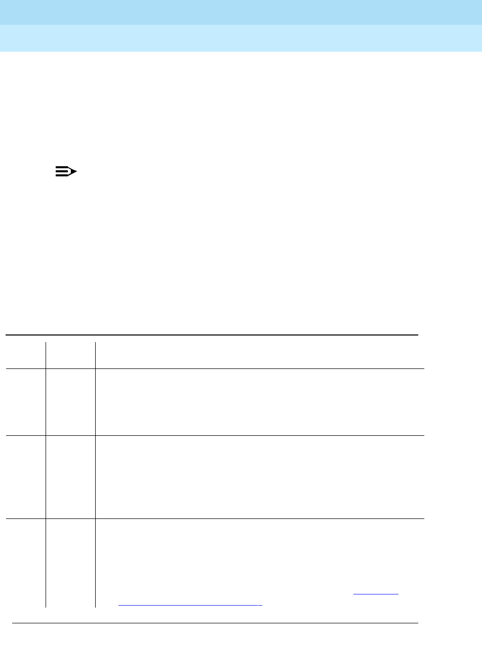
DEFINITY Enterprise Communications Server Release 6
Maintenance for R6r Volumes 1 & 2
555-230-126 Issue 2
January 1998
Maintenance Object Repair Procedures
Page 9-1074PKT-INT (Packet Interface Circuit Pack)
9
Maintenance Looparound Test (#886)
This test checks whether the Packet Interface circuit pack can send and receive
data correctly. It establishes a LAPD link from a Packet Interface circuit pack
back to the same Packet Interface circuit pack and transmits and receives test
data over that testing link. While timing signals from the Packet Bus are used for
the data transfer, the data itself is looped around on the circuit pack at the
interface to the Packet Bus and does not get sent over the Packet Bus.
NOTE:
This test is not run if the Packet Interface circuit pack is on a standby SPE in
a system equipped with duplicated SPEs. However, a failure of the
Maintenance Looparound test may have caused an SPE interchange which
would result in an alarm associated with the looparound failure error code
769 being reported against a Packet Interface circuit pack that is currently
on the standby SPE. If that is the case, and if all other Packet Interface tests
associated with the test packet-interface CS long pass, force the standby
SPE to go active by using the SPE-SELECT switches. Then enter the test
packet-interface CS command to run the Maintenance Looparound test to
make sure the problem has been cleared.
Table 9-381. TEST #886 Maintenance Looparound Test
Error
Code Test
Result Description/ Recommendation
1006
1137 ABORT Packet Interface circuit pack is in the out-of-service state so normal
maintenance tests will not run on that circuit pack.
1. Request a Packet Interface circuit pack reset using the reset
packet-interface CS command. Refer to the Packet Interface Reset Test
(#889) maintenance documentation for further action.
1139 ABORT The Packet Bus is alarmed
1. Try to retire the alarm associated with the Packet Bus. Refer to the Alarm
Log via the display alarms command. Refer to the maintenance
documentation for Packet Bus Maintenance for further action.
2. Retry the command when the alarm associated with the Packet Bus is
retired.
1335 ABORT Internal system error. The Packet Interface circuit pack is on the standby SPE
and this test is not allowed to execute on a Packet Interface circuit pack on the
standby SPE.
1. If you wish to run this test on the standby Packet Interface, you must first
make it active with reset system interchange. Be sure you understand
the implications explained in
Planned SPE Interchange
in Chapter 5,
‘‘Responding to Alarms and Errors’’.
Continued on next page

DEFINITY Enterprise Communications Server Release 6
Maintenance for R6r Volumes 1 & 2
555-230-126 Issue 2
January 1998
Maintenance Object Repair Procedures
Page 9-1075PKT-INT (Packet Interface Circuit Pack)
9
1338 ABORT The test is not allowed to run since a planned SPE interchange is in progress.
A planned interchange may be caused by 24 hour scheduled testing. During
this time the terminal will be held out of service but it should recover
automatically after 3 minutes.
1. Wait 3 minutes and retry the command.
1373 ABORT Could not establish the link loop around link to run this test.
1. Retry the command at 1-minute intervals, a maximum of 3 times.
2060 ABORT Packet link bus went down during maintenance looparound test.
1. Retry the command at 1-minute intervals, a maximum of 5 times.
2. If there are errors associated with the Packet Bus, refer to the
maintenance information associated with the Packet Bus.
2100 ABORT Could not allocate the necessary system resources to run this test.
1. Retry the command at 1-minute intervals, a maximum of 5 times.
2500 ABORT Internal system error
1. Retry the command at 1-minute intervals, a maximum of 5 times.
NO
BOARD The Packet Interface circuit pack is administered but it is not detected as
being physically present.
1. If the Packet Interface circuit pack is present, replace it.
2. If the Packet Interface circuit pack is not physically present, use the
display system-parameters maintenance command to check if the
Packet Interface circuit pack is administered as being present. If it is
administered, use the change system-parameters maintenance
command to change the Packet Interface circuit packs administered to be
those actually present.
Table 9-381. TEST #886 Maintenance Looparound Test — Continued
Error
Code Test
Result Description/ Recommendation
Continued on next page

DEFINITY Enterprise Communications Server Release 6
Maintenance for R6r Volumes 1 & 2
555-230-126 Issue 2
January 1998
Maintenance Object Repair Procedures
Page 9-1076PKT-INT (Packet Interface Circuit Pack)
9
Read and Clear Board Counters (#887)
This test involves sending commands to read on-circuit pack error counters on
the Packet Interface circuit pack. It also verifies the message interface between
the SPE and the Packet Interface circuit pack.
This test checks different circuit pack counters depending on whether the circuit
pack is on the active or standby SPE.
If the Packet Interface circuit pack is on the active SPE, this test reads and clears
the Parity Error counter and FIFO Overflow counter. Those counters are not used
when a Packet Interface circuit pack is in standby mode.
If the Packet Interface circuit pack is on the standby SPE, this test reads but does
not clear a Translation RAM counter. The Translation RAM counter is not cleared
1-3 FAIL The test failed. Maintenance was unable to establish a looparound link from
the Packet Interface circuit pack back to itself or was unable to receive data
that was sent out over one side of the looparound link.
1. Issue the test packet-interface CS command to retry the test. If the same
error code is observed, background maintenance software will
automatically attempt to reset the circuit pack and clear the problem.
2. Retry the command and if the test fails, replace the circuit pack.
3. If the test continues to fail after replacing the circuit pack, run the test
packet P long command. If any of the tests fail, the fault may be on the
Packet Bus. Refer to the PKT-BUS (Packet Bus) Maintenance
documentation for recommended repair procedures.
4. If the test continues to fail after the circuit pack is replaced and with no
other alarms associated with the Packet Bus or circuit packs connected to
the Packet Bus, follow normal escalation procedures.
PASS This test passed. The circuit pack and its interface with the SPE are
functioning properly. If the system is unable to place calls on cabinets other
than the SPE cabinet, then:
1. Check for errors on the Packet Bus and Maintenance/Test circuit pack.
Solve those errors first.
2. Check all other circuit packs connected to the Packet Bus in the same
cabinet. Packet Bus failures are likely to be caused by a faulty circuit pack
connected to the backplane or bent pins on the back plane.
3. Check the Packet Interface circuit pack connections to the Packet Bus.
Table 9-381. TEST #886 Maintenance Looparound Test — Continued
Error
Code Test
Result Description/ Recommendation
Continued on next page

DEFINITY Enterprise Communications Server Release 6
Maintenance for R6r Volumes 1 & 2
555-230-126 Issue 2
January 1998
Maintenance Object Repair Procedures
Page 9-1077PKT-INT (Packet Interface Circuit Pack)
9
since the number of bad translations RAM locations indicates bad locations that
cannot be used. For a Packet Interface Circuit Pack on the active SPE,
information about the number of bad Translation location is sent to maintenance
software as an in-line error from the circuit pack so it is not necessary to read a
counter location.
Table 9-382. TEST #887 Read and Clear Board Counters
Error
Code Test
Result Description/ Recommendation
1006
1137 ABORT Packet Interface circuit pack is in the out-of-service state so normal
maintenance tests will not run on that circuit pack.
1. Request a Packet Interface circuit pack reset using the reset
packet-interface CS command. Refer to the Packet Interface Reset Test
(#889) maintenance documentation for repair procedures.
1338 ABORT The test is not allowed to run since a planned SPE interchange is in progress. A
planned interchange may be caused by 24 hour scheduled testing. During this
time the terminal will be held out of service but it should recover automatically
after 3 minutes.
1. Wait 3 minutes and retry the command.
1339 ABORT The test could not run on the standby Packet Interface circuit pack because the
standby SPE is unavailable.
1. Refer to the STBY-SPE maintenance documentation for information on why
a standby SPE may be unavailable and what repair actions should be
taken. The status spe screen should indicate that handshake is down. This
may be caused by a variety of reasons such as the setting the
SPE-SELECT switches on the DUPINT circuit packs to the position of the
active SPE, a failure of the DUPINT circuit pack, or loss of power on the
standby SPE, The
SPE Selected field
on the status spe screen will display
spe a
or
spe b
if the SPE-SELECT switches are in the a or b position,
respectively.
1347 ABORT The test could not run because refresh of the standby SPE’s memory is not
complete.
1. Enter status spe and verify that refresh is not complete. Wait until the
status screen indicates that refresh is complete and try the command
again. The status screen should indicate that shadowing is on. If some
event such as a major alarm on a Packet Interface circuit pack on the
standby SPE causes shadowing to turn off, refresh cannot complete and
abort code 1350 will be returned when the test packet-interface command
is entered.
Continued on next page

DEFINITY Enterprise Communications Server Release 6
Maintenance for R6r Volumes 1 & 2
555-230-126 Issue 2
January 1998
Maintenance Object Repair Procedures
Page 9-1078PKT-INT (Packet Interface Circuit Pack)
9
1350 ABORT The test could not run because memory shadowing has not started.
1. Enter status spe and verify that shadowing has not started. The SPE is
locked when the SPE-SELECT switches on the DUPINT circuit pack are set
to the position of the active SPE. Return the switches to the neutral position.
If the SPE is not locked, verify that there are no alarms active for the
standby SPE. If there are, enter display alarms and verify that there are no
major alarms against the standby Packet Interface circuit packs. If there
are, clear those alarms first.
2000 ABORT Response to the test request was not received within the allowable time period.
If the system is equipped with the High Reliability or Critical Reliability
Configuration and if the Packet Interface circuit pack is on the standby SPE,
this abort code may indicate that the standby SPE is not responding to the
handshake message. If this is the case, the standby SPE maintenance software
may take up to two minutes to indicate that handshake communication with the
standby SPE is down. The ABORT code will then change to 1339 (standby SPE
unavailable).
1. Retry the command at 1-minute intervals, a maximum of 3 times.
2500 ABORT Internal system error
1. Retry the command.
NO
BOARD The Packet Interface circuit pack is administered but it is not detected as being
physically present.
1. If the Packet Interface circuit pack is present, replace it.
2. If the Packet Interface circuit pack is not physically present, use the
display system-parameters maintenance command to check if the
Packet Interface circuit pack is administered as being present. If it is
administered, use the change system-parameters maintenance
command to change the Packet Interface circuit packs administered to be
those actually present.
Table 9-382. TEST #887 Read and Clear Board Counters — Continued
Error
Code Test
Result Description/ Recommendation
Continued on next page

DEFINITY Enterprise Communications Server Release 6
Maintenance for R6r Volumes 1 & 2
555-230-126 Issue 2
January 1998
Maintenance Object Repair Procedures
Page 9-1079PKT-INT (Packet Interface Circuit Pack)
9
256
512
768
FAIL The Packet Interface circuit pack on the active SPE has an error counter set.
The following error codes are possible: 256: Parity error 512: FIFO overflow
768: Parity error and FIFO overflow error
1. If error code 256 or 768 is reported the Packet Interface circuit pack
received a parity error off the Packet Bus.
a. First check for alarms logged against the Packet Bus. Refer to the
PKT-BUS maintenance documentation to clear those errors first.
b. Then check for alarms and errors logged against other circuit packs
connected to the Packet bus in the Processor Port Network cabinet. A
list of packet circuit packs is presented in the first section of this repair
procedure. Refer to the repair procedures for those circuit packs, in this
manual, to clear those errors first.
c. If the system is not equipped with the High Reliability or Critical
Reliability Configuration, replace the circuit pack at a time that would
cause the least disruption of service. The circuit pack is still functional
but should be replaced.
d. If the system is equipped with the High Reliability or Critical Reliability
Configuration and if the Packet Interface circuit pack is on the standby
SPE, replace that circuit pack.
e. If the system is equipped with the High Reliability or Critical Reliability
Configuration and if the Packet Interface circuit pack is on the active
SPE, perform a planned SPE interchange by entering the command
reset system interchange. Replace the circuit pack on the standby
SPE.
256
512
768
FAIL
(cont’d.)
2. If error code 512 or 768 is reported for a Packet Interface on an active
SPE, the receive FIFO in the PKT-INT has overflowed. This may be an
indication that additional Packet Interface circuit packs are required. For
the current hardware configuration, only one Packet Interface circuit pack
is allowed so the problem should be escalated if the repair steps
presented below do not correct the problem. Retry the command after a
one minute delay and if the test continues to fail:
a. If the system is equipped with the High Reliability or Critical Reliability
Configuration and if the Packet Interface circuit pack is on the active
SPE, perform a planned SPE interchange by entering the command
reset system interchange. Replace the circuit pack
b. ) Otherwise, (the system is not equipped with the High Reliability or
Critical Reliability Configuration) replace the circuit pack at a time that
would cause the least service disruption.
3. If error code 512 or 768 is reported for a Packet Interface on a standby
SPE, replace the Packet Interface circuit pack.
Table 9-382. TEST #887 Read and Clear Board Counters — Continued
Error
Code Test
Result Description/ Recommendation
Continued on next page

DEFINITY Enterprise Communications Server Release 6
Maintenance for R6r Volumes 1 & 2
555-230-126 Issue 2
January 1998
Maintenance Object Repair Procedures
Page 9-1080PKT-INT (Packet Interface Circuit Pack)
9
Active-Standby Peer Link Test (#888)
The Active-Standby Peer Link Test is only run in a system equipped with the High
Reliability or Critical Reliability Configuration. It verifies that the Peer Link can be
set up between the active and standby SPEs. The Peer Link is a link set up
across the Packet Bus between the Packet Interface circuit pack on the active
and standby SPEs. It is used for forwarding data and control messages between
the active and standby SPE in preparation for a planned SPE interchange. This
test not only checks the operation of setting up a Peer Link but it also verifies that
the active and standby Packet Interface circuit packs can communicate over the
Packet Bus.
This test is run against the standby Packet Interface circuit pack although it
checks functionality on both the active and standby Packet Interface Circuit
Packs.
1024-
1096 FAIL The Packet Interface circuit pack on the standby SPE has bad Translation RAM
locations. A MINOR alarm is generated when the number of bad locations is
from 1 and 4. A MAJOR alarm is generated if the number of bad locations is 5
or more. The MAJOR alarm prevents a planned SPE interchange. (A planned
interchange may be administered to occur automatically every 24 hours or it
may be requested by using the reset system interchange command.)
1. If a MAJOR alarm is associated with this error, replace the alarmed Packet
Interface circuit pack.
2. If a MINOR alarm is associated with this error, replace the alarmed Packet
Interface circuit pack at a time that would cause the least disruption to
service.
PASS The SPE is able to communicate with the Packet Interface circuit pack. If
problems are still reported on the circuit pack, check for failures using the
Private Looparound test (#885) and Maintenance Looparound test (#886).
Table 9-382. TEST #887 Read and Clear Board Counters — Continued
Error
Code Test
Result Description/ Recommendation
Continued on next page

DEFINITY Enterprise Communications Server Release 6
Maintenance for R6r Volumes 1 & 2
555-230-126 Issue 2
January 1998
Maintenance Object Repair Procedures
Page 9-1081PKT-INT (Packet Interface Circuit Pack)
9
Table 9-383. TEST #888 Active-Standby Peer Link Test
Error
Code Test
Result Description/ Recommendation
1006
1137 ABORT Packet Interface circuit pack is in the out-of-service state so normal
maintenance tests will not run on that circuit pack.
1. Request a Packet Interface circuit pack reset using the reset
packet-interface CS command. Refer to the Packet Interface Reset Test
(#889) repair procedures for further action.
1139 ABORT The Packet Bus is alarmed.
1. Try to retire the alarm associated with the Packet Bus. Refer to the Alarm
Log via the display alarms command. Refer to the PKT-BUS Packet Bus
maintenance documentation for further action.
2. Retry the command when the alarm associated with the Packet Bus is
retired.
1336 ABORT Internal system error.
1. If you wish to run this test on the standby Packet Interface, you must first
make it active with reset system interchange. Be sure you understand the
implications explained in
Planned SPE Interchange
in Chapter 5,
‘‘Responding to Alarms and Errors’’.
1337 ABORT The test is not allowed to run since a PNC (Port Network Connectivity)
interchange is in progress. A PNC interchange may be initiated on demand with
the use of the reset pnc interchange command or as a result of a recovery
action.
1. Wait 3 minutes and retry the command.
1338 ABORT The test is not allowed to run since a planned SPE interchange is in progress. A
planned interchange may be caused by 24 hour scheduled testing. During this
time the terminal will be held out of service but it should recover automatically
after 3 minutes.
1. Wait 3 minutes and retry the command.
1339 ABORT The test could not run on the standby Packet Interface circuit pack because the
standby SPE is unavailable.
1. Refer to the STBY-SPE maintenance documentation for information on why
a standby SPE may be unavailable and what repair actions should be
taken. The status spe screen should indicate that handshake is down. This
may be caused by a variety of reasons such as the setting the SPE-SELECT
switches on the DUPINT circuit packs to the position of the active SPE, a
failure of the DUPINT circuit pack, or loss of power on the standby SPE. The
SPE Selected field
on the status spe screen will display
spe a
or
spe b
if
the SPE-SELECT switches are in the a or b position, respectively.
Continued on next page

DEFINITY Enterprise Communications Server Release 6
Maintenance for R6r Volumes 1 & 2
555-230-126 Issue 2
January 1998
Maintenance Object Repair Procedures
Page 9-1082PKT-INT (Packet Interface Circuit Pack)
9
1347 ABORT The test could not run because refresh of the standby SPE’s memory is not
complete.
1. Enter status spe and verify that refresh is not complete. Wait until the
status screen indicates that refresh is complete and try the command
again. The status screen should indicate that shadowing is on. If some
event such as a major alarm on a Packet Interface circuit pack on the
standby SPE causes shadowing to turn off, refresh cannot complete and
abort code 1350 will be returned when the test packet-interface command
is entered.
1350 ABORT The test could not run because memory shadowing has not started.
1. Enter status spe and verify that shadowing has not started. The SPE is
locked when the SPE-SELECT switches on the DUPINT circuit pack are set
to the position of the active SPE. If the SPE is licked, return the switches to
the neutral position. If the SPE is not locked, verify that there are no alarms
active for the standby SPE. If there are, enter display alarms and verify that
there are no major alarms against the standby Packet Interface circuit
packs. If there are, clear those alarms first.
2000 ABORT Response to the test request was not received within the allowable time period.
If the system is equipped with the High Reliability or Critical Reliability
Configuration and if the Packet Interface circuit pack is on the standby SPE, this
abort code may indicate that the standby SPE is not responding to the
handshake message. If this is the case, the standby SPE maintenance software
may take up to two minutes to indicate that handshake communication with the
standby SPE is down. The ABORT code will then change to 1339 (standby SPE
unavailable).
1. Retry the command at 1-minute intervals, a maximum of 3 times.
2500 ABORT Internal system error
1. Retry the command.
NO
BOARD The Packet Interface circuit pack is administered but it is not detected as being
physically present.
1. If the Packet Interface circuit pack is present, replace it.
2. If the Packet Interface circuit pack is not physically present, use the
display system-parameters maintenance command to check if the
Packet Interface circuit pack is administered as being present. If it is
administered, use the change system-parameters maintenance
command to change the Packet Interface circuit packs administered to be
those actually present.
Table 9-383. TEST #888 Active-Standby Peer Link Test — Continued
Error
Code Test
Result Description/ Recommendation
Continued on next page

DEFINITY Enterprise Communications Server Release 6
Maintenance for R6r Volumes 1 & 2
555-230-126 Issue 2
January 1998
Maintenance Object Repair Procedures
Page 9-1083PKT-INT (Packet Interface Circuit Pack)
9
1 FAIL Peer link setup between the active and standby Packet Interface circuit packs
failed.
1. Use the display alarms command to display the active alarms. If there are
any errors associated with the Packet Bus, refer to the PKT-BUS
maintenance documentation to clear the Packet Bus problems first.
2. Retry the test command after a one minute delay.
3. If the test continues to fail, replace the Packet Interface circuit pack on the
standby SPE.
1
(cont’d.)
FAIL 4. If the test continues to fail:
a. Use the display alarms command to display the active alarms. Verify
that there are no alarms on the standby SPE components other than the
PKT-INT alarms for the Peer Link failure. If there are other alarms for SPE
components, clear those alarms first.Enter the status spe command
and verify that refresh is complete. If it is not, refer to the repair
procedures for STBY-SPE for further action.
b. Initiate an SPE interchange by moving the SPE SELECT switches on the
DUPINT circuit packs to the position corresponding to the carrier
location of the standby SPE. This will cause an SPE interchange using a
WARM restart, assuming refresh is complete. Established calls will not
be disconnected.
c. Replace the Packet Interface circuit pack on the standby SPE and
restore the SPE SELECT switches to their neutral position. (Refer to
Replacing SPE Circuit Packs in Chapter 5, ‘‘Responding to Alarms and
Errors’’ for procedures for replacing circuit packs in a standby SPE
carrier.)
d. Enter the status SPE command at on minute intervals up to 10 minutes
to check for completion of memory refresh.
Table 9-383. TEST #888 Active-Standby Peer Link Test — Continued
Error
Code Test
Result Description/ Recommendation
Continued on next page

DEFINITY Enterprise Communications Server Release 6
Maintenance for R6r Volumes 1 & 2
555-230-126 Issue 2
January 1998
Maintenance Object Repair Procedures
Page 9-1084PKT-INT (Packet Interface Circuit Pack)
9
Reset Test (#889)
The reset action initializes the Packet Interface circuit pack and causes the
firmware on the Packet Interface circuit pack to run a comprehensive set of
diagnostic tests.
The demand reset action will abort if the specified Packet Interface circuit pack is
on an active SPE (versus a standby SPE) and if that Packet Interface circuit pack
is in the in-service state.
A Packet Interface circuit pack is put in the out-of-service state automatically if it
has been reset 3 times by background maintenance within the last 15 minutes,
independent of the results of the reset action.
If the system is equipped with the High Reliability or Critical Reliability
Configuration and if the Packet Interface circuit pack is on the standby SPE, the
2 FAIL No response from the active Packet Interface circuit pack to a request to the
Packet Interface on the active SPE for peer link setup between the active and
standby Packet Interface circuit pack.
1. Retry the test command after a one minute delay.
2. If the test continues to fail:
a. Use the display alarms command to display the active alarms. Verify
that there are no alarms on the standby SPE components other than the
alarm for the Peer Link failure. If there are, clear those alarms first.
b. Initiate an SPE interchange by moving the SPE SELECT switches on the
DUPINT circuit packs to the position corresponding to the carrier
location of the standby SPE. This will cause an SPE interchange using a
WARM restart. Established calls will not be disconnected.
c. Replace the Packet Interface circuit pack on the standby SPE and
restore the SPE SELECT switches to their neutral position. (Refer to
Replacing SPE Circuit Packs in Chapter 5, ‘‘Responding to Alarms and
Errors’’ for procedures for replacing circuit packs in a standby SPE
carrier.)
d. Enter the status SPE command at on minute intervals up to 10 minutes
to wait for memory refresh to complete.
PASS The SPE is able to communicate with the Packet Interface circuit pack. If
problems are still reported on the circuit pack, check for errors on the Private
Looparound Tests (#885) and Maintenance Looparound Tests (#886).
Table 9-383. TEST #888 Active-Standby Peer Link Test — Continued
Error
Code Test
Result Description/ Recommendation
Continued on next page

DEFINITY Enterprise Communications Server Release 6
Maintenance for R6r Volumes 1 & 2
555-230-126 Issue 2
January 1998
Maintenance Object Repair Procedures
Page 9-1085PKT-INT (Packet Interface Circuit Pack)
9
demand reset action will run if handshake is up, independent of the service state
of the circuit pack. Shadowing is turned off automatically when a standby
PKT-INT is reset. Memory refresh can then take up to 10 minutes to complete.
Table 9-384. TEST #889 Reset Test
Error
Code Test
Result Description/ Recommendation
1334 ABORT The Packet Interface circuit pack command queue is full. This should be a
temporary condition caused by a high rate of commands being sent to a
Packet Interface circuit pack. Continued operation with a full command queue
will cause a system WARM restart that may escalate to more severe restart
levels.
1. Retry the command at 10 second intervals, a maximum of 5 times.
1338 ABORT The test is not allowed to run since a planned SPE interchange is in progress.
A planned interchange may be caused by 24 hour scheduled testing. During
this time the terminal will be held out of service but it should recover
automatically after 3 minutes.
1. Wait 3 minutes and retry the command.
1339 ABORT The test could not run on the standby Packet Interface circuit pack because
the standby SPE is unavailable.
1. Refer to “STBY-SPE” for information on why a standby SPE may be
unavailable and what repair actions should be taken. The status spe
screen should indicate that handshake is down. This may be caused by
setting the SPE-SELECT switches on the DUPINT circuit packs to the
position of the active SPE, a failure of the DUPINT circuit pack, or loss of
power on the standby SPE, The
SPE Selected field
on the status spe
screen will display
spe a
or
spe b
if the SPE-SELECT switches are in the a
or b position, respectively.
1347 ABORT The Packet Interface circuit pack on the standby SPE is in an uninstalled state
even though it is physically present. This can be caused by replacing that
circuit pack without following the ‘‘lock-and-power-down’’ procedure for
replacing SPE circuit packs.
1. Use the status packet-interface command to determine the service state
of the Packet Interface circuit pack. If the state is not "uninstalled", follow
normal escalation procedures.
2. Remove and restore power to the standby SPE carrier.
3. Enter status spe and wait until that screen indicates that memory refresh
is complete.
4. If refresh does not complete, check the alarm log for alarms against a
shadowing-relevant component and follow recommendations for that
component.
5. If there is an alarm against PKT-INT, replace the Packet Interface circuit
pack and retry the command.
Continued on next page

DEFINITY Enterprise Communications Server Release 6
Maintenance for R6r Volumes 1 & 2
555-230-126 Issue 2
January 1998
Maintenance Object Repair Procedures
Page 9-1086PKT-INT (Packet Interface Circuit Pack)
9
1362 ABORT The Reset test is not allowed to run because the Packet Interface circuit pack
is in service. Resetting a Packet Interface circuit pack that is in-service on an
active SPE is not allowed since this is a destructive test (existing phone calls
involving telephones connected to Expansion Port Networks would be
disconnected).
1. Use the status packet-interface command to determine the service state
of the Packet Interface circuit pack. If the state is "out-of-service", try the
Reset command again.
2000 ABORT Response to the test request was not received within the allowable time
period. If the system is equipped with the High Reliability or Critical Reliability
Configuration and if the Packet Interface circuit pack is on the standby SPE,
this abort code may indicate that the standby SPE is not responding to the
handshake message. If this is the case, the standby SPE maintenance
software may take up to two minutes to indicate that handshake
communication with the standby SPE is down. The ABORT code will then
change to 1339 (standby SPE unavailable).
1. Retry the command at 1-minute intervals, a maximum of 3 times.
2500 ABORT Internal system error
1. Retry the command.
Table 9-384. TEST #889 Reset Test — Continued
Error
Code Test
Result Description/ Recommendation
Continued on next page
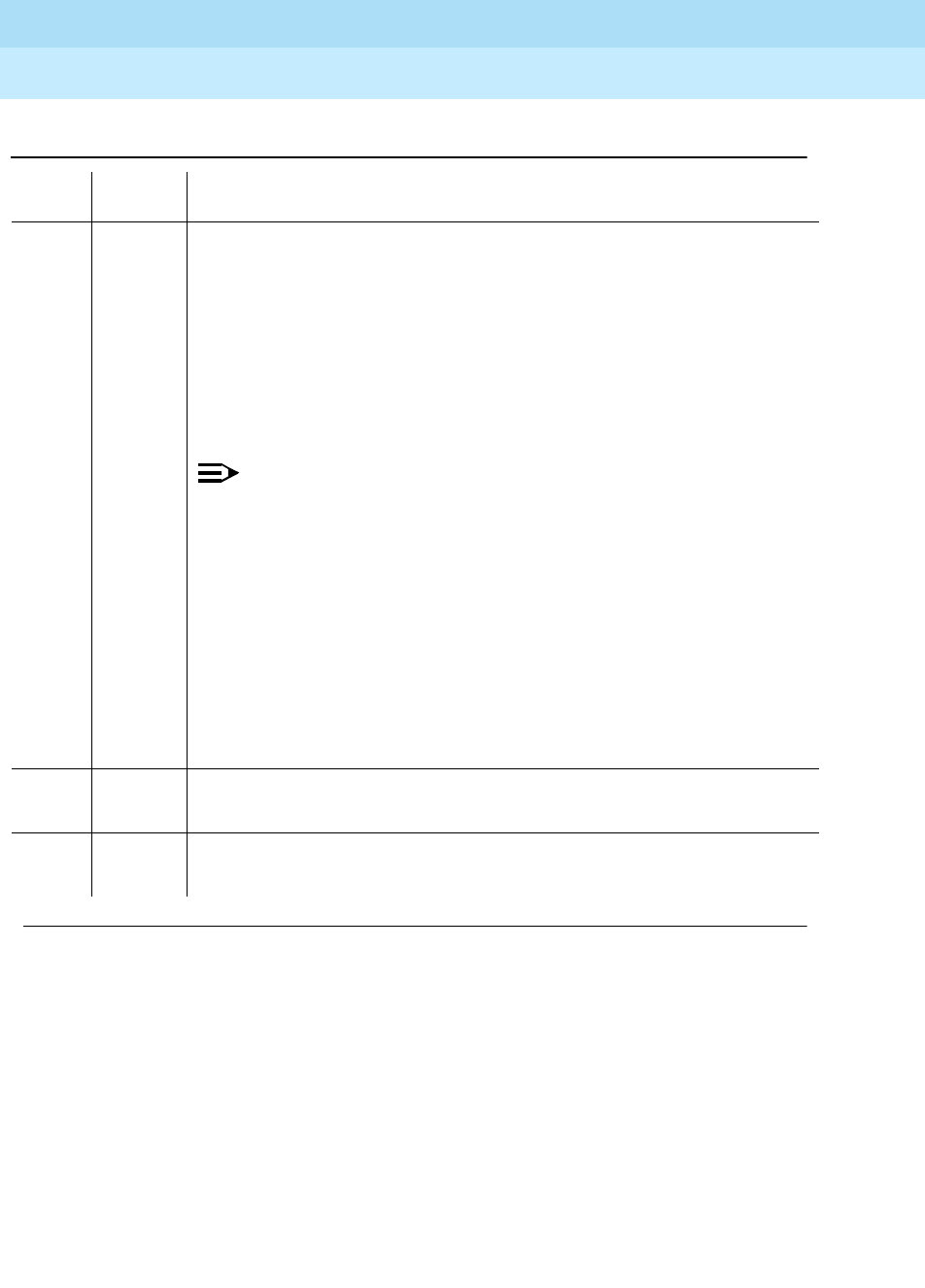
DEFINITY Enterprise Communications Server Release 6
Maintenance for R6r Volumes 1 & 2
555-230-126 Issue 2
January 1998
Maintenance Object Repair Procedures
Page 9-1087PKT-INT (Packet Interface Circuit Pack)
9
NO
BOARD The Packet Interface circuit pack is administered but is not detected as being
physically present.
1. If the Packet Interface circuit pack is present, replace it.
2. If the Packet Interface circuit pack is not physically present, use the
display system-parameters maintenance command to check if the
Packet Interface circuit pack is administered as being present. If it is
administered, use the change system-parameters maintenance
command to change the Packet Interface circuit packs administered to be
those actually present.
NOTE:
If the system is equipped with the High Reliability or Critical Reliability
Configuration, the Packet Interface entry on the system-parameters
maintenance screen will show "y" if translation data is present for a
Packet Interface circuit pack on either the active or standby SPE or if a
Packet Interface circuit pack is present on either the active or standby
SPE. The corresponding entry on the screen can only be changed from
"y" to "n" if a Packet Interface circuit pack is not physically present in the
active SPE. However, if the system is restarted with a restart level equal
or greater than a WARM restart, the Packet Interface circuit pack
maintenance software will automatically detect any Packet Interface
circuit pack physically present on the active or standby SPE and the
corresponding field on the system-parameters maintenance screen will
show a ‘‘y.’’
5001 FAIL The TDM clock on the Processor Port Network has failed.
1. Refer to the “TDM-CLK” to clear this failure.
5002 FAIL The Packet Bus on the Processor Port Network has failed.
1. Refer to “PKT-BUS” to clear this failure.
Table 9-384. TEST #889 Reset Test — Continued
Error
Code Test
Result Description/ Recommendation
Continued on next page

DEFINITY Enterprise Communications Server Release 6
Maintenance for R6r Volumes 1 & 2
555-230-126 Issue 2
January 1998
Maintenance Object Repair Procedures
Page 9-1088PKT-INT (Packet Interface Circuit Pack)
9
Any
Other
Than
Those
Listed
Above
FAIL The Packet Interface circuit pack diagnostic tests failed. If the system is
equipped with the High Reliability or Critical Reliability Configuration, the reset
will run only on demand if the Packet Interface circuit pack is on the standby
SPE or if Packet Interface circuit pack is in an out-of-service state on the active
SPE (which means an SPE interchange was not allowed because the standby
SPE is not healthy). If the latter case is true, also refer to the repair procedures
for STBY-SPE for clearing the problem on the standby SPE.
1. Retry the command reset packet-interface
2. If the reset fails, replace the circuit pack. (Refer to Replacing SPE Circuit
Packs in Chapter 5, ‘‘Responding to Alarms and Errors’’ for procedures for
replacing circuit packs in a standby SPE carrier.)
3. If the Packet Interface circuit pack is on the standby SPE, enter the status
SPE command at one minute intervals up to 10 minutes after the circuit
pack is replaced to check for completion of memory refresh.
PASS The Packet Interface circuit pack diagnostic software passed. The Packet
Interface circuit pack is put back into service automatically. If the Packet
Interface on the standby SPE continues to report an in-line fatal fault code
(error 257) and as a result goes into the out-of-service state even though the
demand reset test passes, the firmware version of the Packet Interface circuit
pack on the standby SPE may not be the same as the firmware version of the
Packet Interface circuit pack on the active SPE. Use the list configuration
control command to determine if the vintage of the Packet Interface circuit
packs on the active and standby SPEs is the same.
Table 9-384. TEST #889 Reset Test — Continued
Error
Code Test
Result Description/ Recommendation
Continued on next page

DEFINITY Enterprise Communications Server Release 6
Maintenance for R6r Volumes 1 & 2
555-230-126 Issue 2
January 1998
Maintenance Object Repair Procedures
Page 9-1089PMS-LINK (Property Management System Link)
9
PMS-LINK (Property Management
System Link)
Property Management System (PMS) is a stand-alone computer system that
environments such as hotels or hospitals use for services such as reservations,
registration, messaging, housekeeping, night audit, billing, and inventory. The
PMS Link provides a communications channel between the switch and the
customer-owned PMS so that the PMS can interrogate the system for information
related to the following features:
■Message Waiting Notification
■Controlled Restriction
■Housekeeping Status
■Check-in/Check-out
■Room Change/Room Swap
Refer to
DEFINITY Communications System Generic 3 Feature Description,
555-230-204, for details of the PMS feature. The PMS device connects to the
system via a data module (PDM, MPDM, DTDM) connected to a port on a TN754
Digital Line circuit pack which is administered as a data extension. A PMS device
can also be connected through an ADU to a port on TN726B. The PMS link to the
processor is via a system port. A system port is comprised of a port on the
TN726B Data Line circuit pack and a port on the TN553 Packet Data circuit pack
connected to each other in a null-modem fashion. Refer to the PDATA-PT section
for information on the system port connectivity.
PMS Link maintenance provides a strategy for maintaining the link between the
switch and a PMS device. The strategy includes a set of tests for periodic
diagnosis, detection of errors during normal operation, actions for
troubleshooting, and raising alarms for serious problems. PMS Link Maintenance
uses a ‘‘try-and-wait’’ mechanism for maintaining the PMS Link. If a PMS Link is
torn down due to an error, PMS Link Maintenance attempts to bring up the link
immediately. If the Link Setup fails, PMS Link Maintenance will wait for five
minutes before the next retry. If the number of retries reaches a threshold (12), a
Minor alarm is raised for service attention.
PMS Link Maintenance does not cover the maintenance of the elements
composing the PMS physical link (the external PMS device, Data Module
(PDM/MPDM/DTDM), Digital Line Port of a TN754 Digital Line circuit pack, ADU,
or Data Line Port of TN726B Data Line circuit pack). If PMS Link Maintenance
MO Name (in
Alarm Log) Alarm Level Initial Command to
Run Full Name of MO
PMS-LINK MINOR test pms l PMS Link
PMS-LINK WARNING test pms PMS Link

DEFINITY Enterprise Communications Server Release 6
Maintenance for R6r Volumes 1 & 2
555-230-126 Issue 2
January 1998
Maintenance Object Repair Procedures
Page 9-1090PMS-LINK (Property Management System Link)
9
cannot restore the PMS Link, then the maintenance tests of these individual
components of the PMS Link must be executed to diagnose faults. If the test
pms-link command fails, no alarm will be generated.
The list pms-down command lists all events that have meaning to the PMS that
have occurred while the link between the switch and the PMS was down. For
example, any room status codes entered by hotel housekeeping staff during a
time of PMS outage would be shown in this report.
Procedures for Restoring the PMS Link
1. Determine the status of the PMS Link.
Enter status pms command and make sure that the PMS Link is not
busied out for maintenance. If the link is ‘‘down,’’ then continue with the
next step.
2. Where does the PMS Link connect?
Enter display system hospitality and find out the destinations of the PMS
Link.
3. Determine the status of the data extension.
Enter status data extension command and verify whether the data
extension is in in-service/idle state. If the data extension is NOT available,
then look for the extension number in Alt Name field of Hardware Error
Log. Refer to the "XXX-BD (Common Port Circuit Pack)" section for
resolutions.
4. Is the external PMS device available?
Make sure that the PMS device is ON-LINE and ready for service. Check
the physical connectivity between Data Module and the PMS device.
5. If the problem is not found in the above steps, check the system port for
any problems. Refer to the PDATA-PT section for for description about
system port and its connectivity.
When restoring the PMS link it is necessary to execute maintenance test on
different objects that comprise the PMS link It is recommended that you busy out
the PMS link before trying to restore the link. When the PMS Link is busied out, all
PMS Link maintenance actions are deactivated, and interference with tests of
other MOs is prevented.

DEFINITY Enterprise Communications Server Release 6
Maintenance for R6r Volumes 1 & 2
555-230-126 Issue 2
January 1998
Maintenance Object Repair Procedures
Page 9-1091PMS-LINK (Property Management System Link)
9
Hardware Error Log Entries and Test to Clear
Values
Notes:
a. The PMS Link has been busied out with the busyout pms-link command.
The link is torn down. Enter the release pms-link command to restore the
link.
b. The Link Retry Test (#215) fails. An error was detected when setting up the
link. Refer to the
Procedures for Restoring the PMS Link
above.
c. The PMS physical link is down for one of the following reasons:
■Cable to the PMS device is disconnected.
■The PMS device is powered off.
1. Run the Short Test Sequence first. If all tests pass, run the Long Test Sequence. Refer to the appropriate
test description and follow the recommended procedures.
2. Minor alarms on this MO may be downgraded to Warning alarms based on the value used in the set
options command.
Table 9-385. PMS Link Maintenance Error Log Entries
Error
Type Aux Data Associated Test Alarm Level On/Off
Board Test to Clear Value
010 Any Any Any test pms sh r 1
18 (a) 0 busyout pms-link WARNING OFF release pms-link
257 (b) Any Link Retry Test
(#215) MINOR/2
WARNING OFF test pms-link l
513 (c) Any None test pms-link
769 (d) Any None
1025 (e) 40-49 None
1281 (f) 10-19 None
1537 (g) N0-N9 None
1793 (h) Any None test pms-link
2049 (i) Any None
2305 (j) 50-59 None release pms-link or test
pms-link
2561 (k) Any None test pms-link
2817 (l) 100-109
200-209
300-309
None
3073 (m) 70-79 None
3841 (n) 20-29 None

DEFINITY Enterprise Communications Server Release 6
Maintenance for R6r Volumes 1 & 2
555-230-126 Issue 2
January 1998
Maintenance Object Repair Procedures
Page 9-1092PMS-LINK (Property Management System Link)
9
■The data extension to which the PMS device connects has been
busied out.
Check the connectivity of wire and cable among wall jacket, data module,
and the PMS device. Enter status data <extension> and verify that the
data extension of the PMS device is in in-service/idle state. If the data
extension is not available, then refer to
Procedures for Restoring the PMS
Link
above.
d. There has been no communication between the switch and the PMS for a
period of time specified in ‘‘system hospitality’’ administration. The PMS
Link is torn down. To clear this error, refer to
Procedures for Restoring the
PMS Link
above.
e. The link was taken down because the switch could not receive an
incoming message from the PMS. The message from the PMS repeatedly
had corrupted data or the switch received requests for acknowledgment
but never received a message to be processed. If this error type occurs
frequently (more than once a month), advise the customer to call the
vendor of the PMS to check out the PMS device. Once the PMS Link is
successfully established, this error disappears from the Hardware Error
Log.
f. The link was taken down because the switch could not send an outgoing
message. The message, which was sent but not acknowledged, was
flushed. If this error type occurs frequently (more than once a month),
advise the customer to call the vendor of the PMS to check out the PMS
device. Once the PMS Link is successfully established, this error
disappears from the Hardware Error Log.
g. The PMS has been busied out for maintenance at the request of the PMS.
The PMS Link is torn down. The reason code (N), if present, is that
supplied by the PMS in the request message. If this error type recurs
frequently (that is, more than once a month), advise the customer to call
the vendor of the PMS to check out the PMS device. Once the PMS Link is
successfully established, this error disappears from the Hardware Error
Log. No alarm is raised against this error.
h. Due to either heavy call traffic, or the PMS protocol message rate being
faster than the PMS/PBX protocol specifications allow, the PMS Link is torn
down. PMS Link maintenance software will wait for five minutes before
attempting to set up the link again. If this error type occurs frequently
(more than once a month), advise the customer to call the vendor of the
PMS to check out the PMS device. Once the PMS Link is successfully
established, this error disappears from the Hardware Error Log. The PMS
should be checked for adherence to message rate defined in the
PMS/PBX protocol specifications. No alarm is raised against this error.
i. The attempt to swap the database between PBX and PMS failed three
times consecutively due to excessive PMS/PBX protocol violations, buffer
overflows, or PMS Link outages. The PMS Link is NOT torn down. If this
error type occurs frequently (more than once a month), advise the

DEFINITY Enterprise Communications Server Release 6
Maintenance for R6r Volumes 1 & 2
555-230-126 Issue 2
January 1998
Maintenance Object Repair Procedures
Page 9-1093PMS-LINK (Property Management System Link)
9
customer to call the vendor of the PMS to check out the PMS device. Once
the PMS Link is successfully established, this error disappears from the
Hardware Error Log. No alarm is raised against this error.
j. The PMS Link has been busied out with the busyout pms-link command
or has been brought down with the test pms-link long command. The
PMS Link is torn down, and PMS Link maintenance will stop attempting to
reestablish the link in the case where the busyout pms-link command
has been used. When the test pms-link long command has been used,
PMS Link maintenance will continue to try to reset the link. To restore the
PMS Link after use of the busyout pms-link command, issue the release
pms-link command. To restore the PMS Link after use of the test
pms-link long command, issue the test pms-link command.
k. The PMS Link is physically established, but the protocol has not been
started by the PMS before the protocol timer expires. The PMS Link is NOT
torn down. If this error type occurs frequently (more than once a month),
advise the customer to call the vendor of the PMS to check out the PMS
device. Once the PMS Link is successfully established, this error
disappears from the Hardware Error Log. The PMS should be checked to
make sure that it will attempt to start the protocol according to the
PMS/PBX protocol specifications. No alarm is raised against this error.
l. For Error Type 2817 look for the following AUX data:
The PMS should be assessed for adherence to the PMS/PBX protocol
specifications.
10x The PMS violated the application protocol. The first message after a
request to initiate a database exchange was not the start of a database
exchange. The message is processed. If this error type with this aux data
value occurs frequently (more than once a month), advise the customer
to call the vendor of the PMS to check out the PMS device. Once the PMS
Link is successfully established, this error disappears from the Hardware
Error Log.
20x The PMS violated the application protocol. The start of a database
exchange was received in a state in which it was not expected. The
message is ignored. If this error type with this Aux data value occurs
frequently (more than once a month), advise the customer to call the
vendor of the PMS to check out the PMS device. Once the PMS Link is
successfully established, this error disappears from the Hardware Error
Log.
30x The PMS violated the application protocol. The end of a database
exchange was received when no exchange was in progress. The
message is ignored. If this error type with this Aux Data value occurs
frequently (more than once a month), advise the customer to call the
vendor of the PMS to check out the PMS device. Once the PMS Link is
successfully established, this error disappears from the Hardware Error
Log. No alarm is raised against this error.

DEFINITY Enterprise Communications Server Release 6
Maintenance for R6r Volumes 1 & 2
555-230-126 Issue 2
January 1998
Maintenance Object Repair Procedures
Page 9-1094PMS-LINK (Property Management System Link)
9
m. The link was taken down by the switch because the threshold for
application protocol violations has been exceeded by the PMS. The
protocol never started and messages were received and/or messages
were received in a state in which they were not expected. (Refer to Error
Type 2817 for recommended strategy.)
n. Link was taken down by the switch because the threshold for link protocol
violations has been exceeded by the PMS. PMS is sending ‘‘garbage’’ to
the switch.
System Technician-Demanded Tests:
Descriptions and Error Codes
Always investigate tests in the order presented in the table below. By clearing
error codes associated with the
Link Retry Test
, for example, you may also clear
errors generated from other tests in the testing sequence.
Link Tear Down Test (#213)
This test is destructive.
This test disconnects the existing link between the system and the external PMS
device. If the link has been disconnected already, then this test just returns
‘‘PASS.’’ All resources allocated for a PMS Link are released after this test.
1. D = Destructive; ND = Nondestructive
Order of Investigation Short Test
Sequence Long Test
Sequence D/ND1
Link Tear Down Test (#213) X D
Link Retry Test (#215) X X ND
Table 9-386. TEST #213 Link Tear Down Test
Error
Code Test
Result Description/ Recommendation
40
50 ABORT Internal system error.
1. Retry the command at one-minute intervals a maximum of 5 times.
1010 ABORT The PMS Link has been busied out and placed in the out-of-service state.
1. Enter release pms-link command to release the PMS Link from busyout
state.
2. Retry test pms long command to execute the test.
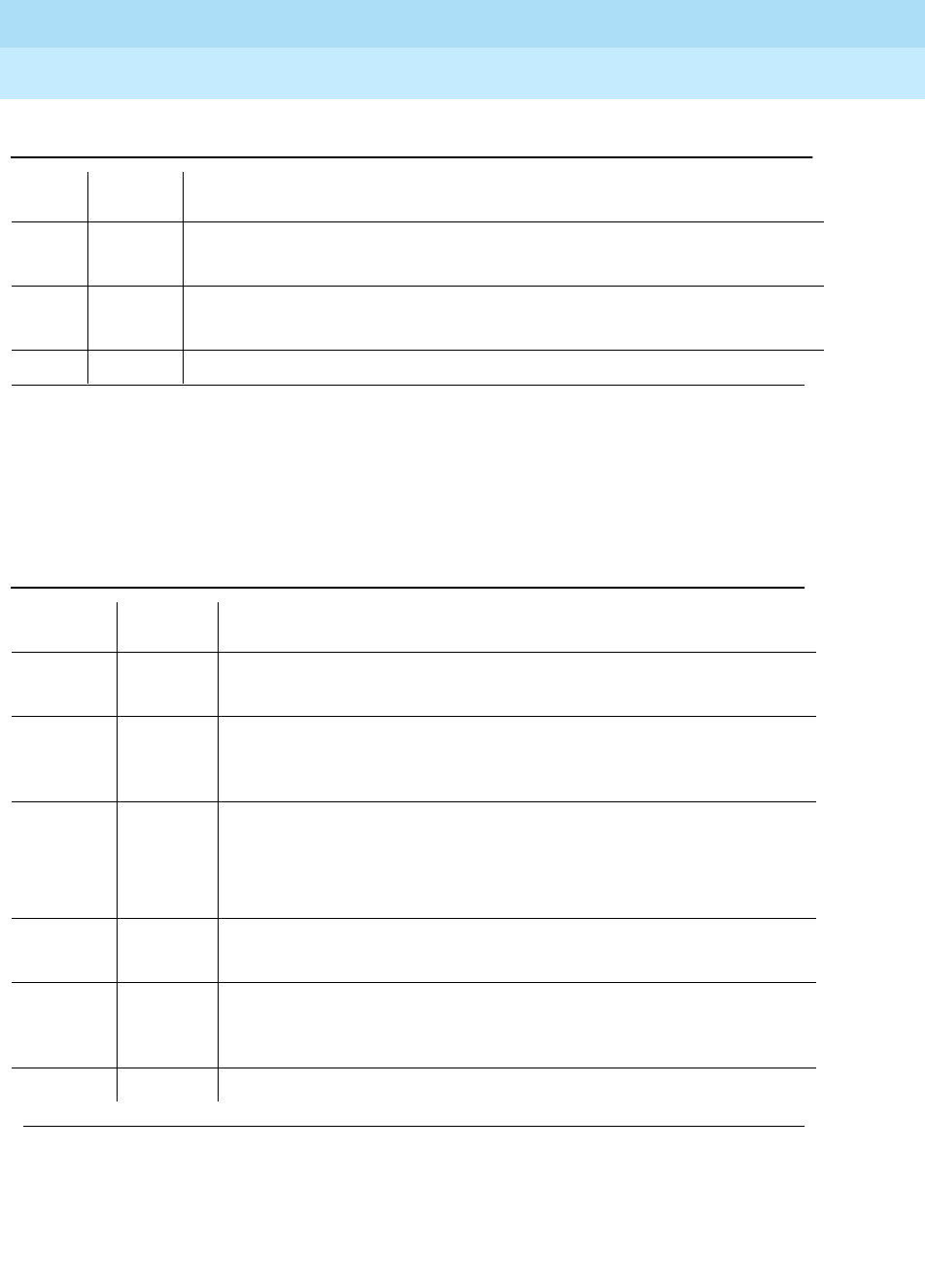
DEFINITY Enterprise Communications Server Release 6
Maintenance for R6r Volumes 1 & 2
555-230-126 Issue 2
January 1998
Maintenance Object Repair Procedures
Page 9-1095PMS-LINK (Property Management System Link)
9
Link Retry Test (#215)
This test sends a message to the PMS software process to make a data call to
the extension where the PMS device connects. If the PMS Link is already up, then
this test passes without making any data call.
2012 ABORT Internal system error.
1. Retry the command at one-minute intervals a maximum of 5 times.
FAIL Internal system error.
1. Retry the command at one-minute intervals a maximum of 5 times.
PASS The PMS Link is torn down.
Table 9-387. TEST #215 Link Retry Test
Error
Code Test
Result Description/ Recommendation
10
20 ABORT Internal system error.
1. Retry the command at one-minute intervals a maximum of 5 times.
30 ABORT Internal system error.
1. Refer back to the ‘‘Procedures for Restoring the PMS Link’’ section for
resolution.
1010 ABORT The PMS Link has been busied out and placed in the out-of-service state.
1. Enter release pms-link command to release the PMS Link from
busyout state.
2. Retry test pms command to execute the test.
2012 ABORT Internal system error.
1. Retry the command at one-minute intervals a maximum of 5 times.
FAIL The PMS Link CANNOT be established.
1. Refer back to the ‘‘Procedures for Restoring the PMS Link’’ section for
restoring the PMS Link.
PASS The PMS Link is up.
Continued on next page
Table 9-386. TEST #213 Link Tear Down Test
Error
Code Test
Result Description/ Recommendation

DEFINITY Enterprise Communications Server Release 6
Maintenance for R6r Volumes 1 & 2
555-230-126 Issue 2
January 1998
Maintenance Object Repair Procedures
Page 9-1096PMS-PRNT/JNL-PRNT (PMS Printer Link)
9
PMS-PRNT/JNL-PRNT (PMS Printer
Link)
A journal printer is a printer to which Emergency Access to Attendant, Wakeup
and Property Management System (PMS) events are printed as they occur. The
PMS-log printer is used as a backup of the PMS output device to print an audit
trail of all PMS transactions and Housekeeping Status Change events when the
PMS Printer Link is not available. There may be one or two journal printers. If
there is one, all events are printed there. If there are 2, then emergency access,
wakeup events, and scheduled reports are printed on one printer (JNL-PRNT),
and PMS events are printed at the other (PMS-PRNT).
The scheduled report printer is where summaries of daily wakeup activity and
emergency access activity are printed. If the customer requests a summary
report, the report will be printed exactly once per day.
The distinction between Journal and Scheduled report printers is logical rather
than physical. Whether or not there are two printers, the scheduled reports are
always sent to the printer that journals the wakeup and emergency access
events. A scheduled report will temporarily suspend the journal activity. Upon
completion of the scheduled report, journaling will be resumed after the printing
of all the withheld events.
The journal printer device connects to the system via a data module (PDM,
MPDM, DTDM) connected to a port on a TN754 Digital Line circuit pack that is
administered as a data extension. A journal printer device can also be connected
through an ADU to a port on TN726B Data Line circuit pack. The journal printer
link to the processor is via a system port. comprised of a port on the TN726B
Data Line circuit pack and a port on the TN553 Packet Data circuit pack
connected to each other in a null-modem fashion. Refer to the PDATA-PT
Maintenance Service Description for information on the system port connectivity.
PMS/JOURNAL Printer Link Maintenance provides a strategy for maintaining the
link between the system and a PMS device (an external Journal Printer device).
The strategy includes a set of tests for periodic diagnosis, detection of errors
during normal operation, actions for troubleshooting, and raising alarms for
serious problems. PMS Printer Link Maintenance uses a try-and-wait mechanism.
If a PMS Printer Link is torn down due to an error, PMS Printer Link Maintenance
will try to bring the link up immediately. If the link setup fails, PMS Link
MO Name (in
Alarm Log) Alarm Level Initial Command to Run Full Name of MO
PMS-PRNT/JNL-
PRNT MINOR test journal [pms-log | wakeup-log]
lPMS Printer/ Journal
Printer
PMS-PRNT/JNL-
PRNT WARNING test journal [pms-log | wakeup-log] PMS Printer/ Journal
Printer

DEFINITY Enterprise Communications Server Release 6
Maintenance for R6r Volumes 1 & 2
555-230-126 Issue 2
January 1998
Maintenance Object Repair Procedures
Page 9-1097PMS-PRNT/JNL-PRNT (PMS Printer Link)
9
Maintenance will wait for five minutes before the next trial. If the number of retries
reaches a threshold (15), a Minor alarm is raised for service attention.
PMS Printer Link Maintenance does not cover the maintenance of the elements
composing the journal printer physical link (for instance, the external printer
device, Data Module (PDM/MPDM/DTDM), Digital Line Port or ADU and Data
Line Port). If PMS Printer Link maintenance cannot restore the PMS Printer Link,
then the maintenance tests of individual components of the PMS Link must be
executed to diagnose faults.
The list pms-down command lists all events that have meaning to the PMS that
have occurred while the link between the switch and the PMS was down. For
example, any room status codes entered by hotel housekeeping staff during a
time of PMS outage would be reflected in this report.
Procedures for Restoring the PMS Printer Link
1. Determine the status of the PMS Printer Link.
Enter status journal-printer wakeup-log|pms-log and make sure that the
journal printer link is not busied out for maintenance. If the link is down,
then continue to the next step.
2. Where does the journal printer link connect?
Enter display system hospitality and find out the destinations of the PMS
Printer Link.
3. Determine the status of the data extension.
Enter status data extension command and verify that the data extension
is in the in-service/idle state. If the data extension is
not
available, look for
the extension number in the Alt Name field of the Hardware Error Log.
Refer to "XXX-BD (Common Port Circuit Pack)" for resolutions.
4. Is the external printer device available?
Make sure that the printer device is ON-LINE and ready for service. Check
the physical connectivity between Data Module and the printer device.
5. If the problem is not found in the above steps, check the system port for
any problems. Refer to “PDATA-PT” for a description of system ports.
It should be noted that when restoring the PMS printer link, it is necessary to
execute tests on different maintenance objects that comprise the link; it is
recommended that you busy out the PMS printer link before trying to restore the
link. If the PMS printer Link is busied out, then all PMS printer Link maintenance
actions are deactivated, and interference with tests of other MOs is prevented.
DEFINITY Enterprise Communications Server Release 6
Maintenance for R6r Volumes 1 & 2
555-230-126 Issue 2
January 1998
Maintenance Object Repair Procedures
Page 9-1098PMS-PRNT/JNL-PRNT (PMS Printer Link)
9
Error Log Entries and Test to Clear Values
Notes:
a. Craft busied out the Journal Printer Link. The link is torn down. Enter
release command to restore the link.
b. Link Retry Test (#215) fails. Physical link cannot be set up, usually
because of hardware problems such as power off or cable disconnect.
Refer to “Procedures for Restoring the PMS Printer Link” above.
c. Physical link cannot be set up, usually because of hardware problems
such as power off or cable disconnect. The PMS Printer Link physical link
is down due to the following causes: cable to the printer device is
disconnected, the printer device is powered off, or the data extension
where the printer device connects to has been busied out. Check the
connectivity of wire and cable among wall jacket, data module, and the
printer device. Enter status data <extension> and verify that the data
extension of the printer device is in the in-service/idle state. If the data
extension is not available, then refer to the ‘‘Procedures for Restoring the
PMS Printer Link’’ above.
d. Link idle timer; link comes down. This indicates that the printer device is in
an off-line state, for example, paper jam or paper out. Check the printer
device and act promptly to put it back to on-line state. Enter test journal
wakeup-log|pms-log command to set up the printer link.
1. Run the Short Test Sequence first. If all tests pass, run the Long Test Sequence. Refer to the
appropriate test description and follow the recommended procedures. Both PMS Printer and Journal
Printer are administered to the same extension, and the printer is not connected. Refer to the
Procedures for Restoring the PMS Printer Link
above for resolution.
2. Minor alarms may be downgraded to Warning alarms based on the value used in the set options
command.
Table 9-388. PMS-PRNT/JNL-PRNT Link Maintenance Error Log Entries
Error
Type Aux
Data Associated Test Alarm
Level On/Off
Board Test to Clear Value
010 Any Any Any test journal
wakeup-log|pms-log sh
18 (a) 0 busyout journal
wakeup-log/pms-log WARNING OFF release journal
wakeup-log|pms-log
257 (b) Any Link Retry Test(#215) MINOR/2
WARNING OFF test journal
wakeup-log|pms-log l
513 (c) Any test journal
wakeup-log|pms-log
769 (d)
DEFINITY Enterprise Communications Server Release 6
Maintenance for R6r Volumes 1 & 2
555-230-126 Issue 2
January 1998
Maintenance Object Repair Procedures
Page 9-1099PMS-PRNT/JNL-PRNT (PMS Printer Link)
9
System Technician-Demanded Tests:
Descriptions and Error Codes
Always investigate tests in the order presented in the table below. By clearing
error codes associated with the
Link Retry Test
, for example, you may also clear
errors generated from other tests in the testing sequence.
Link Tear Down Test (#213)
This test is destructive.
This test disconnects the existing link between the system and the external
printer device. If the link has been disconnected already, this test just returns
PASS. All resources allocated for a PMS Printer Link are released after this test.
1. D = Destructive; ND = Nondestructive
Order of Investigation Short Test
Sequence Long Test
Sequence D/ND1
Link Tear Down Test (#213) X D
Link Retry Test (#215) X X ND
Table 9-389. TEST #213 Link Tear Down Test
Error
Code Test
Result Description/ Recommendation
40 ABORT Internal system error.
50 ABORT Internal system error.
1. Retry the command at one-minute intervals a maximum of 5 times.
1010 ABORT The link has been busied out to out-of-service.
1. Enter release journal wakeup-log|pms-log command to release the link
from busyout state.
2. Retry test journal wakeup-log|pms-log l command to execute the test.
2012 ABORT Internal system error.
1. Retry the command at one-minute intervals a maximum of 5 times.
FAIL Internal System error.
1. Retry the command at one-minute intervals a maximum of 5 times.
PASS The link is torn down.

DEFINITY Enterprise Communications Server Release 6
Maintenance for R6r Volumes 1 & 2
555-230-126 Issue 2
January 1998
Maintenance Object Repair Procedures
Page 9-1100PMS-PRNT/JNL-PRNT (PMS Printer Link)
9
Link Retry Test (#215)
This test sends a message to the journal printer management software process
to make a data call to the extension where the printer device connects to. If the
journal printer link is already up, this test passes without making any data call.
Table 9-390. TEST #215 Link Retry Test
Error
Code Test
Result Description/ Recommendation
10 ABORT Internal system error.
20 ABORT Internal system error.
1. Retry the command at one-minute intervals a maximum of 5 times.
30 ABORT Internal system error.
1. Refer to the ‘‘Procedures for Restoring the PMS Printer Link’’ section for
instructions.
1010 ABORT The PMS Printer Link has been busied out to out-of-service.
1. Enter release journal wakeup-log|pms-log command to release the link
from busyout state.
2. Retry test journal wakeup-log|pms-log l command to execute the test.
2012 ABORT Internal system error.
1. Retry the command at one-minute intervals a maximum of 5 times.
FAIL The link CANNOT be established.
1. Refer to the ‘‘Procedures for Restoring the PMS Printer Link’’ section for
instructions.
PASS The link is up.

DEFINITY Enterprise Communications Server Release 6
Maintenance for R6r Volumes 1 & 2
555-230-126 Issue 2
January 1998
Maintenance Object Repair Procedures
Page 9-1101PNC-DUP (PNC Duplication)
9
PNC-DUP (PNC Duplication)
In systems with the Critical Reliability option, the following components, which
together comprise the Port Network Connectivity (PNC), are duplicated:
■Expansion Interface (EI) TN570 circuit packs in the port networks (PNs)
■Switch Node Interface (SNI) TN573 circuit packs in switch nodes
■DS1 Converter (DS1C) TN574 circuit packs for remote EPN connections
■Fiber-optic cables (metallic in certain cases) connecting the above circuit
packs
■DS1 facilities between the DS1Cs
■Switch Node Clock (SNC) TN572 circuit packs
Although not part of the PNC, Tone-Clock circuit packs are also duplicated in
each PN. The PNC is available in two different configurations: direct connect, in
which each port network is connected directly by fiber optic links to each other
PN; and Center Stage Switch (CSS) which utilizes one or two switch nodes to
interconnect the PNs. All systems have one Processor Port Network (PPN). Direct
connect systems can have up to two Expansion Port Networks (EPNs). CSS
systems with one switch node can have up to 15 EPNS. CSS systems with two
switch node can have up to 21 EPNS. See the following figures.
PNC duplication architecture utilizes an active/standby duplication scheme, in
which one complete set of PNC components supports call processing, while the
duplicate PNC is held in reserve. All calls on the active PNC are simultaneously
set up, or shadowed, on the standby PNC in order for it to be capable of instantly
assuming active status when necessary, allowing for interchanges without
service disruption (in the case of single faults).
The PNC-DUP maintenance object tracks the health of the active and standby
PNCs, controls planned and spontaneous interchanges, and manages related
functions such as double call refresh and unrefresh, antithrashing, and so on.
The main responsibility of PNC-DUP is to recover the system to full service in the
event of a fault. In the event of multiple faults PNC-DUP will do its best to
maximize service continuity.
PNC duplication does not introduce any additional types of hardware or
hardware faults, and there are no tests associated with the PNC-DUP MO.
Instead, it’s error log entries are used to log useful information about the
occurrence and causes of interchanges in order to facilitate diagnosis of
problems which can then be addressed by using the documentation for the
individual maintenance object involved.
MO Name (in
Alarm Log) Alarm
Level Initial Command to
Run Full Name of MO
PNC-DUP NA status pnc PNC duplication

DEFINITY Enterprise Communications Server Release 6
Maintenance for R6r Volumes 1 & 2
555-230-126 Issue 2
January 1998
Maintenance Object Repair Procedures
Page 9-1102PNC-DUP (PNC Duplication)
9
PNC-DUP Related Commands
The following commands and their output screens are fully described in Chapter
8, ‘‘Maintenance Commands’’.
Busyouts and PNC-DUP
Busyout pnc puts the standby PNC in the busyout state. In this condition:
1. Double call set up is turned off.
2. The standby PNC is unrefreshed; existing duplicate call connections are
removed.
3. PNC interchanges are prevented.
Upon release, interchanges are re-enabled and a global refresh of double call
setup on the standby is performed.
When PNC duplication is in effect:
■An active PNC component cannot be busied-out.
■A standby PNC component can only be busied-out when the standby
PNC is first busied-out.
■The standby PNC cannot be released unless all standby PNC
components are released.
status pnc This command displays information about the operational status of
both PNCs including state of health, alarms, busyouts and locks,
and so on.
reset pnc
interchange
This command is used to initiate a demand PNC interchange. If the
standby is healthy (state of health indexes all zero), there is no
effect on service. Otherwise, calls may be dropped.
set pnc This command is used to lock or unlock the active PNC, preventing
interchanges. It does not interfere with double call setup.
busyout pnc This removes the standby PNC from service. See also the following
section on busyout of PNC components.
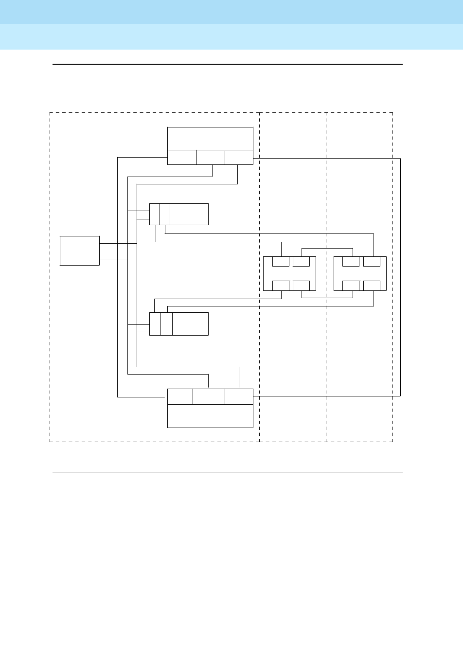
DEFINITY Enterprise Communications Server Release 6
Maintenance for R6r Volumes 1 & 2
555-230-126 Issue 2
January 1998
Maintenance Object Repair Procedures
Page 9-1103PNC-DUP (PNC Duplication)
9
Figure 9-65. Duplicated Direct Connect PNC Connectivity
EPN 2
SPE A
AA PKTINTDUP
E
IE
I
PORT CARRIER
E
I
E
I
PORT CARRIER
MAINT/
TEST
LAN
LAN
TDM
TDM
PKTINT AADUP
SPE B
EI
EI EI
EIEI EI
EI EI
PPN EPN 1
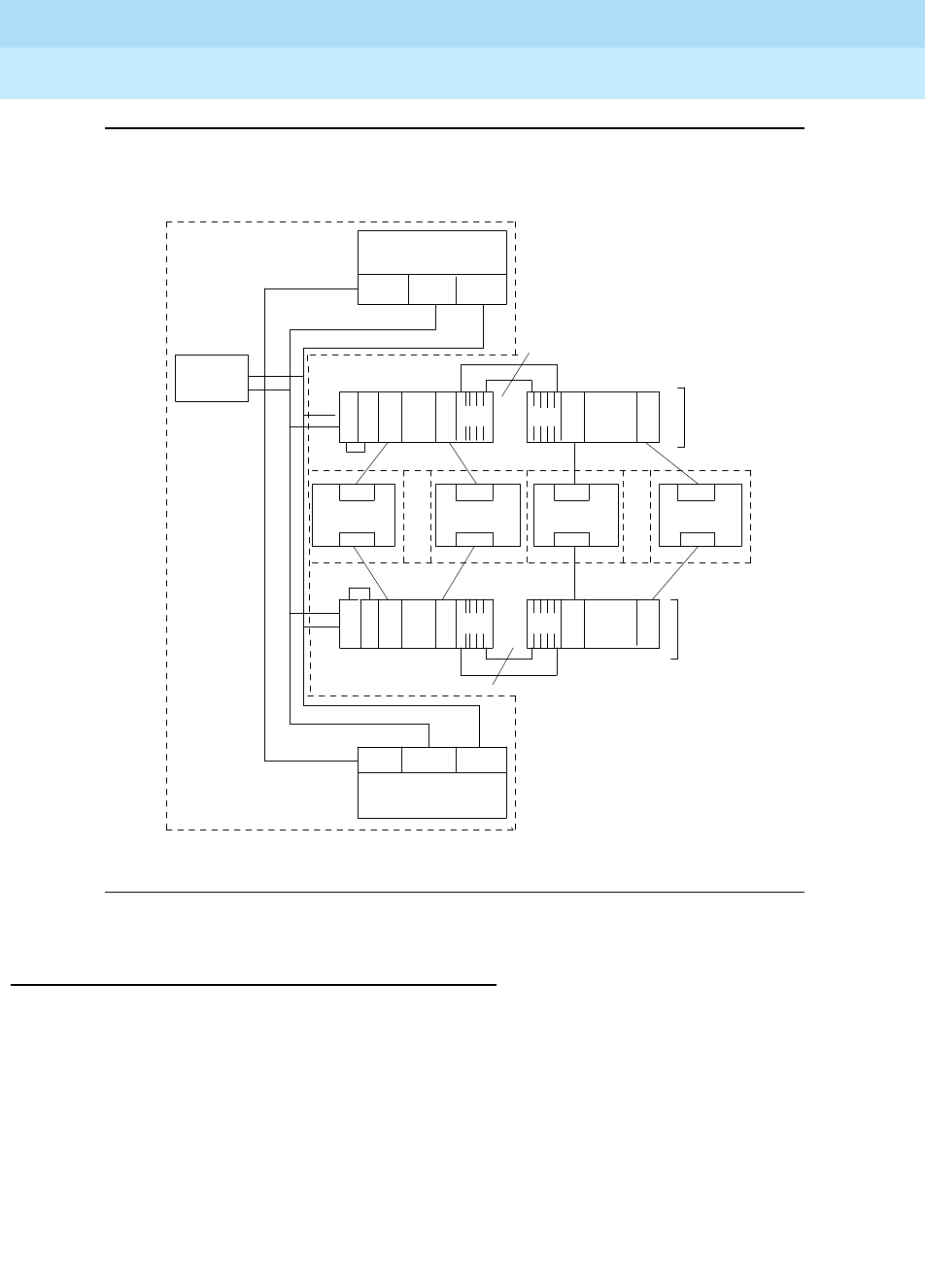
DEFINITY Enterprise Communications Server Release 6
Maintenance for R6r Volumes 1 & 2
555-230-126 Issue 2
January 1998
Maintenance Object Repair Procedures
Page 9-1104PNC-DUP (PNC Duplication)
9
Figure 9-66. Duplicated PNC with Center Stage Switch
Enabling and Removing PNC Duplication
To enable PNC duplication perform the following sequence of steps:
1. Enable PNC-DUP on the change system-parameters customer-options
form.
2. Fully administer duplicate fiber link connectivity. Verify by list fibers.
3. Trun on PNC-DUP via the change system-parameters duplication form.
This is note allowed if any component of either PNC (A or B) is busied out.
TDM
TDM
LAN
SPE A
AA PKTINTDUP
PKTINT AADUP
SPE B
EPN 1 EPN 10 EPN 11 EPN 21
. . . . . .
PPN
5
5
SNIS
SWITCH NODE
S
N
I
S
N
I
S
N
I
S
N
I
S
N
I
SNIS
SNIS SNIS
S
N
I
S
N
I
S
N
I
S
N
I
S
N
I
E
I
E
I
EI
EI EI EI
EI
EI
EI EI
SWITCH NODE
SWITCH NODE SWITCH NODE
MAINT/
TEST
LAN
CSS A
CSS B

DEFINITY Enterprise Communications Server Release 6
Maintenance for R6r Volumes 1 & 2
555-230-126 Issue 2
January 1998
Maintenance Object Repair Procedures
Page 9-1105PNC-DUP (PNC Duplication)
9
4. The system must insert all connectivity-related components for both
standby and active PNC. For CSS configurations this takes up to 5
minutes depending upon CSS circuit pack insertion. For Direct Connect
configurations this is declared complete at 5 minutes after the first
appearance of the terminal login prompt.
5. The PNC-DUP initialization anti-thrashing timer must expire (this occurs 5
minutes after completion of board insertion, PNC interchange, or system
reset of level 2 or higher).
To disable PNC duplication perform the following sequence of steps:
1. Verify that the A-PNC is active. A forced interchange may be required. See
reset pnc in Chapter 8, ‘‘Maintenance Commands’’.
2. Busyout the standby PNC (B-PNC).
3. Turn off the system parameter for PNC-DUP via change
system-parameters duplication.
After PNC duplication has been removed, configuration audits will
generate the alarm shown below and possibly others. To clear this alarm,
the B-PNC fibers, circuit packs in switch node carriers ( EIs, SNIs, SNCs,
and DS1Cs), and switch node carriers must be removed as outlined in the
following steps.
01D SN_CONF 5000 255
In this case, 01D is the B-PNC switch node from which uplication was
removed.
4. Remove the B-PNC fibers by removing the Endpoint Board Locations on
the change fiber form for all fibers. For fibers using DS1Cs, remove the
B-PNC DS1C Board Locations on page 3 of the change fiber form.
5. Remove the B-PNC circuit packs starting with the switch node carrier most
distant from the SPE complex. Use change circuit pack UUC, page to the
B-PNC carrier and remove all of the circuit packs there. Remove all circuit
packs in the other B-PNC switch node carriers.
If the Expansion Interface circuit pack associated with the PPN is located
in the switch node carrier closest to the SPE, it cannot be removed from
translation until it has been busied-out and disconnected from the carrier
slot.
When SNI, SNC, or DS1C circuit packs are removed from a B-PNC carrier,
any alarms against them should be resolved.
6. Remove the B-PNC switch node carriers. Use change cabinet UUC and
enter not-used for B-PNC carriers.
Any alarm against the carrier such as 01D SN-CONF should be resolved.
The B-PNC carriers and associated circuit packs should not be alarmed.

DEFINITY Enterprise Communications Server Release 6
Maintenance for R6r Volumes 1 & 2
555-230-126 Issue 2
January 1998
Maintenance Object Repair Procedures
Page 9-1106PNC-DUP (PNC Duplication)
9
7. Disable PNC duplication on the change system-parameters
customer-options form by changing ‘‘PNC Duplication’’ to ‘‘no.’’
If an alarm exists against any Expansion Interface circuit pack connected
to a B-PNC carrier, attempt to use test board UUCSS long clear to clear
the alarm.
Alterations to PNC which involve only the
addition
of fiber connectivity can be
done with PNC-DUP operational. Alterations requiring the
removal
of fiber
connectivity must be done with PNC-DUP removed. PNC-DUP must be removed
and translations should be saved before any hardware changes are made.
Steady State LEDs
The LEDs of PNC components in a stable duplicated system should appear as
follows:
■The
active
EIs in the EPNs are functioning as archangels. Their LEDs flash
in a pattern of 2 seconds on 200 milliseconds off.
■The EPN standby EIs yellow LEDs are off.
■The PPN active EI yellow LED is on solid.
■The PPN standby EI yellow LED is off.
■The SNIs on the active switch node(s) have yellow LEDs on solid.
■The SNIs on the standby switch node(s) have yellow LEDs off.
■Active DS1Cs yellow LEDs are on solid.
■Standby DS1Cs yellow LEDs are off.
■DS1C facility green LEDs are on if the corresponding facility is equipped.
PNC State of Health
PNC-DUP software monitors the health of the two PNCs as determined by their
state of health (SOH) vectors, and initiates an interchange when the health of the
active falls below that of the standby (unless prevented from doing so by a PNC
lock, busyout, or antithrashing mechanism). Potentially service-disrupting faults
which occur in PNC components are reported to PNC-DUP and incorporated in
the state of health for the affected PNC. The SOHs of both PNCs are displayed
on the status pnc screen.

DEFINITY Enterprise Communications Server Release 6
Maintenance for R6r Volumes 1 & 2
555-230-126 Issue 2
January 1998
Maintenance Object Repair Procedures
Page 9-1107PNC-DUP (PNC Duplication)
9
Screen 0-1. Status PNC Screen with Standby PNC Fully In-Service
PNC State of Health Indexes
The Inter-PN and Inter-SN Indexes form the state of health vector, which is used
to track and compare the states of health of both PNCs. The fields making up the
indexes are two digit numbers separated by periods (.), with each field
representing a different class of faults. The fault class fields are arranged in order
of decreasing importance from left to right. In other words, each field in the index
supersedes the following fields in determining which PNC is healthiest. A fault
class drives an interchange only when all of the higher priority fault classes are
equal. A zero entry indicates no faults in that class. Increasing numbers indicate
increasingly higher numbers of faults present in that class.
The Inter-PN Index contains five fields (XX.XX.XX.XX.XX), and the Inter-SN Index
has two (XX.XX). The Inter-PN Index reports faults in connectivity between port
networks and supersedes the Inter-SN Index, which reports faults in connectivity
between switch nodes. (The Inter-SN Index is only meaningful for systems with a
center stage switch having 2 switch nodes, each of which is duplicated).
The meaning of each fault class field is given in the following table. A zero entry
indicates that there are no such faults reported. Higher numbers indicate
increasing number of faults. All zeros indicates perfect state of health. Unless the
PNCs are locked, the active PNC’s state of health should always be equal to or
better than the standby’s. (Otherwise, the system would perform a spontaneous
interchange.)
status pnc page 1 of 1
PORT NETWORK CONNECTIVITY
Duplicated? yes
Software Locked? no
Standby Busied? no
Direct Connect? no
Standby Refreshed? yes
Interchange Disabled? no
A-PNC B-PNC
Mode: active Mode: standby
State of Health: functional State of Health: functional
Inter PN Index: 00.00.00.00.00 Inter PN Index: 00.00.00.00.00
Inter SN Index: 00.00 Inter SN Index: 00.00
Major Alarms: 0 Major Alarms: 0
Minor Alarms: 0 Minor Alarms: 0
Warning Alarms: 0 Warning Alarms: 0
SN Locations: 01E SN Locations: 01D

DEFINITY Enterprise Communications Server Release 6
Maintenance for R6r Volumes 1 & 2
555-230-126 Issue 2
January 1998
Maintenance Object Repair Procedures
Page 9-1108PNC-DUP (PNC Duplication)
9
After a PNC-related alarm is cleared, the system performs a partial refresh of the
standby PNC. The corresponding fault class field is not updated to reflect the
improved state of health until the refresh is done. The state of health indexes will
not agree with the current alarm status during this period.
Inter SN Index: FC_SNIL s11.s10 FC_SNIHW
In multinode CSS configurations FC_DS1 is considered less critical that FC_
SNINL since DS1C constraints affect only one EPN and indicate restricted
bandwidth. However FC_SNINL can indicate problems for all EPNs on the far
end switch node (the one downlink from the PPN) If the DS1C problem is critical
(for example, loss of all bandwidth to the affected EPN) a constraint with a higher
order fault class will be reported to PNC DUP.
Resolving Poor State of Health
When the SOHs for both PNCs are not all zeros (perfect health), use the following
steps to identify and repair the problem.
1. Look for PNC component alarms (major or minor) for the PNC side whose
SOH is not all zero. The standby PNC should be repaired first.
2. Busy-out the standby PNC.
Table 9-391. PNC State of Health Fault Classes
Fault
Class Priority Description MOs
FC_EAL 1 Number of PNs with EALs down EXP-PN
FC_INL 2 Number of PNs with LINL, RINL, or EI-SNI
neighbor link faults EXP-PN SN-CONF
FC_HW 3 Number of PNs affected by hardware
faults in a link having an EI as an endpoint
(Endpoints can be determined with list
fiber-link.)
EXP-INTF SN-CONF
FIBER-LK SNI-BD
DS1C-BD
FC_PER 4 Number of PNs affected by SNI peer link
faults for SNIs connected to EIs SNI-PEER
FC_DS1 5 Number of PNs affected by DS1C facility
faults DS1FAC
FC_SNIL 6 Number of inter-switch-node fibers
affected by peer or neighbor link faults SNI-PEER
FC_
SNIHW 7 Number of inter-switch-node fibers
affected by hardware faults SN-CONF SNI-BD
FIBER-LK

DEFINITY Enterprise Communications Server Release 6
Maintenance for R6r Volumes 1 & 2
555-230-126 Issue 2
January 1998
Maintenance Object Repair Procedures
Page 9-1109PNC-DUP (PNC Duplication)
9
3. Follow the appropriate diagnostic and repair procedures for the alarmed
PNC components just as with a simplex PNC. Both the alarm and error
logs should be examined to isolate the fault.
4. Verify that the related PNC SOH is restored to all zeros.
5. Release the standby PNC for busy-out.
Refresh and Unrefresh of the Standby PNC
In a fully functional PNC with healthy standby and active sides, the standby PNC
has a complete set of call connections corresponding to those in the active PNC.
If, however, the state of health of the standby PNC degrades, a selective
unrefresh of those connections which utilize the faulted component(s) is
performed. If the health of the standby PNC improves, a selective refresh of
connections on the affected route is performed. so that call setup is consistent
between the active PNC and the healthy parts of the standby PNC.
The Standby Refreshed? field on the status pnc screen does
not
refer to the
selective type of refresh. It refers only to a global refresh which is performed
when:
■The system is initialized and PNC duplication is enabled.
■There has been a spontaneous PNC interchange.
■The standby PNC has been released from busy-out.
■A system reset of level 2 or higher has taken place.
The refreshed field may display yes when in fact the standby is partially
unrefreshed. An interchange into an incompletely refreshed standby will result in
dropped calls. This can happen when a more severe fault occurs on the active
PNC, or when set pnc interchange is used with the override option.
PNC Interchanges
PNC spontaneous interchanges occur when PNC duplication software
determines that the SOH of the standby PNC is better than that of the active PNC.
PNC-DUP executes a spontaneous interchange only when a message from a
PNC component maintenance object sends a message indicating that either a
fault has occurred on the active PNC, or a fault has been resolved on the standby
PNC such that the state of health of the active PNC is now lower than that of the
standby.
This message will usually indicate the type and location of the failed connectivity
component. A corresponding major or minor alarm is logged by the reporting
MO, stimulating an alarm report.

DEFINITY Enterprise Communications Server Release 6
Maintenance for R6r Volumes 1 & 2
555-230-126 Issue 2
January 1998
Maintenance Object Repair Procedures
Page 9-1110PNC-DUP (PNC Duplication)
9
In the less common situation when the resolution of a fault on the standby
renders it more healthy than a simultaneously faulted active PNC, the message
will indicate the type and location of the
improved
component.
Once the interchange completes, the failed component will be on the standby
PNC. A demand interchange can be requested in the presence or absence of
standby PNC faults. The following sequence of actions can be observed during a
fault-free interchange:
1. The Expansion Interfaces currently acting as archangels in the EPNs are
deactivated as indicated by the yellow LEDs going from flashing to on
solid.
2. The PPN EIs are interchanged as indicated by the new standby EI yellow
LED off and the new active EI yellow LED on solid.
3. One by one the EPN EIs are interchanged as indicated by new standby EI
yellow LED turning off and the new active EI yellow LED flashing (2
seconds on, 200 milliseconds off). At this point the interchange is
functionally complete.
4. The SNIs yellow LEDs are updated. so that the SNIs on the active SN have
yellow LEDs on, while the standby SN’s SNIs yellow LEDs turn off.
Certain conditions may interfere with the normal execution of the interchange:
1. In a faulted spontaneous interchange it is possible the EPN/EPNs directly
affected by the fault will be the last to interchange.
2. A user directly affected by the single fault instigating a PNC interchange
can experience a momentary outage of voice path connectivity during the
switch.
3. If faults exist on both the standby and active PNC, it is possible to have
some EPNs go out of service while others are returned to service.
4. The new standby SNIs yellow LED my not be off due to a fault in the line of
communication path to the standby SNIs. In a multi-fault interchange,
LEDs on the new active SNIs may not be on for the same reason.
In any multifault situation, rely on status pnc to determine which is the active
PNC.
PNC duplication informs Timing Synchronization maintenance when a PNC
interchange has been completed and indicates which PNC is active. This will
cause Synchronization to audit and insure that the primary source for
synchronization of Tone-Clocks in each PN is supplied by a path associated with
the active PNC.

DEFINITY Enterprise Communications Server Release 6
Maintenance for R6r Volumes 1 & 2
555-230-126 Issue 2
January 1998
Maintenance Object Repair Procedures
Page 9-1111PNC-DUP (PNC Duplication)
9
Antithrashing and PNC Interchanges
Following a spontaneous PNC interchange, subsequent PNC interchanges are
prevented for 5 minutes. This condition is indicated by a "yes" in the Interchange
Disabled? field of the status pnc screen. After 5 minutes, the antithrashing, timer
expires, interchange decisions are re-enabled, and the field displays ‘‘no.’’
Should a catastrophic failure occur on the active PNC during the period when
"Interchange Disabled?" is set to "yes" there will be no spontaneous PNC
interchange.
Demand PNC interchanges also invoke anti-thrashing, but only for a
period of 30 seconds. During antithrashing mode, demand interchanges are also
prevented unless the override option is specified. Use of this option will cause a
service disruption.
Repairs on the Standby PNC Components
!CAUTION:
If there is a TDM-CLK alarm, system timing may be routed through part of
the standby PNC, and circuit switched data may be affected by the
following repair procedures. This can happen, for example, when a slave
tone/clock circuit pack experiences a loss of signal and switches to receive
timing from the standby EI. In this case TDM-CLK 2305 error will be logged,
and the clock problem should be addressed first, if possible.
To repair PNC components in a duplicated PNC proceed as follows:
1. Most repairs will involve fixing a single fault on the standby PNC. Use set
pnc lock or busy-out pnc to prevent an interchange into the PNC being
repaired.
2. If a faulty component exists on the currently active PNC, the standby PNC
is more severely faulted. Normally the standby PNC will be fully repaired
first since it is the most severely impaired. To repair the active PNC,
request an interchange via the reset pnc interchange override-and-lock
command. The
override-and-lock
option ensures that no subsequent
interchange will occur during the repair of the standby PNC. The demand
interchange may not be necessary if the following conditions drive a
spontaneous interchange:
■The anti-thrashing period from the last interchange has expired.
■The global refresh from releasing the standby PNC has completed.
The standby PNC SOH is better than the active.
3. At this point, the faulty component will be on the standby PNC, and the
PNCs are locked in their current active/standby state. Busy-out the PNC.
Then fault isolation and component testing procedures for the individual
PNC components can be used just as for a simplex PNC. Replacement of
components will not disrupt operation of the active PNC.

DEFINITY Enterprise Communications Server Release 6
Maintenance for R6r Volumes 1 & 2
555-230-126 Issue 2
January 1998
Maintenance Object Repair Procedures
Page 9-1112PNC-DUP (PNC Duplication)
9
4. Once the failed component is replaced, test the standby PNC component
from the terminal to ensure the replacement is functioning properly.
5. When confident that the problem has been resolved, as indicated by a
state of health with all zeros, (status pnc), unlock and release the pnc.
Note that no further PNC interchange is required since you can test the
standby PNC as thoroughly as the active.
Interactions: SPE Resets and PNC Interchanges
■After a system reset 4 (reboot), the A PNC is always the active.
■A system reset of level 1 (warm), 2 (cold2) or 3 (cold1) does not change
which PNC is active. If a PNC interchange was in progress when the reset
took place, the PNC interchange still goes to completion.
■If a system reset level 1 (warm) takes place during a PNC interchange, the
reset is escalated to level 2 (cold2).
Fault Isolation Using Duplicated PNC
PNC duplication, can, in some cases aid in the isolation of faults. PNC
interchanges can be used to help indict the faulty hardware. Following are two
examples demonstrating this technique.
■There is a fault which can occur in either the PPN EI or the PKT-INT which
cannot be readily attributed to one board or the other. If the packet bus
transceivers on either the PKT-INT or EI fail, it will be apparent that the two
boards cannot communicate, but it will not be clear which board is at fault.
In this case, a planned interchange of the PNC can be used to indict one
of the two boards. If the interchange cures the problem, the EI was at fault.
If the interchange does not cure the problem, the PKT-INT is suspect,
provided there are no PKT-BUS faults.
■A similar relationship exists for the EPN Archangel (active EI) and certain
TDM bus problems. If the EAA is unable to communicate with a port board
over the TDM bus, either the EAA has a fault, the port board has a fault, or
there is a problem with the TDM bus itself. If TDM bus maintenance tests
find no problems with the bus, then it is either the port board or the EAA. It
may be simpler to replace the port board than to request a PNC
interchange. However, if it is not clear which port board may be at fault, or
maintenance is being performed remotely, verify that the EAA is not at
fault by executing a PNC interchange. If the interchange solves the
problem, then the EAA is faulty. If the problem persists after the
interchange, but TDM bus maintenance finds no problem, then the port
board is faulty.

DEFINITY Enterprise Communications Server Release 6
Maintenance for R6r Volumes 1 & 2
555-230-126 Issue 2
January 1998
Maintenance Object Repair Procedures
Page 9-1113PNC-DUP (PNC Duplication)
9
Error Log Entries
Whenever a PNC interchange takes place, an error is logged against PNC-DUP
with a code that conveys information about the cause of the interchange and
which PNC became active. There are no alarms associated with PNC-DUP
errors, but there should be an alarm against the PNC component that drove the
interchange. There are no PNC-DUP test sequences, but status pnc will provide
information regarding the status of the PNCs. The information given in the
following tables will help to identify areas of the Alarm Log to be investigated to
find the source the problem. .
Notes:
a. An error took place in generating the error code.
1. The Aux Data indicates which PNC became active after the PNC interchange: ‘‘0’’
denotes PNC-A; ‘‘1’’ denotes PNC-B.
Error Code Aux
Data Error Code Aux
Data
00000 (a) None 20200 to 20221 (r) 1
10000 to 10021 (b) 120300 to 20321 (s) 1
10100 to 10121 (c) 120400 to 20421 (t) 1
10200 to 10221 (d) 120601 to 20627 (u) 1
10300 to 10321 (e) 120701 to 20727 (v) 1
10400 to 10421 (f) 121000 to 21021 (w) 1
10601 to 10627 (g) 121100 to 21121 (x) 1
10701 to 10727 (h) 121200 to 21221 (y) 1
11000 to 11021 (i) 121300 to 21321 (z) 1
11100 to 11121 (j) 121400 to 21421 (aa) 1
11200 to 11221 (k) 121601 to 21627 (ab) 1
11300 to 11321 (l) 121701 to 21727 (ac) 1
11400 to 11421 (m) 151000 (ad) 1
11601 to 11627 (n) 152000 (ae) 1
11701 to 11727 (o) 153000 (af) 1
20000 to 20021 (p) 160801 (ag) 1
20100 to 20121 (q) 160800 (ah) 1
Error
Type Aux
Data Associated Test Alarm Level On/Off
Board Test to Clear Value
18 None busy PNC-DUP WARNING ON release pnc-dup

DEFINITY Enterprise Communications Server Release 6
Maintenance for R6r Volumes 1 & 2
555-230-126 Issue 2
January 1998
Maintenance Object Repair Procedures
Page 9-1114PNC-DUP (PNC Duplication)
9
b. A spontaneous PNC interchange took place in response to the retiring of
an alarm on the A-PNC associated with fault class FC_EAL. Use status
pnc to look at the state of health indexes for the PNCs, and investigate any
associated alarms. Adding 1 to the last two digits of the error code gives
the PN number of the port network that reported the retired alarm. (10003
points to port network 4) List config port-network gives the cabinet
number associated with a port network.
c. A spontaneous PNC interchange took place in response to the retiring of
an alarm on the A-PNC associated with fault class FC_INL. Use status
pnc to look at the state of health indexes for the PNCs, and investigate any
associated alarms. Adding 1 to the last two digits of the error code gives
the PN number of the port network that reported the retired alarm. (10003
points to port network 4) List config port-network gives the cabinet
number associated with a port network.
d. A spontaneous PNC interchange took place in response to the retiring of
an alarm on the A-PNC associated with fault class FC_HW. Use status
pnc to look at the state of health indexes for the PNCs, and investigate any
associated alarms. Adding 1 to the last two digits of the error code gives
the PN number of the port network that reported the retired alarm. (10203
points to port network 4.) List config port-network gives the cabinet
number associated with a port network.
e. A spontaneous PNC interchange took place in response to the retiring of
an alarm on the A-PNC associated with fault class FC_PER. Use status
pnc to look at the state of health indexes for the PNCs, and investigate any
associated alarms. Adding 1 to the last two digits of the error code gives
the PN number of the port network that reported the retired alarm. (10303
points to port network 4.) List config port-network gives the cabinet
number associated with a port network.
f. A spontaneous PNC interchange took place in response to the retiring of
an alarm on the A-PNC associated with fault class FC_DS1. Use status
pnc to look at the state of health indexes for the PNCs, and investigate any
associated alarms. Adding 1 to the last two digits of the error code gives
the PN number of the port network that reported the retired alarm. (10403
points to port network 4.) List config port-network gives the cabinet
number associated with a port network.
g. A spontaneous PNC interchange took place in response to the retiring of
an alarm on the A-PNC associated with fault class FC_SNIL. Use status
pnc to look at the state of health indexes for the PNCs, and investigate any
associated alarms. The last two digits of the error code indicate the
fiber-link number (01-27) of the fiber that reported the retired alarm. List
fiber-link gives the location of the fiber.
h. A spontaneous PNC interchange took place in response to the retiring of
an alarm on the A-PNC associated with fault class FC_SNIHW. Use status
pnc to look at the state of health indexes for the PNCs, and investigate any
associated alarms. The last two digits of the error code indicate the
fiber-link number (01-27) of the fiber that reported the retired alarm. List
fiber-link gives the location of the fiber.

DEFINITY Enterprise Communications Server Release 6
Maintenance for R6r Volumes 1 & 2
555-230-126 Issue 2
January 1998
Maintenance Object Repair Procedures
Page 9-1115PNC-DUP (PNC Duplication)
9
i. A spontaneous PNC interchange took place in response to the occurrence
of a major or minor alarm on the A-PNC associated with fault class FC_
EAL. This indicates that one or more Expansion Archangel Links are
down. Investigate any EXP-PN alarms. Adding 1 to the last two digits of
the error code gives the PN number of the port network that reported the
alarm. (11003 points to port network 4.) List config port-network gives
the cabinet number associated with a port network.
j. A spontaneous PNC interchange took place in response to the occurrence
of a major or minor alarm on the A-PNC associated with fault class FC_
INL. This indicates that one or more neighbor or indirect neighbor links
with an EI as an endpoint have experienced faults. Investigate any alarms
against EXP-PN and SN-CONF. Adding 1 to the last two digits of the error
code gives the PN number of the port network that reported the alarm.
(11103 points to port network 4.) List config port-network gives the
cabinet number associated with a port network.
k. A spontaneous PNC interchange took place in response to the occurrence
of a major or minor alarm on the A-PNC associated with fault class FC_
HW. This indicates that one or more neighbor or indirect neighbor links
with an EI as an endpoint have experienced faults. Investigate any alarms
against EXP-PN and SN-CONF. Adding 1 to the last two digits of the error
code gives the PN number of the port network that reported the alarm.
(11203 points to port network 4.) List config port-network gives the
cabinet number associated with a port network.
l. A spontaneous PNC interchange took place in response to the occurrence
of a major or minor alarm on the A-PNC associated with fault class FC_
PER. This indicates one or more faults on peer links that connect SNIs to
EIs. Investigate any alarms against SNI-PEER. Adding 1 to the last two
digits of the error code gives the PN number of the port network that
reported the alarm. (11303 points to port network 4.) List config
port-network gives the cabinet number associated with a port network.
m. A spontaneous PNC interchange took place in response to the occurrence
of a major or minor alarm on the A-PNC associated with fault class FC_
DS1. This indicates faults on one or more DS1C facilities. Investigate any
alarms against DS1-FAC. Adding 1 to the last two digits of the error code
gives the PN number of the port network that reported the alarm. (11403
points to port network 4.) List config port-network gives the cabinet
number associated with a port network.
n. A spontaneous PNC interchange took place in response to the occurrence
of a major or minor alarm on the A-PNC associated with fault class FC_
SNIL. This indicates one or more faults on peer or neighbor links between
SNIs on different switch nodes. Investigate any alarms against SNI-PEER.
The last two digits of the error code indicate the fiber-link number (01-27)
of the fiber that reported the retired alarm. List fiber-link gives the
location of the fiber.
o. A spontaneous PNC interchange took place in response to the occurrence
of a major or minor alarm on the A-PNC associated with fault class FC_
SNIHW. This indicates one or more faults on hardware connecting SNIs on

DEFINITY Enterprise Communications Server Release 6
Maintenance for R6r Volumes 1 & 2
555-230-126 Issue 2
January 1998
Maintenance Object Repair Procedures
Page 9-1116PNC-DUP (PNC Duplication)
9
different switch nodes. Investigate any alarms against SN-CONF, SNI-BD,
FIBER-LK. The last two digits of the error code indicate the fiber-link
number (01-27) of the fiber that reported the retired alarm. List fiber-link
gives the location of the fiber.
p. A spontaneous PNC interchange took place in response to the retiring of
an alarm on the B-PNC associated with fault class FC_EAL. Use status
pnc to look at the state of health indexes for the PNCs, and investigate any
associated alarms. Adding 1 to the last two digits of the error code gives
the PN number of the port network that reported the retired alarm. (20003
points to port network 4.) List config port-network gives the cabinet
number associated with a port network.
q. A spontaneous PNC interchange took place in response to the retiring of
an alarm on the B-PNC associated with fault class FC_INL. Use status
pnc to look at the state of health indexes for the PNCs, and investigate any
associated alarms. Adding 1 to the last two digits of the error code gives
the PN number of the port network that reported the retired alarm. (20103
points to port network 4.) List config port-network gives the cabinet
number associated with a port network.
r. A spontaneous PNC interchange took place in response to the retiring of
an alarm on the B-PNC associated with fault class FC_HW. Use status
pnc to look at the state of health indexes for the PNCs, and investigate any
associated alarms. Adding 1 to the last two digits of the error code gives
the PN number of the port network that reported the retired alarm. (20203
points to port network 4.) List config port-network gives the cabinet
number associated with a port network.
s. A spontaneous PNC interchange took place in response to the retiring of
an alarm on the B-PNC associated with fault class FC_PER. Use status
pnc to look at the state of health indexes for the PNCs, and investigate any
associated alarms. Adding 1 to the last two digits of the error code gives
the PN number of the port network that reported the retired alarm. (20303
points to port network 4.) List config port-network gives the cabinet
number associated with a port network.
t. A spontaneous PNC interchange took place in response to the retiring of
an alarm on the B-PNC associated with fault class FC_DS1. Use status
pnc to look at the state of health indexes for the PNCs, and investigate any
associated alarms. Adding 1 to the last two digits of the error code gives
the PN number of the port network that reported the retired alarm. (20403
points to port network 4.) List config port-network gives the cabinet
number associated with a port network.
u. A spontaneous PNC interchange took place in response to the retiring of
an alarm on the B-PNC associated with fault class FC_SNIL. Use status
pnc to look at the state of health indexes for the PNCs, and investigate any
associated alarms. The last two digits of the error code indicate the
fiber-link number (01-27) of the fiber that reported the retired alarm. List
fiber-link gives the location of the fiber.

DEFINITY Enterprise Communications Server Release 6
Maintenance for R6r Volumes 1 & 2
555-230-126 Issue 2
January 1998
Maintenance Object Repair Procedures
Page 9-1117PNC-DUP (PNC Duplication)
9
v. A spontaneous PNC interchange took place in response to the retiring of
an alarm on the B-PNC associated with fault class FC_SNIHW. Use status
pnc to look at the state of health indexes for the PNCs, and investigate any
associated alarms. The last two digits of the error code indicate the
fiber-link number (01-27) of the fiber that reported the retired alarm. List
fiber-link gives the location of the fiber.
w. A spontaneous PNC interchange took place in response to the occurrence
of a major or minor alarm on the B-PNC associated with fault class FC_
EAL. This indicates that one or more Expansion Archangel Links are
down. Investigate any EXP-PN alarms. Adding 1 to the last two digits of
the error code gives the PN number of the port network that reported the
alarm. (21003 points to port network 4.) List config port-network gives
the cabinet number associated with a port network.
x. A spontaneous PNC interchange took place in response to the occurrence
of a major or minor alarm on the B-PNC associated with fault class FC_
INL. This indicates that one or more neighbor or indirect neighbor links
with an EI as an endpoint have experienced faults. Investigate any alarms
against EXP-PN and SN-CONF. Adding 1 to the last two digits of the error
code gives the PN number of the port network that reported the alarm.
(21103 points to port network 4.) List config port-network gives the
cabinet number associated with a port network.
y. A spontaneous PNC interchange took place in response to the occurrence
of a major or minor alarm on the B-PNC associated with fault class FC_
HW. This indicates that one or more neighbor or indirect neighbor links
with an EI as an endpoint have experienced faults. Investigate any alarms
against EXP-PN and SN-CONF. Adding 1 to the last two digits of the error
code gives the PN number of the port network that reported the alarm.
(21203 points to port network 4.) List config port-network gives the
cabinet number associated with a port network.
z. A spontaneous PNC interchange took place in response to the occurrence
of a major or minor alarm on the B-PNC associated with fault class FC_
PER. This indicates faults on peer links that connect SNIs to EIs.
Investigate any alarms against SNI-PEER. Adding 1 to the last two digits of
the error code gives the PN number of the port network that reported the
alarm. (21303 points to port network 4.) List config port-network gives
the cabinet number associated with a port network.
aa. A spontaneous PNC interchange took place in response to the occurrence
of a major or minor alarm on the B-PNC associated with fault class FC_
DS1. This indicates faults on one or more DS1C facilities. Investigate any
alarms against DS1-FAC. Adding 1 to the last two digits of the error code
gives the PN number of the port network that reported the alarm. (21403
points to port network 4.) List config port-network gives the cabinet
number associated with a port network.
ab. A spontaneous PNC interchange took place in response to the occurrence
of a major or minor alarm on the B-PNC associated with fault class FC_
SNIL. This indicates faults on peer or neighbor links between SNIs on

DEFINITY Enterprise Communications Server Release 6
Maintenance for R6r Volumes 1 & 2
555-230-126 Issue 2
January 1998
Maintenance Object Repair Procedures
Page 9-1118PNC-DUP (PNC Duplication)
9
different switch nodes. Investigate any alarms against SNI-PEER. The last
two digits of the error code indicate the fiber-link number (01-27) of the
fiber that reported the alarm. List fiber-link gives the location of the fiber.
ac. A spontaneous PNC interchange took place in response to the occurrence
of a major or minor alarm on the B-PNC associated with fault class FC_
SNIHW. This indicates faults on hardware connecting SNIs on different
switch nodes. Investigate any alarms against SN-CONF, SNI-BD,
FIBER-LK. The last two digits of the error code indicate the fiber-link
number (01-27) of the fiber that reported the alarm. List fiber-link gives
the location of the fiber.
ad. A spontaneous PNC interchange took place upon the expiration of the
anti-thrashing timer.
ae. A spontaneous PNC interchange took place upon the unlocking of the
PNCs with the set pnc unlock command.
af. A spontaneous PNC interchange took place upon the completion of a
global refresh of the standby.
ag. A demand interchange was executed with the reset pnc
interchangecommand.
ah. A demand interchange was executed with the reset pnc
interchangecommand using the override-and-lock option.

DEFINITY Enterprise Communications Server Release 6
Maintenance for R6r Volumes 1 & 2
555-230-126 Issue 2
January 1998
Maintenance Object Repair Procedures
Page 9-1119POWER
9
POWER
Battery and Charger for AC-Powered Systems
DEFINITY Systems support two different cabinet types: multicarrier and single
carrier. Single carrier cabinets are used only for EPNs. Both cabinet types may
be powered by either AC or DC external power source. Environmental
maintenance differs according to cabinet type and external power supply.
AC-powered Multi-Carrier Cabinets can be equipped with rechargeable batteries
that provide backup power during short power outages. Battery backup is
optional on cabinets powered by an Uninterruptible Power Supply (UPS), and is
required on those that are not. DC-powered cabinets and single-carrier cabinets
do not have battery backup, and this MO is not valid for those cabinets.
The battery backup for the J58890CH unit consists of one battery assembly and
charger. The battery backup for the J58890CE unit consists of three 48V
batteries and a battery charger. Each cabinet so equipped has its own
independent battery backup unit. When power to the cabinet is interrupted, a
warning alarm is logged against AC-POWER and the system draws power from
the backup batteries. This is known as Nominal Power Holdover (NPH). If power
is restored before the NPH time expires, the alarm is resolved. If power does not
return, error logs are saved to the Mass Storage System. The nominal power
holdover provided is as follows:
When AC power is restored after an outage, the battery charger fully recharges
the batteries within 30 hours.
In a multi-carrier cabinet system, the Battery & Battery Charger maintenance
object represents the battery charger and the battery which are located in the
1.
UU
is the cabinet number indicated in the PORT field from the Alarm or Error Log.
MO Name (in
Alarm Log) Alarm
Level Initial Command to
Run1Full Name of MO
POWER MINOR test environment
UU
Battery and Battery Charger
PPN Cabinet:
All carriers 10 seconds
Simplex control carrier 10 minutes
Duplicated control carriers 5 minutes
EPN cabinet:
All carriers 15 seconds
Expansion control carrier 10 minutes

DEFINITY Enterprise Communications Server Release 6
Maintenance for R6r Volumes 1 & 2
555-230-126 Issue 2
January 1998
Maintenance Object Repair Procedures
Page 9-1120POWER
9
lower left corner of the cabinet. Should anything go wrong with the battery or
charger, they must be replaced using the procedure described in the ‘‘Replacing
the Battery and Battery Charger’’ section below. The system will detect one of the
following three problems with the batteries or charger:
■Reserve Fault: the charger has detected a problem within itself or the
batteries and has notified the system.
■High Charge Rate: the batteries have been charging at a high charge rate
for an excessively long period of time. This indicates that there is a short in
the batteries or the charger.
■Prepare to Disconnect (Low Battery): the batteries are in danger of being
drained to a point where the batteries would be damaged. This warning
often occurs after multiple power failures.
The batteries take 30 hours to fully charge after being drained. A fully
charged battery pack should bridge two power failures without causing a
low battery warning to occur.
Replacing the Battery and Battery Charger
(J58890CE)
1. Move the power switch on the battery charger to OFF.
!WARNING:
Always turn off the battery charger before replacing the batteries.
Failure to do so will result in damage to the 397C battery charger.
2. Disconnect the cord from the outlet on the front of the battery charger.
3. Remove the screw at the top left of the cover and open the cover to
access the charger.
4. Check the battery voltages at the test points. Check all 3 batteries wired in
series (the voltage should be 144 volts, 3 X 48 volts = 144 volts) .
NOTE:
An ordinary voltmeter can be used to check battery voltages at the
test points, but it may not produce valid results. If the battery voltage
readings are below 48 volts (the voltages at test points should read
144 volts, 3 x 48 volts = 144 volts), the battery is probably defective.
However, a normal voltage reading does not necessarily mean the
battery is good; under load, a defective battery with a normal
reading on the voltmeter may discharge rapidly.
5. Check the battery dates and the preventive maintenance log. Replace the
batteries if they are more than 2.5 years-old.

DEFINITY Enterprise Communications Server Release 6
Maintenance for R6r Volumes 1 & 2
555-230-126 Issue 2
January 1998
Maintenance Object Repair Procedures
Page 9-1121POWER
9
NOTE:
If any defective batteries are found, replace all of them. Batteries are
ordered in sets of three and should be replaced as such.
6. If no defective batteries are found, replace the entire charger.
7. Close the cover and secure it with the screw.
8. Reconnect the cord and move the power switch to ON.
Replacing the Battery Assembly (J58890CH)
The batteries are replaced as an entire assembly.
1. Check the battery voltages at the test points (on the Battery Interface Unit
(BIU)).
2. Remove the BIU from the power distribution unit.
3. Disconnect the battery plug from the power distribution unit (J20).
4. Remove the battery assembly from the rear of the cabinet.
5. Install the new battery assembly in the reverse order.
6. Plug the BIU back into the power distribution unit.
Error Log Entries and Test to Clear Values
Table 9-392. Battery & Battery Charger Error Log Entries
Error
Type Aux
Data Associated Test Alarm
Level On/Off
Board Test to Clear Value
010 Any Any Any test environment
UU
sh r 1
1 Any Battery & Battery
Charger Query Test
(#5) (error code 8)
MINOR ON test environment
UU
s r 1
257 Any Battery & Battery
Charger Query Test
(#5) (error code 4)
MINOR ON test environment
UU
s r 1
769 Any Battery & Battery
Charger Query Test
(#5) (error code 2)
MINOR ON test environment
UU
s r 1
Continued on next page

DEFINITY Enterprise Communications Server Release 6
Maintenance for R6r Volumes 1 & 2
555-230-126 Issue 2
January 1998
Maintenance Object Repair Procedures
Page 9-1122POWER
9
Note:
a. Check to see if the battery charger is connected. If the cabinet is powered
by a UPS, there is no battery backup, and this error can be ignored.
System Technician-Demanded Tests:
Descriptions and Error Codes
Always investigate tests in the order presented in the table below when
inspecting errors in the system. By clearing error codes associated with the
Battery & Battery Charger Query Test,
for example, you may also clear errors
generated from other tests in the testing sequence.
1. Run the Short Test Sequence first. If all tests pass, run the Long Test Sequence. Refer to the appropriate
test description and follow the recommended procedures.
3840(a) 1005 or
1028 Associated Battery
& Battery Charger
Query Test (#5)
test environment
UU
s r 1
Table 9-393. System Technician-Demanded Tests: POWER
Order of Investigation Short Test
Sequence Long Test
Sequence D/ND1
Battery & Battery Charger Query Test (#5) X X ND
AC Power Query Test (#78) (a) X X ND
Power Unit Query Test (carrier E) (#127) (b) X X ND
Power Unit Query Test (carrier D) (#127) (b) X X ND
Power Unit Query Test (carrier A) (#127) (b) X X ND
Power Unit Query Test (carrier B) (#127) (b) X X ND
Power Unit Query Test (carrier C) (#127) (b) X X ND
Emergency Transfer Query Test (#124) (c) X X ND
Continued on next page
Table 9-392. Battery & Battery Charger Error Log Entries — Continued
Error
Type Aux
Data Associated Test Alarm
Level On/Off
Board Test to Clear Value
Continued on next page

DEFINITY Enterprise Communications Server Release 6
Maintenance for R6r Volumes 1 & 2
555-230-126 Issue 2
January 1998
Maintenance Object Repair Procedures
Page 9-1123POWER
9
Notes:
a. Refer to AC-POWER (AC Power) for a description of this test.
b. Refer to CARR-POW for a description of this test.
c. Refer to EMG-XFER (Emergency Transfer) for a description of this test.
d. Refer to CABINET (Cabinet Sensors) for a description of this test.
e. Refer to EXT-DEV (External Alarm) for a description of this test.
f. Refer to RING-GEN (Analog Ring Generator) for a description of this test.
Battery & Battery Charger Query Test (#5)
This test queries the SYSAM in the PPN or the EPN Maintenance circuit pack in
an EPN for the status of the battery pack and battery charger, and reports the
result. During this test, the status LED on the battery charger is lit and
extinguished if the status of the battery charger is reported as normal. This event
is a result of checking that the battery charger is connected.
1. D = Destructive, ND = Non-destructive
Cabinet Sensors Query Test (#122) (d) X X ND
External Alarm Lead Query Test (#120) (e) X X ND
Analog Ring Generator Initialization Test (#117) (f) X X ND
Analog Ring Generator Query Test (#118) (f) X X ND
Table 9-394. TEST #5 Battery & Battery Charger Query Test
Error
Code Test
Result Description/ Recommendation
1000 ABORT System resources required to run this test are not available.
1. Retry the command at 1-minute intervals a maximum of 5 times.
Continued on next page
Table 9-393. System Technician-Demanded Tests: POWER — Continued
Order of Investigation Short Test
Sequence Long Test
Sequence D/ND1
Continued on next page

DEFINITY Enterprise Communications Server Release 6
Maintenance for R6r Volumes 1 & 2
555-230-126 Issue 2
January 1998
Maintenance Object Repair Procedures
Page 9-1124POWER
9
1005 ABORT The battery charger is not connected. If the system has a UPS, ignore this
error since the batteries and charger are not required.
1. The batteries will probably need charging and may be drained if there
were power outages. Reconnect the battery charger to allow the batteries
to recharge. If test #5 is run before the batteries are completely charged,
the test will fail.
2. Wait 24 hours and rerun the test.
2000 ABORT Response to the test request was not received within the allowable time
period.
1. Retry the command at 1-minute intervals a maximum of 5 time.
2. If the test continues to ABORT with error code 2000, check for system
powering problems with the A carrier (PPN or EPN). Look for and resolve
all AC-POWER and CARR-POW alarms in a multicarrier cabinet system.
Then, repeat the test.
3. If the test continues to ABORT with a 2000 error code, check for and
resolve all SYSAM errors in a PPN or MAINT (EPN Maintenance circuit
pack) errors in an EPN. Then, repeat the test.
2029
2319
2320
2500
ABORT Internal system error
1. Retry the command at 1-minute intervals a maximum of 5 times.
2 FAIL The system is in nominal power holdover, and the battery is currently so low
that the system will disconnect power very shortly.
1. If power returns, then the port carriers in the PPN should power-up again.
All the circuit packs should be reinserted, and the system should continue
to operate normally. There will probably be a minor alarm against Battery
& Battery Charger due to the fact that the batteries are recharging.
2. If power does not return, the system will shut down to prevent damage to
the batteries. Restore power, and the system will reboot.
No manual
intervention is required.
3) Rerun the test. If the test still fails, then the
SYSAM in a PPN or the EPN MAINT (Maintenance) circuit pack in an EPN
could be reporting this condition incorrectly. Resolve all alarms on these
MOs and rerun the test. There are failures that can occur on the SYSAM
and EPN Maintenance circuit pack that
will not
be detected by their
respective maintenance, but which will cause many, if not all, environment
tests to fail. If many environment tests are failing, the suspect circuit pack,
depending on the system configuration, should be replaced and the test
rerun.
Table 9-394. TEST #5 Battery & Battery Charger Query Test — Continued
Error
Code Test
Result Description/ Recommendation
Continued on next page
DEFINITY Enterprise Communications Server Release 6
Maintenance for R6r Volumes 1 & 2
555-230-126 Issue 2
January 1998
Maintenance Object Repair Procedures
Page 9-1125POWER
9
4 FAIL The battery is currently being charged.
1. After 30 hours, the battery should be fully charged, and this error should
clear.
2. If after 30 hours the battery is still in the high charge rate, an alarm will be
raised. Display the Error Log with the display errors command and select
the category ‘‘environ’’ to display only environment-related errors. Look for
POWER errors of type 257. The
first occurrence
of this error indicates the
time when the battery started charging. Use this time as the starting point
to determine if the battery has been charging for 30 hours. If the battery
has been charging for 30 hours, then replace the battery and battery
charger.
!CAUTION:
Read the section, ‘‘Replacing the Battery and Battery Charger’’ before
proceeding. 3) Rerun the test. If the test still fails, then SYSAM in a PPN
or the EPN MAINT (Maintenance) circuit pack in an EPN could be
reporting this condition incorrectly. There are failures that can occur on
the SYSAM and EPN Maintenance circuit pack that will not be detected
by their respective maintenance, but which will cause many, if not all,
environment tests to fail. If many environment tests are failing, the
suspect circuit pack, depending on the system configuration, should be
replaced and the test rerun. Resolve all alarms on these MOs, and rerun
the test.
6 FAIL This indicates that error codes 2 and 4 have occurred. Refer to these
descriptions. Also, refer to the description for error code 14 for this test.
Table 9-394. TEST #5 Battery & Battery Charger Query Test — Continued
Error
Code Test
Result Description/ Recommendation
Continued on next page
DEFINITY Enterprise Communications Server Release 6
Maintenance for R6r Volumes 1 & 2
555-230-126 Issue 2
January 1998
Maintenance Object Repair Procedures
Page 9-1126POWER
9
8FAIL NOTE:
For a Global AC MCC (J58890CH) use the procedures outlined in step
3.
There is a reserve power fault. A problem exists with the battery charger or,
less likely, the batteries.
1. Replace the battery charger and the battery. The fault should disappear.
!WARNING:
Always turn off the battery charger before replacing the batteries.
2. Rerun the test. If the test still fails, then SYSAM in a PPN or the EPN MAINT
(Maintenance) circuit pack in an EPN could be reporting this condition
incorrectly. Resolve all alarms on these MOs and rerun the test. There are
failures that can occur on the SYSAM and EPN Maintenance circuit pack
that
will not
be detected by their respective maintenance, but which will
cause many, if not all, environment tests to fail. If many environment tests
are failing, the suspect circuit pack, depending on the system
configuration, should be replaced and the test rerun.
More information continues.
8
(cont’d.
)
FAIL
(cont’d.)
3. Procedures for a Global MCC (J58890CH):
a. Look to see if any “red” LEDs are “on” on any of the rectifier modules or
the BIU (Battery Interface Unit) located in the Power Distribution Unit
(J58890CH).
b. If the BTW (Battery Temp Warning) LED on the BIU is “on” check the
batteries for a over temp condition(a) if temp is normal(a) replace the
BIU, If the test still fails replace the battery in a small battery system.
For a large battery system escalate the problem.
c. If the BNA (Battery Not Available) LED is “on” check the battery
connections including connector J20.
Table 9-394. TEST #5 Battery & Battery Charger Query Test — Continued
Error
Code Test
Result Description/ Recommendation
Continued on next page
DEFINITY Enterprise Communications Server Release 6
Maintenance for R6r Volumes 1 & 2
555-230-126 Issue 2
January 1998
Maintenance Object Repair Procedures
Page 9-1127POWER
9
a The equipment must be installed in a well-ventilated area. Maximum equipment performance is
obtained at an ambient room temperature between 40 and 120 degrees Fahrenheit (4 and 49
degrees Celsius) for short term operation (not more than 72 consecutive hours or 15 days in a year)
and up to 110 degrees Fahrenheit (43 degrees Celsius) for continuous operation.
d. If you have an alarm and all LEDs are ok (PWR OK and BOK) on the
rectifier modules, and the BIU (Battery Interface Unit), make sure the
BIU and the RM0850 rectifiers are seated properly (plugged in). If the
BOK LED on the BIU is ok use the following information to check the
number of rectifiers serving this cabinet:
Number of carriers Number of rectifiers
per cabinet per cabinet
----------------------------|---------------------------------
1 2
2 3
3 3
4 4
5 4
If the number of rectifiers is correct replace the maintenance circuit pack
in the EPN or PPN.
10 FAIL Error codes 2 and 8 have occurred. Refer to these descriptions. Also, refer to
the description for error code 14 for this test.
12 FAIL Error codes 4 and 8 have occurred. Refer to these descriptions. Also, refer to
the description for error code 14 for this test.
14 FAIL Error codes 2, 4, and 8 have occurred. Refer to these descriptions.
NOTE:
This could also indicate that the detection logic on the SYSAM or EPN
MAINT (Maintenance) circuit pack is defective. Such an error will not be
detected by the respective maintenance. If many environment tests are
failing, replace the suspect circuit pack (depending on system
configuration).
PASS The SYSAM in a PPN or the EPN Maintenance circuit pack in an EPN has
reported that the status of Battery & Battery Charger is good.
Table 9-394. TEST #5 Battery & Battery Charger Query Test — Continued
Error
Code Test
Result Description/ Recommendation
Continued on next page
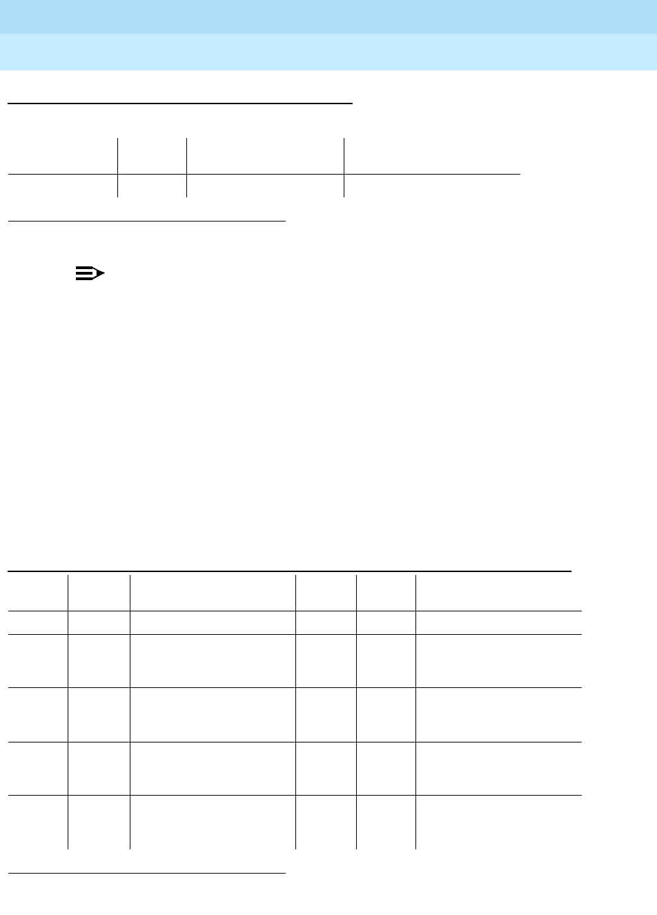
DEFINITY Enterprise Communications Server Release 6
Maintenance for R6r Volumes 1 & 2
555-230-126 Issue 2
January 1998
Maintenance Object Repair Procedures
Page 9-1128POWER
9
Battery and Charger for DC-Powered Systems
NOTE:
This MO applies to the J58890CE and the J58890CH-1 with large battery
holdover.
This MO represents the battery backup unit found in AC-powered multi-carrier
cabinets. Because the system does not recognize the type of external power, this
MO exists in DC-Powered multi-carrier cabinets but serves no functional
purpose. In such cabinets, all POWER tests should always either pass or abort,
and no POWER alarms should be raised.
DEFINITY Systems support two different cabinet types: multi-carrier and
single-carrier. Single-carrier cabinets are used only for EPNs. Both cabinet types
may be powered by either AC or DC external power source. Environmental
maintenance differs according to cabinet type and external power supply.
Error Log Entries and Test to Clear Values
1.
UU
is the cabinet number indicated in the PORT field from the Alarm or Error Log.
1. Run the Short Test Sequence first. If all tests pass, run the Long Test Sequence. Refer to the
appropriate test description and follow the recommended procedures.
MO Name (in
Alarm Log) Alarm
Level Initial Command to
Run1Full Name of MO
POWER MINOR test environment
UU
Battery & Battery Charger
Table 9-395. Battery & Battery Charger Error Log Entries
Error
Type Aux
Data Associated Test Alarm
Level On/Off
Board Test to Clear Value
010 Any Any Any test environment UU sh r 1
1 Any Battery & Battery Charger
Query Test (#5) (error
code 8)
MINOR ON test environment UU s r 1
257 Any Battery & Battery Charge
Query Test (#5) (error
code 4)
MINOR ON test environment UU s r 1
769 Any Battery & Battery Charger
Query Test (#5) (error
code 2)
MINOR ON test environment UU s r 1
3840(a) 1005 or
1028 Associated Battery &
Battery Charger Query
Test (#5)
test environment UU s r 1
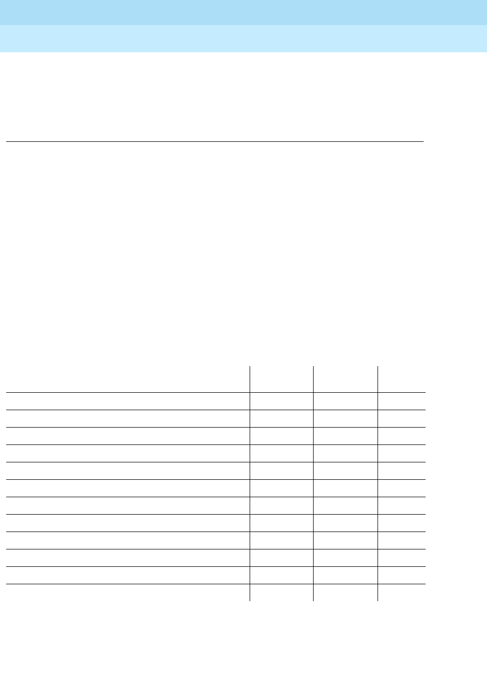
DEFINITY Enterprise Communications Server Release 6
Maintenance for R6r Volumes 1 & 2
555-230-126 Issue 2
January 1998
Maintenance Object Repair Procedures
Page 9-1129POWER
9
Note:
a. This error occurs is valid only for AC-powered multi-carrier cabinets with
battery backup. For DC-powered cabinets, you cannot clear the error and
it should be ignored.
Battery Holdover (Large Batteries)
The large batteries are mounted inside a separate battery cabinet and can
supply holdover times of 2 to 8 hours depending on the size of the battery. The
batteries are circuit breaker protected and are charged by the J58890CH-1. The
batteries also contain a thermal sensor that change the charging voltage
depending on the battery temperature.
System Technician-Demanded Tests:
Descriptions and Error Codes
Always investigate tests in the order presented in the table below when
inspecting errors in the system. By clearing error codes associated with the
Battery & Battery Charger Query Test,
for example, you may also clear errors
generated from other tests in the testing sequence.
Notes:
a. Refer to AC-POWER for a description of this test.
b. Refer to CARR-POW for AC- and DC-Powered Systems section for a
description of this test.
Order of Investigation Short Test
Sequence Long Test
Sequence D/ND*
Battery & Battery Charger Query Test (#5) X X ND
AC Power Query Test (#78) (a) X X ND
Power Unit Query Test (carrier E) (#127) (b) X X ND
Power Unit Query Test (carrier D) (#127) (b) X X ND
Power Unit Query Test (carrier A) (#127) (b) X X ND
Power Unit Query Test (carrier B) (#127) (b) X X ND
Power Unit Query Test (carrier C) (#127) (b) X X ND
Emergency Transfer Query Test (#124) (c) X X ND
Cabinet Sensors Query Test (#122) (d) X X ND
External Alarm Lead Query Test (#120) (e) X X ND
Analog Ring Generator Initialization Test (#117) (f) X X ND
Analog Ring Generator Query Test (#118) (f) X X ND

DEFINITY Enterprise Communications Server Release 6
Maintenance for R6r Volumes 1 & 2
555-230-126 Issue 2
January 1998
Maintenance Object Repair Procedures
Page 9-1130POWER
9
c. Refer to EMG-XFER for a description of this test.
d. Refer to CABINET for a description of this test.
e. Refer to EXT-DEV for a description of this test.
f. Refer to RING-GEN for a description of this test.
Battery & Battery Charger Query Test (#5)
This test queries the SYSAM in the PPN or the EPN Maintenance circuit pack in
an EPN for the status of the battery pack and battery charger, and reports the
result. In a DC-Powered system, this test should never fail. During this test, the
status LED on the battery charger is lit and extinguished if the status of the
battery charger is reported as normal. This event is a result of checking that the
battery charger is connected.
Table 9-396. TEST #5 Battery & Battery Charger Query Test
Error
Code Test
Result Description/ Recommendation
1000 ABORT System resources required to run this test are not available.
1005 ABORT Battery charger is not connected. DC-powered cabinets do not have battery
backup; ignore this error.
2000 ABORT Response to the test request was not received within the allowable time
period.
2028 ABORT Internal system error prevented the extinguishing of the Battery Charger status
LED.
1. Since this test is not relevant for DC-powered systems, an occurrence of
this error indicates possible existence of internal system problems.
2029
2319
2320
2500
ABORT Internal system error
1. Try the command again at 1-minute intervals up to 5 times.
any FAIL The SYSAM in a PPN or the EPN Maintenance circuit pack in an EPN is
incorrectly reporting a problem with power. If this test fails for a DC-powered
cabinet, the circuit pack has a problem. Replace the suspect circuit pack and
run the test again.
PASS All that can be inferred is that the SYSAM in a PPN or the EPN Maintenance
circuit pack in an EPN in an EPN multicarrier cabinet system is working
properly for this test.

DEFINITY Enterprise Communications Server Release 6
Maintenance for R6r Volumes 1 & 2
555-230-126 Issue 2
January 1998
Maintenance Object Repair Procedures
Page 9-1131PRI-CDR/SEC-CDR (Call Detail Recording Link)
9
PRI-CDR/SEC-CDR (Call Detail
Recording Link)
The CDR feature records detailed call information on all incoming and outgoing
calls on specified trunk groups and sends this information to a CDR output
device. The two physical links can be administered for connecting external CDR
output devices to the system. They are identified as the primary CDR (PRI-CDR)
link and the secondary CDR (SEC-CDR) link. The CDR device connects to the
system via a data module (PDM, MPDM, DTDM) connected to a port on a TN754
Digital Line circuit pack that is administered as a data extension. A CDR device
can also be connected through an ADU to a port on TN726B. The CDR link to the
processor is via a system port. A system port is comprised of a port on the
TN726B Data Line circuit pack and a port on the TN553 Packet Data circuit pack
connected to each other in a null-modem fashion. Refer to the PDATA-PT section
for information on the system port connectivity. External CDR output devices
include:
■94A Local Storage Unit (LSU)
■TELESEER CDR Unit
■Call Accounting System (CAS)
■Call Detail Recording Unit (CDRU)
■Printer
■Host computer
■Personal computer (PC)
■Customer-provided equipment
CDR Link Maintenance provides a strategy for maintaining the link between the
system and an external CDR output device. The strategy includes a set of tests
for periodic diagnosis, detection of errors during normal operation, actions for
troubleshooting, and raising alarms for serious problems. CDR Link Maintenance
uses a try-and-wait mechanism for maintaining the CDR link. If the CDR link is
torn down due to an error, CDR Link Maintenance tries to bring the CDR link up.
If the Link Setup fails, CDR Link Maintenance will wait for 30 seconds before the
next retry. If the number of retries reaches a threshold (two), a Minor alarm is
raised for service attention.
MO Name (in Alarm
Log) Alarm
Level Initial Command to Run Full Name of MO
PRI-CDR/SEC-CDR MINOR test cdr primary/secondary l CDR Link
PRI-CDR/SEC-CDR WARNING test cdr primary/secondary CDR Link

DEFINITY Enterprise Communications Server Release 6
Maintenance for R6r Volumes 1 & 2
555-230-126 Issue 2
January 1998
Maintenance Object Repair Procedures
Page 9-1132PRI-CDR/SEC-CDR (Call Detail Recording Link)
9
CDR Link Maintenance does not cover the maintenance of the elements
composing the CDR physical link:
■External CDR output device
■Data Module (PDM/MPDM/DTDM) and Digital Line Port of TN754 Digital
Line circuit pack
■ADU and Data Line Port of TN726B Data Line circuit pack
If CDR Link Maintenance cannot restore the CDR link, the maintenance tests of
these individual components of the CDR link must be executed to diagnose
faults.
Procedures for Restoring the CDR Link
1. Determine the status of CDR links.
Enter status cdr command and make sure that the CDR links are not
busied out for maintenance. If the link is down, then continue to the next
step.
2. Where does the CDR link connect to?
Enter display system feature and find out the destinations of CDR links.
Continue to the next step.
3. Enter the status data extension command and verify whether the data
extension is in the in-service/idle state. If the data extension is
not
available, then look for the extension number in the Alt Name field of the
Hardware Error Log and refer to "XXX-BD (Common Port Circuit Pack)" for
resolutions.
4. Is the external CDR output device available?
Make sure that the CDR output device is on-line and ready for service.
Check the physical connectivity between Data Module and the CDR
output device.
5. If the problem is not found in the above steps, check the system port for
any problems. Refer to the PDATA-PT section for for description about
system port and its connectivity.
When restoring the CDR link it is necessary to execute maintenance test on
different objects that comprise the CDR link. It is recommended that you busy out
the CDR link before trying to restore the link. When the CDR Link is busied out,
then all CDR Link maintenance actions are deactivated, and interference to tests
of other MOs is prevented.
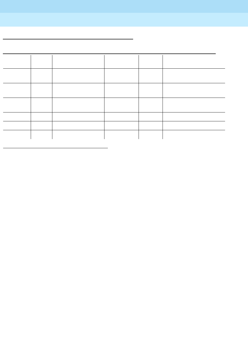
DEFINITY Enterprise Communications Server Release 6
Maintenance for R6r Volumes 1 & 2
555-230-126 Issue 2
January 1998
Maintenance Object Repair Procedures
Page 9-1133PRI-CDR/SEC-CDR (Call Detail Recording Link)
9
Error Log Entries and Test to Clear Values
Notes:
a. The CDR link is busied out. The CDR link is torn down.
b. Link Retry Test (#215) fails. An error was detected when setting up the
link. Refer to the preceding section ‘‘Procedures for Restoring the CDR
Link’’ for resolution.
c. The CDR physical link is down for one of the following reasons:
■Cable to the CDR output device is disconnected.
■CDR output device is powered off.
■The data extension where the CDR output device connects to has
been busied out or there is a scheduled daily interchange.
Check the connectivity of wire and cable among wall jacket, data module,
and the CDR output device. Enter status data extension and verify that
the data extension of the CDR output device is in the in-service/idle state.
If the data extension is not available, then refer to The preceding section
‘‘Procedures for Restoring the CDR Link’’ for resolution. Issue the display
system-parameters-maintenance command to see the start time of daily
maintenance. If the error occurs and is resolved during of daily
maintenance, it can be ignored.
1. Run the Short Test Sequence first. If all tests pass, run the Long Test Sequence. Refer to the appropriate
test description and follow the recommended procedures.
2. Minor alarms may be downgraded to Warning alarms based on the value used in the set options
command.
Table 9-397. CDR Link Maintenance Error Log Entries
Error
Type Aux
Data Associated Test Alarm Level On/Off
Board Test to Clear Value
010 Any Any Any test cdr primary|secondary
sh
18(a) 0 busyout cdr
primary|secondary WARNING OFF release cdr
primary|secondary
257(b) Any Link Retry Test (#215) MINOR/2
WARNING OFF test cdr primary|secondary
l
513(c) test cdr primary|secondary
1025(d)
1281(e) Any

DEFINITY Enterprise Communications Server Release 6
Maintenance for R6r Volumes 1 & 2
555-230-126 Issue 2
January 1998
Maintenance Object Repair Procedures
Page 9-1134PRI-CDR/SEC-CDR (Call Detail Recording Link)
9
d. This error indicates that the CDR output device is in an off-line state, (for
example, due to paper jam or paper out for a printer device). The CDR link
is torn down. Check the CDR output device and act promptly to put it back
to on-line state. Enter test cdr primary|secondary command to set up the
CDR link.
e. Software detects an overflow of CDR records generated in the switch due
to the heavy trunk traffic and low speed CDR output device. If both
primary and secondary links are ON, the secondary link is torn down
temporarily for two minutes to speed up the output process to the primary
link. No action is necessary for this error type.
System Technician-Demanded Tests:
Descriptions and Error Codes
Always investigate tests in the order presented in the table below when
inspecting errors in the system. By clearing error codes associated with the
Link
Retry Test
, for example, you may also clear errors generated from other tests in
the testing sequence.
Link Tear Down Test (#213)
This test is destructive.
This test disconnects the existing link between the system and the external CDR
output device. If the link has been disconnected already, this test just returns
PASS. All resources allocated for a CDR link are released after this test.
1. D = Destructive; ND = Nondestructive
Order of Investigation Short Test
Sequence Long Test
Sequence D/ND1
Link Tear Down Test (#213) X D
Link Retry Test (#215) X X ND
Table 9-398. TEST #213 Link Tear Down Test
Error
Code Test
Result Description/ Recommendation
40 ABORT Internal system error.
50 ABORT Internal system error.
1. Retry the command at one-minute intervals for a maximum of 5 times.
Continued on next page

DEFINITY Enterprise Communications Server Release 6
Maintenance for R6r Volumes 1 & 2
555-230-126 Issue 2
January 1998
Maintenance Object Repair Procedures
Page 9-1135PRI-CDR/SEC-CDR (Call Detail Recording Link)
9
Link Retry Test (#215)
This test sends a message to the CDR software process to make a data call to
the extension where the CDR output device connects to. If the CDR link is
already up, then this test will be passed without making any data call.
1010 ABORT The CDR link has been busied out to out-of-service.
1. Enter the release cdr primary|secondary command to release the
CDR link from busyout state.
2. Retry the test cdr primary|secondary long command to execute the
test.
2012 ABORT Internal system error.
1. Retry the command at one-minute intervals a maximum of 5 times.
FAIL Internal system error.
1. Retry the command at one-minute intervals for a maximum of 5 times.
PASS The CDR link is torn down.
Table 9-399. TEST #215 Link Retry Test
Error
Code Test
Result Description/ Recommendation
10 ABORT Internal system error.
20 ABORT Internal system error.
1. Retry the command at 1-minute intervals for a maximum of 5 times.
30 ABORT Internal system error.
1. Refer to ‘‘Procedures for Restoring the CDR Link’’ for instructions.
1010 ABORT The CDR link has been busied out to out-of-service.
1. Enter release cdr primary|secondary command to release the CDR
link from busyout state.
2. Retry test cdr primary|secondary long command to execute the
test.
Continued on next page
Table 9-398. TEST #213 Link Tear Down Test
Error
Code Test
Result Description/ Recommendation
Continued on next page

DEFINITY Enterprise Communications Server Release 6
Maintenance for R6r Volumes 1 & 2
555-230-126 Issue 2
January 1998
Maintenance Object Repair Procedures
Page 9-1136PRI-CDR/SEC-CDR (Call Detail Recording Link)
9
2012 ABORT Internal system error.
1. Retry the command at 1-minute intervals a maximum of 5 times.
FAIL The CDR link CANNOT be established.
1. Refer to the ‘‘Procedures for Restoring the CDR Link’’ for instructions.
PASS The CDR link is up.
Table 9-399. TEST #215 Link Retry Test
Error
Code Test
Result Description/ Recommendation
Continued on next page

DEFINITY Enterprise Communications Server Release 6
Maintenance for R6r Volumes 1 & 2
555-230-126 Issue 2
January 1998
Maintenance Object Repair Procedures
Page 9-1137PROC-SAN (Process Sanity Audits)
9
PROC-SAN (Process Sanity Audits)
The Process Sanity Audits maintenance object is responsible for monitoring the
sanity of software processes in the system. If the Process Sanity Audits MO
detects that a process has gone insane (does not respond to a sanity message
within an allotted time period), the process will be restarted. If the Process Sanity
Audits MO detects that multiple processes (or a single key process) do not
respond to sanity messages within an allotted time period, a system recovery
action will be initiated.
The Process Sanity Audits MO has no alarms and no tests. Certain errors are
logged to the Hardware Error Log for information purposes only.
Error Log Entries and Test to Clear Values
Note:
a. These errors indicate that a system recovery action has been taken
because one or more software processes failed to respond to a sanity
audit in a timely fashion. As a result of the recovery action, the system may
have temporarily suspended service for a period of time surrounding the
error.
MO Name (in
Alarm Log) Alarm
Level Initial Command to
Run Full Name of MO
PROC-SAN none none Process Sanity Audits
Table 9-400. Process Sanity Audits Error Log Entries
Error
Type Aux Data Associated
Test Alarm Level On/Off
Board Test to Clear Value
0 0 Any Any Any none
10 (a) 0 none none none none
204 (a) any none none none none

DEFINITY Enterprise Communications Server Release 6
Maintenance for R6r Volumes 1 & 2
555-230-126 Issue 2
January 1998
Maintenance Object Repair Procedures
Page 9-1138PROCR (RISC Processor Circuit Pack)
9
PROCR (RISC Processor Circuit Pack)
The UN331B Processor circuit pack executes the system software, including all
call processing, maintenance and administration functions. The Processor circuit
pack is the most critical component for correct system operation.
Full system operation depends on nearly every circuit pack in the SPE. However,
the ability to load and run the maintenance software by the Processor circuit
pack depends only on correct Memory, Processor Bus, Tape-Disk-MSSNET and
SYSAM operation.
There are many Processor circuit pack problems (or other SPE problems) that
will result in the SPE being unable to load or run software. This condition is
indicated by the message "SPE Down" displayed on the terminal. In these cases,
refer to the SPE DOWN section of this manual for repair procedures.
The Processor circuit pack contains an instruction cache and a data cache.
These caches provide local, high speed memory that is closely coupled with the
processing function on the Processor circuit pack. The local nature of the caches
speeds up system operation by eliminating many external Memory accesses
when reading instructions or data. As the Processor runs, it tries to use
information already in the cache so that time will not be wasted going out to
memory. If it does not find the information in the cache, it reads it from memory
and stores it in the cache for possible future use. Over time, most instruction or
data accesses are likely to be satisfied by current information in the cache.
Problems in the cache circuits may stop the Processor from running or may only
result in reduced system performance.
The Processor circuit pack contains a Burst Read function that transfers multiple
words of instructions from memory with each request. This is done to speed up
the transfer of information from the Memory to the Processor, and is especially
helpful for "filling up" the cache in parallel with internal processing on Processor
circuit pack. Most of the circuitry needed to support this function is found on the
1. UU is the cabinet number (always 1, not required). With simplex SPE, carrier designation is not
required. With duplicated SPEs, carrier a or b must be specified.
2. After a spontaneous SPE interchange has occurred, the Alarm Log retains for three hours a
record of any MAJOR ON-BOARD alarm against an SPE component that took place before the
interchange. If a spontaneous interchange has occurred (as indicated by STBY-SPE error type
103 or the display initcauses screen), and handshake is down, (check with status spe),
replace the alarmed circuit pack on the standby SPE. If handshake is up, execute a test long
clear of the alarmed circuit pack and follow recommended procedures.
MO Name (in
Alarm Log) Alarm
Level Initial Command to
Run1Full Name of MO
PROCR MAJOR2test processor UUC l RISC Processor Circuit Pack
PROCR MINOR test processor UUC s RISC Processor Circuit Pack

DEFINITY Enterprise Communications Server Release 6
Maintenance for R6r Volumes 1 & 2
555-230-126 Issue 2
January 1998
Maintenance Object Repair Procedures
Page 9-1139PROCR (RISC Processor Circuit Pack)
9
Memory circuit packs, but part of this function is on the Processor as well. Refer
to Memory documentation for test information.
The Processor circuit pack contains a Write Buffer function that helps prevent
internal processing operations from being held up by Processor Bus activity. If
the Processor needs to write to Memory, it writes to the Write Buffer. If the
Processor Bus is in use at this time, the information is transferred to Memory at an
appropriate time. Up to 12 processor writes can be pending, waiting for transfer
to memory.
The Processor Bus contains parity checking functions. If one address or data bit
is corrupted during an access cycle, the error detection logic detects and
reports this to Processor circuit pack.
The Processor circuit pack contains interrupt and exception signals that tell the
Processor when normal or erroneous events occur in SPE components. An
example of a normal event is an interrupt that occurs when data provided by an
SPE component such as the SYSAM is available for the Processor. An example
of an error-indicating exception is detection of a parity error on the Bus when
Processor reads Memory. These types of errors result in system recovery actions
which are described in Chapter 4, ‘‘Initialization and Recovery’’.
The Processor circuit pack contains an erasable, programmable read-only
memory (BOOTPROM) that contains the system initialization and low-level
diagnostic programs. Problems in this hardware may result in difficulties with
system start-up, restart, or SPE maintenance testing in general.
If the PBX system is equipped with High Reliability or Critical Reliability option
(i.e. with duplicated SPEs), and if a failure of the active Processor circuit pack
causes a MAJOR on-board alarm, a SPE interchange will occur if the health of
the standby SPE permits the interchange. Refer to Replacing SPE Circuit Packs
in Chapter 5 for more information about duplicated SPEs.

DEFINITY Enterprise Communications Server Release 6
Maintenance for R6r Volumes 1 & 2
555-230-126 Issue 2
January 1998
Maintenance Object Repair Procedures
Page 9-1140PROCR (RISC Processor Circuit Pack)
9
Error Log Entries and Test to Clear Values
Notes:
a. This error (150) indicates that a SPE interchange has occurred and that
the Processor circuit pack was the cause of the spontaneous interchange.
1. If other PROCR errors are present, investigate these errors.
2. If no other PROCR errors are present, run the test processor a|b
long clear command and investigate any test failures.
b. A parity error was detected in the processor’s data cache or instruction
cache. In a system with duplicated SPEs, this error can be generated only
while the processor is running on the active SPE since the software
running on the standby processor does not use the Processor data and
instruction caches. Therefore, if PROC error 1026 is present for a
processor on the standby SPE, that error must have been generated some
time in the past when the processor was running as the active SPE.
Execute the test processor long command for a processor either on the
active or standby SPE, and if any tests fail, follow the repair procedures for
those failures. It is unlikely that a parity error will occur at the time the
1. Run the Short Test Sequence first. If all tests pass, run the Long Test Sequence. Refer to the
appropriate test description and follow the recommended procedures.
2. If a spontaneous interchange has occurred (as indicated by STBY-SPE error type 103 or the display
init causes screen), and handshake is down, (check with status spe), replace the alarmed circuit
pack on the standby SPE. If handshake is up, execute a test long clear of the alarmed circuit pack
and follow recommended procedures.
Table 9-401. PROCR Error Log Entries
Error
Type Aux
Data Associated Test Alarm
Level On/Off
Board Test to Clear Value
010 Any Any Any test processor UUC s r 1
1 BOOTPROM Checksum
Test (#897) MAJOR2ON test processor UUC s r 1
150(a) Any None MAJOR†ON test processor UUC l c
257 Parity Checker Test
(#899) MINOR ON test processor UUC s r 2
513 Write Buffer Test (#900) MAJOR†ON test processor UUC s r 1
1025 Cache Audit (#896) MINOR ON test processor UUC s r 2
1026(b) Cache Audit (#896) MAJOR ON test processor UUC s r 2
1281 Cache Test (#895) MAJOR†ON test processor UUC l r 1

DEFINITY Enterprise Communications Server Release 6
Maintenance for R6r Volumes 1 & 2
555-230-126 Issue 2
January 1998
Maintenance Object Repair Procedures
Page 9-1141PROCR (RISC Processor Circuit Pack)
9
Processor Cache Audit test (#896) is run on demand. However, the
processor Cache test (#895) may uncover a failure that can cause cache
parity errors.
If no tests fail but a MAJOR alarm is present as a result of the 1026 error,
replace the Processor circuit pack since multiple cache parity errors have
occurred in the past and will probably occur again which can cause call
processing failures.
System Technician-Demanded Tests:
Descriptions and Error Codes
Always investigate tests in the order presented in the table below. By clearing
error codes associated with the
Processor Cache Test
, for example, you may
also clear errors generated from other tests in the testing sequence.
Processor Cache Test (#895)
This test is destructive.
This test overwrites the contents in the Instruction and Data Caches, requiring
them to be refilled during normal execution.
This test verifies that the Processor Instruction and Data Caches are functional.
Some errors in the caches will cause the Processor to stop functioning, while
others simply reduce performance by forcing instructions or data to be read from
memory more often than would normally be necessary. In any case, cache
problems are serious and the Processor circuit pack must be replaced as soon
as possible if they are detected.
1. D = Destructive; ND = Nondestructive
Order of Investigation Short Test
Sequence Long Test
Sequence Reset Board
Sequence D/ND1
Processor Cache Test (#895) X D
Processor Cache Audit (#896) X X ND
Processor BOOTPROM Checksum Test (#897) X X ND
Processor Parity Checker Test (#899) X X ND
Processor Write Buffer Test (#900) X X ND

DEFINITY Enterprise Communications Server Release 6
Maintenance for R6r Volumes 1 & 2
555-230-126 Issue 2
January 1998
Maintenance Object Repair Procedures
Page 9-1142PROCR (RISC Processor Circuit Pack)
9
Table 9-402. TEST #895 Processor Cache Test
Error
Code Test
Result Description/ Recommendation
100 ABORT The requested test did not complete within the allowable time period.
1. Retry the command.
1022
1335
2500
ABORT Internal system error
1. Retry the command.
1338 ABORT The test is not allowed to run since a planned SPE interchange is in
progress. This may be caused by a planned interchange initiated
automatically during 24 hour scheduled testing.
1. Wait 3 minutes and retry the command.
1339 ABORT The test could not run on the standby Processor circuit pack in the standby
SPE carrier because the standby SPE is unavailable.
1. Refer to “STBY-SPE” for information on why a standby SPE may be
unavailable and what repair actions should be taken. The screen for the
status spe command should indicate that handshake is down. This
may be caused by a variety of reasons such as the SPE-SELECT
switches on the DUPINT circuit packs being set to the position of the
active SPE, a failure of the DUPINT circuit pack, or loss of power on the
standby SPE. The
SPE Selected
field on the status spe screen will
display
spe a
or
spe b
if both SPE-SELECT switches are in the a or b
positions, respectively.
2000 ABORT Response to the test request was not received within the allowable time
period. If the system is equipped with the high reliability or critical reliability
configuration and if the Processor circuit pack is on the standby SPE, this
abort code may indicate that the standby SPE is not responding to the
handshake message. If this is the case, the standby SPE maintenance
software may take up to two minutes to indicate that handshake
communication with the standby SPE is down. The ABORT code will then
change to 1339 (standby SPE unavailable).
1. Retry the command at 1-minute intervals, a maximum of 3 times.
2334 ABORT The hardware mail on the standby Duplication Interface board is not ready
to receive messages.
1. Retry the command at 1-minute intervals, a maximum of 5 times.
FAIL The Processor cache is not functioning correctly.
1. Replace the Processor circuit pack immediately. To replace the
Processor circuit pack, refer to
Replacing SPE Circuit Packs
in Chapter
5.
PASS The cache portion of the Processor circuit pack is operating correctly.
Continued on next page

DEFINITY Enterprise Communications Server Release 6
Maintenance for R6r Volumes 1 & 2
555-230-126 Issue 2
January 1998
Maintenance Object Repair Procedures
Page 9-1143PROCR (RISC Processor Circuit Pack)
9
Processor Cache Parity Audit (#896)
This audit checks the state of the Cache Parity bit maintained by the R3000 CPU.
If this bit is set, there may be problems with either the CPU, the Instruction, or
Data Cache. An indication of bad cache parity won’t itself mean that the system
won’t operate, but minor to severe performance degradation may be present. For
example, a single bad bit in either cache could cause this bit to be set. If the
faulty word is seldom accessed, the impact will be small. If the bit is accessed
frequently, there could be serious problems with much, or all, of the cache (stuck
data bit) with the only direct indication again being the cache parity error or
cache test error.
Table 9-403. TEST #896 Processor Cache Parity Audit
Error
Code Test
Result Description/ Recommendation
100 ABORT The requested test did not complete within the allowable time period.
1. Retry the command.
1022 ABORT Internal system error
1. Retry the command.
1335 ABORT This test is only run on the active SPE since the standby processor does not
use the cache memory. Cache failures may cause cause cache parity errors
on the active SPE which can be logged against a standby SPE is an SPE
interchange has taken place.
If a PROC 1026 error code is present in the hardware error log for a processor
on the standby SPE:
a. Enter the test memory long command to run the Processor Cache test
(#895) to verify that the cache has not failed.
b. Request an SPE interchange by entering reset system interchange
and run the short processor test sequence test processor while the
processor is on the active SPE.
c. If all test pass but a MAJOR alarm is present as a result of a 1026 error
in the hardware error log, replace the processor circuit pack since
multiple cache parity errors have occurred in the past and will probably
occur again which can cause call processing failures.
2500 ABORT Internal system error
1. Retry the command.
1338 ABORT The test is not allowed to run since a planned SPE interchange is in progress.
This may be caused by a planned interchange initiated automatically during 24
hour scheduled testing.
1. Wait 3 minutes and retry the command.
Continued on next page

DEFINITY Enterprise Communications Server Release 6
Maintenance for R6r Volumes 1 & 2
555-230-126 Issue 2
January 1998
Maintenance Object Repair Procedures
Page 9-1144PROCR (RISC Processor Circuit Pack)
9
Processor BOOTPROM Checksum Test (#897)
This test computes the checksum of the Processor’s bootstrap BOOTPROM and
compares it to a predetermined value stored within the BOOTPROM. A failure of
this test indicates the BOOTPROM is corrupt.
1339 ABORT The test could not run on the standby Processor circuit pack in the standby
SPE carrier because the standby SPE is unavailable.
1. Refer to the STBY-SPE maintenance documentation for information on why
a standby SPE may be unavailable and what repair actions should be
taken. The screen for the status spe command should indicate that
handshake is down. This may be caused by a variety of reasons such as
the SPE-SELECT switches on the DUPINT circuit packs being set to the
position of the active SPE, a failure of the DUPINT circuit pack, or loss of
power on the standby SPE. The
SPE Selected
field on the status spe
screen will display
spe a
or
spe b
if both SPE-SELECT switches are in the
a or b positions, respectively.
2000 ABORT Response to the test request was not received within the allowable time period.
If the system is equipped with the High Reliability or Critical Reliability
Configuration and if the Processor circuit pack is on the standby SPE, this
abort code may indicate that the standby SPE is not responding to the
handshake message. If this is the case, the standby SPE maintenance
software may take up to two minutes to indicate that handshake
communication with the standby SPE is down. The ABORT code will then
change to 1339 (standby SPE unavailable).
1. Retry the command at 1-minute intervals, a maximum of 3 times.
2334 ABORT The hardware mail on the standby Duplication Interface board is not ready to
receive messages.
1. Retry the command at 1-minute intervals, a maximum of 5 times.
FAIL The Cache Parity Error bit is set, there may be problems with either the CPU or
the Instruction or Data Cache.
1. Retry the command.
2. If the test continues to fail, run test processor a|b long.
3. If the Processor Cache test (#895) or the Processor Cache Parity Audit
(#896) fails, replace the Processor circuit pack. To replace the Processor
circuit pack, refer to
Replacing SPE Circuit Packs
in Chapter 5.
PASS The Processor has not detected any parity errors in the Instruction and Data
Caches since the last time this audit was run.
Table 9-403. TEST #896 Processor Cache Parity Audit — Continued
Error
Code Test
Result Description/ Recommendation
Continued on next page

DEFINITY Enterprise Communications Server Release 6
Maintenance for R6r Volumes 1 & 2
555-230-126 Issue 2
January 1998
Maintenance Object Repair Procedures
Page 9-1145PROCR (RISC Processor Circuit Pack)
9
Table 9-404. TEST #897 Processor BOOTPROM Checksum Test
Error
Code Test
Result Description/ Recommendation
100 ABORT The requested test did not complete within the allowable time period.
1. Retry the command.
1022
1335
2500
ABORT Internal system error
1. Retry the command.
1338 ABORT The test is not allowed to run since a planned SPE interchange is in progress.
This may be caused by a planned interchange initiated automatically during
24 hour scheduled testing.
1. Wait 3 minutes and retry the command.
1339 ABORT The test could not run on the standby Processor circuit pack in the standby
SPE carrier because the standby SPE is unavailable.
1. Refer to the STBY-SPE maintenance documentation for information on why
a standby SPE may be unavailable and what repair actions should be
taken. The screen for the status spe command should indicate that
handshake is down. This may be caused by a variety of reasons such as
the SPE-SELECT switches on the DUPINT circuit packs being set to the
position of the active SPE, a failure of the DUPINT circuit pack, or loss of
power on the standby SPE. The
SPE Selected
field on the status spe
screen will display
spe a
or
spe b
if both SPE-SELECT switches are in the
a or b positions, respectively.
2000 ABORT Response to the test request was not received within the allowable time
period. If the system is equipped with the High Reliability or Critical Reliability
Configuration and if the Processor circuit pack is on the standby SPE, this
abort code may indicate that the standby SPE is not responding to the
handshake message. If this is the case, the standby SPE maintenance
software may take up to two minutes to indicate that handshake
communication with the standby SPE is down. The ABORT code will then
change to 1339 (standby SPE unavailable).
1. Retry the command at 1-minute intervals, a maximum of 3 times.
2334 ABORT The hardware mail on the standby Duplication Interface board is not ready to
receive messages.
1. Retry the command at 1-minute intervals, a maximum of 5 times.
FAIL The computed checksum did not match the BOOTPROM checksum. The
system may not continue to operate correctly. The system may fail at some
future date when the corrupted area the bootstrap BOOTPROM is accessed.
1. Replace the Processor circuit pack. To replace the Processor circuit pack,
refer to
Replacing SPE Circuit Packs
in Chapter 5, ‘‘Responding to Alarms
and Errors’’.
Continued on next page

DEFINITY Enterprise Communications Server Release 6
Maintenance for R6r Volumes 1 & 2
555-230-126 Issue 2
January 1998
Maintenance Object Repair Procedures
Page 9-1146PROCR (RISC Processor Circuit Pack)
9
Processor Parity Checker Test (#899)
This test verifies that the Processor can detect parity errors on the bus. If this part
of the Processor circuit pack is faulty, the system may continue to operate
properly, but may not correctly respond if a bus problem arises later. The
Processor reads a special memory location on the SYSAM circuit pack to
perform this test. Problems with the SYSAM may also cause this test to fail.
PASS The computed checksum matched the BOOTPROM checksum. This part of
the Processor will continue to operate normally.
Table 9-405. TEST #899 Processor Parity Checker Test
Error
Code Test
Result Description/ Recommendation
100 ABORT The requested test did not complete within the allowable time period.
1. Retry the command.
1022
1335
2500
ABORT Internal system error
1. Retry the command.
1338 ABORT The test is not allowed to run since a planned SPE interchange is in progress.
This may be caused by a planned interchange initiated automatically during 24
hour scheduled testing.
1. Wait 3 minutes and retry the command.
1339 ABORT The test could not run on the standby Processor circuit pack in the standby SPE
carrier because the standby SPE is unavailable.
1. Refer to the STBY-SPE maintenance documentation for information on why
a standby SPE may be unavailable and what repair actions should be
taken. The screen for the status spe command should indicate that
handshake is down. This may be caused by a variety of reasons such as
the SPE-SELECT switches on the DUPINT circuit packs being set to the
position of the active SPE, a failure of the DUPINT circuit pack, or loss of
power on the standby SPE. The
SPE Selected
field on the status spe
screen will display
spe a
or
spe b
if both SPE-SELECT switches are in the a
or b positions, respectively.
Continued on next page
Table 9-404. TEST #897 Processor BOOTPROM Checksum Test — Continued
Error
Code Test
Result Description/ Recommendation
Continued on next page

DEFINITY Enterprise Communications Server Release 6
Maintenance for R6r Volumes 1 & 2
555-230-126 Issue 2
January 1998
Maintenance Object Repair Procedures
Page 9-1147PROCR (RISC Processor Circuit Pack)
9
Processor Write Buffer Test (#900)
This test verifies that the Write Buffer operates properly on the Processor circuit
pack. Failure of this test is serious. The Processor circuit pack must be replaced
as soon as possible.
2000 ABORT Response to the test request was not received within the allowable time period.
If the system is equipped with the High Reliability or Critical Reliability
Configuration and if the Processor circuit pack is on the standby SPE, this abort
code may indicate that the standby SPE is not responding to the handshake
message. If this is the case, the standby SPE maintenance software may take
up to two minutes to indicate that handshake communication with the standby
SPE is down. The ABORT code will then change to 1339 (standby SPE
unavailable).
1. Retry the command at 1-minute intervals, a maximum of 3 times.
2334 ABORT The hardware mail on the standby Duplication Interface board is not ready to
receive messages.
1. Retry the command at 1-minute intervals, a maximum of 5 times.
FAIL The Processor cannot detect bus parity error conditions.
1. Retry the command.
2. If the test continues to fail, replace the Processor circuit pack.
3. If the test continues to fail after replacing the Process circuit pack, replace
the SYSAM circuit pack. To replace the Processor circuit pack, refer to
Replacing SPE Circuit Packs
in Chapter 5.
PASS The Processor Parity Checker is functional.
Table 9-406. TEST #900 Processor Write Buffer Test
Error
Code Test
Result Description/ Recommendation
100 ABORT The requested test did not complete within the allowable time period.
1. Retry the command.
Continued on next page
Table 9-405. TEST #899 Processor Parity Checker Test — Continued
Error
Code Test
Result Description/ Recommendation
Continued on next page

DEFINITY Enterprise Communications Server Release 6
Maintenance for R6r Volumes 1 & 2
555-230-126 Issue 2
January 1998
Maintenance Object Repair Procedures
Page 9-1148PROCR (RISC Processor Circuit Pack)
9
1022
1335
2500
ABORT Internal system error
1. Retry the command.
1338 ABORT The test is not allowed to run since a planned SPE interchange is in progress.
This may be caused by a planned interchange initiated automatically during
24 hour scheduled testing.
1. Wait 3 minutes and retry the command.
1339 ABORT The test could not run on the standby Processor circuit pack in the standby
SPE carrier because the standby SPE is unavailable.
1. Refer to the STBY-SPE maintenance documentation for information on
why a standby SPE may be unavailable and what repair actions should be
taken. The screen for the status spe command should indicate that
handshake is down. This may be caused by a variety of reasons such as
the SPE-SELECT switches on the DUPINT circuit packs being set to the
position of the active SPE, a failure of the DUPINT circuit pack, or loss of
power on the standby SPE. The
SPE Selected
field on the status spe
screen will display
spe a
or
spe b
if both SPE-SELECT switches are in the
a or b positions, respectively.
2000 ABORT Response to the test request was not received within the allowable time
period. If the system is equipped with the High Reliability or Critical Reliability
Configuration and if the Processor circuit pack is on the standby SPE, this
abort code may indicate that the standby SPE is not responding to the
handshake message. If this is the case, the standby SPE maintenance
software may take up to two minutes to indicate that handshake
communication with the standby SPE is down. The ABORT code will then
change to 1339 (standby SPE unavailable).
1. Retry the command at 1-minute intervals, a maximum of 3 times.
2334 ABORT The hardware mail on the standby Duplication Interface board is not ready to
receive messages.
1. Retry the command at 1-minute intervals, a maximum of 5 times.
FAIL The Processor Write Buffer is not operating correctly.
1. Replace the Processor circuit pack immediately. To replace the
Processor circuit pack, refer to
Replacing SPE Circuit Packs
in Chapter 5.
PASS The Write Buffer portion of the Processor circuit pack is operating correctly.
Table 9-406. TEST #900 Processor Write Buffer Test — Continued
Error
Code Test
Result Description/ Recommendation
Continued on next page

DEFINITY Enterprise Communications Server Release 6
Maintenance for R6r Volumes 1 & 2
555-230-126 Issue 2
January 1998
Maintenance Object Repair Procedures
Page 9-1149RING-GEN
9
RING-GEN
Analog Ring Generator
Analog phones must be provided with a voltage that allows them to ring. The
Analog Ring Generator maintenance object represents the device that provides
the ringing voltage for all analog phones associated with a given cabinet. In a
multi-carrier cabinet, the ring generator resides in the power distribution unit . It is
protected by a fuse located next to the main circuit breaker on the front of the
unit. In single-carrier cabinets, the ring generator is part of the WP-91153 power
supply. Failure of the ring generator results in loss of ringing on analog phones.
Ringing on digital and hybrid phones is not affected.
The ringing voltage is monitored by the Tone-Clock circuit pack. In a port
network with duplicated Tone-Clocks, it is the active Tone-Clock that performs
this function. In an EPN made up of single-carrier cabinets, the Tone-Clock
monitors only the ringing voltage in the carrier that contains the tone clock.
The TN2036 Voltage Range circuit pack provides easy access for testing the
various voltages on the backplane pins. For more information, refer to Chapter 5.
1. P is the port network number indicated in the PORT field from the Alarm or Error Log.
MO Name (in
Alarm Log) Alarm Level Initial Command to
Run1Full Name of MO
RING-GEN MAJOR test environment P Analog Ring Generator

DEFINITY Enterprise Communications Server Release 6
Maintenance for R6r Volumes 1 & 2
555-230-126 Issue 2
January 1998
Maintenance Object Repair Procedures
Page 9-1150RING-GEN
9
Error Log Entries and Test to Clear Values
System Technician-Demanded Tests:
Descriptions and Error Codes
Always investigate tests in the order presented in the table below when
inspecting errors in the system. By clearing error codes associated with the
Analog Ring Generator Initialization
Test, for example, you may also clear errors
generated from other tests in the testing sequence.
1. Run the Short Test Sequence first. If all tests pass, run the Long Test Sequence. Refer to the
appropriate test description and follow the recommended procedures.
1. D = Destructive, ND = Non-destructive
Table 9-407. Analog Ring Generator Error Log Entries
Error
Type Aux
Data Associated Test Alarm
Level On/Off
Board Test to Clear Value
010 Any Any Any test environment UU
1 Analog Ring Generator
Query (#118) MAJO
RON test environment UU r 3
Table 9-408. Multicarrier Cabinet
Order of Investigation Short Test
Sequence Long Test
Sequence D/ND1
Analog Ring Generator Initialization Test (#117) X X ND
Analog Ring Generator Query Test (#118) X X ND
Battery & Battery Charger Query Test (#5) (a) X X ND
AC Power Query Test (#78) (b) X X ND
OLS Query Test (Carrier E) (#127) (c) X X ND
OLS Query Test (Carrier D) (#127) (c) X X ND
OLS Query Test (Carrier A) (#127) (c) X X ND
OLS Query Test (Carrier B) (#127) (c) X X ND
OLS Query Test (Carrier C) (#127) (c) X X ND
Emergency Transfer Query Test (#124) (d) X X ND
Cabinet Sensors Query Test (#122) (e) X X ND
External Alarm Lead Query Test (#120) (f) X X ND
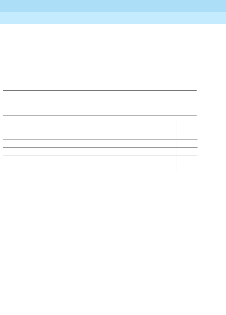
DEFINITY Enterprise Communications Server Release 6
Maintenance for R6r Volumes 1 & 2
555-230-126 Issue 2
January 1998
Maintenance Object Repair Procedures
Page 9-1151RING-GEN
9
Notes:
a. Refer to POWER for a description of this test.
b. Refer to AC-POWER for a description of this test.
c. Refer to CARR-POW for a description of this test.
d. Refer to EMG-XFER for a description of this test.
e. Refer to CABINET for a description of this test.
f. Refer to EXT-DEV for a description of this test.
Notes:
a. Refer to DC-POWER for a description of this test.
b. Refer to EMG-XFER for a description of this test.
c. Refer to EXT-DEV for a description of this test.
Analog Ring Generator Initialization Test (#117)
The TN768, or TN780 will report an error to the system software if the ringing
voltage falls to low (only if system software has made a request to the TN768, or
TN780 to monitor the voltage). The Analog Ring Generator Initialization Test
sends a request to the TN768, or TN780. If there are redundant tone/clock circuit
packs in the port network, then the request is sent only to the active tone/clock.
1. D = Destructive, ND = Non-destructive
Table 9-409. Single-Carrier Cabinet
Order of Investigation Short Test
Sequence Long Test
Sequence D/ND1
Analog Ring Generator Initialization Test (#117) X X ND
Analog Ring Generator Query Test (#118) X X ND
Single-Carrier Cabinet Power Query Test (#79) (a) X X ND
Emergency Transfer Query Test (#124) (b) X X ND
External Alarm Lead Query Test (#120) (c) X X ND

DEFINITY Enterprise Communications Server Release 6
Maintenance for R6r Volumes 1 & 2
555-230-126 Issue 2
January 1998
Maintenance Object Repair Procedures
Page 9-1152RING-GEN
9
Analog Ring Generator Query Test (#118)
The Analog Ring Generator Query Test requests the active Tone/Clock circuit
pack to check the ringing voltage. The tone/clock circuit pack replies with PASS
if the ringing voltage is adequate to ring the analog phones. If not, the active
tone/clock circuit pack replies with a FAIL.
Table 9-410. TEST #117 Analog Ring Generator Initialization Test
Error
Code Test
Result Description/ Recommendation
1
1000
1001
1003
1115
2012
2100
ABORT The system software is unable to determine the active tone/clock circuit pack,
unable to allocated the resources necessary to run the test, or unable to send
a down link message.
1. Wait for the green LED on the active tone/clock to go out; use the status
port-network command to determine the active Tone/Clock circuit pack.
2. Rerun the test. If the test aborts again, refer to TDM-CLK.
2000 ABORT Response to the request was not received within the allowable time period.
1. Look for TDM-CLK errors and alarms. Resolve all other Tone/Clock
problems first.
2. Rerun the test.
PASS The active Tone/Clock has successfully been enabled to monitor the ringing
voltage level.
Table 9-411. TEST #118 Analog Ring Generator Query Test
Error
Code Test
Result Description/ Recommendation
1
1000
1001
1003
1115
2012
2100
ABORT Could not seize the resources to run the test. Other maintenance is running on the
active tone/clock circuit pack.
1. Wait for the green LED on the active tone/clock circuit pack to go out; use the
status port-network command to determine the active Tone/Clock circuit pack.
2. Rerun the test. If the test aborts again, refer to TDM-CLK.
2000 ABORT Response to the request was not received within the allowable time period.
1. Look for TDM-CLK errors and alarms. Resolve all other tone/clock problems first.
2. Rerun the test.
Continued on next page

DEFINITY Enterprise Communications Server Release 6
Maintenance for R6r Volumes 1 & 2
555-230-126 Issue 2
January 1998
Maintenance Object Repair Procedures
Page 9-1153RING-GEN
9
FAIL The ringing voltage is below acceptable levels. Procedure for a multicarrier cabinet
system:
1. If this is a duplicated SPE system, then determine the active Tone/Clock circuit
pack by issuing a status port-network command. Make the Standby Tone/Clock
circuit pack active via the set tone-clock PC command and rerun the test.
a. If the test passes, then the trouble is with the now Standby Tone/Clock circuit
pack. Refer to “TONE-BD” for details on replacing the Standby Tone/Clock
circuit pack. After the circuit pack is replaced, make this Tone/Clock active
again by issuing the set tone-clock PC command and rerun the test.
b. If the test fails, then proceed with Step 2.
2. Resolve CARR-POW alarms first, and then rerun the test.
3. Check fuse on the power distribution unit. Replace if it is open, and rerun the test.
If the test still fails, then an analog line circuit pack could be defective and
causing the ring generator and/or fuse to fail.
4. Unseat all analog circuit packs in the affected cabinet, and rerun the test.
5. If the test passes, then the ring generator is healthy, and one of the analog circuit
packs is defective. Replace the analog circuit packs one at a time, and rerun the
test to determine which circuit pack is causing the problem. When the defective
analog circuit pack is found, replace it and rerun the test. If the test still fails,
proceed with Step 6.
FAIL
(cont’d.)
6. Since the test still fails, the ring generator is defective.
a. If the reset button on the ring generator is out, press it in.
b. Originate calls to several analog stations on different port circuit packs in
different carriers in the affected port network.
c. If called stations ring, the fault is cleared. Proceed to Step d. If no stations
ring, replace the ring generator.
d. Rerun the test. If the test still fails, proceed to Step 7.
7. The active tone/clock may be faulty and incorrectly reporting the level of the
ringing voltage. Replace the active tone/clock and rerun the test. Refer to
“TONE-BD” for details on replacing the tone/clock. Rerun the test.
Table 9-411. TEST #118 Analog Ring Generator Query Test — Continued
Error
Code Test
Result Description/ Recommendation
Continued on next page

DEFINITY Enterprise Communications Server Release 6
Maintenance for R6r Volumes 1 & 2
555-230-126 Issue 2
January 1998
Maintenance Object Repair Procedures
Page 9-1154RING-GEN
9
FAIL
(cont’d.)
Procedure for a single-carrier cabinet system:
This failure indicates that there is no ringing voltage in the carrier where the active
tone/clock circuit pack resides. Other carriers may or may not have ringing voltage.
1. If this is a duplicated system, determine the active Tone-Clock circuit pack by
issuing a status system command. Make the Standby Tone-Clock circuit pack
active via the set tone-clock PC command and rerun the test.
a. If the test passes, then the trouble is with the ‘‘new’’ stand by Tone-Clock
circuit pack. Refer to “TONE-BD” for details on replacing the standby
Tone-Clock circuit pack. After the circuit pack is replaced, make this
Tone-Clock active again by issuing the set tone-clock PC command and
rerun the test.
b. If the test fails, then proceed with Step 2.
2. Unseat all analog circuit packs in the cabinet that contains the Active Tone/Clock
circuit pack and rerun the test.
3. If the test passes, then the ring generator is healthy and one of the analog circuit
packs is defective. Replace the analog circuit packs one at a time, and rerun the
test to determine which circuit pack is causing the problem. Replace the
defective analog circuit pack. Rerun the test. If the test still fails, go to Step 4.
4. Replace the WP-91153 power unit for the affected carrier, and rerun the test. If
the test still fails, go to Step 5.
5. The active tone/clock may be faulty and incorrectly reporting the level of the
ringing voltage. Replace the active tone/clock and rerun the test. Refer to
“TONE-BD” for details on replacing the active tone/clock circuit pack. Rerun the
test.
PASS The analog ringing voltage level is acceptable. For a single-carrier cabinet stack,
ringing voltage is acceptable in the cabinet containing the active tone/clock circuit
pack.
Table 9-411. TEST #118 Analog Ring Generator Query Test — Continued
Error
Code Test
Result Description/ Recommendation
Continued on next page

DEFINITY Enterprise Communications Server Release 6
Maintenance for R6r Volumes 1 & 2
555-230-126 Issue 2
January 1998
Maintenance Object Repair Procedures
Page 9-1155S-SYN-BD (Speech Synthesis Circuit Pack)
9
9
S-SYN-BD (Speech Synthesis Circuit
Pack)
Refer to "XXX-BD (Common Port Circuit Pack)" for circuit pack level errors. See
also S-SYN-PT (Speech Synthesis Port) for related port information.
1. UU is the universal cabinet number (1 for PPN, 2 - 44 for EPNs). C is the carrier designation (A,
B, C, D, or E). SS is the number of the slot in which the circuit pack resides (01 to 21).
MO Name (in
Alarm Log) Alarm
Level Initial Command to Run1Full Name of MO
S-SYN-BD MIN test board UUCSS sh Speech Synthesis Circuit Pack
S-SYN-BD WRN test board UUCSS sh Speech Synthesis Circuit Pack

DEFINITY Enterprise Communications Server Release 6
Maintenance for R6r Volumes 1 & 2
555-230-126 Issue 2
January 1998
Maintenance Object Repair Procedures
Page 9-1156S-SYN-PT (Speech Synthesis Port)
9
S-SYN-PT (Speech Synthesis Port)
The TN725B Speech Synthesis circuit pack provides four independent Speech
Synthesis Ports which may be connected to any of the voice time slots on the
Time Division Multiplex (TDM) Bus. Each Speech Synthesis Port consists of a
speech synthesizer device (SSD) and is managed by a custom-coded
programmable speech synthesizer (PSS) controller. The PSS controller is, in turn,
controlled by the on-board microprocessor via a command interface specifically
designed for this application. The PSS controller’s main function is the orderly
transfer of encoded speech from the speech vocabulary read-only memory
(ROM) to the SSDs. The SSDs decode it and produce 64 kb/s 5-255 PCM (Pulse
Code Modulation) speech. The encoded speech is stored in up to 512K bytes of
on-board ROM. In addition, each Speech Synthesis Port has an associated
dual-tone multifrequency receiver (DTMR) to receive touch-tone digits from a
station set connected to the port via a voice time slot. The station set may be
connected to the Speech Synthesis Port through either a line or trunk circuit.
When there is an incoming call to a port, the ‘‘listen’’ network time slot is
connected to the DTMF receiver input and the ‘‘talk’’ network time slot is
connected to the SSD output. This enables the Speech Synthesis Port to support
speech synthesis features or touch-tone input with voice response features.
Some of the features that use the Speech Synthesis Port’s capabilities include
Leave Word Calling, Automatic Circuit Assurance, Automatic Wakeup
(hotel-motel), and Do Not Disturb (hotel-motel).
The Speech Synthesis circuit pack should not be confused with the
Announcement circuit pack. Different voice features are supported by each
circuit pack.
1. UU is the universal cabinet number (1 for PPN, 2 - 44 for EPNs). C is the carrier designation (A,
B, C, D, or E). SS is the number of the slot in which the circuit pack resides (01 to 21). pp is the
two digit port number (01, 02, ...).
MO Name (in
Alarm Log) Alarm Level Initial Command to Run1Full Name of MO
S-SYN-PT MAJOR test port UUCSSpp sh Speech Synthesis Port
S-SYN-PT MINOR test port UUCSSpp l Speech Synthesis Port
S-SYN-PT WARNING test port UUCSSpp sh Speech Synthesis Port

DEFINITY Enterprise Communications Server Release 6
Maintenance for R6r Volumes 1 & 2
555-230-126 Issue 2
January 1998
Maintenance Object Repair Procedures
Page 9-1157S-SYN-PT (Speech Synthesis Port)
9
Error Log Entries and Test to Clear Values
Notes:
a. An in-line failure of the on-board microprocessor/PSS handshake has
occurred. Refer to Test #168 for repair procedures.
b. This error type indicates that the circuit pack been removed or has been
insane for more than 11-minutes. To clear the error, reinsert or replace the
circuit pack.
1. Run the Short Test Sequence first. If all tests pass, run the Long Test Sequence. Refer to the appropriate
test description and follow the recommended procedures.
Table 9-412. Speech Synthesis Port Error Log Entries
Error
Type Aux
Data Associated Test Alarm
Level On/Off
Board Test to Clear Value
010 Any Any Any test port UUCSSpp sh r 1
1(a) 17672 None
18 0 busy-out port
UUCSSpp WARNING OFF release port UUCSSpp
130(b) None WARNING ON test port UUCSSpp sh
257 Speech Synthesis PSS
Handshake Test (#168) MAJOR ON test port UUCSSpp sh r 2
513 17922 Speech Synthesis
Memory Test (#166) MINOR ON test port UUCSSpp sh r 2
769 17664 Speech Synthesis
DTMF Receiver Inquiry
Test (#164)
MINOR ON test port UUCSSpp sh r 2
1025 17670 Speech Synthesis SSD
Inquiry Test (#167) MINOR ON test port UUCSSpp sh r 2
1281 Speech Synthesis DSP
Tone Test (#165) MINOR ON test port UUCSSpp sh r 2
1537 Speech Synthesis
Memory Test (#166) MINOR ON test port UUCSSpp sh r 2
1793 Speech Synthesis
DTMF Receiver Test
(#163)
MINOR ON test port UUCSSpp l r 2
2049(c) Conference Circuit Test
(#7) MINOR ON test port UUCSSpp l r 2
2305 NPE Crosstalk Test (#6) MINOR ON test port UUCSSpp l r 2
3840(d) Any None

DEFINITY Enterprise Communications Server Release 6
Maintenance for R6r Volumes 1 & 2
555-230-126 Issue 2
January 1998
Maintenance Object Repair Procedures
Page 9-1158S-SYN-PT (Speech Synthesis Port)
9
c. A transient error that does not cause an alarm can occasionally occur
during a SPE, TDM BUS, or Tone Clock interchange. Test the port and
follow the instructions for conference Test (#7).
d. This error is not service-affecting and no action is required.
System Technician-Demanded Tests:
Descriptions and Error Codes
Always investigate tests in the order presented in the table below when
inspecting errors in the system. By clearing error codes associated with the
NPE
Crosstalk Test,
for example, you may also clear errors generated from other tests
in the testing sequence.
1. D = Destructive, ND = Non-destructive
Order of Investigation Short Test
Sequence Long Test
Sequence D/ND1
Speech Synthesis PSS Handshake Test (#168) X X ND
NPE Crosstalk Test (#6) X ND
Conference Circuit Test (#7) X ND
Speech Synthesis DTMF Receiver Test (#163) X ND
Speech Synthesis Memory Test (#166) X X ND
Speech Synthesis DSP Tone Test (#165) X X ND
Speech Synthesis SSD Inquiry Test (#167) X X ND
Speech Synthesis DTMF Receiver Inquiry Test (#164) X X ND
Speech Synthesis Parameter Update Test (#169) X X ND

DEFINITY Enterprise Communications Server Release 6
Maintenance for R6r Volumes 1 & 2
555-230-126 Issue 2
January 1998
Maintenance Object Repair Procedures
Page 9-1159S-SYN-PT (Speech Synthesis Port)
9
NPE Crosstalk Test (#6)
The NPE Crosstalk Test verifies that this port’s NPE channel talks on the selected
time slot and never crosses over to time slots reserved for other connections. If
the NPE is not working correctly, one-way and noisy connections may occur. This
test is usually only part of a port’s Long Test Sequence and takes about 20 to 30
seconds to complete.
Table 9-413. TEST #6 NPE Crosstalk Test
Error
Code Test
Result Description/ Recommendation
ABORT Could not allocate the necessary system resources to run this test.
1. Retry the command at 1-minute intervals a maximum of 5 times.
1000 ABORT System resources required to run this test are not available. The port may be
busy with a valid call and therefore unavailable for certain tests. You must wait
until the port is idle (yellow LED is off) before retesting.
1. If the port is idle, retry the command at 1-minute intervals a maximum of 5
times.
1001 ABORT Could not allocate the necessary system resources to run this test.
1. Retry the command at 1-minute intervals a maximum of 5 times.
1002 ABORT The system could not allocate time slots for the test. The system may be under
heavy traffic conditions or it may have time slots out-of-service due to
TDM-BUS errors. Refer to TDM-BUS (TDM Bus) Maintenance documentation
to diagnose any Active TDM-BUS errors.
1. If system has no TDM-BUS errors and is not handling heavy traffic, repeat
test at 1-minute intervals a maximum of 5 times.
1003 ABORT The system could not allocate a tone receiver for the test. The system may be
oversized for the number of Tone Detectors present or some Tone Detectors
may be out-of-service.
1. Look for TTR-LEV errors in the Error Log. If present, refer to TTR-LEV (TTR
Level) Maintenance documentation.
2. Look for TONE-PT errors in the Error Log. If present, refer to TONE-PT
(Tone Generator) Maintenance documentation.
3. If neither condition exists, retry the test at 1-minute intervals a maximum of
5 times.
1004 ABORT The port was seized by a valid call during the test and the test has been
aborted. You must wait until the port is idle (yellow LED is off) before retesting.
1. Retry the command at 1-minute intervals a maximum of 5 times.
Continued on next page

DEFINITY Enterprise Communications Server Release 6
Maintenance for R6r Volumes 1 & 2
555-230-126 Issue 2
January 1998
Maintenance Object Repair Procedures
Page 9-1160S-SYN-PT (Speech Synthesis Port)
9
Conference Circuit Test (#7)
One or more Network Processing Elements (NPEs) reside on each circuit pack
with a TDM Bus interface. The NPE controls port connectivity and gain, and
provides conferencing functions on a per-port basis. The Conference Circuit Test
verifies that the NPE channel for the port being tested can correctly perform the
conferencing function. The NPE is instructed to listen to several different tones
and conference the tones together. The resulting signal is then measured by a
Tone Detector port. If the level of the tone is within a certain range, the test
passes.
1020 ABORT The test did not run due to an already existing error on the specific port or a
more general circuit pack error.
1. Examine Error Log for existing errors against this port or the circuit pack
and attempt to diagnose the already existing error.
2000 ABORT Response to the test request was not received within the allowable time
period.
2100 ABORT Could not allocate the necessary system resources to run this test.
1. Retry the command at 1-minute intervals a maximum of 5 times.
Any FAIL The NPE of the tested port was found to be transmitting in error. This will cause
noisy and unreliable connections.
1. Replace the circuit pack.
PASS The port is correctly using its allocated time slots. User-reported troubles on
this port should be investigated using other port tests and by examining the
Error Log.
Table 9-413. TEST #6 NPE Crosstalk Test — Continued
Error
Code Test
Result Description/ Recommendation
Continued on next page

DEFINITY Enterprise Communications Server Release 6
Maintenance for R6r Volumes 1 & 2
555-230-126 Issue 2
January 1998
Maintenance Object Repair Procedures
Page 9-1161S-SYN-PT (Speech Synthesis Port)
9
Speech Synthesis DTMF Receiver Test (#163)
A series of dual-tone multifrequency (DTMF) tones are conferenced from the
TDM Bus into the port’s DTMF receiver and checked to see if the correct tones
have been detected during the correct intervals. If all the DTMF tones were
detected correctly, the test passes. If any of the tones were not detected
correctly, the test fails.
Table 9-414. TEST #7 Conference Circuit Test
Error
Code Test
Result Description/ Recommendation
ABORT Could not allocate the necessary system resources to run this test.
1. Retry the command at 1-minute intervals a maximum of 5 times.
1000 ABORT System resources required to run this test are not available. The port may be
busy with a valid call and therefore unavailable for certain tests. You must wait
until the port is idle (yellow LED is off) before retesting.
1. If the port is idle, retry the command at 1-minute intervals a maximum of 5
times.
1004 ABORT The port was seized by a valid call during the test and the test has been
aborted. You must wait until the port is idle (yellow LED is off) before retesting.
1. Retry the command at 1-minute intervals a maximum of 5 times.
1020 ABORT The test did not run due to an already existing error on the specific port or a
more general circuit pack error.
1. Examine Error Log for existing errors against this port or the circuit pack
and attempt to diagnose the already existing error.
2000 ABORT Response to the test request was not received within the allowable time period.
2100 ABORT Could not allocate the necessary system resources to run this test.
1. Retry the command at 1-minute intervals a maximum of 5 times.
Any FAIL The NPE of the tested port did not conference the tones correctly. This causes
noisy and unreliable connections.
1. Retry the test.
2. If the Test continues to fail then replace the circuit pack.
PASS The port can correctly conference multiple connections. User-reported troubles
on this port should be investigated using other port tests and by examining the
Error Log.
Continued on next page

DEFINITY Enterprise Communications Server Release 6
Maintenance for R6r Volumes 1 & 2
555-230-126 Issue 2
January 1998
Maintenance Object Repair Procedures
Page 9-1162S-SYN-PT (Speech Synthesis Port)
9
Table 9-415. TEST #163 Speech Synthesis DTMF Receiver
Error
Code Test
Result Description/ Recommendation
ABORT Could not allocate the necessary system resources to run this test.
1. Retry the command at 1-minute intervals a maximum of 5 times.
1000 ABORT System resources required to run this test are not available. The port may be
busy with a valid call and therefore unavailable for certain tests. You must wait
until the port is idle (yellow LED is off) before retesting.
1. If the port is idle, retry the command at 1-minute intervals a maximum of 5
times.
2000 ABORT Response to the test request was not received within the allowable time period.
2100 ABORT Could not allocate the necessary system resources to run this test.
1. Retry the command at 1-minute intervals a maximum of 5 times.
Any FAIL DTMF tones were not detected. This type of failure may cause features using
touch-tone input to the Speech Synthesis Port to malfunction.
1. Verify that the Tone-Clock circuit pack is functioning correctly by checking
the Error Log and using the test tone-clock long command.
2. If the test fails again, replace the Speech Synthesis circuit pack.
PASS The port has detected all DTMF tones correctly. User-reported troubles should
be investigated using other tests and by verifying other ports on this circuit
pack are working correctly.
Continued on next page

DEFINITY Enterprise Communications Server Release 6
Maintenance for R6r Volumes 1 & 2
555-230-126 Issue 2
January 1998
Maintenance Object Repair Procedures
Page 9-1163S-SYN-PT (Speech Synthesis Port)
9
Speech Synthesis DTMF Receiver Inquiry Test
(#164)
This test determines the sanity of the port’s dual-tone multifrequency (DTMF)
receiver. The on-board microprocessor tests the port’s DTMF receiver and
determines if it is in a sane (test passes) or insane (test fails) condition.
Speech Synthesis DSP Tone Test (#165)
The digital signal processor (DSP) associated with each port can generate a
440-Hz tone whose presence can be detected by TN748 General Purpose Tone
Detector circuit packs. A 440-Hz tone is generated for 500 ms on a specified
time slot which is being listened to by the detector circuit. If the detector
determines the tone is present on the time slot, the test passes; otherwise, it fails.
Table 9-416. TEST #164 Speech Synthesis DTMF Receiver Inquiry Test
Error
Code Test
Result Description/ Recommendation
ABORT Could not allocate the necessary system resources to run this test.
1. Retry the command at 1-minute intervals a maximum of 5 times.
1000 ABORT System resources required to run this test are not available. The port may be
busy with a valid call and therefore unavailable for certain tests. You must wait
until the port is idle (yellow LED is off) before retesting.
1. If the port is idle, retry the command at 1-minute intervals a maximum of 5
times.
2000 ABORT Response to the test request was not received within the allowable time
period.
2100 ABORT Could not allocate the necessary system resources to run this test.
1. Retry the command at 1-minute intervals a maximum of 5 times.
Any FAIL The DTMF receiver for this port is insane.
1. If the test fails again, replace the circuit pack.
PASS The DTMF receiver for this port is sane. User-reported troubles should be
investigated using other tests and by verifying other ports on this circuit pack
are working correctly.

DEFINITY Enterprise Communications Server Release 6
Maintenance for R6r Volumes 1 & 2
555-230-126 Issue 2
January 1998
Maintenance Object Repair Procedures
Page 9-1164S-SYN-PT (Speech Synthesis Port)
9
Table 9-417. TEST #165 Speech Synthesis DSP Tone Test
Error
Code Test
Result Description/ Recommendation
ABORT Could not allocate the necessary system resources to run this test.
1. Retry the command at 1-minute intervals a maximum of 5 times.
1000 ABORT System resources required to run this test are not available. The port may be
busy with a valid call and therefore unavailable for certain tests. You must wait
until the port is idle (yellow LED is off) before retesting.
1. If the port is idle retry the command at 1-minute intervals a maximum of 5
times.
1001
1002
1003
ABORT System resources required to run this test are not available.
1. Retry the command at 1-minute intervals a maximum of 5 times.
1021 ABORT The 440-Hz tone was not detected by the Tone Detector circuit and inter-digit
time-out has occurred on the Tone Detector circuit.
1. Retry the command at 1-minute intervals a maximum of 5 times.
2. If the test continues to abort, verify all Tone Detector circuit packs in the
system are functioning correctly by checking the Error Log and using the
test board UUCSS long command. Replace any faulty Tone Detector
circuit packs and repeat the test.
3. If the test continues to abort, replace the Speech Synthesis circuit pack.
2000 ABORT Response to the test request was not received within the allowable time period.
2100 ABORT Could not allocate the necessary system resources to run this test.
1. Retry the command at 1-minute intervals a maximum of 5 times.
Any FAIL The 440-Hz tone was not detected by the Tone Detector circuits.
1. If the test fails again, verify all Tone Detector circuit packs in the system are
functioning correctly by checking the Error Log and using the test board
UUCSS long command. Replace any faulty Tone Detector circuit packs
and repeat the test.
2. If the test fails again, replace the Speech Synthesis circuit pack.
PASS The 440-Hz tone has been detected correctly. User-reported troubles should be
investigated using other tests and by verifying other ports on this circuit pack
are working correctly.
Continued on next page

DEFINITY Enterprise Communications Server Release 6
Maintenance for R6r Volumes 1 & 2
555-230-126 Issue 2
January 1998
Maintenance Object Repair Procedures
Page 9-1165S-SYN-PT (Speech Synthesis Port)
9
Speech Synthesis Memory Test (#166)
The encoded speech for the Speech Synthesis circuit pack is stored in on-board
read-only memory (ROM). A checksum is computed for each 32K speech
memory block and compared against a known checksum value. If all computed
checksum values are successfully compared against the stored checksum
values, the test passes. If, while testing the speech complex memory, the
on-board microprocessor finds a memory error, the test is terminated and a
failure is reported. This type of failure may affect other ports on the Speech
Synthesis circuit pack, resulting in errors or alarms on each port.
Table 9-418. TEST #166 Speech Synthesis Memory Test
Error
Code Test
Result Description/ Recommendation
ABORT Could not allocate the necessary system resources to run this test.
1. Retry the command at 1-minute intervals a maximum of 5 times.
1000 ABORT System resources required to run this test are not available. The port may be
busy with a valid call and therefore unavailable for certain tests. You must wait
until the port is idle (yellow LED is off) before retesting.
1. If the port is idle, retry the command at 1-minute intervals a maximum of 5
times.
1019 ABORT Test is already running on a different port, possibly due to background
maintenance activity. Only one of these tests may be active on a circuit pack at
a time.
1. Retry the command at 1-minute intervals a maximum of 5 times.
2000 ABORT Response to the test request was not received within the allowable time period.
2100 ABORT Could not allocate the necessary system resources to run this test.
1. Retry the command at 1-minute intervals a maximum of 5 times.
Any FAIL The computed checksum from the speech vocabulary ROM did not compare
correctly with the stored checksum. This type of failure may cause features
using the Speech Synthesis Port’s speech services to malfunction and result in
degradation of synthesized speech quality ranging from insignificant to major.
1. Replace the circuit pack.
PASS The computed checksum values were successfully compared against the
stored checksum values. User-reported troubles should be investigated using
other tests and by verifying other ports on this circuit pack are working
correctly.
Continued on next page

DEFINITY Enterprise Communications Server Release 6
Maintenance for R6r Volumes 1 & 2
555-230-126 Issue 2
January 1998
Maintenance Object Repair Procedures
Page 9-1166S-SYN-PT (Speech Synthesis Port)
9
Speech Synthesis SSD Inquiry Test (#167)
This test determines the sanity of the specified port’s speech synthesis device
(SSD). The on-board microprocessor tests the port’s SSD and determines if it is
in a sane (test passes) or insane (test fails) condition. Other ports on the Speech
Synthesis circuit pack will continue to function correctly during this type of failure.
Table 9-419. TEST #167 Speech Synthesis SSD Inquiry Test
Error
Code Test
Result Description/ Recommendation
ABORT Could not allocate the necessary system resources to run this test.
1. Retry the command at 1-minute intervals a maximum of 5 times.
1000 ABORT System resources required to run this test are not available. The port may be
busy with a valid call and therefore unavailable for certain tests. You must wait
until the port is idle (yellow LED is off) before retesting.
1. If the port is idle, retry the command at 1-minute intervals a maximum of 5
times.
2000 ABORT Response to the test request was not received within the allowable time period.
2100 ABORT Could not allocate the necessary system resources to run this test.
1. Retry the command at 1-minute intervals a maximum of 5 times.
Any FAIL The SSD is insane.
1. Replace the circuit pack.
PASS The SSD is sane. User-reported troubles should be investigated using other
tests and by verifying other ports on this circuit pack are working correctly.

DEFINITY Enterprise Communications Server Release 6
Maintenance for R6r Volumes 1 & 2
555-230-126 Issue 2
January 1998
Maintenance Object Repair Procedures
Page 9-1167S-SYN-PT (Speech Synthesis Port)
9
Speech Synthesis PSS Handshake Test (#168)
This test verifies control functionality between the on-board microprocessor and
programmable speech synthesizer (PSS) controller. A failure occurs if either of
the following events occur:
■The on-board microprocessor times out while waiting for the PSS
controller to respond.
■An invalid command is received by the on-board microprocessor from the
PSS controller.
This type of failure will affect all four ports on the Speech Synthesis circuit pack,
resulting in errors or alarms on each port.
Table 9-420. TEST #168 Speech Synthesis PSS Handshake Test
Error
Code Test
Result Description/ Recommendation
ABORT Could not allocate the necessary system resources to run this test.
1. Retry the command at 1-minute intervals a maximum of 5 times.
1000 ABORT System resources required to run this test are not available. The port may be
busy with a valid call and therefore unavailable for certain tests. You must wait
until the port is idle (yellow LED is off) before retesting.
1. If the port is idle, retry the command at 1-minute intervals a maximum of 5
times.
2000 ABORT Response to the test request was not received within the allowable time
period.
2100 ABORT Could not allocate the necessary system resources to run this test.
1. Retry the command at 1-minute intervals a maximum of 5 times.
Any FAIL The on-board microprocessor has timed out while waiting for the PSS
controller to respond or an invalid command has been received by the
on-board microprocessor from the PSS controller. This type of failure may
cause features using the Speech Synthesis Port’s speech services to
malfunction.
1. Replace the circuit pack.
PASS The on-board microprocessor/PSS handshake is working correctly.
User-reported troubles should be investigated using other tests and by
verifying other ports on this circuit pack are working correctly.
Continued on next page

DEFINITY Enterprise Communications Server Release 6
Maintenance for R6r Volumes 1 & 2
555-230-126 Issue 2
January 1998
Maintenance Object Repair Procedures
Page 9-1168S-SYN-PT (Speech Synthesis Port)
9
Speech Synthesis Parameter Update Test (#169)
This test updates the dual-tone multifrequency (DTMF) interdigit time-out
parameter used by the Speech Synthesis circuit pack so that it is consistent with
that specified by the switch processing element (SPE).
The SEC-CDR (SEC-CDR Link) maintenance strategy is covered in the
PRI-CDR/SEC-CDR (PRI-CDR Link) Maintenance documentation.
Table 9-421. TEST #169 Speech Synthesis Parameter Update Test
Error
Code Test
Result Description/ Recommendation
ABORT Could not allocate the necessary system resources to run this test.
1. Retry the command at 1-minute intervals a maximum of 5 times.
1000 ABORT System resources required to run this test are not available. The port may be
busy with a valid call and therefore unavailable for certain tests. You must wait
until the port is idle (yellow LED is off) before retesting.
1. If the port is idle, retry the command at 1-minute intervals a maximum of 5
times.
2100 ABORT Could not allocate the necessary system resources to run this test.
1. Retry the command at 1-minute intervals a maximum of 5 times.
Any FAIL An internal system error has occurred.
PASS The DTMF interdigit time-out parameter has been updated.
1. User-reported troubles should be investigated using other tests and by
verifying that other ports on this circuit pack are working correctly.

DEFINITY Enterprise Communications Server Release 6
Maintenance for R6r Volumes 1 & 2
555-230-126 Issue 2
January 1998
Maintenance Object Repair Procedures
Page 9-1169SN-CONF (Switch Node Configuration)
9
SN-CONF (Switch Node
Configuration)
A switch node carrier contains:
■Up to 16 Switch Node Interface (SNI) TN573 circuit packs in slots 2
through 9 and slots 13 through 20
■One or two Switch Node Clock (SNC) TN572 circuit packs in slots 10 and
12
■An Expansion Interface (EI) TN570 circuit pack, a DS1 Converter (DS1C)
TN574 circuit pack, or no circuit pack in slot 1
■An optional DS1 CONV circuit pack in slot 21
SN-CONF errors and alarms are generated for two types of failures:
1. Failure of a board in the switch node carrier to insert (be detected by
software).
2. A problem found by running the Configuration Audit (test #759). Test 759
is executed for either an SNI or SNC circuit pack during scheduled
maintenance or as part of the test board UUCSS s command.
For SNI circuit packs, test 759 queries the SNI for SNCs in the same
switch node carrier, SNI peers, DS1 CONVs, and EI or SNI neighbors that
the SNI can communicate with and compares this data to the
administered data.
For SNC circuit packs, test 759 queries the SNC for SNCs and SNIs in the
same switch node carrier that the SNC can communicate with and
compares this data to the administered data.
Switch node carriers are part of port network connectivity (PNC). For background
information about PNC, refer to the Maintenance Architecture and Hardware
Configurations chapters and related maintenance objects.
1. UU is the universal cabinet number (1 for PPN, 2 — 44 for EPNs). C is the carrier
designation (A, B, C, D, or E). SS is the number of the slot in which the circuit pack
resides (01 to 21). pp is the two digit port number (01, 02, ...).
2. If the error and alarm logs display the switch node carrier location UUC, (cabinet and
carrier only), run the
long
test sequence on the active SNC in the carrier, (slot 10 or 12). If
the error and alarm logs display a circuit pack location, UUCSS, run the
short
test
sequence on the alarmed SNI.
MO Name (in
Alarm Log) Alarm
Level Initial Command to Run1Full Name of MO
SN-CONF MAJOR test board UUCSS s Switch Node Configuration
SN-CONF MINOR test board UUCSS2Switch Node Configuration

DEFINITY Enterprise Communications Server Release 6
Maintenance for R6r Volumes 1 & 2
555-230-126 Issue 2
January 1998
Maintenance Object Repair Procedures
Page 9-1170SN-CONF (Switch Node Configuration)
9
Error Log Entries and Test to Clear Values
Notes:
a. At least one administered circuit pack in this switch node carrier was not
inserted, or one or more administered circuit packs in this switch node
carrier did not respond to Test 760 with an up-link board insertion
message.
To resolve this error, run test 760 via test board UUCSS l for an SNC in
the same switch node carrier that has this error.
b. No neighbor link is administered but the SNI has one. If the aux data is 1,
the type of neighbor connected is an EI. If the aux data is 2, the type of
neighbor connected is an SNI.
To resolve error type 6000 with aux data 1, refer to FAIL code 133 for test
759. To resolve error type 6000 with aux data 2, refer to FAIL code 134 for
test 759.
c. No neighbor link exists between the SNI and its neighbor, but a neighbor
link, i.e. fiber link, is administered.
To resolve this error, refer to FAIL code 135 for test 759.
1. Run the Short Test Sequence first. If all tests pass, run the Long Test Sequence. Refer to the appropriate
test description and follow the recommended procedures.
SN-CONF Error Log Entries
Error
Type Aux
Data Associated Test Alarm
Level On/Off
Board Test to Clear Value
010 Any Any Any test board UUCSS sh r 1
5000(a) Any processor route audit (#760) MINOR OFF test board UUCSS l rep 1
6000(b) 1 configuration audit (#759) MAJOR OFF test board UUCSS rep 1
6000(b) 2 configuration audit (#759) MAJOR OFF test board UUCSS rep 1
6001(c) Any configuration audit (#759) MAJOR OFF test board UUCSS rep 1
6002(d) 1 configuration audit (#759) MAJOR OFF test board UUCSS rep 1
6002(d) 2 configuration audit (#759) MAJOR OFF test board UUCSS rep 1
6003(e) Any configuration audit (#759) MAJOR OFF test board UUCSS rep 1
6004(f) Any configuration audit (#759) MAJOR OFF test board UUCSS rep 1
6005(g) Any configuration audit (#759) MAJOR OFF test board UUCSS rep 1
6005(g) 1 configuration audit (#759) MAJOR OFF test board UUCSS rep 1
6005(g) 2 configuration audit (#759) MAJOR OFF test board UUCSS rep 1
6006(h) Any configuration audit (#759) MINOR OFF test board UUCSS rep 1
6007(i) Any configuration audit (#759) MINOR OFF test board UUCSS rep 1

DEFINITY Enterprise Communications Server Release 6
Maintenance for R6r Volumes 1 & 2
555-230-126 Issue 2
January 1998
Maintenance Object Repair Procedures
Page 9-1171SN-CONF (Switch Node Configuration)
9
d. The physical neighbor type does not match administration. If the aux data
is 1, the type of neighbor administered is an SNI and the type of neighbor
connected is an EI. If the aux data is 2, the type of neighbor administered
is an EI and the type of neighbor connected is an SNI.
To resolve error type 6002 with aux data 1, refer to FAIL code 136 for test
759. To resolve error type 6002 with aux data 2, refer to FAIL code 137 for
test 759.
e. The neighbor location does not match administration.
To resolve this error, refer to FAIL code 138 for test 759.
f. A peer link does not exist to another equipped SNI. The aux data equals
the slot number of the SNI to which this SNI or SNC does not have a peer
link. To resolve this error, refer to the FAIL code for test 759 corresponding
to the aux data on the following table:
g. A link does not exist to one of the SNCs. If the aux data is not 1 or 2, the
link from this SNI to the active SNC does not exist. If the aux data is 1, the
link from this SNC to the active SNC does not exist. If the aux data is 2, the
link from this SNC to the standby SNC does not exist.
To resolve this error, refer to FAIL code 112 for test 759.
h. The SNI is administered to be connected to a DS1C but is not.
To resolve this error, refer to FAIL code 139 for test 759.
Aux Data (slot no.) Test 759 FAIL Code
2102
3103
4104
5105
6106
7107
8108
9109
13 113
14 114
15 115
16 116
17 117
18 118
19 119
20 120
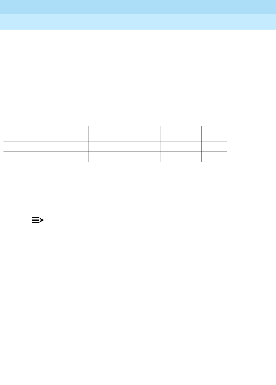
DEFINITY Enterprise Communications Server Release 6
Maintenance for R6r Volumes 1 & 2
555-230-126 Issue 2
January 1998
Maintenance Object Repair Procedures
Page 9-1172SN-CONF (Switch Node Configuration)
9
i. The SNI is connected to a DS1C, but no DS1C is administered.
To resolve this error, refer to FAIL code 140 for test 759.
System Technician-Demanded Tests:
Descriptions and Error Codes
Always investigate tests in the order presented in the table below when
inspecting errors in the system. By clearing error codes associated with the
Configuration Audit
for example, you may also clear errors generated from other
tests in the testing sequence.
Configuration Audit (#759)
This test is non-destructive.
NOTE:
For descriptions of result codes for this test refer to:
■SNC-BD when the circuit pack tested is a Switch Node Clock (circuit pack
slots 10 or 12).
■SNI-BD when the circuit pack tested is a Switch Node Interface (circuit
pack slots 2-9 or 13-20).
This test is run via the test board short or test board long command for SNI
circuit packs or SNC circuit packs.
For SNI circuit packs, this test queries the SNI for SNCs in the same switch node
carrier, SNI peers, DS1Cs, and EI or SNI neighbors that the SNI can
communicate with and compares this data to the administered data.
For SNC circuit packs, this test queries the SNC for SNCs and SNIs in the same
switch node carrier that the SNC can communicate with and compares this data
to the administered data.
Failures of this test cause entries in the error and alarm logs against Switch Node
Configuration (SN-CONF) with the board location of the SNI or SNC.
1. D = Destructive, ND = Non-destructive
Order of Investigation Short Test
Sequence Long Test
Sequence Reset Board
Sequence D/ND1
Configuration Audit (#759) X X ND
Processor Route Audit (#760) X ND

DEFINITY Enterprise Communications Server Release 6
Maintenance for R6r Volumes 1 & 2
555-230-126 Issue 2
January 1998
Maintenance Object Repair Procedures
Page 9-1173SN-CONF (Switch Node Configuration)
9
Incorrectly Connected Administered Fibers
Some physically connected fibers that do not match fiber administration can
cause port network problems that are not detected and alarmed by PNC test.
The symptoms will usually be phone calls not working correctly, and port network
component alarms because of translation mismatches.
This test is unable to detect the case where an SNI is connected to the same type
of board (EI or SNI) as administered but located in a different cabinet but the
same carrier and same slot as the administered fiber endpoint. The administered
fiber endpoint can be viewed with the list fiber-link command. This test can only
detect if the fiber endpoint connected to the SNI is in a different carrier, slot
location than the administered fiber endpoint.
Incorrectly Connected Administered SNI-EI
Fibers
If the SNI is connected to the same type of fiber endpoint as the administered
fiber endpoint, but the location is the same as administered except for the
cabinet, all phone calls will not work correctly; some phone calls will not go
through and some phone calls will ring the wrong phone.
The test led command can be used in this case to check connectivity.
1. Run the test led port-network command on each administered port
network and verify that the LEDs on the correct port network are lit.
2. If they are not lit, check that the fiber connections to the port network are
consistent with the administered fibers (list fiber-link) that does not light
the LEDs as expected.
3. Run test led switch-node on each administered switch node carrier and
verify that the LEDs on the correct carrier are lit.
4. If they are not, check the connectivity to the switch node carrier that does
not light the LEDs as expected.
Incorrectly Connected SNI-SNI Fibers between 3
Switch Nodes
If the system has more than 2 switch nodes, SNI-SNI fibers administered
between 2 switch nodes could be incorrectly connected to a third switch node.
This is a problem that could occur during installation or when inter-switch node
fibers are changed. For multiple fibers to a distant switch node (not the PPN
switch node), an incorrect connection would not appear as a problem unless this
fiber is used for a system-link to a port network connected to the distant switch
node. The status system-link command can be used to determine the boards in
the path from the PPN to a specific port network. A specific SNI-SNI fiber
connection must be in the system-link path to be checked with the port network
LED test.

DEFINITY Enterprise Communications Server Release 6
Maintenance for R6r Volumes 1 & 2
555-230-126 Issue 2
January 1998
Maintenance Object Repair Procedures
Page 9-1174SN-CONF (Switch Node Configuration)
9
Forcing SNI-SNI Fiber Connection
To force an SNI-SNI fiber connection to be used as a system-link remove all
SNI-SNI connections except the fiber-link being tested at the distant switch node
by removing SNI boards in the distant switch node.
1. Use the status system-link command to verify that the fiber selected for
test is in the path to the EPN connected to the distant switch node that will
be used for the LED test.
2. Run the test led sequence to a port network as described above to verify
this fiber connection.
3. Repeat the above procedure for each of the SNI-SNI fibers terminating on
the distant switch node.
Testing Multiple Fiber Connections
To test multiple fiber connections to a distant switch node:
1. Use the list fiber-link command to determine the number of SNI-SNI
fibers that are administered and terminate on the distant switch node.
2. Run the test led port-network command on a port network connected to
the distant switch node and verify the LEDs on the correct port network
are lit.
3. Use the status system-link command and select the active EI in the port
network connected to the distant port network under test. This display will
show the path from the PPN and the SNI-SNI fiber being used.
4. If the port network LEDs are not lit, verify that the fiber connections to the
port network are consistent with the administration assignments by using
the list fiber-link command.
5. If the port network LEDs are lit and there are multiple fibers to the distant
switch node, remove the SNC that is listed by the list fiber-link command
for this path.
6. Use the status system-link command to determine the new path from the
PPN to the distant switch.
7. Run the test led port-network command on a port network connected to
the distant switch node and verify that the LEDs on the correct port
network are lit.
8. Repeat steps 5 — 7 until all SNI-SNI fiber connections to the distant
switch have been tested.
Processor Route Audit Test (#760)
This test is non-destructive.
This test sends processor routes to all SNIs and SNCs in the same carrier as the
SNC that the test board UCSS command was run for. The processor route is

DEFINITY Enterprise Communications Server Release 6
Maintenance for R6r Volumes 1 & 2
555-230-126 Issue 2
January 1998
Maintenance Object Repair Procedures
Page 9-1175SN-CONF (Switch Node Configuration)
9
used for the boards to send uplink messages to the SPE and gives a sequence
of boards for the message to get routed through so that the message ends up at
the SPE. If the SNI and SNC boards do not have processor routes, they will not
be able to send any in-line errors to the SPE.
When each individual board receives the processor routes, it sends a board
insertion message uplink and software inserts that board if it has not already
been inserted. Each board is sent either one or two processor routes depending
on the configuration.
The test led or list config carrier command can be used to see whether boards
are inserted.
The processor route test is run as part of the long test sequence for SNC boards.
Table 9-422. TEST #760 Processor Route Audit Test
Error
Code Test
Result Description/ Recommendation
2100 ABORT Could not allocate the necessary system resources to run this test.
1. Retry the command at 1-minute intervals a maximum of 3 times.
2300 ABORT The downlink message necessary to run this test could not be sent.
1. Retry the command at 1-minute intervals a maximum of 3 times.
2301 ABORT The software timer could not be set before sending the downlink message
necessary to run this test.
1. Retry the command at 1-minute intervals a maximum of 3 times.
2306 ABORT None of the circuit packs in this switch node carrier are responding to the
processor route messages sent by software.
1. Run the test led switch-node for the switch node that this switch node
carrier resides in to verify whether the LEDs on any of the boards light.
2. If none of the LEDs light for the boards in this carrier, fix any problems
associated with the connectivity of this carrier to the SPE. Use list
fiber-link to determine the fiber connections to this carrier. Check the
LEDs on all SNIs and EIs and fix any fiber problems. Enter display errors
and follow the associated repair procedures for any EXP-INTF error entries
associated with the PPN. Also, follow the associated repair procedures for
any SYNC, SNI-BD, SNC-BD, FIBER-LK, or SNI-PEER error entries.
2500 ABORT Internal System Error
1. Retry the command at 1-minute intervals a maximum of 3 times.
Continued on next page

DEFINITY Enterprise Communications Server Release 6
Maintenance for R6r Volumes 1 & 2
555-230-126 Issue 2
January 1998
Maintenance Object Repair Procedures
Page 9-1176SN-CONF (Switch Node Configuration)
9
FAIL If this test fails, not all of the administered circuit packs in this switch node
carrier responded with an up-link board insertion message. Check to see that
administered SNI and SNC boards match the physically installed SNI and SNC
boards by entering list config carrier UUC. The command output will show
"NO BOARD" for every board that is administered, but not inserted.
■If all administered boards are inserted, run this test again.
■If administration does not match the physical configuration, and is
correct
, insert the missing circuit packs in this switch node carrier.
■If administration does not match the physical configuration, and is
incorrect
, change the administration and run this test again.
■If
none
of the administered boards in this switch node carrier were
inserted, fix any other SN-CONF errors by following the associated
repair procedures for SN- CONF. Use display errors with category
pnc to view SN-CONF errors. Next check if any INLs, LNLs, or
RNLs are down with list sys-link. If any INLs, LNLs, or RNLs are
down, refer to the SYS-LINK section for fixing link problems.
PASS If this test passes, all of the administered circuit packs in this switch node
carrier were inserted.
Table 9-422. TEST #760 Processor Route Audit Test — Continued
Error
Code Test
Result Description/ Recommendation
Continued on next page

DEFINITY Enterprise Communications Server Release 6
Maintenance for R6r Volumes 1 & 2
555-230-126 Issue 2
January 1998
Maintenance Object Repair Procedures
Page 9-1177SNC-BD (Switch Node Clock Circuit Pack)
9
SNC-BD (Switch Node Clock Circuit
Pack)
The Switch Node Clock (SNC) TN572 circuit pack is part of the Center Stage
Switch (CSS) configuration. It resides in a switch node carrier that alone or with
other switch nodes make up a CSS. In a high reliability system (duplicated SPE,
simplex PNC), each SNC is duplicated such that there are two SNCs on each
switch node carrier. In a critical reliability system (duplicated SPE and PNC),
each switch node is fully duplicated, and there is one SNC on each switch node
carrier. SNCs are placed in slots 10 and 12 of the switch node carrier.
The active SNC communicates with each circuit pack in the switch node carrier
over the serial channel bus on the backplane. In addition, the active SNC
provides timing to the circuit packs in the switch node carrier via the clock
busses. The active SNC uses Timing Priority Number (TPN) links with each
Switch Node Interface (SNI) and the other SNC to receive and distribute TPNs.
TPNs are used for setting up the correct timing distribution for the switch node
carrier. The active SNC receives timing for the switch node carrier from each SNI
circuit pack in the carrier and chooses the SNI with the best timing reference for
the switch node carrier timing signal the SNC puts out on the clock busses. The
timing reference for each SNI is derived from the fiber signal to each SNI. The
active SNC chooses the SNI to receive timing from by choosing the SNI with the
lowest numbered TPN which means that the SNI is closest to the system timing
source. The active SNC also verifies that the SNI reference signal is good before
using that SNI as the timing reference for the switch node carrier. The active SNC
then supplies this timing over the clock busses on the backplane to all the SNI
and SNC circuit packs in the carrier. For more information on timing
synchronization including how the SNC fits into the overall synchronization
configuration, see the SYNC section.
1. UU is the universal cabinet number (1 for PPN, 2 - 44 for EPNs). C is the carrier designation
(A, B, C, D, or E). SS is the number of the slot in which the circuit pack resides (10 or 12).
MO Name (in
Alarm Log) Alarm
Level Initial Command to Run1Full Name of MO
SNC-BD MAJOR test board UUCSS s SNC Circuit Pack
SNC-BD MINOR test board UUCSS s SNC Circuit Pack
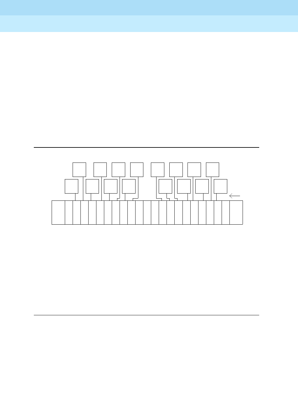
DEFINITY Enterprise Communications Server Release 6
Maintenance for R6r Volumes 1 & 2
555-230-126 Issue 2
January 1998
Maintenance Object Repair Procedures
Page 9-1178SNC-BD (Switch Node Clock Circuit Pack)
9
The SNC circuit packs are associated with three maintenance objects:
■The SNC-BD MO covers general SNC board errors and errors with the
serial communication channel between the active and standby SNCs.
■The SNC-LINK MO covers errors between the active SNC and SNIs over
the serial channel (aux data is 1). Also, the SNC-LINK MO covers TPN Link
errors between the active SNC and SNIs (aux data is 2).
■The SNC-REF MO covers errors the active SNC detects with SNI reference
signals.
SNC circuit packs are part of port network connectivity (PNC). For background
information about PNC, refer to the Maintenance Architecture and Hardware
Configurations chapters.
Figure 9-67. A Center Stage Switch Configuration
Online Switcher (OLS) power supply
carrier
EI
PPN
21
EI
EPN
EI
EPN
EI
EPN EI
EPN
EI
EPN EI
EPN
EI
EPN
EI
EPN
EI
EPN
EI
EPN
EI
EPN
EI
EPN
EI
EPN
EI
EPN
EI
EPN
20 18 17 16 15 14 13 12 11 10 9 8 7 6 5 4 3 2 1
** = A DS1C circuit pack may reside in this slot
Switch Node Clock (SNC) TN572
Switch Node Interface (SNI) TN573
Expansion Interface (EI) TN570
DS1 Converter (DS1C) TN574
OLS OLS
* = An EI or a DS1C circuit pack may reside in this slot
* * *
S
N
C
S
N
C
S
N
I
S
N
I
S
N
I
S
N
I
S
N
I
S
N
I
S
N
I
S
N
I
S
N
I
S
N
I
S
N
I
S
N
I
S
N
I
S
N
I
S
N
I
S
N
I
19 slot number
fiber
links
switch
node
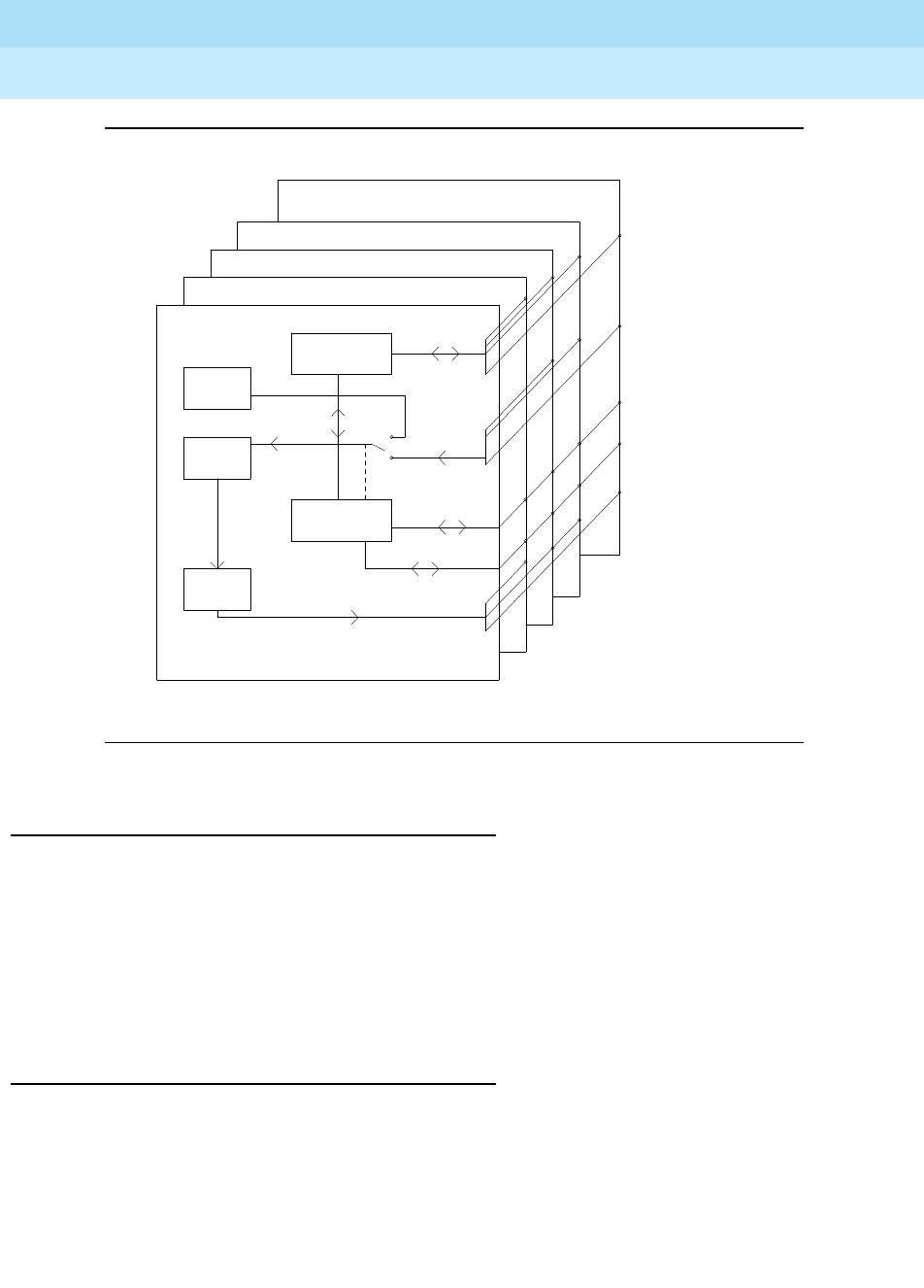
DEFINITY Enterprise Communications Server Release 6
Maintenance for R6r Volumes 1 & 2
555-230-126 Issue 2
January 1998
Maintenance Object Repair Procedures
Page 9-1179SNC-BD (Switch Node Clock Circuit Pack)
9
Figure 9-68. SNC Functions
SNC LEDs
SNC circuit packs have the standard red, green and yellow LEDs. The red and
green LEDs operate as usual: red means an alarm condition and green indicates
maintenance testing in progress. If the yellow LED is lit this indicates that the
SNC is the active circuit pack, supplying timing to the carrier. In a high reliability
system (duplicated SPE, simplex PNC), the standby SNC on a carrier will be
unlit. In a critical reliability system (duplicated PNC), an SNC on a standby switch
node carrier will be lit since it is providing timing for the standby carrier.
Clear Firmware-Counters Command
SNC firmware generates error reports independently of technician-demanded
tests. Therefore, the test board UUCSS clear command will not affect the error
status reported by firmware. The clear firmware-counters command will clear
all firmware-generated errors unconditionally.
The clear firmware-counters UUCSS command sends a downlink message to
the SNC circuit pack, causing it to clear out its firmware error counters and failure
Clock Duplication
9 Clock Busses
SNC-BD
SNC-BD
SNC-LINK
(aux data 1)
SNC-REF
SNC-LINK
(aux data 2)
TPN Links
Reference Signals
Serial Channel
.
Loop
Locked
Phase
Circuit
Generation
Clock
Microcontroller
.
...
Active SNC
Standby SNC
SNI 1e02
SNI 1e20
SNI 1e03
.
Microcontroller
TPN
Oscillator
Stratum 3
Control
16
SNI (TN573)
17

DEFINITY Enterprise Communications Server Release 6
Maintenance for R6r Volumes 1 & 2
555-230-126 Issue 2
January 1998
Maintenance Object Repair Procedures
Page 9-1180SNC-BD (Switch Node Clock Circuit Pack)
9
database. Once the firmware failure database is cleared, the failure audit test
(#777) will pass. If problems still exist, the firmware will increment its error
counters and the failure audit test will begin failing again.
This command should not be used as a replacement for the repair procedures
associated with the hardware error log entries. This command may be useful if a
problem has been fixed and off-board alarms associated with the problem are
still active.
Replacing SNC Circuit Packs
!WARNING:
Do not power down a Switch Node carrier to replace a circuit pack.
Replacing an SNC on a system with unduplicated SNCs disrupts service.
Standard Reliability System (Simplex SPE, PNC
and SNCs)
This procedure is destructive. Any links through the switch node carrier will
go down.
1. Pull out the SNC circuit pack to be replaced.
2. Insert a new SNC circuit pack.
3. Wait for the SNC to reset. (The red and green LEDs light and then go out.
The yellow LED should be on solid.)
4. Test alarm long clear category exp-intf. Do not busyout the Expansion
Interface circuit packs.
5. Wait 5 minutes for SNI-BD, SNI-PEER, FIBER-LK, and DS1 CONV-BD
alarms to clear, or enter clear firmware-counters.
High Reliability System (Duplicated SPE and
SNCs, Simplex PNC)
This procedure is non-destructive.
1. If the SNC circuit pack to be replaced is the active SNC in the switch node
carrier (yellow LED is on solid), first set the standby SNC to active via the
set switch-node-clock command.
2. When the SNC circuit pack is in standby mode (yellow LED is off), pull out
the SNC circuit pack to be replaced.
3. Insert a new SNC circuit pack.
4. Wait for the SNC to reset. (The red and green LEDs light and then go out.)
The yellow LED should be off since the SNC circuit pack is in standby
mode.

DEFINITY Enterprise Communications Server Release 6
Maintenance for R6r Volumes 1 & 2
555-230-126 Issue 2
January 1998
Maintenance Object Repair Procedures
Page 9-1181SNC-BD (Switch Node Clock Circuit Pack)
9
Critical Reliability System (Duplicated SPE and
PNC)
!WARNING:
On a system with duplicated PNC, synchronization may be provided over a
combination of active and standby components. This condition is indicated
by an OFF-BOARD WARNING alarm against TDM-CLK with error type
2305. Repairs to standby PNC in this state may disrupt service. Otherwise,
if the active PNC is functional, replacement of a standby component will not
disrupt service.
STEPS:
Enter status pnc Verify that the component to be replaced is on the standby PNC.
Enter busyout pnc
Enter busyout board
UUCSS UUCSS represents the cabinet-carrier-slot address of the circuit pack
to be replaced.
Replace the circuit pack
Enter release board
UUCSS !CAUTION:
Do not busyout any Expansion Interface circuit pack after
this point.
Enter test alarms long
clear for category
exp-intf
Wait 5 minutes for SNI-BD,
SNI-PEER, FIBER-LK,
and DS1C alarms to clear,
or enter clear firmware
counters <a-pnc or
b-pnc>
Use the letter designation of the pnc which holds the replaced
component (the standby pnc).
Enter status pnc If either PNC state-of-health is not "functional", consult the ‘‘PNC-DUP
(PNC Duplication)’’ section.
Enter release pnc

DEFINITY Enterprise Communications Server Release 6
Maintenance for R6r Volumes 1 & 2
555-230-126 Issue 2
January 1998
Maintenance Object Repair Procedures
Page 9-1182SNC-BD (Switch Node Clock Circuit Pack)
9
Error Log Entries and Test to Clear Values
Notes:
a. Error type 1 indicates SNC on-board microcontroller error. (This occurs
whenever the microcontroller sanity test fails, the ROM has problems, the
processor internal or external RAM is faulty, or the firmware instruction test
fails. In addition, this error indicates problems with the interrupt
capabilities, the dual port RAM and the RTM (Real Time Monitor) interface
on the faceplate of the SNC.)
Replace the SNC circuit pack.
b. This error indicates that the SNC circuit pack has been busied out via the
busyout board UCSS command. To resolve this error, release the SNC
circuit pack via the release board UCSS command.
c. These errors occur whenever firmware detects failure of the phase-locked
loop, inability to lock, or failure of the clock drivers and the problem is
off-board.
1. Enter display errors and if SNC-BD error type 1793 exists in the
hardware error log, follow the associated repair procedures for
SNC-BD error 1793.
2. Enter display errors and if no SNI-BD 1025 errors exist in the error
log, replace the active SNC.
1. Run the Short Test Sequence first. If all tests pass, run the Long Test Sequence. Refer to the appropriate
test description and follow the recommended procedures.
Table 9-423. SNC Board Error Log Entries
Error
Type Aux
Data Associated Test Alarm
Level On/Off
Board Test to Clear Value
010 Any Any Any test board UUCSS r 1
1(a) Any Failure Audit (#777) MAJOR ON test board UUCSS r 1
18(b) 0 busyout board UCSS WARNING OFF release board UCSS
257(c) Any Failure Audit (#777) MAJOR OFF test board UUCSS r 1
513(d) Any Failure Audit (#777) MINOR OFF test board UUCSS r 1
769(e) Any Failure Audit (#777) MINOR OFF test board UUCSS r 1
1025(f) Any Failure Audit (#777) MAJOR ON test board UUCSS r 1
1281(g) Any Failure Audit (#777) MINOR OFF test board UUCSS r 1
1537(h) Any Failure Audit (#777) MINOR ON test board UUCSS r 1
1793(i) Any Failure Audit (#777) MAJOR ON test board UUCSS r 1
2049(j) Any Failure Audit (#777) MAJOR ON test board UUCSS r 1

DEFINITY Enterprise Communications Server Release 6
Maintenance for R6r Volumes 1 & 2
555-230-126 Issue 2
January 1998
Maintenance Object Repair Procedures
Page 9-1183SNC-BD (Switch Node Clock Circuit Pack)
9
3. Enter display errors and if any SNI-BD 1025 errors exist in the error
log, follow the associated repair procedure in the SNI-BD section
for these errors.
d. This error occurs whenever the active SNC determines that there is a
problem communicating with the standby SNC via the connecting serial
channel.
If the switch node carrier is administered with duplicate SNCs:
1. If the standby SNC (the one with its yellow LED off) has this error,
escalate the problem. (Status switch-node will also display the
active and standby SNCs.)
2. If the system originally had duplicate SNCs and the standby SNC
was removed and never replaced and the active SNC has not been
reset after the standby SNC was removed, this error will occur.
If you do not intend to replace the SNC:
a. Remove the standby SNC from circuit pack administration
via change circuit-pack.
b. If the problem persists, replace the active SNC circuit pack.
Otherwise:
a. Insert an SNC circuit pack.
3. Check the error log via display errors. If SNIs in the switch node
carrier also have problems communicating with the active SNC, i.e.
error code 257 is logged against SNI-BD, then replace the active
SNC.
4. Replace the standby SNC circuit pack.
5. Retry the test board command. Check the error log via display
errors. If this error is still in the error log, replace the active SNC.
If the switch node carrier is administered with only one SNC:
1. If step 2 above does not apply, replace the SNC.
e. This error occurs whenever the standby SNC determines that there is a
problem communicating with the active SNC via the connecting serial
channel.
1. If the active SNC (the one with its yellow LED on) has this error,
escalate the problem. (Status switch-node will also display the
active and standby SNCs.)
2. Check the error log via display errors. If more than one SNI in the
switch node carrier has problems communicating with the active
SNC, i.e. error code 257 is logged against SNI-BD, then replace the
active SNC.
3. If a single SNI has SNI-BD error 257, replace the SNI circuit pack.
4. Replace the standby SNC circuit pack.

DEFINITY Enterprise Communications Server Release 6
Maintenance for R6r Volumes 1 & 2
555-230-126 Issue 2
January 1998
Maintenance Object Repair Procedures
Page 9-1184SNC-BD (Switch Node Clock Circuit Pack)
9
5. Retry the test board command. Check the error log via display
errors. If this error is still in the error log, replace the active SNC.
f. This error occurs when the firmware detects problems with the various
hardware circuit monitors (e.g. loss of reference monitor) that verify
correct operation of the reference links.
Replace the SNC circuit pack.
g. This error occurs when the firmware detects problems with the interface
used to track the status of both SNCs when there are duplicated SNCs in a
switch node carrier. When this error occurs, software may have incorrect
information from SNC firmware for which SNC is active. Therefore, the
yellow LEDs on the SNCs must be checked in the following repair
procedure and the status switch-node command should not be used
when this error type occurs.
If the switch node carrier has duplicate SNCs:
1. Replace the SNC that does not have its yellow LED lit.
2. Retry the test board command. Check the error log via display
errors. If this error is still in the error log, replace the SNC that has
its yellow LED lit.
If the switch node carrier has only one SNC, replace the SNC.
h. This error occurs whenever a loss of signal from the SNC on-board
Stratum 3 oscillator is detected by the firmware.
Replace the SNC circuit pack.
i. These errors occur whenever firmware detects failure of the phase-locked
loop, inability to lock, or failure of the clock drivers and the problem is
on-board.
Replace the SNC circuit pack.
If the error persists, follow normal escalation procedures.
j. This error occurs when the firmware detects problems with the
microcontroller used for Timing Priority Number processing.
Replace the SNC circuit pack.
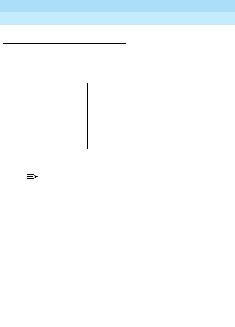
DEFINITY Enterprise Communications Server Release 6
Maintenance for R6r Volumes 1 & 2
555-230-126 Issue 2
January 1998
Maintenance Object Repair Procedures
Page 9-1185SNC-BD (Switch Node Clock Circuit Pack)
9
System Technician-Demanded Tests:
Descriptions and Error Codes
Always investigate tests in the order presented in the table below when
inspecting errors in the system. By clearing error codes associated with the
configuration audit
for example, you may also clear errors generated from other
tests in the testing sequence.
NOTE:
Test #983 is not an actual demand maintenance test. This test number is
used to report results of executing of the clear firmware-counters
command. Refer to error codes for Test #777.
Configuration Audit (#759)
This test is non-destructive.
This test is run via the test board short or test board long command for SNC
circuit packs.
For SNC circuit packs, this test queries the SNC for SNCs and SNIs in the same
switch node carrier that the SNC can communicate with and compares this data
to the administered data.
Failures of this test cause entries in the error and alarm logs against Switch Node
Configuration (SN-CONF) with the board location of the SNC.
1. D = Destructive, ND = Non-destructive
Order of Investigation Short Test
Sequence Long Test
Sequence Reset Board
Sequence D/ND1
Configuration Audit (#759) X X ND
Failure Audit(#777) X X ND
Processor Route Audit(#760) X ND
SNC On-Board Test(#778) X X ND
TPN Test(#779) X X ND
Switch Node Clock Reset Test(#780) X D

DEFINITY Enterprise Communications Server Release 6
Maintenance for R6r Volumes 1 & 2
555-230-126 Issue 2
January 1998
Maintenance Object Repair Procedures
Page 9-1186SNC-BD (Switch Node Clock Circuit Pack)
9
Table 9-424. TEST #759 Configuration Audit
Error
Code Test
Result Description/ Recommendation
2100 ABORT Could not allocate the necessary system resources to run this test.
1. Retry the command at 1-minute intervals a maximum of 3 times.
2300 ABORT The downlink message necessary to run this test could not be sent.
1. Retry the command at 1-minute intervals a maximum of 3 times.
2301 ABORT The software timer could not be set before sending the downlink message
necessary to run this test.
1. Retry the command at 1-minute intervals a maximum of 3 times.
2306 ABORT The SNC circuit pack is not responding to test requests sent by software.
1. Run the test led switch-node for the switch node that this board resides in
to verify whether the LEDs on the board light.
2. If the LEDs on the other boards in the carrier light, but the LEDs on this
board do not light, run test 760 via test board UUCSS l for the active SNC
in this carrier. Wait 5 minutes and then try step 1 one more time. If the LEDs
on this board still do not light, replace this board. Replacing an SNC may
be service interrupting. Refer to the SNC-BD section for the procedure for
replacing an SNC.
3. If none of the LEDs light for the boards in the same carrier as this board, fix
any problems associated with the connectivity of this carrier to the SPE.
Check list fibers to determine the fiber connections to this carrier. Check
the LEDs on all SNIs and EIs and fix any fiber problems. Enter display
errors and follow the associated repair procedures for any EXP-INTF error
entries associated with the PPN. Also, follow the associated repair
procedures for any SYNC, SNI-BD, SNC-BD, FIBER-LK, or SNI-PEER error
entries.
2500 ABORT Internal System Error
1. Retry the command at 1-minute intervals a maximum of 3 times.
Continued on next page

DEFINITY Enterprise Communications Server Release 6
Maintenance for R6r Volumes 1 & 2
555-230-126 Issue 2
January 1998
Maintenance Object Repair Procedures
Page 9-1187SNC-BD (Switch Node Clock Circuit Pack)
9
102 FAIL The SNC circuit pack cannot communicate with the SNI in slot 2.
1. If a standby SNC (one with its yellow LED off) was tested and resulted in
this error code, follow normal escalation procedures. (status switch-node
will also display the active and standby SNCs.)
2. Use list configuration carrier to determine whether an SNI is physically
present in slot 2. If the Vintage field indicates that a circuit pack is
present, proceed to step 3. If the Vintage field reports no board, do
one of the following:
■If an SNI is not supposed to be installed in slot 2:
a. This failure will not affect service. The missing SNI can be removed
from administration with change circuit-pack.
b. If the error persists, reset the active SNC circuit pack with reset board
UUCSS. If the error still persists, replace the active SNC circuit pack.
■If an SNI is supposed to be installed in slot 2, insert one.
3. Display errors for category pnc. If the SNC has SNC-BD error 513, or
SNC-LINK errors with aux data 1 pointing to other SNIs besides the one in
slot 2, replace the active SNC circuit pack.
4. If SNIs in the same carrier have SNI-BD error 257 logged, (indicating they
are having trouble communicating with the SNC), replace the active SNC
circuit pack.
5. If the SNC being tested has SNC-LINK error type 1, replace the SNI in slot
2. Replacing an SNI may interrupt service. Refer to the SNI-BD section for
the procedure for replacing an SNI.
6. If the SNC being tested still has SNC-LINK error type 1, replace the SNC
circuit pack.
Table 9-424. TEST #759 Configuration Audit — Continued
Error
Code Test
Result Description/ Recommendation
Continued on next page

DEFINITY Enterprise Communications Server Release 6
Maintenance for R6r Volumes 1 & 2
555-230-126 Issue 2
January 1998
Maintenance Object Repair Procedures
Page 9-1188SNC-BD (Switch Node Clock Circuit Pack)
9
103 FAIL The SNC circuit pack cannot communicate with the SNI in slot 3.
1. If a standby SNC (one with its yellow LED off) was tested and resulted in
this error code, follow normal escalation procedures. (status switch-node
will also display the active and standby SNCs.)
2. Use list configuration carrier to determine whether an SNI is physically
present in slot 3. If the Vintage field indicates that a circuit pack is
present, proceed to step 3. If the Vintage field reports no board, do
one of the following:
■If an SNI is not supposed to be installed in slot 3:
a. This failure will not affect service. The missing SNI can be removed
from administration with change circuit-pack.
b. If the error persists, reset the active SNC circuit pack with reset board
UUCSS. If the error still persists, replace the active SNC circuit pack.
■If an SNI is supposed to be installed in slot 3, insert one.
3. Display errors for category pnc. If the SNC has SNC-BD error 513, or
SNC-LINK errors with aux data 1 pointing to other SNIs besides the one in
slot 3, replace the active SNC circuit pack.
4. If SNIs in the same carrier have SNI-BD error 257 logged, (indicating they
are having trouble communicating with the SNC), replace the active SNC
circuit pack.
5. If the SNC being tested has SNC-LINK error type 257, replace the SNI in
slot 3. Replacing an SNI may interrupt service. Refer to the SNI-BD section
for the procedure for replacing an SNI.
6. If the SNC being tested still has SNC-LINK error type 257, replace the SNC
circuit pack.
Table 9-424. TEST #759 Configuration Audit — Continued
Error
Code Test
Result Description/ Recommendation
Continued on next page

DEFINITY Enterprise Communications Server Release 6
Maintenance for R6r Volumes 1 & 2
555-230-126 Issue 2
January 1998
Maintenance Object Repair Procedures
Page 9-1189SNC-BD (Switch Node Clock Circuit Pack)
9
104 FAIL The SNC circuit pack cannot communicate with the SNI in slot 4.
1. If a standby SNC (one with its yellow LED off) was tested and resulted in
this error code, follow normal escalation procedures. (status switch-node
will also display the active and standby SNCs.)
2. Use list configuration carrier to determine whether an SNI is physically
present in slot 4. If the Vintage field indicates that a circuit pack is
present, proceed to step 3. If the Vintage field reports no board, do
one of the following:
■If an SNI is not supposed to be installed in slot 4:
a. This failure will not affect service. The missing SNI can be removed
from administration with change circuit-pack.
b. If the error persists, reset the active SNC circuit pack with reset board
UUCSS. If the error still persists, replace the active SNC circuit pack.
■If an SNI is supposed to be installed in slot 4, insert one.
3. Display errors for category pnc. If the SNC has SNC-BD error 513, or
SNC-LINK errors with aux data 1 pointing to other SNIs besides the one in
slot 4, replace the active SNC circuit pack.
4. If SNIs in the same carrier have SNI-BD error 257 logged, (indicating they
are having trouble communicating with the SNC), replace the active SNC
circuit pack.
5. If the SNC being tested has SNC-LINK error type 513, replace the SNI in
slot 4. Replacing an SNI may interrupt service. Refer to the SNI-BD section
for the procedure for replacing an SNI.
6. If the SNC being tested still has SNC-LINK error type 513, replace the SNC
circuit pack.
Table 9-424. TEST #759 Configuration Audit — Continued
Error
Code Test
Result Description/ Recommendation
Continued on next page

DEFINITY Enterprise Communications Server Release 6
Maintenance for R6r Volumes 1 & 2
555-230-126 Issue 2
January 1998
Maintenance Object Repair Procedures
Page 9-1190SNC-BD (Switch Node Clock Circuit Pack)
9
105 FAIL The SNC circuit pack cannot communicate with the SNI in slot 5.
1. If a standby SNC (one with its yellow LED off) was tested and resulted in
this error code, follow normal escalation procedures. (status switch-node
will also display the active and standby SNCs.)
2. Use list configuration carrier to determine whether an SNI is physically
present in slot 5. If the Vintage field indicates that a circuit pack is
present, proceed to step 3. If the Vintage field reports no board, do
one of the following:
■If an SNI is not supposed to be installed in slot 5:
a. This failure will not affect service. The missing SNI can be removed
from administration with change circuit-pack.
b. If the error persists, reset the active SNC circuit pack with reset board
UUCSS. If the error still persists, replace the active SNC circuit pack.
■If an SNI is supposed to be installed in slot 5, insert one.
3. Display errors for category pnc. If the SNC has SNC-BD error 513, or
SNC-LINK errors with aux data 1 pointing to other SNIs besides the one in
slot 5, replace the active SNC circuit pack.
4. If SNIs in the same carrier have SNI-BD error 257 logged, (indicating they
are having trouble communicating with the SNC), replace the active SNC
circuit pack.
5. If the SNC being tested has SNC-LINK error type 769, replace the SNI in
slot 5. Replacing an SNI may interrupt service. Refer to the SNI-BD section
for the procedure for replacing an SNI.
6. If the SNC being tested still has SNC-LINK error type 769, replace the SNC
circuit pack.
Table 9-424. TEST #759 Configuration Audit — Continued
Error
Code Test
Result Description/ Recommendation
Continued on next page

DEFINITY Enterprise Communications Server Release 6
Maintenance for R6r Volumes 1 & 2
555-230-126 Issue 2
January 1998
Maintenance Object Repair Procedures
Page 9-1191SNC-BD (Switch Node Clock Circuit Pack)
9
106 FAIL The SNC circuit pack cannot communicate with the SNI in slot 6.
1. If a standby SNC (one with its yellow LED off) was tested and resulted in
this error code, follow normal escalation procedures. (status switch-node
will also display the active and standby SNCs.)
2. Use list configuration carrier to determine whether an SNI is physically
present in slot 6. If the Vintage field indicates that a circuit pack is
present, proceed to step 3. If the Vintage field reports no board, do
one of the following:
■If an SNI is not supposed to be installed in slot 6:
a. This failure will not affect service. The missing SNI can be removed
from administration with change circuit-pack.
b. If the error persists, reset the active SNC circuit pack with reset board
UUCSS. If the error still persists, replace the active SNC circuit pack.
■If an SNI is supposed to be installed in slot 6, insert one.
3. Display errors for category pnc. If the SNC has SNC-BD error 513, or
SNC-LINK errors with aux data 1 pointing to other SNIs besides the one in
slot 6, replace the active SNC circuit pack.
4. If SNIs in the same carrier have SNI-BD error 257 logged, (indicating they
are having trouble communicating with the SNC), replace the active SNC
circuit pack.
5. If the SNC being tested has SNC-LINK error type 1025, replace the SNI in
slot 6. Replacing an SNI may interrupt service. Refer to the SNI-BD section
for the procedure for replacing an SNI.
6. If the SNC being tested still has SNC-LINK error type 1025, replace the
SNC circuit pack.
Table 9-424. TEST #759 Configuration Audit — Continued
Error
Code Test
Result Description/ Recommendation
Continued on next page

DEFINITY Enterprise Communications Server Release 6
Maintenance for R6r Volumes 1 & 2
555-230-126 Issue 2
January 1998
Maintenance Object Repair Procedures
Page 9-1192SNC-BD (Switch Node Clock Circuit Pack)
9
107 FAIL The SNC circuit pack cannot communicate with the SNI in slot 7.
1. If a standby SNC (one with its yellow LED off) was tested and resulted in
this error code, follow normal escalation procedures. (status switch-node
will also display the active and standby SNCs.)
2. Use list configuration carrier to determine whether an SNI is physically
present in slot 7. If the Vintage field indicates that a circuit pack is
present, proceed to step 3. If the Vintage field reports no board, do
one of the following:
■If an SNI is not supposed to be installed in slot 7:
a. This failure will not affect service. The missing SNI can be removed
from administration with change circuit-pack.
b. If the error persists, reset the active SNC circuit pack with reset board
UUCSS. If the error still persists, replace the active SNC circuit pack.
■If an SNI is supposed to be installed in slot 7, insert one.
3. Display errors for category pnc. If the SNC has SNC-BD error 513, or
SNC-LINK errors with aux data 1 pointing to other SNIs besides the one in
slot 7, replace the active SNC circuit pack.
4. If SNIs in the same carrier have SNI-BD error 257 logged, (indicating they
are having trouble communicating with the SNC), replace the active SNC
circuit pack.
5. If the SNC being tested has SNC-LINK error type 1281, replace the SNI in
slot 7. Replacing an SNI may interrupt service. Refer to the SNI-BD section
for the procedure for replacing an SNI.
6. If the SNC being tested still has SNC-LINK error type 1281, replace the
SNC circuit pack.
Table 9-424. TEST #759 Configuration Audit — Continued
Error
Code Test
Result Description/ Recommendation
Continued on next page

DEFINITY Enterprise Communications Server Release 6
Maintenance for R6r Volumes 1 & 2
555-230-126 Issue 2
January 1998
Maintenance Object Repair Procedures
Page 9-1193SNC-BD (Switch Node Clock Circuit Pack)
9
108 FAIL The SNC circuit pack cannot communicate with the SNI in slot 8.
1. If a standby SNC (one with its yellow LED off) was tested and resulted in
this error code, follow normal escalation procedures. (status switch-node
will also display the active and standby SNCs.)
2. Use list configuration carrier to determine whether an SNI is physically
present in slot 8. If the Vintage field indicates that a circuit pack is
present, proceed to step 3. If the Vintage field reports no board, do
one of the following:
■If an SNI is not supposed to be installed in slot 8:
a. This failure will not affect service. The missing SNI can be removed
from administration with change circuit-pack.
b. If the error persists, reset the active SNC circuit pack with reset board
UUCSS. If the error still persists, replace the active SNC circuit pack.
■If an SNI is supposed to be installed in slot 8, insert one.
3. Display errors for category pnc. If the SNC has SNC-BD error 513, or
SNC-LINK errors with aux data 1 pointing to other SNIs besides the one in
slot 8, replace the active SNC circuit pack.
4. If SNIs in the same carrier have SNI-BD error 257 logged, (indicating they
are having trouble communicating with the SNC), replace the active SNC
circuit pack.
5. If the SNC being tested has SNC-LINK error type 1537, replace the SNI in
slot 8. Replacing an SNI may interrupt service. Refer to the SNI-BD section
for the procedure for replacing an SNI.
6. If the SNC being tested still has SNC-LINK error type 1537, replace the
SNC circuit pack.
Table 9-424. TEST #759 Configuration Audit — Continued
Error
Code Test
Result Description/ Recommendation
Continued on next page

DEFINITY Enterprise Communications Server Release 6
Maintenance for R6r Volumes 1 & 2
555-230-126 Issue 2
January 1998
Maintenance Object Repair Procedures
Page 9-1194SNC-BD (Switch Node Clock Circuit Pack)
9
109 FAIL The SNC circuit pack cannot communicate with the SNI in slot 9.
1. If a standby SNC (one with its yellow LED off) was tested and resulted in
this error code, follow normal escalation procedures. (status switch-node
will also display the active and standby SNCs.)
2. Use list configuration carrier to determine whether an SNI is physically
present in slot 9. If the Vintage field indicates that a circuit pack is
present, proceed to step 3. If the Vintage field reports no board, do
one of the following:
■If an SNI is not supposed to be installed in slot 9:
a. This failure will not affect service. The missing SNI can be removed
from administration with change circuit-pack.
b. If the error persists, reset the active SNC circuit pack with reset board
UUCSS. If the error still persists, replace the active SNC circuit pack.
■If an SNI is supposed to be installed in slot 9, insert one.
3. Display errors for category pnc. If the SNC has SNC-BD error 513, or
SNC-LINK errors with aux data 1 pointing to other SNIs besides the one in
slot 9, replace the active SNC circuit pack.
4. If SNIs in the same carrier have SNI-BD error 257 logged, (indicating they
are having trouble communicating with the SNC), replace the active SNC
circuit pack.
5. If the SNC being tested has SNC-LINK error type 1793, replace the SNI in
slot 9. Replacing an SNI may interrupt service. Refer to the SNI-BD section
for the procedure for replacing an SNI.
6. If the SNC being tested still has SNC-LINK error type 1793, replace the
SNC circuit pack.
Table 9-424. TEST #759 Configuration Audit — Continued
Error
Code Test
Result Description/ Recommendation
Continued on next page

DEFINITY Enterprise Communications Server Release 6
Maintenance for R6r Volumes 1 & 2
555-230-126 Issue 2
January 1998
Maintenance Object Repair Procedures
Page 9-1195SNC-BD (Switch Node Clock Circuit Pack)
9
112 FAIL The SNC circuit pack cannot communicate with the other SNC.
If this test was run on the active SNC and if the switch node carrier is
administered with duplicate SNCs:
1. If the system originally had duplicate SNCs and the standby SNC was
removed and never replaced, this error will occur.
If you do not intend to
replace the SNC:
a. Remove the standby SNC from circuit pack administration via change
circuit-pack.
b. If the problem persists, reset the active SNC circuit pack via reset
board UUCSS. If the problem persists after the reset, replace the active
SNC circuit pack.
2. Check the error log via display errors. If SNIs in the switch node carrier
also have problems communicating with the active SNC, i.e. error code
257 is logged against SNI-BD, then replace the active SNC.
3. Replace the standby SNC circuit pack.
4. Retry the test board command. If this test continues to fail, replace the
active SNC.
If this test was run on the active SNC and if the switch node carrier is
administered with only one SNC:
1. Replace the SNC.
112 FAIL
(cont’d.)
If this test was run on the standby SNC:
1. Check the error log via display errors. If more than one SNI in the switch
node carrier has problems communicating with the active SNC, i.e. error
code 257 is logged against SNI-BD, then replace the active SNC.
2. Replace the standby SNC circuit pack.
3. Retry the test board command. Check the error log via display errors. If
this error is still in the error log, replace the active SNC.
Table 9-424. TEST #759 Configuration Audit — Continued
Error
Code Test
Result Description/ Recommendation
Continued on next page

DEFINITY Enterprise Communications Server Release 6
Maintenance for R6r Volumes 1 & 2
555-230-126 Issue 2
January 1998
Maintenance Object Repair Procedures
Page 9-1196SNC-BD (Switch Node Clock Circuit Pack)
9
113 FAIL The SNC circuit pack cannot communicate with the SNI in slot 13.
1. If a standby SNC (one with its yellow LED off) was tested and resulted in
this error code, follow normal escalation procedures. (status switch-node
will also display the active and standby SNCs.)
2. Use list configuration carrier to determine whether an SNI is physically
present in slot 13. If the Vintage field indicates that a circuit pack is
present, proceed to step 3. If the Vintage field reports no board, do
one of the following:
If an SNI is not supposed to be installed in slot 13:
a. This failure will not affect service. The missing SNI can be removed
from administration with change circuit-pack.
b. If the error persists, reset the active SNC circuit pack with reset board
UUCSS. If the error still persists, replace the active SNC circuit pack.
If an SNI is supposed to be installed in slot 13, insert one.
3. Display errors for category pnc. If the SNC has SNC-BD error 513, or
SNC-LINK errors with aux data 1 pointing to other SNIs besides the one in
slot 13, replace the active SNC circuit pack.
4. If SNIs in the same carrier have SNI-BD error 257 logged, (indicating they
are having trouble communicating with the SNC), replace the active SNC
circuit pack.
5. If the SNC being tested has SNC-LINK error type 2049, replace the SNI in
slot 13. Replacing an SNI may interrupt service. Refer to the SNI-BD
section for the procedure for replacing an SNI.
6. If the SNC being tested still has SNC-LINK error type 2049, replace the
SNC circuit pack.
Table 9-424. TEST #759 Configuration Audit — Continued
Error
Code Test
Result Description/ Recommendation
Continued on next page

DEFINITY Enterprise Communications Server Release 6
Maintenance for R6r Volumes 1 & 2
555-230-126 Issue 2
January 1998
Maintenance Object Repair Procedures
Page 9-1197SNC-BD (Switch Node Clock Circuit Pack)
9
114 FAIL The SNC circuit pack cannot communicate with the SNI in slot 14.
1. If a standby SNC (one with its yellow LED off) was tested and resulted in
this error code, follow normal escalation procedures. (status switch-node
will also display the active and standby SNCs.)
2. Use list configuration carrier to determine whether an SNI is physically
present in slot 14. If the Vintage field indicates that a circuit pack is
present, proceed to step 3. If the Vintage field reports no board, do
one of the following:
If an SNI is not supposed to be installed in slot 14:
a. This failure will not affect service. The missing SNI can be removed
from administration with change circuit-pack.
b. If the error persists, reset the active SNC circuit pack with reset board
UUCSS. If the error still persists, replace the active SNC circuit pack.
If an SNI is supposed to be installed in slot 14, insert one.
3. Display errors for category pnc. If the SNC has SNC-BD error 513, or
SNC-LINK errors with aux data 1 pointing to other SNIs besides the one in
slot 14, replace the active SNC circuit pack.
4. If SNIs in the same carrier have SNI-BD error 257 logged, (indicating they
are having trouble communicating with the SNC), replace the active SNC
circuit pack.
5. If the SNC being tested has SNC-LINK error type 2305, replace the SNI in
slot 14. Replacing an SNI may interrupt service. Refer to the SNI-BD
section for the procedure for replacing an SNI.
6. If the SNC being tested still has SNC-LINK error type 2305, replace the
SNC circuit pack.
Table 9-424. TEST #759 Configuration Audit — Continued
Error
Code Test
Result Description/ Recommendation
Continued on next page

DEFINITY Enterprise Communications Server Release 6
Maintenance for R6r Volumes 1 & 2
555-230-126 Issue 2
January 1998
Maintenance Object Repair Procedures
Page 9-1198SNC-BD (Switch Node Clock Circuit Pack)
9
115 FAIL The SNC circuit pack cannot communicate with the SNI in slot 15.
1. If a standby SNC (one with its yellow LED off) was tested and resulted in
this error code, follow normal escalation procedures. (status switch-node
will also display the active and standby SNCs.)
2. Use list configuration carrier to determine whether an SNI is physically
present in slot 15. If the Vintage field indicates that a circuit pack is
present, proceed to step 3. If the Vintage field reports no board, do
one of the following:
If an SNI is not supposed to be installed in slot 15:
a. This failure will not affect service. The missing SNI can be removed
from administration with change circuit-pack.
b. If the error persists, reset the active SNC circuit pack with reset board
UUCSS. If the error still persists, replace the active SNC circuit pack.
If an SNI is supposed to be installed in slot 15, insert one.
3. Display errors for category pnc. If the SNC has SNC-BD error 513, or
SNC-LINK errors with aux data 1 pointing to other SNIs besides the one in
slot 15, replace the active SNC circuit pack.
4. If SNIs in the same carrier have SNI-BD error 257 logged, (indicating they
are having trouble communicating with the SNC), replace the active SNC
circuit pack.
5. If the SNC being tested has SNC-LINK error type 2561, replace the SNI in
slot 15. Replacing an SNI may interrupt service. Refer to the SNI-BD
section for the procedure for replacing an SNI.
6. If the SNC being tested still has SNC-LINK error type 2561, replace the
SNC circuit pack.
Table 9-424. TEST #759 Configuration Audit — Continued
Error
Code Test
Result Description/ Recommendation
Continued on next page

DEFINITY Enterprise Communications Server Release 6
Maintenance for R6r Volumes 1 & 2
555-230-126 Issue 2
January 1998
Maintenance Object Repair Procedures
Page 9-1199SNC-BD (Switch Node Clock Circuit Pack)
9
116 FAIL The SNC circuit pack cannot communicate with the SNI in slot 16.
1. If a standby SNC (one with its yellow LED off) was tested and resulted in
this error code, follow normal escalation procedures. (status switch-node
will also display the active and standby SNCs.)
2. Use list configuration carrier to determine whether an SNI is physically
present in slot 16. If the Vintage field indicates that a circuit pack is
present, proceed to step 3. If the Vintage field reports no board, do
one of the following:
If an SNI is not supposed to be installed in slot 16:
a. This failure will not affect service. The missing SNI can be removed
from administration with change circuit-pack.
b. If the error persists, reset the active SNC circuit pack with reset board
UUCSS. If the error still persists, replace the active SNC circuit pack.
If an SNI is supposed to be installed in slot 16, insert one.
3. Display errors for category pnc. If the SNC has SNC-BD error 513, or
SNC-LINK errors with aux data 1 pointing to other SNIs besides the one in
slot 16, replace the active SNC circuit pack.
4. If SNIs in the same carrier have SNI-BD error 257 logged, (indicating they
are having trouble communicating with the SNC), replace the active SNC
circuit pack.
5. If the SNC being tested has SNC-LINK error type 2817, replace the SNI in
slot 16. Replacing an SNI may interrupt service. Refer to the SNI-BD
section for the procedure for replacing an SNI.
6. If the SNC being tested still has SNC-LINK error type 2817, replace the
SNC circuit pack.
Table 9-424. TEST #759 Configuration Audit — Continued
Error
Code Test
Result Description/ Recommendation
Continued on next page

DEFINITY Enterprise Communications Server Release 6
Maintenance for R6r Volumes 1 & 2
555-230-126 Issue 2
January 1998
Maintenance Object Repair Procedures
Page 9-1200SNC-BD (Switch Node Clock Circuit Pack)
9
117 FAIL The SNC circuit pack cannot communicate with the SNI in slot 17.
1. If a standby SNC (one with its yellow LED off) was tested and resulted in
this error code, follow normal escalation procedures. (status switch-node
will also display the active and standby SNCs.)
2. Use list configuration carrier to determine whether an SNI is physically
present in slot 17. If the Vintage field indicates that a circuit pack is
present, proceed to step 3. If the Vintage field reports no board, do
one of the following:
If an SNI is not supposed to be installed in slot 17:
a. This failure will not affect service. The missing SNI can be removed
from administration with change circuit-pack.
b. If the error persists, reset the active SNC circuit pack with reset board
UUCSS. If the error still persists, replace the active SNC circuit pack.
If an SNI is supposed to be installed in slot 17, insert one.
3. Display errors for category pnc. If the SNC has SNC-BD error 513, or
SNC-LINK errors with aux data 1 pointing to other SNIs besides the one in
slot 17, replace the active SNC circuit pack.
4. If SNIs in the same carrier have SNI-BD error 257 logged, (indicating they
are having trouble communicating with the SNC), replace the active SNC
circuit pack.
5. If the SNC being tested has SNC-LINK error type 3073, replace the SNI in
slot 17. Replacing an SNI may interrupt service. Refer to the SNI-BD
section for the procedure for replacing an SNI.
6. If the SNC being tested still has SNC-LINK error type 3073, replace the
SNC circuit pack.
Table 9-424. TEST #759 Configuration Audit — Continued
Error
Code Test
Result Description/ Recommendation
Continued on next page

DEFINITY Enterprise Communications Server Release 6
Maintenance for R6r Volumes 1 & 2
555-230-126 Issue 2
January 1998
Maintenance Object Repair Procedures
Page 9-1201SNC-BD (Switch Node Clock Circuit Pack)
9
118 FAIL The SNC circuit pack cannot communicate with the SNI in slot 18.
1. If a standby SNC (one with its yellow LED off) was tested and resulted in
this error code, follow normal escalation procedures. (status switch-node
will also display the active and standby SNCs.)
2. Use list configuration carrier to determine whether an SNI is physically
present in slot 18. If the Vintage field indicates that a circuit pack is
present, proceed to step 3. If the Vintage field reports no board, do
one of the following:
If an SNI is not supposed to be installed in slot 18:
a. This failure will not affect service. The missing SNI can be removed
from administration with change circuit-pack.
b. If the error persists, reset the active SNC circuit pack with reset board
UUCSS. If the error still persists, replace the active SNC circuit pack.
If an SNI is supposed to be installed in slot 18, insert one.
3. Display errors for category pnc. If the SNC has SNC-BD error 513, or
SNC-LINK errors with aux data 1 pointing to other SNIs besides the one in
slot 18, replace the active SNC circuit pack.
4. If SNIs in the same carrier have SNI-BD error 257 logged, (indicating they
are having trouble communicating with the SNC), replace the active SNC
circuit pack.
5. If the SNC being tested has SNC-LINK error type 3329, replace the SNI in
slot 18. Replacing an SNI may interrupt service. Refer to the SNI-BD
section for the procedure for replacing an SNI.
6. If the SNC being tested still has SNC-LINK error type 3329, replace the
SNC circuit pack.
Table 9-424. TEST #759 Configuration Audit — Continued
Error
Code Test
Result Description/ Recommendation
Continued on next page

DEFINITY Enterprise Communications Server Release 6
Maintenance for R6r Volumes 1 & 2
555-230-126 Issue 2
January 1998
Maintenance Object Repair Procedures
Page 9-1202SNC-BD (Switch Node Clock Circuit Pack)
9
119 FAIL The SNC circuit pack cannot communicate with the SNI in slot 19.
1. If a standby SNC (one with its yellow LED off) was tested and resulted in
this error code, follow normal escalation procedures. (status switch-node
will also display the active and standby SNCs.)
2. Use list configuration carrier to determine whether an SNI is physically
present in slot 19. If the Vintage field indicates that a circuit pack is
present, proceed to step 3. If the Vintage field reports no board, do
one of the following:
If an SNI is not supposed to be installed in slot 19:
a. This failure will not affect service. The missing SNI can be removed
from administration with change circuit-pack.
b. If the error persists, reset the active SNC circuit pack with reset board
UUCSS. If the error still persists, replace the active SNC circuit pack.
If an SNI is supposed to be installed in slot 19, insert one.
3. Display errors for category pnc. If the SNC has SNC-BD error 513, or
SNC-LINK errors with aux data 1 pointing to other SNIs besides the one in
slot 19, replace the active SNC circuit pack.
4. If SNIs in the same carrier have SNI-BD error 257 logged, (indicating they
are having trouble communicating with the SNC), replace the active SNC
circuit pack.
5. If the SNC being tested has SNC-LINK error type 3585, replace the SNI in
slot 19. Replacing an SNI may interrupt service. Refer to the SNI-BD
section for the procedure for replacing an SNI.
6. If the SNC being tested still has SNC-LINK error type 3585, replace the
SNC circuit pack.
Table 9-424. TEST #759 Configuration Audit — Continued
Error
Code Test
Result Description/ Recommendation
Continued on next page

DEFINITY Enterprise Communications Server Release 6
Maintenance for R6r Volumes 1 & 2
555-230-126 Issue 2
January 1998
Maintenance Object Repair Procedures
Page 9-1203SNC-BD (Switch Node Clock Circuit Pack)
9
120 FAIL The SNC circuit pack cannot communicate with the SNI in slot 20.
1. If a standby SNC (one with its yellow LED off) was tested and resulted in
this error code, follow normal escalation procedures. (status switch-node
will also display the active and standby SNCs.)
2. Use list configuration carrier to determine whether an SNI is physically
present in slot 20. If the Vintage field indicates that a circuit pack is
present, proceed to step 3. If the Vintage field reports no board, do
one of the following:
If an SNI is not supposed to be installed in slot 20
a. This failure will not affect service. The missing SNI can be removed
from administration with change circuit-pack.
b. If the error persists, reset the active SNC circuit pack with reset board
UUCSS. If the error still persists, replace the active SNC circuit pack.
If an SNI is supposed to be installed in slot 20, insert one.
3. Display errors for category pnc. If the SNC has SNC-BD error 513, or
SNC-LINK errors with aux data 1 pointing to other SNIs besides the one in
slot 20, replace the active SNC circuit pack.
4. If SNIs in the same carrier have SNI-BD error 257 logged, (indicating they
are having trouble communicating with the SNC), replace the active SNC
circuit pack.
5. If the SNC being tested has SNC-LINK error type 3841, replace the SNI in
slot 20. Replacing an SNI may interrupt service. Refer to the SNI-BD
section for the procedure for replacing an SNI.
6. If the SNC being tested still has SNC-LINK error type 3841, replace the
SNC circuit pack.
PASS The administered data and the circuit packs the SNC can communicate with
match.
0NO
BOARD No board was detected by the test.
1. Check that SNC board is properly translated and inserted.
2. Run the test again. If it fails, reset the board. An SNC should be reset
instead of reseating the circuit pack. The reset board command should
almost never be used on an SNC. It may be necessary to use the reset
board command if the SNC circuit pack gets into a mode where it cannot
communicate with software. If an SNC with active errors and alarms is
reset, the errors and alarms may take a while to come back, therefore the
reset board command can mask real problems.
3. Run the test again. If it fails, the ID chip on board may be bad. Replace the
board and retest.
Table 9-424. TEST #759 Configuration Audit — Continued
Error
Code Test
Result Description/ Recommendation
Continued on next page

DEFINITY Enterprise Communications Server Release 6
Maintenance for R6r Volumes 1 & 2
555-230-126 Issue 2
January 1998
Maintenance Object Repair Procedures
Page 9-1204SNC-BD (Switch Node Clock Circuit Pack)
9
Processor Route Audit Test (#760)
This test is non-destructive.
This test sends processor routes to all SNIs and SNCs in the same carrier as the
SNC that the test board UCSS command was run for. The processor route is
used for the boards to send uplink messages to the SPE and gives a sequence
of boards for the message to get routed through so that the message ends up at
the SPE. If the SNI and SNC boards do not have processor routes, they will not
be able to send any in-line errors to the SPE.
When each individual board receives the processor routes, it sends a board
insertion message uplink and software inserts that board if it has not already
been inserted. Each board is sent either one or two processor routes depending
on the configuration.
Use test led or list config carrier to see whether boards are inserted.
Table 9-425. TEST #760 Processor Route Audit Test
Error
Code Test
Result Description/ Recommendation
2100 ABORT Could not allocate the necessary system resources to run this test.
1. Retry the command at 1-minute intervals a maximum of 3 times.
2300 ABORT The downlink message necessary to run this test could not be sent.
1. Retry the command at 1-minute intervals a maximum of 3 times.
2301 ABORT The software timer could not be set before sending the downlink message
necessary to run this test.
1. Retry the command at 1-minute intervals a maximum of 3 times.
2306 ABORT None of the circuit packs in this switch node carrier are responding to the
processor route messages sent by software.
1. Run the test led switch-node for the switch node that this switch node
carrier resides in to verify whether the LEDs on any of the boards light.
2. If none of the LEDs light for the boards in this carrier, fix any problems
associated with the connectivity of this carrier to the SPE. Use the list fiber
link command to obtain a list of the fiber connections to this carrier. Check
the LEDs on all SNIs and EIs and fix any fiber problems. Enter display
errors and follow the associated repair procedures for any EXP-INTF error
entries associated with the PPN. Also, follow the associated repair
procedures for any SYNC, SNI-BD, SNC-BD, FIBER-LK, or SNI-PEER error
entries.
2500 ABORT Internal System Error
1. Retry the command at 1-minute intervals a maximum of 3 times.
Continued on next page

DEFINITY Enterprise Communications Server Release 6
Maintenance for R6r Volumes 1 & 2
555-230-126 Issue 2
January 1998
Maintenance Object Repair Procedures
Page 9-1205SNC-BD (Switch Node Clock Circuit Pack)
9
FAIL If this test fails, not all of the administered circuit packs in this switch node
carrier responded with an up-link board insertion message. Check to see that
administered SNI and SNC boards match the physically installed SNI and SNC
boards by entering list config carrier UUC. The command output will show
"NO BOARD" for every board that is administered, but not inserted.
■If all administered boards are inserted, run this test again.
■If administration does not match the physical configuration, and is
correct, insert the missing circuit packs in this switch node carrier.
■If
none
of the administered boards in this switch node carrier were
inserted, fix any other SN-CONF errors by following the associated
repair procedures for SN-CONF. Use display errors with category
pnc to view SN-CONF errors. Next check if any INLs, LNLs, or
RNLs are down, refer to the SYS-LINK section for fixing link
problems.
PASS If this test passes, all of the administered circuit packs in this switch node
carrier were inserted.
0NO
BOARD No board was detected by the test.
1. Check that SNC board is properly translated and inserted.
2. Run the test again. If it fails, reset the board. An SNC should be reset
instead of reseating the circuit pack. The reset board command should
almost never be used on an SNC. It may be necessary to use the reset
board command if the SNC circuit pack gets into a mode where it cannot
communicate with software. If an SNC with active errors and alarms is
reset, the errors and alarms may take a while to come back, therefore the
reset board command can mask real problems.
3. Run the test again. If it fails, the ID chip on board may be bad. Replace the
board and retest.
Table 9-425. TEST #760 Processor Route Audit Test — Continued
Error
Code Test
Result Description/ Recommendation
Continued on next page

DEFINITY Enterprise Communications Server Release 6
Maintenance for R6r Volumes 1 & 2
555-230-126 Issue 2
January 1998
Maintenance Object Repair Procedures
Page 9-1206SNC-BD (Switch Node Clock Circuit Pack)
9
Failure Audit (#777)
This test is non-destructive.
This test queries the SNC for any existing failures and any unacknowledged
cleared failure messages. Each failure generates an error and alarm entry
against SNC-BD, SNC-LINK, or SNC-REF. An unacknowledged cleared failure
message is a message the SNC circuit pack sent to software indicating a
previous failure is now gone and the SNC circuit pack did not receive a message
from software indicating that the failure message was received by software.
If no failures are detected by the SNC circuit pack, this test will pass.
If this test reports failures, the results screen for the test board command will
show FAIL with no FAIL code. The error log must then be displayed via display
errors with category PNC to view all SNC related errors: SNC-BD, SNC-LINK,
and SNC-REF.
Table 9-426. TEST #777 Failure Audit
Error
Code Test
Result Description/ Recommendation
ABORT Internal System Error
1. Retry the command at 1-minute intervals a maximum of 3 times.
2100 ABORT Could not allocate the necessary system resources to run this test.
1. Retry the command at 1-minute intervals a maximum of 3 times.
2300 ABORT The downlink message necessary to run this test could not be sent.
1. Retry the command at 1-minute intervals a maximum of 3 times.
2301 ABORT The software timer could not be set before sending the downlink message
necessary to run this test.
1. Retry the command at 1-minute intervals a maximum of 3 times.
Continued on next page

DEFINITY Enterprise Communications Server Release 6
Maintenance for R6r Volumes 1 & 2
555-230-126 Issue 2
January 1998
Maintenance Object Repair Procedures
Page 9-1207SNC-BD (Switch Node Clock Circuit Pack)
9
2306 ABORT The SNC circuit pack is not responding to test requests sent by software.
1. Run the test led switch-node for the switch node that this board resides
in to verify whether the LEDs on the board light.
2. If the LEDs on the other boards in the carrier light, but the LEDs on this
board do not light, run test 760 via test board UUCSS l for the active SNC
in this carrier. Wait 5 minutes and then try step 1 one more time. If the
LEDs on this board still do not light, replace this board. Replacing an SNC
may be service interrupting. Refer to the SNC-BD section for the
procedure for replacing an SNC.
3. If none of the LEDs light for the boards in the same carrier as this board,
fix any problems associated with the connectivity of this carrier to the SPE.
Use the list fiber link command to obtain a list of the fiber connections to
this carrier. Check the LEDs on all SNIs and EIs and fix any fiber
problems. Enter display errors and follow the associated repair
procedures for any EXP-INTF error entries associated with the PPN. Also,
follow the associated repair procedures for any SYNC, SNI-BD, SNC-BD,
FIBER-LK, or SNI-PEER error entries.
FAIL The SNC circuit pack reported failures or retransmitted a cleared failure
message.
1. Check the error and alarm logs for SNC-BD, SNC-LINK, or SNC-REF
entries. Use the display errors and display alarms commands with
category PNC. Fix any problems found by referring to the SNC Board,
SNC Link, or SNC Reference Error Log Entries tables in this section and
follow the associated repair procedures.
2. If no SNC-BD, SNC-LINK, or SNC-REF errors exist in the error and alarm
logs, retry the command.
PASS No problems are detected on the board.
0NO
BOARD No board was detected by the test.
1. Check that SNC board is properly translated and inserted.
2. Run the test again. If it fails, reset the board. An SNC should be reset
instead of reseating the circuit pack. The reset board command should
almost never be used on an SNC. It may be necessary to use the reset
board command if the SNC circuit pack gets into a mode where it cannot
communicate with software. If an SNC with active errors and alarms is
reset, the errors and alarms may take a while to come back, therefore the
reset board command can mask real problems.
3. Run the test again. If it fails, the ID chip on board may be bad. Replace
the board and retest.
Table 9-426. TEST #777 Failure Audit — Continued
Error
Code Test
Result Description/ Recommendation
Continued on next page

DEFINITY Enterprise Communications Server Release 6
Maintenance for R6r Volumes 1 & 2
555-230-126 Issue 2
January 1998
Maintenance Object Repair Procedures
Page 9-1208SNC-BD (Switch Node Clock Circuit Pack)
9
SNC On-Board Test (#778)
This test is non-destructive.
This test queries the SNC circuit pack for status of the background tests run
on-board. These background tests include an SNC on-board microcontroller
test, clock test, an SNC on-board Stratum 3 oscillator test, and TPN
microcontroller test.
Table 9-427. TEST #778 SNC On-Board Test
Error
Code Test
Result Description/ Recommendation
2100 ABORT Could not allocate the necessary system resources to run this test.
1. Retry the command at 1-minute intervals a maximum of 3 times.
2300 ABORT The downlink message necessary to run this test could not be sent.
1. Retry the command at 1-minute intervals a maximum of 3 times.
2301 ABORT The software timer could not be set before sending the downlink message
necessary to run this test.
1. Retry the command at 1-minute intervals a maximum of 3 times.
2303 ABORT The SNC circuit pack responded that the software test requested is not valid.
1. Retry the command at 1-minute intervals a maximum of 3 times.
2304 ABORT SNC firmware is not able to run the test.
1. Retry the command at 1-minute intervals a maximum of 3 times.
2306 ABORT The SNC circuit pack is not responding to test requests sent by software.
1. Run the test led switch-node for the switch node that this board resides
in to verify whether the LEDs on the board light.
2. If the LEDs on the other boards in the carrier light, but the LEDs on this
board do not light, run test 760 via test board UUCSS l for the active SNC
in this carrier. Wait 5 minutes and then try step 1 one more time. If the
LEDs on this board still do not light, replace this board. Replacing an SNC
may be service interrupting. Refer to the SNC-BD section for the
procedure for replacing an SNC.
3. If none of the LEDs light for the boards in the same carrier as this board,
fix any problems associated with the connectivity of this carrier to the SPE.
Use the list fiber link command to obtain a list of the fiber connections to
this carrier. Check the LEDs on all SNIs and EIs and fix any fiber
problems. Enter display errors and follow the associated repair
procedures for any EXP-INTF error entries associated with the PPN. Also,
follow the associated repair procedures for any SYNC, SNI-BD, SNC-BD,
FIBER-LK, or SNI-PEER error entries.
Continued on next page

DEFINITY Enterprise Communications Server Release 6
Maintenance for R6r Volumes 1 & 2
555-230-126 Issue 2
January 1998
Maintenance Object Repair Procedures
Page 9-1209SNC-BD (Switch Node Clock Circuit Pack)
9
TPN Test (#779)
This test is non-destructive.
This test queries the SNC circuit pack for status of the ROM and internal RAM
background tests for the TPN microcontroller.
101 FAIL The SNC circuit pack has on-board microcontroller failure.
128 FAIL The SNC circuit pack has a problem with its clock; firmware has detected a
phase-locked loop failure, an inability to lock, or a failure of the clock drivers.
129 FAIL The SNC circuit pack has a problem with the SNC on-board Stratum 3
oscillator.
130 FAIL The SNC circuit pack has a problem with the TPN microcontroller.
1. Replace the SNC circuit pack.
PASS No problems exist with the on-board functions verified by this test.
0NO
BOARD No board was detected by the test.
1. Check that SNC board is properly translated and inserted.
2. Run the test again. If it fails, reset the board. An SNC should be reset
instead of reseating the circuit pack. The reset board command should
almost never be used on an SNC. It may be necessary to use the reset
board command if the SNC circuit pack gets into a mode where it cannot
communicate with software. If an SNC with active errors and alarms is
reset, the errors and alarms may take a while to come back, therefore the
reset board command can mask real problems.
3. Run the test again. If it fails, the ID chip on board may be bad. Replace the
board and retest.
Table 9-427. TEST #778 SNC On-Board Test — Continued
Error
Code Test
Result Description/ Recommendation
Continued on next page

DEFINITY Enterprise Communications Server Release 6
Maintenance for R6r Volumes 1 & 2
555-230-126 Issue 2
January 1998
Maintenance Object Repair Procedures
Page 9-1210SNC-BD (Switch Node Clock Circuit Pack)
9
Table 9-428. TEST #779 TPN Test
Error
Code Test
Result Description/ Recommendation
2100 ABORT Could not allocate the necessary system resources to run this test.
1. Retry the command at 1-minute intervals a maximum of 3 times.
2300 ABORT The downlink message necessary to run this test could not be sent.
1. Retry the command at 1-minute intervals a maximum of 3 times.
2301 ABORT The software timer could not be set before sending the downlink message
necessary to run this test.
1. Retry the command at 1-minute intervals a maximum of 3 times.
2302 ABORT Software received unexpected message data from the SNC circuit pack.
1. Retry the command at 1-minute intervals a maximum of 3 times.
2303 ABORT The SNC circuit pack responded that the software test requested is not valid.
1. Retry the command at 1-minute intervals a maximum of 3 times.
2304 ABORT SNC circuit pack reponded that it is not able to run the test requested by
software.
1. Retry the command at 1-minute intervals a maximum of 3 times.
2306 ABORT The SNC circuit pack is not responding to test requests sent by software.
1. Run the test led switch-node for the switch node that this board resides
in to verify whether the LEDs on the board light.
2. If the LEDs on the other boards in the carrier light, but the LEDs on this
board do not light, run test 760 via test board UUCSS l for the active SNC
in this carrier. Wait 5 minutes and then try step 1 one more time. If the
LEDs on this board still do not light, replace this board. Replacing an SNC
may be service interrupting. Refer to the SNC-BD section for the
procedure for replacing an SNC.
3. If none of the LEDs light for the boards in the same carrier as this board,
fix any problems associated with the connectivity of this carrier to the SPE.
Use the list fiber link command to obtain a list of the fiber connections to
this carrier. Check the LEDs on all SNIs and EIs and fix any fiber
problems. Enter display errors and follow the associated repair
procedures for any EXP-INTF error entries associated with the PPN. Also,
follow the associated repair procedures for any SYNC, SNI-BD, SNC-BD,
FIBER-LK, or SNI-PEER error entries.
FAIL The test failed. Replace the SNC circuit pack.
Continued on next page

DEFINITY Enterprise Communications Server Release 6
Maintenance for R6r Volumes 1 & 2
555-230-126 Issue 2
January 1998
Maintenance Object Repair Procedures
Page 9-1211SNC-BD (Switch Node Clock Circuit Pack)
9
Switch Node Clock Reset Test (#780)
This test is destructive.
This test resets the SNC circuit pack via the reset board UUCSS command
when an SNC circuit pack location is entered. If the system has PNC duplication,
the active SNC on the active PNC cannot be reset.
If the SNC is active and the reset board command is executed, an SNI in the
same carrier as the SNC will be told by software to reset the SNC via the TPN
link. If no inserted SNIs in the same carrier as the SNC can successfully reset the
SNC, software will send a reset message directly to the SNC. Software first tries
to reset the SNC via an SNI in case the SNC is insane because the latter method
(sending the reset message directly to the SNC) will not work if the SNC is
insane.
If an active SNC is reset and a standby SNC exists in the same switch node
carrier, the standby SNC will become active. The reset board command should
not be used to make a standby SNC active. Instead, the set switch-node-clock
UUCSS command should be used.
If the SNC is standby and the reset board command is executed, the active SNC
is told by software to reset the standby SNC via the TPN link.
An SNC should be reset instead of reseating the circuit pack. The reset board
command should almost never be used on an SNC. It may be necessary to use
PASS No problems exist with the TPN microcontroller.
0NO
BOARD No board was detected by the test.
1. Check that SNC board is properly translated and inserted.
2. Run the test again. If it fails, reset the board. An SNC should be reset
instead of reseating the circuit pack. The reset board command should
almost never be used on an SNC. It may be necessary to use the reset
board command if the SNC circuit pack gets into a mode where it cannot
communicate with software. If an SNC with active errors and alarms is
reset, the errors and alarms may take a while to come back, therefore the
reset board command can mask real problems.
3. Run the test again. If it fails, the ID chip on board may be bad. Replace the
board and retest.
Table 9-428. TEST #779 TPN Test — Continued
Error
Code Test
Result Description/ Recommendation
Continued on next page

DEFINITY Enterprise Communications Server Release 6
Maintenance for R6r Volumes 1 & 2
555-230-126 Issue 2
January 1998
Maintenance Object Repair Procedures
Page 9-1212SNC-BD (Switch Node Clock Circuit Pack)
9
the reset board command if the SNC circuit pack gets into a mode where it
cannot communicate with software.
Table 9-429. TEST #780 Switch Node Clock Reset Test
Error
Code Test
Result Description/ Recommendation
2100 ABORT Could not allocate the necessary system resources to run this test.
1. Retry the command at 1-minute intervals a maximum of 3 times.
2300 ABORT The downlink message necessary to run this test could not be sent.
1. Retry the command at 1-minute intervals a maximum of 3 times.
2301 ABORT The software timer could not be set before sending the downlink message
necessary to run this test.
1. Retry the command at 1-minute intervals a maximum of 3 times.
2302 ABORT Software received unexpected message data from the SNC circuit pack.
1. Retry the command at 1-minute intervals a maximum of 3 times.
2303 ABORT The SNC circuit pack responded that the software test requested is not valid.
1. Retry the command at 1-minute intervals a maximum of 3 times.
2304 ABORT SNC circuit pack reponded that it is not able to run the test requested by
software.
1. Retry the command at 1-minute intervals a maximum of 3 times.
2306 ABORT The SNC circuit pack is not responding to test requests sent by software.
1. Run the test led switch-node for the switch node that the SNC resides in
to verify whether the LEDs on the board light.
2. If the LEDs on the other boards in the carrier light, but the LEDs on this
board do not light, run test 760 via test board UUCSS l for the active SNC
in this carrier. Wait 5 minutes and then try step 1 one more time. If the
LEDs on this board still do not light, replace this board. Replacing an SNC
may be service interrupting. Refer to the SNC-BD section for the
procedure for replacing an SNC.
3. If none of the LEDs light for the boards in the same carrier as this board,
fix any problems associated with the connectivity of this carrier to the SPE.
Use the list fiber link command to obtain a list of the fiber connections to
this carrier. Check the LEDs on all SNIs and EIs and fix any fiber
problems. Enter display errors and follow the associated repair
procedures for any EXP-INTF error entries associated with the PPN. Also,
follow the associated repair procedures for any SYNC, SNI-BD, SNC-BD,
FIBER-LK, or SNI-PEER error entries.
2500 ABORT Internal System Error
1. Retry the command at 1-minute intervals a maximum of 3 times.
Continued on next page

DEFINITY Enterprise Communications Server Release 6
Maintenance for R6r Volumes 1 & 2
555-230-126 Issue 2
January 1998
Maintenance Object Repair Procedures
Page 9-1213SNC-BD (Switch Node Clock Circuit Pack)
9
Clear Firmware Counters (#983)
This test number is used to report unsuccessful results of the clear
firmware-counters command. This is not an actual demand maintenance test. If
the command aborts, refer to the error codes listed for Test #777.
PASS The reset message was sent out successfully to the active SNC or to an SNI. A
PASS does not necessarily mean the SNC circuit pack was successfully reset.
The reset can be verified by checking that the red and green LEDs turn on and
then turn off. If an SNC circuit pack fails one of the firmware tests run during its
reset sequence, the red LED will stay on and the circuit pack should be
replaced.
0NO
BOARD No board was detected by the test.
1. Check that SNC board is properly translated and inserted.
2. Run the test again. If it fails, reset the board. An SNC should be reset
instead of reseating the circuit pack. The reset board command should
almost never be used on an SNC. It may be necessary to use the reset
board command if the SNC circuit pack gets into a mode where it cannot
communicate with software. If an SNC with active errors and alarms is
reset, the errors and alarms may take a while to come back, therefore the
reset board command can mask real problems.
3. Run the test again. If it fails, the ID chip on board may be bad. Replace the
board and retest.
Table 9-429. TEST #780 Switch Node Clock Reset Test — Continued
Error
Code Test
Result Description/ Recommendation
Continued on next page

DEFINITY Enterprise Communications Server Release 6
Maintenance for R6r Volumes 1 & 2
555-230-126 Issue 2
January 1998
Maintenance Object Repair Procedures
Page 9-1214SNC-LINK (Switch Node Clock Link)
9
SNC-LINK (Switch Node Clock Link)
The SNC-LINK maintenance object reports errors in communications between
the active Switch Node Clock and Switch Node Interfaces over the serial channel
(aux data 1) and the TPN link (aux data 2). SNC-LINK errors are described on the
following pages. For a complete description of SNCs and SNIs, including circuit
pack replacement instructions, see maintenance objects SNI-BD and SNC-BD.
1. UU is the universal cabinet number (1 for PPN, 2 - 44 for EPNs). C is the carrier
designation (A, B, C, D, or E). SS is the number of the slot in which the circuit pack
resides (10 or 12).
MO Name (in
Alarm Log) Alarm
Level Initial Command to Run1Full Name of MO
SNC-LINK MINOR test board UUCSS s SNC Link
DEFINITY Enterprise Communications Server Release 6
Maintenance for R6r Volumes 1 & 2
555-230-126 Issue 2
January 1998
Maintenance Object Repair Procedures
Page 9-1215SNC-LINK (Switch Node Clock Link)
9
Error Log Entries and Test to Clear Values
Table 9-430. SNC-LINK Hardware Error Log Entries
Error
Type Aux
Data SNI
Slot1Associated Test Alarm
Level On/Off
Board Test to Clear Value
020 Any Any Any test board UUCSS r 1
1 1 (a) 2 Failure Audit (#777) MINOR OFF test board UUCSS r 1
1 2 (b) 2 Failure Audit (#777) MINOR OFF test board UUCSS r 1
257 1 (a) 3 Failure Audit (#777) MINOR OFF test board UUCSS r 1
257 2 (b) 3 Failure Audit (#777) MINOR OFF test board UUCSS r 1
513 1 (a) 4 Failure Audit (#777) MINOR OFF test board UUCSS r 1
513 2 (b) 4 Failure Audit (#777) MINOR OFF test board UUCSS r 1
769 1 (a) 5 Failure Audit (#777) MINOR OFF test board UUCSS r 1
769 2 (b) 5 Failure Audit (#777) MINOR OFF test board UUCSS r 1
1025 1 (a) 6 Failure Audit (#777) MINOR OFF test board UUCSS r 1
1025 2 (b) 6 Failure Audit (#777) MINOR OFF test board UUCSS r 1
1281 1 (a) 7 Failure Audit (#777) MINOR OFF test board UUCSS r 1
1281 2 (b) 7 Failure Audit (#777) MINOR OFF test board UUCSS r 1
1537 1 (a) 8 Failure Audit (#777) MINOR OFF test board UUCSS r 1
1537 2 (b) 8 Failure Audit (#777) MINOR OFF test board UUCSS r 1
1793 1 (a) 9 Failure Audit (#777) MINOR OFF test board UUCSS r 1
1793 2 (b) 9 Failure Audit (#777) MINOR OFF test board UUCSS r 1
2049 1 (a) 13 Failure Audit (#777) MINOR OFF test board UUCSS r 1
2049 2 (b) 13 Failure Audit (#777) MINOR OFF test board UUCSS r 1
2305 1 (a) 14 Failure Audit (#777) MINOR OFF test board UUCSS r 1
2305 2 (b) 14 Failure Audit (#777) MINOR OFF test board UUCSS r 1
2561 1 (a) 15 Failure Audit (#777) MINOR OFF test board UUCSS r 1
2561 2 (b) 15 Failure Audit (#777) MINOR OFF test board UUCSS r 1
2817 1 (a) 16 Failure Audit (#777) MINOR OFF test board UUCSS r 1
2817 2 (b) 16 Failure Audit (#777) MINOR OFF test board UUCSS r 1
3073 1 (a) 17 Failure Audit (#777) MINOR OFF test board UUCSS r 1
3073 2 (b) 17 Failure Audit (#777) MINOR OFF test board UUCSS r 1
3329 1 (a) 18 Failure Audit (#777) MINOR OFF test board UUCSS r 1
Continued on next page

DEFINITY Enterprise Communications Server Release 6
Maintenance for R6r Volumes 1 & 2
555-230-126 Issue 2
January 1998
Maintenance Object Repair Procedures
Page 9-1216SNC-LINK (Switch Node Clock Link)
9
Notes:
a. This error occurs whenever the active SNC determines that there is a
problem communicating with an SNI circuit pack in the same carrier via
the connecting multiprocessor serial channel used for transmitting CSCN
messages. The slot location of the SNI with which the SNC cannot
communicate is given in Table 9-430.
1. Check the error log via display errors.
2. If any SNI-PEER errors exist in the hardware error log, follow the
associated repair procedures for SNI-PEER errors.
3. If the SNC has SNC-LINK errors with aux data of 1 against other
SNIs and/or has SNC-BD error 513, replace the SNC circuit pack.
4. If SNIs in the same carrier have SNI-BD error 257 logged indicating
they are having trouble communicating with the SNC, replace the
SNC circuit pack.
5. Use list configuration carrier to determine whether an SNI is
physically present in the slot pointed to by the SNC-LINK error. If
the Vintage field indicates that a circuit pack is present, proceed
to step 6. If the Vintage field reports no board, do one of the
following:
■If an SNI is not supposed to be installed in this slot:
■Remove the SNI from circuit pack administration with
change circuit-pack.
■If the error remains, readminister the SNI circuit pack and
then remove it from administration again.
■If the error still remains, replace the active SNC circuit pack.
1. The location of the SNI with which the SNC cannot communicate.
2. Run the Short Test Sequence first. If all tests pass, run the Long Test Sequence. Refer to the appropriate
test description and follow the recommended procedures.
3329 2 (b) 18 Failure Audit (#777) MINOR OFF test board UUCSS r 1
3585 1 (a) 19 Failure Audit (#777) MINOR OFF test board UUCSS r 1
3585 2 (b) 19 Failure Audit (#777) MINOR OFF test board UUCSS r 1
3841 1 (a) 20 Failure Audit (#777) MINOR OFF test board UUCSS r 1
3841 2 (b) 20 Failure Audit (#777) MINOR OFF test board UUCSS r 1
Table 9-430. SNC-LINK Hardware Error Log Entries — Continued
Error
Type Aux
Data SNI
Slot1Associated Test Alarm
Level On/Off
Board Test to Clear Value
Continued on next page

DEFINITY Enterprise Communications Server Release 6
Maintenance for R6r Volumes 1 & 2
555-230-126 Issue 2
January 1998
Maintenance Object Repair Procedures
Page 9-1217SNC-LINK (Switch Node Clock Link)
9
■If an SNI should be installed in this slot, but is missing, insert
an SNI circuit pack.
6. Replace the SNI that the SNC is complaining about.
7. Retry the command. If this error is still in the error log, continue with
the following steps.
8. Replace the SNC circuit pack.
9. If a standby SNC (the one with its yellow LED off) has this error,
escalate the problem. (Status switch-node will also display the
active and standby SNCs.)
b. This error occurs whenever the active SNC determines that there is a
problem communicating with an SNI circuit pack in the same carrier via
the TPN communication channel. The slot location of the SNI with which
the SNC cannot communicate is given in Table 9-430.
1. Check the error log via display errors. If more than one SNI in the
same carrier have SNI-BD errors with error type 769, replace the
SNC.
2. Check the error log via display errors. If the SNC has more than
one SNC-LINK error with aux data of 2, replace the SNC.
3. Verify that the SNI the SNC is complaining about exists in the slot
indicated by the error code. If the SNI does not exist:
If you do not intend to replace the SNI:
a. Remove the SNI from circuit pack administration via change
circuit-pack.
b. If the error remains, readminister the SNI circuit pack and
then remove it from administration again.
c. If the problem persists, replace the active SNC circuit pack.
Otherwise:
a. Insert an SNI circuit pack.
If this step does not apply, continue with the following steps.
4. Replace the SNI circuit pack that the SNC is complaining about.
5. Retry the command. If this error is still in the error log, continue with
the following steps.
6. Replace the SNC circuit pack.
7. If a standby SNC (the one with its yellow LED off) has this error,
escalate the problem. (Status switch-node will also display the
active and standby SNCs.)
8. Retry the command. If this error is still in the error log, escalate the
problem.

DEFINITY Enterprise Communications Server Release 6
Maintenance for R6r Volumes 1 & 2
555-230-126 Issue 2
January 1998
Maintenance Object Repair Procedures
Page 9-1218SNC-LINK (Switch Node Clock Link)
9
System Technician-Demanded Tests:
Descriptions and Error Codes
Always investigate tests in the order presented in the table below when
inspecting errors in the system. By clearing error codes associated with the
configuration audit
for example, you may also clear errors generated from other
tests in the testing sequence.
Refer to maintenance object SNC-BD for descriptions of tests and results.
1. D = Destructive, ND = Non-destructive
Order of Investigation Short Test
Sequence Long Test
Sequence Reset Board
Sequence D/ND1
Configuration Audit (#759) X X ND
Failure Audit(#777) X X ND
Processor Route Audit(#760) X ND
SNC On-Board Test(#778) X X ND
TPN test(#779) X X ND
Switch Node Clock Reset Test(#780) X D

DEFINITY Enterprise Communications Server Release 6
Maintenance for R6r Volumes 1 & 2
555-230-126 Issue 2
January 1998
Maintenance Object Repair Procedures
Page 9-1219SNC-REF (Switch Node Clock Reference)
9
SNC-REF (Switch Node Clock
Reference)
The SNC-REF maintenance object reports errors in SNI reference signals
detected by the active Switch Node Clock. Descriptions of SNC-REF errors are
described on the following pages. For a complete description of SNCs and SNIs,
including circuit pack replacement instructions, see maintenance objects
SNI-BD and SNC-BD.
1. UU is the universal cabinet number (1 for PPN, 2 -44 for EPNs). C is the carrier
designation (A, B, C, D, or E). SS is the number of the slot in which the circuit pack
resides (10 or 12).
MO Name (in
Alarm Log) Alarm
Level Initial Command to
Run1Full Name of MO
SNC-REF MAJOR test board UUCSS s SNC Reference

DEFINITY Enterprise Communications Server Release 6
Maintenance for R6r Volumes 1 & 2
555-230-126 Issue 2
January 1998
Maintenance Object Repair Procedures
Page 9-1220SNC-REF (Switch Node Clock Reference)
9
Error Log Entries and Test to Clear Value
Notes:
a. This error occurs whenever the active or standby SNC detects problems
in its timing reference with an SNI circuit pack in the same carrier. The slot
location of the SNI with which the SNC cannot communicate is given in the
error table above.
If duplicated SNCs exist in the carrier:
1. If the SNCs are duplicated in the carrier, check the error log via
display errors. If both SNCs have this error, replace the SNI that
the SNCs are complaining about.
1. The slot location of the SNI with which the SNC cannot communicate.
2. Run the Short Test Sequence first. If all tests pass, run the Long Test Sequence. Refer to the appropriate
test description and follow the recommended procedures.
Table 9-431. SNC Reference Error Log Entries
Error
Type Aux
Data SNI
Slot1Associated Test Alarm
Level On/Off
Board Test to Clear Value
020 Any Any Any test board UUCSS r 1
1(a) Any 2 Failure Audit (#777) MAJOR OFF test board UUCSS r 1
257(a) Any 3 Failure Audit (#777) MAJOR OFF test board UUCSS r 1
513(a) Any 4 Failure Audit (#777) MAJOR OFF test board UUCSS r 1
769(a) Any 5 Failure Audit (#777) MAJOR OFF test board UUCSS r 1
1025(a) Any 6 Failure Audit (#777) MAJOR OFF test board UUCSS r 1
1281(a) Any 7 Failure Audit (#777) MAJOR OFF test board UUCSS r 1
1537(a) Any 8 Failure Audit (#777) MAJOR OFF test board UUCSS r 1
1793(a) Any 9 Failure Audit (#777) MAJOR OFF test board UUCSS r 1
2049(a) Any 13 Failure Audit (#777) MAJOR OFF test board UUCSS r 1
2305(a) Any 14 Failure Audit (#777) MAJOR OFF test board UUCSS r 1
2561(a) Any 15 Failure Audit (#777) MAJOR OFF test board UUCSS r 1
2817(a) Any 16 Failure Audit (#777) MAJOR OFF test board UUCSS r 1
3073(a) Any 17 Failure Audit (#777) MAJOR OFF test board UUCSS r 1
3329(a) Any 18 Failure Audit (#777) MAJOR OFF test board UUCSS r 1
3585(a) Any 19 Failure Audit (#777) MAJOR OFF test board UUCSS r 1
3841(a) Any 20 Failure Audit (#777) MAJOR OFF test board UUCSS r 1

DEFINITY Enterprise Communications Server Release 6
Maintenance for R6r Volumes 1 & 2
555-230-126 Issue 2
January 1998
Maintenance Object Repair Procedures
Page 9-1221SNC-REF (Switch Node Clock Reference)
9
2. If the error occurred only on the standby SNC and the active SNC in
the carrier does not have this error, reset the standby SNC via the
reset board command. (The active and standby SNCs are
displayed via status switch-node.) If this error comes back after
the standby has been reset, replace the standby SNC.
3. Retry the command. If this error is still in the error log, continue with
the following steps.
4. If the active SNC has this error, use the set switch-node-clock
command to set the standby SNC to active. If the new active SNC
had this error, replace the SNI that the SNC is complaining about.
Otherwise, replace the SNC that originally had this error.
If only one SNC exists in the carrier:
1. Replace the SNI that the SNC is complaining about.
2. Retry the command. If this error is still in the error log, continue with
the following step.
3. Replace the SNC.
System Technician-Demanded Tests:
Descriptions and Error Codes
Always investigate tests in the order presented in the table below when
inspecting errors in the system. By clearing error codes associated with the
configuration audit
for example, you may also clear errors generated from other
tests in the testing sequence.
Refer to maintenance object SNC-BD for descriptions of tests and results.
1. D = Destructive, ND = Non-destructive
Order of Investigation Short Test
Sequence Long Test
Sequence Reset Board
Sequence D/ND1
Configuration Audit (#759) X X ND
Failure Audit(#777) X X ND
Processor Route Audit(#760) X ND
SNC On-Board Test(#778) X X ND
TPN test(#779) X X ND
Switch Node Clock Reset Test (#780) X D

DEFINITY Enterprise Communications Server Release 6
Maintenance for R6r Volumes 1 & 2
555-230-126 Issue 2
January 1998
Maintenance Object Repair Procedures
Page 9-1222SNI-BD (SNI Circuit Pack)
9
SNI-BD (SNI Circuit Pack)
The TN573 Switch Node Interface (SNI)circuit pack is part of the Center Stage
Switch (CSS)configuration. It resides in a switch note carrier that alone or with
other switch nodes make up a CSS. SNIs connect to other SNIs or Expansion
Interface (EI) circuit packs via fiber links. SNI to EI fiber links are used to connect
port networks to a switch node carrier and SNI to SNI fiber links are used as
inter-switch node fibers. In critical reliability systems, the fiber link connections
are duplicated as part of Port Network Connectivity (PNC) duplication. In
standard reliability and high reliability systems, the PNC is not duplicated.
There may be up to 16 SNIs in a switch node carrier. They are located in slots 2
through 9 and slots 13 through 20. Slot 11 in a switch node carrier is not used.
One or two TN572 boards (SNCs) must reside in switch node carrier positions 10
and 12. The SNIs connect to other SNIs in the same carrier via the backplane;
these connections within the same carrier are referred to as peer-links. Each SNI
also connects via an optical fiber or metallic connection to another SNI in another
carrier or to an EI in the Processor Port Network (PPN) or in an Expansion Port
Network (EPN). These connections are referred to as fiber-links.
The Switch Node Clock (SNC) provides timing for the SNIs in the entire carrier.
When two SNCs reside in the same switch node carrier, one is in active mode
and one is in standby mode. The yellow LED on the active SNC will be on solid.
The yellow LED on the standby SNC will be off. See the SYNC section for an
explanation of how SNIs are involved in timing synchronization.
Figure 9-69 shows an unduplicated CSS with one switch node. A single switch
node can accommodate up to 16 port networks, including the PPN. A system
with two switch nodes can accommodate up to 22 port networks. Figure 9-70
shows a two-switch node CSS with duplicated PNC (four switch node carriers). In
this configuration, each PNC (A and B) contains two switch nodes. The cabinet
numbers for the switch node carriers are typical cabinet numbers. The EPNs and
PPN on the top half of the figure (PNC A) are the same as the EPNs and PPN on
the bottom half of the figure (PNC B).
1. UU is the universal cabinet number (1 for PPN, 2 -44 for EPNs). C is the carrier
designation (A, B, C, D, or E). SS is the number of the slot in which the circuit pack
resides (01 to 21).
MO Name As It
Appears in
Alarm Log Alarm Level
Initial System
Technician Command
to Run1Full Name of MO
SNI-BD MAJOR test board UUCSS s SNI Circuit Pack
SNI-BD MINOR test board UUCSS s SNI Circuit Pack
SNI-BD WARNING test board UUCSS s SNI Circuit Pack
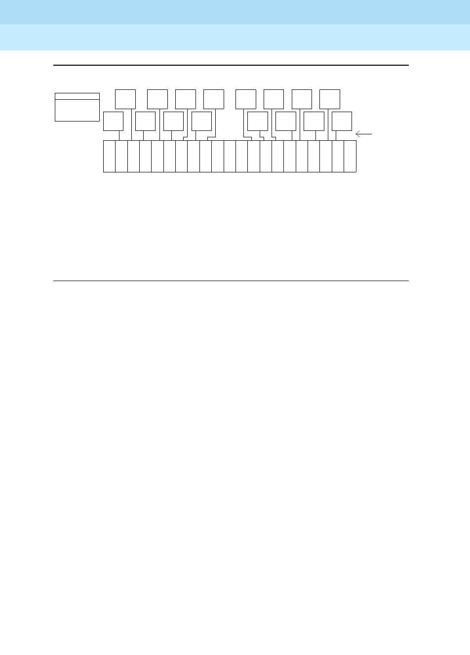
DEFINITY Enterprise Communications Server Release 6
Maintenance for R6r Volumes 1 & 2
555-230-126 Issue 2
January 1998
Maintenance Object Repair Procedures
Page 9-1223SNI-BD (SNI Circuit Pack)
9
Figure 9-69. CSS Configuration with Simplex PNC and 1 Switch Node Carrier
TN Numbers:
SNI - TN573
SNC - TN572
EI - TN570
not
used
...
.
.
.
...
.
.
.
...
.
.
.
...
.
.
.
...
.
.
.
.
.
.
.
.
.
.
.
.
.
.
.
.
.
.
.
.
. . . . . . . . . . . . . . . . . . . .
.
.
.
.
.
.
.
.
.
.
.
.
.
.
.
.
.
.
. . . . . . . . . . . . . . . .
. . . . . . . . . . . .
.
.
.
.
.
.
.
. .
.
.
.
.
.
.
.
.
.
.
links
fiber
slot number 19
I
N
S
I
N
S
I
N
S
I
N
S
I
N
S
I
N
S
I
N
S
I
N
S
I
N
S
I
N
S
I
N
S
I
N
S
I
N
S
I
N
S
I
N
S
I
N
S
C
N
S
C
N
S
* * *
* = An EI or a DS1C circuit pack may reside in this slot
** = A DS1C circuit pack may reside in this slot
1 2 3 4 5 6 7 8 9 10 11 12 13 14 15 16 17 18 20
EPN
EI
EPN
EI
EPN
EI
EPN
EI
EPN
EI
EPN
EI
EPN
EI
EPN
EI
EPN
EI
EPN
EI
EPN
EI
EPN
EI
EPN
EI
EPN
EI EPN
EI
21
PPN
EI
carrier
. . .
. . . . . . .
.
.
.
.
.
node
switch
links
peer
. . . . . . . . . . . . . . . . . . . . . . . . . . . . . . . . . . . . . . . . . . . . . . . . . . . . . . . . . . . . . . . . . . . . .
.
.
.
.
.
.
.
.
.
.
.
.
.
.
.
. .
.
....
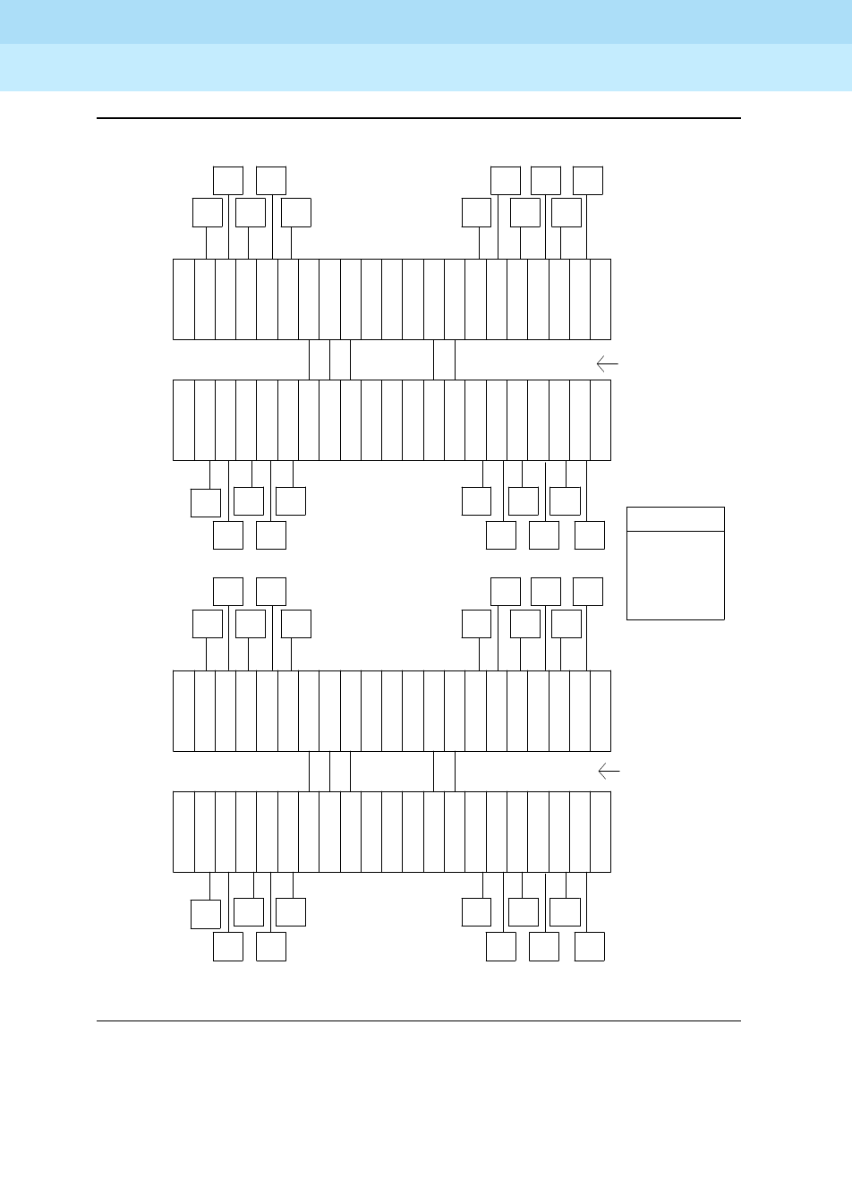
DEFINITY Enterprise Communications Server Release 6
Maintenance for R6r Volumes 1 & 2
555-230-126 Issue 2
January 1998
Maintenance Object Repair Procedures
Page 9-1224SNI-BD (SNI Circuit Pack)
9
Figure 9-70. CSS Configuration with Duplicated PNC and 4 Switch Node
Carriers
D
D
2
1 2 3 4 5 6 7 8 9 10 11 12 13 14 15 16 17 18 20 21
carrier
node
switch
slot number 19
I
N
S
I
N
S
I
N
S
I
N
S
I
N
S
I
N
S
I
N
S
I
N
S
I
N
S
I
N
S
I
N
S
I
N
S
I
N
S
I
N
S
I
N
S
I
N
S
EI
PPN
EI
EPN
EI
EI EI EI
EI EI EI EI
EPN EPN
EPN EPN EPN
EPN EPN EPN
EI
EPN
EI
EPN EI
EI
EPN
EPN
EI
EI EI EI
EI EI EI
EI
EPN
EPN EPN EPN
EPN EPN EPN
EPN
EPN
EPN EPN EPN
EPN EPN EPN
EPN
EI
EI EI EI
EI EI EI
EI
EPN
EPN
EI
EI
EPN
EI
EPN
EI
EPN EPN EPN
EPN EPN EPN
EPN EPN
EI EI EI EI
EI EI EI
EI
EPN
EI
PPN
EI
I
N
S
I
N
S
I
N
S
I
N
S
I
N
S
I
N
S
I
N
S
I
N
S
I
N
S
I
N
S
I
N
S
I
N
S
I
N
S
I
N
S
I
N
S
I
N
S
19 slot number
switch
node
carrier
21 20 18 17 16 15 14 13 12 11 10 9 8 7 6 5 4 3 2 1
2 E C
N
S
C
N
S
EC
N
S
C
N
S
I
N
S
I
N
S
I
N
S
I
N
S
I
N
S
I
N
S
I
N
S
I
N
S
I
N
S
I
N
S
I
N
S
I
N
S
I
N
S
I
N
S
I
N
S
I
N
S
19 slot number 21 20 18 17 16 15 14 13 12 11 10 9 8 7 6 5 4 3 2 1
switch
node
carrier
1
PNC A
fibers
node
inter-switch
fibers
node
inter-switch
PNC B
EI - TN570
SNC - TN572
SNI - TN573
TN numbers:
1
carrier
node
switch
19 slot number 21 20 18 17 16 15 14 13 12 11 10 9 8 7 6 5 4 3 2 1
I
N
S
I
N
S
I
N
S
I
N
S
I
N
S
I
N
S
I
N
S
I
N
S
I
N
S
I
N
S
I
N
S
I
N
S
I
N
S
I
N
S
I
N
S
I
N
S
C
N
S
C
N
S
C
N
S
C
N
S
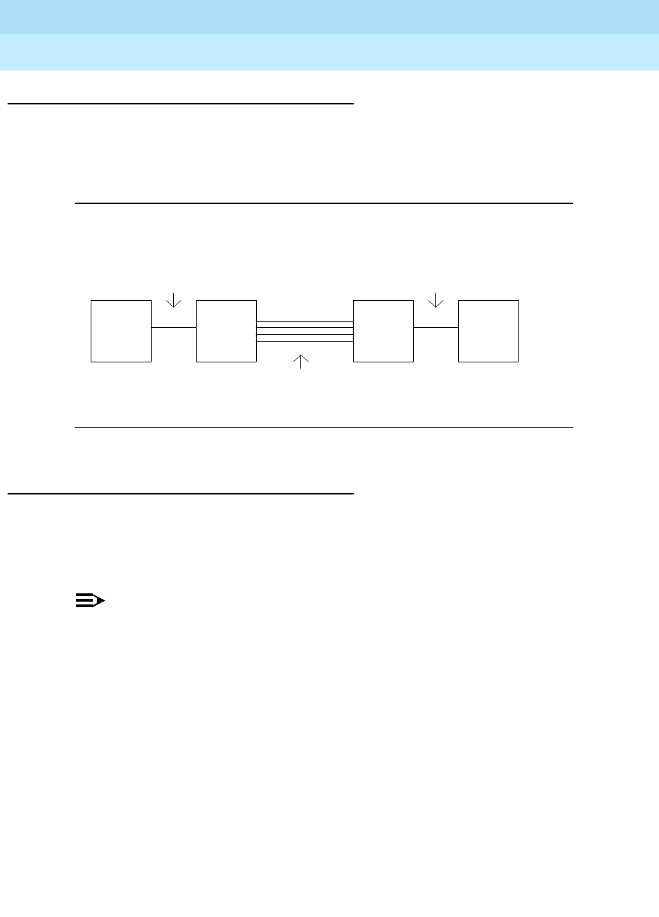
DEFINITY Enterprise Communications Server Release 6
Maintenance for R6r Volumes 1 & 2
555-230-126 Issue 2
January 1998
Maintenance Object Repair Procedures
Page 9-1225SNI-BD (SNI Circuit Pack)
9
Remote EPNs
A DS1 converter complex can used to provide connectivity to a remotely located
port network. The DS1 converter complex consists of two TN574 DS1 converter
(DS1C) circuit packs connected by 1 to 4 DS1 facilities. The DS1C complex is
administered as a fiber link.
Figure 9-71. Fiber Link over a DS1 Converter Complex
SNI LEDs
The SNI circuit pack has red, green and yellow LEDs. The red and green LEDs
have the usual meaning, with red signifying an on-board alarm, and green
signifying maintenance testing in progress. The red and green LEDs will come on
and then turn off when the circuit pack is reset.
NOTE:
If the red LED is on without any alarms active against the circuit pack,
replace the SNI circuit pack. This indicates that SNI firmware has detected
a fault and is unable to notify software.
metallic connection
or
optical fiber
metallic connection
or
optical fiber
1 to 4 DS1 Facilities
TN570 TN574 TN574 TN573
SNI DS1C DS1C EI
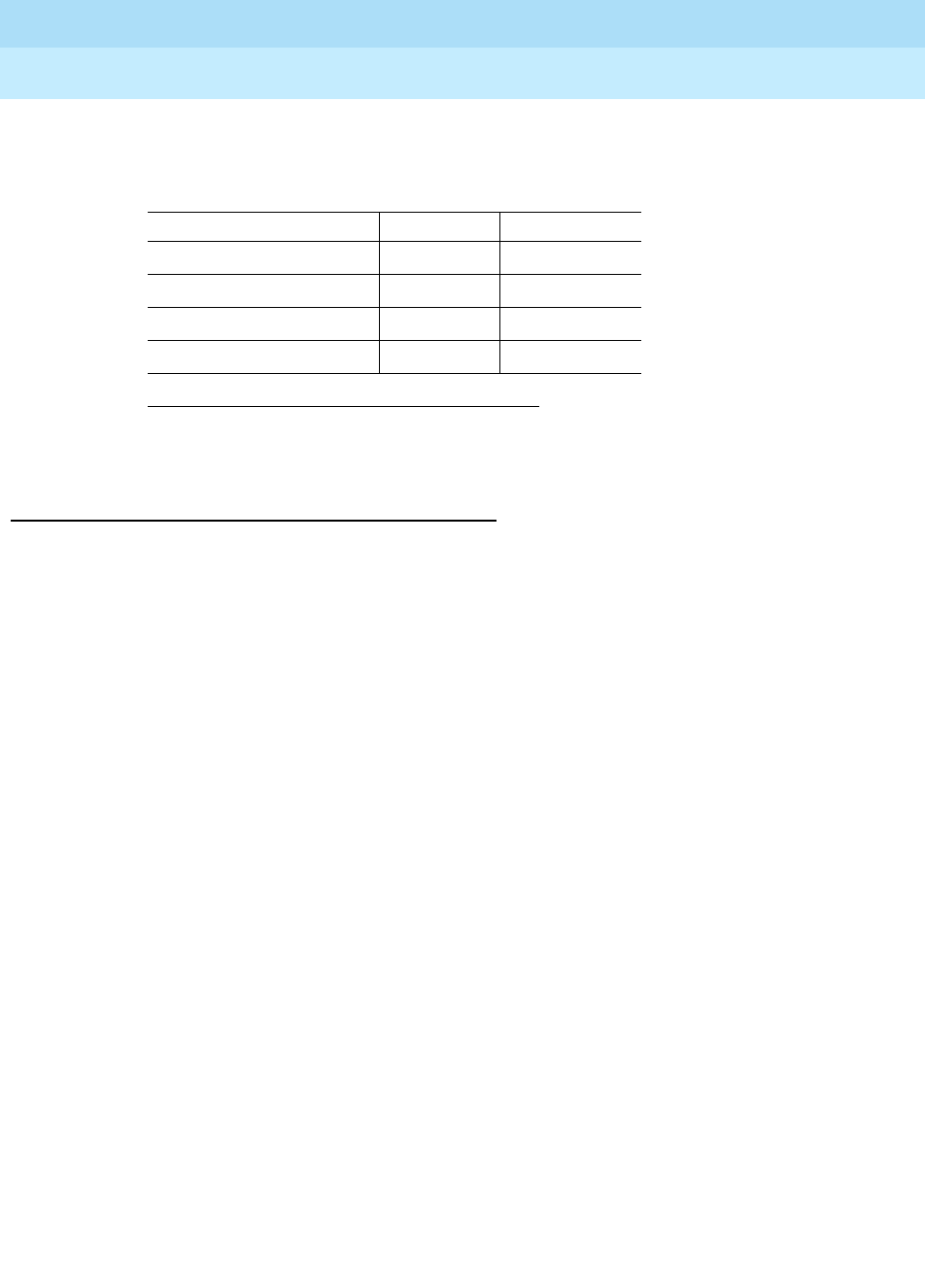
DEFINITY Enterprise Communications Server Release 6
Maintenance for R6r Volumes 1 & 2
555-230-126 Issue 2
January 1998
Maintenance Object Repair Procedures
Page 9-1226SNI-BD (SNI Circuit Pack)
9
The yellow LED indicates status information as follows:
SNI Administration and SNI Board Insertion
The circuit packs in the switch node carrier will not function properly unless
administration is performed first. For example, without fiber link administration,
phone calls cannot be made through the CSS, CSS circuit packs will not be
inserted, and maintenance software cannot test the CSS circuit packs.
For simplex PNC configurations, administration must be done in the following
order before SNIs will be inserted:
1. Cabinet Administration: The switch node carriers must be administered
into the proper cabinets. When this form is submitted by pressing ENTER,
these carriers will be assigned switch node numbers. The list cabinet
command can then be used to determine the numbers for the carriers of
interest.
2. Circuit Pack Administration: All of the boards in the switch node carriers
must be administered.
3. Fiber-link Administration: The fibers between the TN570s and the TN573
(or TN573 to TN573) must be administered via the add fiber-link
command. A DS1C converter complex is added to a fiber link via the add
fiber-link command also.
For duplicated PNC configurations, administration must be done in the following
order before SNIs will be inserted:
1. Activate PNC duplication administration via the change
system-parameters customer-options command.
2. Cabinet Administration: The switch node carriers and duplicate switch
node carriers must be administered into the proper cabinets. When this
form is submitted by depressing the "enter" key, these carriers will be
assigned switch node numbers. The list cabinet command can then be
used to determine the numbers for the carriers of interest.
1. The fiber is in frame but a communication problem exists to
the neighbor.
SNI Yellow LED states
Condition LED on LED off
Fiber out of Frame 0.1 second 0.1 second
In frame, No Neighbor 10.5 second 0.5 second
SNI active solid on never off
SNI standby never on solid off

DEFINITY Enterprise Communications Server Release 6
Maintenance for R6r Volumes 1 & 2
555-230-126 Issue 2
January 1998
Maintenance Object Repair Procedures
Page 9-1227SNI-BD (SNI Circuit Pack)
9
3. Circuit Pack Administration: All of the boards in the switch node carriers
must be administered.
4. Fiber-link Administration: The fibers between the TN570s and the TN573
(or TN573 to TN573) must be administered via the add fiber-link
command. If the system is being changed from a simplex PNC
configuration to a duplicate PNC configuration, the change fiber-link
command can be used to administer the b-pnc fiber link endpoints on the
existing fiber links. A DS1C converter complex is added to a fiber link via
the add fiber-link command also.
5. PNC duplication is enabled via the change system-parameters
duplication command.
Clear Firmware-Counters Command
SNI firmware generates error reports autonomously. This takes place
independently of technician-demanded tests. Therefore, the test board UUCSS
clear command will not affect the error status reported by firmware. The clear
firmware-counters command will clear all firmware-generated errors
unconditionally.
The clear firmware-counters UUCSS command sends a downlink message to
the SNI circuit packs, causing them to clear out their firmware error counters and
failure databases. Once the firmware failure database is cleared, the failure audit
test (#777) will pass. If problems still exist, the firmware will increment its error
counters and the failure audit test will begin failing again.
This command should not be used as a replacement for the repair procedures
associated with the hardware error log entries. This command may be useful if a
problem has been fixed and off-board alarms associated with the problem are
still active.

DEFINITY Enterprise Communications Server Release 6
Maintenance for R6r Volumes 1 & 2
555-230-126 Issue 2
January 1998
Maintenance Object Repair Procedures
Page 9-1228SNI-BD (SNI Circuit Pack)
9
Replacing an SNI Circuit Pack—Simplex PNC
!WARNING:
Do not power down a Switch Node carrier to replace a circuit pack.
!WARNING:
Replacing a Switch Node Interface, Switch Node Clock, Expansion
Interface or DS1 Converter circuit pack on a simplex system disrupts
service. The service effect can range from outage of a single EPN to outage
of the entire system.
1. Enter busyout board UUCSS UUCSS represents the cabinet-carrier-slot
address of the circuit pack to be replaced.
2. Replace the circuit pack
3. Wait for the circuit pack to reset Red and green LEDs will light and then go out.
4. Enter release board UUCSS !CAUTION:
Do not busyout any Expansion Interface
circuit pack after this point.
5. Enter test alarms long clear for
category exp-intf.
6. Wait 5 minutes for SNI-BD, FIBER-LK
AND DS1C-BD alarms to clear, or
enter clear firmware counters a-pnc.

DEFINITY Enterprise Communications Server Release 6
Maintenance for R6r Volumes 1 & 2
555-230-126 Issue 2
January 1998
Maintenance Object Repair Procedures
Page 9-1229SNI-BD (SNI Circuit Pack)
9
Replacing an SNI Circuit Pack— Duplicated PNC
!WARNING:
On a system with duplicated PNC, synchronization may be provided over a
combination of active and standby components. This condition is indicated
by an OFF-BOARD WARNING alarm against TDM-CLK with error type
2305. Repairs to standby PNC in this state may disrupt service. Otherwise,
if the active PNC is functional, replacement of a standby component will not
disrupt service.
1. Enter status pnc Verify that the component to be replaced is on the
standby PNC.
2. Enter busyout pnc
3. Enter busyout board UUCSS UUCSS represents the cabinet-carrier-slot address
of the circuit pack to be replaced.
4. Replace the circuit pack
5. Enter release board UUCSS !CAUTION:
Do not busyout any Expansion Interface
circuit pack after this point.
6. Enter test alarms long clear for
category exp-intf.
7. Wait 5 minutes for SNI-BD, SNI-PEER,
FIBER-LK, and DS1C alarms to clear,
or enter clear firmware counterssp 0
<a-pnc or b-pnc>.
Use the letter designation of the pnc which holds
the replaced component (the standby pnc).
8. Enter status pnc. If either PNC state-of-health is not "functional",
consult the ‘‘PNC-DUP (PNC Duplication)’’ section.
9. Enter release pnc.

DEFINITY Enterprise Communications Server Release 6
Maintenance for R6r Volumes 1 & 2
555-230-126 Issue 2
January 1998
Maintenance Object Repair Procedures
Page 9-1230SNI-BD (SNI Circuit Pack)
9
Switch Node Interface Manual Loop Back
Procedure
This procedure is destructive.
This procedure is to be used when an SNI circuit pack cannot be tested by
software. This can occur when communication between the switch node carrier
and the SPE is down. Before using this procedure, the configuration audit test
(#759) should be run on SNI circuit packs where possible via test board UUCSS
s. Also, the processor route audit test (#760) should be run via the test board
UUCSS long command for the active SNC in the switch node carrier. If the active
SNC is not inserted, test 760 can be run via test hardware-group pnc P, where
P is a-pnc or b-pnc.
Before using this procedure, first determine whether more than one SNI is unable
to communicate with software. Verify SNI and SNC circuit pack insertion via the
list configuration carrier UUC command, where UUC is the cabinet and carrier
location of a switch node carrier. Check for SNI and SNC insertion for every
administered switch node carrier.
If all of the SNIs and SNCs are not inserted ("NO BOARD" is displayed for each
board) in the entire PNC (either the a-pnc or the b-pnc), then the link between the
PPN EI (on the PNC where SNI and SNC circuit packs did not insert) and the
connected SNI is not functioning properly. If this case applies, perform the
following steps:
1. Run the test board UUCSS command on the PPN EI and fix any problems
found.
2. Perform the manual loopback procedure for the PPN EI.
3. Perform the manual loopback procedure for the SNI connected to the PPN
EI.
4. Replace the active SNC.
If the system has a two level switch node carrier configuration, i.e. SNI-SNI fiber
links exist, and the SNIs and SNCs in the second switch node carrier only (the
switch node carrier that has no SNI connected to the PPN EI) are not inserted
and at least two SNI-SNI fiber links exist, perform the following steps:
1. Run the test board UUCSS long command on the SNIs in the first switch
node carrier that are connected to SNIs in the second switch node carrier
and fix any problems found.
2. Replace the active SNC.
3. Perform the manual loopback procedure for the SNIs in the second switch
node carrier that are connected to SNIs in the first switch node carrier.
If software is unable to communicate with an EPN EI but can communicate with
the connected SNI:

DEFINITY Enterprise Communications Server Release 6
Maintenance for R6r Volumes 1 & 2
555-230-126 Issue 2
January 1998
Maintenance Object Repair Procedures
Page 9-1231SNI-BD (SNI Circuit Pack)
9
1. Run the test board UUCSS long command on the connected SNI and fix
any problems found.
2. Perform the manual loopback procedure for the EPN EI.
When the connection to the SNI circuit pack is via fiber, a short length of
optical fiber is required for this procedure. If a metallic cable is used in the
connection, the metallic connector must be removed from the back of the
carrier, and a lightwave transceiver connected in its place. The short
length of optical fiber can then be used.
If this procedure is run on both endpoints on a fiber link (Expansion
Interface circuit packs or Switch Node Interface circuit packs), and both
check out fine, then the failure is most likely in the connection (fiber or
metallic) itself if neither endpoint circuit pack is busied out, but the link
remains inactive.
1. Busyout the circuit pack (Expansion Interface or SNI) using the
busyout board UUCSS command.
2. Disconnect the transmit and receive fiber pair from the lightwave
transceiver on the back of the circuit pack (Expansion Interface or
Switch Node Interface) slot.
NOTE:
Note which is the transmit fiber and which is the receive fiber
for proper re-connection at the end of this procedure. The
fiber connected to the transmit side of the lightwave
transceiver on one circuit pack should be connected to the
receive side of the lightwave transceiver on the circuit pack
on the opposite end of the fiber.
3. Using a spare fiber jumper cable, interconnect the transmit and
receive jacks of the lightwave transceiver as shown in Figure 9-72.
NOTE:
Make sure that the total length of the fiber jumper cable does
not exceed the maximum length recommended for the fiber
link connections between cabinets. This is necessary so that
the testing of the Expansion Interface or SNI circuit pack is
done within connectivity guidelines so that test results are not
influenced due to the cable length not meeting requirements.
4. Go to the front of the cabinet and inspect the yellow LED.
■If the yellow LED flashes on at a rate of once per second, the
(Expansion Interface or Switch Node Interface) circuit pack
or transceiver should be replaced.
■If the yellow LED flashes on at a rate of five times per
second, the circuit pack (Expansion Interface or Switch
Node Interface) or the lightwave transceiver may need
replacement. This condition may also be due to a faulty
DEFINITY Enterprise Communications Server Release 6
Maintenance for R6r Volumes 1 & 2
555-230-126 Issue 2
January 1998
Maintenance Object Repair Procedures
Page 9-1232SNI-BD (SNI Circuit Pack)
9
system clock on the network containing the Expansion
Interface circuit pack or in the switch node carrier containing
the SNI.
■If the yellow LED was blinking before starting this procedure
and the yellow LED is not blinking now, this circuit pack
(Expansion Interface or Switch Node Interface) and the
lightwave transceiver are functioning properly.
5. Replace faulty component(s) and reconnect the original fiber. Be
sure to reconnect the fibers properly as noted in Step 2.
6. Release Expansion Interface circuit pack or Switch Node Interface
circuit pack with the release board UUCSS command.
Figure 9-72. Interconnection of Lightwave Transceiver Transmit/Receive
Jacks
Fiber Jumper
Tx Rx
Transceiver
Lightwave
Back Skin of Cabinet
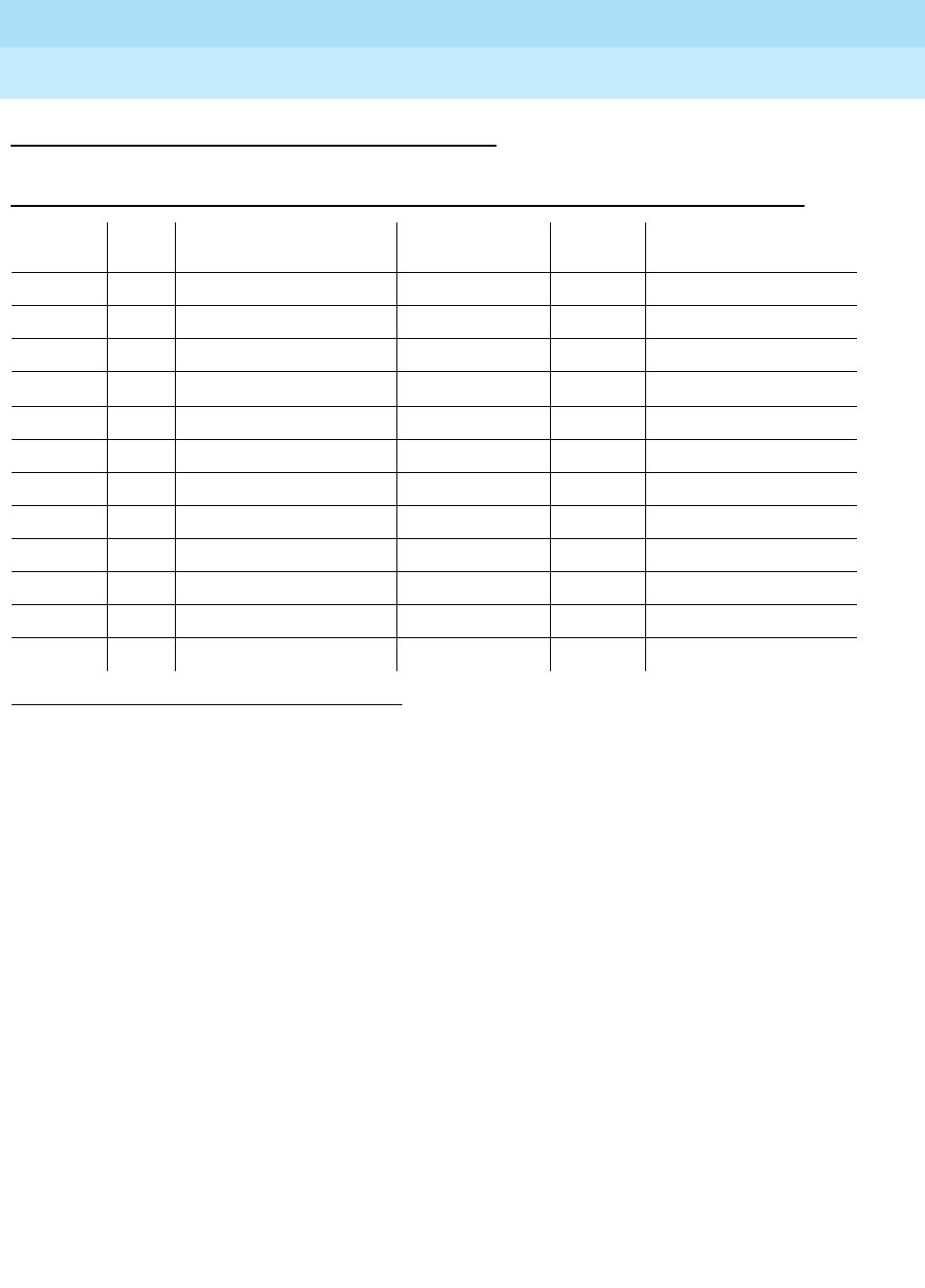
DEFINITY Enterprise Communications Server Release 6
Maintenance for R6r Volumes 1 & 2
555-230-126 Issue 2
January 1998
Maintenance Object Repair Procedures
Page 9-1233SNI-BD (SNI Circuit Pack)
9
Error Log Entries and Test to Clear Values
Notes:
a. The first time you see an SNI-BD error in the error log, run the test board
UUCSS command. If the failure audit test (#777) fails, enter display
errors for this SNI circuit pack and continue with the associated repair
procedures for SNI-BD errors.
b. This error indicates a problem that the SNI may have trouble
communicating with all of the other SNI and SNC circuit packs in the
switch node carrier.
1. Replace the SNI circuit pack.
c. This error indicates that the SNI circuit pack has been busied out via the
busyout board UUCSS command. To resolve this error, release the SNI
circuit pack via the release board UUCSS command.
d. The SNI circuit pack is incompatible with the TN1654 DS1 Converter
board. A TN573B or later suffix SNI board must be used when connecting
to a TN1654 DS1 Converter board. Replace with a newer suffix.
e. This error indicates that the SNI cannot communicate with the active SNC.
1. Run the Short Test Sequence first. If all tests pass, run the Long Test Sequence. Refer to the appropriate
test description and follow the recommended procedures.
Table 9-432. SNI Board Error Log Entries
Error
Type Aux
Data Associated Test Alarm Level On/Off
Board Test to Clear Value
010 Any Any Any test board UUCSS r 1
1(b) any failure audit (#777) (a) MAJ/MIN/WAR ON test board UUCSS r 1
18(c) 0 busyout board UUCSS WARNING OFF release board UUCSS
125(d) None MINOR ON
257(e) any failure audit (#777) (a) MAJ/MIN/WAR OFF test board UUCSS r 1
513(f) any failure audit (#777) (a) MAJ/MIN/WAR OFF test board UUCSS r 1
769(g) any failure audit (#777) (a) MAJ/MIN/WAR OFF test board UUCSS r 1
1025(h) any failure audit (#777) (a) MAJ/MIN/WAR ON/OFF test board UUCSS r 1
1281(i) any failure audit (#777) (a) MAJ/MIN/WAR ON test board UUCSS r 1
1537(j) any failure audit (#777) (a) MAJ/MIN/WAR OFF test board UUCSS r 1
2561(k) any failure audit (#777) (a) MAJ/MIN/WAR ON test board UUCSS r 1
2817(l) any failure audit (#777) (a) MAJ/MIN/WAR ON test board UUCSS r 1

DEFINITY Enterprise Communications Server Release 6
Maintenance for R6r Volumes 1 & 2
555-230-126 Issue 2
January 1998
Maintenance Object Repair Procedures
Page 9-1234SNI-BD (SNI Circuit Pack)
9
1. Check the error log via display errors for other SNI circuit packs
with the 257 SNI-BD error. If other SNI circuit packs in the same
switch node carrier have error 257, then replace the active SNC.
2. Replace this SNI.
3. Replace the active SNC in the same switch node carrier.
4. Enter display errors and if this error is still in the error log, follow
normal escalation procedures.
f. This error indicates that the SNI cannot communicate with the DS1C.
1. Perform the Fiber Fault Isolation Procedure described in Chapter 5.
g. This error indicates a failure communicating synchronization control data
with the active SNC.
Look at all of the SNI-BD errors in the log via display errors and display
alarms to determine whether to follow procedure 1 or procedure 2. See
the table below which lists pairs of SNIs that are considered to be
adjacent. Use Procedure 2 if either of the following two conditions is
present:
— At least one pair of adjacent SNIs in this carrier has Error 769 with
an off-board alarm logged against both SNIs in the pair.
— The active SNC in this carrier has error 257.
If neither of the above is true, follow Procedure 1.
Procedure 1 (suspect TPN link or clock generation out of lock
problem):
1. Enter display alarms and display errors and follow the
procedures for any on-board SNI-BD error and alarm entries.
2. If more than one SNI circuit pack in the same switch node carrier
has SNI-BD error 769 with an off board alarm, replace the active
SNC in the same carrier.
3. Replace this SNI.
Adjacent SNI Slot Numbers
2 & 3
4 & 5
6 & 7
8 & 9
13 & 14
15 & 16
17 & 18
19 & 20

DEFINITY Enterprise Communications Server Release 6
Maintenance for R6r Volumes 1 & 2
555-230-126 Issue 2
January 1998
Maintenance Object Repair Procedures
Page 9-1235SNI-BD (SNI Circuit Pack)
9
4. Replace the active SNC in the same carrier.
Procedure 2 (suspect clock generation out of lock problem):
1. If only one SNC exists in this switch node carrier, replace the SNC.
If two SNCs exist in this switch node carrier, perform the following
steps:
a. Set the standby SNC to active by running the set
switch-node-clock UUCSS command with the standby
SNC’s location.
b. If the problem goes away, replace the SNC that was
previously active. Then set the SNC that was just replaced to
active via the set switch-node-clock UUCSS command. If
the problem returns, assume that the SNC that was just
replaced was not at fault and go to step 2 below.
c. If the problem persists, switch back to the previously active
SNC via the set switch-node-clock command and go to
step 2 below.
2. Replace the leftmost SNI from the pair of adjacent SNIs.
3. Replace the rightmost SNI from the pair of adjacent SNIs.
4. If none of the above steps cleared this error, this could be a switch
node carrier backplane problem.
h. This error indicates a failure communicating synchronization control data
over the fiber-link.
If the error is logged as an on-board error:
1. Replace the SNI circuit pack.
If the error is logged as an off-board error:
1. Enter display errors and follow the associated repair
procedures for FIBER-LK errors.
2. Replace the SNI with this error.
3. Replace the other endpoint of the fiber-link if no DS1C
complex is administered on the fiber-link (use list fiber-link
to determine whether a DS1C complex is administered). If a
DS1C complex is administered on the fiber-link, replace the
circuit packs in this order:
i
. Replace the DS1C circuit pack connected to this SNI.
ii
.. Replace the other DS1C circuit pack.
iii
.. Replace the other endpoint of the fiber-link.
i. This error indicates a processor complex failure.
1. Replace the SNI circuit pack.
j. This error indicates that excessive slips have occurred.
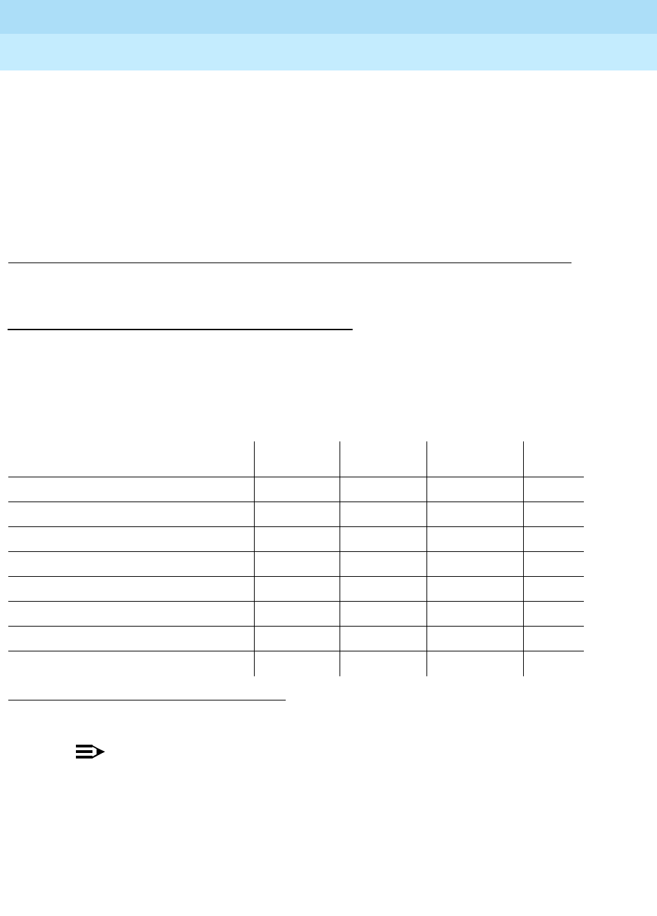
DEFINITY Enterprise Communications Server Release 6
Maintenance for R6r Volumes 1 & 2
555-230-126 Issue 2
January 1998
Maintenance Object Repair Procedures
Page 9-1236SNI-BD (SNI Circuit Pack)
9
Follow the steps for diagnosing synchronization problems when
slips have occurred in the SYNC section.
k. This error indicates that the SNI cannot communicate with its neighbor.
The SNI is at fault.
1. Replace the SNI circuit pack.
l. This error indicates that the SNI cannot communicate with one of its peers.
The SNI is at fault.
1. Replace the SNI circuit pack.
System Technician-Demanded Tests:
Descriptions and Error Codes
Always investigate tests in the order presented in the table below when
inspecting errors in the system. By clearing error codes associated with the
Configuration Audit
for example, you may also clear errors generated from other
tests in the testing sequence.
NOTE:
Test #982 is not an actual demand maintenance test. This test number is
used to report results of executing of the clear firmware-counters
command. Refer to error codes for Test #777.
1. D = Destructive, ND = Non-destructive
Order of Investigation Short Test
Sequence Long Test
Sequence Reset Board
Sequence D/ND1
Configuration Audit (#759) X X ND
Failure Audit(#777) X X ND
Fiber Out of Frame Query(#989) X X ND
Packet Neighbor Test(#767) X X ND
Circuit Path Test(#755) X X ND
Destructive Facility Test(#757) X D
Off-board Destructive Facility Test(#756) X D
Switch Node Interface Reset Test(#761) X D

DEFINITY Enterprise Communications Server Release 6
Maintenance for R6r Volumes 1 & 2
555-230-126 Issue 2
January 1998
Maintenance Object Repair Procedures
Page 9-1237SNI-BD (SNI Circuit Pack)
9
SNI Circuit Path Test (#755)
This test is non-destructive. This test performs a non-destructive test of the circuit
path.
Table 9-433. TEST #755 SNI Circuit Path Test
Error
Code Test
Result Description/ Recommendation
2100 ABORT Could not allocate the necessary system resources to run this test.
1. Retry the command at 1-minute intervals a maximum of 3 times.
2300 ABORT The downlink message necessary to run this test could not be sent.
1. Retry the command at 1-minute intervals a maximum of 3 times.
2301 ABORT The software timer could not be set before sending the downlink message
necessary to run this test.
1. Retry the command at 1-minute intervals a maximum of 3 times.
2302 ABORT Software received incorrect message data from the SNI circuit pack.
1. Retry the command at 1-minute intervals a maximum of 3 times.
2303 ABORT The SNI circuit pack responded that software test requested is not valid.
1. Retry the command at 1-minute intervals a maximum of 3 times.
2304 ABORT SNI circuit pack responded that it is not able to run the test requested by
software.
1. Retry the command at 1-minute intervals a maximum of 3 times.
2306 ABORT The SNI circuit pack is not responding to test requests sent by software.
1. Run the test led switch-node for the switch node that the SNI resides in to
verify whether the LEDs on the board light.
2. If the LEDs on the other boards in the carrier light, but the LEDs on this
board do not light, run test 760 via test board UUCSS l for the active SNC
in this carrier. Wait 5 minutes and then try step 1 one more time. If the
LEDs on this board still do not light, replace this board. Replacing an SNI
may be service interrupting. Refer to the SNI-BD section for the procedure
for replacing an SNI.
3. If none of the LEDs light for the boards in the same carrier as this board, fix
any problems associated with the connectivity of this carrier to the SPE.
Check list fiber-link to determine the fiber connections to this carrier.
Check the LEDs on all SNIs and EIs and fix any fiber problems. Enter
display errors and follow the associated repair procedures for any
EXP-INTF error entries associated with the PPN. Also, follow the
associated repair procedures for any SYNC, SNI-BD, SNC-BD, FIBER-LK,
or SNI-PEER error entries.
4. Follow the procedure described above, SNI Manual Loopback to
determine whether the circuit pack or the fiber connection is faulty.
Continued on next page

DEFINITY Enterprise Communications Server Release 6
Maintenance for R6r Volumes 1 & 2
555-230-126 Issue 2
January 1998
Maintenance Object Repair Procedures
Page 9-1238SNI-BD (SNI Circuit Pack)
9
102 FAIL The SNI circuit pack cannot communicate with the SNI in slot 2 over the circuit
path.
1. Fix any on-board SNI-BD errors against this SNI and the SNI in slot 2. Use
display errors to find any SNI-BD errors and check display alarms to see
whether the errors have on-board alarms. Then follow the associated
repair procedures for SNI-BD.
2. Check the error log via display errors for other SNI circuit packs with
SNI-PEER error type 1. If other SNI circuit packs have SNI-PEER error type
1, then replace the SNI in slot 2. Replacing an SNI may be service
interrupting. Refer to the SNI-BD section for the procedure for replacing an
SNI.
NOTE:
If other SNI circuit packs do not have SNI-PEER error type 1 errors, the
problem could be at either of the peer SNI boards. It is arbitrary as to
which SNI is replaced first. Proceed as follows:
3. Replace this SNI.
4. Replace the SNI in slot 2.
103 FAIL The SNI circuit pack cannot communicate with the SNI in slot 3 over the circuit
path.
1. Fix any on-board SNI-BD errors against this SNI and the SNI in slot 3. Use
display errors to find any SNI-BD errors and check display alarms to see
whether the errors have on-board alarms. Then follow the associated
repair procedures for SNI-BD.
2. Check the error log via display errors for other SNI circuit packs with
SNI-PEER error type 257. If other SNI circuit packs have SNI-PEER error
type 257, then replace the SNI in slot 3. Replacing an SNI may be service
interrupting. Refer to the SNI-BD section for the procedure for replacing an
SNI.
NOTE:
If other SNI circuit packs do not have SNI-PEER error type 257 errors,
the problem could be at either of the peer SNI boards. It is arbitrary as to
which SNI is replaced first. Proceed as follows:
3. Replace this SNI.
4. Replace the SNI in slot 3.
Table 9-433. TEST #755 SNI Circuit Path Test — Continued
Error
Code Test
Result Description/ Recommendation
Continued on next page
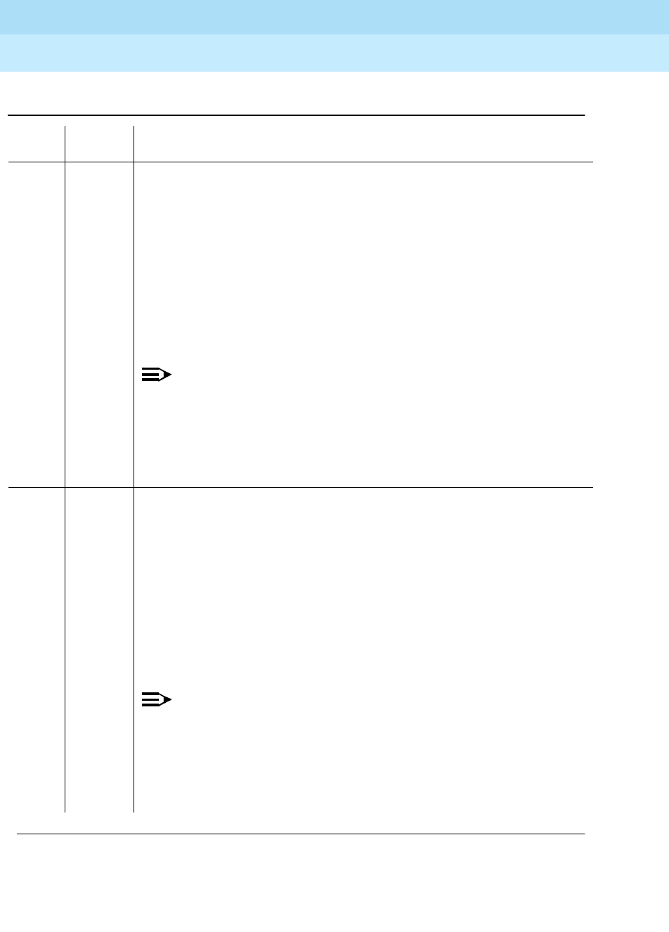
DEFINITY Enterprise Communications Server Release 6
Maintenance for R6r Volumes 1 & 2
555-230-126 Issue 2
January 1998
Maintenance Object Repair Procedures
Page 9-1239SNI-BD (SNI Circuit Pack)
9
104 FAIL The SNI circuit pack cannot communicate with the SNI in slot 4 over the circuit
path.
1. Fix any on-board SNI-BD errors against this SNI and the SNI in slot 4. Use
display errors to find any SNI-BD errors and check display alarms to see
whether the errors have on-board alarms. Then follow the associated
repair procedures for SNI-BD.
2. Check the error log via display errors for other SNI circuit packs with
SNI-PEER error type 513. If other SNI circuit packs have SNI-PEER error
type 513, then replace the SNI in slot 4. Replacing an SNI may be service
interrupting. Refer to the SNI-BD section for the procedure for replacing an
SNI.
NOTE:
If other SNI circuit packs do not have SNI-PEER error type 513 errors,
the problem could be at either of the peer SNI boards. It is arbitrary as to
which SNI is replaced first. Proceed as follows:
3. Replace this SNI.
4. Replace the SNI in slot 4.
105 FAIL The SNI circuit pack cannot communicate with the SNI in slot 5 over the circuit
path.
1. Fix any on-board SNI-BD errors against this SNI and the SNI in slot 5. Use
display errors to find any SNI-BD errors and check display alarms to see
whether the errors have on-board alarms. Then follow the associated
repair procedures for SNI-BD.
2. Check the error log via display errors for other SNI circuit packs with
SNI-PEER error type 769. If other SNI circuit packs have SNI-PEER error
type 769, then replace the SNI in slot 5. Replacing an SNI may be service
interrupting. Refer to the SNI-BD section for the procedure for replacing an
SNI.
NOTE:
If other SNI circuit packs do not have SNI-PEER error type 769 errors,
the problem could be at either of the peer SNI boards. It is arbitrary as to
which SNI is replaced first. Proceed as follows:
3. Replace this SNI.
4. Replace the SNI in slot 5.
Table 9-433. TEST #755 SNI Circuit Path Test — Continued
Error
Code Test
Result Description/ Recommendation
Continued on next page

DEFINITY Enterprise Communications Server Release 6
Maintenance for R6r Volumes 1 & 2
555-230-126 Issue 2
January 1998
Maintenance Object Repair Procedures
Page 9-1240SNI-BD (SNI Circuit Pack)
9
106 FAIL The SNI circuit pack cannot communicate with the SNI in slot 6 over the circuit
path.
1. Fix any on-board SNI-BD errors against this SNI and the SNI in slot 6. Use
display errors to find any SNI-BD errors and check display alarms to see
whether the errors have on-board alarms. Then follow the associated
repair procedures for SNI-BD.
2. Check the error log via display errors for other SNI circuit packs with
SNI-PEER error type 1025. If other SNI circuit packs have SNI-PEER error
type 1025, then replace the SNI in slot 6. Replacing an SNI may be service
interrupting. Refer to the SNI-BD section for the procedure for replacing an
SNI.
NOTE:
If other SNI circuit packs do not have SNI-PEER error type 1025 errors,
the problem could be at either of the peer SNI boards. It is arbitrary as to
which SNI is replaced first. Proceed as follows:
3. Replace this SNI.
4. Replace the SNI in slot 6.
107 FAIL The SNI circuit pack cannot communicate with the SNI in slot 7 over the circuit
path.
1. Fix any on-board SNI-BD errors against this SNI and the SNI in slot 7. Use
display errors to find any SNI-BD errors and check display alarms to see
whether the errors have on-board alarms. Then follow the associated
repair procedures for SNI-BD.
2. Check the error log via display errors for other SNI circuit packs with
SNI-PEER error type 1281. If other SNI circuit packs have SNI-PEER error
type 1281, then replace the SNI in slot 7. Replacing an SNI may be service
interrupting. Refer to the SNI-BD section for the procedure for replacing an
SNI.
NOTE:
If other SNI circuit packs do not have SNI-PEER error type 1281 errors,
the problem could be at either of the peer SNI boards. It is arbitrary as to
which SNI is replaced first. Proceed as follows:
1. Replace this SNI.
2. Replace the SNI in slot 7.
Table 9-433. TEST #755 SNI Circuit Path Test — Continued
Error
Code Test
Result Description/ Recommendation
Continued on next page

DEFINITY Enterprise Communications Server Release 6
Maintenance for R6r Volumes 1 & 2
555-230-126 Issue 2
January 1998
Maintenance Object Repair Procedures
Page 9-1241SNI-BD (SNI Circuit Pack)
9
108 FAIL The SNI circuit pack cannot communicate with the SNI in slot 8 over the circuit
path.
1. Fix any on-board SNI-BD errors against this SNI and the SNI in slot 8. Use
display errors to find any SNI-BD errors and check display alarms to see
whether the errors have on-board alarms. Then follow the associated
repair procedures for SNI-BD.
2. Check the error log via display errors for other SNI circuit packs with
SNI-PEER error type 1537. If other SNI circuit packs have SNI-PEER error
type 1537, then replace the SNI in slot 8. Replacing an SNI may be service
interrupting. Refer to the SNI-BD section for the procedure for replacing an
SNI.
NOTE:
If other SNI circuit packs do not have SNI-PEER error type 1537 errors,
the problem could be at either of the peer SNI boards. It is arbitrary as to
which SNI is replaced first. Proceed as follows:
3. Replace this SNI.
4. Replace the SNI in slot 8.
109 FAIL The SNI circuit pack cannot communicate with the SNI in slot 9 over the circuit
path.
1. Fix any on-board SNI-BD errors against this SNI and the SNI in slot 9. Use
display errors to find any SNI-BD errors and check display alarms to see
whether the errors have on-board alarms. Then follow the associated
repair procedures for SNI-BD.
2. Check the error log via display errors for other SNI circuit packs with
SNI-PEER error type 1793. If other SNI circuit packs have SNI-PEER error
type 1793, then replace the SNI in slot 9. Replacing an SNI may be service
interrupting. Refer to the SNI-BD section for the procedure for replacing an
SNI.
NOTE:
If other SNI circuit packs do not have SNI-PEER error type 1793 errors,
the problem could be at either of the peer SNI boards. It is arbitrary as to
which SNI is replaced first. Proceed as follows:
3. Replace this SNI.
4. Replace the SNI in slot 9.
Table 9-433. TEST #755 SNI Circuit Path Test — Continued
Error
Code Test
Result Description/ Recommendation
Continued on next page

DEFINITY Enterprise Communications Server Release 6
Maintenance for R6r Volumes 1 & 2
555-230-126 Issue 2
January 1998
Maintenance Object Repair Procedures
Page 9-1242SNI-BD (SNI Circuit Pack)
9
113 FAIL The SNI circuit pack cannot communicate with the SNI in slot 13 over the
circuit path.
1. Fix any on-board SNI-BD errors against this SNI and the SNI in slot 13. Use
display errors to find any SNI-BD errors and check display alarms to see
whether the errors have on-board alarms. Then follow the associated
repair procedures for SNI-BD.
2. Check the error log via display errors for other SNI circuit packs with
SNI-PEER error type 2049. If other SNI circuit packs have SNI-PEER error
type 2049, then replace the SNI in slot 13. Replacing an SNI may be
service interrupting. Refer to the SNI-BD section for the procedure for
replacing an SNI.
NOTE:
If other SNI circuit packs do not have SNI-PEER error type 2049 errors,
the problem could be at either of the peer SNI boards. It is arbitrary as to
which SNI is replaced first. Proceed as follows:
3. Replace this SNI.
4. Replace the SNI in slot 13.
114 FAIL The SNI circuit pack cannot communicate with the SNI in slot 14 over the
circuit path.
1. Fix any on-board SNI-BD errors against this SNI and the SNI in slot 14. Use
display errors to find any SNI-BD errors and check display alarms to see
whether the errors have on-board alarms. Then follow the associated
repair procedures for SNI-BD.
2. Check the error log via display errors for other SNI circuit packs with
SNI-PEER error type 2305. If other SNI circuit packs have SNI-PEER error
type 2305, then replace the SNI in slot 14. Replacing an SNI may be
service interrupting. Refer to the SNI-BD section for the procedure for
replacing an SNI.
NOTE:
If other SNI circuit packs do not have SNI-PEER error type 2305 errors,
the problem could be at either of the peer SNI boards. It is arbitrary as to
which SNI is replaced first. Proceed as follows:
3. Replace this SNI.
4. Replace the SNI in slot 14.
Table 9-433. TEST #755 SNI Circuit Path Test — Continued
Error
Code Test
Result Description/ Recommendation
Continued on next page

DEFINITY Enterprise Communications Server Release 6
Maintenance for R6r Volumes 1 & 2
555-230-126 Issue 2
January 1998
Maintenance Object Repair Procedures
Page 9-1243SNI-BD (SNI Circuit Pack)
9
115 FAIL The SNI circuit pack cannot communicate with the SNI in slot 15 over the
circuit path.
1. Fix any on-board SNI-BD errors against this SNI and the SNI in slot 15. Use
display errors to find any SNI-BD errors and check display alarms to see
whether the errors have on-board alarms. Then follow the associated
repair procedures for SNI-BD.
2. Check the error log via display errors for other SNI circuit packs with
SNI-PEER error type 2561. If other SNI circuit packs have SNI-PEER error
type 2561, then replace the SNI in slot 15. Replacing an SNI may be
service interrupting. Refer to the SNI-BD section for the procedure for
replacing an SNI.
NOTE:
If other SNI circuit packs do not have SNI-PEER error type 2561 errors,
the problem could be at either of the peer SNI boards. It is arbitrary as to
which SNI is replaced first. Proceed as follows:
3. Replace this SNI.
4. Replace the SNI in slot 15.
116 FAIL The SNI circuit pack cannot communicate with the SNI in slot 16 over the
circuit path.
1. Fix any on-board SNI-BD errors against this SNI and the SNI in slot 16. Use
display errors to find any SNI-BD errors and check display alarms to see
whether the errors have on-board alarms. Then follow the associated
repair procedures for SNI-BD.
2. Check the error log via display errors for other SNI circuit packs with
SNI-PEER error type 2817. If other SNI circuit packs have SNI-PEER error
type 2817, then replace the SNI in slot 16. Replacing an SNI may be
service interrupting. Refer to the SNI-BD section for the procedure for
replacing an SNI.
NOTE:
If other SNI circuit packs do not have SNI-PEER error type 2817 errors,
the problem could be at either of the peer SNI boards. It is arbitrary as to
which SNI is replaced first. Proceed as follows:
3. Replace this SNI.
4. Replace the SNI in slot 16.
Table 9-433. TEST #755 SNI Circuit Path Test — Continued
Error
Code Test
Result Description/ Recommendation
Continued on next page

DEFINITY Enterprise Communications Server Release 6
Maintenance for R6r Volumes 1 & 2
555-230-126 Issue 2
January 1998
Maintenance Object Repair Procedures
Page 9-1244SNI-BD (SNI Circuit Pack)
9
117 FAIL The SNI circuit pack cannot communicate with the SNI in slot 17 over the
circuit path.
1. Fix any on-board SNI-BD errors against this SNI and the SNI in slot 17. Use
display errors to find any SNI-BD errors and check display alarms to see
whether the errors have on-board alarms. Then follow the associated
repair procedures for SNI-BD.
2. Check the error log via display errors for other SNI circuit packs with
SNI-PEER error type 3073. If other SNI circuit packs have SNI-PEER error
type 3073, then replace the SNI in slot 17. Replacing an SNI may be
service interrupting. Refer to the SNI-BD section for the procedure for
replacing an SNI.
NOTE:
If other SNI circuit packs do not have SNI-PEER error type 3073 errors,
the problem could be at either of the peer SNI boards. It is arbitrary as to
which SNI is replaced first. Proceed as follows:
3. Replace this SNI.
4. Replace the SNI in slot 17.
118 FAIL The SNI circuit pack cannot communicate with the SNI in slot 18 over the
circuit path.
1. Fix any on-board SNI-BD errors against this SNI and the SNI in slot 18. Use
display errors to find any SNI-BD errors and check display alarms to see
whether the errors have on-board alarms. Then follow the associated
repair procedures for SNI-BD.
2. Check the error log via display errors for other SNI circuit packs with
SNI-PEER error type 3329. If other SNI circuit packs have SNI-PEER error
type 3329, then replace the SNI in slot 18. Replacing an SNI may be
service interrupting. Refer to the SNI-BD section for the procedure for
replacing an SNI.
NOTE:
If other SNI circuit packs do not have SNI-PEER error type 3329 errors,
the problem could be at either of the peer SNI boards. It is arbitrary as to
which SNI is replaced first. Proceed as follows:
3. Replace this SNI.
4. Replace the SNI in slot 18.
Table 9-433. TEST #755 SNI Circuit Path Test — Continued
Error
Code Test
Result Description/ Recommendation
Continued on next page

DEFINITY Enterprise Communications Server Release 6
Maintenance for R6r Volumes 1 & 2
555-230-126 Issue 2
January 1998
Maintenance Object Repair Procedures
Page 9-1245SNI-BD (SNI Circuit Pack)
9
119 FAIL The SNI circuit pack cannot communicate with the SNI in slot 19 over the
circuit path.
1. Fix any on-board SNI-BD errors against this SNI and the SNI in slot 19. Use
display errors to find any SNI-BD errors and check display alarms to see
whether the errors have on-board alarms. Then follow the associated
repair procedures for SNI-BD.
2. Check the error log via display errors for other SNI circuit packs with
SNI-PEER error type 3585. If other SNI circuit packs have SNI-PEER error
type 3585, then replace the SNI in slot 19. Replacing an SNI may be
service interrupting. Refer to the SNI-BD section for the procedure for
replacing an SNI.
NOTE:
If other SNI circuit packs do not have SNI-PEER error type 3385 errors,
the problem could be at either of the peer SNI boards. It is arbitrary as to
which SNI is replaced first. Proceed as follows:
3. Replace this SNI.
4. Replace the SNI in slot 19.
120 FAIL The SNI circuit pack cannot communicate with the SNI in slot 20 over the
circuit path.
1. Fix any on-board SNI-BD errors against this SNI and the SNI in slot 20. Use
display errors to find any SNI-BD errors and check display alarms to see
whether the errors have on-board alarms. Then follow the associated
repair procedures for SNI-BD.
2. Check the error log via display errors for other SNI circuit packs with
SNI-PEER error type 3841. If other SNI circuit packs have SNI-PEER error
type 3841, then replace the SNI in slot 20. Replacing an SNI may be
service interrupting. Refer to the SNI-BD section for the procedure for
replacing an SNI.
NOTE:
If other SNI circuit packs do not have SNI-PEER error type 3841 errors,
the problem could be at either of the peer SNI boards. It is arbitrary as to
which SNI is replaced first. Proceed as follows:
3. Replace this SNI.
4. Replace the SNI in slot 20.
Table 9-433. TEST #755 SNI Circuit Path Test — Continued
Error
Code Test
Result Description/ Recommendation
Continued on next page

DEFINITY Enterprise Communications Server Release 6
Maintenance for R6r Volumes 1 & 2
555-230-126 Issue 2
January 1998
Maintenance Object Repair Procedures
Page 9-1246SNI-BD (SNI Circuit Pack)
9
122 FAIL The SNI circuit pack cannot communicate with its neighbor via the circuit path.
1. Fix any on-board errors (SNI-BD, EXP-INTF, and/or DS1C-BD) against the
components of this fiber link by using display errors and display alarms
and following the associated repair procedures. (Use the list fiber-link
command to find the fiber link associated with this SNI. The display
fiber-link command can then be used to find the endpoints of the fiber link
and the DS1C circuit pack locations if this fiber link has a DS1 Converter
Complex administered.)
2. Enter display errors and follow the associated repair procedures for any
FIBER-LK entries for the fiber this SNI is administered on. Check list
fiber-link to determine the administered fiber.
3. If this fiber link has a DS1 converter complex administered, enter display
errors and display alarms and follow the associated repair procedures
for any off-board DS1C-BD or DS1-FAC entries for either of the DS1C
boards administered or for the DS1 facilities associated with either of the
DS1C boards administered.
4. Replace this SNI.
PASS The SNI passed the sni circuit path test.
0NO
BOARD No board was detected by the test.
1. Check that board is properly translated and inserted.
2. Run the test again. If it fails, reset the board. An SNI should be reset
instead of reseating the circuit pack. The reset board command should
almost never be used on an SNI. It may be necessary to use the reset
board command if the SNI circuit pack gets into a mode where it cannot
communicate with software. If an SNI with active errors and alarms is
reset, the errors and alarms may take a while to come back, therefore the
reset board command can mask real problems.
3. Run the test again. If it fails, the ID chip on board may be bad. Replace the
board and retest.
Table 9-433. TEST #755 SNI Circuit Path Test — Continued
Error
Code Test
Result Description/ Recommendation
Continued on next page

DEFINITY Enterprise Communications Server Release 6
Maintenance for R6r Volumes 1 & 2
555-230-126 Issue 2
January 1998
Maintenance Object Repair Procedures
Page 9-1247SNI-BD (SNI Circuit Pack)
9
SNI Off-board Destructive Facility Test (#756)
This test is destructive.
The SNI runs a destructive looparound of the off-board and on-board
looparounds. This test returns the result of the off-board looparound, while test
757 returns the result of the on-board looparound.
Table 9-434. TEST #756 SNI Off-Board Destructive
Facility Test
Error
Code Test
Result Description/ Recommendation
1015 ABORT The system will not allow this test to be run because the SNI circuit pack has
not been busied out. Busy out the SNI circuit pack with busyout board.
Repeat the test board UUCSS long command.
1415 ABORT The lightwave transceiver is not present.
1. If a lightwave transceiver is not supposed to be present, do nothing. For
example, an SNI connected to a DS1C circuit pack or an SNI with a
metallic connection does not have a lightwave transceiver. This test can
only be run when a lightwave transceiver exists.
2. Otherwise, check the lightwave transceiver connections.
3. If OK, replace the lightwave transceiver. If a fiber out of frame condition
exists and lightwave transceivers are used, check that the lightwave
transceivers are of the same type, that is, both are 9823a or both are
9823b. If they are not the same type, replace one of the lightwave
transceivers:
■9823a is used for distances up to 4900 feet.
■9823b is used for distances up to 25,000 feet.
4. If the test continues to abort, replace the SNI circuit pack.
2100 ABORT Could not allocate the necessary system resources to run this test.
1. Retry the command at 1-minute intervals a maximum of 3 times.
2300 ABORT The downlink message necessary to run this test could not be sent.
1. Retry the command at 1-minute intervals a maximum of 3 times.
2301 ABORT The software timer could not be set before sending the downlink message
necessary to run this test.
1. Retry the command at 1-minute intervals a maximum of 3 times.
2304 ABORT SNI circuit pack responded that it is not able to run the test requested by
software.
1. Retry the command at 1-minute intervals a maximum of 3 times.
Continued on next page

DEFINITY Enterprise Communications Server Release 6
Maintenance for R6r Volumes 1 & 2
555-230-126 Issue 2
January 1998
Maintenance Object Repair Procedures
Page 9-1248SNI-BD (SNI Circuit Pack)
9
2306 ABORT The SNI circuit pack is not responding to test requests sent by software.
1. Run the test led switch-node for the switch node that the SNI resides in
to verify whether the LEDs on the board light.
2. If the LEDs on the other boards in the carrier light, but the LEDs on this
board do not light, run test 760 via test board UUCSS l for the active SNC
in this carrier. Wait 5 minutes and then try step 1 one more time. If the
LEDs on this board still do not light, replace this board. Replacing an SNI
may be service interrupting. Refer to the SNI-BD section for the procedure
for replacing an SNI.
3. If none of the LEDs light for the boards in the same carrier as this board,
fix any problems associated with the connectivity of this carrier to the SPE.
Check list fiber-link to determine the fiber connections to this carrier.
Check the LEDs on all SNIs and EIs and fix any fiber problems. Enter
display errors and follow the associated repair procedures for any
EXP-INTF error entries associated with the PPN. Also, follow the
associated repair procedures for any SYNC, SNI-BD, SNC-BD, FIBER-LK,
or SNI-PEER error entries.
4. Follow the procedure described above, SNI Manual Loopback to
determine whether the circuit pack or the fiber connection is faulty.
127 FAIL The data is not correctly looped around.
1. Check the lightwave transceiver or metallic physical connections.
2. If connections OK, replace the lightwave transceiver or the metallic
interconnect.
3. If the test still fails, replace the SNI circuit pack.
PASS No problems associated with this test are detected on the SNI.
0NO
BOARD No board was detected by the test.
1. Check that board is properly translated and inserted.
2. Run the test again. If it fails, reset the board. An SNI should be reset
instead of reseating the circuit pack. The reset board command should
almost never be used on an SNI. It may be necessary to use the reset
board command if the SNI circuit pack gets into a mode where it cannot
communicate with software. If an SNI with active errors and alarms is
reset, the errors and alarms may take a while to come back, therefore the
reset board command can mask real problems.
3. Run the test again. If it fails, the ID chip on board may be bad. Replace
the board and retest.
Table 9-434. TEST #756 SNI Off-Board Destructive
Facility Test — Continued
Error
Code Test
Result Description/ Recommendation
Continued on next page

DEFINITY Enterprise Communications Server Release 6
Maintenance for R6r Volumes 1 & 2
555-230-126 Issue 2
January 1998
Maintenance Object Repair Procedures
Page 9-1249SNI-BD (SNI Circuit Pack)
9
SNI Destructive Facility Test (#757)
This test is destructive.
The SNI runs a destructive looparound of the off-board and on-board
looparounds. This test returns the result of the on-board looparound, while test
756 returns the result of the off-board looparound.
Table 9-435. TEST #757 SNI Destructive Facility Test
Error
Code Test
Result Description/ Recommendation
1015 ABORT The system will not allow this test to be run because the SNI circuit pack has
not been busied out. Busy out the SNI circuit pack with busyout board.
Repeat the test board UUCSS long command.
2100 ABORT Could not allocate the necessary system resources to run this test.
1. Retry the command at 1-minute intervals a maximum of 3 times.
2300 ABORT The downlink message necessary to run this test could not be sent.
1. Retry the command at 1-minute intervals a maximum of 3 times.
2301 ABORT The software timer could not be set before sending the downlink message
necessary to run this test.
1. Retry the command at 1-minute intervals a maximum of 3 times.
2304 ABORT SNI circuit pack responded that it is not able to run the test requested by
software.
1. Retry the command at 1-minute intervals a maximum of 3 times.
Continued on next page

DEFINITY Enterprise Communications Server Release 6
Maintenance for R6r Volumes 1 & 2
555-230-126 Issue 2
January 1998
Maintenance Object Repair Procedures
Page 9-1250SNI-BD (SNI Circuit Pack)
9
2306 ABORT The SNI circuit pack is not responding to software test requests.
1. Run the test led switch-node for the switch node that the SNI resides in to
verify whether the LEDs on the board light.
2. If the LEDs on the other boards in the carrier light, but the LEDs on this
board do not light, run test 760 via test board UUCSS l for the active SNC
in this carrier. Wait 5 minutes and then try step 1 one more time. If the
LEDs on this board still do not light, replace this board. Replacing an SNI
may be service interrupting. Refer to the SNI-BD section for the procedure
for replacing an SNI.
3. If none of the LEDs light for the boards in the same carrier as this board,
fix any problems associated with the connectivity of this carrier to the SPE.
Check list fiber-link to determine the fiber connections to this carrier.
Check the LEDs on all SNIs and EIs and fix any fiber problems. Enter
display errors and follow the associated repair procedures for any
EXP-INTF error entries associated with the PPN. Also, follow the
associated repair procedures for any SYNC, SNI-BD, SNC-BD, FIBER-LK,
or SNI-PEER error entries.
4. Follow the procedure described above, SNI Manual Loopback to
determine whether the circuit pack or the fiber connection is faulty.
127 FAIL The data is not correctly looped around.
1. Replace the SNI circuit pack.
PASS No problems associated with this test are detected on the SNI.
0NO
BOARD No board was detected by the test.
1. Check that board is properly translated and inserted.
2. Run the test again. If it fails, reset the board. An SNI should be reset
instead of reseating the circuit pack. The reset board command should
almost never be used on an SNI. It may be necessary to use the reset
board command if the SNI circuit pack gets into a mode where it cannot
communicate with software. If an SNI with active errors and alarms is
reset, the errors and alarms may take a while to come back, therefore the
reset board command can mask real problems.
3. Run the test again. If it fails, the ID chip on board may be bad. Replace the
board and retest.
Table 9-435. TEST #757 SNI Destructive Facility Test — Continued
Error
Code Test
Result Description/ Recommendation
Continued on next page

DEFINITY Enterprise Communications Server Release 6
Maintenance for R6r Volumes 1 & 2
555-230-126 Issue 2
January 1998
Maintenance Object Repair Procedures
Page 9-1251SNI-BD (SNI Circuit Pack)
9
Configuration Audit (#759)
This test is non-destructive.
NOTE:
For descriptions of result codes for this test refer to:
■SNC-BD when the circuit pack tested is a Switch Node Clock (circuit pack
slots 10 or 12).
■SNI-BD when the circuit pack tested is a Switch Node Interface (circuit
pack slots 2-9 or 13-20).
This test is run via the test board short or test board long command for SNI
circuit packs or SNC circuit packs.
For SNI circuit packs, this test queries the SNI for SNCs in the same switch node
carrier, SNI peers, DS1Cs, and EI or SNI neighbors that the SNI can
communicate with and compares this data to the administered data.
For SNC circuit packs, this test queries the SNC for SNCs and SNIs in the same
switch node carrier that the SNC can communicate with and compares this data
to the administered data.
Failures of this test cause entries in the error and alarm logs against Switch Node
Configuration (SN-CONF) with the board location of the SNI or SNC.
Incorrectly Connected Administered Fibers
Some physically connected fibers that do not match fiber administration can
cause port network problems that are not detected and alarmed by PNC tests.
The symptoms will usually be many phone calls not working correctly, and port
network component alarms because of translation mismatches.
This test is unable to detect the case where an SNI is connected to the same type
of board (EI or SNI) as administered but located in a different cabinet but the
same carrier and same slot as the administered fiber endpoint. The administered
fiber endpoint can be viewed with the list fiber-link command. This test can only
detect if the fiber endpoint connected to the SNI is in a different carrier, slot
location than the administered fiber endpoint.
Incorrectly Connected Administered SNI-EI Fibers
If the SNI is connected to the same type of fiber endpoint as the administered
fiber endpoint, but the location is the same as administered except for the
cabinet, many phone calls will not work correctly; some phone calls will not go
through and some phone calls will ring the wrong phone.
The test led command can be used in this case to check connectivity.
1. Run the test led port-network command on each administered port
network and verify that the LEDs on the correct port network are lit.

DEFINITY Enterprise Communications Server Release 6
Maintenance for R6r Volumes 1 & 2
555-230-126 Issue 2
January 1998
Maintenance Object Repair Procedures
Page 9-1252SNI-BD (SNI Circuit Pack)
9
2. If they are not lit, check that the fiber connections to the port network are
consistent with the administered fibers (list fiber-link) that does not light
the LEDs as expected.
3. Run test led switch-node on each administered switch node carrier and
verify that the LEDs on the correct carrier are lit.
4. If they are not, check the connectivity to the switch node carrier that does
not light the LEDs as expected.
Incorrectly Connected Administered SNI-SNI Fibers between 3 Switch
Nodes
If the system has more than 2 switch nodes, SNI-SNI fibers administered
between 2 switch nodes could be incorrectly connected to a third switch node.
This is a problem that could occur during installation or when inter-switch node
fibers are changed. For multiple fibers to a distant switch node (not the PPN
switch node), an incorrect connection would not appear as a problem unless this
fiber is used for a system-link to a port network connected to the distant switch
node. The status system-link command can be used to determine the boards
and fiber-links in the path from the PPN to a specific port network. A specific
SNI-SNI fiber connection must be in the system-link path to be checked with the
port network LED test.
One method to force an SNI-SNI fiber connection to be used as a system-link is
to physically remove all SNI-SNI connections except the fiber-link being tested at
the distant switch node by physical removing SNI boards in the distant SWItch
node.
1. Use the status system-link command to verify that this fiber selected for
test is in the path to the EPN connected to the distant switch node that will
be used for the LED test.
2. Run the test led sequence to a port network as described above to verify
this fiber connection.
3. Repeat this procedure for each of the other SNI-SNI fibers terminating on
this distant switch node.
Another method for testing multiple fiber connections to a distant switch node is
described below.
1. Use the list fiber-link command to determine the number of SNI-SNI
fibers that are administered and terminating on this switch node.
2. Run the test led port-network command on a port network connected to
this distant switch node and verify that the LEDs on the correct port
network are lit.
3. Use the status system-link command and select the active EI in the port
network connected to the distant switch node being tested. This display
will show the path from the PPN and the SNI-SNI fiber being used in this
path.

DEFINITY Enterprise Communications Server Release 6
Maintenance for R6r Volumes 1 & 2
555-230-126 Issue 2
January 1998
Maintenance Object Repair Procedures
Page 9-1253SNI-BD (SNI Circuit Pack)
9
4. If they are not lit, check that the fiber connections to the port network are
consistent with the administered fibers (list fiber-link) that does not light
the LEDs as expected.
5. If the port network LEDs are lit and we have multiple SNI-SNI fibers to this
distant switch node, physically remove the SNI that is listed in this path.
6. Use the status system-link command to determine the new path from the
PPN to the this distant switch.
7. Run the test led port-network command on a port network connected to
the distant switch node and verify that the LEDs on the correct port
network are lit.
8. Continue with steps 5 — 7 above until the last SNI-SNI fiber to this distant
switch node has been tested.
Table 9-436. TEST #759 Configuration Audit
Error
Code Test
Result Description/ Recommendation
2100 ABORT Could not allocate the necessary system resources to run this test.
1. Retry the command at 1-minute intervals a maximum of 3 times.
2300 ABORT The downlink message necessary to run this test could not be sent.
1. Retry the command at 1-minute intervals a maximum of 3 times.
2301 ABORT The software timer could not be set before sending the downlink message
necessary to run this test.
1. Retry the command at 1-minute intervals a maximum of 3 times.
Continued on next page

DEFINITY Enterprise Communications Server Release 6
Maintenance for R6r Volumes 1 & 2
555-230-126 Issue 2
January 1998
Maintenance Object Repair Procedures
Page 9-1254SNI-BD (SNI Circuit Pack)
9
2306 ABORT The SNI circuit pack is not responding to test requests sent by software.
1. Run the test led switch-node for the switch node that this board resides in
to verify whether the LEDs on the board light.
2. If the LEDs on the other boards in the carrier light, but the LEDs on this
board do not light, run test 760 via test board UUCSS for the active SNC
in this carrier. Wait 5 minutes and then try step 1 one more time. If the
LEDs on this board still do not light, replace this board. Replacing an SNI
may be service interrupting. Refer to the SNI-BD section for the procedure
for replacing an SNI.
3. If none of the LEDs light for the boards in the same carrier as this board, fix
any problems associated with the connectivity of this carrier to the SPE.
Check list fiber-link to determine the fiber connections to this carrier.
Check the LEDs on all SNIs and EIs and fix any fiber problems. Enter
display errors and follow the associated repair procedures for any
EXP-INTF error entries associated with the PPN. Also, follow the
associated repair procedures for any SYNC, SNI-BD, SNC-BD, FIBER-LK,
or SNI-PEER error entries.
4. Follow the procedure described above, SNI Manual Loopback to
determine whether the circuit pack or the fiber connection is faulty.
2500 ABORT Internal System Error
1. Retry the command at 1-minute intervals a maximum of 3 times.
102 FAIL The SNI circuit pack cannot communicate with the equipped SNI in slot 2.
1. Perform the Fiber Fault Isolation Procedure described in Chapter 5. This
will resolve multiple SNI-PEER errors.
2. If the SNI being tested has SNI-PEER error type 1, replace the SNI being
tested. Replacing an SNI may be service interrupting. Refer to the SNI-BD
section for the procedure for replacing an SNI. To view SNI-PEER errors,
use the display errors command with category PNC-PEER. Retry the
command.
3. If the SNI being tested has SNI-PEER error type 1, replace the SNI in slot 2.
Replacing an SNI may be service interrupting. Refer to the SNI-BD section
for the procedure for replacing an SNI. Retry the command.
Table 9-436. TEST #759 Configuration Audit — Continued
Error
Code Test
Result Description/ Recommendation
Continued on next page

DEFINITY Enterprise Communications Server Release 6
Maintenance for R6r Volumes 1 & 2
555-230-126 Issue 2
January 1998
Maintenance Object Repair Procedures
Page 9-1255SNI-BD (SNI Circuit Pack)
9
103 FAIL The SNI circuit pack cannot communicate with the equipped SNI in slot 3.
1. Perform the Fiber Fault Isolation Procedure described in Chapter 5. This
will resolve multiple SNI-PEER errors.
2. If the SNI being tested has SNI-PEER error type 257, replace the SNI being
tested. Replacing an SNI may be service interrupting. Refer to the SNI-BD
section for the procedure for replacing an SNI. To view SNI-PEER errors,
use the display errors command with category PNC-PEER. Retry the
command.
3. If the SNI being tested has SNI-PEER error type 257, replace the SNI in
slot 3. Replacing an SNI may be service interrupting. Refer to the SNI-BD
section for the procedure for replacing an SNI. Retry the command.
104 FAIL The SNI circuit pack cannot communicate with the equipped SNI in slot 4.
1. Perform the Fiber Fault Isolation Procedure described in Chapter 5. This
will resolve multiple SNI-PEER errors.
2. If the SNI being tested has SNI-PEER error type 513, replace the SNI being
tested. Replacing an SNI may be service interrupting. Refer to the SNI-BD
section for the procedure for replacing an SNI. To view SNI-PEER errors,
use the display errors command with category PNC-PEER. Retry the
command.
3. If the SNI being tested has SNI-PEER error type 513, replace the SNI in
slot 4. Replacing an SNI may be service interrupting. Refer to the SNI-BD
section for the procedure for replacing an SNI. Retry the command.
105 FAIL The SNI circuit pack cannot communicate with the equipped SNI in slot 5.
1. Perform the Fiber Fault Isolation Procedure described in Chapter 5. This
will resolve multiple SNI-PEER errors.
2. If the SNI being tested has SNI-PEER error type 769, replace the SNI being
tested. Replacing an SNI may be service interrupting. Refer to the SNI-BD
section for the procedure for replacing an SNI. To view SNI-PEER errors,
use the display errors command with category PNC-PEER. Retry the
command.
3. If the SNI being tested has SNI-PEER error type 769, replace the SNI in
slot 5. Replacing an SNI may be service interrupting. Refer to the SNI-BD
section for the procedure for replacing an SNI. Retry the command.
Table 9-436. TEST #759 Configuration Audit — Continued
Error
Code Test
Result Description/ Recommendation
Continued on next page

DEFINITY Enterprise Communications Server Release 6
Maintenance for R6r Volumes 1 & 2
555-230-126 Issue 2
January 1998
Maintenance Object Repair Procedures
Page 9-1256SNI-BD (SNI Circuit Pack)
9
106 FAIL The SNI circuit pack cannot communicate with the equipped SNI in slot 6.
1. Perform the Fiber Fault Isolation Procedure described in Chapter 5. This
will resolve multiple SNI-PEER errors.
2. If the SNI being tested has SNI-PEER error type 1025, replace the SNI
being tested. Replacing an SNI may be service interrupting. Refer to the
SNI-BD section for the procedure for replacing an SNI. To view SNI-PEER
errors, use the display errors command with category PNC-PEER. Retry
the command.
3. If the SNI being tested has SNI-PEER error type 1025, replace the SNI in
slot 6. Replacing an SNI may be service interrupting. Refer to the SNI-BD
section for the procedure for replacing an SNI. Retry the command.
107 FAIL The SNI circuit pack cannot communicate with the equipped SNI in slot 7.
1. Perform the Fiber Fault Isolation Procedure described in Chapter 5. This
will resolve multiple SNI-PEER errors.
2. If the SNI being tested has SNI-PEER error type 1281, replace the SNI
being tested. Replacing an SNI may be service interrupting. Refer to the
SNI-BD section for the procedure for replacing an SNI. To view SNI-PEER
errors, use the display errors command with category PNC-PEER. Retry
the command.
3. If the SNI being tested has SNI-PEER error type 1281, replace the SNI in
slot 7. Replacing an SNI may be service interrupting. Refer to the SNI-BD
section for the procedure for replacing an SNI. Retry the command.
108 FAIL The SNI circuit pack cannot communicate with the equipped SNI in slot 8.
1. Perform the Fiber Fault Isolation Procedure described in Chapter 5. This
will resolve multiple SNI-PEER errors.
2. If the SNI being tested has SNI-PEER error type 1537, replace the SNI
being tested. Replacing an SNI may be service interrupting. Refer to the
SNI-BD section for the procedure for replacing an SNI. To view SNI-PEER
errors, use the display errors command with category PNC-PEER. Retry
the command.
3. If the SNI being tested has SNI-PEER error type 1537, replace the SNI in
slot 8. Replacing an SNI may be service interrupting. Refer to the SNI-BD
section for the procedure for replacing an SNI. Retry the command.
Table 9-436. TEST #759 Configuration Audit — Continued
Error
Code Test
Result Description/ Recommendation
Continued on next page

DEFINITY Enterprise Communications Server Release 6
Maintenance for R6r Volumes 1 & 2
555-230-126 Issue 2
January 1998
Maintenance Object Repair Procedures
Page 9-1257SNI-BD (SNI Circuit Pack)
9
109 FAIL The SNI circuit pack cannot communicate with the equipped SNI in slot 9.
1. Perform the Fiber Fault Isolation Procedure described in Chapter 5. This
will resolve multiple SNI-PEER errors.
2. If the SNI being tested has SNI-PEER error type 1793, replace the SNI
being tested. Replacing an SNI may be service interrupting. Refer to the
SNI-BD section for the procedure for replacing an SNI. To view SNI-PEER
errors, use the display errors command with category PNC-PEER. Retry
the command.
3. If the SNI being tested has SNI-PEER error type 1793, replace the SNI in
slot 9. Replacing an SNI may be service interrupting. Refer to the SNI-BD
section for the procedure for replacing an SNI. Retry the command.
112 FAIL The SNI circuit pack cannot communicate with the active SNC.
1. Check the error log for other SNI circuit packs in the same carrier with a
257 SNI-BD error. Use display errors with category PNC to view SNI-BD
errors. If other SNI circuit packs in the same switch node carrier have error
257, then replace the active SNC in this switch node carrier. Replacing an
SNC may be service interrupting. Refer to the SNC-BD section for the
procedure for replacing an SNC. If other SNI circuit packs in the same
carrier do not have SNI-BD error type 257 logged, proceed to step 2.
2. Replace this SNI. Replacing an SNI may be service interrupting. Refer to
the SNI-BD section for the procedure for replacing an SNI.
3. Replace the active SNC in the same switch node carrier. Replacing an
SNC may be service interrupting. Refer to the SNC-BD section for the
procedure for replacing an SNC.
113 FAIL The SNI circuit pack cannot communicate with the equipped SNI in slot 13.
1. Perform the Fiber Fault Isolation Procedure described in Chapter 5. This
will resolve multiple SNI-PEER errors.
2. If the SNI being tested has SNI-PEER error type 2049, replace the SNI
being tested. Replacing an SNI may be service interrupting. Refer to the
SNI-BD section for the procedure for replacing an SNI. To view SNI-PEER
errors, use the display errors command with category PNC-PEER. Retry
the command.
3. If the SNI being tested has SNI-PEER error type 2049, replace the SNI in
slot 13. Replacing an SNI may be service interrupting. Refer to the SNI-BD
section for the procedure for replacing an SNI. Retry the command.
Table 9-436. TEST #759 Configuration Audit — Continued
Error
Code Test
Result Description/ Recommendation
Continued on next page

DEFINITY Enterprise Communications Server Release 6
Maintenance for R6r Volumes 1 & 2
555-230-126 Issue 2
January 1998
Maintenance Object Repair Procedures
Page 9-1258SNI-BD (SNI Circuit Pack)
9
114 FAIL The SNI circuit pack cannot communicate with the equipped SNI in slot 14.
1. Perform the Fiber Fault Isolation Procedure described in Chapter 5. This
will resolve multiple SNI-PEER errors.
2. If the SNI being tested has SNI-PEER error type 2305, replace the SNI
being tested. Replacing an SNI may be service interrupting. Refer to the
SNI-BD section for the procedure for replacing an SNI. To view SNI-PEER
errors, use the display errors command with category PNC-PEER. Retry
the command.
3. If the SNI being tested has SNI-PEER error type 2305, replace the SNI in
slot 14. Replacing an SNI may be service interrupting. Refer to the SNI-BD
section for the procedure for replacing an SNI. Retry the command.
115 FAIL The SNI circuit pack cannot communicate with the equipped SNI in slot 15.
1. Perform the Fiber Fault Isolation Procedure described in Chapter 5. This
will resolve multiple SNI-PEER errors.
2. If the SNI being tested has SNI-PEER error type 2561, replace the SNI
being tested. Replacing an SNI may be service interrupting. Refer to the
SNI-BD section for the procedure for replacing an SNI. To view SNI-PEER
errors, use the display errors command with category PNC-PEER. Retry
the command.
3. If the SNI being tested has SNI-PEER error type 2561, replace the SNI in
slot 15. Replacing an SNI may be service interrupting. Refer to the SNI-BD
section for the procedure for replacing an SNI. Retry the command.
116 FAIL The SNI circuit pack cannot communicate with the equipped SNI in slot 16.
1. Perform the Fiber Fault Isolation Procedure described in Chapter 5. This
will resolve multiple SNI-PEER errors.
2. If the SNI being tested has SNI-PEER error type 2817, replace the SNI
being tested. Replacing an SNI may be service interrupting. Refer to the
SNI-BD section for the procedure for replacing an SNI. To view SNI-PEER
errors, use the display errors command with category PNC-PEER. Retry
the command.
3. If the SNI being tested has SNI-PEER error type 2817, replace the SNI in
slot 16. Replacing an SNI may be service interrupting. Refer to the SNI-BD
section for the procedure for replacing an SNI. Retry the command.
Table 9-436. TEST #759 Configuration Audit — Continued
Error
Code Test
Result Description/ Recommendation
Continued on next page

DEFINITY Enterprise Communications Server Release 6
Maintenance for R6r Volumes 1 & 2
555-230-126 Issue 2
January 1998
Maintenance Object Repair Procedures
Page 9-1259SNI-BD (SNI Circuit Pack)
9
117 FAIL The SNI circuit pack cannot communicate with the equipped SNI in slot 17.
1. Perform the Fiber Fault Isolation Procedure described in Chapter 5. This
will resolve multiple SNI-PEER errors.
2. If the SNI being tested has SNI-PEER error type 3073, replace the SNI
being tested. Replacing an SNI may be service interrupting. Refer to the
SNI-BD section for the procedure for replacing an SNI. To view SNI-PEER
errors, use the display errors command with category PNC-PEER. Retry
the command.
3. If the SNI being tested has SNI-PEER error type 3073, replace the SNI in
slot 17. Replacing an SNI may be service interrupting. Refer to the SNI-BD
section for the procedure for replacing an SNI. Retry the command.
118 FAIL The SNI circuit pack cannot communicate with the equipped SNI in slot 18.
1. Perform the Fiber Fault Isolation Procedure described in Chapter 5. This
will resolve multiple SNI-PEER errors.
2. If the SNI being tested has SNI-PEER error type 3329, replace the SNI
being tested. Replacing an SNI may be service interrupting. Refer to the
SNI-BD section for the procedure for replacing an SNI. To view SNI-PEER
errors, use the display errors command with category PNC-PEER. Retry
the command.
3. If the SNI being tested has SNI-PEER error type 3329, replace the SNI in
slot 18. Replacing an SNI may be service interrupting. Refer to the SNI-BD
section for the procedure for replacing an SNI. Retry the command.
119 FAIL The SNI circuit pack cannot communicate with the equipped SNI in slot 19.
1. Perform the Fiber Fault Isolation Procedure described in Chapter 5. This
will resolve multiple SNI-PEER errors.
2. If the SNI being tested has SNI-PEER error type 3585, replace the SNI
being tested. Replacing an SNI may be service interrupting. Refer to the
SNI-BD section for the procedure for replacing an SNI. To view SNI-PEER
errors, use the display errors command with category PNC-PEER. Retry
the command.
3. If the SNI being tested has SNI-PEER error type 3585, replace the SNI in
slot 19. Replacing an SNI may be service interrupting. Refer to the SNI-BD
section for the procedure for replacing an SNI. Retry the command.
Table 9-436. TEST #759 Configuration Audit — Continued
Error
Code Test
Result Description/ Recommendation
Continued on next page

DEFINITY Enterprise Communications Server Release 6
Maintenance for R6r Volumes 1 & 2
555-230-126 Issue 2
January 1998
Maintenance Object Repair Procedures
Page 9-1260SNI-BD (SNI Circuit Pack)
9
120 FAIL The SNI circuit pack cannot communicate with the equipped SNI in slot 20.
1. Perform the Fiber Fault Isolation Procedure described in Chapter 5. This
will resolve multiple SNI-PEER errors.
2. If the SNI being tested has SNI-PEER error type 3841, replace the SNI
being tested. Replacing an SNI may be service interrupting. Refer to the
SNI-BD section for the procedure for replacing an SNI. To view SNI-PEER
errors, use the display errors command with category PNC-PEER. Retry
the command.
3. If the SNI being tested has SNI-PEER error type 3841, replace the SNI in
slot 20. Replacing an SNI may be service interrupting. Refer to the SNI-BD
section for the procedure for replacing an SNI. Retry the command.
133 FAIL No neighbor link is administered, but the SNI has an EI neighbor.
1. Administer the SNI on a fiber link to the EI neighbor it is connected to via
the add fiber-link next command. Or remove both fiber endpoints (i.e.,
this SNI and its EI neighbor) and remove the fiber endpoints from circuit
pack administration via change circuit-pack.
134 FAIL No neighbor link is administered, but the SNI has an SNI neighbor.
1. Administer the SNI on a fiber link to the SNI neighbor it is connected to via
the add fiber-link next command. Or remove both fiber endpoints (i.e.,
this SNI and its SNI neighbor) and remove the fiber endpoints from circuit
pack administration via change circuit-pack.
135 FAIL The SNI circuit pack cannot communicate with its neighbor. The SNI has an
administered neighbor, but cannot communicate with its neighbor.
1. Check if the administered neighbor is inserted. If not, insert the neighbor
circuit pack.
2. Perform the Fiber Fault Isolation Procedure described in Chapter 5.
136 FAIL The SNI’s administered neighbor does not match the physical neighbor
connected. The type of neighbor administered is an SNI and the type of
neighbor physically connected is an EI. Enter list fiber-link and verify that the
fiber optic cable and metallic cable connections are installed as administered.
137 FAIL The SNI’s administered neighbor does not match the physical neighbor
connected. The type of neighbor administered is an EI and the type of
neighbor physically connected is an SNI. Enter list fiber-link and verify that
the fiber optic cable and metallic cable connections are installed as
administered.
Table 9-436. TEST #759 Configuration Audit — Continued
Error
Code Test
Result Description/ Recommendation
Continued on next page

DEFINITY Enterprise Communications Server Release 6
Maintenance for R6r Volumes 1 & 2
555-230-126 Issue 2
January 1998
Maintenance Object Repair Procedures
Page 9-1261SNI-BD (SNI Circuit Pack)
9
138 FAIL The physical neighbor location does not match administered neighbor
location. The carrier and slot of the administered neighbor do not match the
carrier and slot of the physical neighbor. Enter list fiber-link and verify that the
fiber optic cable and metallic cable connections are installed as administered.
If the problem does not seem to be caused by a physical connection problem
or an administration problem, replace the neighbor circuit pack. It is possible
for the neighbor circuit pack to have a hardware problem that causes it to
report a wrong angel address (physical carrier/slot address) to software.
139 FAIL The SNI is administered to be connected to a DS1C but is not physically
connected to a DS1C.
If a DS1C is not supposed to be connected to this SNI
,
change administration to remove the DS1 converter complex from the fiber link
associated with this SNI by:
1. Determine which fiber that this SNI is an endpoint of by checking list
fiber-link.
2. Remove this fiber with the remove fiber-link command.
3. Add the fiber back via add fiber-link, and do not administer the DS1
converter complex at this time.
140 FAIL The SNI is physically connected to a DS1C but is not administered to be
connected to a DS1C.
Either add the DS1 converter complex to the fiber that this SNI is associated
with by:
1. Determine which fiber that this SNI is an endpoint of by checking list
fiber-link.
2. Remove this fiber with the remove fiber-link command.
3. Add the fiber back via add fiber-link, and at this time also administer the
DS1 converter complex.
Or:
1. Remove the DS1C connection and connect the SNI directly to its
administered fiber endpoint.
2. Verify that the fiber optic cable and metallic cable connections are
installed as administered by entering list fiber-link.
PASS The administered data and the circuit packs the SNI can communicate with
match.
Table 9-436. TEST #759 Configuration Audit — Continued
Error
Code Test
Result Description/ Recommendation
Continued on next page

DEFINITY Enterprise Communications Server Release 6
Maintenance for R6r Volumes 1 & 2
555-230-126 Issue 2
January 1998
Maintenance Object Repair Procedures
Page 9-1262SNI-BD (SNI Circuit Pack)
9
0NO
BOARD No board was detected by the test.
1. Check that board is properly translated and inserted.
2. Run the test again. If it fails, reset the board. An SNI should be reset
instead of reseating the circuit pack. The reset board command should
almost never be used on an SNI. It may be necessary to use the reset
board command if the SNI circuit pack gets into a mode where it cannot
communicate with software. If an SNI with active errors and alarms is
reset, the errors and alarms may take a while to come back, therefore the
reset board command can mask real problems.
3. Run the test again. If it fails, the ID chip on board may be bad. Replace the
board and retest.
Table 9-436. TEST #759 Configuration Audit — Continued
Error
Code Test
Result Description/ Recommendation
Continued on next page

DEFINITY Enterprise Communications Server Release 6
Maintenance for R6r Volumes 1 & 2
555-230-126 Issue 2
January 1998
Maintenance Object Repair Procedures
Page 9-1263SNI-BD (SNI Circuit Pack)
9
Switch Node Interface Reset Test (#761)
This test is destructive.
This test resets the SNI circuit pack via the reset board UUCSS command when
an SNI circuit pack location is entered. The SNI is reset via the active SNC circuit
pack in the carrier. If the SNI is connected to the PPN EI, the SNI is reset via its
PPN EI neighbor. If an SNI with an EPN EI or another SNI as its neighbor cannot
be reset via the active SNC, i.e., if no software communication exists between the
active SNC and the SPE, an attempt will be made to reset the SNI via its
neighbor.
An SNI should be reset instead of reseating the circuit pack. The reset board
command should almost never be used on an SNI. It may be necessary to use
the reset board command if the SNI circuit pack gets into a mode where it
cannot communicate with software.
If an SNI with active errors and alarms is reset, the errors and alarms may take a
while to come back, therefore the reset board command can mask real
problems.
Table 9-437. TEST #761 Switch Node Interface Reset Test
Error
Code Test
Result Description/ Recommendation
2100 ABORT Could not allocate the necessary system resources to run this test.
1. Retry the command at 1-minute intervals a maximum of 3 times.
2300 ABORT The downlink message necessary to run this test could not be sent.
1. Retry the command at 1-minute intervals a maximum of 3 times.
2301 ABORT The software timer could not be set before sending the downlink message
necessary to run this test.
1. Retry the command at 1-minute intervals a maximum of 3 times.
2302 ABORT Software received incorrect message data from the SNI circuit pack.
1. Retry the command at 1-minute intervals a maximum of 3 times.
2303 ABORT The SNI circuit pack responded that the software test requested is invalid.
1. Retry the command at 1-minute intervals a maximum of 3 times.
2304 ABORT SNI circuit pack responded that it is not able to run the test requested by
software.
1. Retry the command at 1-minute intervals a maximum of 3 times.
Continued on next page

DEFINITY Enterprise Communications Server Release 6
Maintenance for R6r Volumes 1 & 2
555-230-126 Issue 2
January 1998
Maintenance Object Repair Procedures
Page 9-1264SNI-BD (SNI Circuit Pack)
9
2306 ABORT The SNI circuit pack is not responding to test requests sent by software.
1. Run the test led switch-node for the switch node that the SNI resides in to
verify whether the LEDs on the board light.
2. If the LEDs on the other boards in the carrier light, but the LEDs on this
board do not light, run test 760 via test board UUCSS l for the active SNC
in this carrier. Wait 5 minutes and then try step 1 one more time. If the
LEDs on this board still do not light, replace this board. Replacing an SNI
may be service interrupting. Refer to the SNI-BD section for the procedure
for replacing an SNI.
3. If none of the LEDs light for the boards in the same carrier as this board,
fix any problems associated with the connectivity of this carrier to the SPE.
Check list fiber-link to determine the fiber connections to this carrier.
Check the LEDs on all SNIs and EIs and fix any fiber problems. Enter
display errors and follow the associated repair procedures for any
EXP-INTF error entries associated with the PPN. Also, follow the
associated repair procedures for any SYNC, SNI-BD, SNC-BD, FIBER-LK,
or SNI-PEER error entries.
4. Follow the procedure described above, SNI Manual Loopback to
determine whether the circuit pack or the fiber connection is faulty.
2316 ABORT The reset of the SNI circuit pack was attempted via the connected DS1C
circuit pack. This ABORT code indicates that the fiber is not administered, but
in this particular case it also indicates a software problem.
1. Retry the command at 1-minute intervals a maximum of 1 time.
2500 ABORT Internal System Error
1. Retry the command at 1-minute intervals a maximum of 3 times.
PASS The reset message was sent out successfully to the active SNC or to the SNI’s
neighbor. A PASS does not necessarily mean the SNI circuit pack was
successfully reset. The reset can be verified by checking that the red and
green LEDs turn on and then turn off. If an SNI circuit pack fails one of the
firmware tests run during its reset sequence, the red LED will stay on and the
circuit pack should be replaced.
Table 9-437. TEST #761 Switch Node Interface Reset Test — Continued
Error
Code Test
Result Description/ Recommendation
Continued on next page

DEFINITY Enterprise Communications Server Release 6
Maintenance for R6r Volumes 1 & 2
555-230-126 Issue 2
January 1998
Maintenance Object Repair Procedures
Page 9-1265SNI-BD (SNI Circuit Pack)
9
0NO
BOARD No board was detected by the test.
1. Check that board is properly translated and inserted.
2. Run the test again. If it fails, reset the board. An SNI should be reset
instead of reseating the circuit pack. The reset board command should
almost never be used on an SNI. It may be necessary to use the reset
board command if the SNI circuit pack gets into a mode where it cannot
communicate with software. If an SNI with active errors and alarms is
reset, the errors and alarms may take a while to come back, therefore the
reset board command can mask real problems.
3. Run the test again. If it fails, the ID chip on board may be bad. Replace the
board and retest.
Table 9-437. TEST #761 Switch Node Interface Reset Test — Continued
Error
Code Test
Result Description/ Recommendation
Continued on next page

DEFINITY Enterprise Communications Server Release 6
Maintenance for R6r Volumes 1 & 2
555-230-126 Issue 2
January 1998
Maintenance Object Repair Procedures
Page 9-1266SNI-BD (SNI Circuit Pack)
9
Packet Neighbor Link Test (#767)
This test is non-destructive.
This test checks the packet path of the neighbor circuit pack and the peer circuit
packs. A packet is sent from the SNI being tested to the peer SNIs and to the
neighbor EI or SNI. If the other EI or SNI sends the same data back in the packet,
this test passes. Otherwise, this test fails.
Table 9-438. TEST #767 Packet Neighbor Link Test
Error
Code Test
Result Description/ Recommendation
2100 ABORT Could not allocate the necessary system resources to run this test.
1. Retry the command at 1-minute intervals a maximum of 3 times.
2300 ABORT The downlink message necessary to run this test could not be sent.
1. Retry the command at 1-minute intervals a maximum of 3 times.
2301 ABORT The software timer could not be set before sending the downlink message
necessary to run this test.
1. Retry the command at 1-minute intervals a maximum of 3 times.
2302 ABORT Software received incorrect message data from the SNI circuit pack.
1. Retry the command at 1-minute intervals a maximum of 3 times.
2303 ABORT The SNI circuit pack responded that the software test requested is invalid.
1. Retry the command at 1-minute intervals a maximum of 3 times.
2304 ABORT SNI firmware is not able to run the test. For this particular test, the SNI circuit
pack must be able to communicate with its neighbor.
1. Verify that the SNI can communicate with its neighbor by checking the
yellow LED of the SNI to make sure the SNI is in frame or by running the
test board command for the SNI and checking test 989 for fiber
out-of-frame. If the results of Test 989 indicate that the fiber is
out-of-frame, follow the recommendation associated with the test failure. If
a DS1 converter complex exists on the fiber link, enter display errors and
follow the associated repair procedures for any DS1C-BD and DS1-FAC
entries.
2. Retry the command at 1-minute intervals a maximum of 3 times.
Continued on next page

DEFINITY Enterprise Communications Server Release 6
Maintenance for R6r Volumes 1 & 2
555-230-126 Issue 2
January 1998
Maintenance Object Repair Procedures
Page 9-1267SNI-BD (SNI Circuit Pack)
9
2306 ABORT The SNI circuit pack is not responding to test requests sent by software.
1. Run the test led switch-node for the switch node carrier that the SNI
resides in to verify whether the LEDs on the board light.
2. If the LEDs on the other boards in the carrier light, but the LEDs on this
board do not light, run test 760 via test board UUCSS l for the active SNC
in this carrier. Wait 5 minutes and then try step 1 one more time. If the
LEDs on this board still do not light, replace this board. Replacing an SNI
may be service interrupting. Refer to the SNI-BD section for the procedure
for replacing an SNI.
3. If none of the LEDs light for the boards in the same carrier as this board,
fix any problems associated with the connectivity of this carrier to the SPE.
Check list fiber-link to determine the fiber connections to this carrier.
Check the LEDs on all SNIs and EIs and fix any fiber problems. Enter
display errors and follow the associated repair procedures for any
EXP-INTF error entries associated with the PPN. Also, follow the
associated repair procedures for any SYNC, SNI-BD, SNC-BD, FIBER-LK,
or SNI-PEER error entries.
4. Follow the procedure described above, SNI Manual Loopback to
determine whether the circuit pack or the fiber connection is faulty.
102 FAIL The SNI circuit pack cannot communicate with the SNI in slot 2 over the packet
path.
1. Fix any on-board SNI-BD errors against this SNI and the SNI in slot 2. Use
the display errors command to find any SNI-BD errors and use the
display alarms command to determine whether the errors have on-board
alarms. Then, follow the associated repair procedures for the SNI-BD as
described in the Maintenance manual.
2. Using the display errors command, check the error log for other SNI
circuit packs with SNI-PEER error type 1. If other SNI circuit packs have
SNI-PEER error type 1 errors, replace the SNI in slot 2. Replacing an SNI
may be service interrupting. Refer to the SNI-BD Maintenance
documentation for the procedure for replacing an SNI.
NOTE:
If other SNI circuit packs do not have SNI-PEER error type 1 errors, the
problem could be at either of the peer SNI boards. It is arbitrary as to
which SNI is replaced first.
3. Replace the SNI being tested.
4. Replace the SNI in slot 2.
Table 9-438. TEST #767 Packet Neighbor Link Test — Continued
Error
Code Test
Result Description/ Recommendation
Continued on next page
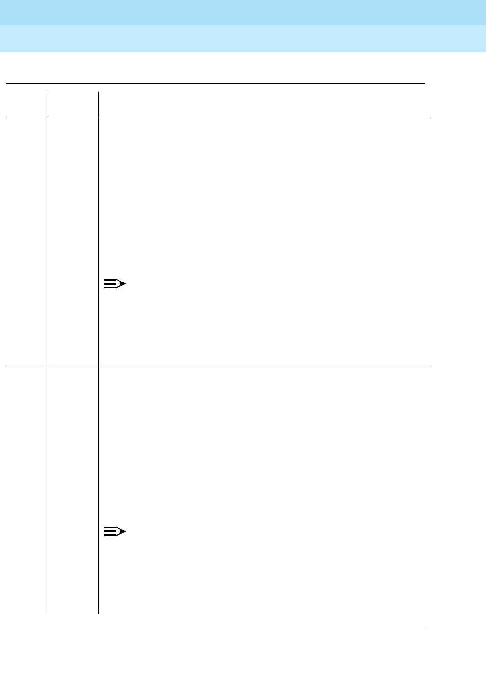
DEFINITY Enterprise Communications Server Release 6
Maintenance for R6r Volumes 1 & 2
555-230-126 Issue 2
January 1998
Maintenance Object Repair Procedures
Page 9-1268SNI-BD (SNI Circuit Pack)
9
103 FAIL The SNI circuit pack cannot communicate with the SNI in slot 3 over the packet
path.
1. Fix any on-board SNI-BD errors against this SNI and the SNI in slot 3. Use
the display errors command to find any SNI-BD errors and use the
display alarms command to determine whether the errors have on-board
alarms. Then, follow the associated repair procedures for the SNI-BD as
described in the Maintenance manual.
2. Using the display errors command, check the error log for other SNI
circuit packs with SNI-PEER error type 257. If other SNI circuit packs have
SNI-PEER error type 257 errors, replace the SNI in slot 3. Replacing an
SNI may be service interrupting. Refer to the SNI-BD Maintenance
documentation for the procedure for replacing an SNI.
NOTE:
If other SNI circuit packs do not have SNI-PEER error type 257 errors,
the problem could be at either of the peer SNI boards. It is arbitrary as
to which SNI is replaced first.
3. Replace the SNI being tested.
4. Replace the SNI in slot 3.
104 FAIL The SNI circuit pack cannot communicate with the SNI in slot 4 over the packet
path.
1. Fix any on-board SNI-BD errors against this SNI and the SNI in slot 4. Use
the display errors command to find any SNI-BD errors and use the
display alarms command to determine whether the errors have on-board
alarms. Then, follow the associated repair procedures for the SNI-BD as
described in the Maintenance manual.
2. Using the display errors command, check the error log for other SNI
circuit packs with SNI-PEER error type 513. If other SNI circuit packs have
SNI-PEER error type 513 errors, replace the SNI in slot 4. Replacing an
SNI may be service interrupting. Refer to the SNI-BD Maintenance
documentation for the procedure for replacing an SNI.
NOTE:
If other SNI circuit packs do not have SNI-PEER error type 513 errors,
the problem could be at either of the peer SNI boards. It is arbitrary as
to which SNI is replaced first.
3. Replace the SNI being tested.
4. Replace the SNI in slot 4.
Table 9-438. TEST #767 Packet Neighbor Link Test — Continued
Error
Code Test
Result Description/ Recommendation
Continued on next page

DEFINITY Enterprise Communications Server Release 6
Maintenance for R6r Volumes 1 & 2
555-230-126 Issue 2
January 1998
Maintenance Object Repair Procedures
Page 9-1269SNI-BD (SNI Circuit Pack)
9
105 FAIL The SNI circuit pack cannot communicate with the SNI in slot 5 over the packet
path.
1. Fix any on-board SNI-BD errors against this SNI and the SNI in slot 5. Use
the display errors command to find any SNI-BD errors and use the
display alarms command to determine whether the errors have on-board
alarms. Then, follow the associated repair procedures for the SNI-BD as
described in the Maintenance manual.
2. Using the display errors command, check the error log for other SNI
circuit packs with SNI-PEER error type 769 . If other SNI circuit packs have
SNI-PEER error type 769 errors, replace the SNI in slot 5. Replacing an
SNI may be service interrupting. Refer to the SNI-BD Maintenance
documentation for the procedure for replacing an SNI.
NOTE:
If other SNI circuit packs do not have SNI-PEER error type 769 errors,
the problem could be at either of the peer SNI boards. It is arbitrary as
to which SNI is replaced first.
3. Replace the SNI being tested.
4. Replace the SNI in slot 5.
106 FAIL The SNI circuit pack cannot communicate with the SNI in slot 6 over the packet
path.
1. Fix any on-board SNI-BD errors against this SNI and the SNI in slot 6. Use
the display errors command to find any SNI-BD errors and use the
display alarms command to determine whether the errors have on-board
alarms. Then, follow the associated repair procedures for the SNI-BD as
described in the Maintenance manual.
2. Using the display errors command, check the error log for other SNI
circuit packs with SNI-PEER error type 1025. If other SNI circuit packs
have SNI-PEER error type 1025 errors, replace the SNI in slot 6. Replacing
an SNI may be service interrupting. Refer to the SNI-BD Maintenance
documentation for the procedure for replacing an SNI.
NOTE:
If other SNI circuit packs do not have SNI-PEER error type 1025 errors,
the problem could be at either of the peer SNI boards. It is arbitrary as
to which SNI is replaced first.
3. Replace the SNI being tested.
4. Replace the SNI in slot 6.
Table 9-438. TEST #767 Packet Neighbor Link Test — Continued
Error
Code Test
Result Description/ Recommendation
Continued on next page

DEFINITY Enterprise Communications Server Release 6
Maintenance for R6r Volumes 1 & 2
555-230-126 Issue 2
January 1998
Maintenance Object Repair Procedures
Page 9-1270SNI-BD (SNI Circuit Pack)
9
107 FAIL The SNI circuit pack cannot communicate with the SNI in slot 7 over the packet
path.
1. Fix any on-board SNI-BD errors against this SNI and the SNI in slot 7. Use
the display errors command to find any SNI-BD errors and use the
display alarms command to determine whether the errors have on-board
alarms. Then, follow the associated repair procedures for the SNI-BD as
described in the Maintenance manual.
2. Using the display errors command, check the error log for other SNI
circuit packs with SNI-PEER error type 1281. If other SNI circuit packs
have SNI-PEER error type 1281 errors, replace the SNI in slot 7. Replacing
an SNI may be service interrupting. Refer to the SNI-BD Maintenance
documentation for the procedure for replacing an SNI.
NOTE:
If other SNI circuit packs do not have SNI-PEER error type 1281 errors,
the problem could be at either of the peer SNI boards. It is arbitrary as
to which SNI is replaced first.
3. Replace the SNI being tested.
4. Replace the SNI in slot 7.
108 FAIL The SNI circuit pack cannot communicate with the SNI in slot 8 over the packet
path.
1. Fix any on-board SNI-BD errors against this SNI and the SNI in slot 8. Use
the display errors command to find any SNI-BD errors and use the
display alarms command to determine whether the errors have on-board
alarms. Then, follow the associated repair procedures for the SNI-BD as
described in the Maintenance manual.
2. Using the display errors command, check the error log for other SNI
circuit packs with SNI-PEER error type 1537. If other SNI circuit packs
have SNI-PEER error type 1537 errors, replace the SNI in slot 8. Replacing
an SNI may be service interrupting. Refer to the SNI-BD Maintenance
documentation for the procedure for replacing an SNI.
NOTE:
If other SNI circuit packs do not have SNI-PEER error type 1537 errors,
the problem could be at either of the peer SNI boards. It is arbitrary as
to which SNI is replaced first.
3. Replace the SNI being tested.
4. Replace the SNI in slot 8.
Table 9-438. TEST #767 Packet Neighbor Link Test — Continued
Error
Code Test
Result Description/ Recommendation
Continued on next page

DEFINITY Enterprise Communications Server Release 6
Maintenance for R6r Volumes 1 & 2
555-230-126 Issue 2
January 1998
Maintenance Object Repair Procedures
Page 9-1271SNI-BD (SNI Circuit Pack)
9
109 FAIL The SNI circuit pack cannot communicate with the SNI in slot 9 over the packet
path.
1. Fix any on-board SNI-BD errors against this SNI and the SNI in slot 9. Use
the display errors command to find any SNI-BD errors and use the
display alarms command to determine whether the errors have on-board
alarms. Then, follow the associated repair procedures for the SNI-BD as
described in the Maintenance manual.
2. Using the display errors command, check the error log for other SNI
circuit packs with SNI-PEER error type 1793. If other SNI circuit packs
have SNI-PEER error type 1793 errors, replace the SNI in slot 9. Replacing
an SNI may be service interrupting. Refer to the SNI-BD Maintenance
documentation for the procedure for replacing an SNI.
NOTE:
If other SNI circuit packs do not have SNI-PEER error type 1793 errors,
the problem could be at either of the peer SNI boards. It is arbitrary as
to which SNI is replaced first.
3. Replace the SNI being tested.
4. Replace the SNI in slot 9.
113 FAIL The SNI circuit pack cannot communicate with the SNI in slot 13 over the
packet path.
1. Fix any on-board SNI-BD errors against this SNI and the SNI in slot 13.
Use the display errors command to find any SNI-BD errors and use the
display alarms command to determine whether the errors have on-board
alarms. Then, follow the associated repair procedures for the SNI-BD as
described in the Maintenance manual.
2. Using the display errors command, check the error log for other SNI
circuit packs with SNI-PEER error type 2049. If other SNI circuit packs
have SNI-PEER error type 2049 errors, replace the SNI in slot 13.
Replacing an SNI may be service interrupting. Refer to the SNI-BD
Maintenance documentation for the procedure for replacing an SNI.
NOTE:
If other SNI circuit packs do not have SNI-PEER error type 2049 errors,
the problem could be at either of the peer SNI boards. It is arbitrary as
to which SNI is replaced first.
3. Replace the SNI being tested.
4. Replace the SNI in slot 13.
Table 9-438. TEST #767 Packet Neighbor Link Test — Continued
Error
Code Test
Result Description/ Recommendation
Continued on next page

DEFINITY Enterprise Communications Server Release 6
Maintenance for R6r Volumes 1 & 2
555-230-126 Issue 2
January 1998
Maintenance Object Repair Procedures
Page 9-1272SNI-BD (SNI Circuit Pack)
9
114 FAIL The SNI circuit pack cannot communicate with the SNI in slot 14 over the
packet path.
1. Fix any on-board SNI-BD errors against this SNI and the SNI in slot 14.
Use the display errors command to find any SNI-BD errors and use the
display alarms command to determine whether the errors have on-board
alarms. Then, follow the associated repair procedures for the SNI-BD as
described in the Maintenance manual.
2. Using the display errors command, check the error log for other SNI
circuit packs with SNI-PEER error type 2305. If other SNI circuit packs
have SNI-PEER error type 2305 errors, replace the SNI in slot 14.
Replacing an SNI may be service interrupting. Refer to the SNI-BD
Maintenance documentation for the procedure for replacing an SNI.
NOTE:
If other SNI circuit packs do not have SNI-PEER error type 2305 errors,
the problem could be at either of the peer SNI boards. It is arbitrary as
to which SNI is replaced first.
3. Replace the SNI being tested.
4. Replace the SNI in slot 14.
115 FAIL The SNI circuit pack cannot communicate with the SNI in slot 15 over the
packet path.
1. Fix any on-board SNI-BD errors against this SNI and the SNI in slot 15.
Use the display errors command to find any SNI-BD errors and use the
display alarms command to determine whether the errors have on-board
alarms. Then, follow the associated repair procedures for the SNI-BD as
described in the Maintenance manual.
2. Using the display errors command, check the error log for other SNI
circuit packs with SNI-PEER error type 2561. If other SNI circuit packs
have SNI-PEER error type 2561 errors, replace the SNI in slot 15.
Replacing an SNI may be service interrupting. Refer to the SNI-BD
Maintenance documentation for the procedure for replacing an SNI.
NOTE:
If other SNI circuit packs do not have SNI-PEER error type 2561 errors,
the problem could be at either of the peer SNI boards. It is arbitrary as
to which SNI is replaced first.
3. Replace the SNI being tested.
4. Replace the SNI in slot 15.
Table 9-438. TEST #767 Packet Neighbor Link Test — Continued
Error
Code Test
Result Description/ Recommendation
Continued on next page

DEFINITY Enterprise Communications Server Release 6
Maintenance for R6r Volumes 1 & 2
555-230-126 Issue 2
January 1998
Maintenance Object Repair Procedures
Page 9-1273SNI-BD (SNI Circuit Pack)
9
116 FAIL The SNI circuit pack cannot communicate with the SNI in slot 16 over the
packet path.
1. Fix any on-board SNI-BD errors against this SNI and the SNI in slot 16.
Use the display errors command to find any SNI-BD errors and use the
display alarms command to determine whether the errors have on-board
alarms. Then, follow the associated repair procedures for the SNI-BD as
described in the Maintenance manual.
2. Using the display errors command, check the error log for other SNI
circuit packs with SNI-PEER error type 2817. If other SNI circuit packs
have SNI-PEER error type 2817 errors, replace the SNI in slot 16.
Replacing an SNI may be service interrupting. Refer to the SNI-BD
Maintenance documentation for the procedure for replacing an SNI.
NOTE:
If other SNI circuit packs do not have SNI-PEER error type 2817 errors,
the problem could be at either of the peer SNI boards. It is arbitrary as
to which SNI is replaced first.
3. Replace the SNI being tested.
4. Replace the SNI in slot 16.
117 FAIL The SNI circuit pack cannot communicate with the SNI in slot 17 over the
packet path.
1. Fix any on-board SNI-BD errors against this SNI and the SNI in slot 17.
Use the display errors command to find any SNI-BD errors and use the
display alarms command to determine whether the errors have on-board
alarms. Then, follow the associated repair procedures for the SNI-BD as
described in the Maintenance manual.
2. Using the display errors command, check the error log for other SNI
circuit packs with SNI-PEER error type 3073. If other SNI circuit packs
have SNI-PEER error type 3073 errors, replace the SNI in slot 17.
Replacing an SNI may be service interrupting. Refer to the SNI-BD
Maintenance documentation for the procedure for replacing an SNI.
NOTE:
If other SNI circuit packs do not have SNI-PEER error type 3073 errors,
the problem could be at either of the peer SNI boards. It is arbitrary as
to which SNI is replaced first.
3. Replace the SNI being tested.
4. Replace the SNI in slot 17.
Table 9-438. TEST #767 Packet Neighbor Link Test — Continued
Error
Code Test
Result Description/ Recommendation
Continued on next page

DEFINITY Enterprise Communications Server Release 6
Maintenance for R6r Volumes 1 & 2
555-230-126 Issue 2
January 1998
Maintenance Object Repair Procedures
Page 9-1274SNI-BD (SNI Circuit Pack)
9
118 FAIL The SNI circuit pack cannot communicate with the SNI in slot 18 over the
packet path.
1. Fix any on-board SNI-BD errors against this SNI and the SNI in slot 18.
Use the display errors command to find any SNI-BD errors and use the
display alarms command to determine whether the errors have on-board
alarms. Then, follow the associated repair procedures for the SNI-BD as
described in the Maintenance manual.
2. Using the display errors command, check the error log for other SNI
circuit packs with SNI-PEER error type 3329. If other SNI circuit packs
have SNI-PEER error type 3329 errors, replace the SNI in slot 18.
Replacing an SNI may be service interrupting. Refer to the SNI-BD
Maintenance documentation for the procedure for replacing an SNI.
NOTE:
If other SNI circuit packs do not have SNI-PEER error type 3329 errors,
the problem could be at either of the peer SNI boards. It is arbitrary as
to which SNI is replaced first.
3. Replace the SNI being tested.
4. Replace the SNI in slot 18.
119 FAIL The SNI circuit pack cannot communicate with the SNI in slot 19 over the
packet path.
1. Fix any on-board SNI-BD errors against this SNI and the SNI in slot 19.
Use the display errors command to find any SNI-BD errors and use the
display alarms command to determine whether the errors have on-board
alarms. Then, follow the associated repair procedures for the SNI-BD as
described in the Maintenance manual.
2. Using the display errors command, check the error log for other SNI
circuit packs with SNI-PEER error type 3585. If other SNI circuit packs
have SNI-PEER error type 3585 errors, replace the SNI in slot 19.
Replacing an SNI may be service interrupting. Refer to the SNI-BD
Maintenance documentation for the procedure for replacing an SNI.
NOTE:
If other SNI circuit packs do not have SNI-PEER error type 3585 errors,
the problem could be at either of the peer SNI boards. It is arbitrary as
to which SNI is replaced first.
3. Replace the SNI being tested.
4. Replace the SNI in slot 19.
Table 9-438. TEST #767 Packet Neighbor Link Test — Continued
Error
Code Test
Result Description/ Recommendation
Continued on next page
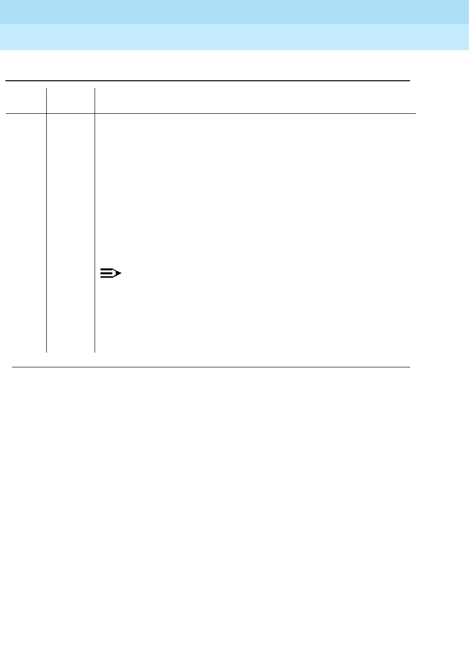
DEFINITY Enterprise Communications Server Release 6
Maintenance for R6r Volumes 1 & 2
555-230-126 Issue 2
January 1998
Maintenance Object Repair Procedures
Page 9-1275SNI-BD (SNI Circuit Pack)
9
120 FAIL The SNI circuit pack cannot communicate with the SNI in slot 20 over the
packet path.
1. Fix any on-board SNI-BD errors against this SNI and the SNI in slot 20.
Use the display errors command to find any SNI-BD errors and use the
display alarms command to determine whether the errors have on-board
alarms. Then, follow the associated repair procedures for the SNI-BD as
described in the Maintenance manual.
2. Using the display errors command, check the error log for other SNI
circuit packs with SNI-PEER error type 3841. If other SNI circuit packs
have SNI-PEER error type 3841 errors, replace the SNI in slot 20.
Replacing an SNI may be service interrupting. Refer to the SNI-BD
Maintenance documentation for the procedure for replacing an SNI.
NOTE:
If other SNI circuit packs do not have SNI-PEER error type 3841 errors,
the problem could be at either of the peer SNI boards. It is arbitrary as
to which SNI is replaced first.
3. Replace the SNI being tested.
4. Replace the SNI in slot 20.
Table 9-438. TEST #767 Packet Neighbor Link Test — Continued
Error
Code Test
Result Description/ Recommendation
Continued on next page

DEFINITY Enterprise Communications Server Release 6
Maintenance for R6r Volumes 1 & 2
555-230-126 Issue 2
January 1998
Maintenance Object Repair Procedures
Page 9-1276SNI-BD (SNI Circuit Pack)
9
123 FAIL The SNI circuit pack cannot communicate with its neighbor via the packet
path.
1. Fix any on-board errors (SNI-BD, EXP-INTF, and/or DS1C-BD) against the
components of this fiber link by using display errors and display alarms
and following the associated repair procedures. (Use the list fiber-link
command to find the fiber link associated with this SNI. The display
fiber-link command can then be used to find the endpoints of the fiber link
and the DS1C circuit pack locations if this fiber link has a DS1 Converter
Complex administered.)
2. Enter display errors and display alarms and follow the associated repair
procedures for any SNC-BD error entries with corresponding on-board
alarm entries.
3. Enter display errors and follow the associated repair procedures for any
SYNC entries.
4. If this FIBER-LK has circuit, packet, and control path errors, check the
lightwave transceiver connections or metallic connections. Use the LED
states to verify whether the connections are correct. Also, a test fiber-link s
command can be run to determine whether a fiber out of frame condition
exists on the fiber link; the SNI Fiber Out-of-Frame Query (#989) reports
whether a fiber out of frame condition exists for an SNI endpoint and the
Expansion Interface Fiber Out-of-Frame Query test (#238) reports whether
a fiber out of frame condition exists for an Expansion Interface endpoint.
5. Replace the lightwave transceivers if present.
6. Replace one of the endpoint boards.
7. Replace the other endpoint board.
8. Replace the DS1 CONV circuit packs if a DS1 CONV converter complex is
administered on this fiber.
PASS The SNI can communicate with the peer SNIs and the neighbor over the
packet path.
Table 9-438. TEST #767 Packet Neighbor Link Test — Continued
Error
Code Test
Result Description/ Recommendation
Continued on next page

DEFINITY Enterprise Communications Server Release 6
Maintenance for R6r Volumes 1 & 2
555-230-126 Issue 2
January 1998
Maintenance Object Repair Procedures
Page 9-1277SNI-BD (SNI Circuit Pack)
9
Failure Audit (#777)
This test is non-destructive.
This test queries the SNI for any existing failures and any unacknowledged
cleared failure messages. Each failure generates an error and alarm entry
against SNI-BD, SNI-PEER, or FIBER-LK. An unacknowledged cleared failure
message is a message the SNI circuit pack sent to software indicating a previous
failure is now gone and the SNI circuit pack did not receive a message from
software indicating that the failure message was received by software.
If no failures are detected by the SNI circuit pack, this test will pass.
If this test reports failures, the results screen for the test board command will
show FAIL with no FAIL code. The error log must then be displayed via display
errors with category PNC to view all SNI-BD and FIBER-LK errors and category
PNC-PEER to view all SNI-PEER errors.
0NO
BOARD No board was detected by the test.
1. Check that board is properly translated and inserted.
2. Run the test again. If it fails, reset the board. An SNI should be reset
instead of reseating the circuit pack. The reset board command should
almost never be used on an SNI. It may be necessary to use the reset
board command if the SNI circuit pack gets into a mode where it cannot
communicate with software. If an SNI with active errors and alarms is
reset, the errors and alarms may take a while to come back, therefore the
reset board command can mask real problems.
3. Run the test again. If it fails, the ID chip on board may be bad. Replace the
board and retest.
Table 9-439. TEST #777 Failure Audit
Error
Code Test
Result Description/ Recommendation
ABORT Internal System Error
1. Retry the command at 1-minute intervals a maximum of 3 times.
Continued on next page
Table 9-438. TEST #767 Packet Neighbor Link Test — Continued
Error
Code Test
Result Description/ Recommendation
Continued on next page

DEFINITY Enterprise Communications Server Release 6
Maintenance for R6r Volumes 1 & 2
555-230-126 Issue 2
January 1998
Maintenance Object Repair Procedures
Page 9-1278SNI-BD (SNI Circuit Pack)
9
2100 ABORT Could not allocate the necessary system resources to run this test.
1. Retry the command at 1-minute intervals a maximum of 3 times.
2300 ABORT The downlink message necessary to run this test could not be sent.
1. Retry the command at 1-minute intervals a maximum of 3 times.
2301 ABORT The software timer could not be set before sending the downlink message
necessary to run this test.
1. Retry the command at 1-minute intervals a maximum of 3 times.
2306 ABORT The SNI circuit pack is not responding to test requests sent by software.
1. Run the test led switch-node for the switch node that the SNI resides in to
verify whether the LEDs on the board light.
2. If the LEDs on the other boards in the carrier light, but the LEDs on this
board do not light, run test 760 via test board UUCSS l for the active SNC
in this carrier. Wait 5 minutes and then try step 1 one more time. If the
LEDs on this board still do not light, replace this board. Replacing an SNI
may be service interrupting. Refer to the SNI-BD section for the procedure
for replacing an SNI.
3. If none of the LEDs light for the boards in the same carrier as this board, fix
any problems associated with the connectivity of this carrier to the SPE.
Check list fiber-link to determine the fiber connections to this carrier.
Check the LEDs on all SNIs and EIs and fix any fiber problems. Enter
display errors and follow the associated repair procedures for any
EXP-INTF error entries associated with the PPN. Also, follow the
associated repair procedures for any SYNC, SNI-BD, SNC-BD, FIBER-LK,
or SNI-PEER error entries.
4. Follow the procedure described above, SNI Manual Loopback to
determine whether the circuit pack or the fiber connection is faulty.
Table 9-439. TEST #777 Failure Audit — Continued
Error
Code Test
Result Description/ Recommendation
Continued on next page

DEFINITY Enterprise Communications Server Release 6
Maintenance for R6r Volumes 1 & 2
555-230-126 Issue 2
January 1998
Maintenance Object Repair Procedures
Page 9-1279SNI-BD (SNI Circuit Pack)
9
Clear Firmware Counters (#982)
This test number is used to report unsuccessful results of the clear
firmware-counters command. This is not an actual demand maintenance test. If
the command aborts, refer to the error codes listed for Test #777.
SNI Fiber Out of Frame Query (#989)
This test is non-destructive.
FAIL The SNI circuit pack reported failures or retransmitted a cleared failure
message.
1. If this is the first time this test was run, run the test again. If there were any
previous failure messages that software did not acknowledge, this test will
FAIL even if the failure messages indicate a FAIL to PASS transition, i.e., a
problem has gone away. If this test is run twice and FAILs both times, then
at least one problem still exists.
2. Fix any SNI-BD, SNI-PEER, and FIBER-LK errors by following the
associated repair procedures. Use the display errors and display alarms
commands with category PNC for SNI-BD and FIBER-LK and category
PNC-PEER for SNI-PEER. Fix any problems found by referring to the SNI
Board or SNI Peer Error Log Entries tables in this section or Fiber Link
Error Log Entries tables in the ‘‘FIBER-LK (Fiber Link)’’ section.
3. If no SNI-BD, SNI-PEER, or FIBER-LK entries exist in the error and alarm
logs, retry the command.
PASS No problems are detected on the board.
0NO
BOARD No board was detected by the test.
1. Check that board is properly translated and inserted.
2. Run the test again. If it fails, reset the board. An SNI should be reset
instead of reseating the circuit pack. The reset board command should
almost never be used on an SNI. It may be necessary to use the reset
board command if the SNI circuit pack gets into a mode where it cannot
communicate with software. If an SNI with active errors and alarms is
reset, the errors and alarms may take a while to come back, therefore the
reset board command can mask real problems.
3. Run the test again. If it fails, the ID chip on board may be bad. Replace the
board and retest.
Table 9-439. TEST #777 Failure Audit — Continued
Error
Code Test
Result Description/ Recommendation
Continued on next page

DEFINITY Enterprise Communications Server Release 6
Maintenance for R6r Volumes 1 & 2
555-230-126 Issue 2
January 1998
Maintenance Object Repair Procedures
Page 9-1280SNI-BD (SNI Circuit Pack)
9
The SNI circuit pack reports whether a fiber out of frame condition exists,
whether a loss of signal condition exists, and whether the lightwave transceiver is
present.
Table 9-440. TEST #989 SNI Fiber Out of Frame Query
Error
Code Test
Result Description/ Recommendation
2100 ABORT Could not allocate the necessary system resources to run this test.
1. Retry the command at 1-minute intervals a maximum of 3 times.
1415 ABORT The lightwave transceiver is not present.
1. If a lightwave transceiver is not supposed to be present, do nothing. For
example, an SNI connected to a DS1C circuit pack or an SNI with a
metallic connection does not have a lightwave transceiver.
2. Otherwise, check the lightwave transceiver connections.
3. If OK, replace the lightwave transceiver. If a fiber out of frame condition
exists and lightwave transceivers are used, check that the lightwave
transceivers are of the same type, that is, both are 9823a or both are
9823b. If they are not the same type, replace one of the lightwave
transceivers:
■9823a is used for distances up to 4900 feet.
■9823b is used for distances up to 25,000 feet.
4. If the test continues to abort, replace the SNI circuit pack.
2300 ABORT The downlink message necessary to run this test could not be sent.
1. Retry the command at 1-minute intervals a maximum of 3 times.
2301 ABORT The software timer could not be set before sending the downlink message
necessary to run this test.
1. Retry the command at 1-minute intervals a maximum of 3 times.
2304 ABORT SNI circuit pack responded that it is not able to run the test requested by
software.
1. Retry the command at 1-minute intervals a maximum of 3 times.
Continued on next page

DEFINITY Enterprise Communications Server Release 6
Maintenance for R6r Volumes 1 & 2
555-230-126 Issue 2
January 1998
Maintenance Object Repair Procedures
Page 9-1281SNI-BD (SNI Circuit Pack)
9
2306 ABORT The SNI circuit pack is not responding to test requests sent by software.
1. Run the test led switch-node for the switch node that the SNI resides in to
verify whether the LEDs on the board light.
2. If the LEDs on the other boards in the carrier light, but the LEDs on this
board do not light, run test 760 via test board UUCSS l for the active SNC
in this carrier. Wait 5 minutes and then try step 1 one more time. If the
LEDs on this board still do not light, replace this board. Replacing an SNI
may be service interrupting. Refer to the SNI-BD section for the procedure
for replacing an SNI.
3. If none of the LEDs light for the boards in the same carrier as this board, fix
any problems associated with the connectivity of this carrier to the SPE.
Check list fiber-link to determine the fiber connections to this carrier.
Check the LEDs on all SNIs and EIs and fix any fiber problems. Enter
display errors and follow the associated repair procedures for any
EXP-INTF error entries associated with the PPN. Also, follow the
associated repair procedures for any SYNC, SNI-BD, SNC-BD, FIBER-LK,
or SNI-PEER error entries.
4. Follow the procedure described above, SNI Manual Loopback to
determine whether the circuit pack or the fiber connection is faulty.
2500 ABORT Internal System Error
1. Retry the command at 1-minute intervals a maximum of 3 times.
141 FAIL The SNI circuit pack has a fiber out of frame condition, but no loss of signal
condition. Also, a lightwave transceiver is connected to the SNI circuit pack.
1. Check that the connected circuit pack is physically installed. The
connected circuit pack is the other endpoint of the fiber-link if no DS1C
complex is administered (check via list fiber-link). Otherwise, if a DS1C
complex is administered, the connected circuit pack is the DS1C circuit
pack connected to the SNI circuit pack.
2. Perform the Fiber Fault Isolation Procedure described in Chapter 5.
3. Replace this SNI circuit pack.
4. Replace the connected circuit pack.
Table 9-440. TEST #989 SNI Fiber Out of Frame Query — Continued
Error
Code Test
Result Description/ Recommendation
Continued on next page

DEFINITY Enterprise Communications Server Release 6
Maintenance for R6r Volumes 1 & 2
555-230-126 Issue 2
January 1998
Maintenance Object Repair Procedures
Page 9-1282SNI-BD (SNI Circuit Pack)
9
142 FAIL The SNI circuit pack has a fiber out-of-frame condition, but no loss of signal
condition. Also, no lightwave transceiver is connected to the SNI circuit pack.
1. Check that the connected circuit pack is physically installed. The
connected circuit pack is the other endpoint of the fiber-link if no DS1C
complex is administered (check via list fiber-link). Otherwise, if a DS1C
complex is administered, the connected circuit pack is the DS1C circuit
pack connected to the SNI circuit pack.
2. If a lightwave transceiver is not supposed to be present, go to step 2. For
example, an SNI connected to a DS1C circuit pack or an SNI with a
metallic connection does not have a lightwave transceiver. Otherwise,
check the lightwave transceiver connections. If OK, replace the lightwave
transceiver. If a fiber out-of-frame condition exists and lightwave
transceivers are used, check that the lightwave transceivers are of the
same type, that is, both are 9823a or both are 9823b. If they are not the
same type, replace one of the lightwave transceivers:
■9823a is used for distances up to 4900 feet.
■9823b is used for distances up to 25,000 feet.
3. Perform the Fiber Fault Isolation Procedure described in Chapter 5.
4. Replace this SNI circuit pack.
5. Replace the connected circuit pack.
143 FAIL The SNI circuit pack has a loss of signal condition, but no fiber out of frame
condition. Also, a lightwave transceiver is connected to the SNI circuit pack.
1. Check that the connected circuit pack is physically installed. The
connected circuit pack is the other endpoint of the fiber-link if no DS1C
complex is administered (check via list fiber-link). Otherwise, if a DS1C
complex is administered, the connected circuit pack is the DS1C circuit
pack connected to the SNI circuit pack.
2. Perform the Fiber Fault Isolation Procedure described in Chapter 5.
3. Replace this SNI circuit pack.
4. Replace the connected circuit pack.
Table 9-440. TEST #989 SNI Fiber Out of Frame Query — Continued
Error
Code Test
Result Description/ Recommendation
Continued on next page

DEFINITY Enterprise Communications Server Release 6
Maintenance for R6r Volumes 1 & 2
555-230-126 Issue 2
January 1998
Maintenance Object Repair Procedures
Page 9-1283SNI-BD (SNI Circuit Pack)
9
144 FAIL The SNI circuit pack has a loss of signal condition, but no fiber out of frame
condition. Also, no lightwave transceiver is connected to the SNI circuit pack.
1. Check that the connected circuit pack is physically installed. The
connected circuit pack is the other endpoint of the fiber-link if no DS1C
complex is administered (check via list fiber-link). Otherwise, if a DS1C
complex is administered, the connected circuit pack is the DS1C circuit
pack connected to the SNI circuit pack.
2. If a lightwave transceiver is not supposed to be present, go to step 2. For
example, an SNI connected to a DS1C circuit pack or an SNI with a
metallic connection does not have a lightwave transceiver. Otherwise,
check the lightwave transceiver connections. If OK, replace the lightwave
transceiver. If a fiber out-of-frame condition exists and lightwave
transceivers are used, check that the lightwave transceivers are of the
same type, that is, both are 9823a or both are 9823b. If they are not the
same type, replace one of the lightwave transceivers:
■9823a is used for distances up to 4900 feet.
■9823b is used for distances up to 25,000 feet.
3. Perform the Fiber Fault Isolation Procedure described in Chapter 5.
4. Replace this SNI circuit pack.
5. Replace the connected circuit pack.
145 FAIL The SNI circuit pack has a fiber out of frame condition and a loss of signal
condition. Also, a lightwave transceiver is connected to the SNI circuit pack.
1. Check that the connected circuit pack is physically installed. The
connected circuit pack is the other endpoint of the fiber-link if no DS1C
complex is administered (check via list fiber-link). Otherwise, if a DS1C
complex is administered, the connected circuit pack is the DS1C circuit
pack connected to the SNI circuit pack.
2. Perform the Fiber Fault Isolation Procedure described in Chapter 5.
3. Replace this SNI circuit pack.
4. Replace the connected circuit pack.
Table 9-440. TEST #989 SNI Fiber Out of Frame Query — Continued
Error
Code Test
Result Description/ Recommendation
Continued on next page

DEFINITY Enterprise Communications Server Release 6
Maintenance for R6r Volumes 1 & 2
555-230-126 Issue 2
January 1998
Maintenance Object Repair Procedures
Page 9-1284SNI-BD (SNI Circuit Pack)
9
146 FAIL The SNI circuit pack has a fiber out of frame condition, and a loss of signal
condition. Also, no lightwave transceiver is connected to the SNI circuit pack.
1. Check that the connected circuit pack is physically installed. The
connected circuit pack is the other endpoint of the fiber-link if no DS1C
complex is administered (check via list fiber-link). Otherwise, if a DS1C
complex is administered, the connected circuit pack is the DS1C circuit
pack connected to the SNI circuit pack.
2. If a lightwave transceiver is not supposed to be present, go to step 2. For
example, an SNI connected to a DS1C circuit pack or an SNI with a
metallic connection does not have a lightwave transceiver. Otherwise,
check the lightwave transceiver connections. If OK, replace the lightwave
transceiver. If a fiber out-of-frame condition exists and lightwave
transceivers are used, check that the lightwave transceivers are of the
same type, that is, both are 9823a or both are 9823b. If they are not the
same type, replace one of the lightwave transceivers:
■9823a is used for distances up to 4900 feet.
■9823b is used for distances up to 25,000 feet.
3. Perform the Fiber Fault Isolation Procedure described in Chapter 5.
4. Replace this SNI circuit pack.
5. Replace the connected circuit pack.
PASS No problems associated with this test are detected on the SNI.
0NO
BOARD No board was detected by the test.
1. Check that board is properly translated and inserted.
2. Run the test again. If it fails, reset the board. An SNI should be reset
instead of reseating the circuit pack. The reset board command should
almost never be used on an SNI. It may be necessary to use the reset
board command if the SNI circuit pack gets into a mode where it cannot
communicate with software. If an SNI with active errors and alarms is
reset, the errors and alarms may take a while to come back, therefore the
reset board command can mask real problems.
3. Run the test again. If it fails, the ID chip on board may be bad. Replace the
board and retest.
Table 9-440. TEST #989 SNI Fiber Out of Frame Query — Continued
Error
Code Test
Result Description/ Recommendation
Continued on next page

DEFINITY Enterprise Communications Server Release 6
Maintenance for R6r Volumes 1 & 2
555-230-126 Issue 2
January 1998
Maintenance Object Repair Procedures
Page 9-1285SNI-PEER (SNI Peer Link)
9
SNI-PEER (SNI Peer Link)
SNI Peers are Switch Node Interfaces residing on the same Switch Node Carrier.
SNI-PEER maintenance involves testing of the links between SNI Peers.
SNI-PEER errors are described on the following pages. For a full description of
SNIs, including circuit pack replacement, see SNI-BD.
1. UU is the universal cabinet number (1 for PPN, 2 -44 for EPNs). C is the carrier designation (A,
B, C, D, or E). SS is the number of the slot in which the circuit pack resides (01 to 21).
MO Name (in
Alarm Log) Alarm Level Initial Command to Run1Full Name of MO
SNI-PEER MAJOR test board UUCSS s SNI Peer Link
SNI-PEER MINOR test board UUCSS s SNI Peer Link
SNI-PEER WARNING test board UUCSS s SNI Peer Link
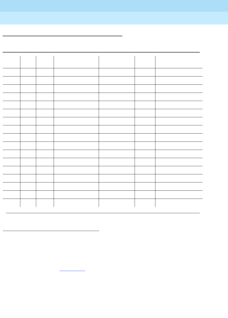
DEFINITY Enterprise Communications Server Release 6
Maintenance for R6r Volumes 1 & 2
555-230-126 Issue 2
January 1998
Maintenance Object Repair Procedures
Page 9-1286SNI-PEER (SNI Peer Link)
9
Error Log Entries andTest to Clear Values
Notes:
For all errors in Table 9-441, the SNI circuit pack reporting the error is indicating
that it has a problem with the control path, circuit path, or packet path to the SNI
peer in the slot indicated on the error table.
First, the Failure Audit test (#777) should be run to confirm whether the error still
exists.
If the SNI is reporting an SNI-PEER error against a slot that does not contain an
SNI, either change circuit pack administration via change circuit-pack to
1. Run the Short Test Sequence first. If all tests pass, run the Long Test Sequence. Refer to the
appropriate test description and follow the recommended procedures.
2. The slot location of the SNI at the other end of the peer link indicted by the SNI reporting the error.
Table 9-441. SNI-PEER Hardware Error Log Entries
Error
Type Aux
Data SNI
Slot1Associated Test Alarm Level On/Off
Board Test to Clear Value
020 Any Any Any test board UUCSS r 1
1 any 2 Failure Audit (#777) MAJ/MIN/ WAR OFF test board UUCSS r 1
257 any 3 Failure Audit (#777) MAJ/MIN/ WAR OFF test board UUCSS r 1
513 any 4 Failure Audit (#777) MAJ/MIN/ WAR OFF test board UUCSS r 1
769 any 5 Failure Audit (#777) MAJ/MIN/ WAR OFF test board UUCSS r 1
1025 any 6 Failure Audit (#777) MAJ/MIN/ WAR OFF test board UUCSS r 1
1281 any 7 Failure Audit (#777) MAJ/MIN/ WAR OFF test board UUCSS r 1
1537 any 8 Failure Audit (#777) MAJ/MIN/ WAR OFF test board UUCSS r 1
1793 any 9 Failure Audit (#777) MAJ/MIN/ WAR OFF test board UUCSS r 1
2049 any 13 Failure Audit (#777) MAJ/MIN/ WAR OFF test board UUCSS r 1
2305 any 14 Failure Audit (#777) MAJ/MIN/ WAR OFF test board UUCSS r 1
2561 any 15 Failure Audit (#777) MAJ/MIN/ WAR OFF test board UUCSS r 1
2817 any 16 Failure Audit (#777) MAJ/MIN/ WAR OFF test board UUCSS r 1
3073 any 17 Failure Audit (#777) MAJ/MIN/ WAR OFF test board UUCSS r 1
3329 any 18 Failure Audit (#777) MAJ/MIN/WAR OFF test board UUCSS r 1
3585 any 19 Failure Audit (#777) MAJ/MIN/WAR OFF test board UUCSS r 1
3841 any 20 Failure Audit (#777) MAJ/MIN/WAR OFF test board UUCSS r 1
Continued on next page

DEFINITY Enterprise Communications Server Release 6
Maintenance for R6r Volumes 1 & 2
555-230-126 Issue 2
January 1998
Maintenance Object Repair Procedures
Page 9-1287SNI-PEER (SNI Peer Link)
9
unadminister the SNI, or insert an SNI into the indicated slot. List configuration
carrier can be used to determine whether an SNI circuit pack is inserted.
Otherwise, display errors and look at
all
of the SNI-PEER errors in the log. If
either of the following two conditions are present, follow Procedure 2 below.
■Do many SNIs have SNI-PEER errors pointing to the same 2 adjacent
SNIs?
■Do 2 adjacent SNIs have SNI-PEER errors pointing to many other SNIs?
If neither condition is present, follow Procedure 1 below. When using either
procedure, refer to SNI-BD or SNC-BD for circuit pack replacement instructions.
Procedure 1: Proceed through the following steps
until
the problem is resolved:
1. Perform the Fiber Fault Isolation Procedure described in Chapter 5.
2. Replace the SNI pointed to by the SNI-PEER error type (see the SNI Slot
column in the preceding table,
SNI-PEER Error Log Entries
).
3. Replace the SNI reporting the SNI-PEER error.
4. Replace the active SNC.
Procedure 2: If either of the two patterns described before are present, then the
clock signal between active SNC and 2 Adjacent SNIs is suspect. Proceed
through the following steps
until
the problem is resolved:
1. If only one SNC exists in this switch node carrier, replace the SNC. If two
SNCs exist in this switch node carrier, perform the following steps:
a. Set the standby SNC to active by executing set switch-node-clock
UUCSS with the standby SNC’s location.
b. If the problem persists, switch back to the previously active SNC
via the set switch-node-clock command and go to step 2 below.
Slot Numbers of
Adjacent SNIs Point to This SNI Pair
2, 3 1, 257
4, 5 513, 769
6, 7 1025, 1281
8, 9 1537, 1793
13, 14 2049, 2305
15, 16 2561, 2817
17, 18 3073, 3329
19, 20 3585, 3841

DEFINITY Enterprise Communications Server Release 6
Maintenance for R6r Volumes 1 & 2
555-230-126 Issue 2
January 1998
Maintenance Object Repair Procedures
Page 9-1288SNI-PEER (SNI Peer Link)
9
c. If the problem went away, replace the SNC that was previously
active. Then set the newly replaced SNC to active. If the problem
returns, assume that the SNC that was just replaced was not at fault
and go to step 2 below.
2. Replace the leftmost SNI from the pair of adjacent SNIs.
3. Replace the rightmost SNI from the pair of adjacent SNIs.
4. This could indicate a problem with the switch-node-carrier backplane.
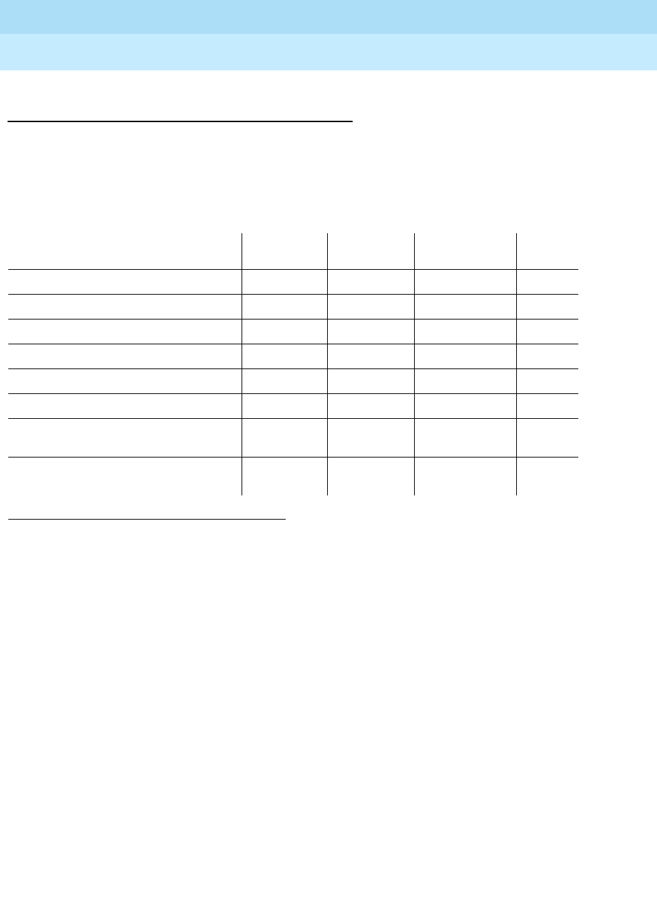
DEFINITY Enterprise Communications Server Release 6
Maintenance for R6r Volumes 1 & 2
555-230-126 Issue 2
January 1998
Maintenance Object Repair Procedures
Page 9-1289SNI-PEER (SNI Peer Link)
9
System Technician-Demanded Tests:
Descriptions and Error Codes
Always investigate tests in the order presented in the table below when
inspecting errors in the system. By clearing error codes associated with the
Configuration Audit
for example, you may also clear errors generated from other
tests in the testing sequence.
For descriptions of these tests, refer to the SNI-BD section of this chapter.
1. D = Destructive, ND = Non-destructive
Order of Investigation Short Test
Sequence Long Test
Sequence Reset Board
Sequence D/ND1
Configuration Audit (#759) X X ND
Failure Audit (#777) X X ND
Fiber Out of Frame Query (#989) X X ND
Packet Neighbor Test (#767) X X ND
Circuit Path Test (#755) X X ND
Destructive Facility Test (#757) X D
Off-board Destructive Facility Test
(#756) XD
Switch Node Interface Reset Test
(#761) XD

DEFINITY Enterprise Communications Server Release 6
Maintenance for R6r Volumes 1 & 2
555-230-126 Issue 2
January 1998
Maintenance Object Repair Procedures
Page 9-1290SPE-SELE (SPE Select Switch)
9
SPE-SELE (SPE Select Switch)
The SPE Select Switch MO monitors the position of the SPE Select switches
located on the front of each UN330B Duplication Interface board. Each switch
may be in one of three possible positions: Auto, A selected, B selected. Both
switches, one on the active Duplication Interface board and one on the standby,
should be set to the same designation. The switches control selection of the
active SPE and cause alarms as follows:
■If both switches are in the AUTO position, the SPE that is the healthiest, as
determined by the state-of-health bits on the boards, is selected as active.
No alarm is raised.
■If one SPE Select switch is in the AUTO position and one selecting either A
or B carrier as active, or one switch selects A and the other selects B, the
boards default to handling the selection of which carrier is active as if both
switches were in the AUTO position. A WARNING alarm appears after one
hour. The alarm is resolved 5 minutes after the switches are returned to
identical positions.
■If both switches select either A carrier or B carrier active, then the
Duplication Interface boards will force that carrier active (irrespective of
state-of-health) and the red Override LED is lit. A MAJOR alarm is raised
by SPE-SELE if the switches remain in these positions for more than 6
hours. The alarm is resolved within 5 minutes of the switches being
returned to AUTO.
MO Name (in
Alarm Log) Alarm
Level Initial Command to Run Full Name of MO
SPE-SELE MAJOR none SPE Select Switch
SPE-SELE WARNING none SPE Select Switch
DEFINITY Enterprise Communications Server Release 6
Maintenance for R6r Volumes 1 & 2
555-230-126 Issue 2
January 1998
Maintenance Object Repair Procedures
Page 9-1291SPE-SELE (SPE Select Switch)
9
Figure 9-73. Duplication Interface Circuit Pack
Error Log Entries and Test to Clear Values
Notes:
a. Error 1 appears when one SPE Select Switch is in the AUTO position and
the other is in the select A or select B position. Placing both switches in
the AUTO position will retire the alarm immediately.
b. Error 257 appears when both SPE Select Switches are in the select A or
select B position for more that 6 hours. Placing both switches in the AUTO
position will retire the alarm immediately.
1. Check the position of the SPE-Select switches.
Table 9-442. SPE Select Switch Error Log Entries
Error
Type Aux
Data Associated Test Alarm
Level On/Off
Board Test to Clear Value
010 Any Any Any
1(a) 0 none WARNING OFF
257(b) 0 none MAJOR OFF
SPE-Select Switch
SPE-Select LED (Red)
Alarm LED (Red)
Test LED (Green)
Busy LED (Yellow)
O
O
O
SPE
AUTO
Override
B A
O
O

DEFINITY Enterprise Communications Server Release 6
Maintenance for R6r Volumes 1 & 2
555-230-126 Issue 2
January 1998
Maintenance Object Repair Procedures
Page 9-1292STBY-SPE (Standby SPE Maintenance)
9
STBY-SPE (Standby SPE Maintenance)
The general principles of SPE duplication, including the following topics, are
discussed in Chapter 1:
■Standby Maintenance Architecture
■Standby State-of-Health and Availability
■Handshake Communication
■Memory Shadowing and Refresh
■Maintenance Software
■Standby Initialization
Troubleshooting a duplicated SPE, and replacing SPE components, are
discussed in Chapter 5. The SPE-Down or SPE-Locked interface is discussed in
Chapter 4.
Maintenance of the standby SPE is organized around the STBY-SPE
maintenance object. It relies on documentation of the other SPE maintenance
objects:
Once a general SPE problem has been isolated to the level of one of these
individual packs, the service documentation for that MO should be consulted. It
is the responsibility of standby SPE maintenance described here to keep the
standby SPE fully available for an interchange.
MO Name (in
Alarm Log) Alarm
Level Initial Command to Run Full Name of MO
STBY-SPE MAJOR test spe-standby l Standby SPE Maintenance
STBY-SPE MINOR test spe-standby l Standby SPE Maintenance
STBY-SPE WARNING test spe-standby l Standby SPE Maintenance
PROCR SYSAM MEM-BD
SW-CTL H-ADAPTR TAPE
DISK DUPINT DUP-CHL

DEFINITY Enterprise Communications Server Release 6
Maintenance for R6r Volumes 1 & 2
555-230-126 Issue 2
January 1998
Maintenance Object Repair Procedures
Page 9-1293STBY-SPE (Standby SPE Maintenance)
9
Standby Availability
Various factors affect the availability of the standby SPE:
■The condition of the individual hardware components of the standby SPE
■Standby memory content
■Standby State-of-Health (SOH)
■Standby SPE-Down
■System Time-of-Day
The health of both the active and standby is tracked as a State-of-Health (SOH)
value. State-of-Health is discussed fully in Chapter 1.
The SOH of the standby SPE can be determined with the "status spe" command.
A complete description of this command and its output appears in Chapter 8. For
the standby to be fully available, the fields (for the SPE with mode
standby
, where
applicable) should read as follows:
Any divergence from these conditions, except during system recovery or
technician-initiated maintenance, requires immediate investigation.
Locking the Active SPE
Duplication Interface hardware supports the ability to lock the active SPE into
active mode. On each Duplication Interface circuit pack is an SPE-SELECT
switch which can be set in three positions: A, B, Auto. These are normally set with
both switches on AUTO, allowing system software to govern which SPE is active.
When the SPE-SELECT switches on both SPE’s Duplication Interface circuit
packs are set to the position A, then the SPE in carrier A is locked active and the
B-carrier SPE is locked standby. Setting both to B locks the B carrier active. Any
other combination of settings results in AUTO mode.
In locked mode, the system
operates as if it is simplex:
Duplicated? yes
SPE Selected? auto (otherwise, the
SPE-Select switches will
prevent any interchange)
Standby Busied no
Standby Refreshed? yes
Standby Shadowing on
Standby Handshake? up
Recent Spontaneous
Interchange? no
State-of-Health functional

DEFINITY Enterprise Communications Server Release 6
Maintenance for R6r Volumes 1 & 2
555-230-126 Issue 2
January 1998
Maintenance Object Repair Procedures
Page 9-1294STBY-SPE (Standby SPE Maintenance)
9
■The standby SPE is inaccessible to the active SPE and active G3-MT
login.
■No SPE-interchange is possible.
■Handshake is down and memory shadowing is off.
!WARNING:
Transition the system into the lock mode with extreme care. Always move
the switches into the position designating the active SPE carrier. Switching
to a faulted standby can cause a total service outage.
The locked state is intended for temporary use to prevent interchanges during
maintenance sessions. Alarms are raised if the switches are left out of the AUTO
position for an extended length of time (SPE-SEL).
To lock the SPEs, first determine which is active:
■The active Duplication Interface’s yellow LED will be lit.
■status spe reports active/standby status of each SPE.
Making sure you are grounded, move the switches one at a time
to the letter
designating the active carrier. Wait a few seconds, then verify that the lock took
effect:
■The red LED labeled OVERRIDE on both Duplication Interface circuit
packs should be lit.
■status spe displays spe-a locked in the SPE SELECTED field if the A
SPE is locked active. This verifies that internal software is aware of the lock
state. The screen will also indicate that handshake is down, memory
shadowing is off and the standby is not refreshed. The standby SPE is
technically not in service while locked, and its SOH can vary.
To unlock the active SPE, move both SPE-SELECT switches back to AUTO.
System software will automatically try to bring the standby SPE into full service,
by establishing handshake, refreshing memory, and raising the standby’s SOH if
appropriate.
!CAUTION:
When exiting the locked state, a spontaneous SPE interchange is possible if
active SPE SOH is not functional. Always check first with status spe (unless
the interchange is desired).
After exiting the locked state, make sure the standby returns fully to service (SOH
functional). When the system is in the locked state, all alarms against the standby
SPE (STBY-SPE), (except the WARNING alarm raised in the busyout state), are
automatically cleared by the system.

DEFINITY Enterprise Communications Server Release 6
Maintenance for R6r Volumes 1 & 2
555-230-126 Issue 2
January 1998
Maintenance Object Repair Procedures
Page 9-1295STBY-SPE (Standby SPE Maintenance)
9
Replacing SPE Circuit Packs
To replace any SPE circuit pack on a duplicated system, always use the
"lock-and-power-down" procedure described fully in Chapter 5. This procedure
allows replacements without service disruption, and guarantees that the system
is returned to full normal operation.
Memory Shadowing
Memory shadowing is used to keep the standby SPE’s memory content
up-to-date relative to the active SPE’s memory. A standby SPE that has just
rebooted, exited lock mode or just been released from busyout must undergo
this full re-initialization. System software tracks the operation and raises a major
alarm when refresh failure occurs. If shadowing stays on, system software
automatically tries to refresh again 5 minutes later.
Generally, memory shadowing should always remain on unless:
■The standby SPE is undergoing any restart.
■The active SPE is undergoing a restart level of 2 or greater.
■The active SPE is locked.
■The standby SPE is busied out.
In any other situation, it is an error condition for shadowing to be off. The first two
situations are transitory and shadowing should automatically be restored within
10 minutes. If shadowing has been on for several minutes, it is an error condition
for the standby not to be refreshed. A standby SPE with no critical component
alarms that is either not refreshed or does not have shadowing on should have
SOH level
not refreshed.
Busyout of the Standby SPE
The standby SPE can be placed in the state of maintenance busyout with the
command busyout spe-standby. This creates the following conditions:
■The SOH of the standby SPE is kept artificially at level
partially-functional
regardless of the actual state of its components.
■Memory shadowing is turned off. Standby memory content is not in
agreement with that of the active SPE
■A Warning alarm is raised against STBY-SPE with error type 18. This
Warning alarm supersedes all other alarms against STBY-SPE.
■The status spe field Standby Busied? will display yes.

DEFINITY Enterprise Communications Server Release 6
Maintenance for R6r Volumes 1 & 2
555-230-126 Issue 2
January 1998
Maintenance Object Repair Procedures
Page 9-1296STBY-SPE (Standby SPE Maintenance)
9
release spe-standby causes the following:
■The standby SPE’s SOH returns to the appropriate level based on its
component alarms.
■After verifications, software turns on shadowing and refreshes the
standby’s memory.
Busyout is used to discourage the likelihood of interchange and prevent side
effects of memory shadowing. For example:
■When it is necessary to run the long demand test sequence for the
duplication-interface hardware or to reset the standby SPE’s
Packet-interface circuit packs
■To allow destructive testing of components relevant to shadowing
(packet-interface, memory, or duplication interface packs).
When the standby SPE is busied out, handshake communication is maintained if
possible. The standby SPE can be busied-out at any time the G3-MT interface is
available, including when the system is initializing or when the active SPE is
locked. Busyout applies to only one instance of the SPEs. If SPE B is busied out
and an SPE interchange occurs A-carrier SPE is not busied out.
When releasing a standby SPE from the busyout state, make sure that the
standby SPE is brought fully back to service. Wait until the standby is refreshed
and its SOH returns to level
functional
to make sure repair actions did not disable
the standby SPE.
Initialization: Bringing the Standby SPE Up
When the standby SPE has been out of service or is first coming up, SPE
software executes the following steps:
1. Establishes handshake communication
2. Raises the standby SPE’s SOH to
not refreshed
if it has no critical
component alarms, or
partially functional
if it does have critical component
alarms
3. Tests for component mismatch (test number 920)
4. Turns on memory shadowing
5. Refreshes standby memory
6. If there are no critical-component major alarms, raises the standby SPE’s
SOH to
functional
This normally takes about 5 minutes. Should a step of this initialization sequence
fail, the step is retried until it succeeds. The failed condition is alarmed so that it
can be diagnosed and corrected.

DEFINITY Enterprise Communications Server Release 6
Maintenance for R6r Volumes 1 & 2
555-230-126 Issue 2
January 1998
Maintenance Object Repair Procedures
Page 9-1297STBY-SPE (Standby SPE Maintenance)
9
Other Mechanisms: Status Command and
SPE-Down Interface
There are certain maintenance tools available for dealing with the standby SPE
which can be used regardless of the state of handshake communication or
memory shadowing.
Always start with and continue to use status spe to determine completely the
status of the standby SPE.
When handshake communication is down, there is no access from the usual
G3-MT connection to test the standby. In this case, locking the active SPE with
the switches has no harmful effect on switch service and allows terminal access
into the standby SPE via the SPE-Down or SPE-Locked Interface. With this
interface, you can run low level tests on individual components and request
reboots of the standby SPE. Whenever the SPEs are locked and the SPE-Locked
Interface is in use. Instructions on how to bring up and use this interface are
described in Chapter 4. When using this tool, do not unlock the SPE until all tests
of standby SPE components have passed.
Recent Interchange Mode
The event of a spontaneous SPE interchange is intended to be a rare event and
reflects a serious hardware failure on the formerly active SPE. Generally, when
such an interchange has occurred, that SPE (now standby) requires diagnosis
and repair action. There should be information in the error and alarm logs to
indicate the specific problem. System software will attempt to establish
handshake communication with the SPE, refresh its memory, bring it into service
as a standby SPE, and diagnose its problems.
Regardless of any success in bringing that standby SPE into service, software
will not improve the SOH of that SPE until either:
■Technician-demanded testing addresses the problem
■One hour has passed since the interchange
This mode, called Recent Interchange Mode, is reported on the status spe
screen and serves to prevent further interchanges from occurring too quickly.
Additionally, a minor alarm with error 103 is logged against STBY-SPE and the
SOH of that SPE is allowed to get no better than
partially functional
.
Troubleshooting a Duplicated SPE
in Chapter 5 describes an approach to
diagnosing problems under this condition.

DEFINITY Enterprise Communications Server Release 6
Maintenance for R6r Volumes 1 & 2
555-230-126 Issue 2
January 1998
Maintenance Object Repair Procedures
Page 9-1298STBY-SPE (Standby SPE Maintenance)
9
There are two ways in which the standby SPE can exit recent interchange mode.
a. You can run test spe-standby long clear and wait until all the tests of
STBY-SPE have completed. (this runs tests of
all
components of the
standby SPE in addition to those for STBY-SPE). The first test of the
sequence (#855) fails, because the standby SOH is at level
partially
functional
. The execution of this sequence clears the minor alarm against
STBY-SPE and allows normal treatment of the standby SPE. If the standby
is refreshed and has no major alarms against critical components, its SOH
will be allowed to improve to
functional
.
b. Alternately, when one hour has passed since the last spontaneous
interchange, system software automatically transitions the standby SPE
out of recent interchange mode. The minor alarm clears and the standby
SPE’s SOH level is allowed to go to its appropriate value (typically
functional
if there are no major component alarms and it is refreshed).
Resolving Error Conditions on the Standby SPE
Divergence of the standby SPE from the state of full availability involves one of
the following events:
■Handshake communication is down
■Memory shadowing is off
■The standby SPE is not refreshed
■The standby SOH is not
functional
A hierarchical approach is recommended in the above order. Follow the steps
presented in the following diagram.

DEFINITY Enterprise Communications Server Release 6
Maintenance for R6r Volumes 1 & 2
555-230-126 Issue 2
January 1998
Maintenance Object Repair Procedures
Page 9-1299STBY-SPE (Standby SPE Maintenance)
9
Figure 9-74. Resolving Standby-SPE Errors
Resolving Handshake Failure
When handshake fails, a major alarm with error 1 is repeatedly logged against
STBY-SPE reflecting the fact that over a 2-minute period, no successful
communication has occurred with the standby SPE. When the system is in lock
mode, handshake is taken down with no alarm or error logged. When the
standby SPE is busied out, handshake communication is kept up. If handshake
Order of
Investigation
NO
NO
NO
NO
Standby SPE!
Fully In-Service
YES
YES
YES
YES
See Resolving Handshake Failure
See Resolving Refresh Problems
See Resolving Shadowing Failure
See Resolving Poor Health
Is the Standby SPE Refreshed?
SOH "functional"?
Is the Standby SPE
Is Memory Shadowing on?
Is Handshake communication Up?
Fix the Handshake Problem
Fix the Shadowing Problem
Fix the Refresh Problem
Fix the Health Problem

DEFINITY Enterprise Communications Server Release 6
Maintenance for R6r Volumes 1 & 2
555-230-126 Issue 2
January 1998
Maintenance Object Repair Procedures
Page 9-1300STBY-SPE (Standby SPE Maintenance)
9
should fail during busyout, the major alarm will not appear, but error 1 and the
usual busyout warning alarm with error 18 will be logged. You can always
determine if handshake is up with status spe.
To restore handshake, proceed through the following steps.
1. Make sure that the SPE is not locked, and that it has power. Resolve any
CARR-POW alarms on the standby SPE carrier. (If the standby SOH is
partially functional or better, you can assume that the standby SPE has
power.)
2. Busyout the standby SPE and run test dup long. Some DUP-CHL tests
may abort due to the absence of handshake. If any tests
fail
, follow
procedures in DUPINT and then DUP-CHL to resolve the problem. If you
replace any DUPINT hardware, wait to see if the standby SPE can be fully
restored to service.
3. If the above tests did not fail, lock the SPEs with the SPE-select switches
and use the SPE-down interface to test the standby components as
described in Chapter 4. If all tests pass, proceed to the next step. Replace
any component that fails testing. (Use the lock-and-power-down
technique.) Bring the SPE back up as described in Chapter 4.
4. With the standby still busied out, issue the command r to reboot the
standby SPE and immediately unplug the STANDBY terminal connector.
The standby should still be busied out. Wait for the yellow LED on the
standby Processor to begin flashing, unlock the SPEs, and monitor the
standby with status spe.
5. If handshake is established, release the standby SPE from busyout and
monitor its recovery with status spe. If the onset of memory shadowing or
refresh causes handshake to fail, then suspicion is cast on these standby
circuit packs:
■DUPINT
■PKT-INT
■MEMORY
■MSSNET
Replace each of these in the standby in the above order, using
lock-and-power-down. For each one, bring up the standby SPE and wait
to see if handshake and memory refresh succeed.
Resolving Shadowing Failure
This section addresses the situation in which handshake communication is up,
but memory shadowing is not on after reasonable initialization time, or is
repeatedly turning on and off. If the onset of memory shadowing is causing
handshake failure, see the preceding section.
The following conditions prevent memory shadowing:

DEFINITY Enterprise Communications Server Release 6
Maintenance for R6r Volumes 1 & 2
555-230-126 Issue 2
January 1998
Maintenance Object Repair Procedures
Page 9-1301STBY-SPE (Standby SPE Maintenance)
9
■Busyout of the standby SPE
■Locking of the SPEs by means of the SPE-select switches
■Alarms against components relevant to shadowing
■A mismatch between the hardware configurations of the active and
standby SPEs
■Incomplete initialization of the standby after a restart
When memory shadowing is not on, system software checks every 30 seconds to
see if the above conditions are gone, allowing it to restore shadowing. Examine
the Hardware Error Log for any of the following indications.
STBY-SPE Error 257
This usually represents inhibiting of memory shadowing by the standby SPE. This
can occur if the standby SPE is undergoing any level of restart or if the standby
PKT-INT circuit pack is being reset. Typically this condition clears quickly. In the
case that the standby SPE has restarted, there should be an STBY-SPE error 514
logged. If the 257 error persists with handshake staying up, look for problems
with the standby PKT-INT board (red LED). It may be necessary to reset the
standby PKT-INT board (reset packet-interface) to clear the inhibiting of
shadowing. See “PKT-INT”.
STBY-SPE Error 260
This indicates that the mechanism in the active SPE’s Duplication Interface circuit
pack to turn on shadowing has somehow failed. When this occurs, busyout the
standby SPE and run test dup long. Follow instructions for DUPINT.
STBY-SPE Error 1537
This error indicates a component mismatch between the active and standby
SPEs. Use list config control to determine what components are in the PPN
carriers A and B. Correct any mismatches. Use the lock-and-power-down
method described in Chapter 5 to replace circuit packs.

DEFINITY Enterprise Communications Server Release 6
Maintenance for R6r Volumes 1 & 2
555-230-126 Issue 2
January 1998
Maintenance Object Repair Procedures
Page 9-1302STBY-SPE (Standby SPE Maintenance)
9
DUPINT or DUP-CHL Alarms
As long as any alarms against either of these MOs persist, memory shadowing
will not be turned on.
Standby PKT-INT Major Alarms
These prevent memory shadowing. See “PKT-INT”. It may be necessary to reset
the board (reset packet-interface).
Standby MEM-BD Major Alarms
These prevent memory shadowing. See “MEM-BD”.
When you observe any of the above problems, first busyout the standby SPE,
then fix the given problem (usually with a lock-and-power-down replacement),
then release the standby SPE.
If any of the above problems persist, or if none of them appears but shadowing
remains off in the presence of good handshake, escalate the problem.
Resolving Refresh Problems
It can happen that handshake communication and memory shadowing can both
be maintained to a standby SPE, but for some reason that SPE cannot be
completely refreshed. In this case, one must distinguish between delays in
refresh completion and outright failure. This section addresses the situation in
which shadowing remains on, handshake remains up, but refresh will not
complete.
Delays in Refresh
Under extremely heavy occupancy loads, standby refresh can be delayed but it
is still expected to complete within 10 minutes of the time when memory
shadowing was turned on. You should not see delays greater than this without
some STBY-SPE alarm.
Failure of Refresh
The refresh operation occurs in two steps:
■Refresh of Packet Interface dual port RAM (very quick execution)
■Refresh of all memory on all memory boards
A failure can occur in either of these steps. When refresh fails, STBY-SPE error
code 1281 is logged. The auxiliary data indicates which aspect of refresh failed.
Aux code 1383 indicates that the memory board part has failed. This typically
indicates a problem with
active
SPE memory circuit packs. Execute the long test
sequence against both active SPE memory circuit packs and see “MEM-BD”. If

DEFINITY Enterprise Communications Server Release 6
Maintenance for R6r Volumes 1 & 2
555-230-126 Issue 2
January 1998
Maintenance Object Repair Procedures
Page 9-1303STBY-SPE (Standby SPE Maintenance)
9
no problems are revealed in the memory long test sequence, but memory refresh
persists in failing with error 1281 error aux 1383, escalate the problem.
Error code 1281 with auxiliary data 1381 indicates that refresh of the
packet-interface dual port RAM has failed. If this persists, one should look for
problems with either active SPE or standby SPE packet-interface boards. Follow
the procedures outlined in PKT-INT to fully test the active SPE’s Packet-interface.
Note that, since the standby SPE is not refreshed, one cannot execute the long
demand test sequence on the standby Packet Interface. One can however
trigger a reset of that circuit pack. If the active PKT-INT passes all tests of the
long sequence and if the standby PKT-INT successfully resets, the problem
should clear. If error 1281 aux 1381 persists, escalate the problem.
Error code 1281 with auxiliary data 1380 indicates that memory shadowing was
turned off during refresh and the refresh has therefore terminated in failure. This
situation should be treated as a shadowing failure and approached as described
in the section
Resolving Shadowing Failure
. If memory shadowing is restored,
but refresh again fails with code 1380, escalate attention to the problem.
One particular way memory or PKT-INT refresh can be led to fail is by inserting
one of these circuit packs into its slot without powering down the carrier. If this
happens, it may be necessary to cycle power on the given carrier and let the
LMM run all tests of components on the carrier to clear the problem. If such an
SPE is in standby mode, reset spe-standby 4 would also cause the appropriate
initialization to occur. Always follow the lock-and-power-down approach to
replace circuit packs on the standby SPE.
Resolving Poor Health
It can happen that a standby SPE is properly maintaining handshake
communication, shadowing is on and the standby is fully refreshed, but for some
reason the SOH of that standby SPE remains at a level other than
functional
.
For example, in a heavily loaded system, the standby SOH may temporarily stay
at
not refreshed
, but eventually it should clear. Once refresh completes, system
software begins an effort to improve the standby SOH from
not refreshed
to
functional
. This effort can be delayed, but within a few minutes one should see
the change. If one sees an indefinite persistence of this health level, in an
otherwise perfect standby SPE, escalate the problem. This should be an
extremely rare event.
If the standby SOH Stays at
partially functional
, either the standby SPE is in
recent interchange mode
or there is a major alarm against some critical standby
component (see the table above). For the first case, verify the situation with
status spe and then clear the recent interchange mode by executing test
spe-standby long. Wait until at least the first four tests of the sequence
complete, then cancel out of the command. The standby SOH should eventually
be raised to
functional.
In the second case, check the alarm log to see if there is
any major alarm against any component of the standby SPE. If you find one, fix

DEFINITY Enterprise Communications Server Release 6
Maintenance for R6r Volumes 1 & 2
555-230-126 Issue 2
January 1998
Maintenance Object Repair Procedures
Page 9-1304STBY-SPE (Standby SPE Maintenance)
9
that problem, (usually by replacing the circuit pack). Then the SOH problem
should eventually clear. If you lock-and-power-down the standby SPE to replace
the given pack, you’ll need to test it while in locked mode until all tests pass and
then unlock and wait for system software to re-initialize the standby SPE. Only
then should you expect standby SOH to be improved to level
functional.
If neither the recent interchange mode nor a standby component alarm exist, but
standby SOH persists at level
partially functional
, escalate the problem.

DEFINITY Enterprise Communications Server Release 6
Maintenance for R6r Volumes 1 & 2
555-230-126 Issue 2
January 1998
Maintenance Object Repair Procedures
Page 9-1305STBY-SPE (Standby SPE Maintenance)
9
Error Log Entries and Test to Clear Values
Notes:
a. Indicates that a single handshake attempt has failed. Use "status spe" to
see if handshake is down. If "status spe" indicates that handshake is up,
ignore this error. If handshake is down, see
Resolving Handshake Failure
.
b. Presence of this error indicates that the standby SPE has is busied out.
When busied out, standby SPE’s health is kept at the level
partially
functional
and memory shadowing is kept off.
c. Error 103 indicates that a spontaneous interchange has taken place. This
lowers the now standby SPE’s state-of-health to
partially functional
, raises
a MINOR alarm against the standby SPE, and invokes recent interchange
mode (anti-thrashing). After one hour, or entering Test spe-standby long
or busyout spe-standby, the alarm clears, recent interchange mode is
lifted, and the standby’s state of health assumes the appropriate value
(usually
functional
).
1. Run the Short Test Sequence first. If all tests pass, run the Long Test Sequence. Refer to the
appropriate test description and follow the recommended procedures.
Table 9-443. STBY-SPE Error Log Entries
Error
Type Aux
Data Associated Test Alarm
Level On/Off
Board Test to Clear Value
010 Any Any Any test spe-standby l
1(a) Standby SPE Handshake Test
(#919) MAJOR OFF
18(b) busyout spe-standby WARNING OFF rel spe-standby
103(c) None MINOR OFF test spe-standby l
257(d) standby SPE status query
(#855) MAJOR OFF
260(e) standby SPE status query
(#855) MAJOR OFF
514(f) None MAJOR OFF
770(g) standby SPE TOD
Comparison Test (#858) MINOR OFF test spe-standby l
1025(h) standby SPE status query
(#855) MAJOR OFF test spe-standby l
1281(i) any standby SPE status query
(#855) MAJOR OFF
1537(j) any standby SPE configuration
Matchup test (#920) MAJOR OFF test spe-standby l

DEFINITY Enterprise Communications Server Release 6
Maintenance for R6r Volumes 1 & 2
555-230-126 Issue 2
January 1998
Maintenance Object Repair Procedures
Page 9-1306STBY-SPE (Standby SPE Maintenance)
9
After a spontaneous SPE interchange has occurred, the Alarm Log retains
a record of any MAJOR ON-BOARD alarm against an SPE component that
took place before the interchange. This record is retained for three hours
and may indicate the cause of the interchange when testing is not
possible or conclusive. If handshake has not been restored (check with
status spe), replace the alarmed circuit pack on the standby SPE. If
handshake is up, and such an alarm is logged against SW-CTL, replace
the standby MSSNET circuit pack. If handshake is up, and such an alarm
is logged against one of the other SPE components, execute a test long
clear of the alarmed standby component and follow repair instructions for
that maintenance object.
d. This error represents inhibiting of memory shadowing by the standby SPE.
If this error occurs accompanied by error 514, then the standby SPE has
reset, so wait 5 minutes for this condition to clear. If the 257 error persists,
or did not occur with a 514, then how you proceed depends on whether
handshake is up. If handshake is not up, deal with the handshake failure
problem (see the section
Resolving Handshake Failure
). If handshake is
up, look for errors or red LEDs indicting the standby packet-interface
circuit pack or either of the duplication-interface circuit packs. If such
problems exist consult the appropriate MO documentation. When no
PKTINT errors or alarms are present, the PKTINT may still be the cause of
the problem. Try reset packet-interface [a|b] to reset the standby PKTINT
and wait two minutes, after which shadowing should be turned on. If 257
continues to persist, with handshake up, and no associated
packet-interface or duplication-interface problems, escalate the problem.
e. This error indicates that shadowing could not be turned on due to a
problem with the duplication-interface hardware. Busyout spe-standby,
run test duplication-interface long, and consult the DUPINT section.
Once all tests of duplication-interface have passed, and all alarms against
it have cleared, release spe-standby and wait 10 minutes for normal
initialization to complete. If error 260 recurs, escalate the problem.
f. This error indicates that the standby SPE has been reset. Wait 5 minutes
and then use "status spe" to see if the standby SPE is refreshed. If so,
ignore the 514 error. If not, or if 514 recurs frequently, then lock the
standby SPE and proceed to trouble-shoot it with the SPE-Down Interface.
If all SPE-Down Interface tests pass, and error 514 recurs, then there is
probably a software problem in the standby SPE: follow normal escalation
procedures.
g. Indicates that the two Time-of-Day (TOD) clocks of the active and standby
SPEs were detected to be more than 30 seconds apart. Run the short test
sequence on each of the two SPEs’ SYSAM circuit packs (see service
documentation for TN1648). If any of these tests fail, fix the problem with
that SYSAM pack (as described in TN1648 service documentation). If no
SYSAM tests fail, and if the 770 persists, then replace the standby SYSAM
pack (via the lock-and-power-down approach) and wait for the repaired
standby SPE to initialize again (after unlocking). If, after all this, the 770
persists, then, once the standby SPE is fully refreshed and of
functional
health, perform a planned SPE interchange ("reset system interchange")

DEFINITY Enterprise Communications Server Release 6
Maintenance for R6r Volumes 1 & 2
555-230-126 Issue 2
January 1998
Maintenance Object Repair Procedures
Page 9-1307STBY-SPE (Standby SPE Maintenance)
9
and replace the now-standby (other) SYSAM pack (again: use
lock-and-power-down). Now let the standby re-initialize. If, the 770 error
persists, escalate the problem.
h. This indicates that the standby SPE is down (has a power or sanity
problem) and is associated with a
non-functional
SOH level (as revealed
by "status spe"). Check for any power alarms (CARR-POW) and deal with
them. If none, trouble-shoot the standby SPE by locking and using the
SMT. Do not unlock the standby SPE until all SMT tests of it have passed.
i. Represents an instance of refresh failure. Look at the auxiliary data
associated with the error. There are the following possibilities:
■Aux data 1380
This indicates that memory shadowing was turned off during
refresh. Proceed as you would to solve a shadowing problem (see
the section
Resolving Shadowing Failure
). If shadowing returns,
wait 10 minutes for the system to automatically retry refresh. Also,
problems with the standby PKT-INT might lead standby software to
turn off shadowing during refresh. So look for a red LED on the
standby PKT-INT. If you find this, follow PKT-INT service
documentation to repair. Then wait for the automatic retry of
refresh.
■Aux data 1381
This indicates a failure of PKT-INT refresh. Consult PKT-INT service
documentation to test and repair both active and standby PKT-INTs
while the standby is not refreshed. Then wait for the automatic retry
of refresh.
■Aux data 1383
This indicates that refresh of one of the memory packs has failed.
Typically this indicates a problem with one of the active SPE
MEM-BDs. Consult MEM-BD service documentation of execute the
long test sequence on these packs. Fix any problems you
encounter. Then wait for the automatic retry of refresh.
■any other value
System software problem; escalate the problem.
If all memory and packet-interface packs pass all test and refresh failure
persists, escalate the problem.
j. This error indicates a possible mismatch in hardware configuration
between active and standby SPEs for other than disk and tape
components. Auxiliary data indicates the general area of the mismatch:
■Aux data 1374
Indicates a mismatch of PKT-INT circuit packs
■Aux data 1375
Indicates a mismatch of MEM-BD circuit packs

DEFINITY Enterprise Communications Server Release 6
Maintenance for R6r Volumes 1 & 2
555-230-126 Issue 2
January 1998
Maintenance Object Repair Procedures
Page 9-1308STBY-SPE (Standby SPE Maintenance)
9
■Aux data 1376
Indicates a mismatch of Processor, SYSAM, DUPINT or MSSNET
circuit packs
If handshake is up, use the "list config control" command to compare
components of the two SPEs; then verify and correct the discrepancy. If
no discrepancies are revealed, escalate the problem. If handshake is
down, fix that problem (see
Resolving Handshake Failure
).
System Technician-Demanded Tests:
Descriptions and Error Codes
Always investigate tests in the order presented in the table below.
The reset spe-standby [1|2|3|4] command executes a restart of the specified
level on the standby SPE. It can be used to attempt to clear certain apparent
software problems. Handshake must be up. Any standby restart causes memory
shadowing to be turned off, requiring several minutes for refresh to complete.
Standby SPE Status Query Test (#855)
This test
does not require handshake communication.
It reads the active SPE’s
duplication interface circuit pack hardware register to determine standby SOH,
status of the lock switches, and whether shadowing is currently turned on. It
updates all internal status data kept about the standby SPE (which can be read
via the "status spe" command). This test is considered to pass if standby SOH is
functional
, memory shadowing is turned on and the standby memory is fully
refreshed. It returns different failure codes depending of which of these
conditions is not met. Abort codes reflect that the status data could not be read.
1. D = Destructive, ND = Non-destructive
Order of Investigation Short Test
Sequence Long Test
Sequence D/ND1
Standby SPE Status Query Test (#855) X X ND
Standby SPE Handshake Test (#919) X X ND
Standby SPE Time-of-Day Comparison Test (#858) X X ND
Standby SPE Configuration Matchup Test (#920) X ND

DEFINITY Enterprise Communications Server Release 6
Maintenance for R6r Volumes 1 & 2
555-230-126 Issue 2
January 1998
Maintenance Object Repair Procedures
Page 9-1309STBY-SPE (Standby SPE Maintenance)
9
Table 9-444. TEST #855 Standby SPE Status Query Test
Error
Code Test
Result Description/ Recommendation
1330 ABORT Test cannot run due to duplication-interface hardware failure.
1. busyout spe-standby
2. test duplication-interface long
3. Proceed according to the DUPINT and DUP-CHL service documentation in
this chapter.
4. If all DUPINT tests pass, rerun command.
1338 ABORT Test cannot run because a planned SPE interchange is in progress
1. Wait for the planned SPE interchange to complete (this might have been
stimulated by a craft request or by scheduled maintenance).
1321 FAIL Test failed because the SPEs are in locked mode.
1. Check that the SPE-SELECT switches on the two DUPINT packs agree with
this. This failure will clear once the SPEs are unlocked.
1322 FAIL Test failed because memory shadowing is off (but not inhibited). When not
inhibited by the standby SPE, memory shadowing can be off for the following
reasons:
1. Shadowing has not been turned on yet (temporary condition). To allow for
this, the test again (or status spe) after 5 minutes to see if shadowing is
then on.
2. There is a failure in the duplication-interface hardware: to allow for this, look
for errors or alarms against the duplication-interface hardware (DUPINT
and DUP-CHL): address these according to duplication-interface
documentation. Then re-run the test.
3. Handshake has not been established between the two SPEs: use "status
spe" to see if handshake is up. If it is not, address that problem according
to the section
Resolving Handshake Failure
.
4. There is a hardware configuration mismatch between components of the
two SPEs. Look for error 1537 in the hardware error log and use "list config
control" to identify the hardware discrepancy between SPEs. Fix this.
5. There is a major alarm against the memory (MEM-BD), packet-interface
(PKT-INT) or switch-control (SW-CTL) circuit packs of the standby SPE.
Look for alarms against these and correct the problem.
Continued on next page

DEFINITY Enterprise Communications Server Release 6
Maintenance for R6r Volumes 1 & 2
555-230-126 Issue 2
January 1998
Maintenance Object Repair Procedures
Page 9-1310STBY-SPE (Standby SPE Maintenance)
9
1324 FAIL Test failed because standby SPE has
partially functional
SOH;
1. Use "display alarms" to see alarms against standby SPE components.
2. If a MINOR alarm is active against the current carrier of STBY-SPE,
associated with an error 103, then clear this condition with "test
spe-standby long". If a WARNING alarm exists against STBY-SPE, use
"status spe" to see if the standby is busied out. If so, "release spe-standby"
will clear the health problem.
3. Use "status spe" to see if handshake is up. If it is not, deal with that problem
according to the section
Resolving Handshake Failure
.
4. Otherwise look for a MAJOR, ON-BOARD alarm against the processor
(PROCR), memory (MEM-BD), switch-control (SW-CTL), packet-interface
(PKT-INT), or SYSAM circuit packs of the standby SPE. Using the
lock-and-power-down approach, replace the offending circuit pack on the
standby SPE. Consult the documentation for that component to clear its
alarms. Once the alarm against the offending component clears, the SOH
of the standby SPE will automatically improve from the
partially functional
level. If error 1324 persists and either none of the above cases is true or
you have fixed all of these particular problems, escalate the problem.
1325 FAIL Test failed because memory shadowing is off due to its being inhibited from the
standby SPE
1. This can be a temporary condition, wait 5 minutes and run the test again.
2. If handshake is not established (use status spe to see this), deal with that
problem according to the preceding section ‘‘Resolving Handshake
Failure’’
3. Rerun the test; if the same 1325 failure recurs, look for problems with the
duplication-interface circuit packs (both SPEs) or with the standby SPE’s
packet-interface pack (look for red LEDs on these). Fix these problems
according to the service documentation for these packs.
1326 FAIL Test failed because standby memory is not refreshed.
1. Retry the test (or "status spe") after 10 minutes, to see if standby is then
refreshed.
Table 9-444. TEST #855 Standby SPE Status Query Test — Continued
Error
Code Test
Result Description/ Recommendation
Continued on next page

DEFINITY Enterprise Communications Server Release 6
Maintenance for R6r Volumes 1 & 2
555-230-126 Issue 2
January 1998
Maintenance Object Repair Procedures
Page 9-1311STBY-SPE (Standby SPE Maintenance)
9
Standby SPE Time-of-Day Comparison Test
(#858)
This test, available only when handshake communication is up, compares the
SYSAM board’s Time-of-Day clock values in the two SPEs. The test passes if the
two clocks differ by less than 20 seconds. Failure of this test means that the two
clocks have drifted apart but that each clock appears to be moving forward.
Having the two TOD clocks more than 20 seconds apart can make spontaneous
SPE interchanges disruptive to the point of dropping calls. Repeated failure of
this test indicates that one or both of the two SYSAM packs will have to be
replaced.
1329 FAIL Test failed because standby SPE has
non-functional
SOH; this means that the
standby SPE is down.
1. Look for power alarms (CARR-POW) against the standby SPE carrier;
address these.
2. Otherwise, lock the standby SPE and trouble-shoot it with the SMT (as
you’d diagnose any down SPE. If you cannot revive the standby SPE or if,
upon getting it out of the SPE-down state, error 1339 persists for this test,
follow normal escalation procedures.
PASS Standby SPE is fully in service (SOH functional, memory content refreshed).
Table 9-445. TEST #858 Standby SPE Time-of-Day
Comparison Test
Error
Code Test
Result Description/ Recommendation
1000
2029 ABORT Either of these codes indicates that the test cannot run because internal
resources cannot be allocated to read active clock.
1. Consult SYSAM service documentation for time-of-day clock tests.
1338 ABORT Test cannot run because a planned SPE interchange is pending.
1. Wait for the planned interchange to complete, then for handshake to come
up, then re-run test on newly standby SPE.
Continued on next page
Table 9-444. TEST #855 Standby SPE Status Query Test — Continued
Error
Code Test
Result Description/ Recommendation
Continued on next page

DEFINITY Enterprise Communications Server Release 6
Maintenance for R6r Volumes 1 & 2
555-230-126 Issue 2
January 1998
Maintenance Object Repair Procedures
Page 9-1312STBY-SPE (Standby SPE Maintenance)
9
Standby SPE Handshake Test (#919)
This test causes software to send a handshake request message to the standby
SPE (this is the same handshake request message sent every 30 seconds
automatically by the software). For this test to pass, standby software must
respond to this message in less than 3 seconds. Persistent failure of this test
indicates that handshake communication is down (as can be discerned from the
"status spe" command). This should be dealt with as described in the preceding
section ‘‘Resolving Handshake Failure.’’
1339 ABORT Test cannot run because handshake communication is not up.
1. Wait 5 minutes and try test again. If handshake is still not up (you get a
1339), solve the handshake problem as described in
Resolving
Handshake Failure
1346 ABORT Test could not read standby SPE’s TOD clock.
1. Test standby SPE’s SYSAM and consult that section in this chapter.
1377 ABORT A-carrier SPE’s clock is not moving forward.
1. Test A-carrier SYSAM’s time-of-day clock according to SYSAM service
documentation.
1378 ABORT B-carrier SPE’s clock is not moving forward.
1. Test B-carrier SYSAM’s time-of-day clock according to SYSAM service
documentation.
2000 ABORT Effort to read the clock timed out.
1. Test each of the two SPE’s SYSAMs (test maint {1a|1b}) as described in
SYSAM service documentation. Once these all pass, repeat this test.
FAIL Standby TOD clock differs from active’s by more than 20 seconds.
1. Wait 1-minute; repeat the test. If test passes, there is no problem.
2. If test fails, use the lock-power-down approach to replace the TN1648
SYSAM circuit pack on the standby SPE. After the repaired standby SPE is
fully initialized (handshake has been re-established), repeat the test.
3. If the test fails again, run it again it 1-minute later. If it fails again, perform a
planned SPE interchange and wait for it to complete, Replace the standby
SYSAM pack with another new replacement pack. Note that this repair
procedure requires two extra SYSAM circuit packs.
PASS The two SPE’s TOD clocks are within tolerable limits of one another.
Table 9-445. TEST #858 Standby SPE Time-of-Day
Comparison Test — Continued
Error
Code Test
Result Description/ Recommendation
Continued on next page

DEFINITY Enterprise Communications Server Release 6
Maintenance for R6r Volumes 1 & 2
555-230-126 Issue 2
January 1998
Maintenance Object Repair Procedures
Page 9-1313STBY-SPE (Standby SPE Maintenance)
9
Standby SPE Configuration Matchup Test (#920)
This test requires that handshake be up. It checks to see if the hardware
configuration of the standby SPE is in agreement with that of the active SPE,
ignoring tape and disk components.
Active SPE software sends a message to
the standby requesting a list of the latter’s components. This list is compared to
the list of known components on the active SPE.
This match is necessary for memory shadowing to operate correctly, and for the
standby SPE to be able to take on active SPE status correctly. Failure indicates
that, for some SPE component other than disk or tape, the two SPE
configurations disagree. This is a serious problem. Memory shadowing is
automatically turned off as long as a configuration mismatch exists. As long as
this condition holds, any spontaneous SPE interchange which might occur
results in all calls being dropped and a COLD-1 restart on the newly active SPE.
Table 9-446. Test #919 Standby SPE Handshake Test
Error
Code Test
Result Description/ Recommendation
1321 ABORT Test cannot run due to SPEs being locked.
1. Inter-SPE communication is not possible while in locked mode. Verify that
SPEs are locked with lock switches. Handshake communication may
resume once the SPEs are unlocked.
1330 ABORT Test cannot run due to problem in DUPINT hardware.
1. Test the duplication-interface hardware according to the service
documentation for DUPINT and DUP-CHL.
1338 ABORT Test cannot run due to planned SPE interchange pending.
1. Wait for the planned SPE interchange to complete, then retry the test.
FAIL Standby SPE did not respond to handshake request within 3 seconds.
1. Wait 2 minutes and try the test again.
2. If test fails again, use "status spe" to see if handshake communication is
up. If it is not and there is a STBY-SPE MAJOR alarm, then deal with the
problem according to the preceding section Resolving Handshake
Failure.’’
PASS Handshake request was responded to within 3 seconds; handshake
communication is up.
Continued on next page

DEFINITY Enterprise Communications Server Release 6
Maintenance for R6r Volumes 1 & 2
555-230-126 Issue 2
January 1998
Maintenance Object Repair Procedures
Page 9-1314STBY-SPE (Standby SPE Maintenance)
9
Table 9-447. TEST #920 Standby SPE Configuration
Matchup Test
Error
Code Test
Result Description/ Recommendation
1338 ABORT Test cannot run because a planned SPE interchange is pending.
1. Wait for the planned interchange to complete, then for handshake to come
up, then re-run test on newly standby SPE.
1339 ABORT Test cannot run because handshake communication is not up.
1. Wait 5 minutes and try test again. If handshake is still not up (you get a
1339), solve the handshake problem as described in ‘‘Resolving
Handshake Failure’’.
2000 ABORT Communication with Standby SPE timed out.
1. Retry the test once after 2 minutes.
1374 FAIL Test failed due to mismatch in packet-interface circuit packs.
1. Use list config control to verify discrepancy.
2. Fix the indicated discrepancy in packet-interface packs.
3. Re-run test. This mismatch test is not sensitive to firmware differences
between the two packet-interface circuit packs. See the PKT-INT section
for dealing with firmware variations.
1375 FAIL Test failed due to mismatch in memory circuit packs.
1. Use "list config control" to verify discrepancy.
2. Fix the indicated discrepancy in memory packs.
3. Re-run test.
1376 FAIL Test failed due to mismatch in either PROCR, SYSAM, DUPINT, or MSSNET
circuit packs.
1. Use list config control to verify this highly unlikely discrepancy.
2. Fix the indicated discrepancy.
3. Re-run test.
PASS Active and standby SPEs’ hardware configurations agree in all critical
components.
Continued on next page

DEFINITY Enterprise Communications Server Release 6
Maintenance for R6r Volumes 1 & 2
555-230-126 Issue 2
January 1998
Maintenance Object Repair Procedures
Page 9-1315STO-DATA (Stored Data)
9
STO-DATA (Stored Data)
NOTE:
STO-DATA problems can be caused by faulty MSS hardware or hardware
used to provide communication between active and standby SPEs. If
hardware errors are present for H-ADAPTER, TAPE, DISK, or DUPINT,
investigate those first and then run test stored-data to address file
inconsistencies.
The Mass Storage System (MSS) consists of the following components which are
part of the system’s SPE:
■TN1656 Disk circuit pack
■TN1656 Tape circuit pack
■Host Adapter circuit located on the UN332 MSS/Network Control circuit
pack
Each disk and tape drive stores 2 copies of each of the following:
■The software that the system runs (the ‘‘boot image’’)
■Translation data
■Software update data (also known as program updates or patches)
■Announcement files from the TN750 Announcement circuit pack
■File directory
■Error log
■In special circumstances, a core dump of all system memory (single copy)
The disk is the primary storage device. Files on disk are generally used to reboot
the system or to restore files that are lost or corrupted during a malfunction. The
tape is used to backup the disk and as a portable medium for data, such as is
used for introduction of a new software load.
In High and Critical Reliability systems (duplicated SPE) the tape and disk drives
are duplicated as part of the PPN control carrier, resulting in a total of 4 devices,
each storing 2 copies of the aforementioned files. Ideally, the files on all of the
devices are identical, but malfunctions or even normal operations can lead to
inconsistencies.
MO Name (in
Alarm Log) Alarm Level Initial Command to Run Full Name of MO
STO-DATA MINOR test stored-data [long]* Stored Data
STO-DATA WARNING test stored-data Stored Data

DEFINITY Enterprise Communications Server Release 6
Maintenance for R6r Volumes 1 & 2
555-230-126 Issue 2
January 1998
Maintenance Object Repair Procedures
Page 9-1316STO-DATA (Stored Data)
9
Data Inconsistencies and STO_DATA Tests
The STO-DATA maintenance object is not a hardware component, but a strategy
used to test for consistency between corresponding files on the different storage
devices. When inconsistencies are found, STO-DATA errors and alarms are
generated. The translation, announcement, and software update files are
checked by comparing timestamps created when the files were saved from
system memory. The boot image files are checked by comparing vintage
numbers. The other files are not checked.
On systems with simplex SPE, a STO-DATA test compares the files on tape to
those on the disk. On systems with duplicated SPEs, the following comparisons
of corresponding files are made:
1. Disk to tape (active SPE)
2. Disk to tape (standby SPE)
3. Disk (active SPE) to disk (standby SPE)
4. Tape (active SPE) to tape (standby SPE)
The data consistency tests are run as part of the short and long demand test
sequences and automatically during daily scheduled maintenance. Test results
point to which files, if any, are out of date.
In addition to the data consistency tests, checksum tests are run during the long
demand test sequence to verify that the checksums of both copies of the boot
image on each storage device are the same. This capability is useful when the
system has booted using a boot image other than the first copy on disk. (An
alarm and unique error code identify this situation). In addition to test results, you
can use the list configuration software command to retrieve detailed
information about the files on each storage device.

DEFINITY Enterprise Communications Server Release 6
Maintenance for R6r Volumes 1 & 2
555-230-126 Issue 2
January 1998
Maintenance Object Repair Procedures
Page 9-1317STO-DATA (Stored Data)
9
Backing Up Data: MSS Commands
Several commands are available for copying files from system memory to the
MSS, and for copying files from one MSS device to another. They are
summarized in the following table. Refer to Chapter 8, for complete descriptions
and additional options for these commands.
The following commands are not used in normal backup or maintenance
procedures. They are sometimes useful in special situations such as software
updates or resolving specific file inconsistencies between devices.
1. Execution times vary; those shown are expected maximums. Entries in brackets ([]) are defaults and
need not be entered. Pipes (|) indicate a choice between options.
Table 9-448. Mass Storage System Commands
Command Execution
Time * Action/Remarks
save translation
[disk]12 minutes Copy translation from system memory to disk File is
timestamped at time of command.
save announcement 40 minutes Copy announcement file from TN750 to disk File is
timestamped at time of command. Use after recording
announcements.
restore announcement 40 minutes Copy announcement file from disk back to TN750 Use
after a TN750 or announcement administration error.
backup disk
[incremental] 20-50
minutes Copy from disk to tape all files on disk that are newer
Done to both SPEs if duplicated
backup disk full 50 minutes Copy all disk files to tape Done to both SPEs if duplicated
Use after replacing tape cartridge.
restore disk [full] 50 minutes Copy all tape files to disk Use after disk is replaced. Done
to both SPEs if duplicated.
copy announcement
tape 2 minutes Copy announcement file from disk to tape Keeps
timestamps consistent.
copy update-file tape 2 minutes Copy update file from disk to tape Keeps timestamps
consistent.

DEFINITY Enterprise Communications Server Release 6
Maintenance for R6r Volumes 1 & 2
555-230-126 Issue 2
January 1998
Maintenance Object Repair Procedures
Page 9-1318STO-DATA (Stored Data)
9
Automatic Backups
During normal operations, files in system memory, on disk, and on tape can
become inconsistent (for example, when translations are changed, when
announcements are saved). During daily scheduled maintenance, several
actions are take to keep data files consistent:
1. At the start of scheduled maintenance, translations and error logs are
saved. This step must be enabled by the ‘‘Save Translation’’ field on the
change system-parameters maintenance form.
2. Disk files are backed up to tape.
3. STO-DATA tests are run along with other daily maintenance tests.
At the end of this sequence, disk and tape files should all be identical, and
translations and error logs files should be current with system memory.
Announcement files are not saved automatically, and should be manually saved
after recording or altering announcements. The automatic backup will however
transfer these from disk to tape.
1. Execution times vary; those shown are expected maximums. Entries in brackets ([]) are defaults and
need not be entered. Pipes (|) indicate a choice between options.
Table 9-449. Special Purpose MSS Commands
Command Execution
Time1Action/Remarks
save translation tape 10 minutes Copy translation from memory to tape Use only for
special situations. Causes STO-DATA tests to fail
since tape timestamp is newer than disk.
copy announcement
spe-a|spe-b disk 2 minutes Copy announcement data from tape to disk Useful for
restoring announcement file on disk
copy update-file
spe-a|spe-b disk 2 minutes Copy update (patch) data from tape to disk Useful for
restoring update data on disk
copy bootimage
[spe-a|spe-b|both] tape 2 minutes Copy boot image from disk to tape Useful for restoring
boot image on tape
copy bootimage
[spe-a|spe-b|both] disk 2 minutes Copy boot image from tape to disk Useful for restoring
boot image on disk

DEFINITY Enterprise Communications Server Release 6
Maintenance for R6r Volumes 1 & 2
555-230-126 Issue 2
January 1998
Maintenance Object Repair Procedures
Page 9-1319STO-DATA (Stored Data)
9
File Inconsistencies: Causes
A number of things can cause files to become inconsistent between devices.
Test stored data and list configuration software can be used to identify which
files are affected. Described below are some of the causes of inconsistencies.
Save commands
Whenever a save translation or announcements is executed, the files on disk
are newer than the files on tape until a backup disk is performed either by
command or by daily scheduled maintenance. If test stored-data is run before a
backup, Tests #833 and #834 will fail with error code 1 or 8, generating a
warning alarm against STO-DATA. Once a disk backup is performed, running the
stored data tests will clear the alarm. A copy command can be used instead of
backup to save time; take extra care to enter the right options so good files are
not lost.
When save translation tape or save announcements tape is executed,
timestamps on the tape files will be newer than those on the disk files. (This is the
opposite of normal operational sequences.) These commands should not be
used as part of standard administration or repair procedures. When the files are
in this state, automatic or demand incremental backups from disk will be
prevented from overwriting the tape files, and subsequent STO-DATA tests will
fail, generating warning alarms.
Save to tape commands may be useful when the disk has failed and the tape is
being used temporarily for primary storage. Once the disk is replaced, restore
disk can be used to recoordinate the files.
Dirty Files
Two copies of each file are stored on each MSS device. This protects against
data loss in case a failure occurs while data is being written. If such a failure
occurs, or if a tape cartridge is pulled out of the drive while data is being written
to it, the incomplete file is marked as a ‘‘dirty’’ file. The system will then use the
other copy for reading data and will generate a minor alarm against TAPE or
DISK. AS long as one of the copies is clean, STO-DATA tests will test the clean
copy and not report any errors.
Tape Replacement
Tape cartridges are periodically replaced (for example, after a TAPE warning
alarm with error type 2305, indicating that 90% of its useful life has been
exceeded). Until a full disk backup is performed, the new tape will be
inconsistent with the disk.

DEFINITY Enterprise Communications Server Release 6
Maintenance for R6r Volumes 1 & 2
555-230-126 Issue 2
January 1998
Maintenance Object Repair Procedures
Page 9-1320STO-DATA (Stored Data)
9
Inconsistent Files: Solutions
The best way to clear STO-DATA alarms is to perform a save translation or
announcements (if those files are affected), followed by a backup disk. Daily
scheduled maintenance also performs this sequence. There are unusual
situations in which other actions are required. If problems exist on the TN750
Announcement circuit pack, avoid saving announcements until resolving those
problems. Otherwise, good copies of the files could be overwritten by bad ones.
The default for the backup command is ‘‘incremental,’’ meaning that files on tape
with newer timestamps than those on disk are not overwritten. This can occur
when a save is made to tape. Save followed by backup will still work, but time
can be saved by restore disk.
Inconsistency across SPEs
When the SPE is duplicated, disruptions to inter-SPE communication, or MSS
writes on one SPE but not on the other, can cause files to be inconsistent
between devices on the different SPEs. You can detect this situation by running
list configuration software long and inspecting the timestamps and software
version numbers. Correct procedure depends on which device has the correct
boot image.
Disk on Active SPE Has Correct Boot Image:
1. save translation active (2 min)
2. backup disk active (40 min)
3. Put the tape cartridge from the active SPE into the tape drive on the
standby SPE. Put the tape cartridge from the standby SPE into the tape
drive on the active SPE.
4. backup disk active (40 min)
5. restore disk standby (40 min)
6. test stored data
Tape on Active SPE Has Correct Boot Image:
1. save translation tape active (2 min)
2. restore disk active (40 min)
3. Put the tape cartridge from the active SPE into the tape drive on the
standby SPE. Put the tape cartridge from the standby SPE into the tape
drive on the active SPE.
4. backup disk active (40 min)
5. restore disk standby (40 min)
6. test stored data

DEFINITY Enterprise Communications Server Release 6
Maintenance for R6r Volumes 1 & 2
555-230-126 Issue 2
January 1998
Maintenance Object Repair Procedures
Page 9-1321STO-DATA (Stored Data)
9
Error Log Entries and Test to Clear Values
Table 9-450. STORED-DATA Error Log Entries
Error
Type Aux
Data Associated Test Alarm
Level On/Off
Board Test to Clear Value
1 (a) 1 to 6 Carrier A Tape-Disk
Consistency Test (#833) WARNING OFF test stored-data
257 (b) 1 Carrier A Tape-Disk
Consistency Test (#833 WARNING OFF test stored-data
513 (a) 1 to 6 Carrier B Tape-Disk
Consistency Test (#834) WARNING OFF test stored-data
542 (c) 0 Scheduled translation save - -
543 (d) 0 Scheduled disk backup - -
769 (b) 1 Carrier B Tape-Disk
Consistency Test (#834) WARNING OFF test stored-data
1025 (e) 1 to 6 Tape-Tape Consistency
Test (#835) MINOR OFF test stored-data
1281 (f) 1 Tape-Tape Consistency
Test (#835) MINOR OFF test stored-data
1537 (e) 1 to 6 Disk-Disk Consistency Test
(#836) MINOR OFF test stored-data
1793 (f) 1 Disk-Disk Consistency Test
(#836) MINOR OFF test stored-data
2049 (g) 1 to 3 Carrier A Boot Image Test
(#837) (Runs at system
boot time only)
MINOR OFF test stored-data long
2305 (g) 1 to 3 Carrier B Boot Image Test
(#837) (Runs at system
boot time only)
MINOR OFF test stored-data long
2561 (h) 300043
001430
201
Carrier A Tape Checksum
Test (#829) MINOR OFF test stored-data long
2817 (h) 300043
001430
201
Carrier A Disk Checksum
Test (#830) MINOR OFF test stored-data long
3073 (h) 30004
30014
30201
Carrier B Tape Checksum
Test (#831) MINOR OFF test stored-data long
Continued on next page
DEFINITY Enterprise Communications Server Release 6
Maintenance for R6r Volumes 1 & 2
555-230-126 Issue 2
January 1998
Maintenance Object Repair Procedures
Page 9-1322STO-DATA (Stored Data)
9
Notes:
a. Error types 1 and 513 indicate that one or more of the following conditions
has occurred on Carrier A or Carrier B respectively: the timestamps of the
translation files on the two storage devices are inconsistent, the
timestamps of the announcement files on the two storage devices are
inconsistent, or the timestamps of the program update files on the two
storage devices are inconsistent.
The auxiliary data for the error type can be used to determine which files
are inconsistent. That information is presented in the table below. More
than one data inconsistency may exist, but only the fault with the highest
auxiliary data number will appear in the error log. Enter the test
stored-data command to obtain more information about the failure and
follow the associated repair procedures..
3329 (h) 30004
30014
30201
Carrier B Disk Checksum
Test (#832) MINOR OFF test stored-data long
3585 (i) Any WARNING OFF test stored-data
3586 (j) Any WARNING OFF test stored-data
3587 (k) Any WARNING OFF test stored-data
3841 (i) Any WARNING OFF test stored-data
3842 (j) Any WARNING OFF test stored-data
3843 (k) Any WARNING OFF test stored-data
Table 9-451. Auxiliary Data for Error Types 1 and 513
Aux
Data Data File Inconsistency
1 Disk translation data is newer than the tape translation data
2 Tape translation data is newer than the disk translation data
3 Disk announcement data is newer than the tape announcement data
4 Tape announcement data is newer than the disk announcement data
5 Disk program update data is newer than the tape program update data
6 Tape program update data is newer than the disk program update data
Table 9-450. STORED-DATA Error Log Entries — Continued
Error
Type Aux
Data Associated Test Alarm
Level On/Off
Board Test to Clear Value
Continued on next page

DEFINITY Enterprise Communications Server Release 6
Maintenance for R6r Volumes 1 & 2
555-230-126 Issue 2
January 1998
Maintenance Object Repair Procedures
Page 9-1323STO-DATA (Stored Data)
9
b. Error types 257 and 769 indicate that the vintages of the boot images on
the two storage devices on Carrier A or Carrier B respectively, are
inconsistent.
1. Use the list configuration software-vintage command to get the
vintage numbers and install the correct vintage.
2. Run the data storage tests by entering test stored-data to retire the
alarm.
3. If the STORED-DATA tests fail, refer to the repair procedures for
those tests for further information.
c. Error type 542 indicates that the scheduled daily save-translation
operation failed. If a STORED-DATA alarm is active, it is due to a data
inconsistency.
1. Refer to the alarm log and clear any failures associated with the
HOST ADAPTER, TAPE, or DUPINT circuit and clear those
problems first.
2. Then save translation manually by entering save translation and
backup the disk manually by entering backup disk. Note: this
operation may take up to an hour.
3. Run the data storage tests by entering test stored-data to retire the
alarm.
4. If the STORED-DATA tests fail, refer to the repair procedures for
those tests for further information.
d. Error type 543 indicates that the scheduled daily disk backup operation
failed. If a STORED-DATA alarm is active, it is due to a data inconsistency.
1. Refer to the alarm log and clear any failures associated with the
HOST ADAPTER, DISK, or DUPINT circuit and clear those
problems first.
2. Then backup translation manually by entering backup disk. Note:
this operation may take up to an hour.
3. Run the data storage tests by entering test stored-data to retire the
alarm.
4. If the STORED-DATA tests fail, refer to the repair procedures for
those tests for further information.
e. Error types 1025 and 1537 indicate that one or more of the following
conditions has occurred between the tapes or between the disks
respectively, in each carrier: the timestamps of the translation files on the
two storage devices are inconsistent, the timestamps of the
announcement files on the two storage devices are inconsistent, or the
timestamps of the program update files on the two storage devices are
inconsistent.

DEFINITY Enterprise Communications Server Release 6
Maintenance for R6r Volumes 1 & 2
555-230-126 Issue 2
January 1998
Maintenance Object Repair Procedures
Page 9-1324STO-DATA (Stored Data)
9
This auxiliary data for the error type can be used to determine which files
are inconsistent. That information is presented in the table below. More
than one data inconsistency may exist, but only the fault with the highest
auxiliary data number will appear in the error log. Enter the test
stored-data command to obtain more information about the failure and
follow the associated repair procedures.
f. Error types 1281 and 1793 indicate that the vintages of the boot images
on two the storage devices on Carrier A or Carrier B respectively, are
inconsistent. Use the list configuration software-vintage command to
get the vintage numbers and install the correct vintage.
g. Error types 2049 and 2305 indicate that a copy of the boot image other
than the primary copy on the primary device on Carrier A or Carrier B,
respectively, was used to boot the system. The check of which copy of the
boot image was used is made only at boot time. Use the following
procedures based on the Auxiliary Data to clear the problem on Carrier A
or Carrier B.
Auxiliary Data for Error Types 1025 and 1537
Aux
Data Data File Inconsistency
1 Translation data on the carrier A device is newer than the translation data on the carrier
B device
2 Translation data on the carrier B device is newer than the translation data on the carrier
A device
3 Announcement data on the carrier A device is newer than the announcement data on
the carrier B device
4 Announcement data on the carrier B device is newer than the announcement data on
the carrier A device
5 Program update data on the carrier A device is newer than the program update data on
the carrier B device
6 Program update data on the carrier B device is newer than the program update data on
the carrier A device

DEFINITY Enterprise Communications Server Release 6
Maintenance for R6r Volumes 1 & 2
555-230-126 Issue 2
January 1998
Maintenance Object Repair Procedures
Page 9-1325STO-DATA (Stored Data)
9
h. Error types 2561, 2817, 3073, and 3329 indicate that the checksum test
for the two copies of the boot image on the Carrier A tape, Carrier A disk,
Carrier B tape, or Carrier B disk, respectively, are inconsistent. (Auxiliary
data 30004 indicates that the device could not be read, auxiliary data
30014 indicates that the file type is invalid, and auxiliary data 30201
indicates the checksum is bad).
i. Error types 3585 and 3841 indicate that a save translation to disk failed on
carrier A or B, respectively.
1. Refer to the alarm log and clear any H-ADAPTR, DISK, TAPE, or
DUPINT alarms first.
2. Enter save translation. This operation may take up to an hour.
Table 9-452. Auxiliary Data for Error Types 2049 and 2305
Aux
Data Description / Recommendation
1 The secondary boot image on the disk was used to boot the system.
1. Run test stored-data long to verify that the primary copy of the boot image is
invalid.
2. Restore the bad copy from the tape by issuing a restore disk command.
3. Run test stored-data long to retire the alarm.
2 The primary boot image on the tape was used to boot the system.
1. Run test disk long for the disk on the SPE carrier which reports the failure. If any
tests fail, refer to DISK repair procedures for further action.
2. ) Run test stored-data long to verify that the primary and secondary copies of the
boot image on the disk are invalid.
3. Restore the copies on the primary device from the copies on the secondary device
by issuing a restore disk command.
4. Run test stored-data long to retire the alarm.
3 The secondary boot image on the tape was used to boot the system.
1. Run test stored-data long to verify that the primary and secondary copies of the
boot image on the disk and the primary copy of the boot image on the tape are all
invalid.
2. Insert a backup tape of the correct vintage.
3. Run save translation tape to get the latest translation on the backup tape.
4. Run copy announcement tape to get the latest announcements on the backup
tape.
5. Run restore disk to copy the good boot images, translations, announcements and
software update files to the disk.
6. Run test stored-data long to retire the alarm.

DEFINITY Enterprise Communications Server Release 6
Maintenance for R6r Volumes 1 & 2
555-230-126 Issue 2
January 1998
Maintenance Object Repair Procedures
Page 9-1326STO-DATA (Stored Data)
9
3. Run test stored-data to retire the alarm.
4. If the Stored Data tests fail, refer to the repair procedures for those
tests.
j. Error types 3586 and 3842 indicate that an attempt to restore the disk from
tape failed on carrier A or B, respectively.
1. Refer to the alarm log and clear any H-ADAPTR, DISK, TAPE, or
DUPINT alarms first.
2. Enter restore disk. This operation may take up to an hour.
3. Run test stored-data to retire the alarm.
4. If the Stored Data tests fail, refer to the repair procedures for those
tests.
k. Error types 3587 and 3843 indicate that an attempt to backup the disk to
the tape failed on carrier A or B, respectively.
1. Refer to the alarm log and clear any H-ADAPTR, DISK, TAPE, or
DUPINT alarms first.
2. Enter backup disk. This operation may take up to an hour.
3. Run test stored-data to retire the alarm.
4. If the Stored Data tests fail, refer to the repair procedures for those
tests.

DEFINITY Enterprise Communications Server Release 6
Maintenance for R6r Volumes 1 & 2
555-230-126 Issue 2
January 1998
Maintenance Object Repair Procedures
Page 9-1327STO-DATA (Stored Data)
9
System Technician-Demanded Tests
The sequence of tests performed depends on whether the SPE is duplicated.
Always investigate tests in the order presented in the table below when
inspecting errors in the system. By clearing error codes associated with the
A
Carrier Tape Checksum Test
, for example, you may also clear errors generated
from other tests in the testing sequence.
The A/B Carrier Boot Image Test (#837) runs only at system boot time.
Short Sequence Long Sequence
SPE: Simplex Duplex Simplex Duplex
MSS (D:disk/tape, T:tape only) D T D T D T D T
A Carrier Tape Checksum Test (#829) X X X X
B Carrier Tape Checksum Test (#830) X X
A Carrier Disk Checksum Test (#831) X X
B Carrier Disk Checksum Test (#832) X
A Carrier Tape to Disk Consistency Test
(#833) XXXX
B Carrier Tape to Disk Consistency Test
(#834) XXX
A to B Carrier Tape Consistency Test
(#835) XX XX
A to B Carrier Disk Consistency Test
(#836) XX

DEFINITY Enterprise Communications Server Release 6
Maintenance for R6r Volumes 1 & 2
555-230-126 Issue 2
January 1998
Maintenance Object Repair Procedures
Page 9-1328STO-DATA (Stored Data)
9
A Carrier and B Carrier Tape Checksum Tests
(#829/#830)
A checksum is done on the primary copy of the boot image on the tape and also
on the secondary copy of the boot image on the tape. A comparison is made to
verify that these two checksums are the same. This test is run as part of the test
stored-data long demand test.
Table 9-453. TESTS #829 and #830 Tape Checksum Tests
Error
Code Test
Result Description/ Recommendation
1303 ABORT Could not run the test—internal MSS error
1. Retry the command
1304 ABORT Could not allocate the Mass Storage System to run this test
1. Retry the command at 1-minute intervals for a maximum of 5 retries.
2. If the test continues to abort, verify that the daily translation-save operation
is not in progress (Use the display system-parameters maintenance
command to display the start time for scheduled maintenance and the
"y/n" option for saving translation daily).
1338 ABORT Could not run the test on the Standby SPE—Interchange pending.
1. Refer to the documentation for STBY-SPE maintenance.
2. After interchange occurs, run test on new active SPE.
1339 ABORT Could not run the test on the Standby SPE—Handshake down.
1. Refer to the documentation for STBY-SPE maintenance.
2. When the standby SPE is restored to service (use status spe to determine
state of standby SPE) retry the command.
1347 ABORT Could not run the test on the Standby SPE—Refresh not complete.
1. When the standby SPE is restored to service (use status spe to determine
state of standby SPE) retry the command.
1350 ABORT Could not run the test on the Standby SPE—Shadowing not enabled.
1. When the standby is restored to service (use status spe to determine
state of standby) retry the command.
2000 ABORT Response to the test request was not received within the allowable time
period.
1. Retry the command at 1-minute intervals for a maximum of 5 retries.
2500 ABORT Could not run the test on the Standby SPE—Internal software error.
1. Retry the command at 1-minute intervals a maximum of 5 retries.
Continued on next page

DEFINITY Enterprise Communications Server Release 6
Maintenance for R6r Volumes 1 & 2
555-230-126 Issue 2
January 1998
Maintenance Object Repair Procedures
Page 9-1329STO-DATA (Stored Data)
9
30004 FAIL The tape could not be read.
1. Verify a tape cartridge is in the tape drive.
2. Retry the command at 1-minute intervals for a maximum of 5 retries.
30014 FAIL An invalid file system was found.
1. Verify the correct tape cartridge is in the tape drive.
2. Otherwise, insert the correct tape cartridge and re-run test stored-data
long.
30201 FAIL The checksums of the boot images for the tape are inconsistent.
1. If a tape-only system, replace the tape. Follow the procedures presented
in the Section XXX of this manual.
2. If a disk/tape system, run backup disk full on the carrier containing the
bad tape (this could take up to an hour to complete).
3. Run test stored-data long to resolve the alarms.
PASS The checksums are consistent between the two boot images on the tape.
1. If other mss errors are present, refer to the maintenance information for the
HOST ADAPTER, TAPE, and DISK maintenance objects to clear those
errors.
Table 9-453. TESTS #829 and #830 Tape Checksum Tests — Continued
Error
Code Test
Result Description/ Recommendation
Continued on next page

DEFINITY Enterprise Communications Server Release 6
Maintenance for R6r Volumes 1 & 2
555-230-126 Issue 2
January 1998
Maintenance Object Repair Procedures
Page 9-1330STO-DATA (Stored Data)
9
A and B Carrier Disk Checksum Tests (#831/#832)
A checksum is done on the primary copy of the boot image on the disk and also
on the secondary copy of the boot image on the disk. A comparison is made to
verify that these two checksums are the same. This test is run as part of the test
stored-data long demand test.
Table 9-454. TESTS #831 and #832 Disk Checksum Tests
Error
Code Test
Result Description/ Recommendation
1303 ABORT Could not run the test—internal MSS error.
1304 ABORT Could not allocate the Mass Storage System to run this test
1. Retry the command at 1-minute intervals for a maximum of 5 retries.
2. If the test continues to abort, verify that the daily translation-save operation
is not in progress (issue the display system-parameters maintenance
command to display the time for scheduled maintenance and the "y/n"
option for saving translation daily).
1338 ABORT Could not run the test on the Standby SPE—Interchange pending.
1. Refer to the documentation for STBY-SPE maintenance.
2. After interchange occurs, run test on new active SPE.
1339 ABORT Could not run the test on the Standby SPE—Handshake down.
1. Refer to the documentation for STBY-SPE maintenance.
2. When the standby is restored to service (use status spe to determine
state of standby) retry the command.
1347 ABORT Could not run the test on the Standby SPE—Refresh not complete.
1. When the standby is restored to service (use status spe to determine
state of standby) retry the command.
1350 ABORT Could not run the test on the Standby SPE—Shadowing not enabled.
1. When the standby is restored to service (use status spe to determine
state of standby) retry the command.
2000 ABORT Response to the test request was not received within the allowable time
period.
1. Retry the command at 1-minute intervals for a maximum of 5 retries.
2500 ABORT Could not run the test on the Standby SPE—Internal software error.
1. Retry the command at 1-minute intervals for a maximum of 5 retries.
Continued on next page

DEFINITY Enterprise Communications Server Release 6
Maintenance for R6r Volumes 1 & 2
555-230-126 Issue 2
January 1998
Maintenance Object Repair Procedures
Page 9-1331STO-DATA (Stored Data)
9
30201 FAIL The checksums of the boot images for the disk were inconsistent.
1. Run restore disk full on the carrier containing the bad disk (this could
take up to an hour to complete).
2. Run test stored-data long to resolve the alarms.
PASS The checksums are consistent between the two boot images on the disk.
1. If other mss errors are present, refer to the maintenance information for the
HOST ADAPTER, TAPE, and DISK maintenance objects to clear those
errors.
Table 9-454. TESTS #831 and #832 Disk Checksum Tests — Continued
Error
Code Test
Result Description/ Recommendation
Continued on next page

DEFINITY Enterprise Communications Server Release 6
Maintenance for R6r Volumes 1 & 2
555-230-126 Issue 2
January 1998
Maintenance Object Repair Procedures
Page 9-1332STO-DATA (Stored Data)
9
Test #833 (A Carrier) and #834 (B Carrier) Tape to
Disk Consistency Tests
There are two copies of the boot image, translation data, announcement data,
and program update date on each storage device. In each of the checks
performed by these tests, the system chooses one copy of each that it deems
"best." These tests then perform four checks. First, the vintage of one of the boot
images on tape is compared to the vintage of one of the boot images on disk.
The test verifies that the two chosen copies are consistent. Second, the time
stamp of one of the copies of the translation file on the tape is compared to the
time stamp of one of the translation files on the disk. If the files are inconsistent,
the test reports which one is newer. Next, the time stamp of one of the copies of
the announcements file on the tape is compared to the time stamp of one of the
announcements files on the disk. Finally, the time stamp of one of the copies of
the program update file on the tape is compared to the time stamp of one of the
program update files on the disk. If the files are inconsistent, the test again
reports which one is newer.
This test is run as part of the test stored-data demand test and during daily
scheduled maintenance. The following table is used in diagnosing fail results.
Table 9-455. TESTS #833 and #834 Failure Numbers
Failure
Number File Inconsistency
1 The translation file on the disk is newer than the translation file on the tape.
2 The translation file on the tape is newer than the translation file on the disk.
4 The vintages of the boot images on the tape and disk are inconsistent.
8 The announcement file on the disk is newer than the announcement file on the tape.
16 The announcement file on the tape is newer than the announcement file on the disk.
32 The program update file on the disk is newer than the program update file on the tape.
64 The program update file on the tape is newer than the program update file on the disk.

DEFINITY Enterprise Communications Server Release 6
Maintenance for R6r Volumes 1 & 2
555-230-126 Issue 2
January 1998
Maintenance Object Repair Procedures
Page 9-1333STO-DATA (Stored Data)
9
Table 9-456. TESTS #833 (A Carrier) and #834 (B Carrier)
Tape to Disk Consistency Tests
Error
Code Test
Result Description/ Recommendation
1304 ABORT Could not allocate the Mass Storage System to run this test
1. Retry the command at 1-minute intervals for a maximum of 5 retries.
2. If the test continues to abort, verify that the daily translation-save operation
is not in progress (issue the display system-parameters maintenance
command to display the time for scheduled maintenance and the "y/n"
option for saving translation daily).
1333 ABORT Could not run the test—internal MSS error.
1338 ABORT Could not run the test on the Standby SPE—Interchange pending.
1. Refer to the documentation for STBY-SPE maintenance.
2. After interchange occurs, run test on new active SPE.
1339 ABORT Could not run the test on the Standby SPE—Handshake down.
1. Refer to the documentation for STBY-SPE maintenance.
2. When the standby is restored to service (use status spe to determine state
of standby) retry the command.
1347 ABORT Could not run the test on the Standby SPE—Refresh not complete.
1. When the standby is restored to service (use status spe to determine state
of standby) retry the command.
1350 ABORT Could not run the test on the Standby SPE—Shadowing not enabled.
1. When the standby is restored to service (use status spe to determine state
of standby) retry the command.
2000 ABORT Response to the test was not received within the allowable time period.
1. Retry the command at 1-minute intervals for a maximum of 5 retries.
2500 ABORT Could not run the test on the Standby SPE—Internal software error.
1. Retry the command at 1-minute intervals for a maximum of 5 retries.
Continued on next page

DEFINITY Enterprise Communications Server Release 6
Maintenance for R6r Volumes 1 & 2
555-230-126 Issue 2
January 1998
Maintenance Object Repair Procedures
Page 9-1334STO-DATA (Stored Data)
9
Tape to Tape and Disk to Disk Consistency Tests
(#835/#836)
There are two copies of the boot image, translation data, announcement data
and program update data on each storage device. In each of the checks
performed by these tests, the system chooses one copy of each that it deems
"best." These tests then perform four checks. First, the vintage of one boot image
on the Carrier A device is compared to the vintage of one boot image on the
Carrier B device. The test verifies that the two chosen copies are consistent.
Second, the time stamp of one copy of the translation file on the Carrier A device
is compared to the time stamp of one copy of the translation file on the Carrier B
device. If the files are inconsistent, the test reports which one is newer. Next, the
time stamp of one copy of the announcement file on the Carrier A device is
compared to the time stamp of one copy of the announcement file on the Carrier
B device. Finally, the time stamp of one copy of the program update file on the
Any FAIL One or more of the 4 files checked was inconsistent with the file on the other
device.
1. Enter list configuration software to determine the inconsistent file. If a file
on tape is the older file, use backup disk to copy the disk file to the tape. If
a file on disk is older file, use restore disk to copy the tape file to the disk.
2. If for some reason the list configuration software command does not
provide the necessary data:
a. Convert the error code to a set of failure numbers. The error code
returned by the test is the sum of one or more failure numbers listed in
the table at the beginning of this test description,
Tests 833 and 834
Failure Numbers
. Using that table, subtract the largest failure number
possible (so as to leave a positive remainder) from the error code and
note the associated inconsistency from the table. Continue subtracting
failure numbers from the remainder until the remainder is 0. The
numbers subtracted represent the inconsistencies found.
b. Use the results of the four consistency tests (#833, #834, #835 and
#836) to determine the device with the incorrect files. If the files on the
tape are newer than the files on the disk, restore the disk from the tape
(restore disk). If the files on the disk are newer than the files on the
tape, backup the tape from its disk (backup disk).
PASS The files are consistent between the disk and the tape.
1. If other MSS errors are present, refer to the H-ADAPTR, TAPE, and DISK
sections.
Table 9-456. TESTS #833 (A Carrier) and #834 (B Carrier)
Tape to Disk Consistency Tests — Continued
Error
Code Test
Result Description/ Recommendation
Continued on next page
DEFINITY Enterprise Communications Server Release 6
Maintenance for R6r Volumes 1 & 2
555-230-126 Issue 2
January 1998
Maintenance Object Repair Procedures
Page 9-1335STO-DATA (Stored Data)
9
Carrier A device is compared to the time stamp of one copy of the program
update files on the Carrier B device. If the files are inconsistent, the test again
reports which one is newer.
This test is run as part of the test stored-data demand test and during daily
scheduled maintenance. The following table is used in diagnosing fail results.
Table 9-457. TEST #835 and #836 Failure Numbers
Failure
Number File Inconsistency
1 The translation file on the Carrier A device is newer than the translation file on the
Carrier B device.
2 The translation file on the Carrier B device is newer than the translation file on the
Carrier A device.
4 The vintages of the boot images on the two devices are inconsistent.
8 The announcement file on the Carrier A device is newer than the announcement file on
the Carrier B device.
16 The announcement file on the Carrier B device is newer than the announcement file on
the Carrier A device.
32 The program update file on the Carrier A device is newer than the program update file
on the Carrier B device.
64 The program update file on the Carrier B device is newer than the program update file
on the Carrier A device.
Table 9-458. TESTS #835 and #836 Tape to Tape and
Disk to Disk Consistency Tests
Error
Code Test
Result Description/ Recommendation
1304 ABORT Could not allocate the Mass Storage System to run this test
1. Retry the command at 1-minute intervals for a maximum of 5 retries.
2. If the test continues to abort, verify that the daily translation-save
operation is not in progress (issue the display system-parameters
maintenance command to display the time for scheduled maintenance
and the "y/n" option for saving translation daily).
1333 ABORT Could not run the test—internal MSS error.
1338 ABORT Could not run the test on the Standby SPE—Interchange pending.
1. Refer to the documentation for STBY-SPE maintenance.
2. After interchange occurs, run test on new active SPE.
Continued on next page

DEFINITY Enterprise Communications Server Release 6
Maintenance for R6r Volumes 1 & 2
555-230-126 Issue 2
January 1998
Maintenance Object Repair Procedures
Page 9-1336STO-DATA (Stored Data)
9
1339 ABORT Could not run the test on the Standby SPE—Handshake down.
1. Refer to the documentation for STBY-SPE maintenance.
2. When the standby is restored to service (use status spe to determine
state of standby) retry the command.
1347 ABORT Could not run the test on the Standby SPE—Refresh not complete.
1. When the standby is restored to service (use status spe to determine
state of standby) retry the command.
1350 ABORT Could not run the test on the Standby SPE—Shadowing not enabled.
1. Retry the command at 1-minute intervals for a maximum of 5 retries.
2000 ABORT Response to the test request was not received within the allowable time
period.
1. Retry the command at 1-minute intervals for a maximum of 5 retries.
2500 ABORT Could not run the test on the Standby SPE—Internal software error.
1. Retry the command at 1-minute intervals for a maximum of 5 retries.
Any FAIL One or more of the 4 files checked was inconsistent with the file on the other
device.
1. Enter list configuration software to determine the inconsistent file. If a
file on tape is the older file, use backup disk to copy the disk file to the
tape. If a file on disk is older file, use restore disk to copy the tape file to
the disk.
2. If for some reason the list configuration software command does not
provide the necessary data:
a. Convert the error code to a set of failure numbers. The error code
returned by the test is the sum of one or more failure numbers listed
in the table at the beginning of this test description,
Tests 835 and
836 Failure Numbers
. Using that table, subtract the largest failure
number possible (so as to leave a positive remainder) from the error
code and note the associated inconsistency from the table. Continue
subtracting failure numbers from the remainder until the remainder is
0. The numbers subtracted represent the inconsistencies found.
b. Use the results of the four consistency tests (#833, #834, #835 and
#836) to determine the device with the incorrect files. If the files on
the tape are newer than the files on the disk, restore the disk from the
tape (restore disk). If the files on the disk are newer than the files on
the tape, backup the tape from its disk (backup disk).
Table 9-458. TESTS #835 and #836 Tape to Tape and
Disk to Disk Consistency Tests — Continued
Error
Code Test
Result Description/ Recommendation
Continued on next page

DEFINITY Enterprise Communications Server Release 6
Maintenance for R6r Volumes 1 & 2
555-230-126 Issue 2
January 1998
Maintenance Object Repair Procedures
Page 9-1337STO-DATA (Stored Data)
9
PASS The files are consistent between the compared devices.
1. If other MSS errors are present, refer to the H-ADAPTR, TAPE, and DISK
sections.
Table 9-458. TESTS #835 and #836 Tape to Tape and
Disk to Disk Consistency Tests — Continued
Error
Code Test
Result Description/ Recommendation
Continued on next page

DEFINITY Enterprise Communications Server Release 6
Maintenance for R6r Volumes 1 & 2
555-230-126 Issue 2
January 1998
Maintenance Object Repair Procedures
Page 9-1338STRAT-3 (Stratum 3 Clock)
9
STRAT-3 (Stratum 3 Clock)
The
Digital Synchronization Network Plan (PUB 60110)
specifies a hierarchy of
synchronization nodes consisting of strata 1 to 4, where the sole Stratum 1 clock
in the network is the most accurate. The Release 5r system supports both
Stratum 3 and Stratum 4 operations. Refer to “SYNC (Synchronization)” for
details on Stratum 4 operation.
A Stratum 3 clock derives its timing from two DS1 references connected to a
Stratum 3 or better source. The Stratum 3 clock provides a holdover of at least 24
hours should both DS1 references fail. (After 24 hours, the Stratum 3 clock still
provides service but its accuracy may be degraded). The
Digital Synchronization
Network Plan (PUB 60110)
requires that the Stratum 3 clock have duplicated
components.
The Stratum 3 clock can be configured with only one DS1 input if one of the
Clock Input cards is removed. Also, the Stratum 3 clock can free run (use its
internal clock without using DS1 inputs, if both Clock Input cards are removed).
The recognition of the Stratum 3 clock itself as well as its alarm signals, is
supported only by the TN780 Tone-Clock circuit pack. The TN780 Tone-Clock
circuit pack is also backwards-compatible with the TN768 Tone-Clock circuit
pack. The Stratum 3 clock may be connected to the PPN if the TN780 Tone-Clock
circuit pack(s) is present in that port network. The Stratum 3 clock should never
be connected to an EPN.
The only operation that software can perform is a query of the alarm leads. The
only recovery action that can be performed on a catastrophic failure of the
Stratum 3 clock is using the local oscillator on the active TN780 Tone-Clock
circuit pack. Neither software nor the TN780 Tone-Clock circuit pack can request
additional information about the health of the Stratum 3 clock other than the
information provided by the alarm leads. Furthermore, neither the software nor
the TN780 Tone-Clock circuit pack can request that the external clock switch
references, change configuration, disable/enable, initialize, and so forth.
In the system, the Stratum 3 clock has been implemented as an external which
follows the specification in PUB 60110 for Stratum 3. The only external Stratum 3
clock that is supported is the Telecom Solutions Digital Clock Distributor™ for
Customer Premise Timing (DCD-CPT) Stratum 3 clock. Figure 9-75 shows how
the Stratum 3 hardware configuration provides clock and alarm signals to the
TN780 Tone-Clock circuit pack(s). The reference DS1 facilities connect directly
to the Stratum 3 clock for timing purposes, but the DS1 data may be routed into
MO Name (in
Alarm Log) Alarm Level Initial Command to Run Full Name of MO
STRAT-3 MAJOR test synchronization Stratum 3 Clock
STRAT-3 MINOR test synchronization Stratum 3 Clock
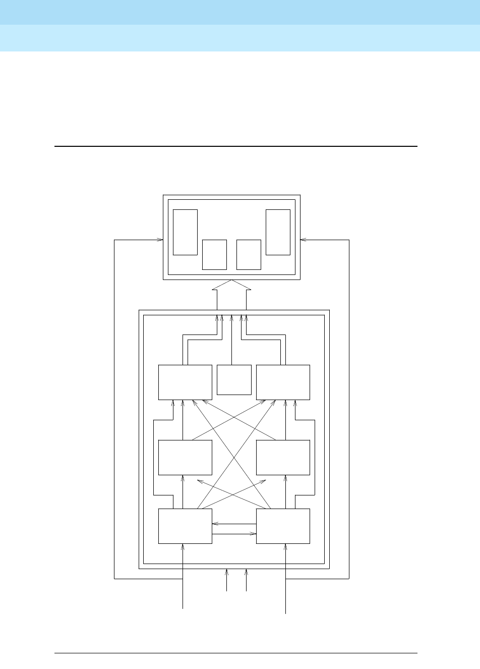
DEFINITY Enterprise Communications Server Release 6
Maintenance for R6r Volumes 1 & 2
555-230-126 Issue 2
January 1998
Maintenance Object Repair Procedures
Page 9-1339STRAT-3 (Stratum 3 Clock)
9
the switch by using a Y connector (H-600-274 G1 for the 50 pin DS1 end or
H-600-274 G2 for the 15 pin DS1 end).
For more information on the installation of the Stratum 3 clock, see the
DEFINITY
Enterprise Communications Server Release 5.4 Installation and Test for
Multi-Carrier Cabinets
.
Figure 9-75. Stratum 3 Clock Hardware Configuration
Tone-
Clock
TN780
Tone-
Clock
TN780
TOC
DS1
Ref A
PAI
Alarms
PPN
DS1
Ref B
TOC
ST3 ST3
CI CI
A B
A
A
B
B
DS1
TN464
TN767
or
TN722
DS1
TN464
TN767
or
TN722
Timing output Timing output
-48V -48V
DEFINITY Enterprise Communications Server Release 6
Maintenance for R6r Volumes 1 & 2
555-230-126 Issue 2
January 1998
Maintenance Object Repair Procedures
Page 9-1340STRAT-3 (Stratum 3 Clock)
9
Stratum 3 Clock LED Strategy
NOTE:
When looking in the Stratum 3 cabinet, ‘‘A’’ card is on the left and ‘‘B’’ card
is on the right.
NOTE:
The normal LED scheme is not followed for this device. Green LEDs do not
indicate maintenance activity. There are no yellow LEDs, and there are
more than three LEDs per circuit pack.
NOTE:
Removal of a card in the Stratum 3 clock may cause alarm(s) to be resolved
and the query test to pass. However, the removed cards should still be
replaced to restore the Stratum 3 clock to full service.
The Stratum 3 clock has the following components:
■2 Clock Input cards (CI)
Provides the logic to select the better DS1 reference or Clock Input card.
The red FAIL LED on this card indicates a failure with the card or the DS1
reference connected to it.
■2 Stratum 3 Cards (ST3)
Provides 24-hour holdover. The red FAIL LED on this card indicates a
failure with the card. Replace the card.
■2 Timing Output Cards (TOC)
Provides cable length compensation, multiple output ports, selection of
the ST3, and CI outputs. This type of card has two red failure LEDs: one
indicates a failure of the card; the other indicates a failure in one or more
output ports. In either case, replace the card.
■1 PBX (Private Branch Exchange) Alarm Interface (PAI)
Filters power supplied to the clock, provides fuse protection, and provides
alarm indications based on inputs supplied by other cards. The six LEDs
on this card provide indications for the six alarm or status conditions as
follows:
— Loss of DS1 reference A
— Loss of DS1 reference B
— Loss of one clock unit
— Loss of both clock units
— Loss of one power supply
— Loss of both power supplies

DEFINITY Enterprise Communications Server Release 6
Maintenance for R6r Volumes 1 & 2
555-230-126 Issue 2
January 1998
Maintenance Object Repair Procedures
Page 9-1341STRAT-3 (Stratum 3 Clock)
9
The output of the CI and PAI cards go directly to the TN780 Tone-Clock circuit
pack via two 25-pair amphenol-terminated cables. All of the cards have red
and/or green LEDs for providing status or alarm indications. The abbreviations
used in the table are defined above except for SRC (source) and PLL (Phase
Locked Loop).
1. Composite Clock (CC) source refers to the protocol used to electrically transfer timing from the
Stratum 3 clock to the switch. The Composite Clock source is not relevant to the system.
Table 9-459. Stratum 3 Clock LED Indications
Card Name Color Indication
PAI REF A Red Loss of input reference A or CI A failed
REF B Red Loss of input reference B or CI A failed
ST A Red Failed Stratum 3 clock A
ST B Red Failed Stratum 3 clock B
PWR A Green -48VDC A present
PWR B Green -48VDC B present
CI FAIL Red Card failure
DS1 Green DS1 source present
CC Green Composite clock source1 present
SRC ACTIVE Green Card is currently on-line
ST3 FAIL Red Card failure
LOCK Red PLL lost sync with reference or holdover mode
REF A Red Timing Reference from CI A
REF B Red Timing Reference from CI B
TOC FAIL Red Card failure
PORT ALM Red Output port alarm (one or more)
ST Green Reference present from ST clock
INPUT Green Reference present from CI
500’ Green 500 feet phase advance
1000’ Green 1000 feet phase advance

DEFINITY Enterprise Communications Server Release 6
Maintenance for R6r Volumes 1 & 2
555-230-126 Issue 2
January 1998
Maintenance Object Repair Procedures
Page 9-1342STRAT-3 (Stratum 3 Clock)
9
Error Log Entries and Test to Clear Values
Notes:
a. This error type corresponds to FAIL code 1 of the Stratum 3 Clock Alarm
Query (test #649): either reference A failed or the CI card A failed.
b. This error indicates that Synchronization Maintenance has been disabled
via the disable synchronization-switch command. Execute the enable
synchronization-switch command to enable Synchronization
Maintenance reference switching and to resolve this alarm.
c. This error type corresponds to FAIL code 2 of the Stratum 3 Clock Alarm
Query (test #649): one power supply failed.
d. This error type corresponds to FAIL code 4 of the Stratum 3 Clock Alarm
Query (test #649): one clock unit failed.
e. This error type corresponds to FAIL code 8 of the Stratum 3 Clock Alarm
Query (test #649): either reference B failed or the CI card B failed.
1. Run the Short Test Sequence first. If all tests pass, run the Long Test Sequence. Refer to the appropriate
test description and follow the recommended procedures.
Table 9-460. Stratum 3 Clock Error Log Entries
Error
Type Aux
Data Associated Test Alarm Level On/Off
Board Test to Clear Value
010 Any Any Any test synchronization r 4
1(a) Any Stratum 3 Clock Alarm
Query (#649 MINOR OFF test synchronization r 4
18(b) 0 disable sync WARNING OFF enable sync
257(c) Any Stratum 3 Clock Alarm
Query (#649) MINOR OFF test synchronization r 4
513(d) Any Stratum 3 Clock Alarm
Query (#649 MINOR ON test synchronization r 4
769(e) Any Stratum 3 Clock Alarm
Query (#649) MINOR ON test synchronization r 4
1025(f) Any Stratum 3 Clock Alarm
Query (#649) MINOR/
MAJOR(h) ON test synchronization r 4
1281(g) Any Stratum 3 Clock Alarm
Query (#649) MINOR
/MAJOR(h) ON test synchronization r 4
1537(i) none MINOR/
MAJOR(h) ON
1793(j) none MINOR/
MAJOR(h) ON

DEFINITY Enterprise Communications Server Release 6
Maintenance for R6r Volumes 1 & 2
555-230-126 Issue 2
January 1998
Maintenance Object Repair Procedures
Page 9-1343STRAT-3 (Stratum 3 Clock)
9
f. This error type corresponds to FAIL code 16 of the Stratum 3 Clock Alarm
Query (test #649): all power supplies failed.
g. This error type corresponds to FAIL code 32 of the Stratum 3 Clock Alarm
Query (test #649): all clock unit(s) failed.
h. An OFF-BOARD alarm on the Stratum 3 clock, indicates a DS1 facility
problem; an ON-BOARD alarm indicates a fault in either the Stratum 3
clock or the connection between the Stratum 3 clock and the switch. If the
Stratum 3 clock cannot be referenced and the local oscillator on the
TN780 Tone-Clock circuit pack must serve as the reference, a Major alarm
is raised. Otherwise, a Minor alarm is raised.
i. This error can be caused by one of the following conditions:
■One or both TOCs (Timing Output Cards) has failed.
■The connection between the Stratum 3 clock and the TN780
Tone-Clock circuit pack is faulty.
■The TN780 Tone-Clock circuit pack is defective.
A Minor alarm results if the Stratum 3 clock can still provide timing to the
switch; otherwise, a Major alarm will be raised because the Stratum 3
clock is not providing timing and the switch is referencing the local
oscillator on the TN780 Tone-Clock circuit pack. If only the Active TN780
Tone-Clock circuit pack is faulty, the Standby TN780 Tone-Clock circuit
pack becomes active and remains synchronized to the Stratum 3 clock.
When the system switches to the Standby Tone-Clock circuit pack, the
alarm is resolved, and a TDM-CLK alarm is raised to indicate a possible
problem on the TN780 Tone-Clock.
If the alarm is minor:
Look for a red LED on either or both TOC cards. If there is a red LED, then
replace the card. If there is no red LED, then, using the
Stratum 3 Wiring
Guide
, check that the wiring installation is correct. After replacing the card
or correctly rewiring the installation, clear the alarm by first issuing the
disable synchronization-switch command followed by the enable
synchronization-switch command. The latter procedure will cause
synchronization software to switch back to using the Stratum 3 clock
again. Wait 2 minutes and then execute the status synchronization
command. If Maintenance Name on the status screen shows ‘‘STRAT-3,’’
then the problem is resolved.
!CAUTION:
The disable synchronization-switch command followed by the
enable synchronization-switch command may cause slip alarms.
The circuit packs that can experience slips and the associated error
log entry for slips are as follows.

DEFINITY Enterprise Communications Server Release 6
Maintenance for R6r Volumes 1 & 2
555-230-126 Issue 2
January 1998
Maintenance Object Repair Procedures
Page 9-1344STRAT-3 (Stratum 3 Clock)
9
If the alarm is major:
Check connections between the Stratum 3 clock and the switch. If
there are no loose connections, then, using the
Stratum 3 Wiring
Guide
, check that the wiring installation is correct. After
reconnecting the loose connection or correctly rewiring it, clear the
alarm by first issuing the disable synchronization-switch
command followed by the enable synchronization-switch
command. Wait 1-minute, and then execute the status
synchronization command. If Maintenance Name on the status
screen shows ‘‘STRAT-3,’’ then the problem is resolved.
If the Standby Tone-Clock circuit pack became active:
Check the connection between the Stratum 3 clock and the TN780
Tone-Clock circuit pack from which the system has just switched. If
there are no loose connections, then, replace the TN780
Tone-Clock circuit pack. Refer to the ‘‘How to Replace the
Tone-Clock circuit pack’’ section in the TDM-CLK (TDM Bus Clock)
Maintenance documentation. Before switching back to the new
TN780 Tone-Clock circuit pack, use the test tone-clock UC long
command to check that the Tone-Clock is receiving a signal from
the Stratum 3 clock. If all tests pass, switch to the new Tone-Clock
circuit pack via the set tone-clock UC override command. If Test
#651 fails, then the original TN780 Tone-Clock should be
reinserted, and the cable between the Stratum 3 clock and the
TN780 Tone-Clock circuit pack should be replaced. If Test #651
continues to fail, then escalate the problem.
For all of the above cases if slip alarms exist after following the repair
procedures, clear the slip alarms by running the test board command
with the clear option. See the table on the previous page for a list of circuit
packs and associated slip error log entries.
Table 9-461. Timing Slip Error Types
Circuit Pack Name Error Log Name Error Log Entry for Slips
DS1 Interface DS1-BD 3073 to 3160
Expansion Interface EXP-INTF 2305
Switch Node Interface SNI-BD 1537
Tone-Clock TDM-CLK 1025
UDS1 Interface UDS1-BD 3073 to 3160

DEFINITY Enterprise Communications Server Release 6
Maintenance for R6r Volumes 1 & 2
555-230-126 Issue 2
January 1998
Maintenance Object Repair Procedures
Page 9-1345STRAT-3 (Stratum 3 Clock)
9
This error indicates that the Tone-Clock circuit pack in the master port
network is not a TN780. If duplicate Tone-Clock circuit packs exist in the
master port network, this error may mean that one or both Tone-Clock
circuit packs are not TN780s. Verify that the Tone-Clock(s) in the master
port network are TN780s.
System Technician-Demanded Tests:
Descriptions and Error Codes
Always investigate tests in the order presented in the following table when
inspecting errors in the system. By clearing error codes associated with the
Stratum 3 Clock Alarm Query Test,
for example, you may also clear errors
generated from other tests in the testing sequence.
The test synchronization commands also runs the Test Synchronization test
(test #417). Test 417 is described in the SYNC section.
Stratum 3 Clock Alarm Query (#649)
This test queries the Stratum 3 clock for its alarm status and reports the results of
the query. The Stratum 3 clock provides the system with the following six alarm
indications via the TN780 Tone-Clock circuit pack:
■Reference A failed or CI card A failed.
■Reference B failed or CI card B failed.
■One power supply failed.
■All power supplies failed.
■One clock unit failed.
■All clock unit(s) failed.
!CAUTION:
The removal of a card in the Stratum 3 clock may cause alarm(s) to be
resolved and the query test to pass. However, the removed cards should
still be replaced to restore the Stratum 3 clock to full service.
1. D = Destructive, ND = Non-destructive
Order of Investigation Short Test
Sequence Long Test
Sequence D/ND1
Stratum 3 Clock Alarm Query (#649) X X ND

DEFINITY Enterprise Communications Server Release 6
Maintenance for R6r Volumes 1 & 2
555-230-126 Issue 2
January 1998
Maintenance Object Repair Procedures
Page 9-1346STRAT-3 (Stratum 3 Clock)
9
Table 9-462. TEST #161 Looparound Test
Error
Code Test
Result Description/ Recommendation
1001 ABORT The system could not allocate the necessary resources to run this test.
1. Retry the command at 1-minute intervals up to a maximum of 3 times.
1005 ABORT This test aborts when it is run on a Stratum 4 system. Do not change
synchronization to Stratum 3 without consulting the synchronization plan
administrator for this switch.
2500 ABORT Internal System Error
1. Retry the command at 1-minute intervals a maximum of 3 times.
1 FAIL Either Reference A failed or CI card A failed. This condition usually indicates a
failure of the DS1 reference; however, there may also be a failure of the CI card
to which the reference is connected. The system technician dispatched to
investigate this problem should take a spare CI card in case the CI card
caused the failure. If you are NOT ON-SITE, use the following procedure:
1. Look for DS1-BD (DS1 Interface Circuit Pack) errors using the display
error command. Refer to the DS1-BD Maintenance documentation for
recommended strategy to resolve any DS1-BD errors found.
2. If there are no DS1-BD errors OR after resolving all DS1-BD errors, issue
the test synchronization r 4 command to determine if the alarm is still
present. If all repetitions of the tests pass, then the alarm no longer exists.
Otherwise, the system technician should be dispatched with a spare CI
card to use the following instructions on-site. (
continued
)
Continued on next page

DEFINITY Enterprise Communications Server Release 6
Maintenance for R6r Volumes 1 & 2
555-230-126 Issue 2
January 1998
Maintenance Object Repair Procedures
Page 9-1347STRAT-3 (Stratum 3 Clock)
9
1FAIL(
continued
)
If you are ON-SITE, use the following procedure:
1. Look for a red LED on CI card A (i.e., the left CI card). If there is a red LED,
then replace the CI card, if a spare is available. If no spare CI is available
on-site, proceed to Step 3. If after replacing the CI card, the red LED on
the new CI card lights also, then proceed to Step 3.
2. If a spare CI card is available, replace the suspect CI card. Otherwise,
issue the test synchronization r 4 command to clear the alarm. If any test
repetitions fail, then follow the procedure for those failures.
3. Look for DS1-BD (DS1 Interface Circuit Pack) errors using the display
error command. Refer to the DS1-BD Maintenance documentation for
recommended strategy to resolve any DS1-BD errors found. If there are no
DS1-BD errors, then proceed to Step 5.
4. After all DS1-BD errors have been resolved, then determine if the alarm
still exists by issuing the test synchronization r 4 command to clear the
alarm. If any test repetitions fail, then follow the procedure for those
failures.
5. Check the DS1 reference A connections to the Stratum 3 clock.
6. Determine if the alarm still exists by issuing the test synchronization r 4
command to clear the alarm. If any test repetitions fail, then follow the
procedure for those failures.
2 FAIL One power supply failed. This error only occurs when the Stratum 3 clock has
two power supplies, and one of them has failed. However, the clock can
function with one power supply.
1. Locate the failed power supply by looking for a power supply with a red
LED and replace it. The power supply is located under the Stratum 3 clock
carrier.
2. Determine if the alarm still exists by issuing the test synchronization r 4
command to clear the alarm. If any test repetitions fail, then follow the
procedures for those test failures.
4 FAIL One clock unit failed.
1. Look at the Stratum 3 cabinet for a red LED on a circuit card marked
‘‘ST3.’’ Replace the card.
2. Determine if the alarm still exists by issuing the test synchronization r 4
to clear the alarm. If any test repetitions fail, then follow the procedures for
those failures.
Table 9-462. TEST #161 Looparound Test — Continued
Error
Code Test
Result Description/ Recommendation
Continued on next page

DEFINITY Enterprise Communications Server Release 6
Maintenance for R6r Volumes 1 & 2
555-230-126 Issue 2
January 1998
Maintenance Object Repair Procedures
Page 9-1348STRAT-3 (Stratum 3 Clock)
9
8 FAIL Reference B failed or CI card B failed. This condition usually indicates a failure
of the DS1 reference; however, there may also be a failure of the CI card to
which the reference is connected. The system technician dispatched to
investigate this problem should take a spare CI card in case the CI card
caused the failure. If you are NOT ON-SITE, use the following procedure:
1. If there were no DS1-BD errors, OR if all DS1-BD errors have been
resolved, enter test synchronization r 4 to determine if the alarm is still
present. If all repetitions of the tests pass, the alarm no longer exists.
Otherwise, the system technician should be dispatched with a spare CI
card to perform the following instructions on-site.
8FAIL
(cont’d.)
If you are ON-SITE, use the following procedure:
1. Look for a red LED on a CI card B (the CI card on the right). If there is a
red LED, then replace the CI card, if a spare is available. If no spare CI is
available on-site, proceed to Step 3. If, after replacing the CI card, the red
LED on the new CI card lights, proceed to Step 3.
2. Otherwise, enter test synchronization r 4 to clear the alarm. If any test
repetitions fail, follow the procedure for those failures.
3. Enter display errors and look for DS1-BD errors. If there are any, refer to
“DS1-BD”. If there are no DS1-BD errors, proceed to Step 5.
4. After all DS1-BD errors have been resolved, determine if the alarm still
exists with test synchronization r 4. If any test repetitions fail, follow
procedures for those failures.
5. Check the DS1 reference A connections to the Stratum 3 clock.
6. Determine if the alarm still exists with test synchronization r 4 to clear the
alarm. If any test repetitions fail, then follow procedures for those failures.
16 FAIL All power supplies failed.
1. Replace the failed power supplies.
2. If battery backup for the Stratum 3 clock is not supplied or if the battery
backup holdover time has been exceeded, then the system will be
referencing the local oscillator on the Active TN780 Tone-Clock circuit
pack until software detects that one or both power supplies has(have)
been restored (approximately 40 minutes). To speed up this restoration,
issue the test synchronization r 4 command. All tests should pass. If any
repetitions should fail, then follow the procedures for those failures. The
battery backup is located under the Stratum 3 clock carrier.
Table 9-462. TEST #161 Looparound Test — Continued
Error
Code Test
Result Description/ Recommendation
Continued on next page

DEFINITY Enterprise Communications Server Release 6
Maintenance for R6r Volumes 1 & 2
555-230-126 Issue 2
January 1998
Maintenance Object Repair Procedures
Page 9-1349STRAT-3 (Stratum 3 Clock)
9
32 FAIL All clock unit(s) failed.
1. Look at the Stratum 3 cabinet for red LEDs on circuit cards marked ‘‘ST3.’’
Replace the card(s).
2. Determine if the alarm still exists by issuing the test synchronization r 4
command to clear the alarm. If any test repetitions fail, then follow the
procedure for those failures.
2101 FAIL The TN780 Tone-Clock circuit pack detects loss of signal. Refer to note h of
the STRAT-3 Hardware Error Log Entries table in the STRAT-3 (Stratum 3
Clock) Maintenance documentation for replacement procedures.
PASS The Stratum 3 clock has reported that it has no alarm conditions. If
synchronization problems have been reported, look for SYNC errors and refer
to SYNC (Synchronization) Maintenance documentation for recommended
strategy for those errors.
Table 9-462. TEST #161 Looparound Test — Continued
Error
Code Test
Result Description/ Recommendation
Continued on next page

DEFINITY Enterprise Communications Server Release 6
Maintenance for R6r Volumes 1 & 2
555-230-126 Issue 2
January 1998
Maintenance Object Repair Procedures
Page 9-1350SVC-SLOT (Service Slot)
9
SVC-SLOT (Service Slot)
The Service Slot maintenance object detects the insertion of an invalid circuit
pack a dedicated SERVICE slot. The SERVICE slot is the leftmost slot in the
J58890BB Port Carrier, and is identified as slot location "00" in all commands,
field entries, and displays on the management terminal.
Since this slot does not provide tip and ring connectivity to the wall field, only the
following circuit packs are allowed:
■TN744 Call Classifier
■TN750 Integrated Announcement
■TN771 Maintenance/Test
■TN725 Speech Synthesizer
■TN433 Speech Synthesizer
■TN457 Speech Synthesizer
■TN748 Tone Detector
■TN420 Tone Detector
■TN755 Neon Power Unit
A MINOR alarm is generated against the Service Slot maintenance object when a
circuit pack with a type other than that listed above is inserted in a SERVICE slot.
The Service Slot maintenance object name is used instead of the maintenance
object name for the illegal circuit pack to prevent any attempt to assign a port to
an illegal circuit pack physically inserted in the SERVICE slot.
MO Name (in
Alarm Log) Alarm Level Initial Command to Run Full Name of MO
SVC-SLOT MINOR none Service Slot

DEFINITY Enterprise Communications Server Release 6
Maintenance for R6r Volumes 1 & 2
555-230-126 Issue 2
January 1998
Maintenance Object Repair Procedures
Page 9-1351SVC-SLOT (Service Slot)
9
Error Log Entries and Test to Clear Values
Note:
a. Error type 600 indicates that a non-permitted circuit pack was inserted in
slot 00, the SERVICE slot, of a J58890BB port carrier. See the preceding
list of valid circuit packs for this slot.
The code of the invalid circuit pack can be displayed by using the list
configuration board UUCSS command where UU is the cabinet number,
C is the carrier letter, and SS is the slot number (always 00) of the alarmed
circuit pack.
To retire the alarm, remove the invalid circuit pack.
Table 9-463. Service Slot Error Log Entries
Error
Type Aux
Data Associated Test Alarm
Level On/Off
Board Test to Clear Value
600(a) None MINOR ON

DEFINITY Enterprise Communications Server Release 6
Maintenance for R6r Volumes 1 & 2
555-230-126 Issue 2
January 1998
Maintenance Object Repair Procedures
Page 9-1352SW-CTL (Switch Control)
9
SW-CTL (Switch Control)
The Switch Control resides on the MSSNET (Mass Storage System and Network
Control) circuit pack (UN332). The Mass Storage System Host Adapter (HA) also
resides on the MSSNET circuit pack. Systems equipped with the Standard
Reliability configuration have a single MSSNET circuit pack and systems
equipped with the High Reliability or Critical Reliability configuration have two
MSSNET circuit packs, one in each Switch Processing Element (SPE) complex.
The MSSNET cannot be replaced in a system with one SPE complex without
bringing the system down. The MSSNET in the standby SPE of a system
equipped with the High Reliability or Critical Reliability option can be replaced
without affecting normal system operation.
The Switch Control sends control information between the SPE and port circuit
packs on the Processor Port Network (PPN) as shown in Figure 9-76. This control
information is sent via the PPN cabinet’s TDM (Time Division Multiplexed) bus.
The portion of the TDM bus used to transmit control messages is called the
control channel. The control channel can be on either TDM bus A or TDM bus B,
but only one of the two buses is used for the control channel at any give time.
The Switch Control is involved in sending control channel messages for the setup
and takedown of all calls involving endpoints connected to the PPN, but is not
involved in the voice or data transmission that takes place during established
calls. The Switch Control is also involved in setting up system links used for
control of calls involving endpoints connected to Expansion Port Networks
(EPNs). Once those links are set up at system boot time, a failure of the Switch
Control will not affect existing calls or new calls involving those EPN endpoints.
One of the functions of the Switch Control is to detect when port circuit packs are
plugged into or removed from the PPN cabinet. The Switch Control also monitors
the health of the control channel on the PPN cabinet TDM bus and informs the
SPE when errors occur.
1. In a system with simplex SPE, the carrier location, a need not be specified. In a system with
duplicated SPEs, carrier a or b must be specified.
2. After a spontaneous SPE interchange has occurred, the Alarm Log retains for three hours a
record of any MAJOR ON-BOARD alarm against an SPE component that took place before
the interchange. If a spontaneous interchange has occurred (as indicated by STBY-SPE
error type 103 or the display initcauses screen), and such an alarm is logged against
SW-CTL, then replace the standby MSSNET circuit pack using the "lock-and-power-down"
procedure described in Chapter 5.
MO Name (in
Alarm Log) Alarm
Level Initial Command to Run1Full Name of MO
SW-CTL MAJOR2test switch-control [a|b] short Switch Control
SW-CTL WARNING test switch-control [a|b] short Switch Control

DEFINITY Enterprise Communications Server Release 6
Maintenance for R6r Volumes 1 & 2
555-230-126 Issue 2
January 1998
Maintenance Object Repair Procedures
Page 9-1353SW-CTL (Switch Control)
9
The Switch Control also contains hardware to monitor critical system timing
signals and informs the SPE when these signals fail. For example, if the timing
signals from a Tone/Clock circuit pack fail, the Switch Control will inform the SPE
and the SPE can then switch to a standby Tone/Clock circuit pack, (if
Tone-Clocks are duplicated).
On High and Critical Reliability systems (duplicated SPE), a MAJOR alarm failure
of the Switch Control circuit on the active SPE results in an SPE interchange, if
the health of the standby SPE permits. (Refer to Chapter 1for more information
about duplicated SPEs.) The following sections assume that if the SPEs are
duplicated, and if a Switch Control circuit has a MAJOR alarm, the MSSNET
circuit pack associated with that Switch Control circuit is located in the standby
SPE.
As mentioned above, the MSSNET circuit pack contains both the Switch Control
circuit and the MSS Host Adapter circuit. A failure of either circuit will light the red
LED on the MSSNET circuit pack.
The test mssnet command tests both the Switch Control circuit and the MSS
Host Adapter circuit on the MSSNET circuit pack. Whenever the MSSNET circuit
pack is replaced, test mssnet should be used to verify that both circuits are
operating correctly.
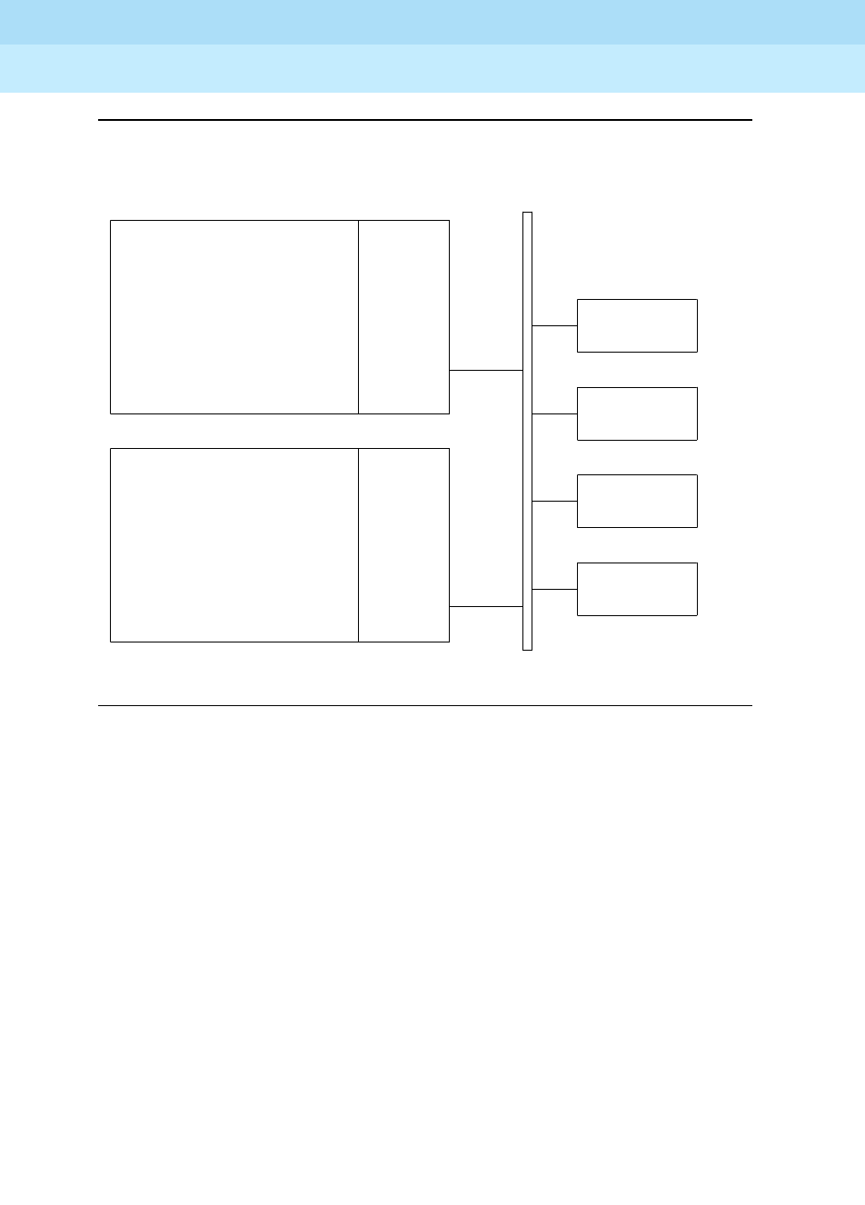
DEFINITY Enterprise Communications Server Release 6
Maintenance for R6r Volumes 1 & 2
555-230-126 Issue 2
January 1998
Maintenance Object Repair Procedures
Page 9-1354SW-CTL (Switch Control)
9
Figure 9-76. Switch Control Connectivity
.
.
.
.
.
.
.
.
.
.
.
.
.
.
.
.
.
.
.
.
.
.
.
.
.
.
.
.
.
.
.
.
.
.
.
.
.
.
.
.
.
.
.
.
.
.
.
.
.
.
.
.
.
.
.
.
.
.
.
.
.
.
.
.
.
.
.
.
.
.
.
.
.
.
.
. . . . . . . . . . . . . . . . . . . . . . . . . . . .
.
.
.
.
.
.
.
.
.
.
.
.
.
.
.
.
.
.
.
.
.
.
.
.
.
.
.
.
.
.
.
.
.
.
.
.
.
.
.
.
.
.
.
.
.
.
.
.
.
.
.
.
.
.
.
.
.
.
.
.
.
.
.
.
.
.
.
.
.
.
.
.
.
.
.
. . . . . . . . . . . . . . . . . . . . . . . . . . . .
EXP-INTF
Circuit Pack
Port
Circuit Pack
Port
Circuit Pack
Port
Circuit Pack
UN332
MSSNET
Circuit
Pack
Switch
Control
Circuit
. . . . . . . . . . . . . . . . .
Switch
Processing
Element
A
TDM Bus
UN332
MSSNET
Circuit
Pack
Switch
Control
Circuit
. . . . . . . . . . . . . . . . .
Switch
Processing
Element
B
(if SPEs are
duplicated)
PPN

DEFINITY Enterprise Communications Server Release 6
Maintenance for R6r Volumes 1 & 2
555-230-126 Issue 2
January 1998
Maintenance Object Repair Procedures
Page 9-1355SW-CTL (Switch Control)
9
Error Log Entries and Test to Clear Values
Notes:
a. A 1 error indicates that there has been 8 or more Processor Port Network
circuit pack removals in less than 15 minutes. This action may be forced
manually by removing power to a port carrier or pulling out at least 8 port
circuit packs within 15 minutes. The generation of this error may indicate
that there is a problem with the Switch Control circuit on the MSSNET
circuit pack or that there is a problem with the TDM bus. Three successful
completions of the Control Channel test (#94) will resolve the MAJOR
alarm caused by this error.
b. A 2 error indicates that the Switch Control Channel Transmission test (#94)
failed. This error may not cause a Switch Control alarm if Error Type 769 is
also present since this error may actually be caused by the loss of clock
signals and not by a Switch Control failure. If the system is not equipped
1. Indicates that an alarm was raised but the associated error could not be entered into the hardware error
log due to a momentary overload condition. Run the short test sequence and refer to the appropriate test
description for tests that fail.
2. After a spontaneous SPE interchange has occurred, the Alarm Log retains for three hours a record of any
MAJOR ON-BOARD alarm against an SPE component that took place before the interchange. If a
spontaneous interchange has occurred (as indicated by STBY-SPE error type 103 or the display
initcauses screen), and such an alarm is logged against SW-CTL, then replace the standby MSSNET
circuit pack using the "lock-and-power-down" procedure described in Chapter 5.
Table 9-464. Switch Control Error Log Entries
Error
Type Aux
Data Associated Test Alarm
Level On/Off
Board Test to Clear Value
01 0 Any Any Any test switch-control [a|b] r 3
1(a) Control Transmission
Test (#94)Channel MAJOR2ON test switch-control [a|b] r 3
2(b) Control Channel
Transmission Test (#94) MAJOR2ON test switch-control [a|b] r 3
150(c) Any None MAJOR2ON test switch-control [a|b] l c
257(d) Any None
769(e) None
1025(f) Control Channel
Interface Test (#92) MAJOR2ON test switch-control [a|b] r 2
1281(g) None
1537(h) Switch Control Reset
Test (#93) MAJOR2ON test switch-control [a|b] l r 2
1793(i) None
2561(j) None WARNING OFF

DEFINITY Enterprise Communications Server Release 6
Maintenance for R6r Volumes 1 & 2
555-230-126 Issue 2
January 1998
Maintenance Object Repair Procedures
Page 9-1356SW-CTL (Switch Control)
9
with the High Reliability or Critical Reliability option, or if the Switch control
circuit is on the active processor, use the test switch-control command
to test the Switch Control.
In a system is equipped with duplicated SPEs and the hardware error is
reported against the Switch Control on the standby processor, use the
following procedures. The Control Channel Transmission test which
detected this error cannot run on the Switch Control circuit on the standby
SPE since the Switch Control circuit on the standby SPE is not allowed
access to the TDM bus. Therefore if the system is equipped with
duplicated SPEs and if this error is associated with the Switch Control
circuit on the standby SPE, the error was detected while the Switch
Control circuit was running on an active SPE.
To allow the Control Channel test to run on this circuit, it will be necessary
to initiate an SPE interchange, using the procedures described below.
This action should only be taken during a time that would cause the least
service disruption since exiting calls may disconnect if a failure detected
on the newly active Switch Control circuit causes a spontaneous switch
back to the other SPE. If this possible action is
not
acceptable, first verify
that no TDM bus problems are detected when the test TDM 1 command is
entered and then replace the MSSNET circuit pack on the standby SPE. If
TDM problems are detected, refer to the TDM-BUS maintenance
documentation to clear those problems.
1. Initiate a test of the Switch Control circuit on the standby SPE using
the test switch-control C long command (where C represents the
carrier location of the standby SPE) to make sure no other failure
conditions can be detected. If failures are detected, use the
diagnostic information associated with those tests to clear the
failure before proceeding.
2. Initiate an SPE interchange using the reset system interchange
command. This should be done at a time that would cause the least
service disruption since a fault may still exist on the MSSNET circuit
pack. If the system reset command fails, refer to
Failure of Planned
Interchange
in Chapter 5 for further actions.
3. Enter the test switch-control command for the Switch Control now
on the active SPE and verify that the Control Channel Transmission
test (#94) passes. If a failure occurs, an automatic SPE interchange
may occur. If an interchange back to the original SPE occurs,
replace the MSSNET board on the standby SPE and go back to
step 1 above. If other failures are detected, use the repair
procedures associated with those tests to clear the failure.
c. A 150 error indicates that a SPE interchange occurred and that the Switch
Control circuit on the MSSNET circuit pack was the cause of the
spontaneous interchange.
1. If other SW-CTL errors are present, investigate those errors
2. If no other SW-CTL errors are present, run the test switch-control
a|b long clear command and investigate those failures.

DEFINITY Enterprise Communications Server Release 6
Maintenance for R6r Volumes 1 & 2
555-230-126 Issue 2
January 1998
Maintenance Object Repair Procedures
Page 9-1357SW-CTL (Switch Control)
9
d. A 257 error is logged when the Switch Control circuit reports that tests of
its internal memory (RAM or ROM) have failed. The receipt of this error
causes Switch Control maintenance to run specific Switch Control tests. If
there is a problem, the Switch Control tests will normally cause other errors
to be logged. In the rare case where no other errors are logged but 257
errors are occurring at a high rate (more than 10 in the last hour) the
MSSNET circuit pack should be replaced during a time that would cause
the least service disruption. If the system is equipped with the High
Reliability or Critical Reliability Configuration this can be done immediately
since a MSSNET circuit pack on the standby SPE can be replaced without
affecting service.
e. A 769 error occurs when the Switch Control reports a loss of timing signals
to the SPE. When this error is present, the Switch Control will not normally
be alarmed since any Switch Control test failures are really the result of
faulty signals from the Tone/Clock circuit pack. See “TDM-CLK” for the
procedures needed to diagnose Tone/Clock circuit pack troubles.
f. A 1025 error indicates that there has been a failure of the Control Channel
Interface Test (#92). Refer to the diagnostics for that test to clear the
problem.
g. A 1281 error is called a Switch Control handshake error. It is an in-line
error not produced by any test. The Aux Data for this error is not
meaningful. This error can be ignored.
The receipt of this errors causes Switch Control maintenance to run
specific Switch Control tests. If there is a problem, the Switch Control tests
would cause other errors to be logged. 1281 errors do not cause alarms
so there is no specific action that can be taken when these errors are
observed.
h. A 1537 error indicates that the Switch Control Reset test (#92) failed. A
MAJOR alarm is raised if this test fails. Refer to the repair procedures for
the Switch Control Reset test (#93).
i. A 1793 error is an in-line error that indicates a possible problem with the
interface between the Switch Control and the SPE. The Aux Data for this
error is not meaningful. The receipt of this error causes Switch Control
maintenance to run specific Switch Control tests. If there is a problem, the
Switch Control tests will normally cause other errors to be logged. In the
rare case where no other errors are logged but 1793 errors are occurring
at a high rate (more than 10 in the last hour) the MSSNET circuit pack
should be replaced during a time that would cause the least service
disruption. If the system is equipped with the High Reliability or Critical
Reliability Configuration this can be done immediately since a MSSNET
circuit pack on the standby SPE can be replaced without affecting
service.
j. A 2561 error indicates that a software message buffer for downlink port
board messages has overflowed and those messages were thrown away.
The Aux Data for this error is not meaningful. The SPE is sending more
downlink port board messages to the Switch Control than the Switch

DEFINITY Enterprise Communications Server Release 6
Maintenance for R6r Volumes 1 & 2
555-230-126 Issue 2
January 1998
Maintenance Object Repair Procedures
Page 9-1358SW-CTL (Switch Control)
9
Control is able to process. A WARNING alarm for this condition will
automatically be resolved if no errors of this type are detected within a 15
minute period. If no other errors are logged but 2561 errors are occurring
at a high rate (more than 10 in the last hour), follow normal escalation
procedures.
System Technician-Demanded Tests:
Descriptions and Error Codes
Always investigate tests in the order presented in the table below when
inspecting errors in the system. By clearing error codes associated with the
Switch Control Reset Test
for example, you may also clear errors generated from
other tests in the testing sequence.
1. D = Destructive, ND = Non-destructive
2. When the SPE is duplicated, this test runs only on the Switch Control circuit on the active SPE. An
interchange must be performed to test the other one.
Order of Investigation Short Test
Sequence Long Test
Sequence Reset Board
Sequence D/ND1
Switch Control Reset Test (#93) X D
Control Channel Interface Test (#92) X X ND
Control Channel Transmission Test
(#94)2XX ND

DEFINITY Enterprise Communications Server Release 6
Maintenance for R6r Volumes 1 & 2
555-230-126 Issue 2
January 1998
Maintenance Object Repair Procedures
Page 9-1359SW-CTL (Switch Control)
9
Switch Control Channel Interface Test (#92)
Loop-back messages are sent to the Switch Control via the interface used for
control channel messages. The messages are returned to the SPE for verification
via the same interface. The TDM bus is not involved in this test since the
messages are looped back on the MSSNET circuit pack.
Table 9-465. TEST #92 Control Channel Interface Test
Error
Code Test
Result Description/ Recommendation
1338 ABORT The test is not allowed to run since a planned SPE interchange is in progress.
This may be caused by a planned interchange initiated automatically during 24
hour scheduled testing.
1. Wait 3 minutes and retry the command.
1339 ABORT The test could not run on the standby Switch Control on the MSSNET circuit
pack in the standby SPE carrier because the standby SPE is unavailable.
1. Refer to the STBY-SPE maintenance documentation for information on why
a standby SPE may be unavailable and what repair actions should be
taken. The screen for the status spe command should indicate that
handshake is down. This may be caused by a variety of reasons such as
the SPE-SELECT switches on the DUPINT circuit packs being set to the
position of the active SPE, a failure of the DUPINT circuit pack, or loss of
power on the standby SPE. The
SPE Selected
field on the status spe
screen will display
spe a
or
spe b
if both SPE-SELECT switches are in the a
or b positions, respectively.
2000 ABORT Response to the test request was not received within the allowable time period.
If the system is equipped with the High Reliability or Critical Reliability
Configuration and if the MSSNET circuit pack is on the standby SPE, this abort
code may indicate that the standby SPE is not responding to the handshake
message. If this is the case, the standby SPE maintenance software may take
up to two minutes to indicate that handshake communication with the standby
SPE is down. The ABORT code will then change to 1339 (standby SPE
unavailable).
1. Retry the command at 1-minute intervals, a maximum of 3 times.
2012
2500 ABORT Internal System Error
1. Retry the command.
2100
none ABORT Could not allocate the necessary system resources to run this test.
1. Retry the command at 1-minute intervals a maximum of 3 retries.
2334 ABORT The hardware mailbox in the standby Duplication Interface circuit pack is not
ready to receive messages.
1. Retry the command at 1-minute intervals for a maximum of 5 times.
Continued on next page

DEFINITY Enterprise Communications Server Release 6
Maintenance for R6r Volumes 1 & 2
555-230-126 Issue 2
January 1998
Maintenance Object Repair Procedures
Page 9-1360SW-CTL (Switch Control)
9
Any FAIL Messages could not be looped back through the control channel interface. If
the system is equipped with the Standard Reliability configuration, you will
probably not be able to make or receive calls involving telephones connected
to the Processor Port Network.
1. This failure could be due to either a MSSNET circuit pack hardware failure
or the loss of system timing signals. If the Switch Control is alarmed, then a
MSSNET circuit pack failure should be suspected. If the Switch Control is
not alarmed, then investigate the possibility of the loss of system timing
signals before attempting to replace the MSSNET circuit pack. See
“TDM-CLK”. A TDM Bus Clock problem may cause many port circuit pack
red LEDs to light. If only the MSSNET circuit pack LED is lit, suspect the
MSSNET circuit pack. If many port circuit pack red LEDs are lit, suspect a
TDM Bus Clock problem. Test #92 and Test #94 run as part of the test
sequence for the test switch-control C command (where C represents the
carrier location of the circuit under test). Both tests will fail if the system
timing signals are lost. If test #94 passes, then do not suspect the loss of
timing signals.
Any
(cont’
d.)
FAIL 2. Run the short test sequence several times to make sure that this failure is
occurring consistently. Then run the long test sequence to reset the Switch
Control. Sometimes running the long test sequence may clear the problem.
If the test is still failing, proceed to step 3 or 4.
3. If the system is still able to process calls, replace the MSSNET circuit pack
during a time that would cause the least service disruption. If the system is
equipped with the High Reliability or Critical Reliability Configuration this
can be done immediately since a MSSNET circuit pack on the standby SPE
can be replaced without affecting service. The procedure for replacing the
MSSNET circuit pack is described in ‘‘Replacing SPE Circuit Packs’’ in
Chapter 5.
4. If calls cannot be made, then replace the MSSNET circuit pack
immediately. The procedure for replacing the MSSNET circuit pack is
described in ‘‘Replacing SPE Circuit Packs’’ in Chapter 5.
PASS The control channel interface between the SPE and the Switch Control is
working correctly
Table 9-465. TEST #92 Control Channel Interface Test — Continued
Error
Code Test
Result Description/ Recommendation
Continued on next page

DEFINITY Enterprise Communications Server Release 6
Maintenance for R6r Volumes 1 & 2
555-230-126 Issue 2
January 1998
Maintenance Object Repair Procedures
Page 9-1361SW-CTL (Switch Control)
9
Switch Control Reset Test (#93)
This test is destructive if the Switch Control is on the active SPE.
This test resets the Switch Control and determines if it can successfully go
through its initialization sequence. The test is destructive if the Switch Control
circuit is on an active SPE since there is the possibility of losing some control
messages to or from port circuit packs. This test will not affect established calls
but call setup may be affected for several seconds.
Table 9-466. TEST #93 Switch Control Reset Test
Error
Code Test
Result Description/ Recommendation
1338 ABORT The test is not allowed to run since a planned SPE interchange is in progress.
This may be caused by a planned interchange initiated automatically during 24
hour scheduled testing.
1. Wait 3 minutes and retry the command.
1339 ABORT The test could not run on the standby Switch Control on the MSSNET circuit
pack in the standby SPE carrier because the standby SPE is unavailable.
1. Refer to the STBY-SPE maintenance documentation for information on why
a standby SPE may be unavailable and what repair actions should be
taken. The screen for the status spe command should indicate that
handshake is down. This may be caused by a variety of reasons such as
the SPE-SELECT switches on the DUPINT circuit packs being set to the
position of the active SPE, a failure of the DUPINT circuit pack, or loss of
power on the standby SPE. The
SPE Selected
field on the status spe
screen will display
spe a
or
spe b
if the SPE-SELECT switches are in the a
or b positions, respectively.
2000 ABORT Response to the test request was not received within the allowable time period.
If the system is equipped with the High Reliability or Critical Reliability
Configuration and if the MSSNET circuit pack is on the standby SPE, this abort
code may indicate that the standby SPE is not responding to the handshake
message. If this is the case, the standby SPE maintenance software may take
up to two minutes to indicate that handshake communication with the standby
SPE is down. The ABORT code will then change to 1339 (standby SPE
unavailable).
1. Retry the command at 1-minute intervals, a maximum of 3 times.
2012 ABORT Request for results timed out.
2500 ABORT Internal System Error
1. Retry the command two times.
2013
2100
none
ABORT Could not allocate the necessary system resources to run this test.
1. Retry the command at 1-minute intervals a maximum of 3 retries.
Continued on next page

DEFINITY Enterprise Communications Server Release 6
Maintenance for R6r Volumes 1 & 2
555-230-126 Issue 2
January 1998
Maintenance Object Repair Procedures
Page 9-1362SW-CTL (Switch Control)
9
2334 ABORT The hardware mailbox in the standby Duplication Interface circuit pack is not
ready to receive messages.
1. Retry the command at 1-minute intervals for a maximum of 5 times.
FAIL The Switch Control could not be successfully reset. If the system is equipped
with the Standard Reliability configuration, you will probably not be able to
make or receive calls involving telephones connected to the Processor Port
Network.
1. This failure could be due to either a MSSNET circuit pack hardware failure
or the loss of system timing signals. If the Switch Control is alarmed, then a
MSSNET circuit pack failure should be suspected. If the Switch Control is
not alarmed, then investigate the possibility of the loss of system timing
signals. See “TDM-CLK”. A TDM Bus Clock problem may cause many port
circuit pack red LEDs to light. If only the MSSNET circuit pack LED is lit,
suspect the MSSNET circuit pack. If many port circuit pack red LEDs are
lit, suspect a TDM Bus Clock problem. Test #92 and Test #94 run as part of
the test sequence for the test switch-control C command (where C
represents the carrier location of the circuit under test). Both tests will fail if
the system timing signals are lost. If test #94 passes, then do not suspect
the loss of timing signals. If the MSSNET circuit pack is determined to be at
fault, proceed to step 2.
2. If the system is still able to process calls, replace the MSSNET circuit pack
during a time that would cause the least service disruption. If the system is
equipped with the High Reliability or Critical Reliability Configuration this
can be done immediately since a MSSNET circuit pack on the standby
SPE can be replaced without affecting service. The procedure for
replacing the MSSNET circuit pack is described in ‘‘Replacing SPE Circuit
Packs’’ in Chapter 5.
3. If calls cannot be made, then replace the MSSNET circuit pack
immediately. The procedure for replacing the MSSNET circuit pack is
described in ‘‘Replacing SPE Circuit Packs’’ in Chapter 5.
PASS The Switch Control has initialized correctly. Look at results of the other tests to
see if it is operating correctly.
Table 9-466. TEST #93 Switch Control Reset Test — Continued
Error
Code Test
Result Description/ Recommendation
Continued on next page

DEFINITY Enterprise Communications Server Release 6
Maintenance for R6r Volumes 1 & 2
555-230-126 Issue 2
January 1998
Maintenance Object Repair Procedures
Page 9-1363SW-CTL (Switch Control)
9
Switch Control-Channel Transmission Test (#94)
Control channel messages are sent from the SPE to selected port circuit packs
and the response from the port circuit packs is checked. This tests the ability of
the Switch Control to send and receive messages on the control channel of the
TDM bus.
For the case when the system is equipped with the High Reliability or Critical
Reliability configuration, this test cannot run on the Switch Control in a standby
SPE. However, this test may have run and failed while the Switch Control was on
the active SPE which will alarm the Switch Control and cause an SPE
interchange. In that case, Error Types 2 and 150 will be entered in the error log
for the Switch Control on the standby SPE, indicating that a failure of the Switch
Control Transmission Test caused a spontaneous SPE interchange. Refer to the
Error Log information presented earlier in this repair document for the
procedures to clear problems associated with a SW-CTL error log entry of 2.
Table 9-467. TEST #94 Control Channel Transmission Test
Error
Code Test
Result Description/ Recommendation
0 ABORT The port circuit packs necessary for this test are not available. For this test to
pass, it must receive a successful response to a circuit pack query message
from at least one of the following circuit pack types in the PPN cabinet:
Tone/Clock circuit pack (TN768 or TN780) Tone Detector circuit pack (TN599)
1. Retry the command at 1-minute intervals a maximum of 5 retries.
2. If the test keeps aborting with this abort code, replace the MSSNET circuit
pack.
3. If the test keeps aborting with this abort code, verify that the PPN has at
least one of the circuit packs listed above.
1335 ABORT Internal System Error. The MSSNET circuit pack is on the standby SPE and this
test is not allowed to execute on a MSSNET circuit pack on the standby SPE.
1. If this abort code is received for a Switch Control on a standby SPE in a
system equipped with the High Reliability or Critical Reliability configuration,
there must be a software error. Test #94 is not allowed to run on a standby
Switch Control.
2. Retry the command at 1-minute intervals, a maximum of 5 times.
1338 ABORT The test is not allowed to run since a planned SPE interchange is in progress.
This may be caused by a planned interchange initiated automatically during 24
hour scheduled testing.
1. Wait 3 minutes and retry the command.
2012
2500 ABORT Internal System Error
1. Retry the command.
Continued on next page

DEFINITY Enterprise Communications Server Release 6
Maintenance for R6r Volumes 1 & 2
555-230-126 Issue 2
January 1998
Maintenance Object Repair Procedures
Page 9-1364SW-CTL (Switch Control)
9
2013
2100
none
ABORT Could not allocate the necessary system resources to run this test.
1. Retry the command at 1-minute intervals a maximum of 3 retries.
0 FAIL The Switch Control cannot communicate on the TDM bus control channel. If the
system is equipped with the Standard Reliability configuration, you will probably
not be able to make or receive calls involving telephones connected to the
Processor Port Network.
1. Run the short test sequence several times to make sure that this failure is
occurring consistently. Then run the long test sequence to reset the Switch
Control. Sometimes, running the long test sequence may clear the problem.
Remember that the long test sequence is
destructive
. Placing and receiving
of calls will be affected for several seconds.
2. If there are no TDM Bus alarms against the standby TDM bus, switch the
control channel from its current bus to the standby bus using the set tdm
command. Refer to the TDM-BUS maintenance documentation for
information on how to use this command. If this test passes on the new bus,
then investigate the possibility of TDM Bus failures. If the test fails even after
the control channel is switched to the standby TDM bus, then proceed to
Step 3 or 4.
3. If the system is still able to process calls, replace the MSSNET circuit pack
during a time that would cause the least service disruption. If the system is
equipped with the High Reliability or Critical Reliability Configuration this
can be done immediately since a MSSNET circuit pack on the standby SPE
can be replaced without affecting service. The procedure for replacing the
MSSNET circuit pack is described in ‘‘Replacing SPE Circuit Packs’’ in
Chapter 5.
4. If calls cannot be made, then replace the MSSNET circuit pack immediately.
The procedure for replacing the MSSNET circuit pack is described in
‘‘Replacing SPE Circuit Packs’’ in Chapter 5.
PASS The Switch Control can communicate with selected port circuit packs over the
TDM bus.
Table 9-467. TEST #94 Control Channel Transmission Test — Continued
Error
Code Test
Result Description/ Recommendation
Continued on next page

DEFINITY Enterprise Communications Server Release 6
Maintenance for R6r Volumes 1 & 2
555-230-126 Issue 2
January 1998
Maintenance Object Repair Procedures
Page 9-1365SYNC (Synchronization)
9
SYNC (Synchronization)
This section discusses synchronization problems local to the switch. For further
information about synchronization including network synchronization, see the
AT&T Network and Data Connectivity
document 555-025-201.
Synchronization Maintenance is composed of both hardware and software
components and its purpose is to provide a common reference frequency for
reliable digital communication between the G3r system and other PBXs, Central
Offices(COs) or Customer-Premises Equipment (CPE). Synchronization is
implemented using several system components including:
■TN768 or TN780 Tone-Clock
■TN722, TN767 and TN 464 DS1 Interfaces (all suffixes)
■TN572 Switch Node Clock
■TN573 Switch Node Interface
■TN570 Expansion Interface
Synchronization is achieved between the Processor Port Network (PPN) and the
Expansion Port Networks (EPNs) via the port network connectivity (PNC)
between the networks. Depending on the network synchronization plan and the
status of synchronization sources, the system timing reference may be a
Tone-Clock circuit pack, DS1 interface or UDS1 circuit packs, or an external
Stratum 3 clock. Stratum 4 synchronization extracts timing information directly
from a DS1 reference, UDS1 reference, or a Tone-Clock. Stratum 3
synchronization requires the use of a Stratum 3 clock that provides a timing
signal derived from DS1 references to the Tone-Clock circuit pack. The external
Stratum 3 clock is a more stable timing source than the Stratum 4 clock and
provides 24-hour holdover in case of reference failures and redundant
components.
If both a primary and a secondary reference are administered for Stratum 4
synchronization, both references must reside in the same port network.
MO Name (in
Alarm Log) Alarm Level Initial Command to Run Full Name of MO
SYNC MINOR display errors Synchronization
SYNC WARNING test synchronization Synchronization

DEFINITY Enterprise Communications Server Release 6
Maintenance for R6r Volumes 1 & 2
555-230-126 Issue 2
January 1998
Maintenance Object Repair Procedures
Page 9-1366SYNC (Synchronization)
9
Stratum 4 Synchronization
The system can be configured with primary and secondary synchronization
references (DS1 or UDS1 interface circuit packs) when using Stratum 4
synchronization. If this is the master synchronization source for the network, then
its local oscillator is used and no DS1s are used as references. If this system is a
slave in the network, a primary reference must be used as the synchronization
reference and the secondary reference is optional:
■If the primary synchronization reference is not providing a valid timing
signal, the system automatically switches to the secondary
synchronization reference.
■If the primary synchronization reference is invalid and secondary
reference does not provide a valid timing signal or is not administered as
a synchronization reference, a Tone-Clock circuit pack provides the
system timing source.
■If the system is using the local oscillator as the timing source (both the
primary and secondary references are providing invalid timing signals),
should either the primary or secondary reference becomes valid again,
the system switches back to the primary or secondary source.
■When both the primary and secondary source become valid, the system
switches to the primary source, since the primary source is always
preferred over the secondary source when both sources are equally
healthy.
Figure 9-77 shows a possible duplicated, direct-connect configuration:
Figure 9-77. Duplicated Direct-Connect Stratum 4 Synchronization

DEFINITY Enterprise Communications Server Release 6
Maintenance for R6r Volumes 1 & 2
555-230-126 Issue 2
January 1998
Maintenance Object Repair Procedures
Page 9-1367SYNC (Synchronization)
9
If the primary synchronization reference in the above diagram is providing a valid
timing signal, then the flow of system synchronization would travel from the DS1
interface circuit pack in the PPN across the active PPN to EPN fiber links to the
two EPNs. The PPN DS1 interface circuit pack provides a timing signal for the
PPN Tone-Clock circuit pack and the PPN Tone-Clock circuit pack provides
timing for all circuit packs in the PPN. Each PPN Expansion Interface circuit pack
uses the timing generated by the Tone-Clock circuit pack to clock data from the
fiber links to the Expansion Interface circuit packs in the two EPNs. The active
EPN Expansion Interface circuit pack uses the received data stream to generate
a timing signal. The Tone-Clock circuit packs in the EPNs use this signal to
generate timing for all the circuit packs in their respective EPNs. The PPN, in the
above mentioned scenario, is designated the
master
port network and the EPNs
are called
slave
port networks. The
master
port network is defined as the port
network that contains the system synchronization source. If the primary
synchronization reference does not provide a valid timing signal, Synchronization
Maintenance will switch to the secondary reference.
Both the primary and
secondary references must reside in the same port network, which may be any
port network. The PPN is the recommended location.
If TDM-CLK error 2305 is in the error log, then a slave Tone-Clock loss of signal
condition exists on the slave Tone-Clock circuit pack that has this error. If only
one loss of signal occurred, the slave Tone-Clock circuit pack is receiving the
timing signal from the standby EI circuit pack (in this example, the timing is
coming from the PPN to the EPN over the standby fiber link). If another loss of
signal occurred after the Tone-clock circuit pack switched to receive timing from
the standby EI, the Tone-clock circuit pack will run on its local oscillator. The
yellow LED on the Tone-clock circuit pack flashes at the 2.7 seconds on and .3
seconds off rate (mostly on) if timing is received from an external source (an EI in
this example). Otherwise, if the Tone-clock circuit pack is running on its local
oscillator, the yellow LED flashes at the .3 seconds on and 2.7 seconds off rate
(mostly off).
The TN722 DS1 Interface circuit pack does not provide a synchronization
reference as reliable as the TN767 or TN464C circuit packs. Therefore, it is
recommended that the TN767 or TN464C circuit packs are used as primary or
secondary sources instead of the TN722 type DS1 circuit packs.
Stratum 3 Synchronization
Figure 9-78 illustrates one possible configuration of Stratum 3 synchronization.
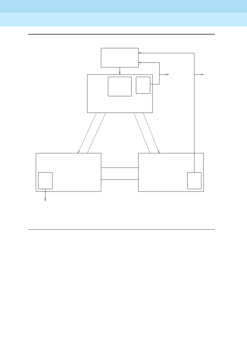
DEFINITY Enterprise Communications Server Release 6
Maintenance for R6r Volumes 1 & 2
555-230-126 Issue 2
January 1998
Maintenance Object Repair Procedures
Page 9-1368SYNC (Synchronization)
9
Figure 9-78. Typical Duplicated Direct-Connect Stratum 3 Synchronization
Configuration
For Stratum 3 synchronization, an external clock provides a timing signal to a
TN780 Tone-Clock circuit pack, and the TN780 provides timing to all circuit
packs in the PPN in which the TN780 resides (the external stratum 3 clock is only
allowed in the PPN). Each PPN Expansion Interface circuit pack uses the timing
generated by the TN780 to clock data from the active PPN to EPN fiber links. The
active EPN Expansion Interface circuit packs use the received data stream to
generate a timing signal which is used by the Tone-Clock circuit packs in the
EPNs to provide timing for all circuit packs in their respective EPNs. (The EPN
Tone-Clock circuit packs can be either TN780s or TN768s; only the Tone-Clock
circuit pack(s) connected to the external Stratum 3 clock must be TN780s.) The
PPN, in the above mentioned scenario, is designated the
master
port network
and the EPNs are called
slave
port networks. The
master
port network is defined
as the port network that contains the system synchronization source, the Stratum
DS-1
INTF
Clock
STRATUM 3
External
TONE/
TN780
CLOCK
and
standby
fiber
link
standby
fiber
link
active fiber link
timing info
active fiber link
and
timing info
PPN
* The EPN to EPN fiber link does not carry timing
standby
active
fiber link
fiber link
EPNEPN
DS1 References
DS-1
INTF
DS-1
INTF

DEFINITY Enterprise Communications Server Release 6
Maintenance for R6r Volumes 1 & 2
555-230-126 Issue 2
January 1998
Maintenance Object Repair Procedures
Page 9-1369SYNC (Synchronization)
9
3 clock in this case. The Stratum 4 equipment (usually a PBX) should never
provide timing to a Stratum 3 PBX.
If TDM-CLK error 2305 is in the error log, then a slave Tone-Clock loss of signal
condition exists on the slave Tone-Clock circuit pack that has this error. If only
one loss of signal occurred, the slave Tone-Clock circuit pack is receiving the
timing signal from the standby EI circuit pack (in this example, the timing is
coming from the PPN to the EPN over the standby fiber link). If another loss of
signal occurred after the Tone-clock circuit pack switched to receive timing from
the standby EI, the Tone-clock circuit pack will run on its local oscillator. The
yellow LED on the Tone-clock circuit pack flashes at the 2.7 seconds on and .3
seconds off rate (mostly on) if timing is received from an external source (an EI in
this example). Otherwise, if the Tone-clock circuit pack is running on its local
oscillator, the yellow LED flashes at the .3 seconds on and 2.7 seconds off rate
(mostly off).
Synchronization in a Center Stage Switch
Configuration
In the following typical duplicated Center Stage Switch (CSS) configuration, the
timing signal from the
master
port network, the PPN in this diagram, is sent to all
circuit packs in its network. The timing signal is sent from the Expansion Interface
(EI) circuit packs in the PPN to the Switch Node Interface (SNI) circuit packs in
the switch node carriers. The EIs in the
master
port network also sends out a
timing priority number (TPN) of 1. Every
slave
port network EI sends out a TPN of
30. The active Switch Node Clock (SNC) circuit pack in each switch node carrier
decides which SNI is providing the timing signal that the switch node carrier
should synchronize to by looking at each SNI’s incoming TPN. The SNC chooses
the SNI with the lowest numbered TPN to synchronize to. The SNC then sends
the timing signal to all SNIs and the standby SNC, if a standby SNC is present, in
the switch node carrier. The SNC also sends out a TPN equal to 1 plus the lowest
incoming TPN. Each SNI in the switch node sends the timing signal received
from the SNC and the TPN from the SNC out on its associated fiber.
If TDM-CLK error 2305 is in the error log, then a slave Tone-Clock loss of signal
condition exists on the slave Tone-Clock circuit pack that has this error. In this
case, the slave Tone-Clock circuit pack is receiving the timing signal from the
standby EI circuit pack in the port network that has the TDM-CLK 2305 error or
from its local oscillator. The yellow LED on the Tone-clock circuit pack flashes at
the 2.7 seconds on and .3 seconds off rate (mostly on) if timing is received from
an external source (for example, an EI circuit pack). Otherwise, if the Tone-clock
circuit pack is running on its local oscillator, the yellow LED flashes at the .3
seconds on and 2.7 seconds off rate (mostly off).

DEFINITY Enterprise Communications Server Release 6
Maintenance for R6r Volumes 1 & 2
555-230-126 Issue 2
January 1998
Maintenance Object Repair Procedures
Page 9-1370SYNC (Synchronization)
9
Figure 9-79. Typical Center Stage Switch Synchronization Configuration
-Two Switch Nodes, Duplicated PNC
Synchronization Troubleshooting
For both Stratum 3 and 4 operation, major and minor alarms indicate that there is
a problem with the system synchronization references. These alarms will be
resolved when the alarmed synchronization reference is restored.
The change synchronization command is used to administer whether Stratum 3
or Stratum 4 synchronization is being used. The change synchronization
command allows primary and secondary references to be administered for the
Stratum 4 option.
Timing information is sent through both the active and standby PNCs,
but the EPNs normally derive timing from the EIs on the active PNC.
EI
EI
Tone-
Clock Tone-
Clock
STANDBY PNC
ACTIVE PNC
TPN=30
TPN=30
TPN=3
TPN=3
TPN=2
TPN=2
TPN=1
TPN=1
EPN
EI
EI
PPN
SNC
SNI
SNI SNI
SNC
SNI SNI
SNC
SNI SNI
SNC
SNI
Switch Node 2 - A PNC
Switch Node 2 - B PNC Switch Node 1 - B PNC
Switch Node 1 - A PNC

DEFINITY Enterprise Communications Server Release 6
Maintenance for R6r Volumes 1 & 2
555-230-126 Issue 2
January 1998
Maintenance Object Repair Procedures
Page 9-1371SYNC (Synchronization)
9
The status synchronization command shows the current synchronization
reference. The display synchronization command shows the synchronization
references (e.g. primary, secondary, stratum 3) that are administered.
The list timing-source command displays all DS1 and UDS1 locations that are
allowed to be administered as primary or secondary references with the change
synchronization command.
Other commands associated with Synchronization Maintenance are disable
synchronization-switch and enable synchronization-switch. These
commands are used to disable the ability of Synchronization Maintenance to
switch between synchronization references and to enable this switching ability,
respectively. The set synchronization command is executed only after
synchronization has been disabled and is used to manually switch to a specific
synchronization reference. This command is useful to diagnose synchronization
problems by forcing a specific reference (DS1, UDS1, or Tone-Clock) to be the
system synchronization reference to determine if a specific reference is
providing a valid timing signal. To switch synchronization to the Stratum 3 clock,
use the enable synchronization-switch command after verifying that the
Stratum 3 clock is wired correctly.
Approach to Troubleshooting
Slip errors are the primary symptom associated with being unsynchronized.
A correct Synchronization plan for the network keeps the systems within the
network transmitting data at approximately the same rate to avoid situations
where:
■One system transmits data at a rate faster than another system can
receive the data (in which case data is lost).
■One system transmits data at a rate slower than another system expects to
receive data (in which case data is repeated).
Either of these situations, data being lost or repeated, is a slip.
When troubleshooting synchronization problems when slips are the primary error
log entry indications of a synchronization problem, requires that the problem be
isolated to:
■A problem outside of the switch, i.e., the switch is not properly
synchronized to the rest of the network.
■A problem internal to the switch.
DS1 and UDS1 circuit packs can be administered with slip detection enabled via
the Slip Detection? field set to a y (see the add ds1, change ds1, and display
ds1 commands). All DS1 and UDS1 circuit packs administered as slip enabled
will be counted in the following algorithm:
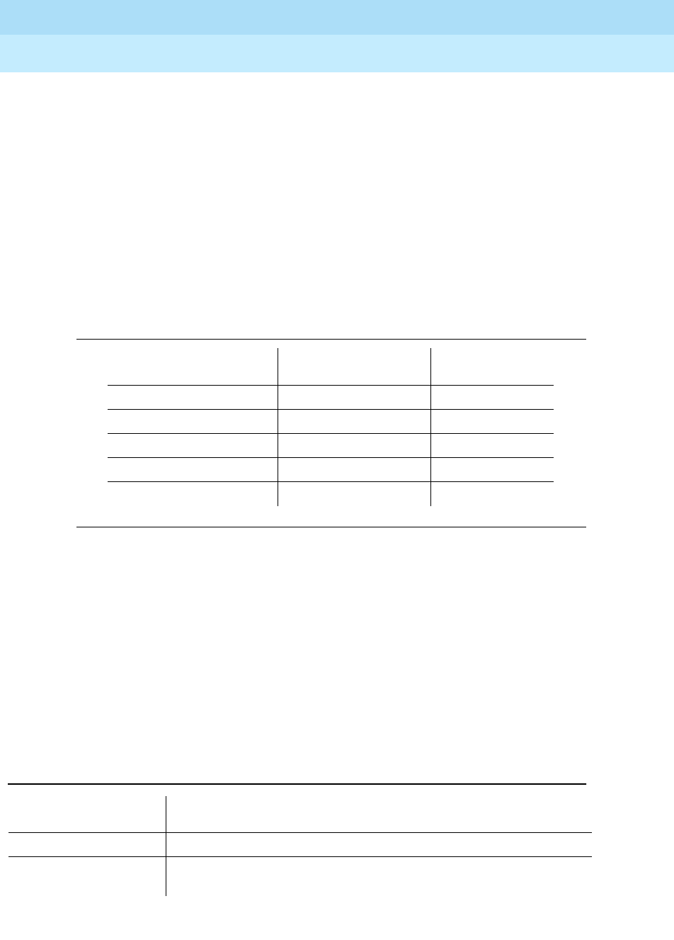
DEFINITY Enterprise Communications Server Release 6
Maintenance for R6r Volumes 1 & 2
555-230-126 Issue 2
January 1998
Maintenance Object Repair Procedures
Page 9-1372SYNC (Synchronization)
9
When over half of the DS1 and UDS1 circuit packs administered as slip enabled
are experiencing slips, and the primary or secondary synchronization reference
is the current synchronization reference, synchronization will try the other
administered synchronization reference.
In situations where one or many circuit packs in the system are experiencing
slips, the problem could be with the synchronization reference, with individual
circuit packs, or with phase modulation of the transmitted digital bit streams due
to environmental variations of the transmission facilities (such as temperature
variations that affect the electrical length of a transmission line). The circuit packs
that can experience slips and the associated error log entry for slips are as
follows.
When slips occur on the circuit packs mentioned above, first consult the
individual circuit pack section in the manual for each circuit pack that has slips. If
slips occur in low numbers, they may be due to environmental conditions as
described above. If no service degradation is occurring, no action is necessary.
Whenever the system switches synchronization sources, slips can be expected
from DS1-BD, UDS1-BD, and EXP-INTF circuit packs. If service degradation
occurs, after following the repair steps in the individual section, use the following
trouble shooting techniques.
The following table lists circuit packs that can report slips and related circuit
packs whose hardware problems that cause those slips.
Table 9-468. Error Log Entries for Slip Errors
Circuit Pack Error Log Name Error Log Entry
for Slips
DS1 Interface DS1-BD 3073 to 3160
Expansion Interface EXP-INTF 2305
Switch Node Interface SNI-BD 1537
Tone-Clock TDM-CLK 1025
UDS1 Interface UDS1-BD 3073 to 3160
Table 9-469. Slips and Related Circuit Packs
Circuit Pack Reporting
Slips Associated Circuit Packs That Can Cause Slips
DS1 Interface Active Tone-Clock in same port network
Expansion Interface Active Tone-Clock in same port network or circuit pack at opposite end
of fiber or metallic connection

DEFINITY Enterprise Communications Server Release 6
Maintenance for R6r Volumes 1 & 2
555-230-126 Issue 2
January 1998
Maintenance Object Repair Procedures
Page 9-1373SYNC (Synchronization)
9
Troubleshooting Synchronization Problems
The following flow chart presents a logical approach to troubleshooting
synchronization problems in conjunction with the background information
presented above. Explanatory notes follow the charts.
Switch Node Interface Circuit pack at opposite end of fiber or metallic connection, or active
Switch Node Clock circuit pack in same switch node carrier
Tone-Clock Current DS1 reference
UDS1 Interface Active Tone-Clock in same port network
Table 9-469. Slips and Related Circuit Packs
Circuit Pack Reporting
Slips Associated Circuit Packs That Can Cause Slips
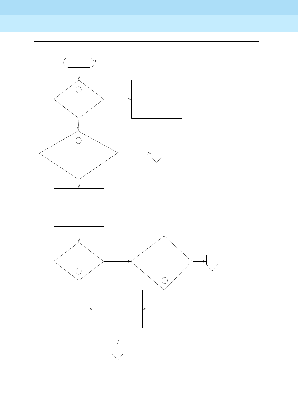
DEFINITY Enterprise Communications Server Release 6
Maintenance for R6r Volumes 1 & 2
555-230-126 Issue 2
January 1998
Maintenance Object Repair Procedures
Page 9-1374SYNC (Synchronization)
9
Figure 9-80. Synchronization Troubleshooting, Page 1 of 6
3
SLIPS
ON DS1
FACILITIES?
SYSTEM IS
OPERATING AS
A TIMING SLAVE
IN NETWORK
REFERENCE
IS FREE RUN TONE
CLOCK OR FREE RUN
STRATUM III
SYNC
ENABLED
1
1
2
SLIPS
ENABLE
SYNCHRONIZATION
Yes
No
No
No
PAGE 5
SLIPS ON EIs, SNIs,
TONE CLOCKS OR
NON-REFERENCE PN DS1s
SYNCHRONIZATION ENABLED
IN SYSTEM OPERATING AS
NETWORK TIMING MASTER
APAGE 2
Yes
Yes
No
C
PROBLEM
IS IN
SWITCH
B
Yes
PROBLEMS WITH
REFERENCE PN OR
SYNCHRONIZATION
PLAN
PAGE 4
SLIPS
ON SOME DS1
FACILITIES IN
SAME PN AS
REF?

DEFINITY Enterprise Communications Server Release 6
Maintenance for R6r Volumes 1 & 2
555-230-126 Issue 2
January 1998
Maintenance Object Repair Procedures
Page 9-1375SYNC (Synchronization)
9
Figure 9-81. Synchronization Troubleshooting, Page 2 of 6
SLIPS
ON DS1
FACILITIES?
No
No
Yes
A
2
4
IS
THIS SWITCH
SUPPOSED TO BE
TIMING MASTER?
FROM
PAGE 1
SLIPS
ON EI’S, SNI’S,
TONE CLOCKS?
DONE
TO
PAGE 5
C
PROBLEM
IS IN
SWITCH
Yes
EXAMINE
SYNCHRONIZATION
PLAN FOR
NETWORK
REFER PROBLEM
FOR INVESTIGATION
AT OTHER END
OF FACILITY
Yes
No
MAKE CHANGES TO
HAVE SWITCH OPERATE
IN ACCORDANCE
WITH NETWORK
SYNCHRONIZATION PLAN
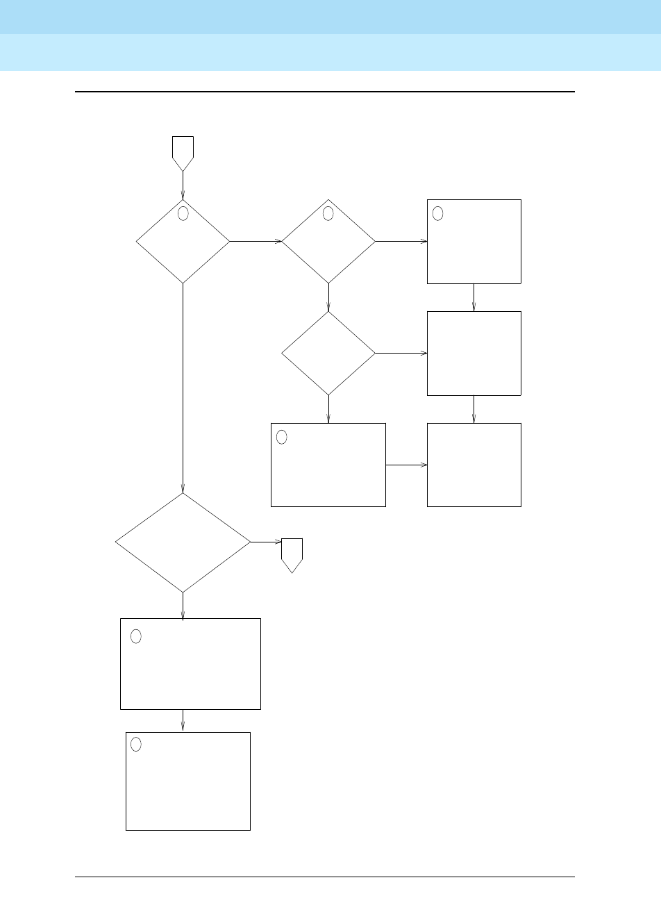
DEFINITY Enterprise Communications Server Release 6
Maintenance for R6r Volumes 1 & 2
555-230-126 Issue 2
January 1998
Maintenance Object Repair Procedures
Page 9-1376SYNC (Synchronization)
9
Figure 9-82. Synchronization Troubleshooting, Page 3 of 6
USE THE FACILITY FAULT
SECTIONALIZATION
TECHNIQUE SECTION WITH
SLIP COUNTS AS THE
PASS/FAIL INDICATION TO
ISOLATE THE TROUBLE
Yes
Yes
No
No
REPLACE THE
CIRCUIT PACKS:
•TONE CLOCK IN
TIMING MASTER PN
•DS1 IN TIMING
MASTER PN
IS THERE A
LOSS OF SIGNAL
OR NETWORK
ALARM?
6
7
65
FROM
PAGE 4
ESCALATE IF THE
PROBLEM IS
NOT FIXED
FIX STRAT-3
ALARMS
FIX DS1-BD AND
UDS1-BD ALARMS
SLIPS ON
REFERENCE
FACILITY?
D
Yes
No
STRAT-3
ALARMS?
CHECK THE OVERALL TIMING
NETWORK TO VERIFY THE
SOURCE IS TRACEABLE
BACK TO THE SAME SOURCE
(EXAMPLE, HILLSBORO, MO.)
8
8
ARE THERE
MANY FACILITIES WITH
EXCESSIVE SLIPS?
Few
Many
PROBLEM
IN SWITCH
TO
PAGE 5
C
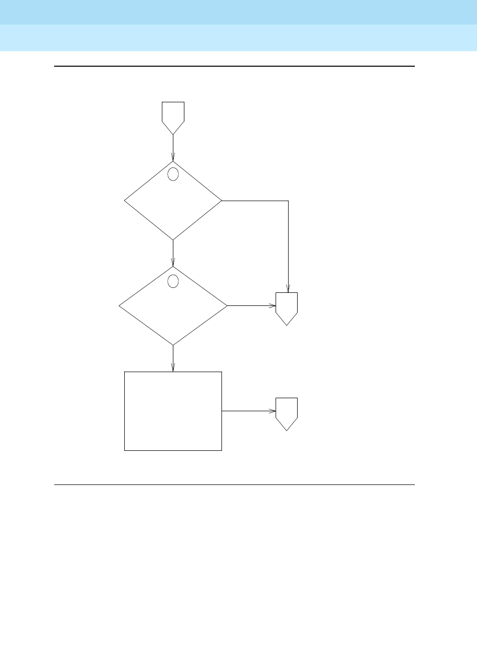
DEFINITY Enterprise Communications Server Release 6
Maintenance for R6r Volumes 1 & 2
555-230-126 Issue 2
January 1998
Maintenance Object Repair Procedures
Page 9-1377SYNC (Synchronization)
9
Figure 9-83. Synchronization Troubleshooting, Page 4 of 6
10
No
Yes
IS THE REFERENCE
ADMINISTERED AND
SYNC ENABLED?
ADMINISTER THE
REFERENCE
AND ENABLE
SYNCHRONIZATION
B
FROM
PAGE 1
9
IS A REFERENCE
ON LINE?
No
Yes
D
D
TO
PAGE 3
TO
PAGE 3
PROBLEM
IN SWITCH
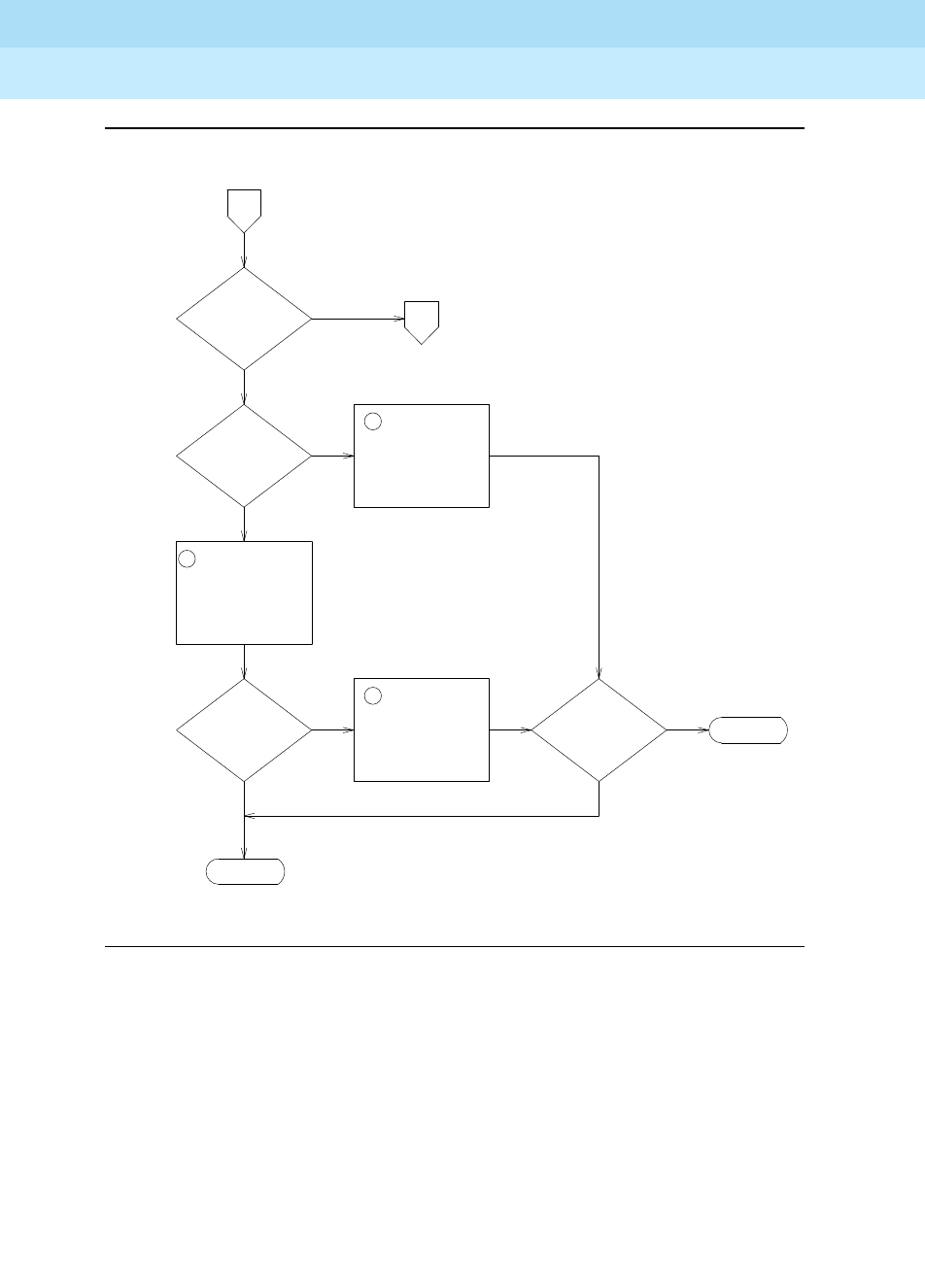
DEFINITY Enterprise Communications Server Release 6
Maintenance for R6r Volumes 1 & 2
555-230-126 Issue 2
January 1998
Maintenance Object Repair Procedures
Page 9-1378SYNC (Synchronization)
9
Figure 9-84. Synchronization Troubleshooting, Page 5 of 6
11
11
12
C
CSS
SYSTEM
SLIPS
ON MORE THAN
ONE SLAVE
PN?
ESCALATE
DONE
TO
PAGE 6
E
SLIPS
REMAIN?
REPLACE EIs
ASSOCIATED WITH
FIBER BETWEEN
TIMING MASTER
PN and SLAVE PN
REPLACE
TONE-CLOCK
IN TIMING
SLAVE PN
Yes Yes
Yes
Yes
REPLACE
TONE-CLOCK
IN MASTER
TIMING PN
No
No
No
No
SLIPS
REMAIN?
PROBLEM IS IN SWITCH (EI,
SNI, TONE-CLOCK or DS1’s in
PNs other than the timing master PN)
DIRECT
CONNECT
FROM PAGES
1, 2, OR 3
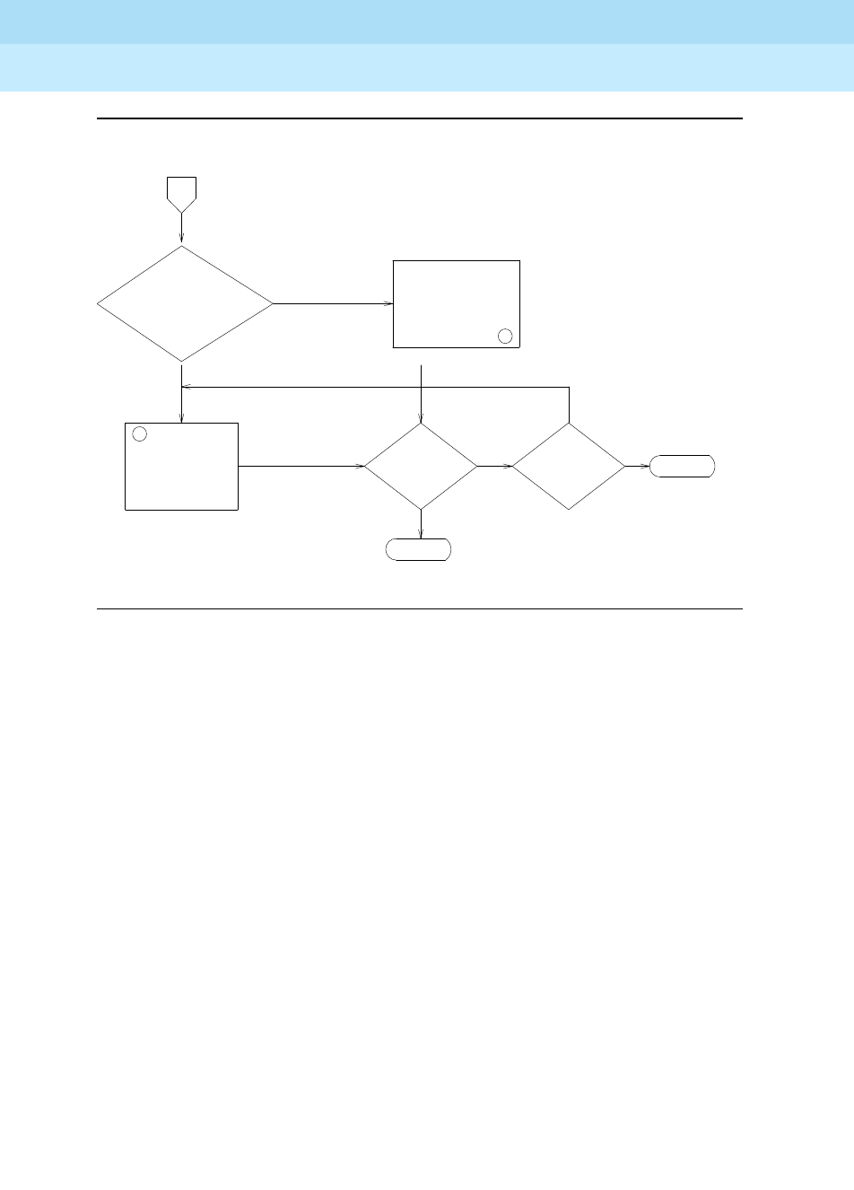
DEFINITY Enterprise Communications Server Release 6
Maintenance for R6r Volumes 1 & 2
555-230-126 Issue 2
January 1998
Maintenance Object Repair Procedures
Page 9-1379SYNC (Synchronization)
9
Figure 9-85. Synchronization Troubleshooting, Page 6 of 6
Notes for Sheet 1 through Sheet 6 flowcharts (when checking for slip errors, use
the table above,
Error Log Entries for Slip Errors
):
1. Use the status synchronization command to determine whether
synchronization is enabled and to determine the on-line reference. If the
on-line reference is a tone-clock board, the switch is operating in free run
mode. If the Stratum 3 is displayed, and no DS1s are connected to the
Stratum 3 clock or no DS1 connection existed to the Stratum 3 clock for
over 24 hours, then the Stratum 3 clock is in free run mode.
2. Check for slip errors against DS1-BD and UDS1-BD.
3. If Stratum 3 is administered (display synchronization) and on-line
(status synchronization), check for DS1-BD or UDS1-BD slip errors for
the DS1(s) or UDS1(s) used as input to the Stratum 3 clock. Check the
LED indications on the Stratum 3 clock to determine which DS1 is
providing input to the Stratum 3 and examine the cross connect
information for that DS1.
4. Check for slips errors against EXP-INTF, SNI-BD, and TDM-CLK.
Yes
13
GOOD REFERENCE
BUT SN NOT
IN SYNC
REPLACE ONE AT A
TIME: EI, SNI, AND
TONE-CLOCK
ASSOCIATED WITH
REFERENCE PN.
IF SLIPS REMAIN,
REPLACE SNC.
SLIPS ON MANY
EIs, TONE-CLOCKs,
OR SNIs ASSOCIATED
WITH AN SN
CARRIER
REPLACE SNI, EI,
TONE-CLOCK FOR
PN WITH SLIPS
CSS SYSTEM NOT
TOTALLY IN SYNC
E
ESCALATE
DONE
Yes
Yes
14
No
No
SLIPS
ISOLATED
TO A PN?
SLIPS
REMAIN?
No

DEFINITY Enterprise Communications Server Release 6
Maintenance for R6r Volumes 1 & 2
555-230-126 Issue 2
January 1998
Maintenance Object Repair Procedures
Page 9-1380SYNC (Synchronization)
9
5. Check status synchronization for the current DS1 reference. If a DS1 or
UDS1 is on-line, check for slips on that DS1 or UDS1. If Stratum 3
synchronization is administered and the Stratum 3 clock is used as the
reference (i.e. the tone-clock local oscillator is not on-line), follow the
procedure in step 3 to determine the DS1 reference used as input to the
Stratum 3 clock and check for slips on that reference.
6. Check for LOS, Blue, Yellow, and Red Alarms on the on-line reference
facility and fix those problems first. See the DS1-BD and/or UDS1-BD for
the error log entries associated with the above mentioned alarms. Replace
the circuit packs one at a time and wait at least one hour to determine if
the problem has gone away. This procedure is disruptive and should be
done after hours if possible. An alternative to replacing the tone-clock
circuit pack in systems where the tone-clocks are duplicated, is to run the
set tone-clock command to switch tone-clocks. If the problem goes
away, the previously active tone-clock should be replaced.
7. If a few facilities are experiencing slips or are unusable references, the
clock source for facilities with slips or that are unusable is not traceable to
the same ultimate source as the clock source for the on-line reference
facility.
Examine the overall timing network for the interconnected DS-1 to
determine if the clock can be traced back to a single source and if the
reference designations for each location in the distribution of timing is
supplied in accordance with the
synchronization plan
for the customer.
Examine the capability of the external transmission equipment to pass or
provide timing.
Verify the integrity of the on-site hardware by using the
Facility Fault
Sectionalization
section, which loops the transmit signal to the receive
signal and verifies that the excessive slips or the unusable reference are
no longer observed.
This is a time consuming process that disrupts service. You should
perform it after hours if the service being provided by the system is
acceptable as determined by checking with the customer.
8. Use status synchronization to determine the on-line reference. If a DS1
or Stratum 3 reference is not on-line and the local oscillator of a tone-clock
board is on-line, then the answer to this question is "no".
9. Use display synchronization to find out what references, if any, are
administered. Use status synchronization to find out whether
synchronization is enabled.
10. If tone-clocks are duplicated, the set tone-clock command can be used
to switch tone-clocks. If slips go away, then replace the tone-clock that
was just switched away from.

DEFINITY Enterprise Communications Server Release 6
Maintenance for R6r Volumes 1 & 2
555-230-126 Issue 2
January 1998
Maintenance Object Repair Procedures
Page 9-1381SYNC (Synchronization)
9
11. Use status pnc to determine which PNC is active. Then use list
fiber-links to determine the EIs on the active PNC and the EIs associated
with the slave PN. If the switch does not have PNC duplication, the EIs are
all on the active PNC, A-PNC. A PNC interchange can be done via reset
pnc interchange before replacing EIs if the system has PNC duplication.
If the slips go away after the PNC interchange, replace the EIs that were
previously active.
12. Replace the circuit packs one at a time and wait at least one hour to
determine if the problem has gone away. This procedure is disruptive and
should be done after hours if possible.
An alternative to replacing the EI and SNI in systems where the PNC is
duplicated, is to perform a PNC interchange via reset pnc interchange. If
the problem goes away, either the EI or the SNI on the previously active
PNC should be replaced. Replace one at a time and make that PNC active
again to determine whether the problem is fixed.
An alternative to replacing the tone-clock circuit pack in systems where
the tone-clocks are duplicated, is to run the set tone-clock command to
switch tone-clocks. If the problem goes away, the previously active
tone-clock should be replaced.
Also, before replacing an SNC circuit pack, the set switch-node-clock
command can be used if SNCs are duplicated in the carrier. If the
problem goes away, the previously active SNC should be replaced.
13. Replace the circuit packs one at a time and wait at least one hour to
determine if the problem has gone away. This procedure is disruptive and
should be done after hours if possible.
An alternative to replacing the EI and SNI in systems where the PNC is
duplicated, is to perform a PNC interchange via reset pnc interchange. If
the problem goes away, either the EI or the SNI on the previously active
PNC should be replaced. Replace one at a time and make that PNC active
again to determine whether the problem is fixed.
An alternative to replacing the tone-clock circuit pack in systems where
the tone-clocks are duplicated, is to run the set tone-clock command to
switch tone-clocks. If the problem goes away, the previously active
tone-clock should be replaced.
Also, before replacing an SNC circuit pack, the set switch-node-clock
command can be used if SNCs are duplicated in the carrier. If the
problem goes away, the previously active SNC should be replaced.
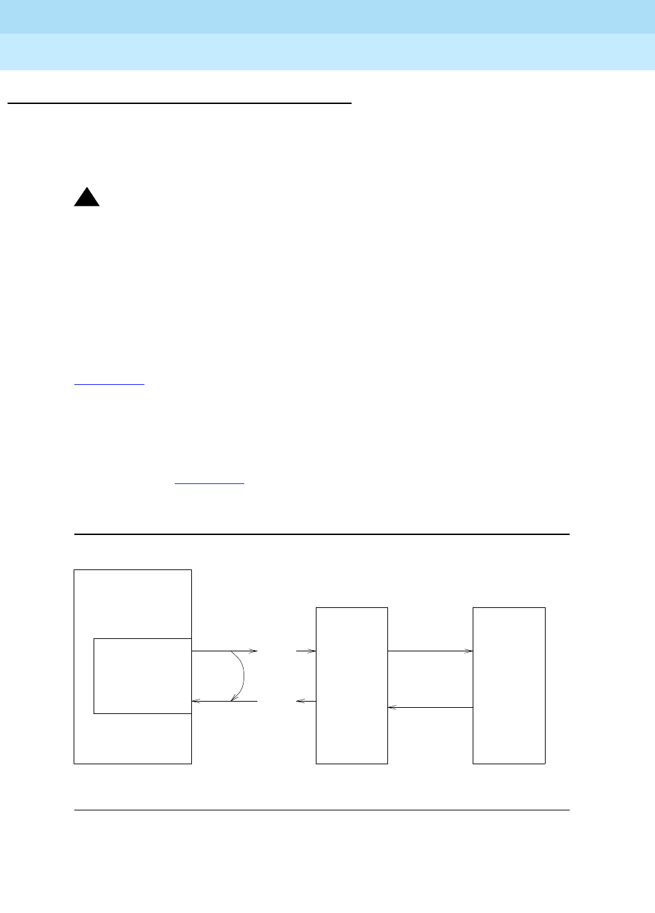
DEFINITY Enterprise Communications Server Release 6
Maintenance for R6r Volumes 1 & 2
555-230-126 Issue 2
January 1998
Maintenance Object Repair Procedures
Page 9-1382SYNC (Synchronization)
9
Facility Fault Sectionalization
DS-1 facility fault sectionalization involves looping around the DS-1 signal at
on-site access points to localize the source of the problem to equipment and
wiring on either the near side or far side of the loop-around point.
!WARNING:
The facility fault sectionalization technique disrupts service. When you
perform the looparound on a facility, make sure it is not the on-line
synchronization reference or a system outage will occur.
When you use this technique to investigate problems on facilities with multiplex
or DACS equipment, the technique becomes cumbersome because all of the 64
Kbps (B-channels) or subrate channels corresponding to the DS-1 facility need
to be looped around.
Figure 9-86 shows a sequence of units (1 though n) that may be connected as
the on-site equipment. A typical example is the case where the only on-site
equipment is channel-terminating equipment designated Unit #1. A more
complex, less typical example might have a DACS as Unit #1, a protection switch
as Unit #2, and a DS-1-level microwave radio system as Unit #3.
The flowchart in Figure 9-87 gives an overview of the facility fault sectionalization
technique. It is important that you know the configuration and wiring of the
equipment for the problem facility in order to support this technique.
Figure 9-86. Manual Looparound for Facility Fault Sectionalization
Since the technique is time consuming, fix any DS1-BD, UDS1-BD, STRAT-3, or
SYNC errors first that are not slip errors.
Next
Unit
(#1)
Pairs Open
at Next
Unit
Manually
Wired
Loop-Around
TN722,
TN767, or
TN464
DS1 interface
G3r System
Span
Line
Side
Next
Unit
(#N)

DEFINITY Enterprise Communications Server Release 6
Maintenance for R6r Volumes 1 & 2
555-230-126 Issue 2
January 1998
Maintenance Object Repair Procedures
Page 9-1383SYNC (Synchronization)
9
Figure 9-87. Facility Fault Sectionalization
Enter busyout board
for the DS1 Interface.
This circuit pack should
not be the on-line
synchronization reference.
Since this technique is time-consuming, first fix any DS1-BD,
UDS1-BD, STRAT-3 or SYNC errors that are not slip errors.
START (DS1 Interface refers to the TN722, TN767 or TN464 circuit pack.)
Loop transmit to receive on the
G3r side of the equipment
connected to the DS1 Interface.
(See Note 1).
NO
Restore service:
enter release
board for the
DS1 Interface.
YES
The fault lies beyond the
loop-around point. Remove
the loop-around and rewire
the connections. Is the
unit just tested the last unit
on the G3r side of the
maintenance boundary?
FAIL
The fault lies before the
loop-around point. Repair
or replace the defective
wiring or circuit pack.
If the problem cannot be
identified, escalate the
problem.
Move the loop-around point
to the next unit toward the
span line side. Loop transmit
to receive on the G3r side of
the next piece of equipment.
Report to the
appropriate
personnel that
the problem is
beyond the
maintenance
boundary.
PASS
Execute the Slip Alarm
Inquiry Test (#144) via
test board command.
(See Note 2).

DEFINITY Enterprise Communications Server Release 6
Maintenance for R6r Volumes 1 & 2
555-230-126 Issue 2
January 1998
Maintenance Object Repair Procedures
Page 9-1384SYNC (Synchronization)
9
Notes to Facility Fault Sectionalization Flowchart
1. Loop transmit to receive on the system side.
Remove the transmit signal from the TN722, TN767, or TN464 circuit pack
inputs and outputs and loop it around to the receive signal going toward
the TN722, TN767, or TN464 circuit pack at the first unit wired to the
TN722, TN767, or TN464 circuit pack. (See Figure 9-86).
The looparound signal may take different forms depending on the
installation.
■In some cases, the unit connected to the system may provide a
switch or a terminal interface to control the desired looparound.
Make sure that the signal is looped toward the system and that the
timing signal is looped.
■In most cases, it may be necessary to temporarily rewire
connections at the cross-connect fields to loop the signal back
toward the switch.
The point at which the signal is looped should be one at which physical
access is easy and where the signal level is within the line compensation
(i.e. equalization) range of the hardware connected. A few cases exist
where access to the looparound cannot be easily provided at locations
where the signal level is within the line compensation range of the
hardware. The line compensation can be changed via the change ds1
UUCSS command.
2. Execute the test board UUCSS command for the TN722, TN767 or
TN464. Look at results of Test #144, the Slip Alarm Inquiry Test. When this
test fails, the error code gives the number of slips detected since the last
Slip Inquiry Test was run. If the test fails, run it at least one more time to
ensure that slips have occurred since the looparound was installed.
Timing Loops
A timing loop exists whenever a system receives timing from another system
whose timing reference is directly or indirectly derived from itself. The system
synchronization planner
must avoid creating a timing loop
when administering
the synchronization references in a system. Timing loops can lead to loss of
digital data between systems that are exchanging data with any system within
the loop. An invalid timing signal will also be generated by any system within the
loop, thus propagating the invalid timing signal to any system(s) using a system
within the loop as a synchronization reference.
A correctly designed network has no loops and each piece of equipment in the
network is supplied by a clock of equal or lower stratum (i.e.,: the inputs to a
Stratum 3 clock should NEVER be from a Stratum 4 device).
Synchronization
administration changes should never be done without consulting the overall
synchronization plan for the network. If you suspect that synchronization
administration changes are needed, follow normal escalation procedures.

DEFINITY Enterprise Communications Server Release 6
Maintenance for R6r Volumes 1 & 2
555-230-126 Issue 2
January 1998
Maintenance Object Repair Procedures
Page 9-1385SYNC (Synchronization)
9
Synchronization Switches Away from the Current Timing Reference
Synchronization will switch away from a DS1 reference (primary or secondary) if
the current DS1 reference is not providing a valid timing signal. The other DS1
reference will be used if one is administered and providing a valid timing signal.
Otherwise, the local oscillator of the Tone-Clock circuit pack in the same port
network as the DS1 reference will be used. The following conditions will cause a
synchronization switch:
■The current DS1 reference is not inserted (i.e. list configuration board
UUCSS shows "no board").
■The current DS1 reference has a loss of signal error (DS1-BD and
UDS1-BD error type 1281), a blue alarm error (DS1-BD and UDS1-BD
error type 1793), a red alarm error (DS1-BD and UDS1-BD error type
2049), or a hyperactive angel error (DS1-BD and UDS1-BD error type
1538). A corresponding alarm log entry is not required.
■DS1 and UDS1 circuit packs can be administered with slips detection
enabled via the Slip Detection? field set to a y (see the add ds1, change
ds1, and display ds1 commands). When over half of the DS1 and UDS1
circuit packs administered as slip enabled are experiencing slips, and the
primary or secondary synchronization reference is the current
synchronization reference, synchronization will try the other administered
synchronization reference if the other administered reference does not
have the above two conditions. The list measurements ds1-log
command can be used to get an historical perspective of DS1 facility
operation.
The following conditions will cause a switch to the other DS1 reference if one
exists and the other DS1 reference is more healthy:
■The current DS1 reference has a misframe error (DS1-BD error type 3329
to 3345 or UDS1-BD error type 3585-3601). A corresponding alarm log
entry is not required.
■The current DS1 reference has a slip alarm (DS1-BD and UDS1-BD error
type 3073 to 3160). A corresponding alarm log entry is required.
If the above conditions are repaired and no longer apply, synchronization will
switch back to the primary reference.
Tone-Clock Circuit Pack LEDs
The yellow and green LEDs of the TN768 and TN780 Tone-Clock circuit packs
flash in a specific pattern to indicate the status of the circuit pack. For example,
these flashing LED patterns are used to indicate if a Tone-Clock circuit pack is
deriving timing from an external source or whether the Tone-Clock circuit pack is
providing the timing signal for the port network.

DEFINITY Enterprise Communications Server Release 6
Maintenance for R6r Volumes 1 & 2
555-230-126 Issue 2
January 1998
Maintenance Object Repair Procedures
Page 9-1386SYNC (Synchronization)
9
The yellow and green LED patterns for the TN768 and TN780 Tone-Clock circuit
pack are as follows:
1. The external synchronization reference being used is a primary reference, a secondary reference, or
the external stratum 3 clock when the Tone-Clock is in the master port network. The external
synchronization reference used in a slave port network is the Expansion Interface circuit pack.
Table 9-470. Tone-Clock Yellow/Green LED Flashing Codes
Circuit Pack Condition Tone-Clock
State Explanation
1flashing yellow
2.7 seconds on
.3 seconds off
active This light pattern indicates that an external
timing source is being used as a
synchronization reference.
flashing yellow
.3 seconds on
2.7 seconds off
active This light pattern indicates that the circuit pack
is being used as a synchronization reference.
steady yellow
on active This light pattern indicates that the light has
been reset but has not been told which
synchronization reference source to use.
steady yellow
off standby This light pattern indicates that the circuit pack
is in standby mode (neither generating tones
nor supplying clocks).
"jingle bells"
green and yellow
.1 seconds on, .2 seconds off, .1
seconds on, .4 seconds off, .4
seconds on, .4 seconds off,
standby The system is running maintenance tests on
the standby circuit pack. (the standby
Tone-Clock circuit pack is providing tones.)
other green and yellow active The system is running maintenance tests on
the active circuit pack
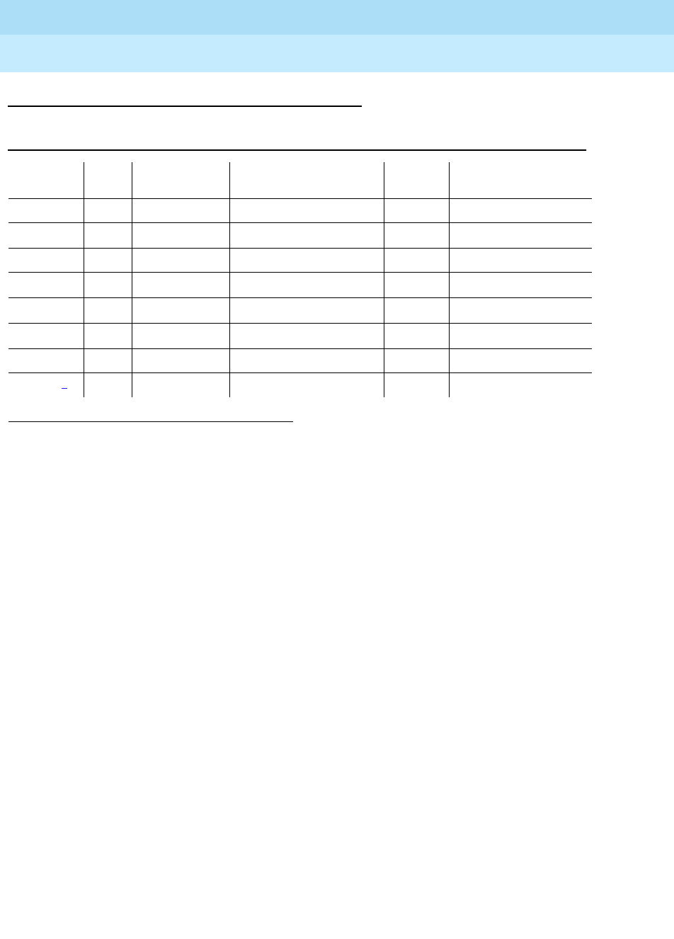
DEFINITY Enterprise Communications Server Release 6
Maintenance for R6r Volumes 1 & 2
555-230-126 Issue 2
January 1998
Maintenance Object Repair Procedures
Page 9-1387SYNC (Synchronization)
9
Error Log Entries and Test to Clear Values
Notes:
a. This error indicates a problem with the primary DS1 reference. It will be
cleared when the primary reference is restored. The following steps
should give an indication of the source of the problem:
1. Check if the primary DS1 interface circuit pack is inserted in the
carrier via the list configuration board UUCSS command.
2. Verify that the administered primary reference matches the DS1
reference from the network synchronization plan.
3. Test the primary DS1 interface circuit pack via the test board
UUCSS long command. Check the Error Log for DS1-BD or
UDS1-BD errors and refer to the DS1-BD or UDS1-BD (DS1
Interface Circuit Pack or UDS1 Interface Circuit Pack) Maintenance
documentation to resolve any errors associated with the primary
DS1 (DS1 or UDS1) interface circuit pack. If the only errors against
DS1-BD or UDS1-BD are slip errors, then follow the procedures
described in the troubleshooting section above. If no errors are
listed in the Error Log for the primary DS1 interface circuit pack,
continue with the following steps.
4. Test the active Tone-Clock circuit pack in the master port network
via the test tone-clock UUC long command. Check the Error Log
for TDM-CLK errors and verify that TDM Bus Clock Test #148 (TDM
Bus Clock Circuit Status Inquiry test) passes successfully. If Test
1. Run the Short Test Sequence first. If all tests pass, run the Long Test Sequence. Refer to the
appropriate test description and follow the recommended procedures.
2. It may take up to 1 hour for these alarms to clear via the ‘‘leaky bucket’’ strategy.
Table 9-471. Synchronization Maintenance Error Log Entries
Error
Type Aux
Data Associated
Test Alarm Level On/Off
Board Test to Clear Value
010 Any Any Any test synchronization
1(a)* None WARNING/MINOR(h) OFF None
18(b) 0 disable sync WARNING OFF enable sync
257(c)* None WARNING/MINOR(h) OFF None
513(d)* None WARNING/MAJOR(h) OFF None
769(e) None MAJOR OFF None
1793(f)20-50 None MAJOR OFF None
2049(g)20 None WARNING OFF None

DEFINITY Enterprise Communications Server Release 6
Maintenance for R6r Volumes 1 & 2
555-230-126 Issue 2
January 1998
Maintenance Object Repair Procedures
Page 9-1388SYNC (Synchronization)
9
#148 fails with an Error Code 2 through 32, refer to the TDM-CLK
(TDM Bus Clock) Maintenance documentation to resolve the
problem. If not, continue with the following steps.
5. Execute the disable synchronization-switch and then the enable
synchronization-switch commands. These two commands (when
executed together) will switch the system synchronization
reference to the primary DS1 interface circuit pack. Check the Error
Log and execute the status synchronization command to verify
that the primary DS1 interface circuit pack is still the system
synchronization reference. If the primary DS1 interface circuit pack
is not the system synchronization reference, and the master port
network does not have duplicate Tone-Clock circuit packs,
escalate the problem. If not, continue with the following step.
6.
Duplicated Tone-Clock circuit packs in the master port network:
Switch Tone-Clock circuit packs on the master port network via the
set tone-clock UUC command, and repeat the disable/enable
commands described in the previous step.
Switch Tone-Clock circuit packs on the master port network via the
set tone-clock UUC command, and repeat the disable/enable
commands described in the previous step.
b. This error indicates that Synchronization Maintenance has been disabled
via the disable synchronization-switch command. Execute the enable
synchronization-switch command to enable Synchronization
Maintenance reference switching and to resolve this alarm.
c. This error indicates a problem with the secondary DS1 reference. It will be
cleared when the secondary reference is restored. Refer to note (a) to
resolve this error substituting secondary for primary in the preceding
resolution steps.
d. This error indicates that the Tone-Clock circuit pack is providing the timing
source for the system. The primary and secondary (if administered) are
not providing a valid timing signal. Investigate errors 1 and 257 to resolve
this error.
e. This error indicates that the external Stratum 3 Clock fails to provide the
system timing reference. Refer to Stratum 3 Clock Maintenance document
to resolve the defective synchronization reference.
f. This error indicates excessive switching of system synchronization
references has occurred. When this error occurs, synchronization is
disabled and the Tone-Clock circuit pack (in the master port network)
becomes the synchronization reference for the system. Execute the
following steps to resolve this error:
1. Check for timing loops and resolve any loops that exist.
2. Test the active Tone-Clock circuit pack in the master port network
via the test tone-clock UUC long command. Check the Error Log
for TDM-CLK errors and verify that TDM Bus Clock Test #148 (TDM

DEFINITY Enterprise Communications Server Release 6
Maintenance for R6r Volumes 1 & 2
555-230-126 Issue 2
January 1998
Maintenance Object Repair Procedures
Page 9-1389SYNC (Synchronization)
9
Bus Clock Circuit Status Inquiry test) passes successfully. If Test
#148 fails with an Error Code 2 through 32, refer to “TDM-CLK” to
resolve the problem. If not, continue with the following steps.
3.
Duplicated Tone-Clock circuit packs in the master port network:
Switch Tone-Clock circuit packs on the master port network via the
set tone-clock UUC command.
Switch Tone-Clock circuit packs on the master port network via the
set tone-clock UUC command.
For simplex Tone-Clock circuit packs in the master port network:
If
this is not a Stratum 3 system, replace the primary and secondary
(if administered) DS1 Interface circuit packs.
4. Investigate any other SYNC or STRAT-3 errors.
g. This error indicates that the Expansion Interface circuit packs are
experiencing timing slips. This error will increase the bit error rates for
data transmission between port networks. The Expansion Interface circuit
packs with timing slips have EXP-INTF error 2305.
1. Check the LEDs on the active Tone-Clock circuit packs in the
system and verify that the system is properly synchronized.
2. Verify that all the TDM/LAN Bus cables on the backplane are
marked WP-91716. Also for a Multi-Carrier Cabinet (MCC), check
that the bus terminator type is a ZAHF4 TDM/LAN.
For a Single Carrier Cabinet verify that the bus terminator type is a
AHF110 TDM/LAN.
3. Check for timing loops, and resolve any loops that exist.
4. Check the Error Log for any active as well as resolved Expansion
Interface circuit pack errors and refer to EXP-INTF (Expansion
Interface Circuit Pack) Maintenance documentation to resolve any
errors found.
5.
Duplicated Tone-Clock circuit packs in the slave port networks:
■Switch Tone-Clock circuit packs in the slave port networks
where EXP-INTF error 2305 also occurs via the set
tone-clock UUC system technician command. The error
count for this particular error should start decrementing once
the problem is solved—if the count does not decrease in 15
minutes the problem still persists.
■If the problem still persists, switch the Tone-Clock in the
slave port network back to the previous configuration. Then,
perform a PNC interchange via the reset pnc interchange
command.
■If the problem still persists, switch the PNC back to the
previous configuration via the reset pnc interchange
command. Then, switch the Tone-Clock circuit packs in the
master port network via set tone-clock UUC.

DEFINITY Enterprise Communications Server Release 6
Maintenance for R6r Volumes 1 & 2
555-230-126 Issue 2
January 1998
Maintenance Object Repair Procedures
Page 9-1390SYNC (Synchronization)
9
■If the problem still persists, switch the Tone-Clock circuit
packs in the master port network back to the previous
configuration via set tone-clock UUC.
■Replace the active Expansion Interface circuit pack in the
master port network.
■In a CSS configuration, replace the Switch Node Interface
circuit pack connected to the active Expansion Interface
circuit pack in the master port network. The list fiber-link
command can be used to determine the Switch Node
Interface circuit pack that is connected to the active
Expansion Interface circuit pack in the master port network.
■If the system synchronization reference is a Tone-Clock
circuit pack or the Stratum 3 Clock, follow normal escalation
procedures. If the system synchronization reference is a DS1
interface circuit pack, administer a different DS1 interface
circuit pack as the primary synchronization reference. If the
problem still is not resolved and any slip errors remain, follow
the procedures described in the troubleshooting section
above.
6.
Simplex Tone-Clock circuit packs in the slave port networks:
■Switch the Tone-Clock circuit packs in the master port
network via set tone-clock UUC.
■If the problem still persists, switch the Tone-Clock circuit
packs in the master port network back to the previous
configuration via set tone-clock UUC. Test the Tone-Clock
circuit packs in the master and slave port networks via the
test tone-clock UUC long command. Check the Error Log
for TDM-CLK errors and verify that TDM Bus Clock Test #148
(TDM Bus Clock Circuit Status Inquiry test) passes
successfully. If Test #148 fails with an Error Code 2 through
32, refer to “TDM-CLK” to resolve the problem. If not,
continue with the following steps.
■If the master and slave Tone-Clock circuit packs
do not
fail
TDM Bus Clock Test #150 (TDM Bus Clock PPM Inquiry
test), replace the Expansion Interface circuit packs that have
EXP-INTF error 2305.
■If the system synchronization reference is a Tone-Clock
circuit pack and the master Tone-Clock circuit pack fails
TDM Bus Clock Test #150, follow the steps listed in
“TDM-CLK” to replace the master Tone-Clock circuit pack.
■If the system synchronization reference is a DS1 interface
circuit pack and the master Tone-Clock circuit pack fails
TDM Bus Clock Test #150, the primary or secondary (if
administered) synchronization references are not providing
valid timing signals for the system. Check the system

DEFINITY Enterprise Communications Server Release 6
Maintenance for R6r Volumes 1 & 2
555-230-126 Issue 2
January 1998
Maintenance Object Repair Procedures
Page 9-1391SYNC (Synchronization)
9
synchronization references administered, and follow the
steps outlined in note (a) if the primary synchronization
reference is providing timing for the system or note (c) if the
secondary synchronization reference is providing timing for
the system.
■If the slave Tone-Clock circuit pack fails TDM Bus Clock Test
#150 but the master Tone-Clock
does not
fail this test, the
master Tone-Clock circuit pack must be replaced. Follow the
Tone-Clock replacement steps listed in “TDM-CLK”.
■Replace the active Expansion Interface circuit pack in the
master port network.
■In a CSS configuration, replace the Switch Node Interface
circuit pack connected to the active Expansion Interface
circuit pack in the master port network. The list fiber-link
command can be used to determine the Switch Node
Interface circuit pack that is connected to the active
Expansion Interface circuit pack in the master port network.
■If the problem still is not resolved and any slip errors remain,
follow the procedures described in the troubleshooting
section above.
This error is cleared by a leaky bucket strategy and takes one hour to
clear (leak away) the error counter once it is alarmed. Therefore, it may
take up to one hour to clear the alarm after the problem is cleared.
h. Noise on the DS1 line can cause transient alarms on synchronization.
Therefore, when a sync problem occurs on error types 1, 257, or 513, a
WARNING alarm is first raised for 15 to 20 minutes before the alarm is
upgraded to a MINOR or MAJOR alarm.

DEFINITY Enterprise Communications Server Release 6
Maintenance for R6r Volumes 1 & 2
555-230-126 Issue 2
January 1998
Maintenance Object Repair Procedures
Page 9-1392SYNC (Synchronization)
9
System Technician-Demanded Tests:
Descriptions and Error Codes
Always investigate tests in the order presented in the table below when
inspecting errors in the system.
If Stratum 3 is administered via change synchronization, the Stratum 3 Clock
Alarm Query test (test #649) will also execute when the test synchronization
command is run. Test 649 is described in the STRAT-3 section.
1. D = Destructive, ND = Non-destructive
Order of Investigation Short Test
Sequence Long Test
Sequence D/ND1
Test Synchronization Test (#417) X X ND

DEFINITY Enterprise Communications Server Release 6
Maintenance for R6r Volumes 1 & 2
555-230-126 Issue 2
January 1998
Maintenance Object Repair Procedures
Page 9-1393SYNC (Synchronization)
9
Test Synchronization Test (#417)
This test updates all the Synchronization Maintenance component circuit packs
with the correct information regarding their role in providing synchronization for
the system. All the Tone-Clock, Expansion Interface, DS1 Interface and UDS1
Interface circuit packs in the system are updated via this test. This test will either
pass or abort.
Table 9-472. TEST #417 Test Synchronization Test
Error
Code Test
Result Description/ Recommendation
1000 ABORT System resources required to run this test are not available.
1. Retry the command at 1-minute intervals a maximum of 3 times.
1115 ABORT Could not allocate the necessary system resources to run this test.
1. Retry the command at 1-minute intervals a maximum of 3 times.
2500 ABORT Internal System Error
1. Retry the command at 1-minute intervals a maximum of 3 times.
PASS The Synchronization Maintenance component circuit pack parameters have
been successfully updated. The system should be synchronized after
successful execution of this test. If synchronization problems still exist, refer to
the Error Log to obtain information regarding the source of the problem.
Continued on next page

DEFINITY Enterprise Communications Server Release 6
Maintenance for R6r Volumes 1 & 2
555-230-126 Issue 2
January 1998
Maintenance Object Repair Procedures
Page 9-1394SYS-LINK (System Links)
9
SYS-LINK (System Links)
System Links are packet links that originate at the Packet Interface board and
traverse various hardware components to specific endpoints. The hardware
components involved on the forward and reverse routes can be different,
depending upon the configuration and switch administration. Various types of
links are defined by their endpoints:
Recording System Link Events
The system links maintenance object is used to record all errors encountered on
the links. Most of these events are not extra-ordinary, unless they occur with an
alarming frequency. The events are logged as they occur, so as to leave a trail
helping analyze abnormal behavior exhibited by the endpoints attached to the
links or the links themselves.
When a link goes down, an alarm is raised immediately. For EAL, and INL link
types, a MINOR alarm is raised while a WARNING alarm is raised for the rest of
the link types. Other alarming conditions which do not cause the link to go down
get a WARNING alarm regardless of the link type.
MO Name As It
Appears in
Alarm Log Alarm
Level Initial System Technician
Command to Run Full Name of MO
SYS-LINK MINOR test sys-link UUCSSpp SYSTEM LINKS
SYS-LINK WARNING test sys-link UUCSSpp SYSTEM LINKS
EAL Expansion Archangel Link terminating at an Expansion Interface board
INL Indirect Neighbor Link terminating at a Switch Node Interface board
PGC Packet Gateway Call-Control Link terminating at a Packet Gateway
board
PRI ISDN PRI D-Channel Link terminating at a Universal DS1 board
SAP System (Access) Port Link terminating at a Packet Data port
X.25 BX.25 Link terminating at a Packet Gateway port

DEFINITY Enterprise Communications Server Release 6
Maintenance for R6r Volumes 1 & 2
555-230-126 Issue 2
January 1998
Maintenance Object Repair Procedures
Page 9-1395SYS-LINK (System Links)
9
Identifying a System Link
In order to trace problems associated with a system link, it is necessary to find its
location. The following methods can be used to find the location of the system
link:
In case of the X.25 link type, a single endpoint carries multiple links. A
combination of the endpoint and channel number is used to uniquely identify the
link. All other links can be uniquely identified by their endpoints.
Display Errors/Alarms
The output of the display errors or display alarm commands shows the location
of the system link for entries with a Maintenance Name of SYS-LINK. You can
restrict the scope of the output of these commands by specifying category
sys-link on the input form. The link type and channel number, if any, are listed
under the Alt Name field.
List sys-link
The command list sys-link lists all system links present in the system. The
location of the system link, the link type, and channel number are displayed for
each link.
Common Procedure for Repairing Link Problems
The state of a system link is dependent on the state of the various hardware
components that it travels over. To resolve any problems associated with a
system link, use the following procedure.
The switch maintains a list of hardware components over which the link travels
called the hardware path. There are two hardware paths, the current hardware
path and the faulted hardware path for each of the system links. The current
hardware path is present only for those links that are currently up. When a link is
down, the current hardware path is empty. The faulted hardware path, is always
present once the link has gone down and is
not cleared when the link
subsequently recovers.
The faulted path preserves the path that the link
traversed when it last went down. The time at which the faulted path was last
recorded is preserved and is accessible via the status sys-link location and list
sys-link commands. Therefore, the focus of attention for problems which do not
involve a link that is down, is the current hardware path. If the link is down, faulted
hardware path is the focus of attention.
The command status sys-link location will present the state of both the
hardware paths (current and faulted) along with the state of each of the
components in the hardware path. When analyzing any system link problem, look
for alarms on the components listed under desired hardware path. If any alarms
are present, then follow the maintenance procedures for the alarmed
components to clear those alarms first.

DEFINITY Enterprise Communications Server Release 6
Maintenance for R6r Volumes 1 & 2
555-230-126 Issue 2
January 1998
Maintenance Object Repair Procedures
Page 9-1396SYS-LINK (System Links)
9
When all the components are alarm free, wait for 3 minutes to allow the links to
recover. Test the system link via test sys-link UUCSSpp long clear and notice
any tests that fail. If any failures are found, fix the problems indicated by the tests
and repeat the procedure.
Error Log Entries and Test to Clear Values
Notes:
a. This error indicates that the link went down. The link may have gone down
or never come up. Enter command status sys-link location and check
the value of the field "Faulted Path". If the value is "default", then the link
never came up. If the value is "present", then the link came up and went
down.
Follow the Common Procedure described above. Wait for 3 min before
checking the link state. Repeat the procedure till there are no problems
with the components.
b. This error indicates that the link has experienced uplink flow control.
Manifest effect of this error is that the end-point may be hyperactive. The
system link is alarmed if 4 or more errors of this type are detected within
10 min.
To correct the problem, follow the Common Procedure described above.
Clear errors and wait for 10 min.
c. This error indicates that the link has experienced downlink flow control.
Manifest effect of this error is that some information packets from the
packet interface board have been lost. The link is reset on first
occurrence, hence, error 1025 will also be logged. The system link is
alarmed if 2 or more errors of this type are detected within 10 min.
Table 9-473. Maintenance Error Log Entries
Error
Type Aux
Data Associated Test Alarm
Level On/Off
Board Test to Clear Value
13 (a) System Link Status
(985) MINOR/
WARNING OFF
257 (b) WARNING OFF test sys-link UUCSSpp l cl
513 (c) WARNING OFF test sys-link UUCSSpp l cl
772 (d) WARNING OFF test sys-link UUCSSpp l cl
1025 (e) WARNING OFF test sys-link UUCSSpp l cl
1281 (f) WARNING OFF test sys-link UUCSSpp l cl
1537 (g) WARNING OFF test sys-link UUCSSpp l cl
1793 (h) WARNING OFF test sys-link UUCSSpp l cl

DEFINITY Enterprise Communications Server Release 6
Maintenance for R6r Volumes 1 & 2
555-230-126 Issue 2
January 1998
Maintenance Object Repair Procedures
Page 9-1397SYS-LINK (System Links)
9
To correct the problem, follow the Common Procedure described above.
Clear errors and wait for 10 min.
d. This error indicates that the link experienced a temporary disconnect due
to excessive resets or state transitions. Manifest effect of this error is that
the link is taken down and then brought up again. The system link is
alarmed if 2 or more errors of this type are detected within 10 min.
To correct the problem, follow the Common Procedure described above.
Clear errors and wait for 10 min.
e. This error indicates that the link has been reset. Manifest effect of this error
is that information packets queued at the time of reset are been lost. The
system link is alarmed if 20 or more errors of this type are detected within
10 min.
To correct the problem, follow the Common Procedure described above.
Clear errors and wait for 10 min.
f. This error indicates that the link has experienced slow transmit rate due to
remote endpoint being busy. Manifest effect of this error is that the
end-point location may experience slower throughput rate and/or noisy
transmission. The system link is alarmed if 4 or more errors of this type are
detected within 10 min.
To correct the problem, ensure that the remote endpoint is functioning
properly. If the problem persists, follow the Common Procedure described
above. Clear errors and wait for 10 min.
g. This error indicates that the link has experienced slow transmit rate due to
excessive retransmission. Possible causes for this error may be that the
switch is overrunning the end-point or that the end-point is sick. Manifest
effect of this error is that the end-point location may experience slower
throughput rate. The system link is alarmed if 4 or more errors of this type
are detected within 10 min.
To correct the problem, follow the Common Procedure described above.
Clear errors and wait for 10 min.
h. This error indicates that the link has experienced slow transmit rate due to
unknown causes. Manifest effect of this error is that the end-point location
may experience slower throughput rate and the Packet Interface may
experience backup or congestion. The system link is alarmed if 4 or more
errors of this type are detected within 10 min.
To correct the problem, follow the Common Procedure described above.
Clear errors and wait for 10 min.

DEFINITY Enterprise Communications Server Release 6
Maintenance for R6r Volumes 1 & 2
555-230-126 Issue 2
January 1998
Maintenance Object Repair Procedures
Page 9-1398SYS-LINK (System Links)
9
System Technician-Demanded Tests:
Descriptions and Error Codes
Testing for system links is different from the standard test procedures for
maintenance objects. In addition to testing the system link maintenance object,
the user is allowed to test all the components in the path of the system link. There
are two paths preserved for the link. The current path, if present, represents the
path traversed by the link currently. This path will not be present when the link is
down. The other path, the faulted path is present if the link has ever gone down
or never come up. If the link came up and went down, then the faulted path is
marked "Present". If the link never came up, the faulted path is marked "Default".
Either case, it represents the path on which the link was attempted or established
unsuccessfully.
Test command for the system links, test sys-link UUCSSpp can be specified
with current or faulted as an optional argument if the user wishes to test all the
components in the specified path. The tests executed will be the same if the user
were to test each component manually. In the event that the user does not
specify any path, then only the tests specified for the system links are executed.
1. D = Destructive, ND = Non-destructive
Order of Investigation Short Test
Sequence Long Test
Sequence D/ND1
System Link Status (#985) X X N

DEFINITY Enterprise Communications Server Release 6
Maintenance for R6r Volumes 1 & 2
555-230-126 Issue 2
January 1998
Maintenance Object Repair Procedures
Page 9-1399SYS-LINK (System Links)
9
System Link Status (#985)
This test queries the switch for the status of the system link and verifies that all
switch components have the same view of the link state.
This test is non-destructive
Table 9-474. TEST #985 System Link Status
Error
Code Test
Result Description/ Recommendation
1007 ABORT Could not locate the system link associated with this location
1. Retry the command at 1-minute intervals for a maximum of 5 times.
2500 ABORT Internal system error
1. Retry the command at 1-minute intervals for a maximum of 5 times.
6 FAIL The system link is down.
1. Follow the procedure for error type 13.
PASS The system link is up.

DEFINITY Enterprise Communications Server Release 6
Maintenance for R6r Volumes 1 & 2
555-230-126 Issue 2
January 1998
Maintenance Object Repair Procedures
Page 9-1400SYS-PRNT (System Printer)
9
SYS-PRNT (System Printer)
The Report Scheduler feature provides the capability to schedule printing of
output form selected administration commands on an asynchronous System
Printer (SYS-PRNT) or a Personal Computer (PC). The System Printer device
connects to the system via a data module (PDM, MPDM, DTDM) connected to a
port on a TN754 Digital Line circuit pack which is administered as a data
extension. A System Printer device can also be connected through an ADU to a
port on TN726B Data Line circuit pack. The System Printer link to the processor is
via a system port. A system port is comprised of a port on the TN726B Data Line
circuit pack and a port on the TN553 Packet Data circuit pack connected to each
other in a null-modem fashion. Refer to the PDATA-PT section for information on
the system port connectivity.
System Printer Link Maintenance provides a strategy for maintaining the link
between the system and an external SYS-PRNT output device. The strategy
includes a set of tests for detection of errors during normal operation,
troubleshooting actions, and alarms for serious problems. System Printer Link
Maintenance uses a try-and-wait mechanism for maintaining the SYS-PRNT link.
A minor alarm is raised when the link set-up fails. A warning alarm is raised when
the SPE has been busied out. A maximum of two link retry attempts is made.
After the second attempt, set-up attempts are only made by the application
software. (The 15-minute timer fires and jobs are printed unless an immediate job
was entered.) After two unsuccessful attempts to establish the link, a MINOR
alarm is raised. If the System Printer Link is torn down due to an error, System
Printer Link Maintenance will raise a MINOR alarm but will not attempt to bring up
the System Printer Link.
System Printer Link Maintenance does not cover the elements comprising the
SYS-PRNT physical link: the external SYS-PRNT output device, the Data Module
(PDM/MPDM/DTDM) and TN754 Digital Line, or the ADU and TN726B Data Line.
If System Printer Link Maintenance cannot restore the System Printer Link, the
maintenance tests of these individual components of the System Printer Link
must be executed to diagnose faults.
MO Name As It
Appears in Alarm
Log Alarm
Level
Initial System
Technician
Command to Run Full Name of MO
SYS-PRNT MINOR test sp-link l System Printer
SYS-PRNT WARNING release sp-link System Printer

DEFINITY Enterprise Communications Server Release 6
Maintenance for R6r Volumes 1 & 2
555-230-126 Issue 2
January 1998
Maintenance Object Repair Procedures
Page 9-1401SYS-PRNT (System Printer)
9
Procedures for Restoring the System Printer Link
1. Determine the status of the System Printer Link via the status sp-link
command. Verify that the System Printer Link is not busied out for
maintenance. This is indicated by a no in the Maintenance Busy? field.
If the System Printer Link has been busied out, issue the release sp-link
command. If the link is down, proceed to Step 2.
2. Issue the display system feature command to determine the location of
the System Printer Link.
Enter the status data-module <extension> command and verify that the
data extension is in-service/idle. If the data extension is
not
available, refer
to the Port field. Look for errors and/or alarms on the circuit pack with
which this extension is associated. Follow repair instructions for the
appropriate MO. Continue with Step 3.
3. Verify the availability of the external SYS-PRNT output device. Make sure
that the output device is
on-line
and ready-for-service. Check the physical
connectivity between the Data Module and the SYS-PRNT output device.
4. Verify that there is at least one system port available. The System Printer
Link can not be established unless there is a system port available. Refer
to “PDATA-PT” for more information on system ports.
5. If the problem is not found in the above steps, check the system port for
any problems. Refer to “PDATA-PT” for description about system port and
its connectivity.
It should be noted that when restoring the System Printer link it is necessary to
execute tests on different maintenance objects that comprise the System Printer
link. It is recommended that you busy out the System Printer link before trying to
restore the link. When the System Printer Link is busied out, all System Printer
Link maintenance actions are deactivated, and interference with tests of other
MOs is prevented.
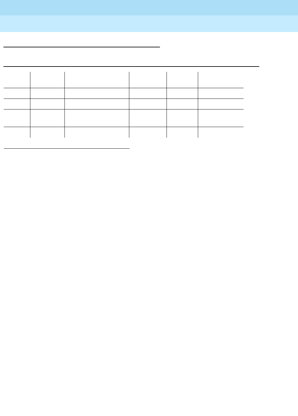
DEFINITY Enterprise Communications Server Release 6
Maintenance for R6r Volumes 1 & 2
555-230-126 Issue 2
January 1998
Maintenance Object Repair Procedures
Page 9-1402SYS-PRNT (System Printer)
9
Error Log Entries and Test to Clear Values
Notes:
a. The System Printer Link has been busied out.
b. A failure was encountered while attempting to set up the System Printer
Link. This attempt could have been initiated by either Report Scheduler
software or by link maintenance during automatic link retry or as a result of
a Link Retry Test (#215) request. The Aux Data field indicates the
following:
Refer to the preceding section ‘‘Procedures for Restoring the System
Printer Link for recommended maintenance strategy.
c. The SYS-PRNT was interrupted for one of the following reasons:
■The cable to the SYS-PRNT output device is disconnected
■The SYS-PRNT output device is powered off
■The data extension to which the SYS-PRNT output device connects
has been busied out
■Internal software error
1. Minor alarms may be downgraded to Warning alarms based on the value used in the set
options command.
Table 9-475. SYS-PRNT Maintenance Error Log Entries
Error
Type Aux Data Associated Test Alarm
Level On/Off
Board Test to Clear
Value
0 0 Any Any Any test sp-link
18 (a) 0 busyout sp-link WARNING OFF release sp-link
257(b) 1, 3 4, 5, 6 Link Retry Test (#215) MINOR/1
WARNING OFF test sp-link l
513 (c) 0 None MINOR OFF test sp-link
1 No system port available. Refer to PDATA-PT for explanation.
3, 4 Time-out during setup attempt. Most likely due to problem with physical
link or printer status.
5 Internal system error. Most likely temporary/sporadic failure.
6 The data module the printer is trying to use is busy with another call. Use
the Status data module command to determine when the port is
available for testing.

DEFINITY Enterprise Communications Server Release 6
Maintenance for R6r Volumes 1 & 2
555-230-126 Issue 2
January 1998
Maintenance Object Repair Procedures
Page 9-1403SYS-PRNT (System Printer)
9
Check the connectivity of the wires and cables among the wall jacket,
data module, and SYS-PRNT output device. Follow the instructions
provided in
Procedures for Restoring the System Printer Link
above.
System-Technician-Demanded Tests:
Descriptions And Error Codes
When inspecting errors in the system and deciding which ones to address,
always investigate errors in the order they are presented in the table below. By
clearing error codes associated with the
Link Retry Test
, for example, you may
also clear errors generated from other tests in the testing sequence.
Link Tear Down Test (#213)
This test is destructive.
The Link Tear Down Test disconnects the existing link between DEFINITY
Generic 3 and the external SYS-PRNT output device. If the link has been
disconnected already, this test just returns PASS. All resources allocated for a
System Printer Link are released after this test.
1. D = Destructive, ND = Non-destructive
Order of Investigation Short Test
Sequence Long Test
Sequence D/ND1
Link Tear Down Test (#213) X D
Link Retry Test (#215) X X ND
Table 9-476. TEST #213 Link Tear Down Test
Error
Code Test
Result Description/ Recommendation
40, 50 ABORT Internal System Error.
1. Retry the command at 1 -minute intervals a maximum of two times.
1010 ABORT The System Printer Link has been busied out.
1. Enter the release sp-link command to release the System Printer Link from
the busyout state.
2. Reissue the test sp-link long command to execute the test.
2012 ABORT Internal System Error.
1. Retry the command at 1-minute intervals a maximum of five times.

DEFINITY Enterprise Communications Server Release 6
Maintenance for R6r Volumes 1 & 2
555-230-126 Issue 2
January 1998
Maintenance Object Repair Procedures
Page 9-1404SYS-PRNT (System Printer)
9
Link Retry Test (#215)
This test sends a message to the System Printer management software process
instructing it to make a data call to the extension connected to the printer. If the
System Printer link is already up, this test passes without making any data call.
FAIL Internal System Error.
1. Retry the command at 1-minute intervals a maximum of two times.
PASS The System Printer Link is torn down or a Short Test Sequence was executed
and the link was not torn down.
Table 9-477. TEST #215 Link Retry Test
Error
Code Test
Result Description/ Recommendation
10, 20 ABORT Internal System Error.
1. Retry the command at 1-minute intervals a maximum of two times.
30 ABORT Internal System Error.
1. Refer to the ‘‘Procedures for Restoring the System Printer Link’’ section for
recommended maintenance strategy.
1010 ABORT The System Printer Link has been busied out.
1. Enter the release sp-link command to release the System Printer Link
from the busyout state.
2. Reissue the test sp-link long command to execute the test.
2012 ABORT Internal System Error.
1. Retry the command at 1-minute intervals a maximum of five times.
FAIL The System Printer Link CANNOT be established.
1. Refer to the ‘‘Procedures for Restoring the System Printer Link’’ section for
recommended maintenance strategy.
PASS The System Printer Link is up.
Continued on next page
Table 9-476. TEST #213 Link Tear Down Test — Continued
Error
Code Test
Result Description/ Recommendation

DEFINITY Enterprise Communications Server Release 6
Maintenance for R6r Volumes 1 & 2
555-230-126 Issue 2
January 1998
Maintenance Object Repair Procedures
Page 9-1405SYSAM (Circuit Pack)
9
SYSAM (Circuit Pack)
The System Access and Maintenance (SYSAM) circuit pack, TN1648, is a
required component of the SPE Complex. The SYSAM circuit pack is responsible
for monitoring the sanity of the RISC Processor circuit pack, as well as
environmental conditions. The SYSAM provides the serial interface for the G3-MT
terminal and the communication interface to INADS or other service locations for
alarm reporting and remote maintenance capability. The SYSAM also provides
the Time-Of-Day Clock for the system.
In addition to the usual red, green, and red LEDs, the SYSAM circuit pack has
alarm, acknowledgment and emergency transfer LEDs whose meanings are
explained in Chapter 7. Indications given by these extra LEDs on a
standby
SYSAM (in a system with duplicated SPEs) are not meaningful. Pay attention to
the extra LEDs on the
active
SYSAM only.
1. UU is the cabinet number (always 1, not required). C is the carrier designation (a or b). With
simplex SPE the carrier location is not required. With duplicated SPEs, carrier a or b must be
specified.
2. After a spontaneous SPE interchange has occurred, the Alarm Log retains for three hours a
record of any MAJOR ON-BOARD alarm against an SPE component that took place before
the interchange. If a spontaneous interchange has occurred (as indicated by STBY-SPE error
type 103 or the display initcauses screen), and handshake is down, (check with status spe),
replace the alarmed circuit pack on the standby SPE. If handshake is up, execute a test long
clear of the alarmed circuit pack and follow recommended procedures.
MO Name (in
Alarm Log) Alarm
Level Initial Command to Run1Full Name of MO
SYSAM MAJOR2test maintenance UUC l System Access and
Maintenance circuit pack
SYSAM MINOR test maintenance UUC s System Access and
Maintenance circuit pack
SYSAM WARNING test maintenance UUC s System Access and
Maintenance circuit pack

DEFINITY Enterprise Communications Server Release 6
Maintenance for R6r Volumes 1 & 2
555-230-126 Issue 2
January 1998
Maintenance Object Repair Procedures
Page 9-1406SYSAM (Circuit Pack)
9
Error Log Entries and Test to Clear Values
Notes:
a. Error 150 indicates that a SPE interchange has occurred and that the
SYSAM circuit pack was the cause of the spontaneous interchange.
1. If other SYSAM errors are present, investigate these errors.
2. If no other SYSAM errors are present, run the test maintenance a|b
long clear command and investigate any test failures.
b. Error 513 indicates that the circuitry associated with active port on the
SYSAM circuit pack is not functioning properly. This circuitry can only be
tested when the SYSAM is in the active SPE.
1. Run the Short Test Sequence first. If all tests pass, run the Long Test Sequence. Refer to the appropriate
test description and follow the recommended procedures.
2. After a spontaneous SPE interchange has occurred, the Alarm Log retains for three hours a record of any
MAJOR ON-BOARD alarm against an SPE component that took place before the interchange. If a
spontaneous interchange has occurred (as indicated by STBY-SPE error type 103 or the display
initcauses screen), and handshake is down, (check with status spe), replace the alarmed circuit pack on
the standby SPE. If handshake is up, execute a test long clear of the alarmed circuit pack and follow
recommended procedures.
Table 9-478. SYSAM Error Log Entries
Error
Type Aux
Data Associated Test Alarm
Level On/Off
Board Test to Clear Value
010 Any Any Any test processor UUC s r 1
1 SYSAM Reset Test MAJOR2ON test maintenance UUC l r 1
150 (a) Any None MAJOR2ON test maintenance UUC l c
257 Analog Looparound
Test (#917) MINOR ON test maintenance UUC l r 3
513 (b) G3-MT Looparound
Test (#915) MINOR ON test maintenance UUC s r 3
769(c) Any Sanity Handshake Test WARNING OFF test maintenance UUC s r 3
1025 Out-Pulse Relay Test
(#916) MINOR OFF test maintenance UUC l r 5
1281 Time of Day Clock Test MAJOR2ON test maintenance UUC s r 3
1537 Sanity Handshake Test MINOR ON test maintenance UUC s r 3
1793(d) None WARNING ON
2049 SYSAM Dual Port Ram
Test MAJOR2ON test maintenance UUC l r 1
2561 (e) G3-MT Looparound
Test(#915) MINOR ON test maintenance UUC s r 3

DEFINITY Enterprise Communications Server Release 6
Maintenance for R6r Volumes 1 & 2
555-230-126 Issue 2
January 1998
Maintenance Object Repair Procedures
Page 9-1407SYSAM (Circuit Pack)
9
c. Error 769 indicates that one of the following in-line errors has occurred:
1. The "No Case" error indicates that the SYSAM firmware received a
message that does not match any known message format.
2. The "Background Fault" error indicates that one of the following
SYSAM firmware background test failed: CPU Test, EPROM
Checksum Test, RAM Test, or NVRAM Checksum Test.
3. The "Logical Inconsistency" error indicates that the SYSAM
firmware has determined that the SYSAM circuit pack is in a
logically inconsistent state.
These errors indicate that the SYSAM’s sanity may be questionable.
SYSAM software will run the Sanity Handshake Test in response to these
errors. If these errors are reported repeatedly, SYSAM software will reset
the SYSAM circuit pack via the SYSAM Reset Test.
d. Error 1793 indicates that the Sanity Timer Test initialization test failed on
the last time the system rebooted. Routine Maintenance Procedures").
Replace the SYSAM circuit pack and verify that the Sanity Timer Test
passes after replacing the circuit pack. To replace the SYSAM circuit
pack, refer to ‘‘Replacing SPE Circuit Packs’’ in Chapter 5.
e. Error 2561 indicates that the standby G3-MT port on the standby SYSAM
circuit pack is not functioning properly. Standby port circuitry on the active
SYSAM is not tested.

DEFINITY Enterprise Communications Server Release 6
Maintenance for R6r Volumes 1 & 2
555-230-126 Issue 2
January 1998
Maintenance Object Repair Procedures
Page 9-1408SYSAM (Circuit Pack)
9
System Technician-Demanded Tests:
Descriptions and Error Codes
Always investigate tests in the order presented in the table below when
inspecting errors in the system. By clearing error codes associated with the
SYSAM Reset Test
, for example, you may also clear errors generated from other
tests in the testing sequence.
Notes:
a. If you are invoking the long test sequence from the PPN G3-MT, the
SYSAM Reset Test and SYSAM DPR Test will cause the PNN G3-MT to
logoff and tear down any SYSAM Remote Access connection. After the
test sequence runs, the Error Log should be examined for SYSAM errors
of type 1 and 2049 to determine if either SYSAM Reset Test or SYSAM
DPR Test have failed. If you are invoking the long demand test sequence
from an EPN G3-MT, all tests listed above will run and the results will
display on the EPN G3-MT. The PPN G3-MT will still be logged off and any
SYSAM Remote Access connection will be torn down.
b. These tests can be run only on the active SYSAM circuit pack. If you are
invoking the long test sequence on the standby SYSAM circuit pack, these
tests (Outpulse Relay Test and Analog Looparound Test) will not be run.
SYSAM Reset Test (#909)
This test is destructive.
This test will reset the SYSAM circuit pack. The destructive nature of this test will
cause the PNN G3-MT to logoff and any SYSAM Remote Access connection
(e.g.,. INADS connection) to be torn down.
1. D = Destructive, ND = Non-destructive
Order of Investigation Short Test
Sequence Long Test
Sequence Reset Board
Sequence D/ND1
SYSAM Reset Test (#909)(a) X X D
SYSAM Dual Port Ram Test (#910)(a) X X D
Sanity Handshake Test (#911) X X ND
Time of Day Clock Test (#913) X X ND
G3-MT Looparound Test (#915) X X ND
Outpulse Relay Test (#916) (b) X ND
Analog Looparound Test (#917) (b) X ND

DEFINITY Enterprise Communications Server Release 6
Maintenance for R6r Volumes 1 & 2
555-230-126 Issue 2
January 1998
Maintenance Object Repair Procedures
Page 9-1409SYSAM (Circuit Pack)
9
The reset test causes terminals connected to the SYSAM either directly or
through the remote access port to logoff prior to the test results being displayed.
To determine a test result from one of these locations, log back in and examine
the Error Log for SYSAM error type 1 with no aux data. This error entry indicates
that the SYSAM Reset Test failed and that the SYSAM circuit pack should be
replaced.
If the test is being run from somewhere other than the SYSAM ports, (for
example, a G3-MT connected to an EPN Maintenance circuit pack) test results
will be displayed on the screen without a logoff taking place.
Table 9-479. Test #909 SYSAM Reset Test
Error
Code Test
Result Description/ Recommendation
100 ABORT The requested test did not complete within the allowable time period.
1. Retry the command.
1000 ABORT System resources required to run this test are not available.
1. Retry the command at 1-minute intervals, a maximum of 5 times.
1318
1335
2029
2033
2500
ABORT Internal System Error
1. Retry the command.
1338 ABORT The test is not allowed to run since a planned SPE interchange is in progress.
This may be caused by a planned interchange initiated automatically during
24 hour scheduled testing.
1. Wait 3 minutes and retry the command.
1339 ABORT The test could not run on the standby SYSAM circuit pack in the standby SPE
carrier because the standby SPE is unavailable.
1. Refer to the STBY-SPE maintenance documentation for information on why
a standby SPE may be unavailable and what repair actions should be
taken. The screen for the status spe command should indicate that
handshake is down. This may be caused by a variety of reasons such as
the SPE-SELECT switches on the DUPINT circuit packs being set to the
position of the active SPE, a failure of the DUPINT circuit pack, or loss of
power on the standby SPE. The
SPE Selected
field on the status spe
screen will display
spe a
or
spe b
if both SPE-SELECT switches are in the
a or b positions, respectively.
Continued on next page

DEFINITY Enterprise Communications Server Release 6
Maintenance for R6r Volumes 1 & 2
555-230-126 Issue 2
January 1998
Maintenance Object Repair Procedures
Page 9-1410SYSAM (Circuit Pack)
9
2000 ABORT Response to the test request was not received within the allowable time
period. If the system is equipped with the High Reliability or Critical Reliability
Configuration and if the SYSAM circuit pack is on the standby SPE, this abort
code may indicate that the standby SPE is not responding to the handshake
message. If this is the case, the standby SPE maintenance software may take
up to two minutes to indicate that handshake communication with the standby
SPE is down. The ABORT code will then change to 1339 (standby SPE
unavailable).
1. Retry the command at 1-minute intervals, a maximum of 3 times.
2334 ABORT The hardware mailbox on the standby Duplication Interface board is not ready
to receive messages.
1. Retry the command at 1-minute intervals, a maximum of 5 times.
FAIL The circuit pack was reset, but responded with a NOT PASS status indicating it
did not pass initialization correctly. The SYSAM is not functioning correctly.
The system should continue to operate but will not have the ability to perform
alarm origination, if needed. Environmental monitoring, the PNN G3-MT, and
the System Sanity Timer are lost.
1. Retry the command.
2. If test continues to fail, replace the SYSAM circuit pack. To replace the
SYSAM circuit pack, refer to ‘‘Replacing SPE Circuit Packs’’ in Chapter 5.
PASS The circuit pack was reset, it did pass initialization correctly. The other SYSAM
tests should be examined to verify that the SYSAM is functioning normally.
1. Execute test maintenance a|b short and verify that the SYSAM is
operating correctly.
Table 9-479. Test #909 SYSAM Reset Test — Continued
Error
Code Test
Result Description/ Recommendation
Continued on next page

DEFINITY Enterprise Communications Server Release 6
Maintenance for R6r Volumes 1 & 2
555-230-126 Issue 2
January 1998
Maintenance Object Repair Procedures
Page 9-1411SYSAM (Circuit Pack)
9
SYSAM Dual Port RAM Test (#910)
This test is destructive.
This test will terminate any PPN G3-MT or SYSAM Remote Access session. This
is a coordinated test of the Processor circuit pack’s and SYSAM circuit pack’s
on-board microprocessor ability to access the SYSAM’s Dual Port RAM (DPR).
Control messages and data are passed through the DPR. The test forces both
the Processor and the on-board microprocessor to read and write the DPR
simultaneously in alternate locations.
The DPR test causes the PNN G3-MT and SYSAM Remote Access sessions to
logoff prior to the test result being displayed. To determine the test result, if the
test is run from the PNN G3-MT or SYSAM Remote Access connection, System
Technician should log back in and examine the Error Log for an error against
SYSAM, with error code 2049, no aux data. This error entry indicates that the
SYSAM DPR Test did fail and that the SYSAM circuit pack should be replaced.
If the test is being run from somewhere other than the PPN G3-MT or SYSAM
Remote Access connection (for example, EPN G3-MT), the test results will be
displayed on the screen.
Table 9-480. Test #910 SYSAM Dual Port RAM Test
Error
Code Test
Result Description/ Recommendation
100 ABORT The requested test did not complete within the allowable time period.
1. Retry the command.
1000 ABORT System resources required to run this test are not available.
1. Retry the command at 1-minute intervals, a maximum of 5 times.
1318
1335
2029
2033
2500
ABORT Internal System Error
1. Retry the command.
1338 ABORT The test is not allowed to run since a planned SPE interchange is in progress.
This may be caused by a planned interchange initiated automatically during 24
hour scheduled testing.
1. Wait 3 minutes and retry the command.
Continued on next page

DEFINITY Enterprise Communications Server Release 6
Maintenance for R6r Volumes 1 & 2
555-230-126 Issue 2
January 1998
Maintenance Object Repair Procedures
Page 9-1412SYSAM (Circuit Pack)
9
1339 ABORT The test could not run on the standby SYSAM circuit pack in the standby SPE
carrier because the standby SPE is unavailable.
1. Refer to the STBY-SPE maintenance documentation for information on why
a standby SPE may be unavailable and what repair actions should be
taken. The screen for the status spe command should indicate that
handshake is down. This may be caused by a variety of reasons such as
the SPE-SELECT switches on the DUPINT circuit packs being set to the
position of the active SPE, a failure of the DUPINT circuit pack, or loss of
power on the standby SPE. The
SPE selected
field on the status spe
screen will display
spe a
or
spe b
if both SPE-SELECT switches are in the a
or b positions, respectively.
2000 ABORT Response to the test request was not received within the allowable time period.
If the system is equipped with the High Reliability or Critical Reliability
Configuration and if the SYSAM circuit pack is on the standby SPE, this abort
code may indicate that the standby SPE is not responding to the handshake
message. If this is the case, the standby SPE maintenance software may take
up to two minutes to indicate that handshake communication with the standby
SPE is down. The ABORT code will then change to 1339 (standby SPE
unavailable).
1. Retry the command at 1-minute intervals, a maximum of 3 times.
2334 ABORT The hardware mailbox on the standby Duplication Interface board is not ready
to receive messages.
1. Retry the command at 1-minute intervals, a maximum of 5 times.
FAIL The DPR is not functioning correctly. Communication between the Processor
and SYSAM is lost. The system will not be able to report environmental alarms,
use the PPN G3-MT, or use the SYSAM Remote Access connection if the need
should arise.
1. Retry the command.
2. If the test continues to fail, replace the SYSAM circuit pack.
3. Retry the command.
4. If the test continues to fail, replace the Processor circuit pack.
5. Retry the command.
6. Replace the SPE circuit pack. See ‘‘Replacing SPE Circuit Packs’’ in
Chapter 5.
PASS Dual Port RAM is functioning. Communication does exist between the
Processor and SYSAM circuit packs.
Table 9-480. Test #910 SYSAM Dual Port RAM Test — Continued
Error
Code Test
Result Description/ Recommendation
Continued on next page

DEFINITY Enterprise Communications Server Release 6
Maintenance for R6r Volumes 1 & 2
555-230-126 Issue 2
January 1998
Maintenance Object Repair Procedures
Page 9-1413SYSAM (Circuit Pack)
9
Sanity Handshake Test (#911)
This test checks the SYSAM circuit pack’s ability to respond to queries. A
message is sent to the SYSAM circuit pack which then returns a message. The
SYSAM must reply for this test to pass. If this test fails, the SYSAM circuit pack
should be considered insane, the circuit pack should be reset via the reset
maintenance a|b command.
Table 9-481. Test #911 Sanity Handshake Test
Error
Code Test
Result Description/ Recommendation
100 ABORT The requested test did not complete within the allowable time period.
1. Retry the command.
1000 ABORT System resources required to run this test are not available.
1. Retry the command at 1-minute intervals, a maximum of 5 times.
1318
1335
2029
2033
2500
ABORT Internal System Error
1. Retry the command.
1338 ABORT The test is not allowed to run since a planned SPE interchange is in progress.
This may be caused by a planned interchange initiated automatically during 24
hour scheduled testing.
1. Wait 3 minutes and retry the command.
1339 ABORT The test could not run on the standby SYSAM circuit pack in the standby SPE
carrier because the standby SPE is unavailable.
1. Refer to the STBY-SPE maintenance documentation for information on why
a standby SPE may be unavailable and what repair actions should be
taken. The screen for the status spe command should indicate that
handshake is down. This may be caused by a variety of reasons such as
the SPE-SELECT switches on the DUPINT circuit packs being set to the
position of the active SPE, a failure of the DUPINT circuit pack, or loss of
power on the standby SPE. The
SPE selected
field on the status spe
screen will display
spe a
or
spe b
if both SPE-SELECT switches are in the a
or b positions, respectively.
Continued on next page

DEFINITY Enterprise Communications Server Release 6
Maintenance for R6r Volumes 1 & 2
555-230-126 Issue 2
January 1998
Maintenance Object Repair Procedures
Page 9-1414SYSAM (Circuit Pack)
9
SYSAM Refresh Test (#912)
This test checks the current state of the Alarm Panel LEDs on the SYSAM circuit
pack and attempts to resynchronize these LEDs to reflect the current alarm levels
in the system. Any discrepancies are resolved by changing the Alarm Panel
LEDs to what maintenance believes the alarm levels should be. The SYSAM
Refresh Test runs only in G3r V1 software loads preceding 6.0.
2000 ABORT Response to the test request was not received within the allowable time period.
If the system is equipped with the High Reliability or Critical Reliability
Configuration and if the SYSAM circuit pack is on the standby SPE, this abort
code may indicate that the standby SPE is not responding to the handshake
message. If this is the case, the standby SPE maintenance software may take
up to two minutes to indicate that handshake communication with the standby
SPE is down. The ABORT code will then change to 1339 (standby SPE
unavailable).
1. Retry the command at 1-minute intervals, a maximum of 3 times.
2318 ABORT The standby SYSAM was not responding within the allowable time period.
1. Retry the command at 1-minute intervals, a maximum of 3 times.
2334 ABORT The hardware mailbox on the standby Duplication Interface board is not ready
to receive messages.
1. Retry the command at 1-minute intervals, a maximum of 5 times.
FAIL The SYSAM did not respond to the sanity handshake query.
1. Run the test maintenance 1a|b long command. The terminal login will
drop and you must log in again.
2. If test continues to fail, replace the SYSAM circuit pack at the earliest
convenience.
3. Retry the command.
4. Replace the SYSAM circuit pack. To replace the SYSAM circuit pack, refer
to ‘‘Replacing SPE Circuit Packs’’ in Chapter 5.
PASS The SYSAM did respond to the sanity handshake query.
1. Examine other SYSAM tests for errors.
Table 9-481. Test #911 Sanity Handshake Test — Continued
Error
Code Test
Result Description/ Recommendation
Continued on next page

DEFINITY Enterprise Communications Server Release 6
Maintenance for R6r Volumes 1 & 2
555-230-126 Issue 2
January 1998
Maintenance Object Repair Procedures
Page 9-1415SYSAM (Circuit Pack)
9
Table 9-482. Test #912 SYSAM Refresh Test
Error
Code Test
Result Description/ Recommendation
100 ABORT The requested test did not complete within the allowable time period.
1. Retry the command.
1000 ABORT System resources required to run this test are not available.
1. Retry the command at 1-minute intervals, a maximum of 5 times.
1318
1335
2029
2033
2500
ABORT Internal System Error
1. Retry the command.
1338 ABORT The test is not allowed to run since a planned SPE interchange is in progress.
This may be caused by a planned interchange initiated automatically during 24
hour scheduled testing.
1. Wait 3 minutes and retry the command.
1339 ABORT The test could not run on the standby SYSAM circuit pack in the standby SPE
carrier because the standby SPE is unavailable.
1. Refer to the STBY-SPE maintenance documentation for information on why a
standby SPE may be unavailable and what repair actions should be taken.
The screen for the status spe command should indicate that handshake is
down. This may be caused by a variety of reasons such as the SPE-SELECT
switches on the DUPINT circuit packs being set to the position of the active
SPE, a failure of the DUPINT circuit pack, or loss of power on the standby
SPE. The
SPE selected
field on the status spe screen will display
spe a
or
spe b
if both SPE-SELECT switches are in the a or b positions, respectively.
2000 ABORT Response to the test request was not received within the allowable time period. If
the system is equipped with the High Reliability or Critical Reliability
Configuration and if the SYSAM circuit pack is on the standby SPE, this abort
code may indicate that the standby SPE is not responding to the handshake
message. If this is the case, the standby SPE maintenance software may take up
to two minutes to indicate that handshake communication with the standby SPE
is down. The ABORT code will then change to 1339 (standby SPE unavailable).
1. Retry the command at 1-minute intervals, a maximum of 3 times.
2005 FAIL Could not handshake with the SYSAM circuit pack. The SYSAM circuit pack did
not respond to a query message sent to it. Run the test maintenance a|b short,
and refer to the repair procedures outlined for Test, the Sanity Handshake Test.
2318 ABORT The standby SYSAM was not responding within the allowable time period.
1. Retry the command at 1-minute intervals, a maximum of 3 times.
Continued on next page

DEFINITY Enterprise Communications Server Release 6
Maintenance for R6r Volumes 1 & 2
555-230-126 Issue 2
January 1998
Maintenance Object Repair Procedures
Page 9-1416SYSAM (Circuit Pack)
9
Time-Of-Day Clock Test (#913)
The short term accuracy of the time-of-day clock is tested. The test reads the
clock once, waits a short time (10 seconds) and reads the clock again. The
second reading of the clock must be within certain limits (10 seconds) relative to
the first reading for the test to pass. The command display time can be used to
display the current setting of the time-of-day clock.
If the time-of-day clock is not functioning correctly, the software time-of-day clock
is used (this clock is not as accurate as the hardware clock).
2334 ABORT The hardware mailbox on the standby Duplication Interface board is not ready to
receive messages.
1. Retry the command at 1-minute intervals, a maximum of 5 times.
FAIL Internal System Error
1. Retry the command
PASS The SYSAM circuit pack has been sent the correct state for the system LEDs. If
the LEDs do not reflect the system alarms shown in the alarm log, the SYSAM
circuit pack may have problems.
1. Verify the LEDs on the SYSAM circuit pack can be changed by issuing the
test led port-network 1 command. All the SYSAM circuit pack LEDs should
go on and then off, and then be refreshed.
2. After the test led port-network 1 command finishes, if the SYSAM circuit
pack LEDs do not reflect the alarm log, follow normal escalation procedures.
Table 9-483. Test #913 Time-Of-Day Clock Test
Error
Code Test
Result Description/ Recommendation
100 ABORT The requested test did not complete within the allowable time period.
1. Retry the command.
1000 ABORT System resources required to run this test are not available.
1. Retry the command at 1-minute intervals, a maximum of 5 times.
Continued on next page
Table 9-482. Test #912 SYSAM Refresh Test — Continued
Error
Code Test
Result Description/ Recommendation
Continued on next page

DEFINITY Enterprise Communications Server Release 6
Maintenance for R6r Volumes 1 & 2
555-230-126 Issue 2
January 1998
Maintenance Object Repair Procedures
Page 9-1417SYSAM (Circuit Pack)
9
1318
1335
2029
2033
2500
ABORT Internal System Error
1. Retry the command.
1338 ABORT The test is not allowed to run since a planned SPE interchange is in progress.
This may be caused by a planned interchange initiated automatically during 24
hour scheduled testing.
1. Wait 3 minutes and retry the command.
1339 ABORT The test could not run on the standby SYSAM circuit pack in the standby SPE
carrier because the standby SPE is unavailable.
1. Refer to the STBY-SPE maintenance documentation for information on why
a standby SPE may be unavailable and what repair actions should be
taken. The screen for the status spe command should indicate that
handshake is down. This may be caused by a variety of reasons such as
the SPE-SELECT switches on the DUPINT circuit packs being set to the
position of the active SPE, a failure of the DUPINT circuit pack, or loss of
power on the standby SPE. The
SPE selected
field on the status spe
screen will display
spe a
or
spe b
if both SPE-SELECT switches are in the a
or b positions, respectively.
2000 ABORT Response to the test request was not received within the allowable time period.
If the system is equipped with the High Reliability or Critical Reliability
Configuration and if the SYSAM circuit pack is on the standby SPE, this abort
code may indicate that the standby SPE is not responding to the handshake
message. If this is the case, the standby SPE maintenance software may take
up to two minutes to indicate that handshake communication with the standby
SPE is down. The ABORT code will then change to 1339 (standby SPE
unavailable).
1. Retry the command at 1-minute intervals, a maximum of 3 times.
2318 ABORT The standby SYSAM was not responding within the allowable time period.
1. Retry the command at 1-minute intervals, a maximum of 3 times.
2334 ABORT The hardware mailbox on the standby Duplication Interface board is not ready
to receive messages.
1. Retry the command at 1-minute intervals, a maximum of 5 times.
Table 9-483. Test #913 Time-Of-Day Clock Test — Continued
Error
Code Test
Result Description/ Recommendation
Continued on next page
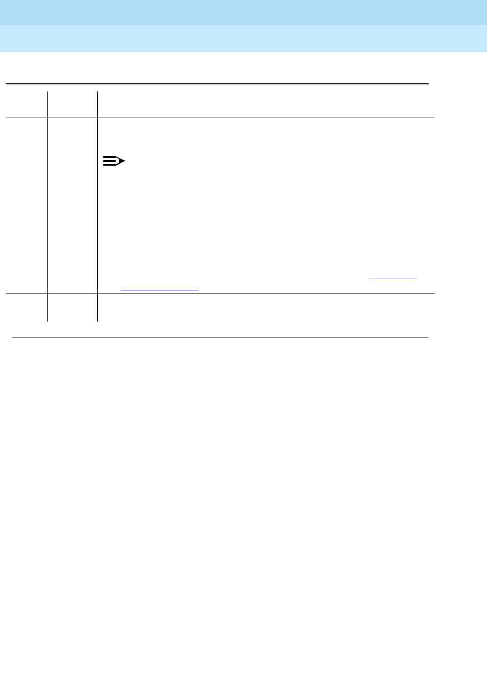
DEFINITY Enterprise Communications Server Release 6
Maintenance for R6r Volumes 1 & 2
555-230-126 Issue 2
January 1998
Maintenance Object Repair Procedures
Page 9-1418SYSAM (Circuit Pack)
9
any FAIL The short term accuracy of the time-of-day clock is not within limits (10 seconds
>= difference <= 20 seconds).
NOTE:
any
indicates the difference between the two reads. A zero (0) indicates
that the time-of-day clock is not running.)
1. Run the short test sequence several times to make sure the error is
occurring consistently.
2. If test continues to fail consistently, replace the SYSAM circuit pack at the
earliest convenience.
3. After replacing the SYSAM, you must set the time-of-day clock via the set
time command. To replace the SYSAM circuit pack, refer to ‘‘Replacing
SPE Circuit Packs’’ in Chapter 5.
PASS The short term accuracy of the time-of-day clock on the SYSAM circuit pack is
within limits.
Table 9-483. Test #913 Time-Of-Day Clock Test — Continued
Error
Code Test
Result Description/ Recommendation
Continued on next page

DEFINITY Enterprise Communications Server Release 6
Maintenance for R6r Volumes 1 & 2
555-230-126 Issue 2
January 1998
Maintenance Object Repair Procedures
Page 9-1419SYSAM (Circuit Pack)
9
SYSAM G3-MT Looparound Test (#915)
This test places the G3-MT port on the SYSAM circuit pack into loop-around
mode and verifies the data integrity of the channel. The test is non-destructive
but may cause a momentary loss of keyboard input from the G3-MT while the test
is running (about 1 second).
On High and Critical Reliability systems, there are two G3-MT ports on each of
the two SYSAM circuit packs: one is labeled ACTIVE and the other STANDBY. On
the currently active SYSAM circuit pack, only the ACTIVE port is tested. On the
currently standby SYSAM circuit pack, only the STANDBY port is tested.
Table 9-484. TEST #915 SYSAM G3-MT Looparound Test
Error
Code Test
Result Description/ Recommendation
100 ABORT The requested test did not complete within the allowable time period.
1. Retry the command.
1000 ABORT System resources required to run this test are not available.
1. Retry the command at 1-minute intervals, a maximum of 5 times.
1318
1335
2029
2033
2500
ABORT Internal System Error
1. Retry the command.
1338 ABORT The test is not allowed to run with a planned SPE interchange in progress. This
may be caused by a planned interchange initiated automatically during 24
hour scheduled testing.
1. Wait 3 minutes and retry the command.
1339 ABORT The test could not run on the standby SYSAM circuit pack in the standby SPE
carrier because the standby SPE is unavailable.
1. Refer to the STBY-SPE maintenance documentation for information on why
a standby SPE may be unavailable, and related repair actions. The screen
for the status spe command should indicate that handshake is down. This
may be caused by a variety of reasons such as the SPE-SELECT switches
on the DUPINT circuit packs being set to the position of the active SPE, a
failure of the DUPINT circuit pack, or loss of power on the standby SPE.
The
SPE selected
field on the status spe screen will display
spe a
or
spe
b
if both SPE-SELECT switches are in the a or b positions, respectively.
Continued on next page

DEFINITY Enterprise Communications Server Release 6
Maintenance for R6r Volumes 1 & 2
555-230-126 Issue 2
January 1998
Maintenance Object Repair Procedures
Page 9-1420SYSAM (Circuit Pack)
9
2000 ABORT Response to the test request was not received within the allowable time period.
If the system is equipped with the High Reliability or Critical Reliability
Configuration and if the SYSAM circuit pack is on the standby SPE, this abort
code may indicate that the standby SPE is not responding to the handshake
message. If this is the case, the standby SPE maintenance software may take
up to two minutes to indicate that handshake communication with the standby
SPE is down. The ABORT code will then change to 1339 (standby SPE
unavailable).
1. Retry the command at 1-minute intervals, a maximum of 3 times.
2334 ABORT The hardware mailbox on the standby Duplication Interface board is not ready
to receive messages.
1. Retry the command at 1-minute intervals, a maximum of 5 times.
2318 FAIL The STANDBY port on the SYSAM circuit pack on the standby SPE did not
respond to the test in time. If this test fails at least 3 times in a row, the
STANDBY port is probably be unusable for diagnostics via the SPE-Down or
SPE-Standby Interfaces. Other than this unavailability, this failure should cause
no service effects.
1. Try the test again at 1-minute intervals up to a maximum of 3 times.
2. If the test fails all 3 attempts, replace the standby SYSAM circuit pack at
the earliest convenience. To replace the SYSAM circuit pack, refer to
‘‘Replacing SPE Circuit Packs’’ in Chapter 5.
FAIL The SYSAM G3-MT channel failed the loop around test. The G3-MT will
probably be unusable for administration or maintenance. The EPN G3-MT, if
available, or remote access can still be used.
1. Retry the command.
2. If test continues to fail, replace the SYSAM circuit pack at the earliest
convenience. To replace the SYSAM circuit pack, refer to ‘‘Replacing SPE
Circuit Packs’’ in Chapter 5.
PASS The G3-MT channel passed the loop around test.
1. If the PPN G3-MT is not usable, check the G3-MT and associated cabling.
Table 9-484. TEST #915 SYSAM G3-MT Looparound Test — Continued
Error
Code Test
Result Description/ Recommendation
Continued on next page

DEFINITY Enterprise Communications Server Release 6
Maintenance for R6r Volumes 1 & 2
555-230-126 Issue 2
January 1998
Maintenance Object Repair Procedures
Page 9-1421SYSAM (Circuit Pack)
9
SYSAM Outpulse Relay Test (#916)
This test validates the operation of the SYSAM Remote Access CO trunk used for
Alarm Origination and remote access. The SYSAM will go off-hook and then
on-hook on this trunk. If loop current is detected then the test passes. This test is
not allowed if the remote access line is in use or if the SYSAM is on the Standby
SPE in SPE Duplication Option systems. Also, this test must be administered for
testing via the change system-parameters maintenance screen.
Table 9-485. TEST #916 SYSAM Outpulse Relay Test
Error
Code Test
Result Description/ Recommendation
100 ABORT The requested test did not complete within the allowable time period.
1. Retry the command.
1000 ABORT System resources required to run this test are not available.
1. Retry the command at 1-minute intervals, a maximum of 5 times.
1018 ABORT The test has been disabled via administration.
1. To enable test, set the "Test Remote Access Port" field to ’y’ on the
system-parameters maintenance screen.
2. Retry the command.
1318
1335
2029
2033
2500
ABORT Internal System Error
1. Retry the command.
1338 ABORT The test is not allowed to run since a planned SPE interchange is in progress.
This may be caused by a planned interchange initiated automatically during 24
hour scheduled testing.
1. Wait 3 minutes and retry the command.
1339 ABORT The test could not run on the standby SYSAM circuit pack in the standby SPE
carrier because the standby SPE is unavailable.
1. Refer to the STBY-SPE maintenance documentation for information on why
a standby SPE may be unavailable and what repair actions should be
taken. The screen for the status spe command should indicate that
handshake is down. This may be caused by a variety of reasons such as
the SPE-SELECT switches on the DUPINT circuit packs being set to the
position of the active SPE, a failure of the DUPINT circuit pack, or loss of
power on the standby SPE. The
SPE selected
field on the status spe
screen will display
spe a
or
spe b
if both SPE-SELECT switches are in the a
or b positions, respectively.
Continued on next page

DEFINITY Enterprise Communications Server Release 6
Maintenance for R6r Volumes 1 & 2
555-230-126 Issue 2
January 1998
Maintenance Object Repair Procedures
Page 9-1422SYSAM (Circuit Pack)
9
1364 ABORT The component on which the test was to be run is on the Standby SPE. This test
may only be run on this component when it resides on the Active SPE.
1. To verify the remote access line is working (connected), run this on the
Active SYSAM.
1379 ABORT System could not determine if testing of remote access port is administered.
1. Check system-parameters maintenance screen for a ’y’ in the "Test Remote
Access Port" field.
2. Retry the command.
2000 ABORT Response to the test request was not received within the allowable time period.
If the system is equipped with the High Reliability or Critical Reliability
Configuration and if the SYSAM circuit pack is on the standby SPE, this abort
code may indicate that the standby SPE is not responding to the handshake
message. If this is the case, the standby SPE maintenance software may take
up to two minutes to indicate that handshake communication with the standby
SPE is down. The ABORT code will then change to 1339 (standby SPE
unavailable).
1. Retry the command at 1-minute intervals, a maximum of 3 times.
2034 ABORT The remote access port is busy. A remote user is probably dialed into the
switch.
1. If a remote user is dialed in, remote access line is working. No need to run
test. Use the status logins command to verify that the SYSAM-RMT port is
in use.
FAIL SYSAM reported test failure. No loop current detected.
1. Retry the command.
2. If test continues to fail, examine SYSAM remote access line for connectivity,
manually check line for loop current.
3. If SYSAM remote access line checks out fine, but test still fails, check
backplane connector cabling. Also, check the cabling from the wall field to
the backplane.
4. If backplane cabling checks out fine, replace SYSAM circuit pack at
earliest convenience. To replace the SYSAM circuit pack, refer to
‘‘Replacing SPE Circuit Packs’’ in Chapter 5.
PASS SYSAM detected loop current on remote access port.
1. If system cannot call remote maintenance facility or remote maintenance
facility cannot contact system, check with local Central Office for problems
with SYSAM remote access line.
Table 9-485. TEST #916 SYSAM Outpulse Relay Test — Continued
Error
Code Test
Result Description/ Recommendation
Continued on next page
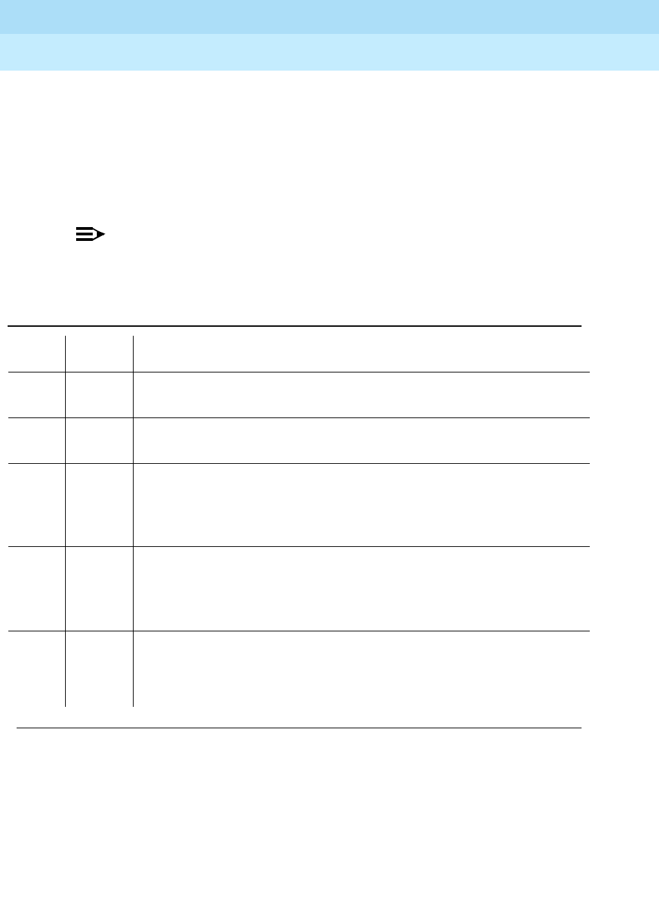
DEFINITY Enterprise Communications Server Release 6
Maintenance for R6r Volumes 1 & 2
555-230-126 Issue 2
January 1998
Maintenance Object Repair Procedures
Page 9-1423SYSAM (Circuit Pack)
9
SYSAM Analog Looparound Test (#917)
This test checks the on-board modem circuitry of the SYSAM circuit pack
associated with the SYSAM remote access port. Test data is looped through the
on-board modem and verified for integrity. This test is not allowed if the remote
access port is in use or if the SYSAM is on the Standby SPE in SPE Duplication
Option systems. Also, this test must be administered for testing via the change
system-parameters maintenance screen.
NOTE:
This test does not send any data onto the SYSAM remote access line, but
the test does require the line to be present to pass reliably.
Table 9-486. TEST #917 SYSAM Analog Looparound Test
Error
Code Test
Result Description/ Recommendation
100 ABORT The requested test did not complete within the allowable time period.
1. Retry the command.
1000 ABORT System resources required to run this test are not available.
1. Retry the command at 1-minute intervals, a maximum of 5 times.
1018 ABORT The test has been disabled via administration.
1. To enable test, set the "Test Remote Access Port" field to "y" on the
system-parameters maintenance screen.
2. Retry the command.
1318
1335
2029
2033
2500
ABORT Internal System Error
1. Retry the command.
1338 ABORT The test is not allowed to run since a planned SPE interchange is in progress.
This may be caused by a planned interchange initiated automatically during 24
hour scheduled testing.
1. Wait 3 minutes and retry the command.
Continued on next page

DEFINITY Enterprise Communications Server Release 6
Maintenance for R6r Volumes 1 & 2
555-230-126 Issue 2
January 1998
Maintenance Object Repair Procedures
Page 9-1424SYSAM (Circuit Pack)
9
1339 ABORT The test could not run on the standby SYSAM circuit pack in the standby SPE
carrier because the standby SPE is unavailable.
1. Refer to the STBY-SPE maintenance documentation for information on why
a standby SPE may be unavailable and what repair actions should be
taken. The screen for the status spe command should indicate that
handshake is down. This may be caused by a variety of reasons such as
the SPE-SELECT switches on the DUPINT circuit packs being set to the
position of the active SPE, a failure of the DUPINT circuit pack, or loss of
power on the standby SPE. The
SPE selected
field on the status spe
screen will display
spe a
or
spe b
if both SPE-SELECT switches are in the a
or b positions, respectively.
1364 ABORT The component on which the test was to be run is on the Standby SPE. This test
may only be run on this component when it resides on the Active SPE.
1. To verify the remote access line is working (connected), run this on the
Active SYSAM.
1379 ABORT System could not determine if testing of remote access port is administered.
1. Check system-parameters maintenance screen for a ’y’ in the "Test Remote
Access Port" field.
2. Retry the command.
2000 ABORT Response to the test request was not received within the allowable time period.
If the system is equipped with the High Reliability or Critical Reliability
Configuration and if the SYSAM circuit pack is on the standby SPE, this abort
code may indicate that the standby SPE is not responding to the handshake
message. If this is the case, the standby SPE maintenance software may take
up to two minutes to indicate that handshake communication with the standby
SPE is down. The ABORT code will then change to 1339 (standby SPE
unavailable).
1. Retry the command at 1-minute intervals, a maximum of 3 times.
2034 ABORT The remote access port is busy. A remote user is probably dialed into the
switch.
1. Wait until the remote user session is terminated, retry the command.
2317 ABORT Test #916 SYSAM Outpulse Relay Test failed.
1. Follow instructions for FAIL result for SYSAM Outpulse Relay Test (#916).
Table 9-486. TEST #917 SYSAM Analog Looparound Test — Continued
Error
Code Test
Result Description/ Recommendation
Continued on next page

DEFINITY Enterprise Communications Server Release 6
Maintenance for R6r Volumes 1 & 2
555-230-126 Issue 2
January 1998
Maintenance Object Repair Procedures
Page 9-1425SYSAM (Circuit Pack)
9
FAIL SYSAM reported test failure. The system will not be able to reliably contact any
remote maintenance facility with alarm data or be called into via the SYSAM
remote access port. The system will continue to provide good service.
1. If SYSAM Outpulse Relay test (#916) is also failing, check for presence of
SYSAM remote access line and resolve SYSAM remote access line
problems.
2. If test #916 passes, the fault in on the SYSAM circuit pack, replace at the
earliest convenience. To replace the SYSAM circuit pack, refer to
‘‘Replacing SPE Circuit Packs’’ in Chapter 5.
PASS SYSAM detected correct data through loop around connection.
1. If system cannot call remote maintenance facility or remote maintenance
facility cannot contact system, check with local Central Office for problems
with SYSAM remote access line.
Table 9-486. TEST #917 SYSAM Analog Looparound Test — Continued
Error
Code Test
Result Description/ Recommendation
Continued on next page

DEFINITY Enterprise Communications Server Release 6
Maintenance for R6r Volumes 1 & 2
555-230-126 Issue 2
January 1998
Maintenance Object Repair Procedures
Page 9-1426SYSTEM (System)
9
SYSTEM (System)
The SYSTEM maintenance object is used to log information about system resets,
including interchanges. When software encounters a problem with hardware, or
with its own processes, and requests a restart to clear the problem, an error is
logged under SYSTEM. For example, if there is a loss of clock in the Processor
Port Network (PPN) in a system with duplicated SPEs, the system switches to the
other clock and then executes a level 2 system reset to recover from hardware
problems caused by the loss of clock. Errors logged under SYSTEM can help to
determine the cause of a reset. The display initcauses screen should also
contain information about the reset. See
Troubleshooting a Duplicated SPE
in
Chapter 5 for more information about interchanges.
1. SYSTEM has no associated alarms and thus appears only in the Error Log. There are
no tests that run on SYSTEM.
MO Name As It
Appears in Alarm
Log Alarm
Level Initial System Technician
Command to Run1Full Name of MO
SYSTEM None None System

DEFINITY Enterprise Communications Server Release 6
Maintenance for R6r Volumes 1 & 2
555-230-126 Issue 2
January 1998
Maintenance Object Repair Procedures
Page 9-1427SYSTEM (System)
9
Error Log Entries and Test to Clear Values
Notes:
a. Software requested a System Restart Level 3.
b. Software requested a System Restart Level 2.
c. Software requested a System Restart Level 1.
d. An error occurred during initialization.
e. Translation data was corrupted, so the system requested a Restart Level 3
to reload translation data from the Mass Storage System (MSS).
f. A reset system interchange or a scheduled SPE interchange failed. The
AUX Data indicates the cause of the failure. Consult the table in note p.
Use status spe to determine the current SPE status and follow the
Standby SPE Maintenance procedures to resolve the problems that are
preventing the SPE interchange.
g. A reset system interchange health-override command has failed. The
standby SPE state-of-health (SOH) would not allow a spontaneous SPE
interchange. Use status spe to determine the current SPE status and
follow the Standby SPE Maintenance procedures to resolve the problems
that are preventing the SPE interchange.
Table 9-487. System Error Log Entries
Error Type Aux Data Associated Test Alarm
Level On/Off
Board Test to Clear Value
8 (a) 0 None
9 (b) Any None
10 (c) Any None
601 (d) Any None
602 (e) Any None
605 (f) (p) None
606 (g) Any None
607 (h) Any None
6001 (i) Any None
6002 (j) (o) None
6003 (k) (o) None
6101 (l) Any None
6102 (m) (o) None
6103 (n) (o) None

DEFINITY Enterprise Communications Server Release 6
Maintenance for R6r Volumes 1 & 2
555-230-126 Issue 2
January 1998
Maintenance Object Repair Procedures
Page 9-1428SYSTEM (System)
9
h. A requested SPE interchange has failed because the SPEs are locked by
means of the SPE-Select switches on the duplication interface circuit
packs. with the SYSAM lock switches.
i. Error 6001 indicates that an operating system error occurred on the active
SPE. The aux data gives the source of the error:
j. Error 6002 indicates that an application error occurred on the active SPE.
See note (o) to diagnose the error using the aux data.
k. Error 6003 indicates that an application alarm occurred on the active SPE.
See note (o) to diagnose the error using the aux data.
l. Error 6100 indicates that an operating system error occurred on the
standby SPE. See error 6001 (i) to interpret the aux data.
m. Error 6102 indicates that an application error occurred on the standby
SPE. See note (o) to diagnose the error using the aux data.
n. Error 6103 indicates that an application alarm occurred on the standby
SPE. See note (o) to diagnose the error using the aux data.
o. For error types 6002, 6003, 6102, and 6103, the aux-data value points to
the MO that the error or alarm is logged against. The following table lists
possible aux-data values and their associated MOs. Locate the Error Log
entry for the indicated MO and follow the instructions for that error.
p. The following table and notes give causes and recommendations for each
AUX data value for error 605.
Aux-Data Value Operating System Error Type
5 Software Abort
6 SPE Bus Error
AUX Data Implicated
Maintenance Object
4137 PKT-INT
16384 PROCR
16385 MEM-BD
16386 SYSAM
16389 DUPINT
16391 SW-CTL
16392 HOST-ADAPTER
16397 TAPE
16398 DISK

DEFINITY Enterprise Communications Server Release 6
Maintenance for R6r Volumes 1 & 2
555-230-126 Issue 2
January 1998
Maintenance Object Repair Procedures
Page 9-1429SYSTEM (System)
9
Table 9-488. SYSTEM Error 605 AUX Data, Failure of Planned Interchange
Aux
Data See Note Explanation
1352 1 Standby SOH "non-functional"
1353 1 Standby SOH not "functional"
1355 1 Handshake Communication with Standby SPE is down
1356 1 Memory Shadowing not enabled
1357 1 Standby memory not refreshed
1358 2 Mass Storage System was in use
1359 3 PKT-INT link migration failed
1360 1 Interchange failed *
1361 4 SW-CTL failure
1369 7 Could not suspend G3-MT connectivity *
1370 4 Could not freeze active SW-CTL *
1371 5 Internal Error associated with processor interrupts *
1372 6 Minor alarm on standby SYSAM or PKT-INT
1395 SPE Duplication not administered
1396 3 PKT-INT Link Migration failure in Begin Step *
1397 3 PKT-INT Link Migration denied, (peer test in progress)
1398 3 PKT-INT Link Migration failure in Completion Step *
1399 3 PKT-INT Link Migration failure in Finish Step *
1400 4 Could Not Idle SW-CTL dual port RAM *
1401 4 Could Not Refresh SW-CTL dual port RAM *
1402 5 Internal Error (could not get duplication status)
1403 5 Unable to inhibit Standby Maintenance Monitor
1404 5 Failure to determine Standby SPE alarm status
1406 3 Active SPE’s PKT-INT in held-reset state
1418 8 Active Duplication Interface circuit pack is in a bad state and
needs to be reset.
2500 5 Internal Software failure (* sometimes)

DEFINITY Enterprise Communications Server Release 6
Maintenance for R6r Volumes 1 & 2
555-230-126 Issue 2
January 1998
Maintenance Object Repair Procedures
Page 9-1430SYSTEM (System)
9
Notes for SYSTEM Error 605 AUX Data:
1. Follow repair instructions in “STBY-SPE” for the particular standby SPE
problem. After fixing that problem, try the interchange again.
2. Mass Storage System is in use. Check Disk and Tape LEDs for activity.
Wait until all MSS activity completes, then retry the interchange again. If
the problem persists, check for alarms and errors against MSS
components and follow the repair procedures for the “MSS” maintenance
object.
3. Test the PKT-INT on both carriers with the long test sequence. Follow
procedures for “PKT-INT”. Once
all
tests of both PKT-INTs pass, try the
interchange again.
4. Consult SW-CTL service documentation. Test SW-CTL on both carriers
with the long test sequence. Follow repair instructions for any failures.
Once
all
tests of both SW-CTLs pass, try the interchange again.
5. Make sure the standby SPE is refreshed, then try the interchange again.
6. Examine alarm log to determine which of the PKT-INT or SYSAM circuit
packs has a minor alarm against it. Consult the section in this chapter for
that circuit pack.
7. Check for errors or alarms against active SPE’s SYSAM. If you find any,
consult SYSAM service documentation. If you find none, and if all tests of
the SYSAM long sequence pass, try the interchange again.
8. Run test duplication-interface long and follow instructions for any test
that does not pass.

DEFINITY Enterprise Communications Server Release 6
Maintenance for R6r Volumes 1 & 2
555-230-126 Issue 2
January 1998
Maintenance Object Repair Procedures
Page 9-1430TAPE
9
9
TAPE
Description
The TN1656 Tape circuit pack is part of the Mass Storage System (MSS). The
MSS provides non-volatile storage for system software, translation data,
announcement data and program update data. As shown in Figure 9-88, the
MSS consists of a Host Adapter circuit on the UN332 MSS-Network Control
circuit pack (MSSNET), a Small Computer System Interface (SCSI) bus, a
TN1656 Tape circuit pack and the TN1657 Disk Drive circuit pack. The Disk
Drive acts as the primary storage device. The Tape Drive serves as a backup
device and as a removable medium for system data.
The system is usually booted from the bootimage stored on disk. The save
translation and save announcements commands save to disk the
memory-resident translation data and TN750-resident announcement data,
respectively. The backup disk command copies data from the disk to the tape
for backup storage. The restore disk command copies data from the tape back
to disk. All MSS components reside in the SPE, or PPN control carrier (carrier A
for a simplex SPE, carriers A and B for a duplicated SPE).
The Tape circuit pack contains SCSI bus terminators, a -48V to +12V power
converter, an industry standard SCSI based Tape Drive, and interface circuitry to
the private bus to control the LEDs, detect the presence of the circuit pack, and
identify the vintage of the hardware.
A -48V to +12V converter circuit on the Tape circuit pack provides power for both
the Tape Drive and the Disk Drive. The presence of +12V on these circuit packs
is monitored separately by maintenance software so that a failure of the +12V
converter on the Tape circuit pack can be identified or ruled out as the source of
the problem when the Disk Drive loses +12V power.
1. In a system with a simplex SPE, the carrier need not be specified. In a system with
duplicated SPEs, carrier a or b must be specified.
2. This alarm occurs when the system undergoes a reset of level 3, 4, or 5, and the switch
cannot load translation from tape; it also occurs when a program update cannot be
applied. See the Error Log Table, error type 3585.
MO Name (in
Alarm Log) Alarm
Level Initial Command to
Run1Full Name of MO
TAPE WARNING test tape a|b long MSS Tape circuit pack
TAPE MINOR test tape a|b long MSS Tape circuit pack
TAPE MAJOR2test tape a|b long MSS Tape circuit pack
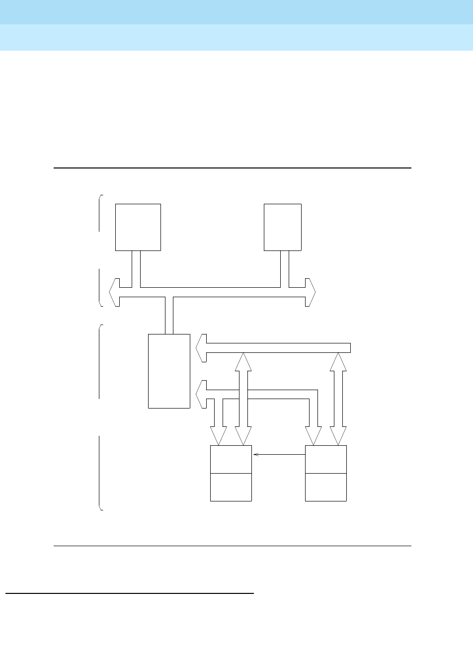
DEFINITY Enterprise Communications Server Release 6
Maintenance for R6r Volumes 1 & 2
555-230-126 Issue 2
January 1998
Maintenance Object Repair Procedures
Page 9-1431TAPE
9
The Host Adapter Circuit, Tape circuit pack, and Disk circuit pack are treated as
separate, but related, maintenance objects (H-ADAPTER,TAPE, and DISK).
Since the Disk circuit pack is controlled by SCSI commands which are generated
by the Host Adapter, problems with the Host Adapter can prevent
communications with the Disk. Whenever the Host Adapter is taken out of service
by the busy-out host-adapter command, or due to failure of a critical Host
Adapter test, the Tape and Disk maintenance objects are also placed in a
maintenance busyout state.
Figure 9-88. Mass Storage System Interactions
General Repair Procedures for TAPE
The following guidelines should be followed when troubleshooting and resolving
tape problems.
Switch System
Processor Memory
SPE
System Bus
SCSI BUS
MSSNET
Circuit HOST
Pack ADAPTER
(UN332) Private Bus
Mass
Storage
System
+ 12 V
DISK DISK TAPE TAPE
Circuit DRIVE DRIVE Circuit
Pack Pack
(TN1657) DISK TAPE (TN1656)

DEFINITY Enterprise Communications Server Release 6
Maintenance for R6r Volumes 1 & 2
555-230-126 Issue 2
January 1998
Maintenance Object Repair Procedures
Page 9-1432TAPE
9
1. Cleaning the tape drive head is very important. Dirty tape drive heads may
cause problems that appear to be hardware related.
A tape drive head with abrasive particles can permanently damage a new
tape. A worn tape may leave abrasive particles in the tape drive head.
Follow the tape head cleaning instructions that appear at the end of the
test descriptions for TAPE.
2.
Avoid saving translations or announcements
on the backup tape cartridge
if all other Tape Drive and Host Adapter problems have not been resolved.
If there is something wrong with the Mass Storage System, an attempt to
save translations or announcements could destroy a good copy of the files
on the tape cartridge.
3. In a system configured with duplicated SPEs, the tests run on the standby
Tape circuit pack are identical to those run on the active Tape circuit
pack. Communications between the active and standby SPEs is provided
by the DUPINT circuit pack for both the control channel and memory
shadowing. Therefore, problems with the DUPINT circuit pack may affect
maintenance tests of the standby Tape circuit pack.
4. Check the error log for power related problems and refer to the
maintenance documentation on power.
5. The
data on the tape cartridge will likely be destroyed
if:
■The tape cartridge is removed when the amber LED on the Tape
circuit pack is on.
■The Tape circuit pack is removed while the amber LED on the Tape
Circuit is on.
■Power is removed from the Tape Drive while the amber LED on the
Tape circuit pack is on.
6. The
data on the disk will likely be destroyed
if the Tape circuit pack is
removed while the amber LED on the Disk Drive is on.
7. Dirty Tape Drive heads may cause problems that appear to be hardware
related. To clean the tape heads in the Tape Drive, follow the tape head
cleaning procedure at the end of this section.
8. Since maintenance software cannot always distinguish between errors
caused by the tape cartridge and those caused by the Tape Drive or Host
Adapter, check for tape cartridge errors first.
■Make sure there is a tape cartridge in the Tape Drive.
■Make sure that the write protect lock is not active. To deactivate
write protect, slide the
RECORD
switch on the tape cartridge in the
direction of the arrow on the switch.
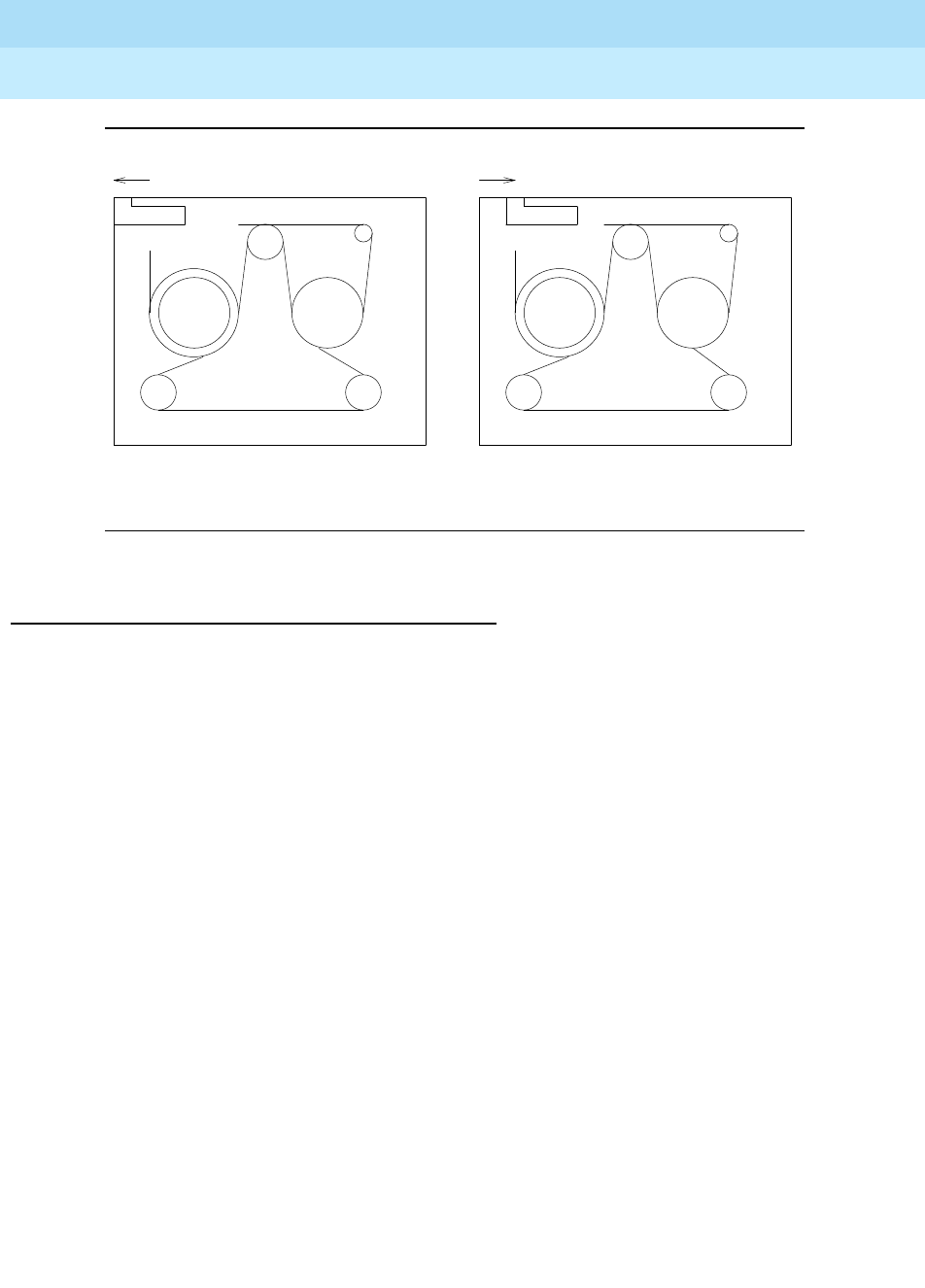
DEFINITY Enterprise Communications Server Release 6
Maintenance for R6r Volumes 1 & 2
555-230-126 Issue 2
January 1998
Maintenance Object Repair Procedures
Page 9-1433TAPE
9
Figure 9-89. Mass Storage System Interactions
Replacing a TAPE Cartridge
If the tape cartridge needs to be replaced, follow the procedure given below:
1. Resolve all other Tape circuit pack alarms/problems.
2. Install a new tape cartridge which has the same release number or, if that
is not practical, install a tape cartridge with the same file layout as the
original tape cartridge. Generally the file layouts are the same for tapes
formatted for same product (G3r V1 or G3r V2). However, for G3r V1, a
new file was added to the tape starting with the 6.1 release to support the
restore disk install command. Therefore depending on the release
number of the existing tape, a tape earlier than 6.1 or later than 6.0 should
be used for G3r V1.
When a tape cartridge is first inserted, there should be a spinning noise
indicating that the Tape Drive is performing a retension pass (moving the
tape forward and then back to the tape mark several times). This may take
several minutes.
3. Verify that the tape cartridge has an acceptable release number by
checking the Software Version via the list configuration
software-vintage command.
4. If a new tape cartridge is not available, but all other tape alarms/problems
have been resolved, then replace the damaged tape cartridge with the
backup tape cartridge. Wait for the retension pass to complete.
5. Verify that the tape cartridge has the latest translations by issuing the list
configuration software-vintage command. If the tape cartridge does not
have the latest translation or announcement files, then perform a backup
disk.
<--RECORD<--RECORD
Tape cartridge in write-protect position Tape cartridge in record position

DEFINITY Enterprise Communications Server Release 6
Maintenance for R6r Volumes 1 & 2
555-230-126 Issue 2
January 1998
Maintenance Object Repair Procedures
Page 9-1434TAPE
9
Replacing the TAPE Circuit Pack
For a Simplex SPE:
a. Enter busyout host-adapter. The Host Adapter should be "busied out" to
prevent other applications from trying to access the tape or the disk. The
Tape circuit pack supplies +12V to the Disk circuit pack so when it is
removed, the Disk circuit pack will also go out of service.
b. Replace the Tape circuit pack and insert the tape cartridge into the new
Tape circuit pack.
c. Issue the reset host-adapter command. This may take up to 3 minutes to
complete since it waits for the tape to retension.
d. Issue the release host-adapter command.
e. Issue the status spe command and check that the status screen indicates
that the tape and disk are now in service.
For a Duplicated SPE:
a. See ‘‘Replacing SPE Circuit Packs’’ in Chapter 5.
b. After the standby SPE is powered up and fully refreshed, test the standby
tape using the test tape long command.
Error Log Entries and Test to Clear Values
Table 9-489. TAPE Error Log Entries
Error
Type Aux
Data1Associated Test Alarm
Level On/Off
Board Test to Clear Value
1 (a) any Tape Reset (#894) MINOR OFF reset tape a|b2
18 (b) 0 Busyout Tape (#817) WARNING OFF release tape a|b2
250 (c) 0 Reset Tape (#894) WARNING OFF reset tape a|b2
257 (d) any Tape Looparound
(#814) WARNING OFF test tape a|b2 sh rep 2
513 (e) any Tape Diagnostics
(#813) MINOR ON test tape a|b2 sh rep 2
526 (f) 0 Busyout Host-adapter WARNING OFF release host-adptr a|b2
529 (g) 0 WARNING OFF reset tape a|b2
769 (h) any Tape Looparound
(#814) MINOR ON test tape a|b2 sh rep 2
Continued on next page
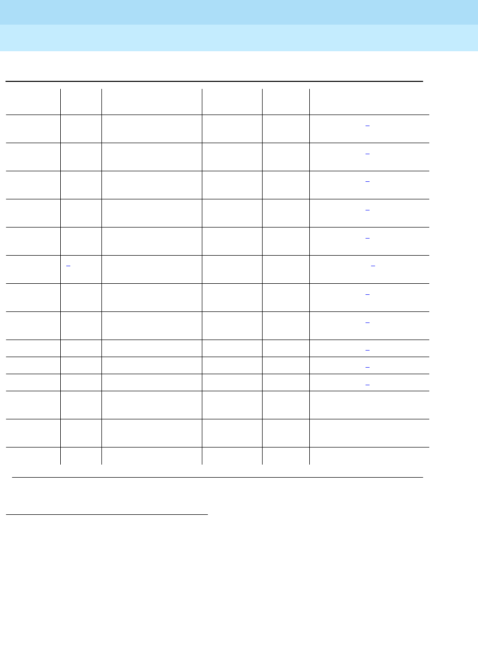
DEFINITY Enterprise Communications Server Release 6
Maintenance for R6r Volumes 1 & 2
555-230-126 Issue 2
January 1998
Maintenance Object Repair Procedures
Page 9-1435TAPE
9
The "service state" field in the Alarm Log refers to the accessibility of the device.
IN (in service) means that users can access the device and all maintenance tests
will run. MTC (maintenance busy) means that the device is "busied out" and
users cannot access it although all demand maintenance tests will run. OUT (out
of service) means that users cannot access the device but background and
demand testing can run.
1. The number of times the tape has been accessed. This number is at least 90% of the manufacturer’s
recommended limit.
2. In a system with a simplex SPE, the carrier does not have to be specified. In a system with duplicated
SPE, the carrier (a or b) must be specified.
3. If error type 1 with aux data of 123 is present, this field will have the out of service cause data. See the
MSS Error Actions
table at the end of the section on TAPE.
1025 (i) any Tape Write-Read
(#810) MINOR OFF test tape a|b2 long rep 2
1281 (j) any Tape Diagnostics
(#813) MINOR ON test tape a|b2 sh rep 2
1537 (k) any Tape Write-Read
(#810) WARNING OFF test tape a|b2 long rep 2
1793 (l) any Tape Looparound
(#814) MINOR OFF test tape a|b2 sh rep 2
2049 (m) any Tape Looparound
(#814) MINOR OFF test tape a|b2 sh rep 2
2305 (n) 2Tape Frmwr
Counters (#812) WARNING OFF reset tape a|b2
2306 (o) 5504 Tape Frmwr
Counters (#812) WARNING OFF test tape a|b2 sh rep 2
2561 (p) any Tape Write-Read
(#810) MINOR OFF test tape a|b2 long rep 2
2817 (q) any Tape Status (#815) WARNING ON test tape a|b2 sh rep 2
3073 (r) any In-line MINOR ON test tape a|b2 long rep 2
3329 (s) any Tape Audit (#811) MINOR OFF test tape a|b2 long rep 2
3585 (t) 408 MAJOR/
MINOR OFF
3585 (u) 409 MAJOR/
MINOR OFF
3841 (v) 3Miscellaneous MINOR OFF test tape a|b* long rep 1
Table 9-489. TAPE Error Log Entries — Continued
Error
Type Aux
Data1Associated Test Alarm
Level On/Off
Board Test to Clear Value
Continued on next page

DEFINITY Enterprise Communications Server Release 6
Maintenance for R6r Volumes 1 & 2
555-230-126 Issue 2
January 1998
Maintenance Object Repair Procedures
Page 9-1436TAPE
9
Notes:
a. Error type 1 means that the device is out of service as a result of
maintenance tests detecting a critical failure of the tape drive.
b. Error type 18 means that the Tape was busied out on demand from the
System Access Terminal.
c. Error type 250 means that the Reset Test (#809 or #894) failed.
d. Error type 257 means that the device could not be accessed.
e. Error type 513 means that on-board tape drive diagnostics tests
requested by the Tape Diagnostic Test (#813) failed.
f. Error type 526 means that the Host Adapter was busied out. This also
causes the Tape to be busied out.
g. Error type 529 means that there was a failure to put the tape in service or
to take it out of service.
h. Error type 769 means that the tape Loop-around Test (#814) failed.
i. Error type 1025 means that a tape medium error was detected when the
tape was read or written. The tape cartridge should be replaced if this
error continues to be reported.
j. Error type 1281 indicates that a hardware failure condition was detected
by the Firmware Error Counters Read and Clear Test (#812). See the
MSS
Error Actions
table at the end of the section on TAPE.
k. Error type 1537 indicates that the tape cartridge is write protected. Check
the RECORD switch on the tape cartridge. It should be pushed forward in
the direction shown by the arrow on the switch.
l. Error type 1793 is an in-line error from the tape control software that
indicates there was a problem with the SCSI Bus Access Failure or
Memory Access Failure between the Host Adapter circuit pack and the
Tape circuit pack. See the
MSS Error Actions
table at the end of the
section on TAPE.
m. Error type 2049 indicates that a bad command was sent to the tape drive.
This may be caused by a software error or a hardware failure. Execute the
test tape long command and fix any failures associated with those tests.
n. Error type 2305 means that the tape has exceeded 90% of the
manufacturer’s recommended limit of accesses. The tape should be
replaced as soon as practical. This alarm can be retired by issuing the
reset tape command but it will reappear each time the Tape Firmware
Counter Test (#812) is run.
o. Error type 2306 means that a block has been reassigned on the tape or an
attempt to reassign a block has failed. The tape should be replaced as
soon as practical.
p. Error type 2561 indicates that the Data Write-Read Test (#810) failed.

DEFINITY Enterprise Communications Server Release 6
Maintenance for R6r Volumes 1 & 2
555-230-126 Issue 2
January 1998
Maintenance Object Repair Procedures
Page 9-1437TAPE
9
q. Error 2817 indicates that the Tape Status Test (#815) detected a fault. See
the
MSS Error Actions
table at the end of the section on TAPE.
r. Error type 3073 indicates in-line errors reported by the tape control
software. See the
MSS Error Actions
table at the end of the section on
TAPE.
s. Error type 3329 indicates that the Tape Audit Test (#811) detected a
corrupted directory file. Execute the test tape long command and fix any
failures associated with those tests. The Auxiliary Code for this Error Log
entry and the failure code for the Tape Audit test indicate the directory file
that is corrupted. If Test 811 does not fail, follow normal escalation
procedures.
t. Error type 3585 with auxiliary data 408 indicates that there was an error in
reading translation data from the tape and/or disk.
This error only occurs on a system reset 3,4, or 5 (Cold 1, system reboot,
or extended system reboot). If a disk is present, the system first tries to
read translation from the first and second copies of translation on the disk
and, if that fails, it tries to read translation from the first and second copies
of translation on the tape.
If an error was detected with reading translation from the disk and then the
tape, a 408 error will be logged. This error will invoke
Emergency Transfer
on a system with simplex SPE. It will cause an SPE interchange if the
system is equipped with duplicated SPEs. To clear this alarm, correct all
other tape errors.
If the SPE is not duplicated, it may be necessary to use a backup tape to
first restore translation data to the disk. A new backup tape should be
obtained as soon as possible.
If the system is equipped with duplicated SPEs and if the alarm is
associated with the tape on the standby SPE the active SPE should be
running with the most current translation. Therefore after correcting any
hardware failures associated with the tape and disk on the standby SPE, a
save translation command should be used to save translations to the
disk and tape on the standby SPE.
u. Error type 3585 with auxiliary data 409 means that there was an error in
reading the program update file from both the disk and tape or there was
an error in applying the program update file once it was successfully read
from the disk or tape.
This error only occurs during a system reset 4 or 5 (system reboot or
extended system reboot). If a disk is present, the system will try to read
the program update file from the disk first and, if that fails, it will try to read
the program update file from the tape. After it succeeds in reading a copy
of the program update file, it will check to see if the program update
information is appropriate for the software version in memory before it
applies it to the software boot image.

DEFINITY Enterprise Communications Server Release 6
Maintenance for R6r Volumes 1 & 2
555-230-126 Issue 2
January 1998
Maintenance Object Repair Procedures
Page 9-1438TAPE
9
If an error is detected with any part of the process of reading the program
update file from the disk or tape and applying the program update to
memory, a hardware error 409 will be generated. This error will invoke a
MAJOR alarm and
Emergency Transfer
on a system with simplex SPE. It
will initiate an SPE interchange followed by a MINOR alarm on a system
with duplicated SPEs. When this error occurs, the copies of the program
update files on the disk and tape are invalidated so that those files no
longer appear when a list configuration software command is entered
from the System Access terminal.
To clear this alarm, first correct any other tape and disk alarms. Then
restore the two copies of the program update files on the disk and tapes
and apply those upgrades using ‘‘Software Updates’’ in Chapter 6.
v. Error type 3841 is used to record miscellaneous data when an
out-of-service condition occurs. See the
MSS Error Actions
table at the
end of the section on TAPE.
System Technician-Demanded Tests:
Descriptions and Error Codes
Always investigate tests in the order presented in the table below when
inspecting errors in the system. By clearing error codes associated with the
Reset Test
, for example, you may also clear errors generated from other tests in
the testing sequence.
1. D = Destructive; ND = Nondestructive
Order of Investigation Short Test
Sequence Long Test
Sequence Reset Board
Sequence D/ND1
Tape Reset Test (#809) X X ND
Tape Diagnostic Test (#813) X X ND
Tape Looparound Test (#814) X X ND
Tape Status Test (#815) X X ND
Tape Firmware Error
Counters Read and Clear Test (#812) X X ND
Tape Write-Read Test (#810) X ND
Tape Audit Test (#811) X ND
Tape Reset (#894) X ND

DEFINITY Enterprise Communications Server Release 6
Maintenance for R6r Volumes 1 & 2
555-230-126 Issue 2
January 1998
Maintenance Object Repair Procedures
Page 9-1439TAPE
9
Tape Reset Test (#809 and #894)
The Tape Reset Test consists of the following steps controlled by firmware on the
Host Adapter Circuit (located on the MSSNET CIRCUIT PACK):
■Tape Drive reset
An SCSI ‘‘BUS DEVICE RESET’’ message is transmitted to the Tape Drive
to reset it.
■Presence test
An SCSI ‘‘INQUIRY’’ command is sent to the Tape Drive to attempt to
query with it. If the Tape Drive is present, it will return information about the
device type, whether or not its medium is removable, compatibility with
established standards, vendor and product IDs, and other miscellaneous
information.
■Capacity test
An SCSI ‘‘READ CAPACITY’’ command is sent to the Tape Drive. It returns
with the logical block address and the block length of the last logic block
on the medium.
An SCSI ‘‘READ DATA BUFFERS’’ command is sent to the Tape Drive.
This returns the size of the controller memory data buffers.
An SCSI ‘‘READ DEFECT DATA’’ command is sent to the Tape Drive. This
returns the addresses of bad blocks on the tape that must be mapped
around.
■Device Diagnostic Tests
An SCSI ‘‘SEND DIAGNOSTICS’’ command is sent to the Tape Drive to
initiate a set of device-dependent self-tests that are run as a unit. Failures
can be for multiple reasons and the return code which indicates the cause
of failure is vendor unique. A failure condition will be reported as single
failure type since the only repair action is to replace the Tape circuit pack.
Table 9-490. TEST #809/#894 Tape Reset Test
Error
Code Test
Result Description/ Recommendation
526 ABORT The Host Adapter has been busied out.
1. Issue the release host-adapter command.
Continued on next page

DEFINITY Enterprise Communications Server Release 6
Maintenance for R6r Volumes 1 & 2
555-230-126 Issue 2
January 1998
Maintenance Object Repair Procedures
Page 9-1440TAPE
9
1316 ABORT Could not get access to the Mass Storage System. Other application software
may be using it or background maintenance tests may be running.
1. Retry the command at 1-minute intervals for a maximum of 5 retries.
2. If the test continues to abort, verify that the daily translation-save operation
is not in progress (issue the display system-parameters maintenance
command to display the time for scheduled maintenance and the "y/n"
option for saving translation daily).
1335 ABORT Could not run the test on the Standby SPE—Duplication not administered.
1. Refer to the documentation for STBY-SPE maintenance.
2. Administer standby present.
1338 ABORT Could not run the test on the Standby SPE—Interchange pending.
1. Refer to the documentation for STBY-SPE maintenance.
2. After interchange occurs, run test on new active SPE.
1339 ABORT Could not run the test on the Standby SPE—Handshake down.
1. Refer to the documentation for STBY-SPE maintenance.
2. When the standby is restored to service (use status spe to determine state
of standby) retry the command.
1347 ABORT Could not run the test on the Standby SPE—Refresh not complete.
1. When the standby is restored to service (use status spe to determine state
of standby) retry the command.
1350 ABORT Could not run test on Standby SPE—Shadowing not enabled.
1. When the standby is restored to service (use status spe to determine state
of standby) retry the command.
2000 ABORT Response to the test request was not received within the allowable time period.
1. Retry the command at 1-minute intervals for a maximum of 5 retries.
2500 ABORT Could not run the test on the Standby SPE—Internal software error.
1. Retry the command at 1-minute intervals for a maximum of 5 retries.
5102 ABORT Could not allocate the Mass Storage System to run this test
1. Retry the command at 1-minute intervals for a maximum of 5 retries.
2. If the test continues to abort, verify that the daily translation-save operation
is not in progress (issue the display system-parameters maintenance
command to display the time for scheduled maintenance and the "y/n"
option for saving translation daily).
Table 9-490. TEST #809/#894 Tape Reset Test — Continued
Error
Code Test
Result Description/ Recommendation
Continued on next page

DEFINITY Enterprise Communications Server Release 6
Maintenance for R6r Volumes 1 & 2
555-230-126 Issue 2
January 1998
Maintenance Object Repair Procedures
Page 9-1441TAPE
9
Tape Write-Read Test (#810)
The Tape Write-Read Test verifies that data can be written to a specific file on the
tape and read back successfully. It does not test the integrity of other files on the
tape. This test consists of the following steps:
1. Maintenance software in the SPE issues a request to the Host Adapter for
a transfer of data between SPE memory and a specified block on the tape.
1. See the MSS Error Actions table at the end of the section on TAPE.
NO
BOARD The tape has been placed in the "uninstalled" state.
1. Verify that a tape cartridge is installed and not write-protected and that the
tape drive is fully inserted and powered up.
2. Attempt a demand reset of the tape.
201 FAIL The Tape Drive is not responding or it may not be present.
1. Verify that the Tape circuit pack is present and powered.
2. Replace the Tape circuit pack.
3. If the reset continues to fail with this error code, replace the Host Adapter
circuit pack.
5124 FAIL It has been detected that no tape cartridge is installed.
1. Verify that a tape cartridge is installed and not write-protected.
2. If the reset continues to fail with this error code, continue with the steps
below for the general reset failure case.
1FAIL The Tape could not be reset successfully.
1. Verify that a tape cartridge is installed and not write-protected.
2. If the test continues to fail, replace the Tape cartridge. Wait for the
retension pass to complete. If the test succeeds, issue the backup disk
command.
3. If the test continues to fail, replace the Tape circuit pack.
4. If the test continues to fail, replace the MSSNET circuit pack.
PASS The Tape was reset correctly. Check other test results to see if it is operating
correctly.
Table 9-490. TEST #809/#894 Tape Reset Test — Continued
Error
Code Test
Result Description/ Recommendation
Continued on next page

DEFINITY Enterprise Communications Server Release 6
Maintenance for R6r Volumes 1 & 2
555-230-126 Issue 2
January 1998
Maintenance Object Repair Procedures
Page 9-1442TAPE
9
The Host Adapter firmware issues an SCSI WRITE command to the Tape
Drive which results in a transfer of data between the SPE memory and the
tape.
2. Maintenance software in the SPE issues a request to the Host Adapter to
run a checksum on the data previously written to the tape.
The Host Adapter reads the data off the tape and computes a checksum
which is returned to the SPE maintenance software.
3. Maintenance software compares the value of the checksum from the Host
Adapter with the checksum it previously calculated on the data it stored
on the tape.
Multiple failure conditions can occur during this test since it uses both the
software and hardware functions used during normal operations.
Table 9-491. TEST #810 Tape Write-Read Test
Error
Code Test
Result Description/ Recommendation
1301 ABORT Could not run the test—internal MSS error
1302 1. Retry the command
1304 ABORT Could not allocate the Mass Storage System to run this test. Other application
software may be using it or background maintenance tests may be running.
1. Retry the command at 1-minute intervals for a maximum of 5 retries.
2. If the test continues to abort, verify that the daily translation-save operation
is not in progress (Use the display system-parameters maintenance
command to display the start time for scheduled maintenance and the
"y/n" option for saving translation daily).
1316 ABORT Could not get access to the Mass Storage System. Other application software
may be using it or background maintenance tests may be running.
1. Retry the command at 1-minute intervals for a maximum of 5 retries.
2. If the test continues to abort, verify that the daily translation-save operation
is not in progress (issue the display system-parameters maintenance
command to display the time for scheduled maintenance and the "y/n"
option for saving translation daily).
1335 ABORT Could not run the test on the Standby SPE—Duplication not administered.
1. Refer to the documentation for STBY-SPE maintenance.
2. Administer standby present.
1338 ABORT Could not run the test on the Standby SPE—Interchange pending.
1. Refer to the documentation for STBY-SPE maintenance.
2. After interchange occurs, run test on new active SPE.
Continued on next page

DEFINITY Enterprise Communications Server Release 6
Maintenance for R6r Volumes 1 & 2
555-230-126 Issue 2
January 1998
Maintenance Object Repair Procedures
Page 9-1443TAPE
9
1339 ABORT Could not run the test on the Standby SPE—Handshake down.
1. Refer to the documentation for STBY-SPE maintenance.
2. When the standby is restored to service (use status spe to determine
state of standby) retry the command.
1347 ABORT Could not run the test on the Standby SPE—Refresh not complete.
1. When the standby is restored to service (use status spe), retry the
command.
1350 ABORT Could not run the test on the Standby SPE—Shadowing not enabled.
1. When standby is restored to service (use status spe), retry command.
2000 ABORT Response to the test request was not received within the allowable time
period.
1. Retry the command at 1-minute intervals for a maximum of 5 retries.
2500 ABORT Could not run the test on the Standby SPE—Internal software error.
1. Retry the command at 1-minute intervals for a maximum of 5 retries.
5102 ABORT Could not allocate the Mass Storage System to run this test
1. Retry the command at 1-minute intervals for a maximum of 5 retries.
2. If the test continues to abort, verify that the daily translation-save operation
is not in progress (issue the display system-parameters maintenance
command to display the time for scheduled maintenance and the "y/n"
option for saving translation daily).
NO
BOARD The tape has been placed in the "uninstalled" state.
1. Verify that a tape cartridge is installed and not write-protected and that the
tape drive is fully inserted and powered up.
2. Attempt a demand reset of the tape.
1FAIL The tape could not be accessed, the checksum on the data written did not
match the checksum in memory or the data read did not match the data
written.
1. Verify that a tape cartridge is installed and not write-protected.
2. If a non-write-protected tape was inserted, remove it and clean the Tape
Heads.
3. If the test continues to fail, replace the Tape Cartridge. Wait for the
retension pass to complete. If the test succeeds, issue the backup disk
command.
4. If the test continues to fail, replace the Tape circuit pack.
5. If the test continues to fail, replace the MSSNET circuit pack.
Table 9-491. TEST #810 Tape Write-Read Test — Continued
Error
Code Test
Result Description/ Recommendation
Continued on next page

DEFINITY Enterprise Communications Server Release 6
Maintenance for R6r Volumes 1 & 2
555-230-126 Issue 2
January 1998
Maintenance Object Repair Procedures
Page 9-1444TAPE
9
Tape Audit Test (#811)
The Tape Audit Test verifies the following Tape Medium conditions.
■The directory can be read.
■There are no "dirty" files. A file is said to be "dirty" if the data in the file is not
complete or if the directory entry for that file was not updated after the
data was written to the device.
■The tape has not exceeded the number of passes recommended by the
manufacturer. If the tape has exceeded 90% of the manufacturer’s
recommended limit of accesses, the tape should be replaced. An alarm
indicating this will appear nightly after scheduled maintenance is
executed. This alarm can be retired by issuing the reset tape command.
1. See the MSS Error Actions table at the end of the section on TAPE.
PASS The Tape write-read test succeeded. Check other test results to see if it is
operating correctly.
Table 9-492. TEST #811 Tape Audit Test
Error
Code Test
Result Description/ Recommendation
1316 ABORT Could not get access to the Mass Storage System. Other application software
may be using it or background maintenance tests may be running.
1. Retry the command at 1-minute intervals for a maximum of 5 retries.
2. If the test continues to abort, verify that the daily translation-save operation
is not in progress (issue the display system-parameters maintenance
command to display the time for scheduled maintenance and the "y/n"
option for saving translation daily).
1335 ABORT Could not run the test on the Standby SPE—Duplication not administered.
1. Refer to the documentation for STBY-SPE maintenance.
2. Administer standby present.
Continued on next page
Table 9-491. TEST #810 Tape Write-Read Test — Continued
Error
Code Test
Result Description/ Recommendation
Continued on next page

DEFINITY Enterprise Communications Server Release 6
Maintenance for R6r Volumes 1 & 2
555-230-126 Issue 2
January 1998
Maintenance Object Repair Procedures
Page 9-1445TAPE
9
1338 ABORT Could not run the test on the Standby SPE—Interchange pending.
1. Refer to the documentation for STBY-SPE maintenance.
2. After interchange occurs, run test on new active SPE.
1339 ABORT Could not run the test on the Standby SPE—Handshake down.
1. Refer to the documentation for STBY-SPE maintenance.
2. When the standby is restored to service (use status spe to determine state
of standby) retry the command.
1347 ABORT Could not run the test on the Standby SPE—Refresh not complete.
1. When the standby is restored to service (use status spe to determine state
of standby) retry the command.
1350 ABORT Could not run the test on the Standby SPE—Shadowing not enabled.
1. When the standby is restored to service (use status spe to determine state
of standby) retry the command.
2000 ABORT Response to the test request was not received within the allowable time period.
1. Retry the command at 1-minute intervals for a maximum of 5 retries.
2500 ABORT Could not run the test on the Standby SPE—Internal software error.
1. Retry the command at 1-minute intervals for a maximum of 5 retries.
5102 ABORT Could not allocate the Mass Storage System to run this test
1. Retry the command at 1-minute intervals for a maximum of 5 retries.
2. If the test continues to abort, verify that the daily translation-save operation
is not in progress (issue the display system-parameters maintenance
command to display the time for scheduled maintenance and the "y/n"
option for saving translation daily).
NO
BOARD The tape has been placed in the "uninstalled" state.
1. Verify that a tape cartridge is installed and not write-protected and that the
tape drive is fully inserted and powered up.
2. Attempt a demand reset of the tape.
Table 9-492. TEST #811 Tape Audit Test — Continued
Error
Code Test
Result Description/ Recommendation
Continued on next page

DEFINITY Enterprise Communications Server Release 6
Maintenance for R6r Volumes 1 & 2
555-230-126 Issue 2
January 1998
Maintenance Object Repair Procedures
Page 9-1446TAPE
9
Tape Firmware Error Counters Read
and Clear Test (#812)
The Host Adapter firmware is constantly running background tests on each of its
devices. When an error is detected by one of these background tests, the
appropriate counter in the host adapter dual port RAM is incremented. The Tape
Firmware Error Counters Read and Clear Test requests that the firmware return
these errors to the software and clear the area in dual port RAM. If any counter is
non-zero, the software then increments the appropriate software counter. The 16
errors reported by the firmware are:
■Unexpected interrupt from the SCSI Bus Interface Controller Chip (SBICC)
■SBICC timed out during SCSI command
■Error interrupt from the Direct Memory Access Controller (DMAC)
■DMAC timeout without issuing interrupt
■Tape self-test failed
■Tape external looparound test failed
■Command failed with bad sense key
■Tape could not be accessed
■Flaw detected in tape medium
1. See the MSS Error Actions table at the end of the section on TAPE.
1FAIL The audit of the tape directory failed.
1. Verify that a tape cartridge is installed.
2. Perform a backup disk. This may take up to an hour to complete.
3. If the test continues to fail, replace the Tape Cartridge. Wait for the retension
pass to complete and rerun the test. If the test succeeds, issue the backup
disk command.
4. If the test continues to fail, replace the Tape circuit pack.
5. If the test continues to fail, determine if other Tape, Disk, or Host Adapter
tests fail, and if they do, follow the repair procedures for those failures.
PASS The tape directory audit succeeded. Check other results to see if it is operating
correctly.
Table 9-492. TEST #811 Tape Audit Test — Continued
Error
Code Test
Result Description/ Recommendation
Continued on next page

DEFINITY Enterprise Communications Server Release 6
Maintenance for R6r Volumes 1 & 2
555-230-126 Issue 2
January 1998
Maintenance Object Repair Procedures
Page 9-1447TAPE
9
■Unrecoverable hardware error on tape
■Invalid parameter in SCSI command
■Media removed or device reset
■Tape is write protected
■Tape reached end of medium
■Block reassigned on tape
■Block reassignment on tape failed
Also this test checks for two other conditions: the presence of grown defects on
the tape medium, and whether the tape has been accessed in excess of 90% of
the manufacturer’s suggested maximum.
Table 9-493. TEST #812 Tape Firmware Error Counters Read
and Clear Test
Error
Code Test
Result Description/ Recommendation
1305 ABORT Could not read firmware error counters.
1. Retry the command at 1-minute intervals a maximum of 5 times.
1306 ABORT Could not read configuration area for defect information.
1. Retry the command at 1-minute intervals a maximum of 5 times.
1316 ABORT Could not get access to the Mass Storage System. Other application software
may be using it or background maintenance tests may be running.
1. Retry the command at 1-minute intervals a maximum of 5 times.
2. If the test continues to abort, verify that the daily translation-save operation
is not in progress (issue the display system-parameters maintenance
command to display the time for scheduled maintenance and the "y/n"
option for saving translation daily).
1335 ABORT Could not run the test on the Standby SPE—Duplication not administered.
1. Refer to the documentation for STBY-SPE maintenance.
2. Administer standby present.
1338 ABORT Could not run the test on the Standby SPE—Interchange pending.
1. Refer to the documentation for STBY-SPE maintenance.
2. After interchange occurs, run test on new active SPE.
1339 ABORT Could not run the test on the Standby SPE—Handshake down.
1. Refer to the documentation for STBY-SPE maintenance.
2. When standby is restored to service (use status spe to determine state of
standby) retry command.
Continued on next page

DEFINITY Enterprise Communications Server Release 6
Maintenance for R6r Volumes 1 & 2
555-230-126 Issue 2
January 1998
Maintenance Object Repair Procedures
Page 9-1448TAPE
9
1347 ABORT Could not run the test on the Standby SPE—Refresh not complete.
1. When standby is restored to service (use status spe to determine state of
standby) retry command.
1350 ABORT Could not run the test on the Standby SPE—Shadowing not enabled.
1. When standby is restored to service (use status spe to determine state of
standby) retry command.
2000 ABORT Response to the test request was not received within the allowable time
period.
1. Retry the command at 1-minute intervals a maximum of 5 times.
2500 ABORT Could not run the test on the Standby SPE—Internal software error.
1. Retry the command at 1-minute intervals a maximum of 5 times.
5102 ABORT Could not allocate the Mass Storage System to run this test
1. Retry the command at 1-minute intervals a maximum of 5 times.
2. If the test continues to abort, verify that the daily translation-save operation
is not in progress (issue the display system-parameters maintenance
command to display the time for scheduled maintenance and the "y/n"
option for saving translation daily).
NO
BOARD The tape has been placed in the "uninstalled" state.
1. Verify that a tape cartridge is installed and not write-protected and that the
tape drive is fully inserted and powered up.
2. Attempt a demand reset of the tape.
7 FAIL Background tests run by the Host Adapter detected that the tape could not be
accessed at some time previous to executing the read-and-clear test. This
error may have been caused by removing and reinserting the tape cartridge.
The read-and-clear test or reset test must be run at least once before this error
is cleared.
1. Try test tape again to see if the error has cleared.
2. Verify that the Tape Cartridge is present.
3. If the test continues to fail, replace the Tape circuit pack.
Table 9-493. TEST #812 Tape Firmware Error Counters Read
and Clear Test — Continued
Error
Code Test
Result Description/ Recommendation
Continued on next page

DEFINITY Enterprise Communications Server Release 6
Maintenance for R6r Volumes 1 & 2
555-230-126 Issue 2
January 1998
Maintenance Object Repair Procedures
Page 9-1449TAPE
9
11 FAIL Background tests run by the Host Adapter detected that the Tape drive was
reset at some time previous to executing the read-and-clear test. This error
may have been caused by removing and reinserting the tape cartridge. The
read-and-clear test or reset test must be run at least once before this error is
cleared.
1. Try test tape again to see if the error has cleared.
2. If the test continues to fail, replace the Tape circuit pack.
5504 FAIL A tape block has been reassigned to a different location on the tape as a
result of a medium error. This is referred to as a "grown defect." Tape
performance will be affected since the tape drive must search ahead to read
or write this block and then return to where it left off. Continued testing will not
correct the problem. The tape should be replaced as soon as practicable.
1. Run the STO-DATA tests to verify that the boot images, translations,
announcements, etc., are valid.
2. If errors are detected, run backup disk full to restore good copies to the
tape.
3. If the STO-DATA tests continue to fail, replace the tape.
5512 FAIL Ninety per cent of the manufacturer’s recommended limit for tape accesses
has been exceeded. Continued testing will not correct the problem and the
tape will need to be replaced as soon as practicable.
1FAIL At least one of the firmware error counters was non-zero.
1. Run the test tape command again to verify that this failure was not from a
failure condition which has been cleared as a result of this test clearing
the firmware counters.
2. Verify that a tape cartridge is installed and not write-protected.
3. If a non-write-protected tape was inserted, retry the command at 1-minute
intervals a maximum of 5 times.
4. If the test continues to fail, remove the tape cartridge and clean the Tape
Heads.
5. If the test continues to fail, replace the Tape Cartridge. Wait for the
retension pass to complete. If the test succeeds, issue the backup disk
full command.
6. If the test continues to fail, replace the Tape circuit pack.
7. If the test continues to fail, replace the MSSNET circuit pack.
PASS The firmware error counters were zero. Check other test results to see if it is
operating correctly.
Table 9-493. TEST #812 Tape Firmware Error Counters Read
and Clear Test — Continued
Error
Code Test
Result Description/ Recommendation
Continued on next page

DEFINITY Enterprise Communications Server Release 6
Maintenance for R6r Volumes 1 & 2
555-230-126 Issue 2
January 1998
Maintenance Object Repair Procedures
Page 9-1450TAPE
9
Tape Diagnostic Test (#813)
The Tape Diagnostic test causes the Host Adapter to send an SCSI SEND
DIAGNOSTICS command to the TAPE circuit pack. This initiates a set of
device-dependent self-tests that are run as a unit. Failures can be for multiple
reasons. The return code which indicates the cause of failure is vendor unique. A
failure condition will be reported as single failure type since the only repair action
is to replace the Tape circuit pack.
1. See the MSS Error Actions table at the end of the section on TAPE.
Table 9-494. TEST #813 Tape Diagnostic Test
Error
Code Test
Result Description/ Recommendation
1316 ABORT Could not get access to the Mass Storage System Other application software
may be using it or background maintenance tests may be running.
1. Retry the command at 1-minute intervals a maximum of 5 times.
2. If the test continues to abort, verify that the daily translation-save
operation is not in progress (issue the display system-parameters
maintenance command to display the time for scheduled maintenance
and the "y/n" option for saving translation daily).
1335 ABORT Could not run the test on the Standby SPE—Duplication not administered.
1. Refer to the documentation for STBY-SPE maintenance.
2. Administer standby present.
1338 ABORT Could not run the test on the Standby SPE—Interchange pending.
1. Refer to the documentation for STBY-SPE maintenance.
2. After interchange occurs, run test on new active SPE.
1339 ABORT Could not run the test on the Standby SPE—Handshake down.
1. Refer to the documentation for STBY-SPE maintenance.
2. When the standby is restored to service (use status spe to determine
state of standby) retry the command.
1347 ABORT Could not run the test on the Standby SPE—Refresh not complete.
1. When the standby is restored to service (use status spe to determine
state of standby) retry the command.
1350 ABORT Could not run the test on the Standby SPE—Shadowing not enabled.
1. When the standby is restored to service (use status spe to determine
state of standby) retry the command.
Continued on next page

DEFINITY Enterprise Communications Server Release 6
Maintenance for R6r Volumes 1 & 2
555-230-126 Issue 2
January 1998
Maintenance Object Repair Procedures
Page 9-1451TAPE
9
Tape Loop-around Tests (#814)
This test extends the Host Adapter Loop-Around test to send data from the Host
Adapter to buffers on the Tape circuit pack and back to the Host Adapter. It may
detect errors related to the Host Adapter, SCSI bus, and the Tape circuit pack. It
is intended to functionally test the Tape Drive circuit pack to the extent possible
without actually writing data to the tape.
1. See the MSS Error Actions table at the end of the section on TAPE.
2000 ABORT Response to the test request was not received within the allowable time
period.
1. Retry the command at 1-minute intervals a maximum of 5 times.
2500 ABORT Could not run the test on the Standby SPE—Internal software error.
1. Retry the command at 1-minute intervals a maximum of 5 times.
5102 ABORT Could not allocate the Mass Storage System to run this test
1. Retry the command at 1-minute intervals a maximum of 5 times.
2. If the test continues to abort, verify that the daily translation-save
operation is not in progress (issue the display system-parameters
maintenance command to display the time for scheduled maintenance
and the "y/n" option for saving translation daily).
NO
BOARD The tape has been placed in the "uninstalled" state.
1. Verify that a tape cartridge is installed and not write-protected and that
the tape drive is fully inserted and powered up.
2. Attempt a demand reset of the tape.
1FAIL A Tape diagnostic test failed.
1. Verify that a tape cartridge is installed and not write-protected.
2. If a tape was inserted, remove it and clean the Tape Heads.
3. If the test continues to fail, replace the Tape Cartridge. Wait for the
retension pass to complete. If the test succeeds, issue the backup disk
command.
4. If the test continues to fail, replace the Tape circuit pack.
5. If the test continues to fail, replace the MSSNET circuit pack.
PASS The Tape passed all diagnostic tests. Check other test results to see if it is
operating correctly.
Table 9-494. TEST #813 Tape Diagnostic Test — Continued
Error
Code Test
Result Description/ Recommendation
Continued on next page

DEFINITY Enterprise Communications Server Release 6
Maintenance for R6r Volumes 1 & 2
555-230-126 Issue 2
January 1998
Maintenance Object Repair Procedures
Page 9-1452TAPE
9
This test consists of two sets of tests:
■Tape Internal Loop-around
Data is generated in the RAM of the Host Adapter and transferred to its
SCSI Data Memory. An SCSI WRITE DATA BUFFERS command is sent
to the Tape circuit pack which causes the Tape Drive circuit pack to copy
the data to its buffers. An SCSI READ DATA BUFFERS command is then
sent by the Host Adapter to the Tape Drive circuit pack which causes the
Tape circuit pack to transfer the data from its buffers back to the Host
Adapter’s SCSI Data Memory. The Host Adapter then copies the data
back to its private RAM where it compares it with the original test data.
■Tape External Loop-around
This test is similar to the Internal Loop-around test except that the data
originates in the Host Adapter’s Dual Port RAM and it is transferred to and
from the SCSI Data Memory using SPE system bus accesses. Only a small
amount of data is sent to the Tape Drive circuit pack in order to keep
system bus access to a minimum.
Table 9-495. TEST #814 Tape Loop-around Test
Error
Code Test
Result Description/ Recommendation
1316 ABORT Could not get access to the Mass Storage System. Other application software
may be using it or background maintenance tests may be running.
1. Retry the command at 1-minute intervals a maximum of 5 times.
2. If the test continues to abort, verify that the daily translation-save operation
is not in progress (issue the display system-parameters maintenance
command to display the time for scheduled maintenance and the "y/n"
option for saving translation daily).
1335 ABORT Could not run the test on the Standby SPE—Duplication not administered.
1. Refer to the documentation for STBY-SPE maintenance.
2. Administer standby present.
1338 ABORT Could not run the test on the Standby SPE—Interchange pending.
1. Refer to the documentation for STBY-SPE maintenance.
2. After interchange occurs, run test on new active SPE.
1339 ABORT Could not run the test on the Standby SPE—Handshake down.
1. Refer to the documentation for STBY-SPE maintenance.
2. When the standby is restored to service (use status spe to determine state
of standby) retry the command.
Continued on next page

DEFINITY Enterprise Communications Server Release 6
Maintenance for R6r Volumes 1 & 2
555-230-126 Issue 2
January 1998
Maintenance Object Repair Procedures
Page 9-1453TAPE
9
1. See the MSS Error Actions table at the end of the section on TAPE.
1347 ABORT Could not run the test on the Standby SPE—Refresh not complete.
1. When the standby is restored to service (use status spe to determine state
of standby) retry the command.
1350 ABORT Could not run the test on the Standby SPE—Shadowing not enabled.
1. When the standby is restored to service (use status spe to determine state
of standby) retry the command.
2000 ABORT Response to the test request was not received within the allowable time period.
1. Retry the command at 1-minute intervals a maximum of 5 times.
2500 ABORT Could not run the test on the Standby SPE—Internal software error.
1. Retry the command at 1-minute intervals a maximum of 5 times.
5102 ABORT Could not allocate the Mass Storage System to run this test
1. Retry the command at 1-minute intervals a maximum of 5 times.
2. If the test continues to abort, verify that the daily translation-save operation
is not in progress (issue the display system-parameters maintenance
command to display the time for scheduled maintenance and the "y/n"
option for saving translation daily).
NO
BOARD The tape has been placed in the "uninstalled" state.
1. Verify that a tape cartridge is installed and not write-protected and that the
tape drive is fully inserted and powered up.
2. Attempt a demand reset of the tape.
1FAIL The Tape loop-around test failed.
1. Verify that a tape cartridge is installed and not write-protected.
2. If a tape was inserted, remove it and clean the Tape Heads.
3. If the test continues to fail, replace the Tape Cartridge. Wait for the retension
pass to complete. If the test succeeds, issue the backup disk command.
4. If the test continues to fail, replace the Tape circuit pack.
5. If the test continues to fail, replace the MSSNET circuit pack.
PASS The Tape loop-around test passed. Look at the results of other tests to see if it is
operating correctly.
Table 9-495. TEST #814 Tape Loop-around Test — Continued
Error
Code Test
Result Description/ Recommendation
Continued on next page

DEFINITY Enterprise Communications Server Release 6
Maintenance for R6r Volumes 1 & 2
555-230-126 Issue 2
January 1998
Maintenance Object Repair Procedures
Page 9-1454TAPE
9
Tape Status Test (#815)
The Tape Status Test verifies the following:
■The Host Adapter knows about the existence of the Tape Drive circuit
pack.
■The LEDs on the faceplate can be turned on and off correctly.
Note that this only verifies that the control and status logic for the LEDs is
operating correctly. The operation of the LEDs may also be tested visually
by using the test led command.
■+12V from on-board DC-to-DC converters are present.
Table 9-496. TEST #815 Tape Status Test
Error
Code Test
Result Description/ Recommendation
1306
1307
1308
ABORT Internal software error between maintenance software and MSS driver.
1. Retry the command at 1-minute intervals a maximum of 5 times.
1316 ABORT Could not get access to the Mass Storage System. Other application software
may be using it or background maintenance tests may be running.
1. Retry the command at 1-minute intervals a maximum of 5 times.
2. If the test continues to abort, verify that the daily translation-save operation
is not in progress (issue the display system-parameters maintenance
command to display the time for scheduled maintenance and the "y/n"
option for saving translation daily).
1335 ABORT Could not run the test on the Standby SPE—Duplication not administered.
1. Refer to the documentation for STBY-SPE maintenance.
2. Administer standby present.
1338 ABORT Could not run the test on the Standby SPE—Interchange pending.
1. Refer to the documentation for STBY-SPE maintenance.
2. After interchange occurs, run test on new active SPE.
1339 ABORT Could not run the test on the Standby SPE—Handshake down.
1. Refer to the documentation for STBY-SPE maintenance.
2. When the standby is restored to service (use status spe to determine state
of standby) retry the command.
1347 ABORT Could not run the test on the Standby SPE—Refresh not complete.
1. When the standby is restored to service (use status spe to determine state
of standby) retry the command.
Continued on next page

DEFINITY Enterprise Communications Server Release 6
Maintenance for R6r Volumes 1 & 2
555-230-126 Issue 2
January 1998
Maintenance Object Repair Procedures
Page 9-1455TAPE
9
1. See the MSS Error Actions table at the end of the section on TAPE.
1350 ABORT Could not run the test on the Standby SPE—Shadowing not enabled.
1. When the standby is restored to service (use status spe to determine state
of standby) retry the command.
2000 ABORT Response to the test request was not received within the allowable time period.
1. Retry the command at 1-minute intervals a maximum of 5 times.
2500 ABORT Could not run the test on the Standby SPE—Internal software error.
1. Retry the command at 1-minute intervals a maximum of 5 times.
5102 ABORT Could not allocate the Mass Storage System to run this test
1. Retry the command at 1-minute intervals a maximum of 5 times.
2. If the test continues to abort, verify that the daily translation-save operation
is not in progress (issue the display system-parameters maintenance
command to display the time for scheduled maintenance and the "y/n"
option for saving translation daily).
NO
BOARD The tape has been placed in the "uninstalled" state.
1. Verify that a tape cartridge is installed and not write-protected and that the
tape drive is fully inserted and powered up.
2. Attempt a demand reset of the tape.
1FAIL The tape configuration information shows the tape circuit pack is missing or the
tape LED test failed.
1. Verify that a tape cartridge is installed and not write-protected.
2. If a tape was inserted, remove it and clean the tape heads.
3. If the test continues to fail, replace the Tape Cartridge. Wait for the
retension pass to complete. If the test succeeds, issue the backup disk
command.
4. If the test continues to fail, replace the Tape circuit pack.
5. If the test continues to fail, replace the MSSNET circuit pack.
PASS The Tape status test passed successfully. Check other test results to see if it is
operating correctly.
Table 9-496. TEST #815 Tape Status Test — Continued
Error
Code Test
Result Description/ Recommendation
Continued on next page

DEFINITY Enterprise Communications Server Release 6
Maintenance for R6r Volumes 1 & 2
555-230-126 Issue 2
January 1998
Maintenance Object Repair Procedures
Page 9-1456TAPE
9
Tape Reset Test (#894)
The Tape Reset Test is run on as part of the reset tape command. The test
results for Test 894 are the same as those for Test 809, which is run as part of the
test tape sequence. All tape alarms are cleared when Test 894 passes, while
only some tape alarms may clear when Test 809 passes. Refer to results for Test
809 for repair procedures.
Tape Drive Head Cleaning Procedure
The following procedures should be used to clean the PBX Tape Drive(s). A
Tape Drive should be cleaned once every three months to reduce the risk of
losing information and to prevent unexpected service calls. An entry should be
made in the Lucent Preventive Maintenance Log when this is done (see Chapter
6).
A DC2000 Series Data Cartridge Tape Drive Cleaning Kit from 3M is used to
clean the tape head and the tape capstan. This kit consists of a Cleaning
Positioning Cartridge and 20 cleaning wands (Comcode 406622464 or 3M
Reorder number DC051111-12947). A refill kit of 20 cleaning wands is also
available (Comcode 406622472 or 3M Reorder Number DC051111-12948).
NOTE:
The cleaning wands are flammable. Dispose of properly.
1. Busy out the Tape circuit pack using the busyout tape c command where
c
is the carrier number (a or b). This prevents background maintenance
tests and other application software from trying to access the tape.
2. Eject the Tape Cartridge from the Tape circuit pack (TN1656). Insert the
Cleaning Position Cartridge into the Tape Drive with the label side to the
left (see Picture 1).
3. Prepare the cleaning wand for use as follows: Hold the bristle end down,
crush the wand at the "x" area and squeeze to release fluid and saturate
the bristles.
4. Insert the wand into R/W Head Slot (top of cartridge, see Picture 2) with
gentle twisting motion. Stop when solid resistance is felt. Rotate the wand
6 turns while raising and lowering end of wand.
5. Remove the used wand and discard.
6. Prepare a second wand as described in step 3 above.
7. Eject the Cleaning Position Cartridge out of the Tape circuit pack and
reinsert it. This will condition the tape drive to move the capstan when the
cleaning wand is inserted in the next step.
8. Insert the wand into the Capstan Slot (middle of cartridge, see Picture 2)
within 10 seconds after the Cleaning Position Cartridge was reinserted.

DEFINITY Enterprise Communications Server Release 6
Maintenance for R6r Volumes 1 & 2
555-230-126 Issue 2
January 1998
Maintenance Object Repair Procedures
Page 9-1457TAPE
9
9. Apply a gentle forward pressure to the wand for about 15 seconds. You
should be able to feel the capstan moving.
10. Remove the used wand and discard.
11. Eject the Cleaning Positioning Cartridge and insert the PBX Tape
Cartridge back into the Tape Drive.
NOTE:
After the Tape Cartridge is inserted back into the Tape Drive, it will
run through a retension pass which will take up to two minutes to
complete. During that time, the reset tape command entered in the
next step causes a "please wait" message to flash on the terminal
screen while the tape is retensioning, but the command will
complete after the retension pass completes.
12. Reset the Tape circuit pack using the reset tape c command where
c
is
the carrier number (a or b). This will clear out a tape error that indicates
the tape cartridge had been removed and reinserted.
13. Release the Tape from its maintenance busy-out state using the release
tape c command where
c
is the carrier number (a or b).
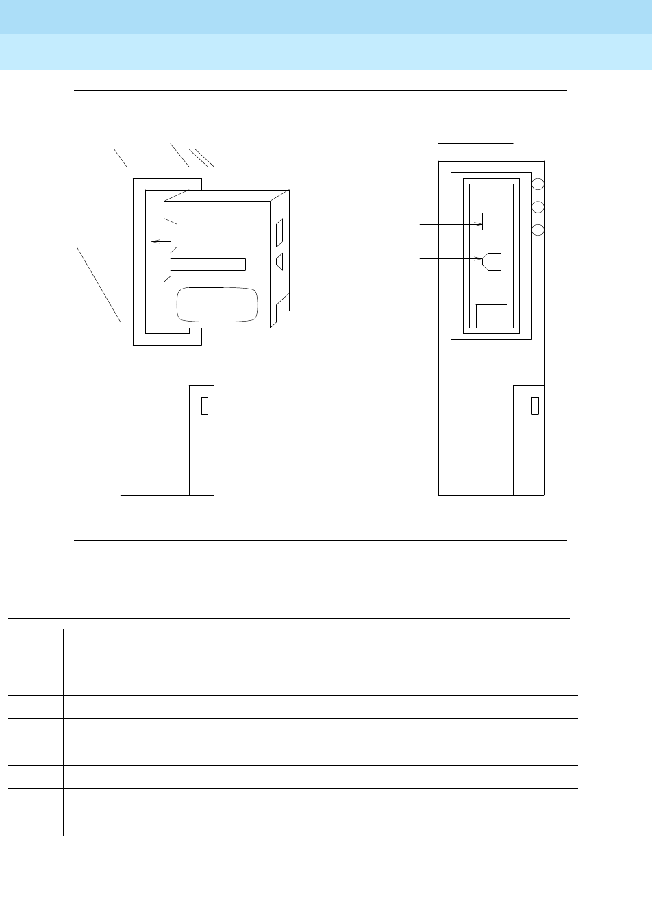
DEFINITY Enterprise Communications Server Release 6
Maintenance for R6r Volumes 1 & 2
555-230-126 Issue 2
January 1998
Maintenance Object Repair Procedures
Page 9-1458TAPE
9
Figure 9-90. Mass Storage System Interactions
Table 9-497. MSS Error Actions
Code Description
0 Unexpected interrupt from SBICC.
1 SBICC timed out during SCSI command.
2 DMAC generated error interrupt.
3 DMAC timed out without interrupt.
4 Tape self-test failed.
5 Tape external looparound test failed.
6 Command failed with bad SENSE key.
7 Tape could not be accessed.
Continued on next page
Capstan Slot
Picture #2
Label
Picture #1
R/W
Head Slot

DEFINITY Enterprise Communications Server Release 6
Maintenance for R6r Volumes 1 & 2
555-230-126 Issue 2
January 1998
Maintenance Object Repair Procedures
Page 9-1459TAPE
9
8 Flaw detected in tape medium.
9 Unrecoverable hardware failure on tape.
10 Invalid parameter in SCSI command.
11 Media removed or tape reset.
12 Tape is write protected.
13 Tape reached end of medium.
14 Block reassigned on tape.
15 Block reassignment failed on tape.
16 Inconsistent capacity data
17 Device busy
18 Device reservation conflict
19 Request sense failed
101 Unrecognized
opcode
.
102 Unrecognized
modifier
.
103
xlist_length
too long.
104 Invalid transfer address.
105 Intra-device copy ranges overlap.
121 Device invalid for
opcode
requested.
122 Device non-existent.
123 Device is out of service.
124
to_byte
or
from_byte
is out of range.
125
to_byte
+
numbytes
is invalid or
from_byte
+
numbytes
is invalid.
126 Type of device is invalid for
opcode
requested.
201 An unexpected interrupt code was returned from the SBICC. This represents a protocol
error that could be the result of the HA or the target device. The device may not be present.
251 SBICC timed out. This could be the fault of the HA or target device. The HA will attempt to
reset the SBICC.
301 DMAC error. This could be the fault of the HA or the SCSI target device.
351 DMAC timed out. This could be the fault of the HA or the SCSI target device. The HA will
attempt to reset the SBICC.
401 Could not save announcements or program update file.
Table 9-497. MSS Error Actions — Continued
Code Description
Continued on next page

DEFINITY Enterprise Communications Server Release 6
Maintenance for R6r Volumes 1 & 2
555-230-126 Issue 2
January 1998
Maintenance Object Repair Procedures
Page 9-1460TAPE
9
408 Could not read translation from the Disk and Tape as part of system initialization.
409 Could not apply program update file.
422 Could not save translations.
501 A non-critical diagnostic test failed on the Host Adapter. This includes the USART chip test
and the LED tests.
511 A diagnostic test requiring bus mastership failed. This happens only as the result of an
MSS_DIAG command. This could be the fault of the HA or the system. Therefore the board
does not put itself in held reset state. Rather, the error is reported and counters are
incremented.
521 The HA looparound test requiring bus mastership failed. This happens only as the result of
an MSS_LOOPAROUND command. This could be the fault of the HA or the system.
Therefore the board does not put itself in held reset state. Rather, the error is reported and
counters are incremented.
531 Target device SEND DIAGNOSTICS self-test indicated a hardware error. This indicates
that there are problems with the controller or the device, and it should be taken out of
service. This error will not occur if other errors (e.g. SBICC) prevent the SEND
DIAGNOSTICS command from running.
551 The target device internal looparound failed due to data corruption. Other errors (SBICC,
SCSI check condition) would cause a different error code to be reported. This failure
demonstrates that the target may potentially corrupt data and it should be taken out of
service.
552 The target device external looparound failed due to data corruption. Other errors (SBICC,
SCSI check condition) cause a different error code to be reported. This failure
demonstrates that the target may potentially corrupt data. However, the HA does not take
the device out of service as a result of this error. This test is only run following the target
device internal looparound which detects actual problems with the target device. This
failure implicates the HA bus interface or a system problem.
561 When the MSS_RESET command was issued for a device, it was found not to be present.
562 When the MSS_RESET command was issued for a device, the NQUIRY command failed.
563 When the MSS_RESET command was issued for a device, the TEST UNIT READY
command failed
564 When the MSS_RESET command was issued for a device, the READ CAPACITY command
failed
565 The device reset failed.
566 Device type not supported.
567 Capacity data is inconsistent.
568 Block size doesn’t divide into 8K.
Table 9-497. MSS Error Actions — Continued
Code Description
Continued on next page

DEFINITY Enterprise Communications Server Release 6
Maintenance for R6r Volumes 1 & 2
555-230-126 Issue 2
January 1998
Maintenance Object Repair Procedures
Page 9-1461TAPE
9
601 REQUEST SENSE failed.
700 Indicates that there is no specific sense key information for a SCSI target on which a
REQUEST SENSE was issued. This should never happen because firmware only asks for
sense information if errors occurred.
701 SCSI sense information reported a recovered error on a SCSI target where it didn’t make
sense. Normally recovered errors are filtered by the HA firmware for reads and writes.
However, for other commands, this is reported to software.
702 SCSI sense information indicates that the target device cannot be accessed. This will occur
if the tape cartridge is not present.
703 SCSI sense information indicates that a SCSI command terminated with a nonrecovered
error condition probably caused by a flaw in the medium or an error in the recorded data.
704 SCSI sense information indicates a nonrecoverable hardware failure occurred. The tape
may be broken.
705 SCSI sense information indicates that there was an illegal parameter in the command
descriptor block or in additional parameters supplied. This could be caused by a HA
firmware failure or a problem with the target device.
706 SCSI sense information indicates that the target device’s removable medium may have
been changed or the target controller has been reset.
707 SCSI sense information indicates that reads or writes were attempted for a medium that
was protected from this operation.
708 SCSI sense information indicates that a write-once read-multiple device or a
sequential-access device encountered a blank block while reading or a write-once
read-multiple device encountered a nonblank block while writing. This should never
happen; the HA only supports direct access devices.
709 SCSI sense information indicates a vendor-unique sense key.
710 SCSI sense information indicates a COPY, COMPARE, or COPY AND VERIFY command
was aborted due to an error condition on the source device, the destination device, or both.
This shouldn’t happen since these commands aren’t issued by the HA.
711 SCSI sense information indicates that the target controller aborted the command.
712 SCSI sense information indicates that a SEARCH DATA command has satisfied an equal
comparison. This should not happen since this command is not issued by the HA.
713 This indicates that a buffered peripheral device has reached the end-of-medium and data
remains in the buffer that has not been written to the medium.
714 This indicates that the source data did not match the data read from the medium. This
should not happen since the HA does not issue any commands involving comparisons.
715 SCSI sense information returned a reserved sense key. This should not happen.
758 Device returned busy.
Table 9-497. MSS Error Actions — Continued
Code Description
Continued on next page

DEFINITY Enterprise Communications Server Release 6
Maintenance for R6r Volumes 1 & 2
555-230-126 Issue 2
January 1998
Maintenance Object Repair Procedures
Page 9-1462TAPE
9
764 Device returned reservation conflict status.
801 HA firmware was attempting to process a command requiring system bus access and the
NOGOINT interrupt occurred. This probably indicates that system software failed to enable
bus access before issuing an MSS command requiring it. It also could indicate a system
problem or a HA problem.
802 HA firmware was accessing the system bus and it timed out. This could be a result of MSS
command argument errors, system problems, or a HA problem.
803 HA firmware was accessing the system bus and received a data-parity interrupt. This could
indicate a system or HA problem.
804 HA firmware was accessing the system bus and received a error detection and correction
interrupt. This could indicate a system or HA problem.
805 System bus error test failed.
1001 Firmware error
1002 Cheetah/Pecos error
1003 Both the 68020 and the DMAC tried to access the same location in the SDM concurrently.
1004 HA firmware couldn’t put a response in the response queue because it was full. This could
be the fault of the HA, or system software. However, there is no way to recover, therefore
the HA places itself in held reset.
2001 A critical diagnostic test on the Host Adapter failed making it dangerous to continue
service.
2002 The Host Adapter internal looparound test failed because of data corruption.
3001 An exception occurred indicating a serious hardware or firmware problem. Additional
information will be placed in HA DPRAM about which exception occurred and the address
at which it occurred.
3002 An interrupt occurred when it should not have. This includes interrupts that are a normal
part of command processing but that occurred unexpectedly.
4001 The checksum of the firmware image in memory prior to FLASH PROM programming failed.
4002 Flash PROM programming failed.
5000 The tape cartridge has been changed or the tape drive has been reset by firmware.
5001 Alternate copy of file used—primary could not be accessed.
5113 Device out of service
5124 No tape cartridge in tape drive.
5126 Handshake not up
5127 Memory refresh not complete
Table 9-497. MSS Error Actions — Continued
Code Description
Continued on next page

DEFINITY Enterprise Communications Server Release 6
Maintenance for R6r Volumes 1 & 2
555-230-126 Issue 2
January 1998
Maintenance Object Repair Procedures
Page 9-1463TAPE
9
5200 Kernel call received a notification.
5201 Spurious interrupt from MSSNET.
5202 Message received on an unexpected class.
5203 File system on the device is corrupt.
5204 Driver failed to get parity error interrupt.
5205 Driver failed to get EDC error interrupt.
5206 Driver failed to get timeout interrupt.
5207 Alternate file could not be accessed.
5208 Bad path index on software call.
5209 Driver failed to get bus error interrupt.
5210 MSS client died.
5212 File 0 (directory) corrupt.
5213 File 1 (alternate directory) corrupt.
5214 File 2 (small boot image) corrupt.
5215 File 3 (alternate small boot image) corrupt.
5216 File 4 (program update file) corrupt.
5217 File 5 (alternate program update file) corrupt.
5218 File 6 (translation file) corrupt.
5219 File 7 (alternate translation file) corrupt.
5220 File 8 (error log) corrupt.
5221 File 9 (alternate error log) corrupt.
5222 File 10 (downloadable firmware) corrupt.
5223 File 11 (alternate downloadable firmware) corrupt.
5224 File 12 (announcement file) corrupt.
5225 File 13 (alternate announcement file) corrupt.
5226 File 14 (maintenance scratch file) corrupt.
5227 File 15 (small config core dump) corrupt.
5228 File 16 (large boot image) corrupt.
5229 File 17 (alternate boot image) corrupt.
5230 File 18 (large core dump on disk) corrupt.
Table 9-497. MSS Error Actions — Continued
Code Description
Continued on next page

DEFINITY Enterprise Communications Server Release 6
Maintenance for R6r Volumes 1 & 2
555-230-126 Issue 2
January 1998
Maintenance Object Repair Procedures
Page 9-1464TAPE
9
5231 File 19 (large core dump on tape) corrupt.
5300 Command timed out.
5301 Driver ran out of resources.
5302 Device or host adapter is not ready.
5303 State information is invalid.
5304 Firmware returned unexpected tag.
5305 MSSNET board is not inserted.
5400 Initialization error.
5401 Kernel call failed.
5402 Timer call failed.
5403 DUPINT call failed.
5404 DRIP call failed.
5405 Critical path destroyed.
5406 Internal error.
5504 Block reassigned on tape as a result of a medium error
5505 While running status test, configuration test failed.
5506 While running status test, LED test failed.
5507 Status test found host adapter in "held reset" state.
5508 Unable to obtain path to PAM.
5509 Translations were not locked.
5510 +5V not present
5511 +12V not present
5512 Exceeded 90% of manufacturer’s recommended tape access limit.
5513 Disk capacity not sufficient for memory size.
5514 Disk not configured for larger memory size.
30003 Cannot write to tape, cartridge or device error.
30004 Cannot read from tape, cartridge or device error.
30017 Checksum error in block.
30203 Write-read mismatch error.
Table 9-497. MSS Error Actions — Continued
Code Description
Continued on next page

DEFINITY Enterprise Communications Server Release 6
Maintenance for R6r Volumes 1 & 2
555-230-126 Issue 2
January 1998
Maintenance Object Repair Procedures
Page 9-1465TBRI-BD (TN2185 ISDN Trunk-Side BRI)
9
TBRI-BD (TN2185
ISDN Trunk-Side BRI)
The TN2185 circuit pack contains eight, 4-wire ports that interface to the network
at the ISDN S/T reference point over two 64 Kb/s channels (B1 and B2) and over
a 16Kb/s signaling (D) channel. The B1 and B2 channels can be simultaneously
circuit switched or individually packet switched. Only one channel per trunk can
be packet switched due to Packet Processing Element (PPE) limitations. The D
channel is either circuit switched or packet switched. Packet switching uses the
PPE to combine all D channels into a single physical channel, which is then
routed via the concentration highway to the Network Control Element (NCE) and
then to the TDM bus. The circuit-switched connections have a Mu-law or A-law
option for voice and operate as 64Kb/s clear data channels. The
packet-switched channels support the LAPD protocol and conform with the
CCITT Q.920 Recommendations for D-channel signaling.
LEDs
The three LEDs on the circuit pack’s faceplate indicate board status. When
illuminated, the red LED indicates a board failure or a major or minor on-board
alarm, the green LED indicates that testing is in progress, and the amber LED
indicates that the board is in use.
1. Where UU is the universal cabinet number (1 for PPN, 2 -44 for EPN), C is the carrier
designation (A, B, C, D, or E), SS is the carrier slot address where the circuit pack is located
(1, 2, and so forth), and pp is the two-digit port number (1, 2, 3, and so forth).
MO Name (in
Alarm Log) Alarm Level Initial Command to Run1Full Name of MO
TBRI-BD MINOR test board UUCSS l r# TBRI-BD
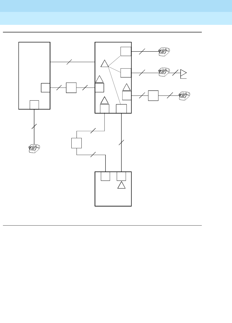
DEFINITY Enterprise Communications Server Release 6
Maintenance for R6r Volumes 1 & 2
555-230-126 Issue 2
January 1998
Maintenance Object Repair Procedures
Page 9-1466TBRI-BD (TN2185 ISDN Trunk-Side BRI)
9
Figure 9-91. Integrated Trunk-Side BRI, ISDN Interface Reference Points
ISDN Interface Reference Point definitions:
LT Logical Terminal
V Primary Rate user/network (asymmetrical) trunk interface. The
ECS is capable of acting as the user or as the network side of
this 1.544 - or 2.048-Mbps interface.
R Interface between Terminal Equipment and Network
Termination
S Basic Rate network-side 4-wire line interface
S/T 4-wire Basic Rate connection to a Network Termination1.
T 4-wire Basic Rate interface to a Network Termination.2
CO
NT
2-Wire
NT
2-Wire
NT
2-Wire
NT
4-Wire
4-Wire
4-Wire
NT
2-Wire NT
4-Wire
PBX
PBX
LT TE
TE TE
cydfisdn RPY 072397
NT2 LT
LT
NT2
NT2
Terminal
Adapter
NT2
S/T
TE
TE
NT1
VPRI
U
U
T
S/T
T
S
S
UT
R
NT1
NT1
ISDN Interface Reference Points
1
2
3
4
5

DEFINITY Enterprise Communications Server Release 6
Maintenance for R6r Volumes 1 & 2
555-230-126 Issue 2
January 1998
Maintenance Object Repair Procedures
Page 9-1467TBRI-BD (TN2185 ISDN Trunk-Side BRI)
9
Hardware Error Log Entries and Test to Clear
Values
1. Network Termination 2 (NT2), that terminates Layer 1 and higher layers. PBXs,
LANs, and terminal controllers typically provide NT2 functionality including
protocol handling and multiplexing for Layers 2 and 3.
2. Network Termination 1 (NT1), that terminates Layer 1 and monitors
maintenance, performance, timing, power transfer, multiplexing, and multi-drop
termination with contention resolution.
TE Terminal Equipment
U Basic Rate network-side 2-wire line interface.
1 TN556B ISDN-BRI 4-Wire S/T-NT Line (A-law)
2 TN 2185 ISDN-BRI 4-Wire S Interface (Trunk Side)
3 TN2198 ISDN-BRI 2-Wire U Interface
4 TN2198 ISDN-BRI 2-Wire U Interface
5 TN 2185 ISDN-BRI 4-Wire S Interface (Trunk Side)
Table 9-498. TBRI-BD Error Log Entries
Error
Type Aux
Data Associated Test Alarm
Level On/Off
Board Test to Clear Value
010 Any Any Any test board UUCSS sh r 1
1 (a) Any None MINOR ON
257 (b) 65535 Control Channel Loop
Test (#52) MINOR ON test board UUCSS r 20
513 (c) 4352
to 4357 None ON
769 (d) 4358
1025 (e) NPE/NCE Audit Test
(#50) None ON
1291 (f) 4359 Clear Error Counters
(#270) MINOR ON
1294 (g) 46088
to
46096
SAKI Sanity Test (#53) MINOR ON See (h)
1537 (h) 46082 MINOR ON
1793 (i) 46080 MINOR ON
1794 (i) 46094 MINOR ON
Continued on next page
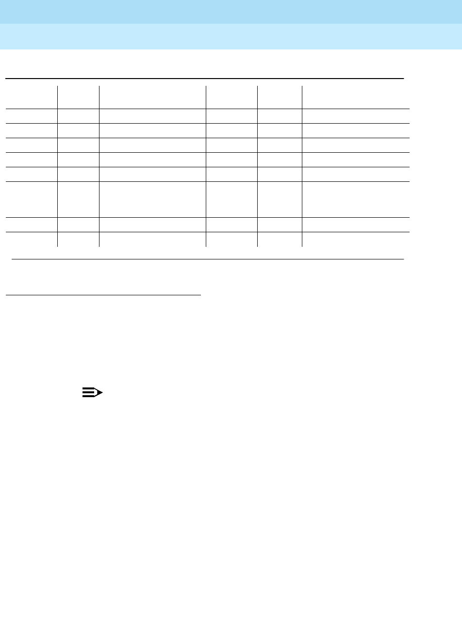
DEFINITY Enterprise Communications Server Release 6
Maintenance for R6r Volumes 1 & 2
555-230-126 Issue 2
January 1998
Maintenance Object Repair Procedures
Page 9-1468TBRI-BD (TN2185 ISDN Trunk-Side BRI)
9
Notes:
a. The circuit pack stopped functioning or is physically removed from the
system.
NOTE:
This alarm logs approximately 11 minutes after removing the circuit
pack and/or the SAKI Sanity Test (#53) fails.
If the circuit pack is not in the system, insert a circuit pack in the same slot
as the error indicates. See note (g).
b. Transient communication problems between the switch and this circuit
pack. Execute the test board UUCSS command and refer to the repair
procedures for the Control Channel Loop Around Test (#52).
c. On-board hardware failure. Aux data values correspond to the following
detected errors:
1. Run the Short Test Sequence first. If all tests pass, run the Long Test Sequence. Refer to the
appropriate test description and follow the recommended procedures.
1795 (i) 46085 MINOR ON
2305 (j) 46104 None ON
2306 (i) 46081 None ON
3330 (j) 46083 MINOR OFF
3586 (k) MINOR OFF
3840(l) 4096
to
4101
3842 (m) 46095
3843 (n) 46097
4352 External RAM error
4353 Internal RAM error
4355 ROM Checksum error
4357 Instruction set error
Table 9-498. TBRI-BD Error Log Entries — Continued
Error
Type Aux
Data Associated Test Alarm
Level On/Off
Board Test to Clear Value
Continued on next page

DEFINITY Enterprise Communications Server Release 6
Maintenance for R6r Volumes 1 & 2
555-230-126 Issue 2
January 1998
Maintenance Object Repair Procedures
Page 9-1469TBRI-BD (TN2185 ISDN Trunk-Side BRI)
9
Reset the circuit pack with the busyout board UUCSS and reset board
UUCSS commands. When reset, the circuit pack executes a set of tests to
detect the presence of any of the faults listed above. Detection of one of
these errors during initialization causes the circuit pack to lock-up and
appear insane to the system. See the repair procedure in Note (a).
d. The circuit pack detects a program logic error. While no action is required,
this error can lead to other errors against this circuit pack.
e. The circuit pack cannot update and read back NPE/NCE memory. This
error can be ignored, but may lead to other errors against this circuit pack.
f. The TN2185 board notifies maintenance software that it has detected a
parity error while accessing its dynamic RAM (that stores the board’s
translation information and downloadable application firmware).
Maintenance software resets the circuit pack.
g. Unable to write LAN Translation RAM Error (internal memory access error).
Translation RAM locations for the call connection attempt are not
available, and one or more RAM locations are bad due to a translation
RAM read-back error. Reset the circuit pack with the busyout board
UUCSS and reset board UUCSS commands. If the Circuit Pack Restart
Test (#594) passes, then the on-board circuitry is healthy. Retire the alarm
with the test board UUCSS long clear command. If the Circuit Pack
Restart Test (#594) fails, replace the circuit pack.
h. Frame overrun at Packet Bus interface. Due to an on-board fault or by
faulty data received on one of the circuit pack’s external ports. If any of the
ports on this circuit pack is alarmed, refer to the repair procedures for
those maintenance objects. If this error persists, maintenance software
removes the board from service; replace the circuit pack.
i. The circuit pack is has problems transmitting/receiving data to/from the
Packet Bus.
1793 Parity errors are detected when transmitting data to the
Packet Bus.

DEFINITY Enterprise Communications Server Release 6
Maintenance for R6r Volumes 1 & 2
555-230-126 Issue 2
January 1998
Maintenance Object Repair Procedures
Page 9-1470TBRI-BD (TN2185 ISDN Trunk-Side BRI)
9
j. Error Type (2305, 3330): A critical failure in the Circuit Pack’s Packet Bus
interface. Possible causes include either a Packet Bus fault or an
on-board fault, for example, the board received a bad CRC or invalid
DLCI. If the Packet Bus is alarmed, refer to the “
Maintenance Manual
”
section for Packet Bus fault location and recommended repair
procedures. The number of ISDN circuit packs displaying this error
increases the probability of errors due to Packet Bus problems.
If there are no Packet Bus alarms, reset the circuit pack with the busyout
board UUCSS and reset board UUCSS commands. If the Circuit Pack
Restart Test (#594) passes, then the on-board circuitry is healthy. Retire
the alarm with the test board UUCSS long clear command. If the Circuit
Pack Restart Test (#594) fails, replace the circuit pack.
k. The SPE software detects an excessive number of up-link messages from
the TN2185 board within a certain time period. To prevent the faulty board
from flooding the switch with data, the switch software takes the board out
of service and alarms it. The switch software also tells the Archangel to
ignore up-link messages from the board.
When the board is alarmed due to this error, the switch software
periodically puts the board back in service and tells the Archangel to
process up-link messages from the board. If the problem still exists, the
software takes the circuit pack out of service again. If the circuit pack
does not exhibit the problem for a certain time period, then maintenance
software resolves the alarm and the circuit pack is left in service.
l. The circuit pack received an inconsistent down-link message (a bad
header, port number, data, subqualifier, or logical link) over the Control
Channel.
m. The board is receiving data from the bus faster than it can distribute the
data to its endpoints, causing the FIFO RAM buffer to overflow. This error
can occur occasionally due to the statistical sizing of the buffers. If it
1794 Packet Bus transmit buffers overflow.
1795 Circuit pack cannot find end of frame when transmitting to
Packet Bus. Clear the alarm with: busyout board UUCSS,
reset board UUCSS, test board UUCSS long clear,
release board UUCSS. If the error recurs within 10 minutes,
replace the circuit pack.
2306 Error in a received frame from the Packet Bus, most likely
caused by a packet bus problem, but may be due to a
circuit pack fault. An invalid Link Access Procedure Data
(LAPD) frame error occurs if the frame contains a bad
Cyclical Redundancy Check (CRC). If bus parity errors
occur, run the LAN Receive Parity Error Counter Test (#595)
to determine if the condition has cleared. Refer to the
maintenance documentation to determine if the problem is
isolated to this circuit pack or is caused by Packet Bus
faults.

DEFINITY Enterprise Communications Server Release 6
Maintenance for R6r Volumes 1 & 2
555-230-126 Issue 2
January 1998
Maintenance Object Repair Procedures
Page 9-1471TBRI-BD (TN2185 ISDN Trunk-Side BRI)
9
occurs frequently, it may indicate a LAPD parameter mismatch. LAPD
should recover from this problem, but it may degrade the performance of
the LAN bus.
When this error is reported, maintenance reads and clears the board
counter and logs the problem in the maintenance error log.
n. Bad translation RAM detected, but the call continues by using another
translation location. The circuit pack reports this error when it cannot
update NPE/NCE memory and read it back. This error is not
service-affecting and can be ignored, but can lead to other types of errors
against this circuit pack.
System Technician-Demanded Tests:
Descriptions and Error Codes
When inspecting errors in the system, always investigate tests in the order listed
below. By clearing error codes associated with the
Control Channel Loop Around
Test,
for example, you may also clear errors generated from other tests in the
testing sequence.
Control Channel Loop Around Test (#52)
Refer to the repair procedure described in the "XXX-BD (Common Port Circuit
Pack)" section.
NPE /NCE Audit Test (#50)
Refer to the repair procedure described in the "XXX-BD (Common Port Circuit
Pack)" section.
SAKI Sanity Test (#53)
This is a destructive test.
Refer to the repair procedure described in the "XXX-BD (Common Port Circuit
Pack)" section. This test is only run as a part of a reset board procedure.
1. D = Destructive; ND = Nondestructive
Order of Investigation Short Test
Sequence Long Test
Sequence D/ND1
Control Channel Loop-Around Test (#52) X X ND
NPE/NCE Audit Test (#50) X ND
LAN Receive Parity Error Counter Test (#595) X ND

DEFINITY Enterprise Communications Server Release 6
Maintenance for R6r Volumes 1 & 2
555-230-126 Issue 2
January 1998
Maintenance Object Repair Procedures
Page 9-1472TBRI-BD (TN2185 ISDN Trunk-Side BRI)
9
LAN Receive Parity Error Counter Test (#595)
This test is nondestructive. The test reads and clears the circuit pack’s LAN
Receive Parity Error Counter. This counter increments when it detects a parity
error from the Packet Bus. These errors may indicate problems with a circuit
pack, Packet Bus, or with another circuit pack on the bus. Use this test to verify
the repair.
Table 9-499. TEST #595 LAN Receive Parity Error Counter Test
Error
Code Test
Result Description/ Recommendation
2000 ABORT Response to the test was not received from the circuit pack within the
allowable time period.
1. If the test aborts repeatedly a maximum of 5 times, reset the circuit
pack via the busyout board UUCSS and reset board UUCSS
commands.
2. If the test aborts again, replace the circuit pack.
2100 ABORT Could not allocate the necessary system resources to run this test.
2012 ABORT Internal system error.
1. Retry the command at 1-minute intervals a maximum of 5 times.
1-10 FAIL The circuit pack is still detecting errors of this type. The error code
indicates the value of the on-board error counter.
1. Retry the command at 1-minute intervals a maximum of 5 times.
2. If the test continues to fail, verify the validity of the Packet Bus. Run the
Packet Bus maintenance test with the test pkt P long command. If any
Packet Bus tests fail, refer to the "PKT-BUS (Packet Bus)" section for
recommended repair procedures.
3. If the Packet Bus test passes, check the validity of the circuit pack.
Execute a test that involves data transmission onto the Packet Bus. For
example, the test port UUCSSpp command may use the connectivity
tests of the BRI-PORT maintenance object. If the test fails, refer to the
repair procedures; otherwise, proceed to the next step.
4. Other circuit packs on the Packet Bus may be causing of the parity
error. Use the display errors command to check the Error Log for
alarmed other circuit packs. Resolve any alarms for other circuit packs
as well. Rerun the LAN Receive Parity Error Counter Test (#595).
PASS No errors detected.
Continued on next page
DEFINITY Enterprise Communications Server Release 6
Maintenance for R6r Volumes 1 & 2
555-230-126 Issue 2
January 1998
Maintenance Object Repair Procedures
Page 9-1473TBRI-PT (TN2185 ISDN Trunk-Side BRI Port)
9
TBRI-PT (TN2185
ISDN Trunk-Side BRI Port)
This document describes the port maintenance features of the DEFINITY® ISDN
Trunk-side BRI board (TN2185). The circuit pack provides 8 S/T ISDN 2B+D
ports that interface to either the central office or another PBX.
The TN2185 circuit pack contains eight, 4-wire ports that interface to the network
at the ISDN S/T reference point over two 64 Kb/s channels (B1 and B2) and over
a 16Kb/s signaling (D) channel. The B1 and B2 channels can be simultaneously
circuit switched, or individually packet switched. Only one channel per trunk can
be packet switched due to Packet Processing Element (PPE) limitations. The D
channel is either circuit switched or packet switched. Packet switching uses the
PPE to combine all D channels into a single physical channel, which is then
routed via the concentration highway to the Network Control Element (NCE) and
then to the TDM bus. The circuit-switched connections have a Mu-law or A-law
option for voice and operate as 64Kb/s clear data channels. The
packet-switched channels support the LAPD protocol and conform with the
CCITT Q.920 Recommendations for D-channel signaling.
LEDs
The three LEDs on the circuit pack’s faceplate indicate board status. When
illuminated, the red LED indicates a board failure or a major or minor on-board
alarm, the green LED indicates that testing is in progress, and the amber LED
indicates that the board is in use.
1. Where UU is the universal cabinet number (1 for PPN, 2 -44 for EPN), C is the carrier designation
(A, B, C, D, or E), SS is the carrier slot address where the circuit pack is located (1, 2, and so
forth), and pp is the two-digit port number (1, 2, 3, and so forth).
MO Name (in
Alarm Log) Alarm Level Initial Command to Run1Full Name of MO
TBRI-PT MAJOR test port UUCSS l r# TBRI-PT
TBRI-PT MINOR test port UUCSS l r# TBRI-PT
TBRI-PT WARNING test port UUCSS s r# TBRI-PT
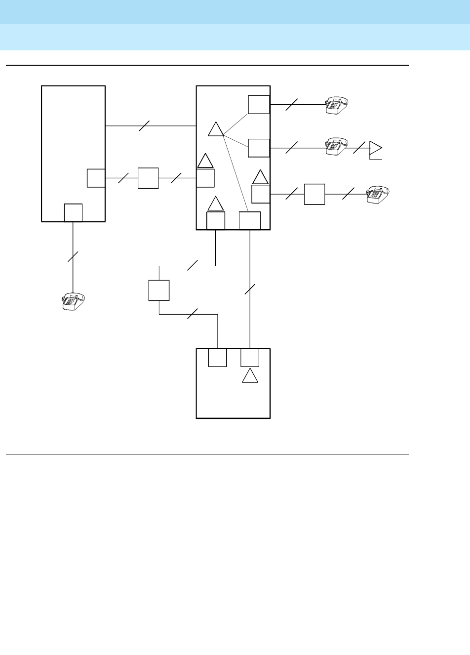
DEFINITY Enterprise Communications Server Release 6
Maintenance for R6r Volumes 1 & 2
555-230-126 Issue 2
January 1998
Maintenance Object Repair Procedures
Page 9-1474TBRI-PT (TN2185 ISDN Trunk-Side BRI Port)
9
Figure 9-92. Integrated Trunk-Side BRI, ISDN Interface Reference points
ISDN Interface Reference Point definitions:
LT Logical Terminal
V Primary Rate user/network (asymmetrical) trunk interface. The
ECS is capable of acting as the user or as the network side of
this 1.544 - or 2.048-Mbps interface.
R Interface between Terminal Equipment and Network
Termination
S Basic Rate network-side 4-wire line interface
S/T 4-wire Basic Rate connection to a Network Termination1.
T 4-wire Basic Rate interface to a Network Termination.2
CO
NT
2-Wire
NT
2-Wire
NT
2-Wire
NT
4-Wire
4-Wire
4-Wire
NT
2-Wire NT
4-Wire
PBX
PBX
LT TE
TE TE
cydfisdn RPY 072397
NT2 LT
LT
NT2
NT2
Terminal
Adapter
NT2
S/T
TE
TE
NT1
VPRI
U
U
T
S/T
T
S
S
UT
R
NT1
NT1
ISDN Interface Reference Points
1
2
3
4
5

DEFINITY Enterprise Communications Server Release 6
Maintenance for R6r Volumes 1 & 2
555-230-126 Issue 2
January 1998
Maintenance Object Repair Procedures
Page 9-1475TBRI-PT (TN2185 ISDN Trunk-Side BRI Port)
9
Hardware Error Log Entries and Test to Clear
Values
1. Network Termination 2 (NT2), that terminates Layer 1 and higher layers. PBXs,
LANs, and terminal controllers typically provide NT2 functionality including
protocol handling and multiplexing for Layers 2 and 3.
2. Network Termination 1 (NT1), that terminates Layer 1 and monitors
maintenance, performance, timing, power transfer, multiplexing, and multi-drop
termination with contention resolution.
TE Terminal Equipment
U Basic Rate network-side 2-wire line interface.
1 TN556B ISDN-BRI 4-Wire S/T-NT Line (A-law)
2 TN 2185 ISDN-BRI 4-Wire S Interface (Trunk Side)
3 TN2198 ISDN-BRI 2-Wire U Interface
4 TN2198 ISDN-BRI 2-Wire U Interface
5 TN 2185 ISDN-BRI 4-Wire S Interface (Trunk Side)
Table 9-500. TBRI-PT Error Log Entries
Error
Type Aux
Data Associated Test Alarm
Level On/Off
Board Test to Clear Value
010 Any Any Any test Port UCSSPP sh r 1
1 (a) Level 1 Status Test
(#1242) MINOR OFF
1292
257(b)
513 (c) 46222 XMIT FIFO
Overflow MINOR ON
514 (d) XMIT FIFO
Overflow (TDM) MINOR ON
769 (e) Traffic
Hyperactivity MINOR OFF
1025 (f)
1281 (g) NPE Crosstalk Test
(#617) MINOR ON
1537 (h) 46210 CRC error
(D-Channel) MINOR OFF
Continued on next page
DEFINITY Enterprise Communications Server Release 6
Maintenance for R6r Volumes 1 & 2
555-230-126 Issue 2
January 1998
Maintenance Object Repair Procedures
Page 9-1476TBRI-PT (TN2185 ISDN Trunk-Side BRI Port)
9
Notes:
a. Loss of continuity of Layer 1 to the far-end. It is assumed that Layer 1
remains active, even when both B-Channels are idle.
This test determines whether Layer 1 is active or not. If Layer 1 is not
active, the test attempts to activate it. If Layer 1 cannot be activated, the
port is taken out of service, and the test fails.
1. Run the Short Test Sequence first. If all tests pass, run the Long Test Sequence. Refer to the
appropriate test description and follow the recommended procedures.
2. The far-end switch changed the ISDN service state. This may be a temporary condition.
1538 (i) CRC error (TDM
D-Channel) MINOR OFF
1793 (j) BRI Port Local TDM
Looparound Test
(#619)
MINOR ON
2049 (k) MINOR OFF
2305 (l) Layer 3 Query
(#1243) MINOR OFF
3073 (m) Slip Query Test
(#1244) MINOR OFF
3585 (n) Receive FIFO
Overflow (TDM
D-Channel)
Log Only ON
3586 (o)
3587 (p)
3588 (q) 46223
3589 (r)
3590 (s) 46211
3591 (t)
3592 (u)
3841 to
3942 (v)
Table 9-500. TBRI-PT Error Log Entries — Continued
Error
Type Aux
Data Associated Test Alarm
Level On/Off
Board Test to Clear Value
Continued on next page

DEFINITY Enterprise Communications Server Release 6
Maintenance for R6r Volumes 1 & 2
555-230-126 Issue 2
January 1998
Maintenance Object Repair Procedures
Page 9-1477TBRI-PT (TN2185 ISDN Trunk-Side BRI Port)
9
b. The D-Channel failed at Layer 2. Expiration of this timer indicates that
attempts to bring the failed link back into service have not succeeded and
some recovery actions should be taken on the associated B-Channels.
Upon expiration, associated in-service B-channels are put in the
out-of-service/far end state.
c. Error Type (513): On-board hardware failure. The FIFO RAM buffers have
overflowed, indicating a hardware problem.
d. Error Type (514): Transmit FIFO Overflow - This error indicates that the
circuit pack is having problems transmitting data to the TDM D-Channel.
This error only occurs only a system that switches the packet
implementation of the D-channel over the TDM Bus. This error indicates an
on board problem related to the packet implementation of the D-Channel
(R6.2 and higher).
e. Error Type (769): The port is generating too many uplinks. The link is being
suspended.
f. Error Type (1025): An expired timer has created an unexpected event.
The timer could be any of the following:
g. Error Type (1281): This error occurs when the NPE Crosstalk Test (#617)
has failed. The test will be repeated every 15 minutes until it passes.
Follow normal trouble shooting procedures for NPE Crosstalk Test (#617).
If this does not fix the problem, follow normal escalation procedures.
h. Error Type (1537): The board received a bad Cyclical Redundancy Check
(CRC) over the D-Channel. This error is reported on a per-port basis.
When the CRC errors exceed 5 within 15 minutes, the port is taken out of
service for 5 seconds. If 5 more CRC errors are received within 15 minutes
of the first set of 5 errors, the port is taken out of service for 1 minute. If 5
more CRC errors are received within 15 minutes of the previous 5, the port
is taken out of service for 15 minutes.
This error is most likely due to a problem with backplane wiring, a noise
source, or no termination (an open circuit). It usually does not indicate a
problem with the circuit pack.
Timer Event
T3031 ISDN T3031 timeout
T3032 ISDN T3032 timeout
T305 ISDN T305 timeout
T3081 ISDN T3081 timeout
T3082 ISDN T3082 timeout
TL3 Status Inquiry
T304 Setup ACK
T310 Call Proceeding Receive
T313 Connect SEND

DEFINITY Enterprise Communications Server Release 6
Maintenance for R6r Volumes 1 & 2
555-230-126 Issue 2
January 1998
Maintenance Object Repair Procedures
Page 9-1478TBRI-PT (TN2185 ISDN Trunk-Side BRI Port)
9
1. Check the backplane wiring.
2. If the problem persists escalate the problem.
i. Error Type (1538): This error occurs when a frame with a bad CRC is
received by the BRI trunk board. This error only occurs on a system that
switches the packet implementation of the D-channel over the TDM bus.
This error indicates an off board problem related to the packet
implementation of the TDM D-Channel (R6.2 and later).
j. Error Type (1793): The BRI Port Local TDM Loop Around Test (#619)
failed. Run the Long Test Sequence paying particular attention to the
results of the BRI TDM Port Loop Test (#619).
k. Error Type (2049): The Layer 2 Link Query failed. The test is repeated
every 15 minutes until it passes.
l. Error Type (2305): The Remote Layer 3 Query failed. The test is repeated
every 15 minutes until it passes.
m. Error Type (3073): A frame of information had to be repeated or deleted.
Slips usually occur when the received bit rate is not synchronized with the
TDM Bus clock.
n. Error Type (3585): The circuit pack detected an overflow of its receive
buffers. This error occurs only a system that switches the packet
implementation of the D-Channel over the TDM bus. This error indicates
an on board problem related to the packet implementation of the TDM
D-Channel (R6.2 and higher).
o. Error Type (3586): Each port can support up to three Terminal Endpoint
Identifiers (TEIs). Each channel on the port can request a TEI assignment
from the switch if it supports ISDN-BRI TEI assignment procedures. If
switch services gets a request for a fourth TEI on a port, it reports this
event to maintenance software and initiates TEI check procedures on the
port. Check to see if the correct number of channels are administered for
this port.
The user side supports automatic TEI assignment by the network. Both
fixed and automatic TEI assignment are supported on the network side.
p. Error Type (3587)Service Profiler IDentifier (SPID) value is invalid or is a
duplicate of another SPID that is already initialized at Layer 3 on the port.
SPIDs are not used on the TN2185 circuit pack. However there will be
related events.
q. Error Type (3588): The board receives D-Channel data from the bus faster
than it can process the data. The FIFO RAM buffers overflowed. This error
occurs occasionally due to the statistical sizing of the buffers; however,
frequent occurrences may indicate a LAPD parameter mismatch between
the two endpoints of a packet-switched connection. Run the Long Test
Sequence paying particular attention to the results of the Receive FIFO
Overflow Test (#625).

DEFINITY Enterprise Communications Server Release 6
Maintenance for R6r Volumes 1 & 2
555-230-126 Issue 2
January 1998
Maintenance Object Repair Procedures
Page 9-1479TBRI-PT (TN2185 ISDN Trunk-Side BRI Port)
9
r. Error Type (3589): The BRI Port Local LAN Loop Around Test (#618)
failed. Run the Long Test Sequence and pay particular attention to the
results of Test #618.
s. Error Type (3590): An activated BRI port receives a frame containing a
DLCI over a D-Channel for which it does not have a translation. This error
normally indicates an off-board problem related to a state mismatch
between the far-end and the switch. This error is logged only.
t. Error Type (3591): The port is generating too many uplinks and is taken
out of service.
u. Error Types (3841-3942): Table 9-501 contains the received ISDN cause
values for Errors 3841-3942 that are recorded in the hardware error logs.
Unless otherwise stated, the cause values are D-Channel events. The aux
data field shows which port caused the error.
Table 9-501. Cause Values for Error 3841-3942
Value Type of Problem Meaning
2 admin No route to specific transit network
3 admin No route to destination (or Germany bcap not imp)
6 admin Channel unacceptable
18 switch problems No user responding
38 switch problems Network failure
50 subscription Requested facility not subscribed
52 admin Outgoing calls barred
54 admin Incoming calls barred
62 subscription Service not authorized
63 admin/sub Service/option not available
65 admin/sub Bearer capability not implemented
66 admin/sub Channel type not implemented
69 admin/sub Requested facility not implemented
70 admin/sub Only restricted digital BC available
79 admin Service/option not implemented
88 admin Incompatible destination
102 switch problems Recovery on timer expired
DEFINITY Enterprise Communications Server Release 6
Maintenance for R6r Volumes 1 & 2
555-230-126 Issue 2
January 1998
Maintenance Object Repair Procedures
Page 9-1480TBRI-PT (TN2185 ISDN Trunk-Side BRI Port)
9
System Technician-Demanded Tests:
Descriptions and Error Codes
When inspecting errors in the system, always investigate tests in the order listed
below. By clearing error codes associated with the
Control Channel Loop Around
Test,
for example, you may also clear errors generated from other tests in the
testing sequence.
Clear Error Counters Test (#270)
This test is nondestructive.
This test clears the various error counters associated with each TBRI-PT. This
test passes if maintenance software is able to successfully send the downlink
messages; the test aborts otherwise.
1. D = Destructive; ND = Nondestructive
Order of Investigation Short Test
Sequence Long Test
Sequence D/ND1
BRI Local LAN Port Loop Around Test (#618) X D
BRI TDM Port Loop Around Test (#619) X D
L1 State Query Test (#1242) X X D
CRC Error Counter Test (#623) X ND
Receive FIFO Overflow Test (#625) X ND
Layer 3 Query Test (#1243) X ND
Slip Query Test (#1244) X X ND
Clear Error Counters Test (#270) X X ND
NPE Crosstalk Test (#617) X D
Table 9-502. TEST #270 Clear Error Counters
Error
Code Test
Result Description/ Recommendation
Any ABORT Maintenance could not send the downlink message.
PASS The message to clear the error counters of the TBRI-PT maintenance
object has been sent.
Continued on next page

DEFINITY Enterprise Communications Server Release 6
Maintenance for R6r Volumes 1 & 2
555-230-126 Issue 2
January 1998
Maintenance Object Repair Procedures
Page 9-1481TBRI-PT (TN2185 ISDN Trunk-Side BRI Port)
9
NPE Crosstalk Test (#617)
This test is conditionally destructive.
One or more NPEs reside on each circuit pack with a TDM Bus interface. The
NPE controls port connectivity and gain and provides conferencing functions on
a per-port basis. The NPE Crosstalk Test verifies that this port’s NPE channel
talks on the selected time slot and never crosses over to time slots reserved for
other connections. If the NPE is not working correctly, one-way and noisy
connections may be observed. This test is part of a port’s Long Test Sequence
and takes approximately 20 to 30 seconds to complete. Crosstalk testing is
performed on both B-channels (B1 and B2) associated with a BRI port. If this test
fails on either channel, any channel connected to the port is taken out-of-service.
This test aborts if the port and its associated channels are not in the idle state.
Table 9-503. TEST #617 NPE Crosstalk Test
Error
Code Test
Result Description/ Recommendation
1000 ABORT System resources required to run this test are not available. The port may
be busy with a valid call. Use the display port UUCSSpp command to
determine the station extension or trunk group/member number of the port.
Use the status bri-port UUCSSpp command to determine the service
state of the port. If the service state indicates that the port is in use, then
the port is unavailable for certain tests. Wait until the port is idle before
retesting.
1. If the port status is idle, then retry the command at 1-minute intervals a
maximum of 5 times.
1004 ABORT The port has been seized by a user for a valid call. Use the status bri-port
command to determine when the port is available for testing.
1. Retry the command at 1-minute intervals a maximum of 5 times.
2. If the test continues to abort and the port is not in use, escalate the
problem.
1005 ABORT This test is not valid for this type of translation. Ports administered as
“ASAI” or “ADJK” can not run this test, because the B channels associated
with the port are not used by ASAI or Lucent Adjunct Links. This is a normal
condition.
2012 ABORT Internal system error
2100 ABORT Could not allocate the necessary resources to run this test.
1. Retry the command at 1-minute intervals a maximum of 5 times.
Continued on next page

DEFINITY Enterprise Communications Server Release 6
Maintenance for R6r Volumes 1 & 2
555-230-126 Issue 2
January 1998
Maintenance Object Repair Procedures
Page 9-1482TBRI-PT (TN2185 ISDN Trunk-Side BRI Port)
9
BRI Port Local LAN Looparound Test (#618)
This test is destructive.
This test checks the connectivity of the BRI port across the LAN bus. Because
this test is destructive, run this test only if the port is out-of-service.
Failures of this test indicate either on-board faults associated with the TBRI-PT
hardware on the circuit pack or problems with the LAN Bus, which is used to
form connectivity between the switch and the TBRI-PT.
If the port is in a state other than out-of-service, the BRI Port Local LAN
Looparound Test will abort. If the port is out-of-service, then the port is put into a
local looparound mode and the following test is executed.
A looparound test is performed across the Packet Bus for the D-Channel. The
switch sends data over a packet connection, which is looped back by the BRI
port (D-Channel) and received back by the switch. The test passes if the packet
connection can be established and the transmitted data is received unaltered.
The test aborts if the Packet Bus is alarmed in the Processor Port Network (or the
port network in which that circuit pack resides) or if the Packet Interface board is
out-of-service. The test fails due to either on-board faults associated with the BRI
port hardware on the circuit pack or problems with the LAN bus.
1, 2 FAIL The NPE of the tested port was found to be transmitting in error, causing
noisy and unreliable connections. Error code 1 indicates that the NPE
Crosstalk Test failed on Channel B1. Error code 2 indicates that the NPE
Crosstalk Test failed on Channel B2.
1. Replace circuit pack.
PASS The port is correctly using its allocated time slots.
1. To be sure that this is not an intermittent problem, repeat this test a
maximum of 10 times to ensure it continues to pass.
2. If complaints still exist, examine the connections and wiring.
Table 9-503. TEST #617 NPE Crosstalk Test — Continued
Error
Code Test
Result Description/ Recommendation
Continued on next page

DEFINITY Enterprise Communications Server Release 6
Maintenance for R6r Volumes 1 & 2
555-230-126 Issue 2
January 1998
Maintenance Object Repair Procedures
Page 9-1483TBRI-PT (TN2185 ISDN Trunk-Side BRI Port)
9
Table 9-504. TEST #618 BRI Port Local LAN Looparound
Error
Code Test
Result Description/ Recommendation
1015 ABORT The port is not out-of-service.
1. Use the status bri-port UUCSSpp command to determine the status
of the port.
2. If it is in use, wait until it is idle, and then use the busyout port
UUCSSpp command to place it in the out-of-service state and repeat
this test.
!CAUTION:
Since the busyout command is destructive, execution of this
command prior to the port being idle causes all calls
associated with the BRI port to be torn down.
1139 ABORT The Packet Bus in the port network is out-of-service.
1. Follow the repair procedures for the Packet Bus.
2. Run the test port long UUCSSpp command and verify the repair by
viewing the results of the BRI Port Local LAN Looparound Test (#618).
1141 ABORT The PKT-CTRL is out-of-service.
1. Follow the repair procedures for the PKT-CTRL.
2. Run the test port long UUCSSpp command and verify the repair by
viewing the results of the BRI Port Local LAN Looparound Test (#618).
1144 ABORT The PPN Packet Bus is out-of-service.
1. Follow the repair procedures for the Packet Bus.
2. Run the test port long UUCSSpp command and verify the repair by
viewing the results of the BRI Port Local LAN Looparound Test (#618).
2012
2100 ABORT Internal system error
Could not allocate the necessary system resources to run this test.
1. Retry the command at 1-minute intervals a maximum of 5 times.
FAIL The Looparound Test has failed.
1. If the test fails repeatedly, attempt to reset the circuit pack with the
busyout board UUCSS and the reset board UUCSS commands if the
other ports on the board are not in use.
2. If the test fails again, execute test pkt P. If this fails, follow failure
procedures in the PKT-BUS section.
3. If the tests in Step 2 pass, the problem is local to the BRI board.
Replace the trunk circuit pack.
PASS The BRI Port Local LAN Looparound Test passed.
Continued on next page

DEFINITY Enterprise Communications Server Release 6
Maintenance for R6r Volumes 1 & 2
555-230-126 Issue 2
January 1998
Maintenance Object Repair Procedures
Page 9-1484TBRI-PT (TN2185 ISDN Trunk-Side BRI Port)
9
BRI Port Local TDM Looparound Test (#619)
This test is conditionally destructive.
This test verifies the connectivity of a BRI port across the TDM Bus. It aborts if
calls associated with the port are in progress. Failure of this test indicates an
on-board fault associated with the port hardware on the circuit pack.
This Looparound Test runs the following individual tests on the two B-channels
(B1 and B2) associated with the port:
■A Looparound Test across the TDM Bus for B1.
■A Conference Circuit Test for B1.
■A Looparound Test across the TDM Bus for B2.
■A Conference Circuit Test for B2.
The tests are run in the above order. If one fails, the remaining tests in the
sequence are not executed, and maintenance software returns an error code.
Table 9-505. TEST #619 BRI Port Local TDM Loop Around
Error
Code Test
Result Description/ Recommendation
1000 ABORT The system resources required to run this test are not available. The port
may be busy with a valid call. Use the display port UUCSSpp command to
determine the trunk group/member number of the port. Use the status
bri-port UUCSSpp command to determine the service state of the port. If
the service state indicates that the port is in use, then the port is
unavailable for certain tests. Wait until the port is idle before retesting.
1. If the port is idle, then retry the command at 1-minute intervals a
maximum of 5 times.
1002 ABORT The system could not allocate time slots for the test. The system may be
under heavy traffic conditions or it may have time slots out-of-service due
to TDM-BUS errors. Refer to TDM-BUS to diagnose any active TDM Bus
errors.
1. If the system has no TDM-BUS errors and is not handling heavy traffic,
repeat test at 1-minute intervals a maximum of 5 times.
Continued on next page

DEFINITY Enterprise Communications Server Release 6
Maintenance for R6r Volumes 1 & 2
555-230-126 Issue 2
January 1998
Maintenance Object Repair Procedures
Page 9-1485TBRI-PT (TN2185 ISDN Trunk-Side BRI Port)
9
1003 ABORT The system could not allocate a tone receiver for the test. The system may
be oversized for the number of Tone Detectors present or some Tone
Detectors may be out-of-service.
1. Look for TTR-LEV errors in the Error Log and if present, refer to
TTR-LEV.
2. Look for TONE-PT errors in the Error Log and if present, refer to
TONE-PT.
3. If neither condition exists, retry the test at 1-minute intervals a
maximum of 5 times.
1004 ABORT The port has been seized by a user for a valid call. Use the status trunk
command for the trunks associated with this port and determine when the
port is available for testing.
1. Retry the command at 1-minute intervals a maximum of 5 times.
2. If the test continues to abort and the port is not in use, escalate the
problem.
1005 ABORT This test is not valid for this type of translation. Ports administered as ASAI
or ADJK cannot run this test because the B channels associated with the
port are not used by ASAI or Lucent Adjunct Links. This is a normal
condition.
2000 ABORT Response to the test was not received from the BRI-LINE circuit pack
within the allowable time period.
1. If this result occurs repeatedly, attempt to reset the circuit pack with
the busyout board UUCSS and the reset board UUCSS commands if
the other ports on the board are not in use.
2. If this result occurs again, replace the circuit pack.
2012 ABORT Internal system error
2100 ABORT Could not allocate the necessary resources to run this test.
1. Retry the command at 1-minute intervals a maximum of 5 times.
2103 ABORT The system could not make the conference connection for the test.
1. Retry the command at 1-minute intervals a maximum of 5 times.
1, 2 FAIL The TDM Looparound failed on one of the channels.
■Error Code 1 — TDM Loop Around Test failed on B1.
■Error Code 2 — TDM Loop Around Test failed on B2.
Table 9-505. TEST #619 BRI Port Local TDM Loop Around — Continued
Error
Code Test
Result Description/ Recommendation
Continued on next page

DEFINITY Enterprise Communications Server Release 6
Maintenance for R6r Volumes 1 & 2
555-230-126 Issue 2
January 1998
Maintenance Object Repair Procedures
Page 9-1486TBRI-PT (TN2185 ISDN Trunk-Side BRI Port)
9
CRC Error Counter Test (#623)
This test is nondestructive.
This test reads the BRI port’s CRC error counters that are maintained on the BRI
circuit pack. The Cyclic Redundancy Check (CRC) is a means of error detection
used to determine the integrity of data frame contents. The CRC error counter is
incremented by the circuit pack when it detects a CRC error. The test passes if
the value of the counter is 0 (that is, the error is cleared). If the counter is
non-zero, the test fails, and the value of the counter is displayed in the Error
Code field.
7, 8 FAIL The Conference Circuit Tests failed on a B-channel.
■Error Code 7 — test failed on B1
■Error Code 8 — test failed on B2.
1. If the test fails repeatedly, attempt to reset the circuit pack with the
busyout board UUCSS and the reset board UUCSS commands if the
other ports on the board are not in use.
2. If the test fails again, replace the circuit pack.
PASS The BRI Port Local TDM Loop Around Test passed.
Table 9-506. TEST #623 CRC Error Counter Test
Error
Code Test
Result Description/ Recommendation
ANY FAIL This error occurs when a frame with a bad CRC is received over the
D-Channel by the BRI board. This error is reported on a per-port basis
when the counter goes over the threshold. This error is most likely due to a
problem with the wiring or interference on the wiring caused by a noise
source or no termination. It usually does not indicate a problem with the
circuit pack.
PASS The CRC error counter was read correctly and has a value of 0.
Continued on next page
Table 9-505. TEST #619 BRI Port Local TDM Loop Around — Continued
Error
Code Test
Result Description/ Recommendation
Continued on next page

DEFINITY Enterprise Communications Server Release 6
Maintenance for R6r Volumes 1 & 2
555-230-126 Issue 2
January 1998
Maintenance Object Repair Procedures
Page 9-1487TBRI-PT (TN2185 ISDN Trunk-Side BRI Port)
9
Receive FIFO Overflow Error
Counter Test (#625)
This test is nondestructive.
This test reads and clears the BRI port’s Receive FIFO Overflow error counter
maintained on the TBRI-BD circuit pack. This counter is incremented by the
circuit pack when it detects an overflow of its receive buffers. The test passes if
the value of the counter is 0 (that is, the error is cleared). If the counter is
non-zero, the test fails, and the value of the counter is displayed in the Error
Code field.
This error can occur if signaling frames are being received from the Packet Bus
at a rate sufficient to overflow the receive buffers on the circuit pack for a port OR
if a hardware fault is causing the receive buffers not to be emptied properly by
the circuit pack. This test is useful for verifying the repair of the problem.
Table 9-507. TEST #625 Receive FIFO Overflow
Error Counter Test
Error
Code Test
Result Description/ Recommendation
2000 ABORT Response to the test was not received from the circuit pack within the
allowable time period.
1. If the test aborts repeatedly a maximum of 5 times, reset the circuit
pack with the busyout board UUCSS and reset board UUCSS
commands.
2. If the test aborts again, replace the circuit pack.
2012 ABORT Internal system error
2100 ABORT Could not allocate the necessary system resources to run this test.
1. Retry the command at 1-minute intervals a maximum of 5 times.
value FAIL The TBRI-BD circuit pack is still detecting errors of this type. The Error
Code field contains the value of this counter.
1. Retry the command at 1-minute intervals a maximum of 5 times.
2. If the test continues to fail, run the Long Test Sequence and pay
particular attention to the Looparound Tests (#618 and #619). See the
repair procedures for the executed test if it fails. Otherwise, go to the
next step.
3. Replace the circuit pack.
PASS The Receive FIFO Overflow error counter was read correctly and has a
value of 0.
Continued on next page
DEFINITY Enterprise Communications Server Release 6
Maintenance for R6r Volumes 1 & 2
555-230-126 Issue 2
January 1998
Maintenance Object Repair Procedures
Page 9-1488TBRI-PT (TN2185 ISDN Trunk-Side BRI Port)
9
Level 1 Status Inquiry Test (#1242)
This test is nondestructive.
This test determines the state of the transmission facility of a BRI port at the
Level 1 (L1) physical layer: Activated, Pending Activation, or Deactivated.
The Activated state is the correct state for an ISDN-BRI port. In this state the L1
interface can send and receive synchronized signals. This test passes if the state
of L1 is Activated. This test also passes if software has taken this port out of
service. See the description of the L1 “Deactivated State” below for more details.
The Pending Activation state indicates a problem with the channels, the wiring, or
the TBRI-BD circuit pack. When in this state, the Level 1 interface is either not
receiving any L1 framing from the channel, or it is communicating with the
channel but cannot transition to the Activated state.
The Deactivated state indicates a problem with the TBRI-BD circuit pack. When
in this state, the Level 1 interface is not active, and an idle signal is transmitted to
the channels or that Layer 1 was deactivated by the switch. When an TBRI-PT
port is placed in the out-of-service state, Level 1 is also put into the Deactivated
state. This could be due either to the system detecting a fault with the port or to a
busyout port UUCSSpp request.
Table 9-508. TEST #1242 Level 1 Status Inquiry
Error
Code Test
Result Description/ Recommendation
1187 ABORT The board or port may be busied out.
1. Look in the Error Log for Error Type 18 (port busied out) for this port
and TBRI-BD (board busied out). If this error type is present for
TBRI-PT only, then release the port with the release port pp command
and run the test again. If the error is present for both TBRI-BD and
TBRI-PT, then release the board with the release board UUCSS
command and run the test again.
NOTE:
When you release a port, you release all ports associated with it. If
certain ports still need to be busied out, use the release port
UUCSSpp command to busy them out.
2. Make sure the terminal is connected.
3. Retry the command at 1-minute intervals a maximum of 5 times.
Continued on next page

DEFINITY Enterprise Communications Server Release 6
Maintenance for R6r Volumes 1 & 2
555-230-126 Issue 2
January 1998
Maintenance Object Repair Procedures
Page 9-1489TBRI-PT (TN2185 ISDN Trunk-Side BRI Port)
9
2000 ABORT Response to the test was not received from the circuit pack within the
allowable time period.
1. If the test aborts repeatedly a maximum of 5 times, reset the circuit
pack with the busyout board UUCSS and reset board UUCSS
commands.
2. If the test aborts again, replace the circuit pack.
2012 ABORT Internal system error
2100 ABORT Could not allocate the necessary system resources to run this test.
1. Retry the command at 1-minute intervals a maximum of 5 times.
1 FAIL Received a status of Level 1 Pending Activation. U interface down
indicating a problem with a connection between the switch and the NT1, a
2- to 4-wire converter that is used to connect 4-wire terminals to a 2-wire
TN2198 or TN2185 circuit pack.
1. Verify that the connections between the switch and the NT1 are good.
Verify that the NT1 has power.
2. Execute the test port UUCSSpp command and review the results of
the Level 1 Status Inquiry Test to verify the repair. If this test still fails,
proceed to Step 3.
3. Follow the manufacturers repair procedures for the NT1. Then execute
the test port UUCSSpp command and review the results of the Level
1 Status Inquiry Test to verify repair.
2 FAIL Received a status of Level 1 Pending Activation. U interface up, S/T
interface down, which indicates a problem with the NT1 or the wiring
between the NT1 and the BRI endpoint (S/T interface).
1. Execute the test port UUCSSpp command and review the results of
the Level 1 Status Inquiry test to verify the repair. If this test still fails,
proceed to Step 2.
2. Follow the manufacturer-recommended repair procedures for the NT1.
Then execute the test port UUCSSpp command and review the
results of the Level 1 Status Inquiry test to verify repair.
Table 9-508. TEST #1242 Level 1 Status Inquiry — Continued
Error
Code Test
Result Description/ Recommendation
Continued on next page

DEFINITY Enterprise Communications Server Release 6
Maintenance for R6r Volumes 1 & 2
555-230-126 Issue 2
January 1998
Maintenance Object Repair Procedures
Page 9-1490TBRI-PT (TN2185 ISDN Trunk-Side BRI Port)
9
Layer 3 Query Test (#1243)
This test is nondestructive.
This test is used to check the application layer communications across the
in-service ISDN D-Channel. The test passes if a status enquiry message is
successfully sent, fails if the signaling link is down, and aborts if a query is
already running or there is an internal error.
3 FAIL Received a status of Level 1 Deactivated; the port is out-of-service.
1. Issue the status bri-port UUCSSpp command to verify that the
service state of the port is out-of-service. If the service state of the port
is not out-of-service, escalate the problem to the next tier. Otherwise,
proceed to Step 2.
2. If the port has been placed out-of-service with the busyout port
UUCSSpp command, try releasing the port by executing the release
port UUCSSpp command. Then issue the test port long UUCSSpp
command and review the results of Level 1 Status Inquiry test. If this
test still fails, proceed to Step 3.
3. After executing the test port long UUCSSpp command, review the
results of all the tests. Follow the repair procedures for any tests that
fail. Verify repair of the problem by executing the test port UUCSSpp
command and by determining that the Level 1 Status test passes. If
the test continues to fail for this reason, escalate the problem to the
next tier.
4 FAIL Received a status of Level 1 Pending Activation, the NT1 has a loss of
power indicating a problem with the NT1.
1. Follow the manufacturer-recommended repair procedures for the NT1.
2. Execute the test port UUCSSpp command and review the results of
the Level 1 Status Inquiry test to verify the repair.
PASS This test indicates that Level 1 is activated or that software has taken the
port out of service.
Table 9-508. TEST #1242 Level 1 Status Inquiry — Continued
Error
Code Test
Result Description/ Recommendation
Continued on next page
DEFINITY Enterprise Communications Server Release 6
Maintenance for R6r Volumes 1 & 2
555-230-126 Issue 2
January 1998
Maintenance Object Repair Procedures
Page 9-1491TBRI-PT (TN2185 ISDN Trunk-Side BRI Port)
9
Table 0-3. TEST #1243 Layer 3 Query
Error
Code Test
Result Description/ Recommendation
1019 ABORT Test is already running.
1113 ABORT The signaling link is down.
1. Use the test port UUCSSpp long command to clear any errors which
prevent establishment of the signaling link.
2. Examine the results of Test #626, which is executed with the
command. If this test aborts or fails, follow the repair procedure for the
Signaling Link Status Test.
3. Escalate problem if BRI Layer 3 Query Test continues to abort.
1139 ABORT The Packet Bus in the port network is out-of-service.
1. Follow the repair procedures for the Packet Bus.
2. After completing Step 1, execute the test port long UUCSSpp
command and review the results of the BRI Port Local LAN
Looparound Test to verify the repair.
1141 ABORT The PKT-CTRL is out-of-service.
1. Consult the repair procedure for PKT-CTRL.
2. If Step 1 does not resolve the problem, escalate to the next tier.
1144 ABORT The PPN Packet Bus is out-of-service.
1. Follow the repair procedures for the Packet Bus in the PPN.
2. After completing Step 1, execute the test port long UUCSSpp
command and review the results of the BRI Port Local LAN
Looparound Test to verify the repair.
1187 ABORT The circuit pack or port may have been busied out by a technician.
1. Look in the Error Log for Error Type 18 (busied out) for TBRI-BD or
TBRI-PT.
a. If this error type is present for TBRI-PT, then release the port with
the release port UUCSSpp command and run the test again.
b. If the error is present for both TBRI-BD and TBRI-PT, then release
the circuit pack with the release board PUUCSS command and
run the test again.
NOTE:
When you release the circuit pack, you release all ports associated
with it. If certain ports still need to be busied out, use the release
port UUCSSpp command to busy them out.
2. Make sure the terminal is connected.
3. Retry the command at 1-minute intervals a maximum of 5 times.
Continued on next page

DEFINITY Enterprise Communications Server Release 6
Maintenance for R6r Volumes 1 & 2
555-230-126 Issue 2
January 1998
Maintenance Object Repair Procedures
Page 9-1492TBRI-PT (TN2185 ISDN Trunk-Side BRI Port)
9
Slip Query Test (#1244)
This test is nondestructive.
Slips occur when the transmitter and receiver are not running at precisely the
same clock rate. The Slip Alarm Inquiry Test polls the total number of slips that
have occurred on a link.
When the TN2185 circuit pack detects a slip condition, maintenance software
initiates the Slip Alarm Inquiry Test to query the slip counters on the TN2185
circuit pack and total the slip counts in the maintenance software.
If the slip count is over the threshold, a Minor alarm is raised against the TN2185
circuit pack, leaving all ports of the TN2185 circuit pack in the in-service state. If
the TN2185 circuit pack is used to supply the system synchronization source, the
MINOR alarm will initiate a synchronization source switch. See TDM-BUS and
SYNC for additional information.
2012 ABORT Internal system error
2100 ABORT Could not allocate the necessary system resources to run this test.
1. Retry the command at 1-minute intervals a maximum of 5 times.
PASS The switch has successfully sent a Status Enquiry message.
Table 0-4. TEST #1244 Slip Alarm Inquiry Test
Error
Code Test Result Description/ Recommendation
ABORT Internal System Error
2000 ABORT Response to the test request was not received within the allowable time
period. If Error Type 1538 is present in the Error Log, follow the
maintenance strategy recommended for this error type.
2100 ABORT Could not allocate the necessary system resources to run this test.
1. Retry the command at 1-minute intervals for a maximum of 5 times.
Continued on next page
Table 0-3. TEST #1243 Layer 3 Query — Continued
Error
Code Test
Result Description/ Recommendation
Continued on next page

DEFINITY Enterprise Communications Server Release 6
Maintenance for R6r Volumes 1 & 2
555-230-126 Issue 2
January 1998
Maintenance Object Repair Procedures
Page 9-1493TBRI-PT (TN2185 ISDN Trunk-Side BRI Port)
9
1 to 88 FAIL The circuit pack and the remote endpoint are not synchronized to the
same clock rate, which has generated the Slip alarm. The error code
equals the number of slips detected by the TN2185 circuit pack since
the last Slip Alarm Inquiry Test.
1. Retry the command at 1-minute intervals a maximum of 5 times.
2. If the circuit pack is a TN2185, enter the list measurement ds1-log
UUCSS command to read the error seconds measurement.
3. Verify that both endpoints of the DS1 link are administered using
the same signaling mode, framing mode, and line coding.
4. Check the physical connections of DS1 Interface circuit packs and
cable.
5. Replace the local DS1 Interface circuit pack and repeat the test.
6. Contact T1 Network Service to diagnose the remote DS1 endpoint.
PASS No Slip alarm is detected on the DS1 Interface circuit pack.
0 NO BOARD The DS1 Interface circuit pack is not administered.
1. Administer the DS1 Interface circuit pack by issuing the add ds1
UUCSS command.
2. Run the test again.
3. If the test continues to return NO BOARD, escalate the problem.
Table 0-4. TEST #1244 Slip Alarm Inquiry Test — Continued
Error
Code Test Result Description/ Recommendation
Continued on next page

DEFINITY Enterprise Communications Server Release 6
Maintenance for R6r Volumes 1 & 2
555-230-126 Issue 2
January 1998
Maintenance Object Repair Procedures
Page 9-1494TBRI-TRK (TN2185 ISDN Trunk-Side BRI)
9
TBRI-TRK (TN2185
ISDN Trunk-Side BRI)
The TN2185 circuit pack contains eight, 4-wire ports that interface to the network
at the ISDN S/T reference point over two 64 Kb/s channels (B1 and B2) and over
a 16Kb/s signaling (D) channel. The B1 and B2 channels can be simultaneously
circuit switched, or individually packet switched. Only one channel per trunk can
be packet switched due to Packet Processing Element (PPE) limitations. The D
channel is either circuit switched or packet switched. Packet switching uses the
PPE to combine all D channels into a single physical channel, which is then
routed via the concentration highway to the Network Control Element (NCE) and
then to the TDM bus. The circuit-switched connections have a Mu-law or A-law
option for voice and operate as 64Kb/s clear data channels. The
packet-switched channels support the LAPD protocol and conform with the
CCITT Q.920 Recommendations for D-channel signaling.
LEDs
The three LEDs on the circuit pack’s faceplate indicate board status. When
illuminated, the red LED indicates a board failure or a major or minor on-board
alarm, the green LED indicates that testing is in progress, and the amber LED
indicates that the board is in use.
1. Where UU is the universal cabinet number (1 for PPN, 2 -44 for EPN), C is the carrier designation
(A, B, C, D, or E), SS is the carrier slot address where the circuit pack is located (1, 2, and so
forth), and pp is the two-digit port number (1, 2, 3, and so forth).
2. For additional repair information, also see TBRI-BD and TBRI-PT Maintenance documentation.
3. A MAJOR alarm on a trunk indicates that alarms on these trunks are not downgraded by the set
options command and that at least 75 percent of the trunks in this trunk group are alarmed.
MO Name (in
Alarm Log) Alarm Level Initial Command to Run1Full Name of MO
TBRI-TRK2MAJOR3test trunk UUCSSpp l MO_TBRI_TRK
TBRI-TRK MINOR test trunk UUCSSpp l MO_TBRI_TRK
TBRI-TRK WARNING test trunk UUCSSpp sh MO_TBRI_TRK

DEFINITY Enterprise Communications Server Release 6
Maintenance for R6r Volumes 1 & 2
555-230-126 Issue 2
January 1998
Maintenance Object Repair Procedures
Page 9-1495TBRI-TRK (TN2185 ISDN Trunk-Side BRI)
9
System Technician-Demanded Tests:
Descriptions and Error Codes
Always investigate tests in the order presented in the table below when
inspecting errors in the system. By clearing error codes associated with the
Services State Test
, for example, you may also clear errors generated from other
tests in the testing sequence.
Signaling Link State (#1251)
This test is non-destructive.
This test checks the current state of the signaling link. The test looks at the
board-level translations, checks that the board is physically inserted, gets the
state of the D-Channel and service state of the port.
The test passes if the signaling link (D-Channel) is connected and operating
normally. The test fails if the board is not installed, the signaling link is
disconnected, or if the port is out of service. The test aborts otherwise.
1. Destructive; ND = Nondestructive
Order of Investigation Short Test
Sequence Long Test
Sequence D/ND1
Signaling Link State Check Test (#1251) X X ND
Service State Audit Test (#256) X X ND
Call State Audit Test (#257) X X ND
ISDN Test Call Test (#258) X ND
Table 9-509. TEST #1251 Signaling Link State Test
Error
Code Test
Result Description/ Recommendation
ABORT Internal system error
1018 ABORT The test is disabled.
1. Enable the test by entering enable test #1251.
1114 ABORT The signaling link is in a transitional state.
1. Retry the command at 1-minute intervals a maximum of 5 times.
2. If the test continues to abort, escalate the problem.
Continued on next page

DEFINITY Enterprise Communications Server Release 6
Maintenance for R6r Volumes 1 & 2
555-230-126 Issue 2
January 1998
Maintenance Object Repair Procedures
Page 9-1496TBRI-TRK (TN2185 ISDN Trunk-Side BRI)
9
Service State Audit (#256)
This test is nondestructive.
This test performs a service state audit on an ISDN B-Channel. The test passes if
Call Processing informs Maintenance that the Restart message was transmitted
successfully, or if the B-Channel was busy and could not send the message.
The test fails if the board is not inserted or translated properly, or if a reply is not
received within a certain amount of time.
The test aborts if the signaling link is disconnected, if a message is already
outstanding, or if the necessary resources could not be allocated.
To investigate the service state of the TN2185 ISDN Trunk-Side BRI Channel,
issue the status trunk trunk-group/trunk-member command.
8 FAIL The signaling link is down.
1. Consult the procedures for the TBRI-PT maintenance object.
9 FAIL The port is out of service.
1. Return the port to an in-service state.
PASS The signaling link is connected and operating normally.
Table 9-510. TEST #256 Service State Audit Test
Error
Code Test
Result Description/ Recommendation
1000 ABORT System resources required to run this test are not available. The port may
be on a valid call. Use status trunk to determine when trunk is available
for testing.
1. Check the results of Test #1251 (Signaling Link State Check).
1018 ABORT The test is disabled.
1. Enable maintenance by entering y in the Maintenance Tests?
field on page 2 of the change trunk-group form.
Continued on next page
Table 9-509. TEST #1251 Signaling Link State Test — Continued
Error
Code Test
Result Description/ Recommendation
Continued on next page

DEFINITY Enterprise Communications Server Release 6
Maintenance for R6r Volumes 1 & 2
555-230-126 Issue 2
January 1998
Maintenance Object Repair Procedures
Page 9-1497TBRI-TRK (TN2185 ISDN Trunk-Side BRI)
9
Call State Audit Test (#257)
This test is nondestructive.
This test performs a call state audit on an ISDN B-Channel, and upon successful
completion, guarantees that both sides of the interface are in a consistent call
state for connections using the B-Channel. The test can be helpful when trying to
clear a hung call. If the internal call state data to the near-end switch is different
from that of the far-end switch, the call will be torn down.
The test passes if the audit is successful.
1113 ABORT The signaling link has failed, so the system cannot send any messages on
behalf of this trunk.
1. Check the results of Test #1251 (Signaling Link State Test).
1114 ABORT The signaling link is in a transitional state.
1. Retry the command at 1-minute intervals a maximum of 5 times.
1116 ABORT The trunk is not in a service state which is appropriate for running the test.
This test is only performed in the OOS/FE state.
1117 ABORT A service state audit message is outstanding.
1. Wait two minutes and then try again.
2100 ABORT Could not allocate the necessary system resources to run this test.
1. Retry the command at 1-minute intervals a maximum of 5 times.
FAIL Internal system error
1. Retry the command at 1-minute intervals a maximum of 5 times.
PASS Wait 4 minutes and then check the Error Log for any new errors of type
3073. If there are none, then both sides of the ISDN connection agree on
the service state; the negotiation succeeded. If there is a new 3073 error,
then the negotiation failed (the far-end switch twice failed to respond within
2 minutes). The switch automatically retries every 15 minutes. If the trunk
was initially in-service, it is now placed in the maintenance/far-end state.
Incoming calls are accepted, but no outgoing calls can be originated. If an
incoming call is presented, another Service State Audit is immediately
performed in an attempt to put the TN2185 ISDN Trunk-Side BRI Channel
in the proper state.
Table 9-510. TEST #256 Service State Audit Test — Continued
Error
Code Test
Result Description/ Recommendation
Continued on next page

DEFINITY Enterprise Communications Server Release 6
Maintenance for R6r Volumes 1 & 2
555-230-126 Issue 2
January 1998
Maintenance Object Repair Procedures
Page 9-1498TBRI-TRK (TN2185 ISDN Trunk-Side BRI)
9
The test fails if the board is not inserted, if there is an internal system error, or if a
reply was not received within the prescribed amount of time.
The test aborts if the signaling link is disconnected, the request is already active,
or if the B-Channel is in an Out-Of-Service state.
ISDN Test Call Test (#258)
This test performs a far-end loop around to a far-end switch over an ISDN trunk.
The trunk’s service state must be in-service, maint-NE, or out-of-service/NE, and
no call can be active on the trunk.
A test call connection is established to a far-end switch over the ISDN trunk to be
tested. The digital port on a TN711D Maintenance/Test circuit pack generates a
test-pattern bit stream that is sent to the far-end switch and echoed back. The
received pattern is then compared to the sent pattern and checked for errors that
indicate a loss of integrity on the communications path.
Table 9-511. TEST #257 Call State Audit Test
Error
Code Test
Result Description/ Recommendation
1018 ABORT The test is disabled.
1. Enable the test by entering y in the Maintenance Tests? field on
page 2 of the change trunk-group form.
1019 ABORT An audit is already in progress.
1. Wait two minutes and try again.
1113 ABORT The signaling link has failed, so the system cannot send any messages on
behalf of this trunk.
1. Check the results of Test #1251 (Signaling Link State Check).
1114 ABORT The signaling link is in a transitional state.
1. Retry the command at 1-minute intervals a maximum of 5 times.
1116 ABORT The trunk is in an out-of-service ISDN service state.
1. A call cannot be present if the trunk is in an ISDN out-of-service state,
so a call state audit would be inappropriate. No action necessary.
(Use the status trunk command.)
2100 ABORT Could not allocate the necessary system resources to run this test.
1. Retry the command at 1-minute intervals a maximum of 5 times.
FAIL Internal system error
1. Retry the command at 1-minute intervals a maximum of 5 times.
PASS The audit passed successfully.
Continued on next page

DEFINITY Enterprise Communications Server Release 6
Maintenance for R6r Volumes 1 & 2
555-230-126 Issue 2
January 1998
Maintenance Object Repair Procedures
Page 9-1499TBRI-TRK (TN2185 ISDN Trunk-Side BRI)
9
If a test call is running when scheduled maintenance starts, the green LED is
turned off. To determine if a test call is still running, use the list isdn-testcall and
status isdn-testcall commands. A lit yellow LED on the Maintenance/Test circuit
pack also indicates that a test call is running.
There are two methods available to place an outgoing ISDN Trunk-side BRI trunk
test call:
1. The test call connection is established over the TDM Bus of the transmit
and receive sides of the ISDN Trunk-side BRI trunk to a data channel. This
method is selected when no Maintenance/Test circuit pack resides in the
system.
2. The test call connection is established over the TDM Bus of the transmit
and receive sides of the ISDN Trunk-side BRI trunk to a digital trunk
testing port on the Maintenance/Test circuit pack. The Maintenance/Test
Digital Port generates a pseudo bit stream.
A test is run periodically to check if the call is hung. If so, it gracefully tears down
the call to release the resources.
Synchronous Commands
You can demand a synchronous outgoing test call by using the following
maintenance commands:
■test trunk trunk-group-no/member-no long [repeat number]
■test board UUCsspp long [repeat number]
■test port port-location long [repeat number]
Whenever a circuit translates to an ISDN Trunk-side BRI trunk during a Long Test
Sequence, an outgoing test call is invoked, and the duration of the test call is 8.6
seconds. Once the test call completes, the bit error rate is retrieved from the
Maintenance/Test Digital Port. A bit error rate greater than zero is reported as a
failure to the Manager I terminal (MGRI). A failure indicates the need to run
further diagnostics.
If no Maintenance/Test circuit pack exists, the outgoing ISDN Trunk-side BRI
trunk test call is established over a high-speed data channel on the Network
Control (NETCON) circuit pack (DATA-BD).
Asynchronous Commands
NOTE:
Only one trunk can be tested in a given port network, until the test call is
canceled or completes.

DEFINITY Enterprise Communications Server Release 6
Maintenance for R6r Volumes 1 & 2
555-230-126 Issue 2
January 1998
Maintenance Object Repair Procedures
Page 9-1500TBRI-TRK (TN2185 ISDN Trunk-Side BRI)
9
Table 9-512. TEST #258 ISDN TEST Call
Error
Code Test
Result Description/ Recommendation
4 ABORT There is a problem with the Processor Interface Link.
1. Refer to the PI-LINK (Processor Interface Link) Maintenance
documentation.
1004 ABORT B channel in use.
1. Determine if a call is active on this ISDN Trunk-side BRI trunk via the
status trunk command.
2. When the service state indicates in-service/idle, retry the test.
1005 ABORT Bad Configuration (that is, no Maintenance/Test circuit pack)
Issue the test trunk <trunk Group/trunk member> command and make
sure there is a DATA-CHL (NETCON channel) administered.
1018 ABORT Test call is disabled.
1. Enable Maintenance on the Trunk Group form.
1024 ABORT (M/T-DIG) Maintenance/Test Digital Port in use.
1. Wait until yellow and green LEDs are turned off on the M/T-BD
(Maintenance/Test circuit pack).
2. Retry the test. If problem persists, refer to M/T-DIG (Maintenance/Test
Digital Port) documentation.
1113 ABORT The signaling link has failed; the system cannot send any messages on
behalf of this trunk.
1. Check the results of Test #1251 (Signaling Link State Check Test).
1114 ABORT The signaling link is in a transitional state.
1. Retry the command at 1-minute intervals a maximum of 5 times.
1116 ABORT The switch could not appropriately change the ISDN service state.
1. Determine if a call is active on this ISDN Trunk-side BRI trunk (use the
status trunk command).
2. If not, check the Error and Alarm Logs for problems with this TBRI-TRK
MO.
1117 ABORT ISDN B-channel maintenance message is already outstanding.
1. Wait two minutes, then try again.
1118 ABORT Far-end of ISDN trunk is not administered.
1. Check the administration of the far-end ISDN trunk.
2. Issue the status trunk command and try the test again.
Continued on next page

DEFINITY Enterprise Communications Server Release 6
Maintenance for R6r Volumes 1 & 2
555-230-126 Issue 2
January 1998
Maintenance Object Repair Procedures
Page 9-1501TBRI-TRK (TN2185 ISDN Trunk-Side BRI)
9
1119 ABORT The test call was aborted due to a normal call attempt on this trunk. The
test call is performed only if the trunk is idle.
1. Either wait for the normal call to terminate normally, or force it to be
dropped by using the busyout trunk command.
1120 ABORT The ISDN Trunk-side BRI trunk is in the ISDN out-of-service/far-end state.
1. Try to change the service state via Test #256 (Service State Audit
Test). Then retry this test. However, the trunk may be in the
out-of-service/far-end state due to problems at the far-end switch.
If that is the case, no remedial action can be taken at this end.
1122 ABORT There is no test line number for the far-end switch.
1. Check the Trunk Group Administration form.
1123 ABORT There is no Feature Access Code administration for this Facility Test.
1. Check the Dial Plan and Feature Administration forms.
2012
None
2000
ABORT Internal system error
1. Retry the command at 1-minute intervals a maximum of 5 times.
2035 ABORT The call has timed out, perhaps because of a lack of system resources.
1. Wait 1 minute and try again.
2036
2037 ABORT Internal system error
1. Follow the recommendation for ABORT code 2012.
2038
2039 ABORT A problem occurred while trying to read the test data.
1. Wait one minute and then try again.
2. If the test aborts again in the same manner, there is a serious internal
problem. If so, escalate the problem.
2040 ABORT Internal system error
1. Follow the recommendations for ABORT code 2012.
2041 ABORT The call has timed out, perhaps because of a lack of system resources.
1. Follow the recommendations for ABORT code 2035.
2066 ABORT Could not establish test call.
1. Retry the command at 1-minute intervals a maximum of 5 times.
2067 ABORT The call has timed out, perhaps because of a lack of system resources.
1. Follow the recommendations for ABORT code 2035.
Table 9-512. TEST #258 ISDN TEST Call — Continued
Error
Code Test
Result Description/ Recommendation
Continued on next page

DEFINITY Enterprise Communications Server Release 6
Maintenance for R6r Volumes 1 & 2
555-230-126 Issue 2
January 1998
Maintenance Object Repair Procedures
Page 9-1502TBRI-TRK (TN2185 ISDN Trunk-Side BRI)
9
2074 ABORT Bit and Block Error query failed.
1. Retry the command at 1-minute intervals a maximum of 5 times.
2. If the test continues to abort, there may be a serious internal problem
with M/T-DIG (Maintenance/Test Digital Port). If this is the case, refer to
the M/T-DIG (Maintenance/Test Digital Port) Maintenance
documentation.
2075 ABORT Internal system error
1. Follow the recommendations for ABORT code 2012.
2100 ABORT Could not allocate the necessary system resources to run this test.
1. Retry the command at 1-minute intervals a maximum of 5 times.
2104 ABORT Call dropped or could not be originated.
1. Make sure service is provisioned by the network.
2. Check the administration of the far-end test line extension on the trunk
group administration form.
3. Check the administration of the test call BCC (Bearer Capability Class)
on the trunk group administration form.
4. Try the test again.
2201
2202
2203
2204
2205
ABORT Internal system error
1. Follow the recommendations for ABORT code 2012.
2206 ABORT Could not allocate the necessary system resources to run this test.
1. Follow the recommendations for ABORT code 2100.
2208 ABORT Internal system error
1. Follow the recommendations for ABORT code 2012.
2209
2210 ABORT Could not allocate the necessary system resources to run this test.
1. Follow the recommendations for ABORT code 2100.
2211 ABORT Internal system error
1. Follow the recommendations for ABORT code 2012.
2212 ABORT Call terminated by unexpected disconnect.
1. Wait one minute and then try again.
2213 ABORT The call has timed-out, perhaps because of a lack of system resources.
1. Follow the recommendations for ABORT code 2035.
Table 9-512. TEST #258 ISDN TEST Call — Continued
Error
Code Test
Result Description/ Recommendation
Continued on next page

DEFINITY Enterprise Communications Server Release 6
Maintenance for R6r Volumes 1 & 2
555-230-126 Issue 2
January 1998
Maintenance Object Repair Procedures
Page 9-1503TBRI-TRK (TN2185 ISDN Trunk-Side BRI)
9
2214 ABORT Call terminated by unexpected disconnect.
1. Wait one minute and then try again.
2215
2216
2217
2218
2219
ABORT Internal system error
1. Follow recommendations for ABORT code 2012.
2220 ABORT Call terminated prematurely.
1. Wait one minute and try again.
2221
2222
2223
2224
2225
2226
ABORT Internal system error
1. Follow recommendations for ABORT code 2012.
2227 ABORT Could not allocate the necessary system resources to run this test.
1. Follow the recommendations for ABORT code 2100.
2042 FAIL This is the main purpose of the test. The comparison of the data sent
with the data received indicates a loss of integrity on the communications
path.
1. The trunk should be taken out-of-service and the quality of the ISDN
Trunk-side BRI line should be investigated. The investigation should
include an in-depth analysis of the facility including the transmission
facility and any external equipment such as DACs, CSUs, etc.
PASS The call worked. A test pattern was sent and received properly; the
communications path is OK if the synchronous test call command was
issued. An in-depth analysis of the ISDN Trunk-side BRI trunk facility
including the transmission facility and any external equipment such as
DACs, CSUs, and others should take place if the bit and block error rates
are not acceptable.
Table 9-512. TEST #258 ISDN TEST Call — Continued
Error
Code Test
Result Description/ Recommendation
Continued on next page

DEFINITY Enterprise Communications Server Release 6
Maintenance for R6r Volumes 1 & 2
555-230-126 Issue 2
January 1998
Maintenance Object Repair Procedures
Page 9-1504TDM-BUS (TDM Bus)
9
TDM-BUS (TDM Bus)
Each port network has a pair of TDM busses, designated TDM Bus A and TDM
Bus B, each with 256 time slots. This division allows for duplication of control
channels and dedicated tone time slots. The first five time slots on each bus are
reserved for the control channel, which is active on only one bus at a time in each
Port Network. The next 17 time slots are reserved for system tones such as dial
tone, busy tone and so on. As with the control channel, these time slots are active
on only one bus, A or B, at a time. The rest of the time slots on each bus are for
general system use such as carrying call-associated voice data. The 17
dedicated tone time slots that are inactive can also be used for call processing
when all other available time slots are in use.
When the system initializes, the control channel is on TDM Bus A and the
dedicated tones on TDM Bus B in each Port Network. If a failure occurs on one of
the two busses, the system will switch any control, tone and traffic channels to
the other bus. Service will still be provided, though at a reduced capacity.
The set tdm PC command has the effect of putting both the control channel and
tone time slots on a specified bus, A or B. P specifies the port network number,
and C specifies the TDM bus, A or B. Throughout this discussion, PC refers to a
specific TDM Bus. References to
port circuit packs
include all circuit packs that
terminate on the TDM bus, including the Expansion Interface TN570, and the
following service circuit port boards: Call Classifier (TN744), Integrated
Announcement (TN750), Maintenance/Test (TN771), Speech Synthesizer
(TN725B), Tone Detector (TN748 or TN420). Other terms used are:
■Control Channel Bus: the TDM Bus carrying the active control channel.
■Non-Control Channel Bus: the tdm bus with the inactive control channel.
■Tone Bus: the TDM bus carrying the active tone time slots
■Non-Tone Bus: the TDM Bus with the inactive tone time slots
1. P is the Port Network number. Use list cabinet to find the port network(s) contained in a
given cabinet.
MO Name (in
Alarm Log) Alarm
Level Initial Command to Run1Full Name of MO
TDM-BUS MAJOR test tdm P TDM Bus
TDM-BUS MINOR test tdm P TDM Bus
TDM-BUS WARNING test tdm P TDM Bus

DEFINITY Enterprise Communications Server Release 6
Maintenance for R6r Volumes 1 & 2
555-230-126 Issue 2
January 1998
Maintenance Object Repair Procedures
Page 9-1505TDM-BUS (TDM Bus)
9
TDM Bus Fault Detection and Isolation
TDM Bus are usually caused by one of the following:
■A defective circuit pack connected to the backplane
■Bent pins on the backplane
■Defective bus cables or terminators
It is possible that a circuit pack can cause a TDM Bus fault and still exhibit
trouble-free operation. For example, insertions of any circuit pack into a slot with
TDM Bus terminations may bend the backplane pins and short two leads
together. Since the TDM Bus is a shared resource, identification of the cause of a
TDM Bus fault can be difficult. If a TDM Bus problem is suspected, run the test
tdm P command. If any of the resulting tests fail, you must perform a manual
TDM Bus isolation procedure to identify the cause of the problem.
!WARNING:
Since the TDM Bus fault isolation procedure involves removing circuit
packs and possibly disconnecting entire carriers, the procedure is
extremely destructive to the port network that contains the TDM Bus being
tested. If possible, arrange to perform this procedure at a time when traffic
is minimal.
As circuit packs are removed or entire carriers are disconnected, any active calls
terminating on those circuit packs or carriers will be dropped. If you have any
hints about a particular circuit pack that may be causing the TDM Bus problem
investigate those before performing this procedure (for example, look at any
circuit packs that were inserted into the PN just before the TDM bus problem
appeared.
When straightening or replacing backplane pins in a carrier that contains a
CFY1B Current Limiter, power to the
cabinet
must be removed. When
straightening or replacing backplane pins in a carrier that does NOT contain a
CFY1B Current Limiter, power to that
carrier
must be shut off. Failure to follow this
procedure may result in damage to circuit packs and power supplies, and can
be hazardous to the technician.
NOTE:
Maintenance software requires TN748 or TN420 Tone Detector circuit pack
to test the TDM Bus. Before starting these procedures, make sure that one
of these is installed in the port network being investigated.
Procedure 1
This procedure is an attempt to isolate the TDM Bus fault to circuit packs that are
essential to the system operation. For each of the following circuit packs in the
port network where the TDM Bus fault appears, perform Procedure 1.

DEFINITY Enterprise Communications Server Release 6
Maintenance for R6r Volumes 1 & 2
555-230-126 Issue 2
January 1998
Maintenance Object Repair Procedures
Page 9-1506TDM-BUS (TDM Bus)
9
1. Display the Alarm Log for the circuit pack via the display alarms
command.
2. If there are alarms for the circuit pack, refer to that section and try to
resolve the alarms.
3. Whether or not all the alarms can be cleared, test the TDM Bus again via
the test tdm P command.
4. If some TDM Bus tests fail, implement Procedure 1 for the next circuit
pack.
5. If all the TDM Bus tests pass, the problem has been fixed.
6. If all circuit packs in the list have been investigated, go to Procedure 2.
Procedure 2
Procedure 2 removes and reinserts port circuit packs (those in the purple slots)
one or more at a time. Use this procedure for each port circuit pack in the port
network until the problem is resolved or until all circuit packs in the port network
have been tried. To execute diagnostic procedures on the Expansion Interface
and Tone/Clock circuit packs, refer to Procedure 3. Although these circuit packs
reside in purple slots, procedure 2 does not apply. This procedure
does
apply to
the Tone Detector circuit pack.
If the TDM Bus problem is present when the circuit pack is inserted, but is
resolved when the circuit pack is removed, either the circuit pack or the
backplane pins in that slot are causing the problem. If the backplane pins are
intact, replace the circuit pack. If some of the tests fail regardless of whether the
circuit pack is inserted or removed, and the backplane pins are intact, the circuit
pack is not the cause of the problem. In a multiple failure situation, the circuit
pack could be one cause of the TDM Bus problem. However, other simultaneous
failures might also be responsible for TDM Bus faults. In Procedure 2, an option
of working either with one circuit pack at a time or with multiple circuit packs
simultaneously is available. In view of this capability, determine the level of
service interruption that will be acceptable during the procedure. If causing a
disruption to all users in the port network is deemed permissible, large groups of
circuit packs should be worked with in order to get the job done quickly.
However,
if large service disruptions are to be avoided
, work with one circuit
Circuit Pack Error Log Names
Tone-Clock TONE-BD, TONE-PT, and TDM-CLK
MSS/Network Control* SW-CTL and H-ADAPTER
Tone Detector DETR-BD, GPTD-PT, and DTMR-PT
Expansion Interface EXP-INTF
Packet Interface* PKT-INT

DEFINITY Enterprise Communications Server Release 6
Maintenance for R6r Volumes 1 & 2
555-230-126 Issue 2
January 1998
Maintenance Object Repair Procedures
Page 9-1507TDM-BUS (TDM Bus)
9
pack at a time. This option is slower, but it disrupts only the users of a single
circuit pack.
1. Remove one or several circuit packs as appropriate. Any circuit packs
that reside on the TDM Bus that have been recently inserted should be
checked first.
If you decide to remove multiple circuit packs, consider working with an
entire carrier at a time to more quickly and reliably determine which circuit
packs are
not
the source of trouble.
2. Run
test tdm P
to determine if the TDM Bus fault is still present.
3. If any of the TDM Bus tests fail:
■Determine if the backplane pins in the removed circuit pack’s slot
appear to be bent.
■If the backplane pins are not bent, reinsert the circuit pack(s), and
perform Procedure 2 for the next set of circuit packs.
■If the backplane pins are bent, remove power to this carrier in the
manner described previously.
■Straighten or replace the pins and reinsert the circuit pack.
■Restore power and repeat Procedure 2, beginning with Step 2, for
the same circuit pack(s).
4. If none of the TDM Bus tests fail:
■Reinsert the circuit pack(s)
one at a time,
and repeat the following
substeps until all of the circuit packs have been reinserted.
■Run test tdm P to determine if the TDM Bus fault has returned.
■If any of the TDM Bus tests fail, the reinserted circuit pack is
defective. Replace this circuit pack and repeat this procedure for
the next circuit pack.
■If none of the TDM Bus tests fail when all of the circuit packs have
been reinserted, the problem has been fixed and the procedure is
completed.
Continue with Procedure 3 if all the port circuit packs have been checked, but
the TDM Bus fault is still not resolved.
Procedure 3
This procedure removes and reinserts SPE and EPN control circuit packs, as
listed in the table at the beginning of this section. In the PPN processor carrier
(SPE), the TDM Bus terminates on slots 11-15. When running diagnostics in the
PPN, the following circuit packs should be tested:
■TN1655 Packet Interface (three slots available per carrier)
■TN768/TN780 Tone/Clock

DEFINITY Enterprise Communications Server Release 6
Maintenance for R6r Volumes 1 & 2
555-230-126 Issue 2
January 1998
Maintenance Object Repair Procedures
Page 9-1508TDM-BUS (TDM Bus)
9
■UN332 MSSNET
■TN570 Expansion Interface
Although the Packet Interface circuit pack does not communicate over the TDM
bus, the bus does terminate at those slots. TDM Bus failures could be caused by
bent backplane pins.
When running TDM Bus diagnostics in an EPN, the following circuit packs should
be tested with this procedure:
■TN570 Expansion Interface
■TN768/TN780 Tone/Clock
When using this procedure on an EPN, the Tone/Clock circuit pack should be the
next-to-last one checked. The Expansion Interface circuit pack (TN570) should
be the last one checked, since removing this circuit pack disconnects its EPN. In
a system with duplicated PNC, disruption of traffic can be minimized by following
the procedure for the standby TN570 Expansion Interface circuit pack, then
entering a reset pnc interchange. The formerly active Expansion Interface will
now be standby and can be checked without affecting service to the EPN.
At steps in the procedure that require the removal and/or replacement of circuit
packs, refer to the Maintenance Object documentation for the given circuit pack
for instructions. SPE and/or PNC interchanges may be required to complete
these steps with the least amount of service disruption.
Procedure for PPN with Simplex SPE or EPN
with Simplex PNC
1. Remove the suspect circuit pack.
2. As in Procedure 2, determine if the backplane pins in the removed circuit
pack’s slot are bent.
3. If the backplane pins are bent, do the following:
a. Power down the control carrier as described in the previous
warning statement.
b. Straighten or replace the pins.
c. Insert the same circuit pack.
d. Turn the power back on to reboot the system or to restart the EPN.
e. Run test tdm P to determine if the TDM Bus fault still exists.
f. If none of the TDM Bus test fail, the procedure is complete.
g. If some of the TDM Bus tests fail, replace the suspect circuit pack
and go to step 6.
4. If the backplane pins are not bent, replace the circuit pack.
5. Turn the power back on to reboot the system.

DEFINITY Enterprise Communications Server Release 6
Maintenance for R6r Volumes 1 & 2
555-230-126 Issue 2
January 1998
Maintenance Object Repair Procedures
Page 9-1509TDM-BUS (TDM Bus)
9
6. Run test tdm P to determine if the TDM Bus fault is still present. If none of
the TDM Bus tests fail, the procedure is completed.
7. If the TDM Bus fault is still present, the suspect circuit pack was not the
cause of the TDM Bus failure. Do the following:
a. Remove the replacement circuit pack that was just inserted and
replace it with the previously suspected circuit pack.
b. Repeat Procedure 3 for the next circuit pack on the list for this
procedure.
If Procedure 3 fails to identify the cause of the problem, go to Procedure 4.
Procedure for PPN with Duplicated SPE or
EPN with Duplicated PNC
In this type of configuration, the test procedure is made up of several
independent parts. In a duplicated system it is desirable to investigate whether
or not circuit packs are causing problems on the TDM Bus when they are in
active mode or when they are in standby mode or both. The procedure utilizes
SPE interchange in the PPN, or a PNC interchange in the EPN. If the TDM Bus
fault disappears after the interchange takes place, the newly standby MSSNET
(PPN), or Expansion Interface (EPN), is suspect and should be replaced. If the
problem still exists, the Tone/Clocks are then interchanged. If the TDM Bus
failure then disappears, the newly standby Tone/Clock is suspect and should be
replaced. If the TDM Bus problem still exists, then the procedure begins
diagnostics on individual circuit packs and backplane pins.
Part 1 (PPN Procedure)
1. If performing this procedure for a PPN carrier, execute status
port-network to determine which SPE is currently active. Run reset
system interchange to make the currently active SPE standby.
2. Run test tdm P to determine if the TDM Bus fault is still present.
3. If the TDM Bus fault is gone, replace the formerly active MSSNET circuit
pack.
4. Run reset system interchange again to get the new MSSNET circuit pack
on the active SPE.
5. Run test tdm P to determine if the TDM Bus fault is still present.
6. If the TDM Bus fault is still present, replace the new MSSNET circuit pack
with the original suspect circuit pack, and continue on to Part 3.
7. If the TDM Bus fault has disappeared, the procedure is complete.
Part 2 (EPN Procedure)
1. If doing this procedure for an EPN carrier, execute the status pnc
command to determine which PNC is currently active. Run reset pnc
interchange to make the currently active PNC standby.

DEFINITY Enterprise Communications Server Release 6
Maintenance for R6r Volumes 1 & 2
555-230-126 Issue 2
January 1998
Maintenance Object Repair Procedures
Page 9-1510TDM-BUS (TDM Bus)
9
2. Run test tdm P to determine if the TDM Bus fault is still present.
3. If the TDM Bus fault is gone, replace the formerly active Expansion
Interface circuit pack.
4. Run reset pnc interchange again to make get the new Expansion
Interface circuit pack on the active SPE.
5. Run test tdm P to determine if the TDM Bus fault is still present.
6. If the TDM Bus fault is still present, replace the new Expansion Interface
circuit pack with the original suspect circuit pack, and continue on to Part
3.
7. If the TDM Bus fault has disappeared, the procedure is complete.
Part 3
1. Run set tone-clock to make the currently active Tone/Clock standby.
2. Run test tdm P to determine if the TDM Bus fault is still present.
3. If the TDM Bus fault is gone, replace the formerly active Tone/Clock circuit
pack.
4. Run set tone-clock again to make the new Tone/Clock circuit pack active.
5. Run test tdm P to determine if the TDM Bus fault is still present.
6. If the TDM Bus fault is still present, replace the new Tone/Clock circuit
pack with the original suspect circuit pack, and continue on to Part 4.
Part 4
Part 4 should be used for each individual circuit pack as listed in the previous
table. Run this procedure on all circuit packs on the standby SPE or standby
PNC. If the TDM Bus failure still exists once the standby circuit packs have all
been tested, execute either reset system interchange (PPN) or reset pnc
interchange (EPN), followed by set tone-clock to get the currently active circuit
packs into standby mode so that this procedure can be run on each of them.
1. Remove the inactive suspect circuit pack.
2. As in Procedure 2, determine if the backplane pins in the removed circuit
pack’s slot are bent.
3. If the pins are bent, do the following:
a. Remove power as described in the previous warning statement.
b. Straighten or replace the pins.
c. Restore power.
d. Run test tdm P to determine if the TDM Bus fault is still present.
e. If the TDM Bus failure is still present, the problem is with another
circuit pack. Reinsert the original suspect circuit pack and continue
with Part 4 for the next circuit pack.

DEFINITY Enterprise Communications Server Release 6
Maintenance for R6r Volumes 1 & 2
555-230-126 Issue 2
January 1998
Maintenance Object Repair Procedures
Page 9-1511TDM-BUS (TDM Bus)
9
f. If the TDM Bus failure has disappeared, reinsert the circuit pack
and run the test tdm P command to see if the TDM Bus failure is
still present.
If any of the TDM Bus tests fail, replace the suspect circuit pack.
The procedure is complete.
If none of the TDM Bus test fail, the procedure is complete.
4. If the backplane pins are not bent, run the test tdm P command to
determine if the TDM Bus fault is still present.
command to determine if the TDM Bus fault is still present.
a. If any of the TDM Bus tests fail, the problem is with another circuit
pack. Reinsert the original suspect circuit pack and continue with
Part 4 for the next circuit pack.
b. If none of the TDM Bus tests fail, replace the suspect circuit pack.
The procedure is complete.
5. If all standby circuit packs have been tested, and the TDM Bus failure still
exists, execute the reset system interchange (PPN) or the reset pnc
interchange commands (EPN), and the set tone-clock command to get
the currently active circuit packs into standby mode. Continue with Part 4
of this procedure for each of the newly active circuit packs.
Procedure 4
Procedure 4 attempts to isolate the TDM Bus failure to a particular set of carriers.
Only the circuit packs in selected carriers are checked. Procedure 4 is used if
the preceding procedures fail, because it can help locate multiple circuit pack
failures and failures of the carrier hardware itself.
In this procedure, the TDM/LAN Cable Assemblies and TDM/LAN Bus
terminators are replaced. If this action does not resolve the TDM Bus fault, the
carriers are reconfigured so that certain carriers are disconnected from the TDM
Bus. This is done by moving the TDM/LAN Bus terminators (ZAHF4) on the
carrier backplane. To terminate a TDM Bus at the end of a particular carrier, the
TDM Bus cable that connects the carrier to the next carrier should be unplugged
and replaced with the TDM/LAN Bus terminator (see tFigure 9-93). When the
length of the TDM Bus is modified the circuit packs that are essential to the
system operation and TDM Bus maintenance (for example, MSSNET and
Tone/Clock), must still be connected to the new
shortened
TDM Bus.
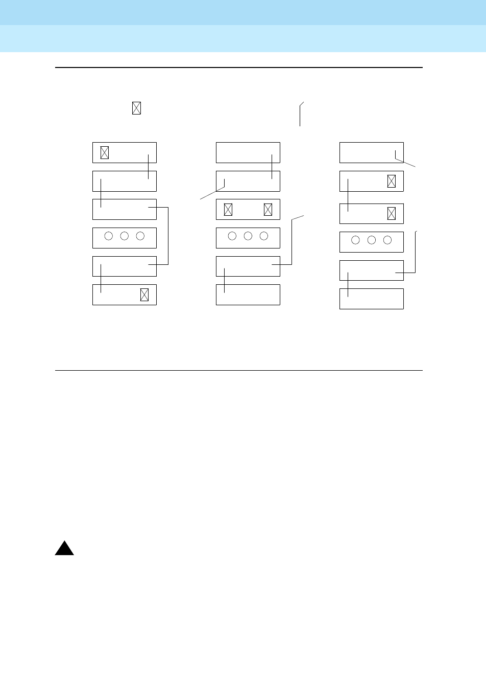
DEFINITY Enterprise Communications Server Release 6
Maintenance for R6r Volumes 1 & 2
555-230-126 Issue 2
January 1998
Maintenance Object Repair Procedures
Page 9-1512TDM-BUS (TDM Bus)
9
Figure 9-93. Carrier Rewiring Example—Rear View of Five-Carrier Cabinet
After cabling changes are made and verified, power must be restored to the port
network. Circuit packs in carriers that are not part of the shortened bus are not
inserted. As a result, these circuit packs are alarmed. Ignore these alarms for
now. All alarms should be resolved when the cabinet is restored to its original
configuration.
Procedure 4 is organized into two parts. Part 1 attempts to clear the TDM Bus
fault by replacing all the bus cabling and terminators within a port-network. Part 2
attempts to isolate the fault to a particular carrier by extending the TDM Bus from
the control carrier to additional carriers one at a time.
!WARNING:
Power must be removed from the entire port network before any cables or
terminators are removed. Failure to follow this procedure can cause
damage to circuit packs and power supplies, and can be hazardous to the
technician.
Part 1
1. If spare TDM/LAN Cable assemblies and TDM/LAN Bus Terminators are
not available, go to Part 2 of this procedure.
A and B
Include
Extended to
Shortened Bus
(Control Carrier)
to Carrier A Only
Bus Shortened
. . . . . . . . . . . . . .
. . . . . . . . . . . . . .
. . . . . . . . . . .
TDM/LAN Bus Cable TDM/LAN Bus Terminator
(All 5 Carriers
Cabinet
Configured
Normally
Carrier E
Carrier D
Fans
Carrier A
Carrier B
Carrier C
. . . . . . . . . . . . . .
. . . . . . . . . . . . . . . .
. . . . . . . . . . . . . . . .
. . . . . . . . . . . . . . . .
. . . . . . . . . . . . . .

DEFINITY Enterprise Communications Server Release 6
Maintenance for R6r Volumes 1 & 2
555-230-126 Issue 2
January 1998
Maintenance Object Repair Procedures
Page 9-1513TDM-BUS (TDM Bus)
9
2. Power down the port network.
3. Replace all of the TDM/LAN Cable Assemblies and both TDM/LAN Bus
Terminators.
4. Restore power to the port network.
5. Run the test tdm P command to determine if the TDM Bus fault is still
present.
command to determine if the TDM Bus fault is still present.
6. If the TDM Bus fault is resolved, the procedure is completed. Otherwise,
go to Part 2.
Processor Port Network:
1. Terminate the TDM Bus so that it extends only across the Active SPE
control carrier.
2. Determine if the TDM Bus fault is still present by running the test tdm P
command. While the TDM bus is extended only across SPE control
carriers the non-control channel test (#297) will not run on the non-control
channel because of the absence of a Tone Detector on the shortened bus.
After the TDM Bus tests are run once, run the set tdm PC command to
move the control channel to the non-active bus (the status
port-network P command will show which bus is currently active). After
the bus switch has occurred, run the
command will show which bus is currently active). After the bus switch has
occurred, run the test tdm P command again to determine if the newly
active bus is faulted.
3. If none of the TDM Bus tests fail, extend the TDM Bus to another carrier. If
that carrier is an SPE control carrier, repeat this procedure beginning at
step 2. If the carrier is not an SPE control carrier, the test tdm P command
only needs to be executed once since there is now a Tone Detector
present on the bus and both the control and non-control channels will be
tested in one test sequence.
4. If some of the TDM Bus tests fail, and since Procedures 2 and 3 have not
resolved the problem, the added carrier(s) are defective and must be
replaced.
Expansion Port Networks:
1. Terminate the TDM Bus so that it extends only across the carrier that
contains the Active Expansion Interface.

DEFINITY Enterprise Communications Server Release 6
Maintenance for R6r Volumes 1 & 2
555-230-126 Issue 2
January 1998
Maintenance Object Repair Procedures
Page 9-1514TDM-BUS (TDM Bus)
9
2. Determine if the TDM Bus fault is still present by running the test tdm P
command.
If the
shortened
TDM Bus does not extend to a carrier that contains the
Tone Detector circuit pack, the non-control channel test (#297) will not be
able to run and the bus that the non-control channel was on will not be
tested. If this is the case, run the set TDM PC command to move the
control channel to the non-active Bus. The status port-network P
command will show which Bus is currently active. After the Bus switch has
occurred, run the test tdm P command again to determine if the newly
active Bus is faulted.
Another option in an EPN is to move a Tone Detector circuit pack to an
empty slot (if one is available) in the carrier where the TDM bus is
terminated. This would allow both the control channel and non-control
channel tests to run and would not require that the set tdm P command
be run.
3. If none of the TDM Bus tests fail, extend the TDM Bus to another carrier,
and repeat the procedure in the previous step. When a carrier that causes
the fault to recur is added, perform Procedure 2 for only the circuit packs
in that carrier.
4. If any of the TDM Bus test fail, and Procedures 2 and 3 have not resolved
the problem, the added carrier(s) are defective and must be replaced.
Restarting Non-functioning Port Circuit Packs
A defective TDM Bus Control Channel or system timing reference on one of the
networks can result in port circuit packs (those not on a control carrier) on this
port network entering the reset state. When this situation occurs, the circuit pack
will stop functioning and its red LED will light. The system will not detect the
presence of a circuit pack when the circuit pack is in the reset state. Hence,
executing the list config board command will indicate that the circuit pack is not
present.
If a circuit pack enters the reset state it will remain out of service until it receives a
restart message form the control channel on the same TDM Bus, A or B, that was
active when it reset, or until it is powered up again.
To force the system to send a restart message to all circuit packs on a network,
try one of the following methods, depending on the circumstances. A circuit pack
that is functioning normally (is not in the reset state) will ignore the restart
message.
Procedure 1 (Non-destructive)
Execute the Idle Time Slot Test (#294) by issuing the command test tdm P when
the control channel is on the same TDM Bus as it was when the circuit pack
entered the reset state.

DEFINITY Enterprise Communications Server Release 6
Maintenance for R6r Volumes 1 & 2
555-230-126 Issue 2
January 1998
Maintenance Object Repair Procedures
Page 9-1515TDM-BUS (TDM Bus)
9
Procedure 2 (Non-Destructive)
If you are at the site
, reseat the circuit pack. This action will cause the circuit
pack that was in the reset state to begin functioning on the
current
Control
Channel bus.
Procedure 3 (Destructive)
Reset the port network that contains the circuit pack that is in the reset state.
When a network is reset, two restart messages, one on the control channel of
each TDM Bus, are sent to each circuit pack on the network.
To reset an EPN
only
, execute the reset port-network
P
level 2 command.
Resetting the EPN will
disrupt all calls going to and originating from the EPN.
Procedure 4 (Destructive)
Execute the recycle carrier
PC
command.
This command will remove and return
power to the designated port carrier. Thus, any other circuit packs on this carrier
will also be temporarily taken out-of-service.
Error Log Entries and Test to Clear Values
Notes:
a. The TDM Bus has been busied out by the technician. The error will retire
when the technician releases the TDM Bus.
Table 9-513. TDM Bus Error Log Entries
Error
Type Aux
Data Associated Test Alarm Level On/Off
Board Test to Clear
Value
0 0 Any Any Any test tdm P
1 0 Control Channel Test (#296) MINOR ON test tdm P r 3
18(a) 0 busyout tdm PC WARNING ON release tdm PC
35(b) 0-1 TDM Bus Corruption MINOR ON set tdm PC
257(c) 0 None MAJOR ON
513(d) Any Idle Time Slot Test (#294) MINOR ON test tdm P r 3
769(e) Any Idle Time Slot Test (#294) WARNING ON test tdm P r 3
769(f) Any Idle Time Slot Test (#294) (see Notes)
1025(g) Any None
3872(h) Any None
3873(h) Any None
3874(h) Any None
3877(h) Any None

DEFINITY Enterprise Communications Server Release 6
Maintenance for R6r Volumes 1 & 2
555-230-126 Issue 2
January 1998
Maintenance Object Repair Procedures
Page 9-1516TDM-BUS (TDM Bus)
9
b. This error indicates the TDM Bus is corrupted. If the corruption was on the
Control Channel bus, TDM Bus maintenance will automatically switch the
control channel and/or tones to the other bus. The same strategy applies if
the corruption was on the bus carrying the tones.
An aux data value of 0 indicates the last reported TDM Bus corruption was
on the Control channel bus.
An aux data value of 1 indicates the last reported TDM Bus corruption was
on the Non-Control channel bus.
If this error is logged on both TDM Buses (A and B) on the PPN within two
or three minutes, the red LED of several circuit packs may or may not be lit
and there could be Switch Control (SW-CTL) errors. Under these
circumstances do the following:
■Display the Hardware Error Log via the display errors command
and look for SW-CTL (Switch Control) errors.
■If there are any errors logged against the Switch Control, try to
resolve them.
■Test the TDM Bus via the test tdm P command.
■If all the TDM Bus tests pass, the problem has been fixed.
c. This error indicates the TDM Bus was switched to the other bus due to
TDM Bus corruption. The aux data value is not meaningful and no action is
required. Look for other TDM-BUS errors to determine the cause of this
error.
d. This error indicates that some time slots are corrupted in the specified
TDM Bus. The Minor alarm is raised when there are more than 50 bad time
slots in the bus. The aux data indicates the number of bad time slots found
by the test.
e. This error indicates that some time slots are corrupted in the specified
TDM Bus. The Warning alarm is raised when there are more than 10 bad
time slots but less than or up to 50 bad ones in the bus. The aux data
value indicates the number of bad time slots found by the test.
f. This error indicates the idle time slot test found less than 10 bad time slots
in the TDM Bus. The aux data value indicates the number of bad time slots
found by the test. There is no alarm associated with this error.
g. This error indicates that the daily TDM Bus switch was not successful. The
Switch Control (PPN) or Active Expansion Interface (EPN) cannot talk on
the bus that software was trying to switch into. There is no alarm
associated with this error.

DEFINITY Enterprise Communications Server Release 6
Maintenance for R6r Volumes 1 & 2
555-230-126 Issue 2
January 1998
Maintenance Object Repair Procedures
Page 9-1517TDM-BUS (TDM Bus)
9
h. These errors indicate communication problems which may be causing
message loss. TDM Bus maintenance may switch the Control Channel bus
and/or Tone bus to the other bus. Test the TDM Bus via the test tdm P
command and follow the procedures according to the error codes
reported from the test. The aux data value shows the Angel id number for
which a downlink message was lost.
Technician-Demanded Tests:
Descriptions and Error Codes
Always investigate tests in the order presented in the table below. By clearing
error codes associated with the
Control Channel Test
, for example, you may also
clear errors generated from other tests in the testing sequence.
Idle Time Slot Test on TDM Bus A or B (#294)
The Idle Time Slot Test detects noisy time slots on the bus and takes them
out-of-service. The Tone Detector circuit pack is told to listen to idle time slots
and if it detects any noise on a time slot, it returns a failure. At the end of the test,
any out-of-service time slots are retested to see if they are still noisy and restored
to service if they are idle. After all the time slots have been tested, maintenance
counts the number of bad time slots and reports the number to the technician in
the error code field. No more than 220 time slots will be taken out-of-service on
one bus and no more than 300 will be taken out-of-service on both buses at one
time.
1. D = Destructive; ND = Nondestructive
Order of Investigation Short Test
Sequence Long Test
Sequence D/ND1
Control Channel Test on the Control
Channel Bus (#296) X X ND
Digit Detection Test on the Non-Control Channel Bus
(#297) XXND
Idle Time Slot Test (#294) X X ND

DEFINITY Enterprise Communications Server Release 6
Maintenance for R6r Volumes 1 & 2
555-230-126 Issue 2
January 1998
Maintenance Object Repair Procedures
Page 9-1518TDM-BUS (TDM Bus)
9
Control Channel Test (#296)
This tests the integrity of the Control Channel bus by ensuring that
communication through the TDM Bus is operational. The test attempts to query a
circuit pack whose presence is required in each port network for proper
operation (Tone/Clock or Tone Detector). If a reply from the queried circuit pack
is received, the TDM Bus is considered operational and the test passes. If no
reply is received, the Bus is not operational and the test fails.
Table 9-514. TEST #294 Idle Time Slot Test on TDM Bus A or
TDM Bus B
Error
Code Test
Result Description/ Recommendation
None ABORT Could not allocate the necessary system resources to run this test. For
example, maintenance could be running on the Tone Detector circuit pack and
it is using the CPTRs.
1115 ABORT Could not allocate the necessary system resources to run this test.
1. Retry the command at 1-minute intervals for a maximum of 3 times.
Any FAIL The error code indicates the number of bad time slots that were detected. The
cause of this failure is most likely due to a bad port circuit pack and not the
TDM Bus itself.
1. Execute the command again.
2. If the error persists, check the Error and Alarm Logs for alarms, on the port
network where the faulted TDM Bus resides, on port circuit packs from the
NPE Crosstalk Test. Also check for EXP-INTF alarms associated with error
type 1537.
3. Refer to the appropriate circuit pack’s documentation to clear the circuit
pack’s problem.
4. Test the TDM Bus again. If the error continues, refer to the ‘‘TDM Bus Fault
Detection and Isolation Procedure’’ described earlier.
PASS The success of this test indicates all the idle time slots that are supposed to be
idle are indeed idle. There is no noise on any of the idle time slots.
Continued on next page

DEFINITY Enterprise Communications Server Release 6
Maintenance for R6r Volumes 1 & 2
555-230-126 Issue 2
January 1998
Maintenance Object Repair Procedures
Page 9-1519TDM-BUS (TDM Bus)
9
Table 9-515. TEST #296 Control Channel Test
Error
Code Test
Result Description/ Recommendation
Any
other
than
1005
ABORT Internal system error.
1. Retry the command at one-minute intervals for a maximum of three times.
1005 ABORT Since this test is valid only on the control channel bus, it aborts execution
when run on the non-control channel bus. This is a valid response. Use the
status port-network command to verify which bus is the control channel bus.
None FAIL Communication through the Control Channel is not working. The problem is not
necessarily the TDM Bus itself.
1. Display the hardware error and alarm log for the Tone-Clock circuit pack
and for the Tone Detector circuit pack in the port network where the
faulted TDM Bus resides. Refer to Maintenance documentation for
TONE-BD (Tone-Clock Circuit Pack), TONE-PT (Tone Generator),
GPTD-PT (General Purpose Tone Detector Port), and DTMR-PT (Dual
Tone Multi-Frequency Port).
2. Resolve the errors and alarms for the Tone-Clock and Tone Detector
circuit packs.
3. If the faulted TDM Bus is in the PPN, display the hardware error and alarm
log and look for SW-CTL errors and alarms.
4. If the faulted TDM Bus is on the EPN, display the hardware error and alarm
log and look for errors and alarms for the active Expansion Interface circuit
pack. Refer to EXP-INTF (Expansion Interface Circuit Pack) Maintenance
documentation and resolve its errors.
5. Execute the test tdm P command again.
6. If the test still fails, refer to the ‘‘TDM Bus Fault Detection and Isolation
Procedure’’ described earlier.
PASS Communication through the control channel bus is operational.
Continued on next page

DEFINITY Enterprise Communications Server Release 6
Maintenance for R6r Volumes 1 & 2
555-230-126 Issue 2
January 1998
Maintenance Object Repair Procedures
Page 9-1520TDM-BUS (TDM Bus)
9
Digit Detection Test (#297)
This test is executed on the Non-Control Channel bus. The Tone-Clock circuit
pack is told to put a tone on the Non-Control Channel bus and the Tone Detector
circuit pack is told to listen to it. The test passes if the tone is successfully
transmitted on the Non-Control Channel bus.
Table 9-516. TEST #297 Digit Detection Test
Error
Code Test
Result Description/ Recommendation
None
1001
2100
ABORT Could not allocate the necessary system resources to run this test.
1005 ABORT Since this test is valid only on the non-control channel bus, it aborts execution
when run on the control channel bus. This is a valid response. Use the status
port-network command to verify which bus is the control channel bus.
2000 ABORT Response to the test request was not received within the allowable time period.
1. Retry the command at one-minute intervals a maximum of three times.
None FAIL This failure indicates that communication on the Non-Control Channel is not
reliable.
1. Execute the command again.
2. If the problem persists, test the active Tone-Clock circuit pack and Tone
Detector circuit pack in the port network where the faulted TDM Bus
resides, to make sure they are healthy. Refer to TONE-BD (Tone-Clock
Circuit Pack), TONE-PT (Tone Generator), GPTD-PT (General Purpose
Tone Detector Port), and DTMR-PT (Dual Tone Multi-Frequency Port).
3. Execute the command again.
4. If the problems persists, refer to the ‘‘TDM Bus Fault Detection and
Isolation Procedure’’ described earlier.
PASS The non-control channel bus is operational.
Continued on next page
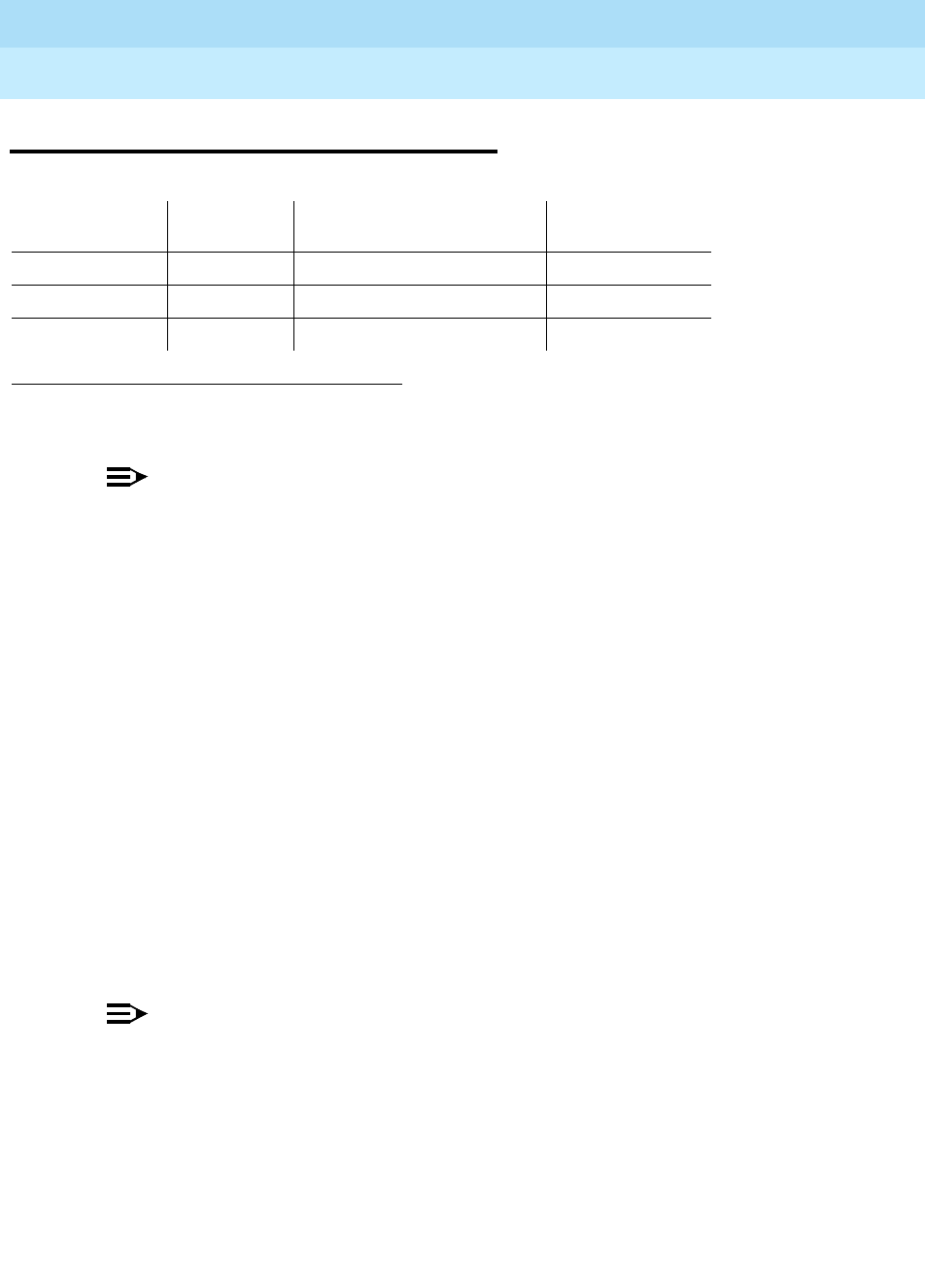
DEFINITY Enterprise Communications Server Release 6
Maintenance for R6r Volumes 1 & 2
555-230-126 Issue 2
January 1998
Maintenance Object Repair Procedures
Page 9-1521TDM-CLK (TDM Bus Clock)
9
TDM-CLK (TDM Bus Clock)
NOTE:
Replacing the tone/clock circuit pack requires a special procedure
described in the documentation for TONE-BD. That section also describes
the LED displays for this board.
The Time Division Multiplex (TDM) Bus Clock resides on the Tone-Clock circuit
pack, providing clocking signals both for the TDM Bus and the LAN Bus. The
Tone-Clock circuit pack is a critical component in the system and is necessary to
ensure the operation of all port circuit packs in the system. The TDM buses of the
PPN and any EPNs are synchronized together. The system timing reference can
be derived internally from the Tone-Clock circuit pack in any PN, or from an
external (off-board) timing reference. Currently, the TDM Bus Clock supports
synchronizing the TDM Bus with interface rates from Digital Signal 1 (DS1)
facilities as primary or primary and secondary references, and from Stratum 3
Clock (STRAT-3) facilities. Only the TN780 tone-clock supports a Stratum 3
clock.
Moreover, the Tone-Clock circuit pack aids in monitoring and selecting
synchronization references. The Tone-Clock circuit pack, after detecting that the
external source of timing is not valid, will automatically begin its escalation
procedure, according to the facilities administered. In the following table,
successive losses of signal cause escalation from left to right.
NOTE:
Switching back to a DS1 source is handled by synchronization
maintenance, once any problems with it have been corrected and tested.
However, once synchronization has been switched to the internal timing
source of the master Tone-Clock circuit pack,
switching back to a Stratum 3
Clock must be initiated by a technician
after the external reference has
been repaired.
1. UU is the universal cabinet number (1 for PPN, 2 -44 for EPNs). C is the carrier
designation (A, B, C, D, or E).
MO Name (in
Alarm Log) Alarm Level Initial Command to Run1Full Name of MO
TDM-CLK MAJOR test tone-clock UUC short TDM Bus Clock
TDM-CLK MINOR test tone-clock UUC short TDM Bus Clock
TDM-CLK WARNING release tone-clock UUC TDM Bus Clock
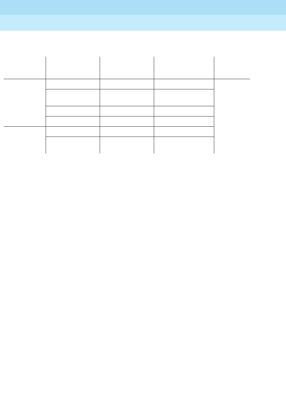
DEFINITY Enterprise Communications Server Release 6
Maintenance for R6r Volumes 1 & 2
555-230-126 Issue 2
January 1998
Maintenance Object Repair Procedures
Page 9-1522TDM-CLK (TDM Bus Clock)
9
See “Synchronization” for more details of the escalation plan.
There exists a
strong interdependency among the DS1 Interface circuit pack Maintenance,
Synchronization Maintenance, and TDM Bus Clock Maintenance MOs
.
See the section on “TONE-BD” for a discussion of the relationship of Tone-Clock
circuit packs with the various Reliability Options.
Tone-Clock
Role Synchronization
Facilities
Initial External
Synchronization
Source
Backup External
Synchronization
Source Internal
Source
MASTER
Stratum 3 Clock Source "A" Source "B"
Local
oscillator
DS1 Primary and
Secondary DS1 Primary DS1 Secondary
DS1 Primary Only DS1 Primary None
No External Source None None
SLAVE
PNC Duplication Active EI Standby EI
No PNC
Duplication Active EI None

DEFINITY Enterprise Communications Server Release 6
Maintenance for R6r Volumes 1 & 2
555-230-126 Issue 2
January 1998
Maintenance Object Repair Procedures
Page 9-1523TDM-CLK (TDM Bus Clock)
9
Error Log Entries and Test to Clear Values
Notes:
a. The Tone-Clock circuit pack may have a clock at the edge of its specified
frequency. This can cause Expansion Interface circuit packs and SNI
circuit packs to go out-of-frame or report no-neighbor conditions. This can
is turn cause EPNs, Expansion Archangel Links (EALs), Remote Neighbor
Links (RNLs), and/or Local Neighbor Links LNLs) to go down. When this
error is alarmed, Clock Health Inquiry Test (#46) will fail with an error code
of 1.
1. Replace the Tone-Clock circuit pack identified in the error log. See
How to Replace the Tone-Clock Circuit Pack
in the TONE-BD
section.
1. As a general rule, any
on board
errors against the TDM Bus Clock should be resolved before pursuing any
other errors against SPE or PNC components.
Off board
clock errors may be caused by other board errors,
and should usually be addressed once any on board errors have been resolved.
2. Run the Short Test Sequence first. If all tests pass, run the Long Test Sequence. Refer to the appropriate
test description and follow the recommended procedures.
3. Major or Minor alarms on this MO may have been downgraded to Warning alarms based on the values
used in the set options command.
Table 9-517. TDM Bus Clock Error Log Entries
Error
Type Aux
Data Associated Test Alarm Level On/Off
Board1Test to Clear Value
020 Any Any Any test tone-clock UUC sh r 1
1(a) 0 None MINOR OFF
18(b) 0 busyout tone-clock UUC WARNING OFF release tone-clock UUC
130(c) None
257(d) None WARNING OFF
513(e) Any Clock Circuit Status
Inquiry (#148) MINOR3OFF test tone-clock UUC
769(f) Any Clock Circuit Status
Inquiry (#148) MAJOR‡ON test tone-clock UUC sh r 10
1025(g) Any Clock Slip Inquiry(#149) test tone-clock UUC sh
1281(h)
1282(h) Any None MINOR OFF
1537 Any Clock PPM Inquiry(#150) test tone-clock UUC sh
2049(i) Any Standby Reference
Health Check Test(#651) MAJOR3ON test tone-clock UUC
2305(j) 0 None WARNING OFF

DEFINITY Enterprise Communications Server Release 6
Maintenance for R6r Volumes 1 & 2
555-230-126 Issue 2
January 1998
Maintenance Object Repair Procedures
Page 9-1524TDM-CLK (TDM Bus Clock)
9
b. The indicated Tone-Clock circuit pack has been made unavailable via the
busyout tone-clock UUC command. It only applies to systems which
have the High or Critical Reliability Option administered, because only a
standby Tone-Clock circuit pack may be made busy by that command. To
resolve this error, execute the release tone-clock UUC command for the
alarmed circuit pack.
c. This error type indicates that the circuit pack has been removed or has
been insane for more than 11-minutes. To clear the error, reinsert or
replace the circuit pack.
d. The Tone-Clock circuit pack in the PPN is not a TN780 while a Stratum 3
synchronization is administered. Replace the Tone-Clock in the PPN with a
TN780, or change synchronization administration to Stratum 4 if a Stratum
3 clock is not being used.
e. The tone-clock has reported an out-of-lock condition. A aux value of 1
indicates this error is an out-of-lock with the primary reference. A aux
value of 2 indicates this error is an out-of-lock with the secondary
reference. It could not lock onto the frequency of that synchronization
reference. This will lead to a change in the synchronization reference if the
condition continues.
f. The Tone-Clock circuit pack may be defective.
1. If this error was logged against an Active Tone-Clock circuit
pack, then test that circuit pack via the test tone-clock UUC. If
there are error codes from any tests, follow the recommended
maintenance procedures for the error code(s) to resolve the
problem(s). If all tests pass, consider the 769 error type to have
been a transient problem, and clear the error log entry with test
tone-clock UUC long clear.
2. If this error was logged against the Standby Tone-Clock circuit
pack, and if the Aux Data value was 18369, Synchronization
maintenance acts on this error. No corrective action is required. For
all the other Aux Data values, replace the Standby Tone-Clock
circuit pack. Refer to the TONE-BD section on ‘‘How to Replace the
Tone-Clock Circuit Pack’’.
g. Tone-Clock circuit pack on-board maintenance has detected one or more
clock slips
, timing differences between its internal reference source and
the synchronization signal provided by the master Tone-Clock. Although
no clock slip errors are expected during normal operation, both manual
and automatic interchanges of Tone-Clock circuit packs, synchronization
references, and PNCs, may result in clock slip counts.
If error 1281 also is logged for the same Tone-Clock circuit pack, it is
related to this problem, and should be corrected first. Otherwise, continue
with the procedure below.

DEFINITY Enterprise Communications Server Release 6
Maintenance for R6r Volumes 1 & 2
555-230-126 Issue 2
January 1998
Maintenance Object Repair Procedures
Page 9-1525TDM-CLK (TDM Bus Clock)
9
1. Use test tone-clock UUC, and examine the results of test #149 to
see if slip errors are still occurring. If no new slip errors are
reported, and if these errors are not causing a TDM-CLK alarm,
they may be ignored. Use test tone-clock UUC long clear to clear
the errors.
2. Otherwise, enter the display errors command, and follow
corrective procedures for any other TDM-CLK, TONE-BD, SYNC,
DS1C-BD, EXP-INTF, SNC-BD, and SNI-BD errors logged, except
for those in Table 9-518.
3. If 1025 errors persist, refer to SYNC Maintenance in this manual
and follow the procedures in the "Approach to Troubleshooting"
section.
h. Error Type 1281This error is an indication that the Tone-Clock circuit
pack has detected a loss of timing signal from the system synchronization
reference. The Tone-Clock circuit pack has switched synchronization
references.
1. Resolve any errors logged against the SYNC or STRAT-13
maintenance objects.
2. Refer to SYNC maintenance, in the “Approach to Troubleshooting”
section, if the error is not resolved by step 1
Error Type 1282Indicates that the TN2182 tone-clock was synchronized
to a DS1 facility and that the reference frequency provided by the DS1
drifted beyond a range that could be tracked by the TN2182. Therefore
the TN2182 is no longer synchronized to that DS1 reference. If a second
DS1 is available, the tone-clock may be synchronized to that reference. If
no secondary DS1 reference is available, the tone-clock will run off of its
internal clock. This may result in slips being reported by the tone-clock
and all DS1 facilities.
i. The tone-clock circuit pack in the master port network was unable to
detect the incoming synchronization signal, but the other tone-clock was
able to detect the references. If the aux data is 0, the problem is with the
signal on the primary. If the aux data is 1, the problem is with the signal on
the secondary. The system should switch clocks in this situation.
Table 9-518. Error Log Entries for Slip Errors
Circuit Pack Name Error Log
Name Error Log Entry
for Slips
DS1 Interface DS1-BD 3073 to 3160
Expansion Interface EXP-INTF 2305
Switch Node Interface SNI-BD 1537
Tone-Clock TDM-CLK 1025
UDS1 Interface UDS1-BD 3073 to 3160
DS1C Circuit Pack DS1C-BD 3329

DEFINITY Enterprise Communications Server Release 6
Maintenance for R6r Volumes 1 & 2
555-230-126 Issue 2
January 1998
Maintenance Object Repair Procedures
Page 9-1526TDM-CLK (TDM Bus Clock)
9
1. If this error is against a PPN clock board and the system is using a
Stratum 3 clock, check the cabling that brings the stratum 3 signal
to this clock board.
2. Replace the current standby Tone-Clock circuit pack. See
How to
Replace the Tone-Clock Circuit Pack
in the TONE-BD section.
j. The indicated active Tone-Clock circuit pack, which is on a port network
that does not contain the system synchronization reference (a slave
Tone-Clock), has detected a loss of timing signal from its EXP-INTF
synchronization source.
1. Enter display errors and display alarms, and follow the
associated repair procedures for EXP-INTF, TDM-CLK, and
TONE-BD error log entries that have on-board alarms.
2. If the 2305 errors persist, follow the repair procedures for EXP-INTF
error log entries 257, 769, or 770, or any errors logged against
SNI-BD, SNC-BD, or FIBER-LK.
3. If the 2305 errors persist:
a.
For Port Networks with more than one Tone-Clock circuit
pack
, execute the command test synchronization r 10, and
check to see if new 2305 errors against TDM-CLK were
reported. If not, execute reset PNC interchange and then
test synchronization r 10 again, and recheck for new 2305
errors against TDM-CLK
b.
For Port Networks with a single Tone-Clock circuit pack
,
execute the command test synchronization r 10, and check
to see if new 2305 errors were reported.
If no new instances of the 2305 errors were logged for either test,
then enter test tone-clock UUC long clear to clear the TDM-CLK
errors and the procedure is complete.
4. For Port Networks with more than one Tone-Clock circuit pack,
interchange Tone-Clocks with the set tone-clock UUC, then run
test synchronization r 10, and check to see if new 2305 errors are
reported against the new active Tone-Clock circuit pack. If not,
replace the standby Tone-Clock circuit pack. See
How to Replace
the Tone-Clock Circuit Pack
in the TONE-BD section. If this clears
the error, the problem has been resolved.
5. Replace the EI circuit pack for the active PNC. In the direct-connect
case, use the list fibers command to identify which active EI
connects with the PPN.
6. If the problem is still not cleared, and the Tone-Clock circuit pack
reported in the error log has not been replaced up to now, replace
it. See
How to Replace the Tone-Clock Circuit Pack
in the TONE-BD
section.

DEFINITY Enterprise Communications Server Release 6
Maintenance for R6r Volumes 1 & 2
555-230-126 Issue 2
January 1998
Maintenance Object Repair Procedures
Page 9-1527TDM-CLK (TDM Bus Clock)
9
System Technician-Demanded Tests:
Descriptions and Error Codes
Always investigate tests in the order presented in the table below when
inspecting errors in the system. By clearing error codes associated with the
SAKI
Reset Test
for example, you may also clear errors generated from other tests in
the testing sequence.
Notes:
a. Refer to XXX-BD (Common Port Circuit Pack) Maintenance documentation
for descriptions of these tests.
b. Refer to TONE-BD (Tone-Clock Circuit Pack) documentation for a
description of this test.
c. Refer to TONE-PT (Tone Generator) documentation for descriptions of
these tests.
1. D = Destructive; ND = Nondestructive
Order of Investigation Short Test
Sequence Long Test
Sequence Reset Board
Sequence D/ND1
SAKI Reset Test (#53) (a) X D
Clock Health Test (#46) (b) X X ND
Control Channel Looparound Test (#52)
(a) XX ND
Tone Generator Crosstalk Test (#90) (c) X ND
Tone Generator Transmission Test (#40)
(c) XX ND
Tone Generator Audit/Update Test (#41)
(c) XX ND
TDM Bus Clock Circuit Status Inquiry
Test (#148) XX ND
TDM Bus Clock Slip Inquiry Test
(#149)(e) XX ND
TDM Bus Clock PPM Inquiry Test (#150) X X ND
TDM Bus Clock Parameter Update Test
(#151) XX ND
Board Type Check Test (#574) X X ND
Standby Reference Health Check Test
(#651) (d) XND

DEFINITY Enterprise Communications Server Release 6
Maintenance for R6r Volumes 1 & 2
555-230-126 Issue 2
January 1998
Maintenance Object Repair Procedures
Page 9-1528TDM-CLK (TDM Bus Clock)
9
d. This test only runs on the Standby Tone-Clock circuit pack in a Port
Network with more than one Tone-Clock circuit pack (High or Critical
Reliability Option). The circuit pack must be a TN780 code with firmware
revision 2 or above, or be a TN2182.
e. Test #149 is not run on the TN2182.
TDM Bus Clock Circuit Status Inquiry Test (#148)
The TDM Bus Clock circuitry is checked for sanity. Any problems that are found
are reported via error codes
Table 9-519. TEST #148 TDM Bus Clock Circuit Status
Inquiry Test
Error
Code Test
Result Description/ Recommendation
None
1001 ABORT The system could not allocate the necessary resources for the test.
1. Wait 1-minute, and retry the test.
2000 ABORT Response to the test was not received within the allowable time period.
2100 ABORT System resources required to run this test are not available.
1. Retry the command at 1-minute intervals a maximum of 5 times.
1 FAIL This error means the Tone-Clock circuit pack framing verification firmware
reports an error in the clock synchronization signal coming into this Port
Network.
1. If the Tone-Clock circuit pack reporting the problem is a master clock, then
the system synchronization reference is providing a bad timing source.
Refer to SYNC (Synchronization) or STRAT-3 (Stratum 3 Clock)
Maintenance documentation to change the system synchronization
reference.
2. If the Tone-Clock circuit pack is a slave clock, then the EI to which it is
listening is providing a bad timing source. Follow the diagnostic
procedures specified for TDM-CLK Error Code 2305.
3. If no problem can be found with the incoming synchronization signal,
replace the Tone-Clock circuit pack. See
How to Replace the Tone-Clock
Circuit Pack
in the TONE-BD section.
2 FAIL This error indicates that Tone-Clock circuit pack has inaccurately detected loss
of signal on the incoming synchronization timing source.
4
or
8
FAIL The local oscillator on the Tone-Clock circuit pack has failed.
Continued on next page

DEFINITY Enterprise Communications Server Release 6
Maintenance for R6r Volumes 1 & 2
555-230-126 Issue 2
January 1998
Maintenance Object Repair Procedures
Page 9-1529TDM-CLK (TDM Bus Clock)
9
TDM Bus Clock Slip Inquiry Test (#149)
This test evaluates the quality of the synchronization source for the Tone-Clock
circuit pack.
NOTE:
This test does not apply to the TN2182
16
or
32
FAIL The circuitry on the Tone-Clock circuit pack used to detect synchronization
timing errors has failed.
1. Errors 2, 4, 8, 16, and 32 indicate that there is poor synchronization
between port networks and external facilities. It may be noticeable to the
customer in the form of errors in data communications. The Tone-Clock
circuit pack is defective. See
How to Replace the Tone-Clock Circuit Pack
in the TONE-BD section.
64 FAIL This message is only sent when an uplink message has reported the loss of
valid synchronization timing information coming into this Port Network. It has
been reported in TDM-CLK Error Log entries; one or more of 1025, 1281, 1537,
2049 and 2305.
1. Resolve the errors indicated. No separate corrective action is required.
65 FAIL The tone-clock is currently not able to lock on to the current synchronization
reference. If this tone-clock is in the master port networK:
1. Examine the error log for any DS1-BD, SYNC or other TDM-CLK errors and
resolve as applicable.
2. Run this test again via the test tone-clock UUC command.
3. Examine the DS1 measurements to determine if the facility is healthy.
4. Administer a new synchronization reference.
5. Replace the DS1 board currently supplying the reference.
If this tone-clock is in the slave port networK:
1. Examine the error log for any SYNC, EXP-INTF or other TDM-CLK errors.
2. Run this test again via the test tone-clock UUC command.
66 FAIL There is an on-board failure of TDM clock hardware.
1. Replace this faulty tone-clock circuit pack.
PASS TDM Bus Clock Circuit Status is sane. There are no clock-detection circuit
problems on the Tone-Clock circuit pack.
Table 9-519. TEST #148 TDM Bus Clock Circuit Status
Inquiry Test — Continued
Error
Code Test
Result Description/ Recommendation
Continued on next page

DEFINITY Enterprise Communications Server Release 6
Maintenance for R6r Volumes 1 & 2
555-230-126 Issue 2
January 1998
Maintenance Object Repair Procedures
Page 9-1530TDM-CLK (TDM Bus Clock)
9
TDM Bus Clock PPM Inquiry Test (#150)
This test evaluates the quality of the synchronization source for the Tone-Clock
circuit pack
Table 9-520. TEST #149 TDM Bus Clock Slip Inquiry Test
Error
Code Test
Result Description/ Recommendation
ABORT The system could not allocate the necessary resources for the test.
1001 ABORT The system could not allocate the necessary resources for the test.
1. Wait 1-minute, and retry the test.
2000 ABORT Response to the test request was not received within the allowable time period.
2100 ABORT System resources required to run this test are not available.
1. Retry the command at 1-minute intervals a maximum of 5 times.
Any FAIL The error code represents the number of timing slips detected on the incoming
synchronization source since the last slip inquiry was sent to the Tone-Clock
circuit pack. The incoming synchronization signal can be from one of four
sources:
1. A Stratum 3 Clock, if that option is administered and the circuit pack tested
was the active Tone-Clock in the PPN.
2. A DS1 Interface circuit pack, if DS1 Synchronization is administered, and
associated with the circuit pack tested.
3. The local oscillator on the master Tone-Clock circuit pack, if it is providing
the system clocking signals.
4. An EXP-INTF circuit pack, if the port network on which the test was
executed does not contain the current system synchronization reference.
The error code is a variable amount ranging from 1 to 255.
1. Small numbers of slips should not result in service degradation. If the error
code is small (1 or 2), rerun the test. If the error only occurs infrequently, it
may be ignored.
2. Otherwise, refer to the “Approach to Troubleshooting” section in the
Synchronization (SYNC) Maintenance section of this manual.
PASS The Tone-Clock circuit pack does not detect any timing slips. This indicates that
the incoming synchronization timing source is valid or that the system
synchronization reference is a Tone-Clock circuit pack. The status
synchronization command should be used to verify that the desired
synchronization reference is providing timing for the system.
Continued on next page

DEFINITY Enterprise Communications Server Release 6
Maintenance for R6r Volumes 1 & 2
555-230-126 Issue 2
January 1998
Maintenance Object Repair Procedures
Page 9-1531TDM-CLK (TDM Bus Clock)
9
Table 9-521. TEST #150 TDM Bus Clock PPM Inquiry Test
Error
Code Test
Result Description/ Recommendation
ABORT The system could not allocate the necessary resources for the test.
1001 ABORT The system could not allocate the necessary resources for the test.
1. Wait 1-minute, and retry the test.
255 ABORT The test was not executed because the Tone-Clock circuit pack was using its
local oscillator rather than synchronizing to an external source.
1. Verify that this Tone-Clock circuit pack is expected to be the
synchronization source. If not, correct the synchronization information and
re-execute the test.
2000 ABORT Response to the test request was not received within the allowable time period.
2100 ABORT System resources required to run this test are not available.
1. Retry the command at 1-minute intervals a maximum of 5 times.
Any FAIL The error code represents the rate (in Parts Per Million, or PPM) at which clock
slip errors have been detected on the incoming synchronization source since
the last PPM inquiry was sent to the Tone-Clock circuit pack. A failure of this
test indicates that we are outside of Stratum 4 or Stratum 3 timing
specifications on the incoming timing source.
The error code is a variable amount ranging from 1 to 254.
1. If error 1537 is entered in the hardware error log against TDM-CLK, then
the board has switched timing sources. Follow the procedures associated
with hardware log error code 1537.
2. Otherwise, refer to "Approach to Troubleshooting" in the Synchronization
(SYNC) Maintenance section of this manual.
PASS The Tone-Clock circuit pack does not detect timing any PPM errors. This
indicates that the external synchronization timing source is valid or that the
system synchronization reference is a Tone-Clock circuit pack. Use the status
synchronization command to verify that the desired synchronization
reference is providing timing for the system.
Continued on next page

DEFINITY Enterprise Communications Server Release 6
Maintenance for R6r Volumes 1 & 2
555-230-126 Issue 2
January 1998
Maintenance Object Repair Procedures
Page 9-1532TDM-CLK (TDM Bus Clock)
9
TDM Bus Clock Parameter Update Test (#151)
This test updates the following internal parameters on the Tone-Clock circuit
pack:
■Disable in-line duplication status messages.
■Disable in-line subrate frame maintenance messages (TN768, TN780
only).
■Set the PPM threshold at 60 PPM for TN768 and TN780. Set the PPM
threshold at 85 PPM for TN2182.
■Enable PPM threshold switching
■Set the number of slips to trigger
loss of signal
- currently 30 per 5
millisecond period
■Enable the on-board synchronization switching algorithm (see above)
■Enable holdover operation (TN2182 only).
This is not a test and will always pass without identifying or reporting any
Tone-Clock circuit pack errors
Table 9-522. TEST #151 TDM Bus Clock Parameter Update Test
Error
Code Test
Result Description/ Recommendation
ABORT Internal system error
FAIL Internal system error
1. Retry the command at 1-minute intervals a maximum of 5 times.
PASS The Tone-Clock circuit pack parameters have been successfully updated.
Continued on next page

DEFINITY Enterprise Communications Server Release 6
Maintenance for R6r Volumes 1 & 2
555-230-126 Issue 2
January 1998
Maintenance Object Repair Procedures
Page 9-1533TDM-CLK (TDM Bus Clock)
9
Board Type Check Test (#574)
This test verifies that a Tone-Clock circuit pack administered with a Stratum 3
Clock source has code TN780
Standby Reference Health Check Test (#651)
This test evaluates the quality of the external synchronization timing source for a
standby Tone-Clock circuit pack. All administered synchronization timing
sources must be valid for this test to pass. If the tone-clock circuit pack and the
synchronization timing sources are in different port networks, the EI circuit packs
transport the timing sources to the tone-clock.
Table 9-523. TEST #574 Board Type Check Test
Error
Code Test
Result Description/ Recommendation
2012 ABORT Internal system error
1. Retry the command at 1-minute intervals a maximum of 5 times.
ANY FAIL Stratum 3 Clock Synchronization is administered for the carrier in which this
Tone-Clock circuit pack resides, but the Tone-Clock does not have code
TN780.
1. If the Stratum 3 Clock option is incorrectly administered, remove it.
2. Otherwise, replace the circuit pack. See
How to Replace the Tone-Clock
Circuit Pack
in the TONE-BD section.
PASS The proper (TN780) Tone-Clock circuit pack code is present for Stratum 3
Clock synchronization.
Continued on next page
Table 9-524. TEST #651 Standby Reference Health Check Test
Error
Code Test
Result Description/ Recommendation
ABORT This test may already be running due to a tone-clock installation, scheduled
maintenance, alarm activity, or a technician-demand test from another terminal.
This abort can also occur due to an internal system error.
1. Try the command again at 1-minute intervals up to five times.
1184 ABORT This test requires an external synchronization source to be administered (DS1
primary, DS1 primary and secondary, or Stratum 3 Clock).
1. Administer the external synchronization source and retry the test.
Continued on next page

DEFINITY Enterprise Communications Server Release 6
Maintenance for R6r Volumes 1 & 2
555-230-126 Issue 2
January 1998
Maintenance Object Repair Procedures
Page 9-1534TDM-CLK (TDM Bus Clock)
9
2500 ABORT Internal system error
1. Try the command again at 1-minute intervals up to 5 times.
0 FAIL The external synchronization timing source for side A of the Stratum 3 clock, or
for the primary DS1 reference is either absent or invalid. The external
synchronization timing source for side B of the Stratum 3 clock, or for the
secondary DS1 reference is not yet tested.
1 FAIL The external synchronization timing source for side B of the Stratum 3 clock, or
for the secondary DS1 reference is either absent or invalid.
1. Correct the synchronization source problem. Refer to the Synchronization
(SYNC) maintenance section of this manual.
2. If the error still exists, replace the Tone-Clock circuit pack reported in the
error log. See
How to Replace the Tone-Clock Circuit Pack
in the TONE-BD
section.
PASS The external synchronization timing source is valid.
Table 9-524. TEST #651 Standby Reference Health Check Test — Continued
Error
Code Test
Result Description/ Recommendation
Continued on next page

DEFINITY Enterprise Communications Server Release 6
Maintenance for R6r Volumes 1 & 2
555-230-126 Issue 2
January 1998
Maintenance Object Repair Procedures
Page 9-1535TDMODULE (Trunk Data Module)
9
TDMODULE (Trunk Data Module)
The TDMODULE (Trunk Data Module) is covered in the PDMODULE (Data
Module).
1. UU is the universal cabinet number (1 for PPN, 2 -44 for EPNs). C is the carrier
designation (A, B, C, D, or E). SS is the number of the slot in which the circuit pack
resides (01 to 21). pp is the two digit port number (01, 02, and so forth).
MO Name (in
Alarm Log) Alarm
Level Initial Command to
Run1Full Name of MO
TDMODULE MIN test port UUCSSpp | Trunk Data Module
TDMODULE WRN test port UUCSSpp | Trunk Data Module

DEFINITY Enterprise Communications Server Release 6
Maintenance for R6r Volumes 1 & 2
555-230-126 Issue 2
January 1998
Maintenance Object Repair Procedures
Page 9-1536TIE-BD (Tie Trunk Circuit Pack)
9
TIE-BD (Tie Trunk Circuit Pack)
Refer to XXX-BD (Common Port Circuit Pack) Maintenance documentation for
circuit pack level errors. See also TIE-TRK (Tie Trunk) Maintenance
documentation for related trunk information.
1. UU is the universal cabinet number (1 for PPN, 2 - 44 for EPNs). C is the carrier
designation (A, B, C, D, or E). SS is the number of the slot in which the circuit pack
resides (01 to 21). pp is the two digit port number (01, 02, ...).
MO Name (in
Alarm Log) Alarm
Level Initial Command To Run1Full Name of MO
TIE-BD MIN test board UUCSS sh Tie Trunk Circuit Pack
TIE-BD WRN test board UUCSS sh Tie Trunk Circuit Pack
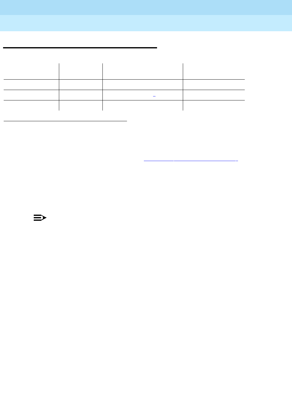
DEFINITY Enterprise Communications Server Release 6
Maintenance for R6r Volumes 1 & 2
555-230-126 Issue 2
January 1998
Maintenance Object Repair Procedures
Page 9-1537TIE-DS1 (DS1 Tie Trunk)
9
TIE-DS1 (DS1 Tie Trunk)
NOTE:
Many trunk problems are caused by incorrect settings of parameters on the
trunk group administration form. Settings must be compatible with the local
environment and with parameter settings on the far-end. Refer to
DEFINITY
Enterprise Communications Server Release 5.4 Administration and Feature
Description
, for information on how to administer trunks. The Application
Notes section of that book shows the correct settings for administrable
timers and other parameters on a country-by-country basis.
The DS1 tie trunk provides both voice and data communications between two
PBX switches. There are two types of DS1 interfaces:
■24 DS0 channels on a 1.544 Mbps link
■31 DS0 channels + 1 framing channel on a 2.048 Mbps link
32-channel mode is supported only on TN464 circuit packs and on G3r V2
systems.
DS1 Tie Trunks are used widely in the Distributed Communications System
(DCS) and Central Attendant Service (CAS) system features.
A DS1 tie trunk can also be used as an access endpoint which is a non-signaling
channel with bandwidth for voice-grade data, 56 Kbps data or 64 Kbps data.
1. For additional repair information, see DS1-BD documentation if the tie trunk is on a TN722 or
TN767 DS1 circuit pack. See UDS1-BD documentation if the tie trunk is on a TN464C/D UDS1
circuit pack.
2. A MAJOR alarm on a trunk indicates that alarms on these trunks are not downgraded by the
set options command and that at least 75% of the trunks in this trunk group are alarmed. For
more information on the set options command, see Chapter 8, ‘‘Maintenance Commands’’
3. For TN767B vintage 8 or 9 circuit packs, a failure of Test #136 causes a subsequent failure of
Test #7. Test #136 is part of the short sequence and generates off-board alarms Test #7 is part
of the long sequence and generates on-board alarms. Before entering busyout, release, reset
or test board long commands, check the vintage number of the circuit pack with list
configuration board UUCSS. If it is TN767B vintage 8 or 9, do not use the above commands
until first making sure that Test #136 passes via test board short. Otherwise, extraneous
on-board alarms may be generated.
MO Name (in
Alarm Log) Alarm Level Initial Command to Run Full Name of MO
TIE-DS11MAJOR2test trunk
grp/mbr
l3DS1 Tie Trunk
TIE-DS1 MINOR test trunk
grp/mbr
l3DS1 Tie Trunk
TIE-DS1 WARNING test trunk
grp/mbr
DS1 Tie Trunk

DEFINITY Enterprise Communications Server Release 6
Maintenance for R6r Volumes 1 & 2
555-230-126 Issue 2
January 1998
Maintenance Object Repair Procedures
Page 9-1538TIE-DS1 (DS1 Tie Trunk)
9
DS1 tie trunk maintenance provides a strategy to maintain a DS1 tie trunk via a
port on either the TN722 or TN767 DS1 Interface circuit pack or the TN464C/D
UDS1 Interface circuit pack. Throughout this TIE-DS1 section, the term DS1
Interface applies to DS1 and UDS1 circuit packs.
The DS1 tie trunk maintenance strategy covers logging DS1 tie trunk hardware
errors, running tests for trunk initialization, periodic and scheduled maintenance,
system technician-demanded tests, and alarm escalation and resolution. Three
different trunk service states are specified in DS1 tie trunk maintenance:
If the DS1 Interface circuit pack is out of service, then all trunks on the DS1
Interface circuit pack are also placed into the out-of-service state and a Warning
alarm is raised.
Out-of-service The trunk is deactivated and cannot be used for incoming or
outgoing calls.
In-service The trunk is activated and can be used for both incoming
and outgoing calls.
Disconnect
(ready-for-service) The trunk is in an activated state but can only be used for an
incoming call.

DEFINITY Enterprise Communications Server Release 6
Maintenance for R6r Volumes 1 & 2
555-230-126 Issue 2
January 1998
Maintenance Object Repair Procedures
Page 9-1539TIE-DS1 (DS1 Tie Trunk)
9
Hardware Error Log Entries and Test to Clear
Values
1. Run the Short Test Sequence first. If all tests pass, run the Long Test Sequence. Refer to the appropriate
test description and follow the recommended procedures.
2. For TN767B vintage 8 or 9 circuit packs, a failure of Test #136 causes a subsequent failure of Test #7.
Test #136 is part of the short sequence and generates off-board alarms. Test #7 is part of the long
sequence and generates on-board alarms. Before entering busyout, release, reset or test board long
commands, check the vintage number of the circuit pack with list configuration board UUCSS. If it is
TN767B vintage 8 or 9, do not use the above commands until first making sure that Test #136 passes
via test board short. Otherwise, extraneous on-board alarms may be generated.
Table 9-525. DS1 Tie Trunk Maintenance Error Log Entries
Error
Type Aux
Data Associated Test Alarm
Level On/Off
Board Test to Clear Value
010 Any Any Any test trunk
grp
/
mbr
1(a) 57476
57477
57485
57487
15(b) Any Port Audit and Update
Test (#36)
18(c) 0 busyout trunk
grp
/
mbr
WARNING OFF release trunk
grp
/
mbr
2
130(d) None WARNING ON test trunk
grp
/
mbr
257(e) 57473
57474
513(f) 57392 DS1 Tie Trunk Seizure
Test (#136) MIN/MAJ3
769(g) 57393 DS1 Tie Trunk Seizure
Test (#136) MIN/MAJ3
1025 DS1 Tie Trunk Seizure
(Test #136) MIN/ WRN4OFF test trunk
grp
/
mbr
r 2
1281 Conference Circuit
(Test #7) MIN/ WRN4ON test trunk
grp
/
mbr
l r 4 2
1537 NPE Crosstalk Test
(#6) MIN/ WRN4ON test trunk
grp
/
mbr
l r 3 2
1793(h) test board UUCSS long 2
2305(i) 50944 DS1 Tie Trunk Seizure
Test (#136) MIN/MAJ3OFF
2562(j) 16665
2817(k) 52992
3840(l) Any Port Audit and Update
(Test #36)

DEFINITY Enterprise Communications Server Release 6
Maintenance for R6r Volumes 1 & 2
555-230-126 Issue 2
January 1998
Maintenance Object Repair Procedures
Page 9-1540TIE-DS1 (DS1 Tie Trunk)
9
Notes:
a. Error Type 1—The DS1 Interface circuit pack detects a hardware error on
the DS1 tie trunk. This error can be caused by incompatible translations.
Make sure the parameters administered on the DS1 circuit pack form
match those administered on the far-end switch. See
DEFINITY
Communications System Generic 3 V2 Implementation,
555-230-653, and
DEFINITY Communications System Generic 2.2 and Generic 3 V2
DS1/CEPT/ISDN-PRI Reference
, 555-025-107, for details.
The Aux Data field indicates the following hardware error types:
If all administration errors between the switch and the far-end match, and
these errors continue to recur, follow normal escalation procedures.
b. Error Type 15—This is a software audit error that does not indicate any
hardware malfunction. Run Short Test Sequence and investigate
associated errors (if any).
c. Error Type 18—The DS1 tie trunk has been busied out by a busyout trunk
grp/mbr command. No calls can be made on this trunk except for the
Facility Access Test Call. Facility Access Test Calls are described in
Chapter 6 and in
DEFINITY Enterprise Communications Server Release
5.4 Administration and Feature Description
.
d. Error Type 130—This error type indicates that the circuit pack has been
removed or has been insane for more than 11-minutes. To clear the error,
reinsert or replace the circuit pack.
e. Error Type 257—The DS1 Interface circuit pack detects a hardware error
on the DS1 tie trunk. The trunk cannot communicate with the far end
because it is unable to interpret digits sent from the far-end switch. The
Aux Data field indicates the following:
Check with the far-end switch or operating company for proper trunk
connection.
3. This alarm will only be raised when the System-Parameter Country form has the Base Tone Generator
field set to 4 (Italy). This alarm will be a MINOR alarm unless 75% or more trunks in this trunk group are
out of service, then the alarm will be upgraded to a MAJOR alarm.
4. Major or Minor alarms on this MO may be downgraded to Warning alarms based on the values used in
the set options command.
57476 On-hook before wink
57477 On-hook before ready to receive digits
57485 Wink too short for valid signal
57487 The timer expired while waiting for an off-hook signal from
the far end as a response at end of digits dialing. Check
the far-end switch for related problems.
57473 The rotary dial rate is below 8 pulses per second.
57474 The rotary dial rate is above 12 pulses per second.

DEFINITY Enterprise Communications Server Release 6
Maintenance for R6r Volumes 1 & 2
555-230-126 Issue 2
January 1998
Maintenance Object Repair Procedures
Page 9-1541TIE-DS1 (DS1 Tie Trunk)
9
f. Error Type 513—DS1 Interface circuit pack detects a hardware error on
the DS1 tie trunk. The trunk is in-service/active and waiting for an
‘‘on-hook’’ from the far-end switch. No calls can be routed over the trunk
while it is in this state. Aux Data 57392 indicates no external release on
PBX disconnect. Check with the far-end switch or operating company for
proper trunk connection.
g. Error Type 769—The DS1 Interface circuit pack detects a hardware error
on the DS1 tie trunk. This error usually occurs after an occurrence of error
type 513. The trunk has received the belated ‘‘on-hook’’ that it has been
waiting for from the far-end switch. The trunk is restored to in-service/idle
and can be used for calls. Aux Data 57393 indicates delayed external
release on PBX disconnect. This error can be ignored.
h. Error Type 1793—The DS1 Interface circuit pack is out-of-service. See the
appropriate DS1-BD/UDS1-BD (DS1/UDS1 Interface Circuit Pack)
Maintenance documentation for details.
i. Error Type 2305—Reorder message. The trunk could not be seized. This
error causes the Trunk Seizure Test (#136) to run and is only a problem if
the Seizure Test fails (in which case Error Type 1025 also appears). In this
case, the trunk may be put in ‘‘Ready-for-Service’’ state (shown as
‘‘disconnected’’ by the status command), which allows only incoming
calls. Run the Trunk Seizure Test (#136) and follow its procedures.
j. Error Type 2562—Retry Failure error. This error is logged only. It is not a
hardware failure and hence does not start any testing or generate any
alarms. This error comes from call processing and is generated when a
second attempt (retry) to seize an outgoing trunk fails.
k. Error Type 2817—Glare error. This error is logged only. It is not a
hardware failure and hence does not start any testing or generate any
alarms. This error is the result of a simultaneous seizure of a two-way trunk
from both the near-end and the far-end. Attempt to place the call again. If
the error persists, execute the DS1 Tie Trunk Seizure Test (#136) and
follow its outlined procedures.
l. Error Type 3840—Port Audit and Update Test (#36) failed due to an
internal system error. Enter status trunk command and verify the status of
the trunk. If the trunk is out-of-service, then enter release trunk command
to put it back to in-service. Retry the test command.

DEFINITY Enterprise Communications Server Release 6
Maintenance for R6r Volumes 1 & 2
555-230-126 Issue 2
January 1998
Maintenance Object Repair Procedures
Page 9-1542TIE-DS1 (DS1 Tie Trunk)
9
System Technician-Demanded Tests:
Descriptions and Error Codes
Always investigate tests in the order presented in the table below when
inspecting errors in the system. By clearing error codes associated with the
NPE
Crosstalk Test
, for example, you may also clear errors generated from other tests
in the testing sequence.
For TN767B vintage 8 or 9 circuit packs, a failure of Test #136 causes a
subsequent failure of Test #7. Test #136 is part of the short sequence and
generates off-board alarms Test #7 is part of the long sequence and generates
on-board alarms. Before entering busyout, release, reset or test board long
commands, check the vintage number of the circuit pack with list configuration
board UUCSS. If it is TN767B vintage 8 or 9, do not use the above commands
until first making sure that Test #136 passes via test board short. Otherwise,
extraneous on-board alarms may be generated.
NPE Crosstalk Test (#6)
The NPE Crosstalk Test verifies that this port’s NPE channel talks on the selected
time slot and never crosses over to time slots reserved for other connections. If
the NPE is not working correctly, one-way and noisy connections may be
observed. This test is usually only part of a port’s Long Test Sequence and takes
on the order of 20 to 30 seconds to complete.
1. D = Destructive; ND = Nondestructive
Order of Investigation Short Test
Sequence Long Test
Sequence D/ND1
NPE Crosstalk Test (#6) X ND
Conference Circuit Test (#7) X ND
DS1 Tie Trunk Seizure Test (#136) X X ND
Port Audit and Update Test (#36) X X ND
Table 9-526. TEST #6 NPE Crosstalk Test
Error
Code Test
Result Description/ Recommendation
ABORT System resources required for this test are not available.
1. Retry the command at 1-minute intervals a maximum of 5 times.
Continued on next page

DEFINITY Enterprise Communications Server Release 6
Maintenance for R6r Volumes 1 & 2
555-230-126 Issue 2
January 1998
Maintenance Object Repair Procedures
Page 9-1543TIE-DS1 (DS1 Tie Trunk)
9
1000 ABORT System resources required to run this test were not available. The port may be
busy with a valid call. Use the display port UUCSSpp command to determine
the trunk group/member number of the port. Use the status trunk command to
determine the service state of the port. If the service state indicates that the port
is in use, then the port is unavailable for certain tests. You must wait until the
port is idle before retesting.
1. If the port status is active but the port is not in use (no calls), check the error
log for error type 1025 (see the error log table for a description of this error
and required actions). The port may be locked up.
2. If the port status is idle, retry the command at 1-minute intervals for a
maximum of 5 times.
1001 ABORT System resources required to run this test are not available.
1. Retry the command at 1-minute intervals for a maximum of 5 times.
1002 ABORT The system could not allocate time slots for the test. The system may be under
heavy traffic conditions, or it may have time slots out of service due to TDM-BUS
errors. Refer to “TDM-BUS” to diagnose TDM-BUS errors.
1. If the system has no TDM-BUS errors and is not handling heavy traffic and
the port status is idle, retry the command at 1-minute intervals for a
maximum of 5 times.
1003 ABORT The system could not allocate a tone receiver for the test. The system may be
oversized for the number of tone detectors present or some of the tone
detectors may be out of service. Issue the list measurements tone-receiver
command to display basic information about the system's tone receivers.
1. Look for TTR-LEV errors in the error log. If present, refer to the TTR-LEV
Maintenance documentation.
2. Look for TONE-PT errors in the error log. If present, refer to the TONE-PT
Maintenance documentation.
3. If neither condition exists, retry the test at 1-minute intervals for a maximum
of 5 times.
1004 ABORT The port was seized by a user for a valid call. Use the display port UUCSSpp
command to determine the trunk group/member number of the port. Use the
status trunk command to determine the service state of the port. If the service
state indicates that the port is in use, then the port is unavailable for certain
tests. You must wait until the port is idle before retesting.
1. If the port status is idle, retry the command at 1-minute intervals for a
maximum of 5 times.
Table 9-526. TEST #6 NPE Crosstalk Test — Continued
Error
Code Test
Result Description/ Recommendation
Continued on next page

DEFINITY Enterprise Communications Server Release 6
Maintenance for R6r Volumes 1 & 2
555-230-126 Issue 2
January 1998
Maintenance Object Repair Procedures
Page 9-1544TIE-DS1 (DS1 Tie Trunk)
9
1020 ABORT The test did not run because of a previously existing error on the specific port or
a more general circuit pack error.
1. Examine the Error Log for existing errors against this port or the circuit pack
and attempt to diagnose the already existing error.
2000 ABORT Response to the test request was not received within the allowable time period.
2100 ABORT System resources required for this test are not available.
1. Retry the command at 1-minute intervals a maximum of 5 times.
2053 ABORT At least one of the following errors is found on the DS1 circuit pack:
■1281—Loss of signal
■1793—Blue Alarm
■2049—Red Alarm
■2305—Yellow Alarm
■1537—Hyperactivity
Look for the above error types in the Hardware Error Log and follow the
procedures given in the appropriate DS1-BD or UDS1-BD maintenance
documentation for the listed error types.
FAIL This can be due to on-board or off-board problems. Off-board problems of
concern include EXP-PN and EXP-INTF faults, TDM-BUS faults, and faults
associated with the tone detectors/tone generators. Clear all off-board problems
before replacing the board. Keep in mind that a TDM-BUS problem is usually
the result of a faulty board connected to the backplane or bent pins on the
backplane.
1. Look for EXP-PN and/or EXP-INTF errors in the error log. If present, refer to
the EXP-PN Maintenance documentation and the EXP-INTF Maintenance
documentation.
2. Look for TDM-BUS errors in the error log. If present, refer to the TDM-BUS
Maintenance documentation.
3. Look for TONE-BD and/or TONE-PT errors in the error log. If present, refer to
the TONE-BD Maintenance documentation and the TONE-PT Maintenance
documentation.
4. Retest when the faults from steps 1, 2, and 3 are cleared. Replace the
board only if the test fails.
PASS The port is correctly using its allocated time slots. User-reported troubles on this
port should be investigated using other port tests and by examining station,
trunk, or external wiring.
Table 9-526. TEST #6 NPE Crosstalk Test — Continued
Error
Code Test
Result Description/ Recommendation
Continued on next page

DEFINITY Enterprise Communications Server Release 6
Maintenance for R6r Volumes 1 & 2
555-230-126 Issue 2
January 1998
Maintenance Object Repair Procedures
Page 9-1545TIE-DS1 (DS1 Tie Trunk)
9
Conference Circuit Test (#7)
One or more Network Processing Elements (NPEs) reside on each circuit pack
with a TDM Bus interface. (The TN464C/D UDS1 circuit pack has one
SCOTCH-NPE chip instead of several NPE chips). The NPE controls port
connectivity and gain, and provides conferencing functions on a per-port basis.
The Conference Circuit Test verifies that the NPE channel for the port being
tested can correctly perform the conferencing function. The NPE is instructed to
listen to several different tones and conference the tones together. The resulting
signal is then measured by a Tone Detector port. If the level of the tone is within a
certain range, the test passes.
0NO
BOARD The test could not relate the internal ID to the port (no board). This could be due
to incorrect translations, no board is inserted, an incorrect board is inserted, or
an insane board is inserted.
1. Check to ensure that the board translations are correct. Use the list config
command, and resolve any problems that are found.
2. If the board was found to be correctly inserted in step 1, issue the busyout
board command.
3. Issue the reset board command.
4. Issue the release busy board command.
5. Issue the test board long command. This should re-establish the linkage
between the internal ID and the port. If this is not the case, check to see that
there is a valid board inserted.
Table 9-527. TEST #7 Conference Circuit Test
Error
Code Test
Result Description/ Recommendation
ABORT System resources required for this test are not available.
1. Retry the command at 1-minute intervals a maximum of 5 times.
Continued on next page
Table 9-526. TEST #6 NPE Crosstalk Test — Continued
Error
Code Test
Result Description/ Recommendation
Continued on next page

DEFINITY Enterprise Communications Server Release 6
Maintenance for R6r Volumes 1 & 2
555-230-126 Issue 2
January 1998
Maintenance Object Repair Procedures
Page 9-1546TIE-DS1 (DS1 Tie Trunk)
9
1000 ABORT System resources required to run this test were not available. The port may be
busy with a valid call. Use the display port UUCSSpp command to determine
the trunk group/member number of the port. Use the status trunk command to
determine the service state of the port. If the service state indicates that the
port is in use, then the port is unavailable for certain tests. You must wait until
the port is idle before retesting.
1. If the port status is active but the port is not in use (no calls), check the
error log for error type 1025 (see the error log table for a description of this
error and required actions). The port may be locked up.
2. If the port status is idle, retry the command at 1-minute intervals for a
maximum of 5 times.
1002 ABORT The system could not allocate time slots for the test. The system may be under
heavy traffic conditions, or it may have time slots out of service due to
TDM-BUS errors. The status health command can be used to determine if the
system is experiencing heavy traffic. Refer to the TDM-BUS (TDM bus)
Maintenance Documentation to diagnose any active TDM-BUS errors.
1. If the system has no TDM-BUS errors and is not handling heavy traffic and
the port status is idle, retry the command at 1-minute intervals for a
maximum of 5 times.
1003 ABORT The system could not allocate a tone receiver for the test. The system may be
oversized for the number of tone detectors present or some of the tone
detectors may be out of service. Issue the list measurements tone-receiver
command to display basic information about the system’s tone receivers.
1. Look for TTR-LEV errors in the error log. If present, refer to the TTR-LEV
Maintenance documentation.
2. Look for TONE-PT errors in the error log. If present, refer to the TONE-PT
Maintenance documentation.
3. If neither condition exists, retry the test at 1-minute intervals for a maximum
of 5 times.
1004 ABORT The port was seized by a user for a valid call. Use the display port UUCSSpp
command to determine the trunk group/member number of the port. Use the
status trunk command to determine the service state of the port. If the service
state indicates that the port is in use, then the port is unavailable for certain
tests. You must wait until the port is idle before retesting.
1. If the port status is idle, retry the command at 1-minute intervals for a
maximum of 5 times.
1018 ABORT Test disabled via administration. This only applies to analog stations.
1. To enable test, set the Test field on the station administration screen for the
particular analog station being tested to ‘‘y.’’ Use the change station
extension
command.
Table 9-527. TEST #7 Conference Circuit Test — Continued
Error
Code Test
Result Description/ Recommendation
Continued on next page

DEFINITY Enterprise Communications Server Release 6
Maintenance for R6r Volumes 1 & 2
555-230-126 Issue 2
January 1998
Maintenance Object Repair Procedures
Page 9-1547TIE-DS1 (DS1 Tie Trunk)
9
1020 ABORT The test did not run due to a previously existing error on the specific port or
because of a more general circuit pack error.
1. Examine the Error Log for existing errors against this port or circuit pack,
and attempt to diagnose the previously existing error.
2000 ABORT Response to the test request was not received within the allowable time period.
2100 ABORT System resources required to run this test are not available.
1. Retry the command at 1-minute intervals a maximum of 5 times.
2053 ABORT At least one of the following errors is found on the DS1 circuit pack: 1281—
Loss of signal,1793—Blue Alarm, 2049—Red Alarm, 2305—Yellow Alarm, or
1537—Hyperactivity.
Look for the above error types in the Hardware Error Log and follow the
procedures given in the appropriate DS1-BD or UDS1-BD maintenance
documentation for the listed error types.
Table 9-527. TEST #7 Conference Circuit Test — Continued
Error
Code Test
Result Description/ Recommendation
Continued on next page
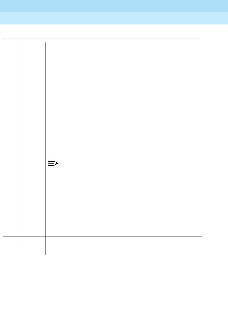
DEFINITY Enterprise Communications Server Release 6
Maintenance for R6r Volumes 1 & 2
555-230-126 Issue 2
January 1998
Maintenance Object Repair Procedures
Page 9-1548TIE-DS1 (DS1 Tie Trunk)
9
FAIL The NPE of the tested port did not conference the tones correctly. This can
cause noisy and unreliable connections.
1. Enter the list configuration board UUCSS command. If the circuit pack is
a TN767B vintage 8 or 9, replace the circuit pack with a TN767C V3 or
later. The error log may have error type 1281 entries.
2. Test all administered trunks on the board. If one fails, this could be an
off-board problem (such as an incoming seizure or an off-hook port
seizure during the test). Retest the board.
3. If all of the ports fail, check the CARR-POW (see note below).
4. If several ports fail, check the error log for TONE-BD or TONE-PT errors. If
there are such errors, take the appropriate action. When the TONE errors
have cleared, rerun the test.
5. If the retry passes and troubles have been reported, coordinate isolation
with the far-end PBX. Make sure that the near-end and far-end switches
and any NTCE equipment (the CSUs) have the correct administration.
6. Replace the circuit pack.
NOTE:
If the conference circuit test fails for all ports on a circuit pack, a -5 volt
power problem is indicated. If a TN736 or TN752 power unit circuit pack
is present, either the 631DB AC power unit or the 676B DC power unit
may be defective. (The 631DB power unit is used in a medium cabinet
powered by an AC source. The 645B power unit is used in a medium
cabinet powered by a DC power source.) The system may contain a
TN736 or TN752 power unit or a 631DB AC power unit, but not both
types of power units. To investigate problems with a 631DB AC power
unit, refer to the CARR-POW (carrier port power unit for AC-powered
systems) Maintenance documentation. To investigate problems with a
645B DC power unit, refer to the CARR-POW (carrier port power unit for
DC-powered systems) Maintenance documentation. If a red LED on
TN736 or TN752 power unit circuit pack is on, replace the pack.
PASS The port can correctly conference multiple connections. User-reported
troubles on this port should be investigated using other port tests and by
examining station, trunk, or external wiring.
Table 9-527. TEST #7 Conference Circuit Test — Continued
Error
Code Test
Result Description/ Recommendation
Continued on next page

DEFINITY Enterprise Communications Server Release 6
Maintenance for R6r Volumes 1 & 2
555-230-126 Issue 2
January 1998
Maintenance Object Repair Procedures
Page 9-1549TIE-DS1 (DS1 Tie Trunk)
9
Port Audit and Update Test (#36)
This test sends port level translation data from switch processor to the DS1
Interface circuit pack to ensure that the trunk’s translation is correct. Translation
updates include the following data: trunk type (in/out), dial type, timing
parameters, and signaling bits enabled. The port audit operation verifies the
consistency of the current state of the trunk kept by the DS1 Interface circuit
pack and the switch software.
0NO
BOARD The test could not relate the internal ID to the port (no board). This could be
due to incorrect translations, no board is inserted, an incorrect board is
inserted, or an insane board is inserted.
1. Check to ensure that the board translations are correct. Use the list config
command, and resolve any problems that are found.
2. If the board was found to be correctly inserted in step 1, issue the busyout
board command.
3. Issue the reset board command.
4. Issue the release busy board command.
5. Issue the test board long command. This should re-establish the linkage
between the internal ID and the port. If this is not the case, check to see
that there is a valid board inserted.
Table 9-528. TEST #36 Audit and Update Test
Error
Code Test
Result Description/ Recommendation
ABORT Internal system error
1. Retry the command at 1-minute intervals a maximum of 5 times.
Continued on next page
Table 9-527. TEST #7 Conference Circuit Test — Continued
Error
Code Test
Result Description/ Recommendation
Continued on next page

DEFINITY Enterprise Communications Server Release 6
Maintenance for R6r Volumes 1 & 2
555-230-126 Issue 2
January 1998
Maintenance Object Repair Procedures
Page 9-1550TIE-DS1 (DS1 Tie Trunk)
9
1000 ABORT System resources required to run this test were not available. The port may be
busy with a valid call. Use the display port UUCSSpp command to determine
the trunk group/member number of the port. Use the status trunk command to
determine the service state of the port. If the service state indicates that the
port is in use, then the port is unavailable for certain tests. You must wait until
the port is idle before retesting.
1. If the port status is active but the port is not in use (no calls), check the
error log for error type 1025 (see the error log table for a description of this
error and required actions). The port may be locked up.
2. If the port status is idle, retry the command at 1-minute intervals for a
maximum of 5 times.
1006 ABORT The test was aborted because the trunk is out of service.
1. Use the status trunk command to verify that the trunk is out of service.
2. If the trunk is out of service, determine why.
3. If it is OK to put the trunk back in service, issue the release trunk
command to put the trunk back in service, and then retry the test.
2000 ABORT Response to the test request was not received within the allowable time period.
2100 ABORT Could not allocate the necessary system resources to run this test.
1. Retry the command at 1-minute intervals a maximum of 5 times.
FAIL Internal system error.
1. Retry the command at 1-minute intervals a maximum of 5 times.
PASS Trunk translation has been updated successfully. The current trunk states kept
in the DS1 Interface circuit pack and switch software are consistent. If the trunk
is busied out, the test will not run but will return PASS. To verify that the trunk is
in-service:
1. Enter the status trunk command to verify that the trunk is in-service. If the
trunk is in-service, no further action is necessary. If the trunk is
out-of-service, continue to step 2.
2. Enter the release trunk command to put the trunk back into in-service.
3. Retry the test command.
Table 9-528. TEST #36 Audit and Update Test — Continued
Error
Code Test
Result Description/ Recommendation
Continued on next page

DEFINITY Enterprise Communications Server Release 6
Maintenance for R6r Volumes 1 & 2
555-230-126 Issue 2
January 1998
Maintenance Object Repair Procedures
Page 9-1551TIE-DS1 (DS1 Tie Trunk)
9
DS1 Tie Trunk Seizure Test (#136)
The DS1 Tie Trunk Seizure Test is run to verify the trunk’s signaling capability.
The test is composed of two parts. The first part queries the circuit pack for the
following errors: Loss of Signal, Red Alarm, Blue Alarm, Yellow Alarm, and
Hyperactivity Alarm. The second part of the test is performed by sending a
seizure message to the DS1 Interface circuit pack and expecting an active reply
by the DS1 Interface circuit pack. If maintenance software does not receive any
reply and the timer expires, the test fails. Once the active message is received, a
dial pause message is sent to the DS1 Interface circuit pack. If the DS1 Interface
circuit pack replies with a dial pulse tone message when the far end responds to
the seizure, then the DS1 tie trunk Seizure Test passes. If the far end does not
respond to the seizure and the timer expires, and the DS1 Interface circuit pack
sends a reorder message back to the maintenance software, then the test fails.
This second part of this test
cannot
be run on a trunk if one of the following cases
is true:
1. The trunk direction is administered as an incoming only trunk.
2. The trunk is the 24th port on a DS1 Interface circuit pack which is
administered using 24th Common Channel Signaling.
3. The trunk has been seized by a normal trunk call.
4. The trunk is administered with maintenance test disabled.
5. The outgoing signal type of the trunk is either automatic or
immediate-start.
0NO
BOARD The test could not relate the internal ID to the port (no board). This could be
due to incorrect translations, no board is inserted, an incorrect board is
inserted, or an insane board is inserted.
1. Check to ensure that the board translations are correct. Use the list config
command, and resolve any problems that are found.
2. If the board was found to be correctly inserted in step 1, issue the busyout
board command.
3. Issue the reset board command.
4. Issue the release busy board command.
5. Issue the test board long command. This should re-establish the linkage
between the internal ID and the port. If this is not the case, check to see
that there is a valid board inserted.
Table 9-528. TEST #36 Audit and Update Test — Continued
Error
Code Test
Result Description/ Recommendation
Continued on next page

DEFINITY Enterprise Communications Server Release 6
Maintenance for R6r Volumes 1 & 2
555-230-126 Issue 2
January 1998
Maintenance Object Repair Procedures
Page 9-1552TIE-DS1 (DS1 Tie Trunk)
9
Table 9-529. TEST #136 DS1 Tie Trunk Seizure Test
Error
Code Test Result Description/ Recommendation
ABORT Internal system error
1. Retry the command at 1-minute intervals a maximum of 5 times.
1000 ABORT System resources required to run this test were not available. The port may
be busy with a valid call. Use the display port UUCSSpp command to
determine the trunk group/member number of the port. Use the status
trunk command to determine the service state of the port. If the port is in
use, wait until the port is idle before testing.
1. If the port status is active but the port is not in use (no calls), check the
error log for error type 1025 (see the error log table for a description of
this error and required actions). The port may be locked up.
2. If the port status is idle, retry the command at 1-minute intervals for a
maximum of 5 times.
1004 ABORT Far end is seizing the trunk while the test is ongoing. A glare situation is
detected. Current test is designed to be aborted. Use the display port
UUCSSpp command to determine the trunk group/member number of the
port. Use the status trunk command to determine the service state of the
port. If the port is in use, wait until the port is idle before testing.
1. If the port status is idle, retry the command at 1-minute intervals for a
maximum of 5 times.
1005 ABORT Test failed due to incompatible configuration administered in trunk group
form.
1. Verify the following fields on the trunk group administration screen:
a. Is trunk direction incoming only?
b. Is trunk outgoing type either automatic or immediate-start?
c. Is trunk the 24th port of the DS1 Interface circuit pack while common
control channel signaling is specified?
2. If the trunk has been administered using the above information, then
this test should abort.
1018 ABORT The test was disabled via translation. You may want to determine why the
test has been disabled before you enable it.
1. Verify that the ’Maintenance Test’ field on the ’Trunk Administration’
screen is set to ’n.’ To enable the test, change the trunk administration
and enter ’y’ into the ’Maintenance Test’ field.
2. Repeat the test.
Continued on next page

DEFINITY Enterprise Communications Server Release 6
Maintenance for R6r Volumes 1 & 2
555-230-126 Issue 2
January 1998
Maintenance Object Repair Procedures
Page 9-1553TIE-DS1 (DS1 Tie Trunk)
9
1020 ABORT The test did not run due to an already existing error on the specific port or
due to a more general circuit pack error.
1. Examine the error log for existing errors against this port or the circuit
pack and attempt to diagnose the already existing error.
2. Retry the test.
1040 ABORT The test is invalid for this trunk port because it is administered as an access
endpoint.
1. Use display port to verify that this port is administered as an access
endpoint. In this case the test should abort.
2000 ABORT Response to the test request was not received within the allowable time
period.
1. Retry the command at 1-minute intervals for a maximum of 5 times.
2053 ABORT/
FAIL1At least one of the following errors is found on the DS1 circuit pack: 1281:
Loss of Signal 1793: Blue Alarm 2049: Red Alarm 2305: Yellow Alarm 1537:
Hyperactivity
1. Look for the above error types in the Hardware Error Log and follow the
procedures given in the appropriate DS1-BD/UDS1-BD Maintenance
documentation for the listed error types.
2100 ABORT Could not allocate the necessary system resources to run this test.
1. Retry the command at 1-minute intervals for a maximum of 5 times.
FAIL The far-end trunk did not respond to the seizure of the near-end trunk within
the allowable time period. This test could have associated in-line errors in
the error log.
1. Enter the list configuration board UUCSS command. If the circuit
pack is a TN767B vintage 8 or 9, a failure of test 136 causes a
subsequent failure of test 7 due to a firmware bug. Eventually, the
board and all of its ports will be taken out of service and extraneous
on-board alarms will be generated. Replace the circuit pack with a
TN767C V3 or later.
2. Verify that the ’Trunk Type’ field on the ’Trunk Administration’ screen
matches the trunk type administered on far-end switch.
3. Look for DS1-BD or UDS1-BD errors in the hardware error log. If
present, refer to the DS1-BD (DS1 trunk circuit pack) Maintenance
documentation or to the UDS1-BD (UDS1 trunk circuit pack)
Maintenance documentation.
4. Retry the test at 1-minute intervals for a maximum of 5 times.
Table 9-529. TEST #136 DS1 Tie Trunk Seizure Test — Continued
Error
Code Test Result Description/ Recommendation
Continued on next page

DEFINITY Enterprise Communications Server Release 6
Maintenance for R6r Volumes 1 & 2
555-230-126 Issue 2
January 1998
Maintenance Object Repair Procedures
Page 9-1554TIE-DS1 (DS1 Tie Trunk)
9
1. Earlier G1 Software Versions reported Error Code 2053 as a FAIL
2000 FAIL Response to the seizure message was not received within the allowable
time period.
1. Enter the list configuration board UUCSS command. If the circuit
pack is a TN767B vintage 8 or 9, a failure of test 136 causes a
subsequent failure of test 7 due to a firmware bug. Eventually, the
board and all of its ports will be taken out of service and extraneous
on-board alarms will be generated. Replace the circuit pack with a
TN767C V3 or later.
2. Verify that the ’Trunk Type’ field on the ’Trunk Administration’ screen
matches the trunk type administered on far-end switch.
3. Look for DS1-BD or UDS1-BD errors in the hardware error log. If
present, refer to the DS1-BD (DS1 trunk circuit pack) Maintenance
documentation or to the UDS1-BD (UDS1 trunk circuit pack)
Maintenance documentation.
4. Retry the test at 1-minute intervals for a maximum of 5 times.
PASS The trunk can be seized for an outgoing call.
0 NO BOARD The test could not relate the internal ID to the port (no board). This could be
due to incorrect translations, no board is inserted, an incorrect board is
inserted, or an insane board is inserted.
1. Check to ensure that the board translations are correct. Use the list
config command, and resolve any problems that are found.
2. If the board was found to be correctly inserted in step 1, issue the
busyout board command.
3. Issue the reset board command.
4. Issue the release busy board command.
5. Issue the test board long command. This should re-establish the
linkage between the internal ID and the port. If this is not the case,
check to see that there is a valid board inserted.
Table 9-529. TEST #136 DS1 Tie Trunk Seizure Test — Continued
Error
Code Test Result Description/ Recommendation
Continued on next page
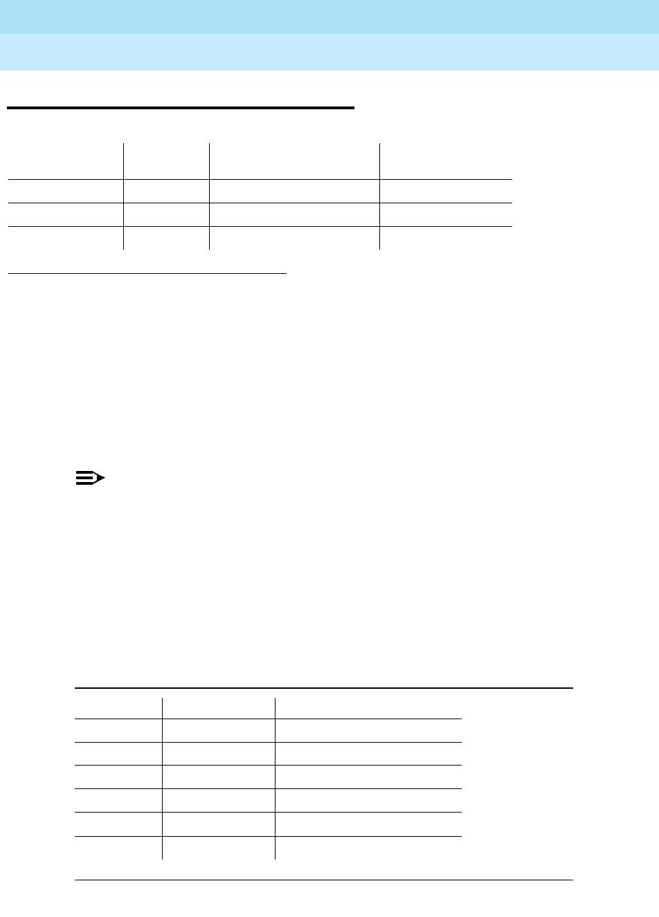
DEFINITY Enterprise Communications Server Release 6
Maintenance for R6r Volumes 1 & 2
555-230-126 Issue 2
January 1998
Maintenance Object Repair Procedures
Page 9-1555TIE-TRK (Analog Tie Trunk)
9
TIE-TRK (Analog Tie Trunk)
NOTE:
Many trunk problems are caused by incorrect settings of parameters on the
trunk group administration form. Settings must be compatible with the local
environment and with parameter settings on the far-end. Refer to
DEFINITY
Communications System Generic 3 V2 Implementation
, 555-230-653, for
information on how to administer trunks. The Application Notes section of
that book shows the correct settings for administrable timers and other
parameters on a country-by-country basis.
The following circuit packs, including all suffixes such as TN760D, support
analog tie trunks:
1.
UU
is the universal cabinet number (1 for PPN, 2 - 44 for EPNs).
C
is the carrier
designation (A, B, C, D, or E).
SS
is the number of the slot in which the circuit pack
resides (01 to 21).
pp
is the two digit port number (01, 02, ...).
2. If ATMS testing is enabled, check the error log for ATMS errors 3840 and 3841. If the
error log indicates that measurements exceeded acceptable thresholds, and no other
trouble is found with test trunk, run the ATMS test call with test analog-testcall port
UUCSSpp full.
3. A Major alarm on a trunk indicates that alarms on these trunks are not downgraded by
the set options command and that at least 75 percent of the trunks in this trunk group
are alarmed.
This alarm does not apply to TN497.
MO Name (in
Alarm Log) Alarm
Level Initial Command to Run12 Full Name of MO
TIE-TRK MAJOR3test port UUCSSpp l Tie Trunk
TIE-TRK MINOR test port UUCSSpp l Tie Trunk
TIE-TRK WARNING test port UUCSSpp sh Tie Trunk
Table 9-530. Analog Tie Trunk Circuit Packs
Code Trunk Type Signaling Leads
TN760 4-wire E&M
TN437 4-wire E&M
TN439 2-wire A&B (two-way circuits only)
TN458 4-wire E&M
TN497 2-wire A&B
TN2140 4-wire E&M

DEFINITY Enterprise Communications Server Release 6
Maintenance for R6r Volumes 1 & 2
555-230-126 Issue 2
January 1998
Maintenance Object Repair Procedures
Page 9-1556TIE-TRK (Analog Tie Trunk)
9
Each tie trunk circuit pack occupies a port circuit pack slot and contains 4 port
circuits. Each port circuit supports 1 analog tie trunk used to connect the switch
to another PBX across one-way or two-way dedicated circuits (see preceding
list).
A tie trunk port can also be administered as an access endpoint which is a
non-signaling channel with a voice-grade data bandwidth. Tie trunk maintenance
employs up to 6 tests, depending on the hardware involved, to monitor the
operating condition of the trunk and its connections. These are described in the
following sections on each test. The port must be idle for these tests to run. If an
incoming call seizes the port while a test is in progress, the test aborts and the
call proceeds (except for TN497).
Additional in-line testing is performed whenever a call is in progress, logging
errors that occur during operation. You can reproduce these types of errors by
making a call over the trunk and then checking the Hardware Error Log.
By making translation and cross-connect changes, circuit packs (except for
TN497) can be configured for back-to-back testing, also known as connectivity
testing. Port operation is tested by connecting two tie trunk ports together in
either E&M or simplex modes. See the section
Analog Tie Trunk Back-to-Back
Testing
.
Error Log Entries and Test to Clear Values
Table 9-531. TIE Trunk Error Log Entries
Error
Type Aux
Data Associated Test Alarm Level On/Off
Board Test to Clear Value
010 Any Any Any test port
UUCSSpp
sh r 1
1(a) 16384 None WARNING OFF
1(b) 57476 None WARNING OFF
1(c) 57477 None WARNING OFF
1(d) 57483 None WARNING OFF
1(e) 57485 None WARNING OFF
15(f) Any Port Audit Update
Test (#36)
18(g) 0 busyout trunk
grp/mbr
WARNING OFF release trunk
grp/mbr
130(h) None WARNING ON test trunk
grp/mbr
257(i) 57473 None WARNING OFF
Continued on next page
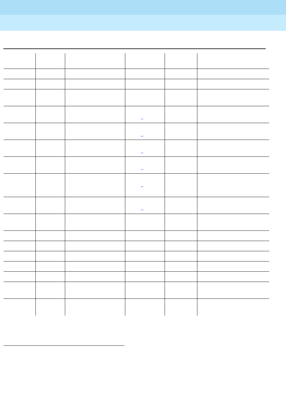
DEFINITY Enterprise Communications Server Release 6
Maintenance for R6r Volumes 1 & 2
555-230-126 Issue 2
January 1998
Maintenance Object Repair Procedures
Page 9-1557TIE-TRK (Analog Tie Trunk)
9
1. Run the Short Test Sequence first. If all tests pass, run the Long Test Sequence. Refer to the appropriate
test description and follow the recommended procedures.
2. Minor alarms on this MO may be downgraded to Warning alarms based on the values used in the set
options command. If the MINOR alarm is not downgraded by the set options values, then the MINOR
alarm will be upgraded to a MAJOR alarm if 75% of the trunks in this trunk group are alarmed. These errors,
if applicable, always log a MINOR alarm for TN439 and TN497.
257(j) 57474 None WARNING OFF
257(k) 57475 None WARNING OFF
513(l) Any EPF M and E Lead
(#74) MAJ/MIN/
WRN2OFF test port
UUCSSpp
sh r 3
769(l) 57481 EPF M and E Lead
(#74) MAJ/MIN/
WRN2ON test port
UUCSSpp
sh r 3
1025(m) Any None MAJ/MIN/
WRN2OFF
1281(l) Any EPF M and E Lead
(#74) MAJ/MIN/
WRN2ON test port
UUCSSpp
sh r 3
1537 Looparound and
Conference (#33) MAJ/MIN/
WRN2ON test port
UUCSSpp
l r 3
1793 Tie Trunk Seizure
(#73) (Dial Test #747
for TN439)
MAJ/MIN/
WRN2OFF test port
UUCSSpp
sh r 2
2049 NPE Crosstalk (#6) MAJ/MIN/
WRN2ON test port
UUCSSpp
l r 3
2305(n) 57424
50944 None (l)
2561(o) 0 None WARNING OFF
2562(p) 16665
2817(o) 0 None MINOR OFF
2817(q) 52992
3073(o) 0 None
3840(r) 8000 Transmission Tests
(ATMS)(#844-848) OFF test analog-testcall
3841(r) Transmission Tests
(ATMS)(#844-848) MINOR OFF test analog-testcall
UUCSSpp r 2
Table 9-531. TIE Trunk Error Log Entries — Continued
Error
Type Aux
Data Associated Test Alarm Level On/Off
Board Test to Clear Value
Continued on next page

DEFINITY Enterprise Communications Server Release 6
Maintenance for R6r Volumes 1 & 2
555-230-126 Issue 2
January 1998
Maintenance Object Repair Procedures
Page 9-1558TIE-TRK (Analog Tie Trunk)
9
Notes:
a. Digit time-out. This occurs when the far-end PBX began transmitting digits
too late (10 seconds) after receiving the signal indicating ready to receive
digits (if any). This can occur on an incoming immediate, wink, or delay
dial line. Check the far-end PBX to ensure a translation match at both
ends. This error does not apply to TN497.
b. Rotary dial before wink. This occurs when the far-end PBX starts dialing
before the PBX sends the wink on a wink-start or delay-dial trunk. Check
the far-end PBX to ensure a translation match at both ends. This error
does not apply to TN497.
c. Rotary dial too early. This occurs when the far-end PBX starts dialing too
soon (about 50ms) after seizure on a wink start or delay dial line. Check
the far-end PBX to ensure a translation match at both ends. This error
does not apply to TN497.
d. On hook before wink. This occurs when the far end goes on hook before a
wink. Check the far-end PBX to ensure a translation match at both ends.
This error applies only to TN439.
e. On an outgoing wink-start or delay-dial trunk, the wink time was too short
(less than 80ms) for a valid signal. Check the far-end PBX to ensure a
translation match at both ends. This error does not apply to TN497.
f. This is a software audit error that does not indicate any hardware
malfunction. Run Short Test Sequence and investigate associated errors
(if any).
g. This indicates that the trunk in question has been busied-out by
maintenance personnel.
h. The circuit pack has been removed or has been insane for more than
11-minutes. To clear the error, reinsert or replace the circuit pack. TN439
does not alarm this error. This error does not apply to TN497.
i. The rotary dial rate was too slow — less than 8 pulses per second. Check
the far-end PBX to ensure a translation match at both ends.
j. The rotary dial rate was too fast — above 12 pulses per second. Check
the far-end PBX to ensure a translation match at both ends.
k. The time between digits was too short (less than 300ms). Check the
far-end PBX to ensure a translation match at both ends.
l. These errors do not apply to TN439 and TN497.
m. This indicates that the trunk is still seized with an incoming call. The
far-end PBX is not releasing the trunk after the call was dropped. Check
the far-end PBX for problems.
Once the trunk is released from the call, the severity of this problem is
decreased. If Error Type 1025 does not appear again, this means that the
problem has been corrected. Verify that Error Type 1025 does not
reappear in the Error Log.

DEFINITY Enterprise Communications Server Release 6
Maintenance for R6r Volumes 1 & 2
555-230-126 Issue 2
January 1998
Maintenance Object Repair Procedures
Page 9-1559TIE-TRK (Analog Tie Trunk)
9
n. Reorder message. The trunk could not be seized. This error causes the
Tie Trunk Seizure Test (#73) to run and is considered a problem only if that
test fails, logging error 1793. In this case, the trunk may be placed in the
ready-for-service state, allowing only incoming calls. This service state
shows up as disconnected on the trunk status screen. Run the Tie Trunk
Seizure Test and follow recommended procedures.
TN439 logs aux data 57424 or 50944. Other circuit packs log 50944. This
error is associated with Test #747 for TN439, Test #73 for TN497, and no
test for the others.
o. These errors apply only to TN497.
p. Retry Failure error. This error is logged only. It is not a hardware failure
and hence does not start any testing or generate any alarms. This error
comes from call processing and is generated when a second attempt
(retry) to seize an outgoing trunk fails.
q. Glare error. This error is logged only. It is not a hardware failure and hence
does not start any testing or generate any alarms. This error is the result of
a simultaneous seizure of a two-way trunk from both the near-end and the
far-end. Attempt to place the call again. If the error persists, execute the
Tie Trunk Seizure Test (#73) and follow its outlined procedures.
r. Error 3841 indicates that test calls made by the Automatic Transmission
Measurement System (ATMS) returned measurements in the
unacceptable range. Error 3840 indicates measurements were in the
marginal range. Use list testcall detail to examine the specific
transmission parameters which are out of spec, and investigate the trunk
for that kind of noise. If the noise is acceptable, then the AMTS thresholds
administered on page 4 of the trunk group form should be changed.
System Technician-Demanded Tests:
Descriptions and Error Codes
Always investigate tests in the order presented in Table 9-532 when inspecting
errors in the system. By clearing error codes associated with the
NPE Crosstalk
Test
for example, you may also clear errors generated from other tests in the
testing sequence.
Table 9-532. System Technician-Demanded Tests: TIE-TRK
Order of Investigation Short Test
Sequence Long Test
Sequence D/ND1
NPE Crosstalk Test (#6) X ND
Looparound and Conference Circuit Test (#33) X ND
Continued on next page
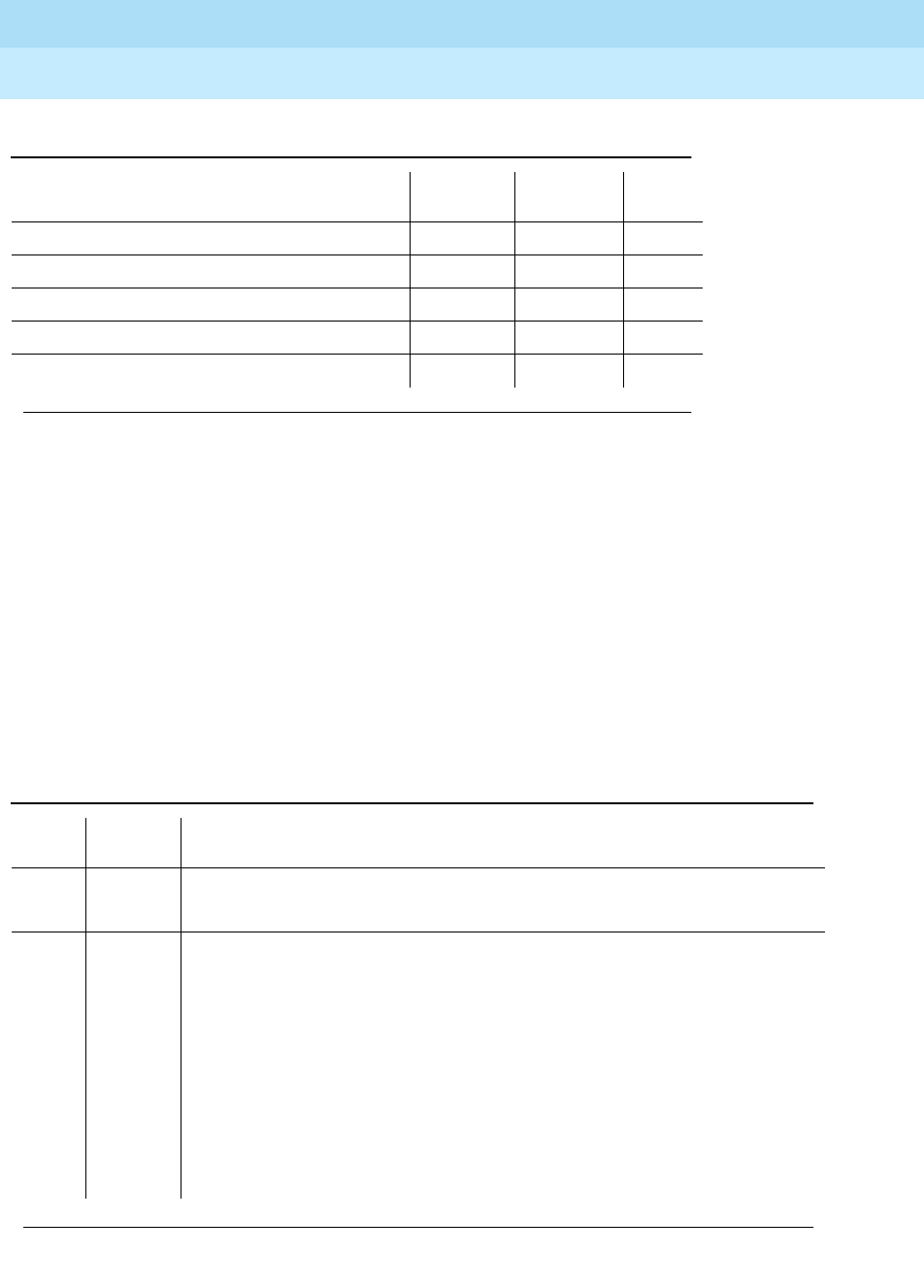
DEFINITY Enterprise Communications Server Release 6
Maintenance for R6r Volumes 1 & 2
555-230-126 Issue 2
January 1998
Maintenance Object Repair Procedures
Page 9-1560TIE-TRK (Analog Tie Trunk)
9
NPE Crosstalk Test (#6)
The NPE Crosstalk Test verifies that a port’s NPE channel talks on the time slot
assigned to it and does not cross over to time slots reserved for other
connections. If the NPE is not working correctly, one-way and noisy connections
may be observed. The test takes 20 to 30 seconds to complete.
1. D = Destructive, ND = Non-destructive
2. ATMS tests are not part of either sequence. They are run either on demand with test
analog-testcall, or by the ATMS schedule.
Tie Trunk Seizure Test (#73) X X ND
Dial Test #747 X X ND
Tie Trunk EPF Test (#74) X X ND
Port Audit and Update Test (#36) X X ND
Transmission Test - ATMS (#844-848) 2†ND
Table 9-533. TEST #6 NPE Crosstalk Test
Error
Code Test
Result Description/ Recommendation
ABORT Could not allocate the necessary system resources to run this test.
1. Retry the command at 1-minute intervals a maximum of 5 times.
1000 ABORT System resources required to run this test are not available. The trunk may be
busy with a valid call. Use the display trunk xx command to determine the
trunk group/member number of the port. Use the status trunk command to
determine the service state of the port. If the service state indicates that the port
is in use, then the port is unavailable for certain tests. You must wait until the
port is idle before retesting.
1. If the port status is active, but the port is not in use (no connected ports),
then check the Error Log for Error Type 1025 (see Error Log table for
description of this error and required actions). The port may be locked up.
2. If the port status is idle, then retry the command at 1-minute intervals a
maximum of 5 times.
Continued on next page
Table 9-532. System Technician-Demanded Tests: TIE-TRK — Continued
Order of Investigation Short Test
Sequence Long Test
Sequence D/ND1
Continued on next page

DEFINITY Enterprise Communications Server Release 6
Maintenance for R6r Volumes 1 & 2
555-230-126 Issue 2
January 1998
Maintenance Object Repair Procedures
Page 9-1561TIE-TRK (Analog Tie Trunk)
9
1001 ABORT System resources required to run this test are not available. This could be due
to a failure to seize the port.
1. Retry the command at 1-minute intervals a maximum of 5 times.
1002 ABORT The system could not allocate time slots for the test. The system may be under
heavy traffic conditions or it may have time slots out-of-service due to TDM-BUS
errors. Refer to TDM-BUS Maintenance to diagnose any active TDM-BUS errors.
1. If system has no TDM-BUS errors and is not handling heavy traffic, repeat
test at 1-minute intervals a maximum of 5 times.
1003 ABORT The system could not allocate a tone receiver for the test. The system may be
oversized for the number of Tone Detectors present or some Tone Detectors
may be out-of-service.
1. Look for TTR-LEV errors in the Error Log. If present, refer to TTR-LEV
Maintenance documentation.
2. Look for TONE-PT errors in the Error Log. If present, refer to TONE-PT
Maintenance documentation.
3. If neither condition exists, retry the test at 1-minute intervals a maximum of 5
times.
1004 ABORT The port was seized by a valid call during the test. The test has been aborted.
Use the display trunk xx command to determine the trunk group/member
number of the port. Use the status trunk command to determine the service
state of the port. If the service state indicates that the port is in use, then the port
is unavailable for certain tests. You must wait until the port is idle before
retesting.
2000 ABORT Response to the test request was not received within the allowable time period.
2100 ABORT Could not allocate the necessary system resources to run this test. This could
be due to a failure to seize the port.
1. Retry the command at 1-minute intervals a maximum of 5 times.
Table 9-533. TEST #6 NPE Crosstalk Test — Continued
Error
Code Test
Result Description/ Recommendation
Continued on next page

DEFINITY Enterprise Communications Server Release 6
Maintenance for R6r Volumes 1 & 2
555-230-126 Issue 2
January 1998
Maintenance Object Repair Procedures
Page 9-1562TIE-TRK (Analog Tie Trunk)
9
Looparound and Conference Circuit Test (#33)
This test verifies signal transmission and conferencing capabilities of a port using
404-Hz, 1004-Hz, and 2804-Hz tones. This is an on-board test only: each tone is
transmitted to and looped around within the port and then returned.
This test can fail due to noise induced by adjacent electric power lines. If this is
the case, the customer must resolve it with their local power company. To
temporarily alleviate an alarm caused by failure of this test, you can disable it via
the Test field on the trunk administration form.
Any FAIL This test can fail due to on-board or off-board problems. Off-board problems of
concern include EXP-PN and EXP-INTF faults, TDM-BUS faults, and faults
associated with the tone detectors/tone generators. Clear all off-board problems
before replacing the board. Keep in mind that a TDM-BUS problem is usually
the result of a faulty board connected to the backplane or bent pins on the
backplane.
1. Look for EXP-PN and/or EXP-INTF errors in the error log. If present, refer to
the EXP-PN Maintenance documentation and the EXP-INTF Maintenance
documentation.
2. Look for TDM-BUS errors in the error log. If present, refer to the TDM-BUS
Maintenance documentation.
3. Look for TONE-BD and/or TONE-PT errors in the error log. If present, refer to
the TONE-BD Maintenance documentation and the TONE-PT Maintenance
documentation.
4. Test the board when the faults from steps 1, 2, and 3 are cleared. Replace
the board only if the test fails.
PASS The port is correctly using its allocated time slots. User-reported troubles on this
port should be investigated using other port tests and examining station, trunk
or external wiring.
0NO
BOARD The test could not relate the internal ID to the port (no board).
1. Check to ensure that the board translations are correct. Translate the board,
if necessary.
2. Issue the busyout board command.
3. Issue the reset board command.
4. Issue the release busy board command.
5. Issue the test board command. This should re-establish the linkage
between the internal ID and the port.
Table 9-533. TEST #6 NPE Crosstalk Test — Continued
Error
Code Test
Result Description/ Recommendation
Continued on next page

DEFINITY Enterprise Communications Server Release 6
Maintenance for R6r Volumes 1 & 2
555-230-126 Issue 2
January 1998
Maintenance Object Repair Procedures
Page 9-1563TIE-TRK (Analog Tie Trunk)
9
Table 9-534. TEST #33 Looparound and Conference
Circuit Test
Error
Code Test
Result Description/ Recommendation
ABORT Could not allocate the necessary system resources to run this test. This could
be due to a failure to seize the port.
1. Retry the command at 1-minute intervals a maximum of 5 times.
7 ABORT The conference circuit test was aborted.
1. Retry the command at 1-minute intervals a maximum of 5 times.
129 ABORT The 404-Hz reflective loop around test aborted. Response to the test request
was not received within the allowable time period.
131 The 1004-Hz reflective loop around test aborted. Response to the test request
was not received within the allowable time period.
133 The 2804-Hz reflective loop around test aborted. Response to the test request
was not received within the allowable time period.
1. Retry the command at 1-minute intervals for a maximum of 5 times.
1000 ABORT System resources required to run this test are not available. The trunk may be
busy with a valid call. Use the display trunk xx command to determine the
trunk group/member number of the port. Use the status trunk command to
determine the service state of the port. If the service state indicates that the
port is in use, then the port is unavailable for certain tests. You must wait until
the port is idle before retesting.
1. If the port status is active, but the port is not in use (no calls), then check
the Error Log for Error Type 1025 (see Error Log table for description of
this error and required actions). The port may be locked up.
2. If the port status is idle, then retry the command at 1-minute intervals a
maximum of 5 times.
1002 ABORT The system could not allocate time slots for the test. The system may be under
heavy traffic conditions or it may have time slots out-of-service due to
TDM-BUS errors. Refer to TDM-BUS Maintenance to diagnose any active
TDM-BUS errors.
1. If system has no TDM-BUS errors and is not handling heavy traffic, repeat
test at 1-minute intervals a maximum of 5 times.
Continued on next page

DEFINITY Enterprise Communications Server Release 6
Maintenance for R6r Volumes 1 & 2
555-230-126 Issue 2
January 1998
Maintenance Object Repair Procedures
Page 9-1564TIE-TRK (Analog Tie Trunk)
9
1003 ABORT The system could not allocate a tone receiver for the test. The system may be
oversized force.
1. Look for TTR-LEV errors in the Error Log. If present, refer to TTR-LEV
Maintenance documentation.
2. Look for TONE-PT errors in the Error Log. If present, refer to TONE-PT
Maintenance documentation.
3. If neither condition exists, retry the command at 1-minute intervals a
maximum of 5 times.
1004 ABORT The port was seized by a valid call during the test. The test has been aborted.
Use the display trunk xx command to determine the trunk group/member
number of the port. Use the status trunk command to determine the service
state of the port. If the service state indicates that the port is in use, then the
port is unavailable for certain tests. You must wait until the port is idle before
retesting.
1018 ABORT The test has been disabled via administration.
Verify that the 'Maintenance Test' field on the 'Trunk Group' form is set to 'n.’
To enable the test, issue the 'change trunk-group x' command (x equals the
number of the trunk group to be tested). Then, change the entry in the
'Maintenance Test' field on the form to 'y.'
2000 ABORT Response to the test request was not received within the allowable time
period.
2100 ABORT Could not allocate the necessary system resources to run this test. This could
be due to a failure to seize the port.
1. Retry the command at 1-minute intervals a maximum of 5 times.
7, FAIL The conference capabilities of the port failed (Error Code 7).
129, The reflective 404-Hz Tone Test failed. No transmission was detected to or
from the port (Error Code 129).
131, or The reflective 1004-Hz Tone Test failed. No transmission was detected to or
from the port (Error Code 131).
Table 9-534. TEST #33 Looparound and Conference
Circuit Test — Continued
Error
Code Test
Result Description/ Recommendation
Continued on next page
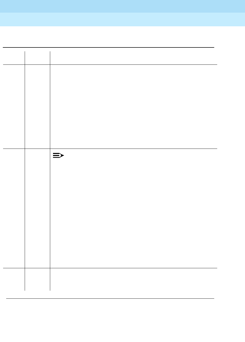
DEFINITY Enterprise Communications Server Release 6
Maintenance for R6r Volumes 1 & 2
555-230-126 Issue 2
January 1998
Maintenance Object Repair Procedures
Page 9-1565TIE-TRK (Analog Tie Trunk)
9
133 The reflective 2804-Hz Tone Test failed. No transmission was detected to or
from the port (Error Code 133).
FAULT ISOLATION: Proceed as follows unless power or tone problems are
suspected (see notes on the next page).
1. To make sure the problem is on-board, disconnect the port from the CO
and retry the test. Coordinate this with the CO, or do it after busy hours;
otherwise, the CO may put the connection out of service.
2. If the retry fails, replace the circuit pack.
3. If the retry passes and no troubles have been reported, disable the test. If
the retry passes and troubles have been reported, refer the problem to the
CO.
More information continues on the next page.
7,
129,
131, or
133
(cont’d.)
FAIL
(cont’d.)
NOTE:
If the loop around and conference circuit test fails for all ports on a
circuit pack, a -5 volt power problem is indicated. If a TN736 or TN752
power unit circuit pack is present, either the 631DB AC power unit or
the 676B DC power unit may be defective. (The 631DB power unit is
used in a medium cabinet powered by an AC source. The 645B power
unit is used in a medium cabinet powered by a DC power source.) The
system may contain a TN736 or TN752 power unit circuit pack or a
631DB AC power unit, but not both types of power units. To investigate
problems with a 631DB AC power unit, refer to the CARR-POW (carrier
port power unit for AC-powered systems) Maintenance documentation.
To investigate problems with a 645B DC power unit, refer to the
CARR-POW (carrier port power unit for DC-powered systems)
Maintenance documentation. If a red LED on TN736 or TN752 power
unit circuit pack is on, replace the pack.
If the test fails on more than 1 port, check for errors on the TONE-BD or
the TONE-PT. If errors, take appropriate actions. When the tone errors
are cleared, rerun the test. If the test fails again, see FAULT ISOLATION
above.
PASS Tie trunk Looparound and Conference Test is successful. This port is
functioning properly.
1. If users are reporting troubles, examine loop connections to the port.
Table 9-534. TEST #33 Looparound and Conference
Circuit Test — Continued
Error
Code Test
Result Description/ Recommendation
Continued on next page

DEFINITY Enterprise Communications Server Release 6
Maintenance for R6r Volumes 1 & 2
555-230-126 Issue 2
January 1998
Maintenance Object Repair Procedures
Page 9-1566TIE-TRK (Analog Tie Trunk)
9
Audit Update Test (#36)
This test sends to the circuit pack updates of translations for all administered
ports on the circuit pack. It is non-disruptive and guards against possible
corruption of translation data contained on the circuit pack. No response is
expected from the circuit pack. Port translation data includes:
■Start type: immediate, automatic, wink-start, or delay dial
■Rotary or DTMF senderization in or out
■Disconnect timing: 10 to 2550ms in 10ms increments
■DMTF time slot
■Continuous-seize-ack? (TN2140
0NO
BOARD The test could not relate the internal ID to the port (no board).
1. Check to ensure that the board translations are correct. Translate the
board, if necessary.
2. Issue the busyout board command.
3. Issue the reset board command.
4. Issue the release busy board command.
5. Issue the test board command. This should re-establish the linkage
between the internal ID and the port.
Table 9-535. TEST #36 Audit Update Test
Error
Code Test
Result Description/ Recommendation
ABORT Could not allocate the necessary system resources to run this test.
1. Retry the command at 1-minute intervals a maximum of 5 times.
2100 ABORT Could not allocate the necessary system resources to run the test. This could
be due to a failure to seize the port.
1. Retry the command at 1-minute intervals a maximum of 5 times.
Continued on next page
Table 9-534. TEST #33 Looparound and Conference
Circuit Test — Continued
Error
Code Test
Result Description/ Recommendation
Continued on next page

DEFINITY Enterprise Communications Server Release 6
Maintenance for R6r Volumes 1 & 2
555-230-126 Issue 2
January 1998
Maintenance Object Repair Procedures
Page 9-1567TIE-TRK (Analog Tie Trunk)
9
Tie Trunk Seizure Test (#73)
and Tie Trunk Dial Test (#747)
For wink-start, delay-dial and TN2140 (cont-seize-ack or discont-seize-ack)
trunks, this test activates the M lead and checks for a response from the far end
within 10 seconds.
For TN497, the test seizes a trunk and outpulses a pause. The port reports uplink
the result of the seizure. This test can be disabled via the Test field on the trunk
group administration form.
For TN439, Test #747 is run instead of #73. This test seizes a trunk and outpulses
a pause digit. This test aborts on ports administered as access endpoints.
FAIL Internal system error
1. Retry the command at 1-minute intervals a maximum of 5 times.
PASS This test passed. Translation information was successfully updated on the
circuit pack. If the trunk is busied out, the test will not run, but will return PASS
(except on TN439 and TN497).
1. If signaling troubles are reported, verify translation information for this port.
2. To verify that the trunk is in-service, enter status trunk command to verify
that the trunk is in-service. If the trunk is in-service, no further action is
necessary. If the trunk is out-of-service, continue to Step 2.
3. Enter release trunk command to put trunk back into in-service.
4. Retry the test command.
0NO
BOARD The test could not relate the internal ID to the port (no board).
1. Check to ensure that the board translations are correct. Translate the
board, if necessary.
2. Issue the busyout board command.
3. Issue the reset board command.
4. Issue the release busy board command.
5. Issue the test board command. This should re-establish the linkage
between the internal ID and the port.
Table 9-535. TEST #36 Audit Update Test — Continued
Error
Code Test
Result Description/ Recommendation
Continued on next page

DEFINITY Enterprise Communications Server Release 6
Maintenance for R6r Volumes 1 & 2
555-230-126 Issue 2
January 1998
Maintenance Object Repair Procedures
Page 9-1568TIE-TRK (Analog Tie Trunk)
9
Table 9-536. TEST #73,#747 Tie Trunk Seizure Test
Error
Code Test
Result Description/ Recommendation
ABORT Could not allocate the necessary system resources to run this test.
1. Retry the command at 1-minute intervals a maximum of 5 times.
1000 ABORT System resources required to run this test are not available. The trunk may be
busy with a valid call. Use the display trunk xx to determine the trunk
group/member number of the port. Use the status trunk command to
determine the service state of the port. If the service state indicates that the port
is in use, then the port is unavailable for certain tests. You must wait until the
port is idle before retesting.
1. If the port status is active, but the port is not in use (no calls), then check the
Error Log for Error Type 1025 (see Error Log table for description of this
error and required actions). The port may be locked up. The far-end PBX
may not be releasing.
2. If the port status is idle, then retry the command at 1-minute intervals a
maximum of 5 times.
1004 ABORT The port was seized by a valid call during the test. The test has been aborted.
Use the display trunk xx to determine the trunk group/member number of the
port. Use the status trunk command to determine the service state of the port.
If the service state indicates that the port is in use, then the port is unavailable
for certain tests. You must wait until the port is idle before retesting.
1. Retry the command at 1-minute intervals a maximum of 5 times.
1005 ABORT This test is not valid for this trunk translation. Must be a wink-start or delay dial
trunk and must be outgoing or two-way for this test to run. For the TN2140, the
trunk must also be continuous-seize-ack or discontinuous-seize-ack.
1. Check trunk translation. If it is not a wink-start or delay dial trunk, this abort
message should be ignored.
1018 ABORT Test disabled via administration.
1. Verify that the ‘‘Maintenance Tests?’’ field on the Trunk Group Form is set to
"n". To enable the test, issue the change trunk-group x command where
‘‘x’’ equals the number of the trunk group to be tested. Then change the
entry in the ‘‘Maintenance Tests?’’ field on the form to ‘‘y.’’
1040 ABORT This test is not performed for trunk ports administered as access endpoints.
1. Verify this port is an access endpoint by using the display port command.
2. If the port has been administered as an access endpoint, then this test
should abort.
2100 ABORT Could not allocate the necessary system resources to run the test. This could be
due to a failure to seize the port.
1. Retry the command at 1-minute intervals a maximum of 5 times.
Continued on next page

DEFINITY Enterprise Communications Server Release 6
Maintenance for R6r Volumes 1 & 2
555-230-126 Issue 2
January 1998
Maintenance Object Repair Procedures
Page 9-1569TIE-TRK (Analog Tie Trunk)
9
Tie Trunk EPF Test (#74)
The first part of this test checks for proper activation and deactivation of the
port’s E lead. The second part checks the M lead electronic power feed current
flow.
3 FAIL No dial tone detected from the other end. (TN439 circuit packs only.)
1. Retry the command at one minute intervals a maximum of five times.
2. If the test continues to fail, check the far-end PBX to ensure a translation
match at both ends.
3. Check the facility.
2000 FAIL Seizure message is not received back within 10 seconds.
1. Retry the command at 1-minute intervals a maximum of 5 times.
2. If the test continues to fail, check the far-end PBX to ensure a translation
match at both ends.
3. Check the facility.
PASS The Tie Trunk Seizure Test passes. This port is functioning properly.
1. If users are reporting troubles, examine loop connections to the port, wiring,
and stations.
0NO
BOARD The test could not relate the internal ID to the port (no board).
1. Check to ensure that the board translations are correct. Translate the
board, if necessary.
2. Issue the busyout board command.
3. Issue the reset board command.
4. Issue the release busy board command.
5. Issue the test board command. This should re-establish the linkage
between the internal ID and the port.
Table 9-536. TEST #73,#747 Tie Trunk Seizure Test — Continued
Error
Code Test
Result Description/ Recommendation
Continued on next page

DEFINITY Enterprise Communications Server Release 6
Maintenance for R6r Volumes 1 & 2
555-230-126 Issue 2
January 1998
Maintenance Object Repair Procedures
Page 9-1570TIE-TRK (Analog Tie Trunk)
9
Table 9-537. TEST #74 Tie Trunk EPF Test
Error
Code Test
Result Description/ Recommendation
ABORT Could not allocate the necessary system resources to run the test. This could be
due to a failure to seize the port.
1. Retry the command at 1-minute intervals a maximum of 5 times.
1 ABORT Internal system error
1. Retry the command at 1-minute intervals a maximum of 5 times.
1000 ABORT System resources required to run this test are not available. The trunk may be
busy with a valid call. Use the display trunk xx to determine trunk
group/member number of the port. Use the status trunk command to determine
the service state of the port. If the service state indicates that the port is in use,
then the port is unavailable for certain tests. You must wait until the port is idle
before retesting.
1. If the port status is active, but the port is not in use (no calls), then check the
Error Log for Error Type 1025 (see Error Log table for description of this
error and required actions). The port may be locked up. The far-end PBX
may not be releasing.
2. If the port status is idle, then retry the command at 1-minute intervals a
maximum of 5 times.
1004 ABORT The port was seized by a valid call during the test. The test has been aborted.
Use the display trunk xx to determine the trunk group/member number of the
port. Use the status trunk command to determine the service state of the port.
If the service state indicates that the port is in use, then the port is unavailable
for certain tests. You must wait until the port is idle before retesting.
1. Retry the command at 1-minute intervals a maximum of 5 times.
1005 ABORT This test is not valid for this trunk translation. Must be a type-1 standard trunk for
this test to run.
1. Check trunk configuration. If it is not a type-1 standard trunk, this abort
message should be ignored.
1014 ABORT The test was aborted because the circuit pack has not been inserted into the
system.
1. Use the list configuration board command to make sure the circuit pack is
inserted in the carrier.
2. If the board is not inserted, make sure the circuit pack is inserted in the
carrier and fully seated.
1040 ABORT This test is not performed for trunk ports administered as access endpoints.
1. Verify this port is an access endpoint by using the display port command.
2. If the port has been administered as an access endpoint, then this test
should abort.
Continued on next page

DEFINITY Enterprise Communications Server Release 6
Maintenance for R6r Volumes 1 & 2
555-230-126 Issue 2
January 1998
Maintenance Object Repair Procedures
Page 9-1571TIE-TRK (Analog Tie Trunk)
9
Transmission Test (#844-848)
This test is non-destructive.
NOTE:
Tests #844-848 are not supported on a International switch.
These tests are run by the Automatic Transmission Measurement System
(ATMS). They are not part of the long or short trunk test sequences. Instead, they
are run on demand with the test analog-testcall command or as part of ATMS
scheduled testing. For more information, see ‘‘Automatic Transmission
Measurement System (ATMS)’’ in Chapter 6.
2000 ABORT Response to the test request was not received within the allowable time period.
2100 ABORT Could not allocate the necessary system resources to run the test. This could be
due to a failure to seize the port.
1. Retry the command at 1-minute intervals a maximum of 5 times.
1 FAIL The E lead test failed due to an on-board port problem.
1. Replace the circuit pack.
2 FAIL The M lead test failed. The EPF has experienced an overcurrent condition,
perhaps due to the external M lead.
1. To make sure the problem is on-board, disconnect the facility from the pack
and retry the test.
2. If the test fails, replace the circuit pack. Otherwise, check the external
wiring toward the far-end PBX.
PASS Tie Trunk EPF test is successful. This port is functioning properly.
1. If users are reporting troubles, examine loop connections to the port.
0NO
BOARD The test could not relate the internal ID to the port (no board).
1. Check to ensure that the board translations are correct. Translate the board,
if necessary.
2. Issue the busyout board command.
3. Issue the reset board command.
4. Issue the release busy board command.
5. Issue the test board command. This should re-establish the linkage
between the internal ID and the port.
Table 9-537. TEST #74 Tie Trunk EPF Test — Continued
Error
Code Test
Result Description/ Recommendation
Continued on next page

DEFINITY Enterprise Communications Server Release 6
Maintenance for R6r Volumes 1 & 2
555-230-126 Issue 2
January 1998
Maintenance Object Repair Procedures
Page 9-1572TIE-TRK (Analog Tie Trunk)
9
The test call is run from an analog port on a TN771 Maintenance/Test circuit
pack. It attempts to seize a port and make a call to a terminating test line (TTL) on
the trunk’s far end. Transmission performance measurements are made and
compared to administered thresholds. Errors are generated when results fall
outside of ‘‘marginal’’ or ‘‘unacceptable’’ thresholds. Detail and summary
measurement reports are obtainable via the list testcalls command.
Table 9-538. TEST #844-848 Transmission Test
Error
Code Test
Result Description/ Recommendation
1000 ABORT System resources required to run this test are not available. The port may be
busy with a valid call. Use display port UUCSSpp to determine the trunk
group/member number of the port. Use the "status trunk" command to determine
the service state of the port. If the service state indicates that the port is in use,
then the port unavailable for this test. (Refer to section on "status" commands for
a full description all possible states). You must wait until the port is idle before
retesting.
1. If the port status is idle, then retry the command at 1-minute intervals for a
maximum of 5 retries.
1001 ABORT Could not allocate the necessary system resources to run this test.
1. Retry the command at 1-minute intervals for a maximum of 5 retries.
1002 ABORT The system could not allocate timeslots for the test. The system may be under
heavy traffic conditions or it may have timeslots out of service due to TDM bus
errors. Refer to TDM Bus Maintenance to diagnose any active TDM bus errors.
1. If system has no TDM bus errors and is not handling heavy traffic, repeat
test at 1-minute intervals for a maximum of 5 retries.
1004 ABORT The port has been seized by a user for a valid call. Use status trunk to determine
when the port is available for testing.
1. Retry the command at 1-minute intervals for a maximum of 5 retries.
1005 ABORT Trunk has been administered as incoming-only; transmission tests can only be
run on outgoing trunks.
1115 ABORT The near end test line on the TN771 circuit pack could not be allocated.
1. Verify that the TN771 circuit pack is in service and that port 1 is
administered and in service with the status port command.
2. retry the command at 1-minute intervals for a maximum of 5 retries.
1900 ABORT The test completion message was not received from the TN771 circuit pack.
1. Test the TN771 circuit packs.
1901 ABORT This error occurs when the TN771 circuit pack uplinks a message that is not the
proper response for this test. The anticipated uplink messages are seize, ring or
answer.
1. Verify that the Trunk is administered properly.
Continued on next page

DEFINITY Enterprise Communications Server Release 6
Maintenance for R6r Volumes 1 & 2
555-230-126 Issue 2
January 1998
Maintenance Object Repair Procedures
Page 9-1573TIE-TRK (Analog Tie Trunk)
9
1905 ABORT Intercept tone detected from far end.
1. Get the test line data and verify it with the far end. Dial the test number
manually to see if the TTL is reached. If it is not, then either the number is
wrong, or the far end is administered incorrectly.
1906 ABORT Reorder tone detected from far end.
1. See actions for error code 1905.
1907 ABORT Other unexpected tone detected from far end.
1. See actions for error code 1905.
1913 ABORT Audible Ring detected from far end.
1. See actions for error code 1905.
1914 ABORT Unidentified interrupted tone detected from far end.
1. See actions for error code 1905
1915 ABORT Busy tone detected from far end.
1. Since the test line at the far end was busy. Try the test again.
2. If the test continues to abort, the problem is with the far end system.
1918 ABORT Test progress tone not removed from far end (type 105 test line only).
1. The problem is with the far end system; a technician at the far end should
test the test line (TN771 or ADFTC).
1919 ABORT Unexpected far end release
1. The problem is with the far end system; a technician at the far end should
test the test line (TN771 or ADFTC).
1920 ABORT No response from far end.
1. The problem is with the far end system; a technician at the far end should
test the test line (TN771 or ADFTC).
1921 ABORT No data returned from far end.
1. The problem is with the far end system; a technician at the far end should
test the test line (TN771 or ADFTC).
1922 ABORT Steady, unidentifiable tone from far end
1. See actions for error code 1905.
1923 ABORT Broadband energy detected from far end (such as voice or announcement).
1. See actions for error code 1905.
1924 ABORT No test tone from far end
1. See actions for error code 1905.
Table 9-538. TEST #844-848 Transmission Test — Continued
Error
Code Test
Result Description/ Recommendation
Continued on next page

DEFINITY Enterprise Communications Server Release 6
Maintenance for R6r Volumes 1 & 2
555-230-126 Issue 2
January 1998
Maintenance Object Repair Procedures
Page 9-1574TIE-TRK (Analog Tie Trunk)
9
1938 ABORT Near-end self test failed.
1. Test the TN771 circuit packs.
1939 ABORT Loss self check at 0dBm at 1004 Hz failed.
1. Test the TN771 circuit packs.
1940 ABORT Far end noise self check failed.
1. The problem is with the far end system; a technician at the far end should
test the test line (TN771 or ADFTC).
1941 ABORT High frequency singing return loss self check failed.
1. Test the TN771 circuit packs.
1942 ABORT Echo return loss self check failed.
1. Test the TN771 circuit packs.
1943 ABORT Singing return loss self check failed.
1. Test the TN771 circuit packs.
1944 ABORT Loss self check at -16 dBm at 1004 Hz failed.
1. Test the TN771 circuit packs
1945 ABORT Loss self check at -16 dBm at 404 Hz failed.
1. Test the TN771 circuit packs.
1946 ABORT Loss self check at -16 dBm at 2804 Hz failed.
1. Test the TN771 circuit packs.
1947 ABORT Noise with tone self check failed.
1. Test the TN771 circuit packs.
2000 ABORT The test timed out while waiting for a response from the TN771 circuit pack.
1. Retry the command at 1-minute intervals for a maximum of 5 retries.
2012 ABORT An internal software error occurred.
1. Retry the command at 1-minute intervals for a maximum of 5 retries.
2053 ABORT The test call could not be established, but no information on why is available.
1. Retry the command at 1-minute intervals for a maximum of 5 retries.
2056 ABORT An error occurred while trying to obtain results from the TN771 circuit pack.
1. Test the TN771 circuit packs.
Table 9-538. TEST #844-848 Transmission Test — Continued
Error
Code Test
Result Description/ Recommendation
Continued on next page

DEFINITY Enterprise Communications Server Release 6
Maintenance for R6r Volumes 1 & 2
555-230-126 Issue 2
January 1998
Maintenance Object Repair Procedures
Page 9-1575TIE-TRK (Analog Tie Trunk)
9
FAIL Measured transmission performance was in the unacceptable range as
administered on the trunk group form. Retrieve a measurement report via the list
testcalls command. Make sure that ATMS thresholds are set properly on page 4
of the trunk group form. Besides the facility, test failures can be caused by faulty
test lines or switch paths. If the measurements point to a facility problem, report
the results to the trunk vendor.
8000 FAIL Measured transmission performance was in the marginal range as administered
on the trunk group form. This generally means that the trunk is usable but has an
undesirable amount of noise or loss. If the user does not report unacceptable
effects, it may not be necessary to take any action. Retrieve a measurement
report via the list testcalls command. Make sure that ATMS thresholds are set
properly on page 4 of the trunk group form.
Table 9-538. TEST #844-848 Transmission Test — Continued
Error
Code Test
Result Description/ Recommendation
Continued on next page

DEFINITY Enterprise Communications Server Release 6
Maintenance for R6r Volumes 1 & 2
555-230-126 Issue 2
January 1998
Maintenance Object Repair Procedures
Page 9-1576TIME-DAY (Time of Day)
9
TIME-DAY (Time of Day)
The time of day contains the current year, month, day of the week, day of the
month, hour, minute, and second. The Time of Day maintenance object is
responsible for monitoring the time-of-day clock and raising an alarm if the
time-of-day clock is not set or cannot be read by the software. If the time-of-day
clock is not set or cannot be read by the software, many features such as
Time-of-Day Routing, CDR, ISDN Call-by-Call, Duplication, and so on will be
either inoperative or incorrect. The time-of-day clock should be set using the set
time command whenever the system is initially powered up or the TN1648
SYSAM circuit pack is replaced.
The time-of-day clock can be read with the display time command and set via
the set time command. The time-of-day clock resides on the TN1648 SYSAM
circuit pack and has a backup battery to save the time of day during power
failures. If the TN1648 SYSAM circuit pack is physically removed from the carrier,
the contents of the time-of-day clock is lost and the time of day must be set when
the TN1648 SYSAM circuit pack is re-inserted.
Error Log Entries and Test to Clear Values
To resolve the alarm, do the following:
1. Use the set time command to set the time of day.
2. Use the display time command to display the time of day. If the time of
day is displayed correctly, wait 15 minutes and verify that the alarm is
retired. If the alarm has not been retired, continue with Step 3.
1. This error indicates that software cannot read the time-of-day clock on the TN1648 SYSAM
circuit pack. During this condition, all time stamps on Alarm Log entries, Hardware Error Log
entries, and Software Error Log entries are potentially inaccurate. In addition, any features that
are sensitive to the time of day (such as SMDR, Time-of-Day Routing, ISDN Call-by-Call) will not
function correctly.
MO Name (in
Alarm Log) Alarm
Level Initial Command To
Run Full Name of MO
TIME-DAY MINOR set time Time of Day
Table 9-539. Time of Day Error Log Entries
Error
Type Aux
Data Associated Test Alarm
Level On/Off
Board Test to Clear Value
0 0 Any Any Any display time
24710 none MINOR OFF set time

DEFINITY Enterprise Communications Server Release 6
Maintenance for R6r Volumes 1 & 2
555-230-126 Issue 2
January 1998
Maintenance Object Repair Procedures
Page 9-1577TIME-DAY (Time of Day)
9
3. Test the active TN1648 SYSAM circuit pack using the test maintenance
[a | b] sh command. If any tests fail, refer to the repair procedures for the
SYSAM circuit pack before further investigating time-of-day problems. If
all tests PASS and the alarm has not been retired, proceed to Step 4.
4. Replace the active TN1648 SYSAM circuit pack must be replaced. See
"Replacing SPE Circuit Packs"
in Chapter 5. The alarm should be resolved
within 15 minutes of replacing the SYSAM and resetting the time with set
time.

DEFINITY Enterprise Communications Server Release 6
Maintenance for R6r Volumes 1 & 2
555-230-126 Issue 2
January 1998
Maintenance Object Repair Procedures
Page 9-1578TONE-BD (Tone-Clock Circuit Pack)
9
TONE-BD (Tone-Clock Circuit Pack)
The Tone-Clock circuit packs house two independent components. The tone
generator provides all the tones needed by the system, and the clock generates
the system clocks for the Time Division Multiplex (TDM) Bus and the LAN Bus,
and aids in monitoring and selecting internal synchronization references.
When resolving errors/alarms on the Tone-Clock circuit pack, the following
sections should also be consulted:
■Use the set tone-clock PC command to establish the tone and
synchronization resources for the system.
■TONE-PT (Tone Generator)
■TDM-CLK (TDM Bus Clock)
■SYNC (Synchronization)
The TN2182 is a combined Tone-Clock-Detector circuit pack which contains a
third independent function not available on the TN768 or TN780. The TN2182
contains 8 ports used for all-purpose tone detection. These ports are called
Enhanced Tone Receiver ports (ETR-PT) and are described in the
documentation for ETR-PT.
Tone-Clock Circuit Packs and System
Reliability Options
The following sections describe the relationship between the various System
Reliability Options and Tone-Clock circuit pack configurations.
Standard Reliability Option
Systems with the Standard Reliability Option (no duplication options) have one
Tone-Clock circuit pack in each port network (PPN and EPN). For the PPN or the
first EPN of a cabinet this is in the A carrier. Cabinets containing a second EPN
1. UU is the universal cabinet number (1 for PPN, 2 -44 for EPNs). C is the carrier designation (A,
B, C, D, or E).
MO Name (in
Alarm Log) Alarm Level Initial Command to Run1Full Name of MO
TONE-BD MAJOR test tone-clock UUC short Tone-Clock Circuit Pack
TONE-BD MINOR test tone-clock UUC short Tone-Clock Circuit Pack
TONE-BD WARNING release tone-clock UUC Tone-Clock Circuit Pack

DEFINITY Enterprise Communications Server Release 6
Maintenance for R6r Volumes 1 & 2
555-230-126 Issue 2
January 1998
Maintenance Object Repair Procedures
Page 9-1579TONE-BD (Tone-Clock Circuit Pack)
9
will also have a Tone-Clock circuit pack in the E carrier. This Tone-Clock circuit
pack generates clocks and provides system tones for all carriers of the port
network it resides on.
High Reliability Option
Systems with the High Reliability Option (duplicated SPE, simplex PNC) have one
Tone-Clock circuit pack in each PPN control carrier, A and B. One Tone-Clock
circuit pack will be actively generating system clock signals for PPN
components, while the other will be in standby mode, ready to take over in the
event of a Tone-Clock interchange. Similarly, one Tone-Clock circuit pack will be
actively providing system tones for the PPN, while the other will be in standby
mode. Normally, the same Tone-Clock circuit pack will be active for both tones
and clock signals, but these responsibilities may be divided if neither circuit pack
is able to perform both functions. The status port-network PN# command will
indicate which Tone-Clock circuit pack is actively performing each function.
For systems using the TN2182 Tone-Clock-Detector circuit pack, tone generation
and clock generation behaves the same as other clock boards with one being
active and one being standby. But the tone detector ports (ETR-PTs) of the
TN2182 are always considered available and in-service regardless of the
active/standby state of the tones or clock for a specific circuit pack.
EPN Tone-Clock circuit pack configuration is the same as for the Standard
Reliability Option. Each EPN Tone-Clock circuit pack will be active for both tones
and clock signals for its port network.
Critical Reliability Option
Systems with the Critical Reliability Option (SPE duplication and PNC duplication)
have two Tone-Clock circuit packs associated with the PPN, as in the High
Reliability Option case, and two more Tone-Clock circuit packs for each EPN. For
the first EPN in a cabinet, these are in carriers A and B; for the second EPN,
where configured, they are in carriers D and E. As in the previous case, one
Tone-Clock in each Port Network is active, supplying system clocks and tones,
and the other is in standby mode.
Tone-Clock Interchange Strategy
Tone-Clock circuit pack interchanges are controlled both by manual intervention
and by maintenance software strategies.
The manual interchange strategy for Tone-Clock circuit packs differs slightly
between the PPN and any EPNs on a system.

DEFINITY Enterprise Communications Server Release 6
Maintenance for R6r Volumes 1 & 2
555-230-126 Issue 2
January 1998
Maintenance Object Repair Procedures
Page 9-1580TONE-BD (Tone-Clock Circuit Pack)
9
Manual PPN Tone-Clock Interchange
In a PPN with more than one Tone-Clock circuit pack, the intention is to assure
that the one considered most healthy is active at any given time.
This is
independent of the SPE Duplication strategy
, in the sense that the active
Tone-Clock circuit pack need not change with an interchange of SPE carriers.
Rather, except for the effect of the manual intervention discussed earlier,
Tone-Clock interchanges occur only as a result of changes in the health of
Tone-Clock circuit packs, as perceived by maintenance software. When both
Tone-Clock circuit packs are equally healthy, no preference is given to one over
the other, regardless of which SPE carrier is active.
It is possible to manually control Tone-Clock interchanges in three ways.
1. The standby Tone-Clock circuit pack may be made unavailable for most
purposes by using the busyout tone-clock UUC command. Such a
Tone-Clock may not be selected with console commands, nor with normal
maintenance software activities, until it has been made available again
with the restore tone-clock UUC command.
NOTE:
busyout tone-clock is not allowed for active Tone-Clock circuit
packs.
2. The SPE processor lock switches may be used to force a particular SPE to
be active.
This method overrides all other Tone-Clock interchange
controls
. If there is a Tone-Clock circuit pack in the same carrier as the
active SPE, it will become active, regardless of its health. If the Tone-Clock
circuit pack in the selected SPE was in the
busyout
state (see item 1
above), it will automatically be released and made active. While the lock
switches are set for a particular carrier,
no manual intervention or software
error detection
will cause an interchange of Tone-Clocks; the Tone-Clock
circuit pack in the standby SPE carrier can never become active. If there
is no Tone-Clock circuit pack in the selected SPE at the time the switches
are set, but one is later installed, the system will interchange to it
regardless of its health. If the Tone-Clock circuit pack is removed from an
SPE while the switches are set,
no interchange will occur
; the system will
have no active tone-clock. When the lock switches are restored to the
neutral position, a tone clock interchange will occur only if the standby
Tone-Clock circuit pack is healthier than the active one.
3. A particular Tone-Clock circuit pack can be made active by issuing the
set tone-clock UUC [override] command. If the Tone-Clock to be made
active is less healthy than the currently active one, no interchange will
occur unless the override option is specified; without it a message will
inform the user that it is required.
Once a Tone-Clock circuit pack is made active by the set tone-clock
UUC command, it will stay active until either the set tone-clock UUC
command is issued again to make the other circuit pack active, or until a
fault occurs in the active Tone-Clock circuit pack, which causes the
system to interchange Tone-Clocks.

DEFINITY Enterprise Communications Server Release 6
Maintenance for R6r Volumes 1 & 2
555-230-126 Issue 2
January 1998
Maintenance Object Repair Procedures
Page 9-1581TONE-BD (Tone-Clock Circuit Pack)
9
Manual EPN Tone-Clock Interchange
In an EPN with duplicated Tone-Clock circuit packs, one circuit pack is always
preferred
over the other. For the first Port Network in a cabinet, this is the
Tone-Clock circuit pack in carrier A. If a second Port Network is configured in a
cabinet, its preferred Tone-Clock is the one in carrier E. The intention is that the
preferred circuit pack be active whenever it is healthy. Once a failing preferred
Tone-Clock circuit pack has been replaced or repaired, the system will make it
active as soon as possible.
Control over interchanges for an EPN is accomplished in essentially the same
ways as items 1 and 3 in the PPN case above. In addition, when the
non-preferred Tone-Clock circuit pack in an EPN is active, and the preferred
circuit pack is repaired and proven capable of filling its roles, the system will
automatically interchange back to it as soon as possible.
Software Maintenance Interchange
Interchanges may be instigated by software Tone-Clock maintenance in two
ways.
1. A scheduled Tone-Clock circuit pack interchange occurs according to the
parameters set by the change system-parameters maintenance
command. This can be disabled or set to run weekly, but the standard
(default) situation is for it to occur daily, at the time specified in the
system-parameters list for scheduled maintenance to begin. This
interchange will be blocked if the lock switches are set, if the
non-preferred Tone-Clock circuit pack in an EPN has been selected with
the set tone-clock command, if the standby Tone-Clock has been set to
the busyout state, or if the clock generation capability of the standby
Tone-Clock circuit pack is known to be impaired. When this scheduled
interchange occurs, the standby Tone-Clock circuit pack becomes active
for a period of 20 seconds to test its ability to generate clock signals, and
then is returned to standby mode.
2. Unscheduled interchanges occur when on-board Tone-Clock circuit pack
maintenance, or ongoing switch maintenance tests of TONE-BD,
TONE-PT, or TDM-CLK uncover failures serious enough to raise any
MAJOR or MINOR alarm against the active Tone-Clock circuit pack.
International Settings [G3r V2]
The TN780 Tone-Clock circuit pack uses three firmware configuration
parameters for international support [G3r V2]. The following two are automatically
set by the software load for the targeted country:
■The circuit pack’s country-code (USA, ITALY, AUSTRALIA, etc.)
■The circuit pack’s companding mode (mu-Law or A-Law)

DEFINITY Enterprise Communications Server Release 6
Maintenance for R6r Volumes 1 & 2
555-230-126 Issue 2
January 1998
Maintenance Object Repair Procedures
Page 9-1582TONE-BD (Tone-Clock Circuit Pack)
9
The third configuration parameter is used only for Italy (country code: ITALY),
and selects whether
new
versus
old
ISPT (Istituto Superiore Poste Telegrafi)
tones will be used for dial and confirmation tones. Values for dial confirmation
tone can be set independently on the change system-parameters
miscellaneous form. Whenever such changes are made, the effects are
immediately enforced on all TN780 Tone-Clock circuit packs without disrupting
tone or timing services.
In addition the TN780 allows customization of up to six system tones in order to
meet specific country needs. These changes are made via the change
system-parameters country-options form.
The TN2182 allows the same internation changes as the TN780 but allows the
customization of up to 24 system tones in order to meet specific country needs.
These changes are made via the change system-parameters country-options
form.
How to Replace the Tone-Clock Circuit Pack
Replacing the Tone-Clock circuit pack is a service-disrupting procedure on Port
Networks with a single Tone-Clock, because the Tone-Clock circuit pack is
always needed to generate clocks for its network. For EPN Tone-Clock
replacement where no second Tone-Clock circuit pack exists, only that EPN is
affected. When the circuit pack is removed, all calls are dropped immediately,
the EPN enters emergency transfer within one minute, and no calls can be set up
from or to that EPN. However, if the PPN Tone-Clock is removed for replacement
in a Standard Reliability Option system, the System Emergency Transfer feature
is activated within milliseconds, and the entire system is disrupted; no calls can
be placed, and existing calls are dropped.
Tone New ISPT
Value(default) Old ISPT Value
Dial continuous cadenced
Confirmation cadenced continuous

DEFINITY Enterprise Communications Server Release 6
Maintenance for R6r Volumes 1 & 2
555-230-126 Issue 2
January 1998
Maintenance Object Repair Procedures
Page 9-1583TONE-BD (Tone-Clock Circuit Pack)
9
When replacing the Tone-Clock circuit pack, always make sure to replace it with
the appropriate Tone-Clock circuit pack for the system. Three circuit pack codes
are supported by G3r systems:
Port Networks with a Single Tone-Clock
Circuit Pack:
This procedure is destructive.
1. Pull out the defective Tone-Clock circuit pack. This will remove the clocks
and cause the system to activate emergency measures:
■For the PPN Tone-Clock, the system will immediately go into the
Emergency Transfer state.
■For an EPN Tone-Clock, all calls to and from the EPN will drop and
the EPN will activate Emergency Transfer within about one minute,
but the rest of the system should operate normally.
2. Insert a new Tone-Clock circuit pack. The system will detect the return of
the clocks and will automatically recover as follows:
■If the Tone-Clock circuit pack being replaced is in the Processor
Port Network, the system will perform a reset system 2 (system
cold 2 restart) automatically. First, all red LEDs of the PPN will
come on and off within 30 seconds. Then, all red LEDs of any
Expansion Port Networks will come on and go off within the next 30
seconds.
■If the Tone-Clock circuit pack being replaced is in an Expansion
Port Network, the system will reset the EPN (EPN cold restart) and
all the red LEDs of the EPN will come on and go off within 30
seconds.
3. If the red LEDs come on but do not go off within 30 seconds, pull the
circuit pack out and reseat it. If the LEDs perform as expected this time,
continue with step 6. Otherwise, there may be a problem with the TDM
Bus; possibly a bent pin in the Tone-Clock circuit pack slot. Follow the
directions in the TDM-BUS maintenance section.
TN768 This is the general purpose Tone-Clock circuit pack for port networks on a
G3r switch. It can be used in every situation except as the Master
Tone-Clock circuit pack when a Stratum 3 Clock is administered.
TN780 The Stratum 3 Clock feature requires the use of this circuit pack code for
the PPN (in both carriers of High and Critical Reliability systems). The
Stratum 3 Clock will operate only with this code as the Master Tone-Clock
circuit pack. The TN780 circuit pack is upward compatible with the TN768
code, and can be used in any place a TN768 would be allowed. The
TN780 is used in many countries outside the U.S. where the TN768 does
not provide local tones.
TN2182 This Tone-Clock-Detector may be used anywhere a TN768 or TN780 is
used with the exception of configurations requiring Stratum 3 Clock. The
TN2182 may be used in all country configurations.

DEFINITY Enterprise Communications Server Release 6
Maintenance for R6r Volumes 1 & 2
555-230-126 Issue 2
January 1998
Maintenance Object Repair Procedures
Page 9-1584TONE-BD (Tone-Clock Circuit Pack)
9
4. If the red LEDs did light, as explained above, then go to Step 6. If the red
LEDs do NOT light, as explained above, then go on to Step 5.
5. Restart the affected Port Network:
■In the PPN, restart the system via the reset system 2 command.
■In an EPN, restart the EPN by resetting its Expansion Interface
circuit pack via the reset port-network PN# 2 command, using the
Port Network number of the affected EPN. (Use the list cabinet UU
command to determine the Port Network number for a given
cabinet and carrier.)
6. Test the new Tone-Clock circuit pack to verify that it is functioning
properly, using the test tone-clock UUC long command, and verify that
the system is operational by placing several phone calls. Where possible,
try calls into, out from, and within the affected Port Network.
Port Networks with Two Tone-Clock
Circuit Packs:
Table 9-540. LED Condition/Tone-Clock Circuit States
(Two Tone-Clock Pack)
Condition Tone-Clock
Circuit State Explanation
flashing yellow
2.7 seconds on
.3 seconds off
active An external timing source is being used as a
synchronization reference1.
flashing yellow
.3 seconds on
2.7 seconds off
active The local oscillator on the Tone-Clock circuit pack is
being used as a synchronization reference.
yellow
on continuously active The circuit pack has been reset but has not been told
which synchronization source to use.
yellow
LED off standby The circuit pack is in standby mode, (neither
generating tones nor supplying clocks).
"jingle bells"
green and yellow
.1 sec on, .2 sec off,
.1 sec on, .4 sec off,
.4 sec on, .4 sec off
standby Maintenance software is testing the standby circuit
pack (the standby Tone-Clock is providing tones).
Continued on next page
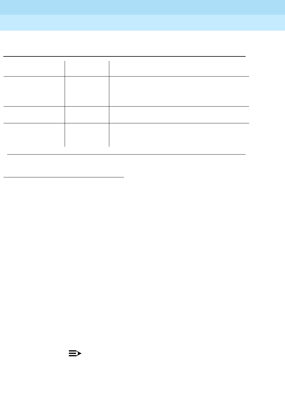
DEFINITY Enterprise Communications Server Release 6
Maintenance for R6r Volumes 1 & 2
555-230-126 Issue 2
January 1998
Maintenance Object Repair Procedures
Page 9-1585TONE-BD (Tone-Clock Circuit Pack)
9
1. Use the list cabinet command to determine the Port Network number of
the cabinet and carrier containing the Tone-Clock circuit pack to be
replaced. If both Tone-Clock circuit packs in a Port Network need to be
replaced, first replace and test the one that is in standby mode. Make sure
that it is healthy and active before replacing the second one. Make sure
the Tone-Clock circuit pack to be replaced is in Standby Mode by
displaying its status via the status port-network command or making
sure its yellow LED is off.
The active/standby state of a Tone-Clock circuit pack may also be
determined by looking at its LED. A continuously lit red LED on the
Tone-Clock circuit pack indicates a reported fault on one or more of the
maintenance objects on the circuit pack. Flashing patterns of the yellow
and green LEDs correspond to the following service states:
2. If the Tone-Clock circuit pack to be replaced is active, then switch to the
other Tone-Clock circuit pack by doing the following:
■set tone-clock UUC—Where UUC is the Standby Tone-Clock
circuit pack.
NOTE:
When Port Network Connectivity Duplication is active, the
system generally expects an EPN to have its "preferred"
Tone-Clock circuit pack active. For the first Port Network in a
given cabinet, this is carrier A. For a second PN in a given
1. For a Tone-Clock in the master port network, the external source is the primary or secondary DS1
source, or a Stratum 3 clock. For a Tone-Clock in a slave port network, the external source is the
Expansion Interface circuit pack.
"double blink"
yellow
.3 sec on, .3 sec off,
.3 sec on, 2.4 sec off,
active TN2182 has lost all external references and is in
holdover mode.
other green and
yellow patterns active Maintenance software is testing the active circuit pack.
random yellow standby If the circuit pack is a TN2182, the yellow LED may
come on and off intermittently as ETR-PTs on the board
are used for tone detection services.
Table 9-540. LED Condition/Tone-Clock Circuit States
(Two Tone-Clock Pack) — Continued
Condition Tone-Clock
Circuit State Explanation
Continued on next page

DEFINITY Enterprise Communications Server Release 6
Maintenance for R6r Volumes 1 & 2
555-230-126 Issue 2
January 1998
Maintenance Object Repair Procedures
Page 9-1586TONE-BD (Tone-Clock Circuit Pack)
9
cabinet this is carrier E. There is no "preferred" tone clock for
the PPN, regardless of reliability options.
■status system—Verify the Tone-Clock circuit pack switched to the
other Tone-Clock circuit pack or check the LEDs. The yellow LED of
the new Standby Tone-Clock circuit pack should be off (provided
maintenance is not running on it) and the yellow LED of the active
Tone-Clock circuit pack should be blinking.
■If the interchange was not successful, the standby Tone-Clock
circuit pack may be defective. In particular, if the error message
"must use override" is displayed, fix the standby Tone-Clock circuit
pack before attempting to replace the active one.
3. If the Tone-Clock circuit pack to be replaced is in the PPN, it is
recommended, but not required, that the SPE carrier containing it be
locked in standby mode by executing an interchange if necessary, and
locking the SPE-Select switches. This protects you from disrupting service
in case of inadvertent errors in replacing the circuit pack. See "Repairing
SPE Components" in Chapter 5, ‘‘Responding to Alarms and Errors’’.
NOTE:
If the SPE-Select switches are locked, be sure to release them at the
conclusion of the replacement procedure.
4. Pull out the defective Tone-Clock circuit pack. No calls should be
affected. If this is a TN2182 circuit pack, some ETR-PTs may be in use and
removal of the pack will affect some individual users. It may be less
disruptive to busyout the standby TN2182 before removing it.
5. Insert a new Tone-Clock circuit pack of the appropriate code in the same
slot where the defective Tone-Clock circuit pack was removed.
6. Test the new Tone-Clock circuit pack via the test tone-clock UUC long
command to make sure it is functioning properly. If the Tone-Clock circuit
pack is being replaced due to loss of c locks, the Clock Health Inquiry
(#46) will still report a failure, proceed with the next step.
7. To verify that the new Tone-Clock circuit pack can generate clocks for the
system, switch to the new Tone-Clock with set tone-clock UUC override,
and execute test tone-clock UUC. (In a PPN, the SPE-Select switches
must be in the auto position.)
!CAUTION:
If the new Tone-Clock circuit pack is not able to generate system
clocks, this procedure becomes destructive. The system will detect
a loss of clock and recover accordingly.
In this case if the Tone-Clock circuit pack being replaced is in the
PPN the system will perform a reset system 2 (cold 2 restart)
automatically. If the Tone-Clock circuit pack being replaced is in an
EPN, the system will reset the EPN (EPN cold restart). After either

DEFINITY Enterprise Communications Server Release 6
Maintenance for R6r Volumes 1 & 2
555-230-126 Issue 2
January 1998
Maintenance Object Repair Procedures
Page 9-1587TONE-BD (Tone-Clock Circuit Pack)
9
type of restart, the faulty Tone-Clock circuit pack will be in standby
mode.
If the new Tone-Clock circuit pack is able to generate system clocks,
there will be no system disruption.
8. Place several phone calls.
9. After replacing a Tone-Clock circuit pack in an SPE, if the SPE lock
switches were set during the procedure, they should be released.
Additionally, after repairs in an EPN, the set tone-clock UUC command
should be used if required to make the preferred Tone-Clock circuit pack
active.

DEFINITY Enterprise Communications Server Release 6
Maintenance for R6r Volumes 1 & 2
555-230-126 Issue 2
January 1998
Maintenance Object Repair Procedures
Page 9-1588TONE-BD (Tone-Clock Circuit Pack)
9
Error Log Entries and Test to Clear Values
1. Run the Short Test Sequence first. If all tests pass, run the Long Test Sequence. Refer to the appropriate
test description and follow the recommended procedures.
2. Minor alarms on this MO may be downgraded to Warning alarms based on the value used in the set
options command.
Table 9-541. Tone-Clock Circuit Pack Error Log Entries
Error
Type Aux
Data Associated Test Alarm Level On/Off
Board Test to Clear Value
010 Any Any Any test tone-clock PC sh
1(a) 0 Circuit pack removed
or SAKI Sanity Test
(#53)
MINOR ON
18(b) 0 busyout tone-clock PC WARNING OFF release tone-clock PC
23(c) 0 None WARNING OFF
125(d) None MINOR ON
126(e) None MINOR ON
257 65535 Control Channel Test
(#52) MINOR ON test tone-clock PC r 20
257(f) Any None
513(g) Any None
769(h) 4358 None
1025(i) 4363 NPE Audit Test (50) test tone-clock PC sh
1538(j) Any None MINOR ON
2049(k) 0 Clock Health Inquiry
Test (#46) MAJOR ON set tone-clock PC override
2305(k) 0 Clock Health Inquiry
Test (#46) MAJOR ON set tone-clock PC override
2561(l) Any None MAJOR ON
3329(m) 0 None MINOR/
WARNING2OFF set tone-clock PC
3840(n) Any None
3848(o) 0 Clock Health Inquiry
Test (#46) set tone-clock PC override
3872(p) 0 None set tone-clock PC override
3999 (q) Any None
DEFINITY Enterprise Communications Server Release 6
Maintenance for R6r Volumes 1 & 2
555-230-126 Issue 2
January 1998
Maintenance Object Repair Procedures
Page 9-1589TONE-BD (Tone-Clock Circuit Pack)
9
Notes:
a. Error Type 1This error indicates the circuit pack totally stopped
functioning or it was physically removed from the system.
NOTE:
The alarm is logged approximately 11-minutes after the circuit pack
is removed/SAKI Sanity Test (#53) fails.
If the circuit pack is not present in the system, insert a circuit pack in the
slot indicated by the error to resolve the error.
If the circuit pack is present in the system, it is faulty and must be
replaced. See the preceding section,
How to Replace the Tone-Clock
Circuit Pack
.
If the faulty circuit pack is in standby mode, a MINOR alarm is raised, but
no other system action is taken. If the circuit pack is the active
Tone-Clock, further effects of this error depend on the Reliability Option for
the switch.
If an interchange is attempted and the system is unable to activate the
standby Tone-Clock, Emergency Transfer is activated. If the problem is in
the PPN the entire system is affected. Otherwise only the EPN in question
is affected. When this happens, both circuit packs are faulty and must be
replaced. See the preceding section,
How to Replace the Tone-Clock
Circuit Pack
.
If a successful interchange occurs in response to a failure of the active
Tone-Clock, or if a standby Tone-Clock fails, the faulty Tone-Clock should
be replaced.
b. Error Type 18The indicated Tone-Clock circuit pack has been made
unavailable via the busyout tone-clock PC command. This error applies
only to High or Critical Reliability systems (an active Tone-Clock may not
be busied out). To resolve this error, execute release tone-clock PC.
c. Error Type 23The circuit pack has been logically administered but not
physically installed. Installing the circuit pack will resolve the alarm.
Table 9-542. Location of Tone-Clock Circuit Pack
Reliability
Option PPN EPN
Standard System Emergency Transfer
(entire system affected) Emergency Transfer in the affected EPN
High Interchange to standby
Tone-Clock in the PPN Emergency Transfer in the affected EPN
Critical Interchange to standby
Tone-Clock in the PPN Interchange to standby Tone-Clock in the
affected EPN

DEFINITY Enterprise Communications Server Release 6
Maintenance for R6r Volumes 1 & 2
555-230-126 Issue 2
January 1998
Maintenance Object Repair Procedures
Page 9-1590TONE-BD (Tone-Clock Circuit Pack)
9
d. Error Type 125A wrong circuit pack is inserted in the slot where this
circuit pack is logically administered. To resolve this problem, either
remove the wrong circuit pack and insert the logically administered circuit
pack OR use the change circuit-pack command to readminister this slot
to match the circuit pack inserted.
e. Error Type 126The port network specified in the PORT field of the error
log entry booted up without a Tone-Clock circuit pack, or with a one that
cannot communicate at all with the system. The error is logged five
minutes after the port network is restarted. If no circuit pack is present,
install one of the proper code. If there is a circuit pack present, replace it.
See the preceding section,
How to Replace the Tone-Clock Circuit Pack
.
f. Error Type 257Τhis error indicates transient communication problems
with this circuit pack. This error is not service-affecting and no action is
required.
g. Error Type 513This circuit pack has an on-board hardware failure.
Replace the circuit pack using the procedure described in preceding
section,
How to Replace the Tone-Clock Circuit Pack
.
h. Error Type 769This error can be ignored, but look for other errors on this
circuit pack.
i. Error Type 1025This error is not service-affecting and no action is
required.
j. Error Type 1538The circuit pack was taken out of service because of an
excessive rate of uplink messages. Use test tone-clock PC long to reset
the circuit pack and put it back into service. If the command is not
successful, replace the circuit pack using the procedure described in the
preceding section,
How to Replace the Tone-Clock Circuit Pack
. If the
alarmed circuit pack is the active Tone-Clock of a duplicated pair, first
interchange Tone-Clocks via the set tone-clock PC command to avoid a
service outage. If the error occurs again within 15 minutes, follow normal
escalation procedures.
k. Error Type 2049 or 2305These errors indicate the loss of one or more
clock signals from the reported Tone-Clock circuit pack, which was active
at the time of the error. The effect of any of these errors is described in the
table for error type 1. Diagnosis of the problem is the same for all four error
types, with the exception noted below.
1. Examine the Hardware Error Log for errors reported against circuit
packs in the same Port Network, especially TDM-CLK, TONE-BD,
DUPINT, SW-CTL, and EXP-INTF. Follow the repair or replacement
procedures indicated for any such errors found.
2. If the error is not corrected by resolving errors found in step 1, the
Tone-Clock circuit pack should be replaced. See the preceding
section,
How to Replace the Tone-Clock Circuit Pack
.

DEFINITY Enterprise Communications Server Release 6
Maintenance for R6r Volumes 1 & 2
555-230-126 Issue 2
January 1998
Maintenance Object Repair Procedures
Page 9-1591TONE-BD (Tone-Clock Circuit Pack)
9
NOTE:
Replacing the circuit pack and retesting it with the test
tone-clock command is not adequate to retire this alarm and
return the Tone-Clock Circuit Pack to full service; the Clock
Health Inquiry test (#46) will continue to fail. Because the
ability to generate clocks was considered lost, once any
repairs have been made it is necessary to execute the set
tone-clock PC override command, forcing the circuit pack to
become active. If the problem has not actually been
corrected, this action may cause a disruption in service for
active digital facilities users.
3. If error 2305 or 3848 persists, all clock signals from the indicated
board were lost. If the reported Tone-Clock circuit pack is in a Port
Network with duplicated Tone-Clocks, the problem may lie with the
circuit pack responsible for selecting the active Tone-Clock circuit
pack (the
t/c selector
).
■For a PPN, the t/c selector is the DUPINT circuit pack on
carrier A.
■For an EPN, the t/c selector is the active EXP-INTF circuit
pack that is connected to the PPN. This is EXP-INTF 2A01 or
2B02 for EPN1 and 3A01 or 3B02 for EPN2.
The t/c selector circuit pack of interest is the one which was active
at the time the error was logged. This is the currently active t/c
selector unless there has been an SPE interchange for PPN
problem, or an EXP-INTF link switch for EPN problem, In order to
determine whether an interchange has occurred since the
TONE-BD error, examine the display initcauses log for SPE
interchanges, and EXP-LNK entries in the hardware error log for
expansion link interchanges.
If the t/c selector circuit pack was not replaced as part of the
previous step, replace it now. Follow procedures described in
"Replacing SPE Circuit Packs" in Chapter 5; Chapter 7, ‘‘LED
Indicators’’, for the DUPINT circuit pack, or in the EXP-INTF section
of this chapter for the Expansion Interface.
4. If the error has not been corrected at this point, there is a problem
with the TDM Bus within the Port Network containing the reported
Tone-Clock circuit pack. This may include TDM Bus intercarrier
cables, Bus terminators, bent pins on the backplane, and errors on
any circuit pack plugged into the same Port Network. Refer to the
TDM-BUS section.
l. Error Type 2561This error indicates that a Tone-Clock circuit pack, with
a different circuit pack code as required for this system, has been inserted
in the port slot as shown in the Hardware Error Log. To resolve this error,
refer to the "How to Replace the Tone-Clock Circuit Pack" section for an

DEFINITY Enterprise Communications Server Release 6
Maintenance for R6r Volumes 1 & 2
555-230-126 Issue 2
January 1998
Maintenance Object Repair Procedures
Page 9-1592TONE-BD (Tone-Clock Circuit Pack)
9
appropriate circuit pack code and replace the Tone-Clock circuit pack
according to the procedures indicated for this system. The meanings of
the aux data values are as follows:
m. Error Type 3329The system attempted but failed to interchange
Tone-Clock circuit packs. (This error occurs only in Port Networks with
duplicated Tone-Clocks.) The fault may lie in the standby Tone-Clock or in
the circuit pack that controls selection of the active Tone-Clock (the
t/c
selector
). The goal of the following procedure is to ensure that both
Tone-Clocks can be interchanged into while either t/c-selector circuit pack
is active.
1. Examine the Error Log for errors reported against circuit packs in
the same Port Network, paying special attention to TDM-CLK,
TONE-BD, DUPINT, SW-CTL, and EXP-INTF. Follow the procedures
indicated for any such errors found. After eliminating the above
potential problem sources, proceed with the following steps.
2. Determine which circuit pack was controlling the choice of
Tone-Clock at the time the error occurred.
■For a PPN, the t/c selector is the DUPINT circuit pack on the
A-carrier.
■For an EPN, the t/c selector is the active EXP-INTF circuit
pack that is connected to the PPN. This is EXP-INTF 2A01 or
2B02 for EPN1 and 3A01 or 3B02 for EPN2.
The t/c-selector circuit pack of interest is the one which was active
at the time the error was logged. An EXP-LNK interchange since
the time of the error may have made that circuit pack the current
standby. Determine whether an interchange affecting the t/c
selector has occurred since the TONE-BD error. When investigation
an EPN Tone-Clock, look for EXP-LNK entries in the hardware error
log for PNC interchanges, which would affect the EXP-INTF.
3. If the t/c selector has not undergone an interchange since the error
occurred, go to the next step. If such an interchange has taken
place, interchange back to the formerly active t/c selector. Use the
1001 A TN756 Tone-Clock circuit pack is in the PPN of a one port network
system without High or Critical Reliability (Multicarrier Cabinet).
1002 A TN756 Tone-Clock circuit pack is in the EPN of a one port network
system without High or Critical Reliability (Multicarrier Cabinet).
1003 Either a TN741 or TN714 Tone-Clock circuit pack (instead of a TN768,
TN780 or TN2182) is in a one port network system without High or
Critical Reliability (Multicarrier Cabinet).
1004 Either a TN741 or TN714 Tone-Clock circuit pack (instead of a TN768,
TN780 or TN2182) is in a High or Critical Reliability system.
1005 Same as for aux value 1004.

DEFINITY Enterprise Communications Server Release 6
Maintenance for R6r Volumes 1 & 2
555-230-126 Issue 2
January 1998
Maintenance Object Repair Procedures
Page 9-1593TONE-BD (Tone-Clock Circuit Pack)
9
set expansion-interface command when investigating an EPN
Tone-Clock.) If the interchange attempt fails due to other errors,
resolve those problems first.
4. Interchange the Tone-Clock circuit packs using the set tone-clock
PC command. If the command succeeds, the interchange which
previously failed has been accomplished and the problem has
been satisfactorily resolved. If it fails, proceed to the next step. (You
may want to proceed in any case to definitively test all relevant
components.)
5. Interchange the t/c selector using set expansion-interface if
investigating an EPN. If errors prevent this interchange, resolve
them first.
6. Attempt again to interchange Tone-Clocks with the set tone-clock
PC command.
— If the Tone-Clock interchange failed for both t/c selectors:
Replace the standby Tone-Clock circuit pack which could
not be interchanged into and return to this step. (See
How to
Replace the Tone-Clock Circuit Pack
.) Test the new circuit
pack as follows:
a. Execute the set tone-clock PC command.
b. Execute a set expansion-interface, if this is an EPN
Tone-Clock.
c. Execute the set tone-clock PC command again.
If these commands successfully complete, the problem has
been resolved.
— If these commands successfully complete, the problem has
been resolved.
— If the Tone-Clock circuit packs successfully interchange
when one EXP-INTF is active, but not when the other one is:
The t/c-selector circuit pack on the failing side is suspect.
a. Replace the A carrier DUPINT or EXP-INTF board that is
active when the Tone-Clock interchange fails. (Follow
procedures in "Replacing SPE Circuit Packs" in Chapter 5 for
the DUPINT circuit pack; for the Expansion Interface, see
‘‘EXP-INTF (Expansion Interface Circuit Pack)’’.)
b. Make sure the new t/c selector is active and execute the set
tone-clock PC command.
— If both Tone-Clocks can be interchanged into, and
interchanges succeed when either t/c selector is active, the
problem has been resolved.

DEFINITY Enterprise Communications Server Release 6
Maintenance for R6r Volumes 1 & 2
555-230-126 Issue 2
January 1998
Maintenance Object Repair Procedures
Page 9-1594TONE-BD (Tone-Clock Circuit Pack)
9
n. Error Type 3840This error is not service-affecting and can be ignored. It
indicates that the circuit pack has received a bad control message from
the switch.
o. Error Type 3848This error indicates that the Tone/Clock circuit pack
had a loss of clock. If error 2305 is also logged, see note (j).
p. Error Type 3872These errors indicate this Tone/Clock circuit pack had
a loss of Data Clocks. This error will impact mainly users on station
connected to Digital circuit packs. These users could be with out service.
If error 2049 is also logged see note (i).
q. Error type 3999 indicates that the circuit pack sent a large number of
control channel messages to the switch within a short period of time. If
error type 1538 is also present, then the circuit pack was taken
out-of-service due to hyperactivity. If error type 1538 is not present, then
the circuit pack has not been taken out-of-service, but it has generated
50% of the messages necessary to be considered hyperactive. This may
be completely normal during heavy traffic periods. However, if this error
type is logged when the circuit pack is being lightly used, it may indicate a
problem with the circuit pack or the equipment attached to it.
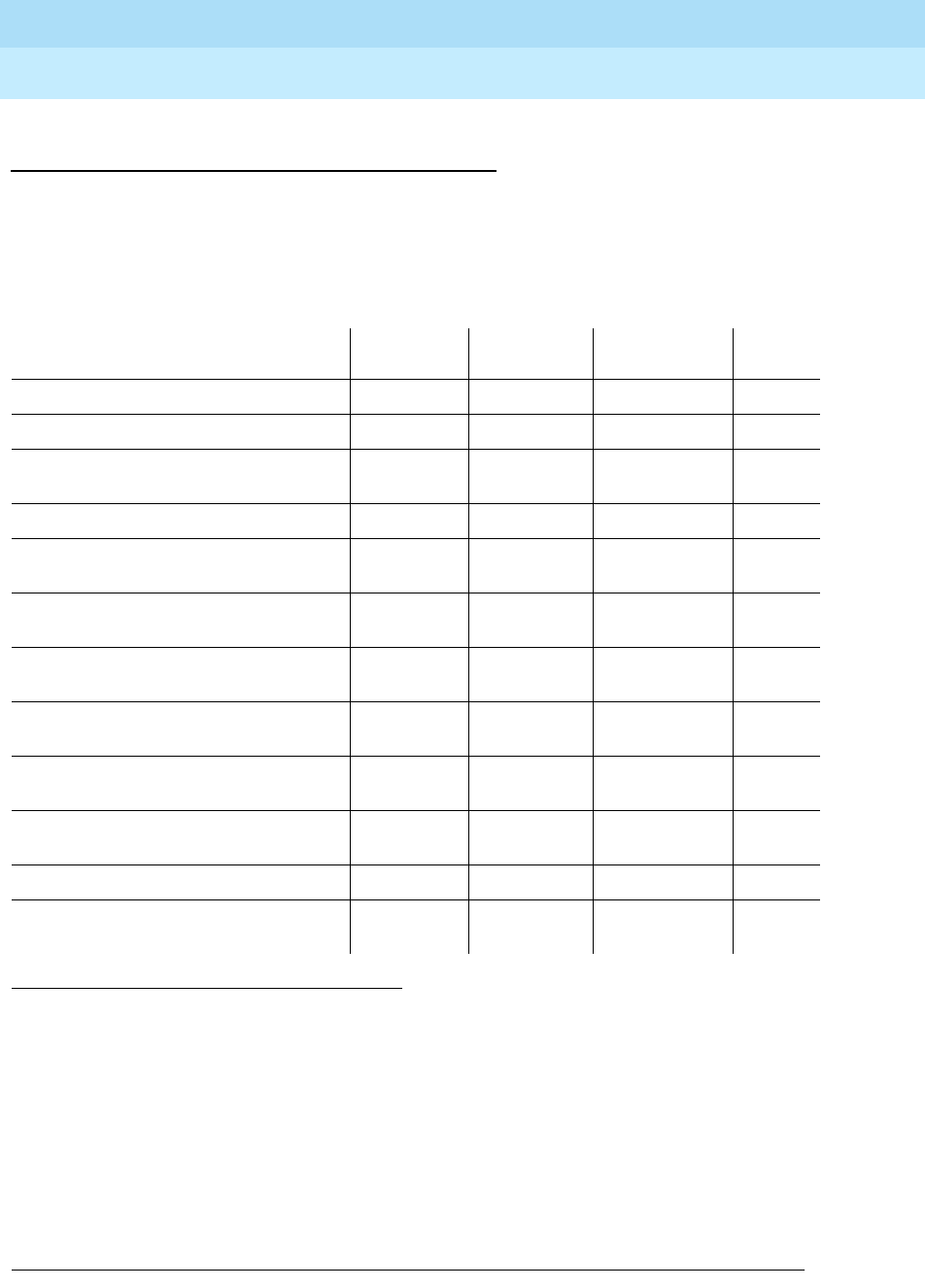
DEFINITY Enterprise Communications Server Release 6
Maintenance for R6r Volumes 1 & 2
555-230-126 Issue 2
January 1998
Maintenance Object Repair Procedures
Page 9-1595TONE-BD (Tone-Clock Circuit Pack)
9
System Technician-Demanded Tests:
Descriptions and Error Codes
Always investigate tests in the order presented in the table below when
inspecting errors in the system. By clearing error codes associated with the
SAKI
Reset Test
for example, you may also clear errors generated from other tests in
the testing sequence.
Notes:
a. Refer to XXX-BD for descriptions of these tests.
b. Refer to TONE-PT for descriptions of these tests.
c. Refer to TDM-CLK for descriptions of these tests.
d. This test runs only on the standby Tone-Clock circuit pack in a Port
Network with duplicated Tone-Clocks (High or Critical Reliability systems).
The circuit pack must be a TN780 with firmware version 2 or above.
1. D = Destructive; ND = Nondestructive
Order of Investigation Short Test
Sequence Long Test
Sequence Reset Board
Sequence D/ND1
SAKI Reset Test (#53) (a) X D
Clock Health Test (#46) X X ND
Control Channel Looparound Test
(#52)(a) XX ND
Tone Generator Crosstalk Test (#90) (b) X ND
Tone Generator Transmission Test
(#40)(b) XX ND
Tone Generator Audit/Update Test
(#41)(b) XX ND
TDM Bus Clock Circuit Status Inquiry
Test (#148) (c) XX ND
TDM Bus Clock Slip Inquiry Test
(#149)(c)(e) XX ND
TDM Bus Clock PPM Inquiry Test
(#150)(c) XX ND
TDM Bus Clock Parameter Update Test
(#151) (c) XX ND
Board Type Check Test (#574) (c) X X ND
Standby Reference Health Check Test
(#651) (c,d) XND

DEFINITY Enterprise Communications Server Release 6
Maintenance for R6r Volumes 1 & 2
555-230-126 Issue 2
January 1998
Maintenance Object Repair Procedures
Page 9-1596TONE-BD (Tone-Clock Circuit Pack)
9
Clock Health Inquiry Test (#46)
This inquiry reads special data stored in memory to determine if this Tone-Clock
circuit pack had a loss of any of three clock types:
■SYSCLK
■SYSFM
■SYSDCLK
If this data indicates this Tone-Clock circuit pack had a loss of any of these
clocks, the inquiry reports FAIL. In addition, if TDM-CLK error 1 is at threshold,
this test will FAIL. TDM-CLK error 1 indicates a suspect clock is at the edge of its
specified frequency. If the circuit pack did not have a loss of clock or TDM-CLK
error 1 at threshold, the inquiry reports PASS.
This is not really a test, in the sense that it simply reports status held by the
system, and does not generate new information or raise alarms. If this test fails
with no error code, there is at least one Major alarm against a Tone-Clock circuit
pack. If this test fails with an error code of 1, there is at least one Minor off-board
alarm against a TDM-CLK.
Table 9-543. TEST #46 Clock Health Inquiry Test
Error
Code Test
Result Description/ Recommendation
ABORT Internal system error.
1. Retry the command at 11-minute intervals for a maximum of 5 times.
none FAIL This Tone-Clock circuit pack had an apparent loss of clock. One or more of
error types 2049, 2305, 3834, and 3872 will appear in the error log. Correct the
problem according to the appropriate error log entries.
Once this test fails, the only way to make it pass, and to retire the associated
alarm, is to repair the problem and to execute the set tone-clock UUC
override command against the indicated Tone-Clock circuit pack.
1 FAIL This Tone-Clock circuit pack is suspect of having a clock at the edge of its
specified frequency. A Tone-Clock circuit pack with this problem can cause
Expansion Interface circuit packs and SNI circuit packs to go out-of-frame or
report no neighbor conditions, thus causing EPNs, Expansion Archangel Links
(EALs), Remote Neighbor Links (RNLs), and/or Local Neighbor Links LNLs) to
go down.
1. Replace the Tone-Clock circuit pack identified in the error log. Refer to the
‘‘How to Replace the Tone-Clock Circuit Pack’’ section.
PASS This Tone-Clock circuit pack has not reported a loss of clock.
Continued on next page
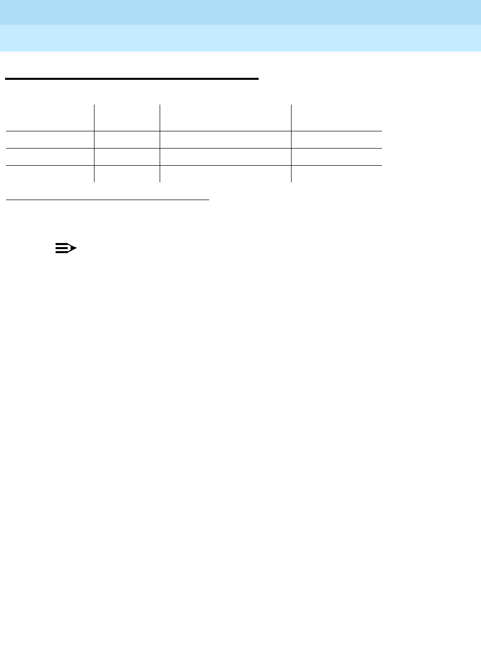
DEFINITY Enterprise Communications Server Release 6
Maintenance for R6r Volumes 1 & 2
555-230-126 Issue 2
January 1998
Maintenance Object Repair Procedures
Page 9-1597TONE-PT (Tone Generator)
9
TONE-PT (Tone Generator)
NOTE:
Replacing the tone/clock circuit pack requires a special procedure which is
described in the documentation for TONE-BD. That section also describes
the LED display for this board.
The tone generator resides on the Tone/Clock circuit pack and provides all
system tones such as dial tone, busy tone, and so on. If an active tone generator
fails, its port network may not have tones (see the Tone Generator Transmission
Test #40). For instance, a user may go off-hook and hear no dial tone. This
problem will affect only users on the same port network in which the faulty
Tone-Clock circuit pack resides. The system will be able to process certain type
of calls (that is, internal calls will succeed while outgoing calls will not).
The Tone-Clock circuit pack also provides the clocks for the system and can
serve as the synchronization reference. Therefore, when resolving alarms on the
Tone-Clock circuit pack, the TDM-CLK (TDM Bus Clock) and SYNC
(Synchronization) Maintenance documentation should be utilized as well as the
TONE-BD (Tone-Clock Circuit Pack) Maintenance documentation.
See the section on TONE-BD Maintenance in this manual for a discussion of the
relationship of Tone-Clock circuit packs with the various Reliability Options.
1. UU is the universal cabinet number (1 for PPN, 2 -44 for EPNs). C is the carrier designation
(A, B, C, D, or E).
MO Name (in
Alarm Log) Alarm Level Initial Command To Run1Full Name of MO
TONE-PT MAJOR test tone-clock UUC short Tone Generator
TONE-PT MINOR test tone-clock UUC short Tone Generator
TONE-PT WARNING release tone-clock UUC Tone Generator

DEFINITY Enterprise Communications Server Release 6
Maintenance for R6r Volumes 1 & 2
555-230-126 Issue 2
January 1998
Maintenance Object Repair Procedures
Page 9-1598TONE-PT (Tone Generator)
9
Error Log Entries and Test to Clear Values
Notes:
a. A failure in the tone generation facility on the indicated circuit pack has
been detected. Replace the circuit pack. See
How to Replace the
Tone-Clock Circuit Pack
in the TONE-BD section.
b. The indicated Tone-Clock circuit pack has been made unavailable via the
busyout tone-clock UUC command. It only applies to systems which
have the High or Critical Reliability Option administered, because only a
standby Tone-Clock circuit pack may be made busy by that command. To
resolve this error, execute the release tone-clock UUC command for the
alarmed circuit pack.
c. This error type indicates that the circuit pack has been removed or has
been insane for more than 11-minutes. To clear the error, reinsert or
replace the circuit pack.
1. Run the Short Test Sequence first. If all tests pass, run the Long Test Sequence. Refer to the
appropriate test description and follow the recommended procedures.
2. MAJOR alarm if the alarmed Tone-Clock circuit pack is not duplicated; MINOR if it duplicated within
the same Port Network.
Table 9-544. Tone Generator Error Log Entries
Error
Type Aux
Data Associated Test Alarm
Level On/Off
Board Test to Clear Value
010 Any Any Any test tone-clock UUC r 1
1(a) 17664 Tone Generator
Audit/ MAJOR/ ON test tone-clock UUC r 2
Update Test (#41) MINOR2
18(b) 0 busyout tone-clock
UUC WARNING OFF release tone-clock UUC
130(c) None MINOR ON test tone-clock UUC Sh
257(d,f) 17667 None MINOR ON
513(e,f) 17666 Tone Generator
Audit/ Update Test
(#41)
MINOR ON test tone-clock UUC r 3
769 Any Transmission Test
(#40) MAJOR/
MINOR2ON test tone-clock UUC r 3
1025 Crosstalk Test (#90) MAJOR/
MINOR2ON test tone-clock UUC l r 2
1281(g) Any Tone Generator
Audit/ Update Test
(#41)
MINOR ON test tone-clock UUC r 3

DEFINITY Enterprise Communications Server Release 6
Maintenance for R6r Volumes 1 & 2
555-230-126 Issue 2
January 1998
Maintenance Object Repair Procedures
Page 9-1599TONE-PT (Tone Generator)
9
d. The tone generation facility is having problems verifying that tones have
been connected as requested.
e. The tone generation facility may or may not be able to generate tones.
f. Infrequent errors, at a rate which does not bring up an alarm, probably do
not affect service, unless there are customer complaints of no tones, or
incorrect tones which can not be explained in any other way. However, if
an alarm is raised because this error is being repeatedly logged, then the
circuit pack should be replaced. See
How to Replace the Tone-Clock
Circuit Pack
in the TONE-BD section.
g. The system-parameters country-options administration are setup such
that a TN780 or TN2182 are required and the existing tone-clock circuit
pack will not provide the needed functionality. The Base Tone Generation
Set on page 1 or the custom tones beginning on page 2 of the
system-parameters country options form may have values not supported
by the existing tone-clock.
This error (1281) indicates that the system parameters country-options
form has custom tones translated and that the alarmed tone board does
not support the customized tones. TN768 tone boards do not support any
customized tones. TN780 tone boards support up to 6 customized tones
using the following frequencies/levels only:
Silence
350Hz at 17.25 dB
425Hz at 4.0 dB
425Hz at 11.0 dB
425Hz at 17.25 dB
440Hz at 17.25 dB
350Hz+425Hz at 4.0 dB
350Hz+440Hz at 13.75 dB
480Hz at 17.25 dB
620Hz at 17.25 dB
440Hz+480Hz at 19.0 dB
404Hz at 11.0 dB
404Hz at 16.0 dB
480Hz+620Hz at 24.0 dB
404Hz+425Hz at 11.0 dB
375Hz+425Hz at 15.0 dB
404Hz+450Hz at 11.0 dB
1000Hz at 0.0 dB

DEFINITY Enterprise Communications Server Release 6
Maintenance for R6r Volumes 1 & 2
555-230-126 Issue 2
January 1998
Maintenance Object Repair Procedures
Page 9-1600TONE-PT (Tone Generator)
9
1000Hz at +3.0 dB
525Hz at 11.0 dB
1400Hz at 11.0 dB
System Technician-Demanded Tests:
Descriptions and Error Codes
Always investigate tests in the order presented in the table below when
inspecting errors in the system. By clearing error codes associated with the
SAKI
Reset Test
for example, you may also clear errors generated from other tests in
the testing sequence.
Notes:
a. Refer to XXX-BD (Common Port Circuit Pack) section for descriptions of
these tests.
1. D = Destructive; ND = Nondestructive
Order of Investigation Short Test
Sequence Long Test
Sequence Reset Board
Sequence D/ND1
SAKI Reset Test (#53) (a) X D
Clock Health Test (#46) (b) X X ND
Control Channel Looparound Test
(#52) (a) XX ND
Tone Generator Crosstalk Test (#90) X ND
Tone Generator Transmission Test
(#40) XX ND
Tone Generator Audit/Update Test
(#41) XX ND
TDM Bus Clock Circuit Status Inquiry
Test (#148) (c) XX ND
TDM Bus Clock Slip Inquiry Test
(#149)(c)(e) XX ND
TDM Bus Clock PPM Inquiry Test
(#150) (c) XX ND
TDM Bus Clock Parameter Update
Test (#151) (c) XX ND
Board Type Check Test (#574) (c) X X ND
Standby Reference Health Check Test
(#651) (c,d) XND

DEFINITY Enterprise Communications Server Release 6
Maintenance for R6r Volumes 1 & 2
555-230-126 Issue 2
January 1998
Maintenance Object Repair Procedures
Page 9-1601TONE-PT (Tone Generator)
9
b. Refer to TONE-BD (Tone-Clock Circuit Pack) section for descriptions of
these tests.
c. Refer to TDM-CLK (TDM Bus Clock) section for descriptions of these tests.
d. This test only runs on the Standby Tone-Clock circuit pack in a Port
Network with more than one Tone-Clock circuit pack (High or Critical
Reliability Option). The circuit pack must be a TN780 code with firmware
revision 2 or above.
e. Test #149 does not run on the TN2182.
Tone Generator Transmission Test (#40)
The purpose of this test is to verify that the tone generation hardware on the
tone-clock circuit pack is capable of generating a subset of system tones and a
set of test tones. This test does not verify all system tones the tone generator
produces during normal system operation.
The test is performed in two parts. For the first part, the Tone Generator is told to
generate the touch-tone digits. The digits are received and checked by a Tone
Detector touch-tone detector. If any of the digits fail, the test is repeated using a
touch-tone detector in another Tone Detector circuit pack.
For the second part, the Tone Generator is told to generate call progress tones
that are detected and identified by a tone detector. These tones are:
■440 Hz
■2225 Hz
■Digital Count
The tone generator is then told to generate a sequence of test tones whose
output levels are measured by a tone detector. These tones are:
■404 Hz at 0 dB
■1004 Hz at -16 dB
■1004 Hz at 0 dB
■2804 Hz at 0 dB
A Tone Detector general purpose tone detector listens for the tones and
measures the quality of the tone. If any of the measured values are not within
limits, the test is repeated using a general purpose tone detector in a different
Tone Detector circuit pack. If the values are still out of the limits, the test will fail.
For all the failure cases of Test #40, do the following:
1. Check that all Tone Detector circuit packs have the same companding
mode as that administered for the system. Correct the situation if there is a
mismatch.

DEFINITY Enterprise Communications Server Release 6
Maintenance for R6r Volumes 1 & 2
555-230-126 Issue 2
January 1998
Maintenance Object Repair Procedures
Page 9-1602TONE-PT (Tone Generator)
9
2. Run the long test sequence: test tone-clock PC long repeat 1.
3. If the problem persists, replace the Tone-Clock circuit pack by following
the steps outlined in the ‘‘How to Replace the Tone-Clock Circuit Pack’’
section
Table 9-545. TEST #40 Tone Generator Transmission Test
Error
Code Test
Result Description/ Recommendation
None ABORT The system was not able to allocate all the resources needed for this test or
there was an Internal system error.
1 ABORT The system could not allocate all the resources needed to test the DTMF
tones.
1001 ABORT The system was not able to put the tone generation facility in the
appropriate mode to test it.
1002 ABORT The system could not allocate time slots for the test connection. This can
happen when the system is heavily loaded. If the system is not heavily
loaded, then test the TDM Bus via the test tdm port-network PN#
command. Refer to TDM-BUS section for details.
1. Retry the command at 1-minute intervals a maximum of 5 times.
1003 ABORT The system could not allocate a tone receiver for the test connection. This
can happen when the system is heavily loaded or there is not a Tone
Detector circuit pack in the port network where this test is being executed.
1. Make sure there is a Tone Detector circuit pack in the same port
network.
2. If a Tone Detector circuit pack is missing, install one in the same port
network.
3. Allow approximately 1-minute for Tone Detector maintenance to run on
the newly inserted Tone Detector circuit pack.
4. Retry the command at 1-minute intervals a maximum of 5 times.
1022 ABORT [G3r V2] Tone detection for the system is administered as wide broadband
(tone detection mode 5), and the Tone Detector used for this test was not a
TN420C. (the only circuit packs with this capability). GPTD ports on other
types of Tone Detector circuit packs are taken out of service since they
cannot provide the administered function.
1. Change the tone-detection mode administered on the
system-parameters country-options form (see
DEFINITY
Communications System Generic 3 V2 Implementation,
555-230-653,
Or
2. Remove all non-TN420C circuit packs from the system.
Continued on next page

DEFINITY Enterprise Communications Server Release 6
Maintenance for R6r Volumes 1 & 2
555-230-126 Issue 2
January 1998
Maintenance Object Repair Procedures
Page 9-1603TONE-PT (Tone Generator)
9
Notes:
Except in Port Networks containing more than one Tone-Clock circuit pack,
replacing the circuit pack is a service disrupting procedure. The test should be
run several times with more than one failure before the replacement policy
specified in the following notes is executed. Use the procedure described in
How
to Replace the Tone-Clock Circuit Pack
in the TONE-BD section.
a. All the failure error codes marked with (a) may affect users if the failure is
on the active tone generator. When this type failure is detected, the
system will attempt to move the tone generation function to the alternate
Tone-Clock circuit pack, if one is present in the affected Port Network.
When the tone generation facility fails in this way, especially in a Port
Network without duplicated Tone-Clock circuit packs, the faulty
Tone-Clock should be replaced promptly.
2000 ABORT Response to the test request was not received within the allowable time
period. System resources required for this test are not available.
1. Retry the command at 1-minute intervals a maximum of 5 times.
2100 ABORT System resources required for this test are not available.
1. Retry the command at 1-minute intervals a maximum of 5 times.
1 (a) FAIL DTMF generation failed for the active tone generator.
105 (a) FAIL Generation of 440-Hz failed.
109 (a) FAIL Generation of 2225-Hz failed.
110 (b) FAIL Generation of 404-Hz level invalid.
111 (b) FAIL Generation of 1004-Hz low level invalid.
112 (b) FAIL Generation of 1004-Hz high level invalid.
113 (b) FAIL Generation of 2804-Hz level invalid.
115 (b,c) FAIL Generation of digital count sequence invalid.
120 (a) FAIL Generation of quiet tone failed.
1044 (a) FAIL DTMF generation failed to generate Digit 1 for the standby tone generator.
1045 (a) FAIL DTMF generation failed to generate Digit 5 for the standby tone generator.
1046 (a) FAIL DTMF generation failed to generate Digit 9 for the standby tone generator.
1047 (a) FAIL DTMF generation failed to generate Digit D for the standby tone generator.
PASS The tone generation facility is able to generate and transmit all the tones.
Table 9-545. TEST #40 Tone Generator Transmission Test — Continued
Error
Code Test
Result Description/ Recommendation
Continued on next page

DEFINITY Enterprise Communications Server Release 6
Maintenance for R6r Volumes 1 & 2
555-230-126 Issue 2
January 1998
Maintenance Object Repair Procedures
Page 9-1604TONE-PT (Tone Generator)
9
b. All the failure error codes marked with (b) are almost transparent to the
user. Again, when this type failure is detected, the system will attempt to
move the tone generation function to the alternate Tone-Clock circuit
pack, if one is present in the affected Port Network. Users may or may not
hear any noisy tones. This type of failure affects maintenance on other
objects. Maintenance may not be able to run on other objects which use
the tone generation facility (that is, Tone Detector Circuit Pack
maintenance). In this case, the Tone-Clock circuit pack can be replaced
as suitable to the customer.
c. Error code 115 may also be caused by TDM Bus corruption. This normally
means a physical problem with bent backplane pins, TDM/LAN Bus
cabling, or TDM/LAN Bus terminators. Such physical problems should
especially be suspected if board replacement or other physical activity
has occurred just before this error is observed.
Use display errors to look for errors on other circuit packs in the carriers
of the same Port Network as the indicated Tone-Clock. If any are found,
they should be resolved if possible, and the Tone-Clock circuit pack
retested. If this does not clear the problem, the Tone-Clock circuit pack
should be replaced and the new one tested. If the problem persists, follow
instructions for TDM Bus maintenance in this manual.
Tone Generator Update/Audit Test (#41)
The active tone generation facility is refreshed with all the time slot tone
information. This test also triggers in-line error messages the Tone-Clock circuit
pack generates when it detects problems by itself.
A check is also made between the type of tone-clock being tested and the type
of tone-clock needed based on system administration. The administration on the
system-parameters country-options form may imply that a TN780 is required
Table 9-546. TEST #41 Tone Generator Update/Audit Test
Error
Code Test Result Description/ Recommendation
none ABORT The system was not able to allocate all the resources needed for this test.
2100 ABORT System resources required for this test are not available.
Continued on next page

DEFINITY Enterprise Communications Server Release 6
Maintenance for R6r Volumes 1 & 2
555-230-126 Issue 2
January 1998
Maintenance Object Repair Procedures
Page 9-1605TONE-PT (Tone Generator)
9
1 FAIL The system requires a TN780 tone-clock to support the administered
country-options tone generation parameters.
1. Check the administration on the system-parameters country-option
form. Specifically, the Base Tone Generation Set on page 1 and any
custom tone administration beginning on page 2.
2. Replace existing tone-clock circuit packs with TN780.
PASS The tone generation facility has been successfully refreshed with its time-slot
translation and system administration is consistent with this type of
tone-clock.
1. Display the Hardware Error Log via the display errors command to
make sure this circuit pack did not generate new errors.
Table 9-546. TEST #41 Tone Generator Update/Audit Test — Continued
Error
Code Test Result Description/ Recommendation
Continued on next page

DEFINITY Enterprise Communications Server Release 6
Maintenance for R6r Volumes 1 & 2
555-230-126 Issue 2
January 1998
Maintenance Object Repair Procedures
Page 9-1606TONE-PT (Tone Generator)
9
Tone Generator Crosstalk Test (#90)
This test checks the ability of the Tone Generator to talk on a specific time slot.
The tone generator is told to talk on a specific time slot. The other idle time slots
are checked to make sure the Tone Generator put the tone on only the specified
time slot
Table 9-547. TEST #90 Tone Generator Crosstalk Test
Error
Code Test
Result Description/ Recommendation
None ABORT Internal system error
1. Retry the command at 1-minute intervals a maximum of 5 times.
1001 ABORT The system was not able to put the tone generation facility in the appropriate
mode to test it.
1002 ABORT The system could not allocate time slots for the test connection. This can
happen when the system is heavily loaded. If the system is not heavily loaded,
then test the TDM-BUS via the test tdm port-network PN# command. Refer to
TDM-BUS section for details.
2000 ABORT Response to the test request was not received within the allowable time period.
2100 ABORT Could not allocate the necessary system resources to run this test.
1. Retry the command at 1-minute intervals a maximum of 5 times.
FAIL The Tone Generator could be defective. In a Port Network with more than one
Tone-Clock circuit pack, the system will attempt to move the tone generation
function to the alternate one.
1. Test the Tone-Clock circuit pack again via the test tone-clock UUC
command.
2. If the test fails again, look at the Hardware Error Log for Tone Detector
circuit pack errors.
3. If there are Tone Detector circuit pack errors, refer to Tone Detector
Maintenance documentation (DTMR-PT, GPTD-PT, CLAS-PT, ETR-PT) to
resolve these errors first.
4. If there are no Tone Detector circuit pack errors, then the Tone-Clock
circuit pack should be replaced. See
How to Replace the Tone-Clock
Circuit Pack
in the TONE-BD section.
PASS The tone generation facility is able to put tones out.
Continued on next page

DEFINITY Enterprise Communications Server Release 6
Maintenance for R6r Volumes 1 & 2
555-230-126 Issue 2
January 1998
Maintenance Object Repair Procedures
Page 9-1607TSC-ADM (Administered Temporary Signaling Connections)
9
TSC-ADM (Administered Temporary
Signaling Connections)
No alarms are generated for Administered Temporary Signaling Connections
(TSC-ADM, also called ADM TSCs).
Administered temporary signaling connections provide a path through ISDN-PRI
networks for supplementary D-channel messages. ISDN-PRI applications such
as the Distributed Communications System (DCS) use temporary signaling
connections to exchange user information across an ISDN-PRI network. What
makes Administered TSCs unique is that these particular TSCs stay active for an
extended period of time, similar to a permanent data connection. These ADM
TSCs are used for DCS features that require Non-Call Associated (NCA) TSCs,
and the ADM TSC provides the logical channel function in a DCS network.
An NCA TSC is a virtual connection established within a D-channel without
associating any B-channel connections. The connection provides user-to-user
service by exchanging USER INFORMATION messages without associated
B-channel connections.
An Administered TSC is a special NCA TSC defined for the DCS over the
ISDN-PRI D-channel. The ADM TSC has an administratively defined endpoint
and is established for an extended period of time.
There are two types of ADM TSCs:
■Permanent
These are established by the originating PBX (Near-end ADM TSC) or by
the terminating PBX (Far-end ADM TSC). Once these ADM TSCs are
established, they remain active.
■As-Needed
These are established only when needed.
ADM TSC maintenance provides a strategy to verify that a far-end can respond
to an ISDN-PRI USER INFORMATION TSC heartbeat message, thereby
indicating that user-user signaling is functioning. In addition, maintenance can
retrieve the status of the ADM TSC’s connection state.
Since ADM TSCs are administered on a per signaling group basis, the health of
an ADM TSC also depends on the state of the D-channel or D-channel pair
administered per signaling group. Refer to ISDN-SGR documentation for details
on ISDN-PRI NFAS and D-channel Backup maintenance.
MO Name (in
Alarm Log) Alarm
Level Initial Command
to Run Full Name of MO
TSC-ADM none none Administered Temporary Signaling Connections

DEFINITY Enterprise Communications Server Release 6
Maintenance for R6r Volumes 1 & 2
555-230-126 Issue 2
January 1998
Maintenance Object Repair Procedures
Page 9-1608TSC-ADM (Administered Temporary Signaling Connections)
9
The two administration commands for ADM TSCs are as follows:
■add signaling group number
■change signaling group number
The two maintenance commands for ADM TSCs are as follows:
■test tsc-administered signaling group number [/tsc index]
■status tsc-administered signaling group number [/tsc index]
Error Log Entries and Test to Clear Values
Note:
a. There is no Test to Clear Value for error types 3840-3967. These error
types provide the following additional data that may prove useful when
tracking down problems.
Any of these errors indicates that a TSC Heartbeat Inquiry Test was run on
an active far-end Administered TSC from the switch. Upon receiving the
heartbeat message, the network communicated that the call was unable to
complete. As a result, the error was logged. Check the signaling group
status of the D-channel or D-channel pair via the status signaling-group
<group> command for the Administered TSC. Check the status of the
Administered TSC via the status tsc-administered command. Also check
the administration of the Administered TSC on the switch.
This error may only be affecting service for some DCS customers. Upon
receipt of this error condition, the switch will tear down and re-establish
the ADM TSC within 20 minutes.
Table 9-548. ADM TSC Error Log Entries
Error Type Aux Data Associated Test Alarm
Level On/Off
Board Test to Clear Value
3840-3967 (a) tsc index # test tsc-administered

DEFINITY Enterprise Communications Server Release 6
Maintenance for R6r Volumes 1 & 2
555-230-126 Issue 2
January 1998
Maintenance Object Repair Procedures
Page 9-1609TSC-ADM (Administered Temporary Signaling Connections)
9
System Technician-Demanded Tests:
Descriptions and Error Codes
Always investigate tests in the order presented in the following tables when
inspecting errors in the system. By clearing error codes associated with the
TSC
Heartbeat Inquiry Test,
for example, you may also clear errors generated from
other tests in the testing sequence.
TSC Heartbeat Inquiry Test (#604)
This test can be invoked by system technician personnel for any ADM TSC
administered in the switch. Most of the error conditions on the following table will
not log an error, but switched services may take some type of recovery action in
certain instances.
This test sends a USER INFORMATION TSC heartbeat message inquiry across
an ADM TSC to determine if the far-end can respond to a USER INFORMATION
TSC heartbeat message.
1. D = Destructive; ND = Nondestructive
Order of Investigation Short Test
Sequence Long Test
Sequence D/ND1
TSC Heartbeat Inquiry Test (#604) ND
Table 9-549. TEST #604 TSC Heartbeat Inquiry Test
Error
Code Test
Result Description/ Recommendation
2100 ABORT Could not allocate the necessary system resources to run this test.
1. Reissue the test tsc-administered command at 1-minute intervals a
maximum of 5 times.
1005 ABORT The Administered TSC does not exist.
1. Display the administration for the Administered TSC.
2. If an Administered TSC exists, reissue the test tsc-administered
command.
1113 ABORT The D-channel is out-of-service.
1. Refer to the “ISDN-LNK”.
Continued on next page

DEFINITY Enterprise Communications Server Release 6
Maintenance for R6r Volumes 1 & 2
555-230-126 Issue 2
January 1998
Maintenance Object Repair Procedures
Page 9-1610TSC-ADM (Administered Temporary Signaling Connections)
9
1145 ABORT There is congestion in the network.
1. Issue the status tsc-administered command at 1-minute intervals a
maximum of 5 times.
2. If the congestion does not clear, disable and enable the Administered TSC
via the change sig-group <group> command.
NOTE: To disable the Administered TSC, display the (administration)
Signaling Group Form via the change sig-group <group> command
where <group> refers to the number of the signaling group under which
the suspect TSC is administered. Change the Enable field to ‘‘n.’’ To
enable the ADM TSC, change the ‘‘Enable’’ field to ‘‘y.’’
3. If the congestion still does not clear, check other nodes in the network.
1146 ABORT The congestion just occurred in the network.
1. Issue the status tsc-administered command at 1-minute intervals a
maximum of 3 times.
2. If congestion does not clear, disable and enable the Administered TSC via
the change sig-group <group> command.
NOTE: To disable the Administered TSC, display the (administration)
Signaling Group Form via the change sig-group <group> command
where <group> refers to the number of the signaling group under which
the suspect TSC is administered. Change the Enable field to ‘‘n.’’ To
enable the ADM TSC, change the ‘‘Enable’’ field to ‘‘y.’’
3. If congestion still does not clear, check the other nodes in the network.
1147 ABORT The ADM TSC is being torn down.
1. Issue the status tsc-administered command at 1-minute intervals a
maximum of 3 times.
2. If ADM TSC is still down, disable and enable the ADM TSC via the change
sig-group <group> command.
NOTE:
To disable the ADM TSC, display the (administration) Signaling Group
Form via the change sig-group <group> command where <group>
refers to the number of the signaling group under which the suspect
TSC is administered. Change the Enable field to ‘‘n.’’ To enable the ADM
TSC, change the ‘‘Enable’’ field to ‘‘y.’’
3. If the ADM TSC is still down, check the other nodes in the network.
Table 9-549. TEST #604 TSC Heartbeat Inquiry Test — Continued
Error
Code Test
Result Description/ Recommendation
Continued on next page

DEFINITY Enterprise Communications Server Release 6
Maintenance for R6r Volumes 1 & 2
555-230-126 Issue 2
January 1998
Maintenance Object Repair Procedures
Page 9-1611TSC-ADM (Administered Temporary Signaling Connections)
9
1148 ABORT The ADM TSC is enabled, but inactive (near-end).
1. Disable and enable the ADM TSC.
2. Reissue the test tsc-administered command.
3. If the ADM TSC is still inactive, check the other nodes in the network.
1149 ABORT The ADM TSC is disabled.
1. Enable the TSC, and see if the status indicates ‘‘active.’’
2. Reissue the test tsc-administered command.
3. If the TSC still disabled, remove the ADM TSC from the system.
1181 ABORT Ran out of ADM TSC resources.
1. Reissue the test tsc-administered command at 1-minute intervals a
maximum of 3 times.
1182 ABORT The BX.25 link is down at the gateway.
1. Disable the ADM TSC.
2. Check the status of the gateway link via the status link link-no command.
3. Once the gateway link indicates an ‘‘in-service’’ state, enable the
Administered TSC.
4. Reissue the test tsc-administered command.
2000 ABORT The Administered TSC is not responding to a TSC heartbeat inquiry.
1. Retry the test tsc-administered command at 1-minute intervals a
maximum of 3 times.
2. If the problem continues to fail, obtain the status of the D-channel or
D-channel pair associated with the ADM TSC via the status sig-group
<group> command. If the D-channel is INS (i.e., in-service) and the status
of the ADM TSC appears to be active, then disable and enable the ADM
TSC through administration.
NOTE:
To disable the ADM TSC, display the (administration) Signaling Group
Form via the change sig-group <group> command where <group>
refers to the number of the signaling group under which the suspect
TSC is administered. Change the ‘‘Enable’’ field to ‘‘n.’’ To enable the
ADM TSC, change the ‘‘Enable’’ field to ‘‘y.’’
3. Reissue the test tsc-administered command.
4. If the test fails, check the ADM TSC node on the other side of the network
to verify that the ADM TSC is indeed active.
Table 9-549. TEST #604 TSC Heartbeat Inquiry Test — Continued
Error
Code Test
Result Description/ Recommendation
Continued on next page

DEFINITY Enterprise Communications Server Release 6
Maintenance for R6r Volumes 1 & 2
555-230-126 Issue 2
January 1998
Maintenance Object Repair Procedures
Page 9-1612TSC-ADM (Administered Temporary Signaling Connections)
9
2012 ABORT Internal system error.
1. Reissue the test tsc-administered command at 1-minute intervals a
maximum of 5 times.
1 FAIL The Administered TSC is not active (far-end).
1. Reissue the test tsc-administered command.
2. Verify that the Administered TSC node on the other side of the network is
active.
3. Disable and enable the Administered TSC.
4. Retry the test tsc-administered command.
2 FAIL Facility IE (Information Element) reject.
1. Check all other nodes in the network, and make sure Administered TSC is
active.
PASS The Administered TSC responded to a heartbeat.
Table 9-549. TEST #604 TSC Heartbeat Inquiry Test — Continued
Error
Code Test
Result Description/ Recommendation
Continued on next page

DEFINITY Enterprise Communications Server Release 6
Maintenance for R6r Volumes 1 & 2
555-230-126 Issue 2
January 1998
Maintenance Object Repair Procedures
Page 9-1613TTR-LEV (TTR Level)
9
TTR-LEV (TTR Level)
TN748 and TN420 Tone Detector circuit packs and TN744 Call Classifier circuit
packs provide tone receivers for detecting various types of signaling tones.
These circuit packs are shared resources that serve all users of the PBX. This
discussion uses the following terms and abbreviations (note that the
maintenance-related system parameters form uses different names than the
alarm and error logs):
TN748s and TN420s each have 4 DTMR-PTs and 2 GPTD-PTs. DTMR-PTs
interpret dual-tone multifrequency (DTMF) calling signals and translate them into
logical digits 0 through 9, *, and #. GPTD-PTs detect call progress tones, modem
answer tones, and transmission test tones.
TN744 Call Classifier circuit packs have 8 CLSFY-PTs. These ports detect DTMF
tones and classify network and MFC (multifrequency compelled) signaling tones.
(That is, CLSFY-PTs can function as DTMR-PTs or GPTD-PTs, and have other
additional capacities).
1. See Repair Procedure for the TTR-LEV below.
MO Name (in
Alarm Log) Alarm
Level Initial Command
to Run Full Name of MO
TTR-LEV WARNING 1TTR Level
TTR-LEV MINOR 1TTR Level
TTR-LEV MAJOR 1TTR Level
Type of Tone
Receiver Maintenance
Object Also Known
As Alternate
Abbreviation Location
Dual-tone
Multifrequency
Tone Receiver
DTMR-PT Touch Tone
Receiver TTR 4 per
TN420/TN748
General
Purpose Tone
Detector
GPTD-PT Call Progress
Tone Receiver CPTR 2 per
TN420/TN748
Call Classifier CLSFY-PT CCTR 8 per TN744

DEFINITY Enterprise Communications Server Release 6
Maintenance for R6r Volumes 1 & 2
555-230-126 Issue 2
January 1998
Maintenance Object Repair Procedures
Page 9-1614TTR-LEV (TTR Level)
9
When a user goes off-hook to place a call, dial tone is returned to the user,
indicating that a tone detector is connected and ready to receive and interpret
tones. The tone detector is in use until the total number of digits needed is
collected or until a time-out occurs. If all tone detectors in the system are being
used simultaneously, the next user to go off-hook will not receive dial tone until a
tone detector becomes available. It is therefore necessary to have a sufficient
number of tone detectors in the system to prevent delays in receiving dial tone.
The list measurements tone-receiver command shows the level of tone
detector usage. For more information on this command, refer to the following
documents:
■
DEFINITY Enterprise Communications Server Release 5.4 Administration
and Feature Description
■
DEFINITY Communications System Generic 3 V2 Traffic Reports,
555-230-511
In order to prevent dial-tone delays and other shortcomings in system
performance, threshold levels for the 3 types of tone receivers are administered
on the change system-parameters maintenance form. Whenever the number of
tone receivers in service falls below the administered threshold for that type of
tone receiver, an alarm is logged against the TTR Level maintenance object. At
this point, the system is operating properly, but call processing capacity is
reduced. Another alarm is logged if the number falls to zero. At this point, system
operation is severely compromised.
Typical causes of these events are:
1. The threshold for GPTD-PTs or DTMR-PTs is administered incorrectly on
the maintenance-related system parameters form.
2. Too many GPTD-PTs, DTMR-PTs, or CLSFY-PTs have been taken out of
service, possibly by maintenance software or a demand busyout.
3. A tone detector circuit pack has been removed or suffered a fatal failure,
resulting in the loss of all its ports.
4. The system has an insufficient number of TN748/TN744/TN420 circuit
packs.
Repair Procedure for TTR-LEV
To resolve a TTR-LEV alarm:
1. Display errors and use the TTR-LEV Error Log Table to determine which
type of tone receiver has fallen below its threshold.
2. Enter change system-parameters maintenance, and check the
administered value. On the form, TTR represents DTMR-PTs, CPTR
represents GPTD-PTs, and Call Classifier represents CLSFY-PTs. If the
threshold value is set too high, change it to a lower value and wait a
minute for the alarm to clear.

DEFINITY Enterprise Communications Server Release 6
Maintenance for R6r Volumes 1 & 2
555-230-126 Issue 2
January 1998
Maintenance Object Repair Procedures
Page 9-1615TTR-LEV (TTR Level)
9
To determine the correct thresholds, first find the total number of
TN478/TN420 Tone Detector and TN744 Call Classifier circuit packs in the
system using the list configuration command. Then calculate the total
number of tone receiver ports of each type. Each Tone Detector circuit
pack has 4 TTR (DTMR) ports and 2 CPTR (GPTD) ports. Each TN744 Call
Classifier circuit pack has 8 Call Classifier (CLSFY-PT) ports.
For each type of tone receiver, if the total number of ports installed in the
system is less than the administered threshold, then either add more
circuit packs to the system or reduce the threshold to match the number
already in the system. If the TTR Level alarm is still present, then proceed
to Step 3.
3. Display errors for error type 18 and look for GPTD-PTs, DTMR-PTs, or
CLSFY-PTs that have been busied out.
For each of the busied-out ports:
■Determine why the port was busied out.
■If the port can be placed back into service, then test the port via the
test port UUCSSpp command.
■If all tests pass, release port and wait 1-minute for the TTR Level
alarm to clear.
If this does not clear the TTR Level alarm, proceed to Step 4.
4. Display alarms and determine the location of the circuit pack with the
alarmed GPTD-PT, DTMR-PT, or GPTD-PT.
Test board UUCSS long rep 3 for that circuit pack.
If this does not clear the TTR Level alarm, replace the Tone Detector or
Call Classifier circuit pack with the alarmed GPTD-PT, DTMR-PT or
CLSFY-PT.
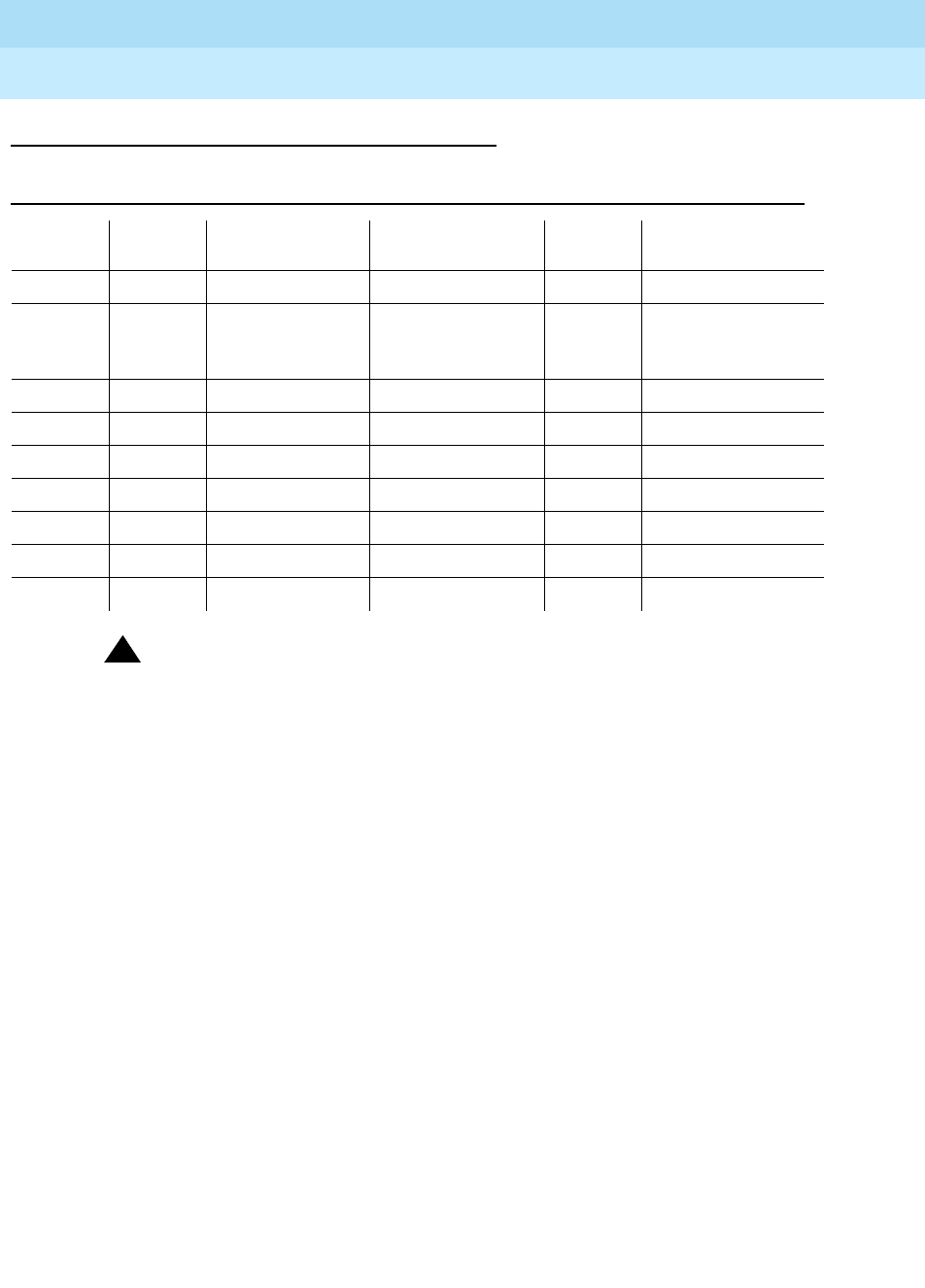
DEFINITY Enterprise Communications Server Release 6
Maintenance for R6r Volumes 1 & 2
555-230-126 Issue 2
January 1998
Maintenance Object Repair Procedures
Page 9-1616TTR-LEV (TTR Level)
9
Error Log Entries and Test to Clear Values
!WARNING:
The Alarm is upgraded to MAJOR if the Base Tone Generator is set to 12
(France).
Notes:
a. Error code 1 does not indicate a current error condition. It indicates that
the number of DTMR ports in service was below the administered
threshold, but is now equal to or greater than the threshold. These errors
are typically generated during boot time or other transitional states when
the ports are being brought into service.
b. The total number of DTMR ports currently in service is below the
administered threshold. To clear the alarm, refer to the repair procedure
described above.
c. Error code 3 does not indicate a current error condition. It indicates that
the number of GPTD ports in service was below the administered
threshold, but is now equal to or greater than the threshold. These errors
are typically generated during boot time or other transitional states when
the ports are being brought into service.
d. The total number of GPTD ports currently in service is below the
administered threshold. To clear the alarm, refer to the repair procedure
describe above.
Table 9-550. TTR Level Error Log Entries
Error
Type Aux
Data Associated Test Alarm Level On/Off
Board Test to Clear Value
1 (a) 1 None
2 (b) 2 WARNING
(See WARNING
message below)
OFF
3 (c) 3 None
4 (d) 4 WARNING OFF
5 (e) 5 None
6 (f) 6 WARNING OFF
7 (g) 7 MAJOR OFF
8 (h) 8 MINOR OFF
9 (i) 9 MINOR OFF

DEFINITY Enterprise Communications Server Release 6
Maintenance for R6r Volumes 1 & 2
555-230-126 Issue 2
January 1998
Maintenance Object Repair Procedures
Page 9-1617TTR-LEV (TTR Level)
9
e. Error code 5 does not indicate a current error condition. It indicates that
the number of Call Classifier ports (CLSFY-PT) service was below the
administered threshold, but is now equal to or greater than the threshold.
These errors are typically generated during boot time or other transitional
states when the ports are being brought into service.
f. The total number of Call Classifier ports (CLSFY-PT) currently in service is
below the administered threshold. To clear the alarm, refer to the repair
procedure described above.
g. There are currently no DTMR ports in service. To clear the alarm, refer to
the repair procedure described above.
h. There are currently no GPTD ports in service. To clear the alarm, refer to
the repair procedure described above.
i. There are currently no Call Classifier ports (CLSFY-PT) in service. To clear
the alarm, refer to the repair procedure described above.

DEFINITY Enterprise Communications Server Release 6
Maintenance for R6r Volumes 1 & 2
555-230-126 Issue 2
January 1998
Maintenance Object Repair Procedures
Page 9-1618UDS1-BD (UDS1 Interface Circuit Pack)
9
UDS1-BD (UDS1 Interface Circuit
Pack)
The TN464C, D, E, and F Universal DS1 Interface circuit packs provide an
interface to the DS1 facility and are designed to support 24 DS0 channels on a
1.544 Mbps DS1 link or 32 DS0 channels on a 2.048 Mbps link. (The 32-channel
interface is not supported on G3r V1 systems.) The DS0 channels can be
administered as trunks to other switches, lines to off-premises stations, ports to
line-side PRI terminating devices, or ports to other line-side non-PRI terminating
devices. (DS0 channels on TN464/Bs can only be administered as trunks to other
switches.) For more information on how TN464 ports can be used, see the
following sections in this chapter ISDN-SGR, ISDN-TRK, ISDN-LNK, PE-BCHL,
TIE-DS1, CO-DS1, DID-DS1, OPS-LINE and WAE-PT. For information on other
DS1 circuit packs, see DS1-BD.
Throughout this section on the UDS1-BD MO name, the term TN464 will mean
any TN464C or later suffix UDS1 circuit pack. If part of this section refers to a
specific suffix TN464 board, it will be noted as such.
The UDS1 maintenance strategy includes logging in-line errors reported by the
UDS1 circuit pack, running tests for error diagnosis and recovery, and raising or
clearing maintenance alarms.
TN464 circuit packs support the following:
■Digital Tie, CO, and DID trunks
■DS1 off-premises (OPS) lines
■Narrowband and wideband access endpoint ports
■ISDN-PRI trunks and accompanying signaling channel
■PRI endpoint ports (PE-BCHL) and accompanying signaling channel
The TN464 supports digital Tie, CO, and DID trunks, and OPS lines. On-board
firmware performs call control signaling for the Tie, CO and DID trunks and OPS
lines. ISDN-PRI trunk and PRI endpoint signaling (Q.921, Q.931) is received and
generated by system software and is transmitted on a system link through the
1. UU is the universal cabinet number (1 for PPN, 2 - 44 for EPNs). C is the carrier designation
(A, B, C, D, or E). SS is the number of the slot in which the circuit pack resides (01 to 21).
MO Name (in
Alarm Log) Alarm
Level Initial Command to Run1Full Name of MO
UDS1-BD MAJOR test board UUCSS sh UDS1 Interface Circuit Pack
UDS1-BD MINOR test board UUCSS l UDS1 Interface Circuit Pack
UDS1-BD WARNING test board UUCSS sh UDS1 Interface Circuit Pack

DEFINITY Enterprise Communications Server Release 6
Maintenance for R6r Volumes 1 & 2
555-230-126 Issue 2
January 1998
Maintenance Object Repair Procedures
Page 9-1619UDS1-BD (UDS1 Interface Circuit Pack)
9
TN1655 Packet Interface and packet bus to the UDS1 where it is placed on the
D-channel. Signaling over the DS1 link has to be synchronized between the
transmitting and receiving ends to ensure error-free communication. Refer to
‘‘SYNC (Synchronization)’’ in this chapter for details.
Each trunk, line or endpoint has its own maintenance strategy but all depend on
the health of the UDS1 Interface circuit pack. Refer to the following sections for
details: TIE-DS1, CO-DS1, DID-DS1, OPS-LINE, ISDN-TRK, ISDN-LNK,
ISDN-SGR, WAE-PT and PE-BCHL. The maintenance strategy for the TN464
UDS1 Interface circuit pack (UDS1-BD) is very similar to the maintenance
strategy for the TN767 DS1 Interface circuit pack (DS1-BD). The same
commands are used for administering and testing the boards. The differences in
maintenance strategy between the boards are due to the UDS1 circuit pack’s
direct interface to the Packet Bus which is used for ISDN-PRI signaling
(ISDN-LNK). While both the TN464 and TN767 can support ISDN-PRI
B-channels, ISDN-PRI D-channel signaling applications require a TN464 UDS1
circuit pack.
The TN464F or later circuit pack combined with the 120A1 CSU Module forms an
Enhanced Integrated CSU. The new 120A1 CSU Module, when combined with
the functionality provided by the TN464F hardware and firmware, and new switch
software, provides functionality equivalent to an external stand-alone Lucent ESF
T1 CSU. The 120A1 CSU Module connects to the TN464F circuit pack on the I/O
connector panel on the back of the port carrier. The new CSU Module, thus
becomes an integrated part of the DEFINITY. system. Throughout the document,
the term 120A1 will mean a 120A1 or later suffix CSU Module.
The Enhanced Integrated CSU is for use in the United States of America with
1.544 Mbps DS1 service. For further details on the 120A1 CSU Module see
DEFINITY Communications System Generic 1, Generic 2, and Generic 3 V1 and
V2 - Integrated CSU Module Installation and Operation
.
The TN464F and 120A1 CSU Module support on-demand loopback tests that
assist in the detection of faults between the TN464F circuit pack and the CSU
Module, between the Integrated CSU and the optional Customer Premises
Loopback Jack, or between the Integrated CSU and remote CSU. These
loopback tests are explained in detail later in this UDS1-BD section, but Figure
9-94 gives a high level overview of the loopback points.

DEFINITY Enterprise Communications Server Release 6
Maintenance for R6r Volumes 1 & 2
555-230-126 Issue 2
January 1998
Maintenance Object Repair Procedures
Page 9-1620UDS1-BD (UDS1 Interface Circuit Pack)
9
Figure 9-94. High Level Overview Of Loopback Points
The following list of acronym definitions are for the Figure 9-94:
■PLB = Payload Loopback
■BLB = Board Loopback
■ELB = Equipment Loopback
■LLB = Line Loopback
■RLB = Repeater Loopback
■CLJ = Loopback Jack Loopback
■R-LLB = Remote Line Loopback
■SMRT = Smart Jack
■LPBK = Loopback
CPE
LPBK
JACK
NET
SMRT
JACK
CSU
MOD
NET
SMRT
JACK
CPE
LPBK
JACK
DS1
BRD
CSU
MOD
DS1
BRD
NET-
WORK
CSU module to CSU module
Remote end
NETWORK ENVIRONMENT
Local end
NETWORK
SMRT
JACK
BLB
R-LLB
CPE
LPBK
JACK
DS1
BOARD
Remote end loop backs (* CSU or External CSU)
NETWORK
SMRT
JACK
CSU*
MOD
CSU
MOD
CLJ-LB LLB RLB ELB
PLB
CPE
LPBK
JACK
DS1
BOARD
Local end loop backs

DEFINITY Enterprise Communications Server Release 6
Maintenance for R6r Volumes 1 & 2
555-230-126 Issue 2
January 1998
Maintenance Object Repair Procedures
Page 9-1621UDS1-BD (UDS1 Interface Circuit Pack)
9
Circuit Pack Administration and Options
The DS1 configuration for each circuit pack is administered on the DS1 Circuit
Pack form.
Bit Rate
is set to 1.544 Mbps for 24-channel systems, and 2.048
Mbps for 32-channel systems.
Country Protocol
is used to drive layer 3 protocol
decisions based on PRI specifications specific to a given country (not those
related to specific features). This Country Protocol is independent of the
Country
parameter administered on the country-options system-parameters form.
Different UDS1 circuit packs may be administered with different Country
Protocols, allowing the switch to act as a gateway between two incompatible
ISDN-PRI implementations (for example, between two different countries). US
systems use country protocol 1.
Near-End CSU Type
is set to
other
for no CSU
installed or for an external CSU such as an Lucent ESF T1 CSU, or
integrated
for
the 120A1 CSU Module. Answering
integrated
will cause additional fields to be
displayed for administering the Enhanced Integrated CSU Module. In addition to
the above there are numerous other fields defining such parameters as framing
modes, line coding companding mode and so on. For details, see
DEFINITY
Communications System Generic 3 V2 Implementation,
555-230-653, and
DEFINITY Communications System Generic 2.2 and Generic 3 V2
DS1/CEPT/ISDN-PRI Reference
, 555-025-107.
Two option jumpers located on the side of the TN464C/D circuit pack must be
installed correctly. The figures on the following page shows how to configure the
circuit pack for 24-channel or 32-channel DS1, and for 75*W (coaxial) or 120*W
trunk connections. The channel selection must match the parameters
administered on the corresponding DS1 Circuit Pack Form. (US applications use
24 Channels.)
Figure 9-95. TN464C/D DS1 Option Jumpers
Backplane Connectors
24/32 Channel Selector
75/120 Ohm Selector
Top
Bottom
Faceplate
TN464C/D
DEFINITY Enterprise Communications Server Release 6
Maintenance for R6r Volumes 1 & 2
555-230-126 Issue 2
January 1998
Maintenance Object Repair Procedures
Page 9-1622UDS1-BD (UDS1 Interface Circuit Pack)
9
Figure 9-96. TN464C/D DS1 Option Jumpers (Continued)
The option switch located on the component side of the TN464E/F circuit pack
must be set correctly. Figure 9-97 shows how to configure the circuit pack for
24-channel or 32-channel DS1. The channel selection must match the
parameters administered on the corresponding DS1 Circuit Pack Form. (US
applications use 24 Channels.)
Insert the jumpers into the blocks
so as to join the center row of
pins and the row designating the
desired options.
120 OHM
32 CHNL
24 CHNL
75 OHM
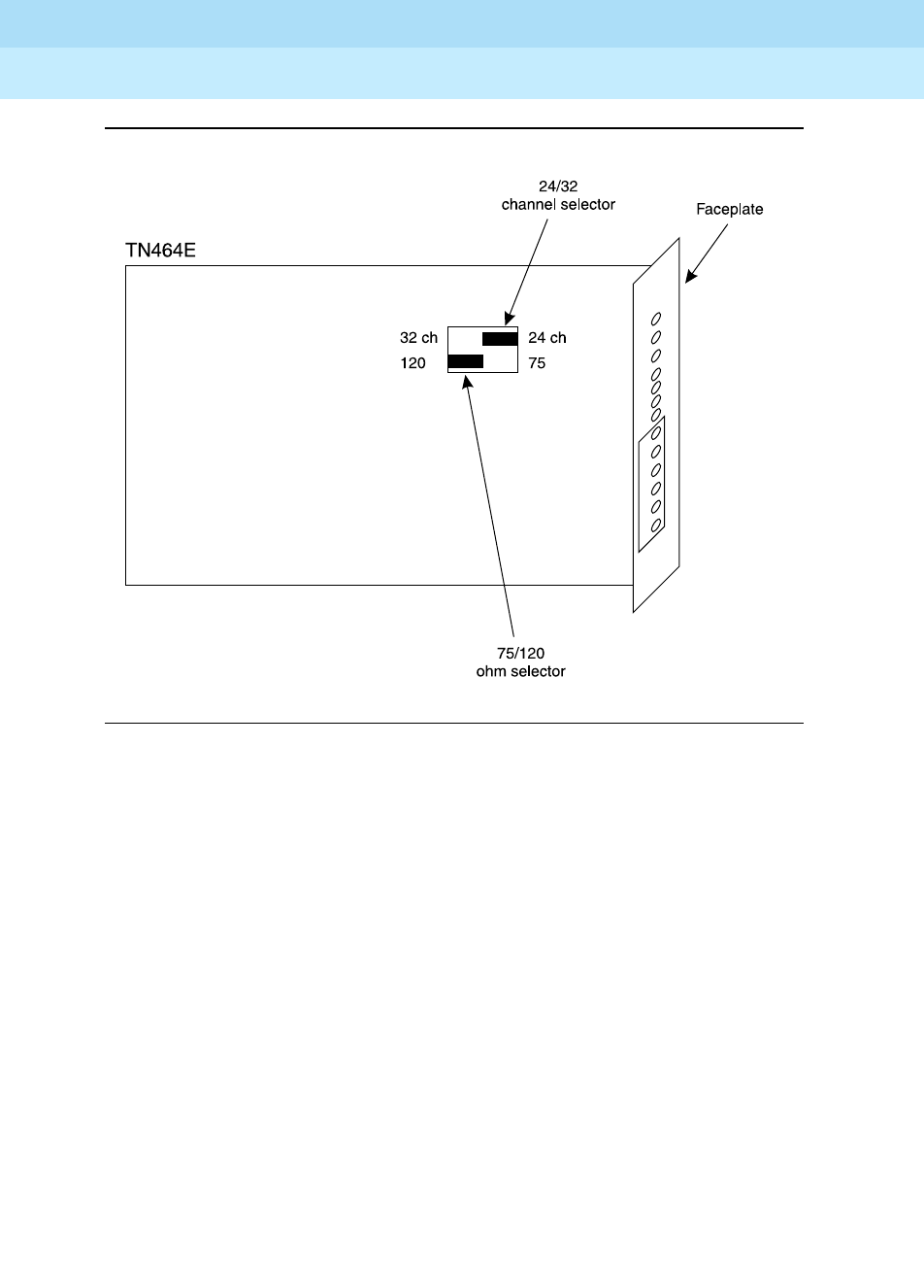
DEFINITY Enterprise Communications Server Release 6
Maintenance for R6r Volumes 1 & 2
555-230-126 Issue 2
January 1998
Maintenance Object Repair Procedures
Page 9-1623UDS1-BD (UDS1 Interface Circuit Pack)
9
Figure 9-97. TN464E/F DS1 Option switches
ΩΩ

DEFINITY Enterprise Communications Server Release 6
Maintenance for R6r Volumes 1 & 2
555-230-126 Issue 2
January 1998
Maintenance Object Repair Procedures
Page 9-1624UDS1-BD (UDS1 Interface Circuit Pack)
9
Error Log Entries and Test to Clear Values
Table 9-551. DS1 Interface Circuit Pack Maintenance Error Log Entries
Error
Type Aux
Data Associated Test Alarm Level On/Off
Board Test to Clear Value
010 Any Any Any test board UUCSS
1(a) 0 Circuit pack removed or
SAKI Test (#53) MIN/WRN2ON
18(b) 0 busyout board UUCSS WARNING OFF release board UUCSS
23(c) 0 WARNING OFF add ds1 UUCSS
125(d) none 3 None MIN/WRN3ON
257 65535 Control Channel Loop
Test (#52) MINOR ON test board UUCSS l r 20
257(e) Any None
513(f) Any MIN/WRN3ON
514(g) 46086 MIN/WRN3ON
769(h) 46085 MIN/WRN3ON
770(i) 46096 MIN/WRN3ON
1025(e) 4363 NPE Audit Test (#50)
1281 Any Loss of Signal Alarm
Inquiry Test (#138) MIN/WRN3OFF test board UUCSS
1300(j) Any Loss Of Signal Alarm
Inquiry Test (#138) WARNING OFF test board UUCSS
1301(k) Any Loss Of Signal Alarm
Inquiry Test (#138) WARNING OFF test board UUCSS
1302(l) Any Loss Of Signal Alarm
Inquiry Test (#138) MIN/WRN3OFF test board UUCSS
1303(m) Any Loss Of Signal Alarm
Inquiry Test (#138) MIN/WRN3ON test board UUCSS
1310(n) Any Board Loopback Test
(#1209) MINOR ON test ds1-loop UUCSS
ds1/csu-loopback-tests
1311(o) Any Equipment Loopback
Test (#1210) MIN/WRN3OFF test ds1-loop UUCSS
ds1/csu-loopback-tests
1312(p) Any Repeater Loopback
Test (#1211) MIN/WRN3OFF test ds1-loop UUCSS
ds1/csu-loopback-tests
1313(q) Any CPE Loopback Jack
Test (#1212) MIN/WRN3OFF test ds1-loop UUCSS
end-loopback/span-test
Continued on next page

DEFINITY Enterprise Communications Server Release 6
Maintenance for R6r Volumes 1 & 2
555-230-126 Issue 2
January 1998
Maintenance Object Repair Procedures
Page 9-1625UDS1-BD (UDS1 Interface Circuit Pack)
9
1314(r) Any Far CSU Loopback Test
(#1213) MIN/WRN3OFF test ds1-loop UUCSS
end-loopback/span-test
1320 Any Loss of Signal Alarm
Inquiry Test (#138) MIN/WRN3OFF test board UUCSS
1321 Any Loss of Signal Alarm
Inquiry Test (#138) MIN/WRN3OFF test board UUCSS
1322 Any Loss of Signal Alarm
Inquiry Test (#138) MINOR ON test board UUCSS
1323 Any Loss of Signal Alarm
Inquiry Test (#138) MIN/WRN3OFF test board UUCSS
1324 Any Loss of Signal Alarm
Inquiry Test (#138) WARNING OFF test board UUCSS
1537(s) 46082 MIN/WRN3ON
1538(t) Any MIN/WRN3ON
1793 Any Blue Alarm Inquiry Test
(#139) MAJ/MIN/W
RN 4OFF test board UUCSS
1794 Any Blue Alarm Inquiry Test
(#139) MAJ/MIN/W
RN4OFF test board UUCSS
1795 Any Blue Alarm Inquiry Test
(#139) MAJ/MIN
/WNG4OFF test board UUCSS
2049 Any Red Alarm Inquiry Test
(#140) MIN/WRN3OFF test board UUCSS
2305 Any Yellow Alarm Inquiry
Test (#141) MIN/WRN3OFF test board UUCSS
2306 Any Yellow Alarm Inquiry
Test (#141) MIN/WRN3OFF test Board UUCSS
2561 Any Major Alarm Inquiry
Test (#142) MIN/WRN3OFF test board UUCSS
2817 Minor Alarm Inquiry
Test (#143) MIN/WRN3OFF test board UUCSS
3073 to
3160 (u) Any Slip Alarm Inquiry Test
(#144) MIN/WRN3OFF test board UUCSS r 6
3330(v) 46083 MIN/WRN3ON
3585 to
3601 (w) Any Misframe Alarm Inquiry
Test (#145) MIN/WRN3OFF test board UUCSS r 6
3840(x) Any None
Table 9-551. DS1 Interface Circuit Pack Maintenance Error Log Entries — Continued
Error
Type Aux
Data Associated Test Alarm Level On/Off
Board Test to Clear Value
Continued on next page
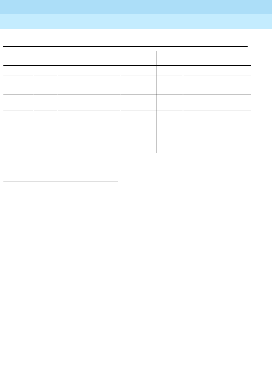
DEFINITY Enterprise Communications Server Release 6
Maintenance for R6r Volumes 1 & 2
555-230-126 Issue 2
January 1998
Maintenance Object Repair Procedures
Page 9-1626UDS1-BD (UDS1 Interface Circuit Pack)
9
Notes:
a. Error 1 indicates that the circuit pack has totally stopped functioning or is
not fully administered. The alarm is logged about 15 minutes after the
circuit pack has been removed or 11-minutes after the SAKI Test (#53)
fails.
To be fully administered, a UDS1 circuit pack must meet all of these 3
conditions:
1. Have an entry in the circuit plan via the change circuit pack
command
2. Be administered via the add ds1 UUCSS command
3. Be physically inserted into the correct slot
If the circuit pack has an entry in the circuit plan and either of the other two
conditions are
not
met, a MINOR alarm is logged. To resolve the error
either
1. Make sure all conditions for administration are met and that a
functioning UDS1 circuit pack is inserted in the correct slot, or
1. Run the Short Test Sequence first. If all tests pass, run the Long Test Sequence. Refer to the appropriate
test description and follow the recommended procedures.
2. If ports are assigned to the circuit pack, then a minor alarm is raised. If no ports are assigned to the circuit
pack, then a warning alarm is raised. The alarm is raised after the circuit pack has been missing for a
period of 15 minutes. Warning alarms are also raised against any ports administered on the circuit pack.
3. Minor alarms on this MO may be downgraded to warning alarms based on values set in the set options
command.
4. Major alarms on this MO may be downgraded to minor or warning alarms based on values set in the set
options command.
3841(y) 4358
3842(z) 46097
3843(aa) 46081
3900(ab) Any CPE Loopback Jack
Test (#1212)
3901(ac) Any Far CSU Loopback Test
(#1213)
3902(ad) Any One-Way Span Test
(#1214)
3999(ae) Any None
Table 9-551. DS1 Interface Circuit Pack Maintenance Error Log Entries — Continued
Error
Type Aux
Data Associated Test Alarm Level On/Off
Board Test to Clear Value
Continued on next page

DEFINITY Enterprise Communications Server Release 6
Maintenance for R6r Volumes 1 & 2
555-230-126 Issue 2
January 1998
Maintenance Object Repair Procedures
Page 9-1627UDS1-BD (UDS1 Interface Circuit Pack)
9
2. Completely remove the UDS1-BD from the system using the
following steps:
a. Remove any administered DS1 trunks, access endpoints or
PRI endpoints associated with the circuit pack from their
trunk groups.
b. Execute the remove ds1 UUCSS and change circuit pack
UUCSS commands.
If all the administration conditions are met for this circuit pack and the red
LED is still on, follow the instructions for
LED Alarms with Error Type 1
in
Chapter 7.
b. The UDS1 Interface circuit pack has been busied out by a busyout board
UUCSS command.
c. The UDS1-BD circuit pack is not completely administered. To be fully
administered, the UDS1 circuit pack must:
1. Have an entry in the circuit plan via the change circuit pack
command,
2. Be administered via the add ds1 UUCSS command, and
3. Be physically inserted into the correct slot.
A DS1 (UDS1-BD and DS1-BD) differs from most circuit packs in that
inserting the circuit pack into the switch is not enough to make the board
usable. It must also be administered with the add ds1 command.
d. No Aux Data: A wrong circuit pack is inserted in the slot where this circuit
pack is logically administered. To resolve this problem, either remove the
wrong circuit pack and insert the logically administered circuit pack OR
use the change circuit-pack command to readminister this slot to match
the circuit pack inserted.
Aux Data 3: The 24/32-channel option jumper setting on the circuit pack
does not match the option set on the DS1 circuit pack administration form.
The circuit pack must be physically removed to see the setting of the
jumper.
e. This error is associated with the Common Port Circuit Pack Maintenance
Test. Refer to XXX-BD (Common Port Circuit Pack) Maintenance
documentation for details.
f. The UDS1 Interface circuit pack has detected a transient hardware
problem. The value in the Aux Data field indicates the type of hardware
problem.
4352 External RAM failure
4353 Internal RAM failure
4355 Internal ROM failure

DEFINITY Enterprise Communications Server Release 6
Maintenance for R6r Volumes 1 & 2
555-230-126 Issue 2
January 1998
Maintenance Object Repair Procedures
Page 9-1628UDS1-BD (UDS1 Interface Circuit Pack)
9
If the UDS1 board detects only one of these hardware problems, then the
error will disappear when none of these faults are detected for 10 minutes.
If the same Aux Data value is logged more than once in a 24 hour period,
the circuit pack should be replaced.
g. LAN External RAM Error. This error occurs when there is a hardware fault
in the PPE external RAM. The RAM is used for message buffering to and
from the Packet Bus. This error should not occur regularly. If this error is
seen quite frequently (10 times within 30 minutes), the circuit pack should
be replaced.
h. Transmit FIFO Underflow Error. This error occurs when the circuit pack
cannot find the "end of frame" bit when transmitting a frame to Packet Bus.
An alarm will be raised if this error occurs three times within 10 minutes.
Clear the alarm via the following commands: busyout board UUCSS,
reset board UUCSS, test board UUCSS long, release board UUCSS. If
the error recurs within 10 minutes, then replace the circuit pack.
i. Unable to Write LAN Translation RAM Error. This error occurs when a call
is aborted because there are no available translation RAM locations for
the call connection attempt. An alarm will be raised if this error occurs two
times within 10 minutes. Clear the alarm via the following commands:
busyout board UUCSS, reset board UUCSS, test board UUCSS long,
release board UUCSS. If the error recurs within 10 minutes, then replace
the circuit pack.
j. CSU Module missing. The
Near-End CSU Type
field on the
add ds1
form
has been administered as
integrated
but the 120A1 CSU Module is not
physically connected (or is improperly connected) to the TN464F board
on the back of the port carrier.
If using the 120A1 CSU Module, plug (or replug) the CSU Module into the
TN464F circuit pack’s connector on the I/O connector panel on back of
the carrier. Otherwise, change the
Near-End CSU Type
field using the
change ds1
form to
other
.
If this error remains after plugging the CSU Module into the board’s
connector, there could be a problem with the I/O connector panel.
k. CSU Module not expected. The 120A1 CSU Module is physically
connected to the TN464F board on the back of the port carrier but the
Near-End CSU Type
field on the
add ds1
form has not been administered
as
integrated
.
If the 120A1 CSU Module is to be used, use the
change ds1
command to
change the
Near-End CSU Type
field to
integrated
. Otherwise, physically
remove the 120A1 CSU Module from the back of the port carrier.
l. DS1 configuration error. Attempting to use the 120A1 CSU Module with a
TN464F circuit pack that is configured for 32-channel (2.048 Mbps)
operation. The CSU Module only works with a DS1 board configured for
24-channel (1.544 Mbps) operation in the United States of America.

DEFINITY Enterprise Communications Server Release 6
Maintenance for R6r Volumes 1 & 2
555-230-126 Issue 2
January 1998
Maintenance Object Repair Procedures
Page 9-1629UDS1-BD (UDS1 Interface Circuit Pack)
9
m. DS1 circuit pack suffix incorrect for CSU Module. The
Near-End CSU Type
field on the
add ds1
form has been administered as
integrated
but the
DS1 circuit pack is not a TN464F or later suffix UDS1 board.
If the 120A1 CSU Module is to be used, remove the circuit pack and
replace it with a TN464F or later suffix board. Otherwise, use the
change
ds1
command to change the
Near-End CSU Type
field to
other
.
n. BLB failure. This error occurs when the DS1 Board Loopback (BLB)
demand test fails. Repeat the test using the following commands:
busyout
board UUCSS
,
test ds1-loop UUCSS ds1/csu-loopback-tests
,
release
board UUCSS
. If the BLB test continues to fail, then the TN464F circuit
pack needs to be replaced.
o. ELB failure. This error occurs when the Integrated CSU (I-CSU) Module
Equipment Loopback (ELB) test fails. This test is executed by the I-CSU
during I-CSU power-up/reset (i.e.- TN464F board physically inserted and
120A1 CSU Module already installed) or when the 120A1 CSU Module is
plugged on to an already initialized TN464F DS1 board. The ELB test is
also executed as part of the command
test ds1-loop UUCSS
ds1/csu-loopback-tests
.
Attempt to clear the alarm via the following commands:
busyout board
UUCSS
,
test ds1-loop UUCSS ds1/csu-loopback-tests
,
release board
UUCSS
. If the ELB test continues to fail, then either the TN464F board, the
CSU Module, or the I/O cable between the backplane and the CSU
module (or any combination thereof) has failed. Attempt to isolate where
the failure is occurring by re-executing the test and by replacing one
piece of hardware at a time.
p. RLB failure. This error occurs when the Integrated CSU (I-CSU) Module
Repeater Loopback (RLB) test fails. This test is executed by the I-CSU
during I-CSU power-up/reset (i.e.- TN464F board physically inserted and
120A1 CSU Module already installed) or when the 120A1 CSU Module is
plugged on to an already initialized DS1 board. The RLB test is also
executed as part of the command
test ds1-loop UUCSS
ds1/csu-loopback-tests
.
Attempt to clear the alarm via the following commands:
busyout board
UUCSS
,
test ds1-loop UUCSS ds1/csu-loopback-tests
,
release board
UUCSS
. If the RLB test continues to fail, then the CSU Module needs to be
replaced.
q. CPE Loopback Jack deactivation error. This error occurs when the
TN464F circuit pack could not deactivate a CPE Loopback Jack on
power-up/reset or upon software request.
Attempt to clear the alarm via the following commands:
busyout board
UUCSS
,
test ds1-loopback UUCSS end-loopback/span-test
,
release
board UUCSS
. If the attempt to deactivate the CPE Loopback Jack
continues to fail, other steps must be taken to deactivate the loopback.

DEFINITY Enterprise Communications Server Release 6
Maintenance for R6r Volumes 1 & 2
555-230-126 Issue 2
January 1998
Maintenance Object Repair Procedures
Page 9-1630UDS1-BD (UDS1 Interface Circuit Pack)
9
r. Far CSU Loopback deactivation error. This error occurs when the TN464F
circuit pack could not deactivate a far-end CSU loopback on
power-up/reset or upon software request.
Attempt to clear the alarm via the following commands:
busyout board
UUCSS
,
test ds1-loop UUCSS end-loopback/span-test
,
release board
UUCSS
. If the attempt to deactivate the Far CSU loopback continues to
fail, then escalate the problem.
s. LAN Bus Timeout Error. This error occurs when the circuit pack transmits
too many bytes on the LAN bus for a single frame. This condition may be
caused by an on-board fault or by faulty data received on one of the
circuit pack’s external ports. If any of the ports on this circuit pack are
alarmed, refer to the repair procedures for those maintenance objects.
If the error occurs three times within 10 minutes, the board will be isolated
from the Packet Bus and the board will be alarmed. To clear the alarm and
restore the board to the Packet Bus, use the following commands:
busyout board UUCSS, reset board UUCSS, test board UUCSS long,
release board UUCSS.
If the problem persists, and there are no PKT-BUS alarms or port alarms,
then replace the circuit pack.
t. The hyperactive circuit pack is out-of-service and may exhibit one or more
of the following symptoms:
1. The common circuit pack level tests such as Test #50 and/or Test
#52 are aborting with error code 2000.
2. The tests run on the ports of this circuit pack are returning with a
NO-BOARD.
3. A busyout/release of the circuit pack has no affect on test results.
4. A list configuration command shows that the circuit pack and
ports are properly installed.
The circuit pack is isolated from the system and all trunks or ports on this
circuit pack are placed into the out-of-service state. The system will try to
restore the circuit pack within 20-30 minutes. When no faults are detected
for 20-30 minutes, the UDS1 Interface circuit pack is restored to normal
operation. All trunks or ports of the UDS1 Interface circuit pack are then
returned to the in-service state. If the board is not restored to normal
operation, or the error recurs after the board was restored to normal
operation, escalate the problem.
u. For later releases of G3V4 and beyond, only error 3073 will show that this
board is receiving slips and the AUX data shows the last slip count that
was reported.
v. LAN Critical Error. A critical failure has been detected in the Packet Bus
interface of the circuit pack. This failure may be due to an on-board fault or
a Packet Bus fault. If the Packet Bus is alarmed, refer to the PKT-BUS
Maintenance documentation for recommended repair procedures.

DEFINITY Enterprise Communications Server Release 6
Maintenance for R6r Volumes 1 & 2
555-230-126 Issue 2
January 1998
Maintenance Object Repair Procedures
Page 9-1631UDS1-BD (UDS1 Interface Circuit Pack)
9
This error will isolate the board from the Packet Bus and raise an alarm. If
the Packet Bus is not alarmed, enter the following commands: busyout
board UUCSS, reset board UUCSS, test board UUCSS, release board
UUCSS. This should clear the alarm and restore the board to the Packet
Bus.
If the problem persists, and there are no PKT-BUS alarms, then replace
the circuit pack.
w. For later releases of G3V4 and beyond, only error 3585 will show that this
board is receiving misframes and the AUX data shows the last misframe
count that was reported.
x. These errors are not service-affecting. No action is required. These errors
are reported by the circuit pack when it receives a bad control channel
message from the switch. The auxiliary data identifies the following error
events:
y. The UDS1 Interface circuit pack has detected a transient hardware logic
error (for example, program logic inconsistency). This error will disappear
when no faults are detected for 100 minutes. The value in Aux Data field
indicates the type of hardware problem.
z. Bad Translation RAM Location Found Error. This error is not
service-affecting. No action is required. A Bad Translation RAM is
detected, but the call continues by using another translation location.
aa. LAN Receive Parity Error. This error occurs when the circuit pack detects
an error in a received frame from the Packet Bus. These errors are most
likely caused by a Packet Bus problem, but may be due to a circuit pack
fault.
Refer to the PKT-BUS Maintenance documentation to determine if the
problem is isolated to this circuit pack or if the problem is caused by
Packet Bus faults.
ab. Error 3900 is used to give status information on a CPE Loopback Jack
Test. The value in the Aux Data field indicates the status of the loopback
test.
4096 Bad major heading
4097 Bad port number
4098 Bad data
4099 Bad sub-qualifier
4100 State inconsistency
4101 Bad logical link
1. Test is currently running.
2. Test failed because loopback could not be activated.
3. Test failed because test pattern could not be detected.
4. Test has been terminated.

DEFINITY Enterprise Communications Server Release 6
Maintenance for R6r Volumes 1 & 2
555-230-126 Issue 2
January 1998
Maintenance Object Repair Procedures
Page 9-1632UDS1-BD (UDS1 Interface Circuit Pack)
9
ac. Error 3901 is used to give status information on a Far CSU Loopback Test.
The value in the Aux Data field indicates the status of the loopback test.
ad. Error 3902 is used to give status information on a One-Way Span Test. The
value in the Aux Data field indicates the status of the span test.
ae. Error type 3999 indicates that the circuit pack sent a large number of
control channel messages to the switch within a short period of time. If
error type 1538 is also present, then the circuit pack was taken
out-of-service due to hyperactivity. If error type 1538 is not present, then
the circuit pack has not been taken out-of-service, but it has generated
50% of the messages necessary to be considered hyperactive. This may
be completely normal during heavy traffic periods. However, if this error
type is logged when the circuit pack is being lightly used, it may indicate a
problem with the circuit pack or the equipment attached to it.
System Technician-Demanded Tests:
Descriptions and Error Codes
Investigate tests in the order they are presented in Table 9-552. By clearing error
codes associated with the
NPE Connection Audit Test,
for example, you may also
clear errors generated from other tests in the testing sequence.
1. Test is currently running.
2. Test failed because loopback could not be activated.
3. Test failed because test pattern could not be detected.
4. Test has been terminated.
1. Test is currently running.
2. Test has failed because test could not be activated.
3. Test pattern was not received from the far end.
4. Test has been terminated.
Table 9-552. System Technician-Demanded Tests
Order of Investigation
Short
Test
Sequence
Long
Test
Sequence
Reset
Board
Sequence test
ds1-loop D/ND1
NPE Connection Audit Test (#50) X ND
Control Channel Loop Test (#52) X ND
Loss of Signal Alarm Inquiry Test (#138) X X ND
Blue Alarm Inquiry Test (#139) X X ND
Continued on next page

DEFINITY Enterprise Communications Server Release 6
Maintenance for R6r Volumes 1 & 2
555-230-126 Issue 2
January 1998
Maintenance Object Repair Procedures
Page 9-1633UDS1-BD (UDS1 Interface Circuit Pack)
9
NPE Connection Audit Test (#50)
The system sends a message to the on-board microprocessor to update the
network connectivity translation for the SCOTCH-NPE chip on the circuit pack
1. D = Destructive; ND = Nondestructive
Red Alarm Inquiry Test (#140) X X ND
Yellow Alarm Inquiry Test (#141) X X ND
Major Alarm Inquiry Test (#142) X X ND
Minor Alarm Inquiry Test (#143) X X ND
Slip Alarm Inquiry Test (#144) X X ND
Misframe Alarm Inquiry Test (#145) X X ND
Translation Update Test (#146) X X ND
ICSU Status LEDs Test (#1227) X X ND
SAKI Sanity Test (#53) X D
Internal Looparound Test (#135) X D
DS1/CSU Loopback Tests:
DS1 Board Loopback Test (#1209)
CSU Equipment Loopback Test (#1210)
CSU Repeater Loopback Test (#1211)
X
X
X
D
D
D
CPE Loopback Jack Test (#1212) X D
Far CSU Loopback Test (#1213) X D
One-Way Span Test (#1214) X D
Inject Single Bit Error (#1215) X D
End Loopback/Span Test (#1216) X D
Table 9-552. System Technician-Demanded Tests — Continued
Order of Investigation
Short
Test
Sequence
Long
Test
Sequence
Reset
Board
Sequence test
ds1-loop D/ND1
Continued on next page

DEFINITY Enterprise Communications Server Release 6
Maintenance for R6r Volumes 1 & 2
555-230-126 Issue 2
January 1998
Maintenance Object Repair Procedures
Page 9-1634UDS1-BD (UDS1 Interface Circuit Pack)
9
Control Channel Looparound Test (#52)
This test queries the circuit pack for its circuit pack code and vintage and verifies
its records.
Table 9-553. TEST #50 NPE Connection Audit Test
Error
Code Test
Result Description/ Recommendation
None
2100 ABORT System resources required for this test are not available.
1. Retry the command at 1-minute intervals a maximum of 5 times.
1019 ABORT The test aborted because a test was already running on the port.
1. Retry the command at 1-minute intervals for a maximum of 5 times.
FAIL Internal system error
1. Retry the command at 1-minute intervals a maximum of 5 times.
PASS The circuit pack’s SCOTCH-NPE chip have been updated with its translation.
0NO
BOARD The test could not relate the internal ID to the port (no board). This could be
due to incorrect translations, no board is inserted, an incorrect board is
inserted, or an insane board is inserted.
1. Ensure that the board translations are correct. Execute the add ds1
UUCSS command to administer the UDS1 interface if it is not already
administered.
2. If the board was already administered correctly, check the error log to
determine whether the board is hyperactive. If this is the case, the board is
shut down. Reseating the board will re-initialize the board.
3. If the board was found to be correctly inserted in step 1, then issue the
busyout board command.
4. Issue the reset board command.
5. Issue the release busy board command.
6. Issue the test board long command.
This should re-establish the linkage between the internal ID and the port.
Continued on next page

DEFINITY Enterprise Communications Server Release 6
Maintenance for R6r Volumes 1 & 2
555-230-126 Issue 2
January 1998
Maintenance Object Repair Procedures
Page 9-1635UDS1-BD (UDS1 Interface Circuit Pack)
9
SAKI Sanity Test (#53)
This test is destructive.
This test resets the circuit pack. The test is highly destructive and can only be
initiated by a system technician-demanded reset board UUCSS command.
Table 9-554. TEST #52 Control Channel Looparound Test
Error
Code Test
Result Description/ Recommendation
None
2100 ABORT System resources required for this test are not available.
1. Retry the command at 1-minute intervals a maximum of 5 times.
FAIL The circuit pack failed to return the circuit pack code or vintage.
1. Retry the command a maximum of 5 times.
2. If the problem continues, and if the circuit pack is one of the Port circuit
packs, replace the circuit pack. Otherwise, if the circuit pack is part of the
SPE, use the procedure described in
Replacing SPE Circuit Packs
in
Chapter 5.
3. Retry the command a few times a maximum of 5 times.
PASS Communication with this circuit pack is successful.
0NO
BOARD The test could not relate the internal ID to the port (no board). This could be
due to incorrect translations, no board is inserted, an incorrect board is
inserted, or an insane board is inserted.
1. Ensure that the board translations are correct. Execute the add ds1
UUCSS command to administer the UDS1 interface if it is not already
administered.
2. If the board was already administered correctly, check the error log to
determine whether the board is hyperactive. If this is the case, the board
is shut down. Reseating the board will re-initialize the board.
3. If the board was found to be correctly inserted in step 1, then issue the
busyout board command.
4. Issue the reset board command.
5. Issue the release busy board command.
6. Issue the test board long command.
This should re-establish the linkage between the internal ID and the port.
Continued on next page

DEFINITY Enterprise Communications Server Release 6
Maintenance for R6r Volumes 1 & 2
555-230-126 Issue 2
January 1998
Maintenance Object Repair Procedures
Page 9-1636UDS1-BD (UDS1 Interface Circuit Pack)
9
Table 9-555. TEST #53 SAKI Sanity Test
Error
Code Test
Result Description/ Recommendation
None ABORT System resources required for this test are not available.
1. Retry the reset board command at 1-minute intervals a maximum of 5
times.
1005 ABORT Wrong circuit pack configuration to run this test. This error applies only to DS1
Interface circuit packs. It means the DS1 Interface circuit pack is providing
timing for the system and, therefore, it cannot be reset without major system
disruptions.
1. If the circuit pack needs to be reset, then set synchronization to another
DS1 Interface circuit pack or to the Tone-Clock circuit pack and try again.
Refer to ‘‘SYNC (Synchronization)’’ Maintenance documentation.
1015 ABORT Port is not out-of-service.
1. Busyout the circuit pack.
2. Execute the reset board command again.
2100 ABORT System resources required for this test are not available.
1. Retry the reset board command at 1-minute intervals a maximum of 5
times.
1 FAIL The circuit pack failed to reset.
2 FAIL The circuit pack failed to restart.
1. Execute the reset board command again.
2. If the problem persists, replace the circuit pack.
PASS The circuit pack initializes correctly.
1. Run the Short Test Sequence.
Continued on next page

DEFINITY Enterprise Communications Server Release 6
Maintenance for R6r Volumes 1 & 2
555-230-126 Issue 2
January 1998
Maintenance Object Repair Procedures
Page 9-1637UDS1-BD (UDS1 Interface Circuit Pack)
9
Internal Looparound Test (#135)
This test is destructive.
The Internal Looparound Test is run by looping the transmitted DS1 bit stream
back into the UDS1’s board receiver. The loop occurs just before the DS1 facility
interface. The test is highly destructive and can only be initiated by a system
technician-demanded reset board UUCSS command.
All trunks or ports on the UDS1 Interface circuit pack must be busied out via the
system technician busyout board command before running the Internal
Looparound Test. When the Internal Looparound Test is initiated, maintenance
software sends appropriate messages to the UDS1 Interface circuit pack to start
the test. The test uses the Tone Generator and Tone Detector to exercise a bit
pattern consistency test for all ports. If the transmitted and received bit patterns
on a trunk or port are different, the test fails.
When the test is complete, the maintenance software sends a stop loop around
message to the UDS1 Interface circuit pack to put the circuit pack back into the
normal operation mode. All trunks or ports of the UDS1 Interface circuit pack are
restored to the in-service state after the release board command is entered.
0NO
BOARD The test could not relate the internal ID to the port (no board). This could be
due to incorrect translations, no board is inserted, an incorrect board is
inserted, or an insane board is inserted.
1. Ensure that the board translations are correct. Execute the add ds1
UUCSS command to administer the UDS1 interface if it is not already
administered.
2. If the board was already administered correctly, check the error log to
determine whether the board is hyperactive. If this is the case, the board is
shut down. Reseating the board will re-initialize the board.
3. If the board was found to be correctly inserted in step 1, then issue the
busyout board command.
4. Issue the reset board command.
5. Issue the release busy board command.
6. Issue the test board long command.
This should re-establish the linkage between the internal ID and the port.
Table 9-555. TEST #53 SAKI Sanity Test — Continued
Error
Code Test
Result Description/ Recommendation
Continued on next page

DEFINITY Enterprise Communications Server Release 6
Maintenance for R6r Volumes 1 & 2
555-230-126 Issue 2
January 1998
Maintenance Object Repair Procedures
Page 9-1638UDS1-BD (UDS1 Interface Circuit Pack)
9
Table 9-556. TEST #135 Internal Looparound Test
Error
Code Test
Result Description/ Recommendation
1002 ABORT The system could not allocate time slots for the test. The system may be under
heavy traffic conditions or it may have time slots out-of-service due to
TDM-BUS errors. Refer to TDM-BUS Maintenance documentation to diagnose
any active TDM-BUS errors.
1. If system has no TDM-BUS errors and is not handling heavy traffic, repeat
test at 1-minute intervals a maximum of 5 times.
1003 ABORT The system could not allocate a tone receiver for the test. The system may be
oversized for the number of Tone Detectors present or some Tone Detectors
may be out-of-service.
1. Look for TTR-LEV errors in the Error Log. If present, refer to TTR-LEV (TTR
Level) Maintenance documentation.
2. Look for TONE-PT errors in the Error Log. If present, refer to TONE-PT
(Tone Generator) Maintenance documentation.
3. If neither condition exists, retry the reset board command at 1-minute
intervals a maximum of 5 times.
1004 ABORT Received an incoming call on a port of the UDS1 circuit pack during the test.
1. Enter the busyout board UUCSS command to put all trunks or ports of the
UDS1 Interface circuit pack to out-of-service state.
2. Retry the reset board command at 1-minute intervals a maximum of 5
times.
1015 ABORT Ports on the UDS1 Interface circuit pack have not been busied out to
out-of-service.
1. Enter the busyout board UUCSS command to put all trunks or ports of the
UDS1 Interface circuit pack into the out-of-service state.
2. Retry the reset board command.
1039 ABORT The UDS1 Interface circuit pack is providing timing for the system. Therefore, it
cannot be reset without major system disruption.
If the UDS1 Interface circuit pack needs to be tested, set the synchronization
reference to another UDS1 Interface circuit pack or to the Tone-Clock circuit
pack via the following command sequence:
1. Issue the disable synchronization-switch command.
2. Next, issue the set synchronization UUCSS command.
3. Lastly, issue the enable synchronization-switch command.
2000 ABORT Response to the test request was not received within the allowable time period.
If Error Type 1538 is present in the Error Log, follow the maintenance strategy
recommended for this error type.
Continued on next page

DEFINITY Enterprise Communications Server Release 6
Maintenance for R6r Volumes 1 & 2
555-230-126 Issue 2
January 1998
Maintenance Object Repair Procedures
Page 9-1639UDS1-BD (UDS1 Interface Circuit Pack)
9
2012 ABORT Internal system error
1. Retry the reset board command at 1-minute intervals a maximum of 5
times.
2100 ABORT Could not allocate the necessary system resources to run this test.
1. Retry the reset board command at 1-minute intervals for a maximum of 5
times.
FAIL The UDS1 Interface circuit pack failed in the Internal Looparound Test.
If the UDS1 connects to a T1 network facility or another switch:
1. Retry the reset board command at 1-minute intervals a maximum of 5
times.
2. Enter the list measurement ds1-log UUCSS command to read the error
seconds measurement.
3. Verify that both endpoints of the DS1 link are administered using the same
signaling mode, framing mode, and line coding.
4. Check the physical connectivity of DS1 Interface circuit packs and cable.
5. Replace the local UDS1 Interface circuit pack and repeat the test.
6. Contact T1 Network Service to diagnose the remote DS1 endpoint.
Table 9-556. TEST #135 Internal Looparound Test — Continued
Error
Code Test
Result Description/ Recommendation
Continued on next page

DEFINITY Enterprise Communications Server Release 6
Maintenance for R6r Volumes 1 & 2
555-230-126 Issue 2
January 1998
Maintenance Object Repair Procedures
Page 9-1640UDS1-BD (UDS1 Interface Circuit Pack)
9
FAIL
(cont’d.)
If the UDS1 connects to a line-side terminating device such as a PRI terminal
adapter:
1. Retry the reset board command at 1-minute intervals a maximum of 5
times.
2. Enter the list measurement ds1-log UUCSS command to read the error
seconds measurement.
3. Verify that the switch DS1 and the line-side terminating device are
administered using the same signaling mode, framing mode, and line
coding.
4. Investigate the maintenance status of the line-side terminating device.
Obtain the error seconds measurement on the terminating device (if
possible). Refer to the line-side terminating device operating manual for
information.
5. Check the physical connection of the UDS1 Interface circuit pack to the
terminating device. Check premise distribution system (or intra-premise
wiring) for physical connection failures. If the error seconds measurement
is severe, investigate premise distribution system wiring for noise and
distance limitation.
6. Replace the local UDS1 Interface circuit pack and repeat the test.
7. Contact the vendor of the line-side terminating device to diagnose the
equipment.
PASS All administered trunks or ports of the UDS1 Interface circuit pack pass the
Internal Looparound Test. The bit pattern consistency test is executed
successfully over the path that covers a DS1 port, cable, and the external
NCTE device.
Table 9-556. TEST #135 Internal Looparound Test — Continued
Error
Code Test
Result Description/ Recommendation
Continued on next page

DEFINITY Enterprise Communications Server Release 6
Maintenance for R6r Volumes 1 & 2
555-230-126 Issue 2
January 1998
Maintenance Object Repair Procedures
Page 9-1641UDS1-BD (UDS1 Interface Circuit Pack)
9
Loss of Signal Alarm Inquiry Test (#138)
This test verifies the synchronization status and continuity of the DS1 link. The
Loss of Signal alarm indicates that the UDS1 Interface circuit pack is unable to
derive the synchronization clock from the DS1 facility. When the UDS1 Interface
circuit pack detects a Loss of Signal alarm, it stops providing the synchronization
clock for the system if it is administered as a timing source and transmits a
Yellow alarm to the remote DS1 endpoint.
When the Loss of Signal alarm is confirmed, the maintenance software places all
trunks or ports of the UDS1 Interface circuit pack into the out-of-service state.
The inquiry test will run every 10 minutes until the loss of signal has been
restored.
The UDS1 Interface circuit pack raises a Loss of Signal alarm after the signal has
been lost for about 1 second. It will not retire the alarm until the signal has
returned for about 10 seconds.
This test is also used to maintain the new Lucent 120A1 CSU Module. This CSU
Module, when combined with the functionality provided by the TN464F circuit
pack, provides functionality equivalent to an external stand-alone Lucent ESF T1
CSU. The combination of the TN464F and 120A1 CSU Module is known as an
Enhanced Integrated CSU (I-CSU).
0NO
BOARD The test could not relate the internal ID to the port (no board). This could be
due to incorrect translations, no board is inserted, an incorrect board is
inserted, or an insane board is inserted.
1. Ensure that the board translations are correct. Execute the add ds1
UUCSS command to administer the UDS1 interface if it is not already
administered.
2. If the board was already administered correctly, check the error log to
determine whether the board is hyperactive. If this is the case, the board is
shut down. Reseating the board will re-initialize the board.
3. If the board was found to be correctly inserted in step 1, then issue the
busyout board command.
4. Issue the reset board command.
5. Issue the release busy board command.
6. Issue the test board long command.
This should re-establish the linkage between the internal ID and the port.
Table 9-556. TEST #135 Internal Looparound Test — Continued
Error
Code Test
Result Description/ Recommendation
Continued on next page

DEFINITY Enterprise Communications Server Release 6
Maintenance for R6r Volumes 1 & 2
555-230-126 Issue 2
January 1998
Maintenance Object Repair Procedures
Page 9-1642UDS1-BD (UDS1 Interface Circuit Pack)
9
If a TN464F circuit pack detects certain I-CSU hardware errors, it will notify
maintenance. When the maintenance subsystem receives notification of the
I-CSU error, it will execute this Loss of Signal Inquiry test. The test, in addition to
querying for a Loss Of Signal alarm condition, will also query the TN464F board
to confirm the I-CSU error. A Minor or Warning alarm will be raised depending on
the severity of the I-CSU error. The trunks on the board may be taken out of
service if the I-CSU error is deemed serious.
If a Loss Of Signal alarm and an I-CSU error co-exist, the Loss Of Signal alarm
condition will take priority and the board and all trunks on the board will be put in
the out-of-service state. Errors will be logged, however, for both.
When the maintenance subsystem receives notification that the I-CSU hardware
error condition no longer exists, maintenance will restore the board and all trunks
to their previous service state if the alarm can be cleared (no other I-CSU errors
or Loss Of Signal alarm exist)
Table 9-557. TEST #138 Loss of Signal Alarm Inquiry Test
Error
Code Test
Result Description/ Recommendation
ABORT Internal system error
1. Retry the command at 1-minute intervals for a maximum of 5 times.
2000 ABORT Response to the test was not received within the allowable time period. This
may be due to hyperactivity. Error type 1538 in the error log indicates
hyperactivity. The hyperactive circuit pack is out of service and one or more of
the following symptoms may be exhibited.
1. The UDS1-BD tests (such as test 138 and test 139) are aborting with error
code 2000.
2. The tests run on the ports of this circuit pack are returning a no board
result.
3. A busyout or a release command has no affect on the test results.
4. A list config command shows that the circuit pack and the ports are
properly installed.
When hyperactivity occurs, the circuit pack is isolated from the system, and all
of the trunks for this circuit pack are placed into the out of service state. The
system will try to restore the circuit pack within 15 minutes. When no faults are
detected for 15 minutes, the UDS1 interface circuit pack is restored to normal
operation. All of the trunks for the UDS1 interface circuit pack are then returned
to the in service state. Hyperactivity is often caused by the associated facility. In
such a case, faults (such as slips, misframes, or blue alarms) would be entered
in the error log. In addition, many hardware errors would be logged against the
associated trunk circuits. If the facility is OK and the error occurs again after 15
minutes, replace the circuit pack.
Continued on next page

DEFINITY Enterprise Communications Server Release 6
Maintenance for R6r Volumes 1 & 2
555-230-126 Issue 2
January 1998
Maintenance Object Repair Procedures
Page 9-1643UDS1-BD (UDS1 Interface Circuit Pack)
9
2100 ABORT Could not allocate the necessary system resources to run this test.
1. Retry the command at 1-minute intervals for a maximum of 5 times.
FAIL UDS1 Interface circuit pack detects a Loss of Signal alarm. The physical link is
broken or the remote DS1 endpoint is down. All trunks or ports of this UDS1
interface circuit pack are out-of-service. If the UDS1 Interface circuit pack is
designated as the supplier of the system synchronization source, then the
system synchronization maintenance will adopt a source elsewhere. Refer to
the ‘‘SYNC (Synchronization)’’ section in this chapter for details. If the UDS1
connects to a T1 network facility:
1. Check the physical connection of the UDS1 Interface circuit pack and the
cable. If a 120A1 CSU Module is physically connected to a TN464F board
on the back of the port carrier, check the physical connection of the CSU
Module and make sure the Network Interface cable is plugged into the
CSU Module’s NETWORK jack.
2. If the UDS1 Interface circuit pack connects to a T1 facility, call the vendor
of the T1 carrier to diagnose the remote DS1 endpoint. If the UDS1
Interface circuit pack connects directly to a switch, call the system
technician of the remote switch to diagnose the DS1 endpoint.
If the UDS1 connects to a line-side terminating device such as a PRI terminal
adapter:
1. Check the physical connection of the UDS1 Interface circuit pack to the
terminating device. Check premise distribution system (or intra-premise
wiring) for physical connection failures. If a 120A1 CSU Module is
physically connected to a TN464F board on the back of the port carrier,
check the physical connection of the CSU Module and make sure the
Network Interface cable is plugged into the CSU Module’s NETWORK jack.
2. Contact the vendor of the line-side terminating device to diagnose the
equipment.
1300 FAIL The CSU Module is missing. The
Near-End CSU Type
field on the
add ds1
form
has been administered as
integrated
but the 120A1 CSU Module is not
physically connected to the TN464F board on the back of the port carrier.
1. If using the 120A1 CSU Module, plug the CSU Module into the TN464F
circuit pack’s connector on the I/O connector panel on back of the carrier.
Otherwise, change the
Near-End CSU Type
field using the
change ds1
form to
other
.
2. Run the test again.
Table 9-557. TEST #138 Loss of Signal Alarm Inquiry Test — Continued
Error
Code Test
Result Description/ Recommendation
Continued on next page

DEFINITY Enterprise Communications Server Release 6
Maintenance for R6r Volumes 1 & 2
555-230-126 Issue 2
January 1998
Maintenance Object Repair Procedures
Page 9-1644UDS1-BD (UDS1 Interface Circuit Pack)
9
1301 FAIL The 120A1 CSU Module is physically connected to the TN464F board on the
back of the port carrier but the
Near-End CSU Type
field on the
add ds1
form
has not been administered as
integrated
.
1. If the 120A1 CSU Module is to be used, use the
change ds1
command to
change the
Near-End CSU Type
field to
integrated
. Otherwise, physically
remove the 120A1 CSU Module from the back of the port carrier.
2. Run the test again.
1302 FAIL Attempting to use the 120A1 CSU Module with a TN464F circuit pack that is
configured for 32-channel (2.048 Mbps) operation. The CSU Module only works
with a DS1 board configured for 24-channel (1.544 Mbps) operation in the
United States of America.
1. If the 120A1 CSU Module is to be used, physically remove the TN464F
circuit pack and reconfigure for 24-channel (1.544 Mbps) operation.
2. Reinsert the circuit pack and run the test again.
1303 FAIL The DS1 circuit pack Suffix is incorrect for CSU Module administration. The
Near-End CSU Type
field on the
add ds1
form has been administered as
integrated
but the DS1 circuit pack is not a TN464F or later suffix UDS1 board.
1. If the CSU Module is to be used, and the
Near-End CSU
Type field is set to
integrate to allow for CSU Module administration, remove the circuit pack
and replace it with a TN464F or later suffix board. Otherwise use the
change ds1
command to change the
Near-End CSU Type
field to
other
.
1310 FAIL The DS1 Board Loopback (BLB) demand test (#1209) failed.
1. Repeat the test using the
test ds1-loop UUCSS ds1/csu-loopback-tests
command.
2. If the BLB test continues to fail, then replace the TN464F circuit pack.
3. Run this test again.
Table 9-557. TEST #138 Loss of Signal Alarm Inquiry Test — Continued
Error
Code Test
Result Description/ Recommendation
Continued on next page

DEFINITY Enterprise Communications Server Release 6
Maintenance for R6r Volumes 1 & 2
555-230-126 Issue 2
January 1998
Maintenance Object Repair Procedures
Page 9-1645UDS1-BD (UDS1 Interface Circuit Pack)
9
1311 FAIL The Integrated CSU (I-CSU) Module Equipment Loopback (ELB) test (#1210)
failed. This test is executed by the I-CSU during I-CSU power-up/reset (i.e.-
TN464F board physically inserted and 120A1 CSU Module already installed) or
when the 120A1 CSU Module is plugged on to an already initialized DS1 board.
The ELB test is also executed as part of the command
test ds1-loop UUCSS
ds1/csu-loopback-tests
.
1. Execute the
test ds1-loop UUCSS ds1/csu-loopback-tests
command.
2. If the ELB test continues to fail, then either the TN464F board, the CSU
Module, or the I/O cable between the backplane and the CSU module (or
any combination thereof) has failed. Attempt to isolate the problem to one
of these areas. Begin by replacing the CSU Module and running the
test
ds1-loop UUCSS ds1/csu-loopback-tests
command again.
3. If the ELB test continues to fail, then replace the TN464F board and run the
test ds1-loop UUCSS ds1/csu-loopback-tests
command again.
4. If the ELB test continues to fail, the problem could be in the I/O cable
between the backplane and the CSU module.
1312 FAIL The Integrated CSU (I-CSU) Module Repeater Loopback (RLB) test (#1211)
failed. This test is executed by the I-CSU during I-CSU power-up/reset (i.e.-
TN464F board physically inserted and 120A1 CSU Module already installed) or
when the 120A1 CSU Module is plugged on to an already initialized DS1 board.
The RLB test is also executed as part of the command
test ds1-loop UUCSS
ds1/csu-loopback-tests
.
1. Execute the
test ds1-loop UUCSS ds1/csu-loopback-tests
command.
2. If the RLB test continues to fail, then replace the CSU Module.
3. Run this test again.
1313 FAIL The TN464F circuit pack could not deactivate a CPE Loopback Jack loopback.
1. Execute the
test ds1-loop UUCSS end-loopback/span-test
command.
2. If the attempt to deactivate the CPE Loopback Jack is not successful,
check the cabling and investigate the problem at the CPE Loopback Jack.
3. Run the test again.
1314 FAIL The TN464F circuit pack could not deactivate a far-end CSU loopback.
1. Execute the
test ds1-loop UUCSS end-loopback/span-test
command.
Table 9-557. TEST #138 Loss of Signal Alarm Inquiry Test — Continued
Error
Code Test
Result Description/ Recommendation
Continued on next page

DEFINITY Enterprise Communications Server Release 6
Maintenance for R6r Volumes 1 & 2
555-230-126 Issue 2
January 1998
Maintenance Object Repair Procedures
Page 9-1646UDS1-BD (UDS1 Interface Circuit Pack)
9
1320 FAIL A 120A1 CSU module hardware failure or an ICSU serial interface audit failure
was detected by the TN464F UDS1 circuit pack.
1. Replace the CSU module, and then run the test again.
2. If the test continues to fail with this error code, replace the TN464F and run
the test again.
3. If the test continues to fail with this error code, then the problem could be in
the I/O cable between the backplane and the CSU module.
1321 FAIL DTE LOS (loss of signal) was detected between the TN464F UDS1 board and
the 120A1 CSU Module. Either the TN464F board, the 120A1 CSU Module, or
the I/O cable between the backplane and the CSU module (or any combination
thereof) has failed. Attempt to isolate the problem to one of these areas.
1. Replace the CSU Module and run the test again.
2. If the test continues to fail with this error code, then replace the TN464F
board and run the test again.
3. If the test continues to fail with this error code, the problem could be in the
I/O cable between the backplane and the CSU module.
1322 FAIL No 5 volts power detected from the TN464F circuit pack to the 120A1 CSU
Module. Problem probably due to an open fuse on the DS1 board or a faulty
ICSU.
NOTE:
Do not immediately swap DS1 boards as this may blow the fuse on the
new board.
1. If the test continues to fail with this error code, then replace the CSU
Module and run the test again.
2. Remove the TN464F from the system and reinsert.
3. Run the test again once the board has finished its reset.
4. If the test continues to fail with this error code, then replace the TN464F
board and run the test again.
5. If the test continues to fail with this error code, the problem could be in the
I/O cable between the backplane and the CSU module.
1323 FAIL A service affecting CSU Module audit failure was detected by the TN464F
UDS1 circuit pack. All administered ports on the UDS1 circuit pack are affected
and maintenance software will place the ports into the out-of-service state.
1. Replace the 120A1 CSU Module.
Table 9-557. TEST #138 Loss of Signal Alarm Inquiry Test — Continued
Error
Code Test
Result Description/ Recommendation
Continued on next page

DEFINITY Enterprise Communications Server Release 6
Maintenance for R6r Volumes 1 & 2
555-230-126 Issue 2
January 1998
Maintenance Object Repair Procedures
Page 9-1647UDS1-BD (UDS1 Interface Circuit Pack)
9
Blue Alarm Inquiry Test (#139)
The Blue Alarm is a signal sent by the remote DS1 endpoint when it is
out-of-service. The Blue Alarm Inquiry Test checks the blue alarm status of the
remote DS1 endpoint.
When the UDS1 Interface circuit pack detects a Blue Alarm signal from the
remote DS1 endpoint, the circuit pack will transmit a Yellow alarm to the remote
DS1 endpoint and send a BLUE ALARM message to the maintenance software.
When the Blue alarm is confirmed, the maintenance software places all trunks or
ports of the UDS1 Interface circuit pack into the out-of-service state. The inquiry
test will be run every 10 minutes until the Blue alarm is cleared.
The UDS1 Interface circuit pack takes 1 seconds to recognize and report a Blue
alarm and 16 seconds to recognize and report the resolution of a Blue alarm.
1324 FAIL A non-service affecting CSU Module audit failure was detected by the TN464F
UDS1 circuit pack. No ports should be affected. No immediate action is
required. These errors indicate that the CSU Module hardware may have a
problem, and that it should be replaced when practical to avoid further
deterioration.
PASS DS1 signal is present and the physical link is healthy. In addition, no Integrated
CSU errors are detected.
0NO
BOARD The test could not relate the internal ID to the port (no board). This could be due
to incorrect translations, no board is inserted, an incorrect board is inserted, or
an insane board is inserted.
1. Ensure that the board translations are correct. Execute the add ds1
UUCSS command to administer the UDS1 interface if it is not already
administered.
2. If the board was already administered correctly, check the error log to
determine whether the board is hyperactive. If this is the case, the board is
shut down. Reseating the board will re-initialize the board.
3. If the board was found to be correctly inserted in step 1, then issue the
busyout board command.
4. Issue the reset board command.
5. Issue the release busy board command.
6. Issue the test board long command.
This should re-establish the linkage between the internal ID and the port.
Table 9-557. TEST #138 Loss of Signal Alarm Inquiry Test — Continued
Error
Code Test
Result Description/ Recommendation
Continued on next page

DEFINITY Enterprise Communications Server Release 6
Maintenance for R6r Volumes 1 & 2
555-230-126 Issue 2
January 1998
Maintenance Object Repair Procedures
Page 9-1648UDS1-BD (UDS1 Interface Circuit Pack)
9
When the Blue alarm is cleared, the UDS1 Interface circuit pack stops
transmitting the Yellow alarm and places the trunks or ports back into the service
state before the Blue alarm occurs.
Line Loopback Alarm
The Line Loopback (LLB) is used by the remote DS1 endpoint to put the ICSU or
DS1 board into a loopback mode. When the ICSU or DS1 board is in the LLB
mode, the arriving bit pattern is regenerated and sent back. Line Loopback (LLB)
Alarm is activated when the in-band activate LLB bit pattern has been arriving
continuously for 5 seconds on the DS1 line. LLB is deactivated when the in-band
deactivate LLB bit pattern has been arriving continuously for 5 seconds on the
DS1 line.
Since LLB is a maintenance condition rendering all DS0 channels unavailable for
signaling or bearer traffic, maintenance software treats this the same as a Blue
Alarm.
Payload Loopback Alarm
The Payload Loopback (PLB) is used by the remote DS1 endpoint to put the
switch DS1 into a loopback mode. PLB Alarm is activated when a network
protocol activate bit pattern arrives over the 4Kbps ESF data link on the DS1 line.
PLB is deactivated when a network protocol deactivate bit pattern arrives over
the 4Kbps ESF data link on the DS1 line.
Since PLB is a maintenance condition rendering all DS0 channels unavailable for
signaling or bearer traffic, maintenance software treats this the same as a Blue
Alarm

DEFINITY Enterprise Communications Server Release 6
Maintenance for R6r Volumes 1 & 2
555-230-126 Issue 2
January 1998
Maintenance Object Repair Procedures
Page 9-1649UDS1-BD (UDS1 Interface Circuit Pack)
9
Table 9-558. TEST #139 Blue Alarm Inquiry Test
Error
Code Test
Result Description/ Recommendation
ABORT Internal system error
1. Retry the command at 1-minute intervals for a maximum of 5 times.
2000 ABORT Response to the test was not received within the allowable time period. This
may be due to hyperactivity. Error type 1538 in the error log indicates
hyperactivity. The hyperactive circuit pack is out of service and one or more of
the following symptoms may be exhibited.
1. The UDS1-BD tests (such as test 138 and test 139) are aborting with error
code 2000.
2. The tests run on the ports of this circuit pack are returning a no board
result.
3. A busyout or a release command has no affect on the test results.
4. A list config command shows that the circuit pack and the ports are
properly installed.
When hyperactivity occurs, the circuit pack is isolated from the system, and all
of the trunks for this circuit pack are placed into the out of service state. The
system will try to restore the circuit pack within 15 minutes. When no faults are
detected for 15 minutes, the UDS1 interface circuit pack is restored to normal
operation. All of the trunks for the UDS1 interface circuit pack are then returned
to the in service state. Hyperactivity is often caused by the associated facility. In
such a case, faults (such as slips, misframes, or blue alarms) would be entered
in the error log. In addition, many hardware errors would be logged against the
associated trunk circuits. If the facility is OK and the error occurs again after 15
minutes, replace the circuit pack.
2100 ABORT Could not allocate the necessary system resources to run this test.
1. Retry the command at 1-minute intervals for a maximum of 5 times.
FAIL The remote DS1 endpoint is out-of-service.
1
1794 FAIL The UDS1 Interface circuit pack detects a Line Loopback Alarm (LLB).
If the UDS1 interface circuit pack connects to a T1 facility, call the vendor of the
T1 carrier to diagnose the remote DS1 endpoint.
If the UDS1 interface circuit pack connects directly to a switch, call the system
technician of the remote switch to diagnose the DS1 endpoint.
If the UDS1 interface circuit pack connects directly to a line-side terminating
device (for example, a PRI terminal adapter), call the vendor of the terminating
device to diagnose the equipment.
Continued on next page

DEFINITY Enterprise Communications Server Release 6
Maintenance for R6r Volumes 1 & 2
555-230-126 Issue 2
January 1998
Maintenance Object Repair Procedures
Page 9-1650UDS1-BD (UDS1 Interface Circuit Pack)
9
Red Alarm Inquiry Test (#140)
A UDS1 Interface circuit pack raises a Red alarm when the framing pattern of the
incoming DS1 bit stream has been lost. The Red Alarm Inquiry Test checks the
framing status of a UDS1 Interface circuit pack. A UDS1 Interface circuit pack
takes 3 seconds to recognize and report a Red alarm and 10 seconds to
recognize and report the resolution of a Red alarm.
When the UDS1 Interface circuit pack detects a Red alarm, the circuit pack will
transmit a Yellow alarm to the remote DS1 endpoint and send a RED ALARM
message to the maintenance software. After the Red alarm is confirmed, the
maintenance software places all trunks or ports of the circuit pack into the
1795 FAIL The UDS1 Interface circuit pack detects a Payload Loopback Alarm (PLB). If
the UDS1 Interface circuit pack connects to a leased T1 facility, call the vendor
of the T1 carrier to diagnose the remote DS1 endpoint. If the UDS1 Interface
circuit pack connects directly to another DS1 board, call the system technician
of the remote switch to diagnose the DS1 endpoint. If the UDS1 Interface circuit
pack connects directly to a line-side terminating device such as a PRI terminal
adapter contact the vendor of the terminating device to diagnose the
equipment.
PASS Remote DS1 endpoint is in-service. Neither a Blue alarm nor a Line Loopback
alarm nor a Payload Loopback Alarm is detected by the UDS1 Interface circuit
pack.
0NO
BOARD The test could not relate the internal ID to the port (no board). This could be due
to incorrect translations, no board is inserted, an incorrect board is inserted, or
an insane board is inserted.
1. Ensure that the board translations are correct. Execute the add ds1
UUCSS command to administer the UDS1 interface if it is not already
administered.
2. If the board was already administered correctly, check the error log to
determine whether the board is hyperactive. If this is the case, the board is
shut down. Reseating the board will re-initialize the board.
3. If the board was found to be correctly inserted in step 1, then issue the
busyout board command.
4. Issue the reset board command.
5. Issue the release busy board command.
6. Issue the test board long command.
This should re-establish the linkage between the internal ID and the port.
Table 9-558. TEST #139 Blue Alarm Inquiry Test — Continued
Error
Code Test
Result Description/ Recommendation
Continued on next page

DEFINITY Enterprise Communications Server Release 6
Maintenance for R6r Volumes 1 & 2
555-230-126 Issue 2
January 1998
Maintenance Object Repair Procedures
Page 9-1651UDS1-BD (UDS1 Interface Circuit Pack)
9
out-of-service state. The inquiry test will be run every 10 minutes until the Red
alarm is cleared.
When the Red alarm is cleared, the UDS1 Interface circuit pack will stop
transmitting the Yellow alarm to the remote DS1 endpoint. The maintenance
software restores all trunks or ports of the UDS1 Interface circuit pack to the
service state before the Red alarm occurs.
Loss of Multiframe Alarm
If the UDS1 Interface circuit pack is administered using DMI-BOS signaling, the
UDS1 Interface circuit pack raises a Loss of Multiframe Alarm (LMA) when it
cannot interpret the incoming signaling bits to synchronize to the multiframe
pattern received in the 24th channel. Once the UDS1 Interface circuit pack
detects an LMA, the circuit pack will transmit a Remote Multiframe Alarm (RMA)
to the remote DS1 endpoint. Maintenance software handles both Red alarm and
LMA alarm(s) using the same mechanism.
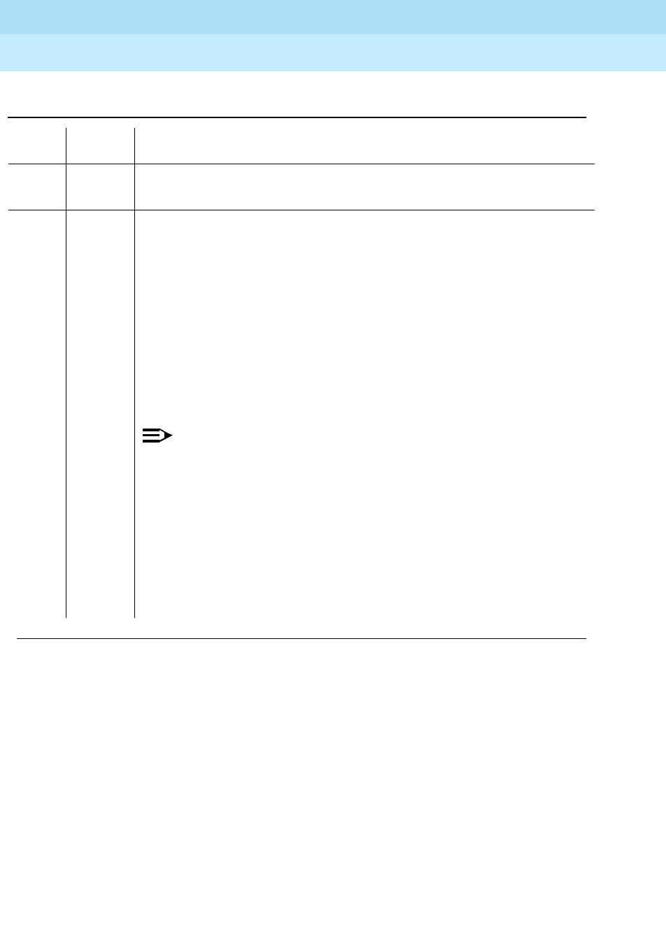
DEFINITY Enterprise Communications Server Release 6
Maintenance for R6r Volumes 1 & 2
555-230-126 Issue 2
January 1998
Maintenance Object Repair Procedures
Page 9-1652UDS1-BD (UDS1 Interface Circuit Pack)
9
Table 9-559. TEST #140 Red Alarm Inquiry Test
Error
Code Test
Result Description/ Recommendation
ABORT Internal system error
1. Retry the command at 1-minute intervals a maximum of 5 times.
2000 ABORT Response to the test was not received within the allowable time period. This
may be due to hyperactivity. Error type 1538 in the error log indicates
hyperactivity. The hyperactive circuit pack is out of service and one or more of
the following symptoms may be exhibited.
1. The UDS1-BD tests (such as test 138 and test 139) are aborting with error
code 2000.
2. The tests run on the ports of this circuit pack are returning a no board
result.
3. A busyout or a release command has no affect on the test results.
4. A list config command shows that the circuit pack and the ports are
properly installed.
NOTE:
When hyperactivity occurs, the circuit pack is isolated from the system,
and all of the trunks for this circuit pack are placed into the out of service
state. The system will try to restore the circuit pack within 15 minutes.
When no faults are detected for 15 minutes, the UDS1 interface circuit
pack is restored to normal operation. All of the trunks for the UDS1
interface circuit pack are then returned to the in service state.
Hyperactivity is often caused by the associated facility. In such a case,
faults (such as slips, misframes, or blue alarms) would be entered in the
error log. In addition, many hardware errors would be logged against the
associated trunk circuits. If the facility is OK and the error occurs again
after 15 minutes, replace the circuit pack.
Continued on next page

DEFINITY Enterprise Communications Server Release 6
Maintenance for R6r Volumes 1 & 2
555-230-126 Issue 2
January 1998
Maintenance Object Repair Procedures
Page 9-1653UDS1-BD (UDS1 Interface Circuit Pack)
9
FAIL The UDS1 interface circuit pack detected a red alarm. An out of frame
condition occurred on the UDS1 interface circuit pack. The UDS1 interface
circuit pack will transmit a yellow alarm to the remote UDS1 endpoint until the
red alarm is retired.
If the UDS1 connects to a T1 network facility or to another switch, do the
following.
1. Verify that both endpoints of the DS1 link are administered using the same
signaling mode, framing mode, and line coding.
2. Contact T1 Network Service or a technician at the far-end switch to
diagnose the remote DS1 endpoint.
3. Check the physical connectivity of the UDS1 packs and of the cable.
4. Replace the local UDS1 interface circuit pack, and repeat the test.
If the UDS1 connects to a line-side terminating device (for example, a PRI
terminal adapter), do the following.
1. Verify that the switch DS1 and the line-side terminating device are
administered using the same signaling mode, framing mode, and line
coding.
2. Investigate the maintenance status of the line-side terminating device.
Refer to the ’Line-Side Terminating Device Operating Manual’ for
information.
3. Contact the vendor of the line-side terminating device to diagnose the
equipment.
4. Check the physical connection of the UDS1 interface circuit pack to the
terminating device, and check the premise distribution system (or the
intra-premise wiring) for physical connection failures.
5. Replace the local UDS1 interface circuit pack and repeat the test.
Table 9-559. TEST #140 Red Alarm Inquiry Test — Continued
Error
Code Test
Result Description/ Recommendation
Continued on next page

DEFINITY Enterprise Communications Server Release 6
Maintenance for R6r Volumes 1 & 2
555-230-126 Issue 2
January 1998
Maintenance Object Repair Procedures
Page 9-1654UDS1-BD (UDS1 Interface Circuit Pack)
9
1 FAIL The test failed. The UDS1 interface circuit pack detected a loss of multiframe
alarm (LMA). An out of frame condition occurred on the UDS1 interface circuit
pack. The UDS1 interface circuit pack will transmit a remote multiframe alarm
(RMA) to the remote UDS1 endpoint until the LMA is retired.
If the UDS1 connects to a T1 network facility or to another switch, do the
following:
1. Verify that both endpoints of the DS1 link are administered using the same
signaling mode, framing mode, and line coding.
2. Contact T1 Network Service or a technician at the far-end switch to
diagnose the remote DS1 endpoint.
3. Check the physical connectivity of the UDS1 packs and of the cable.
4. Replace the local UDS1 interface circuit pack, and repeat the test.
If the UDS1 connects to a line-side terminating device (for example, a PRI
terminal adapter), do the following.
1. Verify that the switch DS1 and the line-side terminating device are
administered using the same signaling mode, framing mode, and line
coding.
2. Investigate the maintenance status of the line-side terminating device.
Refer to the ’Line-Side Terminating Device Operating Manual’ for
information.
3. Contact the vendor of the line-side terminating device to diagnose the
equipment.
4. Check the physical connection of the UDS1 interface circuit pack to the
terminating device, and check the premise distribution system (or the
intra-premise wiring) for physical connection failures.
5. Replace the local UDS1 interface circuit pack and repeat the test.
Table 9-559. TEST #140 Red Alarm Inquiry Test — Continued
Error
Code Test
Result Description/ Recommendation
Continued on next page

DEFINITY Enterprise Communications Server Release 6
Maintenance for R6r Volumes 1 & 2
555-230-126 Issue 2
January 1998
Maintenance Object Repair Procedures
Page 9-1655UDS1-BD (UDS1 Interface Circuit Pack)
9
PASS No Red alarm is detected on the UDS1 Interface circuit pack.
0NO
BOARD The test could not relate the internal ID to the port (no board). This could be
due to incorrect translations, no board is inserted, an incorrect board is
inserted, or an insane board is inserted.
1. Ensure that the board translations are correct. Execute the add ds1
UUCSS command to administer the UDS1 interface if it is not already
administered.
2. If the board was already administered correctly, check the error log to
determine whether the board is hyperactive. If this is the case, the board is
shut down. Reseating the board will re-initialize the board.
3. If the board was found to be correctly inserted in step 1, then issue the
busyout board command.
4. Issue the reset board command.
5. Issue the release busy board command.
6. Issue the test board long command.
This should re-establish the linkage between the internal ID and the port.
Table 9-559. TEST #140 Red Alarm Inquiry Test — Continued
Error
Code Test
Result Description/ Recommendation
Continued on next page

DEFINITY Enterprise Communications Server Release 6
Maintenance for R6r Volumes 1 & 2
555-230-126 Issue 2
January 1998
Maintenance Object Repair Procedures
Page 9-1656UDS1-BD (UDS1 Interface Circuit Pack)
9
Yellow Alarm Inquiry Test (#141)
Receiving a Yellow alarm from remote DS1 endpoint indicates that the remote
DS1 endpoint has an out-of-frame condition. The Yellow Alarm Inquiry Test is
used to determine whether the remote DS1 endpoint is transmitting a Yellow
alarm. The UDS1 Interface circuit pack takes 500 msec to recognize and report a
Yellow alarm and 500 msec to recognize and report that a Yellow alarm condition
is cleared.
When the UDS1 Interface circuit pack detects a Yellow alarm from the remote
DS1 endpoint, it will send a YELLOW-ALARM uplink message to the
maintenance software. After the maintenance software receives the
YELLOW-ALARM message, the Yellow Alarm Inquiry Test is run to confirm the
Yellow alarm. Once the Yellow alarm is confirmed, the maintenance software
places all trunks or ports on the circuit pack into the out-of-service state. The
Inquiry Test will be run every 10 minutes until the Yellow alarm is cleared.
When the Yellow alarm is cleared, the maintenance software restores all trunks or
ports on the UDS1 Interface circuit pack back to their previous service state
before the Yellow alarm was raised.
This Yellow alarm corresponds to the yellow F2 state documented in CCITT
Recommendation I.431.
Remote Multiframe Alarm
Remote Multiframe Alarm (RMA) indicates that the remote DS1 endpoint is in a
Loss of Multiframe Alarm condition while the UDS1 Interface circuit pack is
administered using the DMI-BOS common channel signaling. The RMA is
handled as a Yellow alarm.
Yellow F5 Fault Alarm
For 32-channel E1 operation with CRC4 on, the F5 fault state is defined as a fault
in the user-network interface, specifically in the direction from the user (PBX) to
the network. Refer to CCITT recommendation I.431.
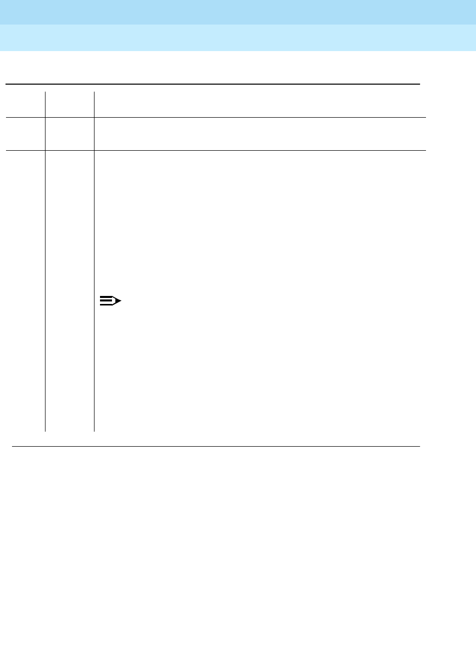
DEFINITY Enterprise Communications Server Release 6
Maintenance for R6r Volumes 1 & 2
555-230-126 Issue 2
January 1998
Maintenance Object Repair Procedures
Page 9-1657UDS1-BD (UDS1 Interface Circuit Pack)
9
Table 9-560. TEST #141 Yellow Alarm Inquiry Test
Error
Code Test
Result Description/ Recommendation
ABORT Internal system error
1. Retry the command at 1-minute intervals a maximum of 5 times.
2000 ABORT Response to the test was not received within the allowable time period. This may
be due to hyperactivity. Error type 1538 in the error log indicates hyperactivity.
The hyperactive circuit pack is out of service and one or more of the following
symptoms may be exhibited.
1. The UDS1-BD tests (such as test 138 and test 139) are aborting with error
code 2000.
2. The tests run on the ports of this circuit pack are returning a no board result.
3. A busyout or a release command has no affect on the test results.
4. A list config command shows that the circuit pack and the ports are
properly installed.
NOTE:
When hyperactivity occurs, the circuit pack is isolated from the system,
and all of the trunks for this circuit pack are placed into the out of service
state. The system will try to restore the circuit pack within 15 minutes.
When no faults are detected for 15 minutes, the UDS1 interface circuit
pack is restored to normal operation. All of the trunks for the UDS1
interface circuit pack are then returned to the in service state.
Hyperactivity is often caused by the associated facility. In such a case,
faults (such as slips, misframes, or blue alarms) would be entered in the
error log. In addition, many hardware errors would be logged against the
associated trunk circuits. If the facility is OK and the error occurs again
after 15 minutes, replace the circuit pack.
Continued on next page

DEFINITY Enterprise Communications Server Release 6
Maintenance for R6r Volumes 1 & 2
555-230-126 Issue 2
January 1998
Maintenance Object Repair Procedures
Page 9-1658UDS1-BD (UDS1 Interface Circuit Pack)
9
FAIL The UDS1 interface circuit pack detected a yellow alarm sent by the remote DS1
endpoint. An out of frame condition occurred at the DS1 endpoint. If the UDS1
connects to a T1 network facility or to another switch, do the following:
1. Verify that both endpoints of the DS1 link are administered using the same
signaling mode, framing mode, and line coding.
2. Contact T1 Network Service or a technician at the far-end switch to
diagnose the remote DS1 endpoint.
3. Check the physical connectivity of the UDS1 packs and of the cable.
4. Replace the local UDS1 interface circuit pack, and repeat the test.
If the UDS1 connects to a line-side terminating device (for example, a PRI
terminal adapter), do the following:
1. Verify that the switch DS1 and the line-side terminating device are
administered using the same signaling mode, framing mode, and line
coding.
2. Investigate the maintenance status of the line-side terminating device. Refer
to the ’Line-Side Terminating Device Operating Manual’ for information.
3. Contact the vendor of the line-side terminating device to diagnose the
equipment.
4. Check the physical connection of the UDS1 interface circuit pack to the
terminating device, and check the premise distribution system (or the
intra-premise wiring) for physical connection failures.
5. Replace the local UDS1 interface circuit pack and repeat the test.
Table 9-560. TEST #141 Yellow Alarm Inquiry Test — Continued
Error
Code Test
Result Description/ Recommendation
Continued on next page

DEFINITY Enterprise Communications Server Release 6
Maintenance for R6r Volumes 1 & 2
555-230-126 Issue 2
January 1998
Maintenance Object Repair Procedures
Page 9-1659UDS1-BD (UDS1 Interface Circuit Pack)
9
1 FAIL The UDS1 interface circuit pack detected a remote multiframe alarm (RMA) sent
by the remote DS1 endpoint. An out of frame condition occurred at the DS1
endpoint.
If the UDS1 connects to a T1 network facility or to another switch, do the
following:
1. Verify that both endpoints of the DS1 link are administered using the same
signaling mode, framing mode, and line coding.
2. Contact T1 Network Service or a technician at the far-end switch to
diagnose the remote DS1 endpoint.
3. Check the physical connectivity of the UDS1 packs and of the cable.
4. Replace the local UDS1 interface circuit pack, and repeat the test.
If the UDS1 connects to a line-side terminating device (for example, a PRI
terminal adapter), do the following:
1. Verify that the switch DS1 and the line-side terminating device are
administered using the same signaling mode, framing mode, and line
coding.
2. Investigate the maintenance status of the line-side terminating device. Refer
to the ’Line-Side Terminating Device Operating Manual’ for information.
3. Contact the vendor of the line-side terminating device to diagnose the
equipment.
4. Check the physical connection of the UDS1 interface circuit pack to the
terminating device, and check the premise distribution system (or the
intra-premise wiring) for physical connection failures.
5. Replace the local UDS1 interface circuit pack and repeat the test.
Table 9-560. TEST #141 Yellow Alarm Inquiry Test — Continued
Error
Code Test
Result Description/ Recommendation
Continued on next page

DEFINITY Enterprise Communications Server Release 6
Maintenance for R6r Volumes 1 & 2
555-230-126 Issue 2
January 1998
Maintenance Object Repair Procedures
Page 9-1660UDS1-BD (UDS1 Interface Circuit Pack)
9
2 FAIL The UDS1 interface circuit pack is reporting a Yellow F5 fault alarm. There is a
fault in the User-Network interface from the user (PBX) to the network. An
out-of-frame condition occurs on the remote DS1 endpoint.
If the UDS1 connects to a T1 network facility:
1. Verify that both endpoints of the DS1 link are administered using the same
signaling mode, framing mode, and line coding.
2. Contact T1 Network Service to diagnose the remote DS1 endpoint.
3. Check the physical connectivity of the DS1 Interface circuit packs and
cable.
4. Replace the local UDS1 Interface circuit pack and repeat the test.
If the UDS1 connects to a line-side terminating device such as a PRI terminal
adapter:
1. Verify that the switch DS1 and the line-side terminating device are
administered using the same signaling mode, framing mode, and line
coding.
2. Investigate the maintenance status of the line-side terminating device. Refer
to the ’Line-Side Terminating Device Operating Manual’ for information.
3. Contact the vendor of the line-side terminating device to diagnose the
equipment.
4. Check the physical connection of the UDS1 Interface circuit pack to the
terminating device. Check premise distribution system (or intra-premise
wiring) for physical connection failures.
5. Replace the local UDS1 Interface circuit pack and repeat the test.
Table 9-560. TEST #141 Yellow Alarm Inquiry Test — Continued
Error
Code Test
Result Description/ Recommendation
Continued on next page

DEFINITY Enterprise Communications Server Release 6
Maintenance for R6r Volumes 1 & 2
555-230-126 Issue 2
January 1998
Maintenance Object Repair Procedures
Page 9-1661UDS1-BD (UDS1 Interface Circuit Pack)
9
Major Alarm Inquiry Test (#142)
The Major alarm raised by a UDS1 Interface circuit pack indicates that the
average bit error rate on the DS1 facility is greater than 1/1000. The Major Alarm
Inquiry Test is used to determine that the received DS1 bit error rate is greater
than 1/1000. The UDS1 Interface circuit pack takes 10 seconds to recognize and
report a Major alarm and 10 seconds to recognize and report that a Major alarm
condition is cleared.
When the UDS1 Interface circuit pack detects a Major alarm, it will send a
MAJOR-ALARM message to the maintenance software. (32-channel interfaces
send a YELLOW alarm to the far end). After the maintenance software receives a
MAJOR-ALARM message, the Major Alarm Inquiry Test is initiated to confirm the
Major alarm on the UDS1 Interface circuit pack. The Inquiry Test will be run every
10 minutes until the Major alarm is cleared. The maintenance software places all
trunks or ports on the circuit pack in the out-of-service state if the Major alarm
persists for more than 20 minutes.
When the Major alarm is cleared, the maintenance software restores all trunks or
ports on the circuit pack to their previous service state before a Major alarm
occurs.
PASS Neither a Yellow alarm nor a Remote Multiframe Alarm nor a F5 state alarm is
being received from the remote DS1 endpoint.
0NO
BOARD The test could not relate the internal ID to the port (no board). This could be due
to incorrect translations, no board is inserted, an incorrect board is inserted, or
an insane board is inserted.
1. Ensure that the board translations are correct. Execute the add ds1 UUCSS
command to administer the UDS1 interface if it is not already administered.
2. If the board was already administered correctly, check the error log to
determine whether the board is hyperactive. If this is the case, the board is
shut down. Reseating the board will re-initialize the board.
3. If the board was found to be correctly inserted in step 1, then issue the
busyout board command.
4. Issue the reset board command.
5. Issue the release busy board command.
6. Issue the test board long command.
This should re-establish the linkage between the internal ID and the port.
Table 9-560. TEST #141 Yellow Alarm Inquiry Test — Continued
Error
Code Test
Result Description/ Recommendation
Continued on next page

DEFINITY Enterprise Communications Server Release 6
Maintenance for R6r Volumes 1 & 2
555-230-126 Issue 2
January 1998
Maintenance Object Repair Procedures
Page 9-1662UDS1-BD (UDS1 Interface Circuit Pack)
9
Table 9-561. TEST #142 Major Alarm Inquiry Test
Error
Code Test
Result Description/ Recommendation
ABORT Internal system error
1. Retry the command at 1-minute intervals a maximum of 5 times.
2000 ABORT Response to the test was not received within the allowable time period. This
may be due to hyperactivity. Error type 1538 in the error log indicates
hyperactivity. The hyperactive circuit pack is out of service and one or more of
the following symptoms may be exhibited.
1. The UDS1-BD tests (such as test 138 and test 139) are aborting with error
code 2000.
2. The tests run on the ports of this circuit pack are returning a no board
result.
3. A busyout or a release command has no affect on the test results.
4. A list config command shows that the circuit pack and the ports are
properly installed.
NOTE:
When hyperactivity occurs, the circuit pack is isolated from the system,
and all of the trunks for this circuit pack are placed into the out of service
state. The system will try to restore the circuit pack within 15 minutes.
When no faults are detected for 15 minutes, the UDS1 interface circuit
pack is restored to normal operation. All of the trunks for the UDS1
interface circuit pack are then returned to the in service state.
Hyperactivity is often caused by the associated facility. In such a case,
faults (such as slips, misframes, or blue alarms) would be entered in the
error log. In addition, many hardware errors would be logged against the
associated trunk circuits. If the facility is OK and the error occurs again
after 15 minutes, replace the circuit pack.
2100 ABORT Could not allocate the necessary system resources to run this test.
1. Retry the command at 1-minute intervals for a maximum of 5 times.
Continued on next page

DEFINITY Enterprise Communications Server Release 6
Maintenance for R6r Volumes 1 & 2
555-230-126 Issue 2
January 1998
Maintenance Object Repair Procedures
Page 9-1663UDS1-BD (UDS1 Interface Circuit Pack)
9
FAIL If the UDS1 connects to a T1 network facility or to another switch, do the
following:
1. The performance of the DS1 link between the UDS1 interface circuit pack
and the remote DS1 endpoint is very poor. Enter the list measurement
ds1-log UUCSS command to read the error seconds measurement.
2. Verify that both endpoints of the DS1 link are administered using the same
signaling mode, framing mode, and line coding.
3. Contact T1 Network Service or the technician at the remote switch to
diagnose the equipment.
4. Check the physical connectivity of the UDS1 interface circuit packs and the
cable.
5. Replace the local UDS1 interface circuit pack, and repeat the test.
FAIL
(cont’d.)
If the UDS1 connects to a line-side terminating device (for example, a PRI
terminal adapter), do the following:
1. The performance of the DS1 link between the UDS1 interface circuit pack
and the line-side terminating device is very poor. Enter the list
measurement ds1-log UUCSS command to read the error seconds
measurement.
2. Verify that the switch DS1 and the line-side terminating device are
administered using the same signaling mode, framing mode, and line
coding.
3. Investigate the maintenance status of the line-side terminating device.
Refer to the ’Line-Side Terminating Device Operating Manual’ for
information.
4. Contact the vendor of the line-side terminating device to diagnose the
equipment.
5. Check the physical connection of the UDS1 interface circuit pack to the
terminating device, and check the premise distribution system (or the
intra-premise wiring) for physical connection failures.
6. Replace the local UDS1 interface circuit pack and repeat the test.
Table 9-561. TEST #142 Major Alarm Inquiry Test — Continued
Error
Code Test
Result Description/ Recommendation
Continued on next page

DEFINITY Enterprise Communications Server Release 6
Maintenance for R6r Volumes 1 & 2
555-230-126 Issue 2
January 1998
Maintenance Object Repair Procedures
Page 9-1664UDS1-BD (UDS1 Interface Circuit Pack)
9
Minor Alarm Inquiry Test (#143)
The Minor alarm raised by a UDS1 Interface circuit pack indicates that the
average bit error rate on the DS1 facility is greater than 1/1,000,000, but less than
1/1000. The Minor Alarm Inquiry Test is used to determine that the received DS1
bit error rate is greater than 1/1,000,000 and less than 1/1000. When D4 framing
mode is selected, the UDS1 Interface circuit pack takes 41-minutes to recognize
and report a Minor alarm and 41-minutes to recognize and report that a Minor
alarm condition has cleared. If ESF framing mode is selected, the UDS1 Interface
circuit pack takes 10 minutes to recognize and report a Minor alarm and 10
minutes to recognize and report that a Minor alarm condition has cleared.
When the UDS1 Interface circuit pack detects a Minor alarm condition, it will
send a MINOR-ALARM message to the maintenance software. After the
maintenance software receives a MINOR-ALARM message, the Minor Alarm
Inquiry Test is initiated to confirm the Minor alarm. All trunks or ports on the circuit
pack are kept in the in-service state after the Minor alarm is confirmed. The Minor
Alarm Inquiry Test is run every 10 minutes until the Minor alarm is cleared.
PASS No Major alarm is detected in the UDS1 Interface circuit pack.
0NO
BOARD The test could not relate the internal ID to the port (no board). This could be
due to incorrect translations, no board is inserted, an incorrect board is
inserted, or an insane board is inserted.
1. Ensure that the board translations are correct. Execute the add ds1
UUCSS command to administer the UDS1 interface if it is not already
administered.
2. If the board was already administered correctly, check the error log to
determine whether the board is hyperactive. If this is the case, the board is
shut down. Reseating the board will re-initialize the board.
3. If the board was found to be correctly inserted in step 1, then issue the
busyout board command.
4. Issue the reset board command.
5. Issue the release busy board command.
6. Issue the test board long command.
This should re-establish the linkage between the internal ID and the port.
Table 9-561. TEST #142 Major Alarm Inquiry Test — Continued
Error
Code Test
Result Description/ Recommendation
Continued on next page
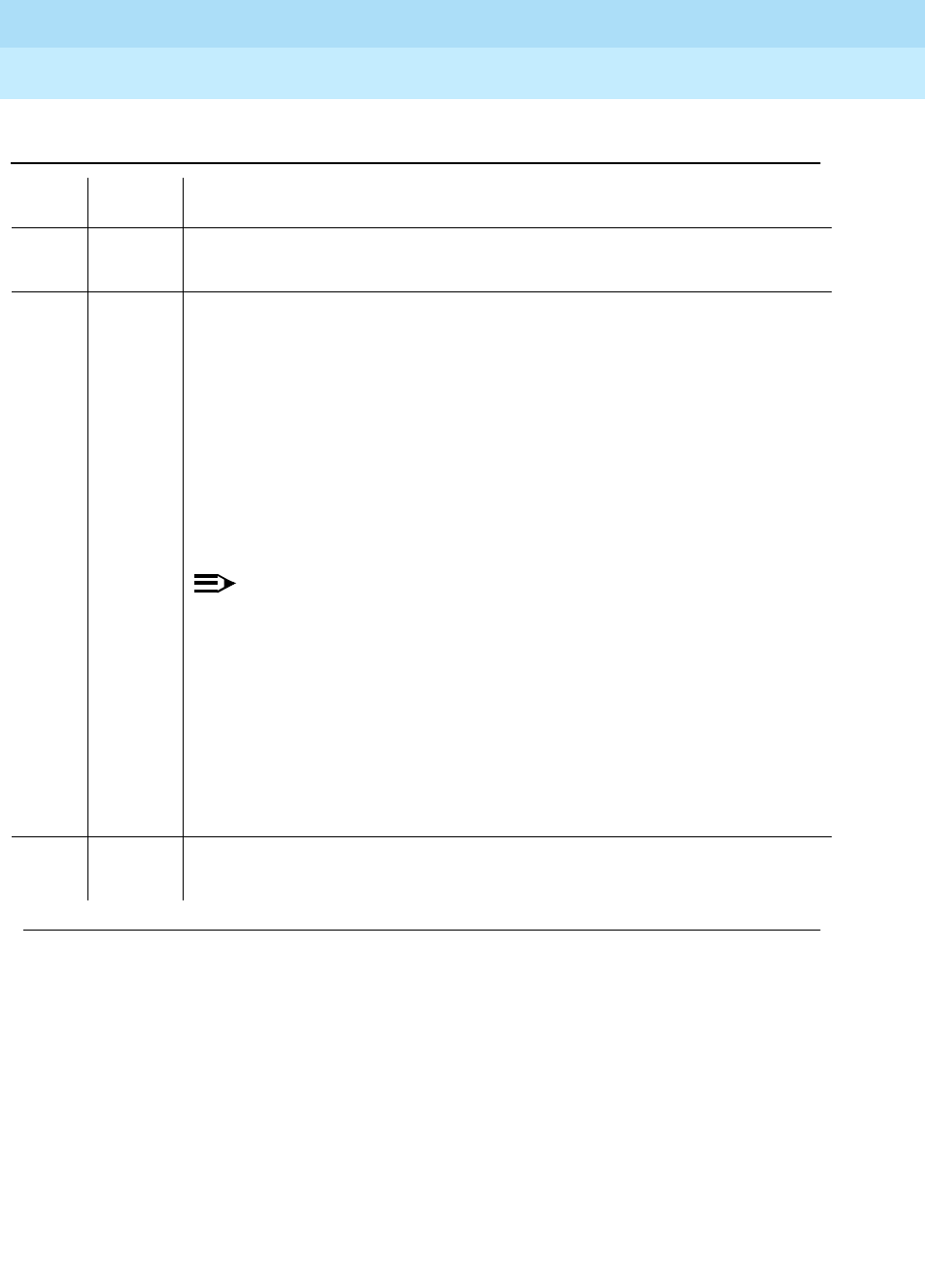
DEFINITY Enterprise Communications Server Release 6
Maintenance for R6r Volumes 1 & 2
555-230-126 Issue 2
January 1998
Maintenance Object Repair Procedures
Page 9-1665UDS1-BD (UDS1 Interface Circuit Pack)
9
Table 9-562. TEST #143 Minor Alarm Inquiry Test
Error
Code Test
Result Description/ Recommendation
ABORT Internal system error
1. Retry the command at 1-minute intervals a maximum of 5 times.
2000 ABORT Response to the test was not received within the allowable time period. This may
be due to hyperactivity. Error type 1538 in the error log indicates hyperactivity.
The hyperactive circuit pack is out of service and one or more of the following
symptoms may be exhibited.
1. The UDS1-BD tests (such as test 138 and test 139) are aborting with error
code 2000.
2. The tests run on the ports of this circuit pack are returning a no board result.
3. A busyout or a release command has no affect on the test results.
4. A list config command shows that the circuit pack and the ports are
properly installed.
NOTE:
When hyperactivity occurs, the circuit pack is isolated from the system,
and all of the trunks for this circuit pack are placed into the out of service
state. The system will try to restore the circuit pack within 15 minutes.
When no faults are detected for 15 minutes, the UDS1 interface circuit
pack is restored to normal operation. All of the trunks for the UDS1
interface circuit pack are then returned to the in service state.
Hyperactivity is often caused by the associated facility. In such a case,
faults (such as slips, misframes, or blue alarms) would be entered in the
error log. In addition, many hardware errors would be logged against the
associated trunk circuits. If the facility is OK and the error occurs again
after 15 minutes, replace the circuit pack.
2100 ABORT Could not allocate the necessary system resources to run this test.
1. Retry the command at 1-minute intervals for a maximum of 5 times.
Continued on next page

DEFINITY Enterprise Communications Server Release 6
Maintenance for R6r Volumes 1 & 2
555-230-126 Issue 2
January 1998
Maintenance Object Repair Procedures
Page 9-1666UDS1-BD (UDS1 Interface Circuit Pack)
9
FAIL Minor alarms are often accompanied by slip and misframe alarms against the
board. Trunk alarms and hardware error logs may occur on the associated
trunks.
If the UDS1 connects to a T1 network facility or to another switch, do the
following:
1. The performance of the DS1 link between the UDS1 interface circuit pack
and the remote DS1 endpoint is poor. Enter the list measurement ds1-log
UUCSS command to read the error seconds measurement.
2. Verify that both endpoints of the DS1 link are administered using the same
signaling mode, framing mode, and line coding.
3. Contact T1 Network Service or the technician at the remote switch to
diagnose the equipment.
4. Check the physical connectivity of the UDS1 interface circuit packs and the
cable.
5. Replace the local UDS1 interface circuit pack, and repeat the test.
FAIL
(cont’d.)
If the UDS1 connects to a line-side terminating device (for example, a PRI
terminal adapter), do the following:
1. The performance of the DS1 link between the UDS1 interface circuit pack
and the line-side terminating device is very poor. Enter the list
measurement ds1-log UUCSS command to read the error seconds
measurement.
2. Verify that the switch DS1 and the line-side terminating device are
administered using the same signaling mode, framing mode, and line
coding.
3. Investigate the maintenance status of the line-side terminating device.
Obtain the error seconds measurement on the terminating device (if
possible). Refer to the ’Line-Side Terminating Device Operating Manual’ for
information.
4. Contact the vendor of the line-side terminating device to diagnose the
equipment.
5. Check the physical connection of the UDS1 interface circuit pack to the
terminating device, and check the premise distribution system (or the
intra-premise wiring) for physical connection failures.
6. Replace the local UDS1 interface circuit pack and repeat the test.
Table 9-562. TEST #143 Minor Alarm Inquiry Test — Continued
Error
Code Test
Result Description/ Recommendation
Continued on next page

DEFINITY Enterprise Communications Server Release 6
Maintenance for R6r Volumes 1 & 2
555-230-126 Issue 2
January 1998
Maintenance Object Repair Procedures
Page 9-1667UDS1-BD (UDS1 Interface Circuit Pack)
9
Slip Alarm Inquiry Test (#144)
Slips occur when transmitter and receiver are not running at precisely the same
clock rate. The UDS1 Interface circuit pack can detect both positive and
negative slips on the DS1 facility. The Slip Alarm Inquiry Test is used to acquire
the total number of slips that have occurred on a DS1 link.
When the UDS1 Interface circuit pack detects a slip condition, the circuit pack
will increase the on-board slip counter by 1. A SLIP-COUNT message is
spontaneously sent to the system software after the counter reaches a threshold
(for example, 88). When the maintenance software receives the SLIP-COUNT
message, the Slip Alarm Inquiry Test is initiated to query the slip counters on a
UDS1 Interface circuit pack and total the slip counts in the maintenance
software.
If the count of slips is over the threshold, a Minor alarm is raised against the
UDS1 Interface circuit pack. All trunks or ports of the UDS1 Interface circuit pack
remain in the in-service state. If the UDS1 Interface circuit pack is used to supply
the system synchronization source, the MINOR alarm will initiate a
synchronization source switch. See “TDM-BUS” and ‘‘SYNC (Synchronization)’’
for details.
PASS No Minor alarm is detected in the UDS1 Interface circuit pack.
0NO
BOARD The test could not relate the internal ID to the port (no board). This could be due
to incorrect translations, no board is inserted, an incorrect board is inserted, or
an insane board is inserted.
1. Ensure that the board translations are correct. Execute the add ds1 UUCSS
command to administer the UDS1 interface if it is not already administered.
2. If the board was already administered correctly, check the error log to
determine whether the board is hyperactive. If this is the case, the board is
shut down. Reseating the board will re-initialize the board.
3. If the board was found to be correctly inserted in step 1, then issue the
busyout board command.
4. Issue the reset board command.
5. Issue the release busy board command.
6. Issue the test board long command.
This should re-establish the linkage between the internal ID and the port.
Table 9-562. TEST #143 Minor Alarm Inquiry Test — Continued
Error
Code Test
Result Description/ Recommendation
Continued on next page
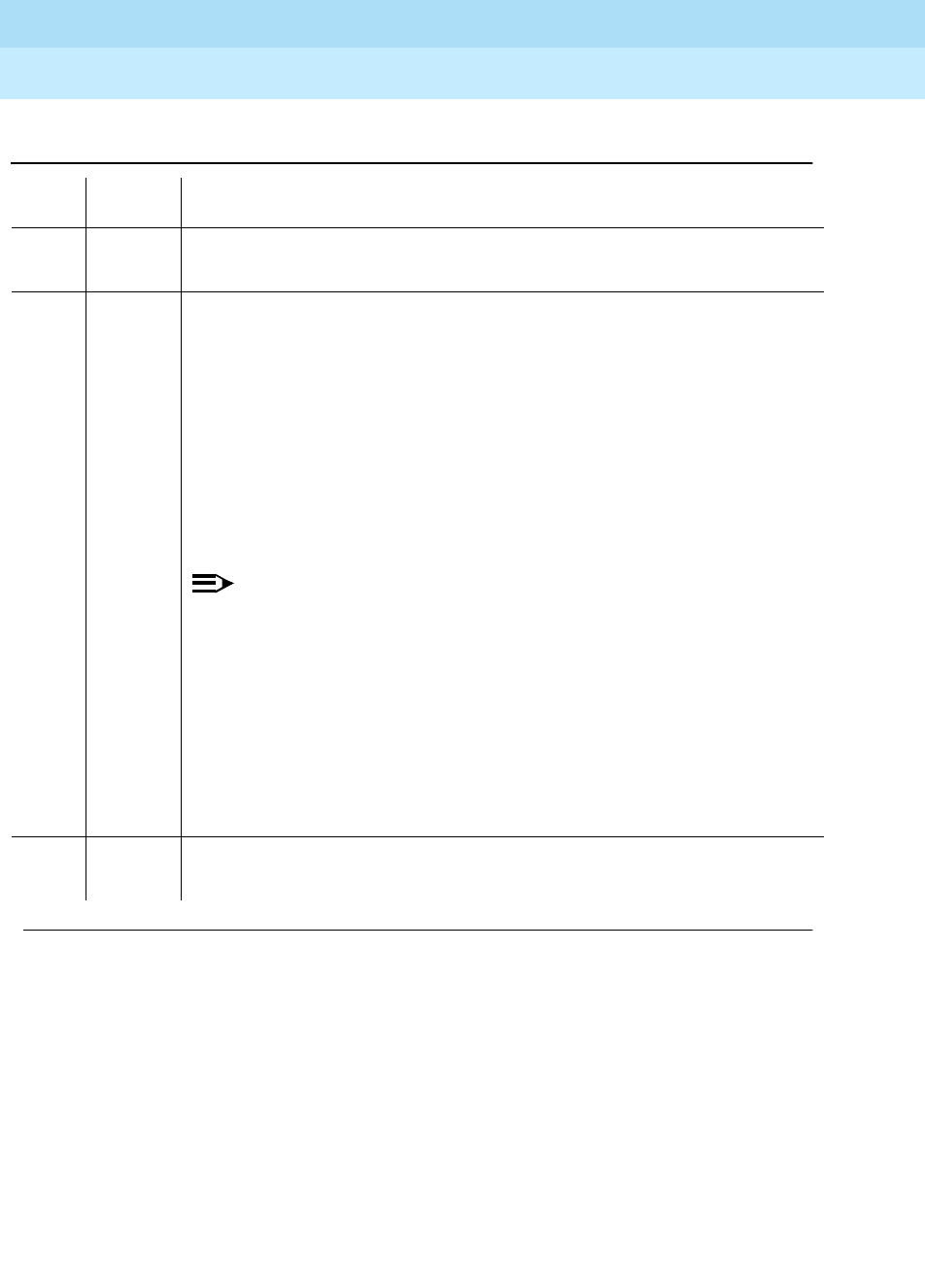
DEFINITY Enterprise Communications Server Release 6
Maintenance for R6r Volumes 1 & 2
555-230-126 Issue 2
January 1998
Maintenance Object Repair Procedures
Page 9-1668UDS1-BD (UDS1 Interface Circuit Pack)
9
Table 9-563. TEST #144 Slip Alarm Inquiry Test
Error
Code Test
Result Description/ Recommendation
ABORT Internal system error
1. Retry the command at 1-minute intervals a maximum of 5 times.
2000 ABORT Response to the test was not received within the allowable time period. This
may be due to hyperactivity. Error type 1538 in the error log indicates
hyperactivity. The hyperactive circuit pack is out of service and one or more of
the following symptoms may be exhibited.
1. The UDS1-BD tests (such as test 138 and test 139) are aborting with error
code 2000.
2. The tests run on the ports of this circuit pack are returning a no board result.
3. A busyout or a release command has no affect on the test results.
4. A list config command shows that the circuit pack and the ports are
properly installed.
NOTE:
When hyperactivity occurs, the circuit pack is isolated from the system,
and all of the trunks for this circuit pack are placed into the out of service
state. The system will try to restore the circuit pack within 15 minutes.
When no faults are detected for 15 minutes, the UDS1 interface circuit
pack is restored to normal operation. All of the trunks for the UDS1
interface circuit pack are then returned to the in service state.
Hyperactivity is often caused by the associated facility. In such a case,
faults (such as slips, misframes, or blue alarms) would be entered in the
error log. In addition, many hardware errors would be logged against the
associated trunk circuits. If the facility is OK and the error occurs again
after 15 minutes, replace the circuit pack.
2100 ABORT Could not allocate the necessary system resources to run this test.
1. Retry the command at 1-minute intervals for a maximum of 5 times.
Continued on next page

DEFINITY Enterprise Communications Server Release 6
Maintenance for R6r Volumes 1 & 2
555-230-126 Issue 2
January 1998
Maintenance Object Repair Procedures
Page 9-1669UDS1-BD (UDS1 Interface Circuit Pack)
9
1 to
88 FAIL The test failed because the UDS1 interface circuit pack and the remote DS1
endpoint are not synchronized to the same clock rate. The UDS1 interface
circuit pack detected a slip alarm. The error code equals the number of slips
detected by the UDS1 interface circuit pack since the last slip alarm inquiry test.
If the UDS1 connects to a T1 network facility or to another switch, do the
following:
1. Retry the command at 1-minute intervals for a maximum of 5 times.
2. If the DS1 interface circuit pack is a TN464C, enter the list measurement
ds1-log UUCSS command to read the error seconds measurement.
3. Verify that both endpoints of the DS1 link are administered using the same
signaling mode, framing mode, and line coding.
4. Check the active alarm and error logs for recent alarms and errors against
the synchronization (SYNC). Follow the suggested repair procedure for
these errors.
5. Contact T1 Network Service or the technician at the remote switch to
diagnose the remote DS1 endpoint.
6. Check the physical connectivity of the UDS1 interface circuit packs and the
cable.
7. Replace the local UDS1 interface circuit pack, and repeat the test.
Information continues on the next page.
1 to
88
(cont’
d.)
FAIL
(cont’d.)
If the UDS1 connects to a line-side terminating device (for example, a PRI
terminal adapter), do the following:
1. Retry the command at 1-minute intervals for a maximum of 5 times.
2. Enter the list measurement ds1-log UUCSS command to read the error
seconds measurement.
3. Verify that the switch DS1 and the line-side terminating device are
administered using the same signaling mode, framing mode, and line
coding.
4. Investigate the maintenance status of the line-side terminating device.
Refer to the ’Line-Side Terminating Device Operating Manual’ for
information.
5. Contact the vendor of the line-side terminating device to diagnose the
equipment.
6. Check the physical connection of the UDS1 interface circuit pack to the
terminating device, and check the premise distribution system (or the
intra-premise wiring) for physical connection failures.
7) Replace the local UDS1 interface circuit pack and repeat the test.
Table 9-563. TEST #144 Slip Alarm Inquiry Test — Continued
Error
Code Test
Result Description/ Recommendation
Continued on next page

DEFINITY Enterprise Communications Server Release 6
Maintenance for R6r Volumes 1 & 2
555-230-126 Issue 2
January 1998
Maintenance Object Repair Procedures
Page 9-1670UDS1-BD (UDS1 Interface Circuit Pack)
9
Misframe Alarm Inquiry Test (#145)
Misframe Alarm indicates that framing bits observed on a UDS1 Interface circuit
pack are in error. The Misframe Alarm Inquiry Test queries the total number of
misframes that have occurred on a DS1 Interface circuit pack since the last
inquiry.
When the DS1 Interface circuit pack detects a misframe error, it will increase its
misframe counter by 1. If the counter reaches a specified threshold (i.e.- 17), a
MISFRAME-COUNT message is automatically sent to the switch maintenance
software. After the maintenance software receives the MISFRAME-COUNT
message, the Misframe Alarm Inquiry Test is initiated to collect the misframe
counts from the UDS1 Interface circuit pack.
When the threshold of misframes is reached, if the UDS1 Interface circuit pack is
supplying the system synchronization source, then a switching synchronization
source message is sent to the TDM Bus Clock. See TDM-BUS (TDM Bus)
Maintenance documentation for details. A Minor alarm against the UDS1
Interface circuit pack is raised, but all trunks or ports of the UDS1 Interface circuit
pack remain in the in-service state.
PASS No Slip alarm is detected on the UDS1 Interface circuit pack.
0NO
BOARD The test could not relate the internal ID to the port (no board). This could be due
to incorrect translations, no board is inserted, an incorrect board is inserted, or
an insane board is inserted.
1. Ensure that the board translations are correct. Execute the add ds1 UUCSS
command to administer the UDS1 interface if it is not already administered.
2. If the board was already administered correctly, check the error log to
determine whether the board is hyperactive. If this is the case, the board is
shut down. Reseating the board will re-initialize the board.
3. If the board was found to be correctly inserted in step 1, then issue the
busyout board command.
4. Issue the reset board command.
5. Issue the release busy board command.
6. Issue the test board long command.
This should re-establish the linkage between the internal ID and the port.
Table 9-563. TEST #144 Slip Alarm Inquiry Test — Continued
Error
Code Test
Result Description/ Recommendation
Continued on next page
DEFINITY Enterprise Communications Server Release 6
Maintenance for R6r Volumes 1 & 2
555-230-126 Issue 2
January 1998
Maintenance Object Repair Procedures
Page 9-1671UDS1-BD (UDS1 Interface Circuit Pack)
9
Table 9-564. TEST #145 Misframe Alarm Inquiry Test
Error
Code Test
Result Description/ Recommendation
ABORT Internal system error
1. Retry the command at 1-minute intervals a maximum of 5 times.
2000 ABORT Response to the test was not received within the allowable time period. This
may be due to hyperactivity. Error type 1538 in the error log indicates
hyperactivity. The hyperactive circuit pack is out of service and one or more of
the following symptoms may be exhibited.
1. The UDS1-BD tests (such as test 138 and test 139) are aborting with error
code 2000.
2. The tests run on the ports of this circuit pack are returning a no board
result.
3. A busyout or a release command has no affect on the test results.
4. A list config command shows that the circuit pack and the ports are
properly installed.
NOTE:
When hyperactivity occurs, the circuit pack is isolated from the system,
and all of the trunks for this circuit pack are placed into the out of service
state. The system will try to restore the circuit pack within 15 minutes.
When no faults are detected for 15 minutes, the UDS1 interface circuit
pack is restored to normal operation. All of the trunks for the UDS1
interface circuit pack are then returned to the in service state.
Hyperactivity is often caused by the associated facility. In such a case,
faults (such as slips, misframes, or blue alarms) would be entered in the
error log. In addition, many hardware errors would be logged against the
associated trunk circuits. If the facility is OK and the error occurs again
after 15 minutes, replace the circuit pack.
2100 ABORT Could not allocate the necessary system resources to run this test.
1. Retry the command at 1-minute intervals for a maximum of 5 times.
Continued on next page

DEFINITY Enterprise Communications Server Release 6
Maintenance for R6r Volumes 1 & 2
555-230-126 Issue 2
January 1998
Maintenance Object Repair Procedures
Page 9-1672UDS1-BD (UDS1 Interface Circuit Pack)
9
1 to 17 FAIL The test failed because the UDS1 interface circuit pack detected errors in the
received framing bits pattern. The error code equals the number of misframes
detected by the UDS1 interface circuit pack since the last misframe alarm
inquiry test. Major bit and minor bit error rate (error types 2561 and 2817) error
logs often accompany misframe alarms. Clearing the cause of these error logs
may clear the misframes which are occurring.
If the UDS1 connects to a T1 network facility or to another switch, do the
following:
1. Retry the command at 1-minute intervals for a maximum of 5 times.
2. If the DS1 interface circuit pack is a TN464C, enter the list measurement
ds1-log UUCSS command to read the error seconds measurement.
3. Verify that both endpoints of the DS1 link are administered using the same
signaling mode, framing mode, and line coding.
4. Check the active alarm and error logs for recent alarms and errors against
the synchronization (SYNC). Follow the suggested repair procedure for
these errors.
5. Contact T1 Network Service or the technician at the remote switch to
diagnose the remote DS1 endpoint.
6. Check the physical connectivity of the UDS1 interface circuit packs and the
cable.
7. Replace the local UDS1 interface circuit pack, and repeat the test.
More information continues on the next page.
Table 9-564. TEST #145 Misframe Alarm Inquiry Test — Continued
Error
Code Test
Result Description/ Recommendation
Continued on next page

DEFINITY Enterprise Communications Server Release 6
Maintenance for R6r Volumes 1 & 2
555-230-126 Issue 2
January 1998
Maintenance Object Repair Procedures
Page 9-1673UDS1-BD (UDS1 Interface Circuit Pack)
9
1 to 17
(cont’
d.)
FAIL
(cont’d.)
If the UDS1 connects to a line-side terminating device such as a PRI terminal
adapter:
1. Retry the command at 1-minute intervals for a maximum of 5 times.
2. Enter the list measurement ds1-log UUCSS command to read the error
seconds measurement.
3. Verify that the switch DS1 and the line-side terminating device are
administered using the same signaling mode, framing mode, and line
coding.
4. Investigate the maintenance status of the line-side terminating device.
Refer to the ’Line-Side Terminating Device Operating Manual’ for
information.
5. Contact the vendor of the line-side terminating device to diagnose the
equipment.
6. Check the physical connection of the UDS1 interface circuit pack to the
terminating device, and check the premise distribution system (or the
intra-premise wiring) for physical connection failures.
7. Replace the local UDS1 interface circuit pack and repeat the test.
PASS No Misframe alarm is detected on the UDS1 Interface circuit pack.
0NO
BOARD The test could not relate the internal ID to the port (no board). This could be
due to incorrect translations, no board is inserted, an incorrect board is
inserted, or an insane board is inserted.
1. Ensure that the board translations are correct. Execute the add ds1
UUCSS command to administer the UDS1 interface if it is not already
administered.
2. If the board was already administered correctly, check the error log to
determine whether the board is hyperactive. If this is the case, the board is
shut down. Reseating the board will re-initialize the board.
3. If the board was found to be correctly inserted in step 1, then issue the
busyout board command.
4. Issue the reset board command.
5. Issue the release busy board command.
6. Issue the test board long command.
This should re-establish the linkage between the internal ID and the port.
Table 9-564. TEST #145 Misframe Alarm Inquiry Test — Continued
Error
Code Test
Result Description/ Recommendation
Continued on next page

DEFINITY Enterprise Communications Server Release 6
Maintenance for R6r Volumes 1 & 2
555-230-126 Issue 2
January 1998
Maintenance Object Repair Procedures
Page 9-1674UDS1-BD (UDS1 Interface Circuit Pack)
9
Translation Update Test (#146)
The Translation Update Test sends the circuit-pack-level information specified by
System Administration to the UDS1 Interface circuit pack. Translation includes
the following data administered for a UDS1 Interface circuit pack (see output of
display ds1 UUCSS command): DS1 Link Length between two DS1 endpoints,
Synchronization Source Control, All Zero Suppression, Framing Mode, Signaling
Mode, Time Slot Number of 697-Hz Tone, Time Slot Number of 700-Hz Tone, etc.
In G3V3, if a TN464F or later UDS1 circuit pack is combined with an Lucent
120A1 CSU Module to form and Integrated CSU Module, this test will also send
the administration for this Integrated CSU to the circuit pack to assure the
board’s translations are correct. The administration of the CSU Module is done
using the DS1 circuit pack administration form. Translation for the CSU Module
includes the following data: Transmit LBO, Receive ALBO, Supply CPE
Loopback Jack Power, etc.
Table 9-565. TEST #146 Translation Update Test
Error
Code Test
Result Description/ Recommendation
ABORT Internal system error
1. Retry the command at 1-minute interval s a maximum of 5 times.
FAIL Internal system software error.
1. Enter the display ds1 UUCSS command to verify the UDS1 Interface
circuit pack translation.
PASS Translation data has been downloaded to the UDS1 Interface circuit pack
successfully.
0NO
BOARD The test could not relate the internal ID to the port (no board). This could be
due to incorrect translations, no board is inserted, an incorrect board is
inserted, or an insane board is inserted.
1. Ensure that the board translations are correct. Execute the add ds1
UUCSS command to administer the UDS1 interface if it is not already
administered.
2. If the board was already administered correctly, check the error log to
determine whether the board is hyperactive. If this is the case, the board is
shut down. Reseating the board will re-initialize the board.
3. If the board was found to be correctly inserted in step 1, then issue the
busyout board command.
4. Issue the reset board command.
5. Issue the release busy board command.
6. Issue the test board long command.
This should re-establish the linkage between the internal ID and the port.
Continued on next page

DEFINITY Enterprise Communications Server Release 6
Maintenance for R6r Volumes 1 & 2
555-230-126 Issue 2
January 1998
Maintenance Object Repair Procedures
Page 9-1675UDS1-BD (UDS1 Interface Circuit Pack)
9
DS1 Board Loopback Test (#1209)
This test is destructive.
The DS1 Board Loopback (BLB) Test causes a loopback at the TN464F DS1
board edge and tests DS1 board internal circuitry.
The test is destructive and can only be initiated by a system technician
demanded
test ds1-loop UUCSS ds1/csu-loopback-tests
command.
All trunks or ports on the UDS1 Interface circuit pack must be busied out via the
system technician busyout board command before running the BLB Test.
When the BLB Test is initiated, maintenance software sends an appropriate
message to the TN464F UDS1 Interface circuit pack to start the test. The board
will set up the BLB loopback, transmit a test pattern, and verify that the pattern is
received unaltered through the loopback. If the transmitted and received pattern
is different, the test fails.
When the test is complete, all trunks or ports on the TN464F UDS1 Interface
circuit pack are restored to the in-service state after the release board command
is entered.
Table 9-566. TEST #1209 DS1 Board Loopback Test
Error
Code Test
Result Description/ Recommendation
ABORT Internal system error
1. Retry the
test ds1-loop UUCSS ds1/csu-loopback-tests
command at
1-minute intervals a maximum of 5 times.
1005 ABORT DS1 Board Loopback Test cannot be executed in the current configuration. To
run this, the TN464F or later suffix UDS1 must be administered for 24-channel
operation. The "Bit Rate" field on the DS1 circuit pack administration form must
be set to "1.544" for 24-channel operation.
1015 ABORT Ports on the UDS1 Interface circuit pack have not been busied out to
out-of-service.
1. Enter the busyout board UUCSS command to put all trunks or ports of the
UDS1 Interface circuit pack into the out-of-service state.
2. Retry the command.
Continued on next page
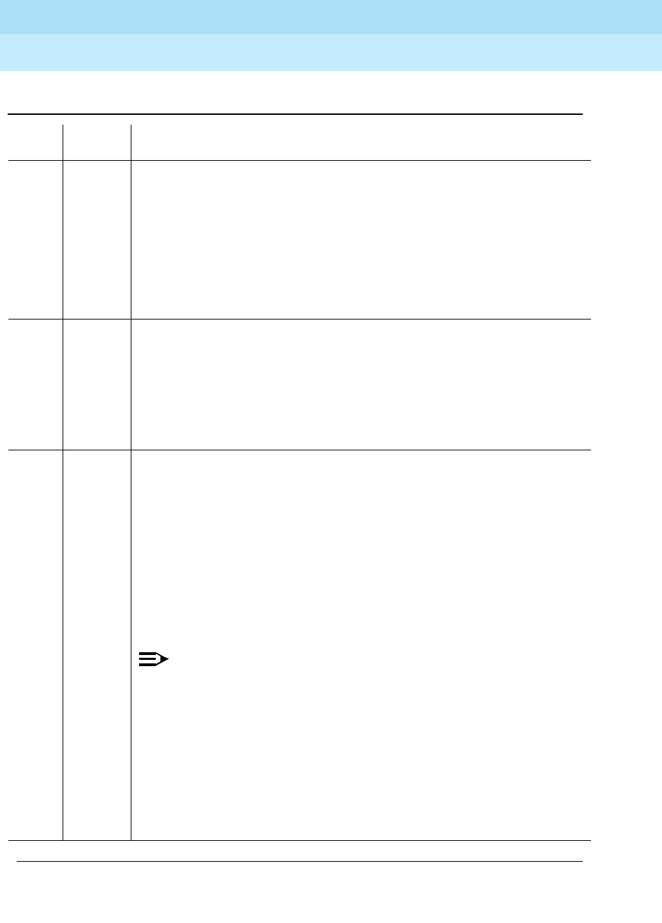
DEFINITY Enterprise Communications Server Release 6
Maintenance for R6r Volumes 1 & 2
555-230-126 Issue 2
January 1998
Maintenance Object Repair Procedures
Page 9-1676UDS1-BD (UDS1 Interface Circuit Pack)
9
1039 ABORT The UDS1 Interface circuit pack is providing timing for the system. Executing
this test could cause major system disruption.
If the UDS1 Interface circuit pack needs to be tested, set the synchronization
reference to another DS1 Interface circuit pack or to the Tone-Clock circuit pack
via the following command sequence:
1. Issue the disable synchronization-switch command.
2. Next, issue the set synchronization UUCSS command.
3. Lastly, issue the enable synchronization-switch command.
1950 ABORT Another loopback/span test is already executing on the DS1 board or the board
is in a network requested loopback mode (Line loopback or Payload loopback).
The hardware error log will indicate whether a Customer Loopback Jack Test,
Far CSU Loopback Test, or the One-Way Span Test is executing or if the board
is in line loopback or payload loopback mode. Only one long-duration
loopback/span test can be active at a given time. Thus, if a loopback/span test
is already active, that test must be terminated via the test ds1-loop UUCSS
end-loopback/span-test command in order to execute this test.
2000 ABORT Response to the test was not received within the allowable time period. This
may be due to hyperactivity. Error type 1538 in the error log indicates
hyperactivity. The hyperactive circuit pack is out of service and one or more of
the following symptoms may be exhibited.
1. The UDS1-BD tests (such as test 138 and test 139) are aborting with error
code 2000.
2. The tests run on the ports of this circuit pack are returning a no board result.
3. A busyout or a release command has no affect on the test results.
4. A list config command shows that the circuit pack and the ports are
properly installed.
NOTE:
When hyperactivity occurs, the circuit pack is isolated from the system,
and all of the trunks for this circuit pack are placed into the out of service
state. The system will try to restore the circuit pack within 15 minutes.
When no faults are detected for 15 minutes, the UDS1 interface circuit
pack is restored to normal operation. All of the trunks for the UDS1
interface circuit pack are then returned to the in service state.
Hyperactivity is often caused by the associated facility. In such a case,
faults (such as slips, misframes, or blue alarms) would be entered in the
error log. In addition, many hardware errors would be logged against the
associated trunk circuits. If the facility is OK and the error occurs again
after 15 minutes, replace the circuit pack.
Table 9-566. TEST #1209 DS1 Board Loopback Test — Continued
Error
Code Test
Result Description/ Recommendation
Continued on next page

DEFINITY Enterprise Communications Server Release 6
Maintenance for R6r Volumes 1 & 2
555-230-126 Issue 2
January 1998
Maintenance Object Repair Procedures
Page 9-1677UDS1-BD (UDS1 Interface Circuit Pack)
9
CSU Equipment Loopback Test (#1210)
This test is destructive.
The CSU Equipment Loopback (ELB) Test causes a loopback at the near-edge
of the local Lucent 120A1 CSU Module and tests the connection from the TN464F
DS1 board to the CSU Module (DS1 board edge interconnecting cable, and CSU
Module edge). This test will only be performed if the Lucent 120A1 CSU Module
is present, administered, and connected to a 1.544 Mbps TN464F DS1 circuit
pack on the back of the port carrier.
The test is destructive and can only be initiated by a system technician
demanded
test ds1-loop UUCSS ds1/csu-loopback-tests
command.
2100 ABORT Could not allocate the necessary system resources to run this test.
1. Retry the command at 1-minute intervals for a maximum of 5 times.
FAIL UDS1 Interface circuit pack failed the DS1 Board Loopback Test.
1. Retry the
test ds1-loop UUCSS ds1/csu-loopback-tests
command.
2. If the BLB test continues to fail, then replace the UDS1 circuit pack.
PASS The BLB test executed successfully. The test pattern was transmitted and
received successfully up to the TN464F DS1 board edge.
0NO
BOARD The test could not relate the internal ID to the port (no board). This could be due
to incorrect translations, no board is inserted, an incorrect board is inserted, or
an insane board is inserted.
1. Ensure that the board translations are correct. Execute the add ds1 UUCSS
command to administer the UDS1 interface if it is not already administered.
2. If the board was already administered correctly, check the error log to
determine whether the board is hyperactive. If this is the case, the board is
shut down. Reseating the board will re-initialize the board.
3. If the board was found to be correctly inserted in step 1, then issue the
busyout board command.
4. Issue the reset board command.
5. Issue the release busy board command.
6. Issue the test board long command.
This should re-establish the linkage between the internal ID and the port.
Table 9-566. TEST #1209 DS1 Board Loopback Test — Continued
Error
Code Test
Result Description/ Recommendation
Continued on next page

DEFINITY Enterprise Communications Server Release 6
Maintenance for R6r Volumes 1 & 2
555-230-126 Issue 2
January 1998
Maintenance Object Repair Procedures
Page 9-1678UDS1-BD (UDS1 Interface Circuit Pack)
9
All trunks or ports on the UDS1 Interface circuit pack must be busied out via the
system technician busyout board command before running the ELB Test.
When the ELB Test is initiated, maintenance software sends an appropriate
message to the TN464F UDS1 Interface circuit pack to start the test. The board
will set up the ELB loopback, transmit a test pattern, and verify that the pattern is
received unaltered through the loopback. If the transmitted and received pattern
is different, the test fails.
When the test is complete, all trunks or ports on the TN464F UDS1 Interface
circuit pack are restored to the in-service state after the release board command
is entered.
Table 9-567. TEST #1210 CSU Equipment Loopback Test
Error
Code Test
Result Description/ Recommendation
ABORT Internal system error
1. Retry the
test ds1-loop UUCSS ds1/csu-loopback-tests
command at
1-minute intervals a maximum of 5 times.
1005 ABORT CSU Equipment Loopback Test cannot be executed in the current
configuration. To run this test, the
Near-End CSU Type
field on the DS1circuit
pack administration form must be set to
integrated
and the "Bit Rate" field on
the DS1 circuit pack administration form must be set to "1.544" (24-channel
configuration).
1. Use the change ds1 UUCSS command to set the
Near-End CSU Type
field on the DS1 circuit pack administration form to
integrated
, and/or
change the "Bit Rate" field to "1.544" if the board is to be used in 24-channel
configuration.
2. Retry the
test ds1-loop UUCSS ds1/csu-loopback-tests
command.
1015 ABORT Ports on the UDS1 Interface circuit pack have not been busied out to
out-of-service.
1. Enter the busyout board UUCSS command to put all trunks or ports of the
UDS1 Interface circuit pack into the out-of-service state.
2. Retry the command.
1039 ABORT The UDS1 Interface circuit pack is providing timing for the system. Executing
this test could cause major system disruption.
If the UDS1 Interface circuit pack needs to be tested, set the synchronization
reference to another DS1 Interface circuit pack or to the Tone-Clock circuit
pack via the following command sequence:
1. Issue the disable synchronization-switch command.
2. Next, issue the set synchronization UUCSS command.
3. Lastly, issue the enable synchronization-switch command.
Continued on next page
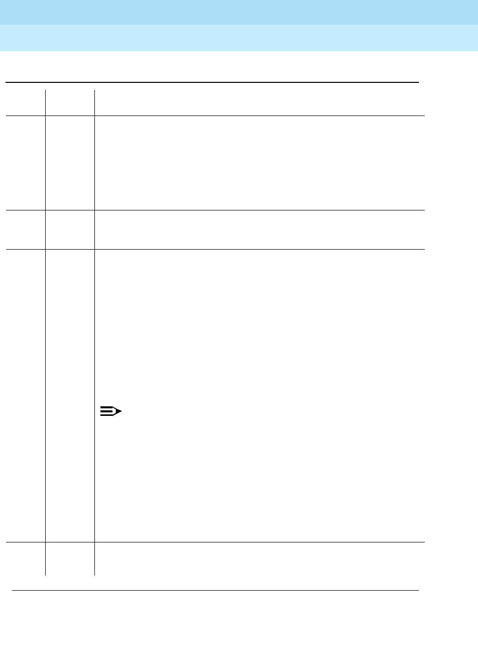
DEFINITY Enterprise Communications Server Release 6
Maintenance for R6r Volumes 1 & 2
555-230-126 Issue 2
January 1998
Maintenance Object Repair Procedures
Page 9-1679UDS1-BD (UDS1 Interface Circuit Pack)
9
1950 ABORT Another loopback/span test is already executing on the DS1 board or the board
is in a network requested loopback mode (Line loopback or Payload loopback).
The hardware error log will indicate whether a Customer Loopback Jack Test,
Far CSU Loopback Test, or the One-Way Span Test is executing or if the board
is in line loopback or payload loopback mode. Only one long-duration
loopback/span test can be active at a given time. Thus, if a loopback/span test
is already active, that test must be terminated via the
test ds1-loop UUCSS
end-loopback/span-test
command in order to execute this test.
1951 ABORT The CSU Equipment Loopback Test could not be executed because the 120A1
CSU Module was not physically installed. Physically connect the 120A1 CSU
Module to the TN464F board on the back of the port carrier.
2000 ABORT Response to the test was not received within the allowable time period. This
may be due to hyperactivity. Error type 1538 in the error log indicates
hyperactivity. The hyperactive circuit pack is out of service and one or more of
the following symptoms may be exhibited.
1. The UDS1-BD tests (such as test 138 and test 139) are aborting with error
code 2000.
2. The tests run on the ports of this circuit pack are returning a no board
result.
3. A busyout or a release command has no affect on the test results.
4. A list config command shows that the circuit pack and the ports are
properly installed.
NOTE:
When hyperactivity occurs, the circuit pack is isolated from the system,
and all of the trunks for this circuit pack are placed into the out of service
state. The system will try to restore the circuit pack within 15 minutes.
When no faults are detected for 15 minutes, the UDS1 interface circuit
pack is restored to normal operation. All of the trunks for the UDS1
interface circuit pack are then returned to the in service state.
Hyperactivity is often caused by the associated facility. In such a case,
faults (such as slips, misframes, or blue alarms) would be entered in the
error log. In addition, many hardware errors would be logged against the
associated trunk circuits. If the facility is OK and the error occurs again
after 15 minutes, replace the circuit pack.
2100 ABORT Could not allocate the necessary system resources to run this test.
1. Retry the command at 1-minute intervals for a maximum of 5 times.
Table 9-567. TEST #1210 CSU Equipment Loopback Test — Continued
Error
Code Test
Result Description/ Recommendation
Continued on next page

DEFINITY Enterprise Communications Server Release 6
Maintenance for R6r Volumes 1 & 2
555-230-126 Issue 2
January 1998
Maintenance Object Repair Procedures
Page 9-1680UDS1-BD (UDS1 Interface Circuit Pack)
9
FAIL UDS1 Interface circuit pack failed the CSU Equipment Loopback Test.
1. Retry the
test ds1-loop UUCSS ds1/csu-loopback-tests
command.
2. If the ELB test continues to fail, then either the TN464F board, the CSU
Module, or the I/O cable between the backplane and the CSU module (or
any combination thereof) has failed. Attempt to isolate the problem to one
of these areas. Begin by replacing the CSU Module and running the
test
ds1-loop UUCSS ds1/csu-loopback-tests
command again.
3. If the ELB test continues to fail, then replace the TN464F board and run the
test ds1-loop UUCSS ds1/csu-loopback-tests
command again.
4. If the ELB test continues to fail, the problem could be in the I/O cable
between the backplane and the CSU module.
PASS The ELB test executed successfully. The test pattern was transmitted and
received successfully over the connection from the TN464F DS1 board to the
near-edge of the 120A1 CSU Module.
0NO
BOARD The test could not relate the internal ID to the port (no board). This could be
due to incorrect translations, no board is inserted, an incorrect board is
inserted, or an insane board is inserted.
1. Ensure that the board translations are correct. Execute the add ds1
UUCSS command to administer the UDS1 interface if it is not already
administered.
2. If the board was already administered correctly, check the error log to
determine whether the board is hyperactive. If this is the case, the board is
shut down. Reseating the board will re-initialize the board.
3. If the board was found to be correctly inserted in step 1, then issue the
busyout board command.
4. Issue the reset board command.
5. Issue the release busy board command.
6. Issue the test board long command.
This should re-establish the linkage between the internal ID and the port.
Table 9-567. TEST #1210 CSU Equipment Loopback Test — Continued
Error
Code Test
Result Description/ Recommendation
Continued on next page

DEFINITY Enterprise Communications Server Release 6
Maintenance for R6r Volumes 1 & 2
555-230-126 Issue 2
January 1998
Maintenance Object Repair Procedures
Page 9-1681UDS1-BD (UDS1 Interface Circuit Pack)
9
CSU Repeater Loopback Test (#1211)
This test is destructive.
The CSU Repeater Loopback (RLB) Test causes a loopback at the far-edge of
the local Lucent 120A1 CSU Module and tests the connection from the TN464F
DS1 board to and including the CSU Module circuitry. This test will only be
performed if the Lucent 120A1 CSU Module is present, administered, and
connected to a 1.544 Mbps TN464F DS1 circuit pack on the back of the port
carrier.
The test is destructive and can only be initiated by a system technician
demanded
test ds1-loop UUCSS ds1/csu-loopback-tests
command.
All trunks or ports on the UDS1 Interface circuit pack must be busied out via the
system technician busyout board command before running the RLB Test.
When the RLB Test is initiated, maintenance software sends an appropriate
message to the TN464F UDS1 Interface circuit pack to start the test. The board
will set up the RLB loopback, transmit a test pattern, and verify that the pattern is
received unaltered through the loopback. If the transmitted and received pattern
is different, the test fails.
When the test is complete, all trunks or ports on the TN464F UDS1 Interface
circuit pack are restored to the in-service state after the release board command
is entered.
Table 9-568. TEST #1211 CSU Repeater Loopback Test
Error
Code Test
Result Description/ Recommendation
ABORT Internal system error
1. Retry the
test ds1-loop UUCSS ds1/csu-loopback-tests
command at
1-minute intervals a maximum of 5 times.
1005 ABORT CSU Repeater Loopback Test cannot be executed in the current
configuration. To run this test, the
Near-End CSU Type
field on the DS1circuit
pack administration form must be set to
integrated
and the "Bit Rate" field on
the DS1 circuit pack administration form must be set to "1.544" (24-channel
configuration).
1. Use the change ds1 UUCSS command to set the
Near-End CSU Type
field on the DS1 circuit pack administration form to
integrated
, and/or
change the "Bit Rate" field to "1.544" if the board is to be used in
24-channel configuration.
2. Retry the
test ds1-loop UUCSS ds1/csu-loopback-tests
command.
Continued on next page

DEFINITY Enterprise Communications Server Release 6
Maintenance for R6r Volumes 1 & 2
555-230-126 Issue 2
January 1998
Maintenance Object Repair Procedures
Page 9-1682UDS1-BD (UDS1 Interface Circuit Pack)
9
1015 ABORT Ports on the UDS1 Interface circuit pack have not been busied out to
out-of-service.
1. Enter the busyout board UUCSS command to put all trunks or ports of
the UDS1 Interface circuit pack into the out-of-service state.
2. Retry the command.
1039 ABORT The UDS1 Interface circuit pack is providing timing for the system. Executing
this test could cause major system disruption.
If the UDS1 Interface circuit pack needs to be tested, set the synchronization
reference to another DS1 Interface circuit pack or to the Tone-Clock circuit
pack via the following command sequence:
1. Issue the disable synchronization-switch command.
2. Next, issue the set synchronization UUCSS command.
3. Lastly, issue the enable synchronization-switch command.
1950 ABORT Another loopback/span test is already executing on the DS1 board or the
board is in a network requested loopback mode (Line loopback or Payload
loopback). The hardware error log will indicate whether a Customer Loopback
Jack Test, Far CSU Loopback Test, or the One-Way Span Test is executing or
if the board is in line loopback or payload loopback mode. Only one
long-duration loopback/span tests can be active at a given time. Thus, if a
loopback/span test is already active, that test must be terminated via the
test
ds1-loop UUCSS end-loopback/span-test
command in order to execute this
test.
1951 ABORT The CSU Repeater Loopback Test could not be executed because the 120A1
CSU Module was not physically installed. Physically connect the 120A1 CSU
Module to the TN464F board on the back of the port carrier.
Table 9-568. TEST #1211 CSU Repeater Loopback Test — Continued
Error
Code Test
Result Description/ Recommendation
Continued on next page

DEFINITY Enterprise Communications Server Release 6
Maintenance for R6r Volumes 1 & 2
555-230-126 Issue 2
January 1998
Maintenance Object Repair Procedures
Page 9-1683UDS1-BD (UDS1 Interface Circuit Pack)
9
2000 ABORT Response to the test was not received within the allowable time period. This
may be due to hyperactivity. Error type 1538 in the error log indicates
hyperactivity. The hyperactive circuit pack is out of service and one or more of
the following symptoms may be exhibited.
1. The UDS1-BD tests (such as test 138 and test 139) are aborting with error
code 2000.
2. The tests run on the ports of this circuit pack are returning a no board
result.
3. A busyout or a release command has no affect on the test results.
4. A list config command shows that the circuit pack and the ports are
properly installed.
NOTE:
When hyperactivity occurs, the circuit pack is isolated from the system,
and all of the trunks for this circuit pack are placed into the out of
service state. The system will try to restore the circuit pack within 15
minutes. When no faults are detected for 15 minutes, the UDS1
interface circuit pack is restored to normal operation. All of the trunks for
the UDS1 interface circuit pack are then returned to the in service state.
Hyperactivity is often caused by the associated facility. In such a case,
faults (such as slips, misframes, or blue alarms) would be entered in the
error log. In addition, many hardware errors would be logged against
the associated trunk circuits. If the facility is OK and the error occurs
again after 15 minutes, replace the circuit pack.
2100 ABORT Could not allocate the necessary system resources to run this test.
1. Retry the command at 1-minute intervals for a maximum of 5 times.
FAIL UDS1 Interface circuit pack failed the CSU Repeater Loopback Test.
1. Retry the
test ds1-loop UUCSS ds1/csu-loopback-tests
command.
2. If the RLB test continues to fail, and the CSU Equipment Loopback Test
(#1210) passed, then replace the CSU Module.
Table 9-568. TEST #1211 CSU Repeater Loopback Test — Continued
Error
Code Test
Result Description/ Recommendation
Continued on next page

DEFINITY Enterprise Communications Server Release 6
Maintenance for R6r Volumes 1 & 2
555-230-126 Issue 2
January 1998
Maintenance Object Repair Procedures
Page 9-1684UDS1-BD (UDS1 Interface Circuit Pack)
9
CPE Loopback Jack Test (#1212)
This test is destructive.
The CPE Loopback Jack (CLJ-LB) Test causes a loopback at the CPE Loopback
Jack and tests the building wiring connection between the TN464F DS1 board
and the CPE Loopback Jack.
The test is highly destructive and can only be initiated by a system technician
demanded
test ds1-loop UUCSS cpe-loopback-jack-test-begin
[number-of-bits bit-pattern]
command. The System technician has the choice
of entering a loopback activation code on the command line or using the default
code
0x47F
.
All trunks or ports on the UDS1 Interface circuit pack must be busied out via the
system technician busyout board command before running the CPE Loopback
Jack Test.
The CPE Loopback Jack Test has the TN464F UDS1 Interface circuit pack
transmit a loopback activation code to the CPE Loopback Jack, waits up to 10
PASS The RLB test executed successfully. The test pattern was transmitted and
received successfully over the connection from the TN464F DS1 board to the
far-edge of the 120A1 CSU Module.
0NO
BOARD The test could not relate the internal ID to the port (no board). This could be
due to incorrect translations, no board is inserted, an incorrect board is
inserted, or an insane board is inserted.
1. Ensure that the board translations are correct. Execute the add ds1
UUCSS command to administer the UDS1 interface if it is not already
administered.
2. If the board was already administered correctly, check the error log to
determine whether the board is hyperactive. If this is the case, the board
is shut down. Reseating the board will re-initialize the board.
3. If the board was found to be correctly inserted in step 1, then issue the
busyout board command.
4. Issue the reset board command.
5. Issue the release busy board command.
6. Issue the test board long command.
This should re-establish the linkage between the internal ID and the port.
Table 9-568. TEST #1211 CSU Repeater Loopback Test — Continued
Error
Code Test
Result Description/ Recommendation
Continued on next page

DEFINITY Enterprise Communications Server Release 6
Maintenance for R6r Volumes 1 & 2
555-230-126 Issue 2
January 1998
Maintenance Object Repair Procedures
Page 9-1685UDS1-BD (UDS1 Interface Circuit Pack)
9
seconds for return of the code to verify the loopback has been established,
transmits a framed 3-in-24 test pattern, begins counting bit errors in the received
test pattern, and returns a PASS result to indicate that the pattern was
successfully sent. If the loopback is not established within the 10 seconds, the
test returns FAIL or abort.
The status of the CPE Loopback Jack test will be available in the hardware error
log via error type 3900. Several distinct aux values will be used to give the user
information of the status of the test.
The
list measurements ds1 summary
command will display the length of time the
test has been running (
Test Duration
field) and number of bit errors detected
(
Loopback/Span Test Bit-Error Count
field). If the test pattern is being passed
through the loopback cleanly, the number of bit errors should be very low. The
command will also display the type of Loopback/Span test executing (
Test
field),
the type of pattern generated for the Loopback/Span test (
Pattern
field), and
whether the pattern (
i.e
.
3-in-24 Pattern
) is synchronized (
Synchronized
field).
To terminate the test, enter the
test ds1-loop UUCSS end-loopback/span-test
command or the release board command. Using the release board command
will restore all trunks or ports on the TN464F UDS1 Interface circuit pack to the
in-service state.
Table 9-569. TEST #1212 CPE Loopback Jack Test
Error
Code Test
Result Description/ Recommendation
ABORT Internal system error
1. Retry the
test ds1-loop UUCSS cpe-loopback-jack-test-begin
command at
1-minute intervals a maximum of 5 times.
1005 ABORT CPE Loopback Jack Test cannot be executed in the current configuration. To
run this test, the TN464F or later suffix UDS1 must be administered for
24-channel operation. The "Bit Rate" field on the DS1 circuit pack
administration form must be set to "1.544" for 24-channel operation.
1015 ABORT Ports on the UDS1 Interface circuit pack have not been busied out to
out-of-service.
1. Enter the busyout board UUCSS command to put all trunks or ports of the
UDS1 Interface circuit pack into the out-of-service state.
2. Retry the command.
Continued on next page

DEFINITY Enterprise Communications Server Release 6
Maintenance for R6r Volumes 1 & 2
555-230-126 Issue 2
January 1998
Maintenance Object Repair Procedures
Page 9-1686UDS1-BD (UDS1 Interface Circuit Pack)
9
1039 ABORT The UDS1 Interface circuit pack is providing timing for the system. Executing
this test could cause major system disruption.
If the UDS1 Interface circuit pack needs to be tested, set the synchronization
reference to another DS1 Interface circuit pack or to the Tone-Clock circuit
pack via the following command sequence:
1. Issue the disable synchronization-switch command.
2. Next, issue the set synchronization UUCSS command.
3. Lastly, issue the enable synchronization-switch command.
1950 ABORT Another loopback/span test is already executing on the DS1 board or the
board is in a network requested loopback mode (Line loopback or Payload
loopback). The hardware error log will indicate whether a Customer Loopback
Jack Test, Far CSU Loopback Test, or the One-Way Span Test is executing or
if the board is in line loopback or payload loopback mode. Only one
long-duration loopback/span test can be active at a given time. Thus, if a
loopback/span test is already active, that test must be terminated via the
test
ds1-loop UUCSS end-loopback/span-test
command in order to execute this
test.
Table 9-569. TEST #1212 CPE Loopback Jack Test — Continued
Error
Code Test
Result Description/ Recommendation
Continued on next page
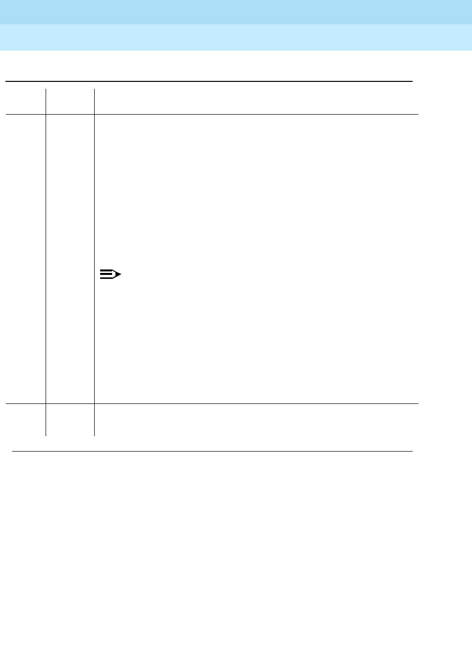
DEFINITY Enterprise Communications Server Release 6
Maintenance for R6r Volumes 1 & 2
555-230-126 Issue 2
January 1998
Maintenance Object Repair Procedures
Page 9-1687UDS1-BD (UDS1 Interface Circuit Pack)
9
2000 ABORT Response to the test was not received within the allowable time period. This
may be due to hyperactivity. Error type 1538 in the error log indicates
hyperactivity. The hyperactive circuit pack is out of service and one or more of
the following symptoms may be exhibited.
1. The UDS1-BD tests (such as test 138 and test 139) are aborting with error
code 2000.
2. The tests run on the ports of this circuit pack are returning a no board
result.
3. A busyout or a release command has no affect on the test results.
4. A list config command shows that the circuit pack and the ports are
properly installed.
NOTE:
When hyperactivity occurs, the circuit pack is isolated from the system,
and all of the trunks for this circuit pack are placed into the out of service
state. The system will try to restore the circuit pack within 15 minutes.
When no faults are detected for 15 minutes, the UDS1 interface circuit
pack is restored to normal operation. All of the trunks for the UDS1
interface circuit pack are then returned to the in service state.
Hyperactivity is often caused by the associated facility. In such a case,
faults (such as slips, misframes, or blue alarms) would be entered in the
error log. In addition, many hardware errors would be logged against
the associated trunk circuits. If the facility is OK and the error occurs
again after 15 minutes, replace the circuit pack.
2100 ABORT Could not allocate the necessary system resources to run this test.
1. Retry the command at 1-minute intervals for a maximum of 5 times.
Table 9-569. TEST #1212 CPE Loopback Jack Test — Continued
Error
Code Test
Result Description/ Recommendation
Continued on next page

DEFINITY Enterprise Communications Server Release 6
Maintenance for R6r Volumes 1 & 2
555-230-126 Issue 2
January 1998
Maintenance Object Repair Procedures
Page 9-1688UDS1-BD (UDS1 Interface Circuit Pack)
9
2 FAIL The CLJ-LB test failed because it was not set up properly. The UDS1 interface
pack could not successfully put the CPE loopback jack into loopback mode.
1. Rerun the test ds1-loop UUCSS cpe-loopback-jack-test-begin
command.
2. If the test continues to fail, the problem could be with the TN464F board,
the CPE loopback jack equipment, or somewhere between. Run the test
ds1-loop UUCSS ds1/csu-loopback-tests command to determine if the
loopback tests that are closer to the TN464F board are successful. If any
of these tests fail, follow the maintenance strategy that is associated with
the test that fails.
3 FAIL The CPE Loopback Jack Test was not set up properly. The framed 3-in-24 test
pattern, generated by the UDS1 Interface circuit pack and looped back
through the CPE Loopback Jack, could not be detected properly by the UDS1
circuit pack.
1. Retry the
test ds1-loop UUCSS cpe-loopback-jack-test-begin
command.
2. If the CPE Loopback Jack test continues to fail, the problem could be with
the TN464F board, the CPE Loopback Jack equipment, or somewhere in
between. Run the
test ds1-loop UUCSS ds1/csu-loopback-tests
command
to see if the loopback tests closer to the TN464F board are successful. If
any of those loopback tests fail, follow the maintenance strategy
associated with those loopbacks.
PASS The CPE Loopback Jack test has successfully began executing. The test will
continue to run until the system technician enters the
test ds1-loop UUCSS
end-loopback/span-test
command or the
release board UUCSS
command.
0NO
BOARD The test could not relate the internal ID to the port (no board). This could be
due to incorrect translations, no board is inserted, an incorrect board is
inserted, or an insane board is inserted.
1. Ensure that the board translations are correct. Execute the add ds1
UUCSS command to administer the UDS1 interface if it is not already
administered.
2. If the board was already administered correctly, check the error log to
determine whether the board is hyperactive. If this is the case, the board is
shut down. Reseating the board will re-initialize the board.
3. If the board was found to be correctly inserted in step 1, then issue the
busyout board command.
4. Issue the reset board command.
5. Issue the release busy board command.
6. Issue the test board long command.
This should re-establish the linkage between the internal ID and the port.
Table 9-569. TEST #1212 CPE Loopback Jack Test — Continued
Error
Code Test
Result Description/ Recommendation
Continued on next page

DEFINITY Enterprise Communications Server Release 6
Maintenance for R6r Volumes 1 & 2
555-230-126 Issue 2
January 1998
Maintenance Object Repair Procedures
Page 9-1689UDS1-BD (UDS1 Interface Circuit Pack)
9
Far CSU Loopback Test (#1213)
This test is destructive.
The Far CSU Loopback (R-LLB) Test causes a loopback at the far-end CSU and
tests all circuitry and facilities from the local TN464F DS1 board to the far-end
CSU.
The test is destructive and can only be initiated by a system technician
demanded
test ds1-loop UUCSS far-csu-loopback-test-begin
command.
All trunks or ports on the UDS1 Interface circuit pack must be busied out via the
system technician busyout board command before running the Far CSU
Loopback Test.
If the far-end CSU is not an Lucent 120A1 CSU Module, and the DS1 is
administered for ami-zcs line coding, one’s density protection must be disabled
on the CSU during the test due to the large number of zero’s in the 3-in-24 test
pattern.
The Far CSU Loopback Test has the TN464F UDS1 Interface circuit pack
transmit a loopback activation code to the remote CSU, waits up to 15 seconds
for return of the code to verify the loopback has been established, transmits a
framed 3-in-24 test pattern, begins counting bit errors in the received test
pattern, and returns a PASS result. If the loopback is not established within the 15
seconds, the test fails.
The status of the Far CSU Loopback test will be available in the hardware error
log via error type 3901. Several distinct aux values will be used to give the user
information of the status of the test.
The
list measurements ds1 summary
command will display the length of time the
test has been running (
Test Duration
field) and number of bit errors detected
(
Loopback/Span Test Bit-Error Count
field). If the test pattern is being passed
through the loopback cleanly, the number of bit errors should be very low. The
command will also display the type of Loopback/Span test executing (
Test
field),
the type of pattern generated for the type of Loopback/Span test (
Pattern
field),
and whether the pattern (
i.e.
3-in-24 Pattern
) is synchronized (
Synchronized
field).
To terminate the test, enter the
test ds1-loop UUCSS end-loopback/span-test
command or the release board command. Using the release board command
will restore all trunks or ports on the TN464F UDS1 Interface circuit pack to the
in-service state.

DEFINITY Enterprise Communications Server Release 6
Maintenance for R6r Volumes 1 & 2
555-230-126 Issue 2
January 1998
Maintenance Object Repair Procedures
Page 9-1690UDS1-BD (UDS1 Interface Circuit Pack)
9
Table 9-570. TEST #1213 Far CSU Loopback Test
Error
Code Test
Result Description/ Recommendation
ABORT Internal system error
1. Retry the
test ds1-loop UUCSS far-csu-loopback-test-begin
command at
1-minute intervals a maximum of 5 times.
1005 ABORT Far CSU Loopback Test cannot be executed in the current configuration. To
run this, the TN464F or later suffix UDS1 must be administered for 24-channel
operation. The "Bit Rate" field on the DS1 circuit pack administration form must
be set to "1.544" for 24-channel operation.
1015 ABORT Ports on the UDS1 Interface circuit pack have not been busied out to
out-of-service.
1. Enter the busyout board UUCSS command to put all trunks or ports of the
UDS1 Interface circuit pack into the out-of-service state.
2. Retry the command.
1039 ABORT The UDS1 Interface circuit pack is providing timing for the system. Executing
this test could cause major system disruption.
If the UDS1 Interface circuit pack needs to be tested, set the synchronization
reference to another DS1 Interface circuit pack or to the Tone-Clock circuit
pack via the following command sequence:
1. Issue the disable synchronization-switch command.
2. Next, issue the set synchronization UUCSS command.
3. Lastly, issue the enable synchronization-switch command.
1950 ABORT Another loopback/span test is already executing on the DS1 board or the
board is in a network requested loopback mode (Line loopback or Payload
loopback). The hardware error log will indicate whether a Customer Loopback
Jack Test, Far CSU Loopback Test, or the One-Way Span Test is executing or
if the board is in line loopback or payload loopback mode. Only one
long-duration loopback/span test can be active at a given time. Thus, if a
loopback/span test is already active, that test must be terminated via the
test
ds1-loop UUCSS end-loopback/span-test
command in order to execute this
test.
Continued on next page
DEFINITY Enterprise Communications Server Release 6
Maintenance for R6r Volumes 1 & 2
555-230-126 Issue 2
January 1998
Maintenance Object Repair Procedures
Page 9-1691UDS1-BD (UDS1 Interface Circuit Pack)
9
2000 ABORT Response to the test was not received within the allowable time period. This
may be due to hyperactivity. Error type 1538 in the error log indicates
hyperactivity. The hyperactive circuit pack is out of service and one or more of
the following symptoms may be exhibited.
1. The UDS1-BD tests (such as test 138 and test 139) are aborting with error
code 2000.
2. The tests run on the ports of this circuit pack are returning a no board
result.
3. A busyout or a release command has no affect on the test results.
4. A list config command shows that the circuit pack and the ports are
properly installed.
NOTE:
When hyperactivity occurs, the circuit pack is isolated from the system,
and all of the trunks for this circuit pack are placed into the out of
service state. The system will try to restore the circuit pack within 15
minutes. When no faults are detected for 15 minutes, the UDS1 interface
circuit pack is restored to normal operation. All of the trunks for the
UDS1 interface circuit pack are then returned to the in service state.
Hyperactivity is often caused by the associated facility. In such a case,
faults (such as slips, misframes, or blue alarms) would be entered in the
error log. In addition, many hardware errors would be logged against
the associated trunk circuits. If the facility is OK and the error occurs
again after 15 minutes, replace the circuit pack.
2100 ABORT Could not allocate the necessary system resources to run this test.
1. Retry the command at 1-minute intervals for a maximum of 5 times.
2 FAIL The test failed because it was not set up properly. The UDS1 pack could not
successfully put the far-end CSU into loopback mode.
1. Rerun the test ds1-loop UUCSS far-csu-loopback-test-begin command.
2. If the test continues to fail, the problem could be with the TN464F board,
the CPE loopback jack equipment, or somewhere between. Run the test
ds1-loop UUCSS cpe-loopback-jack-test-begin command to determine
if the CPE loopback jack loopback test is successful. If a CPE loopback
jack device is not being used, issue the test ds1-loop UUCSS
ds1/csu-loopback-tests command instead. If the closer loopback test
fails, follow the maintenance strategy associated with that test.
Table 9-570. TEST #1213 Far CSU Loopback Test — Continued
Error
Code Test
Result Description/ Recommendation
Continued on next page

DEFINITY Enterprise Communications Server Release 6
Maintenance for R6r Volumes 1 & 2
555-230-126 Issue 2
January 1998
Maintenance Object Repair Procedures
Page 9-1692UDS1-BD (UDS1 Interface Circuit Pack)
9
3 FAIL The Far CSU Loopback Test was not set up properly. The framed 3-in-24 test
pattern, generated by the UDS1 Interface circuit pack and looped back
through the far-end CSU, could not be detected properly by the UDS1 circuit
pack.
1. Retry the
test ds1-loop UUCSS far-csu-loopback-test-begin
command.
2. If the Far CSU Loopback test continues to fail with this error code, the
problem could be with the TN464F board, the far-end CSU equipment, or
somewhere in between. Run the
test ds1-loop UUCSS
cpe-loopback-jack-test-begin
command to see if the CPE Loopback Jack
test which is closer to the TN464F board is successful. (If a CPE Loopback
Jack device is not being used, then run the
test ds1-loop UUCSS
ds1/csu-loopback-tests
command to see if these even closer loopback
tests succeed). If the closer loopback test fails, follow the maintenance
strategy associated with that loopback.
PASS The Far CSU Loopback test has successfully began executing. The test will
continue to run until the system technician enters the
test ds1-loop UUCSS
end-loopback/span-test
command or the
release board UUCSS
command.
0NO
BOARD The test could not relate the internal ID to the port (no board). This could be
due to incorrect translations, no board is inserted, an incorrect board is
inserted, or an insane board is inserted.
1. Ensure that the board translations are correct. Execute the add ds1
UUCSS command to administer the UDS1 interface if it is not already
administered.
2. If the board was already administered correctly, check the error log to
determine whether the board is hyperactive. If this is the case, the board is
shut down. Reseating the board will re-initialize the board.
3. If the board was found to be correctly inserted in step 1, then issue the
busyout board command.
4. Issue the reset board command.
5. Issue the release busy board command.
6. Issue the test board long command.
This should re-establish the linkage between the internal ID and the port.
Table 9-570. TEST #1213 Far CSU Loopback Test — Continued
Error
Code Test
Result Description/ Recommendation
Continued on next page

DEFINITY Enterprise Communications Server Release 6
Maintenance for R6r Volumes 1 & 2
555-230-126 Issue 2
January 1998
Maintenance Object Repair Procedures
Page 9-1693UDS1-BD (UDS1 Interface Circuit Pack)
9
One-Way Span Test (#1214)
This test is destructive.
The One-Way Span Test allows one-way span testing to and from remote test
equipment or another DEFINITY communications system. This will test all
circuitry and facilities from the local TN464F DS1 board to the remote test
equipment or other DEFINITY communications system.
The test is destructive and can only be initiated by a system technician
demanded
test ds1-loop UUCSS one-way-span-test-begin
command.
All trunks or ports on the UDS1 Interface circuit pack must be busied out via the
system technician busyout board command before running the One-Way Span
Test.
The One-Way Span Test has the TN464F UDS1 Interface circuit pack transmit a
framed 3-in-24 test pattern and attempt to receive and verify the pattern. If the
TN464F board receives a framed 3-in-24 test pattern sent from another DEFINITY
G3V3 or test equipment at the far-end of the DS1, it will begin counting bit errors
within the received pattern.
The status of the One-Way Span test will be available in the hardware error log
via error type 3902. Several distinct aux values will be used to give the user
information of the status of the test.
The
list measurements ds1 summary
command will display the length of time the
test has been running (
Test Duration
field) and number of bit errors detected
(
Loopback/Span Test Bit-Error Count
field). If the test pattern is being sent
cleanly over the span from the far-end, the number of bit errors should be very
low. The
Test Duration
field will show
0
until the test pattern is received from the
far-end. Upon receiving the test pattern, the board will begin calculating the test
duration and number of bit errors. The command will also display the
Loopback/Span test executing (
Test
field), the type of pattern generated for the
Loopback/Span test (
Pattern
field), and whether the pattern (
i.e.
3-in-24 Pattern
)
is synchronized (
Synchronized
field).
To terminate the test, enter the
test ds1-loop UUCSS end-loopback/span-test
command or the release board command. Using the release board command
will restore all trunks or ports on the TN464F UDS1 Interface circuit pack to the
in-service state.

DEFINITY Enterprise Communications Server Release 6
Maintenance for R6r Volumes 1 & 2
555-230-126 Issue 2
January 1998
Maintenance Object Repair Procedures
Page 9-1694UDS1-BD (UDS1 Interface Circuit Pack)
9
Table 9-571. TEST #1214 One-Way Span Test
Error
Code Test
Result Description/ Recommendation
ABORT Internal system error
1. Retry the
test ds1-loop UUCSS one-way-span-test-begin
command at
1-minute intervals a maximum of 5 times.
1005 ABORT One-Way Span Test cannot be executed in the current configuration. To run
this, the TN464F or later suffix UDS1 must be administered for 24-channel
operation. The "Bit Rate" field on the DS1 circuit pack administration form must
be set to "1.544" for 24-channel operation.
1015 ABORT Ports on the UDS1 Interface circuit pack have not been busied out to
out-of-service.
1. Enter the busyout board UUCSS command to put all trunks or ports of
the UDS1 Interface circuit pack into the out-of-service state.
2. Retry the command.
1039 ABORT The UDS1 Interface circuit pack is providing timing for the system. Executing
this test could cause major system disruption.
If the UDS1 Interface circuit pack needs to be tested, set the synchronization
reference to another DS1 Interface circuit pack or to the Tone-Clock circuit
pack via the following command sequence:
1. Issue the disable synchronization-switch command.
2. Next, issue the set synchronization UUCSS command.
3. Lastly, issue the enable synchronization-switch command.
1950 ABORT Another loopback/span test is already executing on the DS1 board or the
board is in a network requested loopback mode (Line loopback or Payload
loopback). The hardware error log will indicate whether a Customer Loopback
Jack Test, Far CSU Loopback Test, or the One-Way Span Test is executing or
if the board is in line loopback or payload loopback mode. Only one
long-duration loopback/span test can be active at a given time. Thus, if a
loopback/span test is already active, that test must be terminated via the
test
ds1-loop UUCSS end-loopback/span-test
command in order to execute this
test.
Continued on next page
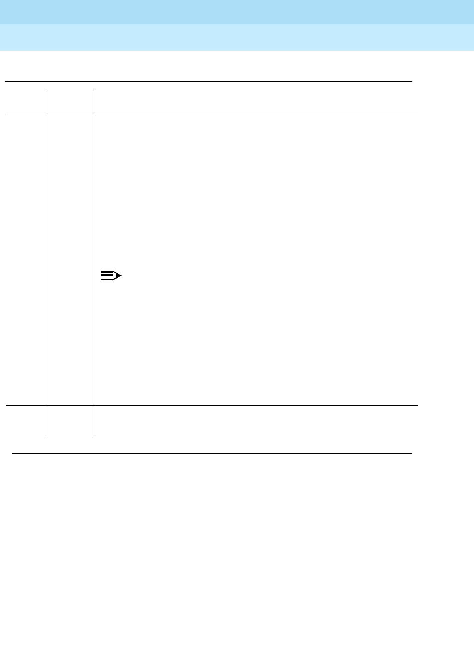
DEFINITY Enterprise Communications Server Release 6
Maintenance for R6r Volumes 1 & 2
555-230-126 Issue 2
January 1998
Maintenance Object Repair Procedures
Page 9-1695UDS1-BD (UDS1 Interface Circuit Pack)
9
2000 ABORT Response to the test was not received within the allowable time period. This
may be due to hyperactivity. Error type 1538 in the error log indicates
hyperactivity. The hyperactive circuit pack is out of service and one or more of
the following symptoms may be exhibited.
1. The UDS1-BD tests (such as test 138 and test 139) are aborting with error
code 2000.
2. The tests run on the ports of this circuit pack are returning a no board
result.
3. A busyout or a release command has no affect on the test results.
4. A list config command shows that the circuit pack and the ports are
properly installed.
NOTE:
When hyperactivity occurs, the circuit pack is isolated from the system,
and all of the trunks for this circuit pack are placed into the out of
service state. The system will try to restore the circuit pack within 15
minutes. When no faults are detected for 15 minutes, the UDS1
interface circuit pack is restored to normal operation. All of the trunks for
the UDS1 interface circuit pack are then returned to the in service state.
Hyperactivity is often caused by the associated facility. In such a case,
faults (such as slips, misframes, or blue alarms) would be entered in the
error log. In addition, many hardware errors would be logged against
the associated trunk circuits. If the facility is OK and the error occurs
again after 15 minutes, replace the circuit pack.
2100 ABORT Could not allocate the necessary system resources to run this test.
1. Retry the command at 1-minute intervals for a maximum of 5 times.
Table 9-571. TEST #1214 One-Way Span Test — Continued
Error
Code Test
Result Description/ Recommendation
Continued on next page

DEFINITY Enterprise Communications Server Release 6
Maintenance for R6r Volumes 1 & 2
555-230-126 Issue 2
January 1998
Maintenance Object Repair Procedures
Page 9-1696UDS1-BD (UDS1 Interface Circuit Pack)
9
PASS The One-Way Span test has successfully began transmitting a framed 3-in-24
test pattern. The test will continue to run until the system technician enters the
test ds1-loop UUCSS end-loopback/span-test
command or the
release board
UUCSS
command.
0NO
BOARD The test could not relate the internal ID to the port (no board). This could be
due to incorrect translations, no board is inserted, an incorrect board is
inserted, or an insane board is inserted.
1. Ensure that the board translations are correct. Execute the add ds1
UUCSS command to administer the UDS1 interface if it is not already
administered.
2. If the board was already administered correctly, check the error log to
determine whether the board is hyperactive. If this is the case, the board
is shut down. Reseating the board will re-initialize the board.
3. If the board was found to be correctly inserted in step 1, then issue the
busyout board command.
4. Issue the reset board command.
5. Issue the release busy board command.
6. Issue the test board long command.
This should re-establish the linkage between the internal ID and the port.
Table 9-571. TEST #1214 One-Way Span Test — Continued
Error
Code Test
Result Description/ Recommendation
Continued on next page

DEFINITY Enterprise Communications Server Release 6
Maintenance for R6r Volumes 1 & 2
555-230-126 Issue 2
January 1998
Maintenance Object Repair Procedures
Page 9-1697UDS1-BD (UDS1 Interface Circuit Pack)
9
Inject Single Bit Error Test (#1215)
This test is destructive.
The Inject Single Bit Error Test will cause a single bit error to be sent within an
active framed 3-in-24 test pattern.
The test is highly destructive and can only be initiated by a system technician
demanded
test ds1-loop UUCSS inject-single-bit-error
command. An attempt to
use this command will be rejected if none of the three long-duration DS1
loopback/span tests (CPE Loopback Jack Test, Far CSU Loopback Test,
One-Way Span Test) are active on a TN464F circuit pack.
All trunks or ports on the UDS1 Interface circuit pack must be busied out via the
system technician busyout board command before running the Inject Single Bit
Error Test.
The
list measurements ds1 summary
command displays the number of bit errors
detected (
Loopback/Span Test Bit-Error Count
field). Injecting this single bit error
should increment the bit error count of the loopback/span test by one.
Table 9-572. TEST #1215 Inject Single Bit Error Test
Error
Code Test
Result Description/ Recommendation
ABORT Internal system error
1. Retry the
test ds1-loop UUCSS inject-single-bit-error
command at 1-minute
intervals a maximum of 5 times.
1015 ABORT Ports on the UDS1 Interface circuit pack have not been busied out to
out-of-service.
1. Enter the busyout board UUCSS command to put all trunks or ports of the
UDS1 Interface circuit pack into the out-of-service state.
2. Retry the command.
Continued on next page
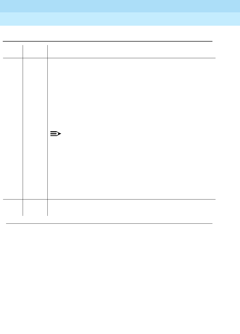
DEFINITY Enterprise Communications Server Release 6
Maintenance for R6r Volumes 1 & 2
555-230-126 Issue 2
January 1998
Maintenance Object Repair Procedures
Page 9-1698UDS1-BD (UDS1 Interface Circuit Pack)
9
2000 ABORT Response to the test was not received within the allowable time period. This may
be due to hyperactivity. Error type 1538 in the error log indicates hyperactivity.
The hyperactive circuit pack is out of service and one or more of the following
symptoms may be exhibited.
1. The UDS1-BD tests (such as test 138 and test 139) are aborting with error
code 2000.
2. The tests run on the ports of this circuit pack are returning a no board result.
3. A busyout or a release command has no affect on the test results.
4. A list config command shows that the circuit pack and the ports are
properly installed.
NOTE:
When hyperactivity occurs, the circuit pack is isolated from the system,
and all of the trunks for this circuit pack are placed into the out of service
state. The system will try to restore the circuit pack within 15 minutes.
When no faults are detected for 15 minutes, the UDS1 interface circuit
pack is restored to normal operation. All of the trunks for the UDS1
interface circuit pack are then returned to the in service state.
Hyperactivity is often caused by the associated facility. In such a case,
faults (such as slips, misframes, or blue alarms) would be entered in the
error log. In addition, many hardware errors would be logged against the
associated trunk circuits. If the facility is OK and the error occurs again
after 15 minutes, replace the circuit pack.
2100 ABORT Could not allocate the necessary system resources to run this test.
1. Retry the command at 1-minute intervals for a maximum of 5 times.
Table 9-572. TEST #1215 Inject Single Bit Error Test — Continued
Error
Code Test
Result Description/ Recommendation
Continued on next page

DEFINITY Enterprise Communications Server Release 6
Maintenance for R6r Volumes 1 & 2
555-230-126 Issue 2
January 1998
Maintenance Object Repair Procedures
Page 9-1699UDS1-BD (UDS1 Interface Circuit Pack)
9
End Loopback/Span Test (#1216)
This test is destructive.
The End Loopback/Span Test will terminate an active loopback or span test on a
TN464F UDS1 circuit pack. Bit error counting against the received test pattern
stream is terminated and sending of the framed 3-in-24 test pattern is halted. If
either the CPE Loopback Jack or the far-end CSU is looped, the appropriate
loopback deactivate code is sent. If the loopback could not be deactivated, then
the test will FAIL and a MINOR alarm will be noted in the alarm log until the
loopback is cleared.
The test is highly destructive and can only be initiated by a system technician
demanded
test ds1-loop UUCSS end-loopback/span-test
command. Since only
one of these three different long-duration loopback/span tests can be active at a
time, the TN464F circuit pack knows which loopback/span test to terminate.
All trunks or ports on the UDS1 Interface circuit pack must be busied out via the
system technician busyout board command before running this End
Loopback/Span Test.
PASS A single bit error has been successfully injected into an active framed 3-in-24
test pattern.
0NO
BOARD The test could not relate the internal ID to the port (no board). This could be due
to incorrect translations, no board is inserted, an incorrect board is inserted, or
an insane board is inserted.
1. Ensure that the board translations are correct. Execute the add ds1 UUCSS
command to administer the UDS1 interface if it is not already administered.
2. If the board was already administered correctly, check the error log to
determine whether the board is hyperactive. If this is the case, the board is
shut down. Reseating the board will re-initialize the board.
3. If the board was found to be correctly inserted in step 1, then issue the
busyout board command.
4. Issue the reset board command.
5. Issue the release busy board command.
6. Issue the test board long command.
This should re-establish the linkage between the internal ID and the port.
Table 9-572. TEST #1215 Inject Single Bit Error Test — Continued
Error
Code Test
Result Description/ Recommendation
Continued on next page

DEFINITY Enterprise Communications Server Release 6
Maintenance for R6r Volumes 1 & 2
555-230-126 Issue 2
January 1998
Maintenance Object Repair Procedures
Page 9-1700UDS1-BD (UDS1 Interface Circuit Pack)
9
The
list measurements ds1 summary
command will display the length of time the
test ran (
Test Duration
field) and number of bit errors detected (
Loopback/Span
Test Bit-Error Count
field).
To restore the trunks or ports on the TN464F UDS1 Interface circuit pack to the
in-service state, execute the release board command.
Table 9-573. TEST #1216 End Loopback/Span Test
Error
Code Test
Result Description/ Recommendation
ABORT Internal system error
1. Retry the
test ds1-loop UUCSS end-loopback/span-test
command at
1-minute intervals a maximum of 5 times.
1005 ABORT End Loopback/Span Test cannot be executed in the current configuration. To
run this test, the TN464F or later suffix DS1 board must be administered for
24-channel operation. The "Bit Rate" field on the DS1 circuit pack
administration form must be set to "1.544" for 24-channel operation.
1015 ABORT Ports on the UDS1 Interface circuit pack have not been busied out to
out-of-service.
1. Enter the busyout board UUCSS command to put all trunks or ports of
the UDS1 Interface circuit pack into the out-of-service state.
2. Retry the command.
Continued on next page
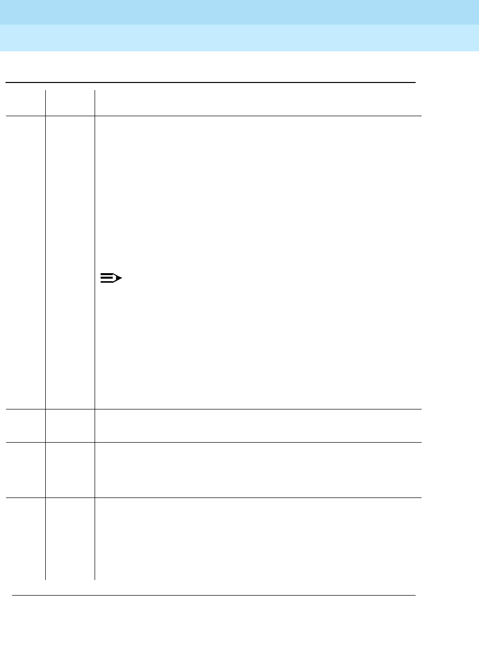
DEFINITY Enterprise Communications Server Release 6
Maintenance for R6r Volumes 1 & 2
555-230-126 Issue 2
January 1998
Maintenance Object Repair Procedures
Page 9-1701UDS1-BD (UDS1 Interface Circuit Pack)
9
2000 ABORT Response to the test was not received within the allowable time period. This
may be due to hyperactivity. Error type 1538 in the error log indicates
hyperactivity. The hyperactive circuit pack is out of service and one or more of
the following symptoms may be exhibited.
1. The UDS1-BD tests (such as test 138 and test 139) are aborting with error
code 2000.
2. The tests run on the ports of this circuit pack are returning a no board
result.
3. A busyout or a release command has no affect on the test results.
4. A list config command shows that the circuit pack and the ports are
properly installed.
NOTE:
When hyperactivity occurs, the circuit pack is isolated from the system,
and all of the trunks for this circuit pack are placed into the out of
service state. The system will try to restore the circuit pack within 15
minutes. When no faults are detected for 15 minutes, the UDS1
interface circuit pack is restored to normal operation. All of the trunks for
the UDS1 interface circuit pack are then returned to the in service state.
Hyperactivity is often caused by the associated facility. In such a case,
faults (such as slips, misframes, or blue alarms) would be entered in the
error log. In addition, many hardware errors would be logged against
the associated trunk circuits. If the facility is OK and the error occurs
again after 15 minutes, replace the circuit pack.
2100 ABORT Could not allocate the necessary system resources to run this test.
1. Retry the command at 1-minute intervals for a maximum of 5 times.
1313 FAIL The TN464F UDS1 circuit pack could not deactivate the loopback through the
Customer Loopback Jack.
1. Retry the
test ds1-loop UUCSS end-loopback/span-test
command at
1-minute intervals for a maximum of 5 times.
1314 FAIL The TN464F UDS1 circuit pack could not deactivate the loopback through the
far-end CSU.
1. Make sure that the far-end DS1 is installed if the far-end CSU is a 120A1
Lucent CSU Module.
2. Retry the
test ds1-loop UUCSS end-loopback/span-test
command at
1-minute intervals for a maximum of 5 times.
Table 9-573. TEST #1216 End Loopback/Span Test — Continued
Error
Code Test
Result Description/ Recommendation
Continued on next page

DEFINITY Enterprise Communications Server Release 6
Maintenance for R6r Volumes 1 & 2
555-230-126 Issue 2
January 1998
Maintenance Object Repair Procedures
Page 9-1702UDS1-BD (UDS1 Interface Circuit Pack)
9
PASS The active long-duration loopback or span test on the TN464F circuit pack
was successfully terminated.
0NO
BOARD The test could not relate the internal ID to the port (no board). This could be
due to incorrect translations, no board is inserted, an incorrect board is
inserted, or an insane board is inserted.
1. Ensure that the board translations are correct. Execute the add ds1
UUCSS command to administer the UDS1 interface if it is not already
administered.
2. If the board was already administered correctly, check the error log to
determine whether the board is hyperactive. If this is the case, the board
is shut down. Reseating the board will re-initialize the board.
3. If the board was found to be correctly inserted in step 1, then issue the
busyout board command.
4. Issue the reset board command.
5. Issue the release busy board command.
6. Issue the test board long command.
This should re-establish the linkage between the internal ID and the port.
Table 9-573. TEST #1216 End Loopback/Span Test — Continued
Error
Code Test
Result Description/ Recommendation
Continued on next page

DEFINITY Enterprise Communications Server Release 6
Maintenance for R6r Volumes 1 & 2
555-230-126 Issue 2
January 1998
Maintenance Object Repair Procedures
Page 9-1703UDS1-BD (UDS1 Interface Circuit Pack)
9
ICSU Status LEDs Test (#1227)
The TN464F UDS1 circuit pack has four status LEDs on the faceplate in addition
to the three standard faceplate LEDs. These four status LEDs are associated with
the 120A1 Channel Service Unit (CSU) Module that can be connected to the
TN464F board via the I/O connector panel on the back of the port carrier. The
TN464F circuit pack combined with the 120A1 CSU Module forms an Integrated
CSU (ICSU).
This test is a visual test. It will light the four status LEDs red for 5 seconds, then
light them green for 5 seconds, then light them yellow for 5 seconds, then turn
the LEDs off and returns control of the status LEDs to the circuit pack.
This test will only be executed on TN464F or later suffix UDS1 circuit packs
administered for 24-channel operation (1.544 bit rate).
If the 120A1 CSU Module is not physically installed, the status LEDs are always
off and this test will abort.
Table 9-574. TEST #1227 ICSU Status LEDs Test
Error
Code Test
Result Description/ Recommendation
ABORT Internal system error
1. Retry the command at 1-minute intervals a maximum of 5 times.
1005 ABORT The ICSU Status LEDs test can not be executed for the current configuration.
The test applies only to TN464F or later UDS1 circuit packs administered for
24-channel operation (1.544 bit rate).
1. If the circuit pack is a TN464F or later suffix UDS1 circuit pack, then retry
the command.
1951 ABORT The ICSU Status LEDs Test can not be executed because a 120A1 or later
suffix CSU Module is not physically installed. If using a 120A1 CSU Module,
physically connect it to the TN464F board on the back of the port carrier.
Otherwise, ignore this abort.
2100 ABORT Could not allocate the necessary system resources to run this test.
1. Retry the command at 1-minute intervals for a maximum of 5 times.
2500 ABORT Internal system error.
1. Retry the command.
Continued on next page

DEFINITY Enterprise Communications Server Release 6
Maintenance for R6r Volumes 1 & 2
555-230-126 Issue 2
January 1998
Maintenance Object Repair Procedures
Page 9-1704UDS1-BD (UDS1 Interface Circuit Pack)
9
PASS The ICSU Status LEDs test executed successfully. A PASS result, however,
does not necessarily mean that the status LEDs behaved properly. It only
means that the software successfully attempted to light the status LEDs. This is
a visual test. The service technician must visually exam the behavior of the
LEDs while the test is running. The LEDs are functioning properly if the four
status LEDs are lit red for 5 seconds, then lit green for 5 seconds, then lit yellow
for 5 seconds. If the LEDs behave differently, the board should be replaced at
the customer’s convenience.
0NO
BOARD The test could not relate the internal ID to the port (no board). This could be
due to incorrect translations, no board is inserted, an incorrect board is
inserted, or an insane board is inserted.
1. Ensure that the board translations are correct. Execute the add ds1
UUCSS command to administer the UDS1 interface if it is not already
administered.
2. If the board was already administered correctly, check the error log to
determine whether the board is hyperactive. If this is the case, the board is
shut down. Reseating the board will re-initialize the board.
3. If the board was found to be correctly inserted in step 1, then issue the
busyout board command.
4. Issue the reset board command.
5. Issue the release busy board command.
6. Issue the test board long command.
This should re-establish the linkage between the internal ID and the port.
Table 9-574. TEST #1227 ICSU Status LEDs Test — Continued
Error
Code Test
Result Description/ Recommendation
Continued on next page
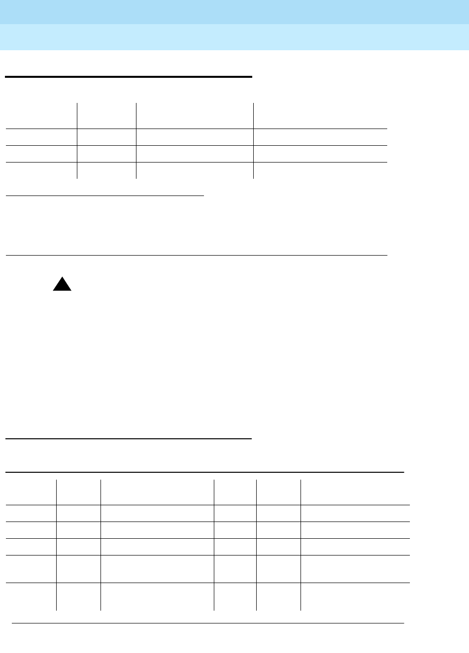
DEFINITY Enterprise Communications Server Release 6
Maintenance for R6r Volumes 1 & 2
555-230-126 Issue 2
January 1998
Maintenance Object Repair Procedures
Page 9-1705VC-BD
9
VC-BD
!CAUTION:
If the TN788 Voice Conditioner Circuit Pack (VC-BD) is not Vintage 2 or
later, it must be replaced.
The TN788 Voice Conditioner Circuit Pack (VC-BD) is a service circuit pack that
provides conditioning for the audio signals from multimedia equipment based on
the CCITT H.221 standard. The TN788 transcodes, gain adjusts, and bridges the
audio bit streams demultiplexed by the TN787 (MMI) circuit pack and transmits
encoded, exclusive audio conference sums onto the TDM bus so that the MMI
can multiplex the audio, video, and data streams for the H.221 endpoints.
Error Log Entries and Test to Clear Values
1. Where UU is the universal cabinet number (1 for PPN and 2-44 for EPN); C is the carrier
designation (for example, A, B, C, D, or E); SS is the address of the slot in the carrier where
the circuit pack is located (for example, 01, 02, ...); and pp is the two digit port number (01,
02, 03, ...).
2. Refer to XXX-BD (Common Port Board) Maintenance documentation.
MO Name (in
Alarm Log) Alarm
Level Initial Command to Run1Full Name of MO
VC-BD MAJOR test board UUCSS l r# Voice Conditioner Circuit Pack
VC-BD MINOR test board UUCSS l r# Voice Conditioner Circuit Pack
VC-BD WARNING2test board UUCSS s r# Voice Conditioner Circuit Pack
Table 9-575. VC-BD Error Log Entries
Error
Type Aux
Data Associated Test Alarm
Level On/Off
Board Test to Clear Value
010 Any Any Any test board UUCSS sh r 1
1 (a) Any None MIN ON
18 (b) 0 busyout board UUCSS WNG OFF release board UUCSS
257 (c) Any Control Channel Loop
Test (#52) MIN ON test board UUCSS r 20
513 (d) 4352 to
4357
Continued on next page
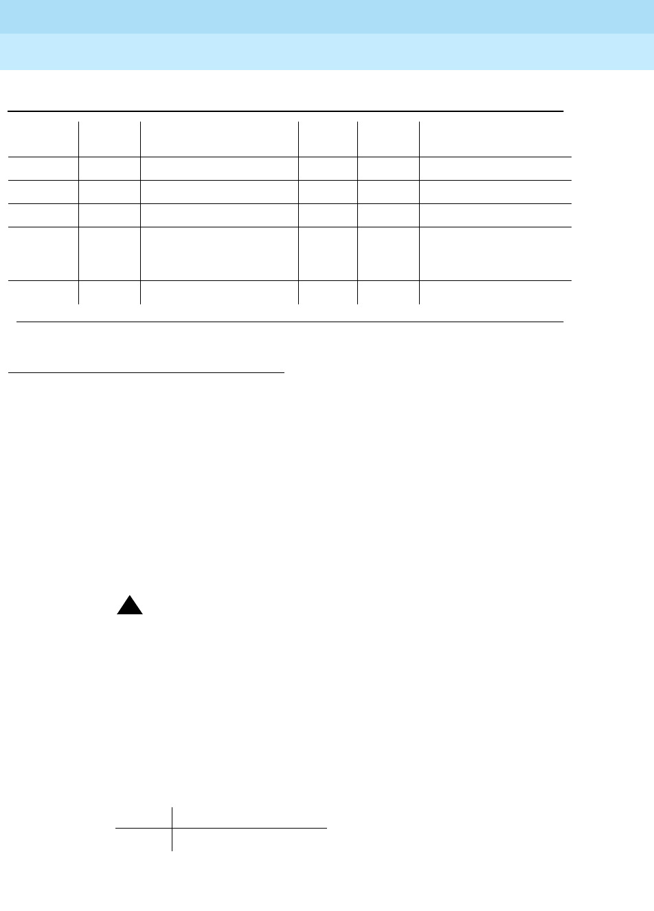
DEFINITY Enterprise Communications Server Release 6
Maintenance for R6r Volumes 1 & 2
555-230-126 Issue 2
January 1998
Maintenance Object Repair Procedures
Page 9-1706VC-BD
9
Notes:
a. The circuit pack stopped functioning or it was removed from the system.
This alarm is logged approximately 11-minutes after the circuit pack is
removed and/or the SAKI Sanity Test (#53) fails.
To resolve this error, insert a circuit pack in the same slot as the error
indicates, if the circuit pack is not already in the system. Or, if the circuit
pack is in the system and the red LED is on, then follow instructions for
Red alarms.
!CAUTION:
If the TN788 Voice Conditioner Circuit Pack (VC-BD) is not Vintage 2
or later, it must be replaced.
b. This circuit pack is busied out by the busyout board UUCSS command.
c. Transient communication problems exist between the switch and this
circuit pack. Execute the test board UUCSS command and refer to the
repair procedures for the Control Channel Looparound Test (#52).
d. The circuit pack detected an on-board hardware failure. The reported aux
data values correspond to the following detected errors:
1. Run the short test sequence first. If all tests pass, run the long test sequence. Refer to the
appropriate test description and follow the recommended procedures.
769 (e) 4358
1025 (f) 4363 NPE Audit Test (#50)
1281 (g) Any SAKI Sanity Test (#53) MAJ On
1293 to
1294 (h) 46088
to
46096
SAKI Sanity Test (#53) MIN ON
1538 (i) 46082 MIN ON
Error Description
4352 External RAM error
Table 9-575. VC-BD Error Log Entries — Continued
Error
Type Aux
Data Associated Test Alarm
Level On/Off
Board Test to Clear Value
Continued on next page

DEFINITY Enterprise Communications Server Release 6
Maintenance for R6r Volumes 1 & 2
555-230-126 Issue 2
January 1998
Maintenance Object Repair Procedures
Page 9-1707VC-BD
9
Reset the circuit pack by executing the busyout board UUCSS, reset
board UUCSS, and release board UUCSS commands. When it is reset,
the circuit pack executes a set of tests to detect the presence of any of the
above faults. The detection of one these errors during initialization causes
the circuit pack to lock-up and appear insane to the system. See the
repair procedures in footnote (a) for error type 1.
e. The circuit pack detects a program logic error. While no action is required,
this error may lead to errors of other types being reported against this
circuit pack.
f. The circuit pack cannot update NPE memory and read it back. This error
type can be ignored, but it may lead to other error types being reported
against this circuit pack.
g. A critical hardware failure has been detected on the circuit pack. Use
busyout board UUCSS, reset board UUCSS, followed by release board
UUCSS. If test #53 passes, the on-board circuitry is healthy. Use test
board UUCSS long clear to retire the alarm. If test #53 fails, replace the
circuit pack.
h. The circuit pack detected a critical hardware failure. Reset the circuit pack
by issuing the busyout board UUCSS, reset board UUCSS, and release
board UUCSS commands. If the Circuit Pack Restart Test (#594) passes,
then the on-board circuitry is healthy. Retire the alarm by issuing the test
board UUCSS long clear command. If the Circuit Pack Restart Rest
(#594) fails, replace the circuit pack.
The reported error types correspond to the following detected errors:
i. The circuit pack is hyperactive — it is flooding the switch with messages
sent over the control channel. The circuit pack is taken out of service when
a threshold number of these errors is reported to the switch. Clear the
alarm by using busyout board UUCSS, reset board UUCSS, test board
UUCSS long clear, and release board UUCSS. If the error recurs within
10 minutes, then replace the circuit pack.
4353 Internal RAM error
4355 ROM Checksum error
4357 Instruction set error
Error Description
1293 On-board auxiliary processor insane
1294 Internal memory access error

DEFINITY Enterprise Communications Server Release 6
Maintenance for R6r Volumes 1 & 2
555-230-126 Issue 2
January 1998
Maintenance Object Repair Procedures
Page 9-1708VC-BD
9
System Technician-Demanded Tests:
Descriptions and Error Code
Control Channel Looparound Test (#52)
Refer to the repair procedure described in the XXX-BD (Common Port Circuit
Pack) maintenance documentation as Control Channel Looparound Test (#52).
1. D = Destructive; ND = Nondestructive
2. Refer to the repair procedure described in the XXX-BD (Common Port Circuit Pack)
maintenance documentation for a description of this test.
!CAUTION:
If the TN788 Voice Conditioner Circuit Pack (VC-BD) is not Vintage 2 or
later, it must be replaced.
Order of Investigation Short Test
Sequence Long Test
Sequence D/ND1
Control Channel Loop-Around Test (#52)2XXND

DEFINITY Enterprise Communications Server Release 6
Maintenance for R6r Volumes 1 & 2
555-230-126 Issue 2
January 1998
Maintenance Object Repair Procedures
Page 9-1709VC-DSPPT
9
VC-DSPPT
Each Voice Conditioner Circuit Pack (VC-BD) provides two types of resources:
1. Transcoder Resources used for encoding and decoding audio formats
2. Summer Resources used for summing audio from different sources
The eight Voice Conditioner DSP ports are the transcoder resources on the
VC-BD.
1. Where UU is the universal cabinet number (1 for PPN and 2-44 for EPN); C is the carrier
designation (for example, A, B, C, D, or E); SS is the address of the slot in the carrier where the
circuit pack is located (for example, 01, 02, ...); and pp is the two digit port number (01, 02,
03, ...).
MO Name (in
Alarm Log) Alarm
Level Initial Command to Run1Full Name of MO
VC-DSPPT MAJOR test port UUCSSpp Voice Conditioner DSP Port
VC-DSPPT MINOR test port UUCSSpp Voice Conditioner DSP Port
VC-DSPPT WARNING test port UUCSSpp Voice Conditioner DSP Port
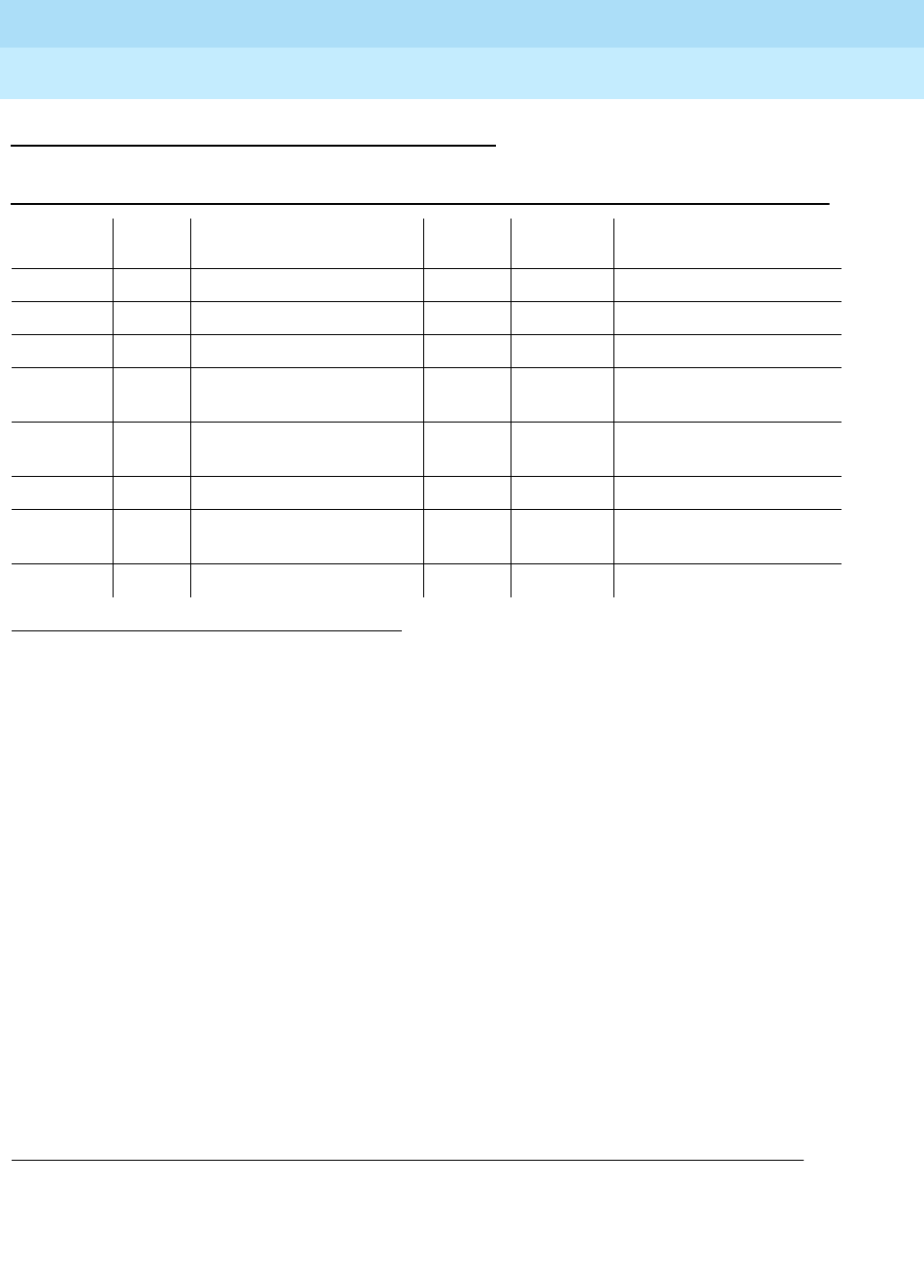
DEFINITY Enterprise Communications Server Release 6
Maintenance for R6r Volumes 1 & 2
555-230-126 Issue 2
January 1998
Maintenance Object Repair Procedures
Page 9-1710VC-DSPPT
9
Error Log Entries and Test to Clear Values
Notes:
a. This port has been busied out by the busyout port UUCSSpp command.
b. The VC DSP Port NPE Crosstalk Test(#1103) failed.
c. The VC DSP Port Local TDM Loopback Test(#1104) failed. Run the Long
Test Sequence.
d. A critical hardware failure has been detected on the circuit pack. Reset
the port by the busyout port UUCSSpp and reset port UUCSSpp
commands. If the VC Reset DSP Test (#1106) passes, then the on-board
circuitry is healthy. Retire the alarm with the test port UUCSSpp long
clear command.
e. The VC DSP port reported loss of framing on the Service Channel between
the VC and MMI circuit packs.
f. The VC DSP Port DSP Loopback Test (#1105) failed.
g. The DSP corresponding to this port on the VC circuit pack reported a
firmware error. No action is required.
1. Run the short test sequence first. If all test pass, run the long test sequence. Refer to the appropriate
test description and follow the recommended procedures.
Table 9-576. VC-DSPPT Error Log Entries
Error
Type Aux
Data Associated Test Alarm
Level On/ Off
Board Test to Clear Value
010 Any Any Any test port UUCSSpp sh r 1
18 (a) 0 busyout port UUCSSpp WNG OFF release port UUCSSpp
257 (b) Any NPE Crosstalk Test (#6) MIN ON test port UUCSSpp 1 r 3
513 (c) Any VC DSP Port Local TDM
Loopback Test (#1104) MIN ON test port UUCSSpp sh r 3
778 to
781 (d) Any VC Port Reset DSP Test
(#1106) MAJ ON See note (d)
1025 (e) WNG ON
1281 (f) Any VC DSP Port DSP
Loopback Test #(1105) MIN ON test port UUCSSpp sh r 3
3840 (g)
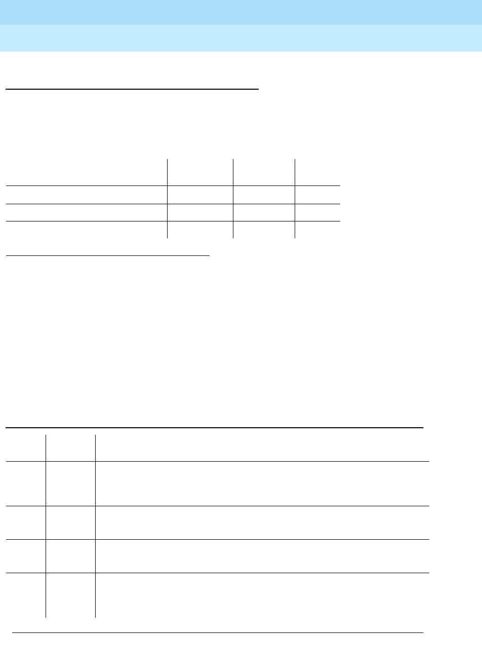
DEFINITY Enterprise Communications Server Release 6
Maintenance for R6r Volumes 1 & 2
555-230-126 Issue 2
January 1998
Maintenance Object Repair Procedures
Page 9-1711VC-DSPPT
9
System Technician-Demanded Tests:
Descriptions and Error Codes
Always investigate tests in the order presented in the table below. By clearing
error codes associated with the DSP NPE Crosstalk Test, for example, you may
also clear errors generated from other tests in the testing sequence.
DSP NPE Crosstalk Test (#1103)
This test is destructive.
The NPE Crosstalk test verifies that this port’s NPE channel talks on the selected
time slot and never crosses over to time slots reserved for other connections. If
the NPE is not working correctly, one-way and noisy connections may be
observed. This test is part of the port’s long test sequence and takes
approximately 20 to 30 seconds to complete.
1. D = Destructive; ND = Nondestructive
Order of Investigation Short Test
Sequence Long Test
Sequence D/ND1
DSP NPE Crosstalk Test (#1103) X D
TDM Loopback Test (#1104) X X D
DSP Loopback Test (#1105) X X D
Table 9-577. TEST #1103 NPE Crosstalk Test
Error
Code Test
Result Description/Recommendation
1000 ABORT System resources required to run this test are not available. The port may be
busy with a valid call.
1. Try (a).
2012 ABORT Internal system error
1. Try (a).
2100 ABORT Could not allocate the necessary resources for this test.
1. Try (a).
FAIL The NPE of the tested port was transmitting in error, causing noisy and
unreliable connections.
1. Replace the circuit pack.
Continued on next page

DEFINITY Enterprise Communications Server Release 6
Maintenance for R6r Volumes 1 & 2
555-230-126 Issue 2
January 1998
Maintenance Object Repair Procedures
Page 9-1712VC-DSPPT
9
Note:
a. Retry the command at 1-minute intervals a maximum of 5 times.
VC DSP Port Local TDM Loopback Test (#1104)
This test is destructive.
This test verifies the connectivity of a VC DSP Port across the TDM bus. It aborts
if calls associated with the port are in progress. Failure of this test indicates an
on-board fault associated with the port hardware on the circuit pack. The
Loopback Test runs the following tests:
1. A Looparound test across the TDM bus.
2. A conference Circuit Test.
The tests are run in the above order; if one test fails, an error code is returned
and the remaining tests in the sequence are not executed.
PASS The port is correctly using its allocated time slots.
1. To be sure that this is not an intermittent problem, repeat this test a
maximum of 10 times.
2. If complaints still persist, examine the station, connections, and wiring.
Table 9-577. TEST #1103 NPE Crosstalk Test — Continued
Error
Code Test
Result Description/Recommendation
Continued on next page
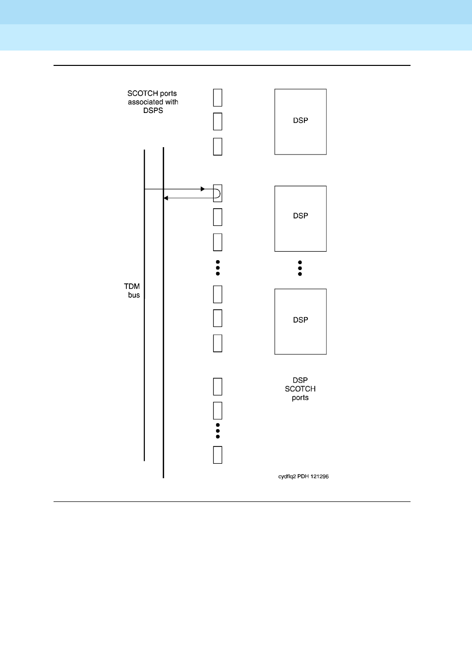
DEFINITY Enterprise Communications Server Release 6
Maintenance for R6r Volumes 1 & 2
555-230-126 Issue 2
January 1998
Maintenance Object Repair Procedures
Page 9-1713VC-DSPPT
9
Figure 9-98. VC Circuit Pack DSP Port Local TDM Loopback Test

DEFINITY Enterprise Communications Server Release 6
Maintenance for R6r Volumes 1 & 2
555-230-126 Issue 2
January 1998
Maintenance Object Repair Procedures
Page 9-1714VC-DSPPT
9
Table 9-578. TEST #1104 VC DSPPT Local TDM Loopback Test
Error
Code Test
Result Description/Recommendation
1000
1001 ABORT System resources required to run this test are not available, or the port is busy
with a valid call.
1. Retry the command at 1-minute intervals a maximum of 5 times.
1002 ABORT The system could not allocate time slots for the test. The traffic load on the
system is very high, or time slots may be out-of-service due to TDM-BUS errors.
Refer to TDM-BUS maintenance documentation to diagnose any active TDM
Bus errors.
1. If the system has no TDM-BUS errors and is not handling heavy traffic,
repeat the test at 1-minute intervals a maximum of 5 times.
1003 ABORT The system could not allocate a Tone Detector for the test. The system is
oversized for the number of Tone Detectors present, or some Tone Detectors
are out-of-service.
1. Look for TTR-LEV errors in the Error Log. If present, refer to TTR-LEV.
2. Look for TONE-PT errors in the Error Log. If present, refer to TONE-PT
3. If neither condition exists, retry the command at 1-minute intervals a
maximum of 5 times.
1004 ABORT The port is seized by a user for a valid call. Use the status station command
for the station associated with this port and determine if the port is available for
testing.
1. Retry the command at 1-minute intervals a maximum of 5 times.
2000 ABORT Response to the test was not received from the VC-BD circuit pack within the
allowable time period.
1. If this result occurs repeatedly, attempt to reset the port by using the
busyout port UUCSSpp and reset port UUCSSpp commands.
2. If this result occurs again, replace the circuit pack.
2012 ABORT Internal system error
1. Retry the command at 1-minute intervals a maximum of 5 times.
2100 ABORT Could not allocate the necessary resources to run this test.
1. Retry the command at 1-minute intervals a maximum of 5 times.
2103 ABORT The system could not make the conference connection for the test.
1. Retry the command at 1-minute intervals a maximum of 5 times.
0-3 FAIL The TDM Looparound Test failed.
1. Replace circuit pack.
Continued on next page

DEFINITY Enterprise Communications Server Release 6
Maintenance for R6r Volumes 1 & 2
555-230-126 Issue 2
January 1998
Maintenance Object Repair Procedures
Page 9-1715VC-DSPPT
9
VC-DSP Port DSP Loopback Test (#1105)
This test is destructive.
This test verifies the connectivity of a VC-DSPPT across the TDM bus. It aborts if
calls associated with the port are in progress. Failure of this test indicates an
on-board fault associated with the port hardware on the circuit pack.
4-7 FAIL The Conference Circuit Test failed.
1. Replace circuit pack.
PASS The VC DSP Port Local TDM Looparound Test passed.
Table 9-578. TEST #1104 VC DSPPT Local TDM Loopback Test — Continued
Error
Code Test
Result Description/Recommendation
Continued on next page
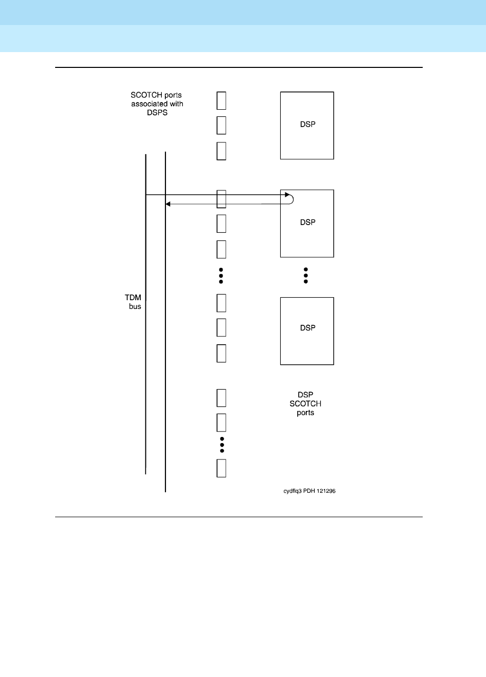
DEFINITY Enterprise Communications Server Release 6
Maintenance for R6r Volumes 1 & 2
555-230-126 Issue 2
January 1998
Maintenance Object Repair Procedures
Page 9-1716VC-DSPPT
9
Figure 9-99. VC Circuit pack DSP Port DSP Looparound Test

DEFINITY Enterprise Communications Server Release 6
Maintenance for R6r Volumes 1 & 2
555-230-126 Issue 2
January 1998
Maintenance Object Repair Procedures
Page 9-1717VC-DSPPT
9
Table 9-579. TEST #1105 VC-DSP Port DSP Loopback Test
Error
Code Test
Result Description/Recommendation
1000 ABORT System resources required to run this test are not available, or the port is busy
with a valid call.
1. Retry the command at 1-minute intervals a maximum of 5 times.
1002 ABORT The system could not allocate time slots for the test, the traffic load on the
system is very high, or time slots are out-of-service due to TDM-BUS errors.
Refer to TDM-BUS maintenance documentation to diagnose any active TDM
Bus errors.
1. If the system has no TDM-BUS errors and is not handling heavy traffic,
retry the command at 1-minute intervals a maximum of 5 times.
1003 ABORT The system could not allocate a Tone Detector for the test, the system is
oversized for the number of Tone Detectors present, or some Tone Detectors
are out-of-service.
1. Look for TTR-LEV errors in the Error Log. If present, refer to TTR-LEV.
2. Look for TONE-PT errors in the Error Log. If present, refer to TONE-PT.
3. If neither condition exists, retry the command at 1-minute intervals a
maximum of 5 times.
1004 ABORT The port has been seized by a user for a valid call. Use the status station
command for the station associated with this port and determine if the port is
available for testing
1. Retry the command at 1-minute intervals a maximum of 5 times.
2000 ABORT Response to the test request was not received from the VC-BD circuit pack
within the allowable time period.
1. If this result occurs repeatedly, reset the circuit pack if the other ports are
not in use by using the busyout port UUCSSpp and reset port
UUCSSpp commands.
2. If this result occurs again, replace the circuit pack.
2012 ABORT Internal system error
1. Retry the command at 1-minute intervals a maximum of 5 times.
2100 ABORT Could not allocate the necessary system resources to run this test.
1. Retry the command at 1-minute intervals a maximum of 5 times.
0, 1 FAIL The VC-DSPPT DSP Loopback Test failed.
1. Replace the circuit pack.
PASS The VC DSPPT DSP Loopback Test passed
Continued on next page

DEFINITY Enterprise Communications Server Release 6
Maintenance for R6r Volumes 1 & 2
555-230-126 Issue 2
January 1998
Maintenance Object Repair Procedures
Page 9-1718VC-DSPPT
9
VC Port Reset DSP Test (#1106)
This test is destructive.
This test resets the VC-DSPPT and the DSP associated with it. As part of the reset
procedure, the VC-DSPPT will execute a series of self- tests on the hardware. If
these self- tests fail, the test will fail; otherwise the test will pass.
Before executing the test, the VC-DSPPT must be busied out by executing the
busy port UUCSSpp command. After the completion of the test, the VC-DSPPT
must be released by executing the release port UUCSSpp command.
Table 9-580. TEST #1106 VC Port Reset DSP Test
Error
Code Test
Result Description/Recommendation
1000 ABORT System resources required to run this test are not available, or the port may be
busy with a call.
1. Retry the command at 1-minute intervals a maximum of 5 times.
1015 ABORT The VC-DSPPT is not busied out.
1. Busy out the VC-DSPPT by executing the busy port UUCSSpp command
and then retry the test.
2000 ABORT Response to the test was not received from the VC-DSPPT within the allowable
time period.
1. Retry the command at 1-minute intervals a maximum of 5 times.
2. If this result occurs again, replace the circuit pack.
2012 ABORT Internal system error
1. Retry the command at 1-minute intervals a maximum of 5 times.
2100 ABORT Could not allocate the necessary resources to run this test.
1. Retry the command at 1-minute intervals a maximum of 5 times.
FAIL The reset of the VC-DSPPT was unsuccessful.
1. Replace circuit pack.
PASS The VC-DSPPT was successfully reset.
1. Release the VC-DSPPT by executing the reset port UUCSSpp command.
Continued on next page

DEFINITY Enterprise Communications Server Release 6
Maintenance for R6r Volumes 1 & 2
555-230-126 Issue 2
January 1998
Maintenance Object Repair Procedures
Page 9-1719VC-LEV (Voice Conditioner DSP Port Level)
9
VC-LEV (Voice Conditioner
DSP Port Level)
Enable the MMCH feature on the
system-parameters customer-options
form
before changing the fields.
The Voice Conditioner (VC) Port Level MO monitors VC efficiency by tracking the
number of VC ports that are in-service, and then comparing that number with the
value entered in the VC field on the System-Parameters Maintenance form. This
VCs field is located under the Minimum Maintenance Thresholds section. The
VCs field contains the minimum number of VC ports needed for the Multimedia
Call Handling (MMCH) feature, and is an administrable field. The VCs field must
contain a number between 0 and 126, and is entered by the system
administrator. The MMCH feature must be enabled on the System-Parameters
Customer-Options form before the VCs field can be changed to a number
greater than 0. For example, administering 8 in that field means 1 circuit pack.
The algorithm for determining that a low level of VC resources exists uses the
number entered in the VCs field, and the number of VCs that are in-service in the
system.
Each VC circuit pack contains 16 physical ports: 8 ports are reserved for
VC-DSPPT ports, and the remaining 8 ports are designated as VC-SUMPT ports.
The 8 DSP ports are made up of 4 encoder and 4 decoder resources that
encode and decode audio formats. Thus,
one VC circuit pack is required for
every 8 ports of MMCH port capacity
. If the number of in-service VC ports falls
below the MMCH port capacity (value entered on the System-Parameters
Maintenance form under the Minimum Maintenance Thresholds section
and
in
the VCs
field), a VEC-LEV error is logged. If this outage continues for 15 minutes
a MAJOR alarm is raised.
Resolving VC-LEV Errors/Alarms
VC ports are a key part of the MMCH feature, any loss in the number of ports
available for use degrades the MMCH customer defined service level.
If a VC circuit pack or port is busied out using the busyout board or busyout
port command, these out-of-service ports are not included in the VC level
calculation, thus allowing a technician to busy out a VC circuit pack for
maintenance reasons without causing a MAJOR alarm to be raised.
MO Name (in
Alarm Log) Alarm
Level Initial Command to Run Full Name of MO
VC-LEV MAJOR See ‘‘Resolving VC-LEV Errors/Alarms’’ VC-LEV

DEFINITY Enterprise Communications Server Release 6
Maintenance for R6r Volumes 1 & 2
555-230-126 Issue 2
January 1998
Maintenance Object Repair Procedures
Page 9-1720VC-LEV (Voice Conditioner DSP Port Level)
9
NOTE:
When diagnosing a VC-LEV problem, resolve any alarms raised against
VC-BD or VC-DSPPT maintenance objects. Clearing VC-BD or VC-DSPPT
alarms may clear the VC-LEV alarm.
The VC circuit pack is maintained by the software similarly to the Tone Detector
circuit pack. Tone Detector circuit packs may be removed and reinserted in any
port board slot without administration. The same rule applies to VC circuit packs.
If a VC circuit pack is removed from service logically (by failing the Archangel
sanity scan test) or is removed from service physically (by physically removing
the circuit pack from the carrier), no error/alarm is raised against VC-BD or
VC-DSPPT maintenance objects. Therefore, if a VC-LEV error/alarm exists, and
none has been raised against VC-BD or VC-DSPPT maintenance objects, a VC
circuit pack may have been removed from service causing the VC-LEV
error/alarm. To resolve a VC-LEV MAJOR alarm, restore the number of VC ports
available for service to be equal to or more than the calculated port capacity
(value entered in the VCs field).
To determine how many VC circuit packs are needed for the MMCH feature:
1. Display the System-Parameters Maintenance form by executing the
command display system-parameters maintenance.
2. Locate the number listed in the Minimum Maintenance Threshold (VCs)
field. The MMCH feature requires one VC circuit pack for each four ports
listed in the Minimum Maintenance Threshold (VCs)
field.
3. Divide the Minimum Maintenance Threshold value by 8 to determine the
number of VC circuit packs needed. For example, a port capacity of 12
listed in the Minimum Maintenance Threshold (VCs) field would require 2
VC circuit packs.
4. Use the list configuration command to verify that the number of VC
circuit packs listed agrees with the required number of VC circuit packs
(determined in step 3). If the number of VC circuit packs listed in the step
3 differs from the calculated number, restore the number of VC circuit
packs to the correct value, in order to resolve the VC-LEV alarm.
Error Log Entries and Test to Clear Values
Notes:
a. The number of VC resources in the system that are in service has fallen
below the calculated minimum value. If the number of in-service VC ports
falls below the MMCH port capacity (value entered in the Minimum
Table 9-581. VC-LEV Error Log Entries
Error
Type Aux
Data Associated Test Alarm
Level On/ Off
Board Test to Clear Value
1 (a) Any None MAJOR OFF

DEFINITY Enterprise Communications Server Release 6
Maintenance for R6r Volumes 1 & 2
555-230-126 Issue 2
January 1998
Maintenance Object Repair Procedures
Page 9-1721VC-LEV (Voice Conditioner DSP Port Level)
9
Maintenance Threshold VCs field on the system parameters maintenance
form), a VEC-LEV error is logged. If this outage continues for 15 minutes a
MAJOR alarm is raised. To resolve this alarm, correct the out-of-service
problem by following the procedures below:
1. See “VC-DSPPT” and “VC-BD” and resolve any associated alarms.
2. If a VC-LEV error/alarm exist and none has been raised against
VC-BD or VC-DSPPT maintenance objects, a VC circuit pack may
have been removed from service causing the VC-LEV error/alarm.
To resolve a VC-LEV MAJOR alarm, restore the number of VC ports
available for service to be equal to or more than the calculated port
capacity. See “Resolving VC-LEV ERRORS/ALARMS” for details.
System Technician-Demanded Tests:
Descriptions and Error Code
There are no System Technician-Demanded test for VC-LEV.
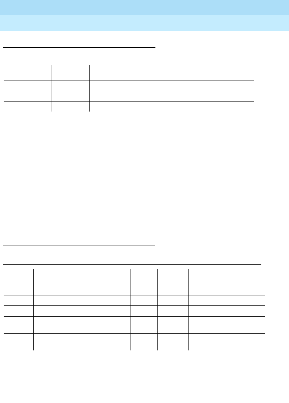
DEFINITY Enterprise Communications Server Release 6
Maintenance for R6r Volumes 1 & 2
555-230-126 Issue 2
January 1998
Maintenance Object Repair Procedures
Page 9-1722VC-SUMPT
9
VC-SUMPT
Each Voice Conditioner Circuit Pack (VC-BD) provides two types of resources:
1. Transcoder Resources that are used for encoding and decoding audio
formats
2. Summer Resources that are used for summing audio formats from
different sources.
The Voice Conditioner Summer ports (VC-SUMPT) are the summer resources on
the VC-BD. There are 8 such ports on a VC-BD.
Error Log Entries and Test to Clear Values
Notes:
1. Where UU is the universal cabinet number (1 for PPN and 2-44 for EPN); C is the carrier
designation (for example, A, B, C, D, or E); SS is the address of the slot in the carrier where
the circuit pack is located (for example, 01, 02, ...); and pp is the two digit port number
(01, 02, 03, ...).
1. Run the short test sequence first. If all test pass, run the long test sequence. Refer to the appropriate
test description and follow the recommended procedures.
MO Name (in
Alarm Log) Alarm
Level Initial Command to Run1Full Name of MO
VC-SUMPT MAJOR test port UUCSSpp Voice Conditioner Summer Port
VC-SUMPT MINOR test port UUCSSpp Voice Conditioner Summer Port
VC-SUMPT WARNING test port UUCSSpp Voice Conditioner Summer Port
Table 9-582. VC-SUMPT Error Log Entries
Error
Type Aux
Data Associated Test Alarm
Level On/Off
Board Test to Clear Value
010 Any Any Any test port UUCSSpp sh r 1
18 (a) 0 busyout port UUCSS WNG OFF release port UUCSSpp
130 (b) WNG ON test port UUCSSpp sh
257 (c) Any Control Channel Loop Test
(#52) MIN ON test board UUCSSpp 1 r 3
513 (d) Any VC Summer Port Local
Loopback Test #(1100) MIN ON test board UUCSSpp sh r 3

DEFINITY Enterprise Communications Server Release 6
Maintenance for R6r Volumes 1 & 2
555-230-126 Issue 2
January 1998
Maintenance Object Repair Procedures
Page 9-1723VC-SUMPT
9
a. This port has been busied out with the busyout port UUCSSpp
command.
b. The circuit pack has been removed or has been insane for more than
11-minutes. To clear the error, replace or reinsert the circuit pack.
c. The NPE Crosstalk Test(#1103) failed.
d. The VC Summer Port Local TDM Loopback Test(#1100) failed.
System Technician-Demanded Tests:
Descriptions and Error Codes
Always investigate tests in the order presented in the table below. By clearing
error codes associated with the NPE Crosstalk Test, for example, you may also
clear errors generated from other tests in the testing sequence.
VC-SUMPT Port NPE Crosstalk Test (#6)
This test is destructive.
The NPE controls port connectivity and gain and provides conferencing
functions. The NPE Crosstalk test verifies that this port’s NPE channel talks on the
selected time slot and never crosses over to time slots reserved for other
connections. If the NPE is not working correctly, one-way and noisy connections
1. D = Destructive; ND = Nondestructive
Order of Investigation Short Test
Sequence Long Test
Sequence D/ND1
NPE Crosstalk Test (#6) (a) X D
TDM Loopback Test (#1100) X X D

DEFINITY Enterprise Communications Server Release 6
Maintenance for R6r Volumes 1 & 2
555-230-126 Issue 2
January 1998
Maintenance Object Repair Procedures
Page 9-1724VC-SUMPT
9
may be observed. This test is part of the port’s long test sequence and takes
approximately 20 to 30 seconds to complete.
VC Summer Port Local TDM Loopback
Test (#1100)
This test is destructive.
This test verifies the connectivity of a VC Summer Port across the TDM bus. It
aborts if calls associated with the port are in progress. Failure of this test
indicates an on-board fault associated with the port hardware on the circuit pack.
The Loopback Test runs the following tests:
■A Looparound test across the TDM bus.
■A conference circuit test.
The tests are run in the above order. If the first test fails, the switch returns an
error code, and the second test is not executed.
Table 9-583. TEST #6 VC-SUMPT Port NPE Crosstalk Test
Error
Code Test
Result Description/ Recommendation
1000
1001 ABORT System resources required to run this test are not available. The port may be
busy with a valid call.
1. Retry the command at 1-minute intervals a maximum of 5 times.
2012 ABORT Internal system error
2100 ABORT Could not allocate the necessary resources for this test.
1. Retry the command at 1-minute intervals a maximum of 5 times.
0-3 FAIL The NPE of the tested port was transmitting in error. This causes noisy and
unreliable connections.
1. Replace circuit pack.
PASS The port is correctly using its allocated time slots.
1. Verify that this is not an intermittent problem by repeating this test a
maximum of 10 times.
2. If complaints continue, examine the station, connections, and wiring.
Continued on next page
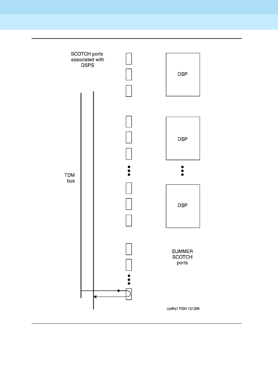
DEFINITY Enterprise Communications Server Release 6
Maintenance for R6r Volumes 1 & 2
555-230-126 Issue 2
January 1998
Maintenance Object Repair Procedures
Page 9-1725VC-SUMPT
9
Figure 9-100. VC Circuit Pack Summer Port Loopback Test

DEFINITY Enterprise Communications Server Release 6
Maintenance for R6r Volumes 1 & 2
555-230-126 Issue 2
January 1998
Maintenance Object Repair Procedures
Page 9-1726VC-SUMPT
9
Table 9-584. TEST #1100 VC Summer Port Local TDM Loopback Test
Error
Code Test
Result Description/Recommendation
1000 ABORT System resources required to run this test are not available, or the port may be
busy with a valid call.
1. Retry the command at 1-minute intervals a maximum of 5 times.
1002 ABORT The system could not allocate time slots for the test. The traffic load on the
system is very high or time slots are out-of-service due to TDM-BUS errors.
Refer to “TDM-BUS” to diagnose any active TDM Bus errors.
1. If the system has no TDM-BUS errors and is not handling heavy traffic,
retry the command at 1-minute intervals a maximum of 5 times.
1003 ABORT The system could not allocate a Tone Detector for the test, the system is
oversized for the number of Tone Detectors present, or some Tone Detectors
are out-of-service.
1. If TTR-LEV errors are in the Error Log, refer to “TTR-LEV.”
2. If TONE-PT errors are in the Error Log, refer to “TONE-PT.”
3. If neither condition exists, retry the command at 1-minute intervals a
maximum of 5 times.
1004 ABORT The port has been seized by a user for a valid call. Use the status station
command for the station associated with this port to determine whether the port
is available for testing.
1. Retry the command at 1-minute intervals a maximum of 5 times.
2000 ABORT Response to the test request was not received from the VC-BD circuit pack
within the allowable time period.
1. If this result occurs repeatedly, reset the circuit pack if the other ports are
not in use. Reset the circuit pack by issuing the busyout board UUCSS
and the reset board UUCSS commands.
2. If this result occurs again, replace the circuit pack.
2012 ABORT Internal system error
1. Retry the command at 1-minute intervals a maximum of 5 times.
2100 ABORT Could not allocate the necessary system resources to run this test.
1. Retry the command at 1-minute intervals a maximum of 5 times.
2103 ABORT The system could not make the conference connection for the test.
1. Retry the command at 1-minute intervals a maximum of 5 times.
0 FAIL The TDM Looparound Test failed.
1 FAIL The Conference Circuit Test failed.
1. Replace circuit pack.
Continued on next page

DEFINITY Enterprise Communications Server Release 6
Maintenance for R6r Volumes 1 & 2
555-230-126 Issue 2
January 1998
Maintenance Object Repair Procedures
Page 9-1727VC-SUMPT
9
PASS The VC Summer Port Local TDM Loopback Test passed.
Table 9-584. TEST #1100 VC Summer Port Local TDM Loopback Test — Continued
Error
Code Test
Result Description/Recommendation
Continued on next page

DEFINITY Enterprise Communications Server Release 6
Maintenance for R6r Volumes 1 & 2
555-230-126 Issue 2
January 1998
Maintenance Object Repair Procedures
Page 9-1728WAE-PORT (Wideband Access Endpoint Port)
9
WAE-PORT (Wideband Access
Endpoint Port)
Wideband Switching supports end-to-end connectivity between customer
endpoints at data rates from 128 to 1536 kbps over T1 facilities and to 1984 kbps
over E1 facilities. DEFINITY switching capabilities are extended to support
wideband calls comprised of multiple DS0s that are switched end-to-end as a
single entity.
Wideband Switching extends the Administered Connections feature to include
non-signaling wideband access endpoints. Endpoint application equipment with
direct T1 or E1 interfaces may connect directly to the switch’s line-side facilities;
application equipment without T1 or E1 interfaces requires a terminal adapter
such as a DSU/CSU. The terminal adapter or endpoint application equipment is
connected to the TN464C Universal DS1 circuit pack.
These endpoints are administered as wideband access endpoints and have no
signaling interface to switch; they simply transmit and receive data. (Some
applications detect and respond to the presence or absence of data). Calls are
initiated from these endpoints using the Administered Connections feature.
Multiple access endpoints on one line-side UDS1 circuit pack facility are
separate and distinct within the facility. Endpoint application equipment must be
administered to send and receive the correct data rate over the correct DS0s. All
Administered Connections originating from wideband access endpoints use the
entire bandwidth administered for the endpoint. An incoming call of a different
data rate then that administered of the endpoint cannot be routed to the
endpoint.
Although Wideband Access Endpoints are used primarily for line-side facilities,
these endpoints can also be administered on network DS1 facilities to connect
DEFINITY to non-switched network services, such as the Lucent fractional T-1
service. An example of this is the Lucent Static Integrated Network Access,
where a trunk group to AT&T 4ESS Switched Services shares an access T-1
facility with a Wideband Access Endpoint. In this case, the Wideband Access
Endpoint is connected to the AT&T fractional T-1 service, and it does not
terminate on local endpoint equipment but is connected to a far-end CPE (for
example, another DEFINITY PBX) via the dedicated fractional T-1. All Wideband
Access Endpoint functionality and operation is identical on both line-side and
1. For additional repair information, see also DS1-BD (DS1 Interface Circuit Pack).
MO Name (in
Alarm Log) Alarm
Level Initial Command to Run1Full Name of MO
WAE-PORT (a) MINOR test access-endpoint
extension
l Wideband Access
WAE-PORT WARNING test access-endpoint
extension
Endpoint Port

DEFINITY Enterprise Communications Server Release 6
Maintenance for R6r Volumes 1 & 2
555-230-126 Issue 2
January 1998
Maintenance Object Repair Procedures
Page 9-1729WAE-PORT (Wideband Access Endpoint Port)
9
network facilities. However, because maintenance capabilities are limited to the
Wideband Access Endpoint interface, and because faults can occur end-to-end,
troubleshooting procedures based on an end-to-end view of the network is
required.
Wideband access endpoint port maintenance provides a strategy to maintain a
wideband access endpoint port via a port on the Universal DS1 interface circuit
pack hardware. The maintenance strategy covers logging wideband access
endpoint port hardware errors, running tests for port initialization, periodic and
scheduled maintenance, demand tests, and alarm escalation and resolution.
Two different port service states are specified in the wideband access endpoint
port maintenance:
■
out-of-service
: the port is in a deactivated state and cannot be used for
calls
■
in-service
: the port is in an activated state and can be used for calls
If the UDS1 Interface circuit pack is out of service, all ports on it are taken
out of service and a Warning alarm is raised.

DEFINITY Enterprise Communications Server Release 6
Maintenance for R6r Volumes 1 & 2
555-230-126 Issue 2
January 1998
Maintenance Object Repair Procedures
Page 9-1730WAE-PORT (Wideband Access Endpoint Port)
9
Error Log Entries and Test to Clear Values
Notes:
a. The wideband access endpoint has been busied out by a busyout
access-endpoint extension command. No calls can be made to this
extension.
b. The circuit pack has been removed or has been insane for more than
11-minutes. To clear the error, reinsert or replace the circuit pack.
c. The Conference Circuit Test (#7) failed on this port. See Test #7 for repair
procedures.
d. The NPE Crosstalk Test (#6) failed on this port. See Test #6 for repair
procedures.
e. The TN464C UDS1 Interface circuit pack has failed. See UDS1-BD.
f. The Port Audit and Update Test (#36) failed due to an internal system
error. Enter status access-endpoint extension and verify the status of the
port. If the wideband access endpoint port is out of service, enter release
access-endpoint extension to put it back into service. Retry the test
command.
1. Run the Short Test Sequence first. If all tests pass, run the Long Test Sequence. Refer to the appropriate
test description and follow the recommended procedures.
Table 9-585. Wideband Access Endpoint Maintenance Error Log Entries
Error
Type Aux
Data Associated Test Alarm
Level On/Off
Board Test to Clear Value
010 Any Any Any test access-endpoint
extension
sh r 1
18(a) 0 busyout access-endpoint WARNING OFF release access-endpoint
extension
130(b) None WARNING ON test access-endpoint
extension
1281(c) Conference Circuit (Test
#7) MINOR ON test access-endpoint
extension
l r 4
1537(d) NPE Crosstalk Test (#6) MINOR ON test access-endpoint
extension
l r 3
1793(e) None test board
UUCSS
long
3840(f) Any Port Audit and Update
(Test #36)

DEFINITY Enterprise Communications Server Release 6
Maintenance for R6r Volumes 1 & 2
555-230-126 Issue 2
January 1998
Maintenance Object Repair Procedures
Page 9-1731WAE-PORT (Wideband Access Endpoint Port)
9
Technician-Demand Tests: Descriptions and
Error Codes
Always investigate tests in the order presented in the table below when
inspecting errors in the system. By clearing error codes associated with the
NPE
Crosstalk Test
, for example, you may also clear errors generated from other tests
in the testing sequence.
1. D = Destructive; ND = Nondestructive
Order of Investigation Short Test
Sequence Long Test
Sequence D/ND1
NPE Crosstalk Test (#6) X ND
Conference Circuit Test (#7) X ND
Port Audit and Update Test (#36) X X ND

DEFINITY Enterprise Communications Server Release 6
Maintenance for R6r Volumes 1 & 2
555-230-126 Issue 2
January 1998
Maintenance Object Repair Procedures
Page 9-1732WAE-PORT (Wideband Access Endpoint Port)
9
NPE Crosstalk Test (#6)
The NPE Crosstalk Test verifies that this port’s NPE channel talks on the selected
time slot, and does not cross over to time slots reserved for other connections. If
the NPE is not working correctly, one-way and noisy connections may be
observed. This test is usually part of a port’s long test sequence and takes 20 to
30 seconds to complete
Table 9-586. TEST #6 NPE Crosstalk Test
Error
Code Test
Result Description/ Recommendation
ABORT System resources required for this test are not available.
1. Retry the command at 1-minute intervals a maximum of 5 times.
1000 ABORT System resources required to run this test are not available. The port may be in
use on a valid call. Use the status access-endpoint extension or command to
determine when the port is available for testing.
1. Retry the command at 1-minute intervals a maximum of 5 times.
1001 ABORT System resources required for this test are not available.
1. Retry the command at 1-minute intervals a maximum of 5 times.
1002 ABORT The system could not allocate time slots for the test. The system may be under
heavy traffic conditions or it may have time slots out-of-service due to
TDM-BUS errors. Use status health to determine if the system is experiencing
heavy traffic. Refer to the TDM-BUS to diagnose any active TDM-BUS errors.
1. If system has no TDM-BUS errors and is not handling heavy traffic, retry
the command at 1-minute intervals a maximum of 5 times.
1003 ABORT The system could not allocate a tone receiver for the test. The system may be
too big for the number of Tone Detectors present, or some Tone Detectors may
be out of service. List measurement tone-receiver displays information on
the system’s tone receivers.
1. Resolve any TTR-LEV errors in the Error Log.
2. Resolve any TONE-PT errors in the Error Log.
3. If neither condition exists, retry the command at 1-minute intervals a
maximum of 5 times.
1004 ABORT The port has been seized by a user for a valid call. Use status
access-endpoint extension to determine when the port is available for testing.
The port is available when it is in the in-service/idle state.
1. Retry the command at 1-minute intervals a maximum of 5 times.
Continued on next page

DEFINITY Enterprise Communications Server Release 6
Maintenance for R6r Volumes 1 & 2
555-230-126 Issue 2
January 1998
Maintenance Object Repair Procedures
Page 9-1733WAE-PORT (Wideband Access Endpoint Port)
9
Conference Circuit Test (#7)
The Conference Circuit Test verifies that the NPE channel for the port being
tested can correctly perform the conferencing function. The NPE is instructed to
listen to several different tones and conference the tones together. The resulting
signal is then measured by a Tone Detector port. If the level of the tone is within a
certain range, the test passes
1020 ABORT The test did not run because of a previously existing error on the specific port
or a more general circuit pack error.
1. Examine the Error Log for existing errors against this port or the circuit
pack and attempt to diagnose the already existing error.
2000 ABORT Response to the test request was not received within the allowable time
period.
2100 ABORT System resources required for this test are not available.
1. Retry the command at 1-minute intervals a maximum of 5 times.
FAIL The NPE of the tested port was found to be transmitting in error. This causes
noisy and unreliable connections.
1. Replace the circuit pack.
PASS The port is correctly using its allocated time slots.
1. Investigate user-reported troubles on this port using other port tests and
by examining the terminal adapter or external wiring.
Table 9-587. TEST #7 Conference Circuit Test
Error
Code Test
Result Description/ Recommendation
ABORT System resources required for this test are not available.
1. Retry the command at 1-minute intervals a maximum of 5 times.
1000 ABORT System resources required to run this test are not available. The port may be in
use on a valid call. Use the status access-endpoint extension command to
determine when the port is available for testing.
Continued on next page
Table 9-586. TEST #6 NPE Crosstalk Test — Continued
Error
Code Test
Result Description/ Recommendation
Continued on next page

DEFINITY Enterprise Communications Server Release 6
Maintenance for R6r Volumes 1 & 2
555-230-126 Issue 2
January 1998
Maintenance Object Repair Procedures
Page 9-1734WAE-PORT (Wideband Access Endpoint Port)
9
1004 ABORT The port has been seized by a user for a valid call. Use the status
access-endpoint extension command to determine when the port is available
for testing. The port is available when it is in the in-service/idle state.
1. Retry the command at 1-minute intervals a maximum of 5 times.
1020 ABORT The test did not run due to a previously existing error on the specific port or
because of a more general circuit pack error.
1. Examine the Error Log for existing errors against this port or circuit pack,
and attempt to diagnose the previously existing error.
2000 ABORT Response to the test was not received within the allowable time period.
2100 ABORT System resources required for this test are not available.
1. Retry the command at 1-minute intervals a maximum of 5 times.
FAIL The NPE of the tested port did not conference the tones correctly. This causes
noisy and unreliable connections. Even though wideband calls do not use the
conferencing feature on the NPE, this failure indicates problems with the circuit
pack hardware.
1. Replace the circuit pack.
PASS The port can correctly conference multiple connections.
1. Investigate user-reported troubles on this port using other port tests and
by examining the terminal adapter or external wiring.
Table 9-587. TEST #7 Conference Circuit Test — Continued
Error
Code Test
Result Description/ Recommendation
Continued on next page

DEFINITY Enterprise Communications Server Release 6
Maintenance for R6r Volumes 1 & 2
555-230-126 Issue 2
January 1998
Maintenance Object Repair Procedures
Page 9-1735WAE-PORT (Wideband Access Endpoint Port)
9
Port Audit and Update Test (#36)
This test sends port level translation data from switch processor to the UDS1
Interface circuit pack to ensure that the wideband access endpoint port’s
translation is correct
Table 9-588. TEST #36 Audit and Update Test
Error
Code Test
Result Description/ Recommendation
ABORT Internal system error
1. Retry the command at 1-minute intervals a maximum of 5 times.
1006 ABORT The port is out-of-service. If the port is busied out:
1. Issue release access-endpoint <extension> command to put the port
back into in-service.
2. Retry the test command. If the port is not busied out:
a. Check the error and alarm logs for WAE-PORT and UDS1-BD
errors and alarms and follow the recommended repair
procedures.
2000 ABORT Response to the test request was not received within the allowable time period.
2100 ABORT Could not allocate the necessary system resources to run this test.
1. Retry the command at 1-minute intervals a maximum of 5 times.
FAIL Internal system error
1. Retry the command at 1-minute intervals a maximum of 5 times.
PASS Port translation has been updated successfully.
Continued on next page

DEFINITY Enterprise Communications Server Release 6
Maintenance for R6r Volumes 1 & 2
555-230-126 Issue 2
January 1998
Maintenance Object Repair Procedures
Page 9-1736XXX-BD (Common Port Circuit Pack)
9
XXX-BD (Common Port Circuit Pack)
Common Port Circuit Pack Maintenance is a set of common tests used by all the
circuit packs listed in the tables below. The common portion of these circuit
packs is the generic hardware that interfaces with the TDM Bus. The XXX-BD
designation is also used on G3-MT displays when reset board is entered with an
empty circuit pack slot, or with a circuit pack type that is in conflict with the actual
board type administered for that slot. All circuit pack suffixes (B,C, D, and so
forth) are supported by “XXX-BD.”
When any of the Common Port Circuit Packs are physically removed from the
backplane, no alarm will be logged for approximately 11-minutes. (In the case of
the TN754 Digital Line,TN566 DEFINITY AUDIX, and TN758 Pooled Modem
circuit packs, Digital Line and Pooled Modem circuit packs, approximately
21-minutes will elapse before an alarm is logged.) When a circuit pack that has
been removed is alarmed, the alarm type is minor and is classified as an
on-board alarm. The time delay permits maintenance activity to be performed
without triggering an additional alarm.
Alarms are logged against only those common port circuit packs on which ports
have been administered. In a heavily loaded system, the interval between the
removal of a Common Port Circuit Pack and the logging of the alarm may be
several minutes longer. The circuit packs in the following list contain ports on the
TDM bus. Suffixes are not shown; for a list of all circuit packs supported, see the
table in Chapter 2. Those that appear in bold type are documented separately
under their own maintenance object name. Only those with an asterisk are
supported by G3r V1 systems
1. UU is the universal cabinet number (1 for PPN, 2-44 for EPNs). C is the carrier designation (A, B,
C, D, or E). SS is the number of the slot in which the circuit pack resides (01 to 21).
2. Refer to the appropriate circuit pack documentation for the correct MO name displayed in this field.
It usually ends with BD.
MO Name (in
Alarm Log) Alarm
Level Initial Command to Run 1Full Name of MO
XXX-BD2MAJOR test board UUCSS Common Port Circuit Pack
Maintenance
XXX-BD2 MINOR test board UUCSS Common Port Circuit Pack
Maintenance
XXX-BD2 WARNING test board UUCSS Common Port Circuit Pack
Maintenance
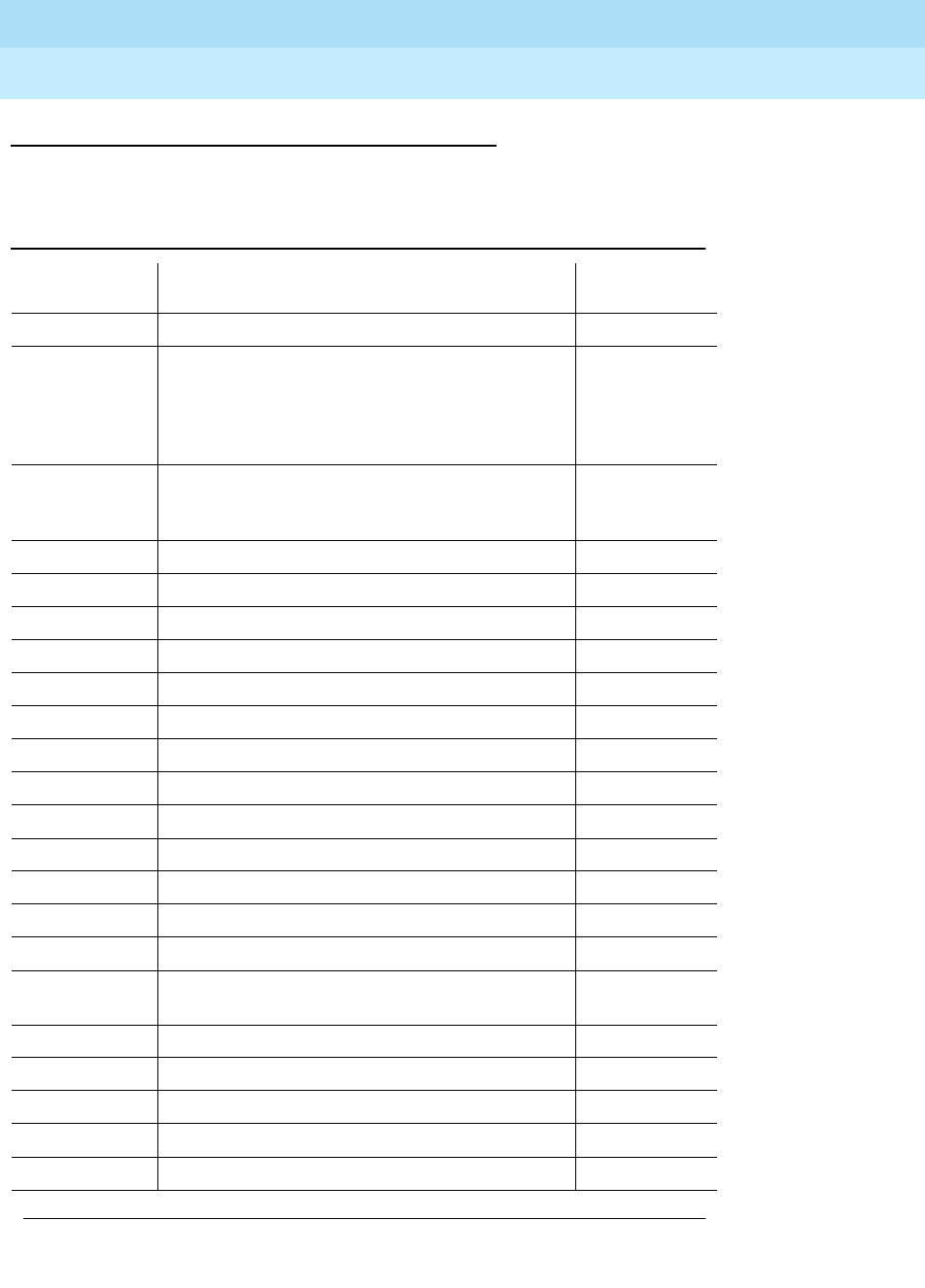
DEFINITY Enterprise Communications Server Release 6
Maintenance for R6r Volumes 1 & 2
555-230-126 Issue 2
January 1998
Maintenance Object Repair Procedures
Page 9-1737XXX-BD (Common Port Circuit Pack)
9
XXX-BD Common Circuit Packs
The following list of circuit packs are listed by apparatus code.
Table 9-589. XXX-BD Common Circuit Packs
Apparatus
Code Name Type
CPP1 Memory Expansion Control
ED-1E546
(TN2169)
(TN2170)
(TN566)
(TN567)
DEFINITY AUDIX R3 System Port Assembly
ED-1E546
(TN2208)
(TN2170)
Call Visor ASAI over the DEFINITY (LAN) Gateway
R1 Port Assembly
TN417 Auxiliary Trunk Port
TN419B Tone-Clock Control
TN420B/C Tone Detector Service
TN429 Direct Inward/Outward Dialing (DIOD) Trunk Port
TN433 Speech Synthesizer Service
TN436B Direct Inward Dialing Trunk Port
TN437 Tie Trunk Port
TN438B Central Office Trunk Port
TN439 Tie Trunk Port
TN447 Central Office Trunk Port
TN457 Speech Synthesizer Service
TN458 Tie Trunk Port
TN459B Direct Inward Dialing Trunk Port
TN464C/D/E/F DS1/E1 Interface - T1, 24 Channel - E1, 32
Channel Port
TN465/B/C Central Office Trunk Port
TN467 Analog Line Port
TN468B Analog Line Port
TN479 Analog Line Port
TN497 Tie Trunk Port
Continued on next page

DEFINITY Enterprise Communications Server Release 6
Maintenance for R6r Volumes 1 & 2
555-230-126 Issue 2
January 1998
Maintenance Object Repair Procedures
Page 9-1738XXX-BD (Common Port Circuit Pack)
9
TN553 Packet Data Line Port
TN556/B ISDN-BRI 4-Wire S/T-NT Line (A-Law) Port
TN570/B/C Expansion Interface Port
TN572 Switch Node Clock Control
TN573/B Switch Node Interface Control
TN574 DS1 Converter - T1, 24 Channel Port
TN577 Packet Gateway Port
TN722B Digital Signal Level 1 Tie Trunk Port
TN725B Speech Synthesizer Service
TN726/B Data Line Port
TN735 MET Line Port
TN742 Analog Line Port
TN744/B Call Classifier Service
TN744/C/D Call Classifier - Detector Service
TN746/B Analog Line Port
TN747B Central Office Trunk Port
TN748/B/C/D Tone Detector Service
TN750/B/C Announcement Service
TN753 Direct Inward Dialing Trunk Port
TN754/B Digital Line 4-Wire DCP Port
TN755B Neon Power Unit Power
TN756 Tone Detector Service
TN758 Pooled Modem Port
TN760B/C/D Tie Trunk Port
TN762B Hybrid Line Port
TN763B/C/D Auxiliary Trunk Port
TN765 Processor Interface Control
TN767B/C/D/E DS1 Interface - T1, 24 Channel Port
TN768 Tone-Clock Control
TN769 Analog Line Port
Table 9-589. XXX-BD Common Circuit Packs — Continued
Apparatus
Code Name Type
Continued on next page

DEFINITY Enterprise Communications Server Release 6
Maintenance for R6r Volumes 1 & 2
555-230-126 Issue 2
January 1998
Maintenance Object Repair Procedures
Page 9-1739XXX-BD (Common Port Circuit Pack)
9
TN771D Maintenance/Test Service
TN772 Duplication Interface Control
TN773 Processor Control
TN775/B Maintenance Service
TN776 Expansion Interface Port
TN777/B Network Control Control
TN778 Packet Control Control
TN780 Tone-Clock Control
TN786 Processor Control
TN786B Processor Control
TN787F Multimedia Interface Service
TN788/B Multimedia Voice Conditioner Service
TN789 Radio Controller Control
TN790 Processor Control
TN793 Analog Line, 24-Port, 2-Wire Port
TN796B Processor Control
TN800 Multi-Application Platform for DEFINITY (MAPD) Service
TNPRI/BRI PRI to BRI Converter Port
TN1648 System Access/Maintenance Control
TN1650B Memory Control
TN1654 DS1 Converter - T1, 24 Channel/E1, 32 Channel Port
TN1655 Packet Interface Control
TN1656 Tape Drive Control
TN1657 Disk Drive Control
TN2135 Analog Line Port
TN2136 Digital Line 2-Wire DCP Port
TN2138 Central Office Trunk Port
TN2139 Direct Inward Dialing Trunk Port
TN2140/B Tie Trunk Port
TN2144 Analog Line Port
Table 9-589. XXX-BD Common Circuit Packs — Continued
Apparatus
Code Name Type
Continued on next page
DEFINITY Enterprise Communications Server Release 6
Maintenance for R6r Volumes 1 & 2
555-230-126 Issue 2
January 1998
Maintenance Object Repair Procedures
Page 9-1740XXX-BD (Common Port Circuit Pack)
9
TN2146 Direct Inward Dialing Trunk Port
TN2147/C Central Office Trunk Port
TN2149 Analog Line Port
TN2180 Analog Line Port
TN2181 Digital Line 2-Wire DCP Port
TN2182/B Tone-Clock -Tone Detector and Call Classifier Control
TN2183 Analog Line Port
TN2184 DIOD Trunk Port
TN2198 ISDN-BRI 2-Wire U Interface Port
TN2199 Central Office Trunk Port
TN2202 Ring Generator Power
TN2224 Digital Line, 24-Port, 2-Wire DCP Port
Table 9-589. XXX-BD Common Circuit Packs — Continued
Apparatus
Code Name Type
Continued on next page

DEFINITY Enterprise Communications Server Release 6
Maintenance for R6r Volumes 1 & 2
555-230-126 Issue 2
January 1998
Maintenance Object Repair Procedures
Page 9-1741XXX-BD (Common Port Circuit Pack)
9
Error Log Entries and Test to Clear Values
Notes:
a. Error type 1 indicates the circuit pack has stopped functioning or has
been physically removed from the system. This error type does not apply
to ANN-BD, DETR-BD, S-SYN-BD, M/T-BD, or CLSFY-BD. The alarm is
logged approximately 11 minutes after removal of the circuit pack or
failure of the SAKI Sanity Test (#53).
1. Run the Short Test Sequence first. If all tests pass, run the Long Test Sequence. Refer to the appropriate
test description and follow the recommended procedures.
Table 9-590. Common Port Circuit Pack Maintenance Error Log Entries
Error
Type Aux
Data Associated Test Alarm
Level On/Off
Board Test to Clear Value
010 Any Any Any test board UUCSS sh r 1
1(a) 0 Circuit pack removed
or SAKI Sanity Test
(#53)
MINOR ON
18(b) 0 busy-out board UUCSS WARNING OFF release board UUCSS
23(c) 0 None WARNING OFF
36 (d) 4368 none
125 (e) None MINOR ON
217 (f) 0 None WARNING ON
257 65535 Control Channel Test
(#52) MINOR ON test board UUCSS sh r 20
257 (g) Any None
267 (f) 0 None WARNING ON
513 (h) Any None MINOR ON test board UUCSS sh
769 (i) 4358 None
1025 (j) 4363 NPE Audit Test (#50) test board UUCSS l r 20
1281 (k) Ringing Application
Test (#51) MINOR ON test board UUCSS r 2
1538 (l) Any None WARNING/
MINOR ON
1793 (m) Neon Test (#220) MINOR ON test board UUCSS r 2
3840 (n) Any None
3999 (o) Any None

DEFINITY Enterprise Communications Server Release 6
Maintenance for R6r Volumes 1 & 2
555-230-126 Issue 2
January 1998
Maintenance Object Repair Procedures
Page 9-1742XXX-BD (Common Port Circuit Pack)
9
Check for the physical presence of the circuit pack in the slot indicated by
the alarm. If the circuit pack is not present, insert one of the proper type. If
the circuit pack is present and its red LED is lit, see
LED Alarm Without
Alarm Log Entry
in Chapter 7.
b. This error indicates the circuit pack has been busied out. Release the
circuit pack via release board UUCSS.
c. The circuit pack has been logically administered but not physically
installed. The alarm should clear when the circuit pact is installed.
If the circuit pack is already installed:
1. Run test board UUCSS long and look at any test failures or error
codes generated.
2. If the test does not clear error 23, then execute reset board
UUCSS and run the long test again.
3. If the reset/test does not clear error 23, replace the circuit pack.
d. This error applies only to the Maintenance/Test circuit pack (TN771B or
TN771C). The error indicates that the hardware associated with the
Analog Trunk Testing port of the circuit pack failed to initialize. Note that
when this error occurs, the Maintenance/Test circuit pack may report an
invalid vintage. Although this error is not service-affecting, the
Maintenance/Test circuit pack should be replaced.
e. The circuit pack physically installed in the slot does not match the type
that is administered for that slot. Do one of the following:
■Remove the incorrect circuit pack and replace it with one of the
type that is administered for that slot.
■Use change circuit pack to readminister the slot so that it matches
the board that is installed, and follow with reset board.
f. This error applies to the Maintenance/Test circuit pack TN771D), Tone
Detector (TN748B, TN748C, or TN748D), and Call Classifier (TN748)
circuit packs. For the Maintenance/Test circuit pack, the error indicates
that there is more than one Maintenance/Test circuit pack in the port
network. For the Tone Detector or Call Classifier packs, the error indicates
that there are more than 10 circuit packs in the system. Remove the circuit
pack against which the error is logged.
g. This error indicates transient communication problems with this circuit
pack. This error is not service-affecting and no action is required.
h. This error, when reported with Aux data in the range of 4352 to 4358,
indicates that the circuit pack has reported an on-board hardware failure.
The circuit pack will continuously test the hardware and report the results
approximately every 10 minutes. If the hardware problem is resolved, the
‘‘leaky bucket’’ strategy should clear the alarm in approximately 30
minutes. However, if the alarm does NOT clear in 30 minutes, then the
circuit pack should be replaced.
i. This error can be ignored, but look for other errors on this circuit pack.

DEFINITY Enterprise Communications Server Release 6
Maintenance for R6r Volumes 1 & 2
555-230-126 Issue 2
January 1998
Maintenance Object Repair Procedures
Page 9-1743XXX-BD (Common Port Circuit Pack)
9
j. This error is not service-affecting and no action is required.
k. This error indicates that no ringing current is detected. Run Test #51,
Ringing Application Test, and follow the procedures for Test #51. This
error is only applicable to Analog Line circuit packs.
l. The hyperactive circuit pack is out-of-service and may exhibit one or more
of the following symptoms:
1. The common circuit pack level tests such as Test #51 and/or Test
#220 are aborting with error code 2000.
2. The tests run on the ports of this circuit pack are returning with a
NO-BOARD.
3. A busy-out/release of the circuit pack has no affect on test results.
4. A list configuration command shows that the circuit pack and
ports are properly installed.
If the XXX-BD is not a TN754 Digital Line Circuit Pack (DIG-BD), and if this
error happens again within 15 minutes, then replace the circuit pack. If the
XXX-BD is a TN754 Digital Line Circuit Pack (DIG-BD), then check the
alarm level. If the alarm level is a WARNING, this indicates that users are
probably causing the hyperactivity by playing with their digital stations. If
the circuit pack is really hyperactive then this alarm will be upgrade to a
MINOR alarm within 1 hour. If the alarm level is a MINOR alarm, then
replace the circuit pack. To replace the circuit pack, refer to Replacing
Circuit Packs in Chapter 5.
m. This error indicates that no neon current is detected. Run test board
UUCSS short and follow the procedures for Test #220. This error is only
applicable to TN769 and TN746 Analog Line circuit packs.
n. This error is not service-affecting and no action is required.
o. Error type 3999 indicates that the circuit pack sent a large number of
control channel messages to the switch within a short period of time. If
error type 1538 is also present, then the circuit pack was taken
out-of-service due to hyperactivity. If error type 1538 is not present, then
the circuit pack has not been taken out-of-service, but it has generated
50% of the messages necessary to be considered hyperactive. This may
be completely normal during heavy traffic periods. However, if this error
type is logged when the circuit pack is being lightly used, it may indicate a
problem with the circuit pack or the equipment attached to it.

DEFINITY Enterprise Communications Server Release 6
Maintenance for R6r Volumes 1 & 2
555-230-126 Issue 2
January 1998
Maintenance Object Repair Procedures
Page 9-1744XXX-BD (Common Port Circuit Pack)
9
Technician-Demand Tests: Descriptions and
Error Codes
Always investigate tests in the order presented in the table below when
inspecting errors in the system. By clearing error codes associated with the
NPE
Audit
, for example, you may also clear errors generated from other tests in the
testing sequence.
Notes;
a. Only applicable to Analog Line circuit packs.
b. The SAKI Sanity Test is run in the Long Test Sequence for the Tone/Clock
circuit packs (TN768, TN780) only. The test is run on other circuit packs
only when they are reset via the reset board command.
c. Only applicable to TN746 and TN769 Analog Line circuit packs.
1. D = Destructive; ND = Nondestructive
Order of Investigation Short Test
Sequence Long Test
Sequence Reset Board
Sequence D/ND1
NPE Audit Test (#50) X ND
Ringing Application Test (#51) (a) X X ND
Control Channel Looparound Test (#52) X X ND
SAKI Sanity Test (#53) (b) X D
Neon Test (#220) (c) X X ND

DEFINITY Enterprise Communications Server Release 6
Maintenance for R6r Volumes 1 & 2
555-230-126 Issue 2
January 1998
Maintenance Object Repair Procedures
Page 9-1745XXX-BD (Common Port Circuit Pack)
9
NPE Audit Test (#50)
The system sends a message to the on-board microprocessor to update the
network connectivity translation for all the Network Processing Elements (NPEs)
on the circuit pack.
Table 9-591. TEST #50 NPE Audit Test
Error
Code Test
Result Description/ Recommendation
None
2100 ABORT System resources required for this test are not available.
1019 ABORT Test already in progress.
FAIL Internal system error
1. Retry the command at 1-minute intervals a maximum of 5 times.
PASS The circuit pack’s NPEs have been updated with their translation.
EXTRA
BD Certain circuit packs have limitations on how many circuit packs can be in the
system or port network such as the Maintenance/Test circuit pack (TN771B or
TN771C), the Tone Detector circuit pack (TN748B, TN748C or TN748D) and
the Call Classifier (TN744). The Maintenance/Test circuit pack allows only one
circuit pack per port network. The Tone Detector and Call Classifier allow only
10 circuit packs in each system. All additional circuit packs will return
EXTRA-BD and should be removed.
Any NO
BOARD This is normal if the test is being done when (a) the board is not physically in
the system or (b) the system is booting up. Otherwise, there is some
inconsistency between the physical configuration and the data kept in the
system.
1. Verify that the board is physically in the system.
2. Verify that the system is not in a stage of booting up.
3. Retry the command at 1-minute intervals for a maximum of 5 times.
Continued on next page

DEFINITY Enterprise Communications Server Release 6
Maintenance for R6r Volumes 1 & 2
555-230-126 Issue 2
January 1998
Maintenance Object Repair Procedures
Page 9-1746XXX-BD (Common Port Circuit Pack)
9
Ringing Application Test (#51)
This test checks the ringing application circuitry common to all ports on an
Analog Line circuit pack.
Table 9-592. TEST #51 Ringing Application Circuit Test
Error
Code Test
Result Description/ Recommendation
1000
2100 ABORT Could not allocate the necessary system resources to run test.
ABORT Could not allocate the necessary system resources to run test. The circuit
pack is not installed. Internal system error
2000 ABORT There was no response from the board.
1. If error type 1538 (hyperactivity) is present in the error log, follow the
maintenance strategy that is recommended for this error type.
2. Run the busyout board, reset board, and release busy board
commands,and then retest.
3. If the test still aborts, dispatch with the circuit pack.
4. Check the off-board wiring and the terminal, and, if there are no problems
found, replace the circuit pack.
1004 ABORT The port was seized by a valid call during the test. The test has been aborted.
Use the display port UUCSSpp command to determine the station extension.
Use the status station command to determine the service state of the port. If
the service state indicates that the port is in use, then the port is unavailable
for certain tests. (Refer to Chapter 8, for a full description of all possible
states). You must wait until the port is idle before retesting.
1. Retry the command at 1-minute intervals a maximum of 5 times.
Continued on next page

DEFINITY Enterprise Communications Server Release 6
Maintenance for R6r Volumes 1 & 2
555-230-126 Issue 2
January 1998
Maintenance Object Repair Procedures
Page 9-1747XXX-BD (Common Port Circuit Pack)
9
1008 ABORT Could not allocate a ringing circuit for one of the following reasons: all the
ringing circuits are in use; the ringing generator is defective; ringing generator
is not wired correctly.
1. If the test continues to abort, look for RING-GEN error in Error Log.
a. If there are RING-GEN errors, refer to RING-GEN Maintenance
documentation and try to resolve any problem(s). Then, go to
Step 2.
b. If there are no RING-GEN errors, and the test continues to
abort, issue the test board UUCSS command on other TN742,
TN769, or TN746 Analog circuit packs. If an ABORT with error
code 1008 occurs for this test on other circuit packs as well,
then the ringing generator may be defective or may not be
wired properly. Refer to RING-GEN Maintenance
documentation for details. If an ABORT with error code 1008
does NOT occur on the other ports, then all four ring generators
are in use. Exit from this documentation.
2. Retry the command.
FAIL No ringing current is detected. The ringing application circuitry on this circuit
pack probably is not healthy.
1. Retry the command again.
2. If the test continues to fail, look for RING-GEN error in Error Log.
a. If there are RING-GEN errors, refer to the RING-GEN
Maintenance documentation and try to resolve any problem(s).
b. If there are no RING-GEN errors, then replace the circuit pack.
3. Retry the command again.
PASS Ringing current is detected or this vintage of the Analog Line circuit pack
does not support the Ringing Application Circuit Test. Analog Line circuit
packs that DO NOT support Test #51 include TN712 Vintage 13 and earlier
and TN742 Vintage 3 and earlier.
Any NO
BOARD This is normal if the test is being done when (a) the board is not physically in
the system or (b) the system is booting up. Otherwise, there is some
inconsistency between the physical configuration and the data kept in the
system.
1. Verify that the board is physically in the system.
2. Verify that the system is not in a stage of booting up.
3. Retry the command at 1-minute intervals for a maximum of 5 times.
Table 9-592. TEST #51 Ringing Application Circuit Test — Continued
Error
Code Test
Result Description/ Recommendation
Continued on next page

DEFINITY Enterprise Communications Server Release 6
Maintenance for R6r Volumes 1 & 2
555-230-126 Issue 2
January 1998
Maintenance Object Repair Procedures
Page 9-1748XXX-BD (Common Port Circuit Pack)
9
Control Channel Looparound Test (#52)
This test queries the circuit pack for its circuit pack code and vintage and verifies
its records.
SAKI Sanity Test (#53)
This test is destructive.
This test resets the circuit pack. It is executed as part of the long test sequence
only for the Tone-Clock circuit pack and DS1 interface circuit packs. Other
common circuit packs can be reset with the reset board UUCSS command
which also executes this test.
Table 9-593. TEST #52 Control Channel Looparound Test
Error
Code Test
Result Description/ Recommendation
None
2100 ABORT System resources required for this test are not available.
1. Retry the command at 1-minute intervals a maximum of 5 times.
FAIL The test failed because the circuit pack failed to return the circuit pack code or
vintage.
1. Retry the command for a maximum of 5 times.
2. If the test still fails, issue the busyout board, reset board, and release
busy board commands, and then retest.
3. If the problem continues, replace the circuit pack.
4. Run the test again.
PASS Communication with this circuit pack is successful.
EXTRA
BD This result should only appear when more than one TN771D Maintenance/Test
circuit pack has been installed in this port network. Remove this circuit pack.
Any NO
BOARD This is normal if the test is being done when (a) the board is not physically in the
system or (b) the system is booting up. Otherwise, there is some inconsistency
between the physical configuration and the data kept in the system.
1. Verify that the board is physically in the system.
2. Verify that the system is not in a stage of booting up.
3. Retry the command at 1-minute intervals for a maximum of 5 times.
Continued on next page

DEFINITY Enterprise Communications Server Release 6
Maintenance for R6r Volumes 1 & 2
555-230-126 Issue 2
January 1998
Maintenance Object Repair Procedures
Page 9-1749XXX-BD (Common Port Circuit Pack)
9
Table 9-594. TEST #53 SAKI Sanity Test
Error
Code Test
Result Description/ Recommendation
None ABORT System resources required for this test are not available.
1. Retry the command at 1-minute intervals a maximum of 5 times.
1005 ABORT Wrong circuit pack configuration to run this test. This error applies only to DS1
interface circuit packs. It means the DS1 interface circuit pack is providing
timing for the system and, therefore, it cannot be reset without major system
disruptions.
1. If the circuit pack needs to be reset, then set synchronization to another
DS1 interface circuit pack or the Tone-Clock circuit pack and try again.
Refer to SYNC (Synchronization) Maintenance documentation.
1015 ABORT Port is not out-of-service.
1. Busy out the circuit pack.
2. Execute command again.
2100 ABORT System resources required for this test are not available.
1. Retry the command at 1-minute intervals a maximum of 5 times.
1 FAIL The circuit pack failed to reset.
2 FAIL The circuit pack failed to restart.
1. Execute command again.
2. If the problem persists, replace the circuit pack.
PASS The circuit pack initializes correctly.
1. Run the short test sequence.
Any NO
BOARD This is normal if the test is being done when (a) the board is not physically in
the system or (b) the system is booting up. Otherwise, there is some
inconsistency between the physical configuration and the data kept in the
system.
1. Verify that the board is physically in the system.
2. Verify that the system is not in a stage of booting up.
3. Retry the command at 1-minute intervals for a maximum of 5 times.
Continued on next page

DEFINITY Enterprise Communications Server Release 6
Maintenance for R6r Volumes 1 & 2
555-230-126 Issue 2
January 1998
Maintenance Object Repair Procedures
Page 9-1750XXX-BD (Common Port Circuit Pack)
9
Neon Test (#220)
This test checks the voltage required to light the neon lamp on an analog
terminal. A relay connects a 150V DC source from the backplane of the circuit
pack onto the voltage bus, and another relay connects a 2K shunt from the bus
to ground. Current in the line is then monitored to determine if the voltage is
present. The neon test runs only for TN746 and TN769 Analog circuit packs. If
the circuit pack is not a TN746 or TN769, the test will return PASS, but the test is
not actually run.
Table 9-595. TEST #220 Neon Test
Error
Code Test
Result Description/ Recommendation
ABORT Cannot get the list of translated ports on the circuit pack.
1004 ABORT The port was seized by a valid call during the test. The test has been aborted.
Use the display port UUCSSpp command to determine the station extension.
Use the status station command to determine the service state of the port. If
the service state indicates that the port is in use, then the port is unavailable for
certain tests. Refer to the status commands described in Chapter 8 for a full
description of all possible states.) You must wait until the port is idle before
retesting.
1. Retry the command at 1-minute intervals a maximum of 5 times.
1008 ABORT Could not allocate a ringing circuit. Either all the ringing circuits are in use, or
the ringing generator is defective or is not wired correctly.
1. Retry the command at 1-minute intervals a maximum of 5 times.
2. If the test continues to abort, look for RING-GEN errors in the Error Log. If
an ABORT 1008 occurs for this test on other circuit packs as well, then the
ringing generator may be defective or is not wired correctly (see errors for
RING-GEN). If it does not occur on port test 48 for ANL-16-L, then all four
ring phases are in use.
2000 ABORT Response to the request was not received within the allowable time period.
2100 ABORT Could not allocate the necessary system resources to run this test.
ABORT Could not allocate the necessary system resources to run this test. Internal
system error.
1. If Error Type 1538 is present in the Error Log, follow the recommended
maintenance strategy.
Continued on next page

DEFINITY Enterprise Communications Server Release 6
Maintenance for R6r Volumes 1 & 2
555-230-126 Issue 2
January 1998
Maintenance Object Repair Procedures
Page 9-1751XXX-BD (Common Port Circuit Pack)
9
FAIL The test failed because no neon current was detected.
1. Determine if there is a TN755 or TN752 power unit circuit pack installed in
the same carrier as the TN746 or TN769 analog line circuit pack that failed
the test. Look for the failure of test 220 on other TN746 or TN769 circuit
packs in the carrier. If test 220 fails on the other circuit packs, replace the
TN755 or TN752 power unit circuit pack.
2. Retry the command again.
3. If the test continues to fail, replace the circuit pack.
4. Retry the command again.
PASS This circuit pack is a TN746 or TN769 Analog Line circuit pack and the neon
current is detected. If this test passes, it can also mean that this circuit pack is
not a TN746 or TN769 Analog Line circuit pack.
Any NO
BOARD This is normal if the test is being done when (a) the board is not physically in the
system or (b) the system is booting up. Otherwise, there is some inconsistency
between the physical configuration and the data kept in the system.
1. Verify that the board is physically in the system.
2. Verify that the system is not in a stage of booting up.
3. Retry the command at 1-minute intervals for a maximum of 5 times.
Table 9-595. TEST #220 Neon Test — Continued
Error
Code Test
Result Description/ Recommendation
Continued on next page

Index
Page IN-1
DEFINITY Enterprise Communications Server Release 6
Maintenance for R6r Volumes 1 & 2
555-230-126 Issue 2
January 1998
IN
Index
Numerics
120A ICSU,6-14
513 BCTs,3-27
715 BCTs,3-25
8-port analog line (ANL-LINE, ANL-NE-L),9-59
A
AC power
distribution in multi-carrier cabinets,9-229
AC Power Distribution Unit,9-230
AC-powered systems,9-3, 9-1119
administered temporary signaling connections (TSC-ADM),9-1607
administration
circuit packs,7-3, 9-1621
customer logins,3-10
Forced Password Aging,3-10
login command permissions,3-13
logins,3-12
super-users,3-12
user access,3-1
air filters,6-31
Alarm Origination to OSS Numbers,8-56
alarms
categories,7-1
classifications,1-7
external leads,1-24
levels,7-1
maintenance objects (MOs),1-7
spontaneous interchanges,5-12
Terminal Alarm Notification,7-2
warning,7-1
American National Standards Institute, see ANSI
analog
carrier signal,1-28
analog port
insertion loss,1-36
analog ring generator (RING-GEN),9-1149
analog transmission by a modem,1-28
analog-to-analog
echo path delay,1-38
frequency response,1-35
intermodulation distortion,1-36
peak noise level,1-38
quantization distortion loss,1-37
analog-to-digital
coder/decoder,1-28
frequency response,1-35
intermodulation distortion,1-36
peak noise level,1-38
quantization distortion loss,1-37
ANSI,1-34

DEFINITY Enterprise Communications Server Release 6
Maintenance for R6r Volumes 1 & 2
555-230-126 Issue 2
January 1998
Index
Page IN-2
application protocols,1-32 to 1-38
ASAI ISDN-BRI port (ABRI-PORT),9-158
Asynchronous Data Unit
proprietary signal,1-28
ATMS, see Automatic Transmission Measurement System
attendant console, LEDs,7-2
audits (tests), see tests and audits
AUDIX circuit pack (ADXDP-BD),9-14
AUDIX digital port (ADXDP-PT),9-15
Automatic Transmission Measurement System (ATMS),6-40
auxiliary error codes,5-13
B
backup
backup power
batteries, preventative maintenance,6-32
battery
charger,9-231
BIU,5-6
bulletin boards,3-5
C
cabling
DS1 connectors,5-25
DS1 CONV,2-10
fiber optic,2-8
metallic,2-10
call-dropping updates,6-3
call-preserving updates,6-3
capabilities, system,1-24 to 1-38
carriers
multi-carrier cabinets,2-3
multicarrier cabinets,2-3
center stage switches,9-614
CEPT1,1-28
character code
8-bit,1-28
characteristics, transmission,1-34 to 1-38
charger, battery,9-231
circuit breaker,9-230, 9-235
circuit packs
administration,7-3, 9-1621
combined tone/generators,9-605
DS1 CONV,5-6
DS1 CONV LEDs,7-9
duplication interface LEDs,7-7
electrostatic discharge (ESD),5-3
expansion interface (EI),9-618
expansion interface (IE) LEDs,7-4
expansion port networks (EPNs),7-5
expansion port networks (EPNs) maintenance,3-25
Generic 3r,2-12
green LEDs,7-3

DEFINITY Enterprise Communications Server Release 6
Maintenance for R6r Volumes 1 & 2
555-230-126 Issue 2
January 1998
Index
Page IN-3
hyperactive,9-949
LEDs,7-3
maintenance LEDs,7-5
miantenance/test LEDs,7-13
packet bus failures,5-50
red LEDs,7-3
replacing,5-5
requiring special procedures,5-6
reseating,5-5
switch processing elements (SPEs),1-12, 5-7
SYSAM,7-14
system access-maintenance (SYSAM),7-5
TN1648,5-6
TN1650B,5-6
TN1655,5-6
TN1656,5-6
TN1657,5-6
TN2182,9-1578
TN464,9-406
TN570,7-4, 9-611
TN572,5-6
TN573,5-6
TN722,9-406
TN750,5-6
TN767,9-406
TN768,9-1521, 9-1578, 9-1597
TN775,9-618
TN780,9-1521, 9-1578
TONE-BD, tone-clock,9-1578
tone-clock,9-618, 9-1578
tone-clock LEDs,7-13
UN330B,5-6
UN331B,5-6
UN332,5-6
universal DS1 (UDS1) interface,9-406, 9-1618
using the packet bus,5-49
yellow LEDs,7-3
clocks, system,9-1521, 9-1578
CODEC,1-28
coder/decoder, analog-to-digital, see CODEC
codes
service,1-38
cold restarts,4-5, 4-6
combined tone generator/detectors, circuit packs,9-605
command interfaces, SPE-down,4-9
command lines,3-28
syntax,8-1
Command Permissions Categories form,3-13
commands
error messages,8-2
reboots,4-15
release,8-8, 8-145
reset pnc interchange,5-68
reset system interchange,5-68
set tone-clock,5-68
SPE-down interface,4-13
status,5-63
status port-network,5-67
testing,4-13
companding,9-605, 9-1581

DEFINITY Enterprise Communications Server Release 6
Maintenance for R6r Volumes 1 & 2
555-230-126 Issue 2
January 1998
Index
Page IN-4
Conference, Transfer, and Call-Forwarding Denial,1-32
connecting/connectivity
G3-MT,3-24
ISDN-BRI/packet bus,5-38
management terminal to system,3-24
packet bus,5-48
connectivity
rules,1-30
CO-trunk-to-digital interface frequency response,1-35
country codes,9-1581
D
data
service unit,1-27
Data Communications Equipment, see DCE
data terminal equipment,1-24
data-link layer, OSI,1-25
DC power
distribution unit,9-235
relay,9-231
DCE,1-24
D-channel
protocol,1-24
DCP,1-27
DC-powered systems,9-8, 9-1128
DEC VT220,3-27
delay, echo path,1-38
Digital Multiplexed Interface,1-28
digital port
insertion loss,1-36
Digital Signal Level 1 (DS1),1-28
digital-to-analog
peak noise level,1-38
quantization distortion loss,1-37
digital-to-digital
echo path delay,1-38
Disconnect Supervision,1-31
distortion
intermodulation,1-36
quantization loss,1-37
distribution unit, power,9-235
DS0 channels,9-1618
DS1
cable connectors,5-25
CO trunk (CO-DS1),9-254, 9-362
converter (DS1 CONV-BD),9-502
convertor complex,9-616
facility LEDs,7-10
interface circuit packs,9-406, 9-1618
option jumpers,9-1621
signaling,9-406
trunks,9-1618
DS1 CONV
cabling,2-10
circuit pack LEDs,7-9
circuit packs,5-6

DEFINITY Enterprise Communications Server Release 6
Maintenance for R6r Volumes 1 & 2
555-230-126 Issue 2
January 1998
Index
Page IN-5
loopbacks,5-24
DS1 loopback,6-10
DS1 span,6-11
DS1 span test,6-11
DS1 span, T1,6-10
DSO frequency response,1-35
DSO Loop-Around Test Call,6-24
DSU, see Data Service Unit
DTE, see data terminal equipment
DTMR Test Call,6-25
duplicated PNCs,9-613
duplicated SPEs,4-16, 6-2, 7-7
duplication
reliability options,2-17
tone-clocks,9-1578
E
echo path delay,1-38
Echo-Return Loss,1-38
EIA,1-34
EIA RS-232C,9-947
electrical components in power distribution unit,9-230
electromagnetic interference filter,9-230
Electronic Industries Association, see EIA
electrostatic discharge (ESD), circuit packs,5-3
Emergency Transfer,5-7
Emergency Transfer (ET),9-596
EMI filter,9-230
enhanced integrated CSU,9-1619
enhanced tone receiver (ETR) ports,9-605
enhanced tone receiver port (ETR-PT),9-1578
EPN, see expansion port networks (EPNs)
ERL, see Echo-Return Loss
error
control,1-25
error logs
hardware,1-7
spontaneous interchanges,5-12
error type 1,9-948
errors
605,5-16
codes, auxiliary,5-13
codes, busyout commands,8-10
codes, release commands,8-10
codes, reset commands,8-10
codes, test commands,8-10
messages, commands,8-2
reporting, maintenance objects (MOs),1-7
ESD, See electrostatic discharge
European conference of postal and telecommunications rate 1, see CEPT1
expansion control carrier (J58890AF),2-6
expansion interface (EI)
circuit packs,9-618
fiber links, viability,9-618
TN570 circuit packs,7-4, 9-611
tone-clock interactions,9-618

DEFINITY Enterprise Communications Server Release 6
Maintenance for R6r Volumes 1 & 2
555-230-126 Issue 2
January 1998
Index
Page IN-6
expansion port networks (EPNs),9-618
maintenance circuit packs,3-25, 7-5
multi-carrier cabinets,2-3
single-carrier cabinets,2-3
troubleshooting packet bus,5-76
F
Facility Interface Code,1-39
Facility Test Calls,6-23
fan units
power converter 631DA,9-235
FCC,1-38
feature capacities,1-24 to 1-38
Federal Communications Commission, see FCC
fiber administration,2-8
fiber connections, metallic cabling,2-10
fiber fault isolation procedure,5-18
fiber hardware,2-8
fiber link (FIBER-LK),9-682
fiber links, DS1 converter complex,9-616, 9-682
fiber optic cables,2-8
FIC, see Facility Interface Code
FIFO overflow,9-949
filter
circuits,9-235
First OSS,8-55
First OSS Telephone Number,8-86
flow control,1-25
Forced Password Aging,3-6, 3-10
frequency response
analog-to-analog,1-35
analog-to-digital,1-35
fuses
20 Amp,9-230
G
G3-MT terminals
connecting,3-24
description,3-1
Generic 3 management terminal (G3-MT),3-1
Global AC MCC (J58890CH),9-1126
global AC/DC power
distribution in multi-carrier cabinets,9-233
grounding jacks,5-3
H
handshake communication
definition,1-17
path,1-18
hot restarts,4-3

DEFINITY Enterprise Communications Server Release 6
Maintenance for R6r Volumes 1 & 2
555-230-126 Issue 2
January 1998
Index
Page IN-7
hyperactive circuit packs,9-949
I
impedances
loop in,1-38
termination,1-38
INADS, see Initialization and Administration System (INADS)
initialization
and recovery,4-1
diagnostics,4-7
diagnostics for reset levels,4-8
reboots,4-1
standby switch processing elements (SPEs),1-17
Initialization and Administration System (INADS)
alarm notification,5-1
alarms,1-7
maintenance objects (MOs),9-762
insertion loss,1-36
install a BIU or Rectifier,5-6
interchanges, tone-clocks,9-1579
interface
physical,1-27
intermodulation distortion,1-36
intervening switching systems,1-30
ISDN
BRI definition,1-27
D-channel treatment,1-24
PRI definition,1-27
ISDN-BRI data module (BRI-DAT),9-157
ISDN-BRI line circuit pack (BRI-BD),9-148
ISDN-BRI port (BRI-PORT),9-158
ISDN-BRI/ASAI, troubleshooting,5-38
ISDN-PRI
DS0 channels,9-1618
signaling link port (ISDN-LNK),9-770
troubleshooting,5-33
J
jacks, network,1-39
journal printers
command permissions,3-18
L
layers, protocol,1-27
LEDs
attendant consoles,7-2
circuit packs,7-3
DS1 CONV circuit packs,7-9
DS1 facility,7-10
electrostatic discharge (ESD),5-3

DEFINITY Enterprise Communications Server Release 6
Maintenance for R6r Volumes 1 & 2
555-230-126 Issue 2
January 1998
Index
Page IN-8
expansion interface (IE) circuit packs,7-4
indicators,7-1
interface circuit packs,7-7
maintenance circuit packs,7-5
maintenance/test circuit packs,7-13
standby components,7-14
switch node interface,7-8
TN573 circuit packs,7-8
tone-clock circuit packs,7-13
yellow,7-13
logging in,3-5, 3-7, 3-26
logging off,3-8, 3-28
login administration,3-12
Login Administration screen,3-12
Login Kill after "N" Attempts,3-1
Login Security Violation Notification Following a Security Violation,3-1
logins,3-5
adding,3-10
administrable,3-6
changing attributes,3-12
displaying,3-9
listing,3-9
maintenance,3-2
removing,3-9
security,3-1
testing,3-10
Logoff Notification (G3V4),3-2, 3-28
Logoff screen,3-9
logoff screen,8-125
loop input impedances,1-38
loopback jack,6-10
loopback tests
fiber fault isolation procedure,5-23
loopbacks
DS1 CONV,5-24
DS1 CONV tests,5-24
loss
echo return,1-38
insertion,1-36
quantization distortion,1-37
single-frequency,1-38
M
maintenance
circuit pack LEDs,7-5
common port circuit pack,9-1736
logins,3-2
packet bus,5-52
preventative,6-31
standby components,1-18
test circuit pack LEDs,7-13
user access,3-1
wideband access endpoint port,9-1729
maintenance object repair procedures
ADXDP-PT (AUDIX Digital Port),9-15
BRI-DAT (ISDN-BRI Data Module),9-157

DEFINITY Enterprise Communications Server Release 6
Maintenance for R6r Volumes 1 & 2
555-230-126 Issue 2
January 1998
Index
Page IN-9
BRI-PORT (ISDN-BRI Port), ABRI-PORT (ASAI ISDN-BRI Port),9-158
BRI-SET, ASAI-ADJ, BRI-DAT,9-188
ISDN-LNK (ISDN-PRI Signaling Link Port),9-770
M/T-DIG (Maintenance/Test Digital Port),9-913
M/T-PKT (Maintenance/Test Packet Bus Port),9-928
TIE-BD (Tie Trunk Circuit Pack),9-1536
maintenance objects (MOs)
alarms,1-7
circuit pack codes,1-12
circuit pack names,1-12
definition,1-7
display alarms commands,8-13
display errors commands,8-13
error conditions,1-7
INADS,9-762
SPE circuit packs,1-12
maintenance/test circuit pack (M/T-BD),9-909
maintenance/test digital port,9-913
maintenance/test packet bus port (M/T-PKT),9-928
major alarms,7-1
management information system (MIS),9-861
management terminals
connecting to system,3-24
Generic 3,3-1
mass storage system (MSS),9-1431, 9-1458
memory shadowing, switch processing elements (SPEs),1-17
MET line (MET-LINE),9-844
metallic cabling,2-10, 2-17
minor alarms,7-1
mismatch of signals,1-31
MO, see maintenance objects (MOs),1-8
multi-carrier cabinets
(J58890A),2-1
carriers,2-3
expansion port networks (EPNs),2-3
N
network
jacks,1-39
network interface,6-14
noise
peak level,1-38
O
Off-Premises Station (OPS) Line,9-933
Open System Interconnect model,1-25
data-link layer,1-25
physical layer,1-25
option jumpers
TN464,9-1621
universal DS1 (UDS1) interface circuit packs,9-1621
OSI, see Open System Interconnect model
OSS Numbers field,8-54

DEFINITY Enterprise Communications Server Release 6
Maintenance for R6r Volumes 1 & 2
555-230-126 Issue 2
January 1998
Index
Page IN-10
P
packet bus
circuit pack failures,5-50
circuit packs,5-49
connectivity,5-48
correcting faults,5-67
definition,5-47
duplicated systems,5-68
fault detection,9-928
faults,5-48
ISDN-BRI connectivity,5-38
maintenance,5-52
reconfiguration,9-928
repair,5-45
reset pnc interchange,5-68
reset system interchange,5-68
set tone-clock,5-68
TDM bus comparison,5-52
troubleshooting,5-64, 5-69
Password Aging,3-6
Password Expiration screen,3-8
passwords,3-5
assigning,3-10
security,3-1
PBX standard RS-464A,1-34
PCM-encoded analog signal,1-28, 1-31
PDATA-PT,9-947
peak noise level,1-38
performance,1-24 to 1-38
echo-return loss,1-38
single-frequency return loss,1-38
PGATE,9-1032
physical
layer, OSI,1-25
PMS printer link (PMS-PRNT/JN),9-1096
PNC duplication (PNC-DUP),9-1101
port carrier (J58890BB),2-5
port network connectivity (PNC)
configurations,1-9
definition,1-9
port-to-port insertion loss,1-36
power
distribution in multi-carrier cabinets
AC,9-229
AC/DC,9-233
distribution unit,9-235
electrical components,9-230
distribution units,6-32
removing,6-39
restoring,6-39
single-carrier cabinets,9-3
power converter
631DA,9-235
power interruptions,1-22
power units
397B,9-231

DEFINITY Enterprise Communications Server Release 6
Maintenance for R6r Volumes 1 & 2
555-230-126 Issue 2
January 1998
Index
Page IN-11
397C,9-231
electrical components,9-230
PPN, see processor port networks (PPNs)
precautions, safety,xvi
preventative maintenance,6-31
air filters,6-31
batteries,6-32
logs,6-31
procedures,6-31
tape drives,6-32
PRI,1-27
PRI endpoint port (PE-BCHL),9-985
printers
715 BCTs,3-26
journal,3-18
private line service codes,1-38
procedures
fiber fault isolation,5-18
SNI/EI manual loop back,5-22
process sanity audits (PROC-SAN),9-1137
processor port networks (PPNs)
cabinets,2-2
control carriers (J58890AP),2-3
troubleshooting packet bus,5-76
property management system (PMS),9-1089, 9-1096
property management system link (PMS-LINK),9-1089
protocols
8-bit character code,1-28
ADU,1-28
analog,1-28
BRI,1-27
CEPT1
DCP,1-27
Digital Multiplexed Interface,1-28
for applications,1-32 to 1-38
layers,1-27
PRI,1-27
summary of states,1-29
system,1-24
voice-grade data,1-28
Q
quantization distortion loss,1-37
R
R2-MFC signaling,9-605
rear panel connector,1-39
reboots,4-2
commands,4-15
initialization,4-1
reset level 4,4-6
reset level 5,4-7
switch processing elements (SPEs),4-16

DEFINITY Enterprise Communications Server Release 6
Maintenance for R6r Volumes 1 & 2
555-230-126 Issue 2
January 1998
Index
Page IN-12
Rectifer,5-6
relay, DC power,9-231
release commands,8-8, 8-145
reliability options
critical,2-18
duplication,2-17
high,2-17
standard,2-17
Remote Access,3-12
REN, see ringer equivalency numbers
replacement procedures, tone-cock circuit packs,9-1582
reset levels
1 (warm restarts),4-3
2 (cold-2 restarts),4-5
3 (cold-1 restarts),4-6
4 (reboots),4-6
5 (extended reboots),4-7
initialization diagnostics,4-8
reboots,4-1
reset pnc interchange command,5-68
reset system command,5-15
reset system interchange command,5-68
ringer equivalency numbers,1-39
RISC processor circuit pack (PROCR),9-1138
RS-232
interface,1-27
RS-232 connector,9-230
RS-232C,9-947
RS-449
physical interface,1-27
RS-464A,1-34
rules, connectivity,1-30
S
safety precautions,xvi, 5-1, 5-5
sanity audits,9-1137
Second OSS,8-55
Second OSS Telephone Number,8-87
security
logins,3-1
password,3-1
service
codes,1-38
service slot (SVC-SLOT),9-1350
set tone-clock command,5-68
SFRL, see single-frequency return loss,1-38
signals
mismatch,1-31
PCM-encoded analog,1-31
simplex SPEs,4-16, 6-2
single carrier cabinet environment (DC-POWER),9-308
single-carrier cabinets
expansion port networks (EPNs),2-3
power system,9-3
single-frequency return loss,1-38
SNI circuit pack (SNI-BD),9-1222

DEFINITY Enterprise Communications Server Release 6
Maintenance for R6r Volumes 1 & 2
555-230-126 Issue 2
January 1998
Index
Page IN-13
SNI peer link (SNI-PEER),9-1285
SNI, see switch node interface (SNI)
SNI/EI manual loop back procedure,5-22
software
standby maintenance monitor (SMM),1-16
updates, duplicated SPEs,6-7
updates, simplex SPEs,6-5
version numbers,6-1
SPE interchange,4-3
SPE locked standby interface,4-10
SPE select switch (SPE-SELE),9-1290
SPE, see switch processing elements (SPEs)
specifications,1-24 to 1-38
SPE-down
command interface,4-9
interface,4-12
interface commands,4-13
mode,4-10
spontaneous interchanges,5-10, 5-11
standby components
LEDs,7-14
standby maintenance monitor (SMM) software,1-16
standby SPE
availability,1-13
down interface,4-10
initialization,1-17
maintenance architecture,1-15
state of health,1-14
station-to-CO trunk frequency response,1-35
station-to-digital interface frequency response,1-35
station-to-station frequency response,1-35
status commands,5-63
status commands, diagnosing ISDN-BRI problems,5-39
status port-network command,5-67
status spe command,4-17
summary of protocol states,1-29
switch
transmission characteristics,1-34 to 1-38
switch node carrier (J58890SA),2-7
switch node interface (SNI), LEDs,7-8
switch processing elements (SPEs),2-3
circuit packs,1-12, 5-7
down interface,4-10
duplicated,6-2
duplicated, troubleshooting,5-10
interchange, prerequisites,5-15
interchanges, failures,5-15
locked standby,4-11
locked states,1-17
memory shadowing,1-17
rebooting,4-16
spontaneous interchanges,5-10
standby connection,3-26
standby, testing,5-14
upgrade software command,6-2
Switch-Based Bulletin Board,3-2
synchronization,1-25
synchronization (SYNC),9-1364
SYSAM circuit packs,7-14
system

DEFINITY Enterprise Communications Server Release 6
Maintenance for R6r Volumes 1 & 2
555-230-126 Issue 2
January 1998
Index
Page IN-14
insertion loss,1-36
protocols,1-24
quantization distortion loss,1-37
specifications,1-24 to 1-38
system access and maintenance (SYSAM),9-1404
system access ports (SAPs,3-25
system access-maintenance (SYSAM) circuit pack,7-5
system errors, 605,5-16
system login procedure,3-26
system resets,7-3
System Tone Test Call,6-28
T
T1 DS1 span,6-10
tape drives, preventative maintenance,6-32
TDM bus
clocks,9-1521, 9-1578
packet bus comparison,5-52
time slots,6-26
TDM bus (TDM-BUS),9-1504
TDM bus clock (TDM-CLK),9-1521
TDM Bus Time Slot Test Call,6-25
technical specifications,1-24 to 1-38
terminal
blocks,9-235
equipment port wiring,1-38
Terminal Alarm Notification
alarms,7-2
description,7-1
terminals
513 BCTs,3-27
610 BCTs,3-25
715 BCTs,3-27
G3-MT,3-24
system access ports (SAPs),3-25
system ports,3-25
Terminating Trunk Transmission (TTT),6-38
termination impedances,1-38
test commands,4-13
testing
analog tie trunk back-to-back,6-34
commands,4-13
common port circuit pack maintenance,9-1736
fiber fault isolation,5-23
standby SPEs,5-14
standby switch processing elements (SPEs),5-14
system technician-demanded,9-632, 9-1632
tests and audits
#0 Dial Tone Test,9-276
#106 Sanity Handshake Test,9-822
#11 Digital Line Electronic Power Feed Test,9-354
#115 Customer-Provided Alarming Device Test,9-298
#117 Analog Ring Generator Initialization Test,9-1152
#118 Analog Ring Generator Query Test,9-1152
#120 External Device Alarm Test,9-677, 9-681
#1201 Digital Terminal Remote Loop Around Test,9-349

DEFINITY Enterprise Communications Server Release 6
Maintenance for R6r Volumes 1 & 2
555-230-126 Issue 2
January 1998
Index
Page IN-15
#1209 Board Loopback Test,9-449
#1209 DS1 Board Loopback Test,9-449, 9-1675
#1210 CSU Equipment Loopback Test,9-452, 9-453, 9-1678
#1211 CSU Repeater Loopback Test,9-455, 9-456, 9-1681
#1212 CPE Loopback Jack Test,9-460, 9-1685
#1213 Far CSU Loopback Test,9-464, 9-1690
#1214 One-Way Span Test,9-467, 9-1694
#1215 Inject Single Bit Error Test,9-471, 9-1697
#1216 End Loopback/Span Test,9-473, 9-1700
#122 Cabinet Temperature Query Test,9-225
#1227 ICSU Status LEDs Test,9-476, 9-1703
#124 Emergency Transfer Query Test,9-600
#126 OLS Recycle Test,9-241
#127 OLS Query Test,9-242
#13 Analog Port Digital Loop Around Test,9-904
#13 Information and Control Channel Local Loop Test,9-977
#13 Voice and Control Channel Local Loop Test,9-19, 9-20, 9-356, 9-591
#135 Customer-Provided Alarming Device Test,9-298
#135 Internal Loop Around Test,9-421, 9-1638
#136 DS1 Tie Trunk Seizure Test,9-1552
#138 Loss of Signal Alarm Inquiry Test,9-423, 9-424, 9-1642
#139 Blue Alarm Inquiry Test,9-430, 9-1649
#139 Red Alarm Inquiry Test,9-433
#140 Red Alarm Inquiry Test,9-432, 9-1652
#141 Yellow Alarm Inquiry Test,9-435, 9-436, 9-1657
#142 Major Alarm Inquiry Test,9-438, 9-1662
#143 Minor Alarm Inquiry Test,9-441, 9-1665
#144 Slip Alarm Inquiry Test,9-443, 9-1492, 9-1668
#145 Misframe Alarm Inquiry Test,9-445, 9-1671
#146 Translation Update Test,9-448, 9-1674
#148 TDM Bus Clock Circuit Status Inquiry Test,9-1528
#149 TDM Bus Clock Slip Inquiry Test,9-1529
#150 TDM Bus Clock PPM Inquiry Test,9-1530
#151 TDM Bus Clock Parameter Update Test,9-1532
#16 DIG-LINE Station Lamp Updates Test,9-358, 9-594
#161 Loop Around Test,9-110, 9-794, 9-1481
#163 Speech Synthesis DTMF Receiver,9-1162
#164 Speech Synthesis DTMF Receiver Inquiry Test,9-1163
#165 Speech Synthesis DSP Tone Test,9-1164
#166 Speech Synthesis Memory Test,9-1165
#167 Speech Synthesis SSD Inquiry Test,9-1166
#168 Speech Synthesis PSS Handshake Test,9-1167
#169 Speech Synthesis Parameter Update Test,9-1168
#17 Data Module Audits Test,9-979
#17 Station (Digital) Audits Test,9-359
#171 Digital Loop Around Test,9-305
#175 Data Module Internal Loop Around Test,9-982
#205 Channel Administration Memory Array (CAMA) Test,9-106
#206 Playback Speech Memory Array (PSMA) Test,9-108
#208 Angel-Speech Processor (SP) Handshake Test,9-94
#209 Announcement Checksum Test,9-95
#210 140AY Loop Around Test,9-99
#211 Super Frame Match Inquiry,9-101
#213 Link Tear Down Test,9-1094, 9-1099, 9-1134, 9-1402
#215 Link Retry Test,9-1095, 9-1100, 9-1135, 9-1403
#220 Neon Test,9-1750
#228 Management Terminal Channel Local Loop-Around Test,9-824
#229 Serial Channel Local Loop Around Test,9-825
#237 Expansion Interface Neighbor Query Test,9-634, 9-688
#238 Expansion Interface Fiber Out-of-Frame Query Test,9-636, 9-690

DEFINITY Enterprise Communications Server Release 6
Maintenance for R6r Volumes 1 & 2
555-230-126 Issue 2
January 1998
Index
Page IN-16
#240 Expansion Interface Local Looparound,9-637
#241 Expansion Interface 2-way Transmission Test,9-640
#242 Expansion Interface Lightwave Transceiver Looparound,9-646
#252 Circuit Pack Restart Test,9-1008, 9-1010
#255 Signaling Link State Check Test,9-802
#256 Service State Audit Test,9-804, 9-998, 9-1000
#257 Call State Audit Test,9-805, 9-1001
#258 ISDN Test Call,9-808
#270 Clear Error Counters,9-134, 9-1480
#294 Idle Time Slot Test on TDM Bus A or TDM Bus B,9-1518
#296 Control Channel Test,9-1519
#297 Digit Detection Test,9-1520
#3 CO Demand Diagnostic Test,9-279
#303 EPN Maintenance Circuit Pack Sanity Maze Test,9-827
#306 EPN Maintenance Circuit Pack Reset Test,9-828
#312 DS1 OPS Switchhook Inquiry Test,9-945
#314 DS1 CO Dial Tone Seizure Test,9-266, 9-371
#316 Expansion Interface Control Channel Test,9-651
#33 Loop Around and Conference Circuit Test,9-283, 9-333, 9-1563
#33 Loop Around and ConferenceCircuit Test,9-380
#336 Expansion Interface Reset Test,9-654
#337 EPN Maintenance Circuit Pack Serial Link Test,9-830
#35 Battery Feed Test,9-40
#35 Battery Feed Test Results,9-67
#35 Port Diagnostic Test,9-335, 9-850
#36 Audit and Update Test,9-801, 9-943, 9-1549, 9-1735
#36 Audit Update Test,9-146, 9-304, 9-1566
#36 Port Audit and Update Test,9-264, 9-323, 9-370
#36 Port Audit Update Test,9-286, 9-337, 9-381
#36 Station Status and Translation Audits and Updates,9-52
#36 Station Status and Translation Audits and Updates Test,9-41, 9-72
#40 Tone Generator Transmission Test,9-1602
#41 Tone Generator Update/Audit Test,9-1604
#417 Test Synchronization Test,9-1392
#42 Tone Detection Verification Test,9-250, 9-536, 9-607, 9-723
#43 Tone Detector Audit/Update Test,9-251, 9-537, 9-609, 9-725
#46 Clock Health Inquiry Test,9-1596
#47 Loop Around and Conference Test,9-77
#48 Station Present Test,9-54, 9-83
#5 Battery & Battery Charger Query Test,9-1123, 9-1130
#50 NPE Audit Test,9-1745
#50 NPE Connection Audit Test,9-416, 9-1634
#51 Ringing Application Circuit Test,9-1746
#52 Control Channel Loop Around Test,9-417, 9-1635, 9-1748
#52 Control Channel Loop-Around Test,9-1009
#53 SAKI Sanity Test,9-419, 9-1636, 9-1749
#558 LAPD Connectivity Test,9-963
#56 Hybrid Electronic Power Feed Test,9-748
#56 MFAT Electronic Power Feed Test,9-851
#565 Digital Port Sanity Test,9-924
#567 Consistency Test,9-932
#57 Hybrid Circuit and Conference Circuit Test,9-749, 9-853
#572 Maintenance/Test Circuit Pack Query Test,9-1048
#573 Packet Circuit Pack Audit Test,9-1051
#574 Board Type Check Test,9-1533
#58 Hybrid Line Local Digital Loop Around Test,9-753
#589 Expansion Interface Packet Interface Test,9-659
#59 Hybrid Line Remote Digital Loop Around Test,9-754
#595 LANBIC Receive Parity Error Counter Test,9-155, 9-1011, 9-1472
#595 LANHO Receive Parity Error Counter Test,9-951

DEFINITY Enterprise Communications Server Release 6
Maintenance for R6r Volumes 1 & 2
555-230-126 Issue 2
January 1998
Index
Page IN-17
#596 Receive FIFO Overflow Error Counter Test,9-1012
#597 Invalid LAPD Frame Error Counter Test,9-1013
#598 Packet Interface Test,9-1013
#599 Packet Gateway Switched Port Loop-Around Test,9-1030
#6 NPE Crosstalk Test,9-33, 9-62, 9-142, 9-258, 9-281, 9-301, 9-318, 9-330, 9-366, 9-379, 9-745,
9-799, 9-847, 9-936, 9-995, 9-1542, 9-1560, 9-1732
#60 Hybrid Line Lamp Updates Test,9-756
#60 MET Line Station Lamp Updates Test,9-856
#600 Congestion Query Test,9-1014
#601Link Status Test,9-1016
#602 PDATA Port Local Loop-Around Test,9-965
#603 System Port Connectivity Test,9-966
#604 TSC Heartbeat Inquiry Test,9-1609
#61 Hybrid Line Audits Test,9-758
#61 MET Line Station Audits Test,9-858
#610 Packet Gateway Port Local Loop-Around Test,9-1031
#611 Packet Gateway Port Remote Loop-Around Test,9-1035
#613 Level 1 State Inquiry Test,9-1037
#617 NPE Crosstalk Test,9-167
#618 BRI Port Local LAN Loop Around,9-129, 9-1483
#619 BRI Port Local TDM Loop Around,9-1484
#62 Hybrid Line Ringer Update Test,9-760
#620 Electronic Power Feed Restoral,9-176
#621 Level 1 Status Inquiry,9-131, 9-1488
#624 Layer 1 Transmission Error Counter Test,9-132, 9-133
#625 Receive FIFO Overflow Error Counter Test,9-1486, 9-1487
#626 Signaling Link Status Test,9-124
#629 BRI Layer 3 Query,9-213, 9-1491
#630 BRI Set Audits,9-216
#637 Remote Layer 3 Query,9-784
#639 Secondary Signaling Link Hardware Check,9-787
#643 Signaling Link Board Check,9-768, 9-773
#651 Standby Reference Health Check Test,9-1533
#7 Conference Circuit Test,9-48, 9-260, 9-303, 9-321, 9-368, 9-800, 9-939, 9-996, 9-1161,
9-1545, 9-1733
#73 Tie Seizure Test,9-1568
#747 Tie Trunk Dial Test,9-1568
#755 SNI Circuit Path Test,9-1237
#756 SNI Off-Board Destructive Facility Test,9-691, 9-1247
#757 SNI Destructive Facility Test,9-693, 9-1249
#759 Configuration Audit,9-695, 9-1253
#760 Processor Route Audit Test,9-1175, 9-1204
#767 Packet Neighbor Link Test,9-1266
#768 Fiber Link Reset Test,9-712
#777 Failure Audit,9-713, 9-1206, 9-1277
#778 SNC On-Board Test,9-1208
#779 TPN Test,9-1210
#78 Power Query Test,9-6, 9-10
#780 Switch Node Clock Reset Test,9-1212
#787 Reset Board,9-521
#788 Far-end DS1 Converter Board Loopback Test,9-523
#789 Far-end FOT (Lightwave Transceiver) Loopback Test,9-525
#79 Single Carrier Cabinet Power Query Test,9-311
#790 DS1 Facilities Connectivity Loopback Test,9-528
#795 Board Options Audit,9-530
#797 Far-End Internal Loopback Test,9-496
#798 DS1 Interface Options Audit,9-498
#799 Near-end External Loopback Test,9-500
#809 Disk Reset Test,9-389
#809/#894 Tape Reset Test,9-1439

DEFINITY Enterprise Communications Server Release 6
Maintenance for R6r Volumes 1 & 2
555-230-126 Issue 2
January 1998
Index
Page IN-18
#810 Disk Write-Read Test,9-392
#810 Tape Write-Read Test,9-1442
#811 Disk Audit Test,9-394
#811 Tape Audit Test,9-1444
#812 Disk Firmware Error Counters Read and Clear Test,9-396
#812 Tape Firmware Error Counters Read and Clear Test,9-1447
#813 Disk Diagnostic Test,9-398
#813 Tape Diagnostic Test,9-1450
#814 Disk Loop-Around Test,9-400
#814 Tape Loop-around Test,9-1452
#815 Disk Status Test,9-402
#815 Tape Status Test,9-1454
#820/#893 Host Adapter Reset Test,9-731
#822 Host Adapter Read and Clear Firmware Error Counters Test,9-733
#823 Host Adapter Diagnostic Test,9-735
#824 Host Adapter Loop Around Test,9-737
#825 Host Adapter Status Test,9-739
#844-848 Transmission Test,9-287, 9-1572
#855 Standby SPE Status Query Test,9-1309
#858 Standby SPE Time-of-Day Comparison Test,9-1311
#865 Control Register Test,9-575
#866 Mailbox Loop-around Test,9-576
#867 Local Loop-around Test,9-577
#868 Memory Shadowing Bounds Test,9-578
#869 Remote Loop-Around Test,9-546
#871 FIFO Full Interrupt Test,9-547
#873 State-Of-Health Test,9-553
#874 Duplication Channel Test,9-555
#875 Remote SPE Error Interrupt Test,9-557
#876 Memory Shadowing Test,9-560
#884 Memory Checksum Test,9-1067
#885 Private Loop Around Tests,9-1071
#886 Maintenance Loop Around Test,9-1074
#887 Read and Clear Board Counters,9-1077
#888 Active-Standby Peer Link Test,9-1081
#893 Host Adapter Reset Test,9-740
#895 Processor Cache Test,9-1142
#896 Processor Cache Parity Audit,9-1143
#897 Processor BOOTPROM Checksum Test,9-1145
#899 Processor Parity Checker Test,9-1146
#9 Digital Line NPE Crosstalk Test,9-352, 9-589
#9 NPE Cross Talk Test,9-902, 9-917
#9 NPE Crosstalk Test,9-18, 9-27, 9-975
#90 Tone Generator Crosstalk Test,9-1606
#900 Processor Write Buffer Test,9-1147
#902 Memory Single/Multiple Bit Error Audit,9-835
#903 RAM Checksum Test,9-837
#906 Memory Parity Checker Test,9-838
#907 Memory Error Detection/ Correction Test,9-840
#908 Memory Burst Read Test,9-841
#909 SYSAM Reset Test,9-1408
#910 SYSAM Dual Port RAM Test,9-1410
#911 Sanity Handshake Test,9-1412
#912 SYSAM Refresh Test,9-1414
#913 Time-Of-Day Clock Test,9-1415
#915 SYSAM G3-MT Loop Around Test,9-1418
#916 SYSAM Outpulse Relay Test,9-1420
#917 SYSAM Analog Loop Around Test,9-1422
#919 Standby SPE Handshake Test,9-1313
#92 Control Channel Interface Test,9-1358

DEFINITY Enterprise Communications Server Release 6
Maintenance for R6r Volumes 1 & 2
555-230-126 Issue 2
January 1998
Index
Page IN-19
#920 Standby SPE Configuration Matchup Test,9-1314
#93 Switch Control Reset Test,9-1360
#939 Signaling Port LAN Loopback,9-769, 9-775
#94 Control Channel Transmission Test,9-1362
#949 Failure Audit,9-501, 9-531
#955 EPN Cold Restart,9-672
#956 EPN Warm Restart,9-673
#96 Modem Pool NPE Crosstalk Test,9-891
#97 Modem Pool Conference Test,9-893
#976 Session Status Query Test,9-1040, 9-1041
#98 Modem Pool Conversion Resource Loop Around Test,9-896
#980 Status Register Comparison Test,9-562
#985 System Link Status,9-1398
#989 SNI Fiber Out of Frame Query,9-715, 9-1280
114 Diagnostic Test—Auxiliary Trunk Test,9-147
761 Switch Node Interface Reset Test,9-1263
Test #833 (A Carrier) and #834 (B Carrier) Tape to Disk Consistency Tests,9-1332
tie trunk circuit pack (TIE-BD),9-1536
time slots, TDM bus,6-26
time-division multiplex (TDM),9-1504
TN1648 circuit packs,5-6
TN1650B circuit packs,5-6
TN1655 circuit packs,5-6, 9-644, 9-656
TN1656 circuit packs,5-6
TN1657 circuit packs,5-6
TN2182 circuit packs
description,9-605
duplication,9-1578
enhanced tone receiver (ETR) ports,9-605
interchanges,9-1579
international settings,9-1581
replacing,9-1582
time division multiplex (TDM) bus clocks,9-1521
tone-clock,9-1578
TN264 circuit packs,9-933
TN464 circuit packs
DS1 interface,9-406, 9-1618
option jumpers,9-1621
trunks,9-1618
TN553 circuit packs,9-947
TN570 circuit packs,9-611
TN572 circuit packs,5-6
TN573 circuit packs,5-6
LEDs,7-8
switch node interface (SNI),7-8
TN722 circuit packs,9-406
TN750 circuit packs,5-6
TN767 circuit packs,9-406, 9-933
TN768 circuit packs
description,9-1578
duplication,9-1578
interchanges,9-1579
international settings,9-1581
replacing,9-1582
time division multiplex (TDM) bus clocks,9-1521
tone generator,9-1597
TN775,9-618
TN775 circuit packs
expansion port network (EPN) maintenance,7-5
expansion port networks (EPNs),9-618

DEFINITY Enterprise Communications Server Release 6
Maintenance for R6r Volumes 1 & 2
555-230-126 Issue 2
January 1998
Index
Page IN-20
TN780 circuit packs
duplication,9-1578
interchanges,9-1579
international settings,9-1581
replacing,9-1582
time division multiplex (TDM) bus clocks,9-1521
tone generator,9-1597
tone clocks, circuit packs,9-618
tone detectors, enhanced tone receiver ports,9-605
tone generators,9-1578, 9-1597
tone-clock circuit packs
duplication,9-1578
interchanges,9-1579
international settings,9-1581
LEDs,7-13
replacing,9-1582
time division multiplex (TDM) bus clocks,9-1521
TN2182,9-1578
tone generators,9-1597
tones, Italian,9-1581
Transfer on Ringing,1-32
transmission
characteristics,1-34 to 1-38
errors,1-25
stream,1-25
troubleshooting
duplicated switch processing element (SPE),5-10
ISDN-BRI/ASAI problems,5-38
ISDN-PRI endpoints (wideband),5-36
ISDN-PRI problems,5-33
ISDN-PRI test call problems,5-42
outgoing ISDN-testcall command,5-44
packet bus,5-64, 5-69
trunk data module (TDMODULE),9-1535
trunk speed,1-31
Trunk Test Call,6-23
trunking facilities,1-30
trunks, DS1,9-1618
TTT. See Terminating Trunk Transmission
U
UN330B circuit packs,5-6
UN331B circuit packs,5-6
UN332 circuit packs,5-6
uninterruptible power supply (UPS),1-22
uninterruptible power supply, see UPS
universal DS1 (UDS1) interface circuit packs,9-406, 9-1618, 9-1621
updates, software,6-1
UPS,9-233
users, multiple access,3-1
V
V.35,1-27


DEFINITY Enterprise Communications Server Release 6
Maintenance for R6r Volumes 1 & 2
555-230-126 Issue 2
January 1998
Index
Page IN-22
