PDF DEFINITY G3 Feature Description
Definity G3 Feature Description Definity G3 Feature Description
User Manual: PDF T E X T F I L E S
Open the PDF directly: View PDF ![]() .
.
Page Count: 1584 [warning: Documents this large are best viewed by clicking the View PDF Link!]
- Table of Contents
- About This Document
- 1. Introduction
- 2. Functional Description
- 3. Feature Descriptions
- Overview
- AAR/ARS Partitioning
- Abandoned Call Search
- Abbreviated Dialing (AD)
- Add/Remove Skills
- Administered Connections
- Administrable Language Displays
- Feature Availability
- Description
- Feature Displays
- Automatic Wakeup
- ASAI
- Busy Verification of Stations and Trunks
- Call Appearance Designation
- Call Detail Record
- Call Progress Feedback
- Class of Restriction
- Date/Time Mode and Formats
- Do Not Disturb (Hotel/Motel feature)
- Expert Agent Selection
- Field Separator
- Integrated Directory Display Mode
- ISDN
- Leave Word Calling
- Malicious Call Trace
- Miscellaneous Attendant Features
- Party Identifiers
- Property Management System Interface
- Security Violation Notification
- Stored Number
- Time of Day Routing
- Considerations
- Interactions
- Administration
- Hardware and Software Requirements
- Administration Without Hardware (AWOH)
- Advice of Charge
- Agent Call Handling
- Alphanumeric Dialing
- Alternate Facility Restriction Levels (AFRL)
- Answer Detection
- Attendant Auto-Manual Splitting
- Attendant Call Waiting
- Attendant Control of Trunk Group Access
- Attendant Direct Extension Selection With Busy Lam...
- Attendant Direct Trunk Group Selection
- Attendant Display
- Attendant Intrusion (Call Offer)
- Attendant Override of Diversion Features
- Attendant Priority Queue
- Attendant Recall
- Attendant Release Loop Operation
- Attendant Room Status
- Attendant Serial Calling
- Audible Message Waiting
- Audio Information Exchange (AUDIX) Interface
- Authorization Codes
- Auto Start and Don’t Split
- Auto-Available Split (AAS)
- Automatic Alternate Routing (AAR)
- Automatic Call Distribution (ACD)
- Feature Availability
- Description
- Considerations
- Interactions
- Administration
- Hardware and Software Requirements
- Automatic Callback
- Automatic Circuit Assurance (ACA)
- Automatic Incoming Call Display
- Automatic Route Selection (ARS)
- Automatic Transmission Measurement System (ATMS)
- Automatic Wakeup
- Basic Call Management System (BCMS)
- Feature Availability
- Description
- Acceptable Service Level
- BCMS Real-Time Reports
- BCMS Historical Reports
- Considerations
- Interactions
- Administration
- Bridged Call Appearance— Multi-Appearance Voice Te...
- Bridged Call Appearance— Single-Line Voice Termina...
- Busy Verification of Terminals and Trunks
- Call Coverage
- Call Detail Recording (CDR)
- Call Forwarding All Calls
- Call Forward Busy/Don’t Answer
- Call Management System (CMS)
- Call Park
- Call Pickup
- Call Prompting
- Call Vectoring
- Feature Availability
- Description
- Vector Directory Numbers and Vectors
- Applications
- What Happens When a Call is Processed by a Vector
- Vector Commands
- ACD Split/Hunt Group Operation with Call Vectoring...
- Call Vectoring and PBX Toll Fraud
- Call Vectoring and the Call Management System (CMS...
- DNIS
- Vector Routing Tables (G3V4 and later releases)
- Considerations
- Interactions
- Administration
- Hardware and Software Requirements
- Call Waiting Termination
- Calling Line Identification (CLI) Prefix
- Call-By-Call Service Selection
- CallVisor Adjunct/Switch Applications Interface (A...
- Feature Availability
- Description
- G3V4 ASAI Enhancements
- Third Party Call Control Capabilities Group
- Third Party Domain (Station/ACD Split) Control Cap...
- Notification Capabilities Group
- Set Value Capabilities Group
- Value Query Capabilities Group
- Request Feature Capabilities Group
- Routing Capabilities Group
- Maintenance Capabilities Group
- CallVisor ASAI Applications
- Considerations
- Feature Initialization and Recovery
- Interactions
- Administration
- Hardware and Software Requirements
- CDR Account Code Dialing Forced Entry of Account C...
- Centralized Attendant Service (CAS)
- Class of Restriction (COR)
- Feature Availability
- Description
- Use of CORs
- Calling Party and Called Party Restrictions
- Forced Entry of Account Codes
- Partitioned Group Number (PGN)
- Service Observing
- VDN of Origin Announcement
- Priority Queuing
- DAC
- Facility Access Trunk Test
- Fully Restricted Service (G3i-Global, G3rV1, and G...
- Restriction Override (3-way COR calling)
- Restricted Call List
- Unrestricted Call List
- Selective Denial of Public Network Calling Through...
- ARS/AAR FRL for Control of Call Routing
- Miscellaneous Restriction Groups
- COR Examples
- Use of CORs
- Considerations
- Interactions
- Administration
- Hardware and Software Requirements
- Class of Service (COS)
- Code Calling Access
- Conference — Attendant
- Conference — Terminal
- Constellation Voice/Data Terminal Support
- Consult
- Coverage Callback
- Coverage Incoming Call Identification (ICI)
- Customer-Provided Equipment (CPE) Alarm
- Data Call Setup
- Feature Availability
- Description
- Data Call Setup for DCP Modules
- Data Call Setup for ISDN-BRI Modules
- Voice Terminal Dialing for ISDN-BRI Data Modules
- Data Terminal (Keyboard) Dialing for ISDN-BRI Data...
- Basic Digit Dialing
- Alphanumeric Dialing
- Default Dialing
- Call Forwarding All Calls
- Data Hotline
- Administered Connections
- Call Request
- Cause Value
- Endpoint Initialization
- Multipoint Configurations on BRI ports
- Exchange of User Information
- Considerations
- Interactions
- Administration
- Hardware and Software Requirements
- Data Hot Line
- Data Privacy
- Data Restriction
- Data-Only Off-Premises Extensions
- DCS Alphanumeric Display for Terminals
- DCS Attendant Control of Trunk Group Access
- DCS Attendant Direct Trunk Group Selection
- DCS Attendant Display
- DCS Automatic Callback
- DCS Automatic Circuit Assurance (ACA)
- DCS Busy Verification of Terminals and Trunks
- DCS Call Coverage
- DCS Call Forwarding All Calls
- DCS Call Waiting
- DCS Distinctive Ringing
- DCS Leave Word Calling
- DCS Multi-Appearance Conference/Transfer
- DCS Over ISDN-PRI D-Channel
- DCS Trunk Group Busy/Warning Indication
- Default Dialing
- Dial Access to Attendant
- Dial Plan
- Digital Multiplexed Interface
- Direct Department Calling (DDC) and Uniform Call D...
- Direct Inward and Outward Dialing (DIOD) — Interna...
- Distinctive Ringing
- DS1 Trunk Service
- Do Not Disturb
- E1 Trunk Service
- EIA Interface
- Emergency Access to the Attendant
- End-to-End Signalling
- Enhanced 84xx Display
- Enhanced Abbreviated Dialing (EAD)
- Enhanced ICSU
- Enhanced DCS (EDCS)
- Expert Agent Selection (EAS)
- Extended Trunk Access
- Extension Number Portability
- Facility Busy Indication
- Facility Restriction Levels (FRLs) and Traveling C...
- Facility Test Calls (with Security Measures)
- Facility and Non-Facility Associated Signaling
- Flexible Billing
- Generalized Route Selection (GRS)
- Go to Cover
- Hold
- Hold - Automatic
- Hot Line Service
- Hunting
- Inbound Call Management (ICM)
- Individual Attendant Access (IAA)
- Information System Network (ISN) Interface
- Integrated Directory
- Integrated Services Digital Network (ISDN) — Basic...
- Integrated Services Digital Network (ISDN) — Prima...
- Inter-PBX Attendant Calls
- Intercept Treatment
- Intercom — Automatic
- Intercom—Dial
- Internal Automatic Answer (IAA)
- Intraflow and Interflow
- Last Number Dialed
- Leave Word Calling
- Line Lockout
- Look Ahead Interflow
- Loudspeaker Paging Access
- Loudspeaker Paging Access — Deluxe
- Malicious Call Trace (MCT)
- Manual Message Waiting
- Manual Originating Line Service
- Manual Signaling
- MERLIN®/System 25 Voice Terminal Support — 731xH S...
- Misoperation Handling
- Modem Pooling
- Move Agents From CMS
- Multi-Appearance Preselection and Preference
- Multiple Call Handling
- Multiple Listed Directory Numbers
- Music-on-Hold Access
- Names Registration
- Network Access — Private
- Network Access — Public
- Night Service — Hunt Group
- Night Service — Night Console Service
- Night Service — Night Station Service
- Night Service — Trunk Answer From Any Station
- Night Service — Trunk Group
- Off-Premises Station
- PC Interface
- PC/PBX Connection
- Personal Central Office Line (PCOL)
- Personalized Ringing
- Power Failure Transfer
- Priority Calling
- Privacy — Attendant Lockout
- Privacy — Manual Exclusion
- Property Management System (PMS) Interface
- Pull Transfer
- QSIG Global Networking
- Queue Status Indications
- R2-MFC Signaling
- Recall Signaling
- Recent Change History
- Recorded Announcement
- Recorded Telephone Dictation Access
- Redirection On No Answer (RONA)
- Remote Access (with Security Measures)
- Remote Call Coverage
- Report Scheduler and System Printer
- Restriction — Controlled
- Restriction — Fully Restricted Service
- Restriction — Miscellaneous Terminal
- Restriction — Miscellaneous Trunk
- Restriction — Toll
- Restriction — Voice Terminal — Inward
- Restriction — Voice Terminal — Manual Terminating ...
- Restriction — Voice Terminal — Origination
- Restriction — Voice Terminal — Outward
- Restriction — Voice Terminal — Public
- Restriction — Voice Terminal — Termination
- Ringback Queuing
- Ringer Cutoff
- Ringing — Abbreviated and Delayed
- Rotary Dialing
- Security Violation Notification (SVN)
- Send All Calls
- Senderized Operation
- Service Observing
- Single-Digit Dialing and Mixed Station Numbering
- Straightforward Outward Completion
- Subnet Trunking
- Switch Based Bulletin Board
- System Measurements
- System Status Report
- Temporary Bridged Appearance
- Tenant Partitioning
- Terminal Translation (with Security Measures)
- Terminating Extension Group (TEG)
- Time of Day Routing
- Timed Reminder and Attendant Timers
- Touch-Tone Dialing
- Transfer
- Transfer — Outgoing Trunk to Outgoing Trunk (with ...
- Trunk Flash
- Trunk Group Busy/Warning Indicators to Attendant
- Trunk Identification By Attendant
- Trunk-to-Trunk Transfer
- Uniform Dial Plan (UDP)
- VDN of Origin Announcement (VOA)
- Visually Impaired Attendant Service (VIAS)
- Voice Message Retrieval
- Voice Response Integration (VRI)
- Voice Terminal Alerting Options
- Voice Terminal Display
- Voice Terminal Flash Timing
- VuStats
- Wideband Switching
- World Class Basic Rate Interface (BRI)
- World Class Tone Detection
- World Class Tone Generation
- A. System Parameters
- B. References
- C. Generic 3 V3 to Generic 3 V4 Transition Reference
- Abbreviations
- Glossary
- Index

555-230-204
Issue 3
March, 1996
DEFINITY Communications
System Generic 3
Feature Description
Graphics © AT&T 1988
Table of
Contents

Contents
Issue 3 March 1996 iii
Table of Contents i
About This Document lxxiii
■Purpose lxxiii
■Intended Audiences lxxiv
■Reason For Reissue lxxiv
■How to Use This Document lxxiv
■Organization lxxiv
■Security Requirements lxxv
■Conventions Used in This Document lxxv
■Trademarks and Service Marks lxxv
■How to Make Comments About This Document lxxvi
1 Introduction 1-1
■Overview 1-1
■Generic 3 Version 1 1-3
G3i Version 1 1-3
G3i-Global Version 1 1-4
G3r Version 1 1-4
G3s Version 1 1-6
G3vs Version 1 1-6
■Generic 3 Version 2 1-7
New Features for Version 2 1-7
■Generic 3 Version 3 1-7
New Features for Version 3 1-8
■Generic 3 Version 4 1-8
New Features for Version 4 1-9
■Generic 3 Notation 1-10
■Security Measures 1-13

Contents
iv Issue 3 March 1996
Logoff Notification 1-14
Passwords 1-14
Physical Security 1-14
Remote Administration Port 1-15
Trunks 1-15
AUDIX 1-15
Automated Attendant 1-16
Call Forwarding 1-16
Call Vectoring 1-16
Action 1-17
Enhanced Call Transfer 1-17
Action 1-18
Remote Access 1-18
Other Features Requiring Security Precautions 1-19
■Organization of Features 1-20
Organization of Each Feature Section 1-20
2 Functional Description 2-1
■Overview 2-1
■Voice Management Overview 2-2
Voice Management Features 2-2
■Data Management 2-7
Data Networking 2-10
Data Communications Protocols and Interfaces 2-13
ISDN Protocols 2-14
Electronic Industries Association (EIA) 2-14
EIA RS-232D 2-14
RS-449 2-15
RS-366 2-15
Digital Communications Protocol (DCP) Interface 2-15
BX.25 Packet Switching Protocol 2-16
■International Telecommunications
Union - Telecommunications,
Specifications Sector (ITU-T) Interface 2-20

Contents
Issue 3 March 1996 v
X.25 Packet-Switching Protocol 2-20
Wideband Switching 2-21
■Data Management Features 2-22
■Network Services 2-23
Network Services Features 2-23
Private Network Configurations 2-24
Electronic Tandem Network (ETN) 2-25
Distributed Communications System (DCS) 2-25
Main/Satellite/Tributary 2-29
Trunking 2-30
■System Management 2-34
System Management Features 2-34
System Administration 2-35
Remote Administration 2-36
Technical Service Center (TSC) 2-36
■Hospitality Services 2-37
Hospitality Services Features 2-37
■Call Center Services 2-38
Call Center Services Features 2-38
3 Feature Descriptions 3-1
■Overview 3-1
■AAR/ARS Partitioning 3-2
Feature Availability 3-2
Description 3-2
Considerations 3-3
Interactions 3-3
Administration 3-4
Hardware and Software Requirements 3-4
■Abandoned Call Search 3-5
Feature Availability 3-5
Description 3-5
Considerations 3-5

Contents
vi Issue 3 March 1996
Interactions 3-6
Administration 3-6
Hardware and Software Requirements 3-6
■Abbreviated Dialing (AD) 3-7
Feature Availability 3-7
Description 3-7
List Types 3-7
List Entries 3-8
Personal Number List Entries 3-8
Group Number and System Number
List Entries 3-9
Enhanced Number List 3-9
List Assignments and Designations 3-9
Privileged Lists 3-10
Special Characters 3-10
Access Options 3-11
Programming Personal Lists, Abbreviated
Dialing Buttons and Automatic Dialing Buttons 3-13
Programming Group Lists 3-13
Considerations 3-14
Security Measures 3-15
Interactions 3-15
Administration 3-16
Hardware and Software Requirements 3-17
■Add/Remove Skills 3-18
Feature Availability 3-18
Description 3-18
Feature History 3-19
Considerations 3-19
Interactions 3-19
Administration 3-19
Hardware and Software Requirements 3-20
■Administered Connections 3-21
Feature Availability 3-21
Description 3-21
Access Endpoints 3-21
Typical Administered Connection Configurations 3-22

Contents
Issue 3 March 1996 vii
Establishment of Administered Connections 3-22
Administered Connection Establishment Retries 3-23
Dropping an Administered Connection 3-23
Administered Connection Failure:
Auto Restoration and Fast Retry 3-24
Interactions 3-25
Administration 3-27
Hardware and Software Requirements 3-30
■Administrable Language Displays 3-31
Feature Availability 3-31
Description 3-31
Feature Displays 3-31
Automatic Wakeup 3-31
ASAI 3-33
Busy Verification of Stations and Trunks 3-33
Call Appearance Designation 3-33
Call Detail Record 3-34
Call Progress Feedback 3-34
Class of Restriction 3-35
Date/Time Mode and Formats 3-35
Do Not Disturb (Hotel/Motel feature) 3-37
Expert Agent Selection 3-38
Field Separator 3-39
Integrated Directory Display Mode 3-39
ISDN 3-39
Leave Word Calling 3-40
Malicious Call Trace 3-44
Miscellaneous Attendant Features 3-45
Caller Information 3-45
Emergency Access to Attendant 3-45
Queue Status 3-46
Queue Status Indication 3-46
Miscellaneous Call Identifier 3-46
Party Identifiers 3-51
Property Management System Interface 3-51
Security Violation Notification 3-53
Stored Number 3-53
Time of Day Routing 3-54
Considerations 3-55
Interactions 3-56
Administration 3-56

Contents
viii Issue 3 March 1996
Hardware and Software Requirements 3-56
■Administration Without Hardware (AWOH) 3-57
Feature Availability 3-57
Description 3-57
Considerations 3-58
Interactions 3-58
Voice Terminal Interactions 3-58
Attendant Interactions 3-61
Data Terminal Interactions 3-63
Association/Disassociation of Terminal Feature
Interactions 3-63
World Class Attendant 3-66
Data Modules 3-67
Administration 3-68
Hardware and Software Requirements 3-68
■Advice of Charge 3-69
Feature Availability 3-69
Description 3-69
When Information Is Received 3-70
During and End 3-70
End Only 3-70
AOC in CDR Reports 3-70
Reported Units 3-71
Considerations 3-71
Interactions 3-71
Administration 3-72
Hardware and Software Requirements 3-72
■Agent Call Handling 3-73
Feature Availability 3-73
Description 3-73
Agent Log-in and Log-out 3-73
Agent Answering Options 3-75
Automatic Answer 3-75
Manual Answer 3-76
ACD Work Modes 3-76
Agent Request for Supervisor Assistance 3-78
ACD Call Disconnecting 3-79

Contents
Issue 3 March 1996 ix
Stroke Counts 3-80
Call Work Codes 3-81
Forced Entry of Stroke Counts and
Call Work Codes 3-82
Agent Sizing (G3V3 and later releases) 3-82
Considerations 3-84
Interactions 3-86
Administration 3-87
Hardware and Software Requirements 3-88
■Alphanumeric Dialing 3-89
Feature Availability 3-89
Description 3-89
Considerations 3-89
Interactions 3-90
Administration 3-90
Hardware and Software Requirements 3-90
■Alternate Facility Restriction Levels (AFRL) 3-91
Feature Availability 3-91
Description 3-91
Terminal User Perspective 3-92
Attendant Perspective 3-92
Line Originator Case 3-92
Trunk Originator Case 3-93
Authorization Code Case 3-93
Considerations 3-94
Interactions 3-94
Administration 3-94
Field Description 3-94
Error Messages 3-94
Help Messages 3-95
Initial Values 3-95
Administration of AFRL Feature Button 3-95
Attendant Class of Operations 3-95
Hardware/Software Requirements 3-96
■Answer Detection 3-97
Feature Availability 3-97
Description 3-97
Considerations 3-98

Contents
xIssue 3 March 1996
Administration 3-98
Interactions 3-98
Hardware and Software Requirements 3-98
■Attendant Auto-Manual Splitting 3-99
Feature Availability 3-99
Description 3-99
Considerations 3-99
Administration 3-99
Hardware and Software Requirements 3-99
■Attendant Call Waiting 3-100
Feature Availability 3-100
Description 3-100
Considerations 3-101
Interactions 3-101
Administration 3-102
Hardware and Software Requirements 3-102
■Attendant Control of Trunk Group Access 3-103
Feature Availability 3-103
Description 3-103
Considerations 3-104
Interactions 3-104
Administration 3-105
Hardware and Software Requirements 3-105
■Attendant Direct Extension Selection
With Busy Lamp Field 3-106
Feature Availability 3-106
Description 3-106
Standard DXS Tracking with Hundreds
Select Buttons 3-107
Enhanced DXS Tracking 3-108
The Group Display Button 3-108
Considerations 3-109
Interactions 3-109
Administration 3-110
Hardware and Software Requirements 3-110
■Attendant Direct Trunk Group Selection 3-111

Contents
Issue 3 March 1996 xi
Feature Availability 3-111
Description 3-111
Considerations 3-111
Interactions 3-112
Administration 3-112
Hardware and Software Requirements 3-112
■Attendant Display 3-113
Feature Availability 3-113
Description 3-113
Call-Related Information 3-115
Call Appearance Identification 3-115
Calling Party Identification 3-115
Called Party Identification 3-115
Internal COR 3-115
Call Progress Feedback 3-116
Call Purpose 3-116
Sample Displays 3-118
Considerations 3-119
Interactions 3-120
Hospitality 3-120
Administration 3-120
Hardware and Software Requirements 3-121
■Attendant Intrusion (Call Offer) 3-122
Feature Availability 3-122
Description 3-122
Considerations 3-122
Interactions 3-122
Administration 3-123
Hardware/Software Requirements 3-123
■Attendant Override of Diversion Features 3-124
Feature Availability 3-124
Description 3-124
Considerations 3-124
Interactions 3-124
Administration 3-124

Contents
xii Issue 3 March 1996
Hardware/Software Requirements 3-125
■Attendant Priority Queue 3-126
Feature Availability 3-126
Description 3-126
Priority by Call Type 3-128
Considerations 3-128
Interactions 3-128
Interactions for Priority by Call Type (G3V4 and later
releases) 3-129
Administration 3-129
Hardware/Software Requirements 3-130
■Attendant Recall 3-131
Feature Availability 3-131
Description 3-131
Considerations 3-131
Interactions 3-131
Administration 3-131
Hardware and Software Requirements 3-131
■Attendant Release Loop Operation 3-132
Feature Availability 3-132
Description 3-132
Considerations 3-132
Interactions 3-132
Administration 3-133
Hardware and Software Requirements 3-133
■Attendant Room Status 3-134
Feature Availability 3-134
Description 3-134
Feature History and Description 3-134
Check-In/Check-Out Status 3-135
Maid Status 3-135
Interactions 3-136
Considerations 3-136
Administration 3-137
Attendant Console Form 3-137

Contents
Issue 3 March 1996 xiii
System-Parameters Customer-Options Form 3-137
System-Parameters Hospitality Form 3-137
Hardware and Software Requirements 3-137
■Attendant Serial Calling 3-138
Feature Availability 3-138
Description 3-138
Considerations 3-138
Interactions 3-138
Administration 3-139
Hardware/Software Requirements 3-139
■Audible Message Waiting 3-140
Feature Availability 3-140
Description 3-140
Considerations 3-140
Interactions 3-140
Administration 3-140
Hardware and Software Requirements 3-140
■Audio Information Exchange (AUDIX) Interface 3-141
Description 3-141
DEFINITY AUDIX 3-142
AUDIX (external to the DEFINITY Switch) 3-143
Security Measures 3-144
Considerations 3-145
Interactions 3-146
Administration 3-150
Hardware and Software Requirements 3-150
■Authorization Codes 3-151
Feature Availability 3-151
Description 3-151
AAR and ARS Calls 3-152
Remote Access Calls 3-153
Considerations 3-153
Interactions 3-154
Administration 3-155
Hardware and Software Requirements 3-155

Contents
xiv Issue 3 March 1996
■Auto Start and Don’t Split 3-156
Feature Availability 3-156
Description 3-156
Considerations 3-156
Interactions 3-156
Administration 3-157
Hardware and Software Requirements 3-157
■Auto-Available Split (AAS) 3-158
Feature Availability 3-158
Description 3-158
Considerations 3-158
Interactions 3-158
ACD Splits 3-158
Auto-Answer 3-159
Agent Logout 3-159
Group Administration 3-160
CMS Notifications 3-160
Adjunct CMS Move Agent 3-160
Administration 3-160
Hunt Group Administration 3-160
Hardware/Software Requirements 3-160
■Automatic Alternate Routing (AAR) 3-161
Feature Availability 3-161
Description 3-161
AAR Dialing 3-163
Inter-Digit Time-out 3-163
Digit Conversion 3-163
Time of Day Routing 3-164
AAR Analysis 3-164
Routing Patterns 3-166
Considerations 3-167
Interactions 3-167
Administration 3-169
Hardware and Software Requirements 3-169
■Automatic Call Distribution (ACD) 3-170
Feature Availability 3-170
Description 3-170

Contents
Issue 3 March 1996 xv
Call Distribution 3-170
Direct Department Calling 3-170
Uniform Call Distribution 3-171
Expert Agent Distribution 3-171
Split Queuing and Announcements 3-171
Forced First Announcement 3-172
Entering the Queue 3-173
First Announcement 3-173
Second Announcement 3-174
Forced Disconnect 3-175
Announcement Rules 3-175
Intraflow and Interflow 3-175
Queue Status Indications 3-176
Priority Queuing 3-176
Agent Call Handling 3-176
CMS 3-180
BCMS 3-180
Abandoned Call Search 3-180
Service Observing 3-180
Direct Agent Calling 3-181
Delivery of Direct Agent Calls 3-181
Answering a Direct Agent Call 3-181
Vector-Controlled Splits 3-182
Agent Sizing 3-182
Stroke Counts 3-182
Call Work Codes 3-182
Forced Entry of Stroke Counts and
Call Work Codes 3-182
Considerations 3-183
Interactions 3-185
Administration 3-189
Hardware and Software Requirements 3-191
■Automatic Callback 3-192
Feature Availability 3-192
Description 3-192
Considerations 3-192
Interactions 3-193

Contents
xvi Issue 3 March 1996
Administration 3-194
Hardware and Software Requirements 3-195
■Automatic Circuit Assurance (ACA) 3-196
Feature Availability 3-196
Description 3-196
Considerations 3-198
Interactions 3-198
Administration 3-199
Hardware and Software Requirements 3-200
■Automatic Incoming Call Display 3-201
Feature Availability 3-201
Description 3-201
Considerations 3-201
Interactions 3-202
Administration 3-202
Hardware and Software Requirements 3-202
■Automatic Route Selection (ARS) 3-203
Feature Availability 3-203
Description 3-203
ARS Dialing 3-204
Inter-Digit Timeout 3-204
Special Dialing Patterns 3-204
Digit Conversion 3-207
Time of Day Routing 3-210
ARS Digit Analysis 3-210
Routing Patterns 3-211
Digit 1 Outpulsing 3-212
NPA Deletion and Insertion 3-213
IDDD and Service Code Dialing 3-213
Operator and Operator-Assisted Calls 3-214
Considerations 3-214
Interactions 3-214
Administration 3-216
Hardware and Software Requirements 3-217
■Automatic Transmission Measurement System (ATMS) 3-218
Feature Availability 3-218

Contents
Issue 3 March 1996 xvii
Description 3-218
Considerations 3-219
Terminating Test Lines 3-219
Interactions 3-220
Administration 3-220
Hardware/Software Requirements 3-220
■Automatic Wakeup 3-221
Feature Availability 3-221
Description 3-221
Considerations 3-225
Interactions 3-227
Administration 3-227
Hardware and Software Requirements 3-228
3 ■Basic Call Management System (BCMS) 3-229
Feature Availability 3-229
Description 3-229
Acceptable Service Level 3-230
Percent Within Service Level 3-230
BCMS Real-Time Reports 3-231
BCMS Split Status Report 3-232
Report Headers, Abbreviations, and
Their Definitions 3-233
BCMS System Status Report 3-236
Report Headers, Abbreviations, and
Their Definitions 3-237
BCMS VDN Status Report 3-239
Report Headers, Abbreviations, and
Their Definitions 3-240
BCMS Historical Reports 3-243
BCMS Agent Report 3-244
Report Headers, Abbreviations, and
Their Definitions 3-246
BCMS Agent Summary Report 3-248

Contents
xviii Issue 3 March 1996
Report Headers, Abbreviations, and
Their Definitions 3-249
BCMS Split Report 3-251
Report Headers, Abbreviations, and
Their Definitions 3-253
BCMS Split Summary Report 3-257
Report Headers, Abbreviations, and
Their Definitions 3-259
BCMS Trunk Group Report 3-264
Report Headers, Abbreviations, and
Their Definitions 3-266
BCMS Trunk Group Summary Report 3-268
Report Headers, Abbreviations, and
Their Definitions 3-270
BCMS VDN Report 3-272
Report Headers, Abbreviations, and
Their Definitions 3-273
BCMS VDN Summary Report 3-276
Report Headers, Abbreviations, and
Their Definitions 3-277
Considerations 3-280
Interactions 3-280
Administration 3-282
Hardware and Software Requirements 3-283
■Bridged Call Appearance—
Multi-Appearance Voice Terminal 3-284
Feature Availability 3-284
Description 3-284
Extension Administrable Buttons and Lamps 3-285
Sample Applications 3-285
Security 3-286
Considerations 3-286
Interactions 3-287
Administration 3-295
Hardware and Software Requirements 3-295
■Bridged Call Appearance—
Single-Line Voice Terminal 3-296

Contents
Issue 3 March 1996 xix
Feature Availability 3-296
Description 3-296
Sample Applications 3-297
Considerations 3-298
Interactions 3-299
Administration 3-306
Hardware and Software Requirements 3-306
■Busy Verification of Terminals and Trunks 3-307
Feature Availability 3-307
Description 3-307
Considerations 3-309
Interactions 3-310
Administration 3-311
Hardware and Software Requirements 3-311
3 ■Call Coverage 3-312
Feature Availability 3-312
Description 3-312
Call Coverage Path 3-312
Multiple Coverage Paths 3-313
Redirection Criteria 3-313
Covering User Options 3-316
What Happens When a Call Goes to Coverage 3-317
VDN in a Call Coverage Path 3-318
Typical Call Coverage Arrangements 3-318
Considerations 3-320
Interactions 3-320
Administration 3-324
Hardware and Software Requirements 3-325
■Call Detail Recording (CDR) 3-326
Feature Availability 3-326
Description 3-326
Splitting of CDR Records 3-327
CDR Privacy 3-328

Contents
xx Issue 3 March 1996
Resource Limitation Call Record Handling
Options 3-328
Set Time and Date 3-329
CDR Data Formats 3-329
Date Record Format 3-329
Call Detail Record Format 3-331
Call Detail Record Fields 3-361
CDR Output Devices 3-379
Remove # from CDR Records 3-381
Considerations 3-381
Capacities 3-381
Account Code Recording 3-381
CDR Device Baud Rate Limits 3-381
Interactions 3-382
Administration 3-392
System Parameters 3-392
Date and Time 3-393
Trunks, Loudspeaker Paging, and
Code Calling Access 3-393
COR 3-393
Feature Access Codes 3-393
IXC Codes 3-394
Data Modules and Modems 3-394
Security 3-395
■Call Forwarding All Calls 3-396
Feature Availability 3-396
Description 3-396
Call Forwarding Override 3-397
Security Measures 3-397
Considerations 3-397
Interactions 3-398
Administration 3-400
Hardware and Software Requirements 3-400
■Call Forward Busy/Don’t Answer 3-401
Feature Availability 3-401
Description 3-401
Call Forwarding Override 3-401
End User Operation 3-402

Contents
Issue 3 March 1996 xxi
Security Measures 3-402
Considerations 3-402
Interactions 3-403
Administration 3-405
Hardware and Software Requirements 3-405
■Call Management System (CMS) 3-406
Feature Availability 3-406
Description 3-406
■Call Park 3-407
Feature Availability 3-407
Description 3-407
Considerations 3-408
Interactions 3-408
Administration 3-409
Hardware and Software Requirements 3-410
■Call Pickup 3-411
Feature Availability 3-411
Description 3-411
Considerations 3-412
Interactions 3-413
Administration 3-414
Hardware and Software Requirements 3-415
■Call Prompting 3-416
Feature Availability 3-416
Description 3-416
Call Prompting Vector Commands 3-416
Collect
<# of digits>
digits after announcement
<extension> 3-417
Goto step
<step #>
if digits
<comparator> <digits>
or
if unconditionally 3-420
Goto vector
<vector #>
if digits
<comparator>
<digits>
or if unconditionally 3-421
Route-to number
<#>
with cov
<y/n>
if digit
<comparator> <digits> 3-421
Route-to digits with coverage
<y/n> 3-422
Stop 3-422

Contents
xxii Issue 3 March 1996
Vector Processing and Calling Party Feedback 3-423
Agent Set Caller Display Information 3-423
Call Prompting Applications 3-424
Automated Attendant 3-424
Data In/Voice Answer (DIVA) 3-424
Data Collection 3-425
Message Collection 3-426
Considerations 3-427
Interactions 3-427
Administration 3-433
Hardware and Software Requirements 3-433
■Call Vectoring 3-434
Feature Availability 3-434
Description 3-434
Vector Directory Numbers and Vectors 3-434
Applications 3-435
What Happens When a Call is Processed
by a Vector 3-436
General 3-436
Calling Party Feedback 3-437
Additional Information 3-438
Vector Commands 3-439
Adjunct Routing 3-439
Announcement 3-440
Busy 3-440
Check-Backup Split/Skill 3-440
Collect Digits 3-441
Converse-On Command 3-441
Disconnect 3-442
Goto Step 3-443
Goto Vector 3-444
Messaging Split/Skill 3-444
Queue-To Main Split/Skill 3-445
Route-to Number 3-446
Route-To Digits 3-447
Stop 3-447

Contents
Issue 3 March 1996 xxiii
Wait-Time 3-447
ACD Split/Hunt Group Operation with
Call Vectoring 3-448
Overview 3-448
Vector Controlled Splits/Skills 3-448
Split/Skill Queue Priority Levels 3-449
Split/Skill Thresholds 3-449
Call Vectoring and PBX Toll Fraud 3-449
Front Ending Remote Access 3-450
Replacing Remote Access 3-451
Call Vectoring and the Call Management System
(CMS) 3-451
DNIS 3-451
Vector Routing Tables (G3V4 and later releases) 3-452
Considerations 3-452
Interactions 3-453
Administration 3-462
Hardware and Software Requirements 3-465
■Call Waiting Termination 3-466
Feature Availability 3-466
Description 3-466
Considerations 3-467
Interactions 3-467
Administration 3-467
Hardware and Software Requirements 3-467
■Calling Line Identification (CLI) Prefix 3-468
Feature Availability 3-468
Description 3-468
Considerations 3-468
Interactions 3-469
Administration 3-470
Hardware Requirements 3-470
■Call-By-Call Service Selection 3-471
Feature Availability 3-471
Description 3-471
Services Used With Call-By-Call Service Selection3-471

Contents
xxiv Issue 3 March 1996
ISDN-PRI Messages and Information Elements
Used for Call-By-Call Service Selection 3-473
Usage Allocation Plan 3-474
Incoming Call Handling Treatment 3-476
Considerations 3-479
Interactions 3-480
Administration 3-480
Hardware and Software Requirements 3-481
■CallVisor Adjunct/Switch Applications Interface (ASAI) 3-482
Feature Availability 3-482
Description 3-482
G3V4 ASAI Enhancements 3-482
CallVisor ASAI Capabilities 3-484
Third Party Call Control Capabilities Group 3-485
CallVisor ASAI Call Types 3-486
Switch-Classified Calls 3-486
Answering Machine Detection (AMD) 3-487
User-Classified Calls 3-487
Direct-Agent Calls 3-488
Supervisor Assist Calls 3-489
Third Party Domain (Station/ACD Split) Control
Capabilities Group 3-490
Notification Capabilities Group 3-491
Set Value Capabilities Group 3-493
Value Query Capabilities Group 3-493
Request Feature Capabilities Group 3-494
Adjunct-Controlled Splits 3-495
Routing Capabilities Group 3-497
Maintenance Capabilities Group 3-498
CallVisor ASAI Applications 3-498
Considerations 3-500
Feature Initialization and Recovery 3-501
Interactions 3-501
Administration 3-517
Hardware and Software Requirements 3-521
■CDR Account Code Dialing Forced
Entry of Account Codes 3-522

Contents
Issue 3 March 1996 xxv
Feature Availability 3-522
Description 3-522
Considerations 3-523
Interactions 3-523
Administration 3-524
Hardware and Software Requirements 3-524
■Centralized Attendant Service (CAS) 3-525
Feature Availability 3-525
Description 3-525
Considerations 3-527
Interactions 3-528
Administration 3-531
Hardware and Software Requirements 3-531
■Class of Restriction (COR) 3-532
Feature Availability 3-532
Description 3-532
Use of CORs 3-533
Calling Party and Called Party Restrictions 3-533
Forced Entry of Account Codes 3-535
Partitioned Group Number (PGN) 3-536
Service Observing 3-536
VDN of Origin Announcement 3-536
Priority Queuing 3-536
DAC 3-537
Facility Access Trunk Test 3-537
Fully Restricted Service (G3i-Global, G3rV1,
and G3V2 and later) 3-537
Restriction Override (3-way COR calling) 3-537
Restricted Call List 3-537
Unrestricted Call List 3-538
Selective Denial of Public Network Calling Through a
CCSA or EPSCS Network (APLT) 3-538
ARS/AAR FRL for Control of Call Routing 3-538
Miscellaneous Restriction Groups 3-539
COR Examples 3-540

Contents
xxvi Issue 3 March 1996
Example Using Miscellaneous Restrictions 3-540
Example Using Calling Party Restrictions, Called Party
Restrictions, and Miscellaneous Restrictions 3-542
Considerations 3-545
Interactions 3-546
Administration 3-548
Assignment of Restrictions 3-549
Voice Terminals 3-549
Trunk Groups 3-549
Attendant Consoles (as a group) and Individual
Attendant Extensions 3-549
Data Module, Loudspeaker Paging Access Zone,
Code Calling Access Zone, and Remote Access
Barrier Code 3-550
Terminating Extension Group, Automatic Call Distribution
Split, Uniform Call Distribution Group, and Direct
Department Calling Group 3-550
Hardware and Software Requirements 3-550
■Class of Service (COS) 3-551
Feature Availability 3-551
Description 3-551
Considerations 3-552
Interactions 3-552
Administration 3-552
Hardware and Software Requirements 3-553
■Code Calling Access 3-554
Feature Availability 3-554
Description 3-554
Considerations 3-554
Interactions 3-554
Administration 3-555
Hardware and Software Requirements 3-556
■Conference — Attendant 3-557
Feature Availability 3-557
Description 3-557
Considerations 3-557
Interactions 3-557

Contents
Issue 3 March 1996 xxvii
Administration 3-558
Hardware and Software Requirements 3-558
■Conference — Terminal 3-559
Feature Availability 3-559
Description 3-559
Considerations 3-559
Interactions 3-559
Administration 3-560
Hardware and Software Requirements 3-560
■Constellation Voice/Data Terminal Support 3-561
Feature Availability 3-561
Description 3-561
Feature History and Development 3-561
Applications and Benefits 3-561
Configuration 3-562
Considerations 3-563
Administration 3-563
Hardware/Software Requirements 3-563
■Consult 3-564
Feature Availability 3-564
Description 3-564
Considerations 3-564
Interactions 3-564
Administration 3-564
Hardware and Software Requirements 3-565
■Coverage Callback 3-566
Feature Availability 3-566
Description 3-566
Considerations 3-566
Interactions 3-566
Administration 3-566
Hardware and Software Requirements 3-566
■Coverage Incoming Call Identification (ICI) 3-567
Feature Availability 3-567
Description 3-567

Contents
xxviii Issue 3 March 1996
Considerations 3-567
Interactions 3-567
Administration 3-567
Hardware and Software Requirements 3-567
■Customer-Provided Equipment (CPE) Alarm 3-568
Feature Availability 3-568
Description 3-568
Considerations 3-569
Interactions 3-569
Administration 3-569
Hardware and Software Requirements 3-569
3 ■Data Call Setup 3-572
Feature Availability 3-572
Description 3-572
Data Call Setup for DCP Modules 3-572
Voice Terminal Dialing for DCP Data Modules 3-572
Data Terminal (Keyboard) Dialing for DCP Data
Modules 3-573
Single-Line Dialing 3-574
Multiple-Line Dialing 3-575
Alphanumeric Dialing 3-575
Call Forwarding All Calls 3-575
Default Dialing 3-575
Administered Connections 3-575
Hotline Dialing 3-576
Data Call Setup for ISDN-BRI Modules 3-578
Voice Terminal Dialing for ISDN-BRI
Data Modules 3-578
Data Terminal (Keyboard) Dialing for ISDN-BRI Data
Modules 3-578
Basic Digit Dialing 3-579
Alphanumeric Dialing 3-579
Default Dialing 3-579

Contents
Issue 3 March 1996 xxix
Call Forwarding All Calls 3-580
Data Hotline 3-580
Administered Connections 3-580
Call Request 3-580
Cause Value 3-580
Endpoint Initialization 3-581
Multipoint Configurations on BRI ports 3-581
Exchange of User Information 3-581
Considerations 3-583
Interactions 3-583
Administration 3-585
Hardware and Software Requirements 3-585
■Data Hot Line 3-588
Feature Availability 3-588
Description 3-588
Considerations 3-588
Interactions 3-588
Administration 3-589
Hardware and Software Requirements 3-589
■Data Privacy 3-590
Feature Availability 3-590
Description 3-590
Considerations 3-590
Interactions 3-590
Administration 3-591
Hardware and Software Requirements 3-591
■Data Restriction 3-592
Feature Availability 3-592
Description 3-592
Considerations 3-592
Interactions 3-592
Administration 3-593
Hardware and Software Requirements 3-593
■Data-Only Off-Premises Extensions 3-594
Feature Availability 3-594

Contents
xxx Issue 3 March 1996
Description 3-594
Considerations 3-594
Interactions 3-594
Administration 3-595
Hardware and Software Requirements 3-595
■DCS Alphanumeric Display for Terminals 3-596
Feature Availability 3-596
Description 3-596
Considerations 3-596
Interactions 3-597
Administration 3-598
Hardware and Software Requirements 3-598
■DCS Attendant Control of Trunk Group Access 3-599
Feature Availability 3-599
Description 3-599
Considerations 3-600
Interactions 3-601
Administration 3-601
Hardware and Software Requirements 3-601
■DCS Attendant Direct Trunk Group Selection 3-602
Feature Availability 3-602
Description 3-602
Considerations 3-602
Interactions 3-602
Administration 3-602
Hardware and Software Requirements 3-603
■DCS Attendant Display 3-604
Feature Availability 3-604
Description 3-604
Considerations 3-604
Interactions 3-605
Administration 3-605
Hardware and Software Requirements 3-605
■DCS Automatic Callback 3-606
Feature Availability 3-606

Contents
Issue 3 March 1996 xxxi
Description 3-606
Considerations 3-607
Interactions 3-607
Administration 3-607
Hardware and Software Requirements 3-607
■DCS Automatic Circuit Assurance (ACA) 3-608
Feature Availability 3-608
Description 3-608
Considerations 3-608
Interactions 3-608
Administration 3-608
Hardware and Software Requirements 3-609
■DCS Busy Verification of Terminals and Trunks 3-610
Feature Availability 3-610
Description 3-610
Considerations 3-610
Interactions 3-610
Administration 3-611
Hardware and Software Requirements 3-611
■DCS Call Coverage 3-612
Feature Availability 3-612
Description 3-612
Feature Applications 3-613
Previous Feature Operation 3-613
New Feature Operation 3-615
Detailed Operation 3-616
User Interface 3-618
Interactions 3-625
Interworking 3-626
Hardware and Software Requirements 3-628
■DCS Call Forwarding All Calls 3-629
Feature Availability 3-629
Description 3-629
Considerations 3-629
Interactions 3-629
Administration 3-630

Contents
xxxii Issue 3 March 1996
Hardware and Software Requirements 3-630
■DCS Call Waiting 3-631
Feature Availability 3-631
Description 3-631
Considerations 3-631
Interactions 3-631
Administration 3-632
Hardware and Software Requirements 3-632
■DCS Distinctive Ringing 3-633
Feature Availability 3-633
Description 3-633
Considerations 3-633
Interactions 3-633
Administration 3-634
Hardware and Software Requirements 3-634
■DCS Leave Word Calling 3-635
Feature Availability 3-635
Description 3-635
Considerations 3-635
Interactions 3-636
Administration 3-636
Hardware and Software Requirements 3-636
■DCS Multi-Appearance Conference/Transfer 3-637
Feature Availability 3-637
Description 3-637
Considerations 3-637
Interactions 3-637
Administration 3-638
Hardware and Software Requirements 3-638
■DCS Over ISDN-PRI D-Channel 3-639
Feature Availability 3-639
Description 3-639
Considerations 3-640
Interactions 3-640
Administration 3-641

Contents
Issue 3 March 1996 xxxiii
Hardware and Software Requirements 3-642
■DCS Trunk Group Busy/Warning Indication 3-643
Feature Availability 3-643
Description 3-643
Considerations 3-643
Interactions 3-644
Administration 3-644
Hardware and Software Requirements 3-644
■Default Dialing 3-645
Feature Availability 3-645
Description 3-645
Considerations 3-645
Interactions 3-645
Administration 3-646
Hardware and Software Requirements 3-646
■Dial Access to Attendant 3-647
Feature Availability 3-647
Description 3-647
Considerations 3-647
Interactions 3-647
Administration 3-647
Hardware and Software Requirements 3-648
■Dial Plan 3-649
Feature Availability 3-649
Description 3-649
Considerations 3-651
Interactions 3-651
Administration 3-651
Hardware and Software Requirements 3-652
■Digital Multiplexed Interface 3-653
Feature Availability 3-653
Description 3-653
Considerations 3-654
Interactions 3-654
Administration 3-654

Contents
xxxiv Issue 3 March 1996
Hardware and Software Requirements 3-655
■Direct Department Calling (DDC) and
Uniform Call Distribution (UCD) 3-656
Feature Availability 3-656
Description 3-656
Considerations 3-659
Interactions 3-661
Administration 3-663
Hardware and Software Requirements 3-664
■Direct Inward and Outward Dialing
(DIOD) — International 3-665
Feature Availability 3-665
Description 3-665
Considerations 3-665
Interactions 3-666
Administration 3-666
Hardware and Software Requirements 3-666
■Distinctive Ringing 3-667
Feature Availability 3-667
Description 3-667
Considerations 3-669
Interactions 3-670
Administration 3-670
■DS1 Trunk Service 3-671
Feature Availability 3-671
Description 3-671
Voice Grade DS1 Tie Trunks 3-671
AVD Tie Trunks 3-672
Tie Trunks 3-672
DMI Tie Trunks 3-673
CO, FX, and WATS Trunks 3-673
Remote Access Trunks 3-673
DID Trunks 3-674
Off-Premises Stations 3-674
Access Endpoints 3-674
Considerations 3-674
Interactions 3-674

Contents
Issue 3 March 1996 xxxv
Administration 3-675
Hardware and Software Requirements 3-675
■Do Not Disturb 3-676
Feature Availability 3-676
Description 3-676
Feature Activation by Voice Terminal Users 3-676
Feature Activation by Attendant 3-677
Activation of Do Not Disturb Through a PMS 3-677
Audit Trail Reports 3-677
Considerations 3-678
Interactions 3-678
Administration 3-679
Hardware and Software Requirements 3-679
3 ■E1 Trunk Service 3-680
Feature Availability 3-680
Description 3-680
■EIA Interface 3-681
Feature Availability 3-681
Description 3-681
Considerations 3-681
Interactions 3-682
Administration 3-682
Hardware and Software Requirements 3-683
■Emergency Access to the Attendant 3-684
Feature Availability 3-684
Description 3-684
Considerations 3-686
Interactions 3-686
Administration 3-688
Hardware and Software Requirements 3-688
■End-to-End Signalling 3-689
Feature Availability 3-689
Description 3-689

Contents
xxxvi Issue 3 March 1996
Interactions 3-689
Considerations 3-689
Administration 3-689
Hardware and Software Requirements 3-689
■Enhanced 84xx Display 3-690
Feature Availability 3-690
Description 3-690
End User Operation 3-690
Security Measures 3-690
Considerations 3-690
Interactions 3-691
Internal Feature interactions 3-691
External Feature Interfaces 3-691
Administration 3-692
Hardware and Software Requirements 3-694
■Enhanced Abbreviated Dialing (EAD) 3-695
Feature Availability 3-695
Description 3-695
Considerations 3-695
Interactions 3-695
Administration 3-696
Hardware and Software Requirements 3-696
■Enhanced ICSU 3-697
Feature Availability 3-697
Description 3-697
Testing 3-698
Performance Measurements 3-698
Considerations 3-699
Interactions 3-699
Administration 3-700
Hardware and Software Requirements 3-700
■Enhanced DCS (EDCS) 3-701
Feature Availability 3-701
Description 3-701
Considerations 3-701

Contents
Issue 3 March 1996 xxxvii
Interactions 3-701
Administration 3-701
Hardware and Software Requirements 3-701
■Expert Agent Selection (EAS) 3-702
Feature Availability 3-702
Purpose 3-702
Identifying Caller Needs 3-702
AT&T Network DNIS/ISDN Called Party 3-703
Call Prompting/VRU Digits 3-703
ASAI Host Database Lookup 3-703
Routing Digits 3-703
Agents Skills 3-703
EAS Application 3-703
Writing Vectors 3-704
EAS Agent Operations 3-705
Other Login ID Applications 3-706
Administration of Skills 3-707
Call Distribution 3-707
EAS Logical Agent 3-708
Direct Agent Calling 3-708
Expert Agent Selection 3-709
Publishing Login ID Extensions Instead of
Physical Extensions 3-709
Direct Agent Calling 3-710
Class of Restriction 3-710
Considerations 3-710
Caller Interactions 3-711
Agent Login Procedure 3-711
Logout Procedure 3-711
Calling an EAS Agent 3-711
Making a Direct Agent Call to the Agent 3-712
Single Set of Work Mode Buttons 3-712
Message Waiting Lamp 3-712
Adjunct Interactions 3-713
ASAI 3-713
Call Control 3-713
Feature Requests 3-714
Value Queries 3-714

Contents
xxxviii Issue 3 March 1996
Event Notification 3-714
Adjunct-Controlled Splits 3-714
AUDIX 3-715
Speech Processing Adjuncts 3-715
Feature Interactions 3-715
Administration 3-719
System Parameters 3-719
Logical Agent 3-719
Station Administration 3-719
VDN Administration 3-720
Vector Administration 3-720
Hardware and Software Requirements 3-720
■Extended Trunk Access 3-721
Feature Availability 3-721
Description 3-721
Considerations 3-721
Capacity Requirements and Constraints 3-721
Interactions 3-722
Administration 3-724
Hardware/Software Requirements 3-725
■Extension Number Portability 3-726
Feature Availability 3-726
Description 3-726
Considerations 3-726
Interactions 3-726
Administration 3-726
Hardware/Software Requirements 3-727
■Facility Busy Indication 3-728
Feature Availability 3-728
Description 3-728
Considerations 3-728
Interactions 3-729
Administration 3-729
Hardware and Software Requirements 3-729
■Facility Restriction Levels (FRLs) and
Traveling Class Marks (TCMs) 3-730

Contents
Issue 3 March 1996 xxxix
Feature Availability 3-730
Description 3-730
Call Originating Facilities 3-731
Call Terminating Facilities 3-732
Considerations 3-732
Interactions 3-733
Administration 3-733
Assignment Guidelines 3-733
Hardware and Software Requirements 3-734
■Facility Test Calls (with Security Measures) 3-735
Feature Availability 3-735
Description 3-735
Security Measures 3-736
Considerations 3-736
Interactions 3-737
Administration 3-737
Hardware and Software Requirements 3-737
■Facility and Non-Facility Associated Signaling 3-738
Feature Availability 3-738
Description 3-738
Facility Associated Signaling 3-738
Non-Facility Associated Signaling 3-738
D-Channel Backup 3-738
Considerations 3-740
Interactions 3-740
Administration 3-740
Hardware and Software Requirements 3-741
■Flexible Billing 3-742
Feature Availability 3-742
Description 3-742
Applications 3-743
Detailed Operation 3-743
Considerations 3-744
Interactions 3-744
Administration 3-744
Hardware and Software Requirements 3-744

Contents
xl Issue 3 March 1996
■Generalized Route Selection (GRS) 3-745
Feature Availability 3-745
Description 3-745
Bearer Capability Classes (BCCs) 3-746
ISDN-PRI BCC Parameters 3-748
Information Transfer Capability 3-748
Low-Layer Compatibility 3-749
DCP/DMI Mode 3-749
Determination of BCC at Tandeming or Terminating
System 3-750
GRS Operation 3-750
BCC and ITC Determination on Calls from
Endpoints to ISDN-PRI Trunks 3-753
BCC and ITC Determination on Calls from
Trunks to ISDN-PRI 3-755
BCC and ITC Determination on Calls from ISDN-PRI
Trunks to Endpoints (GRS not Involved) 3-757
Considerations 3-757
Interactions 3-758
Administration 3-759
Hardware and Software Requirements 3-761
■Go to Cover 3-762
Feature Availability 3-762
Description 3-762
Consideration 3-762
Interactions 3-762
Administration 3-762
Hardware and Software Requirements 3-762
■Hold 3-763
Feature Availability 3-763
Description 3-763
Multi-appearance Voice Terminal Hold 3-763
Single-line Voice Terminal Hold 3-763
Considerations 3-764
Interactions 3-764
Administration 3-765
Hardware and Software Requirements 3-765

Contents
Issue 3 March 1996 xli
■Hold - Automatic 3-766
Feature Availability 3-766
Description 3-766
Considerations 3-766
Interactions 3-767
Administration 3-767
Hardware/Software Requirements 3-767
■Hot Line Service 3-768
Feature Availability 3-768
Description 3-768
Considerations 3-768
Interactions 3-769
Administration 3-769
Hardware and Software Requirements 3-769
■Hunting 3-770
Feature Availability 3-770
Description 3-770
Considerations 3-770
Interactions 3-770
Administration 3-770
Hardware and Software Requirements 3-771
3 ■Inbound Call Management (ICM) 3-772
Feature Availability 3-772
Description 3-772
Data Screen Delivery 3-773
Integration With Speech Processing Adjuncts 3-774
Host/Adjunct Call Routing 3-775
Direct Agent Calling 3-776
Adjunct Activation of Direct Agent Calling 3-776
Delivery of DAC 3-776
Answering a Direct Agent Call 3-777
Considerations 3-777
Interactions 3-777

Contents
xlii Issue 3 March 1996
Administration 3-779
Hardware and Software Requirements 3-779
■Individual Attendant Access (IAA) 3-780
Feature Availability 3-780
Description 3-780
Considerations 3-780
Interactions 3-781
Administration 3-783
Hardware and Software Requirements 3-783
■Information System Network (ISN) Interface 3-784
Feature Availability 3-784
Description 3-784
Considerations 3-785
Interactions 3-785
Administration 3-786
Hardware and Software Requirements 3-787
■Integrated Directory 3-788
Feature Availability 3-788
Description 3-788
Considerations 3-790
Interactions 3-791
Administration 3-791
Hardware and Software Requirements 3-791
■Integrated Services Digital Network
(ISDN) — Basic Rate Interface (BRI) 3-792
Feature Availability 3-792
Description 3-792
ISDN-BRI Endpoint Configurations 3-793
Terminal Equipment Identifier (TEI) 3-794
Service Profile Identifier (SPID) 3-794
ISDN-BRI Voice/Data Terminal Equipment 3-795
Endpoint Initialization 3-795
Multipoint Configurations on BRI Ports 3-796
Exchange of User Information 3-796
ISDN-BRI Data Service 3-796

Contents
Issue 3 March 1996 xliii
Basic Digit Dialing 3-796
Default Dialing 3-796
Data Hotline 3-796
Administered Connections 3-797
Call Request 3-797
Cause Value 3-797
Considerations 3-797
Interactions 3-798
Administration 3-799
BRI Voice/Data 3-799
BRI Data 3-800
Hardware Requirements 3-801
■Integrated Services Digital Network
(ISDN) — Primary Rate Interface 3-802
Feature Availability 3-802
Description 3-802
AT&T Switched Network Protocol 3-804
Access to AT&T Switched Network Services 3-805
Call Identification Display 3-805
CPN/BN to Host Call Identification 3-808
Private Network Services 3-809
Wideband Switching 3-810
Call-by-Call Service Selection 3-810
Access to Software Defined Data Network
(SDDN) 3-811
Access to Switched Digital International (SDI) 3-811
ISDN-PRI Interworking 3-811
National ISDN-2 Services 3-812
Calling Line Identification 3-812
Non-Facility Associated Signaling 3-813
D-Channel Backup 3-813
Wideband Switching 3-813
Call-by-Call Service Selection 3-813
Global ISDN-PRI 3-813
Considerations 3-813
Interactions 3-814

Contents
xliv Issue 3 March 1996
Administration 3-815
Hardware and Software Requirements 3-817
■Inter-PBX Attendant Calls 3-819
Feature Availability 3-819
Description 3-819
Considerations 3-819
Interactions 3-819
Administration 3-820
Hardware and Software Requirements 3-820
■Intercept Treatment 3-821
Feature Availability 3-821
Description 3-821
Considerations 3-822
Interactions 3-822
Administration 3-823
Hardware and Software Requirements 3-823
■Intercom — Automatic 3-824
Feature Availability 3-824
Description 3-824
Considerations 3-824
Interactions 3-824
Administration 3-825
Hardware and Software Requirements 3-825
■Intercom—Dial 3-826
Feature Availability 3-826
Description 3-826
Considerations 3-826
Interactions 3-826
Administration 3-827
Hardware and Software Requirements 3-827
■Internal Automatic Answer (IAA) 3-828
Feature Availability 3-828
Description 3-828
IAA Feature Operations 3-829
Considerations 3-829

Contents
Issue 3 March 1996 xlv
Interactions 3-830
Administration 3-832
Hardware and Software Requirements 3-832
■Intraflow and Interflow 3-834
Feature Availability 3-834
Description 3-834
Considerations 3-836
Interactions 3-836
Administration 3-837
Hardware and Software Requirements 3-837
■Last Number Dialed 3-838
Feature Availability 3-838
Description 3-838
Considerations 3-838
Interactions 3-839
Administration 3-839
Hardware and Software Requirements 3-839
■Leave Word Calling 3-840
Feature Availability 3-840
Description 3-840
Considerations 3-842
Interactions 3-842
Administration 3-843
Hardware and Software Requirements 3-844
■Line Lockout 3-845
Feature Availability 3-845
Description 3-845
Considerations 3-845
Interactions 3-845
Administration 3-845
Hardware and Software Requirements 3-845
■Look Ahead Interflow 3-846
Feature Availability 3-846
Description 3-846
Look Ahead Interflow Basics 3-847

Contents
xlvi Issue 3 March 1996
Two-Switch Look Ahead Interflow Configuration 3-847
Sending Switch Operation 3-848
Receiving Switch Operation 3-849
Tandem Switch Configuration 3-853
Sending Switch Operation 3-853
Tandem Switch Operation 3-853
Example of Tandem Switch Vector 3-854
Far End Switch Operation 3-854
Display Information 3-854
Answering Agent’s Display 3-854
Originator’s Display 3-855
Audible Feedback 3-855
Considerations 3-855
Interactions 3-856
Administration 3-860
Hardware and Software Requirements 3-860
■Loudspeaker Paging Access 3-861
Feature Availability 3-861
Description 3-861
Considerations 3-862
Interactions 3-862
Administration 3-863
Hardware and Software Requirements 3-863
■Loudspeaker Paging Access — Deluxe 3-864
Feature Availability 3-864
Description 3-864
Paging Zones 3-864
PagePac Paging 3-865
Operations 3-865
Activation of Deluxe Paging by Single-Line
Voice Terminal Users 3-865
Activation of Deluxe Paging by Multi-Appearance
Voice Terminal Users 3-866
Activation of Deluxe Paging by an Attendant for
Another Party 3-867

Contents
Issue 3 March 1996 xlvii
Activation of Deluxe Paging Answer-Back by the
Paged Party 3-868
Unparking a Loudspeaker Paging Call 3-868
Considerations 3-868
Interactions 3-869
Administration 3-871
Hardware and Software Requirements 3-872
3 ■Malicious Call Trace (MCT) 3-873
Feature Availability 3-873
Description 3-873
Feature Activation 3-874
Feature Control 3-875
Feature Deactivation 3-875
Considerations 3-876
Display Information 3-876
Switch Failure 3-876
Interactions 3-876
Administration 3-880
Hardware/Software Requirements 3-881
■Manual Message Waiting 3-882
Feature Availability 3-882
Description 3-882
Considerations 3-882
Interactions 3-882
Administration 3-882
Hardware and Software Requirements 3-882
■Manual Originating Line Service 3-883
Feature Availability 3-883
Description 3-883
Considerations 3-883
Interactions 3-883
Administration 3-883
Hardware and Software Requirements 3-883

Contents
xlviii Issue 3 March 1996
■Manual Signaling 3-884
Feature Availability 3-884
Description 3-884
Considerations 3-884
Interactions 3-884
Administration 3-884
Hardware and Software Requirements 3-884
■MERLIN®/System 25 Voice Terminal
Support — 731xH Series 3-885
Feature Availability 3-885
Description 3-885
Considerations 3-888
■Misoperation Handling 3-890
Feature Availability 3-890
Description 3-890
Standard Operation 3-890
Analog Operation 3-890
Digital Operation 3-891
G3V4 and Later Releases 3-891
Analog Operation 3-891
Digital Operation 3-892
Attendant Console 3-892
Interactions 3-893
Administration 3-893
Hardware and Software Requirements 3-893
■Modem Pooling 3-894
Feature Availability 3-894
Description 3-894
Considerations 3-895
Interactions 3-896
Administration 3-897
Hardware and Software Requirements 3-897
■Move Agents From CMS 3-898
Feature Availability 3-898
Description 3-898

Contents
Issue 3 March 1996 xlix
Move Agent While Staffed 3-899
Considerations 3-900
Interactions 3-901
Administration 3-901
Hardware and Software Requirements 3-901
■Multi-Appearance Preselection and Preference 3-902
Feature Availability 3-902
Description 3-902
Considerations 3-903
Interactions 3-903
Administration 3-904
Hardware and Software Requirements 3-904
■Multiple Call Handling 3-905
Feature Availability 3-905
Description 3-905
None 3-906
On Request 3-906
One Forced 3-906
One Per Skill 3-907
Many Forced 3-908
MCH Example 3-908
Considerations 3-909
Work Modes 3-909
Interactions 3-910
Administration 3-912
Hardware and Software Requirements 3-912
■Multiple Listed Directory Numbers 3-913
Feature Availability 3-913
Description 3-913
Considerations 3-913
Interactions 3-913
Administration 3-914
Hardware and Software Requirements 3-914
■Music-on-Hold Access 3-915
Feature Availability 3-915
Description 3-915

Contents
lIssue 3 March 1996
Considerations 3-915
Interactions 3-915
Administration 3-916
Hardware and Software Requirements 3-916
■Names Registration 3-917
Feature Availability 3-917
Description 3-917
Check-In and Check-Out 3-917
Guest Information Input/Change 3-918
Names Registration Information Format 3-918
Call Coverage 3-919
Considerations 3-919
Interactions 3-919
Administration 3-920
Hardware and Software Requirements 3-921
■Network Access — Private 3-922
Feature Availability 3-922
Description 3-922
Considerations 3-922
Interactions 3-923
Administration 3-923
Hardware and Software Requirements 3-923
■Network Access — Public 3-924
Feature Availability 3-924
Description 3-924
Considerations 3-924
Interactions 3-924
Administration 3-924
Hardware and Software Requirements 3-925
■Night Service — Hunt Group 3-926
Feature Availability 3-926
Description 3-926
Considerations 3-926
Interactions 3-927
Administration 3-927
Hardware and Software Requirements 3-928

Contents
Issue 3 March 1996 li
■Night Service — Night Console Service 3-929
Feature Availability 3-929
Description 3-929
Considerations 3-929
Interactions 3-929
Administration 3-930
Hardware and Software Requirements 3-930
■Night Service — Night Station Service 3-931
Feature Availability 3-931
Description 3-931
Considerations 3-932
Interactions 3-932
Administration 3-933
Hardware and Software Requirements 3-934
■Night Service — Trunk Answer From Any Station 3-935
Feature Availability 3-935
Description 3-935
Considerations 3-935
Interactions 3-935
Administration 3-936
Hardware and Software Requirements 3-936
■Night Service — Trunk Group 3-937
Feature Availability 3-937
Description 3-937
Considerations 3-937
Interactions 3-938
Administration 3-939
Hardware and Software Requirements 3-939
■Off-Premises Station 3-940
Feature Availability 3-940
Description 3-940
Considerations 3-940
Interactions 3-940
Administration 3-940
Hardware and Software Requirements 3-941

Contents
lii Issue 3 March 1996
3 ■PC Interface 3-942
Feature Availability 3-942
Description 3-942
Configurations 3-942
Configuration Group 1 3-942
Configuration Group 2 3-943
Configuration Group 3 3-944
Applications and Benefits 3-944
Switch Features and Services 3-945
PC Features and Services 3-945
Feature History and Development 3-946
User Operations 3-947
Considerations 3-947
Interactions With Other Features 3-949
Restricting Feature Use 3-949
Hardware Requirements 3-950
Group 1 3-950
Group 2 3-950
Group 3 3-951
System Connections 3-952
Group 1 3-952
Group 2 3-952
Group 3 3-953
Feature Administration 3-953
■PC/PBX Connection 3-955
Feature Availability 3-955
Description 3-955
Security Measures 3-955
Considerations 3-955
Interactions 3-956
Administration 3-956
Hardware and Software Requirements 3-956
■Personal Central Office Line (PCOL) 3-957
Feature Availability 3-957
Description 3-957
Considerations 3-957

Contents
Issue 3 March 1996 liii
Interactions 3-957
Administration 3-958
Hardware and Software Requirements 3-959
■Personalized Ringing 3-960
Feature Availability 3-960
Description 3-960
Considerations 3-961
Interactions 3-961
Administration 3-961
Hardware and Software Requirement 3-961
■Power Failure Transfer 3-962
Feature Availability 3-962
Description 3-962
Considerations 3-962
Interactions 3-962
Administration 3-962
Hardware and Software Requirements 3-963
■Priority Calling 3-964
Feature Availability 3-964
Description 3-964
Considerations 3-964
Interactions 3-964
Administration 3-966
Hardware and Software Requirements 3-966
■Privacy — Attendant Lockout 3-967
Feature Availability 3-967
Description 3-967
Considerations 3-967
Interactions 3-967
Administration 3-967
Hardware and Software Requirements 3-967
■Privacy — Manual Exclusion 3-968
Feature Availability 3-968
Description 3-968
Considerations 3-968

Contents
liv Issue 3 March 1996
Interactions 3-968
Administration 3-968
Hardware and Software Requirements 3-968
■Property Management System (PMS) Interface 3-969
Feature Availability 3-969
Description 3-969
Message Waiting Notification 3-972
Controlled Restriction 3-972
Housekeeping Status 3-973
Check-In/Check-Out 3-973
Room Change/Room Swap 3-974
Names Registration 3-974
Guest Information Input/Change 3-974
Considerations 3-975
Interactions 3-975
Administration 3-976
Hardware and Software Requirements 3-978
■Pull Transfer 3-979
Feature Availability 3-979
Description 3-979
Considerations 3-979
Interactions 3-980
Administration 3-980
Hardware and Software Requirements 3-980
■QSIG Global Networking 3-981
Feature Availability 3-981
Description 3-981
QSIG Global Networking Basic Call 3-981
QSIG Global Networking Platform 3-981
Supplementary Services 3-982
Identification Services 3-982
Call Forwarding (Diversion) 3-983
Transfer 3-983
Interactions 3-984
Identification Services Interactions 3-984
Call Forwarding (Diversion) Interactions 3-984
Transfer Interactions 3-985
Administration 3-985

Contents
Issue 3 March 1996 lv
Hardware and Software Requirements 3-985
■Queue Status Indications 3-986
Feature Availability 3-986
Description 3-986
Considerations 3-987
Interactions 3-987
Administration 3-988
Hardware and Software Requirements 3-988
3 ■R2-MFC Signaling 3-989
Feature Availability 3-989
Description 3-989
Considerations 3-989
Interactions 3-990
Administration 3-991
Hardware and Software Requirements 3-992
■Recall Signaling 3-993
Feature Availability 3-993
Description 3-993
Considerations 3-993
Administration 3-993
Hardware and Software Requirements 3-993
■Recent Change History 3-994
Feature Availability 3-994
Description 3-994
Commands 3-994
Data Commands 3-994
Transaction Log and History Report 3-996
Considerations 3-999
Interactions 3-999
Administration 3-999
Hardware and Software Requirements 3-999
■Recorded Announcement 3-1000
Feature Availability 3-1000

Contents
lvi Issue 3 March 1996
Description 3-1000
Integrated Announcements 3-1002
Single Integrated Announcement Boards 3-1002
Multiple Integrated Announcement Boards 3-1003
End User Operation 3-1003
Considerations 3-1004
Interactions 3-1004
Administration 3-1005
Hardware and Software Requirements 3-1005
■Recorded Telephone Dictation Access 3-1006
Feature Availability 3-1006
Description 3-1006
Considerations 3-1006
Interactions 3-1006
Administration 3-1006
Hardware and Software Requirements 3-1007
■Redirection On No Answer (RONA) 3-1008
Feature Availability 3-1008
Description 3-1008
Considerations 3-1009
Determining Which Agents Have Timed Out 3-1009
Using BCMS/CMS Reports With RONA 3-1010
BCMS 3-1010
R3 CMS 3-1010
Interactions With Other Ringing Call Timers 3-1011
Miscellaneous Considerations 3-1012
Interactions 3-1012
Administration 3-1025
Hardware and Software Requirements 3-1026
■Remote Access (with Security Measures) 3-1027
Feature Availability 3-1027
Description 3-1027
Setting up an Abbreviated Dialing List on
Remote Access Trunks 3-1027
Remote Access Status (G3V4 and later releases) 3-1028
Security Measures 3-1028

Contents
Issue 3 March 1996 lvii
Barrier Codes 3-1029
Authorization Codes 3-1029
Alternate Facility Restriction Levels (AFRL) 3-1030
Class of Restriction 3-1030
Time of Day Routing 3-1030
Toll Restriction and Analysis 3-1030
Trunk Access Code 3-1030
Trunk Administration 3-1030
Logoff Notification 3-1030
Considerations 3-1031
Interactions 3-1032
Administration 3-1032
■Remote Call Coverage 3-1033
Feature Availability 3-1033
Description 3-1033
Hardware Requirements 3-1033
■Report Scheduler and System Printer 3-1034
Feature Availability 3-1034
Description 3-1034
Scheduling (Adding) Reports 3-1034
Changing Scheduled Reports 3-1036
Removing Scheduled Reports 3-1037
Listing Scheduled Reports 3-1037
Establishing the Printer Link 3-1038
Considerations 3-1038
Interactions 3-1039
Administration 3-1039
Hardware and Software Requirements 3-1039
■Restriction — Controlled 3-1041
Feature Availability 3-1041
Description 3-1041
Considerations 3-1041
Interactions 3-1042
Administration 3-1042
Hardware and Software Requirements 3-1042
■Restriction — Fully Restricted Service 3-1043
Feature Availability 3-1043

Contents
lviii Issue 3 March 1996
Description 3-1043
Considerations 3-1043
Interactions 3-1043
Prohibitive 3-1044
Accessible 3-1045
Administration 3-1046
Hardware/Software Requirements 3-1046
■Restriction — Miscellaneous Terminal 3-1047
Feature Availability 3-1047
Description 3-1047
Considerations 3-1047
Interactions 3-1047
Administration 3-1047
Hardware and Software Requirements 3-1047
■Restriction — Miscellaneous Trunk 3-1048
Feature Availability 3-1048
Description 3-1048
Considerations 3-1048
Interactions 3-1048
Administration 3-1048
Hardware and Software Requirements 3-1049
■Restriction — Toll 3-1050
Feature Availability 3-1050
Description 3-1050
Considerations 3-1051
Interactions 3-1051
Administration 3-1051
Hardware and Software Requirements 3-1052
■Restriction — Voice Terminal — Inward 3-1053
Feature Availability 3-1053
Description 3-1053
Considerations 3-1053
Interactions 3-1053
Administration 3-1054
Hardware and Software Requirements 3-1054

Contents
Issue 3 March 1996 lix
■Restriction — Voice Terminal — Manual
Terminating Line 3-1055
Feature Availability 3-1055
Description 3-1055
Considerations 3-1055
Interactions 3-1055
Administration 3-1055
Hardware and Software Requirements 3-1055
■Restriction — Voice Terminal — Origination 3-1056
Feature Availability 3-1056
Description 3-1056
Considerations 3-1056
Interactions 3-1056
Administration 3-1056
Hardware and Software Requirements 3-1056
■Restriction — Voice Terminal — Outward 3-1057
Feature Availability 3-1057
Description 3-1057
Considerations 3-1057
Interactions 3-1057
Administration 3-1057
Hardware and Software Requirements 3-1057
■Restriction — Voice Terminal — Public 3-1058
Feature Availability 3-1058
Description 3-1058
Considerations 3-1058
Interactions 3-1058
Administration 3-1059
Hardware and Software Requirements 3-1059
■Restriction — Voice Terminal — Termination 3-1060
Feature Availability 3-1060
Description 3-1060
Considerations 3-1060
Interactions 3-1060
Administration 3-1060

Contents
lx Issue 3 March 1996
Hardware and Software Requirements 3-1060
■Ringback Queuing 3-1061
Feature Availability 3-1061
Description 3-1061
Considerations 3-1061
Interactions 3-1062
Administration 3-1063
Hardware and Software Requirements 3-1063
■Ringer Cutoff 3-1064
Feature Availability 3-1064
Description 3-1064
Considerations 3-1065
Interactions 3-1065
Administration 3-1066
Hardware and Software Requirements 3-1066
■Ringing — Abbreviated and Delayed 3-1067
Feature Availability 3-1067
Description 3-1067
What Is Ringing — Abbreviated and Delayed? 3-1067
What Ring Options Are Available? 3-1068
Abbreviated Ring 3-1068
Delayed Ring 3-1068
No Ring 3-1068
Ring 3-1068
Sample Operation 3-1068
End-User Operation 3-1070
Sample Application 3-1070
Considerations 3-1070
Interactions 3-1071
Administration 3-1073
Hardware and Software Requirements 3-1073
■Rotary Dialing 3-1074
Feature Availability 3-1074
Description 3-1074
Considerations 3-1074
Interactions 3-1074

Contents
Issue 3 March 1996 lxi
Administration 3-1074
Hardware and Software Requirements 3-1074
3 ■Security Violation Notification (SVN) 3-1075
Feature Availability 3-1075
Description 3-1075
SVN Enhancements 3-1075
Referral Call Activation/Deactivation 3-1075
Login ID Kill After ‘‘N’’ Attempts 3-1076
Remote Access Kill After ‘‘N’’ Attempts 3-1076
Authorization Code Security Violation 3-1076
SVN Referral Call With Announcement 3-1077
Monitor Security Violations Report 3-1077
Administering SVN System Parameters 3-1079
Administering the SVN Login Security Violation
Notification Feature 3-1079
Enable/Disable a Login ID 3-1080
List the Status of a Login ID 3-1081
Administering Remote Access Security Violation
Notification Parameters 3-1081
Enable/Disable Remote Access Code 3-1082
Administering Authorization Code Security Violation
Parameters 3-1083
■Send All Calls 3-1087
Feature Availability 3-1087
Description 3-1087
Considerations 3-1087
Interactions 3-1087
Administration 3-1088
Hardware and Software Requirements 3-1088
■Senderized Operation 3-1089
Feature Availability 3-1089
Description 3-1089
Considerations 3-1089
Interactions 3-1089

Contents
lxii Issue 3 March 1996
Administration 3-1089
Hardware and Software Requirements 3-1089
■Service Observing 3-1090
Feature Availability 3-1090
Description 3-1090
Service Observing Logical Agent IDs 3-1091
Service Observing VDNs 3-1092
Service Observing Remotely/By FAC 3-1093
Service Observing User Interface 3-1095
Security 3-1099
General Service Observing Security 3-1099
Vector Initiated Service Observing Security 3-1099
Remote/FAC Observing 3-1099
Remote Access Feature Access to Service
Observing 3-1100
VDN Call Observing Security 3-1100
Considerations 3-1100
Interactions 3-1102
Administration 3-1107
Hardware and Software Requirements 3-1107
■Single-Digit Dialing and Mixed Station Numbering 3-1108
Feature Availability 3-1108
Description 3-1108
Single-Digit Dialing 3-1108
Prefixed Extensions 3-1108
Mixed Numbering 3-1110
Considerations 3-1112
Interactions 3-1112
Administration 3-1113
Hardware and Software Requirements 3-1113
■Straightforward Outward Completion 3-1114
Feature Availability 3-1114
Description 3-1114
Considerations 3-1114
Interactions 3-1114
Administration 3-1114
Hardware and Software Requirements 3-1114

Contents
Issue 3 March 1996 lxiii
■Subnet Trunking 3-1115
Feature Availability 3-1115
Description 3-1115
Considerations 3-1117
Interactions 3-1118
Administration 3-1118
Hardware and Software Requirements 3-1118
■Switch Based Bulletin Board 3-1119
Feature Availability 3-1119
Description 3-1119
Access to the Switch Based Bulletin Board 3-1119
Bulletin Board Commands 3-1120
System Commands Used to Access the Switch
Based Bulletin Board 3-1120
Commands Used to Change Switch Based
Bulletin Board Messages 3-1120
Entering Messages into the Switch Based
Bulletin Board 3-1120
Displaying Messages on the Switch Based
Bulletin Board 3-1121
Considerations 3-1121
Administration 3-1121
Feature Initialization and Recovery 3-1122
■System Measurements 3-1123
Feature Availability 3-1123
Description 3-1123
Considerations 3-1124
Interactions 3-1124
Administration 3-1125
Hardware and Software Requirements 3-1125
■System Status Report 3-1126
Feature Availability 3-1126
Description 3-1126
Considerations 3-1127
Interactions 3-1127
Administration 3-1127
Hardware and Software Requirements 3-1127

Contents
lxiv Issue 3 March 1996
■Temporary Bridged Appearance 3-1128
Feature Availability 3-1128
Description 3-1128
Considerations 3-1128
Interactions 3-1129
Administration 3-1129
Hardware and Software Requirements 3-1129
■Tenant Partitioning 3-1130
Feature Availability 3-1130
Description 3-1130
Partitioning Tenants 3-1130
Access Control 3-1131
Attendant Services 3-1132
Multiple Music on Hold 3-1132
Network Route Selection 3-1133
Sample Tenant Partitioning 3-1133
Considerations 3-1135
Capacities 3-1135
Interactions 3-1135
Administration 3-1138
Hardware and Software Requirements 3-1139
■Terminal Translation (with Security Measures) 3-1140
Feature Availability 3-1140
Description 3-1140
Terminal Association from a Voice TTI Port 3-1140
Terminal Disassociation from a Voice Station 3-1141
Other Types of Terminals 3-1141
Attendants 3-1141
Analog Queue Warning Ports and External
Alert Ports 3-1141
Data Modules 3-1142
Tone differences 3-1142
Digit sequence differences 3-1142
Voice/Data terminals 3-1142
ISDN BRI Terminals 3-1143
Security Measures 3-1143
Considerations 3-1143

Contents
Issue 3 March 1996 lxv
Interactions 3-1144
Administration 3-1147
TTI Port Assignment 3-1147
Terminal Moves and Site Data 3-1147
Administration without Hardware 3-1148
Enabling/Disabling TTI 3-1148
System Parameters Customer Option Screen 3-1148
System Parameters Features Screen 3-1148
System Parameter Operation 3-1148
TTI Status Form 3-1149
Save Translation Operation 3-1150
Transaction Logging 3-1150
TTI Security Code 3-1150
Feature Access Codes 3-1150
Hardware/Software Requirements 3-1150
■Terminating Extension Group (TEG) 3-1151
Feature Availability 3-1151
Description 3-1151
Considerations 3-1151
Interactions 3-1152
Administration 3-1153
Hardware and Software Requirements 3-1154
■Time of Day Routing 3-1155
Feature Availability 3-1155
Description 3-1155
Time of Day Routing Example 3-1156
Overriding the Time of Day Routing Plan 3-1157
Immediate Manual Override 3-1158
Clocked Manual Override 3-1159
Considerations 3-1160
Interactions 3-1160
Administration 3-1162
Hardware and Software Requirements 3-1162
■Timed Reminder and Attendant Timers 3-1163
Feature Availability 3-1163
Description 3-1163
Considerations 3-1164

Contents
lxvi Issue 3 March 1996
Interactions 3-1165
Administration 3-1166
Hardware and Software Requirements 3-1166
■Touch-Tone Dialing 3-1167
Feature Availability 3-1167
Description 3-1167
Considerations 3-1167
Interactions 3-1167
Administration 3-1167
Hardware and Software Requirements 3-1167
■Transfer 3-1168
Feature Availability 3-1168
Description 3-1168
Considerations 3-1168
Interactions 3-1168
Administration 3-1169
Hardware and Software Requirements 3-1169
■Transfer — Outgoing Trunk to
Outgoing Trunk (with Security Measures) 3-1170
Feature Availability 3-1170
Description 3-1170
Considerations 3-1171
Security Measures 3-1171
Interactions 3-1171
DCS Trunk Turnaround 3-1171
Incoming Disconnect Supervision 3-1172
Release Link Trunks (RLT) 3-1172
Restriction 3-1172
Trunk-to-Trunk Transfer 3-1172
PCOL Interactions 3-1173
Administration 3-1173
Hardware/Software Requirements 3-1174
■Trunk Flash 3-1175
Feature Availability 3-1175
Description 3-1175
Considerations 3-1175

Contents
Issue 3 March 1996 lxvii
Interactions 3-1177
Administration 3-1177
Hardware and Software Requirements 3-1177
■Trunk Group Busy/Warning Indicators to Attendant 3-1178
Feature Availability 3-1178
Description 3-1178
Considerations 3-1178
Interactions 3-1178
Administration 3-1178
Hardware and Software Requirements 3-1179
■Trunk Identification By Attendant 3-1180
Feature Availability 3-1180
Description 3-1180
Considerations 3-1180
Interactions 3-1181
Administration 3-1181
Hardware and Software Requirements 3-1181
■Trunk-to-Trunk Transfer 3-1182
Feature Availability 3-1182
Description 3-1182
Considerations 3-1182
Interactions 3-1183
Administration 3-1183
Hardware and Software Requirements 3-1183
3 ■Uniform Dial Plan (UDP) 3-1184
Feature Availability 3-1184
Description 3-1184
Considerations 3-1187
Interactions 3-1188
Administration 3-1189
Hardware and Software Requirements 3-1189
■VDN of Origin Announcement (VOA) 3-1190

Contents
lxviii Issue 3 March 1996
Feature Availability 3-1190
Feature History 3-1190
Description 3-1190
Considerations 3-1192
Interactions 3-1193
Administration 3-1197
Hardware and Software Requirements 3-1197
■Visually Impaired Attendant Service (VIAS) 3-1198
Feature Availability 3-1198
Description 3-1198
Considerations 3-1199
Interactions 3-1199
Administration 3-1199
Hardware and Software Requirements 3-1199
■Voice Message Retrieval 3-1200
Feature Availability 3-1200
Description 3-1200
Considerations 3-1203
Interactions 3-1203
Administration 3-1204
Hardware and Software Requirements 3-1204
■Voice Response Integration (VRI) 3-1205
Feature Availability 3-1205
Description 3-1205
Security Measures 3-1209
Considerations 3-1209
Interactions 3-1209
Administration 3-1216
Hardware and Software Requirements 3-1216
■Voice Terminal Alerting Options 3-1217
Feature Availability 3-1217
Description 3-1217
Considerations 3-1218
Interactions 3-1218
Administration 3-1219

Contents
Issue 3 March 1996 lxix
Hardware and Software Requirements 3-1219
■Voice Terminal Display 3-1220
Feature Availability 3-1220
Description 3-1220
Considerations 3-1225
Interactions 3-1226
Administration 3-1226
Hardware and Software Requirements 3-1227
■Voice Terminal Flash Timing 3-1228
■VuStats 3-1229
Feature Availability 3-1229
What Is VuStats? 3-1229
VuStats Applications 3-1230
Self-Managed Teams 3-1230
Information Distribution 3-1231
Call Center Management 3-1231
Detailed Description 3-1231
What Information Appears on the Display 3-1231
Object Type 3-1231
Data Type 3-1232
Interval 3-1232
Thresholds 3-1233
Text 3-1233
Display Linking 3-1233
How the Information Looks 3-1234
When the Information Updates, or Vanishes 3-1235
End User Operation 3-1235
Agent Operation (Agent Object Type) 3-1235
Supervisor Operation (Agent-extension, split,
VDN, or Trunk Group Object Type) 3-1236
Administered ID 3-1236
ID Not Administered 3-1237
Error Messages 3-1238
Call Center Example 3-1239
Split 1 3-1240
Splits 2 and 3 3-1242
Split 4 3-1244

Contents
lxx Issue 3 March 1996
Agent 12 3-1245
Split Supervisors 3-1246
Supervisor 1 3-1247
Sample Administration 3-1248
Considerations 3-1248
Interactions 3-1248
Administration 3-1250
Hardware Requirements 3-1250
■Wideband Switching 3-1251
Feature Availability 3-1251
Description 3-1251
Technical Description 3-1252
Channel Allocation 3-1253
Typical Uses 3-1253
Considerations 3-1254
Glare 3-1254
Blocking 3-1255
Interactions 3-1255
Administration 3-1257
Access Endpoint 3-1257
PRI Endpoint 3-1258
Trunk Groups 3-1258
Routing Patterns 3-1258
Customer Option Form 3-1258
Hardware and Software Requirements 3-1259
■World Class Basic Rate Interface (BRI) 3-1260
Feature Availability 3-1260
Description 3-1260
Considerations 3-1260
Interactions 3-1260
Administration 3-1261
Hardware and Software Requirements 3-1261
■World Class Tone Detection 3-1262
Feature Availability 3-1262
Description 3-1262
Considerations 3-1262

Contents
Issue 3 March 1996 lxxi
Interactions 3-1262
Administration 3-1263
Hardware and Software Requirements 3-1263
■World Class Tone Generation 3-1264
Feature Availability 3-1264
Description 3-1264
Considerations 3-1264
Interactions 3-1264
Administration 3-1264
Hardware and Software Requirements 3-1264
A System Parameters A-1
■Overview A-1
Administration Not Required A-1
Administration Required A-2
■Feature Access A-7
Dial Access Only A-7
Button Access Only A-9
Dial and Button Access A-11
Feature Status Button Indicators A-12
■Overview A-12
■System Hardware and Software Capacity Limits A-12
B References B-1
■Basic B-1
■Call Center B-6
■Networks B-7
■Application Specific B-7


Issue 3 March 1996 lxxxv
About This Document
This document describes DEFINITY® Communications System Generic 3
features. Differences between the various Generic 3 (G3) releases, are
specifically identified throughout this document.
Purpose
This document helps switch administrators and managers select communication
features to include in their initial system or to add after the system is in service. It
provides feature descriptions, administration and hardware information, and
other considerations applicable for each available feature.
Along with the
DEFINITY Communications System Generic 3 System Description
and Specifications
, 555-230-206, this document provides an overall reference for
the planning, operation, and administration of your DEFINITY switch. It is also a
tool for answering questions about the interactions between specific features.
Feature capacities and limitations are described in the System Capacity Limits
table in Appendix A.
This document is used in conjunction with the
DEFINITY Communications System
Generic 3 Version 4 Implementation
, 555-230-655, for software initialization and
subsequent changes in feature assignments for systems G3sV1, 555-230-650
and 555-230-650ADD; G3iV1, 555-230-650; G3rV1, 555-230-651; G3i-Global,
555-230-652; G3V2, 555-230-653; G3V3, 555-230-653ADD1; G3V4, 653ADD1.

About This Document
lxxxvi Issue 3 March 1996
Intended Audiences
This document is intended for the DEFINITY switch administrators and managers
in your company, end-users interested in information about specific features, and
AT&T support personnel responsible for planning, designing, configuring, and
selling the system.
Reason For Reissue
This document is updated to include Generic 3 Version 4 information.
How to Use This Document
This document is designed to be used as a reference document. If you are
interested in information about a particular feature, use the table of contents or
index to locate the page number where the feature is described.
Organization
This document is organized as follows:
■Chapter 1, "Introduction" provides an introduction to this document and
provides a general description of the functions and services provided with
the system. Chapter 1 also recommends various security measures to
protect your system from unauthorized use.
■Chapter 2, "Functional Description" provides descriptions of the
DEFINITY switch features, functions, and services. This chapter also
presents these capabilities classified into six categories: Voice
Management, Data Management, Network Services (including World
Class Routing), System Management, Hospitality Services, and Call
Center Services. Each group of functions and services, including a listing
of associated features, is described separately in a section of this chapter.
See Chapter 3, "Feature Descriptions" for detailed information on
individual features.
■Chapter 3, "Feature Descriptions" provides detailed information of the
system features. The features are arranged in alphabetical order,
regardless of the functional area to which they apply. The information for
each feature is presented under six headings: Feature Availability,
Description, Considerations, Interactions, Administration, and Hardware
and Requirements.
■Appendix A, "System Parameters" provides information relating to
overall system characteristics and capacities. This chapter includes items
that must be considered when planning for system implementation.

Security Requirements
Issue 3 March 1996 lxxxvii
■Appendix B, "References" provides a list and brief descriptions of
reference documents.
■Appendix C, "Generic 3 V3 to Generic 3 V4 Transition Reference"
provides a list indicating new and enhanced features for G3V4 and briefly
describes G3V4 feature enhancements.
■Abbreviations provides a list of abbreviations for the entire document.
■Glossary provides a glossary for the entire document.
■Index provides an index for the entire document.
Security Requirements
Chapter 1, "Introduction" contains a section describing security practices you
should follow and list the features requiring special measures to secure them
from unauthorized use. (You can also consult the index under ‘‘Security
Measures.’’)
The feature descriptions for these features have an extra section, entitled
‘‘Security Measures,’’ describing the security steps you should perform.
Conventions Used in This Document
This document uses the following conventions:
■
Italic
typeface is used to emphasize key words in text.
■Command names, file names, and parameters are shown in Helvetica
Bold typeface.
■Variables and information you type are shown in
Helvetica Bold Italic
.
■System messages, screens, and responses are shown using Constant
Width typeface.
■Variables are shown in
Helvetica Light Oblique
typeface.
■Keyboard keys are shown inside an oval (for example, ).
■Telephone dial-pad buttons are shown inside square boxes (for example,
or ) and may refer to either rotary or touch-tone telephones.
Trademarks and Service Marks
The following are trademarks or registered trademarks of AT&T:
■ACCUNET®
■AUDIX®
■CallVisor™
RETURN
2*

About This Document
lxxxviii Issue 3 March 1996
■CALLMASTER®
■CentreVu™
■CONVERSANT®
■DATAPHONE®
■DEFINITY®
■DIMENSION®
■4ESS™
■MEGACOM®
■MERLIN®
■MULTIQUEST®
■TELESEER®
■VOICE POWER®
■UNIX®
The following are trademarks or registered trademarks of other companies:
■Ascend®(registered trademark of Ascend, Inc.)
■Audichron® (registered trademark of the Audichron Company)
■MS-DOS® (registered trademark of the Microsoft Corporation)
■MicroChannel® (registered trademark of IBM Systems)
■MULTIQUEST® (registered trademark of Telecommunications Service)
■PagePac® (trademark of the Dracon Division of the Harris Corporation)
How to Make Comments About This
Document
Reader comment cards are provided at the back of this document. While we
have tried to make this document fit your needs, we are interested in your
suggestions for improving it and urge you to complete and return a reader
comment card.
If the reader comment cards have been removed from this document, please
send your comments to:
AT&T
Product Documentation Development Group
Room 22-2C11
11900 North Pecos Street
Denver, CO 80234

Issue 3 March 1996 1-1
1
Introduction
Overview
This document describes the DEFINITY Generic 3 family of cost-effective digital
communication systems. These systems:
■Route voice and data information between various endpoints (telephones,
terminals, computers, etc.)
■Provide highly robust networking capabilities
■Include an extensive set of standard features (for example, Attendant
Consoles, Voice Processing Interface, Call Coverage, DS1/E1
Connectivity, Hospitality Support, Recorded Announcement, and
Trunk-to-Trunk Transfer)
■Provide flexibility and allow for the addition of optional features and/or
upgrades to the system as business needs change
The term ‘‘DEFINITY Generic 3’’ refers to four distinct hardware platforms:
■DEFINITY Generic 3vs [A wall mounted unit] (G3vs)
■DEFINITY Generic 3s [A small floor or table unit] (G3s)
■DEFINITY Generic 3i [A medium size i386-based switch available in
several configurations] (G3i)
■DEFINITY Generic 3r [A large MIPS-based switch also available in multiple
configurations] (G3r)
These switches meet and exceed the needs of a wide variety of businesses. For
example, G3s is a cost-effective switch for businesses with less than 200 stations
and 100 trunks. G3i, on the other hand, meets the requirements of larger
businesses that require more than 200 stations and 100 trunks. G3r, the largest
switch, provides even greater capacities.

Introduction
1-2 Issue 3 March 1996
The current release of Generic 3 introduces Version 4 of the G3 switches. These
phone switches are now more powerful and full-featured than ever.
This document describes versions of Generic 3. This chapter briefly describes
the differences between the various Generic 3 switches and is organized into the
following sections:
■Generic 3 Version 1
This section describes the Generic 3 Version 1 offering; it compares the
G3i, G3i-Global, and G3r Version 1 switches to the earlier G1 switch; and
it compares the G3s and G3vs Version 1 switch to the G3i Version 1
switch.
■Generic 3 Version 2
This section describes the Generic 3 enhancements introduced in Version
2.
■Generic 3 Version 3
This section describes the Generic 3 enhancements introduced in Version
3.
■Generic 3 Version 4
This section describes the Generic 3 enhancements introduced in Version
4.
■Generic 3 Notation
This section explains notation used throughout this document to
differentiate the various switches, and the different versions of the same
switch.
For a list of the features available with each switch, see Table 1-6 in this chapter;
for a summary of the system capacities for each switch, see Appendix A,
"System Parameters".

Generic 3 Version 1
Issue 3 March 1996 1-3
Generic 3 Version 1
Generic 3 Version 1 includes the following switches:
■Generic 3i Version 1
■Generic 3i-Global (Contains features for international requirements)
■Generic 3r Version 1
■Generic 3s Version 1
■Generic 3vs Version 1
Each switch is described next.
G3i Version 1
G3i Version 1 is an enhanced version of earlier DEFINITY switches and combines
many of the features of Generic 1 and Generic 2. G3i Version 1 addresses the
needs of businesses in the United States and supports up to 1600 stations and
400 trunks.
G3i Version 1 introduced the following features and functions that are not part of
G1 or G2:
■Access Endpoints (See the Administered Connections Feature)
■Administered Connections
■Administration Without Hardware
■Alphanumeric Dialing
■Attendant Serial Calling
■Attendant Intrusion (Call Offer)
■Attendant Override of Diversion Features
■Attendant Priority Queue
■Call Pickup Alerting
■Call Prompting
■Call Vectoring
■CallVisorTM ASAI (Adjunct/Switch Application Interface)
■DCS Over ISDN-PRI D-Channel
■Default Dialing
■Non-Facility Associated Signaling and D-Channel Backup
■Inbound Call Management
■Integrated Services Digital Network — Basic Rate Interface (ISDN-BRI)

Introduction
1-4 Issue 3 March 1996
■Look Ahead Interflow
■Security Violation Notification
Additional G1 features are significantly enhanced for G3i Version 1. These
features include:
■ARS and AAR also known as ‘‘Ten-to-Seven Digit Conversion’’ are
enhanced to support Multi-National Call Routing and Multi-National Toll
Analysis
■Forced Entry of Account Codes, now known as CDR Account Code
Dialing
■Agent Call Handling — Stroke Counts, Call Work Codes, and Forced Entry
of Stroke Counts and Call Work Codes are added
■Automatic Call Distribution — Direct Agent Calling is added
■Call Detail Recording — New CDR record formats are added
■Class of Restriction — New restrictions are added
■Integrated Services Digital Network — Primary Rate Interface (ISDN-PRI)
— Software Defined Data Network (SDDN) was added
■Toll Restriction
G3i-Global Version 1
G3i Version 1 is an enhanced version of earlier DEFINITY switches and combines
many of the features of Generic 1 and Generic 2. G3i-Global Version 1
addresses business needs in the global market and supports up to 2400 stations
and 400 trunks.
The number of differences between G1 and G3i-Global is predicated on whether
you had an international version of G1 or the United States (US) version. Some
international features were built into the G1 switches produced for locations
outside this country.
G3r Version 1
G3r Version 1 is an enhanced version of earlier DEFINITY switches and
combines many of the features of Generic 1 and Generic 2. It is the DEFINITY
switch required for large applications or large offices. G3r Version 1 addresses
the needs of businesses in the United States and supports up to 10,000 stations
and 4,000 trunks.
G3r Version 1 introduced the following features and functions that are not part of
G1. It also contains most of the G3iV1 features. New features are shown below:
■Alternate Facilities Restriction Levels
■Attendant Serial Calling

Generic 3 Version 1
Issue 3 March 1996 1-5
■Attendant Intrusion (Call Offer)
■Attendant Override of Diversion Features
■Attendant Priority Queue
■ACD — Auto-Available Split
■Audible Message Waiting
■Auto-Start/Don’t Split
■Automatic Transmission Measurement System
■DCS Over ISDN-PRI D-Channel
■Extension Number Portability
■Extended Trunk Access
■Hold — Automatic
■Malicious Call Trace
■Multiple User Access — Maintenance and Administration
■Restriction — Fully Restricted Service
■Terminal Translation Initialization
■Transfer — Outgoing Trunk to Outgoing Trunk
Other G1 features are significantly enhanced for G3r Version 1. These features
include:
■Administration Without Hardware
■Attendant Dial Access
■Attendant Timers and Timed Reminders
■Automatic Alternate Routing (AAR)
■Automatic Route Selection (ARS)
■AUDIX
■Call Detail Recording (CDR) [Formerly called SMDR]
■CallVisor ASAI (Adjunct/Switch Application Interface)
■Class of Restrictions (COR)
■Conference — Attendant
■Conference — Voice Terminal
■Dial Plan
■Direct Inward Dialing (DID)
■Distinctive Ringing
■DS1 Tie Trunk Service

Introduction
1-6 Issue 3 March 1996
■Emergency Access to Attendant
■Facilities Test Calls
■Leave Word Calling
■Line Lockout
■Trunk Group Hunting
G3s Version 1
DEFINITY Generic 3s Version 1 is designed to provide businesses with up to 200
stations with greater flexibility in choosing their telecommunication systems. Not
only does G3s carry the same strength of architecture, price performance, and
investment protection provided by Generic 3i and Generic 3r, DEFINITY Generic
3s also includes many of the Generic 3i features and applications in packages
that serve a variety of business needs.
DEFINITY Generic 3s offers two distinct packages: the Premier Business
Package (PBP) and the Advantage Business Package (ABP). Each package
contains a subset of the DEFINITY Generic 3i features and options that meet
specific business needs and provide flexible communication solutions.
The Premier Business Package is designed for customers with up to 200 stations
and 100 trunks, while the Advantage Business Package is designed for
customers with up to 200 stations and 50 trunks. The optional features for PBP
are the same as for G3i; the optional features for ABP includes a subset of the
G3i optional features and are available through various option packages. See
Table 1-6 for further details.
G3vs Version 1
DEFINITY Generic 3vs is a new member of the Generic 3 family of cost-effective
digital communications systems designed to: provide businesses with 80 or
fewer stations greater flexibility in choosing their telecommunication systems. It
also provides satellite affiliates of multi-location businesses with the same
telecommunication services available at larger locations using the G3s, G3i, and
G3r switches.
G3vs is a convenient compact single-carrier cabinet switch that is wall-mounted.
It has a FLASH memory cartridge that supports all G3s features and options
except, Integrated Services Digital Network — Basic Rate Interface (ISDN-BRI)
and CallVisor Adjunct/Switch Application Interface (ASAI).
As stated for G3s, the Advantage Business Package and the Premier Business
Package are available.

Generic 3 Version 2
Issue 3 March 1996 1-7
Generic 3 Version 2
Version 2 combines almost all features available in Version 1 software across all
hardware platforms into one software base. This base is available on all
platforms. For example, the international features that were only available for
DEFINITY G3i-Global are now available for G3r, G3i, and G3s/G3vs. Generic 3
Version 2 includes the following switches:
■Generic 3i Version 2 (G3iV2)
G3i Version 2 also runs on two distinct processor platforms: an i286 and
i386. To distinguish between these products this document will sometimes
specify G3iV1-286 and G3iV1-386 or G3iV2-286 and G3iV2-386. The
major differences between these packages are that G3i-386 has larger
capacity limits than the G3i-286 (see Appendix A, "System Parameters" for
details).
■Generic 3r Version 2 (G3rV2)
■Generic 3s Version 2 (G3sV2)
G3s Version 2 has two packages: the Premier Business Package (PBP)
and the Advantage Business Package (ABP).
■Generic 3vs Version 2 (G3vsV2)
G3vs Version 2 has two packages: the Premier Business Package (PBP)
and the Advantage Business Package (ABP).
New Features for Version 2
The following new features are supported in Generic 3 Version 2:
■EAS (Expert Agent Selection)
■ECMA (European Computer Manufactures Association) ISDN-PRI Basic
Call
■Japan NTT ISDN-PRI Basic Call
■Redirection on No Answer (RONA)
■Spain Telephone System Compatibility
■Voice Response Integration (VRI)
■Wideband Switching
Generic 3 Version 3
Generic 3 Version 3 includes the following switches:
■Generic 3i Version 3 (G3iV3)
G3i Version 3 runs on the i386 processor platform.

Introduction
1-8 Issue 3 March 1996
■Generic 3r Version 3 (G3rV3)
■Generic 3s Version 3 (G3sV3)
G3s Version 3 has two packages: the Premier Business Package (PBP)
and the Advantage Business Package (ABP).
■Generic 3vs Version 3 (G3vsV3)
G3vs Version 3 has two packages: the Premier Business Package (PBP)
and the Advantage Business Package (ABP).
New Features for Version 3
The following new features are supported in Generic 3 Version 3:
■ Add/Remove Skills
■Administrable Logins
■Agent Sizing
■Attendant Room Status
■Constellation Voice/Data Terminal Support
■Forced Password Aging
■Multiple Call Handling
■Switch Based Bulletin Board
■VDN of Origin Announcements
■VuStats
Many Generic 3 features were also enhanced for G3V3. See
DEFINITY
Communications System Generic 3V2 to Generic 3V3 Transition Reference
,
555-230-621, for a complete description of all V2 to V3 additions and
enhancements.
Generic 3 Version 4
Generic 3 Version 4 includes the following switches:
■Generic 3i Version 4 (G3iV4)
G3i Version 4 runs on the i386 processor platform.
■Generic 3r Version 4 (G3rV4)
■Generic 3s Version 4 (G3sV4)
G3s Version 4 has two packages: the Premier Business Package (PBP)
and the Advantage Business Package (ABP).
■Generic 3vs Version 4 (G3vsV4)

Generic 3 Version 4
Issue 3 March 1996 1-9
G3vs Version 4 has two packages: the Premier Business Package (PBP)
and the Advantage Business Package (ABP).
New Features for Version 4
The following new features are supported in Generic 3 Version 4:
■Advice of Charge (ISDN-PRI)
■Call Forward Busy/Don’t Answer
■DCS Call Coverage
■Flexible Billing
■Misoperation Handling (modified)
■PC Application Software Translation Exchange (PASTE)
■Ringing — Abbreviated and Delayed
■Tenant Partitioning
■World Class Core BRI
Many Generic 3 features were also enhanced for G3V4. See Appendix C,
"Generic 3 V3 to Generic 3 V4 Transition Reference"
for a complete description of
all V3 to V4 additions and enhancements.

Introduction
1-10 Issue 3 March 1996
Generic 3 Notation
The Generic 3 notation refers to ALL G3 releases. To differentiate between the
Generic 3 (G3) switches as a group, and the different implementations of the
Generic 3 switches, the notations listed below are used in this document
.
Table 1-1. Generic 3 Version 1 Switches
Abbreviation Refers to...
G3sV1 Generic 3s Version 1
G3sV1 ABP Generic 3s Version 1 Advantage Business Package
G3sV1 PBP Generic 3s Version 1 Premier Business Package
G3vsV1 Generic 3vs Version 1
G3vsV1 ABP Generic 3vs Version 1 Advantage Business Package
G3vsV1 PBP Generic 3vs Version 1 Premier Business Package
G3iV1 Generic 3i Version 1
G3i-Global International Generic 3i Version 1
G3rV1 Generic 3r Version 1
G3V1 G3sV1, G3vsV1, G3iV1, G3i-Global, and G3rV1
Table 1-2. Generic 3 Version 2 Switches
Abbreviation Refers to...
G3sV2 Generic 3s Version 2
G3sV2 ABP Generic 3s Version 2 Advantage Business Package
G3sV2 PBP Generic 3s Version 2 Premier Business Package
G3vsV2 Generic 3vs Version 2
G3vsV2 ABP Generic 3vs Version 2 Advantage Business Package
G3vsV2 PBP Generic 3vs Version 2 Premier Business Package
G3iV2 Generic 3i Version 2
G3iV2-286 Generic 3i Version 2 on 286 processor
G3iV2-386 Generic 3i Version 2 on 386 processor
G3rV2 Generic 3r Version 2
G3V2 G3sV2, G3vsV2, G3iV2, and G3rV2

Generic 3 Notation
Issue 3 March 1996 1-11
Table 1-3. Generic 3 Version 3 Switches
Abbreviation Refers to...
G3sV3 Generic 3s Version 3
G3sV3 ABP Generic 3s Version 3 Advantage Business Package
G3sV3 PBP Generic 3s Version 3 Premier Business Package
G3vsV3 Generic 3vs Version 3
G3vsV3 ABP Generic 3vs Version 3 Advantage Business Package
G3vsV3 PBP Generic 3vs Version 3 Premier Business Package
G3iV3 Generic 3i Version 3
G3rV3 Generic 3r Version 3
G3V3 G3sV3, G3vsV3, G3iV3 and G3rV3
Table 1-4. Generic 3 Version 4 Switches
Abbreviation Refers to...
G3sV4 Generic 3s Version 4
G3sV4 ABP Generic 3s Version 4 Advantage Business Package
G3sV4 PBP Generic 3s Version 4 Premier Business Package
G3vsV4 Generic 3vs Version 4
G3vsV4 ABP Generic 3vs Version 4 Advantage Business Package
G3vsV4 PBP Generic 3vs Version 4 Premier Business Package
G3iV4 Generic 3i Version 4
G3rV4 Generic 3r Version 4
G3V4 G3sV4, G3vsV4, G3iV4 and G3rV4

Introduction
1-12 Issue 3 March 1996
The following table identifies switches independent of their versions.
Table 1-5. Generic 3 Switches
Abbreviation Refers to...
G3s G3sV1, G3sV2, G3sV3, G3sV4
G3vs G3vsV1, G3vsV2, G3vsV3, G3vsV4
G3i G3iV1, G3iV2, G3iV3, G3iV4
G3i-Global G3V1-Global
G3r G3rV1, G3rV2, G3rV3, G3rV4
G3 G3V1, G3V2, G3V3, G3V4

Security Measures
Issue 3 March 1996 1-13
Security Measures
Security on the Remote Administration port cannot be overemphasized. If it is not
secure, an unauthorized user can compromise the system in many ways, such
as viewing Barrier and Authorization codes or viewing Feature Access Codes.
!WARNING:
If you suspect that unauthorized access has occurred, the system
administrator should change the barrier codes, authorization codes,
passwords, and any other sensitive codes.
To help secure the system, the system administrator should follow the steps
below:
■Change the factory default passwords after the system is powered up if
you have a DEFINITY release prior to G3V3. With G3V3 and higher, the
switch is equipped with init, inads, and craft passwords. These are the
only default logins and are AT&T services logins. The first superuser
customer login must be created during the installation process.
■If you are upgrading to V3 or V4, your logins and passwords will be
preserved as part of the upgrade process. In this case, change logins and
passwords following the upgrade.
■Change passwords quarterly.
■Administer the Security Violation Notification feature to report
unsuccessful attempts to access the system. With G3V3 and later
releases, the Security Violation Notification Feature has the added
capability of disabling a valid login ID following a security violation
involving that login ID and disabling remote access following a security
violation involving a barrier code or authorization code.
■Use the Recent Change History feature to determine if unauthorized
changes have been made to the system. To assist in identifying
unauthorized use of the system, in G3V4, the Recent Change History
Report lists each time a user logs in or off the system.
NOTE:
With the exception of log ins and log offs with G3V4 and later
releases, the Recent Change History feature does not record and
display administration commands that only display information.
Please pay special attention to the features and security measures discussed in
the following sub-sections.
For assistance with toll fraud prevention, call either AT&T Corporate Security at
800 821-8235 or the DEFINITY Helpline at 800 225-7585.
If you have identified fraudulent calling in progress, and require assistance in
stopping the fraud, call the AT&T Technical Service Center at 800 242-2121.

Introduction
1-14 Issue 3 March 1996
When you have dialed the service center number from a touch-tone phone, you
will make selections on several menus to access toll fraud help. Follow the verbal
instructions provided by the menu topics.
Logoff Notification
G3V4 and later releases provide for notification at logoff when the Remote
Access or Facility Test Calls features remain active. Logoff Notification is
administered on the Login Administration form and can be assigned to any login
ID. The notification can be administered to force acknowledgment from the user.
Logoff Notification is primarily used to notify the system administrator when one
of these security risk features is still active at logoff. Notification guards against
inadvertently leaving a security risk feature active. It can also alert the system
administrator to unauthorized feature activation. See the
GBCS Products Security
Handbook
, 555-025-600, for more information.
Passwords
1. Change all default passwords in both the switch and adjuncts (CMS,
CSM, AUDIX, Trouble Tracker, VMAAP, Manager II/III, Conversant, Intuity,
and others)
2. The following customer logins are included in the G1 and G3 (pre-V3)
product: cust, rcust, browse, bcms, and nms. The “cust” login is for
superuser access. The remaining logins are non-superuser access.
G3V3 and later releases have administrable logins.
3. AT&T will change the password quarterly on its login IDs.
4. Use the maximum number of digits, mixing both alpha and numeric
5. Change passwords at least quarterly
G3V3 and later releases enhanced switch security by adding Forced Password
Aging and Administrable Logins. This security feature enables the user to define
their own login IDs and specify a set of commands that each login has access
to. In addition, the user is required to change the password for each login at
specified time intervals when Forced Password Aging is administered.
Physical Security
1. Keep wiring closets and switch rooms secure
2. Keep any documentation pertaining to switch operation secure
3. Keep any reports that may reveal trunk access code, remote access
barrier codes, authorization codes, or password information secure

Security Measures
Issue 3 March 1996 1-15
Remote Administration Port
Security on the Initialization and Administration System (INADS) Remote
Administration Port is critical. The optional Remote Port Security Device (RPSD)
is a password encryption device that can be attached to the Remote
Administration Port for increased security. It is virtually impenetrable and
provides maximum protection.
To increase system security, G3V4 by default disables customer access to the
INADS Remote Administration Port. For a customer to have access, AT&T must
enable customer super-user login access. Once access is enabled, the
customer must enable port access as needed per user login.
Trunks
1. If ARS is provided, do not allow Dial Access by Trunk Access Codes
2. Remove the Facility Test Call feature code (Feature Access Codes)
3. On the COR form disable the Facility Access Trunk Test (N)
4. If provided, administer a trk-ac-alm on the console to alert whenever the
Facility Test Call feature is enabled
5. Disallow Trunk-To-Trunk Transfer if not needed
6. Disallow or limit outgoing calls from tie lines by assigning appropriate
FRL’s
7. Require Forced Entry of Account Codes or Authorization Codes on toll
calls
8. Block International calls if no business is conducted overseas or use the
ARS tables to limit calling to specific country codes or North American
area codes.
9. Block area codes if calls to certain states are not permitted
AUDIX
1. Limit voice mail to internal calling only by Outward Restricting the COR of
the voice ports and assigning the lowest possible FRL to the COR
2. Allow outbound calls to only certain numbers as defined by the
Unrestricted Call List
3. Activate Enhanced Call Transfer if available in the AUDIX, DEFINITY
AUDIX, or Intuity and if supported by the switch
4. Restrict the transfer capability of AUDIX from accessing trunks by
assigning a COR that prohibits access.
For details on how to administer a DEFINITY AUDIX installation, refer to
Switch
Administration for DEFINITY AUDIX System R1.0
, 555-300-509.

Introduction
1-16 Issue 3 March 1996
Automated Attendant
1. Restrict menu options to internal extensions only, by Outward Restricting
the automated attendant ports
2. Restrict calls that transfer off-premises to specific numbers as defined in
the Restricted Call List
3. Force disconnect or route to an attendant any menu option that is not valid
NOTE:
The above values may differ in different switches. Always try to use the
maximum value for the feature as defined by the switch documentation.
This list is to provide ideas in preventing fraud and does not list all possible
ways fraud may occur. AT&T does not guarantee that the list above will stop
all fraud.
Call Forwarding
Use the list call-forwarding command, available with G3V4 and later releases,
to identify unauthorized Call Forwarding feature activation. The command can be
used to list: all stations with Call Forwarding Active; a subset of stations with Call
Forwarding active; or the Call Forwarding status of a specified station.
The list identifies stations with either Call Forwarding All Calls (on-net or off-net)
or Call Forwarding Busy/Don’t Answer active. It shows the station extension, the
station name and the forwarded-to destination.
Call Vectoring
Call vectoring allows processing of incoming and internal calls according to a
programmed set of commands. Vector commands can direct calls to
on-premises or off-premises destinations, to a hunt group or split, or to a specific
call treatment such as an announcement, forced disconnect or delay treatment.
It is possible for the system to collect digits from the user and route calls to a
destination specified by those digits, and/or do conditional processing
according to the digits dialed (Call Prompting feature).
Calls access vectors using Vector Directory Numbers (VDNs). A VDN is a ‘‘soft’’
switch extension not assigned to a physical equipment location but having many
of the properties of a normal extension number, including a Class Of Restriction
(COR). The VDN, when dialed (or inferred), routes calls to the vector. Calls
processed by the vector carry the permissions and restrictions associated with
the COR of the Vector Directory Number.
Putting this all together, if a vector in the switch is written to collect digits, and
then to route to the digits dialed, the restrictions on what calls can be placed are
determined by the COR of the VDN. An incoming caller can access Trunk
Access Codes, some Feature Access Codes, or most other sets of dialed digits.

Security Measures
Issue 3 March 1996 1-17
In order to deny incoming callers access to outgoing facility paths, the COR of
the Vector Directory Number must be configured to disallow outgoing access.
This should include; lowering the Facility Restriction Level in the COR to the
lowest acceptable value (FRL=0 provides the most restricted access to network
routing preferences), assigning a Calling Party Restriction of ‘‘Toll’’ or ‘‘Outward’’,
denying Facility Test Call capability, and blocking access to specific COR’s
assigned to outgoing Trunk Groups using the Calling Permissions section of the
Class Of Restriction Screen.
Action
Review the Classes of Restriction assigned to your VDNs. If they are not
restricted, consider assigning restrictions on the VDN to prevent callers exiting
the system via the vector. For assistance, please contact the DEFINITY Helpline
at 800 225-7585.
Enhanced Call Transfer
When using AUDIX, DEFINITY AUDIX, or Intuity, remember to activate the
Enhanced Call Transfer (ECT) feature as part of your security plan. While this
powerful feature limits transfers to valid extensions, there are some extension
numbers that should NOT be made available to AUDIX transfers.
ECT allows callers to transfer out of AUDIX to valid extension numbers (as
determined by the switch’s Dial Plan.) However, there are certain extension
numbers, within the Dial Plan, that provide capabilities AUDIX transfers should
be denied access to. Examples would include extension numbers used to
dial-access system administration capabilities within the switch or extension
numbers that are associated with features that provide second dial tone (Remote
Access Extension).
To block AUDIX access to these extension numbers, they should be placed in
special Class(es) of Restriction (COR). Using COR-To-COR calling permissions,
the COR of the AUDIX analog ports should be denied access to the CORs
containing these special extension numbers. To do this, access the Change -
Class Of Restriction screen for the COR assigned to the analog ports that
connect to AUDIX.
NOTE:
AUDIX ports should always reside in a separate COR designed specifically
for them. In the COR-To-COR permissions area at the bottom of the screen,
enter ‘‘no’’ in each COR field corresponding to the CORs assigned to the
extensions you want protected.

Introduction
1-18 Issue 3 March 1996
Action
Review the Classes of Restriction assigned to your AUDIX analog ports and your
Remote Access/Netcon (G3vs, G3s, G3i) or system port (G3r) data extensions. If
they are not restricted, consider assigning restrictions that would prevent callers
in AUDIX from being transferred to these extensions. For assistance, please
contact the DEFINITY Helpline at 800 225-7585.
Remote Access
1. Use maximum Barrier Code Length (7)
G3V3 and later releases provide a 7-digit barrier code with Remote
Access Barrier Code Aging. Remote Access Barrier Code Aging limits the
length of time a barrier code remains valid, and/or the number of times a
barrier code can be used. The ability to define the life span and number of
times a barrier code can be used reduces the opportunity for
unauthorized use of the Remote Access feature.
2. Activate Authorization Code Required (Y)
3. Assign each barrier code a COR and COS that allow only necessary calls
4. Assign an appropriate Facility Restriction Level (FRL) and other
restrictions for each COR (outward, toll, etc.)
5. Use maximum Authorization Code Length (7)
6. If providing attendant coverage, activate Timeout To Attendant (Y)
7. Change or remove authorization codes when authorized users leave the
company
8. If Time of Day Routing is provided, raise the FRLs on route patterns during
hours that remote access should not be used.
9. Suppress dial tone in the Remote Access Dial Tone field (Y)
10. If Remote Access is not going to be used, permanently disable the
Remote Access feature. This feature is available on RV3, G1, and G3 V1.1
and higher.
Use the status remote-access command in G3V4 to check the status of the
remote access feature and barrier codes. The command displays information
that can help in determining why and when use of the remote access feature or a
particular barrier code was denied.
If Remote Access is not permanently disabled, but is not administered, set Logoff
Notification, available with G3V4 and later releases, to notify the system
administrator at logoff when the Remote Access feature is enabled. Logoff
Notification is administrable on a login ID basis.
For a detailed description of the status remote-access command and Logoff
Notification, see the
GBCS Products Security Handbook
, 555-025-600.

Security Measures
Issue 3 March 1996 1-19
Other Features Requiring Security Precautions
Follow the specific security measures recommended in this chapter when
administering the following features:
— AUDIX Interface
— Call Vectoring
— Facility Test Calls
— Remote Access
— Remote Administration
— Transfer - Trunk to Trunk
— Terminal Translation Initialization
(See the index under ‘‘Security Measures’’ for the specific page numbers where
the security measures are described for each of these features.)
Consult the
GBCS Products Security Handbook
, 555-025-600, for additional
steps to secure your system and to find out how to regularly obtain information
concerning security developments.

Introduction
1-20 Issue 3 March 1996
Organization of Features
The next few chapters describe the DEFINITY switch features, functions, and
services. Chapter 2 presents these capabilities classified into six categories:
■Voice Management Overview
■Data Management
■Network Services (including World Class Routing)
■System Management
■Hospitality Services
■Call Center Services
NOTE:
It is useful to consider the features and functions from the perspective of
the following functional views: System View, Call Center View, PBX-to-Host
View, Voice Processing View, Network View (including World Class
Routing), System Management View, Desktop View, Hospitality View, and
Support View. Some features and functions support several of these views,
so the views should not be seen as discrete categories for listing features
and functions. For a description of the system organized from a functional
perspective, see
An Introduction to DEFINITY Communications System
Generic 3
, 555-230-020.
Organization of Each Feature Section
In Chapter 3 the features are arranged in alphabetical order. The information for
each feature is generally presented under six headings with some differences
among the sections:
■Feature Availability
Defines in which release(s) the feature is available. (Also see the table
later in this chapter for a listing of the G3 feature set.)
■Description
Defines the feature, tells what it does for the user, or how it serves the
system, and briefly describes how it is used.
■Considerations
Discusses the applications and benefits of the feature, followed by the
feature parameters and any other factors to be considered when the
feature is used.
■Interactions
Lists and briefly discusses other features that may significantly affect the
feature being described. Interacting features are those that:

Organization of Features
Issue 3 March 1996 1-21
— Depend on each other — one of the features must be provided if
the other one is.
— Cannot coexist — one of the features cannot be provided if the
other one is.
— Affect each other — the normal operation of one feature modifies,
or is modified by, the normal operation of the other feature.
— Enhance each other — the features, in combination, provide
improved service to the user.
■Administration
States whether or not administration is required, how the feature is
administered, who administers the feature, and lists items requiring
administration. See the
DEFINITY Communications System Generic 3
Version 4 Implementation
, 555-230-655, for details.
■Hardware and Software Requirements
Lists any additional hardware and/or software requirements needed for
the feature.
Table 1-6 provides a complete list of the Generic G3 features and, for each
feature, indicates whether the feature is standard (always part of the offering) or
optional (can be purchased separately) with the Advantage Business Package,
the Premier Business Package, Generic G3i, and Generic G3r.
The following notations indicate feature availability:
NOTE:
Customers outside of North America should refer to the column marked
G3vs PBP for feature availability.
Standard features may require additional hardware.
LEGEND:
S Standard
O Optional
N/A Not Available
V2 Only available with G3V1.1, G3V2 and later releases. Not
available with G3V1. Please note that feature availability
between G3V1.1 is somewhat different. Any feature identified
as V2 is NOT available with G3V1.1 except as an upgrade.
GD Available with G3i-Global and G3iV2 (and later releases). Not
available with G3iV1.
V3 Only available with G3V3 and later releases.
V4 Only available with G3V4 and later releases.

Introduction
1-22 Issue 3 March 1996
1. Abbreviated Dialing is a standard feature; however, Enhanced Abbreviated Dialing is not available
with the Advantage Business Package.
2. Abbreviated Dialing is a standard feature; however, Enhanced Abbreviated Dialing is a Premier
Business Package, G3i, and G3r option.
3. Available when the Basic Call Center Option is active.
4. Available when ACD software is active.
Table 1-6. Feature Availability
Feature G3vs ABP G3vs PBP G3s ABP G3s PBP G3i G3r
AAR/ARS Partitioning S S S S S S
AAR/ARS Digit Conversion O O O O S S
Abandoned Call Search S S S S S S
Abbreviated Dialing S1S2S2S2S2S2
Abbreviated Dialing (Enhanced) N/A O N/A O O O
Add/Remove Skills V3 V3 V3 V3 V3 V3
Administrable Language Displays V2 V2 V2 V2 GD V2
Administrable Logins V3 V3 V3 V3 V3 V3
Administered Connections N/A S N/A S S S
Administration Without Hardware S S S S S S
Advice of Charge V4 V4 V4 V4 V4 V4
Agent Call Handling O3O4O3O4O4O4
Agent Sizing V3 V3 V3 V3 V3 V3
Alphanumeric Dialing S S S S S S
Alternate Facility Restriction Levels V2 V2 V2 V2 V2 O
Answer Detection by Call Classifier N/A O N/A O O S
Attendant Auto-Manual Splitting S S S S S S
Attendant Call Waiting S S S S S S
Attendant Control of Trunk Group Access S S S S S S
Attendant Direct Extension Selection With
Busy Lamp Field
SSSSSS
Attendant Direct Trunk Group Selection S S S S S S
Attendant Display S S S S S S
Attendant Intrusion (Call Offer) V2 V2 V2 V2 GD S
Attendant Override of Diversion Features V2 V2 V2 V2 GD S
Attendant Priority Queue V2 V2 V2 V2 GD S
Attendant Recall S S S S S S
Attendant Release Loop Operation S S S S S S

Organization of Features
Issue 3 March 1996 1-23
1. Available with Private Network Access (PNA) software.
2. Available with the Basic Call Center Option.
Table 1-6. Feature Availability — Continued
Feature G3vs ABP G3vs PBP G3s ABP G3s PBP G3i G3r
Attendant Room Status V3 V3 V3 V3 V3 V3
Attendant Serial Calling V2 V2 V2 V2 GD V2
Audible Message Waiting V2 V2 V2 V2 V2 S
Audio Information Exchange
(AUDIX) Interface
SSSSSS
Authorization Codes O O O O O O
Automatic Alternate Routing (AAR) N/A O1N/A O1O1O1
Automatic Callback S S S S S S
Automatic Call Distribution (ACD) O2OO
2OOO
ACD Auto-Available Split (AAS) V2 V2 V2 V2 V2 S
Automatic Circuit Assurance S S S S S S
Automatic Hold V2 V2 V2 V2 GD S
Automatic Incoming Call Display S S S S S S
Automatic Route Selection (ARS) O O O O O O
Automatic Transmission
Measurement System
V21V21V21V21V21S
Automatic Wakeup S S S S S S
Auto-Start/Don’t Split V2 V2 V2 V2 GD V2
Basic Call Management System
(BCMS)
O2OO
2OOO
Bridged Call Appearance —
Multi-Appearance Voice Terminal
SSSSSS
Bridged Call Appearance —
Single-Line Voice Terminal
SSSSSS
Busy Verification of Terminals and
Trunks
SSSSSS

Introduction
1-24 Issue 3 March 1996
.
1. Available as an option when ISDN-PRI software is purchased for public and private networking.
2. Linked Call Coverage Paths are not standard. However, Linked Call Coverage Paths are available
as part of the Voice Mail Application Support Option package.
3. CMS is optionally available as an adjunct.
Table 1-6. Feature Availability — Continued
Feature G3vs ABP G3vs PBP G3s ABP G3s PBP G3i G3r
Call-By-Call Service Selection N/A O1N/A O10101
Call Coverage S2SS
2SSS
Call Detail Recording (CDR) S S S S S S
Call Forwarding All Calls S S S S S S
Call Forward Busy/Don’t Answer V4 V4 V4 V4 V4 V4
Call Management System (CMS) O3O3O3O3O3O3
Call Park S S S S S S
Call Pickup S S S S S S
Call Prompting N/A O N/A O O O
Call Vectoring N/A O N/A O O O
CallVisor Adjunct/Switch Application
Interface (ASAI)
N/A N/A N/A O O O
Call Waiting Termination S S S S S S
Centralized Attendant Service (CAS) N/A O N/A O O O
Class of Restriction (COR) S S S S S S
Class of Service (COS) S S S S S S
CDR Account Code Dialing S S S S S S
Code Calling Access S S S S S S
Conference — Attendant S S S S S S
Conference — Terminal S S S S S S
Constellation Voice/Data Terminal
Support
V3 V3 V3 V3 V3 V3
Consult S S S S S S
Coverage Callback S S S S S S
Coverage Incoming Call Identification
(ICI)
SSSSSS
Customer-Provided Equipment (CPE)
Alarm
SSSSSS

Organization of Features
Issue 3 March 1996 1-25
1. Available when DCS software is purchased.
2. Available when DCS is purchased, but not available with DCS over PRI D-Channel when the PRI
D-Channel is connected to the public network.
3. Optional feature with DCS.
Table 1-6. Feature Availability — Continued
Feature G3vs ABP G3vs PBP G3s ABP G3s PBP G3i G3r
Data Call Setup S S S S S S
Data Hot Line S S S S S S
Data-Only Off-Premises Extensions S S S S S S
Data Privacy S S S S S S
Data Restriction S S S S S S
DCS Alphanumeric Display for
Terminals
N/A O1N/A O1O1O1
DCS Attendant Control of Trunk
Group Access
N/A O2N/A O2O2O2
DCS Attendant Direct Trunk Group
Selection
N/A O2N/A O2O2O2
DCS Attendant Display N/A O2N/A O1N/A O1
DCS Automatic Callback N/A O2N/A O1O1O1
DCS Automatic Circuit Assurance
(ACA)
N/A O1N/A O1O1O1
DCS Busy Verification of Terminals
and Trunks
N/A O2N/A O2O2O2
DCS Call Coverage N/A V4/O3N/A V4/O3V4/O3V4/O3
DCS Call Forwarding All Calls N/A O1N/A O1O1O1
DCS Call Waiting N/A O1N/A O1O1O1
DCS Distinctive Ringing N/A O1N/A O1O1O1
DCS Leave Word Calling N/A O1N/A O1O1O1
DCS Multi-Appearance
Conference/Transfer
N/A O1N/A O1O1O1

Introduction
1-26 Issue 3 March 1996
1. Available when DCS software is purchased.
Table 1-6. Feature Availability — Continued
Feature G3vs ABP G3vs PBP G3s ABP G3s PBP G3i G3r
DCS Over ISDN-PRI D-Channel N/A O1N/A O1O1O1
DCS Trunk Group Busy/Warning
Indication
N/A O1N/A O1O1O1
Default Dialing S S S S S S
Dial Access to Attendant S S S S S S
Dial Plan S S S S S S
Digital Multiplexed Interface S S S S S S
Direct Department Calling (DDC) and
Uniform Call Distribution (UCD)
SSSSSS
Direct Inward Dialing (DID) S S S S S S
Direct Inward and Outward Dialing
(DIOD) — International
SSSSSS
Direct Outward Dialing (DOD) S S S S S S
Distinctive Ringing S S S S S S
Do Not Disturb S S S S S S
DS1 Trunk Service S S S S S S
E1 Trunk Service V2 V2 V2 V2 GD V2
EIA Interface S S S S S S
Emergency Access to the Attendant S S S S S S
Enhanced DCS (EDCS) V2 V2 V2 V2 GD V2
End-to-End Signaling V2 V2 V2 V2 GD V2
Expert Agent Selection N/A V2† N/A V2† V2† V2†
Extension Number Portability V2 V2 V2 V2 V2 S
Extended Trunk Access V2 V2 V2 V2 V2 S

Organization of Features
Issue 3 March 1996 1-27
1. Available when ISDN-PRI software is purchased for public and private networking.
2. Available when the Basic Call Center Option is purchased.
3. Available when ACD software is purchased.
Table 1-6. Feature Availability — Continued
Feature G3vs ABP G3vs
PBP G3s ABP G3s PBP G3i G3r
Facility and Non-Facility Associated
Signaling
N/A O1N/A O1O1O1
Facility Busy Indication S S S S S S
Facility Restriction Levels (FRLs) S S S S S S
Facility Test Calls S S S S S S
Flexible Billing V4/O V4/O V4/O V4/O V4/O V4/O
Forced Entry of Account Codes N/A O N/A O O O
Forced Password Aging V3 V3 V3 V3 V3 V3
Generalized Route Selection N/A O1N/A O1O1O1
Go to Cover S S S S S S
Hold S SS SSS
Hold—Automatic V2 V2 V2 V2 GD S
Hot Line Service S S S S S S
Hunting S SS SSS
Inbound Call Management N/A O N/A O O O
Individual Attendant Access S S S S S S
Information System Network (ISN)
Interface
SSS SSS
Integrated Directory S S S S S S
Integrated Services Digital Network
— Basic Rate Interface
N/A N/A S S S S
Integrated Services Digital Network
— Primary Rate Interface
N/AON/AOOO
Intercept Treatment S S S S S S
Intercom — Automatic S S S S S S
Intercom — Dial S S S S S S
Internal Automatic Answer S S S S S V2
Inter-PBX Attendant Calls S S S S S S
Intraflow and Interflow O2O3O2O3O3O3
Last Number Dialed S S S S S S

Introduction
1-28 Issue 3 March 1996
1. Available when the Voice Mail Application Support Option is purchased.
2. CMS is optionally available as an adjunct. Move Agents from CMS is only available if CMS is
selected.
Table 1-6. Feature Availability — Continued
Feature G3vs ABP G3vs PBP G3s ABP G3s PBP G3i G3r
Leave Word Calling O1SO
1SSS
Line Lockout S S S S S S
Look Ahead Interflow N/A O N/A O O O
Loudspeaker Paging Access S S S S S S
Loudspeaker Paging Access — Deluxe S S S S S S
Malicious Call Trace V2 V2 V2 V2 V2 S
Manual Message Waiting S S S S S S
Manual Originating Line Service S S S S S S
Manual Signaling S S S S S:S
MERLIN./System 25 — Voice Terminal
Support (731xH Series)
SSSSSV2
Modem Pooling S S S S S S
Move Agents from CMS O2O2O2O2O2O2
Multi-Appearance Preselection and
Preference
SSSSSS
Multiple Call Handling V3/O V3/O V3/O V3/O V3/O V3/O
Multiple Listed Directory Numbers S S S S S S
Music-on-Hold Access S S S S S S
Names Registration S S S S S S
Network Access — Private S S S S S S
Network Access — Public S S S S S S
Night Service — Hunt Group S S S S S S
Night Service — Night Console Service S S S S S S
Night Service — Night Station Service S S S S S S
Night Service — Trunk Answer from Any
Station
SSSSSS

Organization of Features
Issue 3 March 1996 1-29
Table 1-6. Feature Availability — Continued
Feature G3vs ABP G3vs PBP G3s ABP G3s PBP G3i G3r
Night Service — Trunk Group S S S S S S
Off-Premises Station S S S S S S
PC Application Software Translation
Exchange (PASTE)
V4 V4 V4 V4 V4 V4
PC Interface S S S S S S
PC/PBX Connection S S S S S S
Personal Central Office Line (PCOL) S S S S S S
Personalized Ringing S S S S S S
Power Failure Transfer S S S S S S
Priority Calling S S S S S S
Privacy — Attendant Lockout S S S S S S
Privacy — Manual Exclusion S S S S S S
Property Management System Interface S S S S S S
Pull Transfer V2 V2 V2 V2 GD V2
QSIG Global Networking V2 V2 V2 V2 V2 V2
Queue Status Indications S S S S S S
Recall Signaling S S S S S S
Recent Change History S S S S S S
Recorded Announcement S S S S S S
Recorded Telephone Dictation Access S S S S S S
Redirection On No Answer (RONA) V2 V2 V2 V2 V2 V2
Remote Access S S S S S S
Report Scheduler and System Printer S S S S S S
Restriction — Controlled S S S S S S
Restriction — Fully Restricted Service V2 V2 V2 V2 GD S
Restriction — Miscellaneous Terminal S S S S S S
Restriction — Miscellaneous Trunk S S S S S S

Introduction
1-30 Issue 3 March 1996
1. Available when the System Measurements Option package or the Basic Call Center Option
package is purchased.
Table 1-6. Feature Availability — Continued
Feature G3vs ABP G3vs PBP G3s ABP G3s PBP G3i G3r
Restriction — Toll S S S S S S
Restriction — Voice Terminal — Inward S S S S S S
Restriction — Voice Terminal — Manual
Terminating Line
SSSSSS
Restriction — Voice Terminal —
Origination
SSSSSS
Restriction — Voice Terminal —
Outward
SSSSSS
Restriction — Voice Terminal — Public V2 V2 V2 V2 GD V2
Restriction — Voice Terminal —
Termination
SSSSSS
Ringback Queuing S S S S S S
Ringer Cutoff S S S S S S
Ringing — Abbreviated and Delayed V4 V4 V4 V4 V4 V4
Rotary Dialing S S S S S S
R2-MFC V2 V2 V2 V2 GD V2
Security Violation Notification (SVN) S S S S S S
Send All Calls S S S S S S
Senderized Operation S S S S S S
Service Observing S S S S S S
Single-Digit Dialing and Mixed Station
Numbering
SSSSSS
Straightforward Outward Completion S S S S S S
Subnet Trunking S S S S S S
Switch Based Bulletin Board V3 V3 V3 V3 V3 V3
System Measurements O1SO
1SSS
System Status Report S S S S S S
Temporary Bridged Appearance S S S S S S
Tenant Partitioning V4/O V4/O V4/O V4/O V4/O V4/O
Terminal Translation Initiation V2 V2 V2 V2 V2 S
Terminating Extension Group S S S S S S

Organization of Features
Issue 3 March 1996 1-31
1. Available with ARS or Private Network Access (PNA) software.
2. Timed Reminder and Attendant Timers held call timer transfer to ‘‘aatd.’’ Standard in
G3vs/G3sABP, G3vs/G3sPBP, G3i, and G3r.
3. Transfer Outgoing Trunk to Outgoing Trunk is not available with G3vs/G3s ABP.
Table 1-6. Feature Availability — Continued
Feature G3vs ABP G3vs PBP G3s ABP G3s PBP G3i G3r
Through Dialing S S S S S S
Time of Day Routing O1O1O1O1O1O1
Timed Reminder and Attendant
Timers
S2S2S2S2S2S2
Touch-Tone Dialing S S S S S S
Transfer S S S S S S
Transfer Outgoing Trunk to Outgoing
Trunk
V23V2 V23V2 V2 S
Traveling Class Marks (TCMs) N/A O N/A O 0 0
Trunk Flash S S S S S S
Trunk Group Busy/Warning Indicators
to Attendant
SSSSSS
Trunk Identification By Attendant S S S S S S
Trunk-to-Trunk Transfer S S S S S S
Uniform Dial Plan (UDP) N/A O N/A O O O
Unrestricted Uniform Dial Plan (UDP) NA V2 NA V2 V2
VDN of Origin Announcements V3 V3 V3 V3 V3 V3
Visually Impaired Attendant Services
(VIAS)
V2 V2 V2 V2 GD V2
Voice Message Retrieval S S S S S S
Voice Response Integration V2† V2† V2† V2† V2† V2†
Voice Terminal Alerting Options V2 V2 V2 V2 V2 V2
Voice Terminal Display S S S S S S
VuStats V3 V3 V3 V3 V3 V3
Wideband Switching V2† V2† V2† V2† V2† V2†
World Class Core BRI V4 V4 V4 V4 V4 V4
World Class Tone Detection V2 V2 V2 V2 GD V2
World Class Tone Generation V2 V2 V2 V2 GD V2

Issue 3 March 1996 2-1
2
Functional Description
Overview
This chapter describes the DEFINITY switch features, functions, and services,
and presents these capabilities classified into six categories: Voice
Management, Data Management, Network Services (including World Class
Routing), System Management, Hospitality Services, and Call Center Services.
Each group of functions and services, including a listing of associated features,
is described separately in a section of this chapter.
See Chapter 3 for detailed information on individual features. (The feature
descriptions in Chapter 3 are arranged in alphabetical order.)
NOTE:
It is useful to consider the features and functions from the perspective of
the following functional views: System View, Call Center View, PBX-to-Host
View, Voice Processing View, Network View (including World Class
Routing), System Management View, Desktop View, Hospitality View, and
Support View. Some features and functions support several of these views,
so the views should not be seen as discrete categories for listing features
and functions. For a description of the system organized from a functional
perspective, see
An Introduction to DEFINITY. Communications System
Generic 3
, 555-230-020.

Functional Description
2-2 Issue 3 March 1996
Voice Management Overview
The Voice Management features try to meet the individual communications
needs of everyone in the system. As the individual needs change, the assigned
features can also be changed. The Voice Management features provide many
important services with benefits such as saving time and making calling more
convenient.
Voice Management Features
The following features are associated with Voice Management:
■Abbreviated Dialing
■Alternate Facilities Restriction Levels
■Attendant Auto-Manual Splitting
■Attendant Call Waiting
■Attendant Control of Trunk Group Access
■Attendant Direct Extension Selection With Busy Lamp Field
■Attendant Direct Trunk Group Selection
■Attendant Display
■Attendant Intrusion (Call Offer)
■Attendant Override
■Attendant Priority Queue
■Attendant Recall
■Attendant Release Loop Operation
■Attendant Serial Calling
■Audio Information Exchange (AUDIX) Interface
■Audible Message Waiting
■ACD - Auto-Available Split
■Auto-Start/Don’t Split
■Automatic Callback
■Automatic Incoming Call Display
■Automatic Transmission Measurement System (ATMS)
■Authorization Codes
■Automatic Callback
■Automatic Incoming Call Display
■Bridged Call Appearance — Multi-Appearance Voice Terminal

Voice Management Overview
Issue 3 March 1996 2-3
■Bridged Call Appearance — Single-Line Voice Terminal
■Busy Verification of Terminals and Trunks
■Call By Call Service Selection
■Call Coverage
■Call Forwarding All Calls
■Call Forward Busy/Don’t Answer
■Call Park
■Call Pickup
■Call Waiting Termination
■CDR Account Code Dialing
■Centralized Attendant Service
■Class of Restriction
■Class of Service
■Code Calling Access
■Conference — Attendant
■Conference — Terminal
■Consult
■Coverage Callback
■Coverage Incoming Call Identification
■Dial Access to Attendant
■Dial Plan
■Direct Department Calling and Uniform Call Distribution
■Direct Inward Dialing
■Direct Outward Dialing
■Distinctive Ringing
■Emergency Access to the Attendant
■Facility Busy Indication
■Go To Cover
■Hold
■Hold - Automatic
■Hot Line Service
■Hunting
■Individual Attendant Access

Functional Description
2-4 Issue 3 March 1996
■Integrated Directory
■Integrated Services Digital Network — Basic Rate Interface (ISDN-BRI)
■Intercept Treatment
■Intercom — Automatic
■Intercom — Dial
■Internal Automatic Answer (G3i)
■Inter-PBX Attendant Calls
■Last Number Dialed
■Leave Word Calling
■Line Lockout
■Loudspeaker Paging Access
■Loudspeaker Paging Access — Deluxe
■Manual Message Waiting
■Manual Originating Line Service
■Manual Signaling
■MERLIN/System 25 Voice Terminal Support — 731xH Series
■Misoperation Handling
■Multi-Appearance Preselection and Preference
■Multiple Listed Directory Numbers
■Multiple Music-on-Hold
■Music-on-Hold Access
■Night Service — Hunt Group
■Night Service — Night Console Service
■Night Service — Night Station Service
■Night Service — Trunk Answer From Any Station
■Night Service — Trunk Group
■Personal Central Office Line
■Personalized Ringing
■Power Failure Transfer
■Priority Calling
■Privacy — Attendant Lockout
■Privacy — Manual Exclusion
■Recall Signaling

Voice Management Overview
Issue 3 March 1996 2-5
■Recorded Announcement
■Recorded Telephone Dictation Access
■Remote Access
■Restriction — Controlled
■Restriction — Fully Restricted Service
■Restriction — Miscellaneous Terminal
■Restriction — Miscellaneous Trunk
■Restriction — Toll
■Restriction — Toll/Code
■Restriction — Voice Terminal — Inward
■Restriction — Voice Terminal — Manual Terminating Line
■Restriction — Voice Terminal — Origination
■Restriction — Voice Terminal — Outward
■Restriction — Voice Terminal — Termination
■Ringback Queuing
■Ringer Cutoff
■Ringing Abbreviated and Delayed
■Rotary Dialing
■Send All Calls
■Senderized Operation
■Single-Digit Dialing and Mixed Station Numbering
■Straightforward Outward Completion
■Temporary Bridged Appearance
■Tenant Partitioning
■Terminal Translation Initialization
■Terminating Extension Group
■Through Dialing
■Timed Reminder
■Touch-Tone Dialing
■Transfer
■Transfer - Outgoing Trunk to Outgoing Trunk Trunk Flash
■Trunk Group Busy/Warning Indicators to Attendant
■Trunk Identification by Attendant

Functional Description
2-6 Issue 3 March 1996
■Trunk-to-Trunk Transfer
■Voice Message Retrieval
■Voice Terminal Display
■Voice Terminal Alerting Options
Specific Attendant Features are listed below.
■DCS Attendant Control of Trunk Group Access
■DCS Attendant Display
■DCS Attendant Direct Trunk Group Selection
■Attendant Auto-Manual Splitting
■Attendant Control of Trunk Group Access
■Attendant Call Waiting
■Attendant Direct Extension Selection With Busy Lamp Field
■Attendant Direct Trunk Group Selection
■Attendant Intrusion (Call Offer)
■Attendant Override of Diversion Features
■Attendant Priority Queue
■Attendant Recall
■Attendant Release Loop Operation
■Attendant Serial Calling
■Attendant Display
■Conference — Attendant
■Centralized Attendant Service (CAS)
■Dial Access to Attendant
■Emergency Access to the Attendant
■Individual Attendant Access
■Inter-PBX Attendant Calls
■Privacy — Attendant Lockout
■Trunk Group Busy/Warning Indicators to Attendant
■Trunk Identification By Attendant
■Timed Reminder and Attendant Timers
■Visually Impaired Attendant Service (VIAS)

Data Management
Issue 3 March 1996 2-7
Data Management
The DEFINITY switch is a private digital switching system that permits
connections with a variety of data equipment. Data terminals, printers, graphics,
facsimile equipment, and computers can be connected to the switch through
various protocols or interfaces. The physical connection can be through a digital
data module, analog modem, or access endpoint.
For use outside the United States, modems that comply with the ITU-T 108.1
signaling procedures are supported. Administration forms are available to
support combined (external) modem pools.
The system provides the ability to option data modules [or data-like devices such
as a Data Line Circuit (DLC)] for Terminal Dialing. Also, data modules can be
used without Terminal Dialing with host computers, printers, or other such
applications. Computer file transfer at a rate of 64 kbps is possible with the
Modular Processor Data Module (MPDM) and the Modular Trunk Data Module
(MTDM).
The family of data modules includes a Wideband Data Module (WDM), Processor
Data Module (PDM), a Digital Terminal Data Module (DTDM), a Trunk Data
Module (TDM), a Z702AL1-DSU Data Module Base, a 7400A Data Module, a
7500B Data Module, an ISDN Asynchronous Data Module (ADM), and a 3270
Data Module. The data modules are generally more versatile than modems,
operate at faster data rates, and provide additional features.
The WDM provides Wideband (128 kbps plus any multiple of 64 kbps, up to a
total of 1984 kbps) communications between a Wideband data and dialing
interfaces and an ISDN PRI interface. WDM provides for extremely high-speed
data transmission and is used by applications ranging from video conferencing
to data backup.
The DTDM provides synchronous or asynchronous data communications to
7403D and 7405D digital voice terminal users who have a terminal or personal
computer. The DTDM and voice terminal integrate data and voice into the Digital
Communications Protocol (DCP) to the digital switch.
The Z702AL1-DSU Data Module Base provides the Data Communications
Equipment (DCE) interface connection for a 7407D voice terminal to data
terminals. The module provides full-duplex asynchronous operation only. The
module and 7407D voice terminal integrate data and voice into the DCP to the
digital switch.
The MTDM provides an EIA RS-232D Data Terminal Equipment (DTE) interface
for connection to off-premises (out of building) private-line trunk facilities, or a
switched telecommunications network, and a DCP interface for connection to the
digital switch. The MTDM may also serve as part of a conversion resource for
modem pooling. The MTDM is also used to interface with DCE-type multiplexers.

Functional Description
2-8 Issue 3 March 1996
The MPDM provides a DCE asynchronous or synchronous interface for
connection to data terminals, Call Detail Recording (CDR) output devices,
DEFINITY Communications System Generic 3 Management Terminals (G3-MT),
Generic 3 Management Application Systems (G3-MA), on-premises (in building)
administration terminals, and host computers. The MPDM can be preset in the
factory to provide the following interfaces: EIA RS-232C, RS-449, V.35, and
RS-366 to support Automatic Calling Unit (ACU) type dialing. The MPDM can be
configured to support the Data Call Setup or Off-Premises Data-Only Extension
feature. The MPDM also supports data rates of 56 and 64 kbps for downloading
and other high-speed data transfer requirements.
The 7400A Data Module may be used instead of an MTDM when supporting the
combined Modem Pooling feature. The 7400A Data Module supports
asynchronous operation and provides a DCP interface to the switch and an EIA
RS-232C interface to the associated modem. The 7400A Data Module also can
be used with a data terminal and supports keyboard dialing in the same manner
as the MPDM.
The 7500B Data Module is a stand-alone unit that supports asynchronous or
synchronous DCE and asynchronous DTE on the ISDN Basic Rate Interface
(BRI) switch interface (G3, DEFINITY Generic 2 (G2) and the 5ESS switch). In
asynchronous mode, the 7500B supports packet or circuit-switched data
communications, and can be controlled via the front panel or the keyboard of a
connected terminal. In synchronous mode, the 7500B supports circuit-switched
or nailed-up data communications, requires either the Multipurpose
Enhancement Board or the High-Speed Synchronous Enhancement Board, and
only can be controlled via the front panel.
When configured as an asynchronous DCE, the 7500B provides an EIA RS-232D
interface and supports full-duplex data transmission at rates of 300, 1200, 2400,
4800, 9600, and 19200 bps. The following optional enhancements are available
for the 7500B in an asynchronous DCE configuration: an RS-366 ACU interface
and a second asynchronous EIA RS-232D interface. With an additional
asynchronous EIA RS-232D interface, the 7500B can simultaneously support
either two D-channel packet data calls or one D-channel packet call and one
B-channel circuit call. However, the 7500B cannot simultaneously support two
B-channel circuit-switched calls.
When configured as an asynchronous DTE, the 7500B provides an EIA RS-232D
interface and supports full-duplex data transmission at rates of up to 19200 bps.
This configuration is most commonly used for modem pooling applications.
In order to be configured as a synchronous DCE, the 7500B must have either the
Multipurpose Enhancement Board or the High-Speed Synchronous
Enhancement Board. With the Multipurpose Board, the 7500B provides an EIA
RS-232D interface and an RS-366 ACU interface, and supports full-duplex data
transmission at rates of 1200, 2400, 4800, 9600, 19200, 56000, and 64000 bps.
The 7500B also supports half-duplex emulation at rates of 1200, 2400, 4800,
9600, 19200, and 56000 bps. With the High-Speed Synchronous Enhancement
Board, the 7500B provides a V.35 interface and supports full-duplex data

Data Management
Issue 3 March 1996 2-9
transmission at rates of 48000, 56000, and 64000 bps. The 7500B only provides
half-duplex emulation at a rate of 56000 bps. Regardless of the configuration, the
7500B provides no voice functions and is not used with voice terminals.
The ISDN ADM may be used with asynchronous DTE as a data stand for
7500-series BRI voice terminals. Consisting of a board located inside the BRI
voice terminal, the ISDN ADM allows simultaneous voice and data transmissions
through one terminal. The ISDN ADM supports the standard Hayes command set
for compatibility with existing PC communications packages and provides AT&T
extensions to the standard Hayes command set to allow even greater flexibility in
future applications. PC applications that use the ISDN ADM Applications
Programming Interface (API) can simultaneously control, monitor, and process
both voice and data calls.
The DLC, which provides eight ports to connect user’s asynchronous EIA
RS-232D interface to DTE, can be used as an alternative to DTDM or PDM.
Data modules support the following interfaces:
■All data modules (except the WDM, MPDM, and 3270) provide a modified
EIA RS-232D interface.
■The WDM provides a ITU-T interface for Wideband transmissions.
■The MPDM provides either EIA RS-232D V.35 or RS-449 interface. The
MPDM can also emulate an Automatic Call Unit (ACU) and supports the
RS-366 interface. The ACU emulation and RS-366 interface are required
for Keyboard Dialing and are discussed in the Data Call Setup feature
description.
■The 3270 Data Module provides a Category A coaxial DCE interface for
connection to 3270-type data terminals or a cluster controller. It also
provides a DCP interface for connection to the digital switch.
The 3270 Data Module is available in the following three models:
■3270T (Terminal) — connects to a Category A 3270-type terminal, such as
the IBM. 3278 Information Delivery System. The 3270T Data Module must
connect through the switch to a 3270C (Controller) Data Module.
■3270A (Asynchronous) — provides the same function as the 3270T Data
Module. It also allows the 3270-type terminal to emulate a Digital
Equipment Corporation VT100 or an AT&T asynchronous terminal.
■3270C (Controller) — connects an IBM 3274 or 3276 cluster controller to
the switch. A 3270C Data Module can contain as many as eight ports.
Trunks or channels of a DS1/E1 can also be used as non-signaling data
endpoints with the Access Endpoints function. An access endpoint is either a
non-signaling channel on a DS1/E1 interface or a non-signaling port on an
Analog Tie Trunk circuit pack that is assigned a unique extension. Since an
access endpoint is non-signaling, it neither generates nor responds to signaling.
As a result, an access endpoint cannot be used as a trunking facility (it cannot

Functional Description
2-10 Issue 3 March 1996
receive incoming calls or route outgoing calls). An access endpoint is used
primarily to support devices, switches, or services that have a trunk interface but
do not support signaling for the trunk. An access endpoint may be designated as
the originating (local) endpoint or destination endpoint in an Administered
Connection. The status of an access endpoint can be displayed by entering the
status access-endpoint command from the G3-MT/G3-MA or a PC with a
terminal emulator.
The system supports digital-to-digital, digital-to-analog, analog-to-digital, and
analog-to-analog data calls. For data calls, the user can access the system
through these digital or analog data endpoints. Digital data endpoints are data
modules and associated data equipment, PCs, and data channels [used for
remote G3-MT terminals, and CDR]. Analog data endpoints are modems (or
acoustic coupled modems) and associated data equipment connected to the
system through analog lines or trunks. Voice-band data calls using modems can
be connected to the system through digital trunks.
The system supports DCP. This protocol provides framing, control, and signaling
for each of two information channels. Only one channel is used for voice-only or
data-only applications. Both channels are used for simultaneous voice and data
transmission. Simultaneous voice and data information can be transmitted on
calls to or from a 7403D or 7405D voice terminal with a DTDM, a 7404D with its
built-in data module, any 7400-series with an optional data module base, and
any 8400 series voice terminal with listed 7400 data module. Calls to or from
other equipment are either voice-only or data-only.
ISDN-BRI provides one 16 kbps signaling channel (D-channel) and two 64 kbps
information channels (B-channels), with a total information rate of 144 kbps. The
primary purpose of the signaling channel is to convey Q.931 message-oriented
signaling for the setup and tear down of calls carried by the B-Channels on the
BRI. Since all the signaling is done on the D-channel, both B-channels are
‘‘clear.’’ As a result, the entire widths of the B-channels are used for
simultaneously carrying voice and circuit-switched data. Voice and data
information can be simultaneously transmitted on calls to or from a 7505, 7506, or
7507 voice terminal equipped with an optional ADM. Without the optional ADM,
the 7505, 7506, and 7507 voice terminals can handle voice-only calls.
Data Networking
Data networking connects two or more data endpoints. The system is a highly
reliable, centralized switch that provides switched access between endpoints.
Typical data communications configurations for the system are shown in Figure
2-1.
Switched access allows one terminal to connect to one of any number of
devices. Therefore, more effective use of data equipment is obtained than with
dedicated (hard-wired) links. Switched access also reduces the need for
duplicated (dedicated) equipment. Switched Access systems can emulate
hardwired networks through use of the Administered Connections feature.
Data Management
Issue 3 March 1996 2-11
The system uses twisted-pair standard building wiring and eight-pin modular wall
jacks. Each wall jack is a single outlet that can handle simultaneous voice and
data information.
The digital switch, data modules, DCP, twisted-pair wiring, modular wall jacks,
and switched data features give the system its unique capabilities. These
capabilities merge the business office data processing and telecommunications
functions into a single system.
Figure 2-1. System Data Communications Configuration
Generally, data networks are either local area networks, extended networks, or
combinations of both. The two networks and their implementation within the
system are defined as follows:
HOST
COMPUTER
513 BCT
TERMINAL
7404D WITH
BUTTON
DATA MODULE
DATA
TERMINAL
PROCESSOR
DATA MODULE
515 BCT
TERMINAL
ANALOG
DCP
DCP
DCP
DCP
DLC‡
DCP
DCP DCP*
COAX A
RS-232C
RS-232C
RS-232C
RS-232C
RS-232C
RS-232C
DEFINITY
GENERIC 3
PROCESSOR
DATA MODULE
3270-TYPE
DATA MODULE
DATA
TERMINAL
EIA PRINTER
LEGEND
* DCP - DIGITAL COMMUNICATIONS PROTOCOL
† ADU - ASYNCHRONOUS DATA UNIT
‡ DLC - DATA LINE CIRCUIT
ADU†
DATA MODEM
3270-TYPE
DATA
TERMINAL
ANALOG
VOICE
TERMINAL
PROCESSOR
DATA MODULE
DATA
TERMINAL
DATA
TERMINAL
DIGITAL VOICE
TERMINAL WITH
AN ATTACHED
DIGITAL
TERMINAL DATA
MODULE

Functional Description
2-12 Issue 3 March 1996
■Local Area Networks (LANs)
The system provides this capability by connecting communication
devices physically located within a local-area or campus-like environment.
These include conventional, semi-intelligent, and intelligent data
terminals, personal computers, host computers, and virtually any device
with the proper communications interface.
The centralized network provides circuit-switched paths using twisted-pair
building cable that extends to the endpoints. Since the business office
equipment can access multiple data systems, the data equipment and
applications can be used more productively. The system also provides
several data-related features that are easy to use and contribute to
expedient use of the system and its networking capabilities.
■Extended Networks
Extended networks mainly provide connections between the system and
other distant switches, including remote access facilities. With remote
access facilities, a local terminal can access remote host computers. Also,
remote terminals can access either local computer facilities or other
remote computer facilities. Extended networks are constructed of analog
or digital facilities and can be either public or private. Typical networking
configurations are shown in Figure 2-2. Public networks available in the
US include the following:
— Local Central Office (CO) switching extended through direct
distance dialing
— Foreign exchange (FX) central office trunking
— Wide Area Telecommunications Service (WATS)
— MEGACOM Telecommunications Service
— MEGACOM 800 Telecommunications Service
— Software Defined Network (SDN)
— Software Defined Data Network (SDDN) (G3i)
— ACCUNET. Digital Service
■Private networks include:
— AT&T DATAPHONE. Data Communications Service
— Distributed Communications System (DCS)
— Electronic Tandem Network (ETN)
— Enhanced Private Switched Communications Service (EPSCS)
— Private line (PL)
— Software Defined Network (SDN)
— Software Defined Data Network (SDDN)
— Tandem tie trunk
Data Management
Issue 3 March 1996 2-13
Figure 2-2. System Networking Configurations
Data Communications Protocols and Interfaces
A protocol is a set of conventions or rules that governs how data is transmitted
and received. The rules generally cover the following:
■Physical interface
■Mechanical interface
■Electrical interface
■Framing
ANALOG - PRIVATE
NETWORK FACILITIES
EPSCS
ETN
PL
TANDEM TIE TRUNKS
DIGITAL - PRIVATE
NETWORK FACILITIES
ANALOG - PUBLIC
NETWORK FACILITIES
DIGITAL SERVICE
"DATAPHONE "
ETN
DS1
LOCAL AREA
DATA TERMINALS
PERSONAL COMPUTERS
PRINTERS
FACSIMILE EQUIPMENT
OTHERS
COMPUTER
HOST
PRIVATE LINES
APPLICATIONS
PROCESSOR
CENTRAL
OFFICE
DATA
TERMINAL
HOST
COMPUTER
REMOTE ACCESS FACILITIES
SYSTEM A
SYSTEM C
SYSTEM B
WATS
FX TRUNKS
CO TRUNKS
DIGITAL - PUBLIC
NETWORK FACILITIES
DS1/CO
DS1/FX
DS1/WATS
ISDN-PRI

Functional Description
2-14 Issue 3 March 1996
■Error detection and control
Communications protocols are designed to meet the transmission requirements
for specific data exchange and data communications equipment. These
communications protocols are sponsored by a national or international
organization or a major corporation. The system equipment and communications
processing software provide the following protocols:
■ISDN Protocols
■EIA RS-232C
■RS-449
■RS-366
■Standard Serial Interface (SSI)
■Teletypewriter (TTY) Modes
■Digital Communications Protocol (DCP)
■BX.25 Packet Switching
■ITU-T V.35
■Wideband Switching
■Binary Synchronous Communications (Bisync)
ISDN Protocols
The ISDN Q.931 Protocol is used to support Layer 3 call control signaling for both
the network and user sides of an ISDN Primary Rate Interface (PRI). Both DS1
and E1 digital transmission standards are supported on a per-interface basis.
This implementation provides call state transition, proper message content, and
error recovery, as well as protocol support for other related features. For all
switches (except G3vs/G3s ABP), the ISDN Q.932 Protocol is used to support the
CallVisor Adjunct Switch Applications Interface (ASAI) required for the Inbound
Call Management feature.
Electronic Industries Association (EIA)
EIA RS-232D
This protocol is widely used for short distance and low-speed applications such
as data terminals and modems connecting data terminals. The data link consists
of a 25-conductor cable. The conductors are used for data-link control and
timing, as well as for transmitting and receiving signals. Data-link control is
accomplished by handshake signaling between the transmit and receive
devices. Data speeds are limited to 19.2 kbps or fewer.

Data Management
Issue 3 March 1996 2-15
The EIA RS-232D protocol provides two interface connectors. The female side
connector is known as data communications equipment (DCE). The male side
connector is known as data terminal equipment (DTE). Data equipment
manufacturers design either the DCE or DTE interface into their products.
Products such as modems, data service units (DSUs), Digital Terminal Data
Modules (DTDMs), and Processor Data Modules (PDMs) have a built-in DCE
interface. Products such as some types of multiplexers, data terminals, printers,
computer ports, and Trunk Data Modules (TDMs) have a built-in DTE interface.
Modular Data Modules (MDMs) can be configured as either DCE or DTE.
The maximum cable length recommended by EIA for the EIA RS-232D protocol is
25 feet (15 meters). However, practical applications have shown that the cable
length can be much greater. Factors limiting cable length include transmission
speed, cable capacitance, and nearness of noise sources such as fluorescent
lights or electric generators. Each application should be considered separately.
RS-449
This protocol allows longer cables than the EIA RS-232D. Maximum cable
lengths for various data speeds are as follows:
■19.2 kbps — 200 feet (61 meters)
■9.6 kbps — 400 feet (122 meters)
■4.8 kbps — 800 feet (244 meters)
■2.4 kbps — 1,600 feet (488 meters)
The RS-449 protocol is provided as a communications link interface on the
Applications Processor (AP). This standard uses a 37-conductor cable. The AP
RS-449 interface contains unbalanced driver/receivers that also permit
interconnection to the EIA RS-232D interface when used with a 37- to 25-pin
cable adapter. Since the AP RS-449 interface is compatible with the EIA
RS-232D protocol, it also is limited to the same maximum 19.2 kbps data rate.
RS-366
The RS-366 communications protocol specifies the standards for interfacing
computers to ACUs. This permits a computer to originate data calls over a
switched telephone network. The AP provides one RS-366 interface for each six
EIA RS-232D interface ports.
Digital Communications Protocol (DCP) Interface
The DCP is used by the system’s digital switch, digital voice terminals, data
modules, the 510D terminal, and the 515 BCT. This protocol permits
simultaneous voice and data over the same communications link to the switch.
The DCP consists of a 160 kbps, four-wire serial data link that operates
full-duplex over standard twisted-pair building cable. For data-only transmission,

Functional Description
2-16 Issue 3 March 1996
the maximum cable length is 5,000 feet (1,524 meters). When voice and data
transmission is carried over the same data link, as when a 510D terminal, 515
BCT, or a DTDM is used, the cable length is limited by the voice transmission
distance.
The DCP sends digitized voice and digital data in frames. Each frame consists of
four fields or channels (see Figure 2-3). The first field is a unique three-bit framing
pattern that defines the frame boundary. The second field is a one-bit control or
signaling channel between the digital switch and digital data endpoint. The third
and fourth fields are two independent information (I) channels. The information
channels are eight bits each and are used to send digitized voice or digital data.
Figure 2-3. Digital Communications Protocol Frame Structure
There are 8,000 frames per second. Therefore, the bit rate available is eight for
the signaling channel and 64 kbps for the information channel. The digital switch
routes each information channel independently so that simultaneous voice and
data can be completed to different destinations.
The full capacity of the information channels (64 kbps) is available for digitized
voice. Data terminals typically operate at speeds from below 300 bps up to 19.2
kbps, asynchronous or synchronous. The DCP uses data modules to map the
data terminal data into a 64 kbps information channel.
The framing rate of 8,000 per second and eight bits per information channel is
consistent with other telecommunication systems such as the DS1/E1 carrier.
This minimizes potential conversion problems when interfacing to different digital
facilities.
BX.25 Packet Switching Protocol
The BX.25 protocol implements the international standard for packet switching. It
is a multilayered protocol. [Layering is a structuring of specific protocol functions
(for example, error detection and correction) that are grouped together as a
unique layer or level.]
FRAMING
FIELD SIGNAL INFORMATION
#1
INFORMATION
#2
FRAMING
FIELD
DCP FRAME

Data Management
Issue 3 March 1996 2-17
The BX.25 protocol is similar to the ITU-T X.25 protocol and, from a user
perspective, is compatible with the standard. The BX.25 protocol has three
layers that are not specified for the X.25 protocol. These layers are Application,
Presentation, and Session. The Application and Presentation layers are defined
in the Transaction-Oriented Protocol (TOP) of the BX.25.
The TOP is a high-level protocol, intended to standardize communications
between transaction-oriented systems. Transaction-oriented communications
involve communication of small messages or requests describing a single unit of
work that may result in a reply being sent back to the originating system. The
Session layer is intended to establish, manage, and terminate sessions for use
by higher-level protocols or, in some cases, by user applications directly. Other
differences between X.25 and BX.25 are as follows:
■The X.25 protocol specifies network standards only; the BX.25 protocol
places requirements on the user interface as well.
■The X.25 protocol provides for datagram services while the BX.25 protocol
does not. Datagram service has not been implemented within the
continental United States.
■The X.25 protocol leaves the users in a point-to-point environment to
develop their own solutions to the following areas of potential conflict,
while the BX.25 protocol provides solutions:
— Link layer addressing
— Logical channel selection
— Call collision
Basic elements of the Application and Presentation layers must be user defined
under both protocols. The following figures shows the relationship and similarity
between the BX.25 and X.25 protocols.
The BX.25 protocol is used in the system to provide communications between
the switch and the switch-related features. The BX.25 protocol is also used in the
system to provide communications between the switch and the AUDIX and to
provide communication between DCS switches

Functional Description
2-18 Issue 3 March 1996
Figure 2-4. BX.25 Packet-Switching Protocol
USER
APPLICATION
LAYER
PRESENTATION
LAYER
SESSION
LAYER
NETWORK
LAYER
DATA LINK
LAYER
PHYSICAL
LAYER
TRANSPORT
LAYER
---
---
---
---
---
BX.25 Protocol Layers
USER
PACKET
LAYER
LINK
LAYER
PHYSICAL
LAYER
SESSION
LAYER
T
O
P
*

Data Management
Issue 3 March 1996 2-19
Figure 2-5. X.25 Packet-Switching Protocol
USER
PACKET
LAYER
LINK
LAYER
PHYSICAL
LAYER
Not
Specified
by
Protocol
USER
APPLICATION
LAYER
PRESENTATION
LAYER
SESSION
LAYER
NETWORK
LAYER
DATA LINK
LAYER
PHYSICAL
LAYER
TRANSPORT
LAYER
---
---
---
---
---
X.25 Protocol Layers

Functional Description
2-20 Issue 3 March 1996
International Telecommunications
Union - Telecommunications,
Specifications Sector (ITU-T) Interface
X.25 Packet-Switching Protocol
The ITU-T (formerly CCITT) is one of three divisions of the International
Telecommunications Union, an agency of the United Nations. The standards set
by the ITU-T generally deal with public networks. Two series of standards or
recommendations specifically deal with data transmission:
■The V-series provides recommendations for data transmission over analog
or voice telephone networks.
■The X-series provides recommendations for data transmission over digital
networks.
The V-series includes the V.10, V.11, V.24, V.28, and V.35. Also, V.26, V.27, and
V.28 are modem recommendations for 2400, 4800, and 9600 bps, respectively.
V.10 and V.11 are the equivalent to the EIA RS-423 and RS-422.
V.24 provides definitions for all interchange circuits crossing the DTE/DCE
interface.
V.28 defines a set of electrical characteristics compatible with EIA RS-232D.
V.35 provides the constant current interface for 48 kbps operation.
The X.25 protocol is the ITU-T recommendation for implementing International
Standards Organizations Reference Model of Open Systems Interconnection.
This is the international model for packet-switching networks and is a
bit-oriented, layered-type protocol. The transport, network, data link, and
physical layers (levels) are defined functionally by the ITU-T.
The X.25 protocol specifies network requirements and procedures to provide the
user interface for a packet-switching network. Typically, users generate
low-speed asynchronous data. The X.25 software segments this data into
packets, adds framing and routing information, and queues the packets into a
buffer memory. User data packets, along with the added framing bits, are then
transmitted over high-speed carriers. This permits efficient and dynamic sharing
of these high-speed data links.
The X.25 protocol provides the communications links between multiple APs.

International Telecommunications Union -
Telecommunications, Specifications Sector (ITU-T)
Interface
Issue 3 March 1996 2-21
Wideband Switching
Wideband Switching provides a range of data transmission speeds (from 128 to
1984 kbps for E1 services, 128 to 1536 kbps for T1 services). The higher
transmission rates are needed for applications such as video conferencing, data
backup, scheduled batch processing, and primary data connectivity.

Functional Description
2-22 Issue 3 March 1996
Data Management Features
The following features are associated with Data Management:
■Administered Connections
■Alphanumeric Dialing
■Data Call Setup [including Default Dialing and Alphanumeric Dialing]
■Data Hot Line
■Data-Only Off-Premises Extensions
■Data Privacy
■Data Restriction
■Default Dialing
■Digital Multiplexed Interface
■DS1/E1 Tie Trunk Service
■EIA Interface
■Information System Network (ISN) Interface
■Modem Pooling
■PC Interface
■PC/PBX Connection
■Uniform Call Distribution (See Direct Department Dialing [a VOICE
Management Feature])
■Wideband Switching
■World Class Core BRI

Network Services
Issue 3 March 1996 2-23
Network Services
Network Services allows a group of switches (consisting of DEFINITY Generic 1,
Generic 2, Generic 3, System 75 and System 85, and/or other systems) to be
configured to meet the communications needs of a medium- to large-size
corporation. Possible arrangements include an "Electronic Tandem Network
(ETN)", "Distributed Communications System (DCS)", and Main/Satellite/Tributary.
Each is briefly described in this chapter.
Do not assume that the system has any capabilities other than those explicitly
stated herein.
Refer to the
System 75/85 AT&T Network and Data Services
Reference
manual
,
555-025-201, for differences between this system and other
AT&T systems.
Network Services Features
The following features are associated with Network Services:
■AAR/ARS Partitioning
■ARS to AAR Conversion
■Automatic Alternate Routing
■Automatic Circuit Assurance
■Automatic Route Selection
■DCS Alphanumeric Display for Terminals
■DCS Attendant Control of Trunk Group Access
■DCS Attendant Direct Trunk Group Selection
■DCS Attendant Display
■DCS Automatic Callback
■DCS Automatic Circuit Assurance
■DCS Busy Verification of Terminals and Trunks
■DCS Call Coverage
■DCS Call Forwarding All Calls
■DCS Call Waiting
■DCS Distinctive Ringing
■DCS Leave Word Calling
■DCS Multi-Appearance Conference/Transfer
■DCS Trunk Group Busy/Warning Indication
■Non-Facility Associated Signaling and D-channel Backup (G3i)
■Facility Restriction Levels and Traveling Class Marks

Functional Description
2-24 Issue 3 March 1996
■Forced Entry of CDR Account Codes
■Generalized Route Selection
■Integrated Services Digital Network — Primary Rate Interface
■Network Access — Private
■Network Access — Public
■Off-Premises Station
■QSIG Global Networking
■Restriction — Toll
■Subnet Trunking
■Time of Day Routing
■Uniform Dial Plan
Private Network Configurations
A private network is a configuration of trunk and switching facilities dedicated to
the use of a business or organization. It may have as few as two switches or it
may have hundreds of switches located throughout the world. Although they
normally serve moderate to heavy calling between locations, the following
configurations make it possible for organizations of all sizes to realize the
benefits of a private network.
■"Electronic Tandem Network (ETN)" — Serves the needs of customers with
many locations in a large geographic area. This configuration provides for
calling between locations without accessing toll facilities.
■"Distributed Communications System (DCS)" — Serves the needs of
customers with several locations in a small or large geographic area. A
Distributed Communications System (DCS) appears as a single switch
with respect to certain features.
■"Main/Satellite/Tributary" — Serves the needs of customers with a few
locations in a small geographic area.
The system also can be used within a Tandem Tie Trunk Network (TTTN). A TTTN
is a nonhierarchical network of tie trunks interconnecting three or more switches.
User dialing into each switch in the call’s path is required. That is, the user at one
switch dials the trunk access code for a tie trunk group to another switch,
receives dial tone from that switch, and then dials another trunk access code to
reach another switch. When dial tone is received from the final (desired) switch,
the user dials the desired extension number.

Network Services
Issue 3 March 1996 2-25
Electronic Tandem Network (ETN)
An Electronic Tandem Network (ETN) is a hierarchical network of privately owned
trunk and switching facilities that can provide a cost-effective alternative to toll
calling between locations. An ETN consists of tandem switches, the intertandem
tie trunks that interconnect them, the access or bypass tie trunks from a tandem
switch to a main switch, and the capability to control call routing over these
facilities. A Main/Satellite/Tributary configuration can be served by an ETN or a
DCS can also be part of an ETN.
The system can serve as an ETN tandem switch.
Within an ETN each location is identified by a unique private network office code.
With G3i, this private network office code may be of the form RN, RNX, RX, XX,
RNX, RXX, XXX, and RNXX, depending on administration (R = digits 2 through 9,
N = digits 2 through 9, and X = digits 0 through 9). After accessing the ETN, the
user simply dials the private network office code plus the desired extension
number, for a total of ten digits or less.
Private network office codes are unique within an ETN. Private network office
codes are assigned when the ETN is established. When Direct Inward Dialing
(DID) is provided by the local central office, the extension numbers (last four
digits of the number) will match. Network Inward Dialing (NID) is the ETN
equivalent of DID and can be provided without DID.
The software program that controls call routing over an ETN is called Automatic
Alternate Routing (AAR). AAR not only determines the route for a call, but,
through the Facilities Restriction Level (FRL) function, defines up to eight levels of
calling privileges for users of the ETN. Another function of AAR, Subnet Trunking,
can convert an on-network number to a public network or international number.
This function is useful when all on-network routes are busy or are not provided.
The details of Automatic Alternate Routing, Facilities Restriction Level, and
Subnet Trunking are provided in this chapter.
AAR digit conversion can be used to convert private network numbers to other
private network numbers or public network numbers. This allows the system to
steer some AAR calls to other switches in the private network or, by changing
specific dialed digits to a public network number, eventually route some calls via
ARS. Also, unauthorized private network calls can be routed to an attendant or
receive intercept treatment. Details on AAR digit conversion can be found in the
Automatic Alternate Routing feature description.
Distributed Communications System (DCS)
A Distributed Communication System (DCS) is a cluster of private
communications switches (nodes) interconnected among several geographic
locations. These switches can be either a DEFINITY Generic 1, DEFINITY
Generic 2, DEFINITY Generic 3, System 75, System 85, or DIMENSION PBX.

Functional Description
2-26 Issue 3 March 1996
Refer to the System Parameters table In Appendix A for the node limitations of
each system type.
An attribute of a DCS configuration that distinguishes it from other networks is
that it appears as a single switch with respect to certain features. This provides
simplified dialing procedures between locations, as well as the convenience of
using some of the system’s features between locations. DCS is particularly useful
if there is frequent interlocation calling.
Each DCS node is connected with every other DCS node by tie trunks or
ISDN-PRI trunks (DEFINITY Generic 3) for voice communications and data links
that send and receive control and feature information. However, each DCS node
does not have to be directly connected to every other node. Communication may
be through a DCS tandem node. The data links and voice channels may be
directly between nodes or may pass through a tandem node. Nodes that cannot
serve as a tandem node (that is, those that cannot receive information from one
node and pass it on to another node) are called endpoints (or endpoint nodes).
Nodes that can pass information are simply referred to as nodes. DEFINITY
Generic 3i can serve as either an endpoint node or a regular (tandem) node.
Figure 2-6 shows a typical DCS configuration.
A DCS can consist of all endpoints. That is, each node in the DCS may be
directly connected by data links and voice channels with every other node in the
DCS.
Some of the applications of the DCS configuration are as follows:
■In a ‘‘campus environment’’ that has two or more separate buildings and
the nodes are connected by local cable.
■In a larger area such as a city, several states, or even the entire country,
where the nodes are separated by distances too great for local cable and
may be connected to different central offices.
A DCS has the property of ‘‘transparency’’ with respect to inside calling and
some features. Transparency is the ability of the system, from the user’s
standpoint, to operate across several nodes in the same way it does at the local
node. This allows users to dial from any terminal to any other terminal within the
DCS without regard for which nodes are involved. Likewise, transparency allows
certain voice features to be used across nodes.
Network Services
Issue 3 March 1996 2-27
Figure 2-6. Typical Distributed Communications System
Some voice features have transparency in a DCS configuration. The following
voice features have unique aspects in a DCS environment and are described in
detail in this book.
■DCS Alphanumeric Display for Terminals
■DCS Attendant Call Waiting (described under DCS Call Waiting)
■DCS Attendant Control of Trunk Group Access
■DCS Attendant Direct Trunk Group Selection
■DCS Attendant Display
■DCS Automatic Callback
■DCS Automatic Circuit Assurance
■DCS Busy Verification of Terminals and Trunks
■DCS Call Coverage
TIE TRUNKS
SYSTEM B
ENDPOINT NODE
TIE TRUNKS
DATA LINK
CO OUTSIDE
TRUNKS
MAIN LOCATION
BRANCH
CO
OUTSIDE
TRUNKS RELEASE LINK TRUNKS* DATA LINK
TIE TRUNKS
DATA LINK
CENTRALIZED
ATTENDANT SERVICE
CO
CO
OUTSIDE
TRUNKS
OUTSIDE
TRUNKS
SYSTEM D
(SYSTEM A)
SYSTEM C
ENDPOINT NODE
* REQUIRED ONLY IF THE NETWORK HAS OPTIONAL
CENTRALIZED ATTENDANT SERVICE. RELEASE
LINK TRUNKS ARE NOT REQUIRED FOR DCS.
WITH V2, SYSTEM 75 CAN ONLY BE AN ENDPOINT
IN DCS.

Functional Description
2-28 Issue 3 March 1996
■DCS Call Forwarding All Calls
■DCS Call Waiting — Termination (described under DCS Call Waiting)
■DCS Distinctive Ringing
■DCS Leave Word Calling
■DCS Multi-Appearance Conference/Transfer
■DCS Priority Calling (described under DCS Call Waiting)
■DCS Trunk Group Busy/Warning Indication.
■Enhanced DCS (described under Enhanced DCS).
Abbreviated Dialing and Last Number Dialed also have transparency in a DCS
configuration. These features operate the same in a DCS as they do at a single
switch.
A DCS cluster can consist of up to 64 nodes. Since AUDIX and the Call
Management System (CMS) and ISDN-PRI each require the same data link
facilities as a node, each of these included in the system reduces the number of
available data links, which, depending on the system configuration, may reduce
the maximum number of nodes.
Use of the DCS over the ISDN-PRI D-channel feature on the other hand, may
increase the maximum number of nodes. (Note that on G3r, ISDN-PRI does not
require the same data link facilities as a node.)
DCS Message Hopping lets a DCS message route through an intermediate node
without tandeming an associated trunk call. This is accomplished through the
use of hop channels. The system provides Message Hopping through up to two
hops.
DCS transparency is more restricted when the tandem node is an Enhanced
DIMENSION PBX or a System 85 Release 2 Version 1 than when it is a System 85
Release 2 Version 2, or later, or a DEFINITY Generic 2.1, or later. (See the DCS
Alphanumeric Display for Terminals and DCS Leave Word Calling features.)
Certain feature capabilities are unique to a particular type of node (for example,
a DEFINITY Generic 3 endpoint node). Therefore, a detailed feature description
should be consulted for each type of node.
The Centralized Attendant Service (CAS) feature can be used as an advantage in
DCS networks where all attendants are at one node. CAS reduces traffic volume
on interconnecting tie trunks caused by incoming attendant-seeking calls at the
endpoint nodes. DEFINITY Generic 3 can serve as the main location for CAS
attendants. Centralized Attendant Service capabilities are given in detail in this
manual.
With DCS Call Coverage (G3V4 and later releases), calls to an extension on one
system can be covered by extensions administered as coverage points on

Network Services
Issue 3 March 1996 2-29
remote systems. DCS Call Coverage provides transparency across systems for
the Call Coverage feature.
Main/Satellite/Tributary
Figure 2-7 shows a Main/Satellite/Tributary configuration. It can function
independently or serve as an ETN access arrangement. For a Main/Satellite
configuration, attendant positions and public network trunk facilities are
concentrated at the Main, and calls to or from satellite locations pass through the
Main. To a caller outside the Main/Satellite complex, the system appears to be a
single switch with one Listed Directory Number. This is accomplished with the
optional Uniform Dial Plan software.
Tributary and Satellite locations are similar except that a Tributary has one or
more attendant positions and its own Listed Directory Number.
DEFINITY Generic 3 can serve as a Main, Satellite, or Tributary.
A small business can start with a single Main/Satellite or Main/Tributary complex
and add trunk and switching facilities as the business grows. In this situation, tie
trunks connect the main locations within an urban area and intercity traffic is
routed via the public network. This arrangement favors a medium-size
organization or one that has small isolated locations where the intercity traffic is
too small to justify the cost of tie trunks.
Figure 2-7. Main/Satellite/Tributary Configuration
TIE TRUNKS
SATELLITE TRIBUTARY
SYSTEM SYSTEM
MAIN

Functional Description
2-30 Issue 3 March 1996
Trunking
Trunking is the use of communications links to interconnect two switching
systems, such as connecting the switch to a local central office or to another
switch. These links, called trunks, can be grouped together in Trunk Groups
when all the trunks in the group perform the same function. This grouping
simplifies administration since the required service characteristics (parameters)
are assigned to the group rather than to each trunk. Grouping also simplifies call
processing. Calls requiring a trunk are routed to the appropriate trunk group and
an idle trunk, if available, is selected from the group.
There are analog trunks and digital type trunks. The type of signal is specified for
each trunk in the list below. The following types of trunk groups can be used with
the system:
■Auxiliary — Provides internal trunk applications for features such as
Loudspeaker Paging and Music-on-Hold. This is an analog signal.
■CO — Provides a link with the local Central Office (CO) for Direct Outward
Dialing (DOD) and manually completed incoming calls, not Direct Inward
Dialing (DID) calls. The signals may be analog or digital
■Direct Inward Dialing (DID) — Provides a link with the local CO that is only
usable for incoming calls and allows the CO to send digits to the PBX so
the call can be routed to a particular station. The signal can be analog or
digital
■Direct Inward/Outward Dialing (DIOD) — Provides a link with the local CO
that allows digits to be sent in either direction for incoming and outgoing
calls. The signal can be either analog or digital
■DS1/E1 Tie Trunk — Provides for two types of digital tie trunk interfaces:
Voice-Grade DS1/E1 and Alternate Voice/Data (AVD) DS1/E1 tie trunks.
The Voice-Grade DS1 tie trunks are an alternative to four-wire analog E&M
tie trunks and may be used to interface with other properly-equipped
switching systems. AVD DS1/E1 tie trunks permit alternate voice and data
calling between a System 75, DEFINITY Generic 1, DEFINITY Generic 3
and a System 85 or DEFINITY Generic 2. DS1/E1 tie trunks also can be
used with Release Link trunks for Centralized Attendant Service, and can
be used with AT&T unbanded telecommunications service. (digital signal)
■FX — Provides a link with a CO other than the local CO. (analog or digital
signal)
■ISDN-PRI — Provides end-to-end digital connectivity and supports a wide
range of voice and non-voice services. Calls to a variety of switched nodal
services and calls destined for different inter-exchange carriers can be
processed. (digital signal)
■Tie and Release Link — Provide a link with another private switching
system for calls between the systems. Release link trunks are used only
with Centralized Attendant Service. The signal can be analog or digital.
Tie trunks are used on calls to or from the following:

Network Services
Issue 3 March 1996 2-31
— a Private Branch Exchange (PBX)
— an ETN switch
— an EPSCS or Common Control Switching Arrangement (CCSA)
office
— MEGACOM Service (AT&T unbanded long distance service.)
■WATS —Provides access to a portion of the DDD network via dedicated
trunks to a WATS serving office. Each WATS trunk terminates as a WATS
line in the WATS serving office. The trunks used are always one-way
outgoing. Outgoing WATS calls to various geographic areas are made on
an attendant-handled basis or a station direct-outward-dial basis. Signals
can be analog or digital.
Tie trunks used with the system are administered as either internal or external.
The internal or external designation controls the type of ringing (which is
administrable) received at a voice terminal when an incoming tie trunk call
arrives and controls the routing of the call if it is redirected through the Call
Coverage feature. The default ringing pattern is the following:
■Incoming internal tie trunk calls cause internal-call ringing and will redirect
according to the redirection criteria administered for internal calls.
■Incoming external tie trunk calls cause external-call ringing and redirect
according to the redirection criteria administered for external calls.
The number of bursts for internal/external/priority calls is administrable in
G3i-Global and G3V2 and later releases. The "Call Coverage" feature interaction
with Tie Trunks is described in detail in Chapter 3 of this manual.
Selection of the trunk group to be used for a given call is determined by digit
translation on the trunk access code by the AAR/ARS routing tables. Assuming
an idle trunk in the selected group is found, a seizure signal (service request) is
sent to the distant switch. If the distant switch requires the called number, a start
dial signal is normally returned to the calling switch, indicating readiness to
accept digit transmission.
The start dial signal(s) used is dictated by the serving FX office, WATS office, or
local CO. For interconnection with other private switching systems, the System
Manager may select the start dial signal(s) to be used.
‘‘Trunk type’’ refers to the physical design of a trunk circuit. Trunk type and the
start dial signal are often used interchangeably, although trunk type is a more
accurate term. A brief description of the available trunk types follows:
■Ground Start — A ground signal is sent over the trunk ring lead and is
received over the trunk tip lead.
■Loop Start — A closure signal is sent through the loop formed by the trunk
leads.

Functional Description
2-32 Issue 3 March 1996
■Immediate Start — No start dial signals are used. On outgoing calls, the
system waits at least 80 milliseconds (a configurable amount of time) after
sending the seizure signal before sending the digits required at the distant
switch. This gives the distant switch enough time to attach a digit receiver
to the call.
■Wink Start — A momentary signal (wink) is sent to the distant switch when
the trunk is ready to receive digits.
■Delay Dial — A steady signal is sent to the distant switch and is removed
when the trunk is ready to receive digits.
■Automatic — No dialing is performed. The seizure signal sent or received
is sufficient to route the call. The call destination is specified when the
trunk group is administered. The destination can be the attendant group
or any extension number assigned in the system.
Trunk groups connecting with a WATS office, FX office, or local CO can be
ground or loop start. DID trunk groups can be immediate or wink start. Tie trunk
groups can be delay dial, wink start, immediate start, or automatic.
Trunk groups can be one-way incoming, one-way outgoing, or two-way. Whether
the trunk group is available for incoming, outgoing, or two-way traffic is called
direction. A two-way loop-start trunk is subject to glare. Glare occurs when the
distant switch is trying to use a given trunk for a call to a DEFINITY PBX at the
same time the DEFINITY system is trying to use the same trunk for a call to the
distant switch. Incoming calls are not aborted because of glare. The incoming
call will complete, and the outgoing call will receive reorder tone (G3i and
G3vs/G3s). In G3r and G3V2 and later releases, glare retry handling for two-way
trunks is administrable. Queuing at both ends of a two-way trunk group
compounds the possibility of glare and is, therefore, not recommended.
Each non-DCS outgoing and two-way trunk group can have a queue. If all trunks
in the group are busy, the call waits in the queue until a trunk becomes idle. The
queue length, which is the number of calls waiting, may be from one to 100. A
queue length of 0 (zero) indicates no queue has been established. This
information is entered on the trunk group form when the trunk group is
administered.
Dual Tone Multifrequency (DTMF) (touch-tone) signaling or rotary dial
(dial-pulse) signaling can be used between switches. The system can send or
receive either type of signaling required by the distant switch as well as
ISDN-PRI and R2-MFC and others.
An incoming trunk call to the system can be connected to another trunk, a voice
terminal, an attendant console, or an announcement. When the call is answered,
‘‘an answer supervision’’ signal is sent to the distant public network switching
office. This signal initiates the recording of the call details normally used for
charging. Any CO call routed outward is deemed ‘‘answered’’ 10 seconds
(system default; however, this may be administered as higher or lower on the
trunk group form) after the last digit is dialed. Tie trunk calls are deemed

Network Services
Issue 3 March 1996 2-33
‘‘answered’’ when answer supervision is returned from the far end or when
answer supervision time-out expires. Also, if there is a trunk incoming from one of
the previously listed offices on a call of this type, then answer supervision is sent
to that office. An incoming call to a Direct Department Calling (DDC) or Uniform
Call Distribution (UCD) recorded delay announcement is deemed ‘‘answered’’
when the calling party is connected to the announcement. Other types of
announcements, such as unassigned number announcements, are treated as an
unanswered call.

Functional Description
2-34 Issue 3 March 1996
System Management
System Management provides the capabilities to control and maintain the system
and also provides system usage reports to help determine if the system is being
used as intended. In short, System Management allows the System Manager to
establish the system, monitor its use, and make additions and/or changes as
necessary. System management devices are the Generic 3 Management
Terminal (G3-MT) or the Generic 3 Management Adjunct (G3-MA). The G3-MA
system management device is an enhanced PC-based administration system.
!WARNING:
Secure your system from unauthorized access by following the guidelines
suggested in the GBCS Products Security Handbook, 555-025-600, and in
the "Security Measures" section, Chapter 1.
System Management features and functions are described in this chapter.
Functions are more fully described in the following documents.
■
DEFINITY Communications System Generic 3 V4 Implementation,
555-230-655
■
DEFINITY Communications System Generic 3 V2 Traffic Reports,
555-230-511
■
DEFINITY Communications System Generic 3r Maintenance
, 555-230-105
Changes made to system translations are effected only at the single system for
which the changes were made. If a system is part of a network, changes may
need to be made at more than one system to effect the desired changes to the
network. Similarly, changes intended for only a single system could affect the
network. Therefore, the System Manager must understand the effect on the
network before making any changes.
System Management Features
The following features are associated with System Management:
■Administration
■Advice of Charge
■Call Detail Recording (CDR)
■Customer-Provided Equipment (CPE) Alarm
■Facility Test Calls
■Move Agent From CMS
■Recent Change History
■Report Scheduler and System Printer
■Security Violation Notification

System Management
Issue 3 March 1996 2-35
■System Measurements
■System Status Report
System Administration
Allows the user to implement (initialize) and administer all the terminal and
system features and system parameters. System Administration allows the
following:
■Initializing the system
■Managing system, voice terminal, and data terminal features on a
day-to-day basis
■Performing system back-up procedures
■Monitoring, detecting, and determining system performance
■Maintaining system security
System administration and maintenance are performed at the G3-MT or G3-MA,
a Remote Administration terminal, or AT&T location. The G3-MT and G3-MA are
referred to from here on as the administration terminal. The G3r multiple
administration feature supports up to eight simultaneous system management
sessions. Up to five of these sessions may be performing administration updates
simultaneously. Up to five of these sessions may be executing a maintenance
command simultaneously.
The administration terminal can be any of the following:
■715 BCT
■G3-MA
■G3-MT
■MS-DOS compatible PC with 4410 emulation software
The administration terminal must be located within 50 feet of the system cabinet
and must be connected directly to the “terminal” or “duplication option terminal”
connected on the Switch Processing Element (SPE). The administration terminal
consists of a video display and keyboard that allow a System Manager to input
system commands and translations. The administration terminal is first used to
initialize the system. After initialization, the administration terminal is used to
reconfigure translations and to monitor system performance. Remote AT&T
service locations have access to the same administration capabilities as the local
administration terminal.
G3V3 and later releases provide enhanced login/password security by adding a
security feature that allows the user to define their own logins/passwords and to
specify a set of commands for each login. For complete instructions about
logging in and password administration, see the AT&T document
DEFINITY
Communications System Generic 3 V4 Implementation
555-230-655.

Functional Description
2-36 Issue 3 March 1996
Remote Administration
Allows the system to be administered from a remote terminal located either on or
off the customer’s premises. A terminal located more than 50 feet from the
system cabinet is considered remote. A remote administration terminal can be on
the same premises as the local administration terminal or it can be off-premises.
The remote terminal performs the same functions as the local administration
terminal.
The VT 220, 610 BCT, 615 MT BCT, 715 BCT, 4410 terminal, or 4425 terminal
may be used as either an on-premises or off-premises remote terminal. If the
remote terminal is a 4410 terminal, VT220, 513 BCT, 610 BCT, 615 MT, or 715
BCT, it must be connected to the system through a PDM, 7400A data module,
7400B data module, or Data Line circuit pack. If a 4425 terminal (models that
include a built-in modem) is used as a remote terminal, a PDM, 7400A is not
required. See the
DEFINITY Communications System Generic 1 and Generic 3
Installation and Test
manual, 555-230-104, for additional information.
Technical Service Center (TSC)
The TSC is an organization of AT&T service personnel who provide system
administration and maintenance from a remote location.
Personnel at the TSC access the system and perform administrative tasks
assigned to the System Manager. The administrative commands used by the
System Manager are also available to the TSC personnel. TSC personnel can
also execute maintenance routines.
During system access, the TSC personnel automatically receive major and minor
alarm notifications from the system. When an alarm is received, TSC personnel
can access the system and perform the following tasks:
■Clear errors
■Display alarms
■Display errors
■Download a copy of the system tape
■Perform any required administration
■Receive backup translations for the system
■Set time and date
■Test and busyout circuit packs, voice terminals, and trunks
■Dispatch field technicians when required
■Notify customer of disposition and status of alarms.

Hospitality Services
Issue 3 March 1996 2-37
Hospitality Services
The Hospitality Services features meet the lodging industry’s need to provide
services for their guests. The basic feature set is included in the basic voice
application software and is sometimes referred to as the hotel/motel feature
software package.
Hospitality Services Features
The following features are associated with Hospitality Services:
■Automatic Wakeup
■Do Not Disturb
■Names Registration
■Property Management System Interface
— Check-In/Check-Out
— Housekeeping Status
— Controlled Restriction
— Guest Information Input/Change
— Room Change/Room Swap
— Message Waiting Notification

Functional Description
2-38 Issue 3 March 1996
Call Center Services
The Call Center Services features support industries such as airlines, travel
agencies, and catalogs that have a large number of similar incoming and/or
outgoing calls. These features can provide balanced call distribution to a large
group of voice terminals.
Call Center Services Features
The following features are associated with Call Center Services:
■Abandoned Call Search
■Agent Call Handling
— Stroke Counts
— Call Work Codes
— Forced Entry of Stroke Counts and Call Work Codes
■Automatic Call Distribution (ACD)
■Basic Call Management System (BCMS)
■Call Prompting
■Call Vectoring
■CallVisor (ASAI)
■Expert Agent Selection (EAS)
■Flexible Billing
■Inbound Call Management
■Intraflow and Interflow
■Look Ahead Interflow
■Malicious Call Trace (MCT)
■Move Agent From CMS (See Appendix A, "System Parameters")
■Multiple Call Handling
■PC Application Software Translation Exchange (PASTE)
■Queue Status Indications
■Redirection on No Answer (RONA)
■Service Observing
■Voice Response Integration (VRI)
■VuStats

Issue 3 March 1996 3-1
Overview
This chapter defines the DEFINITY Communications System features. The
features are arranged in alphabetical order, regardless of the functional area to
which they apply. The information for each feature is usually presented under six
headings: Feature Availability, Description, Considerations, Interactions,
Administration, and Hardware and Software Requirements.
■Feature Availability: Defines the release in which the feature is available.
■Description : Defines the feature, describes what it does for the user or
how it serves the system, and briefly describes how it is used.
■Considerations: Discusses the applications and benefits of the feature
and any other factors to be considered when the feature is used.
■Interactions: Lists and briefly discusses other features that may
significantly affect the feature. Interacting features depend on each other;
one of the features must be provided if the other one is. Other features
may enhance each other; the features, in combination, provide improved
service to the user. Some features cannot coexist; one of the features
cannot be provided if the other one is. Finally, one feature can affect
another; the normal operation of one feature modifies, or is modified by,
the normal operation of the other feature.
■Administration: States whether or not administration is required, how the
feature is administered, who administers the feature, and lists items
requiring administration.
■Hardware and Software Requirements: Lists any additional hardware
and/or software requirements for the feature.
3
Feature Descriptions

Feature Descriptions
3-2 Issue 3 March 1996
AAR/ARS Partitioning
Feature Availability
This feature is available with all Generic 3 releases.
Description
Provides for the Automatic Alternate Routing (AAR) and Automatic Route
Selection (ARS) services to be partitioned among as many as eight different
groups of users within a single DEFINITY Generic 3 switch. This provides
individual routing treatment for the different groups of users.
A partitioned user group consists of those users who are grouped together and
share the same Partition Group Number (PGN). The PGN is not a restriction, but
a means used to indicate the choice of routing tables to be used on a particular
call. Each Class of Restriction (COR) is assigned a specific PGN or Time of Day
specification. Different CORs may be assigned the same PGN. Therefore, it is
possible for members of the same partitioned user group to have different CORs.
When the "AAR/ARS Partitioning" feature is used in a hotel/motel or a hospital
environment, different facilities access is provided through ARS for guest/patient
voice terminals and administrative staff member voice terminals. For example,
within a hotel or motel, the guests and staff voice terminals might be partitioned
into two user groups. When a guest places an interstate call, the guest user
group’s ARS tables may specify that the call be routed using AT&T QUOTE
Service, a telephone billing information system that is used to bill back or allocate
long-distance charges. A similar call placed by a staff member might be routed
over a Direct Distance Dialing (DDD) trunk.
All partitioned user groups share the same pool of Routing Patterns. (See the
"Automatic Alternate Routing (AAR)" and "Automatic Route Selection (ARS)"
features for further explanations on routing.) The translation tables that specify
the Routing Pattern number are unique for each partitioned user group. Routing
Patterns may be shared among the user groups or may be dedicated to a
particular user group. Once a user activates the "Automatic Route Selection
(ARS)" or "Automatic Alternate Routing (AAR)" feature and dials enough digits for
the system to search for the Routing Pattern, the PGN of the originator’s COR is
used to select the table to look up the Routing Pattern.
Users of AAR/ARS Partitioning include the following:
■Single-Line Voice Terminals
■Multi-Appearance Voice terminals
■Attendants
■Remote Access Users

AAR/ARS Partitioning
Issue 3 March 1996 3-3
■Data Endpoints
■Incoming Tie Trunks
■Other Trunks, used when calls are forwarded to an off-premises number
Considerations
With AAR/ARS Partitioning, different groups of users within the same system can
receive individual routing treatment. For example, the following types of
situations may require AAR/ARS Partitioning:
■Groups of users with different routing preferences for calls to a given area
due to special billing needs
■Groups of users who wish to have dedicated use of a particular network
facility
■Groups of users in different businesses in one or more buildings serviced
by a single system
■Data users who require special facility types on outgoing calls
Partition user groups are only used with UDP, AAR and ARS. There is no
capability to access the partitioned user groups directly. Operation of the groups
is completely transparent.
Interactions
The following features interact with the "AAR/ARS Partitioning" feature.
■Bridged Call Appearance
If a Bridged Call Appearance is used for an AAR or ARS call, the system
will use the PGN of the bridged principal’s extension instead of the PGN of
the originating user’s extension.
■Call Detail Recording (CDR)
The PGN used to route the call is not recorded in CDR.
■Call Forwarding All Calls
If a call terminates at a voice terminal that has Call Forwarding All Calls
activated and the forwarded-to number uses AAR or ARS, the COR of the
calling user is used to look up the PGN for the call.
■DCS
The "AAR/ARS Partitioning" feature can cause different Routing Patterns to
be used on DCS calls. For example, one user’s Routing Pattern may
specify a DCS trunk group as a member of the pattern. A user of a second
PGN may use a different Routing Pattern that does not specify the DCS
trunk group. In this case, one user has DCS feature transparency and the
second user does not.

Feature Descriptions
3-4 Issue 3 March 1996
When a call routes over a DCS trunk, no PGN information is sent to the
far-end PBX. Thus, the far-end PBX only will be capable of using the
incoming trunk’s PGN to route the call.
■Remote Access
If a Remote Access user activates ARS, the COR assigned to the barrier
code dialed (or the Authorization Code, if required) is used to select the
PGN for the call.
■Straightforward Outward Completion and Through Dialing
If the attendant assists or extends a call for a user and activates ARS, the
attendant’s COR is used to select the PGN for the call.
■Uniform Dial Plan (UDP)
Since UDP calls expand the dialed digits into seven-digit numbers and
then use AAR to route the call, these calls will make use of partitioning.
Once the call begins to be handled by AAR, the user’s active COR will be
used to identify the proper PGN to handle the call.
Administration
AAR/ARS Partitioning is administered by the System Manager. The following
items require administration:
■Different Digit Analysis tables must be administered for each partitioned
user group.
■A PGN must be assigned to each COR table. Up to eight PGNs can be
used. If the "Time of Day Routing" feature is assigned, a Time of Day Plan
Number is assigned to the COR instead of the PGN.
Hardware and Software Requirements
No additional hardware or software is required.

Abandoned Call Search
Issue 3 March 1996 3-5
Abandoned Call Search
Feature Availability
This feature is available with all Generic 3 releases.
Description
Provides identification of abandoned calls for CO offices that do not provide
timely disconnect supervision.
Before an incoming Automatic Call Distribution (ACD) split rings the hunt group
member or agent, the system checks to make sure the calling party has not
abandoned the call (hung up). If the calling party has abandoned the call, the
call does not ring the hunt group member or agent. Abandoned Call Search
adds an overhead of up to one second to each call delivered to an agent.
To see if the calling party has abandoned the call, after the call has been
abandoned by an announcement, the system must determine if the calling party
is still connected to the ground-start trunk at the central office (CO). To do this,
the system flashes (opens the tip-ring loop for 150 to 200 ms) the CO end of the
trunk. If the calling party is still connected, the CO will not respond. If the calling
party has hung up on the call, the CO will send a disconnect signal within 700 to
800 ms. The system interprets this as an abandoned call, releases the trunk, and
the call does not ring the hunt group member or agent.
Outside of the US, a flash of this duration may be responded to differently. Please
see the "Trunk Flash" feature for more information.
After it is administered for a trunk group, this feature is performed automatically
by the system. No operation is required by system users.
Considerations
Abandoned Call Search is suitable only for older COs that do not provide timely
answer supervision. Most COs provide timely disconnect supervision, and
therefore do not require the "Abandoned Call Search" feature. Some older COs
can take as long as two minutes to notify the PBX of a disconnect and, thus,
require the PBX to determine, within one second, whether the call has been
abandoned, prior to extending the call. Even with Abandoned Call Search or
disconnect supervision, a small probability exists that a call will be extended to
the destination hunt group after the caller has hung up. Abandoned Call Search
and disconnect supervision significantly reduce that probability.
Abandoned Call Search works only with ground-start analog trunks.

Feature Descriptions
3-6 Issue 3 March 1996
Abandoned Call Search allows agents and hunt group members to answer more
calls because time is not wasted on abandoned calls. In addition, call handling
statistics generated by the CMS are more accurate because the CMS knows
when a call is abandoned.
Interactions
None.
Administration
Abandoned Call Search is administered on a per trunk group basis by the
System Manager. Each ground start CO, FX, and WATS trunk group is
administered as either having Abandoned Call Search or not having it.
Hardware and Software Requirements
For G3i-Global, Abandoned Call Search requires the use of a TN747B CO Trunk
circuit pack. The same requirement is in effect if the serving CO is a No.1 or No.
5 Crossbar switch.
No additional software is required.

Abbreviated Dialing (AD)
Issue 3 March 1996 3-7
Abbreviated Dialing (AD)
Feature Availability
Abbreviated Dialing is available with all Generic 3 releases. Enhanced
Abbreviated Dialing (also known as Enhanced Number List) is optional with all
releases except G3vs/G3s ABP. Enhanced Abbreviated Dialing is not available
with G3vs/G3s ABP. Automatic Dialing Buttons and designated user
programming of group lists are available with G3V4 and later releases.
Description
Provides lists of stored numbers that can be accessed to place local,
long-distance, and international calls; to activate features; or to access remote
computer equipment. Stored numbers can be accessed by voice terminal users
and data terminal users. Certain stored numbers can also be accessed by
attendants.
Automatic Dialing Buttons, available with G3V4 and later releases, allow users
direct access to a designated number that is not stored on an Abbreviated
Dialing list. See "Access Options" later in this section for more information about
Automatic Dialing Buttons.
List Types
Desired numbers are stored in any of four types of lists. Each stored number is
one list entry. To use Abbreviated Dialing, a user accesses the appropriate list by
dialing an access code, and then dials the one-, two-, three or four-digit list entry
number where the desired number is stored. The number is then dialed
automatically by the system. For a frequently called number, the list and list entry
number can be stored on an Abbreviated Dialing button. In this case, simply
pressing the button places the call.
The following section describes the types of Abbreviated Dialing lists. The
number of lists per system and the number of entries per list is determined by the
type and version of the switch. See "System Hardware and Software Capacity
Limits" on page A-12 for more information.
■Personal Number Lists
Allow voice and data terminal users to have a personal set of stored
numbers. A user can have up to three Personal Number Lists. The user, or
the System Manager, programs the Personal Number Lists. The System
Manager determines the users that are allowed to have a personal list and
the size of each list.
The Personal Number Lists are created automatically when the capability
of accessing a personal list is administered for the individual station.

Feature Descriptions
3-8 Issue 3 March 1996
■Group Number Lists
Allow access by a group of users, such as purchasing or personnel
departments, who frequently dial the same numbers. An individual user
can access up to three specific Group Number Lists, as set by the System
Manager.
The Group Number Lists are administered by the System Manager. G3V4
and later releases also provide for the administration of a designated user
(extension number) who can program a Group Number List. The
designated user for each list is specified on the “Abbreviated Dialing
Group List” form.
■System Number List
Can contain any number or dial access code. The System Manager
programs the System Number List and sets which users can access the
list. One System Number List is allowed per system.
■Enhanced Number List
One Enhanced Number List is allowed per system in addition to the
System Number List. The Enhanced Number List can contain any number
or dial access code. The System Manager programs the Enhanced
Number List and sets which users can access the list.
NOTE:
The enhanced number list capability is an optional feature which, if
desired, must be purchased separately. The Enhanced Number List
option is called the "Enhanced Abbreviated Dialing (EAD)" feature.
List Entries
The following sections describe the numbering schemes used to select a list
entry once an Abbreviated dialing list is accessed.
Personal Number List Entries
For Personal Number Lists administered for 5 or 10 entries, the user dials a single
digit to access a list entry number. Entries are numbered 1 through 9 and 0 (list
entry 10). For example, to access entry 6 the user dials
6
, to access entry 10 the
user dials
0
.
For Personal Number Lists administered for more than 10 entries (G3V4 and later
releases only), the user dials a two-digit number to access a list entry. For
example, to access entry 6 the user dials
06
, to access entry 100 the user dials
00
.

Abbreviated Dialing (AD)
Issue 3 March 1996 3-9
Group Number and System Number
List Entries
G3V4 provides the option of selecting between two Group Number and System
Number List entry numbering schemes. The type of numbering scheme used is
administered on the “System-Parameters Customer-Options” form. The first
numbering scheme corresponds to the one used in G3V3 and earlier releases.
The second numbering scheme corresponds to the one used in G2 switches.
Enhanced Number List
List entries for the Enhanced Number list are numbered 000 through 999 in G3V3
and earlier releases. With G3V4 and later releases, the system can be
administered to have list entry numbers of either 000 through 999 or 0000
through 9999.
List Assignments and Designations
Each extension number can be assigned up to three Abbreviated Dialing Lists
— List 1, List 2, and List 3. Each of these three lists is designated as being either
Personal, Group, System, or Enhanced. The three lists may be any combination
of the above as long as there is no more than one System and/or Enhanced List.
When a list is designated as being a Group List, the particular number of the
Group List is specified (for example, group list 42). Personal Lists must have a
group number as well (Personal Lists are designated P1, P2, P3, etc.).
Table 3-1. Group Number and System Number List Entry
Numbering Schemes
List Entry Number User Dials (Scheme 1) User Dials (Scheme 2)
1
2
.
.
.
11
12
..
..
..
01
02
..
..
..
10
11
..
89
90
91
..
..
20
21
..
99
00
01
..
..
10
11
..
89
90
91
..
..
100 10 00

Feature Descriptions
3-10 Issue 3 March 1996
To access Abbreviated Dialing, the user accesses List 1, List 2, or List 3 either by
dialing the access code or by using a button programmed with the access code.
The access codes for List 1, List 2, and List 3 are the same systemwide.
Therefore, it is possible for a System List or a particular Group List to have a
different access code at different voice terminals. For example, suppose the
feature access codes for List 1 and List 2 are 101 and 102, respectively.
One voice terminal may have List 2 administered as ‘‘group 42.’’ Another voice
terminal may have List 1 administered as ‘‘group 42.’’ In this case, the access
code for ‘‘group 42’’ is 102 for the first voice terminal and 101 for the second
voice terminal.
Privileged Lists
All Group Number Lists, the System Number List, and the Enhanced Number List
can be designated as Privileged by the System Manager. Calls automatically
dialed from a Privileged List are completed without Class of Restriction or FRL
checking. (FRLs are associated with the "Automatic Route Selection (ARS)" and
"Automatic Alternate Routing (AAR)" features.) This allows access to selected
numbers certain voice terminal users might otherwise be restricted from
manually dialing. For example, a voice terminal user may be restricted from
making long-distance calls. However, the number of another office location may
be long distance. This number could be entered in a list designated as
Privileged. The user could then call the office location using Abbreviated Dialing,
while still being restricted from making other long-distance calls.
Special Characters
A number stored in an Abbreviated Dialing List can be a combination of
numerical digits and special characters. A special character instructs the system
to take a different action when dialing reaches the point where the character is
stored. Each special character counts as two digits toward the maximum
number of digits in a list entry. Refer to the AT&T document
DEFINITY
Communications System Generic 3 V4 Implementation,
555-230-655 for more
information. The following special characters can be stored:
■Pause (~p)
When a Pause is included in a string of stored digits to be outpulsed over
a trunk, outpulsing of the digit(s) following the Pause is delayed 1.5
seconds. Outpulsing automatically resumes after expiration of the delay
timing.
The Pause is useful when there is good probability the far-end dial tone
(provided by another switch) will be returned within 1.5 seconds. Typical
applications include tandem switching through private networks and
end-to-end signaling over the public or a private network.
The pause characters may not operate properly if used on buttons
pressed after the call is connected. Use of pause characters on calls
where the total number of digits sent exceeds 36 may cause loss of digits.

Abbreviated Dialing (AD)
Issue 3 March 1996 3-11
■Wait (~w)
When a Wait precedes, or is included in, a string of stored digits to be
outpulsed over a trunk, outpulsing of the digit(s) following the Wait is
delayed 5 to 25 seconds or until dial tone is detected, whichever occurs
first. Outpulsing resumes after the End-Wait signal is received or when
delay timing expires.
The Wait is useful in cases where dial tone delays of variable length and/or
network blocking outside the system are frequently experienced. Typical
applications include tandem switching through private networks and
end-to-end signaling over the public or a private network.
■Indefinite Wait (~W)
When an Indefinite Wait precedes, or is included in a string, outpulsing of
the digits following the Indefinite Wait is delayed until dial tone is detected
no matter how long it takes or until the calling party goes on hook. The
Indefinite Wait is useful in situations where Dial Tone is frequently delayed
for many minutes.
■Mark (~m)
When a Mark precedes, or is included in a string of stored digits, all digits
following the Mark are treated as end-to-end signaling digits to be
outpulsed over an outgoing trunk in “Touch-Tone Signal” form even if a
dial pulse trunk was used to set up the call. As a typical application, a
DTMF data call can be made over a dial pulse trunk (for example,
retrieving messages from AUDIX). The mark character should be placed
immediately after the extension, before any digits being sent to the
answering station.
■Suppress (~s)
When a Suppress precedes, or is included in a string of stored digits, the
system treats all digits following the Suppress the same as any other digits
for call setup and digit outpulsing. The Suppress character only affects
the display of the stored number. Stored numbers are normally displayed
when an alphanumeric display is provided through the "Voice Terminal
Display" feature; however, the digits following the Suppress character are
not displayed. The display shows the lowercase letter s instead of the
stored digits.
The Pause and Wait special characters are needed to delay outpulsing of the
initial digits following access of an outgoing trunk if the system does not know
when to start outpulsing over a trunk (for example, in Europe). Use of these
characters as the very first character could cause calls to be aborted. These
characters are used when outpulsing should be delayed until dial tone is
returned from a distant point reached through a switched connection outside the
system.
Access Options
Abbreviated Dialing numbers can be accessed by any of the following options:

Feature Descriptions
3-12 Issue 3 March 1996
■Abbreviated Dialing-Code (AD Code)
This option allows users to access a stored number by dialing the
"Abbreviated Dialing (AD)" feature access code and a list entry number.
Each AD code automatically dials the number stored in the list the user
accessed.
■Abbreviated Dialing-Button (AD Button)
This option allows multi-appearance voice terminal users and attendants
to access stored numbers by pressing one or more buttons. Each AD
button automatically dials the number stored in the list and the list entry
number administered to the button.
Access to any list and associated list entry number can be programmed in
an AD button on a multi-appearance voice terminal. An AD button on an
attendant console can be programmed to access a Group List, the
System List, or the Enhanced List and associated list entry number.
The System Manager administers the AD button. If the button is
administered to access a number in the user’s Personal Number List, the
user can change the number assigned to the button. If the number
assigned to the button accesses an entry on a Group List either the
System Manager or a designated user (G3V4 and later releases) can
make the change. If the number assigned to the button accesses an entry
on the System List or the Enhanced List only the System Manager can
make the change.
■Automatic Dialing Button
Available with G3V4 and later releases, this option allows users to directly
dial numbers by pressing one or more buttons. Each Automatic Dialing
button is administered to automatically dial a number that is not stored on
any of the Abbreviated Dialing lists. The number can be up to 16
characters long. The Automatic Dialing buttons are programmed by the
user or the System Manager.
A separate list, called the 7103A Group Number List, is used only by 7103A
Fixed Feature voice terminal users as a group. This list allows button access to
stored numbers and can have eight list entries. Any number can be stored in the
7103A Group Number List; however, it is intended primarily for feature access
codes. The System Manager programs the 7103A Group Number List.
All users can program their Personal Number List, any AD button that accesses a
number from their Personal Number List, and their Automatic Dialing buttons.
Only designated users can program an AD button that accesses a number from
a Group Number List. Programming is done by dial access or by pressing the
PROGRAM button, if assigned.

Abbreviated Dialing (AD)
Issue 3 March 1996 3-13
Programming Personal Lists, Abbreviated
Dialing Buttons and Automatic Dialing Buttons
To program an entry in a Personal Number List, the user dials the Program
access code or presses the PROGRAM button, then dials the personal list number,
the Dial Code number, and the number to be stored (up to 24-digits), and then
presses either the # key or the AD button. Confirmation tone is heard when the
number is stored. While in the program mode, users can program all Personal
Number List entries, if desired. To exit the program mode, the user simply hangs
up.
To program an AD button administered to access a particular entry in the
Personal Number List, the user dials the Program access code or presses the
PROGRAM button, if assigned. The user presses the AD button, dials the desired
number (up to 24-digits), and presses the
#.
Confirmation tone is heard when the
number is stored. In the program mode, the user can program as many assigned
AD buttons (as well as Automatic Dialing buttons) as desired. To exit the
program mode, the user hangs up.
Only the System Manager and multi-appearance voice terminal users can
program special characters. Voice terminal users need PAUSE, MARK, WAIT,
INDEFINITE WAIT, and SUPPRESS buttons or a Function Entry button to program
special characters. Pressing a PAUSE, MARK, WAIT, INDEFINITE WAIT, or SUPPRESS
button programs the special character administered to the button. Pressing the
AD FUNCTION ENTRY button and then dialing 1, 2, 3, or 4 programs Pause, Wait,
Mark, or Suppress respectively. Special characters count as two toward the total
number of digits that can be stored in a list entry or button. See "Special
Characters" on page 3-10 for additional information.
Programming Group Lists
With G3V4 and later releases, voice terminal users can program the Group Lists
to which they are assigned as the designated user. For example, a department
secretary may be the designated user for a Group List created for the
department. Designated users are assigned (as Program Ext) per Group List on
the “Abbreviated Dialing Group List” form. Users who attempt to program group
lists for which they are not the designated user receive intercept tone.
The method a designated user will use to program a Group List is dependent
upon the access codes and buttons administered for the terminal and system.
The designated user can:
■Program the Group List using the Program access code or AD Program
button (ABR_PROG) in conjunction with an Abbreviated Dialing (ABRV_DIAL)
button. In this case, the number to be programmed must be associated
with that AD button.

Feature Descriptions
3-14 Issue 3 March 1996
■Program the Group List using the Program access code or AD Program
button (ABR_PROG) when an Abbreviated Dialing (ABRV_DIAL) button is not
available. In this case, the user can only program lists assigned (as List 1,
2 or 3) to the terminal he or she is using. Other lists for which the user is
the designated user cannot be programmed in this way.
Group Lists can only be programmed in this way if the “Abbr Dial
Programming By Assigned List” field is set to
y
on the “Feature-Related
System-Parameters” form.
■Program the Group List using the AD Group List Program FAC, which is
available with G3V4 and later releases. When the AD Group List Program
FAC is used to program a group list, the user can program any list for
which they are specified as the designated user.
The following instructions describe how designated users program group lists
from their voice terminals. Group lists can also be programmed on the switch by
the System Administrator.
■Programming the Group List With the AD Program Access Code or AD
Program Button With an Abbreviated Dialing Button
An Abbreviated Dialing button can be used by the designated user to
program the Group List number associated with that button. The user dials
the AD Program access code or presses the AD Program button. The user
then presses the AD button, dials the desired number, and then presses
the #. Confirmation tone is heard when the number is stored.
■Programming the Group List With the AD Program Access Code or AD
Program Button (No Abbreviated Dialing Button)
The user dials the AD Program access code or presses the AD Program
button. The user then dials 1, 2, or 3 to select a Group List (administered
on their “Station” form) followed by the 2-digit List Entry Number of the
entry to be programmed. The user then dials the desired number, and
then presses the
#
. Confirmation tone is heard when the number is stored.
■Programming the Group List With the AD Group List Program FAC
The user dials the AD Group List Program FAC. He or she then dials the
three, or four-digit Group List Number to select a Group List followed by
the two-digit List Entry Number of the entry to be programmed. The user
then dials the desired number, and then presses the
#
. Confirmation tone
is heard when the number is stored.
Considerations
Abbreviated Dialing provides easy access to selected numbers by decreasing
the number of dialed digits required to place the call. Instead of dialing the entire
number, the user merely dials a short code to access the desired number. The
system then dials the stored number automatically. For frequently called
numbers, an Abbreviated Dialing button or Automatic Dialing button can be

Abbreviated Dialing (AD)
Issue 3 March 1996 3-15
assigned, allowing the call to be placed by merely pressing the button. By
assigning a Privileged list of numbers, a user is allowed to place calls to selected
numbers that might otherwise be restricted.
Users can be assigned access to three AD lists. The three lists can be made up
of any combination of up to three Personal Lists, up to three Group Lists, the
System List, and the Enhanced List. A Personal List cannot be administered to an
attendant console.
A number stored in any list in the switch can contain up to 24 digits. A special
character used for Pause, Wait, Indefinite Wait, Mark, or Suppress counts as
2-digits.
A terminal or attendant cannot be removed if it is designated as the extension
number that is permitted to program a Group List.
Abbreviated dialing digits may be used after the call is connected to send digits
from the originator to other connected parties. Other parties may not use
abbreviated dialing buttons to send digits back to the originator. Pause
characters in abbreviated dialing strings may be ignored if used after the call is
connected, and may cause loss of digits when the total number of digits used
exceeds 36.
Security Measures
Privileged group, system and enhanced lists give access to calls from stations
that would otherwise be restricted.
Interactions
The following features interact with the "Abbreviated Dialing (AD)" feature.
■Attendant Consoles
Automatic Dialing Buttons are not allowed on Attendant Consoles.
■AUDIX Interface
When using an Abbreviated Dialing button to access AUDIX, the user’s
login and password may be assigned to the button.
■Bridged Call Appearance
A user, accessing Abbreviated Dialing while on a bridged call
appearance, accesses his or her own Abbreviated Dialing lists. The user
does not access the Abbreviated Dialing lists of the primary extension
associated with the bridged call appearance.

Feature Descriptions
3-16 Issue 3 March 1996
A designated user permitted to program a Group List is not permitted to
program the Group List from the bridged call appearance of the
designated extension number.
■Last Number Dialed
This feature places a call to the same number as called previously, even if
Abbreviated Dialing was used on the previous call.
If the previously called number was in an Abbreviated Dialing Privileged
List, and if the user is not normally allowed to dial the number because of
his or her Class of Restriction, Intercept Treatment is given when using
Last Number Dialed. To redial the number, the user must again use the
Abbreviated Dialing Privileged List.
■Remote Access
Remote Access users cannot access Abbreviated Dialing.
Administration
Abbreviated Dialing is administered by the System Manager. However, an
Abbreviated Dialing Personal List can be programmed by either the System
Manager or the voice terminal user. With G3V4 and later releases, the Group List
can be programmed by a designated user or the System Manager.
The System Manager must establish a Personal Number List. For example,
during implementation, a voice terminal must first be assigned a Personal
Number List on the “Individual Voice Terminal” form. The list can be established
on the “Abbreviated Dialing Personal List” form or from the user’s voice terminal.
In order to use all members of a Personal List for an individual voice terminal, the
list must be modified to expand it to the maximum members for that list on the
Abbreviated Dialing List form.
The following items, if required, are set by the System Manager:
■Feature Access Codes for List 1, List 2, and List 3, for accessing a
personal list. Also FAC for programming a personal or group list
■Voice Terminal Assignments
— AD buttons, if desired
— AD Program button, if desired
— Automatic Dialing buttons, if desired
— Mark, Pause, Suppress, Wait and Function Entry buttons, if desired
— Access to as many as three lists
■Data Module Assignments (Access to an Abbreviated Dialing list)
■Abbreviated Dialing Lists
— Personal Number Lists

Abbreviated Dialing (AD)
Issue 3 March 1996 3-17
— Group Number Lists
— System Number List
— Enhanced Number List
— 7103A Group Number List
■Wait Delay Interval (5 to 25 seconds)
■Attendant Console Parameters
See
DEFINITY Communications System Generic 3 Version 4 Implementation
,
555-230-655 or
DEFINITY Communications System Generic 3 V2/V3
Implementation
, 555-230-653, for complete instructions for administering the
"Abbreviated Dialing (AD)" feature.
Hardware and Software Requirements
Additional tone detectors such as TN744C-Tone Detector/Call Classifier,
TN748C-Tone Detector, TN420C-Tone Detector, or TN2182-Tone
Clock/Detector/Generator may be required if the special
wait
character is used
frequently. See
DEFINITY Communications System Generic 3 System
Description and Specifications,
555-230-206, for more specifics.
Optional software is required for the Enhanced Abbreviated Dialing list.

Feature Descriptions
3-18 Issue 3 March 1996
Add/Remove Skills
Feature Availability
This feature is available with all G3V3 and later versions with the "Expert Agent
Selection (EAS)" feature enabled.
Description
This feature allows agents using Expert Agent Selection (EAS) to add or remove
skills.
A
skill
is a talent or ability of an agent and a requirement of a caller that is
identified within the switch by a number. For example, if an agent has the ability
to speak English and Spanish, that agent could be assigned a Spanish speaking
skill that has a numerical identifier, such as
50
. The agent can then add skill 50 to
his/her set of working skills. If a customer requires a Spanish-speaking agent, the
system can route the call to the agent(s) with that skill. Skills can be administered
for a vector directory number (VDN) and an ACD agent login ID, and can be
active for an ACD caller via vector commands. Each agent can have up to four
skills active at any one time.
NOTE:
In the EAS environment, agents must have at least one skill assigned to
them during a login session. Therefore, if an agent with only one skill tries to
remove that skill, the system does not remove the skill. Also, the system
does not allow an agent with four active skills to add a fifth skill.
This feature allows agents to add or remove a skill by dialing a feature access
code (FAC). Agents use one FAC to add a skill and another FAC to remove a
skill. Also, any voice terminal user with console permission can add or remove an
agent’s skill on behalf of the agent by entering the agent’s login ID.
Agents and supervisors can use queue-status indications, VuStats, or Call
Management System (CMS) or Basic Call Management System (BCMS)
information to determine if they need to add or remove a skill. When adding a
skill, the agent must specify if the skill is primary or secondary. A primary skill is
one that the agent answers before answering any secondary skills, if there are
calls in queue for both skills. Therefore, it is worth noting that adding or removing
a primary or secondary skill does impact how calls are distributed to an agent.
The system displays text to
prompt
the agent through the process of adding or
removing a skill (assuming the terminal is equipped with a display).
When an agent adds or removes a skill, the system displays on the voice terminal
(assuming the terminal is equipped with display) the updated set of skills. Each
skill number is preceded by either
p
for primary or
s
for secondary.

Add/Remove Skills
Issue 3 March 1996 3-19
If a supervisor with console permission adds or removes a skill for an agent, the
agent does not receive any notification that the change has taken place.
Feature History
This feature was available in the DEFINITY G2 Version 2 release with EAS.
Therefore, its addition to G3V3 and later releases fills a void in previous G3
releases. However, the feature has been enhanced in this release by the addition
of agent ability to designate a skill as primary or secondary when they add the
skill.
Considerations
A skill cannot be removed from an agent’s skill set if the agent is on a call for that
skill. A skill cannot be removed from an agent’s skill set if the agent is in the
After-Call-Work (ACW) state for that skill.
If a supervisor with console permission adds or removes a skill for an agent, the
agent does not receive any notification that the change has taken place. An
agent or other user does not need to be logged in for a skill to be added or
removed. Also, agents and users cannot add or remove a skill while on a call or
in ACW.
Interactions
■Auto-Available Splits (AAS)
If an agent adds a skill that is administered as Auto-Available, the agent’s
login ID must have the “AAS” field set to
y
on the "Agent Login ID" form, or
the agent cannot add the skill.
■BCMS
BCMS begins tracking the new skill as soon as it is added. When an agent
removes a skill, the real-time agent information specific to that skill is
removed from the real-time reports. The data for the skill still appears on
the historical reports.
■VuStats
Because VuStats displays information gathered by BCMS (whether BCMS
is enabled or not), the BCMS interaction mentioned above applies to
VuStats also.
Administration
EAS must be enabled on the “Feature-Related System-Parameters” form before
using the "Add/Remove Skills" feature.

Feature Descriptions
3-20 Issue 3 March 1996
Feature access codes (FACs) for adding and removing skills must be entered in
the “Feature Access Code” form. Also, for each class of restriction (COR), the
ability for users with that COR to add and remove skills must be enabled or
disabled. This is done on the “Class of Restriction” form. Console permissions
are administered on the “Class of Service” form.
Text for user-defined displays for the "Add/Remove Skills" feature are
administered on page 5 of the “Display-Messages Miscellaneous” form.
NOTE:
Skills are defined on the “Hunt Group” form. Each skill can be administered
on the ‘Vector Directory Number’ form or directly in vectors.
Hardware and Software Requirements
EAS is required.

Administered Connections
Issue 3 March 1996 3-21
Administered Connections
Feature Availability
Administered Connections is available with all Generic 3 releases except
G3vs/G3s ABP and replaces the Permanent Switched Calls feature of previous
System 75 releases and of DEFINITY Generic 1.
Description
Automatically establishes an end-to-end connection between two access/data
endpoints. The "Administered Connections" feature provides the following
enhanced capabilities.
■Support of both permanent and scheduled connections
■Auto Restoration (preserving the active session) for connections routed
over Software Defined Data Network (SDDN) trunks
■Administrable retry interval (from 1 to 60 minutes) per Administered
Connection
■Administrable alarm strategy per Administered Connection
■Establishment/retry/auto restoration order based on administered priority
The status of an Administered Connection (disabled, connected, and so on) can
be displayed by entering the status administered-connection command from
the Management Terminal.
The endpoints which can be connected via the "Administered Connections"
feature are either access endpoints or data endpoints. Access endpoints are
nonsignaling trunks and data endpoints are devices that connect the switch to
data terminal/communication equipment. Throughout this section the term
endpoint
is used to mean either data endpoint or access endpoint.
Access Endpoints
An access endpoint is either a nonsignaling channel on a DS1 interface or a
nonsignaling port on an Analog Tie Trunk circuit pack that is assigned a unique
extension. Since an access endpoint is nonsignaling, it will neither generate nor
respond to signaling. As a result, an access endpoint cannot be used as a
trunking facility (it cannot receive incoming calls or route outgoing calls). An
access endpoint is used primarily to support devices, switches, or services that
have a trunk interface but do not support signaling for the trunk. An access
endpoint may be designated as the originating (local) endpoint or destination
endpoint in an Administered Connection. The status of an access endpoint can
be displayed by entering the status access-endpoint command from the
Management Terminal.

Feature Descriptions
3-22 Issue 3 March 1996
If a data call/connection between two access endpoints is set up from a voice
station via the "Transfer" feature, the call can only be dropped (and the endpoints
freed) by busying out either one of the Access Endpoints or a trunk over which
the connection is routed (if one exists) from the Management Terminal. This is
required since neither of the endpoints can initiate a drop (access endpoints are
nonsignaling).
Typical Administered Connection Configurations
The "Administered Connections" feature allows a great amount of flexibility in
assigning the destination address of the connection. As a result, many different
configurations are possible with an Administered Connection. An Administered
Connection can be established between two endpoints on the same switch;
between two endpoints in the same private network, but on different switches; or
between an endpoint on the controlling switch and another endpoint off the
private network. In all configurations, the Administered Connection must be
administered on the same switch as the originating endpoint.
If the two endpoints of the Administered Connection are on two different switches
within a private network, normally, the connection will be routed through tie trunks
(such as ISDN-PRI, DS1 or analog tie trunks) and possibly intermediate switches.
However, if preferred, the connection can be routed through the public network.
The following are typical Administered Connection configurations and their
application examples:
■A local data endpoint connects to a local or a remote access endpoint.
One example of this is an MPDM connecting to a T1 Multiplexer via a DS0.
■A local access endpoint connects to a local/remote access endpoint.
Two examples are a DS0 cross-connect and a four-wire leased line
modem to a four-wire leased line modem connection via analog tie trunks.
■A local data endpoint connects to a local/remote data endpoint.
One example is a connection between two 3270 data modules.
Establishment of Administered Connections
The originating switch will only attempt to establish an Administered Connection
if the following conditions exist:
a. the Administered Connection is enabled
b. the Administered Connection is due to be active (either a permanent
Administered Connection or the time of day requirements are satisfied if a
scheduled Administered Connection)
c. the originating endpoint is in the in-service/idle state
If the originating endpoint is not in-service/idle, no activity will take place for the
Administered Connection until the endpoint transitions to the desired state. The

Administered Connections
Issue 3 March 1996 3-23
destination address is used by the originating switch to route the connection to
the desired endpoint. When two or more Administered Connections are to be
established at the same time, they are established in priority order.
Administered Connection Establishment Retries
Administered Connection establishment attempts can fail for the following
reasons:
■resources are unavailable to route to the destination
■a required conversion resource is not available
■access is denied. COR, FRL, BCC, or an attempt is made to route
voice-band-data over SDDN trunks in the 4ESS switch network (or other
public switch network)
■incorrect destination address
■destination endpoint is busy
■other network or signaling failure
In the event of a failure, an error will be logged in the error log and an alarm will
be generated, if it is warranted by the alarming strategy. The reason an
Administered Connection has failed can be displayed by the System Manager
via the status administered-connection command. This information is also
contained in the error log.
As long as an Administered Connection is due to be active, continued attempts
to establish an Administered Connection will be made by the originating switch
unless the establishment attempt failed because of an administrative error (like a
wrong number) or service blocking condition (like outgoing calls barred).
Establishment attempts for Administered Connections that fail as a result of one
of these conditions will resume when the problem is resolved (that is,
Administered Connection administration has been changed). The frequency at
which failed establishment attempts are retried is determined by the
administered retry interval (1 to 60 minutes) of each Administered Connection.
Retries will be made after the retry interval has elapsed regardless of the
restorable attribute of the Administered Connection. If more than one
Administered Connection is to be retried at the same time, they will be retried in
priority order. When the customer changes the time of day on the switch, an
attempt will be made to establish all Administered Connections in the ‘waiting for
retry’ state.
Dropping an Administered Connection
Once established, an Administered Connection will remain active until one of the
following events occurs:

Feature Descriptions
3-24 Issue 3 March 1996
■The Administered Connection is changed, disabled, or removed. (See the
“Administration” section for identification of which attributes, when
changed, will result in the dropping of an active Administered
Connection.)
■The time of day requirements of a scheduled Administered Connection
are no longer satisfied.
■One of the endpoints initiates dropping the connection. This could be a
result of a user initiated drop (in the case of a data endpoint),
maintenance activity resulting from an endpoint failure, or the busying out
of the endpoint or handshake failure. If the endpoints involved in an
Administered Connection are incompatible, the connection will
successfully connect before the handshake failure occurs.
NOTE:
Administered Connections between access endpoints will remain
connected even if the attached access equipment fails to
handshake.
■An interruption (that is, facility failure) occurs in the path between the
endpoints involved in the Administered Connection.
No action is taken if an Administered Connection drops because it was
disabled/removed or is no longer due to be active. If an Administered
Connection drops because of changed Administered Connection attributes, an
immediate attempt will be made to establish the connection with the changed
attributes if it is still due to be active. Existing entries in the error/alarm log are
resolved if they no longer apply. If it can be determined that handshake failure
resulted in the dropping of the connection, in the case of an Administered
Connection involving at least one data endpoint, no action will be taken for that
Administered Connection until the change administered-connection command
has been executed.
Administered Connection Failure:
Auto Restoration and Fast Retry
When an active (established) Administered Connection drops prematurely, either
auto restoration or fast retry will be invoked. It can be determined whether or not
auto restoration will be attempted for an active Administered Connection by
observing the contents of the restorable field displayed on the Status
Administered Connection screen.
Auto restoration will be attempted if the Administered Connection was optioned
for auto restoration and the connection was routed over SDDN trunks. During
restoration, connections are maintained between the switch and endpoint at both
ends of the connection. In addition to allowing the active session to be
maintained, this also provides a high level of security by prohibiting other
connections from intervening in active sessions. The ‘Auto Restoration’ feature
cannot guarantee restoration within a certain time period, but successful

Administered Connections
Issue 3 March 1996 3-25
restorations (involving remote endpoints on a G3i switch) must be completed
before the expiration of the 60-second endpoint holdover timer utilized during
restoration. If auto restoration is successful, the session that was active when the
failure occurred might be maintained (no guarantee). If the session is
maintained, the restoration is transparent to the user with the exception of a
temporary disruption of service while the restoration is in progress. A successful
restoration is reflected by the
restored
state on the Status Administered
Connection screen. The restored status will be displayed, even if the destination
endpoint was idle (that is, already dropped) when the restoration attempt arrived
at the destination node. (Although the restoration was successful, the data
session may not have been preserved.)
If the auto restoration function is not optioned or the Administered Connection is
not routed over SDDN trunk(s), the switch will immediately attempt to reestablish
the connection (fast retry). Fast retry will also be attempted if the originating
endpoint initiated the drop. In the event of a fast retry, connections are not
maintained on both ends. Fast retry will not be attempted for an Administered
Connection which was last established via fast retry, unless the Administered
Connection has been active for at least two minutes.
If the auto restoration or fast retry attempt fails to restore/reestablish the
connection, the connection will be dropped and the Administered Connection
will go into retry mode. Retry attempts will continue, at the administered retry
interval, as long as the Administered Connection is due to be active.
Interactions
The following features and functions interact with the "Administered Connections"
feature:
■Abbreviated Dialing
Abbreviated dialing entries can be used in the “Destination Address” field.
Entries must comply with the restrictions of the dial plan.
■AAR/ARS/Generalized Routing Selection (GRS)
These features may be used in the routing of an Administered Connection.
■Busy Verification of Stations and Trunks
This feature does not apply to access endpoints because access
endpoints are used only for data.
■Class of Restriction
A COR should be reserved for Administered Connection endpoints and
SDDN trunks. This would restrict endpoints, not involved in Administered
Connections, from connecting to SDDN trunks or endpoints involved in
Administered Connections.
■Class of Service/Call Forwarding

Feature Descriptions
3-26 Issue 3 March 1996
An Administered Connection endpoint should be assigned a Class of
Service that will block call forwarding activation of the endpoint.
■Data Call Setup
A Default Dialing destination should not be assigned to a data module that
is used in an Administered Connection.
■Data Call Hotline
A hotline destination should not be assigned to a data module that is used
in an Administered Connection.
■Digital Multiplexed Interface (DMI)
DMI endpoints can be used as the destination in an Administered
Connection. DMI endpoints do not have associated extensions, so they
cannot be used as the originator in an Administered Connection.
■Facility Test Calls
The feature does not apply to access endpoints because an access
endpoint acts as an endpoint rather than as a trunk.
■Hunting
A hunt group extension is not allowed to be used as the origination
extension of an Administered Connection.
■Modem Pooling
If a conversion resource (pooled modem) is required in an Administered
Connection, one will be inserted. If no conversion resource is available,
the connection will be dropped.
■Non-Facility Associated Signaling (NFAS) and D-Channel Backup
Auto Restoration for Administered Connections, initially routed over an
NFAS facility, may fail if the only backup route is over the facility on which
the backup D-channel is administered, since the backup D-channel may
not come into service in time to handle the restoration attempt.
■Set Time Command
When the System Manager changes the system time via the set time
command, all scheduled Administered Connections are examined. If the
system time change causes an active Administered Connection to be
outside its scheduled period, the Administered Connection will be
dropped. If the time change causes an inactive Administered Connection
to now be within its scheduled period, the switch will attempt to establish
the Administered Connection.
Also, if any Administered Connection (scheduled or continuous) is in the
retry mode and the system time changes, the switch will attempt to
establish the Administered Connection immediately.
■CDR

Administered Connections
Issue 3 March 1996 3-27
For an Administered Connection that uses a trunk which has CDR
enabled, the origination extension of the Administered Connection will be
used as the originator of the call.
CDR is not available for access endpoints.
■System Measurements
Access endpoints are not measured. All other trunks in an Administered
Connection are measured as usual.
■Terminal Dialing
It is recommended that the terminal dialing capability be turned off for
data modules involved in an Administered Connection.
NOTE:
This will stop call processing related messages (INCOMING
CALL,...) from being displayed on the terminal.
■Trunk Groups
In order for auto restoration to be invoked, an Administered Connection
must be routed over SDDN trunks. Since a successful restoration
depends on there being an SDDN path over which to route the restoration
attempt, some SDDN trunks should be kept idle to be used in the event of
failure for restoration. SDDN trunk group usage should be restricted to
Alternating Current (AC) related traffic.
Administration
Each Administered Connection is administered by the System Manager. The
following items require administration.
■Endpoints
If an Administered Connection involves local endpoints, the endpoints
must be administered before the Administered Connection using those
endpoints can be administered. An endpoint cannot be removed if it is
involved in a locally administered Administered Connection, or if it is
currently involved in an active Administered Connection. If the user
desires to change any of the translation data associated with an endpoint
(except for the “Name” field which may be changed at any time) that is
involved in an active Administered Connection, the Administered
Connection must first be disabled or removed.
■Administered Connection
An Administered Connection must be administered on the same switch as
the originating endpoint. The System Manager may change the attributes
of an Administered Connection at any time, but not all changes take effect
immediately. These attributes are as follows (included in each description
is a statement as to whether or not changes take effect immediately):

Feature Descriptions
3-28 Issue 3 March 1996
—Originating Address — The address of the originating endpoint is
its local extension on the originating switch. When this attribute is
changed for an active Administered Connection, the connection will
be dropped and reestablished using the new originating address.
—Destination Address — The destination address is used to route
the Administered Connection to the desired destination. When this
attribute is changed for an active Administered Connection, the
connection will be dropped and reestablished using the new
destination address.
—Enable — The “Enable” field allows the System Manager to specify
whether the system should attempt to establish the connection
when it is due to be active. Answering
yes
to the enable option
indicates that the system should be established when the
Administered Connection is due to be active. Answering
no
indicates that the System Manager does not want the Administered
Connection to be considered for activation at this time (that is, held
for future use). A disabled Administer Connection is displayed
along with the other Administered Connections administered locally
in response to the list administered-connection command. A
disabled Administered Connection may be enabled at any time.
Since Administered Connection administration is done on the
originating switch, disabling an Administered Connection can only
be done on the originating switch.
If an Administered Connection is currently active, answering
no
causes the Administered Connection to be dropped immediately. If
an Administered Connection is disabled, answering
yes
will cause
the originating switch to attempt to establish the connection
immediately if the Administered Connection is due to be active.
The
disabling and enabling of an Administered Connection after an
attribute of the Administered Connection has been changed
guarantees that the change will take effect immediately.
—Name — A one through 15 character long, optional “Name” field is
provided to allow for additional identification information. Changing
this field has no effect on the Administered Connection connection.
—Authorized Time of Day — An Administered Connection may be
continuous (permanent) or scheduled. Scheduled Administered
Connections are described by indicating the days of the week, start
time, and the duration for which the Administered Connection is to
be active. The modification of any of the attributes associated with
the authorized time of day will not affect the current status of an
Administered Connection unless the change results in activating or
deactivating an Administered Connection.
—Priority — The System Manager can specify the priority of a given
Administered Connection. This priority is used to determine the
order in which Administered Connections are established if two or
more Administered Connections are due to be active at the same
time. The “Priority” field allows the user to specify a number

Administered Connections
Issue 3 March 1996 3-29
between one and eight (with one being the highest and eight being
the lowest). Changes to the priority attribute have no effect on an
active Administered Connection.
—Auto Restoration — The System Manager may specify whether an
attempt should be made to restore an Administered Connection,
via the ‘Auto Restoration’ feature, if the connection is dropped due
to failure and the connection was routed over SDDN trunk(s).
Reestablishment (retry) of dropped connections is attempted
regardless of the value specified in this field. This field has no effect
on Administered Connections routed over non-SDDN trunks. The
System Manager must disable and enable an active Administered
Connection to have changes to this attribute take effect.
—Retry Interval — The System Manager must specify a retry interval
of 1 to 60 minutes. The default is two minutes. This interval is the
number of minutes waited before a retry is attempted. When this
field is changed, the new interval will be used for the next retry. An
Administered Connection, which is in retry mode when this field is
changed, will retry after the old interval has elapsed and then use
the new interval for the next retry time. Twenty-three of the
Administered Connections will be restored within the required time.
The remaining Administered Connections will be restored, but after
the time limit.
—Alarm Type — An alarm type of none, warning, minor or major
must be chosen. The default will be warning.
None
indicates that
no alarms will be generated on establishment or restoration failure.
A choice of
warning
will cause alarms to be generated and logged
in the alarm and error log. A minor or major indication will also
cause alarms to be generated and logged in the alarm and error
log and forwarded to an Operations Support System such as
INADS if OSS is administered.
Changing this field to
none
will cause an existing alarm to be
cleared. Changing the field to one of the other values will cause the
upgrading or the downgrading of an existing alarm.
—Alarm Threshold — The “Alarm Threshold” field indicates the
number of consecutive failures (1 to 10) that must occur before an
Administered Connection alarm is generated. Entering 1 in this field
will cause alarms to be generated immediately upon failure to
establish or reestablish an Administered Connection.
Changes to this field take effect immediately. A comparison of the
new value and the current retry count will be made to determine if
an alarm should be generated or possibly cleared due to the
change.
■Access Endpoint
The access endpoint has the following attributes which must be
administered:

Feature Descriptions
3-30 Issue 3 March 1996
—Extension — This is a unique one- to five-digit identifier, consistent
with the current dial plan, by which this access endpoint is
addressed.
—Port — This is the port address of the DS1 or analog tie trunk port.
A DS1 trunk can be used regardless of the signaling mode of the
DS1 circuit pack.
—Name — This can be any alphanumeric string (up to 10
characters) representing a name that is useful to the customer.
—Communication Type — A communication type of 64K data, 56K
data, or voice-band data must be assigned. An access endpoint
on an analog tie trunk port is restricted to a communication type of
voice-band data. In addition, a communication type of 64K is not
allowed for access endpoints on DS1 circuit packs administered for
robbed-bit signaling.
—COR — A Class of Restriction may be administered for each
access endpoint.
—COS — A Class of Service may be administered for each access
endpoint. Class of Service administration should be used to block
call forwarding activation of an endpoint.
Hardware and Software Requirements
Hardware requirements vary depending on the type of Administered Connection
desired. The following hardware may be required for Administered Connections:
■Access Endpoint Circuit Packs — TN767 DS1 Interface circuit pack
(TN464B/C/D support A-law), TN760B Analog Tie Trunk (TN760D
supports A-law).
■Data Endpoint Circuit Packs — TN726 Data Line or TN754 Digital Line
(TN413, TN754B support A-law).
■Data Modules — 700A/700D PDM or MPDM, 700B/700C/700E TDM or
MTDM, 7400D series voice terminal with DTDM, PC/PBX, 510D, 515BCT.
■Trunk Circuit Packs — TN767 DS1 Interface circuit pack (TN464B/C/D
support A-law), TN760 Analog Tie Trunk (TN760D supports A-law).
■TN758 Pooled Modem circuit pack.
No additional software is required.

Administrable Language Displays
Issue 3 March 1996 3-31
Administrable Language Displays
Feature Availability
This feature is available with Generic G3i-Global and all Generic V2 and later
releases.
The user-defined display language option is only available with the Generic V2
and later releases.
Description
There is a set of messages that appear on a DCP/ISDN-BRI Station/Attendant
users set that provide call related information.
The "Administrable Language Displays" feature allows 40-character display
station users or an attendant user to select a display language for these
messages. This display language selection is made via administration; with the
options being English (default), French, Italian, or Spanish. Note that the
messages themselves do not change, only the wording that is used to present
the message is changed.
The Generic V2 and later releases allow the addition of one user customized
language display message set to the system. This additional display message
set is entered into the system via administration by either a customer or an AT&T
in-country partner and is accessed by a user as their display language
preference by selecting the user defined display language option.
Feature Displays
This section shows the English, French, Italian, and Spanish language display
message sets subdivided by feature. Since none of the feature functions are
modified, no explanation of the feature is made.
The user-defined language display message set is the user customized
language display message set that was added to the system via administration.
If user-defined is selected as the display language preference and the
user-defined
language display message set has not been entered into the
system, all display messages appear as a string of asterisks.
When the time is displayed, only the English display set uses the AM/PM
notation, all others use the 24 hour clock.
Automatic Wakeup
The following displays are associated with the "Automatic Wakeup" feature.

Feature Descriptions
3-32 Issue 3 March 1996
■
‘‘AUTO WAKEUP - Ext: xxxxx Time: --:-- xM’’
(English)
— French -
‘‘REVEIL AUTO. - POSTE: xxxxx HEURE: --:--’’
— Italian -
‘‘SERVIZIO SVEGLIA - Tel: xxxxx Ora: --:--’’
— Spanish -
‘‘DESPERT AUTOMA - EXT: xxxxx HORA: --:--’’
■
‘‘INVALID EXTENSION - TRY AGAIN’’
(English)
— French -
‘‘NUMERO DE POSTE EST ERRONE - REESSAYER’’
— Italian -
‘‘NUMERO ERRATO - RIPETERE’’
— Spanish -
‘‘EXTENSION NO VALIDO - INTENTE DE NUEVO’’
■
‘‘WAKEUP ENTRY DENIED - INTERVAL FULL’’
(English)
— French -
‘‘DEM. REVEIL REFUSEE - INTERVALLE PLEIN’’
— Italian -
‘‘SVEGLIA NON ATTIVATA - ORARIO OCCUP’’
— Spanish -
‘‘ENTRADA DENEGADA - INTERVALO COMPLETO’’
■
‘‘WAKEUP ENTRY DENIED - NO PERMISSION’’
(English)
— French -
‘‘DEM. REVEIL REFUSEE - SANS AUTORISATION’’
— Italian -
‘‘SVEGLIA NON ATTIVATA - NON PERMESSO’’
— Spanish -
‘‘ENTRADA DENEGADA - SIN PERMISO’’
■
‘‘WAKEUP ENTRY DENIED - SYSTEM FULL’’
(English)
— French -
‘‘DEM. REVEIL REFUSEE - ENCOMBREMENT’’
— Italian -
‘‘SVEGLIA NON ATTIVATA - CONGESTIONE’’
— Spanish -
‘‘ENTRADA DENEGADA - SISTEMA COMPLETO’’
■
‘‘WAKEUP ENTRY DENIED - TOO SOON’’
(English)
— French -
‘‘DEM. REVEIL REFUSEE - TROP TOT’’
— Italian -
‘‘SVEGLIA NON ATTIVATA - TROPPO PRESTO’’
— Spanish -
‘‘ENTRADA DENEGADA - MUY PRONTO’’
■
‘‘WAKEUP REQUEST CANCELED’’
(English)
— French -
‘‘DEMANDE DE REVEIL EST ANNULEE’’
— Italian -
‘‘RICHIESTA SVEGLIA CANENTRYATA’’
— Spanish -
‘‘SOLICITUD DE DESPERTADOR CANCELADA’’
■
‘‘WAKEUP REQUEST CONFIRMED’’
(English)
— French -
‘‘DEMANDE DE REVEIL EST CONFIRMEE’’
— Italian -
‘‘RICHIESTA SVEGLIA CONFERMATA’’
— Spanish -
‘‘SOLICITUD DE DESPERTADOR CONFIRMADA’’
■
‘‘Wakeup Call’’
(English)

Administrable Language Displays
Issue 3 March 1996 3-33
— French -
‘‘APPEL DE REVEIL’’
— Italian -
‘‘Serv. Sveglia’’
— Spanish -
‘‘Despierte’’
ASAI
The following display is associated with the "CallVisor Adjunct/Switch
Applications Interface (ASAI)" feature.
■
‘‘You have adjunct messages’’
(English)
— French -
‘‘MESSAGES SUPPLEMENTAIRES’’
— Italian -
‘‘MESSAGGI AGGIUNTIVI’’
— Spanish -
‘‘TIENE MENSAJES ADICIONALES’’
Busy Verification of Stations and Trunks
Table 3-2 lists the displays associated with the "Busy Verification of Terminals
and Trunks" feature.
Call Appearance Designation
For each of the display language options, the display to indicate call appearance
designation appears as:
■
‘‘a =’’
(English)
Call appearance buttons are designated on the display by a lower case
letter (a through z for the first 26 call appearances then A through Z) in
position 1, followed by an ‘‘=.’’
Table 3-2. Busy Verification of Stations and Trunks Displays.
English Display French Display Italian Display Spanish Display
‘‘ALL MADE BUSY’’ ‘‘TOUS OCC.’’ ‘‘TUTTI OCCUPATI’’ ‘‘TODAS OCUPADAS’’
‘‘BRIDGED’’ ‘‘EN DERIVATION’’ ‘‘OCCUPATO’’ ‘‘PUENTEADA’’
‘‘DENIED’’ ‘‘INTERDIT’’ ‘‘NON PERMESSO’’ ‘‘DENEGADO’’
‘‘INVALID’’ ‘‘ERRONE’’ ‘‘NON VALIDO’’ ‘‘NO VALIDO’’
‘‘NO MEMBER’’ ‘‘AUCUN MEMBRE’’ ‘‘NESSUN ELEMENTO’’ ‘‘NINGUN MIEMBRO’’
‘‘OUT OF SERVICE’’ ‘‘HORS SERVICE’’ ‘‘FUORI SERVIZIO’’ ‘‘FUERA SERVICIO’’
‘‘RESTRICTED’’ ‘‘RESTREINT’’ ‘‘RISTRETTO’’ ‘‘RESTRINGIDO’’
‘‘TERMINATED’’ ‘‘TERMINE’’ ‘‘TERMINATO’’ ‘‘TERMINADO’’
‘‘TRUNK SEIZED’’ ‘‘CIRCUIT SAISI’’ ‘‘GIUNZIONE IMP.’’ ‘‘ENLACE OCUPADO’’
‘‘VERIFIED’’ ‘‘VERIFIE’’ ‘‘VERIFICATO’’ ‘‘VERIFICADO’’

Feature Descriptions
3-34 Issue 3 March 1996
Call Detail Record
The following display is associated with the "Call Detail Recording (CDR)"
feature.
■
‘‘CDR OVERLOAD’’
(English)
— French -
‘‘SURCHARGE EDA’’
— Italian -
‘‘SVRACCARICO DAC’’
— Spanish -
‘‘SOBRECARGA DAT’’
Call Progress Feedback
Table 3-3 lists the call progress displays.
Table 3-3. Call Progress Feedback Displays
‘‘English Display’’
(stands for) ‘‘French Display’’
(stands for) ‘‘Italian Display’’
(stands for) ‘‘Spanish Display’’
(stands for)
‘‘busy’’
(Extension Busy,
Intrusion Not Allowed,
Call Waiting Not Allowed)
‘‘OCCUPE’
’
(Occupe)
‘‘occ’’
(Occupato)
‘‘OCUPADA’’
(Ocupada)
‘‘busy(I)’’
(Extension Busy,
Intrusion Allowed,
Call Waiting Not Allowed)
‘‘OCC.(E)’’
(Entree ligne
occupe)
‘‘occ(I)’’
(Occupato-
Intrusione)
‘‘OCUP(I)’’
(Ocupada-
intrusion)
‘‘ringing’’
(Extension Ringing)
‘‘SONNE’’
(Libre)
‘‘libero’’
(Libero)
‘‘LIBRE’’
(Libero)
‘‘wait’’
(Extension Busy,
Intrusion Not Allowed,
Call Waiting Allowed)
‘‘ATTENTE’’
(Attente)
‘‘auat’’
(Autoattesa)
‘‘ESPERA’’
(Espera)
‘‘(I) wait’’
(Extension Busy,
Intrusion Allowed,
Call Waiting Allowed)
‘‘(E) ATTENTE’’
(Entree ligne
attente)
‘‘(I) auat’’
(Intrusione-
Autoattesa)
‘‘(I) ESPERA’’
(Intrusion,
en espera)

Administrable Language Displays
Issue 3 March 1996 3-35
Class of Restriction
Table 3-4 lists displays associated with the "Class of Restriction (COR)" feature.
Date/Time Mode and Formats
The following displays are associated with the ‘Date & Time’ feature.
If the time is
not
available:
■English -
‘‘SORRY, TIME UNAVAILABLE NOW’’
■French -
‘‘HEURE ET DATE INDISPONIBLES’’
■Italian -
‘‘ORA E DATA TEMP. NON DISPONIBILI’’
■Spanish -
‘‘HORA Y FECHA NO DISPONIBLES AHORA’’
If the time
is
available, Screen 3-1 lists the English date/time mode and formats
attributes; Screen 3-2 lists the French, Italian, Spanish, or user-defined date/time
mode and formats attributes;
— English -
Screen 3-1. Date/Time Mode and Formats — English
— French, Italian, & Spanish, user-defined -
Table 3-4. Class of Restriction Displays
Restriction ‘‘English Display’’ ‘‘French Display’’ ‘‘Italian Display’’ ‘‘Spanish Display’’
Toll
‘‘TOLL’’ ‘‘INT.’’ ‘‘TASS’’ ‘‘TARF’’
Full
‘‘FULL’’ ‘‘COM.’’ ‘‘DISB’’ ‘‘LLEN’’
No Restrictions
‘‘NONE’’ ‘‘AUC.’’ ‘‘ABIL’’ ‘‘NING’’
Origination
‘‘ORIG’’ ‘‘DEP.’’ ‘‘ORIG’’ ‘‘ORIG’’
Outward
‘‘OTWD’’ ‘‘SOR.’’ ‘‘USCN’’ ‘‘SALI’’
<DATE/TIME> <TIME><b><b><DATE>
<TIME> <HR>:<MIN><b><M>
<HR> 1-12 (hour of day, no leading zeroes)
<MIN> 00-59 (minute of hour)
<M> ‘‘am’’ or ‘‘pm’’
<DATE> <DOW><b><MONTH><b><DOM>,<b><YEAR>
<DOW> Day of week, upper case, unabbreviated
<MONTH> Month of year, upper case, unabbreviated
<DOM> 1-31 (day of month, no leading zeroes)
<YEAR> Year in 4 digits
<b> Blank

Feature Descriptions
3-36 Issue 3 March 1996
Screen 3-2. Date/Time Mode and Formats — French, Italian,
Spanish, or User-Defined
Table 3-5 lists the days of the week format.
Table 3-5. Days of the Week Format
‘‘English Display’’ ‘‘French Display’’ ‘‘Italian Display’’ ‘‘Spanish Display’’
‘‘SUNDAY’’ ‘‘DIMANCHE’’ ‘‘DOMENICA’’ ‘‘DOMINGO’’
‘‘MONDAY’’ ‘‘LUNDI’’ ‘‘LUNEDI’’ ‘‘LUNES’’
‘‘TUESDAY’’ ‘‘MARDI’’ ‘‘MARTEDI’’ ‘‘MARTES’’
‘‘WEDNESDAY’’ ‘‘MERCREDI’’ ‘‘MERCOLEDI’’ ‘‘MIERCOLES’’
‘‘THURSDAY’’ ‘‘JEUDI’’ ‘‘GIOVEDI’’ ‘‘JUEVES’’
‘‘FRIDAY’’ ‘‘VENDREDI’’ ‘‘VENERDI’’ ‘‘VIERNES’’
‘‘SATURDAY’’ ‘‘SAMEDI’’ ‘‘SABATO’’ ‘‘SABADO’’
<DATE/TIME> <TIME><b><b><DATE>
<TIME> <HR>:<MIN>
<HR> 0-23 (hour of day, no leading zeroes)
<MIN> 00-59 (minute of hour)
<DATE> <DOW><b><DOM><b><MONTH>,<b><YEAR>
<DOW> Day of week, upper case, unabbreviated
<DOM> 1-31 (day of month, no leading zeroes)
<MONTH> Month of year, upper case, unabbreviated
<YEAR> Year in 4 digits
<b> Blank

Administrable Language Displays
Issue 3 March 1996 3-37
Table 3-6 lists the months of the year format.
Do Not Disturb (Hotel/Motel feature)
The following displays are associated with the Do Not Disturb (DND) feature.
■
‘‘DO NOT DIST - Group: xx Time: --:-- xM’’
(English)
— French -
‘‘NE PAS DERANGER GROUPE: xx HEURE: --:--’’
— Italian -
‘‘NON DISTURBARE - Grp: xx Ora: --:--’’
— Spanish -
‘‘NO MOLESTAR - GRUPO: xx HORA: --:--’’
■
‘‘DO NOT DIST - Ext: xxxxx Time: --:-- xM’’
(English)
— French -
‘‘NE PAS DERANGER POSTE:xxxxx HEURE: --:--’’
— Italian -
‘‘NON DISTURBARE - Tel: xxxxx Ora: --:--’’
— Spanish -
‘‘NO MOLESTAR - EXT: xxxxx HORA: --:--’’
■
‘‘DO NOT DIST ENTRY DENIED - INTERVAL FULL’’
(English)
— French -
‘‘DEMANDE EST REFUSEE - INTERVALLE PLEIN’’
— Italian -
‘‘SERVIZIO NON ATTIVATO - ORARIO OCCUP’’
— Spanish -
‘‘ENTRADA DENEGADA - INTERVALO COMPLETO’’
■
‘‘DO NOT DIST ENTRY DENIED - NO PERMISSION’’
(English)
— French -
‘‘DEMANDE EST REFUSEE - SANS AUTORISATION’’
Table 3-6. Months of the Year Format
‘‘English Display’’ ‘‘French Display’’ ‘‘Italian Display’’ ‘‘Spanish Display’’
‘‘JANUARY’’ ‘‘JANVIER’’ ‘‘GENNAIO’’ ‘‘ENERO’’
‘‘FEBRUARY’’ ‘‘FEVRIER’’ ‘‘FEBBRAIO’’ ‘‘FEBRERO’’
‘‘MARCH’’ ‘‘MARS’’ ‘‘MARZO’’ ‘‘MARZO’’
‘‘APRIL’’ ‘‘AVRIL’’ ‘‘APRILE’’ ‘‘ABRIL’’
‘‘MAY’’ ‘‘MAI’’ ‘‘MAGGIO’’ ‘‘MAYO’’
‘‘JUNE’’ ‘‘JUIN’’ ‘‘GIUGNO’’ ‘‘JUNIO’’
‘‘JULY’’ ‘‘JUILLET’’ ‘‘LUGLIO’’ ‘‘JULIO’’
‘‘AUGUST’’ ‘‘AOUT’’ ‘‘AGOSTO’’ ‘‘AGOSTO’’
‘‘SEPTEMBER’’ ‘‘SEPTEMBRE’’ ‘‘SETTEMBRE’’ ‘‘SEPTIEMBRE’’
‘‘OCTOBER’’ ‘‘OCTOBRE’’ ‘‘OTTOBRE’’ ‘‘OCTUBRE’’
‘‘NOVEMBER’’ ‘‘NOVEMBRE’’ ‘‘NOVEMBRE’’ ‘‘NOVIEMBRE’’
‘‘DECEMBER’’ ‘‘DECEMBRE’’ ‘‘DICEMBRE’’ ‘‘DICIEMBRE’’

Feature Descriptions
3-38 Issue 3 March 1996
— Italian -
‘‘SERVIZIO NON ATTIVATO - NON PERMESSO’’
— Spanish -
‘‘ENTRADA DENEGADA - SIN PERMISO’’
■
‘‘DO NOT DIST ENTRY DENIED - SYSTEM FULL’’
(English)
— French -
‘‘DEMANDE EST REFUSEE - ENCOMBREMENT’’
— Italian -
‘‘SERVIZIO NON ATTIVATO - CONGESTIONE’’
— Spanish -
‘‘ENTRADA DENEGADA - SISTEMA COMPLETO’’
■
‘‘DO NOT DIST ENTRY DENIED - TOO SOON’’
(English)
— French -
‘‘DEMANDE EST REFUSEE - TROP TOT’’
— Italian -
‘‘SERVIZIO NON ATTIVATO - TROPPO PRESTO’’
— Spanish -
‘‘ENTRADA DENEGADA - MUY PRONTO’’
■
‘‘INVALID GROUP - TRY AGAIN’’
(English)
— French -
‘‘GROUPE ERRONE - REESSAYER’’
— Italian -
‘‘GRUPPO NON VALIDO - RIPETERE’’
— Spanish -
‘‘GRUPO NO VALIDO - INTENTE DE NUEVO’’
■
‘‘THANK YOU - DO NOT DIST ENTRY CONFIRMED’’
(English)
— French -
‘‘MERCI - DEMANDE EST CONFIRMEE’’
— Italian -
‘‘NON DISTURBARE - RICHIESTA CONFERMATA’’
— Spanish -
‘‘NO MOLESTAR - ENTRADA CONFIRMADA’’
■
‘‘THANK YOU - DO NOT DIST REQUEST CANCELED’’
(English)
— French -
‘‘MERCI - DEMANDE EST ANNULEE’’
— Italian -
‘‘NON DISTURBARE - RICHIESTA CANENTRYATA’’
— Spanish -
‘‘MUCHAS GRACIAS - SOLICITUD CANCELADA’’
Expert Agent Selection
The following displays are associated with the "Expert Agent Selection (EAS)"
feature.
■
‘‘Skills:’’
(English)
— French -
‘‘Capacites:’’
— Italian -
‘‘Capacita:’’
— Spanish -
‘‘Capacidades:’’
■
‘‘p’’
(English for Primary)
— French (for Principale) -
‘‘p’’
— Italian (for Primaria) -
‘‘p’’
— Spanish (for Primaria) -
‘‘p’’

Administrable Language Displays
Issue 3 March 1996 3-39
■
‘‘s’’
(English for Secondary)
— French (for Secondaire) -
‘‘s’’
— Italian (for Secondaria) -
‘‘s’’
— Spanish (for Secundaria) -
‘‘s’’
Field Separator
The following displays show field separation.
■<calling party>
‘‘to’’
<called party> (English)
— French - <calling party>
‘‘a’’
<called party>
— Italian - <calling party>
‘‘a’’
<called party>
— Spanish - <calling party>
‘‘a’’
<called party>
Integrated Directory Display Mode
The following displays are associated with the "Integrated Directory" feature.
■
‘‘DIRECTORY - PLEASE ENTER NAME’’
(English)
— French -
‘‘ANNUAIRE - ENTRER LE NOM’’
— Italian -
‘‘ELENCO UTENTI - INTRODURRE NOME’’
— Spanish -
‘‘GUIA TELEFONICA - INTRODUZCA NOMBRE’’
■
‘‘DIRECTORY UNAVAILABLE - TRY LATER’’
(English)
— French -
‘‘ANNUAIRE INDISPONIBLE - REESSAYER’’
— Italian -
‘‘ELENCO UTENTI TEMP. NON DISPONIBILE’’
— Spanish -
‘‘GUIA TEL INDISPONIBLE - INTENTE DESPUES’’
■
‘‘NO MATCH - TRY AGAIN’’
(English)
— French -
‘‘INTRO UVABLE - REESSAYER’’
— Italian -
‘‘NESSUNA CORRISPONDENZA - RIPETERE’’
— Spanish -
‘‘NO CORRESPONDE - INTENTE DE NUEVO’’
ISDN
The following displays are associated with the ‘ISDN’ feature.
■
‘‘ANSWERED BY’’
(English)
— French -
‘‘REPONDU PAR’’
— Italian -
‘‘RISPOSTA DA’’
— Spanish -
‘‘RESPONDIDO POR’’
■
‘‘CALL FROM’’
(English)

Feature Descriptions
3-40 Issue 3 March 1996
— French -
‘‘APPEL DE’’
— Italian -
‘‘CHIAMATA DA’’
— Spanish -
‘‘LLAMADA DE’’
■
‘‘INTL’’
(English) - ‘‘International’’
— French -
‘‘INTL’’
— Italian -
‘‘INTL’’
— Spanish -
‘‘INTL’’
Leave Word Calling
The following screens list displays associated with the "Leave Word
Calling"feature.
The format of the
English
Leave Word Calling message is listed in Screen 3-3:
■English -
Screen 3-3. Leave Word Calling — English
NOTE:
If nine or more identical messages accumulate, the count remains at nine
but the date and time are updated.
<CALLER_ID><b><DATE><b><TIME><M><b><C><b>CALL<EXT_NO>
<CALLER_ID> The calling identifier, up to 15 characters
<DATE> <MONTH>/<DOM>
<MONTH> 1-12 (month of year, no leading zeroes)
<DOM> 1-31 (day of month, no leading zeroes)
<TIME> <HR>:<MIN>
<HR> 1-12 (hour of day, no leading zeroes)
<MIN> 00-59 (minute of hour)
<M> ‘‘a’’ or ‘‘p’’
<C> Number of calls received, 1 digit *
<EXT_NO> Calling extension number, up to 5 digits
<b> blank
Administrable Language Displays
Issue 3 March 1996 3-41
The format of the
French
Leave Word Calling message is listed in Screen 3-4:
■French -
Screen 3-4. Leave Word Calling — French
NOTE:
If nine or more identical messages accumulate, the count remains at nine
but the date and time are updated.
The format of the Italian Leave Word Calling message is listed in Screen 3-5:
■Italian -
Screen 3-5. Leave Word Calling — Italian
NOTE:
If nine or more identical messages accumulate, the count remains at nine
but the date and time are updated.
<CALLER_ID><b><DATE><b><TIME><b><C><b>APPL<b><EXT_NO>
<CALLER_ID> The calling identifier, up to 15 characters
<DATE> <DOM>/<MONTH>
<DOM> 1-31 (day of month, no leading zeroes)
<MONTH> 1-12 (month of year, no leading zeroes)
<TIME> <HR>:<MIN>
<HR> 0-23 (hour of day, no leading zeroes)
<MIN> 00-59 (minute of hour)
<C> Number of calls received, 1 digit *
<EXT_NO> Calling extension number, up to 5 digits
<CALLER_ID><b><DATE><b><TIME><b><C><b>TEL<b><EXT_NO>
<CALLER_ID> The calling identifier, up to 15 characters
<DATE> <DOM>/<MONTH>
<DOM> 1-31 (day of month, no leading zeroes)
<MONTH> 1-12 (month of year, no leading zeroes)
<TIME> <HR>:<MIN>
<HR> 0-23 (hour of day, no leading zeroes)
<MIN> 00-59 (minute of hour)
<C> Number of calls received, 1 digit *
<EXT_NO> Calling extension number, up to 5 digits
Feature Descriptions
3-42 Issue 3 March 1996
The format of the
Spanish
Leave Word Calling message is listed in Screen 3-6:
■Spanish -
Screen 3-6. Leave Word Calling — Spanish
NOTE:
If nine or more identical messages accumulate, the count remains at nine
but the date and time are updated.
The format of the
user-defined
Leave Word Calling message is listed in Screen
3-7:
■user-defined -
Screen 3-7. Leave Word Calling — User-Defined
Following are the list of Leave Word Calling messages and their respective
translations. Messages can be a maximum of 40 characters.
■
‘‘CANNOT BE DELETED - CALL MESSAGE CENTER’’
(English)
— French -
‘‘NE PEUT ETRE SUPP./APPELER RECEP. MESS.’’
— Italian -
‘‘NON CANENTRYATO. CHIAMARE CENTRO MESSAGGI’’
— Spanish -
‘‘NO ELIMINADO-LLAMA CENTRO DE MENSAJES’’
<CALLER_ID><b><DATE><b><TIME><b><C><b>LLAM<b><EXT_NO>
<CALLER_ID> The calling identifier, up to 15 characters
<DATE> <DOM>/<MONTH>
<DOM> 1-31 (day of month, no leading zeroes)
<MONTH> 1-12 (month of year, no leading zeroes)
<TIME> <HR>:<MIN>
<HR> 0-23 (hour of day, no leading zeroes)
<MIN> 00-59 (minute of hour)
<C> Number of calls received, 1 digit *
<EXT_NO> Calling extension number, up to 5 digits
<CALLER_ID><b><DATE><b><TIME><b><C><b><b><EXT_NO>
<CALLER_ID> The calling identifier, up to 15 characters
<DATE> <DOM>/<MONTH>
<DOM> 1-31 (day of month, no leading zeroes)
<MONTH> 1-12 (month of year, no leading zeroes)
<TIME> <HR>:<MIN>
<HR> 0-23 (hour of day, no leading zeroes)
<MIN> 00-59 (minute of hour)
<C> Number of calls received, 1 digit *
< The user-defined language string for the
English string ‘‘CALL’’
<EXT_NO> Calling extension number, up to 5 digits

Administrable Language Displays
Issue 3 March 1996 3-43
■
‘‘DELETED’’
(English)
— French -
‘‘SUPPRIME’’
— Italian -
‘‘MESSAGGIO CANENTRYATO’’
— Spanish -
‘‘ELIMINADO’’
■
‘‘END OF MESSAGES (NEXT TO REPEAT)’’
(English)
— French -
‘‘FIN DES MESSAGES (SUIVANT POUR REPETER)’’
— Italian -
‘‘FINE MESSAGGI. <successivo> PER RIPETERE’’
— Spanish -
‘‘FIN DE MENSAJES (SIGUIENTE PARA REPITIR)’’
■
‘‘GET DIAL TONE, PUSH Cover Msg Retrieval’’
(English)
— French -
‘‘TONALITE D’ENVOI - <LECT. MESS. COUV.>’’
— Italian -
‘‘<rec mess copert> DOPO IL TONO DI CENTR’’
— Spanish -
‘‘OBTENGA TONO OPRIMA <RECUP MNSJE COBERT>’’
■
‘‘IN PROGRESS’’
(English)
— French -
‘‘EN COURS’’
— Italian -
‘‘ATTENDERE...’’
— Spanish -
‘‘EN CURSO’’
■
‘‘MESSAGE RETRIEVAL DENIED’’
(English)
— French -
‘‘LECTURE DE MESSAGES INTERDITE’’
— Italian -
‘‘LETTURA MESSAGGIO NON PERMESSA’’
— Spanish -
‘‘RECUPERACION DE MENSAJES DENEGADA’’
■
‘‘MESSAGE RETRIEVAL LOCKED’’
(English)
— French -
‘‘LECTURE DE MESSAGES BLOQUEE’’
— Italian -
‘‘LETTURA MESSAGGIO BLOCCATA’’
— Spanish -
‘‘RECUPERACION DE MENSAJES BLOQUEADA’’
■
‘‘MESSAGES FOR’’
(English)
— French -
‘‘MESSAGES POUR’’
— Italian -
‘‘MESSAGGI PER’’
— Spanish -
‘‘MENSAJES PARA’’
■
‘‘MESSAGES UNAVAILABLE - TRY LATER’’
(English)
— French -
‘‘MESSAGES INDISPONIBLES - REESSAYER’’
— Italian -
‘‘MESSAGGI TEMPORANEAMENTE NON DISPONIBILI’’
— Spanish -
‘‘MENSAJES NO DISPONIBLES, INTENTE DESPUES’’

Feature Descriptions
3-44 Issue 3 March 1996
■
‘‘Message Center (AUDIX) CALL’’
(English)
— French -
‘‘APPEL DE LA RECEPTION DE MESS. (AUDIX)’’
— Italian -
‘‘Chiamata dal Centro Messaggi (AUDIX)’’
— Spanish -
‘‘LLAMADA DEL CENTRO DE MENSAJES (AUDIX)’’
■
‘‘NO MESSAGES’’
(English)
— French -
‘‘PAS DE MESSAGES’’
— Italian -
‘‘NESSUN MESSAGGIO’’
— Spanish -
‘‘NINGUN MENSAJE’’
■
‘‘WHOSE MESSAGES? (DIAL EXTENSION NUMBER)’’
(English)
— French -
‘‘MESSAGES DE QUEL NO.? (ENTRER NO. POSTE)’’
— Italian -
‘‘LETTURA MESSAGGI. INTRODURRE NUMERO TEL.’’
— Spanish -
‘‘MENSAJES DE QUIEN? (MARCAR EXTENSION)’’
Malicious Call Trace
The following displays are associated with the "Malicious Call Trace (MCT)"
feature:
■
‘‘MALICIOUS CALL TRACE REQUEST’’
(English)
— French -
‘‘DEPISTAGE D’APPELS MALVEILLANTS’’
— Italian -
‘‘RICHIESTA RINTRACCIO CHIAMATE MALEVOLE’’
— Spanish -
‘‘RASTREO DE LLAMADA MALINTENCIONADA’’
■
‘‘MCT activated by: for:’’
(English)
— French -
‘‘DAM ACTIVE par: pour:’’
— Italian -
‘‘RCM attivato da: per:’’
— Spanish -
‘‘RLM activada por: para:’’
■
‘‘original call redirected from:’’
(English)
— French -
‘‘redirection appel initial de: (EXTENSION)’’
— Italian -
‘‘chiamata iniziale rinviata da:’’
— Spanish -
‘‘llamada orig. transferida de:’’
■
‘‘party: (EXTENSION)’’
(English)
— French -
‘‘demandeur: (EXTENSION)’’
— Italian -
‘‘utente: (INTERNO)’’
— Spanish -
‘‘usuario: (EXTENSION)’’
■
‘‘party: (ISDN SID/CNI)’’
(English)
— French -
‘‘demandeur: (NIP/INA ISDN)’’

Administrable Language Displays
Issue 3 March 1996 3-45
— Italian -
‘‘utente: (NIC/INC ISDN)’’
— Spanish -
‘‘usuario: (ISDN NIE/INU)’’
■
‘‘party: (PORT ID)’’
(English)
— French -
‘‘demandeur: (REF. PORT ISDN)’’
— Italian -
‘‘utente: (ID DELLA PORTA ISDN)’’
— Spanish -
‘‘usuario: (ID DEL PUERTO ISDN)’’
■
‘‘party: (ISDN PORT ID)’’
(English)
— French -
‘‘demandeur: (REF. PORT)’’
— Italian -
‘‘utente: (ID DELLA PORTA)’’
— Spanish -
‘‘usuario: (ID DEL PUERTO)’’
■
‘‘END OF TRACE INFORMATION’’
(English)
— French -
‘‘FIN DES INFO DE DEPISTAGE’’
— Italian -
‘‘INFORMAZIONI FINALI SUL RINTRACCIO’’
— Spanish -
‘‘FIN DE INFORMACION DE RASTREO’’
■
‘‘voice recorder port:’’
(English)
— French -
‘‘port enregistreur vocal:’’
— Italian -
‘‘porta del registratore:’’
— Spanish -
‘‘puerto de grabado de voz:’’
Miscellaneous Attendant Features
The following displays are associated with miscellaneous attendant features.
Caller Information
■
‘‘Info:’’
(English)
— French -
‘‘INFO.:’’
— Italian -
‘‘Info:’’
— Spanish -
‘‘INFORM:’’
Emergency Access to Attendant
■
‘‘a=xxxxxxxxxxxxxxx Ext xxxxx xx in EMRG Q’’
(English)
— French -
‘‘a=xxxxxxxxxxxxxxx POSTE xxxxx xx FIL URG’’
— Italian -
‘‘a=xxxxxxxxxxxxxxx Der xxxxx xx in C EMRG’’
— Spanish -
‘‘a=xxxxxxxxxxxxxxx EXT xxxxx xx EN C EMRG’’

Feature Descriptions
3-46 Issue 3 March 1996
Queue Status
■
‘‘HUNT GROUP <x> NOT ADMINISTERED’’
(English)
— French -
‘‘GROUPE DE DIST. <x> NON ADMINISTRE’’
— Italian -
‘‘GRUPPO <x> NON AMMINISTRATO’’
— Spanish -
‘‘GRUPO BUSQUEDA <x> NO ADMINISTRADO’’
Queue Status Indication
■
‘‘<15 chrs> Q-time xx:xx calls xx’’
(English)
— French -
‘‘<15 chrs> TEMPS-F xx:xx APPELS xx’’
— Italian -
‘‘<15 chrs> T-coda xx:xx chiam xx’’
— Spanish -
‘‘<15 chrs> HORA-C xx:xx LLAMADAS xx’’
Miscellaneous Call Identifier
Table 3-7 lists displays associated with Miscellaneous Call Identifiers.
Table 3-7. Miscellaneous Call Identifiers
‘‘English Display’’
(stands for) ‘‘French Display’’
(stands for) ‘‘Italian Display’’
(stands for) ‘‘Spanish Display’’
(stands for)
‘‘sa’’
(ACD Supervisor
Assistance)
‘‘AS’’
(Assistance
surveillant)
‘‘as’’
(Assistenza
Supervisoree)
‘‘AS’’
(Ayuda del
supervisor)
‘‘ac’’
(Attd
Assistance Call)
‘‘AA’’
(Appel
assistance)
‘‘ao’’
(Assistenza
Operatore)
‘‘AO’’
(Ayuda de
operadora)
‘‘tc’’
(Attd Control Of
A Trunk Group)
‘‘CF’’
(Commande
faisceau)
‘‘fc’’
(Fascio
Controllato)
‘‘CE’’
(Control
enlaces)
‘‘an’’
(Attd No Answer)
‘‘TR’’
(Telephoniste
sans reponse)
‘‘on’’
(Operatore
Non Risponde)
‘‘ON’’
(Operadora
no responde)
‘‘pc’’
(Attd
Personal Call)
‘‘AP’’
(Appel
personnel)
‘‘cp’’
(Chiamata
Personale)
‘‘LP’’
(Llamada
personal)
‘‘rc’’
(Attd Recall Call)
‘‘RA’’
(Rappel)
‘‘rc’’
(Richiamata)
‘‘RL’’
(Rellamada)
‘‘rt’’
(Attd Return Call)
‘‘RE’’
(Retour)
‘‘rt’’
(Ritornata)
‘‘RT’’
(Retorno)
Continued on next page

Administrable Language Displays
Issue 3 March 1996 3-47
‘‘sc’’
(Attd
Serial Call)
‘‘AS’’
(Appel
en serie)
‘‘ic’’
(Inoltro
a Catena)
‘‘LS’’
(Llamada
en serie)
‘‘co’’
(Controlled
Outward
Restriction)
‘‘RD’’
(Restriction
de depart)
‘‘cu’’
(Controllata
Uscente)
‘‘RS’’
(Restriccion
saliente)
Table 3-7. Miscellaneous Call Identifiers — Continued
‘‘English Display’’
(stands for) ‘‘French Display’’
(stands for) ‘‘Italian Display’’
(stands for) ‘‘Spanish Display’’
(stands for)
Continued on next page

Feature Descriptions
3-48 Issue 3 March 1996
‘‘cs’’
(Controlled
Station to Station
Restriction)
‘‘RP’’
(Restriction
vers postes)
‘‘cd’’
(Controllata
Derivati)
‘‘CS’’
(Control
estacion)
‘‘ct’’
(Controlled
Termination
Restriction)
‘‘AR’’
(Restriction
d’arrivee)
‘‘ct’’
(Controllata
Terminante)
‘‘RE’’
(Restriccion
entrante)
‘‘db’’
(DID Find Busy
Station With
CO Tones)
‘‘OP’’
(Occupation
du poste)
‘‘po’’
(Passante
Occupata)
‘‘EO’’
(Estacion
occupada)
‘‘da’’
(DID Recall
Go To Attd)
‘‘RT’’
(Rappel
telephoniste)
‘‘pr’’
(Richiamata
su Passante)
‘‘RD’’
(Rellamada
directa)
‘‘qf’’
(Emerg. Queue
Full Redirection)
‘‘FP’’
(File d’urgence
pleine
deviation)
‘‘de’’
(Deviata
Emergenza)
‘‘DE’’
(Desvio
de emergencia)
‘‘hc’’
(Held Call
Timed Reminder)
‘‘AG’’
(Indicatif d’appel
en garde)
‘‘at’’
(Avviso Chiamata
in tenuta)
‘‘LR’’
(Recordatorio
de llamada retenida)
‘‘ic’’
(Intercept)
‘‘IN’’
(Interception)
‘‘in’’
(Intercettata)
‘‘IN’’
(Intercepcion)
‘‘ip’’
(Interposition
Call)
‘‘AI’’
(Appel
interposition)
‘‘ip’’
(Interposizione)
‘‘EP’’
(Entre
posiciones)
‘‘ld’’
(LDN Calls on
DID Trunks)
‘‘SD’’
(Selection
directe)
‘‘pd’’
(Diretta
Passante)
‘‘LD’’
(Larga
distancia)
‘‘so’’
(Service
Observing)
‘‘ES’’
(ecoute
du service)
‘‘is’’
(Inclusione
Supervisore)
‘‘SS’’
(Supervision
del servicio)
Table 3-7. Miscellaneous Call Identifiers — Continued
‘‘English Display’’
(stands for) ‘‘French Display’’
(stands for) ‘‘Italian Display’’
(stands for) ‘‘Spanish Display’’
(stands for)
Continued on next page

Administrable Language Displays
Issue 3 March 1996 3-49
‘‘na’’
(Unanswered or
Incomplete DID
Call)
‘‘SR’’
(Sans reponse)
‘‘pn’’
(Passante
Non Risposta)
‘‘SR’’
(Sin respuesta)
‘‘ACB’’
(Automatic
Callback)
‘‘R. AUTO.’’
(Rappel
automatique)
‘‘PRN’’
(Prenotazione
Automatica)
‘‘RA’’
(Rellamada
automatica)
‘‘callback’’
(Callback Call)
‘‘RAPPEL’’
(Rappel)
‘‘prenotaz’’
(Prenotazione)
‘‘RELLAM’’
(Rellamada)
‘‘park’’
(Call Park)
‘‘G. I.’’
(garde par)
indicatif
‘‘parch.’’
(Parcheggiata)
‘‘ESTAC’’
(Estacionamiento
de llamada)
‘‘control’’
(Control)
‘‘CONTROLE’’
(Controle)
‘‘cntr.op.’’
(Controllo
Operatore)
‘‘CONTROL’’
(Control)
‘‘ICOM’’
(Intercom Call)
‘‘INTERCOM’’
(Intercommunicatio
n)
‘‘ICOM’’
(Intercom)
‘‘INTERF’’
(Llamda interfono)
‘‘OTQ’’
(Outgoing
Trunk Queuing)
‘‘FFD’’
(File faisceaux
de depart)
‘‘RFO’’
(Richiamata su
Fascio Occupato)
‘‘EES’’
(Espera de enlace
de salida)
‘‘priority’’
(Priority Call)
‘‘PRIORITE’’
(Appel prioritaire)
‘‘priorita’’
(Priorita’)
‘‘PRIORIT’’
(Llamada prioritaria)
‘‘recall’’
(Recall Call)
‘‘APP.RAP.’’
(Appel rappel)
‘‘richiam’’
(Richiamata)
‘‘REPET’’
(Rellamada)
‘‘return’’
(Return Call)
‘‘RETOUR’’
(Retour)
‘‘ritorno’’
(Chiamata
Ritornata)
‘‘RETORNO’’
(Llamada
de retorno)
‘‘ARS’’
(Automatic
Route Selection)
‘‘SAA’’
(Selection
de l’acheminement
automatiqe)
‘‘SAI’’
(Selez. Autom.
Instradam.)
‘‘SAR’’
(Seleccion
automatica)
de rutas)
‘‘forward’’
(Call Forwarding)
‘‘RENVOI’’
(Renvoi)
‘‘deviata’’
(Deviata)
‘‘REENVIO’’
(Reenvio de llamada)
Table 3-7. Miscellaneous Call Identifiers — Continued
‘‘English Display’’
(stands for) ‘‘French Display’’
(stands for) ‘‘Italian Display’’
(stands for) ‘‘Spanish Display’’
(stands for)
Continued on next page

Feature Descriptions
3-50 Issue 3 March 1996
‘‘cover’’
(Cover)
‘‘SUPPL.’’
(Suppleance)
‘‘copert.’’
(Copertura)
‘‘COBER’’
(Cobertura)
‘‘DND’’
(Do Not Disturb)
‘‘NPD’’
(Ne pas deranger)
‘‘nd’’
(Non Disturbare)
‘‘NM’’
(No molestar)
‘‘p’’
(Call Pickup)
‘‘P’’
(Prise)
‘‘a’’
(Assente)
‘‘C’’
(Captura
de llamada)
‘‘c’’
(Cover All Calls)
‘‘s’’
(Suppleance)
‘‘c’’
(Copertura)
‘‘c’’
(Cobertura
de toda llamada
‘‘n’’
(Night Sta. Serv.,
Incoming
No Answer)
‘‘N’’
(Service nuit,
entrant
pas reponse)
‘‘n’’
(Serv. Notte,
Esterna
Non Risposta)
‘‘N’’
(Servicion noct.
ext. no responde)
‘‘B’’
(All Calls Busy)
‘‘O’’
(Tous occupes)
‘‘O’’
(Tutte Occupate)
‘‘O’’
(Todas ocupadas)
‘‘f’’
(Call Forwarding)
‘‘R’’
(Renvoi)
‘‘d’’
(Deviata)
‘‘R’’
(Reenvio de llamada)
‘‘b’’
(Cover Busy)
‘‘o’’
(Suppleance
occupee)
‘‘o’’
(Copertura
per Occupato)
‘‘o’’
(Cobertura
ocupada)
‘‘d’’
(Cover Don’t
Answer)
‘‘n’’
(Suppleance
pas de reponse)
‘‘n’’
(Copertura per
Non Risposta)
‘‘n’’
(Cobertura
sin respuesta)
‘‘s’’
(Send All Calls)
‘‘E’’
(Envoi
tous appels)
‘‘r’’
(Rinvio)
‘‘E’’
(Envio de toda
llamada)
Table 3-7. Miscellaneous Call Identifiers — Continued
‘‘English Display’’
(stands for) ‘‘French Display’’
(stands for) ‘‘Italian Display’’
(stands for) ‘‘Spanish Display’’
(stands for)
Continued on next page

Administrable Language Displays
Issue 3 March 1996 3-51
Party Identifiers
Table 3-8 lists displays associated with Party Identifiers. Party Identifiers can
show up in two different ways (through administration and through DCS).
Identifiers administrable are not translated. Party identifiers appearing on a
display, due to DCS calling, are translated.
Property Management System Interface
The following displays are associated with the "Property Management System
(PMS) Interface" feature.
■
‘‘CHECK IN - Ext:’’
(English)
— French -
‘‘ENREGISTREMENT - POSTE:’’
— Italian -
‘‘CHECK IN - Tel:’’
— Spanish -
‘‘REGISTRARSE - EXTENSION:’’
■
‘‘CHECK IN: ROOM ALREADY OCCUPIED’’
(English)
— French -
‘‘ENREGISTREMENT: CHAMBRE OCCUPEE’’
— Italian -
‘‘CHECK IN: CAMERA OCCUPATA’’
— Spanish -
‘‘REGISTRARSE: HABITACION OCUPADA’’
■
‘‘CHECK IN COMPLETE’’
(English)
— French -
‘‘ENREGISTREMENT EFFECTUE’’
— Italian -
‘‘CHECK IN COMPLETATO’’
— Spanish -
‘‘REGISTRO TERMINADO’’
1. These displays are administrable and appear translated if associated with a DCS call. If not
associated with a DCS call, the name that appears is the name administered on the “Associated
Administration” form.
2. This display is never translated.
Table 3-8. Party Identifiers Displays
Identifier ‘‘English Display’’ ‘‘French Display’’ ‘‘Italian Display’’ ‘‘Spanish Display’’
Attendant1
‘‘OPERATOR’’‘ ‘‘TELEPHONISTE’’ ‘‘OPERATORE’’ ‘‘OPERADORA’’
Conference Call
‘‘CONFERENCE’’ ‘‘CONFERENCE’’ ‘‘CONFERENZA’’ ‘‘CONFERENCIA’’
Extension
‘‘EXT’’ ‘‘POSTE’’ ‘‘DER’’ ‘‘EXTENSION’’
Paging2
‘‘PAGING’’ ‘‘PAGING’’ ‘‘PAGING’’ ‘‘PAGING’’
Trunk Group1
‘‘OUTSIDE CALL’’ ‘‘APPEL EXT.’’ ‘‘ESTERNA’’ ‘‘LLAMADA EXT.’’
Unknown
‘‘UNKNOWN NAME’’ ‘‘INTROUVABLE’’ ‘‘NOME SCONOSC.’’ ‘‘DESCONOCIDO’’

Feature Descriptions
3-52 Issue 3 March 1996
■
‘‘CHECK IN FAILED’’
(English)
— French -
‘‘ECHEC D’ENREGISTREMENT’’
— Italian -
‘‘CHECK IN ERRATO’’
— Spanish -
‘‘REGISTRARSE: FALLIDO’’
■
‘‘CHECK OUT - Ext:’’
(English)
— French -
‘‘DEPART - POSTE:’’
— Italian -
‘‘CHECK OUT - Tel:’’
— Spanish -
‘‘PAGAR LA CUENTA - EXTENSION:’’
■
‘‘CHECK OUT COMPLETE: MESSAGE LAMP OFF’’
(English)
— French -
‘‘DEPART: PAS DE MESSAGES’’
— Italian -
‘‘CHECK OUT COMPLETATO: NESSUN MESSAGGIO’’
— Spanish -
‘‘PAGO TERMINADO: NINGUN MENSAJE’’
■
‘‘CHECK OUT COMPLETE: MESSAGE LAMP ON’’
(English)
— French -
‘‘DEPART: MESSAGES’’
— Italian -
‘‘CHECK OUT COMPLETATO: MESSAGGI IN ATTESA’’
— Spanish -
‘‘PAGO DE CUENTA TERMINADO: MENSAJES’’
■
‘‘CHECK OUT FAILED’’
(English)
— French -
‘‘ECHEC PROCEDURE DE DEPART’’
— Italian -
‘‘CHECK OUT ERRATO’’
— Spanish -
‘‘PAGAR LA CUENTA: FALLIDO’’
■
‘‘CHECK OUT: ROOM ALREADY VACANT’’
(English)
— French -
‘‘DEPART - CHAMBRE INOCCUPEE’’
— Italian -
‘‘CHECK OUT: CAMERA NON OCCUPATA’’
— Spanish -
‘‘PAGAR LA CUENTA: HABITACION VACANTE’’
■
‘‘MESSAGE LAMP OFF’’
(English)
— French -
‘‘PAS DE MESSAGES’’
— Italian -
‘‘NESSUN MESSAGGIO IN ATTESA’’
— Spanish -
‘‘LUZ DE MENSAJE APAGADA’’
■
‘‘MESSAGE LAMP ON’’
(English)
— French -
‘‘MESSAGES’’
— Italian -
‘‘MESSAGGI IN ATTESA’’
— Spanish -
‘‘LUZ DE MENSAJE ENCENDIDA’’
■
‘‘MESSAGE NOTIFICATION FAILED’’
(English)

Administrable Language Displays
Issue 3 March 1996 3-53
— French -
‘‘ECHEC D’AVIS MESSAGES’’
— Italian -
‘‘NOTIFICA MESSAGGI ERRATA’’
— Spanish -
‘‘AVISO DE MENSAJE FALLIDO’’
■
‘‘MESSAGE NOTIFICATION OFF - Ext: xxxxx’’
(English)
— French -
‘‘AVIS DE MESSAGES DESACTIVE - POSTE:xxxxx’’
— Italian -
‘‘NOTIFICA MESSAGGI DISABIL. - Tel: xxxxx’’
— Spanish -
‘‘AVISO DE MENSAJE APAGADO - EXT: xxxxx’’
■
‘‘MESSAGE NOTIFICATION ON - Ext: xxxxx’’
(English)
— French -
‘‘AVIS DE MESSAGES ACTIVE - POSTE:xxxxx’’
— Italian -
‘‘NOTIFICA MESSAGGI ABILITATA - Tel: xxxxx’’
— Spanish -
‘‘AVISO DE MENSAJE ENCENDIDO - EXT: xxxxx’’
Security Violation Notification
The following displays are associated with the "Security Violation Notification
(SVN)" feature.
■
‘‘Barrier Code Violation’’
(English)
— French -
‘‘VIOLATION DU CODE D’ENTREE’’
— Italian -
‘‘Violazione di codici di taglio’’
— Spanish -
‘‘VIOLACIAON CONDIGO LIMITE’’
■
‘‘Login Violation’’
(English)
— French -
‘‘VIOLATION DE L’ACCES A L’ADMINISTRATION’’
— Italian -
‘‘Violazione di inizio di registrazione’’
— Spanish -
‘‘VIOLACION CLAVE ACCESO’’
Stored Number
The following displays are associated with the ‘Stored Number’ feature.
■
‘‘NO NUMBER STORED’’
(English)
— French -
‘‘AUCUN NUMERO EN MEMOIRE’’
— Italian -
‘‘NESSUN NUMERO IN MEMORIA’’
— Spanish -
‘‘NINGUN NUMERO ALMACENADO’’
Stored numbers are displayed just as dialed. Numeric and touch-tone characters
are not changed. Special codes appear as listed in Table 3-9.

Feature Descriptions
3-54 Issue 3 March 1996
Time of Day Routing
The following displays are associated with the "Time of Day Routing" feature.
■
‘‘ENTER ACTIVATION ROUTE PLAN, DAY & TIME’’
(English)
— French -
‘‘ENTRER PLAN D’ACTIVATION, JOUR ET HEURE’’
— Italian -
‘‘INTRODURRE PIANO DA ATTIV., GIORNO E ORA’’
— Spanish -
‘‘INTRODUZCA PLAN ACT DE RUTAS, DIA Y HORA’’
■
‘‘ENTER DEACTIVATION DAY AND TIME’’
(English)
— French -
‘‘ENTRER JOUR ET HEURE DE DESACTIVATION’’
— Italian -
‘‘INTRODURRE GIORNO E ORA DI DISATTIVAZ’’
— Spanish -
‘‘INTRODUZCA DIA Y HORA DE DESACTIVACION’’
■
‘‘OLD ROUTE PLAN: x ENTER NEW PLAN:’’
(English)
— French -
‘‘ACHEMINEMENT ANT.: x ENTRER NOUVEAU:’’
— Italian -
‘‘INSTRADAMENTO PREC: x INTROD IL NUOVO:’’
— Spanish -
‘‘PLAN RUTAS ANT: x INTRODUZCA EL NUEVO:’’
■
‘‘OLD ROUTE PLAN: x NEW PLAN: y’’
(English)
— French -
‘‘ACHEMINEMENT ANT.: x NOUVEAU PLAN: y’’
— Italian -
‘‘INSTRADAMENTO PREC: x NUOVO PIANO: y’’
— Spanish -
‘‘PLAN RUTAS ANT: x NUEVO PLAN: y’’
■
‘‘ROUTE PLAN: x FOR yyy ACT-TIME: zz:zz’’
(English)
Table 3-9. Stored Number Special Codes
‘‘English Display’’
(stands for) ‘‘French Display’’
(stands for) ‘‘Italian Display’’
(stands for) ‘‘Spanish Display’’
(stands for)
‘‘m’’
(Mark) ‘‘M’’
(Marquer) ‘‘m’’
(Marcato) ‘‘M’’
(Marca)
‘‘p’’
(Pause)
‘‘P’’
(Pause)
‘‘p’’
(Pausa)
‘‘P’’
(Pausa)
‘‘s’’
(Suppress)
‘‘S’’
(Supprimer)
‘‘s’’
(Soppresso)
‘‘S’’
(Suprimir)
‘‘w’’
(Wait)
‘‘A’’
(Attendre)
‘‘a’’
(Attesa)
‘‘E’’
(Espera)
‘‘W’’
(Indefinite Wait)
‘‘a’’
(Attendre)
‘‘A’’
(Attesa)
‘‘e’’
(Espera)

Administrable Language Displays
Issue 3 March 1996 3-55
— French -
‘‘ACHEM.: x POUR yyy ACT-HEURE: zz:zz’’
— Italian -
‘‘INSTRADAMENTO: x PER yyy ATTIV ORE:zz:zz’’
— Spanish -
‘‘PLAN RUTAS: x PARA yyy HORA-ACT: zz:zz’’
■
‘‘ROUTE PLAN: x FOR yyy DEACT-TIME: zz:zz’’
(English)
— French -
‘‘ACHEM.: x POUR yyy DESACT-HEURE: zz:zz’’
— Italian -
‘‘INSTRADAM.: x PER yyy DISATTIV ORE:zz:zz’’
— Spanish -
‘‘PLAN RUTAS: x PARA yyy HORA-DESACT:zz:zz’’
For the above displays, x and y denotes the Route Plan Number (RPN 1-8),
yyy
is a three letter abbreviation for the day of the week and
zz:zz
is the activation
time (military time). The three-letter abbreviations for the day of the week are
listed in Table 3-10.
— To enter the day of the week, the user dials 1 for Sunday, 2 for Monday,
and so on.
Considerations
Each DCP/ISDN-BRI user and each attendant can select the language of their
choice. In other words, one user can view his or her call related messages in
Italian and another user can view his or her call related messages in English.
Language selection is made via administration (English is the default language).
Once the language is selected and administered on the “Station/Attendant” form,
all display messages (except those that are administered, for example, station
and group names) are in the language selected.
Users of a 32-character display set do not have the option of choosing a display
language. These sets (in particular, the hybird MERLIN 7315H and the 7317H
sets) default to English.
Table 3-10. Three Letter Abbreviation for Days of Week
‘‘English Display’’ ‘‘French Display’’ ‘‘Italian Display’’ ‘‘Spanish Display’’
‘‘Mon’’ ‘‘LUN’’ ‘‘Lun’’ ‘‘LUN’’
‘‘Tue’’ ‘‘MAR’’ ‘‘Mar’’ ‘‘MAR’’
‘‘Wed’’ ‘‘MER’’ ‘‘Mer’’ ‘‘MIE’’
‘‘Thu’’ ‘‘JEU’’ ‘‘Gio’’ ‘‘JUE’’
‘‘Fri’’ ‘‘VEN’’ ‘‘Ven’’ ‘‘VIE’’
‘‘Sat’’ ‘‘SAM’’ ‘‘Sab’’ ‘‘SAB’’
‘‘Sun’’ ‘‘DIM’’ ‘‘Dom’’ ‘‘DOM’’

Feature Descriptions
3-56 Issue 3 March 1996
One additional language display message set can be added to the system. This
allows the flexibility of one additional language (in addition to those already
provided by the system) in which a user can view his or her call related
messages. This user customized language display message set is entered into
the system via administration by either a customer or an AT&T in-country partner
and is accessed by a 40-character display user as their display language
preference by selecting the display language option, user-defined.
If user-defined is selected as the display language preference and the
user-defined
language display message set has not been entered into the
system, all display messages appear as a string of asterisks.
Interactions
See the ‘‘Feature Displays’’ section above for the details about the displays
associated with specific features.
Administration
The ‘‘Attendant’’ form and the ‘‘Station’’ form (if the station is equipped with a
forty-character display) ask for the display language preference. The choices are
English (the default), French, Italian, Spanish, and user-defined.
The addition of the user customized language display message set to the system
(the user-defined language display message set) is accomplished by translating
the English language display message set into another language via
administration. This process is done either by a customer or an AT&T in-country
partner. To select this language display message set as a user’s display
language, set the display language option to user-defined. If user-defined is
chosen as the display language preference, and a
user-defined
language
display message set has not been entered into the system, all display messages
appear as a string of asterisks.
Hardware and Software Requirements
None required.

Administration Without Hardware (AWOH)
Issue 3 March 1996 3-57
Administration Without Hardware
(AWOH)
Feature Availability
Administration Without Hardware is available with all Generic 3 releases.
Description
Provides the ability to administer “Station” forms without specifying a port
location. Such stations are referred to as
phantom
and do not generate alarms
and errors when the station is translated but not yet installed. The "Administration
Without Hardware (AWOH)" feature works for administration the same way as
administration with hardware translation does. For example, when terminals are
moved, user-activated features such as call forwarding and send all calls are
preserved and functional.
An AWOH station is considered
disassociated
when no hardware ports are
assigned to the station. Once a port is assigned, the AWOH station is considered
associated.
The "Administration Without Hardware (AWOH)" feature supports the following
applications:
■The ability to ‘Administer Station’ forms without specifying a port location.
■The ability by use of a phantom extension to provide call coverage
(including AUDIX) for users who do not have stations physically located
on the switch.
■The ability to use phantom extensions for ACD Dialed Number
Identification Service (DNIS). This application allows a phantom extension
to be administered on the switch for each call type that needs to be
identified to ACD agents. The phantom extension is either
Call Forwarded
(via an attendant console) to an ACD split, or its coverage path is defined
to include the ACD split. The “Name” field that is administered for the
phantom extension will identify to the ACD agent which service the caller
is attempting to reach, allowing the agent to properly address the caller.
■The ability to store station templates that can later be used with the
duplicate station command when implementing many ‘Station’ forms of
the same type in the system.
NOTE:
G3rV1, G3V2, and later releases offer two methods for joining an
AWOH translation to a port location. The terminal can be
administered to include a valid port location (this method is also
available for G3iV1) or, for G3rV1, G3V2, and later releases, the

Feature Descriptions
3-58 Issue 3 March 1996
Terminal Translation feature can be used. For more information see
the "Terminal Translation (with Security Measures)" feature.
Considerations
The primary use of the "Administration Without Hardware (AWOH)" feature is to
streamline system initializations, major additions, and rearrangement/changes by
allowing voice terminal translations to be entered before the actual ports are
assigned. Port assignments can be done at a later time, as required.
For G3i prior to V2, use of this feature is limited to voice-only terminal types
including analog, Digital Communications Protocol (DCP) 7400D series of
terminals, and hybrid terminal types.
For G3r prior to V2, use of this feature is limited to analog, Basic Rate Interface
(BRI) sets, certain data modules, attendants, queue warning ports, DCP (7400D
series of terminals), and hybrid terminal types.
For G3V2 and later releases all terminal types mentioned above are supported.
Interactions
Unless otherwise stated, AWOH terminals act like busy terminals. This section
describes how feature interact if association or disassociation is performed while
a feature is active.
■G3iV1 and G3vsV1/G3sV1 supports a limited form of AWOH as described
in ‘‘Considerations’’ above but does not support TTI.
Association/disassociation gives a port to a station formerly translated with
an
x
in the “Port ID” field.
■For G3r and G3V2 and later releases, see the ‘Terminal Translation
Initialization (TTI)’ feature for more information on interactions.
Voice Terminal Interactions
The following are descriptions of how voice terminal features interact with the
"Administration Without Hardware (AWOH)" feature.
■Abbreviated Dialing
Abbreviated dialing used to call a station administered without hardware
behaves as a normally dialed station-to-station call to an extension
administered without hardware. A station with abbreviated dialing that
becomes disassociated will not lose any entries in its lists.

Administration Without Hardware (AWOH)
Issue 3 March 1996 3-59
■ACD
A voice terminal user may transfer an ACD call to a bridged appearance
of an AWOH station, put the call on hold, and/or receive another call. A
bridged appearance of an AWOH extension cannot be logged into an
ACD split and cannot receive calls directed to a hunt group to which it
belongs.
■Automatic Callback
Attempting automatic callback to any station administered without
hardware translation sends an intercept tone to the caller, indicating that
the feature cannot be activated.
■Bridged Call Appearance
A normal station with a bridged call appearance can originate a call on the
bridged call appearance even if the primary extension associated with the
bridged appearance has been administered without hardware translation.
Bridged call appearance buttons are lit on a normal set when the bridged
appearance has been administered without hardware translation. Calls
can be made to the bridged call appearance of terminals administered
without hardware translation. A station without hardware translation may
contain bridged call appearances.
A bridged appearance of an AWOH extension cannot be logged into an
ACD split and cannot receive calls directed to a hunt group to which it
belongs.
■Busy Verification of Terminals and Trunks
A terminal administered without hardware translation will appear to be out
of service when busy verification of terminals and trunks is attempted on
that terminal.
■Call Coverage
Stations administered without hardware translation interact with "Call
Coverage" feature as if all their call appearances were busy. A
disassociated station can have call coverage active. The call coverage
groups referred to are:
— coverage answer groups
— hunt groups
— intercom groups
— pickup groups
— terminating extension groups
■Call Forward
A station administered without hardware translation can have call
forwarding activated while in a disassociated state. When the station is
associated, call forward is active and must be turned off by the user.
Association of the station turns on the call forward light.

Feature Descriptions
3-60 Issue 3 March 1996
■Call Park
A call to a station administered without hardware translation can only be
parked if the primary extension of that station is a bridged call appearance
on a normal station. When a call is parked from a bridged call
appearance, it is parked on the primary extension assigned to the bridged
call appearance.
■Call Waiting Termination
Call waiting termination can be administered on a single-line terminal
administered without hardware translation, but, the caller receives a busy
signal, as long as the station is disassociated.
■Conference
No direct conferencing of stations without hardware translation is allowed.
A bridged appearance button can be used to make conference calls.
■Customer-Provided Equipment (CPE) Alarm
If a CPE alarm is activated for a terminal without hardware translation, no
equipment is available to ring or light.
■Data Buttons
Data buttons are not lit for data modules administered without hardware
translation.
■Display
The display for calls originating/terminating from a bridged call
appearance for stations administered without hardware translation, is the
same as for normal bridging.
■Facility Busy Indication
Normal stations can have busy indicator lights for stations administered
without hardware but the lights are not lit.
The reason for this particular interaction is that Facility Busy Indication is
designed to indicate if a station is off or on-hook. Since a station without
hardware translation is always on-hook (even if it is treated as busy), any
busy indicator lights pointing to it are not turned on.
When a port is assigned to the AWOH station, busy indicator lights
function the same as for a normal station. Busy indicator lights can be
administered on stations administered without hardware translation.
The operations invoked by pressing a facility busy indicator button do not
deviate from the current operation of the feature. That is, depressing the
button rings the station.
■Incoming Destination
If the incoming destination is a station without hardware, the caller hears a
ringback tone from the central office. Incoming destination calls are routed
based on features active for the station, such as, call forwarding and call
coverage.

Administration Without Hardware (AWOH)
Issue 3 March 1996 3-61
■Leave Word Calling
A station administered without hardware can be left a leave word calling
message.
A leave word calling message left by a user on a bridged call appearance
leaves a message for the called party to call the primary extension number
assigned to the bridged call appearance. When a user calls a primary
extension and activates Leave Word Calling, the message is left for the
primary extension even if the call was answered at a bridged call
appearance.
■Manual Message Waiting
If Manual Message Waiting is activated, and the receiving terminal is
administered without hardware translation, then only the originating
terminal’s light goes on. The status of this light is held by the receiving
terminal while in a disassociated state, and is turned on upon association.
■Manual Signaling
If the receiving terminal is administered without hardware translation,
Manual Signaling is denied. The status light for the Manual Signaling
button at the originating voice terminal flutters briefly to indicate the denial.
■Personal Central Office Line
Stations administered without hardware translation can be administered
with the "Personal Central Office Line (PCOL)" feature. If a call is
terminated at a station administered without hardware translation and it
has no coverage, the caller receives ringback (no answer). Otherwise, the
call is routed to coverage.
■Priority Calling
A priority call terminating to a station administered without hardware
translation hears a busy signal.
■Send All Calls
Send all calls can be active on a station administered without hardware
translation.
■Station-to-Station Call
A call attempting to terminate on an extension administered without
hardware translation is treated like a call to a station with all call
appearances busy.
■Transfer
See ‘‘Station-to-Station Call’’ and ‘‘Call Coverage.’’
Attendant Interactions
Below are descriptions of how active attendant features interact with the AWOH
characters.

Feature Descriptions
3-62 Issue 3 March 1996
■Attendant Group
If all attendants of the group are administered without hardware, the caller
receives ringback tone indefinitely for all calls made internally. Attendants
administered without hardware translation will behave the same as
stations without hardware in group interactions.
Responses are similar for these features:
— Centralized Attendant Service (CAS)
— Inter-PBX Attendant Service (IAS)
— Attendant Call Waiting (cannot be activated on a call to a terminal
administered without hardware translation)
— Attendant Direct Extension Selection with “Busy Lamp” field
— Attendant-to-Station Call (the attendant is not allowed to extend a
call to a terminal administered without hardware translation)
■Emergency Access to Attendant
If emergency access to the attendant is activated while all attendants are
administered without hardware translation, and there is no backup
extension or the backup extension is also administered without hardware
translation, the originating party will receive a busy signal. This is the same
situation as an attendant queue being full and no backup extension.
■Interposition Calling (Attendant to Attendant)
Using the individual attendant access extension, as opposed to the group,
the caller hears a busy signal for all attendants administered without
hardware translation.
■Night Station Service
If a night console is not assigned or not operational and an attendant
activates the night station service feature, response to the caller depends
on the administration of the destination endpoint. For instance, if the
endpoint is a station administered without hardware translation, the caller
hears a busy signal. This response is governed by the endpoint rather
than the feature.
■World Class Attendant
This feature and its two subfeatures apply.
— Attendant Override
If an attendant activates Attendant Override (and therefore
bypasses coverage), the attendant hears a busy signal for calls to
terminals administered without hardware.
— Attendant Serial Calling
Attempting to extend a call to a terminal administered without
hardware translation causes a busy signal.

Administration Without Hardware (AWOH)
Issue 3 March 1996 3-63
Data Terminal Interactions
Below are descriptions of how active data terminal features interact with the
"Administration Without Hardware (AWOH)" feature
■Data Call Setup
Three methods are provided to set up a data call:
— Data Terminal Dialing — An attempt to use keyboard dialing to
terminate a call to a data endpoint administered without hardware
translation causes a BUSY message on the screen, indicating that
the terminal is in use, out of service, or administered without
hardware translation.
— Voice Terminal Dialing — see ‘‘Station-to-Station Call’’ section.
— Other Devices — [like a modular processor data module (MPDM)
equipped with an automatic calling unit (ACU) interface module]
Depending on the attached hardware, the call is handled like a
data call.
— Voice Terminal Dialing.
■Hunt-Group (UCD/DDC) See ‘‘Coverage’’ section.
■Incoming Destination
See ‘‘Incoming Destination’’ section
■Administered Connections
Endpoints for ACs can be administered without hardware translation.
■Terminal-to-Data Module Call
If the data endpoint has been administered without hardware translation,
the result is either be a printed BUSY on the screen or a busy signal,
depending on the hardware associated with the terminal originating the
call. See ‘‘Station-to-Station Call’’ section.
Association/Disassociation of Terminal Feature
Interactions
This refers to whether a voice terminal has been assigned a port location.
Association/Disassociation interactions are described next. Some of these
functions are limited to multibutton sets.
■Automatic Callback
If a station becomes disassociated while a normal station has automatic
callback activated for that station, the normal station’s automatic callback
light is turned off and the sequence is broken.

Feature Descriptions
3-64 Issue 3 March 1996
■Bridged Call Appearance
If a station has a bridged call appearance of another station, which is
off-hook, the station administered with the bridged call appearance can
disassociate at any time and not disrupt the call in progress on the bridge.
If a station with a bridged appearance of a normal station associates itself
while the extension for the bridged appearance is on a call, the station
associating itself can join the call after it has completed the association
sequence.
Disassociation cannot be performed from a bridged call appearance.
Disassociation (TTI) of a station must be performed from the port on which
the set resides. For example, the port from which disassociation is
performed, must match the port for the extension that is to be
disassociated.
■Call Coverage
If a station disassociates while Send-all-calls or Go-to-coverage is active,
then these features remain active while the station has no hardware
translation.
■Call Coverage Answer Group
Members in a group cannot be disassociated while there is an incoming
call to the group. In this case all sets are seen as active and therefore
cannot be disassociated.
If any endpoint previously administered without hardware translation is
inserted into translation via TTI or station administration, that endpoint is
excluded from all transactions taking place in the call coverage answer
group. This means that a member cannot join the other members of an
incoming call for one that is taking place during the binding of the station
to the port location. The member can join in all subsequent calls to the
group.
■Call Forward
A station can disassociate while call forwarding is active. If a destination
extension for call forwarding disassociates, call forwarding to that
extension remains active.
■Call Park
A terminal is not allowed to be disassociated while placed in a parked
state by another set. It is virtually put on hold. If a normal station parks an
incoming call, the station that parked the call can disassociate itself after
the call is parked and still perform the retrieval sequence from another
voice terminal.
■Call Pickup
The primary extension of a call pickup group cannot disassociate while a
call is being attempted. All secondary members are allowed to
disassociate while a call is ongoing to a primary extension.

Administration Without Hardware (AWOH)
Issue 3 March 1996 3-65
If a call is ongoing to any extension in the group, any member of the group
can disassociate. Any member of the group can associate. That member
will not join the group for the call that is currently in progress, but is
available for all subsequent calls to the group.
■CPE Alarm
If a station that has been administered with a CPE alarm enters the system
translation while an alarm is active, then the newly associated station
receives the alarm indication upon entering the system.
■Hunt Group UCD/DDC
Any member of a hunt group that is not the target of the current call (not
ringing) can disassociate itself. The primary, or ringing, extension cannot.
If any endpoint previously administered without hardware translation is
inserted into translation via TTI or station administration, that endpoint is
excluded from all transactions taking place in the hunt group. This means
that a member does not become available to take an incoming call that
was already taking place during the binding of the station to the port
location. The member is available for subsequent calls to the group.
■Hold
A station that is on hold or has put another call on hold cannot undergo
disassociation.
■Incoming Destination
See ‘‘Station-to-Station Call’’ section
■Intercom Group - Auto/Dial
See ‘‘Station-to-Station Call’’ section
■Message Light
All messages needn’t be deleted before disassociation. If a station
receives messages while it is in the disassociated state, when the terminal
receives hardware translation, the message light is updated.
■Send All Calls
Send all calls remains activated when a station becomes disassociated.
■Station-to-Station Call
No disassociation can be performed while a call is in progress. No
disassociation can be performed while a set is ringing.
■Terminating Extension Group
Members in a group cannot be disassociated while there is an incoming
call to the group. This is because all members of the group are seen as
active, since they are ringing and busy indicator lights are flashing.
If any endpoint previously administered without hardware translation is
inserted into translation via TTI or station administration, that endpoint is
excluded from all transactions taking place in the terminating extension

Feature Descriptions
3-66 Issue 3 March 1996
group. This means that a member cannot join the other members of an
incoming call for one that is taking place during the binding of the station
to the port location. The member can join in all subsequent calls to the
group.
■Transfer
After a connection has been made from first to third party, the second
party, the one who performed the transfer, can be disassociated. Parties
one and three are treated as a station-to-station call.
■Attendant
Because the attendant is a central focus for incoming calls, it is advisable
to have the attendant in position busy mode so as to route incoming calls.
Attendant Priority Queuing, which a World Class Core feature, provides
that individual attendant access and interposition calling are not
reclassified and directed to the attendant group. These calls queue for the
individual attendant and prevent the attendant from disassociating. To
prevent the attendant from attempting to disassociate while in
position-available mode, calls queued, held, or seen as active for the
attendant, will prevent disassociation.
■Incoming Destination
An incoming destination is not allowed to be disassociated while a call is
in progress to that extension, regardless of whether the extension is a
station or an attendant.
■Attendant Night Service
The night service station cannot be removed while in night service. For the
removal of any endpoint administered without hardware translation while
night service is activated, see ‘‘Night Service’’ section.
■Attendant Release Loop Operation
All calls held with the release loop operation by the attendant are
reclassified as attendant group calls if the attendant disassociates before
the attendant timed reminder interval expires.
■Night Service-Trunk Group
If the night service destination is a station, disassociation operates the
same way as disassociation for stations. See “Station-to-Station” section. If
the night service destination is an attendant, disassociation operates the
same way as disassociation for attendants. See “Attendants”.
World Class Attendant
Below are ‘World Class Attendant’ features that interact with AWOH.

Administration Without Hardware (AWOH)
Issue 3 March 1996 3-67
■Serial Calling
In a serial call, the attendant is not in a busy state after releasing a call. In
this situation, the attendant is allowed to perform disassociation. If the
attendant is disassociated upon return from a call that has been extended
to a station, the call is reclassified as an attendant group call and is routed
to the group.
■Attendant Return Call
If the attendant is disassociated upon return from a call that has been
extended to a station, the call is reclassified as an attendant group call
and is routed to the group.
Data Modules
This section describes association/disassociation of data terminals. Data
modules can be associated/disassociated by:
— Data Terminal Dialing
— Voice Terminal Dialing
— Other Devices - this includes using a default set type to make the
association, and then removing the default set type and replacing it with
the proper data endpoint.
Since DTDM’s reside on certain station types, the port is automatically inherited
from the host station. The DTDM receives its port identification when the station is
associated/disassociated.
■Hunt Group (UCD/DDC)
See ‘‘Hunt Groups’’ section.
■Incoming Destination
See ‘‘Incoming Destination’’ section.
■Administered Connections
If an administered connection is administered without hardware translation
the system attempts to establish a connection only when both endpoints
are associated with hardware translation.
AC can be disassociated by changing the port for the data module to an
X, either by administration or via TTI.
■Terminal to Data Module Call
See ‘‘Station-to-Station Call’’ section.
■Transfer
See ‘‘Transfer’’ section.

Feature Descriptions
3-68 Issue 3 March 1996
Administration
AWOH is administered on a per-voice terminal basis by the System Manager.
Normal station administration is required with the exception of entering an X in
the “Port” field to indicate that there is no hardware associated with the station.
Four maintenance commands can be executed on terminals administered
without hardware translation:
■Busy-out extension object
■Release extension object
■Status extension object
■Test extension object
In all cases, the message: hardware not administered is displayed on the
G3-MT.
Hardware and Software Requirements
No additional hardware or software is required.

Advice of Charge
Issue 3 March 1996 3-69
Advice of Charge
Feature Availability
Advice of Charge (AOC) is available with G3V4 and later releases. It is only
available in France, Germany, Australia, and countries with public networks
running European Telecommunication Standards Institute (ETSI) compatible
ISDN-PRI. It is not available in the United States.
Description
AOC collects charge advice information from the public network for each
outgoing call and enters the information in that call’s Call Detail Record (CDR).
Charge advice is a number representing the cost of a call; it is recorded as either
a charging or currency unit. AOC is the ISDN equivalent of Periodic Pulse
Metering (PPM).
AOC is only available for outgoing calls placed on an ISDN-PRI trunk. It is not
available for incoming calls.
The system administrator can use AOC information to account accurately for the
cost of outgoing calls without waiting for the next bill from the local
telecommunications provider. This is especially important in countries where
telephone bills are not itemized, but contain only the total number of units used.
AOC information can also be used to let employees know the cost of their phone
calls, thereby encouraging employees to manage the company’s
telecommunications expenses. Note, however, that AOC information cannot
necessarily be relied upon to dispute telephone bills with the network service
provider.
The type of AOC information that is received, the way in which the information is
received, and the switch administration required to receive AOC information, all
vary from country to country. For example:
■ In some countries AOC is only received at the end of a call. In others it
can accumulate during a call as well.
■In some countries, users must subscribe to AOC from the public network.
In others it is available simply by administering the switch to receive AOC
information.
■In some countries once subscribed to, AOC information will be received
automatically for each call. In others, the system must request AOC
information for each call.
See the country application notes or your AT&T representative for
country-specific parameter settings for the "Advice of Charge" feature.

Feature Descriptions
3-70 Issue 3 March 1996
When Information Is Received
Depending upon what is available in any given country, and how the DEFINITY
switch is administered, AOC information can be received either during and at the
end of a call, or only at the end of a call. The following sections describe these
options.
During and End
With this option, the public network provides AOC information periodically
throughout a call and at the end of the call. Cumulative charge values are stored
and the final value received is reported on the call CDR. For the ‘CDR Call
Splitting’ feature to work properly, updates during a call are required. However,
periodic updates increase message activity on the signaling channel and may
reduce the maximum call capacity of the DEFINITY Communications System.
This is especially true in countries such as Germany and France where the
network sends charging information updates as often as every 3 to 10 seconds
for each active international call. See "CDR Call Splitting" later in this description
for more information about AOC with the ‘CDR Call Splitting’ feature.
End Only
With this option, the public network provides AOC information for a call when the
call is dropped. The value is reported on the call CDR. AOC only at the end of the
call eliminates the performance cost due to extra ISDN-PRI messaging on the
signaling channel associated with periodic updates. However, if the ‘CDR Call
Splitting’ feature is enabled, the CDR record associated with the final party on the
call will contain the AOC for the entire call. This is true because no charge advice
data is available until the final party drops off the call. The charge advice in all
earlier CDR records will be zero. See the "CDR Call Splitting" feature for more
information about the "Advice of Charge" with the ‘CDR Call Splitting’ feature.
AOC in CDR Reports
Because AOC information is cumulative, it is assumed that each succeeding
value will be larger than the previous value. If a charge update is received that is
smaller than the previous value, the new smaller value is ignored.
If an ISDN-PRI trunk group has CDR enabled, and has been administered to
expect AOC information, and if the selected CDR output format contains an
“ISDN Call Charge (ISDN CC)” field, then the “ISDN Call Charge” field will
contain the following information:
■If the Call Splitting or Attendant Call Recording feature is enabled with
AOC being received during the call, and if a CDR record is generated
because a call has been transferred for the first time, the “ISDN Call
Charge” field contains the cumulative charge most recently received from
the network. For all subsequent transfers, the “ISDN Call Charge” field
contains the difference between the cumulative charge most recently
received and the value generated in the previous CDR record for the
same call.

Advice of Charge
Issue 3 March 1996 3-71
■When a CDR record is generated because a call is dropping, the “ISDN
Call Charge” field contains the last cumulative charge received from the
network.
Four CDR report formats support AOC:
■Enhanced 24-word Standard ASCII unformatted record (unformatted)
■Enhanced 24-word Standard ASCII expanded record (expanded)
■International ISDN Expanded record (int_isdn)
■Customized record (customized)
A zero appears in the “Call Charge” field when: no AOC information is received;
a value of zero is the last charge information received; or the outgoing trunk
group is not administered for AOC.
Reported Units
The public network may send AOC information either as charging units or
currency value. This charging unit or currency encoding is country dependent.
The DEFINITY Communications System does not differentiate the stored charge
as currency or charging unit.
Considerations
The DEFINITY Communications System does not tandem AOC information via
ISDN-PRI messages through a private network to other DEFINITY switches.
Therefore, the CDR adjunct that records AOC information must receive its input
from the DEFINITY system directly connected to the public network.
Interactions
■Call Forwarding — Off Net
AOC for a call to a station whose calls are forwarded over a
public-network PRI trunk is charged to the forwarding station, not the
calling station.
■Call Transfer
If a transferred call is routed over a public-network ISDN-PRI trunk group,
AOC administration for the outgoing trunk group controls whether AOC
information is requested or recorded for the call. If two or more outgoing
trunks are connected together via trunk-to-trunk transfer, the DEFINITY
Communications System may receive AOC information from the network
for each outgoing trunk involved in the call.

Feature Descriptions
3-72 Issue 3 March 1996
■CDR Call Splitting
If Call Splitting is enabled, when an outgoing call is transferred, a CDR
record is issued for the initial portion of the call and the “ISDN Call
Charge” field reports the AOC information received thus far. Subsequent
AOC information received from the network for the outgoing call is
charged to the party remaining on the call until the call is dropped or
transferred again. Attendant Call Recording, a form of Call Splitting,
generates a CDR record when an attendant drops from a call.
Users who rely on Call Splitting or Attendant Call Recording should
subscribe to or request AOC information during the call in order to have
correct AOC information recorded for each party that participated in the
call. However, this increases message activity on the signaling channel
and reduces Busy Hour Call Capacity of the DEFINITY system.
In some countries, or with specific protocols, AOC information during a
call is not available. However, the Elapsed Time in the CDR records can
be used to allocate the AOC among the parties on the call.
For more information about Call Splitting and its interactions see the "Call
Detail Recording (CDR)" feature.
Administration
Administration of AOC is dependent upon the country where the feature is being
used. See
DEFINITY Communications System Generic 3 Version 4
Implementation,
555-230-655, or
DEFINITY Communications System Generic 3
V2/V3 Implementation
, 555-230-653, for general instructions for administering
AOC. See the country application notes or AT&T representative for
country-specific instructions for administering AOC.
Hardware and Software Requirements
A CDR adjunct or printer is required to record AOC information. No additional
software or hardware is necessary.

Agent Call Handling
Issue 3 March 1996 3-73
Agent Call Handling
Feature Availability
Agent Call Handling available with all Generic 3 releases. ACD software is
required.
Description
Provides ACD agents with the capabilities required to answer and process ACD
calls.
The agent capabilities provided by this feature are:
■Agent Log-In and Log-Out
■Agent Answering Options
— Automatic Answer (zip tone)
— Manual Answer
■ACD Work Modes
— Auxiliary Work Mode
— After Call Work
— Auto-In
— Manual-In
■Agent Request for Supervisor Assistance
■ACD Call Disconnecting (Release button)
■Stroke Counts
■Call Work Codes
■Forced Entry of Stroke Counts and Call Work Codes
This feature description also explains Agent Sizing.
NOTE:
All of the agent capabilities listed above are also supported through the
CallVisor ASAI. For information on CallVisor ASAI, consult the "CallVisor
Adjunct/Switch Applications Interface (ASAI)" feature.
Agent Log-in and Log-out
The information below applies generally to traditional ACD. See the "Expert
Agent Selection (EAS)" feature for additional EAS procedures.

Feature Descriptions
3-74 Issue 3 March 1996
To receive ACD calls, the agent must log into the system. An agent logging into a
split automatically enters the Auxiliary Work mode (described later) for that split.
An agent can be logged into multiple splits. An agent will be required to enter a
log-in identification number when logging in if the hunt group is measured via
CMS or BCMS. If the hunt group is not measured, entry of a login ID is optional.
Entry of a login is also optional with BCMS.
To log in, an agent must go off-hook and dial the log-in feature access code,
followed by the two-digit split group number (three-digit split group number for
G3r) and the log-in identification number (if required). If the log-in procedure is
successful, the agent enters the Auxiliary Work mode and the lamp associated
with that split’s Auxiliary Work button, if provided, lights steadily on the agent’s
terminal and the agent hears confirmation tone. At the same time, the system
sends two messages to the CMS or BCMS (if it is a measured split): a message
that the agent has logged in (including the identification number) and a message
that the agent has entered the Auxiliary Work mode.
If, during the log-in process, any of the following situations occur, the log-in
attempt is canceled and the agent receives Intercept Treatment.
■The agent dials an invalid log-in feature access code.
■The agent dials an invalid split group number (that is, the agent dials the
number of a split that does not exist or of one to which the agent is not
assigned).
■The agent is already logged into the maximum number of splits. In this
case, Intercept Treatment is received after dialing the split group number.
■The agent dials a split group number for a split that he or she is already
logged into.
■The agent dials the wrong number of digits.
The agent should log out when he or she leaves his or her position for an
extended period of time (such as the end of a shift or when changing voice
terminals) and is therefore unavailable for ACD calls. If an agent logs out and is
administered for measurement by CMS or BCMS, a message is sent to the
BCMS/CMS so that it no longer measures the agent’s status. If an agent is
logged into more than one split, he or she should log out of each split. AUX work
mode is typically used for temporary situations when BCMS/CMS tracking of the
Aux-Work time is desired. Otherwise, log out.
To log out of a split, the user goes off-hook and dials the log-out feature access
code followed by the split group number. If the log-out attempt is successful, the
agent hears confirmation tone and all lamps associated with work mode buttons
(described later) go dark. If the agent is logged into more than one split, logging
out of one split does not affect the state of the other split.
If, during the log-out process, any of the following situations occur, the log-out
attempt is canceled, and the agent receives Intercept Treatment.
■The agent dials an invalid log-out feature access code.

Agent Call Handling
Issue 3 March 1996 3-75
■The agent dials an invalid split group number.
■The agent dials a split group number for a split that he or she is not logged
into.
If an agent is in the Automatic Answer mode (described later) and is using a
handset, the agent can log out simply by hanging up. (This does not mean
pressing the release button on a Call Master voice terminal.) If an agent in the
Automatic Answer mode is using a headset instead of a handset, the agent can
log out by turning off the headset. This does not apply to quick-disconnect. If this
method is used to log out, the agent is automatically logged out of all splits that
he or she has logged into.
If calls are in the split queue, the last available agent in a non-vector controlled
split can still log out of the split by dialing the log-out feature access code.
Agent Answering Options
An agent can answer ACD calls by using either a headset, handset, or
speakerphone. An agent can be assigned one of two answering options:
Automatic Answer or Manual Answer.
Automatic Answer
The following procedure applies to traditional ACD and EAS environments.
An agent assigned to Automatic Answer is connected directly to incoming calls
without ringing. Instead of the usual process where an agent receives ringing
and then goes off-hook and answers the call, the agent hears zip tone through
the headset, handset, or speakerphone and is automatically connected to the
incoming ACD call.
It is recommended that Automatic Answer be used with a headset. In this case,
the agent hears zip tone through the headset and is then automatically
connected to the call. (If the incoming trunk group is data restricted, the zip tone
is not heard. If the agent’s extension is data restricted, the zip tone is not heard.
A headset user should not be assigned data restriction.)
Although possible, it is not recommended that a handset or speakerphone be
used with Automatic Answer. In order for an agent with Automatic Answer and a
handset or speakerphone to answer an ACD call, the handset or speakerphone
must be off-hook (handset lifted or speakerphone turned on) at all times. While
off-hook, the agent hears zip tone through the handset or speakerphone.
NOTE:
Automatic Answer can be administered to apply only to ACD calls or to
apply to all calls terminating to the agent’s set. If all calls terminating to the
set are automatic answer and if the agent receives direct extension calls,
he or she should always activate Call Coverage, Call Forwarding or Send
All Calls when leaving his or her position and make himself or herself

Feature Descriptions
3-76 Issue 3 March 1996
unavailable for ACD calls (by logging out or entering AUX work mode) so
calls will not terminate to an unmanned station.
Manual Answer
An agent is assigned to Manual Answer hears ringing, and then goes off-hook to
answer the incoming call. If the agent does not go off-hook, the call will continue
ringing. The agent can use either a headset, handset, or speakerphone to
answer the call.
ACD Work Modes
This information generally applies to a traditional ACD environment. See the
"Expert Agent Selection (EAS)" feature for more specific EAS procedures. If the
"Multiple Call Handling" feature is enabled, it will affect when agents can enter
different work modes and when calls will be delivered to agents in Manual-In or
Auto-In work modes. See the "Multiple Call Handling" feature for detailed
information.
At any given time, an agent can be in one of four work modes. An agent can
change work modes at any time. If an agent is not active on a call or does not
have a call on hold, the mode change is immediate. However, if an agent tries to
change modes while he or she is active on a call or has a call on hold, the mode
is not changed until the agent is disconnected from the calls. An agent can
change modes by using either button or dial access. The four work modes are
described in the following paragraphs.
■Auxiliary Work
■Auto-In
■Manual-In
■After Call Work
Auxiliary Work Mode:
An agent should enter the Auxiliary Work mode for a
particular split whenever he or she is doing non-ACD activities such as taking a
break or going to lunch. This makes the agent unavailable for ACD calls to that
split (and the agent is not in the most idle agent [MIA] queue), but BCMS/CMS
tracking of the agent continues.
When an agent logs into a split, he or she automatically enters this mode for that
split. To change to the Auxiliary Work mode while in another mode, the agent can
dial the feature access code for the Auxiliary Work mode followed by the split
group number or can press the Auxiliary Work button for that split. If the attempt
to change modes is successful and the agent has no active or held calls, the
lamp associated with the Auxiliary Work button lights steadily and the
BCMS/CMS is informed of the mode change for that agent. If the attempt to
change modes is successful, but the agent has any active or held calls, the lamp
flashes until all calls are dropped, at which point the AUX lamp lights steadily and
the BCMS/CMS is informed of the agent’s state change. The attempt is canceled
and the agent receives intercept treatment if the agent:

Agent Call Handling
Issue 3 March 1996 3-77
■Tries to enter the Auxiliary Work mode for an invalid split
■Tries to enter the Auxiliary Work mode for a split of which he or she is not a
member
■Dials an invalid feature access code
If an agent is the last agent logged into a non-vector controlled split and calls are
in queue for that split, the agent cannot enter the Auxiliary Work mode until the
queued calls are handled. Refer to the considerations section near the end of
this feature description for more details. An attempt to enter the Auxiliary Work
mode under these conditions prevents new calls from entering the queue for that
split.
Once an agent has entered the Auxiliary Work mode for a particular split, the
agent is no longer available to answer other ACD calls to that split. However, the
agent may be available for ACD calls to other splits that the agent is logged into
depending on the agent’s state in those splits and the agent is still available for
non-ACD calls. The BCMS/CMS is notified whenever an agent in the Auxiliary
Work mode receives an incoming non-ACD call or makes an outgoing call.
NOTE:
Agents in vector-controlled splits can go into AUX work even if they are the
last agent and calls are queued to that split.
Auto-In Mode:
When an agent enters the Auto-In mode, he or she, upon
disconnecting from an ACD call, automatically becomes available for answering
new ACD calls.
To change to the Auto-In mode while in another mode, the agent can dial the
feature access code for the Auto-In mode followed by the split group number or
can press the AUTO-IN button for that split. If the attempt to change modes is
successful, the lamp associated with the AUTO-IN button lights steadily and the
BCMS/CMS is informed of the mode change for that agent. If the attempt to
change modes is successful, but the agent has any active or held calls, the lamp
flashes until all calls are dropped, at which point the lamp lights steadily and the
BCMS/CMS is informed. If the agent tries to enter the Auto-In mode for an invalid
split or for a split of which he or she is not a member, or if the agent dials an
invalid feature access code, the attempt is canceled and the agent receives
intercept treatment.
Manual-In Mode:
When an agent enters the Manual-In mode, he or she, upon
disconnecting from an ACD call, automatically enters the After Call Work mode
(described later) for that split, and is not available for any ACD calls. The agent
must then manually reenter either the Auto-In mode or Manual-In mode to
become available for ACD calls.
To change to the MANUAL-IN mode while in another mode, the agent can dial the
feature access code for the Manual-In mode followed by the split group number
or can press the MANUAL-IN button for that split. If the attempt to change modes is
successful, the lamp associated with the MANUAL-IN button lights steadily and the

Feature Descriptions
3-78 Issue 3 March 1996
CMS is informed of the mode change for that agent. If the attempt to change
modes is successful, but the agent has any active or held calls, the lamp flashes
until all calls are dropped, at which point the lamp lights steadily and the CMS is
informed. If the agent tries to enter the Manual-In mode for an invalid split or for a
split of which he or she is not a member, or if the agent dials an invalid feature
access code, the attempt is canceled and the agent receives intercept
treatment.
After Call Work Mode:
An agent should enter the After Call Work (ACW) mode
when he or she needs to perform ACD-related activities. For example, an agent
may need to fill out a form as a result of an ACD call. The agent can enter the
ACW mode to fill out the form. The agent is unavailable for ACD calls to all splits
while in the ACW mode, although the agent is placed in the MIA queue upon
entering this state and advances in queue until entering the AUX state or until he
or she becomes available and reaches the front of the MIA queue and receives a
call.
When an agent is in the Manual-In mode and disconnects from an ACD call, he
or she automatically enters this mode. To change to the ACW mode while in
another mode, the agent can dial the feature access code for the ACW mode
followed by the split group number, or press the ACW button for that split. (Since
BCMS/CMS statistics for ACW provide the average ACW time, entering the ACW
node manually may skew reports.) If the attempt to change modes is successful,
the lamp associated with the ACW button lights steadily and the BCMS/CMS is
informed of the mode change for that agent. If the attempt to change modes is
successful, but the agent has any active or held calls, the lamp flashes until all
calls are dropped, at which point the BCMS/CMS is informed. If the agent tries to
enter the ACW mode for an invalid split or for a split of which he or she is not a
member, if the agent is already in the ACW mode for another split, or if the agent
dials an invalid feature access code, the attempt is canceled and the agent
receives intercept treatment.
Once an agent has entered the ACW mode for a particular split, the agent is no
longer available to answer ACD calls to that or any other split. [The agent is
automatically placed in the AUX work mode for any other split(s).] However, the
agent is still available for non-ACD calls. The BCMS/CMS is notified whenever an
agent in the ACW mode receives an incoming non-ACD call or makes an
outgoing call.
Agent Request for Supervisor Assistance
Agents can request assistance (whether on an active ACD call or not) from the
split supervisor by pressing the ASSIST button or by putting the call on hold and
dialing the Assist feature access code, followed by the split group number. The
agent must be logged into the split. Assist generates three burst ring at the
supervisor’s station. If a split supervisor is not assigned, the agent receives
intercept tone.
To request supervisor assistance using the Assist button, the agent does as
follows:

Agent Call Handling
Issue 3 March 1996 3-79
■If the agent is active on an ACD call, the agent presses the ASSIST button
for that split. This automatically places the ACD call on hold and places a
call to the split supervisor. The BCMS/CMS is notified of the request and
the supervisor’s display (if provided) shows that the call is a request for
assistance. After the agent has talked to the supervisor, the agent can
drop the assist call and return to the ACD call, or the agent can set up a
conference call with the agent, the supervisor, and the calling party. The
agent can also transfer the call to the split supervisor, if desired. The
calling party hears silence or music on hold (if administered) when the
agent depresses the assist button.
If the agent is an attendant, he or she should first press the START button
before pressing the ASSIST button. This will allow the attendant to later
transfer the call. This rings like a priority call at the supervisor’s set.
■If the agent is not active on a call, the agent goes off-hook and presses the
ASSIST button. This automatically places a call to the split supervisor. The
BCMS/CMS is notified of the request and the supervisor’s display (if
provided) shows that the call is a request for assistance. This rings like a
priority call at the supervisor’s set.
To request supervisor assistance using the Assist feature access code, the
agent does as follows:
■If the agent is active on an ACD call, the agent places the call on hold,
receives dial tone, and dials the Assist feature access code followed by
the split group number. The Assist call is then placed to the split
supervisor. The Call Management System is notified of the request for
assistance, and the supervisor’s display (if provided) shows the call is a
request for assistance. After the agent has talked to the supervisor, the
agent can drop the Assist call and return to the ACD call, or the agent can
set up a conference call with the agent, the supervisor, and the calling
party. The agent can also transfer the call, if desired. This rings like a
priority call at the supervisor’s set. Assist calls will not follow the
supervisor’s call coverage path.
■If the agent is not active on an ACD call, the agent goes off-hook and then
dials the Assist feature access code followed by the split group number.
The Assist call is then placed to the split supervisor. The CMS is notified of
the request for assistance, and the supervisor’s display (if provided)
shows that the call is a request for assistance. This is an exception report
and must be set up. This rings like a priority call at the supervisor’s set.
Assist calls will not follow the supervisor’s call coverage path.
ACD Call Disconnecting
An agent can be disconnected from an ACD call in either of four ways.
■The agent can press the RELEASE button (if provided). Dial tone is not
heard after the RELEASE button is pressed.
■The agent can press the DROP button (if provided). The agent hears dial
tone after pressing the DROP button and is not available for calls.

Feature Descriptions
3-80 Issue 3 March 1996
■The call can be dropped by the calling party.
■The agent can go on-hook (hang up).
Agents using Automatic Answer are logged out of all splits when they
disconnect from an ACD call by going on hook (hanging up). The
preferred method of operation is to use the RELEASE button (if provided).
Stroke Counts
Stroke Counts provide ACD agents with the ability to record up to nine
customer-defined events on a per-call basis when the adjunct CMS is active. The
feature also provides a tenth event count to track audio difficulty. Stroke Count
“0” is reserved for Audio Difficulty and the other nine Stroke Counts are customer
definable.
Stroke counts are reported to the CMS in real time. The switch does not store any
Stroke Count information. Therefore, Stroke Counts are only useful when CMS is
connected and ACD splits are administered to be measured by CMS
ACD Stroke Counts allow agents to record relevant events on a per-call basis. A
Stroke Count represents an event that the customer wants to measure. For
example, a Stroke Count may be used to keep track of the number of inquiries
about a specific item. Each time an agent receives an inquiry on a specific item,
he or she can enter the Stroke Count (one through nine) assigned to that item.
Stroke count “0” is used to indicate audio difficulty. For troubleshooting
purposes, CMS will record the equipment location for the trunk the agent was
using when the Audio-difficulty button was depressed. This count refers to calls
with poor transmission quality experienced by ACD agents. Audio transmission
quality is not improved by pressing the Audio Difficulty Stroke Count button, the
specific trunk used for the call is recorded
Ten button types maybe assigned for use with Stroke Counts: 0-Stroke, 1-Stroke,
2-Stroke, 3-Stroke, and so on.
An ACD agent enters a Stroke Count by pressing a Stroke Count button while
off-hook. The system then validates that the activating agent is either active on an
ACD call or in the ACW work mode for an ACD split. If these conditions are met,
the feature lamp lights steadily for two seconds to indicate successful activation
and a message is sent to the CMS containing the Stroke Count. If the preceding
conditions are not met, the feature lamp will flutter to indicate unsuccessful
activation and no message will be sent to the CMS. The lamp goes dark after two
seconds.

Agent Call Handling
Issue 3 March 1996 3-81
Call Work Codes
Call Work Codes allow ACD agents to enter up to 16 digits for an ACD call to
record the occurrence of customer-defined events (such as account codes,
social security numbers, or phone numbers). The switch does not store any Call
Work Code information. Call Work Codes are sent to an adjunct CMS for storage.
Release 3 of the CMS is required to record Call Work Code information.
Data will be sent to the CMS only for the splits that are measured by the CMS and
only when the link to the CMS is up. The activating agent must be on an ACD call
or in the ACW mode after disconnecting from a call while in the Manual-In mode
or in the Auto-In mode and pending for the ACW mode. Activation in any other
work mode is denied.
To enter a Call Work Code, while off-hook and active on an ACD split, the agent
presses the CALL WORK CODE button.
To enter a Call Work Code after disconnecting from a Manual-In ACD call
(Auto-In and pending ACW applies as well, the agent must remain off-hook after
disconnecting from the ACD call. To disconnect from the ACD call while
remaining off-hook, the agent can either press the RELEASE button or wait for the
far-end caller to hang up.
The system then validates that the activating agent is either active on an ACD call
or in the ACW mode after disconnecting from an ACD call. If these conditions are
met, the associated lamp lights steadily and a C: prompt appears on the display.
This indicates that the feature is ready for digit collection. After receiving this
visual indication, the agent can enter the desired digits. (The agent must wait for
the visual indication before entering the digits, or the calling party will hear the
touch-tone digits being dialed). The agent may enter up to 16 digits. Any digits
beyond 16 will be ignored by the system and will not appear on the display. The
agent then presses
#
to send the Call Work Code entry to the CMS. The Call
Work Code lamp will go dark and the display will return to normal mode. If an
error is made while entering digits, the user may press
*
to erase all previous
digits and begin entering digits again.
If any button is pressed at the agent’s voice terminal, or if the agent hangs up
during digit collection, the Call Work Code entry is aborted and no message is
sent to the CMS. Also, the Call Work Code lamp is extinguished and the display
is cleared (only one CWC may be entered per call).
The Call Work Codes function may be used by as many as 40 agents
simultaneously. If 40 agents are simultaneously using this function, and another
agent attempts to enter a call work code, this agent will receive a display
message telling the agent to try again later.
This feature requires display-equipped voice terminals (for example, CallMaster).

Feature Descriptions
3-82 Issue 3 March 1996
Forced Entry of Stroke Counts and
Call Work Codes
An agent is always allowed to enter a Stroke Count and/or Call Work Code for an
ACD call (as long as the agent is on an ACD call or in the ACW mode after
disconnecting from a call while in the manual-in mode). Activation in any other
work mode is denied. However, each split can be administered so that agents in
that split are forced to complete a Stroke Count and/or a Call Work Code entry for
every call answered in the Manual-In mode. For details on Forced Entry of Stroke
Counts and Call Work Codes, see "Automatic Call Distribution (ACD)" on page
3-170.
Agent Sizing (G3V3 and later releases)
This feature adds a maximum capacity to the number of logged-in ACD agents. It
can be used to limit the number of logged-in ACD agents to a number less than
(or equal to) the maximum supported by the system Hunt Group member
capacity of the hardware configuration.
The new logged-in ACD agents limit applies to ACD agents in traditional ACD
and Expert Agent Selection (EAS) calls. Auto-Available Split (AAS) agent ports
are logged in and counted when they are first assigned, while the non-AAS
agents are counted when they actually log in. Each logged-in agent is counted
as a single agent independent of the number of splits or skills logged in to for the
new logged-in ACD agents limit.
In addition to the logged-in ACD agents limit, the number of agents supported is
dependent on the upper limits that the hardware platform supports. The following
existing limits must also be considered in sizing a call:
■System Hunt Group members — Agent/split pairs assigned or agent/skill
pairs logged in
■Hunt Group member per group (referred to as per group member limit
herein)
■EAS agent login IDs per system
■Call Management System (CMS) measured agent/split pairs assigned or
agent/skill pairs logged in
■Basic Call Management System (BCMS) measured agents assigned in
non-EAS and logged-in EAS
When the maximum number of non-EAS ACD agents are logged in, an ACD
agent who attempts to log in hears reorder (fast busy) tone. In the EAS
environment, if the maximum number of agent members are currently logged in
(that is, the system has reached the logged in ACD agent limit) and an agent
attempts to log in the logical agent ID, the system denies the login and the agent
hears reorder (fast busy) tone.

Agent Call Handling
Issue 3 March 1996 3-83
This maximum capacity is administrable by authorized AT&T personnel via the
Agent Sizing option on the “System-Parameters Customer-Options” form. The
maximum number of allowed logged in ACD agents are set to correspond to the
configuration a customer purchases. These size limits correspond to price
element codes (PECs) and permit the customer to purchase agent capacity
based on their individual needs.
For Agent Sizing, customers with agents working in shifts should purchase
enough agent capacity to allow for a smooth shift change. If agents on a
subsequent shift are logging in before agents in the previous shift have logged
out, agents could be denied login because too many agents are currently logged
in. Additionally, Call Center managers need to be aware of their logged-in ACD
agent limit when adding agents to handle a traffic peak or when planning a
special campaign.
In G3V3 and later releases, the new logged-in ACD agent limit is added to the
existing limits. Any of the following limits may cause a log-in attempt to fail:
■The number of agents currently logged in matches the logged-in ACD
agent limit that was purchased.
■The number of agents currently logged in to this split/skill matches the per
group member limit for this G3 hardware configuration.
■The number of non-ACD hunt group members plus agent/skill pairs
currently logged in matches the system hunt group members limit for this
G3 hardware configuration.
■The number of EAS agent/skill pairs currently logged in matches the CMS
measured agent/skill pairs limit for this CMS memory configuration.
■The number of EAS agents currently logged in matches the BCMS
measured agents limit for this G3 hardware configuration.
The administrator of a non-EAS system can also be blocked from adding agents
to splits if the agent/split pairs plus non-ACD hunt group members currently
administered match the system hunt group members limit or the split/agent pairs
currently administered match the CMS measured agent/split limit or the number
of agents administered matches the BCMS measured agents limit.
In addition to purchasing the correct number of logged-in ACD agents, the
customer must also purchase the correct hardware configuration and CMS
memory configuration to actually use all of the logged-in ACD agents purchased.
There is no additional configuration required for BCMS. The G3 hardware
platform has always limited the capacity of ACD agents and will continue to do
so. The following are G3V2 limits that will carry into G3V3 and later releases.
■The system hunt group member maximum provides an upper limit on the
total number of hunt group members. Hunt group members consist of
non-ACD members assigned, AAS agent ports assigned (traditional ACD
and EAS), traditional ACD agent members assigned and logged-in EAS
agent members. Agents in multiple splits/skills count as multiple system
hunt group members.

Feature Descriptions
3-84 Issue 3 March 1996
■The BCMS measured agents maximum provides an upper limit on the
number of BCMS measured non-EAS agents assigned or the number of
BCMS measured EAS agents logged in.
■The CMS measured agents maximum provides an upper limit on the
number of CMS measured non-EAS agent/split pairs assigned or the
number of CMS measured EAS agent/skill pairs logged in.
The users of ‘Agent Sizing via the Customer Option’ form are provisioning
personnel. When a customer orders a G3V3 or later release with traditional ACD
or EAS capability, he/she also orders the maximum number of logged in agents.
Using the ‘Customer Option’ form, provisioning sets the allowable maximum
number of logged-in agents.
NOTE:
The Customer Option form field “Logged-in ACD Agents” sets the
maximum number of ACD agents that can log in simultaneously. The switch
keeps a separate count of logged in agents. On a log-in attempt, the value
for “Logged-in ACD Agents” administered on the form is compared to the
count of logged in agents kept by the login/logout software. If the number
of logged-in agents is already equal to the number of “Logged-in ACD
Agents,” then new login attempts are denied.
The value for “Logged-in ACD Agents” cannot be compared with the
allowable number CMS measured agents. The switch has multiple limits
with respect to ACD agents. The limit on the CMS should be four times the
number of agents purchased and administered on the switch.
Considerations
The "Agent Call Handling" feature is really a combination of features and
functions that allow ACD split agents to handle ACD calls quickly and efficiently.
An agent, although he or she can be assigned to one or more splits, can be
logged only into four splits at a time.
The number of digits in the log-in identification number must equal the number
assigned through system administration (0 to 9). The agent’s individual
identification number is used for record keeping purposes on CMS or BCMS. To
track individual agent data, the login ID must be at least one digit. The system
checks the number of digits in the identification number and verifies that it is not
already active. It does not check to see if the identification number is a valid
number although CMS and BCMS use the login identification for reports.
For each split to which an agent is assigned, he or she can be assigned a
maximum of one of each of the following feature function buttons:
■Manual-In
■Auto-In

Agent Call Handling
Issue 3 March 1996 3-85
■Auxiliary Work
■After Call Work
A terminal or console can be assigned a maximum of one ACD RELEASE button.
This button is in addition to the fixed RELEASE button on the attendant console.
For non-vector-controlled splits, the last available agent in a split cannot enter the
Auxiliary Work mode if any calls are remaining in the split queue. An attempt by
the last available group member to enter the Auxiliary Work mode results in the
following:
■The Auxiliary Work button flashes.
■New calls on the ACD split either receive the busy tone or redirect to
coverage. Calls in the split queue continue to route to the last available
agent until the split queue is empty.
■At the last available voice terminal or console, the status lamp associated
with the Auxiliary Work button, if provided, flashes until the split queue is
empty. When no more calls remain in the split queue, the Auxiliary Work
mode is entered and the associated status lamp, if provided, lights
steadily. (The same sequence applies when the Auxiliary Work mode is
dial activated instead of button activated, except there is no status lamp.)
NOTE:
The agent can, however, log out.
If an agent is logged into more than one split, the agent may become unavailable
for calls to one split, because of activity at another split. For example, an agent
may enter the After Call Work mode for one split. This makes the agent
unavailable for calls to other splits the agent is logged into.
An ACD agent on conference with more than three parties may cause inaccurate
CMS measurements.
An agent should not log into a split while a call is on hold at his or her extension.
On direct calls to ACD agents with Auto-Answer, incoming notification (zip tone)
will be sent instead of ringing the station once. This includes attendants. If the
agent is active on a call, the direct call will provide a single ring.
Any calls to non-ACD Auto-Answer agents will be announced by Incoming Call
ID tone. Ringing not longer be heard.
Calls for CALLMASTER digital voice terminals and attendant stations will be
announced by double tones. The user hears part of the first tone and all of the
second tone. The tones that are doubled are Zip (Auto-Answer ACD agent calls)
and Incoming Call ID (all other Auto-Answer calls).
Agents should not be used for hunt group calls and ACD split calls
simultaneously. Otherwise, all of the calls from one split (either ACD or hunt

Feature Descriptions
3-86 Issue 3 March 1996
group) will be answered first. For example, if the ACD calls are answered first,
none of the hunt group calls will be answered until all of the ACD calls are
answered.
The oldest call waiting termination is only supported for agents who are servicing
ACD calls only.
Interactions
The following features interact with the "Agent Call Handling" feature.
■Abbreviated Dialing
An agent may have Abbreviated Dialing buttons assigned to make the
log-in process easier. An Abbreviated Dialing button can be programmed
to dial the access code, split number, and/or identification number.
■Auto-Avail-Split/Skill (AAS)
AAS split or skill members are logged in and counted as members
towards the system hunt group member, the per group member, and the
logged-in ACD agents limits during administration. Reaching any one of
the limits can prevent some of the skills or the Login ID from being logged
in (see Req 2). If the port for an AAS split or skill member goes out of
service (that is, RONA), the count of agents logged in is not updated.
These counts for these members are updated only during administration.
■Bridging
ACD split/skill calls are not bridged. When an agent handles an ACD
split/skill call, bridged appearances of that agent will not be bridged to the
call.
Station calls are bridged and agents are able to bridge onto them. If an
agent bridges onto a call, the call is considered a non-ACD extension-in
call. The agent will not be available for an ACD call at this time unless the
agent is a member of a "many-forced," "one-forced," or "one-per-skill" MCH
split/skill. The agent can hold this call and become available to receive
ACD calls even in non-MCH splits/skills if only bridged appearances are
active.
■Call Pickup
A MCH agent can pick up a call with calls on hold. When a call is
answered by an ACD agent via the "Call Pickup" feature, the call will be
treated as an incoming non-ACD call. The agent can also put a call pickup
call on hold and become available for additional calls.
■Expert Agent Selection (EAS)
When EAS is active, all ACD hunt groups are assigned as skills and all
skills are vector controlled. Agents must log in using Logical Agent IDs
which are preassigned on the ‘Login ID’ form. Skills can be preassigned to
login IDs, however, preassignment on the ‘Login ID’ form does not actually

Agent Call Handling
Issue 3 March 1996 3-87
assign a non-AAS login ID to the skills (that is, not counted as a hunt
group member or logged-in ACD member) until the ID is logged in. When
the login ID is logged in, each skill is counted as a hunt group member
towards the system hunt group member limit, the per group member limit,
and each agent is counted as a logged-in ACD agent.
■Hunt Groups (Non-ACD Hunt Groups)
While non-ACD hunt group members are not counted as part of the
logged-in ACD agents limit, they can affect the actual number of
traditional ACD or EAS agents that may be logged in if the system hunt
group members maximum is reached.
The number of non-EAS system hunt group members is non-ACD hunt
group members assigned plus agent/split pairs assigned.
The number of EAS system hunt group members is non-ACD hunt group
members assigned plus AAS agent/skill pairs assigned plus non-AAS
agent/skill pairs logged in.
■Hunt Groups (Unmeasured ACD Hunt Groups)
Unmeasured ACD hunt group members are counted as part of the
logged-in ACD agents limit and the system hunt group members limit.
■Port Sizing
Port Sizing is a customer option that allows AT&T to make port capacity
price sensitive on a per customer basis. All ports used on a system are
included in this customer optioned size. While each logged-in agent uses
one port, additional ports are needed for trunks, announcements, etc. For
this reason, there is no error checking done between the “Port Sizing
Option” field and the “Logged-in ACD Agents” field.
Administration
Agent Call Handling is administered by the System Manager. The following items
require administration on a per-terminal or per-console basis:
■Whether it has Automatic Answer or Manual Answer
■Whether or not it has Idle Appearance Preference (for placing calls)
The following items are optional:
■Manual-In button
■Auto-In button
■Auxiliary Work button
■After Call Work button
■Assist button
■Release button (required with CallMaster voice terminal)

Feature Descriptions
3-88 Issue 3 March 1996
■Stroke Count buttons
■Call Work Code buttons
■VuStats display and buttons
In addition to the above, the following items require administration on a
per-system basis:
■Feature access codes:
— Agent Log-In
— Agent Log-Out
— Manual-In
— Auto-In
— After Call Work
— Auxiliary Work
— Assist
■Number of digits in log-in identification
Each split must be assigned Forced Entry of Stroke Counts and Call Work Codes
if agents in that split are to be required to enter these items.
‘System-Parameters Customer-Options’ form:
■The “Logged-In ACD Agents” field must be administered for the
appropriate maximum number of agents allowed to log in.
Hardware and Software Requirements
No additional hardware is required, although CallMaster voice terminals are
recommended for ACD agents. ACD software is required.

Alphanumeric Dialing
Issue 3 March 1996 3-89
Alphanumeric Dialing
Feature Availability
Alphanumeric Dialing is available with all Generic 3 releases.
Description
Alphanumeric Dialing enhances Data Terminal Dialing by allowing data terminal
users to place a data call by entering an alphanumeric name. This capability
makes Data Terminal Dialing both convenient and user-friendly. Instead of
dialing a long string of numbers, the users can enter a simple alphanumeric
name.
When an alphanumeric name is entered from a user’s terminal, the system’s call
processing software converts the name to a sequence of digits by searching
through an administered Alphanumeric Dialing Table. The system then dials
those digits just as if the user had entered the digits. If the entered name is not
found in the Alphanumeric Dialing Table, the call attempt is denied and the user
receives either an Invalid Address message (for DCP) or a Wrong Address
message (for ISDN-BRI).
Since data terminals access the switch via DCP or ISDN-BRI data modules, the
procedures for using Alphanumeric Dialing vary. For data terminals using DCP,
users type the alphanumeric name and enter a carriage return at the DIAL:
prompt. For data terminals using ISDN-BRI, users type
d
, enter a space, type the
alphanumeric string, and enter a carriage return at the CMD: prompt.
Alphanumeric dialing does not apply to endpoints with Hayes interface.
More than one alphanumeric name can refer to the same digit string. Also,
multiple names (mixed with number strings) can be used to dial a number. For
example, a company may administer the Alphanumeric Dialing Table to convert
the alphanumeric name
home
to the digit string for the area code and office
code of the home office. In this example, a data terminal user with a DCP data
module could access extension 3797 at the home office by typing
home 3797
and entering a carriage return at the DIAL: prompt. A data terminal user with an
ISDN-BRI module could access extension 3797 at the home office by typing
d
home 3797
and entering a carriage return at the CMD: prompt.
Considerations
Alphanumeric Dialing allows a data terminal user to place a data call by entering
an alphanumeric name. This makes Data Terminal Dialing both convenient and
user-friendly. Instead of dialing a long string of numbers, the user can enter a
simple alphanumeric name.

Feature Descriptions
3-90 Issue 3 March 1996
Interactions
The following feature interacts with the "Alphanumeric Dialing" feature.
■Data Call Setup
Alphanumeric Dialing enhances Data Terminal Dialing by allowing a data
terminal user to place a data call by entering an alphanumeric name.
Administration
Alphanumeric Dialing is administered by the System Manager. In addition to
those items listed in the "Data Call Setup" feature description, elsewhere in this
chapter, alphanumeric names and associated digit strings must be assigned in
the Alphanumeric Dialing Table.
Hardware and Software Requirements
No additional hardware or software is required.

Alternate Facility Restriction Levels (AFRL)
Issue 3 March 1996 3-91
Alternate Facility Restriction Levels
(AFRL)
Feature Availability
This feature is available with Generic 3rV1 and all Generic V2 and later releases.
Description
This feature allows the DEFINITY Communications System to adjust facility
restriction levels for devices (lines or trunks) as well as authorization codes within
a given system.
Alternate Facility Restriction Levels provides an alternate mode of operation than
that prescribed by the original set of facility restriction levels. Facility Restriction
Levels (FRLs) are used to determine the privileges an originating party can have
when making an outgoing trunk call. This originator can be either a line or a trunk.
An FRL is assigned to all devices and/or device groups through its associate
Class Of Restriction (COR). When a device originates an outgoing trunk call its
FRL is compared to the FRL of the preference route in the case of AAR/ARS
routing. If the FRL of the originator is greater than or equal to the terminated to
FRL, the call can proceed. If the FRL of the originator is less than that of the
terminated to trunk, the call is blocked (unless an authorization code is used to
override the blockage, this is explained later). For example, if the FRL assigned
to a particular trunk group is three (where seven is least accessible and zero
most accessible from the perspective of someone wishing to access the trunk
group) only originators with an FRL of three or greater are allowed to use this
trunk. FRL’s are administered within the system to allow or restrict outgoing calls
according to their particular destination, tariffs applied on certain calls at certain
times of day, or to facility problems (trunk outages for example).
The "Alternate Facility Restriction Levels (AFRL)" feature allows a change of the
administered FRLs for all originating devices and authorization codes to a new
value. With the "Alternate Facility Restriction Levels (AFRL)" feature, a change of
an FRL level can be established by the technician or the customer. For example,
through AFRL all FRLs less than three are assigned a value of three and FRLs
greater than three can be assigned a value of seven. Whether the original FRL
value or the AFRL value is used, it is controlled through any attendant or station
with an AFRL feature button. By depressing the button, the user can control
whether calls in the switch which require FRL’s for determining access are using
FRL’s or AFRL’s.
AFRL affects two types of users. The attendant and a voice terminal user.
Therefore, two perspectives are addressed. These are:
■The perspective of the physical terminal user, for example, the person
who wishes to make an outgoing trunk call.

Feature Descriptions
3-92 Issue 3 March 1996
■The perspective of the attendant who must enable or disable the AFRL
feature for the system.
Terminal User Perspective
In general, persons who desire to make outgoing trunk calls should see no
changes to their mode of operation. A minor change is the ability or inability to
make certain calls based upon the administration of the switch at a given time.
This means that a user may suddenly not be able to make a call that at another
time of day was able to be completed by the system. Although the user does not
know why the call was disallowed, policies regarding the application of this
feature and its effect on the users should be made known to all users by the
technician prior to the AFRL feature being activated and used.
Attendant Perspective
An ALT-FRL feature button can be administered to any attendant consoles and
one station per entire system. An ALT-FRL button on the attendant console or the
station activates or deactivates the "Alternate Facility Restriction Levels (AFRL)"
feature. This button simply toggles whether the feature is activated or not. The
depression of the feature button on any console always affects the status of the
button on all other consoles and station administered with this feature button.
When the feature is active, all AFRL feature buttons on equipped
consoles/station are lit. When the feature is deactivated, all feature buttons on
equipped consoles and stations are extinguished. Also, as the feature is
activated and deactivated as the ALT-FRL button is depressed, the status of the
AFRL for the ‘System Management’ form is changed so that the technician can
monitor the state of the machine at any given time.
When AFRL is activated the user perceives a sudden increase or decrease in
calling privileges. For example the user may have been able to make long
distance calls but due to the activation of AFRL’s (which have been administered
to add restrictions to the calling parties) the call is no longer allowed to be
completed. In this mode the user can be anyone of three types of alterable FRL
entities. These include:
■An originating line
■An originating trunk (for example, an incoming trunk call)
■A dialed authorization code
Line Originator Case
A line in this case is any device (other than a trunk), which wishes to complete an
outgoing trunk call. This includes Analog Stations, Multi-Function Stations, Digital
Stations, Data Terminals, Attendants, etc. Each of these facilities is administered
to have a class of restriction, which in turn is assigned a Facility Restriction Level.
This FRL is used to determine if the originating party has access to this outgoing

Alternate Facility Restriction Levels (AFRL)
Issue 3 March 1996 3-93
trunk. When the AFRL feature is activated, the FRL for the device shall be the
AFRL values administered by the technician. The user has no control over the
activation or deactivation of the feature, nor the engineering of the AFRL values.
Trunk Originator Case
In this case, the originator is in reality an incoming trunk. Incoming trunk calls can
be DID calls to a station, incoming calls on access tie trunks, or the possibility of
intertandem tie trunk calls. In either case the FRL of the device is first used to
determine if it is at a high enough level to select the outgoing device. If it is not,
then the FRL associated with this signaling entity, called a Traveling Class Mark
(TCM), is used. By default, every device has associated with it an FRL (indirectly
through the application of its assigned COR). However, tandem trunk groups are
administered to pass along the FRL level associated with the other switch as part
of the interoffice signaling protocol. This can be done inband as part of the
addressing information which is sent between two switches using tone sending
on the trunk itself, or can be done using special ISDN Q.931 messaging in the
case of an ISDN facility. In either case, the seizure of the outgoing trunk is not
done until either the TCM is received or (in the case of inband signaling) an
interdigital timeout occurs while waiting for the TCM digit.
If AFRLs are active, the FRL associated with the incoming trunk group is set to a
new FRL. If after doing so, the originator is blocked from the trunk facility due to
insufficient FRL, the TCM, if any, is used. The TCM, which is in reality just another
FRL, is also set to a new FRL value. Therefore, the TCM information recorded in
the billing data (CDR) is the AFRL value, not the original TCM.
Due to the application of AFRL on tandem and tie trunk applications, entire
networks can be affected by the application of the "Alternate Facility Restriction
Levels (AFRL)" feature. This means that a judicious use of this feature must be
applied when engineering AFRLs as
now calls
which may be part of a
cross-country PBX network and may be blocked from completion due to the
engineering of a restrictive AFRL arrangement.
Authorization Code Case
The "Authorization Codes" feature is used to prevent unauthorized access to
various facilities on the system. It can be used to restrict access to certain trunk
groups or to Remote Access trunk groups as examples. When a user dials an
Authorization Code, it is validated by the system against all the technician
administered Authorization Codes. If invalid, the call is routed to an administrable
intercept. If the code is valid, an associated Class Of Restriction (COR) is
determined. This COR has an FRL associated with it that can be changed with
the "Alternate Facility Restriction Levels (AFRL)" feature.

Feature Descriptions
3-94 Issue 3 March 1996
Considerations
You need to consider the impact on your operations when there are sudden
changes in the calling privileges of your users. You should consider announcing
the change and preparing your telecommunications department to handle user
inquiries.
Interactions
AFRL interacts with the "Facility Restriction Levels (FRLs) and Traveling Class
Marks (TCMs)" feature by setting up alternate levels to those normally provided
by FRL. See the "Facility Restriction Levels (FRLs) and Traveling Class Marks
(TCMs)" feature for more information on interactions. AAR/ARS call routing is
affected because ARFL could change route preferences. AFRL could have an
impact on the cost of usage-sensitive calls.
Administration
The administration of the "Alternate Facility Restriction Levels (AFRL)" feature is
done through the use of the CHANGE Alternate FRL command. The commands
which affect the AFRL are the CHANGE and the DISPLAY commands. There is
no ADD or DELETE command associated with an AFRL since the default values
are set to the same value as the FRL.
Field Description
There are only two field types which can be changed using the “CHANGE
Alternate FRL” screen. These are:
■For AFRL
The values entered must be within the current range allowed for FRL
entries (0 through 7) found in the “ADD/CHANGE COR” forms for
example.
■For Status
The value entered is either active or inactive.
Error Messages
There are only two types of error messages returned for the “CHANGE Alternate
FRL” screen.
■For AFRL
Error messages returned are identical to those returned for FRL entries
found in the “ADD/CHANGE COR” forms.
Entry out of range - used when value not 0 through 7.
Field cannot be blank - used when value entered is blank.

Alternate Facility Restriction Levels (AFRL)
Issue 3 March 1996 3-95
■For Status
Error message states that value entered is not active or inactive.
Status must be active or inactive - when invalid status value entered.
Help Messages
There are only two types of help messages returned for the CHANGE AFRL
screen.
■For AFRL
Enter a number between 0 through 7.
■For Status
Either active or inactive.
Initial Values
There are only two field types needing initialization. These are:
■For AFRL
The initial (default) values for the AFRL associated with an FRL are the
same value as the FRL. This means the FRL 0 has an AFRL of 0, FRL 1 a
AFRL of 1 etc.
■For Status
Will be defaulted to inactive which means either the technician or an
attendant with an assigned "Alternate Facility Restriction Levels (AFRL)"
feature button must activate the feature.
Administration of AFRL Feature Button
A new option is allowed when engineering the feature buttons on a station. The
new feature button type of ALT-FRL can be used to allow one station the ability to
activate or deactivate the changing of originating FRL to AFRL values. The
extension number of this station is administered on the ‘Console Parameter’ form.
Attendant Class of Operations
An attendant or a station with console permissions, can be set up to have an
"Alternate Facility Restriction Levels (AFRL)" feature button on it. By depressing
this button and activating the feature (also can be activated by technician from
the SAT or SAT PC) the following takes place:
■Calls requiring FRL authorization checks have the FRL set to a new AFRL
value.
■Calls using authorization codes have the FRL associated with the
authorization code mapped to a new AFRL value.

Feature Descriptions
3-96 Issue 3 March 1996
■The status light associated with all the "Alternate Facility Restriction Levels
(AFRL)" feature buttons assigned in the system is lit.
■The status of the "Alternate Facility Restriction Levels (AFRL)" feature is set
to active and can be displayed using either the CHANGE AFRL or
DISPLA AFRL commands from the administration terminal.
By depressing the button again, the feature is deactivated (also can be activated
by technician from the SAT or SAT PC as) and the following occurs:
■Calls requiring FRL authorization checks now use the FRL value.
■Calls using authorization codes now use the FRL associated with the
authorization code.
■The status light associated with all the "Alternate Facility Restriction Levels
(AFRL)" feature buttons assigned in the system is turned off.
The status of the "Alternate Facility Restriction Levels (AFRL)" feature is set to
inactive and can be displayed using either the CHANGE AFRL or DISPLA AFRL
commands from the administration terminal.
The administration of the "Alternate Facility Restriction Levels (AFRL)" feature is
done through the use of the CHANGE AFRL command. The commands which
affect the AFRL are the CHANGE and the DISPLAY commands. There is no
ADD or DELETE command associated with an AFRL since the default values are
set to the same value as the FRL.
Hardware/Software Requirements
No additional hardware is required for this feature.

Answer Detection
Issue 3 March 1996 3-97
Answer Detection
Feature Availability
Answer Detection is available with all Generic 3 releases except G3vs/G3s ABP.
Description
Improves the accuracy of the call duration in CDR call detail records by
detecting the state of outgoing trunk calls that do not receive Network Answer
Supervision.
A timer is used to determine when the called party has answered. Since Network
Answer Supervision may or may not be sent back, a normal outgoing trunk call
without the "Answer Detection" feature relies upon the Far End Answer
Supervision timer once an outgoing call is placed.
The Far End Answer Supervision timer is an internal, administrable timer that
estimates when the far end should have answered the call. The interval for the
Far End Answer Supervision timer is specified on the ‘Trunk Group’ form. As soon
as the specified Far End Answer Supervision time interval is reached, CDR
generates a call detail record. However, if the call terminates before the timeout
interval is reached, CDR does not generate a call detail record.
Answer Detection allows the system administrator to set the answer supervision
timeout to larger values while generating CDR call detail reports on short duration
calls.
The "Answer Detection" feature uses a port on the Call Classifier circuit pack to
detect various tones and voice-frequency signals received from the outgoing
trunk, and classifies the call as answered, unanswered, busy, etc. based on this
tone detection. A call that has been classified as answered by this tone
detection capability is assumed to have been answered for the purpose of
generating a CDR call record, even if Network Answer Supervision has not been
received and/or the Far End Answer Supervision timer has not been timed out.
This provides a more accurate time of call duration and therefore improves Call
Detail Recording and any subsequent billing based on CDR records.
NOTE:
A CDR call record is generated if a call classifier is involved and the call is
classified prior to the Far End Answer Supervision timer expiring.

Feature Descriptions
3-98 Issue 3 March 1996
Considerations
The "Answer Detection" feature does not accurately detect all types of tones
especially in countries whose tone schemes are not similar to the US. For a
normal answered call, the call will usually be correctly classified as answer.
However, some calls may be misclassified as Fast Busy when they are actually
answer. Miscellaneous tones, such as the PBX tones (that is, confirmation) will be
classified as answer. In addition, loud background noise may activate Answer
Detection, causing the call to be classified as answer, even if the call is not
connected. If Answer Detection is accidentally activated, but the call is not
connected, the call is recorded in CDR records on the PBX. If Answer Detection
is accidentally activated and the call is connected, the caller is billed erroneously
for the time that elapses between Answer Detection activating and the called
party answering.
Administration
While Answer Supervision is a system-wide option, the timer interval that applies
to a particular trunk must be administered on a trunk group basis. Only trunks
administered as CO, FX, or WATS trunks receive this treatment.
Interactions
The following features interact with the "Answer Detection" feature.
■CallVisor ASAI
Answer Detection competes with CallVisor ASAI switch-classified calls for
ports on the Call Classifier circuit pack. Answer Detection triggers
reporting of a Connect Event to ASAI.
■Call Prompting
Answer Detection competes with Call Prompting for ports on the Call
Classifier circuit pack.
■CDR
Answer Detection provides more accurate CDR records where tone
detection is possible and Network Answer Supervision is not received.
Answer Detection triggers reporting of a Connect Event to ASAI.
Hardware and Software Requirements
Requires a TN744 Call Classifier circuit pack.

Attendant Auto-Manual Splitting
Issue 3 March 1996 3-99
Attendant Auto-Manual Splitting
Feature Availability
This feature is available with all Generic 3 releases.
Description
Allows the attendant to announce a call or consult privately with the called party
without being heard by the other party on the call.
This feature is activated automatically when the attendant, active on a call,
presses the START button, a Hundreds Select button and a Direct Extension
Selection button (if provided), or a Trunk Group Select button. Any of these
actions temporarily separates the party on the call from the connection and
allows the attendant to call and talk privately with another party.
The connection is reestablished when the attendant presses one of the following
buttons:
■Cancel — Cancels the call attempt and reconnects the attendant and the
separated party.
■Split — Establishes a three-way conversation with the attendant, the
separated party, and the called party.
■Release — Connects the separated party and the called party and
disconnects the attendant.
Considerations
Attendant Auto-Manual Splitting provides for splitting the calling party away so
attendant can confidentially determine if the called party can accept the call.
Administration
To use Auto-Manual Splitting, one SPLIT button must be assigned per console
and “Auto Start’’ must be disabled on ‘‘System Parameter’’ form for G3i-Global,
G3rV1, G3V2, G3V3, G3V4, and later releases.
Hardware and Software Requirements
No additional hardware or software is required.

Feature Descriptions
3-100 Issue 3 March 1996
Attendant Call Waiting
Feature Availability
This feature is available with all Generic 3 releases.
Description
Allows an attendant originated or extended calls to a busy single-line voice
terminal to wait at the called terminal. The attendant is free to handle other calls.
Attendant Call Waiting is activated for a single-line station whenever an attendant
originates or extends a call to a busy single-line voice terminal. The attendant
hears a Call Waiting ringback tone and the busy voice terminal user hears a call
waiting tone. This burst tone is heard only by the called voice terminal user. The
number of bursts (one, two, or three bursts) is administrable in G3i-Global, G3V2;
and later releases.
When the Attendant Call Waiting is activated the attendant may choose to cancel
the call, release the call, or hold the call on the console. However, releasing an
attendant-originated call results in the call being dropped completely. If the
attendant activates the "Attendant Call Waiting" feature, and the administered
Return Call Time-Out or Timed Reminder on Hold interval expires without the call
being answered, the call returns to the console.
The call in progress at the voice terminal can be placed on hold. In order to
answer the waiting call, after receiving recall dial tone, the user then dials the
answer call waiting access code. After answering the waiting call, the voice
terminal user can use the "Hold" feature to return to the held call or toggle back
and forth between the two calls.
As an example of how Attendant Call Waiting is used, assume extension 123, a
single-line voice terminal, is busy. An attendant extends a call to extension 123
and hears the Call Waiting Ringback Tone which indicates that Attendant Call
Waiting is activated. The attendant may choose to announce the call waiting
condition to the calling party. However, after doing this, the attendant cannot
cancel the call. The attendant could cancel the call and ask the calling party to
call again later, or the attendant could release the call or place the call on hold at
the console. This allows the attendant to handle other calls. The voice terminal
user at extension 123 hears a two-burst tone and knows a call is waiting. The
voice terminal user at extension 123 can then terminate the call in progress, or
place the call in progress on hold, and answer the waiting call. If the waiting call
is not answered before a preassigned time interval (Return Call Timeout or Timed
Reminder on Hold) expires, the call returns to the attendant.

Attendant Call Waiting
Issue 3 March 1996 3-101
Considerations
Attendant Call Waiting allows an attendant to originate or extend calls to a busy
single-line voice terminal while allowing the attendant to handle other calls.
Since the attendant is able to handle other calls while a call is waiting, more calls
can be answered.
Attendant Call Waiting applies only for calls to single-line voice terminals within
the system. Only one call per voice terminal can wait at a time.
Interactions
The following features interact with the "Attendant Call Waiting" feature.
■Automatic Callback
If Automatic Callback is activated at the called voice terminal, Attendant
Call Waiting is denied.
■Call Coverage
Attendant Call Waiting calls can be redirected to coverage if the called
voice terminal has Data Privacy or Data Restriction activated. If one of
these conditions exist, and
■Call Coverage is assigned to a voice terminal, and
■Send All Calls is activated or coverage criteria are met,
the call does not wait and can be redirected to the coverage path. In
some cases, the call can wait and then be redirected to coverage. In
other cases the call returns to the console, rather than be redirected to
coverage. The operation is as follows:
— The Coverage Don’t Answer interval (two to nine ringing cycles or
the equivalent time) specifies how long a call remains directed to
the called voice terminal before redirecting to coverage. This
interval applies to both the Busy and Don’t Answer criteria. If
Attendant Call Waiting is applicable on the call, this feature is active
for the duration of the Don’t Answer interval only. At the expiration
of this interval, the call redirects to coverage.
— If the Return Call Timeout (Timed Reminder) interval expires before
the Don’t Answer interval expires, the call does not go to coverage
but returns to an attendant console. If the Don’t Answer interval
expires first, the call redirects to coverage, but can still return to the
attendant console if a coverage point does not answer the call
before the Return Call Time-out.
— If Send All Calls is active or if the redirection criterion is Cover All
Calls, the call immediately redirects to coverage instead of waiting.
— An attendant can release from an extended call at any point during
the call, without affecting the preceding operations.

Feature Descriptions
3-102 Issue 3 March 1996
■Data Privacy
If Data Privacy is activated at the called voice terminal, Attendant Call
Waiting is denied.
■Data Restriction
If Data Restriction is activated at the called voice terminal, Attendant Call
Waiting is denied.
■DDC and UCD
Calls to a DDC or UCD group do not wait; however, such calls can enter
the group queue, if provided.
■Loudspeaker Paging Access
If Loudspeaker Paging Access is activated at the called voice terminal,
Attendant Call Waiting is denied.
■Music-on-Hold Access
Music-on-Hold can be heard by the calling party, if the call is a trunk
transferred call and this type of call is administered to receive
Music-on-Hold for call waiting calls. Otherwise, the calling party does not
hear Music-on-Hold, but hears ringing.
■Recorded Telephone Dictation Access
If Recorded Telephone Dictation Access is activated at the called voice
terminal, Attendant Call Waiting is denied.
■Timed Reminder
The Timed Reminder interval determines how long a call waits before
returning to an attendant console. If the call is not answered or does not
redirect to coverage before this interval expires, the call returns to the
attendant console.
Administration
"Attendant Call Waiting" is a standard system feature. Attendant Call Waiting is
assigned to single-line voice terminals on a per-terminal basis. The call waiting
interval is administered through the "Timed Reminder and Attendant Timers"
feature by the System Manager. Also, transferred trunk calls that are waiting to
be answered can be administered to receive Music-on-Hold.
Hardware and Software Requirements
No additional hardware or software is required.

Attendant Control of Trunk Group Access
Issue 3 March 1996 3-103
Attendant Control of Trunk Group
Access
Feature Availability
This feature is available with all Generic 3 releases.
Description
Allows the attendant to control trunk groups, and prevents voice terminal users
from directly accessing a controlled trunk group.
Each attendant console has 12 designated Trunk Hundreds Select buttons to be
used with the "Attendant Direct Trunk Group Selection" feature. Each console
may have up to 12 of its feature buttons administered as additional Trunk
Hundreds Select buttons, for a total of 24 Trunk Hundreds Select buttons per
console. The attendant gains direct access to an outgoing trunk group by merely
pressing the button assigned to that trunk group.
All Trunk Hundreds Select buttons (including any administered on the console’s
feature buttons) have a Busy lamp which lights when all trunks in the associated
trunk group are busy. If one of the two-lamp feature buttons on a basic console
is administered as a Trunk Hundreds Select button, the bottom lamp is used as
the Busy lamp (the top lamp is not used). Six of the designated buttons (basic
console) or all 12 designated buttons (enhanced console) have two additional
lamps that are used for Attendant Control of Trunk Group Access. The two
additional lamps are as follows:
■Warn (warning) lamp
Lights when a preset number of trunks are busy in the associated trunk
group (the busy threshold of the trunk group is reached).
■Cont (control) lamp
Lights when the attendant activates Attendant Control of Trunk Group
Access for the associated trunk group.
The attendant activates Attendant Control of Trunk Group Access by pressing a
CONT ACT (Control Activate) button followed by the desired Trunk Hundreds
Select button. The Trunk Group Select button used must have a Cont. (control)
lamp. If a user attempts to access a controlled trunk group directly, the call
automatically redirects to the attendant. If the attendant decides to allow the call
to go through, the attendant can connect the user to the desired trunk group by
pressing the associated Trunk Group Select button. The attendant can then
release the call or hold the call on the console.
Calls already in queue for a trunk are not affected by the activation of Attendant
Control of Trunk Group Access for that trunk group. For example, if an attendant

Feature Descriptions
3-104 Issue 3 March 1996
activates Attendant Control of Trunk Group Access for a specific trunk group
while a user is waiting in queue for an outside trunk in that trunk group, the call is
not affected. The call remains in queue until an idle trunk becomes available, at
which time the call is connected to that idle trunk.
The attendant deactivates Attendant Control of Trunk Group Access by pressing
the CONT DEACT (Control Deactivate) button followed by the desired Trunk
Hundreds Select button. [The Trunk Group Select button used must have a Cont.
(control) lamp.] Attendant Control of Trunk Group Access is activated and
deactivated separately for each trunk group.
After an attendant presses a CONT ACT or CONT DEACT button, the attendant can
perform other operations before pressing the desired Trunk Hundreds Select
button. This has no effect on the activation or deactivation of the feature. For
example, if the attendant presses the CONT ACT button and then has to answer
another call, the desired Trunk Hundreds Select button can be pressed after
answering the call. Attendant Control of Trunk Group Access is then activated for
the associated trunk group.
Considerations
By activating Attendant Control of Trunk Group Access, the attendant obtains
control of access to specific trunk groups. This allows the attendant to monitor
the use of these trunk groups. By watching the lamps associated with the trunk
groups, the attendant can determine if the number of busy trunks in a specific
trunk group has reached a preset warning level and if all trunks in a specific trunk
group are busy. The attendant can then handle other calls to these trunk groups
accordingly.
This feature can be activated for any trunk group assigned to a Trunk Group
Select button with an associated control lamp. Each attendant in the system can
control access to six (basic console) or 12 (enhanced console) different trunk
groups.
If Attendant Control of Trunk Group Access is activated, and no attendant is
assigned, or the attendant is later removed, calls to a controlled trunk group
route to the attendant queue.
Interactions
The following features interact with the "Attendant Control of Trunk Group
Access" feature.
■Attendant Direct Trunk Group Selection
This feature must be assigned with "Attendant Control of Trunk Group
Access" feature.

Attendant Control of Trunk Group Access
Issue 3 March 1996 3-105
■Attendant Display
When a call redirects to the console because Attendant Control of Trunk
Group Access is activated, the alphanumeric display identifies the calling
party and shows that the call has attempted to access a controlled trunk
group.
■Automatic Route Selection and Automatic Alternate Routing (ARS/AAR)
Activating Attendant Control of Trunk Group Access removes the
controlled trunk group(s) from the Automatic Route Selection and
Automatic Alternate Routing patterns. Deactivating the feature reinserts
the group(s) into the patterns. Automatic Route Selection calls are not
routed to the attendant.
■Trunk Group Busy/Warning Indicators to Attendant
This feature keeps the attendant informed of trunk group status. This
status can be used to determine when to activate control.
■Uniform Dial Plan (UDP)
Activating Attendant Control of Trunk Group Access removes the
controlled trunk group(s) from preferences. Deactivating the feature
enables the (UDP) to access the trunk groups.
■Authorization Codes
When a trunk group has an incoming destination set to the Attendant,
authorization codes are
not
collected.
Administration
Attendant Control of Trunk Group Access is assigned on a per-attendant console
basis by the System Manager. The following items require administration:
■Attendant Console
— Trunk groups which are to be controlled
— The Control Activate button is ACT-TR-GRP and the Control
Deactivate button is DEACT-TR-GRP.
■Controlled Trunk Groups
— Busy Threshold
Hardware and Software Requirements
No additional hardware or software is required.

Feature Descriptions
3-106 Issue 3 March 1996
Attendant Direct Extension Selection
With Busy Lamp Field
Feature Availability
This feature is available with all Generic 3 releases.
Description
Allows the attendant to track extension status (idle or busy) and to place or
extend calls to extension numbers assigned to the system without having to dial
the extension number. The attendant can use this feature in two ways:
■Using standard Direct Extension Selection (DXS) access. If you use an
attendant console that has one or more Hundreds Select buttons, you can
press a Hundreds Select button and a DXS button to access a station.
■Using enhanced DXS access. The functionality is useful when:
— You use an attendant console that does not use Hundreds Select
buttons.
— You use an attendant console with Hundreds Select buttons, but
you have one or more hundreds groups not administered by a
Hundreds Select button. In this case, you can use a Group Select
button and dial the first two or three digits of the station and then
use the DXS button to access the station. Please see the
"Enhanced DXS Tracking" subsection below.
In both cases (using a Hundreds Select button or the Group Select button), when
the system is tracking a group of extensions, the attendant can place or extend
subsequent calls to extensions in that group simply by pressing the DXS button,
without having to reselect the group. Both of these capabilities eliminate the need
to dial extensions.
The extension numbers may be voice terminal extensions, hunt group
extensions, off-switch extensions (such as UDP extensions), or nonvoice terminal
extensions.
Whichever method you use to access and track DXS extensions, you can view
the group of extensions currently being tracked by using a Group Display feature
button. This button, on the console display, indicates the range of extensions
being tracked by the selector console.

Attendant Direct Extension Selection With Busy Lamp
Field
Issue 3 March 1996 3-107
Standard DXS Tracking with Hundreds
Select Buttons
Eight Hundreds Select buttons and 100 DXS buttons are located on the basic
selector console. The enhanced selector console has 20 Hundreds Select
buttons and 100 DXS buttons. Twelve additional Hundreds Select buttons can be
assigned to feature buttons on the attendant console. However, if these feature
buttons are used, the total number of Hundreds Select buttons per attendant
(including both the attendant console feature buttons and the selector console
buttons) cannot exceed 20. Each Hundreds Select button is labeled with a
different hundreds group number used in the system. For example, if a system
uses four-digit extension numbers, the Hundreds Select buttons could be
labeled 2400, 2500, 2800, and so on. Likewise, a three-digit system could have
these buttons labeled as 100, 200, 300, and so on. A two-digit system would
have a 0 Group Select number (G3iV1 and G3vsV1/G3sV1 only). (For G3i-Global
and G3rV1, 2 digit extensions can be dialed from a DXS, but the BLF lamps does
not track them. This is done by selecting an unadministered hundreds group
button on the DXS and then pressing the DXS extension button with the 2 digits
of the extension you wish to reach. G3V2 and later releases support tracking of
2-digit extensions via the BLF as well as dialing of 2-digit extensions via the BLF.)
A five-digit system, for example, could have group select buttons labeled 28400,
28500, 28600, and so on.
The 100 DXS buttons are labeled 00 to 99, and each button represents the last
two digits of an extension number. Each DXS button, when combined with a
Hundreds Select button, represents a unique extension number. To place a call
to an extension number, the attendant merely presses the appropriate Hundreds
Select button followed by the appropriate DXS button. For example, to call
extension 4321, the attendant would press Hundreds Select button 4300
followed by DXS button 21.
A lamp associated with each Hundreds Select button indicates the selected
hundreds group. A selected hundreds group remains selected until another
Hundreds Select button is pressed. The associated lamp lights and remains
lighted until another Hundreds Select button is pressed. Each DXS button also
has an adjacent lamp, which is used to determine the idle/busy active status of
the facility associated with the button. When a facility is busy/active, the lamp at
the associated DXS button is lighted. When the associated facility is idle the
lamp is dark. For multifunction voice terminals with a speakerphone or the
CallMaster voice terminal, the facility is busy when a user is active on a call
appearance (talking or originating a call) and idle when all call appearances are
idle, ringing, or held. For other voice terminals, the facility is busy when the
station is off-hook and idle when the station is on-hook.
The 100 lamps adjacent to the DXS buttons are referred to as a “Busy Lamp”
field. Although the Group Select and DXS buttons may be used to dial any
extension, the “Busy Lamp” field only reflects the status of on-switch resources.
After the Hundreds Select button is pressed, if the lamp adjacent to the desired
DXS button is lighted to indicate busy status, the call can sometimes still be

Feature Descriptions
3-108 Issue 3 March 1996
placed or extended. Attendant Call Waiting is activated for a single-line voice
terminal. A multiappearance voice terminal user receives the call on an idle
appearance. If no idle appearances are available, the call can route to coverage,
if available, or receive busy tone.
Enhanced DXS Tracking
Enhanced DXS Tracking can help you if you have more than 100 stations, but
you use a console that does not have Hundreds Select buttons administered, or
if you have more stations than you do Hundreds Select buttons (and thus have
hundreds groups that are administered with Hundreds Select buttons). This
means that if you have the basic selector console but you have more than 800
stations, or if you have the enhanced selector console but you have more than
2,000 stations, you can still use the selector console to track the
extra
unadministered stations and extend calls to them.
To do this, you must have a Group Select feature button. This feature button
allows you to track and extend calls to stations that do not have Hundreds Select
buttons administered for them. This feature button is also useful if the attendant
prefers to use the dial pad to access a group of stations rather than pressing a
Hundreds Select button.
The Group Select feature button works for extensions of 3-, 4-, or 5-digits
(extension numbers 100 through 99999).
NOTE:
The Enhanced DXS Tracking feature supports only stations that reside on
the same PBX as the attendant console. The attendant can extend calls to
another DCS switch via the Enhanced DXS feature, but the DXS console
does not show busy/idle status of stations on the other DCS.
To view extension status or extend calls using the Group Select button, you press
the Group Select button and dial the 2- or 3-digit prefix of the extension you want
and you press the pound (
#
) button. The lamps on the selector console light for
all extensions in that group that are busy. For example, to view the status of
extension 84463, you press the Group Select button, dial
844,
and press the
pound
(#)
button. The lamps on the selector console indicate busy extensions for
the group 84400-84499. At this time, you can handle the call as normal. If you
want to extend the call to a station in the group, you press the DXS button for that
station.
If you press any Hundreds Select button on the DXS module and the console
currently is in the Group Select mode, the console exits this mode and enters the
normal mode.
The Group Display Button
You can administer a Group Display button to help you with tracking extension
status. The purpose of the button is to enable you to see which group of

Attendant Direct Extension Selection With Busy Lamp
Field
Issue 3 March 1996 3-109
extensions the system is currently tracking. You press this button and the system
indicates on the display panel the range of extensions currently being tracked by
the selector console.
NOTE:
You can administer the Group Display button for either the feature area or
the display area of the console.
If you select this button, the system identifies the digits associated with a
Hundreds Select button, unless it finds no Hundreds Select button is lit, in which
case it identifies the digits last entered with the Group Select button. The system
continues to track the selected group of extensions until you either press a
Hundreds Select button, or press the Group Select feature button and dial the
prefix for the new extension group and the pound (
#
) button. In either case, the
system tracks the new group of stations.
Considerations
With the "Attendant Direct Extension Selection With Busy Lamp Field" feature, the
attendant can place calls to 800 extensions using the basic selector console,
and 2,000 extensions using the enhanced selector console; or up to 99899
extensions using the Group Select feature button (extension numbers from 100 to
99999). If the desired hundreds group is being tracked, using either a Hundreds
Select button or the Group Select feature button, the attendant needs only to
press the desired DXS button to access a station.
This feature also provides the attendant with a visual indication of the idle/active
status of the extension numbers assigned to the selected hundreds group. A
maximum of 100 extension numbers can be monitored for idle/active status at
any one time.
The enhanced DXS functionality does not support extensions that have less than
3-digits.
Station tracking is possible only for the PBX on which the attendant resides.
Interactions
■Attendant Display
When the attendant uses the "Attendant Direct Extension Selection With
Busy Lamp Field" feature, the call is identified on the alphanumeric display
through the "Attendant Display" feature.
■Call Coverage
If Send All Calls is activated, or if the Call Coverage redirection criteria are
met, then an extended call redirects to the coverage path.
■CAS

Feature Descriptions
3-110 Issue 3 March 1996
When a DXS button is used to make a CAS call, it takes a few seconds
before the attendant hears ringback tone.
Administration
If you are using Hundreds Select buttons, you must administer the hundreds
group assignment for each of the Hundreds Select buttons. Have your System
Manager make these assignments on the ‘Attendant Console’ form.
If you are using the Group Select and Group Display feature buttons, you must
have feature button assignments for GROUP-SEL and GROUP-DISP. Have your
System Manager make these assignments on the ‘Attendant Console’ form.
Hardware and Software Requirements
Requires a selector console. No additional software is required.

Attendant Direct Trunk Group Selection
Issue 3 March 1996 3-111
Attendant Direct Trunk Group
Selection
Feature Availability
This feature is available with all Generic 3 releases.
Description
Allows the attendant direct access to an idle outgoing trunk by pressing the
button assigned to the desired trunk group.
Each attendant console has 12 designated Trunk Hundreds Select buttons to be
used with the "Attendant Direct Trunk Group Selection" feature. In addition, each
console may have up to 12 of its feature buttons administered as additional Trunk
Hundreds Select buttons, for a total of 24 Trunk Hundreds Select buttons per
console. Each button allows the attendant direct access to an outgoing trunk
group by simply pressing the button assigned to that trunk group.
If the attendant is talking on a call, then that call is split away and a new call is
placed to the outgoing trunk specified by the trunk group select button. The
attendant can then press release to connect the split away parties to the trunk’s
dial tone, or the attendant can dial the destination and press release to connect
the split away party to the called party.
All Trunk Hundreds Select buttons (including any administered on the feature
buttons) have a Busy lamp that lights when all trunks in the associated trunk
group are busy. If one of the two-lamp feature buttons on a basic console is
administered as a Trunk Hundreds Select button, the bottom lamp is used as the
Busy lamp (the top lamp is not used). Six of the designated buttons (basic
console) or all 12 designated buttons (enhanced console) also have a Cont
(control) lamp and a Warn (warning) lamp. The Warn lamp lights when a preset
number of trunks in the associated trunk group are busy. The Cont lamp lights
when the attendant has activated the "Attendant Control of Trunk Group Access"
feature for the associated trunk group.
Instead of trunk groups, Loudspeaker Paging zones can be assigned to Trunk
Hundreds Select buttons. In this case, the Busy lamp indicates the idle/busy
status of the associated Loudspeaker Paging zone.
Considerations
Attendant Direct Trunk Group Selection eliminates the need for the attendant to
memorize, or look up, and dial the trunk access codes associated with frequently
used trunk groups. A label associated with each Trunk Hundreds Select button
identifies its destination or use, for example, Chicago, FX, or WATS. Pressing the
button selects an idle trunk in the desired group.

Feature Descriptions
3-112 Issue 3 March 1996
Each attendant console has 12 designated Trunk Hundreds Select buttons. Each
console may have up to 12 of its feature buttons administered as additional Trunk
Hundreds Select buttons, for a total of 24 Trunk Hundreds Select buttons per
console.
Interactions
If the "Attendant Control of Trunk Group Access" feature is provided, this feature
must also be provided.
Administration
Attendant Direct Trunk Group Selection is assigned on a per-attendant basis by
the System Manager. Administration consists of assigning trunk groups or
Loudspeaker Paging zones to the Trunk Group Select button.
Hardware and Software Requirements
No additional hardware or software is required.

Attendant Display
Issue 3 March 1996 3-113
Attendant Display
Feature Availability
This feature is available with all Generic 3 releases.
Description
The "Attendant Display" feature shows call-related information that helps the
attendant to operate the console more efficiently. It also shows personal service
and message information. Information is shown on the alphanumeric display on
the attendant console.
For G3i-Global and G3V2 and later releases, attendants can select one of several
available display message languages. The language choices are English
(default), French, Italian, or Spanish. The system administrator can also define
the displays for one additional language. See the "Administrable Language
Displays" feature for more information.
The following display modes can be assigned to the eight buttons in the display
area of the console, or to any of the programmable feature buttons on the
console. The Normal and Test modes are always provided; the others are
optional.
■Normal Mode
Displays call-related information for the active call appearance. The
alphanumeric display is in the Normal mode unless the attendant selects
one of the other modes. The display must be in the normal mode to
answer incoming calls.
■Inspect Mode
Displays call-related information for a call on hold or an unanswered call.
■Stored Number Mode
Displays the number assigned to a button administered through the
"Facility Busy Indication" feature or the number assigned to an
Abbreviated Dialing button.
■Date/Time Mode
Displays the current date and time of day.
■Test Mode
Displays a test pattern representing each of the 40 characters that can be
displayed. The Lamp Test switch is provided on the console; an additional
button assignment is not needed.
■Elapsed Time

Feature Descriptions
3-114 Issue 3 March 1996
Displays elapsed time in hours, minutes, and seconds. The timing starts
or stops when the button is pressed.
■Integrated Directory
Turns off the touch-tone signals and allows the touch-tone buttons to be
used to key in the name of a system user. After a name is keyed in, the
display shows that name and associated extension number. (Refer to the
"Integrated Directory" feature.)
■Coverage Message Retrieval Mode
Retrieves and displays Leave Word Calling and Call Coverage messages
for system users. Messages can be retrieved at any time. The attendant
can be active on a call and still retrieve messages.
Three additional buttons should be assigned to the console when the Coverage
Message Retrieval mode or the Integrated Directory mode is assigned:
■Next Message
Retrieves and displays the next message, displays NO MESSAGES, or
displays END OF MESSAGES, (PUSH Next TO REPEAT) when in the
Coverage Message Retrieval Mode. Displays the next name in the
alphabetical listing when in the Integrated Directory mode. This button
should be assigned when the Retrieval mode button is assigned.
■Call Display
Automatically returns the call requested by the currently displayed
message or the currently displayed name and extension number. This
button is optional.
■Delete
Deletes the currently displayed message. This button must be assigned
when the Retrieval mode button is assigned. This button is not used with
the "Integrated Directory" feature.
With G3V4 and later releases, a Call Type button can also be administered for
the Attendant Console. When pressed, this button displays the call type of the
active call. The call type appears for one second and then the display returns to
normal mode. The following list describes the three possible call types.
■Call Type 1: An outgoing public network call is classified as Type 1 when it
is ringing or answered. An incoming call is classified as Type 1 when it is
answered.
■Call Type 2: An incoming external public network call that has not yet
been answered is classified as Type 2.
■Call Type 3: All other calls, that is, all internal calls, conference calls, and
tie trunk calls of any type are classified as Type 3.

Attendant Display
Issue 3 March 1996 3-115
Call-Related Information
The system provides the following call-related information.
Call Appearance Identification
The attendant call appearance buttons are labeled alphabetically beginning with
the letter ‘a’. The display shows, for example, a= for a call incoming on the first
call appearance button, b= for a call incoming on the second call appearance
button, and so on.
Calling Party Identification
When the call is from a system user, the display shows the caller’s name or a
unique identification administered for the voice terminal being used, along with
the calling party’s extension number. When the call is from outside the system,
the display shows the trunk identification, such as CHICAGO, and the trunk
access code assigned to the trunk group used for the call.
With the "Integrated Services Digital Network (ISDN) — Primary Rate Interface"
feature, additional calling party information is provided. See the "Integrated
Services Digital Network (ISDN) — Primary Rate Interface" feature for details.
Called Party Identification
On calls to a system user, the display shows the digits as they are dialed. After
the dialing is complete, the display shows the called party’s name and extension
number. If no name is assigned, only the called party’s extension number is
displayed.
On outgoing calls, the display shows the digits as they are dialed or the name
and trunk access code assigned to the trunk group being used. The System
Manager can suppress the name of any trunk group.
With the "Integrated Services Digital Network (ISDN) — Primary Rate Interface"
feature, additional called party information is provided. See the "Integrated
Services Digital Network (ISDN) — Primary Rate Interface" feature for details.
Internal COR
All system users have a COR to define their calling privileges. The COR is a
two-digit number followed immediately by a hyphen and a four-character
identifier. A COR button must be pressed to display a user’s COR. The COR
information can be obtained from the System Manager. The restriction identifiers
follow:
ORIG — Origination restriction
OTWD — Outward restriction
TOLL — Toll restriction

Feature Descriptions
3-116 Issue 3 March 1996
CODE — Code restriction
NONE — No restriction
Call Progress Feedback
Call Progress Feedback including ringing, busy, and call waiting is
presented if a G3i-Global or G3V2 or later release switch is used.
Call Purpose
This refers to calls directed, redirected, or returning to the console. The English
language call purpose identifiers follow:
an — Attendant No Answer — indicates the call was redirected to another
attendant because the ‘‘attendant no answer’’ and ‘‘attendant alerting interval’’
timers expired.
co — Controlled Outward Restriction Call — indicates a call from an
internal user has been redirected to the attendant because the user has
Controlled Outward Restriction and has attempted to make an outgoing call.
ct — Controlled Termination Restriction Call — indicates a call has
been redirected to the attendant because a user has Controlled Termination
Restriction and the calling party has tried to call that user.
cs — Controlled Station-to-Station Restriction Call — indicates
a call from an internal user has been redirected to the attendant because the
user has Controlled Station-to-Station Restriction and has tried to make a
station-to-station call.
da — DID Recall — indicates the Central Office operation has activated the
DID recall feature when the switch disconnected first from an incoming DID call
placed by the operator. The resulting call is routed to the attendant group. DID
Recall is used only in some countries.
hc — Held Call — indicates, for G3iV1, G3vs/G3sV1, G3i-Global, and G3V2
or later release, that a held call for the attendant has been on hold for longer than
the ‘‘held call’’ timeout value.
ic — Intercept Call — indicates the incoming call has been redirected to
the attendant as a result of Intercept Treatment.
ip — Inter-Position Call — indicates the incoming call was placed to the
attendant’s individual extension by another attendant.
ld — DID LDN Call — indicates the incoming call is a Listed Directory Number
(LDN) call on a DID trunk.

Attendant Display
Issue 3 March 1996 3-117
n — night service — indicates the call was routed to the attendant due to
night service on a trunk group or hunt group.
na — no answer — indicates an incoming DID call was unanswered for longer
than the ‘‘no answer’’ timeout value.
p — Call Pickup — indicates the attendant answered the call via the "Call
Pickup" feature.
pc — Personal Call — indicates the incoming call was placed to the
attendant’s individual extension, and not to the attendant group.
rt — Returned Call — indicates an attendant-extended call was not answered
within the administered interval and the call has returned to the console.
qf — Queue Full — indicates the call has been redirected to this attendant
(or switch) because the emergency queue is full.
rc — Recall Call — indicates an internal user, active on a call held on the
console, is requesting attendant assistance.
sc — Serial Call — used in G3i-Global and G3V2 or later release to indicate
a serial call.
tc — Trunk Control — indicates an internal user attempted to access an
attendant-controlled trunk and the call was redirected to the console.
f — Call Forwarding — indicates an internal user has calls forwarded
automatically to the attendant.
When the "Call Coverage" feature is active and the attendant is a covering user,
the following call purpose identifiers are displayed:
s — Send All Calls — indicates the called voice terminal user is temporarily
sending all calls to coverage.
d — Don’t Answer or Cover — indicates the called voice terminal was not
answered or the calling system user has sent the call to coverage, or the called
voice terminal user is not available. This identifier also indicates the called voice
terminal user has a temporary bridged appearance of the call.
b — Busy — indicates the called voice terminal user is active on a call, and the
called voice terminal user has a temporary bridged appearance of the call.
B — Busy — indicates the called voice terminal user is active on a call, and the
called voice terminal user does not have a temporary bridged appearance of the
call. All calls to single-line voice terminals that go to coverage displays B.
c — Cover All — indicates the called voice terminal user has had all calls
redirected to coverage.

Feature Descriptions
3-118 Issue 3 March 1996
sc — Serial Call — indicates the incoming call is a serial call.
Sample Displays
The attendant console has a one-line 40-character alphanumeric display. Some
typical displays follow:
Internal call originated by the attendant:
a=3602
then
a= TOM BROWN 3062
or
a= EXT 3602 3602
Outgoing trunk call originated by the attendant:
b=87843541
Where 8 is the trunk access code and 784-3541 is the number dialed.
then
b= OUTSIDE CALL 8
or
b= WATS 101
Where 101 is the trunk access code of the outgoing trunk group.
Incoming trunk call to the attendant:
a= OUTSIDE CALL 102
Where 102 is the trunk access code of the incoming trunk group.
Conference call originated by the attendant:
b= CONFERENCE 4
Where 4 is the number of conferees. The number does not include the attendant.
Internal call redirected to coverage:
b= EXT 3174 to EXT 3077 d

Attendant Display
Issue 3 March 1996 3-119
or
b= BOB SMITH to JOYCE THOMAS d
Where d indicates that Go to Cover was activated by the calling voice terminal
user.
Incoming trunk call redirected to coverage:
b= OUTSIDE CALL to DON SMITH s
Where s indicates that Send All Calls was activated by the called voice terminal
user.
Coverage Message Retrieval
IN PROGRESS
then
MESSAGES FOR BETTY R. SIMS
then
JOE JONES 10/16 11:40a 2 CALL 3124
This message means that Joe Jones called Betty R. Sims the morning of October
16. The second message was stored at 11:40 a.m. Joe wants Betty to call his
extension number, 3124.
Integrated Directory mode:
CARTER, ANN 3408 3
This display shows the name and extension number as administered in the
system. The 3 indicates that three buttons were pressed to reach this particular
display.
Considerations
If the attendant group is administered for system-wide message retrieval,
attendants can retrieve messages for voice terminal users. Permission to have
coverage message retrieval must also be administered for the voice terminal
user. It is not possible for selected attendants to retrieve messages for selected
voice terminal users.
The display must be in the Normal mode for the attendant to answer incoming
calls. See
DEFINITY Communications System Generic 1 and Generic 3 Console
Operation
, 555-230-700, for details on Incoming Call Identification.

Feature Descriptions
3-120 Issue 3 March 1996
Interactions
With the "Bridged Call Appearance— Multi-Appearance Voice Terminal" feature,
a call from the primary extension number or a bridged call appearance of the
primary extension number is displayed as a call from the primary extension
number.
Hospitality
When Hospitality Services are optioned, incoming trunk calls that return to the
attendant after being extended by the attendant to a client room do not have the
standard return call display but show the client name and room number along
with the
rt
Indicator. Client room calls to the attendant that return to the attendant
after being extended to a second client room display the client name and room
number with a
ex
Reason Indicator.
NOTE:
The
ex
Reason Indicator does not appear for any other type of call.
Administration
The "Attendant Display" feature is administered on a per-attendant basis by the
System Manager. Administration consists of assigning feature related buttons to
each attendant console. The following buttons can be assigned:
■Call Display (optional, used with the Retrieval mode or the Integrated
Directory mode)
■Call Type
■Coverage Message Retrieval
■Date and Time (one button)
■Delete Message (must be assigned if the Coverage Message Retrieval
button is assigned)
■Elapsed Time
■Inspect Mode
■Integrated Directory
■Next Message (must be assigned if the Coverage Message Retrieval
button is assigned)
■Normal Mode
■Stored Number
■COR

Attendant Display
Issue 3 March 1996 3-121
Hardware and Software Requirements
No additional hardware or software is required.

Feature Descriptions
3-122 Issue 3 March 1996
Attendant Intrusion (Call Offer)
Feature Availability
This feature is available for all G3 switches.
Description
The "Attendant Intrusion (Call Offer)" feature enables an attendant to enter an
existing call on either a multifunction station or analog station to offer a new call
or message to the called party. Upon intrusion, tone may be applied if
administered. Upon the attendant’s release from the intruded call, the calling
party’s call is held by the "Call Waiting Termination" feature for the analog
intruded-on party or rings on an available line appearance for multifunction set.
The intruded-on party must be on an analog station in order for the "Call Waiting
Termination" feature to be activated.
Considerations
Only attendant users can activate this feature by pressing the intrusion button.
Interactions
The following are interactions with other features:
■If a station is on a conference call with administered maximum number of
conferees, the attempt to intrude on the station is denied.
■If there is one call already Call Waiting for the intruded-on party, the
source (split from attendant) party is unable to wait for the intruded party
using Call Waiting.
■If a call is established with Data Privacy activated, the attempt to intrude
on the call is denied.
■If a station in a call is administered with Data Restriction, the attempt to
intrude on the call is denied.
■If an attendant attempts to intrude on a call on a station which is a
forward-to point of another station, the intrusion is denied.
■If an attendant attempts to intrude on a busy station where the station is
talking to another attendant, the intrusion is denied.
■The attendant display shows the character l adjacent to wait or busy if
an intrusion is possible. Otherwise, the display shows wait or busy.
■G3i-Global, G3V2, and later releases provide Attendant Intrusion on
Satellite PBX stations via TGU/TGE trunks.

Attendant Intrusion (Call Offer)
Issue 3 March 1996 3-123
Administration
An Attendant Intrusion button is required at the attendant console. There can be
only one button per console. If intrusion tone is desired, this must be enabled on
the ‘‘System Parameter’’ form.
Hardware/Software Requirements
No special hardware is required for this feature in a stand alone system.

Feature Descriptions
3-124 Issue 3 March 1996
Attendant Override of Diversion
Features
Feature Availability
This feature is available with all Generic 3 releases.
Description
Diversion Override enables an attendant to bypass any diversion features
invoked by and/or associated with a dialed extension. A diversion feature is any
feature that, when activated, causes the call to alert at a point different from the
dialed station. Specifically, the diversion features are "Send All Calls", "Call
Coverage", and "Call Forwarding All Calls" including cases in which the call alerts
at the dialed station and is later transferred (as in the case of Busy Don’t
Answer).
Depressing the OVERRIDE button before originating a call invokes the feature
and causes the OVERRIDE lamp to light.
If an invalid extension is dialed, the override button lamp gives denial. If the
CANCEL, RELEASE, or FORCED RELEASE button is depressed during dialing, the
diversion override feature is deactivated. A second depression of the button
deactivates the feature and extinguishes the lamp. The feature is also
deactivated when the call to the dialed extension is terminated, or if a trunk
access code is dialed.
Activation or deactivation of the override feature while dialing is permitted.
Considerations
This feature together with "Attendant Intrusion (Call Offer)" feature can be used to
get an emergency or urgent call through to a station user.
Interactions
Calls directed to a station on which diversion features are active, which would
normally cause the call to terminate on another extension, are treated as though
the diversion features are not active.
Administration
Only one OVERRIDE button is allowed per console.

Attendant Override of Diversion Features
Issue 3 March 1996 3-125
Hardware/Software Requirements
No special hardware requirements exist for this feature.

Feature Descriptions
3-126 Issue 3 March 1996
Attendant Priority Queue
Feature Availability
This feature is available with all Generic 3 releases. Priority by call type is
available with G3V4 and later releases.
Description
The "Attendant Priority Queue" feature handles incoming calls to the attendant
group or to an individual attendant when the call cannot be immediately
terminated to an attendant. These calls are placed in the Attendant Priority
Queue in an order based on a priority queue level and timestamp associated
with the call. Calls within the same priority level are served on a first come, first
serve basis. The calling party hears ringback until the call is answered by an
attendant. Priority queuing is not transparent over DCS.
Twelve different categories of incoming attendant calls are defined. Each has a
designated Attendant Priority Queue level. Although each of these categories is
given a default level, the user can specify a priority queue level for any or all
categories via a system administration function. There are twelve priority queue
levels available.
The category for ‘‘Emergency Call to the Attendant Group’’ always defaults to the
highest priority queue level: all other categories default to a lower priority.
A call placed in the Attendant Priority Queue is associated with one of the
following priority queue categories:
■Emergency Call to the Attendant Group - Originated by a station user who
has dialed the customer- administrable emergency access code.
■Assistance Call to the Attendant Group - Originated by a station user who
has dialed the attendant group access code, or originated by a station
that has the "Manual Originating Line Service" feature activated.
■Attendant Group Call over a CO/FX/WATS Trunk - An incoming trunk call
directed to an attendant group (this does not include trunk calls returned
to the attendant group after a timeout or some type of deferred attendant
recall).
■Attendant Group Call over a DID Trunk - Same as previous category
except for a DID trunk.
■Attendant Group Call over a Tie Trunk - Same as previous category except
for a tie trunk (dial-repeating or direct types).
■Redirected DID or Redirected ACD Call - A DID or ACD call which times
out due to ring/no-answer, busy condition (if applicable), or Number
Unobtainable and is rerouted back to the attendant group.

Attendant Priority Queue
Issue 3 March 1996 3-127
■Redirected Call - A call initially assigned to one attendant, but
subsequently reassigned to the group because the position has become
busy.
■Attendant Return Call - A call returned to the attendant after a timeout of
an extended station or trunk call. Such a call is intended to return to the
attendant who extended it. However, if that console is busy on another
call, the extended call is returned to the attendant group. This category is
a type of Attendant Redirected Call with its own identity to allow
assignment of a Attendant Priority Queue level.
■Serial Call - Originated by the Attendant Serial Call feature when an
outside trunk call (designated as a serial call by an attendant) is extended
to and completed at a station, and then the station user goes on-hook. If
the attendant who extended the serial call is busy on another call, the
serial call is redirected to the attendant group.
■Individual attendant access call - Originated by a station user, incoming
trunk call, or a system feature which uses the Individual Attendant Access
(IAA) extension to direct a call to a specific attendant. If the individual
attendant is busy on another call, the Individual Attendant Access call is
queued until the individual console is idle. Then the queued IAA call is
terminated to the individual attendant console.
■Interposition Call - Originated by one attendant who directs a call to
another attendant by dialing the Individual Attendant Access extension.
This category is a type of Individual Attendant Access call with its own
identity to allow assignment of a Attendant Priority Queue level.
■Miscellaneous Call - Other calls (such as Automatic Circuit Assurance
calls) not covered in the above call categories.
A priority level is assigned to each category, so that calls are answered on a
priority basis. The assignment of a priority level to each category is
administrable. The same priority level can be assigned to more than one
category. By assigning all categories the same priority level, a first-in/first-out
queue is achieved.
Calls are prioritized within a Attendant Priority Queue level on a first-come
first-serve basis by a timestamp associated with each call. This timestamp
indicates the relative time (with respect to all calls in the queue) when a call was
placed in the Attendant Priority Queue after attempting to terminate to the
attendant group or an individual attendant.
When at least one call is queued in the Attendant Priority Queue, the Calls
Waiting lamp is lighted steady on all active attendant consoles. If the number of
calls in the queue reaches the customer-administrable attendant group
calls-waiting threshold, the Queue Warning lamp is lighted steady on all active
attendant consoles.

Feature Descriptions
3-128 Issue 3 March 1996
Priority by Call Type
With DEFINITY Communications System G3V4 and later releases, it is possible to
further define the priority assigned to calls in the Attendant Priority Queue. Calls
are first assigned a priority level based on one of the twelve priority categories.
Then, within each priority category, calls are assigned a further priority based on
call type. Then, within each call type, calls are prioritized by time (first-in
first-out). The following list describes the call types.
■Call Type 1: An outgoing public network call is classified as Type 1 when it
is ringing or answered. An incoming call is classified as Type 1 when it is
answered.
■Call Type 2: An incoming external public network call that has not yet
been answered is classified as Type 2.
■Call Type 3: All other calls, that is all internal calls, conference calls, and
tie trunk calls of any type are classified as Type 3. This includes calls over
RLTs, DCS, inter-PBX attendant calls, and other private networking
features.
Within each priority category, Type 1 calls have priority over Type 2 calls, which
have priority over Type 3 calls. In this way external public network calls have
priority over all other calls including conference calls. And, answered external
public network calls have priority over public network calls that have not yet been
answered.
With G3V4 and later releases, it is also possible to assign a Call Type button on
the attendant console. When pressed, this button displays the Call Type of the
active call.
Considerations
Note that even though the "Attendant Priority Queue" feature may reroute an
incoming call from an individual attendant to the attendant group under some
conditions, the routing reason (and hence the associated Attendant Priority
Queue level) for the call is not typically changed. Hence, the reason code display
on the answering attendant’s alphanumeric display remains the same for the
rerouted call.
Interactions
In general, interaction with System Features that cause a call to be routed to the
attendant group or an individual attendant assign a ‘‘routing reason’’ to the call.
Each routing reason is used by the "Attendant Priority Queue" feature to
determine the Attendant Priority Queue category (and hence the particular
Priority Queue level) for the call.
Therefore, the routing reason designated by a feature determines the priority of a
call in the "Attendant Priority Queue". Note that even though the "Attendant

Attendant Priority Queue
Issue 3 March 1996 3-129
Priority Queue" feature may reroute an incoming call from an individual attendant
to the attendant group under some conditions, the routing reason (and hence the
associated Attendant Priority Queue level) for the call is not typically changed.
■Individual Attendant Access Call
An Individual Attendant Access (IAA) call requires special handling by the
"Attendant Priority Queue" feature. If the console to which an IAA call is
directed is in the active mode because the handset/headset is plugged in
and the module associated with the individual console is operational, a
queued IAA call is not terminated to the individual attendant until that
attendant is able to receive the call.
If the handset/headset for the individual attendant console is unplugged,
or the module associated with that attendant is not operational, a queued
IAA call is rerouted to the global attendant queue.
Interactions for Priority by Call Type (G3V4 and
later releases)
■Multi-Party Calls
Multi-party calls are always treated as Type 3 calls when placed into the
Attendant Priority Queue. If a multi-party call becomes a single-party call
while in the queue due to one or more parties disconnecting, it remains a
Type 3 call.
■Night Service - Hunt Group
When Night Service Hunt Groups are used, calls may be retrieved from
hunt groups rather than the Attendant Priority Queue. Since the Call Type
prioritizing is not applied to hunt groups, calls may not be retrieved in
order of Call Type when Night Service calls terminate in hunt groups.
However, if and only if the Attendant Priority Queue is used as the
termination for Night Service calls, ordering by Call Type can be
maintained.
■Off Premises Station
Calls from Off-Premises Stations (OPS) always are identified as Type 3
calls.
Administration
System administration functions are provided to allow the customer to:
■Designate Attendant Priority Queue levels for any or all Attendant Priority
Queue call categories (including the highest priority level).
■Designate the attendant group calls-waiting threshold, which is used to
light the Queue Warning Indication lamp on all active consoles if that
threshold is exceeded.
■Indicate whether calls should be subordered by Call Type.

Feature Descriptions
3-130 Issue 3 March 1996
Note that the ‘‘Emergency Call to the Attendant Group’’ category is set as a
default to the highest level of 1, and all other call categories are set to a lower
priority of 2. If an attempt is made to change the Emergency Call category from
the highest priority level, a warning message is displayed on the administration
terminal.
For instructions for administering a Call Type button for an attendant console, see
"Attendant Console" of the
DEFINITY Communications System Generic 3 Version
4 Implementation
manual, 555-230-655, or
DEFINITY Communications System
Generic 3 V2/V3 Implementation
, 555-230-653.
Hardware/Software Requirements
There is no special hardware required for this feature.

Attendant Recall
Issue 3 March 1996 3-131
Attendant Recall
Feature Availability
This feature is available with all G3 releases.
Description
Allows voice terminal users on a two-party call, or on an Attendant Conference
call held on the console, to recall the attendant for assistance.
Single-line users press the RECALL button or flash the switchhook to recall the
attendant.
Multi-appearance users press the Conference or Transfer button to recall the
attendant, and remains on the connection when either button is used.
Considerations
Attendant Recall provides a convenient means for a voice terminal user, on a call
held on the console, to recall the attendant if further assistance is required.
The call must be held on the console.
Interactions
The following features interact with the "Attendant Recall" feature.
■Individual Attendant Access
If a hunt group call to an individual attendant is being held on the console,
a system user, active on the call, cannot recall the attendant. However, he
or she can transfer calls or make conference calls.
Administration
None required.
Hardware and Software Requirements
No additional hardware or software is required.

Feature Descriptions
3-132 Issue 3 March 1996
Attendant Release Loop Operation
Feature Availability
This feature is available with all G3 releases.
Description
Allows the attendant to hold the connection of any call off the console if
completion of the call is delayed (such as a call extended to a busy single-line
voice terminal or to a voice terminal that does not answer). This feature frees the
attendant to handle other calls.
When an incoming call arrives on a call appearance at an attendant console and
is answered, extended, and released by the attendant, the call is released from
that call appearance. The console is then available to receive the next call.
Timed Reminder (Return Call Time-out) starts once the call is off the console. If
the called terminal or coverage point user does not answer before the
administered interval expires, the call returns to the attendant queue. Once the
call comes out of queue and terminates at a console, the special recall tone is
applied and the alphanumeric display shows the call identification. G3i-Global
and G3r Versions 1 apply the normal ringing tone to recall calls. For Version 2
and later releases, the ringing may be administered to apply either secondary
ringing, (recall ringing) or primary ringing (incoming call ringing).
For G3i-Global, G3rV1, G3V2, and later releases, Timed Reminders attempt to
return the call to the attendant who previously handled it; only when the original
attendant is unavailable are calls returned to the queue. For G3vsV1/G3sV1, and
G3iV1, Timed Reminders are returned to the attendant queue for distribution to
the first available attendant (which is not necessarily the attendant who
previously handled the call).
Once a Timed Reminder occurs, the call is returned to the queue and the called
station is no longer notified of the call.
Considerations
Attendant Release Loop Operation improves efficiency in handling calls by
allowing the attendant to release from a call without having to wait for an answer.
The attendant is immediately available to handle other calls.
Interactions
The following features interact with the "Attendant Release Loop Operation"
feature.

Attendant Release Loop Operation
Issue 3 March 1996 3-133
■Timed Reminder
Timed reminder tone is provided by this feature.
The Return Call Time-out interval is provided by this feature.
■Attendant Display
Call identification is provided by this feature.
Administration
None required.
Hardware and Software Requirements
No additional hardware or software is required.

Feature Descriptions
3-134 Issue 3 March 1996
Attendant Room Status
Feature Availability
This feature is available with G3V3 and later releases.
Description
Beginning with G3V3, the DEFINITY Communications System offers room status
access from the attendant console. The "Attendant Room Status" feature enables
an attendant to see whether a room is vacant or occupied and what the
housekeeping status of each room is without having to use a property
management system (PMS).
Feature History and Description
This feature is designed for those customers who require the ability to quickly get
room status using the DXS module without having to have a PMS. It is modeled
after two features in the PMS Interface: ‘Check-In/Check-Out’ and ‘Housekeeping
Status’. These two features combined make up the "Attendant Room
Status"feature.
The Dimension 400 PBX and Dimension 2000 PBX systems contained a feature
similar to "Attendant Room Status", which was called ‘Room Status and
Selection’. This feature was part of ‘Dimension’s Hotel/Motel’ feature package. It
provided the capability for the switch to store and display the occupancy and
cleaning status of each guest room. Dimension also provided the first interface to
a general trade PMS. However, in the systems that followed Dimension,
beginning with System 75, the ability to display this information on an attendant
console was based solely on a PMS. In other words, without a PMS, the room
status information could not be seen easily. The switch systems still stored the
information and the information was available by printing it on hard copy (as is
still the case with all the DEFINITY Communications System releases), but the
switches no longer displayed the information on an attendant console.
Therefore, the new "Attendant Room Status" feature, which allows you to see
room status on the attendant console without a PMS, fills the gap in releases that
came between Dimension and the DEFINITY Communications System G3V3.

Attendant Room Status
Issue 3 March 1996 3-135
Check-In/Check-Out Status
Check-in/Check-out status is available by pressing the OCC-ROOMS (occupied
rooms) button on the attendant console. Rooms are either occupied or vacant.
This function enables you to identify which rooms are occupied and which are
vacant.
NOTE:
The OCC-ROOMS button must be administered on the ‘Attendant Console’
form.
When you press the OCC-ROOMS button on the attendant console, the console
enters the Check-in/Check-out mode and the DXS lamps light for all rooms that
are occupied (that is, checked in) and stay unlit for all rooms that are vacant (that
is, checked out). Also, the console displays a message indicating that it is in the
Check-in/Check-out mode. As with other display messages, this message may
be administered for a specific language.
If your console includes hundreds keys, you can view the status of stations in
hundred groups using the same procedure you would follow to view idle/busy
status in hundreds groups: by pressing the appropriate hundreds buttons.
The occupancy status normally updates as guests are checked in and out. While
the console remains in this mode, it updates lamps for any rooms that change
status.
Maid Status
Maid status is available by pressing the MAID-STAT (maid status) button on the
attendant console. A room may be in one of six maid states (also known as
housekeeping states). This function enables you to see which rooms are in a
specified maid state.
NOTE:
The MAID-STAT button must be administered on the “Attendant Console”
form.
When you press the MAID-STAT button on the attendant console, the console
enters the Maid Status mode and prompts you to enter a status number (1
through 6). If the attendant enters an incorrect number, the system displays an
error message. When the attendant enters a valid Maid Status number, the
display indicates the status that corresponds to that number and lights the DXS
lamps for all rooms currently in that status. The DXS lamps are unlit for all rooms
that are not in that state.
While the console is in Maid Status mode, the attendant can view another status
by pressing the status number — that is, the attendant does not need to repress
the MAID-STAT button. When the attendant presses a new status number, the

Feature Descriptions
3-136 Issue 3 March 1996
console display identifies the new status and the DXS lamps indicate the rooms
that are in the new maid status.
The cleaning status of a room is updated when a maid or inspector dial from the
room and change the status. While the console remains in the Maid Status mode,
it automatically changes the lamps on the DXS module when a room’s Maid
Status changes. That is, while the console and DXS lamps display rooms in one
status, and a room changes to or from that status, the lamp for that room
automatically changes.
If your console includes hundreds keys, you can view the status of stations in
hundred groups using the same procedure you would follow to view idle/busy
status in hundreds groups by pressing the appropriate hundreds buttons.
The Maid Status messages that appear on the console identify each of the six
states and are user-defined. For example, you might define room state 1 as
clean, ready to use
and room state 2 as
occupied, needs cleaning
. The
messages are administered on the ‘System-Parameters Hospitality’ form. Your
system administrator has the ability to change these messages to display
appropriate information. As with other display messages, the Maid Status
prompts and status messages may be administered for a specific language.
Interactions
When the console is in the Check-in/Check-out mode, the attendant may make
outgoing calls via the key pad. The only difference between this mode and
Normal mode is in the state of the DXS lamps. The attendant can return to Normal
mode or any other mode by pressing the appropriate button on the console. The
Check-in/Check-out mode does not affect other attendant operations.
When the console is in the Maid Status mode, the attendant may not make
outgoing calls via the key pad. However, the attendant may make calls via the
DXS module or the feature buttons. The console remains in the Maid Status mode
until the attendant changes it to another mode. To change to Normal or another
mode, press the appropriate button on the console. When the console is no
longer in Maid Status mode, the DXS lamps return to the normal state (showing
whether a station is busy or idle).
Considerations
Only attendants may use this feature. The feature is not available for attendants
connected to the switch by a distributed communications system (DCS). Also,
attendant consoles are the only terminals that can access this feature.

Attendant Room Status
Issue 3 March 1996 3-137
Administration
Attendant Console Form
The OCC-ROOM and MAID-STAT buttons must be administered on the ‘Attendant
Console’ form.
System-Parameters Customer-Options Form
The “Enhanced Hospitality” field must be enabled on the ‘System-Parameters
Customer-Options’ form. Note that this field cannot be enabled unless the G3
version is V3 or later. The Hospitality option must be enabled on the
‘System-Parameters Customer-Options’ form before you can administer
associated forms and fields. See your AT&T support representative for
assistance with the ‘System-Parameters Customer-Options’ form.
System-Parameters Hospitality Form
The six maid state display messages should be administered on the
‘System-Parameters Hospitality’ form. Defaults are:
for maid status 1: ‘‘Rooms in State 1’’
for maid status 2: ‘‘Rooms in State 2’’
for maid status 3: ‘‘Rooms in State 3’’
for maid status 4: ‘‘Rooms in State 4’’
for maid status 5: ‘‘Rooms in State 5’’
for maid status 6: ‘‘Rooms in State 6’’
‘Language Translations Property-Management’ form
Translations for display messages may be administered on the ‘Language
Translations Property-Management’ form.
Hardware and Software Requirements
You must have a DXS module to use this feature.

Feature Descriptions
3-138 Issue 3 March 1996
Attendant Serial Calling
Feature Availability
This feature is available with all G3 releases.
Description
The "Attendant Serial Calling" feature enables the attendant to transfer trunk calls
that return to the same attendant position after the called party hangs up. The
returned call may then be transferred to another station within the switch and this
can continue to recur. This feature is particularly useful if trunks are scarce and
Direct Inward Dialing services unavailable. This can cause an outside caller to
have to redial often to get through to a location because trunks are so busy.
Once callers have been able to get through to a switch attendant and have
several calls to make to others on the switch, this feature permits them to keep
the use of the line into the switch until all their calls are completed.
The Attendant’s display shows that the incoming call is a Serial Call. This
information is displayed in the Call Purpose area (far right hand side) of the
display. The reason code displayed is sc.
Once the "Attendant Serial Calling"feature has been activated it remains
activated until either the trunk drops from the switch or the attendant deactivates
the feature manually (by depressing the Serial Call button). Once the attendant
answers the serialized call the lamp associated with the serial call button is
turned on. If that button is not administered then the feature is still activated,
however no external indication shows that the feature is active (except the
attendant’s display). If an attendant received a serialized call but has no serial
call button then the feature cannot be deactivated until the trunk hangs up or until
an attendant with a serial call button becomes the controlling party.
If no attendants are available then the call is placed in the attendant’s priority
queue.
Considerations
Only attendant users can activate this feature. The "Attendant Serial Calling"
feature is only valid on calls that have only one trunk on the connection. Only one
serial call button may be administered per attendant console. The Serial Call
button cannot be assigned to an analog or digital station. The feature can be
activated on a conference call as long as only one trunk is on the conference.
Interactions
The following features interact with the "Attendant Serial Calling" feature:

Attendant Serial Calling
Issue 3 March 1996 3-139
■Priority Queue: A special priority exists for serialized calls.
■CDR/Call Charging: CDR/Call Charging must consider that a single
outgoing trunk call may have to be broken up and charged to the different
parties that dealt with the call.
■The "Attendant Serial Calling" feature only works in a DCS environment if
the attendant who is activating the "Attendant Serial Calling" feature
resides on the same node as the trunk that the attendant is currently
connected to. In addition, the attendant must not be conferenced in with a
DCS party when activating Serial Call since this would have two trunks on
the connection that is not allowed for Serial Call activation.
Administration
The Serial Call button can only be administered on an attendant console on the
“Console Attendant” form.
Hardware/Software Requirements
No special hardware is required for this feature.

Feature Descriptions
3-140 Issue 3 March 1996
Audible Message Waiting
Feature Availability
Audible Message Waiting is available with Generic 3rV1 and all Generic V2 and
later releases. However, this feature may not be applicable in countries that
restrict the characteristics of dial tones provided to users.
Description
Audible Message Waiting is typically, but not necessarily, used on voice
terminals without message waiting lights. (Often these are analog terminals.) The
feature places a stutter at the beginning of station dial tone on a station that has a
message waiting for it. The message can be waiting in system memory (to be
accessed via display or via the voice synthesizer), PMS, MSA, or AUDIX.
Considerations
The system administrator must inform the user where to call to retrieve messages
that can only come from one messaging system source.
Interactions
None
Administration
Audible Message Waiting is first enabled on a system-wide basis on the ‘System
Parameter Customer Option’ form. When turned on for the system, an additional
field appears on the ‘Station’ form for enabling the feature on a station-by-station
basis.
Hardware and Software Requirements
No additional hardware or software is required. Requires a separate software
right to use fee.

Audio Information Exchange (AUDIX) Interface
Issue 3 March 1996 3-141
Audio Information Exchange (AUDIX)
Interface
Description
AUDIX is a message-handling system for recording and distributing spoken
messages or voice mail. The system contains stored voice prompts that guide
users when creating, sending, retrieving, answering, saving, and forwarding
spoken messages.
NOTE:
Your administrator is urged to consult the
GBCS Products Security
Handbook,
555-025-600, for information on measures to help secure this
feature from possible toll fraud. Also see the "Security Violation Notification
(SVN)" feature.
The following is a non-inclusive list of AUDIX applications. This list depends on
the type of AUDIX system you are using:
■Voice Mail — allows users to send and receive messages to and from
their voice mail
■Call Answer — provides switch extensions answer coverage via AUDIX
■Automated Attendant — presents callers with a voice menu of options,
then routes calls according to the keys the caller presses
■Bulletin Board — (sometimes called Information Service) plays a
recorded message to callers
■Broadcast Message — enables an AUDIX administrator to send
broadcast messages to all AUDIX users on the system
■Directory Service — provides a directory of subscribers to the caller
The following activities are available for use by AUDIX subscribers:
■Create Message — Record or modify a new message, address it,
schedule it for delivery, and save a copy (optional).
■Scan Incoming Mail— Review new messages and reply or redirect them
with an added comment, and review or delete old saved messages.
■Personal Greeting Administration — Record or modify one or more
personal greetings to be played for callers who reach AUDIX through the
Call Answer feature, or select the standard AUDIX greeting.
■Scan Outgoing Mail— Review, modify, or redirect messages scheduled
for delivery; check the status of delivered messages; and review, modify,
redirect, or delete messages saved in the file cabinet.

Feature Descriptions
3-142 Issue 3 March 1996
■Password and List Administration — Change user’s personal AUDIX
password and create, modify, review, or delete mailing lists.
■AUDIX Networking — Send and receive network messages, status
information, and administrative update information to and from other
members of the AUDIX product family.
NOTE:
Two types of networking are available: Audio Message Interchange
Specification (AMIS) analog networking and digital networking. AMIS
networking is available with all AUDIX configurations; digital
networking is available when AUDIX is configured as a system
external to the DEFINITY switch, as discussed below.
Several documents, quick references, and other material that fully describe how
to use AUDIX are available through the Customer Information Center.
Several versions of AUDIX are available: the first, referred to as ‘‘DEFINITY
AUDIX,’’ is a system comprised of circuit packages resident in the switch; the
second, referred to as ‘‘AUDIX,’’ is a system that is external to the DEFINITY
switch and connected to the switch by station lines and data links. Additionally,
AUDIX systems can be networked through switches or other AUDIX machines.
Examples of such systems are AUDIX Voice Power™ (VP), AUDIX VP Lodging
and AUDIX VP Auto Attendant. They rely on a data link between the AUDIX
adjunct on the switch.
The following two sections describe only the ‘‘DEFINITY AUDIX’’ and ‘‘AUDIX’’
offerings.
DEFINITY AUDIX
The DEFINITY AUDIX offering is a circuit package
sandwich
assembly that fits
inside the DEFINITY system carrier and requires five contiguous slots in the
switch carrier. For a full description of DEFINITY AUDIX, see the following
DEFINITY AUDIX documents:
■
DEFINITY AUDIX System
—
System Description
, 585-300-205
■
DEFINITY AUDIX System
—
Feature Descriptions
, 585-300-206
■
DEFINITY AUDIX
—
Documentation Guide
, 585-300-011
■
Planning for DEFINITY AUDIX System
, 585-300-904
■
DEFINITY AUDIX System Installation
, 585-300-111
■
DEFINITY AUDIX System Installation Checklist
, 585-300-109
■
Switch Administration for DEFINITY AUDIX System
, 585-300-509
■
DEFINITY AUDIX System Administration
, 585-300-507
■
DEFINITY AUDIX System Forms Reference
, 585-300-207
■
AUDIX Administration and Data Acquisition Package
, 585-302-502

Audio Information Exchange (AUDIX) Interface
Issue 3 March 1996 3-143
■
AMIS Analog Networking
, 585-300-512
■
A Portable Guide for Voice Messaging
, 585-300-701
■
Voice Messaging Quick Reference
, 585-300-702
■
Voice Messaging Subscriber Document Artwork
, 585-300-703
■
Voice Messaging Wallet Card
, 585-300-704
■
AUDIX Business Card Sticker
, 585-304-705
■
DEFINITY AUDIX System Maintenance
, 585-300-110
■
DEFINITY AUDIX System Announcement Customization
, 585-300-516
For details on DEFINITY AUDIX, refer to the above documents.
AUDIX (external to the DEFINITY Switch)
NOTE:
This section describes AUDIX systems external to the DEFINITY switch and
connected to the switch by station lines and a data link. Do not refer to this
section if AUDIX is configured using circuit packages resident in the
DEFINITY switch. For those systems, called DEFINITY AUDIX systems, see
the previous section, entitled "DEFINITY AUDIX".
The AUDIX offering is an interface between the DEFINITY system and an AUDIX
consisting of up to 32 analog (voice) connections for exchange of voice
messages, and a data link for status and control information exchange. An
AUDIX adjunct is available in both one-cabinet and two-cabinet configurations.
The one-cabinet configuration provides up to 16 ports. The two-cabinet
configuration provides up to 32 ports. The analog port interface on the switch
can be provided by TN742, TN746B, or TN769 circuit packs.
Up to eight AUDIX systems may be connected to a Generic 3r, or G3vs/G3s
switch, but only one AUDIX system may be directly connected to a Generic 3i
switch. However, all switches allow the use of AUDIX in a DCS arrangement.
Each switch can have its own AUDIX which serves only the users connected to
that switch; or a single AUDIX connected to the switch may serve other switches
in a DCS network.
For a full description of AUDIX, see the following AUDIX documents:
■
AUDIX Administration
, 585-305-501
■
AUDIX Administration and Data Acquisition Package
, 585-302-502
■
AUDIX Call Detail Recording Package
, 585-305-506
■
AUDIX Documentation Guide
, 585-300-010
■
AUDIX Feature Descriptions
, 585-305-203
■
AUDIX Installation
, 585-305-105

Feature Descriptions
3-144 Issue 3 March 1996
■
AUDIX Networking
, 585-300-903
■
Planning for DEFINITY AUDIX System
, 585-300-904
■
AUDIX System Description
, 585-305-201
■
AUDIX Training Tape
, 585-300-050
■
AUDIX Upgrade Instructions
, 585-302-108
■
Switch Administration for AUDIX Voice Messaging
, 585-305-505
Refer to the
AUDIX Documentation Guide
, 585-300-010, for the latest issue
numbers and release-specific information.
Security Measures
Fraudulent long-distance calls may be placed through your voice mail and auto
attendant system if proper security precautions are not implemented.
The following actions help secure your system from unauthorized use.
■For both AUDIX and DEFINITY AUDIX:
— To help prevent exchange of information through unassigned Voice
Mail, remove any unused or unassigned mail.
— Secure the system lines that serve AUDIX and control where calls
can be placed. Pay special attention to assigning restrictive COR,
COS, and FRL to the station lines and trunks serving AUDIX. Use
switch CDR reports to determine if the station lines connected to
AUDIX are being used for calls that are normally not within your
sphere of business.
— Change default passwords on voice mailboxes immediately after
installation and use random numbers for passwords.
— Require passwords at least five digits long for user mailboxes.
— Change all system administration passwords to alphanumeric
codes.
■For AUDIX only:
— To help prevent having billable calls placed from unauthorized
transfers outside of the system, turn on the Enhanced Call Transfer
(ECT) feature. This feature is available in later AUDIX systems that
connect to an AT&T digital switch. ECT performs call transfer over
the data link between AUDIX and the DEFINITY switch. (The
destination extensions must be administered on the switch dial
plan.)

Audio Information Exchange (AUDIX) Interface
Issue 3 March 1996 3-145
■For DEFINITY AUDIX only:
— The administrator determines whether to allow transfer only to
another AUDIX subscriber or to any extension of the correct
extension length (that is, the number of digits for extensions
administered through the DEFINITY switch.) For example, you may
be configured to support the four-digit plan, the five-digit plan, etc.
The most secure approach, which is the default, is to only allow
transfers to other AUDIX subscribers. If the administrator decides
to allow transfers to any extension, then you should administer the
COR on the AUDIX ports to prevent calls outside the PBX.
■Both AUDIX and DEFINITY AUDIX provide a maintenance/administration
port. To prevent unauthorized access to this port, a remote port security
device provides an added layer of security.
Consult the
GBCS Products Security Handbook,
555-025-600, for additional
steps to secure your system and to obtain periodic information about security
developments.
Considerations
For DEFINITY AUDIX, you must have five contiguous slots in the switch carrier.
In addition to supporting multiple AUDIX systems, the DEFINITY system can
have multiple hunt groups associated with a single AUDIX system. This allows
partitioning of the voice ports into different hunt groups and different coverage
paths to cover different voice ports. Thus voice ports can be reserved for
particular users or groups of users (for example, those that use the particular
coverage path).
The following features do not use coverage paths:
■Transfer into AUDIX with the feature access code or with the GOTO AUDIX
button.
■Return Call doesn’t use the coverage path. When a user is in message
display mode, and the user is displaying the message that says Call
AUDIX, the CALL-DISP button is used.
For a review of considerations related to AUDIX, see the planning documents:
■
AUDIX System Description
, (the external unit), 585-300-905.
■
Planning for DEFINITY AUDIX System
, (the circuit pack system),
585-300-904.

Feature Descriptions
3-146 Issue 3 March 1996
Interactions
The following features interact with the AUDIX Interface feature.
NOTE:
For further details about features that interact with an external AUDIX
system, see the
AUDIX Feature Descriptions
, 585-305-203; for further
details about features that interact with the DEFINITY AUDIX system, see
the
DEFINITY AUDIX System Feature Descriptions
, 585-300-206.
■Abbreviated Dialing (For AUDIX only)
The FAC for Transfer Into AUDIX may be programmed into an abbreviated
dialing button.
■Attendant Conference
An attendant that has split a call can conference the call with AUDIX by
dialing the Transfer Into AUDIX access code. The attendant presses
Release to drop out of the conference call.
■ACD (for external AUDIX only)
A hunt group can be administered as an AUDIX ACD split. AUDIX traffic
measurements are then available utilizing the ACD Call Management
System. Login occurs when AUDIX signals the switch to make a voice port
available for AUDIX service and logout occurs when AUDIX signals the
switch to disable the port.
The AUDIX adjunct and ACD CMS must be connected to the same switch.
If the AUDIX in the DCS feature is active, a CMS located on a switch other
than the host switch (AUDIX location) does not provide measurements for
the AUDIX ports.
Because AUDIX frequently takes voice ports in and out of service for
maintenance testing, high login activity may be seen for the AUDIX split in
measurement reports.
On CMS reports that display an agent’s login identifier, AUDIX voice ports
always show a login identifier that is the same as the extension, even if
login identifiers are not administered on the switch.
■Call Coverage
When a coverage call successfully completes to AUDIX or is routed from a
remote switch to the host switch because of coverage, the principal is
dropped from the call (no temporary bridge appearance is maintained).
Coverage calls from a remote switch that fail to reach AUDIX as a
coverage point cannot be returned to the original coverage path on the
remote switch.
Call Transfer Out of AUDIX interacts with Call Coverage as listed in Table
3-11.

Audio Information Exchange (AUDIX) Interface
Issue 3 March 1996 3-147
■Call Forwarding
An AUDIX user can forward calls to a remote AUDIX hunt group or to the
host AUDIX hunt group.
The system administrator must correctly administer the AUDIX destination
for the remote AUDIX hunt group.
■Call Transfer
A call transfer out of AUDIX can be to a UDP extension. If the destination
extension is a UDP extension on a remote switch, the call is treated as a
direct call. Additional trunks are used for calls transferred between DCS
nodes.
Calls may be transferred into AUDIX by users handling redirected calls for
principals who are AUDIX subscribers.
■Class of Restriction (COR)
A high FRL assigned in the COR allows callers to transfer to long-distance
numbers. To prevent toll fraud, assign a low FRL to the AUDIX system
ports.
■Facility Test Call
Unauthorized calls may be placed using the facility test call access code.
To prevent this fraud, remove the facility test call access code.
■DCS Leave Word Calling (external unit only)
In a DCS network, the called party may be on a different switch than the
calling party. If the DCS link is down, attempts to store LWC messages are
denied and intercept tone is returned. Leave Word Cancel requests are
Table 3-11. Transfer Out of AUDIX (Enhanced) and Coverage
Interactions
Source Transfer Destination Coverage Type
External Local Station
Remote Station (DCS)
Remote Station (ISDN)
Internal
External
Internal
Internal (local) Local Station
Remote Station (DCS)
Remote Station (ISDN)
Internal
Internal
Internal
Internal (remote) Local Station
Remote Station (DCS)
Remote Station (ISDN)
Internal
Internal
Internal

Feature Descriptions
3-148 Issue 3 March 1996
always denied for principals with AUDIX LWC; in some instances, the
request may appear to be activated when it actually is not (see Leave
Word Calling).
■Leave Word Calling (LWC)
For AUDIX, the system administrator has the option of indicating that a
principal’s LWC messages are kept by AUDIX. This means that an LWC
message left for a principal causes the extension of the calling and called
parties to be reported to AUDIX. The principal can retrieve the message
by calling AUDIX. The principal cannot retrieve the message using other
retrieval methods (station display, demand print, Message Center agent,
or synthesized voice), but is notified of the existence of AUDIX messages
via these methods.
If the administrator assigns a principal’s LWC to another messaging
service, AUDIX can still report the existence of waiting LWC messages for
the principal, but not the message content. This means that an LWC
message left for a principal causes an indication of a waiting LWC
message to be sent to AUDIX. The principal can retrieve the message
using other retrieval methods (station display, demand print, Message
Center agent, or synthesized voice). However, the principal is still notified
of the existence of AUDIX messages.
If the data link between the system and AUDIX is down, attempts to
activate LWC for an AUDIX-covered principal are denied and the reorder
tone is returned.
If a caller attempts to cancel a LWC message sent to AUDIX, the caller
receives an intercept tone if the called party is on the same switch. If the
called party is on another switch in the DCS network, then the caller
receives a confirmation tone as long as the DCS data link to the called
party’s switch is operational,
even though the message is not actually
canceled
.
■Message Waiting Lamp (MWL) Activation/Deactivation
The MWL interactions are the same whether the switch is a host switch or
a remote switch. If a message is left for a principal on AUDIX, the switch
lights the principal’s MWL when AUDIX tells it there is an AUDIX message.
If the principal retrieves the message, the switch extinguishes the AUDIX
MWL only if the combined status of LWC, Message Center Service (MCS),
and AUDIX indicate there are no more messages.
■PCOL
A PCOL may not be covered by AUDIX.
■Queuing
Queuing maybe utilized with the AUDIX hunt group. This allows callers to
wait for an available AUDIX system port.

Audio Information Exchange (AUDIX) Interface
Issue 3 March 1996 3-149
■Ringback Queuing
On direct calls to the remote AUDIX, where all trunks to the host AUDIX
are busy, a busy tone is returned. On coverage calls, if all trunks to the
DCS host AUDIX are busy, AUDIX is treated as a busy coverage point. If
there are coverage points after AUDIX, then the call terminates there;
otherwise, the call remains at the principal. In summary, Ringback
Queuing does not apply to AUDIX calls.
■Single-Digit Dialing and Mixed Station Numbering
AUDIX is designed for use with a Uniform Dial Plan. It supports only one
extension number length (three-, four-, or five-digit) that is used by AUDIX
subscribers. Single-Digit and Mixed Station Numbering cannot be used.
However, nothing prohibits connecting a switch to AUDIX that provides
these features, as long as all AUDIX subscribers have the same extension
number length.
■Temporary Bridged Appearance
Stations that normally have a temporary bridged appearance with their
coverage point do not if the coverage point is AUDIX.
■UCD (for DEFINITY AUDIX only)
For DEFINITY AUDIX, a hunt group must be administered using a Uniform
Call Distribution (UCD) split.
■Voice (Synthesized) Message Retrieval
If your system has the TN725B Speech Synthesis circuit pack, and if LWC
Activation is enabled, then messages are retrieved from two locations:
— LWC messages sent by pressing the LWC button on a voice
terminal are retrieved via Voice Message Synthesized Retrieval.
— All other messages are retrieved via AUDIX.
If your system does not have a TN725B Speech Synthesis circuit pack,
and if LWC Activation is enabled, then LWC messages sent by pressing
the LWC button on a voice terminal are not retrievable by a nondisplay set.

Feature Descriptions
3-150 Issue 3 March 1996
Administration
The AUDIX Switch Interface is administered by the System Manager. For more
information, refer to:
■
Switch Administration Guide for AUDIX Voice Messaging
, 585-305-505,
for further details on AUDIX switch administration when AUDIX is
configured external to the switch
■
Switch Administration for DEFINITY AUDIX System R1.0
, 585-300-509,
and
DEFINITY AUDIX System R1.0 Administration
, 585-300-507,
for DEFINITY AUDIX
■
AUDIX System Description
, 585-305-201,
for AUDIX
Hardware and Software Requirements
For DEFINITY AUDIX, you must have five contiguous slots in the switch carrier.
See the DEFINITY AUDIX documentation for further details.
The data link for the external AUDIX (either the one- or two-cabinet configuration)
varies depending on the type of switch.
■An AUDIX system connected to a DEFINITY Generic 3r switch uses the
TN577 Packet Gateway (PGATE) circuit pack. This board provides X.25
connectivity to support external adjuncts such as AUDIX and DCS nodes.
■An AUDIX system connected to a Generic 3i switch uses the TN765
Processor Interface (PI) circuit pack. This board has one Electronics
Industries Association (EIA) port which allows direct access to one of its
four data links. The EIA port is the recommended interface for the system.
Refer to the
AUDIX System Description
manual, 585-305-201, for more
information on AUDIX hardware and software requirements.
For DCS AUDIX, DCS software is required.

Authorization Codes
Issue 3 March 1996 3-151
Authorization Codes
Feature Availability
This is an optional feature available with all G3 releases.
Description
Provides the means for extending control of system users’ calling privileges and
security for remote access callers.
The "Authorization Codes" feature is optional, is closely linked to the "Facility
Restriction Levels (FRLs) and Traveling Class Marks (TCMs)" feature, and can be
used with the "Automatic Route Selection (ARS)", "Automatic Alternate Routing
(AAR)", and "Remote Access (with Security Measures)" features, as well as with
incoming trunk calls.
Authorization codes may be used for any or all of the following reasons:
■To allow a calling user to override the FRL assigned to the originating
station or trunk
■To restrict individual incoming tie trunks and remote access trunks from
accessing an outgoing trunk
■To identify certain calls on CDR records for cost-allocation purposes
■To provide additional security control for the system
When an authorization code is dialed, the FRL assigned to the extension number,
attendant console, incoming trunk group, or remote access trunk group being
used for the call is replaced by the FRL assigned to the authorization code. The
new FRL functions the same as the one it replaces; however, the new FRL may
represent greater or lesser calling privileges than the FRL that it replaces.
Access to any given facility depends on the restrictions associated with the
authorization code FRL.
For example, a supervisor may be at a desk of another user and want to make a
call that is not normally allowed by the FRL assigned to that extension. The
supervisor, however, can still make the call by dialing an authorization code that
has been assigned an FRL that is not restricted from making that type call.
For security reasons, authorization codes range from four to seven digits. The
number of digits in the codes must be a fixed length for a particular switch.
Incoming trunk groups within a system may be administered to always require an
authorization code. The system applies recall dial tone to a call when the user
must dial an authorization code. If the user dials a correct authorization code
within 10 seconds (inter-digit time-out), the call completes as dialed. If the user
does not dial an authorization code or dials an incorrect authorization code, the

Feature Descriptions
3-152 Issue 3 March 1996
call routes to the attendant, or routes to intercept tone, depending on system
administration.
Normally, DID trunks should not require authorization codes. However, it can be
done and care should be taken when administering DID trunks to require an
authorization code, because different type calls could terminate at different
endpoints, and requiring an authorization code could be confusing to the caller.
A Cancellation of Authorization Code Request (CACR) digit may be
administered. The CACR digit cancels the 10-second interval between dialing.
When the CACR digit is dialed, the call immediately routes according to system
administration. (Incoming trunk calls receive intercept treatment or go to the
attendant.) Other calls receive intercept treatment unless the user’s FRL is high
enough to route the call. A CACR digit from an off-premises extension over
DID/Tie trunks use DID/Tie trunk intercept treatment. Internal calls receive
intercept tone.
!CAUTION:
Do not program passwords or authorization codes onto auto dial buttons.
Display telephones display the programmed buttons, providing internal
abusers access to the auto dial buttons to originate unauthorized calls. If
passwords or authorization codes must be programmed onto auto dial
buttons, use the ~s (suppress) character to prevent the codes from being
displayed.
AAR and ARS Calls
Each authorization code is assigned a COR that contains an associated FRL.
Within a system, access privileges are determined by the FRL assigned to the
facility where the call is originated. When an AAR/ARS call is dialed, the system
allows or denies the call based on the FRL of the originating station. COR is used
to restrict internal or non-AAR/ARS calls.
Authorization codes are given to individual users and provide a method of
specifying the level of calling privileges for that user regardless of the originating
facility. Once an authorization code is required and dialed on an AAR/ARS call,
the FRL assigned to the authorization code replaces the originating FRL and
controls and defines the user’s privileges.
An AAR or ARS call originated by a system user or routed over an incoming tie
trunk may require a dialed authorization code to continue routing.
Extreme care should be taken when administering authorization codes, so that a
user does not have to dial the authorization code more than once. For example, if
a user makes an AAR or ARS call and the user’s FRL is not high enough to
access any of the trunks in the routing pattern, the system prompts the user for
an authorization code. If the FRL assigned to the authorization code is high
enough to access the next trunk group in the routing pattern, the user is not
prompted to dial the code again. If the call is routed through another PBX, the

Authorization Codes
Issue 3 March 1996 3-153
user may be required to dial an authorization code again. This type of situation
can be avoided through careful administration.
When an authorization code is required on some, but not all, trunk groups, the
system prompts for an authorization code when the originating FRL is not
adequate to access the next available trunk group in the routing pattern.
Remote Access Calls
When a remote access caller dials the assigned remote access number and
establishes a connection to the system, the system may request the caller to dial
an authorization code and/or a barrier code. The authorization code defines the
caller’s calling privileges within the system.
If entry of an authorization code is required, it applies to all remote access trunk
groups in the system. If a remote access user must dial an authorization code to
gain access to the system facilities, an authorization code is not requested again
even if the user places a call that routes through the "Automatic Route Selection
(ARS)" or "Automatic Alternate Routing (AAR)" feature.
The system may be administered for a Time-out to Attendant option. This option
routes a remote access call to the attendant if the user fails to dial within 10
seconds after receiving the system request for an authorization code. Also, the
remote access user can dial the CACR digit code, if administered, which cancels
the 10-second time-out interval. In this case, the call routes immediately to the
attendant. If an off-premises user on a DID/tie trunk cancels an Authorization
Code, DID/tie intercept treatment is received.
Considerations
From a remote location, all authorization codes as well as all barrier codes (if
required) are normally entered using touch-tone dialing. However, rotary dialing
may be used in some cases, depending on where the authorization code is
forced and how the trunks are administered. A user with a rotary dial telephone
can also dial the LDN for access to the attendant or, after dialing the remote
access number, wait 10 seconds for Time-out to Attendant. In either case, the
attendant must extend the incoming call.
The "Authorization Codes" feature is entirely in addition to, and in no way limits,
other methods of call control such as Toll Restriction, Miscellaneous Trunk
Restriction, and Outward Restriction.
For security reasons, Authorization codes must be assigned randomly. This also
makes it difficult for one user to guess the authorization code assigned to another
user.
A CACR digit code, if administered, can be either the # symbol or the digit 1.
The # symbol is used when the tandem and main switches are DEFINITY system

Feature Descriptions
3-154 Issue 3 March 1996
Generic 1 and Generic 3i. If a System 85, DIMENSION PBX, DEFINITY Generic 1
switch, or DEFINITY system Generic 3i switch is part of the network, then the digit
1 is used as the CACR digit code. If the digit one is used as the CACR digit code,
then it cannot also be used as the first digit of an authorization code.
If the Time-out to Attendant option is not administered and if a user dials the
CACR digit code instead of an authorization code, the system assumes that an
invalid authorization code was dialed and routes the call to intercept tone.
Calling privileges are affected by the "Authorization Codes" feature as follows:
■For incoming trunk calls, where an authorization code is required due to
administration on the ‘Trunk Group’ form, the authorization code does not
change the privileges of the user in any way.
■For outgoing calls, where the FRL of the user is insufficient for accessing
the routing pattern preference assigned by AAR/ARS, the authorization
code changes the FRL of the user only. The FRL used is the one assigned
to the COR that is associated with the authorization code entered. No
other data assigned to that COR is assigned to the user.
■For remote access calls, where the user is required to enter an
authorization code, the user is assigned the COR of the dialed
authorization code, with all connected data, such as the FRL. This COR
overrides the COR assigned to a barrier code, if a barrier code is also
required.
Interactions
The following features interact with the "Authorization Codes" feature.
■AAR/ARS Partitioning
Since PGNs are assigned according to COR and Authorization Codes can
change a COR, PGNs can be changed on incoming Remote Access calls
by the use of Authorization Codes. On originating calls, the user’s COR
determines the PGN.
■COR and FRL
When an internal system user dials an authorization code on an AAR/ARS
call, the FRL associated with the authorization code overrides the FRL
assigned to the system user.
When a remote access user dials an authorization code, the associated
COR determines the caller’s access privileges to the system’s features
and services.
■Forced Entry of Account Codes and CDR
On the 94A LSU (no longer supported) and 3B2 CDRU 18-word records,
the authorization code is output only if the administered account code
length is less than six digits in length. On the 59-character record, the
authorization code is never recorded.

Authorization Codes
Issue 3 March 1996 3-155
When an authorization code is required after the destination address is
dialed, that code is recorded. Thus, all unauthorized attempts to dial an
invalid authorization code is recorded, and a pattern of such calls can be
traced using the CDR printouts.
Administration
The use of authorization codes is optional. However, if authorization codes are
used, the following items must be administered by the System Manager:
■Authorization Code Parameters
— Enable the "Authorization Codes" feature
— Authorization code length — Can be from four to seven digits, and
all authorization codes must be the same length
— CACR digit — Choice is the digit 1 or the # symbol
— Whether or not the Time-out to Attendant option is used
— The authorization codes themselves — This is a list of all
authorization codes and their associated CORs. As many as 5,000
codes may be used. Authorization codes should be selected
randomly and cannot begin with the digit 1 if the digit 1 is used as
the CACR digit code.
■Remote Access
— Whether or not an authorization code is required on a remote
access call
— Whether or not the system applies recall dial tone to request that an
authorization code be dialed
■AAR and ARS
— If possible, assign COR FRLs and Routing Pattern FRLs so that no
more than one authorization code is required when making an
AAR/ARS call.
■Trunk Groups
— Whether or not each incoming or two-way trunk group requires an
authorization code for incoming calls on that trunk group to
complete to their destination.
Hardware and Software Requirements
No additional hardware is required.

Feature Descriptions
3-156 Issue 3 March 1996
Auto Start and Don’t Split
Feature Availability
This feature is available with G3i-Global, G3rV1, G3V2, and later releases, and is
not available with G3vsV1/G3sV1, or G3iV1.
Description
The "Auto Start and Don’t Split" feature allows the attendant to initiate a phone call
by depressing any button on the dial keypad without having to first press the
Start Button, thus reducing the number of buttons that attendant console users
need to use to handle calls. This is a system-wide feature. If the attendant is on
an active call and presses digits on the keypad, the system automatically splits
the call and begins dialing the next call. When the "Auto Start and Don’t Split"
feature is enabled, the Start button is disabled and end-to-end signaling is not
allowed. That is, digits pressed on the keypad are always interpreted and are
not passed to another device, such as a voice mail service.
Auto Start is temporarily deactivated when the Don’t Split button is pressed and
remains deactivated until the Don’t Split button is depressed again or the current
call is terminated. This allows end-to-end signaling: When the Don’t split is
pressed, digits pressed on the console keypad are heard by the parties on the
call. For example, use Don’t split if you need to send touch-tones to the far end to
pick up answering machine messages.
To extend an active call to another extension, begin dialing the digits of the other
extension. The active call is automatically put on hold. Once the called party
answers, press Release to extend the call.
To send touch-tones on an active call, press Don’t Split. The call remains active.
Press the keypad digits; the tones are sent to the far end. To deactivate Don’t
Split, press Cancel.
Considerations
When Auto Start is enabled and an attendant dials an AAR number where the min
and max in the AAR analysis table are not equal, then the attendant must dial a
‘‘#’’
after the digit string or the call is not processed.
Interactions
Release, Forced Release, and Cancel deactivate the "Auto Start and Don’t Split"
feature.

Auto Start and Don’t Split
Issue 3 March 1996 3-157
The "Auto Start and Don’t Split" feature is deactivated when the ‘Don’t Split’
feature is activated and reactivated upon deactivation of ‘Don’t Split’.
If the system is using the "CDR Account Code Dialing Forced Entry of Account
Codes" feature, Auto Start and Don’t Split cannot be activated. If VIS (Visually
Impaired Service) is activated or deactivated while Don’t Split was enabled, then
Don’t Split is deactivated.
Administration
This feature is administered on a system-wide basis on the ‘System Parameters
Features’ form by enabling the ‘‘Auto Start’’ field. The Don’t Split button is
administered on each ‘Attendant’ form.
Hardware and Software Requirements
No special hardware or software is required for this feature.

Feature Descriptions
3-158 Issue 3 March 1996
Auto-Available Split (AAS)
Feature Availability
This feature is available with G3rV1, G3V2, and later releases.
Description
AAS provides a way for members of an ACD
split
(Automatic Call Distribution
group members: usually found in call centers) to be in a continuously AUTO-IN
work mode. Although not restricted to such, this feature is intended to be used
for splits containing only nonhuman members (for example, recorders or Voice
Response Units). Its principal value is in bringing ACD members back into
AUTO-IN work mode after a system restart.
Considerations
AUDIX does not require the "Auto-Available Split (AAS)" feature since it uses
BX.25 messages to automatically activate its ACD agent ports after a PBX restart.
The "Auto-Available Split (AAS)" feature is primarily intended for nonBX.25 and
nonASAI PBX adjuncts, which require extra help in getting their PBX ports back
on-line after a restart.
Interactions
AAS is not intended for any agent port hardware that can effect a change of its
work mode state since a request to move to any state other than AUTO-IN is
denied; however, administration of such sets is not blocked.
ACD Splits
Standard operation for ACD Splits remains the same. The major difference is in
the handling of work modes. For non-Auto-Available splits, when an agent logs
in, they are immediately placed in the AUX-WORK mode and must generate a
buttonpush (or FAC) requesting a change to the AUTO-IN or MANUAL-IN work
mode in order to receive calls. For Auto-Available splits, the agent log in
operation and work mode change requests are handled differently. An agent is
automatically logged in under the following circumstances:
■CMS successfully completes an Agent Move request into an
Auto-Available split.
■A previously maintenance-busied-out port (which is defined as an agent in
an Auto-Available split) is released.
■The system (or a particular process) reinitializes and requires a relogging
in of agents.

Auto-Available Split (AAS)
Issue 3 March 1996 3-159
■Administrator administers a split as AAS =
y
(Hunt Group Screen).
■Administrator administers an agent into a previously defined AAS split.
Agents are automatically logged out under the following circumstances:
■The adjunct successfully completes an Agent Move request out of an
Auto-Available split.
■The Auto-Available agent’s port is unavailable due to a periodic or system
technician-initiated maintenance busy request.
■Administrator administers a split as AAS =
n
.
■Administrator removes an agent from a previously defined AAS split.
Once an agent is logged into an Auto-Available split, it is immediately moved to
the AUTO-IN work mode. After an agent is logged into an Auto-Available split,
subsequent requests to change out of the AUTO-IN work mode are denied (in
other words, if appropriate, an intercept tone is returned to the user and/or the
lamp associated with the work mode request receives denial flutter).
Auto-Answer
The ‘Auto-Answer’ feature was originally implemented for the benefit of human
agents. Since AAS is intended for nonhuman agents, administering an
Auto-Answer terminal as a member of an AAS is not recommended or supported;
unexpected/undesirable feature interaction may result. Currently, if a nonanalog
terminal is administered to be Auto-Answer and that terminal is logged into a split
then when the terminal goes on-hook (or pulls the handset) then the terminal is
logged out. For analog terminals administered to be auto-answer and the
terminal is logged into a split, the agent must dial the ACD logout FAC in order to
be logged out. If this terminal is a member of an AAS split, a logout FAC entry is
denied. The agent is logged out by removing the terminal from the split when it is
not active on a call or by busying-out the terminal. For an agent in an
Auto-Available split, if that agent’s terminal is also defined as Auto-Answer, then
going off-hook logs the agent’s station into any AAS of which it is a member.
Going on-hook logs the agent’s station out of any AAS of which it is a member.
However, the agent must first push an administrable RELEASE button. However,
the agent is first put in AUX-Work until the agent pushes the administered
RELEASE button on nonanalog sets or generates a disconnect on analog sets.
This delay in putting the agent in Auto-IN work mode allows the set to go off-hook
to place a personal or emergency call prior to receiving any ACD calls that may
be in queue.
Agent Logout
Any logout request initiated from an agent in an Auto-Available split is denied
(that is, if appropriate, intercept tone is returned to the user and/or the light
associated with the work mode request receives denial flutter).

Feature Descriptions
3-160 Issue 3 March 1996
Group Administration
See “Hunt Group Administration” in
DEFINITY Communications System Generic
3 Version 4 Implementation
, 555-230-655, or
DEFINITY Communications System
Generic 3 V2/V3 Implementation
, 555-230-653. When ACD has been optioned for
the system and the “ACD” field on the “Hunt Group” form has been set to
y
, then
a new “Auto-Available” field appears.
CMS Notifications
The "Auto-Available Split (AAS)" feature notifies CMS (Call Management System)
of any login, logout, or change into the AUTO-IN work mode on a per agent
basis. An AAS agent is identified to CMS with a LoginID equivalent to the agent’s
administered extension in a non-EAS environment. With EAS, the AAS LoginID
and port are assigned on the “LoginID” form.
Adjunct CMS Move Agent
Move agent requests initiated by an Adjunct CMS simulate the normal
administrative requests to remove the member from one split then add the
member to another split. As such, CMS requests are subject to the same end
validation checks that are provided any time these administrative changes are
issued via the G3-MT. However, it is possible to move (that is, remove then add)
a member of an Auto-Available split while that member is LOGGED IN (subject to
the end validation outlined in Hunt Group Administration).
Administration
Hunt Group Administration
When ACD has been optioned for the system and the “ACD” field on the "Hunt
Group" form has been set to
y
, then a new “AAS” field appears. For more
information, see the feature description for Hunt Group Administration.
Hardware/Software Requirements
No special hardware is required to support this feature.

Automatic Alternate Routing (AAR)
Issue 3 March 1996 3-161
Automatic Alternate Routing (AAR)
Feature Availability
This optional feature is available with G3s/G3vs PBP, G3i, and G3r, and is not
available with G3s/G3vs ABP.
Description
Provides alternative routing choices for private on-network calls. With Automatic
Alternate Routing (AAR), the system automatically selects the most desirable
(normally the least expensive) route over various trunking facilities for private
network calls. AAR also provides digit modification to allow on-network calls to
route through the public network when an on-network route is not available.
The private network of PBXs that utilizes the "Automatic Alternate Routing (AAR)"
feature is called an ETN. An ETN is a hierarchical network of privately owned
trunk and switching facilities that can provide a cost-effective alternative to toll
calling between locations. An ETN consists of tandem switches, the intertandem
tie trunks that interconnect them, the access or bypass tie trunks from a tandem
switch to a main switch, and the capability to control call routing over these
facilities.
Within an ETN, each switching facility is identified by a unique private network
office code. Private network office codes may be one to eight digits in length.
Throughout the rest of this description, the private network office code will simply
be referred to as the
office code
.
ETN addresses for DCS or UDP destinations are limited to a seven-digit format.
This means that the location code part for UDP/DCS is a three-digit code of the
‘RNX’ form and the extension number is a four-digit number in the XXXX format
(along with limitations that the UDP/DCS number cannot start with a 0). Note that
5-digit UDP extensions are supported. For other destinations, ETN addresses
are not limited to the seven-digit RNX format.
The principal use of AAR is to provide routing of private network calls. Private
network calls are those calls that originate and terminate at a customer location
without accessing the public network. The normal scenario is as follows: The
calling party dials the AAR access code followed by an on-network number. AAR
then selects the route for the call and performs any necessary digit manipulation.
AAR selects the most desirable route for the call. If the first choice route is not
available, another route is chosen automatically.
To use AAR, the user dials the AAR access code and the called number. Feature
operation is completely transparent to the user. The AAR access code is
normally the digit 8. Normally, the called number is a private network number.
However, it may also be a public network number, a service code, an IDDD

Feature Descriptions
3-162 Issue 3 March 1996
number, an operator code 0 (or any other digit assigned to the operator), or a
CDOS (Customer Dialed/Operator Serviced) number (0+ or 01+ the number).
Private network (on-network) numbers are handled by the "Automatic Alternate
Routing (AAR)" feature. An on-network number can be changed into a public
network direct-distance dialing number, a CDOS number, or an IDDD number
by, administering the
ars
call-type for such numbers.
The private network location codes may match public network central office
codes. Therefore, the only way to determine the intended network for seven-digit
calls is by the dialed AAR or ARS access code or by specific administration of
the
ars
call-type on the AAR Analysis’ form.
AAR and Subnet Trunking provide a convenient means to place IDDD calls to a
frequently called foreign city. Such calls route as far as possible over the private
network before exiting the network. The office code is, of course, reserved to
represent a particular country and city. At the final on-network switch, the office
code is deleted. The international prefix code 011 (in the US, 00 in most of
Europe, and so on), the country code, and the city code are inserted. The
inserted digits plus the last four digits of the originally dialed number constitute
the IDDD number. "Subnet Trunking", which also has ARS applications, is
discussed elsewhere in this chapter.
Similar to the IDDD case, certain domestic calls may reach a point on the
network where they can route no further because tie trunks to the next switch are
busy or none are provided. In this case, the office code can be deleted and the
appropriate public network code inserted. Calls of this type route off-network via
a central office. The central office may be connected to either an ETN tandem or
main switch. Toll charges, if any, are from the final ETN switch to the destination.
Each office code can point to any one of several Routing Patterns, numbered 1
through a maximum limit for your system. More than one office code can point to
the same pattern. A blank pattern provides intercept treatment and pattern 254
(640 for G3r) is the default for all office codes. Routing Patterns are shared with
ARS. Access to a route within the pattern is controlled by FRL assignments.
"Facility Restriction Levels (FRLs) and Traveling Class Marks (TCMs)" are fully
described elsewhere in this chapter. For outgoing ISDN calls, route selection is
dependent on Bearer Capability Class (BCC), FRL, and type of facility.
The system may serve as an ETN tandem switch. This distinction as a tandem
switch is important with respect to the routing of certain calls. As a tandem
switch, the system can access or be accessed by Intertandem Tie Trunks to/from
other tandem switches and/or Access Tie Trunks to/from ETN main switches.
Traveling Class Marks (TCMs) are appended to numbers outpulsed on tandem
trunks. (TCMs represent the originating user’s FRL.) The system can also access
Bypass Tie Trunks to an ETN main switch.

Automatic Alternate Routing (AAR)
Issue 3 March 1996 3-163
AAR Dialing
AAR begins when a user dials the AAR access code (normally the digit 8),
followed by the number to be called.
As soon as the user dials the AAR access code, the system checks to see if the
user’s voice terminal extension has been Origination Restricted or Outward
Restricted by its assigned COS. The system also checks to see if the user has a
Controlled Restriction of either Outward or Total. If any of these restrictions apply,
intercept treatment is applied to the call. Otherwise, the AAR call continues and
the user can enter the number to be called.
A second dial tone may or may not be heard after the AAR access code is
dialed, depending on the system administration.
Inter-Digit Time-out
The system uses a short inter-digit timer and a long inter-digit timer during the
dialing process. Normally, a 10-second inter-digit timer is used between each
digit for the user to continue dialing. If the digits dialed so far point to a valid
destination, but there is a similar string of digits which is of different length, the
short three-second inter-digit timer will be started. If dialing does not continue
before the timer expires, it is assumed that no more digits will follow, and # is
appended by the system to indicate end of dialing. To override the timer for
faster call processing, the originator may dial # to indicate end of dialing.
A 10-second long inter-digit timer is used when the digits dialed so far are not a
valid destination. But more digits may be required, and a 10-second timer is
allowed for dialing the next digit. Time out of this timer results in Intercept tone to
the caller if it is not a valid number. To indicate the end of dialing for valid strings
with a lesser number of digits, the user may, however, dial # on any of these calls
to cancel the time-out interval and indicate end of dialing.
When no length ambiguity exists and all digits are collected, the call is routed,
and no timer or # is required.
Digit Conversion
Once the AAR access code and the called number are dialed, the dialed number
is compared to entries in the “Matching Pattern” fields of the AAR Digit
Conversion Table screen. If all or part of the dialed number matches one of the
Matching Patterns on the screen, the dialed number is replaced by a new
number from the “Replacement String” field on the screen. This new number is
then used to route the call, the call becomes an ARS call, and is routed using the
ARS Analysis Table. This function may be used to route specific dialed number
strings to a different number, intercept, and so on. The Digit Conversion Table is
only used once per call.
The purpose of AAR digit conversion is simply to convert private network
numbers to public network numbers. This allows the system to change specific

Feature Descriptions
3-164 Issue 3 March 1996
dialed digits to a public network number and route some calls via ARS. Also,
unauthorized private network calls can be routed to an attendant or receive
intercept treatment. In G3r, conversion can be to an extension, AAR, or ARS.
Time of Day Routing
The Time of Day Plan Number of the calling party is used to make the choice of
an associated Time of Day Routing screen. After this, for G3s/G3vs and G3i, an
AAR call passes through AAR digit conversion. For G3r, the opposite is true, as
PGN chooses the pattern after the routing analysis is successful. On this screen,
a Routing Plan Number (RPN), which is identical to the Partition Group Number,
is identified based on the time of day. This plan is then used to select the AAR
Analysis Table screen, discussed later in this feature description, which will
determine how the call is routed.
If Time of Day Routing is not assigned, the user’s PGN is used to select the ARS
Analysis screen.
See the "AAR/ARS Partitioning" and "Time of Day Routing" features for more
information.
AAR Analysis
After an AAR call passes through AAR Digit Conversion and Time of Day
Routing, AAR Analysis is performed based on the Time of Day Routing Plan
Number or (if Time of Day Routing is not assigned) the user’s PGN.
The system uses AAR Analysis to compare the dialed number with entries in an
AAR Analysis Table. When the system finds a dialed string entry in the table that
matches the dialed number, the AAR Analysis Table maps the dialed number to
a specific Routing Pattern (discussed later) and Call Type. The selected Routing
Pattern and Call Type are then used to route the call. If the “Call Type” field on
the AAR Analysis Table for a digit string is ars, call processing crosses over to
ARS and the call is processed as an ARS call. The ‘AAR Analysis Table Screen’
form also shows the minimum and maximum number of digits required for digit
analysis of each dialed number.
Dialed string entries may contain the letter
x
or
X
, which is used as a wildcard
character. This wildcard character matches any of the digits 0 through 9. For
example, a dialed string entry of
3x
applies to all calls beginning with 30 through
39. This wildcard makes it possible for traditional three-digit RNXs to be
represented in several ways in the AAR Analysis Table. For example, RNXs 200
through 299 can be assigned to the AAR Analysis Table in either of the following
ways:

Automatic Alternate Routing (AAR)
Issue 3 March 1996 3-165
It is possible that some numbers may overlap other numbers. For example, the
AAR Analysis Table may have dialed string entries of
645
and
6452
. In this case,
for example, the number 645-2045 will be routed according to the 6452 entry (the
longest dialed string). In G3r, analysis can specify a node number, not a pattern
(the pattern is obtained from the node number routing table).
When the UDP is used, the three-digit RNX dial string representation must be
used on the AAR Analysis Table to match the administration in the UDP table.
Possible Call Types in the AAR Analysis Table are as follows:
■Regular AAR call (the only one for G3r)
■Crossover to ARS call (administered as a digit conversion in G3r)
■Attendant (indicates that the call will be terminated to remote attendant)
(G3i only).
Dialed String Min. # of Digits Max. # of Digits
277
or
20 7 7
21 7 7
22 7 7
... ... ...
29 7 7
or
2xx 7 7
or
20x 7 7
21x 7 7
22x 7 7
... ... ...
29x 7 7

Feature Descriptions
3-166 Issue 3 March 1996
■Home ETN address (indicates that the call should be terminated locally on
the home switch instead of routing to another ETN node. If the UDP is
administered, then that dial plan is used to convert the number to a local
extension number. Otherwise, the location code is deleted from the dialed
number, and the remaining digits are used to route the call to a local
extension). This is administered as a digit conversion in G3r.
■AAR calls that should be sent to the local attendant group. This is
administered as a digit conversion in G3r.
Some special dialing patterns are automatically mapped to a specific Routing
Pattern and Call Type. These special dialing patterns are preassigned and
require no administration. However, they can be changed by the system
administrator. See the
DEFINITY Communications System Generic 3 Version 4
Implementation
, 555-230-655, or
DEFINITY Communications System Generic 3
V2/V3 Implementation
, 555-230-653, for a list of these default translations.
Normally, the “Route Pat” (routing pattern) field on the Analysis Table screen
contains a routing pattern number. However, this field may instead contain a
Remote Home Numbering Plan Area (RHNPA) table number. When an AAR
Analysis table points to an RHNPA table, the next three dialed digits are
compared with codes in the selected RHNPA table. Each code on the table is
then mapped to a specific routing pattern number.
In summary, AAR Digit Analysis is merely a method of selecting a routing pattern.
The routing pattern may be selected in several ways:
■It may be selected directly from the AAR Analysis table.
■The AAR Analysis table may first have to select an RHNPA table which will
in turn select the routing pattern.
■For G3r only, it may be selected from the node number routing table.
Routing Patterns
The digit translations performed on an AAR call by the AAR Analysis and RHNPA
tables cause a specific Routing Pattern to be selected for the call. More than one
combination of dialed digits can point to the same pattern. A blank entry instead
of a Routing Pattern number provides intercept treatment. However, with AAR,
digit translation should always point to a Routing Pattern. If calls to some
numbers are to be denied, this should be handled by FRL assignment, not by
intercept on the codes. "Facility Restriction Levels (FRLs) and Traveling Class
Marks (TCMs)" are discussed elsewhere in this chapter.
The Routing Pattern applicable for a given call contains a list of trunk groups that
can be used for the call. Trunk group access is controlled by FRLs. The digit
manipulation necessary to route the call is controlled by the "Subnet Trunking"
feature. See the "Subnet Trunking" feature. Otherwise, the digit string to be
outpulsed is as dialed by the user or as converted by AAR Digit Conversion.

Automatic Alternate Routing (AAR)
Issue 3 March 1996 3-167
Considerations
AAR provides efficient use of private network facilities.
Routing patterns and RHNPA tables are shared between partitions.
If a customer changes AAR routing assignments, it is the customer’s
responsibility to notify the RSC network designer and the SCO technician of the
changes in order to receive their continued support.
If a system is the last ETN tandem switch for a main ETN switch that has no tie
trunks, but has DID trunks, then digit deletion/insertion can be used to route calls
to the ETN main switch.
Internal memory resources used for AAR Digit Analysis are shared by "Automatic
Route Selection (ARS)", "Automatic Alternate Routing (AAR)", Digit Conversion,
and Toll Analysis features. A “Percent Full” field on the ARS and AAR Digit
Analysis screens indicates how many of these resources have been used.
Interactions
The following features interact with the "Automatic Alternate Routing (AAR)"
feature.
■ARS
ARS and AAR can access the same trunk groups and share the same
Routing Patterns and RHNPAs. Also, AAR calls can be administered to
cross over to ARS via digit analysis and digit conversion (or, for G3r, ARS
to AAR).
■Abbreviated Dialing
FRL checking is bypassed on an AAR call made via a privileged
Abbreviated Dialing Group List.
■Attendant Control of Trunk Group Access
Attendant control of a trunk group, in effect, removes a trunk group from
the Routing Pattern. A controlled trunk group is never accessed by AAR.
■Authorization Codes
An AAR or ARS call originated by a system user or routed over an
incoming tie trunk may require a dialed authorization code to continue
routing. If authorization codes are required for an incoming trunk call,
then an authorization code must be dialed even if the originating FRL was
adequate to complete the call. The authorization code’s FRL is used in
preference selection.

Feature Descriptions
3-168 Issue 3 March 1996
■CAS
A CAS Attendant may extend a call out of a Branch PBX by use of AAR.
The call is extended over an RLT by dialing the appropriate feature
access code and number. The call is routed as determined by AAR
administration at the Branch PBX.
■Toll Restriction
Toll Restriction is not checked on AAR calls, unless they cross over to ARS
or digit conversion occurs.
■Controlled Restriction, Origination Restriction, and Outward Restriction
These features prohibit access to the "Automatic Alternate Routing (AAR)"
feature.
■Miscellaneous Trunk Restrictions
Miscellaneous Restrictions are not checked on AAR calls.
■Ringback Queuing
Ringback Queuing can be used on AAR calls originated at the switch that
provides the queuing. Incoming tie trunk calls will not queue on an
outgoing trunk group.
If a multi-appearance voice terminal user has an Automatic Callback
button, makes an AAR call, and all trunks are busy, Ringback Queuing is
activated automatically.
■CDR Account Codes
An CDR Account Code may be required for an AAR call if it crosses over
and becomes an ARS call via AAR Analysis or AAR Digit Conversion.
■CDR
An AAR call using a trunk group marked for CDR is indicated by the dialed
access code and by a Condition Code. The dialed number is recorded as
the called number.
Subnet Trunking does not affect CDR. The dialed digits are recorded, not
the outpulsed digits.
The originating FRL associated with the call is recorded. However, if
15-digit CDR account codes are used, the FRL value is overwritten.
If CDR generation is administered for a trunk group assigned to a Routing
Pattern, data will be collected for all calls routed through the trunk group.
If an CDR account code is to be dialed with an AAR call, it must be dialed
before the AAR access code is dialed.
■Voice Terminal Display
The voice terminal display shows the dialed digits (not outpulsed digits).
The called-party shown on the display is that of the trunk group actually
used. The “Miscellaneous Call Identification” field displays the Trunk
Access Code (tac) associated with the trunk used for the outgoing call.

Automatic Alternate Routing (AAR)
Issue 3 March 1996 3-169
An ISDN-BRI station may format these display fields differently and the
timing of display updates may be different.
■UDP
When a UDP number is dialed (four or five digits), the routing software
initially converts the dialed number to a seven-digit format. The location
code in the UDP table equates to a three-digit RNX plus four digits. In a
four-digit UDP, the number created is the RNX plus the four extension
digits originally dialed. In a five-digit UDP, the number created is the RNX
plus the last four extension digits dialed.
UDP destinations are limited to a seven-digit format. This means that the
location code part for UDP/DCS is a three-digit code of the ‘RNX’ form and
the extension number is a 4-digit number in the XXXX format (along with
limitations that the UDP/DCS number cannot start with a zero).
When the UDP is used, the three-digit RNX dial string representation must
be used on the AAR Analysis Table to match the administration in the UDP
table.
Administration
AAR is initially assigned on a per-system basis by an AT&T service technician.
After the feature is activated, the following items are administered by either the
System Manager or the service technician:
■AAR Access Code (one to three digits)
■AAR Analysis Table (one per PGN)
■AAR digit conversion table Up to 32 RHNPA Tables
■Routing Patterns
■FRLs — Assigned via Class of Restriction to each originating facility,
authorization codes, and barrier codes
■Trunk Groups to be used with AAR
■Whether or not the system returns dial tone after the AAR FAC is dialed on
trunk calls
Hardware and Software Requirements
AAR may require additional tie trunks. These additions are, however, cost
effective when compared to the other alternatives for call routing.
AAR is provided as a part of the optional Private Networking software.
Optional ARS/AAR Digit Conversion software is required in G3s/G3vs and G3i.
This can be established in the system when ARS and either UDP or Private
Networking are ordered. Note that this is not optional for G3r.

Feature Descriptions
3-170 Issue 3 March 1996
Automatic Call Distribution (ACD)
Feature Availability
This optional feature is available with all G3 releases.
Description
Provides automatic connection of incoming calls to specific splits (hunt groups).
Calls to a specific split are automatically distributed among the agents (hunt
group members) assigned to that split. ACD data, transmitted from the switch to
the CMS or BCMS, is used to generate various reports on the status of ACD
agents, splits, and trunks.
An ACD split is simply a hunt group that is designed for use wherever a high
volume of similar calls are received. ACD split call handling features can be
measured by BCMS/CMS.
Members of a split are called agents. An agent can be a voice terminal extension
or individual attendant extension. A voice terminal or individual attendant can be
an agent in one or more splits. However, at any one time, an agent can be
logged into a maximum of three or four ACD splits. (Non-EAS agents can only be
logged into one split if that split is administered for Multiple Call Handling.)
In addition to the agents, a split supervisor can be assigned to each split. The
split supervisor can listen in on agent calls, monitor the split queue status
(discussed later) via queue warning buttons (see "Queue Status Indications"
feature) and can assist agents on ACD calls. Although split supervisors can
assist agents on ACD calls, the supervisors themselves do not normally receive
ACD calls unless they are also members of the split. The request for assistance
comes from the agents. An agent can request supervisory assistance by
pressing an Assist button or by dialing the assist feature access code and the
split number.
Call Distribution
An ACD split can use one of three methods to select an idle available line
appearance, terminal, or console. The three distribution methods are described
below.
Direct Department Calling
If a split is administered for direct hunting (DDC), an incoming call rings the first
available extension number in the administered sequence. If the first split agent
in the sequence is not available, the call routes to the next split agent with all call

Automatic Call Distribution (ACD)
Issue 3 March 1996 3-171
appearances idle, and so on. In other words, incoming calls always try to
complete at the first split agent in the administered sequence. Therefore, the
calls are not evenly distributed among the split agents.
Uniform Call Distribution
Uniform Call Distribution (UCD) uses the Most-Idle Agent (MIA) algorithm to route
calls. The MIA algorithm creates a queue of agents who are available to receive
calls. An incoming call is routed to the agent who has waited the longest time
since completing an ACD call for that split. An agent who receives a call is
placed on the bottom of the queue for that split. However, the agent remains in
the MIA queue for any other splits/skills they are logged into. UCD ensures that
calls to a split/skill are distributed evenly among agents logged into that split.
Expert Agent Distribution
Expert Agent Distribution (EAD) is only available with EAS. EAD also uses the
MIA algorithm to route calls. The only difference is that EAD maintains a queue of
idle agents by primary and secondary skill type. When agents with primary skills
become idle, they enter the MIA queue in front of secondary agents. When calls
are routed to an EAD skill, the call goes to the most-idle primary agent. If no
primary agent is available, the call is routed to a secondary agent.
Split Queuing and Announcements
The ACD feature can be enhanced via the "Call Prompting" feature and/or "Call
Vectoring" feature (see the appropriate feature sections). This information on
Queuing announcements and priority applies to ACD without Call Vectoring or
Call Prompting.
A queue can be established for an ACD split. When all agents are active on a call
or in After Call Work, the queue allows incoming calls to wait for an idle terminal.
If an agent becomes available while an incoming call is in the split queue, the call
is automatically connected to the available agent.
NOTE:
Multiple Call Handling allows an agent to receive an ACD call while other
calls are active or held at the agent’s station. See the "Multiple Call
Handling" feature for more information.
For non-vector-controlled splits, calls will not queue to a split that has no agents
logged in, all logged-in agents in the Aux Work mode, or no queue slots
available. A busy signal is returned to the caller unless a call has come in via an
automatic-in central office facility, in which case the caller hears ringback from
the CO, and the system continues trying to place the call in queue.
Two announcements can be assigned to each split. The second announcement
can be administered so that it will repeat itself.

Feature Descriptions
3-172 Issue 3 March 1996
When an incoming call is directed to an ACD split, the call, depending on the
administration of the split, will either try to access a split agent or will
automatically be connected to the first announcement (Forced First
Announcement), if available.
Forced First Announcement
The first announcement delay interval (0 to 99 seconds) indicates how long a call
will remain in queue before the call is connected to the first announcement. If
this interval is set to 0 seconds, the incoming call will automatically be connected
to the first announcement, if available. The result is a forced first announcement,
and the call will not attempt to access an agent until after the first announcement
is heard.
NOTE:
If a call forwards from a dummy split to a destination that has forced first
announcement administered, the caller will hear the first announcement if it
is not forced. The caller will not hear the first announcement if it is forced.
The caller will hear a forced first announcement on the dummy split. Also, if
a call reaches a split via the "Call Coverage" feature, the first announcement
(forced or delay) will not be provided to the covered call.
When a forced first announcement is assigned, the system tries to connect the
incoming call to the first announcement, with the results being one of the
following:
■If the first announcement is available, the caller receives audible ringing
followed by the first announcement. The system then tries to connect the
call to an agent.
■If the announcement is busy and has no queue, the system will wait 10
seconds and then try to access the announcement again.
■If the announcement is busy and has a queue, one of the following
happens:
— If the queue is full, the system will wait 10 seconds and then try to
access the announcement again.
— If the queue is not full, the call enters the announcement queue and
the caller receives audible ringing until the first announcement is
heard. The system then tries to connect the call to an agent.
■If the announcement is not busy, but is still unavailable (it might have been
deleted), then the system tries to connect the call to an agent.
After a forced first announcement, the caller always hears ringback until the call
is answered or until it is connected to a second delay announcement. After a first
or second delay announcement, the caller hears music on hold (if administered).

Automatic Call Distribution (ACD)
Issue 3 March 1996 3-173
Entering the Queue
When a forced first announcement is not assigned, the system will try to connect
an incoming call to an available agent. If an agent is available, the call is
connected to the agent. If all agents in the split are active (either on an ACD call
or in ACW mode), the call enters the split queue. If there is no queue assigned, or
if no queue slots are available and the incoming facility is a CO trunk, the caller
will hear ringing. The system will continue trying to put the call in queue until a
queue slot becomes available, or until the call is abandoned. If a split queue is
not assigned, if the queue is full, if there are no agents logged in, or if all the
logged in agents are in AUX, and the incoming facility is a digit-oriented facility
(digits are being sent to the PBX as in DID, incoming wink, or immediate tie
trunks), the caller receives busy tone or the call is redirected by the "Intraflow and
Interflow" feature (discussed later) associated with the "Call Coverage" and "Call
Forwarding All Calls" features.
NOTE:
Central office trunk (non-DID) calls receive ringback from the central office,
so the PBX cannot provide a busy signal to these callers. The system will
keep trying to put such calls into queue until successful or until the caller
abandons.
First Announcement
After a call enters a split queue, the caller receives audible ringing and the first
announcement delay interval begins. (If there is no first announcement, the
second announcement delay interval begins. If there is no second
announcement, the call remains in queue until answered or removed from the
queue.) If an agent becomes available during the first announcement delay
interval, the call is connected to the available agent. Otherwise, the first
announcement delay interval expires and the system tries to connect the
incoming call to the first announcement, with the result being one of the following:
■If the first announcement is available, the caller receives audible ringing
followed by the first announcement.
■If the announcement is busy and has no queue, the caller receives audible
ringing and the first announcement delay interval is reset. The system will
try to access the announcement again when the interval expires.
■If the announcement is busy and has a queue, one of the following
happens:
— If the queue is full, the caller receives audible ringing and the first
announcement delay interval is reset. The system will try to access
the announcement again when the interval expires.
— If the queue is not full, the call enters the announcement queue and
the caller receives audible ringing until the first announcement is
heard. The system then tries to connect the call to an agent.

Feature Descriptions
3-174 Issue 3 March 1996
■If the announcement is not busy, but is still unavailable (it might have been
deleted), the second announcement delay interval begins and the system
attempts to connect the call to the second announcement. If there is no
second announcement, the call will remain in queue until answered or
removed from the queue.
After the first delay announcement, the caller will hear music on hold (if
administered).
Second Announcement
After the first announcement has completed, the second announcement delay
interval begins and the caller hears music (only if the first announcement is not a
forced first announcement, in which case the caller hears ringing), if provided. (If
there is no second announcement, the call remains in queue until answered or
removed from the queue.) If an agent becomes available during the second
announcement delay interval, the call is connected to the available agent.
Otherwise, the second announcement delay interval expires and the system tries
to connect the incoming call to the second announcement, with the result being
one of the following:
■If the second announcement is available, the caller receives audible
ringing or music followed by the second announcement.
■If the announcement is busy and has no queue, the caller receives audible
ringing and the second announcement delay interval is reset. The system
will try to access the announcement again when the interval expires.
■If the announcement is busy and has a queue, one of the following
happens:
— If the queue is full, the caller receives audible ringing (only if the
first announcement has not been heard) and the second
announcement delay interval is reset. The system will try to access
the announcement again when the interval expires.
— If the queue is not full, the call enters the announcement queue and
the caller receives audible ringing (only if the first announcement
has not been heard) until the second announcement is heard. The
system then tries to connect the call to an agent.
■If the announcement is not busy, but is still unavailable (it might have been
deleted), the call will remain in queue until answered or removed from the
queue.
After the second announcement is heard, the caller hears music (if provided) or
silence (if music is not provided), and one of the following occurs:
■If the split has been administered so that the second announcement is
repeated, the system will attempt to connect the call to the second
announcement after the delay expires.

Automatic Call Distribution (ACD)
Issue 3 March 1996 3-175
■If the split has been administered so that the second announcement is not
repeated, the call will remain in queue until answered or removed from the
queue.
Forced Disconnect
At times, it may be desired to connect an incoming call directly to an
announcement and then disconnect the call after the announcement has
completed. This can be accomplished two ways:
■The incoming destination can be administered as an announcement
extension. This way the calling party will hear the announcement and be
disconnected. Also, the call is never queued for a split because it goes
directly to the announcement.
■An announcement extension can be administered as a point in a split’s
coverage path. This way, calls that have been in the queue for a long
period of time are forced to go directly to the announcement and are then
disconnected.
Announcement Rules
The following rules govern which announcements a caller hears:
1. Calls coming directly into a split will always hear a forced first
announcement if assigned, regardless of subsequent treatment such as
Call Coverage, Call Forwarding, Night Service, or busy signal. If these
calls queue for a sufficient period of time, they will hear delay first and
second announcements.
2. Calls that reach a split via Call Coverage from another split or a station will
NOT receive a forced first or delay first announcement at the destination
split. They will hear a delay second announcement if administered and if
the delay interval is met. The assumption is the caller has heard a first
announcement at the original destination or that a call redirected from a
station should not receive the first announcement, if administered.
3. Calls that reach a split via Call Forwarding from another split or a station
WILL receive delay first and second announcements at the destination
split if administered and the delay interval is met. These calls will receive
a forced first announcement at the original split (if administered) but will
NOT receive a forced first announcement at the ‘‘forwarded-to’’ split.
Intraflow and Interflow
The "Intraflow and Interflow" feature allows splits to be redirected to other
destinations on the system. This is accomplished via the "Call Forwarding All
Calls" or "Call Coverage" features. CMS receives a track count on forwarded calls
that intraflow via Call Coverage. CMS is notified only if the call goes into the
queue before redirecting. Splits can be assigned coverage paths. Also, a split
can be a part of a coverage path. Thus, the "Call Coverage" feature can be used
to redirect ACD calls from one split to another split according to the coverage

Feature Descriptions
3-176 Issue 3 March 1996
path’s redirection criteria. For instance, a split’s coverage path can be
administered so that incoming ACD calls are automatically redirected to another
split during busy or unanswered conditions.
If Intraflow via Call Coverage is provided, the Coverage Don’t Answer Interval (1
to 99 ringing cycles) associated with Call Coverage may begin when the call
enters the split queue. The Coverage Don’t Answer Interval does not begin until
after the forced first announcement completes (if assigned). If the Coverage
Don’t Answer Interval expires before either of the two announcement delay
intervals expires, the call is redirected to coverage. If no coverage point is
available to handle the call, the call remains in queue and may then be
connected to a delay announcement. If either of the announcement delay
intervals expires before the Coverage Don’t Answer Interval, the call is
connected to a recorded announcement, if available, but the call will still go to
coverage after the announcement.
The "Intraflow and Interflow" feature allows ACD calls to be redirected from one
split to a split on another switch. This is accomplished by forwarding calls to an
off-premises location via the "Call Forwarding All Calls" feature.
For a detailed description of the "Call Forwarding All Calls" feature and the
"Intraflow and Interflow" feature, consult the appropriate feature section.
Queue Status Indications
The system provides queue status indications for ACD calls based on the
number of calls in queue and time in queue. These indications are provided via
lamps assigned to the terminals or consoles of split agents or supervisors. In
addition, an auxiliary warning lamp can be provided to track queue status based
on time in queue and another for number of calls in queue. Also,
display-equipped voice terminals and consoles can display the time in queue of
a split’s oldest call and the number of calls in that split’s queue. For more
detailed information, consult the "Queue Status Indications" feature.
Priority Queuing
Priority Queuing allows calls with increased priority to be queued ahead of calls
with normal priority. Priority Queuing can be provided two ways:
■A calling party’s COR can be assigned Priority Queuing.
■An ACD split can be assigned Priority on Intraflow. This allows calls from
the split, when intraflowed (via the "Call Coverage" feature, but not via the
"Call Forwarding All Calls" feature) into another split, to be queued ahead
of nonpriority calls already queued in the other split.
Agent Call Handling
"Agent Call Handling" is a separate feature that includes the various agent
functions and operations. For details, see the "Agent Call Handling" feature
description in this chapter. The following is a brief summary of the Agent Call

Automatic Call Distribution (ACD)
Issue 3 March 1996 3-177
Handling functions and operations. The information below applies generally to
traditional ACD. See the "Expert Agent Selection (EAS)" feature for additional
EAS procedures.
NOTE:
Parts of this section describe when agents are available to receive ACD
calls. Multiple Call Handling modifies the situations under which an agent
can receive an ACD call. See the "Multiple Call Handling" feature for more
information.
■Agent Log-in and Log-out — An agent is required to log in before he or
she is able to receive ACD calls. The agent may or may not be required to
enter a personal identification number, depending on administration. An
agent performs the following steps to log in:
1. Dial the login Feature Access Code (FAC).
2. Enter the 2-digit (3-digit for G3r) split ID number.
3. Enter the agent ID if IDs are administered.
In addition, an agent can log out to let the system know that he or she is
unavailable for ACD calls. To log out, the agent performs the following
steps:
1. Dial the logout FAC.
2. Dial the two-digit or three-digit (G3r) split ID number.
■ACD Call Work Modes
— Auxiliary Work — An agent can enter the Auxiliary Work mode when
he or she is doing non-ACD activities such as taking a break or
going to lunch but wants the relevant time tracked by BCMS/CMS.
This makes the agent unavailable for ACD calls for that split.
Entering the AUX work mode in one split does not affect the agent’s
status in other splits. The agent is not in the Most Idle Agent queue
while in AUX work mode.
— After Call Work — An agent can enter the ACW mode to perform
ACD-related activities when needed. For example, an agent may
need to fill out a form as a result of an ACD call. The agent can
enter the ACW mode to fill out the form. The agent is unavailable for
ACD calls from any split while in the ACW mode (the agent is
placed in the AUX work mode for other splits). The agent is in the
Most Idle Agent queue, but he or she is unavailable while in ACW.
— Auto-In or Manual-In — An agent can enter either the Auto-In mode
or the Manual-In mode to become available for ACD calls.
When an agent enters the Auto-In mode, he or she, upon
disconnecting from an ACD call, automatically becomes available
for answering new ACD calls.

Feature Descriptions
3-178 Issue 3 March 1996
When an agent enters the Manual-In mode, he or she, upon
disconnecting from an ACD call, enters the After Call Work mode
for that split, and is not available for ACD calls. The agent must then
manually reenter either the Auto-In mode or Manual-In mode to
become available for ACD calls.
An agent may be required to enter a Stroke Count or Call Work
Code when in the Manual Mode. For details on this interaction, see
the ‘‘Forced Entry of Stroke Counts and Call Work Codes’’ later in
this ACD description.
■Agent Answering Options
— Automatic Answer All Calls — An agent with Automatic Answer All
Calls will be connected directly to an incoming call if the station is
idle.
If an ACD split/skill call or direct agent call is directed to an idle
agent with Automatic Answer All Calls then the agent will hear Zip
Tone in the headset or handset and be connected directly to the
call with no audible ringing. Agents in this situation must be aware
that Zip Tone is the only signal they will receive when they are
connected to this call. In this context the agent is idle if there are no
calls on the station.
If a non-ACD call is directed to an idle agent with Automatic Answer
All Calls then the agent terminal will receive one cycle of audible
ringing. At the same time the agent will hear Incoming Call
Identification Tone in the headset or handset and be connected
directly to the call. In this context the agent is idle if there are no
calls on the station or all calls are on hold.
— Automatic Answer ACD Calls Only — An agent with Automatic
Answer ACD Calls Only will be connected directly to an incoming
ACD split/skill call or direct agent call if the station is idle. In this
context the agent is idle if there are no calls on the station.
Non-ACD calls directed to an Multi-Appearance Voice Terminals
with Automatic Answer ACD Calls Only will ring until answered,
redirected or abandoned. The ringing treatment applied to these
calls depends on the Voice Terminal Alerting Option administered
for this agent.
If an Analog Voice Terminal with Automatic Answer ACD Calls Only
is off-hook and idle, then only ACD split/skill calls and direct agent
calls will be directed to this agent. Non-ACD calls to this agent will
receive busy treatment. However, if this analog agent is active on
an ACD split/skill call or direct agent call and a non-ACD call is
directed to the agent, the agent will hear Call Waiting Tone if
appropriate. The agent may then answer the waiting call by going
on-hook or flashing the switch-hook and dialing the Hold/Unhold
Feature Access Code.

Automatic Call Distribution (ACD)
Issue 3 March 1996 3-179
— Automatic Answer No Calls — Automatic Answer No Calls is also
known as Manual Answer. When a call is directed to an agent the
agent hears ringing, and then goes off-hook to answer the incoming
call. The ringing treatment applied to the agent terminal is
determined by the Voice Terminal Alerting Option administered for
the agent.
— Headset Use Recommended — It is recommended this feature be
used with a headset. In this case, the agent hears zip tone through
the headset and is then automatically connected to the call. (If the
incoming trunk group is data restricted, the zip tone is not heard. If
the agent’s extension is data restricted, zip tone is not heard.
Therefore, trunk groups terminating to auto answer positions and
auto answer agent positions should not be assigned data
restriction.)
Although not recommended, the automatic answering option can
also be used with a handset or speakerphone. The feature works
the same as with a headset, except the agent must be off-hook in
order to receive the call. Zip tone, in this case, is heard through the
handset or speakerphone.
Please see the
DEFINITY Communications System Generic 3
Version 4 Implementation
, 555-230-655, or
DEFINITY
Communications System Generic 3 V2/V3 Implementation
,
555-230-653, for more information about administration.
■Multiple Call Handling (MCH) — Multiple Call Handling allows an agent to
be interrupted with an additional ACD call either after putting a call on
hold, or when the agent is active on another ACD call. With MCH, the
agent can either receive additional calls only when he or she requests one
(G3V3 and later releases). Or, an additional call will automatically alert by
ringing at the agent’s terminal (G3V4 and later releases). Calls can be
received up to the limit of non-restricted line appearances on the terminal.
■Voice Terminal Alerting Options — The ringing treatment applied to an
agent’s voice terminal is specified by the Voice Terminal Alerting Option
administered for the agent. This option is used to determine whether the
alerting call receives: no audible ringing, a single ring cycle or continuous
ringing. For details, see the "Voice Terminal Alerting Options" feature
description in this chapter.
■Agent Request for Supervisor Assistance — Agents can request
assistance (whether on an active ACD call or not) from the split supervisor
by using the Assist button or the assist feature access code.
■ACD Call Disconnecting — An agent can be disconnected from an ACD
call in either of three ways. The agent can press a Release or Drop button,
the call can be dropped by the calling party, or the agent without the
automatic answering option can go on-hook. If the agent presses the Drop
button, he or she will receive dial tone and be unavailable for calls. The
Drop button is not recommended for disconnecting calls.

Feature Descriptions
3-180 Issue 3 March 1996
CMS
CMS is an optional adjunct to the system that collects and processes ACD data.
CMS uses this data to generate various reports on the status of agents,
measured splits, measured trunks and, measured VDNs and vectors. These
reports can be stored for later use or can be displayed on a terminal for real-time
information.
For information on CMS for G3r and G3i, see
G3 Call Management System
Administration
, 585-215-511. For information on CMS for G3i, see the
3B Call
Management System Administration
, 585-215-504.
BCMS
The "Basic Call Management System (BCMS)" feature provides real-time and
historical reports that assist a customer in managing individual agents, ACD
splits (hunt groups), trunk groups and VDNs. These reports, provided by the
system, are a subset of those available on the CMS adjunct. BCMS reports can
be accessed and displayed on the Management Terminal, or printed on demand
on the printer associated with the Manager I terminal or G3 Management
Terminal. In addition, the historical reports can be scheduled to print on the
system printer. For a detailed description, see the "Basic Call Management
System (BCMS)" feature.
Abandoned Call Search
The "Abandoned Call Search" feature (G3V3 and later releases only) is used to
identify abandoned calls on ground start, CO, FX, and WATS trunks. When the
calling party on an ACD call abandons (drops) the call while waiting to be
connected to an agent, the call is not connected to the agent, and the call is
reported to the BCMS or CMS as being abandoned. For a detailed description,
see the "Abandoned Call Search" feature.
Service Observing
Split supervisors (or other specified users) can use the "Service Observing"
feature to train new agents and to observe in-progress ACD calls. The
supervisor can observe in either a listen-only or a listen/talk mode. An optional
warning tone can be administered to let the agents know that someone is
observing the call. For more details on this feature, see the "Service Observing"
feature.
NOTE:
The use of "Service Observing" feature may be subject to federal, state, or
local laws, rules, or regulations and may be prohibited pursuant to the laws,
rules, or regulations or require the consent of one or both of the parties to
the conversation. Customers should familiarize themselves with and
comply with all applicable law, rules, and regulations before using these
features.

Automatic Call Distribution (ACD)
Issue 3 March 1996 3-181
Direct Agent Calling
Direct Agent Calling causes a call to a particular ACD agent to be treated as an
ACD call. Direct agent calling requires ASAI or EAS. Whether or not ASAI is
turned on, Direct Agent Calling must be invoked by a calling endpoint with Direct
Agent in its COR calling a station with Direct Agent in its COR.
Agents may receive zip tone, ring, or ring/ping when these calls are delivered.
Agents may have ‘‘After Call Work’’ associated with these calls. The CMS and the
BCMS correctly measure these calls as ACD calls.
Delivery of Direct Agent Calls
If the agent receiving the direct agent call is available to answer an ACD call in
the associated split, the direct agent call is delivered to the agent. Zip tone is
applied if the agent is in the automatic answer mode.
If the receiving agent is not available to answer an ACD call, (for example, the
agent is busy on a call, in the After Call Work mode, or in the Auxiliary Work
Mode), the receiving agent is notified with a ring-ping if the agent has a
multifunction voice terminal or is on-hook. If the receiving agent has a single line
voice terminal and is not available, the receiving agent will hear call waiting tone
(even when the "Call Waiting Termination" feature is not assigned) if the agent is
off-hook. The ring-ping or call waiting tone is given only once per call when the
call is queued. The currently lit work mode button lamp for the associated split on
the receiving agent’s voice terminal flash, indicates a direct agent call is waiting.
Flashing starts when the call queues and stops when all direct agent calls leave
the queue (answered, abandoned, or sent to coverage).
Direct agent calls are queued and served in a first-in first-out order before any
non-Direct Agent Call (including priority calls). Therefore, when an agent
becomes available, the switch first checks for any direct agent calls before
serving normal ACD calls in queue.
Direct agent calls follow the receiving agent’s coverage and call forwarding, if
activated. Once the call goes to coverage or is forwarded, the call is no longer
treated as a direct agent call. CMS is informed that the call has been forwarded.
Answering a Direct Agent Call
The receiving agent answers a direct agent call by becoming available in the
split with which the direct agent call is associated. While on a direct agent call,
the agent becomes unavailable to subsequent ACD calls.
NOTE:
For initialized ASAI or user dialed EAS, both originating and called party
CORs, need to be set for direct agent dialing.
If the receiving agent logs off by unplugging the headset, the agent may still
answer a direct agent call in queue by logging back in and becoming available.
Agents who have direct agent calls waiting will be denied if they attempt to

Feature Descriptions
3-182 Issue 3 March 1996
log-off using a feature access code. If the agent is in the MAN-IN mode or has
pushed the After Call Work (ACW) button while on a Direct Agent Call, the agent
will go to ACW.
Vector-Controlled Splits
For detailed information on vector-controlled splits, see ‘‘ACD Split/Hunt Group
Operation with Call Vectoring’’ in the "Call Vectoring" feature. Vector controlled
splits/skills (that is, ACD hunt group with vector =
y
) can be called directly via the
split/skill extension (instead of calling a VDN mapped to a vector that will
terminate the call to a vector controlled split/skill); however, the calls will not
receive any announcements, be forwarded, redirect to coverage, or
intraflow/interflow to another hunt group.
Agent Sizing
Agent Sizing provides a maximum limit of logged-in ACD agents. For more
information on Agent Sizing, see ‘‘Agent Sizing’’ in the "Agent Call Handling"
feature.
Stroke Counts
Stroke Counts provide ACD agents with the ability to record customer-defined
events on a per-call basis when the CMS is active. For details on the Stroke
Counts function, see the "Agent Call Handling" feature description elsewhere in
this manual.
Call Work Codes
Call Work Codes allow ACD agents to enter up to 16 digits for an ACD call to
record the occurrence of customer-defined events (such as account codes,
social security numbers, or phone numbers). For details on the Call Work Codes
function, see the "Agent Call Handling" feature description elsewhere in this
manual.
Forced Entry of Stroke Counts and
Call Work Codes
An agent is always allowed to enter a Stroke Count and/or Call Work Code for an
ACD call. However, each split can be administered so agents in that split are
forced to complete a Stroke Count and/or a Call Work Code entry before
becoming available for another call using Manual-In mode. The rest of this
discussion assumes this has been done.
An agent can enter the Stroke Count and/or Call Work Code while on the call, or
while in the ACW mode after the call releases. After a call has been released by
an agent in the Manual-In mode, the agent automatically enters the ACW mode.
The agent is not permitted to return to the Manual-In mode until a Stroke Count or
a Call Work Code is completed. If the Manual-In button is depressed before a

Automatic Call Distribution (ACD)
Issue 3 March 1996 3-183
Stroke Count or a Call Work Code has been completed, the Manual-In lamp
flutter. If the Manual-In FAC is used before a Stroke Count or a Call Work Code
has been completed, intercept tone is given. (However, the agent can subvert
the Forced Entry mechanism by going into AUX first or by entering (
*
) only for
forced entry of call work codes.)
Once a Stroke Count or a Call Work Code entry is completed, pressing the
Manual-In button (or FAC) returns to Manual-In mode, and lights the Manual-In
lamp.
ACD agents with an attendant console or multi-appearance voice terminals can
enter Stroke Counts or Call Work Codes.
An Agent is permitted to be logged into 3 or 4 splits (R3/R3V2 CMS) at the same
time. Any of these splits may have the Forced Entry option active. A transition into
the Aux-Work mode in any split will remove the Forced Entry requirement for all
other splits.
The ACD feature must be enabled on the ‘System Parameters Customer Options’
form. The Call Work Code feature may also be enabled on this screen. If Call
Work Code is not selected, the Forced Entry capability applies only to Stroke
Counts.
Considerations
ACD is particularly useful whenever a department or answering group receives a
high volume of calls of the same type (for example, a catalog ordering
department). Members of the department or answering group can be assigned
to an ACD split. Call completion time is minimized and, since calls go directly to
the split, attendant assistance is not required.
For a complete list of the ACD parameters please see Appendix A, "System
Parameters".
A voice terminal or individual attendant can be an agent in one or more splits.
However, an agent cannot be logged into more than 4 splits simultaneously. If an
agent is assigned to more than one split, each assignment applies to the
maximum number of agents. When computing the number of agents measured
by BCMS, count one agent as one agent regardless of the number of splits that
the agent will be logged into. For CMS, count one agent for each agent in each
split measured by CMS; one agent logged into three splits counts as three
agents.
Announcements can be analog, aux trunk (G3r only), DS1 (G3V4 and later
releases) or integrated. Integrated announcements use the 16-channel
announcement board and queuing is based on whether or not one of the 16
channels is available. When a channel becomes available, any of the
announcements on the board can be accessed. Therefore, a caller may be in
queue for an announcement (because a channel is not available), even though

Feature Descriptions
3-184 Issue 3 March 1996
that announcement is not being used. The maximum queue length for all digital
announcements is shown in the Capacities Table. Queues for analog and aux
trunk announcements are on a per-announcement basis. The capability to install
multiple Integrated Announcement boards is available with G3V4 and later
releases.
If a delay announcement is used, answer supervision is sent to the distant office
when the caller is connected to the announcement. Charging for the call, if
applicable, begins when answer supervision is returned.
Calls incoming on a non-DID trunk group can route to an ACD split instead of to
an attendant. Calls incoming on any non-DID trunk group can have only one
primary destination; therefore, the trunk group must be dedicated to the ACD
split.
Agents using multiappearance voice terminals can receive only one ACD call at
a time unless Multiple Call Handling is administered. Without MCH, a voice
terminal is available for an ACD call only if all call appearances are idle. The
agent may, however, receive non-ACD calls while active on an ACD call.
Leave Word Calling messages can be stored for an ACD split and can be
retrieved by a member of the ACD split, a covering user of the split, or a
systemwide message retriever. The "Voice Terminal Display" feature and proper
authorization must be assigned to the message retriever. Also, a remote
Automatic Message Waiting lamp can be assigned to a split agent to provide a
visual indication that a message has been stored for the split. The status lamp
associated with this button informs the user that at least one message has been
left for the split.
Each ACD split and each individual agent is assigned a COR. Miscellaneous
Restrictions can be used to prohibit selected users from accessing certain splits.
Either Miscellaneous Restrictions or restrictions assigned through the COR can
be used to prohibit the agents from being accessed individually. Unless such
restrictions are administered, each agent can be accessed individually as well
as through the split.
CMS measurements may be inaccurate on calls to splits that intraflow to the
attendant group.
If an agent becomes available while a caller is listening to an announcement
(other than a forced first announcement), the call is removed from the
announcement and is connected to the available agent.
For MEGACOM 800 Service with DNIS over a wink/wink-tie trunk, if all agents are
logged out or in the AUX-Work mode, incoming MEGACOM telecommunications
service calls receive a busy signal if no coverage path is provided (unlike other
automatic-in trunk groups which receive ringback from the central office).
When a CO call enters a full ACD split queue, there may be a difference in the
switch measurement and the CMS measurement. This is because it is a CO call.

Automatic Call Distribution (ACD)
Issue 3 March 1996 3-185
The switch measurement will indicate the maximum number of calls allowed in
the queue. The CMS measurement will indicate all the calls in the ACD split
queue plus any call on the CO trunk waiting to terminate on the ACD split.
CO switches will usually drop calls which remain unanswered after a period of
two to three minutes. Therefore, if an incoming CO call queues to a split without
hearing an announcement or music, and the caller listens to CO ringback for two
to three minutes, the call will be dropped by the CO.
If an ACD split extension is assigned as the incoming destination of a trunk
group, and that split’s extension is later changed, the trunk group’s incoming
destination must also be changed to a valid extension.
Agents should not be used for hunt group calls and ACD split calls
simultaneously. Otherwise, all of the calls from one split (either ACD or hunt
group) will be answered first. For example, if the ACD calls are answered first,
none of the hunt group calls will be answered until all of the ACD calls are
answered.
The oldest call waiting termination is only supported for agents who are servicing
ACD calls only.
Interactions
The following features interact with the "Automatic Call Distribution (ACD)"
feature:
■Attendant Call Waiting
An attendant can originate or extend a call to an ACD split. Attendant Call
Waiting cannot be used on such calls. However, such calls can enter the
split queue, if provided.
■Attendant Intrusion
Attendant Intrusion will not work with ACD split extensions since an ACD
extension has many agent extensions. Therefore, it would not be possible
for the switch to determine which agent extension to intrude upon.
■Automatic Callback
Automatic Callback calls cannot be activated toward an ACD split.
■Call Coverage
Calls can redirect to or from an ACD split.
A vector-controlled split cannot be assigned a coverage path.
For a call to an ACD split to be redirected to Call Coverage on the busy
criterion, one of the following conditions must exist:
— Each agent in the split must be active on at least one call
appearance and the queue, if there is one, must be full

Feature Descriptions
3-186 Issue 3 March 1996
— No agents are logged in
— All agents are in AUX work mode
If the queue is not full, a call will enter the queue when at least one agent is
on an ACD call or in ACW mode. Queued calls remain in queue for a time
interval equal to the Coverage Don’t Answer Interval before redirecting to
coverage. If any agent in the split becomes idle, the call directs to that
voice terminal.
Calls that redirect on the ‘‘don’t answer’’ criterion are reported to
BCMS/CMS as intraflowed calls. Calls that redirect on the ‘‘busy’’
coverage criterion are not reported to BCMS/CMS as intraflowed calls.
Calls can be redirected to another ACD split via Call Coverage to activate
the "Intraflow and Interflow" feature.
If a call is queued for an ACD split and redirects via call coverage directly
to an announcement, the call will be dropped upon completion of the
announcement.
When a call is redirected via Call Coverage to an ACD split, the calling
party will not hear a forced first announcement or a first delay
announcement at the covering split, if administered. The redirected call
will receive a second delay announcement only.
Calls to a split that are directed to an agent’s voice terminal will not follow
the agent’s call coverage path. Activating Send All Calls for an agent
terminal will not affect the distribution of ACD calls. An ACD call directed
to an agent’s station will follow the split’s call coverage path if the
specified "don’t answer" interval is met at the agent’s set.
■Call Forwarding All Calls
When activated for an individual extension, the ACD functions of the
individual extension are not affected.
When activated for the split extension, calls directed to the split are
forwarded away from the split. No announcements (other than a forced
first announcement, if administered) associated with that split are
connected to the call. The system reports to the BCMS/CMS that the call is
queued on the split and then reports to the CMS that the call has been
removed from the queue and forwarded.
Calls can be forwarded to an off-premises destination to activate the
"Intraflow and Interflow" feature. Destinations may be domestic or
international numbers that can be reached via the public switched
network.
Calls can be forwarded to destinations outside your PBX (that is, domestic
and international phone numbers on the public-switched telephone
network).
On calls forwarded to an ACD split, the caller will hear the forwarded-to
split’s first and second delay announcement(s), if assigned. A forced first
announcement at the forwarded-to split will not be delivered.

Automatic Call Distribution (ACD)
Issue 3 March 1996 3-187
■Data Call Setup (to or from a member of an ACD split)
Voice Terminal Dialing or Data Terminal (Keyboard) Dialing can be used
on calls to an ACD split.
■Data Restriction
If the trunk group used for an ACD call has Data Restriction activated,
agents with automatic answer activated will not hear the zip tone that is
normally heard.
■DDC and UCD
Before the System Manager changes a ‘‘hunt group’’ from ACD to
non-ACD (DDC or UCD), all agents in that hunt group must be logged out.
When the System Manager changes a hunt group from ACD to non-ACD
(DDC or UCD), all agents in that hunt group are placed in a ‘‘hunt group
busy’’ state by the system software. If any voice terminals in the hunt
group have an Auxiliary Work button, the lamp associated with that button
will light. In order to become available for calls, the agent can press the
Auxiliary Work button. Voice terminals without Auxiliary Work buttons can
dial the Hunt Group Busy Deactivation feature access code followed by
the hunt group number to be able to receive calls.
■DCS
ACD is not a DCS-transparent feature. CMS cannot measure ACD splits
on a DCS network as though they were one switch. Agents for a split must
be all on the same switch. If a call to an ACD split is forwarded to a split at
another DCS node, the caller will not hear the forced first announcement of
the forwarded-to split.
If an ACD split is in night service, with a split at another DCS node as the
night service destination, a call to the first split will be connected to the
first forced announcement of the split serving as the night service
destination.
■Dial Intercom
An agent with origination and termination restriction can receive ACD calls
and can make and receive Dial Intercom calls.
■EAS
The interactions of EAS and ACD are closely knit. Please see the "Expert
Agent Selection (EAS)" feature section for information on using EAS with
ACD.
■Forced ACD Calls
Multiple Call Handling and Forced ACD Call features are mutually
exclusive. Forced ACD Call features are
not
available in G3V4 and later
versions.

Feature Descriptions
3-188 Issue 3 March 1996
■Hold
If an agent puts an ACD call on Hold, information is reported to the CMS
via the Personal Call Tracking Feature. Therefore, the CMS records the
amount of time the agent is actually talking on the call.
■Individual Attendant Access
Individual attendant extensions can be assigned to ACD splits. Unlike
voice terminal users, individual attendants can answer ACD calls as long
as there is an idle call appearance and no other ACD call is on the
console.
■Internal Automatic Answer (IAA)
Internal calls placed to an ACD split number are eligible for IAA.
IAA and ACD Automatic Answer cannot be administered simultaneously
on the same station.
■Multi-Appearance Preselection and Preference
All assigned call appearances must be idle before an ACD call is directed
to a voice terminal.
■Multiple Call Handling
"Multiple Call Handling" and Forced ACD Call features are mutually
exclusive. Forced ACD Call features are available beginning with G3V4
and later releases.
■Night Service — Hunt Group
When Hunt Group Night Service is activated for a split and the
night-service destination is a hunt group, the caller will hear the first forced
announcement for the original split, if administered. The call is then
redirected to the night service destination hunt group. When an agent in
the night service hunt group becomes available, the call goes to that
agent. If all agents in the night destination hunt group are busy, the caller
will hear the following, if assigned: forced or delayed first announcement,
ringback, music-on-hold or silence, and a second announcement.
■Priority Calling
A priority call directed to an ACD split is treated the same as a nonpriority
call, except that the distinctive three-burst ringing is heard (if three bursts
have been administered for priority calls).
A call made to an ACD split from a user or trunk group with a COR that has
priority queuing is inserted ahead of normal priority calls in the split queue.
However, if the call intraflows to another split without priority queuing, it is
queued as a normal priority call in the covering split’s queue.

Automatic Call Distribution (ACD)
Issue 3 March 1996 3-189
■CDR
When a CO caller enters a full ACD split queue, CDR and the CMS may
show different measurements. CDR measurements indicate the maximum
number of calls allowed in the queue, whereas the CMS measurements
indicate all calls in the queue plus any call on the CO trunk waiting to enter
the split queue.
■Terminating Extension Group
A Terminating Extension Group cannot be a member of an ACD split.
■Restriction — Origination and Termination
An agent with Origination and Termination Restriction can receive ACD
calls and use the assist feature.
■Termination Restriction (COR)
A station that is in a COR with Termination Restriction can receive ACD
calls.
■Transfer
Calls cannot be transferred to a busy split. The transfer operation will fail
and the transferring party will be re-connected to the call. If the
transferring party depresses the TRANSFER button, dials the hunt group
extension number, and then disconnects (and the split is busy), the call
will be disconnected.
■Vector Disconnect Timing
This timer can be administered on the System Parameters Form (“Vector
Disconnect Timing” line). When disconnect supervision is not available, a
call may stay up even
after
the called party hangs up. To prevent this, the
timeout may be set (from 1 to 240 minutes) to force-disconnect the call.
Vector Disconnect Timing features are available in G3V4 and later
versions.
■Voice Terminal Display.
On calls dialed directly to an ACD split extension number, the calling
party’s identity (trunk name or user name) and the ACD split’s identity
(split name) are displayed at the called extension.
Administration
ACD is administered by the System Manager. The following items can be
administered for each ACD split (hunt group):
■Split extension number, name, and type of hunting. The type of hunting is
administered as DDC (Direct), UCD (Most-Idle Agent), or EAD (Expert
Agent Selection).
■Whether or not it is an ACD split.
■Whether the hunt group is a skill hunt group.

Feature Descriptions
3-190 Issue 3 March 1996
■Whether or not the split is adjunct-controlled.
■Whether or not each split is vector-controlled. If a split is
vector-controlled, announcement attributes, night service destination,
intraflow, coverage path, and message information cannot be
administered for the split.
■Whether split measurements are to be internal, external, both, or none.
■When Multiple Call Handling is enabled, if the split/skill has a MCH type of
‘‘none,’’ ‘‘on-request,’’ “one-forced,” “one-per-skill’’ or “many-forced.”
■First announcement extension.
■First announcement delay interval.
■Second delay announcement extension.
■Second delay announcement interval.
■Whether or not the second delay announcement is recurring.
■Night service destination.
■Whether or not calls redirected by Intraflow have priority over other calls.
■Inflow threshold (0 to 999 seconds). If the oldest call in queue has been in
queue for this amount of time, the split will not accept any redirected calls.
■Split supervisor extension.
■Split coverage path.
■Class of Restriction.
■Four-Digit security code.
■Type of Message Center the split serves as (AUDIX, LWC reception,
AUDIX name, Message Server name, or blank).
■Whether or not the split is served by a queue.
■Queue length (1 to 200 calls for G3i, 1 to 999 calls for G3r).
■Queue Warning Threshold for number of calls (1 to 200 calls for G3i,
1 to 999 calls for G3r).
■Queue Warning Threshold for time in queue of oldest call (0 to 999
seconds).
■Port Number assigned to auxiliary queue warning lamp (based on number
of calls).
■Port Number assigned to auxiliary queue warning lamp (based on time in
queue of oldest call).
■Group Members (extension numbers).
■Whether or not agents in the split are required to enter Stroke Counts
and/or Call Work Codes.
■Redirection on No Answer (RONA).

Automatic Call Distribution (ACD)
Issue 3 March 1996 3-191
Hardware and Software Requirements
Each auxiliary queue warning level lamp requires one port on a TN742 or
TN746B Analog Line circuit pack. An indicator lamp may be used as a queue
warning level lamp. The lamp operates on ringing voltage and can be mounted
at a location convenient to the split.
A reload indicator can be optioned on a button to indicate when a system reload
has completed so agents know when calls begin again. Each delay
announcement requires either one port on an Integrated Announcement circuit
pack or external announcement equipment and one port on a TN742 or TN746B
Analog Line circuit pack or a port on an Auxiliary Trunk pack.
NOTE:
There are 16 ports available for listening to any one of the announcements.
In addition, any announcement may be played over one or more physical
channels on the integrated announcement board. External Announcement
Units may also require a port on an Analog Line circuit pack for remote
recording capabilities. No more than four external announcements should
be assigned on the TN742 ports since it can ring only four ports at a time.
G3V4 and later releases allow for the installation of multiple Integrated
Announcement packs (TN750C) in a system. See Appendix A, "System
Parameters" for the number of boards that can be installed in each system.
If music is to be heard after an announcement, a music source and a port on a
TN763 Auxiliary Trunk circuit pack (TN763D supports A-law) is required. Music
sources are not provided by the system.
If a CMS is to be used, CMS hardware is required.
The MERLIN 731x series hybrid voice terminals are not recommended for ACD
agent application because in heavy traffic conditions display information may be
lost. Furthermore, display functionality is limited to only calling and called
information.

Feature Descriptions
3-192 Issue 3 March 1996
Automatic Callback
Feature Availability
Automatic Callback is available with all G3 releases.
Description
Allows internal users who placed a call to a busy or unanswered internal voice
terminal to be called back automatically when the called voice terminal becomes
available.
A single-line voice terminal user activates this feature by pressing the Recall
button or flashing the switchhook and then dialing the Automatic Callback
access code. Only one call can be activated at a time by a single-line user.
A multiappearance voice terminal user can activate Automatic Callback for the
number of Automatic Callback buttons assigned to the terminal. After placing a
call to a voice terminal that is busy or that is not answered, the caller simply
presses an idle Automatic Callback button and hangs up.
When activated, the system monitors the called voice terminal. When the called
voice terminal becomes available to receive a call, the system then originates the
Automatic Callback call. A busy voice terminal becomes available when the user
hangs up after completing the current call. An unanswered voice terminal
becomes available after it is used for another call and is then hung up.
When the called voice terminal becomes available, the system originates the
Automatic Callback call and the calling party receives three-burst ringing (the
number of bursts is administrable). The calling party then lifts the handset and
the called party receives the same ringing provided on the original call. The
ringing at the called voice terminal occurs immediately after the calling voice
terminal user lifts the handset.
If the calling voice terminal user answers an Automatic Callback call, and for
some reason the called extension cannot accept a new call, the calling user
hears confirmation tone and then silence. The call still is queued.
Considerations
The maximum number of callback calls that the system can process at one is
shown in Appendix A, "System Parameters".
An Automatic Callback request is canceled for any of the following reasons:
■The called party is not available within 30 minutes.

Automatic Callback
Issue 3 March 1996 3-193
■The calling party does not answer the callback call within the administered
interval (two to nine ringing cycles).
■The calling party decides not to wait and presses the same Automatic
Callback button a second time (multiappearance voice terminal) or dials
the Automatic Callback cancellation code (single-line voice terminal).
Automatic Callback eliminates the need for voice terminal users to continually
redial busy or unanswered calls to internal voice terminals. Instead, the user
simply activates Automatic Callback. The system then calls the user back when
the called voice terminal becomes available.
Automatic Callback is administered to individual voice terminals by their COS
and cannot be assigned to the attendant(s).
Multiappearance voice terminals must have an Automatic Callback button to
activate the feature.
Interactions
The following features interact with the "Automatic Callback"feature.
■Attendant Intrusion
■Attendant Call Waiting and Call Waiting Termination
If the "Automatic Callback" feature is activated to or from a single-line
voice terminal, the "Call Waiting Termination" features are denied.
■Bridged Call Appearance
Automatic Callback calls cannot originate from a bridged call
appearance. When a call is originated from a primary extension number,
the return call notification rings at all bridged call appearances.
■Busy Verification
■Call Coverage
Automatic Callback calls do not redirect to coverage.
■Call Waiting
■Call Pickup
A group member cannot answer a callback call for another group
member.
■Call Forwarding
Automatic Callback cannot be activated toward a voice terminal that has
Call Forwarding activated. However, if Automatic Callback was activated
before the called voice terminal user activated Call Forwarding, the
callback call attempt is redirected toward the forwarded-to party.
■Conference and Transfer

Feature Descriptions
3-194 Issue 3 March 1996
■Internal Automatic Answer (IAA)
Automatic Callback calls are not answered automatically via the
"Individual Attendant Access (IAA)" feature.
■DCS
■Ringback Queuing
An Automatic Callback button is used to activate the "Ringback Queuing"
feature.
■Voice Terminal Display
■Hold
■Auto and Dial ICOM
Voice terminals with the following features cannot activate the "Automatic
Callback" feature:
■Hot Line Service
■Manual Originating Line Service
■Restriction — Origination
Automatic Callback cannot be activated to the following:
■The attendant console group
■A voice terminal assigned Termination Restriction
■A voice terminal when using Automatic Call Distribution
■An extension with Automatic Callback already activated toward it
■A data terminal (or data module)
■A Direct Department Calling group
■A Uniform Call Distribution group
■A Terminating Extension Group
■A VDN Extension
Administration
The System Manager assigns Automatic Callback to individual voice terminals by
their COS. The following items also require administration:
■No Answer Time-Out Interval (number of times the callback call rings
before it is canceled). This interval is assigned on a per-system basis.
■Feature Access Codes — For activating and deactivating Automatic
Callback.
■Automatic Callback Buttons — For multiappearance voice terminals.

Automatic Callback
Issue 3 March 1996 3-195
Hardware and Software Requirements
No additional hardware or software is required.

Feature Descriptions
3-196 Issue 3 March 1996
Automatic Circuit Assurance (ACA)
Feature Availability
Automatic Circuit Assurance is available with all Generic 3 releases.
Description
Assists users in identifying possible trunk malfunctions. The system maintains a
record of the performance of individual trunks relative to short and long holding
time calls. The system automatically initiates a referral call to an attendant or
display-equipped voice terminal user when a possible failure is detected.
Holding time is the elapsed time from the time a trunk is accessed to the time a
trunk is released. When the "Automatic Circuit Assurance (ACA)" feature is
enabled by the System Manager, the system measures the holding time of each
call.
A short holding time limit and a long holding time limit are preset by the System
Manager for each trunk group. The short holding time limit can be from 0 to 160
seconds. The long holding time limit can be from 0 to 10 hours. The measured
holding time for each call is compared to the preset limits for the trunk group
being used.
A short holding time counter and a long holding time counter associated with
each trunk group member are kept by the system. When the measured holding
time of a call is compared to the preset limits, these counters are incremented or
decremented as follows:
■Measured holding time less than short holding time limit — Short holding
time counter is incremented.
■Measured holding time greater than short holding time limit and less than
long holding time limit — Short holding time counter is decremented.
■Measured holding time greater than long holding time limit — Long
holding time counter is incremented.
The short holding time counter is constantly compared to a preset threshold.
This threshold can be from 0 to 30 and is set by the System Manager. The
threshold for the long holding time counter is always 1. Each time a counter
reaches a preset threshold, two things occur as soon as the system clock
reaches the next hour or the call is dropped:
■If ACA referral has been activated by an attendant or voice terminal user,
a referral call is sent by the system to a designated attendant console or
display-equipped voice terminal.
■An entry is made in an audit trail which stores information on the
occurrence.

Automatic Circuit Assurance (ACA)
Issue 3 March 1996 3-197
When ACA is enabled by the System Manager, the ACA measurements are
made and the audit trail is updated each time a preset counter threshold is
reached. However, in order for a referral call to be sent, ACA referral must be
activated. ACA referral is activated whenever an attendant or user presses an
ACA button. When this is done, the system can send referral calls to the
destination specified by the System Manager.
The referral call destination can be the attendant console group, a specific
attendant console, a display-equipped voice terminal, or, if Voice Message
Retrieval is provided, a non-display voice terminal. The information appearing on
the display identifies the call as an ACA call, identifies the trunk group access
code and the trunk group member number, and shows the reason for referral
(short or long holding time). When the call is answered, this information is
displayed and remains displayed until the call is released.
Each time a counter threshold is reached, a record of the information is stored in
the audit trail. The audit trail records are available to the System Manager. Each
record contains the following information:
■Time and Date of occurrence
■Trunk group number, trunk access code, and trunk group member
■Type of referral (short or long holding time)
If the referral call destination does not answer the call within three minutes, the
call times out and this information is entered in the audit trail. The audit trail is
examined once each hour. If any entries indicate a referral call was not
completed, the call is tried again.
ACA can be enabled or disabled for the entire system by the System Manager.
The System Manager can also enable or disable ACA for each individual trunk
group. When ACA is disabled, ACA measurements are not made.
Two extensions must be assigned for the purpose of letting the referral call
destination identify the type of ACA call (short or long holding time). The two
extensions are assigned as a short holding time origination extension and a long
holding time origination extension. These extension numbers do not require
hardware circuit packs.
As an illustration of how ACA functions, assume the following:
■The ACA is enabled for the entire system.
■The ACA referral destination is extension 389.
■The ACA long holding time origination extension is 423.
■The long holding time limit for trunk group 3 (trunk access code is 9) is
one hour.
■The ACA referral is activated.

Feature Descriptions
3-198 Issue 3 March 1996
With the above information, assume a call is made on a trunk in trunk group 3
and the call lasts more than one hour. Then, the threshold for the long holding
time counter is reached, a referral call is made to extension 389, the display
reflects a long holding time call, and the information is entered in the audit trail.
The referral destination can then have the operation of the trunk checked and
taken out of service if defective.
Considerations
The "Automatic Circuit Assurance (ACA)" feature provides better service through
early detection of faulty trunks and consequently reduces out-of-service time.
Some types of trunk failures cause people to shorten their calls. For example, an
excessive number of short calls may indicate a noisy trunk. Similarly, a trunk that
remains busy for an abnormally long time may be permanently busy due to a
trunk fault. This feature takes advantage of these characteristics to identify
possibly defective trunks. Once the trunk has been identified as possibly being
defective, the "Busy Verification of Terminals and Trunks" feature can be used to
check the trunk.
The audit trail contains a maximum of 64 records at any one time. The oldest
information is overwritten by the newest information.
Measurements are not made on personal central office lines, out-of-service
trunks, or trunks undergoing maintenance testing.
If ACA referral calls are sent off the PBX generating the referral, the display
information indicating the failed trunk will be lost even if the referral call is made
over a DCS network.
Interactions
The following features interact with the "Automatic Circuit Assurance (ACA)"
feature.
■CAS
When CAS is activated, the referral call destination must be on the local
switch. A referral destination of
0
is interpreted as the local attendant, if
one exists.
The CAS attendant cannot activate or deactivate ACA referral calls at a
branch location.
■Internal Automatic Answer (IAA)
Calls generated by the "Automatic Circuit Assurance (ACA)" feature are
not eligible for IAA.
■Night Service — Night Station Service

Automatic Circuit Assurance (ACA)
Issue 3 March 1996 3-199
Referral calls will not be placed if the system is in the Night Service mode.
■Visually Impaired Attendant Service
Automatic Circuit Assurance applies for both Station and Attendant users.
However:
— If the attendant presses the DISPLAY STATUS button and an incoming
ACA call has not been answered, then Automatic Circuit
Assurance is voiced to the visually-impaired attendant.
— If the attendant presses the DISPLAY STATUS button and the
incoming ACA call has been answered, then Automatic
Circuit Assurance and the extension number assigned to the
phantom ACA call are simultaneously voiced to the
visually-impaired attendant.
— If the switch is equipped with a voice synthesis board, ACA referral
calls are accompanied by an audible message identifying the type
of ACA infraction encountered. The message is “Automatic circuit
assurance <long> or <short> holding time threshold has been
exceeded for trunk group <#> member number <#>. The member
number here is actually the Trunk Access Code (TAC).
Administration
ACA is administered by the System Manager. The following items require
administration:
■Whether ACA is enabled or disabled (per system)
■Short holding time origination extension (per system). Assigned name
must reflect short holding time nomenclature.
■Long holding time origination extension (per system). Assigned name
must reflect long holding time nomenclature.
■Referral destination (per system)
■Whether ACA is assigned (per trunk group)
■Short holding time limit (per trunk group)
■Long holding time limit (per trunk group)
■Threshold for short holding time counter (per trunk group)
■ACA activate/deactivate button on attendant console or voice terminal
(one per system)
Administer these items on the ‘‘Feature Related Parameter’’, ‘‘Attendant
Console’’, ‘‘Trunk Group’’, and ‘‘Station’’ forms.

Feature Descriptions
3-200 Issue 3 March 1996
Hardware and Software Requirements
A TN725 Speech Synthesizer circuit pack is required if the referral destination is
not a display-equipped voice terminal. A TN457 Speech Synthesizer circuit pack
is required to hear ACA messages is English, and a TN433 Speech Synthesizer
circuit pack is required to hear ACA messages in Italian.
No additional software is required.

Automatic Incoming Call Display
Issue 3 March 1996 3-201
Automatic Incoming Call Display
Feature Availability
Display of Incoming Calls is available with all Generic 3 releases.
Description
Provides display-equipped voice terminal users who are already active on a call
with the identity of a second or subsequent caller. The identity is automatically
displayed on the terminal’s alphanumeric terminal for 30 seconds. The displays
(which are administrable) can be in English, French, Italian, or Spanish. This
feature applies when an incoming call terminates at a user’s voice terminal while
the user is active on another call appearance. The information displayed on the
current call is replaced by the identity of the incoming call. The identity of the
incoming call normally remains displayed for 30 seconds unless there is another
incoming call, the user hangs up, or the calling party hangs up. After 30
seconds, the display returns to the current call information. With the
CALLMASTER terminal, the display goes blank after 30 seconds.
A third or subsequent incoming call overwrites the information displayed on the
previous call and restarts the 30-second interval. In any case, the most recent
call to terminate at the user’s voice terminal is the call identified by the display.
If the party whose identity is currently being displayed hangs up, the display
returns to the current call information. If the user hangs up on the current call
before the 30-second interval expires on the incoming call, the display is cleared.
The information displayed on the current call is not replaced by the identity of the
incoming call if the called user is in the process of dialing the current call or if the
Outgoing Display Option is not administered to the trunk group being used.
Considerations
The "Automatic Incoming Call Display" feature lets certain users, while active on
one call, know the identity of another incoming caller. This is done without the
use of an Inspect button. By knowing who is calling, the user can handle the
calls accordingly.
The incoming call must terminate at the user’s voice terminal in order to be
displayed. Calls forwarded to another extension are not displayed.

Feature Descriptions
3-202 Issue 3 March 1996
The display must be in the normal mode to display the identity of the incoming
call. The Automatic Incoming Call Display does not apply under the following
conditions:
■The called station user is not off-hook on a call.
■The called user’s display is turned OFF.
■The called user’s display is in any other mode other than normal mode.
■The called station is being dialed.
Interactions
This feature enhances the "Voice Terminal Display" feature by providing
automatic identification of incoming calls. The same incoming call information
can be provided by putting the display in the inspect mode; however, this is not
automatic and must be done manually for each call.
When a station is optioned for PC/PBX, then, depending on the set type, the call
appearance designation (a=, b=, c=, d=) may be omitted from the displayed
information in order for the
find
feature of the Call Log in the PC/PBX Connection
software to work properly.
Administration
Unless you want to administer a language other than English for the displays, no
administration is required. See the "Administrable Language Displays" feature for
a description of multi-language displays.
Hardware and Software Requirements
Requires a 515 BCT, a display-equipped voice terminal, or a voice terminal
capable of displaying information through an attached data terminal. No
additional software is required.

Automatic Route Selection (ARS)
Issue 3 March 1996 3-203
Automatic Route Selection (ARS)
Feature Availability
This feature is optional with all Generic 3 releases.
Description
Routes calls over the public network based on the preferred (normally the least
expensive) route available at the time the call is placed.
ARS provides a choice of routes for any given public network call. The following
types of trunk groups can be accessed by ARS:
■Local central office — Used for local calls and to provide access to a
long-distance carrier. Access to the long-distance carrier can be
provided either automatically by the central office or by a carrier access
code (where supported).
■Foreign exchange — Used to emulate local calling in an area not served
by the local central office. Like the local central office, the foreign
exchange office provides a choice of long-distance carriers.
■WATS — Used to provide calling to predefined geographic areas at a
rate based on expected usage.
■Tie trunks — Used to provide access to an ETN, or to an EPSCS or CCSA
office. (In some cases, it is preferable to allow a private network to handle
the routing of calls destined for the public network.)
■ISDN-PRI — Used for calls over an ISDN and provides users access to a
variety of switched nodal services such as MEGACOM
telecommunications service, INWATS, and ACCUNET digital service and
allows access to other inter-exchange carriers or private networks.
A variety of numbers can be called using ARS, including 7-digit numbers,
10-digit numbers, International Direct Distance Dialing (IDDD) numbers, service
codes, Customer-Dialed Operator-Serviced (CDOS) numbers (for example, in
the United States, 0+ or 01+), and Inter-Exchange Carrier (IXC) numbers.
ARS is particularly useful when one or more long-distance carriers and WATS are
provided. The system selects the most preferred (normally least expensive)
route for the call. Long-distance carrier code dialing is not required on routes
selected by the system. Long-distance carrier codes are assigned in
translations to best benefit the customer on any given call. These codes are
inserted as needed to guarantee automatic carrier selection.
The system may serve as an ETN tandem switch. In this case, the system can
access or be accessed by Intertandem Tie Trunks to/from other tandem switches
and/or Access Tie Trunks to/from ETN main switches. The system can also

Feature Descriptions
3-204 Issue 3 March 1996
access Bypass Tie Trunks to an ETN main switch. This distinction as a tandem
switch is important with respect to the routing of certain calls.
ARS Dialing
ARS begins when a user dials the ARS access code (normally the digit 9),
followed by the number to be called.
As soon as the user dials the ARS access code, the system checks to see if the
user’s voice terminal extension has been Origination Restricted or Outward
Restricted by its assigned COR. The system also checks to see if the user has a
Controlled Restriction of either Outward or Total. If any of these restrictions apply,
intercept treatment is applied to the call. Otherwise, the ARS call continues and
the user can enter the number to be called.
A second dial tone may or may not be heard after the ARS access code is dialed,
depending on the system administration.
Inter-Digit Timeout
The system uses a short inter-digit timer and a long inter-digit timer during the
dialing process. Normally, a 10-second inter-digit timer is used between each
digit for the user to continue dialing. If the digits dialed so far point to a valid
destination, but there is a similar string of digits which is of different length, the
short three-second inter-digit timer will be started. If dialing does not continue
before the timer expires, it is assumed that no more digits will follow, and # is
appended by the system to indicate end of dialing. To override the timer for
faster call processing, the originator may dial # to indicate end of dialing.
A 10-second long inter-digit timer is used to wait for another digit when the digits
dialed so far are not a valid destination. Timeout of this timer results in Intercept
tone to the caller.
When no length ambiguity exists and all digits are collected, the call is routed,
and no timer or # is required.
Special Dialing Patterns
The system recognizes certain dialing patterns on outgoing calls and routes
these calls accordingly. The descriptions of these dialing patterns reflect the
system defaults as used in the United States. Other countries may require
different administration of these values. The following dialing patterns are
recognized:
■DDD Calls With Prefix Digit 1 Required
The user may or may not be required to dial a 1 before dialing a seven- or
10-digit number, depending on the system’s dial plan administration.
There are two cases where the digit 1 must be dialed:

Automatic Route Selection (ARS)
Issue 3 March 1996 3-205
— Some metropolitan areas are so densely populated that there
simply are not enough traditional central office codes. Therefore, it
is possible that some NPA codes, also called
area codes
may also
serve as CO codes. In this case, the digit 1 must be dialed if a
10-digit call is intended. The first digit tells the system whether to
route the call as a seven-digit call within the home NPA (1 not
dialed) or as a 10-digit call to another NPA (1 dialed). In this case,
the dial plan should be administered so that the user is required to
dial 1 for 10-digit calls. (This is unnecessary in G3r.)
— Digit 1 dialing may also be required in areas near an NPA
boundary. In these areas, certain calls to the adjacent NPA may be
local calls rather than toll calls. However, central office codes may
be duplicated in the home and adjacent NPAs. Also a CO code in
the home NPA may be a toll call. Therefore, if the digit 1 is not
required on certain adjacent NPA local calls, then it must be dialed
on the home NPA seven-digit toll calls so the system can
differentiate between the intended destinations.
■DDD Calls with Prefix Digit 1 Not Required
The first digit following the ARS access code may or may not be a 1. In
systems where the 1 prefix is dialed, but not required (as administered on
the ‘Dial Plan’ form), dialing the 1 prefix before a 10-digit call is optional
and the prefix will be ignored.
■IDDD Calls
IDDD numbers consist of a Country Code and a National Number. The
National Number is simply the number used when calling within the
country. The Country Code can be from one to three digits in length. In
the NANP the National Number is 10 digits in length. The Country Code
and National Number together cannot exceed 12 digits. In the NANP,
international numbers are recognized by special prefix codes:
—011 — Indicates that the caller is making a station paid direct
international call. The Country Code and National Number follow
the 011 prefix.
—01 — Indicates the caller desires operator assistance on an
international call, such as person-to-person, credit card, collect
call, and so on. The Country Code and National Number follow the
01 prefix.
■Operator Assistance Calls
The first digit following the ARS access code is a 0. If a 0 is dialed by itself
to access an operator, a special inter-digit time-out occurs, the route for
dial 0 calls is selected and a 0# is outpulsed. If the user dials another 0,
the route for 00 is selected and a 00# is outpulsed. The call is routed to
the toll operator (if one exists) instead of the local operator in this case.

Feature Descriptions
3-206 Issue 3 March 1996
■Operator Assisted and International Calls
The first digits following the ARS access code are 0 (operator) or 00 (toll
operator) optionally followed by a 10-digit DDD number, or 01 or 010
(international operator) for international dialing followed by international
destination address digits. Because of the variable number of digits
required on these calls, an inter-digit time-out is used to recognize end of
dialing.
■Special Service Codes
The first three digits following the ARS access code are of the form X11
(where X = 0 through 9) with or without dialing the 1 prefix digit. This is
called a service code. These are recognized as complete addresses if no
further digits are dialed, and are routed to the appropriate facility. If it is
administered with a length of three to seven digits, the inter-digit time-out
determines whether the call is a 3- or 7-digit call. For example, if the user
dials
911
, the call will route to the police/emergency operator; if the user
dials
811-XXXX
, the call will be translated as a seven-digit call for the
repair bureau corresponding to the last four digits (
811
is a service code
for repair). In any case, the call is routed based on the first three digits
(
X11
) for these special services. If the first three digits after the prefix digit
(if any) are not in the form X11, further processing is required to route the
call.
■Calls Dialed with Inter-Exchange Carrier (IXC) Access
The first digits following the ARS access code are an IXC Access Code.
The access code may be followed by a DDD or an IDDD number. This
gives the user control over which carrier or facilities should be used for
routing the call. The call is routed based on the administration of the IXC
prefixes in the ARS Digit Analysis Table (and Page 2 of the “IXC” form)
discussed later in this chapter. For G3r, the system may ignore the IXC
code when routing if it cannot find a route using the IXC code.
The system supports access to three general IXC arrangements which are
commonly referred to as Feature Groups A, B, and D:
■Feature Group A access dialing is of the form NXX-XXXX (where N is any
digit 2 through 9, and X is any digit from 0 through 9) and may be followed
by a Personal Identification Number (PIN) (for example, 800-XXXX).
■Feature Group B access dialing is of the form 950-0XXX or 950-1XXX
(where X is any digit from 0 through 9) and may be followed by a PIN.
■Feature Group D access dialing is of the form 10XXX (where X is any digit
from 0 through 9). As of 1993, equal access codes of the form 101XXXX
will be permitted.
From a caller’s perspective, the major differences between use of the various
groups are:
■Access to Feature Groups A and B requires the dialing of seven digits,
whereas access to Feature Group D requires just five digits.

Automatic Route Selection (ARS)
Issue 3 March 1996 3-207
■Single-stage dialing is supported for access to Feature
Group D, whereas access to Feature Groups A and B requires two-stage
dialing. Two-stage dialing means that there is a pause for dial tone
between the two groups of dialed digits.
■No customer identification digits are required for access to Feature
Group D.
■A touch-tone telephone is required to enter a PIN code when accessing
Feature Group A or B. A rotary or touch-tone telephone may be used with
Feature Group D.
Digit Conversion
When the ARS access code and the called number are dialed, the dialed
number is compared to entries in the Matching Pattern fields of the ARS Digit
Conversion Table screen. If all or part of the dialed number matches one of the
Matching Patterns on the form, the matching part of the dialed number is
replaced by a new number from the “Replace” field on the form. This new
number is then used to route the call. The new number will route the call via AAR
over a private network. If no corresponding entry is found in the AAR Digit
Analysis table, the ARS Digit Analysis table is searched for a match with the new
modified number and routed accordingly. (An intercept tone is supplied if a
match is not found and the call fails.)
In G3r, digit analysis precedes toll analysis. Digit analysis implies both route and
conversion. The algorithm for deciding how to analyze a call is as follows:
■number of digits
■most digits matched
■explicit digits over wildcards (from left to right)
■conversion nodes over route nodes
The dialed number is compared with digit string entries on the ‘System’s Toll
Analysis’ form for a relationship with the system’s Restricted Call List or
Unrestricted Call List. If the dialed number matches a number assigned to a
Restricted Call List, the call may not be allowed to complete. Also, if the user is
toll restricted and the dialed number matches a number on the Toll List, the call
may not be allowed to complete. Calls that are not allowed to complete receive
intercept treatment when allowed by the unrestricted call list.
The primary purpose of ARS digit conversion is to convert public network
numbers (to be routed with ARS) to private network numbers (to be routed with
AAR).
NOTE:
You can convert back to another AAS number or an extension, where the
extension most likely is a UUP.

Feature Descriptions
3-208 Issue 3 March 1996
This can save toll charges and allow users to route calls on the customer’s
private network facilities. Also, unauthorized public network calls can be blocked
and routed to an attendant or receive intercept treatment via digit conversion.
Table 3-12 shows several ARS Digit Conversion examples.
The following conditions are assumed for the examples: ARS Access Code = 9,
AAR Access Code = 8, Home RNX (Private Network Office Code) = 222, Prefix 1
is required on all long-distance DDD calls, Dashes (-) shown in the table are for
readability only. (G3r analysis is more flexible because multiple conversions are
permitted.)

Automatic Route Selection (ARS)
Issue 3 March 1996 3-209
NOTE:
The dialed digits are matched to the Matching Pattern that most closely matches the
dialed number. For example, if the dialed string is 957-1234 and matching patterns
Table 3-12. ARS Digit Conversion Examples
Operation Actual Digits
Dialed Matching
Pattern Replacement
String Modified
Address Notes
DDD call to ETN 9-1-303-538-1345 1-303-538 362 362-1345 The call will be
routed via AAR on
the route selected
for RNX 362.
Long-distance call
to presubscribed
carrier
9-10222 10222+DDD (blank) (blank) The call will be
routed as dialed
with the DDD
number over the
customer’s network
facilities.
Terminating a
local DDD call to
an internal station
1-201-957-5567
or 957-5567
1-201-957-5
or
957-5
222-5 222-5567. The call goes to the
home RNX 222,
Extension 5567
Unauthorized call
to intercept
treatment
9-1-212-976-1616 1-XXX-976 # (blank) The ‘‘#’’ signifies the
end of dialing. Any
digits dialed after
976 are ignored by
ARS. The user will
receive intercept
treatment.
International calls
to an attendant
9-011-91-672530 011-91 222-0111# 222-0111 The call is routed to
local switch (RNX
222), then to the
attendant
(222-0111). This
method may also
be used to block
unauthorized IDDD
calls. The call can
be routed to an
announcement by
replacing 0111 with
an announcement
extension.
International call
from certain
European
countries
needing dial tone
detection
0-00-XXXXXXXX 00 +00+ 00+XXXX The first 0 denotes
ARS, the second
pair of zeroes
denotes an
international call, the
pluses denote
‘‘wait,’’ for dial tone
detection

Feature Descriptions
3-210 Issue 3 March 1996
957-1 and 957-123 are in the table, the match is on pattern 957-123. The call will be
routed as dialed.
Time of Day Routing
After an ARS call passes through ARS digit conversion (with no Matching Pattern
found) and toll analysis allows the call, the Time of Day Plan Number of the
calling party is used to make the choice of an associated ‘Time of Day Routing’
form. On this form, a RPN is identified based on the time of day that is identified
to the Partition Group Number. This plan is then used to select the specific
partition of the ‘ARS Digit Analysis’ form, discussed later in this chapter, which
will determine how the call is routed.
If Time of Day Routing is not assigned and partitioning is enabled, the user’s
PGN is used to select the specific ‘ARS Digit Analysis’ form.
See the "AAR/ARS Partitioning" and "Time of Day Routing" features for more
information. G3r searches analysis and conversion tables simultaneously.
ARS Digit Analysis
The following applies to G3vs/G3s, G3i, and G3i-Global. ARS calls that pass
through ARS Digit Conversion, Toll Analysis, and Time of Day Routing, are
analyzed based on the Time of Day Routing Plan Number or (if Time of Day
Routing is not assigned) the user’s PGN.
The system uses ARS Digit Analysis to compare the dialed number with entries in
an ARS Digit Analysis Table. When the system finds a Dialed String entry in the
table that matches the dialed number, the ARS Digit Analysis Table maps the
dialed number to a specific Routing Pattern, discussed later in this chapter, and
Call Type. The selected Routing Pattern will then be used to route the call. The
ARS Digit Analysis Table screen also shows the minimum and maximum number
of trailing digits required for digit analysis of each dialed number. G3r supports
node number routing.
Possible Call Types in the ARS Digit Analysis Table are as follows:
■10-digit call within North America
■7-digit call within North America
■International call (in the United States, the international prefix
is 011)
■International operator
■Operator-assisted call (0+)
■Service call (such as 811 for repair or 911 for emergency)
■National numbers within a country (used outside North America)
■Unknown call

Automatic Route Selection (ARS)
Issue 3 March 1996 3-211
Some special dialing patterns are automatically mapped to a specific Routing
Pattern and Call Type. They can, however, be changed by the system administrator and
probably will be changed for PBXs used outside North America. See
DEFINITY
Communications System Generic 3 Version 4 Implementation
, 555-230-655, or
DEFINITY
Communications System Generic 3 V2/V3 Implementation
, 555-230-653, for a list
of these default translations.
Normally, the “Route Pat” (routing pattern) field on the ARS Digit Analysis Table
screen contains a routing pattern number. However, this field may instead
contain a Remote Home Numbering Plan Area (RHNPA) table number (r1
through r32). An RHNPA is simply a concentrator for up to 1,000 calls. Calls are
routed to these tables by ARS/AAR Digit Analysis when an ARS Digit Analysis
table points to an RHNPA table. The next three dialed digits (the code) are
compared with the codes in the selected RHNPA table. Each code on the table
is then mapped to a specific routing pattern number (one through 254).
The RHNPA tables allow up to 1000 codes to be handled by one entry in the Digit
Analysis table.
In summary, Digit Analysis is merely a method of selecting a routing pattern. The
routing pattern may be selected in two ways:
■It may be selected directly from the Digit Analysis table.
■The Digit Analysis table may first have to select an RHNPA table which will
in turn select the routing pattern.
Routing Patterns
The digit translations performed on an ARS call by the Digit Analysis and RHNPA
tables cause a specific Routing Pattern to be selected for the call. More than one
combination of dialed digits can point to the same pattern. A blank entry instead
of a Routing Pattern number provides intercept treatment. However, with ARS,
digit translation should always point to a Routing Pattern. This way, calls to
unassigned office codes will be intercepted by the central office, not by the
system. By allowing the unassigned codes to be intercepted by the central
office, the System Manager does not have to keep track of which office codes
are in service. If calls to some codes are to be denied, this should be handled by
FRL assignment, not by intercept on the codes. "Facility Restriction Levels
(FRLs) and Traveling Class Marks (TCMs)" are discussed elsewhere in this
chapter.
The Routing Pattern applicable for a given call contains a list of trunk groups that
can be used for the call. Trunk group access is controlled by FRLs. If access to
the public network is through a main switch (an Access trunk group is selected
for the call), then the call will route through the main switch to one of the public
network offices serving the main switch. The digit manipulation necessary to
route the call is controlled by the "Subnet Trunking" feature. See the "Subnet
Trunking" feature. Otherwise, the digit string to be outpulsed is controlled by
ARS. ARS digit manipulation is called code conversion. Code conversion is used

Feature Descriptions
3-212 Issue 3 March 1996
to determine whether or not to outpulse the digit 1 on toll calls and whether to
insert, keep, or delete the NPA on toll calls.
The following paragraphs describe how the switch decides what digits to
outpulse in specific situations.
Digit 1 Outpulsing
The digit 1 may or may not be required at the public network office to which the
call will be routing. (If 1 is dialed on 7-digit calls at a stand-alone system
(non-ETN), the 1 is outpulsed by the system.) In the other cases, the 1
outpulsing requirements are indicated in the system. Since any given call may
have a choice of routes, some of which may require a 1 and some of which may
not, this indication is associated with each route. Five choices are available and
are identified in translations by a Prefix Mark. Digit 1 outpulsing only applies to
calls administered as ‘‘fnpa’’ or ‘‘hnpa’’ in the ARS Digit Analysis table. The
values and meanings of the Prefix Marks are as follows:
■Prefix Mark 0 — Suppress a user-dialed Prefix digit 1 for 10-digit FNPA
calls, but leave a user-dialed Prefix digit 1 for the following types of calls:
— 10-digit calls that are not administered as FNPA or HNPA types in
the ARS Routing Table.
— 7-digit HNPA calls
■Prefix Mark 1 — Send a 1 on 10-digit calls, but not on 7-digit calls.
■Prefix Mark 2 — Send a 1 on all toll calls (for example, all 10-digit calls
and 7-digit toll calls).
■Prefix Mark 3 — Send a 1 on all toll calls and keep or insert the NPA to
ensure that all toll calls are 10-digit calls. Note that a user-dialed Prefix
digit 1 for a 7-digit call makes it a toll call and, hence, NPA is also inserted
in this case.
■Prefix Mark 4 — Always suppress a user-dialed Prefix digit 1.
NOTE:
This capability is required, for example, when routing ISDN-PRI calls
to an AT&T 4ESS. If the prefix digit 1 were not suppressed, then the
4ESS would reach calls.
Which of the five possible treatments of the 1 prefix digit should be administered
on a given route is based on the characteristics of the distant office. Prefix Mark 0
is prevents the system from sending a 1 prefix digit for 10-digit FNPA calls.
However, the system leaves a user-dialed prefix digit 1 for 7-digit HNPA calls
and 10-digit calls that are not administered as FNPA or HNPA types in the ARS
Routing Table.
Prefix Mark 1 causes the system to send a 1 prefix on all 10-digit FNPA calls.
With Prefix Marks 2 and 3, the decision is based on whether the call is a toll call.
Toll Lists are provided in the system to furnish this information. A Toll List simply

Automatic Route Selection (ARS)
Issue 3 March 1996 3-213
indicates if the office code associated with the call constitutes a toll call from the
interconnecting office (not from the local system). Up to 32 Toll Lists are
provided. The applicable list number, if any, for the call is given in the Routing
Pattern.
Prefix Marks are only applicable on 7- or 10-digit DDD public network calls.
Requirements for outpulsing a 1 are specified via Prefix Marks and go into effect
when the call accesses is outpulsed. Digit 1 outpulsing only applies to calls
administered as ‘‘fnpa’’ or ‘‘hnpa’’ in the ARS Digit Analysis table.
NPA Deletion and Insertion
Each public network route in the ARS Routing Pattern contains an indication of
the NPA of the distant end of the trunk group. If this NPA is the same as the NPA
associated with the call, the NPA is deleted prior to outpulsing unless the Prefix
Mark is 3 and the call is a toll call in the associated Toll List.
NPA deletion and insertion only applies to calls administered as ‘‘fnpa’’ or ‘‘hnpa’’
in the ARS Digit Analysis table.
The NPA is inserted on 7-digit calls if the distant NPA is different from the home
NPA or if the Prefix Mark is 3 and the call is a toll call in the associated Toll List.
The preceding paragraphs describe NPA deletion or insertion when the call is an
ARS 7- or 10-digit DDD call. An ARS call accessing a tandem trunk is another
example of NPA insertion. If the call is a 7-digit ARS call, the system inserts the
home NPA before sending the call to the tandem trunk. Therefore, all ARS calls
accessing a tandem trunk are 10-digit calls. Whether or not the digit 1 is sent on
a tandem call is determined by the prefix rules. This enables the system to
distinguish between ARS calls and the 7-digit on-network calls.
IDDD and Service Code Dialing
IDDD calls other than those using Subnet Trunking need not be modified before
outpulsing. Since international numbers can be of variable length, the system
awaits a dialing time-out before processing the call. The US ARS default dialing
time-out is three seconds for the 0 and 1 prefix digits, but is 10 seconds for the
called number. In other countries, the three second timer will apply to all
numbers administered as valid dialed destinations that also happen to be
sub-strings of a longer valid dialed destination. The calling party can speed up
call processing by dialing the end-of-dialing digit # after the called number.
Receipt of this digit cancels the remaining time-out interval. The system always
outpulses the # digit for use by the distant switch, whether dialed by the calling
party or not (unless it is an ISDN trunk or it is suppressed on the ‘Trunk’ form).
Subnet Trunking is not required for service codes. If the prefix digit 1 is dialed
before the code, it is outpulsed.
ARS can provide individual Routing Patterns for each type of call. An ARS call
can be processed via the RHNPA table. This is particularly useful on international

Feature Descriptions
3-214 Issue 3 March 1996
calls, since the RHNPA table can be used on the country code. Thus, call
routing can be determined according to the called country, rather than handling
all international calls alike.
Operator and Operator-Assisted Calls
Calls to an operator (0 by itself) with 0 as the attendant access code, require a
three-second time-out or dialing of the # digit before the call is processed.
Operator-assisted calls (0 plus a 7- or 10-digit number) require 10-digit dialing if
the call is within a home NPA and there are office codes within the home NPA
which look like NPAs. (On directly dialed calls, this distinction was made by
prefix digit 1 dialing.) All other dialing is the same as direct dialing.
Operator-assisted calls, like IDDD calls, can be routed on the first three digits of
the called number. Through the use of Subnet Trunking, this means that different
long-distance carriers can be selected for different calls.
These examples are for the US and will differ in other countries.
Considerations
ARS provides the most-preferred usage of public network facilities available at a
system.
Routing Patterns, toll lists, and RHNPA tables are shared between partitions.
Internal memory resources used for ARS Digit Analysis are shared by "Automatic
Route Selection (ARS)", "Automatic Alternate Routing (AAR)", Digit Conversion,
and Toll Analysis features. A “Percent Full” field on the ‘ARS’ and ‘AAR Digit
Analysis’ screens indicate how many of these resources have been used.
If a customer changes ARS routing assignments, it is the customer’s
responsibility to notify the RSC network designer and the SCO technician of the
changes in order to receive their continued support.
Interactions
The following features interact with the "Automatic Route Selection (ARS)" feature.
■AAR
ARS and AAR can access the same trunk groups and share the same
Routing Patterns, toll lists, and RHNPA tables. ARS calls may be
converted to AAR calls.
■ARS
When an ISDN/BRI station dials sufficient digits to route a call, but could
route differently if additional digits were dialed, the station will not
recognize the Conference or Transfer buttons. The user must delay dialing

Automatic Route Selection (ARS)
Issue 3 March 1996 3-215
for three seconds or dial a # to indicate the call can be routed based on
the digits already dialed. The Conference or Transfer buttons are then
recognized and the operation is completed by the switch.
■Abbreviated Dialing
FRL checking is bypassed on an ARS call made via a privileged
Abbreviated Dialing Group List.
■Attendant Control of Trunk Group Access
Attendant control of a trunk group, in effect, removes the trunk group from
the Routing Pattern. The trunk group is never accessed by the "Automatic
Route Selection (ARS)" feature. ARS calls do not route to the attendant.
■CAS
A CAS Attendant may extend a call out of a Branch PBX by use of ARS.
The call is extended over an RLT by dialing the appropriate feature
access code and number. The call is routed as determined by ARS
administration at the Branch PBX.
■Toll Restriction
Toll Restriction is checked on ARS calls.
■Controlled Restriction, Origination Restriction, and Outward Restriction
These features prohibit access to the "Automatic Route Selection (ARS)"
feature.
■Forced Entry of Account Codes
Prefix marks and other digits inserted from routing patterns will not be
used in determining whether a call is a toll call. See the Forced Entry of
Account Codes feature for more information.
■GRS
The "Generalized Route Selection (GRS)" feature works with ARS to
provide call routing over the appropriate trunking facilities. Routing is
determined by the type of call being made. With GRS, calls may be
routed differently than they would with just ARS. For details on GRS, see
the "Generalized Route Selection (GRS)" feature description elsewhere in
this chapter.
■Miscellaneous Trunk Restrictions
Miscellaneous Restrictions are not checked on ARS calls.
■PCOL
A trunk assigned as a PCOL may not be assigned to any ARS routing
pattern.
■Ringback Queuing
Ringback Queuing can be used on ARS calls originated at the switch that
provides the queuing. Incoming tie trunk calls will not queue on an
outgoing trunk group.

Feature Descriptions
3-216 Issue 3 March 1996
If a multi-appearance voice terminal user has an Automatic Callback
button, makes an ARS call, and all trunks are busy, Ringback Queuing is
activated automatically.
■CDR
An ARS call using a trunk group marked for CDR is indicated by the dialed
access code and by a Condition Code. The dialed number is recorded as
the called number. Subnet Trunking does not affect CDR.
G3r can record outpulsed digits. If CDR generation is administered for a
trunk group assigned to a Routing Pattern, data will be collected for all
calls routed through the trunk group. If an CDR account code is to be
dialed with an ARS call, it must be dialed before the ARS access code is
dialed.
■Voice Terminal Display
The voice terminal display shows the dialed digits (not outpulsed digits).
The called-party shown on the display is that of the trunk group actually
used. The “Miscellaneous Call Identification” field on the display will show
ARS.
An ISDN-BRI station may format these display fields differently, and the
timing of display updates may be different.
Administration
ARS is initially assigned on a per-system basis by an AT&T service technician.
After the feature is activated, the following items are administered by either the
System Manager or the service technician:
■ARS Access Code 1 (one to three digits)
■ARS Access Code 2 (one to three digits)
■ARS Digit Analysis Table (1 per PGN)
■ARS Digit Conversion Table
■Up to 32 RHNPA Tables
■Up to 32 Toll Lists
■FRLs — Assigned via COR to each originating facility.
■Up to 254 ARS Routing Patterns
■Trunk Groups to be used with ARS
■Whether or not the system returns dial tone after the ARS FAC is dialed on
trunk calls

Automatic Route Selection (ARS)
Issue 3 March 1996 3-217
Hardware and Software Requirements
ARS may be used on a stand-alone system or may be an integral part of a private
network. No additional hardware is required for a stand-alone system.
A private network may require additional tie trunks and tone detector circuit
packs such as TN744C-Tone Detector/Call Classifier, TN748C-Tone Detector,
TN420C-Tone Detector, or TN2182-Tone Clock/Detector/Generator. TN420C,
TN744C, and TN2182 support A-law. These additions are, however, cost
effective when compared to the alternatives for call routing.
Optional ARS software and ARS/AAR Digit Conversion software is required in
G3vs/G3s and G3i. For G3r, ARS/AAR Digit Conversion is included in ARS. Also,
for G3r, ‘‘Node’’ (Node Number Routing) may be included.

Feature Descriptions
3-218 Issue 3 March 1996
Automatic Transmission
Measurement System (ATMS)
Feature Availability
Automatic Transmission Measurement System is available with Generic 3rV1 and
all Generic V2 and later releases.
Description
The Automatic Transmission Measurement System (ATMS) provides for voice
and data trunk facilities to be measured for satisfactory transmission
performance. The performance of the trunks are evaluated according to
measurements produced by a series of analog tests and are compared against
user defined threshold values. The reporting mechanism provides for a way to
display the measurements produced by these tests. This feature requires
knowledge of traffic engineering terms and concepts in order to obtain useful
information. See the
DEFINITY Communications System Generic 3 Version 4
Traffic Reports
, 555-230-511, for additional information.
The measurement report contains data on trunk signal loss, noise, signaling
return loss, and echo return loss. The purpose of the report is to provide
measurement data to help customers determine the quality of their trunk lines.
These measurements are produced by a set of analog trunk tests generated on
the TN771B (or later version) board. The tests are initiated by a maintenance
demand test or by a set of scheduled tests. The biggest part of these
measurements is collected through scheduled testing during system quiet hours
(hours where the traffic volume is low).
Each trunk test performed by the system stores the results of the test in a
database. The trunk measurements in this database reflect the current state of
each trunk at the time of its last test. If trunks are being tested on a regular basis,
trunk measurements should not be any more than two to three weeks old.
The measurement data can be output to the G3-MT printer, to the system printer,
or a G3-MA. If a printer is attached, then the data is printed directly to the printer.
If a G3-MA is attached to the port, then the data is collected by the personal
computer for off-line data analysis.
The commands used to generate ATMS measurements are described in the
Implementation guide. Further information is available in the Reports guide and
G3-MA manual.

Automatic Transmission Measurement System (ATMS)
Issue 3 March 1996 3-219
Considerations
The number of pages generated for each report are dependent upon the
selection criteria and the number of outgoing trunks in the system. Approximately
10 measurements can be listed per page on the G3-MT screen or about 50
measurements can be listed on a printer.
The entire set of measurements for all test cases is usually be polled by an
adjunct for historical reporting. By default all measurements are printed. Ranging
and filtering is available to limit the amount of information printed. (Ranging and
filtering are not supported in G3iV1, V2, and later releases.)
ATMS reports allow a user to review individual trunk measurements from the most
recent test entries. The number of transmission parameters that can be
measured depends on the type (Terminating Test Line) and the transmission test
executed on that. For example, some TTLs allow you to measure loss in one
direction at one frequency only, while other TTLs allow you to measure up to 18
different parameters (such as the TN771B circuit pack). The kinds of
measurements that can be reported on different TTLs with ATMS are:
■Two-way transmission loss at 404 Hz, 1004 Hz, and 2804 Hz
■Near-end and far-end C-message and C-notched noise
■Near-end and far-end signaling and echo return loss
■Central office 100-type TTLs
■One-way transmission loss at 1004 Hz
■Near-end C-message noise
■Near-end signaling and echo return loss
■Central office 102-type TTLs
■One-way transmission loss at 1004 Hz
■Central office 105-type TTLs
■Two-way transmission loss at 404 Hz, 1004 Hz, and 2804 Hz
■Near-end and far-end C-message and C-notched noise
■Near-end and far-end signaling and echo return loss
Terminating Test Lines
A terminating test line is an extension over a DID or tie trunk that users call into in
order to generate a random set of far-end measurements (see bullets above for
examples of measurements) about the facility used to make the call. The
originating switch uses the far-end measurements to compare with the near-end
measurements that it obtains to determine the quality of the facility (per customer
set thresholds).

Feature Descriptions
3-220 Issue 3 March 1996
Interactions
The report interacts with the trunk threshold values defined on the ‘Trunk Group’
form. The marginal values defined on that form are used to highlight
measurements on the G3-MT report which are out of tolerance. The
unacceptable values are used to identify (by blinking) the trunk members on the
G3-MT report which are unusable. These mechanisms help a user to quickly
identify out of tolerance or unusable trunks.
Administration
The "Automatic Transmission Measurement System (ATMS)" feature must be
turned
on
in the ‘System Customer Options’ form in order to access these
reports. The extension assigned to the TN771B or later must be set to a COR that
allows access to Facility Test Calls.
Hardware/Software Requirements
The TN771B or later version circuit pack is required in order for ATMS to function.
The customer must acquire the license for ATMS to be activated on the switch.
The G3-MA is convenient but not required.

Automatic Wakeup
Issue 3 March 1996 3-221
Automatic Wakeup
Feature Availability
Automatic Wakeup is available with all Generic 3 releases.
Description
Allows attendants, front desk users, and guests to request that a wakeup call be
placed automatically to a certain extension number at a later time. Wakeup
requests may be placed from five minutes to 23 hours and 55 minutes in
advance of the wakeup call.
When a wakeup call is placed and answered, the system can provide a recorded
announcement, speech synthesis announcement, music, or simply silence.
All wakeup times entered into the system are rounded to the nearest five minutes.
For example, a requested time of 6:58 a.m. would be stored in the system as
7:00 a.m. Time validity checks are based on the rounded figure.
Wakeup calls are placed within two and one half minutes of the requested time,
and are never rerouted, forwarded, or sent to coverage. Prior to placing the
wakeup call, the system overrides Do Not Disturb for the extension, if applicable.
If a wakeup call attempt is not answered or if the extension is busy, the system
will try two more times at five-minute intervals. If the call is not completed after
the three attempts, the system can leave a LWC message for a designated
extension, if administered. In addition, the system maintains a complete record of
all wakeup call activity for the past 24 hours.
Touch-tone dialing is required for a wakeup request to be entered. Users with
rotary dial terminals must call the attendant to request a wakeup call.
The "Automatic Wakeup" feature can be activated either by dialing the FAC or by
pressing the Automatic Wakeup Entry button. If the FAC is used, the system
provides voice prompting. If the Automatic Wakeup Entry button is used, the
system provides display prompting.
■Voice Prompting
A guest can enter his or her own wakeup call request; however, the
request can be entered
only
for the extension number where the call is
originated.
After the user dials the Automatic Wakeup FAC, the system generates
voice prompts (through the use of a Speech Synthesizer circuit pack).
These prompts tell the user when to enter information and what
information is needed. The touch-tone buttons are used to enter

Feature Descriptions
3-222 Issue 3 March 1996
the required information, and military and standard time are accepted.
The user must dial the Automatic Wakeup FAC again to change or delete
a wakeup request.
If invalid entries are made, a standard message is generated to notify the
user of the error. The system then repeats the original prompt for input. If
an invalid input occurs on the second try, the system informs the user to
dial the attendant for assistance.
■Display Prompting
Display prompting is provided to attendants, front desk users, and to other
users with display-equipped voice terminals. Front desk users are
administered with console permission COS and can perform the same
actions as the attendant. Other users can enter a wakeup request only for
the extension number where they are originating the call. The attendant
presses the Automatic Wakeup Entry button to activate the feature. If the
attendant is on an active call with a system user, the user’s extension
number will be displayed as the default extension by pressing the pound
sign. If the displayed extension number is not the extension number of the
user desiring the wakeup call, the attendant can change it. Display
prompting continues until the attendant has entered all necessary
information and the request for the wakeup call is confirmed.
If a condition exists that the system does not accept the wakeup request,
the system displays the reason for denial. Wakeup requests may be
denied for one of the following reasons:
— Too Soon — Indicates that the requested wakeup time is within the
current five-minute wakeup interval.
— System Full — Indicates that the maximum number of system
wakeup calls has been reached.
— Interval Full — Indicates that the maximum number of wakeup calls
in any 15-minute interval has been reached.
The attendant can change or cancel a wakeup call request at any time.
When the system places a wakeup call, one of the following will occur:
■Extension Is Busy — The wakeup call will be placed again later.
■No Answer — The system will apply ringing for 30 seconds. If the call is
not answered, the system will try again later.
■Ringing Blockage — If four or more ports on the same Analog circuit pack
are already ringing, the system will wait 16 seconds and try again. If the
second attempt is blocked, the call is considered to have failed and the
system will wait five minutes before trying again.

Automatic Wakeup
Issue 3 March 1996 3-223
■Call Is Answered — When a wakeup call is answered, the guest hears
music, a recorded announcement (from the Speech Synthesis circuit
pack, the Audichron® Recorder/Announcer, the TN750B circuit pack, or
silence, according to system administration.
■System Reset — Indicates that a system reset level 1 or system reset level
2 occurred while the system attempted to place the wakeup call. Calls
affected by these conditions are treated as other wakeup attempts.
If a wakeup call was not completed because of a busy, no answer, ringing
blockage, or system reset, the system attempts to place the call two more times
at five-minute intervals. If the call is not completed after the three attempts, the
system leaves an LWC message for the designated extension.
A special extension, called the Wakeup Messages Extension, must be
administered exclusively for receiving failed wakeup call LWC messages. When
such a message is retrieved, the display shows the date, time, and extension
number for the failed wakeup call attempt.
An Automatic Message Waiting (AMW) button and associated lamp can be
assigned to attendant consoles or front desk terminals. The number associated
with the button can be the Wakeup Messages extension. The AMW lamp lights
when a failed wakeup message is waiting. The user may retrieve the message by
invoking Coverage Message Retrieval on the wakeup message extension. When
the button associated with the AMW lamp is pressed, the console or terminal is
placed in the Coverage Retrieval mode. The user then retrieves the failed
wakeup call attempt messages. Only attendants and specified voice terminal
users can retrieve and delete the failed wakeup messages.
The system maintains an audit trail record of wakeup call activity for the past 24
hours. Not all records are saved for the past 24 hours. The wakeup call buffer
can only hold a number of records equal to the maximum number of stations
administrable on the switch. For example, if the switch is a G3V4s, a maximum of
200 stations is administrable, therefore, only 200 Automatic Wakeup records can
be stored.
The System Manager can request that wakeup events be displayed at the
Management Terminal, or printed at a designated printer. If the system has a
journal printer, wakeup events are printed as they occur.
The audit trail record contains the following information:
■Type of event, such as:
— Request — A new wakeup call request has been made.
— Change — The time has been changed on an existing wakeup call
request.
— Cancel — A wakeup request has been canceled. This event can
be caused by a user request, a front desk request, or a room check
out.

Feature Descriptions
3-224 Issue 3 March 1996
— Move To — The wakeup request for this room has been moved to
another room. This event occurs when the PMS sends a room
change message.
— Move From — The wakeup request for another room has been
moved from that room to this room. This event occurs when the
PMS sends a room change message.
— Move-Cancel — A wakeup request from another room has
replaced the request for this room. This event occurs when the PMS
sends a room change request.
— Swap — A room swap has occurred and at least one of the rooms
had a wakeup request. Wakeup calls are swapped when a room
swap is performed. A journal entry is made for each room. If the
room has received a wakeup call as the result of the swap, the time
of the call is provided in the entry. If the room has lost a wakeup call
as the result of the swap (and has not received another), the time is
not present in the entry.
— Completed — The wakeup call was completed successfully.
— Not Completed — The wakeup call failed (not answered, busy, and
so on.)
— Skip — The wakeup call was skipped. This event occurs if the
system time is advanced past the requested time of a wakeup call.
■Time of the event
■Extension number receiving the call
■Time of the wakeup request
■Extension number (or 0 for the attendant) where the event took place
■Number of call attempts that were placed
■An indication of why a wakeup call attempt failed
In addition, all wakeup time changes are recorded. This record shows the
original time requested and the changed time. The audit trail record is not
backed up and all wakeup data is lost if a system failure occurs.
The following reports can be scheduled for printing on a daily basis:
■Wakeup Activity Report — This report summarizes the wakeup activity for
each extension that had any wakeup activity over the past 24 hours.
■Wakeup Summary Report — This report gives an hour-by-hour summary
of the number of scheduled wakeup calls, the number of wakeup calls that
were completed, and a list of extensions to which wakeup calls were
attempted but not completed during that hour. The report covers all
Automatic Wakeup events for each hour over the past 24-hour period.
G3V3 offers an additional announcement type, integrated. This type uses the
TN750B or TN750 C circuit pack, which is available on previous releases for

Automatic Wakeup
Issue 3 March 1996 3-225
announcement types other than Automatic Wakeup. This type of announcement
operated similarly to the Audichron adjunct; however, it offers a less costly
solution to voice-synthesized announcements because it is part of the existing
system. The integrated type enables several new features, including multiple
announcements.
The ability to use multiple announcements provides the benefit of having
customized announcements for different purposes. For example, for the
convenience of your foreign guests, you can use wakeup announcements in a
variety of languages. Additionally, because you are able to use a vector directory
number (VDN), as a wakeup announcement extension. With VDNs and multiple
announcements, a hotel administrator can choose as the announcement
extension a VDN that reaches one announcement if the system clock is less than
12:00 and another if the system clock is greater than 12:00. The hotel guest
could then hear good morning before noon and good evening after noon. Or,
a business customer could choose as the announcement extension a VDN that
points to an extension assigned to a Quorum Bridge, with the ‘‘wakeup’’ time
being a scheduled teleconference time. When the wakeup call comes through,
the customer is automatically connected to the teleconference bridge.
Also, you may administer this type of announcement to repeat. To enable
repeating announcements, enter the announcement type
integ-rep
on the
‘Recorded Announcement’ form. With the repeating integrated message
functionality, the announcement keeps repeating from when the first guest (of a
group of guests receiving the same wakeup announcement at the same time)
goes off-hook until the last guest goes on-hook.
If the announcement type is either an externally-recorded announcement or is
integrated-repeating, you may administer the wakeup call queue for ‘‘barge-in.’’
Barge-in means that the guest receiving the wakeup call hears the
announcement as soon as he or she is off-hook, even if the announcement is not
at the beginning — that is, the wakeup call, when it is answered by the guest,
‘‘barges-in’’ to the announcement. This provides the capability of many users
being bridged onto the same announcement port, eliminating the need for a
separate port for each wakeup call. for additional information, see the "Recorded
Announcement" feature.
Considerations
The "Automatic Wakeup" feature lessens the attendant’s work load since each
user can activate the feature and request his or her own wakeup call. In addition,
the system places the wakeup calls automatically.
The voice and display prompting assures the user that his or her request is
confirmed. Also, the audit trail record information assures the staff that users will
not miss their wakeup calls.
The following items should also be considered:

Feature Descriptions
3-226 Issue 3 March 1996
■Verification of Wakeup Announcements — A special access code can be
administered for the attendant or front desk users to verify that wakeup
announcements are operating properly.
■If an announcement resource is not available or is not operating properly
when a wakeup call is placed, the user still receives the call but hears
silence instead of an announcement.
■A time change entered at Management Terminal may cause some calls to
be skipped. Moving the system clock ahead will skip the calls scheduled
during the skipped interval; moving the clock back a maximum of one and
one half hours has no effect on wakeup calls. If an initial call attempt was
made before the time change, the retry call attempts will still be placed.
■Once a wakeup call request has been completed, skipped, or failed after
three attempts, the request is deleted from the system. A record of the
call request is, however, maintained in the audit trail record.
■One wakeup request at any one time is allowed per extension number.
■Wakeup requests may be entered from five minutes to 23 hours and 55
minutes in advance of the actual wakeup call. If the requested wakeup
hour entered is 0 or from 13 to 23, the system assumes military time. If the
requested wakeup hour is from 1 to 12, the system prompts the user to
enter 2 (for a.m.) or 7 (for p.m.) to indicate morning or evening.
■Up to 10 attendant consoles and/or front desk terminals may be in the
wakeup display mode at any one time.
■The number of available speech synthesis ports is the only limit to the
number of users entering wakeup call requests at the same time. If
overflow occurs, such calls are routed to the attendant or to the specially
administered Wakeup VoiceSynthesis-Unavailable Extension.
Speech synthesis for Automatic Wakeup is available with US speech
synthesis boards (United Kingdom customers can use the US board for
speech synthesis if the American accent is acceptable for their
application). Italian and the United Kingdom boards do not support
Automatic Wakeup.
■Wakeup call attempts are not rerouted, forwarded, or sent to coverage.
■An RS-Alert lamp on the attendant console or a station would enable you
to know when a reset system levels three to five has occurred. Resets at
these levels will erase any AWU requests from the system. When the
RS-Alert lamp is lit, check the AWU journal printer to see if there were any
outstanding requests. During a reset system 3, the AWU journal printer will
notify you of the reset only if there were wakeup requests in the system
when the reset occurred. This report will include the time of the reset.
Reset system 4 and reset system 5 are always journaled, since the system
cannot determine whether or not there were wakeup requests prior to the
reset.

Automatic Wakeup
Issue 3 March 1996 3-227
Interactions
The following features interact with the "Automatic Wakeup" feature.
■Attendant or Voice Terminal Display
If the console or terminal is in the Automatic Wakeup mode and the user
presses another display mode button, the Wakeup mode is aborted and
the wakeup request is not entered, changed, or deleted.
■Do Not Disturb
If Do Not Disturb is active at a voice terminal, the "Automatic Wakeup"
feature deactivates Do Not Disturb for that terminal, and then the system
places the wakeup call.
■PMS Interface
A Check-Out request will cancel an active wakeup call request for the
guest room. Also, a Room Change/Room Swap request through the PMS
will cause a wakeup request to be changed or swapped.
■Voice Synthesis Board
Auto Wakeup competes with the following features for use of the Speech
Synthesis board.
— Do Not Disturb
— Voice Message Retrieval
— Visually Impaired Attendant Service
Administration
The "Automatic Wakeup" feature is administered by the System Manager. The
following items require administration:
■Wakeup call announcement type — Choose one of the following: music,
external recorded announcement, voice synthesis announcement,
integrated, multiple integrated, or silence.
■Length of time to leave a voice terminal connected to the announcement.
■Extension number to receive LWC messages for failed wakeup call
attempts.
■Extension number to receive wakeup call attempts when voice synthesis
prompting is not available.
■Automatic Wakeup Entry button (per attendant console or
display-equipped terminal).
■Feature access code for voice prompting.
■Special access code for the attendant to verify that speech synthesis
announcements are operating properly.

Feature Descriptions
3-228 Issue 3 March 1996
■Hospitality-Related System Parameters assignments:
— Extension number for the wakeup log printer, if a journal printer is
used
— The time for the scheduled Wakeup Activity Report to be printed
— The time for the scheduled Wakeup Summary Report to be printed
— Integrated Announcement Extension if the Announcement Type is
integrated
— Default Announcement Extension if the Announcement Type is
multiple-integrated
(G3V3 and later releases) If you are going to use the integrated announcement
types, you must administer the following:
■The “G3V3 Options” field on the ‘System-Parameters Customer-Options’
form (contact your AT&T support representative for assistance).
■The “G3V3 Enhanced Hospitality” field on the ‘System-Parameters
Customer-Options’ form (contact your AT&T support representative for
assistance).
■The extensions used for the announcements, administered on the
‘Announcements/Audio Sources’ form.
■Repeating announcements and barge-in queues, administered on the
‘Announcements/Audio Sources’ form.
Hardware and Software Requirements
If voice prompting is used, a TN725 Speech Synthesizer circuit pack is required.
Each circuit pack has four ports to provide voice prompting. If speech synthesis
is selected for wakeup call announcements, two ports must be reserved for
wakeup announcements.
If recorded announcements are used, a model HQD 614B Recorder/Announcer
manufactured by the Audichron Company is required. Each
Recorder/Announcer requires four auxiliary trunk ports which must be on the
same TN763B circuit pack.
With hospitality features such as "Automatic Wakeup", it is recommended that a
journal printer be used with switch configurations larger than 800 stations. The
journal printer requires an MPDM and a port on a Digital Line circuit pack or an
ADU and a port on a Data Line circuit pack.
No additional software is required.
Integrated announcement types require the TN750B recorded announcements
circuit pack. Multiple integrated announcements require the TN750C circuit
packs. See the "Recorded Announcement" feature for details.

Basic Call Management System (BCMS)
Issue 3 March 1996 3-229
3Basic Call Management System
(BCMS)
Feature Availability
This feature is available with all Generic 3 releases.
Description
Provides real-time and historical reports to assist customers in managing
individual agents, ACD splits (hunt groups), VDNs, and trunk groups. These
reports are a subset of those available on the CMS adjunct. BCMS reports can
be accessed and displayed on the Management Terminal or printed on demand
on the printer associated with the Management Terminal. In addition, the
historical reports can be scheduled to print on the system printer.
The BCMS report feature collects and displays information pertaining to
individual agents (based on the agent’s extension), ACD splits, trunk groups,
and VDNs. Data is stored by hour or half hour for 25 time intervals (includes
current time interval). Daily summary data are also calculated and stored for
seven days.
The following reports are available with the BCMS:
■Real Time Reports
— Split Status
— System Status
— VDN Status
■Historical Reports
— Agent
— Agent Summary
— Split
— Split Summary
— Trunk Group
— Trunk Group Summary
— VDN
— VDN Summary
The reports can be displayed and/or printed both locally and remotely. Locally,
the reports can be accessed by the ACD administrator from the Management
Terminal. Customers with multiple premises may wish to centralize the

Feature Descriptions
3-230 Issue 3 March 1996
measurements data evaluation and access the switch data remotely. Reports
can also be scheduled to print on the Report Scheduler system printer.
An example of each BCMS report follows, along with a brief description of the
data in the report. More detailed information on these reports can be found in
DEFINITY Communications System Generic 3 Basic Call Management System
(BCMS) Operations
, 555-230-704.
VuStats, available in G3V3 and later releases, provides call measurements for
voice terminals equipped with displays. This feature can be used in conjunction
with R3 CMS or BCMS to supplement the number of individuals receiving
real-time information about call performance. This feature can also be used
without BCMS. (Refer to ‘‘Considerations’’ at the end of this section.)
NOTE:
The screens and calculations for some of the field values differ between
G3V1, V2, V3, and V4.
Also, if the EAS feature is optioned on the switch, the word ‘‘split’’ on menus
and screens actually prints as ‘‘skill’’ since the concept of skills and skill
groups replaces splits in an EAS environment.
Acceptable Service Level
Before using BCMS, you must understand the concept of Acceptable Service
Level and then set the “Acceptable Service Level” field on various forms.
Acceptable Service Level is the desired time to answer for a given VDN or hunt
group. Timing for a call begins when the call encounters a VDN or enters a hunt
group queue. If the number of seconds to answer the call is equal to or less than
the administered acceptable service level for the VDN or hunt group, the call is
recorded as acceptable.
Percent Within Service Level
A service level can be administered for each hunt group or VDN, if the customer
option has been set to ‘‘y’’ and if the hunt group or VDN is measured by BCMS.
The service level is the amount of time (number of seconds) allowed the switch to
answer calls (from 0 to 9999).
To calculate the percentage of calls within the acceptable service level, BCMS
divides the number of acceptable calls by the calls offered.
For hunt groups, BCMS calculates the Percent Within Service Level as follows:
%IN SERV LEVL =ACDcalls +abandons +out f lows +dequeued
accepted * 100
_ ________________________________________

Basic Call Management System (BCMS)
Issue 3 March 1996 3-231
where
accepted — Is the number of calls answered for which the queue time was less
than or equal to the administered service level for the split.
dequeued — Is the number of calls that encountered t he split’s queue, but were
NOT answered, abandoned, or outflowed. This occurs with multiple split
queuing.
For VDNs, BCMS calculates the Percent Within Service Level as follows:
where
accepted — Is the number of answered calls (
num ans
) for which the answer
time was less than or equal to the administered service level for the VDN.
num
ans
here refers to the data item on the form of the same name.
calls offered — Is the total number of completed calls that accessed the VDN
during the interval.
BCMS Real-Time Reports
BCMS provides three real-time reports:
■BCMS Split Status Report
■BCMS System Status Report
■BCMS VDN Status Report
The BCMS Split Status Report provides the current (real-time) status and
cumulative measurement data for those agents assigned to the split you specify.
The BCMS System Status Report provides current (real-time) status information
for either all BCMS splits or selected splits. The BCMS VDN Status Report
provides the current (real-time) status and cumulative measurement data for
VDNs monitored by BCMS.
You may generate these reports using the monitor command. These reports
display data accrued since the last interval boundary. The time intervals may be
in one-hour or half-hour increments. (To select the desired increment, access the
Feature-Related System Parameters screen and enter hour or half-hour in the
“Measurement Interval” field.
%IN SERV LEVL =calls o ff ered
accepted * 100
_ _____________

Feature Descriptions
3-232 Issue 3 March 1996
There are three monitor commands, one to print each real-time report:
■bcms split
■bcms system
■bcms vdn
The bcms split command generates the BCMS Split Status Report. The bcms
system command generates the BCMS System Status Report. The bcms vdn
command generates the BCMS VDN Status Report.
Whenever a status report is displayed on the G3 Management Terminal, it is
updated automatically approximately every 30 seconds. You can immediately
update the on-screen status report by pressing UPDATE. To cancel the monitor
command and return to the command prompt, press CANCEL. If the status report
consists of more than one page, press NEXTPAGE to display any subsequent
pages and PREVPAGE to display any previous pages.
If you incorrectly enter the command, or if the qualifier is not applicable or cannot
be measured, a descriptive error message appears on the message line, located
on the bottom of the screen. Usually, the error message descriptions provide
enough information about the problem so that you will not need to research it.
However, if you require more information about the error message, press HELP.
Some examples of error messages are listed below:
■
‘‘??’’ invalid report type for specified time or day
■
?? number of BCMS measured agents exceeds maximum
■
Split not measured by BCMS
BCMS Split Status Report
The BCMS Split Status Report provides the current (real-time) status and
cumulative measurement data for those agents assigned to the split you specify.
This report displays data accrued since the last interval boundary. For example,
if the interval is set for hourly, and you issue the command to display the BCMS
Split Status Report at 11:10 a.m., the report displays the data accrued since
11:00 a.m. Although this report is updated approximately every 30 seconds, you
can immediately update the information on the screen by pressing UPDATE. At the
beginning of the next interval, the report resets. Screen 3-8 shows the BCMS
Split Status Report.

Basic Call Management System (BCMS)
Issue 3 March 1996 3-233
Screen 3-8. BCMS Split Status Report Screen
Report Headers, Abbreviations, and
Their Definitions
The header information at the top of each page includes the command entered
to generate the report, the page number and the total number of pages in the
report, the title of the report, and the time and date the report was generated. If
there are more than nine agents in the split, the remaining agent information
appears on subsequent pages.
Split — The split number specified with the command line.
NOTE:
With BCMS, splits do not have to be numbered from 1, and split numbers
do not have to be consecutive.
* An asterisk precedes the ‘‘Call Waiting’’ field if any of the calls are Direct
Agent calls.
& The ‘‘LOGIN ID’’ column is empty if the BCMS login system parameter is set
to ‘‘no.’’
$ If name is not administered, this column is blank for the agent.
'"Split" is displayed as "Skill" when EAS is optioned.
monitor bcms split 30
BCMS SPLIT (AGENT) STATUS
Split: 30 Date: 12:13 pm MON MAY 15, 1995
Split Name: headquarters
Calls Waiting: 5 Acceptable Service Level: xxx
Oldest Call: 1:39 % Within Service Level: xxx
Staffed: 7 Avail: 1 ACD: 1 ACW: 1 AUX: 1 Extn Calls: 2 Other: 1
ACD EXT IN EXT OUT
AGENT NAME LOGIN ID EXT STATE TIME CALLS CALLS CALLS
Agent 1 32191 12345 Avail 12:00 0 0 0
Agent 2 32192 12346 ACD 12:04 1 0 0
Agent 3 32193 12347 ACW 12:12 3 0 0
Agent 4 32194 12348 AUX 11:30 0 0 0
Agent 5 32195 12349 Ext In 12:08 1 2 0
Agent 6 32196 12350 Ext Out 12:10 0 0 1
Agent 7 32197 12351 Other 11:58 0 0 0
$ 32198 12352 INIT 00:00 0 0 0

Feature Descriptions
3-234 Issue 3 March 1996
Split Name — The administered name of the split. This name usually describes
the purpose or service of the split (for example, sales, service, or help line). If no
name exists, BCMS displays the split extension (for example, EXT 65222).
NOTE:
The split name is limited to a maximum of 11 characters. If you enter more
than 11 characters, the additional characters are not printed on the System
Printer.
Calls Waiting — The number of calls currently queued and calls ringing at an
agent’s phone. If any of the calls in the queue are Direct Agent calls, an asterisk
appears before the value in this field. The Glossary describes the Direct Agent
feature.
Oldest Call — The number of minutes and seconds that the oldest call in queue
has been waiting to be answered. This includes calls ringing at an agent’s
phone.
Acceptable Service Level — The desired time to answer for a given hunt group
or VDN. Timing for a call begins when the call enters the hunt group queue.
% Within Service Level — The percentage of calls answered within the
administered service level. This field is blank if no calls have been recorded for
this time interval or if there is no ‘‘Acceptable Service Level’’ administered on the
Hunt Group form.
Staffed — The number of agents currently logged into the split.
Avail — The number of agents in this split currently available to receive an ACD
call. In order to be counted as being available, agents must either be in the
Auto-In or Manual-In work mode. Refer to the Glossary for a description of work
modes (or ACD work modes). If the agent is on another split’s call or is
performing After Call Work for another split, the agent is not considered available
and is not recorded here. If a call is ringing at the agent’s phone or a call is on
hold, the agent is not considered available unless "Multiple Call Handling" is
active and the agent selects AI/MI with a call on hold.
ACD — The number of agents who are currently on an ACD call for this split.
This value also includes Direct Agent calls and those agents who are currently on
ACD calls that flowed in from another split.
ACW — The number of agents in this split who are currently in ACW mode for
this split. Refer to the Glossary for a description of after call work (ACW) mode. If
an agent is in ACW mode for another split, the agent is included in the Other
state count for this split. Also, if an agent is on a call while in ACW mode, the
agent appears in the Extn state count, and not in the ACW state.
AUX — The number of agents in this split who are currently in the AUX work
mode for this split. If an agent is answering a call from another split or is in ACW
work mode for another split, that agent is not considered in AUX work mode for

Basic Call Management System (BCMS)
Issue 3 March 1996 3-235
this split and is not included in this number. The agent is included in the Other
state count.
Extn — The number of agents in this split who are currently on non-ACD calls.
These non-ACD calls may be either incoming (direct to the extension) or
outgoing (direct from the extension). Those agents receiving or making extension
calls while in Avail, ACW, or AUX work mode is recorded as being on extension
calls.
Other — The number of agents in this split who:
■Are on a call from another split
■Are in ACW work mode for another split
■Have placed a call on HOLD and made no other state selections
■Have a call ringing at their voice terminals
■Are dialing a number (to place a call or activate a feature)
All of the agents in the Other state are unavailable for ACD calls.
AGENT — The name of the agent. Generally, this is the agent’s first or last
name. However, if no name is administered on the station form, this field is left
blank. When the field is blank, the data can be identified by the extension.
LOGIN ID — The BCMS login ID(s) (taken from the BCMS Login ID form or EAS
Login form) for which you requested the report. This column does not appear if
BCMS logins are not optioned.
EXT — The 2-, 3-, 4-, or 5-digit extension number for the agent.
STATE — The current work state for the agent. Possible work states are Avail,
ACD, ACW, AUX, Extn, and Other. (The sum of the time the agent spends in the
possible work states is the agent’s ‘‘staffed’’ time.) Unstaffed agents do not
appear on the report. When the system time is changed, agents are in the INIT
state. Each agent remains in the INIT state until he or she takes a call or pushes a
work button.
NOTE:
Refer to the Glossary for a description of the term "work state".
TIME — The 24-hour clock time that the agent entered this work state.
ACD CALLS — The number of ACD calls that the agent has completed since
the beginning of the current interval. This value includes any calls that flowed in
from other splits. (Calls in process are not counted until they are completed.)
EXT IN CALLS — The number of non-ACD calls that the agent has received
(incoming) since the beginning of the current interval. (Calls in process are not
counted until they are completed.) The maximum value is 255.

Feature Descriptions
3-236 Issue 3 March 1996
EXT OUT CALLS — The number of non-ACD calls that the agent has made
(outgoing) since the beginning of the current interval. (Calls in process are not
counted until they are completed.) The maximum value is 255.
BCMS System Status Report
The BCMS System Status Report provides current (real-time) status information
for either all BCMS splits or selected BCMS splits. This report displays data
accrued since the last interval boundary. For example, if the interval is set to
hour, and you issue the command to display the BCMS System Status Report at
11:10 a.m., the report displays the data accrued since 11:00 a.m. Although this
report is updated approximately every 30 seconds, you can immediately update
the information on the screen by pressing UPDATE. This report is reset at the
beginning of the time interval (for example, hour or half-hour). Screen 3-9 shows
the BCMS System Status Report.
NOTE:
When analyzing this report, keep the following things in mind:
■All averages are for completed calls only.
■A completed call may span more than one time interval. ACD calls
that are in process (have not terminated) are counted in the time
interval in which they terminate. For example, if an ACD call begins
in the 10:00 to 11:00 time interval, but terminates in the 11:00 to
12:00 time interval, the data for this call is counted in the 11:00 to
12:00 time interval.
■Asterisks indicate that the maximum for the associated field has
been exceeded.
Screen 3-9. BCMS System Status Report Screen
monitor bcms system
BCMS SYSTEM STATUS
Date: 12:53 MON MAY 15, 1995
AVG AVG AVG AVG % IN
CALLS OLDEST SPEED AVAIL ABAND ABAND ACD TALK AFTER SERV
SPLIT NAME WAIT CALL ANS AGENT CALLS TIME CALLS TIME CALL LEVL
Service 3 1:03 :45 0 3 :30 20 2:30 1:25 85
EXT 4000 5 :33 :15 0 11 :45 36 1:32 :35 91

Basic Call Management System (BCMS)
Issue 3 March 1996 3-237
Report Headers, Abbreviations, and
Their Definitions
This report presents header information at the top of each page. This information
includes the command entered to generate the report, the page number and the
total number of pages in the report, the title of the report, and the time and date
the report was generated. If more than 14 splits are being measured by BCMS,
the remaining splits are displayed on multiple pages.
SPLIT NAME — The name of the split (for example, sales, service, or help line).
If no name exists, the split extension (for example, EXT 12345) is displayed.
CALLS WAIT — The number of calls in the split’s queue that are currently
waiting to be answered and calls ringing at an agent’s phone. If any of the calls in
the queue are Direct Agent calls, an asterisk appears before this field. Consult
the Glossary for a description of the Direct Agent feature.
OLDEST CALL — The number of minutes and seconds the oldest call in queue
has been waiting to be answered. This includes calls ringing at an agent’s
phone.
AVG SPEED ANS — The average amount of time it takes before the calls are
being answered. This value includes time waiting in the queue and time ringing
at the agent’s voice terminal. The calculation is:
NOTE:
Keep the following things in mind:
■Calls that flow in from other split(s) do not include ‘‘time in queue’’
from the other splits in this calculation. Also, the AVG SPEED ANS
does not include time spent listening to a forced first
announcement.
■A completed call may span more than one time period. ACD calls
that are in process (have not terminated) are counted in the time
period in which they terminate. For example, if an ACD call begins
in the 10:00 to 11:00 time period, but terminates in the 11:00 to
12:00 time period, the data for this call is counted in the 11:00 to
12:00 time period.
& Split name is not administered — default is EXT xxxx, where xxxx is
the extension administered for the split.
‘‘SPLIT’’ is displayed as ‘‘SKILL’’ when EAS is optioned.
AVG SPEED ANS =The Total Number o f ACD Calls Answered
Sum o f Each Completed Call′s Time In Queue +Time Ringing
_ ________________________________________________________

Feature Descriptions
3-238 Issue 3 March 1996
■Asterisks indicate that the maximum for the associated field has
been exceeded.
AVAIL AGENT — The number of agents in this split who are currently available
to receive an ACD call directed to this split.
ABAND CALLS — The total number of ACD calls that have hung up while
waiting to be answered. This includes those calls that have abandoned while in
queue or while ringing. Calls that are not queued (for example, because the
queue is full, the caller receives a forced first announcement and abandons
during the announcement, or no agents are staffed) are not counted as
abandoned for the hunt group.
AVG ABAND TIME — The average time before an ACD call abandons. This
does not include any time spent in another split’s queue before intraflowing to
this split. The calculation is:
NOTE:
This value does not include time spent listening to a forced first
announcement or calls that ‘‘abandon’’ while listening to a forced first
announcement.
ACD CALLS — The number of ACD calls completed during the current interval.
This number also includes those calls that flow in from other splits.
AVG TALK TIME — The average duration of ACD calls for each split. This
calculation includes the time each agent spent talking but does not include ring
time at an agent’s voice terminal. The calculation is:
AVG AFTER CALL — the average ACW time for call-related ACW time
completed by agents in this split during this time interval. Call-related ACW is the
time that occurs immediately after an ACD call (that is, when an agent was in
Manual mode and an ACD call ended, or when the agent presses the ACW
button during an ACD call). AVG AFTER CALL does not include time spent on
direct incoming or outgoing calls while in ACW or time that immediately follows
an EXTN call. The calculation is:
AVG ABAND TIME =Total Number o f Abandoned Calls
Total Abandon Time
_ ______________________________
AVG TALK TIME =Total Number o f ACD Calls Answered
Total ACD Talk Time
_ _________________________________

Basic Call Management System (BCMS)
Issue 3 March 1996 3-239
NOTE:
The average is for ACW sessions, which may not correspond to the number
of ACD calls either because some ACD calls did not have ACW time or
because the call was recorded in another interval.
% IN SERV LEVL — The percentage of calls answered with in the administered
service level for this split. Calculation is based on the following:
where
accepted is calls answered whose queue time was less than or equal to the
administered service level for the split.
dequeued is a call that encountered the split’s queue, but which was NOT
answered, abandoned, or outflowed. This occurs with multiple split queuing.
BCMS VDN Status Report
The VDN Status Report gives real-time status information for internally measured
VDNs. You can monitor up to 99 VDNs at one time, however; the report can
display up to 13 VDNs on a single page. Therefore, if you are monitoring 99
VDNs, the report is 6 pages long. You must specify the extensions of the VDNs
you want the system to monitor. You can specify the extension in a list or in a
range format. For example, monitor bcms vdn 12345 12346
12350-12359.
AVG AFTER CALL =Number o f Call Related ACW Sessions
Total Call Related ACW Time
_ _________________________________
%IN SERV LEVL =ACD calls +Abandons +Out f lows +dequeued
Accepted * 100
_ _________________________________________

Feature Descriptions
3-240 Issue 3 March 1996
Screen 3-10. BCMS Vector Directory Number Status
Report Headers, Abbreviations, and
Their Definitions
Date — The current date and time (updated every 30 seconds or when the
update key is pressed).
VDN NAME — The name of the VDN being reported. If the VDN does not have a
name administered, this field displays ‘‘EXT XXXXX’’ where "‘‘XXXXX’’ is the
VDN’s extension.
CALLS WAIT — The number of calls that encountered this VDN and have not
been answered, abandoned, outflowed, or forced busy/disc. Includes calls in
queues in vector processing, and ringing at an agent’s station.
OLDEST CALL — The time the oldest call currently waiting has waited in the
VDN. Timing starts when the call enters the VDN.
ACD CALLS — The number of completed ACD calls answered in a
BCMS-measured split. The split may have been reached via the queue-to-main,
check backup, route-to, messaging split, or adjunct routing commands. Includes
Direct Agent calls.
AVG SPEED ANS — The average speed of answer for ACD and connect calls
that have completed for this VDN during the current period. This includes the
time in vector processing, in a split’s queue, and time ringing. The calculation is:
* Indicates that the VDN name is not administered for the VDN; default
extension is as shown.
monitor bcms vdn 12345-12349
BCMS VECTOR DIRECTORY NUMBER STATUS
Date: 15:30 Mon May 15, 1995
AVG AVG AVG CALLS % IN
CALLS OLDEST ACD SPEED ABAND ABAND TALK/ CONN FLOW BUSY/ SERV
VDN NAME WAIT CALL CALLS ANS CALLS TIME HOLD CALLS OUT DISC LEVL
knives 5 :25 50 :39 5 :45 2:30 0 0 24 91
EXT 12346 0 :00 0 :00 0 :00 :00 0 0 0 0

Basic Call Management System (BCMS)
Issue 3 March 1996 3-241
NOTE:
Answer time for a call is recorded when the call ends. If a call originates in
interval x, is answered in interval y, and ends in interval z, the associated
answer and talk times are recorded in interval z.
ABAND CALLS — The number of calls to this VDN that have abandoned before
being answered during the current period. This includes VDN calls that were
routed to an attendant, station, or announcement, and abandoned before being
answered.
AVG SPEED ANS =Total ACD Calls +Total CONNect CALLS
Total Answer Time
_ _____________________________________

Feature Descriptions
3-242 Issue 3 March 1996
AVG ABAND TIME — The average time abandoned calls waited before
abandoning during the current period. The calculation is:
AVG TALK/HOLD — The average talk time for ACD calls completed by this VDN
during the current period. This does not include ring time, but it does include any
time the caller spent on Hold. The calculation is:
CONN CALLS — The number of calls that were routed to a station (agent or
non-ACD), attendant, or announcement, and were answered there.
FLOW OUT — The number of calls that were routed to another VDN or to a
trunk, including successful look-ahead attempts.
CALLS BUSY/DISC — The number of calls that encountered a busy or
disconnect step (and the announcement ends).
% IN SERV LEVL — The percent of calls offered that completed and were
answered within the acceptable service level defined on the VDN form. The
calculation is:
‘‘Offered’’ is defined as:
‘‘Acceptable’’ is the number of ACD and CONNect calls that were answered
within the administered service level. This field is blank if no calls were recorded
for this time interval. This field is also blank if no ‘‘Acceptable Service Level’’ has
been administered on the VDN form.
AVG ABAND TIME =Total Calls Abandoned
Total Abandon Time
_ ___________________
AVG TALK / HOLD =ACD Calls
Total Talk Time
_ ______________
%SERV LEVL =O ff ered
Acceptable * 100
_ _______________
acdcalls + flowout calls + abandoned + connect + busy/disc

Basic Call Management System (BCMS)
Issue 3 March 1996 3-243
BCMS Historical Reports
BCMS provides eight historical reports. These reports give you information for an
interval of time. You can print the reports for a period time measured in minutes
or hours, or a period of time measured in days. The BCMS historical reports are:
■Agent Report
■Agent Summary Report
■Split Report
■Split Summary Report
■Trunk Group Report
■Trunk Group Summary Report
■VDN Report
■VDN Summary Report
You are able to print the historical reports using the list commands.
The list commands are used to display historical information for agents, splits,
system, trunk groups, and VDNs. There are eight secondary list commands.
■bcms agent
■bcms summary agent
■bcms split
■bcms summary split
■bcms trunk
■bcms summary trunk
■bcms vdn
■bcms summary vdn
With these commands, you can specify:
■Whether you want the data in the reports to be displayed in
hourly/half-hourly or daily intervals
■The times or days for which you wish to see data
■The system to immediately display the report on your terminal
■The system to print the report.
If you include print at the end of the command, the system will
immediately print the report to a slaved printer. If you include schedule
at the end of the command, the system will allow you to schedule the
report to print to the system printer immediately (immediate), at a later time
(deferred), or routinely at specified times (scheduled).

Feature Descriptions
3-244 Issue 3 March 1996
NOTE:
Time interval data may be collected in half-hour or one-hour
increments. (To select the desired increment, access the
Feature-Related System Parameters screen and enter half-hour
or hour in the “Measurement Interval” field.) The switch stores time
interval data in a time database which holds a maximum of 25
intervals. Data for the 26th interval overwrites the first interval in the
time database (and so on). Therefore, if the half-hour option is
selected, care should be exercised to ensure that time interval
reports are run while the data for the desired interval is still available
in the time database. For example, if you select the half-hour option,
print the report twice daily to ensure that you do not lose information.
BCMS Agent Report
The BCMS Agent Report provides traffic information for the specified agent.
Depending on specifics from the command line, the information may be
displayed as either a time interval or a daily summary. If neither ‘‘time’’ nor ‘‘day’’
is specified, ‘‘time’’ is the default. In this case, the report displays data accrued
for the previous 24 time intervals (hour or half-hour), including data from the most
recently completed time interval. To get information on the current time interval,
you must use a monitor bcms command. Screen 3-11 shows the BCMS Agent
Report — Hourly, and Screen 3-12 shows the BCMS Agent Report — Daily.
NOTE:
BCMS can track agents based on their phone numbers, or based on login
IDs. If BCMS/VuStats Login IDs is optioned, BCMS tracks login IDs.
NOTE:
When analyzing this report, keep the following things in mind:
■All averages are for completed calls only.
■A completed call may span more than one time interval. ACD calls
that are in process (have not terminated) are counted in the time
interval in which they terminate. For example, if an ACD call begins
in the 10:00 to 11:00 time interval, but terminates in the 11:00 to
12:00 time interval, the data for this call is counted in the 11:00 to
12:00 time interval.
■Asterisks indicate that the maximum for the associated field has
been exceeded.
Basic Call Management System (BCMS)
Issue 3 March 1996 3-245
Screen 3-11. BCMS Agent Report — Hourly
NOTE:
4222 could be a login ID or an extension, depending on whether
BCMS/VuStats Login IDs is administered.
Screen 3-12. BCMS Agent Report — Daily
NOTE:
4222 could be a login ID or an extension.
list bcms agent 4222 8:00
BCMS AGENT REPORT
Switch Name: Lab Model Date: 11:05 am MON MAY 15, 1995
Agent: 4222
Agent Name: s-jones
AVG TOTAL TOTAL TOTAL AVG TOTAL TOTAL
ACD TALK AFTER AVAIL AUX/ EXTN EXTN TIME HOLD
TIME CALLS TIME CALL TIME OTHER CALLS TIME STAFFED TIME
8:00- 9:00 10 1:15 7:30 25:00 10:40 1 4:00 60:00 :20
9:00-10:00 18 1:40 18:00 4:20 :00 2 3:20 60:00 1:00
10:00-11:00 10 1:20 8:20 16:10 :00 0 :00 38:00 :10
----------- ----- ------ ------- ------- ------- ----- ----- -------- ------
SUMMARY 38 1:28 33:50 45:30 10:40 3 3:33 158:00 1:30
list bcms agent 4222 day 5/17
BCMS AGENT REPORT
Switch Name: Lab Model Date: 11:05 am MON MAY 15, 1995
Agent: 4222
Agent Name: s-jones
AVG TOTAL TOTAL TOTAL AVG TOTAL TOTAL
ACD TALK AFTER AVAIL AUX/ EXTN EXTN TIME HOLD
DAY CALLS TIME CALL TIME OTHER CALLS TIME STAFFED TIME
5/14/95 200 1:30 100:00 35:00 80:00 10 2:00 540:00 5:00
5/13/95 38 1:28 34:12 45:30 10:40 3 3:33 158:00 1:30
----------- ----- ------ ------- ------- ------- ----- ----- -------- ------
SUMMARY 238 1:30 134:12 80:30 90:40 13 2:22 698:00 6:30

Feature Descriptions
3-246 Issue 3 March 1996
Report Headers, Abbreviations, and
Their Definitions
This report presents header information at the top of each page. This information
includes the command entered to generate the report, the page number of the
report, the title of the report, and the time and date the report was generated. If
this is a time report and there are more than 11 time intervals, this report is
displayed on multiple pages. A daily summary report is displayed on the last
page of the report.
AGENT NAME — The name of the agent. If no name is administered, the
agent’s extension is displayed in the form ‘‘EXT 65432.’’
TIME/DAY — The time or day interval specified in the command line.
Time is always expressed in 24-hour format. Start and stop times are optional.
Reports always start at the earliest time interval (either hour or half-hour). If no
start time is given, the oldest time interval is the default. A stop time requires an
associated start time. If no stop time is given, the last completed time interval
(hour or half-hour) is the default. If no start time or stop time is given, the report
displays data accrued for the previous 24 time intervals. If you specify ‘‘day’’ in
the command and do not include a start day or stop day, the report displays data
accrued for the previous six days and data accrued through the most recently
completed interval (hour or half-hour).
ACD CALLS — The number of ACD calls answered by this agent for all splits
during the reporting interval. This value includes calls that flowed in from other
splits and Direct Agent calls.
AVG TALK TIME — The average duration of ACD calls for all splits the agent
was logged into. This value includes time spent talking but does not include the
amount of time the agent was holding an ACD call or ring time at the agent’s
voice terminal. The calculation is:
TOTAL AFTER CALL — The total amount of time that the agent spent in
call-related or non-call-related ACW work states for all splits during the reporting
interval. This does not include time spent on direct incoming or outgoing calls
while in ACW. If an agent entered ACW in one interval, but ended ACW in
another interval, the appropriate amount of ACW time is credited to each of the
intervals.
TOTAL AVAIL TIME — The sum of the time that the agent was available to
receive ACD calls during the current interval. During this time, the agent:
■Was in Auto-In or Manual-In work modes for at least one split
AVG TALK TIME =Total Number o f ACD Calls Answered
Total ACD Talk Time
_ _________________________________

Basic Call Management System (BCMS)
Issue 3 March 1996 3-247
■Was not in ACW in any split
■Was not on any call or placing any call (unless MCH is active)
■Did not have ringing calls
TOTAL AUX/OTHER — The sum of the time that the agent has the AUX button
pressed and is not doing anything else for any of the other splits (that is, the sum
of the time that the agent is in AUX work mode for all splits). This value does not
include time the agent spent on an EXTN call or in Manual-In, Auto-In, or ACW
mode for another split. Note that if the agent was in Other for all logged-in splits
that time is reflected here. For example, ringing calls can cause several seconds
of AUX time to accrue.
For the agent report, any non-ACD call time is totaled in the AVG EXTN TIME
column. Two points of contrast are:
1. The measurement TOTAL AUX/OTHER is time-interval based, rather than
being call related. For example, assuming that the previously identified
stipulations are met, then if the agent is in AUX from 9:55 to 10:05, five
minutes is pegged in the 9:00 to 10:00 time interval and five minutes is
pegged in the 10:00 to 11:00 time interval.
2. The measurement AVG EXTN TIME is call related. For example, if an agent
is on a non-ACD call from 9:55 to 10:05, the call and ten minutes of EXTN
time is pegged in the 10:00 to 11:00 time interval.
Because the agent report includes some call-related items, the sum of all
items for a given hour may not exactly equal 60 minutes.
EXTN CALLS — The total number of non-ACD incoming and outgoing calls for
this agent during the reporting interval. Only those non-ACD calls that are
originated and/or received while the agent is logged into at least one split are
counted.
AVG EXTN TIME — The average amount of time that the agent spent on
non-ACD calls while logged into at least one split during the reporting interval.
This average does not include time when the agent was holding the EXTN call.
The calculation is:
TOTAL TIME STAFFED — The total time that the agent spent logged into at
least one split during the reporting interval. Staff time is clocked for an agent who
is in multiple splits as long as the agent is logged into any split. Concurrent times
for each split are not totaled.
AVG EXTN TIME =Total Number o f Ext Calls
Total Ext Time
_ _______________________

Feature Descriptions
3-248 Issue 3 March 1996
TOTAL HOLD TIME — The total time that the agent placed ACD calls on hold.
This time is the ‘‘caller’s hold time’’ and is independent of the state of the agent.
TOTAL HOLD TIME does not include the hold time for non-ACD calls.
SUMMARY — The total of each of the columns that do not contain averages.
Columns that do contain averages are the total time divided by the number of
calls.
BCMS Agent Summary Report
This report is similar to the BCMS Agent Report except that this report provides
one line of data for each agent. You can specify one or more agents by entering
agent IDs or extensions. You can not include more than 30 agents in a single
report. An agent does not appear on the report if there is no data for that agent. If
you specify that you want the report to include more than one time period, and
the data exists for one or more, but not all of the specified times, the system uses
the available data to calculate and display the one-line summary; the system
does not identify which times are not included in the calculations.
NOTE:
BCMS can track agents based on their phone numbers, or based on login
IDs. If BCMS/VuStats Login IDs is optioned, BCMS tracks login IDs.
Screen 3-13. BCMS Agent Summary Report — Hourly Summary
NOTE:
4222-4224 in the command line could be a login ID or an extension,
depending on whether BCMS/VuStats Login IDs is administered.
list bcms summary agent 4222-4224 4869 time 8:00-12:00
BCMS AGENT SUMMARY REPORT
Switch Name: Lab Model Date: 11:05 am MON MAY 15, 1995
Time: 8:00-12:00
AVG TOTAL TOTAL TOTAL AVG TOTAL TOTAL
ACD TALK AFTER AVAIL AUX/ EXTN EXTN TIME HOLD
AGENT NAME CALLS TIME CALL TIME OTHER CALLS TIME STAFFED TIME
s-jones 10 1:15 7:30 25:00 10:40 1 4:00 60:00 :20
t-anderson 18 1:40 18:00 4:20 :00 2 3:20 60:00 1:00
j-jacobsen 10 1:20 8:20 16:10 :00 0 :0 38:00 :10
----------- ----- ------ ------- ------- ------- ----- ----- -------- ------
SUMMARY 38 1:28 33:50 45:30 10:40 3 3:33 158:00 1:30

Basic Call Management System (BCMS)
Issue 3 March 1996 3-249
Screen 3-14. BCMS Agent Summary Report — Daily Summary
NOTE:
4222-4224 in the command line could be a login ID or an extension,
depending on whether BCMS/VuStats Login IDs is administered.
Report Headers, Abbreviations, and
Their Definitions
This report presents header information at the top of each page. This information
includes the command entered to generate the report, the page number of the
report, the title of the report, and the time and date the report was generated. If
this is a time report and there are more than 11 time intervals, this report is
displayed on multiple pages. A summary time is displayed on the last page of the
report.
TIME/DAY — The time or day interval specified in the command line.
Time is always expressed in 24-hour format. Start and stop times are optional.
Reports always start at the earliest time interval (either hour or half-hour). If no
start time is given, the most recent time interval is the default. A stop time
requires an associated start time. If no stop time is given, only the start
interval/day is used. If no start time or stop time is given, the most current
interval/day is used. If you specify ‘‘day’’ in the command and do not include a
start day or stop day, the report displays data for the current day accrued
through the most recently completed interval (hour or half-hour).
AGENT NAME — The name of the agent. If no name is administered, the
agent’s extension is displayed in the form ‘‘EXT 65432.’’
list bcms sum agent 4222-4223 4869 day 5/14
BCMS AGENT SUMMARY REPORT
Switch Name: Lab Model Date: 11:05 am MON MAY 15, 1995
Day: 5/14
AVG TOTAL TOTAL TOTAL AVG TOTAL TOTAL
ACD TALK AFTER AVAIL AUX/ EXTN EXTN TIME HOLD
AGENT NAME CALLS TIME CALL TIME OTHER CALLS TIME STAFFED TIME
s-jones 10 1:15 7:30 25:00 10:40 1 4:00 60:00 :20
t-anderson 18 1:40 18:00 4:20 :00 2 3:20 60:00 1:00
j-jacobsen 10 1:20 8:20 16:10 :00 0 :0 38:00 :10
----------- ----- ------ ------- ------- ------- ----- ----- -------- ------
SUMMARY 38 1:28 33:50 45:30 10:40 3 3:33 158:00 1:30

Feature Descriptions
3-250 Issue 3 March 1996
ACD CALLS — The number of ACD calls answered by this agent for all splits
during the reporting interval. This value includes calls that flowed in from other
splits and Direct Agent calls.
AVG TALK TIME — The average duration of ACD calls for all splits the agent
was logged into. This value includes time spent talking but does not include the
amount of time the agent was holding an ACD call or ring time at the agent’s
voice terminal. The calculation is:
TOTAL AFTER CALL — The total amount of time that the agent spent in
call-related or non-call-related ACW work states for all splits during the reporting
interval. This does not include time spent on direct incoming or outgoing calls
while in ACW. If an agent entered ACW in one interval, but ended ACW in
another interval, the appropriate amount of ACW time is credited to each of the
intervals.
TOTAL AVAIL TIME — The sum of the time that the agent was available to
receive ACD calls during the current interval. During this time, the agent:
■Was in Auto-In or Manual-In work modes for at least one split
■Was not in ACW in any split
■Was not on any call or placing any call
■Did not have ringing calls
TOTAL AUX/OTHER — The sum of the time that the agent has the AUX button
pressed and is not doing anything else for any of the other splits (that is, the sum
of the time that the agent is in AUX work mode for all splits). This value does not
include time the agent spent on an EXTN call or in Manual-In, Auto-In, or ACW
mode for another split. Note that if the agent was in Other for all logged-in splits
that time is reflected here. For example, ringing calls can cause several seconds
of AUX time to accrue.
For the agent report, any non-ACD call time is totaled in the AVG EXTN TIME
column. Two points of contrast are:
1. The measurement TOTAL AUX/OTHER is time-interval based, rather than
being call related. For example, assuming that the previously identified
stipulations are met, then if the agent is in AUX from 9:55 to 10:05, five
minutes is pegged in the 9:00 to 10:00 time interval and five minutes is
pegged in the 10:00 to 11:00 time interval.
2. The measurement AVG EXTN TIME is call related. For example, if an agent
is on a non-ACD call from 9:55 to 10:05, the call and ten minutes of EXTN
time is pegged in the 10:00 to 11:00 time interval.
AVG TALK TIME =Total Number o f ACD Calls Answered
Total ACD Talk Time
_ _________________________________

Basic Call Management System (BCMS)
Issue 3 March 1996 3-251
Because the agent report includes some call-related items, the sum of all
items for a given hour cannot exactly equal 60 minutes.
EXTN CALLS — The total number of non-ACD incoming and outgoing calls for
this agent during the reporting interval. Only those non-ACD calls that are
originated and/or received while the agent is logged into at least one split are
counted.
AVG EXTN TIME — The average amount of time that the agent spent on
non-ACD calls while logged into at least one split during the reporting interval.
This average does not include time when the agent was holding the EXTN call.
The calculation is:
TOTAL TIME STAFFED — The total time that the agent spent logged into at
least one split during the reporting interval. Staff time is clocked for an agent who
is in multiple splits as long as the agent is logged into any split. Concurrent times
for each split are not totaled.
TOTAL HOLD TIME — The total time that the agent placed ACD calls on hold.
This time is the ‘‘caller’s hold time’’ and is independent of the state of the agent.
TOTAL HOLD TIME does not include the hold time for non-ACD calls.
SUMMARY — The total of each of the columns that do not contain averages.
Columns that do contain averages are the total time divide by the number of
calls.
BCMS Split Report
The BCMS Split Report provides traffic information for the specified split number.
Depending on specifics from the command line, the information may be
displayed as either a time interval or a daily summary. If neither time nor day is
specified, time is the default. In this case, the report displays data accrued for
the previous 24 time intervals (hour or half-hour), including data from the most
recently completed time interval. To get information on the current time interval,
you must use a monitor bcms command. Screen 3-15 shows the BCMS Split or
Skill Summary Report — Hourly, and Screen 3-16 shows the BCMS Split or Skill
Report — Daily.
NOTE:
When analyzing this report, keep the following things in mind:
■All averages are for completed calls only.
AVG EXTN TIME =Total Number o f Ext Calls
Total Ext Time
_ _______________________

Feature Descriptions
3-252 Issue 3 March 1996
■A completed call may span more than one time interval. ACD calls
that are in process (have not terminated) are counted in the time
interval in which they terminate. For example, if an ACD call begins
in the 10:00 to 11:00 time interval, but terminates in the 11:00 to
12:00 time interval, the data for this call is counted in the 11:00 to
12:00 time interval.
■Asterisks within a field indicate that the maximum for that field has
been exceeded.
Screen 3-15. BCMS Split or Skill Report — Hourly
Screen 3-16. BCMS Split or Skill Report — Daily
* Acceptable service level changed.
‘‘Split’’ is displayed as ‘‘Skill’’ when EAS is optioned.
list bcms split 3 time 8:00-10:00
BCMS SPLIT REPORT
Switch Name: Lab Model Date: 11:05 am MON MAY 15, 1995
Split: 03
Split Name: services Acceptable Service Level: 17
AVG AVG AVG TOTAL TOTAL % IN
ACD SPEED ABAND ABAND TALK AFTER FLOW FLOW AUX/ AVG SERV
TIME CALLS ANS CALLS TIME TIME CALL IN OUT OTHER STAFF LEVL
8:00- 9:00 32 :25 4 :32 5:15 16:00 3 5 3:30 4.0 80*
9:00-10:0 8 :07 1 :03 3:20 :00 0 0 9:30 2.2 85
----------- ----- ----- ----- ----- ----- ------- ---- ---- ------ ----- ---
SUMMARY 40 :21 5 :26 4:52 :26 3 5 13:00 3.1 81
list bcms split 3 day 5/14/95
BCMS SPLIT REPORT
Switch Name: Lab Model Date: 11:05 am MON MAY 15, 1995
Split: 03
Split Name: services Acceptable Service Level: 17
AVG AVG AVG TOTAL TOTAL % IN
ACD SPEED ABAND ABAND TALK AFTER FLOW FLOW AUX/ AVG SERV
DAY CALLS ANS CALLS TIME TIME CALL IN OUT OTHER STAFF LEVL
5/14/95 40 :21 5 :26 4:52 17:20 3 5 13:00 3.1 81
-------- ----- ----- ---- ----- ----- ------- ---- ---- ------- ----- ---
SUMMARY 40 :21 5 :26 4:52 17:20 3 5 13:00 3.1 81

Basic Call Management System (BCMS)
Issue 3 March 1996 3-253
Report Headers, Abbreviations, and
Their Definitions
This report presents header information at the top of each page. This information
includes the command entered to generate the report, the page number of the
report, the title of the report, and the time and date the report was generated. If
this is a time report and there are more than 10 time intervals, this report is
displayed on multiple pages. A daily summary report is displayed on the last
page of the report.
SPLIT — The split number specified with the command line.
SPLIT NAME — Displays the name that is administered for this split number. If
no name exists, BCMS displays the split extension (for example, EXT 65432).
ACCEPTABLE SERVICE LEVEL — The desired time to answer for a given hunt
group. Timing for a call begins when the call enters the hunt group queue.
TIME/DAY — The time or day interval specified in the command line.
Time is always expressed in 24-hour format. Start and stop times are optional.
Reports always start at the earliest time interval (either hour or half-hour). If no
start time is given, the oldest time interval is the default. A stop time requires an
associated start time. If no stop time is given, the last completed time interval
(hour or half-hour) is the default. If no start or stop time is given, the report
displays data accrued for the previous 24 time intervals. If you specify ‘‘day’’ in
the command and do not include a start day or stop day, the report displays data
accrued for the previous six days and data accrued through the most recently
completed interval (hour or half-hour).
ACD CALLS — The number of ACD calls completed for this split during the
current interval. This number also includes calls that flowed in from other splits
and Direct Agent calls.
AVG SPEED ANS — The average amount of time answered ACD calls (split and
Direct Agent) spent in queue and ringing at an agent’s station before being
answered during the reporting interval. Calls that flowed in do not have queue
time from the previous split included in this average. This calculation is:
‘‘Split’’ is displayed as ‘‘Skill’’ when EAS is optioned.
AVG SPEED ANS =
Total Number o f ACD Calls Answered
Sum o f Each Answered Call′s Time In Queue +Time Ringing at the Agent′s Extension
_ _____________________________________________________________________________

Feature Descriptions
3-254 Issue 3 March 1996
NOTE:
Keep the following things in mind:
■This value does not include time listening to a forced first announcement.
■A completed call may span more than one time period. ACD calls that are
in process (have not terminated) are counted in the time period in which
they terminate. For example, if an ACD call begins in the 10:00 to 11:00
time period, but terminates in the 11:00 to 12:00 time period, the data for
this call is counted in the 11:00 to 12:00 time period.
ABAND CALLS — The total number of ACD calls that have hung up while
waiting to be answered during this time interval. This value includes those calls
that have abandoned while in queue or while ringing. Calls that are not queued
(because the queue is full, the caller receives a forced first announcement and
abandons during the announcement, or no agents are staffed) are not counted
as abandoned. Also, calls that abandon while on hold are not counted as
abandoned.
AVG ABAND TIME — The average time before an ACD call abandons. This
value does not include any time spent in another split’s queue before flowing into
this split. The calculation is:
NOTE:
This value does not include time listening to a forced first announcement or
calls that ‘‘abandon’’ while listening to a forced first announcement.
AVG TALK TIME — The average amount of time agents are active on ACD calls
(split and direct agent) for each split. This includes time spent talking. The
calculation does not include ring time at an agent’s voice terminal or time spent
on hold. The calculation is:
TOTAL AFTER CALL — The amount of time that the agents in this split spent in
call-related or noncall-related ACW mode during the reporting interval. This value
includes time spent on direct incoming or outgoing calls while in ACW. If an
agent entered ACW in one interval, but left ACW in another interval, each interval
is credited with ACW time.
FLOW IN — The total number of completed calls that this split received as a
coverage point (intraflowed) from another BCMS-measured split, or are call
AVG ABAND TIME =Total Number o f Abandoned Calls
Total Abandon Time
_ ______________________________
AVG TALK TIME =Total Number o f ACD Calls
Total ACD Talk Time
_________________________

Basic Call Management System (BCMS)
Issue 3 March 1996 3-255
forwarded (interflowed) to this split during the reporting interval. This total does
not include calls that are interflowed from a remote switch by means of the Look
Ahead Interflow feature. FLOW INs are recorded when a call ends.
FLOW OUT — The total number of calls queued to this split that were:
■Successfully sent to the split’s coverage point after queuing for the
specified ‘‘don’t answer’’ interval. (This does not include calls that went to
coverage based on any other criterion.)
■Forwarded-out via call forwarding
■Forwarded-out via a route to station extension vector step
■Answered via the Call Pickup feature
■Forwarded-out via Look Ahead Interflow
■First queued to this split and answered by the second or third split queued
to
■Were redirected back to this split or its coverage path due to Redirect On
No Answer timing.
FLOW OUTs are recorded when a call ends.
NOTE:
In a multiple split-queuing environment, inflows and outflows become a bit
more complicated. Consider the following scenarios:
■If a multiply queued call is answered in a nonprimary split (that is, a
second or third split), an outflow is recorded to the statistics for the
first split, and an inflow and an answer are recorded to the statistics
for the answering split. For example, suppose there are three splits
numbered 1 through 3. A call comes in for split 1, but all agents are
busy on this split. The call then goes into queue for splits 2 and 3.
An agent on split 3 answers the call. In this example, an outflow is
recorded to the statistics for split 1, and an inflow and an answer
are recorded to the statistics for split 3. The statistics for split 2 are
unaffected because the call was not answered in this split. This
scenario is shown in the following table.
If the call is answered in the primary split, no inflows or outflows are
recorded to the statistics for any split. Splits 2 and 3 record the call
as dequeued.
Table 3-13. Call Answered by Nonprimary Split
Split Pegging
Split 1 Split 2 Split 3
BCMS outflow dequeued inflow answer

Feature Descriptions
3-256 Issue 3 March 1996
■If a call is queued on three splits (for example, splits 1, 2, and 3,
with split 1 being the primary split), then encounters a route-to
command that sends the call to another VDN, that queues to
different splits (for example, splits 4 and 5), an outflow is recorded
to the statistics for split 1. If the call is answered in split 4, an
answer is recorded to the statistics for split 4. However, no inflow is
recorded to the statistics for split 4. This scenario is shown in the
following table.
If the call is answered on split 5, an outflow is recorded for the
statistics to split 4, and both an inflow and an answer are recorded
to the statistics for split 5. This scenario is shown in the following
table.
Similarly, if a multiply queued call routes to another split, an outflow
is recorded to the statistics for the primary split, but no inflow is
recorded to the statistics for the routed-to split.
TOTAL AUX/OTHER — The total time that logged-in agents in this split were
unavailable to receive calls during the reporting interval. This value includes time
spent on non-ACD calls while in AUX for this split. This value does not include the
time agents spent on another split’s calls or in ACW for another split.
NOTE:
A split totals AUX TIME whenever any agent logs into the split and:
■Receives a EXTN call while in AUX or AVAIL state
■Makes a EXTN call while in AUX or AVAIL state
■Hits his/her AUX button
■Other
Table 3-14. Call Answered by Primary Split After a Route to
VDN
Split Pegging
Split 1 Split 2 Split 3 Split 4 Split 5
BCMS outflow dequeued dequeued answer dequeued
Table 3-15. Call Answered by Non-Primary Split After a Route
to VDN
Split Pegging
Split 1 Split 2 Split 3 Split 4 Split 5
BCMS outflow dequeued dequeued outflow inflow
answer

Basic Call Management System (BCMS)
Issue 3 March 1996 3-257
Furthermore, the split report measurement AUX TIME is time-interval
based, since it is not directly related to a call. For example, if an agent is in
AUX for any of the previously identified reasons from 9:55 to 10:05, then
five minutes is pegged in the 9:00 to 10:00 time interval and five minutes is
pegged in the 10:00 to 11:00 time interval.
If you perform these calculations for each agent within a split and total them —
The calculated number should generally be the same as displayed on the split
report. However, because of differences in how the agent and split reports
handle EXTN calls you may (occasionally) see different numbers between the
two reports.
AVG STAFF — The average number of agents who were logged into this split
(staffed) during the reporting interval.
% IN SERV LEVL — The percentage of calls answered within the administered
service level.
where
accepted is calls answered whose queue time was less than or equal to the
administered service level for the split
dequeued is a call that encountered the split’s queue, but that was NOT
answered, abandoned, or outflowed. This occurs with multiple split queuing.
SUMMARY — For those columns that specify averages, the summary is an
average for the entire reporting interval. For the ACD CALLS, ABAND CALLS,
TOTAL AFTER CALL, FLOW IN, FLOW OUT, AUX TIME, and TOTAL HOLD TIME
columns, the summary is the sum of individual time intervals or specified days.
BCMS Split Summary Report
NOTE:
This report replaces (and enhances) the BCMS System Report. Customers
with upgrades from previous DEFINITY system releases running BCMS will
see that their scheduled list bcms system command is changed
automatically to the list bcms summary split command to get this
new report.
AVG STAFF =Time Interval
Total Sta ff Time
_ ______________
%IN SERV LEVL =ACD calls +abandons +out f lows +dequeued
Accepted * 100
_ _________________________________________

Feature Descriptions
3-258 Issue 3 March 1996
The BCMS Split Summary Report provides traffic measurement information for a
specified group of BCMS splits. Depending on specifics from the command line,
the information may be displayed as either a time interval or daily summary. If
neither ‘‘time’’ nor ‘‘day’’ is specified, ‘‘time’’ is the default. In this case, the report
displays data accrued for the previous 24 time intervals (hour or half-hour),
including data from the most recently completed time interval. To get information
on the current time interval, you must use a monitor bcms command. Screen
3-17 shows the BCMS Split or Skill Summary Report — Hourly Summary, and
Screen 3-18 shows the BCMS Split or Skill Summary Report — Daily Summary.
This report is similar to the Split Report except that this report provides one line of
data for each split, and that includes all data for the specified times. A split does
not appear on the report if there is no data for that split. If you specify more than
one time period, and data exists for one or more, but not all, of the specified
times, the system uses the available data to calculate and display the one-line
summary; the system does not identify which agents are not included in the
calculations.
Time is always expressed in 24-hour format. Start and stop times are optional.
Reports always start at the earliest time interval (either hour or half-hour). If no
start time is given, the most recent time interval is the default. A stop time
requires an associated start time. If no stop time is given, then, only the last
interval of data will be used to calculate the one-line display for each split. If you
specify ‘‘day’’ in the command and do not include a start day or stop day, the
report displays data for the current day accrued through the most recently
completed interval (hour or half-hour).
NOTE:
When analyzing this report, keep the following things in mind:
■All averages are for completed calls only.
■Asterisks indicate that the maximum for the associated field has
been exceeded.

Basic Call Management System (BCMS)
Issue 3 March 1996 3-259
Screen 3-17. BCMS Split or Skill Summary Report — Hourly
Summary
Screen 3-18. BCMS Split or Skill Summary Report — Daily
Summary
Report Headers, Abbreviations, and
Their Definitions
This report presents header information at the top of each page. This information
includes the command entered to generate the report, the page number of the
report, the title of the report, and the time and date the report was generated. If
‘‘SPLIT’’ is displayed as ‘‘SKILL’’ when EAS is optioned.
‘‘SPLIT’’ is displayed as ‘‘SKILL’’ when EAS is optioned.
list bcms summary split 3 15 time 9:00-16:00
BCMS SPLIT SUMMARY REPORT
Switch Name: Lab Model Date: 11:05 am MON MAY 15, 1995
Time: 9:00-16:00
AVG AVG AVG TOTAL TOTAL % IN
ACD SPEED ABAND ABAND TALK AFTER FLOW FLOW AUX/ AVG SERV
SPLIT NAME CALLS ANS CALLS TIME TIME CALL IN OUT OTHER STAFF LEVL
Sales 32 :25 4 :32 5:15 16:00 3 5 3:30 4.0 75
Service 8 :07 1 :03 3:20 :00 0 0 9:30 2.2 83*
-------- ----- ----- ---- ----- ----- ------- ---- ---- ------- ----- ---
SUMMARY 40 :21 5 :26 4:52 16:00 3 5 13:00 3.1 76
list bcms summary split 5 3 day
BCMS SPLIT SUMMARY REPORT
Switch Name: Lab Model Date: 11:05 am MON MAY 15, 1995
Day: 5/15/95
AVG AVG AVG TOTAL TOTAL % IN
ACD SPEED ABAND ABAND TALK AFTER FLOW FLOW AUX/ AVG SERV
SPLIT NAME CALLS ANS CALLS TIME TIME CALL IN OUT OTHER STAFF LEVL
Sales 32 :25 4 :32 5:15 16:00 3 5 3:30 4.0 75
Service 8 :07 1 :03 3:20 :00 0 0 9:30 2.2 83*
-------- ----- ----- ---- ----- ----- ------- ---- ---- ------- ----- ---
SUMMARY 40 :21 5 :26 4:52 16:00 3 5 13:00 3.1 76

Feature Descriptions
3-260 Issue 3 March 1996
this is a time report and there are more than 10 time intervals, this report is
displayed on multiple pages. A daily summary report is displayed on the last
page of the report.
TIME/DAY — The time or day interval specified in the command line.
Time is always expressed in 24-hour format. Start and stop times are optional.
Reports always start at the earliest time interval (either hour or half-hour). If no
start time is given, the oldest time interval is the default. A stop time requires an
associated start time. If no stop time is given, the last completed time interval
(hour or half-hour) is the default. If no start or stop time is given, the report
displays data accrued for the previous 24 time intervals. If you specify ‘‘day’’ in
the command and do not include a start day or stop day, the report displays data
accrued for the previous six days and data accrued through the most recently
completed interval (hour or half-hour).
SPLIT NAME — Displays the name that is administered for this split number. If
no name exists, the split extension (for example, EXT 65432) is displayed.
ACD CALLS — The number of ACD calls completed for this split during the
current interval. This number also includes calls that flowed in from other splits
and Direct Agent calls.
AVG SPEED ANS — The average amount of time ACD calls (split and Direct
Agent) spent in queue and ringing at an agent’s station before being answered
during the reporting interval. Calls that flowed in do not have queue time from the
previous split included in this average. This calculation is:
NOTE:
Keep the following things in mind:
■This value does not include time listening to a forced first
announcement.
■Asterisks indicate that the maximum for the associated field has
been exceeded.
ABAND CALLS — The total number of ACD calls that have hung up while
waiting to be answered during this time interval. This value includes those calls
that have abandoned while in queue or while ringing. Calls that are not queued
(because the queue is full, the caller receives a forced first announcement and
abandons during the announcement, or no agents are staffed) are not counted
AVG SPEED ANS =
Total Number o f ACD Calls Answered
Sum o f Each Completed Call′s Time In Queue +Time Ringing at the Agent′s Extension
_ _____________________________________________________________________________

Basic Call Management System (BCMS)
Issue 3 March 1996 3-261
as abandoned. Also, calls that abandon while on hold are not counted as
abandoned.
AVG ABAND TIME — The average time before an ACD call abandons. This
value does not include any time spent in another split’s queue before flowing into
this split. The calculation is:
NOTE:
This value does not include time listening to a forced first announcement or
calls that ‘‘abandon’’ while listening to a forced first announcement.
AVG TALK TIME — The average duration of ACD calls (split and direct agent)
for each split. This includes time spent talking. The calculation does not include
ring time at an agent’s voice terminal or time spent on hold. The calculation is:
TOTAL AFTER CALL — The amount of time that the agents in this split spent in
call-related or noncall-related ACW mode during the reporting interval. This value
includes time spent on direct incoming or outgoing calls while in ACW. If an
agent entered ACW in one interval, but left ACW in another interval, each interval
is credited with ACW time.
FLOW IN — The total number of calls that this split received as a coverage point
(intraflowed) from another BCMS-measured split, or are call forwarded
(interflowed) to this split during the reporting interval. This total does not include
calls that are interflowed from a remote switch by means of the Look Ahead
Interflow feature. FLOW INs are recorded as they occur.
FLOW OUT — The total number of calls queued to this split that were:
■Successfully sent to the split’s coverage point after queuing for the
specified ‘‘don’t answer’’ interval. (This does not include calls that went to
coverage based on any other criterion.)
■Forwarded-out via call forwarding
■Answered via the Call Pickup feature
■Forwarded-out via Look Ahead Interflow
■Forwarded-out via a "route to" station extension vector step
AVG ABAND TIME =Total Number o f Abandoned Calls
Total Abandon Time
_ ______________________________
AVG TALK TIME =Total Number o f ACD Calls
Total ACD Talk Time
_________________________

Feature Descriptions
3-262 Issue 3 March 1996
■First queued to this split and answered by the second or third split queued
to
■Were redirected back to this split or its coverage path due to Redirect On
No Answer timing.
FLOW OUTs are recorded when a call ends.
NOTE:
In a vectoring environment, inflows and outflows become a bit more
complicated. Consider the following scenarios:
■If a multiple queued call is answered in a nonprimary split (that is, a
second or third split), an outflow is recorded to the statistics for the
first split, and an inflow and an answer are recorded to the statistics
for the answering split. For example, suppose there are three splits
numbered 1 through 3. A call comes in for split 1, but all agents are
busy on this split. The call then goes into queue for splits 2 and 3.
An agent on split 3 answers the call. In this example, an outflow is
recorded to the statistics for split 1, and an inflow and an answer
are recorded to the statistics for split 3. The statistics for split 2 are
unaffected because the call was not answered in this split. This
scenario is shown in the following table.
If the call is answered in the primary split, no inflows or outflows are
recorded to the statistics for any split. Splits 2 and 3 record the call
as not recorded.
■If a call is queued on three splits (for example, splits 1, 2, and 3,
with split 1 being the primary split), then encounters a route-to
command that sends the call to another VDN, that queues to
different splits (for example, splits 4 and 5), an outflow is recorded
to the statistics for split 1. If the call is answered in split 4, an
Table 3-16. Call Answered by Nonprimary Split
Split Pegging
Split 1 Split 2 Split 3
BCMS outflow dequeued inflow answer
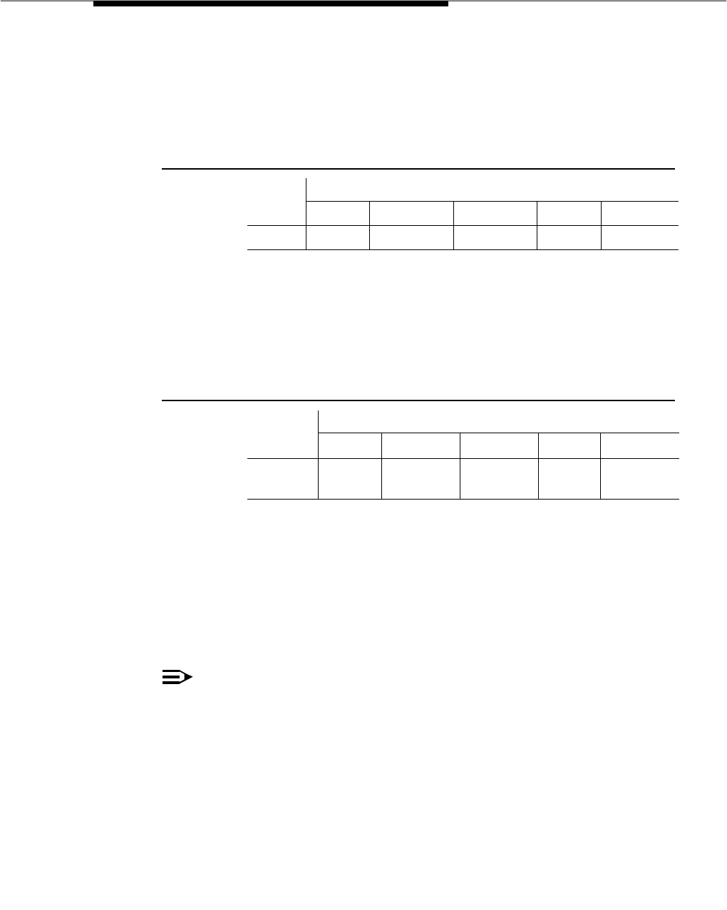
Basic Call Management System (BCMS)
Issue 3 March 1996 3-263
answer is recorded to the statistics for split 4. However, no inflow is
recorded to the statistics for split 4. This scenario is shown in the
following table.
If the call is answered on split 5, an outflow is recorded for the
statistics to split 4, and both an inflow and an answer are recorded
to the statistics for split 5. This scenario is shown in the following
table.
Similarly, if a multiple queued call routes to another split, an outflow
is recorded to the statistics for the primary split, but no inflow is
recorded to the statistics for the routed-to split.
TOTAL AUX/OTHER — The total time that logged-in agents in this split were
unavailable to receive calls during the reporting interval. This value includes time
spent on non-ACD calls while in AUX for this split. This value does not include the
time agents spent on another split’s calls or in ACW for another split.
NOTE:
A split totals AUX/OTHER TIME whenever any agent logs into the split and:
■Receives a EXTN call while in AUX or AVAIL state
■Makes a EXTN call while in AUX or AVAIL state
■Hits his/her AUX button
■Other
Furthermore, the split report measurement AUX TIME is time-interval
based, since it is not directly related to a call. For example, if an agent is in
AUX for any of the previously identified reasons from 9:55 to 10:05, then
five minutes is pegged in the 9:00 to 10:00 time interval and five minutes is
pegged in the 10:00 to 11:00 time interval.
Table 3-17. Call Answered by Primary Split After a Route to
VDN
Split Pegging
Split 1 Split 2 Split 3 Split 4 Split 5
BCMS outflow dequeued dequeued answer dequeued
Table 3-18. Call Answered by Non-Primary Split After a Route
to VDN
Split Pegging
Split 1 Split 2 Split 3 Split 4 Split 5
BCMS outflow dequeued dequeued outflow inflow
answered

Feature Descriptions
3-264 Issue 3 March 1996
If you perform these calculations for each agent within a split and total them —
the calculated number should generally be the same as displayed on the split
report. However, because of differences in how the agent and split reports
handle EXTN calls you may (occasionally) see different numbers between the
two reports.
AVG STAFF — The average number of agents who were logged into this split
(staffed) during the reporting interval.
% IN SERV LEVL — The percentage of calls answered within the administered
service level.
where
accepted is calls answered whose queue time was less than or equal to the
administered service level for the split
dequeued is a call that encountered the split’s queue, but that was NOT
answered, abandoned, or outflowed. This occurs with multiple split queuing.
SUMMARY — For those columns that specify averages, the summary is an
average for the entire reporting interval. For the ACD CALLS, ABAND CALLS,
TOTAL AFTER CALL, FLOW IN, FLOW OUT, AUX TIME, and TOTAL HOLD TIME
columns, the summary is the sum of individual time intervals or specified days.
BCMS Trunk Group Report
The BCMS Trunk Group Report gives statistical information for all BCMS trunk
groups. The BCMS Trunk Group Report may be used by the ACD administrator
and/or manager to monitor use of the trunk group and to determine the optimal
number of trunks for the trunk group. Depending on specifics from the command
line, the information may be displayed as either a time interval or a daily
summary. If neither ‘‘time’’ nor ‘‘day’’ is specified, ‘‘time’’ is the default. In this
case, the report displays data accrued for the previous 24 time intervals (hour or
half-hour), including data from the most recently completed time interval. The
next two screens show the BCMS Trunk Group Time Interval Report and the
BCMS Trunk Group Daily Report.
NOTE:
When analyzing this report, keep the following things in mind:
AVG STAFF =Time Interval
Total Sta ff Time
_ ______________
%IN SERV LEVL =ACD calls +abandons +out f lows +dequeued
Accepted *100
_ _________________________________________

Basic Call Management System (BCMS)
Issue 3 March 1996 3-265
■All averages are for completed calls only.
■A completed call may span more than one time interval. ACD calls
that are in process (have not terminated) are counted in the time
interval in which they terminate. For example, if an ACD call begins
in the 10:00 to 11:00 time interval, but terminates in the 11:00 to
12:00 time interval, the data for this call is counted in the 11:00 to
12:00 time interval.
■Asterisks in a field indicate that the maximum for that field has been
exceeded.
■A single asterisk at the end of a time or date field indicates that
during the interval, trunk group administration occurred that
changed the number of trunks.
Screen 3-19. BCMS Trunk Group Time Interval Report
list bcms trunk 1 time 8:00 11:00
BCMS TRUNK GROUP REPORT
Switch Name: Lab Model Date: 12:59 pm THU APR 20, 1995
Group: 1
Group Name: TG 1 Number of Trunks: 11
| INCOMING | OUTGOING |%ALL %TIME
TIME |CALLS ABAND TIME CCS | CALLS COMP TIME CCS|BUSY MAINT
8:00- 9:00* 23 2 2:15 31.02 1 1 1:36 .96 0 0
9:00-10:00 35 2 1:48 35.74 4 4 1:42 4.08 0 0
10:00-11:00 24 1 1:40 22.93 0 0 :00 .00 0 0
----------- ----- ---- ------ -------- ----- ---- ------ ------ --- ---
SUMMARY 82 5 1:54 29.89 5 5 1:39 2.52 0 0

Feature Descriptions
3-266 Issue 3 March 1996
Screen 3-20. BCMS Trunk Group Daily Report
Report Headers, Abbreviations, and
Their Definitions
This report presents header information at the top of each page. This information
includes the command entered to generate the report, the page number of the
report, the title of the report, and the time and date the report was generated. If
this is a time interval report and there are more than 11 time intervals, this report
is displayed on multiple pages. A daily summary report is displayed on one
page.
Group — The trunk group number specified with the command line.
Group Name — The name that is administered for this trunk group. If no name is
administered, then this field is displayed as blank.
Number of Trunks — The number of individual trunks in the trunk group at the
end of the first interval being reported.
TIME/DAY — The time or day interval specified in the command line.
Time is always expressed in 24-hour format. Start and stop times are optional.
Reports always start at the top of the time interval (either hour or half-hour). If no
start time is given, the report displays data accrued for the previous 24 time
intervals. A stop time requires an associated start time. If no stop time is given,
the last completed time interval (hour or half-hour) is the default. If no start time or
stop time is given, the report displays data accrued for the previous 24 time
intervals. If you specify ‘‘day’’ in the command and do not include a start day or
stop day, the report displays data accrued for the previous six days and data
accrued through the most recently completed interval (hour or half-hour).
list bcms trunk 1 day 4/17
BCMS TRUNK GROUP REPORT
Switch Name: Lab Model Date: 12:59 pm THU APR 20, 1995
Group: 1
Group Name: TG 1 Number of Trunks: 11
| INCOMING | OUTGOING |%ALL %TIME
DAY |CALLS ABAND TIME CCS | CALLS COMP TIME CCS|BUSY MAINT
4/17/95* 82 5 1:54 29.89 5 5 1:39 2.52 0 0
----------- ----- ---- ------ -------- ----- ---- ------ ------ --- ---
SUMMARY 82 5 1:54 29.89 5 5 1:39 2.52 0 0

Basic Call Management System (BCMS)
Issue 3 March 1996 3-267
If switch administration causes the number of trunks in a BCMS-measured trunk
group to change during a day or a time interval, an asterisk appears in the
‘‘DAY/TIME’’ field.
INCOMING CALLS — The total number of incoming calls carried by this trunk
group.
INCOMING ABAND — The number of incoming calls that queued to ACD splits,
then abandoned (without being answered by a staffed agent within this split)
during the reporting interval. Calls that cannot queue (for example, queue full, or
calls that receive a busy signal from the Central Office because there aren’t any
available trunks) are not included in the INCOMING ABAND number. Also
included are calls directly to staffed ACD agents that are unanswered.
INCOMING TIME — The average holding time for incoming calls to this trunk
group during the specified reporting interval. Holding time is defined as the
length of time in minutes and seconds that a facility is used during a call. The
calculation for incoming time is:
INCOMING CCS — The total holding time (usage) for incoming calls to the trunk
group during the specified reporting interval. The units are expressed in hundred
call seconds (CCS). Refer to the Glossary for a description of the term CCS or
hundred call seconds.
OUTGOING CALLS — The total number of outgoing calls for this trunk group
during the specified reporting interval.
OUTGOING COMP — The total number of outgoing calls that were placed over
this trunk group and answered during the specified reporting interval.
NOTE:
Completion is determined by either return of network answer supervision, or
a call that lasts longer than the answer supervision time-out parameter;
whichever occurs first.
OUTGOING TIME — The average holding time for outgoing calls during the
specified reporting interval. The calculation is:
OUTGOING CCS — The total holding time for outgoing calls from this trunk
group. The units are expressed in CCS.
INCOMING TIME =Total Number o f Incoming Calls
Total Holding Time for all Incoming Calls
_ ___________________________________
_
OUTGOING TIME =Total Number o f Outgoing Calls
Total Holding Time for Outgoing Calls
_ ________________________________
_

Feature Descriptions
3-268 Issue 3 March 1996
% ALL BUSY — The percentage of time that all the trunks in this trunk group
were busy. This value includes trunks that are maintenance busy. The calculation
is:
where Busy Times is expressed in minutes and is the sum of all times when all
trunks were simultaneously busy.
% TIME MAINT — The percentage of time that one or more trunks have been
busied-out for maintenance purposes. The calculation is:
where:
■Total Maintenance Busy Time is the sum of Maintenance Busy Time (in
minutes) for all trunks (individually) in this trunk group during this interval
■Time Interval is expressed in minutes (for example,
30
if using a half-hour
interval,
60
if using a one-hour interval, and
1440
if using a daily summary)
NOTE:
For reporting purposes, call data is stored during the time interval
(hour or half-hour) that the trunk goes idle, not when the station
releases. Also, changing the number of trunks in a trunk group can
cause unexpected results for that interval.
BCMS Trunk Group Summary Report
The BCMS Trunk Group Summary Report provides information about
BCMS-measured trunk groups. You can specify the trunk groups you want
included in the report. The BCMS Trunk Group Report can be used by the ACD
administrator and/or manager to monitor use of one or more trunk groups and to
determine the optimal number of trunks for the trunk groups. Note that this
applies only to trunk groups measured by BCMS.
This report is similar to the BCMS Trunk Group Report except that the information
for a trunk appears on separate lines of the report, with totals of activity for all
trunks in the trunk group for the specified time. You can specify up to 30 trunk
groups. You can print the report for a certain time period specified in either hours
or days (up to 7 days).
The report displays only the information that exists and does not identify absent
data. If data does not exist for a specified trunk group, the trunk group does not
%ALL BUSY =Time Interval
Total o f all Busy Times
_ _____________________ ×( 100 )
%TIME MAINT =Time Interval ×Number o f Trunks in Group
Total Maintenance Busy Time ×100
_ ______________________________________

Basic Call Management System (BCMS)
Issue 3 March 1996 3-269
appear on the report. Also, if information does not exist for a portion of the
specified time period, the report displays all existing information but does not
identify where there is no data. Screen 3-21 shows the BCMS Trunk Group
Summary Report for an interval of hours, and Screen 3-22 shows the BCMS
Trunk Group Summary Report for a daily interval.
NOTE:
When analyzing this report, keep the following things in mind:
■All averages are for completed calls only.
■Asterisks in a field indicate that the maximum for that field is
exceeded.
■A single asterisk at the end of a time or date field indicates that
during the interval, trunk group administration occurred that
changed the number of trunks.
Screen 3-21. BCMS Trunk Group Summary Report — Hourly
list bcms trunk sum 23-25 time 8:00
BCMS TRUNK GROUP SUMMARY REPORT
Switch Name: Lab Model Date: 12:59 pm THU APR 20, 1995
Time: 8:00-13:00
| INCOMING | OUTGOING |%ALL %TIME
GROUP NAME |CALLS ABAND TIME CCS | CALLS COMP TIME CCS|BUSY MAINT
IN-800 23 2 2:15 31.02 1 1 1:36 0.96 0 0
OUT-WATTS* 35 2 1:48 35.74 4 4 1:42 4.08 0 0
TIE-GROUP 24 1 1:40 22.93 0 0 :00 0.00 0 0
----------- ----- ---- ------ -------- ----- ----- ------ ------ --- ---
SUMMARY 82 5 1:54 29.89 5 5 1:39 2.52 0 0

Feature Descriptions
3-270 Issue 3 March 1996
Screen 3-22. BCMS Trunk Group Summary Report — Daily
Report Headers, Abbreviations, and
Their Definitions
This report presents header information at the top of each page. This information
includes the command entered to generate the report, the page number of the
report, the title of the report, and the time and date the report was generated.
TIME/DAY — The time or day interval specified in the command line. Time is
always expressed in 24-hour format. Start and stop times are optional. Reports
always start at the top of the time interval (either hour or half-hour). If no start time
is given, the report displays data accrued for the previous 24 time intervals. A
stop time requires an associated start time. If no stop time is given, the last
completed time interval (hour or half-hour) is the default. If no start time or stop
time is given, the report displays data accrued for the previous 24 time intervals.
If you specify ‘‘day’’ in the command and do not include a start day or stop day,
the report displays data accrued for the previous six days and data accrued
through the most recently completed interval (hour or half-hour).
If switch administration causes the number of trunks in a BCMS-measured trunk
group to change during a day or a time interval, an asterisk appears in the
‘‘DAY/TIME’’ field.
GROUP NAME — The name that is administered for this trunk group. If no name
is administered, this field is displayed as blank.
INCOMING CALLS — The total number of incoming calls carried by this trunk
group.
INCOMING ABAND — The number of incoming calls that queued to ACD splits,
then abandoned (without being answered by a staffed agent within this split)
during the reporting interval. Calls that cannot queue (for example, queue full, or
calls that receive a busy signal from the central office because there are no
available trunks) are not included in the INCOMING ABAND number. Also
included are calls directly to staffed ACD agents that are unanswered.
list bcms trunk sum 23 day 4/20/95
BCMS TRUNK GROUP SUMMARY REPORT
Switch Name: Lab Model Date: 12:59 pm THU APR 20, 1995
Day: 5/17/95
| INCOMING | OUTGOING |%ALL %TIME
GROUP NAME |CALLS ABAND TIME CCS | CALLS COMP TIME CCS|BUSY MAINT
IN-800* 82 5 1:54 29.89 5 5 1:39 2.52 0 0
----------- ----- ---- ------ -------- ----- ----- ------ ------ --- ---
SUMMARY 82 5 1:54 29.89 5 5 1:39 2.52 0 0

Basic Call Management System (BCMS)
Issue 3 March 1996 3-271
INCOMING TIME — The average holding time for incoming calls to this trunk
group during the specified reporting interval. Holding time is defined as the
length of time in minutes and seconds that a facility is used during a call. The
calculation for incoming time is:
INCOMING CCS — The total holding time (usage) for incoming calls to the trunk
group during the specified reporting interval. The units are expressed in hundred
call seconds (CCS). Refer to the Glossary for a description of the term CCS or
hundred call seconds.
OUTGOING CALLS — The total number of outgoing calls for this trunk group
during the specified reporting interval.
OUTGOING COMP — The total number of outgoing calls that were placed over
this trunk group and answered during the specified reporting interval.
NOTE:
Completion is determined by either return of network answer supervision, or
a call that lasts longer than the answer supervision time-out parameter;
whichever occurs first.
OUTGOING TIME — The average holding time for outgoing calls during the
specified reporting interval. The calculation is:
OUTGOING CCS — The total holding time for outgoing calls from this trunk
group. The units are expressed in CCS.
% ALL BUSY — The percentage of time that all the trunks in this trunk group
were busy. This value includes trunks that are maintenance busy. The calculation
is:
where
Busy Times is expressed in minutes and is the sum of all times when all trunks
were simultaneously busy.
INCOMING TIME =Total Number o f Incoming Calls
Total Holding Time for all Incoming Calls
_ __________________________________
OUTGOING TIME =Total Number o f Outgoing Calls
Total Holding Time for Outgoing Calls
_ ________________________________
%ALL BUSY =Time Interval
Total o f all Busy Times
_ _____________________ ×( 100 )

Feature Descriptions
3-272 Issue 3 March 1996
% TIME MAINT — The percentage of time that one or more trunks have been
busied-out for maintenance purposes. The calculation is:
where
■Total Maintenance Busy Time is the sum of Maintenance Busy Time (in
minutes) for all trunks (individually) in this trunk group during this interval
■Time Interval is expressed in minutes (for example,
30
if using a half-hour
interval,
60
if using a one-hour interval, and
1440
if using a daily summary)
NOTE:
For reporting purposes, call data is stored during the time interval
(hour or half-hour) that the trunk goes idle, not when the station
releases. Also, changing the number of trunks in a trunk group can
cause unexpected results for that interval.
BCMS VDN Report
The BCMS VDN Report provides statistical information for the specified VDN.
Depending on specifics from the command line, the information may be
displayed as either a time interval or a daily summary. If neither ‘‘time’’ nor ‘‘day’’
is specified, ‘‘time’’ is the default. In this case, the report displays data accrued
for the previous 24 time intervals (hour or half-hour), including data from the most
recently completed interval. The next two screens show the VDN Number Report
— Hourly and the VDN Number Report — Daily.
NOTE:
When analyzing this report, keep the following things in mind:
■All averages are for completed calls only.
■A completed call may span more than one time period. ACD calls that are
in process (have not terminated) are counted in the time period in which
they terminate. For example, if an ACD call begins in the 10:00 to 11:00
time period, but terminates in the 11:00 to 12:00 time period, the data for
this call is counted in the 11:00 to 12:00 time period.
■Asterisks indicate that the maximum for the associated field has been
exceeded.
%TIME MAINT =Time Interval ×Number o f Trunks in Group
Total Maintenance Busy Time ×100
_ ______________________________________

Basic Call Management System (BCMS)
Issue 3 March 1996 3-273
Screen 3-23. BCMS VDN Report — Hourly
Screen 3-24. BCMS VDN Report — Daily
Report Headers, Abbreviations, and
Their Definitions
This report presents header information at the top of each page. This information
includes the command entered to generate the report, the page number of the
report, the title of the report, and the time and date the report was generated. If
this is a time report and there are more than 10 time intervals, this report is
displayed on multiple pages. A daily summary report is displayed on the last
page of the report.
VDN — The VDN specified with the command line.
list bcms vdn 12345 time 8:00 12:00
BCMS VECTOR DIRECTORY NUMBER REPORT
Switch Name: Lab Model Date: 11:05 am MON MAY 15, 1995
VDN: 12345
VDN Name: Ginsu Knives Acceptable Service Level: 17
AVG AVG AVG CALLS % IN
CALLS ACD SPEED ABAND ABAND TALK/ CONN FLOW BUSY/ SERV
TIME OFFERED CALLS ANSW CALLS TIME HOLD CALLS OUT DISC LEVL
08:00-09:00 79 50 :39 5 :45 2:30 0 0 24 85*
----------- ----- ----- ----- ----- ----- ----- ----- ---- ---- ---
SUMMARY 79 50 :39 5 :45 2:30 0 0 24 85
list bcms vdn 12345 day 5/14
BCMS VECTOR DIRECTORY NUMBER REPORT
Switch Name: Lab Model Date: 11:05 am MON MAY 15, 1995
VDN: 12345
VDN Name: Ginsu Knives Acceptable Service Level: 17
AVG AVG AVG CALLS % IN
CALLS ACD SPEED ABAND ABAND TALK/ CONN FLOW BUSY/ SERV
DAY OFFERED CALLS ANSW CALLS TIME HOLD CALLS OUT DISC LEVL
5/14/95 79 50 :39 5 :45 2:30 0 0 24 85*
----------- ----- ----- ----- ----- ----- ----- ----- ---- ---- ---
SUMMARY 79 50 :39 5 :45 2:30 0 0 24 85

Feature Descriptions
3-274 Issue 3 March 1996
VDN NAME — The name that is administered for this VDN. If no name exists, the
VDN extension (for example, EXT 64532) is displayed.
ACCEPTABLE SERVICE LEVEL — The desired time to answer the VDN.
Timing for a call begins when the VDN is encountered.
TIME/DAY — The time or day interval specified in the command line.
Time is always expressed in 24-hour format. Start and stop times are optional.
Reports always start at the earliest time interval (either hour or half-hour). If no
start time is given, the oldest time interval is the default. A stop time requires an
associated start time. If no stop time is given, the last completed time interval
(hour or half-hour) is the default. If no start or stop time is given, the report
displays data accrued for the previous 24 time intervals. If you specify ‘‘day’’ in
the command and do not include a start day or stop day, the report displays data
accrued for the previous six days and data accrued through the most recently
completed interval (hour or half-hour).
CALLS OFFERED — The total number of ended calls that accessed the VDN
during the current interval. This calculation is:
ACD CALLS — The total number of calls to the VDN that ended in the specified
interval and were answered by an agent in a BCMS-measured hunt group. ACD
calls include calls that reached the split via the queue-to-main, check backup,
route-to, messaging split, or adjunct routing commands.
AVG SPEED ANS — The average speed of answer for answered ACD and
CONNect calls that have ended for this VDN during the current period. This
includes time in vector processing, time in a split’s queue, and time ringing. This
calculation is:
NOTE:
A completed call can span more than one time period. ACD calls that are in
process (have not terminated) are counted in the time period in which they
terminate. For example, if an ACD call begins in the 10:00 to 11:00 time
period, but terminates in the 11:00 to 12:00 time period, the data for this call
is counted in the 11:00 to 12:00 time period.
ABAND CALLS — The total number of calls that have abandoned from the VDN
before being answered or outflowed to another position during the current
interval. This value includes calls that abandoned while in vector processing or
CALLS OFFERED =NUM ANS +FLOW OUT +CALLS BUSY / DISC +NUM ABAND
AVG SPEED ANS =Total ACD Calls +Total Connect Calls
Total Answer Time
_ __________________________________

Basic Call Management System (BCMS)
Issue 3 March 1996 3-275
while ringing an agent. Calls that abandoned immediately after the agent
answered are recorded as NUM ANS.
AVG ABAND TIME — The average time calls spent waiting in this VDN before
being abandoned by the caller during the current interval. The calculation is:
AVG TALK/HOLD TIME — The average duration of calls (from answer to
disconnect) for this VDN during the current interval. This includes time spent
talking and on hold. The calculation does not include ring time at an agent’s
voice terminal. The calculation is:
CONN CALLS — The number of ended calls that were routed to a station,
attendant, or announcement, and were answered there.
FLOW OUT — The total number of ended calls that were routed to another VDN
or to a trunk, including successful lookahead attempts.
FLOW OUT does not include calls that encounter a goto vector command.
Once a call outflows, the system does not take further measurements on the call
for this VDN. As a result, if an outflowed call later abandons, it is not recorded in
NUM ABAND for this VDN.
CALLS BUSY/DISC — The total number of calls that were forced busy or forced
disconnect during the current interval. This value does not include abandoned
calls.
% IN SERV LEVL — The percentage of calls that were answered with the
administered service level for this VDN. Calculate as the following:
where
accepted is the number of answered calls (
num ans
) whose answer time was
less than or equal to the administered service level for the VDN.
num ans
here
refers to the data item on the form of the same name.
AVG ABAND TIME =Total Number o f Abandoned VDN Calls
Total VDN Abandon Time
_ __________________________________
AVG TALK TIME =NUM ANS
Total VDN Talk / Hold Time
_ _______________________
%IN SERV LEVL =calls o ff ered
accepted * 100
_ _____________

Feature Descriptions
3-276 Issue 3 March 1996
calls offered the total number of completed calls that accessed the VDN during
the current interval.
This field is blank if no calls have been recorded for this time interval. This field is
also blank if no ‘‘Acceptable Service Level’’ is administered on the VDN form.
SUMMARY — For those columns that specify averages, the summary is also an
average for the entire reporting interval. For the TOTAL ATTEMPTS, NUM ANS,
NUM ABAND, FLOW OUT, and OTHER CALLS columns, the summary is the sum
of individual time intervals or specified days.
enter command:
prompt.
BCMS VDN Summary Report
This report is similar to the VDN Report except that you can specify up to 30
extensions to include in the report. Also, this report provides one line of data for
each VDN included in the report, and the one line includes all data for the
specified times. If no data exists for a VDN, the VDN does not appear on the
report.
Screen 3-25. BCMS VDN Summary Report — Hourly Summary
list bcms summary vdn 12345, 13443-13448 time 8:00-12:00
BCMS VECTOR DIRECTORY NUMBER SUMMARY REPORT
Switch Name: Lab Model Date: 11:05 am MON MAY 15, 1995
Time: 8:00-12:00
AVG AVG AVG CALLS % IN
CALLS ACD SPEED ABAND ABAND TALK/ CONN FLOW BUSY/ SERV
VDN NAME OFFERED CALLS ANSW CALLS TIME HOLD CALLS OUT DISC LEVL
EXT 13443 0 0 :00 0 :00 :00 0 0 0
EXT 13444 0 0 :00 0 :00 :00 0 0 0
EXT 13445 0 0 :00 0 :00 :00 0 0 0
EXT 13446 0 0 :00 0 :00 :00 0 0 0
EXT 13447 0 0 :00 0 :00 :00 0 0 0
EXT 13448 0 0 :00 0 :00 :00 0 0 0
Ginsu Knive 79 50 :39 5 :45 2:30 0 0 24 85*
----------- ----- ----- ----- ---- ----- ----- ----- ---- ---- ---
SUMMARY 79 50 :39 5 :45 2:30 0 0 24 85

Basic Call Management System (BCMS)
Issue 3 March 1996 3-277
Screen 3-26. BCMS VDN Summary Report — Daily Summary
Report Headers, Abbreviations, and
Their Definitions
This report presents header information at the top of each page. This information
includes the command entered to generate the report, the page number of the
report, the title of the report, and the time and date the report was generated. If
this is a time report and there are more than 10 time intervals, this report is
displayed on multiple pages. A daily summary report is displayed on the last
page of the report.
list bcms summary vdn 12345 day 5/14
BCMS VECTOR DIRECTORY NUMBER SUMMARY REPORT
Switch Name: Lab Model Date: 11:05 am MON MAY 15, 1995
Day: 5/14/95
AVG AVG AVG CALLS % IN
CALLS ACD SPEED ABAND ABAND TALK/ CONN FLOW BUSY/ SERV
VDN NAME OFFERED CALLS ANSW CALLS TIME HOLD CALLS OUT DISC LEVL
Ginsu Knives 79 50 :39 5 :45 2:30 0 0 24 85*
----------- ----- ----- ----- ---- ----- ----- ----- ---- ---- ---
SUMMARY 79 50 :39 5 :45 2:30 0 0 24 85

Feature Descriptions
3-278 Issue 3 March 1996
TIME/DAY — The time or day interval specified in the command line.
Time is always expressed in 24-hour format. Start and stop times are optional.
Reports always start at the earliest time interval (either hour or half-hour). If no
start time is given, the oldest time interval is the default. A stop time requires an
associated start time. If no stop time is given, the last completed time interval
(hour or half-hour) is the default. If no start or stop time is given, the report
displays data accrued for the previous 24 time intervals. If you specify ‘‘day’’ in
the command and do not include a start day or stop day, the report displays data
accrued for the previous six days and data accrued through the most recently
completed interval (hour or half-hour).
VDN NAME — The name that is administered for this VDN. If no name exists, the
VDN extension (for example, EXT 64532) is displayed.
CALLS OFFERED — The total number of completed calls that accessed the
VDN during the current interval. This calculation is:
where OTHER CALLS are calls classified as forced busy or forced disconnect.
ACD CALLS — The total number of calls to the VDN that ended in the specified
interval and were answered by an agent as a result of a queue to main or check
backup split step.
AVG SPEED ANS — The average time that calls spend in a vector before being
connected as an ACD call to an agent (for example, via a queue to the main split
or check backup step) during the current interval. This includes queue time and
time ringing at an agent’s station. This calculation is:
NOTE:
A completed call may span more than one time period. ACD calls that are
in process (have not terminated) are counted in the time period in which
they terminate. For example, if an ACD call begins in the 10:00 to 11:00
time period, but terminates in the 11:00 to 12:00 time period, the data for
this call is counted in the 11:00 to 12:00 time period.
ABAND CALLS — The total number of calls that have abandoned from the VDN
before being answered or outflowed to another position during the current
interval. This value includes calls that abandoned while in vector processing or
while ringing an agent. Calls that abandoned immediately after the agent
answered are recorded as NUM ANS.
CALLS OFFERED =NUM ANS +FLOW OUT +OTHER CALLS +NUM ABAND
AVG TIME TO CONNECT =NUM ANS
Total Time Calls spend in VDN be f ore being answered
_ _______________________________________________

Basic Call Management System (BCMS)
Issue 3 March 1996 3-279
AVG ABAND TIME — The average time calls spent waiting in this VDN before
being abandoned by the caller during the current interval. The calculation is:
AVG TALK/HOLD TIME — The average duration of calls (from answer to
disconnect) for this VDN during the current interval. This includes time spent
talking and on hold. The calculation does not include ring time at an agent’s
voice terminal. The calculation is:
CONN CALLS — The number of calls that were routed to a station, attendant, or
announcement, and were answered there.
FLOW OUT — The total number of calls that were routed to another VDN or to a
trunk.
FLOW OUT does not include calls that encounter a goto vector command or
calls that forward to another extension (which are tracked as CONNected
CALLS).
Once a call outflows, the system does not take further measurements on the call
for this VDN. As a result, if an outflowed call later abandons, it is be recorded in
NUM ABAND for this VDN.
CALLS BUSY/DISC — The total number of calls that were forced busy or forced
disconnect during the current interval. This value does not include abandoned
calls.
% IN SERV LEVL — The percentage of calls that were answered with the
administered service level for this VDN. Calculate as the following:
where
accepted is the number of answered calls (
num ans
) whose answer time was
less than or equal to the administered service level for the VDN.
num ans
here
refers to the data item on the form of the same name.
AVG ABAND TIME =Total Number o f Abandoned VDN Calls
Total VDN Abandon Time
_ __________________________________
AVG TALK TIME =NUM ANS
Total VDN Talk / Hold Time
_ _______________________
%IN SERV LEVL =calls o ff ered
accepted * 100
_ _____________

Feature Descriptions
3-280 Issue 3 March 1996
calls offered the total number of completed calls that accessed the VDN during
the current interval.
SUMMARY — For those columns that specify averages, the summary is also an
average for the entire reporting interval. For the TOTAL ATTEMPTS, NUM ANS,
NUM ABAND, FLOW OUT, and OTHER CALLS columns, the summary is the sum
of individual time intervals or specified days.
Considerations
BCMS provides a set of internal switch measurement reports for telemarketing
centers or customer service centers. These reports can help in managing ACD
splits (hunt groups) without the need for an adjunct CMS.
The maximum number of measured agents for the BCMS feature is limited to 200
(Generic 3). An agent can be a member of up to three splits, but is treated as a
single agent. An agent can be assigned to as many splits as you like, but the
agent can only log into three splits at most.
The maximum number of CMS measured agents (both basic and adjunct) is
restricted to 400. Agents in multiple splits are counted as one for each split that
he or she is assigned.
The maximum number of internally measured trunk groups is limited to 32
(Generic 3).
The maximum number of internally measured splits is limited to 99 (Generic 3). If
a split is assigned more than 200 agents in Generic 3, it cannot be measured
internally.
A maximum of 25 time intervals are allocated for storing data. A time interval can
be either a one-hour or a one-half hour interval.
A maximum of seven summary days is stored for each historical report.
The maximum number of internally measured trunk group members is limited to
400.
The addition of an EPN can affect the operation of the measurements only when
the EPN is unavailable. Any resource that resides in the EPN cabinet is not
available for use or for measurement data. If a remote Management Terminal
connected to the EPN and the fiber link goes down, the Management Terminal
session is dropped and the login prompt appears.
Interactions
The following features interact with the BCMS feature:

Basic Call Management System (BCMS)
Issue 3 March 1996 3-281
■Call Coverage
Calls extended to a BCMS measured split as a coverage point are treated
like new incoming calls to that split. These calls increment the FLOW IN
field on the BCMS Split report, provided they were covered from the
queue of another BCMS measured split. Calls successfully going to a
coverage point from a BCMS measured split are included in the FLOW
OUT field on the BCMS Split report. Again, those calls must have first
been in queue for the split. Calls that cover due to the split queue being
full do not cause the FLOW OUT field to be incremented
■Call Forwarding
Calls forwarded to a BCMS measured split from an extension are treated
like new incoming calls to that split. INFLOW and OUTFLOW counts are
not affected.
If a split’s calls are forwarded, inflow and outflow apply. An agent’s call
forwarding does not forward ACD calls.
■Call Pickup
Calls answered using the call pickup feature are treated as non-ACD calls
(EXTN IN) for the agent picking up the call. ACD calls that are picked up
for a BCMS measured agent are included in the FLOW OUT column on the
BCMS Split report.
■Call Vectoring
With Call Vectoring, calls can be queued to up to three splits. ACD call
count are pegged to the answering split. Abandoned calls, outflows, and
disconnects are credited to the first (primary) split. If a call that is queued
for three splits is answered by the second or third split, BCMS records an
outflow for the primary split, both an answer and inflow for the answering
split, and nothing for the other split (the split that is neither the answering
split nor the primary split).
■Conference/Transfer
When an agent conferences or transfers an ACD call, the agent is credited
with an ACD call and an ExtnOut call.
■EAS
BCMS does not use LoginIDs. Tracking for agents is done strictly on
physical extensions. Therefore if multiple agents use a single phone
(different shifts) the data is combined for these agents and accessed via
an extension number.
■Hunt Groups
The BCMS measurements are not determined in the same way as hunt
group measurements although some of the information is similar.
Therefore, the two reports may represent the data differently.

Feature Descriptions
3-282 Issue 3 March 1996
■Move Agents From CMS
If agents are moved from one split to another split by the CMS adjunct,
measurements are stopped for the agent’s “from” split and started for the
agent’s “to” split. Generic 3 denies agent move requests when agents are
logged in (staffed). This denial is important since it eliminates
measurement complications associated with move requests when the
agent is on an ACD call. Move requests are also denied if the agent is
being moved into an unmeasured split.
If the adjunct CMS attempts to move an agent that is not being measured
by BCMS into a split that is being measured by BCMS, and the move
would exceed the maximum of 30 measured agents, the switch rejects the
move. Otherwise, internal BCMS measurements are started for the agent.
If the adjunct CMS moves an agent from a split that is measured by BCMS
to a split that is not BCMS measured, internal measurements for the agent
are stopped.
■Night Service
When night service is activated for a split, new calls go to an alternate
destination. The split in night service does not consider these calls to be
OUTFLOW. The calls are treated as new incoming calls if the destination is
a measured split (that is, they are not considered INFLOW).
■System Measurements
DEFINITY Communications System Generic 3 can have BCMS reports,
adjunct CMS reports, and switch traffic measurements simultaneously.
The BCMS measurements are not determined in the same way as trunk
group measurements although some of the information is similar.
Therefore, the two reports may represent data differently.
Administration
The BCMS is administered by the System Administrator. The following items
require administration:
■Communication Interfaces
If the link to the adjunct CMS has been administered, CMS measurements
must be busied-out (busyout sp-link command) in order to
add/remove adjunct CMS and BCMS measured agents or trunks to the
switch. When the “busyout” has been released, adjunct CMS checks for
translation changes and, if they exist, the current database is updated and
measurements are restarted.
If the link has not been administered (BCMS measurements only), the
busyout sp-link command is not required to change translation data.
■Hunt Group and Trunk Group
The measured field on the Hunt Group and Trunk Group forms should be
administered as one of the following:

Basic Call Management System (BCMS)
Issue 3 March 1996 3-283
— internal—Measured by BCMS only
— external—Measured by CMS adjunct only
— both—Measured by both BCMS and the adjunct CMS
— none—Not measured (default)
If BCMS has not been administered in customer options, neither “internal”
not “both” is allowed. If the split or trunk group is measured by BCMS only,
the busyout sp-link command is not required to make changes.
Measurements can be turned off for a split while agents are logged in, but
agents must be logged off to start measurements.
■System Administration
The BCMS field must be set to
y
by an authorized AT&T employee.
■System-Parameters
The following items require administration:
— Measurement interval—Specifies what time interval is used for
polling and reporting measurement data. The time can be specified
by hour or half-hour intervals with “hour” as the default. There is a
maximum of 25 time slots available for measurement intervals. If
hourly is specified, an entire day of traffic information is available
for history reports; otherwise, only half a day is available. This does
not affect daily summaries as they always reflect traffic information
for the entire day. The interval may be changed anytime, but does
not go into effect until the top of the hour.
— Printer information for the system printer—This includes the printer
extension, EIA device bit rate, and lines per page.
Hardware and Software Requirements
No additional hardware is required to support the BCMS feature. However, a
customer may decide to use an asynchronous system printer to obtain hard
copies of BCMS history reports. The system printer can be interfaced to the
switch through the EIA port on the processor board or through any of the
alternate data interfaces such as PDMs connected to a digital port, or ADUs
connected to a data line circuit port.
BCMS software is required.

Feature Descriptions
3-284 Issue 3 March 1996
Bridged Call Appearance—
Multi-Appearance Voice Terminal
Feature Availability
Bridged Call Appearance—Multi-Appearance Voice Terminal is available with all
Generic 3 releases. Bridging enhancements available only with G3V4 and later
releases are identified throughout this feature description.
Description
The appearance of a voice terminal’s primary extension number at another voice
terminal is called a bridged call appearance. To set up a bridged call
appearance, the primary extension and the button number associated with it is
administered on any two-lamp button on the bridging station voice terminal.
The Bridged Call Appearance feature is used by lifting the handset and pressing
the Bridged Appearance button. The user is then bridged onto the other voice
terminal’s primary extension number and can handle calls on that extension
number. The bridged appearance can be used to originate calls from, and
answer calls to, the other voice terminal’s primary extension number. The user
can also bridge onto an existing call to or from the other voice terminal.
An incoming call rings the primary extension number’s voice terminal and all
voice terminals that have a bridged call appearance of the voice terminal’s
primary extension number. Each voice terminal is visually alerted for all bridged
appearances on the voice terminal, but has the option of audible ringing.
NOTE:
See the "Ringing — Abbreviated and Delayed" feature for other bridged
appearance alerting option.
A bridged call appearance can be assigned to any two-lamp button. It does not
require the use of a regular call appearance. A bridged call appearance can be
used just like a regular call appearance for most features. For example, the
Conference, Transfer, Hold, Drop, and Priority Calling features can be used from
a bridged appearance, just as they would be used from a regular call
appearance.
G3V4 and later releases allow for the administration of a voice terminal with zero
call appearances of its primary extension. In this way, a voice terminal can be
administered to have only bridged appearances.

Bridged Call Appearance— Multi-Appearance Voice
Terminal
Issue 3 March 1996 3-285
Extension Administrable Buttons and Lamps
With G3V4 and later releases, the Message lamp and certain feature buttons can
be administered to apply to a specified extension rather than the extension of the
terminal they reside on.
■The Message lamp can be administered to light when messages are
waiting for the extension specified on the station form. In this way, the
bridged user’s terminal can be set up to indicate when messages are
waiting for the primary extension.
■The Call Forwarding All Calls and Call Forwarding Busy/Don’t Answer
buttons can be administered to activate call forwarding for any extension
that is on the voice terminal even if this extension is a bridged
appearance. In addition, the lamp associated with the call forwarding
button can be administered to track the call forwarding status of any
extension. In this way, a bridged user cannot only activate or deactivate
call forwarding for all primary and bridged appearances of the extension
from the bridged appearance terminal, but the bridged appearance
terminal will show the call forwarding status of the specified extension.
■The Send All Calls button can be administered to activate Send All Calls
for any administered extension. In addition, the lamp associated with Send
All Calls tracks the status of the administered extension. In this way, a
bridged user can activate Send All Calls for the primary extension user.
Sample Applications
The Bridged Call Appearance feature allows calls to be handled from more than
one voice terminal. Some practical uses of this capability are as follows:
■A secretary making or answering calls on an executive’s primary
extension
These calls can be placed on hold for later retrieval by the executive, or
the executive can simply bridge onto the call. In all cases, the executive
handles the call as if he or she had placed or answered the call. It is never
necessary to transfer the call to the executive.
■A secretary taking care of details for an executive who is already active on
a call
A secretary can bridge onto an active call and take down information such
as an address or telephone number.
■Visitor telephones
An executive may have another voice terminal in his or her office that is to
be used by visitors. It may be desirable that the visitor be able to bridge
onto a call which is active on the executive’s primary extension number. A
bridged call appearance makes this possible.

Feature Descriptions
3-286 Issue 3 March 1996
■Service environments
It may be necessary that several people be able to handle calls to a
particular extension number. For example, several users may be required
to answer calls to a hot line number in addition to their normal functions.
Each user may also be required to bridge onto existing hot line calls. A
bridged call appearance provides this capability.
■A user frequently using voice terminals in different locations
A user may not spend all of his or her time in the same place. For this type
of user, it is convenient to have his or her extension number bridged at
several different voice terminals.
■Executive suite environments
With G3V4 and later releases, terminals can be administered with zero call
appearances of their primary extension number. When this feature is
combined with extension administrable buttons and lamps, it is possible to
administer several nearly identical phones for one office suite. The user
can then operate his or her voice terminal the same way regardless of
which voice terminal is being used.
Security
G3V4 and later releases provide a system option that prohibits bridged terminals
from bridging on to a call when the call has Data Privacy or Data Restriction
enabled.
Considerations
A voice terminal’s primary extension number can have an appearance on up to
seven (15 for G3r) other voice terminals. The number of bridged call
appearances allowed at each voice terminal is limited only by the number of
two-lamp buttons available on the voice terminal.
Up to six parties can be off-hook and involved in a conversation on a bridged
appearance of an extension.
It is recommended that a bridging voice terminal have a bridged call
appearance corresponding to each call appearance of the primary extension
number at the bridged voice terminal. For example, if a primary voice terminal
has three call appearances, then a bridging voice terminal should have three
bridged call appearances of that primary extension. This allows users to refer to
the individual call appearances when talking about a specific call.
Bridged call appearances may result in the reduction of available feature
buttons, thereby reducing a user’s capabilities. A Call Coverage module or
expansion module can be used to provide up to 20 bridged call appearances.

Bridged Call Appearance— Multi-Appearance Voice
Terminal
Issue 3 March 1996 3-287
This leaves the other two-lamp buttons as call appearances, or with other
features such as CAS.
If a call terminates at a voice terminal on an extension number other than the
primary extension number (for example, Terminating Extension Group, UCD
Group, Call Coverage Answer Group, or DDC Group extension number), a
bridged call appearance is not maintained. Therefore, it is recommended that
the primary terminal not be made a member of such a group (even though
administration of this is not prohibited).
The Bridged Call Appearance feature should not be considered as a
replacement for Call Coverage.
For G3V2 and later releases, a conference tone can be administered. If the
conference tone is enabled, a conference tone is heard when two parties are
bridged together on an active call with a third party.
Interactions
The following features interact with the Bridged Call Appearance—
Multi-Appearance Voice Terminal feature.
■Abbreviated Dialing
A user, accessing Abbreviated Dialing while on a bridged call
appearance, accesses his or her own Abbreviated Dialing lists. The user
does not access the Abbreviated Dialing lists of the primary extension
associated with the bridged call appearance. This is true even when the
voice terminal has no appearances of its primary extension.
■Attendant Display and Voice Terminal Display
A call from the primary extension number or from a bridged call
appearance of the primary extension number is displayed as a call from
the primary extension number (that is, the call is displayed as coming from
the primary extension number regardless of which appearance placed the
call).
The display at a principal will show the same information for a bridged call
appearance as it would for a non-bridged call. For calls to the principal’s
extension number, the display at a zero call appearance bridging station
shows a call from the originator to the principal with no “redirection
reason” character. As stations bridge onto the call, the display updates to
show the number of parties in the conference.
■Automatic Callback
Automatic Callback calls cannot originate from a bridged call
appearance. However, when Automatic Callback has been activated from
the principal user’s station, the Callback call rings (with priority call

Feature Descriptions
3-288 Issue 3 March 1996
distinctive ringing signal) at all bridged appearances of the extension as
well as at the principal user’s station. Displays at all (principal and bridged
users) stations show that it is a Callback call.

Bridged Call Appearance— Multi-Appearance Voice
Terminal
Issue 3 March 1996 3-289
■Automatic Call Distribution (ACD)
ACD directs calls only to the primary extension, not to bridged
appearances of the primary extension. Furthermore, if a bridged
appearance is active, the primary is considered active and no calls are
directed to the primary from the ACD group (unless administered for
Multiple Call Handling).
■Intercom—Automatic and Intercom—Dial
Bridged appearances of a primary extension number are not rung for
intercom calls. Furthermore, if a station has no primary call appearances it
can never be rung for an intercom call. Therefore, if a secretary is
screening all calls for the principal, and is indicating who is calling via
intercom, the principal must have a call appearance on which to receive
and send intercom calls.
■Call Coverage
Coverage criteria for bridged call appearances is based entirely on the
criteria of the primary extension associated with bridged appearance.
That is, a call to the primary extension that requires call coverage
treatment follows the coverage path of the primary extension and not the
path of any of the bridged appearances. Bridged call appearances do not
receive redirection notification.
A user with bridged call appearances can activate or deactivate Send All
Calls for a principal’s primary call appearance.
It is recommended that the primary terminal not be a member of a call
coverage group, because calls to the primary terminal as a member of the
group are not bridged.
With G3V4 and later releases, the system can be administered so that a
call can appear at a terminal as both a bridged call and a redirected call.
In this way, if the bridged user is the first coverage point the call will
redirect to that terminal when the coverage criteria are met.
With G3V3 and earlier releases, if the principal is an analog voice terminal
with a bridged call appearance on a multi-appearance voice terminal, an
incoming call to the analog voice terminal that goes to coverage will
terminate at a primary call appearance on the bridging user’s voice
terminal as a coverage call. the call is dropped from the analog voice
terminal and the bridged call appearance on the bridging user’s voice
terminal. In G3V4, if the bridging user is a zero primary call appearance
voice terminal, the call cannot redirect to the bridging user since there are
no primary call appearances. Therefore, the call will redirect to the next
available coverage point.
■Call Detail Recording (CDR)
If a bridging user originates and/or answers a call on a bridged
appearance, the extension of the bridge is recorded as the calling/called
terminal. A conference or transfer by a bridging user also appears as
though it was performed by the terminal user.

Feature Descriptions
3-290 Issue 3 March 1996
When a call originated from a bridged call appearance on a terminal
administered for zero primary call appearance is recorded by CDR, the
extension number associated with the appearance is recorded as the
calling party. A conference or transfer by a bridged call appearance on a
zero primary call appearances terminal also appears as though it were
performed by the extension associated with the appearance.
■Call Forwarding All Calls
Call Forward Busy/Don’t Answer
Call Forwarding can be activated or canceled for the primary extension
number from any bridged call appearance of that number; when
activated, calls to the primary extension number do not terminate at the
bridged call appearances, but go to the designated forwarding
destination. Bridged call appearances do not receive redirection
notification of the call to the primary extension when it is forwarded unless
Ringing — Abbreviated and Delayed is administered.
■Call Park
When a call is parked from a bridged call appearance, it is parked on the
primary extension number associated with the bridged appearance.
■Call Pickup
If a voice terminal receives ringing on a bridged call appearance, the
incoming call can be picked up by members of that voice terminal’s Call
Pickup group. This causes all bridged call appearances to be dropped.
Calls ringing at a primary terminal can be picked up by members of the
terminal’s Call Pickup group. However, if the primary terminal and the
bridging user’s primary terminal are not in the same Call Pickup group,
then the bridging user cannot pick up calls to other members of the
primary terminal’s Call Pickup group.
Originating on a bridged appearance and dialing the Call Pickup FAC is
interpreted as an attempt to pick up a call from the primary terminal’s Call
Pickup group.
A bridging user can use Call Pickup to pick up a call that is alerting at a
bridged appearance, instead of selecting the bridged appearance button.
This causes the call to terminate on the bridging user’s primary extension
button, and the primary terminal and all bridged appearances of the call
are dropped.
If the bridging user has appearances of numerous terminals (for example,
Sales, Service, Warehouse, and so on), and it is not desired that the calls
be answered by anyone other than the terminal user or the bridging users,
then the bridging user(s) should not be assigned to a pick up group.
A terminal with zero primary call appearances can be assigned to a Call
Pickup group.
■Class of Restriction (COR)
The COR assigned to a voice terminal’s primary extension also applies to
calls originated from a bridged call appearance.

Bridged Call Appearance— Multi-Appearance Voice
Terminal
Issue 3 March 1996 3-291
■Conference—Attendant
Conference—Terminal
Conferences can be set up on bridged appearances using the usual
conference operations. Either a primary extension button or a bridged
appearance button can be used to make the calls for adding to the
conference. With G3V3 and earlier releases, if the bridging user has at
least one available bridged appearance of the primary extension (other
than the one he or she is currently on), the system automatically selects a
bridged call appearance for the conference when the
Conference/Transfer button is pressed. If the bridging user has no other
available bridged appearances of the primary extension (other than the
one he or she is currently on), the bridging user, after pressing the
Conference/Transfer button, must select a call appearance (or the users’
own primary extension) or a bridged appearance of some other extension
to be used for the conference, before dialing the number.
With G3V4 and later releases, the system can be administered to
automatically select the first idle appearance if there is no idle
appearance with an extension matching the extension that is conferencing
the call.
NOTE:
When the user depresses the Conference button (the second time)
to connect the parties together, the newly formed conference call
appears on the primary or bridged appearance to which the user
was connected at the time of that last Conference button
depression. The other appearance is disassociated from the
Conference call. Thus, if the original call was on a bridged
appearance, and the conference is formed on an appearance of the
bridged user’s own primary extension, the bridged extension
becomes disassociated from the conference call and the principal
user of that bridged extension can no longer bridge onto the
conference.
This disassociation of the conference from the bridged extension
can be avoided by setting up the conference in the opposite order.
To do so the user first uses the Hold button to hold the original call
on the bridged appearance, then selects a call appearance and
calls the party to be added, then depresses the Conference (or
Transfer) button, then selects the held bridged appearance, then
depresses the Conference button (again). When this procedure is
used, the conference is formed on the bridged appearance so the
primary user of the bridged extension can still bridge onto the
conference call.
NOTE:
If the primary user and the bridged user are both on the call when
one user transfers the call, the user performing the transfer becomes
the controlling user for the participation of both users on the

Feature Descriptions
3-292 Issue 3 March 1996
conference. To disassociate the appearance from the call, the
controlling user must be the latter of the two users to hang up from
the call. If the controlling user hangs up first, the appearance goes
on soft hold when the non-controlling party hangs up. In this case,
one of two things must occur to disassociate the appearance from
the call: (1) all other parties on the call hang up, or (2) the controlling
user rejoins the call and hangs up again.
The display shows the number of other active parties in a call, including
active bridged appearances.
■Consult
Bridged call appearances of the primary extension do not ring on a
consult call to the primary extension.
■Coverage Answer Group (CAG)
Bridged call appearances of a primary extension do not ring when there is
a CAG call to the primary. Bridged call appearances cannot bridge onto
the call.
■Data Privacy
Data Restriction
When Data Privacy is activated or Data Restriction is assigned to a station
involved in a bridged call and the primary terminal and/or bridging user
attempts to bridge onto the call, Data Privacy and Data Restriction are
automatically overridden.
G3V4 and later releases provide a system option that prohibits bridged
terminals from bridging on to a call when the call has Data Privacy or Data
Restriction enabled.
■Facility Busy Indication
With G3V3 and earlier releases, when the user presses the busy-ind
button, a call is placed to the resource from an idle primary call
appearance. With G3V4 and later releases, for zero primary call
appearance voice terminals, the call is placed to the resource from the
first available bridged call appearance.
■Hold—Automatic
Any user (primary or bridged appearance) can place an active call on
hold. If only one user is active on a call and places that call on hold, then
the indicator lamp at both the principal’s appearance button and the
bridged party’s appearance button shows that the call is on hold. If more
than one user is bridged onto the active call, and one of the users
activates Hold, the activator receives ‘‘hold’’ indication for the call and
status lamp of all other bridged users remain ‘‘active.’’
■Hunt Group (DDC or UCD)
Bridged call appearances cannot be used in conjunction with DDC or
UCD hunt groups.

Bridged Call Appearance— Multi-Appearance Voice
Terminal
Issue 3 March 1996 3-293
Although a bridged extension can be assigned to a hunt group, such
assignment is not recommended because DDC/UCD calls do not
terminate at any bridged appearances of that extension on other stations.
If a member of a UCD group is off-hook on a bridged appearance, and
that user’s primary extension number (which is in the UCD group) is idle,
then a UCD call will not terminate on that user’s primary extension number
unless it is administered for Multiple Call Handling.
■Intercom—Automatic
Automatic and/or intercom calls to the primary extension do not ring at the
associated bridged appearances.
■Internal Automatic Answer (IAA)
Calls terminating to a bridged appearance of an IAA-eligible station are
not eligible for IAA.
■Last Number Dialed
Activation of the Last Number Dialed feature causes the last number
dialed from the voice terminal to be redialed, regardless of whether its
own call appearance or a bridged call appearance is used.
■Leave Word Calling (LWC)
A LWC message left by a user on a bridged call appearance leaves a
message for the called party to call the primary extension number
assigned to the bridged call appearance.
When a user calls a primary extension, and activates LWC, the message is
left for the primary extension, even if the call was answered at a bridged
call appearance.
LWC messages left by the primary user can be canceled by a bridged
appearance user (for example, a secretary can cancel a LWC message
left by a boss).
■Personal Central Office Line (PCOL)
If a user is active on his or her primary extension number on a PCOL call,
bridged call appearances of that extension number cannot be used to
bridge onto the call. The call can only be bridged onto if another voice
terminal is a member of the same PCOL group and has a PCOL button.
■Priority Calling
The primary terminal user or the bridging user can make a priority call. If a
priority call is made to an idle terminal, the primary terminal and all
bridging users are alerted by priority alerting.
■Privacy-Manual Exclusion
Exclusion prevents any other user from bridging onto the call. Activation of
exclusion by any user (primary or bridged appearance) prior to placing a
call, prevents any other user from bridging onto the call. Activation of
exclusion by any user active on a call, while the primary user and/or any

Feature Descriptions
3-294 Issue 3 March 1996
other bridging users are active on the call, drops all other users from the
call (including the primary user), leaving only the activator and the
calling/called party on the call.
■Redirection Notification
Redirection Notification is not provided at stations with a bridged
appearance of a primary extension number unless Ringing —
Abbreviated and Delayed is administered to give notification.
■Ringback Queuing
Ringback Queuing is not provided on calls originated from a bridged call
appearance. However, after the principal user of the bridged extension
has activated ringback queueing, the resulting Callback call alerts at
bridged appearances as well as at the principal user’s station. The call
can be answered from the primary user’s station or from any bridged
appearance.
■Ringer Cutoff
When activated at a multi-appearance station, Ringer Cutoff prevents any
nonpriority (or non-intercom) incoming call from ringing at that station. This
is independent of whether the call is to the station’s primary extension or to
any of the bridged appearances’ extension(s).
■Service Observing
The terminal user or bridging user can bridge onto a Service Observed
call at any time. If the terminal is being Service Observed and an incoming
call is answered by the bridging user, the call is not observed unless or
until the terminal user bridges onto the call. Conversely, if the bridging
user is being Service Observed and an incoming call is answered by the
terminal user, the call is not observed unless or until the bridging user
bridges onto the call.
If the bridging user activates Service Observing, using a bridged
appearance, Service Observing is activated for the bridging user.
■Terminating Extension Group (TEG)
TEG calls to the primary extension do not ring at the associated bridged
appearances. TEG calls cannot be answered or bridged onto from a
bridged appearance of the TEG Member’s primary extension. The primary
terminal should not be assigned to a TEG.
■Transfer
With G3V3 and earlier releases, if the bridging user has no other available
bridged appearances of the primary extension (other than the one he or
she is currently on), the bridging user, after pressing the
Conference/Transfer button, must select a call appearance to be used for
the transfer, before dialing the number.

Bridged Call Appearance— Multi-Appearance Voice
Terminal
Issue 3 March 1996 3-295
If the bridging user has at least one available bridged appearance of the
primary extension (other than the one he or she is currently on), the
system automatically selects a bridged call appearance for the transfer
when the Conference/Transfer button is pressed.
With G3V4 and later releases, the system can be administered to
automatically select the first idle appearance if there is no idle
appearance with an extension matching the extension that is transferring
the call.
NOTE:
If the primary user and the bridged user are both on the call when
one user transfers the call, the user performing the transfer becomes
the controlling user for the participation of both users on the
conference. The controlling user is immediately dropped from the
call. When the non-controlling user hangs up, the appearance goes
on soft hold. In this case, one of two things must occur to
disassociate the appearance from the call: (1) all other parties on the
call hang up, or (2) the controlling user rejoins the call and hangs up
again.
■Voice Message Retrieval
A voice message to the primary extension can be retrieved on a bridged
appearance by the bridged appearance user. If a security code is
required to retrieve the message, the bridging user must use the security
code of the primary terminal.
■Voice Paging
The use of Voice Paging automatically invokes exclusion; therefore,
interactions for this feature is the same as for Privacy-Manual Exclusion.
Administration
The Bridged Call Appearance — Multi-Appearance Voice Terminal feature is
administered on a per-voice terminal basis by the System Manager. See
“Bridged Call Appearance — Multi-Appearance Voice Terminal” in
DEFINITY
Communications System Generic 3 Version 4 Implementation
, 555-230-655, or
DEFINITY Communications System Generic 3 V2/V3 Implementation
,
555-230-653, for instructions.
Hardware and Software Requirements
No additional hardware or software is required. A Call Coverage module or
expansion module can be used to provide up to 20 bridged call appearances.

Feature Descriptions
3-296 Issue 3 March 1996
Bridged Call Appearance—
Single-Line Voice Terminal
Feature Availability
Bridged Call Appearance—Single-Line Voice Terminal is available with all
Generic 3 releases. Other bridging enhancements available only with G3V4 and
later releases are identified throughout this feature description.
Description
Allows a multi-appearance terminal to have an appearance of a primary
terminal‘s extension number. The appearance of the primary terminal’s extension
number at a multi-appearance terminal is called a bridged call appearance.
G3V4 and later releases also allow an analog voice terminal to have a single
bridged appearance of a multi-appearance voice terminal primary call
appearance.
The bridged call appearance can be used to originate, answer, or bridge onto an
existing call to or from the primary terminal user’s extension number.
The multi-appearance terminal user can use the bridged call appearance by
lifting the handset and pressing the bridged appearance button or by pressing
the bridged appearance button and lifting the handset. The user is then bridged
onto the primary terminal’s extension number and can handle calls on that
extension number.
The bridged single-line voice terminal user bridges onto a call by going off-hook.
When the primary terminal is a single-line voice terminal, the user can also bridge
onto an existing call originated, answered, or bridged onto by the associated
multi-appearance terminal(s) by just going off-hook.
An incoming call alerts at the primary terminal, and at all voice terminals that
have a bridged call appearance of the primary terminal’s extension number.
Each multi-appearance bridging voice terminal has visual alerting with the option
of audible ringing for the bridged appearance of the primary terminal.
When the primary terminal user answers the call, the audible ringing stops at the
primary terminal and at all the bridging user’s terminals, and the status lamps at
all the multi-appearance bridged appearance buttons light steadily. The call can
then be bridged onto by any of the bridging users.
When a bridging user answers the call, the audible ringing stops at the primary
terminal and at all of the bridging user’s terminals, and the status lamps at all of
the multi-appearance bridged appearance buttons light steadily. The call can

Bridged Call Appearance— Single-Line Voice Terminal
Issue 3 March 1996 3-297
then be bridged onto by any of the bridging users or by the primary terminal
station user. After ringing ceases at the single-appearance terminal (primary or
bridged) the terminal user has no indication of the call’s existence. In this case, if
the terminal user did not hear the ringing, the user would not know of the
existence of the call and could inadvertently pick up on an active call.
NOTE:
See the "Ringing — Abbreviated and Delayed" feature for other bridged
appearance alerting option.
A bridged call appearance can be assigned to any two-lamp button. It does not
require the use of a regular call appearance.
A bridged call appearance can only be used to originate and/or answer calls on
the primary terminal’s extension number, or to bridge onto an active call. The
bridging user cannot access a Call Waiting call or a call on hard or soft hold by
the primary terminal user.
Because of the aforementioned restrictions, certain limitations are placed on the
use of the Conference, Transfer, and Hold features for both the primary terminal
user and the bridging users. When more than one user is active on a call (that is,
a primary terminal user and one or more bridging users; or two or more bridging
users; or any configuration that has more than one bridging party on an
established call), attempts to use the Conference, Transfer, or Hold features are
denied.
When Call Waiting and/or Priority Call Waiting is assigned to the primary terminal,
these features apply only when the primary terminal user is off-hook on a call.
They are not active when the multi-appearance terminal user is off-hook on a call
on the bridged appearance of the primary terminal.
When a single-line primary or bridged appearance terminal user is off-hook on an
active call, normal single-line Conference, Transfer, and Hold procedures apply.
When a multi-appearance bridging or primary appearance user is off-hook on an
active call on the primary terminal’s extension number, then normal
multi-appearance terminal Conference, Transfer, and Hold procedures apply.
Sample Applications
The bridging of a primary terminal satisfies certain conditions that require
handling a call from locations other than that of the primary terminal. Some of
these situations are as follows:
■A secretary placing calls for an executive(s)
These calls can be placed on hold for later retrieval by the executive, or
the executive can simply bridge onto the call. In all cases, the executive
handles the call as if he or she had placed or answered the call. It is never
necessary to transfer the call to the executive.

Feature Descriptions
3-298 Issue 3 March 1996
■A secretary taking care of details for an executive, such as a call to the
finance department, traffic department, and so on (any call that requires
automatic identification of the executive’s extension number).
A secretary can bridge onto an active call and take down information such
as an address or telephone number.
■Visitor telephones
An executive may have another voice terminal in his or her office which is
to be used by visitors. It may be desirable that the visitor be able to bridge
onto a call which is active on the executive’s primary extension number.
G3V4 and later releases also allow for the administration of a single-line,
analog terminal as a visitor phone with a bridged appearance of a primary
extension from the executive’s phone.
■Service environments
It may be necessary that several people be able to handle calls to a
particular extension number. For example, several users may be required
to answer calls to a hot line number in addition to their normal functions.
Each user may also be required to bridge onto existing hot line calls.
■A user frequently using voice terminals in different locations
A user may not always spend time in the same place. For this type user, it
is convenient to their extension number bridged at several different voice
terminals.
Considerations
The primary terminal’s extension number can have an appearance on up to
seven ‘‘bridging’’ user’s terminals for G3vs/G3s, and G3i, and 15 for G3r.
(Bridging means other terminals bridged onto the call.) A bridging user cannot
have more than one bridged appearance for a particular primary terminal.
However, a multi-appearance bridging user can have appearances of more than
one analog terminal on their terminal (that is, a multi-appearance bridging user,
by use of different buttons, can bridge onto several different primary terminals).
The number of bridged appearances allowed on a multi-appearance bridging
user’s terminal is limited only by the number of two-lamp buttons available on the
terminal.
If the primary single-line terminal is correctly administered, but not in service,
calls can still be placed, by the bridging users, and received on the bridged
appearances of the terminal. The primary terminal can be out of service for
several reasons, such as an unplugged terminal, a non-existent terminal system
technician busyout command, and so on.
If more than one user goes off-hook on a bridged appearance at the same time,
only the user that was the first to go off-hook can dial.

Bridged Call Appearance— Single-Line Voice Terminal
Issue 3 March 1996 3-299
If a bridging user is not active on a call, and bridges onto the appearance of an
active call, then the user is bridged onto the active call. If a multi-appearance
bridging user is active on a call, and bridges onto the appearance of an active
call, then the previously selected call is dropped and the user is bridged onto the
active call.
The Privacy-Manual Exclusion feature can be activated by the bridging user only,
while active on a call, to prevent accidental bridging of an active call.
If a call terminates at a voice terminal on an extension number other than the
primary extension number (for example, Terminating Extension Group, UCD
Group, Call Coverage Answer Group, or DDC Group extension number), a
bridged call appearance is not maintained. Therefore, it is recommended that
the primary terminal not be made a member of such a group (even though
administration of this is not prohibited).
The Bridged Call Appearance feature should not be considered as a
replacement for Call Coverage or any other similar features.
If two parties are bridged together on an active call with a third party, and if the
conference tone feature is enabled, the conference tone is heard.
Interactions
NOTE:
In the following description of interactions, the term
‘‘TERMINAL-BASED’’
means that the feature applies to that user whether a call appearance or a
bridged appearance is being used to activate/deactivate the feature. The
term
‘‘EXTENSION-BASED’’
means that activation/deactivation of the
feature from a bridged appearance is seen by the system as having been
made by the primary (single-line) terminal.
■Abbreviated Dialing
A user, accessing Abbreviated Dialing while on a bridged call
appearance, accesses his or her own Abbreviated Dialing lists. The user
does not access the Abbreviated Dialing lists of the primary extension
associated with the bridged call appearance.
■Attendant Display and Voice Terminal Display
A call from the primary extension number or from a bridged call
appearance of the primary extension number is displayed as a call from
the primary extension number (that is, the call is displayed as coming from
the primary extension number regardless of which appearance placed the
call).

Feature Descriptions
3-300 Issue 3 March 1996
■
Authorization (COR, FRL)
The COR (including restrictions and FRL) of the primary terminal are
always used when authorization checking is required, even when the call
is originated from a bridged appearance button by a bridging user.
■Automatic Callback
Automatic Callback calls cannot originate from a bridged call
appearance. However, when Automatic Callback has been activated from
the principal user’s terminal, the Callback call rings (with priority call
distinctive ringing signal) at all bridged appearances of the extension as
well as at the principal user’s terminal. Displays at all (principal and
bridged users) stations show that it is a Callback call.
■Automatic Call Distribution (ACD)
Bridged appearances cannot be ACD members (although administrable),
but can be used in multiple call situations.
■Call Coverage
When an analog station is administered as a bridged call appearance, the
terminal user cannot invoke Send All Calls for the extension of their voice
terminal. The user does not have a Send All Calls button, and the call
appearance is associated with another extension. When the user dials a
Feature Access Code (FAC) Send All Calls is activated for the extension
associated with the call appearance.
■Call Forwarding All Calls
Call Forward Busy/Don’t Answer
Call Forwarding can be activated or canceled for the primary terminal
number from the primary terminal or from any bridged call appearance of
that number; then, when activated, calls to the primary extension number
do not terminate at the principal or the bridged call appearances, but go
to the designated forwarding destination. Bridged call appearances do
not receive redirection notification of the call to the primary extension
when it is forwarded unless Ringing-Abbreviated and Delayed is
administered.
When an analog station is administered as a bridged call appearance, the
terminal user cannot invoke call forwarding for the extension of their voice
terminal. The user does not have a call forwarding button, and the call
appearance is associated with another extension. When the user dials a
Feature Access Code (FAC) call forwarding is activated for the extension
associated with the call appearance.
■Call Park
Call Park is
EXTENSION-BASED
; when a call is parked from a bridged call
appearance, it is parked on the primary terminal extension number.

Bridged Call Appearance— Single-Line Voice Terminal
Issue 3 March 1996 3-301
■Call Pickup
Calls to the primary terminal, alerting at bridged appearances of the
primary terminal, can be picked up by member’s of the bridging user’s
Call Pickup group; this causes all bridged appearances of the call to be
dropped.
Calls ringing at a primary terminal can be picked up by members of the
primary terminal’s Call Pickup group. However, if the primary terminal and
the bridging user’s terminal are not in the same Call Pickup group, then
the bridging user cannot pick up calls to other members of the primary
terminal’s Call Pickup group.
Originating on a bridged appearance and dialing the Call Pickup FAC is
interpreted as an attempt to pick up a call from the primary terminal’s Call
Pickup group.
A bridging user can use Call Pickup to pick up a call that is alerting at a
bridged appearance, instead of selecting the bridged appearance button.
This causes the call at the primary terminal and all bridged appearances
of the call to be dropped.
If the bridging user has appearances of numerous single-line (primary)
terminals (for example, Sales, Service, Warehouse, and so on), and it is
not desired that the calls be answered by anyone other than the primary
terminal user or the bridging users, then the bridging user(s) should not
be assigned to a pick up group.
■Call Waiting Termination
Call Waiting Termination applies only to an active call on the primary
terminal which has no one else bridged on. If one or more bridging users
are active on a call, Call Waiting calls are denied whether or not the
primary user is also off-hook on the call. A bridging user cannot bridge
onto a call with the primary user if there is also a call waiting.
■Call Detail Recording (CDR)
If a bridging user originates and/or answers a call on a bridged
appearance, the primary terminal is recorded as the calling/called
terminal. A conference or transfer by a bridging user also appears as
though it was performed by the primary terminal user.
■Conference—Attendant
Conference—Terminal
A bridged call cannot be conferenced if more than one user is active on
that call. This is because the bridging user has no access to the call after
the primary terminal user places the call on soft hold, and the primary
terminal user has no access to the bridging user’s call appearance used
for conference/transfer attempts.
If a bridging user is active on a bridged call and the primary analog
terminal user attempts a conference, the attempt is ignored. The same is
true if an analog bridging user attempts a conference when the primary
terminal user and another bridging user is active on a call.

Feature Descriptions
3-302 Issue 3 March 1996
When the primary terminal user is active on a call, and no other bridging
user is active on the call, then that call can be placed on hold by the
primary terminal user utilizing normal single-line conference procedures.
Any attempt by a bridging user to bridge onto the call during a successful
conference attempt is denied.
A bridging user, alone on a bridged call, can conference the call utilizing
the normal multi-appearance terminal conference procedures. Any
attempt by the analog primary terminal user to bridge onto the call during
a successful conference attempt is ignored; any attempt by other bridging
users is denied (standard denial response is returned to the bridged
appearance).
If a conference is not allowed because of the preceding limitations, the
user can accomplish a transfer by asking an internal non-bridged party in
the connection to create the conference, or asking the remaining bridging
users and/or primary user to disconnect so that the conference can be
completed. At completion of the conference, the parties that left the call
can reenter the call if control of the conference remains with the primary
terminal. If control of the conference does not remain with the primary
terminal, the bridging user must conference the primary terminal and the
bridging user back into the call as required.
If the bridging user has no other available bridged appearances of the
primary extension (other than the one he or she is currently on), the
bridging user, after pressing the Conference/Transfer button, must select
a call appearance to be used for the conference, before dialing the
number.
■Coverage Answer Group
It is recommended that the primary (analog) terminal not be a member of
a call coverage answer group, because calls to the primary terminal as a
member of the group
are not bridged
.
If the primary terminal is made a member of a coverage group, coverage
criteria is based entirely on the criteria of the primary terminal. This means
that a call to the primary terminal that requires call coverage treatment
follows the path of the primary terminal and not the path of any of the
terminals with bridged appearances of the primary terminals. In this case,
it would be desirable to have the bridging user in the coverage path of the
primary terminal. Then, when a call to the primary terminal requires
coverage treatment, it follows the coverage path to the bridging user’s
terminal, call appearances of the call are dropped, and the call terminates
at the bridging user’s terminal as a coverage call.
■Data Privacy
Data Restriction
When Data Privacy is activated or Data Restriction is assigned to a station
involved in a bridged call and the primary terminal and/or bridging user
attempts to bridge onto the call, Data Privacy and Data Restriction are
automatically overridden (or deactivated in the case of Data Privacy).

Bridged Call Appearance— Single-Line Voice Terminal
Issue 3 March 1996 3-303
■Priority Calling
Call Priority Calling apply only to an active call on the primary terminal
which has no one else bridged on. If one or more bridging users are active
on a call, Priority Calling calls are denied whether or not the primary user
is also off-hook on the call. A bridging user cannot bridge onto a call with
the primary user if there is also a call waiting.
■Privacy-Manual Exclusion
Privacy-Manual Exclusion can only be activated by a bridging user (a
button is required for Privacy-Manual Exclusion). Activation of
Privacy-Manual Exclusion prohibits any further bridging onto the call. If a
bridging user activates Privacy-Manual Exclusion while the primary
terminal and/or other bridging users are active on the call, the primary
terminal and all bridging users except the activator are dropped from the
call.
■Hold—Automatic
A call cannot be put on hold if more than one user is active on that call.
The primary terminal user, when no other bridges are active on the call,
can put the call on hold, using normal single-line hold procedures. If the
primary terminal user successfully soft holds the call, the status lamp at all
of the bridged appearances shows the hold indication; and then the call
can be put on hard hold by dialing the hard hold FAC. The hard held call
is no longer accessible to the bridging users until it is taken off hold by the
primary terminal user. After the call is put on hard hold, any new call to the
primary terminal is tracked by the bridged appearances.
A bridging user can place an active call on hold (if the primary terminal or
any other bridges are not active on the call) by using normal
multi-appearance hold procedures. Any attempt to enter the held call
returns it to the status of an active call that can then be accessed using
bridging procedures.
If hold is not allowed because of the preceding reasons, the user can just
go on-hook and then reenter the call as required, because the call
remains accessible as long as the primary terminal or any bridging user is
active on it.
■Hot Line Service
If a single-line voice terminal is administered for Hot Line Service, bridged
appearances of that voice terminal’s extension also places a hot line call
automatically when a user goes off-hook on that bridged appearance.
■Hunt Group (DDC or UCD)
Bridged call appearances cannot be used in conjunction with DDC or
UCD hunt groups.
Although a bridged extension can be assigned to a hunt group, such
assignment is not recommended because DDC/UCD calls do not
terminate at any bridged appearances of that extension on other stations.

Feature Descriptions
3-304 Issue 3 March 1996
■Internal Automatic Answer (IAA)
Calls terminating to a bridged appearance of an IAA-eligible station are
not eligible for IAA.
■Last Number Dialed
Activation of the Last Number Dialed feature causes the last number
dialed from the activating voice terminal to be redialed, regardless of the
extension number used (primary or bridged call appearance).
■Leave Word Calling (LWC)
A LWC message left by a user on a bridged call appearance leaves a
message for the called party to call the primary terminal extension number
(that is, the feature is
EXTENSION-BASED
).
When a user calls a primary terminal, and activates LWC, the message is
left for the primary terminal, even if the call was answered at a bridged call
appearance.
LWC messages left by the primary terminal user can be canceled by a
bridged appearance user (for example, the secretary can cancel a LWC
message left by the boss).
■Personal Central Office Line (PCOL)
A single-line primary terminal cannot be a member of a PCOL group.
■Preference
Ringing Line Preference selects an alerting bridged appearance; Idle Line
Preference does not.
■Priority Calling
The primary terminal user or the bridging user can make a priority call. If a
priority call is made to an idle primary terminal, the primary terminal and all
bridging users are alerted by priority alerting.
For information on termination of a priority call to an active primary
terminal, see Call Waiting Termination/Priority Calling.
■Ringer Cutoff
Ringer Cutoff requires a button; therefore, it cannot be activated by the
primary terminal user. Bridging user activation of Ringer Cutoff has no
impact on the primary terminal or the other bridging users. However, it
prevents the bridged user’s station from ringing on a non-priority call
whether the call is to the user’s primary extension or a bridged
appearance. This a
TERMINAL-BASED
feature.
■Ringback Queuing
Ringback Queuing is not provided on calls originated from a bridged call
appearance. Ringback Queuing is automatically invoked for a primary
terminal (primary terminal), and the resulting Callback call alerts at

Bridged Call Appearance— Single-Line Voice Terminal
Issue 3 March 1996 3-305
bridged appearances as well as at the principal user’s station. That call
can be answered from the primary user’s station or from any bridged
appearance.
■Service Observing
The primary terminal user or bridging user can bridge onto a Service
Observed call at any time. If the primary terminal is being Service
Observed and an incoming call is answered by the bridging user, the call
is not observed unless or until the primary terminal user bridges onto the
call. Conversely, if the bridging user is being Service Observed and an
incoming call is answered by the primary terminal user, the call is not
observed unless or until the bridging user bridges onto the call.
If the bridging user activates Service Observing, utilizing a bridged
appearance, Service Observing is activated for the bridging user (that is,
TERMINAL-BASED
feature).
■Terminating Extension Group (TEG)
TEG calls cannot be answered or bridged onto from a bridged
appearance of the TEG member’s primary extension.
■Transfer
A call cannot be transferred by an analog station if more than one user is
active on that call.
The primary terminal user, when no other bridges are active on the call,
can transfer the call using normal single-line transfer procedures. Any
attempt by a bridging user to bridge onto this call during a successful
transfer attempt is denied (a standard denial response is returned to the
bridged appearance).
An analog bridging user, alone on a bridged call, can transfer the call,
using normal transfer procedures. Any attempt by the primary terminal
user to bridge onto this call during a successful transfer attempt is
ignored; and any attempt to bridge on by a bridging user is denied.
If the bridging user has no other available bridged appearances of the
primary extension (other than the one he or she is currently on), the
bridging user, after pressing the Conference/Transfer button, must select
a call appearance to be used for the transfer, before dialing the number.
■Videophone 2500
A user may not use an analog bridge to a Videophone 2500 principal that
is on a video call.

Feature Descriptions
3-306 Issue 3 March 1996
■Voice Message Retrieval
A voice message to the primary terminal can be retrieved on a bridged
appearance by the bridging user. If a security code is required to retrieve
the message, the bridging user must use the security code of the primary
terminal.
■Voice Paging
The use of Voice Paging automatically invokes Privacy Manual-Exclusion;
therefore, interactions for this feature are the same as for Privacy-Manual
Exclusion.
Administration
The Bridged Call Appearance — Single-Line Voice Terminal feature is
administered on a per voice terminal basis by the system manager. A primary
single-line terminal must be translated before any bridged appearances can be
translated to point to it. Also, the bridged appearances of the primary terminal
must be removed before the primary terminal can be removed.
See “Bridged Call Appearance — Single-Appearance Voice Terminal” in the
DEFINITY Generic 3 Version 4 Implementation
, 555-230-655, or
DEFINITY
Communications System Generic 3 V2/V3 Implementation
, 555-230-653, for
instructions.
Hardware and Software Requirements
No additional hardware or software is required. A Call Coverage module can be
used to provide up to 20 bridged call appearances.

Busy Verification of Terminals and Trunks
Issue 3 March 1996 3-307
Busy Verification of Terminals and
Trunks
Feature Availability
Busy Verification of Terminals and Trunks is available with all Generic 3 releases.
Description
Allows attendants and specified multiappearance voice terminal users to make
test calls to trunks, voice terminals, and hunt DDC and UCD groups. These test
calls check the status of an apparently busy resource.
Busy verification of voice terminal extensions, hunt group extensions, and trunks
can be done by either multiappearance voice terminal users or attendants or
station user. Feature activation is via a Busy Verify button.
An attendant, station user or multiappearance voice terminal user can activate
Busy Verification of Terminals and Trunks by pressing the Busy Verify button. The
attendant or station user then dials an extension number if a voice terminal or
hunt group is to be verified. If a trunk is to be verified, the attendant dials a trunk
access code, followed by a two-digit number (leading 0s may be required) to
specify which member of the trunk group is to be verified.
After an attendant or multiappearance voice terminal user has activated Busy
Verification of Terminals and Trunks, the system checks the validity of the
entered extension number or trunk access code and member number. If the
entered number is not a voice terminal extension number, a DDC/ UCD group
extension number, an ACD split number, or a trunk access code with a valid
member number, the verification attempt is denied.
NOTE:
For G3vs/G3s and G3i, the member number is a two-digit number; for G3r,
the member number is a three-digit number.
If an attendant activates Busy Verification of Terminals and Trunks for a valid
voice terminal extension number, the system initiates a priority call to that
extension. One of the following then occurs:
■Voice terminal is idle.
Priority ringing is heard at the voice terminal and the voice terminal is
successfully verified. The call proceeds as a normal attendant-originated
call.
■Voice terminal is active on a call.

Feature Descriptions
3-308 Issue 3 March 1996
The system first searches for an idle call appearance on the voice
terminal. If one is found, that call appearance is rung. If an idle call
appearance cannot be found, or if the voice terminal is a single-line voice
terminal, the attendant bridges onto the active call. All parties on the
active call receive a warning tone (two-second burst of 440 Hz tone) to let
them know that the attendant is bridging onto the call. A half-second burst
of warning tone is repeated every 15 seconds, as long as the attendant is
bridged onto the call.
NOTE:
If a country requires a different tone than 440 Hz, the attendant
should use the intrusion feature rather than busy verification to make
these test calls.
■Voice terminal is out of service.
Busy verification is denied and the attendant receives reorder tone.
If an attendant activates Busy Verification of Terminals and Trunks for a valid
ACD split, UCD group, or DDC group, the system initiates a priority call to that
group. One of the following then occurs:
■At least one group member is available for incoming calls.
The call rings the available group member and is treated as a priority call
from an attendant to the group.
■All group members have activated the Make Busy function.
Busy verification is denied and the attendant receives reorder tone.
■Not all group members have activated Make Busy, but no group members
are available for incoming calls.
The call is not queued, even if a queue is available. Busy verification is
denied.
If an attendant or a multiappearance voice terminal user activates Busy
Verification of Terminals and Trunks for a valid trunk, the system checks the
status of that trunk. One of the following then occurs:
■The trunk is idle.
If the trunk is an outgoing trunk, the originator of the busy verification
receives a dial tone and can make a call on that trunk to verify that it is in
working order. If the trunk is an incoming trunk, the originator of the busy
verification receives a confirmation tone as an indication that the trunk is
available for use.
■The trunk is busy with an active call.

Busy Verification of Terminals and Trunks
Issue 3 March 1996 3-309
The originator of the busy verification is bridged onto the active call. All
parties on the active call receive a warning tone (two-second burst of 440
Hz tone) to let them know that the originator of the busy verification is
bridging onto the call. A half-second burst of warning tone repeats every
15 seconds, as long as the busy verification originator remains on the call.
■The trunk is out of service.
The busy verification is denied. The attendant receives reorder tone.
If busy verification is denied for any other reason, intercept tone or reorder tone is
returned to the user.
Considerations
Busy Verification of Terminals and Trunks provides attendants with an easy
method of checking the condition of certain extensions and trunks. An attendant
or multifunction voice terminal can distinguish between a voice terminal that is
truly busy and one that only appears busy because of some trouble condition.
Attendants or multifunction voice terminal users can also use the feature to
quickly identify faulty trunks. As a result, better communications service is
provided and faulty trunks can be corrected more quickly.
A busy verification can be performed on the following:
■Voice terminal extensions
■UCD and DDC hunt group extensions
■Members of the following types of trunk groups:
— DID
—CO
—FX
—WATS
— APLT
— Tie
— Remote Access
—RLT
The bridging capability associated with Busy Verification of Terminals and Trunks
is not provided on verification attempts to UCD and DDC groups or RLTs.
Outgoing test calls cannot be made on DID trunks.
Busy verification may be activated for a phantom extension that is ‘‘administered
without hardware.’’ In this case, an ‘‘Out of Service’’ indication is provided.

Feature Descriptions
3-310 Issue 3 March 1996
Interactions
The following features interact with the Busy Verification of Terminals and Trunks
feature.
■Automatic Callback
Once the called party in an Automatic Callback call hangs up, neither
extension number can be busy verified until both the calling and called
parties are connected or the callback attempt is canceled (by the
activating party or by time-out of the callback interval).
■Call Coverage
Since the busy verification call to an extension number is originated as a
priority call, the call does not go to coverage.
■Call Forwarding
A busy verification made to an extension with call forwarding activated,
does not busy verify the forwarded-to extension. Only the called extension
is busy verified.
■Call Waiting Termination
A busy verification cannot be made to an extension which is waiting to be
answered at another extension.
■Conference — Attendant and Terminal
If a conference call involves six parties, busy verification on any extension
number in the conference is denied. If the number of parties in the
conference is five or less, a busy verification can be performed on any of
the associated extension numbers. Busy Verification of a trunk that is busy
on a 6-party call is also denied.
■Data Privacy
Busy verification is denied if it results in a bridging attempt on a voice
terminal which has activated Data Privacy.
■Data Restriction
If Data Restriction is active on a call, and a busy verification bridging
attempt is made on that call, the busy verification is denied.
■Hold
A busy verification of a multiappearance voice terminal is denied if all call
appearances have calls on hold.
■Individual Attendant Access
An attendant cannot make a busy verification of another individual
attendant console or of the attendant group.

Busy Verification of Terminals and Trunks
Issue 3 March 1996 3-311
■Loudspeaker Paging Access
If the voice terminal or trunk to be verified is connected to paging
equipment, the verification attempt is denied.
■Voice Terminal Origination Restriction
A voice terminal that is origination restricted can be assigned a Busy
Verify button. However, the button cannot be used.
■Voice Terminal Termination Restriction
Voice terminals that are termination restricted cannot be busy verified.
■Transfer
Once the originator of the busy verification has bridged onto a call, any
attempt to transfer the call is denied until the Busy Verification originator
drops from the call.
Administration
Busy Verification of Terminals and Trunks is administered on a per-voice terminal
or per-console basis by the System Manager. The only administration required is
the assignment of a Busy Verify button to the desired attendant consoles and
multiappearance voice terminals.
Hardware and Software Requirements
No additional hardware or software is required.

Feature Descriptions
3-312 Issue 3 March 1996
3Call Coverage
Feature Availability
Call Coverage is available with all Generic 3 releases. However, for G3vs/G3s
ABP, Linked Call Coverage Paths are only available with the Voice Mail
Application Software Option package, which is available when you purchase an
AT&T voice processing adjunct (AUDIX, AUDIX Voice Power, AUDIX Voice Power
Lodging, DEFINITY AUDIX). Linked Call Coverage Paths are always included
with all other releases.
Description
Provides automatic redirection of certain calls to alternate answering positions in
a Call Coverage path.
Call Coverage Path
A Call Coverage path is a list of one, two, or three alternate answering positions
(covering users) that are accessed, in sequence, when the called individual or
group (principal) is not available to answer the call. Any of the following can be
assigned a call coverage path and are thus eligible to have their calls redirected
to coverage.
■Voice terminal
■UCD group
■DDC group
■TEG
■PCOL group
■ACD split
The System Manager establishes the coverage paths and sets the redirection
criteria at the time the system is implemented. These paths and criteria can be
changed at later dates. If a coverage path is not assigned to a particular facility,
calls are not redirected from that facility, unless another feature such as Call
Forwarding All Calls is assigned. A coverage path can include any of the
following:
■Voice terminal
■Attendant group
■UCD group
■DDC group
■ACD split

Call Coverage
Issue 3 March 1996 3-313
■Coverage Answer group, which is a group of up to eight voice terminals
specifically established to answer redirected calls. All group members
are rung simultaneously. Any group member can answer the call.
■AUDIX
Multiple Coverage Paths
A principal can be assigned multiple coverage paths. Each extension is
assigned a coverage path. That coverage path, in turn, can be linked to up to
three other coverage paths. This makes a total of four coverage paths that can
be assigned to each extension and so on. If a call does not meet any of the
redirection criteria in the first coverage path, the call then goes to the next
coverage path.
Redirection Criteria
The redirection criteria determine the conditions under which a call redirects
from the principal (called) extension number to the first position in the coverage
path. The criteria and conditions that apply are as follows:
■Active
Redirects call-to-call coverage immediately when the principal is active on
at least one call appearance. For a voice terminal with only one
appearance or a single-line extension, the Busy criterion (discussed
below) should be assigned instead of the Active criterion.
■Busy
Redirects calls to coverage when all available call appearances at the
principal extension are in use. For multiappearance voice terminals, one
call appearance is reserved for outgoing calls or incoming priority calls
(discussed later). The remaining assigned call appearances are available
for other incoming calls. An incoming call (other than a priority call)
redirects to coverage only when all of these unreserved call appearances
are in use. If at least one unreserved call appearance is idle at the
principal extension, the call remains at that idle appearance.
A Terminating Extension Group (TEG) is considered busy if any voice
terminal in the group is active on a call.
For a UCD or DDC group, each voice terminal in the group must be active
on at least one call appearance in order for the call to be redirected to
coverage. If any voice terminal in the group is idle (not active on any call
appearance) the call directs to that voice terminal. If no voice terminal is
available, the call can queue if queuing is provided. If queuing is not
provided or if the queue is full, the call routes to coverage. Queued calls
remain in queue for a time interval equal to the Don’t Answer Interval
(discussed next).

Feature Descriptions
3-314 Issue 3 March 1996
■Don’t Answer
Redirects calls to coverage if unanswered during the assigned Don’t
Answer Interval (1 to 99 ringing cycles). A call rings for the assigned Don’t
Answer Interval and then redirect to coverage.
■Cover All Calls
Redirects all incoming calls to coverage. This criterion has precedence
over any other criterion previously assigned.
■Send All Calls/Go To Cover
Allows users to activate Send All Calls or Go To Cover as an overriding
coverage criteria. This redirection criteria must be assigned before a user
can activate the Send All Calls or Go To Cover features (discussed later).
■No Coverage
Occurs when none of the above criteria have been assigned. Calls are
only redirected to coverage when the principal has activated Send All
Calls or the caller has activated Go to Cover. Both of these overriding
criteria are discussed later.
Redirection criteria can be assigned in combinations; Active/Don’t Answer and
Busy/Don’t Answer can be useful. Other combinations are not possible or do not
provide any useful function. For example, Active/Busy does not accomplish
anything. A busy voice terminal is always active.
Redirection criteria is assigned separately for internal and external calls. Thus,
Busy/Don’t Answer can be assigned for internal calls and Active can be
assigned for external calls. Similarly, Busy/Don’t Answer could apply for external
calls and No Coverage could apply for internal calls. In the latter case, internal
calls remain directed to the called terminal or group.
Certain overriding criteria are possible. These criteria, of course, are checked
before the redirection criteria are checked. The overriding criteria are:
■Go to Cover
Allows users, when making a call to another internal extension, to send the
call directly to coverage. This is optionally assigned to a button on a voice
terminal and is activated by the internal calling party. Use of Go to Cover
is discussed later.
■Send All Calls
Allows principals to temporarily direct all incoming calls to coverage
regardless of the assigned redirection criteria. For example, if the
redirection criteria are administered so that no calls redirect, all incoming
calls terminate at the principal’s voice terminal unless Send All Calls is
activated. Also, activating Send All Calls allows covering users to
temporarily remove their voice terminals from the coverage path.

Call Coverage
Issue 3 March 1996 3-315
Send All Calls is activated by pressing the Send All Calls button or by
dialing the Send All Calls access code. The option is deactivated by
pressing the button a second time or by dialing the deactivate code.
If a user is not assigned a coverage path with Send All Calls or Cover All
Calls redirection criteria, that user cannot activate Send All Calls. An
activation attempt under this condition is denied for both button and dial
access.
Send All Calls is similar to Cover All Calls, discussed previously.
However, Cover All Calls is set by the System Manager and would be
used for screening the principal’s call. The principal may or may not be
rung on an incoming call, depending on how this function is assigned.
Send All Calls is controlled by the principal and is normally used when the
principal is away temporarily.
TEG calls are not affected by the activation of Send All Calls.
If a user has activated Send All Calls and only has one coverage point,
and receives a call from that coverage point, the call rings silently at the
user’s voice terminal, because the coverage point is already on the call.
■Send Term
This is the same function as Send All Calls, except Send Term is for a
TEG. Since a TEG cannot be in a coverage path, this function only applies
to a directly called TEG.
■Call Forwarding All Calls
Call Forwarding provides a temporary override of the redirection criteria.
The call attempts to complete to the forwarded-to extension number
before redirecting to coverage. If the principal’s redirection criteria are
met at the forwarded-to extension, then the call is redirected to the
principal’s coverage path.
All calls extended by the attendant are treated as external.
Call Coverage provides redirection of calls from the called principal or group to
alternate answering positions when certain criteria are met. Yet the call is
intended for the called principal or group. Certain provisions allow calls to direct
to and/or be answered by the principal even though the redirection or overriding
criteria are met. These provisions are:
■If no answering positions are available in the Coverage Path, the call rings
the called voice terminal, if possible; otherwise, the calling party receives
busy tone. This applies even if the Cover All Calls redirection criterion or
the Send All Calls overriding criterion is active.
■Similarly, calls directed to a UCD or DDC group are queued, if queuing is
available, when no group members are available to answer the call. The
call remains in queue for a time interval equivalent to the Don’t Answer
Interval before routing according to the Coverage Path. If no points on the

Feature Descriptions
3-316 Issue 3 March 1996
path are available, the call remains in queue. The worst case is when
group queuing and the coverage points are both unavailable. In this case,
the caller receives busy tone.
■If the redirection criterion is Active or Cover All Calls, a called principal
can receive a redirection notification signal (a short burst of ringing) when
the call routes to coverage. (Redirection Notification is optional on a
per-terminal basis.) Note that in the Active, Cover All Calls, and Don’t
Answer cases, the principal could answer the call. Busy means no call
appearances are available to answer the call. Redirected calls maintain
an appearance on the called voice terminal, if possible. The call
appearance status lamp flashes to indicate an incoming call before the
call redirects. When the call does redirect, the status lamp lights steadily.
The user can answer the call by pressing the call appearance button. If
the call has already been answered, the principal is bridged onto the call.
This provision is called Temporary Bridged Appearance.
■Priority Calling, Dial Intercom, and Automatic Intercom Calls always route
directly to the principal’s voice terminal until the calling party activates Go
to Cover. These calls take precedence over the redirection criteria and
can seize the call appearance normally reserved for outgoing calls, if no
other call appearances are available.
An internal calling party is informed that a call is redirecting to coverage by a
single, short burst of ringing, called a Call Coverage tone. This tone is followed
by an optional period of silence, called a Caller Response Interval. This interval
allows the calling party time to decide what to do: hang up or activate Leave
Word Calling, Automatic Callback, or Go to Cover. Activating Go to Cover
cancels the remaining interval.
Covering User Options
For specific Call Coverage needs, the following options are available to voice
terminal users:
■Consult
Allows the covering user, by first pressing the or Transfer button and then
the Consult button, to call the principal (called party) for private
consultation. These two actions place the calling party on hold and
establish a connection between the principal and the covering user. If the
principal wishes, the covering user can complete the conference and add
the calling party to the conversation. Similarly, the call can be transferred
to the principal. Consult calls use the Temporary Bridged Appearance
maintained on the call, if there is one. If not, the Consult call seizes any
idle call appearance. If there is no idle call appearance, the Consult call is
denied.
■Coverage Callback
Allows a covering user, by pressing the Cover Callback button, to leave a
message for the principal to call the calling party. The Coverage Callback
feature uses Implied Principal Addressing to infer both extension numbers

Call Coverage
Issue 3 March 1996 3-317
so the covering user does not have to dial either the principal’s or the
calling party’s number. The calling party must be an internal caller. The
principal receives no indication that the covering user handled the call.
Alternatively, if the covering user presses the LWC button, a ‘‘call me’’
message is left for the principal. The principal calls the covering user to
get the message. This method is used when an external call is received or
when an internal caller wants to leave a message but is not available for a
return call.
■Coverage Answer Group
A Coverage Answer Group can have up to eight members. When a call is
redirected to a Coverage Answer Group, all voice terminals in the group
ring simultaneously. Anyone in the group can answer the call. A
Coverage Answer Group member already handling a group call is rung
when another call is redirected to that Coverage Answer Group. If a
Coverage Answer Group member is also a member of another Coverage
Answer Group, he or she can also receive calls for the other group. A
second call directed to a Coverage Answer Group lights a Coverage
Incoming Call Identification (ICI) lamp.
■Coverage ICI
A Coverage ICI button can be assigned to multiappearance voice terminal
users without a display in a Coverage Answer Group.
The Coverage ICI status lamp simply identifies a call incoming to that
Coverage Answer Group. If a Coverage Answer Group is assigned to
more than one Call Coverage path, the path number cannot be identified.
Likewise, if a given path is assigned to more than one principal, the
individual principals cannot be identified. To provide unique path and
principal identification, the System Manager must establish a unique path
for each principal and a unique Coverage Answer Group to be included in
the path. A second coverage call takes control of the Coverage ICI lamp
and does not return control to the previous call when the second call is
released.
What Happens When a Call Goes to Coverage
When a call meets the redirection criteria of the principal, the call attempts to
route to one of up to three points in the coverage path, beginning with point one.
If no coverage points are available, the call may revert to the called principal or
group. If any point in the path is available, the call either rings the individual
voice terminal or member of a group specified for that point or queues on the
group. Once a call is ringing or queued at any point in a coverage path, the call
never reverts to the called principal or group, or to the previous point. A call
remains at a coverage point for a time equal to the Don’t Answer Interval for
Subsequent Redirection (1 to 99 ringing cycles). At the end of this time, the call
attempts to route to any remaining points in the coverage path. If no other point
is available to accept the call, the call remains queued or continue ringing the
current coverage point.

Feature Descriptions
3-318 Issue 3 March 1996
VDN in a Call Coverage Path
Allowing VDN extensions to be the last point in a Call Coverage path provides the
flexibility of Call Vectoring for access to a covering point. This provides more
flexibility when using Call Vectoring and the "Call Coverage" features which can
then be used by AUDIX and Message Server Coverage.
The vector assigned to the VDN in the coverage path can be programmed to
queue a redirected call to a messaging split for call answer operation and to
allow the caller to leave a message for the called principal. Vector controlled
splits are used in coverage paths. The same VDN can also be used to retrieve
messages. The vector program may also be varied by time of day or split status
to provide different types of coverage.
When a redirected call covers to a VDN, the caller’s temporary bridged
appearance is removed at the time vector processing starts. VDN override does
not apply to calls that are redirected by the Call Coverage feature.
When covered or direct calls are connected to AUDIX or messaging split via call
vectoring, the original reason for redirection and called principal must be passed
to the adjunct over the Switch Communication Interface (SCI) link. Also the VDN
number must be entered in the ‘‘Group Extension” field instead of the split
extension number.
Use of a VDN as a coverage point functions with the Centralized Messaging
feature. That is, the Distributed Communications System (DCS) message sent to
the remote switch with AUDIX includes the original reason for redirection and
called principal.
An administration change is required to allow an extension that is assigned as a
VDN to be entered as the last point in the coverage path. See
DEFINITY
Communications System Generic 3 Call Vectoring/Expert Agent Selection (EAS)
Guide,
585-230-520,
and
DEFINITY Communications System Generic 3 Version
4 Implementation,
555-230-655, or
DEFINITY Communications System Generic 3
V2/V3 Implementation
, 555-230-653, for more information.
Typical Call Coverage Arrangements
Call Coverage is an extremely flexible feature and allows various combinations of
coverage points. To illustrate the usefulness of Call Coverage, three typical
coverage arrangements are given below as an example.
■Executive Coverage
Provides a principal with call redirection to covering users having a close
working relationship with the principal. Because of the status of the
principal, personalized answering should be provided. Also, the principal
may or may not choose to answer his or her own calls.

Call Coverage
Issue 3 March 1996 3-319
A typical example of this form of coverage is when a principal’s calls are
redirected to a secretary. The secretary would be informed of the
principal’s daily schedule and other pertinent facts such as the
importance of certain calls. The secretary could provide personalized
answering by answering calls with the principal’s name.
If the secretary is unavailable to answer the coverage call for the principal,
the call redirects to a backup answering position. Personalized answering
should also be provided at the backup position.
■Middle Manager Coverage
Provides a group of principals with call redirection to one or more covering
users (such as a secretary). The secretary should have some knowledge
of the principal’s daily schedule. A backup answering position should be
provided in case the secretary is unavailable.
■General User Coverage
Provides less-personal coverage for a broader spectrum of users.
Covering users typically consist of a group or pooled answering
arrangement. With this type of arrangement, coverage calls may be
distributed among the members of the answering group.
As an example of how to provide a particular cover arrangement, the following
provisions for the Executive Coverage arrangement are given.
■Determine if the secretary and backup position have a call display
capability.
— If so, Coverage Answer Groups are not required.
— If not, establish a unique Coverage Answer Group for each one
without a display. Specify only the applicable extension number.
The Coverage Answer Group contains only one member. Establish
two groups, if required. Note that if the secretary and/or the backup
answering position are in a Coverage Answer Group, each receives
only one redirected call for the executive at any given time. Calls do
ring a Coverage Answer Group member already busy on a call to
the group. For frequently called executives, it is desirable that the
secretary and possibly the backup answering position have a
digital display capability.
■Establish a unique Call Coverage Path for the executive.
— If the secretary screens the calls, specify Cover All Calls as the
redirection criteria.
— If the executive answers calls, specify Active, Busy, Don’t Answer,
Active/Don’t Answer, or Busy/Don’t Answer as desired.
— Specify the secretary and the backup position [or the Coverage
Answer Group(s) containing the secretary’s and backup position’s
extension numbers] as the coverage points in the path.

Feature Descriptions
3-320 Issue 3 March 1996
■Optionally, specify a Send All Calls button on the executive’s voice
terminal. If someone else answers the executive’s calls, the button is not
needed.
■Specify a Send All Calls button and a Consult button on the secretary’s
voice terminal. Specify a Coverage ICI button if the secretary does not
have a call display capability. Send All Calls is needed if the secretary is
unavailable for a period of time. Consult is needed to enable private
consultation with the executive during an established call. Coverage ICI is
needed to identify the call as a call to the executive rather than a personal
call to the secretary.
■Specify a Consult button and a Coverage ICI button on the backup
position’s voice terminal for the same reasons these buttons were
specified for the secretary.
Considerations
Call Coverage provides the means to redirect calls to alternate answering
positions. The feature is versatile enough to permit suitable alternate answering
arrangements for virtually every level of employee. Special functions, such as
Send All Calls and Consult, accommodate the day-to-day variations that occur in
an employee’s work schedule. Call Coverage was designed on the premise that
incoming calls are intended for the called party, but suitable alternatives must be
available if the called party cannot, or does not wish to, answer his or her own
calls.
The system allows for hundreds of Coverage Answer groups (See Appendix A,
"System Parameters") with up to eight voice terminals in each group.
Incoming tie trunk calls can be administered as either internal or external and are
redirected to Call Coverage accordingly.
Interactions
The following features interact with the Call Coverage feature.
■Administration Without Hardware
Stations administered without hardware translation interact with call
coverage feature as if all their call appearances are busy. A disassociated
station can have call coverage active for the following call coverage
groups:
■coverage answer groups
■hunt groups
■intercom groups
■pickup groups
■Terminating Extension Groups (TEGs)

Call Coverage
Issue 3 March 1996 3-321
■Agent Call Handling
Cover All Calls should not be assigned to agents with the Automatic
Answer option. Any call (ACD or non-ACD), to an extension that has
Automatic Answer enabled and has its coverage redirection criteria
administered as Cover All Calls, does not go to coverage but to the called
extension. Cover All Calls redirection criteria has no effect on an incoming
call when a user is in the Auto-In mode.
■Attendant Display and Voice Terminal Display
These features provide call identification for the covering user.
■Automatic Callback and Ringback Queuing
Callback calls do not redirect to coverage. The caller can activate
Automatic Callback when ringing, redirection notification signal, or busy
signal is heard.
■Automatic Intercom, Dial Intercom, and Priority Calling
Calls using these features are not redirected to coverage unless the caller
presses the Go to Cover button.
■Bridged Call Appearance
Coverage criteria for bridged call appearances is based entirely on the
criteria of the primary extension associated with the bridged call
appearance.
If a voice terminal user has activated Send All Calls on its primary
extension, incoming calls still ring bridged call appearances of that
extension as long as a Temporary Bridged Appearance of the call is
maintained at the primary extension.
■Call Forwarding
Call Forwarding provides a temporary override of the redirection criteria.
Normally, calls forward instead of redirecting to coverage. When a
forwarding extension number’s redirection criteria are met at the
designated (forwarded-to) extension number, the call redirects to the
forwarding extension’s coverage path. However, when the forwarded call
goes to coverage, a Temporary Bridged Appearance remains at the
forwarded-to voice terminal until the call is answered and released.
If Cover All Calls is part of the coverage redirection criteria and if Call
Forwarding is active at a voice terminal, incoming Priority Calling calls
forward to the designated extension number.
The Redirection Notification Signal applies to both Call Coverage and Call
Forwarding.
If an extension has both Send All Calls and Call Forwarding activated,
calls to that extension that can immediately be redirected to coverage are
redirected. However, other calls, such as priority calls, are forward to the
designated extension.

Feature Descriptions
3-322 Issue 3 March 1996
Activation of Send All Calls at the forwarded-to extension does not affect
calls forwarded to that extension.
■Call Pickup
Any call redirected to a covering user who is a member of a Call Pickup
group can be answered by other members of the Call Pickup Group.
■Centralized Attendant Service (CAS)
If an incoming CAS call is directed to a hunt group, the call is not
redirected to the hunt group’s coverage path.
■Class of Restriction (COR) and Controlled Restrictions
Users who may normally be restricted from receiving calls can still receive
calls directed to them via Call Coverage.
■Direct Department Calling (DDC), Uniform Call Distribution (UCD), and
Automatic Call Distribution (ACD)
If a user has an Auxiliary Work button, and activates or deactivates Send
All Calls, the Auxiliary Work function associated with DDC or UCD is
activated or deactivated simultaneously.
If a user has no Auxiliary Work button, activating or deactivating Send All
Calls still makes the user available or unavailable for DDC, UCD, and ACD
calls, but Auxiliary Work is not activated or deactivated. The Auxiliary Work
activate or deactivate code and the DDC, UCD, and ACD extension must
be dialed to activate the Auxiliary Work function.
Activating or deactivating the Auxiliary Work function does not activate or
deactivate Send All Calls.
■Hold
If a covering user puts a call on hold, and the principal picks up on the
call, the coverage appearance may or may not be dropped, depending
on administration.
■Internal Automatic Answer (IAA)
If an internal call is redirected to another voice terminal by a Call
Coverage redirection criteria, then that call is eligible for IAA at that voice
terminal.
IAA does not apply to calls to the original called extension when:
— The called voice terminal has ‘‘Do Not Disturb’’ activated
— The called voice terminal has activated Send All Calls
— The called voice terminal has selected Cover All Calls
— The calling voice terminal has selected Go To Cover before placing
the call
Calls directed to a Coverage Answering Group are not eligible for IAA.

Call Coverage
Issue 3 March 1996 3-323
■Leave Word Caling (LWC)
Call Coverage can be used with or without Leave Word Calling (LWC).
However, the two features complement each other. When a covering user
activates LWC during a coverage call, a message is left for the principal to
call the covering user. When a covering user activates Coverage Callback
during a coverage call, a message is left for the principal to call the
internal caller.
■Night Service — Night Station Service
A call routed to the Direct Inward Dialed (DID) Listed Directory Number
(LDN) night extension via Night Station Service does not go to coverage,
even if the coverage criteria of the DID LDN night extension is met.
Calls routed to the attendant via Call Coverage or Call Forwarding do not
route to the DID LDN night extension.
■Temporary Bridged Appearance
Calls redirected to coverage maintain an appearance on the called voice
terminal if a call appearance is available to handle the call. The called
party can bridge onto the call at any time. The system can be
administered to allow a temporary bridged appearance of the call to either
remain at or be removed from the covering voice terminal after the
principal bridges onto the call.
Consult calls use the Temporary Bridged Appearance maintained on the
call. At the conclusion of a consult call, the bridged appearance is no
longer maintained. If the principal chooses not to talk with the calling
party, the principal cannot bridge onto the call later.
If a call has or has had a Temporary Bridged Appearance, is conferenced
or transferred, and redirects to coverage again, a Temporary Bridged
Appearance is not maintained at the conferenced-to or transferred-to
extension.
■Tenant Partitioning
The caller and called party must be able to access coverage point. The
caller is considered to be the “covering” user and the called party is
considered to be the “covered” user. Both parties must be able to access
the coverage point.
■Transfer
The Transfer feature interacts with Call Coverage as listed in Table 3-19.

Feature Descriptions
3-324 Issue 3 March 1996
NOTE:
Transferred DID calls follow the external coverage criteria since they are
external calls (trunks).
Administration
Call Coverage is administered by the System Manager. The following items
require administration:
■Coverage Paths
The same coverage path can be used for as many voice terminal users as
desired.
■Cover Answer Groups
■Don’t Answer Interval and Coverage Subsequent Redirection No Answer
Interval
The Don’t Answer Interval specifies the number of ringing cycles heard at
the principal’s terminal before the call is redirected to the first coverage
point. This interval is recommended to be two rings, but can be
administered from 1 to 99 rings. All principals with the same coverage
path are assigned the same Don’t Answer Interval.
The Don’t Answer Interval for Subsequent Redirection specifies the
number of rings at a covering terminal before the call attempts to redirect
to the next coverage point. This interval is recommended to be two rings,
but can be administered from 1 to 99 rings. This interval is administered
as a system parameter.
Table 3-19. Transfer and Coverage Interactions
Source Transfer Initiator Destination Coverage Type
External Local Station
Local Station
Remote Station
Remote Station
Attendant
Attendant
Local Station
Remote Station
Local Station
Remote Station
Local Station
Remote Station
External
External
Internal
Internal
External
External
Internal Local Station
Local Station
Remote Station
Remote Station
Attendant
Attendant
Local Station
Remote Station
Local Station
Remote Station
Local Station
Remote Station
Internal
Internal
Internal
Internal
External
External

Call Coverage
Issue 3 March 1996 3-325
■Caller Response Interval
This interval can be from 0 to 10 seconds. If 0 is administered, the Caller
Response Interval does not apply.
■Redirection Notification Signal
This signal is administered on a per-terminal basis. If administered, the
signal also applies to forwarded calls. With Call Coverage, the signal
indicates to the caller that the call is being redirected to coverage
because of the Active or Cover All Calls redirection criteria.
■Feature Access Codes for Activation and Deactivation of Send All Calls
■Whether incoming tie trunk calls are treated as internal or external calls
■Whether or not a temporary bridged appearance is maintained by the
covering user after the principal bridges onto the call. (“Keep Held SBA at
Coverage Point” field on ‘Feature-Related System Parameters Screen’
form.)
■Buttons on Multi-Appearance Voice Terminals, as desired:
— Consult
— Coverage Callback
— Go to Cover
— Coverage ICI
— Send All Calls
Hardware and Software Requirements
No additional hardware or software is required.

Feature Descriptions
3-326 Issue 3 March 1996
Call Detail Recording (CDR)
Feature Availability
This feature is available with all Generic 3 releases.
NOTE:
‘‘Call Detail Recording (CDR)’’ was previously called ‘‘Station Message
Detail Recording (SMDR).’’
Description
Records detailed call information on all incoming and outgoing calls on specified
trunk groups and extensions administered for intraswitch recording and sends
this information to a CDR output device. The CDR output device provides a
detailed printout that can be used by the System Manager to compute call costs,
allocate charges, analyze calling patterns, detect unauthorized calls, and keep
track of unnecessary calls. For additional information on CDR, see the
Call Detail
Acquisition & Processing Reference
manual, 555-006-202.
Call detail information is provided on trunk groups, loudspeaker paging, and
code calling access administered for CDR. CDR provides detailed call
information for the following types of calls:
NOTE:
Some call accounting systems do not support all the call information
offered by CDR. See your sales representative for details.
■Outgoing Calls — Calls originated by a system voice terminal user or
attendant going out on a trunk group.
■Incoming Calls — Calls incoming on a trunk group and terminating at a
system voice terminal or attendant console.
■Tandem Calls — Calls incoming on a trunk group and outgoing on another
trunk group.
■Ineffective Call Attempt — Calls originated by a system voice terminal
user blocked because the user did not have sufficient calling privileges or
because all outgoing trunks were busy. This includes the unavailable
incoming or outgoing trunks due to trunk usage allocation for ISDN
Call-By-Call Service Selection trunks and incoming calls rejected by the
switch due to NSF mismatch.
■Calls made using the Loudspeaker Paging Access and Code Calling
Access features.
■Calls involving an auxiliary trunk.
■Temporary Signaling Connections (TSC) involving a trunk.

Call Detail Recording (CDR)
Issue 3 March 1996 3-327
■Calls returned to a vector directory number (VDN) via the VDN Return
Destination feature associated with Call Vectoring and "Call Coverage"
features.
■Internal, direct calls that are originated by an extension optioned for
intraswitch CDR, or that have a dialed number which is optioned for
intraswitch CDR (the Intra-switch option on the ‘‘Change System
Parameters CDR’’ form must also be turned on).
NOTE:
If an extension optioned for intraswitch CDR is neither the originator
of the call nor the dialed number of the call, no CDR record is output
even though the extension might be a party on the call (via Call
Pickup, Call Forwarding, etc.).
You have the option of turning off CDR generation for incoming calls, specific
trunk group(s), intra-switch calls, Non-Call Associated Temporary Signaling
Connection (NCA-TSCs), Call Associated Temporary Signaling Connection
(CA-TSCs), and ineffective call attempts with the change sys cdr command.
Intra-Switch CDR
Intra-Switch CDR is an administrable option that allows CDR records to be
generated for some internal calls. An Intra-Switch call is one that originates and
terminates on the same switch. The maximum number of extensions you can
administer for Intra-Switch CDR varies from switch to switch.
If your system can record more than 100 stations, the system only displays two
pages of extensions (112 per page) at one time. When you enter the add
intra-switch-cdr command to add extensions, the system automatically begins
after the last extensions. For example, if you add 575 extensions, the first field on
the first of the two pages is field 576. If you enter the change intra-switch-cdr
command, the system display begins with the first extension administered. If you
enter the change command with an extension number, the system begins the
display with that extension.
Splitting of CDR Records
Where long-distance calls are expensive and difficult to set up, the call transfer
feature is commonly used among different parties (that is, call splitting) to
optimize the use of the connections. It is, therefore, important to provide accurate
cost allocation data for each leg of the call.
For outgoing calls only, an administrable option is provided in G3i-Global, G3V2,
and later releases that creates a separate call record for each leg of calls that are
transferred, attendant handled, or conferenced.

Feature Descriptions
3-328 Issue 3 March 1996
CDR Privacy
To ensure the privacy of calls, an administrable option is provided that allows up
to seven digits of the ‘‘Dialed Number’’ to be blanked from right to left from the
CDR record. This blanks the least significant digits. Certain countries have
requirements that specify a certain number of digits must be blanked from every
call.
NOTE:
When an adjunct originated call is made on behalf of a hunt group and the
CDR system parameter "record hunt group or member extension" option is
set to group, then CDR privacy does not apply. If this field is set to member,
privacy does apply.
NOTE:
Certain report processors do not support this option.
VDN Return Destination
VDN Return Destination is an administrable option that allows users to re-route
calls to an administrable VDN when all parties on the call drop, except for the
originator. When the call re-routes to a return destination VDN, it goes back into
the vector processing specified by the return destination VDN. The originator can
then be re-routed to other destinations without having to hang up and redial or
enter an identification number. Refer to the Interactions section for details of how
CDR interacts with VDN Return Destination.
Resource Limitation Call Record Handling
Options
G3rV1, G3V2, and later releases provide G2-like capabilities for handling of calls
when CDR resource limits are exceeded. If new calls come in when the CDR link
is down and the buffer is filled, G3r provides the following call record handling
options:
— Calls overwrite records (default) - warning
— Calls are blocked with a reorder tone - reorder
— Calls are rerouted to an attendant as non-CDR calls but are not recorded -
attendant
NOTE:
Rerouting calls to an attendant allows the attendant to manually track
calls. This option is only available in MIPS, G3r.
For G3i, G3vsV1/G3sV1, G3iV1, and G3i-Global, records are always overwritten.

Call Detail Recording (CDR)
Issue 3 March 1996 3-329
Set Time and Date
The system clock must be set for daylight savings time when the time changes.
Changing the time and date ensures that CDR records have the correct time and
date for the records being kept. The time and date can be changed using the
Management Terminal.
If the time is changed while calls are in progress, the actual call durations for
these calls are not reflected in the CDR record. A ‘‘9999’’ outputs in the “CDR
Duration” field.
CDR Data Formats
This part covers two types of formats sent to the CDR output device, date record
and call detail formats.
Date Record Format
Several formats are available for date records: one for CDRUs, one for the
printer, and one for the TELESEER. CDR unit. The records sent to the TELESEER
CDR and printer contain the date only while the records sent to the CDRU
contain time. See Table 3-20, Table 3-21, and Table 3-22.
NOTE:
The date format for G3V2 and later releases can either be in month/day or
day/month format, as selected on the ‘‘System Parameters CDR’’ form. For
G3vsV1/G3sV1, G3iV1, and G3rV1, the month/day format is used.
G3i-Global uses the day/month format.

Feature Descriptions
3-330 Issue 3 March 1996
For G3V2 and later releases there is an option on the ‘‘System Parameters CDR’’
form that is used to administer the CDR date record format. It can be in
day/month or month/day format.
Table 3-20. Date Record Format to LSU, LSU-Expand,
Unformatted, and Customized
ASCII Character
Position Data Field Description
01-02 Hour (Leading Zero Added if Needed)
03 Colon (:)
04-05 Minute (Leading Zero Added if Needed)
06 Blank
07-08 Month (Leading Zero Added if Needed)
09 Slash (/)
10-11 Day (Leading Zero Added if Needed)
12 Carriage Return
13 Line Feed
14-16 Null
Table 3-21. Date Record Format for Printer and Expanded
ASCII Character
Position Data Field Description
01-02 Month (Leading Zero Added if Needed)
03 Space
04-05 Day (Leading Zero Added if Needed)
06 Carriage Return
07 Line Feed
08-10 Null

Call Detail Recording (CDR)
Issue 3 March 1996 3-331
.
NOTE:
The date/time may also be reversed for international standards.
Call Detail Record Format
The call detail record format provides detailed information concerning an
incoming call, an outgoing call, or an intraswitch call. Call detail records are
generated during call processing and are sent to the CDR output device in
ASCII.
G3vsV1/G3sV1, G3iV1, and G3i-Global support a variety of standard fixed record
formats. G3rV1, G3V2, and later releases support a variety of standard fixed
record formats and a variable (customized) format.
Customized Format (G3rV1, G3V2, and later releases)
The Variable Record Format (VRF) capability, first introduced in System 85 V4,
provides a flexible means to incorporate new data elements in the call record.
The VRF method allows a record to be defined in terms of its content (from a set
of available data elements) and the position of the data elements in the record.
This method can be used to construct the 24-word standard formats (described
in the next section), and custom formats. Even though the DEFINITY switches
output the record in ASCII character representation, the terminology ‘‘word’’ is
retained here to be compatible with the G2 defined records.
G3rV1, G3V2, and later releases have the same VRF capability as G2 in that it
provides the flexibility to define the data presentation of the call record, along
with its contents and layouts. That is, the record content, the spacing between
the data items and the carriage return, line feed, and nulls can be defined. This
does not require enforcing predefined data presentations on customer devices,
but allows new devices to handle AT&T’s call detail records. This allows support
Table 3-22. Date Record Format for TELESEER 59 Character,
Int-Proc, Int-Direct, and Int-ISDN
ASCII Character
Position Data Field Description
01-02 Month (Leading Zero Added if Needed)
03-04 Day
05 Carriage Return
06 Line Feed
07-09 Null

Feature Descriptions
3-332 Issue 3 March 1996
of any data presentation, currently provided in G2, that is different from G1, thus
allowing support of embedded base devices that handle the data presentation.
Standard Record Formats
Table 3-23 lists the standard record formats and indicates which switch/version
supports each format, followed by a description of the formats. Specific field
definitions are provided in the next section, "Call Detail Record Fields".
Table 3-23. Standard Fixed CDR Formats
CDR Record
Fixed Formats
Supported
Format Name G3vs/
G3sV1/G1 G3iV1 G3rV1 G3i-
Global
G3V2
and later
releases
Older Formats for Early Vintage Switches and Adjuncts:
18-word TELESEER, non-ISDN X X X X X
18-word TELESEER, ISDN X X X X X
18-word 59-Character, non-ISDN X X X X X
18-word Printer, non-ISDN X X X X X
18-word Printer, ISDN X X X X X
Standard Domestic Formats:
18-word LSU, non-ISDN X X X X X
18-word LSU, ISDN X X X X X
18-word LSU-Expand X
24-word Expanded X X X X X
24-word Unformatted X X X X X
Standard International Formats:
Int’l Processing Device X X
Int’l Direct Output Device X X
Int’l 24-word ISDN Expanded X X
Enhanced Formats:
Enhanced ISDN LSU X
Enhanced ISDN TELESEER X
Enhanced ISDN Printer X
Enhanced Expanded X
Enhanced Unformatted X

Call Detail Recording (CDR)
Issue 3 March 1996 3-333
NOTE:
The TELESEER and 94A LSU adjuncts are no longer available. So, although
DEFINITY switches support the formats originally designed for the
TELESEER and 94A LSU adjuncts, DEFINITY switches do not support using
these adjuncts.
The following pages present a table for each CDR format presented in Table
3-23.

Feature Descriptions
3-334 Issue 3 March 1996
1. Data is right justified and padded with blanks (spaces).
2. Data is right justified and padded with zeros.
Table 3-24. CDR Data Format — TELESEER
ASCII Character
Position Data Field Description
01-03 Space
04 Time Hour- (tens)
05 Time Hour- (units)
06 Time Minute (tens)
07 Time Minute (units)
08 Duration Hour
09 Duration Minute (tens)
10 Duration Minute (units)
11 Duration Minute (tenths)
12 Condition Code
13-15 Access Code Dialed1
16-18 Access Code Used1
19-33 Dialed Number1
34-38 Calling Number1
39-53 Account Code1
54 FRL
55 IXC
56-58 Incoming Circuit ID2(tens, units, hundreds)
59-61 Outgoing Circuit ID2(tens, units, hundreds)
62 Feature Flag
63-69 Authorization Code
70-76 Space
77 Carriage Return
78 Line Feed
79-81 Null

Call Detail Recording (CDR)
Issue 3 March 1996 3-335
NOTE:
TELESEER CDR Units are no longer available.
1. Data is right justified and padded with blanks (spaces).
2. Data is right justified and padded with zeros.
Table 3-25. CDR Data Format — ISDN TELESEER
ASCII Character
Position Data Field Description
01-03 Space
04 Time Hour- (tens)
05 Time Hour- (units)
06 Time Minute (tens)
07 Time Minute (units)
08 Duration Hour
09 Duration Minute (tens)
10 Duration Minute (units)
11 Duration Minute (tenths)
12 Condition Code
13-15 IXC1
16-18 Access Code Used1
19-33 Dialed Number1
34-38 Calling Number1
39-53 Account Code1
54 INS (units digit)
55 FRL
56-58 Incoming Circuit ID2(tens, units, hundreds)
59-61 Outgoing Circuit ID2(tens, units, hundreds)
62 Feature Flag
63-69 Authorization Code
70-71 INS (hundreds, tens)1
72-76 Space
77 Line Feed
78-80 Null

Feature Descriptions
3-336 Issue 3 March 1996
1. Data is right justified and padded with blanks (spaces).
2. Data is right justified and padded with zeros.
Table 3-26. CDR Data Format — Enhanced TELESEER
ASCII Character
Position Data Field Description
1-3 Space
4-5 Time of Day-hours
6-7 Time of Day-minutes
8 Duration-hours
9-10 Duration-minutes
11 Duration-tenths of minutes
12 Condition Code
13-16 IXC Code1
17-19 Trunk Access Code Used1
20-34 Dialed Number1
35-39 Calling Number1
40-54 Account Code1
55 ISDN NSV (3rd digit)
56 FRL
57-59 Incoming Circuit ID2 (tens, units, hundreds)
60-62 Outgoing Circuit ID2 (tens, units, hundreds)
63 Feature Flags
64-70 Authorization Code
71-72 ISDN NSV (1st and 2nd digits)
73-76 Space
77 Carriage return
78 Line feed
79 3 null characters (indicates end of record)

Call Detail Recording (CDR)
Issue 3 March 1996 3-337
1. Data is right justified and padded with blanks (spaces).
2. Data is right justified and padded with zeros.
Table 3-27. CDR Data Format — 59 Character
ASCII Character
Position Data Field Description
01 Time-Hour (tens)
02 Time-Hour (units)
03 Time-Minute (tens)
04 Time-Minute (units)
05 Duration-Hour
06 Duration-Minute (tens)
07 Duration-Minute (units)
08 Duration-Minute (tenths)
09 Condition Code
10-12 Access Code Dialed1
13-15 Access Code Used1
16-30 Dialed Number1
31-35 Calling Number1
36-50 Account Code1
51 FRL
52 IXC
53-55 Incoming Circuit ID2 (tens, units, hundreds)
56-58 Outgoing Circuit ID2 (tens, units, hundreds)
59 Carriage Return
60 Line Feed
61-63 Null

Feature Descriptions
3-338 Issue 3 March 1996
Table 3-28. CDR Data Format — Printer
ASCII Character
Position Data Field Description
01 Time Hour- (tens)
02 Time Hour- (units)
03 Time Minute (tens)
04 Time Minute (units)
05 Space
06 Duration Hour
07 Duration Minute (tens)
08 Duration Minute (units)
09 Duration Minute (tenths)
10 Space
11 Condition Code
12 Space
13-15 Access Code Dialed1
16 Space
17-19 Access Code Used1
20 Space
21-35 Dialed Number1
36 Space
37-41 Calling Number1
42 Space
43-57 Account Code1
58 Space
59-65 Authorization Code
66-69 Space
70 FRL
71 Space
72 IXC
73 Space
Continued on next page

Call Detail Recording (CDR)
Issue 3 March 1996 3-339
1. Data is right justified and padded with blanks (spaces).
2. Data is right justified and padded with zeros.
74-76 Incoming Circuit ID2(tens, units, hundreds)
77 Space
78-80 Outgoing Circuit ID2(tens, units, hundreds)
81 Space
82 Feature Flag
83 Carriage Return
84 Line Feed
Table 3-29. CDR Data Format — ISDN Printer
ASCII Character
Position Data Field Description
01 Time Hour- (tens)
02 Time Hour- (units)
03 Time Minute (tens)
04 Time Minute (units)
05 Space
06 Duration Hour
07 Duration Minute (tens)
08 Duration Minute (units)
09 Duration Minute (tenths)
10 Space
11 Condition Code
12 Space
13-15 IXC1
Table 3-28. CDR Data Format — Printer — Continued
ASCII Character
Position Data Field Description
Continued on next page

Feature Descriptions
3-340 Issue 3 March 1996
1. Data is right justified and padded with blanks (spaces).
2. Data is right justified and padded with zeros.
16 Space
17-19 Access Code Used1
20 Space
21-35 Dialed Number1
36 Space
37-41 Calling Number1
42 Space
43-57 Account Code1
58 Space
59-65 Authorization Code1
66 Space
67-68 INS1 (hundreds, tens)
69 Space
70 INS (units digit)
71 Space
72 FRL
73 Space
74-76 Incoming Circuit ID2 (tens, units, hundreds)
77 Space
78-80 Outgoing Circuit ID2 (tens, units, hundreds)
81 Space
82 Feature Flag
83 Carriage Return
84 Line Feed
Table 3-29. CDR Data Format — ISDN Printer — Continued
ASCII Character
Position Data Field Description

Call Detail Recording (CDR)
Issue 3 March 1996 3-341
Table 3-30. CDR Data Format — Enhanced Printer
ASCII Character
Position Data Field Description
1-2 Time of Day-hours
3-4 Time of Day-minutes
5Space
6 Duration-hours
7-8 Duration-minutes
9 Duration-tenths of minutes
10 Space
11 Condition Code
12 Space
13-16 IXC Code1
17 Space
18-21 Trunk Access Code Used1
22 Space
23-37 Dialed Number1
38 Space
39-43 Calling Number1
44 Space
45-59 Account Code1
60 Space
61-67 Authorization Code1
68 Space
69-71 ISDN NSV (1st and 2nd digits)
72 Space
73 FRL
74 Space
75-77 Incoming Circuit ID2 (tens, units, hundreds)
78 Space
79-81 Outgoing Circuit ID2 (tens, units, hundreds)
82 Space

Feature Descriptions
3-342 Issue 3 March 1996
1. Data is right justified and padded with blanks (spaces).
2. Data is right justified and padded with zeros.
83 Feature Flags
84 Carriage Return
85 Line Feed
Table 3-31. CDR Data Format — LSU-Expand
ASCII Character
Position Data Field Description
01 Time Hours (tens)
02 Time Hours (units)
03 Time Minutes (tens)
04 Time Minutes (units)
05 Space
06 Duration-Hours (units)
07 Duration-Minutes (tens)
08 Duration-Minutes (units)
09 Duration-Minutes (tenths)
10 Space
11 Condition Code
12 Space
13-15 Access Code Dialed1
16-18 Access Code Used1
19 Space
20-34 Dialed Number1
35 Space
36-39 Calling Number1
Table 3-30. CDR Data Format — Enhanced Printer
ASCII Character
Position Data Field Description

Call Detail Recording (CDR)
Issue 3 March 1996 3-343
1. Data is right justified and padded with blanks (spaces)
2. Data is right justified and padded with zeros.
40 Space
41-45 Account Code1
46 Space
47-53 Authorization Code1
54 Space
55-56 Time in Queue1
57 Space
58 FRL
59 Space
60 Calling Number 1st digit
61 Space
62-63 Incoming Circuit ID2 (tens, units)
64 Space
65 Feature Flag
66 Space
67-68 Outgoing Circuit ID2 (tens, units)
69 Space
70 Outgoing Circuit ID2(hundreds)
71 Space
72 Incoming Circuit ID2 (hundreds)
73 IXC
74 Carriage Return
75 Line Feed
76-78 Null
Table 3-31. CDR Data Format — LSU-Expand
ASCII Character
Position Data Field Description

Feature Descriptions
3-344 Issue 3 March 1996
1. Data is right justified and padded with blanks (spaces).
2. For a 4-digit dialing plan, this field records first four digits of calling number.
3. Data is right justified and padded with zeros.
Table 3-32. CDR Data Format — LSU
ASCII Character
Position Data Field Description
01 Duration-Hours (units)
02 Duration-Hours (tens)
03 Duration-Minutes (units)
04 Duration-Minutes (tenths)
05 Condition Code
06-08 Access Code Dialed1
09-11 Access Code Used1
12-26 Dialed Number1
27-30 Calling Number1, 2 (second through fifth digits for
five-digit dialing plan)
31-35 Account Code (First five Digits)1
36-42 Authorization Code or sixth through twelfth Digits of
Account Code1
43-44 Time in Queue or thirteenth and fourteenth digits of
account code1
45 FRL or fifteenth Digit of Account Code1
46 Calling Number (first digit of a five-digit calling number)
47-48 Incoming Circuit ID (tens, units)
49 Feature Flag
50-52 Outgoing Circuit ID3 (tens, units, hundreds)
53 Incoming Circuit ID (hundreds)
54 IXC
55 Carriage Return
56 Line Feed
57-59 Null

Call Detail Recording (CDR)
Issue 3 March 1996 3-345
1. Data is right justified and padded with blanks (spaces).
2. Data is right justified and padded with zeros.
Table 3-33. CDR Data Format — ISDN LSU
ASCII Character
Position Data Field Description
01 Duration-Hours
02 Duration-Minutes (tens)
03 Duration-Minutes (units)
04 Duration-Minutes (tenths)
05 Condition Code
06-08 IXC1
09-11 Access Code Used1
12-26 Dialed Number1
27-30 Calling Number1
(second through fifth digits for five-digit dialing plan)
31-35 Account Code (first five digits)1
36-42 Authorization Code or sixth through twelfth Digits of
Account Code1
43-44 INS or thirteenth and fourteenth Digits of Account Code1
45 INS (third Digit), FRL, or fifteenth Digit of Account Code1
46 Calling Number (first digit of five-digit calling number)
47-48 Incoming Circuit ID (tens, units)
49 Feature Flag
50-52 Outgoing Circuit ID2 (tens, units, hundreds)
53 Incoming Circuit ID2 (hundreds)
54 FRL
55 Carriage Return
56 Line Feed
57-59 Null

Feature Descriptions
3-346 Issue 3 March 1996
1. Contains the 1st 4 digits of the Calling Number for a 4-digit dialing plan or the 2nd-5th
digits for a 5-digit plan.
2. Data is right justified and padded with zeros.
Table 3-34. CDR Data Format — Enhanced LSU
ASCII Character
Position Data Field Description
1 Duration-hours
2-3 Duration-minutes
4 Duration-tenths of minutes
5 Condition Code
6-9 IXC Code
10-12 Trunk Access Code Used
13-27 Dialed Number
28-31 Calling Number1
32-35 Account Code (1st 4 digits)
36-42 Authorization Code or 6th-12th digits of Account Code
43-45 ISDN NSV
46 1st digit of a 5-digit Calling Number
47-48 Incoming Circuit ID (tens, units)
49 Feature Flags
50-52 Outgoing Circuit ID2 (tens, units, hundreds)
53 Incoming Circuit ID2 — 100ths digit
54 FRL
55 Carriage Return
56 Line Feed
57 3 Null Characters (indicates end of record)

Call Detail Recording (CDR)
Issue 3 March 1996 3-347
Table 3-35. CDR Data Format — Expanded
ASCII Character
Position Data Field Description
01 Time Hours (tens)
02 Time Hours (units)
03 Time Minutes (tens)
04 Time Minutes (units)
05 Space
06 Duration-Hours (units)
07 Duration-Minutes (tens)
08 Duration-Minutes (units)
09 Duration-Minutes (tenths)
10 Space
11 Condition Code
12 Space
13-16 Access Code Dialed1
17 Space
18-21 Access Code Used1
22 Space
23-37 Dialed Number1
38 Space
39-48 Calling Number1
49 Space
50-64 Account Code1
65 Space
66-72 Authorization Code1
73 Space
74-75 Time in Queue1
76 Space
77 FRL
78 Space
Continued on next page

Feature Descriptions
3-348 Issue 3 March 1996
79-81 Incoming Circuit ID1 (hundreds, tens, units)
82 Space
83-85 Outgoing Circuit ID1 (hundreds, tens, units)
86 Space
87 Feature Flag
88 Space
89-90 Attendant Console1
91 Space
92-95 Incoming Trunk Group Access Code1
96 Space
97-98 Node Number
99 Space
100-102 INS1
103 Space
104-106 IXC1
107 Space
108 BCC
109 Space
110 MA-UUI
111 Space
112 Resource Flag
113 Space
114-117 Packet Count
118 Space
119 TSC Flag
120 Space
121 Reserved
122 Space
Table 3-35. CDR Data Format — Expanded — Continued
ASCII Character
Position Data Field Description
Continued on next page

Call Detail Recording (CDR)
Issue 3 March 1996 3-349
1. Data is right justified and padded with blanks (spaces).
123 Reserved
124 Space
125 Reserved
126 Space
127 Reserved
128 Space
129 Reserved
130 Space
131 Carriage Return
132 Line Feed
133-135 Null
Table 3-35. CDR Data Format — Expanded — Continued
ASCII Character
Position Data Field Description
Continued on next page

Feature Descriptions
3-350 Issue 3 March 1996
Table 3-36. CDR Data Format — Enhanced Expanded
ASCII Character
Position Data Field Description
1-2 Time of Day-hours
3-4 Time of Day-minutes
5 Space
6 Duration-hours
7-8 Duration-minutes
9 Duration-tenths of minutes
10 Space
11 Condition Code
12 Space
13-16 Trunk Access Code Dialed1
17 Space
18-21 Trunk Access Code Used1
22 Space
23-37 Dialed Number1
38 Space
39-48 Calling Number1
49 Space
50-64 Account Code1
65 Space
66-72 Authorization Code1
73 Space
74-75 Time in Queue
76 Space
77 FRL
78 Space
79-81 Incoming Circuit ID2
82 Space
83-85 Outgoing Circuit ID2

Call Detail Recording (CDR)
Issue 3 March 1996 3-351
86 Space
87 Feature Flags
88 Space
89-90 Attendant Console Number
91 Space
92-95 Incoming Trunk DAC
96 Space
97-98 Node Number
99 Space
100-102 ISDN NSV
103 Space
104-107 IXC Code
108 Space
109 ISDN BCC
110 Space
111 ISDN MA-UUI
112 Space
113 Resource Flag
114 Space
115-118 Packet Count
119 Space
120 TSC Flag
121 Space
122-123 Bandwidth
124 Space
125-130 ISDN CC (1-6 digits)
131-135 ISDN CC (7-11 digits)/PPM Count (1-5)
136-146 Reserved for future use
Table 3-36. CDR Data Format — Enhanced Expanded
ASCII Character
Position Data Field Description

Feature Descriptions
3-352 Issue 3 March 1996
1. Data is right justified and padded with blanks (spaces).
2. Data is right justified and padded with zeros.
147 Carriage Return
148 Line Feed
149 3 Null Characters (indicates end of record)
Table 3-37. CDR Data Format — Unformatted
ASCII Character
Position Data Field Description
01 Time Hour (tens)
02 Time Hour (units)
03 Time Minute (tens)
04 Time Minute (units)
05 Duration-Hours
06 Duration-Minutes (tens)
07 Duration-Minutes (units)
08 Duration-Minutes (tenths)
09 Condition Code
10-13 Access Code Dialed1
14-17 Access Code Used1
18-32 Dialed Number1
33-42 Calling Number1
43-57 Account Code1
58-64 Authorization Code1
65-66 Space
67 FRL
Continued on next page
Table 3-36. CDR Data Format — Enhanced Expanded
ASCII Character
Position Data Field Description

Call Detail Recording (CDR)
Issue 3 March 1996 3-353
1. Data is right justified and padded with blanks (spaces).
2. Data is right justified and padded with zeros.
68-70 Incoming Circuit ID2 (hundreds, tens, units)
71-73 Outgoing Circuit ID2 (hundreds, tens, units)
74 Feature Flag
75-76 Attendant Console1
77-80 Incoming Trunk Group Access Code1
81-82 Node Number
83-85 INS1
86-88 IXC1
89 BCC
90 MA-UUI
91 Resource Flag
92-95 Packet Count
96 TSC Flag
97-100 Reserved
101 Carriage Return
102 Line Feed
103-105 Null
Table 3-38. CDR Data Format — Enhanced Unformatted
ASCII Character
Position Data Field Description
1-2 Time of Day-hours
3-4 Time of Day-minutes
5 Duration-hours
Table 3-37. CDR Data Format — Unformatted — Continued
ASCII Character
Position Data Field Description
Continued on next page

Feature Descriptions
3-354 Issue 3 March 1996
6-7 Duration-minutes
8 Duration-tenths of minutes
9 Condition Code
10-13 Trunk Access Code Dialed
14-17 Trunk Access Code Used
18-32 Dialed Number
33-42 Calling Number
43-57 Account Code
58-64 Authorization Code
65-66 Time in Queue1
67 FRL
68-70 Incoming Circuit ID
71-73 Outgoing Circuit ID
74 Feature Flags
75-76 Attendant Console Number
77-80 Incoming Trunk DAC
81-82 Node Number
83-87 ISDN NSV
88-89 IXC Code
90 ISDN BCC
91 ISDN MA-UUI
92 Resource Flag
93-96 Packet Count
97 TSC Flag
98-99 Bandwidth
100-105 ISDN CC (1-6 digits)
106-110 ISDN CC (7-11 digits)/PPM Count (1-5)
111-114 reserved for future use
Table 3-38. CDR Data Format — Enhanced Unformatted
ASCII Character
Position Data Field Description

Call Detail Recording (CDR)
Issue 3 March 1996 3-355
1. The “Time in Queue” field is filled with 2 spaces in this record.
115 Carriage Return
116 Line Feed
117 3 Null Characters (indicates end of record)
Table 3-39. CDR Data Format — Int Process
ASCII Character
Position Data Field Description
01 Format Code (first)
02 Format Code (second)
03 Time Hour - (tens)
04 Time Hour - (units)
05 Time Minute - (tens)
06 Time Minute - (units)
07 Duration Hour
08 Duration Minute - (tens)
09 Duration Minute - (units)
10 Duration Minute (tenths)
11 Space
12 Condition Code
13 Space
14-16 Access Code dialed
17-19 Access Code used
20 Space
21-38 Dialed Number (1st to 18th digit)1,2
39-43 Calling Number (1st - 5th digit)2
44 Space
Continued on next page
Table 3-38. CDR Data Format — Enhanced Unformatted
ASCII Character
Position Data Field Description

Feature Descriptions
3-356 Issue 3 March 1996
1. 21-23 are blank.
2. Data is right justified and padded with blanks (spaces).
3. Data is right justified and padded with zeros
45-59 Account Code (1st - 15th digit)2
60 Space
61 IXC
62 FRL
63-65 Space
66-67 Incoming Circuit ID (1st - 2nd digit)3
68-70 Space
71-72 Outgoing Circuit ID (1st - 2nd digit)3
73 Space
74-78 PPM Count (1st - 5th digit)2
79 Carriage Return
80 Line Feed
81-83 Null
Table 3-39. CDR Data Format — Int Process
ASCII Character
Position Data Field Description
Continued on next page

Call Detail Recording (CDR)
Issue 3 March 1996 3-357
Table 3-40. CDR Data Format — Int-Direct
ASCII Character
Position Data Field Description
01 Date of Month - (tens)
02 Date of Month - (units)
03 Month - (tens)
04 Month - (units)
05 Year - (tens)
06 Year - (units)
07 Space
08 Time Hour - (tens)
09 Time Hour - (units)
10 Time Minute - (tens)
11 Time Minute - (units)
12 Space
13 Duration Hour
14 Duration Minute - (tens)
15 Duration Minute - (units)
16 Duration Minute - (tenths)
17 Space
18 Condition Code
19 Space
20-22 Access Code dialed1
23-25 Access Code used1
26 Space
27-44 Dialed Number used1,2
45 Space
46-50 Calling Number1
51 Space
52-66 Account Code1
67 Space

Feature Descriptions
3-358 Issue 3 March 1996
1. Data is right justified and padded with blanks (spaces).
2. 27-29 are blank
3. Data is right justified and padded with zeros
68-72 PPM Count1
73 Space
74-75 Incoming Circuit ID3
76 Space
77-78 Outgoing Circuit ID3
79 Carriage Return
80 Line Feed
Table 3-41. CDR Data Format — Int-ISDN
ASCII Character
Position Data Field Description
01 Time - Hours (tens)
02 Time - Hours (units)
03 Time - Minutes (tens)
04 Time - Minutes (units)
05 Space
06 Duration - Hours (units)
07 Duration - Minutes (tens)
08 Duration - Minutes (units)
09 Duration - Minutes (tenths)
10 Space
11 Condition Code
Continued on next page
Table 3-40. CDR Data Format — Int-Direct
ASCII Character
Position Data Field Description

Call Detail Recording (CDR)
Issue 3 March 1996 3-359
12 Space
13-16 Access Code dialed1
17 Space
18-21 Access Code used1
22 Space
23-37 Dialed Number1
38 Space
39-48 Calling Number1
49 Space
50-64 Account Code1
65 Space
66-72 Authorization Code1
73 Space
74 Line Feed
75 Space
76 FRL
77 Space
78 Incoming Cir ID (hundreds)
79 Incoming Cir ID (tens)
80 Incoming Cir ID (units)
81 Space
82 Outgoing Cir ID (hundreds)
83 Outgoing Cir ID (tens)
84 Outgoing Cir ID (units)
85 Space
86 Feature Flag
87 Space
88 Attendant Console (1st digit)1
Table 3-41. CDR Data Format — Int-ISDN
ASCII Character
Position Data Field Description
Continued on next page

Feature Descriptions
3-360 Issue 3 March 1996
89 Attendant Console (2nd digit)
90 Space
91 Inc Trk Acc Code (1st digit)1
92 Inc Trk Acc Code (2nd digit)
93 Inc Trk Acc Code (3rd digit)
94 Inc Trk Acc Code (4th digit)
95 Space
96 Node Number (1st digit)1
97 Node Number (2nd digit)
98 Space
99 INS (1st digit)1
100 INS (2nd digit)
101 INS (3rd digit)
102 Space
103 IXC (1st digit)1
104 IXC (2nd digit)
105 IXC (3rd digit)
106 IXC (4th digit)
107 Space
108 BCC
109 Space
110 MA-UUI
111 Space
112 Resource Flag
113 Space
114 Reserved (1st digit)1
115 Reserved (2nd digit)
116 Reserved (3rd digit)
Table 3-41. CDR Data Format — Int-ISDN
ASCII Character
Position Data Field Description
Continued on next page

Call Detail Recording (CDR)
Issue 3 March 1996 3-361
Call Detail Record Fields
The following list describes the CDR data collected for each call and the number
of digits in each field. All information is right adjusted in the respective field,
unless otherwise indicated.
— The CDR output for intraswitch CDR records contain only the time,
duration, condition code, dialed number, calling number, the character
‘‘W’’ for a Wideband call, the bandwidth values 1 through 31 for Bandwidth
calls (only for Enhanced Unformatted, Enhanced Expanded, and
customized formats), and optionally who disconnected first information
(refer to the “FRL” field description) fields. The length of the field can be
customized. For customized or customized formats, Vector Directory
Number (VDN) is available for intraswitch calls.
— The field name for Customized (Variable) Record Formats for G3rV1,
G3V2, and later releases are indicated for each field description.
1. Data is right justified and padded with blanks (spaces).
117 Reserved (4th digit)
118 Reserved (5th digit)
119 Reserved (6th digit)
120 Reserved (7th digit)/PPM (1st digit)
121 Reserved (8th digit)/PPM (2nd digit)
122 Reserved (9th digit)/PPM (3rd digit)
123 Reserved (10th digit)/PPM (4th digit)
124 Reserved (11th digit)/PPM (5th digit)
125-131 Space
132 Carriage return
133 Line Feed
134-136 Null
Table 3-41. CDR Data Format — Int-ISDN
ASCII Character
Position Data Field Description
Continued on next page

Feature Descriptions
3-362 Issue 3 March 1996
■Access Code Dialed (up to three or four digits [24-word formats])
NOTE:
The field name for Customized CDR Records for G3rV1, G3V2, and
later releases is ‘‘code-dial’’; the default length = 4.
This field is used only for outgoing calls. This field can be the ARS access
code, AAR access code, or the access code of a specific trunk group.
This field does not exist in the ISDN 18-word record formats. In G3r, this
field is also used to record the X.25 Feature Access Code of an outgoing
X.25 addressed call. The field is labeled ‘‘access code dialed’’ in the
record layouts.
Intra-switch CDR will not output this field.
■Access Code Used (up to three or four digits [24-word formats])
NOTE:
The field name for Customized CDR Records for G3rV1, G3V2, and
later releases is ‘‘code-used.’’
This field is used only for outgoing calls and when the trunk group used is
different than the access code dialed. It is not used when TAC is dialed.
For example, most customers use FAC for ARS. This field contains the
access code of the actual trunk group that the call was routed over. When
the dialed and used access code are the same, this field will be blank
(unless one of the ISDN record formats is used with ISDN, Enhanced,
TELESEER, LSU, or Printer Only). In this case, the field always shows the
access code of the used trunk group, even if it is the same as the dialed
access code.
■Account Code (up to 15 digits)
NOTE:
The field name for Customized CDR Records for G3rV1, G3V2, and
later releases is ‘‘acct-code.’’
This field is optional but can contain a number to associate call information
with projects or account numbers. Account Codes must be prefixed with
an access code which is either a fixed digit or a series of digits. The
access code is administrable on the ‘Feature Access Code’ form. On
outgoing calls, the account code access code must be dialed before the
trunk access code, AAR access code, or ARS code. Information in this
field is right adjusted. These account codes allow the System Manager to
associate calling information with projects or account numbers. The
access code is not recorded because it is not part of the CDR account
code.
Four digit IXCs will use one digit of the 15-digit account code on the
Enhanced LSU format.

Call Detail Recording (CDR)
Issue 3 March 1996 3-363
Account code dialing can be optional or mandatory (forced). Forced
account code entry is set on a per-COR basis or per system. If the trunk
group used for a call requires an account code and one is not dialed, the
call is denied. Forced account code entry can also be assigned for all toll
calls. Service calls, directory assistance calls, and WATS calls are
excluded.
If the ISDN LSU 18-word format is used, a maximum of 12 account code
digits may be output to the record. If the account code is longer than 12
digits, the least significant digits are dropped. If the Enhanced LSU format
is used, only 11 digits can be used for account code output.
Intra-switch CDR will not output this field.
■Attendant Console (two digits) (24-Word Record Only)
NOTE:
The field name for Customized CDR Records for G3rV1, G3V2, and
later releases is ‘‘attd-console.’’
This field contains the attendant console number of the attendant that
handled the call in a record that is marked as being attendant handled.
Intra-switch CDR will not output this field.
■Authorization Code (seven digits)
NOTE:
The field name for Customized CDR Records for G3rV1, G3V2, and
later releases is ‘‘auth-code.’’
This field contains the four- to seven-digit authorization code used to make
the call. For non-ISDN and ISDN LSU formats, the authorization code is
fewer than six digits in length. It is five for Enhanced LSU. On the
59-character record, the authorization code is never recorded.
Intra-switch CDR will not output this field.
■Bearer Capability Class (BCC) (one digit) (24-Word Record Only)
NOTE:
The field name for Customized CDR Records for G3rV1, G3V2, and
later releases is ‘‘bcc.’’
This field contains the BCC for ISDN calls, identifying the type of an ISDN
call. It will distinguish between voice and different types of data. The BCC
is a single digit. Either of the following digits may appear in this field.
— 0 = Voice Grade Data and Voice
— 1 = Mode 1 (56 kbps synchronous data)
— 2 = Mode 2 (less than 19.2 kbps synchronous or asynchronous
data)

Feature Descriptions
3-364 Issue 3 March 1996
— 3 = Mode 3 (64 kbps data for LAPD protocol)
— 4 = Mode 0 (64 kbps data clear)
— w = Wideband
Intra-switch CDR only outputs a value in this field for Wideband
calls only and, in this case, the value is ‘‘w.’’
■Bandwidth (two digits)(24-word record and customized record for G3V2
and later releases only)
NOTE:
The field name for Customized CDR Records for G3rV1, G3v2, and
later releases is “bandwidth.”
— Used to capture the bandwidth of the wideband calls to support
H0, H11, H12, and N x 64 kbps data rates, where 2 <= N <= 31.
For CDR record formats (Enhanced Expanded, Enhanced
Unformatted and Variable) expressed as the number of DSOs of
64Kbps channels comprising a call and is stored in the two digit
bandwidth field.
■Calling Number (up to five and 10 digits in 24-word format)
NOTE:
The field name for Customized CDR Records for G3rV1, G3V2, and
later releases is ‘‘calling-num.’’
For outgoing or intraswitch calls, this field contains the extension number
of the originating voice terminal user. For incoming and tandem calls, this
field contains the TAC of the trunk group used for the call (in the standard
18-word formats, this field is only four digits — the fifth digit, if used, is
recorded in a separate field). (The fifth digit is the first digit of a 5-digit
dialing plan). In formats where the field is less than 7-digits, this also
shows the TAC of the incoming call, but in the 24-word format, the “Calling
Number” field is 10 digits and contains the CPN/BN information on
incoming ISDN calls. If the CPPN is not output, the field is blank for both
Unformatted and Expanded. The “Calling Number” field contains the local
extension of the NCA-TSC endpoint when the CDR record is for an
outgoing (or originating) NCA-TSC. This field is blank for other NCA-TSC
CDR records (that is, terminating, tandem, or unsuccessful). Information in
this field is right adjusted.
■Calling Number in TAC
NOTE:
The field name for G3rV1 and G3V2 Customized CDR Records is
‘‘clg-num-in-tac.’’

Call Detail Recording (CDR)
Issue 3 March 1996 3-365
If the Calling Number is related to SID/ANI, this field contains SID/ANI
information; otherwise, this field contains TAC information. If an outgoing
call type, this field will contain the calling extension. This field is specified
on the CDR customized record.
■Carriage Return (one character)
NOTE:
The field name for Customized CDR Records for G3rV1, G3V2, and
later releases is ‘‘return.’’
The ASCII carriage return character followed by a line feed is used to
terminate CDR records.
■Condition Code (one character)
These codes, reflect special events relating to the call. Condition codes
for the 59-character CDR record are different from the codes in Table 3-43
but can be mapped to these codes as shown in Table 3-42:
Table 3-43 shows the actual condition codes.
Table 3-42. Condition Code Mapping
CONDITION CODE MAPPING FOR 59-CHARACTER RECORD
59-Character Condition Code Code from Table 3-43
A1
D4
E6
G7
H8
I9
LC
NE

Feature Descriptions
3-366 Issue 3 March 1996
Table 3-43. Condition Codes
Condition Codes Description
0 Identifies an intraswitch call (a call that originates and terminates
on the switch).
1 Identifies an attendant-handled call or an attendant-assisted call
(except conference calls).
4 Identifies an extremely long call (10 hours or more) or an
extremely high message count TSC (9999 messages or more).
On a call exceeding 10 hours, a call record with this condition
code and a duration entry of 9 hours, 59 minutes, and 1 to 9
tenths of a minute is produced after the first period. A similar call
record with this condition code is produced after each
succeeding 10-hour period. When the call does terminate, a final
call record with a different condition code identifying the call type
is produced.
6 Identifies calls that are not recorded because of resource
exhaustion. A record with this condition code is only generated
for calls that are routed to the attendant or calls that require CDR
to overwrite records. This record includes the time and duration
of the outage. Note: This condition code applies to G3r V1 and
V2 only.
7 Identifies calls served by the AAR or ARS Selection feature.
8 Identifies calls which have been served on a delayed basis via
the Ringback Queuing feature.
9 Identifies an incoming or tandem call.
A Identifies an outgoing call.
B Identifies an adjunct-placed outgoing call.
C Identifies a conference call. For trunk CDR, a separate call
record with this condition code is produced for each incoming or
outgoing trunk serving the conference connection. The only
voice terminal recorded for a conference call is the conference
call originator. For intraswitch CDR, if the originator is optioned
for intra-switch, each time the originator dials a non-trunk party a
separate call record is produced with this condition code. If the
originator is not optioned for intraswitch CDR, a separate record
with this condition code is produced for each intraswitch party
dialed.

Call Detail Recording (CDR)
Issue 3 March 1996 3-367
NOTE:
When more than one condition applies to a call, the overriding code is
shown in Table 3-44.
When two condition codes apply on the same call, one will override the other.
The matrix below, Table 3-44, defines the overrides. To illustrate how to use this
matrix, assume that condition codes 7 and A apply to the same call. The matrix
contains 12 horizontal rows (0, 1, 4, 6, 7, 8, 9, A, B, C, E, and F) and 12 vertical
columns (0, 1, 4, 6, 7, 8, 9, A, B, C, E, and F). To find the condition code that
overrides, look at the point of intersection between row 7 and column A. In this
case, condition code 7 overrides. This can also be found by looking at the point
where row A and column 7 intersect.
E An ineffective call attempt due to facilities not being available,
such as all trunks are busy and either no queuing exists or the
queue is full on an outgoing call, or the called voice terminal is
busy or unassigned for an incoming call attempt. This also means
an ISDN Call By Call Service Selection call was unsuccessful
because of an administered trunk usage allocation plan.
Incoming trunk calls to a busy terminal do
not
generate a CDR
record.
F Identifies an ineffective call attempt because of either insufficient
calling privileges of the originator (assigned per FRL), ISDN calls
rejected by the switch due to an NSF mismatch, or an
authorization mismatch which prevents the completion of a data
call.
G Indicates a call terminating to a ringing trunk.
H Indicates that a ringing call has been abandoned.
I Indicates a call terminated to a busy trunk.
Table 3-43. Condition Codes — Continued
Condition Codes Description

Feature Descriptions
3-368 Issue 3 March 1996
■Dialed Number (up to 15 digits)
NOTE:
The field name for Customized CDR Records for G3rV1, G3V2, and
later releases is ‘‘dialed-num.’’
This field contains the number dialed. If it is an outgoing call, the field
contains the number dialed by a system user. If it is an incoming call, the
field contains the extension that was dialed (or implied as in DNIS.) If more
than 15 digits are dialed, the least significant digits are truncated.
Intra-switch CDR will output this number.
The # sign (‘‘E’’ with standard 18-word formats) may be printed in this field
in the following cases for both ARS and TAC calls. To eliminate the # from
the CDR record, refer to “Remove # from CDR Record” on page 3-378.
■When the user dials a feature access code that starts with a #
■When the user dials # at the end of digit dialing (for example, for
WATS and IDDD calls)
■If an outgoing call experiences an interdigit timeout interaction on
the ARS Analysis table
Table 3-44. Condition Code Override Matrix
CONDITION CODE
0146789ABCEF
0 NA 0 4 6 0 NA NA NA B C NA NA
10NA461NA91BCENA
444NA6444444NANA
6666NA66666666
70146NA797BCEF
8 NA NA 4 6 7 NA NA 8 B C E NA
9 NA 9 4 6 9 NA NA NA NA C E F
ANA14678NANABCEF
BBB46BBNABNABEF
CCC46CCCCBNANANA
ENAENA6EEEEENANANA
F NANANA6 F NAF F F NANANA

Call Detail Recording (CDR)
Issue 3 March 1996 3-369
■If CDR Privacy is enabled for the calling number (this feature is
available on a per station basis and is administered on the ‘Station’
form) and this is an outgoing call (not an incoming or intraswitch
call). In this case, the trailing digits of the dialed number is blanked
in the CDR for the call. If more than 15 digits are dialed, the dialed
number will first be truncated to 15 digits, then the appropriate
number of digits is blanked. The number of blanked digits is
administered system-wide on the ‘System Parameters CDR’ form.
NOTE:
When a Trunk Access Code (TAC) is successfully dialed for a Look
Ahead Interflow (LAI), the CDR record at the sending end has in the
“Dialed Number” field of the outgoing CDR a # or E character
depending on the output format. The Unformatted and LSU formats
output an E and all other formats output a #. For example: A
successful LAI to <TAC> 1001 where 1001 is the remote VDN
extension will yield 1001E or 1001# in the “Dialed Number” field of
the CDR record.
The ‘‘#’’ or ‘‘E’’ are used by the vector processing software for end of
dialing digit.
For an outgoing (or originating) NCA-TSC or tandem NCA-TSC, this field
contains the dialed digits used to establish a route to a far-end PBX. It
contains the extension of the local extension used as the NCA-TSC
endpoint when it is for a terminating NCA-TSC. For an unsuccessful
NCA-TSC, this field is blank.
■Duration (four digits)
Calls are rounded down in 6-second increments. Therefore, a call of
5-second duration will be indicated as 0 duration. A call indicated as
9999-second duration is a special sequence that indicates calls in
progress during a time change made in the switch.
NOTE:
The field name for Customized CDR Records for G3rV1, G3V2, and
later releases is ‘‘duration.’’
All calls are timed. The timing is recorded in hours (0 through 9), minutes
(00 through 59), and to the nearest tenth of a minute (0 through 9).
A ‘G3V4 Customized CDR’ form option allows the call duration to be
reported in hours/minutes/seconds with no truncation to tenths of minutes.
■FRL (one digit)
NOTE:
The field name for Customized CDR Records for G3rV1, G3V2, and
later releases is ‘‘fr|.’’

Feature Descriptions
3-370 Issue 3 March 1996
FRLs, numbered zero through seven, are associated with the AAR and
ARS features and define calling privileges. The information contained in
this field is as follows:
— If the call is an outgoing call and an authorization code is not used
to make the call, this field contains the originating voice terminal
user’s FRL.
— If the call is an outgoing call and an authorization code is used to
make the call, this field contains the FRL associated with the dialed
authorization code.
— If the call is an incoming or tandem call, this field contains the FRL
assigned to the incoming trunk group.
— If the call is an incoming tandem tie trunk call, this field contains
either the FRL assigned to the tandem tie trunk or the Traveling
Class Mark (TCM) sent with the tandem tie trunk call, depending on
which was used to complete the call. On ISDN calls, this field
always contains the TCM, if it was received.
— The CDR System Parameters can be administered to have
‘‘Disconnect Information in Place of FRL.’’ For trunk CDR, the
following call disconnect data is printed in this field in place of the
FRL data:
For intraswitch CDR, if ‘‘Disconnect Information in Place of FRL’’
has been administered, the following call disconnect data is printed
in this field in place of the FRL data (which is not output for
intraswitch CDR):
Indeterminate refers to all conference and transfer calls or any
other call where it could not be determined who dropped first.
Data Meaning (for calls)
0 Don’t know who dropped first
1 We dropped first
2 The CO dropped first
3 Maintenance got the trunk
Data Meaning (for calls)
0 Indeterminate
1 calling number dropped first
2 dialed number dropped first

Call Detail Recording (CDR)
Issue 3 March 1996 3-371
■Feature Flag (one digit)
NOTE:
The field name for Customized CDR Records for G3rV1, G3V2, and
later releases is ‘‘feat-flag’’.
Intra-switch CDR will not output this field.
The digit in this field indicates whether or not the switch has received
answer supervision from the network and whether the call was a voice or
data call (Data Call CDR):
— A 4 in this field indicates a voice call with network answer
supervision.
— A 0 in this field indicates a voice call without network answer
supervision.
— A 5 in this field indicates a data call with network answer
supervision.
— A 1 in this field indicates a data call without network answer
supervision.
Answer Supervision is indicated for non interworked ISDN calls, E&M
trunks (digital or analog), Ground Start trunks with battery reversal, calls
placed by adjuncts over any of these trunks (for example, OCM), and calls
that received data modem answer tone.
The answer supervision flag is interpreted as follows:
— For ISDN trunks, if the “Answer Supervision” field contains a 0, the
call interworked with non-ISDN trunks and the duration was
calculated but does not have the degree of accuracy of a strictly
ISDN call. Thus, this field shows whether the call was interworked
or went through a strictly ISDN network.
— If the “Answer Supervision” field contains a 4 or 5, the call went
over a strictly ISDN network and the duration marked is accurate.
— For non-ISDN CO, FX, and WATS trunks that have the “Answer
Supervision” field marked with a 4 or 5, and are receiving answer
supervision from the network, the duration is accurate.
— For Tie, Tandem and Access trunks that have the “Answer
Supervision” field marked with a 4 or 5, the duration can only be
assumed to be accurate if the PBX in question is the ‘‘network
egress’’ PBX in a private network or a stand alone PBX. The
duration is also accurate if all of the trunks the call goes over
provide answer supervision.
When the call duration is not accurate (a 0 appears in the “Answer
Supervision” field), the calls have often been timed via an administered
timeout on a switch or from an earlier point in the call than when they
actually got answered, because the switch could not determine when the
call was answered.

Feature Descriptions
3-372 Issue 3 March 1996
Calls are flagged as data calls if they use a conversion resource (such as
a modem pool) and/or originate or terminate on a data module.
With G3V4 and later releases, the feat-flag bit on the CDR record can be
administered to reflect whether an outgoing ISDN call was reported as
interworked by the network. Prior to G3V4 interworked calls were treated
as if no network answer was received. With the G3V4 option active, the
feat-flag indicates that the call received network answer, but that the call
was interworked in the network. In addition, the call duration starts at the
point of receiving the network answer, not when the Answer Supervision
Timer expired.
■Format Code (two digits)
This field contains two values: 00 is no PPM; 03 denotes a PPM count in
the digits record.
■Incoming TAC (four digits) (24-Word Records Only)
NOTE:
The field name for Customized CDR Records for G3rV1, G3V2, and
later releases is ‘‘in-trk-code.’’
This field contains the access code of the incoming trunk group.
Intra-switch CDR will not output this field.
■INS (three digits)
NOTE:
The field name for Customized CDR Records for G3rV1, G3V2, and
later releases is ‘‘ins.’’

Call Detail Recording (CDR)
Issue 3 March 1996 3-373
This field specifies the INS requested for a call. This field applies only to
ISDN calls. Each Network Specific Facility is translated into an INS
according to Table 3-45.
Intra-switch CDR will not output this field.
■IXC Code (one digit hexadecimal representation) (three or four digits with
an ISDN format)
— Non-ISDN Formats
NOTE:
The field name for Customized CDR Records for G3rV1,
G3V2, and later releases is ‘‘ixc-code.’’
Table 3-45. Network Specific Facility to INS Mapping
Network Specific Facility INS Value
Network Operator 324
Presubscribed Common Carrier Operator 325
Software Defined Network (SDN) 352
MEGACOM 800 353
MEGACOM 354
INWATS 355
Maximum Banded WATS 356
AT&T Long Distance Service 358
ACCUNET Digital Service 357
OUTWATS Band 0 33
OUTWATS Band 1 34
. .
. .
. .
OUTWATS Band 255 288
International 800 359
Multiquest 367

Feature Descriptions
3-374 Issue 3 March 1996
IXC codes, numbered one through 15 (1 through F hexadecimal),
are associated with the AAR and ARS features and depict the
carrier used on the call. This information is sent to the CDR output
device in ASCII code as a hexadecimal representation (for
example, ASCII ‘‘F’’ equals ‘‘15’’).
An IXC access number is used to access a specific common
carrier for a call. In the US, this number is of the form 10XXX, 950
— 1XXX, or NXX — XXXX, where N is any digit 2 through 9 and X is
any digit 0 through 9. The IXC access numbers applicable at a
given location are associated with an IXC code on the ‘IXC’ form.
When ARS is used, and a routing pattern inserts one of the
administered IXC codes, the associated IXC code is recorded. If
no IXC access number is used, a 0 is recorded. In this case, either
an IXC carrier is not used on the call or the carrier is selected at the
CO. A one-character index (1-15 and through F hexadecimal)
corresponding to the administered IXC code’s index in the first
page of the ‘IXC’ form is generated when that matching IXC code is
used on an ARS call. If none of the administered IXC codes is used,
a zero is recorded.
IXC codes on the first page of the ‘IXC’ form can be:
■Any number matching the second page of the ‘IXC’ form
■A 7-digit number of the form 950-XXXX, where ‘‘X’’ is any
digit 0-9 or...
■Any 8 to 11-digit number
— ISDN Formats
With an ISDN record format, this field is a three or four-digit (for
Enhanced) field that identifies the actual IXC used on an ISDN call.
This information is determined from the routing pattern
administration. On AAR and ARS calls, the three-digit IXC value is
administered in the routing pattern for all ISDN calls. If a user dials
an IXC code with a 10XXX format as administered on the ‘IXC
Codes’ form, the CDR device will put only the last three digits (four
for Enhanced) in the CDR record. If a user dials a seven-digit IXC
code, this field will contain a zero.
Intra-switch CDR will not output this field.
■Incoming Circuit Identification (three digits)
NOTE:
The field name for Customized CDR Records for G3rV1, G3V2, and
later releases is ‘‘in-crt-id.’’
This field contains the member number of a trunk within a trunk group
used for an incoming call. For outgoing calls, this field is blank. Tandem
calls contain both incoming and outgoing circuit id-numbers.
Intra-switch CDR will not output this field.

Call Detail Recording (CDR)
Issue 3 March 1996 3-375
■Incoming Ring Interval Duration (G3V4 and later releases)
With G3V4 and later releases each trunk group can be administered so
that CDR will record the ring time to answer or abandon for incoming calls
originated by the trunk group. In addition, CDR will record if the incoming
destination is busy. This record is separate from the normal call duration
record printed for an answered call.
When an incoming call originated by a trunk group with this option set is
terminated to an internal destination, the call is tracked from the time
ringing feedback is given to the originator. If the call is answered, a CDR
record is printed with the condition code “G” and the duration reflects the
time between the start of ringing and the answer of the call. If the call is
abandoned before being answered, a CDR record is printed with the
condition code “H” and the duration reflects the time between the start of
ringing and the time the call was abandoned. If the destination is busy, a
CDR record is printed with the condition code “I” and a duration of 0.
■Line Feed (one character)
NOTE:
The field name for Customized CDR Records for G3rV1, G3V2, and
later releases is ‘‘line-feed.’’
The ASCII line feed character followed by a carriage return is used to
terminate CDR records.
■MA-UUI (one digit)
NOTE:
The field name for Customized CDR Records for G3rV1, G3V2, later
releases is ‘‘ma-uui.’’
MA-UUI is shown in the field which keeps track of the number of ISDN
messages containing user data sent on an outgoing call. Data in this field
can range from 0 to nine and is found only on 24-word records.
Intra-switch CDR will not output this field.
■Node Number (two-digits) (24-Word Records Only)
NOTE:
The field name for Customized CDR Records for G3rV1, G3V2, and
later releases is ‘‘node-num.’’
This field identifies the DCS node number of a switch within a DCS
arrangement. The number output is the same as the node number on the
‘Dial Plan’ form (the local PBX id).
Intra-switch CDR will not output this field.
■Null (one character)

Feature Descriptions
3-376 Issue 3 March 1996
NOTE:
The field name for Customized CDR Records for G3rV1, G3V2, and
later releases is ‘‘null.’’
The NULL is used to terminate and divide CDR Records (usually in
triplets) when needed by the receiving adjunct.
■Outgoing Circuit Identification (three digits)
NOTE:
The field name for Customized CDR Records for G3rV1, G3V2, and
later releases is ‘‘out-crt-id.’’
For outgoing calls, this field contains the member number of the trunk
within a trunk group used. This field is blank for incoming calls. Tandem
calls include both incoming and outgoing circuit id numbers. For outgoing
and tandem NCA-TSCs, this field contains the signaling group used to
carry the NCA-TSC.
Intra-switch CDR will not output this field.
■Packet Count (four digits)
NOTE:
The field name for Customized CDR Records for G3rV1, G3V2, and
later releases is ‘‘tsc_ct.’’
For ISDN TSCs, this field contains the number of ISDN-PRI USER
INFOrmation messages sent, received, or (for tandem TSCs) passing
through the switch.
Intra-switch CDR will not output this field.
■Periodic Pulse Metering
NOTE:
These enhancements are available with G3i-Global, G3V2, and later
releases.
The CDR output interface has been modified to include three new CDR
record formats: Int-Direct, Int-Process, and Int-ISDN. A new International
24-word ISDN Expanded Record has been added. The formats are
identical to the TELESEER CDR Unit and printer formats used in
International System 75 (IR1V2) and provide Periodic Pulse Metering
(PPM) pulse counts in the output record. (PPM is available with
G3i-Global, G3V2, and later releases.)
NOTE:
The field name for Customized CDR Records is ‘‘ppm.’’

Call Detail Recording (CDR)
Issue 3 March 1996 3-377
The new CDR output formats are selected using System Parameters. PPM
uses pulses transmitted over the trunk line from the serving CO at periodic
intervals during the course of the outgoing call to determine call charges.
NOTE:
PPM is only provided by the central office in some countries; in
particular, not in the United States.
Each pulse has an intrinsic value; at the end of the call, the sum of the
pulses represents the charges for the call. The more expensive the call,
the faster the sending rate of the pulses becomes.
The TN465B Loop Start CO Trunk circuit pack is capable of detecting
16 kHz PPM pulses. The pulses can occur at a maximum of once every
1.4 seconds during the call or, if the CO accumulates the total PPM count,
they can occur up to three to five seconds after the call is dropped. In
order to ensure that delayed PPM data is received, the Outgoing Glare
Guard Timer on the trunk group should be adjusted accordingly. The PPM
count may be output to Int-Direct, Int_Process, and Int_ISDN.
PPM pulse detection is applicable for outgoing calls on CO, DIOD, The
“PPM” field on the ‘Trunk Group’ form should be set to ‘‘y’’ (yes) to enable
the PPM detection and reporting functions.
■Resource Flag (one digit) (24-Word Records Only)
NOTE:
The field name for Customized CDR Records for G3rV1, G3V2, and
later releases is ‘‘res_flag.’’
This is a four bit field that exists in the 24-word and customized record for
G3xV2 only. Two bits of the field are used presently. The rest of the bits
are reserved for future use. This field also applies to intraswitch calls. The
new bits are defined as follows:
— The ’’Circuit or Packet Switched Call’’ bit is used to identify whether
the call was circuit switched or packet switched. A ‘‘0’’ value in this
bit indicates that the call used circuit switching. A ‘‘1’’ value in this
bit indicates that the call used packet switching.
— The ‘‘Conversion Devices Used’’ bit indicates whether or not the
call used a conversion device. A ‘‘0’’ value in this bit indicates that
the call did not use a conversion device. A ‘‘1’’ value in this bit
indicates that call used a conversion device.
— G3V1 has a 4-bit “Resource Flag” field of which only 1 bit is used
to indicate whether or not a conversion device was used on the call
(0 means no conversion device was used, and 1 means a
conversion device was used.
— For both releases the bits are interpreted as follows:
Intra-switch CDR will not output this field.

Feature Descriptions
3-378 Issue 3 March 1996
■Space (one to forty characters)
NOTE:
The field name for Customized CDR for G3rV1, G3V2, and later
releases is ‘‘space.’’
The ASCII blank character is used to separate other CDR fields or to blank
fill unused record locations. This field defaults to one character length in
customized records but can be incremented in size up to forty. The ASCII
carriage return character followed by a line feed is used to terminate
customized records.
■TSC Flag (one digit)
NOTE:
The field name for G3rV1 and G3V2 Customized CDR Records is
‘‘tsc_flag.’’
This field distinguishes CDR records pertaining to TSCs. When not equal
to zero, this field will indicate the status of the TSC. Table 3-46 presents
the TSC Flag encoding.
Intra-switch CDR will not output this field.
Table 3-46. Encoding for CDR TSC Flag
Encoding Meaning
0 Circuit-switched call without TSC requests.
1 Reserved for future use.
2 Reserved for future use.
3 Reserved for future use.
4 Call Associated TSC requested, accepted in response to SETUP, no
congestion control (applicable to originating node). Call Associated TSC
received and accepted via SETUP, no congestion control (applicable to
terminating node).
5 Call Associated TSC received and accepted via SETUP, congestion control
(applicable to terminating node).
6 Call Associated TSC requested, accepted after SETUP, no congestion
control (applicable to originating node). Call Associated TSC received and
accepted after SETUP, no congestion control (applicable to terminating
node).
7 Call Associated TSC received and accepted after SETUP, congestion
control (applicable to terminating node).
8 Call Associated TSC requested, rejected (rejection came from outside the
local switch).

Call Detail Recording (CDR)
Issue 3 March 1996 3-379
■Vector Directory Number (five digits)
NOTE:
The field name for G3rV1 and G3V2 Customized CDR Records is
‘‘vdn.’’
This field is only available on the customized record format. The CDR
record will output the VDN extension number.
CDR Output Devices
The following adjuncts are available:
■CAS Plus
■Cost Allocator
■CDRP
■CDRU-NCR
■CDRU-S
■CDRU-SE
A system can have two output formats.
A standard 232C interface is provided by the system’s processor circuit pack.
This allows for direct connection of the CDR output device to the system. If this
9 Call Associated TSC requested, rejected (rejection came from the local
switch, that is, lack of resource).
A Non Call Associated TSC received, accepted, no congestion control
(applicable to terminating node). Non Call Associated TSC received,
accepted, no congestion control (applicable to terminating node).
B Non Call Associated TSC requested, accepted, congestion control
(applicable to originating node). Non Call Associated TSC received,
accepted, congestion control (applicable to terminating node).
C Non Call Associated TSC requested, rejected (rejection came from outside
the local switch).
D Non Call Associated TSC requested, rejected (rejection came from the
local switch, that is, lack of resource).
E Reserved for future use.
F Reserved for future use.
Table 3-46. Encoding for CDR TSC Flag — Continued
Encoding Meaning

Feature Descriptions
3-380 Issue 3 March 1996
port is not used, additional interface equipment is required as described in the
Hardware and Software Requirements part of this feature description. The RS232
interface is only available with G3s/vs/i. The G3r must use additional equipment.
The system can support two CDR output devices. One of these devices can use
the direct EIA-232C connection; the other device will require the additional
interface equipment.
When a system has two CDR output formats, one format is administered as the
primary CDR output format; the other format is administered as the secondary
CDR output format. The secondary output format is typically used for a local
storage format (CDRU) to provide CDR data to NCOSS for assessing network
performance or helping to find network problems.
The primary and secondary ports work independently. Each port will work even if
the link to the other port is down. If a link is down for more than a minute, some
data may be lost. However, the most recent 300 (G3i), or 1,900 (G3r) records are
stored for the primary port even when a loss of records occurs. When the link
comes back up, these records are output on a first-in, first-out basis.
The following information applies to the port used for the Secondary CDR output
device:
■Data going to the secondary port should be the same as that going to the
primary port. However, CDR records sent to the secondary port can only
be in the 18-Word CDRU format, Unformatted, INT-Direct and
INT-Process.
NOTE:
If the CDR buffer is full, G3r provides a call record handling option to
select which of the following occurs:
— Calls are blocked with a reorder tone
— Calls overwrites records
— Calls are routed to an attendant as non-CDR calls
G3i and G3vs/G3s overwrite the CDR records.
■If the system experiences problems in sending records to the primary
CDR Output Device, the system discontinues sending records to the
secondary port for two minutes. The secondary port should be run at the
highest possible speed in order to prevent loss of information on the port.
■If more than 300 (G3i/G3vsV1/G3sV1), 300 (G3iV2), or 1,900 (G3r) have
not been sent to the primary CDR port, the secondary port is busied out
for two minutes. This makes system resources available to send data to
the primary CDR port before the data is lost. The system will continue to
busy out the secondary port for two-minute intervals until less than 200
records (1800 for G3r) remain to be sent to the primary port.
The system can store up to 300 (G3i), or 1,900 (G3r) CDR records which
are sent to the output devices.

Call Detail Recording (CDR)
Issue 3 March 1996 3-381
A 1,200 bits/second rate may only be used over the cable for the
TELESEER CDR unit, 94A LSU, or printer, if the system line size is less
than 1,000. If the system line size is greater than 1,000, a rate of at least
2,400 must be used with the 18-word CDR records. If the system line size
is greater than 600, a rate of at least 2,400 must be used with the 24-word
CDR records.
The time stamp on calls recorded by CDR is applied at the end of the call.
Remove # from CDR Records
One method of removing the # sign from CDR records is to eliminate the
ARS/AAR analysis patterns requiring the inter-digit timeout to determine the
pattern. For example, to remove the # from local directory assistance calls (411),
delete the ARS analysis for the single digit “4” in the string. Until the inter-digit
timeout occurs, the software does not know which pattern to match. By
eliminating entry 1 (in this case), the inter-digit timeout is no longer required for
411.
Considerations
Capacities
The system can store up to 300 (G3i), or 1,900 (G3r) CDR records for the primary
port, which (when the link is down) are sent to the output devices when the link
comes back up.
Account Code Recording
With forced entry or optional entry of the Account Code feature (FEAC), a CDR
record is generated for a particular account number. The CDR access code (for
example, 6) and the account number is dialed before the ARS, AAR, or TAC and
called number are dialed.
If the attendant is extending a call to a voice terminal, an account code can be
dialed before the extension number is dialed.
Voice terminal users cannot dial an account code when transferring a call to
another voice terminal, unless they have console permissions. However, a voice
terminal user transferring a call to a trunk can dial an account code before dialing
the ARS or TAC.
CDR Device Baud Rate Limits
If the system line size is greater than 1,000, the CDR device must support a baud
rate of at least 2,400 bps when using 18-word CDR records. If the system line
size is greater than 600, the CDR device must support a baud rate of at least
2,400 bps when using 24-word CDR records.

Feature Descriptions
3-382 Issue 3 March 1996
Interactions
The following interaction discussions assume CDR is activated.
■Abbreviated Dialing
When Abbreviated Dialing or a Facility Busy Indication button is used to
make or complete a call, all digits outpulsed (up to a maximum of 15) will
appear on the CDR record.
■Answer Detection
G3 provides Answer Detection using the TN744 Call Classifier circuit
pack. This feature is assigned as an option per system and requires
sufficient (8-port) TN744 circuit packs. The circuit packs must be
engineered to handle the expected outgoing calls from end of outpulsing
until either answer is detected by the TN744 or actual Answer Supervision
is received from the trunk. The time the answer is detected by the TN744
is used as the start of a call to record call duration in the CDR record.
■Attendant Console
If an attendant-assisted call involves an outgoing trunk, the primary
extension of the voice terminal user requesting attendant service is
recorded as the calling number, even if the attendant dialed the outside
number. Condition Code 1 indicates the call was assisted by the
attendant.
If the attendant allows through dialing, the primary extension of the voice
terminal user who dialed the number is recorded as the calling party.
Condition Code 1 indicates that a trunk access code was extended by the
attendant. Condition Code 7 indicates that a feature access code was
extended by the attendant.
On attendant-assisted calls that require an account code, the account
code must be entered before the trunk access code.
If the attendant is redirecting an incoming call to a voice terminal, the
attendant may dial an account code before dialing the extension number.
It is not possible to option the attendant for intraswitch calls. -Intraswitch
records are produced for an intraswitch optioned extension calling the
attendant or for a call from the attendant to an intraswitch optioned
extension. In the case of an attendant-assisted call involving an
intraswitch extension, the calling number recorded is the extension of the
party who called the attendant, and the dialed number recorded is the
extension that the attendant extended the call to. The record will have a
Condition Code 0.
■AUDIX
For remote AUDIX over DCS, if station A on node 1 forwards its calls to
AUDIX on node 2, the CDR record is produced on each switch. The
record from node 1 contains A as the dialed number. The record from

Call Detail Recording (CDR)
Issue 3 March 1996 3-383
node 2 contains AUDIX as the dialed number. If the calling number is on a
different switch within the DCS network, or the call comes in over ISDN,
the actual calling number is recorded in the “Calling Number” field, and
the TAC of the trunk bringing the call into the local switch is recorded in
the “Incoming Trunk Access Code” field of 24-word records. If the
forwarded call is an incoming call, then, as in all cases (other than
vectoring) in which an incoming call is forwarded, transferred, or
conferenced using an outgoing trunk, two separate CDR records are
produced, one for incoming and one for outgoing trunk usage. The
outgoing trunk usage record lists AUDIX as the Calling Number.
■Authorization Codes
Authorization codes are recorded on CDR records if account codes do
not exceed five digits for non-ISDN and ISDN LSU formats and four digits
for Enhanced LSU formats. On the 59-character CDR International
Processing and International Direct records, the authorization code is
never recorded.
■AAR and ARS
CDR records the following information for Automatic Route Selection
(ARS):
— Fact that an ARS call was made
— Calling extension number
— FRL of the calling extension
— Called number
— Type of trunk group used for the ARS call
— Time of call completion
— Call duration (how long the parties talked)
— IXC code, if any
If CDR is suppressed for the trunk group actually used on an ARS call, an
CDR record is not generated; otherwise, Condition Code 7 applies. The
ARS access code is recorded in the “Access Code Dialed” field and the
trunk access code for the trunk group actually used is recorded in the
“Access Code Used” field.
If an AAR call is placed to a busy trunk group and CDR is suppressed for
that trunk group, the user hears reorder tone and the CDR output shows
an ineffective call attempt.
If an ARS call is an attendant assisted call (a voice terminal user calls the
attendant, the attendant dials the ARS access code, and then releases the
call), the CDR record shows the call with a Condition Code of 7 (ARS call)
instead of a Condition Code of 1 (attendant assisted call). This occurs
because CDR is not notified until after the trunk is seized and, in this case,
the trunk is not seized until the voice terminal user dials the number.

Feature Descriptions
3-384 Issue 3 March 1996
■Automatic Callback
When the Automatic Callback feature is used for an intraswitch call, no
CDR record will be generated for the first call attempt or the ringback.
However, if the caller or extension being called is optioned for intraswitch
CDR, a record of the actual call will be output provided the call is
answered and completed.
■ACA
ACA calls will generate intraswitch CDR if the terminating extension is
monitored by CDR. The originating extension for ACA calls cannot be
administered for intraswitch monitoring.
■Automatic Call Distribution (ACD)
Either the hunt group extension number or individual hunt group member
extension number (depending on administration) is recorded as the called
number.
■Automatic Wakeup
No CDR intraswitch records are generated for wakeup calls.
■Bridged Call Appearance
CDR does not record any information on the party who bridges onto a call.
Instead, the number that was called appears in the “Dialed Number” field
of the CDR record. The duration of the call is recorded when the last party
drops off the call. This also applies for intraswitch calls.
If the calling user originates a call using a bridged appearance, CDR
records the calling number of the bridged appearance extension and not
the extension number of the original, calling station.
■Call-By-Call Service Selection
When a successful call is made on a Call-By-Call Service Selection trunk,
the network specific facility used on the call is translated into an INS
number and recorded in the “INS” field of the CDR record. If a
Call-By-Call Service Selection call is unsuccessful because of an
administered trunk usage allocation plan, the INS number is recorded in
the “INS” field of the report with a condition code of ‘‘E.’’
■Call Coverage
When an incoming or intraswitch call is answered by a covering voice
terminal, the extension number dialed by the originating party is recorded
as the dialed number.
■Call Forwarding All Calls
When a call is forwarded to another voice terminal, the extension number
dialed by the calling party is recorded as the dialed number.
There will be only one record generated for a forwarded intraswitch call. In
this record, the dialed number will be the same as the extension dialed by
the originating party.

Call Detail Recording (CDR)
Issue 3 March 1996 3-385
If a DSI or ISDN-PRI trunk calls a station and the station is forwarded to
another T1 trunk, the outgoing record will show the station being
forwarded to the second T1 trunk rather than the first T1 trunk being
forwarded to the second T1 trunk.
■Call Park
When a voice terminal user parks an incoming or intraswitch call, that
user’s extension is recorded as the dialed number in the CDR record. Call
duration in CDR reflects the entire time the incoming trunk is busy
(incoming) or until the call ends (intraswitch).
■Call Pickup
When an incoming or intraswitch call is answered by another voice
terminal user in the pickup group, the extension number dialed by the
calling party is recorded as the dialed number.
■Call Vectoring
The ‘CDR-related System Parameters’ form can be administered so that
the VDN extension will be used in place of the Hunt Group or Member
extension. If administered to do so, this overrides the ‘‘Call to Hunt Group -
Record’’ option of CDR for incoming Call Vectoring calls.
For incoming calls to a VDN, the duration of the call is recorded from the
time answer supervision is returned.
— If answer supervision is returned by the vector (via an
announcement, collect, disconnect, or wait with music command),
and the call never goes to another extension, then the VDN
extension is recorded as the called number in the CDR record.
— If the call terminates to a hunt group, then the VDN, hunt group, or
agent extension is recorded as the called number as per the
administration discussed above.
— If the call terminates to a trunk, then the following two CDR records
will be generated:
1. An incoming record with the VDN as the called number and
the duration from the time answer supervision was provided
to the incoming trunk.
2. An outgoing record containing the incoming trunk
information as the calling number and the dialed digits and
the outgoing trunk information as the called number.
Outgoing vector calls generate ordinary outgoing CDR records with the
originating extension as the calling number.
If “member extensions” is administered on the ‘CDR System Parameters’
form and the call successfully completes to a station via the “route-to”
command, the CDR record will show an incoming call to that station.
No Ineffective Call Attempt records will be generated for Call Vectoring
route to commands that are unsuccessful.

Feature Descriptions
3-386 Issue 3 March 1996
If a vector interacts with an extension or group that has Call Forwarding All
Calls active, normal Call Forwarding/CDR interactions apply.
Some calls may originally look like intraswitch calls, but result in trunk calls
(for example, a call from a station administered for intraswitch CDR to a
VDN, which ends up an outgoing call on an outgoing trunk). Such calls
will not generate intraswitch CDR records; the CDR record will have a
condition code A - outgoing.
■Call Waiting Termination
Call duration timing starts when the voice terminal answers an incoming
call.
■CAS
If a CAS attendant extends a call for a user, and CDR is not assigned to
the RLT trunk group, the user’s extension is recorded as the originator of
the call. If the RLT trunk group does have CDR administered, the RLT
trunk is recorded. If a CAS attendant answers a call but does not extend
the call, no CDR records are made.
■CO Trunks
All incoming and outgoing calls on a CO trunk group will be recorded, if
CDR is assigned and incoming calls are recorded.
■Conference
For the purpose of CDR recording, a call is considered a conference call if
it contains at least one trunk which is eligible for CDR recording plus two
or more non-attendant parties, or if it contains at least one party optioned
for intraswitch CDR. Condition Code C applies to each CDR record made
for a conference call.
For a conference call, a separate CDR record is produced for each
outgoing/incoming trunk serving the conference call.
For the outgoing portion of a conference call involving multiple voice
terminals, the voice terminal which requested outside dial tone to bring an
outside party into the conference is recorded as the calling party.
For the outgoing/incoming portion of a conference call, the call duration in
CDR reflects the entire time the trunk was on the conference call.
Trunk-to-trunk transfer calls are treated like conference calls for CDR
purposes. A separate CDR record is produced for each trunk used in a
trunk-to-trunk transfer.
If the originator of the conference call is optioned for intraswitch CDR,
each time the originator dials a non-trunk party, a new CDR record is
started. For example, Station A is optioned for intraswitch CDR and calls
Station B. Station A conferences in Station C. Station A drops from the
call. Station B or C drops from the call. Two CDR records are output with
Condition Code C: one for the A to B call and one for the A to C call.

Call Detail Recording (CDR)
Issue 3 March 1996 3-387
If the originator is not optioned for intraswitch CDR, but one or more
parties brought into the conference are, one record with Condition Code C
is generated for each dialed intraswitch party. For example, Station A
calls Station B, which is optioned for intraswitch CDR. Station A
conferences Station C. Station A drops from the call. Station B or C drops
from the call. One CDR record is output with condition code C for the A to
B call.
Intra-switch conference call CDR records are output when both the calling
number (originator) and dialed number (terminator) of the call drop. The
duration of the call will be from the time the terminator answers until both
the originator and terminator drop from the call.
If the attendant originates the conference, only the dialed numbers
corresponding to intraswitch optioned extensions will stimulate the
creation of CDR records.
■DCS
If the calling number is on a different switch within the DCS network, the
actual calling number will be recorded in the “Calling Number” field, and
the TAC of the trunk bringing in the call will be recorded in the “Incoming
Trunk Access Code” field. DCS signaling messages do not generate CDR
records.
■DDC and UCD
Either the hunt group extension number or individual hunt group member
extension number (depending on administration) is recorded as the called
number.
■DID
All incoming calls on the DID trunk group will be recorded if administered
to record incoming CDR and if CDR is administered for this trunk group.
■Emergency Access to the Attendant
No intraswitch CDR records will be generated for Emergency Access
calls.
■FX Trunks
NOTE:
All calls made on an FX trunk group are recorded if administered to
record CDR and if CDR is administered for this trunk group.
■Expert Agent Selection (EAS)
A logical extension can be assigned to an agent who can log into a phone
using that extension number. You can chose to record logical agent’s
extension rather than the hunt group extension or hunt group member
extension.

Feature Descriptions
3-388 Issue 3 March 1996
■Hot Line Service
The stored number used on an outgoing or intraswitch Hot Line call is
recorded by CDR the same as if it was manually dialed.
■Intercept Treatment
If an outgoing or tandem call is routed to Intercept Treatment, the number
dialed by the calling party is recorded as the dialed number, and
Condition Code F is recorded.
■Intercom — Automatic
Intercom calls can generate intraswitch CDR records.
■Intercom — Dial
Intercom calls can generate intraswitch CDR records.
■Inter-PBX Attendant Calls
If a user calls an Inter-PBX attendant and the trunk group used has CDR
assigned, CDR records the following information:
— Condition Code — A
— Access Code Dialed — blank
— Access Code Used — trunk access code of trunk used
— Dialed Digits — Inter-PBX attendant access code
■ISDN
When specific answer supervision is received from the network, an
indication is sent to the CDR device to this effect. If an ISDN call has been
interworked, the CDR record will not record the call as having answer
supervision.
■Loudspeaker Paging
When loudspeaker or chime paging is used, CDR may not correctly
record the length of time a station was connected to an AUX trunk.
■Manual Originating Line Service
If an attendant establishes an outgoing call for a voice terminal,
designated as a Manual Originating Line, the CDR record for the call is the
same as for any attendant-assisted outgoing call. The calling voice
terminal extension number is recorded as the calling number, and
Condition Code 1 applies.
■Multiple LDNs
If incoming call information is recorded, the called number recorded for
LDN calls is the extension number or trunk group access code to which
the attendant completes the call. If the call terminates at the attendant
console only, the called number recorded is 0, which is used to identify
the attendants.

Call Detail Recording (CDR)
Issue 3 March 1996 3-389
LDNs cannot be administered for intraswitch CDR. However, a call from
an intraswitch optioned extension to a LDN will produce an intraswitch
CDR.
■Night Service — Night Station
The extension number assigned to the attendants is recorded as the
dialed number. For G3vsV1/G3sV1 and G3iv1, the attendant extension
number is always 0. For G3i-Global, G3rV1, G3V2, and later releases, the
attendant extension number is administrable (the default is 0).
■Night Service — Trunk Answer From Any Station
The extension number assigned to the attendants (0) is recorded as the
dialed number.
■Off-Premises Station
CDR data is recorded if the voice terminal is involved in an
outgoing/incoming trunk call or it (or the other terminal involved in the call)
has been optioned for intraswitch CDR.
■PCOL
An outgoing PCOL call shows the dialed number in the “Dialed Number”
field of the CDR record rather than a TAC. An outgoing PCOL call is
recorded as a call from the originating extension number via the trunk
group associated with the PCOL. On incoming PCOL calls the answering
voice terminal’s primary extension is recorded as the called number if
incoming calls are recorded.
■Planned Interchange on Duplicated G3r
When a planned interchange occurs (either demand or scheduled), it is
possible for the CDR records on calls ending within 10-20 seconds after
the interchange to report as “invalid long duration calls” (9:59:9 listed as
call duration with Condition Code other than 4). This is caused by
deviations in the clocks between the two processors and the short
duration of the calls. These records should be considered invalid.
■Private Network Access
Private Network Access calls will be recorded if CDR is administered for
this trunk group. Private Network calls will be recorded if either an
incoming and/or outgoing tie trunk is assigned CDR.
■Remote Access
Remote Access calls will be recorded if Remote Access is provided on a
per trunk group basis.
■Ringback Queuing
Condition Code 8 is recorded for an outgoing call which is queued for a
trunk before completion. The length of time the call is queued will not be
recorded.

Feature Descriptions
3-390 Issue 3 March 1996
When an outgoing call is queued for a trunk and is unsuccessful (the
queue times out or the calling party does not answer the callback) an CDR
record is not generated for the call.
■Security Violations Notification (SVN)
SVN calls will generate intraswitch CDR if the terminating extension is
monitored. The originating extension for SVN calls cannot be administered
for intraswitch monitoring.
■Service Observing
No CDR records will be generated for Service Observing calls.
■Tandem Tie Trunk Switching
The calling party on an incoming trunk can dial the CDR account code.
The “Calling Number” field in CDR is the trunk access code for the
incoming trunk group, the called number is the number dialed.
■Temporary Bridged Appearance
A CDR record is not affected by any second or subsequent voice terminal
bridging a call.
■Temporary Signaling Connections (TSC)
TSCs and TSC requests associated with recorded calls will be recorded in
the CDR record of the associated call, provided the switch is administered
to use the ISDN version of CDR format layouts, which contain the
necessary fields. Non-call-associated TSCs and TSC requests sent or
received by the switch will generate their own CDR records if the switch is
administered to record them. In either case, the “TSC Flag” field and the
“Packet Count” field of the CDR record will be used to record TSC data.
■Tie Trunk Access
Tie trunk calls will be recorded if CDR is administered for this trunk group.
Tie trunk groups will be recorded if either incoming and/or outgoing tie
trunks are assigned CDR.
■Transfer
If a user originates a call on an outgoing trunk and then transfers the call
to another voice terminal, the originating voice terminal will be recorded as
the calling party.
If a voice terminal user receives a call on an incoming trunk and then
transfers the call to another extension, the extension that originally
received the call is recorded as the dialed number.
If a voice terminal user receives an intraswitch call and then transfers it
to another extension, the extension that originally received the call is
recorded as the dialed number.
With the CDR call splitting option (available with G3i-Global V1 and V2 and
later releases), if a user originates a call on an outgoing trunk and then
transfers the call to another voice terminal, two CDR records are

Call Detail Recording (CDR)
Issue 3 March 1996 3-391
generated, one for each ‘leg’ of the call. For example, station 1 to outgoing
number and station 2 to the same outgoing number. The call duration is
appropriately assigned for each ‘leg’.
Intra-switch CDR records are generated for each call to or from an
intraswitch optioned extension. For example, Station A, which is
intraswitch optioned, calls Station B. Station A then transfers the call to
Station C. When either Station B or C drops, two CDR records with
Condition Code 0 are output: one for the A to B call, and the second for
the A to C call.
Intra-switch CDR transfer records are output when both the calling
number (originator) and dialed number (terminator) drop from the call.
The duration of the call is from the time the terminator answers until both
the originator and terminator have dropped from the call.
■Trunk-to-Trunk Transfer
Although they are not really conference calls, Trunk-to-Trunk Transfer
connections are treated as such for CDR purposes. A separate CDR
record is generated for each trunk in the connection.
Unanswered Trunk Calls may or may not be recorded depending on
administration. Each trunk group can be administered so that unanswered
calls will be recorded if they remain unanswered for a specified period of
time.
■UDP
If one user calls another user via a Uniform Dial Plan extension number,
and the trunk group used has CDR assigned, CDR records the following
information:
— Condition Code — 7
— Access Code Dialed — blank
— Access Code Used — trunk access code of trunk used
— Dialed Digits — Uniform Dial Plan extension
■VDN Return Destination
An incoming call does not generate a CDR record until the originator
drops from the call. CDR creates a record when a call goes to the return
destination VDN, the originator has not dropped, and vector processing —
that is, the return destination VDN — has routed the call to an outgoing
trunk. CDR does not create a record if vector processing routes a call from
the return destination VDN to an internal call.
If an incoming VDN call is routed to a station, CDR includes the station in
the record.
If an incoming VDN call is routed to an outgoing trunk, CDR includes the
VDN in the record.

Feature Descriptions
3-392 Issue 3 March 1996
■WATS and 800 Service
Calls made on a WATS or 800 Service trunk group will be recorded, if CDR
is administered for the trunk group.
Administration
CDR is administered by the System Manager. The command is change
system-parameters CDR for G3V2 and later releases. The following items can
be administered.
System Parameters
■Type of CDR output format to be used. The type of output format must be
assigned for both the primary and secondary output formats, if both the
primary and secondary ports are used.
■Extension number assigned to the output format. The extension number
must be assigned for both the primary and secondary output device.
Before the extension number is assigned, the System Manager should
check to make sure that it is not already assigned as a Property
Management System (PMS) extension or a Permanent Switched Call
(PSC) extension.
■Whether standard or ISDN formats are used.
■Whether enhanced formats are used.
■CDR account code length (from one to 15), the system defaults to two
digits.
■The speed at which the CDR device connected to the direct RS-232C
interface on the processor circuit pack will operate (300, 1200, 2400,
4800, or 9600 baud rate). This applies to G3s/vs/i only.
■Whether the reason for disconnect is recorded instead of the FRL.
■Whether an account code is required on a toll call.
■Whether the hunt group extension or the hunt group member extension is
recorded by CDR.
■Whether or not the called VDN is recorded instead of the hunt group
extension or hunt group member extension.
■Whether or not the called logical agent is recorded instead of the hunt
group extension or hunt group member extension.
■CDR can be suppressed for Ineffective Call Attempts or for All Calls
Excluding Outgoing Calls; system defaults to no. Ineffective call attempts
are calls originated by a voice terminal user that are blocked because the
user did not have sufficient calling privileges or because all outgoing
trunks were busy. Ineffective call attempts include calls to incoming or

Call Detail Recording (CDR)
Issue 3 March 1996 3-393
outgoing trunks that are unavailable due to trunk usage allocation for ISDN
Call-By-Call Service Selection trunks and incoming calls rejected by the
switch due to NSF mismatch.
■The number of trailing digits in the “CDR Dialed Number” field to be
blanked on output for an outgoing call originating from a station with CDR
Privacy enabled.
■Whether intraswitch CDR records will be generated for internal calls.
■Whether call splitting is activated.
■Whether attendant call recording is activated.
■Whether to record non-call associated and/or call associated TSC data.
Defaults for both is ‘‘no.’’
■For G3r, what to do when record handling resources are exhausted (when
1900 archived records are full and a new one arrives). The options are:
overwrite oldest record (warning), give reorder tone (reorder), redirect to
attendant (attendant). A warning is the default value on the administration
screen.
■Whether to record dialed or outpulsed (translated digits) for outgoing calls
on the ‘‘Dialed Number’’ field.
Date and Time
The date and time should always be updated for events such as a leap year,
daylight savings time, or a system restart after a power failure. If a time of day is
not administered, CDR records will not be generated.
If the time is changed while a call is in progress, the actual duration for that call is
not reflected in the CDR record. Instead, a special sequence of 9999 is recorded
in the CDR record to indicate that the call was in progress during a time change.
Trunks, Loudspeaker Paging, and
Code Calling Access
CDR can be assigned to all trunk groups, Loudspeaker Paging Access trunks,
and PCOL trunks. The system defaults to yes for CDR. The System Manager
must determine which types of trunks will be assigned CDR.
COR
Specify if CDR account code entry is forced.
Feature Access Codes
Assign CDR account code access code.

Feature Descriptions
3-394 Issue 3 March 1996
IXC Codes
■IXC access numbers
■Name of IXC (optional)
Data Modules and Modems
One or both of the CDR output devices can be connected to a PDM, Trunk Data
Module, or a Modem. The following items must be administered:
■For G3vs/s/i, a netcon channel must be assigned using a ‘Data Module’
form and entering data-channel or netcon channel for the type. This
channel provides a path for CDR data from the Switch Processing Element
to the time-division bus.
If the EIA port on the Processor circuit pack is used by the output device,
the CDR output device extension should be administered as ‘‘eia’’ for
G3s/vs or G3i. The SMDR/CDR EIA port is on the TN773 Processor.
■For G3r, a system port must be assigned using the "Data Module" form
and entering system port for the type. The port is on a TN726B Data line
and Associated PDATA Port is on a TN553 Packet Data Line, these two
parts must be hardwired together at the “Cross-Connect” field. This
provides a path for CDR data from the SPE to the packet-bus through the
hardwired connection to the time-division bus.
Ten system ports can be administered. The TN553 has 12 ports of which
10 can be used for system port applications. The TN726B has eight ports
and would require two circuit packs to get the full 10 system ports. System
ports are used by other applications as well (remote administration,
system printer, PMS-link, etc.)
■For both G3r and G3i/s/vs, a TN726 Data Line circuit pack can also be
used in conjunction with an ADU to connect to an output device. If the
CDR output device is connected to a TN726 Data Line circuit pack via an
ADU, administer a Data Line Type Data Module.
If the CDR output device is connected to a PDM, administer a PDM Type Data
Module.
If the CDR output device is connected to a Trunk Data Module, administer a YDM
Type Data Module.
If the CDR output device is connected to a 212A-type modem, a 2500 Voice
Terminal a Pooled Modem must be administered. This allows circuit switched
data connections between digital data communications equipment (data
modules) and analog data communications equipment (modems).

Call Detail Recording (CDR)
Issue 3 March 1996 3-395
Security
Call detail records should be monitored daily for unusual calling patterns, long
calls, international calls, calls outside of normal business hours, and other
indications of toll fraud. Call accounting systems such as the AT&T Hacker
Tracker provide automatic monitoring for fraudulent calling patterns.

Feature Descriptions
3-396 Issue 3 March 1996
Call Forwarding All Calls
Feature Availability
This feature is available with all Generic 3 releases. Call Forwarding Override and
the List Call Forwarding command are only available with G3V4 and later
releases.
Description
Allows all calls to an extension number to be forwarded to a selected internal
extension number, external (off-premises) number, the attendant group, or a
specific attendant. This feature is activated or deactivated by dial access code
or by a Call Forwarding button.
Call Forwarding All Calls can be activated or deactivated by voice terminal users
and data terminal users. Also, an attendant or voice terminal user with console
permission can activate or deactivate the feature for a particular extension
number, TEG, DDC, UCD group, or ACD split (but not vector-controlled splits;
see Call Vectoring for more information).
Voice terminal users activate Call Forwarding All Calls by dialing a feature
access code or pressing a Call Forwarding button and then dialing the
designated (forwarded-to) number. The feature is deactivated by dialing a
different feature access code or pressing the Call Forwarding button again.
An attendant activates Call Forwarding All Calls by dialing a feature access
code, followed by the forwarding extension number plus the forwarded-to
number. The attendant deactivates the feature by dialing a different access
code, followed by the extension number for which the feature is to be canceled.
The attendant cannot have a Call Forwarding button assigned to the console.
A voice terminal user with console permission activates Call Forwarding All Calls
for another user by dialing a feature access code, followed by the forwarding
extension number plus the forwarded-to number. A voice terminal user with
console permission can also activate Call Forwarding All Calls for himself or
herself by dialing the feature access code or pressing the Call Forwarding
button.
When a Call Forwarding button is used to activate the feature, the status lamp
associated with the button remains lighted until the feature is deactivated.
Calls can be forwarded only once. Calls forwarded to a designated
(forwarded-to) number do not forward again. These calls ring the designated
number, if possible; redirect if the forwarding party’s Call Coverage criteria are
met; or return busy tone to the calling party.

Call Forwarding All Calls
Issue 3 March 1996 3-397
Only one call can be forwarded off-premises from a given voice terminal every 30
seconds. This prevents the possibility of the first call getting forwarded back from
a remote forwarding device and then being forwarded again, thus ultimately
using all available trunks.
When Call Forwarding All Calls is activated at a voice terminal and a call for that
terminal is forwarded, the terminal can (if administered to do so) receive a
redirection notification signal that a call is being forwarded.
If ‘‘save translation’’ is run after call forwarding is activated for a terminal,
forwarding is saved to tape.
Call Forwarding Override
With G3V4 and later releases, Call Forwarding All Calls can be administered to
allow Call Forwarding Override. With the override feature, the forwarded-to
terminal user can override call forwarding by placing a call to the forwarding
terminal. In this way, the forwarded-to user can call the forwarding user for
private consultation, to conference the calling party, or to transfer the call back to
the forwarding terminal. Call Forwarding Override is automatically invoked when
the system-wide override option is set, and the forwarded-to station attempts to
call the forwarding station.
Call Forwarding Override cannot be used when calls forward to an external
number. Call Forwarding All Calls from a data user or a hunt group cannot be
overridden with Call Forwarding Override.
Security Measures
G3V4 and later releases provide a list call-forwarding command. The command
lists stations that have Call Forwarding All Calls and Call Forwarding Busy/Don’t
Answer active. It displays the number and name of the extensions that have the
feature active as well as the forwarded to destination. Use the list
call-forwarding command to identify unauthorized activation of the Call
Forwarding features.
Users who do
not
have permission to call out of the building may do so with Call
Forwarding. The users could forward their work phone to their home and forward
their home phone to work. Proper security precautions should be taken in this
case.
Considerations
With Call Forwarding All Calls, users can have their incoming calls forwarded to
another extension number. This allows users to have their calls follow them when
they know they are temporarily near another extension. A user can also forward
calls to an outside number when temporarily at an off-premises location. There is

Feature Descriptions
3-398 Issue 3 March 1996
no maximum number of calls that can be forwarded simultaneously. For TEG,
UCD groups, and DDC, Call Forwarding All Calls can only be activated by the
attendant or voice terminal user with console permission.
If an incoming call on a CO trunk is forwarded to an external number, any other
calls to the same extension within the next 30 seconds receives busy tone or
redirect to coverage if Send All Calls is assigned.
When a call is forwarded to an off-premises location, the forwarding-to number
can have a maximum of 16 digits. When counting the 16 digit limit, count the TAC
or ARS feature access code (usually a “9”). Do not count the “#” sign that might
append to the end of the terminate the number.
Calls to attendants cannot be forwarded. However, calls can be forwarded to the
attendant group.
Only the attendant, or any station with console permissions, can activate Call
Forwarding All Calls for a data module.
If a user attempts to make a call to an extension that he or she is restricted from
calling, and the called extension has activated Call Forwarding All Calls, the call
is not completed.
A user cannot forward calls to an extension that he or she is normally restricted
from calling.
Interactions
The following features interact with the Call Forwarding All Calls feature.
■Attendant Override of Diversion Features
If an attendant uses redirection override to call a user who has Call
Forwarding active, the call is not forwarded and remains at the user’s
voice terminal.
■Automatic Callback and Ringback Queuing
Automatic Callback cannot be activated toward a voice terminal that has
Call Forwarding activated. If Automatic Callback was activated before
the called voice terminal user activated Call Forwarding, the callback call
attempt is redirected to the forwarded-to party.
■Call Coverage
If the principal’s (forwarding extension number) redirection criteria are met
at the designated (forwarded-to) extension number, the forwarded call is
redirected to the principal’s coverage path and the designated extension
gets a temporary bridged appearance, which remains active after the call
is answered so the designated extension can bridge onto the call if
desired. The temporary bridge appearance remains until the caller hangs
up.

Call Forwarding All Calls
Issue 3 March 1996 3-399
If Cover All Calls is part of the coverage redirection criteria and if Call
Forwarding is active at a voice terminal, incoming Priority Calls forward to
the designated extension number and all other calls redirect according to
the Call Coverage path.
When a covering user has activated Call Forwarding, a coverage
redirected call does not forward to the designated extension number.
Instead, the call is redirected to the next point in the principal’s coverage
path, if available. If no other coverage point is available, the call remains
at the principal’s voice terminal.
■Call Detail Recording (CDR)
When a call is forwarded to an off-premises number, the call is recorded in
CDR records as a call from the forwarding station.
■CDR Account Code Dialing
If forced entry of account codes is required, calls cannot be forwarded to
off-premises destinations.
■Call Forward Busy/Don’t Answer
Call Forwarding All Calls and Call Forward Busy/Don't Answer cannot be
active for the same terminal at the same time.
■Call Park
Calls can be parked on a forwarded-from extension even though Call
Forwarding is active for that extension. If a forwarded-to extension user
parks a call that had been forwarded to that extension, the call is normally
parked on the forwarded-to extension, not the forwarded-from extension.
■Direct Inward Dialing (DID)
If an incoming DID call is forwarded to an external number, any other calls
to the same DID extension within the next 30 seconds receives busy tone
or redirect to coverage, if assigned.
■Expert Agent Selection (EAS)
Agents logged in with EAS enabled
cannot
activate Call Forwarding. The
physical extension where the EAS agent is logged in can be forwarded,
but the EAS agent must first log out. Then, the phone can be forwarded.
■Hot Line Service and Manual Originating Line Service
Voice terminals assigned these features cannot activate Call Forwarding.
However, calls can be forwarded to these terminals. Other users can
active Call Forwarding for the hotline terminal.
■Interflow
The Interflow feature allows ACD calls to be redirected from one split to a
split on another switch or to another external location. This is
accomplished by forwarding calls that are directed to the split extension

Feature Descriptions
3-400 Issue 3 March 1996
to an off-premises location via the Call Forwarding All Calls feature. For
details on the Interflow feature, see the Intraflow and Interflow feature
description elsewhere in this document.
■Intraflow
Call forwarding can be used to unconditionally redirect ACD calls from a
split to another destination on the same switch.
■Leave Word Calling (LWC)
LWC cannot be activated toward a voice terminal that has Call Forwarding
activated. If (LWC) was activated before the called voice terminal user
activated Call Forwarding, the callback call attempt is redirected to the
forwarded-to party.
■Personal Central Office Line (PCOL)
PCOL calls cannot be forwarded.
■Send All Calls
If an extension has both Send All Calls and Call Forwarding All Calls
activated, calls to that extension that can immediately be redirected to
coverage are redirected. However, other calls, such as priority calls, are
forwarded to the designated extension.
Activation of Send All Calls at the forwarded-to extension does not affect
calls forwarded to that extension.
Administration
Call Forwarding All Calls is assigned on a per-extension number basis by the
COS. The following items require administration by the System Manager:
■Voice Terminals
— Class of Service
— Call Forwarding Buttons
— Redirection Notification
■Feature Access Codes for activation and deactivation of Call Forwarding
All Calls
■Enable Call Forward Override if desired (G3V4 and later releases only)
Hardware and Software Requirements
No additional hardware or software is required.

Call Forward Busy/Don’t Answer
Issue 3 March 1996 3-401
Call Forward Busy/Don’t Answer
Feature Availability
Call Forward Busy/Don't Answer is available with G3V4 and later releases.
Description
Allows calls to an extension to be forwarded when the called extension is busy or
when the call is not answered after an administered number of rings. If the called
extension is busy, the call forwards immediately. If the called extension is not
busy, the incoming call rings the called extension, then forwards only if it remains
unanswered longer than the administered "Coverage Subsequent
Redirection/CFWD No Answer Interval" (1-99 ring cycles).
Calls can be forwarded to an internal extension number, external (off-premises)
number, the attendant group, or a specific attendant. The feature is activated or
deactivated with a Feature Access Code (FAC) or Call Forward Busy/Don't
Answer feature button.
An attendant or voice terminal with console permission also can activate or
deactivate the feature for a particular extension by using a Feature Access Code
(FAC).
Calls can be forwarded only once. Calls forwarded to a designated
(forwarded-to) number do not forward again. These calls ring the designated
number, if possible; redirect if the forwarding party's Call Coverage criteria are
met; or return busy tone to the calling party.
Only one call can be forwarded off-premises from a given voice terminal every 30
seconds. This prevents the possibility of the first call getting forwarded back from
a remote forwarding device and then being forwarded again, thus ultimately
using all available trunks.
When Call Forward Busy/Don't Answer is active at a voice terminal and a call for
that terminal is forwarded, the terminal can (if administered to do so) receive a
redirection notification signal that a call is being forwarded.
Call Forward Busy/Don't Answer cannot be activated for hunt groups, data
extensions, or Terminating Extension Groups (TEG). Calls to an attendant or EAS
agent cannot be forwarded.
Call Forwarding Override
With the override feature, the forwarded-to terminal user can override call
forwarding by placing a call to the forwarding terminal. In this way, the

Feature Descriptions
3-402 Issue 3 March 1996
forwarded-to user can call the forwarding user for private consultation, to
conference the calling party, or to transfer the call back to the forwarding
terminal. Call Forwarding Override is automatically invoked when the
forwarded-to station attempts to call the forwarding station.
Call Forwarding Override cannot be used when calls forward to an external
number.
End User Operation
Users activate the feature by dialing the Call Forward Busy/Don't Answer FAC or
by pressing the Call Forward Busy/Don't Answer feature button. Once the feature
is active, the user receives dial tone and dials the phone number that calls
should be routed to when they are forwarded. When forwarding is successful, the
user receives confirmation tone. In addition, when a feature button is used to
activate Call Forwarding, the status light associated with the button remains
lighted until the feature is deactivated. If access to the feature is denied or
activation fails, the user receives intercept tone.
The Call Forward Busy/Don't Answer feature is deactivated by dialing the
deactivation FAC or pressing the feature button. Confirmation tone is given to
indicate that the feature has been successfully deactivated.
The attendant or user of a terminal with console permissions activates the feature
by dialing the FAC followed by the forwarding extension number and then the
forwarded-to extension number. The feature is deactivated by dialing the
deactivation FAC followed by the extension number for which the feature is to be
deactivated.
To activate Call Forward Busy/Don't Answer for their own extension, the user of a
station with console permission must dial the FAC, then dial their own number
and finally dial the forwarded-to extension number.
Security Measures
G3V4 and later releases provide a list call-forwarding command. The command
lists stations that have Call Forwarding All Calls and Call Forwarding Busy/Don’t
Answer active. It displays the number and name of the extensions that have the
feature active as well as the forwarded-to destination. Use the list
call-forwarding command to identify unauthorized activation of the Call
Forwarding features.
Considerations
If an incoming trunk call is forwarded to an external destination and answered by
the forwarded-to destination, any other incoming trunk calls to the forwarding

Call Forward Busy/Don’t Answer
Issue 3 March 1996 3-403
extension within the next 30 seconds will not forward. The call will ring or get
busy tone depending on the status of the terminal.
When a call is directed to an external number, the forwarded-to number can have
a maximum of 16 digits.
If a user attempts to make a call to an extension that he or she is restricted from
calling, the call will not complete even if Call Forwarding Busy/Don’t Answer is
activated on the called station. A user cannot forward calls to a destination that
he or she is normally restricted from calling.
Interactions
The following features interact with Call Forward Busy/Don’t Answer:
■Attendant Override of Diversion Features
If an attendant uses redirection override to call a user who has Call
Forwarding Busy/Don’t Answer active, the call is not forwarded and
remains at the user’s voice terminal.
■Automatic Callback and Ringback Queuing
Automatic Callback cannot be activated toward a voice terminal that has
Call Forwarding Busy/Don’t Answer activated. If Automatic Callback was
activated before the called voice terminal user activated Call Forwarding,
the callback call attempt is redirected to the forwarded-to party.
■Bridging
Calls will not terminate to bridged appearances when Call Forward
Busy/Don’t Answer is active.
■Call Coverage
If the principal’s (forwarding extension number) redirection criteria are met
at the designated (forwarded-to) extension number, the forwarded call is
redirected to the principal’s coverage path and the designated extension
gets a temporary bridged appearance, which remains active after the call
is answered so that the designated extension can bridge onto the call if
desired. However, if the principal (forwarding extension number)
redirection criteria is busy only and the designated (forwarded-to)
extension number is busy, then calls that terminate at the principal will not
be forwarded because the forwarded-to station is not available and the
principal is idle (does not meet coverage criteria).
If Cover All Calls is part of the coverage redirection criteria and if Call
Forwarding Busy/Don’t Answer is active at a voice terminal, incoming
Priority Calls forward to the designated extension number and all other
calls redirect according to the Call Coverage path.

Feature Descriptions
3-404 Issue 3 March 1996
When a covering user has activated Call Forwarding, a coverage
redirected call does not forward to the designated extension number.
Instead, the call is redirected to the next point in the principal’s coverage
path, if available. If no other coverage point is available, the call remains
at the principal’s voice terminal.
■Call Detail Recording (CDR)
When a call is forwarded to an off-premises number, the call is recorded in
CDR records as a call from the forwarding station.
■Call Detail Recording (CDR) Account Code Dialing
If forced entry of account codes is required, calls cannot be forwarded to
off-premises destinations.
■Call Forwarding All Calls
Call Forwarding All Calls and Call Forward Busy/Don't Answer cannot be
active for the same terminal at the same time.
■Call Park
Calls can be parked on a forwarded-from extension by an attendant even
though Call Forwarding Busy/Don’t Answer is active for that extension. If a
forwarded-to extension user parks a call that had been forwarded to that
extension, the call is parked on the forwarded-to extension, not the
forwarding extension.
■Direct Inward Dialing (DID)
If an incoming DID call is forwarded to an external number, any other trunk
calls to the same DID extension within the next 30 seconds receives busy
tone or redirect to coverage, if assigned.
■Expert Agent Selection (EAS)
Agents logged in with EAS enabled cannot activate Call Forwarding
unless the station has a Class Of Service (COS) with console permissions
(console permission set to “y”). Dialing the Feature Access Code (FAC) for
Call Forwarding then requires that the station being forwarded is entered
first.
■Hot Line Service and Manual Originating Line Service
Voice terminals assigned these features cannot activate Call Forwarding.
However, calls can be forwarded to these terminals. Another user can
activate Call Forwarding for a hotline terminal.
■Personal Central Office Line (PCOL)
PCOL calls cannot be forwarded.
■Send All Calls
If an extension has both Send All Calls and Call Forward Busy/Don’t
Answer activated, calls to that extension that can immediately be
redirected to coverage are redirected. However, other calls, such as
priority calls, are forwarded to the designated extension.

Call Forward Busy/Don’t Answer
Issue 3 March 1996 3-405
Activation of Send All Calls at the forwarded-to extension does not affect
calls forwarded to that extension.
Administration
Call Forward Busy Don’t Answer is assigned on a per-extension number basis by
the COS. The following items require administration by the System Manager:
■Voice Terminals
— Class of Service
— Call Forward Busy/Don’t Answer Buttons
— Redirection Notification
■Feature Access Codes for activation and deactivation of Call Forward
Busy/Don’t Answer
■Coverage Subsequent Redirection/CFWD No Answer Interval — the
number of rings before a call forwards
Hardware and Software Requirements
No additional hardware or software is required.

Feature Descriptions
3-406 Issue 3 March 1996
Call Management System (CMS)
Feature Availability
CMS is an adjunct and is optionally available with all Generic 3 releases as an
adjunct.
Description
Provides real-time and historical reports for monitoring ACD facilities and
personnel. Unlike BCMS, the CMS software resides in a computer (usually
referred to as an adjunct) that connects to the switch via a data link. For more
information, refer to the appropriate CMS documentation.

Call Park
Issue 3 March 1996 3-407
Call Park
Feature Availability
This feature is available with all Generic 3 releases.
Description
Allows users to put a call on hold and then retrieve the call from any other voice
terminal within the system.
When a voice terminal user, active on a call, needs to go to another location for
information, the call can be placed in Call Park and retrieved at the other
location.
Conference calls can also be placed in Call Park.
Call Park can be activated by any of the following:
■A single-line voice terminal user — Flash the switchhook, dial the Call
Park access code, and hang up. The call is parked on the user’s
extension number.
■A multiappearance voice terminal user — Press the Transfer or
Conference button, dial the Call Park access code, and press the Transfer
or Conference button again, or simply press the Call Park button (if
assigned). The call is parked on the user’s extension number.
■An attendant — Press Start, dial the Call Park access code followed by
any extension number, and press Release. The call is parked on the
number dialed. An attendant can use the Direct Extension Selection With
Busy Lamp Field feature instead of dialing the extension number.
■The system — When Code Calling Access is used, the call is
automatically parked on the paged party’s extension number.
Calls are retrieved by dialing the Call Park Answer Back access code and the
extension number where the call is parked or, by pressing the same Call Park
button used to park the call.
A system-wide expiration interval can be set for parked calls. When the interval
expires, the parked call redirects to an attendant console (or, if administered, to
the parking user) and no longer is parked on the extension number. However, if
the parked call has already been retrieved when this interval expires, the call
does not redirect. If two parties are connected on a parked call, a third party can
also answer the call before the interval expires, creating a three-way conference.
This option is tied to the default paging option. Timed out parked calls redirect to
the attendant if the default ‘‘Loudspeaker Paging’’ option is assigned and to the
parking user if ‘‘Deluxe Paging and Call Park Timeout to Originator’’ option is
assigned.

Feature Descriptions
3-408 Issue 3 March 1996
If no attendant (this includes CAS, local attendants, and Individual Attendant
Access) or night service extension is administered, and if Night Service — Trunk
Answer From any Station is not administered, the expiration interval is ignored
and the call remains parked.
The attendant console group can have common shared extensions numbers
used exclusively for Call Park. These extension numbers are not assigned to a
voice terminal, but are stored in system translations and used to park a call.
These extension numbers are particularly useful when one party is paged at the
request of another party. The calling party is parked and the extension number is
announced. The lamp associated with the extension number identifies call
parked or no call parked (instead of active or idle status).
Considerations
Call Park can be used whenever a voice terminal user who is on a call needs to
go elsewhere and obtain information, and wishes to complete the call at another
extension. Call Park also allows users to answer a call from any station after
being paged by a voice terminal user or an attendant.
Only one call per extension number can be parked at a time, even if the
extension number has multiple appearances. However, a conference call with
five parties can be parked. The sixth conferee is the retrieving party.
Calls cannot be parked on a group extension number. If a group member places
a call in Call Park, the call is parked on the member extension number. Group
members include the following:
■A Coverage Answer Group member
■A DDC group member
■A TEG member
■A UCD group member
Interactions
■Abbreviated Dialing
An Abbreviated Dialing button can be assigned so that parking calls or
retrieving parked calls can be done by pressing a button, instead of using
the buttons and access codes normally used. This operation reduces the
number of steps required to park a call or retrieve parked calls.
■Automatic Wakeup
Automatic Wakeup calls cannot be parked.
■Bridged Call Appearance

Call Park
Issue 3 March 1996 3-409
If a user, active on a bridged call appearance, activates Call Park, the call
is parked on the primary extension associated with the bridged call
appearance.
■Call Vectoring
A call cannot be parked on a VDN extension. Also, a call that is
undergoing vector processing cannot be parked.
■Data Privacy and Data Restriction
These features are automatically deactivated when a call is parked.
■Loudspeaker Paging Access
Calls to paging zones cannot be parked.
■Loudspeaker Paging Access — Deluxe
If the system is administered to have Deluxe Paging, parked calls are
redirected to the parking user when the Call Park timeout interval expires.
■Music-on-Hold
If a parked call involves only one party, the parked user hears
music-on-hold.
— With a Call Park feature access code
— By pressing the Transfer button, the Call Park button, and Transfer
button again
If a call involves only one party but was parked by pressing the
Conference button, the Call Park button, and then the Conference button
again, the parked user hears music-on-hold.
If a call involves multiple parties (such as a conference call), none of the
parties hears music-on-hold.
If Music-on-Hold is provided, the user activating Call Park also hears
music after the call is parked and confirmation tone is heard.
■Remote Access
A Remote Access caller cannot park a call. However, the Code Calling
Access feature, an answering attendant, or a voice terminal user can park
an incoming Remote Access call.
Administration
Call Park is administered on a per-system basis by the System Manager. The
following items require administration:
■Call Park access code
■Answer Back access code
■Call Park Time-out interval (from one to 90 minutes)

Feature Descriptions
3-410 Issue 3 March 1996
■Call Park button (multiappearance voice terminals only). A Call Park
button should have a lamp so that the voice terminal user can tell when a
call is parked on his or her extension.
■Common shared extension numbers for the attendant group.
■The “Deluxe Paging and Call Park Timeout to Originator” field on the
Feature Related System Parameters form must be administered as ‘‘yes’’
to have parked calls return to the parking user (the originator) when the
Call Park Timeout interval expires. If this field is administered as ‘‘no’’
parked calls go to the attendant when the Call Park Time-out interval
expires.
Hardware and Software Requirements
No additional hardware or software is required.

Call Pickup
Issue 3 March 1996 3-411
Call Pickup
Feature Availability
This feature is available with all Generic 3 releases.
Description
Allows voice terminal users to answer calls to other extension numbers within the
user’s specified Call Pickup group.
Call Pickup groups are established so that when one member of a group is away,
other members of the group can answer that member’s calls. A Call Pickup
group usually consists of users who are located in the same area or have similar
functions.
When a member of a Call Pickup group is away and receives an incoming call,
any member of the Call Pickup group can answer the call. A member simply
goes off-hook and dials the Call Pickup access code or presses a Call Pickup
button. That group member is then connected to the calling party.
A Temporary Bridged Appearance is maintained at the called voice terminal.
This allows the called party to bridge onto the call after it has been picked up by
another member of the Call Pickup group.
If a Call Pickup group member’s voice terminal is equipped with a Call Pickup
button and status lamp, then:
— The status lamp has a steady light when Call Pickup is used to answer a
call.
— The status lamp has a flash feature light when the ‘‘Call Pickup Alerting’’
option on the ‘‘System Parameters Feature’’ form is enabled and there is
an incoming call to any extension in the Call Pickup group, including the
called station. Group members, other than the principal called station, can
answer such calls using Call Pickup; the principal can answer such calls
on the ringing call or bridged appearance.
NOTE:
Call Pickup Alerting for a voice terminal only takes effect when the
Call Pickup status lamp is not lit. If Call Pickup is used to answer a
call, the status lamp displays a steady light and does not flash if
there are additional calls to this Call Pickup group.
For the called station only, both the Call Pickup and the Call
Appearance status buttons flash.

Feature Descriptions
3-412 Issue 3 March 1996
If calls are ringing at two or more voice terminals in a Call Pickup group,
and another group member presses his or her Call Pickup button, then a
distribution algorithm determines which call is answered. In this way,
equal treatment is given to all Call Pickup group members. Specifically,
when a voice terminal’s Call Pickup button is pressed, the algorithm
‘‘cycles’’ through the group extension numbers until it finds an extension
with a call eligible for Call Pickup. The next time a Call Pickup button is
pressed, the algorithm resumes cycling from the
next
extension number.
For example, if extension A has two calls ringing and extension B has one
call ringing, and if one of extension A’s calls is answered using Call
Pickup, then extension B’s call is answered the next time Call Pickup is
activated. After extension B’s call is answered, Call Pickup can be used to
answer the second call to extension A.
When multiple calls are ringing on a single voice terminal, and another
member of the Call Pickup group activates Call Pickup, then:
■All switches (except G3i-Global), the call associated with the lowest
call appearance number is answered. For example, if calls are
ringing on the second and fourth call appearance button on a voice
terminal, and a user at another voice terminal activates Call Pickup,
then the call on the second call appearance button is answered.
■For G3i-Global, the call type and call appearance number
determine which call is answered. The precedence order for call
types is:
1. Priority Calls
2. Attendant or Trunk Calls
3. Intercom Calls
4. All other calls
If multiple calls of the same call type are eligible for Call Pickup, the
call associated with the lowest call appearance number is
answered. For example, if priority calls are ringing on the second
and fourth call appearance button on a voice terminal, and a user
at another voice terminal activates Call Pickup, then the call on the
second call appearance button is answered.
Considerations
With Call Pickup, a user does not have to leave his or her voice terminal to
answer a call at a nearby voice terminal. Instead, the user simply lifts the handset
and dials an access code or presses a Call Pickup button. This allows
unanswered calls to be handled quickly and efficiently.
A voice terminal can be a member of only one Call Pickup group.

Call Pickup
Issue 3 March 1996 3-413
Setting the Call Pickup Alerting option on the ‘‘System Parameters Features’’ form
to yes provides voice terminals equipped with a Call Pickup button and status
lamp with a visual notification that an incoming call is eligible for Call Pickup.
Specifically, the voice terminal Call Pickup status lamp flashes when a call to
another extension is available for Call Pickup.
NOTE:
Call Pickup Alerting for a voice terminal only takes effect when the Call
Pickup status lamp is not lit. If Call Pickup is used to answer a call, the
status lamp displays a steady light and does not flash if there are additional
calls to this Call Pickup group.
When a member of a Call Pickup group is away from his or her voice terminal and
receives an incoming call, the other members of the Call Pickup group voice
terminals do not ring. As a result, the Call Pickup feature is only useful if either:
— The Call Pickup Alerting option is enabled and the Call Pickup group
members have voice terminals equipped with a Call Pickup button and
status lamp.
— The members of a Call Pickup group are located close to one another and
can hear each other’s voice terminal ring.
Interactions
The following features interact with the Call Pickup feature.
■Automatic Callback and Ringback Queuing
Callback calls cannot be answered by Call Pickup group members.
■Bridged Call Appearance
The interaction between Call Pickup and Bridged Call Appearance
depends on whether the Call Pickup Alerting option on the ‘‘System
Parameters Features’’ form is enabled:
— If the Call Pickup Alerting option is set to ‘‘yes,’’ activating Call
Pickup, while a bridged call appearance is ringing on a Call
Pickup group member’s station, does not pickup the call.
For example, if Adrian’s voice terminal receives ringing on a call to
a bridged extension number that is not in Adrian’s Call Pickup
group, then the incoming call cannot be picked up by members of
Adrian’s Call Pickup group.
— If the Call Pickup Alerting option is set to ‘‘no,’’ and if a voice
terminal receives ringing on a bridged call appearance, then the
incoming call can be picked up by members of that voice terminal’s
Call Pickup group.
■Call Waiting Termination
A Call Waiting call cannot be picked up by a Call Pickup group member.

Feature Descriptions
3-414 Issue 3 March 1996
■Conference
If Call Pickup Alerting is enabled and a call is picked up and conferenced
into a conference call, the Call Pickup status lamp flashes if additional
calls are available for Call Pickup.
■Hold
A call, picked up and placed on hold at an extension, remains on that
extension, even if the called party answers the call.
If Call Pickup Alerting is enabled and a call is picked up and placed on
hold, the Call Pickup status lamp flashes if additional calls are available for
Call Pickup.
■Hot Line Service and Manual Originating Line Service
Voice terminals assigned these features can be Call Pickup group
members so their incoming calls can be answered. However, voice
terminal users with these features assigned cannot answer calls for other
group members.
■Intercom—Automatic
Call Pickup can be used to answer an Automatic Intercom call.
■Internal Automatic Answer (IAA)
Internal calls to a voice terminal in a Call Pickup group are eligible for IAA.
If the called extension in a Call Pickup group is IAA-active, the call is
answered automatically. An extension that is IAA-active is not able to
automatically answer calls to other voice terminals in its Call Pickup group.
IAA-eligible calls to an IAA-active extension can’t be answered by Call
Pickup (because they are automatically answered at the called station),
but any non-IAA-eligible calls such as external calls that ring the
IAA-active station can be answered by members of that station’s call
pickup group.
■Transfer
If Call Pickup Alerting is enabled and a call is picked up and transferred,
the Call Pickup status lamp flashes if additional calls are available for
Call Pickup.
Administration
Call Pickup is administered by the System Manager. The following items require
administration:
■Call Pickup group number
■Members (extension numbers) of each Call Pickup group
■Call Pickup access code
■Call Pickup buttons

Call Pickup
Issue 3 March 1996 3-415
Also, to enable Call Pickup Alerting for voice terminals equipped with a Call
Pickup button and status lamp, the ‘‘Call Pickup Alerting’’ option on the ‘‘System
Parameters’’ form must be set to yes
Hardware and Software Requirements
No additional hardware or software is required.

Feature Descriptions
3-416 Issue 3 March 1996
Call Prompting
Feature Availability
This optional feature is available with all Generic 3 releases except G3vs/G3s
ABP.
Description
Uses specialized vector commands to provide flexible handling of incoming calls
based on information collected from the calling party.
Call Prompting can be used in various applications to achieve better and more
flexible handling of incoming calls. This description describes four call prompting
applications. A brief description of each of the four sample applications is given
below. (A more detailed description of each application is given later in this
chapter.)
■Automated Attendant — Allows the calling party to enter the extension of
the party that he/she would like to reach. The call is then routed to that
desired extension.
■Data In/Voice Answer (DIVA) Capability — Allows the calling party to hear
an announcement based on the digits that he or she enters, or to be
directed to a hunt group or another system extension.
■Data Collection — Allows the calling party to enter data which can then
be used by a host/adjunct to assist in call handling. This data, for
example, may be the calling party’s account number.
■Message Collection — Gives the calling party the option of leaving a
message or waiting in queue for an agent.
Since the Call Vectoring feature is used with the Call Prompting feature, it is
recommended that the Call Vectoring feature be read and understood in order to
more easily comprehend this Call Prompting feature description. Call Vectoring
Basic is not a prerequisite for vector prompting. This means that stand-alone call
prompting implementations cannot queue calls, or do any conditional checks
based on queue or agent status, time of day, or day of week.
As in the Call Vectoring feature, VDNs are used to access Call Prompting
vectors. Each VDN routes to a single Call Prompting vector but several VDNs
may route to the same Call Prompting vector.
Call Prompting Vector Commands
The following list shows the complete set of vector commands that are used with
the Call Prompting feature.
■Announcement

Call Prompting
Issue 3 March 1996 3-417
■Collect Digits
■Goto step
■Goto vector
■Messaging Split
■Route-to Digits
■Route-to Number
■Stop
■Wait-time
See the
DEFINITY Communications System Generic 3 Call Vectoring/Expert
Agent Selection (EAS) Guide,
555-230-520, for a complete description of each of
these commands. The following paragraphs describe how the following vector
commands are used with the Call Prompting feature:
■Collect Digits
■Goto Step
■Goto Vector
■Route-to Digits
■Route-to Number... if digits
■Stop
Collect <# of digits> digits after announcement <extension>
In this command,
<# of digits>
is an administered number of digits from one
through 16, and
<extension>
is an administered announcement extension or
none
(digits are collected without a prompt).
With this command, the switch can collect up to 24 touch-tone digits from the
calling party. Up to 16 of these digits can be used immediately, while any
remaining digits are stored as dial-ahead digits (explained later). An optional
announcement (prompt) may be used to request the calling party to enter these
digits. In addition, the announcement can instruct the user to enter an asterisk (
*
)
if incorrect data is entered. When the calling party enters an asterisk (
*
), the
digits collected for the current collect command are deleted, digit collection is
restarted, and the announcement is not replayed.
When programming this command, the maximum number of digits requested of
the calling party must be specified in the administration of the command. If the
calling party can enter less digits than the maximum specified, the
announcement should instruct the calling party to terminate the entry with a
pound (
#
) sign digit as an end-of-dialing indicator. If less digits than the
maximum specified are entered and the calling party does not complete the
entry with a pound (
#
) sign, an inter-digit timeout occurs. The timeout terminates
the command and any digits collected prior to the timeout are available for
subsequent vector processing.

Feature Descriptions
3-418 Issue 3 March 1996
When digit collection for the current
collect
command completes, vector
processing continues at the next vector command. However, the switch
continues to collect any subsequently dialed digits. These ‘‘dialed-ahead’’ digits
are to be saved for use by subsequent collect commands and provide the
calling party with a means to bypass subsequent unwanted announcement
prompts. For example, a frequent caller to a service may not want to listen to all
of the announcements in full. When the dial-ahead digits are provided by ASAI,
the collect command collects these first.
The sum of the digits collected for the current collect command plus the
dial-ahead digits must not exceed the switch storage limit. Any additional digits
dialed are discarded until storage is freed up by a subsequent collect
command. These additional digits are only available for use by subsequent
collect commands and are never used by other vector commands that operate
on digits (such as route-to digits, goto...if digits, and so on). In addition, these
digits are not displayed as part of the ‘Caller Information’ button operation.
This command functions as follows:
1. A DTMF receiver (TTR) is required for the collection of digits (unless the
digits are available from ASAI). A TTR may already be connected to the
call (due to the processing of a previous collect command). If answer
supervision has not been previously returned to the calling party as a
result of a previous vector step, then answer supervision is returned at this
point. Also, if a TTR is required for the collection of digits, the call (with
inter-digit timing disabled) is connected to a TTR. Incoming rotary trunks
and internal hybrid and rotary station sets, for example, do not require
connection of a TTR. Note that external users with rotary sets cannot use
the Call Prompting feature.
■If a TTR is not available and the TTR queue is not full, the call is
queued for the next available TTR. Processing of this command
does not continue until a TTR becomes available and is connected.
Answer supervision is not returned at this time. The caller typically
hears whatever feedback has previously been provided by the
vector. Therefore, it is a good idea to begin each prompting vector
with a wait hearing ringback step.
■If a TTR is not available and the TTR queue is full, then vector
processing continues at the next vector command (the collect
command is unsuccessful).
2. If dial-ahead digits are available, the system reacts as follows:
■The connection of the announcement prompt (if administered) is
skipped.
■If no TTR is connected, no action is taken to connect one.
■If a TTR is connected, the inter-digit timer is started.
■The dial-ahead digits are analyzed up to the maximum number
specified for this collect command or up to the first pound (
#
) digit.
If an asterisk (
*
) is found, the digits up to and including the
*
are

Call Prompting
Issue 3 March 1996 3-419
deleted and any additional digits are again analyzed. Any
remaining dial-ahead digits are to be saved for use by a
subsequent collect command.
3. Once a TTR has been connected to a call, and a valid announcement
extension has been administered for the collect command, the system
reacts as follows:
■If the announcement to be connected is busy (there are no
available announcement ports) and the queue for the
announcement is full or there is no queue, the calling party
continues to hear the current feedback. The system then waits five
seconds and tries again to connect the call to the announcement.
This process continues until the call is successfully queued or
connected to the announcement, or the calling party disconnects
from the call.
■If the announcement to be connected is busy (there are no
available announcement ports) and the queue for the
announcement is not full, the call is queued for the announcement.
■If an announcement port is available (either initially or after system
retry), or if the queued request for the announcement has been
fulfilled, any previous calling party feedback is removed from the
call, and the calling party is connected to the announcement.
4. If no announcement extension is administered for the collect command or
if the announcement extension is not administered or recorded within the
system; the calling party receives silence (the system attempts to collect
digits without the prompt), and the inter-digit timer is started and answer
supervision is returned.
5. If an announcement was connected in one of the previous steps, the
system reacts as follows:
■If the calling party enters a touch-tone digit prior to the completion
of the announcement, the call is disconnected from the
announcement, the inter-digit timer starts, and the collected digit is
analyzed.
■If the announcement completes before the calling party enters a
touch-tone digit, the system starts the inter-digit timer.
6. At this point the system is doing digit collection and analysis. In addition
the inter-digit timer is activated. The system continues digit collection for
this command until one of the following occurs:
■The maximum number of digits specified has been collected
■A pound (#) digit is collected (signifying end of dialing)
■The inter-digit timer expires.
The system then analyzes the collected digits and reacts as follows:

Feature Descriptions
3-420 Issue 3 March 1996
■If the digit is an * (signifying an error was made while entering
digits), the system deletes all digits collected for the current collect
command and restarts the inter-digit timer. The announcement is
not replayed.
■If the calling party has entered the maximum number of digits
specified, if the digit is a pound (
#
), or if the inter-digit timer expires,
then the inter-digit timer is disabled, and vector processing
continues at the next vector command (the collect command is
successful). However, the switch continues to collect any
subsequent dialed digits (including
#
and
*
digits) to allow for the
dial-ahead capability. These additional ‘‘dialed ahead’’ digits are
saved for use by subsequent collect commands.
■When the TTR is disconnected due to a route-to number, route-to
digits, or an adjunct routing step, all dial-ahead digits are
discarded. This means that, following a failed route-to or adjunct
routing step, a subsequent collect
digits
step always requires the
caller to enter digits (unless digits are provided by ASAI when
routing the call).
Dial-ahead digits are available for use only by subsequent collect
digits commands. The digits are never used by other vector
commands that operate on digits (for example, route-to digits,
goto...if digits, etc). In addition, these digits are not displayed as
part of the CALLR-INFO button operation until they are collected via
a collect digits command.
■The TTR required by the touch-tone phone user to collect digits is
disconnected. This occurs under the following conditions:
— Successful or unsuccessful route-to number step is
encountered during vector processing except where the
route-to
number
is a VDN extension.
— Successful or unsuccessful route-to digits step is
encountered during vector processing except where the
route-to
number
is a VDN extension.
— Successful or unsuccessful adjunct routing step is
encountered during vector processing.
— Successful or unsuccessful converse-on step is
encountered during vector processing.
— Timeout occurs, during which time the caller does not dial
any digits, asterisks (
*
) or pound signs (
#
).
Goto step <step #> if digits <comparator> <digits> or if unconditionally
In this command,
<step #>
is an assigned step number.
Digits
(in the if digits
<comparator>
part of the command) refers to the digits entered by the calling
party (via the last collect digits command), and
<digits>
is a digit string from
one through 16 digits in length.

Call Prompting
Issue 3 March 1996 3-421
The if digits
<comparator> <digits>
part of this command is optional. The
unconditional form of the command causes vector processing to continue at the
specified step (command). With the if digits
<comparator> <digits>
part, this
command causes vector processing to continue at the specified step
(command) if the digits entered by the calling party for the last collect digits
command meet the conditions described by the comparator in reference to the
digits administered in the digit string of this command. This command is used for
both skipping vector commands and looping through vector commands.
If the digits entered by the calling party for the last collect digits command do
not meet the conditions described by the comparator in reference to the digits in
the administered digit string, then vector processing continues at the next vector
step.
Goto vector <vector #> if digits <comparator> <digits> or if
unconditionally
In this command,
<vector #>
is an assigned vector number. Digits (in the if
digits
<comparator>
part of the command) refers to the digits entered by the
calling party (via the last
collect digits
command), and
<digits>
is a digit string
from 1 through 16 digits in length. This command allows for the chaining of
vectors in such a way that queuing or feedback treatment applied in the initial
vector continues as vector processing proceeds in the subsequent vector.
The if digits
<comparator> <digits>
part of this command is optional. The
unconditional form of the command causes vector processing to continue at the
specified vector. With the if digits
<comparator> <digits>
part, this command
causes vector processing to continue at the specified vector, if the digits entered
by the calling party for the last collect digits command meet the conditions
described by the comparator in reference the digits administered in the digit
string of this command.
If the digits entered by the calling party for the last collect digits command do
not meet the conditions described by the comparator in reference to the digits in
the administered digit string, then vector processing continues at the next vector
step.
Route-to number <#> with cov <y/n>
if digit <comparator> <digits>
In this command,
<#>
is the number to route to if the digit comparison succeeds,
with cov
<y/n>
refers to whether coverage should apply when routing,
<digit>
(in the if digit
<comparator>
part of the command) refers to the digit entered by
the calling party (via the last collect digits command), and
<digit>
is a single
administered digit from 0 through 9 or #.
This command is simply a conditional route-to number
command. It allows a
call to be conditionally routed to a specified destination based on a single digit
entered by the calling party. In other words, if the digit entered by the calling
party in the last collect digits command is the same as the administered digit,

Feature Descriptions
3-422 Issue 3 March 1996
then the command attempts to route the call to the specified destination. If more
than one digit was collected when this command is encountered, it fails and
vector processing continues at the next command. Everything that applies to
the route-to number command also applies to this command.
This command can only be used for routing based on single-digit comparisons.
If a customer application requires comparisons based on more digits, then the
appropriate combination of a goto and route-to number command must be
used. If coverage applies and the digits are a system extension, vector
processing terminates as soon as this command is encountered.
Route-to digits with coverage <y/n>
In this command, with coverage
<y/n>
refers to whether coverage should apply
when routing, and digits refers to the digits entered by the calling party (via the
last collect digits command). These digits represent a destination which may
be any of the following:
■An internal extension (such as a split/hunt group, voice terminal,
announcement, and so on)
■A VDN extension
■An attendant
■A remote extension
■An external number such as a TAC or AAR/ARS FAC followed by a public
or private network number (however, routing to just such a TAC or to the
"AAR/ARS Partitioning" feature access to return dial tone is never allowed)
This command allows a call to be routed to the destination specified by the digits
entered by the calling party as a result of the last collect digits command. This
command can be used to implement an automated attendant function. The
optional coverage parameter determines whether coverage should apply when
routing. If coverage applies and the digits are a system extension, vector
processing terminates as soon as this command is encountered.
Stop
This command is used to stop processing of any subsequent vector commands
in the vector. In addition, if a TTR is allocated to the call when the stop command
is encountered, the TTR is disconnected since there is no purpose in allowing
digits to be entered when subsequent commands (such as collect digits) are no
longer processed. The calling party continues to hear the current feedback that
was on the call when the stop was encountered. In addition, the stop command
does not affect the queued status of a call (for example, if the call was in a split’s
queue when the stop was encountered, it remains in the split’s queue after the
stop has been processed). An implicit stop command is processed, if necessary,
following the last administered command in a vector. If a stop command or an
implicit stop command is executed when the call is not queued, the call is
dropped.

Call Prompting
Issue 3 March 1996 3-423
Vector Processing and Calling Party Feedback
Vector processing starts when a call routes to a VDN. The called VDN then
passes control of the call to its assigned vector. Processing begins at Step 1 in
the vector and proceeds sequentially through the vector unless a goto
command is encountered. Unadministered steps are skipped and an implicit
stop command is processed after the last administered command within a
vector.
Calling party feedback is provided by the vector. However, incoming CO, FX,
and WATS calls hear CO ringback until answer supervision is supplied (at which
point vector feedback is applied). The initial calling party feedback for non-CO/
FX/WATS (DID type) calls is silence. This silence continues until the vector
processes a command which alters this feedback. Some commands that change
feedback are announcement commands, which apply a recorded
announcement, wait-time, and messaging and route-to commands which
apply ringback. More details on calling party feedback for vectoring are found in
the
DEFINITY Communications System Generic 3 Call Vectoring/Expert Agent
Selection (EAS) Guide,
555-230-520.
Agent Set Caller Display Information
The customer may choose to include the CALLR-INFO button at agents’ display
stations to help process calls that are serviced by the Call Prompting feature.
However, in G3V2 and later releases, if the agent has a two-line display set, such
as a 7407 or Callmaster, the collected digits are automatically displayed on the
second line. These digits remain on this line until they are overwritten, even after
the call is released by the agent. For other display sets, the agent must press the
CALLR-INFO button to display the collected digits.
The CALLR-INFO button displays information in the following format:
‘‘x=Info:1234567890’’ where x is a call appearance letter (a, b, c, and so on) and
1234567890 are the digits collected for the last collect digits command. Any
digits that were ‘’dialed ahead,’’ and not asked for explicitly by the most recently
executed collect digits command, are not displayed as a result of a
CALLR-INFO button depression.
When digits have been collected via the Call Prompting feature, and an attendant
or display-equipped voice terminal user presses the CALLR-INFO button, the
display is updated with the information described in the previous paragraph.
This information remains displayed for 10 seconds, unless an incoming call is
received, or the active call changes status (for example, another party is added
to a conference). In this case, the display changes to show the new call
identification information.
If the answering agent needs to display the collected digits again, the
CALLR-INFO button can be depressed again to repeat the above operation as
long as the agent is active on the call, the call is still alerting (for
display-equipped voice terminals except CALLMASTER), or if the agent attempts
to transfer or conference the call. If the call is on hold, or if the agent attempts to

Feature Descriptions
3-424 Issue 3 March 1996
conference the call, the CALLR-INFO button cannot be used to display
information for an alerting call until the call is answered.
The CALLR-INFO button works when a call is alerting a voice terminal or
attendant console and after a voice terminal user or attendant has answered a
call. If no digits were collected, the attempt is denied.
Call Prompting Applications
Automated Attendant
The Automated Attendant application allows customers, particularly those who
do not have DID trunks, to route incoming calls to a desired location without the
use of an attendant. This allows the customer to reduce costs by reducing the
need to employ live attendants. A sample prompting vector that implements the
Automated Attendant application is shown in Screen 3-27.
In the following sample vector, the calling party is prompted to enter the
destination extension (up to five digits) of the party he/she would like to reach.
For example, the announcement at extension 300 might say, ‘‘Enter the five-digit
extension of the party you wish to reach.’’ The illustrated vector collects the digits
and then routes to the destination. If the route-to digits command fails (for
example, the calling party is an outside rotary user, the calling party does not
enter any digits, etc.), the route-to number command executes and routes the
call to the attendant (default). On the other hand, as long as the destination is a
valid system extension, the route-to digits with coverage y succeeds, coverage
applies, and vector processing terminates. (Even if the destination is busy,
vector processing terminates since call coverage processing takes effect.) If an
invalid extension number is entered, Step 3 fails and Step 4 is executed.
Screen 3-27. Call Vector/Automated Attendant Application
Data In/Voice Answer (DIVA)
The Data In/Voice Answer (DIVA) application allows a calling party to receive
information on a topic selected at a prompt. In addition, DIVA provides a means
to partition different groups of users so that their calls may be handled more
efficiently. A sample prompting vector that implements the DIVA application is
shown in Screen 3-28.
In the following example, the calling party is prompted, by
announcement
extension 310
, to enter a
1
or
2
to receive information on two different subjects.
Then one of the following occurs:
1. collect 5 digits after announcement 300
2. route-to digits with coverage y
3. route-to number 0 with cov n if unconditionally
4. stop

Call Prompting
Issue 3 March 1996 3-425
■If the calling party fails to enter a
1
or
2
, an announcement (extension 320)
is connected (with an explanation of options) and the calling party is
routed to the attendant.
■If a 2 is entered, the calling party receives the chosen information
(announcement ext. 313) and vector processing terminates.
■If a
1
is entered, the calling party is again prompted by announcement
extension 315 to enter a
1
or
2
to further identify the type of information
that is being requested. At this prompt, if either a
1
or
2
is entered, the
calling party receives an announcement on the chosen topic. If anything
else is entered, the calling party is routed to an agent to receive additional
information or assistance. (Extension 50000 is a split extension.)
In addition, the calling party may utilize the Dial-Ahead capability and
enter the digit string
1 1
or
1 2
at the initial prompt. This allows the calling
party to bypass the secondary prompt and get to the information he or
she desires more quickly.
Screen 3-28. Prompting Vector/DIVA Application
Data Collection
The Data Collection application provides the system with a method to collect
digits from a calling party which can be used by an adjunct to assist in the
handling of the call. For example, the calling party could be prompted to enter
an account number which could be used by an adjunct to retrieve calling party
account information. This information could then be displayed on a data terminal
screen to be used by an agent. This capability can be fully automated using an
integrated adjunct via the CallVisor ASAI, "Inbound Call Management (ICM)"
feature. Alternatively, the Caller Information CALLR-INFO button is available,
which allows the prompted information to be displayed on the answering party’s
voice terminal. The answering party can then use this information to manually
retrieve calling party account information via an external adjunct or host
computer. A sample prompting vector that implements the Data Collection
application is shown in Screen 3-29.
1. collect 1 digits after announcement 310
2. goto step 6 if digits = 1
3. goto step 15 if digits = 2
4. announcement 320
5. route-to number 0 with cov y if unconditionally
6. collect 1 digits after announcement 315
7. goto step 11 if digits = 1
8. goto step 13 if digits = 2
9. route-to number 50000 with cov y if unconditionally
10. stop
11. announcement 311
12. stop
13. announcement 312
14. stop
15. announcement 313

Feature Descriptions
3-426 Issue 3 March 1996
In the following example, the calling party is prompted to enter a 10-digit
account number representing his or her customer account. The vector then
routes the call to a split to be answered by an agent. Using the CALLR-INFO
button, the answering agent can display this account number and use it to
retrieve calling party account information from the customer’s host computer.
Screen 3-29. Prompting Vector/Data Collection Application
Message Collection
The Message Collection application gives the calling party the option of not
waiting to be serviced by an agent, but instead leaving a message for the agent
or the agent’s associated split. For example, a customer with both the Call
Prompting and Call Vectoring features enabled can let a calling party waiting in a
split queue be given a choice (via a prompt) of remaining in queue or leaving a
message for that split (or agent).
Message collection allows a calling party who does not have time to wait to be
serviced to leave a message (name, phone number, reason for calling, and so
on) so that an available agent may return the call at a later time. If the customer
prompt requested that certain information be left in the message, a return call
may not even be necessary. A sample prompting vector that implements the
Message Collection application is shown in Screen 3-30.
In the following example, the calling party is prompted to enter a
1
to leave a
message, or enter a
2
to speak with an agent for more information about the
company. If anything other than a
1
or
2
is entered, an announcement is
connected (‘‘You have not selected a valid option’’ or ‘‘Operator will be with you
momentarily to handle your call.’’) The caller is then sent to the attendant via Step
5.
If a
1
is entered, the calling party is connected to AUDIX so that he or she may
leave the pertinent information and be placed on the company mailing list. If the
switch cannot connect to AUDIX (for example, if the AUDIX link is down), an
announcement is played informing the caller to try and call back later. If a
2
is
entered, the call is routed to a split to be answered by an agent to receive
additional information about the company.
1. collect 10 digits after announcement 300
2. queue-to main split 3 pri m
3. stop

Call Prompting
Issue 3 March 1996 3-427
Screen 3-30. Prompting Vector/Message Collection Application
Considerations
With the Call Prompting feature, a caller is prompted to enter information from his
or her DTMF phone. The system then uses this information to route the call (if
necessary) to the right person or group of persons. The call may also be routed
to an announcement, if desired. In addition, a caller may be asked to enter an
account number or some other type of number to be used in handling the call.
Since the system retrieves all of this type of information, and processes the call
accordingly, time is not wasted trying to determine the type of call and to whom it
is supposed to go. Also, agents spend less time gathering information and can
handle more calls.
The route-to number
<#>
if digit command can only be used to conditionally
route a call based on a single digit comparison.
Vector processing executes a maximum of 1,000 vector commands for a given
call. After executing the 1,000th command, an implied stop command is
executed. There are TTR considerations. The default timer results in TTR always
being dropped if no digits are dialed in a specified period. With G3V3 and earlier
releases this specified period is ten seconds. With G3V4 and later releases the
time is administrable. Quantities of TTRs on the TN744 have to be appropriately
sized for each application.
Interactions
The following features and functions interact specifically with the Call Prompting
feature. Interactions with the Call Vectoring feature are found in the Call
Vectoring feature description.
■Answer Detection
Call prompting competes with call classifier for ports on the TN744.
1. collect 1 digits after announcement 300
2. goto step 6 if digits = 1
3. goto step 9 if digits = 2
4. announcement 301
5. route-to number 0 with cov n if unconditionally
6. messaging split 20 for extension 50000
7. announcement 302
8. stop
9. queue-to main split 3 pri m
10. stop

Feature Descriptions
3-428 Issue 3 March 1996
■Answer Supervision
Answer supervision is only returned once during the life of a call. With
respect to prompting commands, answer supervision is returned in
response to a collect digits or an announcement command. In addition,
if a call is answered and answer supervision hasn’t previously been sent, it
is then sent.
■AUDIX
If a route-to command in a vector calls AUDIX, the call is treated as a
direct call to AUDIX and the calling party may retrieve his or her
messages.
■Authorization Codes
Authorization codes are disabled with respect to routing via VDNs. In
other words, if authorization codes are enabled, a route-to command in a
prompting vector accesses AAR or ARS and the VDN’s FRL does not have
the permission to utilize the chosen routing preference, then no
authorization code is prompted for and the route-to command fails.
■AAR/ARS
Any route-to command in a vector can dial an AAR/ARS FAC followed by
other digits. A route-to command cannot just specify the AAR/ARS FAC
and return feature dial tone.
■AAR/ARS Partitioning
When a route-to command in a vector dials an AAR or ARS FAC, the COR
associated with the VDN is used to determine the AAR/ARS PGN. The
PGN then determines the appropriate routing tables to use for the call.
■Automatic Incoming Call Identification
When a call terminates to a display station via a route to number with
coverage n or route to digits with coverage n command, the station
displays the following information: “Originator Name (trunk or station
name) to VDN name.”
■Automatic Call Back
It is recommended that no AUTOMATIC CALL BACK (ACB) buttons be
assigned to stations involved in third party calls (including domain
control).
■Bridging
If a principal extension with bridged appearances receives a call via a
route-to command, that extension’s bridged appearances are be
updated to reflect the state of the call on the principal extension’s call
appearance.

Call Prompting
Issue 3 March 1996 3-429
■CallVisor ASAI
Call prompting competes with CallVisor ASAI switch-classified calls for
ports on the TN744 or TN2182. ASAI-provided digits can be collected by
the Call Vectoring feature via the "collect" vector step as dial-ahead digits.
■Call Coverage
In G3v2 and later releases, a VDN may be administered as the last point in
a coverage path.
When a route-to digits with coverage y or route-to number with
coverage y command terminates to a system extension (not a VDN), then
vector processing terminates and normal routing, termination and
coverage apply to this call.
■Call Forwarding All Calls
A route-to command in a vector cannot dial the Call Forwarding All Calls
FAC.
If a route-to command in a vector calls a system extension (split/hunt
group, voice terminal extension, and so on) that has Call Forwarding All
Calls active, the call is forwarded to the designated (forwarded to)
destination.
Calls that are forwarded to a VDN are considered successfully forwarded
and call coverage is disabled. (For example, if a route to digits with
coverage y command is performed within a vector that has been
accessed via call forwarding, coverage does not apply and the command
is treated as a route to digits with coverage n command.)
■Call Pickup
If a route-to command calls a voice terminal extension that is a member of
a pickup group, that call can be picked up by another pickup group
member.
■Call Waiting Termination
When calls are routed to analog voice terminals via a route-to with
coverage n command, the call is considered successful if the analog
extension is idle. If it is not idle, the route-to is considered unsuccessful
and call waiting does not apply. In other words, call waiting is disabled
for these route-to commands. On the other hand, for a route-to with
coverage y command, call waiting does apply if appropriate.
■Call Vectoring
Call Prompting is administered through Call Vectoring administration. If
only Call Vectoring is enabled, vectors can be administered using only
Call Vectoring commands. If only Call Prompting is enabled, vectors can
be administered using only Call Prompting commands. When both
features are enabled, all the commands associated with vectoring and
prompting are available.

Feature Descriptions
3-430 Issue 3 March 1996
■CAS
If a route-to command calls the attendant and CAS is enabled, the call
completes to the CAS attendant if an RLT trunk can be seized.
■Coverage All Calls
The route-to with coverage y command works like any other call. All
other types of route-to commands fail.
■Coverage Callback
Coverage Callback only operates successfully for route-to with coverage
y commands that terminate successfully to a coverage point. The
covering user is able to initiate coverage callback for the principal.
■Coverage Incoming Call Identification
If a coverage call terminates at a covering user’s display-equipped voice
terminal, via a route-to with coverage y command, the voice terminal
user that the vector routed to is displayed as the called party instead of
the VDN.
■DCS
A route-to command in a prompting vector can route to a UDP extension
and provide DCS transparency (Distinctive Alerting). In addition the DCS
Call Forwarding, "Call Waiting Termination", "DCS Leave Word Calling",
and "DCS Multi-Appearance Conference/Transfer" features apply, where
appropriate, to calls routed via a route-to command.
■DOD
DOD can be provided via a route-to command within a vector. The COR
of the VDN is used to determine calling party permissions/restrictions. A
digit string must follow the TAC in the route-to command. A route-to
command cannot be used to return trunk dialtone.
■FRL
If a route-to command dials an external number via AAR/ARS, the FRL
associated with the VDN COR is used to determine the accessibility of a
routing preference in an AAR/ARS pattern.
■Go To Cover
Go To Cover operates correctly when a route-to with coverage y
command terminates successfully at an internal destination. At all other
times, if the GO TO COVER button is depressed, the feature is denied.
■Hold
If a call is put on hold during the processing of a collect command, the
collect command is restarted, beginning with the announcement prompt,
when the call is taken off hold. All dialed-ahead digits are lost. Similarly, if
a call to a vector is put on hold, vector processing is suspended when a
collect step is encountered. When the call becomes active, the collect
step resumes.

Call Prompting
Issue 3 March 1996 3-431
■Hunting
A route-to command can call a hunt group.
■Inbound Call Management
The Call Prompting feature can be used to collect information from a
calling party which may later be used by an adjunct to assist in the
handling of the call.
■Individual Attendant Access
A route-to command can dial an individual attendant extension.
■Inter-PBX Attendant Calls
If a route-to command calls the attendant and this feature is enabled, the
call completes to the Inter-PBX attendant.
■ISDN-PRI
A route-to command in a prompting vector can route calls over ISDN-PRI
trunks.
■LWC
LWC operates correctly when a route-to with coverage y command
terminates successfully at an internal destination. At all other times, if the
LWC button is depressed, activation is denied.
■Night Service
Route-to commands that route to destinations with night service
activated, redirect to the night service destinations.
■Priority Calling
A route-to command cannot dial the priority calling FAC.
■Queuing
Queuing applies, where appropriate, to any calls that route to an attendant
or hunt group via a route-to command.
■Recorded Announcements
Recorded Announcements can be accessed via a VDN through the use of
the announcement command or the route-to command, if the
destination is an announcement extension. In addition, the collect digits
command has the option to connect an announcement when prompting
for digits.
■Redirect Notification
Redirect notification applies when a call is about to redirect to coverage
via a route-to with coverage y command.

Feature Descriptions
3-432 Issue 3 March 1996
■Ringback Queuing
External call attempts made via route-to with coverage n commands are
not queue via Ringback Queuing when all trunks are busy.
■Rotary Dialing
Outside users using rotary dialing are not able to enter digits requested
via a collect digits command. The inter-digit time-out takes effect and a
collect digits command is skipped for these users. A default route-to
command (such as route-to attendant) should always be provided.
■SAC
When a route-to with coverage y command terminates to a system
extension with SAC active, the call is treated as a normal internal call to a
station having SAC active (call coverage via SAC applies). When a
route-to with coverage n command terminates to an extension having
SAC active, SAC is ignored. If the station has an idle appearance, the call
terminates and the route-to is successful. Otherwise, the route-to
command is considered unsuccessful and vector processing continues at
the next vector command.
If a route to with coverage y command terminates to a system extension
and the station user then activates SAC, the system attempts to redirect
the call to coverage (due to SAC coverage criteria). When a route-to with
coverage n command terminates to a system extension, activation of SAC
by the station user (after termination) is ignored.
■CDR Account Codes
A route-to command cannot dial the CDR account code FAC.
■Subnet Trunking
Subnet trunking applies to any AAR/ARS call dialed via a route-to
command.
■Temporary Bridged Appearance
A Temporary Bridged Appearance is maintained at the principal’s
extension when a route to with coverage y command terminates to a
system extension and redirects to coverage. However, if coverage is to
AUDIX or the principal is an ACD agent, no Temporary Bridged
Appearance is maintained at the principal.
■TEG
A route-to command can call a TEG.
■Transfer
If a call to a VDN is transferred during a collect command, the collect
command restarts when the transfer is complete, and all dialed-ahead
digits are lost. Similarly, if a call to a vector is transferred, vector
processing is suspended when a collect step is encountered. When the
transfer is complete, the collect step resumes. This also applies to
attendant extended calls

Call Prompting
Issue 3 March 1996 3-433
■TCM
A TCM is sent when a route-to command dials a seven-digit ETN or 10-digit
DDD number via AAR/ARS. This TCM is the FRL associated with the VDN
COR.
■UDP
A route-to command can call a UDP extension.
Administration
The Call Prompting feature is administered on a per-system basis by the system
manager. The Call Vectoring feature must be administered as described in the
Call Vectoring feature. In addition, the following items must be administered
specifically for the Call Prompting feature.
■The Call Prompting feature must be enabled on the ‘System-Parameter
Customer-Options’ form and must be done by an authorized AT&T
employee.
■Any display-equipped voice terminal or attendant can be administered
with a Caller Information CALLR-INFO button.
■With G3V4 and later releases the Call Prompting feature timeout is
administrable on the ‘Feature-Related System Parameters’ form.
Hardware and Software Requirements
Each the "Call Prompting" feature announcement requires:
— One port on a TN750 Integrated Announcement circuit pack or
— Announcement equipment and one port on a TN742 or TN746B (Mu-law)
Analog Line circuit pack.
DTMF receivers are required to accept the touch-tone digits entered by the call
prompting users. The TN744 Call Classifier circuit pack or the TN2182 Tone
Clock circuit pack (required for the "Call Prompting" feature) provides eight
DTMF receivers. G3i allows a maximum of 80 TN744 DTMF receivers (10 circuit
packs); G3r allows a maximum of 200 TN744 DTMF receivers (25 circuit packs).
Beginning with G3V4, TN744 DTMF receivers can also be used as general
purpose DTMF receivers in the system. Other DTMF receivers such as those on
the TN748C circuit pack (TN420C, TN744 support A-law) are still required for
normal call processing and maintenance features.
"Call Prompting" software is required. "Call Vectoring" software may be required
depending on the application. If external CMS is being used, "Call Vectoring"
software for CMS is always required if call prompting (with or without call
vectoring) is active on the switch.

Feature Descriptions
3-434 Issue 3 March 1996
Call Vectoring
Feature Availability
This optional feature is available with G3vs/G3s PBP, G3i, and G3r, and is not
available with G3vs/G3s ABP.
Description
This section gives a basic description of the capabilities of the "Call Vectoring"
feature. For instructions for creating and troubleshooting vectors, see the
DEFINITY Communications System Generic 3 Call Vectoring/Expert Agent
Selection (EAS) Guide,
555-230-520.
The "Call Vectoring" feature provides processing of incoming and internal calls
according to a programmed set of commands. The commands, called Vector
commands, determine the type of processing that specific calls receive. Vector
commands may direct calls to on-premise or off-premise destinations, to any
hunt group or split, or to a specific call treatment such as an announcement,
forced disconnect, forced busy, or delay treatment.
It is possible for the system to collect digits from the user, route calls to a
destination specified by those digits, and/or do conditional processing
according to those digits ("Call Prompting" feature). The "Call Prompting" feature
utilizes the "Call Vectoring" feature and a set of specialized vector commands.
Also, the Lookahead Interflow feature uses the "Call Vectoring" feature for its
operation. Expert Agent Selection (EAS) uses vectors to direct calls to agents
with specific skills. Also see Voice Response Integration (VRI) for information
about integrating call vectoring with the capabilities of the VRUs and the
CONVERSANT Voice Information Service.
Vector Directory Numbers and Vectors
Calls access vectors using VDNs. A VDN is a ‘‘soft’’ switch extension number
that is not assigned to a physical equipment location. Access to a VDN may
occur in many ways. Since a VDN is an extension, it can be accessed in almost
any way that an extension can be accessed. The primary ways that a VDN can
be accessed are:
■Internal call — The VDN extension can be dialed from another extension
on the switch.
■CO trunk — A CO trunk may be mapped to a VDN (as an incoming
destination or night service extension).
■Non-CO trunk — A call may come into a DID or PRI trunk and connect to
a VDN extension.
■LDN — A VDN may be the night destination for an LDN.

Call Vectoring
Issue 3 March 1996 3-435
■From a
route-to
step within a vector.
■As a coverage point
A Call Vector is a set of vector commands (described later in this chapter) to be
performed for an incoming, outgoing or internal call. As previously described,
vectors are accessed by VDNs. Each VDN maps to one vector. However,
several VDNs may map to the same vector. The answering user sees the
information (such as the name) associated with the VDN on his or her display and
can respond to the call with knowledge of the dialed number. This operation
provides DNIS (described later in this description).
Applications
There are many different applications for the "Call Vectoring" feature. However,
call vectoring is primarily used to handle the call activity of ACD splits/skills. Call
Vectoring can also manage a queue by keeping calls queued in up to three
splits/skills (with four different priority levels) while also providing a series of other
processing options. Other common applications include:
■Special treatment for selected callers.
For example, calls from preferred credit card customers may receive
priority treatment, but they do not have to be handled by a separate split.
Agents in the same split can handle both preferred customers and all
other customers. A call can be queued into one of four priority levels, and
calls to different VDNs (and vectors) could go to different levels, with
preferred customers having top priority. This means that when all agents
are busy in this split, calls from preferred customers would go to the top of
the queue ahead of other callers already in the queue.
■Night treatment.
During non-business hours, the Call Vector could route calls to a specified
destination such as an announcement and a disconnect. During business
hours, the vector could send calls to splits/skills for connections with
agents, or queue normally.
■Off-loading periodic excess calls resulting from promotions, seasonal
trends, or regular daytime fluctuations in calls.
A vector can test a split for the number of calls already in queue. If the
number is above a certain threshold, the vector bypasses that split and
route the call to someone else, such as an attendant. However, if the
number of calls queued to the split is below the threshold, the vector
would queue the call to that split.
■Information Announcements for the Calling Party
The human intervention needed to distribute common messages can be
minimized with information announcements. A group of people with a
common interest can be instructed to call a specific number (VDN) that
terminates to a specific announcement vector. The vector’s

Feature Descriptions
3-436 Issue 3 March 1996
announcement can be periodically updated to provide current information
to the callers. Vectors providing information announcements are easily
programmed by the System Manager.
What Happens When a Call is Processed
by a Vector
General
When an incoming or internal call goes to a VDN, the VDN directs the call to a
specific call vector. When the call goes to a vector, the call’s routing and
treatment is determined by the commands in that vector. Processing starts at
Step 1 and proceeds sequentially through the vector unless a
goto
command is
encountered. Any steps that have been left blank during administration are
skipped. The process automatically stops after the last step in the vector.
Call vectoring allows the chaining of vector steps and vectors through the use of
a
goto
command. In other words, one vector can direct the call to another vector
or VDN, which can in turn direct the call to yet another vector, and so on.
The "Call Vectoring" feature has an execution limit of 1,000 steps. Once a call
enters vector processing, a loop counter keeps track of the number of vector
steps executed. If the loop counter exceeds 1,000, a
stop
command is executed.
The loop counter remains in effect across
goto vector
commands. This execution
limit is provided as a means of system recovery from vector programmed infinite
loops.
Three examples of how the "Call Vectoring" feature functions are shown in Figure
3-1. An outside call to a VDN is processed based on the various properties of the
VDN form. Handling of the call is based on the commands associated with the
vector. Displayed information is dependent on the setting of the “VDN Override”
field.
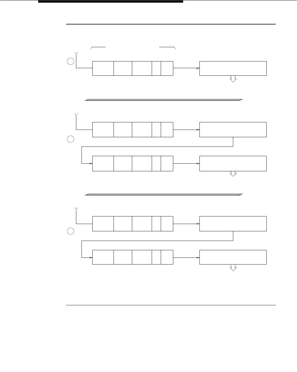
Call Vectoring
Issue 3 March 1996 3-437
Figure 3-1. Typical VDN Call Processing Examples
Calling Party Feedback
The initial feedback that a caller hears as a call is processed by a vector
depends on how the call originates. The call may originate as one of the
following:
■An internal call from another system user
4501 PARTS N 16 7
EXTENSION NAME
ALLOW VDN
OVERRIDE COR
VECTOR
NUMBER
STATION 7000 DISPLAY
SHOWS "OUTSIDE CALL
TO PARTS"
OUTSIDE
CALL
4501 PARTS 16 7
EXTENSION NAME
ALLOW VDN
OVERRIDE COR
VECTOR
NUMBER
OUTSIDE
CALL
VECTOR DIRECTORY NUMBER
VECTOR # 7
Y
VECTOR # 7
16N
STATION 7000 DISPLAY
SHOWS "OUTSIDE CALL
TO PARTS 2"
4501 PARTS 16 7
EXTENSION NAME
ALLOW VDN
OVERRIDE COR
VECTOR
NUMBER
OUTSIDE
CALL
VECTOR # 7
16N
STATION 7000 DISPLAY
SHOWS "OUTSIDE CALL
VECTOR # 9
VECTOR # 9
TO PARTS"
N
- COLLECT 1 DIGIT
1
2
3
PARTS 2
PARTS 2 9
9
5501
5501
ROUTE TO NUMBER 7000
- COLLECT 1 DIGIT
- ROUTE TO NUMBER
5501 IF DIGIT EQUALS 1
ROUTE TO NUMBER 7000
ROUTE TO NUMBER 7000
- ROUTE TO NUMBER
5501 IF DIGIT EQUALS 1

Feature Descriptions
3-438 Issue 3 March 1996
■An incoming call over a non-CO (DID) trunk
■An incoming call over a CO trunk
If the call is an internal or non-CO call, the calling party hears silence until one of
the following occurs:
■An announcement is played
■A
wait-time
command with system music, ringback, or alternative
audio/music source is processed
■A
busy
command is processed
■The call is alerting at an station
If the call is a CO call, the calling party hears CO ringback until one of the
following occurs:
■An announcement is played
■A
wait-time
command with system music or alternative audio/music
source is processed
■The call is answered
Additional Information
If the call is a CO call and answer supervision has been previously supplied (by
processing of an
announcement
or
wait-time
command), the caller hears
feedback specified in the vector commands:
■An announcement when any announcement command is processed
■Ringback, silence, system music or an alternative audio/music source
when a
wait-time
command is processed
■Busy when a
busy
command is processed
■Ringback when the call is alerting an extension
After a
wait-time
command is processed, the calling party continues to hear that
specified treatment unless an announcement is being played, another
wait-time
command with a different treatment is processed, the call is alerting at an
extension, a
busy
command is processed, or vector processing terminates as
whenever an agent becomes available or a successful
route-to
command is
executed.
If a step cannot be executed, the calling party continues to receive the feedback
to which they are currently listening and vector processing continues at the next
step.
When a call terminates to an agent or extension, the calling party hears ringback.
Any announcement or other treatment that is currently being heard is
disconnected and ringback is supplied.

Call Vectoring
Issue 3 March 1996 3-439
After an announcement completes, the calling party hears silence until another
command that specifies treatment is processed (for example,
wait-time
,
announcement
,
busy
), or the call terminates at an extension.
If a call is routed off-premises via a trunk, the calling party hears the standard
call progress tones and/or far-end feedback only if answer supervision has been
passed or the answer detection timer has expired.
If the calling party disconnects at any time while the vector is being processed,
vector processing is terminated, the call is removed from any queues, and the
call is torn down.
Vector Commands
A Call Vector is a set of vector commands. Vector commands determine the type
of processing that specific calls receive. The basic vector commands are listed
below and described in the paragraphs that follow. Please note that most of
these commands require one or more parameters (for example, an extension
number is required with the Announcement command). For more information on
these commands and how they should be used, refer to the
DEFINITY
Communications System Generic 3 Call Vectoring/Expert Agent Selection (EAS)
Guide,
555-230-520.
■Adjunct Routing (used only with the ASAI feature)
■Announcement
■Busy
■Check-Backup Split/Skill
■Collect Digits (used for Call Prompting)
■Converse-on split/skill
■Disconnect
■Goto Step
■Goto Vector
■Messaging
■Queue-To Main Split/Skill
■Route-To Number
■Route-To Digits (used for Call Prompting)
■Stop
■Wait-Time
Adjunct Routing
The
adjunct routing
command is only available with the ASAI feature. This
command causes a message to be sent to an adjunct that is requesting routing

Feature Descriptions
3-440 Issue 3 March 1996
instructions. This command is described in detail in the "Inbound Call
Management (ICM)" description in this chapter.
Announcement
The
announcement
command is used to let callers hear a given announcement.
All calls hear the announcement from the beginning. This may result in a delay
because the call may have to wait in an announcement queue before the
announcement is heard. While a caller is waiting to hear the announcement, the
caller continues to hear whatever treatment he or she is currently hearing.
If the announcement’s queue is currently full, the call retries the announcement
step indefinitely before processing any new vector steps. If the requested
announcement is not administered (in the case of external or integrated
announcements) or recorded (in the case of integrated announcements only),
the current step is skipped and vector processing continues at the next vector
step.
When a call is connected to the announcement, the previous treatment is
discontinued and answer supervision is sent if it has not already been supplied.
During an announcement, if the call is moved from waiting in a split’s queue to
alerting at an agent’s extension, the announcement is disconnected and the
caller hears ringback. When the announcement completes and is disconnected,
the caller hears silence until a vector step with an alternate treatment is
processed or the call reaches an agent’s extension.
Busy
The
busy
command causes termination of vector processing and gives the caller
a busy signal. The busy takes effect on non-CO trunk calls whether or not
answer supervision has been sent; but if the call is a CO (auto-in) trunk call and
answer supervision (via
announcement
command or
wait-time
command) has
not been sent, the CO ignores the busy and continues giving the caller CO
ringback. Non-CO trunks are dropped approximately 45 seconds after busy tone
is applied.
Check-Backup Split/Skill
The
check-backup
command checks the status of a split/skill for possible
termination of the call to that split/skill. When termination is not possible, queuing
at the specified priority is attempted. Termination and/or queuing is attempted if
the split meets certain conditions specified as part of the command. The
possible conditions are shown below:
■Unconditionally (always attempts to queue)
■Number of available (idle) agents in the specified split
■Number of staffed agents in the specified split
■Number of calls queued at a given priority to the specified split.

Call Vectoring
Issue 3 March 1996 3-441
This condition tests for calls in queue at the specified priority level and
higher.
■Age of the oldest call waiting in the specified split’s queue
■The average time it takes for a call to be answered in the specified split.
(G3V4 and later releases only)
■The amount of time a call could expect to wait in the queue of the
specified split before it is answered (G3V4 and later releases only)
A call may be queued in up to three different splits/skills at the same time. A call
remains queued until either vector processing terminates or the call reaches an
agent.
Collect Digits
The
collect digits
command lets the caller enter up to 16 digits from a touch-tone
phone. An optional announcement may be played first. This step is part of the
Call Prompting feature and is described in greater detail in the Call Prompting
feature description elsewhere in this document.
Converse-On Command
The
converse-on
command is an enhancement to the Basic Call Vectoring
customer option. The
converse-on
Call Vectoring step is specifically designed to
integrate a VRU with the DEFINITY switch. Voice Response Integration allows
VRU capabilities to be used while keeping control of the call in the switch. The
inclusion of VRUs with vector processing provides the following advantages:
■Access to local and host databases
■Validation of caller information
■Text to speech capabilities
■Speech recognition
■Increased recorded announcement capacity
■Audiotex applications
■Interactive Voice Response (IVR) applications
■Transaction processing applications
One of the advantages of Voice Response Integration is that it allows users to
make more productive use of queuing time. For example, while the call is waiting
in queue, the caller can listen to product information by using an audiotex
application or by completing an interactive voice response transaction. In some
cases, it may even be possible to resolve the customer’s questions while the call
is in queue. This can help reduce the queuing time for all other callers during
peak intervals.
If the
converse-on
command is successful, it delivers the call to a
pre-determined split (skill), which is referred to as the converse split (skill). A

Feature Descriptions
3-442 Issue 3 March 1996
converse split is administered and behaves exactly as any other split in the
system. The term non-converse split is used to refer to traditional ACD splits
accessed by means of
queue-to main
and
check-backup
vector steps.
Once the call is answered by the VRU, the
converse-on
command may or may
not pass data to the VRU (depending upon the parameters of the command). Up
to two items of data may be passed. This data may be used to select the VRU
script to be executed or it may be information passed to the script. See the
DEFINITY Communications System Generic 3 Call Vectoring/Expert Agent
Selection (EAS) Guide,
555-230-520, for more information about the types of data
that can be passed to the VRU.
Once the VRU script is completed, the VRU may or may not return data to the
DEFINITY system. Whether or not data is returned, once the VRU drops the line
to DEFINITY system, vector processing is then re-activated on the switch starting
with the vector step which follows the
converse-on
step.
Digits returned by the VRU are treated as dialahead digits. Call prompting must
be optioned to collect and use these digits. The rules for collecting and
processing VRU-returned digits are identical to those for Call Prompting.
Digits returned from the VRU can be used in the following way:
■Displayed on the answering agent’s display set (automatically for 2-line
displays (such as a 7407 or Call Master) using the ‘‘callr-info’’ button for
other display sets).
■Treated as an extension in a ‘‘route-to digits’’ vector step.
■Used for vector conditional branching in an ‘‘if digits’’ vector step.
■Tandemed to an ASAI host.
— Voice Response Integration also provides the integration of VRUs
with ASAI hosts. Since collected digits are also passed to ASAI
hosts in ‘‘call offered to domain’’ event reports and in ‘‘route
request’’ messages, caller digits or database information returned
from the VRU may also be tandemed through the DEFINITY system
to ASAI hosts.
Based on administration, with G3V4 and later releases, a DTMF tone can be
used as an answer feedback signal and sent to the VRU when the VRU-to-ACD
call is answered by the agent. Another DTMF tone can be used as a disconnect
feedback signal and sent to the VRU when the incoming call to the VRU
disconnects before it is transferred by the VRU.
Refer to
DEFINITY Communications System Generic 3 Call Vectoring/Expert
Agent Selection (EAS) Guide,
555-230-520, for additional information.
Disconnect
The
disconnect
command ends treatment of a call and removes the call from the
switch. This command also allows the optional assignment of an announcement

Call Vectoring
Issue 3 March 1996 3-443
that plays immediately before the disconnect. If the switch has not yet sent
answer supervision, it does so immediately before disconnecting a call so there
is a charge for calls that terminate with the disconnect command. The exception
is on ISDN calls where disconnect can occur without returning answer
supervision when an announcement is not played.
During playing of the announcement, if the call is moved from waiting in a split’s
queue to alerting at an agent’s extension, the announcement is disconnected,
the caller hears ringback, and the
disconnect
command is aborted.
Goto Step
The
goto step
command is a branching step that provides conditional or
unconditional movement to later or earlier steps in the Call Vector.
Conditional branching may be used to compensate for heavy traffic or for
night/weekend service. Calls in queue and/or any wait treatment in effect before
a
goto
remain in effect after the branch.
The conditions of branching are as follows:
■Unconditionally (always branches)
■Number of available (idle) agents in a specified split
■Number of staffed agents in a specified split
■Number of calls queued at a given priority (or higher) to the specified split
■Age of the oldest call waiting in the specified split’s queue
■Time of Day, start time, and end time specified
■Rolling average speed of answer for the specified split or VDN. (G3V4 and
later releases only)
■Expected wait time for the specified split or for the call being processed
(G3V4 and later releases only)
■Number of calls active in the VDN (G3V4 and later releases only)
■Collected Digits from a
collect digits
step (Call Prompting feature only)
■ANI (caller identity) of the call being processed (G3V4 and later releases
only)
■II-digits (type of originating line) of the call being processed (G3V4 and
later releases only)
With G3V4 and later releases, ANI, II-digits, and digits collected from a
collect
digits
step can be tested against entries in a Vector Routing Table for conditional
branching with the
goto
step.

Feature Descriptions
3-444 Issue 3 March 1996
Goto Vector
The
goto vector
command is a branching step that provides conditional or
unconditional movement to another vector.
The
goto vector
command is used for chaining more than one vector together.
Calls in queue and/or any wait treatment in effect before a
goto
remain in effect
after the branch.
The conditions of branching are:
■Unconditionally (always branches)
■Number of available (idle) agents in a specified split
■Number of staffed agents in a specified split
■Number of calls queued at a given priority (or higher) to the specified split
■Age of the oldest call waiting in the specified split’s queue
■Time of Day, start time, and end time specified
■Rolling average speed of answer for the specified split or VDN. (G3V4 and
later releases only)
■Expected wait time for the specified split or for the call being processed
(G3V4 and later releases only)
■Number of calls active in the VDN (G3V4 and later releases only)
■Collected Digits from a
collect digits
step (Call Prompting feature only)
■ANI (caller identity) of the call being processed (G3V4 and later releases
only)
■II-digits (type of originating line) of the call being processed (G3V4 and
later releases only)
With G3V4 and later releases, ANI, II-digits, and digits collected from a
collect
digits
step can be tested against entries in a Vector Routing Table for conditional
branching with the
goto
command.
Messaging Split/Skill
This command causes the calling party to be connected to the AUDIX or
Message Center split so that he or she may leave a message for the specified
extension (call answering service). If the calling party is successfully connected
to the AUDIX or a Message Center agent, then vector processing terminates and
a message may be left for the specified extension.
Priority can be given to the call by assigning a high priority to the messaging split
extension via the COR.
This command functions as follows:

Call Vectoring
Issue 3 March 1996 3-445
1. If the split number specified in the command is a valid message service
split (such as AUDIX or Message Server Adjunct), and either the extension
is a valid assigned extension or is administered as “none” (defaults to
current VDN), then the system attempts to terminate the call to the
message service split for call answering service.
■If the call is queued to the message service split or if the call
terminates to an available message service agent or AUDIX voice
port, then the calling party is connected to ringback (successful
termination), and vector processing terminates. For DEFINITY
AUDIX the VDN number must be included in the VDN name on the
switch.
■If the split queue is full, the AUDIX link is down, all AUDIX voice
ports are out of service, or the message service split is DCS-AUDIX
and all DCS trunks are busy, then vector processing continues at
the next vector command (unsuccessful termination).
2. If call termination was successful and the administered extension (or
default VDN) is a message service subscriber, the calling party can leave
a message for the specified extension.
If the extension or VDN was not a subscriber of the message service, one
of the following may occur:
■If the message service split is AUDIX, the calling party receives
ringback until he or she disconnects.
■If the message service split is a Message Server Adjunct, the
calling party may be answered by an message service agent but
no message is taken since the specified extension (default VDN) is
not a Message Server Adjunct subscriber.
Queue-To Main Split/Skill
The
queue-to main split
command sends a call to a split and assigns a queuing
priority level to the call if all agents are busy. A call sent with this command
either connects to an agent in the split or enters the split’s queue.
A call may be queued in up to three different splits/skills at the same time. A call
remains queued either until vector processing terminates or the call reaches an
agent. When an agent becomes available in any split to which the call is queued,
the following actions are performed:
■The call begins alerting the agent
■The call is removed from any other queues
■Vector processing terminates
If the desired split is one of the splits/skills to which the call is already queued,
the call is requeued at the new priority level. This step is skipped and vector
processing continues at the next step if any of the following are true:
■The desired split’s queue is full

Feature Descriptions
3-446 Issue 3 March 1996
■The desired split is unstaffed
■All staffed agents are in the auxiliary work mode
■The desired split is not vector controlled
■The call is already queued in this split at the specified priority level
■The call has already been queued to three different splits/skills
■The desired split has no queue and no agents are available
Route-to Number
This command routes a call to the specified number. This digit string represents
a destination number which may be any of the following:
■An internal extension (such as a split/hunt group, voice terminal,
announcement, and so on)
■A VDN extension
■An attendant
■A remote extension
■An external number such as a TAC or AAR/ARS FAC followed by a public
or private network number.
This command allows a call to be routed to a specified destination. The COR
associated with the VDN is used to determine any calling party restrictions (such
as lack of calling permission, FRL restriction, and so on). If this command is
successful (that is, it successfully terminates to a station, seizes a trunk, and so
on) then vector processing terminates. Otherwise, vector processing continues
at the next vector command.
This command functions as follows:
1. If the number is a system extension or attendant group (not a VDN) the
system attempts to terminate the call to the endpoint if one of the following
conditions occur:
■The endpoint is alerted.
■The endpoint has call forwarding or night service (hunt group)
enabled, and the forwarded to (night service) destination is alerted
(or in the case of off-premises call forwarding, a trunk is seized).
The system then provides ringback to the calling party, and vector
processing terminates. However, if the call cannot complete successfully
(for example, no idle appearance is available), and the
route-to number
step is specified with coverage set to no, vector processing continues at
the next vector command. If coverage is set to yes, the call routes to the
destination’s coverage path.
Route-to number
with coverage is only
available when G3V4 and later release software has been installed either
when purchased or as a bugfix release.
2. If the number is a VDN extension, then the following events occur:

Call Vectoring
Issue 3 March 1996 3-447
■Vector processing terminates within the current vector.
■If the current VDN is administered with VDN override, then the new
VDN overrides the current VDN as the VDN to be displayed at the
terminating extension.
■Processing of the vector associated with the VDN extension begins.
■All previous vector queue and wait treatment ends.
3. If the number is an AAR/ARS FAC plus digits, or a remote (UDP)
extension, standard AAR/ARS processing is performed to select the trunk
group and outpulse the digits. If a trunk is seized, vector processing
terminates, and the calling party hears feedback provided by the far end.
Otherwise, the call cannot complete successfully (no trunks available,
FRL/COR restricted, and so on), and vector processing continues at the
next vector command.
4. If the number is a TAC plus digits, and a trunk is seized, then vector
processing terminates and the calling party hears feedback provided by
the far end. Otherwise, the call cannot complete successfully (no trunks
available, COR restricted, and so on), and vector processing continues at
the next vector command.
5. If the number is any other number (such as an FAC plus digits), vector
processing continues at the next vector command (unsuccessful
route-to
command). Note that with G3V4 and later releases, a call can route to a
Service Observing FAC.
Route-To Digits
The
route-to digits
command is a Call Prompting command. It attempts to route
the call like the
route-to number
command, except that the number routed to is a
set of digits collected from the caller (via a
collect digits
step). For more details
see the "Call Prompting" feature description elsewhere in this chapter.
Stop
The
stop
command terminates the processing of any subsequent vector steps.
After the
stop
command, any calls that are already queued remain queued, and
any wait treatment is continued.
Wait-Time
The
wait-time
command is generally used to set a length of time for a call to wait
in the main split’s queue and to specify what the caller will hear while the call
advances in queue. Prior to G3V4 the caller could hear silence, ringback or
system music. G3V4 and later releases also allow the caller to hear an alternative
audio/music source. A wait time of 0 seconds can be used to change the call
treatment without executing a delay. Anytime during a delay if an agent becomes
available
wait-time
treatment is cancelled and the call is connected to the agent.

Feature Descriptions
3-448 Issue 3 March 1996
ACD Split/Hunt Group Operation with
Call Vectoring
A split is considered Vector Controlled if yes has been selected in the “Vector”
field on the Hunt Group Administration screen. Only vector controlled splits/skills
are accessible from the following call vectoring commands:
check-backup split
,
queue-to main split
, and
converse-on split.
Overview
Throughout this description, split is used to specify a hunt group or ACD split.
ACD split is used when the group has ACD optioned. Hunt group is used when
the group does not have ACD optioned. When EAS is optioned only non-ACD
hunt groups and Skills may coexist. Splits and Skills may not coexist.
This section describes the interactions between the Hunting, ACD, and Call
Vectoring features. Some key points to note are:
1. Hunt groups and ACD splits/skills may coexist with one another as well as
with vector-controlled splits/skills.
2. Vector-controlled splits/skills may be called directly. However, these calls
do not receive any announcements, can be forwarded, can be redirected
to coverage, or intraflow/interflow to another hunt group.
3. ACD is required to obtain any CMS and/or BCMS split measurements.
Vector Controlled Splits/Skills
Vector Controlled Splits/Skills have the following properties:
■Agents may be logged into multiple controlled splits/skills simultaneously.
■Agents’ voice terminals are not locked while they are logged into a vector
controlled split.
■A vector controlled split may also be adjunct controlled. If it is, the more
restrictive properties of each controlling function apply.
■A vector controlled split is not mapped to an adjunct via system
administration, unless it is also adjunct controlled.
■Request Notification is allowed (as long as the split is not
adjunct-controlled). The adjunct receiving notification is the same one
requesting it.
■When a vector controlled split is removed via system administration, any
active notification request is terminated.
■A vector controlled split cannot be assigned a coverage path. VDNs
cannot be assigned a coverage path but can be assigned
to
a coverage
path.
■Calls queue when agent is logged out or in AUX work mode.
■When EAS is optioned all ACD hunt groups (skills) must be vector
controlled.

Call Vectoring
Issue 3 March 1996 3-449
■Call Forwarding cannot be activated for a vector controlled split.
■No announcements are associated with vector controlled splits/skills.
Split/Skill Queue Priority Levels
Each call in a split queue can have one of four possible priority levels: Top, High,
Medium, and Low. Calls are processed initially by priority level. Within each
priority level, calls are processed in first-in, first-out (FIFO) order. A vector can be
administered to process queued calls using any of the four priority levels. Calls
not controlled by a vector can use only two priority levels: High and Medium.
The default priority level for non-vector controlled calls queued to a split is
Medium. An ACD split may assign certain calls to the high-priority level. The
high-priority level can be assigned to a call by intraflowing from one ACD split to
another ACD split. This is achieved using the “Call Coverage Option” field and
“Setting the Priority on Intraflow” field on the Hunt group form of the principal
ACD split. The high-priority level can also be assigned to a call from a voice
terminal user whose associated COR has priority queuing optioned.
Direct Agent Calls (DACs) have the highest priority of any calls (including those
mentioned in the previous paragraph).
Split/Skill Thresholds
The split thresholds, available-agents, and staffed-agents, used by the
check-backup
and
goto
vector commands, have slightly different meanings for
hunt groups and ACD splits/skills. For ACD splits/skills, staffed-agents is the
number of agents logged-in. Available-agents is the number of agents logged-in
and ready to receive an ACD call (for example, Auto-in or Manual-in work mode
and not currently on a call). Since hunt groups have no log-in, log-out, or work
modes, a staffed-agent is merely an administered agent. All that is checked is
the number of administered agents. Similarly, available-agents is the number of
agents ready to receive a hunt group call.
When there is no queue, the oldest call waiting is always 0 and the number of
queued calls is always 0. When the system time is not set, the time of day and
oldest call waiting threshold always fail.
Call Vectoring and PBX Toll Fraud
Abuse of PBX remote access is one way in which unauthorized users obtain
services illegally. Call Vectoring features can be used to block unauthorized use
of the DEFINITY Communications System remote access feature.
The following are ways Call Vectoring features are used to alleviate toll fraud:
1. By reaching the remote access extension via call vectoring.
2. By replacing the function of the remote access extension by one or more
call vectors.

Feature Descriptions
3-450 Issue 3 March 1996
Front Ending Remote Access
Authorized external callers are given a VDN extension to call as opposed to the
remote access extension, which is kept private. The corresponding call vector
then implements a number of security checks before routing callers to the remote
access extension.
The following advantages are possible with this feature.
1. A recorded announcement is played to callers, which declares that use of
PBX services by unauthorized callers is illegal and that this call is subject
to monitoring and/or recording.
2. Call prompting is used to prompt for passwords.
3. Use of the remote access extension is limited to certain times of the day or
days of the week.
4. Vectoring introduces a delay before dial-tone is provided to the caller.
NOTE:
Immediate dial-tone is often a searched for by hacker’s programs
when trying to break into a system.
5. If ANI is available on incoming calls, different VDNs are administered for
different geographic areas, such that once a security breach occurs, only
callers from that specific region have the capability to abuse the remote
access capabilities.
6. If the Information Indicator (II) digits are available on the incoming call,
additional security checks based upon the origination information
associated with the calling parties telephone line can be made. The II
digits may indicate that the inbound call originated from a prison,
hotel/motel, or even cellular telephone line and as such would require
unique security treatment.
7. Real-time and historical reports on the use of the remote access feature
are available from BCMS and/or CMS.
8. Different passwords are used on different days of the week or times of
day.
9. Many VDNs are defined which call the remote access extension. In this
way, individuals or groups are given their own VDN with unique
passwords, permissions and reports. Any abuse of the system or security
leak is then attributed to an individual or group.
10. The caller can be routed to a VRU using the
converse-on
step, where
more sophisticated security checking takes place, such as speaker
recognition.
11. Any call failing any of the security checks is routed to a VDN that routes
the caller to security personnel with a display set or to a VRU. Such calls
show security violation and possibly also the attempted password on the

Call Vectoring
Issue 3 March 1996 3-451
display. If the call is passed to a VRU, the VDN, the ANI and/or the
prompted digits are captured. BCMS/CMS reports on this VDN give
information on how often and when security violations occur.
Replacing Remote Access
In this case, the remote access extension is not used. One or more VDNs are
defined which access call vectors employing all the security checks described
for
Front Ending Remote Access
. The same reports and monitoring/recording
capabilities described for
Front Ending Remote Access
are also possible.
Instead of routing the call to the remote access extension, the call vector collects
digits from the caller and then routes to the given destination.
Again, multiple VDNs are created for individuals or groups with different security
checks and different permissions/restrictions. Destination numbers provided by
callers are screened by the vectors and denied if the user does not have
permission to access that destination. For example, an individual user is
restricted to placing calls to numbers beginning with area codes 303 and 908.
Call Vectoring and the Call Management System
(CMS)
The CMS provides the following capabilities to be used with Call Vectoring:
■The CMS can request full translations to initialize its database. The PBX
supplies data for VDNs and measured trunk groups which map to VDNs.
■The CMS can retrieve and change vectors on the PBX. However, no
information is sent to the CMS when vectors are administered via the
Management Terminal.
■The CMS can change the vector the number assigned to VDNs.
■The PBX notifies the CMS when the incoming destination of a trunk group
is changed. This happens when a trunk group maps to either a split or
VDN.
■The PBX notifies the CMS when a VDN is called. State change messages
are also sent as a vector is processed.
■The PBX notifies the CMS when an agent transfers a call to a VDN.
DNIS
Call Vectoring provides DNIS, which allows agents with display-equipped voice
terminals to receive visual displays that specify the name of the called VDN.
In traditional ACD arrangements, groups of agents are organized into splits/skills.
With this type of arrangement, an agent is trained to answer calls for one specific
purpose in an efficient and professional manner. However, ACD managers are
recognizing the need to relax this concept of limiting each split to a single
call-answering task.

Feature Descriptions
3-452 Issue 3 March 1996
The alternative is to provide splits/skills where each group of agents is proficient
with several types of calls. The desired gain is to provide adequate service for
the several call types with fewer agents and with less administrative intervention
by the ACD manager. Using this approach, the changing staff needs of the
several call types are averaged in time, and enough agents are staffed to
provide adequate service for the prevailing average load. Where five agents
might be needed in each of three smaller splits/skills (15-agent total) to handle
three types of calls, only 11 or 12 agents might be needed in the single (more
general) split.
The DNIS function provided by Call Vectoring allows each answering agent to
know the purpose of each incoming call as the call terminates to the agent’s
voice terminal. As a result, the natural efficiencies of the single-split/single-call
type arrangement are not compromised. With the display information provided
by DNIS (for example, the name of the called VDN), agents are aware of each
call’s purpose, and can answer each incoming call with the appropriate greeting.
Agents do not have to waste time trying to determine the purpose of calls.
Vector Routing Tables (G3V4 and later releases)
A
goto
vector step can test digits collected as part of Call Prompting, or ANI
(Automatic Number identification) against numbers in a Vector Routing Table.
Vector Routing Tables contain a list of numbers that can be used to test a
goto...if
digits
or a
goto...if ani
command. The values can be tested to see if they are
either in or not-in the specified table. Tables can have up to 100 entries.
Considerations
Call Vectoring is a valuable feature that provides a highly flexible way of
processing incoming calls to the switch. With Call Vectoring, one can define a
separate set of call processing steps for different types of incoming calls.
Maximum benefits are realized when Call Vectoring is combined with Call
Prompting and ACD.
A maximum of 1,000 vector steps are processed per call.
A maximum of 16 adjunct route steps are supported.
A call can be queued to multiple splits/skills and/or hunt groups at the same time
to minimize the waiting time. The maximum number of queues that a call can be
queued at is three.
A queue size must be assigned for vector-controlled splits/skills (on the Hunt
Group form). If vector processing attempts to queue a call to a split, and if there
are no queue slots available, the step fails, and vector processing continues at
the next step.

Call Vectoring
Issue 3 March 1996 3-453
It is recommended that you not change a vector while it is processing calls
because the calls already in the vector might experience problems. Instead, add
a new vector and change the VDN to go to the new vector.
Agents should not be used for hunt group calls and ACD split calls
simultaneously. Otherwise, all of the calls from one split (either ACD or hunt
group) are answered first. For example, if the ACD calls are answered first, none
of the hunt group calls are answered until all of the ACD calls are answered.
The oldest call waiting termination is only supported for agents who are servicing
ACD calls only.
Call Vectoring operations in DEFINITY Generic 3 systems are different from those
in DEFINITY Generic 2 systems. For Call Vectoring information related to the
DEFINITY Communications System Generic 2, see
DEFINITY Communications
System Generic 2 and System 85 Feature Descriptions
, 555-104-301. The
DEFINITY Communications System Generic 3 Call Vectoring/Expert Agent
Selection (EAS) Guide
, 555-230-520, also discusses differences between G2
and G3 Call Vectoring.
Interactions
The following features interact with the Call Vectoring feature.
■Abbreviated Dialing
A VDN extension can be used in a personal, group, system, or enhanced
number list.
■Administered Connections
The PSC administration screen blocks entry of a VDN.
■Answer Supervision
Answer Supervision is only returned once during the life of a call. With
respect to Call Vectoring commands, answer supervision is returned in
response to an announcement, waiting with music, and disconnect. In
addition, if a call is answered, answer supervision is sent if it has not
previously been sent.
■AP Demand Print
A VDN cannot be used as an argument to the feature access code for AP
Demand Print.
■Attendant Control of Trunk Group Access
If a
route-to
step in a vector dials a controlled trunk group, vector
processing continues at the next step.
■Attendant DXS with Busy Lamp Field
A DXS lamp for a VDN is always off. A DXS button can be used to place a
call to a VDN.

Feature Descriptions
3-454 Issue 3 March 1996
■Attendant Display
A button may be assigned to the attendant to display an internal caller’s
COR. The restriction identifiers are: orig, otwd, toll, code, and none. This
operation is available for calls originated by a
route-to
step in a vector.
The COR of the originator is displayed.
■Attendant Recall
Attendant Recall to a VDN is blocked.
■AUDIX Interface
A
route-to
step in a vector may call the AUDIX extension. If a voice port
can be seized to that adjunct, vector processing is terminated. The
system sends a message to AUDIX requesting retrieval of messages for
the originating extension (not the VDN).
AUDIX may also be accessed by the
queue-to main split
and
check-backup split
commands. Also, the messaging step may use an
AUDIX hunt group in its operation.
■Authorization Codes
Authorization codes are disabled with respect to routing via VDNs. In
other words, if authorization codes are enabled, a
route-to
command in a
prompting vector accesses AAR or ARS and the VDN’s FRL does not have
the permission to utilize the chosen routing preference, then no
authorization code is prompted for and the
route-to
command fails.
■AAR/ARS
Any
route-to
command in a vector can dial an AAR/ARS FAC followed by
other digits. Specifying only the FAC in a
route-to number
command is not
allowed. The
route-to
step is skipped.
■Automatic Callback
Automatic Callback cannot be used for calls placed to a VDN.
■Automatic Call Distribution
Splits/Skills which are not translated as vector-controlled may use all of the
existing ACD features. Splits/Skills which are translated as
vector-controlled lose certain ACD properties.
■Automatic Incoming Call Display
The information displayed for the current call is replaced by the identity of
the incoming call. A
route-to number
step in a vector can initiate a call to
an extension. The name of the originator (or the name of the trunk group)
and the name of the VDN are displayed for that extension.
■Automatic Message Waiting Notification
The Message button can specify a VDN. The associated lamp is lit when
messages are left for that VDN.

Call Vectoring
Issue 3 March 1996 3-455
■Automatic Wakeup
A wakeup call cannot be programmed for a VDN.
■Bridged Call Appearance
VDN extensions cannot be assigned to bridged appearance buttons. A
route-to
command to an extension with bridged appearances updates
bridged appearance button lamps.
■Busy Verification of Terminals and Trunks
Busy verification of VDNs is denied and intercept tone is returned.
■Call Coverage
A VDN may be administered as the last point in a coverage path.
Vectors and VDNs do not have coverage paths associated with them.
■Call Forwarding
Calls can be forwarded to a VDN. Calls placed by a
route-to
command to
an extension that has call forwarding activated are forwarded.
An attendant or voice terminal with console permission can
activate/deactivate call forwarding for a particular extension number, TEG,
or hunt group. However, activation/deactivation of call forwarding for a
VDN is blocked.
If Call Vectoring is enabled, activation/deactivation of call forwarding for a
vector-controlled hunt group is blocked. The user receives intercept tone.
■Call Detail Recording (CDR) Account Code Dialing
If a
route-to number
command in a vector specifies an CDR account code,
vector processing continues at the next step.
■Call Detail Recording (CDR)
The Feature Related System Parameters form can be administered so that
the VDN extension is used in place of the Hunt Group or Agent extension.
If administered to do so, this overrides the ‘‘Call to Hunt Group - Record’’
option of CDR for Call Vectoring calls.
If a vector interacts with an extension or group that has Call Forwarding All
Calls active, normal Call Forwarding/CDR interactions apply.
For incoming calls to a VDN, the duration of the call is recorded from the
time answer supervision is returned.
— If answer supervision is returned by the vector (via an
announcement, collect digits, disconnect
, or
wait-time
command),
and the call never goes to another extension, then the VDN
extension is recorded as the called number in the CDR record.
— If the call terminates to a hunt group, then the VDN, hunt group, or
agent extension is recorded as the called number as per the
administration described above.

Feature Descriptions
3-456 Issue 3 March 1996
— If the call terminates to a trunk, then the following two CDR records
are generated:
1. An incoming record with the VDN as the called number and
the duration from the time answer supervision was provided
to the incoming trunk.
2. An outgoing record containing the incoming trunk
information as the calling number and the dialed digits and
the outgoing trunk information as the called number.
Outgoing vector calls generate ordinary outgoing CDR records with the
originating extension as the calling number.
No Ineffective Call Attempt records are generated for Call Vectoring
route-to
commands that are unsuccessful.
■Call Park
Calls cannot be parked on a VDN. If the call park access code is dialed
and a VDN is entered, the user receives intercept tone. If the call park
answer back access code is dialed and a VDN is entered, the user
receives intercept tone.
■CMS
See the section in this feature description entitled ‘‘Call Vectoring and the
CMS’’ for CMS interactions.
■Call Pickup
A VDN cannot be administered as a member of a pickup group. However,
a vector call that routes to an extension can be picked up, if that extension
is part of a pickup group.
■Call Prompting
Call Prompting is administered through Call Vectoring administration. If
only Call Vectoring is enabled, vectors can be administered using only
"Call Vectoring" commands. If only Call Prompting is enabled, vectors can
be administered using only "Call Prompting" commands, described
elsewhere in this chapter. When both features are enabled, all the
commands associated with vectoring and prompting are available.
Enabling both vectoring and prompting together provides the capability to
prompt the caller to enter pertinent data while the caller is waiting in queue
at an ACD split. For example, prompting and vectoring can be used
together to enhance the message collection capability to provide a caller
who is waiting in queue at an ACD split with the choice of remaining in
queue or leaving a message for that split. In addition to queuing,
vectoring provides the capability to change calling party feedback. In
addition to silence, which both prompting and vectoring supply, vectoring
can provide ringback or music feedback to the calling party.
The implications of having both features enabled are:

Call Vectoring
Issue 3 March 1996 3-457
— When a Call Prompting command (such as a successful
route-to
command) terminates vector processing, the call must be
dequeued and dropped from all queues that it is currently residing
in as part of the termination process.
— If a call is waiting in an announcement queue, waiting to be
connected to an announcement or an announcement queue
(announcement retry), or is currently connected to an
announcement, and the call is dequeued from a split’s queue and
terminates to an agent’s voice terminal extension, the
announcement is disconnected and ringback is connected to the
call.
—If a
collect digits
command is being processed for a call and the
call is dequeued from a split’s queue and terminates to an agent’s
voice terminal extension, the
collect digits
command is terminated
and ringback is connected to the call.
■Call Waiting Termination
A route-to number command in a vector can dial a single-line voice
terminal. If the extension is busy and has call waiting termination
administered, the
route-to with cov n operation is considered
unsuccessful and vector processing continues at the next step. Route-to
with cov y is successful (call will wait) and vector processing terminates.
■CAS
A
route-to number
command in a vector can dial CAS. If a release link
trunk can be seized, the
route-to number
operation is considered
successful and vector processing is terminated.
■COR
Each VDN in the system has a COR associated with it. This VDN COR is
used to determine the calling permissions/restrictions, the AAR/ARS PGN,
and the priority queuing associated with a given vector.
■Code Calling Access
A VDN cannot be used as the argument to the code calling access feature
access code.
If a
route-to number
command in a vector specifies the code calling
feature access code, vector processing continues at the next step.
■Conference
A call to a VDN can be included as a party in a conference call only after
vector processing terminates for that call (for example, after a successful
route-to
command).
■Coverage Callback
A vector call does not follow any coverage paths; therefore, coverage
callback is not available.

Feature Descriptions
3-458 Issue 3 March 1996
■DCS Attendant Control of Trunk Group Access
This allows an attendant at any node in the DCS to exercise control over
an outgoing trunk group at a different node in the cluster. If a
route-to
number
step in a vector dials a controlled trunk group, vector processing
continues at the next step.
■DCS Attendant Display
Calls to/from a system in a DCS environment have calling/called party
identification transparency. The name of the originator is displayed on the
called terminal’s alphanumeric display. The name of the party to whom the
call is directed is displayed on the originator’s display.
The same display operations occur even if the originator, VDNs, and
terminator are on different nodes in a DCS network.
■DCS Automatic Callback
Automatic Callback calls do not apply for VDNs.
■DCS Call Forwarding
Calls can be forwarded to a VDN anywhere in the DCS network. An
attendant cannot activate/deactivate call forwarding for a VDN.
■DCS LWC
LWC messages cannot be generated for a VDN.
■DCS Voice Terminal Display
This feature allows calling and called name information (plus
miscellaneous identifiers) to be sent from a terminal on one node to a
terminal on another node. The name of the originator is displayed on the
called terminal’s alphanumeric display. The name of the party to whom the
call is directed is displayed on the originator’s display.
The same display operations occur even if the originator, VDNs, and
terminator are on different nodes in a DCS network.
■DID
DID trunks can dial a VDN and be subject to the treatment of its
associated vector.
■DOD
DOD can be provided via a
route-to
command within a vector. The COR
of the VDN is used to determine calling party permissions/restrictions.
■Do Not Disturb
Do Not Disturb cannot be activated for a VDN.
■Emergency Access to the Attendant
When night service is in effect, emergency calls to the attendant route to
the night destination. The night destination can be a VDN.

Call Vectoring
Issue 3 March 1996 3-459
The extension number where emergency queue overflow redirects can be
a VDN.
■Facility Busy Indication
The facility busy lamp indication for a VDN is always off. A facility busy
button may be used to call a VDN.
■FRL
If a
route-to
command dials an external number via AAR/ARS, the FRL
associated with the VDN COR is used to determine the accessibility of a
routing preference in an AAR/ARS pattern.
■Facility Test Calls
Provides a voice terminal user with the capability of making test calls to
access specific trunks, touch-tone receivers, time slots, and system tones.
The test call is used to make sure the facility is operating properly. A local
voice terminal user can make a test call by dialing an access code. An
Initialization and Administration System (INADS) terminal user can also
make test calls.
If a
route-to number
command in a vector specifies a Facility Test Call,
vector processing continues at the next step.
■Forced Entry of Account Codes
Requires users to dial an account code when making certain types of
outgoing calls. To maximize system security, it is recommended that the
Forced Entry of Account Codes feature be enabled and administered on
the System. The Forced Entry of Account Codes option must be enabled
on the System-Parameters Customer-Options form before associated
forms and fields on forms can be administered.
If a COR requiring entry of account codes is assigned to a VDN, the
route-to number
commands executed by the associated vector are
unsuccessful and vector processing continues at the next step.
■Individual Attendant Access
Each attendant console can be assigned an individual extension number.
That extension number can be used as the argument to a
route-to number
command in a vector.
Each attendant has a queue that allows two incoming calls to wait. This
individual attendant queue has priority over all other attendant-seeking
calls. A call established by a
route-to number
command in a vector can
wait in this queue and is removed from vector processing.
■ISDN-PRI
A VDN may be accessed by an ISDN-PRI trunk. ISDN-PRI calls may be
disconnected without providing answer supervision.
A vector may initiate calls over ISDN-PRI facilities via a
route-to number
command.

Feature Descriptions
3-460 Issue 3 March 1996
■Integrated Directory
VDN names and extensions are not available in the Integrated Directory
feature.
■Intercept Treatment
A VDN cannot be used for Intercept Treatment.
■Intercom — Automatic
A VDN cannot be included in an intercom group.
■Intercom — Dial
A VDN cannot be included in an intercom group.
■Inter-PBX Attendant Calls
A
route-to number
command in a vector can dial the Inter-PBX Attendant.
If the call attempts to access a controlled trunk group, vector processing
continues at the next step.
■Intraflow and Interflow
The functionality of intraflow and interflow may be obtained using the
check-backup split
and
goto
Call Vectoring commands.
Calls may intraflow from an ACD split which is not vector-controlled into
one that is vector-controlled.
■Last Number Dialed
After a voice terminal user with a Last Number Dialed button dials a VDN
extension, the VDN extension is stored as the Last Number Dialed and
may be redialed by pressing the button.
■LWC
LWC messages cannot be stored, canceled, or retrieved for a VDN.
■Manual Message Waiting
Message Waiting buttons may point to a VDN.
■Manual Signaling
A manual signaling button can point to a VDN. However, activation of a
Manual Signaling button which points to a VDN is ignored.
■Multiple Listed Directory Numbers
The incoming destination for each CO trunk group and each FX trunk
group used for LDNs can be a VDN. The DID LDN night extension can be
a VDN.
■Music-on-Hold Access
The system-wide Music-on-Hold Access feature must be administered in
order for music to be heard when a
wait-time
command with system music
is executed. If it is not administered, the calling party receives silence.

Call Vectoring
Issue 3 March 1996 3-461
■Network Access — Private
A
route-to number
command in a vector can access private networks.
■Network Access — Public
A
route-to number
command in a vector can access public networks.
■Night Service
A VDN can be administered as a night service destination.
Route-to
commands that route to destinations with night service activated
redirect to the night service destinations.
■Priority Calling
A VDN cannot be used with the priority calling access code. Intercept
tone is supplied to the user. If a
route-to number
in a vector specifies the
priority calling access code, vector processing continues at the next step.
■Property Management System Interface
VDNs cannot be used with the following features and functions: Message
Waiting Notification, Check-In, Check-Out, Room Status, and Automatic
Wakeup.
■Recorded Announcement
The first announcement extension, second announcement extension, first
announcement delay, second announcement delay, and recurring second
announcement do not exist for a hunt group translated as
vector-controlled. Recorded announcements may be accessed via the
announcement, collect digits, disconnect
, and
route-to number
vector
commands.
■Remote Access
A remote access user can access a VDN.
■Ringback Queuing
External call attempts made via
route-to
commands with coverage no are
not queue via Ringback Queuing when all trunks are busy. External call
attempts made via
route-to
commands with coverage yes are.
■Send All Calls
If the destination of a
route-to with coverage no
command has the Send All
Calls feature active, the feature activation is ignored. If there is an idle
appearance, the call is terminated and vector processing terminates. If
not, vector processing continues at the next step.
If the Send All Calls button is pressed after a vector call is terminated,
button activation is denied.
■Subnet Trunking
Subnet trunking applies to AAR/ARS calls placed via a
route-to number
command.

Feature Descriptions
3-462 Issue 3 March 1996
■System Measurements
Hunt group measurements need different interpretation when Call
Vectoring is used. For example, If a call queues to splits/skills one, two,
and three, but the caller abandons the call, the measurements show only
split 1 as having an abandoned call (on BCMS and R3 CMS).
■TEG
A VDN cannot be administered as a TEG member.
A
route-to number
command in a vector can specify a TEG extension.
■Timed Reminder
The attendant Timed Reminder is not available for calls placed,
transferred, or extended to a VDN. Vectoring causes all other timers to be
ignored.
■Time of Day Routing
Since a
route-to number
command in a vector can specify the AAR or ARS
access codes, the TOD routing algorithm can be used to route the call.
■Transfer
Stable trunk or internal calls (such as those that are currently in a talking
state) can be transferred to a VDN. Calls in which vector processing is
active are treated the same as ringing calls for transfer purposes.
■TCM
A TCM is sent when a
route-to
command dials a seven-digit ETN or
10-digit DDD number via AAR/ARS. This TCM is the FRL associated with
the VDN COR.
■Trunk Identification by Attendant
This feature is available for incoming or outgoing calls routed through a
VDN.
■UDP
A
route-to
command can call a UDP extension.
■Voice Message Retrieval
If a
route-to number
command in a vector specifies the Voice Message
Retrieval access code, vector processing continues at the next step.
Administration
Call Vectoring is administered on a per-system basis by the System Manager.
For a detailed description of the required administration see
DEFINITY
Communications System Generic 3 Version 4 Implementation,
555-230-655, or
DEFINITY Communications System Generic 3 V2/V3 Implementation
,
555-230-653. The following items require administration:

Call Vectoring
Issue 3 March 1996 3-463
■‘Call Vector" form (one form per vector)
■‘Vector Directory Number" form (one form per VDN)
■‘Hunt Group" form
— Whether or not each hunt group is vector-controlled.
■‘System-Parameters Customer-Options" form
The following list describes the features that are available with each
selection on the System-Parameters Customer-Options form. The system
administer can view this form. However, it can only be changed by AT&T
personnel.
— Basic Call Vectoring, Call Prompting, or both must be enabled.
Basic Call Vectoring allows the vector to place calls in a queue for a
split and to check the size of a queue for a particular split. The latter
facility is useful for directing a call to the split where it receives the
quickest response.
Vectoring with prompting allows the vector to collect digits from a
caller and use these digits for routing the call. This facility can be
used to program an automatic answering service to direct the caller
to the required department.
— Vectoring (G3V4 Enhanced)
Allows for the use of enhanced comparators, wildcards, Vector
Routing Tables, and alternative audio/music sources for the
wait-time
step.
— Vectoring (G3V4 Advanced Routing)
Allows for the use of the Average Speed of Answer, VDN Calls, and
Expected Wait Time conditionals.
— Vectoring (ANI/II-Digits)
Allows for the use of ANI and II-Digits for conditional routing.
For a complete description of the commands and features available
with each customer option, see the
DEFINITY Communications
System Generic 3 Call Vector/Expert Agent Selection (EAS) Guide,
555-230-520.
Administration software
does not
allow a VDN extension to be entered as data in
the listed fields of the following screen forms:
■Recorded Announcements
■Call Coverage Answer Group
— Group Member Assignments

Feature Descriptions
3-464 Issue 3 March 1996
■Call Coverage Paths
— G3v1—Coverage point assignments
— G3v2 and later—Coverage Point Assignments, other than the last
coverage point
■Console Parameters
— CAS Back-up Extension
■Feature-Related System Parameters
— ACA Long Holding Time Originating Extension
— ACA Short Holding Time Originating Extension
— Extensions With System wide Retrieval Permission
— Controlled Outward Restriction Intercept Treatment
— Controlled Termination Restriction (Do Not Disturb)
— Controlled Station-to-Station Restriction
■Hospitality-Related System Parameters
— Extension of PMS Log Printer
— Extension of Journal/Schedule Printer
— Extension of PMS
— Extension to Receive Failed Wakeup LWC Messages
■Hunt Groups
— Supervisor Extension
— Member Extensions
■Intercom Group
— Member Extensions
■Listed Directory Numbers
— LDN Extensions
■Loudspeaker Paging and Code Calling Access
— Extension Numbers Assigned to Codes
■Pickup Groups
— Member Extensions
■Remote Access
— Remote Access Extension
■Terminating Extension Group
— Member Extensions

Call Vectoring
Issue 3 March 1996 3-465
Administration software
does
allow a VDN extension to be entered as data in
specific fields of the following screen forms:
■Abbreviated Dialing Lists
■Call Coverage Paths (G3v2 and later alow it as the last coverage point
only)
■Hunt Groups
— Night Destination
■Listed Directory Numbers
— Night Destination
■Trunk Groups
— Night Destination
— Incoming Destination
Administration software
does not
allow a VDN extension to be entered as
auxiliary data for the following buttons:
■Bridged Appearance (brdg-app)
■Data Call Setup (data-ext)
Administration software
does
allow a VDN extension to be entered as auxiliary
data for the following buttons:
■Remote Message Waiting Indicator (aut-msg-wt)
■Facility Busy Indication (busy-ind)
■Manual Message Waiting (man-msg-wt)
■Manual Signaling (signal)
For more detailed information on the administration of Call Vectoring, see
DEFINITY Communications System Generic 3 Version 4 Implementation
,
555-230-655, or
DEFINITY Communications System Generic 3 V2/V3
Implementation
, 555-230-653.
Hardware and Software Requirements
Announcement hardware is required (see information on the Call Prompting
feature). Call Vectoring software is required.

Feature Descriptions
3-466 Issue 3 March 1996
Call Waiting Termination
Feature Availability
This feature is available with all Generic 3 releases.
Description
Provides for calls to busy single-line voice terminals to wait and sends a
distinctive call waiting tone to the called party.
Generally, the called party hears one quick burst of tone when a call from another
voice terminal user is waiting, two quick bursts of tone when an
attendant-handled or an outside call is waiting, or three quick bursts of tone
when a Priority Call is waiting. The called party hangs up on the current call and
immediately receives ringing from the waiting call. For G3i-Global, G3V2, and
later releases, the defaults for the number of ring bursts may be changed by the
system administrator.
The call in progress at the voice terminal can be placed on hold in order to
answer the waiting call. After answering the waiting call, the voice terminal user
can return to the held call or toggle back and forth between the two calls. The
single-line voice terminal user can only be connected to one call at a time.
The calling party hears special audible ringback tone if the call is allowed to wait.
If Call Waiting is denied, the calling party hears busy tone. Only one call can wait
at a time.
NOTE:
Special ring types are not supported over DID facilities.
The burst(s) of tone heard by the called voice terminal user is not heard by other
parties on the call.
An internal caller can activate LWC or Automatic Callback after Call Waiting has
been activated.
A Priority Call and an attendant-handled call can wait for the voice terminal to
become idle even if the Call Waiting Termination feature is not assigned.
Calls to a DDC or UCD group voice terminal cannot wait. However, such calls
can enter the group queue (if provided) unless the queue is full.

Call Waiting Termination
Issue 3 March 1996 3-467
Considerations
With Call Waiting Termination, the party who calls a busy single-line voice
terminal does not have to hang up and try the call again later. Instead, the call
waits at the called voice terminal until the called party hangs up on the current
call.
Call Waiting Termination applies only to busy single-line voice terminals. Calls to
multi-appearance voice terminals are routed to an idle call appearance and do
not wait.
An analog voice terminal user must place the active call on ‘‘soft’’ hold (see Hold
feature) and dial the Answer Hold-Unhold feature access code to answer the
waiting call. The soft held call at that time becomes a ‘‘hard’’ held call.
If an analog single line set has the Call Wait feature enabled and has created a
conference call, the Call Wait feature is denied. For example, when caller A on an
analog set is talking to caller B, then flashes and is talking to caller C, and flashes
to conference B and C, then, if caller D calls caller A, the Call Wait feature is
denied.
Interactions
Call Waiting is denied when the following features are activated at the single-line
voice terminal:
■Automatic Callback (to or from the voice terminal)
■Data Privacy
■Data Restriction
■Another Call Waiting Call
A Call Waiting call cannot be picked up by a Call Pickup group member.
Administration
Call Waiting Termination is assigned on a per-voice terminal basis by the System
Manager. The only administration required is the assignment of Call Waiting
Termination to the desired voice terminals.
Hardware and Software Requirements
No additional hardware or software is required.

Feature Descriptions
3-468 Issue 3 March 1996
Calling Line Identification (CLI) Prefix
Feature Availability
The Calling Line Identification (CLI) Prefix feature is available with G3V4 Release
3 and later releases.
Description
The Calling Line Identification (CLI) Prefix feature allows DEFINITY to modify
calling party number (CPN) information for ISDN/PRI calls that come in to the
switch on a given trunk group. These calls may terminate locally, or may be
tandemed out to other private switches or central offices. This feature only
applies to incoming calls, and is administered for and applied to
all
calls on a
trunk group. It does not apply to calls originated locally.
Based on the values in the Calling Number - Delete, Insert and Numbering
Format fields, DEFINITY will delete up to 15 of the most significant digits from the
incoming CPN information. If there is a digit string in the Insert field, DEFINITY
appends these numbers to the CPN after deleting the specified number of digits.
Only the first 15 digits are passed on when the call is routed.
This feature is a requirement of the Unisource Network, but anyone may use the
CLI Prefix for call accounting or redirection purposes. By using this feature in
conjunction with Call Vectoring, it is possible to accomplish call routing required
by Unisource, as well as Unisource-specific error handling. For example, if ANI
information is required, a vector step can check whether it is present, and if the
ANI is exactly the same as the inserted digits, this call may be rejected.
Considerations
For switch- or adjunct-based features that require database lookup of CPN/ANI
information, you will need to change the appropriate databases to reflect the CLI
Prefix modifications. For example, if you use the CLI Prefix feature in conjunction
with Call Vectoring, you may need to update the Vector Routing Table.
Because Call Vectoring can determine whether an incoming call has Automatic
Number Identification or not, if you use the CLI Prefix to add digits to incoming
CPNs, you may need to program ANI detection differently.
If you administer the feature to delete incoming digits, this may lead to imprecise
or ambiguous CPN/ANI lookups for features such as Malicious Call Trace.

Calling Line Identification (CLI) Prefix
Issue 3 March 1996 3-469
Interactions
Because this feature affects the calling party information for all calls coming in on
a given trunk group, other features that use the CPN will receive modified calling
number information. However, the functionality of these features will not change.
Terminal displays for calls that have been modified with the CLI Prefix will reflect
the modifications.
The Message Sequence tracer continues to record CPN information as it came in
on the ISDN link, and does not record the modified number.
The following features receive CPN information that may be changed as a result
of the CLI prefix:
■Attendant Display
■Automatic Incoming Call Display
■Coverage Incoming Call Identification
■Call Detail Recording
■Calling Number Delivery to CMS (SID/ANI)
■Calling Number Display
■Call Pickup
■Call Vectoring:
— ANI/II Digits Routing
— Converse Command (VRU Integration) - if digits were added to the
CPN, a slightly longer time may be required when the CPN is
passed inband to a Voice Response Unit.
— Error Trace Log (Vector Events)
■Commonwealth of Independent States - Outbound Call MFR ANI
Transmission
■DS1 Interface
■DCS Alphanumeric Display for Terminals
■ISDN/BRI
■ISDN Call-by-Call Service Selection
■ISDN QSIG Name and Number
■ISDN QSIG Call Diversion
■ISDN QSIG Call Transfer
■ISDN Gateway - 1-Way BRI Interface
■Integrated R2-MFC Signaling (DID/CO)
■Inter-PBX Attendant Calls (IA Service)

Feature Descriptions
3-470 Issue 3 March 1996
■Malicious Call Trace - If the incoming CPN is affected by this feature,
accurate lookup of the number may not be possible.
■Network Access - Public
■Network Access - Private Premises Bases
■Network Access - Private Public Net Based (SDN)
■PC/PBX Connection
■PC/ISDN Connection
■Transfer (single-line and multi-appearance)
■Trunk-to-Trunk Transfer
■Voice Terminal Display - Calling Number Display (SID/ANI/Extn ID)
Administration
This feature can be implemented for incoming calls on a per trunk group
(incoming or two-way) basis. The administration required includes the
assignment of digits to delete and/or append to CPN information, and the
numbering format to use. Send Calling Number must be set to “y." All of these
fields are found on the ISDN/PRI Trunk Group form.
NOTE:
If you have an ISDN trunk group with incoming calls that are mixed
between those that need this feature and those that don’t, partition the calls
into different trunk groups so that the CLI Prefix feature can be
administered only for those calls that need it.
Existing G3MA Bulkload scripts may need to be modified to accommodate the
CLI Prefix Administration fields.
Hardware Requirements
None.

Call-By-Call Service Selection
Issue 3 March 1996 3-471
Call-By-Call Service Selection
Feature Availability
This optional feature is available with G3vs/G3s PBP, Generic 3i, and Generic 3r,
and is not available with G3vs/G3s ABP.
Description
Call-By-Call Service Selection allows a single ISDN-PRI trunk group to carry calls
to many services or facilities (such as a SDN, MEGACOM telecommunications
service, MEGACOM 800 service, and so on) and/or to carry calls using different
Inter-exchange Carriers.
NOTE:
The Call-by-Call Service is only applicable for Country Protocol option 1
(U.S.).
Call-By-Call Service Selection uses the same routing tables and routing
preferences that are used by AAR, ARS, and GRS. The service or facility used on
an outgoing Call-By-Call Service Selection call is determined by information
assigned in the AAR/ARS/GRS routing patterns.
As an example of how Call-By-Call Service Selection works, see the following
figure. Without Call-By-Call Service Selection, each trunk group must be
dedicated to a specific service or facility. Call-By-Call Service Selection
eliminates this requirement by allowing a variety of services to use a single trunk
group. These services are specified on a call-by-call basis. Trunking efficiency
is immediately obtained with Call-By-Call Service Selection by distributing traffic
over the total number of available trunks.
Services Used With Call-By-Call Service
Selection
The services used on incoming and outgoing Call-By-Call Service Selection calls
are assigned after an ISDN-PRI trunk group is assigned a service type of
Call-By-Call Service Selection. A Call-By-Call Service Selection trunk group can
be administered to carry calls to many services. The available services in the US
are as follows:
■ACCUNET Digital Service — AT&T’s digital network services for various
high-volume, high-speed data transmission requirements.
■INWATS — Provides OUTWATS-like pricing and service for incoming
calls.
■AT&T Long Distance Service — A shared use, two-way,
premises-to-premises service that uses the public-switched network to
transmit and receive voice, data, and graphics communications.

Feature Descriptions
3-472 Issue 3 March 1996
■OUTWATS Band — WATS is a voice-grade service providing both voice
and low-speed data transmission capabilities from the user’s location to
defined service areas commonly referred to as bands. Currently, the
widest band is five.
■MEGACOM Service — Provides an AT&T service that provides unbanded
long distance services using special access (PBX to 4ESS switch) from an
AT&T node.
■MEGACOM 800 Service — Provides an AT&T service that provides
unbanded 800 service using special egress (4ESS switch to PBX) from an
AT&T node.
■Network Operator — Provides access to the network operator.
■SDN — An AT&T offering that provides a virtual private network using the
public-switched network. SDN can carry voice and data between
customer locations as well as off-net locations.
■Presubscribed Common Carrier Operator — Provides access to the
presubscribed common carrier operator.
■Maximum Banded WATS — A WATS-like offering for which a user’s calls
are billed at the highest WATS band subscribed to by the user.
■International 800 — Allows a subscriber to receive international calls
without a charge to the call originating party. The subscriber of the
service is charged for the calls.
■MULTIQUEST. Telecommunications Service — Service between callers at
switched-access locations and service providers directly connected to the
AT&T switched network. Callers access the service providers by dialing a
700 number.
■Other User-Defined Services — New service types can be assigned as
they are developed and defined.
■Call-By-Call services by Bellcore NI-2 PRI are Foreign Exchanges (FX),
Tie, OUTWATS, and INWATS. The DEFINITY switch does not support the
NI-2 FX, Tie, and Bonded OUTWATS services.
NOTE:
When the DEFINITY switch is connected to 5ESS, all of the services
supported under the AT&T and NI-2 country options are available.
A call-by-call service selection example is shown in Figure 3-2.
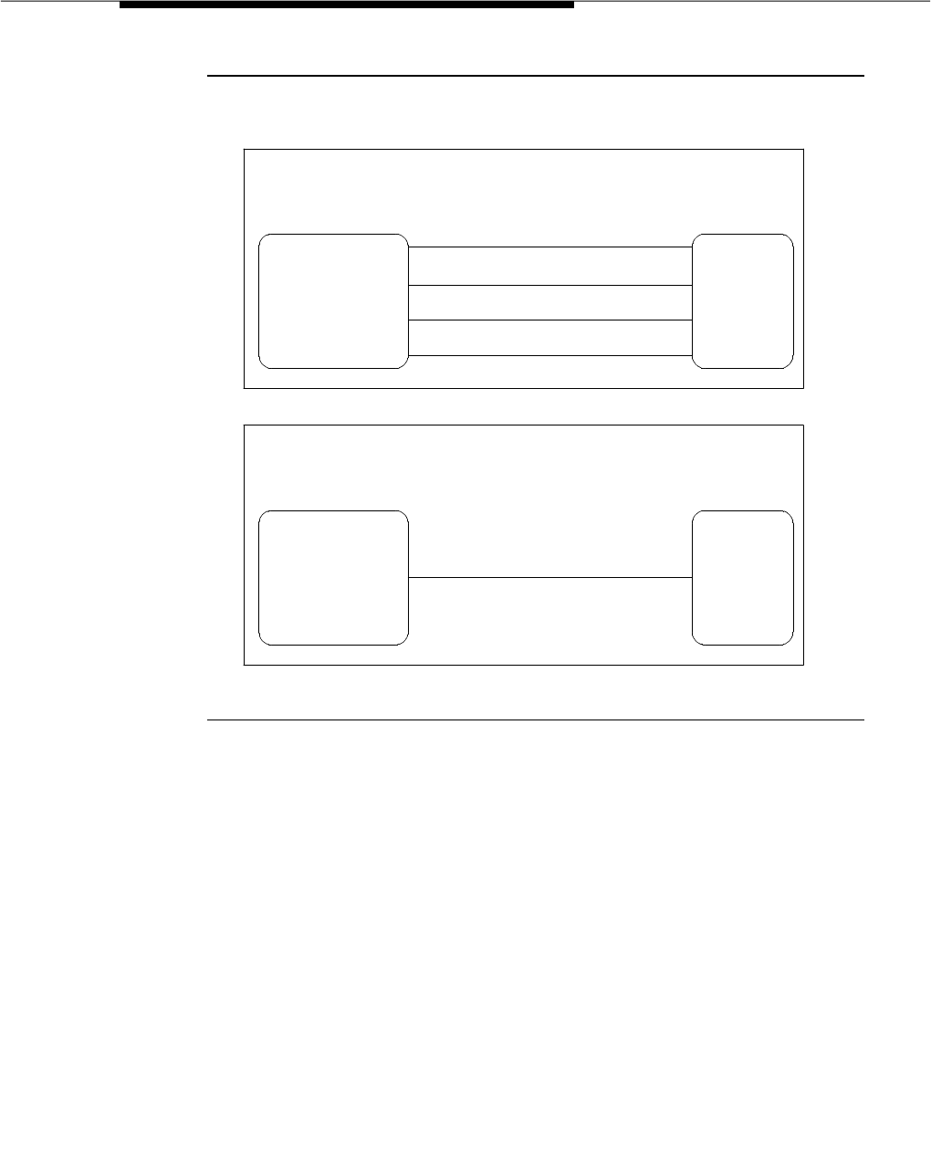
Call-By-Call Service Selection
Issue 3 March 1996 3-473
Figure 3-2. Call-By-Call Service Selection Example
ISDN-PRI Messages and Information Elements
Used for Call-By-Call Service Selection
Although the technical details of ISDN-PRI messages and information elements
are not critical to implementing the ISDN-PRI application, the following details
may aid in the understanding of some readers and are therefore included in this
description.
Call-By-Call Service Selection allows the system to specify one of the preceding
service types on a call-by-call basis. This is done via a SETUP message that
indicates the intent of the originating system to initiate a call using the specified
service or facility. The SETUP message contains units called information
elements which specify call-related information. The information elements used
with Call-By-Call Service Selection are as follows:
■Network Specific Facility — Indicates which facilities or services are to be
used to complete the call.
"MEGACOM" TRUNK GROUP
"MEGACOM" 800 TRUNK GROUP
SDN TRUNK GROUP
OUTWATS TRUNK GROUP
WITH CALL BY CALL SERVICE SELECTION:
A SINGLE TRUNK GROUP CARRIES CALLS FOR A VARIETY OF
SERVICES ON A CALL-BY-CALL BASIS
CALL BY CALL SERVICE SELECTION
TRUNK GROUP
"DEFINITY"
COMMUNICATIONS
SYSTEM
GENERIC 3
"DEFINITY"
COMMUNICATIONS
SYSTEM
GENERIC 3
WITHOUT CALL BY CALL SERVICE SELECTION:
EACH TRUNK GROUP IS DEDICATED TO A SPECIFIC SERVICE
PUBLIC
SWITCHED
NETWORK
PUBLIC
SWITCHED
NETWORK

Feature Descriptions
3-474 Issue 3 March 1996
The system also checks all incoming ISDN-PRI calls for the presence of a
Network Specific Facility information element. If this information element is
present, the system makes sure that the requested service is compatible
with the administration of the trunk. If the requested service is not
compatible with administration, the switch rejects the call.
For an outgoing call on a Call-By-Call trunk group, the Network Specific
Facility information element is constructed using the Service/Feature
specified on the routing pattern preference selected for the call.
■Transit Network Selection — Indicates which Inter-exchange Carrier is to
be used on an inter-LATA call.
If a call requires both the Service/Feature and the Inter-exchange Carrier
to be specified, the Inter-exchange Carrier information is sent in the
Network Specific Facility information element rather than the Transit
Network Selection information element.
Usage Allocation Plan
Optional Usage Allocation Plans (UAPs) may be assigned to provide more
control over a Call-By-Call Service Selection trunk group. Up to three Usage
Allocation Plans can be assigned for each Call-By-Call Service Selection trunk
group. A Usage Allocation Plan allows the customer to set the following:
■A maximum number of trunk group members that each specific service
can use at any given time.
■A minimum number of trunk group members that always is available for
each specific service.
The sum of the allocation plan maximums may exceed the total number of trunk
group members. For example, if a trunk group has 15 members and provides
access to MEGACOM service, MEGACOM 800 service, and SDN, the maximum
number of trunks to be used for each of these services could possibly add up to
more than 15. In this case, for example, you could administer a maximum of
seven MEGACOM service calls, six MEGACOM 800 service calls, and eight SDN
calls. This ensures that all trunk group members are not dominated by a specific
service, yet allows for periodic fluctuations in demand.
The sum of the allocation plan minimums may not exceed the total number of
trunk group members. For example, if a trunk group has 10 members and
provides access to MEGACOM service, MEGACOM 800 service, and SDN, the
minimum number of trunks to be used for each of these services cannot add up
to more than 10.
If a UAP has been defined for a Call-By-Call Service Selection trunk group, and
the type of the incoming call exceeds one of the plan’s limits, the system rejects
the call, even if a trunk is available. If a UAP has been defined for a Call-By-Call
Service Selection trunk group, and a system user makes an outgoing call of a
type that exceeds one of the plan’s limits, the user receives reorder tone unless
other preferences are available.

Call-By-Call Service Selection
Issue 3 March 1996 3-475
As previously mentioned, each Call-By-Call Service Selection trunk group can
have as many as three UAPs. The customer can assign either fixed or scheduled
allocation plans for each Call-By-Call Service Selection trunk group, (see Screen
3-30, Screen 3-31, and Screen 3-32) which are used to administer the Usage
Allocation Schedule and plans).
■Fixed
One plan applies at all times. The minimum and maximum usages
specified in this plan are in effect for the trunk group at all times.
■Scheduled
Two or three plans can be administered to apply at different times based
on the time of day and day of the week. As many as six activation times
and associated plans can be assigned for each day of the week. At the
specified activation time, the associated plan goes into effect for the
Call-By-Call Service Selection trunk group.
Screen 3-31. CBC Service Type Usage Allocation Plan
Assignment Schedule
CBC SERVICE TYPE USAGE ALLOCATION PLAN ASSIGNMENT SCHEDULE
Page x of x
Usage Method:
Fixed? _y Allocation Plan Number: _1
Scheduled? _n
Time # Time # Time # Time # Time # Time #
Sun 00:00 1 __:__ _ __:__ _ __:__ _ __:__ _ __:__ _
Mon 00:00 1 __:__ _ __:__ _ __:__ _ __:__ _ __:__ _
Tue 00:00 1 __:__ _ __:__ _ __:__ _ __:__ _ __:__ _
Wed 00:00 1 __:__ _ __:__ _ __:__ _ __:__ _ __:__ _
Thu 00:00 1 __:__ _ __:__ _ __:__ _ __:__ _ __:__ _
Fri 00:00 1 __:__ _ __:__ _ __:__ _ __:__ _ __:__ _
Sat 00:00 1 __:__ _ __:__ _ __:__ _ __:__ _ __:__ _

Feature Descriptions
3-476 Issue 3 March 1996
Screen 3-32. CBC Service Type Usage Allocation
System administration allows the customer to have anything from a simple fixed
usage allocation plan to a very flexible plan with many scheduling options. The
customer can even start out with no allocation plan and build the plan as the
need arises. This allows the customer to respond to periodic fluctuations in the
environment in a more timely manner. The customer does not have to involve the
network to fine-tune the trunk group administration. To ensure that administration
complexity is kept to a minimum, the following steps should be followed when
assigning UAPs.
1. Assign a Usage Allocation Plan for a Call-By-Call Service Selection trunk
group.
2. If scheduling is desired, add one or two more Usage Allocation Plans for
that trunk group.
3. Administer the scheduling information for the trunk group’s UAPs.
Incoming Call Handling Treatment
Call-By-Call Service Selection provides special Incoming Call Handling
Treatment for ISDN-PRI trunk groups. An incoming call on an ISDN-PRI trunk
group is handled according to a treatment table that is administered for that trunk
group. An example of the screen that contains this table follows.
CBC SERVICE TYPE USAGE ALLOCATION
Page 3 of 8
Trunk Allocation Plan 1 Trunk Allocation Plan 2 Trunk Allocation Plan 3
Service/ Min# Max# Service/ Min# Max# Service/ Min# Max#
Feature Chan Chan Feature Chan Chan Feature Chan Chan
____________ __ __ ____________ __ __ ____________ __ __
____________ __ __ ____________ __ __ ____________ __ __
____________ __ __ ____________ __ __ ____________ __ __
____________ __ __ ____________ __ __ ____________ __ __
____________ __ __ ____________ __ __ ____________ __ __
____________ __ __ ____________ __ __ ____________ __ __
____________ __ __ ____________ __ __ ____________ __ __
____________ __ __ ____________ __ __ ____________ __ __
____________ __ __ ____________ __ __ ____________ __ __
____________ __ __ ____________ __ __ ____________ __ __

Call-By-Call Service Selection
Issue 3 March 1996 3-477
Screen 3-33. Trunk Features
As shown above, a variety of specifications can be administered in the table for
the treatment of incoming calls. The table allows for as many as 12 different
combinations of call treatments. Seven columns are provided for seven different
specifications. These specifications are as follows:
■Selection Criteria
—Service/Feature — Specifies the ISDN-PRI Services/Features to
which the specified call treatment may apply. These
services/features are those discussed in the ‘‘Services Used With
Call-By-Call Service Selection’’ section of this feature description.
The identifier ‘‘other’’ can be used for all Services/Features not
explicitly specified.
—Called Len — Specifies the number of digits contained in the
Called Party Number (the digits received for the incoming call).
The number of digits contained in the Information Element must
exactly match the number of digits specified in this field. Allowable
entries are 0 through 16 or blank. A blank entry indicates a wild
card, meaning that a called number of any length matches.
—Called Number — Specifies the leading digits contained in the
Called Party Number. For this row to be chosen for a call, the data
is this field must exactly match the leading digits in the IE. A blank
entry indicates that the incoming digits are not significant for this
entry. Allowable entries are 1 through 16 digits or blank.
TRUNK FEATURES Page 2 of x
Service/ Called Called Del Insert CPN/BN Night
Feature Len Number Serv
_____________ ___ _______________ ___ ______________ __________ _______
_____________ ___ _______________ ___ ______________ __________ _______
_____________ ___ _______________ ___ ______________ __________ _______
_____________ ___ _______________ ___ ______________ __________ _______
_____________ ___ _______________ ___ ______________ __________ _______
_____________ ___ _______________ ___ ______________ __________ _______
_____________ ___ _______________ ___ ______________ __________ _______
_____________ ___ _______________ ___ ______________ __________ _______
_____________ ___ _______________ ___ ______________ __________ _______
_____________ ___ _______________ ___ ______________ __________ _______
_____________ ___ _______________ ___ ______________ __________ _______

Feature Descriptions
3-478 Issue 3 March 1996
■Action Taken Based on Selection Criteria
—Del — Specifies the number of leading digits to be deleted from
the incoming Called Party Number. Calls of a particular type may
be administered to be routed to a single destination by deleting all
incoming digits and then administering the “Insert” field with the
desired extension.
—Insert — Specifies the digits to be prepended to the front of the
Called Party Number. The new number is used to route the call.
Allowable entries are up to 16 digits or blank.
—CPN/BN — Specifies your preference of a Calling Party Number
(CPN) or Billing Number (BN) request for this type of call. A blank
or ‘‘none’’ indicates that the switch is not requested either CPN or
BN for any incoming calls of this type. Allowable entries are BN
only, prefer BN but accept CPN, CPN only, and prefer CPN but
accept BN.
—Night Serv — Specifies a night service extension per
Service/Feature. An entry other than blank overrides the night
destination entry on Page 1 of the form. Allowable entries are an
assigned extension, attendant, or blank.
NOTE:
Bellcore NI-2 Call-By-Call service does not support the
delivery of CPNI B-N on a per call basis.
The treatment for an incoming call is selected based on the “Service/Feature,
Called Len”, and “Called Number” fields in the table. When the attributes of an
incoming call match these specifications, the call is treated according to the
corresponding Del, Insert, CPN/BN, and Night Service specifications. If an
incoming call matches more than one set of specifications, the most restrictive
case is selected. The following table lists the possible cases in order of most
restrictive to least restrictive:

Call-By-Call Service Selection
Issue 3 March 1996 3-479
Table 3-47 lists the most/least restrictive specifications.
Considerations
Call-By-Call Service Selection provides the following benefits:
■Cost Reduction — Since many services share the same trunks, the total
number of trunks can be reduced.
■Improved Service — Call-By-Call Service Selection trunks can reduce the
probability of features and services being blocked.
■Simplified Networking — Network engineering is simplified because
analysis of trunking needs can be done based on total traffic instead of on
a per-service basis.
■The ability to respond to changes in a more timely fashion. The network
does not have to be consulted because of the flexibility provided by the
usage allocation plans.
■Measurement of Call-By-Call Service Selection calls.
Table 3-47. Call-by-Call Service Selection Most/Least
Restrictive Specifications
Service/ Feature Called Len Called Number
Most Restrictive Specified Specified X Number Of
Leading Digits
Specified
Specified Specified Y Number Of
Leading Digits
Specified, Where
Y < X
Specified Specified Not Specified
Specified Not Specified Not Specified
Specified as ‘‘other’’ Specified X Number Of
Leading Digits
Specified
Specified as ‘‘other’’ Specified Y Number Of
Leading Digits
Specified, Where
Y < X
Specified as ‘‘other’’ Specified Not Specified
Least Restrictive Specified as ‘‘other’’ Not Specified Not Specified

Feature Descriptions
3-480 Issue 3 March 1996
Interactions
The following features interact with the Call-By-Call Service Selection feature.
■AAR
Call-By-Call Service Selection uses the same routing tables and routing
preferences that are used by AAR.
■ARS
Call-By-Call Service Selection uses the same routing tables and routing
preferences that are used by ARS.
■GRS
Call-By-Call Service Selection uses the same routing tables and routing
preferences that are used by GRS.
■CDR
On successful incoming and outgoing Call-By-Call Service Selection calls,
the Network Specific Facility specified by the call’s Network Specific
Facility Information Element is recorded by CDR. CDR refers to this
information as the INS (ISDN Network Service).
If an outgoing Call-By-Call Service Selection call uses an Inter-exchange
Carrier (IXC) other than the presubscribed common carrier, CDR records
the 3- or 4-digit IXC code. CDR may not record the IXC code properly if
the dialed code format differs from the US IXC code formats.
When a Call-By-Call Service Selection call is rejected because of a trunk
group usage allocation plan, CDR records the cause as an ineffective call
attempt.
■Time of Day Routing
Any Time of Day Routing administration that affects routing preference
also affects Call-By-Call Service Selection.
The Time of Day Routing feature can be used to vary the IXC based on the
time of day and day of the week.
■Traffic Measurements
The system provides traffic measurements for each individual service
administered as part of the ISDN Call-By-Call Service Selection trunk
group.
Administration
Call-By-Call Service Selection is administered by the System Manager on a per
trunk group basis. The following items require administration:
■ISDN-PRI Trunk Group — Must be administered with a Service Type of
Call-By-Call Service Selection. The trunk group administration also
includes the following:

Call-By-Call Service Selection
Issue 3 March 1996 3-481
— Incoming Call Handling Treatment
— Whether or not UAPs are required
—UAPs
— UAP Assignment Schedule
— Group Member Assignments
■AAR/ARS Routing Patterns — Routing Patterns can be administered to
include a Network Specific Facility and/or IXC.
■Network Specific Facilities Encoding — New Network Specific Facilities
can be added as needed by the system technician.
Hardware and Software Requirements
A TN767 24-port DS1 circuit pack or TN464B/C/D DS1 interface (24-port
T1/32-port E1) circuit pack is required for assignment of a signaling link and up
to 23 or 30 ISDN-PRI Trunk Group members. For G3vs, a TN765 Processor
Interface circuit pack is required in conjunction with the DS1 circuit pack, for
ISDN D-Channel Links. For G3s and G3i, a TN675 Processor Interface or a
TN778 Packet Control circuit pack are required for ISDN D-Channel Links.
NOTE:
The TN767 and the TN464C and later revisions of the DS1 circuit packs
provide a DSX1 interface.

Feature Descriptions
3-482 Issue 3 March 1996
CallVisor Adjunct/Switch
Applications Interface (ASAI)
Feature Availability
This optional feature may be purchased with any Generic 3 release except
G3vs/G3s ABP and G3i-Global.
Description
Provides one or more links between the DEFINITY switch and one or more
adjuncts. CallVisor ASAI improves the call handling efficiency of ACD agents and
other system users by allowing an adjunct to monitor, initiate, control, and
terminate calls on the switch. The CallVisor ASAI interface may be used for
Inbound Call Management (ICM), Outbound Call Management (OCM), and office
automation/messaging applications.
CallVisor ASAI services are provided using either Integrated Services Digital
Network (ISDN) Basic Rate Interface (BRI) transport (CallVisor ASAI-BRI), or LAN
Gateway Transmission Control Protocol/Internet Protocol transport (CallVisor
ASAI-LAN Gateway).
Regardless of transport type, CallVisor ASAI messages and procedures are
based on the ITU-T Q.932 international standard for supplementary services. A
special information element, the Q.932 Facilities Information Element (FIE),
carries the CallVisor ASAI requests and responses across the interface. An
application program can access CallVisor ASAI services or features by
supporting the ASAI protocol, by using a computer vendor, or by a third-party
provider application programming interface.
The system can have up to eight (four for G3s PBP) CallVisor ASAI links.
G3V4 ASAI Enhancements
■ASAI Accessed Internally Measured Data
This feature allows an ASAI adjunct application to access and retrieve
Internally Measured Data used to provide VuStats information to
display-equipped digital voice stations. The application accesses this
data via a new Value Query message that specifies whether agent,
split/skill, trunk group, or VDN information is being requested. The new
message also specifies a particular observed object of the type (for
example, agent or split) specified in the request.
By providing Internally Measured Data via ASAI, applications can offer
enhanced VuStats-like presentations (for example, using graphics, color,
or multimedia) on a PC or can further process this data to provide

CallVisor Adjunct/Switch Applications Interface (ASAI)
Issue 3 March 1996 3-483
enhanced statistics for better call center management. Also, VuStats-like
service can be provided without requiring a digital display-equipped
station.
■Send DTMF Signals
This feature is an ASAI-accessed service that, when invoked by a client
application, causes the DEFINITY system to send a DTMF sequence on
behalf of one party on an active call. The digit sequence to be transmitted
is contained in the ASAI service message.
The DTMF tones can be heard by any endpoint connected to the sending
talk path. Through such a tone sequence, an adjunct can interact with
far-end applications such as automated bank tellers, automated
attendants, voice mail systems, various databases, and paging services.
An application could provide certain convenience features such as
automated entry of passwords or service-access sequences.
■Flexible Billing
This feature allows an ASAI adjunct to change the rate at which an
incoming 900-type call is billed.
■Redirect Call
This feature allows an ASAI adjunct to direct the switch to move an already
alerting call away from an extension (at which it is alerting) to another
endpoint. Prior to G3V4. such routing was possible only if switch features,
rather than an ASAI-provided service, were used (for example, call
forwarding or Send All Calls). With this service, an application could, for
example, determine, based on call-related information or time of day, etc.,
whether to answer the call or re-route it to some other number.
This service does not support removing a call from a queue. Only calls
alerting
at extensions can be manipulated by this service.
■ASAI-Accessed Integrated Directory Database Service
This feature allows an ASAI adjunct to access and retrieve administered
name-extension associations stored in the switch (all administered names
associated with station extension numbers, trunk groups, and VDNs). The
application accesses this data via a new Value Query message containing
the target extension. If a valid Query Message is submitted, the switch
responds with a message containing the administered name.
■Event Report Capabilities
Enhancements to Event Reports allow ASAI adjuncts to receive Event
Reports when specified events occur at monitored objects. In addition, in
the Alerting Event Report, new cause values are provided to specify a
reason for redirection.
The following are descriptions of new/changed Event Report for G3V4.
These reports are provided only if Link Version 2 is active.

Feature Descriptions
3-484 Issue 3 March 1996
■Agent Login Event Report — This is a new Event Report provided
when an agent logs into a domain controlled ACD group or EAS
skill. Notification of manual login events allows adjunct applications
to maintain accurate views of current agent login/logout status.
■Call-Originated Event Report — This is a new Event Report
provided when a call is manually or otherwise originated from a
domain-monitored station. It also provides the dialed digits to an
application.
■Alerting Event Report — This existing Alerting Report has been
enhanced to provide a new set of cause code values that map
one-to-one to each existing G3V4 reason for redirection that
appears on display-equipped stations when a redirected call is
offered.
The new cause codes are provided in an existing Information
Element of the Report. An adjunct application can use this
information to provide an enhanced information display (for
example, on a computer monitor) to called parties or to otherwise
determine how to best handle an incoming call.
In addition to these GV4 enhancements, a new transport option, ASAI-LAN
Gateway, is available. Also, CPN/BN on BX.25 links has been removed in G3V4.
See the
DEFINITY Communications System Generic 3 CallVisor ASAI Technical
Reference,
555-230-220, for more detail on these enhancements.
CallVisor ASAI Capabilities
The following capability groups are provided by CallVisor ASAI:
■Third Party Call Control Group
■Third Party Domain (Station/ACD Split) Control Group
■Notification Group
■Set Value Group
■Value Query Group
■Request Feature Group
■Routing Group
■Maintenance Group
The following paragraphs provide an overview of these capability groups.
NOTE:
The Third Party Domain (Station/ACD Split) Control Capability Group is a
actually a subsection of the Call Control Capability Group. For the purpose
of this document, the Third Party Domain (Station/ACD Split) Group is
treated as a separate capability group. This section represents the
DEFINITY Communications System implementation of ASAI, as described

CallVisor Adjunct/Switch Applications Interface (ASAI)
Issue 3 March 1996 3-485
in the
DEFINITY Communications System Generic 3 CallVisor ASAI Protocol
Reference
, 555-230-221, and the
DEFINITY Communications System
Generic 3 CallVisor ASAI Technical Reference
, 555-230-220.
Computer vendors may not implement all of the ASAI capabilities with their
respective Application Programming Interface (API). Specific computer vendors
determine which aspects of these capabilities are supported within their APIs.
Third Party Call Control Capabilities Group
Third Party Call control capabilities are used by the adjunct to initiate, control,
and terminate calls to which it is not a party. The following capabilities make up
the Third Party Call Control capabilities:
■Initiating Capabilities:
—Third Party Make Call — Used by the adjunct to set up a call. This
capability supports the following types of adjunct-controlled calls:
— Switch-Classified
— User-Classified
— Direct-Agent
— Supervisor-Assist
These call types are described in the next section of this feature
description, "CallVisor Adjunct/Switch Applications Interface
(ASAI)".
— User-to-User Information (UUI) Transport can be included in
Third Party Make Call.
— Third Party Take Control — Used to take control of a call that
is already in progress if other third party call control
functions (such as hold, drop, and so on) are desired.
■Control Capabilities:
—Third Party Selective Drop — Used by the adjunct to request that
a party be dropped from the specified adjunct-controlled call.
—Third Party Selective Hold — Used by the adjunct to request that
a party on a specified adjunct-controlled call be placed on hold.
—Third Party Reconnect — Used by the adjunct to request that a
party be reconnected to a specified adjunct-controlled call.
—Third Party Merge — Used by the adjunct to request that two
adjunct-controlled calls be merged. Merging two calls means
conferencing the calls or transferring a held call to an active call.
The adjunct specifies the desired type of merge.
—Redirect Alerting Call — Used by the adjunct to reroute a call that
is alerting at a station.

Feature Descriptions
3-486 Issue 3 March 1996
■Terminating Capabilities:
—Third Party Relinquish Control — Used by the adjunct to request
that a specified adjunct-controlled call no longer send call events.
The call must have been previously controlled by the same adjunct.
—Third Party Clear Call — Used by the adjunct to request that a
specified adjunct-controlled call be dropped (all parties on that call
are dropped and all resources are released from the call).
—Third Party Call Ended — Invoked by the switch as a result of an
adjunct-controlled call being dropped. This capability lets the
switch terminate the exchange between the switch and the adjunct
of messages related to CallVisor ASAI.
■Event Reporting Capability:
—Event Report — Used by the switch to convey call feedback and
event information in the form of event reports to the adjunct. Call
events are sent to the adjunct for monitored and controlled calls.
CallVisor ASAI Call Types
Table 3-48 shows the CallVisor ASAI call types that the Third Party Make Call, the
Third Party Auto Dial, and the Route Select capabilities may request.
These call types are described next.
Switch-Classified Calls
A ‘‘Switch-Classified Call’’ is primarily used in Outbound Call Management
(OCM) applications with AutoPace or Predictive Dialing.
An adjunct initiates Switch-Classified calls on behalf of the originator (extension
number associated with a split, hunt group, or announcement) with only the
answered calls are transferred to the originator; other calls are dropped by the
switch.
Table 3-48. CallVisor ASAI Call Types Supported
Supported by...
Call Type Third Party
Make Call Third Party
Auto Dial Adjunct Route or
Route Request
Switch Classified Calls X
User Classified Calls X X X
Direct Agent Calls X X
Supervisor Assist Calls X

CallVisor Adjunct/Switch Applications Interface (ASAI)
Issue 3 March 1996 3-487
With this type of call, the destination is alerted first and the call is then classified
using Call Classification. The destination can be either a valid switch extension or
an external number.
It is recommended that trunks with answer supervision be used for
switch-classified outbound calls. Answer supervision from the network over the
trunk facility provides an accurate and quick indication of when the far end
answers.
Answering Machine Detection (AMD)
Answering Machine Detection for Outbound Calls provides Outgoing Call
Management (OCM) customers the ability to differentiate between calls
answered by a human (‘‘real’’ voice energy) and calls answered by an answering
machine.
An ASAI adjunct can request answering machine detection for a switch classified
call. When AMD is requested, the reporting of the call outcome is delayed
because detection of voice energy is no longer sufficient to classify a call.
Instead, further classification is required to distinguish between a live answer
and a machine answer.
The range for talk duration is from 0.1 to 5.0 seconds in increments of 0.1. The
default value is 2.0 seconds. The range for pause duration if from 0.1 to 2.0
seconds in increments of 0.1. The default value is 0.5 seconds. Customers can
alter the default values to suit their needs. For example, to bias the algorithm so
that it errors on the side of a line error, the customer could lengthen the call
duration.
This feature can be disabled on the System-Parameters Customer-Options form.
User-Classified Calls
A ‘‘User-Classified Call’’ is set up by the adjunct on behalf of an originator to an
internal or external destination. It is a call whose originator is alerted first. Such a
call is ‘‘user classified’’ because the originator (station user) listens to the call
origination and network provided tones, determines the call outcome (for
example, busy, reorder, answered), and decides what to do with the call: allow it
to continue ringing, drop the call, or speak to the destination or answering party.
This type of call is typically used in ViewFirst or Preview Dialing applications, and
can also be used to place and conference/transfer a new call with an existing
call. When priority calling is requested, the destination behaves as specified in
the "Priority Calling" feature description later in this chapter.
The adjunct must provide the switch with the call destination address and notify
the switch of whether priority calling is desired. For Third Party Make Calls, the
adjunct must also provide the originator’s address or extension. Valid originators
for user classified calls are all voice terminal extensions. Valid destinations are
either internal or external extensions [including Vector Directory Numbers
(VDNs)] or external numbers.

Feature Descriptions
3-488 Issue 3 March 1996
When initiating user-classified calls, the switch selects an originator’s call
appearance to set up the call to the destination. If the originator is on-hook, the
switch takes the station off-hook if it can (for example, speaker users) and
originates the call. Otherwise, the switch waits five seconds for the originator’s
station to go off-hook on a idle call appearance. If the originator is off-hook with a
dial tone, the switch completes the dialing with the destination digits provided by
the adjunct.
In the case of an incoming call to a VDN, the Route Select just provides the new
destination for the call.
Direct-Agent Calls
A ‘‘Direct Agent’’ Call is a special type of ACD call that can be set up via
CallVisor ASAI on behalf of any voice terminal user (or VDN caller) to a
specific
ACD agent. Such calls differ from typical ACD calls in that the agent is specified,
not selected by the ACD.
NOTE:
This feature is supported through CallVisor ASAI and is not available as a
feature from the voice terminal.
Direct Agent calls may be used whenever an adjunct or ACD agent decides that
the caller/customer should talk to a specific ACD agent rather than being put in
the split queue for an available agent. For instance, in ‘‘adjunct directed’’ call
routing applications, an adjunct routes incoming calls to a VDN to specific
agents based on agent availability and the call’s DNIS, CPN/BN, Look-Ahead
Interflow information, or digits collected via Call Prompting.
Valid originators for Direct Agent Calls are all voice terminal extensions and VDN
callers.
Valid destinations are the following:
■ACD agent extensions logged into an ACD split.
■Station extension of EAS agent (logged in).
Direct Agent calls are delivered with the highest ACD priority level. That is,
Direct Agent calls have priority over all non-Direct Agent ACD calls and
are inserted ahead of all non-Direct Agent calls in the split queue.
NOTE:
A new Direct Call call agent is queued behind previously queued
Direct Agent calls.
An agent becomes available to receive a Direct Agent call by becoming
available to receive ACD calls in the split or (EAS skill) that the Direct
Agent call is associated with (that is, going into the ‘‘manual-in’’ or
‘‘auto-in’’ work mode for the split). When the direct agent call is delivered
to the agent and the auto-answer option is enabled on the station set, zip
tone is applied to the agent as for any ACD call. If the station set is

CallVisor Adjunct/Switch Applications Interface (ASAI)
Issue 3 March 1996 3-489
optioned for manual answering, the call rings the destination agent’s
station. After disconnecting from a Direct Agent call, the agent’s work
mode follows the same rules as if the agent disconnects from any other
ACD call (refer to the "Automatic Call Distribution (ACD)" feature
description earlier is this chapter).
If an agent is not available to receive a Direct Agent call because the
agent is busy on another ACD call, or is in the ‘‘auxiliary-work’’ or
‘‘after-call-work’’ mode for the split associated with the direct agent call,
the call queues for the agent on the specified ACD split. Agents are
notified of queued Direct Agent calls only once for each Direct Agent call
that queues with either a ring ping (for multifunction sets and on-hook
analog sets) or a three burst call waiting tone (for analog sets that are
off-hook and active on a call).
■If the agent has an analog set, is off-hook, and not active on a call,
then the Direct Agent call queues without a call warning tone.
■If the agent has a multifunction set, the active work mode button
lamp, if administered for the set, indicates that a direct agent call is
waiting in queue by flashing (fast flutter).
■If the agent has an analog set, the three-burst call waiting tone is
provided regardless of how the ‘‘Call Waiting Indication’’ option is
administered for this set.
After a Direct Agent call queues, the switch waits for the agent to become
available or until the coverage answer time out limit expires for the destination
agent. If this timeout value is reached, the call follows the agent’s coverage path.
(If the adjunct requests that the Direct Agent call be a priority call, the call does
not go to coverage and remains queued until the call is delivered to the agent or
the caller disconnects.)
In the case of a Direct Agent call joining the split queue, the destination agent’s
auto-in or manual-in button associated with the destination split will flash.
Flashing will stop when no more Direct Agent calls are in the split queue waiting
for this agent.
When an agent is logged into multiple splits, then all Direct Agent calls destined
for the agent are serviced before all non-Direct Agent calls in all splits. When
there is more than one split with Direct Agent calls waiting for the same agent,
the Direct Agent call with the longest queue waiting time is serviced first.
Direct Agent calls are not included in any of the existing measurements affecting
queue status displays and buttons. However, such calls are included in CMS
measurements.
Supervisor Assist Calls
‘‘Supervisor Assist Calls’’ are set up between an ACD agent’s extension and
another voice terminal extension (typically a supervisor in the ACD split). This
feature is used in either ICM or OCM applications when an agent, while on the

Feature Descriptions
3-490 Issue 3 March 1996
phone with a client or when idle, wants to consult with the supervisor. If the agent
is active on a call, the host application requests that the call first be placed on
hold, then request Supervisor Assist Call. Typically, an agent submits this
request from a data terminal keyboard. Supervisor Assist Calls are tracked by
CMS.
Valid originators for Supervisor Assist Calls are voice terminal extensions logged
into an ACD split or EAS skill; valid destinations are internal voice terminal
extensions.
Third Party Domain (Station/ACD Split) Control
Capabilities Group
Third Party Domain ACD Split Control capability allows an adjunct to receive
agent login and logout event reports for a specified ACD split domain.
Third Party Domain Station Control capabilities allow the adjunct to control only
the station extension associated with the domain-control association instead of
allowing control of all parties (extensions) on a call. With these capabilities, the
adjunct can:
■Control all calls originating and ending at a station extension
■Monitor all calls only at that specific station
■Initiate outbound calls from the station
NOTE:
The Third Party Domain (Station/ACD Split) Call Control Capability Group
is a actually a subset of the Call Control Capability Group. For the purpose
of this document, the Domain (Station/ACD Split) Call Group is treated as a
separate capability group.
The following capabilities make up the Domain (Station/ACD Split) Call Control
capabilities:
■Initiating Capabilities:
—Third Party Domain (Station) Control Request — Monitors
(receive event reports) and control all calls at a specified extension.
After the switch accepts a Third Party Domain Control request from
the adjunct, the extension is referred to as a controlled extension.
(Only station extensions can be domain controlled by a CallVisor
ASAI adjunct.)
—Third Party Domain Control Request for ACD Split Domain —
Receives event reports at the specified split domain. The Login and
Logout Event Reports are available.
■Control Capabilities (Station only):

CallVisor Adjunct/Switch Applications Interface (ASAI)
Issue 3 March 1996 3-491
—Third Party Answer — ‘‘answers’’ a ringing, bridged, or held call
present at a station. Answering a ringing, bridged, or held call
means to connect a call by forcing the station off hook, if the station
is on hook, or cutting through the call to the headset or handset, if
the station is off hook (listening to dial tone or being in the off hook
idle state).
—Third Party Selective Drop — Drops a controlled extension from a
call.
—Third Party Selective Hold — Places the controlled extension on
hold.
—Third Party Reconnect — Reconnects a held call at the controlled
extension to the controlled extension.
—Third Party Merge — Requests that a held call and an active call
at the controlled extension be conferenced or transferred.
—Third Party Autodial — Originates a call from the controlled
extension to an internal or external destination.
—Redirect Call — Reroutes a call alerting at a station.
—Send DTMF Signals — Sends a DTMT sequence on behalf of one
party on an active call.
■Terminating Capabilities (Station/Split):
—Third Party Relinquish Control — Stops monitoring and
controlling the calls at the controlled extension.
—Third Party Domain Control Ended — Used by the switch to
inform an application that domain control association has been
terminated because the domain was removed or changed to
become an invalid domain by administration.
■Event Reporting Capability (Station/Split):
—Event Report — Used by the switch to convey call feedback
(station) and event information in the form of login and logout
events to the adjunct.
Notification Capabilities Group
Notification capabilities are used to request and terminate event reporting on
certain calls. The Notification capabilities are as follows:
■Event Notification Request
■Event Report
■Event Notification Cancel
■Event Notification Ended
■Stop Call Notification

Feature Descriptions
3-492 Issue 3 March 1996
An adjunct uses the Event Notification Request function to request notification of
calls to VDNs and ACD splits. Such splits cannot be vector-controlled or
adjunct-controlled.
NOTE:
This precludes notification on EAS skills, since the EAS skills are equivalent
to vector controlled splits.
In G3V3, up to three adjuncts can request notification on a vector directory
number (VDN) or split. Once the adjunct requests event notification on a VDN or
split, the VDN or split is referred to as a ‘‘monitored’’ VDN or split. From this point
on, any call entering this monitored VDN or split causes the switch to start
sending call events to the monitoring adjunct, and the call becomes a monitored
call. The switch continues to send call events on the monitored call until the call
is disconnected, dropped, abandoned, or enters another monitored VDN or split.
Call events are sent to the adjunct via the Event Report capability. Call events
may be any of the following:
■Alerting
■Trunk Seized
■Cut-through/Progress
■Disconnect/Drop
■Queued
■Busy/Unavailable
■Answered
■Connected
■Reorder/Denial
■Call Offered to Domain
■Call Originated
■Call Transferred
■Call Conferenced
■Call Ended
■Call Redirected
■Hold
■Reconnected
NOTE:
See the next table in this section for a listing of the call events that apply to
each capability group.

CallVisor Adjunct/Switch Applications Interface (ASAI)
Issue 3 March 1996 3-493
The Stop Call Notification capability stops an adjunct from receiving call events
for a specific call. The switch no longer sends call events on that call to this
adjunct. If a call enters another monitored VDN or split after a Stop Call
Notification request, the switch provides event reports for the call over the newly
entered monitored VDN or split.
An adjunct can cancel a notification request for all calls within a VDN or ACD with
the Event Notification Cancel capability. Call events for a particular VDN or ACD
split will no longer be provided.
If a switch administration change causes a VDN or ACD split to become invalid,
the switch informs the adjunct using the Event Notification Ended capability.
Set Value Capabilities Group
Set Value allows the following items to be set to a specified value.
■Message Waiting Lamp
The adjunct uses this capability to set the state of a message waiting
lamp.
■Billing Rate
The adjunct uses this capability to set the value of a billing change for
900-type calls.
Value Query Capabilities Group
The ‘‘Value Query’’ capability allows the adjunct to request information from the
switch about the status or value of switch resources.
The following value queries are supported:
■Time of Day Query — The adjunct asks for the time. The switch response
contains the year, month, day, hour, minute, and second.
■ACD Split Query — The adjunct sends a valid split (or EAS skill)
extension in a value query message. The switch responds with the
number of ACD agents available to receive calls in that split or EAS skill,
the number of calls in queue, and the number of ACD agents logged in.
■Trunk Group Query — The adjunct sends a trunk access code in a value
query message. The switch responds with the number of idle trunks in the
trunk group and the number of in-use trunks.
■Call Classifier Query — The adjunct sends a classifier request in a value
query message. The switch responds with number of idle and in-use call
classifier ports.
■ACD Agent Status Query — The adjunct sends an ACD split (or EAS
skill) and an agent extension in a value query message. The switch
responds with the work mode and idle/busy state of the agent.

Feature Descriptions
3-494 Issue 3 March 1996
■Extension Query — The adjunct sends an extension number in the value
query message and the switch responds with the type or class (for
example, VDN, Hunt Group, EAS skill, Announcement, Voice).
■ACD Agent Login — The adjunct sends an ACD split extension and an
ACD agent login audit flag in a value query message. The switch
responds with a list that contains the extensions for each agent logged
into the split.
■Calls Query — The adjunct passes an extension in the value query
request. The switch responds with the call_id(s) for the calls present at the
primary’s extension, and also sends the party_id and party_state (for
example, alerting, connected, or hold) of that station for each call.
Additionally, information about a maximum of 10 calls present at the
station is reported back to the adjunct. This query is valid for stations and
logical agents only.
■Station Status Query — The adjunct uses this query for status
information on the extension number of the endpoint. The switch responds
with the talk (idle/busy) state of the voice terminal.
■Party ID Query — The adjunct sends a call_id in a value query message.
The switch responds with the party_id and the extension number for all the
local parties on the call.
■Station Feature Query — The application passes an extension number
and the feature to the switch. The extension need not be
domain-controlled, but it must support the particular feature. The switch
responds with the state (active/not-active) of the specified feature at the
specified extension.
The following features may be queried:
— Message Waiting Indication
— Send All Calls
— Call Forwarding
■BCMS Data Value Query — The adjunct uses this query to retrieve BDMS
data that was collected for agent, agent extension, split/skills, trunk group,
or VDN.
■ASAI-Accessed Integrated Directory Database — The application
passes a target extension to the switch. The switch responds with the
administered names associated with the specified extension.
Request Feature Capabilities Group
This capability allows the adjunct to request activation of the following switch
features.
■ACD Agent Login — Log in agent to an ACD split or EAS skill. The
following parameters are required for this function:
— Logical agent login id (EAS skill only)

CallVisor Adjunct/Switch Applications Interface (ASAI)
Issue 3 March 1996 3-495
— Login Identifier (password) — any string of length equal to or
greater than that administered on the switch.
— ACD Split Extension (or EAS skill)
— Agent Extension (Contains physical extension for EAS agent)
— Mode: After Call Work, Auto-In, Manual-In, Auxiliary Work (optional,
corresponds to initial work mode; if not specified, the default is
Auxiliary Work)
■ACD Agent Logout — Logout agent from an ACD split. The following
parameters are required for this function:
— ACD Split Extension (or EAS skill)
— Agent Extension (physical or logical for EAS agent)
■ACD Agent Change of Work Mode — Change work mode of ACD or
EAS agent to another mode. The following parameters are required for this
function:
— ACD Split Extension
— Agent Extension
— Mode: After Call Work, Auto-In, Manual-In, Auxiliary Work
(corresponds to new work mode)
NOTE:
Work mode change ‘‘pending’’ states are not supported by ASAI.
(For example, if the agent is active on an ACD call and is in Auto-In
work mode, a request to place the agent in After Call Work mode is
denied.)
■Send All Calls — Activate or cancel Send All Calls at a specific station.
The adjunct provides the extension where Send All Calls (SAC) is
activated.
■Call Forwarding — Activate or cancel Call Forwarding at a specific
station. The adjunct provides the ‘‘forwarded from’’ and ‘‘forwarded to’’
extensions.
Adjunct-Controlled Splits
The switch may have adjunct-controlled splits. An adjunct-controlled split is an
ACD split designated as adjunct-controlled via switch administration. An
adjunct-controlled split has the following properties:
■An adjunct-controlled split must have an administered controlling adjunct
(CallVisor ASAI link extension).
■Agent login may only be done by the adjunct via Request Feature
capabilities.
■An agent may be logged into only one such split at any given time.

Feature Descriptions
3-496 Issue 3 March 1996
■Change of work modes may only be done by the adjunct via Request
Feature capabilities.
■Work mode changes take effect as soon as they are requested and
processed.
■Agent logout may be done by the adjunct via Request Feature capabilities
or by the agent. When logout is caused by action at the voice terminal, a
logout event report is sent to the adjunct associated with the split
(provided domain control has been requested for that split).
■As long as the corresponding CallVisor ASAI link is up, Agents logged into
an adjunct-controlled split have their voice terminal locked (all buttons and
the touch tone pad) for the duration of the login. These agents must use
Call Control and Request Feature capabilities to access voice terminal
calling and ACD support features. (Adjunct-controlled splits cannot
receive non-adjunct monitored and controlled calls. Non-adjunct
monitored and controlled calls receive busy tones if they try to terminate at
such splits.)
■Agents logged into adjunct-controlled splits can only receive calls that are
monitored (via the Event Notification group) or controlled (via the third
person Call Control group), primarily ASAI-OCM calls.
■An unmonitored or controlled call directed to an adjunct-controlled split
receives a busy tone.
■A unmonitored or controlled call directed to an agent logged into an
adjunct-controlled split receives a busy tone.
■Agents logged into an adjunct-controlled split may not make any calls
from the voice terminal. All telephony functions must be done via third
party call control.
■Adjunct-controlled splits may not have notification active. A request
notification for an adjunct-controlled split will be denied.
■An adjunct-controlled split may be vector-controlled as well.
■When an agent is logged into an adjunct-controlled split, all display
buttons are disabled. The display itself functions normally.
When the CallVisor ASAI link is down, adjunct-controlled splits behave like
non-adjunct-controlled splits. Agents logged into such splits when the link is
down have their voice terminals unlocked without being logged out. When the
CallVisor ASAI link is restored, adjunct controlled splits return to being
adjunct-controlled, and agent’s voice terminals become locked again.
Adjunct-controlled splits may also be vector-controlled. Splits that are both
adjunct-controlled and vector-controlled have all the properties of both. Where
there is a conflict, the more restrictive property applies. For example, agents
logged into such a split cannot log into any other split and their voice terminal is
locked.

CallVisor Adjunct/Switch Applications Interface (ASAI)
Issue 3 March 1996 3-497
An agent cannot be logged into multiple splits if that agent is logged into an
adjunct-controlled split. Because of the numerous restrictions associated with
adjunct-controlled splits, the use of such splits should be limited.
Routing Capabilities Group
The routing capabilities allow the switch to request (from the adjunct) routing
instruction for a call. The adjunct may use incoming call information (such as
CPN/BN and DNIS) to route the call to an internal number, external number, a
split, a VDN, an announcement extension, or a particular agent. The adjunct
might also determine the best route for the incoming call based on the called
number, the dialed digits from a call prompter, the customer database, or agent
availability. Using this information, the adjunct can also provide priority ringing,
priority queuing, or personalized handling of incoming calls by rerouting the call
to a VDN or a specific agent. The Routing Capabilities Group requires that Basic
Call Vectoring be enabled. If digits are collected from the caller, Call Vectoring
Prompting must also be enabled.
The following Routing Capabilities are provided:
■Route
Adjunct routing is initiated with a Route request which is a message from
the switch to the adjunct requesting the routing information. The Route
capability is initiated by the switch when it encounters the ‘‘adjunct
routing’’ command in a call vector. For details, see the
DEFINITY
Communications System Generic 3 Call Vectoring/Expert Agent Selection
(EAS) Guide
, 555-230-520.
■Multiple Outstanding Route Requests
Multiple Outstanding Route Requests allows multiple ASAI route requests
for the same call to be active at the same time. The route requests can be
over the same or different ASAI links. The requests are all made from the
same vector. They must be specified back-to-back, without intermediate
(wait, announcement, goto, or stop) steps. If the adjunct routing
commands are not specified back-to-back, current adjunct routing
functionality applies (that is, previous outstanding route requests are
canceled when an adjunct routing vector step is executed).
The first route select response received by the switch is used as the route
for the call, and all other route requests for the call are canceled.
■Route Select
The Route Select capability is sent from the adjunct to the switch in
response to the Route capability. It provides the switch with the
destination address where the call will be routed. In addition, the adjunct
can request the switch to route the call as a Direct Agent call and/or a
priority call. Other options include ASAI-provided digits, ASAI-requested
digit collection, and user-to-user information (UUI).
■ASAI-Provided Digits

Feature Descriptions
3-498 Issue 3 March 1996
The ASAI-Provided Digits feature allows an adjunct to include digits in a
Route Select capability. These digits are treated as dial-ahead digits for
the call, which are stored in a dial-ahead digit buffer. They can be
collected (one at a time or in groups) using the collect digits vector
command(s).
Although the adjunct can send more than 24 digits in a Route Select, only
the first 24 (or 24-x) digits are retained as dial-ahead digits. The rest are
discarded. (The maximum number of dial-ahead digits that can be stored
in the buffer is dependent on the number of digits already collected for the
call by a previous collect digits command. If x-digits are collected by
vector processing before executing an adjunct vector command, the
x-digits collected reduces the maximum number of digits that can be
stored as dial-ahead digits as a result of a Route Select.)
■ASAI-Requested Digit Collection
ASAI-requested digit collection gives an adjunct the ability to request that
a DTMF tone detector be connected for the purpose of detecting
user-entered digits. The request is made via an option of the Route Select
message. The digits collected as a result of this feature are passed to
ASAI monitoring and/or controlling adjuncts for action. The switch handles
these digits like dial-ahead digits.
These digits are not necessarily collected while the call is in vector
processing. They are sent to an ASAI adjunct, and/or they can be used by
Call Prompting features.
■Route End
The Route End capability is sent by the switch to terminate routing. A call
that is already routed is not affected by this termination. It contains a
success or failure indication to indicate if the call was successfully routed.
User-to-User Information (UUI) Transport is also supported.
Maintenance Capabilities Group
The maintenance capabilities are used to disable and enable
switch-administered alarms for periodic link maintenance and to obtain
information about the condition of the CallVisor ASAI and the CallVisor ASAI link.
The following Maintenance Capabilities are provided:
■Heartbeat — This capability enables the adjunct or the switch to send an
application to application message and receive a response in order to
determine the sanity of the application on the remote endpoint.
■Suspend Alarms — This capability enables the adjunct to disable switch
alarms on an CallVisor ASAI link for maintenance functions.
■Resume Alarms — This capability enables the adjunct to resume switch
alarms on an CallVisor ASAI link.

CallVisor Adjunct/Switch Applications Interface (ASAI)
Issue 3 March 1996 3-499
CallVisor ASAI Applications
The following examples are a few of the many CallVisor ASAI applications:
■Data Screen Delivery
The system can pass network information such as CPN/BN, DNIS and
switch information such as digits collected via the integrated call prompter
and agent extensions to a host/adjunct if the host/adjunct requests
notification. The host/adjunct can use this information to automatically
display the proper data screen.
■Data Screen Transfer
The system can notify the host/adjunct of the transferred-to party, if the
adjunct is monitoring the call. This allows the host/adjunct to transfer the
data screen associated with the call.
■Adjunct Routing
The system can request routing from the host/adjunct. The host/adjunct
may respond with any valid internal/external number.
■Direct Agent Calling
The host/adjunct may wish to route or transfer (using third party make call)
a call to a particular agent, yet have this call treated as an ACD call and
tracked as an ACD call by CMS. The Direct Agent Calling function
provides this treatment.
■Supervisor Assist
The host/adjunct may initiate a call on behalf of an agent to the agent’s
supervisor (as defined by the host/adjunct). This call is treated as a
supervisor assist call by CMS.
■Voice Processor Integration
The system can send information such as CPN/BN, DNIS, or agent
selected to the speech processing adjunct(s). The speech processor can
integrate this information with information the speech processor collects
and send it on to a host for screen delivery or call routing.
■View First Dialing
The system allows a host/adjunct to place a call on behalf of an agent. The
agent may have previewed a data screen and used the data keyboard to
tell the host/adjunct to begin this call.
■Auto Pace Dialing
The system allows a host/adjunct to place several calls on behalf of a
group of agents. The system classifies the call, sending only answered
calls to the agents. The system notifies the host/adjunct of each

Feature Descriptions
3-500 Issue 3 March 1996
classification. Special Network Information Tones are detected and may
be treated as answered or dropped. Answering Machine Detection is
available with Auto Pace Dialing.
■Agent Work Mode Control
The system allows the host/adjunct to log agents into and out of various
splits. The system also allows the host/adjunct to change agents’ work
modes. A supervisor might initiate this type of activity via the host/adjunct
or the host/adjunct might automatically make a change due to work loads.
Considerations
A maximum of eight (four for G3s PBP) CallVisor ASAI links may be administered.
NOTE:
The switch does not recognize or address CallVisor ASAI messages to/from
specific applications on an CallVisor ASAI link. Multiple applications may
exist on the adjunct, but the CallVisor ASAI interface does not address (for
example) event reports to a specific application; the adjunct has to
determine which of its applications receives the messages from the switch.
The switch will, however, send multiple copies of the same event, one for
each active monitor and controller for a given call or user extension.
— The maximum number of simultaneous outstanding route requests per call
is 16.
— The maximum number of pending routing requests on a CallVisor ASAI
link is 127.
— The maximum number of simultaneous notification requests is 50 for G3s
PBP, 170 for G3i, 460 for G3rV1, and 3000 for G3rV2.
— The maximum number of active adjunct-controlled calls is 75 for G3s PBP,
300 for G3iV1 and G3iV2, and 3000 for G3r.
— The maximum number of active Third-Party Domain control stations is 250
for G3s PBP, 2000 for G3i and 6000 for G3r.
— The system-wide maximum number of monitors per call is 3.
— The system-wide maximum number of domain controllers per station
domain is 2.
— The system-wide maximum number of domain controllers per ACD split
domain is 3.
— The system-wide maximum number of call controllers per call is 1.
— The maximum number of simultaneous OCM Predictive Dialing/Auto Pace
calls in the classification stage per system is 20 for G3s, 40 for G3i and
PBP, and 400 for G3r. After the call is classified as answered, no-answer,
busy or reorder, the call does not count toward this limit.

CallVisor Adjunct/Switch Applications Interface (ASAI)
Issue 3 March 1996 3-501
— The maximum number of simultaneous billing change requests is 25 for
G3s, 100 for G3i, and 1,000 for G3r.
— The maximum number of simultaneous internally measured data queries is
25 for G3s/G3i and 50 for G3r.
Feature Initialization and Recovery
The effect of various levels of switch restarting on ASAI links, adjunct-monitored
calls, adjunct associations and adjunct-controlled agents is detailed below:
■Hot Start, Warm Start
— Normally hot and warm starts do not affect ASAI, since the ASAI
links will remain up during these re-starts. However, such a restart
causes the PACCON to send a layer@2 inquiry over the ASAI links.
Normally, the adjunct will reply and the link remains up. If the
adjunct does not reply, the switch tears down the link and
unanswered and queued switch classified calls are dropped. The
PKTINT does not send a layer 2 inquiry over the ASAI links.
During a Warm Start, any buffers that are awaiting transmission are
discarded by the switch.
■Coldstart Level 2
— All calls are dropped
— All links (and therefore ASAI/BRI links) are dropped; all active
associations are cleaned up
— All status data associated with links is initialized
— Agents are logged out and voice set locks removed
■Coldstart Level 1, Reboot
In addition to the effect specified under Coldstart Level 2,
■All translation data (link parameters) is initialized.
NOTE:
SAC
or
CFW
may be lost if ‘‘save translations’’ was not done
before Cold 1.
■Extended Reboot
In addition to the effect specified under Coldstart Level 1,
■All initialization will be run twice.
Interactions
The following features and functions interact with the CallVisor ASAI feature.
■Abbreviated Dialing

Feature Descriptions
3-502 Issue 3 March 1996
When an agent is logged into an adjunct-controlled ACD split,
programmed Abbreviated Dialing buttons or feature activation buttons are
disabled.
Abbreviated Dialing cannot be invoked through a Third Party Call Control
request.
■Announcements
ACD split forced first or second announcements and vector
announcements do not generate event reports for the adjunct. However,
nonsplit announcements generate events which are sent to other parties
on the call.
Extensions assigned to integrated announcements may not be domain
controlled. The Third Party Auto Dial capability may specify integrated
announcement extensions as destination endpoints.
■Answer Detection
CallVisor ASAI switch-classified calls, Answer Detection, and Answering
Machine Detection share the same set of call classifier ports.
■Answer Supervision
The “Answer Supervision Time-Out” field determines how long the CO
trunk circuit pack waits before sending the (simulated) answer message to
the software. This is useful when true answer supervision is not available
on a trunk. This message is used to send call information to CDR to
generate the ASAI "connect" event report, and to trigger the bridging of a
service observer onto an outgoing trunk call. This timer is ignored if the
trunk receives true answer supervision from the network (the switch uses
the true answer supervision whenever available). Monitored or controlled
calls do not change this operation.
With respect to switch-classified calls, when the “Answer Supervision
yes/no (y/n)” field is set to ‘‘no,’’ the switch relies entirely on the call
classifier to determine when the call was answered. When answer
supervision on the trunk is set to ‘‘yes,’’ a switch-classified call is
considered answered when the switch software receives the answer
message from the trunk circuit pack. In reality, switch-classified calls may
receive either an answer message from the trunk circuit pack or (if this
never comes) an indication from the classifier that the far end answered.
In this case, the switch acts on the first indication received and ignores
any subsequent indications.
■Attendant Auto-Manual Splitting
If an individual attendant receives a call with active domain-control
associations and then activates the Attendant Auto-Manual Splitting
feature, a Hold Event Report is returned to the associations controlling the
extensions adjunct. The next event report sent depends on what button
the attendant presses on the set (CANCEL = Reconnect, SPLIT =
Conference, RELEASE = Transfer).
■Attendant Call Waiting

CallVisor Adjunct/Switch Applications Interface (ASAI)
Issue 3 March 1996 3-503
Calls that provide event reports over domain-controlled associations and
are extended by an attendant to a local, busy, single-line voice terminal
will generate the following event reports:
— Hold - when the incoming call is split away by the attendant
— Connect - when the attendant returns the call
The following events are generated, if the busy station does not accept the
extended call and its returns.
— Alerting - when the call is returned to the attendant
— Connect - when the attendant returns to the call
■Attendant Control of Trunk Group Access
Trunks seized for switch-classified Third Party Make Call attempts must
not have attendant control activated. If they do, such calls are denied.
If the adjunct attempts to route a call to a such a trunk, via adjunct routing,
the route fails and vector processing for the call is continued.
■Attendant and Attendant Groups
Individual attendants may be parties on adjunct-monitored calls and are
supported like regular voice terminal users. The attendant group 0 is not
supported in CallVisor ASAI Call Control requests and Event Reports are
not provided for the attendant group.
■Attendant Timers
Vectoring causes all other timers to be ignored.
■AUDIX
Calls that cover to AUDIX do not maintain a simulated bridge appearance
on the principal’s station. The principal receives audible alerting followed
by an interval of coverage response followed by the call dropping from the
principal’s set. When the principal receives alerting, the Alerting Event
Report is sent. When the call is dropped from the principal’s set, the Call
Redirected Event Report is sent to domain controllers for the principal’s
station. Other monitors and controllers for the redirected call receive a
Queue or Alerting Event Report for the AUDIX hunt group or port.
■Authorization Codes
Calls that require authorization codes are not supported for
switch-classified calls. If the check for authorization codes fails, the call
request is denied.
■Automatic Callback on Busy/Does Not Answer
Automatic Callback on Busy/Does Not Answer can be activated by a
controlled station user. The callback appears as an incoming call to the
domain controller(s) for the station.
Automatic Callback on Busy/Does Not Answer cannot be activated by the
adjunct over the CallVisor ASAI interface.

Feature Descriptions
3-504 Issue 3 March 1996
■Automatic Call Distribution
ACD calls can be adjunct monitored and controlled; ACD agents/stations
can be domain controlled. CallVisor ASAI does not affect how ACD calls
are handled by the switch.
An adjunct can monitor (Event Notification) hunt groups administered as
ACD but not as vector controlled or adjunct controlled. The switch denies
Event Notification requests for vector-controlled or adjunct-controlled ACD
splits including EAS skills.
For every call that enters the ACD split, a Call Offered to Domain Event
report is provided to the ACD split monitor. If the call queues to the split, a
Queue Event Report is provided. When the call is delivered to an ACD
agent (zip tone or station alerting), an Alerting Event Report is provided.
No event report are provided for first or second forced announcements.
ACD is used by OCM predictive dialing applications to distribute
answered outbound calls. When an ACD split or hunt group is specified as
the originator of a switch-classified Third Party Make Call, the switch
automatically distributes the answered calls to the available agents on the
specified split. (It is recommended that agents handling OCM predictive
dialing calls be administered as automatic answer with zip tone.)
■Automatic Route Selection (ARS) and Automatic Alternate Routing
(AAR)
The ARS and AAR features are accessible by CallVisor ASAI adjuncts
through Third Party Make Call requests.
When ARS/AAR is used, if the adjunct wants to obtain trunk availability
information, it must query the switch about all trunk groups in the ARS
partition dedicated for that application/adjunct. The adjunct may not use
the ARS/AAR code in the query to obtain trunk availability information.
When using ARS/AAR, the switch does not inform the adjunct which
particular trunk group was selected for a given call.
Care must be given to the proper administration of this feature, particularly
the FRLs. If these are not properly assigned, it is possible that calls will be
denied regardless of trunk availability.
If required by switch administration, the adjunct must include the leading
‘‘1’’ in the destination number of Third Party Make Call, Third Party Auto
Dial, and Route Select requests for long distance calls. (The switch
deletes the leading ‘‘1’’ if switch administration indicates that it is not
needed.)
■Bridging
Direct Agent calls to an agent behave like regular ACD calls and do not
alert bridged users of the agent’s extension. Monitored or controlled calls
delivered to stations with bridged appearances provide an Alerting Event
Report for the principal and for every alerted bridge appearance. A
Connected Event Report is sent every time the principal or a bridged user
connects to the call. Unless the complete bridge is dropped from the call,

CallVisor Adjunct/Switch Applications Interface (ASAI)
Issue 3 March 1996 3-505
no Event Reports are provided when the principal or a bridge user
disconnects from the call. The switch provides a Drop Event Report when
the complete bridge is disconnected.
Third party make calls delivered as non-ACD calls can alert bridging
users. Appropriate events are sent for each bridging user and principal.
However, Third Party Selective Hold, Third Party Merge, Third Party
Reconnect, and Third Party Selective Drop are not permitted on parties in
the bridged state.
■Busy Verification of Terminals
A Connected Event Report is provided when the verifying user is bridged
onto a monitored or controlled call.
A Dropped Event Report is provided for the verifying user when the user
completes the busy verification.
■Call Coverage
Monitored or controlled calls generate an Alerting Event Report for each
coverage endpoint that is alerted.
Switch-classified calls delivered to a local (on switch) destination are not
allowed to go to coverage and remain alerting on the principal destination,
even if the coverage criteria is met. Switch classified calls delivered to the
originator of the call are allowed to go to coverage (either for the split or
the voice terminal) provided the coverage criteria are met.
Direct Agent Calls follow the agent’s coverage path rather than the split’s
coverage path.
If an adjunct-monitored call goes to coverage and is answered or picked
up using the Call Pickup feature, the switch sends events to the adjunct.
■Call Forwarding
Monitored or controlled calls (except for the destination of a switch
classified call) may be forwarded, even when Priority Calling is specified,
provided the forwarding criteria are met.
Direct Agent calls will forward if the destination split has call forwarding
activated. After a Direct Agent call successfully terminates to the
destination split, the call is forwarded if the destination agent has call
forwarding activated.
If any monitored or controlled call is forwarded and is answered or picked
up using the Call Pickup feature, then the switch sends an Alerting and
Connected event to the adjunct with the actual party extension that was
connected. If the call is forwarded off-premises via a non-PRI trunk, a
‘‘trunk seized’’ event is sent.
Forwarded monitored or controlled calls (including Direct Agent calls) are
treated like regular ACD calls when offered to a split. They are treated like
non-ACD calls when offered directly to a voice terminal user. When an

Feature Descriptions
3-506 Issue 3 March 1996
adjunct-monitored call gets forwarded to an internal destination, an
alerting event is sent for the forwarded-to station. No alerting event is sent
for the principal.
Switch-classified calls offered to destinations with Call Forwarding active
remain at the destination. Switch-classified calls offered to originators with
Call Forwarding active are forwarded.
Adjuncts may activate call forwarding for an EAS agent logical identifier.
■Call Park
A call parked at a station using the transfer operation (switchhook flashes,
Transfer button, Call Park button, or attendant or code calling access),
causes the switch to report a Call Transferred Event Report for the call. If
the call is parked using a conference operation (Conference button), the
switch reports a Call Conferenced Event Report for the call. The
‘‘transferred to’’ extension provided in the Event Report is the extension
where the call is parked. When a user or the attendant ‘‘unparks’’ the call,
a Connected Event Report is generated for the call.
■Call Pickup
A monitored or controlled call alerting a member of a Call Pickup group
generates a single Alerting Event Report for the alerting member.
When the call is answered using Call Pickup, the switch provides a
Connected Event Report that includes the extension of the answering
station in the ‘‘Connected Number” field.
The domain controller(s) of principal’s station does not receive any
subsequent events for the call until the principal connects to the call or the
call is dropped from the station.
An attempt to pick up a switch-classified call alerting a destination station
is denied by the switch. Pick up of a switch classified call alerting an
agent’s station (originator) is allowed.
■Call Prompting
Up to 24 digits collected from the last collect digit vector command are
passed to the adjunct in the Call Offered to Domain Event Report and the
Route capability. CallVisor switch classified calls and Call Prompting use
the same call classifier ports.
A maximum of 80 for G3i, and 400 for G3r call classifier ports are available
for Call Prompting, of which 40 for G3s PBP and G3i, and 400 for G3r, are
available for switch-classified calls. The rest of the ports are available for
Call Prompting.
■Call Vectoring
An adjunct can only monitor (Event Notification) Vector Directory Numbers
(VDNs) associated with Call Vectoring. Direct monitoring of call vectors is
not allowed.

CallVisor Adjunct/Switch Applications Interface (ASAI)
Issue 3 March 1996 3-507
An event notification request for a vector-controlled ACD split extension is
denied.
A Call Offered to Domain Event Report is provided to a VDN monitor for
every call that enters a vector via the monitored VDN.
A Queue Event Report is provided every time a monitored call
successfully queues to a split, via queue to main, check backup, or
messaging split vector commands. Additional queue events are provided
for the same split when queuing to the same split with a different priority.
The Alerting Event report provides an indication that the call has been
delivered to an agent and dequeued from all splits to which calls have
been queued. A specific cause value is provided if the call alerts a
converse agent.
A Busy Event Report for the call is sent when a busy vector command is
encountered.
Direct Agent calls are not included or counted as part of the conditional
threshold checks (for example, oldest call waiting or number of calls in
queue) of the call vectoring commands (for example, Check Backup Split
and Goto Step).
Third Party Make Call requests cannot have a VDN as the originator unless
EAS is enabled.
A vector-controlled split could be adjunct-controlled as well. If it is, the
more restrictive properties of each apply.
A vector-controlled split is not mapped to an adjunct via administration,
unless it is also adjunct-controlled.
A vector-controlled split (including an EAS skill) cannot be monitored. An
event notification request for a vector-controlled split is denied.
VDN Return Destination does not take effect if the call has Flexible Billing.
(If all parties but the calling party drop from a call with Flexible Billing and
VDN Return Destination, the call is dropped.
■Call Waiting
The Call Waiting tone is used to alert an analog user when a Direct Agent
call is waiting.
■CDR
Calls originated by the adjunct via the Third Party Auto Dial capability or
Third Party Make Call capability are marked with the condition code ‘‘B.’’
Adjunct originated calls include calls originated by forcing the user
off-hook after a Third Party Auto Dial request or Third Party Make Call
request; calls originated by the user going off-hook and then requesting
Third Party Auto Dial or Third Party Make Call.
Calls originated manually from a domain-controlled station are not marked
with condition code ‘‘B.’’

Feature Descriptions
3-508 Issue 3 March 1996
Starting with G3V4, for externally directed calls, the CDR record shows the
redirected-to number as the called number and the redirected extension
as the calling number.
■Class of Restriction (COR)
Third Party Make Call attempts are placed using the originator’s COR
(voice terminal’s or split’s). The COR associated with the adjunct’s link is
not used at all.
For switch-classified calls, if the destination’s COR check fails, the call is
dropped. COR checking is not done for the originator of a
switch-classified call.
A “Direct Agent Calling” field on the Class of Restriction form indicates
whether the user can originate and receive Direct Agent calls. If either the
originating or the destination party of a Direct Agent call does not have the
proper COR, the call is denied.
In the case of adjunct routing, the COR of the associated VDN is used for
calling party restriction checks.
■Conference/Transfer
When an agent is logged into an adjunct-controlled split, Conference and
Transfer can only be done via the agent’s data terminal, since the voice
terminal is locked.
A voice station user is allowed to transfer or conference
monitored/controlled calls at their voice station using the switchhook
flashes or the Conference and Transfer buttons. The switch reports the
first switchhook flash or push of the Transfer or Conference button as a
Hold Event Report. When the conference or transfer operation completes
(second push of the Transfer or Conference button), the switch provides a
Call Conferenced or Call Transferred Event Report containing a list of
parties active on the call.
■Consult
When the covering user presses the Conference or Transfer feature button
and receives dial tone, a Hold Event Report is returned to all adjuncts
monitoring or controlling the call. The adjunct controlling the covering
user’s station receives a Call Initiated event when the covering user listens
to dial tone after pressing the Conference of Transfer button.
A Call Initiated Event Report is then returned to the covering user’s
adjuncts. After the Consult button is pressed by the covering user,
Alerting and Connected Event Reports are returned to the principal’s and
covering user’s adjuncts. The covering user can then conference or
transfer the call.
■Coverage

CallVisor Adjunct/Switch Applications Interface (ASAI)
Issue 3 March 1996 3-509
Coverage timer. When a call is redirected, the coverage time for the
principal’s party is restarted. Thus, a call may go to coverage (principal’s)
after being redirected.
Don’t Answer Coverage (DAC) timer. If the DAC timer is assigned to the
agent receiving a Direct Agent call, and the call is redirected, the DAC
timer is cancelled. It is reset to the original value later.
Redirection and Coverage Calls. If a call is alerting at the coverage point
and the alerting station is a station extension, the call may be redirected
via the Redirect Alerting Call feature, provided the request specifies the
alerting extension, not the principal.
Redirection and Caller Response Interval (CRI). If a call is redirected from
the principal during the CRI, the CRI timer is cancelled. The call then won’t
go to coverage unless the new destination doesn’t answer.
Coverage/Redirection Tone. When a call is redirected, a redirection tone
is not played.
■Distributed Communication Systems (DCS)
Direct Agent calls cannot be made over a DCS link. The destination on a
Direct Agent call must be an internal ACD agent extension.
Third Party Make Call, Third Party Auto Dial, and Route Select requests
(excluding Direct Agent and switch-classified calls) can be placed over a
DCS network. They are treated like off-switch calls.
CPN/BN is usually not provided unless the call is originated from within the
DCS network. When provided, it is the transparent DCS extension of the
originator.
■Do Not Disturb
Activation of this feature by an ACD agent only blocks personal calls from
terminating at the agent’s voice terminal. ACD calls (including Direct
Agent and Switch-Classified) are still delivered to the ACD agent when
this feature is activated.
■Drop Button Operation
The operation of this button is not changed with CallVisor ASAI.
When Drop is pushed by one party in a two-party call, the
Disconnect/Drop Event Report is sent with the extension of the party that
pushed button. The originating party receives dial tone and the Call
Initiated Event Report is reported on its domain-controller.
When Drop is pushed by the controlling party in a conference, the
Disconnect/Drop Event Report is sent with the extension of the party who
was dropped off the call. This might be a station extension or a group
extension. A group extension is provided in situations when the last added
party to a conference was a group (for example, TEG, split, and
announcement) and Drop was used while the group extension was still

Feature Descriptions
3-510 Issue 3 March 1996
alerting (or was busy). Since the controlling party does not receive dial
tone (it’s still connected to the conference), no Call Initiated Event Report
is reported in this case.
■Expert Agent Selection (EAS)
For G3V2 only, EAS allows incoming calls to be routed to specialized
groups of agents within a larger pool of agents. With EAS, a set of skills
are assigned to ACD agents based on their login identifiers (LoginIDs)
and to incoming calls based on the vector directory number (VDN)
associated with the calls. Incoming calls are delivered to the appropriate
agent by matching the call’s assigned skills and the agent’s skills.
When EAS is enabled all ACD hunt groups become Skill hunt groups and
all ACD agents become logical agents.
Also for G3V2, two types of direct agents are supported:
— Physical Direct Agent Calls
Physical direct agent call are always available independently of
EAS. These calls can only be originated by an ASAI adjunct.
— Logical Direct Agent Calls
Logical Direct agent calls are only available when EAS is enabled.
Logical direct agent calls can be adjunct initiated or voice terminal
initiated and must be allowed by the originating and destination
stations’ class or restriction (COR). Otherwise the call is treated as
a personal call to the specified agent.
■Expansion Port Network (EPN)
The Expansion Interface (EI) board makes it possible for CallVisor ASAIs
to terminate on an EPN as well as the Primary Port Network (PPN).
It is recommended that any CallVisor ASAIs that are critical to your
company’s business terminate on the PPN to enable the CallVisor ASAI to
remain operational in the event of a fiber link or EI failure. Further,
resources that are used by a critical CallVisor ASAI adjunct such as
classifiers, trunks, announcements, and agent ports should also home on
the PPN for the following reasons:
— To keep these resources in service in the event of a fiber link or EI
failure; and
— To minimize the amount of cross carrier traffic that could degrade
CallVisor ASAI response time and system performance.
■Forced Entry of Account Codes
Switch-Classified Call attempts to trunk groups with Forced Entry of
Account Codes are denied. Agents logged into Adjunct-controlled splits
cannot enter account codes from their voice station.
■Hold

CallVisor Adjunct/Switch Applications Interface (ASAI)
Issue 3 March 1996 3-511
When an agent is logged into an adjunct-controlled split, Hold can be
invoked only from the agent’s data terminal. The adjunct must be able to
invoke Third Party Selective Hold on behalf of a party. This party cannot
be an attendant, trunk, announcement, vector, or split.
When the voice terminal is not locked, and the user has a monitored or
controlled call at the voice terminal, the user may place the call on hold
and reconnect it to the voice terminal any number of times. A hold event is
reported for calls placed on hold either via switch-hook flash, hold button,
or conference/transfer button.

Feature Descriptions
3-512 Issue 3 March 1996
■Hot Line
A Third Party Make Call request made on behalf of a voice terminal that
has this feature administered is denied.
■Hunt Groups
Event notification requests are not allowed for hunt groups (other than
ACD splits). Therefore, the call offered event is never sent for hunt groups.
However, the queued event is sent for hunt groups when an
adjunct-monitored call queues at a hunt group.
■Interflow
When a monitored or controlled call interflows to another switch, adjunct
notification ceases except for trunk events (for example, Trunk Seized or
Drop).
■Intraflow
Direct Agent calls do not intraflow since they follow the agent’s coverage
path, rather than the split’s.
■ISDN
The Third Party Auto Dial calls follow ISDN rules for the originator’s name
and number. The Call Initiated Event Report is not sent for
en-bloc
BRI
sets.
■ISDN-PRI Facilities
ISDN-PRI Facilities may be used by either inbound or outbound adjunct
monitored or controlled calls.
An incoming call over an ISDN-PRI facility (if so provisioned by the
network) provides the calling and called party information which is passed
to the adjunct in the Event Report and Route capabilities.
An outgoing call over an ISDN-PRI facility provides call feedback events
from the network (Cut-through, Alerting, and Connected). Trunk Seized
Event Report is not provided for outgoing calls using ISDN-PRI facilities.
Switch-Classified calls always use a call classifier on ISDN-PRI facilities
whether the call is interworked or not.
■Last Number Dialed
The destination number of Third Party Make Call and Third Party Auto Dial
requests (except switch-classified call requests) is recognized as the last
number dialed for the originator of the adjunct controlled call. A user
pushing the last number dialed button originates a call to the number last
dialed on its behalf through a Third Party Make Call or Third Party Auto
Dial attempt. A call originated in this fashion is not adjunct-monitored.
■Lookahead Interflow
For the receiving PBX, the Lookahead interflow information element
passed in the ISDN message is included in all subsequent call offered
Event Report and Route capabilities for the call when the information

CallVisor Adjunct/Switch Applications Interface (ASAI)
Issue 3 March 1996 3-513
exists. This information element includes ANI information, if available, the
originally called VDN, but does not include any digits collected via call
prompting at the original switch.
■Multiple Split Queuing
When a call is queued in multiple splits/skill hunt groups, the ‘‘Party ID
Query’’ provides, in addition to the originator, only one of the split/skill hunt
group extensions in the party list. When the call is dequeued, the Alerting
Event Report provides the split/skill hunt group extension of the alerting
agent. There are no other events provided for the splits from which the call
was removed.
A Queued Event Report is provided every time a monitored or controlled
call is queued to a split, or when the call requeues to the same split at a
different priority.
■Music-On-Hold
Music-on-Hold (if administered and available) is provided to a call placed
on hold via the Third Party Selective Hold capability.
■Night Service
A controlled station can be a night service station. Direct Agent calls
directed to an agent on a split with night service activated redirect to the
night service extension, even if priority calling is requested.
Switch-Classified calls delivered to an originating split with night service
activated, redirect to the night service extension.
■Personal Central Office Line (PCOL)
Members of a PCOL may be domain-controlled. PCOL behaves like
bridging for the purpose of CallVisor ASAI event reporting. When a call is
placed to a PCOL group, the Alerting Event Report is provided to each
member’s domain-controller(s). The called number information passed in
the alerting message is the default station characters. When one of the
members answers the incoming call, the Connected Event Report is
provided with the station which answered the call. If another members
connects to the call, another Connected Event Report is provided. When a
member goes ‘‘on hook’’ but the PCOL itself does not drop from the call,
no event is sent but the state of that party changes from the connected
state to the bridged state. The Disconnect/Drop Event Report is not sent to
each member’s domain-controller(s) until the entire PCOL drops from the
call as opposed to an individual member going on hook.
Members that are not connected to the call while the call is connected to
another PCOL member are in the bridged state. When the only connected
member of the PCOL transitions to the held state, the state for all members
of the PCOL changes to the held state even if they were previously in the
bridged state. There is no event sent to the bridged user
domain-controller(s) for this transition.

Feature Descriptions
3-514 Issue 3 March 1996
All members of the PCOL may be individually domain-controlled. Each
receives appropriate events as applicable to the controlled station. Third
Party Call Control requests are not recommended. However, Third Party
Selective Hold, Third Party Merge, Third Party Reconnect, and Third Party
Selective Drop are not permitted on parties in the bridged state and may
also be more restrictive if the exclusion option is in effect from a station
associated with the PCOL.
A Third Party Auto Dial or Third Party Make Call originate at the primary
extension number of a user. For a call to originate at the PCOL call
appearance of a primary extension, that user must be off hook at that call
appearance when the request is received.
If a Party Query ID is requested while the PCOL is alerting or on hold, one
party member is reported for the group with the extension number
specified as the default extension.
If a Calls Query is requested on an extension while the PCOL call is active,
only one call appearance is associated with the particular call identifier.
■Priority Calling
Third Party Make Call, Third Party Auto Dial, and Route Select calls can be
requested as priority calls. If they are, the priority Call Coverage and
alerting rules apply.
Direct Agent calls can also have priority calling. In this case, the call
follows priority call rules for delivery to the destination. That is, calls are
delivered with three bursts of distinctive ringing, and do not go to the
covering point for Call Coverage or Send All Calls.
■Privacy-Manual Exclusion
Event Reports are not provided to the adjunct when the station user
activates Privacy-Manual Exclusion causing other bridged users to be
dropped from the call (go to the bridged state). Bridged users that are not
allowed to bridge into an existing call because the user has activate
Privacy-Manual Exclusion cannot be bridged into the call using Third Party
Control capabilities (like Third Party Answer or Third Party Reconnect).
■Queue Status Indications
Direct Agent calls are not included or counted in any Queue Status
Indications.
■Queuing
Direct Agent calls have priority over all non-Direct Agent calls in the split
queue. Each Direct Agent call occupies a queue slot from the maximum
length queue administered on the Hunt Group form.
■Ringback Queuing
Calls originated via Third Party Make Call or Third Party Auto Dial requests
to a trunk supporting Ringback Queuing or routing are not allowed to
queue and a busy/reorder tone is provided to the caller.

CallVisor Adjunct/Switch Applications Interface (ASAI)
Issue 3 March 1996 3-515
■Redirection On No Answer (RONA)
An ACD call delivered to an agent is redirected when a ‘‘no answer’’
time-out limit is reached. In this case:
— If the call requeues to the split a Queued Event Report is
generated.
— If the call is delivered to another agent, an Alerting Event Report is
generated.
— If the call cannot be requeued, the caller continues to listen to
ringback and an Event Report is not generated.
— Starting with G3V4, when a call is redirected from an agent with
RONA active, prior to the RONA timer expiry, the RONA timer is
cancelled.
■Send All Calls
If the destination agent has Send All Calls activated, then Direct Agent
calls go to the agent’s coverage path.
If priority calling is used, then the Direct Agent call does not go to the
agent’s coverage path and remains in the queue.
Send All Calls can be activated/deactivated either manually or via the
Request Feature capability.
■Service Observing
Service Observing may only be initiated from the observer’s voice
terminal. Any type of monitored or controlled call may be service observed
as long as the service observing criteria are met.
For a switch-classified call, the observer is bridged onto the connection
when the call is given to the monitored agent. The observer receives the
warning tone after the bridging is complete (provided the warning tone
option is administered).
For a user-classified call, the observer is bridged onto the connection
when the destination answers. When the destination is a trunk with answer
supervision, the observer is bridged onto the call when actual far-end
answer occurs. When the destination is a trunk without answer
supervision, the observer is bridged onto the call after the trunk answer
supervision time-out event.
■Single-Digit Dialing And Mixed Station Numbering
A call routed using the Route Select capability or initiated using the Third
Party Make Call or Third Party Auto Dial capabilities is permitted to use
single digit dialing.
■Single-Line Voice Terminals
If a single-line voice terminal user (with Automatic Answer) is logged into
an adjunct-controlled split and the user goes on-hook, the user is logged
out (regardless of the work mode).

Feature Descriptions
3-516 Issue 3 March 1996
For regular stations or ACD agents, third party call control may be used in
conjunction with switch-hook flash operations. Appropriate events are
reported. For simplicity, it is recommended that third party operations
should not be intermixed with manual ones.
If a user-classified call is placed on behalf of a single-line voice terminal
user, the user must either be off-hook (and not busy on a call), or go
off-hook within five seconds of the call setup request. Otherwise, the call
origination fails.
■Subnet Trunking
Third Party Auto Dial Adjunct monitored or controlled calls are allowed to
use Subnet Trunking.
■Supervisor Assistance
This feature can be accessed in the conventional way from the voice
terminal if the voice terminal is not locked. In this case, the call is placed to
the switch-administered split supervisor.
If the voice terminal is locked (under adjunct control), this feature may only
be accessed via the adjunct. This feature may also be accessed via the
adjunct for voice terminals that are not locked.
■Temporary Bridged Appearances
The operation of this feature has not changed with CallVisor ASAI. There is
no event provided when a temporary bridged appearance is created at a
multifunction set. If the user is connected to the call (becomes active on
such an appearance), the Connected Event Report is provided. If a user
goes on hook after having been connected on such an appearance, a
Disconnect/Drop Event Report is generated for the disconnected
extension (bridged appearance).
If the call is dropped from the temporary bridged appearance by
someone else, a Disconnect/Drop Event Report is also provided.
Temporary bridged appearances are not supported with analog sets.
Analog sets get the Call Redirected Event Report when such an
appearance would normally be created for a multifunction set.
The call state provided to queries on extensions with temporary bridged
appearances are bridged if the extension is not active on the call or
connected if the extension is active on the call.
The Third Party Selective Drop request is denied for a temporary bridged
appearance which is not connected on the call.
Starting with G3V4, temporary bridged appearances are not maintained at
a redirecting extension after the call has disconnected.
■Terminating Extension Group
Members of a TEG may be domain controlled. A TEG behaves similarly to
bridging for the purpose of CallVisor ASAI event reporting. If controlled
stations are members of a terminating group, an incoming call to the

CallVisor Adjunct/Switch Applications Interface (ASAI)
Issue 3 March 1996 3-517
group causes an Alerting Event Report to be sent to all domain-control
associations for the terminating group. For the member of the group that
answers the call, a Connected Event Report is returned to the answering
member domain controller(s) with the station which answered the call. All
the domain controllers for the other group members (non-answering
members without TEG buttons) receive a Call Redirected Event Report.
When a button TEG member goes on hook but the TEG itself does not
drop from the call, no event is sent but the state of that party changes from
the connected state to the bridged state. The Disconnect/Drop Event
Report is not sent to each member’s associations until the entire TEG
drops from the call as opposed to an individual member going on hook.
Members that are not connected to the call while the call is connected to
another TEG member are in the bridged state. When the only connected
member of the TEG transitions to the held state, the state for all members
of the TEG changes to the held state even if they were previously in the
bridged state. There is not event report sent to the bridged user
associations for this transition.
All members of the TEG may be individually ‘‘domain controlled.’’ Each
receives appropriate events as applicable to the controlled station. Third
Party Call Control requests work normally if invoked over the station
domain. However, Third Party Selective Hold, Third Party Merge, Third
Party Reconnect, and Third Party Selective Drop are not permitted on
parties in the bridged state and may also be more restrictive if the
exclusion option is in effect from a station associated with the TEG.
Third Party Auto Dial or Third Party Make Call requests cannot specify the
TEG group extension and the originator. TEGs can only receive calls, not
originate them.
If a Party Query ID is requested while the TEG is alerting or on hold, one
party member is reported for the group with the extension number
specified as the TEG group extension.
If a Calls Query is requested on an extension while the TEG call is active,
only one call appearance is associated with the particular call identifier.
■Timed Reminder
Monitored and controlled calls (including calls originated and routed with
CallVisor ASAI) extended by an attendant and not answered are
redirected back to the attendant when the timed reminder interval expires.
See the "Attendant Call Waiting" feature for events returned to the adjunct.
Vectoring causes all other timers to be ignored.
■Transfer
Manual transfer from domain-controlled station is allowed subject to the
feature’s restrictions. The Hold Event Report is provided as a result of the
first button push. The Transfer Event Report is provided as a result of the
second button push, and only if the transfer is successfully completed.

Feature Descriptions
3-518 Issue 3 March 1996
The Transfer Event Report is sent to all active associations for the resultant
call. For additional information on the Transfer interactions, refer to
Conference/Transfer feature interaction bullet item in this section.
■Trunk-to-Trunk Transfer
When this feature is enabled, adjunct-monitored or controlled calls
(except switch classified calls) transferred from trunk-to-trunk are allowed.
■Voice Message Retrieval
A station user hears ‘‘Please call message for more messages’’ when the
message waiting indicator is activated by an adjunct using the Set Value
capability. If the voice terminal display is used to retrieve messages, and if
the Message Waiting Indicator is activated by an adjunct using the Set
Value Capability, then the voice terminal displays: ‘‘You have adjunct
messages.’’
■VuStats
Concurrent operation of VuStats and ASAI-Accessed BCMS reduces the
operator’s capabilities of both.
■Wait-Answer Supervision Timer (WAST)
Starting with G3V4, if an alerting call is successfully redirected, the WAST
is cancelled.
Administration
The CallVisor ASAI feature is administered on a per-system basis. The following
items require administration:
■System Parameters/Customer Options Form
On this form, the CallVisor ASAI Interface option must be enabled. In
addition, the following CallVisor ASAI Capability Groups (previously
described in this feature description) are also optioned on the form:
—Adjunct Call Control Group — Allows the adjunct to invoke the
Third Party Call Control capabilities.
—Adjunct Routing Group — Allows the adjunct to provide adjunct
routing information to the switch for incoming calls.
—Domain Control Group — Allows an adjunct to control calls and
receive event reports for station sets and receive logout event
reports for adjuncts in a given ACD split.
—Event Notification Group — Allows the adjunct to request
incoming call notification and enables the switch to send event
reports about such calls.
—Request Feature Group — Allows the adjunct to request features
such as change work modes, login/logout, Send All Calls, and Call
Forwarding.

CallVisor Adjunct/Switch Applications Interface (ASAI)
Issue 3 March 1996 3-519
—Set Value Group — Allows the adjunct to request status changes
for Message Waiting lamps (that is, control the on/off state of the
lamps), and billing changes for 900-type calls. Note that billing
changes require that the Flexible Billing option be enabled on page
1 of the System-Parameters Customer Options form.
AT&T-ASAI Links — Allows an AT&T ASAI enabled adjunct to
activate a proprietary link.
Table 3-49 shows which capabilities are automatically available when
CallVisor ASAI is enabled.
Table 3-49. Automatically Enabled CallVisor ASAI Capabilities
Capability
Call
Control
Group
Adjunct
Routing
Group
Domain
Control
Group
Event
Notif.
Group
Request
Feature
Group
Set
Value
Group
Event Reports X X X
- Agent Login
- Agent Logout X1
- Alerting X X X
- Answered X X
- Busy/Unavailable X X X
- Call Ended Event
(FAC message) X
- Call Initiated X
- Call Offered to
Domain X
- Call Originated
- Call Redirected X X
- Call Conferenced X X X
- Connected X X X
- Cut-Through X X X
- Denial/Reorder X X X
- Disconnect/Drop X X X
- Hold X X X
- Queued X X X
- Reconnected X X X
- Call Transferred X X X
- Trunk Seized X X X

Feature Descriptions
3-520 Issue 3 March 1996
Request Feature X
Notification Request X
Notification Cancel X
Notification Ended X
Route End X
Route Request X
Route Select X
Set Value X
Stop Call Notification X
Third Party Answer X
Third Party Auto Dial X
Third Party Call
Ended X
Third Party Clear Call X
Third Party Domain
Control X
Third Party Domain
Control Ended X
Third Party Make Call X
Third Party Merge X X
Third Party
Reconnect XX
Third Party Relinquish
Control XX
Third Party Selective
Hold XX
Third Party Selective
Drop XX
Table 3-49. Automatically Enabled CallVisor ASAI Capabilities — Continued
Capability
Call
Control
Group
Adjunct
Routing
Group
Domain
Control
Group
Event
Notif.
Group
Request
Feature
Group
Set
Value
Group

CallVisor Adjunct/Switch Applications Interface (ASAI)
Issue 3 March 1996 3-521
NOTE:
By enabling the CallVisor ASAI option(s), the following capabilities are
automatically enabled as well, regardless of the groups selected: Value
Query (includes Response Continued Capability), Abort, Heart Beat,
Restart Procedure, Suspend/Resume Alarm.
■Hunt Group Form
If an ACD split is to be adjunct controlled, the “Controlling Adjunct” field of
this form must be administered as only available with ASAI or ‘‘asai’’ (if the
CallVisor ASAI Request Feature Group option has been enabled on the
System Parameters Customer Options form).
If the “Controlling Adjunct” field is administered as asai, an “ASAI Link
Extension” field appears. This field should contain the extension of the
administered CallVisor ASAI BRI link extension (see ‘Station" form
administration).
■Call Vector Form
The CallVisor ASAI Link Extension must be administered for the adjunct
routing step on the ‘Call Vector’ form.
■Class of Restriction Form
Direct Agent Calling is allowed only if both the originator and the
destination agent have a Class of Restriction (COR) that allows Direct
Agent Calling.
■Trunk Group Form
Trunk Groups must be administered to pass or receive CPN/BN calling
party information if the ASAI application expects or requires CPN/BN
information.
1. Login and logout are only provided for Domain Control of ACD Split; all other event reports are
provided for Domain Control of stations.
Third Party, Redirect
Call XX
Third Party, Send
DTMF Signals XX
Third Party Take
Control X
Table 3-49. Automatically Enabled CallVisor ASAI Capabilities — Continued
Capability
Call
Control
Group
Adjunct
Routing
Group
Domain
Control
Group
Event
Notif.
Group
Request
Feature
Group
Set
Value
Group

Feature Descriptions
3-522 Issue 3 March 1996
For an OCM application using network answer supervision, those trunks
which support network answer supervision should have the “Answer
Supervision” field set to ‘‘yes.’’ For trunks that do not receive real answer,
the “Answer Supervision Timeout” field determines when the ASAI event
"connect" is sent.
■Station Form
A CallVisor ASAI endpoint must be administered with station type ‘‘ASAI’’
or ‘‘asai,’’ or ‘‘AT&T-ASAI link.’’ A maximum of four/eight (depending on
system) CallVisor ASAI endpoints can be assigned. An additional station
type is AT&T-adjunct.
■Special Information Tone
Each “Special Information Tone (SIT)” field [there are a total of six different
SITs] and one Answering Machine Detection (AMD) Treatment must be
administered as either dropped or answered. When a particular SIT is
detected by the call classifier circuit pack, the switch acts in accordance
with the choices indicated on this form.
For more detailed information on the administration of CallVisor ASAI, see
DEFINITY Communications System Generic 3 Version 4 Implementation
,
555-230-655, or
DEFINITY Communications System Generic 3 V2/V3
Implementation
, 555-230-653 or
DEFINITY Communications System Generic 3
CallVisor ASAI Technical Reference,
555-230-220.
Hardware and Software Requirements
The TN744 Call Classifier or the TN2182 Tone Clock is required for switch call
classification and is also used by on-switch call prompting. Each port on the
circuit pack acts as a touch-tone receiver or call classifier and is capable of
detecting tones, including Special Information Tones.
NOTE:
This call classification only works if the public network provides similar
tones to those used in the United States.
Each ASAI-BRI Interface Link requires a port on a TN556 ISDN-BRI circuit pack.
Up to eight ports may be assigned for G3v and four for G3v/s/i. Each
ASAI-DEFINITY LAN Gateway Link requires the ED-IE546-70 (with TN2208 and
TN2170 circuit packs, tape and disk drives, and software to support this
transport mechanism). There is a limit of 4 links per LAN Gateway.
The G3s and G3i systems must be equipped with the TN778 packet control
circuit pack and a TN771 Maintenance-Test circuit pack.
If EPNs are present, TN570B expansion interface boards are required.
ASAI Interface software RTU (right to use) with the DEFINITY G3 generic software
is required.

CDR Account Code Dialing Forced Entry of Account
Codes
Issue 3 March 1996 3-523
CDR Account Code Dialing Forced
Entry of Account Codes
Feature Availability
This feature is available with all Generic 3 releases except for G3vs/G3s ABP.
NOTE:
The "Call Detail Recording (CDR)" feature was previously called the ‘‘SMDR
Account Code Dialing’’ feature.
Description
Allows certain calls to be associated with a particular project or account number.
This is accomplished by dialing specified account codes before making
outgoing calls. This information is recorded by the CDR feature and can be used
later for accounting and/or billing purposes.
Requires users to dial an account code when making certain types of outgoing
calls. The conditions under which dialing of account codes is required depends
on system administration. To associate an account code with a particular call, a
user first dials a CDR access code. The user then dials the desired account
code, which can contain up to 15 digits. The user then dials the desired trunk
access code, or ARS access code.
CDR Account Code Dialing can be optional or mandatory (forced). Forced entry
of account codes can be assigned for any of the following:
■Designated Toll Calls
‘‘Toll calls’’ are defined by the administered toll analysis table. Each
‘‘Dialed String’’ entry in the toll analysis table that is designated as a toll
call can also be administered to require forced entry of account codes. If
the system is administered to require forced entry of account codes, and a
specific number or ‘‘Dialed String’’ is administered to require forced entry
of account codes, any system user must dial an account code before
dialing that number.
This includes all calls made by ARS, or TAC.
■Toll Calls Made By Users With a Specific COR
If forced entry of account codes is assigned to a specific COR, any voice
terminal assigned that COR must dial an account code before making toll
calls.
■Designated Toll Calls Made By Users With a Specific COR
If forced entry of account codes is assigned to a specific COR, any voice
terminal assigned that COR must dial an account code before making toll
calls that are administered to require forced entry of account codes.

Feature Descriptions
3-524 Issue 3 March 1996
■All Calls Made on a Trunk Group With a Specific COR
Any trunk group that is assigned a COR with forced entry of account
codes cannot be accessed until an account code is dialed. If a call is
being routed via ARS, account code checking is not done on the trunk
group’s COR.
Any time an account code is required and the user does not enter an account
code, intercept tone is heard. An account code is never required for the
following:
■Attendant originated call
■Busy verification of a trunk by an attendant or voice terminal user
■Distributed Communications System (unless required by the trunk group’s
COR)
■PCOL
■Remote Access Without Barrier Codes
■Trunk-to-Trunk Connections
Considerations
CDR Account Code Dialing provides an easy method of allocating the costs of
specific calls to the correct project, department, and so on. Call information is
recorded by the CDR feature for this purpose.
Account Code length can be up to 15 digits. However, not all CDR formats
support 15 digits. The maximum decreases if an authorization code is dialed.
The validity of the entered account codes cannot be checked by the system.
Interactions
The following features interact with the CDR Account Code Dialing feature.
■Authorization Codes
Authorization codes are recorded on all CDR printouts except for the
59-character, CDRU, and ISDN CDRU formats, without regard to account
code length. For the non-ISDN and the ISDN LSU formats, authorization
codes are recorded on CDR printouts if the account code length does not
exceed six digits. For Enhanced LSU, the account code length must not
exceed six digits.
■ARS
If a trunk group is accessed via ARS, the trunk group’s COR is not used to
determine if an account code needs to be entered.

CDR Account Code Dialing Forced Entry of Account
Codes
Issue 3 March 1996 3-525
■Busy Verification of Terminals and Trunks
An attendant or voice terminal user is never required to enter an account
code when making a busy verification.
■Call Forwarding
Calls cannot be forwarded to a destination where a user is required to
enter an account code.
■Last Number Dialed
The CDR access code and account code dialed are stored as part of the
Last Number Dialed. However, some digits may be lost due to the limit on
the number of digits stored for this feature.
■CDR
CDR does not record the correct account code if the length of the account
code is changed during an active call. For example, if the account code
length is 5, a user dials 12345, and the account code length is changed
during the call to 2, the CDR record shows only the first 2 digits (12) of the
account code.
Administration
CDR Account Code Dialing is administered by the System Manager. The
following items require administration for forced entry of account codes:
■Whether or not all toll calls require account code entry (per system)
■Whether or not each individual COR requires account code entry
■Whether or not each Dialed String in the Toll Analysis table requires
account code entry
Hardware and Software Requirements
No additional hardware is required. Optional CDR Account Code Dialing
software is required.

Feature Descriptions
3-526 Issue 3 March 1996
Centralized Attendant Service (CAS)
Feature Availability
This optional feature is available with all Generic 3 releases except G3vs/G3s
ABP.
Description
Allows services performed by attendants in a private network of switching
systems to be concentrated at a central, or main, location. Each branch in a CAS
has its own LDN or other type of access from the public network. Incoming trunk
calls to the branch, as well as attendant-seeking voice terminal calls, are routed
to the centralized attendants over RLT.
The CAS attendants are located at the main location. The main location can be a
DEFINITY system Generic 1 or 3, a DEFINITY system Generic 2.1, System 85, a
DIMENSION PBX, or a System 75 (V3).
The CAS main PBX operates independently of the CAS branch PBXs. The
operation for CAS main PBX traffic is identical to a stand-alone PBX.
Each branch in a network with CAS is connected to the main by way of RLTs.
These trunks serve three basic functions:
■Paths for sending incoming attendant seeking trunk calls at the branch to
the centralized attendant to be processed and extended back to their
destinations at the branch (both parts of a call use the same trunk)
■Paths for returning timed-out waiting and held calls from the branch to the
main
■Paths for routing calls from voice terminals in the branch to the centralized
attendant at the main
RLTs can be seized only from the branch switch and are used only for CAS calls
and CAS signaling. After processing by a centralized attendant, CAS calls are
extended back over the same RLT to, for example, the requested extension
number or outgoing trunk. The RLT is then dropped and becomes available for
other calls toward the centralized attendants.
Two queues are associated with CAS calls, one at the main and one at the
branch. When idle RLTs are available from the branch to the main, RLTs are
seized and CAS calls are placed in the attendant queue at the main along with
other attendant-seeking calls. If all RLTs are in use, the branch switch puts calls
to the attendant in a RLT trunk queue at the branch. The length of RLT trunk
queue can vary from 1 to 100 and is set during administration of the RLT group.
Backup service provides for all CAS calls to be sent to a backup extension in the
local branch if all RLTs are maintenance busy or out of service, or if a Backup

Centralized Attendant Service (CAS)
Issue 3 March 1996 3-527
button is pressed while not lighted. The backup extension can be assigned a
Backup button and associated status lamp to activate the feature and provide
notification that backup service is in effect. The status lamp remains lighted as
long as backup service is in effect. If the Backup button is pressed while the
status lamp is lighted, calls are not be sent to the backup extension unless all
RLTs are maintenance busy or out of service.
A CAS call from a branch can be put on Remote Hold by the CAS attendant. The
branch holds the call and drops the RLT. After a time-out (same as the timed
reminder for an attendant-held call), the branch automatically attempts to route
the call back to the CAS attendant. It is possible for the returning call to be
queued for the RLT. It is recommended that CAS attendants use Remote Hold
when they have to put a call on hold. This keeps RLTs from being tied up
unnecessarily.
The branch in a CAS network generates call identification tones and transmits
them to the CAS attendant by way of the RLT. These tones indicate to the
attendant the type of call coming from the branch or the status of a call extended
to or held at the branch. The attendant hears these tones in the console handset
prior to actually being connected to the caller. The tones may vary by country.
■Incoming trunk call: 480 Hz (100 ms), 440 Hz (100 ms), 480 Hz (100 ms)
in sequence; heard immediately after attendant lifts handset
■Call from branch terminal to attendant or transferred by branch terminal to
attendant: 440 Hz (100 ms), silence (100 ms), 440 Hz (100 ms) in
sequence; heard immediately after attendant lifts handset
■Call extended to idle station or recall on does not answer: ringback tone
for 300 ms followed by connection to normal ringing cycle
■Call extended to busy terminal — automatically waiting or recall on
attendant call waiting: 440 Hz (100 ms)
■Call extended to busy terminal — waiting denied or not provided: busy
tone
■Remote hold or remote hold recall: a series of four to six cycles of 440 Hz
(50 ms), silence (50 ms)
■Recall on does not answer: 300 ms burst of ringback, then connection to
normal ringback at any point in its cycle
■Recall from a call on remote hold: a series of four to six cycles of 440 Hz
for 50 ms, silence for 50 ms
■Recall from a call waiting at a single-line terminal: 100 ms burst of 440 Hz
The centralized attendant at the main has access, through RLTs, to all outgoing
trunk facilities at the branches in a CAS network. The attendant can extend an
incoming LDN call to an outgoing trunk at a branch by dialing the access code
and allowing the caller to dial the rest of the number or by dialing the complete
outgoing number. ARS is available to the attendant in establishing outgoing calls.

Feature Descriptions
3-528 Issue 3 March 1996
Calls extended to busy single-line voice terminals at the branch wait
automatically. When any waiting extended call is not answered within an
administered interval, the branch switch attempts to return the call to the
centralized attendant. The Call Waiting feature does not apply to
multiappearance terminal; if no appearances are available, busy tone is sent to
the attendant, who tells the caller that the line is busy.
Calls from voice terminals at the branch to a centralized attendant are also
routed over RLTs seized by the branch switch. A branch caller reaches the
attendant by dialing the attendant group access code. For G3vs/G3sV1 and
G3iV1, the access code is 0; for G3i-Global, G3rV1, G3V2, and later releases, the
access code is administrable and the default is 0. The conversation between the
branch caller and the attendant ties up the seized RLT, but calls of this type are
usually short.
Considerations
CAS reduces the number of attendants required at each branch location. More
efficient call handling is provided by letting one group of centralized attendants
handle calls for the individual branches. For example, a chain of department
stores can have a centralized attendant location at the main store. The
centralized attendant can then handle calls for the individual stores.
In a CAS network, DEFINITY Generic 3 switches can function as branches or as
the main; the main location, where the centralized attendants reside, must be a
system capable of providing attendant concentration.
A system can be a branch to only one main location.
A network with CAS can also be a DCS, but this association is not required.
A branch can have a local attendant. Access to the local attendant must be by
way of an individual attendant extension. Incoming trunk calls in a CAS network
may bypass local attendants but can be routed back to them by the centralized
attendant.
The CAS branch calls are terminated on the CAS main PBX based on the
incoming RLT trunk group day-destination or the night-service destination. A
CAS call may also be answered by the Trunk Answer Any Station feature. An
attendant console is not always answering/extending the incoming CAS calls. If a
non-attendant answers a CAS call, the call may be extended back to the branch
through use of the FLASH button on a multiappearance voice terminal or a
switchhook flash on a single-line voice terminal. The branch reaction to Flash
Signals and the branch application of tones is the same whether an attendant or
non-attendant answers/extends the call.
If an extended call returns to the CAS main attendant because it was
unanswered, the called party at the branch is not dropped but continues to be

Centralized Attendant Service (CAS)
Issue 3 March 1996 3-529
alerted until the caller is released. This allows the attendant to talk to the caller,
then extend the call again, if the caller wishes, without redialing the number.
If the recall time-out occurs for an extended CAS call which has gone to
Coverage and no one has answered, then the branch leaves the extended-to
party ringing and drops coverage from the call.
When an analog station’s call goes to coverage, the analog station is dropped
from that call. This is the exception to the branch leaving the extended-to party
ringing. If the CAS main attendant extends a call to an analog station and that
call goes to coverage and later returns to the CAS main attendant, this call is
treated as an incoming LDN call and the attendant must re-extend the call, if
requested by the user.
On an incoming CAS call to the main attendant, the “Name” field from the trunk
group form for that RLT is displayed to the attendant. It is recommended that the
“Name” field in the trunk form provide the attendant with CAS branch
identification information.
If the Music-on-Hold feature is provided in a CAS branch, it is applied to two
stages of LDN calls. During the brief period in which the attendant is extending a
call, the caller (who is on ‘‘soft hold’’ at the branch) receives music.
Music-on-Hold is also connected to callers on Remote Hold.
Interactions
The following features interact with the Centralized Attendant Service feature.
■Attendant Control of Trunk Group Access
If a local attendant has control of the outgoing RLT trunk group, when CAS
is in effect, new attendant seeking calls are routed to the local attendant.
■Abbreviated Dialing
The main attendant may use an Abbreviated Dialing button to extend CAS
calls after obtaining branch dial tone.
■Attendant Auto-Manual Splitting
The SPLIT lamp and button do not function on CAS main calls extended
via the RLT trunk. Attendant conference does not function on CAS calls.
■Busy Indicator Buttons
Busy Indicators can identify incoming calls over an RLT. Busy Indicators
may also be used to dial after the attendant has started to extend the call.
■Call Coverage
Calls can be redirected to a centralized attendant by Call Coverage. Calls
to a CAS backup extension for backup service should not be redirected
via Send All Calls to the backup extension’s coverage path.

Feature Descriptions
3-530 Issue 3 March 1996
■Call Forwarding
Calls to a CAS extension should not be forwarded.
■Call Park
If a CAS Attendant parks a call and the call returns to the CAS attendant
after the Call Park expiration interval, the CAS attendant hears incoming
trunk call notification.
■DXS and DTGS Buttons
DXS and DTGS buttons at the main attendant console can be used with
CAS operation. However, when a DXS button is used to make a CAS call,
it takes a few seconds before the attendant hears ringback tone.
■DCS Operation
If the RLT trunk group is administered as a DCS trunk, the following
interaction applies: On an incoming CAS call to the attendant the DCS
message is displayed instead of the name of the incoming RLT trunk
group. Upon answering the call, the attendant hears the call identification
tones. Receipt of these tones indicates to the attendant that the call is a
CAS call. In this situation, a ‘‘TRUNK-NAME’’ button may be used to obtain
the name of the RLT trunk group.
■Emergency Access to the Attendant
CAS Branch Emergency Access calls generated by Feature Access Code
or Off-hook Alert are routed to the branch’s local attendant group. If there
is no attendant in the branch PBX, the emergency call is routed to the
branch’s administered Emergency Access Redirection Extension. When
the branch PBX is in CAS Backup Service, the emergency calls are routed
to the backup station and the call is treated as a normal call.
■Hunt Groups
If an incoming CAS call is directed to a hunt group, the call does not
redirect to the hunt group’s coverage path. Depending on the
circumstances, the attendant could get a busy tone, or it would ring until
answered.
■Leave Word Calling
If a message is left for a user on a branch switch and the attendant on the
main switch tries to retrieve the message by using LWC message retrieval,
permission is denied.
■Night Service — Night Console Service
When the CAS main enters night service, CAS calls terminate at the CAS
main night service destination. Calls do not go to CAS attendants when
Night Service has been activated at the branch. Calls are routed to the
local attendant night console, the LDN night station, or to the TAAS.

Centralized Attendant Service (CAS)
Issue 3 March 1996 3-531
■Night Service — Trunk Answer From Any Station
In a multiswitch DCS environment with CAS, the result of transferring
incoming trunk calls via the Night Service Extension or the Trunk Answer
From Any Station feature varies depending on the home switch of the
transferred-to station, the home switch of the connected trunk, and the
type of night service function chosen (Night Service Extension, Trunk
Answer From Any Station, or both).
■Non-Attendant Console Handling of CAS Calls
The CAS branch calls are terminated on the CAS main PBX based on the
incoming RLT trunk group day-destination or the night-service destination.
A CAS call may also be answered by the Trunk Answer Any Station
feature.
Normally, a non-attendant extends a CAS call by using the Flash button.
However, if the non-attendant does not have a Flash button, the call can
be extended as follows:
— Multiappearance voice terminal users can extend a CAS call by
pressing the Conference or Transfer button and then dialing the
extension of the party the call is being extended to. To complete
the call, the user must then drop the call. To drop the extended-to
party, the user must press the Conference or Transfer button again.
— Single-line voice terminal users can extend a CAS call by flashing
the switchhook and then dialing the extension of the party the call is
being extended to. To complete the call, the user must then drop
the call. To drop the extended-to party, the user must flash the
switchhook again.
■Non-Attendant Console Releases Call
The non-attendant can drop the RLT by going on-hook, using the
DISCONNECT or DROP button, or by selecting another call appearance.
■Non-Attendant Console Holds Call
A multifunction nonattendant may hold a CAS call by pressing the hold
button.
■Non-Attendant — Display Trunk Name
If the nonattendant with a display presses the ‘‘TRUNK-NAME’’ button
while active on a trunk call, then the PBX displays the “Name” field from
the trunk group form.
■CDR
If the CAS main RLT trunk has the CDR option selected, CDR records are
generated for the incoming CAS calls.
■Timed Reminder
The timer value used for recalling held calls at the attendant console is a
parameter that can be set on the console form.

Feature Descriptions
3-532 Issue 3 March 1996
If an attendant at the main location transfers a call from a branch location
to an extension at the main location, the timed reminder does not apply
and the call does not return to the attendant if unanswered. If a branch call
is unanswered, the branch timed reminder times out and the call is routed
to a new RLT trunk and back to a CAS main attendant.
■Trunk-Name Button
The trunk-name button can be used when an outgoing call has been
made over a trunk which has been administered to have no outgoing
display.
Administration
CAS is administered by the System Manager. The following items require
administration:
■Access to CAS (branch, main, or none)
■Branch attendant individual extension number
■RLT group (outgoing for branch) (incoming for main)
■RLT group queue length (this must be greater than 0)
■CAS backup extension
■CAS Backup buttons (used to activate/deactivate CAS Backup)
■Extension permitted to put system into night service if the system has no
local attendant
■Recall time-out values: Held Call or Return Call Timers
■Remote hold access code
■Trunk-Name Button, if DCS is provided
■Flash Button for a multiappearance voice terminal if a nonattendant
answers CAS calls
Hardware and Software Requirements
Requires a TN760B Tie Trunk circuit pack (TN760D supports A-law). The
TN760B serves all other tie trunk applications in addition to CAS. As an
alternative, the TN722 DS1 Tie Trunk or TN767 DS1 Interface circuit packs
(TN464B/C/D support A-law) can be used for the release link trunks of the CAS
network.
NOTE:
The TN464C and later revision DS1 Interface circuit packs provide a DSX1
interface.
CAS software is required.

Class of Restriction (COR)
Issue 3 March 1996 3-533
Class of Restriction (COR)
Feature Availability
This feature is available with all Generic 3 releases.
Description
Defines different classes of call origination and termination privileges. Systems
may have only a single COR, one with no restrictions, or may have as many
CORs as necessary to effect the desired restrictions.
A COR is assigned to each of the following:
■Attendant consoles (as a group)
■Authorization Code
■ACD split
■Code Calling Access zone
■Data module
■DDC group
■Individual Attendant Consoles
■Loudspeaker Paging Access zone
■Remote Access barrier code
■Terminating Extension Group
■Trunk group
■UCD group
■Voice terminal
■VDN
Use of CORs can be categorized as follows:
■Calling party restrictions
■Called party restrictions
■VDN of Origin Announcement restrictions
■Forced entry of account codes
■Partitioned Group Number
■Service Observing
■Priority Queuing
■Time of Day Plan Number

Feature Descriptions
3-534 Issue 3 March 1996
■Direct Agent Calling
■Facility Access Trunk Test
■Fully Restricted Service (G3i-Global, G3rV1, and G3vsV1/G3sV2)
■Restriction Override (G3i-Global, G3rV1, and G3V2)
■Restricted Call List
■Unrestricted Call List
■Miscellaneous restriction groups
■Selective denial of public network calling through a CCSA or EPSCS
network
■An ARS or AAR FRL for control of call routing
Features assignable as calling party restrictions are as follows:
■Origination Restriction
■Outward Restriction
■All-Toll Restriction
■TAC-Toll Restriction
Features assignable as called party restrictions are as follows:
■Inward Restriction
■Manual Terminating Line Restriction
■Termination Restriction
■Public Restricted (G3i-Global and G3V2)
Use of CORs
CORs can be used to assign a variety of restrictions to a variety of facilities. The
types of restrictions which can be assigned are discussed in the following
paragraphs.
Calling Party and Called Party Restrictions
Calling party restrictions prevent specified users from placing certain calls or
accessing certain features. Features assignable as calling party restrictions are
Code Restriction, Origination Restriction, Outward Restriction, and Toll
Restriction. These individual features are fully described elsewhere in this
chapter. A brief description is given here:
■Outward Restriction — Prevents callers at specified voice terminals from
accessing the Public Network Access feature. Calls can be placed to
other voice terminal users, to an attendant, and to tie trunks.
■Origination Restriction — Prevents callers at specified voice terminals
from originating calls. Voice terminal users can, however, receive calls.

Class of Restriction (COR)
Issue 3 March 1996 3-535
■TAC-Toll Restriction — Prevents callers at specified voice terminals from
making trunk access calls to certain toll areas as defined on the system’s
administered Toll Analysis form, unless the number is on an Unrestricted
Call List associated with the caller’s COR. This restriction applies to calls
made using trunk access codes of CO or FX trunk groups. See the
"Restriction — Toll" feature for more details.
■All-Toll Restriction — This restriction is identical to the TAC-Toll Restriction
described above, except this restriction also applies to ARS calls. See the
"Restriction — Toll" feature for more details.
Called party restrictions prevent specified users from receiving certain calls.
Features assignable as called party restrictions are Inward Restriction, Manual
Terminating Line Restriction, Termination Restriction, and Public Restriction.
These individual features are fully described elsewhere in this chapter. A brief
description is given here:
■Inward Restriction — Restricts users at specified voice terminals from
receiving public network, attendant-originated, and attendant-extended
calls.
■Manual Terminating Line Restriction — Restricts users at specified voice
terminals from receiving calls other than those from an attendant.
■Termination Restriction — Restricts users of specified voice terminals from
receiving any calls.
■Public Restriction — Restricts users of specified voice terminals from
receiving direct public network calls.
Looking at the screen form used to administer CORs, the “Calling Party
Restriction” and the “Called Party Restriction” fields are both administered as
none. However, the “Calling Party Restriction” field could be administered as any
of the other previously described calling party restrictions. Likewise, the “Called
Party Restriction” field could be administered as any of the other previously
described called party restrictions. Including ‘‘none’’ as a choice of restrictions,
as many as 20 combinations of calling and called party restrictions are possible.
However, it is unlikely that all 20 combinations are needed in any one situation.
Therefore, only the required ones should be established.
Calling and called party restrictions are the basis for all CORs. In cases where no
restrictions are needed, a single COR could be assigned with calling and called
party restrictions of ‘‘none.’’ This same COR could be used for unrestricted voice
terminals, trunk groups, terminating extension groups, UCD groups, DDC
groups, data modules, the attendant group, and individual attendant extensions.
The following are typical examples of calling and called party restrictions which
may be assigned to a COR:
■Long-distance calling is limited by All-Toll Restriction, but no restrictions
are placed on incoming calls.
— Calling party restriction=All-Toll

Feature Descriptions
3-536 Issue 3 March 1996
— Called party restriction=None
■A voice terminal in a storeroom should not be used for outside calling.
Also, all incoming calls should be from internal callers.
— Calling party restriction=Outward
— Called party restriction=Inward
■A voice terminal in a certain department cannot be used for outside
calling. Incoming calls must be from the attendant (assuming that
department cannot be dialed directly from the outside).
— Calling party restriction=Outward
— Inward party restriction=Manual Terminating Line
■Certain voice terminals are to be included in a UCD group for answering
business calls only. These terminals are not to be used individually.
— Calling party restriction=Origination
— Called party restriction=Termination
The called party restriction is checked only at the called terminal, module,
attendant console, zone, or group. For example, if a call redirects from one voice
terminal to another, as through the Call Coverage feature, the called party
restriction of the called (redirected from) voice terminal is the only one checked.
Each COR is established as needed and is arbitrarily identified by a number. For
example, if the COR for the storeroom is 12, the storeroom voice terminal(s) is
assigned COR 12.
Forced Entry of Account Codes
Account Codes are used to associate calling information with specific projects or
account numbers. This is accomplished by dialing a specific account code
before making an outgoing call. Account code dialing can be optional or
mandatory (forced) on a per-COR or system-wide basis.
Looking at the screen used to administer CORs (the screen above) the “Forced
Entry of Account Codes” field is preset as n. This means that account code
dialing is optional. A y in the field would indicate that account code dialing is
mandatory for users placing designated calls that have the CDR Forced Entry of
Account Codes activated on the “Toll Analysis” form and have a COR with a y in
the field assigned to that user.
If this field is y and the COR is assigned to a trunk group, all calls made using the
TAC of that trunk group require an account code, no matter what number is
dialed.
If this field is n, account dialing is still required if the system-wide parameter is
set to y on the ‘‘CDR System Parameters’’ form.

Class of Restriction (COR)
Issue 3 March 1996 3-537
Partitioned Group Number (PGN)
When AAR and ARS services are to be partitioned among different groups of
users within a single system, all users in a specific group must share the same
PGN. A PGN is assigned to each COR. The PGN is not a restriction, but a means
used to indicate the choice of route tables to be used on a particular call.
If the Time of Day Routing feature is assigned, this field is replaced with a “Time
of Day Plan Number” field. This field is used to assign each COR one of eight
Time of Day Routing Plans to be used when routing AAR and ARS calls. Time of
Day Routing provides the most economical routing of AAR and ARS calls based
on the time of day or week that each call is made. For more information on Time
of Day Routing, see the "Time of Day Routing" feature elsewhere in this chapter.
Service Observing
Service Observing allows a specified user, such as a split supervisor, to observe
a call that involves other users while the call is in progress. For a user to observe
calls, they must be assigned a COR that allows them to be a service observer.
For someone to have their calls observed, they must be assigned a COR that
allows them to be service observed. If the user wishes to observe VDNs or use
vector initiated service observing, VDNs must also be assigned appropriate
CORS.
When activation of Service Observing occurs through a sequence of multiple
entities, for example several VDNs, Remote Access Barrier Codes, or
Authorization Codes, the COR of the last entity is used to determine observer
permissions. When Service Observing is activated by Remote Access Barrier
Code or Authorization Code, the code must have a COR that allows the user to
be a service observer.
For more information, see the "Service Observing" feature description elsewhere
in this chapter.
VDN of Origin Announcement
VDN of Origin Announcement (VOA) is a feature that provides a brief message
for agents to know a caller’s city of origin or requested service, based on the
vector processing that directed the call to the agent. VOA is COR-dependent.
Users who have a COR that allows VOA can receive the VDN of Origin
messages. Users who have a COR that denies VOA are not able to receive the
VDN of Origin messages.
Priority Queuing
Priority Queuing allows calls with increased priority to be queued (at hunt
groups) ahead of calls with normal priority. If a COR is administered as having
Priority Queuing, calls made by a user with that COR are queued ahead of
non-priority calls and are answered sooner. VDN of Origin Announcement is only
available with G3V3 and later releases.

Feature Descriptions
3-538 Issue 3 March 1996
For intraflowed calls from one hunt group to another to be given priority queuing
treatment, ACD software must be activated.
DAC
The “Direct Agent Calling” field on the COR form indicates whether the user can
originate and receive Direct Agent calls through an adjunct. If either the
originating or the destination party of a Direct Agent call does not have the
proper COR, the call is denied.
Direct Agent Calling allows an adjunct to transfer a call to a particular agent and
have the call treated as a call to a split. For more information on DAC, see the
"Automatic Call Distribution (ACD)" and "Inbound Call Management (ICM)"
features elsewhere in this chapter.
Facility Access Trunk Test
This field on the COR form is used to grant a user permission to make Facility
Test Calls to access trunks. A y in this field allows users with this COR to make
these calls. An n in this field causes users with this COR to receive intercept
treatment when they attempt to make these calls. For more information on Facility
Test Calls, see the "Facility Test Calls (with Security Measures)" feature
elsewhere in this chapter.
Fully Restricted Service (G3i-Global, G3rV1,
and G3V2 and later)
Denies the specified voice terminal access to public network trunks for either
incoming or outgoing completion. Note that Restriction Override should be set to
“none.” See below.
Restriction Override (3-way COR calling)
The Restriction Override feature (available only with G3i-Global and G3V2 and
later releases) determines whether or not there is a 3-way COR check made on
Conference and Transfer calls. If a Conference or Transfer is denied because of
the 3-way COR check, a further check is made to see if Restriction Override is
possible. The COR causing the denial is checked to see if Restriction Override is
assigned to be other than “none.” If the override type is “attendant” or “all,” the
third (or controlling) party is checked to see if it belongs to the restricition
override class of
user.
If so, the call is allowed. If the controlling party is not of the
matching type or the restriction override is set to “none,” the call is denied.
Restricted Call List
A Restricted Call List is assigned to the system by the System Manager. This call
list is made up of specific digit strings which cannot be dialed from facilities that
are restricted by the call list. The “Restricted Call List” field on the COR form is
used to determine which facilities are restricted by this call list. If a COR has this

Class of Restriction (COR)
Issue 3 March 1996 3-539
field administered as y, facilities with that COR cannot be used to dial a number
that matches one of the digit strings in the Restricted Call List.
Unrestricted Call List
Ten Unrestricted Call Lists are assigned to the system by the System Manager.
Each Unrestricted Call List is made up of specific digit strings which can be
dialed from facilities associated with the call list. The “Unrestricted Call List”
fields on the “COR” form are used to determine which facilities have access to
each of the ten call lists. If a COR has any of these ten fields administered with
an Unrestricted Call List number, facilities with that COR can call any numbers
contained in the assigned list(s) (unless the number is included in the Restricted
Call List, which overrides the Unrestricted Call List).
Selective Denial of Public Network Calling Through a CCSA or EPSCS
Network (APLT)
Public network calling via the private CCSA or EPSCS network (commonly
referred to as off-network calling) is optional on a per-private network basis. If
off-network calling is not provided, then the “APLT” field can be ignored. If
off-network calling is provided, then permission or denial to access the
off-network capability is set via the “APLT” field. Users assigned a COR that has
APLT set to n (no) can use off-network calling. Users assigned a COR that has
APLT set to y (yes) cannot. If there is a need for both yes and no choices in a
system, separate CORs must be assigned to reflect this.
Looking at the screen used to administer CORs, the “APLT” field is preset as y.
This means that a facility with this COR is not allowed to access CCSA or EPSCS
off-network capabilities for public network calling. An n in this field would
indicate that the facility can access CCSA or EPSCS off-network capabilities.
ARS/AAR FRL for Control of Call Routing
If the system does not use AAR or ARS to determine the most preferred routing of
calls, then the “FRL” field can be ignored. If AAR or ARS is used, then an FRL is
used to either allow or deny access to certain routes. The FRL for the outgoing
(trunk) side of the call is provided in the AAR/ARS Routing Pattern. Although
each outgoing trunk group has a COR and each COR has an FRL, this FRL is not
used unless the trunk group is the originator of the call. Call routing is
determined by a comparison of the FRLs in the AAR/ARS Routing Pattern and the
FRL in the COR of the call originator (typically, a voice terminal user).
The “FRL” field is preset to 7. However, this field can have a value of 0 through 7.
An originating FRL of 0 has the least calling privileges, whereas an originating
FRL of 7 has the most calling privileges. Each route (For number of routes, see,
Appendix A, "System Parameters") in each of the ARS/AAR Routing Patterns
also has an FRL. These route FRLs can also have a value of 0 through 7. A route
FRL of 0 is the least restrictive, whereas a route FRL of 7 is the most restrictive.
An FRL of 0 is checked before the other routes in a given ARS routing pattern.
To access a route, the originating FRL must be greater than or equal to the route
FRL. Determination of appropriate FRL values must be made with respect to the

Feature Descriptions
3-540 Issue 3 March 1996
outgoing routes from a specific system and the desired levels of calling
privileges. This is part of AAR/ARS customization. The FRL of the call originator is
contained in the COR assigned. The “FRL” field in a COR assigned to an
outgoing trunk group is never checked and should be ignored.
Assuming AAR and/or ARS has been customized for a system, the System
Manager must establish unique CORs for each of the up to eight levels of ARS
calling privileges that is used in the system. However, these CORs must
maintain the desired restrictions dictated by the other fields on the screen form.
The simplest case is a COR specifying no restriction. Ordinarily, this COR can
be assigned to all unrestricted users. However, if some subset(s) of these users
requires different FRLs, separate CORs must be established for each different
FRL required.
For a detailed description of "Automatic Alternate Routing (AAR)", "Automatic
Route Selection (ARS)", and "Facility Restriction Levels (FRLs) and Traveling
Class Marks (TCMs)", refer to the individual feature descriptions given elsewhere
in this chapter.
Miscellaneous Restriction Groups
Miscellaneous Trunk and Miscellaneous Terminal Restriction groups restrict
access to a terminal, module, zone, attendant console, or group. This is
accomplished via the COR assigned to the calling and the called facilities.
When a COR is administered, access by that COR to each of the CORs is either
allowed or denied. Since a given COR can be assigned to both calling and
called facilities, calling to one’s own COR can be restricted. This is fully
explained in the following paragraphs.
The simplest way to understand miscellaneous restrictions is to look at the
screen used during implementation. When a COR is established, the assigned
number is entered in the “COR Number” field. If this COR is assigned to a facility
that originates a call, such as a voice terminal, the calls to CORs associated with
terminating facilities can be prohibited. The Miscellaneous Restriction group
information is found in the “Calling Permission” field. A “y” entry in this field
indicates that the COR specified at the top of the form can call the COR numbers
that contain a “y.” If an “n” is entered, the specified COR cannot be called by the
COR number at the top of the form. On the screen form no restrictions apply
because all CORs are specified as “y.”
Miscellaneous restrictions are checked on the initial call termination and on
redirection.
Miscellaneous Restriction groups apply on a per-COR basis. However, the same
COR can be assigned to more than one facility. Facilities with the same COR
may be like facilities (such as two voice terminals) or different facilities (such as a
voice terminal and a trunk group). In either case, the same restrictions apply to
both facilities.

Class of Restriction (COR)
Issue 3 March 1996 3-541
Certain facilities, such as voice terminals, can originate and receive calls. Call
origination and termination restrictions are specified via a single COR.
Miscellaneous Restrictions can prevent calling any COR, including one’s own
COR.
When a COR is administered, the allowance or denial of access from that COR to
each of the CORs applies only to the COR being administered. For example, if
COR 6 is administered with access denied to COR 3, this only specifies that COR
3 cannot receive a call from COR 6. Whether or not COR 3 can be accessed by
any other COR (for example, COR 7) is determined when that COR (COR 7) is
administered. From this, it follows that a single COR cannot be used to provide
both unrestricted service and miscellaneous restrictions.
COR Examples
The examples given here are designed to help in the understanding of CORs
and to illustrate some of the practical aspects of CORs. These are, however, only
examples. In reality, each system must be administered to meet its individual
needs.
Example Using Miscellaneous Restrictions
As an illustration of miscellaneous restrictions, assume a system installation
provides the following:
■Central office trunks
■WATS
■FX trunks
■Data modules
■Attendant service
■Voice terminals
■DID trunks
■Remote Access
In an unrestricted environment, each of the above facilities could have the same
COR. However, suppose the following requirements exist:
■Attendants cannot make data calls.
■Remote Access can be used for data calls only.
■DID cannot be used for data calls except through Remote Access
(A dedicated Remote Access trunk group is not required, although one or
more could be provided. This example assumes all Remote Access is
via DID.)
■There are three classes of voice terminals:
— Those that can call anywhere, any time.

Feature Descriptions
3-542 Issue 3 March 1996
— Those that can place local central office and in-house calls only.
— Those that can place local central office, FX, and in-house calls
only.
To implement the above requirements, a COR must be assigned to each facility
or group of facilities. For simplicity, each can have a unique COR. The CORs
are arbitrarily assigned as follows:
■COR 30 — Local central office trunks
■COR 31 — WATS trunks
■COR 32 — FX trunks
■COR 33 — Data modules
■COR 34 — Attendant group
■COR 35 — Unrestricted voice terminals
■COR 36 — Voice terminals that can place in-house and local central office
calls only (no FX or WATS calls)
■COR 37 — Voice terminals that can place in-house, local central office,
and FX calls only (no WATS calls)
■COR 38 — DID trunk group
■COR 39 — One of the remote access barrier codes (can be up to 10)
With the CORs defined, it should be individually determined which CORs cannot
call other CORs. This is done as follows:
■COR 30 (local CO trunks) — No restrictions were specified for these
trunks. The default values on the screen form are sufficient. No action is
required, except to specify a COR number of 30.
■COR 31 (WATS) — CORs that cannot use WATS are specified as they are
encountered. WATS itself is an outgoing service without any calling
capabilities. Thus, Miscellaneous Restrictions are not specified on this
form. The Calling Party Restriction should be ‘‘none’’ (although this
restriction does not really have any meaning for an outgoing facility).
Similarly, the Called Party Restriction applies to facilities capable of
answering a call. Since this is not the case with WATS, ‘‘none’’ should be
specified. Again, the default values are sufficient, so only the COR
number needs to be specified.
■COR 32 (FX) — According to the requirements for this example, no
restrictions apply. Reasons are the same as for WATS. Only the COR
number needs to be specified.
■COR 33 (data modules) — No restrictions apply for reasons similar to the
reasons why no restrictions were assigned for WATS. Only the COR
number needs to be specified.

Class of Restriction (COR)
Issue 3 March 1996 3-543
■COR 34 (attendant group) — The attendant group cannot call COR 33
(data modules). Specify an n beside COR 33 in the “CALLING
PERMISSION” field. Specify 34 in the “COR Number” field.
■COR 35 (unrestricted voice terminals) — Since no restrictions were
specified, only the COR number needs to be entered.
■COR 36 (no FX or WATS calls) — This COR cannot call COR 32 (FX) or
COR 31 (WATS). Specify an n beside CORs 32 and 31 in the “CALLING
PERMISSION” field. Specify 36 in the “COR Number” field.
■COR 37 (no WATS calls) — This COR cannot call COR 31 (WATS).
Specify an n beside COR 31 in the “CALLING PERMISSION” field.
Specify 37 in the “COR Number” field.
■COR 38 (DID) — This COR cannot call COR 33 (data modules). Specify n
beside COR 33 in the “CALLING PERMISSION” field. Enter 38 in the
“COR Number” field.
■COR 39 (Remote Access barrier code) — This COR can be used for data
calls only. Thus, this COR can call COR 33, but not CORs 30 (local central
office), 31 (WATS), 32 (FX), 34 (attendant group), 35, 36, or 37 (voice
terminals). Specify an n beside CORs 30, 31, 32, 34, 35, 36, and 37 in the
“CALLING PERMISSION” field. Enter 39 in the “COR Number” field. (The
CORs listed in the “CALLING PERMISSION” field can be viewed as
terminating or screening CORs that can or cannot be called by the
originating COR. Since COR 38 [DID] is neither a terminating nor a
screening COR, it does not have to be considered when assigning the
barrier code COR.)
Example Using Calling Party Restrictions, Called Party Restrictions, and
Miscellaneous Restrictions
To illustrate the use of both Calling and Called Party restrictions, and
Miscellaneous restrictions, assume a system installation provides the following:
■Central office trunks (outgoing)
■WATS
■FX trunks (outgoing)
■Voice terminals
■Data modules
■Terminating Extension Groups
■Loudspeaker Paging
Suppose that the following requirements exist:
■Only the attendant can access loudspeaker paging.
■Terminating Extension Groups can only accept calls from internal voice
terminals.
■There are six classes of voice terminals:

Feature Descriptions
3-544 Issue 3 March 1996
— Those that are toll restricted
— Those that cannot call outside to a public network (outward
restricted)
— Those that can receive calls only from an attendant
— Those that can call anywhere, any time
— Those that cannot place FX or WATS calls
— Those that cannot place WATS calls
To implement the above requirements, a COR must be assigned to each facility
or group of facilities. For simplicity, each can have a unique COR. The CORs
are arbitrarily assigned as follows:
■COR 40 — Local central office trunks
■COR 41 — WATS trunks
■COR 42 — FX trunks
■COR 43 — Attendant group
■COR 44 — Data modules
■COR 45 — Terminating Extension Groups
■COR 46 — Loudspeaker Paging Access Zones
■COR 47 — Unrestricted voice terminals
■COR 48 — Voice terminals that are toll restricted
■COR 49 — Voice terminals that are outward restricted
■COR 50 — Voice terminals that can only receive calls from an attendant
■COR 51 — Voice terminals that cannot place FX or WATS calls
■COR 52 — Voice terminals that cannot place WATS calls
With the CORs defined, it should be determined individually which CORs cannot
call other CORs. This is done as follows:
■COR 40 (local CO trunks) — Restrictions that prohibit access to this COR
are assigned when the originating CORs are considered. Only the COR
number has to be specified on this form.
■COR 41 (WATS) — This is the same case as described in the previous
configuration example. Only the COR number needs to be specified.
■COR 42 (FX) — Again, only the COR number needs to be specified.
■COR 43 (attendant group) — No restrictions were stated, so only the COR
number needs to be specified.
■COR 44 (data modules) — No restrictions were stated, so only the COR
number needs to be specified.

Class of Restriction (COR)
Issue 3 March 1996 3-545
■COR 45 (TEG) — This COR can receive internal voice terminal-originated
calls only. Since no tie trunks are specified for this example, the Inward
Restriction feature can provide the desired restriction. Specify ‘‘inward’’
as the Called Party Restriction. If dial repeating tie trunks are provided,
Miscellaneous Restrictions could be used to deny trunk access to the
group. Also, specify 45 as the COR number.
■COR 46 (Loudspeaker Paging Access zones) — Since this COR can be
accessed by an attendant only, the Manual Terminating Line feature can
provide the restriction. Specify ‘‘manual’’ as the Called Party Restriction.
Specify 46 as the COR number.
■COR 47 (unrestricted voice terminals) — No restrictions were stated, so
only the COR number needs to be specified.
■COR 48 (toll restricted voice terminals) — Specify ‘‘tac-toll’’ as the Calling
Party Restriction. Specify 48 as the COR number.
■COR 49 (outward restricted voice terminals) — Specify ‘‘outward’’ as the
Calling Party Restriction. Specify 49 as the COR number.
■COR 50 (voice terminals that can only receive calls from an attendant) —
Specify ‘‘manual’’ as the Called Party Restriction. Specify 50 as the COR
number.
■COR 51 (voice terminals that cannot place WATS or FX calls) — None of
the Calling Party Restrictions uniquely prohibit WATS and FX calls, so
Miscellaneous Restrictions are used. Enter an n beside COR 41 (WATS)
and COR 42 (FX) in the “CALLING PERMISSION” field. Leave the “Calling
Party Restriction” field as none and specify 51 as the COR number.
■COR 52 (voice terminals that cannot place WATS calls) — Enter an n
beside COR 41 (WATS) in the “CALLING PERMISSION” field. Leave the
“Calling Party Restriction” field as none and specify 52 as the COR
number.
Another method to determine COR assignment is to consider the restrictions to
be assigned. The requirements given for this example were as follows:
■Only the attendant can access loudspeaker paging.
■Terminating Extension Groups can only accept calls from internal voice
terminals.
■The six classes of voice terminals are:
— Those that are toll restricted
— Those that cannot call outside to a public network (outward
restricted)
— Those that can receive calls only from an attendant
— Those that can call anywhere, any time
— Those that cannot place FX or WATS calls
— Those that cannot place WATS calls

Feature Descriptions
3-546 Issue 3 March 1996
Assignments for these requirements could be made as follows:
■COR 20 — Manual Terminating Line Restriction
■COR 21 — Inward Restriction
■COR 22 — Toll Restriction
■COR 23 — Outward Restriction
NOTE:
A new Manual Terminating Line Restriction for voice terminals was
not established. COR 20, above, can be assigned.
■COR 24 — Unrestricted
■COR 25 — COR for WATS
■COR 26 — COR for FX
■COR 27 — Provides Miscellaneous Restrictions for WATS and FX. Enter
an n beside COR 25 and COR 26 on the form for COR 27.
■COR 28 — Provides Miscellaneous Restriction for WATS. Enter an n
beside COR 25 on the form for COR 28.
Now assign the appropriate COR to each physical or screening facility:
■Central office trunks — COR 24 (unrestricted)
■WATS — COR 25 (WATS COR)
■FX — COR 26 (FX COR)
■Attendant group — COR 24 (unrestricted)
■Voice terminals — COR 22 (toll), COR 23 (outward), COR 20 (manual),
COR 24 (unrestricted), COR 27 (WATS and FX miscellaneous), or COR 28
(WATS miscellaneous), as required
■Data Modules — COR 24 (unrestricted)
■Terminating Extension Group — COR 21 (inward)
■Loudspeaker Paging trunks — COR 20 (manual)
This latter method is probably more difficult to use, but it minimizes the number of
CORs established. This method required 9 CORs to effect the same restrictions
as 13 CORs with the previous method.
Considerations
COR provides the means to consolidate assignment and administration of the
various restriction features available with the system.
All items associated with a COR are distinct and separate. A unique COR must
exist for each needed combination of FRLs, CCSA/EPSCS off-network

Class of Restriction (COR)
Issue 3 March 1996 3-547
restrictions, calling party restrictions, called party restrictions, and miscellaneous
restrictions. CORs can be established, as required, to provide the needed
combinations.
Interactions
The following features interact with the Class of Restriction feature.
■AAR/ARS Partitioning
Partition Group Numbers are assigned via a COR.
■AAR/ARS
Originating FRLs are assigned via a COR. Termination and Miscellaneous
Restrictions do not apply to ARS/AAR calls.
■Bridged Call Appearance
The COR assigned to a voice terminal’s primary extension also applies to
calls originated from a bridged call appearance of that extension on
another terminal.
■Call Coverage
Users who may normally be restricted from calls can still receive calls
directed to them via Call Coverage.
When a call goes to coverage, it is the called party’s (not the covering
party’s) restrictions that are used.
■Call Forwarding All Calls
If a call would normally be restricted between the forwarding and
forwarded-to extensions, Call Forwarding activation is denied.
Restrictions are always checked when Call Forwarding is activated, but
not when a call is actually forwarded.
■Controlled Restriction
Restrictions assigned via the Controlled Restriction feature override the
calling and called party restrictions via a COR. Activate and deactivate
controlled restrictions for another extension or group of extensions.
■Emergency Access to Attendant
Emergency Access to Attendant calls are not restricted by COR.
■Forced Entry of Account Code
This feature can be assigned via a COR.
■Inward Restriction
This feature is assigned via a COR.
■Manual Terminating Line Restriction
This feature is assigned via a COR.

Feature Descriptions
3-548 Issue 3 March 1996
■Origination Restriction
This feature is assigned via a COR.

Class of Restriction (COR)
Issue 3 March 1996 3-549
■Outward Restriction
This feature is assigned via a COR.
■Private Network Access and Public Network Access
Access to the public network via the private network is allowed or denied
via a COR (assuming the private network provides the capability to
access the public network).
■Termination Restriction
This feature is assigned via a COR.
■All-Toll Restriction, TAC-Toll Restriction
This feature is assigned to an originating facility via a COR. (Toll
Restriction is assigned to an outgoing trunk group on the trunk group
form.) TAC-toll restriction can be disabled for specific outgoing trunk
groups on the trunk group form.
Administration
COR is administered by the System Manager. For each COR which is assigned,
the following items must be administered:
■Access to Malicious Call Trace
■COR Number
■FRL
■Permission to access EPSCS or CCSA off-net facilities
■Calling Party Restriction
■Called Party Restriction
■Permission to call other CORs
■Forced Entry of account codes for CDR (yes or no)
■Partitioned Group Number
■Priority Queuing (yes or no)
■Can Be Service Observed (yes or no)
■Can Be A Service Observer (yes or no)
■Time of Day Plan Number
■Direct Agent Calling
■Facility Access Trunk Test
■Fully Restricted Service
■Restricted Call List
■Unrestricted Call List

Feature Descriptions
3-550 Issue 3 March 1996
Assignment of Restrictions
A COR is assigned to each of the following:
Voice Terminals
All voice terminals must be assigned a COR. The same COR may be assigned to
all voice terminals or a unique COR may be assigned to a particular voice
terminal or group of voice terminals. This COR applies individually to each voice
terminal and is independent of all other COR applications, such as
Miscellaneous Restriction groups or UCD groups.
The main items of concern for individual voice terminals are calling party
restrictions and called party restrictions (discussed previously under ‘‘Use of
CORs’’). If no restrictions are needed for a certain group of voice terminals,
‘‘none’’ can be specified for both calling party and called party restrictions. If it is
desired to restrict a group of voice terminals from making outside calls, a COR
specifying a calling party restriction of ‘‘outward’’ should be established.
Additionally, miscellaneous restrictions, restrictions to CCSA and EPSCS
off-network calling capabilities, and FRLs also apply. A separate COR must be
established for each unique set of restrictions.
Trunk Groups
Each trunk group is assigned a COR. Trunk groups are assigned CORs mainly
for the use of miscellaneous restrictions.
Calling party and called party restrictions should be ‘‘none.’’ Whether or not a CO
or FX trunk group is restricted is specified on the trunk group form used during
implementation.
CO and FX trunk groups default to being toll restricted for TAC calls. Toll
Restriction for TAC calls can be disabled for certain CO/FX trunk groups on the
trunk form.
Attendant Consoles (as a group) and Individual
Attendant Extensions
Attendants are normally allowed full access to the system’s capabilities.
Therefore, calling and called party restrictions are usually set to
none
. Also,
access to the attendant is normally allowed to all CORs. This is accomplished via
a
y
(yes) for the attendant’s COR in the “CALLING PERMISSION” field on the
screen form for each assigned COR.
Tenant restriction are usually assigned to permit:
— Attendant and served tenants to call each other
— Attendant to call trunks, etc. that served tenants can access.

Class of Restriction (COR)
Issue 3 March 1996 3-551
Data Module, Loudspeaker Paging Access Zone,
Code Calling Access Zone, and Remote Access
Barrier Code
Each data module, Loudspeaker Paging Access zone, Code Calling Access
zone, and Remote Access barrier code is assigned a COR. Through
Miscellaneous Restriction groups certain users are allowed access to certain
facilities, while other users are denied access. For example, if a Loudspeaker
Paging Access zone has a COR of 3, then a voice terminal with a COR marked
Calling Restriction = N for COR 3 cannot access that Loudspeaker Paging
Access zone.
Terminating Extension Group, Automatic Call
Distribution Split, Uniform Call Distribution
Group, and Direct Department Calling Group
These groups are set up to receive calls. A COR is assigned to each group. This
COR is distinct and separate from CORs assigned to the individual group
members. The group COR allows or denies calls to the group. Since
Miscellaneous Restriction groups are normally used to restrict calling, called
party restrictions should be specified as ‘‘none.’’ Since a group cannot originate
a call, calling party restrictions do not apply. However, for simplicity, ‘‘none’’ is
normally specified. For calls by group members or calls to individual group
members, the COR assigned to the voice terminal applies. The group COR has
no effect on calls directly to or from a group member.
The important aspect of these CORs is that they allow the called party restrictions
of the group (normally none) to be different from the called party restrictions of
the individual group members (Inward, Manual Terminating Line, or Termination).
Hardware and Software Requirements
No additional hardware or software is required.

Feature Descriptions
3-552 Issue 3 March 1996
Class of Service (COS)
Feature Availability
Class of Service is available with all Generic 3 releases.
Description
Defines whether or not voice terminal users may access the following features
and functions:
■Automatic Callback
■Call Forwarding
■Data Privacy
■Priority Calling
■Off-Hook Alert
■Console Permission
■Client Room
There are only two choices for each feature; a voice terminal user or individual
attendant
can
or
cannot
access the feature.
There are 16 possible COSs. Each COS is used to allow or deny access to seven
features and functions. The parameters can be changed to meet individual COS
needs. To assign a COS, administer the desired allowed/denied combination of
features and functions for one of the 16 COSs, and indicate that COS number
when implementing voice terminals. Which COS numbers represent which
combination of allowed/denied features are given in the
DEFINITY
Communications System Generic 3 Version 4 Implementation
, 555-230-655, or
DEFINITY Communications System Generic 3 V2/V3 Implementation
,
555-230-653.
In addition to Automatic Callback, Call Forwarding, Data Privacy, and Priority
Calling, the DEFINITY system Generic 3 offers the following functions:
■Off-Hook Alert
Can be administered only if the optional Emergency Access to the
Attendant feature is provided. The Off-Hook Alert function lets the
customer administer yes/no to each of the 16 established COS
parameters according to the allowed/denied capability to access this
feature.

Class of Service (COS)
Issue 3 March 1996 3-553
■Console Permission
Allows multi-appearance voice terminal users to control the same features
the attendant controls. This feature is usually available to front desk
personnel in a hotel/motel. With console permission, you can do the
following:
— Activate Automatic Wakeup for another extension.
— Activate and deactivate controlled restrictions for another extension
or group of extensions.
— Activate and deactivate Do Not Disturb for another extension or
group of extensions.
— Activate Call Forwarding for another extension.
■Client Room
This function can be administered when Hospitality Services are provided.
This function allows the Check-in, Check-out, Room Change/Swap, and
Maid Status features. In addition, it is required at consoles or terminals
that are to receive Message Waiting Notification.
Other than to allow/deny access to the described features, COS has no other use
in the system. Restriction groups and call origination/reception privileges are
defined and assigned by a COR, not a COS.
Considerations
COS is used to assign as many as seven features. Each voice terminal and
individual attendant is assigned one of 16 COSs to determine whether or not it
has any or all of these features. COS serves no other purpose than to assign
these features.
Interactions
None.
Administration
A COS is assigned to each voice terminal extension by the System Manager. The
parameters for each COS can be changed. The only other administration
required is the assignment of a COS to each individual attendant and voice
terminal.
A COS should be assigned on ‘Data Module’ and ‘Access Endpoint’ forms. A
separate COS should be used for data applications.
A COS can also be assigned to a remote access barrier code.

Feature Descriptions
3-554 Issue 3 March 1996
Hardware and Software Requirements
No additional hardware or software is required.

Code Calling Access
Issue 3 March 1996 3-555
Code Calling Access
Feature Availability
Code Calling Access is available with all Generic 3 releases.
Description
Allows attendants, voice terminal users, and tie trunk users to page with coded
chime signals.
As many as nine individual paging zones can be provided. (A zone is the location
of the loudspeakers, for example, conference rooms, warehouses, etc.) In
addition, one zone can be provided to activate all zones simultaneously. Each
paging zone requires a separate Code Calling Access code.
A paging party dials the Code Calling Access code and the extension number
assigned to the person to be paged. The paging party is automatically parked
(through the Call Park feature) on the paged party’s extension number. The
system translates the number to a chime code and then plays the code over
loudspeakers. The paged party, recognizing the chime code, can answer the
call from any voice terminal within the system by dialing the Call Park Answer
Back access code and his or her own extension number.
Considerations
With Code Calling Access, users do not have to be at their own voice terminal in
order to answer calls. Users who are frequently away from their voice terminal or
at a location where a ringing voice terminal might be disturbing can be assigned
a chime code. When a user’s chime code is heard, that user can answer the
parked call from a nearby voice terminal.
The system can have up to nine individual zones plus one zone to activate all
zones simultaneously.
As many as 125 three-digit chime codes can be provided. Only one extension
number can be assigned to each chime code.
Interactions
The following features interact with the Code Calling Access feature.
■Abbreviated Dialing
If Abbreviated Dialing is used for Code Calling Access, special characters
should not be used. If they are used, the call is denied.

Feature Descriptions
3-556 Issue 3 March 1996
■Call Park
This feature is automatically provided with Code Calling Access.
■Conference — Attendant
A call cannot be conferenced while accessing paging equipment. The
attendant can, however, release the call after paging the called party.
■Conference — Terminal
A call cannot be conferenced while accessing paging equipment.
■Controlled Restriction
Controlled Total restriction prohibits use of Code Calling Access.
■Loudspeaker Paging Access
It is not possible to use a PagePac. paging system for Code Calling
Access when multi-zone paging is desired. The PagePac paging systems
expect a two-digit code to access a particular zone. The system, however,
immediately plays the chime code once a connection is established.
■Miscellaneous Trunk Restriction
Voice terminals and tie trunks with this restriction cannot use Code Calling
Access.
■Origination Restriction
This restriction prohibits use of Code Calling Access.
■Transfer
A call cannot be transferred while accessing paging equipment.
Administration
Code Calling Access is administered by the System Manager. The following
items can be administered:
■Trunk access code and COR for each of the nine individual paging zones
and for the zone used to activate all zones simultaneously.
■Number of times (one to three) the chime code plays. If the chime code is
set to play more than once, the paging party must remain on the call until
the chime code is repeated the desired number of times.
■Loudspeaker locations (name of zone).
■Three-Digit chime codes for extensions. The codes are combinations of
the digits one through five.

Code Calling Access
Issue 3 March 1996 3-557
Hardware and Software Requirements
Requires loudspeaker paging equipment and one port on a TN763 Auxiliary
Trunk circuit pack (TN763D supports A-law and Mu-law) for each individual
zone. (These hardware requirements can be shared with the Loudspeaker
Paging Access feature. Activation of each feature is by the assigned trunk
access code.)
No additional software is required.

Feature Descriptions
3-558 Issue 3 March 1996
Conference — Attendant
Feature Availability
This feature is available with all Generic 3 releases.
Description
Allows the attendant to set up a conference call for as many as six conferees,
including the attendant. Conferees from inside and outside the system can be
added to a conference call. To set up a conference, the attendant dials a number
and uses the split key to add each party to the rest of the conference.
Considerations
Whenever an attendant needs to talk with more than one party at the same time,
the Attendant Conference feature can be used. An attendant can also establish
a conference call for other voice terminal users or parties outside the system.
The attendant can set up only one conference call at a time. The attendant can
hold a conference call on the console or release from it.
The attendant cannot handle any other calls while setting up a conference call.
Once an attendant adds a party to a conference call (whether the call was
established by an attendant or other voice terminal user), only the attendant can
add another party to the call.
Interactions
The following features interact with the Conference — Attendant feature.
■Bridged Call Appearance
A Bridged Appearance button can be used to make conference calls.
■Call Vectoring
A call to a VDN can be included as a party in a conference call only after
vector processing terminates for that call (for example, after a successful
route to
command).
■Trunk-to-Trunk Transfer
If Trunk-to-Trunk Transfer is disabled and the attendant releases from a
conference call involving only trunk conferees, the trunks are also
disconnected.

Conference — Attendant
Issue 3 March 1996 3-559
■When a multi-function station (BRI/Digital/Hybrid) dials sufficient digits to
route a call, but could route differently if additional digits were dialed, the
station will not recognize the Conference or Transfer buttons. The user
must delay dialing for ten seconds or dial a # to indicate the call can be
routed based on the digits already dialed. The Conference or Transfer
buttons are then recognized and the operation is completed by the switch.
■Attendant Conferencing may not operate properly if the CO does not
provide answer supervision and the “Answer Supervision Timeout” field is
set to “0” and the “Receive Answer Supervision” is set to “y.” In this case,
the use of any non-zero number can be used to represent the number of
seconds of delay required for answer supervision.
If the CO
does
provide answer supervision, the “Answer Supervision
Timeout” can be set to “0” and the “Receive Answer Supervision” can be
set to “y.”
Administration
For G3i-Global, G3rV1, G3V2, and later releases the administrator may specify
on the System Parameters form lower limits on the number of parties that can be
on a conference call.
Hardware and Software Requirements
No additional hardware or software is required.

Feature Descriptions
3-560 Issue 3 March 1996
Conference — Terminal
Feature Availability
Conference — Terminal is available with all Generic 3 releases.
Description
Allows multi-appearance voice terminal users to set up six-party conference calls
without attendant assistance.
Considerations
With the Conference — Terminal feature, voice terminal users can set up their
own conference calls without assistance from an attendant.
With assistance from other users, a single-line voice terminal can have more than
three parties on a conference call. For example, one user can add a party, who
can add another party, etc.
If a voice terminal user releases from a conference call involving only trunk
conferees, the trunks are also disconnected if trunk-to-trunk connections are
disallowed through administration.
Single-line voice terminal users can set up three-party conference calls without
attendant assistance, only if the “Allow Conference via Flash” field is set to y
(yes) on the “Feature Related System Parameters” form.
Up to six parties may be conferenced together on an active call. If the
conference tone feature is turned on, all six conferees hears the conference tone.
If an analog single line set has the Call Wait feature enabled and has created a
conference call, the Call Wait feature is denied. For example, when caller A on an
analog set is talking to caller B, then flashes and is talking to caller C, and flashes
to conference B and C, then, if caller D calls caller A, the Call Wait feature is
denied.
Interactions
■Bridged Call Appearance
A Bridged Appearance button can be used to make conference calls.
■Call Vectoring
A call to a VDN can be included as a party in a conference call only after
vector processing terminates for that call (for example, after a successful
route to
command).

Conference — Terminal
Issue 3 March 1996 3-561
■Class of Restriction (COR)
The COR of the party being added is always checked against the COR of
the party controlling the add-on, but the new party’s COR is not checked
against any other conferee’s CORs if Restriction Override is set to ‘‘all.’’ It
is checked against ‘‘attendants’’ or ‘‘none.’’
■Internal Automatic Answer (IAA)
Internal conference calls are eligible to be automatically answered via the
IAA feature. If more than one conference party has joined a conference
call through automatic answer, such parties remain connected until either
they or the controlling party drops the call.
■When a multi-function station (BRI/Digital/Hybrid) dials sufficient digits to
route a call, but could route differently if additional digits were dialed, the
station will not recognize the Conference or Transfer buttons. The user
must delay dialing for ten seconds or dial a # to indicate the call can be
routed based on the digits already dialed. The Conference or Transfer
buttons are then recognized and the operation is completed by the switch.
Administration
On the ‘System Parameters" form there is a field where the administrator may
specify lower limits on the number of parties that can be on a conference call. A
conference tone is available through administration.
Hardware and Software Requirements
No additional hardware or software is required.

Feature Descriptions
3-562 Issue 3 March 1996
Constellation Voice/Data Terminal
Support
Feature Availability
This feature is available with the Generic 3 Version 3 and later release.
Description
Provides support for integrating voice terminals with the Constellation Voice/Data
Terminal. The Constellation is a voice/data workstation that provides an
integrated environment for applications using DCP-based (digital
communications protocol) signaling.
The Constellation operates in conjunction with an adjunct voice terminal.
Feature History and Development
The Constellation was available on the DEFINITY system Generic 2 and on a
custom version of G3i. It is supported in its entirety in Generic 3 V3 and later
releases. The Constellation terminal and its associated Cluster Controller are no
longer manufactured or sold by AT&T. These are Memorex/Telex products that
are natively supported on the DEFINITY system Generic 3 V3 and later releases.
Further details on Constellation terminal applications and installation should be
obtained from Memorex/Telex.
Applications and Benefits
The Constellation Voice/Data Terminal provides enhanced capability for a
telemarketing environment. It is meant to assist a telemarketing environment by
interacting with the switch and a host computer to provide agents with
information about the calling and called party. The Constellation interprets
information about a call, passes the information to a host computer, and receives
from the host information about the either party. The information sent by the host
computer appears on the workstation monitor in a user-supplied application and
format.
The Constellation operates by ‘‘listening’’ to the DCP connection between the
switch and the voice terminal. When a new call originates or terminates on the
switch, the switch sends the Constellation a start-of-call message in the form of a
DCP S-channel message (Transparent Call Control). This message contains the
best available information about the calling party and called party. If either piece
of information is not available, it sends a ‘‘NULL’’ message. Likewise, when the
call has terminated, the switch sends a similar end-of-call message to the
Constellation.
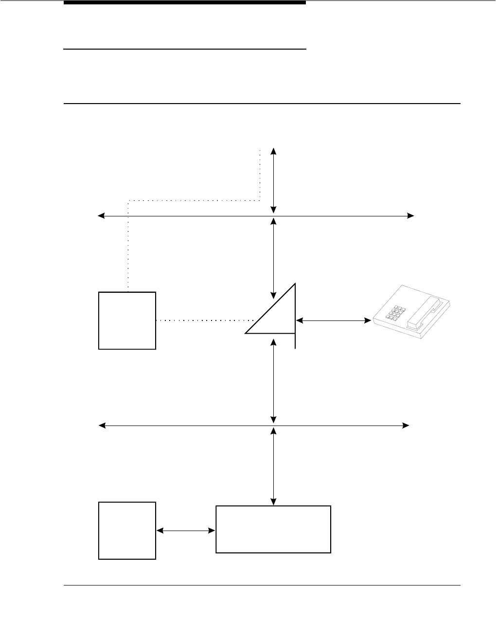
Constellation Voice/Data Terminal Support
Issue 3 March 1996 3-563
Configuration
The following diagram illustrates the hardware/signaling arrangement for the
Constellation.
Figure 3-3. Constellation Hardware/Signaling Arrangement
PRI (D) Signaling Channel
(SID/ANI
PRI (B) Voice Channel
(Incoming call)
TDM Bus
TDM Bus
DCP (11) Voice Channel
SPE
DCP (S)
Signaling Channel
6538/9
DCP (11)
Voice Channel
7401D, 7406D, 602A1,
603A1, 603D1
DCP (12) Data Channel
PRI (B) Data Channel
(PRI Trunk Group)
Host
EIA
Port 6544 Cluster Controller

Feature Descriptions
3-564 Issue 3 March 1996
Considerations
G3V3 and later releases provide native support for the Constellation. ‘‘Native
support’’ means the switch stores a predefined terminal type and fully supports
the terminal operation. The constellation terminal is a Memorex/Telex product.
Memorex/Telex is responsible for manufacturing and installing this terminal.
automatically downloads the terminal type information to the terminal.
Administration
The Constellation is administered on the station form as a type ‘‘6538.’’ The form
for this type includes a “Set” field, which requires one of the following values,
based on the adjunct voice terminal: ‘‘7401D,’’ ‘‘7406D,’’ ‘‘602A1,’’ ‘‘603A1,’’ or
‘‘603D1.’’ The value in the “Set” field determines the remaining fields that appear
on the form.
Hardware/Software Requirements
The Constellation requires the use of one of the following adjunct voice terminals:
7401D, 7406D, 602A1, 603A1, and 603D1.
The adjunct voice terminal can function as a standalone station even when the
Constellation is powered down.
The Constellation also requires a 6544 cluster controller to provide a data
connection to the host.

Consult
Issue 3 March 1996 3-565
Consult
Feature Availability
Consult is available with all Generic 3 releases.
Description
Allows a covering user, after answering a coverage call, to call the principal
(called party) for private consultation.
Consult is activated by first pressing the Conference or Transfer button followed
by the Consult button to call the principal. This places the calling party on hold
and establishes a connection between the principal and the covering user. The
covering user can then add the calling party to the conversation, transfer the call
to the principal, or return to the calling party.
Details of how Consult is used in conjunction with Call Coverage are given in the
Call Coverage feature description elsewhere in this section.
Considerations
Consult can be used to let a covering user consult with the principal, to
determine whether he or she wishes to speak with the called party (for example,
an executive’s secretary may wish to consult the executive on an established
call).
Interactions
Consult calls use the Temporary Bridged Appearance maintained on the call. At
the conclusion of a Consult call, the bridged appearance is no longer
maintained.
Bridged Call Appearances of the principal’s extension are not alerted on a
Consult call to the principal extension.
Consult is only used in conjunction with the Call Coverage feature.
A Consult call acts as a priority call and waits at a single-line voice terminal, even
if the single-line voice terminal does not have Call Waiting Termination assigned.
Administration
Consult is administered by the System Manager on a per-voice terminal basis.
The only administration required is the assignment of a Consult button.

Feature Descriptions
3-566 Issue 3 March 1996
Hardware and Software Requirements
No additional hardware or software is required.

Coverage Callback
Issue 3 March 1996 3-567
Coverage Callback
Feature Availability
Coverage Callback is available with all Generic 3 releases.
Description
Allows a covering user to leave a message for the principal (called party) to call
the calling party.
Coverage Callback is activated by pressing the Cover Callback button after
answering a coverage call.
Details of how Coverage Callback is used in conjunction with Call Coverage are
given in the Call Coverage feature description elsewhere in this section.
Considerations
Coverage Callback is useful whenever it is necessary to let the principal know
that a call has been received from a certain party.
Interactions
Coverage Callback is only used in conjunction with the Call Coverage feature.
Administration
Coverage Callback is administered on a per-voice terminal basis by the System
Manager. The only administration required is to assign a Cover Callback button.
Hardware and Software Requirements
No additional hardware or software is required.

Feature Descriptions
3-568 Issue 3 March 1996
Coverage Incoming Call Identification
(ICI)
Feature Availability
Coverage Incoming Call Identification is available with all Generic 3 releases.
Description
Allows multiappearance voice terminal users without a display in a Coverage
Answer Group to identify an incoming call to that group.
When an incoming call is directed to a Coverage Answer Group, the status lamp
associated with the Coverage Answer Group button lights at group member’s
voice terminal.
Details of how Coverage ICI is used in conjunction with Call Coverage are given
in the Call Coverage feature description, elsewhere in this section.
Considerations
With Coverage ICI, members of Coverage Answer Groups do not have to have a
display in order to identify incoming calls to the group.
A second coverage call takes control of the Coverage ICI lamp and does not
return control to the previous call when the second call is released.
Interactions
Coverage ICI is used only in conjunction with the Call Coverage feature.
Administration
Coverage ICI is administered on a per-voice terminal basis by the System
Manager. The only administration required is to assign a Coverage Answer
Group button.
Hardware and Software Requirements
No additional hardware or software is required.

Customer-Provided Equipment (CPE) Alarm
Issue 3 March 1996 3-569
Customer-Provided Equipment (CPE)
Alarm
Feature Availability
Customer-Provided Equipment (CPE) Alarm is available with all Generic 3
releases.
Description
Provides the customer with an indication that a system alarm has occurred and
that the system has attempted to contact a preassigned service organization
about the problem. A customer-provided device, such as a lamp or a bell, is
used to indicate the alarm situation.
The system can be administered so that the CPE Alarm will be activated during
certain alarm levels. Only one of these levels may be administered. The CPE
Alarm will be activated when an alarm occurs which corresponds to, or is more
severe than, the administered alarm activation level. The levels for which the CPE
Alarm can be activated are listed below in descending order, beginning with the
most severe.
■Major Alarm — This alarm is the most severe system alarm. A major alarm
indicates that a vital system hardware component, which will seriously
affect overall service, has failed.
■Minor Alarm — This alarm indicates that a hardware component, which
may affect service on a limited scale, has failed.
■Warning Alarm — This alarm indicates that a problem may exist with a
hardware component, but the problem does not affect service.
The system can also be administered so that the CPE Alarm is not activated
under any of the previously listed alarm levels.
The CPE Alarm is also activated during a Power Failure Transfer (see the Power
Failure Transfer feature elsewhere in this manual) regardless of the administered
alarm activation level. Even if the system is administered so that the CPE Alarm is
not activated at any alarm level, it will be activated during a Power Failure
Transfer.
The CPE Alarm is deactivated when the problem that caused the alarm is
resolved. If there are multiple problems, the CPE Alarm will not be deactivated
until all problems, at or above the administered alarm activation level, are
resolved.
For more information, see
DEFINITY Communications System Generic 1 and
Generic 3 Installation and Test
, 555-230-104.

Feature Descriptions
3-570 Issue 3 March 1996
Considerations
The CPE Alarm feature lets customers use their own equipment to indicate an
alarm condition. This indication lets the customer know when there is a problem
with the system and when the problem has been resolved.
Interactions
The following features interact with the CPE Alarm feature.
■Power Failure Transfer
The CPE Alarm is always activated during a Power Failure Transfer
regardless of the administered alarm activation level.
Administration
The CPE Alarm feature is administered on a per-system basis by the System
Manager.
Hardware and Software Requirements
The only hardware required is the actual CPE Alarm device (lamp, bell, and so
on). This device must be customer-provided and customer-installed.
No additional software is required.

Customer-Provided Equipment (CPE) Alarm
Issue 3 March 1996 3-571

Feature Descriptions
3-572 Issue 3 March 1996
Data Call Setup
Feature Availability
Data Call Setup is available with all Generic 3 releases.
Description
Provides multiple methods to set up a data call:
■Keyboard dialing
■Voice terminal dialing
■Hayes "AT" command dialing
■Permanent switched connections
■Administered connections
■Automatic calling unit interface (MPD and HSC)
■Hotline dialing
Typically, when a data terminal is available, keyboard dialing is more convenient
and requires less steps; therefore, it should be used whenever possible.
In addition to data terminal dialing and voice terminal dialing, the system accepts
calls from other devices, such as a MPDM equipped with an ACU interface
module. An analog modem interfaced with an ACU can also be used to provide
dialing capability for a host computer.
The "Administered Connections" feature, described elsewhere in this chapter,
may also be used to establish a data call.
This section describes the data call setup features for both DCP sets and ISDN
BRI sets.
Data Call Setup for DCP Modules
Voice Terminal Dialing for DCP Data Modules
Allows voice terminal users to originate and control data calls from the voice
terminal. DCP voice terminal dialing must be used when the Data Terminal is not
accessible for dialing.
The Transfer feature functions the same for data calls as it does for voice calls.
The feature permits a user to set up a call using any unrestricted voice terminal
and then transferring the call to a data endpoint. However, the primary way to
establish data calls is with the multiappearance voice terminal Data Extension
button(s). Any administrable feature button can be assigned as a Data Extension

Data Call Setup
Issue 3 March 1996 3-573
button in system administration. The Data Extension button provides one-touch
access to a data module.
The voice terminal Data Extension buttons control the One-Button Transfer to
Data, Return-to-Voice, and Data Call Preindication operations for the associated
data module. These operations are discussed below. Multiple Data Extension
buttons can be assigned to a multiappearance voice terminal, and that voice
terminal can set up data calls for other data terminals. Also, a single data module
can be accessed by a Data Extension button on a voice terminal. Only one Data
Extension button can be administered for a single data module.
Voice terminal dialing has the advantage that the user may hear the different
types of network tones.
For off-premises dialing, particularly for toll calls, the user may opt for voice
terminal dialing, instead of keyboard dialing.
The following options, either alone or combined, permit flexible procedures for
establishing data calls:
■One-Button Transfer to Data
Allows a user to transfer the call to the associated data module simply by
pressing the Data Extension button after the called data endpoint
answers. This method is recommended for voice terminal data call setup.
■Return-to-Voice
Allows a user to return the data connection to the voice terminal. The user
simply presses the Data Extension button associated with the busy data
module. If the user hangs up following the return, the call is disconnected.
If Return-to-Voice is affected by two voice terminal users, each through
use of the Data Extension button associated with the two data endpoints of
the call, then a voice call is established. Return of a data call to the voice
terminal implies that the same (data) call will be continued in the voice
mode, or transferred to another data endpoint.
■Data Call Preindication
Allows the user, before dialing the distant data endpoint, to reserve the
associated data module by pressing the Data Extension button. This
ensures that a conversion resource, if needed, and the data module are
reserved for the call. Use of Data Call Preindication before one button
transfer to data is recommended when establishing data calls that use toll
network facilities. Needed conversion resources are reserved before any
toll charges are incurred.
Data Terminal (Keyboard) Dialing for DCP Data Modules
Allows a user to set up and disconnect data calls directly from a data terminal. A
voice terminal is not needed. The voice terminal functions of switchhook and the
audible call progress tones are replaced with keyboard dialing and text known
as call progress messages. The message DIAL: prompts the user to enter the

Feature Descriptions
3-574 Issue 3 March 1996
called data number manually from the keyboard, and RINGING informs the user
the called data number is being rung. If the data call is placed in queue, the
message WAIT, xx IN QUEUE is received (xx represents queue position). This
queue number is updated by the system as the call moves up in the queue. The
next table lists the call progress messages.
To originate and disconnect a call using Data Terminal Dialing, the user presses
BREAK on the terminal. [This is equivalent to a voice terminal user lifting the
handset (call origination) or hanging up (call disconnect).] If the terminal being
used does not generate a 2-second continuous break signal, the user can press
Originated/Disconnect on the data module. Then, the data terminal allows the
user to enter digits from the data terminal keyboard, after the message DIAL:
(which is the equivalent of dial tone on a voice terminal).
In addition to the numeral, #, and * characters found on a touch-tone pad, the
dialing information may contain the following special characters:
■SPACE, —, (, and) may be used to improve legibility. These characters are
ignored by the system during dialing.
■+ character (wait) may be used to interrupt or suspend dialing until dial
tone is received from the distant switch.
■, (pause) character may be used to place a 1.5-second pause in dialing
(multiple, can be used).
■% (mark) character may be used to indicate the following digits are for
end-to-end signaling (touch-tone). This is required when the trunk is
rotary. It is not required when the trunk is touch-tone.
■UNDERLINE or BACKSPACE may be used to correct previously typed
characters on the same line.
■@ may be used to delete the entire line and start over with a new DIAL:
prompt.
Each line of dialing information may contain up to 42 characters (the + and %
characters count as two each).
Examples of dialing are as follows:
■DIAL: 3478
■DIAL: 9+(201) 555-1212
■DIAL: 8, 555-2368
■DIAL: 9+555-2368+%9999+123 (remote access)
Single-Line Dialing
All of the dialing information, including pauses and ignored characters, are typed
on a single line. The line with the DIAL: prompt must be complete; that is, the
dialing information must specify a complete call before the carriage return or line
feed.

Data Call Setup
Issue 3 March 1996 3-575
Single-line dialing is recommended if all dialing information can be entered on
one line.
Multiple-Line Dialing
Automatically invoked when a single line of dialing information is incomplete.
Multiple-line dialing is only used with off-premises calling.
In multiple-line dialing, the DIAL: prompt follows on the next line when all of the
dialing information of the previous line has been sent and dial tone has occurred;
additional dialing information is requested.
This is a typical off-premises dialing sequence:
■DIAL: 9
■DIAL: (201) 555-2368
■RINGING
■ANSWERED
Alphanumeric Dialing
Alphanumeric Dialing enhances Data Terminal Dialing by allowing a data
terminal user to place a data call by entering an alphanumeric name. This
capability makes Data Terminal Dialing both convenient and user-friendly.
Instead of dialing a long string of numbers, the user can enter a simple
alphanumeric name. For more detailed information, see the "Alphanumeric
Dialing" feature description, elsewhere in this chapter.
Call Forwarding All Calls
Call Forwarding All Calls allows incoming data calls to be redirected to another
extension that is designated by the user. Activation/deactivation of the feature is
done either by the attendant or by the forwarding party itself through the dialing
of a feature access code.
Default Dialing
Default Dialing enhances Data Terminal (Keyboard) Dialing by allowing a data
terminal user to place a data call to a preadministered destination by simply
entering a carriage return at the DIAL: prompt. The data terminal user can still
place calls to other destinations by entering the complete address after the
DIAL: prompt (normal Data Terminal Dialing or Alphanumeric Dialing). For more
detailed information, see the "Default Dialing" feature description elsewhere in
this chapter.
Administered Connections
An Administered Connection is an end-to-end connection between two access
endpoints or data endpoints that is automatically established by the system
whenever the system is restarted or the Administered Connection is administered

Feature Descriptions
3-576 Issue 3 March 1996
and due to be active. The attributes of these connections are user-defined. To
administer Administered Connections, use the “Administered Connection” form
via the SAT.
Once the ADM has been administered as one endpoint of an administered
connection, the system waits for the scheduled time to set up the connection. At
the scheduled time, the system establishes the connection and maintains it for
the length of time specified. Once the call is accepted, the set will enter into the
continuous mode for the length of time specified. If the switch is rebooted during
the continuous connection, the connection will reinitiate the call setup. At any
time that the connection drops (for example, disconnected cabling), the switch
will reinitiate the call setup.
Hotline Dialing
Hotline Dialing is discussed in detail in the Data Hot Line feature description
elsewhere in this manual. Table 3-50 shows call progress messages for DCP.
Table 3-50. Call Progress Messages for Keyboard Dialing for
DCP
Displayed Message Application Meaning
DIAL: Placing a call Equivalent to dial tone. Enter the desired
number or feature access code followed by
a carriage return or a line feed.
RINGING Placing a call Equivalent to ringing tone. Called terminal
(far-end) is ringing.
BUSY Placing a call Equivalent to busy tone. Called number is in
use or out of service.
ANSWERED Placing or
receiving a call Notifies calling and called users that call
has been answered.
ANSWERED - NOT
DATA Placing a call Notifies calling and called users that call
has been answered and a modem answer
tone has not been detected.
TRY AGAIN Placing a call Equivalent to reorder tone. System facilities
are currently not available.
DENIED Placing a call Equivalent to intercept tone. Call cannot be
placed as dialed.
ABANDONED Receiving a call Notifies called user that the calling user
abandoned the call.
NO TONE Placing a call Notifies user that tone was not detected.
Continued on next page

Data Call Setup
Issue 3 March 1996 3-577
CHECK OPTIONS Placing a call Notifies calling terminal that data module
options are incompatible.
XX IN QUEUE Call in queue Current position of the user in queue.
XX-indicates position.
PROCESSING* Call in queue Notifies user when out of queue. Facility is
available.
TIMEOUT* Call in queue Notifies user when time has been
exceeded. Call will be terminated.
FORWARDED* Receiving a call Equivalent to redirection notification signal.
Called terminal has activated Call
Forwarding and received a call, and call
has been forwarded.
INCOMING CALL-* Receiving a call Equivalent to ringing.
INVALID ADDRESS Placing a call The entered name is not in the
Alphanumeric Dialing Table.
PLEASE ANS- Receiving a call Originating voice terminal user has
transferred call to data module using
One-Button Transfer to Data.
-TRANSFER Call is transferred to
voice Notifies calling terminal when Data Call
Return-to-Voice occurs.
CONFIRMED Activating or
deactivating a
feature
Equivalent to confirmation tone. Feature
request is accepted, or call has gone to a
local coverage point.
-OTHER END During a call Notifies user that the other end
terminated the call.
DISCONNECTED* Call is terminated Call or call attempt is disconnected from
system
WAIT Placing a call Notifies user that normal processing is
continuing.
WAIT, XX IN
QUEUE Placing a call Notifies user that call entered a local hunt
group queue. XX indicates position.
* Bell sounds when message is displayed.
Table 3-50. Call Progress Messages for Keyboard Dialing for
DCP — Continued
Displayed Message Application Meaning
Continued on next page

Feature Descriptions
3-578 Issue 3 March 1996
Data Call Setup for ISDN-BRI Modules
Voice Terminal Dialing for ISDN-BRI
Data Modules
Allows ISDN-BRI voice terminal users to directly originate a data call. To set up a
data call, the user just presses the Data button on the ISDN-BRI voice terminal,
enters the desired number on the dial pad, and then presses the Data button
again.
The following data functions are not supported by BRI terminals:
■One button transfer to data
■Return-to-voice
■Data call pre-indication
■Voice call transfer to data and data call transfer to voice
Data Terminal (Keyboard) Dialing for ISDN-BRI Data Modules
Allows a user to set up and disconnect data calls directly from a data terminal
without using a voice terminal. The voice terminal functions of switchhook and the
audible call progress tones are replaced with keyboard dialing and text known
as call progress messages. Unlike DCP, BRI is terminal dependent, meaning that
the BRI data module, not the switch, prompts the user to enter information.
NOTE:
The 7500B Data Module also allows users to set up calls via its front panel.
For more information on this feature, consult the
7500B Data Module User’s
Manual
, 555-021-717.
Before the user can make a data call using Data Terminal Dialing, CMD: must
appear on the screen of the terminal. To access the CMD: prompt before placing
a call, the user must press Enter on the keyboard a few times. If the CMD: prompt
does not appear, the user must press Break A and T at the same time, and then
press Enter. To make a data call, the user types dial, enters a space, types the
desired telephone number, and presses Enter at the CMD: prompt (For example,
dial 1234567).
To disconnect a data call using Data Terminal Dialing, the user must first enter
+++ to access the CMD: prompt. At the CMD: prompt, the user types end and
presses ENTER.
In addition to the numeral, #, and * characters found on a touch-tone pad, the
dialing information may contain the following special characters:
■SPACE,—, (, and) may be used to improve legibility. These characters are
ignored by the system during dialing.
■+ character (wait) may be used to interrupt or suspend dialing until dial
tone is received from the distant switch.

Data Call Setup
Issue 3 March 1996 3-579
■, (pause) character may be used to place a 1.5-second pause in dialing.
(multiple, can be used).
■% (mark) character may be used to indicate the following digits are for
end-to-end signaling (touch-tone). This is required when the trunk is
rotary. It is not required when the trunk is ‘‘touch-tone.’’
■UNDERLINE or BACKSPACE characters may be used to correct
previously typed characters on the same line.
■@ may be used to delete the entire line and start over with a new
CMD: prompt.
Each line of dialing information may contain up to 42 characters (the + and %
characters count as two each).
Examples of dialing are as follows:
■CMD: d 3478
■CMD: d 9+(201) 555-1212
■CMD: d 8, 555-2368
■CMD: d 9+555-2368+%9999+123 (remote access)
Basic Digit Dialing
Regular digit dialing is provided through the Asynchronous Data Module (ADM)
or 7500B Data Module. Digits from 0 to 9, ‘‘*’’, and ‘‘#’’ can be entered. This
feature can be used by the user either from the associated 7500 Series voice
terminal keypad or from the EIA terminal interface.
Alphanumeric Dialing
Alphanumeric Dialing enhances Data Terminal Dialing by allowing a data
terminal user to place a data call by entering an alphanumeric name. This
capability makes Data Terminal Dialing both convenient and user-friendly.
Instead of dialing a long string of numbers, the user can enter a simple
alphanumeric name. For more detailed information, consult the "Alphanumeric
Dialing" feature description elsewhere in this chapter.
Default Dialing
Default Dialing enhances Data Terminal (Keyboard) Dialing by allowing a data
terminal user to place a data call to a preadministered destination by either
typing a d and entering Return at the CMD: prompt, or by pressing the data
button twice. If no default dialing has been administered, the call will be
disconnected in less than one second. The data terminal user can still place calls
to other destinations by typing a d and the complete address at the CMD:
prompt, and then entering Return (normal Data Terminal Dialing or Alphanumeric
Dialing). This feature is mutually exclusive with the Data Hotline feature. For more
detailed information, see the "Default Dialing" feature description elsewhere in
this chapter.

Feature Descriptions
3-580 Issue 3 March 1996
Call Forwarding All Calls
Call Forwarding All Calls allows incoming data calls to be redirected to another
extension that is designated by the user. Activation/deactivation of the feature is
done either by the attendant or by the forwarding party itself through the dialing
of a feature access code.
Data Hotline
Data Hotline is a security feature. The switch will terminate the call to a
preadministered hotline destination. If a user enters an address either
intentionally or unintentionally, the call processing will discard the address string
received for the hotline endpoint. The call processing will automatically route the
call just as if the hotline destination address had been entered by the user. This
service does not impose any restriction on incoming calls received at the
endpoint. This feature is mutually exclusive with the Default Dialing feature.
Administered Connections
An Administered Connection is an end-to-end connection between two access
endpoints or data endpoints that is automatically established by the system
whenever the system is restarted or the Administered Connection is administered
and due to be active. The attributes of these connections are user-defined. To
administer Administered Connections, use the “Administered Connection” form
via the SAT.
Once the ADM has been administered as one endpoint of an administered
connection, the system waits for the scheduled time to set up the connection. At
the scheduled time, the system establishes the connection and maintains it for
the length of time specified. Once the call is accepted, the set will enter into the
continuous mode for the length of time specified. If the switch is rebooted during
the continuous connection, the connection will reinitiate the call setup. At any
time that the connection drops (for example, disconnected cabling), the switch
will reinitiate the call setup.
Call Request
DEFINITY system Generic 3 call processing will handle all various BRI Bearer
data call requests that are presently defined. Some capabilities that are not
supported by AT&T terminals may be provided by a non-AT&T terminal. The
switch will complete most call requests. For those capabilities that the switch
does not support, a proper cause value will return back to the terminal.
Cause Value
BRI stations will receive a cause or reason code that identifies why the call is
being cleared. The BRI data modules will convert certain cause values to text
messages and display them for the user.

Data Call Setup
Issue 3 March 1996 3-581
Endpoint Initialization
BRI endpoints have to successfully complete endpoint initialization procedures
in order to be fully operative. It is usually carried out at the time of installation, or
as part of reconfiguration.
Multipoint Configurations on BRI ports
In a passive bus multipoint configuration, the system supports two BRI endpoints
per port, thus doubling the capacity of the BRI circuit pack. When changing the
configuration of a BRI from point-to-point to multipoint, the original endpoint need
not be reinitialized. However, only endpoints that support SPID initialization can
be administered in a multipoint configuration.
Exchange of User Information
The BRI protocol provides the users the capability of exchanging up to 128
octets of user information end-to-end. Displayed messages are shown in Table
3-51. The information is passed in the User Information IEs to the receiving
endpoint without being interpreted by the switch. However, there are some
limitations to the exchange of User Information IEs.
Table 3-51. Call Progress Messages for Keyboard Dialing for
BRI
Displayed Message Application Meaning
CMD: Placing a call Equivalent to dial tone. Enter the desired
number or feature access code followed
by a carriage return or a line feed.
RINGING Placing a call Equivalent to ringing tone. Called terminal
(far-end) is ringing.
BUSY Placing a call Equivalent to busy tone. Called number is
in use or out of service.
ANSWERED Placing or
receiving a call Notifies calling and called users that call
has been answered.
TRY AGAIN Placing a call Equivalent to reorder tone. System facilities
are currently not available.
DENIED Placing a call Equivalent to intercept tone. Call cannot be
placed as dialed.
ABANDONED Receiving a call Notifies called user that the calling user
abandoned the call.
NO TONE Placing a call Notifies user that tone was not detected.
Continued on next page

Feature Descriptions
3-582 Issue 3 March 1996
CHECK OPTIONS Placing a call Notifies calling terminal that data module
options are incompatible.
XX IN QUEUE Call in queue Current position of the user in queue.
XX-indicates position.
PROCESSING* Call in queue Notifies user when out of queue.
Facility is available.
TIMEOUT* Call in queue Notifies user when time has been
exceeded. Call will be terminated.
FORWARDED* Receiving a call Equivalent to redirection notification signal.
Called terminal has activated Call
Forwarding and received a call, and call
has been forwarded.
INCOMING CALL-* Receiving a call Equivalent to ringing.
WRONG ADDRESS Placing a call The entered name is not in the
Alphanumeric Dialing Table.
PLEASE ANS- Receiving a call Originating voice terminal user has
transferred call to data module using
One-Button Transfer to Data.
CONFIRMED Activating or
deactivating a
feature
Equivalent to confirmation tone. Feature
request is accepted, or call has gone to a
local coverage point.
-OTHER END During a call Notifies user that the other end terminated
the call.
DISCONNECTED* Call is terminated Call or call attempt is disconnected from
system.
WAIT Placing a call Notifies user that normal processing is
continuing.
* Bell sounds when message is displayed.
Table 3-51. Call Progress Messages for Keyboard Dialing for
BRI — Continued
Displayed Message Application Meaning
Continued on next page

Data Call Setup
Issue 3 March 1996 3-583
Considerations
All systems have Data Call Setup capability. This facilitates data calling by
eliminating the need to dedicate a voice terminal for data calls. DEFINITY system
Generic 3 offers the enhancement of off-premises Multiple Line Dialing.
BRI has a voice to data restriction. A voice terminal cannot call a data terminal,
and a data terminal cannot call a voice terminal.
BRI voice terminals cannot have Data Extension buttons. Although DCP sets
have Data Extension buttons, these sets cannot have Data Extension buttons for
BRI data extensions.
When a voice terminal user places a data call to a digital data endpoint, and
does not transfer the call to another digital data endpoint but uses a modem or
acoustically coupled modem, the user must dial the Data Origination access
code assigned in the system before dialing the distant endpoint.
Data Call Preindication is activated by pressing a Data Extension button before
dialing the distant data endpoint. Preindication is in effect until the associated
Data Extension button is pressed again for a one-button transfer; there is no
time-out.
The number of assigned Data Extension buttons per voice terminal is not limited.
However, only one voice terminal can be assigned buttons that access the same
data module.
When placing outgoing or off-premises calls via keyboard dialing, the call
progress message WAIT indicates recognition of the nature of the call and
acceptance of the call. The ANSWERED text indicates completion of outpulsing
over the selected trunk, or if answer supervision or an answer tone is received.
Interactions
The following features interact with the Data Call Setup feature.
■Abbreviated Dialing
This feature can be used by voice terminal or Data Terminal (Keyboard)
Dialing users on calls to data endpoints. Only 22 of the 24 available digits
in an abbreviated dialing number can be used for keyboard dialing. The
remaining two digits must contain the ‘‘wait’’ indicator for tone detection.
■Call Coverage
A hunt group made up of digital data endpoints should not be assigned a
coverage path.

Feature Descriptions
3-584 Issue 3 March 1996
■Call Forwarding All Calls
Calls incoming to a data module can be forwarded. That is, calls can be
redirected to another endpoint. This feature is activated using Data
Terminal (Keyboard) Dialing. If the forwarded-to endpoint is an analog
data endpoint, and the calling user is a digital endpoint, modem pooling is
activated automatically.
■Data Call Hot Line
Upon going off-hook for origination, the system automatically places a call
to a predesignated local or off-premises destination.
■Default Dialing
Default Dialing enhances Data Terminal (Keyboard) Dialing by allowing a
data terminal user to place a data call to a preadministered destination.
■Internal Automatic Answer (IAA)
Data calls are not eligible for IAA.
■Modem Pooling
When modem pools are provided, this feature is automatically available on
data calls when the system ascertains the need for a conversion resource.
The system automatically inserts the conversion resource. Data Call
Preindication or Data Origination can also be used to indicate that a
conversion resource is needed.
■CDR
Data Call CDR records the use of modem pools on trunk calls.
■UCD
UCD can provide a group of data modules or analog modems for
answering calls to facilities, such as computer ports, connected to the
data modules or modems.
■ISN Interface
ISN consists of packet data switches which support data calls between
data endpoints and the system. The physical connection to the system is
via the DLC board. The DLC provides eight ports for connection with
asynchronous EIA RS-232C compatible Data Terminal Equipment to the
ISN interface.
Data Terminal (Keyboard) Dialing is used to access ISN endpoints.
■World Class Tone Detection
Multiple-Line Data Terminal Dialing is only supported if the administered
Level of Tone Detection is ‘‘precise.’’ G3i-Global and G3V2 and later
releases provide administration of tone detection options. The message
the data call setup feature sends to users vary according to which tone
detection option is selected.

Data Call Setup
Issue 3 March 1996 3-585
If the tone detection option is not set to ‘‘precise,’’ and a data call is set up
over an analog trunk, the data call setup messages describing the status
of the called endpoint (that is, RINGING, BUSY, TRY AGAIN, etc.),
changes according to which tone detection option is selected.
Tone Detection applies to non-ISDN trunk lines as well.
Administration
Data Call Setup does not require assignment as such; however, the following
related items require administration by the System Manager:
■Data Origination Access Code — Allow users to indicate a need for a
conversion resource on an analog to digital data call origination.
■Port Assignments — Assign the data modules, BCTs, DLCs, 7404D,
analog modems.
■Modem Pooling — Assign Circuit Packs or ports.
■Data Extension buttons — Assign Data Extension buttons to
multi-appearance voice terminals.
■Default Dialing — See the "Default Dialing" feature.
■Alphanumeric Dialing — See the "Alphanumeric Dialing" feature.
Hardware and Software Requirements
Data Call Setup is a means of using data equipment to establish data calls.
Requirements for data modules, voice terminals, and modems are as follows:
■Data Modules: Each DCP data module requires one port on a TN754
Digital Line circuit pack (TN413, TN754B support A-law). A DTDM shares
the port with its associated voice terminal.
Each BRI data module requires one port on a TN556 BRI circuit port pack.
Each BRI port may be shared by two endpoints, with each endpoint
providing either voice or data capability. To support ISDN-BRI, the switch
requires the TN778 Packet Control circuit pack. An ADM shares the port
with its associated BRI voice terminal.
■7400A Data Module: The 7400A Data Module may be used instead of an
MTDM when supporting the combined Modem Pooling feature. The 7400A
Data Module supports asynchronous operation and provides a DCP
interface to the switch and a RS-232c interface to the associated modem.
The 7400A can operate in the stand-alone mode as a data module.
■7500B Data Module: The 7500B Data Module is a stand-alone unit that
supports asynchronous or synchronous DCE and asynchronous DTE on
the Basic Rate ISDN (BRI) switch interface. In asynchronous mode, the
7500B supports packet or circuit-switched data communications, and can
be controlled via the front panel or the keyboard of a connected terminal.
The following optional enhancements are available for the 7500B in an

Feature Descriptions
3-586 Issue 3 March 1996
asynchronous DCE configuration: an RS-366 ACU interface and a second
asynchronous EIA-232D interface. In synchronous mode, the 7500B
supports circuit-switched or nailed-up data communications, requires
either the Multi-purpose Enhancement Board or the High-Speed
Synchronous Enhancement Board, and can only be controlled via the front
panel. In order to be configured as a synchronous DCE, the 7500B must
have either the Multi-purpose Enhancement Board or the High-Speed
Synchronous Enhancement Board.
When configured as an asynchronous DTE, the 7500B provides an
EIA-232D interface and supports full-duplex data transmission at rates of
up to 19200 bps. This configuration is most commonly used for modem
pooling applications. Regardless of the configuration, the 7500B provides
no voice functions and is not used with voice terminals.
■7400C HSL: 7400C High Speed Link is a data service unit that allows data
equipment to access the DCP data services. It provides synchronous
data transmission at speeds of 56 and 64 kbps and provides a link to high
speed data networks. It can be used for Group 4 Fax applications that will
include electronic mail and messaging and electronic storage of printed
documents and graphics. It can also be used for video teleconferencing
and LAN interconnect applications.
■7400D Series or CALLMASTER Terminals: For shared use of voice and
data, each Voice Terminal requires one port on the following Digital Line
circuit packs: the 4-wire TN754, TN413, or the TN754B. The TN754B is
A-law or Mu-law selectable. 603EI CALLMASTER uses the TN754,
TN754B, or TN2181 circuit pack. The TN2181 is a 2-wire, 16-port,
A-law/Mu-law selectable circuit pack. The 7403D and 7405D voice
terminals require an optional digital terminal data module. The 7404D
requires an optional messaging cartridge, the 7406D requires an optional
703A Data Stand, and the 7407D requires an optional 702A DSU for
connection to associated data terminals.
■7500 Series ISDN Voice Terminals: Each 7500 Series ISDN Voice Terminal
requires one port on the TN556 BRI port circuit pack. Each voice terminal
requires an optional ISDN ADM to support asynchronous DTE. Consisting
of a board located inside the BRI voice terminal, the ISDN ADM allows the
transmission of integrated voice and data through one voice terminal. The
ISDN ADM shares the port with its associated voice terminal and supports
the Hayes command set for compatibility with PC communications
packages.
■Modems: Each modem requires one port on a TN742 or TN746B (A-law)
Analog Line circuit pack. (Administration designates the modem as a
2500-series voice terminal and assigns an extension number. A modem is
connected to the port instead of a voice terminal. Access is through the
assigned extension number.)

Data Call Setup
Issue 3 March 1996 3-587
■Modem Pooling: DEFINITY system Generic 3 requires either a TN758
Modem Pool circuit pack, or one digital port associated with a Trunk Data
Module (either TDM or MTDM) and one analog port with analog modem
for each conversion resource. A 7400A Data Module may be used in
place of the TDM or MTDM.
■Data Line Data Module: Each port is connected to an ADU that converts to
an RS-232 interface for connection to a data terminal.
Keyboard Dialing to off-premises data endpoints requires the use of a tone
detector circuit pack such as TN748C-Tone Detector, TN420C-Tone Detector,
TN744C-Tone Detector/Call Classifier, or TN2182-Tone
Clock/Detector/Generator.
NOTE:
The TN748C (Mu-law) and TN420 (A-law) support precise tone detection.
However, the TN744C or TN2182 only support precise tone detection in
countries that strictly adhere to U.S. standards. Therefore, if the detectors
are used in countries that do not adhere to U.S. standards, the users may
not experience precise feedback during the data call setup.
T748C and TN2182 support Mu-law. TN420C, TN744C, and TN2182 support
A-law. Extensive use of features and services using tone detection may
necessitate adding additional tone detector circuit packs.
A TN726 Data Line circuit pack can be used to provide direct access for data
terminal users.
No additional software is required.

Feature Descriptions
3-588 Issue 3 March 1996
Data Hot Line
Feature Availability
Data Hot Line is available with all Generic 3 releases.
Description
Data Hot Line provides for automatic nondial placement of a data call to an
endpoint when the originator goes off-hook. It may be used for security
purposes.
Data Hot Line calls are automatically placed, by the system, from specified
digital data endpoints to preassigned extension numbers or off-premises
numbers. Hot Line originating endpoints are destinations connected to the
system by a data module. The destination number is stored in the Abbreviated
Dialing List.
Considerations
Data Hot Line offers fast and accurate call placement to commonly called data
endpoints. Data terminal users that constantly call the same destination number
can use Data Hot Line to automatically place the call by going off hook.
The number of terminals that can be assigned Data Hot Line is not limited, and
the number of terminals that can be assigned the same destination number is not
limited. The only limit, if any, would be on the number of entries stored in the
Abbreviated Dialing List.
Interactions
The following features interact with the Data Hot Line feature.
■Call Forwarding — All Calls
A Hot Line originator cannot activate Call Forwarding, since an off-hook
intended to dial the Call Forwarding Feature Access Code will cause
activation of the Data Call Hot Line feature instead.
■Data Terminal (Keyboard) Dialing
Any Terminal Dialing text may occur when a Data Hot Line Call is being
established, with the exception of the inhibition of the initial dial text
message prompt normally given on off-hook for origination.

Data Hot Line
Issue 3 March 1996 3-589
■System/ISN Access
A data call to an ISN data endpoint from a system digital data endpoint
requires a two-stage dialing. A Hot Line Destination may be an extension
number for an outgoing ISN group only, the Hot Line originator must then
interact with ISN and manually enter the second address (data endpoint).
Administration
Data Hot Line is administered on per-data terminal basis by the System
Manager. The following item requires administration:
■Hot Line Destination Number — The preadministered Hot Line Destination
must be stored in an abbreviated dialing list. This list can be a system list,
group list, personal list, or enhanced list. Therefore, before this feature can
be activated, users’ terminals need to be administered with an
abbreviated dialing list that stores the Hot Line Destination. Then, each
data module needs to specify the index number of the entry which stores
the destination. The following fields from the “Data Module” form are
needed to activate the Data Hotline feature.
— Special Dialing Option (default/hotline) — For Data Hotline,
‘‘hotline’’ must be selected. Default Dialing and the Data Hotline
feature cannot both be assigned to an extension.
— An Abbreviated Dialing List — One entry in the data module’s
abbreviated dialing list needs to store the default destination.
— Dial Code (0-999) — An index to the entry of the abbreviated
dialing list that stores the default destination.
Hardware and Software Requirements
No additional hardware or software is required.

Feature Descriptions
3-590 Issue 3 March 1996
Data Privacy
Feature Availability
Data Privacy is available with all Generic 3 releases.
Description
NOTE:
This feature is know as ‘‘Data Protection’’ in G2.
Protects analog data calls from being disturbed by any of the system’s overriding
or ringing features. Data Privacy, when activated by a user, denies the system
the ability to gain access to, or to superimpose tones onto, the protected call.
To activate this feature, the user dials the activation code at the beginning of the
call.
Considerations
All systems have the capability for Data Privacy to provide interruption protection
by denying the system the ability to gain access to the protected, analog data
call.
Connections involving one or more digital data endpoints (data module) are
automatically protected from receiving system-generated tones. In this case, the
Data Privacy feature is not needed.
Data Privacy, when activated, applies to both voice and data calls. The feature
can be activated on Remote Access calls, but not on other incoming trunk calls.
Data Privacy is canceled if the call is transferred, added to a conference call,
bridged onto, or disconnected from by the activating user. Data Privacy can be
activated on calls originated from attendant consoles.
Interactions
The following features interact with the Data Privacy feature.
■Attendant Call Waiting and Call Waiting Termination
If Data Privacy is activated, Call Waiting is denied.
■Bridged Call Appearance — Single-Line Voice Terminal
When Data Privacy is activated or Data Restriction is assigned to a station
involved in a bridged call and the primary terminal and/or bridging user
attempts to bridge onto the call, Data Privacy and Data Restriction are
automatically overridden.

Data Privacy
Issue 3 March 1996 3-591
■Intercom — Automatic and Dial
An extension with Data Privacy or Data Restriction activated cannot
originate an intercom call. Intercept tone is received when the ICOM
button is pressed under this condition.
■Music-on-Hold Access
If a call with Data Privacy activated is placed on hold, Music-on-Hold
access is withheld to prevent the transmission of some musical tone which
a connected data service might falsely interpret as a data transmission.
■Priority Calls
If Data Privacy is activated, Priority Calls to the activating extension
number are denied on analog voice terminals. However, Priority Calls
appear on the next available line appearance on multi-appearance voice
terminals.
■Busy Verification cannot be done when data privacy is active.
Administration
Data Privacy is activated by dialing a Data Privacy Feature Access Code (FAC)
before originating the call. Permission to use the feature is assigned in COS.
Hardware and Software Requirements
No additional hardware or software is required.

Feature Descriptions
3-592 Issue 3 March 1996
Data Restriction
Feature Availability
Data Restriction is available with all Generic 3 releases.
Description
Protects analog data calls from being disturbed by any of the system’s overriding
or ringing features. Data Restriction, when administered to an extension number
or trunk group, denies the system the ability to gain access to, or to superimpose
tones onto, the protected call.
This feature is administered at the system level to selected analog and
multi-appearance voice terminals and trunk groups. Once administered, the
feature is active on all calls to or from the associated terminal or trunk group.
Considerations
All systems have the capability for Data Restriction to prevent overriding or
ringing features from interrupting the voice or data call.
Connections involving one or more digital data endpoints (data modules) are
automatically protected from receiving system-generated tones. In this case, the
Data Restriction feature is not needed.
Data Restriction applies to both voice and data calls. Also, Data Restriction
cannot be assigned to attendant consoles. Data Restriction is removed from the
current call if it is transferred, added to a conference call, bridged onto, or
disconnected from by the restricted extension.
Interactions
The following features interact with the Data Restriction feature.
■Attendant Call Waiting and Call Waiting Termination
If Data Restriction is assigned, Call Waiting is denied.
■Intercom — Automatic and Dial
An extension with Data Privacy when activated cannot originate an
intercom call. An extension with Data Restriction assigned cannot
originate an intercom call. Intercept tone is received when the ICOM
button is pressed under this condition.

Data Restriction
Issue 3 March 1996 3-593
■Music-on-Hold Access
If a call with Data Restriction assigned is placed on hold, Music-on-Hold
access is withheld to prevent the transmission of some musical tone which
a connected data service might falsely interpret as a data transmission.
■Priority Calls
Priority Calls are not denied if the analog station is idle; Call Waiting
(including Priority Call Waiting) is denied if the station is busy. However,
Priority Calls appear on the next available line appearance on
multi-appearance voice terminals.
■Busy Verification cannot be done when Data Restriction is assigned.
Administration
Data Restriction is assigned on a per-line or trunk basis by the System Manager.
Hardware and Software Requirements
No additional hardware or software is required.

Feature Descriptions
3-594 Issue 3 March 1996
Data-Only Off-Premises Extensions
Feature Availability
Data-Only Off-Premises Extensions is available with all Generic 3 releases.
Description
Allows users to establish data calls involving DCE or DTE that is located remotely
from the System site using DATAPHONE digital service or other private line data
facilities. A Data-Only Off-Premises Extension uses an MTDM located
on-premises. Communication with the remote data equipment is accomplished
through the private line facility linking the on-premises MTDM and the remote
data equipment.
The Trunk Data Module and DCE or DTE constitute a digital data endpoint. Data
calls to this type of data endpoint can be placed using Voice Terminal Dialing or
Data Terminal (Keyboard) Dialing. Since there is no voice terminal at the remote
site, data calls can be originated from the remote data terminal using Keyboard
Dialing only. If computer-generated dialing is used on calls, it must follow the
Keyboard Dialing protocol.
Considerations
The systems have the capability for Data-Only Off-Premises Extensions to allow
for data calls to remote DCE using DATAPHONE digital service or other private
line data facilities.
Data-Only Off-Premises Extensions provides digital data endpoints located
off-premises through a Trunk Data Module located on-premises.
Communications to or from this Trunk Data Module (and the associated
off-premises equipment) must be through an on-premises Processor Data
Module or Digital Terminal Data Module. Communications between two Trunk
Data Module are not supported. Likewise, Modem Pooling, which is conceptually
similar to a Trunk Data Module, cannot be used on calls to or from a Data-Only
Off-Premises Extension.
Interactions
The following features interact with the Data-Only Off-Premises Extensions
feature.

Data-Only Off-Premises Extensions
Issue 3 March 1996 3-595
■Voice Terminal Dialing
An on-premises multiappearance voice terminal may have a Data
Extension button associated with the Trunk Data Module used for a
Data-Only Off-Premises Extension. The voice terminal user and the remote
data equipment user share control of the data module. Actions of the user
at the voice terminal may affect the remote user.
— One-Button Transfer to Data
The on-premises voice terminal user can transfer a call to the
Data-Only Off-Premises Extension. The Data Extension button on
the voice terminal lights and the Call in Progress lamp on the data
module lights during an established data call.
— Return-to-Voice
If a data call has already been established, the voice terminal user
may press the associated busy Data Extension button to transfer
the call to the voice terminal. The data module associated with the
Data Extension button is disconnected from the call. The Call in
Progress lamp on the data module goes dark.
— Data Call Preindication
The multiappearance voice terminal user presses the idle
associated Data Extension button to reserve the data module. The
data module is then busy to all users except the Preindicating user,
including the remote user. When the data module is reserved, the
lamp associated with the Data Extension button winks at the
preindicator’s voice terminal and lights at any other associated
voice terminals. A remote user receives the BUSY message when
attempting to originate a call.
Administration
Data-Only Off-Premises Extensions is assigned on a per-line basis by the System
Manager. The following item requires administration:
■Digital Line Circuit Pack — Assign the associated data module to a vacant
port.
Hardware and Software Requirements
Requires a Trunk Data Module and one port on a TN754 Digital Line circuit pack
(TN413, TN754B support A-law). No additional software is required.

Feature Descriptions
3-596 Issue 3 March 1996
DCS Alphanumeric Display for
Terminals
Feature Availability
DCS is available with all Generic 3 releases except G3vs/G3s ABP.
Description
Allows calls to or from terminals equipped with alphanumeric displays to have
transparency with respect to the display of call-related information.
Calling Name Display is the presentation, on the
called
terminal’s alphanumeric
display, of the name of the party who originated the call. Called Name Display is
the presentation on the
originating
terminal’s display of the name of the party to
whom the call is directed. Both displays provide more useful and precise
information than such general identifiers as a trunk group name or an extension
number.
The transparency allows calling and called name information, plus miscellaneous
identifiers (IDs) to be sent from a terminal on one node to a terminal on another
node. Transparency in this area is limited by the type of systems at the endpoint
nodes and at the intermediate node, if any.
Considerations
DCS Alphanumeric Display for Terminals gives the user considerable call
handling capabilities by displaying call related information on calls to and from
other DCS nodes.
Calls to and from a DEFINITY system Generic 3 in a DCS network have
Calling/Called Name Display transparency under the following conditions:
■The other party is at another DEFINITY system Generic 3 and the tandem
node is a System 75 Version 3 or later, DEFINITY system Generic 1,
DEFINITY system Generic 3, System 85 Release 2 Version 2 or later, or a
DEFINITY system Generic 2.1.
■The call is not routed through a tandem System 85 Release 2 Version 1 or
Enhanced DIMENSION PBX node. (Such calls will display only the
extension number of the calling or called party.)
On outgoing DCS calls, display of the called name may be delayed for a few
seconds until the required information arrives from the distant node. The called
name display only works between DEFINITY systems Generic 1, Generic 3
systems, and System 75s.

DCS Alphanumeric Display for Terminals
Issue 3 March 1996 3-597
Within the same DEFINITY system Generic 1 or Generic 3 node in a DCS,
complete transparency of Calling and Called Name Display exists.
Interactions
The following DCS configurations provide transparency of alphanumeric display
information:
■Networks of two or more DEFINITY switches (Generic 1 or Generic 3i) with
a System 75 Version 3 or later, Generic 2, System 85 Release 2 Version 2
or later, or a Generic 2.1 as an intermediate node
■A DEFINITY system Generic 1 connected to a System 85 Release 2
Version 2 or later, or a Generic 2.1
Configurations in which DEFINITY system Generic 1s are connected to or
through a System 85 Release 2 Version 1 or an Enhanced DIMENSION PBX are
not covered because these nodes do not provide display transparency.
If both DCS and ISDN-PRI features are provided with a system, the ISDN-PRI
display information is displayed in DCS format.
The following features have transparency with respect to Calling and Called
Name Display and miscellaneous ID. If the display for a DCS call differs at all
from the display for a call between terminals at the same system, the difference is
noted. Refer to the
DEFINITY Communications System Generic 1 and Generic 3
Voice Terminal Operations
, 555-230-701, for detailed descriptions of call
information displays.
■Automatic Callback
Complete display transparency.
■Call Coverage
At the calling terminal, the miscellaneous id ‘‘cover’’ is not displayed.
■Call Forwarding
When a system user calls a party on a different node in the DCS and the
call is forwarded, the miscellaneous ID ‘‘forward’’ is not displayed. At the
covering (forwarded-to) user’s terminal, only the calling party’s name is
shown; the called party’s name is not displayed.
■Call Park
When a DCS call between a local system user and a user on another node
is parked by the remote user, the miscellaneous ID ‘‘park’’ is not displayed
at the local terminal.
■Call Pickup
When a DCS call from a system user to another node is answered by way
of Call Pickup, the miscellaneous ID ‘‘cover’’ is not displayed at the caller’s
terminal.

Feature Descriptions
3-598 Issue 3 March 1996
■Call Waiting
When a DCS call from a system user to another node is waiting at the
called terminal, the miscellaneous ID ‘‘wait’’ is not displayed at the caller’s
terminal.
■CAS
When a user dials the extension for CAS, a RLT is seized or the caller is
queued for an RLT. The caller’s terminal will display the trunk group
identifier, such as OPERATOR.
■Conference
When a DCS call is conferenced either at a remote node or at the local
system, all DCS Calling and Called Name Display transparency is lost to
local system users. If all parties drop out except for a local user and
another DCS user, the local user’s terminal will display the trunk group
identifier.
■DDC/UCD
Complete display transparency.
■Internal Terminal-to-Terminal Calling
Complete display transparency.
■Transfer
When a DCS call is transferred at a remote node to a user on any node, all
DCS Calling and Called Name Display transparency is lost to users on the
local system.
Administration
DCS tie trunk groups between nodes must be administered by the System
Manager with the Outgoing Display disabled. This enables the called party’s
name to be displayed at the calling terminal.
Hardware and Software Requirements
DCS interface hardware and DCS software are required.

DCS Attendant Control of Trunk Group Access
Issue 3 March 1996 3-599
DCS Attendant Control of Trunk
Group Access
Feature Availability
DCS is available with all Generic 3 releases except G3vs/G3s ABP.
Description
Allows an attendant at any node in the DCS to exercise control over an outgoing
trunk group at an adjacent node in the cluster.
Each attendant console has 12 Trunk Hundreds Select buttons to be used with
the Attendant Direct Trunk Group selection feature. Each button allows the
attendant direct access to an outgoing trunk group by merely pressing the button
assigned to that trunk group. Each of the 12 buttons has a Busy lamp which
lights when all trunks in the associated trunk group are busy. On a basic console,
six of these buttons have two additional lamps that are used for Attendant Control
of Trunk Group Access. On an enhanced console, all 12 buttons have the
additional lamps. The two additional lamps are as follows:
■Warn (warning) lamp
Lights when a preset number of trunks are busy in the associated trunk
group.
■Cont (control) lamp
Lights when the attendant activates Attendant Control of Trunk Group
Access for the associated trunk group.
Attendant control of a remote trunk group in the DCS network is activated by
pressing the Cont Act button followed by the desired Remote Trunk Hundreds
Select button. Then the initiating node sends a message to the remote node
where the trunk group to be controlled resides. The message indicates that
control of that trunk group has been initiated.
When the remote node receives the control activation message from the initiating
node, it has four seconds to send a reply message back to the initiating node if
control of the remote trunk group can be activated. A confirmation message will
be sent to the initiating node and the Cont lamp at the corresponding Trunk
Hundreds Select button is lighted at the remote node if control of the remote
trunk group can be activated. An error message is sent to the attendant at the
initiating node if the trunk access code is invalid, if the trunk group is already
controlled, or if the remote node is a System 85 or Enhanced DIMENSION PBX
and the attendant does not have a Trunk Hundreds Select button with Cont lamp
for that trunk group.

Feature Descriptions
3-600 Issue 3 March 1996
When a trunk group is controlled in a DCS environment, calls to the trunk group
by anyone other than an attendant are routed to the local attendant at the node
where the trunk group resides. If that node does not have an attendant, the call
is routed to a CAS main attendant or an attendant at a location arranged for
Inter-PBX Attendant Calls. However, if CAS or the Inter-PBX Attendant Calls
feature is not provided, the party attempting to call on the controlled trunk
receives intercept tone.
A detailed description of "Centralized Attendant Service (CAS)" and "Inter-PBX
Attendant Calls" is given elsewhere in this chapter.
Considerations
DCS Attendant Control of Trunk Group Access allows attendants to obtain
control of access to specific trunk groups at any node in the DCS network. This
allows the attendant to monitor the use of the controlled trunk group.
There must be direct DCS tie trunk connections between the initiating node and
the remote node where the trunk group to be controlled originates. Otherwise,
control of remote trunk groups is denied.
If the remote node (where the trunk group to be controlled resides) is a
System 75, Generic 1, or Generic 3, it is not necessary for that node to have an
attendant console with corresponding three-lamp Trunk Hundreds Select button.
However, if the remote node is a System 85, Generic 2.1, or Enhanced
DIMENSION PBX, control of the trunk group is not allowed unless an attendant at
that node has a corresponding three-lamp Trunk Group Select button.
The attendant must use the Remote Trunk Hundreds Select button to directly
access the controlled remote trunk group. If an attendant controls a remote trunk
group, and that attendant dials the trunk access codes of the DCS tie trunk and
the controlled remote trunk group, the call is routed to the attendant at the node
where the trunk group resides.
If Attendant Control of Trunk Group Access is activated, and no attendant is
assigned, or the attendant is later removed, calls to a controlled trunk group
route to the attendant queue.

DCS Attendant Control of Trunk Group Access
Issue 3 March 1996 3-601
Interactions
The following features interact with the DCS Attendant Control of Trunk Group
Access feature.
■DCS Attendant Display
When a user attempts to access a controlled trunk group and is routed to
the local attendant, the display shows the reason the call was redirected.
If the call is routed via CAS or the Inter-PBX Attendant Calls feature, the
display does not show the reason the call was redirected.
■UDP
DCS tie trunks should not be attendant controlled. This would result in all
UDP calls on the controlled tie trunk being routed to the controlling
attendant instead of to the desired destination.
Administration
The ability of an attendant to control access to a remote trunk group is
dependent on the administration by the System Manager of Trunk Hundreds
Select buttons for remote trunk groups in the DCS.
Hardware and Software Requirements
DCS interface hardware and DCS software are required.

Feature Descriptions
3-602 Issue 3 March 1996
DCS Attendant Direct Trunk Group
Selection
Feature Availability
DCS is available with all Generic 3 releases except G3vs/G3s ABP.
Description
Allows attendants at one node to have direct access to an idle outgoing trunk at
a different node in the DCS.
A Trunk Hundreds Select button can be assigned to access a trunk group at the
local node or a trunk group at a remote node. A Trunk Group Select button
assigned to access a remote node is referred to as a remote Trunk Hundreds
Select button. Pressing a remote Trunk Group Select button has the same affect
as dialing the tie trunk group access code for the remote node and the trunk
access code of the selected trunk.
DCS Attendant Direct Trunk Group Selection functions the same as the regular
"DCS Attendant Direct Trunk Group Selection" feature (fully described elsewhere
in this chapter). The only difference is an attendant can access a trunk group at
a remote node.
Considerations
With "DCS Attendant Direct Trunk Group Selection", an attendant can have faster
access to trunk groups at remote nodes. There is no need to look up trunk
access codes, because the press of a button connects the attendant to the
desired trunk group.
There must be a direct DCS tie trunk connection between the initializing node
and the remote node where the trunk group to be accessed originates.
Otherwise, access to the remote trunk group is denied.
Interactions
None.
Administration
The system manager must assign:
— A remote Trunk Hundreds Select button.
— The tie trunk access code to the remote node.

DCS Attendant Direct Trunk Group Selection
Issue 3 March 1996 3-603
— The trunk access code of the remote trunk group.
The trunk access codes (TACs) must be three characters or less.
In addition to the 12 fixed Trunk Hundreds Select buttons on each attendant
console, feature buttons may be assigned remote Trunk Hundreds Select
buttons,
Hardware and Software Requirements
DCS interface hardware and DCS software are required.

Feature Descriptions
3-604 Issue 3 March 1996
DCS Attendant Display
Feature Availability
DCS is available with all Generic 3 releases except G3vs/G3s ABP.
Description
Provides some transparency with respect to the display of call-related
information.
Calls to and from a DEFINITY switch in a DCS environment have Calling/Called
Party Identification transparency under the following conditions:
■The other party is at another DEFINITY system Generic 1, Generic 3, or
System 75, and the intermediate node is a DEFINITY system Generic 1,
Generic 2.1, Generic 3, System 75 Version 3 or later, or a System 85
Release 2 Version 2 or later.
■The other party is at a System 85 Release 2 Version 2 or later, or a
DEFINITY system Generic 2.1.
■The call is not routed through an intermediate System 85 Release 2
Version 1 or Enhanced DIMENSION PBX node. (Such calls will display
only the extension number of the calling or called party.)
A detailed description of the "Attendant Display" feature is given elsewhere in this
chapter.
Considerations
DCS Attendant Display gives the attendant considerable call handling
capabilities by displaying call related information on calls to and from both local
and remote nodes. This detailed information can be very useful in processing
calls.
CORs for a DEFINITY switch may not correspond to those used by an Enhanced
DIMENSION PBX, System 85, or DEFINITY system Generic 2.1. Therefore, if the
DCS network contains nodes other than DEFINITY system Generic 1 or Generic
3, the display CORs may be misinterpreted. If it is important that certain CORs
between various systems correspond with each other, those CORs should be
administered accordingly.
On outgoing calls, the display of called party information may be delayed a few
seconds until the required information arrives from the remote node. The called
party information is displayed only if both nodes are DEFINITY system Generic 1
or System 75.

DCS Attendant Display
Issue 3 March 1996 3-605
DCS tie trunks between nodes must be administered with the Outgoing Display
enabled. This enables the called party’s name to be displayed at the calling
attendant’s display.
Interactions
When both ISDN and DCS display information, or only DCS display information,
are received, the switch will display the DCS display information in the DCS
format. If ISDN display information is received, and no DCS display information
is received, then the ISDN display information is displayed in the ISDN formats.
Administration
The administration required for DCS Attendant Display is the same as that
required for the "Attendant Display" feature. This information is given elsewhere
in this chapter.
Hardware and Software Requirements
DCS interface hardware and DCS software are required.

Feature Descriptions
3-606 Issue 3 March 1996
DCS Automatic Callback
Feature Availability
DCS is available with all Generic 3 releases except G3vs/G3s ABP.
Description
Allows a user at one node to make an automatic callback call to a user at another
node in the DCS.
A DCS Automatic Callback call can be activated from a voice terminal at one
node to a voice terminal at another node in the same way as if at a local node
under the following conditions.
■If the called party is at a System 85, DEFINITY system Generic 2, or
Enhanced DIMENSION PBX node, the callback call can only be activated
if the called node is returning busy tone or special audible ringback.
■If the called party is at a DEFINITY system Generic 3, Generic 1 or System
75 node, the callback call can be activated if the called node is returning
busy tone, Call Waiting ringback tone, or ringback tone.
■The calling party must disconnect within six seconds after hearing the
confirmation tone for Automatic Callback activation.
The callback of the calling or called parties is as follows when a callback call has
been made to a user at another node:
■When the calling party answers the callback call, and no tie trunk to the
called party’s node is available, Automatic Callback is reactivated toward
the called party. The calling party hears confirmation tone instead of
ringback when this occurs.
■If the calling party is on a System 85, DEFINITY system Generic 2, or
Enhanced DIMENSION PBX node and is unable to receive the callback
call (for example, a busy single-line voice terminal without Call Waiting),
Automatic Callback is reactivated by the calling party’s node. If the calling
party is on a DEFINITY system Generic 3, Generic 1, or System 75 node
and is unable to receive the callback call, the callback call is canceled.
■If the called party is unable to receive the callback call because they are
busy again (for example, the called party goes on hook and then off hook
immediately to place another call), the calling party hears busy tone again
and can choose to reactivate Auto Callback, if desired.
A detailed description of the Automatic Callback feature is found on page 3-192.

DCS Automatic Callback
Issue 3 March 1996 3-607
Considerations
DCS Automatic Callback eliminates the need for voice terminal users to
continuously redial busy or unanswered calls to voice terminals within the DCS
network.
An Automatic Callback request is canceled automatically if the called party does
not become available within 40 minutes, or if the calling party does not hang up
within six seconds after activating Automatic Callback.
DCS Automatic Callback does not work on the last trunk between nodes. Thus, if
‘‘n’’
trunks are provided, there can be up to
‘‘n - 1’’
Automatic Callback calls.
Interactions
The following features interact with the DCS Automatic Callback feature.
■Attendant Control of Trunk Group Access and DCS Attendant Control of
Trunk Group Access
Automatic Callback cannot be activated if the call uses a controlled trunk
group.
■Call Forwarding All Calls and DCS Call Forwarding All Calls
Automatic Callback calls cannot be activated on a voice terminal at a
DEFINITY switch or System 75 node that has Call Forwarding activated.
Administration
The administration required for DCS Automatic Callback is the same as that
required for the "Automatic Callback" feature. This information is given elsewhere
in this chapter.
Hardware and Software Requirements
DCS interface and DCS software are required.

Feature Descriptions
3-608 Issue 3 March 1996
DCS Automatic Circuit Assurance
(ACA)
Feature Availability
DCS is available with all Generic 3 releases except G3vs/G3s ABP.
Description
Allows a voice terminal user or attendant at a node to activate or deactivate ACA
referral calls for the entire DCS network. This transparency also allows the referral
calls to be generated at a node other than the node that detects the problem.
If referral calls are generated at a node for one or more remote nodes, the
remote nodes are notified when ACA referral is activated or deactivated.
If referral calls are generated at a remote node for a DEFINITY system Generic 3
node, the DEFINITY system Generic 3 node is notified when ACA referral is
activated or deactivated at the remote node. This notification is accomplished via
the ACA button located on the attendant console or voice terminal at the
DEFINITY system Generic 3 node. The lamp associated with the ACA button
lights when ACA referral is activated and goes dark when ACA referral is
deactivated. The ACA button serves no other purpose when a remote node
generates the DEFINITY system Generic 3 referral calls.
A detailed description of the "Automatic Circuit Assurance (ACA)" feature is given
elsewhere in this chapter.
Considerations
The DCS Automatic Circuit Assurance feature provides better service through
early detection of faulty trunks and consequently reduces out-of-service time.
Interactions
None.
Administration
DCS Automatic Circuit Assurance requires that the System Manager administer
whether ACA referral calls are to be local, remote, or primary:
■If administered as local, referral calls are generated at the Generic 3 node
for the Generic 3 node.

DCS Automatic Circuit Assurance (ACA)
Issue 3 March 1996 3-609
■If administered as remote, referral calls are generated at a remote node
for the Generic 3 node. In this case, the remote node identification must
also be entered.
■If administered as primary, referral calls are made at the Generic 3 node
for a remote node.
Hardware and Software Requirements
DCS interface hardware and DCS software are required.

Feature Descriptions
3-610 Issue 3 March 1996
DCS Busy Verification of Terminals
and Trunks
Feature Availability
DCS is available with all Generic 3 releases except G3vs/G3s ABP.
Description
Allows attendants and multiappearance voice terminal users to make test calls to
voice terminals and trunk groups that are located at other nodes within the DCS.
Attendants and multiappearance voice terminal users can busy verify voice
terminals at a remote location. This is done by first pressing the Verify button and
then entering the desired UDP extension number. The verification then continues
the same as if the voice terminal being verified is on the same node.
Multiappearance voice terminal users can busy verify an adjacent at a remote
location. This is done by first pressing the Verify button, then dialing the trunk
access code of the tie trunk group to the remote node, pressing the Verify button
a second time, and then entering the desired trunk access code and the trunk
group member number to be verified. The verification of the trunk then continues
as if the trunk being verified is on the same node.
Attendant operation is the same except a Trunk Hundreds Select button can be
used to access the tie trunk to the remote node. A detailed description of the
"Busy Verification of Terminals and Trunks" feature is given elsewhere in this
chapter.
Considerations
DCS Busy Verification of Terminals and Trunks provides an easy method of
checking the working condition of extensions and trunks at remote nodes.
Interactions
If the Trunk Identification by Attendant feature is used during busy verification of
a trunk (Trunk ID button is pressed), the trunk access code and trunk group
member number of the DCS tie trunk being used is displayed.
DCS Busy Verification of Terminals and Trunks transparency is lost if the routing
pattern is administered to not delete the RNX and the AAR prefix is inserted on
the terminating switch trunk group. The voice terminal display at the terminating
switch displays only a=station name. The “Extension” field is left blank.

DCS Busy Verification of Terminals and Trunks
Issue 3 March 1996 3-611
Administration
The administration for DCS Busy Verification of Terminals and Trunks is the same
as that for the "Busy Verification of Terminals and Trunks" feature, which is fully
described elsewhere in this chapter.
Hardware and Software Requirements
DCS interface hardware and DCS software are required.

Feature Descriptions
3-612 Issue 3 March 1996
DCS Call Coverage
Feature Availability
This feature is available in G3V4. It is not available in a mixed system of G3V4
and pre-G3V4 systems.
Description
DCS Call Coverage provides the additional DCS messaging required to allow
calls to be covered by coverage points on remote systems providing there is a
DCS signaling link (BX.25 or ISDN PRI) for the trunk groups to which the covered
calls are routed. Thus, with DCS Call Coverage, calls to an extension on one
system can be covered by extensions administered as coverage points on
remote systems in a similar way to how Call Coverage functions within a single
system. It provides transparency across systems for the Call Coverage feature.
NOTE:
DCS Call Coverage should not be confused with coverage to a remote
AUDIX.
DCS Call Coverage appears to the user to operate the same as Call Coverage
with the following exceptions:
■Coverage Answer Groups across nodes are not supported.
■Under some conditions, a call will follow the coverage point’s coverage
path. See "Operation Under Error Conditions" on page 3-618 for specific
information.
■Displays will differ in some cases. See "Displays" on page 3-619 for more
details.
■DCS Call Coverage does not support Coverage Call Back from a remote
node. See “Feature Interactions” for more information.
■Under some conditions consult will not work properly. See "Operation
Under Error Conditions" later in this description for more information.
In releases prior to G3V4, transparent call coverage to remote systems with
normal call coverage functionality was limited to a single point of coverage on the
remote system. Furthermore, that coverage point had to be an AUDIX, DEFINITY
AUDIX, or Intuity. Note that you could cover to a remote point with the Call
Coverage Off Premises feature, but this does not have the normal call coverage
functionality.
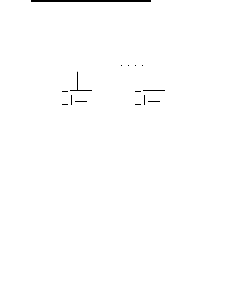
DCS Call Coverage
Issue 3 March 1996 3-613
Feature Applications
Consider the following figure
:
Figure 3-4. Applications for DCS Call Coverage
The following list describes some of the applications for DCS Call Coverage not
otherwise possible without this feature:
■A user spends time in multiple locations. An account executive, for
example, might spend a lot of time at locations A and B. He or she might
want calls to station B, for example, to be covered first by station A and
then by AUDIX, DEFINITY AUDIX, or Intuity.
■A user moves from location A to location B. In this case, the user might
want calls to station A to be covered first at station B then at AUDIX.
■A secretary is located in different locations. A user at station B might want
calls to first be covered by a secretary at station A and then by the AUDIX
at location B.
Previous Feature Operation
The following figure illustrates the extent of call coverage over DCS tie trunks in
pre G3V4 systems. Previous to G3V4 there was only one case when a call would
cover to a point on a remote switch, with normal call coverage functionality,
which was when covering to a remote AUDIX as described below.
G3V4 G3V4
Location A Location B
Station A Station B
AUDIX
DEFINITY
AUDIX
In tu ity
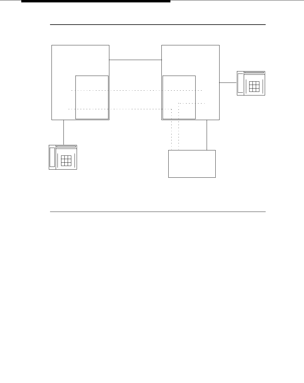
Feature Descriptions
3-614 Issue 3 March 1996
.
Figure 3-5. DCS AUDIX Coverage to Remote System
Prior to G3V4
In this scenario, calls to extensions on system A can be covered by the AUDIX on
system B as follows:
■A call comes into the station at extension 34567. After the administered
number of rings, the call goes to coverage.
■If the coverage point is an AUDIX hunt group with rem-audix in the
“Message Center” field and 44000 in the “AUDIX Extension” field on page
2 of the “Hunt Group” form, the AUDIX, if it is available, will cover this call
with user A’s personal greeting. If the AUDIX is not available, no further
coverage points will be attempted. If the trunk between the two systems is
busy, the next coverage point, which must be on system A, will be tried.
■The connect message sent to AUDIX by System B gets the principal’s
extension (34567) from a DCS message sent on the DCS link between
system A and system B.
System A System B
Tie trunk groups
AUDIX
X44000
G1 or G3 System
PGATE or PI Board
G1 or G3 System
PGATE or PI Board User B
X45678
X.25 or ISDN PRI
DCS signaling link
AUDIX link to system A
viahop. Thislinkis
required in G1 and G3iV1
but not in G3r or G3V2.
hop
AUDIX link
to system B
AUDIX
Voice lines
User A
X34567
Previous to G3V4, calls to extension 34567 can be covered
by the AUDIX on the remote system but not by any other
type of coverage point on the remote system,
such as the station at extension 45678.
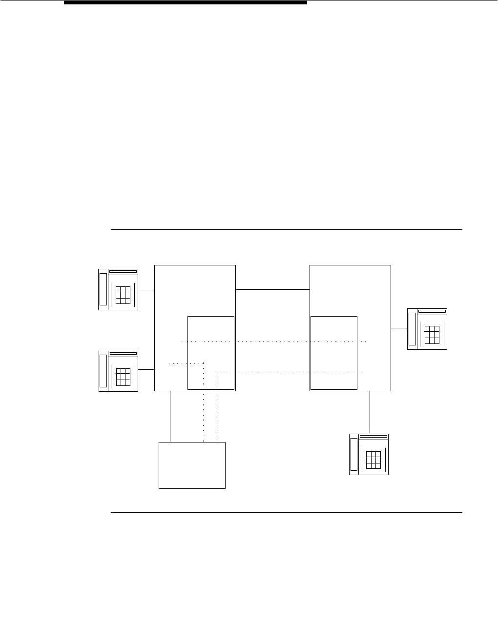
DCS Call Coverage
Issue 3 March 1996 3-615
■After AUDIX answers the covered call, it sends a message to system A via
an AUDIX signaling link to system A lighting user A’s message lamp.
■Since a physical link does not exist between the AUDIX and system A, the
signaling link must hop from the system B-to-AUDIX BX.25 link to the
system B-to-system A BX.25 link. In G1 and G3iV1, this link between
AUDIX and system A must be present for the call to be covered. In G3rV1,
G3V2, and G3V3 the call will be covered without this link present but the
message lamp will not be updated.
New Feature Operation
The DCS Call Coverage feature for G3V4 adds the capability to cover to points
other than AUDIX on a remote system. It does this by providing DCS messaging
that provides transparency for the G3V4 Call Coverage feature. The following
figure illustrates some of the possibilities associated with DCS Call Coverage
.
Figure 3-6. G3V4 DCS Call Coverage
System A System B
Tie trunk groups
AUDIX
X34000
G3V4 System
PGATE or PI Board
G3V4 System
PGATE or PI Board User C
X45678
User A
X34567
User B
X34568
X.25 or ISDN PRI
DCS signaling link
hop
AUDIX
Voice lines
User D
X45679
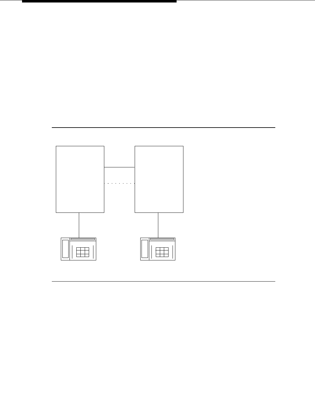
Feature Descriptions
3-616 Issue 3 March 1996
In this scenario using DCS Call Coverage, calls to user A can be covered first by
user B, then by user C, and then finally by the AUDIX on system A. Alternatively,
calls could be covered by user C, then user B, and so on. If the principal party
answers after the call has gone to coverage and the coverage point has
answered, the calling party, the principal, and the coverage point are
conferenced together. In this same case, if the coverage point has not answered,
the call to the coverage point is dropped and the calling party and principal are
connected.
Detailed Operation
To illustrate how DCS Call Coverage works in more detail, consider the following
scenario
.
Figure 3-7. Detailed Operation Scenario
The following sections describe the DCS message flow for possibilities in this
scenario.
Operation under Normal Conditions. In a normal DCS Call Coverage scenario
where the DCS link is up, a DCS trunk group is available, and DCS Call Coverage
is activated on the local and remote systems, DCS Call Coverage works as
follows:
1. A call comes into the principal.
2. The principal does not answer within the administered number of rings or
has Send All Calls activated.
G3V4 G3V4
Local System Remote System
Principal Coverage Point

DCS Call Coverage
Issue 3 March 1996 3-617
3. The call is redirected to the first coverage point, which is on the remote
system. Also, at this time the DCS distinctive ringing message is sent to
the coverage point along with two messages conveying the caller’s name
and the principal’s name.
4. The coverage point rings with internal ringing if the caller is on a DCS
node, or with external ringing otherwise.
5. The covering user answers and receives the calling party’s name and
principal’s name on the display if equipped.
Several other scenarios can occur deviating from this normal situation, as
follows:
■ A call to the principal redirects to the remote coverage point, which is
unavailable. The coverage point is considered unavailable in the following
cases:
— The coverage point is not a valid extension, QDN, or VDN.
— The coverage point is busy with no hunting, forwarded, or has
send all calls activated, or activates send all calls after ringing.
— The coverage point has no staffed agents or an invalid vector.
In the case of an unavailable coverage point, the local system learns of
the availability status either through a time-out or from a message from the
remote system. When the local system determines that the coverage point
is unavailable, it tries the next coverage point. If the last coverage point is
unavailable, the previous coverage point rings until answered or until the
caller hangs up. If only one coverage point exists in the path and it is
unavailable, the principal’s station rings until answered or until the caller
hangs up.
■ A call to the principal is forwarded and the forwarded-to extension is not
available. In this case, the first coverage point in the principal’s path will
be tried. Note that the coverage does not follow the forwarded-to
extension’s coverage path.
■ A call to the principal redirects to the remote coverage point, which
answers. Subsequently, the principal goes off hook. In this case, the local
system bridges the principal onto the call between the calling party and
coverage point creating a conference among the three. The principle
receives the call on the same call appearance as the original call.
■ A call to the principal redirects to the remote coverage point. While the
remote coverage point is ringing, the principal answers the call. In this
case the call is not cut through to the coverage point. Instead, ringing and
ringback is removed from the coverage point and the call is cut through to
the principal.

Feature Descriptions
3-618 Issue 3 March 1996
Operation Under Error Conditions. The following table describes the operation
of DCS Call Coverage under error conditions
In addition, call consult operates as follows when the DCS link is down: If user A
calls user B but the call covers to user C, then if user C consults back to user B,
user B receives the consult call on the next call appearance.
User Interface
The user interface for DCS Call Coverage consists of station alerting and terminal
displays, including hospitality displays
Station Alerting. Station alerting operates the same as in Call Coverage, as
follows:
■If the call to the principal originated from a station within the DCS network,
the coverage point receives internal ringing.
■If the call to the principal originated from a trunk, which means from a
phone on a switch outside the DCS network, the coverage point receives
external ringing.
■If the call to the principal originated from an attendant within the DCS
network, the coverage point receives external ringing.
Table 3-52. Error Conditions
Error Condition Action
DCS link not up.
or
DCS trunk is not available.
or
DCS Call Coverage feature is not
activated on the remote system.
The call is routed to the remote
coverage point. If the call is
answered, it is treated as Call
Coverage Off Premises (also called
Remote Call Coverage.) If the call is
redirected at the remote coverage
point before the DCS SRI expires,
the remote point’s path will be
followed. If the call is not answered
within the DCS SRI time-out period,
the next coverage point is tried with
DCS Call Coverage from the local
system.
All trunks to the remote system, DCS
or otherwise, are busy The next coverage point is tried with
DCS Call Coverage from the local
system.
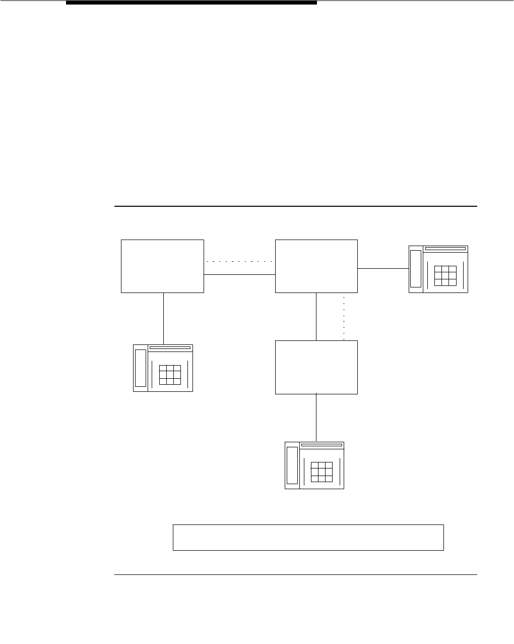
DCS Call Coverage
Issue 3 March 1996 3-619
Displays. Displays at the coverage point work the same as for Call Coverage
with the exceptions caused by DCS. In general, the display at the coverage point
takes the form
a=<Calling Party Name> <to> <Principal Name> <reason for redirection
flag>
For call coverage, this format is always true because the system has all the
information it needs from the calling party, principal, and coverage point. Under
most circumstances, DCS also has all the information it needs, providing it in
messages. In some DCS circumstances, however, some information can be
lacking or substituted with other information. Following are the formats for
displays on the coverage point’s terminal under these special conditions
.
Figure 3-8. Display — DCS Trunks End-to-End
In the Figure 3-8, a call is made from the station on system A to the principal on
system B and covered by the station on system C. The tie trunks between A and
S75, G1,
G3, S85,
or G2
G3V4
System A System B Principal
G3V4
Coverage Point
System C
DCS link
DCS link
ISDN or non-
ISDN Tie trunk
ISDN or non-
ISDN Tie trunk
Calling Party
Coverage Point's Display
a=<Calling Party Name> <to> <Principal's Name> <flag>
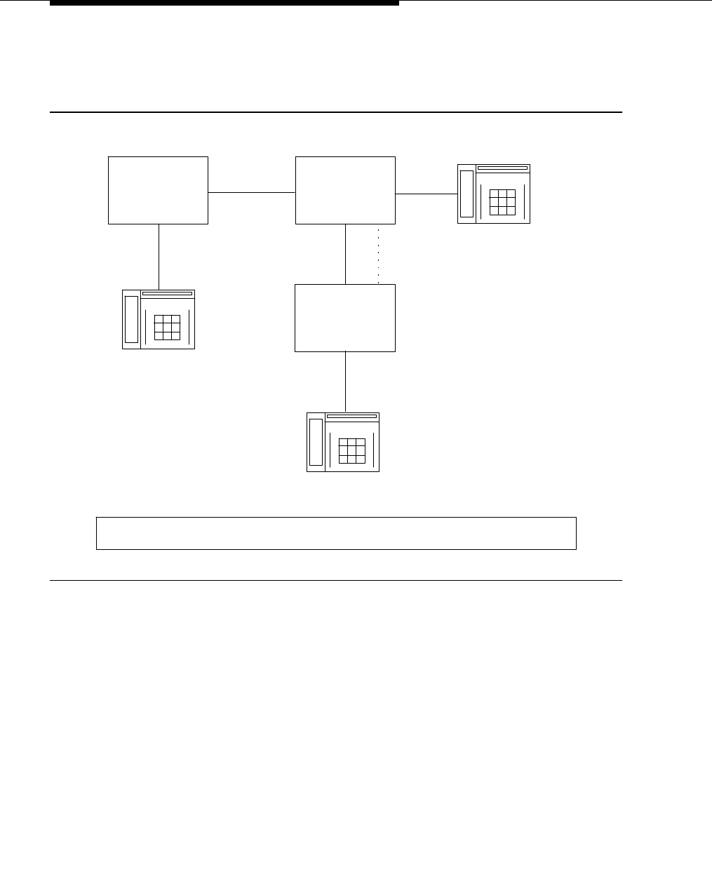
Feature Descriptions
3-620 Issue 3 March 1996
B and B and C are DCS trunks transported over any kind of facility (ISDN or
non-ISDN).
.
Figure 3-9. Display — Non-DCS, Non-ISDN Trunk to DCS
Trunk over Non-ISDN Trunk
In Figure 3-9, a call is made from the station on system A to the principal on
system B and covered by the station on system C. The tie trunk between A and B
is not a DCS trunk and is not an ISDN PRI trunk. The tie trunk between B and C is
a non-ISDN PRI DCS trunk.
S75, G1,
or G3
G3V3
System A System B Principal
G3V3
Coverage Point
System C
DCS link
non-ISDN trunk
non-ISDN trunk
Calling Party
Coverage Point's Display
a=<Trunk group AB's name from B's names database> <to> <Principal's Name> <flag>
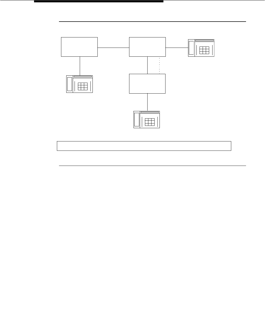
DCS Call Coverage
Issue 3 March 1996 3-621
.
Figure 3-10. Display — Non-DCS, Non-ISDN Trunk to DCS
Trunk over ISDN Trunk
In Figure 3-10, a call is made from the station on system A to the principal on
system B and covered by the station on system C. The tie trunk between A and B
is not a DCS trunk and is not an ISDN PRI trunk. The tie trunk between B and C is
a DCS ISDN PRI trunk.
S75, G1,
G3, S85
or G2
G3V4
System A System B Principal
G3V4
Coverage Point
System C
DCS link
Non-ISDN trunk
ISDN trunk
Callin g Pa rty
Coverage Point's Display
a=<Trunk group AB's nam e from B's names database> <to> <Principal's Name> <flag>
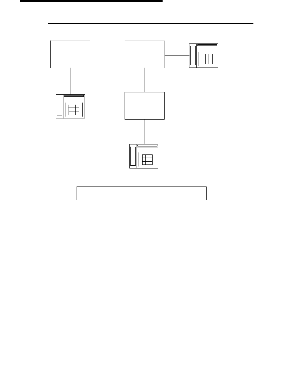
Feature Descriptions
3-622 Issue 3 March 1996
.
Figure 3-11. Display — Non-DCS ISDN Trunk to DCS ISDN
Trunk
In Figure 3-11, a call is made from the station on system A to the principal on
system B and covered by the station on system C. The tie trunk between A and B
is not a DCS trunk but is an ISDN PRI trunk. The tie trunk between B and C is a
DCS ISDN PRI trunk.
G1, G3,
S85 or G2
G3V4
System A System B Principal
G3V4
Coverage Point
System C
DCS link
ISDN trunk
ISDN trunk
Calling Party
Coverage Point's Display
a=<Calling Party's Name> <to> <Principal's Name> <flag>
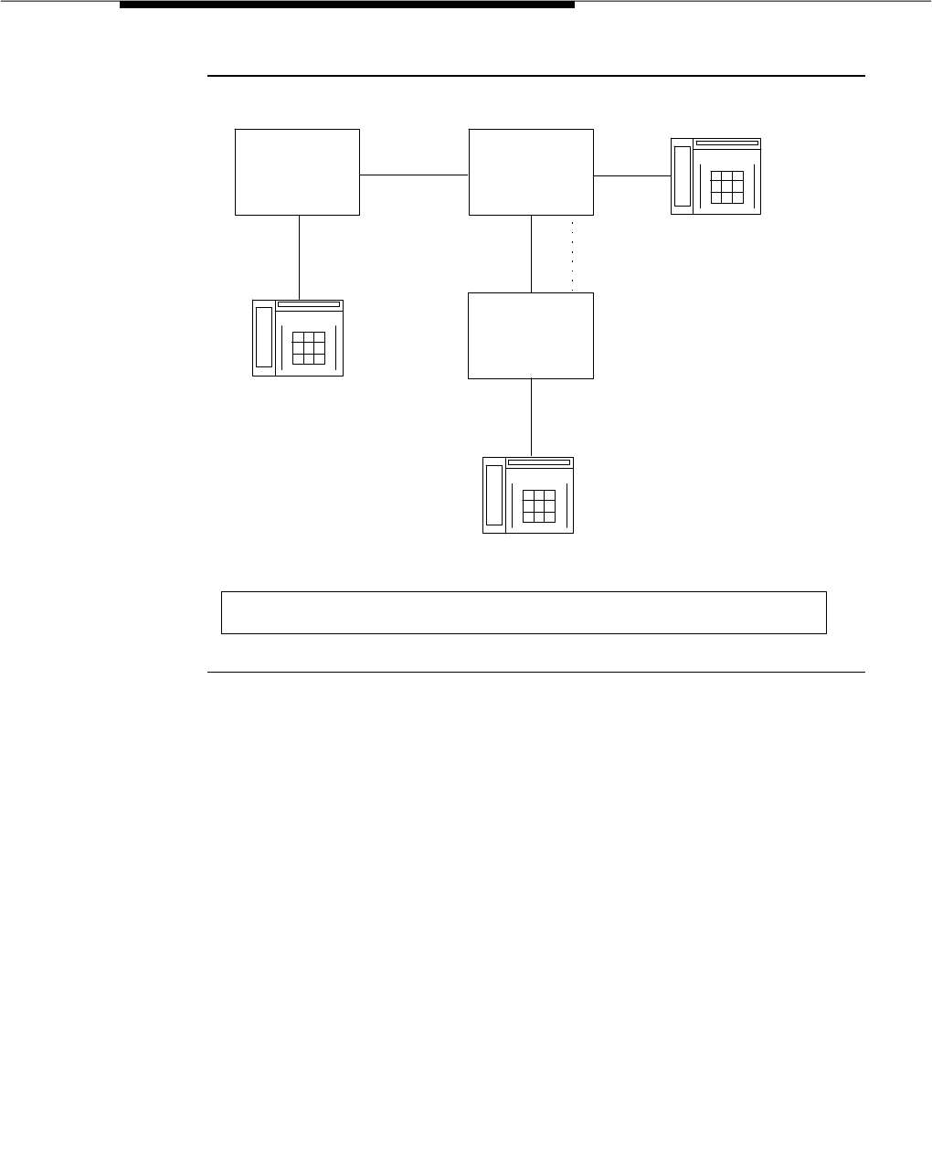
DCS Call Coverage
Issue 3 March 1996 3-623
.
Figure 3-12. Non-DCS ISDN Trunk to Non-ISDN DCS Trunk
In Figure 3-12, a call is made from the station on system A to the principal on
system B and covered by the station on system C. The tie trunk between A and B
is not a DCS trunk but is an ISDN PRI trunk. The tie trunk between B and C is a
DCS trunk but not an ISDN PRI trunk.
If the calling party is a trunk on system A instead of a station, the displays are the
same as above, substituting the calling trunk group’s names database for the
station’s names database. The exception to this is when system A is a System 85
or G2, as follows:
G1, G3,
S85 or G2
G3V4
System A System B Principal
G3V4
Coverage Point
System C
DCS link
ISDN trunk
non-ISDN trunk
Calling Party
Coverage Point's Display
a=<Trunk group AB's name from B's names database> <to> <Principal's Name> <flag>
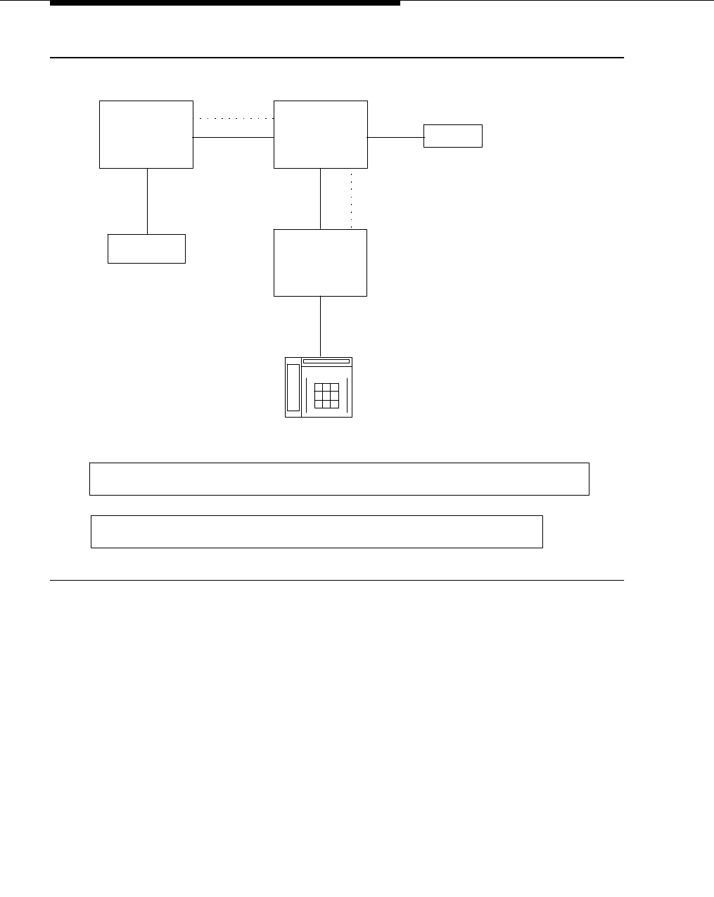
Feature Descriptions
3-624 Issue 3 March 1996
.
Figure 3-13. Display — Call Initiated by a Trunk on System 85
or G2
The display in this case depends on the administration on the G2. If the call is
routed to trunk group AB via the internal dial plan (PROC 354 word 2), the G2
sends a DCS name message for the calling trunk and the first display results. If
the call is routed directly to a pattern without going through the internal dial plan,
however, a name message is not sent, resulting in the second display. If trunk
groups AB and BC are both ISDN PRI trunk groups, however, the first display will
result because the coverage point will display the contents of the ISDN PRI
display information element.
The situations described above assume outgoing trunk group displays are
turned off in the “Trunk Group” form, that the “Send Name” field is yes in the”
ISDN Trunk Group” form, that the name message and display IEs have contents,
which are taken from the station or trunk names databases, and that these
messages are sent and received.
S85 or G2 G3V4
System A System B
G3V4
Coverage Point
System C
DCS link
DCS link
non-ISDN trunk
any trunk
any trunk
Coverage Point's Display
a=<Calling party's trunk group name from A's names database> <to> <Principal's Name> <flag>
a=<Trunk group AB's name from B's names database> <to> <Principal's Name> <flag>
Principal
Calling Party
or

DCS Call Coverage
Issue 3 March 1996 3-625
Hospitality Displays. If the hospitality feature is in use, the display rules can vary
from those shown above depending on administration. The displays on terminals
follow the same rules as above except for one case as described in the following
list.
■The hospitality feature is enabled on the calling party’s system, the
principals’ system, and on the coverage point’s system on page 2 of the
“System Parameters Customer Options” form.
■The client room option is set to y on the “Class of Service” form for the
calling party’s and the principal’s stations.
■The “Display Client Redir?” field is set to n on the “Coverage Point’s
Station” form.
If the above conditions exist, the coverage point displays the following:
a=<Calling party’s name from A’s names database><to><Principal’s
extension>
In most hospitality applications, the extension is administered as the room
number. If this is not the case, however, the administered room number can be
displayed instead of the extension. This is accomplished by doing the following:
■Set the “Display Room Information?” field to y in the “Hospitality-Related
System Parameters” form.
■Enter up to five characters in the “Room” field in the “Principal’s Station”
form.
Interactions
DCS Call Coverage has the same interactions as Call Coverage plus interactions
with the following features. For information on the Call Coverage interactions, see
the "Call Coverage" feature description in this manual.
■Call Coverage Off Premises
DCS Call Coverage interacts with Call Coverage Off Premises as follows.
If the coverage point is a non-UDP number in the remote call coverage
table, Call Coverage Off Premises is applied to the call rather than DCS
Call Coverage, even if a DCS link exists to the remote system.
■Coverage Answer Groups
DCS Call Coverage to Coverage Answer Groups on remote systems are
not supported by DCS Call Coverage. Coverage answer groups cannot
be administered on a system other than the principal’s system.

Feature Descriptions
3-626 Issue 3 March 1996
■Coverage Call Back
DCS Call Coverage does not support Coverage Call Back from a remote
node. This is because the coverage point’s system has no way of knowing
whether the caller can respond to Leave Word Calling. For example, the
coverage point’s system does not know whether the calling party is a trunk
or a station.
■Displays
DCS Call Coverage interacts with displays as follows. Displays on the
coverage point’s terminal can appear different than they do with Call
Coverage in the following situations:
— When the call from the calling party to the principal or the
redirected call to the coverage point travel over ISDN PRI trunk
groups.
— When the calling party is on a System 85 or Generic 2.
— When the DCS name message is not received by the remote
(coverage point’s) system.
For more detail see the Displays section of this feature description.
■Goto Cover
Goto Cover is not supported over DCS and therefore is not supported with
DCS Call Coverage.
■Leave Word Calling (LWC) Back to Principal
With DCS Call Coverage a covering user on a different node cannot press
their LWC button to leave a message for the principal to call the covering
user.
■Queuing
DCS Call Coverage interacts with queuing in the following way. If a call is
queued to a coverage point, such as a queue to a hunt group or an ACD
split, and the queue is not full, the call will stay in the queue without
subsequent redirection until answered or until the caller hangs up.
Interworking
DCS Call Coverage contains considerations associated with interworking with
ISDN PRI and with non-G3V4 systems. The interworking issues with ISDN PRI are
actually issues related to DCS, not to DCS Call Coverage, but they do have
consequences for how displays appear at the coverage point’s display terminal.

DCS Call Coverage
Issue 3 March 1996 3-627
The following list describes the interworking between DCS and ISDN PRI:
■When an incoming call on a DCS trunk is routed to an outgoing ISDN
PRI-only trunk, the contents of the display information element in the ISDN
PRI SETUP message, which contains the calling party name, are taken
from the contents of the DCS name message.
■When an incoming call on an ISDN PRI trunk is routed to an outgoing DCS
trunk over an ISDN PRI trunk, the DCS name message is suppressed in
G3V2 and later systems. The reason for this is that the DCS name
message in this case contains only the trunk group name, if administered,
of the incoming ISDN PRI trunk. Since DCS messages normally take
precedence, the more informative ISDN PRI display IE would not be used.
Thus, the DCS name message is turned off, allowing the ISDN PRI display
IE to be used.
DCS Call Coverage does not work in a mixed system of G3V4 and pre-G3V4
systems. The reason for this is that a pre-G3V4 system will not tandem call
associated messages that they do not understand. Since the call coverage DCS
messages are new starting with G3V4, earlier systems cannot understand them.
The following figure illustrates this
:
Figure 3-14. Interworking
G3V4 G3V4
System A System B
Pre G3V4
Trunk group AC Trunk group CB
Trunk group AB
System C
Principal Cov. Point
Calls to the principal routed to the coverage point over trunk
group AB will work. Calls to the principal routed to the coverage
point over trunk group AC and then tandemed to trunk group CB
will not receive coverage because system C cannot tandem the
new call coverage messages.

Feature Descriptions
3-628 Issue 3 March 1996
Hardware and Software Requirements
The following software is required for DCS Call Coverage:
■G3V4 or later system software
■DCS software
■UDP or PNA software
■DCS Call Coverage must be enabled on all systems having principals or
coverage points and on all intervening systems.
DCS Call Coverage does not require any additional hardware beyond what is
required by DCS or call coverage.

DCS Call Forwarding All Calls
Issue 3 March 1996 3-629
DCS Call Forwarding All Calls
Feature Availability
DCS is available with all Generic 3 releases except G3vs/G3s ABP.
Description
Allows all calls to an extension number to be forwarded to a selected extension
number within the DCS network or to an external (off-premises) number. If the
Call Forwarding and DCS Call Forwarding All Calls features are both active, and
if a call is forwarded between extensions on the same node, the Call Forwarding
coverage path is used. If the nodes are different, the DCS Call Forwarding All
Calls coverage path is used.
This feature is activated or deactivated by dial access code or by a Call
Forwarding button. The feature can be activated or deactivated only by voice
terminal users within the DCS.
Activation and deactivation of the feature is the same as described for the "Call
Forwarding All Calls" feature, described earlier in this chapter.
Considerations
With DCS Call Forwarding All Calls, voice terminal users can have their calls
follow them to any location within the DCS network or outside the DCS network.
Calls to an attendant cannot be forwarded. However, an attendant can activate
or deactivate the feature for other extension numbers within the DCS.
Interactions
If the forwarding extension and the designated extension are at different nodes,
and the designated extension’s coverage criteria are met on a forwarded call, the
call is redirected to a point in the designated extension’s coverage path.
If the forwarding extension and the designated extension are at different nodes,
LWC and Coverage Callback cannot be activated at the designated extension
for a forwarded call.
There is a 30-second interval during which calls forwarded from the DEFINITY
switch to another DCS node is denied. This prevents forwarded incoming trunk
calls from being forwarded ad infinitum between two extensions.

Feature Descriptions
3-630 Issue 3 March 1996
Administration
The administration for DCS Call Forwarding All Calls is the same as that for the
"Call Forwarding All Calls" feature, which is fully described elsewhere in this
chapter.
Hardware and Software Requirements
DCS interface hardware and DCS software are required.

DCS Call Waiting
Issue 3 March 1996 3-631
DCS Call Waiting
Feature Availability
DCS is available with all Generic 3 releases except G3vs/G3s ABP.
Description
Allows calls from one node to busy single-line voice terminals at another node to
wait until the called party is available to accept the call.
DCS Call Waiting includes the following features:
■Attendant Call Waiting
■Call Waiting — Termination
■Priority Calling
Attendant Call Waiting, Call Waiting Termination, and Priority Calling function the
same between the DEFINITY system Generic 1, Generic 3, or System 75 nodes
in a DCS as they do from a single DEFINITY system Generic 1, Generic 3, or
System 75. These features are detailed in Chapter 3, "Feature Descriptions".
Considerations
With DCS Call Waiting, a single-line voice terminal user, by knowing a call is
waiting, can quickly process calls from locations within the DCS.
Call Waiting — Origination can only be received if Generic 3i not activated.
DCS priority calling from the attendant station is
not
available.
Interactions
DCS Call Waiting is denied when the following features are activated at the
single-line voice terminal:
■Automatic Callback (to or from the voice terminal)
■Data Privacy
■Data Restriction
On incoming trunk calls to the attendant extended over DCS trunks, Attendant
Call Waiting interacts with the EDCS feature.

Feature Descriptions
3-632 Issue 3 March 1996
Administration
None required.
Hardware and Software Requirements
DCS interface hardware and DCS software are required.

DCS Distinctive Ringing
Issue 3 March 1996 3-633
DCS Distinctive Ringing
Feature Availability
DCS is available with all Generic 3 releases except G3vs/G3s ABP.
Description
Activates the alerting, or ringing, device of a called terminal so that the user is
aware of the type of incoming call before answering it. Distinctive Alerting
functions in a DCS environment as it does within a System:
■For G3sV1 and G3iV1, internal calls are identified by a 1-burst ringing
pattern; external calls by a 2-burst ringing pattern; and priority calls by a
3-burst ringing pattern.
■For G3i-Global, G3rV1, G3V2, and later releases, these values are
administrable; the defaults are the same as those given above for G3sV1
and G3iV1.
A detailed description of the "Distinctive Ringing" feature is given earlier in this
chapter.
Considerations
DCS Distinctive Ringing allows the user to identify the type of incoming calls. By
knowing the type of incoming call, the user can answer each call properly.
When DCS transparency is lost for any reason, terminal-to-terminal calls made
between nodes produce external ringing instead of the usual internal ringing.
Loss of transparency may occur when the data link between nodes is down or
when data transmission delay exceeds the trunk signaling time.
Interactions
The following features interact with the DCS Distinctive Ringing feature:
■Distinctive Ringing
Distinctive Ringing treats a call from another switch in a DCS arrangement
as external; DCS Distinctive Ringing treats such calls as internal. If both
features are administered, DCS Distinctive Ringing takes precedence. If
EDCS is activated, DID treatment may be different. See the "Enhanced
DCS (EDCS)" feature.
■Intercom — Automatic
This feature and its distinctive ringing are not provided between nodes in
a DCS.

Feature Descriptions
3-634 Issue 3 March 1996
■Intercom — Dial
This feature and its distinctive ringing are not provided between nodes in
a DCS.
■Manual Signaling
This feature and its distinctive ringing are not provided between nodes in
a DCS.
■Tie Trunk Access
On a DEFINITY Generic 3 switch, tie trunk groups can be administered as
either internal or external tie trunk groups. Calls from internal tie trunk
groups are treated as terminal-originated calls and receive one-burst
ringing. Calls from external tie trunk groups are treated as externally
originated calls and receive two-burst ringing.
Administration
None required.
Hardware and Software Requirements
DCS interface hardware and DCS software are required.

DCS Leave Word Calling
Issue 3 March 1996 3-635
DCS Leave Word Calling
Feature Availability
DCS is available with all Generic 3 releases except G3vs/G3s ABP.
Description
Enables terminal users to leave preprogrammed ‘‘call me’’ messages at other
terminals within the DCS network. Messages can be left by calling, called, or
covering users.
LWC transparency in a DCS configuration allows messages from a DEFINITY
switch to another node, depending on the storage capability of the remote node.
Considerations
DCS LWC lets users within the DCS leave short, simple messages for other
users.
LWC cannot be successfully activated toward any system that is not capable of
storing the messages, either internally or in an associated adjunct.
Messages from one node, through an intermediate node, to a remote node do
not require storage capability at the intermediate node.
LWC transparency is supported for all DCS configurations except for cases when
either the activating node or the remote node is either an ENHANCED
DIMENSION PBX or a System 85 R2V1.
Retrieval of LWC messages is permitted only from a terminal at the node where
the messages are stored.
DCS LWC cannot be activated from an attendant console.

Feature Descriptions
3-636 Issue 3 March 1996
Interactions
The following features interact with the DCS LWC feature.
■DCS Multi-appearance Conference/Transfer
Activation of LWC is denied after a DCS call has been conferenced or
transferred.
■DCS Call Forwarding All Calls
If the forwarding extension and the designated extension are at different
nodes, LWC cannot be activated at the designated extension for a
forwarded call.
Administration
The administration for DCS LWC is the same as that for LWC ("Leave Word
Calling"), which is fully described elsewhere in this chapter.
Hardware and Software Requirements
DCS interface hardware and DCS software are required.

DCS Multi-Appearance Conference/Transfer
Issue 3 March 1996 3-637
DCS Multi-Appearance
Conference/Transfer
Feature Availability
DCS is available with all Generic 3 releases except G3vs/G3s ABP.
Description
Provides transparency of transfer of calls, and of conference calls within a DCS
network. A user in the DCS can make conference calls or transfer calls originated
from any extension in the DCS network to another extension within the DCS. (For
transferred calls, the destination need not be within the DCS.)
In a DCS, if a party in a conference hangs up or completes a transfer leaving only
outgoing trunks on the call, an attempt is made to preserve the connection if any
of the remaining parties on the call is a DCS tie trunk. This can be accomplished
if the DCS tie trunk can signal the remote node when the party hangs up. The
remote node sends a reply to the originating node, and disconnect supervision is
provided for that trunk.
Conference Calls can be placed and calls can be transferred to users within the
DCS by dialing the UDP extension number.
A detailed description of the "Conference — Attendant", "Conference —
Terminal", and "Transfer" features is given elsewhere in this chapter.
Considerations
DCS Multi-Appearance Conference/Transfer is useful when it is necessary to talk
to more than one party at one time within a DCS. Multiappearance voice
terminals must have an idle appearance in order to transfer a call.
Interactions
The following features interact with the DCS Multi-Appearance
Conference/Transfer feature.
■Voice Terminal Display
No display transparency is provided for DCS Multi-Appearance
Conference/Transfer.
■EDCS
On calls to or from Public Network Trunks, calling/called party restrictions
are checked when EDCS is active.

Feature Descriptions
3-638 Issue 3 March 1996
Administration
None required.
Hardware and Software Requirements
DCS interface hardware and DCS software are required.

DCS Over ISDN-PRI D-Channel
Issue 3 March 1996 3-639
DCS Over ISDN-PRI D-Channel
Feature Availability
DCS is available with all Generic 3 releases except G3vs/G3s ABP.
Description
Enhances the DCS feature by allowing access to the public network for DCS
feature connectivity between DCS switch nodes. With this feature, DCS features
are no longer restricted to private facilities. The ISDN-PRI B-channel is used for
voice communications, and the ISDN-PRI D-channel is used to transport DCS
control information. The only difference between DCS networks that do not
utilize the DCS Over ISDN-PRI feature and those that do is in the method of
signaling. The DCS Over ISDN-PRI D-Channel feature uses
Message-Associated User-to-User Information (MA-UUI) and Temporary
Signaling Connections (TSCs) to transport certain DCS control information.
MA-UUI allows additional user-specific information to be transported along with
certain ISDN call-control messages.
A TSC provides a temporary signaling path through ISDN switches for
exchanging user-user information. There are two types of temporary signaling
connections: Call Associated Temporary Signaling Connections (CA-TSC) and
Non-Call Associated Temporary Signaling Connections (NCA-TSC).
A CA-TSC refers to a service for exchanging USER INFORMATION messages
that are associated with an ISDN B-Channel connection by the call reference
value of the call control data packets.
An NCA-TSC is a connection not related with any ISDN B-channel connections.
It is an administered virtual connection established for exchanging USER
INFORMATION messages on the ISDN D-channel for the DCS Over ISDN-PRI
D-Channel application as well as for the DCS AUDIX application. Once an
NCA-TSC has been administered and enabled, it will be active for an extended
period of time. There are two types of administered NCA-TSCs depending on
their setup mechanism:
Permanent
and
As-needed
.
Once enabled, a permanent NCA-TSC will remain established while the system
is running. If the permanent NCA-TSC is dropped for any reason, the system will
attempt to reestablish the connection. An as-needed administered NCA-TSC is
established based on user request and the availability of TSC facilities. The
connection will be dropped after an administered period of inactivity.
The system can transport DCS or DCS Audix messages over an ISDN-PRI
D-channel and over BX.25 data links when functioning as a gateway between a
PBX equipped with the DCS Over ISDN-PRI D-Channel feature and a PBX
equipped with traditional DCS using BX.25 data links. In this situation, the

Feature Descriptions
3-640 Issue 3 March 1996
messages travel from the gateway through the %NCA-TSCs or %CA-TSCs to
%TSC-capable PBXs and from the gateway to PBXs that support only traditional
DCS via a BX.25 logical channel.
At least one PBX must be configured as an ISDN DCS Gateway node in a DCS
network that consists of PBXs that support DCS Over ISDN-PRI D-Channel and
PBXs that do not support the feature.
For examples of various DCS network configurations and how they are
administered, see
DEFINITY Communications System Generic 3 Version 4
Implementation
, 555-230-655, or
DEFINITY Communications System Generic 3
V2/V3 Implementation
, 555-230-653.
Considerations
System users should notice no difference between DCS features over ISDN-PRI
and traditional DCS features.
Interactions
Most feature interactions with DCS Over ISDN-PRI D-Channel are the same as
those with traditional DCS features. However, some interactions are unique to
the DCS Over ISDN-PRI D-Channel feature. These unique interactions are listed
below:
■Attendant DXS with Busy Lamp Field
An attempt by the attendant to directly select an extension that has been
previously administered as belonging to a administered NCA-TSC will
result in intercept tone being received.
■D-Channel Backup
In the event of a D-channel switchover (primary to secondary or
secondary back to primary) in a private network, administered NCA-TSCs
that were active are assumed to have remained active. Any
unacknowledged user-user service requests are assumed to be rejected,
and administered NCA-TSCs which were in the process of being
established at the time of the switchover are dropped when the
switchover occurs. Those administered NCA-TSCs that were dropped
will be reattempted again.
If a D-channel switchover occurs on a D-channel going to the public
network then all TSCs will be dropped. A maintenance-provided
‘‘heartbeat’’ message will periodically be sent over each permanent
administered NCA-TSC to ensure that such a situation is detected and
recovered from.
■Distributed Communications System AUDIX (DCS AUDIX)

DCS Over ISDN-PRI D-Channel
Issue 3 March 1996 3-641
The DCS over ISDN-PRI D-Channel feature can be used to support DCS
Audix. (The connection between G3i and AUDIX should be BX.25.)
■GRS
GRS will select TSC compatible facilities when routing NCA-TSCs. In other
words, a NCA-TSC request can only select a routing preference that
supports TSCs.
In a tandem node, GRS will first select facilities that support TSCs if the
call falls into any one of the following two conditions:
— It requests a CA-TSC explicitly
— It contains a DCS information element in the SETUP message
Once a trunk group with available members is selected, the call will
proceed even if all the TSCs belonging to the associated signaling group
are active. In other words, the completion of a call is given priority over
DCS transparency.
■ISDN-PRI
This feature uses ISDN-PRI call control protocol and messages.
■SDN
The DCS over ISDN-PRI D-Channel feature allows the system to access
public networks such as SDN. SDN supports all DCS features except for
the following:
— "DCS Attendant Control of Trunk Group Access"
— "DCS Attendant Direct Trunk Group Selection"
— "DCS Busy Verification of Terminals and Trunks"
■CDR
CDR will record both the status and the utilization of TSCs. Both CA-TSCs
and NCA-TSCs can be recorded. For more information, consult the CDR
description in this manual or the CDR manual.
■Voice Terminals
An attempt to dial an extension that has been previously administered as
belonging to a administered NCA-TSC will result in intercept tone being
received.
Administration
The ISDN-PRI option must be enabled on the “System-Parameters
Customer-Option” form before associated forms and fields on forms can be
administered.
To implement this feature, the following form(s) must be completed.
■Signaling Group Form

Feature Descriptions
3-642 Issue 3 March 1996
■ISDN TSC Gateway Channel Assignment Form — Used to map
administered NCA-TSCs to (BX.25) processor channels in an Integrated
DCS Network. (Form only required for PBX location serving as an ISDN
Gateway in an Integrated DCS Network.) Complete all fields as required.
■ISDN Trunk Group Form
■Routing Pattern Form
■Communications-Links Processor Channels Form — The “Appl” field
specifies to which application channel this processor channel is
connected. Enter gateway in the associated “Appl” field if the processor
channel is used as one end of the gateway channel assigned in the “ISDN
TSC Gateway Channel Assignments” form. The gateway node serves as
the terminating node to the D-Channel DCS network as well as the
terminating node to the traditional DCS network.
A PBX serving as an ISDN DCS Gateway node introduces some
interesting situations when administering processor channels in an
associated traditional DCS PBX. In a traditional DCS network, (BX.25
processor channel links) the “Remote Port” field in the “Processor Channel
Assignments” form refers to the processor channel of the destination PBX.
In an Integrated DCS network, the “Remote Proc Chan” field in the
“Processor Channel Assignments” form refers to the processor channel of
the Gateway PBX (if the destination PBX is an ISDN DCS PBX),
not
the
destination PBX.
On the contrary, the “Machine-ID” field in the “Processor Channel
Assignments” form refers to the destination PBX, either an ISDN DCS PBX
or a traditional DCS PBX. The Gateway PBX number
must
not be used in
this field if the destination PBX is an ISDN DCS PBX.
NOTE:
There are several differences in between G3i and G3r administration. For
example, PRI is translated a little differently in G3r when traditional DCS
and this feature are used in combination. On systems with AUDIX in a DCS
environment, an additional column has been added to the “Signalling
Group” form so the administrator can specify which AUDIX on which
switch to use. When traditional DCS and DCS over ISDN are used in
combination, translations are also different. Refer to the
DEFINITY
Communications System Generic 3 Version 4 Implementation
,
555-230-655, or
DEFINITY Communications System Generic 3 V2/V3
Implementation
, 555-230-653, for further information.
Hardware and Software Requirements
The DCS over ISDN-PRI D-Channel feature requires the same hardware as other
ISDN-PRI features.
ISDN-PRI software is required.

DCS Trunk Group Busy/Warning Indication
Issue 3 March 1996 3-643
DCS Trunk Group Busy/Warning
Indication
Feature Availability
DCS is available with all Generic 3 releases except G3vs/G3s ABP.
Description
Provides attendants with a visual indication that the number of busy trunks in a
remote group has reached an administered level. A visual indication is also
provided when all trunks in a trunk group are busy.
If an attendant has a Trunk Hundreds Select button assigned to a remote trunk
group, the button’s Busy lamp lights when all trunks in the trunk group are busy.
The lamp goes dark when one of the busy trunks becomes available.
If an attendant has a three-lamp Trunk Hundreds Select button assigned to a
remote trunk group, the button’s Warn lamp lights when the number of busy
trunks in the trunk group reaches the Busy Warning Threshold. The lamp goes
dark when the number of busy trunks in the trunk group falls below the Busy
Warning Threshold.
To ensure that the busy, warning, and control status of all Trunk Hundreds Select
buttons in the DCS remain consistent with the status of the corresponding trunk
groups, some nodes in the DCS broadcast the status of a different local trunk
group, every 50 seconds, to all directly connected nodes. A pair of DCS nodes
are directly-connected if the voice tie trunks between them are not connected
through another switch. For example, a node with 30 trunk groups would take
1,500 (50 x 30) seconds to broadcast the status of all 30 trunk groups. This is
called a lamp audit. When a node receives a lamp audit message, its TGB/TGW
lamps are updated accordingly.
Considerations
Trunk Group Busy and Trunk Group Warning Indication is particularly useful with
the Attendant Control of Trunk Group Access feature. The indicators alert the
attendant when control of access to local and remote trunk groups is necessary.
Except for remote S75 R1V3, S85/G2 and S75 R1V2 switches, this feature is only
transparent if the remote switch is directly connected by voice tie trunks. For S75
R1V3 and S85/G2 remote switches, Trunk Group Busy and Trunk Group Warning
Indication is provided regardless of whether the voice tie trunks are
directly-connected or in tandem through an intermediate node; For S75 R1V2
remote switches, no Trunk Group Busy and Trunk Group Warning Indication
transparency is provided.

Feature Descriptions
3-644 Issue 3 March 1996
Interactions
If Trunk Hundreds Select buttons are assigned for Loudspeaker Paging Access
zones, Trunk Group Busy Indicators will provide a visual indication of the busy or
idle status of the zones at the remote location as well as at the local node.
Administration
Administration for DCS Trunk Group Busy/Warning Indication can only be
administered for remote trunk groups that are directly connected to the local
switch. The trunk group access codes for such trunk groups must be three digits
or less.
Hardware and Software Requirements
DCS interface hardware and DCS software are required.

Default Dialing
Issue 3 March 1996 3-645
Default Dialing
Feature Availability
This feature is available with all Generic 3 releases.
Description
Default Dialing enhances Data Terminal (Keyboard) Dialing by allowing a data
terminal user to place a data call to a preadministered destination by either
entering Return at the DIAL: prompt (for data terminals using DCP data modules)
or typing d and entering Return at the CMD: prompt (for data terminals using
ISDN-BRI data modules). The data terminal user with a DCP data module can still
place calls to other destinations by entering the complete address after the
DIAL: prompt (normal Data Terminal Dialing or Alphanumeric Dialing). The data
terminal user with an ISDN-BRI data module can still place calls to other
destinations by typing d, entering a space, typing the complete address, and
entering Return after the CMD: prompt.
Default Dialing provides data terminal users who dial a specific number the
majority of the time a very simple method of dialing that number. Normal Data
Terminal Dialing and Alphanumeric Dialing are unaffected.
For the AT command interface supported by the 7400A data module, the ATD
command may be entered instead of a carriage return to dial the default
destination.
The default destination is administered by the System Manager. Default Dialing
can be assigned to any data endpoint that has the Data Terminal Dialing
capability.
Considerations
Default Dialing provides data terminal users who dial a specific number the
majority of the time a very simple method of dialing that number.
Interactions
The following features interact with the Default Dialing feature.
■Data Call Setup
Default Dialing enhances Data Terminal (Keyboard) Dialing by allowing a
data terminal user to place a data call to a preadministered destination by
either Return at the DIAL: prompt (for DCP) or typing d and entering
Return at the CMD: prompt (for ISDN-BRI).

Feature Descriptions
3-646 Issue 3 March 1996
Administration
Default Dialing is administered by the System Manager. In addition to those items
listed in the "Data Call Setup" feature description, elsewhere in this chapter, the
following items must be administered:
■The preadministered default destination must be stored in an abbreviated
dialing list. This list can be a system list, group list, personal list, or
enhanced list. Therefore, before this feature can be activated, users’
terminals need to be administered with an abbreviated dialing list that
stores the default destination Then, each data module needs to specify
the index number of the entry which stores the default destination. The
following fields from the “Data Module” form are needed to activate the
Default Dialing feature.
— Special Dialing Option (default/hotline) — For Default Dialing,
‘‘default’’ must be selected. Default Dialing and the Data Hotline
feature cannot both be assigned to an extension.
— An Abbreviated Dialing List — One entry in the data module’s
abbreviated dialing list needs to store the default destination.
— Dial Code — An index to the entry of the abbreviated dialing list
that stores the default destination.
Hardware and Software Requirements
No additional hardware or software is required.

Dial Access to Attendant
Issue 3 March 1996 3-647
Dial Access to Attendant
Feature Availability
This feature is available with all Generic 3 releases.
Description
Allows voice terminal users to access an attendant by dialing an attendant
access code. Attendants can then extend the call to a trunk or to another voice
terminal.
In G3vsV1/G3sV1 and G3iV1, the access code is always the single digit 0. For
G3i-Global, G3rV1, G3V2, and later releases, this code is administrable and may
be any one or two digit number; the default is 0.
Considerations
With Dial Access to Attendant, voice terminal users can access the attendant
whenever attendant aid is needed by dialing the attendant access code.
A voice terminal user calling the attendant by dial access cannot be added to an
existing conference by the attendant.
Interactions
Restriction — Origination (administered to a voice terminal by the COR) prohibits
placing any calls, including Dial Access to Attendant calls.
For G3v1/G3sV1 and G3iV1 only, the attendant group dial code must be zero
and cannot be administered to another value. (This dial code can be
administered for G3i-global, G3rV1, G3V2, and later releases.)
Administration
The administrator may select an extension number other than zero for this
feature. However, in the United States 0 has traditionally been used for operator
assistance in both the public network and in PBXs, Also, consideration should be
given to the fact that prior to the emergence of 911 systems, the dialing of 0 was
customary in the United States for emergencies and other urgent assistance
requests. Using an extension number other than 0 for dial access to the
attendant could create confusion and delay response to an emergency.

Feature Descriptions
3-648 Issue 3 March 1996
Hardware and Software Requirements
No additional hardware or software is required.

Dial Plan
Issue 3 March 1996 3-649
Dial Plan
Feature Availability
This feature is available with all Generic 3 releases.
Description
The Dial Plan is the system’s guide to digit translation. When a digit is dialed, the
system must know what to expect, based on that digit. For example, if a voice
terminal user dials a 4, the system must know how many more digits to expect
before the call is processed.
There are a number of enhancements and changes for G3i-Global, G3rV1, G3V2,
and later releases. There are two digit tables giving more flexibility in the dial
plan. The number of extensions is greatly increased and, for G3rV1, G3V2, and
later releases, there is the introduction of Extension Number Portability. The
number of trunk access codes increased significantly as well as other capacities.
See the System Capacity Limits table in for more details.
The Dial Plan, or first-digit (and in G3rV1, G3i-Global, G3V2, and later releases,
the second-digit) table, established during administration for each system,
provides information to the switch on what to do with dialed digits. The tables
define the intended use of a code beginning with a specific first digit (and or first
two digits for G3i-Global, G3rV1, G3i-Global, G3V2, and later releases) and
relates to the system how many digits to collect before processing the code. The
choices of a first digit are 0 through 9, *, and #. Permissible code uses and the
allowable number of digits are listed below.
■Extension Numbers
Flexible numbering allows one, two, three, four, or five-digit extension
numbers. The first digit in the extension number tells the system how many
digits to expect the extension number to have.
Extension numbers can have a first digit of 1 (0 for G3rV1, G3i-Global,
G3V2, and later releases) through 9. For example, if a three-digit extension
number is administered and the first digit is a 4, the extension numbers
can range from 400 to 499. Also, if a four-digit number with a 6 as the first
digit is administered, the extension numbers can range from 6000 to 6999.
If multiple extension number lengths begin with the same digit, G3i-Global
uses a timer to identify when all the digits have been entered.
■Attendant
Dial access to the attendant group may be achieved by dialing the single
digit ‘‘0.’’ It is also possible to set the dial plan so that some other digit is
used to reach the attendant (for example, 9 in Italy). For G3rV1,
G3i-Global, G3V2, and later releases, access can range from 0 to 9 with a

Feature Descriptions
3-650 Issue 3 March 1996
length of one or more digits. In addition, Generic 3 provides for Individual
Attendant Access by assigning each attendant an individual extension
number.
■Trunk Access Codes
A minimum of one digit and a maximum of three (G3iV1) digits or four
(G3i-Global and G3rV1, G3V2, and later releases) can be used. Trunk
access codes can have a first digit of 1 (0 for G3rV1, G3i-Global, and
G3V2) through 9. For example, 9 could be used for local trunks, 8 for
WATS trunks, and 7 for tie trunks. For G3r and G3i-Global, * and # can be
the first digit for TACs. TACs may be a maximum of 4 digit. TACs for DCS
trunk groups and trunk groups controlled by DCS can be a maximum of 3
digits (or 4 if no DCS).
■Feature Access Codes
A minimum of one digit and a maximum of three digits can be used. The *
and # buttons can be used as part of a feature access code and, when
used, must be the first digit. The * or # counts as one digit. For example, *
2 could be used to activate Call Forwarding All Calls and # 2 used to
deactivate Call Forwarding All Calls.
Feature access codes can also have a first digit of 1 through 9. For
example, 3 2 could be used to activate Call Forwarding All Calls and 3 3
used to deactivate Call Forwarding All Calls.
■Prefixed Extensions
The dial plan does not route on the first digit prefix (0 through 9) but routes
on the rest of the digits.
■Miscellaneous Code
Used to indicate that any dialed digit string starting with the first digit uses
the second digit table for interpretation. For G3i-Global, G3V2, and later
releases only, the length of this code can only be one. It can have a
feature access code, trunk access code, attendant access code, and
extensions on the second digit table.
For G3rV1, G3V2, and later releases, UDP has its own forms in administration.
This information is given in the UDP and ENP Tables.
A UDP may also be established during administration as part of the Dial Plan.
This plan provides a common extension number plan that can be shared among
a group of switches. If a UDP is to be established, all extension numbers (in the
UDP numbering plan) must be the same length (four or five digits but not both).
So that calls route to the desired switch, a UDP requires the following information:
■A PBX Code, which represents the first 1 to 4 digits (five digits for G3rV1,
G3V2, and later releases) of a 4- or 5-digit extension number and can
range from 1 to 9999 with a maximum of 240 PBX Codes.
■Whether or not the PBX Code is local to this system — this information is
required for each PBX Code for G3vsV1/G3sV1, G3iV1, and G3i-Global.

Dial Plan
Issue 3 March 1996 3-651
■An RNX, which is associated with the PBX code and is used to select an
AAR pattern for the call — this information is required for each PBX code.
With G3i, the RNX is flexible (no fixed form). (With G3rV1, G3V2,and later
releases, an ENP can also be used to route UDP calls.)
■A PBX ID (1 to 63), which represents a specific switch — this information is
required for G3V1 (except G3rV1) for each PBX Code when the switch is
located within a DCS. For G3rV1, G3V2, and later releases, the PBX ID is
administered in the Node Number column of the ‘‘AAR Analysis” form.’
■A Local PBX ID, which represents the PBX ID of the local switch.
Considerations
The entire Dial Plan is dependent on the first and second digit dialed. The 12
possible choices of a first digit are 0 through 9, *, and #.
Interactions
■All dial access features and services provided by the system require the
Dial Plan.
■When an ISDN/BRI station dials sufficient digits to route a call, but could
route differently if additional digits were dialed, the station will not
recognize the Conference or Transfer buttons. The user must delay dialing
for three seconds or dial a # to indicate the call can be routed based on
the digits already dialed. The Conference or Transfer buttons are then
recognized and the operation is completed by the switch.
■Flexible numbering is supported in countries using R2-MFC trunk
signaling without Group II tones. Different length extension numbers can
exist as long as the extensions have different first digits. Contact your
AT&T representative for more information.
Administration
The Dial Plan is administered on a per-system basis by the System Manager.
The following items require administration:
■Area code where the system is located (in North America only)
■Whether or not the serving central office requires the digit 1 to indicate a
long-distance call (in North America only)
■Whether or not a UDP is to be established
■The type of code and the number of digits in the code for each first digit
■Optionally, a second digit table

Feature Descriptions
3-652 Issue 3 March 1996
If a UDP is to be established on G3i (G3r contains additional features as
described in Uniform Dial Plan feature and is administered on a different form),
the following items can be administered:
■Number of digits in plan (4 or 5)
■PBX Codes
■Whether or not each PBX Code is local to the PBX being administered
■RNX (Per PBX Code)
■PBX ID (Per PBX Code)
Hardware and Software Requirements
No additional hardware or software is required.

Digital Multiplexed Interface
Issue 3 March 1996 3-653
Digital Multiplexed Interface
Feature Availability
This feature is available with all Generic 3 releases.
Description
Supports two signaling techniques: Bit Oriented Signaling and Message
Oriented Signaling for direct connection to host computers.
Message Oriented Signaling is used with ISDN-PRI.
The DMI provides twenty-three 64 kbps data channels, plus one 64 kbps channel
for Common Channel Signaling. Within the data channel, DMI provides control
information exchange and data formats supporting data transport at all standard
data rates; each data channel can be used in one of the following transfer
modes:
■Mode 0 — 64 kbps Channel
■Mode 1 — 56 kbps Channel
■Mode 2 — 0-19.2 kbps Synchronous/Asynchronous
■Mode 3 — Multiple Virtual Channels
ISDN-PRI can be assigned as the signaling mode. In this case, for G3i only, the
TN767 DS1 or TN464C/D DS1 circuit pack and the TN765 Processor Interface
circuit pack must be used. For G3r, the TN464B/C/D circuit pack is required. The
ISDN-PRI is a 1.544 Mbps digital interface that consists of a 1.536 Mbps signal
multiplexed with an 8 kbps framing channel. The 1.536 Mbps signal is divided
into 24 channels of 64 kbps each (23 ‘‘B’’ voice or data channels and 1 ‘‘D’’
signaling channel). The D channel multiplexes signaling messages for the 23
B-channels.
NOTE:
The TN767 and the TN464C and later revisions of the DS1 circuit packs
provide a DSX1 interface.
DMI trunks are accessed the same as tie trunks. The only difference is that DMI
trunks are connected to host computers while tie trunks are connected to another
switch. Each trunk functions like a PDM since the DMI protocol is identical to the
DCP format used by the data modules.

Feature Descriptions
3-654 Issue 3 March 1996
Considerations
System DMI support offers high-volume (high-speed, high-capacity) data
transmission, via DS1 digital facilities, between host computers and analog or
digital data endpoints.
DMI is widely supported. To date, more than 100 data processing suppliers,
communications equipment suppliers, and device manufacturers have licensed
DMI specifications and have obtained the rights to implement DMI in their
products.
DMI trunks with ISDN-PRI signaling can be connected to a host computer,
another PBX, or a public or private network.
Interactions
The following features interact with the Digital Multiplexed Interface feature.
■Data Restriction
DMI trunks cannot be data restricted.
■Modem Pooling
Data calls dialed from a local analog data endpoint to a DMI trunk must
contain the Data Origination Access Code to obtain a conversion
resource. Data calls on DMI trunks to local analog data endpoints will
automatically obtain conversion resources, if available.
Administration
DMI support is assigned on a per-system basis by the System Manager. The
following items require administration.
■DS1 Circuit Pack — Assign the circuit pack to the system before
administration of the associated trunks.
■Processor Interface Circuit or Packet Control pack (for G3i) — If ISDN-PRI
Signaling is used, a TN765 Processor Interface circuit pack or TN778
Packet Control must be assigned to work in tandem with the TN767 DS1
circuit pack or TN464C/D.
NOTE:
The TN767 and the TN464C and later revisions of the DS1 circuit packs
provide a DSX1 interface.
■DMI Trunk Group — Associate the trunks to the groups.

Digital Multiplexed Interface
Issue 3 March 1996 3-655
Hardware and Software Requirements
One TN722B, TN767, or TN464 is required for every 23 DMI trunks. The TN464 is
needed for G3r. If ISDN-PRI signaling is used, a TN765 Processor Interface or
TN778 Packet Control is required for G3i.
No additional software is required.

Feature Descriptions
3-656 Issue 3 March 1996
Direct Department Calling (DDC) and
Uniform Call Distribution (UCD)
Feature Availability
This feature is available with all Generic 3 releases.
Description
Allows direct inward access to an answering group other than the attendant even
if the system does not have the DID feature.
This feature was called ‘‘Enhanced Uniform Call Distribution’’ in G2.
A DDC or UCD answering group can consist of voice terminals and individual
attendants (described in the Individual Attendant Access feature elsewhere in
this document). In addition, a UCD group can consist of data modules, data line
circuit ports, or modems.
One extension number is assigned to all voice terminals, individual attendants,
data modules, data line circuit ports, or modems in a group or department, that
is, to a set that serves the same function and requires call distribution among the
members of the group. Incoming calls to a DDC group or UCD group can be
internal or external.
The hunting algorithm used by the system to select an idle terminal or console is
the only difference between DDC and UCD.
With DDC, an incoming call rings the first available voice terminal or individual
attendant in the administered sequence. If the first group member in the
sequence is active on a call (busy), or has had his or her calls temporarily
redirected (via Send All Calls, Call Forwarding All Calls, or the Hunt Group Busy
Function discussed later), the call routes to the next group member, and so on. In
other words, incoming calls always try to complete at the first group member in
the administered sequence. Therefore, the calls are not evenly distributed
among the DDC group members.
With UCD, an incoming call rings the member of the group that has not received
a UCD group call for the longest period of time (the most idle member). In other
words, incoming calls to a UCD group extension number are distributed evenly
among the group members.
When DDC or UCD is not provided, incoming LDN calls, international exchange
calls, 800 service calls, and automatic tie trunk calls are normally directed to an
attendant who must extend the call. When DDC or UCD is provided on a trunk
group, incoming calls are automatically directed to the desired DDC group by
the switch. Attendant intervention is not required.

Direct Department Calling (DDC) and Uniform Call
Distribution (UCD)
Issue 3 March 1996 3-657
Any voice terminal or individual attendant can be a member of one or more DDC
and/or UCD groups. Data modules, data line circuit ports, and modems are
limited to UCD groups and can be a member of one or more groups. Each
member of a group also has its own unique extension number and can be called
individually. Multi-appearance voice terminals and attendant consoles can have
an assigned status lamp that identifies an incoming DDC or UCD call. However,
the voice terminal or individual attendant must be idle (not active on any call
appearance) before a group call is directed to the terminal or console.
Therefore, a voice terminal can receive only one DDC or UCD call at a time.
A queue can be established for a DDC or UCD group. When all members of the
group are active, the queue allows incoming calls to await an idle terminal.
When a call enters the queue, a delay announcement interval is started. This
interval (0 to 99 seconds) indicates how long a call remains in queue before the
call is connected to a recorded announcement. If Call Coverage is provided, the
Don’t Answer Interval (one to 99 ringing cycles) may also begin when the call
enters the DDC or UCD group queue. After these intervals have begun, one of
the following occurs:
■If the Coverage Don’t Answer Interval expires before the delay
announcement interval expires, the call is redirected to coverage. If no
coverage point is available to handle the call, the call remains in queue
and may then be connected to delay announcement.
■If the delay announcement interval expires before the Coverage Don’t
Answer Interval, the call is connected to a delay recorded announcement,
if available. Once a call is connected to a delay announcement, it remains
in queue until a group member becomes available. If the announcement
is already in use, the delay announcement interval is reset. This process
(as described above) continues until the call is answered, goes to
coverage, is connected to a delay announcement, or the calling party
hangs up.
If the delay announcement interval is administered as 0 seconds, the incoming
call automatically is connected to the announcement, if available. The result is a
‘‘forced first announcement,’’ and the call is not attempted to access a hunt
group member until after the announcement is heard.
Calls connected to a delay recorded announcement remain in queue while the
announcement is heard by the caller. If the call has not been answered by the
time the announcement is over, the call is connected to music (if provided) or
there is silence, as long as the call remains in queue. When the call begins
ringing a member of the hunt group, the calling party hears audible ringing.
Music is not provided after a forced first announcement.
The queue length can be set if queuing is provided. If queuing is not provided,
the queue length must be set to zero. If queuing is not provided, if the queue is
full, or if all group members (voice terminals or individual attendants only) have
activated the Hunt Group Busy option (discussed later), calls to a busy group
receive busy tone (unless using a Central Office trunk) or redirect via the Call

Feature Descriptions
3-658 Issue 3 March 1996
Coverage feature. Lamp indicators may be used to give a warning when the
number of calls waiting in the queue reaches a predetermined limit (queue
warning limit). The queue warning level cannot exceed the queue length.
When the queue warning level is reached, the indicator lamp lights and remains
lighted until the calls waiting in queue are fewer than the queue warning level. A
queue warning level lamp may be provided for each DDC or UCD group queue.
The lamp can be installed at any location convenient for the group.
As an example of queue warning level and delay announcement operation,
assume that there is an incoming call to a DDC or UCD group with the following
parameters.
■Queue length is 10 calls.
■Queue warning level is five calls.
■Recorded announcement delay is 20 seconds.
Also assume the following:
■All DDC or UCD group members are busy.
■The call is the fifth call in the queue.
Since all members in the DDC or UCD group are busy, the incoming call enters
the queue. The incoming call, being the fifth call in the queue, causes the queue
warning level to be reached. This causes the queue warning level lamp to light.
From the indicator lamp, the DDC or UCD group members know the queue
warning level has been reached and try to complete their present calls.
Meanwhile, the incoming call has been in the queue for 20 seconds and hears
the delay recorded announcement. The caller may decide to hang up or may
decide to remain in the queue. Assume the caller remains in the queue. When a
DDC or UCD group member becomes idle, the longest queued call is directed to
that group member. The queue warning level lamp may or may not be lighted at
that time, depending on the number of other calls that have been queued. Also,
the first four calls in the queue have heard the delay announcement after being
queued for 20 seconds. The queue warning level and delay announcement
capabilities are independent of each other.
A Coverage ICI button can be assigned to a hunt group member’s
multiappearance voice terminal. The Coverage ICI button allows the user who is
a member of more than one hunt group to identify a call that is directed to a
specific hunt group. When a hunt group member receives a call that is directed
to the hunt group assigned to that button, the button’s status lamp lights.

Direct Department Calling (DDC) and Uniform Call
Distribution (UCD)
Issue 3 March 1996 3-659
Considerations
DDC and UCD are particularly useful when the answering group assigned
receives a high volume of incoming calls. Call completion time is minimized and
attendant assistance is not required. This feature can also minimize the use of
DID trunks.
If DDC and UCD groups are both used in the system, the number of combined
groups and the number of voice terminals per group are determined by the size
of the system and call traffic requirements.
Each system recorded announcements. Each group queue can be assigned one
of these announcements as a delay announcement. A delay announcement can
be shared among the DDC groups, UCD groups, or a combination of these
groups. Delay announcements may be either analog or digital (integrated). Only
one caller can be connected to an analog announcement at any one time.
Multiple callers can be connected to the same integrated announcement. Callers
are always connected at the beginning of the announcement. More efficient use
of the announcements is realized if the announcements are brief. The capability
to install multiple Integrated Announcement boards is available with G3V4 and
later releases. See the "Recorded Announcement" feature.
Calls incoming on a non-DID trunk group can route to a DDC group instead of to
an attendant. Calls incoming on any non-DID trunk group can have only one
primary destination; therefore, the trunk group must be dedicated to the DDC
group.
If a delay announcement is used, answer supervision is sent to the distant office
when the caller is connected to the announcement. Charging for the call, if
applicable, begins when answer supervision is returned.
Multi-appearance voice terminals can receive only one DDC or UCD call at a
time. A voice terminal is idle for a DDC or UCD call only if all call appearances
are idle.
A Hunt Group Busy option can be administered for the system. When a voice
terminal user or individual attendant dials the Hunt Group Busy activation code
followed by the DDC or UCD group number, or presses the Auxiliary Work
button, the terminal or console appears busy to the DDC or UCD group. This
effectively removes the member from the group until the user dials the Hunt
Group Busy cancellation code or presses the button again. The Auxiliary Work
button can be assigned to multiappearance voice terminals only. Calls to a busy
hunt group receive a busy signal if the caller is internal or incoming on a DID, tie,
or DS1 tie trunk. A Caller to a busy hunt group hears ringing if the caller is
incoming on a CO trunk.
The last available member of a DDC or UCD group cannot activate the Hunt
Group Busy option if any calls are remaining in the queue. An attempt by the last

Feature Descriptions
3-660 Issue 3 March 1996
available group member to activate the Hunt Group Busy option results in the
following:
■New calls to the DDC or UCD group either receive busy tone or redirect to
coverage.
■Calls already in the queue continue to route to the last available voice
terminal until the queue is empty.
■At the last available voice terminal or console, the status lamp associated
with the Auxiliary Work button, if provided, flashes until the queue is
empty. When no more calls remain in the queue, Hunt Group Busy is
activated and the status lamp, if provided, lights steadily. (The same
sequence applies when Hunt Group Busy is dial activated instead of
button activated, except there is no status lamp.)
LWC messages can be stored for a DDC or UCD group and can be retrieved by
a member of the DDC or UCD group, a covering user of the group, or a
systemwide message retriever. The Voice Terminal Display feature and proper
authorization must be assigned to the message retriever. Also, a remote
Automatic Message Waiting lamp can be assigned to a group member to
provide a visual indication that a message has been stored for the group. One
remote Automatic Message Waiting lamp is allowed per DDC or UCD group. The
status lamp associated with this button informs the user that at least one
message has been left for the group.
Members of a UCD group used for data communications must be of the same
type and serve the same function. Either data modules or analog modems can
be used in a UCD group, not a mixture of the two, and the group must be
dedicated to a specific, intended use.
Since any member of a data UCD group can be used on a given call, option
settings must be the same for all group members. This minimizes call setup
failures because of incompatible options between the origination data module or
modem and the UCD group data module or modem selected for the call.
A Data Extension button can be used to access the associated data module,
even if the module is in a UCD group. Individual data modules or modems can
originate and receive calls.
Each UCD group and each individual UCD member is assigned a COR.
Miscellaneous Restrictions, described in this chapter, can be used to prohibit
selected users from accessing certain UCD groups. Either Miscellaneous
Restrictions or restrictions assigned through the COR can be used to prohibit the
group members from being accessed individually. Unless such restrictions are
administered, each group member can be accessed individually as well as
through the group.
When a hunt group is changed from ACD to non-ACD, the agent has to enter the
Hunt Group Busy deactivation code in order to receive calls in that hunt group. If
an Aux-Work button has been administered for that station, then the lamp

Direct Department Calling (DDC) and Uniform Call
Distribution (UCD)
Issue 3 March 1996 3-661
associated with that button lights, and the button can be pressed to make the
agent available for hunt group calls.
Agents should not be used for hunt group calls and ACD split calls
simultaneously.
Oldest call waiting termination is only supported on ACD calls, not on hunt group
calls.
Interactions
The following features interact with the DDC and UCD feature.
■Attendant Call Waiting
An attendant can originate or extend a call to a DDC or UCD group.
Attendant Call Waiting cannot be used on such calls. However, such calls
can enter the group queue, if provided. Attendant Call Waiting can be
used on call to the individual hunt group members.
■Automatic Callback
Automatic Callback calls cannot be activated toward a DDC or UCD
group.
■Call Coverage
Calls can redirect to or from a DDC or UCD group.
If a user has an Auxiliary Work button, and activates or deactivates Send
All Calls, the Hunt Group Busy function associated with DDC or UCD is
activated or deactivated simultaneously.
If a user has no Auxiliary Work button, activating or deactivating Send All
Calls still makes the user available or unavailable for DDC or UCD calls,
but Hunt Group Busy is not activated or deactivated. The Hunt Group
Busy activate or deactivate code and the DDC or UCD extension must be
dialed to activate the Hunt Group Busy function.
Activating or deactivating the Hunt Group Busy function does not activate
or deactivate Send All Calls.
For a call to a DDC or UCD group to be directed to Call Coverage, each
voice terminal in the group must be active on at least one call appearance
and the queue, if there is one, must be full. If the queue is not full, a call
enters the queue when no voice terminal is available. Queued calls
remain in queue for a time interval equal to the Coverage Don’t Answer
Interval before redirecting to coverage. If any voice terminal in the group is
idle, the call directs to that voice terminal.
When a call is redirected via Call Coverage to a hunt group, the calling
party does not hear a forced first announcement, if administered. In order
for the redirected call to receive an announcement, the announcements
must be administered as first or second delay announcements.

Feature Descriptions
3-662 Issue 3 March 1996
■Call Forwarding All Calls
When activated for a hunt group member, the activating voice terminal
appears busy to the DDC or UCD group.
When activated for the hunt group extension, calls directed to the hunt
group are forwarded away from the hunt group. No announcements (other
than a forced first announcement, if administered) associated with that
hunt group are connected to the call.
■Data Call Setup (to or from a member of a UCD group)
Voice Terminal Dialing of Data Terminal (Keyboard) Dialing can be used
on calls to a UCD group.
■DID
If DID is provided and the DDC or UCD group extension number is within
the range of extension numbers that can be dialed directly, then the group
can be called the same as any voice terminal.
■DCS
If a call to a hunt group is forwarded to a hunt group at another DCS node,
the caller does not hear the forced first announcement of the forwarded-to
hunt group.
If a hunt group is in night service, with a hunt group at another DCS node
as the night service destination, a call to the first hunt group is connected
to the first forced announcement of the hunt group serving as the night
service destination.
■Individual Attendant Access
Individual Attendant Extensions can be assigned to DDC and UCD
groups. Unlike voice terminal users, individual attendants can answer
DDC and UCD calls as long as there is an idle call appearance and no
other DDC or UCD call is on the console.
■Internal Automatic Answer (IAA)
Internal calls to a DDC or UCD group member are eligible for IAA.
■Multi-Appearance Preselection and Preference
All assigned call appearances must be idle before a DDC or UCD group
call is directed to a voice terminal.
■Music-on-Hold Access
A call placed in a DDC or UCD group queue can receive a delay
announcement followed by music.

Direct Department Calling (DDC) and Uniform Call
Distribution (UCD)
Issue 3 March 1996 3-663
■Night Service — Hunt Group
When Hunt Group Night Service is activated for a hunt group and the
night-service destination is a hunt group, the caller hears the first forced
announcement, if administered. The call is then redirected to the night
service destination hunt group. When a member of the night service hunt
group becomes available, the call goes to that member.
■Priority Calling
A priority call directed to a DDC or UCD group is treated the same as a
nonpriority call, except that the distinctive three-burst ringing is heard.
■CDR
The system can be administered to record the called number on incoming
calls as the particular hunt group extension number or hunt group
member extension number.
■Terminating Extension Group
A Terminating Extension Group cannot be a member of a DDC or UCD
group.
■Voice Terminal Display
On calls dialed directly to a DDC or UCD group extension number, the
DDC or UCD group’s identity is displayed at the calling extension.
Administration
DDC and UCD are administered by the System Manager. The following items
can be administered for each DDC or UCD group:
■Delay announcement (not applicable for vector-controlled hunt groups)
■Delay announcement interval (not applicable for vector-controlled hunt
groups)
■Group extension number, name, and type (DDC and UCD)
■Coverage Path (not applicable for vector-controlled hunt groups)
■COR
■Four-digit security code
■Whether or not the group is served by a queue
■Queue length (one to 200 calls for G3i, 999 for G3r)
■Queue Warning Threshold (one to 200 calls for G3i, 999 for G3r)
■Port Number assigned to queue warning level lamp
■Group Members (extension numbers)
Also, the system can be administered to record (via CDR) incoming calls to a
particular hunt group or hunt group member.

Feature Descriptions
3-664 Issue 3 March 1996
Hardware and Software Requirements
Each queue warning level lamp requires one port on a TN742, TN746B (A-law),
or TN769 Analog Line circuit pack. A 21C-49 indicator lamp may be used as a
queue warning level lamp. This lamp is approximately two inches in diameter and
has a clear beehive lens. The lamp operates on ringing voltage and can be
mounted at a location convenient to the group.
Each delay announcement requires integrated or external announcement
equipment and one port on a TN742 or TN746B (A-law) Analog Line circuit pack.
If music is to be heard after the delay announcement, a music source and a port
on a TN763 Auxiliary Trunk circuit pack (TN763D supports A-law) is required, or
an auxiliary port (for external announcement equipment). Announcement
equipment and music sources are not provided by the system.
No additional software is required. However, if a hunt group is to be vector
controlled, Call Vectoring software is required.

Direct Inward and Outward Dialing (DIOD) —
International
Issue 3 March 1996 3-665
Direct Inward and Outward Dialing
(DIOD) — International
Feature Availability
This feature is available with G3i-Global, G3V2, and later releases.
Description
Provides a 2-way service, with both inward and outward dialing features,
allowing calls from an international public exchange to be made directly to the
PBX. The Dialing Inward and Outward Dialing (DIOD) feature is a combination of
the Direct Inward Dialing (DID) feature and the Direct Outward Dialing (DOD)
feature via a common analog or digital trunk. The Japanese version of DID,
however, implies a 2-way service, with both inward and outward dialing features.
An analog DIOD trunk has the capability of being used in any of the following
ways:
■DID trunk
■CO trunk — 2-way, 1-way incoming, or 1-way outgoing CO
■DIOD trunk with incoming DID operation and outgoing CO trunk capability
A digital DIOD trunk has the ability to be used with incoming DID operation and
outgoing CO operation.
NOTE:
Two-way CO allows one-way outgoing CO calls plus one-way incoming
calls via a listed directory number (LDN). The one-way incoming is
not
DID.
Two-way DIOD allows two-way CO plus DID.
Considerations
Analog DIOD requires either the TN429 (Japan) or TN2184 (Germany) circuit
boards. The TN429 is an 8-port loop-start circuit pack. The TN2184 is a 4-port
loop-start circuit pack that sends addressing information for incoming and
outgoing calls and detects Periodic Pulse Metering (PPM) signals for metering
outgoing calls.
Digital DIOD must be from a TN464D V2 (or later version) circuit board and must
have a bit rate of 2.048 Mbps.
NOTE:
Individual countries must specify boards and configurations. Refer to each
country’s ‘‘Application Notes’’ for the appropriate hardware and software
requirements.

Feature Descriptions
3-666 Issue 3 March 1996
Interactions
When the DIOD trunk is being used as a DID trunk, the following interactions
apply:
■The Inward Restriction, Manual Terminating Line Restriction, and
Termination Restriction features (administered by the COR) prevent
receiving DID calls at the restricted voice terminal.
■When a DID trunk is accessed via a LDN, the call is routed to the
attendant. The attendant display indicates that the call is an LDN call. If
Night Service is activated, DID LDN calls route to a designated DID LDN
night extension.
■If an incoming DID call is forwarded to another extension and answered
by the forwarded-to extension, any other calls to the same DID extension
within the next 30 seconds receive busy tone.
When the DIOD trunk is being used as a DOD trunk, the calling party restrictions
(assigned by the COR) prevent placing DOD calls from the restricted voice
terminal.
Administration
The System Manager must administer a “DIOD Trunk Group” form.
Hardware and Software Requirements
No additional software is required. Requires one of the following circuit packs:
■TN429 analog (Japan)
■TN2184 analog with PPM detection (Germany)
■TN464 for digital trunks with PPM. Refer to the Application Notes in
Appendix D of the
DEFINITY Communications System Generic 3 Version 4
Implementation
, 555-230-6555, manual for the minimum suffix and/or
vintage needs for each country.
NOTE:
The TN767 and the TN464C and later revisions of the DS1 circuit packs
provide a DSX1 interface.

Distinctive Ringing
Issue 3 March 1996 3-667
Distinctive Ringing
Feature Availability
Distinctive Ringing is available with all Generic 3 releases. This feature is called
‘‘Ringing Distinctive’’ in G2.
Description
Helps voice terminal users and attendants distinguish between various types of
incoming calls.
The ringing cycle, which begins when a voice terminal or attendant console
receives an incoming call, is heard by the voice terminal user or attendant. There
are three basic call types - external, internal, and priority. There are three types of
distinctive ringing cycles (1-, 2-, and 3-burst); and with G3iV1, and
G3vsV1/G3sV1 the association between basic call types and ring cycle types is
FIXED (1-burst = internal, 2-burst = external, 3-burst = priority). With G3i-global,
G3rV1, G3V2, and later releases, this association between basic call types and
ring cycle types is administrable with the default being the same as G1. In
addition to these basic call ringing patterns, there are ringing signals for
(Automatic and Dial) Intercom calls, Manual Signaling, and Redirection
Notification. There are administrable distinctive alerting patterns that can be
administered for internal, external, and priority calls. These are system-wide
patterns which are administered on the “System Parameters Features” form.
The associated call types, types of users, and ringing cycles are as follows:
NOTE:
Table 3-53 shows the default values used in the United States. For further
details, see the "World Class Tone Generation" section later in this chapter

Feature Descriptions
3-668 Issue 3 March 1996
.
Table 3-53. Distinctive Ringing Defaults in United States
If the Default
Ringing Cycle Is: Then the Call Type Is: User
One-burst ringing
(1.2 on, 4.0 off
repetitive)
Internal voice terminal, internal
tie trunk, and Remote Access All voice terminals
Intercom Single-line voice terminals
Two-burst ringing
(0.2 on, 0.4 off; 0.6
on, 4.0 off repetitive)
Attendant-extended,
attendant-originated, and
incoming trunk, including
external tie trunk
All voice terminals
Three-burst ringing
(0.2 on, 0.1 off; 0.2
on, 0.1 off; 0.6 on,
4.0 off repetitive)
Automatic Callback, Priority
Calling, and Ringback
Queuing callback
Single-line voice terminals
Three-burst ringing
(0.1 on, 0.1 off; 0.1
on, 0.3 off; 0.6 on,
4.0 off repetitive)
Multi-appearance voice
terminals
Single tone (0.6 on,
4.6 off repetitive) Intercom Multi-appearance voice
terminals
Single tone (0.2 on) Manual Signaling Multi-appearance voice
terminals
Single tone (0.2 on) Redirection Notification All voice terminals

Distinctive Ringing
Issue 3 March 1996 3-669
Table 3-54 lists the call types and their ringing cycles received at attendant
consoles.
Table 3-55 lists the call types and their ringing cycles received at attendant
consoles.
Considerations
Distinctive Ringing allows the user to identify the type of incoming call. By
knowing the type of incoming call, the user is able to answer each call in a
suitable manner for that type of call.
The two- and three-burst ringing is optional only on single-line voice terminals. If
Distinctive Ringing is disabled, the user hears a one-burst repetitive tone for all
incoming calls. This is useful for equipment interfaced by analog lines, especially
if the Off-Premises Station feature is used.
Table 3-54. Distinctive Ringing Defaults in United States
Received at Attendant Consoles
If the Default Ringing Cycle Is: Then the Call Type Is:
Low-pitched tone (0.4 on, 1.2 off
repetitive) Incoming call
High-pitched tone (0.4 on, 1.2 off
repetitive) Attendant Recall call and when any
call associated with a timed reminder
interval returns to the console
Low-pitched tone (0.25 on, 0.8 off
repetitive) Calls waiting in queue
Table 3-55. Call Types and Ringing Cycles Received at
Attendant Consoles
Call Type Default Ringing Cycle (In Seconds)
Incoming call Low-pitched tone (0.4 on, 1.2 off
repetitive)
Attendant Recall call and when any
call associated with a timed
reminder interval returns to the
console
High-pitched tone (0.4 on, 1.2 off
repetitive)
Calls waiting in queue Low-pitched tone (0.25 on, 0.8 off
repetitive)

Feature Descriptions
3-670 Issue 3 March 1996
A single distinctive ring cycle is used for each new incoming call when a voice
terminal is off-hook or a headset is being used. The CALLMASTER. terminal is
alerted with a single ring cycle whenever either the headset or handset is
plugged into the headset jack.
Interactions
The Distinctive Ringing cycles are altered when the Personalized Ringing feature
is used.
Administration
Ringing is a standard system feature. No administration is required except for the
following items which are set by the System Manager:
■For G3i-Global, G3rV1, G3V2and later releases, the various ringing cycles
and what they are for.
NOTE:
Typically, the one-, two-, and three-burst distinctive ringing patterns
are administered for internal, external, and priority calls,
respectively.
■Redirection Notification can be assigned for any voice terminal.
■Distinctive two- or three-burst ringing can be disabled for single-line voice
terminals.

DS1 Trunk Service
Issue 3 March 1996 3-671
DS1 Trunk Service
Feature Availability
This feature is available with all Generic 3 releases.
Description
Provides a digital interface for the following:
■Voice-Grade DS1 Tie Trunks
■AVD DS1 Tie Trunks
■Robbed-Bit Alternate Voice/Data (RBAVD) DS1 Tie Trunks
■DMI Tie Trunks
■ISDN-PRI Trunks
■CO Trunks
■FX Trunks
■Remote Access Trunks
■WATS Trunks
■DID Trunks
■Off-Premises Stations
■Access Endpoints (G3i)
Voice Grade DS1 Tie Trunks
The Voice-Grade DS1 tie trunks are an alternative to four-wire analog E&M tie
trunks and may be used to interface with other properly equipped switching
systems.
Voice-Grade DS1 tie trunks can also be used as the following:
■ETN or TTTN tie trunks
■Main/Satellite tie trunks
■Tie trunks used to interface with EPSCS and CCSA networks
■Release link trunks for CAS
■Access Trunks.
The TN722B, TN767, or TN464C/D DS1 circuit pack is used to support
Voice-Grade DS1 tie trunks in the Robbed Bit Signaling mode. The Robbed Bit
Signaling mode supports 24 trunks for transmission on the circuit pack because

Feature Descriptions
3-672 Issue 3 March 1996
the least significant bit (robbed) in every sixth frame of data transmission is
replaced by a signaling bit.
This type of tie trunk uses DS1 transmission facilities in the USA and Canada DS1
format, which is a 1.544 Mbps digital signal that consists of a 1.536 Mbps signal
multiplexed with an 8 kbps framing signal.
NOTE:
The TN767 and the TN464C and later revisions of the DS1 circuit packs
provide a DSX1 interface.
AVD Tie Trunks
AVD DS1 tie trunks permit alternate voice and data calling between a Generic 3
and another switch. The other switch can be a System 75 R1V2 or later,
System 85 R2V1 or later, a DEFINITY system Generic 1, Generic 2, or Generic 3.
AVD DS1 tie trunks can be used to connect the system with other digital
switches.
The TN722B, TN767, and TN464 DS1 circuit pack (TN464 supports A-law) is
used to support AVD DS1 tie trunks in the Common Channel Signaling mode.
The Common Channel Signaling mode supports 23 trunks for data transmission
and 1 trunk for signaling purposes. (32 channel signalling mode is supported
with the TN464B/C/D boards.)
This type of tie trunk uses DS1 transmission facilities in the USA and Canada DS1
format, which is a 1.544 Mbps digital signal that consists of a 1.536 Mbps signal
multiplexed with an 8 kbps framing signal.
Tie Trunks
Robbed-Bit Alternate Voice/Data DS1 tie trunks permit alternate voice and data
calling between Generic 3 and another switch. The other switch can be a
DEFINITY system Generic 1, Generic 2, or Generic 3.
Robbed-Bit Alternate Voice/Data DS1 tie trunks can be used to connect the
system with other digital switches.
Robbed-Bit Alternate Voice/Data DS1 tie trunks can be used to dynamically
access voice/data SDN Services.
For normal AVD facilities, modem pool resources are not automatically inserted.
With Robbed-Bit Alternate Voice/Data facilities, a data origination access code
can be used to force modem pool insertion on the call.
The TN722B, TN767, or TN464 DS1 circuit pack is used to support Robbed-Bit
Alternate Voice/Data DS1 tie trunks in the Robbed-Bit Signaling mode.

DS1 Trunk Service
Issue 3 March 1996 3-673
This type of tie trunk uses DS1 transmission facilities in the USA and Canada DS1
format, which is a 1.544 Mbps digital signal that consists of a 1.536 Mbps signal
multiplexed with an 8 kbps framing signal.
DMI Tie Trunks
DMI tie trunks use Bit-Oriented Signaling or ISDN-PRI Message-Oriented
Signaling to interface with a host computer, another PBX, or a public or private
network.
The TN722B DS1 Tie Trunk circuit pack supports Voice-Grade DS1, AVD DS1,
and DMI tie trunks in the Bit-Oriented Signaling modes. In addition, the TN767
and TN464 DS1 circuit packs supports DMI tie trunks in the ISDN-PRI signaling
mode. For details on the DMI signaling modes, see the "Digital Multiplexed
Interface" feature description, elsewhere in this section.
This type of tie trunk uses DS1 transmission facilities in the USA and Canada DS1
format, which is a 1.544 Mbps digital signal that consists of a 1.536 Mbps signal
multiplexed with an 8 kbps framing signal.
When the DS1 circuit pack is assigned ISDN-PRI signaling, Robbed Bit Signaling
and ISDN-PRI signaling can be used over the same DS1 interface. Trunk groups
administered with a communication type of ‘‘voice’’ can use Robbed Bit signaling
and trunk groups administered with a communication type of ‘‘isdn’’ can use the
ISDN-PRI signaling.
CO, FX, and WATS Trunks
When the TN767 or TN464 DS1 circuit pack interface is used to provide CO, FX,
or WATS trunk group service with incoming and outgoing types of ground start or
loop start, Robbed Bit Signaling must be used.
When the DS1 interface is used to provide CO, FX, or WATS trunk group service
with incoming/outgoing dial types administered as auto/auto, auto/delay,
auto-immediate, or auto/wink, either Common Channel Signaling or Robbed Bit
Signaling can be used.
When the DS1 interface is used to provide CO, FX, or WATS trunk group service
with incoming and outgoing types of ground start or loop start, outgoing trunk
calls do not receive answer supervision. Instead, the answer supervision is faked
by the DS1 circuit pack based on a timer administered on the “Trunk Group”
form.
Remote Access Trunks
Signaling for remote access trunks is depends on the trunk group and
incoming/outgoing dial types.

Feature Descriptions
3-674 Issue 3 March 1996
DID Trunks
When the DS1 interface is used to provide DID trunk group service, Robbed Bit
Signaling must be used.
Off-Premises Stations
DS1 off-premises stations do not receive system message waiting indications.
When the DS1 interface is used to provide off-premises stations, Robbed Bit
Signaling must be used.
Access Endpoints
Individual channels of a DS1 can be assigned extensions with the Access
Endpoint function. Access Endpoints are discussed in the Administered
Connections feature description elsewhere in this manual.
Considerations
DS1 tie trunks offer voice and data transmission, via DS1 digital facilities, at lower
cost and faster speed than conventional analog trunks. Data transmission costs
are lower than if large analog trunk groups are used. In the future, digital
transmission is expected to cost less, thus adding to savings over analog
facilities.
Interactions
The following features interact with the DS1 Trunk Service feature.
■CAS
AVD tie trunks and RLTs can share the same DS1 interface. RLTs cannot,
however, be administered or a communication type of avd on the RLT
Trunk screen.
■DCS
AVD DS1 tie trunks can only be used in a DCS between two DEFINITY
system Generic 1s or between a DEFINITY system Generic 1 or Generic 3
and System 75, System 85, or DEFINITY system Generic 2.1.
■ETN
AVD DS1 tie trunks can only be used in an ETN between two Generic 1s or
between Generic 1 or Generic 3 and System 75, br System 85, or
DEFINITY system Generic 2.1.

DS1 Trunk Service
Issue 3 March 1996 3-675
■Modem Pooling
When AVD DS1 tie trunks are used, a conversion resource is not
automatically inserted into the connection because the system cannot
determine whether the transmission is voice or data. A conversion
resource is connected between Voice-Grade tie trunks and digital
endpoints.
■Private Network Access
AVD DS1 tie trunks cannot be used as EPSCS or CCSA access trunks.
Administration
DS1 trunks are assigned on a per-line basis by the System Manager. The
following items require administration:
■DS1 Circuit Pack — Assign the circuit pack to the system before
administration of the associated trunks.
■Synchronization Plan — Administer to provide synchronization between
the switch’s DS1 circuitry and the digital facilities that the switch is
connected to.
■Trunk Groups — Associate the trunks to groups, if desired.
Hardware and Software Requirements
One TN722, TN767, or TN464 DS1 circuit pack is required for every 24 trunks
using Robbed Bit Signaling or for every 23 trunks using Common Channel
Signaling. If ISDN-PRI signaling is used, a TN765 Processor Interface circuit
pack is required for G3vs/G3s and G3i (or for G3i the TN778 Packet Control) in
addition to the DS1 circuit pack. G3r requires the TN1655 packet interface
(PKTINT) circuit pack.
A TN464 circuit pack is required to support 32 trunks.
No additional software is required.

Feature Descriptions
3-676 Issue 3 March 1996
Do Not Disturb
Feature Availability
This feature is available with all Generic 3 releases.
Description
Allows guests, attendants, and authorized front desk voice terminal users to
request that no calls, other than priority calls, terminate at a particular extension
number until a specified time. At the specified time, the system automatically
deactivates the feature and allows calls to terminate normally at the extension.
Do Not Disturb is a form of Termination Restriction that is associated with an
automatic deactivate time. When Do Not Disturb is active at an extension
number, the user will receive only those calls associated with the Automatic
Callback, Automatic Wakeup, and Priority Calling features, and those calls that
are redirected to that extension via the Call Coverage and Call Forwarding All
Calls features. All other call attempts will redirect to a recorded announcement,
an attendant, or intercept tone, as specified by the System Manager through
administration.
This feature may be dial or button accessed from voice terminals equipped with
touch-tone dialing or button accessed from attendant consoles and front desk
terminals. Users with rotary-dial terminals must call the attendant or front desk
user to request Do Not Disturb.
When the Do Not Disturb feature is activated, the system supplies voice
prompting to voice terminal users or display prompting to attendants and front
desk users.
Feature Activation by Voice Terminal Users
A voice terminal user can activate Do Not Disturb by dial access or by button
access if a Do Not Disturb button is assigned to the voice terminal. If dial access
is used, the system automatically deactivates the feature at the requested time.
If button access is used, deactivation is not automatic.
■Dial Access
When a user dials the Do Not Disturb feature access code, the system
generates voice messages (through the use of a Speech Synthesis circuit
pack) that direct the user to enter a deactivate time. The DTMF buttons on
the voice terminal are used to enter this information. The user may later
change or delete the request by dialing the Do Not Disturb FAC again and
entering the required information.

Do Not Disturb
Issue 3 March 1996 3-677
If invalid entries are made (such as 32 for the deactivate time) or if system
conditions (such as all voice synthesis ports busy) prevent entry of a Do
Not Disturb request, the system informs the user to dial the attendant or
front desk assistance.
■Button Access
If a voice terminal has a Do Not Disturb button, the user can press the
assigned button to activate the feature. The handset may be on-hook or
off-hook; voice prompting is not required. The user must press the button
a second time to deactivate the feature.
The lamp associated with the Do Not Disturb button lights when the
feature is activated and remains lighted until the feature is deactivated.
An automatic deactivate time is not provided through button access.
Feature Activation by Attendant
The attendant (or authorized front desk user) can activate Do Not Disturb for a
user or a group of users. (The assigned COR determines which users are in the
group.) The attendant presses the Do Not Disturb — Extension or the Do Not
Disturb — Group button. After pressing the Extension button, the attendant
enters an extension number; after pressing the Group button, the attendant
enters an appropriate COR number.
System prompts appear on the display to direct the attendant on what
information to enter, and a displayed message notifies the attendant when the
request is confirmed. If a Do Not Disturb request is denied, a displayed
message, including a reason for the denial, informs the attendant.
The attendant can cancel a Do Not Disturb request by activating the feature,
entering the desired extension number or group COR number, and pressing the
Delete button.
Activation of Do Not Disturb Through a PMS
The system provides an interface to a PMS. This interface can allow activation
and deactivation of controlled restrictions. Activation of Do Not Disturb through a
PMS is similar to that of Termination Restriction. A scheduled deactivate time is
not specified.
Audit Trail Reports
The system keeps an audit trail record of all voice terminals that are in the Do Not
Disturb mode and that have Termination Restriction activated. The System
Manager or other delegated administration personnel can request a listing of this
information to be displayed at a terminal or to be printed at a designated printer.
The following reports can be administered for printing on a daily basis:

Feature Descriptions
3-678 Issue 3 March 1996
■Do Not Disturb Status Report — This report lists all extension numbers
with Do Not Disturb active. The specified Do Not Disturb deactivate time
for each extension number is also listed.
■Do Not Disturb Plus COR Status Report — This report lists all extension
numbers as defined above, plus a list of those extension numbers whose
Controlled Restriction level is Termination Restriction. (Termination
Restriction is activated by the attendant for a specific extension or COR.
A deactivate time is not associated with Termination Restriction.)
Audit trail records do not include Do Not Disturb information for extensions that
are both termination and Outward Restricted.
Considerations
The Do Not Disturb feature lessens the attendant’s work load since each voice
terminal user can activate the feature. Also, through the voice messages
supplied by the system, the user is assured that his or her request is confirmed.
The Do Not Disturb deactivate time may be requested using standard time or
military time. If standard time is entered, the system will prompt the user to enter
a.m. or p.m.
A front desk user must have console permission COS in order to activate this
feature.
The number of available speech synthesis ports is the only limit on the number of
voice terminal users receiving voice prompting at the same time.
Interactions
The following features interact with the Do Not Disturb feature.
■Automatic Callback
Do Not Disturb does not block an Automatic Callback call. Return calls
will terminate at a voice terminal in the normal way.
■Automatic Wakeup
An Automatic Wakeup call deactivates Do Not Disturb and alerts the guest
at the specified time.
■Call Coverage
If a point in a coverage path has Do Not Disturb active, calls covering to
that coverage point extension still alert that extension unless it has
controlled restriction termination activated. When the feature is set to
“coverage” and a station does not have a coverage, the calls are routed to
the attendant.

Do Not Disturb
Issue 3 March 1996 3-679
■Call Forwarding All Calls
If Do Not Disturb is active at the forwarding extension, the caller will
receive intercept treatment. If Do Not Disturb is active at the forwarded-to
extension, the call alerts the forwarded-to extension.
■Controlled Restriction
When a station has total controlled restriction, it cannot receive or place
any calls. However, it can receive a call if another station has an auto-icom
button pointing to the controlled restriction station.
■Internal Automatic Answer (IAA)
Activation of the Do Not Disturb feature preempts IAA at the called voice
terminal.
■PMS Interface
Check-Out from either a PMS or the switch automatically deactivates Do
Not Disturb for the specified extension number.
Administration
Do Not Disturb is administered by the System Manager. The following items
require administration:
■Feature Access Code (one code can be used to activate and deactivate
Do Not Disturb)
■Do Not Disturb button (per voice terminal, optional)
■Do Not Disturb — Extension button (per attendant console or front desk
terminal)
■Do Not Disturb — Group button (per attendant console or front desk
terminal)
■Intercept treatment for call attempts to a terminal with Do Not Disturb
active — Choice is one of the following: intercept tone, recorded
announcement, coverage, or attendant
Hardware and Software Requirements
Requires a TN725 Speech Synthesis circuit pack if voice prompting is used.
Each circuit pack has four ports to provide voice prompting.
No additional software is required.


EIA Interface
Issue 3 March 1996 3-681
EIA Interface
Feature Availability
This feature is available with all Generic 3 releases.
Description
Provides an alternative for host connections and analog voice terminal users who
use simple data terminals or Personal Computers (PCs) which emulate simple
data terminals. Also for interconnection between an EIA-232 compatible DTE and
the system. However, it is not for use with PCs using PC communications
packages. The EIA Interface consists of a Data Line circuit pack port and an
ADU.
The EIA Interface supports speeds of LOW, 300, 1200, 2400, 9600, and 19200
bps.
A data line port differs from a data module in that the functions (options) are set
in the system rather than at the physical hardware. The user does not have
physical access to the data line port, but has access to all data module related
functions; that is, the user can examine and change such items as speed, parity,
and so on, via a menu-driven selection mode at the DTE, if permitted by the
administrator. Also, the Management Terminal can be used to examine and
change the functions.
A data line port in conjunction with an ADU can be used to connect the system to
the ISN. The ISN consists of packet data switches that support data calls
between data endpoints. Data line ports provide the most economical access to
the ISN. Available ADUs are the Z3A1, Z3A2, Z3A3, and Z3A4.
DCE may also be connected to a data line port by use of a null modem.
Considerations
The system’s EIA Interface support offers a convenient and lower-cost alternative
for host connections and for analog users with simple data terminals. DTEs can
connect directly to a Data Line circuit pack which functions as a data module
connected to a Digital Line port. Since the user does not have physical access to
the data module, all related data module options are settable from the DTE. With
a density of eight data line ports per circuit pack, each port provides connections
of user’s asynchronous EIA-232 compatible DTE.
There is no limit to the number of Data Line circuit packs the system can support,
subject to slot availability and the system limit of digital data endpoints.
Flow control signaling is not provided.

Feature Descriptions
3-682 Issue 3 March 1996
Interactions
The following features interact with the EIA Interface feature.
■Data Terminal Dialing
Data Terminal (Keyboard) Dialing permission must be granted before
Keyboard Dialing can be accessed.
Access to ISN endpoints requires two-stage dialing, the first stage
consisting of dialing a hunt group extension number to access ISN, then
the second stage consisting of an ISN address.
Administration
EIA Interface support is assigned on a per-data terminal basis by the System
Manager. The following items require administration:
■Data Line circuit pack — Assign a vacant port, port options, and
permissions on the circuit pack to the associated DTE.
■Data Extension buttons — Assign Data Extension buttons to
multi-appearance voice terminals.
The following permissions can be administered on a data line port to allow DTEs
to be used.
■Keyboard Dialing (KYBD) — Must be set to allow data endpoints to
receive and send text during data call origination or termination. Text
prompts are provided.
■Configuration — Must be set to allow DTEs to change their data module
options; that is, examine and change options, such as speed, from the
DTE. Keyboard Dialing permission must be granted first.
■Busy-Out — Should be set for DTEs that are members of a hunt group,
and to allow busy out (when DTE turns power off) so that calls will not
terminate on that DTE.
The following options can be examined and changed from the DTE if the
configuration permission has been granted:
■Speed — All speeds (up to 19.2 kbps) at which the DTE can operate are
selectable, including Autoadjust. Autoadjust is the capability of the data
line port to determine what speed and parity the associated DTE is
transmitting at and match it for terminal dialing and/or text feedback
purposes.
■Parity — All choices of parity (even, odd, mark, or space) can be selected.
■Permit Mismatch — The EIA Interface may be operated at a different
transmission speed rate than the rate of the far end data module. This
allows for calls between digital endpoints with different speeds without
changing the speed of the DTE.

EIA Interface
Issue 3 March 1996 3-683
■Dial Echoing — Can be set to echo typed characters back to the DTE
during dialing.
■Disconnect — Set the signal to indicate disconnect. Choices are one
break greater than two seconds or two breaks within one second.
■Answer Text — Can be selected when DTE is an intelligent device to allow
text messages to be delivered to the DTE from the system when a call is
being answered; also, applies to text generated by the data line circuit.
The following call progress messages may be answered:
— INCOMING CALL
— PLEASE ANSWER
— TRANSFER
— FORWARDED
— ANSWERED
— ABANDONED
— DISCONNECTED
— OTHER END
■Connected Indication — Can be set to allow the text ‘‘CONNECTED
SPEED= XXXX’’ to be sent to the DTE when the data call has been
established.
■Other Characteristics — The Data Line circuit always operates in
automatic answer (provided the DTE is on), asynchronous, and full duplex
modes. The ‘‘Loss of Carrier Disconnect’’ is set to off; that is, the Data Line
circuit, unlike other data modules, does not disconnect upon loss of EIA
updates in the previous four seconds.
Hardware and Software Requirements
One TN726 Data Line circuit pack is required for each eight EIA interfaces
provided. One ADU is required for each port on the circuit pack.
No additional software is required.

Feature Descriptions
3-684 Issue 3 March 1996
Emergency Access to the Attendant
Feature Availability
This feature is available with all Generic 3 releases.
Description
Provides for emergency calls to be placed to an attendant. These calls can be
placed automatically by the system or can be dialed by system users. Such calls
can receive priority handling by the attendant.
Emergency calls to the attendant can be placed in the following ways:
■Automatically by the system
If a voice terminal has been assigned the Off-Hook Alert option via COS,
and if that voice terminal is left off-hook until the intercept timeout occurs,
the (administrable) off-hook alerting timer is started. If the station is still
off-hook when the off-hook alerting timer expires, an emergency call is
automatically placed to the attendant.
■Dial access by a system user
A system voice terminal user can place an emergency call to the
attendant by dialing the Emergency Access to the Attendant feature
access code.
When an emergency call is placed, one of the available attendant consoles
receives visual and audible notification of the call. However, if all attendants are
busy, the call enters a unique queue for emergency calls. This queue allows
attendants to handle emergency calls separately from other calls. If the queue is
full, the call, if administered to do so, can be redirected to another extension.
An emergency call causes the following to occur:
■The system selects the first available console to receive the call, even if
the call first entered the emergency queue.
■The Emergency tone alerts the selected attendant and the lamp
associated with the Emergency button, if assigned, lights at that attendant
console. If the console is an older console (does not have emergency tone
capability), normal ringing is heard and the display flashes.
■When the call arrives at an available console, the attendant display shows
the following:
— The call appearance that received the call
— The calling party identification

Emergency Access to the Attendant
Issue 3 March 1996 3-685
— The calling party extension number
— The number of emergency calls remaining in queue
An attendant can place a normal call on hold in order to receive an emergency
call.
An audit record is created for each emergency call event. This record includes
the following:
■The extension number and name where the call was originated
■The extension number of the attendant or attendant group that answered
the call
■The time the call was originated
■One of the following known call results:
— Call Completed
Call answered at attendant or LDN night extension.
— Queue Full
Emergency access queue is full; tries to redirect call to an
emergency access redirection extension.
— No Attd
No active attendants are available to receive the emergency call;
tries to redirect the call to an emergency access redirection
extension.
— Redirected Answered
Call answered by emergency access redirection extension.
— No Redirection Ext.
Could not redirect call to emergency access redirection extension
because none are administered.
— Attd Night Service
System is in night service. Will try to redirect call to attendant night
service.
— Call Abandoned
Caller drops call before it was answered. Call was either waiting in
the attendant emergency queue, ringing at an attendant console, or
ringing at the LDN night extension.
— Redirected Abandoned
Caller drops call before it was answered. Call had previously been
redirected to the emergency access redirection extension.

Feature Descriptions
3-686 Issue 3 March 1996
The emergency audit records are used to generate an Emergency Access
Activity Report. This report summarizes each emergency access call that was
attempted during the past 24 hours. This report can be scheduled for printing
once a day at a designated printer. Also, if the system has a journal printer,
Emergency Access to the Attendant events are printed as they occur.
The System Manager can monitor emergency access call events by displaying
them at the administration terminal. The command for listing emergency call
events is list emergency. Also, a from and to time option can be used with the
command. For example, if the command list emergency from 8:00 a.m. to
12:00 p.m. was entered, all emergency call events are printed at a designated
printer.
Considerations
Emergency Access to the Attendant provides a way for users to quickly and
easily get in touch with an attendant. This results in more efficient call handling
for users.
When the emergency queue is full, any overflow should be redirected to an
extension number or another queue.
The Emergency button on the console has no function other than to provide a
visual indication of an incoming emergency call.
The unique Emergency tone cannot be silenced except by answering the
emergency call.
The system should have at least one day and one night attendant (or night
service station) for this feature to be useful at all times of the day.
Interactions
The following features interact with the Emergency Access to the Attendant
feature.
■CAS
If the system is a branch location and if CAS is in effect, an emergency
call is rerouted to the branch attendant group. If the branch does not have
an attendant or if the branch is not in CAS Backup Service, the call is
denied.
If the Branch PBX is in CAS Backup Service, an emergency call routes to
the backup position and is be treated the same as any other
non-emergency call.

Emergency Access to the Attendant
Issue 3 March 1996 3-687
■COR
If the calling voice terminal is assigned Origination Restriction, an
emergency call attempt is denied. However, an Emergency Access to the
Attendant call overrides any other calling party restrictions, including any
controlled restrictions.
■Individual Attendant Access
An Emergency Call to the Attendant cannot be placed to an individual
attendant.
An Emergency Call to the Attendant does not have priority over a call to an
individual attendant (For G3iV1 and G3vsV1/G3sV1).
■Intercept Treatment
The Intercept With Off-Hook Alert option automatically activates
Emergency Access to the Attendant.
■Inter-PBX Attendant Service
If the system is a branch location and if Inter-PBX Attendant Service is in
effect, an emergency call is rerouted to the local Branch PBX attendant
group. If the branch does not have an attendant or if the attendant is not
on duty, the call is denied.
■Night Service
When Night Service is in effect, Emergency Calls to the Attendant route to
the night destination. Such calls are included on the Emergency Audit
Record, and the call is designated as ‘‘Emergency Night’’ in the audit trail.
When an attendant is in night service, either a night station or redirect
extension must be assigned. Otherwise emergency access calls to the
night atendant hear a busy tone.
■Priority Queue
The priority queue administration can change the priority of an Emergency
Access to the Attendant call to an equal or lower priority than other types
of calls. (For G3r, G3i-Global, G3V2, and later releases)
■Remote Access
An Emergency Call to the Attendant cannot be placed through Remote
Access.
■Restriction—Controlled
An Emergency Access to the Attendant call overrides any Controlled
Restriction.

Feature Descriptions
3-688 Issue 3 March 1996
Administration
The Emergency Access to the Attendant feature is optional on a per-system
basis. The following items require administration by the System Manager:
■Emergency feature access code
■Emergency button and associated lamp (per attendant console)
■Emergency queue length
■Permission to activate Emergency Access to the Attendant via off-hook
alert (per Class of Service)
■Extension number where the emergency queue overflow redirects the call.
■Interval the intercept tone is applied before the emergency call is placed
In addition, the journal printer and the time for the system to print the Scheduled
Emergency Access Activity Report are administered through the
“Feature-Related System Parameters” form.
Hardware and Software Requirements
No additional hardware or software is required.

End-to-End Signalling
Issue 3 March 1996 3-689
End-to-End Signalling
Feature Availability
This feature is available with all G3 releases.
Description
End-to-end signalling allows a DTMF station to send DTMF digits over a trunk
after the far-end has answered. This allows a rotary station user to access
equipment, such as AUDIX, that is controlled by DTMF digits. The trunk can be
either rotary or tone signalling type. For a rotary signalling type, addressing digits
are sent over the trunk as rotary. After addressing is complete and the call is
connected, any additional digits are sent as DTMF. For most situations the
end-to-end signalling DTMF digits are generated at the calling DTMF station and
passed directly to the outgoing trunk, but switch-generated DTMF end-to-end
signalling digits are transmitted if the calling station is a 73nn-series hybrid
terminal and/or the calling station user had used either the Abbreviated Dialing or
Last Number Dialed feature to dial the end-to-end signalling digits. See the "Last
Number Dialed" or "Abbreviated Dialing (AD)" features for examples of using
end-to-end signalling.
Interactions
None.
Considerations
None.
Administration
None.
Hardware and Software Requirements
None.

Feature Descriptions
3-690 Issue 3 March 1996
Enhanced 84xx Display
Feature Availability
Enhanced 84xx Display is available with G3V4 Release 3 and later releases.
Description
The Enhanced 84xx Display feature allows users to administer the switch to
display information and soft key labels using the Katakana alphabet and various
European characters on 84xx series display terminals. The system accepts
entries as Roman characters preceded by a tilde (~), and maps them to
corresponding Katakana or European characters.
The OPTREX character set that displays on 84xx series voice terminals can be
divided into two different groups. Group 1 of the OPTREX character set contains
the Roman alphabet, numerals and special characters, found on the standard
US English keyboard. Group 2 contains Katakana characters, as well as some
European characters and other symbols. The enhanced display feature allows
users to administer the system to display either group.
End User Operation
Users activate the feature by setting the value of the Enhanced 84xx Display field
on the System-Parameters Country-Options form to “y”. Once this value is set,
the administrator can enter the Roman characters that produce the
corresponding Group 2 characters on the terminal display.
In order for Group 2 characters to display, the administrator must make the
proper entries at the form level and submit the form. Users can administer name
fields and soft key labels to display in the character set of choice.
Security Measures
This feature does not require any additional security measures.
Considerations
After the feature is turned on at the system parameter level, the user must still
enter the display field values on the appropriate forms and submit those forms
before the enhanced character set will display. The reverse is also true, in that if
the feature is turned off at the system level after Group 2 display has been
administered, the user must change the display field values to the appropriate
Group 1 characters.

Enhanced 84xx Display
Issue 3 March 1996 3-691
Interactions
Internal Feature interactions
Directory . The Enhanced 84xx Display feature will interact with the Directory
feature to include names administered with OPTREX characters in the Directory.
Terminal users can select directory entries displayed in the Group 2 character
set by using the “Directory” and “Next” buttons on their display terminals.
However, they cannot input directory entries using the voice terminal because of
the special characters used.
ISDN. OPTREX characters are supported for ISDN calls, and if administered
properly, will display correctly for calls between two DEFINITY PBXs.
Data Call Setup Dialing. Not supported.
Message Retreival - Print Messages (Demand Print). Not supported.
Leave Word Calling - Adjunct. Not supported.
OSSI. Does not malfunction, but displays the literal value of the display field, not
the Group 2 characters.
Features with Display Interactions. All features that display administered data
are supported for OPTREX, provided the terminal hardware is compatible.
External Feature Interfaces
AT&T Adjunct Switch Interface. The information sent from the terminal to any
adjunct is useless because the adjunct receives the literal value of the display
field, not the OPTREX display format. The tilde is not a recognized character, so
the resulting display appears as a string of random characters, for example, as
“2<@^.“
The ASAI-Query Names Database feature also will also recieve names as
mentioned above, making this feature useless. The same is true of the
ASAI-Accessed BCMS Data feature.
Call Management System. Not an issue, since CMS maintains its own database.
AUDIX. If AUDIX uses DCIU and/or Control Link Integration, special characters
are not a problem and the AUDIX platform and software version are irrelevant.
However, for any release earlier than 3.2, special characters cause the system to
hang. Older releases should be upgraded to DEFINITY AUDIX R3.2.
The following AUDIX products operate normally with OPTREX enabled:
■Basic R1 AUDIX

Feature Descriptions
3-692 Issue 3 March 1996
■Embedded DCIU Audix
■Embedded DCP Audix (R3.2 or greater)
AUDIX Voice Power/Audix Voice Power Lodging. Not supported.
Property Management System. Not applicable.
Cost Mangement (CDR). Not applicable.
Miscellaneous Adjuncts. Not applicable.
Message Manager. Not an issue, since Message Manager receives its
information from AUDIX.
System Management (G3-MA). Not applicable.
Passageway Direct Connect. Not supported.
Novell Telephony Services. Not supported.
Look Ahead Interflow. Supported.
VUStats. If this feature is used with non-84xx terminals, OPTREX may cause
screens to be cleared or display false information.
DCS Interworking. OPTREX is supported in a DCS environment. All switches in
the network must have the enhanced character set enabled
and
the same
software load must be installed on each switch. The software versions do not
have to be the same. For example, V2 could have a bugfix load installed and
function properly.
Conversant. Not applicable.
Monitor 1 and OneVision. Not supported.
Trouble Tracker. Not applicable.
ECMA QSIG Networking. Not supported between a DEFINITY and
non-DEFINITY switch. If two DEFINITY switches are administered for OPTREX,
this feature is suppproted.
Administration
This feature is activated on a system-wide basis using the System-Parameters
County-Options form. Once activated, the administrator must update those forms
that determine the contents of display fields.

Enhanced 84xx Display
Issue 3 March 1996 3-693
The following forms contain fields that will accept the enhanced display
characters:
■access-endpoint
■agent-loginID
■announcements
■attendant
■bcms-vustats loginIDs
■console-parameters
■data-module
■display-messages
■display-messages auto-wakeup-dn-dst
■display-messages call-identifiers
■display-messages date-time
■display-messages leave-word-calling
■display-messages malicious-call-trace
■display-messages miscellaneous-features
■display-messages property-management
■display-messages softkey-labels
■display-messages time-of-day-routing
■display-messages vustats
■hunt-group
■listed-directory-numbers
■paging loudspeaker
■personal-CO-line
■pri-endpoint
■station
■system-parameters-hospitality
■term-ext-group
■trunk-group
■vdn
■vustats-display-format

Feature Descriptions
3-694 Issue 3 March 1996
Hardware and Software Requirements
The Enhanced 84xx Display feature requires one of the following voice terminals:
■8400 Series DCP Terminals (8410D, 8411D, 8434D)
■603E1 Callmaster III
■9400 Series DCP Terminals (9410, 9434); used only in Europe
NOTE:
Aliased 84xx series terminals are not supported with this feature.

Enhanced Abbreviated Dialing (EAD)
Issue 3 March 1996 3-695
Enhanced Abbreviated Dialing (EAD)
Feature Availability
Enhanced Abbreviated Dialing is optional with all releases except G3vs/G3s
ABP. Enhanced Abbreviated Dialing is not available with G3vs/G3s ABP.
NOTE:
Abbreviated Dialing is available with all Generic 3 releases.
Description
Enhanced Abbreviated Dialing (EAD) option supplements the standard
Abbreviated Dialing feature and provides the Enhanced Number List. Provides
an upgraded version of Abbreviated Dialing via inclusion of the Enhanced
Number List option. One Enhanced Number List is allowed per system in
addition to the System Number List. The Enhanced Number List can contain any
number or dial access code. The System Manager programs the Enhanced
Number List and determines which users can access the list.
List entries for the Enhanced Number list are numbered 000 through 999 in G3V3
and earlier releases. With G3V4 and later releases, the system can be
administered to have list entry numbers of either 000 through 999 or 0000
through 9999.
An Enhanced Number List can be designated as Privileged by the System
Manager. Calls automatically dialed from a Privileged List are completed without
Class of Restriction or FRL checking. (FRLs are associated with the Automatic
Route Selection and Automatic Alternate Routing features.) This allows access
to selected numbers from which certain voice terminal users might otherwise not
be able to dial manually. For example, a voice terminal user may be restricted
from making long-distance calls. However, the number of another office location
may be long-distance, and it could be entered in a list designated as Privileged.
The user could then call the office location using Abbreviated Dialing while still
being restricted from making other long-distance calls. For details, see the
"Abbreviated Dialing (AD)" feature description earlier in this chapter.
Considerations
See the "Abbreviated Dialing (AD)" feature.
Interactions
See the"Abbreviated Dialing (AD)" feature.


Enhanced ICSU
Issue 3 March 1996 3-697
Enhanced ICSU
Feature Availability
This feature is available with Generic 3 V3, release 3.0. The AT&T CPE Loopback
Jack equipment is not available with this release, but is planned for a future
release.
NOTE:
It is not necessary to upgrade to release 3.0 to receive default CSU
functionality from the ICSU. However, the default integrated CSU options on
page two of the ”DS1 Circuit Pack” form cannot be changed without
release 3.0.
Description
The Integrated Channel Service Unit (ICSU) is the combination of an AT&T 120A
CSU module and a TN464E, TN767D, or later suffix DS1 circuit pack.
NOTE:
The term 120A refers to the 120A1 and later suffix CSU modules.
NOTE:
The TN767 and the TN464C and later revisions of the DS1 circuit packs
provide a DSX1 interface.
The DS1 circuit pack automatically initializes and tests the 120A, and detects
on-line alarms. The 120A CSU in combination with the DS1 circuit pack provides
the essential functions that have historically been provided by external CSUs. For
more information about the ICSU, see
DEFINITY Communications System
Generic 1, Generic 2, and Generic 3 V1 and V2 Integrated CSU Module
Installation and Operation
, 555-230-193.
The Enhanced ICSU functionality provides for the administration and
maintenance of the ICSU by local and remote personnel. It also provides for
additional performance measurements of a DS1 facility and for new loopback
tests. Enhanced ICSU is only available for use in the USA with 1.544 Mbps DS1
service. It requires a 120A CSU module with the TN767E, TN464F or later suffix
DS1 board.
NOTE:
A CSU module is not required for the Enhanced ICSU functionality for
performance measurements or the on-demand long-duration loopback
tests.
The following testing and performance measurement functions can be performed
with Enhanced ICSU.

Feature Descriptions
3-698 Issue 3 March 1996
Testing
Provides for:
■On-demand short-duration loopback testing of the DS1 board and CSU
Module, including board loopback, equipment loopback, and repeater
loopback tests
■On-demand long-duration loopback testing of building wiring to the CPE
Loopback Jack
■On-demand long-duration loopback testing to the far-end CSU
■On-demand long-duration one-way span testing to and from remote test
equipment or another DEFINITY Communications System
■The ability to inject bit errors in long-duration loopback test patterns
The enhanced feature allows users to view long-duration loopback/span test
results during testing. Enter the list measurements ds1 summary command to
view these results on the DS-1 Link Performance Measurements Summary
Report. The summary report provides loopback/span test information about: the
type of test being run; the pattern being sent; whether the DS1 board has
synchronized to the looped test pattern; the bit-error count; and the test duration.
It also provides performance information, described below. See the
DEFINITY
Communications System Generic 3 Version 4 Traffic Reports
, 555-230-511, for
more detailed information including a sample summary report.
At any time during testing, the Loopback/Span Test Bit-Error Count and Test
Duration, and/or “ESF Error Events” fields on the summary report can be cleared.
Also, at any time during testing the loopback test can be terminated.
Performance Measurements
The following performance measurements have been added to the DS-1 Link
Performance Measurements Summary Report. An N/A in any of these fields
indicates that enhanced functionality is not activated.
■Controlled Slip Seconds (CSS)
■Loss Of Frame Count (LOFC)
■The “Failed Seconds (FS”) field is replaced by Unavailable/Failed
Seconds (UAS/FS)
■ESF Error Events

Enhanced ICSU
Issue 3 March 1996 3-699
The following performance measurements have been added to the DS-1 Link
Performance Measurements Detailed Log Report. An “N/A” in any of these fields
indicates that enhanced functionality is not activated.
■CSS (Controlled Slip Seconds)
■LOFC (Loss Of Frame Count)
■The “FS (Failed Seconds)” field is replaced by UAS/FS (Unavailable/Failed
Seconds)
Performance measurement reports can be created for local, carrier-local and
remote facilities.
■Local reports display user measurements. These measurements are the
user copies of the local (near-end) performance measurements and can
be cleared by the user. They cannot be cleared by the carrier.
■Carrier-local reports display network measurements. These
measurements are the carrier copies of the local (near-end) performance
measurements. They can only be cleared by the carrier.
■Remote reports display remote CSU measurements. These measurements
are available from the CSU at the far end of the link. They can be cleared
from the near end of the link.
See the
DEFINITY Communications System Generic 3 Version 4 Traffic Reports,
555-230-511, for additional information.
Considerations
The DS1 circuit pack must be taken out of service with the busyout board
command before loopback/span tests can be run on-demand.
Only one loopback/span test can be active at any one time on a DS1 facility.
If the DS1 circuit pack is currently functioning as part of a network requested
loopback test, loopback/span testing will be denied.
If the DS1 span is being used as the clock reference for the switch, a different
reference must be selected before the DS1 span is looped.
Interactions
None.

Feature Descriptions
3-700 Issue 3 March 1996
Administration
The ICSU can be administered for connection to any DS1 service.
The Enhanced ICSU is administered, on the “DS1 Circuit Pack” form, by entering
the add ds1 or change ds1 command. On the “DS1 Circuit Pack” form, when the
Near-End CSU Type is identified as “integrated,” additional CSU module
administration options become available. If the Framing Mode is “esf,” the user
can administer options for the ESF Data Link. See
DEFINITY Communications
System Generic 3 Version 4 Implementation
, 555-230-655,
or
DEFINITY
Communications System Generic 3 V2/V3 Implementation
, 555-230-653, for
more detailed instructions for administering the Enhanced ICSU.
Hardware and Software Requirements
Enhanced ICSU requires the use of a 120A CSU Module with the TN767E,
TN464F, or later suffix DS1 board.

Enhanced DCS (EDCS)
Issue 3 March 1996 3-701
Enhanced DCS (EDCS)
Feature Availability
This feature is available with G3i-Global, G3V2, and later releases. EDCS is not
available with G3vs/G3s ABP.
Description
Enhanced DCS adds features to the existing DCS capabilities. Additional
features include exchanging information to provide class of restriction checking
between PBXs in the EDCS network, providing call progress information for the
attendant, allowing attendant intrusion between a main and a satellite, and
allowing a main PBX to provide DID/CO intercept treatment rather than the
satellite PBX.
Considerations
If the DCS link fails, the administrator can choose to allow calls to continue
without class of restriction checking or to block all DCS calls to inward-restricted
stations.
Enhanced DCS is not available with DCS over an ISDN-PRI D-channel. When
EDCS is used, all nodes in the DCS network must use EDCS.
Interactions
■Class of Restriction
When a call goes to coverage, it is the called party’s (not the covering
party’s) restrictions that will be used.
Administration
This feature is enabled with the System Parameters Feature form.
Hardware and Software Requirements
This feature requires the same hardware as DCS.

Feature Descriptions
3-702 Issue 3 March 1996
Expert Agent Selection (EAS)
Feature Availability
Expert Agent Selection (EAS) is available with Generic 3 Version 2 and later
releases.
Purpose
The EAS feature is an optional feature that allows certain EAS Skill types to be
assigned to a call type or Vector Directory Number (VDN). Routing incoming
calls through a VDN then allows the system administrator to direct calls to agents
who have the particular agent skills required to complete the customers’ inquiry
successfully.
The EAS provides a method for call managers to match the needs of a caller to
the skills/talents of the agents. This arrangement ensures the best possible
service to the caller.
The EAS consists of the following capabilities:
■Call distribution based on Skill provides for matching the VDN Skills
required to handle a particular call (based on VDN) to an agent who has at
least one of the agent Skills that the caller requires.
■EAS agent capabilities are not administered in relation to a physical voice
terminal. Instead, agents are administered in relation to their personal
login IDs, each with its own assigned capabilities. EAS agents can use
their login IDs to login to any voice terminal in the system. This ability is
referred to as the EAS Logical Agent Capability.
■Direct Agent Calling from a voice terminal allows users to call a particular
agent and have the call treated as an ACD call.
Identifying Caller Needs
Caller needs are identified by information passed from the network in DNIS digits
or ISDN messages, by call prompting digits or digits entered at a VRU (voice
response unit), or using ASAI in a host database lookup. A Skill number is
assigned to each need or group of needs. For example, a caller may need to
place a catalog order (Skill 22), ask about a bill (Skill 31), or talk with someone
who speaks Korean to place an order (Skill 122).

Expert Agent Selection (EAS)
Issue 3 March 1996 3-703
AT&T Network DNIS/ISDN Called Party
The AT&T network routes the call to a number based on the type of service
dialed (e.g., 800 number), the state/city the call originates in, the time of day, a
percentage allocator, or combinations of these. Information on the type of
service dialed and the origin of the call is used to determine the needs of the
caller.
Call Prompting/VRU Digits
The call prompting/VRU digits are entered in response to any question about
callers’ needs. For example, a hotline for a product may request that a product
code be entered, or a travel service may request a two-digit state code to
indicate the state the caller is interested in traveling to.
ASAI Host Database Lookup
The ASAI host database lookup uses DNIS and ANI (calling party’s number) to
determine what skills are required or even the agent desired. For example, the
database may show that the caller speaks Spanish or that the caller has been
working with Agent 1367.
Routing Digits
Routing digits received by the switch from DNIS, ISDN, prompting, a VRU, or
ASAI routing are typically assigned a VDN. A VDN is an extension number that
points to a vector routing table. Each VDN can have up to three skill preferences
(skill numbers) corresponding to the callers’ needs.
Agents Skills
Agents are trained or hired based on meeting the callers’ needs. Agents are
assigned Skill numbers based on training or knowledge, access to systems or
information, language (multi-lingual skills), interpersonal skills, etc. Agents are
assigned up to four skills or sets of skills. Examples of agents’ skills are: speaks
Spanish, knows about widget X, can handle complaint calls, knows about
insurance laws for New York, or has access to a database.
If a single caller speaks with an agent who has multiple skills (e.g., speaks
Spanish and has access to the billing system, or knows about widget X and can
handle complaint calls), then a single skill group is created for each set of skills.
EAS Application
Assume a call makes reservations for a chain of resorts. Callers have historically
said that they prefer to talk to someone who personally visited the resort. The
company also determines it is easier to sell additional sightseeing packages if
the agent has a regional accent.

Feature Descriptions
3-704 Issue 3 March 1996
The resort company places a variety of ads in magazines for information on a
particular resort or a state. Callers responding to these ads dial a number that
directly routes them to a VDN for that state’s resorts.
Callers also dials a general number for the resort chain. A vector prompts the
callers to enter a two-digit state code for the state they wish to visit.
If the caller dials the general number and enters the Texas state code, the VRU
returns routing digits 3222 (a VDN) to the vector. Callers who respond to an ad
for a Texas resort are directly routed to VDN 3222. Table 3-56 shows the skill
preferences assigned to Texas VDN 3222.
Each state resort has a VDN and a set of skill preferences.
When callers make a reservation at a resort they are given a call-back number.
When someone dials the call-back number, call prompting requests the
reservation number and passes this to the host in an ASAI adjunct routing
request. The host does a database lookup for the agent who made the
reservation and the resort corresponding to the reservation. If the agent is
currently logged in, the vector routes the call to the agent, or else the vector
routes the call to the state’s VDN for the resort. When the call is delivered to an
agent, the current reservation is automatically displayed at the agent’s data
terminal. This provides quicker and more personal service.
Writing Vectors
The VDN routes the call to a vector. The steps in the vector determine how the
call is processed.
In the following application, Vectors 1 and 3 are written in the same way
traditional vectors are written. A single VDN for each of these two vectors is used
for all states. A single VDN for each state is assigned to Vector 2. The call queues
to the first VDN skill preference at the beginning of vector 2. After allowing some
time for the best-matched agents to answer, the call queues to the second VDN
skill preference. Later the call queues to the third preference as shown in Figure
3-15.
Table 3-56. Skill Preferences
Texas VDN 3222 - Skill Preferences
1st: 30 Agent who has Texas accent and has
been to resorts in Texas
2nd: 31 Agent who has been to resorts in Texas
3rd: 100 Any agent who can take a reservation
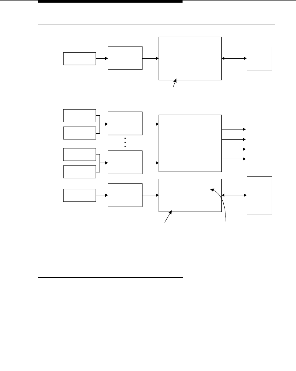
Expert Agent Selection (EAS)
Issue 3 March 1996 3-705
Figure 3-15. Writing Vectors Example
EAS Agent Operations
In an EAS environment, the DEFINITY Communications System treats agent login
IDs as extension numbers. Therefore, the switch treats agents based on their
individual login IDs. Agents are no longer associated with a particular voice
terminal. Agents can use any voice terminal and multiple agents can use the
same terminal on different shifts.
Agent login IDs are assigned up to four skills and each skill is assigned primary
or secondary rank. With EAS, agents can be given preferences in the type of
calls they handle. In the EAS application example, all agents have Skill 100 as a
secondary skill. Agents with a Texas accent who have been to the Texas resorts
and New Mexico resorts would have Skill 30 as a primary skill and Skills 71 and
ISDN/DNIS
general number
VDN 3111
Skill pref 1: none
Skill pref 2:
Skill pref 3:
Vector 1:
1. wait-time 0 secs hearing
ringback
2. converse-on skill 20 pri m
passing vdn and none
3. collect 4 digits after
announcement 3673
4. route-to digits with coverage n
VRU
NM=3244
...
TX=3222
ISDN/DNIS
ad response
Internal call
transfer
Internal call
transfer
VDN 3222 Texas
Skill pref 1: 30
Skill pref 2: 31
Skill pref 3: 130
VDN 3244 NM
Skill pref 1: 70
Skill pref 2: 71
Skill pref 3: 130
VDN 3333
Skill pref 1: none
Skill pref 2:
Skill pref 3:
Vector 2:
1. queue-to main skill 1st pri m
2. wait-time 5 secs hearing
ringback
3. check-backup skill 2nd pri m if
calls-queued < 15
4. announcement 3674
5. check-backup skill 3rd pri m if
oldest-call-wait < 10
6. wait-time 5 secs hearing
music
Vector 3:
1. adjunct routing link 1632
2. wait-time 10 secs hearing
ringback
3. route-to number 3111 with
cov n if unconditionally
ISDN/DNIS
ad response
ISDN/DNIS
call back
Skill 30
Skill 31
Skill 100
Skill ...
ASAI
T/R
Host
Database
Lookup-
Adjunct
Routing
Application
state VDN=
Texas 3222
...
New Mexico 3244
No reservation
Go prompt for state Agent or
state's VDN
if agent unstaffed

Feature Descriptions
3-706 Issue 3 March 1996
100 as secondary skills. When no calls are waiting for Skill 30 for a particular
agent, that agent receives a call for Skill 71 or 100.
Agents use a single set of agent work mode buttons for all their skills. Work
mode buttons no longer have particular splits (or skills) assigned to them. This
provides much greater flexibility in that any voice terminal with work mode
buttons can be used by any agent. Also this requires fewer work mode buttons
and simplifies the agent operation.
Physical aspects of the voice terminal, such as the set type and button layout,
are associated with the voice terminal and not the Login ID. This allows agents to
use any voice terminal with the buttons as are labeled on that set.
In addition to skills, the following capabilities are now associated with agents’
login IDs.
■Calls - calls to the Login ID reach the agent independent of the voice
terminal the agent is currently using. These can be Direct Agent calls
(calls to a particular agent treated as an ACD call).
■Name - calls to the Login ID display the name associated with the Login
ID and not the name associated with the voice terminal. This is also true
for calls made from a voice terminal with an agent logged in.
■Coverage - when the agent is logged out, or when calls go to coverage
because the agent is busy or does not answer, calls to the Login ID go to
the coverage path associated with the agent and not the voice terminal.
■Restrictions - calls to the Login ID or from the agent use the restrictions
associated with the agent and not the voice terminal.
Voice terminals are fully functional when an agent is not logged in. The
restrictions, coverage, and name revert to the voice terminal administration
when the agent logs out.
Other Login ID Applications
Anytime persons share a voice terminal, for example when working shifts or job
sharing, each person can have their own extension and have their calls go to
their coverage mailbox when they are logged out.
Also when persons use multiple phones, because they have multiple offices or
rotate desks (such as guards), using login IDs allows these persons to be
reached independent their desk location.

Expert Agent Selection (EAS)
Issue 3 March 1996 3-707
Administration of Skills
Skills are used in three distinct areas:
■Skills administered for a VDN
■Skills administered for an ACD Agent Login ID
■Skills active for an ACD Caller via vector commands
It is important to note that a particular Skill number always has the same
meaning, whether it is called an Agent Skill, VDN Skill, or Caller Skill. For
example, if Skill 127 means Spanish speaking, then Agent Skill 127, VDN Skill
127, and Caller Skill 127 all mean Spanish speaking.
Up to three different Skills can be administered to a VDN in a prioritized manner.
The first or primary Skill administered to a VDN would be the Skill that is
required or desired to service a call to that VDN. The second (secondary) and
third (tertiary) Skills are optionally administered to a VDN and represent other
Skills that are allowed to handle calls to that VDN.
Call Distribution
Using Automatic Call Distribution (ACD) queuing and the vector commands
‘‘queue-to main’’ and ‘‘check-backup,’’ the incoming call is matched to an agent
who has at least one of the three Skills required to handle the call.
Skill hunt groups replace ACD splits when EAS is optioned on the Hunt-Group
Form.
The hunt group form supports Expert Agent Distribution (EAD) in the ‘‘Type’’ field
when EAS is optioned. When EAD is optioned, a new call to the hunt group
results in a search for the most-idle primary agent. Only if no primary agents are
available, the call goes to the most-idle secondary agent. This distributes a call
to an agent best able to handle the call if multiple agents (primary and
secondary) are available.
The Multiple Split Queuing feature is used to allow calls to queue up to three Skill
hunt groups simultaneously. Agents can log in with up to four Skills at any one
time. Each of the agent’s Skills are administered as a primary Skill or a
secondary Skill. The ACD software distributes any call waiting for one of the
agent’s primary Skills when the agent becomes available. If no calls waiting are
found for a primary Skill, the queued calls for secondary Skills are distributed to
the agent.
With Multiple Call Handling, available with G3V3 and later releases, an agent can
be interrupted with an additional ACD call either after putting a call on hold, or
when the agent is active on another ACD call. Seethe "Multiple Call Handling"
feature for more information.

Feature Descriptions
3-708 Issue 3 March 1996
EAS Logical Agent
With Logical Agent, an agent’s ACD Login ID is associated with a particular
voice terminal only when the agent actually logs in at that terminal. When the
agent logs off, the association of an agent’s ACD Login ID with a particular voice
terminal is removed. The ACD Login IDs used by the EAS capability are
extension numbers used out of the switch’s normal station numbering plan, and
are administered using a new Agent Login ID form.
When the ACD Login ID is called, the call is routed to the associated voice
terminal. With the proper class of restriction (COR), the call could be treated as a
direct agent call. Otherwise, the call is treated as a normal (personal) call.
Agent Login IDs are administered via an ‘‘Agent Login ID’’ form. The form
includes items such as the agent’s name, COR, coverage path, AUDIX, security
code, login password, ‘‘Skills,’’ and ISDN call display option. These attributes
override the physical voice terminal attributes when the agent logs in.
When EAS is optioned, an EAS agent becomes associated with one or more Skill
hunt groups upon login.
The Call Management System (CMS) is able to change an agent’s Skill
assignments. With G3V4 and later releases, one skill can be added, deleted or
moved simultaneously for a group of up to 32 agents. See the "Move Agents
From CMS" feature for more information.
It is important to note that Generic 3 can have either splits or Skill hunt groups to
determine where to route the call (not both simultaneously). Non-ACD hunt
groups can exist with either splits or Skill hunt groups. Skill hunt groups are
required when using EAS.
When EAS is optioned, a single work mode button applies to all the Skills
assigned to the agent currently logged in. Hunt groups are not assigned to work
mode buttons, therefore, logged-in EAS Agents need only a single set of
work-mode buttons for all ‘‘Skills.’’
An EAS agent administered with at least one measured Skill is automatically
measured by CMS independent of whether any other Skills assigned to the
agent are measured.
Direct Agent Calling
ACD calls can be transferred by one agent to another agent using the Direct
Agent Call feature which is initiated by the dialing of an EAS agent’s Login ID or
Adjunct Routing route-to number vector steps. A Direct Agent call can be
originated to a particular agent using Call Prompting.
Calls to an agent’s Login ID are treated as Direct Agent calls if the originator and
the receiver have the ‘‘Direct Agent Calling’’ class of restriction. Direct Agent
calls can be originated by stations or trunks (with the proper COR). If the

Expert Agent Selection (EAS)
Issue 3 March 1996 3-709
originator or receiver does not have the proper COR, the call is treated as a
normal non-ACD (personal) call.
Expert Agent Selection
The EAS feature matches a caller whose call requires certain VDN Skills to an
agent who has at least one of the required Agent Skills. Each Skill has an
associated Skill hunt group administered similar to a vector-controlled hunt
group. As mentioned earlier, Skill hunt groups replace splits when EAS is
optioned.
Agents can have up to four Skills administered for each Login ID. Each agent
Skill is designated as a primary or secondary Skill.
The ‘‘queue-to main skill’’ and ‘‘check-backup skill’’ call vectoring commands
allow the specification of which VDN Skill (1st, 2nd, 3rd), or which specific Skill (1
through 255) a call is to be queued to. Having Skills assigned to VDNs allows the
same vector to be used by multiple VDNs which require different Skills. Allowing
a specific Skill gives the user the same vectoring capabilities that non-Skill
vectoring provides. Caller Skills become active for an ACD call when a
Queue-To-Main-Skill command is executed or a Check-Backup-Skill command is
executed and the threshold condition is met. Once a Skill is active for an ACD
Caller, the ACD Caller cannot be delivered to an available ACD agent unless the
agent also has one of the active Caller Skills.
An ACD call can be queued to up to three different Skill hunt groups at one time.
This is done by executing multiple Queue-To-Main-Skill/Check-Backup-Skill
commands to different Skills. Subsequent “queue-to main skill” and
“check-backup skill” commands to the same skill can be used to change the
priority of the caller.
Since the EAS feature adds to the existing Call Vectoring command set, the full
flexibility of Call Vectoring can be used to the advantage of the EAS feature. R3
CMS supports EAS with the changed vector administration, VDN administration,
as well as the ability to incorporate Skills into real-time and historical reports.
Example EAS applications are described in
DEFINITY Communications System
Generic 3 Call Vectoring/Expert Agent Selection (EAS) Guide
, 555-230-520.
Publishing Login ID Extensions Instead of
Physical Extensions
Telemarketing managers may wish to only publish the Login ID for agents in
applications where the agents move from desk to desk (voice terminal to voice
terminal). Users are able to call the agent without knowing at which physical
voice terminal the agent resides. An optional password has been added to the
login sequence to provide additional security.

Feature Descriptions
3-710 Issue 3 March 1996
Direct Agent Calling
Direct Agent Calling allows users to call agents and have the call treated as an
ACD call (for example, zip tone answer, queuing, after call work, CMS measured
as ACD). Using EAS capabilities, any call (which has the proper class of
restrictions) to the Login ID is treated as a Direct Agent call.
Internal and external users can originate Direct Agent calls. An application for
external users is the insurance industry. People can call their particular claims
adjuster and have the call treated as an ACD call.
Class of Restriction
A byproduct of the EAS capabilities allows for applications which are not calls
These applications could use the EAS capability of allowing a Class of Restriction
to follow a user. Suppose you are in a manufacturing environment where
assembly-line workers are not allowed to make outgoing calls. The voice
terminals in the manufacturing area can be restricted from making outgoing
calls. If a manager tours the manufacturing area and wants to make an outgoing
call, the manager can ‘‘log in’’ using a feature access code and make an
outgoing call (assuming the manager’s login is not outward restricted). The same
is true for the facility restriction level (FRL); the manager’s FRL and not the
extension’s FRL would be used to place the call.
Considerations
When EAS is enabled, all agents must be administered as EAS agents via the
Login ID administration form. Login ID administration and hunt group
administration can be done prior to enabling the feature.
Agents become logical entities and not physical entities. However, physical
attributes of a voice terminal, such as button administration and automatic
answer, do NOT follow the agent.
The Skill hunt group in which a Direct Agent call is queued is determined by the
first skill the agent has been logged into. CMS tracks the queue time for the
Direct Agent call to this Skill, unless it is not measured. If the agent’s first logged
into Skill is not measured, CMS credits the agent Login ID with the Direct Agent
call, but no queue time is tracked.
EAS agent Login IDs are also tracked for personal calls. The first Skill an EAS
Agent is logged into (whether primary or secondary) is used by CMS for
measurements on personal calls. If the first logged-into Skill is unmeasured,
CMS credits the agent Login ID with the personal call, but no Skill hunt group is
credited with the personal call.

Expert Agent Selection (EAS)
Issue 3 March 1996 3-711
Caller Interactions
The caller does not experience any new interface or interactions when Expert
Agent Selection is enabled. The full power of Call Vectoring can be used with
EAS to customize the treatment to the caller. The call is delivered to an agent with
the proper Skill, so in that sense the caller gets better service.
Agent Login Procedure
The login procedure for EAS agent is very similar to the existing login procedure.
The agent goes off hook on an idle call appearance. The agent dials the login
feature access code and second dial tone is given. The agent dials a 1 to 5 digit
EAS agent Login ID (the number must be consistent with the switch dial plan). If
the password length is 0 digits, the agent hears confirmation tone if the Login ID
is valid. If the password is greater than 0 digits, then the agent is given dial tone
again. The agent then dials a password of 1 through 9 digits optionally followed
by ‘‘#.’’ If the Login ID and password entered are valid (administered on the
‘‘Agent Login ID’’ form), the agent hears confirmation tone. If the agent is not
logged into any of the administered skills, the intercept tone is given. The Skills
an agent has assigned are displayed on the second line (or first line on
single-line display terminals) of the agent’s voice terminal display in the format
‘‘Skills: Tnnn, Tnnn, Tnnn, Tnnn,’’ where the Skill type ‘‘T’’ is displayed as ‘‘p’’ or
‘‘s,’’ and ‘‘nnn’’ (left justified, no leading zeros) is the Agent Skill number. This
display is shown upon completion of logging in and remains for five seconds
unless the agent goes on-hook or the display is overwritten.
If the Login ID entered is not valid, the agent hears the intercept tone. If another
agent is already logged in at that physical terminal, the agent hears intercept
tone. If the maximum number of agents are currently logged in, then the login is
denied and the agent hears reorder (in other words, fast busy) tone. If the Login
ID is already logged in, the login is denied and the agent hears intercept tone.
Logout Procedure
To log out, the agent goes off hook on an idle appearance and dials the logout
feature access code. The agent hears the confirmation tone if the agent is
logged in. If the agent is not logged in, the agent is given an intercept tone.
NOTE:
The agent does not login and logout for each Skill.
Calling an EAS Agent
Independent of the CORs for Direct Agent calling, to call an EAS Agent, the
originator dials the Login ID extension. The call is extended to the physical
extension associated with the Login ID. The originator can be internal to the

Feature Descriptions
3-712 Issue 3 March 1996
switch or external. The originator hears the same tones that the originator would
hear when calling a physical extension. The call goes to the Login ID’s coverage
path if a busy condition or ringing time out occurs as indicated in Table 3-57.
After dialing the Login ID, the originator’s display shows the name associated
with the Logical Agent and not the physical extension’s name where the agent is
logged in. All station features for the originator and the agent should work as if
the call had been made to the physical extension, except for messaging features
such as leave word calling, which apply to the Login ID extension.
Making a Direct Agent Call to the Agent
The user makes a Direct Agent call by calling the agent’s Login ID. If the
originator’s or agent’s COR restricts the call from being a Direct Agent call, the
call is treated as a personal (normal) call (for example, ring on an idle
appearance). Otherwise, the call is treated as a Direct Agent call.
Single Set of Work Mode Buttons
EAS Agents need only a single set of work-mode buttons for multiple Skills. With
the EAS feature, agents always are allowed to go to the AUX work-mode state for
all logged-into Skills by pressing a single AUX work-mode button even though
the agent may have a call waiting in-queue (or be the last logged-in agent) for a
particular Skill.
Message Waiting Lamp
With G3V4 and later releases, the Message Waiting Lamp by default tracks the
status of messages waiting for the logged in EAS agent LoginID rather than
messages for the physical terminal. The operation of the Message Waiting Lamp
can be changed so that it tracks the status of messages waiting for the physical
terminal where the agent is logged in. See the Feature-Related
System-Parameters form in
DEFINITY Communications System Generic 3
Version 4 Implementation
, 555-230-655, or
DEFINITY Communications System
Generic 3 V2/V3 Implementation
, 555-230-653, for more information.
Table 3-57. Call Progress Through Called Login ID Coverage
Path
Agent Status Call Progress Through Called Login ID’s
Coverage Path
With Coverage No Coverage
Agent logged in:
Ringing time out
Busy (no appearances) ring coverage
busy coverage continue ringing
busy tone
Agent logged out busy coverage busy tone

Expert Agent Selection (EAS)
Issue 3 March 1996 3-713
Adjunct Interactions
ASAI
ASAI support for EAS may be broken into the following categories: call control,
feature requests, value queries, event notification, and adjunct-controlled splits.
This section provides a high level overview of the behavior of ASAI in the G3V2
EAS environment.
Call Control
Call control capabilities work exactly the same in the EAS environment as in the
traditional ACD environment except for the following:
1. User classified third party make calls (calls classified by originator), may
originate from an EAS Login ID, and terminate to a Login ID. User
classified calls terminating to a Login ID are given Direct Agent treatment
just as they would be if dialed from a station extension.
2. Switch classified third party make calls (calls classified by a call classifier
board; answered calls are delivered to originating hunt group), may
originate from or terminate to EAS Login IDs.
3. Direct Agent third party make calls (ACD call terminated to a selected
member of an ACD split), may be requested by including a Direct Agent
option, an agent’s physical extension and a split extension (compatibility
mode), or by requesting a user classified third party make call with a
Login ID destination. The primary differences between the two methods of
requesting Direct Agent calls are that the compatibility mode allows the
adjunct to specify the split that a given Direct Agent call is queued to, and
the non-compatibility mode allows the adjunct to direct the call to a Login
ID, regardless of which station an agent is logged into. Direct Agent calls
may not originate from an EAS Login ID.
4. Supervisor assist third party make calls (supervisor assist calls originated
by a selected member of an ACD split), may originate from a EAS Login ID
and may terminate to an EAS Login ID. Unlike dialed Direct Agent calls,
supervisor assist calls terminated to a Login ID behave as though they
had been directed to the requested Login ID’s physical extension, for
example, they do not cover if the requested agent is not logged, the
originator’s display shows the agent’s physical extension and not the
agent’s Login ID.
5. Extension (Domain) control may not be requested for an EAS Login ID but
may be requested on behalf of a logical agent’s physical extension.
Auto-dial calls (calls initiated by an extension controlled station) may be
terminated to an EAS Login ID, in which case the call is given Direct Agent
treatment.
6. Adjunct routing calls (vector calls routed by an ASAI adjunct via the
adjunct routing vector command) are similar to third party make calls; they
may include a Direct Agent option, an ACD agent’s physical extension,

Feature Descriptions
3-714 Issue 3 March 1996
and a split extension, in which case they are given compatibility mode
Direct Agent treatment, or they may be terminated to an EAS Login ID (in
which case they behave like dialed Direct Agent calls).
Feature Requests
In the EAS environment, agent login, logout and change work-mode requests are
fully supported. Agent login requests must contain an EAS Login ID and
optional password (delimited by a ’#’) in the login request’s user code IE. Agent
logout requests and change work-mode requests may contain the desired
agent’s physical extension or Login ID. Call forwarding and send all calls feature
requests are denied for EAS Login IDs but may be requested for EAS’s physical
extensions where an EAS agent is logged in.
Value Queries
Value queries function identically in the EAS and traditional environments, except
that the Extension Type/Class Information Query returns a new indication that a
requested extension is an EAS Login ID along with an indication of whether the
Login ID is currently logged in and where (in other words, at which physical
extension).
Event Notification
Because all Skill hunt groups are vector controlled, event notification may not be
requested on the basis of a Skill hunt group extension. Event notification may,
however, be requested on the basis of a controlling VDN extension. Generally, all
event reports involving EAS agents contain the agent’s physical extension rather
than the agent’s Login ID.
Adjunct-Controlled Splits
Agents with adjunct controlled skills are considered to be adjunct-controlled
agents. Adjunct-controlled agents exhibit the same behavior as agents in
adjunct-controlled splits in the traditional ACD environment:
■Stations are locked for all logged-in adjunct-controlled agents. The only
action an agent can take from the station is to go onhook (or unplug the
headset) from an auto-answer station which causes the agent to be
logged out.
■Stations are unlocked whenever the controlling adjunct’s ASAI link goes
down. Stations are locked again when the adjunct’s link is reestablished.
■The adjunct controls all split/agent activities such as login, logout and
change work-mode (with the exception of agent logout via onhook).
■Only adjunct-controlled calls can terminate to the extension of an
adjunct-controlled agent.
■Only adjunct-controlled calls can terminate to an adjunct-controlled
split/Skill extension.

Expert Agent Selection (EAS)
Issue 3 March 1996 3-715
■Agents may not log into more than one adjunct-controlled split/Skill.
■Agents logged into an adjunct-controlled split/Skill may not log into a
non-adjunct-controlled split and vice versa.
Furthermore, adjunct-controlled EAS Agents can only be administered with one
Skill. This implies that EAS agents may not mix adjunct-controlled and
non-adjunct-controlled Skills.
AUDIX
Calls to the EAS agent Login ID can cover to AUDIX. Each agent must enter
his/her Login ID when calling AUDIX to obtain messages.
AUDIX agents are assigned to EAS agent extensions. These Login IDs are used
for CMS tracking if the associated AUDIX Skill hunt group is externally measured.
The ‘‘aut-msg-wt’’ button can be used to indicate that Login ID has a message.
Speech Processing Adjuncts
Speech processing adjuncts which have ‘‘line’’ interface to G3V2 are able to
initiate Direct Agent calls by dialing the Login ID for an agent.
Feature Interactions
EAS interaction with vector-controlled splits:
Unless otherwise specified, the feature interactions for Skill hunt groups are the
same as for vector-controlled splits.
■Abbreviated Dialing
Abbreviated dialing can be used to log in/out EAS agents. Abbreviated
dialing lists/buttons can only be administered for stations.
■Add/Remove Skills
In the EAS environment, agents have the ability to add and remove skills
during a login session by dialing a FAC. Other voice terminal users with
console permissions can add or remove an agent’s skill on behalf of the
agent. (Note that the ability to add and remove skills depends on whether
a user has a class of restriction (COR) that allows adding and removing
skills.)
■Administration Without Hardware
EAS Login ID extensions are extensions without hardware. Login ID
extensions require space in the dial plan. If a coverage path is
administered to a Login ID, calls to a Login ID are immediately directed to
that path when the agent is not logged in. When a Login ID is logged in
and a call is made to the Login ID extension, and the call is routed to the
Login ID coverage path if coverage is administered for the Login ID.

Feature Descriptions
3-716 Issue 3 March 1996
■Agents in Multiple Splits Feature
When the EAS feature is enabled, the ‘‘Agents in Multiple Splits’’ feature is
referred to as ‘‘Agents in Multiple Skills,’’ which allows an EAS agent to be
logged into up to four Skills.
■Agent Work Mode States
With EAS, agents can only be in a single work state mode at any one time.
■Assist
The Assist feature can be used for a Skill hunt group (for example, where
there is one supervisor per Skill hunt group). A voice terminal can be
administered with one or more Assist buttons for each Skill that agents
using the terminal might have. The administered association of an Assist
button with a particular split or Skill is not affected when an EAS agent logs
into that station.
■Automatic Answering with Zip Tone
The Automatic Answer option can only be administered for a physical
extension.
■Auto-Available Splits
If a Skill hunt group is administered as an Auto-Available Skill (AAS) the
EAS Login IDs assigned to this Skill must also be administered as
Auto-Available. When the switch reinitializes, these Login IDs are
automatically logged in with the AUTO-IN work-mode. If any switch
features attempt to change the work-mode to anything except to
AUTO-IN, this attempt is denied. This feature is not intended for human
agents.
■BCMS
The Basic CMS user interface remains the same when EAS is enabled.
Basic CMS is not modified when EAS is optioned, except to change the
labeling of headings from ‘‘split’’ to ‘‘Skill.’’
■Call Forwarding
Skill hunt groups (since they are vector-controlled) cannot be call
forwarded. EAS agent Login IDs can not be forwarded, but the physical
extension where the EAS agent is logged in can be forwarded. If another
station (with console permissions) tries to forward an EAS Login ID, an
intercept is made.
■Call Management System (CMS) Interface
When an EAS Login ID is administered as measured, the BCD format of
that Login ID becomes the internal agent number (called ‘‘position’’) on
CMS. During pump-up to CMS, the switch sends a list of the logged in
agents and their internal agent numbers (position).
■Call Park
Calls cannot be parked on the Skill hunt group extension.

Expert Agent Selection (EAS)
Issue 3 March 1996 3-717
■Call Pickup
Skill hunt group extensions and EAS Login ID extensions cannot be
members of a call pickup group.
■Call Vectoring
The ‘‘goto vector’’ command carries the current VDN’s VDN Skills to the
new vector. ‘‘route-to’’ vector which routes a call to another VDN uses the
VDN Skills of the new VDN if VDN override is set on the current VDN. If
VDN override is not set, the ‘‘original’’ Skills are used after a ‘‘Route to
Vector’’ step to a VDN is executed.
‘‘Route-to’’ vector command with an EAS Login ID as the route to
destination is treated as a Direct Agent call if the VDN and agent have the
COR and the ‘‘Direct Agent’’ field is set to ‘‘y’’.
The same vector can be used for many VDNs since the vector specifies
the algorithm for call delivery, and the VDNs supply the Skills to use when
selecting an agent.
In the same way as for vector-controlled splits, a “queue-to main”
“check-backup vector” command step associated with a skill hunt group
is skipped and the next step is processed if any of the following conditions
are true (where the term ‘‘Skill’’ applies to both a VDN Skill and an Agent
Skill):
— The Skill hunt group queue associated with the desired ‘‘Skill’’ is full
— The Skill hunt group associated with the desired ‘‘Skill’’ is not
vector-controlled
— The call is already queued to the Skill hunt group at the specified
priority level
— The call has already queued to three different Skill hunt groups
— The Skill hunt group associated with a desired ‘‘Skill’’ has no queue
administered for it, and no agents are available in that Skill hunt
group
— A certain VDN Skill level (for example, 1st, 2nd, 3rd) is specified in
the vector command, and no VDN Skill is administered for that level
■Class of Restriction
Skill hunt groups do have a class of restriction. This is used if the Skill hunt
group extension is called directly.
The COR for an EAS agent Login ID overrides the physical extension’s
COR of the voice terminal an EAS agent logs into.
■Class of Service
EAS agents do not have a COS associated with their Login ID. Therefore,
the COS of the voice terminal is not affected when an EAS agent logs into
that terminal.

Feature Descriptions
3-718 Issue 3 March 1996
■Direct Agent Calling
If a called EAS Agent Login ID and the call originator (extension or trunk)
both have a COR that allows Direct Agent calls, the call to the Login ID is
treated as a Direct Agent call. Calls to the voice terminal extension
where an EAS agent is logged in are treated as personal (non-ACD) calls.
■Displays - Voice Terminal
When an EAS agent logs in, the display for originators who call the Login
ID shows the Login ID and agent name (as administered via the Agent
Login ID form). Calls that the agent originates show the Agent Login ID
and agent name at the receiving terminal’s display. However, with G3V4
and later releases, the user can display the name of the physical terminal
where the EAS agent is logged in. The user must be active on a call with
the agent, and must have a terminal with an alphanumeric display and an
inspect button. When the inspect button is pressed during a call to or from
the EAS agent, the physical terminal name of the agent is displayed.
Calls to the physical extension show the physical extension’s number and
name on the originator’s display.
■Look Ahead Interflow
Skills are not sent to another ACD/PBX when a call interflows using Look
Ahead Interflow. If Skills have the same meaning on both ACDs, then a
Look Ahead Interflow command to a VDN with the same Skills assigned
can provide a mapping of the Skills.
■Multiple Split Queuing
When EAS is enabled, the Multiple Split Queuing feature is referred to
Multiple Skill Queuing, which has the same functionality.
■Queue Status Indications
Physical extensions can be administered with Queue Status Indicator
buttons and lamps for Skill hunt groups which operate in the same manner
as split Queue Status Indicators for traditional ACD splits. Queue Status
Indicators can be administered for all Skills needed by agents using that
physical extension, given that enough buttons are available.
■Service Observing
The Service Observing feature is activated in the EAS environment by
dialing the physical extension of the terminal where a EAS agent is
logged in, not the Login ID of an agent.
■VDN Override
If VDN override is set on the ‘‘original’’ VDN, then the VDN Skills of the new
VDN are used. If VDN override is not set, then the VDN Skills of the
‘‘original’’ VDN are used.

Expert Agent Selection (EAS)
Issue 3 March 1996 3-719
Administration
EAS is an optional feature. EAS is also a feature-related parameter that must be
enabled. Once EAS is optioned, most of the EAS related administration can be
done prior to enabling the feature. EAS requires that “Call Vectoring” and “ACD
System Parameter/Customer-Options” fields be set to ‘‘y.’’
System Parameters
A new system parameter indicates the minimum number of digits required for the
agents’ password. Valid entry are 0 through 9. Also, the system parameter for
‘‘Automatic Call Distribution (ACD) Log-in Identification Length’’ is removed
when EAS is enabled. These parameters appear on Page 4 of the
Feature-Related Parameters form.
Logical Agent
EAS agent Login IDs are administered as part of the station numbering plan and
are administered using the Agent Login ID form as extensions without hardware.
In addition, the following is administered for EAS
■Login ID
■Name
■COR
■Coverage path
■Security code (for AP demand printer)
■Auto-avail split and AUDIX information
■Password (this field is not visible)
■ISDN Caller Display
■Up to four Agent Skills
If the maximum number of agents are already administered as internally
measured, or the maximum number of agents are already administered, then an
error is given. If the extension corresponding to the Login ID has already been
assigned, an error is displayed.
If the password is fewer digits than the system parameter or contains
non-numeric characters, then an error message is displayed.
Station Administration
On the Station form with the EAS featured optioned, when a work-mode button is
selected, no ‘‘Gp’’ information can be entered. The assist and queue status
buttons require that ‘‘Group’’ be entered.

Feature Descriptions
3-720 Issue 3 March 1996
VDN Administration
The VDN Skill preferences for handling a particular call type is administered on a
per-VDN basis. Up to three VDN Skills can be administered for each VDN. The
first, second, and third VDN Skills can be considered as the primary, secondary,
and tertiary Skills respectively required for handling the call. All of the VDN Skills
on the VDN form are optional. For example, only the first and third, or only the
second and third VDN Skills might be assigned. Also, for example, if a vector
encounters ‘‘Queue-To-Main-Skill 2nd’’ command, and no second VDN Skill is
administered to the VDN, the step is skipped.
Vector Administration
Vector commands “queue-to main split” and “check-backup split” are changed
to Queue-to-Main-Skill and Check-Backup-Skill when the EAS option is set to ‘‘y’’.
These two queuing vector commands allow queuing the caller using the VDN
Skills by administering ‘‘1st,’’‘‘2nd,’’ or ‘‘3rd’’ in the “Skill Number” field. These two
queuing vector commands also allow a specific Skill number (1 through 255) to
be entered in the “Skill Number” field. Also, the “check-backup skill” step
supports all of the existing conditional checking (for example, available agents,
staffed agents, oldest call, number of queued calls) for a Skill Hunt Group. Also
the conditional checks for ‘‘goto’’ and the ‘‘messaging’’ command use the term
‘‘Skill’’ instead of split and allow entering values first, second, or third as well as
the specific Skill number.
Hardware and Software Requirements
No new or changed hardware is required for the "Expert Agent Selection (EAS)"
feature. This feature requires the appropriate call center package, but places no
limitations on the type of voice terminals that can be used.

Extended Trunk Access
Issue 3 March 1996 3-721
Extended Trunk Access
Feature Availability
This feature is available with Generic 3rV1 and all Generic V2 and later releases.
Description
Extended Trunk Access (ETA) is a software feature that provides a mechanism
for routing calls that are not defined either in the first or second digit tables or the
feature/trunk access code tables. This feature makes use of an ETA routing
pattern and/or an ETA node number for determining how to route an unidentified
call. Using ETA allows the user to fully use the capabilities inherent in the
Automatic Alternate Routing (AAR) and Uniform Dial Plan (UDP) features.
Historically, ETA has been used by satellite switches to access stations, trunks,
and features at the main switch. ETA frees the satellite switch administrator from
having to enumerate the entire dial plan for the main/satellite complex.
Considerations
The user of ETA is usually unaware that it is being used because the feature is
transparent to end users. To use ETA, a user dials a sequence of digits that are
unadministered in the station, trunk, or feature access code dial plans, but may
be successfully directed to an extension, trunk, or feature on the remote switch.
This results in the local switch sending the digits to the remote switch that
provides the appropriate audible signals a user would expect, such as the
ringing of the calling party’s voice terminal.
Capacity Requirements and Constraints
The purpose of the ETA Call-Screening Table is to allow a set of digit strings to
be identified that should not be routed via ETA. For example, if the system
administrator notices that a digit string was misdialed repeatedly and as a result
was routed via ETA to a remote switch that returned intercept treatment, then that
digit string would be a candidate for entry into the ETA call-screening table. Entry
into this table would have the effect of returning intercept treatment to the caller
without first attempting to route the digits to the remote switch for interpretation
via ETA.
The maximum length of the ETA Call-Screening table is 10, each with a maximum
length of seven digits with values ranging from one to 640 and/or special
wildcard characters. The ETA routing pattern is a three-digit string. There is only
one ETA routing pattern per switch. The ETA node number is a three-digit string
with values ranging from one to 999. There is only one ETA node number per
switch. The impact of the ETA feature on the performance of the switch as a

Feature Descriptions
3-722 Issue 3 March 1996
whole is negligible because the extra processing needed by the feature is
negligible.
The difference between normal call routing and ETA call routing is that extra
processing is necessary at the point where the intercept treatment would have
normally been applied during the normal call sequence. Specifically, calls that
would have previously been given intercept treatment will now be routed to a
remote switch across a trunk to be reprocessed at the remote switch if either an
ETA routing pattern or an ETA node number is defined. This means that the
following extra processing is required for each ETA call when ETA is
administered:
■Determination that this is an ETA call because it fails all other possible
routing possibilities and ETA is administered.
■The digit string dialed is not in the call-screening table.
■An available pattern preference is selected from the trunk group specified
by the ETA routing pattern and/or ETA node number.
■The dialed digits are sent to the remote switch.
Interactions
The following features have interactions with ETA. Descriptions of features as
they interact with ETA are provided.
■Abbreviated Dialing
Any digit string that is undefined in the station or feature/trunk
access-code dial plans should route via ETA.
■Attendant
Attendants can access the ETA feature in exactly the same way as
stations. There is no discernible difference in the ETA feature operation for
attendants.
■Automatic Alternate Routing
The ETA feature is implemented as part of Uniform Dial Plan (UDP). The
routing preferences defined for the administered ETA routing pattern
and/or ETA node number are individually checked to determine which
trunk group will be used to route the dialed digit string.
■Data-Call Setup
Analog and digital endpoints can access ETA. The digit string to be sent
goes to the remote switch just as any other digit string is sent. The remote
switch will handle the data-call setup from that point forward.
■DCS
Applies only to ETA calls to an unknown extension (not FAC or TAC calls).

Extended Trunk Access
Issue 3 March 1996 3-723
■Dial Plan Administration
When administering ETA on separate switches, care must be taken to not
create a circular ETA call setup; otherwise, all trunk members using ETA
will be tied up until the calling party releases the call. If switch A routes
calls to switch B and switch B has been administered to route calls to
switch A, then any time an invalid set of digits is dialed, all trunk members
using ETA will be busied in an attempt to route the ETA call. Since both
switches point to each other, an infinite loop has been administered. Care
should be taken not to have a receiving switch administered with ETA
when the destination switch is also the sending switch.
■Dial Plan
Any dialed digit string that is undefined in the station feature/trunk
access-code dial plans will be routed via ETA to the remote switch, if ETA
is administered. This implies that a feature access code is dialed, followed
by some number of digits. For example, if you were dialing an AAR/ARS
access code followed by digits and the dialed string code could not be
routed by the local switch, then the entire digit string would be passed to
the remote switch by the ETA feature. It is also important to note that
undefined dialed digit-strings will not be routed via ETA unless the dial
plan of the local switch recognizes the digits as they are being dialed
during its own screening process as a valid digit-string type.
■Direct Inward Dialing (DID)
Whenever a DID trunk presents undefined digit strings to the local switch
and ETA is administered, the digits will be passed to the remote switch via
ETA for proper handling.
■Facility Restriction Levels
It is possible to restrict trunks that are being used in conjunction with the
ETA feature by assigning restriction levels.
■Last Number Dialed (LND)
If a number is routed via ETA to a remote switch and you want to reaccess
that number, then the reaccess uses ETA and does so transparently.
■Main/Satellite/Tributary
The environment of local and remote switches is the primary target for the
ETA feature. It is within this environment that ETA is most effective in
reducing maintenance of frequent administrative changes.
■Modem Pooling
All trunks in the ETA pattern will be treated like all other trunks. Modem
Pooling is not affected.
■Remote Access
Remote-access trunks are able to access the ETA feature just as any other
trunk or station does.

Feature Descriptions
3-724 Issue 3 March 1996
■Uniform Dial Plan
The Uniform Dial Plan is extended by the ETA feature in that explicit
definition of digit strings to be routed is not necessary. The internal
operation of the UDP feature is not affected, however.
Administration
The switch administrator is able to add, delete, and display the ETA routing
pattern and/or ETA node number as well as the Call-Screening table. The ETA
routing pattern and/or ETA node number appears on the first-digit table.
The “ETA Routing Pattern” and/or “ETA Node Number” field accepts numerical
values that are within the proper range and provides appropriate help and error
messages as does the ETA node number. Likewise, the ETA call-screening table
occupies the screen that allows up to10-digit strings to be enumerated. Any valid
digit string can be entered including special wildcard characters ‘‘*,’’ ‘‘#,’’ and
‘‘x.’’ Appropriate help and error messages are provided.
If ETA routing pattern is administered, then there are two other screens that must
be administered to make the feature work properly. Specifically, the route pattern
for ETA must be administered along with the trunk group that will support ETA
calls. The route-pattern screen is entered from the command line with ‘‘change
route pattern xxx’’ where ‘‘xxx’’ is the ETA routing pattern.
Within this screen a trunk group is associated with the routing pattern, an FRL, an
NPA, a Prefix Mark, a Toll List, and either absorption or deletion of digits if
desired.
Trunk groups are administered with the ‘‘add/change trunk group xxx,’’ where
xxx is the trunk group number. There is no special trunk group administration
necessary for ETA. For additional information on the administration and operation
of the AAR feature, see the "Automatic Alternate Routing (AAR)" feature
description in this document. For G3r if ETA node number is administered, then
node number routing must be administered along with a trunk group.
There are four scenarios that can be envisioned with respect to the above two
fields either being administered or not administered. The following enumerates
these possibilities and indicates what effect the administration will have on the
way the feature either does or does not work.
CASE #1
■ETA Route Pattern — not administered
■ETA Node Number — not administered
In this case, the ETA feature is considered not active and no attempt will be
made to utilize the ETA code to route otherwise undefined calls.

Extended Trunk Access
Issue 3 March 1996 3-725
CASE #2
■ETA Route Pattern — administered
■ETA Node Number — not administered
In this case, the ETA route pattern will be used to determine how to route an
otherwise undefined digit string. Since, however, an ETA node number is not
specified, non-call associated DCS messages have no chance of succeeding in
this scenario.
CASE #3
■ETA Route Pattern — not administered
■ETA Node Number — administered
In this case, the ETA node number will be used to get the routing pattern from the
node number routing tables. DCS messages that are non-call related will also
have a chance of succeeding since a node number will be supplied to the DCS
message handling code.
CASE #4
■ETA Route Pattern — administered
■ETA Node Number — administered
In this case, the ETA route pattern will be used to route all undefined dialed digit
strings while DCS messages will use the ETA node number to attempt to route.
Nodes themselves do not have to be administered for ETA. ETA should not be
used over Tandem Tie trunks.
Hardware/Software Requirements
There is no specialized hardware needed for ETA. However, trunks need to be
administered for ETA. The feature usually uses tie trunks.

Feature Descriptions
3-726 Issue 3 March 1996
Extension Number Portability
Feature Availability
This feature is available with Generic 3rV1 and all Generic V2 and later releases.
Description
ENP provides the ability to assign any extension to any switch in an ENP
subnetwork. The ENP Numbering Plan defines the setting of 4- or 5-digit
extensions in the ENP subnetwork to a 7-digit (Automatic Alternate Routing)
AAR-like number for sending to other nodes in that network. Only the first one or
two leading digits of the extensions are significant in this action. This limits the
number of ENP codes to 100. Each of these ENP codes should be administered
in the AAR analysis table as home on all the nodes within the ENP subnetwork.
Though up to 100 3-digit ENP codes can be used, only one ENP code is required
for a 4-digit ENP, and a 5-digit ENP requires only one ENP code for each leading
digit of extensions used within the subnetwork.
Considerations
This feature is compatible with System 85 and G2 ENP.
Interactions
The Uniform Dial Plan administration and that of Automatic Alternate Routing
Analysis are affected. See “Administration” below. If DCS is used, the ENP node
numbers must correspond to DCS node numbers.
Administration
Administering ENP for a group of extensions is accomplished in G3rV1, G3V2,
and later releases using four administration forms. The UDP table must be
administered so that Extension Codes for non-home extensions in the ENP
subnetwork are node-number routed (one pattern per PGN).
The Node-Number Routing table must be administered to associate a routing
pattern with each node in the ENP subnetwork.
The AAR Digit conversion table must be administered to assign all 3-digit ENP
codes as home, and if using a 5-digit UDP, to associate the ENP codes with a
leading 10 thousands digit. Note that ENP Codes are distinguished from AAR
location codes because ENP Codes are home on every node within the ENP
subnetwork. ENP Codes are administered in the ENP Numbering Plan table as
well as in the AAR Digit conversion table. Since ENP Codes are home on every
node, they cannot be used as AAR location codes.

Extension Number Portability
Issue 3 March 1996 3-727
The ENP Numbering Plan table must be administered to associate the leading
one or two digits of extensions in the ENP subnetwork with a 3-digit ENP code,
used to construct a 7-digit AAR-like ENP number.
Administering the ENP subnetwork in this manner enables stations to move from
one node to another within the ENP subnetwork without having to change their
extensions.
ENP Numbering Plan administration depends on both the UDP customer option
and on the “Dial Plan Administration” field that asks if the administrator wishes to
use UDP. If both of these fields are not administered to ’y’, then ENP Numbering
Plan administration is not allowed. If the UDP customer option is not administered
to ’y’, then ‘‘enp-number-plan’’ is not even listed as an option to the administrator;
if UDP is administered to ’y’, then the option is available, but the command is
denied if UDP is not also administered to ’y’ on the Dial Plan form. The UDP plan
length is also administered on the Dial Plan administration form.
All ENP codes specified in the ENP Numbering Plan should be administered as
home in AAR Analysis administration, but there is no automatic cross checking to
verify that ENP codes have been administered correctly in AAR Analysis.
Hardware/Software Requirements
ENP Numbering Plan does not require any additional hardware or software.
However, a UDP software license must be acquired.

Feature Descriptions
3-728 Issue 3 March 1996
Facility Busy Indication
Feature Availability
This feature is available with all Generic 3 releases.
Description
Provides multi-appearance voice terminal users with a visual indication of the
busy or idle status of an extension number, a trunk group, terminating extension
group, a hunt group (DDC or UCD group), or any loudspeaker paging zone,
including all zones. The Facility Busy Indication button provides the voice
terminal user direct access to the extension number, trunk group, or paging
zone.
When the lamp associated with the Facility Busy Indication button is lighted, the
tracked resource is busy. If the lamp is dark, the resource is idle. If the lamp is
flashing, the tracked resource is placing a call to the voice terminal with the
button.
Pressing the Facility Busy Indication button automatically selects an idle call
appearance and places a call to the resource.
Considerations
With Facility Busy Indication, a user can monitor the busy or idle status of a
frequently called extension number. By knowing when the monitored facility is
busy or idle, the user can wait until the facility is idle to make a call. This reduces
the time spent trying to call busy facilities.
Facility Busy Indication buttons can be administered to track the same resource.
The maximum parameters for the DEFINITY Communications System Generic 1
and Generic 3 hardware and software items can be found in the System
Hardware and Software Capacity Limits tables located throughout the DEFINITY
documentation set. A new state of the tracked resource (a change from idle to
busy) is updated within five seconds after the system detects the change.
Extension numbers, trunk group access codes, and Loudspeaker Paging
Access codes can be stored in a Facility Busy Indication button. However, an
access code followed by other numbers cannot be stored.
It is possible that an incoming call which causes the lamp to flash may go
unanswered. If the lamp represents the status of a trunk group and all trunks in
the trunk group become busy before the flashing call is answered, the system
software lights the lamp steadily to indicate that all trunks are busy. When a trunk
in that trunk group becomes idle, the system software turns off the busy

Facility Busy Indication
Issue 3 March 1996 3-729
indication and the lamp goes dark. Therefore, the lamp flashes, lights steadily,
and goes out while the call has neither been answered nor dropped.
The Facility Busy Indication cannot monitor the status of the attendant console.
Interactions
None.
Administration
Facility Busy Indication is administered on a per-voice terminal basis by the
System Manager. The only administration required is to assign the Facility Busy
Indication button to a voice terminal or attendant console.
Hardware and Software Requirements
No additional hardware or software is required.

Feature Descriptions
3-730 Issue 3 March 1996
Facility Restriction Levels (FRLs) and
Traveling Class Marks (TCMs)
Feature Availability
Facility Restriction Levels (FRLs) are available with all Generic 3 releases;
Traveling Class Marks is an optional feature available with all Generic 3 releases
(except G3vs/G3s ABP) when Private Network Access (PNA) software is
purchased. Traveling Class Marks are not available with G3vs/G3s ABP.
Description
Provides up to eight levels of restriction for users of the AAR and/or ARS features.
FRLs and TCMs provide a method of allowing certain calls to specific users,
while denying the same calls to other users. For example, certain users may be
allowed to use Central Office trunks to other corporate locations while other users
may be restricted to the less expensive private network lines.
FRLs and TCMs are transparent to the user. Appropriate values are
predetermined and programmed into the system. Dialing procedures are
unaffected.
Call routing for each call is determined by the dialed Area Code and/or office
code (either public or private network) or by the administered dial string.
Translation on the first three or six digits of the called number yields Routing
Patterns. More than one translation can point to the same pattern. A blank entry
provides intercept treatment and is used for unassigned private network office
codes. Each Routing Pattern contains up to six routing preferences (16 for G3r).
Each preference includes the following information:
■Trunk Group Number
■Minimum FRL required to access the trunk group
No specific routing order is required.
Each facility, such as a trunk or voice terminal, capable of originating a call also
has an associated FRL. Whether a given call is allowed or not depends on two
things: compatibility between FRLs and availability of an idle trunk.
Compatibility is determined by a comparison of the minimum FRL associated
with the trunk group and the originating-side FRL. Either can have a value of
zero through seven. Access to the associated trunk group is permitted if the
originating-side FRL is greater than or equal to the minimum FRL. Note that lower
originating-side FRLs can access fewer routing preferences, whereas lower
minimum FRLs permit greater access. Stated another way, a 0 originating-side
FRL is the most restricted and a 7 is the least restricted. A 0 minimum FRL is the

Facility Restriction Levels (FRLs) and Traveling Class
Marks (TCMs)
Issue 3 March 1996 3-731
least restrictive, and a 7 is the most restrictive (when applied to the routing
pattern’s FRL). Compatibility checking begins with the first-choice route (the first
one in the pattern). Assuming access is permitted, availability is checked; that
is, is there an idle trunk in the group? If so, the call continues. If not,
compatibility is checked on the next routing preference.
If the compatibility check fails on the first-choice route, the intercept tone
continues.
NOTE:
Intercept is not received unless all possible routes are inaccessible.
If the compatibility check fails on the second or subsequent routing preference,
or if all accessible trunk groups are busy, the call may queue on the first choice
trunk group or first compatible trunk group. (See the "Ringback Queuing" feature
for details.)
If the trunk group selected for a call is an intertandem tie trunk group, then a TCM
is outpulsed as the last digit. A TCM is equivalent to the originating-side FRL. At
the next tandem switch, compatibility and availability checking are done, as
before. In this case, the FRL assigned to the incoming intertandem tie trunk
group is used as the originating-side FRL (to compare with the TCM). If it is
sufficient, then the call continues and no comparison on the TCM and the
outgoing trunks TCM is made. If it is not sufficient, then the TCM is compared
with the outgoing trunk’s FRL to see if the call is allowed to continue. However, if
this fails to yield a route and if the TCM is higher than the tie trunk FRL, then the
TCM is used in another attempt to complete the call.
Call Originating Facilities
At a switch serving as the call origination point, any of the following can be the
originator of an ARS or AAR call:
■Voice terminal
■Remote Access user
■Attendant
■Incoming tie trunk group from a subtending location
■Data terminal capable of Keyboard Dialing
At a tandem switch, either of the following can be the originator of an ARS or AAR
call:
■Incoming Intertandem tie trunk group
■Incoming Access tie trunk group — links a remote main switch to a
tandem switch
Each of these facilities is assigned an FRL via an associated COR, either directly
or indirectly.

Feature Descriptions
3-732 Issue 3 March 1996
Voice terminals and all incoming tie trunk groups use the FRL contained within
the assigned COR. Attendants use the FRL contained within the COR assigned
to the attendant group for extended calls. If Individual Attendant Access is
assigned, the individual attendant’s COR FRL is used. Data terminals use the
FRL contained within the COR assigned to the associated data module.
The Remote Access feature can be accessed via a DID trunk group, tie trunk
group, dedicated central office trunk group, 800 Service trunk group, and/or
dedicated foreign exchange trunk group. In the absence of a Remote Access
Barrier Code, the applicable FRL is contained in the COR assigned to the trunk
group. If a Barrier Code is required on Remote Access calls, the applicable FRL
is the Remote Access default entry (none) contained in the COR assigned to the
Barrier Code.
Call Terminating Facilities
Any of the following trunk types can serve as the termination point for an ARS or
AAR call:
■Tie trunk — excluding RLTs, but including CCSA and EPSCS Access
trunks
■WATS
■CO
■FX
■ISDN-PRI
Each of these outgoing trunk groups has an assigned COR that contains an FRL.
However, this FRL is never used. Terminating-side FRLs are assigned in the
Routing Pattern, not to the outgoing trunk group.
Considerations
FRLs provide the means to restrict certain users from placing selected calls while
allowing other users to place the same calls.
Originating-side FRLs are assigned via the COR of the originating-side facility,
such as an incoming tie trunk group or voice terminal. If an FRL is not assigned,
the system assumes an FRL of 0 for all originating facilities except the attendant
group. An FRL of 7 is assumed for the attendant group.
A COR is also assigned to each trunk group. If the COR specifies an FRL, the
FRL is ignored. The minimum FRL specified in the Routing Pattern is the only FRL
used on the terminating side of the call.
On attendant-extended calls, the attendant group FRL is used rather than the
FRL of the calling party.

Facility Restriction Levels (FRLs) and Traveling Class
Marks (TCMs)
Issue 3 March 1996 3-733
Interactions
■ARS and AAR
FRLs apply only on ARS and AAR calls (including UDP).
■Authorization Codes
Authorizations Codes can be used to raise a user’s FRL.
■CDR Account Codes
If CDR 15-digit account codes are used, the “FRL” field in the CDR record
is overwritten.
■Intercept Treatment
The TCM used to pass on the originating facility’s FRL is sent by ISDN
facilities in the SETUP message.
Administration
FRLs are assigned by the System Manager as a part of ARS and/or AAR
administration. Originating FRLs are assigned on a per-COR basis. Terminating
FRLs are assigned on a per-Routing Pattern basis. TCMs do not require
assignment.
Assignment Guidelines
If there will be users within the system who are not allowed to make outside calls,
use some value other than 0 as the value for the first-choice trunk group. By
assigning these users an FRL of 0, none of the trunk groups can be accessed
(since all trunk group FRLs are greater than 0). Such calls are denied.
Each Routing Pattern must be individually constructed. The same trunk group
can be used in more than one pattern. The associated FRL is assigned within
the pattern and is not associated with the trunk group itself. The same trunk
group can have a different FRL in a different pattern.
Be consistent in FRL assignments. Do not use a range of 0 through 5 in one
pattern and a range of 2 through 7 in another pattern if all users can access the
first-choice route. Admittedly, the trunk group with an FRL of 2 may be more
expensive than the trunk group with an FRL of 0, but there is no real reason to
assign a 2 to a trunk group that everyone can access. For ease of assignments,
always use a 0 for such a trunk group.
There should be a COR established for each FRL used in a Routing Pattern. The
appropriate COR is then assigned to the users who can access the routes
restricted by the FRL value. For example, a middle executive might be able to
access all routes with an FRL of 5 or lower, whereas the president can access all
routes. In this case, the executive is assigned a COR with an FRL of 5 and the
president is assigned a COR with an FRL of 7.

Feature Descriptions
3-734 Issue 3 March 1996
Remote Access users can access the system’s features and services the same
as an on-premises user. FRL assignment is via Remote Access Barrier Codes.
Up to 10 Barrier Codes, each with its own COR (and FRL) can be assigned.
Although the COR defines other restrictions, 10 Barrier Codes are enough to also
provide a range of FRL assignments. Assignment of Barrier Code FRLs is the
same as if the user were on-premises. The simplest way to assign these FRLs is
to duplicate the on-premises FRLs, then merely relate the appropriate Barrier
Code to those that will be using Remote Access.
Hardware and Software Requirements
No additional hardware is required. The optional Private Network Access or
ARS software is required.

Facility Test Calls (with Security Measures)
Issue 3 March 1996 3-735
Facility Test Calls (with Security
Measures)
Feature Availability
This feature is available with all Generic 3 releases. Logoff Notification is
available with G3V4 and later releases.
Description
Provides a voice terminal user with the capability of making test calls to access
specific trunks, DTMF receivers, time slots, and system tones. The test call is
used to make sure the facility is operating properly. A local voice terminal user
can make a test call by dialing an access code. AT&T remote maintenance
personnel may also use this feature to make test calls.
Four types of Facility Test Calls can be made:
■Trunk test call
Accesses specific tie or CO trunks. DID trunks cannot be accessed.
A user’s Class of Restriction must be administered with the Facility Access
Trunk Test option in order for the user to make trunk test calls.
■DTMF receiver test call
Accesses and tests the DTMF receivers located on a Tone Detector or
Call Classifier/Tone Detection circuit pack.
■Time slot test call
Connects the voice terminal user to a specific time slot located on the
Time Division Multiplex buses or out-of-service time slots.
■System tone test call
Connects the voice terminal user to a specific system tone.
For detailed instructions for making test calls, see Chapter 5 of
DEFINITY
Communications System G3i/s/vs Maintenance
, 555-204-105,
DEFINITY
Communications System G3r Maintenance
, 555-230-105,
DEFINITY
Communications System Generic 1 and Generic 3 Voice Terminal Operations
,
555-230-701, or
DEFINITY Communications System Generic 1 and Generic 3
Console Operation
, 555-230-700.

Feature Descriptions
3-736 Issue 3 March 1996
Security Measures
To help secure this feature from unauthorized use the following steps can be
taken:
■Remove the code when not in use.
■Change the code from the factory default.
■Secure records of the code.
■Use COR to restrict which users can use the access code.
Logoff Notification, available with G3V4 and later releases, can be set to notify
the system administrator at logoff that the Facility Test Calls feature is still
enabled. Notification guards against inadvertently leaving the Facility Test Calls
feature active. It can also alert the system administrator to unauthorized feature
activation.
Consult the
BCSystems Security Handbook
, 555-025-600, for additional steps to
secure your system.
Considerations
If a user has a problem with a specific system facility, Facility Test Calls can be
used to test that facility for proper operation.
A DTMF voice terminal must be used to make test calls.
NOTE:
AT&T has designed the Facility Test Calls feature incorporated in this
product that, when properly administered by the customer, will enable the
customer to minimize the ability of unauthorized persons to gain access to
the network. It is the customer’s responsibility to take the appropriate steps
to properly implement the features, evaluate and administer the various
restriction levels, protect access codes and distribute them only to
individuals who have been advised of the sensitive nature of the access
information. Each authorized user should be instructed concerning the
proper use and handling of access codes.
In rare instances, unauthorized individuals make connections to the
telecommunications network through use of test call features. In such
events, applicable tariffs require that the customer pay all network charges
for traffic. AT&T cannot be responsible for such charges, and will not make
any allowance or give any credit for charges that result from unauthorized
access.

Facility Test Calls (with Security Measures)
Issue 3 March 1996 3-737
Interactions
None.
Administration
Facility Test Calls is administered on a per-system basis by the System Manager.
The Facility Test Calls access code must be assigned. Also, a user’s Class of
Restriction must be administered with the Facility Access Trunk Test option in
order for the user to make trunk test calls.
Hardware and Software Requirements
No additional hardware or software is required.

Feature Descriptions
3-738 Issue 3 March 1996
Facility and Non-Facility Associated
Signaling
Feature Availability
This optional feature is available with all Generic 3 releases, except G3vs/G3s
ABP, when ISDN PRI software is purchased.
Description
Provides signaling for ISDN-PRI.
Facility Associated Signaling
Facility Associated Signaling (FAS) allows an ISDN-PRI DS1/E1 Interface
D-channel to carry signaling information for only those B-channels located on the
same DS1/E1 facility (circuit pack) as the D-channel.
Non-Facility Associated Signaling
Non-Facility Associated Signaling (NFAS) allows an ISDN-PRI DS1/E1 Interface
D-channel (signaling channel) to convey signaling information for B-channels
(voice and data channels) on ISDN-PRI DS1/E1 facilities other than the one
containing the D-channel. As a result, a D-channel can carry signaling
information for numerous B-channels located on different DS1/E1 facilities.
NOTE:
NFAS is only valid for DS1/E1 Country Protocol option 1 (U.S.).
D-Channel Backup
To improve reliability in the event of a signaling link failure, a backup D-Channel
may be administered. If a signaling link failure does occur, a switch to a backup
D-channel will then take place.
D-Channel Backup requires that one D-channel be administered as the Primary
D-channel and that a second D-channel be administered as the Secondary
D-channel. These assignments insure that at certain times during D-Channel
Backup procedures that both D-channels are in the same state. This avoids the
occurrence of both switches at each end of the DS1/E1 interface selecting the
same D-channel to be put into service. In these cases, the Primary D-channel is
given precedence over the Secondary D-channel.
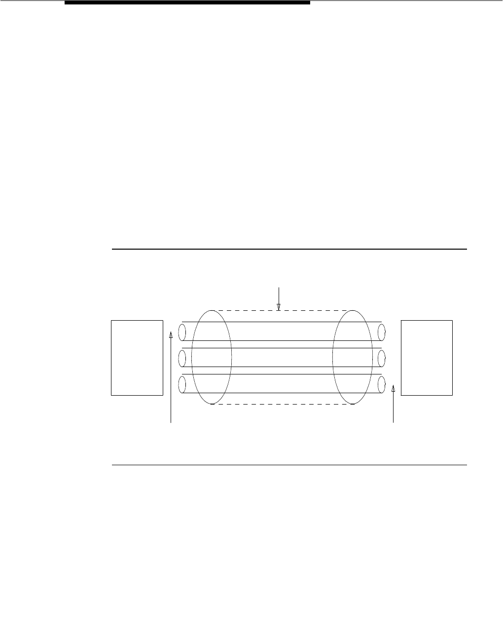
Facility and Non-Facility Associated Signaling
Issue 3 March 1996 3-739
Figure 3-16 shows a possible configuration involving three ISDN-PRIs between a
G3 switch and another DEFINITY system or the public network. With DS1 (24
channel) interfaces, two of the ISDN-PRIs contain a D-channel and 23
B-channels, while the other ISDN-PRI contains 24 B-channels. One of the
D-channels is the Primary D-channel, and the other is the Secondary D-channel.
Together, this pair of D-channels will signal for all 70 (23+24+23) of the
B-channels that are part of the three PRIs.
Since the D-channels are signaling for more than one DS1/E1 facility, the
D-channel Backup feature requires the use of the NFAS feature. At any given
time, one of the two D-channels will be carrying Layer 3 signaling messages,
while the other D-channel will be active at layer 2, but in a standby mode only.
Any layer 3 messages received over the standby D-channel will be ignored.
Since only one of the D-channels can be active at a time, load sharing between
the two D-channels is not possible. The two D-channels can provide signaling
for only a predefined set of B-channels and cannot dynamically back up other
D-channels on other interfaces.
Figure 3-16. Example D-Channel Backup With Three ISDN-PRIs
D-Channel Backup Activation. D-Channel Backup can be invoked in response
to the following events:
■D-Channel Failure
If the signaling link fails on the active D-channel (D1) or the hardware
carrying D1 fails, then the system will send a message over the standby
D-channel (D2), which requests that D2 become the active D-channel. D2
then becomes the active D-channel and will carry all subsequent signaling
messages. When the signaling link or hardware on D1 recovers from the
failure, D1 becomes the standby D-channel.
ISDN PRIMARY RATE INTERFACES CONTROLLED BY D-CHANNEL
PRIMARY D-CHANNEL
FAR-END
SWITCH
NETWORK
OR
SWITCH
DEFINITY
SECONDARY D-CHANNEL
.
.
.
.
.
.
.
.
.
.
.
.
.
.
.
.
.
.
.
.
.
.
.
.
.
.
.
.
.
.
.
.
.
.
.
.
.
.
.
.
.
.
.
.
.
.
.
.
.
.
.
.
.
.
.
.
.
.
.
.
.
.
.
.
.
.
.
.
.
.
.
.
.
.
.
.
.
.
.
.
.
.
.
.
.
.
.
.
.
.
.
.
.
.
.
.
.
.
.
.
.
.
.
.
.
.
.
.
.
.
.
.
(DEFINITY
4 ESS)

Feature Descriptions
3-740 Issue 3 March 1996
■System Technician Commands
If a system technician command requests that a D-channel switch-over
take place, the first action taken by the system will be to tear down the
signaling link on D1. After this has been completed, a message is sent on
D2 to request that D2 become the active D-channel. D2 then becomes the
active D-channel and the switch-over will be complete.
Considerations
NFAS allows a single D-channel to carry signaling information for numerous
B-channels located on different DS1/E1 facilities, thus providing a more
economical interface.
Only those ISDN-PRI facilities that use the NFAS feature will be capable of
providing the D-Channel Backup feature. The reason for this limitation is that the
two D-channels must be located on different PRI DS1/E1 facilities. As a result,
the D-channels must support NFAS so that they can signal for B-channels on
different ISDN-PRI DS1/E1 facilities.
When a transition from one D-channel to another occurs (D-Channel Backup is
activated), all stable calls (calls that have been answered already) will be
preserved. Some messages may be lost, resulting in a loss of call-related
information, but the calls themselves will be maintained. The effect of the
transition on unstable calls (those that have not been answered yet) is
unpredictable since the results depend on which messages were lost and the
contents of those messages.
Interactions
None.
Administration
The following provisioning and administration must be considered when
implementing FAS and NFAS. Coordinate the following with the far-end switch
for the DS1/E1 facilities to be used:
■Decide which DS1/E1 facilities will use FAS.
■Decide which of the remaining DS1/E1 facilities will carry D-channel
signaling information on the 16th (E1) or 24th (DS1) channel. For those
channels that have a D-Channel Backup, D-channel pairs must be
allocated.
■Define Signaling Groups. A Signaling Group is a group of B-channels for
which a given D-channel (or D-channel pair) will carry the signaling
information. Each Signaling Group must be designated as either a FAS or
NFAS Signaling Group.

Facility and Non-Facility Associated Signaling
Issue 3 March 1996 3-741
— A FAS Signaling Group must contain all the ISDN B-Channels on
the DS1/E1 interface associated with the group’s D-channel, and
cannot contain B-channels from any other DS1/E1 circuit pack. For
24-channel DS1 boards, some of the DS1 ports may use in-band
(robbed-bit) signaling and be members in a tie trunk group rather
than an ISDN trunk group. These tie trunks cannot be members of a
Signaling Group.
— There is no restriction on which DS1/E1 ports can belong to an
NFAS Signaling Group. Normally, an NFAS Signaling Group
consists of one or two D-channels and several complete DS1/E1
interfaces.
If a Signaling Group contains only a subset of a DS1/E1’s
B-channels (ports 1 through 12, for example), it is considered an
NFAS Signaling Group, not a FAS Signaling Group. The remaining
B-channels on the DS1/E1 will then be assigned as members of
another NFAS Signaling Group.
■An Interface ID must be assigned to each DS1/E1 facility in an NFAS
Signaling Group. For example, if the B-channels in a Signaling Group
span three DS1/E1 facilities, a unique Interface ID must be assigned to
each of the three DS1/E1 facilities. This designation is required to uniquely
identify the same B-channel (port) number on each of the DS1/E1 facilities
in the signaling group. Therefore, this designation must be agreed upon
by both sides of the interface and administered prior to initialization.
■D-Channel Backup involves two or more ISDN-PRI DS1/E1 facilities that
interconnect the switch to another PBX or to the network. Two D-channels
must be present on the facilities. One of the D-channels is designated as
Primary and the other as Secondary. This designation must be agreed
upon by both sides of the interface and administered prior to initialization.
Hardware and Software Requirements
See the "Integrated Services Digital Network (ISDN) — Primary Rate Interface"
feature for hardware and software requirements.

Feature Descriptions
3-742 Issue 3 March 1996
Flexible Billing
Feature Availability
Available with G3V4 and later releases. Flexible Billing is available in the United
States for use with AT&T MultiQuest® 900 Vari-A-BillTM Service.
Description
With Flexible Billing the DEFINITY switch or an adjunct can communicate with the
AT&T network through ISDN PRI messages to change the rate at which an
incoming 900-type call is billed. Rate change requests can be made anytime
after the call is answered and before it disconnects.
To administer Flexible Billing, the Flexible Billing and ISDN-PRI fields on the
System-Parameters Customer-Options form must be set to yes. Only an AT&T
authorized representative can administer the System-Parameters
Customer-Options form. You can display the form by entering the display
system-parameters customer-options command.
All change requests are initiated by an Adjunct Processor (CPE Host or VRU)
connected to the DEFINITY switch. The Adjunct Processor determines when to
request a rate change based on information from customer-provided software
residing on the processor.
The billing rate can be changed to any of the following:
■New Rate
■Flat Rate (not dependent on length of call)
■Premium Charge (a flat charge in addition to the existing rate)
■Premium Credit (a flat negative charge in addition to the existing rate)
■Free Call
There is never a negative charge for calls. A maximum is set for each 900
number as part of the provisioning process.
NOTE:
It is the responsibility of the customer to notify callers of rate changes.
Before instructing the network to change the caller rate, the customer must
inform the caller of the new rate and gain confirmation of the rate from the
caller.

Flexible Billing
Issue 3 March 1996 3-743
Applications
The following list gives examples of when a customer might decide to change the
rate for a call that is in progress:
■A new rate might be established for higher valued services such as
requests for particularly valuable information, conversion of text mail to
speech, or technical support.
■A flat rate might be desired for consultative support, warranty registration,
maintenance contracts or for the recovery of a fixed-cost service or
product.
■A premium charge could be requested for callers who need specialized
delivery of information such as overnight mail or FAX, recovery of the cost
of a sample product, an account summary, or a transcript.
■A Premium Credit might be appropriate for promotional discounts,
first-time callers, contest winners or those who use low overhead
resources such as electronic media rather than human agents.
Detailed Operation
An incoming PRI call from the network contains messaging that indicates if the
call can use the AT&T MultiQuest® 900 Vari-A-BillSM Service. This information is
passed to the Adjunct Processor using ASAI messaging or to the PRI VRU
adjunct. The Adjunct Processor will only be informed of the Flexible Billing
capability of a call if the called VDN, split or agent is included in a domain for
which notification has been requested by that Adjunct Processor (monitored
domain).
The Adjunct Processor can initiate a rate change request message any time after
the call has been answered and before the call disconnects. The rate change
request specifies the new billing rate.
The DEFINITY switch can handle a limited number of change requests. See
Appendix A, "System Parameters" for capacities information. If the switch cannot
accept a change request, it notifies the Adjunct Processor. Any success or
failure resulting from the request is returned to the adjunct.
Subsequent requests can be made for a call that has already had a rate change.
In this case:
■If the original and subsequent requests were “flat charge” or if both were
“new rate”, the previous change is overwritten. The new rate is effective
from the time the original change took effect.
■If the original request was “premium charge” or “premium credit” the
subsequent request must be either “premium charge” or “premium
credit”. The previous change is overwritten. The new rate is effective from
the time the original change took effect.

Feature Descriptions
3-744 Issue 3 March 1996
Considerations
Cellular End Offices and some other End Offices (NPA-NXX) do not have the
necessary billing software to accept rate changes. Customers who receive a
large percentage of calls from specific exchanges, geographical areas or
cellular callers should do a careful analysis before using Flexible Billing.
Interactions
■Call Detail Recording (CDR)
If the User Data item is being recorded, the count for this item will increase
when Flexible Billing is used.
■Call Vectoring
Incoming Flexible Billing calls can use Call Vectoring for routing.
If a VDN Return Destination is assigned, and Flexible Billing is active for a
call, the return destination is ignored and the call is forced to disconnect.
■Conference
If a call arriving on a trunk that supports Flexible Billing is conferenced
with a call from a trunk that does not support Flexible Billing, the switch
sends billing change requests to the appropriate trunk. However, if calls
are conferenced from different trunks that support Flexible Billing, only
one trunk will be sent billing change requests.Therefore, never conference
calls from two or more incoming Flexible Billing trunks.
■Transfer
If a call is answered by a party on the local switch and is transferred to a
second switch, the second switch will not receive an indication that the
call has variable billing. However, Flexible Billing will be available when a
call is transferred to another monitored domain on the same switch.
Administration
Flexible Billing must be enabled on the Customer-Options System Parameters
form. In addition, ISDN-PRI must be enabled.
Hardware and Software Requirements
Flexible Billing requires an ASAI Adjunct Processor and customer-supplied
application software.

Generalized Route Selection (GRS)
Issue 3 March 1996 3-745
Generalized Route Selection (GRS)
Feature Availability
This optional feature is available when ISDN PRI software is purchased with all
Generic 3 releases, except G3vs/G3s ABP. Generalized Route Selection is not
available with G3vs/G3s ABP.
Description
Generalized Route Selection (GRS) provides the customer voice and data call
routing capabilities to select not only least cost routing, but also optimal routing
over the appropriate facilities.
GRS is a capability built on the current Automatic Alternate Routing (AAR) and
Automatic Route Selection (ARS) features. In AAR or ARS, routing is based on
the dialed number, the Facility Restriction Level (FRL) of the call originator, the
partitioning group number, and the time-of-day. By providing additional
parameters in the routing decision, GRS enhances AAR and ARS and maximizes
the chance of using the right facility to route the call. Also, if an endpoint
incompatibility exists, it provides a conversion resource (such as Modem Pools)
to attempt to match the right facility with the right endpoint.
GRS allows customers to use separate routes for voice and data calls. For data
calls, GRS enables the switch to distinguish between restricted and unrestricted
digital transmissions, allowing the switch to route data calls onto the appropriate
facilities. GRS also provides the opportunity to integrate voice and data on the
same trunk group, thereby providing certain economies.
GRS allows the system to use the Integrated Services Digital Network — Primary
Rate Interface (ISDN-PRI) call-by-call selection of public network services. It
also provides interworking between ISDN-PRI and non-ISDN-PRI entities.
ISDN-PRI interworking is the mixture of ISDN-PRI trunks and non-ISDN-PRI trunks
in a call. A mixture of these signaling procedures is required to provide
end-to-end connectivity when different type trunking facilities are used.
ISDN-PRI services add five additional routing parameters which are specified on
each trunk group preference of the routing pattern. These parameters are:
■Bearer Capability Class (BCC)
Identifies the type of call, such as voice calls and different type data calls.
■Information Transfer Capability (ITC)
Identifies the type of data transmission (restricted, unrestricted, or both).
■Network Specific Facility
Identifies the services and features to be used to complete a call.

Feature Descriptions
3-746 Issue 3 March 1996
■Band
Identifies the OUTWATS band. Wide Area Telecommunications Service
(WATS) is a voice-grade service providing both voice and low speed data
transmission calls to defined areas (bands) for a flat rate charge.
■Inter-Exchange Carrier (IXC)
Identifies the specific common carrier, such as AT&T, to be used for a call.
In GRS, there are five Bearer Capability Classes (BCCs). Customers may specify
routing for each BCC according to their particular transmission needs.
Bearer Capability Classes (BCCs)
The BCCs are the mechanisms by which specialized routing is provided for the
various type data calls and voice calls. Each trunk group preference in the
AAR/ARS routing patterns contains a BCC parameter. When a call is originated,
a route is selected based on the BCC of the originating facility. BCCs are used to
classify the type of traffic permitted on this trunk in the outgoing direction. Details
on how a trunk group preference is determined are given in the GRS Operation
section of this description.
A set of ISDN-PRI bearer capability and low-layer compatibility parameters are
defined by a BCC.
The system will determine the originating endpoint’s BCC from one of the
following:
■For an ISDN-BRI set, the switch determines the BCC by using information
from the Bearer Capability Information Element (IE) and Low Layer
Compatibility IE of the ISDN SETUP message.
■For a non-BRI terminal, the switch creates a BCC by using information
about the station administration for the terminal and information obtained
by performing a terminal query.
■From the administered value of the incoming trunk. For a non-ISDN trunk
group, the switch creates a BCC by using the administered BCC value.
■From the ISDN-PRI bearer capability and low-layer compatibility
parameters, if the call is an ISDN-PRI trunk-originated call.
The BCC associated with the routing preference in the routing pattern is
administered by the system administrator. More than one BCC can be
associated with each preference and the same facility can appear multiple times
in a routing pattern and in multiple routing patterns.
The BCC of the originating endpoint (trunk or terminal) is matched with the BCCs
of the routing preferences. An exact match is not always required. The system
determines when conversion/insertion resources must be used to successfully
complete a call via a compatible, but not identical, BCC.

Generalized Route Selection (GRS)
Issue 3 March 1996 3-747
The GRS capability will recognize one or more of the following five BCCs for each
trunk group preference in the routing pattern (DCP/DMI mode is explained later).
:
Table 3-58. BCC Assignment
Endpoint Voice/
Data Mode BCC Comments
Voice Terminal Voice 0
Data Line Circuit Pack 2 2
Voice Data Set 2 2
Modular Processor
Data Module 0,1,2 1,2,4 See Note
Modular Processor
Data Module-M1 1 1 For ACCUNET Switched
56 kbps Service
Modular Trunk
Data Module 22
Digital Terminal
Data Module 22
510D Personal Terminal 2 2
Digital Communications
Protocol Interface 0,2,3 2,3,4 See Note
7400A Data Module 2 2
3270T Data Module 3 3
3270C Data Module 3 3
3270A Data Module 2,3 2,3 See Note
Legend
BCC Type DCP/DMI Mode
0 Voice-Grade Data and Voice None
1 56 kbps Data (Mode 1) 1
2 64 kbps Data (Mode 2) 2
3 64 kbps Data (Mode 3) 3
4 64 kbps Data (Mode 0) 0

Feature Descriptions
3-748 Issue 3 March 1996
NOTE:
For all endpoints, the switch automatically determines its current operating
mode when the data module originates. Before any call is originated, the
default is Mode 2.
Since call origination from a data module determines the mode to be used
on the call, it is recommended that the data module user press the
Originate/Disconnect button once after changing data options. This way,
the right mode is sure to be assigned to the next call.
ISDN-PRI BCC Parameters
The ISDN-PRI BCC Parameters are:
■Information Transfer Capability
■Low-Layer Compatibility
■DCP/DMI Mode
Information Transfer Capability
The information to be transferred (or type of call) requires different transmission
facilities. For example, transmission needs for voice calls and data calls are
generally different. Voice and voice-grade data calls can be sent over analog
trunks, while high speed data calls require digital trunks.
The Information Transfer Capability parameter in the Bearer Capability
Information Element (BC IE) and Low-Layer Information Element (LLC IE) have
the following four values:
■Voice (speech)
■Voice-grade data (3.1 kHz transmission)
■Unrestricted digital transmission
■Restricted digital transmission.
With data calls, the switch distinguishes the information transfer capability
(restricted or unrestricted) of the originating data endpoint (trunk or terminal),
and then uses the information transfer capability of the data endpoint to route the
call onto the appropriate facility. For BRI and PRI originating data endpoints, the
information transfer capability is contained in the ISDN SETUP message. For
non-ISDN data endpoints, the switch uses the information transfer capability
specified by the system administrator. The default for the information transfer
capability of an endpoint is
restricted
. The system administrator may change the
information transfer capability to restricted or unrestricted for each non-ISDN
originating endpoint.

Generalized Route Selection (GRS)
Issue 3 March 1996 3-749
More than one Information Transfer Capability can be supported by one BCC.
Low-Layer Compatibility
The low-layer compatibility information element provides remote compatibility
checking. This element is used with the bearer capability element and
determines the mode of the originating caller. The low-layer compatibility
information element is optional and sent only in case of data calls.
NOTE:
DCP Mode 0 does not send an LLC IE.
DCP/DMI Mode
The Digital Communications Protocol (DCP) and the Digital Mulitplexed Interface
(DMI) modes are data parameters of the originating data facility. These modes
are not applicable to voice.
The mode values (0, 1, 2, and 3) are administered for data and Alternate
Voice/Date (AVD) non-ISDN-PRI trunk groups. These mode values determine the
BCC of the trunk groups.
1. Use BCC 4 for an unknown data mode that requires a 64 kbps channel.
Table 3-59. Assignment of BCC Based on Information Transfer
Capability
DCP/DMI
MODE Information Transfer
Capability BCC Comments
— Speech 3.1 kHz 0 Used for Voice/ Voice
Grade Data.
M1 Unrestricted/
Restricted Digital 1 Used for Mode 1 Data (56
kbps).
M2 Unrestricted/
Restricted Digital 2 Used for Mode 2 Data
(async data speed up to
19.2 kbps).
M3 Unrestricted/
Restricted Digital 3 Used for Mode 3 Data (64
kbps).
M0 Unrestricted/
Restricted Digital 4 Used for Mode 0 Data1 (64
kbps clear channel).

Feature Descriptions
3-750 Issue 3 March 1996
Determination of BCC at Tandeming or
Terminating System
Determination of the BCC for an incoming call from a ISDN-PRI trunk to a tandem
or terminating switch is based on the BCC parameters received on the signaling
channel (D-channel) of the trunk. This includes the ITC (restricted or unrestricted)
if the call is a data call.
Determination of the BCC for an incoming call from a non-PRI trunk will be as
follows:
■If the incoming trunk is a voice trunk, then the BCC is defaulted to 0.
■If the incoming trunk is a data, AVD, or RBAVD (robbed-bit AVD) trunk,
then the BCC and ITC are administrable.
GRS Operation
The AAR/ARS routing pattern will contain an indication for each trunk group
preference showing which BCC or BCCs can use that trunk group. A trunk
group preference may have more than one BCC.
GRS uses a
look-ahead
algorithm when determining which preference in a
routing pattern to choose. GRS first attempts to find an exact match between the
originator’s BCC and the corresponding allowed BCC for any of the preferences
in the routing pattern. Therefore, if preference 1 does not have an exact match
(even though there are available compatible members in preference 1), it will be
skipped over if a subsequent preference in the same pattern has an allowed
BCC that exactly matches the originator’s BCC.
After matching the BCCs, G3i will then match the ITCs. The originator’s ITC is
matched to the route preference ITC. Unrestricted (unre) matches on ‘‘unr’’ or
‘‘both.’’ Restricted (rest) matches on ‘‘rest’’ or ‘‘both.’’
NOTE:
ITC matching only applies to data calls (BCC 1 through 4).
As an example of how GRS chooses a trunk group preference, assume
preference 1 in a pattern has BCC 0 and BCC 2 set to yes, while preference 2
has BCC 1, BCC 3, and BCC 4 set to yes. A voice or Mode 2 data call accessing
this pattern will use the first preference, while a Mode 1, Mode 3, or Mode 0 data
call will use the second, independent of the availability of trunks in the first
preference.
When an exact match is not found in any of the routing pattern preferences, calls
are treated as follows:
■Calls With an Originating BCC of 0

Generalized Route Selection (GRS)
Issue 3 March 1996 3-751
A BCC 0 originated call (such as voice or analog modem) will not be
denied routing by GRS, even if the routing pattern lacks a preference with
BCC 0 set to yes. This allows the user to use voice transfer to data when
making a data call, without the need for data preindication.
If a BCC 0 originated call accesses a routing pattern for which no
preference has BCC 0 set to yes, then GRS will choose a preference with
BCC 2 set to yes, if one exists. If none exists, the next preferred order
would be a preference with BCC 1 set to yes, followed by BCC 3, and
finally, BCC 4. Since each preference must allow at least one BCC to be
passed, a BCC 0 (voice) originated call will never be blocked by GRS.
The call is of course still subject to other restrictions, such as FRL
restrictions. The ITC does not help select a preference.
Since BCC 0 (voice) has no ITC, the switch selects an ITC from the routing
pattern when a BCC 0 call is being routed as a data call. Table 3-60
shows how the ITC codepoint in the Bearer Capability IE is determined.
■Calls With an Originating BCC of 2
If a BCC 2 originated call accesses a routing pattern for which no
preference has BCC 2 set to yes, then GRS will choose a preference with
BCC 0 set to yes, if one exists. If none exists, the call will be blocked with
intercept treatment.
■Calls With an Originating BCC of 1, 3, or 4
A DCP/DMI Mode 0 (BCC 4), Mode 1 (BCC 1), or Mode 3 (BCC 3)
originated call requires an exact match on at least one preference in a
routing pattern in order for GRS to allow the call to complete. For example,
a Mode 1 originated call will complete only if the accessed routing pattern
has a preference with BCC 1 set to yes. The ITCs must also match.
When an ISDN-PRI trunk group preference is accessed, the BCC information is
encoded and sent in the outgoing ISDN SETUP message to the distant-end as
shown below. The BCC information sent to the far end is important, because the
Table 3-60. Determination of ITC Codepoint
Originating
Endpoint’s
ITC Routing Preference’s ITC
ITC
codepoint
in BC IE
restricted unrestricted both
endpoint both
unrestricted
voice x restricted
voice x unrestricted
voice x unrestricted
voice x unrestricted

Feature Descriptions
3-752 Issue 3 March 1996
BCC information that the far-end receives in the SETUP message will become the
originating BCC for the far-end’s incoming trunk call.
■If an exact match of the originator’s BCC and ITC has been found, then
that Bearer Capability is encoded and sent in the ISDN SETUP message
to the far-end. If the call is a data call, the system uses the ITC of the
routing pattern to encode the SETUP message as shown in Table 3-61.
■If an exact match is not found, but the call is allowed to proceed, then the
BCC encoded in the SETUP message sent to the far-end is that of the
routing pattern. For example, if a BCC 2 (for example, DTDM) endpoint
originates a call that accesses a pattern that has one preference with only
BCC 0 set to yes, then the switch automatically inserts a modem pool for
this call. In effect, the modem pool is converting BCC 2 to BCC 0. The
far-end cannot distinguish this call from a BCC 0 originated call that has
no modem pool inserted. Therefore, BCC 0 is sent in the SETUP message.
This may in turn determine routing decisions by the far-end. Additional
routing decisions are made as shown in the following tables.
1. A voice originated call without data preindication that is routed to a routing
pattern with data preferences only.
Table 3-61. Encoding of Setup message
Originating
Endpoint’s
ITC
Routing Preference’s ITC ITC
codepoint in
BC IErestricted unrestricted both
endpoint both
unrestricted
restricted x restricted
restricted x restricted
restricted x unrestricted
unrestricted x unrestricted
unrestricted x unrestricted
unrestricted x unrestricted
voice1x restricted
voice x unrestricted
voice x unrestricted
voice x unrestricted

Generalized Route Selection (GRS)
Issue 3 March 1996 3-753
BCC and ITC Determination on Calls from
Endpoints to ISDN-PRI Trunks
Table 3-62. Calls from Endpoint to ISDN-PRI Trunks
Originating Chosen BCC from the Routing Pattern
BCC BCC 0 BCC 1 BCC 2 BCC 3 BCC 4
BCC 0 P PT PT PT PT
BCC 1 BPBBB
BCC 2 PMBPBB
BCC 3 BBBPB
BCC 4 BBBBP
Legend
B Block the call with intercept treatment
P Allow the call and send the originating endpoint’s BCC in the
SETUP message. Use the ITC as shown in the following
table
PT Allow the call and send the BCC and ITC chosen from the
routing pattern in the SETUP message
PM Insert a pooled modem for the call and send the BCC and
ITC chosen from the routing pattern in the SETUP message

Feature Descriptions
3-754 Issue 3 March 1996
If BCC 1, 2, 3, or 4 is chosen from the preceding table, the following table is used
to determine the appropriate ITC.
Table 3-63. Calls from Endpoints to ISDN-PRI Trunks
Originating Chosen ITC from the Routing Pattern
ITC unr rest both endpt both unr
unrPBPPU
rest BPPPU
Legend
B Block the call with intercept treatment
P Allow the call and send the originating endpoint’s ITC in the
SETUP message
PU Allow the call and send ‘‘unrestricted’’ in the SETUP
message

Generalized Route Selection (GRS)
Issue 3 March 1996 3-755
BCC and ITC Determination on Calls from
Trunks to ISDN-PRI
Table 3-64. Calls from Trunks to ISDN-PRI Trunks
Originating Chosen BCC from the Routing Pattern
BCC BCC 0 BCC 1 BCC 2 BCC 3 BCC 4
BCC 0 P PT PT PT PT
BCC 1 BPBBB
BCC 2 PTBPBB
BCC 3 BBBPB
BCC 4 BBBBP
Legend
B Block the call with intercept treatment
P Allow the call and send the incoming trunk’s BCC in the
SETUP message. Use the ITC as shown in the following
table
PT Allow the call and send the BCC and ITC chosen from the
routing pattern in the SETUP message

Feature Descriptions
3-756 Issue 3 March 1996
If BCC 1, 2, 3, or 4 is chosen from the preceding table, the following table is used
to determine the appropriate ITC.
The system does not insert pooled modem for any interworking
trunk-to-ISDN-PRI trunk calls. The BCC and ITC of an incoming trunk is
determined as follows:
■ISDN-PRI Trunk BCC and ITC are in the received SETUP message
■AVD Trunk BCC and ITC are the BCC and ITC values administered on the
trunk group form
■RBAVD Trunk BCC and ITC are the BCC and ITC values administered on
the trunk group form
■Data Trunk BCC and ITC are the BCC and ITC values administered on the
trunk group form
■Voice Trunk BCC is 0.
Table 3-65. Calls from Trunks to ISDN-PRI Trunks
Originating Chosen ITC from the Routing Pattern
ITC unr rest both endpt both unr
unr P B P PU
rest B P P PU
Legend
B Block the call with intercept treatment
P Allow the call and send the incoming trunk’s ITC in the
SETUP message
PU Allow the call and send ‘‘unrestricted’’ in the SETUP
message
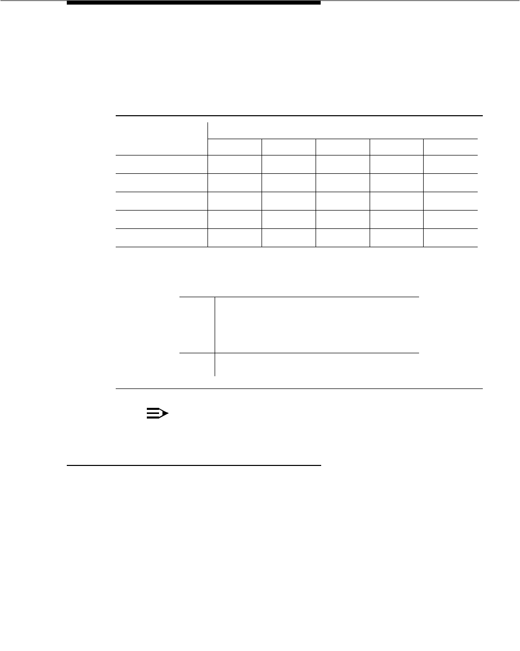
Generalized Route Selection (GRS)
Issue 3 March 1996 3-757
BCC and ITC Determination on Calls from ISDN-PRI Trunks to
Endpoints (GRS not Involved)
NOTE:
The system does not use ITCs when terminating to an endpoint.
Considerations
■ACCUNET and SDDN Services
The system will be able to use ARS tables to route calls to these networks.
For example, BCC 1 is a 56 kbps service. If an ACCUNET 56 kbps
Service trunk group is in a routing pattern that uses GRS, BCC 1 should be
set to yes.
■SDI Service
The system will be able to support the AT&T Switched Digital International
(SDI) Service, which requires 64 kbps unrestricted service for Mode 0
calls or 64 kbps restricted or unrestricted rate adapted to 56 kbps for
Mode 1 calls. SDI will reject calls encoded as 64 kbps restricted without
rate adaptation.
Table 3-66. Calls from ISDN-PRI Trunks to Endpoints
Originating Terminating Endpoint BCC
BCC BCC 0 BCC 1 BCC 2 BCC 3 BCC 4
BCC 0 P P PM P P
BCC 1 PPPPP
BCC 2 PPPPP
BCC 3 PPPPP
BCC 4 PPPPP
Legend
P Allow the call, and (1) if it is a voice originated call, let the
calling user decide whether the terminating endpoint is the
correct endpoint or not based on audible feedback (for
example, data tone), or (2) if it is a data call, the data
handshake procedure will establish or drop the call based
on the compatibility of the endpoints.
PM Insert a pooled modem and terminate the call to the
endpoint. The ITC defaults to restricted in this case.

Feature Descriptions
3-758 Issue 3 March 1996
■Integrated Access on Non-ISDN-PRI Trunks
The T1 carrier access to the AT&T serving office will allow sharing of the
same trunk group for voice and data calls. For example, the same trunk
group may carry both voice calls (requires a BCC of 0) and Mode 1 data
calls (requires a BCC of 1). This situation requires the trunk group
preferences in the ARS routing pattern to be administered with a ‘‘yes’’ for
both BCC 0 and BCC 1.
■Voice and Voice-Grade Data Calls
Voice and voice-grade data calls cannot be routed separately if
voice-grade data calls are assigned BCC 0. Voice-grade data calls could
be assigned BCC 2.
■Modem Pooling
A system originating a data call over a public or private network is
responsible for inserting the pooled modem (when needed). Since the
originating switch knows the speed of the call, it can insert the appropriate
pooled modem. Since tandem switches do not know the speed of the call,
they cannot make the decision on the type of pooled modem needed.
Interactions
The following features interact with the Generalized Route Selection feature.
■Automatic Route Selection (ARS) and Automatic Alternate Routing
(AAR)
In ARS/AAR, routing is based on the dialed number, the Facility
Restriction Level of the call originator, the partitioning group number, and
the time-of-day. In GRS, routing of calls is additionally based on the BCC
and ITC to distinguish voice from data calls. For all trunks, ISDN-PRI as
well as non-ISDN-PRI, the BCC and ITC are checked to see if the route
selected is compatible.
■AAR/ARS Partitioning
It is possible to perform GRS administration for each partition separately
by using different routing patterns.
■Interworking
Generalized Route Selection will support interworking; that is, the routing
patterns may contain a combination of ISDN-PRI and non-ISDN-PRI
trunking facilities. For non-ISDN-PRI trunking facilities, the BCC and ITC
are determined by (default) administration. For ISDN-PRI trunking
facilities, the BCC and ITC are determined by the information received on
the signaling channel (D-channel) of the trunk.

Generalized Route Selection (GRS)
Issue 3 March 1996 3-759
■Call by Call Service Selection
For each preference in a routing pattern, the customer may optionally
administer an IXC code and a Network Specific Facility parameter to be
used when an outgoing call is made using an ISDN-PRI facility. Call by
Call (CBC) Service Selection allows the dynamic identification of a specific
service type request on a per call basis. For CBC Service Selection
feature, the trunk group is administered as CBC. This allows the
customer to pool several types of services together and assigns the
service type to them on a call basis.
■Data Pre-Indication
When the Data button is pressed on DCP voice terminals, the switch uses
the BCC and ITC of the associated data module.
■Electronic Tandem Network (ETN) Services
To provide ETN services, the ISDN-PRI trunks can be used to interconnect
any combination of the following switches: System 85 R2V4, DEFINITY
system Generic 1, Generic 2, or Generic 3. (An ETN is a network of
privately owned trunk and switching facilities that can provide a
cost-effective alternative to toll calling between locations.)
The ETN Traveling Class Mark (TCM) will be passed between the tandem
nodes by the TCM information element of the SETUP message on the
ISDN-PRI facilities. (Traveling Class Marks represent the Facilities
Restriction Level and are used by the distant tandem switch to determine
the best available facility consistent with the user’s calling privileges.)
The Satellite Hop Control (Conditional Routing) Count and End-to-End
Connectivity message, which is used in System 85 R2V2 or Generic G2, is
tandem into the SETUP message without being analyzed. For
non-ISDN-PRI tandem trunks, the TCM is outpulsed after the destination
address.
Administration
The following additional items are administered by the System Manager for GRS.
■Routing pattern BCCs — For each trunk group in the Routing Pattern,
there will be an indication of what BCCs can use that preference. The
values are 0, 1, 2, 3, and 4. More than one BCC may be supported by one
trunk group preference. The BCCs assigned to a trunk group in a Routing
Pattern may or may not be the same value assigned to the same trunk
group in another Routing Pattern.
The ”ITC (Information Transfer Capability)” field administers the type of
traffic (restricted, unrestricted, or both) that this routing preference may
carry. This field is displayed and administrable if at least one of the BCC
data preferences is set to y. If only BCC 0 is set to y, then the “ITC” field is
not displayed. The value of the “ITC” field may be set to rest (restricted),
unre (unrestricted), or both. The default is rest.

Feature Descriptions
3-760 Issue 3 March 1996
The “BCIE (Bearer Capability Information Element)” field specifies how to
create the Information Transfer Capability codepoint in the Bearer
Capability IE of the SETUP message. This field only applies to ISDN-PRI
trunks and is displayed and administrable if the “ITC” field is administered
as both. The value both provides extra flexibility for managing facilities in
a mixed unrestricted/restricted environment. The value of the “BCIE” field
may be set to ept (endpoint), unr (unrestricted), or both. The default is
ept.
If the “BCIE” field is set to ept, the ITC of the originating endpoint is used
to encode the SETUP message. If the “BCIE” field is set to unre, then
unrestricted is encoded in the SETUP message.
■Trunk Group BCCs — Each non-ISDN-PRI, data, AVD, or RBAVD trunk
group is administered a BCC to identify the type of traffic on the trunks in
that group.
The “ITC (Information Transfer Capability)” field is provided for non-ISDN
trunk groups only. This field is displayed and administrable only if the
“Comm Type” field is administered as data, avd, or rbavd and the
“BCC” field is not set to 0. The value of the “ITC” field may be set to rest
(restricted) or unre (unrestricted). The default is rest.
■Access Endpoint BCCs — For access endpoints where the
“Communication Type” field is set to 56K-data or 64K-data, the “ITC
(Information Transfer Capability)” field is displayed and administrable.
The value of this field may be set to restricted or unrestricted. The
default is restricted.
■Station BCCs — For all non-ISDN endpoints, the “ITC (Information
Transfer Capability)” field is displayed and administrable on the Station
Data Module Page. The value of this field may be set to restricted or
unrestricted. The default is restricted. This field is not displayed
for voice-only stations and BRI stations.
For BRI stations, the Default ITC (Information Transfer Capability) is
displayed and administrable on the Station Data Module Page. This field
administers the ITC for BRI data modules that originate an administered
connection (AC). The value of this field may be set to restricted or
unrestricted. The default is restricted.
■Data Module BCCs — For all non-ISDN endpoints specified as ‘‘pdm,’’
data-line, netcon, or tdm, the “ITC (Information Transfer Capability)”
field is displayed and administrable. The value of this field may be set to
restricted or unrestricted. The default is restricted.
For BRI data modules, the Default ITC (Information Transfer Capability) is
displayed and administrable. This field administers the Information
Transfer Capability for BRI data modules that originate an administered
connection (AC). The value of this field may be set to restricted or
unrestricted. The default is restricted.

Generalized Route Selection (GRS)
Issue 3 March 1996 3-761
For endpoints (DCP data modules, voice terminals, and so on) a read-only “BCC”
field appears on the screen form for that endpoint. This field reflects the
endpoint’s current BCC which is determined automatically by switch software.
Hardware and Software Requirements
No additional hardware is required.
Optional AAR, ARS, and ISDN-PRI services software is required.

Feature Descriptions
3-762 Issue 3 March 1996
Go to Cover
Feature Availability
Go to Cover is available with all Generic 3 releases.
Description
Allows users, when making a call to another internal extension, to send the call
directly to coverage.
Go to Cover is activated by pressing a Go to Cover button. This button can be
used only after the call is ringing.
Details of how Go to Cover is used in conjunction with Call Coverage are given in
the "Call Coverage" feature description elsewhere in this chapter.
Consideration
Go to Cover gives the calling party the option to send calls directly to coverage.
Interactions
The following features do not redirect to coverage unless the caller presses the
Go to Cover button:
■Intercom — Automatic
■Intercom — Dial
■Priority Calling
Go to Cover can only be used if the called party is assigned a call coverage
path; that is, the called party must have alternate answering positions assigned.
Administration
Go to Cover is administered on a per-voice terminal basis by the System
Manager. The only administration required is to assign a Go to Cover button.
Hardware and Software Requirements
No additional hardware or software is required.

Hold
Issue 3 March 1996 3-763
Hold
Feature Availability
Hold is available with all Generic 3 releases.
Description
Allows voice terminal users to disconnect from a call temporarily, use the voice
terminal for other call purposes, and then return to the original call.
Multi-appearance Voice Terminal Hold
Multi-appearance voice terminals have a Hold button for activating the Hold
feature. Multi-appearance voice terminal users can hold a call on each call
appearance. To hold a call, a user, while active on a call, simply presses the hold
button and the call is held at the call appearance being used for the call.
Single-line Voice Terminal Hold
Two types of Hold (soft hold and hard hold) are provided for single-line voice
terminal users. With soft hold, the user can hold the current call, consult with
another party or activate/deactivate a feature, and return to the soft held call. This
type of hold is used to conference or transfer a call that
includes the held call.
Hard hold can be used to hold the current call and then perform operations that
do not include the held call.
These operations could include calling another
party, answering a waiting call and transferring or conferencing the waiting call
with another party, activating or deactivating features, and so on.
To activate soft hold, a user, while active on a call, presses the Recall button or
flashes the switchhook. The user can then conference or transfer the call that is
on hold. If the user dials another party and presses the Recall button or flashes
the switchhook a second time, the held call is conferenced with the user and the
other party. For a call transfer, the system ignores any subsequent presses of the
Recall button or flashing of the switchhook. If the user is the controller of a
conference call, and presses the Recall button or flashes the switchhook, the last
party added to the conference is dropped. The user can transfer the call by
hanging up after conferencing the call.
To activate hard hold, a user, while active on a call, presses the Recall button or
flashes the switchhook. The user then dials the Answer Hold-Unhold access
code. This puts the call on hard hold. The user can then perform any operation
that does not involve the held call. When the user wants to return to the hard held
call, the user should go on hook. The held call rings the voice terminal and can
then be answered.

Feature Descriptions
3-764 Issue 3 March 1996
If a user has a call waiting and activates hard hold, the current call is placed on
hard hold and the waiting call is answered automatically.
Considerations
With the Hold feature, voice terminal users can temporarily disconnect from one
call and handle another call. For example, a busy voice terminal user who
receives another call can place the first call on hold and answer the second call.
This results in fewer missed calls. The Hold feature can also be used when a user
receives a call and needs to make another call to obtain information for the
calling party.
A call involving an attendant cannot be held by a single-line voice terminal user.
A call involving an attendant can be held by a multiappearance voice terminal
user, unless the user attempts a conference or transfer of the call.
A call dialed by a single-line voice terminal can be dropped within the first ten
seconds (after dialing is completed) by flashing the switchhook.
One party on hold can hear music if the Music-on-Hold feature is provided. The
music is removed when the voice terminal user reenters the call.
Interactions
The following features interact with the Hold feature.
■Automatic Callback
A single-line voice terminal user cannot receive an Automatic Callback
call while it has a call on Hold.
■Bridged Call Appearance
Any user, active on a bridged call, can place the call on hold. If a call on a
bridged call appearance is placed on hold and no other users with a
bridged call appearance of the same extension number are connected to
the call, the status lamp at the Bridged Appearance button indicates that
the call is on hold. If the primary extension or another bridged
appearance is connected to the call, the status lamp at all bridged
appearances indicates an active status for the call.
■Interaction with Multi-Appearance Conference/Transfer
■Interaction with Priority Calling
It is possible to receive priority ringing and have a call on soft hold.

Hold
Issue 3 March 1996 3-765
■LWC
A held multiappearance voice terminal user can activate LWC toward the
holding user.
A single-line voice terminal user cannot activate LWC toward another user
while a call is on soft hold.
■Personal Central Office Line
When a user, active on a PCOL call, puts the call on Hold, the lamp flutters
or winks the same as a call appearance lamp for hold-button. When a
user, active on a PCOL call, puts the call on Hold, the status lamp
associated with the PCOL button does not track the busy/idle status of the
PCOL.
Administration
The Hold feature is administered by the System Manager. The only
administration required is to assign the Answer Hold-Unhold feature access
code.
Hardware and Software Requirements
No additional hardware or software is required.

Feature Descriptions
3-766 Issue 3 March 1996
Hold - Automatic
Feature Availability
This feature is available with G3i-Global, G3rV1, all G3V2, and later releases.
Description
System-Wide Administrable Hold—Automatic (hereinafter referred to as
Automatic Hold) is a station/attendant feature. The system comes with this
feature turned off by default.
The feature is described for stations as well as the attendant because of the
similarity of the operation. Automatic Hold allows attendants and Multi-Function
station set users to alternate easily between two (or more) calls. For example,
depression of a second call appearance automatically puts the active call (if any)
on hold, and makes the second call appearance active. If the Automatic Hold
feature is disabled (the default), the active call appearance is dropped.
The ability to administer the Automatic Hold feature allows the customer to
enable and disable the Automatic Hold Feature on a system-wide basis. A user
of a multibutton station may place on Automatic-Hold as many calls as the
number of call-appearances minus one.
The controlling station can have only one ’soft’ auto-held call at a time. A ’soft’
hold is the state of a line after the conference or transfer button has been
pressed but before either process is completed. The controlling station is
guaranteed the ability to reenter any auto-held call later unless the auto-held
party or parties disconnect or the auto-held tone times out.
Considerations
When Automatic Hold is disabled, if the Multi-Function Digital Telephone (MFDT)
selects an inactive call appearance while there is still a call on an active call
appearance, the active call is dropped. If Automatic Hold is enabled, when the
MFDT selects an inactive call appearance while there is a call on an active call
appearance, the active call is put on Hard-Hold. This is the same as if the MFDT
had depressed the HOLD button and then selected a call appearance.
Whenever only the Automatic Hold feature is involved, for example, when the
attendant on an active loop presses a second loop, the active call is placed in
Hard-Hold. Soft-Hold allows the attendant to extend calls and conference calls
together.
The Held Call Timed Reminder does not apply to conference calls and is not
initiated when a conference is placed on hold. The net result is that the attendant

Hold - Automatic
Issue 3 March 1996 3-767
Automatic Hold call is treated the same as an attendant call placed in Hold by
the depression of the HOLD button.
The Automatic Hold feature operates in conjunction with the START key or
Automatic Start feature of an attendant console. The START key/Automatic Start
operation has precedence over the Automatic Hold feature. Any feature that uses
the Start key/Automatic Start operation places the call on the active loop on
Soft-Hold.
Interactions
As mentioned earlier, the Automatic Hold feature is identical to the action
generated when an MFDT places a call on hold using the HOLD button and then
selecting the (another) inactive call appearance. The features, therefore, work
identically, except for the saving of a button push. The Automatic Hold feature is
implemented as an equivalent to pressing the HOLD button. A call placed in
Automatic Hold is in Hard-Hold, as with the depression of the HOLD button.
Therefore, Automatic Hold, when invoked by the methods already mentioned,
operates identically to the HOLD feature and its interactions. See the "Hold"
feature for additional information.
Automatic Hold interacts with DCS and Centralized Attendant Service (CAS). It
operates transparently with DCS and CAS. Note that the Auto-Hold feature is
administered separately for each node in a DCS network.
Administration
Automatic Hold is administrable on a system-wide basis only by persons whose
administration ID provides access to system parameters. Administration of the
auto hold feature takes place on the System-Parameters Feature Form.
Hardware/Software Requirements
No special hardware is required.

Feature Descriptions
3-768 Issue 3 March 1996
Hot Line Service
Feature Availability
Hot Line Service is available with all Generic 3 releases.
Description
Allows single-line voice terminal users, by simply lifting the handset, to
automatically place a call to a preassigned extension number, public or private
network telephone number, or feature access code.
The Hot Line Service destination number is stored in an Abbreviated Dialing List.
When the Hot Line Service user lifts the handset, the system automatically routes
the call to the stored number and the call completes as though it had been
manually dialed. If the appropriate feature access code is prefixed to the stored
number, AAR, ARS, Data Privacy, or Priority Calling can be used on the call.
Also, if the Public or Private Network Access code is the stored number, the
voice terminal user is connected to an outgoing trunk and can dial the outside
number.
A Hot Line Service voice terminal receives calls allowed by its COR. Call
reception is not affected by Hot Line Service. Likewise, the Hot Line Service
destination is not affected by Hot Line Service.
A DDC, a UCD, a TEG extension number, or any individual extension number
within any of the groups can be a Hot Line Service destination. Also, any
extension number within a DDC group, UDC group, or TEG can have the Hot
Line Service feature assigned.
Considerations
The Hot Line Service feature is useful in any application where very fast service is
required. Also, if a voice terminal is used only for accessing a certain facility, it
can be assigned to Hot Line Service. The Hot Line Service voice terminal user
simply lifts the handset and is connected to that facility.
The number of voice terminals that can be assigned Hot Line Service is not
limited, and the number of voice terminals that can be assigned the same
destination is not limited. The limit, if any, would be on the number of entries that
can be stored in the Abbreviated Dialing lists.

Hot Line Service
Issue 3 March 1996 3-769
Interactions
A Hot Line Service user cannot activate any feature unless the access code is, or
is part of, the destination number.
■Bridged Call Appearance — Single-Line Voice Terminal
If a single-line voice terminal is administered for Hot Line Service, bridged
appearances of that voice terminal’s extension also places a hot line call
automatically when a user goes off-hook on that bridged appearance.
■Loudspeaker Paging Access
Loudspeaker Paging Access can be used with Hot Line Service to provide
automatic access to paging equipment.
■Ringback Queuing
If a Hot Line Service call accesses a trunk group with Ringback Queuing
assigned, the call can queue unless the voice terminal is termination
restricted by its COR. Queuing, when applicable, is automatic on
single-line voice terminals; dialing is not required.
Administration
Hot Line Service is administered on a per-voice terminal basis by the System
Manager. The following items require administration:
■Abbreviated Dialing Lists
■Hot Line Destination Number
Hardware and Software Requirements
No additional hardware or software is required.

Feature Descriptions
3-770 Issue 3 March 1996
Hunting
Feature Availability
Hunting is available with all Generic 3 releases.
Description
Checks for the active or idle status of extension numbers in one or more ordered
groups. If all members of a group are active, the call can route to another group
through Call Coverage or can wait in a queue for an available group member, if a
queue is provided.
Hunting is accomplished through the ACD, Call Coverage, DDC, and UCD
features. The order of hunting is defined under each individual feature.
Considerations
Hunting is useful whenever a group of voice terminal users receives a high
volume of calls. It minimizes call completion time and attendant assistance is not
required.
Agents should not be used for hunt group calls when they are used for ACD split
calls. This is because all ACD calls are answered before hunt group calls. That
is, no hunt group calls are answered until all ACD calls are answered.
The oldest call waiting termination is only supported for agents who are servicing
ACD calls only.
Interactions
Individual attendant extensions can be in hunt groups. However, attendant return
call features do not work for these types of calls.
Administration
Hunting is administered through the "Automatic Call Distribution (ACD)", "Call
Coverage", "Direct Department Calling (DDC) and Uniform Call Distribution
(UCD)" features. Administration of each of these features is discussed under that
feature elsewhere in this chapter.

Hunting
Issue 3 March 1996 3-771
Hardware and Software Requirements
No additional hardware or software is required for Call Coverage, DDC, and
UCD. ACD requires ACD software. Call Vectoring is also required for
vector-controlled splits.

Feature Descriptions
3-772 Issue 3 March 1996
3Inbound Call Management (ICM)
Feature Availability
Applications running an Inbound Call Management (ICM) application can be
connected to any DEFINITY switch that can be provisioned with the necessary
CallVisor ASAI interface. The G3vs and G3s ABP models cannot be equipped
with a CallVisor ASAI interface.
Planners must consider the ICM traffic, rated switch capacity, CallVisor ASAI
interface traffic, and rated capacity of the adjunct application processor when
planning an ICM installation. AT&T’s Technical Design Center can provide
consulting services to assist in such planning.
Description
ICM improves the handling of inbound calls in such applications as
telemarketing, claims processing, etc. An application on a host processor is
integrated with switch features such as Automatic Call Distribution (ACD), Call
Vectoring, and Call Prompting to provide enhanced features and improve
efficiency. The host process may be a CallVisor/PC, CONVERSANT voice
system, Telephony Services Server (running Novell NetWare(R)) serving a local
area network, or a processor from one of AT&T’s CallVisor ASAI vendor partners.
The CallVisor ASAI Planning Guide provides information on the various vendor
partners.
The CallVisor ASAI link is a two-way interface that lets applications receive
information about calling parties, prompted digits, called number, etc. The
applications can request that the switch route calls, transfer calls, etc. A variety
of queries and notification capabilities are also available.
The following are some typical ICM applications:
■The DEFINITY system passes calling party information (ISDN CPN/BN)
and the call outcomes to a host application for screen pop, and possible
(later) supervisory transfers (with screen duplication).
■The DEFINITY system provides the host application with caller and
prompter information about all incoming calls to a selected number. The
host application consults a database and then tells the switch where to
route the calls (preferred agent,
best customer
treatment, accounts
receivable, etc).
■The DEFINITY system uses the Call Prompting feature to obtain a
customer account number and then passes this information to the host for
call routing or screen pop.

Inbound Call Management (ICM)
Issue 3 March 1996 3-773
■The DEFINITY system can send CPN/BN and DNIS to a voice response
unit (VRU), connect the caller to the voice response unit, and let the VRU
interact with the user to determine handling for the call. Such a system can
verify callers’ identity and provide access to database information (claims
status, account balance, etc).
■A host application can transfer a call to an ACD and have the call treated
(and tracked on CMS) as an ACD call. This is known as ‘‘Direct Agent
Calling.’’
■A host application can attach application-specific information to an ICM
call using “User-to-User Information” fields. If the host then transfers the
call to another DEFINITY switch over primary rate interface (PRI) facilities,
a CallVisor ASAI application at the receiving switch receives the
application-specific information. Therefore, if an ICM application at one
switch has determined a caller’s account number, claim number, etc., the
information could be passed to a special list (for example) on another
switch where the application may have to transfer the call.
The CallVisor ASAI Technical Reference describes additional application
scenarios in greater detail.
Data Screen Delivery
Passing incoming call information (CPN/BN, DNIS, Lookahead Interflow
information, digits collected from Call Prompting, agent selected) to a
CONVERSANT voice system can be used to deliver the appropriate data screen
when the voice call is delivered to an agent. Data screens can also be
transferred or duplicated by the CONVERSANT voice system for transferred or
conferenced calls. A simplified configuration of this type of application is shown
in Figure 3-17. CONVERSANT VIS is referenced for illustrative purposes only,
indicating both switch and CONVERSANT capabilities; other adjunct processors
have similar capabilities but should be verified for a particular application.
In this application, the CONVERSANT voice system or host requests notification
for events (call offered, call ended, call connected, call dropped, call transfer,
alerting, and so on). The switch notifies the CONVERSANT voice system using
event reports when the call arrives, when the agent answers, when the call
drops, and so on. The CONVERSANT then passes the appropriate information to
the host so it can send that data screen to the agent’s data terminal. Knowing a
call drops prior to being answered, the CONVERSANT voice system can track
abandoned calls or use CPN/BN information for call backs.
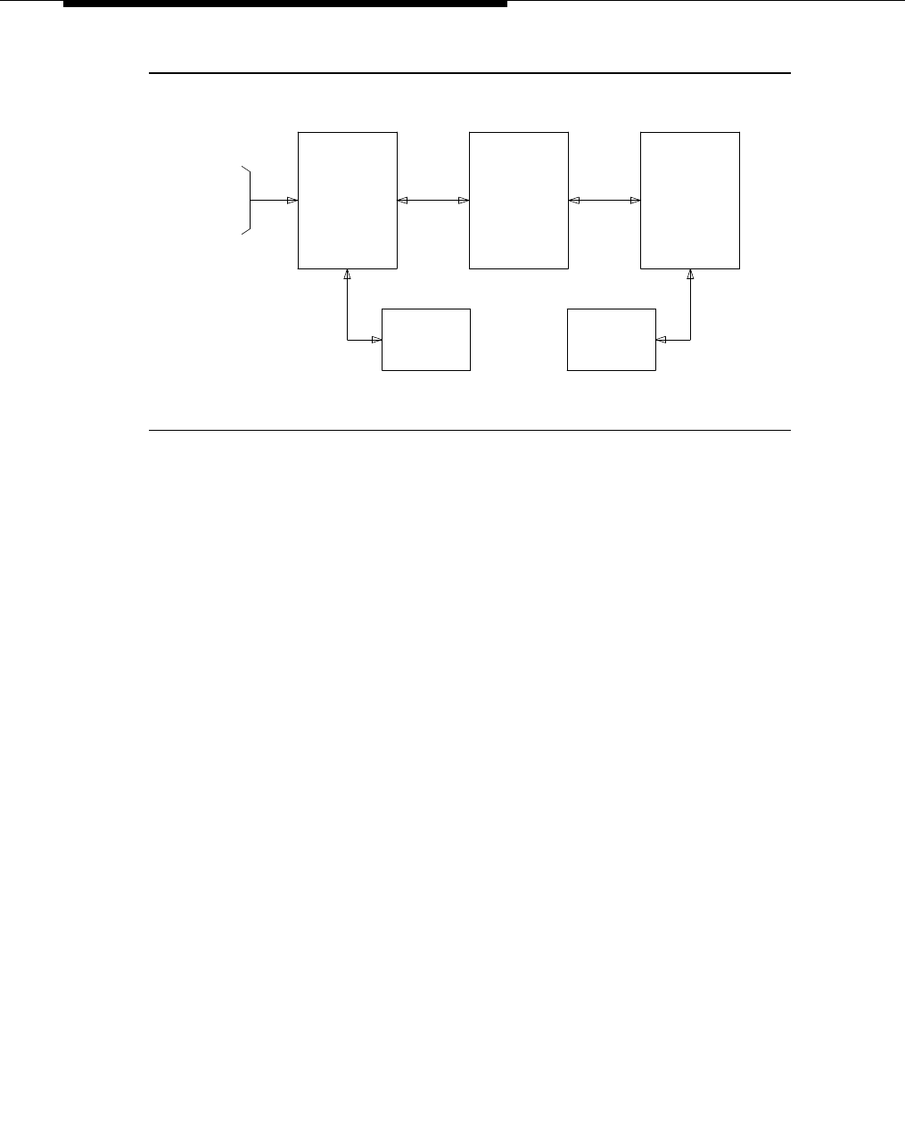
Feature Descriptions
3-774 Issue 3 March 1996
Figure 3-17. Simplified ICM Configuration for Data Screen
Delivery
The ASAI interface could also be shown above direct to the host. CONVERSANT.
does not have to be in the middle if the host supports ASAI.
Integration With Speech Processing Adjuncts
ICM can be used to provide integration with Voice Response Units (VRUs). The
advantages of using ICM with the CallVisor ASAI in addition to tip/ring interfaces
are as follows:
■Data screen integration is provided on transferred calls.
■Notification of answer is provided on internal calls (CallVisor ASAI
capabilities let you know what happens with the call).
■Delivery of ISDN network information such as CPN/BN/DNIS is provided
(instead of having to prompt for this information).
A simplified configuration of this application is shown in Figure 3-18. In this
application, the CallVisor ASAI link is used by the switch to pass incoming call
information to the CONVERSANT voice system. The call is distributed by the
switch ACD to an available voice line. After collecting digits via a DTMF keypad,
the CONVERSANT voice system transfers the call back to an ACD split or
specific agent on the switch via CallVisor ASAI messages. If the call is
transferred to a split agent, the CallVisor ASAI link is used by the switch to pass
an event report containing which agent in the split receives the call. The
CONVERSANT voice system forwards the agent identification to the host for
delivery of the associated data screen to the agent selected to handle the call.
Digits collected by the CONVERSANT voice system are not passed to the switch
to display on the agent’s voice terminals but can be displayed on the agent’s
SWITCH ASAI
AGENT
VOICE
TERMINAL
AGENT
DATA
TERMINAL
HOSTCONVERSANT
INCOMING
CALLS
(ISDN-PRI)
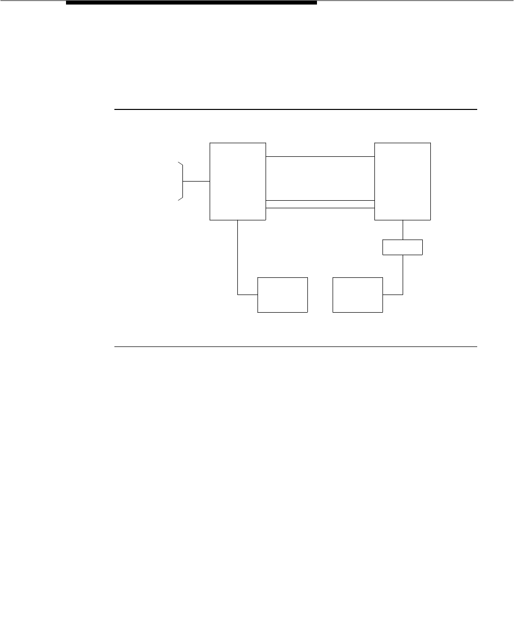
Inbound Call Management (ICM)
Issue 3 March 1996 3-775
data terminals. If the digits collected by the CONVERSANT voice system are
the extension to which the call is to be routed, these routing digits are passed to
the switch as the destination in the CallVisor ASAI third party make call request.
The third party make call request is used by the CONVERSANT voice system to
set up various types of calls.
Figure 3-18. Simplified ICM Configuration for Speech Processor
Integration
Host/Adjunct Call Routing
Incoming call information can be used by the host or CONVERSANT voice
system adjunct to route the call to a split, vector, or particular agent (basically
any valid extension number). The call could even be routed off of the switch if
desired. The CONVERSANT voice system can also use the incoming call
information to tell the switch that the call should be treated as a priority call.
Routing can be based on the area code dialed from, the country code, digits
collected from the Call Prompting feature, dialed number or service, agent
availability, or information in a customer database.
To implement adjunct (CONVERSANT voice system) call routing, calls must
come into a vector which contains an adjunct routing vector command.
When the adjunct routing vector command is encountered, the switch
initiates the route CallVisor ASAI capability. Vector processing proceeds with the
next step (which could provide ringing, announcements, music, and so on) while
the caller waits. A default split or answering position can also be specified in the
vector, in case the CONVERSANT voice system does not respond in the
administered amount of time (determined by the announcement/wait steps).
Announcement and wait steps are needed to give the host time to respond.
INCOMING
CALLS
(ISDN-PRI)
SWITCH
ASAI
TIP/RING LINES
AGENT
VOICE
TERMINAL
AGENT
DATA
TERMINAL
HOST
SPEECH
PROCESSOR

Feature Descriptions
3-776 Issue 3 March 1996
Direct Agent Calling
DAC is a new function that allows an adjunct to initiate or transfer a call to a
particular ACD agent and have the call treated as an ACD call.
Calls that originally enter the switch as ACD calls and are rerouted to a particular
agent via adjunct routing, or transferred from a tip/ring agent to a live agent via a
‘‘third party make call’’ request, are treated as ACD calls for the duration of the
call. This is important for a number of reasons:
— The call may queue for the agent.
— Agents need to receive zip tone when these calls are delivered.
— Agents may have After Call Work associated with these calls.
The CMS and BCMS correctly measure these calls as ACD calls.
Direct Agent Calls have the highest priority of any calls.
Adjunct Activation of Direct Agent Calling
CallVisor ASAI third party make calls and route select calls with the direct agent
call option are treated as direct agent calls. The receiving agent’s extension
appears as the destination and the split extension in the direct agent call option.
Delivery of DAC
If the agent receiving the direct agent call is available to answer an ACD call in
the associated split, the direct agent call is delivered to the agent. Zip tone (480
Hz for a 1/2 second, not repeated) is applied if the agent is automatic answer.
If the receiving agent is not available to answer an ACD call (for example, the
agent is busy on a call, in the After Call Work mode, or in the Auxiliary Work
Mode), the receiving agent is notified with a ring-ping if the agent has a
multi-function voice terminal or is on-hook. If the receiving agent has a single-line
voice terminal and is not available, the receiving agent will hear call waiting tone
(even when the Call Waiting feature is not assigned) if the agent is off-hook. The
ring-ping or call waiting tone is given only once per call when the call is queued.
The active work mode button lamps for the associated split on the receiving
agent’s voice terminal will do a fast flutter, indicating a direct agent call is waiting.
This starts when the first call queues and stops when all direct agent calls leave
the queue (answered, abandoned, or sent to coverage).
The originating agent hears normal call progress tones and ringback. If the
originating agent drops from the call, the caller hears call progress tones and
ringback. A forced first announcements will not be heard by the originating agent
or caller.
Direct agent calls are queued and served in a first-in first-out order, before any
non-DAC. Therefore, when an agent becomes available, the switch first checks
for any direct agent calls before serving normal ACD calls in queue.

Inbound Call Management (ICM)
Issue 3 March 1996 3-777
The voice terminal display for the receiving agent, before a transfer is complete,
shows the originating agent’s name and number. The voice terminal display for
the receiving agent, after the transfer is complete, shows the caller identification
(CPN/BN or trunk group name for external calls, and name/number for internal
calls) and the original split or VDN name.
Direct agent calls follow the receiving agent’s coverage and call forwarding, if
activated. Once the call goes to coverage or is forwarded, the call is no longer
treated as a DAC. CMS is informed that the call has been forwarded.
Answering a Direct Agent Call
The receiving agent answers a direct agent call by becoming available in the
split with which the direct agent call is associated. While on a direct agent call,
the agent becomes unavailable to subsequent ACD calls.
If the receiving agent logs off by unplugging the headset, the agent may still
answer a direct agent call in queue by logging back in and becoming available.
Considerations
A maximum of eight CallVisor ASAI links may be assigned.
Information from a CONVERSANT voice system (except for the dialed number)
cannot be carried with the call and displayed on a voice terminal. For example,
digits collected in a CONVERSANT voice system adjunct cannot be passed to
the switch for display.
CallVisor ASAI and BX.25 CPN/BN-ANI are not supported simultaneously.
Interactions
The following features and functions interact with the ICM feature:
■Automatic Answer
DACs to agents assigned automatic answer will receive single zip tone
answer.
■Queue Status Indications
DAC are not included in the number of calls waiting and oldest call waiting
on the queue status indication for the split.
■Call Coverage
If the split associated with a direct-agent call has call forwarding or night
service activated for the split, the direct-agent call is forwarded. If the
priority calling option is requested, the direct-agent call forwards with
priority ringing at the night service destination.

Feature Descriptions
3-778 Issue 3 March 1996
After a DAC call successfully terminates to a split, if the destination agent
has Call Forwarding or Send All Calls activated, then the DAC calls will be
forwarded. If the priority calling option is requested, then the DAC call will
forward with priority ringing at the call forwarded destination, but will not
forward to the covering point in the case of Send All Calls when the priority
calling option is requested.
Direct-agent calls follow the destination agent’s coverage path. If the
priority calling option was requested, the DAC follows the standard priority
call rules for coverage, meaning the call will not go to coverage. Calls
(either regular ACD or direct-agent) in queue will remain in queue until the
caller abandons or agent answers. Calls follow the agents internal or
external coverage path based on the origin of the call, not the
internal/external status of the adjunct providing routing instructions.
■Call Forwarding
New DAC will forward if the agent activates Call Forwarding. Direct Agent
Calls already in queue prior to Call Forwarding activation will remain in
queue.
■Call Vectoring
Call Vectoring is used in conjunction with CallVisor ASAI capabilities. The
adjunct routing vector command is required. For adjunct routing, if
the call queues to a split or the call leaves vector processing, a route end
request is sent to the CONVERSANT voice system.
Direct agent calls cannot go through vectors.
■Call Prompting
Digits collected by the Call Prompting feature become part of the current
call information that is passed to a CONVERSANT voice system adjunct.
■Call Waiting
Call waiting tone is used to notify single-line users that a DAC is waiting,
whether the call waiting feature is optioned or not.
■DCS
DAC cannot be made over a DCS link. If the receiving agent is not an
internal extension, DAC is denied.
■Night Service
DACs will go to Night Service if Night Service is activated for the receiving
agent’s split.
■Priority Calling
CallVisor ASAI capabilities permit both Priority Calling and DAC for the
same call. Priority DAC will not go to coverage.
■Send All Calls

Inbound Call Management (ICM)
Issue 3 March 1996 3-779
If an agent activates send all calls,
new
DACs will immediately go to the
agent’s coverage. DACs already in queue prior to Send All Calls activation
will remain in queue until the coverage ringing timeout occurs.
Administration
ICM is administered by the System Manager.
The ACD feature must be administered as described in the ACD feature
description elsewhere in this manual.
If the Call Vectoring and/or Call Prompting features are to be used, these
features must be administered as described in the Call Vectoring and Call
Prompting feature descriptions elsewhere in this manual.
In order to make or receive direct agent calls, an agent must be assigned a COR
that allows DAC.
Direct agent calls wait in split queues. Split queues must be properly sized.
Hardware and Software Requirements
The only additional hardware requirements for ICM are those for the CallVisor
ASAI. These requirements are in the following paragraphs.
The system supports TN744C-Tone Detector/Call Classifier, TN748C-Tone
Detector, TN420C-Tone Detector, or TN2182-Tone Clock/Detector/Generator for
use as tone detectors. TN420C, TN744C, and TN2182 support A-law. With
respect to CallVisor ASAI features, the TN744C is required for those customers
who desire switch call classification.
Each port on the eight port TN744C acts as a touch-tone receiver or call
classifier. Each call classifier port is capable of detecting tones as well as
Special Information Tones.
This tone detection will work only if the public network provides similar tones to
those used in the US.
Each CallVisor ASAI BRI Interface Link requires a port on a TN556 ISDN-BRI
circuit pack.
CallVisor ASAI Interface software is required. A TN778 Packet Control board and,
in a multiple port network design, TN570 expansion interface are required.

Feature Descriptions
3-780 Issue 3 March 1996
Individual Attendant Access (IAA)
Feature Availability
This feature is available with all Generic 3 releases.
Description
Allows users to access a specific attendant console. Each attendant console
can be assigned an individual extension number.
A user can access an individual attendant by simply lifting the handset and
dialing the extension number assigned to the desired attendant. An individual
attendant extension number can also be assigned to users’ abbreviated dialing
button for fast access to the specific attendant.
Individual attendants can be accessed by voice terminal users, incoming trunks,
Remote Access, and other attendants. A specific attendant, when called, can
extend the call to another trunk or extension.
Each individual attendant has a queue that allows incoming calls to wait. For
G3iV1, this individual attendant queue has priority over all other attendant
seeking calls. For G3r and all of Version 2 and later releases, the Individual
Attendant Access call is placed in the Attendant queue according to the priority
assigned in Attendant Priority Queueing.
Whenever a call is in an individual attendant’s queue, the top lamp of the Forced
Release button (basic console) or the Personal lamp (enhanced console) lights
to indicate this condition. Call Waiting tones are provided only on calls to the
attendant group and are not provided for waiting individual attendant calls.
An individual attendant can be a part of a hunt group. The hunt group can be a
DDC group or a UCD group. Calls to individual attendants and calls to the
attendant group have priority over hunt group calls to an individual attendant.
Any call made from an attendant console which is assigned an individual
extension is considered to be made from the individual attendant, not the
attendant group.
Considerations
With Individual Attendant Access, attendant consoles can become more flexible
by assigning each one an individual extension number. An individual attendant
extension allows an attendant to use features that an attendant group cannot
use; for example, individual attendant extensions can be a member of a DDC or

Individual Attendant Access (IAA)
Issue 3 March 1996 3-781
UCD group. An individual attendant can also be accessed when the Centralized
Attendant Service feature is in effect. Another advantage is that each individual
attendant extension can have its own Class of Restriction and Class of Service.
The Position Available lamp on the attendant console only indicates whether or
not attendant group calls can be accepted. It does not indicate whether or not
individual attendant calls can be accepted.
Each attendant console has one position busy button. When the lamp
associated with this button is lighted, the attendant does not receive attendant
group calls but can still receive individual attendant calls.
Since hunt groups have better queuing and make busy features than individual
extensions, it may be desirable to assign an individual attendant as the only
member of a hunt group. This way the individual attendant could receive calls as
a hunt group member for more efficient handling of calls.
Interactions
The Individual Attendant Access call is placed in the Attendant Queue
according to the priority assigned in Attendant Priority Queuing (for G3iV1 and all
G3V2 and later releases).
The following features interact with the Individual Attendant Access feature.
■Abbreviated Dialing
Individual attendant extensions can be in Abbreviated Dialing lists.
Individual attendants, however, cannot have their own Abbreviated Dialing
lists.
■Attendant Display
For calls to or from individual attendants, individual attendant names
(when specified) are displayed instead of the individual attendant
extensions.
■Bridged Extension
Individual attendant extensions cannot be assigned to a bridged call
appearance.
■Busy Verification of Terminals and Trunks
An individual attendant extension cannot be busy verified.
■Call Coverage
Individual attendant extensions can be points in a coverage path but
cannot be a member of a coverage answer group.
■Call Park
Individual attendants can park calls on their own extension or another
individual attendant extension.

Feature Descriptions
3-782 Issue 3 March 1996
■Call Pickup
Individual attendant extensions cannot be in Call Pickup groups.
■CAS
Individual attendants can be accessed when CAS is in effect.
■COR and COS
Each individual attendant extension has its own COR and COS. However,
it is recommended that an individual attendant and the group with which
he or she is associated be assigned the same COR.
■DDC and UCD
Individual attendant extensions can be assigned to DDC and UCD
groups. Unlike voice terminal users, individual attendants can answer
DDC and UCD calls as long as there is an idle call appearance and no
other DDC or UCD call is on the console.
■Facility Busy Indication
An individual attendant extension can be stored in a Facility Busy
Indication button.
■Integrated Directory
The names and extensions of the individual attendants are stored in the
directory associated with this feature.
■LWC
A message from an attendant indicates whether it is from the attendant
group or whether it is from an attendant which has an individual extension.
■Night Service — Night Console Service
Activation and deactivation of this feature affects only calls to the
attendant group. Calls to individual attendant extensions are allowed
when night service is active. A night-only attendant console with an
individual extension can receive individual attendant calls when night
service is not active.
■Privacy — Attendant Lockout
This feature applies only to attendant group calls. Individual attendant
calls are not affected.
■Voice Terminal Display
For calls from individual attendants, individual attendant names (when
specified) are displayed instead of the individual attendant extensions.

Individual Attendant Access (IAA)
Issue 3 March 1996 3-783
Administration
Individual Attendant Access is administered on a per-attendant console basis by
the System Manager. The following items require administration for each
attendant console:
■Extension number
■Name
■COR
■COS
Hardware and Software Requirements
No additional hardware or software is required.
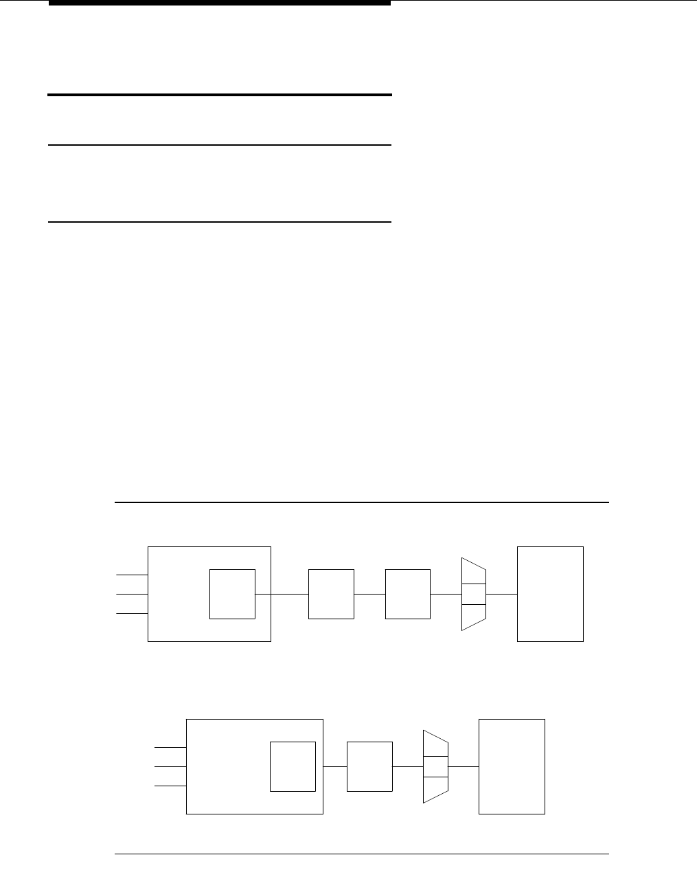
Feature Descriptions
3-784 Issue 3 March 1996
Information System Network (ISN)
Interface
Feature Availability
This feature is available with all Generic 3 releases.
Description
The AT&T ISN is a packet-switched local area network that links mainframe
computers, minicomputers, word processors, storage devices, personal
computers, printers, and communications processors into a single system.
The ISN is a packet-switched local area network. This local area network is made
up of one or more modular data-only digital communications switches.
The interface between the system and the ISN is via a Data Line Port in
conjunction with an Asynchronous Data Unit (ADU). Either a Modular Processor
Data Module (MPDM), a 7400A data module may be used instead of the Data
Line Port and ADU, although the latter is more economical. The MPDM or ADU
connects to an AIM on the Packet Controller or Terminal Concentrator (see
Figure 3-19). This interface allows the system and the ISN to share data
capabilities. (The 7400A connections are the same as shown below for the
MPDM.)
Figure 3-19. System-to-ISN Connectivity
ETN
DID
SWITCH
DIGITAL
LINE
PORT
RS-232C
ADAPTER AIM
CONCENTRATOR
INFORMATION
NETWORK
ETN
DID
SWITCH LINE
PORT
AIM
CONCENTRATOR
INFORMATION
NETWORK
DATA
DS1
MPDM
DS1
ADU
*
SYSTEMs
SYSTEMs

Information System Network (ISN) Interface
Issue 3 March 1996 3-785
Data is transferred between the system and the ISN on one-way trunks (either
incoming or outgoing). Each data line port is administered for a specific data
rate, which can be any of the common asynchronous data rates ranging from low
to 19,200 bps.
Considerations
Connectivity between ISN and the system provides the following major benefits:
■Users on ISN may (in addition to having access to other endpoints directly
connected to ISN) have access to any endpoint connected to the system
or addressable from the system.
■Users who either connect to or have access to the system may also
access endpoints connected to ISN.
Since the ISN switches are modular, the local area data communications network
can be designed so that it is both versatile and cost-effective. A single packet
controller can be configured to support from 40 to 1,920 data ports.
Interactions
The following features interact with the ISN Interface feature.
■Abbreviated Dialing
Outgoing lines cannot use Abbreviated Dialing.
■Automatic Circuit Assurance
Automatic Circuit Assurance is not provided for data line port links to or
from the ISN.
■Data Call Setup
Data Terminal (Keyboard) Dialing is used to access ISN endpoints. A data
call to an ISN data endpoint from a system digital data endpoint requires
two-stage dialing. A user must first dial the extension assigned to the
outgoing ISN group, and then interact with ISN and enter the second
address (data endpoint).
■Data Hotline
Outgoing lines cannot use hot line calling.
■Modem Pooling
If an analog data endpoint is used in an ISN connection, and a conversion
resource is needed, the system will obtain a conversion resource from the
appropriate pool.

Feature Descriptions
3-786 Issue 3 March 1996
■System Measurements
No traffic measurements are made on data line port links to or from the
ISN.
■Uniform Call Distribution
Outgoing lines should be members of a UCD group. This way, the system
automatically selects an idle port when a user tries to access the ISN.
Administration
Data module extensions used to access ISN must be administered by the
System Manager as data lines connected to the ISN. The System Manager can
then administer the other options required for each data line. These options
include:
■Keyboard Dialing — If the line is incoming (to the system), Keyboard
Dialing should be enabled so that the system can be accessed by the
ISN. If the line is outgoing (to the ISN), Keyboard Dialing should be
disabled.
■Configuration — This option should be disabled on both incoming and
outgoing lines to prevent the ISN from changing the data line
configuration.
■Busy Out — This option should be enabled for outgoing lines so that a
member of the outgoing ISN group can be ‘‘busied-out’’ and let calls go
through another member of the group.
■Speeds — Data speeds should be selected according to individual
needs, and should be the same as those at connecting ISN ports. Only
one speed should be assigned to each data line port.
■Autoadjust — This option is not needed with the ISN, and should be
disabled on incoming lines. This option can only be set if Keyboard
Dialing is enabled.
■Permit Mismatch — This option should be disabled on both incoming and
outgoing data lines.
■Disconnect — The disconnect sequence should be administered
according to the characteristics of the device. This option can only be set
if Keyboard Dialing is enabled.
■Parity — This option should be administered as even. This option can only
be set if Keyboard Dialing is enabled.
■Dial Echoing — This option should be disabled so that characters are not
echoed back to the ISN. This option can only be set if Keyboard Dialing is
enabled.
■Answer Text — This option should be disabled, and can only be set if
Keyboard Dialing is enabled.

Information System Network (ISN) Interface
Issue 3 March 1996 3-787
■Connected Indication — This option should be disabled, and can only be
set if Keyboard Dialing is enabled.
■COR — Outgoing lines should be origination restricted. Incoming lines
should be termination restricted.
Hardware and Software Requirements
One TN726 Data Line circuit pack is required for each eight ISN interfaces. No
additional software is required.

Feature Descriptions
3-788 Issue 3 March 1996
Integrated Directory
Feature Availability
Integrated Directory is available with all Generic 3 releases.
Description
Allows internal system users with display-equipped terminals to access the
system database, use the touch-tone buttons to key in a name, and retrieve an
extension number from the system directory. The directory contains an
alphanumeric listing of the names and extension numbers assigned to all voice
terminals administered in the system.
The Integrated Directory feature can be accessed by display-equipped voice
terminal users or Attendants with an assigned Integrated Directory button.
The names in the directory are those administered by the System Manager on
the “Individual Voice Terminal” forms. Names cannot exceed 15 characters
(including spaces and commas) and can be entered in one of the following three
formats.
■Last name, comma, first name, space, then middle name or initial, if
desired. For example, the following entries are acceptable:
— Jones,Betty Ann
— Smith,A E
— Thomas,John J
— Abbott,Lynn
■First name, space, second name or initial, and then last name. For
example, the following entries are acceptable:
— Betty Ann Jones
— A E Smith
— John J Thomas
— Lynn Abbott
■A single entry is also acceptable:
— Cafeteria
— 1J409
— 2F816
— Purchasing
The following is an example of a typical Integrated Directory database:

Integrated Directory
Issue 3 March 1996 3-789
— 1J409
— Abbott,Lynn A
— Brown,Kent J
— Cafeteria
— Carr,Danny
— Carter,Ann
— 2F816
— Purchasing
— Barbara Quincey
— Roberson,Don T
— William Ruoff
— Smith,A E
— Streck,R T
The touch-tone buttons are used to key in the numbers and letters labeled on
them. The following exceptions apply:
■7 (PRS) is also used for a Q.
■9 (WXY) is also used for a Z.
■* is used for a space or comma.
■# is not used.
To activate the Integrated Directory feature, the user presses the Integrated
Directory button. This puts the voice terminal in the Integrated Directory mode
and turns off the tones normally generated when a touch-tone button is pressed.
The touch-tone buttons are now used exclusively for keying in names and not for
dialing.
After the Integrated Directory button is pressed, the alphanumeric display shows
DIRECTORY — PLEASE ENTER NAME. Names are always keyed in the following
order: last name, comma, and then first name or initial. When searching for a
single entry, the letters or numbers are keyed in order. Several letters might be
needed to get the correct entry.
When a button is pressed, the display shows the first name that matches the first
letter on the button. For example, if a user is searching for the name Ann Carter
and presses 2 to key in the letter C, the display might show Abbott,Lynn A and an
extension number. (2 matches A before it matches C.) If the user presses 2 again
to key in the letter A, the display stays the same. (Again, AB is matched before
CA.) If the user now presses 7 to key in an R, the display might show Carr,Danny
and an extension number.

Feature Descriptions
3-790 Issue 3 March 1996
At this point, the user can press 8 to key in the letter T or can press the Next
Message button on the alphanumeric display. Pressing Next Message displays
the next name in the directory and, in this case, might be Ann Carter.
When the desired name and extension number are displayed, the user can
automatically place a call to that person by pressing the Call Display button.
If a name is entered but not found in the directory, the display shows NO MATCH
— TRY AGAIN. You can then enter another name. To search for another name,
the user presses the Integrated Directory button again, and the feature is
reactivated.
To exit the Integrated Directory mode, the user presses one of the other mode
buttons assigned to the alphanumeric display module; for example, the Normal
mode button.
Considerations
With Integrated Directory, users spend less time looking up names and extension
numbers. Instead of searching through lists or directories, a user simply keys in
the desired name and the display shows the name and extension number. Less
dialing time is also required if a Call Display button is provided. When the desired
extension is displayed, the user just presses the Call Display button to
automatically place the call.
A maximum number of users can activate Integrated Directory at the same time.
If more than this maximum number of users try to activate the feature at the same
time, the Integrated Directory button lights and the display shows Directory
unavailable — Try Later.
The entire directory cannot be searched by pressing 2. Pressing 2 and then
continually pressing Next Message displays, one by one, all entries beginning
with A, B, C, and 2. If all entries have been displayed and Next Message is
pressed again, the display repeats from the first entry in the listing associated
with 2.
When the voice terminal is in the Integrated Directory mode, it cannot be used to
make calls or access features by dial code. It can, however, still be used to
activate other features or to place calls if dialing is not required. Also, a user can
enter the Integrated Directory mode while active on a call, and calls can be
received when the Integrated Directory mode is active.
The set of characters allowed in the Integrated Directory database are the
alphanumeric characters (A-Za-z) and digits (0-9) as well as space ( ) and
comma (,) which are used as delimiters. In addition, the following special
characters are allowed: hyphen (-), apostrophe (‘), period (.), slash (/), and
ampersand (&.) These special characters, though considered legal characters,
are not entered into the Integrated Directory. Instead, a period (.) is replaced by a
space ( ). Apostrophe (‘), hyphen (-), slash (/), and ampersand (&) are ignored.

Integrated Directory
Issue 3 March 1996 3-791
For G3r, if a name of a station or data module begins or ends with a comma (,) or
contains more than one comma (,,), the directory search for that name fails.
If a character outside the allowed set is entered as the name of a station or data
module, the directory search for that name fails.
NOTE:
The “/” and “?” characters are punctuation marks and should
not
be used
to represent information. The “+” or “%” characters may be used to
represent information.
Interactions
The following features interact with the Integrated Directory feature.
■Attendant Display and Voice Terminal Display
If prefixed extensions are used in the system’s dial plan, the prefix is not
displayed when the extension is displayed. The Call Display button can be
used to dial prefixed extensions because the system dials the prefix, even
though it is not displayed.
■Merlin®/System 25 Voice Terminal Support — 731xH Series Support
The Merlin/System 25 7309H, 7313H, 7314H, 7315H, 7316H, and 7317H
voice terminals do not support Integrated Directory displays.
■Touch-Tone Dialing
Call origination and feature access by dial code is not allowed when the
Integrated Directory feature is active.
Administration
Integrated Directory is administered on a per-voice terminal basis by the System
Manager. The following items require administration:
■Display Module
■Directory Button
■Call Display Button
■Messaging Cartridge (for 7404D)
■Next button
Hardware and Software Requirements
No additional hardware or software is required.

Feature Descriptions
3-792 Issue 3 March 1996
Integrated Services Digital Network
(ISDN) — Basic Rate Interface (BRI)
Feature Availability
This feature is available with all Generic 3 releases.
Description
Allows connection of the system to equipment or endpoints that support an
Integrated Services Digital Network (ISDN) by using a standard ISDN frame
format called the Basic Rate Interface (BRI).
An ISDN provides end-to-end digital connectivity and uses a high-speed
interface which provides service-independent access to switched services.
Through internationally accepted standard interfaces, an ISDN provides circuit
or packet-switched connectivity within a network and can link to other ISDN
supported interfaces to provide national and international digital connectivity.
Two types of ISDN interfaces are currently defined: the PRI and the BRI. This
description focuses on ISDN-BRI.
The ISDN-BRI is a 192 kbps interface that carries two 64 kbps B-channels and
one 16-kbps D-channel. Each B-channel supports voice and data, while the
D-channel transports data, signaling, and other bits for framing.
NOTE:
■Although ISDN-BRI can support data transmission on the D-channel,
DEFINITY system Generic 3 does not support this capability. DEFINITY
system Generic 3 only provides signaling on the D-channel.
■ISDN-BRI is only available on DEFINITY switches that support 5-law
companding. See the
DEFINITY Communications System Generic 3
System Description and Specifications
, 555-230-206, for further details.
■The word ‘‘endpoint’’ is used whenever statements apply to BRI voice
terminals, BRI data modules, and integrated BRI voice/data terminals.
The DEFINITY switch supports the following across the ISDN-BRI interface to an
endpoint:
— A single voice call
— A single data call
— A voice call and a data call simultaneously
— Two simultaneous data calls

Integrated Services Digital Network (ISDN) — Basic
Rate Interface (BRI)
Issue 3 March 1996 3-793
ISDN-BRI Endpoint Configurations
There are two possible configurations with ISDN-BRI:
■Point-to-point — Only one endpoint connected to a BRI port
■Multipoint — Multiple endpoints connected to a BRI port. This
configuration is also referred to as ‘‘passive bus configuration.’’
Because the DEFINITY system BRI provides non-blocking voice and data
services, a maximum of two endpoints are supported on one BRI port in a
multipoint configuration.
The DEFINITY switch dynamically allocates the two B-channels on a BRI
interface to handle voice and data requests. Because there are two B-channels,
only two simultaneous service requests can be granted at any time on a BRI port
to provide non-blocking service (either through point-to-point or multipoint
configurations).
When one endpoint is capable of providing two service requests (such as an
integrated voice/data endpoint or an endpoint that supports two simultaneous
%B-channel data calls), the endpoint must be configured as point-to-point
because both B-channels can potentially be used simultaneously by the two
services. You can have the following endpoint types in the point-to-point
configuration:
■One voice-only endpoint
■One stand-alone data endpoint
■One integrated voice/data endpoint
NOTE:
Even though an integrated voice/data endpoint supports two service
requests (that is, both voice and data), the integrated endpoint is not
considered to be in multipoint configuration because it is only one
endpoint.
If two endpoints are each capable of providing only one service request, then
they can be administered on the same BRI port. Doing so provides a multipoint
configuration. In this case, both B-channels can potentially be used
simultaneously by two service requests and, since each BRI port provides two
B-channels, no additional endpoints can be administered on this BRI port. You
can have the following endpoint types in the multipoint configuration:
■Two voice-only endpoints
■Two stand-alone data endpoints
■One voice-only endpoint and one stand-alone data endpoint
NOTE:
An endpoint that supports two simultaneous B-channel data calls is not
supported in a multipoint configuration.

Feature Descriptions
3-794 Issue 3 March 1996
Terminal Equipment Identifier (TEI)
The terminal equipment identifier (TEI) is used to set up communication between
the switch and an endpoint. The DEFINITY system supports two types of TEIs:
fixed and automatic. A fixed TEI endpoint supports one fixed TEI value (0 to 63),
which is encoded into the terminal equipment, and the fixed TEI initialization
procedure. When administering a fixed TEI endpoint, you must assign the
endpoint’s fixed TEI value to the “Station” or “Data Module” forms for that
endpoint. If the endpoint’s fixed TEI value differs from the TEI assigned to the
“Station” or “Data Module” forms for that endpoint, no communication is
established between the switch and the endpoint. As a result, the endpoint is
incapable of providing services. Normally, the manufacturer specifies the fixed
TEI value encoded into the terminal or provides procedures for modifying the
fixed TEI value.
An automatic TEI endpoint supports automatic TEI initialization procedures and
receives a TEI from the system during initialization. With automatic TEI endpoints,
you are not entering any TEI values to the “Station” or “Data Module” forms. Only
the automatic TEI endpoints are permitted to be used in multipoint
configurations. Currently, all supported BRI endpoints are automatic TEI
endpoints.
Service Profile Identifier (SPID)
When more than one endpoint is connected to a BRI port (for example, a
multipoint configuration), the switch uses the Service Profile Identifier (SPID) to
associate endpoints with the administered station or data module extensions.
The SPID enables the switch to differentiate between the endpoints connected to
the same BRI port.
You must administer the SPID on the “Station” or “Data Module” forms, and then
program the SPID in the BRI endpoint using the procedure in the endpoint’s
users’ manual. During initialization, the endpoint sends the SPID to the switch.
The SPID administered on the “Station” or “Data Module Administration” forms
must match the SPID which is programmed into the endpoint. If the SPID on the
“Station” or “Data Module Administration” forms does not match the SPID
programmed into the endpoint, the system restricts service to that endpoint.
SPID administration and programming are required for a multipoint configuration.
However, SPID administration is optional in a point-to-point configuration
because there is only one endpoint connected to the BRI port. If the SPID is
administered in a point-to-point configuration, it must match the SPID
programmed into the endpoint. If the SPID is not administered, the switch uses
the port to associate the endpoint to the administered station or data module
extension.
NOTE:
The BRI version of the PC Interface feature, the PC/ISDN Platform, is a
non-initializing terminal and does not require a SPID. In fact, in the
stand-alone configuration, this type of terminal cannot be assigned a SPID.

Integrated Services Digital Network (ISDN) — Basic
Rate Interface (BRI)
Issue 3 March 1996 3-795
ISDN-BRI Voice/Data Terminal Equipment
Voice transmission on ISDN-BRI is provided by the 7505, 7506, 7507, 8503T,
8510, and 8520 voice terminals. All tests and services available to DCP users are
also available to BRI users.
Data transmission on ISDN-BRI is provided by the 7500 Data Module (or a
compatible stand-alone data module) and the Asynchronous Data Module
(ADM). The 7500 Data Module is a stand-alone unit that supports asynchronous
or synchronous DCE and asynchronous DTE:
■In asynchronous mode, the 7500 supports packet- or circuit-switched
data communications, and can be controlled via the front panel or the
keyboard of a connected terminal.
■In synchronous mode, the 7500 supports circuit-switched or nailed-up
data communications, requires either the Multi-purpose Enhancement
Board or the High-Speed Synchronous Enhancement Board, and can only
be controlled via the front panel.
The ADM may be used with asynchronous DTE as a data stand for 7500-series
BRI voice terminals. Consisting of a board located inside the BRI voice terminal,
the ADM allows the transmission of integrated voice and data through one voice
terminal. (Separate extension numbers are used for the voice and data calls.)
The ADM supports the Hayes command set for compatibility with PC
communications packages.
The PC/ISDN Platform provides both voice and data transmission and is part of
the AT&T PC Interface package, Group 3. (Please see the "PC Interface" feature.)
The PC/ISDN Platform can be used in a stand-alone (no associated voice
terminal) configuration. When used this way or with a handset or headset, rather
than one of the 7500 series voice terminals, the PC/ISDN Platform is a
non-initializing terminal that does not support MIMs (Management Information
Messages). This means that these ‘‘stations’’ do not go through an initialization
procedure with the switch. It also means that they do not require a SPID, and that
they do not initiate or respond to MIMs. Even when used with a 7500 series voice
terminal, the endpoint (combined PC and phone) should still be administered as
a non-initializing terminal that does not support MIMs.
NOTE:
When more than one PC/ISDN interface card is used on the same PC, each
separate card provides a separate interface and is translated on the switch
with its own ELL (Equipment Line Location) as a separate station.
Endpoint Initialization
To be fully operative, BRI endpoints must successfully complete endpoint
initialization procedures. These procedures are usually done at installation time
or as part of reconfiguration.

Feature Descriptions
3-796 Issue 3 March 1996
Multipoint Configurations on BRI Ports
In a passive bus multipoint configuration, the system supports two BRI endpoints
per port, thus doubling the capacity of the BRI circuit pack. When changing the
configuration of a BRI from point-to-point to multipoint, the original endpoint need
not be reinitialized. However, only endpoints that support SPID initialization can
be administered in a multipoint configuration.
Exchange of User Information
The BRI protocol provides the users with the capability of exchanging up to 128
octets of user information end-to-end. The information is passed in the
User-to-User Information IEs to the receiving endpoint without being interpreted
by the switch. However, there are some limitations to the exchange of User
Information IEs.
ISDN-BRI Data Service
Basic Digit Dialing
Regular digit dialing is provided through the ADM. Digits from 0 to 9, ‘‘*’’ and ‘‘#’’
can be entered. This feature can be used by the user either from the set keypad
or from the EIA terminal interface.
Default Dialing
Default Dialing is also an enhancement to the user dialing capabilities of the Data
Call Setup feature. By either typing a d followed by or pressing the data
button twice, if a default address is administered, the switch terminates the call to
the default address. If no default dialing has been administered, the call is
disconnected in less than one second. This feature and the Data Hotline feature
are mutually exclusive.
Data Hotline
Data Hotline is a security feature that allows a user to enter a Dial command,
with no address specified, followed by a . The switch terminates the call
to a preadministered hotline destination. If a user enters an address, either
intentionally or unintentionally, the call processing discards the address string
received for the hotline endpoint. The call processing automatically routes the
call just as if the hotline destination address had been entered by the user. This
service does not impose any restriction on incoming calls received at the
endpoint.
NOTE:
This feature and the Default Dialing feature are mutually exclusive.
RETURN
RETURN

Integrated Services Digital Network (ISDN) — Basic
Rate Interface (BRI)
Issue 3 March 1996 3-797
Administered Connections
An Administered Connection is an end-to-end connection between two access
endpoints or data endpoints that is automatically established by the system
whenever the system is restarted or the Administered Connection is administered
and the Administered Connection is due to be active. The attributes of these
connections are user-defined and administered on the “Administered
Connection” form via the G3-MT.
Once the ADM has been administered as one endpoint of an administered
connection, the system waits for the scheduled time to set up the connection. At
the scheduled time, the system establishes the connection and maintains it for
the specified length of time. Once the call is accepted, the set enters into the
continuous mode for the specified length of time. If the switch is rebooted during
the continuous connection, the connection reinitiates the call setup. At any time
that the connection drops (for example, disconnected cabling), the switch
re-initiates the call setup.
Call Request
The DEFINITY system Generic 3 call processing handles all various BRI Bearer
data call requests that are presently defined. Some capabilities that are not
supported by AT&T terminals may be provided by a non-AT&T terminal. The
switch completes most call requests. For those capabilities the switch does not
support, a proper cause value is sent back to the terminal.
Cause Value
BRI stations receive a cause or reason code that identifies why the call is being
cleared. The BRI data modules convert certain cause values to text messages
and displays them for the user.
Considerations
The system supports up to 60 simultaneous voice calls on a BRI since two 7507
terminals (that support 30 call appearances/bridged appearances each) can be
administered on a BRI port.
The following features are not provided to BRI users:
■Since the ISDN-BRI protocol requires that the Bearer Capability must be
specified at the time of sending the SETUP message (and cannot be
changed during the call), the following data functions are not provided to
the BRI voice users:
— One button voice call setup transfer to data
— One button data call setup transfer to voice
— Preindication of a data call
— Voice call transfer to data and data call transfer to voice

Feature Descriptions
3-798 Issue 3 March 1996
These functions require a change in the Bearer Capability after the
establishment of the call, which is currently not allowed by the BRI
protocol.
■Features that use the switchhook and Recall button (for example, Call
Waiting and Analog Conference/Transfer/Hold/Drop) are applicable to
analog voice terminals only
The DEFINITY system supports BRI data endpoints that perform layer 2
disconnect. BRI data endpoints that support layer 2 disconnect are administered
as non-Management Information Message (MIM) supporting data only
endpoints.
The DEFINITY system supports non-AT&T BRI voice and data terminals that
perform enbloc sending using any one of the following formats:
■A SETUP message with all the digits in the Keypad IE and a Sending
Complete IE.
■A SETUP message with all the digits in the Called Party Number IE and a
Sending Complete IE.
■A SETUP message with all the digits in the Called Party Number IE and no
Sending Complete IE.
If you are using a 7506D or 7507D to make calls that require additional digits,
you can place a comma in the dial sequence after you receive a second dial tone
or after the call has been set up. The comma is used to separate the called
number from subsequent information.
Interactions
The following features interact with the ISDN-BRI services:
■Data Button
Besides the call appearance and feature function buttons, BRI voice/data
terminals have a fixed, dedicated data button (button 7 on the 7505D and
7506D voice terminals, and button 31 on the 7507D voice terminal) that is
used for data call setup. In general, feature function buttons such as Call
Forwarding or Send All Calls buttons are always associated with voice
features, and cannot be used in conjunction with the data button. For
example, the user cannot activate call forwarding for the associated data
endpoint by using the data button followed by the Call Forwarding button
and the designated extension.
■Interworking
The same off-premises call types are permitted as for DCP, with the
exception of voice to data and data to voice transfer.

Integrated Services Digital Network (ISDN) — Basic
Rate Interface (BRI)
Issue 3 March 1996 3-799
■Modem Pooling
The Modem Pooling feature provides the necessary protocol conversion
between Mode 2 digital data endpoints and analog data facilities. A
modem pool resource needs to be inserted by call processing during call
setup for both call origination and call answering. This resource translates
data between DMI Mode 2 protocol used by BRI data endpoints and the
modulated signal used by the modem.
■Pre-Selection
When an ISDN-BRI station assigned with the “Select Last Used
Appearance?” field of the “Station” form set to yes completes a transfer
while off-hook using the handset, the user will be left hearing a dial tone on
the last-used appearance, rather than the silence heard in the same
situation by an user of other station types.
■Voice Terminal Display
BRI terminals take control of the display. For example, when the user is in
dialing state (BRI terminal is in the Overlap Sending state) any display
information sent to the terminal from the switch is buffered until the state
changes and is displayed when the state changes.
The 7506 BRI voice terminal, which has a 2-line 24-character display,
splits a message when it recognizes a blank closest to the 24th character.
This is left to the discretion of the terminal. As a result, the switch has no
control over it.
■Busy Tone Forward Disconnect
BRI terminals require that the Busy Tone Forward Disconnect (BTFD)
feature be turned off. With BTFD off, an agent (with Malicious Call Trace) is
able to change states after a call.
Administration
BRI Voice/Data
Administration of BRI voice terminals requires all the fields associated with the
standard DCP station administration. Additional fields are used to enter the
following information:
■TEI information: If the BRI terminal supports a fixed TEI value, it has to be
entered at the time of station administration. The allowed values are 0
through 63. There are two fields: “Fixed TEI” and “TEI Value”. If the answer
to the first field is yes, the second field shows up where the TEI value is
administered. The TEI value on the “Administration” form must match the
value supported by the terminal.
■MIM support: This is an “Administrable” field on the “BRI Station” form. If
the answer to this field is ‘‘yes,’’ the following two fields need to be filled in:

Feature Descriptions
3-800 Issue 3 March 1996
1. Endpoint Initialization: If the BRI terminal supports endpoint
initialization, the administrator has to enter the SPID value. The
default value is the extension; however, the value can be changed
at the time of administration. The SPID can be up to 10 digits, and
uniquely identifies the terminal on the BRI. The SPID on the
“Administration” form and the SPID programmed into the endpoint
must be the same. (Refer to the terminal’s user manual in order to
change the terminal’s SPID.) All SPIDs must be different for each
endpoint on the same port. All SPIDs must be different from the
service SPID, which is administered on the “System Maintenance”
form.
2. MIM Maintenance / Management support: This is another BRI
specific field that indicates if the terminal supports other
maintenance and management messages.
For multipoint (passive bus) environment, the system administration checks the
number of B-channels used for a port. Administration denies any attempt which
might cause call blocking by restricting the number of endpoints on a port.
NOTE:
Separate extensions numbers are used for voice and data calls to the same
endpoint.
Any PC/ISDN Platform configuration (stand-alone, with handset/headset, or
with voice terminal) should be administered with MIM support set to ‘‘no’’.
Other administrable features depend on the PC software application (if the
application supports data transmission, the ‘‘Data Module’’ field must be
set to ‘‘yes’’).
BRI Data
The 7500 Data Module is administered through the “Data Module Administration”
form. The ADM is administered through the “Station Administration” form, using
the data module administration page. In addition to the fields used by the DCP
endpoints, the following new fields are used for BRI data module administration:
■Default Duplex: Full/Half (default Full)
■Default Mode: Synchronous/Asynchronous (default Asynchronous)
■Default Speed: 1200, 2400, 4800, 9600, 19200, 56000, and 64000 (default
1200)
(In synchronous mode, the speed of the 7500 data module may be set to
56,000 or 64,000 bps.)
■Default Data Application: mode 0, mode 1, mode 2 sync, mode 2 async,
and mode 3/2 adaptable
Default Duplex, Default Mode, and Default Speed values are used for initializing
data module default attributes. The defaults are required for modem pooling
conversion resource insertion when the endpoint does not support MIM query

Integrated Services Digital Network (ISDN) — Basic
Rate Interface (BRI)
Issue 3 March 1996 3-801
capability. If you are using supported endpoints (7500 and ADM), you should not
change the default values. Changing the default values with the MIM
Maintenance/Management support option as ‘‘y’’ has no effect on modem
pooling. These endpoints support the MIM query capability, which enables the
switch to query the endpoint when a call arrives.
Default Data Application specifies the default data protocol to be used for
originating data calls if mode is not specified with the calling parameters. This
mode is also used for Administered Connections and for terminating trunk calls
that do not have bearer capability specified.
Data modules that support two simultaneous data calls should be administered
as a 7500 and the MIM Maintenance/Management support option should be set
to ‘‘n.’’
NOTE:
Two simultaneous data calls to a single endpoint use the same extension
number.
Hardware Requirements
BRI services require the following hardware:
■The TN778 Packet Control circuit pack. This circuit pack provides the
interface to the LAN (packet) bus on G3i (but not G3r) for establishing the
signaling connectivity.
■The TN556 BRI port circuit pack, which is the Basic Rate Line circuit pack.
Each BRI port board can support 12 line interfaces, each operating at 192
kbps.
■A TN2198 two-wire BRI port circuit pack can be used in place of the
TN556. In this case an NT1 is also required.
■ISDN-BRI Type B and Type D Terminal Management S/T interface
terminals.
■The AT&T ISDN 7505, 7506, 7507, 8503T, 8510, and 8520 voice terminals.
■The 7500 Data Module and the ADM. The ADM is supported by the AT&T
ISDN 7505, 7506, and 7507 voice terminals with firmware version FP2.0 or
later.
■The PC/ISDN Interface card used in conjunction with a standard PC and
one to four voice terminals. See the
PC/ISDN Platform Installation and
Reference
manual, 555-016-102, for additional information. Also see the
PC Interface feature described in this book.

Feature Descriptions
3-802 Issue 3 March 1996
Integrated Services Digital Network
(ISDN) — Primary Rate Interface
Feature Availability
ISDN-PRI is an optional feature that can be purchased with any Generic 3
releases except G3vs/G3s ABP.
Description
Allows connection of the system to an Integrated Services Digital Network (ISDN)
by using a standard ISDN frame format called the Primary Rate Interface (PRI).
The ISDN gives the system users access to a variety of public and private
network services and facilities. The ISDN-PRI standard consists of layers 1, 2,
and 3 of the Open System Interconnect (OSI) model. In ISDN-PRI, the
transmission standard for layer 1 (the physical layer), is either DS1 (T1) or CEPT1
(E1).
The DS1 (T1) is a digital transmission standard that in North America carries
traffic at the digital signal level-1 (DS1) rate of 1.544 Mbps. T1 facilities are also
used in Japan and some Middle-Eastern countries. It consists of a 1.536 Mbps
signal multiplexed with an 8 kbps framing channel. The 1.536 Mbps signal is
divided into 24 channels (DS0s) of 64 kbps each, numbered 1 - 24. The ‘‘D’’
(data) channel multiplexes signaling messages for the ‘‘B’’ (bearer) channels
carrying voice or data. When a D-channel is present, it occupies Channel 24.
The CEPT1 (E1) is a digital transmission standard that carries traffic at a rate of
2.048 Mbps. It is used in Europe and elsewhere. The E1 facility is divided into 32
channels (DS0s) of 64 kpbs information numbered 0-31. Channel 0 is reserved
for framing and synchronization information. When a D-channel is present, it
occupies channel 16.
The DEFINITY system offers several administrable protocols, each of which
provides a different set of services that ISDN-PRI allows. For country 1 (U.S.A.),
users can administer either the AT&T Switched Network or National ISDN-2.
These protocols are discussed in detail later in this section. For other countries,
the DEFINITY system provides a Global ISDN-PRI. This includes any combination
of services, including (but not limited to) Basic Call, DDI, Display, and QSIG. The
services available with Global ISDN-PRI are country-dependent. (Please refer to
the "QSIG Global Networking" feature.
ISDN-PRI signaling in the system is supported by the TN767 (for 24 channels) or
the TN464C or later version (for 24 or 32 channels) DS1/E1 Trunk circuit packs,
coupled with (for all releases except G3r) the TN765 Processor Interface circuit
pack. The D-channel (signaling channel) is switched through the TN765 circuit
pack.
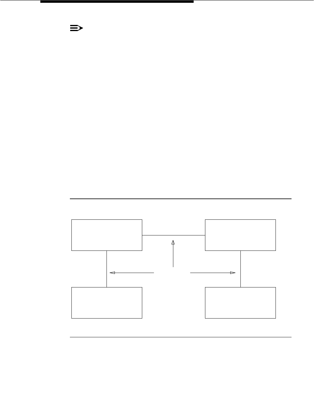
Integrated Services Digital Network (ISDN) — Primary
Rate Interface
Issue 3 March 1996 3-803
NOTE:
For G3r, the D-channel information can only use the TN464C (or later
version) circuit pack; TN767 can be used for NFAS interfaces carrying only
B-channels, but not for ISDN signaling information (D-channel).
With the ISDN-PRI, the system can interface with a wide range of other products
including network switches, PBXs, and host computers. These products include
the following:
■Public Network switches (for example, 4ESS, 5ESS, Northern Telecom
DMS250, etc.)
■DEFINITY Communications System Generic 2 and System 85 R2V4.
■DEFINITY Communications System Generic 1
■DEFINITY Communications System Generic 3
■Some of the other products that adhere to the ISDN-PRI signaling
protocol.
As an example of how the ISDN-PRI is used in private and public network
configurations, see Figure 3-20 and Figure 3-21. As seen in these figures, the
ISDN-PRI can be used to interface a PBX to a Public Switched Network, a PBX to
a Host Computer, or a PBX to another PBX.
Figure 3-20. ISDN-PRI Private Network Configuration
ISDN-PRI
"DEFINITY"
COMMUNICATIONS
SYSTEM
HOST
COMPUTER
"DEFINITY"
COMMUNICATIONS
SYSTEM
"DEFINITY"
COMMUNICATIONS
SYSTEM
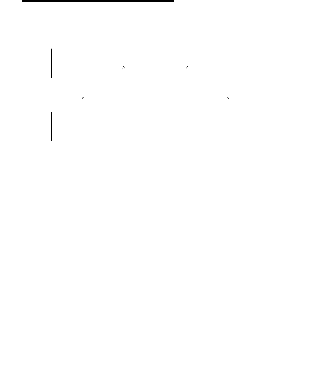
Feature Descriptions
3-804 Issue 3 March 1996
Figure 3-21. ISDN-PRI Public Network Configuration
AT&T Switched Network Protocol
The AT&T Switched Network Protocol is an ISND-PRI protocol that uses 4ESS
implementation. The DEFINITY system ISDN-PRI implementation is consistent
with the ITU-T Recommendation Q.931 and Q.921 for ISDN signaling. The AT&T
Switched Network provides system users with the following services:
■Access to AT&T Switched Network Services (for example, SDN, MEGA,
etc.)
■Call Identification Display
— Calling Party Number (CPN)
— Billing Number (BN)
— Calling and Connected Number Display
— Calling and Connected Party Name Display
■CPN/BN to Host Call Identification
■Private Network Services
■Wideband (NxDSO, H0, H11, H12) (both private and public networks)
■Call-by-Call Service Selection
These services are discussed in detail in the following subsections.
ISDN-PRI
"DEFINITY"
COMMUNICATIONS
SYSTEM
HOST
COMPUTER
PUBLIC
SWITCHED
NETWORK
(4 "ESS")
"DEFINITY"
COMMUNICATIONS
SYSTEM
"DEFINITY"
COMMUNICATIONS
SYSTEM
ISDN-PRI

Integrated Services Digital Network (ISDN) — Primary
Rate Interface
Issue 3 March 1996 3-805
Access to AT&T Switched Network Services
ISDN-PRI provides access to AT&T Switched Network Services such as SDN
(Software Defined Network), SDDN (Software Defined Data Network),
MEGACOM, etc. An ISDN-PRI trunk group may be dedicated to a particular
feature. Alternately, an ISDN-PRI call-by-call trunk group may provide access to
several features. For a description of the ASN services accessible via ISDN-PRI
(either via dedicated or call-by-call trunk groups) see the Call-by-Call Service
Selection feature description elsewhere in this document.
Call Identification Display
ISDN-PRI Call Identification Display provides a transparent name/number display
for all display-equipped voice terminals within an ISDN-PRI network. The feature
is transparent in that the same information is provided at all ISDN-PRI facilities.
Voice terminals using this feature should be digital voice terminals with a
%40-character alphanumeric display. The Merlin hybrid sets with 32-character
displays (7315H and 7317H) also support this feature.
ISDN-PRI Display Information is provided in addition to the normal Voice
Terminal Display and Attendant Display features, when the network supports
end-to-end ISDN-PRI connectivity. When both ISDN-PRI and DCS display
information, or DCS display information only, are received, the switch displays
the DCS display information in the DCS format. If ISDN display information is
received, and no DCS display information is received, then the ISDN display
information is displayed in the ISDN formats.
Two types of identification numbers are provided with the ISDN-PRI. These
identification numbers may be used in the various types of displays used with the
ISDN-PRI. The two types of identification numbers are as follows:
■Calling Party Number (CPN): A 0 to 15 digit DDD number associated with
a specific station. When a system user makes a call that uses the ISDN,
that user’s CPN is provided by the system for the ISDN. The “CPN Prefix”
form is administered to create a 0-15 digit CPN from a local station
number.
■Billing Number (BN): The calling party’s billing number that is provided to
an inter-exchange network via Equal Access or Centralized Automatic
Message Accounting (CAMA). This number is stored at either a local or
network switch. If a customer is connected directly to the AT&T network,
the BN is the customer’s billing number stored in that network. If the CPN
is not provided on an incoming ISDN-PRI call, the system uses the BN for
the station identification number.
The following types of display information are provided with the ISDN-PRI.
■Calling Party’s Number
The calling party’s number is shown on the called party’s display. On calls
generated from a DEFINITY system, the calling party’s number is a 0- to
15-digit DDD number. This number is provided only if the outgoing
ISDN-PRI trunk group is administered to send the CPN and if the “CPN

Feature Descriptions
3-806 Issue 3 March 1996
Prefix” form is administered to create a CPN. For G3vs/G3sV1, G3iV1, and
G3rV1, the Calling Party number, if sent, is always 10 digits long. On calls
incoming to a system, the network may provide either the CPN or BN as
the calling party’s number. Except for G3i-Global, dashes are inserted in
the displayed number between the area code (if shown), the office code,
and the local number. Extension numbers and 12-digit international
numbers are shown without dashes. For G3V2 and later releases, dashes
are only used for 7-digit and 10-digit numbers when the ‘‘North American
Area Code’’ field is administered on the ‘‘Dial Plan” form.’
■Calling Party’s Name
The calling party’s name is shown on the called party’s display. On calls
generated from a DEFINITY system, the calling party’s name is provided if
the ISDN-PRI trunk group is administered to send the name to the network.
On calls incoming to a DEFINITY system, the (public or private) network
may provide the calling party’s name. If the calling party’s name is not
available, the called party’s display shows ‘‘CALL FROM’’ instead,
followed by the calling party’s number (if available).
■Connected Party’s Number
The connected party’s number is shown on the calling party’s display. On
calls generated from a DEFINITY system, the called party’s number is
shown on the calling party’s display as the calling party dials the number.
If the (public or private) ISDN network provides the connected party’s
number, the calling party’s display is updated to show the connected
party’s number. The format of the connected party’s number is the same
as that of the calling party’s number described previously on calls
incoming to a DEFINITY system. The 0-15 digit number of the party who
answers the call is provided to the ISDN network only if the incoming
ISDN-PRI trunk group is administered to send the CPN to the network and
the “CPN Prefix” form is administered to create a CPN.
NOTE:
The connected party may or may not be the party actually called.
For G3vs/G3sv1, G3iV1, and G3rV1, the connected party number, if sent,
is always 10 digits long.
■Connected Party’s Name
The connected party’s name is shown on the calling party’s display. On
calls generated from a DEFINITY system, the (public or private) ISDN
network may provide the connected party’s name to the DEFINITY system,
when the call is answered. If the connected party’s name is not available,
the calling party’s display shows
ANSWERED BY
, followed by the
connected party’s number (if available).

Integrated Services Digital Network (ISDN) — Primary
Rate Interface
Issue 3 March 1996 3-807
On calls incoming to a DEFINITY system, the connected party’s name is
provided if the incoming ISDN-PRI trunk group is administered to send the
name to the network.
NOTE:
The connected party may or may not be the party actually called in
the event that the call is transferred before the connected party
answers the call.
The display fields that may be used for the ISDN-PRI are as follows:
■Name — Maximum of 15 characters
■Number — Maximum of 15 characters
■Miscellaneous Call Identification — Maximum of eight characters
■Reason for Call Redirection — Maximum of two characters
The display information varies, depending on the type of call, how the call is
handled (for example, whether it is redirected or not), and what information is
available on the call. The display information for basic calls (those with just a
calling and called party) and for redirected calls is given in the following
paragraphs.
ISDN-PRI Basic Call
A basic ISDN-PRI call has both a calling and a called party, and the called party
answers the call. When the calling party goes off-hook, a= appears on the
display. The digits then appear as they are dialed. These digits may be
overwritten by the trunk group name if the “Outgoing Display” field of the “Trunk
Group Administration” form is administered as yes. Once the call is answered by
the called party (or by a user with a bridged appearance for the called party), the
displays for the calling and called parties are described below.
■If
both the name and number information are available
, the displays are as
follows. The “MISCID (Miscellaneous Identification)” field may be blank if
that information is not provided.
— Calling Party Display
a= CALLED NAME CALLED NUMBER MISCID
— Called Party Display
a= CALLING NAME CALLING NUMBER MISCID
■If
only the name information is available,
the displays are as follows:
— Calling Party Display
a= CALLED NAME MISCID
— Called Party Display
a= CALLING NAME MISCID

Feature Descriptions
3-808 Issue 3 March 1996
■If
only the number information is available,
the displays are as follows:
— Calling Party Display
a= ANSWERED BY CALLED NUMBER MISCID
— Called Party Display
a= CALL FROM CALLING NUMBER MISCID
■If
neither the name nor the number information is available,
the displays
are as follows:
— Calling Party Display (shows one of the following, depending on
administration)
a= DIALED NUMBER MISCID
a= TRUNK NAME MISCID
— Called Party Display
a= TRUNK NAME MISCID
Redirected ISDN-PRI Call
A redirected ISDN-PRI call is a call that has been redirected from the called
party’s extension by a feature such as Call Coverage, Call Forwarding All Calls,
Bridged Call Appearance, or Call Pickup. Once the call is connected, the
displays for the calling, called, and connected parties are as follows.
— Calling Party Display
a= CONNECTED NAME CONNECTED NUM MISCID
— Called Party Display
The following information appears on the display if the called party
bridges onto the redirected call after it has been answered. In this
situation, the connected party’s display (given later) shows the same
information. The calling party’s display is also updated if the calling and
called parties are on the same switch.
a= CONFERENCE 2
— Connected Party Display
The connected party is the party who answers the redirected call. The ‘‘R’’
indicates the reason for redirection.
a= CALLING ID to CALLED ID R
The CALLING ID and the CALLED ID may be the name or the number,
depending on what has been received from the far end.
CPN/BN to Host Call Identification
The CPN/BN to Host feature enables CPN/BN information to be passed from the
switch to the ISDN Gateway, so that the ISDN Gateway can forward the
information to a host for data screen delivery to agents in an ACD split.
Integrated Services Digital Network (ISDN) — Primary
Rate Interface
Issue 3 March 1996 3-809
By delivering call identification information such as CPN/BN and switch
information such as the answering agent’s extension to an adjunct network (ISDN
Gateway), the adjunct can automatically deliver data screens to agents for new
call arrivals and call transfers.
Figure 3-22 shows a simplified diagram of a CPN/BN to host arrangement. The
ISDN Gateway is a 3B2 or 6386 computer connected to the switch on one side
and to a host computer on the other side. The connection to the switch is over a
synchronous interface with BX.25 protocol.
Figure 3-22. CPN/BN to Host Configuration
Private Network Services
In addition to providing access to switched public networks, the ISDN-PRI can
provide private network services by connecting DEFINITY Generic 1, 2.1, 3,
System 85 R2V4, or G2.2 systems in an Electronic Tandem Network (ETN) or
Distributed Communications System (DCS) configuration. This gives customers
more efficient private networks that support new integrated voice and data
services. ETN and DCS services are provided as follows:
■ETN Services
DEFINITY Communications Systems that function as tandem nodes in an
ETN can be interconnected using DS1 trunking facilities and an ISDN-PRI.
All signaling between the tandem switches is done with the ISDN-PRI
D-channel and normal ISDN procedures. The ISDN-PRI can also be used
to connect ETN tandem and main switches. In this case, the main switch
ISDN-PRI
SID/ANI
G1
SWITCH
BX.25
3B2 OR 6386
ISDN
GATEWAY
EXISTING
INTERFACE HOST
VOICE
TERMINAL
DATA
TERMINAL
ACD AGENT POSITION

Feature Descriptions
3-810 Issue 3 March 1996
collects all of the address digits from local users as well as users at other
satellite and tributary switches, and originates a call over the ISDN-PRI to
the tandem switch.
Automatic Alternate Routing (AAR) and Automatic Route Selection (ARS)
are used with the ISDN-PRI and DS1 trunking facilities to access ETN
facilities. The AAR and ARS features are used to collect the dialing
information for the call that is originated from the main switch.
■DCS Services
ISDN-PRI facilities can be used in a DCS arrangement whenever tie trunks
are used to connect the DCS nodes.
Most DCS features are not affected by the ISDN-PRI. However, the
ISDN-PRI does have a minor impact on a few of the DCS features, as far
as the functions that the local and remote switches must perform. Even
though a DCS feature may be slightly affected in this manner, the use of
the feature is still the same. If there is a conflict between a DCS message
and an ISDN-PRI message on a call (for example, the calling extension
number in the DCS message and the calling party’s number in the
ISDN-PRI message) the DCS message is used.
Wideband Switching
The primary function of the Wideband Switching feature is to provide support for
services that require large bandwidth, such as high speed video conferencing.
These services have traditionally been handled by dedicated facilities. With the
Wideband Switching feature, dedicated facilities are no longer a requirement for
these large bandwidth services.
The Wideband Switching feature supports end-to-end connectivity between
customer endpoints at data rates ranging from 128 to 1536 kbps over T1 facilities
and 128 to 1984 kbps over E1 facilities. Standard data services for use by
Wideband Switching are HO (384 kbps), H11 (1536 kbps), H12 (1920 kbps), and
NxDS0. See
DEFINITY Communications System Generic 3 Wideband Technical
Reference,
555-230-230, for more detail.
Call-by-Call Service Selection
Call-by-Call Service Selection allows the same ISDN-PRI trunk group to carry
calls to a variety of services or facilities (such as a SDN, MEGACOM
telecommunications service, MEGACOM 800 service, and so on) and/or carry
calls using different inter-exchange carriers. This feature is described in detail
under the Call-by-Call Service Selection feature description elsewhere in this
manual.

Integrated Services Digital Network (ISDN) — Primary
Rate Interface
Issue 3 March 1996 3-811
Access to Software Defined Data Network
(SDDN)
With ISDN-PRI, the Software Defined Data Network (SDDN) service may be
accessed. SDDN provides virtual private line connectivity via the AT&T switched
network (4ESS switch). The services provided by SDDN include voice, data, and
video applications. SDDN services complement the Software Defined Network
(SDN) voice services.
Access to Switched Digital International (SDI)
SDI provides 64 kbps unrestricted connectivity to international locations via the
AT&T switched network. It is also the backbone for the AT&T International ISDN
network. SDI complements the ACCUNET digital service already available to
United States locations. This service can be accessed using the Call-by-Call
Service Selection feature. SDI can provide economical high speed data transfer
to international locations.
ISDN-PRI Interworking
ISDN-PRI Interworking is the combination of both ISDN-PRI trunking facilities and
non-ISDN-PRI trunking facilities on a call. A non-ISDN-PRI trunking facility is any
trunk facility supported by the system that does not use the ITU-T recommended
Q.931 message set for signaling. Non-ISDN-PRI trunking facilities include
facilities such as Analog trunks, AVD DS1 trunks, and DS1 trunks with
bit-oriented signaling (robbed-bit or common channel).
The system supports the conversion of ISDN-PRI signaling to non-ISDN-PRI
in-band signaling and the conversion of non-ISDN-PRI in-band signaling to
ISDN-PRI signaling for Interworking purposes.
A mixture of ISDN-PRI and non-ISDN-PRI signaling is required in order to provide
end-to-end signaling when different types of trunk facilities are used on a call.
See Figure 3-23 for an example of Interworking. In this example, a call for
someone at Switch B comes into Switch A. Interworking allows the ISDN-PRI
signaling of the call to be converted at Switch A to non-ISDN-PRI in-band
signaling before the call forwards to Switch B. Even though the call comes into
Switch A on an ISDN-PRI trunk, Switch A can send the call to Switch B over a
non-ISDN-PRI trunk by converting the signaling information.
The system provides accurate CDR billing information on calls that are not
Interworked. Accuracy of CDR billing information on Interworked calls is
equivalent to the accuracy provided by the public network.
The system does not support the conversion of DCS feature transparency
messaging into ISDN-PRI messaging. Therefore, DCS-provided feature
transparency is lost when the call leaves the DCS network. The basic call,
however, still goes through.

Feature Descriptions
3-812 Issue 3 March 1996
Figure 3-23. Interworking Example
National ISDN-2 Services
G3V3 and later releases support National ISDN-2 (NI-2), which is described in
the TR1268 and TR1270 ISDN-PRI protocol standards defined by Bell
Communications Research (Bellcore). Bellcore TR1268 and TR1270 are a
superset of the NIU-302 standard and are part of the National ISDN-2 plan
defined by the North American ISDN Users Forum.
NI-2 offers many of the same services as the AT&T 4ESS protocol, which was the
default in G1, G3i, and G3r, and was the protocol for Country 1 (USA) in
G3i-global and G3V2 and later releases. G3V3 and later releases support both
the 4ESS and the NI-2 protocols and allows you to administer which one you wish
to use. You must administer the protocol on the “DS1 Circuit Pack” form. Refer to
the “DS1 Circuit Pack” form in the
DEFINITY Communications System Generic 3
Version 4 Implementation
, 555-230-655, or
DEFINITY Communications System
Generic 3 V2/V3 Implementation
, 555-230-653, for more information on
administering ISDN-PRI protocols.
NI-2 provides users with the following services:
■Calling Line Identification
■Non-Facility Associated Signaling
■D-Channel Backup
■Wideband Switching
■Call-by-Call Service Selection
Calling Line Identification
Calling Line Identification for NI-2 is essentially Calling Party Number (CPN)
Identification, as previously described in this section.
CALL FROM
NETWORK TO
SWITCH B
ISDN-PRI
TRUNK
NON-ISDN-PRI
TRUNK SWITCH B SWITCH A

Integrated Services Digital Network (ISDN) — Primary
Rate Interface
Issue 3 March 1996 3-813
Non-Facility Associated Signaling
Non-Facility Associated Signaling (NFAS) allows an ISDN-PRI T1/E1 Interface
D-channel (signaling channel) to convey signaling information for B-channels
(voice and data channels) on ISDN-PRI T1/E1 facilities other than the one
containing the D-channel. Please refer to the section on Facility and Non-Facility
Associated Signaling elsewhere in this manual.
D-Channel Backup
D-Channel Backup is provided to improve reliability in the event of a signaling
link failure. D-Channel Backup is discussed in detail in the section on Facility
and Non-Facility Associated Signaling elsewhere in this manual.
Wideband Switching
Wideband Switching for NI-2 is essentially the same as that of the AT&T 4ESS
ISDN-PRI protocol, previously discussed in this section.
Call-by-Call Service Selection
Call-by-Call Service Selection for NI-2 is essentially the same as that for the AT&T
4ESS ISDN-PRI protocol, previously discussed in this section.
Global ISDN-PRI
The DEFINITY system also provides ISDN-PRI for the global market, based on
different countries’ requirements. For example, the DEFINITY system G3V3
includes two separate protocols for connecting to the ISDN-PRI network in
Germany:
■National ISDN-PRI Layer 3 protocol defined by FTZ 1 TR 6, based on the
1983 version of ITU-T Recommendations Q.930 and Q.931.
■ETSI ISDN (E-DSS1), compatible with the standards established by the
European Telecommunications Standards Institute (ETSI).
Additionally, the DEFINITY system includes QSIG Global Networking — a
platform that meets the requirements for the European Computer Manufacturers
Association (ECMA) Private Network Generic Functional Procedures for
Call-Related supplementary services. Please refer to the QSIG Networking
section elsewhere in this manual.
Considerations
With the ISDN-PRI, system users have access to a variety of services that are
only available through the ISDN.
ISDN-PRI Call Identification Display is provided on a call only if that call is routed
through all ISDN-PRI facilities. Non-ISDN-PRI facilities do not carry the necessary
display information. If the called party is at a non-ISDN-PRI facility, the system

Feature Descriptions
3-814 Issue 3 March 1996
displays either the dialed digits or the trunk group name (depending on
administration) on the calling party’s display.
ISDN-PRI facilities support equal access to inter-exchange carriers.
Interactions
The following features interact with the Integrated Services Digital Network —
Primary Rate Interface feature.
■Attendant Display
The information provided by ISDN-PRI Call Identification Display is in
addition to the display features already provided.
When an ISDN-PRI call is redirected to the attendant, and both name and
number display information is available, the name is displayed on the
console for the calling and called party identification.
■Bridged Call Appearance
ISDN-PRI Call Identification Display information is provided at both the
primary extension number and the extension number with the bridged call
appearance. Both displays show the same called party information,
whether the call is made from the primary extension number or the
bridged call appearance. On a call to a primary extension number, the
calling party’s display shows the identification of the called primary
extension number, even if the call is answered by the bridged call
appearance.
■Call Forwarding All Calls
When an ISDN-PRI call is forwarded, no ISDN-PRI Call Identification
Display information is shown on the display of the forwarding extension.
The forwarded-to extension’s display shows information on the calling
party, called party (if the forwarded-to station is on the same switch), and
the reason for redirection.
■Call Pickup
When an ISDN-PRI call is answered via Call Pickup, the calling party’s
display identifies the answering party, the called party’s display identifies
the calling party, and the answering party’s display identifies both the
calling and called parties.
■Conference — Attendant
A conference call is identified as a conference call with ‘‘n’’ number of
conferees. This display information is generated locally and does not
change the display of a user on another switch.

Integrated Services Digital Network (ISDN) — Primary
Rate Interface
Issue 3 March 1996 3-815
■Conference — Terminal
A conference call is identified as a conference call with ‘‘n’’ number of
conferees. This display information is generated locally and does not
change the display of a user on another switch.
■DCS
If both DCS and ISDN-PRI features are provided over the same facility with
a DEFINITY system Generic 3, the ISDN-PRI display information is
displayed in DCS format.
■FRL and TCM
The TCM used to pass on the originating facility’s FRL is sent by ISDN
facilities in the SETUP message.
■Hold
When an ISDN-PRI call is placed on Hold, the display of the party who
activates Hold goes blank and then identifies the newly calling or
connected party if there is one. The held party’s display remains
unchanged. When the held party is reconnected to the holding party, the
holding party’s display is updated to indicate the current status of the call.
■Hunting
On ISDN-PRI calls to a hunt group extension, the calling party’s display
identifies either the group or the group member who answers the call,
depending on administration.
■TEG
On ISDN-PRI calls to a TEG, the calling party’s display identifies either the
group or the group member who answers the call, depending on
administration.
■Transfer
When an ISDN call is transferred, the display of the party who transfers the
call goes blank. The transferred party’s display does not change. The
display of the transferred-to party identifies the party who transferred the
call.
When an ISDN call is transferred to a party on the same switch as the
party who transfers the call, the information on the display of the party who
transfers the call is shown on the transferred-to party’s display.
Administration
ISDN-PRI is administered on a per-system basis by the System Manager. The
following items require administration.
■Communication — Interface Link (G3vs/G3s, G3i, and G3i-global)
■Communication — Interface Processor (G3vs/G3s, G3i, and G3i-global)

Feature Descriptions
3-816 Issue 3 March 1996
■DS1 Circuit Pack (for DS1 and E1)
■DS1 Synchronization Plan (for DS1 and E1)
■Processor Interface Circuit Pack (G3vsV1/G3sV1, and G3iV1)
■ISDN-PRI Trunk Group
■GRS Routing Patterns
■Signaling Group (see the Facility and Non-Facility Associated Signaling
feature description elsewhere in this document).
The following administration items are required for ISDN-PRI Call Identification
Display:
■A Direct Distance Dialing CPN Prefix Table which includes the following
items:
— Extension Length — From 1 through 5
— Extension Code — Defines a set of extensions with the same
leading digits as the extension code
— CPN Prefix — Used to create a 10 (for G3vsV1/G3sV1, G3iV1, and
G3rV1) or 0 to 15 (for G3i-Global, G3V2, and later releases) digit
DDD number for an ISDN-PRI CPN. The CPN prefix can be 10 (for
G3vsV1/G3sV1, G3iV1, and G3rV1) or 0 to 15 (for G3i-Global and
G3V2) digits in length.
For G3vsV1/G3sV1, G3iV1, and G3rV1, the sum of the number of
DDD prefix digits and extension digits must be greater than or
equal to 10. If the sum is greater than 10, then the prefix digits takes
precedence over the extension digits. The system does not send
call identification information on calls from extensions that have an
extension code with the DDD prefix left blank or that have no CPN
prefix administered.
For G3i-Global, G3V2, and later releases, the sum must be greater
than or equal to the administered number of digits to send out.
— Whether to send the calling/connected party number and/or name
“(Send Calling Number?”, “Send Connected Number?”, and “Send
Name?” fields of the “ISDN-PRI Trunk Group” form). Setting these
fields to y (yes), enables the sending of number and/or name,
respectively, to the other side of the interface for display purposes.
■Whether the group name or member name is displayed on the calling
party’s display (per Hunt Group and TEG).
The following administration is required for CPN/BN to Host Call Identification:
■Some administration may be required so that the switch receives CPN/BN
from the originating interface to pass to the ISDN Gateway. If the
originating switch is another DEFINITY system, the trunk group
administration on that switch needs to be administered (Send
Calling/Connected Number? is y) so that CPN info is sent. If the originating

Integrated Services Digital Network (ISDN) — Primary
Rate Interface
Issue 3 March 1996 3-817
switch is a public network switch, it may be necessary to perform some
administration on that switch, or to subscribe to a CPN/BN delivery
feature. For example, CPN/BN delivery from the AT&T Switched Network is
either on a subscription basis (that is, on all calls) or on a per call request
basis. Per call CPN/BN requests at the AT&T Switched Network are
administered on the “ISDN Trunk Group” form. In either case, four types of
CPN/BN delivery may be requested (CPN only, BN only, CPN preferred,
and BN preferred).
Hardware and Software Requirements
For G3vs/G3s PBP, G3i-global and G3i:
■A TN767 or TN464C/D/E DS1 circuit pack is required for assignment of a
T1 signaling link and up to 24 ISDN-PRI Trunk Group members. The DS1
provides up to 24 ports.
■A TN464C/D/E DS1 circuit pack is required for assignment of an E1
signaling link and up to 31 ISDN-PRI Trunk Group members. The DS1
provides up to 31 ports.
■A TN768 or TN780 Tone Clock circuit pack is required to provide
synchronization for the DS1 circuit pack.
■A TN765 Processor Interface circuit pack is required for use with all DS1
circuit packs.
For G3r, the following is required:
■A TN464C/D/E DS1 circuit pack for assignment of a T1 signaling link and
up to 24 ISDN-PRI trunk group members. The DS1 provides up to 24
ports.
■For G3iV2 only, a TN464C/D/E DS1 circuit pack for assignment of an E1
signaling link and up to 31 ISDN-PRI trunk group members. The DS1
provides up to 31 ports.
■A TN767 is not needed, although it can be used for an additional
B-channel in a signaling group as long as there is a TN464C/D/E in that
group to carry the D-channel.
■A TN765 is not needed.
Display-equipped voice terminals are required for the display of ISDN-PRI Call
Identification Display information.
One processor interface link is required per ISDN-PRI for G3i, and G3vs/G3s
only.
If CPN/BN to Host Call Identification is desired, a computer, such as a 3B2, is
required for use as the ISDN Gateway.
ISDN-PRI software is required.

Feature Descriptions
3-818 Issue 3 March 1996
Hardware and software requirements for countries other than the United States of
America are detailed in the Application Notes.

Inter-PBX Attendant Calls
Issue 3 March 1996 3-819
Inter-PBX Attendant Calls
Feature Availability
This feature is available with all Generic 3 releases.
Description
Allows attendant positions for more than one branch location to be concentrated
at one central, or main, location. Incoming trunk calls to the branch location, as
well as attendant-seeking voice terminal calls, are routed over tie trunks to the
attendants at the main location.
Inter-PBX Attendant Calls are incoming tie trunk calls from the branch location to
the main location with the attendant group as the destination. If no attendant in
the attendant group is available, these calls are queued. When an attendant
becomes available, the call is routed to that attendant for handling. Calls can be
extended the same as if the call were an incoming call to the main location.
When the attendant releases the call, the tie trunk associated with the call is tied
up with the call until the call is dropped.
A DEFINITY system Generic 3 can be a branch or a main location for this feature.
A branch location can have local attendants. These local attendants can be
accessed by the Individual Attendant Access feature. The attendants at the
main location are the local attendants for the main location and also the attendant
for the Inter-PBX Attendant Calls.
Considerations
With Inter-PBX Attendant Calls, the number of attendants required at each
branch location is reduced. Also, users at each branch location can use the
main location to access each of the other branch locations.
The Inter-PBX Attendant Calls feature can also be used within an ETN, where, for
example, the attendant group for the network could be located at the main switch
and serve other tandem switches connected by tie trunks.
Interactions
The following features interact with the Inter-PBX Attendant Calls feature.
■Attendant Control of Trunk Group Access
If Inter-PBX Attendant Calls is enabled, and a call at a branch location
attempts to access a controlled trunk group, the call is routed to the local
attendant at the branch location, if there is one. If there is no local
attendant, the call is routed to the attendant group at the main location.

Feature Descriptions
3-820 Issue 3 March 1996
■Attendant Display and DCS Attendant Display
In a DCS environment, an incoming Inter-PBX Attendant Call from a
branch location is displayed at the attendant console the same as a local
call.
In a non-DCS environment, an incoming Inter-PBX Attendant Call is
displayed at the attendant console as an incoming tie trunk call.
■Attendant Recall
If an attendant at the main location holds an Inter-PBX Attendant Call, the
calling parties at the branch location cannot recall the attendant.
■Call Coverage
At a branch location with Inter-PBX Attendant Calls enabled, a call
redirected to a coverage path with the attendant group as a coverage
point skips that coverage point. It goes to the next coverage point at the
local switch, if administered, or continues to ring at the extension that is
the previous coverage point. If the attendant group ‘‘0’’ is the only
coverage point, it continues to ring at the principal’s extension.
■Centralized Attendant Service (CAS)
CAS and Inter-PBX attendant calling cannot be enable at the same time.
■Dial Access to Attendant
Dial Access to Attendant should be administered to the same digit on
both the IAS main switch and the IAS branch switch. This is done via the
dial platform. On the branch switch, the later PBX attendant access code
(“Console Parameters” form) should be administered to match the main
PBXs attendant group dial access code.
■Night Service
The Inter-PBX Attendant Calls feature is deactivated when the branch
location is put into night service, and reactivated when the branch location
is taken out of night service.
Administration
Inter-PBX Attendant Calls is administered by the System Manager. The following
items require administration:
■Branch location access to Inter-PBX Attendant Calls
■Inter-PBX Attendant Calls Trunk Group
■Inter-PBX Attendant Access Code
Hardware and Software Requirements
Requires a tie trunk group between the branch and main locations. No additional
software is required.

Intercept Treatment
Issue 3 March 1996 3-821
Intercept Treatment
Feature Availability
Intercept Treatment is available with all Generic 3 releases.
Description
Provides an intercept tone or a recorded announcement or routes the call to an
attendant for assistance when calls cannot be completed or when use of a
feature is denied.
■Intercept Treatment — Tone
Provides a siren-type tone to internal calls that cannot be completed as
dialed.
Intercept Tone is provided to voice terminals when users lift the handset
and do not dial within 10 seconds, pause longer than 10 seconds between
digits during the dialing process, or remain connected to Loudspeaker
Paging for longer than an administered interval.
When a single-line voice terminal user receives Intercept Tone for 30
seconds and does not hang up, then 10 seconds after the Intercept Tone
stops, the user receives dial tone for a new call origination. Also, when the
user does not hang up after all other parties on the call have hung up, then
10 seconds after all other parties disconnect, the user receives dial tone
for a new call origination.
When multiappearance voice terminal users receive Intercept Tone for 30
seconds and do not hang up, the call appearance returns to idle. If the
multiappearance user is the last party left on a call, the call appearance
immediately returns to idle.
If a voice terminal extension is assigned a COS with Off-hook Alert, and
the user of that voice terminal receives Intercept Tone for a specified
period of time and does not hang up, an emergency call is placed to the
attendant.
On DID calls, if the MFC (Multifrequency Compelled Signaling) Intercept
Treatment is set to provide a tone, this signal is sent to the CO to indicate
that the called number is invalid. (For further details, see the "R2-MFC
Signaling" feature description later in this chapter.)
On DOD calls using MFC signaling, if the PBX receives the MFC Intercept
Tone from the CO indicating the number called is invalid, the PBX sends
an intercept signal to the calling station.

Feature Descriptions
3-822 Issue 3 March 1996
■Intercept Treatment — Recorded Announcement
Provides a recorded announcement to DID and incoming Private Network
Access calls that cannot be completed as dialed or that are transferred to
incomplete or restricted stations. The System Manager selects and
records the message.
Toll charges do not apply to DID and Private Network Access calls routed
to Recorded Announcement.
■Intercept Treatment — Attendant
Allows attendants to provide information and assistance to callers on all
DID or incoming Private Network Access calls that cannot be completed
as dialed or that are transferred to incomplete or restricted stations.
Normal toll charges apply to these calls.
■Intercept Treatment — Station
Allows a specific voice terminal to receive certain calls that cannot be
completed because of a controlled restriction (see Controlled Restrictions
feature) or because the called party has activated Do Not Disturb. The
controlled restrictions which can administered to send calls to station
intercept are Outward, Termination, and Station-to-Station.
The calling party hears audible ringing while the call is being routed to the
voice terminal assigned for Intercept Treatment. The calling party receives
no indication that the call is receiving Intercept Treatment.
Considerations
The Intercept Tone lets a user know when a call cannot be completed as dialed.
The user can then hang up or try the call again. When DID and Private Network
Access calls cannot be completed as dialed, a recorded announcement can be
provided or, for more personal service, the calls can be routed to an attendant or
voice terminal user.
Recorded announcements can be used with the system. None, some, or all of
these announcements can be used for Intercept Treatment.
Only one person can be connected to an announcement at any given time. The
caller is always connected to the beginning of the announcement.
Interactions
■R2-MFC
For DID MF calls, whether the corresponding B.x signal or the Intercept
Tone should be sent to the CO is administrable. The default is to send the
standard DID/TIE/ISDN Intercept Treatment described in this section. If
the option to send the B.x signal is set, then:

Intercept Treatment
Issue 3 March 1996 3-823
— For Group II type calls, the B.x signal for the intercept is sent to the
CO.
— For non-Group II type calls, if the CO dials an invalid number, the
trunk is locked (regardless of this option). If the CO dials the
number which is valid but not assigned, the Intercept Treatment
Tone is sent to the CO.
■Recorded Announcement
Attendant Intercept and Recorded Announcement Intercept (both
optional) cannot be used together. DID calls and Private Network calls
cannot be assigned Intercept Treatment — Tone.
Administration
The Intercept Tone is standard and requires no administration. However,
administration is required to determine whether DID and Private Network Access
calls are routed to the attendant or to an announcement. Administration is
required to determine whether calls sent to intercept because of controlled
restrictions are routed to intercept tone, a voice terminal, an attendant, or an
announcement. If an announcement is to be used, the announcement must be
administered. Intervals are administrable with the “System Parameters” form.
Hardware and Software Requirements
Requires announcement equipment and one port on an Analog Line circuit pack
for each announcement for each external analog announcement device or an
aux trunk port for each external auxtrk device. The Multiple Integrated
Announcements allows equipping additional TN750C circuit packs. See the
"Recorded Announcement" feature for more details.
With DEFINITY system Generic 3i, a TN750 Announcement circuit pack can be
used to provide up to 128 (for G3i), or up to 256 (for G3r) different
announcements. The announcements can be recorded directly onto the TN750
circuit pack.
No announcement equipment is required when this circuit pack is used. No
additional software is required.

Feature Descriptions
3-824 Issue 3 March 1996
Intercom — Automatic
Feature Availability
This feature is available with all Generic 3 releases.
Description
Provides a talking path between two voice terminal users. Calling users press
the Automatic Intercom button and lift the handset, or vice versa. The called user
receives a unique intercom alerting signal, and the status lamp associated with
the Dial or Automatic Intercom button, if provided, flashes.
Considerations
With the Intercom—Automatic feature, users who frequently call each other can
do so by pressing one button instead of dialing an extension number.
Single-line voice terminal users can receive Automatic Intercom calls, but cannot
originate them.
A combination of the Intercom—Automatic and Intercom—Dial features can be
used between terminals so that Intercom—Automatic applies in one direction
and Intercom—Dial applies in the other.
Two terminals with Intercom—Automatic to and from each other, or terminals with
combined Intercom—Automatic and Intercom—Dial to each other, must be in the
same Intercom group.
Interactions
The following features interact with the Intercom—Automatic feature.
■Call Coverage
Intercom calls are redirected only if the caller activates Go to Cover.
■Data Privacy and Data Restriction
An extension with Data Privacy or Data Restriction activated cannot
originate an intercom call. Intercept tone is received when the ICOM
button is pressed under this condition.
■Intercom—Dial
This feature must be provided. Users assigned an Automatic Intercom
button must be a member of the same Dial Intercom group as the
destination extension number.

Intercom — Automatic
Issue 3 March 1996 3-825
■Single-Digit Dialing and Mixed Station Numbering
Prefixed extensions greater than five digits (including the prefix) in length
cannot be assigned to intercom lists.
■Class of Restrictions (COR)
COR may be administered such that station A cannot dial Station B. The
user at Station A would receive intercept tone. However, Station A can be
administered such that it has Intercom—Automatic capability to Station B.
Thus A could call B. The System Manager has control of station
restrictions and which stations are in the same Intercom group.
Administration
Intercom—Automatic is assigned on a per-voice terminal basis by the system
administrator. Before Intercom—Automatic can be assigned, the associated
Intercom group must be established. Each Intercom group requires the
following administration:
■Intercom group number
■Length of dial code
■Extension number within the group
■Dial codes to access Intercom group members
Once the Intercom group is established, Automatic Intercom buttons can be
assigned to members of the group. The following items must be administered for
each button.
■Intercom group number to be accessed
■Dial code assigned to group member to be accessed
Hardware and Software Requirements
No additional hardware or software is required. Voice terminals equipped with a
buttons and a status lamp are useful, but not required.

Feature Descriptions
3-826 Issue 3 March 1996
Intercom—Dial
Feature Availability
This feature is available with all Generic 3 releases.
Description
Allows multiappearance voice terminal users to gain rapid access to selected
other voice terminal users within an administered group. Calling voice terminal
users lift the handset, press the Dial Intercom button, and dial the 1- or 2-digit
code assigned to the desired party. The called user receives alerting tone, and
the status lamp associated with the Intercom button, if provided, flashes.
Considerations
With the Intercom—Dial feature, a group of users who frequently call each other
can do so by pressing a Dial Intercom button and dialing a one- or two-digit code
instead of dialing an extension number.
The maximum number of intercom groups that can be established varies
according to the system. See Appendix A, "System Parameters".
Single-line voice terminals can receive Intercom—Dial calls, but cannot originate
them.
A combination of Intercom—Dial and Intercom—Intercom can be used between
terminals so that Intercom—Dial applies in one direction and Intercom—Intercom
applies in the other.
A Intercom—Dial user can place an intercom call to all members in the group,
including Intercom—Automatic members.
Two terminals with Intercom—Dial to and from each other, or two terminals with
combined Intercom—Dial and Intercom—Automatic to and from each other,
must be in the same Intercom group.
Interactions
The following features interact with the Intercom—Dial feature.
■Intercom—Automatic
Users assigned this feature must be a member of a Dial Intercom group.

Intercom—Dial
Issue 3 March 1996 3-827
■Call Coverage
Intercom calls are redirected to Call Coverage only if the caller activates
Go To Cover.
■Data Privacy and Data Restriction
An extension with Data Privacy or Data Restriction activated cannot
originate an intercom call. Intercept tone is received when the ICOM
button is pressed under this condition.
■Single-Digit Dialing and Mixed Station Numbering
Prefixed extensions greater than five digits (including the prefix) in length
cannot be assigned to intercom lists.
Administration
Intercom—Dial is administered by the system administrator. The following items
require administration:
■Intercom groups
— Group number
— Length of dial code
— Extension numbers within the group
— Dial codes to access Intercom group members
■Dial Intercom buttons.
Hardware and Software Requirements
No additional hardware or software is required. Voice terminals equipped with a
buttons and a status lamp are useful, but not required.

Feature Descriptions
3-828 Issue 3 March 1996
Internal Automatic Answer (IAA)
Feature Availability
This feature is available with all Generic 3 releases except G3i-Global and
G3rV1.
Description
Allows specific voice terminals to answer incoming internal calls automatically.
Internal Automatic Answer (IAA) is intended for use with selected voice terminals
with a built-in speakerphone, or stations with adjunct speakerphone or headset
with the headset option enabled on the ‘‘Station” form’. For G3vsV1/G3sV1 and
G3iV1, this feature is only available with the MERLIN/System 25 7313H, 7314H,
7315H, 7316H, and 7317H terminals. For G3V2 and later releases, this feature is
available for most multi-function stations with a speakerphone or a headphone. A
602A terminal is off-hook when the headset/speakerphone is connected,
therefore IAA answers a call if all other call-appearances are idle.
Internal calls eligible for automatic answer by the IAA feature are:
■Station-to-station voice calls, with both voice terminals on the same switch.
(This includes redirected intra-switch calls.)
■An internal call over a DCS configuration to another internal extension.
(This includes redirected inter-DCS calls.)
■External calls that are extended by an attendant console when the
‘‘Internal Automatic Answer for Attendant Extended Calls’’ option on the
‘‘System Parameters Feature’’ form is enabled.
The following types of calls are
not
eligible to be answered automatically via IAA:
■Calls from public network trunks (including PCOL)
■Calls arriving on non-DCS tie trunks
■Automatic Callback calls
■Automatic Circuit Assurance calls
■Data calls
■External calls extended by an attendant console when the ‘‘Internal
Automatic Answer for Attendant Extended Calls’’ option on the ‘‘System
Parameters Feature’’ form is disabled
■Calls redirected because of queue overflow of Emergency Access to the
Attendant calls
■Terminating Extension Groups
■The receiving station’s “Active Station Ringing” option is set to
“continuous”

Internal Automatic Answer (IAA)
Issue 3 March 1996 3-829
An eligible call is answered automatically via the IAA feature if IAA is activated at
the answering voice terminal and the answering voice terminal is idle (on-hook
and able to accept an incoming call). A voice terminal that is off-hook, in the
process of dialing digits, or has a call on hold is not considered idle.
IAA Feature Operations
With IAA, a single programmable feature button (IAA) can be assigned to voice
terminals during voice terminal administration. When this feature button is
pressed, the associated green status lamp lights and the IAA feature is
activated. Pressing the same button again causes the status lamp to go dark and
the IAA feature is deactivated. (Pressing the feature button has no effect on a
currently active call or a ringing call.) As long as the IAA button’s status lamp is
on, the IAA feature remains activated. The IAA button may be toggled on or off at
any time, regardless of the state of the voice terminal; the voice terminal’s
speakerphone is not affected by this action. Also, using the speakerphone to
place calls does not affect the state of the IAA feature.
The calling voice terminal receives a tone when its call is answered automatically
by a voice terminal with IAA activated. The called voice terminal receives a tone
(a ‘‘ring ping’’) and then goes off-hook when automatically answering an
IAA-eligible call. Both the answering voice terminal’s speaker and microphone
are turned on.
If the user of a voice terminal with IAA activated is currently busy on a call or is in
the process of dialing digits, subsequent incoming calls are treated as if IAA is
not activated. Thus, an already established call or call establishment activity
temporarily disables the IAA feature for incoming calls.
Considerations
IAA provides convenient hands-free answering of internal calls.
The user of a voice terminal with IAA activated should always deactivate the
feature when leaving the work area. Otherwise, incoming calls are unintentionally
‘‘answered’’ by the unattended station. This prevents calls from going to
coverage.
For G3vsV1/G3sV1, and G3iV1, IAA is only available with the MERLIN/System 25
731xH series voice terminals and is not available with any other voice terminals.
There is no feature access code for the IAA feature; the station int-aut-on
must be administered.
IAA is not available with ISDN BRI voice terminals or Attendant Console.
IAA and Automatic Answer are mutually exclusive.
IAA and the Continuous Ring options are mutually exclusive.

Feature Descriptions
3-830 Issue 3 March 1996
Interactions
The following features interact with the Internal Automatic Answer (IAA) feature:
■ACD Calls
IAA applies to internal calls to an ACD agent.
■Automatic Answer
IAA and Automatic Answer cannot be administered simultaneously on the
same voice terminal.
■Automatic Callback
Callback calls via Automatic Callback are not answered automatically by
the IAA feature.
■Automatic Circuit Assurance (ACA)
Calls generated by the ACA feature are not eligible for IAA.
■Bridged Call Appearance — Multi-Appearance Voice Terminal
Calls terminating to a bridged appearance are not eligible for IAA at the
bridged station, even if the bridged station has IAA enabled. (IAA can be
used by the principal station to answer the call.)
■Bridged Call Appearance — Single-Line Voice Terminal
Calls terminating to a bridged appearance are not eligible for IAA at the
bridged station, even if the bridged station has IAA enabled.
■Call Coverage
If an internal call is redirected to another voice terminal by a Call
Coverage redirection criteria, then that call is eligible for IAA at the
redirected voice terminal.
IAA does not apply to calls to the original called extension when:
— The called voice terminal has activated Send All Calls
— The calling voice terminal has selected Go To Cover before placing
the call
Calls directed to a Coverage Answering Group are not eligible for IAA.
NOTE:
If the system administrator sets the coverage path for a station to
‘‘All-Calls’’ and that principal station activates IAA, the first coverage
point hears a ring, the principal station automatically answers and
the coverage-simulated bridge is dropped. The coverage station
rings, but is not able to answer the call because the coverage
simulated bridge has been dropped.

Internal Automatic Answer (IAA)
Issue 3 March 1996 3-831
■Call Forwarding
Calls to a station with IAA and Call Forwarding activated are forwarded
and are not answered by the station dialed.
NOTE:
If the ‘‘forwarded to’’ station, is internal and has IAA active, the
‘‘forwarded to’’ station automatically answers the redirected call.
■DeluxePaging (Call Park)
When using the DeluxePaging feature and call park times out, it returns to
the originating station which parked the call and is eligible for IAA.
■Call Pickup
Internal calls to a voice terminal in a Call Pickup group are eligible for IAA.
If the called extension in a Call Pickup group is IAA-active, the call is
automatically answered. An IAA-active voice terminal is not able to
automatically answer calls to other voice terminals in it’s Call Pickup
group.
■Conference
Internal conference calls are eligible to be automatically answered via the
IAA feature. If more than one conference party has joined a conference
call through automatic answer, such parties remain connected until either
they disconnect or the controlling party drops the call.
■Data Call Setup
Data calls are not eligible for IAA.
■Direct Department Calling (DDC) and Uniform Call Distribution (UCD)
Internal calls to a DDC or UCD group member are eligible for IAA.
■Distributed Communications System (DCS)
If a call is from another switch in a DCS configuration and the origin of the
call is known to be an internal voice terminal on that switch, then that call
is considered internal and is eligible for automatic answer.
■Do Not Disturb
Activation of the Do Not Disturb feature preempts IAA at the called voice
terminal.
■Go To Cover
IAA does not apply to calls to the original called extension when the
calling voice terminal has selected Go To Cover before placing the call.

Feature Descriptions
3-832 Issue 3 March 1996
■ISDN BRI
IAA is not available with ISDN BRI stations.
■Ringback Queuing
Automatic calls generated by the Ringback Queuing feature are not
eligible for IAA.
■Send All Calls
IAA does not apply to calls to the original called extension when the called
voice terminal has selected Send All Calls.
■Terminating Extension Group
Calls to a Terminating Extension Group extension are not eligible for IAA;
however, calls placed to the individual extension are eligible.
■Transfer
Transferred calls are eligible to be automatically answered via the IAA
feature.
Administration
Internal Automatic Answer (IAA) is administered on a per-voice terminal basis by
the System Manager. The only terminal administration required is an IAA button
(int-aut-an), which must be assigned to each voice terminal desiring IAA, and for
multifunction voice terminals that do not have a built-in speakerphone, the
headset option must be set to ‘‘y’’ on the ‘‘Station’’ form.
If a voice terminal’s IAA button is removed via administration while the IAA
feature is active, the IAA feature is deactivated and the associated status lamp
goes dark. Current calls are not affected by this action.
A system-wide option determines whether IAA-administered voice terminals
automatically answer external calls that are extended by an attendant console.
Typically, to avoid redirecting an external call to an unattended IAA voice
terminal, the IAA option on the ‘‘System Parameters’’ form is disabled. However,
you can allow IAA to automatic answer extended external calls by enabling the
System Parameters Form’s IAA option.
Hardware and Software Requirements
For G3V2 and later releases, all multi-function voice terminals equipped with a
speakerphone or headset may use this feature, except ISDN BRI voice terminals.
For G3vsV1/G3sV1 and G3iV1, only the following voice terminal types support
IAA:
■7313H
■7314H

Internal Automatic Answer (IAA)
Issue 3 March 1996 3-833
■7315H
■7316H
■7317H
Each of these hybrid voice terminals listed above requires a port on a TN762B
Hybrid Line circuit pack.
No additional software is required.

Feature Descriptions
3-834 Issue 3 March 1996
Intraflow and Interflow
Feature Availability
This optional feature is available with all Generic 3 releases when ACD software
is purchased.
NOTE:
For G3vs/G3s ABP, ACD is only available as part of the Basic Call Center
Option.
Description
Allows ACD calls to be redirected from one split to another split under busy or
unanswered conditions. Intraflow provides redirection of ACD calls to other splits
within the system and may be activated using Call Coverage or Call Forwarding
All Calls. Interflow uses the Call Forwarding All Calls feature to redirect ACD calls
to an external location.
Intraflow allows splits to be assigned coverage paths or forwarded. Also, a split
can be a point in a coverage path. Thus, Intraflow uses the Call Coverage
feature to redirect ACD calls from one split to another split according to the
coverage path’s redirection criteria. For instance, a split’s coverage path can be
administered so incoming ACD calls are automatically redirected to another split
during busy or unanswered conditions. Additionally, Call Forwarding can be
used to unconditionally intraflow a split’s calls.
An ACD call is intraflowed to another split whenever it is forwarded or the
assigned Call Coverage redirection criteria is met. For a detailed description of
Call Coverage redirection criteria, see the "Call Coverage" feature description in
this chapter. For a detailed description of Call Forwarding, see the "Call
Forwarding All Calls" feature description in this chapter.
If an ACD call is intraflowed to another split, the system attempts to terminate the
call to an available agent. If an agent is not available, the system tries to place
the call in queue at the covering split. The call enters the covering split queue,
unless one of the following conditions exists:
■The destination split’s ‘‘inflow threshold’’ is met
■The queue is full
■There are no agents logged in
■All the logged-in agents are in the AUX work mode
The inflow threshold is a parameter that is assigned to each split. If the oldest call
in the split queue has remained in that queue for a length of time greater than the
inflow threshold (0 to 999 seconds), then ACD calls cannot be intraflowed into
that split. If an ACD call is forwarded or meets the Call Coverage redirection

Intraflow and Interflow
Issue 3 March 1996 3-835
criteria, but cannot be intraflowed to another split or point in the coverage path, it
will remain in queue at the original split even though coverage tone may be
heard.
A split can be administered such that ACD calls intraflowed via Call Coverage
from that split to another split have priority over other calls in queue at that split.
If an ACD call intraflows from a split with ‘‘priority on Intraflow’’ to a covering split,
and enters the queue at the covering split, that call is positioned in the queue
ahead of any nonpriority calls but behind other priority calls already in the queue.
In other words, all priority calls are answered before any nonpriority calls.
If the covering split is assigned a second delay announcement, an ACD call
intraflowed to that split will receive the announcement, if the call remains in
queue for a length of time equal to the second delay announcement interval.
After the announcement is heard, the caller hears either music-on-hold or silence
until the call goes to an agent. An ACD call intraflowed (via Call Coverage) to a
covering split is never connected to the first delay announcement assigned to
the covering split.
Calls redirected via Call Forwarding will receive a delay first announcement at
the forwarded-to split. (A forced first announcement is never delivered at the
destination split.)
As an illustration of how Intraflow works, assume the following:
■A call is intraflowed from split 1 to split 2 via Call Coverage.
■Split 1 is assigned priority on intraflow.
■Split 2 has a queue with three priority calls and four nonpriority calls.
■Split 2 has an inflow threshold of 90 seconds and the oldest call in queue
at split 2 has been in queue for 60 seconds.
■Split 2 has been assigned a second delay announcement and has a
second delay announcement interval of 45 seconds.
■Music-on-Hold is provided.
When the call is intraflowed from split 1 to split 2, the call enters the split 2 queue
and is positioned in the queue ahead of the four nonpriority calls. The
intraflowed call is then the fourth call in queue. Assume the call stays in the
queue for 45 seconds and is still not answered. The call, at the end of 45
seconds, is connected to the second delay announcement for split 2. When the
announcement is complete, the caller hears music-on-hold until the call is
connected to an available agent. If the second delay announcement is
administered to repeat, the system will attempt to connect the call to the second
delay announcement again after the delay interval has expired (45 seconds.)
The Interflow feature allows ACD calls to be redirected from one split to a split on
another switch or to another external location. This is accomplished by
forwarding calls that are directed to the split extension to an off-premises location
via the Call Forwarding All Calls feature. Calls can be forwarded to destinations

Feature Descriptions
3-836 Issue 3 March 1996
off the PBX (that is, phone numbers on the public-switched telephone network).
Calls cannot conditionally interflow. If a coverage point station or split is
forwarded/interflowed, it is taken out of the coverage path. For details on how
calls are forwarded to an off-premises extension, see the "Call Forwarding All
Calls" feature description in this chapter.
A Coverage ICI button can be assigned to an agent’s multi-appearance voice
terminal. The Coverage ICI button allows the agent to identify a call that is
intraflowed from another split. When an agent receives a call that has
intraflowed from the split assigned to that button, the button’s status lamp will
light.
More advanced Interflow capabilities are supported by the "Call Vectoring" and
"Look Ahead Interflow" features discussed in this chapter.
Considerations
Intraflow and Interflow provide the means to redirect ACD calls to alternate splits.
Intraflow via Call Coverage provides for conditional redirection of ACD calls
when certain conditions are met (such as Busy or Don’t Answer); Call Forwarding
All Calls provides unconditional redirection. Therefore, calls can be directed to
less busy splits, resulting in more efficient call handling. Interflow provides for all
ACD calls to a specific split to be redirected to a split at the same location or
another location.
Interactions
The following features interact with the Intraflow and Interflow features.
■Attendant Display and Voice Terminal Display
These features provide call and queue identification for the covering split
agents.
■Call Coverage
When Intraflow via Coverage is provided, the Coverage Don’t Answer
Interval associated with Call Coverage begins when the call enters the
split queue. If the Coverage Don’t Answer Interval expires before either of
the two delay announcement intervals expires, the call is redirected to
coverage. If no coverage point is available to handle the call, the call
remains in queue and may then be connected to a delay announcement. If
either of the delay announcement intervals expires before the Coverage
Don’t Answer Interval, the call is connected to a delay recorded
announcement, if available.
■Temporary Bridged Appearance
If an ACD call terminates to a split agent, but is intraflowed to another split
before being answered, the Temporary Bridged Appearance at the split
agent’s terminal or console is no longer maintained.

Intraflow and Interflow
Issue 3 March 1996 3-837
Administration
Intraflow and Interflow are administered by the System Manager. The following
items require administration:
■Coverage Paths
The same coverage path can be used for as many splits as desired. For
efficient operation of the Intraflow feature, it is recommended that the
redirection criteria for a split’s coverage path be administered so that
calls are redirected under busy or don’t answer conditions (do not use
‘‘all’’ or ‘‘send all calls’’ as the redirection criterion).
■Don’t Answer Interval and Don’t Answer Interval for Subsequent
Redirection
The Don’t Answer Interval specifies the number of ringing cycles that
occur while the call is in queue or, if the call has been sent to an agent, the
number of ringing cycles heard at the agent’s terminal before the call is
redirected to the first coverage point. This interval can be administered.
All splits with the same coverage path are assigned the same Don’t
Answer Interval.
The Don’t Answer Interval for Subsequent Redirection specifies the
number of rings at a covering split before the call attempts to redirect to
the next coverage point. This interval is recommended to be two rings but
can be administered from 1 to 99 rings. This interval is administered as a
system parameter.
NOTE:
The ringing cycle is 5.2 seconds is not administrable; however, the
number of ringing bursts (one, two, or three) is administrable by call
type (internal, external, or priority).
■Whether or not each split has priority on Intraflow
■Inflow threshold
■Coverage ICI buttons as required
■All other items listed under administration of the ACD feature
Hardware and Software Requirements
No additional hardware is required. ACD software is required.

Feature Descriptions
3-838 Issue 3 March 1996
Last Number Dialed
Feature Availability
This feature is available with all Generic 3 releases.
Description
Automatically redials the last number dialed when users press the Last Number
Dialed button or dials the Last Number Dialed feature access code.
The system saves the first 24 digits of the last number dialed whether the call
attempt was manually dialed or an Abbreviated Dialing button was pressed.
Considerations
Last Number Dialed prevents the user from having to redial a busy number. If a
user has dialed a busy number and that was the last number dialed, the user
simply activates Last Number Dialed by button or dial access code. The system
automatically dials the same number again.
Special characters (Pause, Wait, Mark, or Suppress) stored in an Abbreviated
Dialing button are recognized by the system and are outpulsed when such a
number is automatically redialed by the Last Number Dialed feature.
When a manually dialed number is redialed automatically, a delay in dialing is
not recorded. The system outpulses the numbers as one continuous digit string.
Thus, to accomplish automatic redialing, the distant end must accept the
outpulsed digits without delay.
Last Number Dialed information is not saved on tape and can be used only for
the next call origination. End-to-end signaling digits manually dialed are never
saved.

Last Number Dialed
Issue 3 March 1996 3-839
Interactions
The following features interact with the Last Number Dialed feature.
■Abbreviated Dialing
If the previously called number was in an Abbreviated Dialing privileged
list, and if the user is not normally allowed to dial the number because of
his or her COR, Intercept Treatment is given when using Last Number
Dialed. To redial the number, the user must again use the Abbreviated
Dialing privileged list.
■Automatic Callback
Automatic Callback can be used after the Last Number Dialed feature is
used on a call to an internal voice terminal.
■Bridged Call Appearance
Activation of the Last Number Dialed feature causes the last number
dialed from the voice terminal to be redialed, regardless of which
extension number is used (primary or bridged call appearance).
Administration
Last number dialed is administered by the System Manager. The following items
require administration:
■Feature Access Code for Last Number Dialed
■Last Number Dialed button
Hardware and Software Requirements
No additional hardware or software is required.

Feature Descriptions
3-840 Issue 3 March 1996
Leave Word Calling
Feature Availability
Leave Word Calling is standard with all Generic 3 releases except G3vs/G3s
ABP. For G3vs/G3s ABP, Leave Word Calling is only available with the Voice Mail
Application Software Option package, which is available when you purchase an
AT&T voice processing adjunct (AUDIX, AUDIX Voice Power, AUDIX Voice Power
Lodging, DEFINITY AUDIX).
Description
Allows internal system users to leave a short preprogrammed message for other
internal users. For G3r, there can be multiple Message Server Adjuncts and
AUDIX adjuncts.
The LWC feature electronically stores a standard message, for example,
CARTER, ANN 2/7 10:45a 2 CALL 3124. This message means that Ann Carter
called two times, the last time on the morning of February 7 and, wants a return
call to extension 3124.
When a message is stored, the Message lamp on the called voice terminal
automatically lights. This lamp is referred to as an Automatic Message Waiting
lamp since the status of the lamp is controlled automatically by the system.
Another voice terminal may also receive an indication that an LWC message has
been left for the called party. This is accomplished via a remote Automatic
Message Waiting lamp at another voice terminal. The remote Automatic
Message Waiting lamp is a status lamp associated with a button assigned for this
purpose. The remote Automatic Message Waiting lamp lights at the same time
that the Message lamp lights at the called voice terminal. A common use of a
remote Automatic Message Waiting lamp is to provide an indication of an
executive’s message on a secretary’s voice terminal. If the executive calls from
outside to receive any messages, the secretary knows at a glance if any
messages have been left. Remote Automatic Message Waiting lamps also allow
an indication of LWC messages left for a DDC group, a UCD group, an ACD split,
a TEG, and a PCOL group.
When identical messages are entered in the system, the date, time, and number
of messages are updated. When nine or more identical messages accumulate,
the count remains at nine but the date and time are updated.
Messages can be stored by calling, called, and covering users. A covering user
can be through the Call Coverage, Call Pickup, or Call Forwarding All Calls
features. Messages are stored as follows:
■Storage by Calling User

Leave Word Calling
Issue 3 March 1996 3-841
— Before dialing the desired extension number, the user presses the
LWC button or dials the LWC access code and then dials the
desired number.
— After dialing the desired number but before the call is answered, a
multiappearance voice terminal user presses the LWC button or a
single-line voice terminal user presses the Recall button and dials
the access code.
— After the call has been answered by any user, the calling user
presses the LWC button or the Recall button and dials the access
code.
■Storage by Called User
— After answering the call, the called user presses the LWC button.
This leaves a message for the calling user to call back. (A called
user can store an LWC message by dialing the LWC access code
only if the called user has an analog voice terminal.)
■Storage by Covering User
— After answering the call, the covering user presses the Coverage
Callback button. This stores a message for the called user to call
the calling user. After answering the call, the covering user presses
the LWC button. This leaves a ‘‘call me’’ message for the originally
called user.
In addition, a user placed on hold can activate LWC and leave a message for the
holding user to place a return call.
LWC messages can be stored in the switch, in an AUDIX Adjunct or DEFINITY
AUDIX System (but not AUDIX Voice Power), or in a Messaging Server Adjunct
(MSA).
Messages are retrieved by users who have the Voice Terminal Display or
Attendant Display feature. Users without the Voice Terminal Display feature have
their messages retrieved by systemwide message retrievers or by covering users
in their Call Coverage path.
Messages are retrievable with the Voice Message Retrieval feature.
If the following conditions are met, messages for users can be retrieved by
selected voice terminal users or any attendant:
■The retriever must be in the called user’s Call Coverage path or must be
administered as a systemwide retriever.
■Permission to retrieve messages must be administered to the called voice
terminal.
Messages are protected by restricting unauthorized users from displaying,
canceling, or deleting messages. A Lock function restricts a voice terminal, and
an Unlock function releases the restriction. The Lock function is activated by

Feature Descriptions
3-842 Issue 3 March 1996
dialing a systemwide access code. The Lock function is canceled by dialing a
systemwide access code and then an Unlock security code unique to the voice
terminal. These functions apply only to the voice terminal where the operation is
performed. A status lamp can be assigned to show the locked or unlocked status
of the voice terminal.
G3V2 and G3i-Global provide a choice of English or Italian for Voice Message
Retrieval.
A calling user who left an LWC message can cancel that message if it has not
already been accessed. The calling user lifts the handset, presses the LWC
Cancel button or dials the access code, and dials the extension number of the
called party. This deletes the message (even if the count was more than one)
and causes all Message lamps associated with the called voice terminal to go
dark (if the called user has no other messages).
Considerations
LWC lets users automatically leave short, simple messages for other users.
When a voice terminal’s message lamp is lighted, the user simply has the
message retrieved by an authorized user. This reduces the time spent making
handwritten notes.
Ten terminals, or nine terminals and the attendant console group, can be
administered as systemwide message retrievers.
If the stored message level reaches 95 percent of capacity, the status lamp
associated with all Coverage Message Retrieval buttons in the system flashes.
These lamps continues to flash until the stored message level drops below 85
percent capacity. Authorized retrievers can selectively delete messages to gain
storage space. Old messages are not automatically purged by the system.
Interactions
The following features interact with the LWC feature.
■AUDIX Interface
LWC Cancel cannot be used to cancel an AUDIX message.
■Bridged Call Appearance
A LWC message left by a user on a bridged call appearance leaves a
message for the called party to call the primary extension number
assigned to the bridged call appearance. When a user calls a primary
extension, and activates LWC, the message is left for the primary
extension, even if the call was answered at a bridged call appearance.

Leave Word Calling
Issue 3 March 1996 3-843
■Call Coverage
The LWC feature can be used with or without Call Coverage. However, the
two features complement each other. The Coverage Callback option of
the Call Coverage feature is provided by the LWC feature. Also, a caller
can activate LWC for the called party even if the call has been answered
by a covering user.
■Centralized Attendant Service (CAS)
LWC Message Retrieval does not work with CAS.
■Conference
A member of a conference call cannot activate LWC because that user
cannot be uniquely identified.
After LWC has been activated for a party on a conference or transfer, the
conference/transfer originator cannot press the Conference/Transfer
button a second time to return to the original call. The conference/transfer
originator must select the call appearance button to return to the
previously held call.
■Expert Agent Selection (EAS)
With G4V3 and later releases in an EAS environment, the Message
Waiting Lamp by default tracks the status of messages waiting for the
logged in EAS agent LoginID rather than messages for the physical
terminal. With these releases, the operation of the Message Waiting Lamp
can be changed so that it tracks the status of messages waiting for the
physical terminal where the agent is logged in. See the ‘Feature-Related
System-Parameters’ form in the
DEFINITY Communications System
Generic 3 Version 4 Implementation
, 555-230-655, or
DEFINITY
Communications System Generic 3 V2/V3 Implementation
, 555-230-653,
for more information.
■MERLIN/System 25 Voice Terminal — 731xH Series Support
The MERLIN/System 25 7309H, 7313H, 7314H, 7315H, 7316H, and
7317H voice terminals support Leave Word Calling but do not support
Message Retrieval via the display.
Administration
LWC is administered by the System Manager. The following items require
administration:
■Identities of authorized systemwide LWC retrievers
■Locking and unlocking message retrieval and cancellation (per voice
terminal)
■Lock dial access code (systemwide)
■Lock status lamp (per voice terminal)

Feature Descriptions
3-844 Issue 3 March 1996
■LWC activation (per voice terminal and the attendant group)
■LWC activation dial access code (systemwide)
■LWC button (per voice terminal)
■LWC Cancel button (per voice terminal)
■LWC cancellation dial access code (systemwide)
■LWC reception (per voice terminal and per Hunt group, that is, DDC
group, UCD group, TEG, and PCOL group)
Several options are available for G3r: SPE (switch processor element),
msa-spe, AUDIX and none. If a customer administers for spe, then the
message never goes to the MSA or AUDIX, it stays in spe only. If this is
administered for msa-spe and the msa link goes down, the message is
stored in spe until the link is restored and then it is downloaded to the
MSA. If during administration, a station is changed from msa-spe to spe,
all messages must be retrieved from the MSA first. If the opposite change
is performed this is not necessary because, the message is downloaded
to the MSA automatically.
■Maximum number of messages.
■Remote Automatic Message Waiting lamp on another voice terminal 80
allowed per extension, including an extension number for a DDC group,
UCD group, TEG, and PCOL group; 80 allowed per system)
■Retrieval permission for covering users (per voice terminal)
■Unlock dial access code (systemwide)
■Unlock security code (per voice terminal)
All buttons associated with the display modes are administered through the
Attendant Display and Voice Terminal Display features.
Hardware and Software Requirements
The appropriate voice synthesis board — TN725 (US English), TN433 (Italian),
and TN457 (British English) — is required for Voice Message Retrieval.
If Leave Word Calling is used with AUDIX and/or MSA, additional hardware is
required.

Line Lockout
Issue 3 March 1996 3-845
Line Lockout
Feature Availability
This feature is available with all Generic 3 releases.
Description
Removes single-line voice terminal extension numbers from service when users
fail to hang up after receiving dial tone for 10 seconds and then intercept tone for
30 seconds. These intervals are administrable.
Line Lockout occurs as follows:
■A user does not hang up after the other party on a call is disconnected.
In this case, the user receives the dial tone for 10 seconds and then
receives the intercept tone for 30 seconds. The voice terminal is then
taken out of service, if the handset is still lifted.
■A user pauses for 10 seconds between digits while dialing.
In this case, the user receives intercept tone for 30 seconds. The voice
terminal is then taken out of service, if the handset is still lifted.
The out-of-service condition remains in effect until the voice terminal user hangs
up.
Considerations
The out-of-service condition provided by Line Lockout does not tie up switching
facilities or call processing time. The facilities are then available for other users.
This feature does not apply to multiappearance voice terminals.
Interactions
Call intercept is provided by the Intercept Treatment feature.
Administration
The timeout lengths are administrable on the ‘‘System Parameters — Features’’
form.
Hardware and Software Requirements
No additional hardware or software is required.

Feature Descriptions
3-846 Issue 3 March 1996
Look Ahead Interflow
Feature Availability
This optional feature is available with all Generic 3 releases except G3s ABP.
Description
Provides flexible and intelligent ACD load balancing based on the Call Vectoring
feature. Look Ahead Interflow enhances Call Vectoring interflow by ensuring that
calls do not interflow to a backup switch that cannot accept the calls.
A Look Ahead Interflow call is attempted when a route-to digits
or
route-to number
successfully seizes an ISDN-PRI trunk. A vector on the
receiving switch then either accepts or denies the Look Ahead Interflow call
attempt. The sending switch does not relinquish control of the call until it is
accepted by the receiving switch. Until the call is accepted, the caller continues
to hear any tones applied by the sending switch vector and the call remains in
any switch queues.
If the call is accepted, the call is removed from any queues at the sending switch
and control of the call is passed to the receiving switch.
If the call is denied, vector processing simply continues at the sending switch.
Audible feedback and the call’s position in any queues at the sending switch
remains unaltered so the caller is unaware that a Look Ahead Interflow call
attempt has been made. The call vector may then apply alternate treatment,
which may include placing another Look Ahead Interflow call to an alternate
backup switch.
Since Look Ahead Interflow uses the Call Vectoring feature, it is recommended
that the "Call Vectoring" feature description, discussed elsewhere in this chapter,
be read and understood before continuing with this description. This should
make the "Look Ahead Interflow" description easier to comprehend.
Look Ahead Interflow is provided by using private network ISDN-PRI
connections. Look ahead interflow calling SDN service is also provided via PRI.
The sending switch generates an ISDN-PRI Look Ahead Interflow Information
Element that is included with the ISDN SETUP message when the call routes on
an ISDN facility. This information element contains interflow-related data,
including DNIS information. The DNIS name may then be displayed if the call
goes to an agent on the receiving switch.

Look Ahead Interflow
Issue 3 March 1996 3-847
Look Ahead Interflow Basics
When one switch has an overload of incoming calls, it may become necessary to
route some of the incoming calls to another switch so they can be handled more
efficiently and will not be lost. Look Ahead Interflow is simply the means used to
determine whether the other switch is able to handle the calls. When preset
thresholds at one switch are reached (for example, the number of calls in queue),
and another call comes in, that switch checks to see if another switch can handle
the call. The other switch then checks to make sure it can handle the call. If it
can, the call is sent to that switch. If it cannot, the sending switch must try to
process the call in another way, such as intraflowing to a backup split or placing
a second Look Ahead Interflow call attempt to an alternate backup switch.
Look Ahead Interflow is accomplished through the use of call vectors and their
associated commands. These call vectors are administered for both the sending
and receiving switches:
■Sending Switch
Vectors at the sending switch use conditional goto vector commands to
test outflow threshold conditions, and route-to commands to send the
call to another switch. The sending switch may provide alternate treatment
if the call is denied at the receiving switch.
■Receiving Switch
Vectors at the receiving switch use conditional goto vector commands to
do inflow checking and decide whether the call should be accepted or
denied. Call acceptance is accomplished when commands such as
queue-to main, check-backup, announcement, collect, and
wait-time are reached in the call vector at the receiving switch. (See
Table 3-67 for more information on acceptance conditions.) Call denial is
accomplished when commands such as busy and disconnect after
announcement none are reached in the call vector at the receiving
switch.
Two-Switch Look Ahead Interflow Configuration
An example of a Two-Switch Look Ahead Interflow configuration is shown in
Figure 3-24. The operation of the sending switch and the receiving switch are
described in the following paragraphs.
Feature Descriptions
3-848 Issue 3 March 1996
Figure 3-24. Two-Switch Look Ahead Interflow Connections
Sending Switch Operation
As with standard vectoring interflow, outflow checking and outflow is
accomplished by means of conditional goto
and route-to vector commands.
There are no unique vector commands for this feature. If the Look Ahead
Interflow option is enabled, and the call is being routed over an ISDN-PRI facility,
interflow will automatically be carried out on a look ahead basis. (There is one
exception to this rule. A route-to with cov y vector command will never
result in a Look Ahead Interflow call.)
For Look Ahead Interflow calls, vector processing does not immediately
terminate when ISDN-PRI facilities are successfully seized for a route-to
operation. Instead, the call remains in any hunt group or split queues at the
sending switch until it is accepted at the receiving switch. Any audible feedback
initiated by the vector continues. If an agent becomes available at the sending
switch during a Look Ahead Interflow call attempt, the caller is immediately
connected to the available agent, and the Look Ahead Interflow call attempt is
dropped.
The sending switch attempts to interflow the call to the receiving switch. We will
assume a successful ISDN-PRI connection. One of the following then occurs.
■Call Acceptance
If a call acceptance message is returned by the receiving switch before
any call denial message, the sending switch will terminate vector
processing, disconnect any tones applied by the sending switch vector
and remove the call from all queues at the sending switch. Control of the
call is now passed to the receiving switch.
INCOMING
CALLS SENDING
SWITCH SWITCH
ISDN - PRI RECEIVING
MAIN
SPLIT
BACKUP
SPLIT
PRIVATE NETWORK

Look Ahead Interflow
Issue 3 March 1996 3-849
■Call Denial
If a call denial message is returned by the receiving switch before any call
acceptance message, the sending switch will drop the Look Ahead
Interflow call attempt and continue vector processing at the next vector
step.
■Timeout
If a call acceptance or call denial message is not returned from the
receiving switch within 10 seconds after the receiving switch receives the
Look Ahead Interflow call request, the Look Ahead Interflow attempt is
dropped and the sending switch continues vector processing at the next
vector step.
An example of an outflow vector used by a sending switch is as follows:
1. queue-to main split 3 pri m
2. announcement 1001
3. goto step 5 if oldest-call-wait in split 3 pri l > 30
4. wait-time 20 secs hearing music
5. route-to <a ten-digit number> with cov n if unconditionally
6. announcement 1002
7. wait-time 120 secs hearing music
8. goto step 6 if unconditionally
If split 3 has no available agents, Step 1 will place the caller in split 3’s queue at
medium priority. In Step 2, an announcement is played apologizing for the delay.
Step 3 does the outflow checking. If calls have been queued up for longer than
30 seconds, the vector goes to Step 5 and does Look Ahead Interflow.
Otherwise, the vector proceeds to Step 4 and music is played for 20 seconds. If
the call is still not answered after 20 seconds, then the vector goes to Step 5 and
attempts Look Ahead Interflow. In Step 5, a Look Ahead Interflow call is placed to
a remote switch. If the call is accepted, the incoming call is removed from split
3’s queue and control of the call is passed to the receiving switch. If the call is
denied, the caller remains in queue and hears announcement 1002 followed by
music.
Receiving Switch Operation
When the receiving switch receives the Look Ahead Interflow request, the call
routes to a VDN, the VDN maps the call to the receiving switch’s inflow vector
and vector processing begins, starting with inflow checking. Inflow checking is
accomplished with conditional goto commands in the inflow vector. The
decision to accept or reject a call can be based on checks of the following:
■Number of staffed agents
■Number of available agents

Feature Descriptions
3-850 Issue 3 March 1996
■Time of day/week
■Number of calls in split’s queue
■Number of seconds that the oldest call has been waiting in the split’s
queue
■Rolling Average Speed of Answer (G3V4 and later releases)
■Active VDN calls (G3V4 and later releases)
■Expected Wait Time (G3V4 and later releases)
■ANI (G3V4 and later releases)
■II-digits (G3V4 and later releases)
Once inflow checking is complete, acceptance of the look ahead call can be
accomplished by executing any of the vector commands shown in Table 3-67.
Table 3-67. Call Acceptance Vector Commands and
Qualifications
Call Acceptance
Vector Commands Qualification
announcement Announcement available
or
Queued for announcement
or
Retrying announcement
check-backup Call terminates to agent
or
Call queued for split
collect Always
converse-on VRU answers the call
or
Call queued to converse split
disconnect With announcement and announcement available
or
With announcement and queued for announcement
or
With announcement and retrying announcement
messaging Successful
or
Queued
Continued on next page

Look Ahead Interflow
Issue 3 March 1996 3-851
If, during inflow checking, the receiving switch decides that it is unable to accept
the look ahead call, call denial can be accomplished by executing any of the
vector commands listed in Table 3-68. Use of the busy command is
recommended over the disconnect command to allow for compatibility with
network services.
queue-to main Call terminates to agent
or
Call queued for split
route-to Terminates to valid local destination
or
Successfully seizes a non-PRI trunk
or
Results in Look Ahead Interflow call attempt and the
call is accepted by the far end switch
wait-time Always (except
wait-time
hearing i-silent which is
neutral)
Table 3-68. Call Denial Vector Commands and Qualifications
Call Denial Vector
Commands Qualification
busy Always
disconnect With no announcement
or
With announcement but announcement unavailable
Table 3-67. Call Acceptance Vector Commands and
Qualifications — Continued
Call Acceptance
Vector Commands Qualification
Continued on next page

Feature Descriptions
3-852 Issue 3 March 1996
The vector commands shown in Table 3-69 do not generate either call
acceptance or denial messages and are considered neutral.
The following is an example of an inflow vector used by a receiving switch.
1. goto step 6 if staffed-agents in split 12 is < 3
2. goto step 6 if queued-calls in split 12 pri l is > 4
3. queue-to main split 12 pri h
4. wait-time 30 secs hearing music
5. stop
6. busy
Steps 1 and 2 do inflow checking. For split 12, if the number of staffed agents is
less than three or the number of calls in queue is greater than 4, call control is
transferred to Step 6 which denies the look ahead call. Otherwise, Step 3 will
queue the call for split 12 and return a call acceptance message to the sending
switch.
Table 3-69. Neutral Vector Commands and Qualifications
Neutral Vector
Commands Qualification
adjunct routing Always
announcement Announcement unavailable
check-backup The call neither terminates nor queues
converse-on Call neither terminates nor queues
goto step Always
goto vector Always
messaging Failure
queue-to main The call neither terminates nor queues
route-to Unsuccessful termination
or
Trunk not seized
or
Look Ahead Interflow call denied by far end switch
stop Always
wait-time hearing
i-silent Always (New with G3V4)
Look Ahead Interflow
Issue 3 March 1996 3-853
Tandem Switch Configuration
Tandem Look Ahead Interflow can be accomplished with Call Vectoring and
Look Ahead Interflow active at the receiving switch by using route-to
commands that contain external destinations which use ISDN-PRI facilities.
An example of a tandem Look Ahead Interflow configuration is shown in Figure
3-25. The operation of the sending switch and the receiving switch are described
in the following paragraphs.
Figure 3-25. Look Ahead Interflow Using a Tandem Switch
Sending Switch Operation
The sending switch is unaware of the fact that its Look Ahead Interflow call is
being tandemed to an alternate switch. The operation of the sending switch in
the tandeming configuration is exactly as for the two switch configuration.
Tandem Switch Operation
If the receiving switch executes a route-to command that routes the call over
an ISDN facility before call acceptance, the route-to command is performed
on a ‘‘look ahead’’ basis in the same manner as a sending switch. If the call is
accepted at the far end switch, acceptance is passed to the sending switch, and
control of the call is passed to the far end switch with tandeming of the original
calling party information and the original DNIS name. If the call is denied, the
next step of the tandem switch vector is executed. If a denial is retained by the
Tandem Switch to the originating switch, the next vector step on the originating
switch is executed.
INCOMING SENDING
SWITCH SWITCH
ISDN - PRI
MAIN
SPLIT
BACKUP
SPLIT
FAR END
SWITCH
ISDN - PRI
TANDEM
CALLS
ALTERNATE
BACKUP
SPLIT

Feature Descriptions
3-854 Issue 3 March 1996
Great care should be taken by the vector programmer to ensure that the sending
switch is not used as a backup location for the tandem switch or any of the far
end switches. If administered in this manner, all trunk facilities could be tied up
by a single call.
Example of Tandem Switch Vector
An example of a tandem switch vector follows:
1. goto step 4if staffed-agents in split 30 > 5
2. route-to <a 10-digit number> if unconditionally
3. busy
4. queue-to main split 30 pri m
5. announcement 2300
6. wait-time 60 secs hearing music
7. goto step 5 if unconditionally
Step 1 checks the inflow thresholds. If the inflow criteria is acceptable, Step
4(queue-to main) will provide acceptance to the sending switch. Therefore,
Steps 5-7 provide a typical queuing-wait scheme. If the call cannot be handled at
split 30, the route-to command checks another Look Ahead Interflow
equipped switch on a ‘‘look ahead’’ basis. If the far end switch rejects the call,
the busy
command causes a denial to be sent to the sending switch. If the
far-end switch accepts the call, then the acceptance is relayed back to the
sending switch.
Far End Switch Operation
The far end switch is also unaware that tandeming has taken place. The far end
switch will operate the same as in the case of the receiving switch in the
two-switch configuration.
Display Information
Answering Agent’s Display
The DNIS information in the Look Ahead Interflow information element provided
by ISDN-PRI is presented on the answering agent’s display on the receiving
switch if the Look Ahead Interflow option is enabled, the call routes to a VDN, and
the DNIS name is not blank.
The DNIS name included in the Look Ahead Interflow information element is as
follows:
■If this is a tandemed look ahead call, then the Look Ahead Interflow DNIS
information from the original look ahead call is used.
■If no redirection has taken place at the sending switch, the VDN name
according to display override rules are used.

Look Ahead Interflow
Issue 3 March 1996 3-855
■If redirection has occurred, display override rules do not take effect. The
Look Ahead Interflow DNIS will contain the original VDN name, or, if
multiple VDNs are accessed, the name of the VDN last accessed by
means of a route-to vector command.
VDNs that map to vectors which place Look Ahead Interflow calls must have their
ISDN CPN prefixes administered. Failure to administer the ISDN CPN prefix
results in a Look Ahead Interflow DNIS of all spaces being sent and displayed on
the answering agent’s terminal.
Originator’s Display
On internal calls, the originator’s display is the same as for normal Call Vectoring.
However, the following precaution should be taken to prevent undesirable
display updates from being received during Look Ahead Interflow call attempts.
Since most customers would not like the originator’s display to be updated on
each Look Ahead Interflow call attempt, Look Ahead Interflow calls should
normally go out over trunk groups with the “Outgoing Display” field set to no.
Audible Feedback
Audible ringback is provided to the caller when a wait-time hearing
ringback vector command is executed or when the call is successfully routed
to a local destination.
Care must be taken by the vector programmer not to confuse callers by
providing incompatible audible feedback at both the outflow and inflow vectors.
For example, providing ringback at the receiving switch might be confusing to
the caller if ringback and an announcement had previously been supplied by the
sending switch.
Normally a vector for human callers should initially return audible feedback such
as ringback, music, or an announcement so that the caller knows that the call got
through. However, vectors which do not return any audible feedback may be
used in situations where VDNs are accessed by machines and audible feedback
may be inappropriate and/or undesirable.
The receiving switch vector does not initially give Look Ahead Interflow calls any
locally denied termination treatment such as busy tone, reorder tone, or intercept
tone. The caller does not hear these because feedback is still being provided by
the sending switch vector.
Considerations
The receiving vector should not be administered to have calls route back to the
vector for the outflowing switch. If administered as such, all trunk facilities may
eventually be tied up with the same call.

Feature Descriptions
3-856 Issue 3 March 1996
All calls routed over ISDN-PRI facilities by means of route-to number with
cov n
and route-to digits with cov n vector commands on a switch
where the Look Ahead Interflow option is enabled are treated as Look Ahead
Interflow call attempts.
Initial audible feedback may be provided to the caller before interflow is
attempted. Therefore, another audible feedback from the receiving switch may
not be appropriate. For example, a caller hearing ringback on the sending switch
may be confused if music is suddenly applied when the call interflows to the
receiving switch.
Delay in interflowing should be minimized. An acceptance or denial response
should be provided to the sending switch as quickly as possible by the vectors
on the receiving switch.
If, during Look Ahead Interflow, the call terminates to an agent on the sending
switch or the call is abandoned by the originator, the Look Ahead Interflow call is
dropped, vector processing terminates, and the original call is removed from all
split queues.
It is possible during a Look Ahead Interflow call attempt for a call to be accepted
at a receiving switch, by means of a queue-to main or check-backup
command, an instant before the call is answered at the sending switch. If the
acceptance message is delayed due to signal propagation delay, there could be
a short interval when the caller and the receiving switch agent are connected. An
agent at the sending switch may then answer the call before the acceptance
message arrives at the sending switch. The caller would then be disconnected
from the receiving switch agent and connected to the sending switch agent.
These phantom calls can be eliminated by appropriate programming of the
inflow vector. If calls are accepted by wait-time or announcement vector
commands before the call is queued to a split, there is no possibility of a
phantom call occurring.
It is perfectly acceptable for a vector to route a call over an ISDN-PRI facility to a
destination which is not a VDN. As far as the sending switch is concerned, this
call will be treated as a Look Ahead Interflow call even though this is not in fact
the case. Generic ISDN processing at the receiving switch will cause the call to
be accepted. The DNIS name and any other information in the Look Ahead
Interflow information element is ignored.
If a Look Ahead Interflow call terminates to a VDN on a receiving switch where
the Look Ahead Interflow option is not enabled, intelligent interflow will result.
However, the DNIS information in the Look Ahead Interflow information element is
ignored and no intelligent interflow to far-end switches is possible.
Interactions
The following features interact with the Look Ahead Interflow feature:

Look Ahead Interflow
Issue 3 March 1996 3-857
■Attendant Control of Trunk Group Access
Calls will not route over a trunk with Attendant Control of Trunk Group
Access set.
■Authorization Codes
Authorization Codes must not be required for interflow routing. The FRL
assigned to the VDN should be high enough so that the route desired for
routing interflow calls can be used without requiring an Authorization Code
entry. If a route choice is encountered that requires a higher FRL, the
interflow is considered an invalid destination (rejected for Look Ahead
Interflow or not available for standard interflow) without the application of
recall dial tone. Vector processing will continue.
■AAR
ISDN-PRI facilities used to provide Look Ahead Interflow to a VDN on
another switch in the customer’s network can use the AAR feature if
private facilities are to be used for call routing.
■ARS
ISDN-PRI facilities used to provide Look Ahead Interflow to a VDN on
another switch in the customer’s network can use the ARS feature for call
routing.
■ACD
Look Ahead Interflow calls can be interflowed directly to ACD splits on
remote switches which do not have Call Vectoring or Look Ahead Interflow
enabled. In this case, the calls will be accepted or denied by generic call
processing, even though full look ahead functionality will be lost. For
example, an ACD split with a full queue would result in the call being
rejected.
■Call Vectoring
Call vectoring is required at the sending switch and the receiving switch.
Call vectoring operates differently if Look Ahead Interflow is enabled at the
sending switch. If ISDN-PRI facilities are successfully seized for a route-to
operation, vector processing does not terminate until the call is accepted
at the receiving switch.
A forced disconnect at the receiving switch will not cause the originator’s
call to be dropped, but will only result in the failure of the Look Ahead
Interflow attempt.
■CAS
A centralized attendant can be a Look Ahead Interflow destination.

Feature Descriptions
3-858 Issue 3 March 1996
■DID
The Look Ahead Interflow routing over ISDN-PRI facilities can enter the
receiving switch on a ‘‘DID’’ basis. That is, a destination extension address
(a VDN) is included in the ISDN SETUP message in the Called Number
information element.
■Look Ahead EAS Interflow operates as described in this section for EAS
and non-EAS environments.
■FRL and TCMs
The FRL for interflow over ARS/AAR route choices is assigned to the
original VDN used for the incoming call.
■Incoming Call Management
The adjunct routing capabilities of vectoring can be used at the sending
switch to determine if a call should be interflowed. Adjunct routing at the
receiving switch can be used to tandem the call to a far-end switch.
■ISDN-PRI
ISDN-PRI connectivity end-to-end over a private network is required for
Look Ahead Interflow.
■Intercept Treatment
No intercept treatment should be applied toward the caller as part of Look
Ahead Interflow operation unless it results from a tandem connection on a
non-Look Ahead Interflow basis. If the Look Ahead Interflow results in an
intercept condition, the interflow should be rejected as part of the interflow
vector programming, with alternate treatment provided at the sending
switch.
■CDR (Sending Switch)
No Ineffective Call Attempt or Outgoing Call CDR records will be
generated for Call Vectoring route-to commands that are unsuccessful
including denied Look Ahead Interflow attempts.
If a local (on-switch) call to a VDN generates a Look Ahead Interflow call
attempt that is accepted, and answer supervision is returned from the
receiving switch, then one Outgoing Call CDR record is generated with
the originating extension as the calling number.
If an incoming (off-switch) call to a VDN generates a Look Ahead Interflow
call attempt that is accepted, and no answer supervision is returned from
the receiving switch, then one incoming CDR record will be generated.
The VDN is the called number, and the duration is from the time answer
supervision was provided to the incoming trunk.
If an incoming (off-switch) call to a VDN generates a Look Ahead Interflow
call attempt that is accepted, and answer supervision is returned from the
receiving switch, then two incoming CDR records will be generated:

Look Ahead Interflow
Issue 3 March 1996 3-859
1. An incoming record with the VDN as the called number and the
duration as the time since answer supervision was provided to the
incoming trunk.
2. An outgoing record containing the incoming trunk information as
the calling number and the dialed digits and the outgoing trunk
information as the called number.
The sending of a Look Ahead Interflow information element is counted
toward Message Associated User-to-User Information (MA-UUI) counts.
■CDR (Receiving Switch)
On the receiving switch, an incoming Look Ahead Interflow call is treated
like any other incoming vector call as far as CDR is concerned. An
incoming CDR record is recorded on all calls which return answer
supervision. The duration of the call is the time since answer supervision
was returned.
If answer supervision is returned by the vector (via an announcement,
collect, disconnect, or wait with music command), and the call
is never terminated to another destination, then the VDN extension is
recorded as the called number in the CDR record.
If the call terminates to a hunt group, then the VDN, hunt group, or agent
extension is recorded as the called number. If the ‘‘Record VDN in
Record’’ option of the Feature Related System Parameters is administered
as ‘‘y,’’ then the VDN extension will override the ‘‘Call to Hunt Group -
Record’’ administration option for Vector Calls.
If the call terminates to a trunk (tandem), then two CDR records will be
generated:
1. An incoming record with the VDN as the called number and the
duration as the time since answer supervision was provided to the
incoming trunk.
2. An outgoing record containing the incoming trunk information as
the calling number and the dialed digits and the outgoing trunk
information as the called number.
■Trunk-to-Trunk Transfer
Interflowed calls may be transferred by a receiving switch agent to
another trunk connection.

Feature Descriptions
3-860 Issue 3 March 1996
Administration
For full functionality, this feature requires the ISDN-PRI, Call Vectoring and Look
Ahead Interflow options to be enabled at both the sending and receiving
switches.
Private network ISDN implementations require Private Network access software
in the sending and receiving switches. If the destination number is specified as a
10-digit public number, then ARS software could be used; otherwise, Private
Network access software would be required.
"Call Vectoring" and ISDN-PRI ("Integrated Services Digital Network (ISDN) —
Primary Rate Interface") must be administered as described in their separate
feature descriptions discussed elsewhere in this chapter.
Hardware and Software Requirements
Existing ISDN-PRI hardware can be used for ISDN connectivity to the receiving
switch. No new hardware is required. Interconnecting facilities must be ISDN-PRI
with no interworking for the full capabilities of the feature to be operational. Look
Ahead Interflow calls which interwork may interflow successfully but the ability to
do so on an intelligent basis will be lost as will the Look Ahead Interflow DNIS
information.
The ISDN-PRI, ETN (PNA), DCS or UDP, Call Vectoring, and Look Ahead
Interflow features must be activated on both the sending and receiving switches.
As indicated above, PNA or ARS will be required for call routing.

Loudspeaker Paging Access
Issue 3 March 1996 3-861
Loudspeaker Paging Access
Feature Availability
This feature is available with all Generic 3 releases.
Description
Provides attendants and voice terminal users dial access to voice paging
equipment.
As many as nine individual paging zones can be provided by the system. (A
zone is the location of the loudspeakers, for example, conference rooms,
warehouses, or storerooms.) In addition, one zone can be provided by the
system to activate all zones simultaneously.
Each of the 10 zones provided by the system is assigned an individual trunk
access code. The trunk access codes are used to activate Loudspeaker Paging
Access. A user can activate Loudspeaker Paging Access by dialing the trunk
access code of the desired paging zone. In addition, the trunk access codes
can be stored in Abbreviated Dialing lists. This allows multiappearance voice
terminals to activate the feature via Abbreviated Dialing buttons. Attendants can
use a Direct Trunk Group select button to activate Loudspeaker Paging Access,
if the desired paging zone’s trunk access code is assigned to one of the buttons.
Once a user has activated Loudspeaker Paging Access for the desired zone, the
user can speak into the handset and make the announcement.
In addition to, or instead of the system loudspeaker paging equipment, a
PagePac paging system can be used. A PagePac paging system has a distinct
advantage over the switch paging system in that a PagePac system requires only
one port on one circuit pack to provide as many as 39 paging zones. The switch
paging system requires a separate port for each paging zone with a maximum of
nine zones. Three different PagePac paging systems are available for use:
■PagePac 20
This is the smallest PagePac system. The basic system provides a single
paging zone with an input source for music over the paging system. The
music can also serve as the music for the Music-on-Hold Access feature.
Additional add-on hardware is available to provide multizone paging for 3,
9, or 39 paging zones.
■PagePac VS
This system provides 1 to 3 paging zones. It also permits the paging of all
zones simultaneously. Additional hardware is available to provide music
and/or talkback over the paging system.

Feature Descriptions
3-862 Issue 3 March 1996
■PagePac 50/100/200
This system provides up to 24 paging zones. Additional hardware is
available to provide music and/or talkback over the paging system.
PagePac equipment is also easy to use. A user simply dials the extension
number (PagePac 50/100/200 only) or trunk access code assigned to the
PagePac system. This connects the user to the PagePac equipment. If there is
only one paging zone, the user then uses the handset of the voice terminal to
page someone. If there are multiple zones, the user, after hearing a steady tone,
dials a one- or two-digit code to access the desired zone(s) before paging.
Considerations
With Loudspeaker Paging Access, a user can be paged at any location with
loudspeaker paging equipment. This feature is particularly useful when used in
conjunction with the Call Park feature. When a user is away from his or her
location and receives a call, an incoming call can be answered and parked by
another user. The called party can then be paged and told what extension
number the call is parked on. The called party can then answer the parked call
from a nearby voice terminal.
The system can have up to nine individual zones plus one zone to activate all
zones simultaneously. A PagePac paging system can be used to provide up to
39 paging zones.
An LDN or DID call cannot be connected to the paging facility. However, the
attendant can make the page and park the incoming call using the Call Park
feature.
Interactions
The following features cannot be used with Loudspeaker Paging:
■Attendant Conference
■Terminal Conference
■Data Call Setup
■Hold
■Ringback Queuing
■Transfer
Normally, a call to a busy single-line voice terminal results in a call waiting tone
being heard by the called voice terminal user. If that user is in the process of
paging, the call waiting tone is not heard.
It is not possible to use a PagePac paging system for Code Calling Access when
multizone paging is desired. The PagePac systems expect a two-digit code to

Loudspeaker Paging Access
Issue 3 March 1996 3-863
access a particular zone. The system, however, immediately plays the chime
code once a connection is established.
Administration
Loudspeaker Paging Access is administered by the System Manager. The
following items require administration:
■The “Deluxe Paging” and “Call Park Timeout to Originator” field on the
Feature Related System Parameters screen must be administered as no.
■Loudspeaker Paging Access buttons are assigned through the Attendant
Direct Trunk Group Selection, Abbreviated Dialing, and Facility Busy
Indication features.
■Trunk access codes and Class of Restriction (per zone provided).
■Paging expiration interval.
■CDR activation.
If a PagePac paging system is to be used, it must be assigned a trunk access
code or extension number (PagePac 50/100/200 only).
If a PagePac paging system is accessed through a CO or analog trunk,
administration is not done through the “Loudspeaker Paging Access” form.
Instead, the line is accessed as a standard trunk (trunk access code of a CO) or
a standard extension (dialed extension that connects to PagePac).
Hardware and Software Requirements
Requires loudspeaker paging equipment and one port on a TN763 Auxiliary
Trunk circuit pack (TN763D supports A-law) for each individual zone. Paging
interface equipment, consisting of a 278A adapter and a 24 volt power supply, is
also required for each individual zone. (This hardware can be shared with the
Code Calling Access feature. Each feature is activated by the assigned trunk
access code.) A TN417 is also required in Italy, the United Kingdom, and
Australia.
If PagePac equipment is used, one port on a TN747 CO Trunk circuit pack,
TN742 (TN746B supports A-law), TN769, or TN746B, Analog Line circuit pack, or
TN763 Auxiliary Trunk circuit pack (TN763D supports A-law) is required
(depending on which PagePac system is used).
No additional software is required.

Feature Descriptions
3-864 Issue 3 March 1996
Loudspeaker Paging Access — Deluxe
Feature Availability
This feature is available with all Generic 3 releases.
Description
Provides attendants and voice terminal users with integrated dial access to voice
paging equipment and Call Park capabilities.
When Loudspeaker Paging Access — Deluxe (also called Deluxe Paging in the
remainder of this description) is activated, the call is automatically parked. The
Call Park feature does not have to be activated separately. This is consistent with
the Code Calling Access feature activation. In addition to the automatic Call Park
capability, Deluxe Paging also lets parked calls return to the parking user with
special distinctive alerting upon expiration of the Call Park Time-out interval.
Deluxe Paging also provides the ‘‘Meet-Me Paging’’ and ‘‘Meet-Me
Conferencing’’ functions. With Meet-Me Paging, a user can simply activate
Deluxe Paging, make the announcement for someone else to call him or her back
and hang up. When the paged party answers, he or she is connected to the
paging party. With Meet-Me Conferencing, another party can easily be paged
and added onto a conference call.
The customer has the option of having either normal Loudspeaker Paging
Access (discussed elsewhere in this document) or Loudspeaker Paging Access
— Deluxe (Deluxe Paging). This description discusses only Deluxe Paging.
Paging Zones
As many as nine individual paging zones can be provided by the system.
(A zone is the location of the loudspeakers, for example, conference rooms,
warehouses, or storerooms.) In addition, one zone can be provided by the
system to activate all zones simultaneously.
Each of the 10 zones provided by the system is assigned an individual trunk
access code. The trunk access codes are used to activate Deluxe Paging. A
user can activate Deluxe Paging by dialing the trunk access code of the desired
paging zone. In addition, the trunk access codes can be stored in Abbreviated
Dialing lists. This allows multiappearance voice terminals to activate the feature
via Abbreviated Dialing buttons. Attendants can use a Direct Trunk Group select
button to activate Deluxe Paging, if the desired paging zone’s trunk access code
is assigned to one of the buttons.

Loudspeaker Paging Access — Deluxe
Issue 3 March 1996 3-865
PagePac Paging
In addition to, or instead of the system loudspeaker paging equipment, a
PagePac paging system can be used. A PagePac paging system has a distinct
advantage over the switch paging system in that a PagePac system requires only
one port on one circuit pack to provide as many as 39 paging zones. The switch
paging system requires a separate port for each paging zone with a maximum of
nine zones. Three different PagePac paging systems are available for use:
■PagePac 20
This is the smallest PagePac system. The basic system provides a single
paging zone with an input source for music over the paging system. The
music can also serve as the music for the Music-on-Hold Access feature.
Additional add-on hardware is available to provide multizone paging for 3,
9, or 39 paging zones.
■PagePac VS
This system provides 1 to 3 paging zones. It also permits the paging of all
zones simultaneously. Additional hardware is available to provide music
and/or talkback over the paging system.
■PagePac 50/100/200
This system provides up to 24 paging zones. Additional hardware is
available to provide music and/or talkback over the paging system.
PagePac equipment is also easy to use. A user simply dials the extension
number (PagePac 50/100/200 only) or trunk access code assigned to the
PagePac system followed by the extension number where the call is to be
parked. This connects the user to the PagePac equipment. If there is only one
paging zone, the user then uses the handset of the voice terminal to page
someone. If there are multiple zones, the user, after hearing a steady tone, dials
a one- or two-digit code to access the desired zone(s) before paging.
Operations
User operations vary depending on the type of voice terminal the user has and
whether or not the user is an attendant. Therefore, the various user operations
are described separately for single-line voice terminals, multiappearance voice
terminals, and attendants.
Activation of Deluxe Paging by Single-Line
Voice Terminal Users
1. Go off-hook to get dial tone.
If already on a call with another party, press the Recall button or flash the
switchhook. The other party is placed on hold and recall dial tone is
heard.
2. Dial the trunk access code for the desired paging zone. (Dial tone is
heard.)

Feature Descriptions
3-866 Issue 3 March 1996
3. Dial the extension number where the call is to be parked. (Confirmation
tone is heard and the call is temporarily parked.)
To park the call on your own extension, dial a ‘‘#’’ instead of the extension
number.
4. Make the announcement. (The loudspeaker paging timer starts.)
5. Press the Recall button before the administered loudspeaker paging
timeout interval expires and go on-hook. (The paging equipment is
released, the parked call is now waiting to be answered, and the timer for
the Call Park Time-out interval starts.)
If another party was on the call and was placed on hold in Step 1, that
party and the paging party are in conference, parked on the call, and
connected to the paged party when he or she answers the call. (This is
known as Meet-Me Conferencing.)
If the loudspeaker paging time-out interval expires before the Recall
button is pressed, the paging user receives confirmation tone, the paging
equipment is released, the call is automatically parked on your extension,
and the calling party hears music (if provided). When the paged party
answers the call, he or she is connected to the paging party. The paging
party can then transfer the call to the calling party.
If the Call Park Time-out interval expires, the call returns to the paging user
with the proper distinctive alerting (One-burst for internal calls and
conference calls with both internal and external parties; Two-burst for
external calls). If unanswered, the call follows the coverage path of the
paging user.
If no answer-back is required on the call, hang up instead of pressing the
Recall button. The parked call is dropped and the paging equipment is
released.
Activation of Deluxe Paging by Multi-Appearance Voice Terminal
Users
1. Go off-hook to get dial tone.
If already on a call with another party, press the Transfer button. The other
party is placed on hold and dial tone is heard.
2. Dial the trunk access code for the desired paging zone. (Dial tone is
heard.)
3. Dial the extension number where the call is to be parked. (Confirmation
tone is heard and the call is temporarily parked.)
To park the call on your own extension, dial a ‘‘#’’ instead of the extension
number.
4. Make the announcement. (The loudspeaker paging timer starts.)

Loudspeaker Paging Access — Deluxe
Issue 3 March 1996 3-867
5. Press the Transfer button before the administered loudspeaker paging
timeout interval expires and go on-hook. (The paging equipment is
released, the call is parked and is now waiting to be answered, and the
timer for the Call Park Time-out interval starts.)
If another party was on the call and was placed on hold in Step 1, that
party is parked on the call and is connected to the paged party when he
or she answers the call (answer-back). The Conference button can be
pressed instead of the Transfer button to allow both the paging and held
parties to be connected to the paged party on answer-back. (This is
known as Meet-Me Conferencing.)
If the loudspeaker paging time-out interval expires before the Transfer
button is pressed, the paging user receives confirmation tone, the paging
equipment is released, the call is automatically parked on your extension,
and the calling party hears music (if provided). When the paged party
answers the call, he or she is connected to the paging party. The paging
party can then transfer the call to the calling party.
If the Call Park Time-out interval expires, the call returns to the paging user
with the proper distinctive alerting (One-burst for internal calls and
conference calls with both internal and external parties; Two-burst for
external calls). If unanswered, the call follows the coverage path of the
paging user.
If no answer-back is required on the call, hang up instead of pressing the
Transfer or Conference button. The parked call is dropped and the paging
equipment is released.
Activation of Deluxe Paging by an Attendant for Another Party
1. Press the Start button. The other party is placed on hold and the attendant
gets dial tone.
2. Dial the trunk access code for the desired paging zone. (The attendant
gets dial tone.)
3. Dial the extension number where the call is to be parked. (Confirmation
tone is heard and the call is temporarily parked.) The attendant can also
dial a ‘‘#’’ instead of the extension number to park the call on his or her
individual attendant extension (if assigned).
4. Make the announcement. (The loudspeaker paging timer starts.)
5. Press the Release button before the administered loudspeaker paging
timeout interval expires. (The paging equipment is released, the parked
call is now waiting to be answered, and the timer for the Call Park Time-out
interval starts. If the Split button is pressed, the timer for the Call Park
Time-out interval starts, and both the held party and the attendant are
parked and is connected to the call upon answer-back.)
If the loudspeaker paging time-out interval expires before the Release
button is pressed, the attendant receives confirmation tone, the paging
equipment is released, and the call is automatically parked on the
console.

Feature Descriptions
3-868 Issue 3 March 1996
If the loudspeaker paging timeout interval expires before the Release
button is pressed, the attendant receives confirmation tone, the paging
equipment is released, the call is automatically parked on the console,
and the calling party hears music (if provided). When the paged party
answers the call, he or she is connected to the paging party. The paging
party can then transfer the call to the calling party.
Activation of Deluxe Paging Answer-Back by the Paged Party
1. Go off-hook to get dial tone.
2. Dial the answer-back feature access code. (Dial tone is heard.)
3. Dial the extension number where the call is parked, or dial ‘‘#’’ if the call is
parked on the extension you are using. (Music-on-Hold, if provided, is
removed from the parked call, all parties associated with the parked call
receive confirmation tone, and the answer-back and parked parties are
connected.)
Unparking a Loudspeaker Paging Call
If a user wishes to unpark a loudspeaker paging call that is parked on his or her
extension, this can be accomplished by pressing the lighted Call Park button.
Considerations
With Loudspeaker Paging Access — Deluxe, a user can be paged at any
location with loudspeaker paging equipment. Integrated Call Park capabilities
allow the paging party to park the call without dialing a separate Call Park feature
access code. When a user is away from his or her location and receives a call, an
incoming call can be answered by another user. The called party can then be
paged and told what extension number the call is parked on. The called party
can then answer the parked call from a nearby voice terminal.
The system can have up to nine individual zones plus one zone to activate all
zones simultaneously. A PagePac paging system can be used to provide up to
39 paging zones.
An LDN or DID call cannot be connected to the paging facility. However, the
attendant can make the page and park the incoming call.
For non-local access of Deluxe Paging (such as Remote Access users, tie trunk
users, and so on) the ‘‘#’’ cannot be used to park the call on your own extension.

Loudspeaker Paging Access — Deluxe
Issue 3 March 1996 3-869
Interactions
The following features interact with the Loudspeaker Paging Access — Deluxe
feature.
■Bridged Call Appearance
If the parked call includes a shared TEG, a shared PCOL, and/or a
redirected call with a Temporary Bridged Appearance the maximum
number of off-hook parties on the call is five, instead of six. The sixth
position is reserved for the answer-back call.
■Call Coverage
If a coverage call is parked by Deluxe Paging, the Temporary Bridged
Appearance at the principal extension is maintained as long as the
covering user remains off-hook or places the call on hold.
■Call Park
A call cannot be parked on more than one extension at the same time.
More than one call cannot be parked at the same extension at any given
time. If a user tries to park a Deluxe Paging call on an extension that
already has a parked call, that user receives intercept treatment.
The Call Park feature provides up to 10 (40 for G3r) common shared
extensions for use by attendants or by voice terminal extensions with
console permissions. These extension numbers are not assigned to a
voice terminal, but are stored in system translations and used to park a
call. These extension numbers are particularly useful when one party is
paged at the request of another party. The calling party is parked by
Deluxe paging and the extension number is announced. Common shared
extensions should be assigned to the optional selector console in the 00
through 09 (00 through 39 for G3r) block (bottom row) in any hundreds
group that the attendant can easily identify. The lamp associated with the
extension number identifies call parked or no call parked (instead of
active or idle status).
If the Call Park Time-out interval expires during Deluxe Paging, the call
normally returns to the originator of the Deluxe Paging call. However, with
Remote Access and Tie Trunk Access, the call goes to the attendant. If
unanswered, the call follows the coverage path of the paging user.
■Call Pickup
If a Call Pickup call is parked by Deluxe Paging, the Temporary Bridged
Appearance at the principal extension is maintained as long as the
answering pickup group member remains off-hook or places the call on
hold.
■Call Waiting Termination
Normally, a call to a busy single-line voice terminal results in a call waiting
tone being heard by the called voice terminal user. If that user is in the
process of paging, the call waiting tone is not heard.

Feature Descriptions
3-870 Issue 3 March 1996
■Code Calling Access
It is not possible to use a PagePac paging system for Code Calling
Access when multizone paging is desired. The PagePac systems expect
a two-digit code to access a particular zone. The system, however,
immediately plays the chime code once a connection is established.
■Conference — Attendant
The maximum number of conferees on a parked Deluxe Paging call is five.
The sixth conferee position is reserved for the answer-back call.
A Deluxe paging call cannot be conferenced unless a party was placed
on hold and parked with the call. The reason for this is that paging
equipment cannot be placed on hold.
■Conference — Terminal
For multiappearance voice terminals, the maximum number of conferees
on a parked Deluxe Paging call is five. The sixth conferee position is
reserved for the answer-back call.
Single-line voice terminals can have a maximum of two conferees on a
parked Deluxe Paging call.
A Deluxe paging call cannot be conferenced unless a party was placed
on hold and parked with the call. The reason for this is that paging
equipment cannot be placed on hold.
■Data Call Setup
If the Data button has been pressed as a pre-indication for modem
pooling, access to Deluxe paging is denied.
■Data Privacy
If a call, with Data Privacy activated, is parked by Deluxe Paging, Data
Privacy for that call is automatically deactivated.
■DID
A DID call cannot be connected to a Deluxe Paging facility.
■Hold
Deluxe Paging facilities cannot be placed on hold.
■Hunt Groups
If a hunt group member parks a call using Deluxe Paging, the call is
parked on the member’s own individual extension, not the hunt group
extension.
■LWC
If a user parks a call for his or her extension with the Conference button,
any parking or parked parties cannot activate LWC because that party
cannot be uniquely identified.

Loudspeaker Paging Access — Deluxe
Issue 3 March 1996 3-871
■Manual Originating Line Service
Users assigned Manual Originating Line Service cannot access Deluxe
Paging.
■Music-On-Hold Access
Music-On-Hold, if provided, is connected to the parked party when there
is only one conferee left on the parked call. Music-On-Hold is not
connected to a parked call with more than one conferee.
■Multiple LDNs
An LDN call cannot be connected to a Deluxe Paging facility.
■Night Service
If a night station user parks a Night Service call with Deluxe Paging, the
call is parked on the night station’s primary extension.
■PCOL
If a PCOL call is parked by Deluxe Paging, the Temporary Bridged
Appearance of the call is maintained at the PCOL extension until the call is
disconnected.
■Remote Access
Remote Access users can access Deluxe Paging unless they are
restricted by COR from doing so.
■Ringback Queuing
Ringback Queuing is not provided for Deluxe Paging.
■TEG
If a TEG member parks a call using Deluxe Paging, the call is parked on
the member’s own individual extension not the TEG extension.
■Transfer
A Deluxe paging call cannot be transferred unless a party was placed on
hold and parked with the call. The reason for this is that paging
equipment cannot be placed on hold.
Administration
Deluxe Paging is administered by the System Manager. The following items
require administration:
■The “Deluxe Paging” and “Call Park Timeout to Originator” field on the
“Feature Related System Parameters” form must be administered as yes.
■Up to 10 (one per zone) Deluxe Paging buttons (per multiappearance
voice terminal and attendant console). Buttons are assigned through the
Attendant Direct Trunk Group Selection, Abbreviated Dialing, and Facility
Busy Indication features.

Feature Descriptions
3-872 Issue 3 March 1996
■Trunk access codes and Class of Restriction (per zone provided).
■Answer-back access code.
■Paging expiration interval (from 10 seconds to 10 minutes).
■Call Park expiration interval (from 1 to 90 minutes in intervals of one
minute).
■CDR activation.
■Console permissions to allow voice terminal extensions to park calls on
common shared extensions (assigned via COS).
■Up to 10 common shared extension numbers.
If a PagePac paging system is to be used, it must be assigned a trunk access
code or extension number (PagePac 50/100/200 only).
Hardware and Software Requirements
Requires loudspeaker paging equipment and one port on a TN763 Auxiliary
Trunk circuit pack (TN763D supports A-law) for each individual zone. Paging
interface equipment, consisting of a 278A adapter and a 24-volt power supply, is
also required for each individual zone. (This hardware can be shared with the
Code Calling Access feature. Each feature is activated by the assigned trunk
access code.) A TN417 is also required in Italy, the United Kingdom, and
Australia.
No additional software is required.

Malicious Call Trace (MCT)
Issue 3 March 1996 3-873
3Malicious Call Trace (MCT)
Feature Availability
This feature is available with Generic 3r V1 and optional with Generic 3 V2 and
later releases.
Description
MCT provides a way for terminal users to notify a predefined set of users that
they may be party to a malicious call. This set of users may then retrieve certain
information related to the call. Based on this information, it is possible to identify
the source of the malicious call or be capable of providing useful information to
personnel at an adjacent switch to aid in the tracking down of the call’s source.
This feature also provides a method of generating an audio recording of the call.
Airlines, utility companies, government offices and major corporations are a few
examples of customers that may experience malicious calls. Access to a feature
such as MCT may allow them to deter or respond appropriately to bomb threats,
product tampering, threats or other possible malicious calls.
MCT enables a user to collect information which could be used to identify the
calling party. There are three different sets of MCT information that are collected
(and subsequently displayed) depending on whether the malicious call
originated within the system or outside of it.
■If the call originates within the system (the same node or DCS
subnetwork), the calling number is displayed on the controlling terminal.
■If an ISDN calling number identification is available on the incoming trunk,
then the calling number is displayed.
■Otherwise, the incoming trunk equipment location is displayed.
In the latter case it will be necessary for the customer to call the appropriate
connecting switch. For all three types of calls, the controlling terminal will also
display other information including the called number, activating number,
whether the call is active or not, and, if appropriate, identification of any
additional parties that may be on the call.
During the alerting of a MCT-Controller, that controller’s display will show the
message ‘‘MALICIOUS CALL TRACE REQUEST.’’ Incoming calls to the station
while this message is being displayed will not provide the incoming caller’s
display information as it normally would.
Any action from the set itself that normally would impact the station’s display will
still be valid. For example, when a user goes off-hook to dial a number, the
display may read ‘‘a=’’ then it will display the digits the person enters. This still
operates in this manner. Provided there is a call to trace (or that is actively being

Feature Descriptions
3-874 Issue 3 March 1996
traced), when the user’s display is in NORMAL mode, pushing the MCT-Control
button will display the next page of MCT-information for the controller regardless
of the previous state of the display.
A station becomes the official controller of a particular trace by being the first
person to push the MCT-Control button when its display reads ‘‘MALICIOUS
CALL TRACE REQUEST’’. Once this has happened, the subsequent depressions
of this button will cause the following pages of MCT-information to be displayed:
Page 1 ‘‘MALICIOUS CALL TRACE REQUEST’’
Page 2 ‘‘MCT activated by: 1002 for: 51001’’
Page 3 ‘‘original call redirected from: 52001’’
Page 4 ‘‘voice recorder port: 01C0104:
Page 5 ‘‘party2: 01C1505 <PORT ID>’’ or ‘‘party2: 01C1505 <ISDN PORT ID>’’
Page 6 ‘‘party3: 52001 <EXTENSION>:’’ or ‘‘party3: 52001 <ISDN PORT ID>’’
Page 7 ‘‘END OF TRACE INFORMATION’’
The complete trace activity for MCT can be divided into three distinct phases:
■Feature activation
■Feature control
■Feature deactivation
Feature Activation
While the recipient of the malicious call is actively talking on a suspected
malicious call, there are four ways that the MCT feature can be activated:
1. The Recipient pushes a MCT-Activate button previously administered on
his or her set.
2. The MC-Recipient places the call on HOLD, gets a second call
appearance, then dials the MCT-Activate feature access code. Upon
hearing second dialtone, the MC-Recipient dials the extension number
assigned to their set, a # sign, or they wait for timeout (10 seconds). For
obvious reasons, this is not the recommended activation approach.
3. The Recipient signals a coworker to activate the feature for them on
another set. The coworker would push the MCT-Activate button to dial the
feature access code. Upon hearing dialtone, the coworker dials the
extension on which the Recipient is talking.
4. Under certain circumstances, a MCT-Controller on switch A may request a
controller on switch B to continue tracing a call that was tandemed
through switch B. In this case the controller on switch A would supply the

Malicious Call Trace (MCT)
Issue 3 March 1996 3-875
controller on switch B with the trunk member port id they wish to have
traced. The controller on switch B would then activate the feature by
pushing a MCT-Activate button or dialing the FAC and upon hearing
second dialtone, enter a ‘‘*’’ character followed by the trunk port id. For
example, trunk port id 01C0401 would be entered as 0130401. The letters
A through E of a port id are entered as 1 through 5 on the station keypad.
Once the MCT feature has been activated, information associated with the
call is stored. Also, a group of previously administered extensions will
begin alerting. Each should have been previously administered with an
MCT-Control button. In addition, if a MCT-Recorder has been
administered for your system and is available, it will be attached to the
suspected malicious call.
Feature Control
After being alerted of an MCT activation, the first controlling terminal to respond
by pushing an administered MCT-Control button will be considered the
controlling party for the call. Alerting on the rest of the set of controlling terminals,
if any, will stop.
The initial MCT-Control button push generates a display identifying the called
party because both the called extension is displayed. Subsequent button pushes
will cycle through the MCT information. The complete set of MCT information may
be displayed repeatedly by continued pushes of the button.
In the case of a malicious call involving a non-ISDN trunk, the controlling party
would call the personnel at the connecting switch during the feature control
stage to request that a trace be performed. For this to be feasible, the controlling
party should have the telephone number for the connecting switch available as
well as a cross-reference of the system’s trunk-port numbers (including DS1
channel number, if appropriate) versus the trunk equipment locations at the
connecting switch.
Feature Deactivation
The controlling party may at any time (but usually after completing the trace)
complete the MCT feature activity by dialing the MCT-Deactivate FAC. This
deactivation frees any resources involved in the current trace activity that were
blocked by the MCT feature and, if appropriate, disconnects the MCT Voice
Recorder from the call.
The following are the steps in the MCT sequence:
■MCT-Activate FAC — When followed by the extension receiving the
malicious call, this initiates the MCT sequence. When followed by pressing
the asterisk button on the dial pad followed by the port id, this makes the
user the MCT Controller for a call that may involve this particular trunk
member.

Feature Descriptions
3-876 Issue 3 March 1996
■MCT-Activate Button Push — This initiates an MCT sequence with the
assumption that a malicious call is currently active on the terminal
generating the MCT-Activate button push.
■MCT-Control Button Push — When generated from a terminal with a
display, this tracks the progress of the trace information during an MCT
sequence.
■MCT-Deactivate FAC — When entered from a controlling terminal, this
ends an MCT sequence. This FAC will be accepted only when entered
from a currently active controlling terminal.
Considerations
An MCT feature activation does not generate a call within the system to alert the
controlling terminals. Since the alerting is not a call, it is not impacted by the
existence or length queues associated with the controlling terminals.
There are, however, still interactions with real calls at the alerted terminals and
these are noted in the next section. If a trunk is involved in the MCT, this resource
will be blocked from being dropped from the switch-side to facilitate the tracing
activity. Any terminal involved in the call will not be blocked from dropping.
Display Information
Although this is not a feature in and of itself, it is included here to point out that
display information may be affected by MCT. With the exception of Emergency
Access to the Attendant, any feature that would normally provide display
information will not do so on a terminal acting as the controlling terminal. The
remainder of that feature’s functionality would remain the same only its ability to
display information will be blocked. This remains in effect until the terminal
performs an MCT-Deactivate.
Switch Failure
MCT information relating to a currently active malicious call is lost during a switch
failure.
Interactions
The following is a description of how certain features behave differently when
used in conjunction with an MCT activity.
■Attendant Interposition Calling and Transfer
Provided that the console is not busy, an attendant who is acting as a MCT
controller may receive alerting call, but that attendant will not receive the
display information.

Malicious Call Trace (MCT)
Issue 3 March 1996 3-877
■Bridged Appearance — Temporary
If a covering user has activated a trace, the original called party may
bridge on to the call provided the normal rules governing such.
■Bridged Call Appearance
If the user of a primary extension is the Recipient of the indication call,
then a station with a bridged appearance of this extension may bridge
onto the call according to the normal rules governing such. For an
MCT-Activate button push, if the currently active extension is a bridged
appearance, the system will record the primary extension as the MCT
recipient.
For an MCT-Activate FAC, the user should dial the number of the terminal
with the bridged appearance that is actually on the call, instead of the
bridged number. However, the system will log the primary extension as
the Recipient. Likewise, for self-originated MCT activations via the FAC,
the system will log the primary extension as the MCT Recipient provided
that the recently ‘‘held’’ appearance is a bridged appearance. (When
performing an MCT-Activate operation for one’s self, the ability to dial ’#’ or
wait for interdigit timeout is still valid.)
■Busy Verification of Terminals and Trunks
Sometimes while tracing a malicious call, the MCT Controller may need to
contact a potential MCT Controller on an adjacent switch through which
the call may have tandemed. That person, once involved in the call, would
then perform an MCT activation.
This introduces potential problems:
— The malicious caller would hear a warning tone as a result of the
intrusion.
— The person performing the MCT Activate is not guaranteed to be
the same person that will perform the associated MCT Control
operation thereby, losing the ‘‘continuity’’ of tracing this call
because of a trace on another switch.
For G3r, this will be handled by allowing a user to enter an asterisk on the
dial pad followed by the port id, during the second dialtone after an MCT
Activate. In such a case, in order for the controller on the adjacent switch
to get the appropriate MCT information, that person will have to enter onto
the call via the Busy Verification feature. Furthermore, such an intrusion via
busy verification results in a warning tone being applied which alerts all
members on the call of the intrusion. The intrusion tone will not be applied
if the MCT Controller on the adjacent switch activates busy verification
immediately after generating a MCT Activate but before the routing
timeout occurs.
■Call Waiting
A call may not wait on the line of a Recipient indication call. Instead, the
MCT Recipient’s line will appear busy.

Feature Descriptions
3-878 Issue 3 March 1996
■Conference
The conference operation can be used by an MC-recipient to temporarily
place a malicious caller on hold. The MC-recipient may choose to do this
in order for MCT-Activate to generate a stimulus via a FAC.
This is done by the user initiating the conference operation, receiving the
second dialtone, entering the MCT-Activate FAC then halting the
remainder of the conference operation and simply returning to the
malicious caller’s appearance.
MCT-Activate can be generated for a member of a conference. As a point
of clarification, the MCT-Activate is not affected by the number of parties
involved in the conference.
■DCS
If a voice terminal within the DCS network is involved in a malicious call,
then the extension number will be recorded and subsequently displayed
with the MCT information as appropriate. Beyond this functionality, DCS
transparency is not provided for MCT. MCT-Activate, MCT-Control and
MCT-Deactivate activities must be performed by terminals within the same
DCS node.
■Emergency Access to the Attendant
This feature continues to operate as expected however, it can affect how
an MCT-Control operation works. Ordinarily, during an MCT-Control
operation, no other feature may access the display of the terminal acting
as the controlling terminal. However, if an Emergency Access call
terminates at a console acting as the controlling set, MCT will relinquish
control of the display until this call has been completed then MCT will
again maintain exclusive control over the display.
■Individual Attendant Access
An attendant acting as a controlling terminal (provided the attendant has
unbusied the console) may receive alerting for a call to the individual
attendant access extension but, the display information will not be
displayed.
■Make-Busy
Make-Busy activations are attempted by the switch for any station or
console generating an MCT-Control stimulus. The attempt will be made for
Make-Busy button(s) administered on the station or console. The success
or failure of the attempt is determined by the normal rules governing
Make-Busy activation.
When this station generates an MCT-Deactivate stimulus, the state of the
Make-Busy feature for this set will be returned to whatever the state was
prior to the MCT-Control stimulus.
■Personal Central Office Line (PCOL)
If a PCOL is involved in an MCT, then that trunk may be held up by the
switch until the MCT-Deactivate has been processed.

Malicious Call Trace (MCT)
Issue 3 March 1996 3-879
■Position Busy
A Position Busy activation will be attempted by the switch for any
attendant in the role of MC-recipient activating PB. The success or failure
of the attempt will be determined by the normal rules governing a Position
Busy activation.
When this station generates an MCT-Deactivate stimulus, the state of the
Position Busy feature for this set will be returned to whatever the state was
prior to the MCT-Control stimulus.
■Priority Calling
A priority call attempt towards the MCT Recipient will be denied.
■Centralized Attendant Service
An MCT-Activate processed on a branch PBX cannot be controlled by an
attendant at the main PBX. The MCT controlling activity will have to be
processed by a controlling terminal at the branch PBX. MCT-Activate,
MCT-Control, and MCT-Deactivate activities must be performed by
terminals within the same PBX.
■R2 Multi-Frequency Code
MCT does not use R2 Multi-Frequency Code (MFC) signaling.
■Send All Calls
If users’ stations activating MCT-Control have a Send-All-Calls (SAC)
button administered on their sets, then the SAC will be activated. This
provides consistency with the automatic Position Busy activation that
occurs when an attendant activates the MCT-Control button. Like the
Position Busy, the SAC will be an activation attempt whose success or
failure is dependent on the normal rules governing such.
When this station-user generates an MCT-Deactivate stimulus, the state of
the Send All Calls feature for this set will be returned to whatever the state
was prior to the MCT-Control stimulus.
■Transfer
If the MC-Recipient transfers a malicious call, the MCT information
(displayed on the controlling terminal and saved in the MCT history) will
still identify the transferring party as the MCT Recipient.
Also, the Transfer operation can be used by an MC-Recipient to
temporarily place a malicious caller on hold. The MCT Recipient may
choose to do this in order to send an MCT-Activate stimulus via a FAC.
This is done by the user initiating the Transfer operation, receiving the
second dialtone, entering the MCT-Activate FAC, then halting the
remainder of the Transfer operation and simply returning to the malicious
caller’s appearance.

Feature Descriptions
3-880 Issue 3 March 1996
Administration
The following describes administration.
■COR Administration
This provides a user access to MCT features.
■FAC Administration
This provides Feature Access Codes with which MCT-Activate and
MCT-Deactivate may be performed.
■Station Administration
This provides a user access to the MCT-Activate and/or MCT-Control
buttons.
■System Parameters Administration
This determines application of a tone audible to all parties during the
recording of a malicious call and trunk group where the port id of the
recorders are listed. Also, with this administration, the administrator is
provided with the set of controlling terminals and the assignment of ports
for MCT voice recorders. This is done on the “MCT Groups — Extension”
form.
■MCT History Administration
A user may see a history of the last 16 trace activities.
■System-initiated Operations
For completeness, the following are the system initiated operations for
MCT:
— Conversation Recording — After processing a MCT-Activate button
push or FAC, the system will attach a MCT Voice Recorder to
record the conversation.
— Historical Recording — After processing a MCT-Activate button
push or FAC, the system will record the MCT-information to allow
subsequent retrieval of the data via the “MCT History
Administration” form.

Malicious Call Trace (MCT)
Issue 3 March 1996 3-881
■Capacities
Number of Malicious Calls being Traced:
— Up to 16 MCTs may be active in the system at any given time. This
maximum includes currently controlled calls and calls in queue for
being controlled.
Number of Voice Recorders:
— Only one MCT Voice Recorder may be used for each malicious call
being controlled or queued for being controlled. (This also implies
that the system maximum for MCT Voice Recorders is 16 since that
is the maximum number of allowable active MCTs).
Number of Controlling Terminals:
— Up to100 terminals may be identified as controlling terminals.
Hardware/Software Requirements
Below is listed the set of hardware which may be used to support the MCT
feature:
■Stations with displays
■Attendant consoles
■MCT voice recorders
■Auxiliary trunks (278A Adapter in conjunction with a TN763 or SN231)
■Trunks

Feature Descriptions
3-882 Issue 3 March 1996
Manual Message Waiting
Feature Availability
This feature is available with all Generic 3 releases.
Description
Enables multiappearance voice terminal users, by pressing a designated button
on their own terminals, to light the status lamp associated with the Manual
Message Waiting button at another multiappearance voice terminal. Activating
the feature causes the lamp to light on both the originating and receiving voice
terminals. Either terminal user can cause the lamp to go dark by pressing the
button.
Considerations
This feature can be administered only to pairs of voice terminals such as a
secretary and an executive. The secretary might press the designated button to
signal the executive that a call needs answering. The executive might press the
button to indicate Do Not Disturb or Not Available to the secretary. (The
button can be marked to reflect the intended use.)
Interactions
None.
Administration
Manual Message Waiting is administered on a per-voice terminal basis by the
System Manager. The only administration required is the assignment of the
Manual Message Waiting buttons to the voice terminals.
Hardware and Software Requirements
No additional hardware or software is required.

Manual Originating Line Service
Issue 3 March 1996 3-883
Manual Originating Line Service
Feature Availability
This feature is available with all Generic 3 releases.
Description
Connects single-line voice terminal users to the attendant automatically when the
user lifts the handset. The attendant code is stored in an Abbreviated Dialing list.
When the Manual Originating Line Service voice terminal user lifts the handset,
the system automatically routes the call to the attendant using the Hot Line
Service feature.
A Manual Originating Line Service user can receive calls allowed by the
assigned COR. Call reception is not affected by Manual Originating Line
Service.
Considerations
Manual Originating Line Service is useful in any application where all call
originations are screened by the attendant. The user simply lifts the handset and
is connected to the attendant.
The number of single-line voice terminals that can be assigned Manual
Originating Line Service is not limited.
Interactions
A Manual Originating Line Service call is a Hot Line Service call to the attendant.
A voice terminal user cannot activate features that require dialing. When a Night
Service feature is activated, the Manual Originating Line Service call is
redirected.
Administration
Manual Originating Line Service is administered on a per-voice terminal basis by
the System Manager. The following items require administration:
■Abbreviated Dialing Lists (the attendant code must be a list entry)
■Hot Line Destination
Hardware and Software Requirements
No additional hardware or software is required.

Feature Descriptions
3-884 Issue 3 March 1996
Manual Signaling
Feature Availability
This feature is available with all Generic 3 releases.
Description
Allows a voice terminal user to signal another voice terminal user. The receiving
voice terminal user hears a two-second burst of tone.
The signal is sent each time the button is pressed. If the receiving voice terminal
is already being alerted with an incoming call, Manual Signaling is denied. The
status lamp associated with the Manual Signaling button at the originating voice
terminal flutters briefly to indicate the denial.
Considerations
With Manual Signaling, one voice terminal user can signal another voice terminal
user. The meaning of the signal is prearranged between the sender and the
receiver.
When a voice terminal user presses the Manual Signaling button, the associated
status lamp lights for two seconds.
Interactions
None.
Administration
Manual Signaling is assigned on a per-voice terminal basis by the System
Manager. The only administration required is the assignment of the Manual
Signaling button to the originating voice terminal.
Hardware and Software Requirements
No additional hardware or software is required.

MERLIN®/System 25 Voice Terminal Support — 731xH
Series
Issue 3 March 1996 3-885
MERLIN®/System 25 Voice Terminal
Support — 731xH Series
Feature Availability
This feature is available with all Generic 3 releases except G3i-Global and
G3rV1.
Description
The feature allows MERLIN/System 25 customers to reuse the 7309H and the
following 731xH series ATL (hybrid) voice terminals with the DEFINITY
Communications System G3vsV1/G3sV1, G3iV1, G3V2, and later releases:
■7313H
■7314H
■7315H (with built-in display)
■7316H
■7317H (with built-in display)
All of the above voice terminals connect to the DEFINITY switch via existing
TN762B hybrid circuit pack and are supported in native mode. However, not all
fixed-feature buttons on these terminals function completely when connected to
the DEFINITY switch.
Both the 7315H and 7317H are equipped with integrated 16-character LCD
displays
■Use the disp-norm button to toggle between normal call display mode
(to display incoming and outgoing call data) and local voice terminal
mode (to display the voice terminal supplied date and time).
NOTE:
When in local mode, the voice terminal can receive incoming calls or
you can go ‘‘off hook’’ and dial an outgoing call. In these cases, the
voice terminal automatically changes to normal call display mode.
■Displayed Messages consist of one or two 16-character lines. The ‘‘scroll’’
button is used to toggle between the two lines of a display. (For one-line
displays, pressing the ‘‘scroll’’ button has no effect.)
NOTE:
For redirected calls sometimes the name is truncated at 14 characters and
is followed by a space and ‘‘<’’ character. The ‘‘<’’ character indicates that
the call was originally directed to the named party but has been redirected

Feature Descriptions
3-886 Issue 3 March 1996
to this station (for example, using call forwarding or call coverage). Scroll to
the second line of the display to view the name of the calling party.
The 7315H and 7317H voice terminals display information differently from other
voice terminal displays. For example, the 7315H and 7317H do not identify which
call appearance is in use. Another example is that reason codes for calls direct
or redirected to the station are restricted to one character codes. These codes
may be different from what is seen on digital displays. Multiple character reason
codes are changed to one character reason codes for call redirection.
Table 3-70 lists the redirection reason codes for the two different terminal types:
Any that is blank means that there is no flag that applies and/or the feature does
not route the call to the respective voice terminal.
Table 3-70. Merlin Terminal Codes
Call Type Digital Hybrid
Send-All-Calls to Coverage s s
Coverage Path Criteria: Cover-All c C
Coverage Path Criteria: Don’t-Answer d d
Coverage Path Criteria: Busy/Active b b
Return-Call to Attendant rt
Recall-Call rc
Redir Attendant Control Trunk Group
Access tc
Redir by intercept treatment to
Attendant ic
Priority Call priority !
Call Forward f f
Intercom Call ICOM i
Night Station Service Call n n
Call Pick-up p P
DID Trunk Calls to LDN ld #
Call-Park Time-Out ic p
Transfer Call Time-Out rt
Consult to Covered Principle-Station priority !
Continued on next page

MERLIN®/System 25 Voice Terminal Support — 731xH
Series
Issue 3 March 1996 3-887
Control Outward Restriction co r
Control Station to Station Restriction cs r
Automatic Call-Back Call callback Q
ACD Hunt Group Supervisor Assist sa S
Control Termination Restriction ct r
Emergency Call to Attendant Queue
Full Redirection qf E
All Call-Appearances on Station are
Busy BB
CAS Main in Night Service n n
Call Forward to CAS-Main attendant f f
Service Observe agent & one other
party o
Held Call Timed Reminder hc
Call Redirected do to coverage
criteria cover c
Terminate call via intercom ICOM i
Terminate call via ARS ARS A
Terminate call via Call-Forward forward f
Terminate call via Call-Park park p
Automatic Call Back Activate ACB Q
Queued at terminator QTQ q
Terminate via Call Waiting wait w
Terminate to Attendant via Trunk
Group control control
Terminate to Attendant via Recall Call recall
Terminate to Attendant via Return Call return
Terminate to party with Do Not Disturb DND D
Table 3-70. Merlin Terminal Codes — Continued
Call Type Digital Hybrid
Continued on next page

Feature Descriptions
3-888 Issue 3 March 1996
Considerations
The following features of the 731xH series voice terminals are affected when
used with the DEFINITY switch:
■ACD
The 731x hybrid terminals are not recommended for ACD agent
applications because in heavy traffic conditions display information may
be lost.
■Call Appearance Button LEDs
Both the red and green LEDs associated with the first 10 dual-LED feature
buttons are supported for the 7313H, 7314H, 7315H, 7316H, and 7317H
voice terminals when these buttons are administered as call or bridged
appearances:
— The red ‘‘on’’ LED indicates the call appearance that is selected
when the user goes off-hook.
— The green ‘‘on’’ LED indicates the call at that appearance or at a
bridged appearance.
■Feature Buttons
Call appearances or bridged appearances can be assigned only to
feature buttons 1 to 10 on the 731xH voice terminals.
■Feature Button LEDs
The 731xH voice terminals have two LEDs (one red and one green)
associated with each administrable feature button. The DEFINITY switch
only supports the green LEDs associated with the feature buttons.
Operation of the green LEDs is identical to operation of the 7400 series
terminals.
■HFAI
The DEFINITY switch replaces the HFAI capability on System 25 with the
Internal Automatic Answer (IAA) feature. When an internal call arrives at
an idle 731xH series terminal that has IAA activated, the speakerphone
and microphone at that terminal activate and automatically answer the
call. When this occurs, the calling voice terminal receives a distinctive
tone burst, while the called voice terminal emits a distinctive tone burst via
the speaker.
■Message Button
The message button is not supported for the 731xH voice terminals. As a
result, pressing the Message button on one of these voice terminals has
no system or local effect.

MERLIN®/System 25 Voice Terminal Support — 731xH
Series
Issue 3 March 1996 3-889
■Message LED
The Message LED is supported for the 731xH voice terminals. This LED is
controlled by existing AUDIX and Leave Word Calling features on the
DEFINITY switch. With these terminals, users cannot control the state of
the Message LED by pressing the Message buttons. The Message LED
operation is identical to that provided by the 7400 series voice terminals.
The Message Retrieval and Retrieval Using Display modes are not
supported for ATL terminals. As a result, these modes do not affect
Message LEDs on ATL terminals.
■Microphone
Microphone button operation is supported for the 731xH voice terminals.
Each of these voice terminals support the following capabilities:
— If the terminal is off-hook on the handset, pressing the Microphone
button has no effect.
— If the terminal is off-hook with the speakerphone active, pressing
the Microphone button toggles the microphone between ‘‘on’’ and
‘‘off.’’
■Mode Switch
The DEFINITY switch does not support the mode switch for testing or
programming.
■Recall Button
The Recall button is not supported for the 731xH voice terminals. As a
result, the Recall button has no system or local effect when pressed by the
user.
■Speakerphone
Full speakerphone and headset-adjunct operation are supported for the
731xH voice terminals. For each of these voice terminals, the DEFINITY
switch supports the following capabilities:
— Activation/deactivation of the terminal’s microphone via the fixed
MIC button or HFAI/MIC button.
— Activation/deactivation of the speakerphone function via the
Speakerphone button.
— Control of the terminal’s microphone and speaker LEDs in
accordance with the states of the microphone and speakerphone.
If the speakerphone function is activated while the terminal is off-hook on
the handset, the handset becomes inactive and the microphone (and
speaker) become active.
■Stop and Pause (Drop and Hold) Sub-designated buttons
The Stop and Pause functions are not supported for the 731xH voice
terminals.

Feature Descriptions
3-890 Issue 3 March 1996
Misoperation Handling
Feature Availability
Misoperation Handling is available with all Generic 3 releases. G3V4 and later
releases provide for modified misoperation alerting.
Description
Misoperation Handling defines the treatment of calls when a misoperation
occurs. A misoperation occurs when calls are left on hold when the controlling
station goes on hook.
For example, a misoperation can occur under either of the following conditions:
1. When a voice terminal with a call on hold goes on-hook during a feature
operation prior to completion of that operation (in some cases going
on-hook completes the operation, as in call transfer). For example, a
misoperation occurs when a user places a call on hold, begins to transfer
the call, dials an invalid extension number, and then hangs up.
2. When the system enters night service while attendant consoles have calls
on hold.
With G3V4 and later releases, the system administrator can alter the standard
Misoperation Handling to ensure that an external caller is not left on hold
indefinitely, or dropped by the system after a misoperation with no way to reach
someone for help.
Misoperation Handling varies considerably depending upon system
administration, and the conditions that are in effect when the call is placed on
hold. The following sections describe common Misoperation Handling scenarios.
Standard Operation
Standard Misoperation Handling is in effect when “Intercept Treatment on Failed
Trunk Transfer” is “Y” and either:
■The “Misoperation Alerting” field on the “Feature-Related System
Parameters” form is set to "n."
■The software release is earlier than Generic 3 Version 4.
Standard Misoperation Handling is dependent on the type of voice terminal in
use when the misoperation occurs (analog single-line, or digital
multi-appearance).
Analog Operation
The following scenario describes a typical misoperation on an analog terminal.

Misoperation Handling
Issue 3 March 1996 3-891
1. While connected to an incoming external call, an analog station user
flashes with the intent of transferring the call to another terminal.
2. The user hears dial tone and then dials an invalid extension and hangs up.
3. A misoperation has occurred. The analog station user will receive priority
ringback indefinitely
Digital Operation
The following scenario describes a typical misoperation on a digital terminal.
1. While connected to an incoming external call, a digital station user places
the call on hold with the intent of transferring the call to another terminal by
pressing Transfer.
2. The user hears dial tone and then dials an invalid extension and hangs up.
3. A misoperation has occurred. The held call remains on hold indefinitely
with a flashing call appearance lamp.
G3V4 and Later Releases
G3V4 and later releases allow the system administrator to select "Misoperation
Alerting" as an option for Misoperation Handling. With this option, calls receive
different Misoperation Handling depending upon: the type of voice terminal in
use when the misoperation occurs (digital multi-appearance, analog single-line,
or attendant console); and the type of call on hold when the misoperation occurs.
The following list describes the three call types used to determine Misoperation
Handling. The scenarios following the Call Type list describe typical
misoperations with "Misoperation Alerting" enabled.
■Call Type 1: An outgoing public network call is classified as Type 1 when
it is ringing or answered. An incoming call is classified as Type 1 when it is
answered.
■Call Type 2: An incoming external public network call that has not yet
been answered is classified as Type 2. (A misoperation cannot occur with
a Type 2 call because an unanswered incoming call cannot be placed on
hold without being answered first.)
■Call Type 3: All other calls, that is, all internal calls, conference calls, and
tie trunk calls of any type are classified as Type 3.
Analog Operation
The following two scenarios describe typical misoperations on an analog
terminal.
Scenario 1
1. While connected to an incoming external call (Call Type 1), an analog
station user flashes with the intent of transferring the call to another
terminal.

Feature Descriptions
3-892 Issue 3 March 1996
2. The user hears dial tone and dials an invalid extension. The user then
hears intercept tone.
3. At any point after this, when the user hangs up, the call re-alerts the user
for 15 seconds, and is then routed to the attendant.
Scenario 2
1. While connected to an incoming external call (Call Type 1), an analog
station user flashes with the intent of placing the current call on hold while
calling another extension.
2. The user hears dial tone and dials the CAS Remote Hold/Answer
Hold/unhold access code.
3. The user hears dial tone, dials and talks with the second call, and then
hangs up.
4. A misoperation has occurred because the first call has been left on hold.
5. The terminal is alerted for 15 seconds with normal ringing and then the call
is routed to an attendant.
6. If the first call has not been answered by the expiration of the timer, the
call is dropped by the system.
Digital Operation
The following scenario describes a typical misoperation on a digital terminal.
1. While connected to an incoming external call (Call Type 1), a digital
station user places the call on hold with the intent of transferring the call to
another terminal.
2. The user hears dial tone and then dials an invalid extension and hangs up.
3. A misoperation has occurred.
4. The call on hold re-rings the terminal with a normal ring (not priority
ringing) for the number of rings indicated by call coverage administration.
5. After ringing for the administered number of rings, the call is directed to
the terminal’s administered coverage path, which can direct the caller to
an announcement and/or disconnect them.
Attendant Console
A misoperation only occurs on an attendant console when the system enters
night service with calls on hold at an attendant console. The following scenario
describes a typical misoperation on an attendant console.
1. The system enters night service with calls on hold at an attendant console.
2. All calls on hold on the console start re-alerting (as if the held call timed
reminder had expired).

Misoperation Handling
Issue 3 March 1996 3-893
3. When the calls start re-alerting, a timer is started. The timer is set to the
duration entered in the “Alerting (sec)” field on the “Attendant Console”
form.
4. If the attendant has not answered the call by the time the timer has
expired, the call is routed to the system night service destination. (If still
not answered the call will be dropped by the "night service disconnect
timer.")
Interactions
■Attendant Lockout
The attendant lockout feature is temporarily disabled on calls that are
re-alerting the attendant console following a misoperation. This allows the
calls to be answered by the attendant.
Administration
To enable G3V4 and later release misoperation alerting, enter "y" in the
"Misoperation Alerting" field on the “Feature-Related System Parameters” form.
For complete instructions for administering Misoperation Handling, see
"Misoperation Handling" in the
DEFINITY Communications System Generic 3
Version 4 Implementation,
555-230-655, or
DEFINITY Communications System
Generic 3 V2/V3 Implementation
, 555-230-653.
See the country applications notes for complete instructions for administering the
Misoperation Handling feature to meet France Type Approval requirements.
Hardware and Software Requirements
No additional hardware or software is required.

Feature Descriptions
3-894 Issue 3 March 1996
Modem Pooling
Feature Availability
This feature is available with all Generic 3 releases.
Description
Allows switched connections between digital data endpoints (data modules)
and analog data endpoints and acoustic coupled modems. The analog data
endpoint can be either a trunk or line circuit.
Data transmission between a digital data endpoint and an analog endpoint
requires a conversion resource since the DCP format used by the data module is
not compatible with the modulated signals of an analog modem. The conversion
resource translates the DCP format into modulated signals and vice versa.
The Modem Pooling feature provides pools of conversion resources.
Integrated conversion resources and combined conversion resources are
available with the system. The integrated type has functionality integrated on the
TN758 Pooled Modem circuit pack, which provides two conversion resources
and each one emulates a Trunk Data Module cabled to a 212 Modem. This
integrated type is not available for countries that use A law. The combined type is
a Trunk Data Module cabled to any Trunk Data Module-compatible modem to
provide a conversion resource. Combined type applies to all system
independent of system companding.
When a conversion resource is required, the system queries the digital data
module associated with the call to determine if its options are compatible with
those supported by the modem pools. If the data module options are not
compatible, the originating user receives intercept treatment. If the options are
compatible, the system obtains a conversion resource from the appropriate pool.
If a conversion resource is not available, the user receives reorder treatment. If
all data calls, including analog, are not successfully established, the call will be
disconnected within 15 seconds (handshake time-out).
In almost all cases, the system can detect the need for a conversion resource.
Data calls originated from an analog data endpoint to a digital data endpoint
require that the user indicate the need for a conversion resource, since the
system considers an analog call origination as a voice call. This need is
indicated by dialing the Data Origination Access Code before dialing the digital
data endpoint. Use of Data Call Preindication before One-Button Transfer To
Data is recommended when establishing data calls that use toll network facilities.
Needed conversion resources are reserved before any toll charges are incurred.

Modem Pooling
Issue 3 March 1996 3-895
The DEFINITY system provides a ‘‘HOLD Time’’ parameter to specify the
maximum time any conversion resource may be held but not used (while a data
call is in queue).
Combined conversion resources additionally supports the following
configurations:
■IBM bisynchronous protocols typically used in 3270 and 2780/3780
applications. Both require 2400 bps or 4800 bps, half-duplex,
synchronous transmission.
■Interactive IBM-TSO applications using 1200 bps, half-duplex,
asynchronous transmissions.
■DATAPHONE II switched network modems supporting asynchronous and
synchronous communications, and autobaud at 300, 1200, or 2400 bps.
■DEFINITY system Generic 3 can operate up to 19.2 kbps.
■Different pools can have different data transmission characteristics.
The following modem options are supported by the integrated (only) pool:
■Receiver Responds to Remote Loop
■Loss of Carrier Disconnect
■Send Space Disconnect
■Receive Space Disconnect
■CF-CB Common
■Speed, Duplex, and Synch (administered)
Considerations
Modem Pooling offers a pool of conversion resources which increase data call
flexibility. Conversion resources allow analog data endpoints, using modems, to
communicate with digital data endpoints (using data modules). Also, pooling of
conversion resources allows maximum use of such facilities.
Data Call Preindication is recommended for off-premises data calls involving toll
charges.
On data calls between a data module and an analog data endpoint,
Return-to-Voice releases the conversion resource and returns it to the pool. The
voice terminal user is then connected to the analog data endpoint.
For traffic purposes, DEFINITY system Generic 3 accumulates data on modem
pooling calls separate from voice calls. Measurements on the pools are also
accumulated.

Feature Descriptions
3-896 Issue 3 March 1996
When a voice terminal user places a data call to digital data endpoint and does
not transfer the call to another digital data endpoint, but uses a modem or
acoustically coupled modem, the user must dial the Data Origination access
code assigned in the system before dialing the distant endpoint.
DEFINITY system Generic 3i can support up to five pools; Generic 3s can
support up to two pools, and Generic 3r can support up to 63 pools. The pools
may be combined, integrated, or any mix thereof. Each pool has a capacity of up
to 32 conversion resources.
Use of Modem Pooling cannot be restricted. Also, queuing for conversion
resources is not provided, although calls queued on a hunt group retain reserved
conversion resources while queued.
Mixing of modems from different vendors within a combined pool should be
avoided since a difference in transmission characteristics may exist. Mixing is
possible, but satisfactory results are not guaranteed.
Data transmission characteristics (speed, duplex, and synchronization mode), as
administered, must be identical to the Trunk Data Module and modem optioning
by the customer.
Each data call that uses Modem Pooling uses four time slots (not just two). As a
result, heavy usage of Modem Pooling could affect the Trunk Data Module bus
blocking characteristics.
Tandem Switches will not insert a pooled modem. It is the responsibility of the
originating switch to do so.
Interactions
The following features interact with the Modem Pooling feature.
■Data Call Setup
Data calls to or from a Trunk Data Module cannot use Modem Pooling.
■Data-Only Off-Premises Extensions
Modem Pooling is not possible on calls to or from a Data-Only
Off-Premises Extension, when this type of digital data endpoint uses a
Trunk Data Module.
■Data Privacy and Data Restriction
The insertion of a modem pool does not turn off Data Privacy and/or Data
Restriction.

Modem Pooling
Issue 3 March 1996 3-897
■DMI
Data calls originated from a local analog data endpoint to a DMI trunk
must dial the Data Origination Access Code to obtain a conversion
resource. Data calls on DMI trunks to local analog data endpoints
automatically obtain conversion resources.
■DS1 Tie Trunk Service
Conversion resources used for Modem Pooling can only be connected to
AVD DS1 tie trunks via Data Terminal Dialing or by dialing the feature
access code for data origination.
■CDR
With G3i, Data Call CDR records the use of modem pools on trunk calls.
Administration
Modem Pooling is assigned on a per-pool basis by the System Manager. The
following items require administration.
■Conversion Resources — For integrated conversion resources, assign
Pooled Modem circuit packs. For combined conversion resources, assign
Trunk Data Module and associated modems ports, speed (up to three
speeds), and duplex and synchronization characteristics.
■HOLD Time (per pool basis) — Specify the maximum time any conversion
resource may be held and not used (while a data call waits in a queue).
Default value is five minutes.
■Data Origination Access Code — Allow users to indicate a need for a
conversion resource on an analog data call origination.
G3i-Global can only use a modem compatible with the ITU-T 108.1 signaling
procedures. Either a synchronous or asynchronous modem may be used.
Hardware and Software Requirements
One TN758 Pooled Modem circuit pack is required for each two integrated
conversion resources provided. Combined conversion resource requires one
port on the Digital Line circuit pack and one port on an Analog Line circuit pack.
No additional software is required.

Feature Descriptions
3-898 Issue 3 March 1996
Move Agents From CMS
Feature Availability
Move Agents From CMS is available from a CMS adjunct with all G3 releases. In
addition, G3V4 and later releases provide the ability to move agents or change
skills while the agent is staffed. With R3V2 and later CMS releases, a single
agent’s skill assignments can be changed while the agent is staffed. With
CentreVuTM CMS R3V4 and later releases, up to 32 agents’ split or skill
assignments can be changed while the agents are staffed.
Description
Allows a user to move up to 32 agents from one split to another from the CMS
terminal.
G3V3 and earlier releases restrict the move to agents who are not logged in. In
addition, only one Expert Agent Selection (EAS) agent can have skill(s) changed
on the CMS terminal at one time and this change does not take effect until they
log out.
With G3V4 and later releases, users can change agents’ split or skill assignments
while the agents are logged in. In addition, with EAS one skill can be added,
deleted or moved simultaneously for a group of up to 32 agents.
In either case non-EAS agent assignments can only be changed for splits that
are measured by CMS. EAS skills do not need to be measured.
When agents are not logged in, the split/skill changes take effect immediately.
Staffed agent changes are either immediate or pending. See "Move Agent While
Staffed" later in this section for a description of when changes remain pending.
Even though the CMS screen can be used to move multiple agents, the system
makes each move individually. If, for some reason, one of the requested agents
cannot be moved, this does not affect the other move agent requests.
The CMS displays whether a move is successful, pending, or fails. It also gives
the reason for any failed change.
In a non-EAS environment, when CMS is used to move agents from one split to
another, all split-associated buttons assigned to an agent are automatically
assigned to the new split. Split-associated buttons are those buttons assigned to
an agent’s voice terminal or console that are associated with a specific split. For
example, the ACW button is a split-associated button. If an agent is assigned an
ACW button for one split, and is moved to another split via the CMS screen, the
ACW button, instead of being associated with the first split, is then associated
with the second split. However, if a user already has a specific split-associated
button for both the old split (split from which the agent is removed) and the new

Move Agents From CMS
Issue 3 March 1996 3-899
split (split to which the agent is added), the button assignments remain
unchanged. This keeps duplicate split-associated buttons from being assigned
to the same split. The following buttons are split-associated buttons:
■Manual-In
■Auto-In
■Auxiliary Work
■After Call Work
■Assist
■Oldest Queued Time (OQT)
■Number of Queued Calls (NQC)
■ICI
For complete instructions for moving agents, see: the
CentreVu
TM
Call
Management System Release 3 V4 Administration Manual
, 585-215-800; or, the
appropriate version Call Management System administration manual
(585-215-521 or 585-215-511).
Move Agent While Staffed
With G3V4 and later releases, agent’s can be moved between splits and EAS
agent skills can be removed, replaced or added while the agents are staffed. In
this way, Call Centers can be more responsive to changing requirements
including peaks in Call Center activity.
In a non-EAS environment, an agent extension or group of up to 32 agents’
extensions can be moved between splits. In an EAS environment, a skill can be
added, deleted or moved at one time for a group of up to 32 agents.
The changes are effective immediately unless the agent is:
■Active on a call appearance
■Is in After Call Work (ACW)
■Has Direct Agent Calls (DACs) waiting (EAS only)
■Is the last agent in a non-vector controlled split with calls in queue for the
split that is being moved (non-EAS only)
In these cases, the move is pending until the agent logs out or completes all calls
and becomes available or enters AUX work. If a request is pending for a non-EAS
agent, another request to move that agent will be denied.
When a staffed agent is moved between non-EAS splits, the agent work mode for
the new split is the work mode of the removed split. With EAS, when a skill is
added or changed, the agent’s work mode remains the same as it was before the
change.

Feature Descriptions
3-900 Issue 3 March 1996
G3V4 also allows for the administration of a new button used to notify agents of
split/skill changes. If a change is made from CMS while the agent is staffed, the
button (alrt-agchg) flashes at the agent’s terminal. When the agent pushes the
button, the flashing stops. The button also flashes when a user with console
permissions adds or removes an agent’s skill. If an agent changes his or her own
skills from the voice terminal, the button lamp does not flash.
Considerations
Because changing an agent’s split/skill assignments may affect what call is
delivered next, agents need to have prior knowledge that a call of the new type
could be delivered at any time. Supervisors may elect to call agents prior to
making the move.
In a non-EAS environment, agents need to be aware of what splits are associated
with a given set of work mode buttons. This may be difficult for agents in multiple
splits, particularly when moves are common. In some applications, it may be
necessary to limit agents in a single split or use EAS, which has a single set of
work mode buttons.
In applications where agents are often moved between splits/skills, it is
recommended that the VuStats button not have a particular split/skill
administered to the button. The agent can enter the split/skill on the dial pad or
the split can be referenced as the first, second, third, or fourth split logged into
on the VuStats format.
Agents who have been moved from CMS in a non-EAS environment may not
know which splits they are logged into when they need to log off. For this reason,
it is recommended that a VuStats display be created for these agents showing
the splits in which they are currently staffed.
Only agents with voice terminal extensions can be moved using the Move Agents
From CMS feature. Individual attendants serving as agents cannot be moved
using the Move Agents From CMS feature.
Agents cannot be added to or removed from splits via the Move Agents From
CMS feature. They can only be moved from one split to another. Additions and
removals must be done on the Management Terminal.
System administration (local or remote) that requires use of the ADD, CHANGE,
or REMOVE commands cannot be done while the system is making agent moves
as a result of a request from the CMS. After the moves are complete, this type of
administration can be done.
Move agents, Move Vector Directory Numbers, or Change Vector requests from
other CMS terminals will fail if one CMS terminal’s Move Agents request is in
progress.

Move Agents From CMS
Issue 3 March 1996 3-901
Interactions
■Agent Call Handling
If an agent is moved from one split to another via the Move Agent From
CMS feature, the agent’s split-associated buttons are reassigned to the
new split. The agent should be provided with a set of button labels so the
buttons can be updated accordingly.
■G3-MT/G3-MA
Under normal circumstances when a skill is changed from G3-MT or
G3-MA, the change does not take effect until the agent logs in. However, if
a staffed agent is moved from CMS, the switch automatically logs the
agent out and back in again. In this case, the G3-MT or G3-MA changes
would take effect at the same time as the CMS changes.
Administration
None required.
Hardware and Software Requirements
A CMS adjunct and ACD software is required.

Feature Descriptions
3-902 Issue 3 March 1996
Multi-Appearance Preselection and
Preference
Feature Availability
This feature is available with all Generic 3 releases.
Description
Provides multiappearance voice terminal users with options for placing or
answering calls on selected appearances.
■Ringing Appearance Preference
When a user lifts the handset to answer an incoming call, the system
automatically connects the user to the ringing call appearance. If more
than one call is incoming, the user is automatically connected to the eldest
(first-in) ringing call appearance. The in-use (red) lamp tracks the ringing
appearance and the answered appearance.
■Idle Appearance Preference
When a user lifts the handset to place a call, the system automatically
connects the user to an idle appearance even if an incoming call is ringing
at another appearance. The in-use (red) lamp tracks an idle appearance
when the handset is lifted.
■Preselection
Before lifting the handset to place or answer a call, the user can manually
select an appearance (press a call appearance button or a feature button)
where the in-use lamp is dark. Preselection is used, for example, when
the user wants to reenter a held call or activate a feature. Preselection
also activates the speakerphone if the voice terminal is so equipped.
The Preselection option overrides both Preference options. If the user
does not lift the handset within five seconds after using Preselection, the
selected appearance returns to idle.
Preselection can be used with a feature button. For example, if an
Abbreviated Dialing button is pressed, a call appearance is automatically
selected and, if the user lifts the handset within five seconds, the call is
automatically placed. Preference dictates whether the user is connected
to the ringing call appearance or to an idle call appearance. If there is no
incoming call, the user is automatically connected to an idle call
appearance upon lifting the handset. This is true, regardless of the
Preference option assigned.

Multi-Appearance Preselection and Preference
Issue 3 March 1996 3-903
Considerations
Multi-Appearance Preselection and Preference is used to select the call
appearances to which users are connected when they lift the handset.
Multi-appearance voice terminals can have from 2 to 10 call appearances. One
of these call appearances is reserved for placing calls or for receiving a Priority
Calling call. If a voice terminal has two call appearances and one of them is
active, a nonpriority call cannot access the other call appearance, even if the call
appearance is idle. Also, the reserved call appearance is not a fixed-position
button. It is simply the last idle call appearance. For example, assume a voice
terminal has ten call appearances. Any nine can be in use, but the tenth (last)
one is reserved. The restriction of the last call appearance is administrable on
‘‘Station’’ form.
This aspect of system operation should be considered when determining the
number of call appearances for a voice terminal. The default value and
recommended number of call appearances is three.
All incoming and outgoing calls require a call appearance. There are no hidden
or free call appearances. For example, consider a member of a Call Pickup
group with a Call Pickup button. When a call rings some other group member, it
can normally be answered by pressing the Call Pickup button. However,
pressing the button selects a call appearance for the call, if available. If a call
appearance is not available, the call cannot be picked up. Similarly, calls
originated using the Facility Busy Indication feature calls also require a call
appearance. In this case, the call cannot be completed unless an idle call
appearance is available. A Facility Busy Indication button on a called voice
terminal provides a visual indication of the busy or idle status of another facility. It
does not provide a talking path. These facts should be considered when
determining the number of call appearances for a voice terminal.
Interactions
The following features interact with the Multi-Appearance Preselection and
Preference feature.
■Call Coverage
If Cover All Calls (part of the Call Coverage feature) is the redirection
criteria to be used for a voice terminal, Idle Appearance Preference
should also be assigned to the voice terminal. This allows the principal
(called party) to lift the handset without being accidentally connected to a
call which should be screened.
■Automatic Incoming Call Display
Incoming calls are not displayed if Idle Appearance Preference is
activated.

Feature Descriptions
3-904 Issue 3 March 1996
■Integrated Services Digital Network (ISDN) Basic Rate Interface (BRI)
When an ISDN-BRI station assigned with the “Select Last Used
Appearance?” field of the “Station” form set to yes completes a transfer
while off-hook using the handset, the user will be left hearing a dial tone on
the last-used appearance, rather than the silence heard in the same
situation by an user of other station types.
Administration
The Idle Appearance Preference option is administered on a per-terminal basis
by the System Manager. If Idle Appearance Preference is not administered, the
voice terminal has Ringing Appearance Preference. Both preference options
cannot be used on the same voice terminal, and no preference is not an option.
Administratively, Idle Appearance Preference (yes or no) is the only choice. No,
which is the system default, selects Ringing Appearance Preference. No
administration is required for preselection.
Hardware and Software Requirements
No additional hardware or software is required.

Multiple Call Handling
Issue 3 March 1996 3-905
Multiple Call Handling
Feature Availability
Multiple Call Handling on request is available with G3V3 and later releases.
Forced Multiple Call Handling is available with G3V4 and later releases. It is only
available when Automatic Call Distribution (ACD) is optioned. There are also
options for Multiple Call Handling on-Request and Multiple Call Handling Forced.
Description
Multiple Call Handling allows an agent to be interrupted with an additional ACD
call. When MCH is optioned for a split or skill, the agent can receive an additional
call when he or she requests one. Or, an additional call will automatically alert by
ringing at the agent’s terminal.
This feature is useful in applications in which it is important for an agent to take
another call without dropping of the active call. For example:
■In some situations, an agent and a caller may need to wait on a call for
information. MCH allows the agent to put the call on hold until the
information is available and to handle other ACD calls in the meantime.
■In cases where ACD calls are considered to be more important to the
business than non-ACD calls, MCH can be used to interrupt an agent who
is on a non-ACD call with a call from an ACD split or skill.
■Similarly, in an EAS environment calls from one skill may be considered
more important than calls from another skill. In this case, MCH can be
used to interrupt an agent who has a call from the less important skill with
a call from the more important skill.
The agent can only receive multiple calls when in the Auto In (AI) or Manual In
(MI) mode. All forced MCH calls are delivered with ringing at the agent’s station,
not with zip tone. Requested MCH calls can be delivered with ringing or zip tone.
MCH is available in either an EAS or non-EAS environment. However, with EAS
an agent may be administered with any combination of MCH and non-MCH skills.
In a non-EAS environment, agents are limited to being logged in to only one split
if that split is a MCH split. Therefore, a non-EAS agent who is logged in to a MCH
split is not allowed to log in to another split. Similarly, a non-EAS agent logged in
to a non-MCH split is not allowed to log in to an MCH split. If an EAS agent is a
member of both MCH and non-MCH skills, the agent is able to process multiple
simultaneous ACD or Direct Agent calls only in the MCH skills.
Forced MCH is not recommended with DDC distribution since the first agent
would continue to receive calls until all of his or her line appearances were busy.

Feature Descriptions
3-906 Issue 3 March 1996
It is important with forced MCH to limit the number of unrestricted line
appearances for an agent to the number of active calls the agent can handle.
Agents and supervisors in on-request splits or skills can use features such as
Queue Status, VuStats and BCMS/CMS reports to determine if a call is waiting
that must be answered immediately.
The following sections describe each of the MCH options. These options are
administered on the “Hunt Group” form.
None
With this option, agents in the split or skill will not receive an ACD call from this
split or skill if any call appearance has a call ringing, active or held.
On Request
With this option, agents in the split or skill can request additional calls by placing
an active call on hold and then selecting the AI or MI work mode. A queued ACD
split/skill or Direct Agent Call is then routed to the agent. The following conditions
are true for agents on "on-request" splits or skills.
■If an agent goes into AI or MI work mode, but there are no calls in the
queue, the agent is placed at the bottom of the MIA queue, at the bottom
of their skill type in the EAD queue, or is made available in the DDC
queue.
■Agents must select AI or MI work mode for each new ACD call the agent
wants to take while a call is on hold.
■The agent can take additional ACD calls as long as there is an available
line appearance.
On Request MCH is useful in situations where an agent may need to wait for
information and so can elect to take another ACD call while the first call is placed
on hold. It is also useful in conjunction with a feature such as VuStats, where the
agent can determine that the queue for a split is too full and elect to take
additional calls.
One Forced
With this option, an agent who is idle or is active on a non-ACD call will be
automatically interrupted with a single ACD call from this split or skill when:
■The agent is in Manual-in or Auto-in work mode
■The agent is the most idle or next available
■No other ACD call for any of the agent’s splits or skills are alerting, active
or held
■An unrestricted line appearance is available

Multiple Call Handling
Issue 3 March 1996 3-907
■AUX work is not pending
■Move from CMS is not pending
As long as an ACD call is active or held, the agent will not automatically receive
an additional call from the one-forced split or skill. However, an agent who has
received the an ACD call can request another ACD call from a one-forced split or
skill by placing the active call on hold and then selecting MI or AI work mode.
If an agent with multiple skills is active on an ACD call for a group with
"one-forced" MCH, the agent could be forced an ACD call for one of the agent’s
other skills depending on the MCH type of their other skills.
An agent in a "one-forced" split/skill in the MI/AI work mode is unavailable for that
split/skill from the time that any ACD call rings the agent until all ACD calls are
abandoned, redirected or dropped by the agent.
Because One Forced MCH forces an ACD call to alert an agent who is not
currently on an ACD call, it is useful in situation where ACD calls need to take
precedence over other calls.
One Per Skill
One Per Skill MCH is only available with Expert Agent Selection (EAS). With this
option, an agent who has no ACD call for this skill will be automatically
interrupted with a single ACD call from this skill when:
■The agent is in Manual-in or Auto-in work mode
■The agent is the most idle or next available
■No other ACD calls are alerting
■No other ACD calls for this particular skill are active or held
■An unrestricted line appearance is available
■AUX work is not pending
■Move from CMS is not pending
As long as the one per skill call is active or held, the agent will not automatically
receive an additional call from that skill. However, an agent who has received a
forced ACD call can request another ACD call from a one-per-skill skill by
placing the active call on hold and then selecting MI or AI work mode.
If an agent with multiple skills is active on an ACD call for a "one-per-skill" group,
the agent could be forced an ACD call for one of the agent’s other skills if that
skill has a type of "many-forced" or "one-per-skill."
Because One Per Skill MCH allows a call from a split to be delivered even when
the agent is already on an ACD call, it is useful when calls from one skill have
higher priority than other ACD calls.

Feature Descriptions
3-908 Issue 3 March 1996
Many Forced
With this option, an agent will be automatically interrupted with an ACD call
when:
■The agent is in Manual-in or Auto-in work mode
■The agent is the most idle or next available
■No other ACD calls are alerting
■An unrestricted line appearance is available
■AUX work is not pending
■Move from CMS is not pending
When an agent answers an ACD call, the agent becomes immediately available
to receive another ACD call from a "many-forced" split or skill provided the above
conditions are met.
Generally speaking, agents in "many-forced" groups in the MI/AI work mode are
unavailable only when an ACD call is ringing at the agent’s station.
Because Many Forced allows a call to be delivered even when the agent is
already active on an ACD call, it is useful when very important or urgent calls
must be answered, even when that requires putting an equally important call on
hold. It can also be used to force Direct Agent Calls to an agent.
MCH Example
In this example, it is assumed that an agent is logged into four skills each with a
different MCH option. The following table shows when a call would be delivered
under the described conditions when an unrestricted line appearance is
available and the agent is in the Auto-In or Manual-In work mode and when AUX
work is not pending. The left column describes the existing conditions when the

Multiple Call Handling
Issue 3 March 1996 3-909
call arrives. Yes indicates that a call would be delivered for that split under that
condition; "no" indicates that a call would not be delivered.
Considerations
Work Modes
Activation of the AI or MI work mode with calls on hold will only succeed if the
agent has an MCH split or skill and an idle unrestricted call appearance
available. If this is not the case, the activation attempt is denied. If the activation
attempt was via a work mode button, the button lamp flashes denial. If the
activation attempt was via a feature access code, the agent receives intercept
tone.
If an agent is in the AI work mode and activates MI work mode with calls ringing
or active, the agent simply toggles to the MI work mode. Similarly, an agent in the
MI work mode activating the AI work mode with calls ringing or active simply
toggles to the AI work mode.
If an agent selects ACW with calls on hold, ACW is pending until all calls
complete or until an MI call completes. If the agent selects AUX work with calls
on hold, AUX work will be pending until all calls complete. Additional ACD calls
will not be delivered when AUX work is pending. When a MI/AI ACD or Direct
Agent call with pending ACW completes, the agent enters ACW. When an agent
is active on a non-ACD call with ACW pending the agent can receive forced
MCH calls.
Table 3-71. MCH Call Delivery Example
Condition Skill 1
(MCH=on-
request)
Skill 2
(MCH=
forced-one)
Skill 3
(MCH=one-
per-skill)
Skill 4
(MCH=many)
no calls on set yes yes yes yes
one active extn call no yes yes yes
skill 1 call active no yes yes yes
skill 2 or 4 call active no no yes yes
skill 3 call active no no no yes
extn call held, no other action no yes yes yes
skill 1, 2, or 4 call held, no other action no no yes yes
skill 3 call held, no other action no no no yes
extn call held, then AI/MI selected yes yes yes yes
skill 1,2,3, or 4 call held, then AI/MI selected yes yes yes yes

Feature Descriptions
3-910 Issue 3 March 1996
If the agent is active on a MI ACD or Direct Agent call and some other MI ACD or
Direct Agent Call abandons from hold, the agent remains in the MI work mode on
the active call.
If the agent is active on an AI ACD or Direct Agent call or is active on a non-ACD
call and in the AI or MI work mode and a MI ACD or Direct Agent call abandons
from hold, the agent becomes pending for the ACW work mode and the after-call
button lamp flashes pending.
If the agent reconnects to a held ACD or Direct Agent call, the agent work mode
changes to the work mode associated with the held ACD or Direct Agent call
(either Auto-In or Manual-fn). For example, if the agent is in the ACW mode and
reconnects to a held MI work mode ACD call, the agent returns to the MI work
mode. Similarly, if the agent is in the AI work mode and reconnects to a non-ACD
call that was made or received while in the ACW mode, the agent returns to the
ACW mode.
Interactions
The following interactions are true for all MCH options.
■Automatic Hold
An agent in "many-forced," "one-forced," or "force-per-grp" split/skill may
answer a ringing ACD call by pushing the line appearance. If the
automatic hold feature is optioned, the active call will automatically be
placed on hold.
■Call Work Codes (CWC) and Stroke Counts
An agent processing multiple ACD calls simultaneously in a MCH
environment can enter CWCs and Stroke Counts. When an agent enters a
CWC or Stroke Count with multiple ACD calls on the station, the CWC or
Stroke Count will be associated with the last ACD call the agent was
processing. If a CWC or Stroke Count is entered during an active ACD
call, possibly with calls on hold, the CWC or Stroke Count will be
associated with the active ACD call. MCH splits/skills can have Forced
Entry of Call Work Codes and Stroke Counts.
If an "on-request" agent is active on a call that has forced entry of CWC or
Stroke Counts and places that call on hold without entering a CWC or
Stroke Count, the agent cannot request another call. The agent must first
enter a CWC or Stroke Count for the held call.
If a "many-forced" agent is in MI/AI work mode in a split/skill with forced
entry of Stroke Counts and Call Work Codes, the agent will be forced an
ACD call even if a Stroke Count or Call Work Code has not been entered.
If an agent is active on a MI call and another MI call abandons with forced
entry of Stroke Counts and Call Work Codes, the forced entry is ignored
for the abandoned call.

Multiple Call Handling
Issue 3 March 1996 3-911
■Direct Agent Calling
Since ACD agents can service multiple calls from the MCH skills that the
agent has logged in to, the agent can handle multiple Direct Agent calls
from the MCH skills. When a Direct Agent call is queued in a split/skill, the
queue status indicator for the split/skill will not be lit when a Direct Agent
call is queued. ACD agents will be notified that Direct Agent calls are
waiting by a ring ping and the current work mode lamp will flash.
■Move Agent While Staffed
An agent with a move pending may hold a call and request another ACD
call. All calls and ACW must be complete before the pending move will
take place.
■Non-ACD Calls
If an agent has activated AI or MI work mode with calls on hold, he or she
can then answer or originate a non-ACD call. With "on-request" MCH, the
agent is then temporarily unavailable for an ACD or Direct Agent call. With
forced MCH if other conditions are met, a call may be delivered. If an
agent in ACW reconnects to an AUXIN/AUXOUT call, the agent remains in
ACW.
■Queueing
When an agent becomes available, the system places the agent at the
end of the queue for Uniform Call Distribution (UCD) hunt groups, at the
bottom of the skill type for Expert Agent Distribution (EAD) hunt groups, or
makes the agent available for Direct Department Calling (DDC) hunt
groups. When this agent becomes the most available according to the
group type (UCD, EAD, or DDC) a queued ACD or Direct Agent call is
routed to the agent and rings at the agent’s station.
If the last agent on a forced MCH split is pending for AUX work mode in a
non-vector controlled split, the agent will be forced to drain the queue
before the AUX work mode takes effect. This agent will continue to receive
ACD calls based on the MCH type of their split and the AUX work mode
will remain pending until the queue is drained.
■Redirection on No Answer
If an MCH agent has a call active or on hold and the Redirection on No
Answer time expires for another ringing ACD call, the call is redirected
back to the split/skill. However, the agent is not taken out of service.
■Restricted Line Appearance
If the last available line appearance is administered as "Restricted Last
Appearance" on the “Agent’s Station” form, the agent does not receive
additional ACD calls because the appearance is reserved for making
conference or transfer calls.
■Voice Terminal Displays

Feature Descriptions
3-912 Issue 3 March 1996
The call prompting digits shown are those associated with the active ACD
call. If the agent reconnects to a call on hold, the display will show the
digits for the reconnected call.
Administration
Multiple Call Handling is enabled on the “System-Parameters Customer Options”
form. It is administered on the “Hunt Group” form. See “Multiple Call Handling” in
the
DEFINITY Communications System Generic 3 Version 4 Implementation
,
555-230-655, or
DEFINITY Communications System Generic 3 V2/V3
Implementation
, 555-230-653.
Hardware and Software Requirements
With the exception of ACD no additional software or hardware is required. MCH
is only available on multi-appearance terminals. If a CMS adjunct is used, On
Request MCH requires R3V2 or a later release; Forced MCH requires CentreVuTM
CMS (R3V4) or a later release.

Multiple Listed Directory Numbers
Issue 3 March 1996 3-913
Multiple Listed Directory Numbers
Feature Availability
This feature is available with all Generic 3 releases.
Description
Allows a publicly published number for each incoming and two-way (incoming
side) FX and local CO trunk group assigned to the system. Also allows DID
numbers to be treated as LDNs.
When a CO or FX LDN is called, a trunk group is accessed. The trunk group then
routes the call to the incoming destination designated for that trunk group. The
incoming destination for an FX or CO trunk group can be one of the following:
■Attendant group
■ACD split
■DDC group
■UCD group
■Remote Access
All DID LDN calls route directly to the attendant group.
Considerations
Multiple LDNs provide publicly published numbers for a business. These
numbers allow public access to an attendant. LDNs are also useful when it is
necessary that the public be able to contact a particular DDC or UCD group.
The feature can also be used for Remote Access.
A unique display for incoming call identification can be provided for each LDN,
including the DID numbers.
Interactions
If Night Service has been activated and a night console is not assigned or is not
operational, incoming LDN calls route as follows:
■DID LDN calls route to a designated DID LDN night extension. If no DID
LDN night extension is designated, DID LDN calls route to the attendant.
■Other incoming calls on trunk groups route to the night destination
specified for the trunk group. If the night destination is the attendant, calls
route to the DID LDN night extension, if specified. If no DID LDN night
extension is specified, calls route to the attendant. If no night destination is

Feature Descriptions
3-914 Issue 3 March 1996
specified for the trunk group, the calls route to the normal incoming
destination for that trunk group. If that destination is an attendant, calls
route to the DID LDN night extension.
■Internal calls and coverage calls to the attendant route to the DID LDN
night extension.
Administration
Multiple LDNs is administered by the System Manager. The following items
require administration:
■Incoming destination for each CO trunk group and each FX trunk group
used for LDNs
■DID LDNs
■DID LDN night extension
■A unique name for each LDN (optional, for display purposes)
Hardware and Software Requirements
No additional hardware or software is required.

Music-on-Hold Access
Issue 3 March 1996 3-915
Music-on-Hold Access
Feature Availability
This feature is available with all Generic 3 releases.
Description
Provides music to a party that is on hold, waiting in a queue, parked, or on a
trunk call that is being transferred. The music lets the waiting party know that the
connection is still in effect.
The system provides automatic access to the music source.
Considerations
The music provided by Music-on-Hold Access lets the waiting party know that he
or she is still connected. Waiting parties are less likely to hang up. This results in
a greater number of completed calls.
If a multiple-party connection is on hold, waiting in queue, or parked, music is not
provided.
The number of calls that can be connected to Music-on-Hold Access
simultaneously is not limited.
The treatment of transferred trunk calls can be controlled by the System
Parameter field ‘‘Music (or Silence) on Transferred Trunk Calls.’’ Such calls can
be administered to receive either music or silence.
If you use equipment that rebroadcasts music or other copyrighted materials,
you may be required to obtain a copyright license from or pay fees to a third
party such as the American Society of Composers, Artists, and Producers
(ASCAP) or Broadcast Music Incorporated (BMI). You can purchase a Magic on
Hold® system, which does not require such a license, from AT&T.
Interactions
When any one of the following features is activated, music is provided when one
party is waiting or held:
■Hold
■Conference — Terminal
■Transfer (application of music or silence as opposed to ringback tone can
be controlled for trunk calls)

Feature Descriptions
3-916 Issue 3 March 1996
■Call Park
■A call placed in queue for a DDC group, UCD group, or ACD split, can
receive a delayed announcement followed by music.
If a call with either Data Privacy or Data Restriction activated is placed on hold,
Music-on-Hold access is withheld to prevent the transmission of some musical
tone which a connected data service might falsely interpret as a data
transmission.
When Tenant Partitioning is in use, each tenant can be assigned a unique source
for music to be heard when a caller is placed on hold. See the "Tenant
Partitioning" feature for additional information.
Administration
Music-on-Hold Access is administered on a per-system basis by the System
Manager. The only administration required is the assignment of the port number
used to provide the feature, and the assignment of whether music, tone, or
silence is heard on transferred trunk calls.
Hardware and Software Requirements
Requires the music source and one port on a TN763 Auxiliary Trunk circuit pack
(TN763D supports A-law), or one port on a supported Analog Line circuit pack
such as the TN742. A KS-23395L4 coupler is required to connect the music
source to the Analog Line port.
Also, if the music source is not FCC registered, a 36A or 909A voice coupler is
required to provide an interface and system protection for the music source. See
DEFINITY Communications System Generic 3 Wiring
, 555-230-111, for a
description of Music-on-Hold hardware requirements.
Multiple Music-on-Hold sources require Tenant Partitioning Software.

Names Registration
Issue 3 March 1996 3-917
Names Registration
Feature Availability
This feature is available with all Generic 3 releases.
Description
Automatically sends a guest’s name and room extension from the PMS to the
switch at Check-In, and automatically removes this information at Check-Out. In
addition, the guest’s call coverage path (for example, a coverage path that
terminates at a voice mail adjunct or a hotel operator) will also be sent from the
PMS to the Switch during Check-In, and set to the ‘‘Default Coverage Path for
Client Rooms’’ at Check-Out.
The information provided by the Names Registration feature may be displayed
on any attendant console or display-equipped voice terminal located at various
hotel personnel locations (for example, Room Service, Security, and so on). This
allows personnel at these locations to provide personalized greetings to calling
guests. For example, if John Smith called room service, the restaurant personnel
with a display-equipped voice terminal, would see John’s name and room
extension and could answer with a personalized greeting.
Since the updates are sent automatically from the PMS to the switch, the System
Manager does not have to manually add guest names into the switch via the
Management Terminal. Normally, in a hotel environment where the daily turnover
of guests is large, manual administration of the updates using a Management
Terminal would be a full time administrative task, and would be duplicating the
information already resident in the PMS. By linking the automatic updates to the
check-in and check-out sequences, the hotel can provide personalized displays
more efficiently.
Check-In and Check-Out
During the check-in procedure, information about the guest is obtained and
stored in the hotel’s PMS. At this time, the PMS sends a check-in message to the
switch. When the check-in message is sent, the switch removes the outward
restriction on the telephone in the guest room, changes the status of the room to
occupied, clears any previous wake up calls and message waiting lamp
indications, and deactivates Do Not Disturb. Guest Name Registration during
checkin would add two more operations to those already being performed.
These operations would be to update the PBX names internal table and the call
coverage path for the guest station. Names Registration enhances the above list
of operations by automatically sending a guest’s name, extension (room)
number, and preferred call coverage path upon check-in. Also, at check-out,
Names Registration automatically changes the call coverage path to the
administered ‘‘Default Coverage Path for Client Rooms.’’

Feature Descriptions
3-918 Issue 3 March 1996
The Check-In and Check-Out functions are discussed in the PMS description
elsewhere in this document.
Guest Information Input/Change
Guest Information Input/Change, allows guest information (name or coverage
path) to be entered or altered subsequent to the check-in message. Hotel
personnel can change this information at the PMS and it is automatically sent to
the switch.
The Guest Information Input/Change function is used in those situations when
the guest’s name associated with an extension must be changed, input of a
guest’s name must be made after the checkin sequence has taken place, or a
change in call coverage arrangement must be made. For example, a hotel may
check in airline personnel prior to their arrival at the hotel in order to guarantee
their reservation. However, hotel personnel may be unaware of the guests’
names until their actual arrival. The names of the airline personnel could be
updated using the Guest Information Input/Change function upon actual arrival.
Names Registration Information Format
For both Names Registration and Guest Information Input/Change formats, the
guest’s name may consist of as many as 15 characters.
The format used by the PMS (last name first, plus first initial and title, and so on)
will be sent to the switch and is displayed as it is stored within the switch. All
spaces and commas within the name display must also be encoded within the 15
characters. In addition to the 15 character guest name, an extension number
(normally up to five digits, but may be up to six digits with prefixed extensions),
which corresponds to the guest’s room number, will appear on display-equipped
voice terminals at hotel service desks.
The guest’s name may be in all upper-case letters, all lower-case letters or a
mixture of upper- and lower-case. If a hotel would like to be able to use the
Integrated Directory feature (described elsewhere in this document), the guest’s
name must be entered using one of the following methods:
■Last Name, comma, First Name (for example, Jones,Fred)
■Last Name, comma, First Name, space, Title/Middle Initial/Name (for
example, Jones,Fred Mr)
■Last Name Only (for example, Jones)
■First Name, space, Middle Name, space, Last Name (Will appear as
Jones,Fred A)
Only alphanumeric characters, commas and spaces may be used in the “Name”
field when Integrated Directory is desired. When the feature is not in use, the
guest name may be sent to the switch using the above methods and may use
periods. However, the periods will not be displayed.

Names Registration
Issue 3 March 1996 3-919
Call Coverage
Both Names Registration and Guest Information Input/Change messages contain
call coverage path numbers. These numbers are not displayed but are used to
configure the appropriate call coverage arrangements for guest phones. Path
arrangements for voice mail, text messages, any available coverage point, or no
coverage at all is sent by the PMS for automatic call coverage reconfiguration.
The Call Coverage paths are established at the switch and are then used by the
PMS to alter the call coverage arrangement for a guest. If a customized
arrangement is desired, the PMS must send a coverage path number (one
through 600), and manual administration of the specific path can be performed
through the Management Terminal.
Considerations
The guest information provided by the Names Registration feature allows hotel
personnel to provide personalized greetings to calling guests. Since guest
information updates are sent automatically from the PMS to the switch, the
System Manager does not have to manually add guest names into the switch via
the Management Terminal. By linking the automatic updates to the check-in and
check-out sequences, the hotel can provide personalized displays more
efficiently.
A maximum of 15 characters can be entered as a guest’s name on the PMS.
The call coverage path numbers sent by the PMS to the switch for automatic
reconfiguration should be limited to those administered in the switch and stored
in the PMS.
The guest’s room extension number can have a maximum of five digits.
The PMS controls the format of the name displayed on display-equipped voice
terminals.
Interactions
The following features interact with the Names Registration feature.
■Call Coverage
Establishing call coverage arrangements is not limited to the automatic
update during checkin messages sent from the PMS. Hotel personnel
require alternate coverage points other than those designated for guests.
The switch can still be used to manually administer call coverage paths
through the Management Terminal, while automatic updates can still be
sent from the PMS for guests’ extensions.

Feature Descriptions
3-920 Issue 3 March 1996
■COS
If an extension has Client Room COS, the save translation operation clears
the station name and sets the coverage path to the Default Coverage Path
for Client Room when stored on tape. The existing information in memory
is not affected. However, if the translations are read in, existing
extensions will be affected until a database swap synchronizes the switch
and PMS.
■Interface
During a Room Change/Room Swap, the name originally associated with
the first station number is changed/swapped to the second room station
along with call coverage path, automatic wake-up entries, message
waiting status and controlled restrictions.
Administration
PMS administration as described in the "Property Management System (PMS)
Interface" description, elsewhere in this chapter, is required. In addition to this,
the items in the following paragraphs should be taken into consideration.
To maintain necessary guest security, hotels do not divulge guests’ room
numbers to other guests or callers. For this reason, display-equipped voice
terminals should not be assigned to guests’ rooms. A guest with this capability
would be able to dial another extension and view the guest’s name at that
extension.
Call Coverage paths must be administered on the switch, and the associated
path numbers must be used by the PMS to establish coverage arrangements. If
only one coverage arrangement is used by a hotel, this number must be used.
For suite rooms, prearranged paths can be administered on the switch and the
numbers stored within the PMS that would allow one room in the suite to be the
coverage point for the other. Special customized arrangements at time of check
in (coverage from one guest room to another) are performed by sending the
coverage path number from the PMS then manually administering the attributes
of the path at the switch.
Both the PMS and the switch are able to alter guests’ names stored in the switch
The last change that is made (by either system) is the change that is used.
The communication protocol used between the switch and the PMS must be
administered as ‘‘transparent.’’
The Default Coverage Path for Client Rooms must be administered.

Names Registration
Issue 3 March 1996 3-921
Hardware and Software Requirements
A PMS, if used, can be connected through an MPDM and port on a Digital Line
circuit pack or through an ADU and a port on a Data Line circuit pack. A journal
printer can be used and also requires an MPDM and a port on a Digital Line
circuit pack or an ADU and a port on a Data Line circuit pack.
Optional Hospitality Services software is required to provide the PMS Interface
feature.

Feature Descriptions
3-922 Issue 3 March 1996
Network Access — Private
Feature Availability
This feature is available with all Generic 3 releases.
Description
Allows calls to be connected to the following types of networks:
■Common Control Switching Arrangement (CCSA)
■Distributed Communications Systems (DCS)
■Electronic Tandem Network (ETN)
■Enhanced Distributed Communications Systems (EDCS)
■Enhanced Private Switched Communications Service (EPSCS)
(G3i-Global, G3V2, and later releases)
■Tandem Tie Trunk Network (TTTN)
■TGU/TGE/TGI
A private network provides call routing over facilities dedicated to the customer.
Considerations
With Private Network Access, calls can be made to other switching systems
without having to use the public network.
Unless prohibited by the COR, all incoming Private Network trunks except CCSA
can access outgoing trunks without attendant or terminal user assistance. All
incoming CCSA calls must route to an attendant or a terminal user.
When off-network calling is specified as part of the CCSA and EPSCS service,
long-distance calls route as far as possible over these networks before
terminating on the public network. Thus, charges for toll calls are reduced. The
COR administered to individual system users determines whether access to this
capability is allowed or denied.
In Italy, the Traslatore Giunzione Uscente/Entrante/Interno trunks are supported
to provide Private Network Access between two systems and also provide some
feature transparency for COR (Inward Restriction), DID (when reaching busy
stations), and Intrusion features.

Network Access — Private
Issue 3 March 1996 3-923
Interactions
■Attendant Call Waiting
G3i-Global, G3V2, and later releases provide Call Waiting via Italian TGU/
TGE (main/satellite) trunks. Call Waiting is also provided in Italy and all
other countries through DCS.
■Attendant Intrusion
G3i-Global, G3V2, and later releases provide Attendant Intrusion on
Satellite PBX stations via TGU/TGE trunks. Attendant Intrusion is also
provided through DCS.
Administration
Private Network Access is administered by the System Manager. The following
items require administration:
■Tie trunk groups used with private networks.
■Whether or not access to CCSA and/or EPSCS off-network calling is
provided. (This assignment is made on a per-COR basis.)
Hardware and Software Requirements
Requires one port on an analog or DS1 Tie Trunk circuit pack for each trunk
assigned. No additional software is required.

Feature Descriptions
3-924 Issue 3 March 1996
Network Access — Public
Feature Availability
This feature is available with all Generic 3 releases.
Description
Provides voice terminal users and attendants with access to and from the public
network.
Outgoing access is provided to the following:
■COs
■FX offices (distant COs)
■WATS offices (COs receiving toll-free calls)
Incoming access is provided from the following:
■Local COs
■FX offices
■800 Service office (COs sending toll-free calls)
Considerations
The ARS feature can be used to select the most-preferred route, where possible,
for outgoing calls to the public network. Alternatively, trunk access codes can be
dialed for manual route selection. Long-distance carrier access codes can be
dialed to select particular carriers.
Some central offices do not provide disconnect supervision and this information
must be provided on the trunk group administration screen.
Interactions
None.
Administration
Public Network Access is administered by the System Manager. All trunk
groups used for Public Network Access must be administered.

Network Access — Public
Issue 3 March 1996 3-925
Hardware and Software Requirements
Requires one port on a TN747B CO Trunk circuit pack or TN767 DS1 circuit
pack (TN464B/C/D support A-law) for each trunk assigned. No additional
software is required.

Feature Descriptions
3-926 Issue 3 March 1996
Night Service — Hunt Group
Feature Availability
This feature is available with all Generic 3 releases.
Description
Hunt Group Night Service allows an attendant or a split supervisor to individually
assign a hunt group or split to the night service mode. All calls terminating on the
hunt group or split in the night service mode are redirected to the hunt group or
split’s designated Night Service Extension (NSE).
Considerations
The Hunt Group Night Service feature gives added flexibility to attendants and
designated voice terminal users who are responsible for activating or
deactivating individual hunt groups/splits at various times.
The system can have both Hunt Group Night Service and Trunk Group Night
Service features at the same time. An incoming trunk call is redirected to the
trunk group’s designated NSE. If this NSE happens to be a hunt group or split
that happens to be in the Hunt Group Night Service mode, the call is redirected
to the hunt group or split’s designated NSE.
Calls in progress, such as talking, on hold, or waiting in queue, on the hunt group
or split are not affected when the hunt group or split is put in the Hunt Group
Night Service mode.
Once the hunt group is in the Hunt Group Night Service mode, all calls are
prevented from entering into the hunt group or split queue.
All new calls terminating on the hunt group or split in the Hunt Group Night
Service mode are redirected to its designated NSE.
When the hunt group queue becomes empty, all idle members are be put in a
busy condition.
If Night Service is activated for a hunt group or split, and a power failure occurs,
the hunt group or split automatically returns to the Night Service mode.

Night Service — Hunt Group
Issue 3 March 1996 3-927
Interactions
The following features interact with the Night Service — Hunt Group feature.
■ACD
When Hunt Group Night Service is activated for a split and the
night-service destination is a hunt group, the caller hears the first forced
announcement for the original split, if administered, before redirecting.
The call is then redirected to the night service destination hunt group.
When an agent in the night service hunt group becomes available, the
call goes to that agent. If all agents in the destination hunt group are busy,
the caller hears the following, if assigned: forced or delayed first
announcement, ringback, music-on-hold or silence, and a second
announcement.
■Call Coverage
While Night Service is activated, the NSE’s normal coverage criteria and
path applies to night service attempting to terminate at that NSE. If the
destination of a hunt group NSE’s coverage path is AUDIX, AUDIX
answers with the mail of the original hunt group. If the NSE is a hunt group
or split of any type, the hunt group or split’s call coverage criteria and
coverage path apply. The hunt group or split’s coverage criteria and path
can be different from that assigned to the voice terminals that are
members of that hunt group or split.
If a coverage point is a hunt group or split in night service, it is considered
unavailable and the call is not forwarded to the coverage point’s NSE.
■Call Forwarding — All Calls
If the hunt group or split is in the Hunt Group Night Service mode and the
hunt group or split’s NSE has Call Forwarding — All Calls activated, the
night service calls terminating to that NSE are forwarded to its designated
extension.
If the forwarded-to destination is a hunt group or split in the Night Service
mode, the call is not forwarded and is terminated at the forwarding
extension.
■Night Service
A hunt group or split in the night service mode is unavailable as a night
service destination for another group. Night service destinations cannot
be chained.
Administration
Hunt Group Night Service is administered on a voice terminal basis or attendant
console. The following items require administration:

Feature Descriptions
3-928 Issue 3 March 1996
■Assign ‘‘hunt-ns’’ button(s) to designated voice terminal(s). Up to three
hunt group buttons can be assigned to a combination of attendant
consoles and voice terminals in each hunt group. The hunt group number
must be assigned for each button. These buttons should be assigned to
feature buttons that have an associated status lamp. The lamp lights
when Hunt Group Night Service is activated. If the assigned button has no
status lamp, no visual indication of the Hunt Group Night Service status is
given.
■Assign ‘‘hunt-ns’’ button(s) to attendant console(s). Up to three buttons
can be assigned to a combination of voice terminals and attendant
consoles assigned for each hunt group. The hunt group number must be
assigned for each button.
■Assign night service extension to each hunt group that uses the hunt night
service.
Hardware and Software Requirements
No additional hardware or software is required.

Night Service — Night Console Service
Issue 3 March 1996 3-929
Night Service — Night Console Service
Feature Availability
This feature is available with all Generic 3 releases.
Description
Directs all calls for the primary and daytime attendant consoles to a night
console.
Night Service — Night Console Service is typically activated when an attendant
presses the Night button on the principal attendant console, and deactivated by
pressing the Night button again. Night service may also be activated and
deactivated from one station in the system by use of a night service button
assigned to that station.
When Night Service is activated, the night service button for each attendant is lit
and all attendant-seeking calls (and calls waiting) in queue are directed to the
night console. (If a station has been administered to activate and/or deactivate
night service for the entire system, that station’s night service button is also lit.)
Considerations
Night Service — Night Console Service calls to the attendant group are still
handled by an attendant, even though the primary and daytime attendant
consoles are out of service.
Only one night console is allowed in the system. The night console can be
activated only when the primary and daytime consoles have been deactivated.
The attendant activates the night console and deactivates all other consoles by
pressing the Night button on the primary console.
The night console must be identical to, and have the same features as, the
primary console. A daytime console can double as the night console.
If Night Service is activated and a power failure occurs, the system, when
brought back up, automatically returns to the Night Service mode.
Interactions
Activation of Night Service for the attendant consoles also puts trunk groups into
night service, except those trunk groups for which a night service button is
administered. See the "Night Service — Trunk Group" feature for details.

Feature Descriptions
3-930 Issue 3 March 1996
Administration
Night Service — Night Console Service is administered by the System Manager.
The only administration required is the assignment of a night console and
whether or not only DID LDN calls goes to the DID-LDN night service extension.
Each attendant console is required to have a night service button. One additional
night service button may be assigned to another station. This allows the
additional station to activate night service on the system.
Also, the Night Service Disconnect Timer should be administered. This timer
determines when to drop an unanswered incoming trunk call that does not have
disconnect supervision.
Hardware and Software Requirements
Requires an attendant console. No additional software is required.

Night Service — Night Station Service
Issue 3 March 1996 3-931
Night Service — Night Station Service
Feature Availability
This feature is available with all Generic 3 releases.
Description
Redirects incoming attendant-seeking trunk calls to designated extension
numbers whenever the system is placed in Night Service.
This feature is activated under the following two conditions:
■The attendant (or voice terminal user, if the switch has no attendant) has
pressed the Night button on the principal console.
■A night console is not assigned or not activated.
When the above conditions have been met, incoming calls to the attendant route
as follows:
■DID-LDN calls route to a designated DID-LDN night extension.
■Internal calls to the attendant route to the DID-LDN night extension (unless
the system is administered so only DID-LDN calls can route to the LDN
night extension).
■Incoming calls on trunk groups (other than DID trunk groups) which have
the attendant as their destination route to the night destination specified
for the trunk group or individual trunk. If no night destination is specified,
the calls route to the DID LDN night extension.
When Night Station Service is activated, all trunk and internal calls to the
attendant (other than calls redirected via Call Coverage or Call Forwarding All
Calls) route to either the DID-LDN night extension, the trunk group’s specified
night destination, or the individual trunk’s specified night destination as
discussed above. A different extension number can be assigned as the night
destination for each incoming central office, foreign exchange, or 800 Service
trunk group. Both the DID-LDN night extension and the extension number
assigned as a trunk group’s night destination can be a voice terminal or an
answering group, that is, DDC group, UCD group, or TEG.
Calls redirected to the attendant via Call Coverage or Call Forwarding All Calls
do not route to the DID-LDN night extension. These calls enter the attendant
queue, and can be answered via the Trunk Answer From Any Station feature, if
administered.

Feature Descriptions
3-932 Issue 3 March 1996
Considerations
Night Station Service provides for the answering of attendant-seeking calls when
all attendant consoles are out of service due to Night Service activation.
When the Night Station Service feature is active but night station extension
numbers have not been established, the Trunk Answer From Any Station feature
can be activated.
A ‘‘Night-Serv’’ button can be assigned to either an attendant or a voice terminal
extension. This button, when pressed, puts the entire system in night service and
incoming calls on all trunk groups (except DID-LDN) route to the night
destination specified for the trunk group. Pressing the ‘‘night-serv’’ button on an
attendant other than the principal attendant and has no result.
An individual trunk group or hunt group can be put into night service by either an
attendant or a voice terminal extension with the required button (Trunk Night
Service or Hunt Night Service). When the button is pressed, all calls to that
particular trunk group or hunt group are routed to the night service extension
assigned to that group. A second depression of the same button deactivates
night service for that trunk group or hunt group.
If Night Service is activated and the DID LDN night extension is busy, an
incoming DID LDN call receives busy tone or may be forwarded to another
number.
If a trunk without disconnect supervision goes to night service, it is dropped after
a certain period of time to avoid locking up the trunk (G3i-Global, G3V2, and
later releases only). With G3V1, if Night Service is activated, and a call then
returns to the console (for example, an incoming call transferred by the attendant
that has not been answered and has timed out), the call is dropped. The call is
not routed to the DID-LDN night extension.
Interactions
The following features interact with the Night Service — Night Station Service
feature.
■Call Coverage
A call routed to the DID-LDN night extension via Night Station Service
does not go to coverage, even if the coverage criteria of the DID-LDN
night extension is met.
Calls redirected to the attendant via Call Coverage do not route to the
DID-LDN extension.

Night Service — Night Station Service
Issue 3 March 1996 3-933
If a night extension has a coverage path in which Cover All Calls has been
administered, all attendant-seeking calls redirect to coverage and
changes to the protocol for handling DID-LDN calls (that is, forwarding
attendant-seeking calls on or off premise from the night extension) does
not work.
■Call Forwarding All Calls
Calls redirected to the attendant via Call Forwarding All Calls do not route
to the DID LDN extension.
■Inward Restriction
Inward-restricted voice terminals can be administered for Night Station
Service. Night Service features override Inward Restriction.
■Night Service — Trunk Answer From Any Station
Night Service — Trunk Answer From Any Station and Night Service —
Night Station Service can both be assigned within the same system, but
cannot be assigned to the same trunk group.
■Remote Access
The Remote Access extension number can be specified as the Night
Station extension number on an incoming, non-DID, trunk group.
■Timed Reminder
Timed Reminder Calls returning to a console which has been placed in
Night Service and has an assigned DID-LDN night extension are not
redirected to the DID-LDN night extension, but are dropped.
Administration
Night Station Service is assigned by the System Manager. The following items
require administration:
■DID-LDN night extension and permission to let calls other than DID-LDN
calls redirect to the DID-LDN night extension.
■Trunk group night destination (per trunk group)
■Hunt group night destination (per hunt group)
■Night-Serv button
■Night Service Disconnect Timer
(This timer determines when to drop an unanswered incoming trunk call
that does not have disconnect supervision.)
■Hunt Night Service button
■Trunk Night Service button

Feature Descriptions
3-934 Issue 3 March 1996
Hardware and Software Requirements
No additional hardware or software is required.

Night Service — Trunk Answer From Any Station
Issue 3 March 1996 3-935
Night Service — Trunk Answer From
Any Station
Feature Availability
This feature is available with all Generic 3 releases.
Description
Allows voice terminal users to answer all incoming attendant-seeking calls when
the attendant(s) is not on duty and when other voice terminals have not been
designated to answer the calls.
The incoming call activates a gong, bell, or chime. A voice terminal user dials an
access code and answers the call.
Trunk Answer From Any Station (TAAS) is activated only under the following three
conditions:
■The attendant or voice terminal user, if switch has not attendant has
pressed the Night button on the primary console.
■A night console is not assigned or not operational.
■The Night Station Service feature is not active.
Considerations
When Trunk Answer From Any Station is activated, any user can answer the
attendant-seeking trunk call. Even though an attendant is not available, the call
is still answered. This reduces the number of lost calls.
If Night Service is activated and a power failure occurs, the system, when
brought back up, automatically returns to the Night Service mode.
Interactions
Inward-restricted voice terminals can activate TAAS for incoming trunk calls.
Night Service features override Inward Restriction.
Calls which are redirected to the attendant via the Call Coverage and Call
Forwarding All Calls features while the Night Station Service feature is activated
can be answered via TAAS.
Night Service — Trunk Answer From Any Station and Night Service — Night
Station Service can both be assigned within the same system, but cannot be
assigned to the same trunk group. Activation at System Night Service also

Feature Descriptions
3-936 Issue 3 March 1996
activates Night Service - Trunk Group, for any trunk group without an individual
trunk group night service button.
Administration
TAAS is administered on a per-system basis by the System Manager. The
following items require administration:
■Dial access code for TAAS (to answer a call)
■Port for the ringing device
■Enable or disable the Night Service Station from taking internal attendant
greeting calls if Night Station Service is also in effect.
Hardware and Software Requirements
Requires a ringing device and one port on a TN742, TN746B (A-law), or TN769
Analog Line circuit pack. No additional software is required.

Night Service — Trunk Group
Issue 3 March 1996 3-937
Night Service — Trunk Group
Feature Availability
This feature is available with all Generic 3 releases.
Description
The Trunk Group Night Service feature allows an attendant or a designated voice
terminal user to individually assign a trunk group or all trunk groups to the night
service mode. Specific trunk groups (individually) assigned to Trunk Group Night
Service are in the Individual Trunk Night Service Mode. In this mode, incoming
calls made on a specific trunk group are redirected to its designated Night
Service Extension (NSE). Incoming calls on the trunk groups not assigned to
Trunk Group Night Service are be processed normally. The specific trunk
groups can be assigned to Trunk Group Night Service by pressing the individual
Trunk Night Service button(s) on the attendant console or a voice terminal.
All trunk groups can be assigned to the night service mode at the same time. In
this arrangement, the trunk groups are in the System Night Service mode. Any
incoming calls made on the trunk groups are redirected to their designated NSE.
All trunk groups can be assigned to System Night Service by pressing the
System Night Service button on the principal attendant console or a designated
voice terminal.
Considerations
The Trunk Group Night Service feature gives added flexibility to attendants and
designated voice terminal users who are responsible for activating or
deactivating all, or individual, trunk groups at various times.
All incoming calls on individual or system Night Service trunk groups goes to the
trunk group’s NSE unless the trunk group member has its own Trunk Group
Member Night Destination, in which case the calls are redirected to that night
destination instead of the trunk group’s NSE.
Calls already in progress on a trunk group, such as talking, on hold, or waiting in
queue on a trunk group, are not affected when the individual Trunk Group Night
Service or System Night Service feature is activated by the attendant or a voice
terminal user.
Trunk Group Night Service and System Night Service both work independently of
each other. Activation or deactivation of one of these night service features does
not affect the other. Specific situations are described below:
■When System Night Service is deactivated, trunks with individual Trunk
Group Night Service still activated remain in night service.

Feature Descriptions
3-938 Issue 3 March 1996
■When System Night Service is activated, trunks controlled by individual
Trunk Group Night Service buttons remain in day service.
■Trunks with individual Trunk Group Night Service can be taken out of Night
Service even though the rest of the system remains in Night Service.
■Trunks with individual Trunk Group Night Service can be put into Night
Service even though the rest of the system remains in day service.
■Trunk groups assigned to individual Trunk Group Night Service are not
reassigned to System Night Service when the System Night Service
feature is activated. Those trunk groups that are not currently assigned to
Trunk Group Night Service are assigned to System Night Service.
If a trunk is added to a trunk group while that trunk group is in Trunk Group Night
Service, the trunk is brought up in night service.
Individual Trunk Group Night Service does not apply to DID trunk groups.
If Night Service is activated for a trunk group, and a power failure occurs, the
trunk group automatically returns to the Night Service mode.
If for some reason, a voice terminal with a trunk-ns button remains out-of-service
after a system reboot and later comes back in service, the trunk-ns lamp shows
the trunk status within 10 seconds of coming back in service. For example, a
voice terminal with a trunk-ns button may be unplugged when the system is
rebooted. If the voice terminal is later plugged back in, the trunk status is shown
on the trunk-ns button within 10 seconds.
Interactions
The following features interact with the Night Service — Trunk Group feature.
■LDN
In the System Night Service mode, all incoming LDN calls, except those
using DID trunks, which have activated night service are redirected to
their corresponding trunk group’s NSE. Incoming LDN calls using DID
trunks are directed to the Night Console Service, Night Station Service, or
Trunk Answer From Any Station feature, respectively, whichever applies
first. Non-LDN DID trunk calls terminate at the dialed extension.
■Call Forwarding — All Calls
If the Trunk Group Night Service mode and the trunk group’s NSE has Call
Forwarding — All Calls activated, the night service calls terminating to that
NSE are forwarded to its designated extension.
■Forced First Announcements
An interaction occurs with system night service and Forced First
Annoucement. For example, if hunt group A has a forced first
announcement (delay =0), assign the incoming CO trunk to terminate at

Night Service — Trunk Group
Issue 3 March 1996 3-939
hunt group A. Assign the incoming trunk’s night service destination to be
another hunt group (hunt group B). Assign a night service button to the
attendant.
With night service activated on the attendant, the incoming CO call routes
to the night service destination hunt group B and does not play the Forced
First Announcement of the incoming destination’s hunt group A.
Without night service active, the incoming CO call routes to the incoming
destination hunt group A and plays the Forced First Announcement.
Administration
Individual Trunk Group Night Service is administered on a voice terminal basis or
attendant console. The following items require administration:
■Assign ‘‘trunk-ns’’ button(s) to designated voice terminal(s). Up to three
buttons can be assigned to voice terminals in each trunk group. The trunk
group number must be assigned for each button.
If a ‘‘trunk-ns’’ button is assigned for an existing trunk, it is updated
immediately to show the status of the trunk.
■Assign ‘‘trunk-ns’’ button(s) to attendant console(s). Three buttons per
attendant console are allowed. The trunk group number must be assigned
for each button.
■Permission to allow attendant seeking calls other than DID LDP calls
redirect to the DID Listed Directory Number (LDN) night extension, if
desired.
The system can have extension numbers for Night Service per trunk group
member that take precedence over the one assigned to the group. The system
can have Trunk Group Night Service and split Night Service at the same time, but
the calls are redirected to the trunk group’s NSE before it goes to the hunt
group/split’s NSE.
Hardware and Software Requirements
No additional hardware or software is required.

Feature Descriptions
3-940 Issue 3 March 1996
Off-Premises Station
Feature Availability
This feature is available with all Generic 3 releases.
Description
Allows a voice terminal located outside the building where the switch is located
to be connected to the system. If CO trunks are used, the voice terminal must
be analog and must be FCC-registered (or, outside the US, registered by the
appropriate governmental agency).
Considerations
Off-Premises Stations are useful whenever it is necessary to have a voice
terminal located away from the main location.
The maximum loop distance for Off-Premises Stations is 20,000 feet (6093.34
meters) without repeaters.
Interactions
The Distinctive Ringing feature might function improperly at an Off-Premises
Station due to the distance. However, the Distinctive Ringing feature can be
disabled when the Off-Premises Station is administered. If the Distinctive Ringing
feature is not used with an Off-Premises Station, the terminal will receive
one-burst ringing for all calls.
Administration
Off-Premises Stations are administered by the System Manager.
Off-Premises Stations are administered the same as on-premises voice terminals
with the following exceptions:
■For voice terminals used as Off-Premises Stations the “Off-Premises
Station” field must be administered as yes.
■For voice terminals used as Off-Premises Stations the “R Balance
Network” field must be completed.

Off-Premises Station
Issue 3 March 1996 3-941
Hardware and Software Requirements
Requires cross-connecting capabilities or one port on a TN747 or TN464B/C/D
DS1 Tie Trunk circuit pack for each interface to be provided.
NOTE:
TN767 supports Mu-Law, TN464B supports A-Law, and TN464C/D
supports both Mu-Law and A-Law.
No additional software is required

Feature Descriptions
3-942 Issue 3 March 1996
3PC Interface
Feature Availability
This feature is available with all Generic 3 releases.
Description
The PC (Personal Computer) Interface feature consists of the PC/PBX
Connection, the PC/PBX Platforms, and PC/ISDN Platform product family. These
products are used with the and DEFINITY System Generic 3 switches to provide
users of AT&T PCs and other IBM compatible PCs fully integrated voice and data
work station capabilities. PC/PBX Connection is a voice and data call
management application.
NOTE:
See the AT&T Catalog or your account team for other applications available
on the platforms.
The platforms consist of PC interface cards and open voice and data
Applications Programming Interfaces (API). These APIs allow a variety of
applications to operate on the PC and communicate with the switch.
Configurations
Several different configurations are available for the PC Interface feature. For
convenience in referencing, these break down into three groups. Groups 1 and 2
use the DCP (Digital Communications Protocol) while Group 3 uses the ISDN-BRI
(Basic Rate Interface) protocol.
Configuration Group 1
Group 1, consists of those DCP PC/PBX configurations that use a PC Cartridge in
a 7404D voice terminal (manufacture discontinued) to communicate with the
switch. This group was formerly called package 1 (now Release 3.0X) and
package 2. Group 1 is shown in Figure 3-26. (Please note that this configuration
is not available for new installations.)
PC Interface
Issue 3 March 1996 3-943
Figure 3-26. DCP PC Interface Configuration (Group 1)
1 Other IBM-compatible PCs can be used, as well as the PC 6300.
2 UNIX PCs were originally introduced but are no longer supported by the PC Interface feature.
Configuration Group 2
Group 2, consists of those DCP PC/PBX Connection configurations that use the
PC/PBX Interface Card (formerly DCP expansion card) in the PC itself to provide
the communications interface with the switch. Group 2 uses the DCP protocol
and is described in detail in
PC/PBX Connection Release 3
, 555-016-715, and
PC/PBX Platform Installation and Reference
, 555-016-101. Group 2 was formerly
called packages 3, 4, 5, and 6 and now are combined as Release 3.0X. Group 2
is shown in Figure 3-27.
DEFINITY
Generic 3
PC‡ UNIX
PC6300†
7404D with
PC Cartridge
7404D with
PC Cartridge
EIA
RS232 DCP Host
Package 2
Package 1
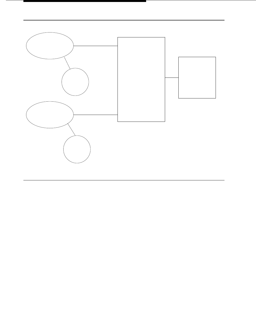
Feature Descriptions
3-944 Issue 3 March 1996
Figure 3-27. DCP PC Interface Configuration (Group 2)
1 Other IBM-compatible PCs can be used, as well as the PC 6300. PCs that use the MicroChannel.
bus (IBM Personal System/2 TM Models 50, 55, 60, 70, 80, or 100 percent compatible) can
use the PC/PBX MicroChannel Platform Interface card.
2 UNIX PCs were originally introduced but are no longer supported by the PC Interface feature.
Configuration Group 3
Group 3 consists of those configurations that use the ISDN-BRI (Basic Rate
Interface) for communications. Connectivity to the switch is provided by the
PC/ISDN Interface Card installed in the PC itself. Possible arrangements in this
group include the PC as a stand alone terminal (PC only), or with from one to four
voice terminals, handsets, or headsets. Group 3 is available on the DEFINITY
switch Generic 3, but not on previous System 85 switches. Group 3, described
in detail in the
PC/ISDN Platform Installation and Reference
manual,
555-016-102, is shown in Figure 3-28.
Applications and Benefits
PC Interface users receive benefits provided by both the PC and the features
and services of the DEFINITY Generic 3 switch.
DEFINITY
Generic 3
Packages 4 and 6
UNIX PC†
With DCP Interface
Card
DCP
DCP
Packages 3 and 5
PC6300*
With DCP Interface
Card
DCP
Voice
Terminal
DCP
Voice
Terminal
Host
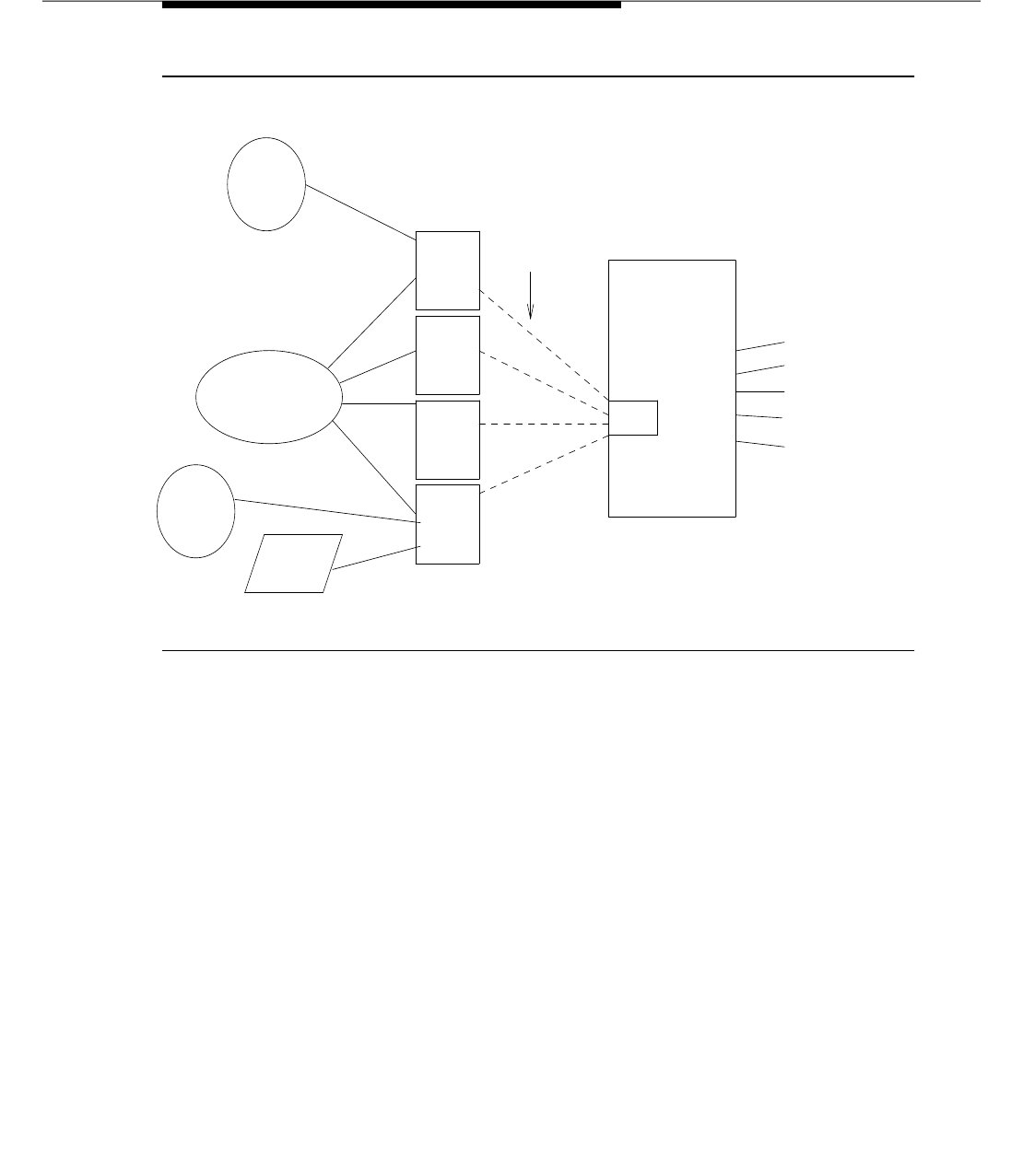
PC Interface
Issue 3 March 1996 3-945
Figure 3-28. ISDN—BRI PC Interface Configuration (Group 3)
Switch Features and Services
PC Interface users have multiple appearances (depending on the software
application used) for their assigned extension. One or more of these
appearances can be designated for use with data calls. With the ISDN-BRI
version, up to four separate PC/ISDN Interface Cards can be used on the same
PC. Each interface card used can be assigned a separate extension number,
and each of these extension numbers can have multiple appearances. The
availability of specific features depends on the class of service of the assigned
extension and the system class of service for the switch. Modem Pooling should
be provided to ensure general availability of off-net data calling services.
PC Features and Services
■PC/PBX Connection
Provides an integrated voice and data workstation interface from the
System to an AT&T PC 6300 or other compatible computer. The
connection provides access to a variety of host computers, allowing the
PC to act as a terminal for the host.
To administer a PC/PBX connection, the PC/PBX connection must be
completed.
DEFINITY
Generic 3
TN556
Handset
or
Headset
PC With Application
2B + D
Switch Features
DMI
Interworking
ISDN
Voice
Terminal
Voice
Terminal
BRI Stations
PRI Trunks
BRI
Interface
Card
BRI
Interface
Card
BRI
Interface
Card
BRI
Interface
Card
ISDN

Feature Descriptions
3-946 Issue 3 March 1996
■Directory Service
■Last Number Dialed
Features and services provided by the PC are a function of the PC
software application in place. With the PC/PBX Connection software, they
include PC based Directory Services (on line), a Last Number Dialed
feature (separate from these features as provided by the switch), and
basic asynchronous terminal emulation.
■3270 Emulation
■Hayes Smart Modem Emulation
■E78 Plus/ISDN
Other options include such functions as synchronous 3270 Emulation and
Hayes Smart Modem Emulation. The E78 Plus./ISDN (no longer available)
software package provides enhanced software based 3270 emulation
with high speed (64 Kbps) connections (through a 3270 data module) to a
local or remote 3270 cluster controller. This includes bulk file transfer
capability over switched links including either ETN (Electronic Tandem
Network) or ISDN circuits. Expensive fixed coaxial connections can be
avoided. The user interface with the E78 Plus/ ISDN software is the same
as with the widely used E78/IRMATM (no longer available) hardware
configurations.
Refer to the AT&T document
PC/PBX Platform Installation and Reference
555-016-101 (for Group 2) and to
PC/ISDN Platform Installation and
Reference
555-016-102 (for Group 3) for details on PC software options
and features, and applications. Also see the AT&T Catalog or your
account representative for more information on available applications.
For additional PC/PBX user information, refer to
AT&T PC/PBX Connection
Package 3 User’s Guide,
555-016-703. A complete set of documents is
available as
AT&T PC/PBX Connection Release 3 Documentation Set
,
555-016-715.
The PC/PBX Platforms and PC/ISDN Platform offers local custom
applications programming capability. A separately orderable publication,
the
PC/ISDN Interface Software Developer’s Guide
, 555-016-103,
provides the information that you need to customize existing applications
software or to develop new applications software to meet local needs.
Feature History and Development
The DCP versions of this feature (Groups 1 and 2) were first supported in
System 85 R2 V4, as the PC/PBX Connection feature. For System 85 R2
V4 and later switches, PCs have their own terminal type (PC). On earlier
versions of the Release 2 System 85 switch, PC/PBX configuration Groups

PC Interface
Issue 3 March 1996 3-947
1 and 2 can be used by administering them as an alias. Use terminal type
BCT 510D for Release 2, Versions 2 and 3. Use 7405D with display
module for Release 2, Version 1 switches.
With DEFINITY system Generic 3, the feature name is changed to PC
Interface to avoid confusion with the PC/PBX Connection software
package which is part of the overall offering. PC Interface Group 3, the
ISDN-BRI version of this feature, is first available on DEFINITY system
Generic 2.1. The PC/ISDN Platform (Group 3) cannot be used with
System 85 switches.
User Operations
User operations depend on the software used with the PC. For specific user
operations, refer to the appropriate PC Interface documentation set as follows:
■555-016-715, PC/PBX Connection
Documentation Set for the DCP versions (Groups 1 and 2) using the
PC/PBX Connection software package.
■555-016-101, PC/PBX Platforms
Installation and Reference manual for PC/PBX Platforms.
■555-016-102, PC/ISDN Platform
Installation and Reference Manual for the PC/ISDN Platform (Group 3).
Considerations
■Use of Speakerphones
Most DEFINITY system Generic 3 speakerphones can be used with the
PC Interface.
■Function Key Module
The Function Key Module of the 7405D can be used with the PC Interface
feature.
■SPID (Service Profile Identifier)
On the DEFINITY switch Generic 3, BRI terminals are normally ‘‘initializing
terminals’’ and require that a SPID be assigned (
see the
"Integrated
Services Digital Network (ISDN) — Basic Rate Interface (BRI)" feature).
The PC/ISDN Platform (Group 3), in a stand alone configuration (no
associated voice terminal), is a ‘‘non-initializing BRI terminal.’’ A
non-initializing terminal does not require a SPID. When the PC/ISDN
Platform is assigned as a stand alone non-initializing terminal, it is
administered using a locally defined terminal type with General Terminal
Administration, Procedure 50, Word 1 (see the
Administration Procedures
Manual
, 555-105-506). When this is done, the terminal type is defined as
a non-initializing terminal that does not support MIMs (Management

Feature Descriptions
3-948 Issue 3 March 1996
Information Messages). This requires a value of ‘‘0’’ in field 6 of Procedure
50, Word 1. Other specific characteristics of the locally defined terminal
type will depend on the telephone manager applications software used
with the PC.
The PC/ISDN Platform can also be assigned with an associated
(initializing) ISDN-BRI voice terminal (such as an ISDN 7505) that uses a
SPID. In this case, the station should also be assigned using a locally
defined terminal type to take full advantage of the capabilities of the PC
Interface. This terminal type should also be non-initializing with no
support of MIMs.
■Internal Features
Specific internal features available depend on the application package
used. The PC/PBX Connection product provides extensive local directory
capability (up to 32,000 entries). They also provide a Last Number Dialed
capability that is separate from the Last Number Dialed feature on the
DEFINITY system Generic 3.
■Data Modules
Voice terminals with data modules are not recommended for use with the
PC Interface feature (except for 3270 Data Modules when 3270 emulation
is used). If a DCP data module (such as a DTDM) or ISDN data module
(such as an ADM-T) is attached to the voice terminal used in conjunction
with the PC Interface card (either DCP or ISDN-BRI), the data module will
be bypassed (not used). All interface functions are performed by the
interface card even if a data module is present.
■Display Modules and Terminals
Display modules can be used. See ‘‘Feature History’’ for administration
limitation.
■Call Appearances
The PC/PBX Connection package supports five appearances, one of
which must be dedicated to data use. This configuration limit may not be
optimal for some users (such as attendants) who need many call
appearances. The PC/PBX Platforms can support the maximum allowed
by switch administration (52). The PC/ISDN Platform supports many more
call appearances. On the DEFINITY system Generic 3, the PC/ISDN
Platform is limited by switch administration to a maximum of 208 call
appearances (52 call appearances per interface card X a maximum of
four interface cards = 208 appearances). Note that each extension
number is limited to 12 appearances. This means that each interface card
can accommodate four and one third extension numbers (without any
bridged appearances). Special applications software must be installed on
the PC to provide access to all these appearances.

PC Interface
Issue 3 March 1996 3-949
■7404D Voice Terminal
The 7404D voice terminal with
messaging
cartridge cannot be used with
the PC Interface. The 7404D is manufacture discontinued and may no
longer be ordered. The 7404D with PC cartridge is used only with Group
1.
Interactions With Other Features
The PC Interface feature interacts with most other features in the same way as
other DCP and ISDN-BRI voice and data terminals.
■Data Communications Access
The PC Interface feature uses a digital interface (either DCP or ISDN-BRI)
and is not directly compatible with the Data Communications Access
feature which uses an analog interface. Modem Pooling like conversion
must be applied if these two features are to be used together.
■Data Protection
The PC Interface feature is used for data communications, therefore Data
Protection—Permanent should be assigned.
■Host Computer Access
Both the PC Interface feature and the Host Computer Access feature use
digital interfaces. These features are directly compatible (no Modem
Pooling conversion needed).
■ISDN-BRI (Basic Rate Interface)
The ISDN-BRI feature must be active on the switch to use the PC/ISDN
Platform (Group 3). With ISDN—BRI configurations, up to four PC/ISDN
interface cards can be installed in one PC. When multiple cards are used,
each card is assigned to a separate and distinct interface on the switch.
Separate interface cards cannot share the same ELL (Equipment Line
Location). Each separate interface card can have its own separate voice
terminal or voice-calling device. When a voice terminal is used, special
applications software is not required on the PC. However, to use a
handset or headset alone, special applications software is needed.
■Modem Pooling
Modem Pooling is needed if the PC Interface feature is used to place calls
to, or receive calls from, off-premises stations over analog trunks.
Restricting Feature Use
The voice and data appearances used by the PC Interface are subject to the
same general restrictions as other like appearances. These can be applied
either as fixed restrictions through the extension class of service, or as temporary
restrictions through the Attendant Control of Voice Terminals feature. Other

Feature Descriptions
3-950 Issue 3 March 1996
restrictive measures, such as the FRL (Facilities Restriction Level) and Attendant
Control of Trunk Group Access features also apply to stations using the PC
Interface feature.
Hardware Requirements
The specific hardware required by the PC Interface varies depending on the
configuration group used.
Group 1
Configuration Group 1 consists of those configurations that use the DCP PC
interface cartridge in the 7404D voice terminal.
■7404D VDS (Voice Data Station)-
Manufacture Discontinued
■31815 PC cartridge
■Standard, EIA RS232C connecting cables
■One of the following Personal Computers:
— AT&T PC 6300 and compatibles, with MS-DOSTM* Version 2.11 or
later
— AT&T PC 6300 Plus, with MS-DOS Version 3.1 or later
— IBM PC and PC/XTTM, with PC-DOSTM Version 2.0 or later existing
versions
—IBM PC/AT
TM, with PC-DOS Version 3.1 or later
■PC Accessories:
— Serial asynchronous communications port (standard on AT&T PC
6300 and 6300 Plus)
— 256K RAM minimum (PC/PBX Connection application package)
or
384K RAM recommended minimum for integrated software
applications such as concurrent Lotus 1-2-3.TM.
Group 2
Configuration Group 2 consists of those DCP configurations that use the PC
Interface card in the PC itself.
■Most DEFINITY system Generic 3 7400-series (DCP) digital voice
terminals can be used
■PC/PBX Interface Card
■One of the following Personal Computers:

PC Interface
Issue 3 March 1996 3-951
— AT&T PC 6300 series and compatibles, including PC 6300, 6300
WGS, 6300 Plus, 6310, 6312 WGS, 6286 WGS, and 6386 WGS,
with MS-DOS Versions up to 4.X (except 3.0) DOS releases
beginning with 1 (for example 1.XX) cannot be used.
— IBM PC, PC/AT, PC/XT, and Personal System/2 Model 30 and
Model 30/286 with PC-DOS Versions up to 4.X (except 3.0)
— IBM Personal System/2 models 50, 60, 70, 80, or 100% compatible
— Memory Configurations (depending on application being run):
320K RAM minimum or 448K RAM recommended for large
integrated software applications such as concurrent Lotus 1-2-3.
Group 3
Configuration Group 3 consists of BRI configurations that use a PC expansion
card in the PC itself (there is no BRI cartridge option).
■Voice Terminal or Voice Calling Devices
— Any DEFINITY system Generic 3 ISDN-BRI Voice Terminal (7500
Series) can be used with the Group 3 configurations.
or
— With appropriate applications software, an AT&T R-Type
replacement Handset (PEC X10150) can be plugged into the
ISDN-BRI PC expansion card instead of a BRI voice terminal.
or
— With appropriate software, a headset can be used instead of either
a BRI voice terminal or the R-Type Handset. The following
Plantronics headsets can be used:
StarSet. Series Communications Headset model StarMate.
MH0228-3
Supra. Series Communications Headset model MH0528-3
Supra Series Communications Headset model MH0529-3
■PC/ISDN Expansion Card (up to four per PC)
■One of the following personal computers:
— AT&T Personal Computers
AT&T PC 6300 (and compatibles)
AT&T PC 6300 Plus
AT&T 6300 WGS
AT&T PC 6310
AT&T PC 6312 WGS

Feature Descriptions
3-952 Issue 3 March 1996
AT&T PC 6286 WGS
AT&T PC 6386 WGS
— IBM Personal Computers
IBM PC
IBM PC/XT
IBM PC/AT
PS/2TM Model 30
PS/2 Model 30-286
— CompaqTM Personal Computers
Compaq DeskPro286
Compaq DeskPro386
■PC Accessories:
— For AT&T, Compaq, and compatible PCs, 2.0 and all later releases
(except 3.0) of MS-DOS
— For IBM PCs, 2.0 and all later releases (except 3.0) of PC-DOS
System Connections
Group 1
■The RS232C port of the 7404D voice/data set is connected via an EIA
RS232C cable to the RS232C port of the PC.
■The 7404D voice/data set has a modular digital port connection to the
DEFINITY system Generic 3.
■Standard operating distance of the 7404D from the PBX is 5,000 feet
maximum for 24-gauge wire or 4,000 feet for 26-gauge wire.
Group 2
■The PC Interface card plugs into an expansion slot on the PC. The card
has two standard, 8-pin modular jacks (line and phone).
■The digital phone plugs into the phone jack on the PC Interface card.
■The line jack on the card provides a digital port connection to DEFINITY
system Generic 3.
■Standard operating distance of the PC Interface card from the PBX is
5,000 feet maximum for 24-gauge wire or 4,000 feet for 26-gauge wire.

PC Interface
Issue 3 March 1996 3-953
Group 3
■The PC/ISDN Interface card (from one to four cards) plugs into an
expansion slot on the PC. The card provides two standard 8-pin modular
jack connections for both a line connection (to the switch) and a phone
connection. A standard 4-pin modular jack is also available for use with a
hand-set or head-set rather than a voice terminal.
■Each expansion card provides separate and distinct line and phone
connections.
■Standard and maximum operating distances for ISDN-BRI terminals are a
function of a number of factors including loop signal loss and power. The
factors affecting operating distance limits are discussed in detail under
Distance Specifications in the
DEFINITY Communications System Generic
3 System Description and Specifications
, 555-230-206.
Feature Administration
Administration guidelines in this section pertain to the DEFINITY switches
Generic 3. For additional information and for information on administering the PC
itself, refer to the
PC/PBX Connection Installation and Reference
(part of
documentation set 555-016-715),
PC/PBX Platform Installation and Reference
,
555-016-101, or
PC/ISDN Platform Installation and Reference
, 555-016-102.
The PC Interface feature is administered on a per-station basis.
On DEFINITY switches Generic 3, this feature is assigned using the DEFINITY
system Manager II.
This feature can also be administered using the Manager IV.
Table 3-72 shows the applicable administration procedures.
Table 3-72. PC Interface Administration Procedures
Procedure Words Purpose SMT
050 1 & 2 Used for General Terminal Administration to
locally define new terminal types (PC/ISDN
Platform).
N/A
051 1 Assigns and removes terminal types. Yes
051 2 Assigns the SPID (Service Profile Identifier)
used with the voice terminal portion of the
PC/ISDN interface.
Yes
Continued on next page

Feature Descriptions
3-954 Issue 3 March 1996
052 1 Assigns extension numbers and images to an
ELL and to specific buttons. Yes
052 2 Assigns additional extension and appearance
(image) characteristics to ELL and buttons. Yes
054 1 Assigns miscellaneous feature buttons,
including the
Wait For Principal
button to a
multiappearance voice terminal. The Wait For
Principal button is used only with the PC
Interface feature in a Message Center role.
Yes
054 2 Assigns and removes Custom Calling feature
buttons. Yes
054 4 Assigns and removes Display feature buttons. Yes
055 1 Assigns and removes Terminal Busy feature
buttons. Yes
055 2 Assigns and removes One Button Transfer
feature buttons. Yes
056 1 Assigns and removes Intercom buttons. Yes
057 1-3 Assigns and removes CO line buttons. Yes
058 1 Performs a station swap between two
equipment locations. Yes
059 1-5 Assigns and removes Abbreviated Dialing
buttons. Yes
063 1 Assigns and removes Automatic Message
Waiting buttons. Yes
070 4 Displays information about the terminal
equipment assigned to an equipment location. Yes
Table 3-72. PC Interface Administration Procedures — Continued
Procedure Words Purpose SMT
Continued on next page

PC/PBX Connection
Issue 3 March 1996 3-955
PC/PBX Connection
Feature Availability
This feature is available with all current Generic 3 releases except new
installations.
Description
PC/PBX Connection is a PC application that runs on the PC/PBX platform. Refer
to the section "PC Interface" in this manual for more details. This feature brings
the voice terminal and PC together into an integrated voice and data workstation.
The PC can be any IBM-compatible PC.
AT&T provides the hardware for this connection. The hardware consists of a PC
expansion card and a 7-foot modular cord. The software includes a variety of
packages available from different vendors. Contact your AT&T representative for
more information.
For information on the UNIX PC, see the section entitled "PC Interface" in this
manual.
Security Measures
There are two areas where unauthorized use may develop with this feature. The
first involves unauthorized users who come to a PC and attempt to make calls
from it. The software in the PC installed by the feature has a security setting. A
user can place the PC in Security Mode when it is to be left unattended.
Automatic Security can also be optioned by the administration program on the
PC. With Automatic Security enabled, when the software is executed, it brings
up the program in security mode. This mode is password-protected on the PC.
The password should be changed often, and records of it should be secured.
The second area involves remote access to the PC over its data extension. Files
stored in the PC can be deleted or copied with this feature. This can also be
password-protected, and this password should be changed frequently and
protected. Consult the
GBCS Product Security Handbook
, 555-025-600, for
additional steps to secure your system and to find out about obtaining
information regularly about security developments.
Considerations
By providing PC users with the voice and data capabilities of a fully integrated
voice/data workstation, the PC/PBX Connection feature makes communications
more efficient. Also, PC users with the PC/PBX Connection feature are linked for
easy access to other PCs, modem pooling, and on- and off-site computers.

Feature Descriptions
3-956 Issue 3 March 1996
Interactions
When a station is optioned for PC/PBX on the station form, and if the set is a
display set, the call display is slightly altered. The appearance identifier (a=, b=,
c=, d=) is omitted. If the Call Log feature is enabled in the PC/PBX Connection
software, the display information is captured to disk. The log can be searched.
The search criteria begins at the left of the displayed information. By omitting the
appearance designator, a user can enter a search string without contending with
the appearance identifiers in the displayed information.
Administration
The PC/PBX Connection feature is administered on a per extension basis by the
System Manager. A PC is assigned to the system just as any other station would
be with the station type administered as ‘‘pc.’’ An additional field is then specified
for the type of digital voice terminal to be connected to the PC.
Hardware and Software Requirements
A port on a TN754 Digital Line Circuit Pack (TN413, TN754B) is required for each
PC to be connected.

Personal Central Office Line (PCOL)
Issue 3 March 1996 3-957
Personal Central Office Line (PCOL)
Feature Availability
This feature is available with all Generic 3 releases.
Description
Provides a dedicated trunk for direct access to or from the public network for
multiappearance voice terminal users.
Each PCOL can have appearance at multiple multiappearance voice terminals.
Users assigned this feature press the PCOL feature button to answer and place
calls — dial access is not provided. The status lamp associated with the PCOL
button indicates the busy or idle status of the trunk.
An incoming PCOL call rings all voice terminals assigned the feature (ringing can
be either audible or silent, depending on administration). The PCOL button
status lamp flashes even if all call appearances at the voice terminal are active.
If a call appearance is idle, the status lamp associated with that appearance also
flashes.
CO, FX, and WATS trunks can be assigned to this feature.
PCOLs are not assigned a COR.
Considerations
PCOLs are useful to users such as executives, dispatchers, or buyers with a high
volume of calls going outside the system, and businesses with specialized
incoming calls (such as a service department).
Interactions
The following features interact with the PCOL feature.
■Abbreviated Dialing
Abbreviated Dialing can be used with the PCOL feature. However, the
accessed lists are associated with the individual voice terminals.
■Bridged Call Appearance
If a user is active on his or her primary extension number on a PCOL call,
bridged call appearances of that extension number cannot be used to
bridge onto the call. The call can only be bridged onto if another voice
terminal is a member of the same PCOL group and has a PCOL button.

Feature Descriptions
3-958 Issue 3 March 1996
■Call Coverage
AUDIX cannot be in the coverage path of a PCOL group.
■Hold
When a user, active on a PCOL call, puts the call on Hold, the status lamp
associated with the PCOL button does not track the busy/idle status of the
PCOL.
■LWC
LWC messages can be stored for a PCOL group. The messages are
retrieved by an authorized systemwide message retriever. When a
message is stored, the remote Automatic Message Waiting lamp assigned
for the PCOL group lights. One remote Automatic Message Waiting lamp
is allowed per group.
■CDR
The CDR feature can be activated for PCOL calls, but the CDR record
does not specifically identify the call as PCOL. A PCOL call can, however,
be identified by the trunk access code used on the call. The call is
recorded to the extension number assigned to the voice terminal where
the call was originated or answered.
■Send All Calls
Send All Calls cannot be activated for a PCOL group.
■Temporary Bridged Appearance
When a PCOL is shared (assigned to a group), any group member can
bridge onto a PCOL call through the Temporary Bridged Appearance
feature. The Privacy — Manual Exclusion feature can be activated on
such a call if the voice terminal is assigned an Exclusion button.
■Transfer
A PCOL can be transferred to an extension that does not have a button for
that PCOL.
The following features cannot be used with the PCOL feature:
■ARS
■Call Forwarding All Calls
■Ringback Queuing
Administration
PCOLs are administered by the System Manager. The following items require
administration:
■Group number
■Group type (CO, FX, or WATS)

Personal Central Office Line (PCOL)
Issue 3 March 1996 3-959
■Group name (optional, used for display purposes)
■Data Restriction activation
■CDR activation
■Call Coverage path (redirection criteria can be Don’t Answer and Cover
All Calls)
■Extension numbers of voice terminals assigned to PCOL group (up to four
terminals can share a PCOL)
■PCOL button (per terminal assigned to the PCOL group)
■Exclusion button (optional on a per-terminal basis)
■Remote Automatic Message Waiting lamp (one allowed per PCOL group)
■Audible or silent ringing
The following items can be administered for the CO, FX, or WATS trunk used for
the PCOL:
■Circuit pack port number
■Trunk type
■Trunk name (for display purposes)
■Trunk access code (nondialable, used to identify the trunk for CDR)
■Outgoing dialing type
■CO disconnect timing
■Terminating area code
■Prefix for code conversion
■Toll table index for code conversion
■Prefix 1 (needed for CO and FX trunks if the prefix 1 is needed for toll
calls)
■Timers based on board capabilities
NOTE:
Timer administration is available for G3i-Global, G3V2, and later
releases.
Hardware and Software Requirements
Requires one port on a TN747 CO Trunk circuit pack for each CO, FX, or WATS
trunk assigned as a PCOL. No additional software is required.

Feature Descriptions
3-960 Issue 3 March 1996
Personalized Ringing
Feature Availability
This feature is available with all Generic 3 releases.
Description
Allows users of certain voice terminals to uniquely identify their own calls. Each
user can choose one of a number of possible ringing patterns.
The eight ringing patterns are tone sequences consisting of different
combinations of three tones. The eight different combinations are listed below.
The tones are heard in the sequence given for each combination.
■750 Hz, 750 Hz, 750 Hz (normal ringing)
■1060 Hz, 1060 Hz, 1060 Hz
■530 Hz, 530 Hz, 530 Hz
■530 Hz, 1060 Hz, 1060 Hz
■1060 Hz, 1060 Hz, 530 Hz
■1060 Hz, 530 Hz, 530 Hz
■1060 Hz, 530 Hz, 1060 Hz
■530 Hz, 1060 Hz, 530 Hz
Each ringing pattern requires 0.6 second (0.2 second for each tone) in the 5.2
seconds ringing cycle. This 0.6 second of personalized ringing occurs at the
given time during the ringing cycles of the following types of calls (times
indicated are in seconds):
■Internal voice terminal, internal tie trunk, and remote access calls
0.6 on, 0.6 personalized ringing, 4.0 off
■Attendant extended, attendant originated, and incoming trunk calls,
including external tie trunk calls
0.2 on, 0.4 off, 0.6 personalized ringing, 4.0 off
■Automatic Callback, Priority Calling, and Ringback Queuing Callback calls
0.1 on, 0.1 off, 0.1 on, 0.3 off, 0.6 personalized ringing, 4.0 off
■Intercom Calls (7404D and 7407D voice terminals only)
0.6 personalized ringing, 4.6 off
One of the eight ringing patterns can be specified for each eligible voice
terminal (7303S and 7305S) by the System Manager. In addition, the 7404D,
7406D, 7407D, 7410D, 7505D, 7506D, 7507D, 8503T, and 7103A

Personalized Ringing
Issue 3 March 1996 3-961
programmable voice terminal users have the capability of setting their own
ringing pattern. The 7404D user can select the desired ringing pattern via the
given menu options. The 7406D or 7407D user can select the desired ringing
pattern by using the Select Ring and PR (Personalized Ringing #) buttons. The
7103A programmable voice terminal user can select one of four ringing patterns
via a slide switch on the voice terminal.
Considerations
With Personalized Ringing, users working closely in the same area can each
specify a different ringing pattern. This enables the users to distinguish their own
ringing voice terminal from other voice terminals in the same area.
Up to eight different ringing patterns are available.
Interactions
The normal ringing cycles are altered as described in the Description section of
this feature. With Administrable Distinctive Ringing (G3i-global, G3r, G3V2, and
later releases) the association between the number of ring bursts and the call
types is administrable.
Administration
Personalized Ringing is administered for the 7303S and 7305S voice terminals
on a per-voice terminal basis by the System Manager. Administration consists
of assigning one of the eight ringing patterns to each eligible voice terminal.
Also, a 7404D, 7406D, 7407D, 7410D, 7505D, 7506D, 7507D, 8503T, or 7103A
programmable voice terminal user can specify his or her own ringing pattern.
The user specified ringing pattern for a 7404D, 7406D, or 7407D, however, is
lost in the event of a power failure. The user specified ringing pattern for a 7410D
is lost if the set loses auxiliary power.
Hardware and Software Requirement
No additional hardware or software is required.

Feature Descriptions
3-962 Issue 3 March 1996
Power Failure Transfer
Feature Availability
This feature is available with all Generic 3 releases.
Description
Provides service to and from the local telephone company CO, including WATs,
during a power failure.
Considerations
Power Failure Transfer provides certain voice terminals with the capability to
access the local CO and to answer certain incoming calls during a power failure.
These voice terminals can be used to make or answer important or emergency
calls.
Each voice terminal can be connected to a separate CO trunk for the Power
Failure Transfer feature. The Power Failure Transfer feature is available in
multiples of five.
Local CO trunks (including incoming WATS lines) can be used for Power Failure
Transfer.
The 500-type (rotary dial) or 2500-type (touch-tone or DTMF) voice terminals
must be used for Power Failure Transfer. Rotary dialing must be used if the local
CO accepts dial pulses only. When a G3 system is not in the power failure mode,
power failure transfer terminals (500-type rotary dial) can be used as regular
extensions.
Interactions
During the Power Failure Transfer mode, no other system features can be
activated.
If Night Service is activated and a power failure occurs, the system, when
brought back up, automatically returns to the Night Service mode.
Administration
None required.

Power Failure Transfer
Issue 3 March 1996 3-963
Hardware and Software Requirements
One emergency transfer panel is required for every five or six trunks assigned to
Power Failure Transfer, depending on the transfer panel used. Two emergency
transfer panels are available:
■Z1A Panel — Each unit serves up to six power failure transfer terminals. A
ground-start key is required at each preselected voice terminal when
ground-start trunks are used.
■Porta-Systems Model 574-5 Panel — Each unit serves up to five failure
transfer terminals. The unit provides automatic ground start or loop start.
No additional software is required.

Feature Descriptions
3-964 Issue 3 March 1996
Priority Calling
Feature Availability
This feature is available with all Generic 3 releases.
Description
Provides a special form of call alerting between internal voice terminal users.
The called voice terminal user receives a distinctive, administrable alerting signal
(default is a three-burst alerting signal).
An active single-line voice terminal user who receives a Priority Calling call hears
a distinctive priority Call Waiting tone (the number of bursts is administrable; see
‘‘Distinctive Ringing’’ for details).
A multi-appearance voice terminal user receives the Priority Calling call on an
idle call appearance. If all call appearances, including the call appearance
normally reserved for call origination, are active, the caller receives a busy tone.
If the call appearance normally reserved for call origination is the only idle call
appearance, an incoming priority call rings at that call appearance.
A user activates priority calling by dialing a Priority Calling access code or
pressing a Priority button, followed by the desired extension number. DCS
priority calling from the attendant station is
not
available.
Whether or not a user can activate Priority Calling is determined by the user’s
COS.
Considerations
With Priority Calling, a voice terminal user can ring another voice terminal with a
distinctive signal that tells the called party the incoming call requires immediate
attention. The called party can then handle the call accordingly. DCS priority
calling from the attendant station is
not
available.
Call Coverage Consult calls and callback calls from Automatic Callback and
Ringback Queuing Attendant Intrusion are Priority Calling calls.
Interactions
The following features interact with the Priority Calling feature.

Priority Calling
Issue 3 March 1996 3-965
■Abbreviated Dialing
If a priority call is to be made to a number in an abbreviated dial list, an
Abbreviated Dial button must be used. The Abbreviated Dial Feature
Access Code is not valid after priority calling has been activated.
■Automatic Callback and Ringback Queuing
Callback calls do not redirect, do not forward, and cannot be picked up
by a Call Pickup group member.
■Bridged Call Appearance
A Bridged Call Appearance receives ringing on a priority call the same as
the called primary extension.
■Call Coverage
Priority Calling calls do not redirect to coverage unless the caller activates
Go To Cover. If the call redirects, it remains a Priority Call, and the
covering user receives a distinctive (default is three-burst) ringing signal.
■Call Forwarding All Calls
Priority Calling calls (except callback calls) are forwarded, and the
forwarded call remains a Priority Calling call.
■Call Waiting Termination
A Priority Calling call waits on an active single-line voice terminal even if
the Call Waiting Termination feature is not assigned to the voice terminal.
The active single-line voice terminal user receiving the call hears a
distinctive (default is three-burst) priority Call Waiting tone.
■Consult
A Consult call acts as a priority call and waits at a single-line voice
terminal, even if the single-line voice terminal does not have Call Waiting
Indication assigned.
■Dial Access to Attendant
A Priority Calling call cannot be originated to the attendant. However, the
attendant can originate Priority Calling calls.
■DCS
On a DCS tandem call to a single-line voice terminal, the called party does
not receive priority ringing if the calling party activates Priority Calling after
he or she has already made the call. The called party in this situation only
receives priority ringing if the calling party activates Priority Calling prior to
dialing the extension.

Feature Descriptions
3-966 Issue 3 March 1996
■Ringing
Single-line voice terminals (2500 series) can be administered so that
distinctive signals are not provided. In this case, one-burst ringing is
provided for Priority calls.
■Last Number Dialed
If a priority call is to be made to the last number dialed, the Last Number
Dialed button must be used. The Last Number Dialed Feature Access
Code is not valid after priority calling has been activated.
Administration
Priority Calling is administered by the System Manager. The following items
require administration:
■Priority Calling access code or priority button
■Permission to activate Priority Calling (per COS)
■Type of alerting signal heard when this feature is used. (The default is a
three-burst alerting signal.)
Hardware and Software Requirements
No additional hardware or software is required.

Privacy — Attendant Lockout
Issue 3 March 1996 3-967
Privacy — Attendant Lockout
Feature Availability
This feature is available with all Generic 3 releases.
Description
Prevents an attendant from reentering a multiple-party connection held on the
console unless recalled by a voice terminal user.
Considerations
Privacy — Attendant Lockout provides privacy for parties on a multiparty call
held on the console. The held parties can hold a private conversation without
being interrupted by the attendant.
Interactions
The following features interact with the Privacy — Attendant Lockout feature.
■Trunk-to-Trunk Transfer
Privacy — Attendant Lockout does not function when a call using the
Trunk-to-Trunk Transfer feature is held on the console.
■Individual Attendant Access
Privacy — Attendant Lockout applies only to attendant group calls.
Individual attendant calls are not affected.
■Attendant Recall
Use Attendant Recall to recall the attendant to a call that is originally
extended by the attendant.
Administration
Privacy — Attendant Lockout is administered on a per-system basis by the
System Manager. The only administration required is to administer whether or
not attendant lockout is active.
Hardware and Software Requirements
No additional hardware or software is required.

Feature Descriptions
3-968 Issue 3 March 1996
Privacy — Manual Exclusion
Feature Availability
This feature is available with all Generic 3 releases.
Description
Allows multiappearance voice terminal users to keep other users with
appearances of the same extension number from bridging onto an existing call.
Exclusion is activated by pressing the Exclusion button on a per-call basis. If the
Exclusion button is pressed while other users are bridged onto the call, the other
users are dropped from the call. The Privacy — Manual Exclusion feature is
automatically deactivated when the Exclusion button is pressed a second time or
when the party who activated Privacy — Manual Exclusion is dropped from the
call.
Privacy — Manual Exclusion is used with the PCOL, TEG, and Bridged Call
Appearance features.
Considerations
Privacy — Manual Exclusion prevents users who have an appearance of another
terminal’s extension from bridging onto that extension.
Interactions
The following features interact with the Privacy — Manual Exclusion feature.
■Bridged Call Appearance
When Privacy — Manual Exclusion is activated, all other users are
prevented from bridging onto the active call.
Administration
Privacy — Manual Exclusion is administered on a per-voice terminal basis by the
System Manager. The only administration required is the assignment of the
Exclusion button to the desired voice terminals.
Hardware and Software Requirements
No additional hardware or software is required.

Property Management System (PMS) Interface
Issue 3 March 1996 3-969
Property Management System (PMS)
Interface
Feature Availability
This feature is available with all Generic 3 releases.
Description
Provides a communications link between the System and a customer-owned
PMS. The PMS allows a customer to control certain features used in both a
hospital-type and a hotel/motel-type environment.
The communications link allows the PMS to interrogate the system and allows
information to be passed between the system and the PMS. Routine operations
related to the following features are simplified through this message exchange
capability:
■Message Waiting Notification
■Controlled Restriction
■Housekeeping Status
■Check-In/Check-Out
■Room Change/Room Swap.
■Names Registration
■Guest Information Input/Change
■Support of five-Digit Extension Numbers
Message Waiting Notification, Controlled Restriction, and Housekeeping Status
are optional features. A customer may elect to operate each of these features
from the system only or to operate each of these features from either the system
or a PMS.
Check-In/Check-Out, Room Change/Room Swap, Names Registration, and
Guest Information Input/Change are controlled from the PMS as long as the
communications link between the system and the PMS is operational. If the link
is not operational (the link is down), these features are affected as follows:
■Control of Check-In/Check-Out transfers to the system. With the system in
control, Check-In/Check-Out operations are performed via feature
buttons.
■Control of Guest Information Input/Change transfers to the system. With
the system in control, Guest Information Input/Change operations are
performed by the System Manager via system administration commands.

Feature Descriptions
3-970 Issue 3 March 1996
■The system does not support Room Change/Room Swap as such.
However, the equivalent of Room Change/Room Swap is executed
through the system by activating Check-Out followed by Check-In.
■Names Registration information which is normally sent automatically from
the PMS to the switch, can be entered manually at the switch by the
System Manager.
The PMS Interface provides the following:
■A communications protocol for controlling message exchange between
the system and a PMS
■An application module for controlling the operation of the PMS features
■Status data on all guest/patient rooms for selected features
The protocol is full-duplex, asynchronous and provides the mechanisms for
setting up a data session with the PMS, message exchange control, error
identification, and recovery. The interface supports standard data rates (1200,
2400, 4800, or 9600 bps in G3i).
Two protocol modes are provided; the normal protocol mode as described
above, and the transparent protocol mode. The transparent protocol mode
supports ASCII character transmission and is required for PMS features such as
Names Registration and Guest Information Input/Change. Systems may be
administered to use either the normal or transparent protocol mode.
The application module of the PMS Interface implements requested features and
provides backup procedures if the communications link between the PMS and
the system is down. Whether or not the communications link with the PMS is
operational, the system always maintains the following data for each room:
■Whether the room is vacant or occupied
■Whether the voice terminal’s Message lamp is on or off
■Whether a Controlled Restriction is active at the voice terminal and, if so,
which one
■The guest’s name and coverage path
When the link to the PMS is down, the system automatically activates
Check-In/Check-Out for the attendant console and front desk terminal with
display capability, and continues to support PMS features that are activated from
guest/patient room voice terminals.
When the link is again operational, the system sends one of the following
messages to the PMS:
■No room status changes occurred during loss of communications.
■Room status changes did occur during loss of communications; therefore,
a status data exchange is needed to synchronize the system and the PMS
data bases.

Property Management System (PMS) Interface
Issue 3 March 1996 3-971
■The system failed momentarily, destroying its record of room status;
therefore, a room status data exchange (full transfer of data from the PMS
to the system) is needed to synchronize the system and the PMS
databases.
Also, when the PMS link is down or if a PMS is not used, the system maintains a
log, called an audit trail report, of all events that would normally be sent to the
PMS.
The audit trail data (accessed via the Management Terminal) is a sequential
listing of all PMS transactions executed by the system when the PMS data link
was down. Also included in the audit trail are some error events that may have
occurred when the link was either up or down. If a printer is configured in the
system, copies of the audit trail data will help the administrative staff to restore
the room status of system and the PMS.
In addition to the PMS audit trail report, if the system has an operational PMS log
printer and the PMS link is down, Housekeeping Status changes will be printed
as they occur. The Housekeeping Status report will contain the following
information:
■Room number
■FAC dialed
■Any additional information digits that were dialed
■Reason for the entry (error message)
■Time the error occurred
In addition to the PMS log printer, a PMS Journal/Schedule printer is also
available. The PMS Journal/Schedule printer prints reports on Automatic Wakeup
activity, Emergency Access to the Attendant activity, and scheduled reports.
A supporting function called Room Data Image synchronizes the switch and
PMS databases after a PMS link goes down and comes back up. The information
included in the Room Data Image is as follows:
■Room extension
■Whether the room is occupied or vacant
■Message Waiting lamp status
■Controlled Restriction status
■Guest’s name
■Call Coverage path

Feature Descriptions
3-972 Issue 3 March 1996
Message Waiting Notification
Message Waiting Notification requests are originated from attendant consoles,
front desk terminals, or PMS terminals. When a request is entered, the PMS
sends a Message to the system to change the state of the Message lamp
associated with a certain extension number. If the Message lamp has been
turned on by the AUDIX or Leave Word Calling (LWC), the PMS cannot be used
to turn the lamp off. However, in the transparent mode, certain events may cause
the switch to inform the PMS that the Message lamp has been turned on by
AUDIX or LWC.
Any console or terminal used to activate and deactivate Message Waiting
Notification must be assigned a Console Permissions Class of Service (COS).
The affected extension must have a Client Room COS.
Controlled Restriction
When the Controlled Restriction feature is activated through the PMS, the PMS
sends a message to the system to assign one of the following restrictions to the
voice terminal in a guest/patient room:
■No restriction
■Outward restriction
■Total restriction
■Station-to-station restriction
■Termination restriction
■Combined outward and termination restriction
■Combined Outward and Station-to-Station restriction
■Combined Termination and Station-to-Station restriction
If a PMS is not used or if the communications link is down, the attendant or front
desk user can still set the Controlled Restriction for a voice terminal, because
activation of this feature is independent of the PMS. When the communications
link is again operational (if a PMS is used), the system asks for a data base
exchange and all status changes are sent to the PMS. At this time, controlled
restrictions can still be assigned.
If user controlled restrictions are activated or deactivated from the switch, the
PMS receives a message with this information.

Property Management System (PMS) Interface
Issue 3 March 1996 3-973
Housekeeping Status
The housekeeping staff can enter status information using voice terminals
located in guest/patient rooms or using designated terminals. Up to 10
Housekeeping Status Access Codes can be assigned in the system.
■Room Voice Terminal Access Code
After the Access Code is dialed, the system accepts up to six additional
information digits. These information digits can be used for items such as
maid identification.
■Designated Voice Terminal Access Code
After the Access Code is dialed, the system waits for the room extension
to be entered and then will accept up to six additional information digits.
If a PMS is used, the system notifies the PMS when Housekeeping Status
information is entered. If a PMS is not used, if the communications link is down, or
if a PMS is connected, but housekeeper information is not sent (the
“Housekeeper Information Configuration” field on the Hospitality-Related System
Parameters screen is administered as act-nopms), then Housekeeping Status
information is written to a log, can be accessed through the Management
Terminal, and can be sent to a printer to obtain a hard copy. If the system has a
PMS log printer and the PMS link is down, each entered event will be printed as it
occurs.
If a PMS is used, but goes down, and a PMS log printer is not operational, the
Housekeeping Status access codes cannot be used.
Check-In/Check-Out
A Check-In request deactivates the Outward Controlled Restriction level on the
terminal in a guest/patient room. A Check-Out request deactivates any
Controlled Restrictions and changes the Controlled Restriction level to Outward
Restriction, checks for any messages, clears the wakeup request (if there is
one), and deactivates Do Not Disturb (if activated).
If a PMS is not used or if the communications link is down, Check-In and
Check-Out can be activated from an attendant console or a front desk terminal
with display capability and console permission. Two buttons are required,
Check-In and Check-Out. Pressing either button places the display in the
respective mode and allows the touch-tone or DTMF buttons to be used for
entering data (rather than for placing calls).
The user exits the Check-In or Check-Out mode by pressing another button
associated with the display (such as the Normal Mode button). This restores the
display and the touch-tone or DTMF buttons to normal operation.
A Check-In/Check-Out request also sends information for the Names
Registration feature to the switch. This information includes the guest’s name (up
to 15 characters), room extension, and Call Coverage path. The switch must be

Feature Descriptions
3-974 Issue 3 March 1996
assigned the transparent communications protocol mode for this information to
be transferred between the switch and the PMS. If the PMS link is down, and
Check-In is done from an attendant console or display-equipped front desk
terminal, the guest’s name and coverage path information is not automatically
updated at Check-In.
If a guest/patient room has both a voice and a data extension, the Check-Out
request applies only to the voice extension.
Room Change/Room Swap
These features are provided only through a PMS and must be activated from a
PMS terminal. When either Room Change or Room Swap is activated, the PMS
sends a message to the system. When Room Change is activated, data
pertaining to the old room, including a pending wakeup request, the guest’s
name (transparent mode), and the guest’s Call Coverage path (transparent
mode), is moved to the new room. When Room Swap is activated, the data
pertaining to the two rooms are swapped. When either feature is activated, if the
occupancy status is inconsistent, the system sends an error message to the
PMS.
Names Registration
Automatically sends a guest’s name and room extension from the PMS to the
switch at Check-In, and automatically removes this information at Check-Out. In
addition, the guest’s call coverage path (for example, voice mail or hotel
operator) will also be sent from the PMS to the Switch during Check-In. The
guest’s call coverage arrangement is set to the administered ‘‘Default Call
Coverage Path for Client Rooms’’ at checkout. The Names Registration feature is
described in detail elsewhere in this document.
Guest Information Input/Change
Guest Information Input/Change, allows guest information (name or coverage
path) to be entered or altered subsequent to the check-in message. Hotel
personnel can change this information at the PMS and it is automatically sent to
the switch.
The Guest Information Input/Change function is used in those situations when
the guest’s name associated with an extension must be changed, input of a
guest’s name must be made after the checking sequence has taken place, or a
change in call coverage arrangement must be made.

Property Management System (PMS) Interface
Issue 3 March 1996 3-975
Considerations
The PMS Interface feature provides a collection of features needed in a hospital
or hotel/motel environment: Message Waiting Notification, Controlled Restriction,
Housekeeping Status, Check-In/Check-Out, Room Change/Room Swap, Names
Registration, and Guest Information Input/Change. All these features, except
Room Change/Swap and Check-In/Check-Out, can operate through the system
with or without a PMS. When these features are entered through a PMS, the
system provides the necessary communications interface.
A customer may elect to use LWC or Integrated Message Center Service for the
hospital or hotel/motel staff and Message Waiting Notification for guests/patients.
However, if Message Waiting Notification is not used, Integrated Message Center
Service can be used for both.
A PMS extension cannot be removed while the PMS link is active. PMS link
parameter changes do not take effect until the PMS link is reset.
The normal protocol mode allows extensions of up to four digits in length. The
transparent protocol mode allows extensions of up to five digits in length.
When a ‘‘save translations’’ is done on a system with the transparent protocol
mode active, station names with Client Room COS are saved as ‘‘blank’’ and
coverage paths are saved as the ‘‘Default Coverage Path for Client Rooms.’’
The PMS interface may not work correctly when there are p-extensions with the
same leading digit and adjacent lengths. For example 3 and 4 p-extensions with
the same leading digit may cause problems. The same applies to 4 and 5, and 5
and 6. If the lengths differ by 2, the PMS interface works correctly. For example,
lengths of 3 and 5, or lengths 4 and 6.
A room extension may begin with “0” only if the PMS sends a prefix digit or if the
PMS sends a fixed number of digits. Refer to the “Administration” section for
system parameters.
Interactions
The following features interact with the PMS Interface feature.
■Attendant Console or Front Desk Terminal
The Controlled Restriction, Check-In/Check-Out, and Message Waiting
Notification features can be activated at an attendant console or a front
desk terminal with console permission. Also, the attendant console can
receive visual notification of the status of the communications link between
the system and the PMS.
■AUDIX Interface

Feature Descriptions
3-976 Issue 3 March 1996
Message lamps activated by this feature cannot be deactivated by feature
buttons or by feature messages from the PMS.
■Automatic Wakeup
An Automatic Wakeup request for a guest/patient room is set or canceled
as a result of Room Change/Room Swap or Check-Out.
■Do Not Disturb
A Do Not Disturb request for a guest/patient room is set or canceled as a
result of a different Controlled Restriction, Room Change/Room Swap, or
Check-Out.
■Leave Word Calling (LWC)
Message lamps activated by this feature cannot be deactivated by
Manual Message Waiting feature buttons.
With a system using the transparent protocol mode, any LWC messages
that are present when a check-In request is processed are deleted.
If Room Change is activated, LWC messages for the old room will
not
be
moved to the new room. If Room Swap is activated, LWC messages for
the two rooms will
not
be swapped. Therefore, use of the LWC feature,
should not be encouraged in guest/patient rooms.
■Restriction — Controlled
Controlled Restriction for a group of users extensions, when activated
from the switch, is not conveyed to the PMS. Also, the PMS is not able to
remove such restrictions by sending feature messages.
Administration
The following Hospitality System Parameters may be administered:
■Number of Digits from PMS—specifies the number of digits the switch
expects from the PMS. A blank (the default) indicates that a variable
number of digits are expected. If the protocol mode is normal, then the
range is 1-4; if the protocol mode is transparent, then the range is 1-5. If
the field is blank and the “PMS Sends Prefix” field is no, then the switch
will not support extensions with a leading digit of 0 as PMS rooms.
■“PMS Sends Prefix?” field—specifies whether the switch should
consider the first digit (if it is designated as a prefix digit in the Dial Plan)
as a prefix and strip it off before trying to find a PMS record for the
extension. Values are y or n. If the field is n and the “Number of Digits
from PMS” field is blank, then the switch will not support extensions with a
leading digit set to 0 as PMS rooms.
■Message Waiting Notification—one of two choices must be
administered:
— Active with no PMS message exchange (act-nopms)

Property Management System (PMS) Interface
Issue 3 March 1996 3-977
— Active with PMS message exchange (act-pms)
■Controlled Restriction—one of two choices must be administered:
— Active with no PMS message exchange (act-nopms)
— Active with PMS message exchange (act-pms)
■Housekeeping Status Information—one of two choices must be
administered:
— Active with no PMS message exchange (act-nopms)
— Active with PMS message exchange (act-pms)
If active is selected, the following additional administration is required:
— The number of additional information (Housekeeper Identification)
digits from zero to six that can be dialed.
■Extension Numbers—assigned to the PMS Journal/Schedule printer and
PMS log printer, if used, and to the PMS. Before an extension is assigned,
the System Manager should check to make sure that the extension is not
already assigned as a Call Detail Recording (CDR) or PSC extension.
■Seconds Before PMS Link Idle Time-Out—specifies the number of
seconds that the system will wait before it concludes that the PMS is not
sending data across the transmission link. Choice is a number of seconds
from 5 to 20.
■Milliseconds Before PMS Link Acknowledgment Time-Out—specifies
the maximum time the system expects acknowledgment from the PMS that
a message was received correctly. Choice is a number of milliseconds
from 100 to 500.
■PMS Link Maximum Retransmissions—specifies the maximum number
of times that the system will retransmit a message in response to a
negative acknowledgment or send an inquiry for an acknowledgment from
the PMS for a message before giving up on the message transmission.
Choice is a number from 1 to 5.
■PMS Link Maximum Retransmission Requests—specifies the
maximum number of times that the system will accept requests from the
PMS to resend a reply (acknowledgment or negative acknowledgment)
that the system did not receive before giving up on the incoming
message. Choice is a number from 1 to 5.
■PMS Protocol—specifies the communication protocol mode used
between the switch and the PMS. The choices are either normal or
transparent.

Feature Descriptions
3-978 Issue 3 March 1996
■Default Coverage Path for Client Rooms—specifies the coverage path
value that is set for an extension when the switch receives a ‘‘check-out’’
message while in the ‘‘transparent’’ communication protocol mode, or
when a save translation is stored for extensions with a Client Room COS.
The choice is a number from 1 to 600.
■Number of Digits in PMS Coverage Path—located on the second page
of the “system-parameter hospitality” form. The coverage path can be set
to “3” or “4”. This is used to determine if the PMS adjunct software is using
a 3- or 4-digit format for coverage path messaging.
Hardware and Software Requirements
A PMS, if used, can be connected through an MPDM and port on a Digital Line
circuit pack or through an ADU and a port on a Data Line circuit pack. A DTDM
(with a null modem), 7400A data module, and 7400B data module can also be
used for the PMS link. Journal/Schedule and PMS log printers can be used and
also require at least an MPDM and a port on a Digital Line circuit pack or an ADU
and a port on a Data Line circuit pack. The Journal/Schedule and PMS log printer
functionality can be on the same or two distinct printers.
For G3r, there is no means for connecting directly to the switch processor circuit
pack, like with G3i. G3r requires, in addition to the data module to connect
directly to the adjunct, a TN726B and a TN553 circuit pack combination.

Pull Transfer
Issue 3 March 1996 3-979
Pull Transfer
Feature Availability
This feature is available with G3i-Global and all Generic V2 and later releases.
Description
NOTE:
G3i-Global, G3V2, and later systems come with this feature turned off by
default.
Pull transfer is an enhancement of the standard transfer operation. Standard
transfer allows voice terminal users to transfer trunk or internal calls to other voice
terminals within the system without attendant assistance. The Pull Transfer
feature allows either the calling or the called party (the party to whom the held
party will be transferred) to complete the transfer operation.
Analog telephone called parties who wish to pull transfer the party that the
controlling party has on hold should momentarily flash the switchhook (or press
the Flash key or the Recall button). This completes the transfer of the held party
to the called party.
Digital telephone called parties who wish to pull transfer the party that the
controlling party has on hold should press the Transfer key. This completes the
transfer of the held party to the called party.
Please see the Transfer feature for a description of the regular (push) transfer
feature.
Considerations
The pull transfer feature provides a convenient way to connect a party with
someone better qualified to handle the call. Attendant assistance is not required
and the call does not have to be redialed.
If the attendant is the controlling party, any attempt to complete a Pull Transfer
operation by the called party is ignored. Pull Transfer cannot be completed if the
Attendant is the called party. A held party can only be transferred by the
attendant with Push Transfer.
Pull Transfer can only be completed if the calling party is a station on the same
switch as the called party, or if the called party on another switch has been
reached via an Italian TGU/TGE tie trunks.

Feature Descriptions
3-980 Issue 3 March 1996
Interactions
■Analog Station Recall Operation and Feature Activation: If the controlling
party (with a party on hold) is talking with the called party, and either
analog station recall or feature activation is initiated by the called party,
the controlling party will not be put into the Hold for Transfer mode but will
be Pull Transferred.
■Digital Station Transfer Operation: if the controlling party (with a party on
hold) is talking with the called party and the transfer operation is initiated
by the called party, the controlling party will not be put into the Hold for
Transfer mode but will be Pull Transferred.
■CDR: Checks will be made to ensure that calls are correctly recorded with
CDR when a Pull Transfer operation is completed.
■Non-BRI Stations:
If the “Pull Transfer” field on page 6 of the System Parameters Features
form is set to “y,” the following could occur: Station A calls Station B, who
answers, then presses the Transfer button and dials Station C. Station C
answers and presses the Transfer button. The call from Station A is
transferred to Station C.
■BRI Stations:
If the “Pull Transfer” field on page 6 of the System Parameters Features
form is set to “y,” the following could occur: Station A calls Station B, who
answers, then presses the Transfer button and dials Station C. Station C
answers and presses the Transfer button to “pull” the transfer. Instead,
Station C goes off hook on another call appearance as if a new transfer is
being originated.
Administration
The ‘‘System Feature’’ form is used to enable Pull Transfer.
Hardware and Software Requirements
No special hardware is required to implement the Pull Transfer feature in a
standalone configuration. However, in a network environment, the TN497
TGU/TGE tie trunks are the only trunks that support the flash signalling necessary
to complete the Pull Transfer operation between switches.

QSIG Global Networking
Issue 3 March 1996 3-981
QSIG Global Networking
Feature Availability
This feature is available with Generic 3 Version 2 and later releases.
Description
QSIG Global Networking provides compliance to the International Organization
for Standardization (ISO) ISDN-PRI private networking specifications.
QSIG Global Networking Basic Call
QSIG Global Networking Basic Call is available with G3V2 and later releases.
The Basic Call complies with ISO standard 11572 for layer 3 to support private
network connectivity. This means it provides the ISDN-PRI connection from
PBX-to-PBX.
QSIG Global Networking Platform
The QSIG Global Networking Platform, available in G3V3 and later releases,
provides a private network protocol for the support of QSIG supplementary
services. This platform meets requirements for the ISO Private Network Generic
Functional Procedures (Standard 11582) for Call-Related supplementary
services. (Supplementary services are services provided by the PBX beyond
voice or data connectivity and number transport and display. Examples of
supplementary services include Name Identification, Call Forwarding, and
Transfer.)
The QSIG Global Networking platform is based on Integrated Services Digital
Network-Primary Rate Interface (ISDN-PRI) basic call setup protocol. It supports
Call Related supplementary service transport, Abstract Syntax Notation 1
(ASN.1)/Basic Encoding Rules (BER), and Remote Operation Service Element
(ROSE) services/protocols.
"QSIG" is the generic name for a family of signaling protocols based on ITU-T
(formerly CCITT) Q.931 access protocols across the Q reference point. (The Q
reference point or interface is the logical point where signaling is passed
between two peer entities in a private network.) The QSIG signaling is used to
provide PBX-to-PBX private networking in a multivendor environment. QSIG is
being defined by the International Standards Organization (ISO) to be the
worldwide standard for PBX-to-PBX private networks. These standards are also
supported by the ISDN Private Networking Specification (IPNS) Forum, which is a
consortium of PBX vendors working to establish worldwide standards for vendors
to follow on a voluntary basis.

Feature Descriptions
3-982 Issue 3 March 1996
The G3V3 release of QSIG Global Networking is a foundation for the QSIG
supplementary services. It provides the Name Identification supplementary
service, as defined by ISO Standards 13864, 13868, and 11572. G3V4 adds to
the QSIG supplementary services by providing for Call Forwarding as defined by
ISO Standards 13872 and 13873 and Call Transfer as defined by ISO Standards
13865 and 13869.
DEFINITY system G3V3 and later releases provide QSIG Global Networking in
addition to some national protocols and the European Telecommunications
Standards Institute (ETSI) protocols for supplementary services. The protocols
are mutually exclusive. Users must specify on the “ISDN-PRI Trunk Group” form
which protocol they wish to use for ISDN-PRI supplementary services. Therefore,
users who require the QSIG Global Networking Platform must administer it on the
“ISDN-PRI Trunk Group” form. On this form, the national supplementary service
protocols are defined as protocol ‘‘a’’, the QSIG Global Networking protocol is
identified as protocol ‘‘b’’, and the ETSI Supplementary Service protocol is
identified as protocol “c”.
Supplementary Services
Identification Services
The Identification Services feature allows the PBX to send or receive the calling
number, calling name, connected number, and connected name. Furthermore, it
allows you to administer ‘‘yes,’’ ‘‘no,’’ or ‘‘restricted’’ for sending identification
information. ‘‘Restricted’’ means that DEFINITY system sends the information but
sends it ‘‘presentation restricted’’, which indicates to the receiving switch that the
information should not be displayed. In the current release, a received restricted
name or number is included on the Call Detail Record (CDR). Due to current
networking limitations, a received Restricted Calling Party Number is displayed.
However, a received restricted Connected Party Number or Calling/Connected
Name is
not
displayed.
The Identification Services feature displays up to 15 characters for the
calling/connected name and up to 15 digits for the calling/connected number
across ISDN-PRI interfaces. When the DEFINITY system acts as a transit PBX (a
PBX, other than the originating or terminating PBX, through which a call passes),
it usually passes the name information as it receives the information. (A "Transit"
PBX is defined as a PBX that routes an incoming call administered for
Supplementary Services protocol “b” to a trunk also administered for
Supplementary Services protocol ‘‘b.’’) However, in the case of tandemed calls,
trunk group administration may override incoming tags, as long as doing so does
not lower the restriction on the information. For example, a tandemed call that
comes in as restricted remains restricted even if the outgoing trunk is
administered for ‘‘presentation restricted.’’ However, nonrestricted data is sent
restricted if the trunk group administration is set for ‘‘presentation restricted.’’
The ability to send Calling Name, Connected Name, Connected Number, and
Calling Number, or to send them restricted, is administered on the ‘ISDN-PRI

QSIG Global Networking
Issue 3 March 1996 3-983
Trunk Group’ form. Also, the ‘ISDN Public-Unknown-Numbering’ and/or ‘ISDN
Private-Numbering’ forms must be administered. The numbering form used to
create the number is based on the ‘Numbering Format:’ field on the ‘isdn-pri
Trunk Group’ form. If
public
or
unknown
is specified, the ‘ISDN
Public-Unknown-Numbering’ form is used. If
private
is specified, the ‘ISDN
Private-Numbering’ form is used.
Call Forwarding (Diversion)
QSIG Call Forwarding is based on the DEFINITY system Call Forwarding All Calls
and Call Forward Off Premise features. It extends the feature transparency
aspects of Call Forwarding if there is a QSIG link between any of the PBXs
involved.
The feature is activated either by dialing a feature access code or by pressing a
Call Forwarding button. See the "Call Forwarding All Calls" feature for a detailed
description of how to use the Call Forwarding feature.
QSIG Call Forwarding differs from other Call Forwarding features in that
additional call information is available to both the caller and the diverted-to
terminal above what is provided if the call is forwarded over a link that is not
administered for QSIG Supplementary Service protocol “b.” The originator
(caller) of the call will see “forward” on their display. The diverted-to user will
receive information that the call has been forwarded with the redirection symbol
“f.” Depending upon QSIG Identification Services administration, the originator
will see the connected party’s name or number followed by “forward.” The
diverted-to user will see the originator’s identification (name or number) and the
diverting user’s (called party) identification (name or number) followed by “f.”
Up to 16 digits can be stored as the forwarded-to number. A total of 20 digits can
be sent at the time of forwarding (including the TAC or AAR/ARS access codes).
When a call has already been forwarded three times, it will not be forwarded
again but instead will terminate at the final forwarded-to terminal. Remote
activation and deactivation are not supported.
Because QSIG Call Forwarding is compatible with the ISO QSIG standards, the
DEFINITY system can provide feature transparency for Call Forwarding with any
PBX designed to these standards.
Transfer
QSIG Transfer is based on the current DEFINITY system Transfer and
Trunk-to-Trunk Transfer features. QSIG Transfer signalling will occur as long as
one of the calls involves a QSIG link between the two PBXs. QSIG Transfer
conforms to ISO 13869 for QSIG Call Transfer By Join. This means that the
transfer occurs through the switch where the transferring user resides and if the
transfer involves two trunks, neither will be released after the transferring party is
dropped from the call.

Feature Descriptions
3-984 Issue 3 March 1996
The user activating the Transfer feature will see no difference between QSIG
Transfer and the standard DEFINITY system Transfer or Trunk-to-Trunk Transfer
features. See the "Transfer" feature and "Trunk-to-Trunk Transfer" feature
descriptions for basic feature operation.
QSIG Transfer differs from the standard DEFINITY system Transfer feature in that
additional call information is available for the connected parties after the transfer
completes. However, the information is only sent on QSIG links, that is, if one call
is local to the transferring PBX, that user will not receive any new call information.
Depending upon QSIG Identification Services administration, the connected
parties’ displays will show each other’s name and/or number. If the name and
number are not available, the display of a connected party is updated with the
name of the trunk group involved.
Interactions
Identification Services Interactions
■Distributed Communications Systems (DCS)
There is no interworking for Calling/Connected Numbers information or for
Connected Name information in a DCS network. The Calling Name from a
DCS network is received by the QSIG Global Network platform. However,
the Calling Name is not sent by the QSIG Global Network platform to a
DCS network.
■Non-DCS Non-QSIG Global Networking ISDN-PRI Networks
Calling/Connected Name and Number information may be sent to and
from a non- DCS non-QSIG Global Network platform, depending on the
protocol version (country protocol) for the interface.
Call Forwarding (Diversion) Interactions
All interactions that apply to the standard DEFINITY Call Forwarding -- All Calls
feature also apply to Call Forwarding with QSIG. See "Call Forwarding All Calls"
on page 3-396 for a description of these interactions. The following are additional
interactions.
■Distributed Communications Systems (DCS)
■Call Forwarding feature transparency will not exist on calls tandemed
between a QSIG (Supplementary Service protocol B) network and a
traditional DCS network. However, the basic call will continue.
■Forwarding and Coverage
If the last coverage point in the coverage path is a number that routes over
an ISDN PRI SSB trunk, the call will be treated as a QSIG Diverting call.

QSIG Global Networking
Issue 3 March 1996 3-985
■QSIG Identification Services
Availability of name and/or number display at the originating and
diverted-to users depends upon how QSIG Identification Services have
been administered for the PBXs involved.
■Terminating Call has Coverage Active
If a call is forwarded off switch, the terminating switch has call coverage
activated, and the criteria are met, the call does not route to the
forwarding party’s coverage path, it routes to the terminating station’s
coverage path.
Transfer Interactions
■Distributed Communications Systems (DCS)
The only DCS transparency that will exist when a call is transferred in a
DCS network and passed over a QSIG administered trunk is calling name.
■QSIG Identification Services
Availability of name and/or number display at the connected parties
depends upon how QSIG Identification Services have been administered
for the PBXs involved.
Administration
QSIG Global Networking and the Supplementary Services it provides require
ISDN-PRI. Therefore, ISDN-PRI must be enabled on the “System-Parameter
Customer-Options” form.
On the ‘ISDN-PRI Trunk Group’ form, the “Supplementary Services Protocol” field
must be administered to ‘‘b’’ to enable the QSIG supplementary services
protocols.
See
DEFINITY Communications System Generic 3 Version 4 Implementation
,
555-230-655, or
DEFINITY Communications System Generic 3 V2/V3
Implementation
, 555-230-653, for information about administering QSIG Name
and Number Identification, Call Forwarding and Transfer.
Hardware and Software Requirements
QSIG Global Networking does not require any hardware or software beyond what
is required for normal ISDN-PRI connectivity. The TN767 circuit board is used for
24 channel applications and the TN464 with suffixes C and greater are used for
both 24 channel and 32 channel applications.
Users must have display-equipped voices terminals for displaying the call
identification information.

Feature Descriptions
3-986 Issue 3 March 1996
Queue Status Indications
Feature Availability
This feature is available with all Generic 3 releases.
Description
Provides indications of queue status for ACD calls based on the number of calls
in queue and time in queue. These indications are provided via lamps assigned
to the terminals or consoles of split agents or supervisors. In addition, an
auxiliary warning lamp can be provided to track queue status based on the
number of calls or time in queue. Also, display-equipped voice terminals and
consoles can display the time in queue of a split’s oldest call and the number of
calls in that split’s queue.
Two types of Queue Status Indications are provided:
■Number of Queued Calls
The Number of Queued Calls status indication is based on the total
number of calls, excluding Direct Agent Calls (DACs), in queue at a split.
DAC calls are not counted here, nor are they included in the count when
checking whether a threshold warning should be given.
The status indication can be provided by an Number of Queued Calls
button with associated lamp on a voice terminal or console. Each split is
assigned a Number of Queued Calls warning threshold. When this
threshold is reached, the lamp associated with the Number of Queued
Calls button flashes. If there are calls in the queue, but the threshold is not
reached, the lamp lights steadily. If there are no calls in queue, the lamp
goes dark.
In addition to the Number of Queued Calls button(s), the Number of
Queued Calls status indication can be provided by an auxiliary queue
warning lamp. This lamp can be installed at any location convenient to the
split agents. When the Number of Queued Calls warning threshold is
reached, the auxiliary queue warning lamp lights steadily.
■Oldest Queued Time
The Oldest Queued Time status indication is based on the time in queue
of the oldest call in a split queue. The status indication can be provided by
an Oldest Queued Time (Oldest Queued Time) button with associated
lamp on a voice terminal or console. Each split is assigned an Oldest
Queued Time warning threshold of 0 to 999 seconds. When the oldest call
in queue has been in queue for this length of time, the lamp associated
with the Oldest Queued Time button flashes. If there are calls in the
queue, but the threshold is not reached, the lamp lights steadily. If there
are no calls in queue, the lamp goes dark.

Queue Status Indications
Issue 3 March 1996 3-987
In addition to the Oldest Queued Time button(s), the Oldest Queued Time
status indication can be provided by an auxiliary queue warning lamp.
This lamp can be installed at any location convenient to the split agents.
When the Oldest Queued Time warning threshold is reached, the auxiliary
queue warning lamp lights steadily.
Each Number of Queued Calls and Oldest Queued Time button is associated
with a specific split. Display-equipped voice terminals and consoles can display
queue status information for a split by pressing the Oldest Queued Time or
Number of Queued Calls button. The same information is displayed no matter
which of the two buttons is pressed. The split name (or extension if name is not
assigned), OQT, and Number of Queued Calls are displayed for five seconds
unless the displaying terminal or console receives an incoming call or the display
is put into another mode. Otherwise, at the end of five seconds, the display
returns to its previous condition. If the display has two lines, the queue status
information is displayed on the second line.
In addition to providing queue status information for splits, the Queue Status
Indications feature can be used to provide status information for attendant
groups or other hunt group types (DDC and UCD). The feature works the same
with attendant groups as it does with splits, except the button names are different
and the display shows ‘‘OPERATOR’’ instead of the split name or extension, and
all status information applies to the attendant group queue. The attendant
buttons are the (Attendant group’s Queued Time) (AQT) and the Attendant
group’s Queued Calls (AQC) buttons.
Considerations
The Queue Status Indications feature allows split agents, split supervisors, and
attendants to monitor queue activity. This information is extremely useful in that it
allows the agents, supervisors, and attendants to better manage their time.
An NQC, OQT, AQC, and/or AQT button can be assigned to any multifunction
voice terminal or console.
Interactions
The following features interact with the Queue Status Indications feature.
■Attendant Display and Voice Terminal Display
The timer and the queue status information may be displayed at the same
time. When this happens, the timer occupies the last eight display
positions and the number of queued calls is not displayed. This applies
only to one-line displays. With a two-line display, the timer is displayed on
the first line and the queue status information is displayed on the second
line.

Feature Descriptions
3-988 Issue 3 March 1996
■Move Agent From CMS
When the CMS is used to move an agent from one split to another, all split
associated buttons (including NQC and OQT buttons) become associated
with the new split.
Administration
The Queue Status Indications feature is administered by the System Manager.
The following items require administration:
■Buttons:
— NQC (Number of Queued Calls)
— OQT (Oldest Queued Time)
— AQT (Attendant Queued Time)
— AQC (Attendant Queued Calls)
■NQC warning threshold (per split or attendant group)
■OQT warning threshold (0 to 999 seconds) (per split or attendant group)
■Port number assigned to auxiliary queue warning lamp (per split)
Hardware and Software Requirements
Each auxiliary queue warning lamp requires one port on a TN742, TN746B
(A-law), or TN769 Analog Line circuit pack. A beehive-type lamp may be used as
an auxiliary queue warning lamp. This lamp is available from the Custom Work
Group. The lamp operates on ringing voltage and can be mounted at a location
convenient to the group. A ‘‘lamped’’ button on a multiline set is required for the
NQC/OQT/AQT or AQC buttons.
No additional software is required.

R2-MFC Signaling
Issue 3 March 1996 3-989
3R2-MFC Signaling
Feature Availability
This feature is available with G3i-Global and G3V2 and later releases.
Description
Multifrequency Compelled (MFC) signaling is a form of number signaling similar
to Dual-Tone MultiFrequency (DTMF) in that tones convey the dialed number.
With MFC, the origination and destination switch exchange call progress tones
that have specific meanings according to the MFC protocol. R2-MFC is a version
of MFC recommended by the CCITT for signaling between a central office (CO)
and a PBX over analog or digital CO, DID, or Tie trunks.
With R2-MFC administration, care must be taken to identify the origination switch
and the destination switch. The switch where the call is made is the origination
switch; the switch where the call is answered is the destination switch. The
origination switch creates
forward
signals; the destination switch creates
backward
signals. Forward signals are classified as group I and group II signals.
Backward signals are classified as group A and group B signals. Group I and
group A signals comprise the basic signaling set, while more elaborate signaling
schemes require group II and group B capabilities.
Considerations
The R2-MFC signaling can be used in CO, DID, DIOD, and TIE trunks. Both
non-group II signaling and group II signaling are supported on incoming R2-MFC
calls. The group II signaling protocol has an extra signal which provides the
caller category information. Only group II signaling is supported on outgoing R2-
MFC calls. Tandem R2-MFC trunk calls are also supported. That is, an incoming
group II R2-MFC call can route to either a group II R2-MFC trunk or a non-group
II R2-MFC trunk after all address signals are collected from the incoming R2-MFC
trunk.
ANI (Automatic number identification) is supported on both incoming (G3V4 and
later releases only) and outgoing R2-MFC calls. When ANI is collected on an
incoming R2-MFC call, it is displayed on the terminal and recorded in the Call
Detail Recording (CDR) record. On a tandem R2-MFC call, if ANI is requested on
an outgoing R2-MFC call, then collected ANI from the incoming trunk is sent out.

Feature Descriptions
3-990 Issue 3 March 1996
Interactions
■ASAI
ANI collected from incoming R2-MFC calls is not passed to the ASAI
interface.
■ARS
For outgoing R2-MFC calls, the number of digits to be collected from a
station and to be outpulsed is based on the ARS translation.
■Call Coverage
The incoming R2-MFC call may be redirected to coverage according to
the coverage criteria assigned for external calls.
■Call Detail Recording (CDR)
If ANI is collected on incoming R2-MFC calls, it is recorded on the CDR
record.
■Call Forwarding
If the called station has the Call Forwarding feature activated, the
incoming R2-MFC call is forwarded to the designated destination.
■Call Pickup
Incoming R2-MFC calls can be answered by Call Pickup (if Call Pickup is
assigned to the station being rung by an incoming R2-MFC call).
■Call Redirection
Calls will be redirected if any of the following are active: Call Forwarding,
Call Coverage, Send All Calls, or Night Service and the call is redirected
to a station other than the one indicated by the R2-MFC signals received
from the CO. For incoming group II R2-MFC calls, the backward signal
B.X sent by the PBX will correspond to the status of the terminating
endpoint after redirection.
■Call Vectoring
ANI collected from incoming R2-MFC calls cannot be used for routing on
vector calls.
■Call Waiting
If this feature is activated on an analog station, and only one call is active
at the analog station and an incoming group II R2-MFC call terminates at
the analog station, then status of the analog station is treated as idle and
the corresponding B.X signal for the ringing is sent to the CO.
■DID No Answer Timer
The DID NO Answer timer is applied to R2-MFC DID calls.

R2-MFC Signaling
Issue 3 March 1996 3-991
■Display Feature
When the display feature is provided, incoming R2-MFC calls will be
identified. If ANI is received on incoming R2-MFC calls, then the caller
number is displayed. If the display feature is activated on the trunk group,
the display is updated after the outgoing R2-MFC call is answered.
■ISDN
If ANI is collected on incoming R2-MFC calls, it is sent out on ISDN
outgoing trunk calls. If an incoming ISDN call is tandemed out to an
outgoing R2-MFC trunk and ANI is requested on the outgoing R2-MFC
trunk, ANI from the ISDN call is sent out.
■LDN and Multiple LDNs
R2-MFC DID calls to LDN numbers should be routed to a LDN extension
with unique identification of each LDN.
■Malicious Call Trace
ANI collected from incoming R2-MFC calls is not recorded on malicious
call trace records.
■Night Service
If night service is activated, R2-MFC DID calls route to a designated night
extension.
■Night Service No Answer Timer
If a R2-MFC DID call is routed to the night service destination and the call
is not answered, the R2-MFC DID call will be dropped when the Night
Service no answer timer is expired.
■Send All Calls
If this feature is activated, the incoming R2-MFC call is immediately
redirected to coverage.
Administration
Group I, group II, group A, and group B signal meanings, and the values for the
timers used for MFC signalling, can be administered.
MFC Signaling is initially assigned on a per-system basis by an AT&T service
technician. When the R2-MFC Signaling feature is activated, the following items
are administered by either the System Manager or the Service Technician:
■System Parameters Multifrequency — The following protocols are
specified:
— Incoming call type (options are group II call type and non-group II
call type; non-group II call type is the default)
— Outgoing call type call (options are group II call type and blank;
blank is the default)

Feature Descriptions
3-992 Issue 3 March 1996
The MF DID Intercept Treatment and the request incoming ANI are also
selected.
■Trunk groups — The trunk groups used with MF Signaling are specified.
The system manager administers the following MFC Signaling options:
■Trunk Group — Select the trunk groups to use with MF signaling
■System Parameter MultiFreq — Test call extension
■System Parameter MultiFreq — Select MFC Interdigit Timer
■Signal meanings for each of these call types are administrable.
Hardware and Software Requirements
A TN744 v7 or later Call Classifier circuit pack or a TN2182 Tone Clock circuit
pack is required as are analog/digital CO/DIOD//DID/TIE trunks.

Recall Signaling
Issue 3 March 1996 3-993
Recall Signaling
Feature Availability
This feature is available with all Generic 3 releases.
Description
Allows the user of an analog station to place a call on hold and consult with
another party or activate a feature. After consulting with that third party, the user
can conference the third party with the original party by another recall signal, or
return to the original party by pressing Recall twice or by flashing the switchhook
twice. (Digital stations have similar functionality using their ‘‘Hold’’ and
‘‘Conference’’ buttons.)
The recall signaling can be accomplished by pressing the flashhook, using a
Ground Key on a Rotary or DTMF station, or by using the Recall Button on a
DTMF station.
Considerations
Use of the flashhook for recall signaling may at times place calls on hold when
the user of the analog station intended the previous call to be dropped before
dialing the third party.
Administration
The length of the time during which the system recognizes the press of the
flashhook as recall signaling is administrable. (Administration of Recall Signaling
is available on G3i-Global, G3V2, and later releases only.) Administrators may
also choose not to administer recall signaling at all. In addition, the recall
signaling can be disabled for particular analog stations.
Hardware and Software Requirements
Some earlier hardware versions of the Analog Line Board do not support the
administration of the length of the flashhook and disabling the feature.

Feature Descriptions
3-994 Issue 3 March 1996
Recent Change History
Feature Availability
This feature is available with all Generic 3 releases.
Description
Allows the user to view or print a history report of the most recent administration
and maintenance changes. In G3V4 and later releases, the Recent Change
History Report also lists each time a user logs in or off the system. The report may
be used for diagnostic, information, or security purposes.
The system maintains a log in a software buffer of the most recent administration
and maintenance commands. The log is called the transaction log. Commands
must be ‘‘data affecting’’ and successfully entered to be saved in the transaction
log. The ‘‘data affecting’’ commands are called data commands.
The transaction log can be displayed or printed as a history report by entering
the list history or list history print command at the Management Terminal, or a
remote terminal. The report can be generated by any login with Display Admin
and Maint Data permissions.
Commands
A command is made up of multiple words, typed on a Management Terminal
keyboard, that instruct the system to do a task. The system command structure
is made up of an Action, Object, and Qualifier format.
The first command word entered is the action. It specifies the operation to be
performed (add, display, change, remove, and so on).
The second command word entered is the object. It specifies the specific object
to be operated on (station, trunk group, hunt group, and so on).
The third command word entered is the qualifier. The Qualifier is one or more
words or digits used to further identify or complete the Object. Depending on the
Object used, a Qualifier may or may not be used. Some commands do not have
a qualifier, such as the Dial Plan and Feature Access Codes.
Data Commands
With the exception of login and logout, only those administration and
maintenance commands that change the data state associated with any object
and qualifier are maintained in the transaction log. The commands that change
data are called data commands.

Recent Change History
Issue 3 March 1996 3-995
For example, the change station 3600 command would change the state of the
translation data and so would be classified as a data command and entered in
the log. However, the command display station 3600 would not change the
state of the translation data and would not be entered in the log.
The following are the commands that are classified as data commands and are
saved in the transaction log:
■add, change, remove, duplicate
■backup
■busyout, release
■cancel
■clear
■configure
■enable, disable
■format
■mark
■recycle
■refresh
■restart
■save
■set, reset
■start
■test
■upgrade
■wp (write physical)
The following are the commands that are not classified as data commands and
are not saved in the transaction log:
■copy
■download
■get
■list, display, status
■load, restore
■monitor
■rp (read physical)
■upload

Feature Descriptions
3-996 Issue 3 March 1996
Transaction Log and History Report
Associated data is saved in the transaction log for every data command. This
data is:
■Date, time
■Port, login
■Action, object, qualifier
A history report of the transaction log data can be displayed or printed by the
system administrator by entering the list history or list history print command.
The data commands are displayed or printed in last in, first out order.
An example of a recent change history report is shown in Screen 3-34.
Screen 3-34. Transaction Log
The following is a brief description of the report entries:
■Date of Translation Loaded — The time and date that the translation is
saved on tape. When a translation is saved on tape, by entering the save
translation command, the time and date of the save is logged on the
tape. Whenever the system is cold started or rebooted, the transaction log
is loaded from the tape and the time and date are included on the Recent
History Report; for example, ‘‘9:53 pm Wed Jul 13, 1994.’’
■Date — The date the data command was entered; for example,
07/18
.
■Time — The time the data command was entered; for example,
12:34.
HISTORY
Date of Loaded Translation: 9:53pm Wed Jul 13, 1994
Date Time Port Login Actn Object Qualifier
07/18 12:34 EPN scust logf
07/18 12:23 EPN cust cha dialplan
07/16 09:44 EPN ncust rel station 504
07/16 09:22 EPN ncust busy station 504
07/15 15:25 EPN cust cha station 507
07/15 15:19 NET cust cha system-param features
07/15 15:18 NET inads dup station 20001 start 30001 call count 8
07/15 15:16 EPN cust add station 507
07/15 15:15 EPN ncust logn
07/15 15:09 NET cust add station 505
07/15 15:06 NET cust cha station 504
07/15 15:04 EPN cust add station 504
07/15 15:02 NET cust add station 503
07/15 15:01 NET cust add station 502
07/15 14:56 NET cust add station 501
07/15 14:23 EPN cust cha dialplan

Recent Change History
Issue 3 March 1996 3-997
■Port — The port, or group of ports, the user was connected to. The users
are defined as:
G3i, G3s, and G3vs Port Types
—G3-MT
— INADS
—EPN
— NET
G3r Port Types
— SYSAM-LCL
— SYSAM-RMT
—MAINT
— SYS-PORT

Feature Descriptions
3-998 Issue 3 March 1996
Table 3-73 shows the way the software correlates the port number to the
user that is displayed under Port on the report.
■Login — The system login of the user entering the data command; for
example,
cust
.
■Action — The first command word entered; specifies the operation to be
performed; for example, add, change, remove. Also indicates when a
user has logged into or off of the system.
Table 3-73. Software Port Correlations for G3i, s, vs, and r
Port No. Access Method Intended Use Displayed G3r (Only)
0 MB (EPN) G3-MT EPN SYSAM-LCL
1 MB (EPN) (not used) EPN SYSAM-RMT
2 MB (EPN) (not used) EPN MAINT
3 Netcon NET SYS-PORT
4 Netcon NET
5 Netcon NET
6 Netcon NET
7 MTP SAT G3-MT
8 MTP INADS INAD
9 MTP CDR CDR
Table Legend:
EPN — Expansion Port Network
INADS — Initialization and Administration System
MB — Maintenance Board
MTP — Maintenance Tape Processor
Netcon — Network Controller
G3-MT — Management Terminal
CDR — Call Detail Recording
SAT — System Administration Terminal
SYSAM-LCL— System Administration — Local
SYSAM-RMT — System Administration — Remote
MAINT — Maintenance Port
SYS-PORT — System Port

Recent Change History
Issue 3 March 1996 3-999
■Object — The second command word or words entered; specifies the
specific object to be acted on; for example station, trunk group. (If the
object is multiple words, only the first word will be displayed. All
succeeding words will be treated as qualifiers.)
■Qualifier — The third command word or words entered; one or more words
or digits used to further identify or complete the object; for example,
1120
(the station number). Some commands do not have a qualifier, such as
dialplan.
Considerations
Any login IDs that have the “Display Admin” and “Maint Data” fields set to y on
the “Command Permissions Categories” form have permission to access the list
history log.
Interactions
The following features interact with the Recent Change History feature.
■Call Processing
There are no interactions with any call processing features.
■Other Users
When a user requests a Recent Change History report, it takes a little time
to read all the pages of the report. If during this time other users are
entering data commands and altering the transaction log, the oldest
entries in the transaction log may have been overwritten by the data
commands entered by these other users.
■Set Time Command
The use of the maintenance Set Time command to change the system
clock could make the ‘Recent Change History’ report look as if it were not
in true last-in, first-out order.
Administration
None.
Hardware and Software Requirements
No additional hardware or software is required.

Feature Descriptions
3-1000 Issue 3 March 1996
Recorded Announcement
Feature Availability
This feature is available with all Generic 3 releases. Barge-in announcements are
available with G3V3 and later releases. The capability to install multiple
Integrated Announcement boards is available with G3V4 and later releases. Also,
the capability to install external lineside T1 (DS1) connected announcements is
available with G3V4 and later releases.
Description
Provides a recorded announcement to callers under a variety of circumstances.
For example, announcements can be used to let callers know that a call cannot
be completed as dialed, that their call is in queue, or that all lines are busy. By
letting announcements perform these tasks, attendants and other users are free
to perform other operations.
Announcements may be required under any of the following circumstances:
■DID calls cannot be completed as dialed
■Incoming Private Network Access calls cannot be completed as dialed
■Calls enter a split or skill (first announcement)
■DDC, UCD or Direct Agent calls have been in queue for an assigned
interval
■ACD calls have been in queue for an assigned interval
■A call’s destination is a Recorded Announcement extension
■A call routes to a vector that contains an ‘‘announcement,’’ ‘‘disconnect
with announcement,’’ or ‘‘collect after announcement,’’ step. When a
vector “wait-time” step is programmed with an alternative audio/music
source. Or when a “route-to” step routes to an announcement extension.
■An announcement extension is specified as a coverage point
■An announcement is specified as the incoming destination of a trunk
group
■VDN of Origin Announcement
■Security Violation Notification
■The Hospitality Automatic Wakeup feature is in use
The following are types of recorded announcements:
■Analog line
An analog announcement requires an external announcement machine
connected by way of an analog line port.

Recorded Announcement
Issue 3 March 1996 3-1001
■DS1 (DS1FD, DS1SA or DS1OPS)
An analog-type announcement connected by way of a DS1 line port. This
announcement type is used with Conversant VIS equipped with lineside
T1 circuit packs providing standard announcements for the DEFINITY
switch.
■Auxiliary Trunk
An auxiliary trunk announcement requires an external announcement
machine connected by way of an auxiliary trunk.
■Integrated
An Integrated Announcement is stored internally on the switch on an
Integrated Announcement board (TN750). Each circuit pack has 16 ports
available for playing announcements.
With all announcement types, multiple callers can be connected to the beginning
of an announcement. In addition, auxiliary trunk and Integrated Announcements
can be administered to allow callers to “barge-in” to announcements. The
following paragraphs describe announcement operation when barge-in is not
administered. Barge-in operation is described later in this section.
If an announcement port is available when a call arrives, the call is connected to
the announcement. If an announcement port is not available, and the
announcement is administered with “n” for the queue option, then the caller
hears busy or other feedback depending upon how the announcement was
accessed.
If an announcement port is not available, and the announcement is administered
with a queue, a call enters the announcement queue. When a port becomes
available, the switch takes the oldest call waiting in queue for the announcement
as well as any other calls in queue for that announcement up to the maximum
number that can be connected. All these calls are connected to the beginning of
the announcement. The announcement queue length is predetermined for
Integrated Announcements and is administered for analog or aux-trunk
announcements.
With barge-in announcements, only one port plays the announcement at any
time. Calls routed to that announcement connect immediately to the port and
hear the announcement from whatever point it was playing when the call
connected. Barge-in announcements are generally administered to repeat
continually while any callers are connected to the port. In this way, a caller that
connects to the middle of an announcement can continue listening until the
whole announcement is heard.

Feature Descriptions
3-1002 Issue 3 March 1996
Integrated Announcements
An Integrated Announcement is stored on the DEFINITY switch on a TN750
Integrated Announcement circuit pack. Multiple announcements can be stored
on each board up to the system capacity. (See Appendix A, "System Parameters"
for Integrated Announcement board system capacities.)
Each Integrated Announcement board has 16 ports, and can play up to 16
simultaneous announcements. Multiple users can be connected to each of these
announcements.
Any announcement stored on a board can play through any port on the board.
And, any announcement (not administered for barge-in) can play simultaneously
through multiple ports. All 16 ports could play the same announcement at the
same time.
Integrated Announcements stored on a TN750(A) are stored at a compression
rate of 32 Kbps. With the TN750B and TN750C, Integrated Announcements are
stored at one of three compressions rates. The compression rate is administered
individually for each announcement extension. In this way, announcements with
different compression rates can be stored on the same board. During playback,
the switch sets the port to the correct compression rate for the announcement
that is being played.
■64 Kbps compression rate allows for 128 seconds of recorded
announcement per board.
■32 Kbps compression rate allows for 256 seconds of recorded
announcement per board. This is the default compression rate.
■16 Kbps compression rate allows for 512 seconds of recorded
announcement per board. The 16 Kbps rate does not provide a high
quality recording. It is not recommended for customer announcements but
is adequate for VDN of Origin Announcements.
Single Integrated Announcement Boards
With releases prior to G3V4, only one Integrated Announcement board can be
installed in any DEFINITY switch. This board can be a TN750, TN750B, or
TN750C.
With a TN750 or TN750B when a board is removed from the switch, or when
power is lost to the switch, any announcements stored on the board are lost.
Therefore, announcements stored on the TN750 and TN750B boards must be
backed up to the Mass Storage System (MSS). When a board is inserted, reset,
or during system powerup, the switch determines if announcements are present
on the board. If announcements are not present, they are automatically restored
from the MSS. See the
DEFINITY Communications System Generic 3 Version 4
Implementation,
555-230-655, or
DEFINITY Communications System Generic 3
V2/V3 Implementation
, 555-230-653, for detailed Save and Restore procedures.

Recorded Announcement
Issue 3 March 1996 3-1003
The TN750C board has on-board FLASH memory backup. When the board is
removed from the switch or power is lost, the announcements are retained on the
board. Therefore, the TN750C does not require the Save and Restore procedure.
However, the Save and Restore procedure can still be used to copy the contents
of a TN750C to another board.
The TN750C substantially reduces the time required for power-up restore and
eliminates the need for a manual save of the board contents. However, a manual
save can also be performed if additional backup is desired.
Multiple Integrated Announcement Boards
With G3V4 and later releases, multiple Integrated Announcement boards can be
installed in G3i and G3r switches. Only one of these boards can be a TN750 or
TN750B. Because the switch will Save and Restore only one board, all additional
boards must be TN750C. The use of multiple Integrated Announcement boards
greatly increases the announcement capacity of the switch.
!CAUTION:
Do not copy announcements from a TN750C to a TN750 or TN750B, as it
may corrupt the announcement data.
End User Operation
Integrated Announcements can be recorded, played back, or deleted by
initiating an announcement session. Announcement sessions can be accessed
only by users with console permissions assigned to the Class of Service (COS)
for the internal station or Remote Access barrier code. Announcement sessions
always use port 0 on the Integrated Announcement board.
To begin an announcement session, the user must dial the administered Feature
Access Code (FAC) followed by the announcement extension. If an
announcement session is already in progress, or if a save or restore command
is in progress, the caller hears reorder tone (fast busy) and is dropped from the
call.
If port 0 is in use, the user hears reorder tone followed by silence. This indicates
that the port has been reserved for an announcement session. The user should
repeatedly redial the FAC and extension to gain access.
Once an announcement session is accessed, the user can dial “1” to record an
announcement, “2” to play an announcement, or “3” to delete the announcement.
If the user gains access to an announcement session and hears stutter dial tone,
it indicates the board memory is more than 90% full. The user should still begin
speaking to record the announcement.
If “1” is dialed, the switch attempts to start a recording session for the extension.
If the announcement is protected (designated as protect=y), the user hears

Feature Descriptions
3-1004 Issue 3 March 1996
intercept tone. If the announcement is currently being played to callers, the user
hears reorder tone. If the recording session is started, the user hears record tone
and can begin recording.
When the recording is complete, dial # if using a hybrid telephone or hang up if
using an analog or digital telephone. When using an analog or digital telephone,
ending with a “#” puts a tone in the message. After hanging up, the user may
record another announcement session operation for this extension. If the board
memory becomes full during recording, the user hears reorder tone and is
dropped.
Upon completion of the recording session (drop), a 15 second timer is set.
During this time, announcements can be recorded but playback is restricted for
the just recorded message. To listen to the recorded announcement, dial the
FAC, the extension, and press 2 (playback). This allows the user to listen to the
announcement before it is available for general playback.
The announcement is not available by directly dialing the announcement
extension or by other call processing features using the announcement extension
until the 15 second time period expires. During the 15 seconds, the
announcement can be heard by dialing the announcement FAC, the
announcement extension, and pressing 2 (playback).
If “2” is dialed, the user hears the announcement recorded for that extension
followed by dial tone. Once dial tone is heard, the user can perform another
operation, such as recording a new announcement.
If “3” is dialed, the announcement is deleted and the user hears confirmation
tone. If the announcement is protected, or is currently being played, it is not
deleted and the user hears reorder tone.
Considerations
In G3V3 and later releases, the Recorded Announcements feature enhances the
Automatic Wakeup feature by allowing Automatic Wakeup to use the built-in
TN750B or later suffix announcement board in place of the more expensive
Audichron adjunct.
Interactions
Recorded Announcement is used in conjunction with ACD, Automatic Wakeup,
Call Vectoring, VDN of Origin Announcement, Call Prompting, Intercept
Treatment, DDC, and UCD features.

Recorded Announcement
Issue 3 March 1996 3-1005
Administration
Recorded Announcement is administered by the System Manager.
Announcements can be recorded by any user with console permissions. See the
DEFINITY Communications System Generic 3 Version 4 Implementation
,
555-230-655, or
DEFINITY Communications System Generic 3 V2/V3
Implementation
, 555-230-653, for instructions for administering Recorded
Announcements.
Hardware and Software Requirements
Hardware requirements may include any of the following:
■For Integrated Announcements, one or more Integrated Announcement
boards (TN750, TN750B, or TN750C)
■For analog announcements, either AT&T (KS-23395 L4) or other external
announcement hardware for connection to an analog port on either a
TN742 or TN746.
■For auxiliary Trunk announcements, auxiliary trunk hardware (AT&T 13A or
15A, or Cook Electric Announcer), requires 4-wire E&M connection to a
port on an auxiliary trunk circuit pack TN763B/C/D

Feature Descriptions
3-1006 Issue 3 March 1996
Recorded Telephone Dictation Access
Feature Availability
This feature is available with all Generic 3 releases.
Description
Permits voice terminal users, including Remote Access and incoming tie trunk
users, to access dictation equipment.
The dictation equipment is accessed by dialing an access code or extension
number (depending on how the feature is administered). After the dictation
equipment is accessed, the start/stop function can be voice- or dial-controlled.
Other functions such as initial activation and playback are controlled by
additional dial codes. The specific dial codes depend on the dictation
equipment selected.
Considerations
This feature provides dictation equipment which users can access at their own
convenience. Dictation can be recorded, corrected, and played back by the
user.
Interactions
The Recorded Telephone Dictation Access feature cannot be used with the
following features:
■Automatic Route Selection
■Conference — Attendant
■Conference — Terminal
Administration
Recorded Telephone Dictation Access is administered on a per-system basis by
the System Manager. The following items require administration:
■One port on an Analog Line circuit pack (per dictation machine) and an
extension number
or
■One port on an Auxiliary Trunk circuit pack and a trunk access code

Recorded Telephone Dictation Access
Issue 3 March 1996 3-1007
Hardware and Software Requirements
Requires telephone dictation machines and, depending on the type of machine,
one port on a TN742 or TN746B (A-law) Analog Line circuit pack or one port on a
TN763 Auxiliary Trunk circuit pack (TN763D supports A-law) for each machine
assigned. No additional software is required.

Feature Descriptions
3-1008 Issue 3 March 1996
Redirection On No Answer (RONA)
Feature Availability
Redirection On No Answer (RONA) is available with G3V2 and later releases.
Description
RONA is an ACD hunt group optional feature that redirects an unanswered
ringing ACD call after an administered number of rings. The call is redirected
back to the split after making the agent unavailable and notifying the Call Center
manager. RONA is an enhancement to the Automatic Call Distribution feature
and to the related Call Vectoring/Call Prompting features.
When Expert Agent Selection (EAS) is active, RONA is relevant to calls
distributed from skills (splits). RONA is also relevant for direct agent calls, which
are redirected to the direct agent’s coverage path instead of back to a split.
RONA can be used for live agent applications that use a manual answering
operation as well as for VRU applications and other adjunct applications, such as
Home Agent. R3V2 CMS is required to support the specific RONA exception
reporting.
RONA applies to split and direct agent ACD calls that are delivered to a manual
answering agent extension from an ACD split which are not answered within a
reasonable time interval. The call might not be answered in time because the
agent has left the agent position while remaining in the available state (for
example, the agent fails to enter AUX-Work state or log out). Currently, ‘‘split
don’t answer’’ coverage is relevant for a call that is distributed from a
non-vector-controlled split and then times out while ringing an agent before
routing to the split coverage path. Vector-controlled splits differ in that they do
not provide a ‘‘don’t answer’’ timeout. Regardless of what type of split is involved,
RONA can make the non-answering agent unavailable and then re-route the call.
An ACD split call is routed back to the split so that another agent can answer. A
direct agent ACD call is routed to the agent’s coverage path.
RONA is especially effective in cases where the ‘‘agent’’ line is terminated to a
Voice Response Unit (VRU) or to another adjunct and the adjunct port
experiences a failure. In such a case, if RONA is not in effect, an adjunct port
failure is not detected by ACD call processing. As a result, calls are distributed
to the failed port, and ringing at that port continues until the caller gives up. On
the other hand, if RONA is in effect, it takes that port out of service and provides
notification of the failure.
Typically, RONA is used with VRU applications in auto-available split
configurations. RONA is used to detect VRU failures and to provide an alternate
operation when failures are detected. In addition, Call Vectoring is used to
provide maximum flexibility in selecting alternate treatments under VRU failure.
RONA can be assigned to a converse-on vector command split, which is

Redirection On No Answer (RONA)
Issue 3 March 1996 3-1009
connected to the Conversant or to equivalent VRU ports. The ‘‘converse’’ hunt
group is an ACD type. It is also vector-controlled, and administered as an
Auto-Available Split (AAS). Whenever RONA times out on a ringing call that was
delivered via the converse-on command to a VRU port, the agent port is logged
out and the call is redirected back to the converse-on split to be distributed to
the next available agent or VRU port. In the event of complete VRU failure, all
VRU ports are eventually logged out, and vector processing for the
converse-on command bypasses that step for new calls.
The following example vector shows how backup for a complete VRU failure can
be automatically provided in vector processing.
1. wait-time 0 secs hearing ringback
2. converse-on split... (VRU returns the digit ‘‘1’’ as a return code followed
by additional digits for the application)
3. collect 1 digits after announcement none
4. goto step 6 if digits = ‘‘1’’
5. goto vector xxx (for backup when the VRU fails)
6. collect 2 digits after announcement none
7. ...
In this example, the application works as expected as long as the VRU returns
the digit string, which includes a
return code
of
1
. In such a case, the condition in
Step 4 is satisfied, and a branch is made to Step 6, which provides the normal
application processing.
On the other hand, if all VRU ports in an AAS split are removed from service
(logged out) by a RONA timeout on each port, the converse-on command step
(Step 2) is skipped, and no digits are collected by Step 3 (after the 10 second
timeout). Accordingly, the condition in Step 4 is not satisfied and vector
processing proceeds to Step 5, which branches to vector xxx to provide a live
agent or other backup treatment.
Considerations
The following sections discuss the considerations that apply to RONA.
Determining Which Agents Have Timed Out
Notification of RONA timeout occurring for an agent/port on the split is indicated
by the RONA (Noans-alrt) lamp lighting steady and also by an exception report
to R3V2 and later releases CMS.
The RONA lamp remains lit until it is cleared by operation of the associated
button.

Feature Descriptions
3-1010 Issue 3 March 1996
The Call Center manager/supervisors can find out which agents had RONA
timeout by looking at BCMS or CMS reports. With R3V2 and later releases CMS,
the exception report has a listing of all agents that were timed out and made
unavailable. Without CMS, BCMS/CMS reports can be used to determine which
agents are in AUX-Work or logged-out (with AAS).
With BCMS, the only way to see which agents are logged out (for AAS
applications) is to use the SAT to do a list of ‘‘unstaffed agents’’ for the split. With
EAS, list ‘‘agent-loginid’’ specifying ‘‘unstaffed’’ and ‘‘AAS" = yes.
With R3 CMS, the real time ‘‘Split Status’’ report can be used to see which agents
are in AUX-Work. A custom report is required to see the logged out agents.
See the
DEFINITY Communications System Generic 3 Version 4 Implementation
,
555-230-655, or
DEFINITY Communications System Generic 3 V2/V3
Implementation
, 555-230-653, for information about logging back in AAS agents
that have experienced a RONA timeout.
Using BCMS/CMS Reports With RONA
Whenever RONA is activated on one or more splits in the system, various RONA
functions, such as the RONA time out initiated notification, making the agent
unavailable, and redirection of the call show up on BCMS/ CMS reports in a
number of ways depending on what is being impacted by the RONA operation.
BCMS
In BCMS, the agent state change to AUX for non-Auto-Available Splits (AAS)
appears in the ‘‘BCMS Split (AGENT) Status’’ report. In an AAS split, the agent
logs out and therefore does not appear in the Split Status report. When the call is
requeued, the System Status report shows only the AVG ANSW SPEED time and
AVG ABAND TIME time for the requeued call. The historical Split and System
reports show both a FLOWOUT (primary split) and FLOWIN (redirected split) for
the call that is requeued by RONA, while the VDN report shows only a
FLOWOUT.
Direct agent calls are recorded as ACD split calls. However, except the flowout
is recorded only if the agent’s coverage path requeues the call to a split.
R3 CMS
On R3 CMS, the agent state change to AUX is shown in the real time ‘‘Split Status
Report.’’ If AAS splits are involved, the agent state change logs out the agent.
The redirected split call is shown as a FLOW OUT (primary split) and a FLOW IN
(redirected split) in the Split historical reports (Daily Split and Interval Split). The
requeued call continues to be shown as one call in the real time status reports.
Direct agent call redirection is shown in the database items
‘‘DA-OTHERCALLS’’ and ‘‘DA-OTHERTIME.’’ The RONA redirection for the direct
agent call adds a count to the OTHER-CALLS item, and the time already spent in

Redirection On No Answer (RONA)
Issue 3 March 1996 3-1011
queue plus the ringing time is added to the OTHERTIME item. This is the same
action taken for any direct agent coverage redirection.
Interactions With Other Ringing Call Timers
There are a number of other features that can time the ringing when an ACD call
is delivered to an agent. By design, RONA permits the other timers to continue in
conjunction with RONA don’t answer timing. Whichever timer expires first applies
to the call. RONA is canceled if any of the other timers expire first, except in the
case of the coverage timers. When a coverage timer expires, RONA timing
continues and is canceled only when the call successfully goes to the coverage
point. If RONA times out first, the other timer(s) either may continue timing or be
stopped and later be reset or not, depending on where the call is redirected and
also on the type and objective of the timer.
The timers that may interact with RONA are listed in the following tables. The first
table provides the name for each timer and a short description. The second
table lists each timer and indicates what happens to the timer if RONA times out
first.
If RONA notification and redirection is desired, and inasmuch as these timers
continue while RONA is timing, the number of rings for a RONA timeout must be
set to a shorter period (rings or equivalent time) than the anticipated timeout
TIMER DESCRIPTION
Split DA Split Call Coverage Don’t Answer (non-vector controlled)
Covering DA Covering Point DA - Subsequent Redirection No Answer
Agent DA Agent DA Coverage (direct agent calls)
NATO DID/CO Trk No Answer Timeout
WAST Wait Answer Supervision Timer
TIMER RONA TIMEOUT RESTARTED AFTER REDIRECTION?
Split DA Stopped If requeued or delivered to another agent
Covering DA Stopped Only if redirects to covering point
Agent DA Stopped Only if covers to direct agent with
coverage
NATO Continues N/A
WAST Stopped When ringing redirected-to destination or
if RONA redirection fails

Feature Descriptions
3-1012 Issue 3 March 1996
period of the other timers. A coverage DA timer (including Split DA, Covering DA,
and Agent DA timers) starts when the call is first placed in queue, and it
continues timing when the call rings the station. Since RONA applies only when
the call is ringing the agent, the interval is usually set to two or three rings, while
the coverage timer should probably be set to 10 or more rings. Since the queue
time is variable and the call could remain in queue until the coverage timer is just
about to expire (if it has not already expired while in queue), it is difficult to
ensure that RONA will always apply. Accordingly, a coverage timeout period that
is greater than the longest expected queue time for the majority of the calls plus
three or four rings (the time the call could ring the agent) should be established.
RONA then applies to that period when the call rings the agent, and it should be
set to fewer than three rings.
The situation with the NATO timer is similar to the coverage timer since it starts
before the call is distributed to and rings the agent. The difference is that the
NATO timer starts when the call first seizes the incoming trunk and that the timer
could be timing even before the call is put in queue during vector processing of
the call. Therefore, the NATO timer should be set to a period greater than the
longest expected period of time before the call rings the agent (before and after
being queued) for the majority of the calls plus three or four rings.
Since the WAST timer starts when the call starts ringing the agent (the same as
RONA), just setting the RONA timer to a shorter equivalent time interval (fewer
than 10 rings) than the WAST 50 second time period ensures RONA action.
Miscellaneous Considerations
RONA can time out while the agent is actually at the terminal if the agent does not
answer soon enough and has perhaps selected another work mode while the call
is ringing the agent (pending mode situation). RONA notification, making the
agent unavailable, and redirection of the call still takes place. With
non-Auto-Available Splits, the agent with a multifunction set knows that the
position has been made unavailable because the AUX-Work lamp will light. The
agent can then operate the Auto-In or Manual-In button to become available
again.
Auto-Available Split (AAS) agent ports are logged out. This requires the agent
position to be logged back into the split. AAS should not be used with actual
agent positions. Therefore, AAS RONA timeout should be due only to VRU port
malfunctions.
Interactions
The following features interact with RONA:
■Abandon Call Search
If applicable to the trunk type used for the incoming call, Abandon Call
Search is reapplied to a call that is requeued by RONA whenever the call
is distributed to another agent.

Redirection On No Answer (RONA)
Issue 3 March 1996 3-1013
■Agents in Multiple Splits
For non-auto-available splits, whenever a RONA timeout occurs, the agent
state is changed to AUX work (and the proper state change message is
sent to CMS) for all splits to which the agent is logged. When the agent
returns, the agent is responsible for becoming available in each split, as
desired. For auto-available splits, whenever a RONA timeout occurs, the
agent is logged out from each of the splits to which the agent is logged.
The agent must be logged back into the AAS splits to which the agent
extension is assigned.
■Agent Login/Out
No interaction exists with the agent login because an agent cannot
receive an ACD call when the agent is logged out. An agent can log out
from a multifunction station set while an ACD call subject to RONA is
ringing the set. However, if the agent logs out before a RONA timeout
occurs on an ACD call that is ringing the agent, RONA timing is canceled,
and RONA redirection and notification treatment takes effect immediately.
The notification message (naevent) is sent to R3V2 and later releases
CMS before the log out state change is sent. The agent state change to
AUX-Work is not performed.
■Agent Position
RONA applies to ACD calls that ring an agent position.
■Agent Work Modes
RONA applies to ACD calls that ring an agent available in the Auto-In or
Manual-In modes.
■Agent Work States
For the After Call Work (ACW) state, whenever an agent is using the ACW
button while an ACD call is ringing the agent set, the change of state
becomes pending. If the agent has a pending change of state to ACW
before a RONA timeout occurs on an ACD call that is ringing the agent,
RONA timing continues. Upon timeout, the call is redirected and
notification is performed, and the agent state change to AUX-Work
overrides the pending ACW state. The final state after the call is redirected
or otherwise cleared is ‘‘AUX-Work.’’ The RONA notification message must
be sent to CMS before the state change message is sent.
For the AUX-Work state, If an agent is using the AUX-Work button while an
ACD call is ringing the agent set, the change to state to AUX-Work
becomes pending. With non-AAS splits, since the RONA time-out
changes the state to AUX-Work, there is no conflict with the pending
AUX-Work state change. With AAS splits, an agent-initiated state change
to AUX-Work is denied per existing operation.
■Analog Station Sets
RONA applies to ACD split calls or direct agent ACD calls ringing at an
analog station in an ACD hunt group with manual answering assigned.

Feature Descriptions
3-1014 Issue 3 March 1996
■ASAI
In cases where RONA is assigned to the associated split, RONA applies
to vector processed calls that successfully adjunct route to an ACD split or
to an agent as a direct agent call.
RONA can also be assigned to ASAI adjunct-monitored splits, and it can
be applied to adjunct-monitored calls. An event report is not sent to the
ASAI adjunct whenever a RONA timeout puts an agent into the AUX-Work
state because event reports are not sent to the adjunct for agent work
state/mode changes for agents in non-adjunct controlled splits. The
adjunct determines the state of an agent via use of an agent query (which
is part of the value query capability group) whenever the adjunct needs to
know the agent state (for example, before sending a direct agent call).
Once the call is requeued back to the split, the ASAI adjunct receives an
event report for the call queued event if event reporting is active for the
domain (VDN or non-vector controlled split).
A adjunct-monitored split that is not adjunct-controlled can be assigned
as an auto-available split. The logout event for an AAS split is sent to the
adjunct when RONA timeout logs out the agent.
RONA cannot be assigned to an adjunct-controlled split. (This
combination is blocked via administration). An adjunct-controlled split
cannot be auto-available. A split for an ASAI-connected VRU does not
need to be auto-available because the ASAI link messaging allows the
VRU/adjunct to login/logout and change the work modes/states for the
agent lines over the link. The adjunct-controlled split option requires that
all state changes and telephone functions for the agents in this split,
including the connection of calls to the agents, are controlled by the
adjunct over the ASAI link. This option is used in applications where the
agent performs all functions through the host-connected data terminal and
where the DEFINITY system voice terminal is used only for voice
connectivity. Typically, the terminal in these applications is an analog set
with auto-answer. With auto-answer analog lines in an adjunct controlled
split, the set must remain off-hook to stay logged in. Although they are not
blocked, manual answering analog lines are not intended to be used in
adjunct-controlled splits. Therefore, calls do not ring analog lines in
adjunct-controlled splits, precluding operation with VRUs.
ASAI CONVERSANT voice services (VRU) applications are configured
with non-vector controlled splits by using manual answer operation on
analog lines to the CONVERSANT ports. The ASAI link provides event
notification for the ACD split, etc., for enhanced services. In addition, the
link uses request feature capabilities to log in and log out the ports, as
required. (AAS splits are not used for this application because the ASAI
link controls the login or logout). RONA can be applied to these splits to
detect failure conditions in the same manner as non-ASAI VRU
applications. No notification of the RONA time-out state change to
AUX-Work is made to the CONVERSANT. In addition, ASAI
CONVERSANT does not support a value query, and it cannot query to
determine the states of its ports. Restoration of the port(s) after the failure

Redirection On No Answer (RONA)
Issue 3 March 1996 3-1015
is corrected is needed to be performed manually via appropriate
CONVERSANT management screens (for example, log out the port and
then log it back in). Complete failure is automatically restored when the
CONVERSANT re-initializes.
The next table indicates the ASAI events that the switch sends to the ASAI
adjunct for various stages of the RONA call. Also included in the table are
the ASAI associations (assuming they are active) for which the events are
provided. For the split to have the Notification association active, the split
must not be vector-controlled or adjunct-controlled.
■Attendant Return Call
This is a call that is extended by the attendant but for which the return call
timer is not activated if the call is extended to an ACD split or to a VDN
and, therefore, does not interact with RONA. A call extended by the
attendant to the logical agent ID (direct agent call) and, therefore, does
not interact with RONA does not qualify as an Attendant Return Call. The
Attendant Return Call Timer is
not
set if an attendant is extending the call
to another attendant.
STAGE OF CALL ASAI EVENT ASAI ASSOCIATIONS
A) RONA timeout Logout (for AAS) Domain (Agent) Control
B) Call redirected to
split Call Redirected Domain (Station) Control (for
agent ext call is leaving)
Queued (only if the call
queues) Domain (Station) Control, (for
new agent & for internal
originator) Call Control,
Notification
C) Call Delivered to
Agent Alerting Domain (Station) Control, (for
new agent & for internal
originator) Call Control,
Notification
D) Call routed to split’s
coverage path Call Redirected followed by
existing operation of ASAI
Events
Domain (Station) Control (for
agent ext call is leaving)
E) Infinite feedback to
caller Call Redirected Domain (Station) Control (for
agent ext call is leaving)
F) Continue Vector
Processing Call Redirected followed by
existing ASAI Events Domain (Station) Control (for
agent ext call is leaving
redirecting to vdn)
G) Call routed to Direct
Agent’s coverage
path
Call Redirected followed by
existing operation of ASAI
Events
Domain (Station) Control (for
agent ext call is leaving)

Feature Descriptions
3-1016 Issue 3 March 1996
■Attendant—Timed Reminders
The Attendant Held Call feature applies only to calls that are placed on
hold by the attendant and, therefore, it does not interact with RONA. The
Attendant No Answer Timeout feature applies only to calls that ring the
attendant (via the attendant group). The feature does not apply to hunt
groups (or direct agent calls) and therefore, it does not interact with
RONA.
■Audio Information Exchange (AUDIX)
AUDIX controls the log-in/log-out state of the ports, and it has its own
means to detect port failures. Since AUDIX is unable to detect the change
of state via the switch, the RONA assignment to AUDIX splits is blocked.
■AUDIX Transfer
RONA applies to a call transferred by AUDIX to an ACD split. A redirected
call to AUDIX will not go to split or agent coverage after it is transferred out
of AUDIX. If RONA times out on this type of transferred call, the call is to
be given ‘‘call-can-not-be-redirected treatment’’ instead of being sent to a
split or to the agent’s coverage path.
■Auto-Available Splits
AAS with RONA is recommended for VRU ACD (non-ASAI adjunct
controlled) split applications. AAS can be assigned only to ACD type hunt
groups. RONA logs the agent out from all splits to which the agent is
logged, and the appropriate messages are sent to CMS. The AAS agent
must be manually logged back into each of the splits. When all lines in a
vector-controlled AAS split are logged out, the split is considered
unavailable, and vector processing subsequently skips the step in the
vector for new calls.
Any remaining calls queued to a split that has been taken out of service
may be left at this split. On system reinitialization, all busied-out ports are
automatically logged back in to the AAS splits. This is acceptable for
RONA since the Call Center administrator was notified due to previous
RONA timeouts. New calls cause a RONA timeout if the adjunct or agent
still does not answer after the system initializes.
■Automatic Answering with Zip Tone
If the agent extension is assigned automatic answering, RONA timing is
canceled when the call is connected to the agent following the application
of a zip tone without ringing the station set.
■BCMS
After a RONA timeout on a non-AAS split, BCMS shows the agent state as
AUX-Work. A RONA timeout on an AAS split shows the agent as logged
out.
The requeuing/forwarding of the redirected call is indicated in BCMS. If
the call is not processed by Call Vectoring, the requeuing is recorded as
one flow out and one flow in to the split. With Call Vectoring, only a flow out

Redirection On No Answer (RONA)
Issue 3 March 1996 3-1017
is recorded. Since BCMS does not support exception reporting, a RONA
event is not reported by BCMS. Call Centers with only BCMS can use the
RONA split lamp indicator for RONA event indication.
■Bridged Call Appearance
A bridged terminal cannot pick up a ACD split call or a direct agent ACD
call. Therefore, bridged call appearances do not interact with RONA.
■Call Coverage Features
Direct agent non-covered RONA timed-out calls are redirected to the
agent’s coverage path. A temporary bridged appearance is not
maintained for a call directed to an ACD hunt group or VDN, or for a direct
agent call. Therefore, a temporary bridged appearance does not interact
with RONA.
Whenever a covered call is redirected to an ACD split or to a direct agent
logical ID (as a point in the coverage path) via Expert Agent Selection
(EAS), a system parameter coverage—subsequent redirection no answer
timer (also called covering point don’t answer) is started on the call.
Covered calls do not cover to the covering point’s coverage path. Instead,
they go to the next point in the principal’s coverage path. If no other point
is available to accept the call, the call remains queued, or it continues to
ring the current coverage point. When RONA times out at the coverage
point, a variation of the procedures in this paragraph along with the
changed condition of the covering point (made unavailable by RONA)
must be considered. The interaction requirements of covered calls with
RONA are included in the following list.
— If the coverage point is either a split with RONA or a logical agent
ID whose associated split has RONA (as is possible in EAS Direct
Agent Calling), RONA timing is started on the call when the call
rings an agent without resetting the subsequent redirection no
answer timer. If the subsequent redirection no answer timer times
out first, the RONA timer is canceled when the call is successfully
redirected to the next coverage point of the principal’s coverage
path according to the existing subsequent redirection operation. If
RONA times out first, the subsequent redirection no answer timer is
canceled and RONA redirection treatment is applied. This
treatment includes notification, making the agent unavailable, and
redirecting the call.
— If the coverage point for a covered call is a direct agent logical
agent ID whose associate split has RONA, and if RONA times out
first, the call is sent to the next point in the principal’s coverage
path (if available) and not to the agent’s coverage path. The
subsequent redirection no answer timer is reset upon redirection to
the next coverage point.
— If the ACD split call to which RONA applied was a previously
redirected coverage call (that is, the RONA split was a point in the
coverage path), RONA is used to attempt to requeue the call as
specified for a non-covered call. However, the call is not designed

Feature Descriptions
3-1018 Issue 3 March 1996
to go to split coverage or forwarding. The system parameter
coverage—subsequent redirection no answer timer is reset if
RONA requeues the call to the RONA split. Both the RONA timer
and subsequent redirection no answer timer are reapplied.
— If the ACD call to which RONA applied was a previously redirected
coverage call (that is, the RONA split was a point in the coverage
path), the call is redirected to the next coverage point (if any) of the
principal’s coverage path if the call cannot be requeued to the
RONA split. The subsequent redirection no answer timer is reset
upon redirection to the next coverage point.
— If there is no other point in the coverage path, or if the remaining
points are unavailable, either the RONA timed-out split covered call
that cannot be requeued or the RONA timed out direct agent
covered call is given the RONA call-cannot-be-redirected
treatment, that is, the caller continue to hear the previously
provided feedback.
■Call Detail Recording (CDR)
Whenever the answering agent is administered to be recorded on the
CDR record as the ‘‘called number,’’ the RONA ‘‘redirected-to’’ answering
destination is recorded as the final ‘‘called’’ number. CDR can be
administered to record either the VDN, the hunt group or the answering
agent as the ‘‘called’’ number.
■Call Forwarding All
If Call Forwarding is activated for the agent before a non-EAS direct agent
call (that is, an adjunct direct agent call is made to the agent’s physical
extension) is redirected due to a RONA timeout, forwarding does not take
precedence over agent coverage. Therefore, the RONA timed-out
non-EAS direct agent call follows the coverage path. A call that is
forwarded via Call Forwarding to a RONA split or logical agent ID whose
associated split has RONA is sent to the forwarding extension’s coverage
path instead of going to the split’s coverage path (if the call cannot be
requeued) or to the agent’s coverage path (for a direct agent call) on
RONA time out redirection.
■Call Management System Interface
CMS interacts with RONA and R3V2 and later releases CMS requires
changes to support the RONA exception reporting.
■Call Pickup
An ACD call being timed for RONA can be picked-up by a member of the
agent’s pickup group via the Call Pickup feature. RONA is to be canceled
upon call pickup.
■Call Vectoring
— RONA applies to vector-controlled ACD splits when calls are
queued via the queue-to main split, or converse-on split, or
check-backup split Basic Call Vectoring command. Also, RONA

Redirection On No Answer (RONA)
Issue 3 March 1996 3-1019
applies to non-vector-controlled or vector-controlled ACD splits
when calls are routed to the split via a route-to or a messaging
split Basic Call Vectoring command. Basic Call Vectoring treats an
AAS split with all agents logged out as an unavailable split (failed
attempt), and it skips the relevant step (in the same manner as it
does for a split with all queue slots busy). This requirement applies
to vector-controlled splits referenced in a queue-to main split,
check-backup split, or converse-on split command. In addition,
this requirement is relevant in the case where a (vector-controlled
or non-vector-controlled) split is the destination of a messaging
split, adjunct routing, route-to without coverage command. With
an adjunct routing or route-to with coverage step that routes to a
vector-controlled split with all agents logged out, the call is given a
busy tone in the same manner as when the call cannot queue to a
non-vector controlled split according to the existing operation.
For a call that RONA times out on the last VRU port in an AAS split,
the call is not requeued to the ‘‘converse’’ split. Instead, it is
processed by the next vector step.
If an AAS split is involved, it is possible that all agent ports
experience RONA timeout. Under this condition, it does not make
sense to queue the call to the split because the agents (or the VRU)
are not available to answer the call. In addition, no one will know
about the call because the logged out ports cannot receive ACD
calls. Moreover, the logged-out state can be changed only via the
administration terminal.
The additional interaction with Call Prompting capabilities is the
route-to digits interaction described previously in this section.
Three events have been added to the error trace log for calls
processed by Call Vectoring. A vector event is generated for a
RONA timeout in a split whenever the call is processed by a Call
Vectoring converse-on vector command. Another vector event is
generated when a Call Vectoring step is skipped because all
agents of an AAS split are logged out. A third vector event is
included for a RONA redirection failure and is also only applicable
for the converse-on vector command.
When EAS is active, ACD skill groups are used instead of split hunt
groups. RONA can be activated for an ACD skill group. After a
RONA timeout on the call, the call is put back into the queue at the
highest priority for the skill from which the call was distributed (after
an attempt is made to deliver the call to another agent) without
regard to any previous multiple skills queuing.
RONA timed-out ACD split calls in a vector-controlled split are
requeued at the highest priority. As a result, RONA calls are
distributed before any other split calls.

Feature Descriptions
3-1020 Issue 3 March 1996
Since a call subject to RONA is already removed from vector
processing by the time the call is delivered to the agent, the RONA
timed-out call is requeued only to the split from which the call was
distributed without regard to previous multiple split queuing.
RONA can be applied to both non-vector-controlled splits and
vector-controlled splits. Vector-controlled splits cannot be assigned
split coverage, split forwarding, or split night service since such
functions are provided via Call Vectoring. Therefore, split
coverage/forwarding/night service does not apply to
RONA-redirected calls that involve vector-controlled splits.
■Calling/Called Number Display
A RONA-redirected call acts like a direct call to the split. If the call goes to
coverage, the destination station display appears as it does for a normal
covered call.
An internal or DCS caller (originator) to an ACD hunt group or VDN sees a
display of the hunt group or Vector Directory Number (VDN) name and
extension whenever the ACD call is placed to the hunt group or VDN. The
display does not change when the call is ringing an agent. A voice
terminal-initiated direct agent call (with EAS) displays the agent name and
logical ID when the call is ringing the agent’s terminal. If the ACD split or
direct agent call goes to coverage, the name remains, but the extension or
logical ID portion changes to ‘‘cover.’’ The operation just described
continues when RONA redirects the call.
■Direct Agent Calling
Direct Agent Calls can be placed by an adjunct using ASAI and/or voice
terminals using logical agent IDs with the EAS feature. When the agent is
not immediately available, the direct agent call is queued to the agent
through an ACD split called the associated split. Without EAS active, the
direct agent call queues to the split specified by the adjunct via ASAI. The
agent must be logged into that split. With EAS active, the direct agent call
(initiated by either an adjunct or by a voice terminal) queues to the first
primary skill hunt group to which the agent is logged.
A RONA timeout applies to direct agent calls that are initiated by an
adjunct or voice terminal if the associated split has RONA assigned.
RONA timing applies only after the direct agent call is delivered to an
available agent with manual answering assigned and while the call is
ringing the agent terminal. The sequence of operation (provide
notification, make agent unavailable, and redirect call) is the same as
specified for ACD split calls. Also, the agent is to be put into AUX-Work or
logged out (AAS splits) even if this is the last agent in the split and if there
are ACD split calls in queue. Direct agent calls already in queue for the
agent are to remain in queue. Such calls are not delivered to an agent that
has RONA timed out since the agent has been made unavailable. Don’t
answer coverage continues to apply to the these calls.

Redirection On No Answer (RONA)
Issue 3 March 1996 3-1021
If don’t answer (DA) coverage is assigned to the agent extension, the DA
timing also to applies to the call. If DA coverage times out first, the RONA
timing is canceled when the call successfully routes to coverage, and
agent DA coverage is applied per existing operation. If RONA times out
first, the coverage DA timing is canceled, and RONA notification is
provided, the agent is made unavailable, and call redirection is provided.
Typically, the agent coverage don’t answer interval is set for a much
longer interval than the RONA time-out interval because the coverage DA
timing applies initially while the call is in queue and continues when the
call rings the agent. The DA interval is normally set for a long enough time
to allow the call to remain in queue for a reasonable period of time and to
ring the agent two or three times.
After the agent is taken out of service for a RONA time-out on a
non-covered direct agent call, and if a coverage path is assigned to the
agent, the call is sent down the agent extension don’t answer coverage
path in the same manner as the coverage don’t answer time-out operation.
When EAS is not assigned, the coverage path used is the agent’s physical
extension coverage path. When EAS is in effect, the coverage path used
is the agent’s logical extension coverage path for direct agent calls that
are initiated by an adjunct or a voice terminal.
If a don’t answer coverage path is not assigned to the agent, or if the path
is unavailable, the call is given the RONA call-can-not-be-redirected
treatment, that is, the caller continues to hear the previously provided
feedback.
If the split associated with the direct agent call has split forwarding or
night service active, the call is immediately forwarded, precluding RONA
timing. If the agent has Call Forwarding or send-all-calls activated, the
direct agent call is immediately forwarded (for non-EAS applications only),
or it goes to coverage, precluding RONA timing.
The Direct Agent Announcement (DAA) capability is available for Direct
Agent calls that are in queue for an agent. RONA does not interact with
DAA since the latter capability applies while the Direct Agent call is
in-queue for the agent. RONA, on the other hand, applies while the call is
ringing the agent. Also, there is no interaction with the forced-first Direct
Agent Announcement option since the DAA announcement is played to
completion before the call is placed in-queue for the agent.
■DID/CO Trunk No Answer Time Out
The DID NATO feature begins timing at the original routing of DID/CO
trunk calls and continues timing through call forwarding or coverage
without being reset. The timer ceases if the call is answered. If the timer
expires, the call is routed to the attendant or recorded announcement.
NATO, when activated, applies to calls to ACD splits or VDNs.
If a call with NATO timing is ringing an agent in a split with RONA active,
both timers apply to the call, and whichever timer expires first takes
precedence and is applied. If the NATO timer expires first, the RONA
timer is canceled. If the RONA timer expires first, the NATO timer

Feature Descriptions
3-1022 Issue 3 March 1996
continues and is canceled when the call is answered. NATO applies to a
call that is given the call-can-not-be-requeued treatment. The assigned
NATO treatment is given and RONA processing is terminated if the NATO
timer expires at any time during or after RONA redirection of the call.
■Direct Department Calling
RONA applies to DDC ACD type hunt group ACD calls.
■Display - Agent Terminal
Connected party display does not come into play since the call has not as
yet been terminated. (Also, see the explanation for ‘‘Calling/Called
Number Display’’ in this section.)
■Delay Announcements
Split assigned delay announcements for non-vector-controlled splits are
applied for requeued RONA calls per normal split redirect call operation.
■Home Agent
RONA applies to home agent lines that terminate on the Conversant home
agent system as a means to detect port failures. The Home Agent split
agent lines are not present in AAS and use manual answer operation.
Once the RONA notification is made, service can be restored manually on
the Conversant system after the failure is corrected.
■Hybrid Stations
RONA applies to an ACD split or to direct agent ACD calls ringing at a
hybrid station in an ACD hunt group with manual answering assigned to
the agent extension.
■Inbound Call Management (ICM) with Host
RONA applies to ICM-managed calls ringing an agent in an ACD split with
RONA assigned. (See the "CallVisor Adjunct/Switch Applications Interface
(ASAI)" feature interactions for details.)
■Manual Answering with Ringing
RONA will only apply to ACD split or direct agent ACD calls ringing an
agent line/extension with manual answering operation.
■Message Center/Server Service
RONA can be assigned to Message Center/Server ACD splits and, as a
result, it can apply to calls ringing a Message Center/Server split port in an
ACD split.
■Most Idle Agent Distribution
See the "Automatic Call Distribution (ACD)" feature.
■Multi-Function Station Sets
RONA applies to ACD split or direct agent ACD calls ringing at a
multifunction station in an ACD hunt group with manual answering
assigned to the agent extension.

Redirection On No Answer (RONA)
Issue 3 March 1996 3-1023
■Music-on-Hold Access— Music on Transferred Trunk Call
When assigned to the system, all trunk callers that are transferred to
another destination continue to hear music (or silence, if so administered)
instead of ringback while the call rings at the transferred destination. This
applies while the transferred call is queued to a split or is ringing an agent.
If the trunk call (either as an ACD split call or a direct agent call) is
transferred to a split with RONA active, timeout applies to the call in the
same manner as to any other call to the split. However, the caller
continues to hear the previous feedback instead of ringback when the call
either is redirected or ‘‘rings in limbo’’ because the call could not be
redirected.
■Music-on-Delay
Non-vector-controlled split assigned music-on-delay will apply after a
delay announcement to requeued RONA timed-out ACD calls per normal
operation.
■Off-Premises Station (Terminals)
RONA applies to Off-Premises Station (OPS) lines in an ACD split.
■Priority Calling
Priority calling can be activated on ACD split calls or on direct agent calls.
With priority calling, ACD split calls or direct agent calls do not go to
coverage. Instead, these calls continue to ring the agent.
If RONA times out a Priority Calling split call or direct agent call, the call is
given the call-can-not-be-redirected treatment instead of being sent to the
split’s or agent’s coverage path.
■Priority Queuing
RONA timed-out ACD split calls in a non-vector-controlled split are
requeued at the highest priority. As a result, such RONA calls are
distributed before any other split calls but after all direct agent calls.
■Queue Size Limiter
When all assigned queue slots for the ACD split with RONA are taken,
RONA timed-out calls cannot be requeued. Instead, the RONA call is sent
to split coverage if assigned/active or the call is to be given the RONA
call-can-not-be-redirected treatment.
■Queue Status Display/Indications/Warning Indication
A call that is requeued via RONA is counted in the ‘‘calls queued to the
split total’’ as a new call to the queue. The call wait time of the call is reset
when the call is requeued. Therefore, the oldest call waiting (OCW) time is
not affected by RONA.
■Split/Group Overflow-Forwarding
If RONA is active for a non-vector-controlled split with split don’t answer
(DA) coverage assigned, RONA timing is applied at the same time as the
DA timing on ACD calls that ring the agent. When coverage times out, the

Feature Descriptions
3-1024 Issue 3 March 1996
RONA timer is canceled only after the call successfully covers to the
coverage point. When RONA times out, the coverage timer is canceled.
This requirement applies even if RONA cannot redirect the call. Split DA
coverage still applies per existing operation when the call is redirected by
RONA back to the split while the call is in queue, and it continues when
the RONA-redirected call is distributed to an agent. Split busy coverage
applies to the RONA-redirected call when there are no queue slots
remaining and when no agents are available.
Under these circumstances, the requeue attempt redirects to the split
coverage path (unless the call was previously covered). If no coverage
point is available, the caller is given the RONA call-can-not-be-redirected
treatment, that is, the caller continues to hear the previously provided
feedback.
Split don’t answer coverage times the call while it is in queue for the
assigned number of rings, and it redirects the call to the split coverage
path. If no coverage point is available, the call remains in queue.
Split forwarding (interflow) immediately forwards an ACD split call or a
direct agent call, precluding RONA operation. If split forwarding is
activated for the split before the ACD call is requeued due to a RONA
timeout, the call is forwarded.
■Split Night Service
Hunt group night service is activated by using the hunt group night
service feature button. When the feature is activated, all calls for the hunt
group are redirected to the assigned night station extension. If night
service is activated before the RONA timed-out call is requeued to the
split, night service redirection applies. If the night service split has RONA
assigned, RONA timing is reapplied to the redirected call.
■Uniform Call Distribution (UCD)
UCD assigned to a hunt group provides most idle agent call distribution to
calls to that hunt group. RONA applies to ACD calls to UCD ACD type
hunt groups.
■Voice Response Integration
RONA can be assigned to converse-on command splits. Upon such an
assignment, RONA timing applies to calls that are queued and delivered
by a converse-on command. RONA timing is canceled if the call is
delivered to an agent in another split to which a previous queuing attempt
was made.
The converse-on split is a vector-controlled split, and it could also be an
auto-available split (AAS). In cases where a converse-on split is involved,
a call that is processed by the converse-on command remains in vector
processing. Such a call could also be queued to other splits as a result of
previous vector commands (for example, queue-to main split or
check-backup split). In addition, the caller continues to hear the previous
feedback from vector processing while the call queues to the converse

Redirection On No Answer (RONA)
Issue 3 March 1996 3-1025
split or while the call rings the converse split agent port (that is, the caller
does not hear ringback during ringing if the caller is already hearing music
or silence from a previous vector command).
If the converse-on split is an AAS, RONA timed out agent lines/ports are
logged out. If all agent ports of an AAS split are logged out, new calls are
not put into queue but are processed by the next vector step (see the
"Auto-Available Split (AAS)" and Vector Controlled Splits feature
interactions).
IF RONA times out on a call while ringing a converse split agent port, and
if the call cannot be requeued due to a queue full or all AAS agents
logged out condition, the call is processed by the next vector step while
the caller continues to hear the previous vector feedback.
■Wait-Answer Supervision Timer—Administrable
The wait-answer supervision timer (WAST) prevents stations on the switch
from ringing more than 50 seconds. WAST can be turned on or off for the
system. WAST applies to all calls ringing stations except for calls ringing
at the attendant console or calls for which the DID or CO trunk no answer
timer applies. On calls to hunt groups (completed directly or via Call
Vectoring), WAST does not start timing until the call is distributed from the
queue and rings an agent. Agent answer cancels the timer. After WAST
expires, the call is given intercept treatment.
If a split/direct agent ACD call is ringing an agent in a split with RONA
active in a system that is equipped with wait-answer timing, both timers
apply to the call. Whichever timer expires first takes precedence and is
applied. If the WAST timer expires first, the RONA timer is canceled. If the
RONA timer expires first, the WAST timer is canceled. WAST is reset and
applied to a RONA-redirected call that rings the redirected call to a
destination. Also, the WAST timer is reset if RONA fails to redirect the call.
Administration
RONA requires administration for the assignment of the feature to an ACD split,
the per split don’t answer time out interval, and the notification lamps.
A field on the “Hunt Group” form is provided to assign RONA to an ACD split. The
split must be the ACD type, and it cannot be an adjunct-controlled or AUDIX
split. The assignment of RONA to an adjunct-controlled or AUDIX split (or
vice-versa) is blocked. Also, the ACD split with RONA may have one or more of
the following split type assignments:
— ASAI-Monitored
— Auto-Available (AAS)
— Skill Hunt Group
— Message Center/Server
— Vector controlled

Feature Descriptions
3-1026 Issue 3 March 1996
Once ACD is optioned for the system and the ‘‘ACD?’’ field on the "Hunt Group"
form is set to ‘‘y,’’ a new ‘‘Redirect On No Answer (rings)’’ field appears on the
"Hunt Group" form. This form is used to administer a don’t answer timeout period
(ring cycles) from 1 to 20 rings. A blank value deactivates the feature, and a
value between ‘‘1’’ and ‘‘20,’’ inclusive, activates the feature.
Upon submittal of the “Hunt Group” form, and if RONA is administered, end
validation checks that the split is not an adjunct-controlled or AUDIX split. If the
split is one or the other or both, the form cannot be submitted, and the cursor is
placed in the ‘‘Redirect On No Answer’’ field, and the following error message is
provided:
Entry must be blank if Controlling Adj not ‘none’ or Message Center
‘audix’
.
The “Basic Station Administration” form is used to assign the RONA notification
lamp feature button. This button is administered by using the name noans-alrt
(that is, no answer alert). The noans-alrt button can be assigned to a feature
button on any station set, and it is administered on a per split/skill basis. The
system wide maximum is one button per split/skill. The auxiliary data for this
button consists of the desired split/skill number. A lit noans-alrt button indicates
that a RONA timeout has occurred for the split. The split does not need to be
administered before the noans-alrt button. If the split is administered, RONA
need not be enabled on the split before the noans-alrt button is administered.
Hardware and Software Requirements
ACD hunt groups are required. If vector-controlled split applications are
involved, Call Vectoring and/or Call Prompting is/are required. RONA exception
reporting/notification to CMS requires that an R3V2 CMS is assigned and
operational.
On hybrid, DCP, or BRI multifunction sets, a normal feature button lamp is
assigned as a RONA notification lamp for a split. An activated split RONA
notification lamp is cleared via operation of the associated feature button. The
existing CMS interface is utilized for RONA notification to CMS. VRUs are
connected to (typically Auto-Available) ACD splits via (typically analog) line ports
with manual answering operation. Other adjuncts, such as Home Agent, are
connected via non-Auto-Available ACD splits with analog lines assigned for
manual answering operation.

Remote Access (with Security Measures)
Issue 3 March 1996 3-1027
Remote Access (with Security
Measures)
Feature Availability
This feature is available with all G3 releases. Logoff Notification and the status
remote-access command are available with G3V4 and later releases.
Description
Permits authorized callers from remote locations to access the system via the
public network and then use its features and services.
Remote Access users can dial into the system using DID, CO, FX, or 800 Service
trunks. The Remote Access feature is assigned an extension number, as any
voice terminal. When a call is received on a trunk group dedicated to Remote
Access, the system routes the call to the assigned extension number. If DID is
provided and if the Remote Access number is within the range of numbers that
can be accessed by DID, then the Remote Access feature can be accessed
through the DID feature.
After access to the feature, the user hears system dial tone, and, for system
security, may be required to dial a Barrier code. If a valid Barrier code is dialed,
the user may again hear dial tone, and can place local or long-distance calls as
allowed. An authorization code may be required to place calls.
The destination of incoming, non-DID, trunk calls can be an attendant or an
extension number. The destination is specified on each individual trunk group.
When the trunk group is dedicated to Remote Access, the Remote Access
extension number is specified. In this case, the user does all dialing. If an
attendant is needed on a call, the user dials the public network telephone
number assigned, the Barrier code, and attd (the attendant access code). To
provide attendant-assisted calling, service can be arranged so the attendant
handles calls during the day, but Remote Access applies after normal business
hours. This is accomplished by setting the trunk group destination as ‘‘attd’’ (the
attendant), and specifying the Remote Access extension number as the Night
Station number. Incoming calls route to the attendant unless the Night button on
the primary console is pressed. When Night Service is in effect, incoming calls
route to Remote Access.
Setting up an Abbreviated Dialing List on
Remote Access Trunks
Users can access the system, group, and enhanced Abbreviated Dialing lists via
the remote access trunk. To set up an Abbreviated Dialing list on a remote
access trunk, perform the following steps:
1. Set up the Abbreviated Dialing list on the “Console” form.

Feature Descriptions
3-1028 Issue 3 March 1996
2. Administer the Abbreviated Dialing list entries.
3. Dial into the system over the remote access trunk.
4. Dial the feature access code followed by the dial code of the list entry.
NOTE:
If a barrier code and authorization code are administered, dial them
first.
Remote Access Status (G3V4 and later releases)
G3V4 provides the ability to check the status of the remote access feature and
barrier codes. The status remote-access command displays information that
can help in determining why and when use of the remote access feature or a
particular barrier code was denied. The display indicates if the remote access
feature is:
■Not administered
■Enabled
■Disabled
■Disabled following detection of a security violation
It also gives the date and time that the remote access feature was last modified.
For each barrier code the command displays:
■The date the code was administered, reactivated or modified
■Expiration date
■The number of calls that can be placed with the code
■The number of calls that have been placed using the code
■Whether the code is active or expired
■The date and reason a code expired
For a detailed description of the status remote-access command and display,
see the
GBCS Products Security Handbook
, 555-025-600.
Security Measures
The Remote Access feature has inherent risks, it can lead to large scale
unauthorized long-distance use. For security purposes, a 7-digit barrier code
with Remote Access Barrier Code Aging should be used. The Remote Access
Barrier Code Aging feature limits the length of time an access code remains
valid, and/or the number of times an access code can be used. The ability to
define the life span and number of times a barrier code can be used reduces the
opportunity for unauthorized use of the Remote Access feature.

Remote Access (with Security Measures)
Issue 3 March 1996 3-1029
Following are security measures for remote access.
Barrier Codes
Remote Access Barrier Code Aging gives the customer the ability to specify,
through the administrative interface, both the time interval a code is valid, and/or
the number of times a code can be used to access the Remote Access feature. A
barrier code automatically expires if an expiration date or number of accesses
has exceeded the limits set by the switch administrator. If both a time interval and
access limits are administered for a barrier code, the barrier code expires when
one of the conditions is satisfied. Expiration dates and access limits must be
administered for each barrier code. There are 10 possible barrier codes. Each
one can be from 4 to 7 digits long. If there are more than 10 users of the Remote
Access feature, the codes have to be shared. When a barrier code is no longer
needed it should be removed from the system. Barrier codes should be
safeguarded by the user and stored in a secure place by the switch
administrator.
If barrier codes are administered, a special answer-back tone is provided that
causes a calling modem to leave dial mode. A modem’s dialer is sometimes
used to gain access (this tone also cancels echo suppressors in the network
preventing DTMF tones from breaking dial tone from a switch.) Barrier codes can
be used alone or together with authorization codes.
Use the status remote-access command (G3V4 and later releases) to view the
status of a remote access barrier code.
NOTE:
Barrier codes are
not
tracked by the CDR. Barrier codes are “incoming”
access codes. Whereas, authorization codes are primarily “outgoing”
access codes.
Authorization Codes
Authorization codes are also used to manage system access. CDR can track
use of authorization codes. There are four areas involving authorization code
management.
■Assigning codes - Codes should be randomly generated, following no
pattern. Assign one each to an individual responsible for protecting the
code.
■Periodic change - If codes are changed regularly, they are harder to
break.
■Deleting codes - Delete when no longer needed.
■Monitor use - Performed via CDR output analysis.
Maximum length authorization codes should be used to prevent unauthorized
access.

Feature Descriptions
3-1030 Issue 3 March 1996
Alternate Facility Restriction Levels (AFRL)
For G3rV1 and G3V2 and later releases, consider changing FRLs with the AFRL
feature after normal business hours to restrict where calls can be made over
your facilities. Take care however, not to restrict callers from summoning
emergency services after hours. See the "Alternate Facility Restriction Levels
(AFRL)" feature.
Class of Restriction
The COR of an authorization code supersedes that of a barrier code.
Time of Day Routing
This is controlled by the time-of-day entries in COR or by the partition. See the
"Time of Day Routing" feature for more details.
Toll Restriction and Analysis
Also controlled by COR. See the "Restriction — Toll" feature description in this
document for more details.
Trunk Access Code
This interacts with toll restriction. A customer can translate the switch so that
users can make toll calls via ARS but not using a TAC.
Trunk Administration
Trunks can be restricted that are assigned to Remote Access.
Consult the
GBCS Products Security Handbook
, 555-025-600, for additional
steps to secure your system and to find out about obtaining information regularly
about security developments.
Logoff Notification
Logoff Notification, available with G3V4 and later releases, is recommended for
use in cases where Remote Access is enabled, but is not being actively used.
Logoff Notification notifies the system administrator at logoff that the Remote
Access feature is enabled. It guards against inadvertently leaving Remote
Access active and can also alert the system administrator to unauthorized
feature activation.
Logoff Notification is administered on a login ID basis.

Remote Access (with Security Measures)
Issue 3 March 1996 3-1031
Considerations
Remote Access provides a caller with access to the system and its features from
the public network. An executive can make business calls from home or use the
Recorded Telephone Dictation Access feature to dictate a letter. Remote Access
may also be used from any extension on the switch. This allows authorized users
to access system features from any voice terminal extension.
Ten barrier codes, each with a different COR and COS, can be administered.
The barrier codes can be from 4 to 7 digits, but all codes must be the same
length. Barrier codes not only provide system security but also define the calling
privileges through the administered COR.
Ringback Queuing and Automatic Callback cannot be used on a Remote Access
call since the system does not have access to the calling (outside) number.
Any feature requiring recall dial tone (for example, Hold and Transfer) cannot be
accessed remotely.
The Remote Access caller must use a touch-tone voice terminal, or equivalent.
After a DTDM’s baud rate is changed from 9600 to 1200, the DTDM cannot be
accessed by Remote Access until an internal call is made to the DTDM. A
Remote Access user attempting the call before an internal call is made receives
intercept treatment.
NOTE:
AT&T has designed the Remote Access feature incorporated in this
product that, when properly administered by the customer, enables the
customer to minimize the ability of unauthorized persons to gain access to
the network. It is the customer’s responsibility to take the appropriate steps
to properly implement the features, evaluate and administer the various
restriction levels, protect access codes and distribute them only to
individuals who have been advised of the sensitive nature of the access
information. Each authorized user should be instructed concerning the
proper use and handling of access codes.
In rare instances, unauthorized individuals make connections to the
telecommunications network through use of remote access features. In
such an event, applicable tariffs require that the customer pay all network
charges for traffic. AT&T cannot be responsible for such charges, and
does not make any allowance or give any credit for charges that result from
unauthorized access.

Feature Descriptions
3-1032 Issue 3 March 1996
Interactions
The following features interact with the Remote Access feature.
■Authorization Codes
When a remote access caller dials the assigned remote access number
and establishes a connection to the system, the system may request the
caller to dial an authorization code in addition to a barrier code. Dial Tone
between the barrier code and authorization code is optional. Calling
privileges associated with the COR assigned to the authorization code
supersede those assigned to the barrier code.
■Class of Restriction (COR)
COR restrictions do not block access to the Remote Access feature.
■Night Service — Night Station Service
The Remote Access extension number can be specified as the Night
Station extension number on an incoming, non-DID, trunk group.
■Integrated Services Digital Network Primary Rate Interface (ISDN-PR)I
A problem may exist when attempting to make a Remote Access call via a
public and private trunk. For example, a caller dials 957-5730. The caller
receives the beep-beep tones for Remote Access, and dials the barrier
code. At this point, the caller may still hear the system dial tone, indicating
the digits are
not
being received by PBX#1. To correct the problem,
change the UDP table on PBX#2 to give the extension its own RNX of 555.
Administration
Remote Access is administered by the System Manager. The following items
require administration:
■Extension number
■Barrier code length (from four to seven digits or blank [no barrier codes])
■Barrier codes
■COR/COS (per Barrier code)
■Authorization Codes
■Whether or not Dial Tone is applied between the barrier code and
authorization code
■Barrier Code expiration date and number of access attempts (per barrier
code) (G3V3 and later releases)
■Logoff Notification (G3V4 and later releases)

Remote Call Coverage
Issue 3 March 1996 3-1033
Remote Call Coverage
Feature Availability
This feature is available with Generic 3 Version 2 and later releases.
Description
Provides automatic redirection of certain calls to alternate answering positions in
a Remote Call Coverage path for any valid dialed number up to 16 digits that
begins with an Automatic Alternate Routing (AAR) or Automatic Route Selection
(ARS) feature access code (FAC), outgoing trunk dial access code (TAC), or
UDP/DCS extension. Once a remote call coverage point is administered for a
user, calls to that user are directed to the remote coverage point when the user
and any other coverage points are unavailable. The call may have been
previously directed to up to two alternate answer points before being redirected
to the remote call coverage point. Once a call is directed to the remote call
coverage point, it cannot be picked up by the principal user and that user’s
bridged appearance lamp is extinguished. Calls redirected to a remote call
coverage point do not time out and go to a subsequent coverage point.
NOTE:
A vector directory number (VDN) can be administered as the last point in a
coverage path.
Hardware Requirements
None.

Feature Descriptions
3-1034 Issue 3 March 1996
Report Scheduler and System Printer
Feature Availability
This feature is available with all Generic 3 releases.
Description
Allows the System Manager to schedule selected administration commands to
be printed by an asynchronous printer. Reports are scheduled at 15-minute
intervals for any combination of days of the week. Most list, display, or test
commands may be scheduled.
Reports may be scheduled, changed, listed, and removed via the system’s
Management Terminal.
Scheduling (Adding) Reports
The System Manager can schedule a report on the Report Scheduler by using
the schedule command line option on the Management Terminal (for example,
list configuration all [schedule]). The system then verifies the command to be
scheduled, and the ‘Report Scheduler’ screen is displayed as shown in Screen
3-35. By setting the “Print Interval” field (described below) to scheduled or
deferred, the additional fields appear as shown in the screens below. If the
Report Scheduler is full (already has 50 jobs scheduled), the error message
Maximum number of reports scheduled; cannot schedule new report is
displayed on the G3 Management Terminal.
When using the schedule command line option to schedule a report, the Report
Scheduler contains the following fields.
■Job Id: (display only) Shows the report identification number
(1 through 50), provided by the system.
■Command: (display only) Shows the command to be executed.
■Print interval: This field has three options: immediate, scheduled and
deferred. Screen 3-35 shows a ‘Report Scheduler’ screen with the
immediate option. Screen 3-36 shows a ‘Report Scheduler’ screen with
the scheduled option. Screen 3-37 shows a ‘Report Scheduler’ screen
with the deferred option.
The scheduled option is used to schedule a report to be printed at a later
time.
The deferred option is used to schedule a report to be printed once at a
later time.

Report Scheduler and System Printer
Issue 3 March 1996 3-1035
The immediate option is used if the System Manager would like to print
the report immediately. If the printer link is not up, the scheduler will
attempt to bring up the link and print the report. If the link is already up, the
scheduler will mark the report for printing during the current 15-minute
time interval. If the printer link cannot be established, the report will be
placed at the head of the queue and will be printed the next time the link is
established.
If the printer link fails before the report has completed printing, no attempt
will be made to print the report when the link is finally established.
The immediate option allows one-shot printing of reports.
■Days of Week: If the scheduled or deferred option of the “Print Interval”
field is chosen, the System Manager will be prompted for the days of the
week and time of day for the report to be printed. A maximum of one day
of the week may be selected for deferred reports.
■Print time: Reports may be scheduled at 15-minute intervals within a
given hour (0, 15, 30, 45).
Screen 3-35. Report Scheduler Example 1
See the another example below in Screen 3-36
Screen 3-36. Report Scheduler Example 2
list configuration all Page 1 of 1
REPORT SCHEDULER
Job Id: 10 Job Status: none
Command: list configuration all
Print Interval: immediate
list configuration all Page 1 of 1
REPORT SCHEDULER
Job Id: 10 Job Status: none
Command: list configuration all
Print Interval: scheduled
Print Time: __21:__15
Sun:___n Mon:___y Tue:___n Wed:___y Thu:___n Fri:___y Sat:___n

Feature Descriptions
3-1036 Issue 3 March 1996
Screen 3-37 provides a third example.
Screen 3-37. Report Scheduler Example 3
Changing Scheduled Reports
The System Manager may change a scheduled report using the change
report-scheduler command. When this command is entered, the ‘Report
Scheduler’ screen is displayed, as shown in Screen 3-38. This screen is similar to
the ‘Report Scheduler’ screen displayed with the schedule command line option,
but has an additional field. This is the “Job Status” field which shows one of the
following:
■print-next — Indicates that the report is scheduled to be printed in the
current time interval.
■printing — Indicates that the report is currently being printed.
■printed — Means that the report has been successfully printed.
■waiting — Means that the report is not scheduled for any activity during
the current 15-minute time interval.
If the Print Interval of a report is changed so that its scheduled time now falls
inside the current 15-minute time interval, the report will not be printed in the
interval. Instead, the report will be printed during its next scheduled time interval.
If a report is scheduled for a given time period, other than the current 15-minute
interval, and has its “Print Interval” field changed from scheduled to immediate,
the report will be printed immediately.
list configuration all Page 1 of 1
REPORT SCHEDULER
Job Id: 10 Job Status: none
Command: list configuration all
Print Interval: deferred
Print Time: __21:__15
Sun:___n Mon:___y Tue:___n Wed:___n Thu:___n Fri:___n Sat:___n

Report Scheduler and System Printer
Issue 3 March 1996 3-1037
Screen 3-38 provides another example of a ‘Report Scheduler’ screen.
Screen 3-38. Report Scheduler Example 4
Removing Scheduled Reports
The System Manager may remove a scheduled report using the remove
report-scheduler command.
If the Job Status of the report is ‘‘print-next,’’ ‘‘printed,’’ or ‘‘waiting’’ (that is, not
being printed), it will be removed immediately. If the report is being printed
(
printing
state), not only will the command be removed, but the printer link will be
torn down as well. The link will be brought up during the next 15-minute time
interval or if an immediate report is scheduled, whichever comes first.
Listing Scheduled Reports
The System Manager may display a list of the scheduled reports on the
Management Terminal, or its printer, using the list report-scheduler command.
A sample list is shown in Screen 3-39. The reports are displayed in the order they
will be printed. The id of the user who scheduled the command is also displayed.
This field is used to identify who scheduled the command.
Reports that are scheduled for immediate execution will be listed at the top of the
queue.
Reports with the same scheduled printing time are displayed according to their
order in the report scheduler queue. The first report in the queue will be
displayed first.
The “Job Status” field indicates the status of a report. There are four possible
values; waiting, print-next, printing, and printed.
The System Manager may send the output of the list report-scheduler
command to the printer attached to the Management Terminal by using the print
option.
change report-scheduler 10 Page 1 of 1
REPORT SCHEDULER
Job Id: 10 Job Status: printed
Command: list configuration all
Print Interval: scheduled
Print Time: __21:__15
Sun:___n Mon:___y Tue:___n Wed:___y Thu:___n Fri:___y Sat:___n

Feature Descriptions
3-1038 Issue 3 March 1996
Establishing the Printer Link
The system will attempt to bring up the link to the Report Scheduler printer at the
beginning of each 15-minute time interval, provided there are reports to be
printed, or when an immediate report is to be printed. After all reports for which
the link was brought up have been printed, the system will tear down the link to
preserve system resources.
Screen 3-39 provides another example of a ‘Report Scheduler’ screen.
Screen 3-39. Report Scheduler Example 5
Considerations
With the Report Scheduler and System Printer, the System Manager can
schedule most list, test, and display administration commands to be printed at
various times on an asynchronous printer. By scheduling these reports to print
automatically at the desired times, the System Manager saves valuable time
which can be used to perform other administrative duties.
The System Manager can schedule a maximum of 50 individual reports. The
system has a single asynchronous printer connection dedicated for use by the
report scheduler. Other printers in the system include those connected to the
Management Terminal, the CDR printer, and the Journal Printer. These are not
used by the Report Scheduler feature.
Page 1
REPORT SCHEDULER
Job Id Days (smtwtfs) Time User Status Type
Command
4 immediate 18:53 bcms printing immediate
list bcms split 7 time hh:mm
2 nynynyn 19:00 bcms waiting scheduled
list bcms split 2 time hh:mm
7 nynnnnn 19:15 bcms waiting deferred
list bcms system
23 nyyyyyn 22:45 bcms waiting scheduled
list bcms agent 4000 day 09/15
Note: hh:mm is used to indicate field size but is not displayed.

Report Scheduler and System Printer
Issue 3 March 1996 3-1039
Reports scheduled for the same time and day are printed according to their
order in the Report Scheduler queue. The first report in the queue will be printed
first.
In order to present the least possible impact on system performance, it is
recommended that reports be scheduled at off-peak hours and staggered so
that they are not all scheduled to be printed at the same time.
Reports that are added to the scheduler queue, and are scheduled to be printed
during the current time interval, will not be printed until the next scheduled time.
If a system error is encountered while trying to print a scheduled report, the error
will be printed on the report, just as it would be displayed for the same command
on the ‘Management Terminal’ screen.
Interactions
There is only one processor board EIA port available for asynchronous output.
The port cannot be administered for both CDR and the Report Scheduler System
Printer on the “System-Parameter Feature” form. Also, the Report Scheduler
System Printer and the Journal Printer used with hospitality features cannot share
the same printer.
Administration
The System Manager may schedule, list, change, and remove the desired
reports as previously described in this description. Before these procedures can
be done, however, the System Manager must supply printer information on Page
4 of the “System-Parameters Features” form by entering the following information:
■Printer Extension: ‘‘EIA’’ for the EIA port or a valid data module extension
if the EIA port is not to be used.
The System Manager must specify the printer link by selecting either the
EIA port, if available, or a data-module extension. If the data-module
extension is chosen, the System Manager must have previously
administered the extension using the add data-module command.
■EIA Device Bit Rate: The speed of the printer (1200, 2400, 4800 or
9600 baud). Default is 1200.
■Lines per Page: The number of printed lines per page (24 to 132). Default
is 60.
Hardware and Software Requirements
The asynchronous printer can be connected to the switch using either of the
following methods:

Feature Descriptions
3-1040 Issue 3 March 1996
■The printer can be connected directly to the EIA port on the switch’s
processor board. In this case the appropriate cable is required.
■The printer can be connected to the switch with a MPDM or a 7400A data
module and a port on a TN754 Digital Line circuit pack (TN413, TN754B
support A-law).
■The printer can be connected to the switch with an ADU and a port on a
TN726 Data Line circuit pack.
There is a single EIA port in DEFINITY system Generic 3i. There may be
contention between the CDR and the Report Scheduler feature for use of this
port. If the Report Scheduler feature is using the EIA port and you would like to
enable the CDR feature, it is recommended that you disconnect the system
printer from the EIA port and use a data module for its connection, freeing the
port for use by CDR.
The EIA port on the processor board is not available in a duplicated system.
Therefore, the data connection to the Report Scheduler System Printer must
interface through a data module. When a processor switch occurs, the link to the
printer is dropped and re-established.
An AT&T 475 or AT&T 572, which uses a serial interface, or compatible printer,
may be use Printer. A PC may be connected to the system printer port for
collection of data; however, a serial interface on the PC must be provided for the
connection.

Restriction — Controlled
Issue 3 March 1996 3-1041
Restriction — Controlled
Feature Availability
This feature is available with all Generic 3 releases.
Description
Allows an attendant or voice terminal user with console permission to activate
and deactivate the following restrictions for an individual voice terminal or a
group of voice terminals:
■Outward — The voice terminal(s) cannot be used for placing calls to the
public network. Such call attempts receive intercept tone.
■Total — The voice terminal(s) cannot be used for placing or receiving
calls. DID calls are routed to the attendant or a recorded announcement.
All other calls receive intercept tone. As an exception, the following call
types are allowed: calls to a remote access extension, terminating trunk
transmission tests, and Emergency Access to Attendant calls.
■Station-to-Station — The voice terminal cannot receive or place
station-to-station calls. Such call attempts receive intercept treatment.
■Termination — The voice terminal cannot receive any calls. Incoming calls
are routed to the attendant, are redirected via Call Coverage, or receive
intercept treatment.
To activate the desired Controlled Restriction, the attendant or voice terminal
user with console permission dials the feature access code for either the
extension or the group, followed by either 1 for Outward, 2 for Total, 3 for
Termination, or 4 for Station-to-Station, and then dials the voice terminal
extension number (Attendant Control — Extension) or the COR for a group of
voice terminals (Attendant Control — COR).
Considerations
Controlled Restriction gives the attendant control of outward, total,
station-to-station, and termination restriction for voice terminals or groups of
voice terminals.
All voice terminals with the same COR are affected by a group restriction. When
a call is placed, both the individual and the group restrictions are checked.

Feature Descriptions
3-1042 Issue 3 March 1996
Interactions
The following features interact with the Controlled Restriction feature:
■Call Coverage
Controlled Restrictions are not checked for covering users.
■Call Forwarding
Controlled Restrictions for the forwarded-to extension are only checked
when Call Forwarding All Calls is activated. Once calls are redirected, the
forwarded-to extension’s restrictions are not checked.
■COR
Both COR and Controlled Restrictions are checked when a call is
authorized.
■UDP
Calls dialed through the UDP are not restricted by Outward Restriction.
Administration
Controlled Restriction is administered on a per-system basis by the System
Manager. The following items require administration:
■Controlled Restriction Activation and Deactivation access codes.
Separate access codes are needed for individual (user) and group
controlled restriction.
■Type of Intercept Treatment for each type of controlled restriction.
Hardware and Software Requirements
No additional hardware or software is required.

Restriction — Fully Restricted Service
Issue 3 March 1996 3-1043
Restriction — Fully Restricted Service
Feature Availability
This feature is available with G3i-Global, G3rV1, G3V2, and later releases.
Description
Fully Restricted Service is a Class of Restriction (COR) that prevents assigned
stations from having access to public network calls. Stations have access to
internal calls only. In addition, fully restricted station users cannot use
authorization codes to deactivate this feature.
Any calls from the public network to a station with Fully Restricted Service are
redirected to intercept treatment or to the attendant. If the call is redirected to the
attendant, the attendant’s display indicates the call is being redirected because
of Fully Restricted Service. The reason-code displayed is FULL.
When the call is redirected to the attendant, the following may be appropriate
actions:
■The attendant connected with a CO call may call or intrude on the called
station user.
■The attendant cannot extend, conference or bridge the redirected call.
■The attendant can place a CO call on hold and call the station with Fully
Restricted Service for consultation.
NOTE:
The name of this feature may imply that there are no circumstances where
a station with Fully Restricted Service can access or be accessed by the
public network. However, there are circumstances when this can occur.
See the ‘‘Interactions’’ section below for specific details.
Considerations
There is no limit to the number of COR’s that can have the “Fully Restricted
Service” field marked
y.
If a user with this COR attempts a call and the call is to
the public network, then the call is routed to intercept treatment.
Interactions
Because of interactions with other features, Fully Restricted Service should not
be assigned to a station under certain conditions (even though the switch allows
the assignment). Conditions that prohibit the proper operation of this feature are

Feature Descriptions
3-1044 Issue 3 March 1996
called prohibitive interactions. Conditions that permit the proper operation of this
feature are called allowable interactions. These interactions, beginning with
prohibitive interactions, are listed on the following page.
Prohibitive
■Station has Abbreviated Dialing - All the calls automatically dialed from a
Privileged List are completed without any restriction checking.
■Station is an Attendant - Each Attendant is assigned a COS and a COR.
When the attendant is called using its assigned extension, the COR
assigned in the ‘Attendant’ screen is used for authorization checks. Any
calls redirected to the attendant group uses the COR assigned in the
‘Console Parameters’ screen for authorization checks. The attendant
group and individual attendants should not be assigned a COR with Fully
Restricted Service.
■Station has mismatched Bridged Call Appearance - The appearance of a
voice terminal’s primary extension number at another voice terminal is
called a bridged call appearance. Calls made to the bridged call
appearance uses the COR of the station that has the same primary
extension as the bridged call appearance for authorization checks.
Stations with Fully Restricted Service should not be assigned bridged call
appearances without Fully Restricted Service as the restriction can be
defeated by using the bridged appearance.
■Station is a call coverage and/or Send All Calls point - The covering station
is only checked for Fully Restricted Service when a call is redirected to
coverage; no other COR checks are made. Calls from the public network
are not redirected to any stations that have Fully Restricted Service. When
defining Call Coverage Paths, the coverage points (Point1, Point2, and
Point3) can be an extension number, hunt group, coverage answer group,
or attendant.
■Station is a Call Forwarding destination for outside calls - Calls from the
public network art not forwarded to a station with Fully Restricted Service
instead they are terminated at the dialed station.
■Station is a Call Pickup point for outside calls - A station with Fully
Restricted Service cannot pickup calls from the public network to another
station in the same pickup group.
■Station number is used for Night Service - The following describes the
interaction with Night Service. Night Console Service directs all calls for
daytime attendant consoles to a night console when Night Service is
activated. The COR assigned in the ‘Console Parameters’ screen is used
for authorization checks. Multiple Night Service Extension redirects
incoming calls from specific trunk groups to assigned Night Service
Extension (for that particular trunk group) whenever Night Service is
activated. The COR of the trunk group is used for authorization checks.
Stations with Fully Restricted Service should not be assigned as the Night
Service Extension for public network trunks, to ensure it does not receive
calls from the public network. Single Night Service Extension redirects

Restriction — Fully Restricted Service
Issue 3 March 1996 3-1045
attendant-seeking calls to a designated extension number whenever Night
Service has been activated and the Night Console is either not provided or
not available. The COR assigned in the ‘Console Parameters’ screen is
used for authorization checks. A station with Fully Restricted Service
should not be assigned as the single night service extension.
■Features that have access to an outgoing trunk with an associated queue.
When a station is in an outgoing trunk queue for a public network trunk
and Fully Restricted Service is activated for its COR, it is still called back
when a trunk becomes available and enabled to place a call over the
public network. However, any further attempts to access a public network
trunk are redirected to intercept treatment.
Accessible
■Station number represents a loudspeaker paging zone - Each
Loudspeaker Paging Access zone is assigned a COR, which is used to
check authorization on all calls to Loudspeaker Paging. Code Calling
Identification is part of Loudspeaker Paging which allows different Code
Calling identifications (chime signals) to be assigned to different Access
zones. Each Code Calling Access zone is assigned a COR, which is used
to check authorization on all incoming calls to Loudspeaker Paging.
■Station denied for Authorization Codes - An authorization code allows, in
certain cases, a terminal user (including an attendant) to dial a four to
seven digit code which changes to a new COR that overrides the COR
associated with the class of user. The Authorization Code feature can be
used with the Automatic Route Selection (ARS), the Automatic Alternate
Routing (AAR), certain incoming trunks and/or the Remote Access
features. Authorization codes do not override Fully Restricted Service.
■Centralized Attendant Service (CAS)-This involves two switches with calls
extended by the attendant on switch A to B. Since COR information is not
passed over Release Link Trunks (RLTs), Fully Restricted Service allows
all CAS calls. Therefore, this feature allows a public network call to be
completed to a station with Fully Restricted Service.
■Distributed Communication System (DCS) - Since COR information is not
transparent for DCS, Fully Restricted Service allows all DCS calls.
Therefore, this feature can allow a public network call to be completed to a
station with Fully Restricted Service.
■Emergency Transfer - All authorization features are bypassed when an
Emergency Transfer station is connected to an Emergency Transfer trunk
in the Emergency Transfer Mode.
■Hunt Group - The COR assigned to the Hunt Group is checked on calls
redirected by either Direct Department Calling (DDC) or Uniform Call
Distribution (UCD) of the hunt group feature. Extensions in the hunt group
that have Fully Restricted Service can receive calls from the public
network (via the hunt group), if the COR of the Hunt Group does not have
Fully Restricted Service. Stations with Fully Restricted Service should not
be assigned to Hunt Groups without Fully Restricted Service.

Feature Descriptions
3-1046 Issue 3 March 1996
■Stations assigned a Personal Central Office Line (PCOL) - If a station with
Fully Restricted Service is assigned a PCOL, calls can still be placed
to/from the PCOL. Stations with Fully Restricted Service should not be
assigned PCOL.
■In a system that associates a barrier code with remote access - If a barrier
code is entered on connection to remote access, the barrier code’s
associated COR is used for authorization checks. If remote access does
not require a barrier code (because the barrier code length is blank on the
‘Remote Access’ screen), then the default barrier code’s COR is used
(’none’ is entered as the only barrier code with an associated COR on the
‘Remote Access’ screen). Remote Access can require an authorization
code instead of or in addition to the barrier code. If an authorization code
is required, the authorization code’s associated COR overrides the barrier
code’s COR. CORs assigned to remote access barrier codes and
authorization codes, should have the ‘CALLING PERMISSION’ field
marked
n
for CORs with Fully Restricted Service, so that remote access
cannot call stations with Fully Restricted Service.
■Stations in a non-restricted Terminating Extension Group - A Terminating
Extension Group (TEG) is assigned a COR for authorization checks on
calls to the TEG extension. TEGs can only receive calls, they cannot
originate calls.
■Stations that may use Through Dialing - On Through Dialing calls, the
attendant’s COR applies (not the COR assigned to the calling party).
Transfer and conference checks would still be done for extensions that
have Fully Restricted Service active.
Also see Class of Restrictions for detailed feature interactions of restrictions.
Administration
Administrable items are:
■COR identifiers and their associated definitions.
■Each class of user is assigned a COR.
Hardware/Software Requirements
There is no special hardware required for this feature.

Restriction — Miscellaneous Terminal
Issue 3 March 1996 3-1047
Restriction — Miscellaneous Terminal
Feature Availability
This feature is available with all Generic 3 releases.
Description
Restricts callers at specified voice terminals from accessing certain other voice
terminals.
Miscellaneous Terminal Restrictions can be used whenever it is undesirable for
users at certain voice terminals to access other specific voice terminals.
Considerations
The Miscellaneous Terminal Restriction is controlled by the COR assigned to the
calling voice terminal user and to the voice terminal being called. Any COR can
be administered to allow or deny access to any other COR. Restricted calls are
routed to intercept tone.
Interactions
A voice terminal user with authorization to access an Abbreviated Dialing
Privileged Group Number List or Privileged System Number List can place calls
to any number on that list. COR assignments are not checked.
Administration
Miscellaneous Terminal Restriction is administered via the COR feature by the
System Manager. The only administration required is the permission for each
COR to access other CORs.
Hardware and Software Requirements
No additional hardware or software is required.

Feature Descriptions
3-1048 Issue 3 March 1996
Restriction — Miscellaneous Trunk
Feature Availability
This feature is available with all Generic 3 releases.
Description
Restricts users at specified voice terminals from accessing certain trunk groups,
such as WATS.
For a detailed description of Miscellaneous Trunk Restrictions, see the Class of
Restriction (COR) description.
Considerations
Miscellaneous Trunk Restriction can be used whenever it is necessary to restrict
users at certain voice terminals from accessing specific trunk groups.
The Miscellaneous Trunk Restriction is controlled by the COR assigned to the
calling voice terminal user and to the trunk group being accessed. Any COR can
be administered to allow or deny access to any other COR. Restricted calls are
routed to intercept tone.
Interactions
The following features interact with the Restriction — Miscellaneous Trunk
feature.
■Abbreviated Dialing
A voice terminal user with authorization to access an Abbreviated Dialing
Privileged Group Number List or a Privileged System Number List can
place calls to any number on that list. COR assignments are not checked.
■ARS
This feature overrides the Miscellaneous Trunk Restriction feature.
Permission or denial of ARS calls is determined by the FRL.
Administration
Miscellaneous Trunk Restriction is administered via the COR feature by the
System Manager. The only administration required is the permission for each
COR to access other CORs.

Restriction — Miscellaneous Trunk
Issue 3 March 1996 3-1049
Hardware and Software Requirements
No additional hardware or software is required.

Feature Descriptions
3-1050 Issue 3 March 1996
Restriction — Toll
Feature Availability
This feature is available with all Generic 3 releases.
Description
Restricts users at specified voice terminals from placing calls that have been
designated as toll calls by system administration.
With the Toll Restriction feature, a Toll Analysis table can be administered to
assign certain dialed digit strings to a ‘‘toll list.’’ A call containing one of the
dialed digit strings assigned to the toll list is designated as being a ‘‘toll call.’’
When a user attempts to dial a toll call, as defined in the Toll Analysis table, he or
she may or may not be able to place the call, depending on his or her assigned
COR:
a. If the user has a COR with a calling party restriction of ‘‘All-Toll,’’ that user
is prevented from making ARS or CO/FX trunk access calls to certain toll
areas as defined in the Toll Analysis table, unless the number is on an
UCL associated with the user’s COR. (Information on Restricted and
Unrestricted Call Lists is provided in the COR feature description
elsewhere in this manual.)
b. If the user has a COR with a calling party restriction of ‘‘TAC-Toll,’’ that
user is prevented from making trunk access calls to certain toll areas as
defined in the Toll Analysis table, unless the number is on an UCL
associated with the user’s COR. TAC-Toll restrictions are included with the
All-Toll calling party restriction. The only difference is that All-Toll also
applies to ARS calls.
If a user is restricted from making an attempted toll call, the user receives
intercept treatment.
If the system is connected to a CO that uses a step-by-step switch, all seven
digits which are normally dialed for a local call may not be required by the CO to
route the call. For example, the central office may only require the last five of the
normally dialed seven digits. If all seven digits are dialed, the step-by-step
switch uses digit absorption to absorb the unneeded digits. Digit absorption can
be provided within the system to emulate the absorption at the central office.
This prevents users from bypassing code and toll restriction by dialing unneeded
digits. For example, assume that the central office absorbs leading sevens
before processing a number and that a toll-restricted user wants to dial a toll
code of the form 1-201 plus seven more digits. The user can dial 77-1-201 plus
seven more digits. The Toll Restriction feature does not recognize the call as a
toll call and the central office routes the call. With digit absorption, the 77 is

Restriction — Toll
Issue 3 March 1996 3-1051
absorbed by the system before Toll Restriction is used. Thus, the call is denied,
as intended. Up to five digit absorption lists can be assigned.
If digit absorption is administered, 0/1 toll restriction is used to determine whether
or not the call is allowed. The Toll Analysis table is not checked.
Considerations
Toll Restriction is used whenever it is necessary to restrict users at certain voice
terminals from making toll calls. The customer can define what numbers are to
be considered toll calls.
One toll list can be assigned per system.
Dialed Digit Strings administered as toll calls in the Toll Analysis table can be a
maximum of 18 digits in length.
The Toll Analysis table can have a maximum of 1,000 dialed string entries. Each
entry can be assigned to the toll list. However, the 1,000 entries in this table are
also used to assign restricted and unrestricted call lists.
Interactions
None.
Administration
Toll Restriction is administered by the System Manager, and is normally enabled
for each of your foreign exchanges (FX) and central office (C0) trunks. This
means that a toll-restricted user is not able to make a toll call using the trunk
group’s TAC. If the System Manager wishes to allow toll-restricted users to place
toll calls over a particular CO/FX trunk group, the “Toll Restricted” field should be
set to ‘‘n.’’ The “Toll Restricted” field is ignored if the originator of the call is not
toll-restricted.
Toll Restriction is also administered by the System Manager to the following by
the COR:
■Attendant consoles as a group
■Incoming tie trunks on a trunk group basis
■Voice terminals on a per-terminal basis
■Data modules on a per-module basis
The Toll Analysis table must be administered by the System Manager to define
which calls are toll calls.

Feature Descriptions
3-1052 Issue 3 March 1996
The System Manager may also administer digit absorption lists containing
absorption treatment of each digit zero through nine.
Hardware and Software Requirements
No additional hardware or software is required.

Restriction — Voice Terminal — Inward
Issue 3 March 1996 3-1053
Restriction — Voice Terminal — Inward
Feature Availability
This feature is available with all Generic 3 releases.
Description
Restricts callers at specified voice terminals from receiving public network,
attendant-originated, and attendant-extended calls. A denied call is routed to
intercept tone, a recorded announcement, or the attendant.
Calls can redirect to an inward-restricted voice terminal. The COR of the
originally called extension number is the only one checked unless the three-way
COR check on Conference and Transfer calls is provided (see Interactions).
Considerations
Inward Restriction is used whenever it is necessary that users at certain voice
terminals receive only internal calls from other voice terminals.
Interactions
The following features interact with the Restriction — Voice Terminal — Inward
feature:
■Controlled Restriction
When the system authorizes a call, Controlled Restrictions are checked as
well as those restrictions assigned by COR.
■Night Service
The Trunk Answer From Any Station and Night Station Service features, if
assigned to an inward-restricted voice terminal, override the Inward
Restriction.

Feature Descriptions
3-1054 Issue 3 March 1996
■Tie Trunk Access
Incoming dial repeating tie trunk calls can be completed directly to an
inward-restricted extension number. However, such calls cannot be
extended by an attendant to an inward-restricted voice terminal.
■Transfer
Incoming trunk calls can be transferred from an unrestricted extension
number to an inward-restricted extension number unless the three-way
COR check on Conference and Transfer (G3i-global and G3V2 only) is not
overridden.
NOTE:
With G3i, G3vs/G3s, G3r, and the default operation on G3i-global,
G3V2, and later releases, no 3-way COR check is made. In
G3i-global, G3V2, and later releases, the 3-way COR check can be
optionally allowed for all stations and attendants, or for all stations
only. When a 3-way COR check is made, Incoming Trunk calls
cannot be transferred to an inward-restricted extension number.
Administration
Inward Restriction is administered by the System Manager to voice terminals by
the COR feature.
Hardware and Software Requirements
No additional hardware or software is required.

Restriction — Voice Terminal — Manual Terminating
Line
Issue 3 March 1996 3-1055
Restriction — Voice Terminal —
Manual
Terminating Line
Feature Availability
This feature is available with all Generic 3 releases.
Description
Restricts callers at specified voice terminals from receiving calls other than those
from an attendant. All other calls are routed to intercept tone, a recorded
announcement, or an attendant. The voice terminal user can originate calls and
activate features.
Calls can redirect to a voice terminal assigned this feature. The COR of the
originally called extension number is the only one checked.
Considerations
Manual Terminating Line Restriction is used whenever it is necessary to have
users at certain voice terminals receive only calls from or extended by an
attendant.
Interactions
The following features interact with the Restriction — Voice Terminal — Manual
Terminating Line feature.
■Controlled Restriction
When the system authorizes a call, Controlled Restrictions are checked as
well as those restrictions assigned by COR.
■Night Service
The Trunk Answer From Any Station or Night Station Service feature, if
assigned to a restricted voice terminal, overrides Manual Terminating Line
Restriction.
Administration
The Manual Terminating Line Restriction feature is administered by the System
Manager to voice terminals by the Class of Restriction feature.

Feature Descriptions
3-1056 Issue 3 March 1996
Hardware and Software Requirements
No additional hardware or software is required.

Restriction — Voice Terminal — Origination
Issue 3 March 1996 3-1057
Restriction — Voice Terminal —
Origination
Feature Availability
This feature is available with all Generic 3 releases.
Description
Restricts callers at specified voice terminals from originating calls. Voice terminal
users can receive calls.
If a voice terminal user attempts to place a call, intercept tone is received. A
voice terminal can, however, activate certain features by dialing the assigned
feature access codes.
Considerations
Origination Restriction is used whenever a voice terminal is to be used only for
answering incoming calls.
Interactions
When the system authorizes a call, Controlled Restrictions are checked as well
as those restrictions assigned by COR.
Administration
The Origination Restriction feature is administered by the System Manager to
voice terminals by the Class of Restriction feature.
Hardware and Software Requirements
No additional hardware or software is required.

Feature Descriptions
3-1058 Issue 3 March 1996
Restriction — Voice Terminal —
Outward
Feature Availability
This feature is available with all Generic 3 releases.
Description
Prevents specified voice terminal users from placing calls to the public network.
Calls can be placed to other voice terminal users, to the attendant, and over tie
trunks.
Considerations
Outward Restriction is used whenever it is desired that a voice terminal make
only internal calls.
The attendant or an unrestricted voice terminal user can extend a call to an
outside number for the outward-restricted voice terminal user.
Interactions
When the system authorizes a call, Controlled Restrictions are checked as well
as those restrictions assigned by COR.
Administration
The Outward Restriction feature is administered by the System Manager to voice
terminals by the COR feature.
Hardware and Software Requirements
No additional hardware or software is required.

Restriction — Voice Terminal — Public
Issue 3 March 1996 3-1059
Restriction — Voice Terminal — Public
Feature Availability
This feature is available with G3i-Global and all Generic 3 V2 and later releases.
Description
Restricts callers at specified voice terminals from receiving public network calls.
A denied call is routed to intercept tone, a recorded announcement, or the
attendant.
Calls can redirect to an public-restricted voice terminal. The COR of the originally
called extension number is the only one checked.
Considerations
Public Restriction is used whenever it is necessary that users at certain voice
terminals receive only internal calls from other voice terminals or calls extended
from the attendant.
Interactions
The following features interact with the Restriction — Voice Terminal — Public
feature:
■Controlled Restriction
When the system authorizes a call, Controlled Restrictions are checked as
well as those restrictions assigned by COR.
■Night Service
The Trunk Answer From Any Station and Night Station Service features, if
assigned to a public-restricted voice terminal, override the Public
Restriction.
■Tie Trunk Access
Incoming dial repeating tie trunk calls can be completed directly to an
public-restricted extension number.
■Transfer
Incoming trunk calls can be transferred from an unrestricted extension
number to an public-restricted extension number.

Feature Descriptions
3-1060 Issue 3 March 1996
Administration
Public Restriction is administered by the System Manager to voice terminals by
the COR feature.
Hardware and Software Requirements
No additional hardware or software is required.

Restriction — Voice Terminal — Termination
Issue 3 March 1996 3-1061
Restriction — Voice Terminal —
Termination
Feature Availability
This feature is available with all Generic 3 releases.
Description
Restricts voice terminal users on specified extension numbers from receiving any
calls. The restricted users can, however, originate calls.
Considerations
Termination Restriction is used whenever a voice terminal is to be used only for
making calls.
Interactions
When the system authorizes a call, Controlled Restrictions are checked as well
as those restrictions assigned by COR.
Administration
The Termination Restriction feature is administered by the System Manager to
voice terminals by the COR.
Hardware and Software Requirements
No additional hardware or software is required.

Feature Descriptions
3-1062 Issue 3 March 1996
Ringback Queuing
Feature Availability
This feature is available with all Generic 3 releases.
Description
Places outgoing calls in an ordered queue (first-in, first-out) when all trunks are
busy. The voice terminal user is automatically called back when a trunk
becomes available. The voice terminal receives a distinctive three-burst alerting
signal (Priority Calling) when called back.
If a multiappearance voice terminal user has an idle Automatic Callback button
and tries to access an all-trunks-busy trunk group, Ringback Queuing is
automatically activated, the lamp associated with the Automatic Callback button
lights, and confirmation tone is heard. The multiappearance voice terminal user
must also be authorized to make the call, Ringback Queuing must be allowed on
the trunk, and the trunk queue must not be full.
Ringback Queuing is automatic for a single-line voice terminal. After dialing is
complete, the user hears confirmation tone if the queue is available. No action is
required by the voice terminal user. The user hangs up and waits for callback.
The callback call is automatically placed to the terminal when a trunk becomes
available. When the user answers the callback call, the original call automatically
continues. Redialing is not required.
Queuing can be specified for any non-DCS outgoing only trunk group, or for the
outgoing direction of a non-DCS 2-way trunk group.
Considerations
With Ringback Queuing, users do not have to keep trying to access a trunk
group when all trunks in the group are busy. This feature provides for the caller
of a busy trunk group to automatically be called back when a trunk becomes
available.
Queuing can reduce the number of trunks required.
A single-line voice terminal can have only one call waiting at a time; therefore,
Ringback Queuing is denied to these voice terminals if a call is already waiting.
A multiappearance voice terminal can have one callback call associated with
each Automatic Callback button assigned to the terminal.
A queue request is canceled for the following reasons:

Ringback Queuing
Issue 3 March 1996 3-1063
■A trunk is not available within 30 minutes.
■The voice terminal user does not answer the callback call within the
administered interval (two to nine ringing cycles).
■The voice terminal is busy when the callback call is attempted.
■The voice terminal user dials the Ringback Queuing cancellation code or
presses the Automatic Callback button associated with the queued call.
Incoming tie trunk calls cannot queue on an outgoing trunk group. The system
does not know the calling number and cannot originate the callback call.
The system checks the busy/idle status of the trunk group just once (immediately
after the trunk access code is dialed). If at this time all of the trunks are busy, the
call is put into queue, even if a trunk has become available by the time the caller
has completed dialing the number. This occasionally results in the caller being
called back immediately after receiving confirmation tone and going on-hook.
At times, a trunk appears to be available, but outgoing calls are still placed in a
queue. In this case, a trunk is not free, but is being reserved for a previous
Automatic Callback request.
Interactions
If Ringback Queuing is provided, Automatic Callback must also be provided.
Automatic Callback is administered through the Class of Service.
Ringback Queuing affects the following features:
■ARS
If a multiappearance voice terminal user has an Automatic Callback
button, makes an ARS call, and all trunks are busy, Ringback Queuing is
activated automatically.
■Bridged Call Appearance
Ringback Queuing is not provided on calls originated from a bridged call
appearance.
■Call Coverage
Callback calls do not redirect even if Send All Calls is activated.
■Call Forwarding All Calls
Callback calls are not forwarded.
■Call Pickup
Callback calls cannot be picked up.

Feature Descriptions
3-1064 Issue 3 March 1996
■Conference or Transfer
A single-line voice terminal cannot receive a callback call while it has a
call on hold and can have only one active call at a time.
■Internal Automatic Answer (IAA)
Automatic calls generated by Ringback Queuing are not eligible for IAA.
■Remote Access
A callback call cannot be made to a Remote Access user because the
system does not know the calling number.
Administration
Ringback Queuing is administered by the System Manager. The following items
require administration:
■Callback call no-answer time-out (from two to nine ringing cycles)
■Automatic Callback button (per multiappearance voice terminal)
■Ringback Queuing cancellation code
■Queue length (per outgoing trunk group)
Hardware and Software Requirements
No additional hardware or software is required.

Ringer Cutoff
Issue 3 March 1996 3-1065
Ringer Cutoff
Feature Availability
This feature is available with all Generic 3 releases.
Description
Allows the user of a multiappearance voice terminal to turn certain audible
ringing signals on and off. Visual alerting is not affected by this feature.
When this feature is enabled, only Priority ring (three-burst ringing), Intercom
ring, and Manual Signaling rings at the voice terminal. One-burst, two-burst, and
redirection notification does not ring. When this feature is disabled, the voice
terminal has normal ringing.
Table 3-74 summarizes the call types affected by the activation of Ringer Cutoff.
The type of ring depends on whether Redirect Notification is active.
NOTE:
If Call Coverage is set to ‘‘Cover All’’ and Ringer Cutoff and Redirect
Notification are both active, then there is no audible alerting.
There are occasions when a user does not wish to be disturbed by the arrival of
incoming calls, and does not want the call to be immediately redirected to
Table 3-74. Summary of Call Types Affected by Ringer Cutoff
Will The Voice Terminal Ring
If Ringer Cutoff Is Active?
Redirect Notification =
Call Type Ring Type No Yes
Voice Terminal to Voice Terminal 1-burst no ring ping
Attendant to Voice Terminal 2-burst no ring ping
Internal Tie to Voice Terminal 1-burst no ring ping
APLT Trunk to Voice Terminal 1-burst no ring ping
Trunk to Voice Terminal 2-burst no ring ping
Priority Call to Voice Terminal 3-burst yes yes
Intercom Call to Voice Terminal Intercom yes yes
Manual Signaling Manual Signal yes yes

Feature Descriptions
3-1066 Issue 3 March 1996
coverage. For example, an executive may have a secretary who has bridged call
appearances of his or her extension. If the executive does not wish to be
disturbed, this feature can be used to allow the secretary a chance to answer the
incoming call before it redirects to coverage. The bridging user (the secretary) is
not affected by the executive’s activation of Ringer Cutoff.
If a bridging user has Bridged Call Alerting administered for his or her voice
terminal (and does not have Ringer Cutoff administered), the bridging user
receives ringing for the principal’s call.
If a primary extension and all other users with bridged appearances of the
primary extension activate Ringer Cutoff, an incoming call silently alerts all of
those voice terminals before the call redirects to coverage.
To activate Ringer Cutoff, the user pushes the voice terminal’s Ringer-Cutoff
button. The associated green status lamp then lights. This lamp remains lighted
until the feature is deactivated. If the feature is activated while the voice terminal
is ringing with a one-burst ring, two-burst ring, or redirection notification, the
ringer is silenced.
To deactivate Ringer Cutoff, the user pushes the active Ringer-Cutoff button on
his or her voice terminal. The green status lamp associated with the button then
goes dark. If the selected call is in any ringing state, the ringer returns to the
proper audible ring. If there are no calls ringing at the voice terminal, the ringer
remains silent.
Considerations
The Ringer Cutoff feature allows a user to turn off audible ringing on his or her
voice terminal.
Each multiappearance voice terminal user may have one Ringer Cutoff button on
his or her voice terminal
Interactions
The following features interact with the Ringer Cutoff feature.
■Automatic Callback
Even if the Ringer Cutoff feature has been activated, the Automatic
Callback call returns to the user’s voice terminal with the normal
three-burst ring.
■Bridging
A bridging user is not affected by a primary extension’s activation of
Ringer Cutoff; nor is the primary extension affected by the activation of
Ringer Cutoff by a bridging user.

Ringer Cutoff
Issue 3 March 1996 3-1067
■Call Forwarding All Calls
If Ringer Cutoff and Call Forwarding All Calls are active, the user does not
receive redirect notification, even if the ‘‘redirection notification’’ is
administered for that extension.
■Distinctive Ringing
Activation of Ringer Cutoff only turns off the ringing of internal and external
calls. Intercom ringing, Priority ringing and Manual Signaling are not
turned off by the feature.
■Intercom (Automatic and Dial)
Even if the Ringer Cutoff feature has been activated, Intercom calls still
ring the user’s voice terminal.
■Manual Signaling
Even if the Ringer Cutoff feature has been activated, Manual Signaling still
rings the user’s voice terminal.
■Ringback Queuing
Even if the Ringer Cutoff feature has been activated, the return call for
Ringback Queuing still rings the user’s voice terminal.
■Priority Calling
Even if the Ringer Cutoff feature has been activated, Priority Calls still ring
at the user’s voice terminal.
■Send All Calls
When Ringer Cutoff and Send All Calls are both active, the user does not
receive redirect notification, even if the redirection notification is
administered for that extension.
■Call Received with Active Call in Progress
If a new call comes in on a station with an active call on it, and ring cutoff
is enabled on the set (with single-ring or continuous-ring enabled for
Active Station Ringing), ringing will stop. If the call is still alerting visually
and the new call is still active when the ringer cutoff is disabled, ringing
will
not
resume.
Administration
The Ringer Cutoff feature is administered on a per-voice terminal basis by the
System Manager. The only administration required is a Ringer Cutoff button,
which can be assigned to any multiappearance voice terminal.
Hardware and Software Requirements
No additional hardware or software is required.

Feature Descriptions
3-1068 Issue 3 March 1996
Ringing — Abbreviated and Delayed
Feature Availability
This feature is available with G3V4 and later releases. It provides ringing options
identical to those available with DEFINITY switches G2.
Description
What Is Ringing — Abbreviated and Delayed?
Ringing — Abbreviated and Delayed allows the System Administrator to assign
one of four ring types to each primary or bridged call appearance on a voice
terminal. Ring types fall into two categories:
■Those that alert consistently either by ringing or silently alerting, and
■Those that transition from ringing to silent alerting or vice versa. The
transition, known as the Abbreviated/Delayed Transition, can occur
automatically based on a system-wide administered interval. Or, it can be
manually forced, by pressing an administered Abbreviated Ringing
button. The Abbreviated Ringing button will only force the transition for
calls that are alerting for the extension number assigned to the button.
Calls to other extensions ringing at the terminal will not be affected.
For example, a call appearance can be administered so that a call will initially
alert the terminal by ringing. Then, after the Abbreviated/Delayed Transition, it
will alert the station silently without ringing. The Abbreviated/Delayed Transition
occurs either when the Abbreviated Ringing button is pressed, or optionally
when the administered Abbreviated/Delayed Transition Interval is reached.
For Ringing — Abbreviated and Delayed each call appearance must:
■Be assigned a ring type
■Be administered to transition either:
— When the Abbreviated/Delayed Transition Interval is reached or
when the Abbreviated Ringing Button is pressed
— Only when the Abbreviated Ring Button is pressed regardless of
the Abbreviated/Delayed Transition Interval.
See the
DEFINITY Communications System Generic 3 Version 4 Implementation,
555-230-655, or
DEFINITY Communications System Generic 3 V2/V3
Implementation
, 555-230-653, for complete instructions for administering Ringing
— Abbreviated and Delayed.

Ringing — Abbreviated and Delayed
Issue 3 March 1996 3-1069
What Ring Options Are Available?
One of the following ring types can be assigned to each line button.
Abbreviated Ring
A call will ring the terminal until the automatic or manual Abbreviated/Delayed
Transition occurs. The call will then silently alert the terminal.
Delayed Ring
A call will silently alert the terminal until the automatic or manual
Abbreviated/Delayed Transition occurs. The call will then ring the terminal.
No Ring
A call will silently alert the terminal regardless of the Abbreviated/Delayed
Transition.
Ring
A call will ring the terminal regardless of the Abbreviated/Delayed Transition.
Sample Operation
Consider the following scenario. The system is administered with an
Abbreviated/Delayed Transition Interval of two rings and with a coverage
Number of Rings interval of four rings. Two terminals on the system are set up as
follows.
Table 3-75. Ring Types
Ring Type When Alerting Starts After Abbreviated/Delayed
Transition
Abbreviated Ring Ringing Silent Alerting
Delayed Ring Silent Alerting Ringing
No Ring Silent Alerting Silent Alerting
Ring Ringing Ringing

Feature Descriptions
3-1070 Issue 3 March 1996
Figure 3-29. Ringing—Abbreviated and Delayed Sample
Terminal Configuration
When a call arrives at extension 2375 at the first call appearance it will begin
ringing at Terminal 1 and will silently alert Terminal 2. If it is not answered after 2
rings (the Abbreviated/Delayed Transition Interval) it will continue ringing at
Terminal 1 and will begin ringing at Terminal 2. If it is not answered after 4 rings
(the coverage Number of Rings interval) it will route to coverage.
When a call arrives at extension 2375 at the second call appearance it will begin
ringing at Terminal 1 and will silently alert Terminal 2. If it is not answered after 2
rings (the Abbreviated/Delayed Transition Interval) it will stop ringing at Terminal
1 but will continue to alert silently. It will begin ringing at Terminal 2. If it is not
answered after 4 rings (the coverage Number of Rings interval) it will route to
coverage.
If a call arrives at extension 2375 at the second call appearance and the
Abbreviated ringing button is pressed, the call will immediately begin ringing at
Terminal 2 and will silently alert Terminal 1. If a call were to arrive at extension
2376 at Terminal 1 at the same time, it would continue to ring Terminal 1 until the
Abbreviated/Delayed Transition Interval was reached despite the fact that the
Abbreviated Ringing Button was pressed. The ringing for the call to extension
2376 would not change because the Abbreviated Ringing Button is assigned
only to extension 2375 calls.
Terminal 1
Primary Appearance Ext 2375
Primary Appearance Ext. 2375
Bridged Appearance Ext. 2376
Abbreviated Ringing Button
Automatic Abbreviated/Delayed Ringing
is set to yes
Ring Type is set to Ringing
Automatic Abbreviated/Delayed Ringing
is set to yes
Ring Type is set to Abbreviated
Automatic Abbreviated/Delayed Ringing
is set to yes
Ring Type is set to Abbreviated
is Assigned to
Ext. 2375
Terminal 2
Primary Appearance Ext 2451
Bridged Appearance Ext. 2375, button 1
Bridged Appearance Ext. 2375, button 2
Abbreviated Ringing Button
Automatic Abbreviated/Delayed Ringing
is set to no
Ring Type is set to Abbreviated
Ring Type is set to Delayed
Ring Type is set to Delayed
is Assigned to
Ext. 2451

Ringing — Abbreviated and Delayed
Issue 3 March 1996 3-1071
If a call arrives at extension 2451 at Terminal 2 it will begin ringing. Because
Automatic Abbreviated/Delayed is set to no, the call will continue to ring at
Terminal 2 until the Abbreviated Ringing Button is pressed.
End-User Operation
As stated, Ringing — Abbreviated and Delayed can be administered per call
appearance to transition automatically or manually. Automatic transition is
caused by the administered Abbreviated/Delayed Transition Interval and
requires no user action.
To cause a manual transition the user presses the Abbreviated Ringing button on
their terminal. Pressing the button forces the Abbreviated/Delayed Transition to
occur for all calls to the administered extension. Calls to other extensions alerting
the terminal are not affected.
Sample Application
In a typical arrangement, for example with an executive and secretary, the
primary call appearance is assigned a ring type of abbreviated ringing while the
bridged call appearance is assigned a ring type of delayed ringing. In this way, if
the primary user does not answer the call after a certain number of rings, the
bridged appearance user is audibly alerted to answer the call.
In the same scenario, if the primary user is on a call, other calls to that same
extension may alert on other call appearances and disturb the conversation
taking place. If an Abbreviated Ringing button is administered for the extension,
the primary user can press the button and in so doing force the alerting calls to
stop ringing at his or her station and start ringing at the bridged appearance.
The feature also allows certain bridged appearances to audibly alert at a terminal
while other bridged appearances only alert visually.
Considerations
If a call appearance is administered for delayed or abbreviated dialing and is not
administered for the automatic Abbreviated/Delayed Transition, an Abbreviated
Ringing button must be assigned to the call appearance extension on that
terminal.
Ringing — Abbreviated and Delayed can be assigned to analog stations whether
they are administered as primary or bridged call appearance sets. However,
since analog stations cannot visually alert, a user may unexpectedly answer an
incoming call while intending to originate a call.

Feature Descriptions
3-1072 Issue 3 March 1996
Interactions
With the following features, when the feature attempts to alert a station, the
ringing presented to the user is influenced by the ring type translations made for
the Ringing — Abbreviated and Delayed feature. Undesirable feature operation
may result if these translations are set inappropriately. For example, a ring type
of no ringing would result in the station not being alerted audibly.
■Automatic Call Distribution (ACD)/Hunting
■Automatic Callback
■Automatic Circuit Assurance (ACA)
■Busy Verification of Terminals
■Consult
■Night Service (Unattended Console Service)
■Personal Central Office Line (PCOL)
■Priority Calling
■Ringback Queuing
■Security Violation Notification
■Terminating Extension Group
The following features have additional interactions with Ringing — Abbreviated
and Delayed.
■Active Station Ringing
Ringing — Abbreviated and Delayed administration determines when a
station is audibly alerted. Active Station Ringing administration determines
if the ring is to be permitted, shortened to a single ring cycle, or
suppressed. Single Ring timing begins when the call begins to ring at
each station that has access to the appearance. In this way, even though
a call has been alerting other ringing or abbreviated ringing stations for
more than one ring cycle, the delayed ringing stations will have a full cycle
of ring in cases where full ringing would normally be applied to an idle
station.
■Administration Without Hardware
It is possible to assign Ringing — Abbreviated and Delayed to stations
administered without a specified port.
■Attendant Console
Ringing — Abbreviated and Delayed cannot be assigned to an attendant
console.

Ringing — Abbreviated and Delayed
Issue 3 March 1996 3-1073
■Call Coverage
When an alerting call redirects to coverage, Call Coverage may cause the
call appearance to no longer alert the call appearance. In this case the
call would not be affected by the Ringing — Abbreviated and Delayed
feature. However, timing continues for the Automatic Transition Interval in
case no coverage point is available and the call continues to alert at the
station.
If the coverage Number of Rings interval is shorter than the Automatic
Transition Interval, the call will redirect to coverage before ringing a station
with a ring type of delayed ringing.
When a call is immediately redirected to coverage (due to Cover Active,
Cover All, Cover Busy or Send All Calls), the Ringing — Abbreviated and
Delayed feature has no affect.
■Call Forwarding—Busy/Don’t Answer
When a call is forwarded because it is not answered in the specified time,
the call stops alerting the station and so is not affected by the Ringing —
Abbreviated and Delayed feature. However, timing continues for the
Automatic Transition Interval in case forwarding fails and the call
continues to alert at the station.
If the Call Forward Don’t Answer Interval is shorter than the Automatic
Transition Interval, the call will redirect to the forwarded-to extension
before ringing a station with a ring type of delayed ringing.
■Call Vectoring—Expert Agent Selection—Logical Agents
Calls routed to a Logical Agent will use the translations for the Ringing —
Abbreviated and Delayed feature of the station being used by the agent.
■Data Extension Calls
Data Extension calls are not affected by the “Ring” values, but will
continue to be directed by the “Bridged Call Alerting?” administration.
■OPS/OPX Lines
The ring type assigned to an Off-Premises Extension is forced to a value of
ring.
■Distinctive Alerting (Ringing)
The Ringing — Abbreviated and Delayed feature will affect all audible
alerting using the 1-burst, 2-burst or 3-burst pattern.
■Hospitality Features—Do Not Disturb
The Do Not Disturb feature takes precedence over the Ringing —
Abbreviated and Delayed feature in blocking ringing to the station.
■Integrated Services Digital Network (ISDN)—World Class Core BRI

Feature Descriptions
3-1074 Issue 3 March 1996
Several of the protocol variations supported by the World Class BRI
feature do not permit the messaging required for control of the station’s
ringer by Ringing — Abbreviated and Delayed. In this case, ring type is
forced to a value of ring.
■Multi-Appearance Preselection and Preference
The system will automatically select any alerting call on a station whether
or not it is ringing if the “Per Button Ring Control?” field is set to n. If the
field is set to y, it will select only ringing calls.
■PCOL Calls
PCOL calls are not affected by the “Ring” values, but will continue to be
directed by the “Bridged Call Alerting?” administration.
■Redirection Notification
If Redirection Notification is enabled, terminals will only receive redirection
notification if the alerting button or first call appearance has an assigned
ring value of ring or abbreviated ring. Bridged terminals will only receive
redirection notification for a forwarded call if the “Per Button Ring
Control?” field is set to y and the call appearance has an assigned ring
value of ring or abbreviated ring.
■Ringer Cutoff
Ringer Cutoff takes precedence over Ringing — Abbreviated and
Delayed. Pressing the Ringer Cutoff button will turn off audible alerting at
all call appearances and bridged appearances on the terminal.
■TEG Calls
TEG calls are not affected by the “Ring” values, but will continue to be
directed by the “Bridged Call Alerting?” administration.
■Temporary Bridged Appearances
Temporary Bridged Appearances are not affected by the Ringing —
Abbreviated and Delayed feature. They always silently alert a station.
■Voice Mail Systems
Voice mail systems may look for ringing applied to a port to trigger call
answer. Undesirable adjunct operation may result if ring type translations
are inappropriately set for ports serving these adjuncts.
Administration
See “Ringing — Abbreviated and Delayed” in the
DEFINITY Communications
System Generic 3 Version 4 Implementation
, 555-230-655, or
DEFINITY
Communications System Generic 3 V2/V3 Implementation
, 555-230-653, for
complete instructions for administering this feature.

Ringing — Abbreviated and Delayed
Issue 3 March 1996 3-1075
Hardware and Software Requirements
Ringing — Abbreviated and Delayed is available for both multi-appearance and
analog terminals.

Feature Descriptions
3-1076 Issue 3 March 1996
Rotary Dialing
Feature Availability
This feature is available with all Generic 3 releases.
Description
Allows rotary dialing voice terminals to be used with a system.
When a number is dialed at a rotary dialing voice terminal, the voice terminal
outpulses at a rate of 10 pulses per second. Each digit dialed sends out the
corresponding number of pulses. For example, dialing a seven results in seven
pulses being sent from the voice terminal. The DEFINITY system Generic 3
software recognizes that the voice terminal is rotary when the user lifts the
handset, and expects to receive dial pulses instead of tones.
Considerations
With Rotary Dialing, existing rotary dialing voice terminals can be used in
situations where very simple call processing functions are required.
Any functions requiring the * and # symbols cannot be performed on a rotary
dialing voice terminal.
Interactions
None.
Administration
Rotary Dialing voice terminals must be administered as a 500 set.
Hardware and Software Requirements
No additional hardware is required.

Security Violation Notification (SVN)
Issue 3 March 1996 3-1075
3Security Violation Notification (SVN)
Feature Availability
This feature is available on all versions of the DEFINITY Communications System.
Description
The Security Violation Notification (SVN) feature notifies a designated referral
point of a security violation. A designated referral point can be an attendant
console, display equipped voice terminal, or voice terminal without display
requiring the notification to be by announcement. The SVN feature provides the
capacity to disable a valid login ID or remote access following a security
violation. The SVN feature also provides an audit trail containing information
about each attempt to access the switch. If disabled, the login ID, or remote
access feature remains disabled until re-enabled by a login ID with correct
permissions.
Sequence of events with the SVN feature enabled and a security violation occurs:
1. SVN parameters are exceeded (the number of invalid attempts permitted
in a specified time interval is exceeded).
2. A SVN referral call with announcements (announcement message
identifying the violation) is placed to a designated point and the SVN
feature provides an audit trail containing information about each attempt
to access the switch.
3. The SVN feature disables a valid login ID or remote access barrier code
following the security violation.
4. The Login ID or Remote Access remains disabled until re-enabled by an
authorized login ID, with the correct permissions.
SVN Enhancements
Referral Call Activation/Deactivation
Referral Call Placement is automatic with G3V3, and later releases. SVN referral
calls are placed by the system any time a security threshold violation occurs. To
stop placement of referral calls, activate these buttons.
NOTE:
Calls are placed if these buttons are not activated.
■The login security violation feature button ‘‘lsvn-halt.’’
■The remote access security violation feature button ‘‘rsvn-halt.’’

Feature Descriptions
3-1076 Issue 3 March 1996
■The authorization code security violation feature button ‘‘asvn-halt.’’
Repeated security violations can result in numerous referral calls being made in
a short period of time.
Login ID Kill After ‘‘N’’ Attempts
The Login ID Kill After ‘‘N’’ Attempts feature provides the ability to disable a login
ID when a login security violation is detected for a valid login ID (the number of
invalid login attempts permitted in a specified time interval is exceeded). If the
login security violation parameters are exceeded, the login ID is disabled until
re-enabled by a login ID with re-activation permissions. This feature is controlled
by an administrable parameter and is optional on a per-login ID basis. The
system default value is to disable a login ID if the SVN feature is active and a
security violation occurs. Any attempt to access the switch using a login ID that
has been disabled by the Security Violation Notification (SVN) feature fails, even
if the correct login ID and password is entered. If the login ID is disabled while
logged in on another session, once that session is terminated any subsequent
attempt to log in using that login ID is prohibited. SVN referral calls are placed by
the system each time a login security violation occurs. A disabled login ID
remains disabled until it is re-enabled by a login ID with reactivation permissions.
A major alarm is logged whenever a security violation is detected involving an
AT&T services login ID and that login ID has been disabled as a result of the
security violation. AT&T is responsible for retiring the alarm.
Remote Access Kill After ‘‘N’’ Attempts
The Remote Access Kill After ‘‘N’’ Attempts SVN feature provides the ability to
disable the Remote Access feature when a remote access barrier code security
violation is detected (the number of invalid Remote Access attempts permitted in
a specified time interval is exceeded), and the “Disable Following a Security
Violation” field is enabled. Any attempt to use the Remote Access feature once it
has been disabled fails, even if a correct barrier code or barrier
code/authorization code combination is given. SVN referral calls are placed by
the system any time a Remote Access security violation occurs. The Remote
Access feature remains disabled until re-enabled by a login ID with re-activation
permissions.
Authorization Code Security Violation
The Authorization Code Security Violation feature generates a referral call upon
detection of a violation. An audit trail containing relevant information about each
attempt is registered.

Security Violation Notification (SVN)
Issue 3 March 1996 3-1077
SVN Referral Call With Announcement
The SVN Referral Call with Announcement option has the capacity to provide a
recorded message identifying the type of violation accompanying the SVN
referral call. Using Call Forwarding, Call Coverage, or Call Vector Time-of-Day
Routing (to route to an extension or a number off the switch), SVN referral calls
with announcements can terminate to a point on or off the switch.
Use of other means to route SVN referral calls to alternate destinations are not
supported at this time. An attempt to use an alternate method to route SVN
referral calls may result in a failure to receive the call or to hear the
announcement.
Monitor Security Violations Report
The security violations reports provide current status information for invalid Login
or Remote Access (barrier code) or Authorization Code attempts. The data
displayed by these reports is updated every 30 seconds. A total of 16 entries is
maintained for each type of violation. The oldest information is overwritten by the
new entries at each 30-second update. When a login is added or removed, the
Security Measurements reports are not updated until the next hourly poll, or a
clear measurements security-violations command is entered. The security
violations report is divided into three distinct reports:
■Login Violations
■Remote Access Barrier Code Violations
■Authorizations Code Violations
To access Monitor Security Violations reports, enter the command interface
command monitor security-violations <report name>. The report names are
‘‘login,’’ remote-access,’’ and ‘‘authorization-code.’’
The following fields are displayed on the Login Violation report:
■Date: The date the attempt occurred.
■Time: The time the attempt occurred.
■Login: The login string entered as part of the login violation attempt. An
invalid password may cause a security violation. If a valid login ID causes
a security violation by entering an incorrect password, the Login Violation
report displays the valid login ID.
■Port: The port on which the failed login session was attempted. The
following abbreviations are used for G3i:
—MGR1: The dedicated management terminal connection (the EIA
connection to the maintenance board).
—NET-N: A network controller dialup port (1-4).
—EPN: The EPN maintenance EIA port.
—INADS: The INADS port (Initialization and Administration System).

Feature Descriptions
3-1078 Issue 3 March 1996
—EIA: Other EIA ports.
The following abbreviations are used for G3r:
—SYSAM-LCL: Local administration to Manager 1.
—SYSAM-RMT: Dial up port on SYSAM board, typically used by
services for remote maintenance, and used by the switch to call out
with alarm information.
—SYS-PORT: System ports accessed through TDM bus.
—MAINT: Ports on expansion port network maintenance boards,
used as a local connection for onsite maintenance.
■Ext: The extension assigned to the network controller board that the failed
login session was attempted on. This field is present only in the case
where the System Manager’s SAT is administered through a network
controller port.
The following fields are displayed on the Remote Access Violations report:
■Date: The date that the attempt occurred.
■Time: The time that the attempt occurred.
■TG No: The trunk group number associated with the trunk where the
remote access attempt terminated.
■Mbr: The trunk group member number associated with the trunk where
the remote access attempt terminated.
■Ext: The extension used to interface with the Remote Access feature.
■Barrier Code: The incorrect barrier code that resulted in the invalid
attempt.
The following fields are displayed on the Authorization Code Violations report:
■Date: The date that the attempt occurred.
■Time: The time that the attempt occurred.
■Originator: The type of resource originating the call that generated the
invalid authorization code access attempt. Originator types include:
— Station.
— Trunk (other than a trunk assigned to a remote access trunk group).
— Remote Access (when the invalid authorization code is associated
with an attempt to invoke the Remote Access feature).
— Attendant.
■Auth Code: The invalid authorization code entered.
■TG No: The trunk group number associated with the trunk where the
attempt terminated. It appears only when an authorization code is used to
access a trunk.

Security Violation Notification (SVN)
Issue 3 March 1996 3-1079
■Mbr: The trunk group member number associated with the trunk where
the attempt terminated. It appears only when an authorization code is
used to access a trunk.
■Barrier Code: The incorrect barrier code that resulted in the invalid
attempt. It appears only when an authorization code is entered to invoke
Remote Access.
■Ext: The extension associated with the station or attendant originating the
call. It appears only when authorization code is entered from the station or
attendant console.
Administering SVN System Parameters
To activate SVN system features, three sets of system level parameters must be
administered:
■SVN Login Violation Notification
■SVN Remote Access Violation Notification
■SVN Authorization Code Violation Notification
Refer to the SVN Referral Call With Announcement section on page 3-1077.
Administering the SVN Login Security Violation
Notification Feature
To administer the login component of the SVN feature, enter the change
system-parameters security command.
To administer system parameters for the login component of the SVN feature
violation notification:
1. Access the “System Parameter Security” form by entering the change
system-parameters security command from the command line
interface.
2. When the “SVN Login Violation Notification Enabled” field is enabled, the
following fields appear on the “Security-Related System Parameters” form:
■Originating Extension
Requires the entry of an unassigned extension local to the switch
and conforms to the dial plan for the purpose of originating and
identifying SVN referral calls for login security violations.
The originating extension initiates the referral call in the event of a
login security violation. It also sends the appropriate alerting
message or display to the referral destination.

Feature Descriptions
3-1080 Issue 3 March 1996
■Referral Destination
This field requires an entry of an extension, assigned to a station,
attendant console, or vector directory number (VDN) that receives
the referral call when a security violation occurs. If a VDN is
assigned the Time-of-Day routing capability, Call Vectoring may be
used to route the referral call to different destinations based on the
time of day or the day of the week. The referral destination must be
equipped with a display module unless the Announcement
Extension is assigned. Administration of the Announcement
Extension is also required if the referral destination is a VDN.
■Login Threshold
This field requires an entry of the minimum number of login
attempts that are permitted before a referral call is made. The
value assigned to this field, in conjunction with the “Time Interval”
field, determines whether a security violation has occurred. The
system default is 5.
■Time Interval
This field requires the entry of the time interval in which a login
security violation must occur. The range for the time interval is one
minute to eight hours (0:01 to 7:59), and is entered in the form
‘‘xx:xx.’’ For example, if you want the time interval to be one minute,
you enter 0:01. If you want the time interval to be seven and
one-half hours, you enter 7:30. The system default is 0:03.
■Announcement Extension
This field requires an entry of a extension that is assigned to an
SVN announcement.
3. Administer an ‘‘lsvn-halt’’ button on any station/attendant console
(maximum 1 per system). The SVN button location can be determined by
entering the command display svn-button location.
Enable/Disable a Login ID
The “Disable a Login ID Following a Security Violation” field on the “Login
Administration” form is used to set the SVN parameters for a single login. When
set to ‘‘y’’ (yes) this SVN disables the specified login ID (system default is y).
When set to ‘‘n’’ the SVN feature does not disable the specified login ID if a
security violation is detected for the login ID. The “Disable a Login ID Following a
Security Violation” field is dynamic and only appears on the “Login
Administration” form when the login component of the SVN feature is enabled.
To enable a login ID that has been disabled by a security violation, or disabled
manually with the command disable login the user must:
1. Log in to the switch using a login ID with the correct permissions.
2. Enter the command enable login <login ID>.

Security Violation Notification (SVN)
Issue 3 March 1996 3-1081
To disable a login ID, the user must:
1. Log in to the switch using a login ID with the correct permissions.
2. Enter the command disable login <login ID>.
List the Status of a Login ID
To list the status of a login ID, the user must:
1. Log in to the switch using a login ID with the correct permissions.
2. Enter the command list login.
You see a display indicating the status of the specified login ID. A login ID status
can be listed as:
■Login ID status equals disabled indicating that the login ID was disabled
manually using the disable login command.
■Login ID status equals svn-disabled indicating that a security violation
was detected for that login ID and the login was disabled by the SVN
feature.
■Login ID status equals active indicating that the login ID is currently
logged in.
■Login ID status equals inactive indicating that the login ID is not logged
in.
Administering Remote Access Security Violation
Notification Parameters
To administer the Remote Access component of the SVN feature:
1. Access the “System Parameter Security” form by entering the change
system-parameters security command from the command line
interface.
2. Enable the Remote Access component of the feature by entering a ‘‘y’’ in
the “SVN Remote Access Violation Notification” field on the “System
Parameters Security” form.
3. When the “SVN Remote Access Violation Notification Enabled” field is
enabled, the following additional fields appear on the “Security-Related
System Parameters” form:
■Originating Extension
This field requires the entry of an unassigned extension that is local
to the switch and conforms to the dial plan for the purpose of
originating and identifying SVN referral calls for remote access
barrier code violations.

Feature Descriptions
3-1082 Issue 3 March 1996
The originating extension initiates the referral call in the event of a
Remote Access security violation. It also sends the appropriate
alerting message or display to the referral destination.
■Referral Destination
This field requires an entry of an extension, assigned to a station,
attendant console, or vector directory number (VDN) that receives
the referral call when a security violation occurs. If a VDN is
assigned the Time-of-Day routing capability, Call Vectoring may be
used to route the referral call to different destinations based on the
time of day or the day of the week. The referral destination must be
equipped with a display module unless the Announcement
Extension is assigned. Administration of the Announcement
Extension is also required if the referral destination is a VDN.
■Barrier Code Threshold
This field requires an entry of the minimum number of remote
access barrier code attempts that are permitted before a referral
call is made. The value assigned to this field, in conjunction with
the “Time Interval” field, determine whether a security violation has
occurred. The system default for Barrier code threshold is 10.
■Time Interval
This field requires the entry of the time interval in which the remote
access barrier code attempts must occur. The range for the time
interval is one minute to eight hours (0:01 to 7:59), and is entered in
the form ‘‘xx:xx.’’ For example, if you want the time interval to be
one minute, you enter ‘‘0:01.’’ If you want the time interval to be
seven and one-half hours, you enter ‘‘7:30.’’ The system default is
0:03.
■Announcement Extension
This field requires an entry of a extension that is assigned to the
SVN remote access barrier code violation announcement.
4. Administer an ‘‘rsvn-halt’’ button on any station or attendant console
(maximum 1 per system). The SVN button location can be determined by
entering the command display svn-button-location.
Enable/Disable Remote Access Code
To enable remote access that has been disabled following detection of a remote
access security violation, or disabled manually with the command disable
remote access, the user must:
1. Log in to the switch using a login ID with the correct permissions.
2. Enter the command enable remote access.

Security Violation Notification (SVN)
Issue 3 March 1996 3-1083
To disable Remote Access, the user must:
1. Log in to the switch using a login ID with the correct permissions.
2. Enter the command disable login.
Administering Authorization Code Security
Violation Parameters
To administer the Authorization Code component of the SVN feature, the user
must:
1. Access the “System Parameter Security” form by entering the change
system-parameters security command from the command line
interface.
2. When the “SVN Authorization Code Violation Notification Enabled” field is
enabled, the following additional fields appear on the “Security-Related
System Parameters” form:
■Originating Extension
This field requires the entry of an unassigned extension that is local
to the switch and conforms to the dial plan for the purpose of
originating and identifying SVN referral calls for authorization code
security violations.
The originating extension initiates the referral call in the event of a
authorization code security violation. It also sends the appropriate
alerting message or display to the referral destination.
■Referral Destination
This field requires an entry of an extension, assigned to a station,
attendant console, or vector directory number (VDN) that receives
the referral call when a security violation occurs. If a VDN is
assigned the Time-of-Day routing capability, Call Vectoring may be
used to route the referral call to different destinations based on the
time of day or the day of the week. The referral destination must be
equipped with a display module unless the Announcement
Extension is assigned. Administration of the Announcement
Extension is also required if the referral destination is a VDN.
■Authorization Code Threshold
This field requires an entry of the minimum number of invalid
authorization code security violations attempts that are permitted
before a referral call is made. The value assigned to this field in
conjunction with the “Time Interval” field, determines whether a
security violation has occurred. The system default for
authorization code security violations threshold is 10.

Feature Descriptions
3-1084 Issue 3 March 1996
■Time Interval
This field requires the entry of the time interval in which the
authorization code security violations must occur. The range for the
time interval is one minute to eight hours (0:01 to 7:59), and is
entered in the form ‘‘x:xx.’’ For example, if you want the time
interval to be one minute, you enter ‘‘0:01.’’ If you want the time
interval to be seven and one-half hours, you enter ‘‘7:30.’’ The
system default is 0:03.
■Announcement Extension
This field requires an entry of a extension that is assigned to an
SVN authorization code announcement.
3. The SVN button location can be determined by entering the command
display svn-button-location
Screen 3-40. Monitor Security Violations Report (Login)
--------------------------------------------------------------------------
monitor security-violations login
--------------------------------------------------------------------------
SECURITY VIOLATIONS STATUS
Date: NN:nn DAY MON nn 199n
LOGIN VIOLATIONS
Date Time Login Port Ext
01/08 07:51 root NET-1 4030
01/08 07:51 admin NET-1 4030
01/07 07:52 system technician MGR1
--------------------------------------------------------------------------
--------------------------------------------------------------------------

Security Violation Notification (SVN)
Issue 3 March 1996 3-1085
Screen 3-41. Monitor Security Violations Report (Remote Access)
Screen 3-42. Monitor Security Violations Report (Authorization
Code)
--------------------------------------------------------------------------
monitor security-violations remote-access
--------------------------------------------------------------------------
SECURITY VIOLATIONS STATUS
Date: NN:nn DAY MON nn 199n
REMOTE ACCESS BARRIER CODE VIOLATIONS
Date Time TG No Mbr Ext Barrier Code
01/08 10:55 31 5 4050 1030
01/08 10:54 31 1 4050 2345
--------------------------------------------------------------------------
--------------------------------------------------------------------------
--------------------------------------------------------------------------
monitor security-violations authorization-code
--------------------------------------------------------------------------
SECURITY VIOLATIONS STATUS
Date: NN:nn DAY MON nn 199n
AUTHORIZATION CODE VIOLATIONS
Date Time Originator Auth Code TG No Mbr Barrier Code Ext
01/07 08:33 STATION 1234567 84321
01/06 07:32 TRUNK 1233555 35 14
01/03 14:22 REMOTE ACCESS 2222222 31 3 3295912
12/25 16:45 ATTENDANT 1212111 84000
--------------------------------------------------------------------------
--------------------------------------------------------------------------

Feature Descriptions
3-1086 Issue 3 March 1996
Screen 3-43. Security Violations Traffic Summary Report
--------------------------------------------------------------------------
--------------------------------------------------------------------------
Switch Name:______________ Date: xx:xx am DAY MON xx, 19xx
SECURITY VIOLATIONS SUMMARY REPORT
Counted Since: xx:x am DAY MON xx,19xx
Barrier Codes Authorization Codes
Security Security
Valid Invalid Violations Originator Valid Invalid Violations
xxxxxxx xxxxxxx xxxxxxx Station xxxxxxx xxxxxxx xxxxxxx
Trunk xxxxxxx xxxxxxx xxxxxxx
Remote Access xxxxxxx xxxxxxx xxxxxxx
Attendant xxxxxxx xxxxxxx xxxxxxx
Total xxxxxxx xxxxxxx xxxxxxx
Successful Invalid Invalid Forced Login Security Trivial
Port Type Logins Attempts IDs Disconnects Violations Attempts
SYSAM-LCL xxxxx xxxxx xxxxx xxxxx xxxxx xxxxx
SYSAM-RMT xxxxx xxxxx xxxxx xxxxx xxxxx xxxxx
MAINT xxxxx xxxxx xxxxx xxxxx xxxxx xxxxx
SYS-PORT xxxxx xxxxx xxxxx xxxxx xxxxx xxxxx
Total xxxxx xxxxx xxxxx xxxxx xxxxx xxxxx
--------------------------------------------------------------------------
--------------------------------------------------------------------------

Send All Calls
Issue 3 March 1996 3-1087
Send All Calls
Feature Availability
This feature is available with all Generic 3 releases.
Description
Allows users to temporarily direct all incoming calls to coverage regardless of the
assigned Call Coverage redirection criteria. Send All Calls also allows covering
users to temporarily remove their voice terminals from the coverage path.
Send All Calls is activated by pressing the Send All Calls button or by dialing the
Send All Calls access code. It is deactivated by pressing the button a second
time or by dialing the deactivate access code.
Details of how Send All Calls is used in conjunction with Call Coverage are given
in the "Call Coverage" feature description, elsewhere in this section.
Considerations
Send All Calls provides the option for all incoming calls to be sent to coverage.
This is useful when a user needs to be away from the desk temporarily.
Interactions
Send All Calls is used only in conjunction with the Call Coverage feature.
■ACD
Activation of Send All Calls does not make an ACD agent unavailable for
ACD calls.
■Automatic Callback
Send All Calls does not work with Automatic Callback calls.
■DDC/UCD
Activation of Send All Calls makes a member of a DDC/UCD hunt group
unavailable for calls.
■Internal Automatic Answer (IAA)
IAA does not apply to calls to the original called extension when the called
voice terminal has selected Send All Calls.
■Console Night Service
With the console in Night Service and the Send All Calls activated, the call
covers
after
the “no answer” ring interval is reached.

Feature Descriptions
3-1088 Issue 3 March 1996
Administration
Send All Calls is administered by the System Manager. The following items
require administration:
■Send All Calls button (per voice terminal)
■Activate and Deactivate access codes for Send All Calls (per system)
■Send All Calls coverage criteria (per coverage path)
Hardware and Software Requirements
No additional hardware or software is required.

Senderized Operation
Issue 3 March 1996 3-1089
Senderized Operation
Feature Availability
This feature is available with all Generic 3 releases.
Description
Reduces the time necessary to place calls to distant locations equipped to
receive touch-tone signals (or DTMF) and allows end-to-end signaling to remote
computer equipment.
The number dialed and end-to-end signaling digits from voice terminals and
trunks are detected by the system and regenerated for transmission over
outgoing trunks. The distant end associated with the trunk must be equipped to
receive touch-tone signals.
Considerations
This feature provides quicker service to remote touch-tone receiving facilities.
Interactions
None.
Administration
None required.
Hardware and Software Requirements
No additional hardware or software is required.

Feature Descriptions
3-1090 Issue 3 March 1996
Service Observing
Feature Availability
This feature is available with all Generic 3 releases. Service Observing Logical
Agent IDs, Service Observing VDNs, and Service Observing Remotely/By FAC
are available with G3V3 and later releases. Vector Initiated Service Observing is
available with G3V4.
Description
Allows a specified user, such as a supervisor, to observe a call that involves
other users while the call is in progress. The call can be observed on a listen-only
or listen-and-talk basis.
In this feature description, the term observer refers to the supervisor or other user
who is observing calls. The observer can service observe a station, attendant,
logical agent ID, or VDN. See "Service Observing Logical Agent IDs"and "Service
Observing VDNs" later in this chapter for more information about these options.
In this feature description, the term “agent” refers to the station, attendant, or
logical agent being observed.
Service Observing can be activated in one of two ways: the Service Observe
button; or Service Observing (SO) feature access codes (FAC.) See "Service
Observing Remotely/By FAC" later in this section for more information about
using SO FACs to access Service Observing.
When using a Service Observe button, Service Observing can be activated by
any user with access to the voice terminal. To activate Service Observing, the
observer presses the Service Observe button followed by the extension number
of the agent whose calls are to be observed. To deactivate Service Observing,
the observer can either hang up, select another call appearance, or press the
Disconnect or Release button.
When Service Observing is activated with the Service Observe button, the
observer is in the listen-only mode. Each additional press of the Service Observe
button causes the observer to toggle between a listen-only and a listen/talk
connection to the call. The lamp signal indicates which mode the observer is in.
The observer can observe consecutive calls without reactivating Service
Observing. In other words, as long as an observer has activated Service
Observing for a specific agent, he or she can observe that agent’s calls until
Service Observing is deactivated.
An optional warning tone can be administered (on a per-system basis) to let the
agent and the calling party know that someone is observing the call. The warning
tone is a 440 Hz tone. A two-second burst of this tone is heard before the split

Service Observing
Issue 3 March 1996 3-1091
supervisor is connected to the call. A half-second burst of this tone is heard
every 12 seconds while a call is being observed. The warning tone is heard by all
parties on the observed call.
It is possible for an observer to activate Service Observing for an agent’s calls
even though the agent is not active on a call. In this case, the observer enters the
‘‘waiting’’ mode until the agent receives a call. When the agent receives a call,
the observer is bridged onto the call.
If an agent makes an outgoing trunk call and is being observed, Service
Observing begins when dialing is completed. For CO trunks with answer
supervision, dialing is considered completed when answer supervision is
returned. For CO trunks without answer supervision, dialing is considered
completed when the answer supervision timeout occurs.
With G3V3 and later releases, when the observer attempts to activate Service
Observing, the system returns different tones to indicate if he or she was
successful or not. If activation of Service Observing was successful, the system
returns confirmation tone. If activation was denied, the system returns intercept,
reorder, or busy tone depending upon the reason for denial. If a call becomes
ineligible while being observed, the system returns "ineligible" tone. If a logical
agent logs out while being observed, the system returns busy tone to indicate
that the observing connection has terminated. Tones are provided whether
Service Observing is accessed by a Service Observe button or Service
Observing FAC. For more information, see "Service Observing User Interface"
later in this feature description.
NOTE:
The use of Service Observing features may be subject to federal, state, or
local laws, rules or regulations and may be prohibited pursuant to the laws,
rules, or regulations or require the consent of one or both of the parties to
the conversation. Customers should familiarize themselves with and
comply with all applicable law, rules and regulations before using these
features.
Service Observing Logical Agent IDs
When EAS is optioned, an observer can observe agents based on their logical
agent ID rather than by the physical voice terminal where they are located. The
observer can enter the logical agent ID extension number of a logged-in agent to
set up the observing connection. When the agent is being observed (based on
the logical agent ID), the observer is able to monitor every ACD, personal, and
Direct Agent call delivered to or placed by the agent, including calls placed to
the physical extension.
When an observer attempts to observe a Logical Agent ID, the “Can Be Service
Observed?” field on the “Class of Restriction” form is used to determine if the
agent can be observed. If the “Can Be Service Observed?” field is set to n, the
observer receives the denial indication of a broken flutter and intercept tone. If

Feature Descriptions
3-1092 Issue 3 March 1996
the agent is not logged in, the observer receives the denial indication of a broken
flutter lamp indication and busy tone.
Only one observer is allowed to observe a physical station at one time. If an
observer requests to observe a login agent ID extension that is at a station
already being observed, the system denies the second observer. Likewise, if an
observer requests to observe a physical extension that is already being
observed as a logical agent ID extension, the system denies the second
observer.
If the logical agent logs out while being observed, the monitoring connection is
dropped and the observer receives busy tone.
Service Observing VDNs
The Service Observing feature provides the option of being able to observe
VDNs. This option allows you to select a specific VDN and be bridged on to calls
(one call at a time) that have just started vector processing for that VDN. The
observer hears all tones, announcements, music, and speech that the caller and
the agent hear and say, including Call Prompting and caller dialing. Also, the
observer hears VDN of Origin announcements, and can replay VDN of Origin
announcements if that observer is at a terminal equipped with a VOA Repeat
feature button, and they have a COR that allows the VOA announcement to be
heard.
Once the system makes an observing connection to a call in vector processing,
it maintains the connection throughout the life of the call until the call is
disconnected or until the observer hangs up. This is the case even if the call is
routed or transferred externally. If the observer does not disconnect after one
observed call is disconnected, the system connects the observer to another new
call on the same VDN. This type of Service Observing is listen-only as long as
the call is in vector processing. Once the call is out of vector processing,
observers with listen/talk capability [activated by the listen/talk Service
Observing (SO) feature access code (FAC) or the SO button] are able to talk as
well as listen. More than one observer can observe the same VDN
simultaneously.
If the optional warning tone is administered, the warning tone is heard by the
caller and the observer only when the system connects the call to the answering
or routed-to internal or external destination (after vector processing is finished).
The system continues to apply the periodic tone throughout the duration of the
call even if the call is transferred off-switch. Consider using a warning
announcement at the first step of the vector to inform the caller of possible
monitoring since warning tone cannot be given until after the call is out of vector
processing.
The ability to service observe VDNs is enabled on the “System-Parameters
Customer-Options” form. As with the other Service Observing capabilities, the
“Service Observing” field on the “Class of Restrictions” form must be set to y for
both the observer and for the agents that received observed calls.

Service Observing
Issue 3 March 1996 3-1093
If an agent or extension to which the call is connected is already being observed,
the call cannot be observed.
Multiple users can observe a single VDN simultaneously. However, only one
observer can be connected to a given call on the VDN.
To service observe a VDN, the observer specifies the VDN extension in the same
manner as he or she would specify a physical extension or logical agent ID
extension. However, if the option is not enabled on the “System-Parameters
Customer-Options” form, the observer is denied and receives a broken flutter
with intercept tone.
NOTE:
When a VDN is observed, the name of the VDN, agent, or trunk appears on
the observer’s display as each is accessed by the VDN. For example,
during vector processing the VDN name is displayed, but when the call
connects to an agent, the agent name is displayed.
Service Observing Remotely/By FAC
This Service Observing feature allows users to observe calls on a listen-only or a
listen/talk basis from a remote location or a local station using Service Observing
(SO) feature access codes (FAC.) This gives observers dial-up access to Service
Observing from any telephone set without a Service Observe button. Different
FACs are required for listen-only and listen/talk observing. When observing
remotely by FAC is used, the observer cannot toggle between listen-only and
listen/talk observing. Service Observing remotely can be used to observe
physical extensions, logical agent ID extensions, and VDNs.
Observers who activate Service Observing by way of a FAC will hear tones to
indicate the status of the observing in place of lamp signals on the voice terminal.
For example, observers will receive confirmation tone when Service Observing is
activated.
Once connected to a call, remote observers have all the same features and
functions as local observers, with the exception of not being able to replay VDN
of Origin announcements if the observing station does not have a VOA Repeat
feature button, or if their COR denies them access to the VOA announcement.
Remote Service Observing can be initiated either through Remote Access to PBX
services or Call Vectoring. When Service Observing occurs through the Remote
Access feature, a remote user gains access to the switch via either a trunk group
dedicated to Remote Access or DID to the Remote Access extension. Remote
Service Observing operates with all types of DID trunks, including ISDN-PRI, tie
trunks, and DCS over analog, T1 or over ISDN PRI.
When Service Observing is initiated through the Call Vectoring feature, a remote
user gains access by dialing the VDN extension or a CO trunk that has as its
incoming destination a VDN extension. Using route-to commands, the Service
Observing vector associated with the VDN can be designed to provide direct

Feature Descriptions
3-1094 Issue 3 March 1996
access to a specific extension to be observed. Or, it can be designed to access
Service Observing dial tone. If Service Observing dial tone is accessed, the
observer has the option of entering the number of any extension they are
authorized to observe. Call Prompting and Call Vectoring can be combined to
provide adequate security and to limit observing capabilities.
The following is a simple example of a Service Observing vector.
1.wait-time 0 seconds hearing ringing
2.collect 5 digits announcement 2300
(“please dial your 5- digit security code”)
3.goto step 5 if digits = 12345
4.disconnect after announcement 2000
5.collect 1 digits announcement 2310
(“enter 1 to observe sales, 2 to observe billing”)
6.route-to number 113001 with cov n if digit = 1
(11=listen-only observe, 3001=”Sales” VDN)
7.route-to number 113002 with cov n if digit = 2
(11=listen-only observe, 3002=”Billing” VDN)
8.goto step 5 if unconditionally
See
DEFINITY Communications System Generic 3 Call Vectoring/Expert Agent
Selection (EAS) Guide,
555-230-520, for additional information about creating a
Service Observing vector.
The ability to service observe remotely and by FACs is enabled on the
“System-Parameters Customer-Options” form. As with the other Service
Observing capabilities, the “Service Observing” field on the “Class of
Restrictions” form must be set to y.’

Service Observing
Issue 3 March 1996 3-1095
Service Observing User Interface
The following table shows the Service Observing condition indicators that the
observer will receive.
The following tables show the feedback that the observer can receive during
activation or operation of Service Observing. In these tables:
■Wait State refers to the state where the observer is in the Service
Observing mode but there is not a call to observe or the call cannot be
observed. Under this state a call appearance is not reserved. An idle call
appearance must be available for the user to go to the observing state
when a new eligible call arrives.
■Ineligible Tone is a tone given to the observer when the call being
observed becomes ineligible. A call becomes ineligible when it
encounters an ineligible condition as described in "Considerations" later in
this feature description. The ineligible tone is the "hold confirmation
Table 3-76. General Indications to Observer
Condition Button Lamp Tone
Not Active Dark None
Denied Activation Broken Flutter Intercept/Busy/Reorder
Activated Steady/Winking Confirmation tone followed by
silence or connection to call.
Observing (listen only) Steady Hear call
Observing (listen/talk) Winking Hear/talk on call
In "wait" state Flash None
Denied observing of
call Flash (wait state) Silence/Ineligible Tone
followed by silence.

Feature Descriptions
3-1096 Issue 3 March 1996
tone"— a rapid series of five short beeps (50 msec on/off) of 440 hz. This
tone is not given to the observer if the agent receiving the call (who is
ineligible for observing) hears zip tone.
1. Extension COR cannot be observed or COR for observer calling permission does not
allow observing the COR of extension to be observed.
Table 3-77. Feedback When Activation Denied
Condition State Lamp Tone
No Such Extension denied broken flutter intercept
Extension Not Observable denied broken flutter intercept
Not Allowed COR1denied broken flutter intercept
Extension Has Data Restriction denied broken flutter intercept
Extension Has Exclusion Active denied broken flutter busy
Extension Has Data Privacy Active on Call denied broken flutter busy
Extension Already Observed denied broken flutter busy
Extension is an Observer denied broken flutter busy
Extension Being Busy Verified denied broken flutter reorder
Extension Has a 6-Party Conference denied broken flutter reorder
COR Doesn’t Allow SO Activation denied broken flutter intercept
Observe VDN Not Optioned denied broken flutter intercept
Logical ID Not Logged In denied broken flutter busy
Activation to Logical with Physical
Observed denied broken flutter busy
Activation to Physical with Logical ID
Observed denied broken flutter busy
Maximum VDNs Being Observed denied broken flutter reorder

Service Observing
Issue 3 March 1996 3-1097
Table 3-78. Feedback When Activation Allowed — At Time of
Activation
Condition State Lamp Tone
Active-Eligible Call observing steady/ winking confirmation tone
followed by
connection to call
No Active Call wait state flash confirmation tone
followed by silence
Call Not Eligible wait state flash confirmation tone
followed by silence
Call Has "No
Observe" COR wait state flash confirmation tone
followed by silence
VDN Call Already
Being Observed wait state flash silence
Table 3-79. Feedback When Activation Allowed — After
Observe Activated
Condition State Lamp Tone
No Active/Eligible Call wait state flash silence
Call in 6-Party
Conference wait state flash silence
Call Already Being
Observed wait state flash silence
Call Is Being Busy
Verified wait state flash silence
Call Has Data Privacy
Active wait state flash silence
Call Has Data
Restriction wait state flash silence
Call Has Exclusion
Active wait state flash silence
Active-Eligible Call
(in listen-only mode) SO listen steady hear call
Continued on next page

Feature Descriptions
3-1098 Issue 3 March 1996
Active-Eligible Call
(in listen/talk mode) SO
listen/talk winking hear/talk on call
Press Button While
Observing in
Listen-only Mode
SO
listen/talk winking hear/talk on call
Observer Presses
Release not
observing dark none
Call Has "No Observe"
COR wait state flash silence
VDN Call Already Being
Observed wait state flash silence
No Active Eligible Call wait state flash silence
Eligible VDN Call observing steady/
winking hear call
Eligible VDN Call (in
vector processing) SO listen steady hear call
Eligible VDN Call (out of
vector processing in
listen-only
SO listen steady hear call
Eligible VDN Call (out of
vector processing in
listen/talk)
SO
listen/talk winking hear/talk on call
Press Button While
Observing in Vector
Processing
SO listen steady no change to mode
Press Button While Not
in Vector and in
listen-only
SO
listen/talk winking hear/talk on call
Call Being Observed
Becomes Ineligible wait state flash ineligible tone
followed by silence
Active Call Disconnects wait state flash silence
Logical Agent Logs Out denied broken flutter busy
Observer (without
button) Hangs Up deactivates
observing n/a n/a
Table 3-79. Feedback When Activation Allowed — After
Observe Activated — Continued
Condition State Lamp Tone
Continued on next page

Service Observing
Issue 3 March 1996 3-1099
Security
The following sections describe the Service Observing security restrictions.
General Service Observing Security
The following COR restrictions guard against unauthorized observing.
■The observer must have a COR with the “Can Be An Observer” field set to
yes.
■The extension to be observed must have a COR with the “Can Be
Observed” field set to yes.
■The observer must be assigned calling permissions to all CORs to be
observed on the Calling Permissions COR Table.
In addition:
■A logical agent must be logged in to be observed.
■An optional warning tone informs the person being observed and the
caller that Service Observing is in effect.
Vector Initiated Service Observing Security
The following COR restrictions guard against unauthorized VDN call observing.
■The VDN extension COR must have an observable COR (“Can Be
Observed” field set to yes).
■The VDN extension must be in the Calling Permissions COR Table of the
observer.
■Each observer is restricted to observing only those VDN CORs in the
Calling Permissions COR table assigned to the observer.
■The VDN destination must have an observable COR.
In addition:
■When the VDN call is connected to its destination, an optional warning
tone informs the destination user and the caller that Service Observing is
in effect.
Remote/FAC Observing
In addition to the general Service Observing restrictions:
■Separate FACs are required for listen-only and listen-talk observing.

Feature Descriptions
3-1100 Issue 3 March 1996
Remote Access Feature Access to Service
Observing
Service Observing is activated remotely by a Service Observing FAC that is
entered after hearing the PBX dial tone. Barrier Codes and Authorization Codes
limit the use of Remote Access to authorized users. Seethe "Remote Access (with
Security Measures)" feature for additional information about these codes and
other Remote Access security measures. To increase security, use different
Authorization Codes for different Service Observing permissions.
In addition:
■Use Call Prompting to create additional access security.
■Use Facility Restriction Levels (FRLs) and other restrictions such as the
Authorization Code COR to restrict Remote Access service observer
access to other destinations (for example, stations or trunks).
COR “can be observer” and Calling Permissions can be assigned to the VDN,
Barrier Code and Authorization Code. The last COR encountered is used to
determine observer permissions.
VDN Call Observing Security
The following restrictions can be used with vector initiated Service Observing
(G3V4 and later releases) to guard against unauthorized use.
■Call prompting commands can be used in Service Observing vectors to
provide passcode protection, and to limit access to observing specific
destinations or verified caller entered digits.
■Time of Day/Day of Week checks can be incorporated in Service
Observing vectors.
■A vector can be created to be used exclusively for Service Observing.
■For a VDN to be observed as the result of a route-to command, the VDN
must have a COR that allows it to be observed.
■The calling permissions of the COR assigned to the Service Observing
VDN in conjunction with the “can be observed” settings of the COR
assigned to the destination determine what agents, stations, or VDNS can
be observed.
Considerations
With Service Observing, a supervisor can monitor an agent while the agent is
active on an ACD call. This allows the supervisor to ensure that calls are being
handled properly. The supervisor can also assist the agent with the call if
necessary.
Although an agent can be a member of more than one split or skill, an agent can
only be observed by one supervisor at a time.

Service Observing
Issue 3 March 1996 3-1101
Each observer will have only one Service Observe button.
If the agent whose calls are to be observed has a COR that does not permit
Service Observing, the observer cannot observe that agent’s calls.
In vector initiated Service Observing, the COR assigned to the VDN used to
access Service Observing, the COR assigned to the internal caller extension,
and the COR assigned to the logical agent or extension to be observed are used
to determine if Service Observing will be allowed. If Service Observing is denied
by the called agent/extension COR, Service Observing is denied regardless of
the VDN or caller COR. If Service Observing is denied by the caller extension
COR, Service Observing is denied regardless of the VDN or called party COR.
When the access call routes through multiple VDNs, the COR of the last VDN is
used for calling/observing permissions regardless of VDN Override settings.
A maximum of fifty observers can be observing VDNs simultaneously. There is no
limit to the number of observers observing the same VDN so long as the total
number of observers actively observing VDNs does not exceed fifty.
A call to an observed VDN or agent/extension is ineligible to be service observed
when:
■It is already being service observed
■It is conferenced with a station/call that is already being service observed
■It is being busy verified
■It has Data Privacy active (i.e., the call was placed with Data Privacy)
■It has Data Restriction (conferenced with an extension with Data
Restriction or a VDN call that reaches an extension with Data Restriction)
■It has Exclusion active (conferenced with an extension with Exclusion
active or a VDN call that reaches an extension with Exclusion active)
■It is in a conference or is connected to a station that is in a conference and
the addition of the observer will result in more than six parties (including
caller, extension/agent and observer)
■It is being observed and is added to a conference where the observer
remaining bridged on the call will result in more than six parties (including
caller, extension/agent and observer)
■It is a VDN observed call that reaches an extension or VDN with the "can
not be observed" COR restriction (The COR of the hunt group, split or skill
used to distribute the call to the station/agent will not be checked. Also the
COR of stations/agents conferenced with the call will not be checked.)
If two agents with different supervisors are being service observed, and one
agent calls the other, the originator’s supervisor observes the call, and the other
supervisor is in the waiting mode.

Feature Descriptions
3-1102 Issue 3 March 1996
An attendant
cannot
be a service observer. However, an attendant can be
observed.
While service observing the only buttons that can be pressed are:
Interactions
The following features interact with the Service Observing feature:
■Agent Login/Logout
If a Logical Agent being observed logs out, service observing of that ID
will be deactivated.
■ASAI
A call to a VDN being service observed will continue to be monitored after
adjunct routing. A call can be routed to a Service Observing FAC by the
adjunct routing command in the same way that it can be with the route-to
command.
■Assist
A VDN observer follows a call during an assist operation. The observer
monitors the caller while on hold and monitors the agent-supervisor
conference after the agent conferences the assist call with the VDN call.
■Attendant Access
The PBX attendant cannot activate Service Observing by way of the
Service Observing FACS. This is because an attendant cannot be a
service observer.
■BCMS
When observing a physical agent (non-EAS), the Report By Login ID
shows the physical extension with the login ID. BCMS does not report on
Service Observing. The BCMS reports show the normal measured call
and/or agent activity related to the Service Observing calls. Neither the
activating call or observed call activity is identified as activity for Service
Observing.
Call Appearance Bridged Appearance
Position Busy Auxiliary Work
Auto-ckt Assure Queue Status (NQC, OQT, AQC, and AQT)
Release (ACD) (This will
end Service Observing) System Night Service
Service Observing Hold (ignored)

Service Observing
Issue 3 March 1996 3-1103
■Bridged Appearances
Service Observing is set up to observe all calls to an extension, not all
calls to the particular station. If the observer is observing agent extension
3082, the observer will only be bridged onto calls to extension 3082. If the
agent with extension 3082 also has a bridged appearance for extension
3282, the calls to extension 3282 will not be observed. The fact that
extensions 3082 and 3282 have a call appearance on the same station
does not mean that the observer will be able to observe both extensions at
the same time.
■Busy Verification of Terminals and Trunks
An observer cannot service observe an agent’s call that is being bridged
onto by busy verification. Also, an agent’s call that is being bridged onto
by Service Observing cannot be busy verified.
■Call Coverage
An observer cannot service observe a call that has been answered by a
covering user until the called agent bridges onto the call.
A call to an observed VDN will continue to be monitored if the call is routed
to a destination that forwards the call.
■Call Forwarding
A call to an observed VDN will continue to be monitored if the call is routed
to a destination that forwards the call.
■Call Park
A split supervisor cannot park a call while service observing the call. The
VDN observer monitoring connection will go with the call.
■Call Pickup
An observer cannot service observe a call that has been answered by a
member of a pickup group until the called agent bridges onto the call. The
VDN observer monitoring connection will go with the call.
■Call Waiting
A call cannot wait on a single-line voice terminal that is being service
observed.
■Call Work Codes/Integrated Directory
The observer will not hear the dialing with these features because the
digits are passed to the switch in S-Channel messages.
■CMS
The system sends an indication to CMS when an observer is bridged on to
a VDN call.
■Conference
The observer cannot use this feature when Service Observing is activated.

Feature Descriptions
3-1104 Issue 3 March 1996
A call in a conference can be monitored up to the limit of a 6-party
conference. If an agent conferences a call while being observed and the
number of parties in the call is less than six, the observer is put into the
waiting mode. The observer is bridged onto any call the agent becomes
active on before the conference is complete. When the conference is
complete, the observer is again bridged onto that call.
If an agent conferences a call while being observed and the number of
parties in the call is six, including the observer, the conference is denied.
A call to an observed VDN cannot be monitored if bridging on the
observer along with the caller and other parties to the call adds up to more
than six parties.
If a conference is being service observed as a result of observing an
agent who enters the conference, when the agent hangs up the
conference will no longer be observed. If a conference is being observed
as a result of observing a VDN call, Service Observing continues until the
call is transferred to an unobservable destination.
All members of a conference are observed during the conference
regardless of whether they would normally be eligible for Service
Observing.
If a VDN call that is being observed is conferenced with a call or station
that is already being observed, the VDN call becomes ineligible for
observing. The observer receives ineligible tone and is then put in the wait
state or begins observing another call.
■Converse Command
Converse split extension ports can be observed as physical extensions. A
call to an observed VDN continues to be monitored if the call is answered
by a VRU through the converse command.
■Data Restriction/Data Privacy
A Data Restricted call or a call placed with Data Privacy to an observed
VDN will not be monitored. If an observed VDN call is routed to a
destination with Data Restriction, the call becomes ineligible and is no
longer observed.
■Dialed Number Identification Service
Observing by VDN provides monitoring by DNIS since the VDNs represent
the DNIS of the service dialed.
■Direct Agent Calling
A direct agent call (placed by an adjunct over ASAI, a voice terminal, or a
route-to command) to a Logical Agent ID is monitored by observing the
Logical Agent.
■DCS
A DCS station extension (on another node) is not a valid Service
Observing extension. However, a user can observe stations on another
node by remote observing that node. A DCS station can only service

Service Observing
Issue 3 March 1996 3-1105
observe another node via remote Service Observing. Service observing
displays are not supported across DCS. A remote observer on another
DCS node will hear the same feedback as any other remote service
observer.
■Hold
The observer cannot use this feature when Service Observing is activated.
If the hold button is pressed, the action is ignored.
If an agent places a call on hold while being observed, the observer is put
into the waiting mode. A VDN observer will continue to monitor the caller
placed on hold.
■Look Ahead Interflow
If an observed VDN call routes to another location as a result of Look
Ahead Interflow, the call will continue to be observed. Warning tone, if
optioned for the sending switch, will be applied when the call is accepted
by the receiving switch. The periodic tone will continue to be applied while
the call is monitored by the VDN observer.
■LWC
Leave Word Calling cannot be used by any party on a call that is being
service observed.
■Move Agent/Change Skills While Staffed
If move or change skills is requested for a physical or logical agent being
service observed, the move or change will take place according to the
move or change rules. Observing will continue.
■Multiple Call Handling
When observing an agent extension or logical ID, only the call that the
agent is active on will be monitored. If all calls are put on hold, the
observer will hear silence. When observing a VDN call, the monitoring
connection stays with the call when the call is put on hold.
■Music on Delay/Music-on-Hold
A VDN observer hears the music provided to the caller
■Night Service
A VDN observer monitoring connection will go with the call.
■No Disconnect Supervision Trunk Operation
Service observing cannot be activated over no disconnect supervision
trunks. Denial indication is given to the caller.
■Privacy — Manual Exclusion
A observer cannot service observe an agent that has activated Privacy —
Manual Exclusion.

Feature Descriptions
3-1106 Issue 3 March 1996
■Recorded Announcement
An observed VDN call will continue to be monitored while the call is
connected to a recorded announcement. A Verify Announcement call
placed by an observed physical or logical agent will be monitored by the
observer.
■Redirection on No Answer (RONA)
An observed VDN call will continue to be monitored when the call is
redirected or rings “in limbo” due to the RONA feature.
■Route-to Number/Digits with Coverage
A route-to number or route-to digits step to a Service Observing FAC or
Service Observing FAC + extension fails when Service Observing
activation is not allowed or when the extension cannot be observed. In this
case, the destination is considered invalid and vector processing goes to
the next step regardless of whether coverage is set to y or n.
■Transfer
The observer cannot use this feature when Service Observing is activated.
If an agent transfers a call while being observed, the observer is put into
the waiting mode. The observer is bridged onto any call that the agent
becomes active on before the transfer is complete.
A VDN observer monitoring connection will go with the call. A VDN call
transferred to a nonobservable destination becomes ineligible for
observing.
■VDN in a Coverage Path
A call that covers to a VDN being service observed can be monitored by
the VDN observer. An observed VDN call that covers to another VDN will
continue to be monitored.
■VDN of Origin Announcements
Service observers will hear the VDN of origin announcement given to the
answering station user and the caller.
■VDN Return Destination
When Service Observing is activated through a prompting VDN that has
return destination assigned, the activation call could return back to the
prompting VDN to allow retry of the Service Observing activation if the first
attempt fails and the denial indication times out. This is true only when the
disconnect due to denial indication occurs after the call leaves vector
processing. Failure detected while in vector processing will execute the
next vector step. Disconnect due to the disconnect or busy commands
will drop the call and not trigger return destination.
When return destination is triggered, the call is monitored through each
return destination operation until the caller disconnects.

Service Observing
Issue 3 March 1996 3-1107
■Voice Terminal Display
If an internal (not remote) observer has a display voice terminal, the
display will mirror exactly what is being displayed on the observed
physical or logical agent’s voice terminal display. For example,
a="3035001234 to Sales SO"
When the observer is observing a VDN, the display will show the name of
the VDN being observed while in vector processing. After the call leaves
vector processing, the display will show the name of the agent or trunk
group the call connected to.
■VuStats
An internal service observer using a 2-line display can activate VuStats for
the agent to be observed. The stats for that agent appear on the second
line of the observer’s display during Service Observing. The VuStats
monitoring must be activated before activating Service Observing.
■Zip Tone
VDN service observers will not hear the zip tone given to the answering
agent.
Administration
Service Observing is administered by the System Manager. See
DEFINITY
Communications System Generic 3 Version 4 Implementation
, 555-230-655, or
DEFINITY Communications System Generic 3 V2/V3 Implementation
,
555-230-653, for complete instructions for administering Service Observing.
Hardware and Software Requirements
No additional hardware or software is required.

Feature Descriptions
3-1108 Issue 3 March 1996
Single-Digit Dialing and Mixed
Station Numbering
Feature Availability
This feature is available with all Generic 3 releases.
Description
Allows easy access to internal hotel/motel services and provides the capability to
associate room numbers with guest room voice terminals.
The following dial plan types are provided:
■Single-Digit Dialing
■Prefixed Extensions
■Mixed Numbering
Single-Digit Dialing
A single-digit extension number can be assigned to internal hotel/motel services
such as room service. These single-digit extension numbers can be assigned to
an individual voice terminal or to a group of voice terminals used, for example, to
service the front desk.
Prefixed Extensions
A prefixed extension is made up of a prefix (or first digit) and an extension
number with up to five digits. The prefix identifies the call type. The switch
collects the dialed digits, removes the prefix digit, and uses the extension
number for any further processing.
Assume that the dial plan listed in the following table is administered for a
hotel/motel system.

Single-Digit Dialing and Mixed Station Numbering
Issue 3 March 1996 3-1109
This example dial plan allows the following call types:
■Single-digit access to the hotel/motel attendant (0)
■Ten TACs beginning with the digit 1 (10 through 19)
■Single-digit access to three hotel/motel services using the digits 2, 3,
and 4
■Nonprefixed access to as many as 100 hotel/motel staff extensions
(500 through 599)
■Room extensions for as many as 100 floors
— Access to floors 1 through 9
(prefix digit 6 + [100 through 999])
— Access to floors 10 through 99
(prefix digit 7 + [1000 through 9999])
■Toll calling access by dialing TAC 8
■Toll calling access by dialing TAC 9
■Two-digit feature access codes (FACs) beginning with * and # and
followed by a second digit
Table 3-80. Hotel/Motel Dial Plan — 1
First Digit Length
123456
1 TAC
2 EXT
3 EXT
4 EXT
5 EXT
6 PEXT
7 PEXT
8 TAC
9 TAC
0 ATTD
* FAC
# FAC

Feature Descriptions
3-1110 Issue 3 March 1996
The system identifies a Prefixed Extension number through translation
processing. Without the prefix digit, the same group of digits could belong to
any call type. In the preceding dial plan example, the digits 71234 are identified
as extension 1234 preceded by the prefix 7. If 1234 is dialed, the system
interprets it as the two-digit trunk access code 12 because a four-digit extension
number beginning with a 1 is not defined.
Mixed Numbering
A dial plan with mixed numbering has the following characteristics:
■Extension numbers can have from one to five digits and can begin with
any digit from 0 to 9.
■The first digit, in combination with the number of digits dialed, defines the
call type that corresponds to the dialed numbers.
The flexibility of mixed numbers, administrative staff extension numbers, service
extension numbers (Single-Digit Dialing), TACs, and FACs may have common
leading digits. To differentiate between two numbers with the same leading digit
but with different lengths, the system applies a 3- to 9-second interdigit time-out
administered on the “System Features” form (Short Interdigit Timer).
Assume that the dial plan listed in Table 3-81 is administered.

Single-Digit Dialing and Mixed Station Numbering
Issue 3 March 1996 3-1111
This dial plan example allows the following dial access:
■Single-digit access to the hotel/motel attendant (0)
■Single-digit access to seven hotel services (extensions 1 through 7)
■Two-digit access to 70 hotel/motel services (extensions 10 through 70)
■Guest room extensions for floors 1 through 7 (extensions 100
through 799)
■Toll calling access by dialing TAC 8
■Toll calling access by dialing TAC 9
■Two-digit FACs by dialing * or # plus another digit
Using the preceding dial plan example, the digit 2 can be assigned as the
extension number for a hotel/motel service, 22 as an extension number for an
administration staff member, and 222 as the extension number for guest room
1. Time-outs are applied after the first, second, and third digits.
Table 3-81. Hotel/Motel Dial Plan — 2
First Digit Length
123456
1 EXT EXT EXT1
2 EXT EXT EXT1
3 EXT EXT EXT1
4 EXT EXT EXT1
5 EXT EXT EXT1
6 EXT EXT EXT1
7 EXT EXT EXT1
8 TAC
9 TAC
0 ATTD
* FAC
# FAC

Feature Descriptions
3-1112 Issue 3 March 1996
222. Interdigit time-outs are used by the DEFINITY switch after the first and
second digits.
Time-out intervals can be canceled if the user dials # after dialing all required
digits.
Considerations
Single-Digit Dialing allows easy access to hotel/motel services.
Mixed Station Numbering allows guest room numbers and room extensions to be
the same. Dialing time is a little longer, however, because of the required
interdigit time-out interval.
Prefixed extensions greater than five digits in length (including the prefix) cannot
be assigned to intercom lists.
A trunk access code and an extension number can only share a first digit if the
extension number is shorter than the trunk access code.
Although extensions with the same first digit can have different lengths, data
channel extensions should have the maximum number of digits possible in order
to avoid timeout problems for data calls that the DEFINITY switch automatically
sets up (for example, the CDR link).
Extension numbers and feature access codes can share the same first digit with
the extension number being longer (as long as they are not used for AAR/ARS
faxs), but these extension numbers only work within the switch. They do not work
as remote UDP extensions.
Interactions
The following features interact with the Single-Digit Dialing and Mixed Station
Numbering feature.
■Attendant Display and Voice Terminal Display
If prefixed extensions are used in the system’s dial plan, the prefix is not
displayed when the extension is displayed. The Return Call button can be
used to dial prefixed extensions, because the system dials the prefix,
even though it is not displayed.
■Property Management
If Prefixed Extensions are assigned in the system, the prefix digit is
removed before messages containing the extension number are sent to
the PMS.
Five-digit extensions cannot be exchanged with a PMS until modifications
are made to the PMS interface.

Single-Digit Dialing and Mixed Station Numbering
Issue 3 March 1996 3-1113
■UDP
The following limitations apply to a DCS environment:
— Extension numbers that differ in length from the UDP cannot be
distributed to other switches.
— If the first two digits of an extension number correspond to the floor
number, floors cannot be serviced by more than one switch.
Administration
The System Manager defines the dial type (extensions, prefixed extensions, trunk
access codes, and feature access codes) when the dial plan is administered for
the system. The timeout affecting this feature (short interdigit timer) is
administrable for G3rV1, G3i-Global, G3V2, and later releases on the “System
Parameters — Features” form.
For each first digit (1 through 9, *, and #), a dial type can be defined for each
length up to six digits.
Hardware and Software Requirements
No additional hardware or software is required.

Feature Descriptions
3-1114 Issue 3 March 1996
Straightforward Outward Completion
Feature Availability
This feature is available with all Generic 3 releases.
Description
Allows an attendant to complete an outgoing trunk call for a voice terminal user,
without requiring the voice terminal user to hang up.
Considerations
With Straightforward Outward Completion the attendant determines which calls
should be allowed and can select the trunk group used for the call.
Interactions
None.
Administration
None required.
Hardware and Software Requirements
No additional hardware or software is required.

Subnet Trunking
Issue 3 March 1996 3-1115
Subnet Trunking
Feature Availability
This feature is available with all Generic 3 releases.
Description
Provides modification of the dialed number so an AAR or ARS call can route over
trunk groups that terminate in switches with different dial plans.
Subnet Trunking provides digit insertion, deletion, pauses, and/or wait for dial
tone in digit outpulsing, as required, to permit calls to route:
■To or through a remote switch
■Over tie trunks to private network switch
■Over CO trunks to the serving central office
All AAR and ARS calls ultimately reach a point where they can no longer route on
a private network. That is, the call reaches a point where another on-network
switch is not available for the call. (In an ARS stand-alone configuration, this is
the originating switch.) Assuming the call is not denied at this point, then the call
must route to one of the following:
■Directly to a party at the local switch.
■To a party at a remote switch (without accessing the public network).
■Through a remote switch to a party at a subtending location (without
accessing the public network).
■Directly to a WATS serving office.
■Directly to a local CO or a FX CO, both of which may or may not provide
dial access to a long-distance carrier. (The alternative to dial access is for
the central office to automatically provide access to a single long-distance
carrier of the subscriber’s choice.)
■Through a remote switch to the local or FX CO serving the remote switch.
■Through a remote switch to the WATS office serving the remote switch.
■To an EPSCS, Common CCSA office, or ETN office.
Subnet Trunking is not required on calls terminating directly to a party at the local
switch. AAR handles these calls.
Subnet Trunking is required on calls routing to or through a remote switch,
regardless of the call’s destination.

Feature Descriptions
3-1116 Issue 3 March 1996
With direct access to a WATS, EPSCS, CCSA, or ETN office, Subnet Trunking is
not normally used. The called number on these types of calls is not normally
modified. Subnet Trunking is needed only if the number is modified or if the call
passes through some intermediate switch, such as a main.
Calls accessing a local or FX CO directly from the terminating switch normally
require Subnet Trunking only if access to a long-distance carrier is other than the
carrier automatically provided by the CO. In this case, the appropriate dial
access code is inserted into the digit string by the system.
Aside from the normal cases, Subnet Trunking can be used to provide added
functionality to the system, for example, to convert an AAR number into an
international number. Also, Subnet Trunking can modify a digit string so that a
Remote Access trunk group can be used on calls. This capability is called
equivalent DID and may be useful when a location has Remote Access but does
not have DID or NID. (NID is the private network equivalent of DID.)
Addition or deletion of an Area Code on an ARS call does not require Subnet
Trunking. ARS handles it via code conversion, as required.
With AAR, an on-network number can be converted into a public network
number. In this case, the conversion may include an Area Code insertion via
Subnet Trunking.
Any of three special characters may be used with Subnet Trunking:
■Pause — Delays outpulsing of subsequent digits for 1.5 seconds.
■Wait — Can be administered in one of two ways. In the first way, delays
outpulsing of subsequent digits for a preprogrammed interval (from 5 to
25 seconds) or, if tone detectors are provided, until dial tone is received
from the distant switch or the interval expires, whichever occurs first. In
the second way, dial tone must be received before any outpulsing is done.
■Convert-to-tone — Causes all remaining digits to be outpulsed using tone
signaling.
Use of these special characters is discussed in the following paragraphs.
During outpulsing of a digit string, it may be necessary to pause or wait for the
distant switch to act upon the digits already sent. A programmed pause (a ‘‘,’’
symbol) is used when the required action by the distant switch occurs within 1.5
seconds. Multiple pauses can be used. A ‘‘wait for dial tone’’ character (a ‘‘+’’
symbol) is used to specify a longer interval with the option of sending or
dropping after waiting a period of time for dial tone. The ‘‘time to wait’’ is the ‘‘off
premises dial tone detect’’ time on the “System Parameters — Features” form.
Receipt of dial tone automatically cancels the remainder of an interval when tone
detectors are provided. If a dial tone detector is not available on a given call, the
system uses the wait interval to determine when to resume outpulsing. Multiple
waits can be used. If ‘‘outpulse without tone’’ on the “System Parameters Country

Subnet Trunking
Issue 3 March 1996 3-1117
Options” form is set to no, the trunk is dropped and intercept tone is returned to
the calling party.
Dial tones will also be heard if Network Feedback During Tone Detect is set to no
on the “System Parameters Country Options” form. Silence will be heard
otherwise.
The type of outpulsing, either dial pulse (rotary) or tone, used on a call is
specified by the trunk group selected for the call. In some cases, it may be
necessary to assure that a portion of the digits are sent using tone signaling. The
convert-to-tone character (a ‘‘%’’ symbol) is used to indicate that all digits
remaining in the string to be outpulsed will use tone signaling.
Digit deletion always begins with the first digit. Subnet Trunking can delete up to
11 digits and can insert up to 36 digits. The last four digits dialed are normally
retained. Thus, the new digit string can be up to 40 digits long. Typical uses of
digit insertion are the conversion of an AAR call to an international call and the
insertion, in the US, of a long-distance carrier code, 10xxx, on a domestic call.
The insertion of a long-distance carrier access code in the string of digits to be
outpulsed does not usually require a pause or wait symbol. Interconnecting
offices, other than crossbar offices, can handle the code and the called number
as a single string. However, a crossbar office returns dial tone after receiving the
long-distance carrier code. Thus, a pause or wait is required between the
long-distance carrier code and the called number. Likewise in some countries,
access to international trunks returns dial tone after dialing the international
access code (for example, 00 in Belgium). Note that the user will not typically
hear this dial tone, especially if Network Feedback is set to no on the “System
Parameters — Features” form.
Considerations
Subnet Trunking allows AAR and ARS calls to access the public network. With
AAR, the major advantage is that the call continues although no on-network
routes are available to handle the call. With ARS, the major advantage is that
calls destined for the public network can route partially over the private network,
if there is one. This saves toll charges for a portion of the call.
It is not necessary to include the trunk access code for the trunk group
connecting to the distant switch in the string of digits to be outpulsed. In fact,
such inclusion must be avoided. Access to the interconnecting trunk group is
automatic. Outpulsing the access code, therefore, serves no purpose, and will
cause mishandling of the call at the distant end.
The wait interval is a System Parameter. This interval can be from 5 to 25
seconds (in increments of one second).
Up to four special characters can be included in a string of digits to be
outpulsed. Each special character counts as two digits.

Feature Descriptions
3-1118 Issue 3 March 1996
Interactions
Subnet Trunking is a function associated with the AAR and ARS features.
Interactions are the same as those given for AAR and ARS.
Administration
Subnet Trunking is set by the System Manager as a part of AAR and/or ARS
administration. The following items require administration:
■Wait — Specify the wait interval used with Subnet Trunking.
■Routing Pattern — Specify the number of digits to delete (beginning with
the first digit) and the specific string of digits to insert. Special characters,
if any, are included in the inserted string.
Hardware and Software Requirements
Additional tone detectors such as TN744C-Tone Detector/Call Classifier,
TN748C-Tone Detector, TN420C-Tone Detector, or TN2182-Tone
Clock/Detector/Generator may be required if the special “wait” character is used
frequently. TN420C, TN744C, and TN2182 support A-law.
Private Network Access or ARS software is required for Subnet Trunking.

Switch Based Bulletin Board
Issue 3 March 1996 3-1119
Switch Based Bulletin Board
Feature Availability
This feature requires DEFINITY Communications System G3V3 or later release
software. (G3V3 does not have to be enabled on the “System-Parameters
Customer-Options” form.) High priority messaging requires G3V4 or later release
software.
Description
This feature provides a switch based bulletin board that allows customers and
AT&T technical personnel to communicate with each other. A SAT user who has
appropriate permissions is able to leave and receive messages on the Switch
Based Bulletin Board. In addition, with G3V4 and later release software, AT&T
services’ personnel can leave high-priority messages that are displayed on the
first ten lines of the bulletin board for easy recognition.
This feature is not intended as a substitute for existing escalation procedures but
as an aid to the existing process.
Access to the Switch Based Bulletin Board
When the user logs in to the system, they are notified of any messages in the
bulletin board and the date of the ‘‘last entered’’ message. If the bulletin board is
at 80% or more capacity, an additional message is displayed indicating how full
the bulletin board is (for example, 86%).
If a high-priority message exists, the user is also notified at login that a
high-priority message exists and when it was entered. In addition, all logged in
users receive a message on the SAT prompt line indicating that high-priority
messages have been entered on the bulletin board, but only after a command
has been executed on these SATs. In other words, if the SAT is idle, the message
will not appear until someone executes a command on that SAT.
The users are responsible for maintaining the bulletin board.
Users who have ‘‘Administer Features’’ permissions can enter or change a
message except in the first ten lines on the bulletin board. Users who have
‘‘Display Admin and Maint Data’’ permissions can display, print, and schedule to
print the contents of the bulletin board. Users with “init” and “inads” logins can
edit the first ten lines of page one of the bulletin board. This area is reserved for
high-priority messages.

Feature Descriptions
3-1120 Issue 3 March 1996
Bulletin Board Commands
System Commands Used to Access the Switch
Based Bulletin Board
Two commands change bulletin board and display bulletin board were added
to access the Switch Based Bulletin Board.
To enter a message into the Switch Based Bulletin Board:
1. Log in to the system with ‘‘Administer Features’’ permissions.
2. Enter the command change bulletin-board.
3. Enter your message.
4. Commit your message by pressing ‘‘Enter.’’
To display messages in the Switch Based Bulletin Board:
1. Log in to the system with ‘‘Display Admin’’ and ‘‘Maint Data’’ permissions.
2. Enter the command display bulletin board.
Commands Used to Change Switch Based
Bulletin Board Messages
The control keys used for changing existing feature forms are used to change
messages on the Switch Based Bulletin Board. To save changes to the “Bulletin
Board Message” field, execute the save translation command. This also
ensures that messages will not be lost during a reset level 3, 4, or 5.
The following characters are allowed in the “Text” field:
■Uppercase and lowercase letters, spaces, numerals, and #$%^ &*()_
-+=[]{};’"<>./?@!~|‘\:.
Tab characters are not allowed. If invalid characters are entered in the
“Message” field, a system message is displayed that prompts the user to enter
the correct characters for the “Message” field.
Entering Messages into the Switch Based
Bulletin Board
After entering the change bulletin board command into the system, the user can
change any message in the “Message” field with the exception of high-priority
messages. The bulletin board can contain up to three pages of text. The first ten
lines of the first page are reserved for high-priority messages that can be entered
only by AT&T service personnel. Each page of the “Message” field contains up to
20 lines of text with 40 characters per line. Each line of the bulletin board has an

Switch Based Bulletin Board
Issue 3 March 1996 3-1121
“Associated Date” field that is populated automatically by the system each time
the form is submitted.
Displaying Messages on the Switch Based
Bulletin Board
While entering the display bulletin-board command into the system, the user
can request, print, or schedule to print any message on the Switch Based
Bulletin Board.
Considerations
User considerations:
■Only one user can change a bulletin board message at a time.
■The user must have the proper permissions to access the bulletin board.
■The user must maintain the information stored in the bulletin board and is
the responsibility of the user to delete old messages. The user can delete
information by pressing the ‘‘space’’ bar as the first character in a line, and
then pressing the return key. If the bulletin board is full, any new
messages overwrite old messages.
System considerations:
■The switch must have G3V3 or later software. (G3V3 does not have to be
enabled on the “System-Parameters Customer-Options” form.)
■Two new commands, change bulletin-board and display bulletin-board
are added to the system commands.
■The bulletin board provides three pages for each message, each page
(except page 1) has 20 lines of text, and each line can have as many as
40 characters. The first line of the first page is reserved for future
enhancements.
Administration
To use the Switch Based Bulletin Board feature, a user must have the correct
permissions administered in the “Command Permission Categories” screen.
■To display messages, a user must have the “Display Admin and Maint
Data” field set to
yes
in the “Command Permission Categories” screen.
■To change messages, a user must have the “Administer Features” field
set to
yes
on the ‘Command Permission Categories’ screen.

Feature Descriptions
3-1122 Issue 3 March 1996
Feature Initialization and Recovery
Feature recovery from a reset condition:
■The bulletin board does not lose information during a reset level 1 or level
2 and is read in from tape during reset levels 3, 4, and 5.

System Measurements
Issue 3 March 1996 3-1123
System Measurements
Feature Availability
This feature is standard with all Generic 3 releases except G3vs/G3s ABP. To
receive this feature with G3vs/G3s ABP, you must purchase the System
Measurements Option package or the Basic Call Center Option Package.
NOTE:
Security Violations is always provided, even with G3vs/G3s ABP when
neither the System Measurements Option package nor the Basic Call
Center Option Package is purchased.
Description
Provides reports on items such as trunk group usage, hunt group usage and
efficiency, attendant group activity and efficiency, and security violations.
Individual reports are available for each of the following:
■Attendant Groups
■Attendant Positions (G3rV1, G3V2, and later releases)
■Automatic Circuit Assurance
■Blockage Study (G3rV1, G3V2, and later releases)
■Call Rate
■Call Summary
■Call By Call Trunk Group
■Coverage Paths
■Coverage Principals
■DS1 Link Performance Measurements
■DS1 Facility Link Performance Measurements (G3rV1, G3V2, and later
releases)
■Hunt Groups
■Lightly Used Trunks G3vsV1/G3sV1, G3iV1, G3i-Global, G3V2, and later
releases)
■Load Balance Study (G3rV1, G3V2, and later releases)
■Modem Pool Groups
■Outage Trunks
■Performance Attendant Group
■Performance Hunt Group

Feature Descriptions
3-1124 Issue 3 March 1996
■Performance Trunk Group
■Performance Summary
■Processor Occupancy and Communications Links
■Route Patterns
■Security Violations
■System Status
■Tone Receiver
■Traffic Summary (G3rV1, G3V2, and later releases)
■Trunk Group Hourly (G3rV1, G3V2, and later releases)
■Trunk Group Summary
■Wideband Trunk Group Hourly (G3V2 and later releases)
■Wideband Trunk Group Summary (G3V2 and later releases)
All reports are on-demand reports. None are given automatically. Reports are
available on the G3-MT or a remote administration terminal. The reports can be
printed if a printer is associated with the terminal. The reports can also be
scheduled to print at the system printer via the Report Scheduler and System
Printer feature.
Considerations
Reports provided by System Measurements contain data that is useful to
determine group efficiency. Details of specific items on the reports, as well as
guidelines to use the data provided, are given in
DEFINITY Communications
System Generic 3 Version 4 Traffic Reports
, 555-230-511.
Traffic measurements are automatically accumulated by the system and are
available on demand. However, reports are not archived. If needed, reports must
be requested periodically. Obtaining a printed copy can aid in maintaining a
history of the system traffic.
Detailed information of each call handled by a specific trunk group, if required,
must be provided by the CDR feature. Processed CDR data can also provide
detailed information on trunk group usage. However, if individual call details are
not required for bill-back or cost-allocation, System Measurements should be
considered as the means to determine and maintain trunk group efficiency.
Interactions
None.

System Measurements
Issue 3 March 1996 3-1125
Administration
Measurements for the Coverage Paths, Coverage Principals, Route Patterns,
Trunk Group Hourly, and Wideband Trunk Group Hourly reports are only
collected for objects that have been administered using the
change
meas-selection
commands.
Hardware and Software Requirements
System administration terminals are required to monitor system measurements. A
system printer is required to generate paper copies of the reports. No additional
software is required.

Feature Descriptions
3-1126 Issue 3 March 1996
System Status Report
Feature Availability
This feature is available with all Generic 3 releases.
Description
Allows the user to view data associated with attendants, major and minor alarms,
and traffic measurements. The information is displayed on the Management
Terminal, and presents a basic picture of the System condition. The report can
only be displayed by the System Manager and maintenance personnel.
The Status Report is displayed by entering one of the commands listed below.
Once the command is entered, the system continually displays the report until it
is canceled.
NOTE:
Cancelling a monitor system view1 or monitor system view2 report
results in automatically logging the user off the system.
■monitor system view1
This command displays the following information:
— Activation status of all attendants (updated every minute)
— Maintenance status which includes major and minor alarms for
trunk ports, terminal ports, and all maintained objects in the system
except terminals and trunks (updated every minute)
— Traffic measurements for trunk groups, hunt groups, and attendant
groups (updated every hour)
■monitor system view2
This report is a subset of the view1 report and displays the same
information listed for the view1 report except the last hour’s measurement
for the hunt groups.
■monitor traffic trunk-groups (updated every minute)
This command displays the following information:
— Trunk group number
— Number of members in each trunk group
— Number of members in each trunk group that are active on a call
— Length of group queue
— Number of calls waiting in the group queue

System Status Report
Issue 3 March 1996 3-1127
■monitor traffic hunt-group (V3 and later releases only) (updated every
minute)
This command displays the following information:
— Hunt group number
— Number of members in each hunt group
— Number of members in each hunt group that are active on a call
— Length of group queue
— Number of calls waiting in the group queue
— Length of time the oldest call in queue has been waiting to be
serviced
When a CO call enters a full ACD split queue, CDR and the CMS may show
different measurements. CDR measurements indicate the maximum number of
calls allowed in the queue, whereas the CMS measurements indicate all calls in
the queue plus any call on the CO trunk waiting to enter the split queue.
Considerations
In addition to providing status reports, this feature also provides an indication
that the administration terminal is functioning. Any attempt to stop the ‘‘monitor
system view1/view2’’ reports logs the administration terminal off the system.
Therefore, no unauthorized administration can be performed.
Interactions
None.
Administration
None required.
Hardware and Software Requirements
No additional hardware or software is required.

Feature Descriptions
3-1128 Issue 3 March 1996
Temporary Bridged Appearance
Feature Availability
This feature is available with all Generic 3 releases.
Description
Allows multiappearance voice terminal users in a Terminating Extension Group
(TEG) or Personal Central Office Line Group (PCOLG) to bridge onto an existing
group call. If a call has been answered using the Call Pickup feature, the
originally called party can bridge onto the call. Also allows a called party to
bridge onto a call that redirects to coverage before the called party can answer
it.
A call incoming to a TEG or PCOLG is not a call to an individual, although one
particular member of the group may be the most qualified person to handle the
given call. If this individual did not answer the call originally, then he or she can
simply bridge onto the call. The call does not have to be transferred.
A call to an individual can be answered by a Call Pickup group member. If the
called person returns while the call is still connected, he or she simply bridges
onto the call and the answering party hangs up.
Call Coverage provides redirection of calls to alternate answering positions
(covering users). A Temporary Bridged Appearance is maintained at the called
voice terminal.
The called party can answer the call at any time, even if already answered by a
covering user. If the called party does not bridge onto the call, the covering user
can use the Consult function of Call Coverage to determine if the called party
wants to accept the call. The Consult function uses the Temporary Bridged
Appearance maintained on the call. When the consult call is finished, the
Temporary Bridged Appearance is removed.
Stations that normally have a temporary bridged appearance with their coverage
point, do not have a temporary bridged appearance if the coverage point is
AUDIX.
Considerations
Temporary Bridged Appearance permits the desired party to bridge onto a call
without manually transferring the call. This provides convenience of operation
and also saves time.

Temporary Bridged Appearance
Issue 3 March 1996 3-1129
Temporary Bridged Appearance does not provide any call originating capability
or the capability to answer another party’s calls. These capabilities are provided
by the Bridged Call Appearance feature.
If two parties are bridged together on an active call with a third party, and if the
conference tone feature is enabled, the conference tone is heard.
The Bridged Call Appearance feature enhances Temporary Bridged
Appearance by allowing more than one call to an extension to be bridged and by
allowing calls to be originated from bridged appearances.
Interactions
Privacy — Manual Exclusion, when activated, prevents other users from bridging
onto a call. A user who attempts to bridge onto a call with the Privacy — Manual
Exclusion feature active is dropped.
Calls redirected to Call Coverage maintain a Temporary Bridged Appearance on
the called voice terminal if a call appearance is available to handle the call. The
called party can bridge onto the call at any time. The system can be
administered to allow a temporary bridged appearance of the call to either
remain at or be removed from the covering voice terminal after the principal
bridges onto the call. If two parties are bridged together on an active call with a
third party, and the bridging tone is administered to yes, all three parties hears
the bridging tone.
Consult calls use the Temporary Bridged Appearance maintained on the call. At
the conclusion of a consult call, the bridged appearance is no longer maintained.
If the principal chooses not to talk with the calling party, the principal cannot
bridge onto the call later.
If a call has, or has had, a Temporary Bridged Appearance, is conferenced or
transferred, and redirects to coverage again, a Temporary Bridged Appearance
is not maintained at the conferenced-to or transferred-to extension.
Administration
The only required administration is to administer whether or not a temporary
bridged appearance is maintained by the covering user after the principal
bridges onto the call. (‘‘Keep Held SBA at Coverage Point’’ field on the
“Feature-Related System Parameters Screen” form.)
Hardware and Software Requirements
No additional hardware or software is required.

Feature Descriptions
3-1130 Issue 3 March 1996
Tenant Partitioning
Feature Availability
Tenant Partitioning is available with G3V4 and later releases.
Description
Provides telecommunications services to multiple independent groups of users
through a single PBX. Most commonly, Tenant Partitioning is used to provide
telecommunications services from a single provider to multiple tenants of an
office complex. It eliminates the need for each tenant to purchase services
separately, while giving each tenant the appearance of a dedicated PBX. The
feature can also be used to provide group services, such as departmental
attendants, on a single-customer PBX.
Services that can be provided to tenants include: telephone equipment; building
wiring; public and private network access; and attendant services. In addition, a
full range of PBX features can be provided to even the smallest tenant office,
including Call Coverage, Call Forwarding, Remote Access, Night Service
Routing, Listed Directory Numbers (LDNs), Trunk Answer Any Station (TAAS),
Call Center features, distinctive music on hold and others. Tenants can also
purchase PBX adjunct features if they are available on the switch, such as voice
mail, or CMS activity reporting.
Tenant Partitioning provides advantages to both the telecommunications service
provider and to the individual tenants.
■Shared resources offer enhanced services at lower cost to the tenant, with
increased profit for the service provider.
■The tenant is provided with the appearance of a dedicated PBX without
the expense.
■Attendant services can be provided to all tenants.
■Installation, administration, and maintenance of the PBX can be delegated
to a trained, full-time staff.
■With proper administration, tenant resources, including trunking facilities,
and all other switch endpoints can be protected from access by other
tenants.
Partitioning Tenants
The Tenant Partitioning feature is delivered with one universal tenant. This tenant
partition, partition 1, is usually reserved for the service provider. By default it has
access to all facilities and can be accessed by any other tenants.

Tenant Partitioning
Issue 3 March 1996 3-1131
It is the function of the service provider to create additional partitions based on
tenant requirements. When deciding which tenant partitions to create,
remember:
■Each switch endpoint can be assigned to one and only one tenant
partition. And, each switch endpoint must be assigned to a partition. For
example, each voice terminal, attendant console, trunk, and virtual
endpoint, such as an LDN or VDN, must be assigned to a tenant partition.
■Most tenant partitions are discrete, separate units. By default, all tenants
except partition 1 are prevented from accessing stations or trunking
facilities belonging to other tenants.
■However, the system administrator can change this default to permit or
forbid any individual tenant to access any other specified tenant. For
example, tenant 6 could be given permission to call tenants 9 and 16 only.
Note that if a tenant has permission to call another tenant, it has access to
every endpoint belonging to that tenant. For example, if tenant 6 has
permission to call tenant 9, tenant 6 can also use any trunking facilities
present in tenant partition 9.
NOTE:
Even if two extensions are blocked from calling each other by Tenant
Partitioning restrictions, either extension can still reach the other by
dialing the extension’s Direct Inward Dialing (DID) number via the
public network.
■If any facilities are to be shared among tenants who do not want complete
access to each other’s facilities, then the shared facilities must be
grouped in a separate partition. For example, if two tenants are going to
share a trunk but not have direct access to each other’s voice terminals,
then that trunk will need to be placed in its own partition so that both
tenants can be given access to it.
NOTE:
Tenant Partitioning restrictions do not override COR restrictions. COR
restrictions are independent of tenant partitions.
It is also important to consider the following constraints and requirements of
access control, attendant services, music sources on hold and route selection
when establishing or assigning partitions.
Access Control
By default, tenant partitions are prevented from accessing or being accessed by
other partitions. Explicit permission must be given for one tenant to access
another. The exception is the "universal" tenant who has permission to call or be
called by any tenant.
PBX features, such as call coverage, are limited by tenant-to-tenant access
restrictions. For example, suppose tenant 1 included a voice terminal from tenant

Feature Descriptions
3-1132 Issue 3 March 1996
2 in its coverage path. If tenant 3 had permission to call tenant 1 but not tenant 2,
a call from tenant 3 to tenant 1 would skip the tenant 2 coverage point.
It may also be desirable to set up tenants with special access privileges. For
example, a restaurant in an office complex could be given permission to be
called by any other tenant. Likewise, permission to call or be called by other
tenants would be helpful for building security or PBX administration or
troubleshooting.
Another example would be to assign all central office trunks to one tenant
partition that could then be accessed by all other tenants.
Attendant Services
One of the advantages of Tenant Partitioning is being able to provide
personalized attendant services to each tenant.
There is one Principal and one Night or Day/Night Attendant per attendant group.
Each tenant is assigned an attendant group for service. Each attendant group
has a separate queue. Queue warning lamps remain dark when Tenant
Partitioning is active. However, the information displayed when a queue status
button is pressed reflects the status of the attendant group queue. The total
number of calls queued for all tenants cannot exceed the system limit.
Attendant groups may serve more than one tenant. In this case, the attendant
group is not able to extend a call from one tenant via facilities belonging to
another tenant unless the former tenant is permitted to access the other’s
facilities.
Each tenant may have a designated night service station. Calls to an attendant
group in night service are directed to the night service station of the appropriate
tenant (when a Night Attendant is not available). When an attendant group is put
into night service all trunk groups and hunt groups that belong to tenants served
by that attendant group are placed into night service and incoming calls are
routed to the night service destination of the appropriate tenant. Each tenant can
have its own Listed Directory number (LDN) night destination, Trunk Answer on
Any Station (TAAS) port, or Night Attendant.
An attendant can specify that access to a trunk group is under attendant control
if
the trunk group is assigned to a tenant served by that attendant’s group. In this
case, any valid user attempt to access the trunk group is directed to the
attendant group serving the tenant to which the trunk group is assigned.
Multiple Music on Hold
With Tenant Partitioning, each tenant can be assigned a unique source for music
to be heard when a call is placed on hold. Customers hear music most
appropriate to the business of the tenant, including type of music and special
advertisements.

Tenant Partitioning
Issue 3 March 1996 3-1133
With the exception of calls placed to the attendant group, the caller hears the
music source of the tenant partition that he or she called. The caller continues to
hear this same music source for the duration of the call regardless of transfers,
call forwarding, or call coverage.
One of the following music on hold types can be assigned to each tenant
partition:
For information on administering Multiple Music on Hold see “Tenant Partitioning”
in the
DEFINITY Communications System Generic 3 Version 4 Implementation
,
555-230-655, or
DEFINITY Communications System Generic 3 V2/V3
Implementation
, 555-230-653.
NOTE:
If you use equipment that rebroadcasts music or other copyrighted
materials, you may be required to obtain a copyright license from or pay
fees to a third party such as the American Society of Composers, Artists
and Producers (ASCAP) or Broadcast Music Incorporated (BMI). You can
purchase a Magic on Hold® system, which does not require such a
license, from AT&T.
Network Route Selection
Network route selection takes account of the tenant partition number assigned to
the caller and to each trunk group. This means that trunk groups belonging to
different tenants can be included in the same route pattern. Calls routing to that
pattern will select the first trunk group in that pattern that is permitted access by
the calling tenant (subject to normal constraints).
Sample Tenant Partitioning
The following is a simple example of how Tenant Partitioning could work in an
office complex.
Tenant partition 1, the universal tenant, is assigned to the service provider. All
other tenants can call and be called by the service provider. Extensions
assigned to this partition are used for a variety of purposes including PBX
troubleshooting and administration, and building security.
Tenant partitions 2-15 are each assigned to individual businesses located in the
complex. Default restrictions are left in place for these tenants. That is, tenants
none A caller placed on hold hears silence
tone A caller placed on hold hears a system-wide administered
tone.
music A caller placed on hold hears the music associated with the
administered port. The number of possible music sources
equals the number of possible tenant partitions. Each partition
can have its own music source.

Feature Descriptions
3-1134 Issue 3 March 1996
are prevented from accessing voice terminals, trunking facilities or other switch
endpoints belonging to other tenants.
Tenant partition 16 is assigned to the restaurant located in the building complex.
All tenants are permitted to call this tenant. However, to prevent the restaurant
from accessing trunks and other facilities belonging to tenants, the restaurant is
not given permission to call any other tenants.
Tenant partition 17 is assigned to all Central Office (CO) trunk groups. All tenants
are given permission to call this tenant.
Tenant partition 18 is assigned to a trunk group that tenants 3 and 7 want to
share. Tenants 3 and 7 are given access to this partition, all other tenants are
denied access. To prevent toll fraud, tenant 18 is not allowed to call itself.
The ARS route pattern can be the same for all tenants. In this example, the
trunk(s) for tenant partition 18 (the private trunk shared by tenants 3 and 7), is
placed first in the route pattern. Tenant partition 17 is placed second in the
pattern. Tenants 3 and 7 route first to partition 18 and then as a second choice to
partition 17. All other tenants are denied access to partition 18 and so are routed
directly to partition 17.
All facilities that are not shared, including trunk groups, VDNs, voice terminals,
attendant consoles and other endpoints, are assigned to the tenant partition they
serve.
The following table summarizes the calling permissions for the different
partitions. Yes indicates that the partitions have permission to call and be called
by each other, no indicates that partitions cannot call or be called by each other.
Table 3-82. Sample Calling Permissions
Calling
Tenant
Partition
Number
Called Tenant Partition Number
1 2, 4-6, 8-15 3,7 16 17 18
1yes yes yes yes yes yes
2, 4-6, 8-15 yes Each partition
can call itself but
not the others
no yes yes no
3,7 yes no Each partition can
call itself but not
the others
yes yes yes
16 yes no no yes yes no
17 yes yes yes yes yes no
18 yes no yes no no no

Tenant Partitioning
Issue 3 March 1996 3-1135
Considerations
For a comparison of the DEFINITY system G2 Tenant Services feature with G3V4
Tenant Partitioning, see the
DEFINITY Communications System Generic 2 to
Generic 3 Version 4 Transition Reference
, 555-230-636.
Capacities
Interactions
Tenant partition identification is not passed between switches. A network of
DEFINITY switches will not enforce Tenant Partitioning restrictions without special
administration. For example, Tenant Partitioning on a network of DEFINITY
switches will not enforce tenant specific tie trunks.
Administration of the following features will require special care to avoid
undesired inter-tenant access.
■Bridging
■Call Pickup
■Controlled Restriction
■Facility Busy Indication
■Facility Test Calls
■Integrated Directory
■Inter-PBX Attendant Calls
■Main/Satellite/Tributary
■Malicious Call Trace
■Personal CO line
■Private Networking (AAR)
■Uniform Dial Plan
The function of any feature that specifies a tenant partition will be affected by
tenant-to-tenant restrictions. The function of the following features is directly
affected by Tenant Partitioning.
Table 3-83. Tenant Partitioning Capacities
G3vs/G3s G3i G3r
Tenant Partitions 20 20 100
Attendant Groups 71628

Feature Descriptions
3-1136 Issue 3 March 1996
■AAR/ARS
Tenant partitions should not be confused with Time of Day Plan Numbers
and Partition Groups in AAR/ARS. Time of Day Plan Numbers and Partition
Groups can still be used to select one of eight route patterns for AAR/ARS
routing when Tenant Partitioning is in effect
■Attendant and Attendant Group Features
Tenant Partitioning creates multiple attendant groups. Attendant
operations such as direct station or trunk-group select (DCS/DTGS) are
subject to tenant-to-tenant restrictions both at selection time and at split
time.
All calls put on hold by an attendant from the attendant group will hear the
music source from the attendant group.
■Attendant Control of Trunk Group Access
An attendant group can only control access to trunk groups that belong to
tenants that are served by that attendant group.
■AUDIX, Intuity AUDIX, DEFINITY AUDIX, and AUDIX Voice Power
AUDIX voice and data ports will be subject to the same tenant-to-tenant
restrictions as any other endpoint.
AUDIX has the capability to restrict one group of subscribers from
sending voice mail to another group of subscribers. The tenant
partitioning provider will be able to create up to 10 different communities
within each AUDIX that have/do not have permission to send voice
messages across community boundaries.
■Automatic Wakeup
The wakeup music will be the music source assigned to the wakeup
station’s tenant partition.
■Bridged Call Appearance
All stations with bridged call appearances should be administered to be
under control of the same tenant.
■Call Coverage
Tenant-to-Tenant access restrictions will apply to coverage paths. If a
tenant cannot access a particular tenant, it will not be able to access that
tenant as part of another tenant’s coverage point.
When an attendant is specified as part of a coverage path, the attendant
group of the called tenant, not the calling tenant, is accessed.
When a call goes to coverage, is answered and then put on hold, the
music on hold will be the music source assigned to the tenant partition of
the terminal that was originally called.

Tenant Partitioning
Issue 3 March 1996 3-1137
■Call Detail Record (CDR)
CDR does not report the Tenant Partition Number of the extension or trunk
group used. The Tenant Partition Number must be inferred from the
extension or trunk group number.
■Call Pickup
All stations in a call pickup group should be administered to be under
control of the same tenant.
■Call Vectoring/VDN
A caller routed to a new destination by a vector step hears the music
assigned to the new destination.
■CMS
CMS can be administered to provide CMS reports to each tenant. Each
login to CMS can be restricted to control, on a permission basis, only
those entities that are assigned to a particular tenant. Outputs to separate
printers will allow any tenant to print their own CMS reports. The tenant
partitioning provider will be responsible for the administration of the CMS
to provide this separation of tenant permissions.
■Dial Access to Attendant
When a tenant dials an attendant it will receive access to its assigned
attendant group.
■Emergency Access to the Attendant
When a tenant dials emergency access, it will receive access to its
assigned attendant group.
■Intercept Treatment
When access to the attendant is designated as intercept treatment, the
caller will receive access to their assigned attendant group.
■Malicious Call Trace
By default, Malicious Call Trace extensions are assigned to Tenant
Partition 1. Therefore, if the Malicious Call Trace feature is enabled, it can
be used by any voice terminal with permission to call Tenant Partition 1.
■Multiple Listed Directory Numbers
Each Listed Directory Number is assigned to a tenant partition.
■Multiple Audio/Music Sources for Vector Delay
When music is administered on the wait-time vector step, the music
played will be the music source of the VDN’s tenant number.
■Night Service
Each tenant can have its own Listed Directory Number (LDN) night
destination, Trunk Answer on Any Station (TAAS) port, or Night Attendant.

Feature Descriptions
3-1138 Issue 3 March 1996
■PC Interfaces
Each PC Interface must be assigned to a tenant partition.
■PC/PBX Connections
Each PC/PBX Connection must be assigned to a tenant partition.
■PC/ISDN
Each PC/ISDN must be assigned to a tenant partition.
■Remote Access
Each Remote Access barrier code is assigned to a tenant.
■Traffic Studies
Traffic Studies do not report the Tenant Partition Number of the extension
or trunk group used. The Tenant Partition Number must be inferred from
the extension or trunk group number.
■Uniform Dial Plan
If a Uniform Dial Plan is in place between switches, Tenant Partitioning
identification will not be passed between the switches, and so Tenant
Partitioning restrictions will not be enforced between the switches without
special administration.
Administration
Because some features are not partitioned, special care must be exercised
during administrative assignment of those features to prevent inter-tenant
access. See the “Interactions” section of this description for a list of these
features.
Careful administration by the service provider will be necessary to ensure that:
■All stations in a call pickup group are under control of the same tenant
■All stations with bridged appearances are under control of the same
tenant
■Stations in different departments (for the purposes of attendant services)
can call each other.
Each object (endpoint, virtual endpoint or other entity) that has an assigned COR
must also be assigned a tenant partition number. The exceptions are
authorization codes and fixed-assignment virtual endpoints.
A “Tenant Partition” form will need to be filled out for each tenant partition. For
complete instructions for administering Tenant Partitioning see "Tenant
Partitioning" in the
DEFINITY Communications System Generic 3 Version 4
Implementation
, 555-230-655, or
DEFINITY Communications System Generic 3
V2/V3 Implementation
, 555-230-653.

Tenant Partitioning
Issue 3 March 1996 3-1139
Hardware and Software Requirements
No additional hardware is required. Multiple Music on Hold will require separate
music sources. Tenant Partitioning requires a separate software right to use fee.

Feature Descriptions
3-1140 Issue 3 March 1996
Terminal Translation (with Security
Measures)
Feature Availability
This feature is available with Generic 3rV1 and all Generic V2 and later releases.
Description
The TTI Feature allows a user to associate a terminal
administered-without-hardware translation to a valid port address by dialing a
special digit sequence (feature access code, TTI security code, and extension)
from a terminal connected to the port. It also allows a user to disassociate a
terminal from its port location by dialing a similar ‘‘disassociate’’ digit sequence.
The feature also includes the administration necessary to change
unadministered ports in the switch to ‘‘TTI Ports’’ — or ports from which the TTI
association sequence can occur. The TTI Feature, when used with the
Administration Without Hardware (AWOH) feature, is expected to reduce costs in
the initial provisioning of a system, and also aids in station and data module
moves from office to office.
Terminal Association from a Voice TTI Port
When you go offhook, you receive dial tone and the selected call appearance
light is lit on multifunction sets. Then you dial the feature access code for station
TTI activation. If you are dialing from a set connected to a TTI Port and TTI is
turned on for VOICE on the “System Parameters — Features” form you get a
second dialtone. Then you dial the TTI security code. If you dial the correct code,
you are allowed to continue and get a third dial tone. (If you dial the wrong code,
you get intercept treatment and are dropped from the call. If you dial a valid
extension and if the extension is being changed on the ‘admin G3-MT’ or ‘G3-MA’
screen, then you get reorder treatment.) You then dial a valid station number and
receive confirmation tone. Reorder tone is also an invitation to try the association
again. Reorder tone could be given if many users are trying to associate at once
in which case trying again immediately probably succeeds. (The extension is
valid in the system if it is within the dialplan, is administered without a hardware
location specified, and the set type of the extension matches the port type of the
TTI Port making the merge request. For example, a digital set type can only be
merged to a port on a digital board). As a result, the TTI Port is associated with
the extension, creating a fully translated station.
If there is a problem you receive intercept treatment and are dropped from the
call. One reason for this might be that you are not dialing from a TTI port or the
TTI is not set to VOICE.

Terminal Translation (with Security Measures)
Issue 3 March 1996 3-1141
Terminal Disassociation from a Voice Station
When you go offhook, you receive dialtone. The selected call appearance light is
lit on multifunction sets. You dial the feature access code for station TTI
disassociation. If you are dialing from a translated voice extension then you get a
second dialtone. You dial the TTI security code. If you dial the correct code, you
are allowed to continue and are given a third dialtone.
NOTE:
If the code is dialed incorrectly, you get intercept treatment and are
dropped from the call. If you dial the extension of the set you are
originating from, and if the extension is being changed on the
‘admin G3-MT’ screen, you get reorder treatment. If not, the station’s
port translation is disassociated from the station, you would get
confirmation tone, and it becomes a station administered without
hardware.
Then dial the extension and get the confirmation tone.
Other Types of Terminals
The examples given so far have been specific for voice terminals. The TTI feature
also supports attendants, data modules, voice/data, and ISDN-BRI terminals.
Attendants
The TTI port translations are the same for digital voice terminals and attendant
consoles. To perform an association between a digital TTI voice port and an
attendant AWOH extension, a digital voice station must be plugged into the jack
assigned to the attendant console, and the TTI association digit sequence must
be entered on the digital voice station. Once the TTI association has been
completed for the attendant, the digital station must be unplugged and the
attendant plugged into the jack.
An attendant can only be separated from its extension translation via the
‘Attendant Administration’ screen. A TTI disassociate request from an attendant
console gives the user intercept treatment.
Analog Queue Warning Ports and External
Alert Ports
The analog queue warning ports (used for hunt groups) and the external alert
port may be administered with an extension but without hardware. These types of
extensions can be associated to an analog port via the TTI feature. The
association must be done by an analog set, and then the analog set is
unplugged from the port. These extensions cannot be disassociated from their
port location with the TTI feature. A TTI disassociate request from one of these
ports gives you intercept treatment.

Feature Descriptions
3-1142 Issue 3 March 1996
Data Modules
There are tone and digit-sequence differences with data modules.
Tone differences
In the association/disassociation control flow, different tones are given to the
voice terminal user to give the current status of the TTI operation. Instead of
audible tones, status messages are displayed on a terminal connected to a data
module when activating the TTI sequence through keyboard dialing. Table 3-84
lists a comparison of messages you get instead of tones. TTI must be turned on
for data in the “Change System Features Parameter” form. These status
messages are:
Digit sequence differences
For a stand alone data module, the TTI associate/disassociate digit sequence is
entered in one line at a dial prompt:
■DIAL: <TTI feature access code><TTI security code><AWOH ext>
Separate prompts are not given for the TTI security code and extension.
Voice/Data terminals
A station with a data terminal (DTDM) is treated the same as voice terminals in
the TTI association/disassociation procedures. The DTDM is
associated/disassociated from its hardware translation at the same time the
station is associated/disassociated. The TTI associate/disassociate sequence
can only be initiated through the voice station for DTDM’s; it cannot be initiated
through the data port.
Table 3-84. Voice Terminal Tones vs. Data Terminal Display
Voice Tone Data Display
dial tone DIAL:
confirmation CONFIRMED
reorder TRY AGAIN
intercept DENIED
busy BUSY

Terminal Translation (with Security Measures)
Issue 3 March 1996 3-1143
ISDN BRI Terminals
The TTI
disassociation
sequence for Automatic TEI SPID initializing BRI terminals
is identical to the sequence used for voice terminals. However, the
association
sequence is different.
■Disassociation sequence:
■Feature Access Code
■Security Code
■Extension
■Association sequence:
■Connect the station to any port to get power
■Program the SPID to the extension with which it will be associated
■Unplug the station (this is necessary even if the station is
connected to its intended port)
■Connect the station to its intended port (this port should indicate
Equipment Type: TTI Port)
■Receive dial tone:
■Dial tone - association is complete
■No dial tone - terminal’s SPID is not an available extension
number
For BRI sets, dialing the TTI association sequence can be used if a user
disassociates a BRI extension from its set and then wants to undo the process by
reassociating the set to the same extension.
Security Measures
This feature may be subject to unauthorized use. A person could disrupt normal
business functions by disassociating voice or data terminals. The administrator
or system manager can help protect against this action by changing the security
code often. Another step is to remove the Feature Access Code from the system
when it does not need to be used (for example, there are no moves going on at
present). Consult the
BCSystems Security Handbook
, 555-025-600, for additional
steps to secure your system and find out about obtaining information regularly
about security developments.
Considerations
The total number of translated voice terminals and Voice TTI ports in a system is
limited to the maximum number of administered stations supported in the
system. The total number of translated data terminals and Data TTI ports in a
system is limited to the maximum number of administered data modules allowed

Feature Descriptions
3-1144 Issue 3 March 1996
in the system. Each time a station is unmerged from a port, two station records
are created. When the maximum number of administered stations is reached,
they are no longer available for TTI.
The provisioning procedures indicate that TTI should be set to TTI Voice first and
then to TTI Data. The reason for the preference in order is to reduce the chance
of a user trying to use TTI on a data-only terminal that does not have TTI Port
Translation. This can happen because the number of voice terminals allowed by
the system is twice the number of data terminals. For example, if the system limit
for voice terminals is 15,000 and 7,500 for data, then when TTI was turned on for
Data first, only the first 7,500 unadministered ports would get TTI port
translations. These 7,500 ports may not be the ‘‘correct’’ 7,500 ports.
The TTI Feature, when used with the Administration Without Hardware feature, is
expected to reduce costs in the initial provisioning of a system, and also aids in
station and data module moves from office to office.
Interactions
The following describes how association/disassociation affects other features in
use or active at the time the association/disassociation is performed. Some
functionality is limited to multibutton sets.
■Automatic Callback
If a station becomes disassociated while a normal station has automatic
callback activated for that station, the normal stations auto-callback light
is turned off and the auto-callback sequence is broken.
■Bridged Call Appearance
If a station has a bridged call appearance of another station, that is off
hook, the station administered with the bridged call appearance can
disassociate at any time and not disrupt the call in progress on the bridge.
If a station with a bridged appearance of a normal station associates itself
while the extension for the bridged appearances involved in the call, that
station associating itself can join the call after it has completed the
association sequence.
Disassociation cannot be performed from a bridged call appearance.
Disassociation (TTI) of a station must be performed from the port on which
the set resides.
■Call Coverage
If a station disassociated while send-all-calls or goto-coverage is active,
then these features remains active while the station has no hardware
translation.

Terminal Translation (with Security Measures)
Issue 3 March 1996 3-1145
■Call Coverage Answer Group
Members in a group cannot be disassociated while there is still an
incoming call to the group. In this case all sets are seen as active and
therefore cannot be disassociated.
If any endpoint previously administered without hardware translation is
inserted into translation via TTI or station administration, that endpoint is
excluded from all transactions taking place in the call coverage answer
group.
■Call Forwarding
A station can disassociate while call forwarding is active. If a destination
extension for call forwarding disassociates, call forwarding to that
extension remains active.
■Call Park
A terminal is not allowed to be disassociated while placed in a parked
state by another set. It is virtually put on hold.
■Call Pickup
The primary extension of a call pickup group cannot disassociate while a
call is attempting to terminate. All secondary members are allowed to
disassociate while a call is terminating to a primary extension. If a call has
terminated to any extension within a group, any member of the group may
disassociate. If a call has or has not terminated, and a member of a group
disassociates, that member does not join the group for the call that is
currently in progress, but is available for all subsequent calls to that
group.
■Conference
See “Hold” below.
■Customer Provided Equipment (CPE) Alarm
If a station that has been administered with a customer provided
equipment alarm, enters the system translation while an alarm is active,
then the newly associated station receives the alarm indication upon
entering the system.
■Hunt Group UCD/DDC
Any member of a hunt group that is not the target of the current call (not
ringing), can disassociate itself. The primary (ringing) extension cannot.
If any endpoint previously administered without hardware translation is
inserted into translation via TTI or station administration, that endpoint is
excluded from all transactions taking place in the hunt group. This means
that a member does not join the other members of an incoming call for one
that is taking place during the ‘‘binding’’ of the station to the port location.
The member is able to join in all subsequent calls.

Feature Descriptions
3-1146 Issue 3 March 1996
■Hold
Neither party, the one that puts another on hold, nor the one that is being
held can perform disassociation.
■Incoming Destination
See the “station-to-Station Call” section.
■Intercom Group
See the “station-to-Station Call” section.
■Message Light
All messages need not be deleted prior to disassociation. If a station
should receive messages while it is in the untranslated state, when the
terminal receives hardware translation, the message light is updated.
■Send All Calls
Send all calls remains active when a station becomes disassociated.
■Station-to-station Call
No disassociation is performed until a call is established. No
disassociation can occur while a set is ringing.
■Terminating Extension Group
Members in a group cannot be disassociated while there is an incoming
call to the group. All members of the group are seen as active, since they
are ringing and busy indicator lights are flashing.
If any endpoint previously administered without hardware translation via
TTI or station administration, that endpoint is excluded from all
transactions taking place in the termination extension group. This means
that a member does not join the other members of an incoming call for one
that is taking place during the binding of the station to the port location.
The member is able to join in all subsequent calls to the group.
■Transfer
After a connection has been established from the first to the third party,
the second party, the one who performed the transfer, can be
disassociated. Parties one and three are treated as a station-to-station
call.
■Attendant
Because the attendant is a central focus for incoming calls, it is advisable
to have the attendant in Position Busy Mode, so as to route incoming calls
away from the attendant attempting to disassociate. It is possible to have
the attendant in Position Available Mode and still disassociate. Any calls
queued, held, or seen as active for the attendant, prevents disassociation.
■Incoming Destination

Terminal Translation (with Security Measures)
Issue 3 March 1996 3-1147
An incoming destination is not allowed to be disassociated while a call is
in progress to that extension, regardless of whether the extension is a
station or an attendant.
■Attendant Night Service
The night service station cannot be disassociated while in night service.
For the removal of any endpoint administered without hardware translation
while night service is activated, see that particular section.
■Attendant Release Loop Operation
All calls held with the release loop operation by the attendant are
reclassified as attendant group calls if the attendant disassociates before
the attendant timed reminder interval expires.
■Attendant to Attendant
To remove an attendant see the station-to-station section.
■Night Service-Trunk Group
If the night service destination is a station, disassociation operates the
same way as disassociation for stations.
Administration
The following provides information on the administration of TTI.
TTI Port Assignment
A TTI Port may be assigned to other resources through the appropriate
administration screen, just as if the port was unadministered. A TTI Port address
may be assigned to an extension on the “Station” form, for example.
Terminal Moves and Site Data
TTI can be used for implementing station moves. That is, the user disassociates
the station from its port with TTI, unplugs the station from the jack, plugs the
station in a another jack in a different location, and associates the station to its
new port location with TTI. Certain translations is associated with the port and
other translations is associated with the extension during a TTI station move.

Feature Descriptions
3-1148 Issue 3 March 1996
Table 3-85 lists these associations.
The ability to automatically move appropriate translation with the station is
needed to prevent time-consuming manual translation changes.
Administration without Hardware
If a fully translated station, attendant, or data module is removed via
administration, or if it is disassociated from its port by putting an
X
in the “Port”
field on the ‘Station’ or ‘Data Module’ screen, the port becomes a Voice or Data
TTI Port if TTI is set to
voice
or
data
in the system. If TTI is
off
in the system, then
a port disassociated from its station or data module becomes an unadministered
port.
Enabling/Disabling TTI
The following is information regarding the enabling and disabling of TTI.
System Parameters Customer Option Screen
A “TTI” field on the “System Parameters Customer-Option” screen gives Services
Personnel the option to turn on the TTI feature for a customer. A
y
(yes) after this
field denotes that TTI is available; a
n
(no) denotes that TTI is not available on the
switch.
System Parameters Features Screen
If TTI is allowed on the switch via the customer option screen, a field on the
‘System Parameters Features’ screen is used to enable or disable TTI on a
system wide basis.
System Parameter Operation
The “TTI System Parameter” field may have one of five values:
Table 3-85. Site Data Association
Port Extension
Building Color
Floor Speakerphone
Room Headset
Jack number Cord length
Cable Mounting

Terminal Translation (with Security Measures)
Issue 3 March 1996 3-1149
■TTI Voice — TTI is turned on, the default translation generated for a TTI
Port is for a voice or voice/data terminal, and the activation/deactivation
sequence comes from a station keypad.
■TTI Data — TTI is turned on, and the default translation generated for a TTI
Port is for a stand alone data module. The activation/ deactivation
sequence comes from a data terminal.
■Off — TTI is turned off for the system.
■Suspended — TTI was previously on for TTI Voice or TTI Data but TTI port
translation generation is temporarily prevented. Existing TTI port
translations are not removed but no further translations are allowed
(including via board insertions) until this flag is manually set to TTI Voice or
TTI Data or Resume.
■Resume — When TTI is manually suspended, the system administrator
may set the “TTI System Parameter” field to Resume. The state of TTI is
then set back to what it was before TTI was manually suspended.
When TTI is turned on for the system (the first two cases above), the following
actions takes place:
■If TTI was previously turned on but in a different state for example, a voice
to data state or vice versa, the old TTI translations are removed and the
new ones added on a board by board basis.
■If TTI is set to TTI Voice mode, then default TTI translations are generated
for every unadministered port on all digital, hybrid, and analog boards.
■If TTI Data translations exist for a digital board when TTI is set to Voice, the
TTI Data translations are removed and TTI Voice translations are added in
their place.
■If TTI is set to TTI Data mode, then default TTI translations are generated
for every unadministered port on all digital and data line boards in the
system.
■When TTI is set to Data, the TTI Voice translations are removed and TTI
Data translations added in their place.
■Whenever a new digital board is inserted when the system is in TTI Data
mode, or when a digital, hybrid, or analog board is inserted when the
system is in TTI Voice mode, the unadministered ports on the board
becomes TTI ports.
■When TTI is turned off, all translation for the TTI ports are removed in the
system; these ports return to an ‘‘unadministered’’ state.
TTI Status Form
This form checks on the status of TTI port translation generation after TTI has
been turned on for the system.

Feature Descriptions
3-1150 Issue 3 March 1996
Save Translation Operation
All TTI port translations are saved if a ‘‘save translation’’ administration operation
is requested. This lessens the impact to booting and board insertion by reading
the translations from disk or tape instead of recreating them.
If a ‘‘save translation’’ operation is requested while the system is actively
generating TTI port translations as a result of turning the TTI system parameter
on, the TTI port generation process is automatically suspended while the ‘‘save
translation’’ operation executes. When the operation finishes, the TTI port
generation is automatically resumed.
Transaction Logging
When a set is associated or disassociated through the use of TTI, the transaction
appears in the system transaction log. This log can be displayed by the ‘‘list
history’’ command on the administration console.
TTI Security Code
A single 1 to 7 digit TTI security code is administrable on the ‘System Parameters
Features’ screen. This code is entered during the TTI associate/disassociate
sequence after the TTI associate/disassociate feature access code. It is not an
optional field.
Feature Access Codes
The TTI Association and Disassociation Feature Access Codes must be
administered on the ‘Feature Access Code’ screen before any TTI transactions
can occur.
Hardware/Software Requirements
None.

Terminating Extension Group (TEG)
Issue 3 March 1996 3-1151
Terminating Extension Group (TEG)
Feature Availability
This feature is available with all Generic 3 releases.
Description
Allows an incoming call to ring (either audible or silent alerting) as many as four
voice terminals at one time. Any user in the group can answer the call.
Any voice terminal can be administered as a Terminating Extension Group (TEG)
member; however, only a multiappearance voice terminal can be assigned a
TEG button with associated status lamp. The TEG button allows the user to
select a TEG call appearance for answering or bridging onto an existing call but
not for call origination.
When an incoming call is answered by a TEG member, a Temporary Bridged
Appearance is maintained at the multiappearance voice terminals in the group.
However, the Temporary Bridged Appearance is not visible on a call
appearance. Any of the TEG members can bridge onto the call by pressing the
TEG button, if assigned. For example, suppose an incoming call has been
answered by a certain TEG member, and this TEG member does not have the
needed information. If another member has the needed information, that
member needs only to bridge onto the call to provide the information.
The Privacy — Manual Exclusion feature can be assigned to any or all of the
multiappearance voice terminals in a TEG. This allows the answering TEG
member, by pressing the Exclusion button, to prohibit bridging by other group
members. Pressing the button again reestablishes the bridging capability.
A single-line voice terminal administered as a TEG member is rung for a TEG call
if it is idle.
A TEG is established by associating the individual member’s extension number
with a TEG extension number. The members have call placing and receiving
privileges for their individual extension numbers, as defined by the assigned
COR. Each TEG is also assigned a COR. The group COR overrides an individual
member’s COR on calls to the group. Thus, the members could be Termination
Restricted, but still receive TEG calls.
Considerations
TEGs are useful when it is desirable to have incoming calls to a specific
extension number ring more than one voice terminal simultaneously. For
example, the appliance department of a large retailer might have three voice

Feature Descriptions
3-1152 Issue 3 March 1996
terminals. Anyone in the department can answer the call. The salesperson most
qualified to handle the call can bridge onto the call from either of the other two
voice terminals.
A voice terminal user can be a member of more than one TEG, but can have only
one TEG button for each group.
A TEG can only handle one TEG call at a time. If any member of a TEG is active
on a call to the TEG, a second call to the TEG waits until the first call is terminated
before it rings the TEG. The TEG members have no way to know when a TEG call
is waiting. If a coverage path is assigned to the TEG, the waiting call routes
accordingly.
Interactions
The following features interact with the TEG feature.
■Automatic Callback
This feature cannot be activated for a TEG.
■Bridged Call Appearance
Calls to a TEG cannot be bridged, except via a Temporary Bridged
Appearance.
■Call Coverage
Calls to a TEG can be redirected to alternate answering positions
whenever the Call Coverage feature is assigned and no group member is
available to answer the call. If any member of a TEG is active on a TEG
call, all subsequent TEG calls redirect to coverage. However, a TEG
cannot serve as an alternate answering position. In other words, a TEG
can have a Call Coverage path assigned, but cannot be a point in a Call
Coverage path.
A Send Term button for the TEG can be assigned to any or all group
members who have multiappearance voice terminals. When the Send
Term button is pressed, all calls to that TEG redirect to coverage. The
associated status lamp lights on the activating voice terminal and all other
voice terminals with a Send Term button. Any member with a Send Term
button can deactivate Send Term by pressing the button. The Send Term
status lamp then goes dark on all voice terminals. Incoming calls are
again directed to the group.
■Call Park
A TEG call cannot be parked on the group extension number; however, a
group member answering a call can park such a call on his or her own
extension number.
■DDC and UCD
A TEG cannot be a member of a DDC or UCD group.

Terminating Extension Group (TEG)
Issue 3 March 1996 3-1153
■Internal Automatic Answer (IAA)
Calls to a Terminating Extension Group extension are not eligible for IAA;
however, calls placed to the individual extension are eligible.
■LWC
LWC messages can be stored for a TEG and can be retrieved by a
member of the group, a covering user of the group, or a systemwide
message retriever. The Voice Terminal Display feature and proper
authorization can be assigned to the message retriever. Also, a remote
Automatic Message Waiting lamp can be assigned to a group member to
provide a visual indication that a message has been stored for the group.
One indicator is allowed per TEG.
■Temporary Bridged Appearance
At multiappearance voice terminals in the TEG, a Temporary Bridged
Appearance is maintained after a call is answered. This allows other
members of the group to bridge onto the call.
The Privacy — Manual Exclusion feature, when activated, prevents other TEG
members from bridging onto a call. A TEG member who attempts to bridge onto
a call with Privacy — Manual Exclusion activated is dropped.
Administration
TEGs are administered by the System Manager. The following items require
administration for each group:
■Group number
■Extension number for the group
■Group name (for display purposes)
■Call Coverage path number
■Group COR
■Up to four group member extension numbers
The following items can be administered to multiappearance voice terminal TEG
members:
■TEG button with associated status lamp.
■Exclusion button associated with the TEG extension number. (Keeps other
group members from bridging onto an existing call.)
■Send Term button for the TEG extension number.
■Remote Automatic Message Waiting lamp (one per TEG extension
number).
■Audible or silent alerting.

Feature Descriptions
3-1154 Issue 3 March 1996
Hardware and Software Requirements
No additional hardware or software is required.

Time of Day Routing
Issue 3 March 1996 3-1155
Time of Day Routing
Feature Availability
This optional feature is available with all Generic 3 releases if you select Private
Networking (AAR) or ARS.
Description
Provides the most economical routing of ARS and AAR calls, based on the time
of day and day of the week that each call is made.
With Time of Day Routing, a company can take advantage of lower calling rates
during specific times of the day and week. In addition, companies with locations
in different time zones may be able to maximize the use of facilities by utilizing
those in a location that has a lower rate at different times of the day or week. This
feature can also be used to change the patterns during the times an office is
closed in order to reduce or eliminate unauthorized calls.
Time of Day Routing uses the Time of Day Plan Number assigned by the COR
feature. A Time of Day Routing Plan (see Screen 3-44). can be administered for
each of the eight Time of Day Plan Numbers. When a user makes an AAR/ARS
call, the call is routed according to the Time of Day Routing Plan associated with
that user’s Time of Day Plan Number.
Screen 3-44. Time of Day Routing Plan 1
Time of Day Routing provides the flexibility to change the routing of outgoing
calls as many as six times a day, each day of the week. Each of the six possible
routing plans (from a pool of eight) is assigned an activation time and a RPN
(shown as PGN # on the “Management Terminal Screen” form). (
PGN #
is the
Partition Group Number.) The RPN selects the ARS or AAR Digit Analysis Table
associated with the RPN to be used to route the calls. When a particular RPN is
Page 1 of 1
TIME OF DAY ROUTING PLAN 1
Act PGN Act PGN Act PGN Act PGN Act PGN Act PGN
Time # Time # Time # Time # Time # Time #
Sun 00:01 1 __:__ _ __:__ _ __:__ _ __:__ _ __:__ _
Mon 00:01 1 __:__ _ __:__ _ __:__ _ __:__ _ __:__ _
Tue 00:01 1 __:__ _ __:__ _ __:__ _ __:__ _ __:__ _
Wed 00:01 1 __:__ _ __:__ _ __:__ _ __:__ _ __:__ _
Thu 00:01 1 __:__ _ __:__ _ __:__ _ __:__ _ __:__ _
Fri 00:01 1 __:__ _ __:__ _ __:__ _ __:__ _ __:__ _
Sat 00:01 1 __:__ _ __:__ _ __:__ _ __:__ _ __:__ _

Feature Descriptions
3-1156 Issue 3 March 1996
activated, it remains in effect until the activation time of the next RPN or until it is
overridden. Activation of a new RPN does not affect calls in progress.
When a user dials the AAR or ARS feature access code followed by the desired
number, and the system has collected enough digits to search for the routing
pattern, the system will then select one of the eight Time of Day Routing Plan
tables based on the Time of Day Plan Number assigned to the user’s COR. Then,
depending on the day of the week and the time of the day the call is being made,
the system selects the RPN (
PGN #
on the ‘Management Applications’ screen).
The system then uses the Digit Analysis Table (G3i) associated with this RPN to
select the Routing Pattern to be used on the call.
When Time of Day Routing is activated, it applies to all outgoing calls from voice
terminals, attendants, data terminals, remote access users, incoming tie trunks,
ISDN-PRI trunks, and trunks used for call forwarding to external numbers.
For additional information on "Automatic Alternate Routing (AAR)" and "Automatic
Route Selection (ARS)", see the respective feature descriptions elsewhere in this
chapter.
Time of Day Routing Example
Assume the following:
■Jim is the user at extension 1234.
■Extension 1234 is assigned a COR of 2.
■COR 2 is assigned a Time of Day Plan Number of 3.
■The Time of Day Routing Plan table for Time of Day Plan Number 3 is
administered as shown in Screen 3-45.
When Jim comes into work on Monday morning at 8:30 and at that time makes an
ARS call (dials the ARS access code followed by the number of the person he is
calling), the system will look at the Time of Day Plan Number assigned to Jim’s
COR to determine which Time of Day Routing Plan table is to be used.
Since Jim has a COR of 2 and COR 2 has a Time of Day Plan Number of 3, the
system will use Time of Day Routing Plan 3 to route the call.
According to Time of Day Routing Plan 3, all calls made between 8:00 a.m. and
12:00 p.m. route according to the Digit Analysis Table associated with RPN 2.
Therefore, these tables will be used to find a Routing Pattern for the call.
If Jim makes a call between 12:00 p.m. and 1:00 p.m. on Monday, the same Time
of Day Routing Plan table (number 3) is used and the call is routed according to
RPN 1. See Screen 3-45.

Time of Day Routing
Issue 3 March 1996 3-1157
Screen 3-45. Time of Day Routing Plan 3
Overriding the Time of Day Routing Plan
An attendant or a voice terminal user with console permission and a display can
temporarily override the activating user’s current routing plan. This can be
accomplished by either of two methods:
■Immediate Manual Override
■Clocked Manual Override
Both types of override are discussed in detail in the following paragraphs. It
should be noted that both types of override cannot be activated simultaneously.
If either type is activated while the other is still in effect, the newly activated
override goes into effect and the other override is automatically deactivated.
There is no indication via the Management Terminal that either type of override
has been activated. Also, since these overrides are temporary, they are not
saved to translations during a ‘‘save translations.’’ This way, the overrides are
not reactivated at a later time when the system reboots. Therefore, in the event of
a system reset, these overrides are deactivated.
Page 1 of 1
TIME OF DAY ROUTING PLAN 3
Act PGN Act PGN Act PGN Act PGN Act PGN Act
Time # Time # Time # Time # Time # Time
Sun 00:01 1 __:__ _ __:__ _ __:__ _ __:__ _ __:__ _
Mon 00:01 1 __08:__00 _2 __12:__00 _1 __13:__00 _2 __17:__00 _1 __:__ _
Tue 00:01 1 __08:__00 _2 __12:__00 _1 __13:__00 _2 __17:__00 _1 __:__ _
Wed 00:01 1 __08:__00 _2 __12:__00 _1 __13:__00 _2 __17:__00 _1 __:__ _
Thu 00:01 1 __08:__00 _2 __12:__00 _1 __13:__00 _2 __17:__00 _1 __:__ _
Fri 00:01 1 __08:__00 _2 __12:__00 _1 __13:__00 _2 __17:__00 _1 __:__ _
Sat 00:01 1 __:__ _ __:__ _ __:__ _ __:__ _ __:__ _

Feature Descriptions
3-1158 Issue 3 March 1996
Immediate Manual Override
This type of override is button activated, takes place immediately upon
activation, and remains in effect for the activating user’s Time of Day Plan
Number (and all who share this Time of Day Plan Number) until it is manually
deactivated or the next scheduled change in the Time of Day Routing Plan takes
place.
When a user presses an idle Immediate Manual Override button, the associated
lamp flashes (unless the user is an attendant, in which case, the lamp will not
flash) and the display shows:
OLD ROUTE PLAN: x ENTER NEW PLAN:
NOTE:
x is the number of the routing plan currently in effect.
The user then enters an RPN (one to eight) using the dial pad and the display
updates to:
OLD ROUTE PLAN: x NEW PLAN: y
The user then presses the flashing Immediate Manual Override button or the
Normal button. The Immediate Manual Override button lamp then lights steadily
and the display is returned to the NORMAL mode. At this time, the old RPN (x) is
deactivated and the new RPN (y) is in effect.
The override attempt is denied if any of the following occurs:
■The activating user is not an attendant or a voice terminal user with
console permission and a display.
■The activating user enters anything other than 1 through 8 when prompted
by the display for the new RPN.
■The activating user presses the flashing Immediate Manual Override
button before entering a new RPN.
■The activating user enters another display mode (that is, ‘‘Normal’’) before
completing the attempt.
When Immediate Manual Override is activated by a user, the override is also in
effect for all other users with the same COR Time of Day Plan Number.
A user can deactivate the override by pressing the steadily lighted Immediate
Manual Override button. When the override is deactivated, the scheduled
routing plan goes into effect. The on/off status of the button lamp is tracked by all
other users with the same COR Time of Day Plan Number who have Immediate
Manual Override buttons. Therefore, a user other than the activating user can
deactivate the override.

Time of Day Routing
Issue 3 March 1996 3-1159
Clocked Manual Override
This type of override requires the user to manually enter a specific day and time
for activation and deactivation of the override. The override occurs at the
specified day and time of activation and remains in effect until the specified day
and time of deactivation. When the override is deactivated, the normally
scheduled routing plan goes into effect.
When a user presses an idle Clocked Manual Override button, the associated
lamp flashes (unless the user is an attendant, in which case, the lamp will not
flash) and the display shows:
ENTER ACTIVATION ROUTE PLAN, DAY & TIME
The user then uses the dial pad to enter an RPN (1 to 8), followed by the day
(1 to 7, where 1 is for Sunday and 7 is for Saturday) and the activation time (0000
to 2359, military time). The display then updates to:
ROUTE PLAN: x FOR: yyy ACT-TIME: zz:zz
In the above display, x is the new RPN, yyy is a three-letter abbreviation for the
day of the week, and zz:zz is the activation time for the override.
The user then presses the flashing Clocked Manual Override button again, the
lamp continues to flash, and the display shows:
ENTER DEACTIVATION DAY AND TIME
The user then uses the dial pad to enter the day (1 to 7, where 1 is for Sunday
and 7 is for Saturday) and the activation time (0001 to 2400, military time). The
display then updates to:
ROUTE PLAN: x FOR: yyy DEACT-TIME: zz:zz
In the above display, x is the new RPN, yyy is a three-letter abbreviation for the
day of the week, and zz:zz is the deactivation time for the override.
The user then presses the flashing Clocked Manual Override button or the
Normal button. The Clocked Manual Override button lamp then lights steadily
and the display is returned to the NORMAL mode. At the entered times and days,
the new RPN (x) is activated and then deactivated.
The override attempt is denied if any of the following occurs:
■The activating user is not an attendant or a voice terminal user with
console permission and a display.
■The activating user enters anything other than valid information when
prompted by the display.

Feature Descriptions
3-1160 Issue 3 March 1996
■The activating user enters another display mode (that is, normal) before
completing the attempt.
When Clocked Manual Override is activated by a user, the override is also in
effect for all other users with the same COR Time of Day Plan Number.
A user can deactivate the override by pressing the steadily lighted Clocked
Manual Override button. The on/off status of the button lamp is tracked by all
other users with the same COR Time of Day Plan Number who have Clocked
Manual Override buttons. Therefore, a user other than the activating user can
deactivate the override.
Considerations
Time of Day Routing enhances AAR and ARS by allowing companies to choose
more economical call routing based on the day of the week and the time of the
day.
Time of Day Routing provides up to eight different routing plans. The routing
plan can be changed as many as six times a day, each day of the week. At least
one time period and RPN must be assigned to each day of the week.
A maximum of 10 Immediate Manual Override buttons and 10 Clocked Manual
Override buttons is allowed per Time of Day Plan Number. These buttons can
only be assigned to and used by attendants and voice terminal users with both
console permission and a display. Each attendant console or voice terminal can
be assigned a maximum of one Immediate Manual Override button and one
Clocked Manual Override button.
Time of Day Routing can only be used if AAR/ARS Partitioning and AAR and/or
ARS are provided.
Interactions
The following features interact with the Time of Day Routing feature.
■Abbreviated Dialing
For Time of Day Routing purposes, a user’s own COR Time of Day Plan
Number is used when accessing an Abbreviated Dialing privileged list.
The call is processed the same as if the call had been dialed directly
using AAR or ARS.
■Attendant Extended Calls
When an attendant extends (places) a call for a station user or trunk and
that call uses AAR or ARS to process the call, the call is routed according
to the Time of Day Plan Number of the attendant’s COR.

Time of Day Routing
Issue 3 March 1996 3-1161
■Authorization Codes
If a user’s FRL has been changed through the use of an Authorization
Code, the COR FRL associated with the entered Authorization Code will
be used in routing pattern selection.
■AAR
When Time of Day Routing is assigned, all AAR calls use the Time of Day
Routing Plans for routing calls.
■ARS
When Time of Day Routing is assigned, all ARS calls use the Time of Day
Routing Plans for routing calls.
■Bridged Call Appearance
The COR Time of Day Plan Number of the primary extension applies to
calls originated from a bridged call appearance of the primary extension.
■Call Forwarding All Calls
If a user has activated Call Forwarding All Calls, and AAR or ARS is used
to route an incoming call to the forwarded-to number, the COR Time of
Day Plan Number of the calling party is used to route the call.
■DCS
Care should be taken when making Time of Day Routing assignments in a
DCS environment. Depending on a user’s Time of Day Plan Number, a
user may or may not be routed to a DCS trunk group. If a user is not
routed to a DCS trunk group, feature transparency will be lost.
When a call routes over a DCS trunk, the switch at the far end will route the
call according to the COR Time of Day Plan Number of the incoming trunk.
■Individual Attendant Access
When an AAR/ARS call is made from an individual attendant (that is, not
extending a call), the individual attendant’s COR Time of Day Plan
Number is used for routing the call.
■Recent Change History
Changes made to Time of Day Routing Plan charts, routing plans, routing
patterns, trunk groups, and CORs are recorded by the Recent Change
History feature.
■Remote Access
When an AAR or ARS call is made via Remote Access, the COR Time of
Day Plan Number of the Barrier Code and/or Authorization Code that was
entered is used for routing the call.

Feature Descriptions
3-1162 Issue 3 March 1996
■CDR
Normal CDR records are generated for AAR/ARS calls on trunks
administered for CDR. However, information about the Time of Day Plan
Number used to route the call is not provided.
■UDP
Since the dialed digits of UDP calls are expanded into an RNX digit string,
the AAR feature creates a potential for the use of different routing patterns.
Once the call begins to be routed by AAR, the originating user’s COR
Time of Day Plan Number is used to route the call.
Administration
Time of Day Routing must be activated on the ‘System Parameter-Customer
Options’ screen. It can then be administered by the System Manager. The
following items require administration:
■AAR/ARS Partitioning must be administered as well as AAR and/or ARS.
■A different Digit Analysis Table must be administered for each Time of Day
Plan Number.
■A Time of Day Routing Plan must be administered for each Time of Day
Plan Number.
■A Time of Day Plan Number must be assigned to each COR table. Up to
eight Time of Day Plan Numbers can be used.
■Immediate Manual Override and Clocked Manual Override buttons may
be administered in order to manually override the Time of Day Routing
Plan. These buttons can only be assigned to and used by attendants and
voice terminal users with both console permission and a display.
Hardware and Software Requirements
No additional hardware or software is required.

Timed Reminder and Attendant Timers
Issue 3 March 1996 3-1163
Timed Reminder and Attendant
Timers
Feature Availability
This feature is available with all Generic 3 releases.
Description
The Timed Reminder feature automatically alerts the attendant after an
administered time interval for the following types of calls:
■Extended calls waiting to be answered or waiting to be connected to a
busy single-line voice terminal
■One-party calls placed on hold on the console
■Incoming calls answered by a voice terminal user, but which are
unanswered after being transferred.
The attendant can reenter the call and decide whether to terminate the call or
permit the waiting to continue.
Like the numerous new trunk timers (these timers existed but were not
administrable as they are now), some attendant timers were brought in from the
international arena. Attendant timers are important for attendant-intensive
settings, like those without Direct Inward Dialing. The attendant timers are:
■Unanswered DID Call Timer - routes the call to the administered
‘‘DID/TIE/ISDN Intercept Treatment’’ if the DID call goes unanswered for
the length of the timer. This timer is available in G3i-Global, G3rV1, G3V2,
and later releases.
■Attendant Return Call Timer — Unanswered calls extended and then
released from an attendant console return to the same attendant position
that released it if the attendant is available. If the attendant is not available,
it goes to the attendant group queue. (This applies to G3i-Global, G3rV1,
and all G3V2 and later releases.) The Attendant Return Call Timer is
not
set for calls extended from one attendant to another individual attendant.
NOTE:
For G3vsV1/G3sV1 and G3iV1, these calls return to the same
attendant group, but not necessarily the same attendant.
■Attendant Timed Reminder of Held Call Timer — Allows the administration
of an interval to be used when determining whether a held call has held
too long. When this timer expires the held call alerts the attendant. The
message hc appears on the attendant display. In G3iV1 and
G3vsV1/G3sV1, the call alerts the attendant with a high pitched ring.

Feature Descriptions
3-1164 Issue 3 March 1996
In G3i-Global and GrV1, the call alerts the attendant with primary alert.
G3V2 and later releases can be administered to use either type of alert for
held calls that time out.
■Attendant No Answer Timer (G3i-global, G3rV1, G3V2, and later releases)
— Calls that terminate at an attendant console ring with primary alerting
until this administrable timeout value is reached. When this timeout value
is reached, the call rings with a secondary, higher pitch ring. If the
Attendant No Answer Timer is disabled, the ringing pattern does not
change over from the primary to the secondary pattern.
■Attendant Alerting Interval Timed Reminder (G3i-global, G3rV1, G3V2,
and later releases) — This timer notifies, via secondary alerting,
attendants in an attendant group of an unanswered call. The ‘‘Attendant
Alerting Interval Timed Reminder’’ starts when a call reaches the
‘‘Attendant No Answer Timer’’ maximum value. (If the ‘‘Attendant No
Answer Timer’’ is disabled, the alerting interval begins as soon as the call
starts ringing at an attendant console.)
If the alerting interval is reached before the call is answered, then the
attendant console is placed into ‘‘position busy mode’’ and the call is
forwarded to the attendant group. If the console where the alerting interval
is reached is the last active day console, and night service is enabled,
then the system is placed into night service.
For G3V2 and later releases only, the alerting interval may be disabled. In
this case, a call continues to ring at the original attendant’s extension until
the caller hangs up or another feature disconnects the call (for example,
the timeout limit is reached for unanswered DID calls during night
service.)
■Line Intercept Tone Timer — the length of time of the line intercept. For
example: LITT:10 seconds means the line intercept stops after 10
seconds.
Considerations
Timed Reminder informs the attendant that a call requires additional attention.
After the attendant reconnects to the call, the user can either choose to try
another extension number, hang up, or continue to wait. This personal attention
can help establish rapport with clients and customers.
The Timed Reminder intervals for calls waiting for connection and for calls
placed on hold are assigned separately. Each interval can be from 10 seconds
to 17 minutes.
If a call has been routed to each attendant and it remains unanswered, the
system is placed into night service. If this is happening more frequently than is
optimal, the answering intervals may be lengthened by the system administrator.

Timed Reminder and Attendant Timers
Issue 3 March 1996 3-1165
Interactions
The following features interact with the Timed Reminder feature.
■Attendant Call Waiting
An attendant-extended call to a busy single-line voice terminal returns to
an attendant console if the Timed Reminder Interval expires before the call
is answered, or redirects to coverage.
■Attendant No Answer
When a “dial 0” call is made to the attendant, after the No Answer Timer
expires, the secondary alerting tone operates as described in the
Attendant No Answer section on the previous page. However, if a call
alerts an attendant as a coverage call (unanswered station-to-station call
with the “attd” (attendant) as an entry in the called station’s coverage path
form) the secondary alerting tone does not operate.
■Call Coverage
After a voice terminal user transfers a call to an on-premises voice
terminal, the call, if unanswered at the expiration of the Timed Reminder
Interval, redirects to an attendant console. Redirection to an attendant
occurs even if the call has redirected via Call Coverage or Call Forwarding
from the transferred-to voice terminal.
An attendant-extended call redirects to coverage instead of returning to
an attendant console, if the coverage criteria are met before the Timed
Reminder Interval expires. However, unanswered calls return to a console
at the expiration of the Timed Reminder Interval.
When a “dial 0” call is made to the attendant, after the No Answer Timer
expires, the secondary alerting tone operates as described in the Call
Coverage section on the previous page. However, if a call alerts an
attendant as a coverage call (unanswered station-to-station call with the
“attd” (attendant) as an entry in the called station’s coverage path form)
the secondary alerting tone does not operate.
■CAS
If an attendant at the main location transfers a call from a branch location
to an extension at the main location, the timed reminder does not apply
and the call does not return to the attendant if unanswered.
■Transfer
A call that is transferred times out and redirects to the attendant after an
interval equal to the attendant return call timer.

Feature Descriptions
3-1166 Issue 3 March 1996
Administration
Timed Reminder and Attendant Timers are administered on a per-system basis
by the System Manager. The screen required is ‘Console Parameters’; the fields
required to change the default timers are ‘No Answer Timeout’ and ‘Alerting’
under the heading ‘Incoming Call Reminders’ as well as the ‘Time Reminder on
Hold’ and ‘Return Call Timeout’ fields.
Hardware and Software Requirements
No additional hardware or software is required.

Touch-Tone Dialing
Issue 3 March 1996 3-1167
Touch-Tone Dialing
Feature Availability
This feature is available with all Generic 3 releases.
Description
Provides quick and easy pushbutton dialing. Touch-Tone Dialing is always
provided with the system. In addition to the 0 through 9 buttons, the * and #
buttons have special functions, such as forming a part of a feature access code.
A distinctive tone is generated when each button is pressed.
If a distant switching system can accept only dial pulse signals, the system
converts the touch-tone signals to the required dial pulses for transmission to the
distant end.
This feature is referred to as Dual-Tone-Multi-Frequency dialing (DTMF) outside
the US.
Considerations
With Touch-Tone Dialing, users are more efficient when placing and handling
calls.
Interactions
None.
Administration
None required.
Hardware and Software Requirements
No additional hardware or software is required.

Feature Descriptions
3-1168 Issue 3 March 1996
Transfer
Feature Availability
This feature is available with all Generic 3 releases.
Description
Allows voice terminal users to transfer trunk or internal calls to other voice
terminals within the system without attendant assistance.
Single-line voice terminal users momentarily flash the switchhook or press the
Recall button, dial the desired extension number, and hang up.
Multiappearance voice terminal users press the Transfer button, dial the desired
extension number, and press the Transfer button again.
Transfer is also known as Push Transfer. Please see the Pull Transfer feature for
a description of a type of transfer that can be used by voice terminal users to
‘‘pull’’ a held call to their own extension.
Considerations
The Transfer feature provides a convenient way to connect a party with someone
better qualified to handle the call. Attendant assistance is not required and the
call does not have to be redialed.
Transferred trunk calls can be administered to receive either music or silence.
Multiappearance voice terminals must have an idle call appearance in order to
transfer a call.
Interactions
■Transferred calls are eligible to be automatically answered via the Internal
Automatic Answer (IAA) feature.
■When a multi-function station (BRI/Digital/Hybrid) dials sufficient digits to
route a call, but could route differently if additional digits were dialed, the
station will not recognize the Conference or Transfer buttons. The user
must delay dialing for three seconds or dial a # to indicate the call can be
routed based on the digits already dialed. The Conference or Transfer
buttons are then recognized and the operation is completed by the switch.
■Station users
cannot
transfer the attendant.

Transfer
Issue 3 March 1996 3-1169
■Integrated Services Digital Network Basic Rate Interface (ISDN BRI)
When an ISDN-BRI station assigned with the “Select Last Used
Appearance?” field of the “Station” form set to yes completes a transfer
while off-hook using the handset, the user will be left hearing a dial tone on
the last-used appearance, rather than the silence heard in the same
situation by an user of other station types.
■Attendant Conferencing may not operate properly if the CO does not
provide answer supervision. If your CO does not provide answer
supervision, the “Answer Supervision Timeout” field must be set to a
non-zero number and the “Receive Answer Supervision” must be set to
“n.”
If the CO
does
provide answer supervision, the “Answer Supervision
Timeout” must be set to “0” and the “Receive Answer Supervision” must
be set to “y.”
Administration
The Transfer feature is administered on a per-system basis by the System
Manager. The only administration required is the treatment received on
transferred trunk calls.
Hardware and Software Requirements
No additional hardware or software is required.

Feature Descriptions
3-1170 Issue 3 March 1996
Transfer — Outgoing Trunk to
Outgoing Trunk (with Security
Measures)
Feature Availability
This feature is available with Generic 3rV1 and all Generic V2 and later releases.
Description
Outgoing trunk to outgoing trunk transfer (OTTOTT) is a feature that permits a
controlling party, such as a station user or attendant, to initiate two or more
outgoing trunk calls and then transfer the trunks together. The transfer operation
removes the controlling party from the connection and conferences the outgoing
trunks. Alternatively, the controlling party can establish a conference call with the
outgoing trunks and then drop out of the conference, leaving only the outgoing
trunks on the conference connection. This is a perilous enhancement of trunk to
trunk transfer. OTTOTT allows calls to be established in which the only parties
involved are external to the switch and are on outgoing trunks. This type of call
can result in locked-up trunks, for example, trunks which cannot be
disconnected except by busying out and releasing the affected trunk circuit. To
clear the lock-up, a Service Technician must reseat the trunk board, or busy-out
and release the affected trunk port.
At least one outgoing trunk must have been administered to support this type of
transfer, and must have provided network answer supervision. The answer
supervision test increases the probability, but does not guarantee, that a
disconnect signal is received from the remote end of the trunk. To mitigate
problems associated with its accidental use, this feature is only administrable on
trunk groups on the “Trunk Group” form and is not a system option.
DCS networks provide a similar but more restrictive version of this feature, called
‘‘DCS Trunk Turn Around’’, which permits two outgoing trunks to be transferred
together when the switch at the remote end of at least one of the trunks agrees to
‘‘turn around’’ the logical direction of the trunk. DCS trunk turn around is
permitted, in general terms, when some other party involved in the call (at the
remote switch) can provide disconnect supervision.
Without the use of OTTOTT, switches in a DCS network provide transfer between
outgoing trunks through DCS Trunk Turnaround. Trunk Turnaround is attempted
after a transfer or drop operation when no remaining parties can provide
disconnect supervision. A message is sent to all remote switches that are
connected to the local switch via an outgoing DCS trunk. If any of the signaled
switches can provide disconnect supervision, they reverse their sense of the
type of the trunk at their end from incoming to outgoing and respond with a
positive acknowledgment. When the local switch receives the positive
acknowledgment, it reverses the sense of its end of the trunk from outgoing to

Transfer — Outgoing Trunk to Outgoing Trunk (with
Security Measures)
Issue 3 March 1996 3-1171
incoming. If no response is received by the local node within four seconds, the
call is aborted.
Without OTTOTT or DCS, a conference involving two or more outgoing trunks is
only permitted when at least one remaining conference party is an attendant,
incoming trunk, or station.
Considerations
OTTOTT is not intended for use in DCS networks, since DCS Trunk Turnaround
provides comparable capabilities in a much safer way. However, use of OTTOTT
with DCS is not prohibited, and may be useful when one or more of the trunks go
off the DCS network.
Security Measures
Administrators and System Managers are cautioned that this feature can be used
to transfer an outside party to a trunk over which toll calls might be made. Since
trunks have to be specifically administered for OTTOTT, the COR and FRL of that
trunk group should be examined to determine if it is appropriate. OTTOTT is not
a system-wide parameter. It is administered on a trunk group basis. There is
however, a systemwide parameter which has to be enabled for this feature to
work. If the administrator deems that the feature is not relevant to the business
practices for the location the switch serves, the feature need not be enabled.
Alternately, if a temporary need presents itself, the feature can be temporarily
enabled and then turned off.
Interactions
The following are feature interactions with OTTOTT.
DCS Trunk Turnaround
OTTOTT increases the set of cases in which DCS Trunk Turnaround may be
accepted. However, use of OTTOTT in combination with a DCS network is
strongly discouraged. The following algorithm specifies the fate of a request for
DCS Trunk Turnaround.
The checks are done in the order specified:
■If any of the parties on the call are receiving local dial, busy, intercept, or
reorder tone, deny turnaround.
■If any remaining party is an answered station or attendant, then accept
turnaround.
■The following applies if any remaining party is on an incoming trunk. For
the purposes of this check, an outgoing DCS trunk that has previously
been turned around (an odd number of times) via DCS trunk turnaround is

Feature Descriptions
3-1172 Issue 3 March 1996
considered an incoming trunk with disconnect supervision. Similarly, an
incoming DCS trunk that has previously been turned around (an odd
number of times) is considered an outgoing trunk.
■If any remaining party is an outgoing trunk administered for OTTOTT
operation that has received answer supervision, accept turnaround.
■If any remaining parties are outgoing DCS trunks, forward the turnaround
request for each.
■Otherwise, deny turnaround.
Incoming Disconnect Supervision
Outside of the US, incoming disconnect supervision is a switch capability that
restricts transfers or conferences for certain incoming trunks. In the United
States, all incoming trunks are assumed to provide disconnect supervision. In
some countries this assumption can not be made, so whether an incoming trunk
provides disconnect supervision is administered for each trunk group.
Release Link Trunks (RLT)
This type of trunk is used by Centralized Attendant Service (CAS). An outgoing
RLT at a remote PBX, the CAS Branch, is used to access an attendant at the CAS
Main. The attendant (at the Main) can transfer the incoming caller to a destination
(station or trunk) at the Branch. The RLT is typically used only for a short period of
time and is usually idled after the transfer is established.
A station at a branch can transfer an outgoing trunk to the CAS attendant (at the
Main). This transfer could be viewed as an outgoing-trunk-to-outgoing-trunk
transfer (the attendant is accessed via an outgoing RLT), although it is not
blocked in G3vsV1/G3sV1 and G3iV1. Since administering outgoing disconnect
supervision for RLT trunks provides no additional capability, this administration is
not provided for RLT trunks.
Restriction
Restrictions on the transferring party may block a transfer or drop operation even
when Outgoing Disconnect Supervision is provided.
Trunk-to-Trunk Transfer
If this feature-related system parameter is set to ‘‘restricted,’’ all trunk-to-trunk
transfer/release/drop operations for public trunks (CO, CPE, CAS, DID, DIOD,
FX, and WATS) have calls terminated or receive denial. If the parameter is set to
‘‘none,’’ all trunk-to-trunk transfers (except CAS and DCS) have calls terminated
or receive denial.
Hence, this option must be set to ‘‘y’’ to enable OTTOTT operation for these types
of trunks. The number of public network trunks allowed on a conference call is an
administrable system parameter. This number defaults to ‘‘1,’’ so if OTTOTT is

Transfer — Outgoing Trunk to Outgoing Trunk (with
Security Measures)
Issue 3 March 1996 3-1173
being used to connect two or more public network trunks this limit must be
increased.
PCOL Interactions
Transfer of personal CO lines (PCOLs) are not subject to the normal restrictions
applied to transfer of other trunks. These transfers are allowed since the PCOL
appearance remains on one or more stations as a feature button. The user must
be aware that the DROP button cannot be used to disconnect the transferred-to
party from the call. Hence, if an outgoing PCOL is transferred to an outgoing
trunk and if neither of the trunks can supply a disconnect signal, then the two
trunks lock up.
Administration
OTTOTT is enabled for all trunks in a particular trunk group by setting the
‘‘Disconnect Supervision - Out?’’ field on the “Trunk Group Administration” form
to the value ‘‘y.’’ This field specifies whether trunks in this trunk group provide
disconnect supervision when used on an outgoing basis.
OTTOTT is allowed if the system-wide Trunk-to-Trunk Transfer feature is
assigned on the ‘‘Feature-Related System Parameters’’ forms and at least one of
the outgoing trunks remaining on the call has its ‘‘Disconnect Supervision - Out’’
field set to ‘‘y.’’
This field is set independently of the trunk-to-trunk transfer system parameter,
although both options must be set appropriately if outgoing trunk to outgoing
trunk transfers are desired. This field appears on the “Trunk Group” form for the
following trunk group types:
■Access
■Aplt
■Co (also for G3r)
■Dmi-bos (DID for G3r)
■Fx (also for G3r)
■Isdn-pri (also for G3r)
■Tandem
■Tie
■WATS
The field appears on the form, but cannot be changed when the “Direction” field
is set to incoming. If the field has a value of y when an incoming only trunk
group is added or changed, the field value is changed (by the system) to n when
the form is submitted, because the next time the trunk group is displayed the
field value is n.

Feature Descriptions
3-1174 Issue 3 March 1996
The allowable values are:
n(o) y(es)
The default is n.
The following warning message is generated whenever this field is changed to
the value y.
!WARNING:
Setting this field to ‘‘y’’ may result in trunk lock-ups.
Hardware/Software Requirements
OTTOTT can be activated for trunk groups with trunks assigned to the following
trunk boards:
■Central Office Trunk board (TN747B)
■Analog Tie trunk Board (TN760C)
■DS1 board (TN722B & TN767 & TN464C [Universal DS1])

Trunk Flash
Issue 3 March 1996 3-1175
Trunk Flash
Feature Availability
This feature is available with all Generic 3 releases. However, for G3V2 and later
releases, this feature encompasses both the G3V1 ‘‘Trunk Flash’’ and ‘‘PCORR’’
features.
Description
Trunk Flash enables multi-function voice terminals to access ‘‘central office
customized services’’ that are provided by the far-end/CO located directly
behind the DEFINITY system. CO customized services are electronic features
(such as conference and transfer) that are accessed by a sequence of flash
signals and dialing from the DEFINITY system station on an active trunk call. The
Trunk Flash feature can help to reduce the number of trunk lines connected to
the DEFINITY switch by:
■Performing trunk-to-trunk call transfers at the far-end/CO, which
eliminates the use of a second trunk line for the duration of the call and
frees the original trunk line for the duration of the call.
■Performing a conference call with a second outside call party, which
eliminates the need for a second trunk line for the duration of the call.
G3V2 supports Trunk Flash activation via Feature Access Code (FAC) and from
CAS and non-CAS attendant terminals.
NOTE:
Some analog DTMF telephone sets used in Italy and the United Kingdom
are equipped with a ‘‘FLASH’’ button that, when pressed, generates a
rotary digit ‘‘1.’’ When an analog station which is administered as a DTMF
station (for example, as a 2500 or 71nn-type station) transmits a rotary digit
‘‘1.’’ G3i-Global, G3V2, and later releases treat the digit 1 signal as a recall
signal from the station set to the PBX. This is called ‘‘Digit 1 as Flash’’ and is
not supported in G3vsV1/G3sV1, G3iV1, or G3rV1.
Considerations
Generic 3 supports the Trunk Flash signal for incoming, outgoing, or two-way call
directions on selected two-wire analog (ground-start or loop-start) or digital
(DS1) trunks. For G3i-Global, G3V2, and later releases, trunk hunting
enhancements have been added which affect trunks that are loop-start and help
handle glare problems.
Access to this feature is restricted to trunk Group Types of co, fx, and wats with
the “Trunk Flash” field enabled.

Feature Descriptions
3-1176 Issue 3 March 1996
In G3V1:
— A Trunk Flash button can be assigned to multifunction stations and CAS
attendants. For stations, this button activates the Trunk Flash feature; for
CAS attendants, this button controls certain CAS features via RLT trunks.
— The Trunk Flash feature is unavailable to analog stations and attendant
consoles and can not be used on PCOLs.
In G3V2 and later releases:
— A Trunk Flash button can be assigned on CAS attendant consoles,
non-CAS attendant consoles, and multifunction stations. For CAS
attendants, use of this button limited to certain CAS features via RLT
trunks. For multifunction and non-CAS attendant consoles, this button is
used for the Trunk Flash feature.
— FAC activation of the trunk flash feature is allowed.
The Flash button is used by the Trunk Flash and CAS features.
Generic 3 features (such as internal conference call, transfer, and call park) may
be combined with custom services (that is, CO-based features that are
activated/controlled by sending a ‘‘flash’’ signal over the trunk to the CO).
However, mixing Generic 3 features with custom services causes complications
for the user when tracking a call. DEFINITY systems cannot give the local station
user status information on the custom services.
The Trunk Flash feature may only be accessed if the call has only one trunk, the
trunk must be outgoing from the PBX’s perspective, and the trunk group of that
trunk has ‘‘Trunk Flash’’ enabled. The Trunk Flash feature is disabled when the
call involves more than one trunk, even if all the trunks have ‘‘Trunk Flash’’
enabled.
NOTE:
The facility connecting a PBX to the CO is referred to, from the perspective
of the PBX, as a trunk and, from the perspective of the CO, as a line.
Any PBX station with a Flash button may access the ‘‘Trunk Flash’’ feature. There
may be up to five PBX stations involved in a PBX conference call with the trunk
line party. However, to access the Trunk Flash feature, at least one of the PBX
stations must have a Flash button.
In a call involving more than one PBX station, one station may press the Flash
button, and another station may dial the phone number. The station that dials the
phone number is not required to have a Flash button.
There must be no other trunk connection between the PBX that the station is
connected to, and the far-end/CO supplying the custom services. If the call
connection passes over a ‘‘tie’’ trunk, the station does not have a direct
connection to the far-end/CO and, as a result, does not have access to the
far-end/CO custom services.

Trunk Flash
Issue 3 March 1996 3-1177
If the far-end/CO does not support custom services, the call may be dropped by
the far-end/CO on sending the flash signal or the signal may be ignored and a
‘‘click click’’ sound is heard.
Interactions
The Trunk Flash feature may be combined with other DEFINITY switch features.
Calls made after the flash are not recorded in CDR records.
Administration
The System Manager must perform the following tasks:
■Administer a “Station” form for each voice terminal and attendant console
that is authorized for Trunk Flash. Each authorized voice terminal must be
assigned a Flash button.
■Administer the “Trunk Flash?” field in the appropriate “Trunk Group”
form(s) for CO, FX, and/or WATS group types.
Also, to access Trunk Flash via the Feature Access Codes (FAC), the ‘‘Flash
Access’’ field on the ‘‘Feature Access’’ form must be administered.
Hardware and Software Requirements
No additional hardware or software is required.

Feature Descriptions
3-1178 Issue 3 March 1996
Trunk Group Busy/Warning Indicators
to Attendant
Feature Availability
This feature is available with all Generic 3 releases.
Description
Provides the attendant with a visual indication that the number of busy trunks in a
group has reached an administered level. A visual indication is also provided
when all trunks in a group are busy.
The two lamps which provide the visual indications are as follows:
■Warn Lamp
Located on Trunk Hundreds Select buttons that have three lamps. The
Warn lamp lights when a preset number (warning threshold) of trunks are
busy in the associated trunk group.
■Busy Lamp
Located at each of the 12 Fixed Trunk Hundreds Select buttons and on
each feature button administered as a Trunk Hundreds Select button. The
Busy lamp lights when all trunks in the associated trunk group are busy.
Considerations
The Trunk Group Busy and the Trunk Group Warning Indicators are particularly
useful when the Attendant Control of Trunk Group Access feature is provided.
The indicators show the attendant that control of access to trunk groups is
necessary.
Interactions
If Trunk Hundreds Select buttons are assigned for Loudspeaker Paging Access
zones, Trunk Group Busy Indicators provides a visual indication of the busy or
idle status of the zones.
Administration
This feature is administered by the System Manager. The following items require
administration:
■Trunk Hundreds Select buttons (per attendant console)
■Warning threshold (per trunk group)

Trunk Group Busy/Warning Indicators to Attendant
Issue 3 March 1996 3-1179
Hardware and Software Requirements
No additional hardware or software is required.

Feature Descriptions
3-1180 Issue 3 March 1996
Trunk Identification By Attendant
Feature Availability
This feature is available with all Generic 3 releases.
Description
Allows an attendant or display-equipped voice terminal user to identify a specific
trunk being used on a call. This capability is provided by assigning a Trunk ID
button to the attendant console or voice terminal.
The Trunk Identification By Attendant feature can be used when a user is on an
established call of one of the following types:
■An incoming trunk call
■An outgoing trunk call
■A transferred or conferenced call involving a trunk
■A trunk-to-trunk call
In addition to its use during an established call, the Trunk ID button can be used
while a trunk is being seized, while digits are being outpulsed on a trunk, or
during intervals between digit outpulsing.
When a user is connected to a trunk, as described above, and presses the Trunk
ID button, the identification of the trunk is displayed on the 40-character
alphanumeric display. The trunk identification consists of the trunk access code
(two-digit) for that trunk group and the trunk group member number (two-digit).
The trunk identification displayed depends on the type of call in process. If the
call is incoming, the incoming trunk identification is displayed. If the call is
outgoing, the outgoing trunk identification is displayed. If the call is
trunk-to-trunk, the identification displayed is of the last trunk added to the call.
Considerations
Trunk Identification By Attendant is useful whenever it is necessary to identify a
particular trunk being used. The feature is particularly useful for identification of
a faulty trunk. That trunk can then be removed from service and the problem
quickly corrected.
A maximum of one Trunk ID button is allowed per each attendant console and
voice terminal with a display.
The Trunk Identification By Attendant feature is denied if there are more than two
trunks on the call.

Trunk Identification By Attendant
Issue 3 March 1996 3-1181
The Trunk Identification By Attendant feature is denied if there are exactly two
trunks on the call, and the station pressing the Trunk ID button is not the
controlling party.
In the case of a conference resulting from an incoming call followed by an
outgoing call, the last trunk added to the conference is the incoming one.
Interactions
The following features interact with the Trunk Identification By Attendant feature.
■Busy Verification
A trunk being busy-verified can be identified.
■Attendant Display and Voice Terminal Display
Any action by the user or the system which changes the display removes
the trunk identification currently displayed. The lamp associated with the
Trunk ID button remains lighted as long as the call on which the button
was used remains active. While the lamp is lighted, the user can use the
associated button to redisplay the trunk identification.
If the Trunk ID button is pressed during a call origination (before all digits
have been dialed), the trunk identification appears. On a voice terminal
display, any subsequently dialed digits are not displayed. On an attendant
display, the subsequently dialed digits overwrite other digits on the
display.
■Hold
A trunk held by a user cannot be identified.
Administration
Trunk Identification By Attendant is assigned by the System Manager on a
per-voice terminal and per attendant console basis. The only administration
required is the assignment of a Trunk ID button.
Hardware and Software Requirements
No additional hardware or software is required.

Feature Descriptions
3-1182 Issue 3 March 1996
Trunk-to-Trunk Transfer
Feature Availability
This feature is available with all Generic 3 releases.
Description
Allows the attendant or voice terminal user to connect an incoming trunk call to
an outgoing trunk.
Considerations
Trunk-to-Trunk Transfer is particularly useful when a caller outside the system
calls a user or attendant and requests a transfer to another outside number. For
example, a worker, away on business, can call in and have the call transferred
elsewhere.
Transferred trunk calls can be administered to receive either music or silence.
Some central office (CO) trunks do not signal the PBX when the CO user
disconnects from the call. The system assures that incoming CO trunks without
Disconnect Supervision are not transferred to outgoing trunks, or other incoming
CO trunks without Disconnect Supervision.
An attendant-assisted call connecting an outgoing trunk or incoming trunk
without Disconnect Supervision to an outgoing trunk must be held on the
console. The system does not allow the attendant to release such a call. The
attendant can, however, use the Forced Release button and disconnect all
parties associated with the call.
If a voice terminal user has connected two outgoing trunks or an outgoing call
and an incoming call without Disconnect Supervision, the user must remain on
the call. Otherwise, the call is dropped. An incoming trunk with Disconnect
Supervision can be connected to an outgoing trunk without the user remaining on
the call. An incoming trunk can also be connected to another incoming trunk
without the user remaining on the call if one of the incoming trunks has
Disconnect Supervision.
G3rV1 and G3V2 and later releases support
‘‘Outgoing-Trunk-to-Outgoing-Trunk’’ transfer, which permits a station user or an
attendant to initiate two or more outgoing trunk calls. If the Trunk-to-Trunk feature
is assigned and one of the trunks is administered as ‘‘y’’ on the “Trunk Group”
form ‘‘Disconnect Supervision-Out?’’ field, the station user or attendant can
transfer the trunks together. Transferring in this way removes the controlling party
from the connection and conferences the two outgoing trunks together.

Trunk-to-Trunk Transfer
Issue 3 March 1996 3-1183
The Trunk-to-Trunk Transfer option on the “Feature Related System Parameters”
form has no affect on tie trunks. Restricted Trunk-to-Trunk Transfer only affects
calls where both trunks are CAS, CO, DIOD, FX, WATS, DID, or CPE.
Interactions
The Attendant Lockout feature does not function on Trunk-to-Trunk Transfer.
Administration
Trunk-to-Trunk Transfer is administered on a per-system basis by the System
Manager. Trunk-to-Trunk Transfer is administered on the “Feature-Related
System Parameters” form. If the “Trunk-to-Trunk Transfer” field contains all, all
trunks are transferred. If the field contains restricted, public trunks (CAS, CO,
DIOD, FX, DID, WATS, and CPE) are not transferred. If the field contains n, all
trunks are restricted. Restriction means that any transfer/release/drop operation
has calls dropped or receives denial.
To enable ‘‘Outgoing-Trunk to Outgoing-Trunk Transfer,’’ set the ‘‘Disconnect
Supervision-Out?’’ field to y.
NOTE:
Setting the value of this field to y may result in trunk lock-ups.
Hardware and Software Requirements
No additional hardware or software is required.

Feature Descriptions
3-1184 Issue 3 March 1996
3Uniform Dial Plan (UDP)
Feature Availability
This feature is available with all Generic 3 releases.
Description
Provides a common 4- or 5-digit dial plan (specified by Dialplan administration)
that can be shared among a group of switches. Interswitch dialing and
intraswitch dialing both require 4- or 5-digit dialing. The UDP is used with ETN,
Main/Satellite/Tributary, and DCS configurations. Additionally, UDP can be used
alone to provide uniform 4- or 5-digit dialing between two or more private
switching systems without ETN, Main/Satellite/Tributary, or DCS configurations.
For G3i, in a UDP, the first one, two, three, or four digits of the 4- or 5-digit
extension number make up a PBX code which determines the switch to which a
call is directed. When a UDP is administered, a list of PBX codes is assigned to
each switch. A UDP can have as many as 240 PBX codes.
For G3r, each PBX code is assigned a private network location code (RNX) or
node number. The RNX of a PBX in a UDP is the equivalent of an office code of a
central office in a public network. It is this RNX that is actually used to determine
how a UDP call is routed. Each PBX code is also administered as either local or
remote to the switch
UDP routes calls off the local PBX by converting the extension number into a type
of private-network number with 7 digits. Such a number is formed by prepending
a 3-digit code (of the form XXX) to the (last) four digits of the extension number.
Three types of conversion are supported: UDPCode, AARCode, and ENPNode.
For UDPCode and AARCode, XXX is a 3-digit private-network location code, and
the result is analyzed and routed via AAR. UDPCode conversion prohibits digit
conversion via AAR; AAR Code conversion permits it, just as if the user had
dialed the AAR number instead of the extension. The third type of conversion,
ENPCode, XXX is called an ‘‘ENP code,’’ and is not used for routing; instead,
node number routing is used. The ENP code is chosen based on the first one or
two digits of the dialed extension. The ENP code can be independent of location
since it is not used for routing.
UDP conversion can be specified for individual extensions, or groups of
extensions sharing the same leading digits, via the “UDP” form and ‘‘extension
codes.’’ An extension code is just the desired leading digits of an extension
followed by ‘x’ (wild cards). For example, ‘‘123xx’’ is the extension code for all
100 possible extensions beginning with ‘‘123’’ (‘‘12345’’ is an extension code
specifying only one extension). Each extension code can be assigned to one of
six possible treatments:

Uniform Dial Plan (UDP)
Issue 3 March 1996 3-1185
■UDPCode — Conversion to AAR with given location code, further
conversion suppressed
■AARCode — Conversion to AAR with given location code, further
conversion allowed
■ENPCode — Conversion to private network number (via “ENP” form), route
to given node number routing
■TempOOS — Temporarily out of service, give reorder
■Intrcpt — Invalid, give intercept treatment
■blank — This extension code does not apply
Whenever a UDP is used to route a call, the number it outputs is in the form of
RNX plus XXXX. This always needs to be taken into account so that the correct
digit deletion and/or insertion can be specified within the routing pattern so that
the receiving switch gets digits in the format it expects.
To understand the function of a UDP, look at the next figure. In this figure, a
five-digit UDP is used in an ETN. Three switches are included in the UDP. Each
switch has an assigned RNX and a prefix code (discussed later). Each switch
has also been assigned a list of PBX codes with an RNX assigned to each PBX
code. Assume that the following PBX codes and associated RNXs have been
assigned:
UDP allows access, via an extension number to extensions on any switch in a
UDP network. This is accomplished by converting the extension to a 7-digit
private network number, in UDP this is XXX-XXXX and is routed on the location
code. In ENP, this is XXX-XXXX and is routed via a location independent
destination node number.
If the user at extension 41000 wants to call extension 61234, he or she has two
choices of how to do this. The user at extension 41000 can either dial ‘‘61234’’ or,
if AAR is provided, the user can dial the AAR access code followed by
‘‘222-1234.’’ If 61234 is dialed, the system recognizes 61 as a PBX code,
determines the associated RNX (222), and uses AAR to route the call to
222-1234. If the AAR access code and 222-1234 are dialed, the system finds the
routing pattern for RNX 222 and routes the call to the PBX associated with that
RNX.
PBX CODE RNX
41 224
51 223
52 223
60 222
61 222
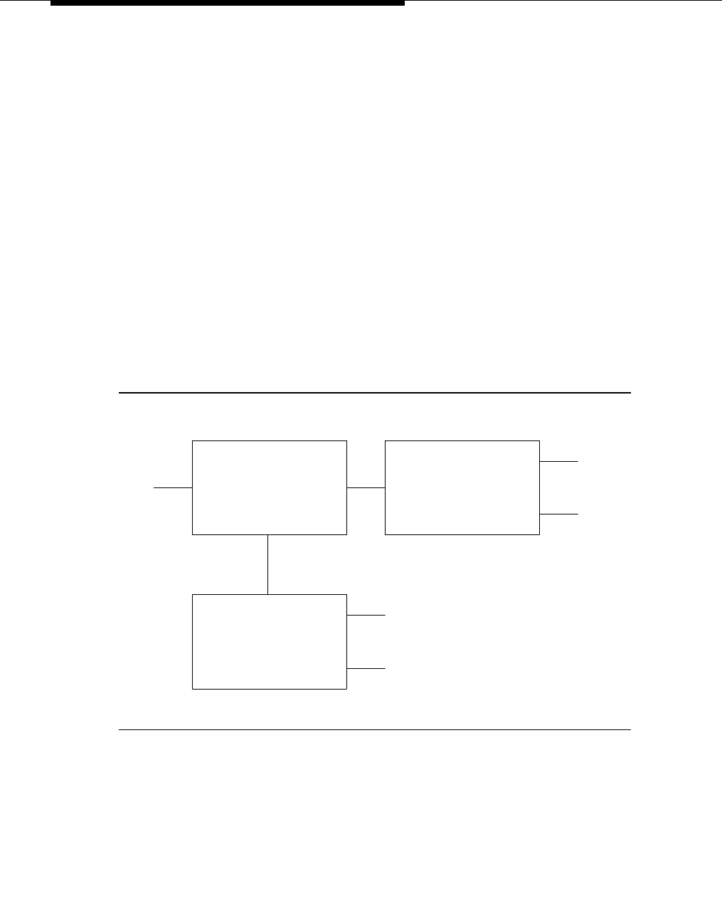
Feature Descriptions
3-1186 Issue 3 March 1996
If AAR is active on the network, then subnet trunking can be used to insert the
AAR feature access code on the originating end, or digit insertion may be used
to insert it on the incoming end. On the destination switch, AAR conversion is
administered to convert 222 with 7 digits to an extension by deleting 3 digits and
inserting a ‘6’. If AAR is not active, then Subnet Trunking must be used on the
source switch to delete the XXX and insert the digit ‘6’ at the beginning of the
extension number so that the receiving switch can continue to route correctly.
If the user at extension 51234 on Switch C dials extension 61234, the call must
first go through Switch A before proceeding to Switch B. When 61234 is dialed,
the system recognizes 61 as a PBX code, determines the associated RNX (222),
and uses AAR to route the call. The call will first be routed to Switch A, where
Switch A will then recognize the RNX 222 as a remote switch and route the call to
Switch B and extension 61234. This same type of call routing occurs when an
extension at Switch B calls an extension at Switch C.
If extension 61234 on Switch B calls extension 61235, the system recognizes 61
as a PBX code with an RNX that is local to the switch, and the call is routed
directly to extension 61235. See Figure 3-30 below.
Figure 3-30. UDP Example
For G3vsV1/G3sV1 and G3iV1 only, once a certain PBX code is assigned to a
switch, no other switch within the UDP can use that same PBX code.
For G3vsV1/G3sV1 and G3iV1, when a user at a switch that is included in a UDP
dials an extension, the system checks to see if the first digit(s) of the extension is
an assigned PBX code. If the first digit(s) is not an assigned PBX code, the call is
routed via the regular, non-UDP, dial plan. If the first digit(s) is an assigned PBX
SWITCH A
DIAL PLAN FOR EXTENSIONS
RNX = 224
EXT.
41000
DIAL PLAN FOR EXTENSIONS
SWITCH B
RNX = 222
EXT.
60123
61234
EXT.
DIAL PLAN FOR EXTENSIONS
EXT.
EXT.
SWITCH C
RNX = 223
51234
52000
IS: 41XXX IS: 60XXX AND 61XXX
IS: 51XXX AND 52XXX

Uniform Dial Plan (UDP)
Issue 3 March 1996 3-1187
code, the system translates the PBX code into the administered RNX. (This is in
reverse for G3r.) If the PBX code indicates that the called extension is on the
same switch, the call is routed to the local extension. If the PBX code indicates
that the called extension is at another switch within the UDP, AAR uses the
associated RNX to route the call to the correct switch within the private network.
(The necessary subset of AAR is provided with the UDP software.) If the PBX
code is not assigned a corresponding RNX, the user receives intercept
treatment. For G3rV1, G3V2, and later releases, when a user at a switch that is
included in a UDP dials an extension, the system first checks to see if the
extension is assigned to a local station on that switch. If so, the call is routed to
the station, and UDP is not invoked. If the extension is not found locally, the
system checks to see if the extension matches an assigned extension code. If
the extension matches an assigned extension code, the system performs the
specified conversion into a private network number and routes the call as
specified. (The necessary subset of AAR is provided with the UDP software.) If
more than one extension code matches, the ‘‘best’’ match (most explicit digits) is
used. For example, ‘‘1234x’’ will be chosen over ‘‘123xx’’ if ‘‘12345’’ is dialed (but
‘‘123xx’’ will be chosen if ‘‘12355’’ is dialed). If no matching extension code is
found, the user receives intercept treatment, or, if enabled, the call will route via
ETA.
The UDP allows a user to call other extensions within a private network by dialing
a 4- or 5-digit number. However, if AAR is provided, a user can also call other
extensions by dialing the AAR access code, the RNX of the switch to be called,
and then the desired extension number. For example, if a user on switch A wants
to call extension 3797 on switch B, the user can either dial 3797 or dial the AAR
access code followed by RNX 3797. When the user dials RNX 3797, AAR will
route the call to the correct switch and extension.
The following applies only if AAR is not implemented. If a five-digit UDP is used,
the routing pattern of each RNX must be administered so that it inserts a prefix
digit at the beginning of the extension. For example, as shown in the earlier
figure, if a user on switch A wants to call extension 61234 on switch B, the user
could dial 222-3797. Then, the routing pattern assigned to the dialed RNX would
insert the prefix 6 at the beginning of the extension and route the call to the
desired extension.
Considerations
The UDP feature enables a terminal user at any switch to call any other terminal
on any switch in the UDP complex, using only the 4- or 5-digit extension number.
Since extensions beginning with 0 may be routed by some switches to the
attendant in a network environment, administrators are discouraged from using
this number as the leading digit when assigning extensions.
When calling an extension on another switch, there is a slight delay before call
progress tones are applied. This delay is due to the trunk signaling necessary to
complete the call to the remote switch.

Feature Descriptions
3-1188 Issue 3 March 1996
For G3i only, it is possible that the first one, two, three, or four digits (PBX code)
of the 4- or 5-digit extension number could be the same as a local extension
number. In this case, the UDP PBX code overrides the extension number at the
local switch. Problems can be avoided by assuring that the PBX code does not
match an extension number.
The list of PBX codes for a switch can contain PBX codes of varying lengths. For
example, a switch may be assigned both 2-digit and 3-digit PBX codes. It is also
possible that one PBX code may be included in another. For example, a switch
may be assigned both 61 and 612 as PBX codes. In this case, all calls beginning
with 61, except those beginning with 612, are routed according to the RNX
assigned to PBX code 61. Calls beginning with 612 are routed according to the
RNX for PBX code 612. (The system always looks at the first four digits before
routing the call.)
For G3r, if AAR is active in the system, tandem tie trunks may be used to send a
traveling class mark, or FRL, along with the private network number. UDPCode
and AARCode conversions use the FRL assigned to the caller. ENPNode
conversion always raise the FRL to the maximum (7). When a user attempts to
make a call where the originating user’s FRL is insufficient to access the facilities,
the user is denied access and is not prompted for an authorization code even if
authorization codes are enabled and administered. Instead, denial is
automatically administered to the originating user (typically an intercept tone). If
AAR is not enabled in the system, tandem tie trunks should never be used to
transport UDP numbers (the TCM will not be recognized as such following the
extension received at the receiving switch).
Interactions
The following features interact with the UDP feature.
■AAR
After the system determines the RNX of the switch being called, AAR
routes the call to the correct switch. The required subset of AAR is
provided with the UDP software. If the AAR feature is provided in addition
to the UDP, then the seven-digit AAR number will provide the exact same
routing as the UDP.
■DID
DID calls to five-digit UDP extension numbers require that the DID trunk
group insert enough digits to make a five-digit extension number.
■Dial Plan
All of the extension numbers on a switch are not necessarily part of the
UDP. Any that do not belong to the UDP are handled by a regular,
non-UDP dial plan associated with the local switch. In G3i only, when
administering the dial plan and designating a group of extensions as UDP
non-local, you can specify on the “Dialplan” form whether you want to
search for local extensions first or last. This allows some flexibility in the

Uniform Dial Plan (UDP)
Issue 3 March 1996 3-1189
changing of extensions from local to non-local. However, after the dial
plan is changed to make an extension UDP, nothing can be administered
with these extensions on the local switch.
■DCS
UDP is required when DCS is provided. The necessary UDP software is
provided with the DCS software.
■ENP
For G3rV1, G3V2, and later releases, if an extension code is administered
to use ENP node routing, ENP routes the call to the correct switch. If the
AAR feature is provided in addition to UDP, then the seven-digit AAR
number provides the exact same routing a s the UDP (that is, via ENP).
Administration
The UDP is administered by the System Manager. The following items require
administration:
■Whether UDP has 4- or 5-digit extension numbers PBX Codes (expands
first one, two, three, or four digits of dialed extension to an RNX)
(G3vsV1/G3sV1, and G3iV1)
■AAR Analysis Table (used by AAR to route calls to the correct switch)
■Routing Patterns
■Node Number Routing (used to route ENP calls) (G3r)
■Extension Codes and type(s) of conversion (G3r, G3V2, and later
releases)
■AAR Digit Conversion (to define conversions for AAR Code extensions or
to define home location codes) (G3rV1, G3V2, and later releases)
NOTE:
If the user changes the “Uniform Dialing Plan” field value from a ‘‘y’’ to a
‘‘n,’’ then a warning message is generated to inform them that this action
causes all UDP extension codes to be lost. The same warning message is
applied if the “Plan Length” field value is changed from a ‘‘4’’ to a ‘‘5’’ or
from a ‘‘5’’ to a ‘‘4.’’
Hardware and Software Requirements
A Processor Interface circuit pack is required for DCS applications. DCS or UDP
software is required.

Feature Descriptions
3-1190 Issue 3 March 1996
VDN of Origin Announcement (VOA)
Feature Availability
This feature is available with Generic 3 Version 3 and later releases. The Call
Vectoring and VDN of Origin Announcements features must be optioned.
Feature History
The VDN of Origin Announcements feature was first available in the System 85
R2V4/Generic 2 releases. In these releases, the feature was known as
‘‘City-of-Origin’’ and ‘‘Queue-of-Origin’’ announcements.
Description
VDN of Origin Announcements provide a short voice message when an agent
answers a VDN call. The message informs the agent of the city of origin of the
caller or of the service requested by the caller, based on the VDN used to
process the call. The message begins as soon as the agent answers the call.
While the agent can hear both the message and the caller, the caller is not able
to hear the message.
If the agent’s terminal is connected to a DEFINITY G3V3, the caller can hear the
agent if the agent speaks during the message. If the agent’s voice terminal is in
Auto Answer mode, when the call reaches the voice terminal, the system applies
a zip tone to the call. The playback of the announcement begins when the zip
tone ends. The agent does not need to wait for the message to complete before
speaking to the caller.
If the agent’s voice terminal is connected to a DEFINITY G3V4 (and later
releases), the caller cannot hear the agent if the agent speaks during the
message since the agent is not connected to the caller until after the message is
finished. If the agent’s voice terminal is configured in Auto Answer mode, the
agent hears a zip tone before the message. The playback of the message begins
when the zip tone ends.
With G3V4 and later releases it is possible to administer the system so that the
agent also hears zip tone after the VOA completes. In this way, the agent knows
that the announcement is completed and a caller is now connected. The agent
must wait until after the second zip tone before speaking to the caller.
For G3V4 and later releases, if the agent is logged in at a multi-line terminal, the
call-appearance button for an incoming call continues to flash until after the VDN
of Origin message is completed. The agent can shorten the VOA message
playback for the incoming call by pressing the flashing call-appearance button
while the message is being heard. Also, if the agent is logged in at a terminal with

VDN of Origin Announcement (VOA)
Issue 3 March 1996 3-1191
an alphanumeric display, no incoming call information is displayed until after the
VOA message is completed.
After listening to the announcement, the agent can appropriately respond to the
caller. For example, if a user has two 800 numbers, one for placing orders and
one for technical support, they can administer two VDNs to route the calls to the
same agents. When a call enters the system and is sent to a VDN, the VDN can
have a VDN of Origin announcement assigned to it. The VDN directs the call to a
vector, and as a result of vector processing, the call can wait in one or more
queues until an agent is available. When an agent answers a call, they hear the
appropriate recording for the VDN (for example, ‘‘new order’’ or ‘‘tech help’’).
The agent then greets the caller.
If a non-ACD agent is in Automatic Answer mode, when a call reaches the voice
terminal, the system applies a call ID tone. The message begins when the call ID
tone ends. If the agent is in Manual Answer mode, when a call reaches the
voice terminal, the system applies a ringing signal. The message begins when
the agent answers the call. Note that in each case, the message begins at the
same time the agent is connected to the call.
If an agent needs to hear a message again, and if the agent’s voice terminal is
administered with a VOA Repeat feature button, the agent can press the VOA
Repeat button. The VOA Repeat button lamp stays lit while the announcement
plays. The VOA Repeat button lamp also remains lit if the system needs to queue
the request for the announcement. The lamp lights with a broken flutter if the
agent presses the VOA Repeat button but the resources to play the
announcement are not available within two to three seconds. For G3V3, if the
agent presses the VOA Repeat button when the lamp is lit, the lamp flutters to
indicate that the subsequent request has been ignored. For G3V4, if the agent
presses the VOA Repeat button when the lamp is lit, the playback of the
announcement is immediately stopped. If there is no VOA assigned, the VOA
Repeat button lamp flutters immediately when the call is answered or when a
user presses the button.
Announcements are assigned on a per-VDN basis. However, the VDN of Origin
announcement applies to a class of restriction (COR). This means you must
administer a COR for all agents who will be expecting or are expected to receive
the VDN of Origin announcements. Note that in G3V3 and later releases, the
COR feature is upgraded to enable or disable an agent’s ability to receive VDN of
Origin announcements.
You can set up VDN of Origin announcements in four different ways. You can use
any or all of these arrangements, which are:

Feature Descriptions
3-1192 Issue 3 March 1996
■The agent can hear a unique announcement based on the dialed number
identification service (DNIS) received from the service end office or carrier
switch. Each DNIS is assigned as the VDN of a vector. The announcement
associated with the VDN announces the services associated with the
DNIS.
NOTE:
The specific announcement associated with the current VDN only
plays if the “VDN Override” field of the previous VDN is marked ‘‘y’’
(yes). If the “VDN Override” field associated with the previous VDN is
set to ‘‘n’’ (no), the announcement of the previous VDN does not
play.
■Vector steps can route (using a route-to step) the call to a VDN. Or, a
response to an integrated prompting or converse-on step can route the
call to a VDN. The announcement associated with the VDN announces the
service the caller requested or can announce a condition that caused the
call to route-to the VDN.
■An incoming call routes to a voice response system, possibly through a
vector. Voice prompting directs the caller to enter a touchtone response,
and the call is then routed to a specific VDN based on the caller’s
response. The announcement associated with the VDN indicates the
service selected by the caller.
■If the agent requires a call’s city of origin, the trunk group is assigned to a
particular VDN. The announcement associated with the VDN provides the
location of the origin of the trunk group. Subsequent VDNs can be used to
handle the call, or multiple VDNs can be assigned to a single vector.
NOTE:
VDN Override applies to VOA in the same way that VDN Override applies to
display information. If a VDN with a VOA has VDN Override enabled, the
system overrides the original VOA with VOAs in subsequent VDNs to which
the call may be routed.
Considerations
Because of the nature of the VDN of Origin announcements (the customer can be
waiting while the message plays), the messages should be kept very brief, no
more than 1.5 seconds in length.
Because the announcements should be very brief, agents receiving the
messages should be using a speakerphone or headset. This way, they do not
miss the message while they are picking up the handset. If the agents cannot
use a speakerphone or headset, you can administer the voice terminals with a
VOA Repeat button that allows them to repeat the message.
The agent who receives the announcement and takes the call must be on the
same switch as the VDN of Origin Announcement.

VDN of Origin Announcement (VOA)
Issue 3 March 1996 3-1193
The system maintains a separate logical queue for the VDN of Origin
Announcements when you use the TN750 circuit board for integrated
announcements. If, because of traffic considerations or inoperative equipment,
the VDN of Origin Announcement cannot be given to the agent within 0 to 1
second, the system stops an attempt to provide the announcement.
NOTE:
VOA announcements receive higher priority than other announcements on
the TN750. A burst of VDN of Origin Announcements can cause other
announcements (such as Forced First Announcements) to be delayed.
Therefore, it is recommended that non-VDN of Origin Announcements be
recorded as auxiliary or analog.
Auxiliary announcements are connected for a duration of 1 to 2 seconds on a
barge-in basis, immediately after the agent answers (or is assigned the call for
auto-answer) and the incoming call is extended to the agent. Integrated and
non-barge-in auxiliary announcements are connected for the duration of the
announcement. This switch does not ensure that the integrated announcement is
shorter than the allowed playback time.
The VOA feature supports Auxiliary Trunk (aux-trunk) announcement types. You
can use aux-trunk with barge-in, queue, or without queue. For aux-trunk with or
without queue, when a VDN call needs the VDN of Origin announcement and the
trunk is idle, the call seizes the trunk to start the announcement and the system
plays the entire announcement (not just 1 to 2 seconds). However, if the
announcement is busy and if aux-trunk has barge-in, the call does not queue but
bridges on to the announcement for the 1 to 2 seconds needed. When the
announcement reaches its end, it causes the trunk to be released along with the
listeners; the next call needing the announcement starts the process over again.
For this reason, your aux-trunk announcements should consist of one short
announcement repeating over and over for the length of the full announcement
time. For example, you might want to record ‘‘New Order’’ over and over as many
times as possible, so that when a call bridges to the announcement, the agent
hears ‘‘New Order’’ no matter where the agent bridges into the announcement.
Also, if you use aux-trunk or integrated announcement without queue, and a port
is busy when a VDN calls comes in, the system cannot play an announcement. If
you use aux-trunk or integrated announcement with queue, the system plays the
current announcement for an agent and then connects the next agent in the
queue.
Interactions
■ASAI Adjunct Routing
If a vector step calls for Adjunct Routing, the VDN of Origin announcement
is played for the agent to which the call is routed.

Feature Descriptions
3-1194 Issue 3 March 1996
■Agent Call Handling
Answering Options
— Automatic Answer
An ACD agent set up for Automatic Answer receives zip tone
instead of ringing. The VDN of Origin Announcement begins
immediately after the zip tone ends. A non-ACD agent set up for
Automatic Answer hears an incoming call ID tone when a call
comes in. Through the use of a route-to vector step, non-ACD
agents can receive a VDN of Origin Announcement. The
announcement begins when the incoming call ID tone ends. For
G3V4 and later releases, the agent also hears a second zip tone
after the announcement indicating connection of caller to agent.
— Manual Answer
If an agent is set up for Manual Answer and is not using a headset
or speakerphone, that agent can miss the message while picking
up the call. Therefore, it is a good idea to provide a headset or
speakerphone to agents on Manual Answer.
■Attendant Console
An attendant’s voice terminal, as all other voice terminals, may have only
one VOA Repeat button. An attendant can use the VOA Repeat to replay
the message for the active call.
■Auto-Available Splits (AAS)
AAS provides a way for members of an ACD split to be in a continuous
Auto-In work mode. Agent positions with this feature are automatically put
in the Auto-In mode after a system restart. This feature is intended to be
used for splits containing only nonhuman adjuncts (such as AUDIX or
Conversant), however, VDN of Origin announcements can be directed to
Auto-Available splits.
■Call Forwarding
VDN of Origin announcements apply to forwarded calls, including those
forwarded to a hunt group. The answering station must be on the same
switch. If a VDN of Origin announcement is forwarded to another
extension, the message is played only if the destination extension is
administered with a COR that allows VDN of Origin announcements.
■Call Hold
An agent cannot use the VOA Repeat button if the agent’s calls are all on
hold. The VOA Repeat button only applies to active calls.
■Call Pickup
Call Pickup allows an agent to pick up a ringing call on another extension.
If the pick-up phone has COR permissions for VOA, the person picking up
the call receives the VOA.

VDN of Origin Announcement (VOA)
Issue 3 March 1996 3-1195
■Conference
If an agent receives a call and then conferences in additional stations,
any station on the connection can replay the message using the VOA
Repeat button. Only the person using the button is able to hear the
message unless the call is being service observed. In such case, the
service observer also hears the message.
■Converse Split
A converse-on split is a split used in a converse-on vector step. When a
converse-on vector step is executed, VOA is not applied. After returning
to the vector, the call can route-to a station or VDN where the answering
agent will receive VOA (as if the converse-on step had not been
encountered). Also, the final routed-to agent can replay the
announcement if the agent has a VOA Repeat button administered.
■Coverage
VOA applies to Coverage paths.
■Data Restriction
The Data Restriction feature prevents tones from being applied to line or
trunk circuits during a data call. The VDN of Origin announcement is not
played for data restricted calls.
■Direct Agent Calling
Direct Agent Calling allows a vector to route-to a particular ACD agent
and have the call treated as an ACD call. The VDN of Origin
announcement applies to the Direct Agent calls only if the calls reach the
agent through vector processing. Direct Agent calls from a voice terminal
on a switch do not encounter a VDN and therefore cannot cause a VDN of
Origin Announcement to be played.
■Enhanced Automatic Wake-up
If you are also using the G3V3 enhancements to Automatic Wake-up with
integrated announcements, these two features can contend for use of the
integrated announcement ports. VDN of Origin Announcements have
priority over Automatic Wake-Up announcements.
■Expert Agent Selection (EAS)
When you are using EAS, the COR option for the logical agent determines
the assignment of VDN of Origin Announcements for each particular
extension. EAS uses the COR of the logical agent instead of the COR for
the terminal being used by the agent.
■Home Agent
An initial VDN of Origin Announcement can be assigned to a Home Agent
port on the switch. However, because home agents require a dial access
code (DAC) to reach features and because the ability to replay a VDN of
Origin Announcement does not use a DAC, the VOA Repeat key function
is not available to a Home Agent user.

Feature Descriptions
3-1196 Issue 3 March 1996
■Hunt Groups
VDN of Origin announcements apply to calls routed to a hunt group. If this
occurs, the COR for extension associated with the answering station
determines whether the station can receive a VDN of Origin
announcement. If the answering station has a VOA Repeat button, the
agent can use it to replay the message.
■Lookahead Interflow
VDN of Origin Announcements apply only to the switch on which the VDN
is defined. If a call interflows to another switch, the VDN of Origin
announcement is lost. You can provide some level of transparency by
having the interflow to the other switch access a VDN with the same VDN
of Origin Announcement. Note that interflow to another switch does pass
on the display information.
■Redirection on No Answer (RONA)
Calls that are not answered before the RONA timer expires are requeued
to await another available agent. The timer stops when an agent answers
the call. If the requeues are a result of the RONA timer expiring, the VDN
of Origin Announcement applies to the call at the time an agent finally
answers the call.
■Service Observing
Service Observing allows an observer to bridge on to ACD agent calls.
The system treats the call as a conference connection. Therefore, the
service observer can press the VOA Repeat button to replay the VDN of
Origin Announcement, and only the service observer hears the
announcement. However, if any other party on the call presses the VOA
Repeat button, both the user and the service observer hear the
announcement.
■Supervisor Assist
If an agent receives a call and then requests supervisor assistance and
conferences in the supervisor, both the agent and the supervisor can use
their VOA Repeat button to replay the message. Only the person who
presses the button hears the message.
■Transfers
If an agent receives a VDN call and subsequently transfers the call, the
receiving station can use the VOA Repeat button to replay the message.
■VOA Distribution
If several VOA announcements are used, or if long VOA announcements
are used, it is possible that a delay may occur between the zip tone and
the announcement. On pre-G3V4 units, it may be possible to install an
auxiliary announcement device on the AUX port. An AT&T 15A unit can be
used in most applications. Also, if the system is a G3V3 or lower, it may be

VDN of Origin Announcement (VOA)
Issue 3 March 1996 3-1197
better to upgrade the system to a G3V4. The G3V4 provides multiple
announcement circuit packs to help prevent the announcement delays.
Contact your AT&T representative for more information.
Administration
VDN of Origin Announcements feature must be enabled on the
“System-Parameters Customer-Options” form. Vectoring must also be enabled.
If you want the attendants and agents to be able to replay VDN of Origin
Announcements, you must administer a VOA Repeat feature button for the
appropriate terminals. This is done using the “Attendant Console” form and the
specific “Voice Terminals Station” forms.
Because agent ability to receive announcements is based on their COR, you
must use the “Class of Restriction” form to administer VDN of Origin
Announcements for each COR you want to receive the announcements.
Each announcement must be administered on the “Recorded Announcements”
form. You can administer aux-trunk types with queue, without queue, and with
barge-in. You can also administer integrated types with queue and without
queue. Analog and integrated repeating announcement types are not allowed for
VOA.
Because VDN of Origin Announcements are associated with VDNs, you must
administer announcement numbers on the “Vector Directory Number” form. A
VDN of Origin Announcement can be assigned to any number of VDNs, but a
single VDN can have, at most, one VDN of Origin Announcement.
Hardware and Software Requirements
This feature requires the following circuit packs: TN7417, TN763C, or TN763D
auxiliary trunk for announcement devices, and/or the TN750B or higher
integrated announcement boards for internal announcements.
The feature can operate on any attendant terminal and any other voice terminal.
If you want to use the VOA Repeat button, the voice terminals must be equipped
with feature buttons. Because of the short length of the announcements, agents
should use speakerphones or headsets.
Vectoring and VDN of Origin Announcements must be enabled.

Feature Descriptions
3-1198 Issue 3 March 1996
Visually Impaired Attendant Service
(VIAS)
Feature Availability
This feature is available with G3i-Global, all Generic 3 V2, and later releases.
Description
Provides voice feedback to a visually impaired attendant in either Italian or British
English. Each voice phrase is a sequence of one or more single voiced
messages.
Six new attendant buttons are defined for the VIAS feature:
■Visually Impaired Service Activation/Deactivation Button: This button
activates or deactivates the feature for the console from which it was
pressed. When VIAS is activated, an indicator lamp lights next to the
button. In addition, all ringers which were disabled (for example, recall,
incoming calls, and so on) are enabled.
■Console Status Button: This button allows the visually impaired attendant
to determine whether the console is in Position Available or Position Busy
state, whether the console is a night console, the status of the attendant
queue, and the status of system alarms.
■Display Status Button: This button allows the visually impaired attendant to
determine what is shown on the console display. Not all display features
are supported by VIAS. Class of restriction information, personal names,
and some call purposes ar not supported.
■Last Operation Button: This button voices the last operation performed.
■Last Voiced Message Button: This button allows the visually impaired
attendant to retrieve the last voiced message.
■Direct Trunk Group Selection Status Button: This button allows the visually
impaired attendant to obtain the status of an attendant monitored trunk
group.
The visually impaired attendant may use the Inspect mode locate each button
and determine the feature assigned to each without actually executing the
feature. To do this, the attendant presses the Inspect button and then presses
each button in turn and listens to the voiced information about it. Afterwards, the
attendant presses the Normal button to end Inspect mode.

Visually Impaired Attendant Service (VIAS)
Issue 3 March 1996 3-1199
Considerations
Some changes on the attendant console are automatically voiced, for example,
alarms reported, night service activated, and call threshold reached.
After system initialization, VIAS is not automatically activated. After a warm restart
operation, VIAS remains activated if it was already activated. After recovery and
cold restart operations, VIAS is not automatically activated even if it was
activated before the recovery or restart attempt. Finally, whenever the attendant
console goes to a busyout state and VIAS is activated, VIAS is automatically
deactivated.
Interactions
When VIAS is activated, Auto Start is always enabled. The attendant can activate
the Don’t Split feature as normal if VIAS is activated, however, the
Don’t Split feature, if currently activated, is automatically deactivated when the
attendant deactivates VIAS.
Administration
VIAS is turned off by default. Before an attendant can use the Activate/Deactivate
button, or any of the VIAS buttons, these buttons must be administered with the
“Attendant Administration” form.
Hardware and Software Requirements
This feature requires at least one Speech Processor circuit pack to be installed
into a system port carrier since VIAS capabilities are performed with speech
synthesis messages voiced to the attendant. The United States speech
processor circuit pack does not support VIAS.

Feature Descriptions
3-1200 Issue 3 March 1996
Voice Message Retrieval
Feature Availability
This feature is available with all Generic 3 releases.
Description
Allows attendants, voice terminal users, and remote access users to retrieve
LWC and Call Coverage messages in the form of a voice output. Voice choices
are UK and US English and Italian; these choices depend on the voice synthesis
circuit pack provided.
Voice Message Retrieval is used only for the retrieval of messages. It can be
used to retrieve a user’s own messages or to retrieve messages for another user.
However, a different user’s messages can only be retrieved by a user at a voice
terminal or attendant console in the associated coverage path, by an
administered systemwide message retriever, or by a Remote Access user when
the extension number and associated security code are known.
Messages are protected by restricting unauthorized users from retrieving
messages. A Lock function restricts a voice terminal and an Unlock function
releases the restriction. The Lock function is activated by dialing a systemwide
access code. The Lock function is canceled by dialing a systemwide access
code and then an Unlock security code unique to the voice terminal. These
functions apply only to the voice terminal where the operation is performed. The
systemwide access codes and security code used for the Lock and Unlock
functions are the same as those used for LWC message retrieval by display. A
status lamp can be assigned to show the locked or unlocked status of a terminal.
Voice Message Retrieval is activated by dial access code. Separate access
codes are used for Message Retrieval and Coverage Message Retrieval
(someone else’s messages). Voice Message Retrieval is activated as follows:
■To retrieve one’s own messages:
Dial the access code for Voice Message Retrieval of LWC messages.
Then, dial a # sign to indicate that the extension whose messages are to
be retrieved is the dialing extension, or enter a specific extension and
corresponding password (same as the security code used for the Lock
and Unlock functions).
■To retrieve someone else’s messages:
Dial the access code for Voice Message Retrieval of Call Coverage
messages, followed by the extension of the user (within the same
coverage path) whose messages are to be retrieved.
After Voice Message Retrieval has been activated, message retrieval may not be
allowed for the following reasons:

Voice Message Retrieval
Issue 3 March 1996 3-1201
■Speech Synthesizer circuit pack fails or all voice channels are busy —
Reorder tone is provided.
■An attempt is made to retrieve a message for a user not in the same
coverage path or an invalid password has been entered — ‘‘Message
Retrieval Denied’’ is heard and the user is disconnected.
■Message retrieval for the terminal whose messages are to be retrieved is
locked — ‘‘Message Retrieval is locked’’ is heard and the user is
disconnected.
■No message is heard within 10 seconds — ‘‘Press 4 for help’’ is heard and
if no messages are heard within another 10 seconds, the user is
disconnected.
When Voice Message Retrieval has successfully been activated, voice
messages are heard as follows:
■If no messages are left, one of the following is heard:
— ‘‘No messages for [abc]’’ — where [abc] are the initials associated
with the user whose messages are to be retrieved
— ‘‘No messages for extension [xxxxx]’’ — where [xxxxx] is the
extension number when no name is associated with the user whose
messages are to be retrieved
■If one message, or more, is left, one of the following is heard:
— ‘‘[n] messages(s) for [abc]’’ — where [n] is the number of
messages left for the user whose messages are being retrieved
— ‘‘[n] messages(s) for [xxxxx]’’
— ‘‘Messages for [abc]’’ — when an AP is provided
— ‘‘Messages for [xxxxx]’’ — when an AP is provided
When a user’s initials are given in a voice message, as previously described, the
initials are computed in the ‘‘first name(s) followed by last name’’ order. If a
single name (Brown, for example) is administered, the entire name is spelled out.
When a user has activated Voice Message Retrieval and has heard the number
of messages that has been left, one of the following functions, as described
below, can be performed:
■NEXT — dial #
■REPEAT — dial 5 or *5
■DELETE — dial 3 or *3
■CALL — dial 8 or *8
■HELP — dial 4 or *4
If NEXT is selected, the next message, if there is one, is played. The following
messages may be heard:

Feature Descriptions
3-1202 Issue 3 March 1996
■‘‘No more messages for [abc]’’ or ‘‘No more messages for extension
[xxxxx]’’ — when there are no more messages.
■‘‘[abc] called [n] times, last message at [time] [date] extension [xxxxx]’’ —
when the user has received more than one message from the same caller;
[abc] are the caller’s initials; [n] is the number of times called; [time] is
expressed an hour followed by minute (for example, ‘‘Nine Thirty-Five
PM’’); [date] is expressed as month followed by day (for example, ‘‘July
third’’) or ‘‘today,’’ if applicable; [xxxxx] is the calling party’s extension
number.
■‘‘extension [xxxxx] called [n] times, last message at [time] [date]’’ — when
the user has received more than one message from the same caller and
no name is associated with the extension.
■‘‘[abc] called at [time] [date] extension [xxxxx]’’ or ‘‘extension [xxxxx]
called at [time] [date]’’ — when only one message has been left by a
particular extension number.
If the REPEAT function is selected, the synthesized voice repeats the previously
retrieved message with the calling party’s name spelled out (instead of initials).
The name is spelled out as it is administered in the system (with pauses between
first and last names and also between first names if there is more than one). If no
name is associated with the extension, the current message is repeated. If a
message has not been retrieved, ‘‘Press pound for the next message’’ is heard.
If the DELETE function is selected, the previously retrieved message is deleted
and the user hears ‘‘Message is deleted.’’ If no message was previously
retrieved, ‘‘Press pound for next message’’ is heard. After a message is deleted,
the user can still place a call to calling party of the deleted message, via the
CALL function, as long as no other function has been entered between DELETE
and CALL.
If the CALL function is selected, the extension of the calling party from the
previously retrieved message is called. If no message was previously retrieved,
‘‘Press pound for next message’’ is heard. Otherwise, the call is initiated and the
user leaves the message retrieval mode.
If the HELP function is selected, the following speech synthesized message is
heard: ‘‘Press pound for the next message, press 3 to delete the message, press
4 for help, press 5 to repeat the message, press 8 to place the call.’’
The system expects the user to enter a function after each voice message. If a
function is not entered before a specified time or if an invalid digit (digit other
than #, *, 3, 4, 5, or 8) is dialed, the voice message ‘‘Press 4 for help’’ is heard. If
no other input is entered within 10 seconds after this message, the user is
automatically disconnected.
Voice Message Retrieval can be deactivated to get out of the voice message
retrieval mode by doing any of the following:

Voice Message Retrieval
Issue 3 March 1996 3-1203
■Hang up
■Press the Drop or Disconnect button
■Activate CALL function
Considerations
With Voice Message Retrieval, a display-equipped voice terminal is not required
to retrieve messages. Authorized users on any touch-tone terminal can retrieve
messages. This results in significantly reduced traffic to the Message Centers
and systemwide message retrievers.
The number of simultaneous Voice Message Retrieval users possible is
dependent on the number of speech synthesizer circuit packs used in the
system.
Voice Message Retrieval cannot be accessed by rotary dialing voice terminals.
Certain voice terminals and attendants can be designated for systemwide
message retrieval. These systemwide retrievers are the same as those used for
display message retrieval and have the same privileges.
When a terminal is in the Voice Message Retrieval mode, it cannot be used to
make calls or access other features.
Interactions
The following features interact with the Voice Message Retrieval feature.
■AUDIX Interface
Retrieval of LWC messages via Voice Message Retrieval is separate and
distinct from AUDIX voice message retrieval. LWC messages left for a
principal on AUDIX may not be accessed via Voice Message Retrieval;
however, the invoker of Voice Message Synthesized Retrieval is told if
there are any new messages for the principal on AUDIX:
— Voice Message Retrieval
voices
that there are message messages
(dialing 8-callout calls AUDIX).
— The display retrieval displays Message Center AUDIX Call.
If your system has a voice synthesis circuit pack, and if LWC Activation is
enabled, then messages are retrieved from two locations:
— LWC messages sent by pressing the LWC button on a voice
terminal are retrieved via Voice Message Synthesized Retrieval.
— All other messages are retrieved via AUDIX.

Feature Descriptions
3-1204 Issue 3 March 1996
If your system does not have a TN725B Voice Messaging Retrieval board,
and if LWC Activation is enabled, then LWC messages sent by pressing
the LWC button on a voice terminal are not retrievable by a nondisplay set.
■Bridged Call Appearance
Activation of Voice Message Retrieval on a Bridged Call Appearance
functions the same as if it was activated by the primary extension
associated with the Bridged Call Appearance.
■Call Forwarding
A forwarded-to user cannot retrieve messages for a forwarding user
unless the forwarded-to user is in the forwarding user’s coverage path.
■Call Pickup
A user cannot retrieve messages for a member of his or her Call Pickup
group, unless the retrieving user is in the other user’s coverage path.
■LWC
Voice Message Retrieval enhances LWC by allowing any authorized
touch-tone terminal user to retrieve messages.
Administration
Voice Message Retrieval is administered by the System Manager. The following
items require administration:
■Voice Message Retrieval Access Code for LWC message retrieval
(per system)
■Voice Message Retrieval Access Code for Call Coverage message
retrieval (per system)
■Lock and Unlock Access Codes (per system)
■Unlock Security Code (per voice terminal)
■Identities of authorized systemwide message retrievers
Hardware and Software Requirements
Requires a TN725 (American English), TN457 (British English), or TN433 (Italian)
Voice Synthesizer. Each circuit pack has four ports to provide Voice Message
Retrieval. No additional software is required.

Voice Response Integration (VRI)
Issue 3 March 1996 3-1205
Voice Response Integration (VRI)
Feature Availability
Voice Response Integration (VRI) is available with G3V2 and later releases.
Description
VRI is designed to enhance the integration of the DEFINITY Communications
System. VRI is designed to integrate the DEFINITY system Call Vectoring with the
capabilities of voice response units (VRUs), particularly AT&T’s CONVERSANT
Voice Information System.
VRI can do the following:
■Execute a VRU script while retaining control of the call in DEFINITY system
vector processing.
■Execute a VRU script while the call remains in the split queue and retains
its position in the queue.
■Pool CONVERSANT ports for multiple applications. (Previously, this was
possible only when ASAI was present.)
■Use a VRU as a flexible external announcement device.
■Pass data between a DEFINITY switch and a VRU.
■Tandem VRU data through a DEFINITY switch to an ASAI host.
The capabilities in the previous list are provided by the converse-on command,
which is an enhancement to the Basic Call Vectoring customer option. The
converse-on Call Vectoring step is specifically designed to integrate a VRU with
the DEFINITY system Automatic Call Distribution (ACD). VRI allows VRU
capabilities to be used while keeping control of the call in the DEFINITY system
ACD. The inclusion of VRUs with vector processing provides the following
advantages:
■Access to local and host databases
■Validation of caller information
■Text to speech capabilities
■Speech recognition
■Increased recorded announcement capacity
■Audiotex applications
■Interactive Voice Response (IVR) applications
■Transaction processing applications

Feature Descriptions
3-1206 Issue 3 March 1996
One of the advantages of VRI is that it allows users to make more productive use
of queuing time. For example, while the call is waiting in queue, the caller can
listen to product information by using an audiotex application or by completing
an interactive voice response transaction. In some cases, it may even be
possible to resolve the customer’s questions while the call is in queue. This can
help reduce the queuing time for all other callers during peak intervals.
During the execution of a VRU script, if the caller previously queued to an ACD
split, the caller retains his/her position in queue. If an agent on the DEFINITY
switch becomes available to service the call, the line to the VRU is immediately
dropped, and the calling party is connected to the available agent.
If the converse-on command is successful, it delivers the call to a
pre-determined split (skill), which is referred to as the converse-on split (skill). A
converse-on split is administered and behaves exactly as any other split in the
system. The term non-converse-on split is used to refer to traditional ACD splits
accessed by means of queue-to main and check-backup vector steps.
The members of the converse-on split are the DEFINITY ports connected to the
VRU. If all VRU ports are currently busy, the call queues to the converse-on split
at the administered priority.
Once the call is answered by the VRU, the converse-on command may or may
not pass data to the VRU (depending upon the parameters of the command). Up
to two items of data may be passed. This data may be used to select the VRU
script to be executed or it may be information passed to the script.
The following values to be passed to the VRU may be administered within the
converse-on split (skill) command:
NOTE:
Up to two items of information can be passed to the VRU.
■Administered digit string. This string can contain up to six characters
consisting of one or more digits (0 through 9) or asterisks (*). The pound
sign (#) may not be included in a digit string because it is reserved as the
end-of-string character. However, a single ‘‘#’’ may be administered.
■‘‘ani’’: If the call is an internal call or an incoming DCS call, this data type
causes the extension of the calling party to be outpulsed. If the call is an
incoming ISDN PRI call with ANI (BN) provided to the DEFINITY system,
the calling party number/billing number (CPN/BN) of the calling party is
outpulsed to the voice information system. If there is no ANI (BN) to send,
the end-of-string pound sign (#) is the only character outpulsed. Any other
type of incoming call results in ‘‘#’’ being outpulsed.
■‘‘vdn’’: This data type causes the VDN extension to be outpulsed. In
cases where multiple VDNs are accessed, normal VDN override rules
determine which VDN extension is outpulsed.

Voice Response Integration (VRI)
Issue 3 March 1996 3-1207
■‘‘digits’’: This data type can be used only if Call Prompting is optioned,
and it causes the most recent set of digits collected in vector processing
to be outpulsed. If no digits are available, the end-of-string pound sign (#)
is the only character outpulsed.
■‘‘qpos’’: This data type causes the value of the queue position of a call in
a nonconverse split to be outpulsed. This value is a variable length data
item from which between one and three digits can be outpulsed. If the call
is not queued, the end-of-string pound sign (#) is the only character that is
outpulsed.
NOTE:
The use of this keyword is not recommended with multiple split
queuing because any queue position value that is sent may not be
meaningful. However, if the call is queued to multiple nonconverse
splits, the value of the caller’s queue position in the first nonconverse
split is sent.
This data may be used by the voice information system to inform callers of
their position in queue or to decide whether to execute a long or short
version of a voice response script.
■‘‘#’’: This is the only character outpulsed. Outpulsing this character
causes the corresponding
prompt and collect
command in the voice
response script to be skipped.
■‘‘none’’: This data type causes no characters to be outpulsed. Also, no
end-of-string pound character (#) is outpulsed, and no time delays are
invoked.
■“wait”: This data type can be used only if the “Vectoring (G3V4 Advanced
Routing)” customer option is enabled. It causes the expected wait time of
the call to be outpulsed. If the call is not queued or if it is queued only to
splits that are unstaffed or splits where all agents are in AUX work mode,
the end-of-string character “#” is the only character outpulsed.
Regardless of whether or not data is passed, the caller is then connected to the
VRU, which in turn executes the VRU script. At this point, any audible feedback
provided by the vector is disconnected, and no further vector steps are executed
until the VRU script is completed.
If the call was queued to a non-converse-on split before the converse-on
command was executed, the call retains its position in the non-converse-on
split queue. If an agent from the non-converse-on split becomes available to
service the call while the VRU script is still being executed, the DEFINITY system
drops the line to the VRU and connects the caller to the available agent. The VRU
in turn detects the disconnect and terminates the VRU script.
Once the VRU script is completed, the VRU may or may not return data to the
DEFINITY system. Whether or not data is returned, once the VRU drops the line
to the DEFINITY system, vector processing is then re-activated on the switch
starting with the vector step which follows the converse-on step.

Feature Descriptions
3-1208 Issue 3 March 1996
Digits returned by the VRU are treated as dialahead digits. Call prompting must
be optioned to collect and use these digits. The rules for collecting and
processing VRU-returned digits are identical to those for Call Prompting.
Digits returned from the VRU can be used in the following way:
■Displayed on the answering agent’s display set (automatically for 2-line
displays (such as a 7407 or Call Master) using the CALLR-INFO button for
other display sets).
■Treated as an extension in a route-to digits vector step. For example the
following:
— converse-on split. . . . (VRU returns 4 digits)
— collect 4 digits after announcement none
— route-to digits coverage y
■Used for vector conditional branching in an if digits equals vector step.
For example the following:
— converse-on split . . . (VRU returns 1 digit)
— collect 1 digit after announcement none
— goto vector 101 if digits = 1
— goto vector 102 if digits = 2
— goto vector 103 if unconditionally
■Tandemed to an ASAI host.
— VRI also provides the integration of VRUs with ASAI hosts. Since
collected digits are also passed to ASAI hosts in ‘’Call Offered to
Domain Event’ reports and in route request messages, caller
digits or database information returned from the VRU may also be
tandemed through the DEFINITY system to ASAI hosts.
For example:
1. converse-on split ... (VRU returns 9 digits)
2. collect 9 digits after announcement none
3. adjunct route link Y
In this vector, the digits returned from the VRU are forwarded to the
ASAI host in the adjunct routing ‘‘route request’’ message.
Refer to
DEFINITY Communications System Generic 3 Call Vectoring/Expert
Agent Selection (EAS) Guide,
555-230-520, for additional information.

Voice Response Integration (VRI)
Issue 3 March 1996 3-1209
Security Measures
When a converse step is used to access a VRU application that returns data for a
collect digits step, the opportunity for toll fraud exists when the VRU application
fails to return any data. To avoid this type of toll fraud be certain that one of the
following is true:
■If the collected digits are used to route calls internally, be certain that the
Class of Restriction (COR) for the Vector Directory Number (VDN) does
not allow calls to route externally.
■If it is necessary to use the collected digits to route calls externally, use a
password to verify that the collected digits have been passed by the VRU
application. For example, in the following vector the VRU application
returns a three-digit password followed by the eight-digit external number.
The vector routes calls without the correct password to a different vector
and routes calls with the correct password to the collected digits.
Considerations
VRI allows the CONVERSANT to be used as a flexible external announcement
device. Although only one caller can be connected to each port within this
scenario, up to 48 callers can be simultaneously connected to CONVERSANT.
VRI can be used to pass the announcement number to CONVERSANT, thus
allowing any announcement to be played on any port.
Interactions
The following features interact with VRI.
NOTE:
If not noted below, the converse-on split has the same interaction as other
vector controlled splits.
■Adjunct Switch Applications Interface (ASAI)
Data returned from the VRU can be tandemed through the DEFINITY
system to the ASAI host with VRI. This provides better integration of VRUs
and ASAI hosts.
If a converse-on step places a call to an ASAI-monitored domain, ASAI
event messages are sent over the ASAI link.
converse-on split 10 pri m passing none and none
collect 3 digits after announcement none
goto vector 23 if digits <> 234
collect 8 digits after announcement none
route-to digits with coverage n

Feature Descriptions
3-1210 Issue 3 March 1996
When an ASAI-monitored call is placed by a converse-on vector step, the
ALERTing message sent to the ASAI host includes a Cause IE, Coding
Standard 3 value 23 (CS3/23). As a result, the ASAI host is informed that
the call has not been de-queued from any non-converse-on splits.
If a converse-on step is executed while an adjunct routing request is
outstanding, the route request is canceled.
Any attempt by ASAI to transfer or conference the call is denied.
■Answer Supervision
Answer supervision is returned only once during the life of a call. If a call is
answered as a result of a converse-on step, answer supervision is sent if
it hasn’t previously been sent. If digits are passed to the VRU, answer
supervision is not sent until after the digits are outpulsed.
■Audio Information Exchange (AUDIX)
If a converse-on step calls AUDIX, the call is treated as a direct call to
AUDIX. The caller hears the ‘‘welcome to AUDIX’’ message and may
retrieve his or her messages in the usual manner.
If a call is forwarded to a VDN and then delivered to an AUDIX hunt group
by a converse-on step, the call to AUDIX is treated as a redirected call,
and the caller may leave a message for the principal.
■Automatic Answering with Zip Tone
When administering conversant ports as agents of a converse-on split,
agents should not be administered as automatic answer. If auto-answer is
administered, the DEFINITY system provided zip tone may interfere with
the interaction between CONVERSANT and the calling party.
■Auto-Available Splits
A converse-on vector step may place a call to an auto-available split.
Except in cases where the converse-on split is ASAI-controlled,
auto-available converse-on splits are recommended for VRI.
■Basic Call Management System (BCMS)
BCMS tracks calls placed by a converse-on step to a BCMS-measured
hunt group. The VDN tracks this call as waiting in the vector. A call is
considered ‘‘answered’’ when it is answered by a non-converse-on split
but never when it is answered by a converse-on split. The converse-on
split tracks this as a separate ‘‘answered’’ call when the VRU answers.
Trunk totals may no longer match split totals, however, VDN totals and
trunk totals match.
■Call Detail Recording (CDR)
For incoming calls to a VDN, the duration of the call is recorded from the
time answer supervision is returned. Answer supervision is returned for a
successful converse-on step. No ineffective call attempt records are
generated for converse-on steps that fail. Also, no outgoing calls can be
placed by a converse-on step.

Voice Response Integration (VRI)
Issue 3 March 1996 3-1211
■Call Management System (CMS)
CMS tracks calls placed by a converse-on step to a CMS-measured hunt
group, split or skill. Converse-on vector steps may be administered from
CMS R3V2 and later releases.
The VDN tracks this call as waiting in the vector. A call is considered
‘‘answered’’ when it is answered by a non-converse-on split but never
when it is answered by a converse-on split. The converse-on split
tracks this as a separate ‘‘answered’’ call when the VRU answers. Trunk
totals may no longer match split totals, however, VDN totals and trunk
totals match.
■Call Park
Calls placed by a converse-on step may not be parked.
■Call Pickup
Calls placed by a converse-on step ringing at an agent station may be
picked up if that agent is part of a pickup group. Subsequent transfers are
denied.
■Call Prompting
The Call Prompting customer option must also be enabled to gain full VRI
functionality. Without Call Prompting, any data returned by CONVERSANT
cannot be collected and processed by the switch.
If the converse-on step places a call to a split of live agents, any digits
collected previously may be displayed by agents using the callr-info
button.
■Call Vectoring — Basic
The converse-on vector step is an enhancement to the Basic Call
Vectoring customer option. This option must be enabled in order to invoke
the VRI feature.
■Class of Restriction (COR)
As is the case for the queue-to main split and check-backup split
vector steps, no COR checking is carried out when a converse-on vector
step places a call to a split.
■Conference
Any attempt to conference a call placed by a converse-on step is
denied.
■Direct Department Calling (DDC)
A converse-on split may be administered as a direct department calling
split.

Feature Descriptions
3-1212 Issue 3 March 1996
■Distributed Communications System (DCS)
If an incoming DCS call is placed to a vector with a converse-on split
x
pri m passing ani... step, the DCS extension of the calling party is
outpulsed.
■Expert Agent Selection (EAS)
The converse-on vector step may place a call to a skill hunt group.
■Feature Access Codes
Dialing the converse data feature access code at any time other than
during a converse-on session produces an intercept tone.
■Four Priority Levels
A call placed by a converse-on step may be queued at one of four priority
levels: low, medium, high or top.
■Hold
Although not recommended, a converse-on step may place a call to a
split of live agents. An agent answering a converse call may put the call on
hold. Music on hold, if administered, is suppressed.
If an agent from a non-converse-on split services the call while the caller is
placed on hold, the agent who placed the caller on hold is dropped from
the call, and the caller is connected to the agent from the non-converse-on
split.
■Hold — Automatic
Automatic hold applies to converse-on calls.
■Hunt Groups
The converse-on vector step may deliver a call to a vector-controlled hunt
group, ACD split, Agent Skill, Message Center or AUDIX hunt group.
■Integrated Services Digital Network (ISDN)
The converse-on step may be administered to outpulse to CONVERSANT
the CPN/BN (calling party number/billing number) of the calling party via
use of the ‘‘caller’’ keyword.
■Intra-switch CDR
If a converse-on call is answered successfully, and if either the calling
party or the VDN relevant to the call is administered for intra-switch
recording, the timing for the call is started. If either the calling party or
VDN is so administered, the CDR record shows ‘‘calling party to VDN’’ as
the originating and answering parties.
■Line Side T1 Connectivity
T1 connectivity between DEFINITY and CONVERSANT is supported for
the VRI feature. The DS1 board must be a TN767E (or later) or TN464F (or
later). On the switch side, all the converse agents should be administered
as DS1FD type stations. The feature operation of the converse step using

Voice Response Integration (VRI)
Issue 3 March 1996 3-1213
Line Side T1 is identical to that over a Tip/Ring line. In particular, the delay
timing and outpulsing speed is the same as for analog lines. Currently, T1
connectivity to CONVERSANT is only supported in the United States and
Canada.
■Live Agents
Although not recommended, the switch does not prevent a converse-on
step from delivering a call to a group of live agents. To the agent, the call
looks like any other ACD call. However, certain features, such as call
transfer, conference, and supervisor assist are denied.
The answering agent can display any digits collected prior to executing
the converse-on step by using the ‘‘callr-info’’ button. Collected digits are
displayed automatically on the second line if the answering agent has a
two-line display set such as a 7407 or a Call Master station.
It is possible for the agent to return data to vector processing by using the
transfer feature and by dialing the converse-on data return code followed
by the digits themselves.
■Look-Ahead Interflow
If a call on the receiving switch is answered by a VRU, or a call placed by
a converse-on vector step is answered by a VRU, or is queued to the
converse-on split while a Look-Ahead Interflow call attempt is
outstanding, the Look-Ahead Interflow call attempt is accepted.
A converse-on step that fails is neutral (neither accepted or rejected).
■Message Center
The converse-on vector step may deliver calls to message hunt groups.
Such calls are treated as direct calls to the message.
If a call is forwarded to a VDN and then delivered to a message split by a
converse-on step, the call is treated as a redirected call.
A call can be queued to three different skills and then to a converse-on
skill group as a result of a converse-on step.
A call can be queued to three different splits and then to a converse-on
split as a result of a converse-on step.
■Music-on-Hold
During the data return phase of a converse-on step, the caller is
temporarily placed on hold. Music on hold, if administered, is suppressed.
■Non-Vector Controlled Splits
A converse-on step may not place a call to a non-vector-controlled split.

Feature Descriptions
3-1214 Issue 3 March 1996
■Priority Queuing
The queue priority of a call placed by a converse-on step is
administrable on the vector step.
■Queue Status
All queue status display, queue status indication and queue warning wall
lamp feature capabilities also apply to converse-on splits.
■Queuing
Converse-on calls queue when they are delivered to busy hunt groups.
Call Vectoring audible feedback is not disconnected while a converse-on
call is in queue.
If a converse-on step is executed while a call is queued to a
non-converse-on split, the call remains in queue for the
non-converse-on split.
The queue priority of the call is administrable on the vector step.
■Recorded Announcement
VRI may be used to increase the system’s recorded announcement
capacity by offloading some recorded announcements to the VRU. Callers
can be redirected by the converse-on step to a group of VRU ports via
passing the number of the announcement to be played. Only one call at a
time is connected to a VRU port.
■Redirection on No Answer (RONA)
If a converse-on step places a call to a hunt group with a ‘‘no answer
timeout’’ administered, and if the call rings at an agent terminal/port for
longer than the administered timeout, the call is redirected, and the
agent/port is put into the AUX work state (or logged out if the agent is a
member of an auto-available split).
Thereafter, under RONA, the call is requeued to the split unless there is no
room in the queue or unless this is an auto-available split whose agents
are all logged out. If the call cannot be requeued, the converse-on step
fails, a vector event is logged, and vector processing is restarted at the
next vector step.
■Service Observing
Calls placed by a converse-on step may be service observed. To prevent
the observer from hearing tones that are being outpulsed to the VRU, the
observer is not connected to the call until the data passing phase is
complete. If data is returned by the VRU, the observer is put in service
observing pending mode, and the calling party is temporarily put on hold
while the VRU digits are outpulsed. Upon completion of the converse-on
session, and once the VRU hangs up the line, the observer remains in
service observing pending mode.

Voice Response Integration (VRI)
Issue 3 March 1996 3-1215
It is not recommended that a service observing warning tone be
administered since the warning tone may interfere with the interaction
between the CONVERSANT and the calling party.
■System Measurements
System measurements track converse-on calls to hunt groups.
■Touch-Tone Dialing
Any touch-tone dialing by the calling party during the digit passing
phases of a converse-on session does not result in corruption of data or in
the collection of this data in the form of dial-ahead digits by the DEFINITY
Communications System.
Only after the DEFINITY switch to CONVERSANT digit passing phase is
complete can the calling party enter touch-tone digits in response to a
CONVERSANT prompt. Only after the CONVERSANT to the DEFINITY
switch data return phase is complete and an additional collect <#> digits
vector step is executed can the calling party enter a touch-tone response
to a DEFINITY system prompt.
■Transfer
A call distributed by a converse-on step may not be transferred. The only
form of transfer allowed is the data passing operation during the data
return phase at the end of a CONVERSANT script.
If an illegal attempt to transfer a converse-on call is made, a vector event
is logged, the line to the CONVERSANT is dropped, and vector
processing is re-activated at the next vector step.
If an illegal transfer is attempted by a live agent with a multifunction set,
the transfer is denied and the agent may reconnect to the call.
■Transfer out of AUDIX
If a converse-on step delivers a call to an AUDIX hunt group, and if the
calling party then attempts to transfer out of AUDIX, the transfer is denied.
Vector processing continues with the next step.
■Uniform Call Distribution (UCD)
A converse-on split may be administered as a Uniform Call Distribution
split.
■VDN Display Override
If a call that accesses multiple VDNs encounters a converse-on step
passing ‘‘vdn,’’ normal display override rules determine which VDN
number is outpulsed to the VRU.
■Vector-controlled splits
A converse-on step may place a call to a split only if that split is
administered as a vector-controlled split.

Feature Descriptions
3-1216 Issue 3 March 1996
Administration
Basic Call Vectoring must be enabled in order to use the converse-on vector
step. To enable complete functionality of VRI, Call Prompting must also be
optioned.
If Call Prompting is not optioned, the Converse Data Return code cannot be
administered, and data cannot be returned from CONVERSANT. Also, since the
DEFINITY system cannot collect any digits from the caller, the ‘‘digits’’ keyword
cannot be administered for the <data_1> or <data_2> fields. All other VRI
capabilities are available.
Hardware and Software Requirements
Basic Call Vectoring must be enabled in order to use the converse-on vector
step. To enable complete functionality of VRI, Call Prompting must also be
optioned.
No new or changed hardware is required for this feature.
The TN744 Call Classifier circuit packs required by Call Prompting are not
required for the returning of digits in-band from CONVERSANT to the DEFINITY
system. Instead, general purpose TTR (TN748) circuit packs are used.

Voice Terminal Alerting Options
Issue 3 March 1996 3-1217
Voice Terminal Alerting Options
Feature Availability
This option is available for the CALLMASTER Voice Terminal with G3V1.1, G3V2,
and later releases. It is available for Digital Voice Terminals and Hybrid Voice
Terminals only with G3V2 and later releases.
Description
Provides multi-appearance voice terminal users with a range of audible ringing
treatments. These treatments primarily affect the audible ringing applied to calls
directed to off-hook stations. They also affect the ringing treatment applied to
calls directed to idle and active CALLMASTER Voice Terminals.
The Voice Terminal Alerting Option for Digital Voice Terminals and Hybrid Voice
Terminals has four possible values. They are:
■continuous
All calls directed to this station will ring continuously until they are
answered, redirected or abandoned.
■single
If this station is off-hook and idle or off-hook and active and a call is
delivered, the call will receive a single ring cycle and then ring silently
until the call is answered, redirected or abandoned. ‘‘single’’ is the default
value.
■if-busy-single
If this station is off-hook and idle and a call is delivered to it, then the call
will ring continuously. If this station is off-hook and active and a call is
delivered to the it, then the call will receive a single ring cycle and then
ring silently.
■silent
If this station is off-hook and idle or off-hook and active, incoming calls will
receive no audible ringing.
The Voice Terminal Alerting Option for CALLMASTER Voice Terminal has four
possible values. They are:
■continuous
All calls directed to this CALLMASTER Voice Terminal will ring
continuously until they are either answered, redirected or abandoned.
■single

Feature Descriptions
3-1218 Issue 3 March 1996
All calls delivered to this CALLMASTER Voice Terminal will receive a
single ring cycle and then ring silently until answered, redirected or
abandoned. single is the default value.
■if-busy-single
If this CALLMASTER Voice Terminal is idle and a call is delivered to it, the
call will ring continuously. If this terminal is active on a call and another call
is delivered it, then the call will receive a single ring cycle and then ring
silently.
■silent-if-busy
If this CALLMASTER Voice Terminal is idle and a call is delivered to it, the
call will ring continuously. If this terminal is active on a call, incoming calls
will receive no audible ringing.
Considerations
Voice Terminal Alerting Options do not affect the ringing treatment applied to
switch-hook equipped terminals which are on-hook. These terminals will always
ring continuously when a call is directed to them. They will ring audibly until the
call is answered, redirected or abandoned.
Certain ringing treatments are specified by these options for "idle" stations.
When a station has no calls or all calls are ringing or on hold, the station is
considered to be "idle".
This option is not available with Analog Voice Terminals, MET Sets (Multi-button
Electronic Telephones) and ISDN-BRI Voice Terminals.
Interactions
■Bridged Call Alerting
If set to yes then bridged call appearances will ring audibly when a call is
directed to that station. The audible alerting applied to the station will be
determined by the Voice Terminal Alerting Option administered on the
station which is ringing.
■Distinctive Ringing
A station can still be administered for Distinctive Ringing. The Voice
Terminal Alerting Option will have no affect on its operation.
■Priority Calling
Priority calls receive a distinctive audible alerting. The Voice Terminal
Alerting Option has not affect on this feature.

Voice Terminal Alerting Options
Issue 3 March 1996 3-1219
Administration
The Alerting Options - Multi-Appearance Voice Terminal feature is administered
on a per-voice terminal basis by the System Manager.
The following item requires administration for Digital Voice Terminals and Hybrid
Voice Terminals:
— ‘‘Active Station Ringing’’ option (per voice terminal)
The following item requires administration for CALLMASTER Voice Terminals:
— ‘‘Idle/Active Ringing’’ option (per voice terminal)
Hardware and Software Requirements
No additional hardware is required.
No additional software is required to use Voice Terminal Alerting Options with
CALLMASTER Voice Terminals. G3V2 or later release software is required to use
Voice Terminal Alerting Options with Digital Voice Terminals and Hybrid Voice
Terminals.

Feature Descriptions
3-1220 Issue 3 March 1996
Voice Terminal Display
Feature Availability
This feature is available with all Generic 3 releases.
Description
Provides multiappearance voice terminal users with updated call and message
information. This information is displayed on a display-equipped terminal. The
information displayed depends upon the display mode selected by the user.
Terminal users may select any of the following as the display message language:
English (default), French, Italian, Spanish, or other. Please see the "Administrable
Language Displays" feature for more information.
NOTE:
The rest of this description applies when English is selected.
Several modes can be assigned to buttons and then selected by pressing the
assigned button. All buttons are located on the display module or voice terminal.
All buttons are administrable.
■Normal Mode
Displays call-related information for the active call appearance. This
display includes information identifying the call appearance, calling or
called party, and calling or called number. The display must be in the
Normal mode to answer incoming calls and to display information
associated with the Automatic Incoming Call Display feature.
■Inspect Mode
Displays call-related information for an incoming call when the user is
active on a different call appearance. This button is pressed when the
user is active on one call appearance and receives a call on another
appearance.
■Stored Number Mode
Displays the last number the user dialed (Last Number Dialed feature), the
number stored in an Abbreviated Dialing button administered to the voice
terminal, a number stored in an Abbreviated Dialing list, or a number
assigned to a button administered through the Facility Busy Indication
feature.
■Date and Time Mode
Displays the current date and time of day.

Voice Terminal Display
Issue 3 March 1996 3-1221
■Integrated Directory Mode
Turns off the touch-tone signals and allows the touch-tone buttons to be
used to key in the name of a system user. After a name is keyed in, the
display shows that name and associated extension number. (Refer to the
Integrated Directory feature for complete details.)
■Message Retrieval Mode
Retrieves messages for voice terminal users. If no messages are stored,
display shows NO MESSAGES.
■Coverage Message Retrieval Mode
Retrieves messages for voice terminal users who do not have a display
module assigned to their voice terminal. Retrieval permission must be
administered for a user to retrieve another user’s messages. Messages
can be retrieved at any time. The retriever does not need to lift the
handset to retrieve messages. Also, messages can be retrieved even if
the retriever is active on a call.
Elapsed Time is a display feature that can be invoked while the display is in the
Normal display mode. It displays elapsed time in hours, minutes, and seconds.
The timing starts or stops when the button is pressed. This button can be
pressed at any time.
The Message Retrieval, Coverage Message Retrieval, or Integrated Directory
buttons have three other associated buttons:
■Next Message
Retrieves the next message or displays END OF FILE, PUSH Next TO
REPEAT when in the retrieval mode. Displays the next name in the
alphabetical listing when in the Integrated Directory mode. This button
must be assigned when a Retrieval button is assigned.
■Delete
Deletes the currently displayed message. This button must be assigned
when a Retrieval button is assigned.
■Return Call
Automatically returns the call requested by the currently displayed
message or the currently displayed name and extension number.
The system provides the following call-related information:
■Call Appearance Identification
The call appearance buttons are designated on the display by a
lowercase letter; for example, a, b, and c. The display shows a= for a call
incoming on the first call appearance button, b= for a call incoming on the
second call appearance button, and so on.

Feature Descriptions
3-1222 Issue 3 March 1996
■Calling Party Identification
When the call is from a system user, the display shows the caller’s name
or a unique identification administered for the voice terminal being used,
along with the calling party’s extension number. When the call is from
outside the system, the display shows the trunk identification, such as
CHICAGO, and the trunk access code, assigned to the trunk group used
for the call. If a user is active on a call, and receives a subsequent call,
the display automatically shows the identification of the subsequent caller
for a few seconds then automatically restores the display associated with
the active call.
■Called Party Identification
On calls to a system user, the display shows the digits as they are dialed.
After the dialing is complete, the display shows the called party’s name
and extension number. If no name is accessed, the dialed digits continue
to be displayed.
On outgoing calls, the display shows the digits as they are dialed,
followed by the name and trunk access code assigned to the trunk group
being used. The System Manager can suppress the name of any trunk
group. If such a trunk group is accessed, the name portion of the display
is blank.
■Call Purpose
This identifies the reason for an incoming call or a redirected call. (A
normal incoming call is not identified by a call purpose.) The following call
purpose identifiers can be displayed:
f — Call Forwarding — Indicates that another user has forwarded calls to
this voice terminal.
s — Send All Calls — Indicates that the called user is temporarily sending
all calls to coverage, and that the call has been redirected to this voice
terminal.
c — Cover All — Indicates that the called user has Cover All criteria
assigned.
d — Coverage on Don’t Answer — Indicates that the call was redirected
because the called voice terminal was not answered. This identifier also
indicates that the called voice terminal user has a temporary bridged
appearance of the call.
b — Busy — Indicates that the called voice terminal user is active on a
call, and the called voice terminal user has a temporary bridged
appearance of the call.
B — Busy — Indicates that the called voice terminal user is active on a
call, and the called voice terminal user does not have a temporary bridged
appearance of the call.

Voice Terminal Display
Issue 3 March 1996 3-1223
Callback — Indicates that the call is an Automatic Callback call from the
system.
Icom — Indicates that the incoming call is an Intercom call.
Park — Indicates that the user parked a call.
Pickup — Indicates that the user answered a Call Pickup group member’s
call.
Priority — Indicates that the incoming call has priority status.
Some typical displays are as follows:
■Internal call
then
or
■Outgoing trunk call
Where 8 is the trunk access code and 784-3541 is the number dialed:
then
or
■Incoming trunk call
Where 102 is the trunk access code of the incoming trunk group.
a=3602
a= TOM BROWN 3062
a= EXT 3602 3062
b=87843541
b= OUTSIDE CALL 8
b= WATS 101
a= OUTSIDE CALL 102

Feature Descriptions
3-1224 Issue 3 March 1996
■Conference call originated by the attendant
Where 4 is the number of conferees. The number does not include the
conference call originator.
■Internal call redirected to coverage
or
Where
d
indicates that Go To Cover was activated by the calling voice
terminal user.
■Incoming trunk call redirected to coverage
Where
s
indicates that Send All Calls was activated by the called voice
terminal user.
■Message Retrieval
then
then
This message means that Joe Jones called Betty Sims the morning of
October 16. The second message was stored at 11:40 a.m. Joe wants
Betty to call his extension number, 3124.
■Integrated Directory mode
This display shows the name and extension number as administered in
the system. The 3 indicates that three buttons were pressed to reach this
particular display.
b= CONFERENCE 4
b= EXT 3174 to EXT 3077 d
b= BOB SMITH to JOYCE THOMAS d
b= OUTSIDE CALL to DON SMITH s
IN PROGRESS
MESSAGES FOR BETTY R. SIMS
JOE JONES 10/16 11:40a 2 CALL 3124
CARTER, ANN 3408 3

Voice Terminal Display
Issue 3 March 1996 3-1225
Considerations
The Voice Terminal Display feature provides an instant display of information
associated with certain system features, functions, and services. Information that
allows personalized call answering is available on many calls. Retrieval of stored
information, such as messages received and directory information, is easy as
well as convenient.
The system supports as many display modules as are needed, provided the
voice terminal has a sufficient number of buttons.
Certain voice terminals and the attendant group can be designated for
systemwide message retrieval. Users of these voice terminals or consoles can
retrieve LWC and Call Coverage messages for other voice terminal users
including DDC groups, UCD groups, PCOL groups, and TEGs. Selected users
cannot retrieve messages for other selected users. Systemwide retrieving voice
terminals or consoles are assigned when the system is implemented.
If the following conditions are met, messages for a voice terminal user can be
retrieved at selected terminals or any attendant console:
■The retriever must be in the user’s Call Coverage path.
■Permission to retrieve messages must be assigned for the user’s voice
terminal.
If permission is granted, any voice terminal with a display module or the
attendant group in the user’s Call Coverage path can retrieve messages for that
user.
When all messages have been displayed and deleted for an extension number,
the Message lamp on the voice terminal and any associated Remote Message
Waiting Indicator, if assigned, go dark.
The display module used with voice terminals is similar to the attendant console
display. However, the display module has an On-Off button, and can be turned
off when not in use. The display module can be used only with specific voice
terminals.
If you are using a 7506D or 7507D to make calls that require additional digits, a
comma may appear in the dial sequence after you receive second dial tone or
after the call has been set up. The comma is used to separate the called number
from subsequent information.

Feature Descriptions
3-1226 Issue 3 March 1996
Interactions
The following features interact with the Voice Terminal Display feature.
■Bridged Call Appearance
A call from the primary extension number or a bridged call appearance of
the primary extension number is displayed as a call from the primary
extension number.
■Last Number Dialed
If the Last Number Dialed feature access code is dialed after the stored
number button has been pressed, the last number dialed is no longer
displayed. However, if the Last Number Dialed button is pressed after the
stored number button has been pressed, the last number dialed is
displayed.
■Single-Digit Dialing and Mixed Station Numbering
If prefixed extensions are used in the system’s dial plan, the prefix is not
displayed when the extension is displayed. The Return Call button can be
used to dial prefixed extensions, because the system dials the prefix,
even though it is not displayed.
Administration
Voice Terminal Display is administered on a per-voice terminal basis by the
System Manager. The following items require administration.
■Whether or not a display module is provided (per display capable voice
terminal)
■Whether or not to restrict other users from reading or canceling the voice
terminal’s message (per display module)
■The following buttons (per display module):
— Normal
— Inspect
— Stored Number
— Date and Time
— Elapsed Time
— Integrated Directory
— Message Retrieval
— Coverage Message Retrieval
— Next Message (must be assigned with either Retrieval button)

Voice Terminal Display
Issue 3 March 1996 3-1227
— Delete (must be assigned with either Retrieval button)
— Return Call (optional with either Retrieval button or the Integrated
Directory button)
Hardware and Software Requirements
DCP services require a display-equipped voice terminal and one port on a
TN754 or TN2181 Digital Line circuit pack (TN413, TN754B, and TN2181 support
A-law). No additional software is required.
ISDN-BRI services require the following hardware:
■TN778 Packet Control circuit pack, which provides the interface to the
LAN (packet) bus on G3i for establishing the signaling connectivity
■TN556 BRI-S/T (4 wire) port circuit pack or TN2198 ISDN BRI-U (2 wire)
line circuit pack
■AT&T ISDN 7506 and 7507 voice terminals


VuStats
Issue 3 March 1996 3-1229
VuStats
Feature Availability
VuStats is available with G3V3 and later releases.
What Is VuStats?
VuStats presents Basic Call Management System (BCMS) statistics on voice
terminal displays. By pressing a button, agents, split supervisors, call center
managers, and other users can access statistics for agents, splits or skills, VDNs,
and trunk groups.
With G3V3 these statistics are limited to information collected either during the
current BCMS interval, or in some cases since the agent logged in. G3V4 and
later releases can also display historical data accumulated over an administered
number of intervals. In either case, the information is limited to 40 characters at
any one time. It can display on demand or update periodically.
With VuStats, any digital display voice terminal user can view BCMS statistics
normally available only on BCMS reports or management terminals. These
statistics can help agents monitor their own performance, or can be used to
manage splits or small call centers.
NOTE:
Although VuStats can run with either BCMS or CMS enabled, neither is
required. BCMS does not need to be optioned for VuStats to be available.
The following picture illustrates a CallMaster terminal with a VuStats display.
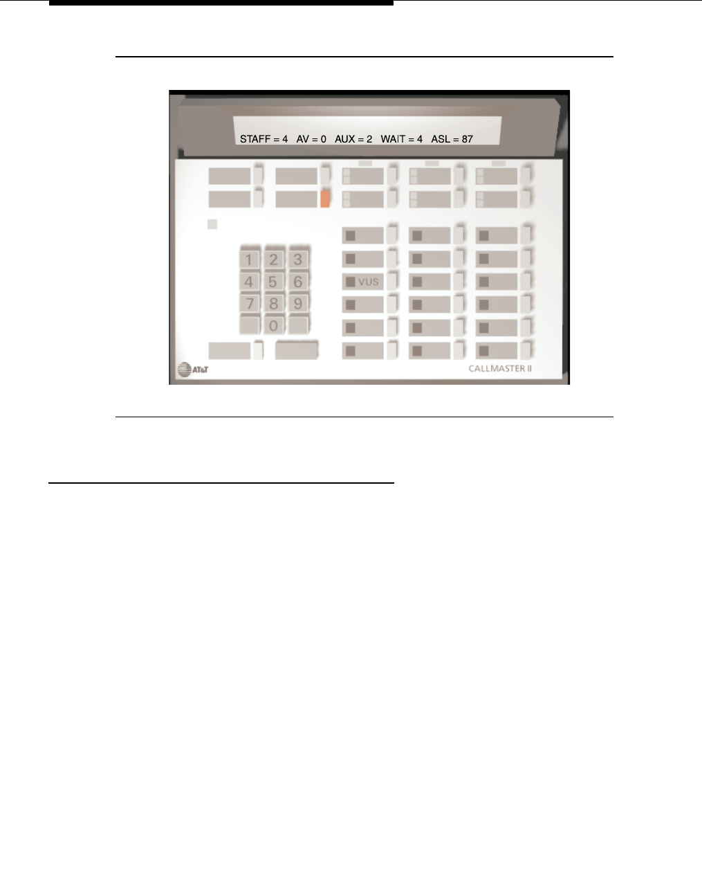
Feature Descriptions
3-1230 Issue 3 March 1996
Figure 3-31. CallMaster Terminal with VuStats Display
VuStats Applications
Self-Managed Teams
VuStats can provide call center agents with statistics about their performance.
For example:
■Agents can review their statistics against a predefined objective for a
given split. This could include an agent comparing their average talk time
per call to a split objective for average talk time, or comparing their calls
handled against a split objective for calls handled. The agent can also
review a split objective for percent of calls within service level to see if they
should improve their performance to improve the overall split percentage.
■Agents can also review their statistics against split averages for all agents.
In this case, an agent could compare their average talk time per call to the
average talk time per call for the entire split.
Statistics also are useful to call center agents in managing their time. For
example:
Agents might examine statistics about the number of agents logged into a split,
the number of agents available to receive Automatic Call Distribution (ACD) calls,
the number of agents who have entered AUX work mode, the number of
abandoned calls, or the time the oldest call in queue has been waiting. This

VuStats
Issue 3 March 1996 3-1231
information can be used to determine if it would be best to log out of one split to
devote time to a busier split, or if it was an appropriate time to take a lunch break.
Information Distribution
VuStats can increase the distribution of performance statistics throughout the call
center. It replaces the need for additional CMS terminals for supervisors while
also providing essential statistics to agents without the need for additional
hardware. It lessens requirements for BCMS paper reports.
Call Center Management
Even small call centers without BCMS or CMS enabled can receive VuStats
statistics. These statistics can be used to evaluate agent performance, balance
workloads, examine split staffing requirements, and generally optimize call
center performance.
Detailed Description
VuStats takes information stored on the switch in BCMS database tables and
shows that information on a display terminal. In general, the system administrator
uses the “VuStats Display Format” form to create a format defining the
information to appear on a display. Up to 25 different formats can be created.
One or more buttons on the voice terminal are then assigned a format. When one
of these buttons is pressed, the information associated with the format is
displayed on the voice terminal.
There is a limit to the number of VuStat buttons that can be administered with the
“ID “ field filled in. For detailed instructions on administering VuStats, or for
completing the VuStats Display Format form, see the
DEFINITY Communications
System Generic 3 Version 4 Implementation,
555-230-655, or
DEFINITY
Communications System Generic 3 V2/V3 Implementation
, 555-230-653.
As stated, the format defines what information appears on the display.
Specifically it determines: what text and database items are shown on the
display; how the information looks on the display; and when the display updates.
The following sections detail the information that can be administered to appear
on the VuStats display.
What Information Appears on the Display
Object Type
To define the information that will appear on the display, the system administrator
must first determine who will use the information or what object the information
will describe. This is the object type. The object type can be an agent (or agent
extension), split/skill, trunk group or vector directory number (VDN). Each object
type is associated with specific information in the BCMS database tables. This

Feature Descriptions
3-1232 Issue 3 March 1996
object type is entered on the “VuStats Format Display” form and controls the
types of information that are available for display. The following list describes
each of these object types.
■Agent The agent object type provides agents with their own statistics,
or statistics about the splits/skills they log into.
■Agent-extension The agent-extension object type provides supervisors
or other users with statistics about agents or the splits/skills the agents log
into. With an object type of agent-extension, the VuStats display can be
administered to automatically show statistics for a specific agent. Or, the
supervisor can enter the ID of any agent they want to review.
■Split The split object type is used to display statistics about a specific
split/skill. Much of the information available with a split object type is also
available with the agent or agent-extension object type. The selection of
object type will depend on the application.
■Trunk-group The trunk-group object type is used to display statistics
about a specific trunk group.
■VDN The VDN object type is used to display statistics about a specific
VDN.
Data Type
Once the object type is selected, the system administrator must define what data
should be displayed for that object. For example, with an object type of agent,
VuStats could display information of interest to an agent, including: the total
number of calls the agent has answered since logging in, the average time the
agent has spent on each ACD call, the number of agents available to receive
calls for a split, or the percent in service level for a given split.
On the other hand, for an object type of split, VuStats could display information
describing the split and performance for the split. For example: the average
speed of answer; the number of calls waiting; or information about agent work
states.
The data displayed for each object is defined with a data type, which is entered
on the “VuStats Format Display” form. A maximum of 10 data types can be
entered for each display. For a complete description of each data type see
"Tables of Data Types" in the “VuStats” section in the
DEFINITY Communications
System Generic 3 Version 4 Implementation,
555-230-655, or
DEFINITY
Communications System Generic 3 V2/V3 Implementation
, 555-230-653.
Interval
With the exception of two agent shift data items, in G3V3 the information
displayed on the terminal only represents data collected during the current
interval. In other words, if VuStats displays the average After Call Work (ACW)
time, it represents the average amount of time the agents on the split have spent
in ACW during the current interval. Likewise, if VuStats displays the number of

VuStats
Issue 3 March 1996 3-1233
ACD calls, it is the number of calls received during the current interval. The
interval is either 1/2 or 1 hour depending upon the value administered for the
BCMS measurement interval on the “Feature-Related System Parameters” form.
With G3V4 and later releases, VuStats also can be administered to show
historical data. It can show statistics that have accumulated for the day or for an
administered number of intervals. For example, if VuStats displays the number of
ACD calls for the past four completed intervals, it will display the number of ACD
calls received in the past two hours (1/2 hour intervals) or four hours (one hour
intervals) plus those completed during the current interval. The use of historical
data can impact processor occupancy depending upon the number of active
users, their update rates, and the number of historical data types.
With an object type of agent or agent-extension, shift data is available for the
number of ACD calls answered and the average ACD talk time for that agent.
Shift data accumulates during the time an agent is logged in. If the agent logs out
of all splits, shift data clears. For this reason, if shift data is required, agents
should enter AUX work mode when taking breaks rather than logging out.
Thresholds
With G3V4 many data types can be administered with a threshold comparator
and value. When the condition defined by the threshold is true, and the data type
is shown on the display, the VuStats button lamp flashes. For example, suppose
a format is created in which the oldest call waiting data type is administered with
a threshold of >= (greater than or equal to) five minutes. Whenever that VuStats
format is displayed, if the oldest call in queue has been waiting for five minutes or
longer, the VuStats lamp flashes on the voice terminal. Each time the display
updates the threshold is checked for each data type being displayed.
Text
Text associated with data can be entered on the “VuStats Display Format” form.
This text will appear on the display to identify the data. For example, in the
illustration at the beginning of this section, "AUX=" was entered as text on the
“VuStats Display Format” form to identify the data type "split-agents-in-aux" (the
number of agents currently in AUX work mode for a specified split). Text is
optional. When used, it appears exactly as entered on the form.
Remembering that each display is limited to 40 characters, it is important to limit
the amount of text, and to use abbreviations when possible. For example "S="
could indicate that the number following the equals sign is the split number.
Display Linking
Display formats can be linked so that users can step through a series of displays
thereby increasing the amount of information they can view. For example, a
display providing information for the agent’s first split could be linked to a second
display providing the same information for the agent’s second split. Or, a split

Feature Descriptions
3-1234 Issue 3 March 1996
supervisor might want one display providing information about the work states of
all agents on a split linked to a second display that provided information about
calls waiting, number of calls abandoned, or the oldest call waiting for the split.
To allow agents to view linked displays, a next button must be administered on
the voice terminals. Displays should have the same object type if they are linked.
For detailed information to administer what will appear on the display, see "What
Information Appears" in the VuStats section in the
DEFINITY Communications
System Generic 3 Version 4 Implementation, 555-230-655,
or
DEFINITY
Communications System Generic 3 V2/V3 Implementation
, 555-230-653.
How the Information Looks
VuStats statistics appear on the second line of two-line DCP terminal displays or
on the first line of one-line DCP terminals and all BRI terminals. For voice
terminals with 2 x 24 displays, the display automatically wraps to the second line
of the display. When VuStats is activated, it overwrites and cancels any display
feature on the second line of a two-line display and on the first line of a one-line
display.
The format of the information on the display is defined exclusively on the “VuStats
Display Format” form. Using this form, the system administrator defines:
■The text associated with each data type and the amount of space left for
each piece of data. For example, "AUX=$$$" indicates the text AUX= will
appear with 3 spaces left for the data associated with this text.
■The order in which the data types will appear on the display.
■The format for time related data types. For example, whether the data will
display as hours rounded to the nearest hour, minutes rounded to the
nearest minute, or minutes and seconds.
■The display that should follow the current one when the next button is
pressed.
Name database items, for example the name of a split or VDN, will be truncated
on the right to fit the data field size specified for the data type. Numerical
database items will display asterisks if the number is too large to fit the data field
size specified for the data type.
For detailed information to administer how the information will look on the display
terminal, see "How the Information Looks" in the VuStats section in Chapter 3 of
the
DEFINITY Communications System Generic 3 Version 4 Implementation,
555-230-655, or
DEFINITY Communications System Generic 3 V2/V3
Implementation
, 555-230-653.

VuStats
Issue 3 March 1996 3-1235
When the Information Updates, or Vanishes
When activated, any display feature that uses the second line of a two-line
display, or the first line of a one-line display will overwrite and cancel the VuStats
feature.
The VuStats display can be cleared by pressing the normal button. The VuStats
button lamp will go dark, and the display will return to normal mode.
The system administrator defines how long the VuStats display will remain on the
terminal, and how frequently the information on the display will update.
VuStats can be administered to display information continuously until the agent
presses the normal button or another operation overwrites the VuStats display.
Or, the display can be administered to only appear for an interval of 5, 10, 15, or
30 seconds and then disappear. When this VuStats display interval ends, the
display automatically returns to normal mode.
Continuous displays can be administered to update the displayed VuStats
statistics every 10, 20, 30, 60 or 120 seconds. Or, statistics can update every
time an agent changes work mode, every time a BCMS Measurement Interval is
completed on the hour or half-hour, or not update at all.
For detailed information to administer when the information updates, and for how
long it appears, see "When the Display Updates" in the VuStats section in the
DEFINITY Communications System Generic 3 Version 4 Implementation,
555-230-655, or
DEFINITY Communications System Generic 3 V2/V3
Implementation
, 555-230-653.
End User Operation
Information about end user operation of the VuStats feature is also included in
DEFINITY Communications System Generic 3 Automatic Call Distribution (ACD)
Agent Instructions, 5
55-230-722, and
DEFINITY Communications System
Generic 3 Automatic Call Distribution (ACD) Supervisor Instructions,
555-230-724. The following sections give some pointers on how agents and
supervisors will interact with the VuStats feature.
Agent Operation (Agent Object Type)
VuStats display formats created to allow agents to view their own performance
statistics are created with the agent object type. Therefore, to view statistics the
agent simply presses the VuStats button on the voice terminal. The display
shows the statistics for that agent as defined in the display format assigned to the
button. The agent must be logged in at the time the VuStats button is pressed if
EAS or BCMS/VuStats loginIDs are used. When VuStats is active the VuStats
button lamp stays lit. Or, if a threshold is met, it will flash. The statistics will
update based on the administered update interval.

Feature Descriptions
3-1236 Issue 3 March 1996
On a two-line DCP display, VuStats statistics appear on the second line. Any
information currently on the second line of the display is overwritten by VuStats.
On a one-line display or BRI terminal, VuStats statistics overwrite the entire
display line. To return to incoming call information, the agent presses the normal
button.
If the display format links to another display, the agent can press the next button
to see additional information.
If the VuStats button is pressed at a terminal where an agent is not logged in
when EAS or BCMS/VuStats loginIDs are in use, the button lamp flashes at a
broken flutter indicating access to the feature is denied. An error message on the
display indicates that the agent must log in.
If the button lamp flashes at a broken flutter for two seconds and no error
message is displayed, it indicates that the maximum number of users are already
displaying VuStats.
If the display shows asterisks instead of data, it indicates that the value of the
data was too large to fit in the number of digits allocated in the display format.
Supervisor Operation (Agent-extension, split,
VDN, or Trunk Group Object Type)
When a supervisor or other user accesses VuStats statistics for an
agent-extension, split, VDN, or trunk group, one of two conditions can exist.
1. The VuStats button can be administered with an ID indicating the specific
agent, split, VDN, or trunk group the information describes.
2. The user enters, on the dial pad, the ID or extension for any agent, split,
VDN, or trunk group they want to monitor.
Administered ID
If the ID is administered for the button, the supervisor simply presses the VuStats
button on the voice terminal. The display shows the statistics for that agent, split,
VDN, or trunk group as defined in the display format and ID assigned to the
button.
When VuStats is active, the VuStats button lamp stays lit. Or, if a threshold is met,
it will flash. The statistics update based on the administered update interval.
On a two-line DCP display, VuStats statistics appear on the second line. Any
information currently on the second line of the display is overwritten by VuStats.
On a one-line display or BRI terminal, VuStats statistics overwrite the entire
display line. The normal button cancels VuStats.
If the display format links to another display, the supervisor can press the next
button to see additional information.

VuStats
Issue 3 March 1996 3-1237
If the VuStats button is administered for an invalid agent, split, VDN, or trunk
group, the button lamp flashes at a broken flutter indicating access to the feature
is denied. An error message on the display indicates invalid administration. This
should be reported to the system administrator.
If the button lamp flashes at a broken flutter for two seconds and no error
message is displayed, it indicates that the maximum number of users are already
displaying VuStats.
If the display shows asterisks instead of data, it indicates that the value of the
data was too large to fit in the number of digits allocated in the display format.
ID Not Administered
If the ID is not administered, the user first presses the VuStats button. The button
lamp lights and the user receives dial tone. The user enters the agent extension
or login ID, split number, VDN extension, or trunk group number followed by the
pound sign. If a valid ID or extension is entered, confirmation tone is returned
and the VuStats statistics appear on the display.
When VuStats is active the VuStats button lamp stays lit. Or, if a threshold is met,
it will flash. The statistics update based on the administered update interval.
On a two-line DCP display, VuStats statistics appear on the second line. Any
information currently on the second line of the display is overwritten by VuStats.
On a one-line display or BRI terminal, VuStats statistics overwrite the entire
display line. The normal button cancels VuStats.
If the display format links to another display, the supervisor can press the next
button to see additional information.
If the user enters an invalid agent extension or login ID, split number, VDN
extension, or trunk group number, the button lamp flashes at a broken flutter
indicating access to the feature is denied. An error message on the display
indicates an invalid entry.
If the button lamp flashes at a broken flutter for two seconds and no error
message is displayed, it indicates that the maximum number of users are already
displaying VuStats.
If the display shows asterisks instead of data, it indicates that the value of the
data was too large to fit in the number of digits allocated in the display format.

Feature Descriptions
3-1238 Issue 3 March 1996
Error Messages
The following error messages may display on the voice terminal when VuStats is
being used.
Table 3-86. VuStats Display Error Messages
Error Message Condition
FORMAT [xx] NOT DEFINED where
xx is the format number assigned to
the button.
The VuStats button is pressed but the
display format assigned to the button
is not defined. (The “Format
Description” field on the “Display
Format” form is blank.)
FORMAT [xx] DOES NOT ALLOW OR
REQUIRE ID where xx is the format
number assigned to the button.
The VuStats button is pressed, agent
is the object type of the format, and
the ID associated with the button is
defined (administered on the
“Station” or “Attendant” form).
AGENT NOT LOGGED IN The VuStats button is pressed, agent
is the object type of the format and no
agent is logged in on the station set.
[object type] [xxxx] NOT
ADMINISTERED where object type is
AGENT, SPLIT/SKILL, TRUNK
GROUP, or VDN and xxxx is the ID
assigned to the button or entered by
the user.
The VuStats button is pressed, and
the ID or extension assigned to the
button or entered by the user has not
been administered (does not exist in
the system).
[object type] [xxxx] NOT MEASURED
where object type is AGENT,
SPLIT/SKILL, TRUNK GROUP, or
VDN and xxxx is the ID assigned to
the button or entered by the user.
The VuStats button is pressed, and
the ID or extension assigned to the
button or entered by the user is not
measured (is not administered as
measured on the appropriate “Hunt
Group”, “VDN”, or “Trunk Group”
form).
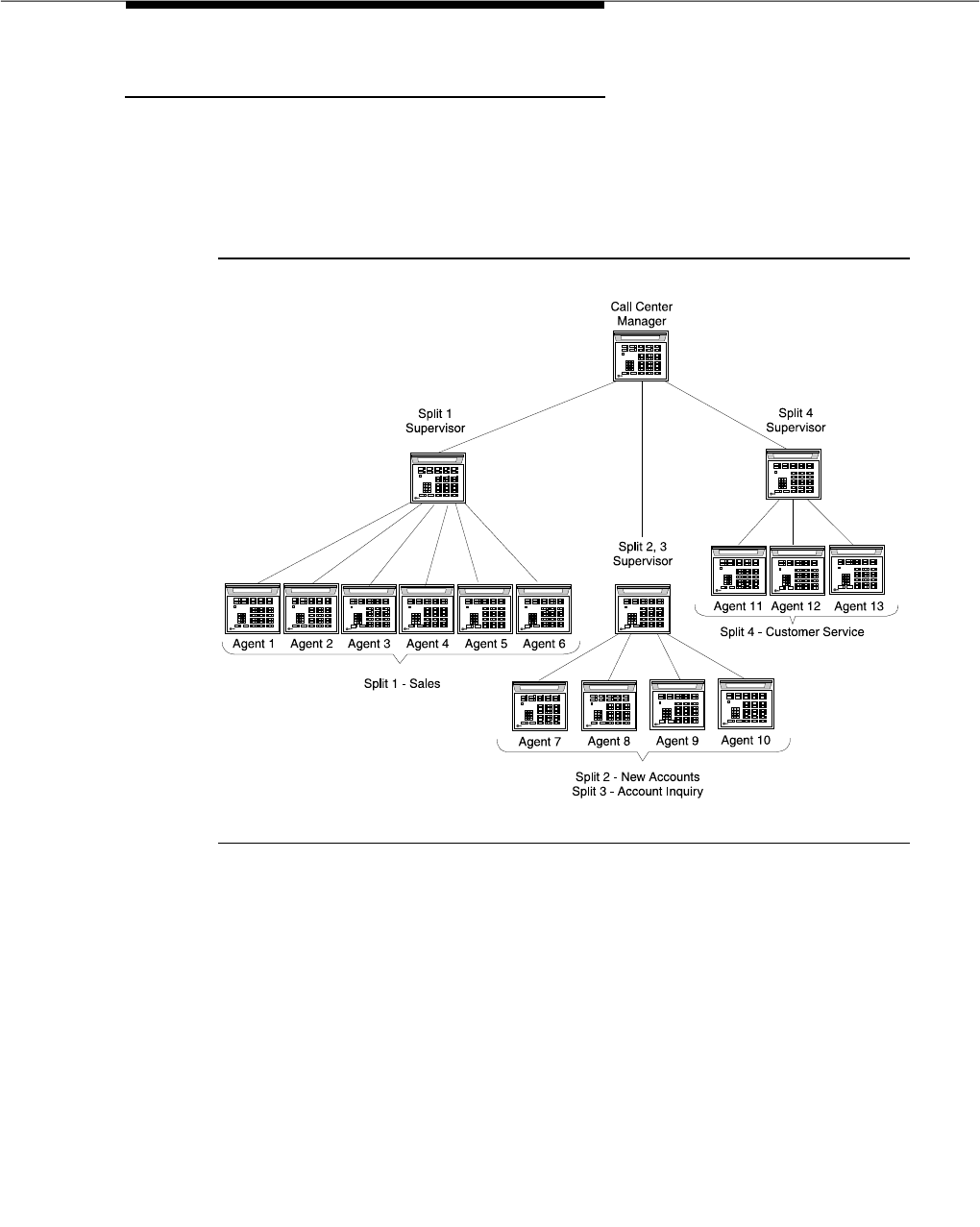
VuStats
Issue 3 March 1996 3-1239
Call Center Example
Because of its flexibility VuStats can be used in a variety of ways, meeting the
requirements of multiple users with different applications. This call center
example is just one representative sample of a VuStats application.
The following illustration shows the structure of a sample call center.
Figure 3-32. Sample Call Center
In the call center pictured above, the following conditions are true:
■If the split queue is full, calls to split 1 will route-to split 2 or to split 3 and
visa versa. (All agents in these splits are trained to handle all three types of
calls.)
■Agents in split 4 do not receive calls from other splits.
■Two VDNs route-to split 1. One of these VDNs, named "elite," is for high
volume sales customers.
■Agent 12 is used as a backup for split 1. Under certain conditions, the
agent goes into AUX work mode on split 4 and logs into split 1.

Feature Descriptions
3-1240 Issue 3 March 1996
The following sections describe the VuStats display requirements for each group,
agent 12, and the three split supervisors.
Split 1
Split 1 has the objective of processing 40 sales calls per hour. To evaluate their
success towards reaching this goal, agents might want to know:
■The objective.
■The rate at which they have been answering calls.
■The rate at which all members of the split have been answering calls.
■How their average time spent talking on each ACD call compares to the
average for other agents on the split.
Agents also would like to be alerted when the call rate for the split drops to 20 or
fewer calls. The display will be administered to cause the VuStats button to flash
if the rate drops this low.
Agents in this company also decide independently when to go into AUX work
mode to take breaks or complete work not directly related to calls, such as
copying or filing. To choose a good time to enter AUX work mode, the agent
might want to know:
■The number of agents staffed.
■The number of agents available.
■The number of agents in AUX work mode.
■The number of calls waiting.
■The percent of calls within the acceptable service level.
Each agent in split 1 will require only 1 VuStats button. Three formats will be
required to present the information requested.
VuStats
Issue 3 March 1996 3-1241
Figure 3-33. Split 1 Displays
Format 1
OBJ = 40 MYRATE = 36 SPLITRATE = 42
Format 2
SPLITTALK = 4:25 MYTALK = 4:00
Format 3
STAFF=6 AV=0 AUX=1 WAIT=4 %SER=87
(The split objective is 40 calls per hour. The agent is handling calls at a rate of
36 per hour. The split is handling calls at a rate of 42 per hour.)
NEXT
NEXT
(The average talk time per call for the split is 4:25, the average talk time per call
for this agent is 4:00.)
(For the split: agents staffed equals 6; agents available equals 0; agents in AUX
work mode equals 1; calls waiting in queue equals 4; and percent of calls answered
within the acceptable service level equals 87%.)

Feature Descriptions
3-1242 Issue 3 March 1996
Splits 2 and 3
Agents in splits 2 and 3 have not defined objectives for their splits. However,
agents still want to review basic performance statistics including:
■The total ACD calls the agent has answered during the day.
■The average speed of answer during the day for each split the agent is
logged into.
The agents also want to be able to view statistics to determine when to enter AUX
mode. In this example a separate display is set up for each split.
Each agent will require only 1 VuStats button. Three formats will be required to
present the information requested.
VuStats
Issue 3 March 1996 3-1243
Figure 3-34. Splits 2 and 3 Displays
Format 4
NEXT
NEXT
Format 5
S=2 STAFF=4 AV=0 AUX=0 WAIT=6 %SER=90
(In split 2 agents staffed equals 4; agents available equals 0; agents in AUX
work mode equals 0; calls waiting in queue equals 6; and percent of calls
answered within the acceptable service level equals 90%.)
Format 6
S = 3 STAFF = 4 AV = 0 AUX = 0 WAIT = 8 %SER = 87
(In split 3 agents staffed equals 4; agents available equals 0; agents in AUX
work mode equals 0; calls waiting in queue equals 8; and percent of calls
answered within the acceptable service level equals 87%.)
ACD = 30 ASA 2 = 1:02 ASA 3 = 0:53
(The number of ACD calls answered by this agent during the day is 30; the
average speed of answer for split 2 is 1:02 minutes, and the average speed
of answer for split 3 is 53 seconds.)

Feature Descriptions
3-1244 Issue 3 March 1996
Split 4
Split 4 has the objective of maintaining 95 percent of calls answered within the
acceptable service level. To meet this objective agents need to know:
■The objective.
■The current percent of calls within the acceptable service level.
■The number of seconds within which calls must be answered to be
acceptable.
■The current average speed of answer for the split.
Agents also would like to be alerted when the percent within service level drops
below 90 percent. The display will be administered to cause the VuStats button
to flash if the percent drops this low.
The agents also want to be able to view statistics to determine when to enter AUX
mode.
Each agent in split 4 will require 1 VuStats button. Two formats will be required to
present the information requested.
VuStats
Issue 3 March 1996 3-1245
Figure 3-35. Split 4 Displays
Agent 12
Agent 12 acts as a backup for split 1 and so has special VuStats requirements.
Agent 12 will enter AUX mode on split 4 and log into split 1 when: no agents are
available on split 1; more than nine calls are waiting in the split 1 queue; and at
least one other agent is available in split 4. Therefore agent 12 must know:
■The number of agents available on split 1.
■The number of calls waiting on split 1.
■The number of agents available on split 4.
The agent can determine the number of agents available on split 4 by viewing
format 3 while logged into split 4.
Format 7
NEXT
Format 8
STAFF = 3 AV = 1 AUX = 1 WAIT = 0 %SER = 96
OBJ = 95 %SER = 96 ASL = 0:30 ASA = 0:28
(The split objective is 95% of calls answered with the acceptable service level,
the percent of calls answered within the acceptable service levels equals 96%,
the number of seconds within which a call must be answered to be within the
acceptable service level is 30, and the average speed of answer for the interval
is 28 seconds.)
(For the split: agents staffed equals 3; agents available equals 1; agents in AUX
work mode equals 1; calls waiting in queue equals 0; and percent of calls
answered within the acceptable service level equals 96%.)

Feature Descriptions
3-1246 Issue 3 March 1996
Because the agent is not logged into split 1 when the information is requested,
an object type of split is used to access split 1 information. A second VuStats
button is used for the split display. The button can be administered with the ID for
split 1 to eliminate the need to enter the split number when accessing this display
and, if necessary, to prevent the agent from viewing statistics for other splits.
One additional format will be required to present split 1 statistics to agent 25.
Figure 3-36. Agent 25 Split 1 Display
Split Supervisors
All three supervisors are interested in receiving statistics for the splits they
manage including:
■The objective for the split.
■The rate at which calls are being answered for the split.
■The percent of calls answered within the acceptable service level.
■The oldest call waiting for the split.
Each supervisor will require 1 VuStats button. One format will be required to
present the information requested.
Format 9
AV=0 WAIT=12
(For split 1: the number of available agents is 0; the number of calls waiting in
queue is 12.)
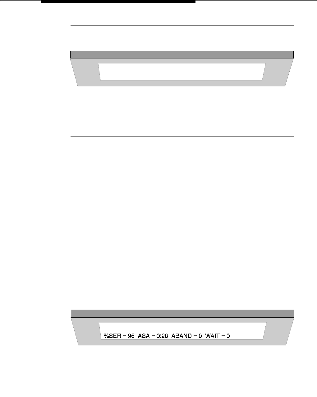
VuStats
Issue 3 March 1996 3-1247
Figure 3-37. Split Supervisor Display
Supervisor 1
Supervisor 1 is also concerned with monitoring the "elite" VDN that routes to split
1. Since this VDN is only accessed by high volume clients, the supervisor wants
to be certain that service is always available. Therefore the supervisor wants to
know:
■The percent of calls answered within the acceptable service level.
■The average speed of answer for a call coming in on the VDN.
■If any calls have abandoned.
■If any calls are waiting.
■How long the oldest call in the queue has been waiting.
A second VuStats button and one additional format are required for the VDN
display.
Figure 3-38. Supervisor 1 VDN Display
Format 10
S=1 OBJ=40 RATE=42 %SER=87 OLD=1:16
(This example shows the display for the split 1 supervisor. The split number is 1;
the objective is 40 calls per hour; calls are being answered at a rate of 42 per
hour; the percent in service level is 87; the oldest call in the split has been
waiting 1 minute and 16 seconds.)
Format 11
(The percent of calls answered within the acceptable service level is 96; the
average speed of answer for a call on the split is 20 seconds; no calls have
abandoned the split during the current interval; no calls are waiting in the queue.)

Feature Descriptions
3-1248 Issue 3 March 1996
Sample Administration
To implement this call center example, a system administrator would need to
create a total of eleven VuStats display formats: eight with an object type of
agent; two with an object type of split; and one with an object type of VDN. See
“Call Center Example” in the VuStats section of the
DEFINITY Communications
System Generic 3 Version 4 Implementation,
555-230-655, or
DEFINITY
Communications System Generic 3 V2/V3 Implementation
, 555-230-653, for
instructions about how this example could be administered.
Considerations
Some of the VuStats data is accumulated for an agent’s login session. If agents
log in in the morning and then log out for lunch, they end their sessions and the
system clears their accumulated data. When agents log in after lunch, they begin
new sessions. To accumulate a full day’s statistics, agents and/or supervisors
must keep a running total of all the agents’ login sessions. To circumvent the
need to keep track of login sessions use historical data or have agents go into
AUX mode when they are on break.
The DEFINITY systems have varying limits on how many measured agents or
login IDs can be monitored and how many terminals can display VuStats data
simultaneously. See Appendix A, "System Parameters" for capacities.
Interactions
■BCMS
If BCMS is not active, you cannot receive BCMS reports. The VuStats
feature displays data collected by BCMS, but you do not need to have
BCMS enabled in order to use VuStats. VuStats operates normally without
BCMS turned on.
■Call Prompting
A Call Prompting digits display automatically cancels the VuStats feature.
The Call Prompting display overwrites the VuStats display and the VuStats
button lamp extinguishes. When the agent reactivates VuStats, the
VuStats display overwrites the Call Prompting display.
■Call Work Codes
When the call work code (CWC) is activated, it automatically cancels the
VuStats feature. The CWC display overwrites the VuStats display and the
VuStats button lamp extinguishes.
If VuStats is activated while a CWC is being entered— that is, the pound
(#) sign is not yet dialed— the CWC display is overwritten. In this case,
the CWC is not sent and must be reentered.

VuStats
Issue 3 March 1996 3-1249
■Change Skills
An agent changing skills automatically cancels the VuStats feature. The
display of the new skills overwrites the VuStats display and the VuStats
button lamp extinguishes. When the agent reactivates VuStats, the
VuStats display overwrites the display of the new skills.
■Integrated Directory
If a user activates the Integrated Directory feature, the VuStats feature is
automatically cancelled. The Integrated Directory display overwrites the
VuStats display and the VuStats button extinguishes. When VuStats is
reactivated, the VuStats display overwrites the Integrated Directory
display.
■Move Agents from CMS
If an agent moves from one split or skill to another, the change does not
affect the ID administered to the VuStats (vu-display) button.
If an agent is moved from one split or skill to another, the switch does not
reassociate VuStats buttons (associated with the agents previous split or
skill) to the new split or skill. Therefore, in a call-environment in which
agents are often moved between splits or skills, VuStats buttons should
not have an assigned association with a specific split or skill. Instead, a
VuStats button associated with the agent format (without an ID) should be
assigned to each agent’s voice terminal, and a split reference can be
used to view the agent’s first, second, third, or fourth split/skill.
■Queue-Status Indications
The queue-status button display automatically cancels the VuStats
feature. The queue-status display overwrites the VuStats display and the
VuStats lamp extinguishes. When VuStats is reactivated, the VuStats
display overwrites the queue-status display.
■Service Observing
On terminals with a one-line display, the Service Observing button display
automatically cancels the VuStats feature. The Service Observing display
overwrites the VuStats display and the VuStats lamp extinguishes. When
VuStats is reactivated, the VuStats display overwrites the Service
Observing display

Feature Descriptions
3-1250 Issue 3 March 1996
Administration
In order to use VuStats, Automatic Call Distribution (ACD) and VuStats must be
optioned on the “System-Parameters Customer-Options” form. Hunt Groups,
Trunk Groups, and VDNs must also be administered as measured ‘internal’’ or
‘‘both.’’
Use the “VuStats Display Format” form to administer the display formats. Up to
25 different 40-character display formats can be created.
A feature button for ‘‘vu-display’’ must be administered on those attendant
consoles and voice terminals that will display VuStats data. A ‘‘next’’ button must
be administered for voice terminals that will display linked formats.
For detailed instructions for administering VuStats, or for completing the “VuStats
Display Format” form, see the
DEFINITY Communications System Generic 3
Version 4 Implementation, 555-
230-655, or
DEFINITY Communications System
Generic 3 V2/V3 Implementation
, 555-230-653.
Hardware Requirements
VuStats is only available for attendant consoles and voice terminals with digital
display capability. VuStats is most effective on voice terminals with two-line
displays (of 40 characters per line), such as the CallMaster voice terminals. This
type of display allows users to see call appearances on the top line and VuStats
on the bottom line. With other displays, VuStats overwrites call appearance
information when a user presses the VuStats button.

Wideband Switching
Issue 3 March 1996 3-1251
Wideband Switching
Feature Availability
The Wideband Switching feature is optional with G3V2 and later releases.
Description
The Wideband feature provides you with the ability to dedicate 2 or more ISDN
B-channels or DS0 endpoints for applications which require large amounts of
bandwidth. The ISDN-PRI divides a T1 (E1 for international switches) trunk into
24 (31 for E1) information channels and one signaling channel for standard
narrowband communication. Certain applications, such as video conferencing,
require greater bandwidth, and it becomes necessary to aggregate several of
those narrowband channels into one ‘‘wideband’’ channel to accommodate the
extra bandwidth requirement. The DEFINITY switch may serve as a gateway to
many types of high bandwidth traffic.
Applications involving the Wideband Switching feature are listed below:
■Video conferencing
■WAN Disaster Recovery
■Scheduled batch processing (for example, nightly file transfers)
■LAN Interconnections and Imaging
■Other applications involving high-speed data or video transmission or a
high degree of bandwidth
NOTE:
For additional information on the DEFINITY system Wideband Switching
feature, see the
DEFINITY Communications System Generic 3 Wideband
Technical Reference
, 555-230-230,
DEFINITY Communications System
Generic 3 Version 4 Implementation
, 555-230-655, or
DEFINITY
Communications System Generic 3 V2/V3 Implementation
, 555-230-653.

Feature Descriptions
3-1252 Issue 3 March 1996
Technical Description
The Wideband Switching feature provides end-to-end connectivity between
endpoints at data rates from 128 to 1536 Kbps over a T1 facility, or up to 1984
Kbps over an E1 (European Standard) facility, according to the ITU-T and ANSI
standards for 384 (H0, a 6 channel aggregate), 1536 (H11, a 24 channel
aggregate or dedicated T1 trunk), and 1920 (H12, a 31 channel aggregate, or
dedicated E1 trunk) Kbps rates and ITU-T and ANSI standards for NX64 Kbps
rates (where
N
may equal 2 to 24 on a T1 trunk and 2 to 31 on an E1 trunk).
NOTE:
Typically, a T1 facility provides for 23 B-channels and 1 data channel while
an E1 facility provides 30 B-channels and 1 D-channel. If however,
Non-Facility Associated Signaling (NFAS) is used, a group of T1/E1
facilities can be configured to share a single data channel allowing all but
one of the T1/E1 facilities to be configured with an extra B-channel.
DEFINITY switches can be configured for Wideband Switching for various uses,
including the following:
■Sending data over a domestic network T1 facility, typically providing 1
D-channel and 23 B-channels.
■Sending data over an international network E1 facility, typically providing
1 D-channel and 30 B-channels.
■An ISDN-PRI line-side (switch to terminal) application
Each B-channel can provide 64 Kbps transmission rates. There are two service
types for encoding the aggregation of channels, both of which are supported by
the DEFINITY switch.
NX64 allows the aggregation of any channel groupings while H0, H11, and H12
have fixed channel assignments.
Table 3-87 summarizes the ISDN channel types with the associated data rates
that support Wideband Switching.
Table 3-87. ISDN Channel Types and Wideband Associated
Data Rates
Channel Type Data Rate
H0 (6 channels) 384 Kbps
H11 (24 channels) 1536 Kbps
H12 (31 channels) 1920 Kbps
NXDS0 (2 to 31 channels) 128 to 1984 Kbps

Wideband Switching
Issue 3 March 1996 3-1253
Any endpoint with an ISDN-PRI interface can be administered for Wideband
Switching applications. For both network and line-side use, a Universal DS1
(UDS1) circuit pack is the interface for carrying wideband calls. On the line side,
an ISDN-PRI terminal adaptor such as the Paradyne Acculink Bandwidth
Controller is used to support switched and permanent connections.
Channel Allocation
Wideband channel allocation is performed using one of three allocation
algorithms: fixed, flexible, or floating. This subject is discussed in greater detail in
the Implementation Guide, but in brief:
■Fixed allocation provides contiguous channel aggregation and the
starting channel is constrained to a predetermined starting point. (Used
only for H0, H11, and H12 calls.)
■Flexible allocation allows a Wideband call to occupy non-contiguous
positions within a single T1 or E1 facility.
■Floating allocation enforces contiguous channel aggregation but the
position of the first channel is not constrained like it is in fixed allocation.
Typical Uses
Many Wideband Switching applications are video applications such as video
conferencing or data applications.
A typical video application is illustrated in Figure 3-39. The video application
uses an ISDN-PRI interface to DS0 1 through 6 of the line-side facility.
NOTE:
A line-side facility is the use of ISDN-PRI between the switch and the
terminal, in this case a video conference facility. Most lines between switch
and audio terminals use the ISDN-BRI, and do not have the available
bandwidth for this kind of application. Special line-side uses of ISDN-PRI
have to be arranged as special implementation needs.
In actual use, the channels aggregated for Wideband use may not be contiguous
and vary constantly.
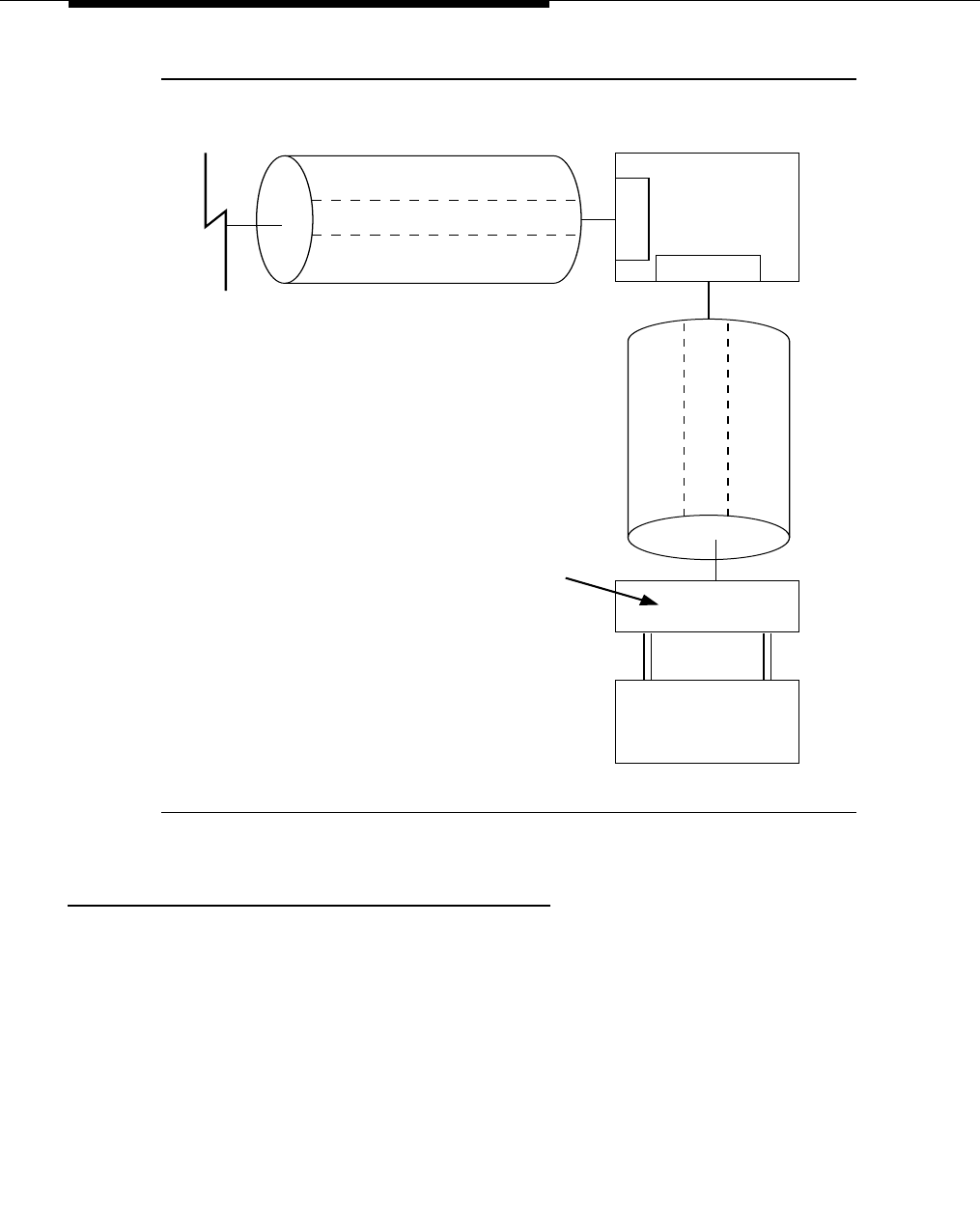
Feature Descriptions
3-1254 Issue 3 March 1996
Figure 3-39. Wideband Switching Video Application
Considerations
Glare and blocking are the two most pertinent trunking considerations when
using Wideband Switching.
Glare
Glare arises when both sides of an ISDN-PRI interface simultaneously select the
same B-channel for call initiation. For example, the user side of the ISDN-PRI
interface selects a B-channel for an outgoing call. Before the network receives
the SETUP message, the network might select the same B-channel for a call.
Even with channel negotiation schemes, glare might cause the call from the user
side to be dropped. Since Wideband Switching uses multiple B-channels, the
possibility of glare is greater than it is with other calls.
Network
Definity
Switch
U
D
S
IUDSI
DSO 24 D-Channel
DSO 7-23 Narrow Bands
DSO 1-6 Wideband
ISDN-PRI Trunk
DSO 24 D-Channel
DSO 7-23 Unused
DSO 1-6 Wideband
Line-side ISDN-PRI
Port 1 Port 2
Video
Application
Ascend
ISDN-PRI
Terminal Adapter

Wideband Switching
Issue 3 March 1996 3-1255
To reduce the possibility of glare, the DEFINITY switch should be administered
so that each side of the ISDN-PRI interface select channels from opposite ends
of the interface.
In other words, one end should be administered to select B-channels from the
high side (DS0 channel 23) and the other administered to select B-channels from
the low side (DS0 channel 1) so as not to interfere with each other. In addition,
there are algorithms in the switch’s operating code which attempt to gain control
of channels closest to the starting DS0 so that Wideband channels are
contiguous.
For example, if the user side is provisioned to start at the high side (DS0 23) and
DS0 22 is idle but DS0 23 is active, DS0 22 should be reselected for the next call.
This is known as linear trunk hunting. The DEFINITY switch uses the linear trunk
hunt method and only the direction of hunt is administrable. See the
DEFINITY
Communications System Generic 3 Version 4 Implementation
, 555-230-655, or
DEFINITY Communications System Generic 3 V2/V3 Implementation
,
555-230-653, for additional details.
Blocking
Blocking occurs when the number of B-channels required to make a call are not
available. Narrow band (64 Kbps) calls require only one channel so blocking is
less likely than with Wideband calls which require multiple B-channels. Blocking
also occurs for Wideband calls when bandwidth is not available in the
appropriate format (that is, fixed, floating, or flexible, see earlier description).
To avoid this situation, the DEFINITY switch selects trunks for both Wideband
and narrowband calls to maximize availability of idle fixed channels for H0, H11,
and H12 calls and idle floating channels for NXDS0 calls. The strategy for
preserving idle channels to minimize blocking depends on the channel type. The
chances for blocking are reduced if the flexible algorithm is used.
Interactions
The following features interact with Wideband Switching:
■Administered Connections
Provides call initiation for Wideband Access Endpoints (WAEs). All
administered connections that originate from WAEs use the entire
bandwidth administered for the WAE. The destination of an Administered
Connection can be a PRI Endpoint.
■Automatic Circuit Assurance (ACA)
Treats Wideband calls as single trunk calls so that only a single ACA
referral call is made if an ACA referral call is required. The referral call is
on the lowest B-channel associated with the Wideband call.

Feature Descriptions
3-1256 Issue 3 March 1996
■Call Detail Recording (CDR)
Wideband calls trigger CDR records containing the Wideband Bearer
Capability Class (BCC) and the call bandwidth.
Both access endpoints and PRI endpoints involved in a call are treated as
line-side entities in that they do not trigger a standard CDR record.
Intra-switch CDR may be used to trigger intra-switch records involving PRI
endpoints. However, the intra-switch CDR capability is automatically
disabled as soon as a trunk is involved with the call. Therefore,
trunk-to-endpoint and endpoint-to-trunk calls must be handled by trunk
group administration using standard CDR records.
■Call Management System (CMS)
Wideband calls may be carried over trunks that are measured by the CMS
but Wideband endpoints are not measured by CMS.
■Call Vectoring
Wideband endpoints may use a vector directory number when dialing. In
other words, PRI endpoints may dial a Vector Directory Number (VDN)
when Vector Routes lead to other Wideband endpoints. For example PRI
endpoint 1001 dials VDN 500. VDN 500 points to Vector 1. Vector 1 can
point to other PRI endpoints such as route-to 1002, or route-to 1003, or
busy.
This is only used by certain specific applications. Typically when an
incoming Wideband call to a DEFINITY switch wants to hunt for an
available Wideband endpoint, the call could route-to a VDN which would
then send the call to the first available Wideband endpoint according to
the vector routing program.
■Class of Restriction (COR)
The COR identifies calling and called party privileges for the Wideband
endpoint(s). Administer the COR in such a way that Account Codes are
not required. Also, Forced Entry of Account Codes should be turned off for
Wideband endpoints.
■Class of Service (COS)
The COS determines the class of features that a Wideband endpoint can
activate. Administer the COS in such a way as to block the activation of
Call Forwarding.
■Facility and Non-Facility Associated Signaling
Non-Facility Associated Signaling with or without the D-channel backup
(DCBU) requires administration via Signaling Groups for trunk-side
Wideband interfaces (not supported on the line-side).
■Facility Busy Indication
It is possible to administer a Busy Indicator button for a Wideband
endpoint extension but the button does not accurately track the endpoint
status.

Wideband Switching
Issue 3 March 1996 3-1257
■Facility Test Calls
Facility Test Calls can be used to perform loop-back testing of the
Wideband call facility.
■Generalized Route Selection
Generalized Route Selection supports a Wideband Bearer Capability
Class (BCC) to identify Wideband calls. The Generalized Route Selection
feature searches a routing pattern for a preference that has the Wideband
BCC. Routing preferences that support Wideband BCC also support other
BCCs to allow different call types to share the same trunk group.
■Integrated Services Digital Network — Primary Rate Interface
Standard ISDN-PRI interfaces can be administered for Wideband
switching.
■Leave Word Calling
Dialing a Wideband endpoint extension as part of the Leave Word Calling
feature applies an intercept to the activator.
■Subnet Trunking
Subnet Trunking is accomplished via Generalized Route Selection and
Routing Pattern administration.
Administration
NOTE:
Refer to the
DEFINITY Communications System Generic 3 Version 4
Implementation
, 555-230-655, or
DEFINITY Communications System
Generic 3 V2/V3 Implementation
, 555-230-653, for procedures describing
how to administer DEFINITY system features to include Wideband
Switching; most importantly see the section on administering ISDN-PRI.
The following forms have to be administered for Wideband service:
■Access Endpoint
■PRI Endpoint
■Trunk Group (ISDN-PRI)
■Routing Patterns
Access Endpoint
Access endpoint administration is required to support Wideband access
endpoints (WAEs). WAEs are administered by defining the starting DS0 and the
number of DS0s that comprise the WAE.

Feature Descriptions
3-1258 Issue 3 March 1996
PRI Endpoint
PRI endpoints are administered to define the number of DS0s to be associated
with an extension. The PRI endpoint’s number of DS0s (that is, the width) is
limited by the type of ISDN-PRI interface but is always between 1 and 31. If the
PRI endpoint is administered for a width narrower than the maximum number of
B-channels supported by the line-side facility, then multiple PRI endpoints can
be administered within that same line-side facility. The parameters H0, H11, H12,
and NXDS0 must be administered to identify the algorithm that the PRI endpoint
uses to provide Wideband service. If the NXDS0 algorithm is administered, then
administration to identify it as floating or flexible (on the “PRI-Endpoint” form
contiguous
y/n
)is also required. All combinations of these are allowed except
floating NXDS0 with H0. Other parameters can be administered for each PRI
endpoint; they include: COR, COS, and whether Auto Restoration should apply to
calls originating from the PRI endpoint.
Trunk Groups
Trunk group administration is required to specify the Wideband service(s) that
are to be supported by each trunk group. The parameters H0, H11, H12, and
NXDS0 must be administered to identify the algorithm that the trunk group uses
to provide Wideband service. If the NXDS0 algorithm is administered, then
administration to identify it as floating or flexible (on the “Trunk Group” form
contiguous
y/n
)is also required. All combinations of these are allowed except
floating NXDS0 with H0. In addition, the trunk search direction must be
administered for the direction that a trunk group searches B-channels within its
facilities (descend — ascend or ascend — descend).
Routing Patterns
Routing parameter administration must be performed to specify the Wideband
Bearer Capability Class (BCC). This administration allows Generalized Route
Selection (GRS) to allow Wideband traffic to choose specific trunk preferences,
namely those trunks supporting Wideband network services. In no way does this
administration imply that Wideband and narrowband traffic must be carried
separately. In fact, any combination of narrowband BCC can be optioned with
the Wideband BCC.
Customer Option Form
Wideband switching must also be administered using the ‘‘Customer Option’’
form. The other Wideband parameter administration is only performed if
Wideband switching is administered for the switch.

Wideband Switching
Issue 3 March 1996 3-1259
Hardware and Software Requirements
Wideband software is optional. The TN464C (Universal DS1) circuit pack or later
must be used on both the line-side and network side of the switch for any facility
that carries Wideband traffic. The only other additional hardware/software
required for Wideband switching is that the PRI endpoints must adhere to the
ISDN-PRI Wideband interface requirements and to PRI line-side requirements.

Feature Descriptions
3-1260 Issue 3 March 1996
World Class Basic Rate Interface (BRI)
Feature Availability
Available with G3V4 and later releases
Description
World Class BRI (WCC BRI) provides an international BRI platform that offers
multiple protocol options to meet specific country and application requirements.
It provides access to Video Conferencing, Desktop Video Conferencing, Data
Transmission, and other non-voice based applications that use BRI as a
communication interface. Voice access is not supported for G3V4 though voice
features are not blocked for WCC BRI terminals.
WCC BRI devices must be administered as the new type “wcbri.” WCC BRI users
select a country protocol for each terminal that will use the feature. This selection
determines both the codeset modifications required to meet the national
standards as well as the terminal initialization procedures if required.
WCC BRI supports the following country protocols:
■Bellcore National ISDN-1 protocol in the United States (TR268)
■National protocols in Australia (AUSTEL TS013, Telecom Australia TPH
1962), Japan (NTT BRI) and Singapore (FETEX 150 TIF 218)
■ETSI NET 3 protocol (ETS 300 102) for use in most of Europe.
WCC BRI supports multipoint (up to two devices per port) only for the Bellcore
National ISDN-1 Country Protocol option.
Considerations
All devices administered on the same port must be of the same Country Protocol.
All devices connected to the same DEFINITY system must use the same
companding mode as the system TDM bus.
Interactions
■ASAI
ASAI will continue to be accessed via current ASAI administration. ASAI
should not be accessed via “wcbri” type administration.

World Class Basic Rate Interface (BRI)
Issue 3 March 1996 3-1261
Administration
The system administrator must specify in the “Endpt Init?” field on the “Data
Module” or “Station” forms whether the administered WCC BRI device supports
Bellcore NI-1 endpoint initialization procedures. This field should be set to “y” for
all Bellcore NI-1 devices, and the field should be set to “n” for all other WCC BRI
devices (Australia, Japan, Singapore and ETSI). If the “Endpt Init” field is set to
“y” then the administrator must also specify an Endpoint ID. In conjunction with
the SPID, the Endpt ID allows for multipoint configuration conformance to
Bellcore terminal initialization procedures.
A Country Protocol also must be specified for each terminal.
Hardware and Software Requirements
WCC BRI requires a TN556B or later suffix BRI port circuit pack. A TN2198
two-wire BRI port circuit pack can be used in place of the TN556. In this case an
NT1 is also required.
WCC BRI supports terminals conforming to country protocols specified under
“Description”.

Feature Descriptions
3-1262 Issue 3 March 1996
World Class Tone Detection
Feature Availability
This feature is available with G3i-Global and Generic V2 and later releases.
Description
World Class Tone Detection allows the DEFINITY switch to identify and handle
different types of call progress tones, depending on the system administration.
The tone detector and identification is used to display on Data Terminal Dialing
and for deciding when to send digits on trunk calls through Abbreviated Dialing,
ARS, AAR, and Data Terminal Dialing.
■‘‘Tone detect mode 1’’ designates countries that use the same tone plan
as Italy.
■‘‘Tone detect mode 2’’ designates countries that use the same tone plan
as Australia.
■‘‘Tone detect mode 3’’ designates countries that use the same tone plan
as the United Kingdom.
■‘‘Tone detect mode 4’’ designates countries that use dial tones between
345 Hz and 625 Hz.
■‘‘Tone detect mode 5’’ designates countries that use dial tones between
345 Hz and 1190 Hz.
■“Tone detect mode 6” designates countries that use the same dial tone
plan as the United States.
■The ‘‘level of tone detection precise’’ is used in countries whose tone plan
matches the tone board’s tone detect mode.
■The ‘‘level of tone detection medium’’ is used in countries that, except for
the continuous dial tone and discontinuous other tones, have tones with
characteristics that do not match those expected by the tone detector
board’s detect mode.
■The ‘‘level of tone detection broadband’’ is used in countries that have a
discontinuous dial tone.
Considerations
When the administered Level of Tone Detection is ‘‘medium’’ or ‘‘broadband,’’
multiple-line Data Terminal Dialing is disabled.
Interactions
The following features interact with the World Class Tone Detection feature.

World Class Tone Detection
Issue 3 March 1996 3-1263
■Data Call Setup Multiple-Line Data Terminal Dialing is supported ONLY if
the administered Level of Tone Detection is ‘‘precise’’.
■The feedback displayed by Data Terminal Dialing in response to received
tones is affected by settings of World Class Tone Detection.
■Abbreviated Dial, AAR, ARS, and Data Terminal Dialing can specify a wait
for dial tone in outpulsing digits over a trunk. The World Class Tone
Detection feature should be configured to match the characteristics of the
dial tone that will be detected.
Administration
Administration of World Class Tone Detection consists of two distinct parts: tone
detection level and tone detection algorithm. System Aministrators address how
tone detection occurs and when it occurs in the outpulsing sequence. The
following specific items are administered:
■“Level of Tone Detection” and “Off Premises Tone Detection Timeout”
fields are administered on the “Feature-Related System Parameters” form.
■“Tone Detection Mode,” “Dial Tone Validation Timer” (for Tone Detection
mode 4 and 5 only), “Outpulse Without Tone y/n,”and “Interdigit Pause”
fields are administered on the “System-Parameters Country-Options”
form.
■The “AAR/ARS Route Pattern” forms allows insertion of special characters
“+” and “!” that indicate when to wait for a dial tone.
■The “Abbreviated Dialing” form allows entry of ~w and ~W that also
indicate when to wait for a dial tone.
Hardware and Software Requirements
Tone Detection Modes 1, 2, and 3 are meaningful only if the system tone
detectors are TN420Bs or greater.
Modes 4 and 5, the Dial Tone Validation Timer, and the Interdigit Pause are
meaningful only if the system tone detectors are TN744C-Tone Detector/Call
Classifier, TN420C-Tone Detector, or TN2182-Tone Clock/Detector/Generator.
Tone detection for countries using the same tone plan as the United States is
also available using an alternate tone detector.
TN420B only recognizes Tone Detection Modes 1,2,and 3. TN420C, TN744C,
and TN2182 recognize modes 1,2,3,4,5,and Dial Tone Validation and Interdigit
Pause. TN2182 and TN744C recognize mode 6. TN748C provides precise tone
detection for the United States tone plan.

Feature Descriptions
3-1264 Issue 3 March 1996
World Class Tone Generation
Feature Availability
This feature is available with G3i-Global, all Generic V2, and later releases.
Description
Allows administrators to specify the base call progress tone set to be generated
by the system and to then customize the set by selecting different values for
frequency and cadence for up to 6 individually administrable tones.
Considerations
If a particular tone (for example, conference tone) is not defined for the
administered base tone generation set (and not administered via the individual
tone administration), silence will be used.
Interactions
Brief call waiting tones are optimal because, while the tone is sounding, speech
cannot be heard on the call. (For G3i-Global, G3V2, and later releases, the
system administrator can administer system so that repeated tones are heard.)
Administration
The base tone generation set and individual tones, along with companding
“Mode”, “Analog Ringing Cadence”, and “Digital Loss Plan” fields are
administrable on Pages 1 through 7 of the “System-Parameters Country-Options”
form by the system technician, the local installer and a remote installer.
Hardware and Software Requirements
Any DEFINITY system Tone Generation board can be used. Some boards are
capable of producing all North American and international tones.
The TN768 generates tones only for North America. The TN780 can generate
almost all the tones required for the world. The TN2182 can generate more tones
than the TN780 and adds support for Hong Kong and France.

Issue 3 March 1996 A-1
A
System Parameters
Overview
This appendix provides information on the overall characteristics and capacities
of the system.
The items presented in this chapter are grouped here for easy reference.
However, most items are discussed under each applicable feature.
Administration Not Required
Administration is not required to activate the following features.
1. Attendant Auto-Manual Splitting
2. Attendant Call Waiting
3. Attendant Recall
4. Attendant Release Loop Operation
5. Automatic Incoming Call Display
6. Conference — Attendant
7. Conference — Terminal
8. Hold
9. Line Lockout
10. Move Agents from CMS
11. Recall Signaling
12. Recent Change History
13. Senderized Operation

System Parameters
A-2 Issue 3 March 1996
14. Straightforward Outward Completion
15. Temporary Bridged Appearance
16. Through Dialing
17. Touch-Tone Dialing (for Terminals)
18. Transfer
Administration Required
Administration is required to activate the following features.
1. AAR/ARS Partitioning
2. Abandoned Call Search
3. Abbreviated Dialing
4. Add/Remove Skills
5. Administered Connections
6. Administration Without Hardware
7. Advice of Charge
8. Alphanumeric Dialing
9. Alternate Facility Restriction Levels
10. Agent Call Handling
11. Attendant Control of Trunk Group Access
12. Attendant Direct Extension Selection With Busy Lamp Field
13. Attendant Direct Trunk Group Selection
14. Attendant Display (Buttons only)
15. Attendant Room Status
16. Attendant Serial Calling
17. Attendant Intrusion (Call Offer)
18. Attendant Override
19. Attendant Priority Queue
20. Audible Message Waiting
21. Audio Information Exchange (AUDIX) Interface
22. Authorization Codes
23. Automatic Alternate Routing
24. Automatic Callback
25. Automatic Call Distribution

Overview
Issue 3 March 1996 A-3
26. ACD - Auto-Available Split
27. Automatic Circuit Assurance
28. Automatic Route Selection
29. Auto Start/Don’t Split
30. Automatic Wakeup
31. Basic Call Management System
32. Bridged Call Appearance — Multi-Appearance Voice Terminal
33. Bridged Call Appearance — Single-Line Voice Terminal
34. Busy Verification of Terminals and Trunks
35. Call-by-Call Service Selection
36. Call Coverage
37. Call Detail Recording
38. Call Forward Busy/Don’t Answer
39. Call Forwarding All Calls
40. Call Park
41. Call Pickup
42. Call Prompting
43. Call Vectoring
44. Call Waiting Termination
45. CDR Account Code Dialing
46. Centralized Attendant Service
47. Class of Restriction
48. Code Calling Access
49. Customer-Provided Equipment (CPE) Alarm
50. Data Call Setup
51. Data Hotline
52. Data-Only Off-Premises Extensions
53. Data Privacy
54. Data Restriction
55. Default Dialing
56. Dial Access to Attendant
57. Digital Multiplexed Interface
58. Direct Department Calling

System Parameters
A-4 Issue 3 March 1996
59. Direct Inward Dialing
60. Direct Inward Dialing and Outward Dialing — International
61. Distinctive Ringing
62. Do Not Disturb
63. DS1 Tie Trunk Service
64. EIA Interface
65. Emergency Access to the Attendant
66. Enhanced Abbreviated Dialing
67. Expert Agent Selection
68. Extension Number Portability
69. Extended Trunk Access
70. Facility and Non-Facility Associated Signaling
71. Facility Busy Indication
72. Facility Test Calls
73. Forced Entry of Account Codes
74. Generalized Route Selection
75. Hold - Automatic
76. Hot Line Service
77. Hunting
78. Inbound Call Management
79. Individual Attendant Access
80. Information Systems Network (ISN) Interface
81. Internal Automatic Answer (IAA)
82. Integrated Directory
83. Integrated Services Digital Network — Basic Rate Interface
84. Integrated Services Digital Network — Primary Rate Interface
85. Intercept Treatment
86. Intercom — Dial
87. Inter-PBX Attendant Calls
88. Intraflow and Interflow
89. Last Number Dialed
90. Leave Word Calling
91. Look Ahead Interflow

Overview
Issue 3 March 1996 A-5
92. Loudspeaker Paging Access
93. Loudspeaker Paging Access — Deluxe
94. Malicious Call Trace
95. Manual Message Waiting
96. Manual Originating Line Service
97. Manual Signaling
98. Merlin/System 25 Voice Terminal Support—731xH Series
99. Modem Pooling
100. Multi-Appearance Preselection and Preference
101. Multiple Call Handling
102. Multiple Listed Directory Numbers
103. Music-on-Hold Access
104. Names Registration
105. Night Service
106. Off-Premises Station
107. PC Application Software Translation Exchange (PASTE)
108. PC/PBX Connection
109. Permanent Switched Calls
110. Personal Central Office Line
111. Personalized Ringing
112. Power Failure Transfer
113. Priority Calling
114. Privacy — Attendant Lockout
115. Privacy — Manual Exclusion
116. Property Management System Interface
117. QSIG Global Networking
118. Queue Status Indications
119. Recorded Announcement
120. Recorded Telephone Dictation Access
121. Remote Access
122. Report Scheduler and System Printer
123. Restrictions
124. Restriction - Fully Restricted Service

System Parameters
A-6 Issue 3 March 1996
125. Ringback Queuing
126. Ringer Cutoff
127. Ringing—Abbreviated and Delayed
128. Rotary Dialing
129. Security Violation Notification
130. Service Observing
131. Single-Digit Dialing and Mixed Station Numbering
132. Switch-Based Bulletin Board
133. Ten-Digit to Seven-Digit Conversion (G1.1)
134. Tenant Partitioning
135. Terminal Translation Initialization
136. Terminating Extension Group
137. Timed Reminder
138. Time of Day Routing
139. Touch-Tone Dialing (for Trunks)
140. Transfer -Outgoing Trunk to Outgoing Trunk
141. Trunk Flash
142. Trunk Group Busy/Warning Indicators to Attendant
143. Trunk-to-Trunk Transfer
144. Uniform Call Distribution (see Direct Department Calling)
145. Uniform Dial Plan
146. VDN of Origin Announcement (VOA)
147. Voice Message Retrieval
148. Voice Terminal Display
149. VuStats
150. World Class Core BRI

Feature Access
Issue 3 March 1996 A-7
Feature Access
Dial Access Only
The following features or feature options can be activated and/or deactivated by
dialing the assigned Feature Access Code or Trunk Access Code.
■Abbreviated Dialing:
— List 1
— List 2
— List 3
— Program
■Agent Call Handling
— Agent Log-In
— Agent Log-Out
— Manual-In
— Auto-In
— After Call Work
— Auxiliary Work
— Assist
■AP Demand Print
■Automatic Route Selection
■Automatic Callback (activate and deactivate) (applies to single-line voice
terminals only)
■Automatic Wakeup
— Wakeup Call
— Verify Wakeup Announcement
■Call By Call Service Selection
■CDR Account Code Dialing
■Call Forwarding All Calls (activate and deactivate)
■Call Park and Call Park Answer Back
■Call Pickup
■Code Calling Access

System Parameters
A-8 Issue 3 March 1996
■Controlled Restriction:
— Single Voice Terminal (activate and deactivate)
— Group of Voice Terminals (activate and deactivate)
■Data Origination (associated with Data Call Setup and Pooled Modem)
■Data Privacy (associated with Data Call Setup and Pooled Modem)
■Do Not Disturb
■Emergency Access to the Attendant
■Facility Test Calls
■Generalized Route Selection
■Hunt Group Make Busy (activate and deactivate) (associated with Direct
Department Calling and Uniform Call Distribution)
■Integrated Services Digital Network — Primary Rate Interface
■Last Number Dialed
■Leave Word Calling:
— Cancel a Message
— Display Module Lock
— Display Module Unlock
— Store a Message
■Loudspeaker Paging Access
■Loudspeaker Paging Access — Deluxe
■Malicious Call Trace
■PC Application Software Translation Exchange (PASTE)
■Priority Calling
■Private Network Access
■Property Management System Interface
■Public Network Access
■Recorded Telephone Dictation Access
■Send All Calls (associated with Call Coverage)
■Trunk Answer From Any Station (associated with Night Service)
■Voice Message Retrieval
— Message Retrieval Mode
— Coverage Message Retrieval Mode
— Delete Message
— Repeat Message

Feature Access
Issue 3 March 1996 A-9
— Next Message
— Help
— Call
Button Access Only
The following features or feature options must be assigned to a button. Feature
Access Codes cannot be provided.
■Agent Change Alerting (alrt-agchg)
■Alternate Facilities Restriction Levels (attendant)
■Attendant Incoming Serial Calling (attendant)
■Attendant Intrusion (Call Offer) (attendant)
■Attendant Override (attendant)
■Automatic Callback (applies to multi-appearance voice terminals only)
■Automatic Circuit Assurance
■Bridged Call Appearance — Multi-Appearance Voice Terminal
■Bridged Call Appearance — Single-Line Voice Terminal
■Busy Verification of Terminals and Trunks
■Call Coverage:
— Consult
— Coverage Callback
— Coverage Message Retrieval
— Go To Cover
■Data Extension (associated with Data Call Setup)
■Display — Attendant or Voice Terminal:
— Date and Time
— Timer (Elapsed Time)
— Inspect
— Integrated Directory
— Normal
— Stored Number (associated with Abbreviated Dialing)
— Don’t Split (attendant console only)
■Facility Busy Indication

System Parameters
A-10 Issue 3 March 1996
■Intercom:
— Automatic
— Dial
■Leave Word Calling:
— Delete Message
— Message Retrieval
— Next Message (also used with Integrated Directory)
— Return Call (also used with Integrated Directory)
■Manual Message Waiting
■Manual Signaling
■Personal Central Office Line
■Privacy — Manual Exclusion
■Property Management System Interface
— Message Waiting Notification (Activate)
— Message Waiting Notification (Deactivate)
— Checkout
■Queue Status Indications
— NQC (number of queued calls)
— OQT (oldest queued time)
— AQC (attendant queued calls)
— AQT (attendant queued time)
■Ringer Cutoff
■Special Characters (associated with Abbreviated Dialing)
Pause, Wait, Mark, and Suppress can each be assigned to a button or a
Function Entry button can be assigned. Pressing Function Entry and then
dialing 1, 2, 3, or 4 depicts Pause, Wait, Mark, or Suppress, respectively.
■Terminating Extension Group
■Time of Day Routing
— Immediate Manual Override
— Clocked Manual Override
■Trunk Identification by Attendant
■VuStats

Feature Access
Issue 3 March 1996 A-11
Dial and Button Access
The following features or feature options can be activated and/or deactivated by
dialing the assigned Feature Access Code; they can also be assigned to a
button for button access.
■Abbreviated Dialing:
— List 1
— List 2
— List 3
— Program
■Agent Call Handling
— Manual-In
— Auto-In
— Auxiliary Work
— After Call Work
— Assist
— Release
■Automatic Wakeup:
— Auto Wakeup Entry
— Failed Messages Wakeup
■Call Forward Busy/Don’t Answer
■Call Forwarding All Calls
■Call Park and Call Park Answer Back
■Call Pickup
■Do Not Disturb
■Emergency Access to the Attendant
■Hunt Group Make Busy (activate and deactivate) (associated with Direct
Department Calling and Uniform Call Distribution)
■Last Number Dialed
■Leave Word Calling:
— Malicious Call Trace
— Cancel a Message
— Display Module Lock
— Store a Message

System Parameters
A-12 Issue 3 March 1996
■Priority Calling
The Priority Calling access code and extension number to be called, or
the Priority Calling access code only, can be assigned to an Abbreviated
Dialing button.
■Send All Calls (associated with Call Coverage)
■Service Observing
Feature Status Button Indicators
The following buttons are not operational, but can be assigned to indicate the
status of a feature or feature option. The light associated with the button lights
when the assigned feature or option is active or is in use.
■Group Call (Lights to indicate that an incoming call is associated with a
Call Coverage Answer group, a Direct Department Calling group, or a
Uniform Call Distribution group.)
■Lock (Associated with the Voice Terminal Display; lights when activated
and means that Leave Word Calling message retrieval is denied from that
terminal. Other display modes still work, including Coverage Message
Retrieval.)
Overview
This appendix provides information on the overall characteristics and capacities
of the system.
System Hardware and Software
Capacity Limits
The maximum parameters for the DEFINITY® Communications System Generic 1
and Generic 3 hardware and software items are listed on the following pages.
Unless otherwise noted, these parameters apply to both the Single-Carrier
Cabinet and Multi-Carrier Cabinet systems. Also:
■For G3sV1/G3sV2 and G3vsV1/G3vsV2, when a capacity limit is the same
for Advantage Business Package (ABP) and Premier Business Package
(PBP), the common limit is listed. When a capacity limit for ABP and PBP
differ, the ABP limit is given first followed by the PBP limit.

System Hardware and Software Capacity Limits
Issue 3 March 1996 A-13
■Terminal and digital station capacities are reduced by such administered
items as: attendant consoles, number of EAS login IDs, and number of
ACD agents
■Most G3iV1 and G3i-Global capacity limits are the same. In the few cases
where a G3i-Global capacity limit differs from the corresponding G3i
capacity limit, the G3i limit is given followed by the G3i-Global limit in
parenthesis.
NOTE:
Not all maximum capacities listed in the following tables can be reached
simultaneously with all versions or all configurations of the system.

System Parameters
A-14 Issue 3 March 1996
1. 100,000 for G3rV3
2. For Single-Carrier Cabinets (SCC), only four BX.25 physical links are supported in G3sV2 and G3iV2.
Table A-1. Maximum System Parameters for G3V1
ITEM G3vsV1
ABP/PBP G3sV1
ABP/PBP G3iV1/
G3i-Global G3rV1
Abbreviated Dialing (AD)
AD Lists per System 200 200 1,600/2,400 5,000
AD List Entry Size 24 24 24 24
AD Entries per System12,000 2,000 10,000/12,000 50,000
Enhanced List (System List) NA/1 NA/1 1 1
Maximum Entries NA/1,000 NA/1,000 1,000 1,000
Group Lists 100 100 100 100
Maximum Entries 90 90 90 90
Group Lists per Extension 3 3 3 3
System List 1 1 1 1
Maximum Entries 90 90 90 90
Personal Lists 200 200 1,600/2,400 5,000
Maximum Entries 10 10 10 10
Personal Lists per Extension 3 3 3 3
Applications Adjuncts
CallVisor ASAI Adjuncts NA/NA NA/4 8 8
Asynchronous Links (RS-232) 5 5 5 10
CDR Output Devices 2 2 2 2
Journal:System Printer 2:1 2:1 2:1 2:1
Property Management Systems 1 1 1 1
BX.25 Physical Links244 816
Application Processors (such as
3B2-MCS)
11 17
AUDIX Adjuncts 1 1 1 8
CMS Adjuncts 1 1 1 1
ICM Adjuncts ISDN Gateway NA/1 NA/1 1 1
BX.25 Processor Channels 64 64 64 128
Hop Channels 64 64 64 128

System Hardware and Software Capacity Limits
Issue 3 March 1996 A-15
1. AAR is not an optional feature in G3sV2 ABP.
2. ARS is available in G3s if the Automatic Route Selection Option is selected.
3. This is the number of 12 character inserted-digit-strings available for AAR/ARS preferences.
Table A-1. Maximum System Parameters for G3V1 — continued
ITEM G3vsV1
ABP/PBP G3sV1
ABP/PBP G3iV1/
G3i-Global G3rV1
ARS/AAR1, 2
AAR/ARS Patterns (Shared) NA/40 NA/40 254 640
ARS/AAR Table Entries
(NPA, NXX, RXX, HNPA, FNPA)
2,000 2,000 2,000 2,000
Choices per RHNPA Table 12 12 12 12
Digit Conversion Entries 300 300 300 400
AAR/ARS Digit Conversion
Digits Deleted for ARS/AAR 23 23 23 23
Digits Inserted for ARS/AAR 18 18 18 18
AAR/ARS Sub-Net Trunking
Digits Deleted for ARS/AAR 23 23 23 23
Digits Inserted for ARS/AAR 36 36 36 36
Entries in HNPA & RHNPA Tables 1,000 1,000 1,000 1,000
FRLs 8 8 8 8
Inserted Digit Strings3450 450 1,200 3,000
Patterns for Measurement
Shared Patterns for Measurement 20 20 20 25
RHNPA Tables 32 32 32 32
Routing Plans 8 8 8 8
Toll Tables 32 32 32 32
Entries per Toll Table 800 800 800 800
Trunk Groups in an ARS/AAR Pattern 6 6 6 16
UDP (Entries) NA/240 NA/240 240 50,000
TOD Charts 8 8 8 8

System Parameters
A-16 Issue 3 March 1996
1. For G3vs, there can be four day consoles if there are no night consoles. Three of the four must be
powered by auxiliary power.
2. This number is the same as the number of trunk groups in the system.
3. The ‘‘Maximum number of queue slots’’ is referred to as ‘‘emergency access queue length’’ in G1.
Table A-1. Maximum System Parameters for G3V1 — continued
ITEM G3vsV1
ABP/PBP G3sV1
ABP/PBP G3iV1/
G3i-Global G3rV1
Attendant Service
Attendant Consoles (day:night)14:1 6:1 6:1/15:1 27:1
Attendant Console 100s
Groups/Attendant
20 20 20 20
Attendant Control Restriction Groups 64 64 64 96
Centralized Attendant Service
Release Link Trunks at Branch NA/99 NA/99 99 99
Release Link Trunk Group at Branch NA/1 NA/1 1 1
Release Link Trunks at Main NA/100 NA/100 400 4,000
Release Link Trunk Group at Main2NA/32 NA/32 99 666
Other Access Queues
Maximum Number of Queues 1 1 1 (12) 12
Maximum Number of Queue Slots330 30 50/80 80
Size range of Reserved Queue NA NA NA (2-75) 2-75
Reserved Queue Default Size NA NA NA (5) 5
Queue Length 30 30 30/80 300
Switched Loops/Console 6 6 6 6
Authorization
Authorization Codes 1,500 1,500 5,000 90,000
Classes of Restriction 64 64 64/96 96
Classes of Service 16 16 16 16
Length of Authorization Code 4-7 4-7 4-7 4-7
Length of Barrier Code 4-7 4-7 4-7 4-7
Length of Forced Entry Account Codes NA/1-15 NA/1-15 1-15 1-15
Restricted Call List 1 1 1 1

System Hardware and Software Capacity Limits
Issue 3 March 1996 A-17
Table A-1. Maximum System Parameters for G3V1 — continued
ITEM G3vsV1
ABP/PBP G3sV1
ABP/PBP G3iV1/
G3i-Global G3rV1
Authorization (Continued)
Remote Access Barrier Codes 10 10 10 10
CDR Forced Entry Account Code List NA/1 NA/1 1 1
Toll Call List 1 1 1 1
Unrestricted/Allowed Call Lists 10 10 10 10
Total Call List Entries 1,000 1,000 1,000 1,000
Automatic Callback Calls 20 20 160/240 1,000
Automatic Wakeup
Simultaneous Display Requests 10 10 10 10
Wakeup Requests per System 200 200 1,600/2,400 10,000
Wakeup Request per Extension 1 1 1 1
Wakeup Requests per 15-minute Interval 150 150 300 950
Basic CMS
Daily Summary Reports 7 7 7 7
Measured Agent Logins, 75 for G3vs
and G3s, 200 for G3i, and 600 for G3r
75 75 200 200
Measured Splits 12/24 12/24 99 99
Measured Trunk Groups 16/32 16/32 99 32
Measured VDNs NA/24 NA/24 99 512
Reporting Periods (30 or 60 min) 25 25 25 25
Number of Terminal User IDs 5 5 5 8

System Parameters
A-18 Issue 3 March 1996
1. 43 for G3rV3 for MCC
164 for G3rV3 for SCC
41 for G3rV3 for Small
44 for G3rV3 for Port Networks
3 for G3rV3 for Switch Node Carriers (Simplex)
6 for G3rV3 for Switch Node Carriers (Duplex)
41 for G3rV3 for DS1 Converter Complex (Simplex)
2. The EPNs in G3r can be DS1-remote EPNs.
3. Small systems refer to the two-carrier cabinet systems that are no longer sold to new customers.
4. MCC includes Medium Cabinet.
Table A-1. Maximum System Parameters for G3V1 — continued
ITEM G3vsV1
ABP/PBP G3sV1
ABP/PBP G3iV1/
G3i-Global G3rV1
Cabinets
Expansion Port Network (EPN)
Multi-Carrier Cabinet (MCC)1,2 NA NA 2 21
Single-Carrier Cabinet (SCC)1,2 NA NA 8 80
Small1 (Upgrades only)3NA NA 2 20
Inter-Port Network Connectivity
Port Networks111 322
Maximum Number of Port
Networks per Cabinet
11 12
Switch Node Carriers1 (Simplex) NA NA NA 2
Switch Node Carriers1 (Duplex) NA NA NA 4
DS1 Converter Complex1 (Simplex) NA NA NA 20
DS1 Converter Complex1 (Duplex) NA NA NA 40
Processor Port Network (PPN)
Multi-Carrier Cabinet (MCC)4NA NA 1 1
Single-Carrier Cabinet (SCC) or
Ehanced Single-Carrier Cabinet
(ESCC)
NA 4 4 NA
Compact Single-Carrier Cabinet
(CSCC)
1NA NANA
Remote Modules
Remote Port Network NA NA 2/1 21

System Hardware and Software Capacity Limits
Issue 3 March 1996 A-19
1. The number of call appearances is the sum of primary and bridged appearances; at most ten can be
primary. A maximum of 54 administrable buttons are supported for the 7434D terminal — 34 buttons
in the basic terminal and an additional 20 buttons in the coverage module.
2. Does not apply to conferencing.
3. Only available with ABP when AT&T Voice Power adjunct (AUDIX, AUDIX Voice Power, AUDIX Voice
Power Lodging, and DEFINITY AUDIX) are used.
4. The maximum number of users per coverage path equals the number of dial plan extensions (including
hunt groups, TEGs, etc.).
5. 1,000 for G3iV3/5,000 for G3rV3
10,604 for G3V3
6. The CDRU adjunct capacity is 40,000 calls per hour, and exceeds the system call capacity for all
systems except for G3r.
Table A-1. Maximum System Parameters for G3V1 — continued
ITEM G3vsV1
ABP/PBP G3sV1
ABP/PBP G3iV1/
G3i-Global G3rV1
Call Appearances
Bridged Images per Appearance 7 7 7 15
Call Appearances per Station154 54 54 54
Maximum Appearances per Extension 10 10 10 10
Minimum Appearances per Extension 2 2 2 2
Total Bridged Appearances 200 200 1600/2,400 10,000
Maximum Simultaneous Off-Hook per Call25555
Call Coverage
Coverage Answer Groups (CAG) 30 30 200 500
Coverage Paths 150 150 600 5,000
With Hospitality Parameter Reduction NA/5 NA/5 5 5
Coverage Paths Including in Call
Coverage Report
100 100 100 100
Coverage Path per Station34444
Coverage Points in a Path 3 3 3 3
Maximum Users/Coverage Path4500 500 2900 (3500) 21,875
Members per CAG 8 8 8 8
Call Detail Recording
CDRU Trackable Extensions 200 200 1,600/2,400 10,000
Intra-switch Call Trackable Extensions5100 100 100 500
Number of CDRUs per System62222

System Parameters
A-20 Issue 3 March 1996
1. The total of VDN, Station, and Login ID extensions cannot exceed 25,000.
2,000 for G3rV3
7,084 for G3rV3 for "Simultaneous three-way Conference Calls"
3,520 for G3rV3 for “Simultaneous six-way Conference Calls”
Table A-1. Maximum System Parameters for G3V1 — continued
ITEM G3vsV1
ABP/PBP G3sV1
ABP/PBP G3iV1/
G3i-Global G3rV1
Call Forwarding (Follow-me)
Call Forwarded Digits (off-net) 16 16 16 16
Call Forwarded Numbers 200 200 1,600/2,400 10,000
Call Park
Attendant Group Common Shared
Extension Numbers
10 10 10 40
Number of Parked Calls5180 180 723 5,302
Call Pickup Groups
Call Pickup Members per Group 50 50 50 50
Call Pickup Members per System 200 200 1600/2400 10,000
Number of Groups 100 100 800 5,000
With Hospitality Parameter Reduction NA/5 NA/5 5 5
Call Vectoring/Call Prompting
Expert Agent Selection
Skill Groups NA NA NA NA
VDN Skill Preferences NA NA NA NA
Multiple Skills per Call NA NA NA NA
Multiple Skills per Agent NA NA NA NA
Agent Login IDs NA NA NA NA
Multiple Splits per Call NA/3 NA/3 3 3
Priority Levels NA/4 NA/4 4 4
Recorded Announcement NA/128 NA/128 128 256
Steps per Vector NA/15 NA/15 15 15
Vector Directory Numbers1NA/100 NA/100 500 3,000
Measured VDNs NA/100 NA/100 500 2,000
Vectors per System NA/48 NA/48 256 512

System Hardware and Software Capacity Limits
Issue 3 March 1996 A-21
1. The total of VDN, Station, and Login ID extensions cannot exceed 25,000.
2,000 for G3rV3
7,084 for G3rV3 for "Simultaneous three-way Conf. Calls"
3,520 for G3rV3 for "Simultaneous six-way Conf. Calls"
2. Simultaneous 3-way Conference Call=(483 / 3)* number PNs. Simultaneous 3-way Conference Call is
limited by the number of Simultaneous
3. Simultaneous 6-way Conference Call=(483 / 6)* number PNs.
Table A-1. Maximum System Parameters for G3V1 — continued
ITEM G3vsV1
ABP/PBP G3sV1
ABP/PBP G3iV1/
G3i-Global G3rV1
CallVisor ASAI
Active Station Controlling Association NA NA/250 2,000/NA 6,000
Call Controllers per Call NA NA/1 1/NA 1
Call Monitors per Call NA NA/14 14/NA 14
Extension Controllers per Station Domain NA NA/2 2/NA 2
Maximum Simultaneous Call Classifications NA NA/40 40/NA 100
Number of ASAI Links NA NA/4 8/NA 8
Notification Requests1NA NA/50 170/NA 460
Simultaneous Active Adjunct Controlled
Calls
NA NA/75 300/NA 3,000
Switch to Adjunct Associations NA NA/127 127/NA 127
Conference Parties 6666
Simultaneous 3-way Conference Calls1,2 161 161 483 3,542
Simultaneous 6-way Conference Calls1,3 80 80 240 1,760
Data Parameters
Administered Connections NA/24 NA/24 128 128
Permanent Switched Call NA NA NA NA
Alphanumeric Dialing
Maximum Entries 50 50 200 1,250
Characters per Entry 22 22 22 22
Digital Data Endpoints 75 75 800 5,000
Table A-1. Maximum System Parameters for G3V1 — continued
ITEM G3vsV1
ABP/PBP G3sV1
ABP/PBP G3iV1/
G3i-Global G3rV1
Dial Plan
DID LDNs 8 8 8 20
Extensions1500 500 2900/ 3500 21,875

System Parameters
A-22 Issue 3 March 1996
1. Extensions include stations, data endpoints, hunt groups, announcements, TEGs, VDNs, common
shared extensions, and code calling IDs.
2. The numbers shown in ‘‘Extension Number Portability’’ are Uniform Dialing Plan (UDP) entries.
3. Used for PCOL groups, common shared extensions, access endpoints, administered TSCs, code
calling IDs, VDNs, LDNs, hunt groups, announcements, and TEGs.
4. The Number of Names = number of stations + attendant consoles + trunk groups + digital data
endpoints + miscellaneous extensions.
Extension Number Portability2NA/240 NA/240 240 50,000
Feature Dial Access Codes
Number of Access Codes 70 70 70 70
Number of Digits 1-3 1-3 1-3 1-4
Integrated Directory Entries 204 207 1607/ 2407 10,000
Maximum Extension Size 5 5 5 5
Minimum Extension Size 1 1 1 1
Miscellaneous Extensions3150 150 900 3317
Names
Number of Names4448/464 448/464 3,406/4,215 22,569
Number of Characters in a Name 15 15 15 15
Non-DID LDNs 50 50 50 666
Prefix Extensions Yes Yes Yes Yes
Trunk Dial Access Codes
Number of Access Codes 105 105 197 884
Number of Digits 1-3 1-3 1-3/1-4 1-4
Do Not Disturb (DND)
DND Requests per System 200 200 1600/ 2400 10,000
Simultaneous Display Requests 10 10 10 10
Facility Busy Indicators
Buttons per Tracked Resource 100 100 100 100
Number of Indicators (Station and Trunk
Groups)
450 450 2400/3600 2400
Table A-1. Maximum System Parameters for G3V1 — continued
ITEM G3vsV1
ABP/PBP G3sV1
ABP/PBP G3iV1/
G3i-Global G3rV1

System Hardware and Software Capacity Limits
Issue 3 March 1996 A-23
1. One supervisor assist per split.
2. Last Number Dialed Entries = Stations + Digital Data Endpoints.
Table A-1. Maximum System Parameters for G3V1 — continued
ITEM G3vsV1
ABP/PBP G3sV1
ABP/PBP G3iV1/
G3i-Global G3rV1
Hunt Groups or Splits
Announcements per Group 2 2 2 2
Announcements per System 128 128 128 256
Groups and/or Splits 12/24 12/24 99 255
With Hospitality Parameter Reduction NA/5 NA/5 5 5
Group Members per Group/Split 150 150 200 999
Group Members per System 150 150 500 3,000
Measured ACD Agents (Switch Limits)
Agents Logged in per System 75 75 400 1023
Logged-In Splits per Agent 3 3 3 3
ACD Supervisor Assist Per System112/24 12/24 99 255
Queue Slots per Group 200 200 200 999
Queue Slots per System 200 200 1,000 10,000
Intercom Translation Table (ICOM)
Automatic/Manual and Dial ICOM
Groups per System
10 10 32 256
Auto/Manual 16 16 32 256
Dial 16 16 32 256
Members per ICOM group
Auto 32 32 32 32
Dial 32 32 32 32
Members per System 320 320 1,024 8,192
Last Number Dialed
Entries per System2275 275 2,400/ 3,200 15,000
Number of Digits 16 16 16 24
Table A-1. Maximum System Parameters for G3V1 — continued
ITEM G3vsV1
ABP/PBP G3sV1
ABP/PBP G3iV1/
G3i-Global G3rV1
Leave Word Calling (Switch-Based)1
Messages Stored 450 450 2,000 2,000
Messages per User 10 10 10 16

System Parameters
A-24 Issue 3 March 1996
1. Leave Word Calling is available with G3s ABP only if the Voice Mail Application Support Option is
purchased.
Remote Message Waiting Indicators
Per Extension 80 80 80 80
Per System 80 80 80 500
Simultaneous Message Retrievers 60 60 60 400
System-Wide Message Retrievers 10 10 10 10
Malicious Call Trace
Maximum Simultaneous Traces NA NA NA 16
MLDN
Via DID 8 8 8 20
Via CO 50 50 50 50
Modem Pool Groups
Mode 2/Analog
Group Members per System 64 64 160 2,016
Number of Groups 2 2 5 63
Members per Group 32 32 32 32
Networking
CAS Nodes NA/99 NA/99 99 99
DCS Nodes
BX.25 NA/20 NA/20 20 63
ISDN PRI NA/63 NA/63 63 63
Hybrid NA/63 NA/63 63 63
UDP Nodes NA/240 NA/240 240 999
Paging
Code Calling IDs 125 125 125 125
Loudspeaker Zones 9 9 9 9
Table A-1. Maximum System Parameters for G3V1 — continued
ITEM G3vsV1
ABP/PBP G3sV1
ABP/PBP G3iV1/
G3i-Global G3rV1

System Hardware and Software Capacity Limits
Issue 3 March 1996 A-25
1. Only port slots are included in this count. For example, there are 99 port slots per MCC EPN cabinet.
One slot in the cabinet is already dedicated for the Tone/Clock board. Other service circuits may be
required which would further reduce the number of port slots available. In G3 carriers, the 21st slot of
MCC port carriers may be equipped with service boards that do not require tip and ring connections.
Table A-1. Maximum System Parameters for G3V1 — continued
ITEM G3vsV1
ABP/PBP G3sV1
ABP/PBP G3iV1/
G3i-Global G3rV1
Partitions
Attendant Partition 1 1 1 1
Extension Partition Group 8 8 8 8
Extension Partition 8 8 8 8
Personal CO Lines (PCOL)
PCOL Appearances 4 4 4 16
PCOL Lines (Trunk Groups) 15 15 40/200 100
PCOL Trunks Per Trunk Group 1 1 1 1
Port Circuit Pack Slots1
Per Expansion Port Network (EPN)
Multi-Carrier Cabinet (MCC) Simplex NA NA 99 99
Multi-Carrier Cabinet (MCC) Duplex NA NA 98 98
Single-Carrier Cabinet (SCC)
Simplex
NA NA 71 71
Single-Carrier Cabinet (SCC) Duplex NA NA 70 70
Small Cabinet Simplex
(Upgrade only)
NA NA 39 39
Small Cabinet Duplex
(Upgrade only)
NA NA 38 38
Per Processor Port Network (PPN)
Multi-Carrier Cabinet (MCC) Simplex NA NA 89 80
Multi-Carrier Cabinet (MCC) Duplex NA NA 78 60
Single-Carrier Cabinet (SCC)
Simplex
NA NA 64 NA
Single-Carrier Cabinet (SCC) Duplex NA NA 56 NA
Enhanced Single-Carrier Cabinet
(ESCC) Simplex
NA 70 NA NA
Enhanced Single-Carrier Cabinet
(ESCC) Duplex
NA NA NA NA
Compact Single-Carrier Cabinet
(CSCC) Simplex
10 NA NA NA

System Parameters
A-26 Issue 3 March 1996
Table A-1. Maximum System Parameters for G3V1 — continued
ITEM G3vsV1
ABP/PBP G3sV1
ABP/PBP G3iV1/
G3i-Global G3rV1
Recorded Announcements
Analog Queue Slots per Announcement 50 50 150 300
Analog Queue Slots per System 50 50 150 300
Calls Connected per Announcement
Integrated Announcement or
Auxiliary Trunk
55 5255
Analog Ports 5 5 5 128
Channels per Integrated
Announcement Circuit Pack
16 16 16 16
Integrated Announcement Circuit Pack 1 1 1 1
Integrated Announcement Recording
Time (Minutes:Seconds)
16 KB recording 8:32 8:32 8:32 8:32
32 KB recording 4:16 4:16 4:16 4:16
Integrated Queue Slots per System 50 50 50 300
Recorded Announcements 128 128 128 256
System Administration
Administrable History File Entries 50 50 250 1,250
Simultaneous Administration Command 1 1 1 5
Simultaneous Maintenance Command 1 1 1 3
Simultaneous SM Sessions 3 3 5 8
Printer Queue Size 50 50 50 50
Speech Synthesis Circuit Packs 66 66
Channels per Speech Circuit Pack 4 4 4 4

System Hardware and Software Capacity Limits
Issue 3 March 1996 A-27
1. 241 Simultaneous Circuit-Switched Calls per port network, except for G3s, where the maximum is 180.
2. 512 time slots per port network.
3. 483 time slots for Voice and Data per port network. Even though an EPN is supported in G3sV2, giving
a total of two port networks, G3sV2 is designed to support only 180 Simultaneous Circuit-Switched
Calls.
4. Only one PI board is supported in G3vs/G3s (both MCC and SCC), and therefore a total of four physical
links, used for BX.25 or PRI, are available.
In G3i, two PI boards can be supported in the MCC, and therefore a total of eight physical links (used
for BX25 or PRI) are available. Since the SCC can only support one PI board, a total of four physical
links (used for BX25 or PRI) are available in the SCC 286 and Medium configurations.
Table A-1. Maximum System Parameters for G3V1 — continued
ITEM G3vsV1
ABP/PBP G3sV1
ABP/PBP G3iV1/
G3i-Global G3rV1
Terminating Extension Groups (TEG)
TEGs 32 32 32 32
Users That May Share a TEG 4 4 4 4
Time Slots
Simultaneous Circuit Switched Calls1180 180 723 5,302
Total Slots2512 512 1536 11,264
Time Slots for Voice and Data3483 483 1449 10,604
Time Slots per Port Network 512 512 512 512
Tone Classifiers
Call Classifier Boards NA/10 NA/10 10 50
Call Progress/Touch Tone Receivers NA/80 NA/80 80 400
Tone Detector Boards 10 20 20 50
General Purpose Tone Detectors 20 40 40 100
Touch-Tone Receivers 40 80 80 200
Prompting TTR Queue Size NA NA 80 80
TTR Queue Size 4 4 4 4
Trunks
DS1 Circuit Packs 8 8 30 166
Queue Slots for Trunks 32/64 32/64 198 1,332
PRI Interfaces via PI4NA/4 NA/4 8 NA
PRI Interfaces via PKTINT NA/4 NA/4 NA/8 166

System Parameters
A-28 Issue 3 March 1996
1. G3vs has the same software capacities for stations and trunks as G3s. However, these software
capacities are limited by the cabinet hardware. A typical switch may have 20 to 50 stations with 10 to
20 trunks. Station capacities can be reached only by administration without hardware (AWOH). This
includes extensions administered without hardware.
Table A-1. Maximum System Parameters for G3V1 — continued
ITEM G3vsV1
ABP/PBP G3sV1
ABP/PBP G3iV1/
G3i-Global G3rV1
Trunks (Continued)
PRI Temporary Signaling Connections
TSCs in System NA/164 NA/164 656 4,256
Call Associated TSCs NA/100 NA/100 400 4,000
Non Call Associated TSCs NA/64 NA/64 256 256
Administered TSCs NA/32 NA/32 128 128
Ringback Queue Slots 120 120 120 1,332
Total PRI Interfaces (30) NA/4 NA/4 8 166
Trunk Groups Hourly Measurements NA NA NA 75
Trunk Groups in the System 16/32 16/32 99 666
Trunk Members in a Trunk Group 50/99 50/99 99 255
Trunks in System (Including Remote
Access)150/100 50/100 400 4,000
With Hospitality Parameter
Reduction
NA/NA NA/NA 50 50
Measured Trunks in System 50/100 50/100 400 2000

System Hardware and Software Capacity Limits
Issue 3 March 1996 A-29
1. All BRI stations can be display stations.
2. In G3, ‘‘Station Button Capacity (units) ‘replaces’ Maximum Button Modules.’’
The following examples show how these units can be used. The assumption is that only three call
appearances are assigned to the sets (except analog sets which have no call appearance).
— Analog sets (for example, 7104A): G3r, 76 units; all other releases, 62 units.
— Digital sets with 10 buttons (for example, 7403D): G3r, 124 units; all other releases, 102
units.
— Digital sets with 34 buttons, without display (for example, 7405D): G3r, 412 units; all other
releases, 342 units.
— Digital sets with 34 buttons, with display (for example, 7405D): G3r, 568 units; all other
releases, 472 units.
— 7406D Digital sets with display: G3r, 412 units; all other releases, 342 units.
BRI sets with 17 buttons, with display (for example, 7506D): G3r, 304 units; all other releases, 250
units.The station button capacity can support all stations equipped as 7406D digital sets with display. For
example, a total of 342* 1200 + 410.4K units for the G3iV1.1-286.
Table A-1. Maximum System Parameters for G3V1 — continued
ITEM G3vsV1
ABP/PBP G3sV1
ABP/PBP G3iV1/
G3i-Global G3rV1
Voice Terminals
Associated Data Modules (such as
DTDMs)
75 75 800 5,000
BRI Stations1NA 50 1,000 5,000
Digital Stations 200 200 1,600 10,000
Stations 200 200 1,600 10,000
Station Button Capacity (K Units)2102.6 102.6 547.2 4120

System Parameters
A-30 Issue 3 March 1996
1. 100,000 for G3rV3
2. In the case of Single-Carrier Cabinets (SCC), only four BX.25 physical links are supported in G3sV2 and
G3iV2.
Table A-2. Maximum System Parameters for G3V1.1 or V2
ITEM G3iV1.1-
286 G3vsV2
ABP/PBP G3sV2
ABP/PBP G3iV2-
386 G3rV2
Abbreviated Dialing (AD)
AD Lists Per System 1,600 200 200 2,400 5,000
AD List Entry Size 24 24 24 24 24
AD Entries Per System110,000 2,000 2,000 12,000 50,000
Enhanced List (System List) 1 NA/1 NA/1 1 1
Maximum Entries 1,000 NA/1,000 NA/1,000 1,000 1,000
Group Lists 100 100 100 100 1,000
Maximum Entries 90 90 90 90 90
Group Lists per Extension 3 3 3 3 3
System List 11 111
Maximum Entries 90 90 90 90 90
Personal Lists 1,600 200 200 2,400 5,000
Maximum Entries 10 10 10 10 10
Personal Lists per Extension 3 3 3 3 3
Applications Adjuncts
CallVisor ASAI Adjuncts 8 NA/NA NA/4 8 8
Asynchronous Links (RS-232) 5 5 5 5 10
CDR Output Devices 2 2 2 2 2
Journal:System Printer 2:1 2:1 2:1 2:1 2:1
Property Management Systems 1 1 1 1 1
BX.25 Physical Links284 4816
Application Processors (such as
3B2-MCS)
11 117
AUDIX Adjuncts 1 1 1 1 8
CMS Adjuncts 11 111
CM Adjuncts
ISDN Gateway 1 NA/1 NA/1 1 1
BX.25 Processor Channels 64 64 64 64 128
Hop Channels 6464 6464128

System Hardware and Software Capacity Limits
Issue 3 March 1996 A-31
1. AAR is not an optional feature in G3sV2 ABP.
2. ARS is available in G3s if the Automatic Route Selection Option is selected.
3. This is the number of 12 character inserted-digit-strings available for AAR/ARS preferences.
Table A-2. Maximum System Parameters for G3V1.1 or V2 — continued
ITEM G3iV1.1-
286 G3vsV2
ABP/PBP G3sV2
ABP/PBP G3iV2-
386 G3rV2
ARS/AAR1, 2
AAR/ARS Patterns (Shared) 254 20/40 20/40 254 640
ARS/AAR Table Entries
(NPA, NXX, RXX, HNPA, FNPA)
2,000 2,000 2,000 2,000 2,000
Choices per RHNPA Table 12 12 12 12 12
Digit Conversion Entries 400 400 400 400 400
AAR/ARS Digit Conversion
Digits Deleted for ARS/AAR 23 23 23 23 23
Digits Inserted for ARS/AAR 18 18 18 18 18
AAR/ARS Sub-Net Trunking
Digits Deleted for ARS/AAR 23 23 23 23 23
Digits Inserted for ARS/AAR 36 36 36 36 36
Entries in HNPA & RHNPA Tables 1,000 1,000 1,000 1,000 1,000
FRLs 8 8 8 8 8
Inserted Digit Strings31,200 450 450 1,200 3,000
Patterns for Measurement
Shared Patterns for
Measurement
20 20 20 20 25
RHNPA Tables 32 32 32 32 32
Routing Plans 8 8 8 8 8
Toll Tables 3232 323232
Entries per Toll Table 800 800 800 800 800
Trunk Groups in an ARS/AAR
Pattern
66 6616
UDP (Entries) 240 NA/240 NA/240 10,000 50,000
TOD Charts 8 8 8 8 8

System Parameters
A-32 Issue 3 March 1996
1. For G3vs, there can be four day consoles if there are no night consoles. Three of the four must be powered
by auxiliary power.
2. This is the same as the number of trunk groups in the system.
3. Referred to as ‘‘emergency access queue length’’ in G1.
Table A-2. Maximum System Parameters for G3V1.1 or V2 — continued
ITEM G3iV1.1-
286 G3vsV2
ABP/PBP G3sV2
ABP/PBP G3iV2-
386 G3rV2
Attendant Service
Attendant Consoles (day:night)115:1 4:1 6:1 15:1 27:1
Attendant Console 100s
Groups/Attendant
20 20 20 20 20
Attendant Control Restriction
Groups
96 96 96 96 96
Centralized Attendant Service
Release Link Trunks
at Branch
99 NA/99 NA/99 99 255
Release Link Trunk Group
at Branch
1 NA/1 NA/1 1 1
Release Link Trunks at Main 400 NA/100 NA/100 400 4,000
Release Link Trunk Groups at
Main299 NA/32 NA/32 99 666
Other Access Queues
Maximum Number of Queues 12 12 12 12
Maximum Queue Slots380 30 30 80 80
Size Range of Reserved
Queue
2-75 2-25 2-25 2-75 2-75
Reserved Queue Default Size 5 5 5 5 5
Queue Length 80 30 30 80 300
Switched Loops/Console 6 6 6 6 6
Authorization
Authorization Codes 5,000 1,500 1,500 5,000 90,000
Classes of Restriction 96 96 96 96 96
Classes of Service 16 16 16 16 16
Length of Authorization Code 4-7 4-7 4-7 4-7 4-7
Length of Barrier Code 4-7 4-7 4-7 4-7 4-7
Length of Forced Entry
Account Codes
1-15 NA/1-15 NA/1-15 1-15 1-15
Restricted Call List 1 1 1 1 1

System Hardware and Software Capacity Limits
Issue 3 March 1996 A-33
Table A-2. Maximum System Parameters for G3V1.1 or V2 — continued
ITEM G3iV1.1-
286 G3vsV2
ABP/PBP G3sV2
ABP/PBP G3iV2-
386 G3rV2
Authorization (con’t)
Remote Access Barrier Codes 10 10 10 10 10
CDR Forced Entry Account Code List 1 NA/1 NA/1 1 1
Toll Call List 11111
Unrestricted/Allowed Call Lists 10 10 10 10 10
Total Call List Entries 1,000 1,000 1,000 1,000 1,000
Automatic Callback Calls 160 20 20 240 1,500
Automatic Wakeup
Simultaneous Display Requests 10 10 10 10 30
Wakeup Requests per System 1,200 200 200 2,400 15,000
Wakeup Request per Extension 11111
Wakeup Requests per 15-minute
Interval
300 150 150 450 950
Basic CMS
Daily Summary Reports 77777
Measured Agent Logins, 75 for
G3vs and G3s, 200 for G3i,
and 600 for G3r
200 75 75 200 200
Measured Splits 99 12/24 12/24 99 99
Measured Trunk Groups 32 16/32 16/32 32 32
Measured VDNs 99 NA/24 NA/24 99 512
Reporting Periods (30 or 60 min) 25 25 25 25 25
Number of Terminal User IDs 55558

System Parameters
A-34 Issue 3 March 1996
1. 43 for G3rV3 for “MCC”
164 for G3rV3 for “SCC”
41 for G3rV3 for “Small”
2. The EPNs in G3r can be DS1-remote EPNs.
3. Small systems refer to the two-carrier cabinet systems that are no longer sold to new customers.
4. MCC includes Medium Cabinet.
Table A-2. Maximum System Parameters for G3V1.1 or V2 — continued
ITEM G3iV1.1-
286 G3vsV2
ABP/PBP G3sV2
ABP/PBP G3iV2-
386 G3rV2
Cabinets
Expansion Port Network (EPN)
MCC1,22NANA221
SCC1,28NANA880
Small1 (Upgrades only)32NANA220
Inter-Port Network Connectivity
Port Networks1311322
Maximum Number of Port
Networks/Cabinet
11112
Switch Node Carriers1 (Simplex) NA NA NA NA 2
Switch Node Carriers1 (Duplex) NA NA NA NA 4
DS1 Converter Complex1 (Simplex) NA NA NA NA 20
DS1 Converter Complex1 (Duplex) NA NA NA NA 40
Processor Port Network (PPN)
MCC41NANA11
SCC/ESCC 4 NA 4 4 NA
CSCC NA 1 NA NA NA
Remote Modules
Remote Port Network 2 NA NA 2 21

System Hardware and Software Capacity Limits
Issue 3 March 1996 A-35
1. The number of call appearances is the sum of primary and bridged appearances; at most ten can be
primary. A maximum of 54 administrable buttons are supported for the 7434D terminal — 34 buttons
in the basic terminal and an additional 20 buttons in the coverage module.
2. Does not apply to conferencing.
3. Only available with ABP when AT&T Voice Power adjunct (AUDIX, AUDIX Voice Power, AUDIX Voice
Power Lodging, and DEFINITY AUDIX) are used.
4. The maximum number of users per coverage path equals the number of dial plan extensions (including
hunt groups, TEGs, etc.).
5. 1,000 for G3iV3/5,000 for G3rV3
10,604 for G3V3
6. The CDRU adjunct capacity is 40,000 calls per hour, and exceeds the system call capacity for all
systems except for G3r.
Table A-2. Maximum System Parameters for Hardware and Software Items for G3V1.1
or V2 — continued
ITEM G3iV1.1-
286 G3vsV2
ABP/PBP G3sV2
ABP/PBP G3iV2-
386 G3rV2
Call Appearances
Bridged Images per Appearance 7 7 7 7 15
Call Appearances per Station154 54 54 54 54
Maximum Appearances per Extension 10 10 10 10 10
Minimum Appearances per Extension 2 2 2 2 2
Total Bridged Appearances 1,600 200 200 2,400 25,000
Maximum Simultaneous Off-Hook per Call255555
Call Coverage
Coverage Answer Groups (CAG) 200 30 30 200 750
Coverage Paths 600 150 150 600 7,500
With Hospitality Parameter Reduction 5 NA/5 NA/5 5 5
Coverage Paths Included in Call Coverage
Report
100 100 100 100 100
Coverage Path per Station344444
Coverage Points in a Path 3 3 3 3 3
Maximum Users per Coverage Path42900 500 500 3,500 36,065
Members per CAG 8 8 8 8 8
Call Detail Recording
CDRU Trackable Extensions 1,600 200 200 2,400 25,000
Intra-switch Call Trackable Extensions5100 100 100 100 500
Number of CDRUs per System611111

System Parameters
A-36 Issue 3 March 1996
1. The total of VDN, Station, and Login ID extensions cannot exceed 25,000.
2,000 for G3rV3
7,084 for G3rV3 for "Simultaneous 3-way Conference Calls"
Table A-2. Maximum System Parameters for G3V1.1 or V2 — continued
ITEM G3iV1.1-
286 G3vsV2
ABP/PBP G3sV2
ABP/PBP G3iV2-
386 G3rV2
Call Forwarding (Follow-me)
Call Forwarded Digits (off-net) 16 16 16 16 16
Call Forwarded Numbers 1,600 200 200 2,400 25,000
Call Park
Attendant Group Common
Shared Extension Numbers
10 10 10 10 80
Number of Parked Calls 723 180 180 723 5,302
Call Pickup Groups
Call Pickup Members per Group 50 50 50 50 50
Call Pickup Members per System 1,600 200 200 2,400 25,000
Number of Groups 800 100 100 800 5,000
With Hospitality Parameter
Reduction
5 NA/5 NA/5 5 5
Call Vectoring/Call Prompting
Expert Agent Selection
Skill Groups NA NA/24 NA/24 99 255
VDN Skill Preferences NA NA/3 NA/3 3 3
Multiple Skills per Call NA NA/3 NA/3 3 3
Multiple Skills per Agent 4 NA/4 NA/4 4 4
Agent Login IDs NA NA/450 NA/450 1,500 10,000
Multiple Splits per Call 3 NA/3 NA/3 3 3
Priority Levels 4 NA/4 NA/4 4 4
Recorded Announcement 128 NA/128 NA/128 128 256
Steps per Vector 32 NA/32 NA/32 32 32
Vector Directory Numbers1500 NA/100 NA/100 512 20,000
Measured VDNs 500 NA/100 NA/100 512 2,000
Vectors per System 256 NA/48 NA/48 256 512

System Hardware and Software Capacity Limits
Issue 3 March 1996 A-37
1. The total of VDN, Station, and Login ID extensions cannot exceed 25,000.
2,000 for G3rV3
7,084 for G3rV3 for "Simultaneous 3-way Conference Calls"
3,520 for G3rV3 for "Simultaneous 6-way Conference Calls"
2. Simultaneous 3-way Conference Call = (483 / 3)* number PNs. Simultaneous 3-way Conference Call
is limited by the number of Simultaneous
3. Simultaneous 6-way Conference Call = (483 / 6)* number PNs.
Table A-2. Maximum System Parameters for G3V1.1 or V2 — continued
ITEM G3iV1.1-
286 G3vsV2
ABP/PBP G3sV2
ABP/PBP G3iV2-
386 G3rV2
CallVisor ASAI
Active Station Controlling Association 2,000 NA NA/250 2,000 6,000
Call Controllers per Call 1 NA NA/1 1 1
Call Monitors per Call 1 NA NA/1 1 1
Extension Controllers per Station
Domain
2 NA NA/2 2 2
Maximum Simultaneous Call
Classifications
40 NA NA/40 40 400
Number of ASAI Links 8 NA NA/4 8 8
Notification Requests1170 NA NA/50 170 460
Simultaneous Active Adjunct
Controlled Calls
300 NA NA/75 300 3,000
Switch to Adjunct Associations 127 NA NA/127 127 127
Conference Parties 66666
Simultaneous 3-way Conference
Calls1,2 483 161 161 483 3,542
Simultaneous 6-way Conference
Calls1,3 240 80 80 240 1,760
Data Parameters
Administered Connections 128 NA/24 NA/24 128 128
Permanent Switched Call NA NA NA NA NA
Alphanumeric Dialing
Maximum Entries 200 50 50 200 1,250
Characters per Entry 22 22 22 22 22
Digital Data Endpoints 800 75 75 800 7,500

System Parameters
A-38 Issue 3 March 1996
1. Extensions include stations, data endpoints, hunt groups, announcements, TEGs, VDNs, common
shared extensions, and code calling IDs.
2. The numbers shown in ‘‘Extension Number Portability’’ are Uniform Dialing Plan (UDP) entries.
3. Used for PCOL groups, common shared extensions, access endpoints, administered TSCs, code
calling IDs, VDNs, LDNs, hunt groups, announcements, and TEGs.
4. The Number of Names = number of stations + attendant consoles + trunk groups + digital data
endpoints + miscellaneous extensions.
Table A-2. Maximum System Parameters for G3V1.1 or V2 — continued
ITEM G3iV1.1-
286 G3vsV2
ABP/PBP G3sV2
ABP/PBP G3iV2-
386 G3rV2
Dial Plan
DID LDNs 8 8 8 8 20
Extensions12900 500 500 3,500 36,065
Extension Number Portability2240 NA/240 NA/240 10,000 50,000
Feature Dial Access Codes
Number of Access Codes 70 70 70 70 70
Number of Digits 1-4 1-4 1-4 1-4 1-4
Integrated Directory Entries 1,616 207 207 2,416 25,028
Maximum Extension Size 5 5 5 5 5
Minimum Extension Size 1 1 1 1 1
Miscellaneous Extensions3900 150 150 900 3317
Names
Number of names43,615 448/464 448/464 4,215 36,511
Number of characters in name 15 15 15 15 15
Non-DID LDNs 50 50 50 50 666
Prefix Extensions Yes Yes Yes Yes Yes
Trunk Dial Access Codes
Number of Access Codes 157 49/65 49/65 317 884
Number of digits 1-4 1-4 1-4 1-4 1-4
Do Not Disturb (DND)
DND Requests per System 1,600 200 200 2,400 25,000
Simultaneous Display Requests 30 10 10 10 30

System Hardware and Software Capacity Limits
Issue 3 March 1996 A-39
1. One supervisor assist per split.
Table A-2. Maximum System Parameters for G3V1.1 or V2 — continued
ITEM G3iV1.1-
286 G3vsV2
ABP/PBP G3sV2
ABP/PBP G3iV2-
386 G3rV2
Facility Busy Indicators
Buttons per Tracked Resource 100 100 100 100 100
Number of Indicators
(Station and Trunk Groups)
2400 450 450 3,600 5,000
Hunt Groups or Splits
Announcements per Group 2 2 2 2 2
Announcements per System 128 128 128 128 256
Groups and/or Splits 99 12/24 12/24 99 255
With Hospitality Parameter
Reduction
5 NA/5 NA/5 5 5
Group Members per Group/Split 200 150 150 200 999
Group Members per System 500 150 150 500 5200
Measured ACD Agents
(Switch Limits)
Agents Logged in per System 400 150 150 500 5200
Logged-In Splits per Agent 4 4 4 4 4
ACD Supervisor Assist
Per System199 12/24 12/24 99 255
Queue Slots per Group 200 200 200 200 999
Queue Slots per System 1000 200 200 1,000 10,500
Intercom Translation Table (ICOM)
Automatic/Manual and Dial ICOM
Groups per System
32 10 10 32 256
Auto/Manual 32 10 10 32 256
Dial 32 10 10 32 256
Members per ICOM group
Auto 32 32 32 32 32
Dial 32 32 32 32 32
Members per System 1,024 320 320 1,024 8,192

System Parameters
A-40 Issue 3 March 1996
1. Last Number Dialed Entries = Stations + Digital Data Endpoints.
2. Available with G3s ABP only if the Voice Mail Application Support Option is purchased.
Table A-2. Maximum System Parameters for G3V1.1 or V2 — continued
ITEM G3iV1.1-
286 G3vsV2
ABP/PBP G3sV2
ABP/PBP G3iV2-
386 G3rV2
Last Number Dialed
Entries per System12,416 282 282 3,216 32,528
Number of Digits 24 24 24 24 24
Leave Word Calling (Switch-Based)2
Messages Stored 2,000 450 450 2,000 2,000
Messages per User 10 10 10 10 16
Remote Message Waiting Indicators
Per Extension 80 80 80 80 80
Per System 80 80 80 80 500
Simultaneous Message Retrievers 60 60 60 60 400
System-Wide Message Retrievers 10 10 10 10 10
Malicious Call Trace
Maximum Simultaneous Traces 16 16 16 16 16
MLDN
Via DID 88 8820
Via CO 50 50 50 50 50
Modem Pool Groups
Mode 2/Analog
Group Members per System 160 64 64 160 2,016
Number of Groups 5 2 2 5 63
Members per Group 32 32 32 32 32
Networking
CAS Nodes 99 NA/99 NA/99 99 99
DCS Nodes
BX.25 20 NA/20 NA/20 20 20
ISDN PRI 63 NA/63 NA/63 63 63
Hybrid 63 NA/63 NA/63 63 63
UDP Nodes 240 NA/240 NA/240 240 999

System Hardware and Software Capacity Limits
Issue 3 March 1996 A-41
1. Only port slots are included in this count. For example, there are 99 port slots per MCC EPN cabinet.
One slot in the cabinet is already dedicated for the Tone/Clock board. Other service circuits may be
required which would further reduce the number of port slots available. In G3 carriers, the 21st slot of
MCC port carriers may be equipped with service boards that do not require tip and ring connections.
Table A-2. Maximum System Parameters for G3V1.1 or V2 — continued
ITEM G3iV1.1-
286 G3vsV2
ABP/PBP G3sV2
ABP/PBP G3iV2-
386 G3rV2
Paging
Code Calling IDs 125 125 125 125 125
Loudspeaker Zones 9 9 9 9 9
Partitions
Attendant Partition 1 1 1 1 1
Extension Partition Group 8 8 8 8 8
Extension Partition 8 8 8 8 8
Personal CO Lines (PCOL)
PCOL Appearances 4 4 4 4 16
PCOL Lines (Trunk Groups) 40 15 15 200 200
PCOL Trunks Per Trunk Group 1 1 1 1 1
Port Circuit Pack Slots1
Per Expansion Port Network (EPN)
MCC Simplex 99 NA NA 99 99
MCC Duplex 98 NA NA 98 98
SCC Simplex 71 NA NA 71 71
SCC Duplex 70 NA NA 70 70
Small Cabinet Simplex
(Upgrade only)
39 NA NA 39 39
Small Cabinet Duplex
(Upgrade only)
38 NA NA 38 38
Per Processor Port Network (PPN)
MCC Simplex 89 NA NA 89 80
MCC Duplex 78 NA NA 78 60
SCC Simplex 64 NA NA 64 NA
SCC Duplex 56 NA NA 56 NA
ESCC Simplex NA 70 70 70 NA
ESCC Duplex NA NA NA 68 NA
CSCC Simplex NA 10 NA NA NA

System Parameters
A-42 Issue 3 March 1996
Table A-2. Maximum System Parameters for G3V1.1 or V2 — continued
ITEM G3iV1.1-
286 G3vsV2
ABP/PBP G3sV2
ABP/PBP G3iV2-
386 G3rV2
Recorded Announcements
Analog Queue Slots per
Announcement
150 50 50 150 1,000
Analog Queue Slots per System 150 50 50 150 1,000
Calls Connected per
Announcement
Integrated Announcement or
Auxiliary Trunk
55 525255
Analog Ports 5 5 5 25 128
Channels per Integrated
Announcement Circuit Pack
16 16 16 16 16
Integrated Announcement Circuit
Packs
11 111
Integrated Announcement
Recording Time (Minutes:Seconds)
16 KB recording 8:32 8:32 8:32 8:32 8:32
32 KB recording 4:16 4:16 4:16 4:16 4:16
Integrated Queue Slots per System 50 50 50 50 1,000
Recorded Announcements 128 128 128 128 256
System Administration
Administrable History File Entries 250 50 50 250 1,250
Simultaneous Administration
Command
11 115
Simultaneous Maintenance
Command
11 115
Simultaneous SM Sessions 5 3 3 5 8
Printer Queue Size 50 50 50 50 50
Speech Synthesis Circuit Packs 66 6640
Channels per Speech
Circuit Pack
44 444
Terminating Extension Groups
(TEG)
TEGs 3232 323232
Users That May Share a TEG 4 4 4 4 4

System Hardware and Software Capacity Limits
Issue 3 March 1996 A-43
1. 241 Simultaneous Circuit-Switched Calls per port network, except for G3s, where the maximum is
180.
2. 512 time slots per port network.
3. 483 time slots for Voice and Data per port network. Even though an EPN is supported in G3sV2,
giving a total of two port networks, G3sV2 is engineered to support only 180 Simultaneous
Circuit-Switched Calls.
Table A-2. Maximum System Parameters for G3V1.1 or V2 — continued
ITEM G3iV1.1-
286 G3vsV2
ABP/PBP G3sV2
ABP/PBP G3iV2-
386 G3rV2
Time Slots
Simultaneous Circuit Switched
Calls1723 180 180 723 5,302
Total Slots21536 512 512 1,536 11,264
Time Slots for Voice & Data31449 483 483 1,449 10,604
Time Slots per Port Network 512 512 512 512 512
Tone Classifiers
Call Classifier Boards 10 NA/10 NA/10 10 50
Call Progress/Touch Tone
Receivers
80 NA/80 NA/80 80 400
Tone Detector Boards 20 10 20 20 50
General Purpose Tone
Detectors
40 20 40 40 100
Touch-Tone Receivers 80 80 80 80 200
Prompting TTR Queue Size 80 NA/80 NA/80 80 80
TTR Queue Size 4 4 4 4 4

System Parameters
A-44 Issue 3 March 1996
1. Only one PI board is supported in G3vs/G3s (both MCC and SCC), and therefore a total of four
physical links, used for BX.25 or PRI, are available.
In G3i, two PI boards can be supported in the MCC, and therefore a total of eight physical links (used
for BX25 or PRI) are available. Since the SCC can only support one PI board, a total of four physical
links (used for BX25 or PRI) are available in the SCC 286 and Medium configurations.
2. All digital stations can be display stations.
3. G3vs has the same software capacities for stations and trunks as does G3s. However, these software
capacities are limited by the cabinet hardware. A typical switch would probably have 20 to 50 stations
with 10 to 20 trunks. Station capacities can be reached only by administration without hardware
(AWCH). This includes extensions administered without hardware.
Table A-2. Maximum System Parameters for G3V1.1 or V2 — continued
ITEM G3iV1.1-
286 G3vsV2
ABP/PBP G3sV2
ABP/PBP G3iV2-
386 G3rV2
Trunks
DS1 Circuit Packs 30 8 8 30 166
Queue Slots for Trunks 198 32/64 32/64 198 1,332
PRI Interfaces via PI18 NA/4 NA/4 8 NA
PRI Interfaces via PKTINT NA NA NA NA 166
PRI Temporary Signaling
Connections
TSCs in System 656 NA/164 NA/164 656 4,256
Call Associated TSCs 400 NA/100 NA/100 400 4,000
Non Call Associated TSCs 256 NA/64 NA/64 256 256
Administered TSCs 128 NA/32 NA/32 128 128
Ringback Queue Slots 198 32/64 32/64 198 1,332
Total PRI Interfaces28 NA/4 NA/4 8 166
Trunk Groups Hourly
Measurements
25 25 25 25 75
Trunk Groups in the System 99 16/32 16/32 99 666
Trunk Members in a Trunk Group 99 50/99 50/99 99 255
Trunks in System
(Including Remote Access)3400 50/100 50/100 400 4,000
With Hospitality Parameter
Reduction
50 NA/50 NA/50 50 50
Measured Trunks in System 400 50/100 50/100 400 4000

System Hardware and Software Capacity Limits
Issue 3 March 1996 A-45
1. All BRI stations can be display stations.
2. In G3, ‘‘Station Button Capacity (units) ‘replaces’ Maximum Button Modules.’’
The following examples show how these units can be used. The assumption is that only three call
appearances are assigned to the sets (except analog sets which have no call appearance).
— Analog sets (for example, 7104A): G3r, 76 units; all other releases, 62 units.
— Digital sets with 10 buttons (for example, 7403D): G3r, 124 units; all other releases,
102 units.
— Digital sets with 34 buttons, without display (for example, 7405D): G3r, 412 units;
all other releases, 342 units.
— Digital sets with 34 buttons, with display (for example, 7405D): G3r, 568 units; all
other releases, 472 units.
— 7406D Digital sets with display: G3r, 412 units; all other releases, 342 units.
— BRI sets with 17 buttons, with display (for example, 7506D): G3r, 304 units; all
other releases, 250 units.
The station button capacity can support all stations equipped as 7406D digital sets with display. For
example, a total of 342* 1200 + 410.4K units for the G3iV1.1-286.
Table A-2. Maximum System Parameters for Hardware and Software Items for G3V1.1
or V2 — continued
ITEM G3iV1.1-
286 G3vsV2
ABP/PBP G3sV2
ABP/PBP G3iV2-
386 G3rV2
Voice Terminals
Associated Data Modules
(such as DTDMs)
800 75 75 800 7,500
BRI Stations11,000 NA 50 1,000 7,000
Digital Stations 1,600 200 200 2,400 25,000
Stations 1,600 200 200 2,400 25,000
Station Button Capacity
(K Units)2410.4 68.4 68.4 547.2 5,260

System Parameters
A-46 Issue 3 March 1996
1. No limit on the maximum number of auto dial buttons (other than the system limit on button capacity).
2. In the case of SCC/ESCC/CSCC, only four BX.25 physical links are supported in the configuration.
Table A-3. Maximum System Parameters for G3V3
ITEM G3vsV3
ABP/PBP G3sV3
ABP/PBP G3iV3 G3rV3
Abbreviated Dialing (AD)
AD Lists Per System 200 200 2,400 5,000
AD List Entry Size 24 24 24 24
AD Entries Per System 2,000 2,000 12,000 100,000
Auto Dialing Button1
Entries per System NA NA NA NA
Enhanced List (System List) NA/1 NA/1 1 1
Maximum Entries NA/1,000 NA/1,000 1,000 1,000
Group Lists 100 100 100 1,000
Maximum Entries 90 90 90 90
Group Lists per Extension 3 3 3 3
System List 1 1 1 1
Maximum Entries 90 90 90 90
Personal Lists 200 200 2,400 5,000
Maximum Entries 10 10 10 10
Personal Lists/Extension 3 3 3 3
Applications Adjuncts
CallVisor ASAI Adjuncts NA NA/4 8 8
Asynchronous Links (RS-232) 5 5 5 10
SMDR Output Devices 2 2 2 2
Journal:System Printer 2:1 2:1 2:1 2:1
Property Management Systems 1 1 1 1
BX.25 Physical Links244 816
Application Processors (such as
3B2-MCS)
11 17
AUDIX Adjuncts 1 1 1 8
CMS Adjuncts 1 1 1 1
ICM Adjuncts (ISDN Gateway) NA/1 NA/1 1 1
BX.25 Processor Channels 64 64 64 128
Hop Channels 64 64 64 128

System Hardware and Software Capacity Limits
Issue 3 March 1996 A-47
1. All references to Hospitality Parameter Reduction on the Customer Option form have been removed.
2. In the case where going from 4 to 3 login maximums, a change to the hunt group form will also be
required, which in turn would require all agents to be logged-out. In one extreme case, this is
potentially avoided and R2 & R3 CMS will handle the fourth login as UNSTAFFED, appropriately.
3. R3V3 CMS was renamed to R3V4 CMS to match the DEFINITY switch numbering.
4. AAR is not an optional feature in the G3vs/G3s ABP.
5. + up to 7 inter-exchange carrier (IXC) digits.
Table A-3. Maximum System Parameters for G3V3 — continued
ITEM G3vsV3
ABP/PBP G3sV3
ABP/PBP G3iV3 G3rV3
Automatic Call Distribution (ACD)
Announcements per Split 2 2 2 2
Announcements per System 128 128 128 256
Splits112/24 12/24 99 255
ACD Members per Split 150 150 200 999
Split Members per System Measured
ACD Agents (Switch Limits)
Logged-In Splits per Agent2
No CMS 4 4 4 4
R2 CMS 3 3 3 3
R3 CMS 3 3 3 3
R3V2 CMS 4 4 4 4
R3V4 CMS344 44
Queue Slots per Group 200 200 200 999
Queue Slots per System 200 200 1,000 10,500
ARS/AAR4
AAR/ARS Patterns (Shared) 20/40 20/40 254 640
ARS/AAR Table Entries
(NPA, NXX, RXX, HNPA, FNPA)
2,000 2,000 2,000 2,000
Choices per RHNPA Table 12 12 12 12
Digit Conversion Entries 400 400 400 400
AAR/ARS Digit Conversion
Digits Deleted for ARS/AAR523 23 23 23
Digits Inserted for ARS/AAR 18 18 18 18
AAR/ARS Sub-Net Trunking
Digits Deleted for ARS/AAR 23 23 23 23
Digits Inserted for ARS/AAR 36 36 36 36

System Parameters
A-48 Issue 3 March 1996
1. This is the number of 12 character inserted-digit-strings available for AAR/ARS preferences.
2. The number for G3vs V2/V3 (4) is the recommended number of consoles that should be supported due
to power limitations. Of the four consoles, one may be used as a night console. The software actually
supports 6:1 day/night attendant consoles.
3. The number of ‘‘Release Link Trunk Groups at Main’’ is the same as the number of trunk groups in the
system.
Table A-3. Maximum System Parameters for G3V3 — continued
ITEM G3vsV3
ABP/PBP G3sV3
ABP/PBP G3iV3 G3rV3
ARS/AAR (Continued)
Entries in HNPA & RHNPA Tables 1,000 1,000 1,000 1,000
FRLs 8 8 8 8
Inserted Digit Strings1450 450 1,200 3,000
Patterns for Measurement
Shared Patterns for Measurement 20 20 20 25
RHNPA Tables 32 32 32 32
Routing Plans 8 8 8 8
Toll Tables 32 32 32 32
Entries per Toll Table 800 800 800 800
Trunk Groups in an ARS/AAR Pattern 6 6 6 16
UDP (Entries) NA/240 NA/240 10,000 50,000
TOD Charts 8 8 8 8
Attendant Service
Attendant Consoles (day:night)24:1 6:1 15:1 27:1
Attendant Console 100s
Groups per Attendant
20 20 20 20
Attendant Control Restriction Groups 96 96 96 96
Centralized Attendant Service
Release Link Trunks at Branch NA/99 NA/99 99 255
Release Link Trunk Group at Branch NA/1 NA/1 1 1
Release Link Trunks at Main NA/100 NA/100 400 4,000
Release Link Trunk Groups at Main3NA/32 NA/32 99 666

System Hardware and Software Capacity Limits
Issue 3 March 1996 A-49
1. Referred to as ‘‘emergency access queue length’’ in G3i.
Table A-3. Maximum System Parameters for G3V3 — continued
ITEM G3vsV3
ABP/PBP G3sV3
ABP/PBP G3iV3 G3rV3
Attendant Service (Continued)
Other Access Queues
Maximum Number of Queues 12 12 12 12
Maximum Number of Queue Slots130 30 80 80
Size Range of Reserved Queue 2-25 2-25 2-75 2-75
Reserved Queue Default Size 5 5 5 5
Queue Length 30 30 80 300
Switched Loops/Console 6 6 6 6
Authorization
Authorization Codes 1,500 1,500 5,000 90,000
Classes of Restriction 96 96 96 96
Classes of Service 16 16 16 16
Length of Authorization Code 4-7 4-7 4-7 4-7
Length of Barrier Code 4-7 4-7 4-7 4-7
Length of Forced Entry Account Codes NA/1-15 NA/1-15 1-15 1-15
Restricted Call List 1 1 1 1
Remote Access Barrier Codes 10 10 10 10
SMDR Forced Entry Account Code List NA/1 NA/1 1 1
Toll Call List 1 1 1 1
Unrestricted/Allowed Call Lists 10 10 10 10
Total Call List Entries 1,000 1,000 1,000 1,000
Automatic Callback Calls 20 20 240 1,500
Automatic Wakeup
Simultaneous Display Requests 10 10 10 30
Wakeup Requests per System 200 200 2,400 15,000
Wakeup Request per Extension 1 1 1 1
Wakeup Requests per 15-minute Interval 150 150 450 950

System Parameters
A-50 Issue 3 March 1996
1. Only EPNs in G3r can be DS1-remote EPNs.
2. Small systems refer to the 2-carrier cabinet systems that are no longer sold to new customers.
3. MCC includes Medium Cabinet.
Table A-3. Maximum System Parameters for G3V3 — continued
ITEM G3vsV3
ABP/PBP G3sV3
ABP/PBP G3iV3 G3rV3
Basic CMS
Measured Agents or Login IDs 75 75 200 600
Measured Splits 12/24 12/24 99 99
Measured Trunk Groups 16/32 16/32 32 32
Measured VDNs NA/24 NA/24 99 512
Reporting Periods
Intervals 25 25 25 25
Days 7 7 7 7
Cabinets
Expansion Port Network (EPN)
Multi-Carrier Cabinet (MCC)1NA NA 2 43
Single-Carrier Cabinet (SCC)1NA NA 8 164
Small (Upgrades only)2NA NA 2 41
Inter-Port Network Connectivity
Port Networks 1 1 3 44
Maximum Number of Port Networks
per Cabinet
11 12
Switch Nodes (Simplex) NA NA NA 3
Switch Nodes (Duplex) NA NA NA 6
DS1 Converter Complex (Simplex) NA NA NA 41
DS1 Converter Complex (Duplex) NA NA NA 82
Processor Port Network (PPN)
Multi-Carrier Cabinet (MCC)3NA NA 1 1
Single-Carrier Cabinet (SCC) or
Enhanced Single-Carrier Cabinet
(ESCC)
NA 4 4 NA
Compact Single-Carrier Cabinet
(CSCC)
1NA NANA

System Hardware and Software Capacity Limits
Issue 3 March 1996 A-51
1. The number of call appearances is the sum of primary and bridged appearances; at most 10 can be
primary. A maximum of 54 administrable buttons are supported for the 7434D terminal — 34 buttons
in the basic terminal and an additional 20 buttons in the coverage module.
2. Does not apply to conferencing.
3. The maximum number of users per coverage path is equal to the number of extensions.
4. The CDRU adjunct capacity is 40,000 calls per hour, and it exceeds the system call capacity for all
systems except for G3r.
Table A-3. Maximum System Parameters for G3V3 — continued
ITEM G3vsV3
ABP/PBP G3sV3
ABP/PBP G3iV3 G3rV3
Call Appearances
Bridged Images per Appearance 7 7 7 15
Call Appearances per Station154 54 54 54
Maximum Appearances per Extension 10 10 10 10
Minimum Appearances per Extension 2 2 2 2
Total Bridged Appearances 200 200 2,400 25,000
Maximum Simultaneous Off-Hook per
Call255 55
Call Coverage
Coverage Answer Groups (CAG) 30 30 200 750
Coverage Paths 150 150 600 7,500
Coverage Paths Included in Call
Coverage Report
100 100 100 100
Coverage Path per Station 4 4 4 4
Coverage Points in a Path 3 3 3 3
Maximum Users per Coverage Path3500 500 3,500 36,065
Members per CAG 8 8 8 8
Number of Coverage Paths for which
Each Station Can Be a Member
NA NA NA NA
Call Detail Recording
CDRU Trackable Extensions 200 200 2,400 25,000
Intra-Switch Call Trackable Extensions 100 100 1,000 5,000
Number of CDRUs/System411 11
Maximum Number of CDR Records that
Can Be Buffered in the Switch
300 300 300 1,900
No. of Records Buffered for the Primary
Output Device that will Cause
Secondary Device to be Busied Out for
2 Minutes
200 200 200 1,800

System Parameters
A-52 Issue 3 March 1996
1. Measured limits depend on the CMS release used.
Table A-3. Maximum System Parameters for G3V3 — continued
ITEM G3vsV3
ABP/PBP G3sV3
ABP/PBP G3iV3 G3rV3
Call Forwarding (Follow-me)
Call Forwarded Digits (off-net) 16 16 16 16
Call Forwarded Numbers 200 200 2,400 25,000
Call Park
Attendant Group Common Shared
Extension Numbers
10 10 80 80
Number of Parked Calls 180 180 723 10,604
Call Pickup Groups
Call Pickup Members per Group 50 50 50 50
Call Pickup Members per System 200 200 2,400 25,000
Number of Groups 100 100 800 5,000
Call Vectoring
Maximum Skills a Call Can
Simultaneously Queue to
NA/3 NA/3 3 3
Priority Levels NA/4 NA/4 4 4
Recorded Announcement NA/128 NA/128 128 256
Steps per Vector NA/32 NA/32 32 32
Vector Directory Numbers NA/100 NA/100 512 20,000
CMS Measured VDNs1NA/100 NA/100 512 2,000
Vectors per System NA/48 NA/48 256 512
Number of Collected Digits for
Call Prompting
NA/16 NA/16 16 16
Number of Dial-Ahead Digits for
Call Prompting
NA/24 NA/24 24 24
Vector Routing Tables NA NA NA NA
CallVisor ASAI
Active Station Control Association NA NA/250 2,000 6,000
Call Controllers per Call NA NA/1 1 1
Call Monitors per Call NA NA/14 14 14
Station Controllers per Station NA NA/2 2 2
Maximum Simultaneous Call
Classifications
NA NA/40 40 400

System Hardware and Software Capacity Limits
Issue 3 March 1996 A-53
1. Proprietary, exists in G3V3 only.
2. Simultaneous 3-way Conference Call = (483 / 3)* number PNs.
3. Simultaneous 6-way Conference Call = (483 / 6)* number PNs.
4. Login IDs count against the “Extensions” switch capacity.
5. These are Uniform Dialing Plan (UDP) entries.
Table A-3. Maximum System Parameters for G3V3 — continued
ITEM G3vsV3
ABP/PBP G3sV3
ABP/PBP G3iV3 G3rV3
CallVisor ASAI (Continued)
Number of CallVisor ASAI Links
(Open & Proprietary)1NA NA/4 8 8
Notification Requests (Monitors) NA NA/50 170 2,000
Simultaneous Active Call
Controlled Calls
NA NA/75 300 3,000
Switch to Adjunct Associations (Routing) NA NA/127 127 127
Number of Open MultiQuest Billing
Requests
NA NA NA NA
Conference Parties 66 66
Simultaneous 3-way Conference Calls2161 161 483 7,084
Simultaneous 6-way Conference Calls380 80 240 3,520
Data Parameters
Administered Connections NA/24 NA/24 128 128
Alphanumeric Dialing
Maximum Entries 50 50 200 1,250
Characters/Entry 22 22 22 22
PRI Endpoints (PE) NA/25 NA/25 25 50
Access Endpoints (Number of Trunks) 50/100 50/100 400 4,000
Digital Data Endpoints 75 75 800 7,500
Dial Plan
DID LDNs 8 8 8 20
EAS Agent Login IDs4NA/450 NA/450 1,500 10,000
Extensions 500 500 3,500 36,065
Extension Number Portability5NA/240 NA/240 10,000 50,000
Feature Dial Access Codes
Number of Access Codes 70 70 70 70
Number of Digits 1-4 1-4 1-4 1-4

System Parameters
A-54 Issue 3 March 1996
1. The Integrated Directory Entries = Stations + Attendant Consoles.
2. Used for PCOL groups, common shared extensions, access endpoints, administered TSCs, code
calling IDs, LDNs, hunt groups, announcements, and TEGs.
3. The Number of Names = number of stations + attendant consoles + trunk groups + digital data
endpoints + miscellaneous extensions.
Table A-3. Maximum System Parameters for G3V3 — continued
ITEM G3vsV3
ABP/PBP G3sV3
ABP/PBP G3iV3 G3rV3
Dial Plan (Continued)
Integrated Directory Entries1207 207 2,416 25,028
Maximum Extension Size 5 5 5 5
Minimum Extension Size 1 1 1 1
Miscellaneous Extensions2150 150 900 3,317
Names
Number of Names3448/464 448/464 4,215 36,511
Number of Characters in a Name 15 15 15 15
Non-DID LDNs 50 50 50 666
Prefix Extensions Yes Yes Yes Yes
Trunk Dial Access Codes
Number of Access Codes 49/65 49/65 317 884
Number of Digits 1-4 1-4 1-4 1-4
Do Not Disturb (DND)
DND Requests per System 200 200 2,400 25,000
Simultaneous Display Requests 10 10 10 30
Expert Agent Selection (EAS)
Skill Groups NA/24 NA/24 99 255
VDN Skill Preferences NA/3 NA/3 3 3
Maximum Skills a Call Can
Simultaneously Queue to
NA/3 NA/3 3 3
Agent Login IDs NA/450 NA/450 1,500 10,000
Maximum Skills per Agent NA/4 NA/4 4 4
Maximum Agents that can be Logged-In
When Each Has 4 Skills Assigned NA/37 NA/37 125 1,300
When Each Has 1 Skill Assigned NA/150 NA/150 500 5,200

System Hardware and Software Capacity Limits
Issue 3 March 1996 A-55
1. The Last Number Dialed Entries = Stations + Digital Data Endpoints + Attendant Consoles.
Table A-3. Maximum System Parameters for G3V3 — continued
ITEM G3vsV3
ABP/PBP G3sV3
ABP/PBP G3iV3 G3rV3
Facility Busy Indicators
Buttons per Tracked Resource 100 100 100 100
Number of Indicators (Station and Trunk
Groups)
450 450 3,600 5,000
Hunt Groups
Announcements per Group 2 2 2 2
Announcements per System 128 128 128 256
Groups 12/24 12/24 99 255
Group Members per Group 150 150 200 999
Group Members per System 150 150 500 5,200
Queue Slots per Group 200 200 200 999
Queue Slots per System 200 200 1,000 10,500
Number of Queue Warning Lamps per
Split
100 100 100 100
Number of Queue Warning Lamps per
System
150 500 500 5,200
Intercom Translation Table (ICOM)
Automatic/Manual and Dial
ICOM groups per system 10 10 32 256
Auto/Manual 10 10 32 256
Dial 10 10 32 256
Members per ICOM group
Auto 32 32 32 32
Dial 32 32 32 32
Members per System 320 320 1,024 8,192
Last Number Dialed
Entries per System1282 282 3,216 32,528
Number of Digits 24 24 24 24

System Parameters
A-56 Issue 3 March 1996
1. Leave Word Calling is available in the ABP only if the Voice Mail Option is purchased.
2. The actual limit in the software is 63, but due to performance considerations the recommended number
of DCS Nodes is 20.
3. The numbers here are node number addresses.
Table A-3. Maximum System Parameters for G3V3 — continued
ITEM G3vsV3
ABP/PBP G3sV3
ABP/PBP G3iV3 G3rV3
Leave Word Calling (Switch-Based)1
Messages Stored 450 450 2,000 6,000
Messages per User 10 10 10 16
Remote Message Waiting Indicators
Per Extension 80 80 80 80
Per System 240 240 240 1,250
Simultaneous Message Retrievers 60 60 60 400
System-Wide Message Retrievers 10 10 10 10
Malicious Call Trace
Maximum Simultaneous Traces 16 16 16 16
MLDN
Via DID 8 8 8 20
Via CO 50 50 50 50
Modem Pool Groups
Mode 2/Analog
Group Members per System 64 64 160 2,016
Number of Groups 2 2 5 63
Members per Group 32 32 32 32
Networking
CAS Nodes NA/99 NA/99 99 99
DCS Nodes2
BX.25 NA/20 NA/20 20 20
ISDN PRI NA/20 NA/20 20 20
Hybrid NA/20 NA/20 20 20
ENP Nodes3NA/999 NA/999 999 999
Paging
Code Calling IDs 125 125 125 125
Loudspeaker Zones 9 9 9 9

System Hardware and Software Capacity Limits
Issue 3 March 1996 A-57
1. G3V2 AND G3V3 do not support Tenant Partitioning.
2. Only port slots are included in this count. For example, there are 100 port slots per MCC EPN cabinet.
One slot in the cabinet is already dedicated for the Tone/Clock board. Other service circuits may be
required which would further reduce the number of port slots available. In G3r and G3i carriers, the
service slot may be equipped with service boards that do not require tip and ring connections
Table A-3. Maximum System Parameters for G3V3 — continued
ITEM G3vsV3
ABP/PBP G3sV3
ABP/PBP G3iV3 G3rV3
Partitions1
Attendant Group 1 1 1 1
Extension Partition Group 8 8 8 8
Extension Partition 8 8 8 8
Tenant Partition NA NA NA NA
Personal CO Lines (PCOL)
PCOL Appearances 4 4 4 16
PCOL Lines (Trunk Groups) 15 15 200 200
PCOL Trunks Per Trunk Group 1 1 1 1
Port Circuit Pack Slots2
Per Expansion Port Network (EPN)
Multi-Carrier Cabinet (MCC)
Standard Reliability
NA NA 99 99
Single-Carrier Cabinet (SCC)
Standard Reliability
NA NA 71 71
Small Cabinet Standard Reliability
(Upgrade only)
NA NA 39 39
Per Processor Port Network (PPN)
Multi-Carrier Cabinet (MCC)
Standard Reliability
NA NA 89 80
Single-Carrier Cabinet (SCC)
Standard Reliability
NA NA 64 NA
Single-Carrier Cabinet (ESCC)
Standard Reliability
NA 70 70 NA
Single-Carrier Cabinet (CSCC)
Standard Reliability
10 NA NA NA

System Parameters
A-58 Issue 3 March 1996
1. The capacity for the G3vs and G3s was reduced to make the capacity proportional to that provided
in the larger sizes (about 25% of the maximum number of system trunks for one board). G3i
integrated queue slots should be increased to 100 for one board (200 for 5 boards) but can not be
done in this release due to memory limitation (each queue slot requires 18 bytes). The G3r has been
resized to 4000 queue slots for the 10 boards maximum (only 1,000 would have been needed for
one board), since the common pool architecture requires a greater number of total queue slots.
Table A-3. Maximum System Parameters for G3V3 — continued
ITEM G3vsV3
ABP/PBP G3sV3
ABP/PBP G3iV3 G3rV3
Recorded Announcements
Analog and Auxiliary Trunk Announcements
Analog and Auxiliary Trunk Queue Slots
per Announcement
50 50 150 1,000
Analog and Auxiliary Trunk Queue Slots
per System
50 50 150 1,000
Calls Connected per Announcement
Auxiliary Trunk 5 5 25 255
Analog Port 5 5 25 128
Integrated Announcements
Integrated Announcement Circuit Pack 1 1 1 1
Channels Connected per Integrated
Announcement Circuit Pack
16 16 16 16
Calls Connected per Integrated
Announcement
5525255
Integrated Announcement Recording
Time (Minutes:Seconds)
16 KB recording 8:32 8:32 8:32 8:32
32 KB recording 4:16 4:16 4:16 4:16
64 KB recording 2:8 2:8 2:8 2:8
Integrated Queue Slots per System150 50 50 1,000
Total Recorded Announcements 128 128 128 256
System Administration
Number of Logins 15 15 15 15
Administrable History File Entries 50 50 250 1,250
Simultaneous Administration Command 1 1 1 5
Simultaneous Maintenance Command 1 1 1 5
Simultaneous SM Sessions 3 3 5 8
Printer Queue Size 50 50 50 50

System Hardware and Software Capacity Limits
Issue 3 March 1996 A-59
1. 241 Simultaneous Circuit-Switched Calls per port network, except for G3vs and G3s which are 180
Simultaneous Circuit Switched Calls and G3r which has a total of 7,712 (limited by the number of call
records supported).
2. There are 483 time slots for Voice and Data per port network.
3. G3V3 Release 3.0 or later, or G3V4, use TN744C Call Classifier-Detector for basic TTR usage as well
as call prompting/call classification/MFC. In addition, the TN2182 Tone/Clock/Detector is used for
multiple tone detection functions. The number of TN748, TN420, or TN744 boards is limited only by the
number of available slots. There is a single limit on the total number of tone receiver (classifier) ports
for the system. For G3V3 Release 3.0 or later, or G3V4: TN748/TN420 have 4 ports for TTR use,
TN748/TN420 have 2 ports for GPTD use, TN744 has 8 ports for call prompting/call
classification/MFC/TTR/GPTD use, and TN2182 has 8 ports for call prompting/call
classification/MFC/TTR/GPTD use.
Table A-3. Maximum System Parameters for G3V3 — continued
ITEM G3vsV3
ABP/PBP G3sV3
ABP/PBP G3iV3 G3rV3
Speech Synthesis Circuit Packs 66 640
Channels per Speech Circuit Pack 4 4 4 4
Terminating Extension Groups (TEG)
TEGs 32 32 32 32
Users That May Share a TEG 4 4 4 4
Time Slots
Simultaneous Circuit Switched Calls1180 180 723 7,712
Total Slots 512 512 1,536 22,528
Time Slots for Voice and Data2483 483 1,449 21,208
Time Slots per Port Network 512 512 512 512
Tone Classifiers
Tone Receivers (General)380 200 200 840
Call Classifier Boards NA NA NA NA
Classifiers / Prompting TTRs NA NA NA NA
Tone Detector Boards NA NA NA NA
General Purpose Tone Detectors NA NA NA NA
Touch-Tone Receivers NA NA NA NA
TTR Queue Size 4 4 4 4
Prompting TTR Queue Size NA/80 NA/80 80 80

System Parameters
A-60 Issue 3 March 1996
1. Only one Processor Interface (PI) board is supported in G3vs (CSCC) and G3s (ESCC) configurations,
and therefore a total of four physical links (used for BX.25 or PRI) are available. PRI interface via the PI
is not available in Germany. PRI interface via the Packet Control must be used.
2. PRI interface via the Packet Control is not available on G3vs. Therefore, PRI is not available on G3vs
in Germany. Other Countries must use the PI when they have the G3vs configuration.
3. In the 286 or the G3i configuration, 2 PI boards can be supported in the MCC, and therefore a total of
8 physical links (used for BX.25 or PRI) is available. Since the SCC/ESCC/CSCC can only support 1 PI
board, a total of 4 physical links (used for BX.25 or PRI) is available in the G3vs and the G3s
configurations. When using the Packet Control, the G3s and the G3i limit is bounded by the DS1 CP
limit.
4. G3vs has the same software capacities for stations and trunks as does G3s. However, these software
capacities are limited by the cabinet hardware. A typical switch would probably have 20 to 50 stations
with 10 to 20 trunks. Station capacities can be reached only by administration without hardware
(AWCH). This includes extensions administered without hardware.
Table A-3. Maximum System Parameters for G3V3 — continued
ITEM G3vsV3
ABP/PBP G3sV3
ABP/PBP G3iV3 G3rV3
Trunks
DS1 Circuit Packs 8 8 30 166
Queue Slots for Trunks 32/64 32/64 198 1,332
PRI Interfaces via PI1NA/4 NA/4 8 NA
PRI Interfaces via PACCON2NA NA/8 30 NA
PRI Interfaces via PKTINT NA NA NA 166
PRI Temporary Signaling Connections
TSCs in System NA/164 NA/164 656 4,256
Call Associated TSCs NA/100 NA/100 400 4,000
Non Call Associated TSCs NA/64 NA/64 256 256
Administered TSCs NA/32 NA/32 128 128
Ringback Queue Slots 32/64 32/64 198 1,332
Total PRI Interfaces3NA/4 NA/8 30 166
Trunk Groups Hourly Measurements 25 25 25 75
Trunk Groups in the System 16/32 16/32 99 666
Trunk Members in a Trunk Group 50 50/99 99 255
Trunks in System (Including Remote
Access)450/100 50/100 400 4,000
Measured Trunks in System 50 50/100 400 4,000

System Hardware and Software Capacity Limits
Issue 3 March 1996 A-61
1. The following items detract from the total number of available “Stations” on a given switch:
— Analog Music-On-Hold
— Attendants
— Modem Pool Conversion Resources
— TAAS Port
— Stations (Digital, Display, BRI, etc.)
— Analog Announcements
— Analog External Alarm Port
— Agent Login IDs
— ACD Agents
2. All BRI stations can be display stations (G3vs does not support BRI).
3. The software limit for digital stations in G3vs is 200 stations, but due to power limitations the
recommended limit is 80 digital stations.
4. Including extensions administered without associated hardware (for the G3s, G3i and G3r
Configurations). The Station Capacity for G3vs (200) is a software limit. The physical capacity of the
CSCC (10 port slots) limits the G3vs configuration from reaching the software limit.
Table A-3. Maximum System Parameters for G3V3 — continued
ITEM G3vsV3
ABP/PBP G3sV3
ABP/PBP G3iV3 G3rV3
Voice Terminals1
Associated Data Modules (such as
DTDMs)
75 75 800 7,500
BRI Stations2NA 50 1,000 7,000
Digital Stations380 200 2,400 25,000
Display Stations 200 200 2,400 10,000
Stations4200 200 2,400 25,000
Station Button Capacity (K Units) 68.4 68.4 700.8 5,260
VuStats
Measured Agents or Login IDs 75 75 400 2,000
Measured Splits 12/24 12/24 99 255
Measured Trunk Groups 16/32 16/32 32 32
Measured VDNs 12/24 12/24 99 512
Reporting Periods
Intervals 1 1 1 1
Days NA NA NA NA
Display Formats 25 25 25 25
Simultaneous Updating Displays 100 100 100 500

System Parameters
A-62 Issue 3 March 1996
1. No limit on the maximum number of auto dial buttons (other than the system limit on button capacity).
2. In the case of SCC/ESCC/CSCC, only four BX.25 physical links are supported in the configuration.
Table A-4. Maximum System Parameters for G3V4 Release 1.0
ITEM G3vsV4
ABP/PBP G3sV4
ABP/PBP G3iV4 G3rV4
Abbreviated Dialing (AD)
AD Lists Per System 200 200 2,400 5,000
AD List Entry Size 24 24 24 24
AD Entries Per System 2,000 2,000 12,000 100,000
Auto Dialing Button1
Entries per System NA NA NA NA
Enhanced List (System List) NA/1 NA/1 1 1
Maximum Entries NA/2,000 NA/2,000 10,000 10,000
Group Lists 100 100 100 1,000
Maximum Entries 100 100 100 100
Group Lists per Extension 3 3 3 3
System List 1 1 1 1
Maximum Entries 100 100 100 100
Personal Lists 200 200 2,400 5,000
Maximum Entries 100 100 100 100
Personal Lists per Extension 3 3 3 3
Applications Adjuncts
CallVisor ASAI Adjuncts NA NA/4 8 8
Asynchronous Links (RS-232) 5 5 5 10
SMDR Output Devices 2 2 2 2
Journal:System Printer 2:1 2:1 2:1 2:1
Property Management Systems 1 1 1 1
BX.25 Physical Links244 816
Application Processors (such as
3B2-MCS)
11 17
AUDIX Adjuncts 1 1 1 8
CMS Adjuncts 1 1 1 1
ICM Adjuncts (ISDN Gateway) NA/1 NA/1 1 1
BX.25 Processor Channels 64 64 64 128
Hop Channels 64 64 64 128

System Hardware and Software Capacity Limits
Issue 3 March 1996 A-63
1. All references to Hospitality Parameter Reduction on the Customer Option form have been removed.
2. In the case where going from 4 to 3 login maximums, a change to the hunt group form is required,
forcing all agents to be logged-out. In one extreme case, this is potentially avoided and R2 & R3 CMS
handles the fourth login as UNSTAFFED appropriately.
3. R3V3 CMS was renamed to R3V4 CMS to match the DEFINITY switch numbering.
4. AAR is not an optional feature in the G3vs/G3s ABP.
5. + up to 7 inter-exchange carrier (IXC) digits.
Table A-4. Maximum System Parameters for G3V4 Release 1.0 — continued
ITEM G3vsV4
ABP/PBP G3sV4
ABP/PBP G3iV4 G3rV4
Automatic Call Distribution (ACD)
Announcements per Split 2 2 2 2
Announcements per System 128 128 128 256
Splits112/24 12/24 99 255
ACD Members per Split 150 150 200 999
Split Members per System Measured
ACD Agents (Switch Limits)
Logged-In Splits per Agent2
No CMS 4 4 4 4
R2 CMS 3 3 3 3
R3 CMS 3 3 3 3
R3V2 CMS 4 4 4 4
R3V4 CMS344 44
Queue Slots per Group 200 200 200 999
Queue Slots per System 200 200 1,000 10,500
ARS/AAR4
AAR/ARS Patterns (Shared) 20/40 20/40 254 640
ARS/AAR Table Entries
(NPA, NXX, RXX, HNPA, FNPA)
2,000 2,000 2,000 2,000
Choices per RHNPA Table 12 12 12 12
Digit Conversion Entries 400 400 400 400
AAR/ARS Digit Conversion
Digits Deleted for ARS/AAR528 28 28 28
Digits Inserted for ARS/AAR 18 18 18 18
AAR/ARS Sub-Net Trunking
Digits Deleted for ARS/AAR 28 28 28 28
Digits Inserted for ARS/AAR 36 36 36 36
Digits Sent for ARS/AAR 40 56 31 68

System Parameters
A-64 Issue 3 March 1996
1. This is the number of 12 character inserted-digit-strings available for AAR/ARS preferences.
2. The number for G3vs V2/V3 (4) is the recommended number of consoles that should be supported due
to power limitations. Of the four consoles, one may be used as a night console. The software actually
supports 6:1 day/night attendant consoles.
3. This number is the same as the number of trunk groups in the system.
4. Referred to as ‘‘emergency access queue length’’ in G3i.
Table A-4. Maximum System Parameters for G3V4 Release 1.0 — continued
ITEM G3vsV4
ABP/PBP G3sV4
ABP/PBP G3iV4 G3rV4
ARS/AAR (continued)
Entries in HNPA & RHNPA Tables 1,000 1,000 1,000 1,000
FRLs 8 8 8 8
Inserted Digit Strings1450 450 1,200 3,000
Patterns for Measurement
Shared Patterns for Measurement 20 20 20 25
RHNPA Tables 32 32 32 32
Routing Plans 8 8 8 8
Toll Tables 32 32 32 32
Entries per Toll Table 800 800 800 800
Trunk Groups in an ARS/AAR Pattern 6 6 6 16
UDP (Entries) NA/240 NA/240 10,000 50,000
TOD Charts 8 8 8 8
Attendant Service
Attendant Consoles (day:night)24:1 6:1 15:1 27:1
Attendant Console 100s
Groups per Attendant
20 20 20 20
Attendant Control Restriction Groups 96 96 96 96
Centralized Attendant Service
Release Link Trunks at Branch NA/99 NA/99 99 255
Release Link Trunk Group at Branch NA/1 NA/1 1 1
Release Link Trunks at Main NA/100 NA/100 400 4,000
Release Link Trunk Groups at Main3NA/32 NA/32 99 666
Other Access Queues
Maximum Number of Queues 12 12 12 12
Maximum Number of Queue Slots430 30 80 80
Size Range of Reserved Queue 2-25 2-25 2-75 2-75
Reserved Queue Default Size 5 5 5 5

System Hardware and Software Capacity Limits
Issue 3 March 1996 A-65
Table A-4. Maximum System Parameters for G3V4 Release 1.0 — continued
ITEM G3vsV4
ABP/PBP G3sV4
ABP/PBP G3iV4 G3rV4
Attendant Service (continued)
Queue Length 30 30 80 300
Switched Loops per Console 6 6 6 6
Authorization
Authorization Codes 1,500 1,500 5,000 90,000
Classes of Restriction 96 96 96 96
Classes of Service 16 16 16 16
Length of Authorization Code 4-7 4-7 4-7 4-7
Length of Barrier Code 4-7 4-7 4-7 4-7
Length of Forced Entry Account Codes NA/1-15 NA/1-15 1-15 1-15
Restricted Call List 1 1 1 1
Remote Access Barrier Codes 10 10 10 10
SMDR Forced Entry Account Code List NA/1 NA/1 1 1
Toll Call List 1 1 1 1
Unrestricted/Allowed Call Lists 10 10 10 10
Total Call List Entries 1,000 1,000 1,000 1,000
Automatic Callback Calls 20 20 240 1,500
Automatic Wakeup
Simultaneous Display Requests 10 10 10 30
Wakeup Requests per System 200 200 2,400 15,000
Wakeup Request per Extension 1 1 1 1
Wakeup Requests per 15-minute Interval 150 150 450 950
Basic CMS
Measured Agents or Login IDs 75 75 400 2,000
Measured Splits 12/24 12/24 99 255
Measured Trunk Groups 16/32 16/32 32 32
Measured VDNs NA/24 NA/24 99 512
Reporting Periods
Intervals 25 25 25 25
Days 7 7 7 7

System Parameters
A-66 Issue 3 March 1996
1. Only EPNs in G3r can be DS1-remote EPNs.
2. Small systems refer to the 2-carrier cabinet systems that are no longer sold to new customers.
3. MCC includes Medium Cabinet.
4. The number of call appearances is the sum of primary and bridged appearances; at most 10 can be
primary. A maximum of 54 administrable buttons are supported for the 7434D terminal — 34 buttons
in the basic terminal and an additional 20 buttons in the coverage module.
5. Does not apply to conferencing.
Table A-4. Maximum System Parameters for G3V4 Release 1.0 — continued
ITEM G3vsV4
ABP/PBP G3sV4
ABP/PBP G3iV4 G3rV4
Cabinets
Expansion Port Network (EPN)
Multi-Carrier Cabinet (MCC)1NA NA 2 43
Single-Carrier Cabinet (SCC)1NA NA 8 164
Small (Upgrades only)2NA NA 2 41
Inter-Port Network Connectivity
Port Networks 1 1 3 44
Maximum Port Networks per Cabinet 1 1 1 2
Switch Nodes (Simplex) NA NA NA 3
Switch Nodes (Duplex) NA NA NA 6
DS1 Converter Complex (Simplex) NA NA NA 41
DS1 Converter Complex (Duplex) NA NA NA 82
Processor Port Network (PPN)
Multi-Carrier Cabinet (MCC)3NA NA 1 1
SCC/ESCC NA 4 4 NA
CSCC 1 NA NA NA
Call Appearances
Bridged Images per Appearance 7 7 7 15
Call Appearances per Station454 54 54 54
Maximum Appearances per Extension 10 10 10 10
Minimum Appearances per Extension 0 0 0 0
Total Bridged Appearances 200 200 2,400 25,000
Maximum Simultaneous Off-Hook per
Call555 55
Call Coverage
Coverage Answer Groups (CAG) 30 30 200 750
Coverage Paths 150 150 600 7,500

System Hardware and Software Capacity Limits
Issue 3 March 1996 A-67
1. The maximum number of users per coverage path is equal to the number of extensions.
2. The CDRU adjunct capacity is 40,000 calls per hour, and it exceeds the system call capacity for all
systems except for G3r.
Table A-4. Maximum System Parameters for G3V4 Release 1.0 — continued
ITEM G3vsV4
ABP/PBP G3sV4
ABP/PBP G3iV4 G3rV4
Call Coverage (Continued)
Coverage Paths Included in Call
Coverage Report
100 100 100 100
Coverage Path per Station 4 4 4 4
Coverage Points in a Path 3 3 3 3
Maximum Users/Coverage Path1500 500 3,500 36,065
Members per CAG 8 8 8 8
Number of Coverage Paths for which
Each Station Can Be a Member
300 300 300 300
Call Detail Recording
CDRU Trackable Extensions 200 200 2,400 25,000
Intra-Switch Call Trackable Extensions 100 100 1,000 5,000
Number of CDRUs/System211 11
Maximum Number of CDR Records
Buffered in the Switch
300 300 300 1,900
No. of Records Buffered for the Primary
Output Device Causing Secondary
Device to be Busied Out for 2 Minutes
200 200 200 1,800
Call Forwarding (Follow-me)
Call Forwarded Digits (off-net) 16 16 16 16
Call Forwarded Numbers 200 200 2,400 25,000
Call Park
Attendant Group Common Shared
Extension Numbers
10 10 80 80
Number of Parked Calls 180 180 723 10,604
Call Pickup Groups
Call Pickup Members per Group 50 50 50 50
Call Pickup Members per System 200 200 2,400 25,000
Number of Groups 100 100 800 5,000

System Parameters
A-68 Issue 3 March 1996
1. Measured limits depend on the CMS release used.
2. Proprietary, exists in G3V3 only.
3. Simultaneous 3-way Conference Call = (483 / 3)* number PNs.
4. Simultaneous 6-way Conference Call = (483 / 6)* number PNs.
Table A-4. Maximum System Parameters for G3V4 Release 1.0 — continued
ITEM G3vsV4
ABP/PBP G3sV4
ABP/PBP G3iV4 G3rV4
Call Vectoring
Maximum Skills a Call Can Simultaneously
Queue to
NA/3 NA/3 3 3
Priority Levels NA/4 NA/4 4 4
Recorded Announcement NA/128 NA/128 128 256
Steps per Vector NA/32 NA/32 32 32
Vector Directory Numbers NA/100 NA/100 512 20,000
CMS Measured VDNs1NA/100 NA/100 512 2,000
Vectors per System NA/48 NA/48 256 512
Number of Collected Digits for
Call Prompting
NA/16 NA/16 16 16
Number of Dial-Ahead Digits for
Call Prompting
NA/24 NA/24 24 24
Vector Routing Tables NA/5 NA/5 10 100
CallVisor ASAI
Active Station Control Association NA NA/250 2,000 6,000
Call Controllers per Call NA NA/1 1 1
Call Monitors per Call NA NA/14 14 14
Station Controllers per Station NA NA/2 2 2
Maximum Simultaneous Call Classification NA NA/40 40 400
Number of CallVisor ASAI Links
(Open and Proprietary)2NA NA/4 8 8
Notification Requests (Monitors) NA NA/50 170 2,000
Simultaneous Active Call Controlled Calls NA NA/75 300 3,000
Switch to Adjunct Associations (Routing) NA NA/127 127 127
Number of Open MultiQuest Billing
Requests
NA 25 100 1,000
Conference Parties 6666
Simultaneous 3-way Conference Calls3161 161 483 7,084
Simultaneous 6-way Conference Calls480 80 240 3,520

System Hardware and Software Capacity Limits
Issue 3 March 1996 A-69
1. Login IDs count against the “Extensions” switch capacity.
2. The numbers shown in ‘‘Extension Number Portability’’ are Uniform Dialing Plan (UDP) entries.
3. The Integrated Directory Entries = Stations + Attendant Consoles.
4. Used for PCOL groups, common shared extensions, access endpoints, administered TSCs, code
calling IDs, LDNs, hunt groups, announcements, and TEGs.
5. The Number of Names = number of stations + attendant consoles + trunk groups + digital data
endpoints + miscellaneous extensions.
Table A-4. Maximum System Parameters for G3V4 Release 1.0 — continued
ITEM G3vsV4
ABP/PBP G3sV4
ABP/PBP G3iV4 G3rV4
Data Parameters
Administered Connections NA/24 NA/24 128 128
Alphanumeric Dialing
Maximum Entries 50 50 200 1,250
Characters/Entry 22 22 22 22
PRI Endpoints (PE) NA/25 NA/25 25 50
Access Endpoints (Number of Trunks) 50/100 50/100 400 4,000
Digital Data Endpoints 75 75 800 7,500
Dial Plan
DID LDNs 8 8 8 20
EAS Agent Login IDs1NA/450 NA/450 1,500 10,000
Extensions 500 500 3,500 36,065
Extension Number Portability2NA/240 NA/240 10,000 50,000
Feature Dial Access Codes
Number of Access Codes 70 70 70 70
Number of Digits 1-4 1-4 1-4 1-4
Integrated Directory Entries3207 207 2,416 25,028
Maximum Extension Size 5 5 5 5
Minimum Extension Size 1 1 1 1
Miscellaneous Extensions4150 150 900 3,317
Names5448/464 448/464 4,215 36,511
Number of Characters in a Name 15 15 15 15
Non-DID LDNs 50 50 50 666
Prefix Extensions Yes Yes Yes Yes
Trunk Dial Access Codes
Number of Access Codes 49/65 49/65 317 884
Number of Digits 1-4 1-4 1-4 1-4

System Parameters
A-70 Issue 3 March 1996
1. With G3V4 and later releases this limit is enforced. However, customers upgrading to V4 or a later
release are not forced to decrease the number of buttons.
Table A-4. Maximum System Parameters for G3V4 Release 1.0 — continued
ITEM G3vsV4
ABP/PBP G3sV4
ABP/PBP G3iV4 G3rV4
Do Not Disturb (DND)
DND Requests per System 200 200 2,400 25,000
Simultaneous Display Requests 10 10 10 30
Expert Agent Selection (EAS)
Skill Groups NA/24 NA/24 99 255
VDN Skill Preferences NA/3 NA/3 3 3
Maximum Skills a Call Can
Simultaneously Queue to
NA/3 NA/3 3 3
Agent Login IDs NA/450 NA/450 1,500 10,000
Maximum Skills per Agent NA/4 NA/4 4 4
Maximum Agents that can be Logged-In
When Each Has 4 Skills Assigned NA/37 NA/37 125 1,300
When Each Has 1 Skill Assigned NA/150 NA/150 500 5,200
Facility Busy Indicators
Buttons per Tracked Resource1100 100 100 500
Number of Indicators (Station and Trunk
Groups)
450 450 3,600 10,000
Hunt Groups
Announcements per Group 2 2 2 2
Announcements per System 128 128 128 256
Groups 12/24 12/24 99 255
Group Members per Group 150 150 200 999
Group Members per System 150 150 500 5,200
Queue Slots per Group 200 200 200 999
Queue Slots per System 200 200 1,000 10,500
Number of Queue Warning Lamps per
Split
100 100 100 100
Number of Queue Warning Lamps per
System
150 500 500 5,200

System Hardware and Software Capacity Limits
Issue 3 March 1996 A-71
1. The Last Number Dialed Entries = Stations + Digital Data Endpoints + Attendant Consoles.
2. Leave Word Calling is available in the ABP only if the Voice Mail Option is purchased.
Table A-4. Maximum System Parameters for G3V4 Release 1.0 — continued
ITEM G3vsV4
ABP/PBP G3sV4
ABP/PBP G3iV4 G3rV4
Intercom Translation Table (ICOM)
Automatic/Manual and Dial
ICOM groups per system 10 10 32 256
Auto/Manual 10 10 32 256
Dial 10 10 32 256
Members per ICOM group
Auto 32 32 32 32
Dial 32 32 32 32
Members per System 320 320 1,024 8,192
Last Number Dialed
Entries/System1282 282 3,216 32,528
Number of Digits 24 24 24 24
Leave Word Calling (Switch-Based)2
Messages Stored 450 450 2,000 6,000
Messages per User 125 125 125 125
Remote Message Waiting Indicators
Per Extension 80 80 80 80
Per System 240 240 240 1,250
Simultaneous Message Retrievers 60 60 60 400
System-Wide Message Retrievers 10 10 10 10
Malicious Call Trace
Maximum Simultaneous Traces 16 16 16 16
MLDN
Via DID 8 8 8 20
Via CO 50 50 50 50
Modem Pool Groups
Mode 2/Analog
Group Members per System 64 64 160 2,016
Number of Groups 2 2 5 63
Members per Group 32 32 32 32

System Parameters
A-72 Issue 3 March 1996
1. The actual limit in the software is 63, but due to performance considerations, the recommended
number of DCS Nodes is 20.
2. The numbers here are node number addresses.
3. G3V2 AND G3V3 do not support Tenant Partitioning.
4. Only port slots are included in this count. For example, there are 100 port slots per MCC EPN cabinet.
One slot in the cabinet is already dedicated for the Tone/Clock board. Other service circuits may be
required which would further reduce the number of port slots available. In G3r and G3si, the service
slot may be equipped with service boards that do not require tip and ring connections
Table A-4. Maximum System Parameters for G3V4 Release 1.0 — continued
ITEM G3vsV4
ABP/PBP G3sV4
ABP/PBP G3iV4 G3rV4
Networking
CAS Nodes NA/99 NA/99 99 99
DCS Nodes1
BX.25 NA/20 NA/20 20 20
ISDN PRI NA/20 NA/20 20 20
Hybrid NA/20 NA/20 20 20
ENP Nodes2NA/999 NA/999 999 999
Paging
Code Calling IDs 125 125 125 125
Loudspeaker Zones 9 9 9 9
Partitions3
Attendant Group 15 15 15 27
Extension Partition Group 8 8 8 8
Extension Partition 8 8 8 8
Tenant Partition 20 20 20 100
Personal CO Lines (PCOL)
PCOL Appearances 4 4 4 16
PCOL Lines (Trunk Groups) 15 15 200 200
PCOL Trunks Per Trunk Group 1 1 1 1
Port Circuit Pack Slots4
Per Expansion Port Network (EPN)
MCC Standard Reliability NA NA 99 99
SCC Standard Reliability NA NA 71 71
Small Cabinet Standard Reliability
(Upgrade only)
NA NA 39 39

System Hardware and Software Capacity Limits
Issue 3 March 1996 A-73
1. This capacity for the G3vs and G3s was reduced to make the capacity proportional to that provided in
the larger sizes (about 25% of the maximum number of system trunks for one board). G3i integrated
queue slots should be increased to 100 for one board (200 for 5 boards) but can not be done in this
release due to memory limitation (each queue slot requires 18 bytes). The G3r has been resized to
4000 queue slots for the 10 boards maximum (only 1,000 would have been needed for one board),
since the common pool architecture requires a greater number of total queue slots.
Table A-4. Maximum System Parameters for G3V4 Release 1.0 — continued
ITEM G3vsV4
ABP/PBP G3sV4
ABP/PBP G3iV4 G3rV4
Port Circuit Pack Slots (Continued)
Per Processor Port Network (PPN)
MCC Standard Reliability NA NA 89 80
SCC Standard Reliability NA NA 64 NA
ESCC Standard Reliability NA 70 70 NA
CSCC Standard Reliability 10 NA NA NA
Recorded Announcements
Analog and Aux. Trunk Announcements
Analog and Auxiliary Trunk Queue
Slots per Announcement
50 50 150 1,000
Analog and Auxiliary Trunk Queue
Slots per System
50 50 150 1,000
Calls Connected per Announcement
Auxiliary Trunk 50 50 150 1,000
Analog Port 50 50 150 1,000
Integrated Announcements
Integrated Announcement Circuit
Packs
11 510
Channels Connected per
Integrated Announcement Circuit
Pack
16 16 16 16
Calls Connected per
Integrated Announcement
25 25 50 1,000
Integrated Announcement
Recording Time (Minutes:Seconds)
16 KB recording 8:32 8:32 8:32 8:32
32 KB recording 4:16 4:16 4:16 4:16
64 KB recording 2:8 2:8 2:8 2:8
Integrated Queue Slots per System125 25 50 4,000
Total Recorded Announcements 128 128 128 256

System Parameters
A-74 Issue 3 March 1996
1. 241 Simultaneous Circuit-Switched Calls per port network, except for G3vs and G3s with 180 and G3r
with f 7,712 (limited by the number of call records supported).
2. There are 483 time slots for Voice and Data per port network.
3. G3V3 Release 3.0 or later, or G3V4, use TN744 Call Classifier for basic TTR usage as well as call
prompting/call classification/MFC. Also, the TN2182 Tone/Clock/Detector is used for multiple tone
detection functions. The number of TN748, TN420, or TN744 boards is limited only by the number of
available slots. There is a single limit on the total number of tone receiver (classifier) ports for the
system. For G3V3 Release 3.0 or later, or G3V4: TN748/TN420 have 4 ports for TTR use, TN748/TN420
have 2 ports for GPTD use, TN744 has 8 ports for call prompting/call classification/MFC/TTR/GPTD
use, and TN2182 has 8 ports for call prompting/call classification/MFC/TTR/GPTD use.
Table A-4. Maximum System Parameters for G3V4 Release 1.0 — continued
ITEM G3vsV4
ABP/PBP G3sV4
ABP/PBP G3iV4 G3rV4
System Administration
Number of Logins 15 15 15 15
Administrable History File Entries 50 50 500 1,250
Simultaneous Administration Command 1 1 1 5
Simultaneous Maintenance Command 1 1 1 5
Simultaneous SM Sessions 3 3 5 8
Printer Queue Size 50 50 50 50
Speech Synthesis Circuit Packs 66 640
Channels per Speech Circuit Pack 4 4 4 4
Terminating Extension Groups (TEG)
TEGs 32 32 32 32
Users That May Share a TEG 4 4 4 4
Time Slots
Simultaneous Circuit Switched Calls1180 180 723 7,712
Total Slots 512 512 1,536 22,528
Time Slots for Voice & Data2483 483 1,449 21,208
Time Slots per Port Network 512 512 512 512
Tone Classifiers
Tone Receivers (General)380 200 200 840
Call Classifier Boards NA NA NA NA
Classifiers / Prompting TTRs NA NA NA NA
Tone Detector Boards NA NA NA NA
General Purpose Tone Detectors NA NA NA NA
Touch-Tone Receivers NA NA NA NA

System Hardware and Software Capacity Limits
Issue 3 March 1996 A-75
1. Only one Processor Interface (PI) is supported in G3vs (CSCC) and G3s (ESCC) configurations,
therefore a total of 4 physical links (used for BX.25 or PRI) are available. PRI interface via the PI is not
available in Germany. PRI interface via the Packet Control must be used.
2. PRI interface via the Packet Control is not available on G3vs. PRI is not available on G3vs in Germany.
Other Countries must use the PI when they have the G3vs configuration.
3. In the 286 or the G3i configuration, 2 PI boards can be supported in the MCC, a total of 8 physical links
(used for BX.25 or PRI) is available. Since the SCC/ESCC/CSCC can only support 1 PI board, a total
of 4 physical links (used for BX.25 or PRI) is available in the G3vs and the G3s configurations. When
using the Packet Control, the G3s and G3i limit is bounded by the DS1 CP limit.
4. G3vs has the same software capacities for stations and trunks as does G3s. However, these software
capacities are limited by the cabinet hardware. A typical switch would have 20 to 50 stations with 10
to 20 trunks. Station capacities can be reached only by administration without hardware (AWOH). This
includes extensions administered without hardware.
Table A-4. Maximum System Parameters for G3V4 Release 1.0 — continued
ITEM G3vsV4
ABP/PBP G3sV4
ABP/PBP G3iV4 G3rV4
Tone Classifiers (Continued)
TTR Queue Size 4 4 4 4
Prompting TTR Queue Size NA/80 NA/80 80 80
Trunks
DS1 Circuit Packs 8 8 30 166
Queue Slots for Trunks 32/64 32/64 198 1,332
PRI Interfaces via PI1NA/4 NA/4 8 NA
PRI Interfaces via Packet Control2NA NA/8 30 NA
PRI Interfaces via PKTINT NA NA NA 166
PRI Temporary Signaling Connections
TSCs in System NA/164 NA/164 656 4,256
Call Associated TSCs NA/100 NA/100 400 4,000
Non Call Associated TSCs NA/64 NA/64 256 256
Administered TSCs NA/64 NA/64 128 128
Ringback Queue Slots 32/64 32/64 198 1,332
Total PRI Interfaces3NA/4 NA/8 30 166
Trunk Groups Hourly Measurements 25 25 25 75
Trunk Groups in the System 16/32 16/32 99 666
Trunk Members in a Trunk Group 50 50/99 99 255
Trunks in System (Including Remote
Access)450/100 50/100 400 4,000
Measured Trunks in System 50 50/100 400 4,000

System Parameters
A-76 Issue 3 March 1996
1. The following items detract from the total number of available “Stations” on a given switch:
— Analog Music-On-Hold
— Attendants
— Modem Pool Conversion Resources
— TAAS Port
— Stations (Digital, Display, BRI, etc.)
— Analog Announcements
— Analog External Alarm Port
— Agent Login IDs
— ACD Agents
2. All BRI stations can be display stations (G3vs does not support BRI).
3. The software limit for digital stations in G3vs is 200 stations, but due to power limitations the
recommended limit is 80 digital stations.
4. Including extensions administered without associated hardware (for the G3s, G3i and G3r
Configurations). The Station Capacity for G3vs (200) is a software limit. The physical capacity of the
CSCC (10 port slots) limits the G3vs configuration from reaching the software limit.
Table A-4. Maximum System Parameters for G3V4 Release 1.0 — continued
ITEM G3vsV4
ABP/PBP G3sV4
ABP/PBP G3iV4 G3rV4
Voice Terminals1
Associated Data Modules (DTDMs) 75 75 800 7,500
BRI Stations2NA 50 1,000 7,000
Digital Stations380 200 2,400 25,000
Display Stations 200 200 2,400 10,000
Stations4200 200 2,400 25,000
Station Button Capacity (K Units) 68.4 68.4 700.8 5,260
VuStats
Measured Agents or Login IDs 75 75 400 2,000
Measured Splits 12/24 12/24 99 255
Measured Trunk Groups 16/32 16/32 32 32
Measured VDNs 12/24 12/24 99 512
Reporting Periods
Intervals 25 25 25 25
Days 1 1 1 1
Display Formats 25 25 25 25
Simultaneous Updating Displays 100 100 100 500

System Hardware and Software Capacity Limits
Issue 3 March 1996 A-77
1. No limit on maximum number of auto dial buttons (other than system limit on button capacity).
2. In the case of SCC/ESCC/CSCC, only four BX.25 physical links are supported in the configuration.
Table A-5. Maximum System Parameters for G3V4 Release 3.0
ITEM G3vsV4
ABP/PBP G3siV4 G3siV4
+m G3rV4
Abbreviated Dialing (AD)
AD Lists Per System 400 400 2,400 5,000
AD List Entry Size 24 24 24 24
AD Entries Per System 2,000 2,000 12,000 100,000
Auto Dialing Button1
Entries per System1NA N/A N/A N/A
Enhanced List (System List) NA/1 1 1 1
Maximum Entries NA/2,000 2,000 10,000 10,000
Group Lists 100 100 100 1,000
Maximum Entries 100 100 100 100
Group Lists per Extension 3 3 3 3
System List 1 1 1 1
Maximum Entries 100 100 100 100
Personal Lists 400 400 2,400 5,000
Maximum Entries 100 100 100 100
Personal Lists per Extension 3 3 3 3
Applications Adjuncts
CallVisor ASAI Adjuncts N/A 4 8 8
Asynchronous Links (RS-232) 5 5 5 10
CDR Output Devices 2 2 2 2
Journal: System Printer 2:1 2:1 2:1 2:1
Property Management Systems 1 1 1 1
BX.25 Physical Links244816
Application Processors (such as 3B2-MCS) 1 1 1 7
AUDIX Adjuncts 1 1 1 8
CMS Adjuncts 1 1 1 1
ICM Adjuncts (ISDN Gateway) NA/1 1 1 1
BX.25 Processor Channels 64 64 64 128
Hop Channels 64 64 64 128

System Parameters
A-78 Issue 3 March 1996
1. All references to Hospitality Parameter Reduction on the Customer Option form have been removed from
the Capacities Tables.
2. When going from 4 to 3 login maximums, a change to the hunt group form is required. This mean all
agents must be logged-out. In one extreme case, this is potentially avoided and R2 & R3 CMS handles
the fourth login as UNSTAFFED, appropriately.
3. R3V3 CMS was renamed to R3V4 CMS to match the DEFINITY switch numbering.
4. AAR is not an optional feature in the G3vs ABP.
5. Plus up to seven inter-exchange carrier (IXC) digits.
Table A-5. Maximum System Parameters for G3V4 Release 3.0 — continued
ITEM G3vsV4
ABP/PBP G3siV4 G3siV4
+m G3rV4
Automatic Call Distribution (ACD)
Announcements per Split 2 2 2 2
Announcements per System 128 128 128 256
Splits112/242499255
ACD Members per Split 150 150 200 999
Split Members per System Measured ACD Agents
(Switch Limits)
Logged-In Splits per Agent2
No CMS 4 4 4 4
R2 CMS 3 3 3 3
R3 CMS 3 3 3 3
R3V2 CMS 4 4 4 4
R3V4 CMS3444 4
Queue Slots per Group 200 200 200 999
Queue Slots per System 200 200 1,000 10,500
ARS/AAR4
AAR/ARS Patterns (Shared) 20/40 40 254 640
ARS/AAR Analysis Tables 2,000 2,000 2,000 2,000
Choices per RHNPA Table 12 12 12 12
Digit Conversion Entries 400 400 400 400
AAR/ARS Digit Conversion
Digits Deleted for ARS/AAR528 28 28 28
Digits Inserted for ARS/AAR 18 18 18 18
AAR/ARS Sub-Net Trunking
Digits Deleted for ARS/AAR 28 28 28 28
Digits Inserted for ARS/AAR 36 36 36 36
Digits Sent for ARS/AAR 40 56 31 68

System Hardware and Software Capacity Limits
Issue 3 March 1996 A-79
1. Number of available 12 character inserted-digit-strings available for AAR/ARS preferences.
2. Recommended number of consoles supported due to power limitations. Of the four consoles, one may
be used as a night console. The software actually supports 6:1 day/night attendant consoles.
3. This is the same as the number of trunk groups in the system.
4. Referred to as ‘‘emergency access queue length’’ in G3s.
Table A-5. Maximum System Parameters for G3V4 Release 3.0 — continued
ITEM G3vsV4
ABP/PBP G3siV4 G3siV4
+m G3rV4
ARS/AAR (Continued)
Entries in each RHNPA Table 1,000 1,000 1,000 1,000
FRLs 8 8 8 8
Inserted Digit Strings1450 450 1,200 3,000
Patterns for Measurement
Shared Patterns for Measurement 20 20 20 25
RHNPA Tables 32 32 32 32
Routing Plans 8 8 8 8
ARS Toll Tables 32 32 32 32
Entries per Toll Table 800 800 800 800
Trunk Groups in an ARS/AAR Pattern 6 6 6 16
UDP (Entries) NA/240 240 10,000 50,000
TOD Charts 8 8 8 8
Toll Analysis Table Entries 1,000 1,000 1,000 1,000
Attendant Service
Attendant Consoles (day:night)24 6:1 15:1 27:1
Attendant Console 100s Groups per Attendant 20 20 20 20
Attendant Control Restriction Groups 96 96 96 96
Centralized Attendant Service
Release Link Trunks at Branch NA/99 99 99 255
Release Link Trunk Group at Branch NA/1 1 1 1
Release Link Trunks at Main NA/100 100 400 4,000
Release Link Trunk Groups at Main3NA/32 32 99 666
Other Access Queues
Maximum Number of Queues 12 12 12 12
Maximum Number of Queue Slots430 30 80 80
Size Range of Reserved Queue 2-25 2-25 2-75 2-75
Reserved Queue Default Size 5 5 5 5
Queue Length 30 30 80 300
Switched Loops per Console 6 6 6 6

System Parameters
A-80 Issue 3 March 1996
Table A-5. Maximum System Parameters for G3V4 Release 3.0 — continued
ITEM G3vsV4
ABP/PBP G3siV4 G3siV4
+m G3rV4
Authorization
Authorization Codes 1,500 1,500 5,000 90,000
Station Security Code Length 4 4 4 4
Classes of Restriction 96 96 96 96
Classes of Service 16 16 16 16
Length of Authorization Code 4-7 4-7 4-7 4-7
Length of Barrier Code 4-7 4-7 4-7 4-7
Length of Account Codes NA/1-15 1-15 1-15 1-15
Restricted Call List 1 1 1 1
Remote Access Barrier Codes 10 10 10 10
CDR Account Code List NA/1 1 1 1
Toll Call List 1 1 1 1
Unrestricted/Allowed Call Lists 10 10 10 10
Total Call List Entries 1,000 1,000 1,000 1,000
Automatic Callback Calls 20 20 240 1,500
Automatic Wakeup
Simultaneous Display Requests 10 10 10 30
Wakeup Requests per System 400 400 2,400 15,000
Wakeup Request per Extension 1 1 1 1
Wakeup Requests per 15-minute Interval 150 150 450 950
Basic CMS
Measured Agents or Login IDs 75 75 400 2,000
Measured Splits 12/24 24 99 255
Measured Trunk Groups 16/32 32 32 32
Measured VDNs NA/24 24 99 512
Reporting Periods
Intervals 25 25 25 25
Days 7 7 7 7

System Hardware and Software Capacity Limits
Issue 3 March 1996 A-81
1. Only EPNs in G3r can be DS1-remote EPNs.
2. Small systems refer to the 2-carrier cabinet systems no longer sold to new customers.
3. MCC includes the Medium Cabinet.
4. The number of appearances is the sum of primary and bridged appearances; at most 10 can be
primary. A maximum of 54 administrable buttons are supported for the 7434D terminal — 34 buttons
in the basic terminal and 20 additional buttons in the coverage module.
5. Does not apply to conferencing.
Table A-5. Maximum System Parameters for G3V4 Release 3.0 — continued
ITEM G3vsV4
ABP/PBP G3siV4 G3siV4
+m G3rV4
Cabinets
Expansion Port Network (EPN)
Multi-Carrier Cabinet (MCC1) N/A N/A 2 43
Single-Carrier Cabinet (SCC1) N/A N/A 8 164
Small (Upgrades only)2N/A N/A 2 41
Inter-Port Network Connectivity
Port Networks 1 1 3 44
Maximum Number of Port Networks per Cabinet 1 1 1 2
Switch Nodes (Simplex) N/A N/A NA 3
Switch Nodes (Duplex) N/A N/A NA 6
DS1 Converter Complex (Simplex) N/A N/A NA 41
DS1 Converter Complex (Duplex) N/A N/A NA 82
Processor Port Network (PPN)
Multi-Carrier Cabinet (MCC)3N/A N/A 1 1
Single-Carrier Cabinet (SCC) or Enhanced
Single-Carrier Cabinet (ESCC)
N/A 4 4 NA
CSCC 1 N/A NA NA
Call Appearances
Bridged Images per Appearance 7 7 7 15
Call Appearances per Station454 54 54 54
Maximum Appearances per Extension 10 10 10 10
Minimum Appearances per Extension 0 0 0 0
Total Bridged Appearances 400 400 2,400 25,000
Maximum Simultaneous Off-Hook per Call55555

System Parameters
A-82 Issue 3 March 1996
1. All references to Hospitality Parameter Reduction on the Customer Option form have been removed
from the Capacities Tables.
2. The maximum number of users per coverage path is equal to the number of extensions.
Table A-5. Maximum System Parameters for G3V4 Release 3.0 — continued
ITEM G3vsV4
ABP/PBP G3siV4 G3siV4
+m G3rV4
Call Coverage
Coverage Answer Groups (CAG) 30 30 200 750
Coverage Paths1150 150 600 7,500
Coverage Paths Including in Call Coverage Report 100 100 100 100
Coverage Paths per Station 4 4 4 4
Coverage Points in a Path 3 3 3 3
Remote Coverage Points 225 225 225 225
Maximum Users per Coverage Path2700 700 3,500 36,065
Members per Call Answer Group 8 8 8 8
Call Detail Recording
Intra-Switch Call Trackable Extensions 100 100 1,000 5,000
Maximum Number of CDR Records Buffered in Switch 300 300 300 1,900
Number of Records Buffered for the Primary Output
Device to Cause Secondary Device to be Busied Out
for 2 Minutes
200 200 200 1,800
Call Forwarding
Call Forwarded Digits (off-net) 16 16 16 16
Call Forwarded Numbers 400 400 2,400 25,000
Call Park
Attendant Group Common Shared Extension Numbers 10 10 80 80
Number of Parked Calls 180 180 723 10,604
Call Pickup Groups
Call Pickup Members per Group 50 50 50 50
Call Pickup Members per System 400 400 2,400 25,000
Number of Groups 100 100 800 5,000

System Hardware and Software Capacity Limits
Issue 3 March 1996 A-83
1. Measured limits depend on the CMS release used.
2. Proprietary, exists in G3V3 only.
3. Simultaneous 3-way Conference Call = (483 / 3)* number PNs.
4. Simultaneous 6-way Conference Call = (483 / 6)* number PNs.
Table A-5. Maximum System Parameters for G3V4 Release 3.0 — continued
ITEM G3vsV4
ABP/PBP G3siV4 G3siV4
+m G3rV4
Call Vectoring
Maximum Skills a Call Can Simultaneously Queue to NA/3 3 3 3
Priority Levels NA/4 4 4 4
Recorded Announcement/Analog NA/128 128 128 256
Steps per Vector NA/32 32 32 32
Vector Directory Numbers NA/100 100 512 20,000
CMS Measured VDNs1NA/100 100 512 2,000
Vectors per System NA/48 48 256 512
Number of Collected Digits for Call Prompting NA/16 16 16 16
Number of Dial-Ahead Digits for Call Prompting NA/24 24 24 24
Vector Routing Tables NA/5 5 10 100
CallVisor ASAI
Active Station Control Association N/A 250 2,000 6,000
Call Controllers per Call N/A 1 1 1
Call Monitors per Call N/A 14 14 14
Station Controllers per Station N/A 2 2 2
Maximum Simultaneous Call Classifications N/A 40 40 400
Number of CallVisor ASAI Links (Open and
Proprietary)2N/A 4 8 8
Notification Requests (Monitors) N/A 50 170 2,000
Simultaneous Active Call Controlled Calls N/A 75 300 3,000
Switch to Adjunct Associations (Routing) N/A 127 127 127
Number of Open MultiQuest Billing Requests N/A 25 100 1,000
Maximum Calls With Send DTMF Active N/A 16 16 32
Selected Listen - Disconnect Paths N/A N/A N/A N/A
LAN Gateway Circuit Pack Maximum Links N/A 4 4 4
Conference Parties 6666
Simultaneous 3-way Conference Calls3161 161 483 7,084
Simultaneous 6-way Conference Calls480 80 240 3,520

System Parameters
A-84 Issue 3 March 1996
1. Login IDs count against the “Extensions” switch capacity.
2. These numbers are Uniform Dialing Plan (UDP) entries.
3. The Integrated Directory Entries = Stations + Attendant Consoles.
4. Used for PCOL groups, common shared extensions, access endpoints, administered TSCs, code
calling IDs, LDNs, hunt groups, announcements, and TEGs.
5. The Number of Names = number of stations + attendant consoles + trunk groups + digital data
endpoints + miscellaneous extensions.
Table A-5. Maximum System Parameters for G3V4 Release 3.0 — continued
ITEM G3vsV4
ABP/PBP G3siV4 G3siV4
+m G3rV4
Data Parameters
Administered Connections NA/24 24 128 128
Alphanumeric Dialing
Maximum Entries 50 50 200 1,250
Characters per Entry 22 22 22 22
PRI Endpoints (PE) NA/25 25 25 50
Access Endpoints (Number of Trunks) 50/100 100 400 4,000
Digital Data Endpoints 75 75 800 7,500
Dial Plan
DID LDNs 8 8 8 20
EAS Agent Login IDs1NA/450 450 1,500 10,000
Extensions 700 700 3,500 36,065
Extension Number Portability2NA/240 240 10,000 50,000
Feature Dial Access Codes 77 77 77 77
Number of Access Codes 70 70 70 70
Number of Digits 1-4 1-4 1-4 1-4
Integrated Directory Entries3407 407 2,416 25,028
Maximum Extension Size 5 5 5 5
Minimum Extension Size 1 1 1 1
Miscellaneous Extensions4150 150 900 3,317
Names
Number of Names5648/664 664 4,215 36,511
Number of Characters in a Name 15 15 15 15
Non-DID LDNs 50 50 50 666
Prefix Extensions Yes Yes Yes Yes

System Hardware and Software Capacity Limits
Issue 3 March 1996 A-85
1. All references to Hospitality Parameter Reduction on the Customer Option form have been removed
from the Capacities Tables.
Table A-5. Maximum System Parameters for G3V4 Release 3.0 — continued
ITEM G3vsV4
ABP/PBP G3siV4 G3siV4
+m G3rV4
Dial Plan (Continued)
Trunk Dial Access Codes
Number of Access Codes 49/65 65 317 884
Number of Digits 1-4 1-4 1-4 1-4
Do Not Disturb (DND)
DND Requests per System 400 400 2,400 25,000
Simultaneous Display Requests 10 10 10 30
Expert Agent Selection (EAS)
Skill Groups NA/24 24 99 255
VDN Skill Preferences NA/3 3 3 3
Maximum Skills a Call Can Simultaneously Queue to NA/3 3 3 3
Agent Login IDs NA/450 450 1,500 10,000
Maximum Skills per Agent NA/4 4 4 4
Maximum Agents that can be Logged-In
When Each Has 4 Skills Assigned NA/37 37 125 1,300
When Each Has 1 Skill Assigned NA/150 150 500 5,200
Facility Busy Indicators
Buttons per Tracked Resource 100 100 100 500
Number of Indicators (Station and Trunk Groups) 450 450 3,600 10,000
Hunt Groups
Announcements per Group 1 1 1 1
Announcements per System 128 128 128 256
Groups112/24 24 99 255
Group Members per Group 150 150 200 999
Group Members per System 150 150 500 5,200
Queue Slots per Group 200 200 200 999
Queue Slots per System 200 200 1,000 10,500

System Parameters
A-86 Issue 3 March 1996
1. The Last Number Dialed Entries = Stations + Digital Data Endpoints + Attendant Consoles.
2. Leave Word Calling is available in the ABP only if the Voice Mail Option is purchased.
Table A-5. Maximum System Parameters for G3V4 Release 3.0 — continued
ITEM G3vsV4
ABP/PBP G3siV4 G3siV4
+m G3rV4
Intercom Translation Table (ICOM)
Automatic/Manual and Dial
ICOM groups per system 10 10 32 256
Auto/Manual 10 10 32 256
Dial 10 10 32 256
Members per ICOM group
Auto 32 32 32 32
Dial 32 32 32 32
Members per System 320 320 1,024 8,192
Last Number Dialed
Entries per System1482 482 3,216 32,518
Number of Digits 24 24 24 24
Leave Word Calling (Switch-Based)2
Messages Stored 650 650 2,000 6,000
Messages per User 125 125 125 125
Remote Message Waiting Indicators
Per Extension 80 80 80 80
Per System 240 240 240 1,250
Simultaneous Message Retrievers 60 60 60 400
System-Wide Message Retrievers 10 10 10 10
Malicious Call Trace
Maximum Simultaneous Traces 16 16 16 16
MLDN
Via Direct Inward Dialing 8 8 8 20
Via Direct Inward Dialing with Tenant Partition 20 20 20 100
Via CO 99 99 99 99
Modem Pool Groups
Mode 2/Analog
Group Members per System 64 64 160 2,016
Number of Groups 2 2 5 63
Members per Group 32 32 32 32

System Hardware and Software Capacity Limits
Issue 3 March 1996 A-87
1. The actual limit in the software is 63, but due to performance considerations the recommended
number of DCS Nodes is 20.
2. These are node number addresses.
3. Only port slots are included in this count. For example, there are 100 port slots per MCC EPN cabinet.
One slot in the cabinet is already dedicated for the Tone/Clock board. Other service circuits may be
required that would further reduce the number of port slots available. In G3r and G3si carriers, the
service slot may be equipped with service boards that do not require tip and ring connections
Table A-5. Maximum System Parameters for G3V4 Release 3.0 — continued
ITEM G3vsV4
ABP/PBP G3siV4 G3siV4
+m G3rV4
Networking
CAS Nodes NA/99 99 99 99
DCS Nodes1
BX.25 NA/20 20 20 20
ISDN PRI NA/20 20 20 20
Hybrid NA/20 20 20 20
ENP Nodes2NA/999 999 999 999
Paging
Code Calling IDs 125 125 125 125
Loudspeaker Zones 9 9 9 9
Partitions
Attendant Group 15 15 15 27
Ext. Partition Group 8 8 8 8
Extension Partition 8 8 8 8
Tenant Partition 20 20 20 100
Personal CO Lines (PCOL)
PCOL Appearances 4 4 4 16
PCOL Lines (Trunk Groups) 15 15 200 200
PCOL Trunks Per Trunk Group 1 1 1 1
Port Circuit Pack Slots3
Per Expansion Port Network (EPN)
MCC Standard Reliability N/A N/A 99 99
SCC Standard Reliability N/A N/A 71 71
Small Cabinet Standard Reliability (Upgrade only) N/A N/A 39 39

System Parameters
A-88 Issue 3 March 1996
1. The G3r has been resized to 4000 queue slots for the 10 boards maximum (only 1,000 is needed for one
board), since common pool architecture requires a greater number of total queue slots.
Table A-5. Maximum System Parameters for G3V4 Release 3.0 — continued
ITEM G3vsV4
ABP/PBP G3siV4 G3siV4
+m G3rV4
Port Circuit Pack Slots (Continued)
Per Processor Port Network (PPN)
MCC Standard Reliability N//A N/A 89 80
SCC Standard Reliability NA N/A 64 NA
ESCC Standard Reliability N/A 70 70 NA
CSCC Standard Reliability 10 N/A NA NA
Recorded Announcements
Analog and Auxiliary Trunk Announcements
Analog and Auxiliary Trunk Queue Slots per
Announcement
50 50 150 1,000
Analog & Auxiliary Trunk Queue Slots per System 50 50 150 1,000
Calls Connected per Announcement
Auxiliary Trunk 50 50 150 1,000
Analog Port 50 50 150 1,000
Integrated Announcements
Integrated Announcement Circuit Packs 1 1 5 10
Channels Connected per Integrated Announcement
Circuit Pack
16 16 16 16
Calls Connected per Integrated Announcement 25 25 50 1,000
Integrated Announcement Recording Time
(Minutes:Seconds)
16 KB recording 8:32 8:32 8:32 8:32
32 KB recording 4:16 4:16 4:16 4:16
64 KB recording 2:8 2:8 2:8 2:8
Integrated Queue Slots per System125 25 50 4,000
Total Recorded Announcements 128 128 128 256

System Hardware and Software Capacity Limits
Issue 3 March 1996 A-89
1. 241 simultaneous circuit-switched calls per port network, except for G3vs and G3si with 180 and G3r
with 7,712 (limited by number of call records supported).
2. G3V4 uses TN744 Call Classifier for basic TTR usage as well as call prompting/call classification/MFC.
Also, the TN2182 Tone/Clock/Detector is used for multiple tone detection functions. The number of
TN748, TN420, or TN744 boards is limited only by the number of available slots. The number of TN2182
boards is limited. There is a single limit on the total number of tone receiver (classifier) ports for the
system: TN748/TN420 have 4 ports for TTR use, TN748/TN420 have 2 ports for GPTD use, TN744 has
8 ports for call prompting/call classification/MFC/TTR/GPTD use, and TN2182 has 8 ports for call
prompting/call classification/MFC/TTR/GPTD use.
Table A-5. Maximum System Parameters for G3V4 Release 3.0 — continued
ITEM G3vsV4
ABP/PBP G3siV4 G3siV4
+m G3rV4
System Administration
Number of Logins 15 15 15 15
Administrable History File Entries 50 50 500 1,250
Simultaneous Administration Command 1 1 1 5
Simultaneous Maintenance Command 1 1 1 5
Simultaneous SM Sessions 3 3 5 8
Printer Queue Size 50 50 50 50
Speech Synthesis Circuit Packs 66640
Channels per Speech Circuit Pack 4 4 4 4
Terminating Extension Groups (TEG)
TEGs 32323232
Users That May Share a TEG 4 4 4 4
Time Slots
Simultaneous Circuit-Switched Calls1180 180 723 7,712
Total Slots 512 512 1,536 22,528
Time Slots for Voice & Data 483 483 1,449 21,208
Time Slots per Port Network 512 512 512 512
Tone Classifiers
Tone Receivers (General)280 200 200 840
Call Classifier Boards N/A N/A NA NA
Classifiers / Prompting TTRs N/A N/A NA NA
Tone Detector Boards N/A N/A NA NA
General Purpose Tone Detectors N/A N/A NA NA
Touch-Tone Receivers N/A N/A NA NA
TTR Queue Size 4 4 4 4
Prompting TTR Queue Size NA/80 80 80 80

System Parameters
A-90 Issue 3 March 1996
1. Only one Processor Interface (PI) circuit pack is supported in G3vs (CSCC) and G3s (ESCC)
configurations, therefore a total of 4 physical links (used for BX.25 or PRI) are available. PRI interface
via the PI is not available in Germany. PRI interface via the Packet Controller is used.
2. PRI interface via the Packet Controller is not available on G3vs. Therefore, PRI is not available on G3vs
in Germany. Other Countries must use the PI when they have the G3vs configuration.
3. All references to Hospitality Parameter Reduction on the Customer Option form have been removed
from the Capacities Tables.
Table A-5. Maximum System Parameters for G3V4 Release 3.0 — continued
ITEM G3vsV4
ABP/PBP G3siV4 G3siV4
+m G3rV4
Trunks
DS1 Circuit Packs 8 8 30 166
Queue Slots for Trunks 32/64 64 198 1,332
PRI Interfaces via PI1NA/4 4 8 NA
PRI Interfaces via PACCON2N/A 8 30 NA
PRI Interfaces via PKTINT N/A N/A NA 166
PRI Temporary Signaling Connections
TSCs in System NA/164 164 656 4,256
Call Associated TSCs NA/100 100 400 4,000
Non-Call Associated TSCs NA/64 64 256 256
Administered TSCs NA/64 64 128 128
Ringback Queue Slots 32/64 64 198 1,332
Total PRI Interfaces NA/4 8 30 166
Trunk Groups Hourly Measurements 25 25 25 75
Trunk Groups in the System 16/32 32 99 666
Trunk Members in a Trunk Group 50 99 99 255
Trunks in System (Including Remote Access)350/100 100 400 4,000
Measured Trunks in System 50 100 400 4,000

System Hardware and Software Capacity Limits
Issue 3 March 1996 A-91
1. The following items detract from the total number of available “Stations” on a given switch:
— Analog Music-On-Hold
— Attendants
— Modem Pool Conversion Resources
— TAAS Port
— Stations (Digital, Display, BRI, etc.)
— Analog Announcements
— Analog External Alarm Port
— Agent Login IDs
— ACD Agents
2. All BRI stations can be display stations (G3vs does not support BRI).
Table A-5. Maximum System Parameters for G3V4 Release 3.0 — continued
ITEM G3vsV4
ABP/PBP G3siV4 G3siV4
+m G3rV4
Voice Terminals1
Associated Data Modules (DTDMs) 75 75 800 7,500
BRI Stations2NA 50 1,000 7,000
Digital Stations 400 400 2,400 25,000
Display Stations 400 400 2,400 25,000
Stations 400 400 2,400 25,000
Station Button Capacity (K Units) 102.8 102.8 700.8 5,260
VuStats
Measured Agents or Login IDs 75 75 400 2,000
Measured Splits 12/24 12/24 99 255
Measured Trunk Groups 16/32 16/32 32 32
Measured VDNs 12/24 12/24 99 512
Reporting Periods
Intervals 25 25 25 25
Days 1 1 1 1
Display Formats 25 25 25 25
Simultaneous Updating Displays 100 100 100 500

System Parameters
A-92 Issue 3 March 1996

Issue 3 March 1996 B-1
B
References
The following is a list of DEFINITY Communications System Generic 3
documents, including a brief description of each document.
To order copies, refer to the address and phone number on the back of this
document’s title page. For addition DEFINITY Communications System
documents, refer to the
GBCS Publications Catalog,
555-000-010, available from
the AT&T Customer Information Center.
Basic
The following are basic documents for anyone using the DEFINITY
Communications System.
Provides comprehensive technical descriptions of system features and
parameters. Includes the applications and benefits, feature interactions,
administration requirements, hardware and software requirements, and a brief
discussion of data communications and private networking configurations.
DEFINITY Communications System Generic 3
Feature Description, Issue 3
555-230-204

References
B-2 Issue 3 March 1996
Provides step-by-step procedures for preparing the hardcopy forms that
correspond to the screens and are required to implement the features, functions,
and services of the system. Includes procedures for completing a
communications survey. Includes an initial set of blank forms (555-230-655B,
555-230-653B).
Provides additional blank hardcopy forms that correspond to the screens that are
required to implement the features, functions, and services of the system.
Copies of these forms are automatically included with the
DEFINITY
Communications System Generic 3 Version 4 Implementation, Issue 1
,
555-230-655 or
DEFINITY Communications System Generic 3 V2/V3
Implementation, Issue 1
, 555-230-653. Use this order number to purchase
additional forms.
Provides a technical description of the systems and is intended for service
personnel, sales personnel, and customers who need a comprehensive overview
of the system. Includes descriptions of hardware, software features, technical
specifications, environment requirements, maintenance requirements, and
illustration of components.
DEFINITY Communications System Generic 3
Version 4 Release 3 Implementation, Issue 2
555-230-655
DEFINITY Communications System Generic 3
V2/V3 Implementation, Issue 1
Addendum and Addendum 2
555-230-653
DEFINITY Communications System Generic 3
Version 4 Implementation Blank Forms, Issue 2
555-230-655B
DEFINITY Communications System Generic 3
V2/V3 Implementation Blank Forms, Issue 1
555-230-653B
DEFINITY Communications System Generic 3
System Description and Specifications, Issue 4
555-230-206

Basic
Issue 3 March 1996 B-3
Provides detailed descriptions of all the measurement, status, and security
reports available in the system and is intended for administrators who validate
traffic reports and evaluate system performance. This document was titled
System Reports
for earlier systems. Includes corrective actions for potential
problems.
Provides descriptions of the procedures for installing and testing the system’s
common equipment and adjuncts. Includes setup procedures for the system
management terminal, power and grounding requirements, and testing steps.
Includes compete details on system wiring. Provides both domestic and
international information.
Provides procedures and information for hardware installation and initial testing
of the DEFINITY Communications System Generic 3, models Generic 3i and
Generic 3 single-carrier cabinet switches only. The UK version will be shipped
with all single-carrier cabinet systems in the US. Some languages may not be
available until a future date.
Provides procedures for an installation technician to convert an existing
DEFINITY Communications System Generic 1, Generic 2, Generic 3 Version 1,
Generic 3 Version 2, Generic 3 Version 3, or System 75 R1V3 to Generic 3r
Version 4. Included are upgrade considerations, lists of required hardware, and
step-by-step upgrade procedures. Also included are procedures to add control
carriers, switch node carriers, port carriers, circuit packs, auxiliary cabinets, and
other equipment.
DEFINITY Communications System Generic 3
Version 4 Traffic Reports, Issue 2
555-230-511
DEFINITY Communications System Generic 1
and Generic 3 Installation and Test, Issue 6
555-230-104
DEFINITY Communications System Generic 3
Installation (for Single-Carrier Cabinets), Issue 1
555-230-894 UK English
555-230-895 German
555-230-896 French
555-230-897 Spanish
555-230-900 Chinese
DEFINITY Communications System Generic 3r
Upgrades and Additions, Issue 1
555-230-109

References
B-4 Issue 3 March 1996
Provides procedures for an installation technician to convert an existing
DEFINITY Communications System Generic 1, Generic 2, Generic 3 Version 1,
Generic 3 Version 2, Generic 3 Version 3, or System 75 R1V3 to Generic 3vs and
G3si Version 4. Included are upgrade considerations, lists of required hardware,
and step-by-step upgrade procedures. Also included are procedures to add
control carriers, switch node carriers, port carriers, circuit packs, auxiliary
cabinets, and other equipment.
Provide detailed descriptions of the procedures for monitoring, testing, and
maintaining the systems. Included are maintenance commands, step-by-step
trouble-clearing procedures, the procedures for using all tests, and explanations
of the system’s error codes.
Provides a detailed overview of the system including descriptions of many of the
major features, applications, hardware, system capabilities, and the AT&T
support provided with the system. This document reflects Generic 3 Version 2
software, but still contains relevant information.
Provides step-by-step procedures for the account team in determining the
customer’s equipment and hardware requirements to configure a system
according to the customer specifications. Includes detailed requirements and
block diagrams. This document reflects Generic 3 Version 2 software, but still
contains relevant information.
DEFINITY Communications System Generic 3Gvs
and Generic G3si Upgrades and Additions, Issue
1
555-230-108
DEFINITY Communications System Generic 3r
Maintenance, Issue 5
555-230-105
DEFINITY Communications System Generic
3i/s/vs Maintenance, Issue 8
555-204-105
An Introduction to DEFINITY Communications
System Generic 3, Issue 1
555-230-023
DEFINITY Communications System Generic 3
Planning and Configuration, Issue 2
555-230-601

Basic
Issue 3 March 1996 B-5
Provides information about the risks of telecommunications fraud and measures
for addressing those risks and preventing unauthorized use of GBCS products.
This document is intended for telecommunications managers, console operators,
and security organizations within companies.
Provides descriptions of the peripheral equipment that can be used with System
75, System 85, and DEFINITY Communications System. This document is
intended for customers and AT&T account teams for selecting the correct
peripherals to accompany a system.
Provides detailed operating instructions for the system features on each type of
voice terminal. Included are definitions of the voice features and user
requirements.
Provides capability to produce laser-printed documentation for specific voice
terminals. The software is supported by a comprehensive user’s guide and
on-line help. This product requires a 386 PC, minimum of 6MB disk space,
minimum of 4MB RAM, a printer supported by Microsoft GDI printer drive, and
Microsoft Windows 3.1 or higher. A mouse is recommended.
GBCS Products Security Handbook, Issue 4
555-025-600
DEFINITY Communications System and System
75 and System 85 Terminals and Adjuncts
Reference, Issue 7
555-015-201
DEFINITY Communications System Generic 1
and Generic 3 Voice Terminal Operations, Issue 1
555-230-701
DEFINITY Communications System Generic 1,
Generic 3, and System 75 Voice Terminal Guide
Builder, Issue 1
555-230-755

References
B-6 Issue 3 March 1996
Call Center
The following list of documents are Call-Center specific. Refer also to the basic
DEFINITY Communications System documents.
Provides information on how to write, use, and troubleshoot vectors, which are
command sequences that process telephone calls in an Automatic Call
Distribution (ACD) environment. It is provided in two parts: tutorial and reference.
The tutorial provides step-by-step procedures for writing and implementing basic
call vector scripts.
The reference includes detailed descriptions of the call vectoring features, vector
management, vector administration, adjunct routing, troubleshooting, and
interactions with management information systems (including the Call
Management System).
Provides detailed instructions on how to generate reports and manage the
system and is intended for telecommunications managers who wish to use
BCMS reports and system managers responsible for maintaining the system. If
Issue 4 is unavailable, use Issue 3.
DEFINITY Communications System Generic 3
Call Vectoring/Expert Agent Selection (EAS)
Guide, Issue 4
585-230-520
DEFINITY Communications System Generic 3
Basic Call Management System (BCMS)
Operations, Issue 4
555-230-704

Networks
Issue 3 March 1996 B-7
Networks
The following list of documents are network-specific. Refer also to the basic
DEFINITY Communications System documents.
Provides detailed information regarding the Wideband Switching feature for the
system and is intended for users and technical support personnel involved with
the installation, administration, and operation of this feature. This feature provides
high speed end-to-end connectivity between customer endpoints where
dedicated facilities are not economical or appropriate. The primary function is to
support high speed video-conferencing and data applications.
Provides a detailed technical description of digital trunks in the DEFINITY
Communications Systems. This includes trunks conforming to the DS1 standard
(1.544 Mbps) and the CEPT1 standard and all other methods of signalling,
including bit-oriented signalling as well as ISDN-PRI signalling. This document
includes background information on these topics, information on how digital
trunk capabilities have been designed into the DEFINITY Communications
System and information for field personnel and customers on how to provision
and administer digital trunk capabilities and features. Provides both domestic
and international information.
Application Specific
The following list of documents are application-specific. Refer also to the basic
DEFINITY Communications System documents.
Provides detailed descriptions of the difference between features and
administrative forms for systems Generic 2 to Generic 3 Version 4 and is
intended for AT&T personnel and customers involved in planning upgrades and
migrations from an older system. Includes descriptions of new administrative
commands.
DEFINITY Communications System Generic 3
Wideband Technical Reference, Issue 1
555-230-230
DEFINITY Communications System Generic 2.2
and Generic 3 Version 2 DS1/CEPT1/ISDN PRI
Reference Manual, Issue 1
555-025-107
DEFINITY Communications System Generic 2 to
Generic 3 Version 4 Transition Reference, Issue 1
555-230-636

References
B-8 Issue 3 March 1996
Provides procedures and directions for the account team and customer
personnel for effectively planning and implementing the CallVisor Adjunct/Switch
Application Interface (ASAI) PBX-Host environment. The CallVisor ASAI is a
communications interface that allows adjunct processors to access switch
features and to control switch calls. It is implemented using an Integrated
Services Digital Network (ISDN) Basic Rate Interface (BRI). Included are
hardware and software requirements.
Provides detailed layer 3 protocol information regarding the CallVisor
Adjunct/Switch Application Interface (ASAI) for the systems and is intended for
the library or driver programmer of an adjunct processor to create the library of
commands used by the applications programmers. Describes the ISDN
message, facility information elements, and information elements.
Provides detailed information regarding the CallVisor Adjunct/Switch Application
Interface (ASAI) for the systems and is intended for the application designer
responsible for building and/or programming custom applications and features.
Provides procedures for installation, administration, and maintenance of the
CallVisor Adjunct/Switch Application Interface (ASAI) Ethernet application and is
intended for system administrators, telecommunications managers, Management
Information System (MIS) managers, LAN managers, and AT&T personnel. The
ASAI-Ethernet application provides ASAI functionality using 10Base-T Ethernet
rather than BRI as a transport media.
DEFINITY Communications System Generic 3
CallVisor ASAI Planning Guide, Issue 4
555-230-222
DEFINITY Communications System Generic 3
CallVisor ASAI Protocol Reference, Issue 4
555-230-221
DEFINITY Communications System Generic 3
CallVisor ASAI Technical Reference, Issue 4
555-230-220
DEFINITY Communications System CallVisor
Installation, Administration, and Maintenance of
CallVisor ASAI over the Definity LAN Gateway,
Issue 1
555-230-223

Application Specific
Issue 3 March 1996 B-9
Provides information for use by agents after they have completed ACD training.
Includes descriptions of ACD features and the procedures for using them.
Provides information for use by supervisors after they have completed ACD
training. Includes descriptions of ACD features and the procedures for using
them.
Provides operating instructions for the attendant console. Included are
descriptions of the console control keys and functions, call-handling procedures,
basic system troubleshooting information, and routine maintenance procedures.
Provides operating instructions for the attendant console. Included are
descriptions of the console control keys and functions, call handling, basic
system-troubleshooting information, and routine maintenance procedures. Some
languages may not be available until a future date.
DEFINITY Communications System Generic 3
Automatic Call Distribution (ACD) Agent
Instructions, Issue 4
555-230-722
DEFINITY Communications System Generic 3
Automatic Call Distribution (ACD) Supervisor
Instructions, Issue 4
555-230-724
DEFINITY Communications System Generic 1
and Generic 3 Console Operation, Issue 2
555-230-700
DEFINITY Communications System Generic 1
and Generic 3 Console Quick Reference, Issue 1
555-230-890 UK English
555-230-891 German
555-230-892 French
555-230-893 Spanish
555-230-920 Chinese

References
B-10 Issue 3 March 1996
Provides an overview of the features available for use by the lodging and health
industries to improve their property management and to provide assistance to
their employees and clients. Included are brief definitions of many of the system
features, descriptions of the hardware, planning considerations, and list of the
system capabilities.
Provides step-by-step procedures for using the features available for use by the
lodging and health industries to improve their property management and to
provide assistance to their employees and clients. Includes detailed descriptions
of reports.
An Introduction to DEFINITY Communications
System Generic 3 Hospitality Services, Issue 1
555-230-021
DEFINITY Communications System Generic 1
and Generic 3 User’s Guide Hospitality
Operations, Issue 2
555-230-723

Issue 3 March 1996 C-1
C
Generic 3 V3 to Generic 3 V4
Transition Reference
The following table indicates which features are new to G3V4, which have been enhanced
for G3V4 and which have not changed. See the individual feature descriptions in Chapter
3 for a detailed explanation of new features. Feature enhancements are summarized later
in this appendix and explained in detail in Chapter 3.
Table C-1. G3V3 to G3V4 Transition Reference
Feature Name New V4
Feature Changed
for V4
Not
Changed
for V4
AAR/ARS Partitioning X
AAR/ARS Digit Conversion X
Abandoned Call Search X
Abbreviated Dialing X
Abbreviated Dialing (Enhanced) X
Add/Remove Skills X
Additional External Alarming1
Administrable Language Displays X
Administrable Logins X
Administered Connections X
Administration Without Hardware X
Advice of Charge X

Generic 3 V3 to Generic 3 V4 Transition Reference
C-2 Issue 3 March 1996
Agent Call Handling X
Agent Sizing X
Alphanumeric Dialing X
Alternate Facility Restriction Levels X
Answer Detection by Call Classifier X
Attendant Auto-Manual Splitting X
Attendant Call Waiting X
Attendant Control of Trunk Group Access X
Attendant Direct Extension Selection With Busy
Lamp Field X
Attendant Direct Trunk Group Selection X
Attendant Display X
Attendant Intrusion (Call Offer) X
Attendant Override of Diversion Features X
Attendant Priority Queue X
Attendant Recall X
Attendant Release Loop Operation X
Attendant Room Status X
Attendant Serial Calling X
Audible Message Waiting X
Audio Information Exchange (AUDIX) Interface X
Authorization Codes X
Automatic Alternate Routing (AAR) X
Automatic Callback X
Automatic Call Distribution (ACD) X
ACD Auto-Available Split (AAS) X
Automatic Circuit Assurance X
Automatic Hold X
Automatic Incoming Call Display X
Automatic Route Selection (ARS) X
Table C-1. G3V3 to G3V4 Transition Reference
Feature Name New V4
Feature Changed
for V4
Not
Changed
for V4

Issue 3 March 1996 C-3
Automatic Transmission Measurement System X
Automatic Wakeup X
Auto-Start/Don’t Split X
Basic Call Management System (BCMS) X
Bridged Call Appearance — Multi-Appearance
Voice Terminal X
Bridged Call Appearance — Single-Line Voice
Terminal X
Busy Verification of Terminals and Trunks X
Call-By-Call Service Selection X
Call Coverage X
Call Detail Recording (CDR) X
Call Forwarding All Calls X
Call Forward Busy/Don’t Answer X
Call Management System (CMS) X
Call Park X
Call Pickup X
Call Prompting X
Call Vectoring X
CallVisor Adjunct/Switch Application Interface
(ASAI) X
Call Waiting Termination X
Centralized Attendant Service (CAS) X
Class of Restriction (COR) X
Class of Service (COS) X
CDR Account Code Dialing X
Code Calling Access X
Conference — Attendant X
Conference — Terminal X
Constellation Voice/Data Terminal Support X
Consult X
Table C-1. G3V3 to G3V4 Transition Reference
Feature Name New V4
Feature Changed
for V4
Not
Changed
for V4

Generic 3 V3 to Generic 3 V4 Transition Reference
C-4 Issue 3 March 1996
Coverage Callback X
Coverage Incoming Call Identification (ICI) X
Customer-Provided Equipment (CPE) Alarm X
Data Call Setup X
Data Hot Line X
Data-Only Off-Premises Extensions X
Data Privacy X
Data Restriction X
DCS Alphanumeric Display for Terminals X
DCS Attendant Control of Trunk Group Access X
DCS Attendant Direct Trunk Group Selection X
DCS Attendant Display X
DCS Automatic Callback X
DCS Automatic Circuit Assurance (ACA) X
DCS Busy Verification of Terminals and Trunks X
DCS Call Coverage X
DCS Call Forwarding All Calls X
DCS Call Waiting X
DCS Distinctive Ringing X
DCS Leave Word Calling X
DCS Multi-Appearance Conference/Transfer X
DCS Over ISDN-PRI D-Channel X
DCS Trunk Group Busy/Warning Indication X
Default Dialing X
DEFINITY LAN Gateway X
Dial Access to Attendant X
Dial Plan X
Digital Multiplexed Interface X
Direct Department Calling (DDC) and Uniform
Call Distribution (UCD) X
Table C-1. G3V3 to G3V4 Transition Reference
Feature Name New V4
Feature Changed
for V4
Not
Changed
for V4

Issue 3 March 1996 C-5
Direct Inward Dialing (DID) X
Direct Inward and Outward Dialing (DIOD) —
International X
Distinctive Ringing X
Do Not Disturb X
DS1 Trunk Service X
E1 Trunk Service X
EIA Interface X
Emergency Access to the Attendant X
Enhanced DCS (EDCS) X
End-to-End Signaling X
Expert Agent Selection X
Extension Number Portability X
Extended Trunk Access X
Facility and Non-Facility Associated Signaling X
Facility Busy Indication X
Facility Restriction Levels (FRLs) X
Facility Test Calls X
Flexible Billing X
Forced Entry of Account Codes X
Forced Password Aging X
Generalized Route Selection X
Go to Cover X
Hold X
Hold—Automatic X
Hot Line Service X
Hunting X
Inbound Call Management X
Individual Attendant Access X
Information System Network (ISN) Interface X
Table C-1. G3V3 to G3V4 Transition Reference
Feature Name New V4
Feature Changed
for V4
Not
Changed
for V4

Generic 3 V3 to Generic 3 V4 Transition Reference
C-6 Issue 3 March 1996
Integrated Directory X
Integrated Services Digital Network — Basic Rate
Interface X
Integrated Services Digital Network — Primary
Rate Interface X
Intercept Treatment X
Intercom — Automatic X
Intercom — Dial X
Internal Automatic Answer X
Inter-PBX Attendant Calls X
Intraflow and Interflow X
ISDN BRI 2-Wire Line X
Last Number Dialed X
Leave Word Calling X
Line Lockout X
Look Ahead Interflow X
Loudspeaker Paging Access X
Loudspeaker Paging Access — Deluxe X
Malicious Call Trace X
Manual Message Waiting X
Manual Originating Line Service X
Manual Signaling X
MERLIN./System 25 — Voice Terminal Support
(731xH Series) X
Misoperations Handling (modified) X
Modem Pooling X
Move Agents from CMS X
Multi-Appearance Preselection and Preference X
Multiple Call Handling X
Multiple Listed Directory Numbers X
Music-on-Hold Access X
Table C-1. G3V3 to G3V4 Transition Reference
Feature Name New V4
Feature Changed
for V4
Not
Changed
for V4

Issue 3 March 1996 C-7
Names Registration X
Network Access — Private X
Network Access — Public X
Night Service — Hunt Group X
Night Service — Night Console Service X
Night Service — Night Station Service X
Night Service — Trunk Answer from Any Station X
Night Service — Trunk Group X
Off-Premises Station X
PC Interface X
PC/PBX Connection X
Personal Central Office Line (PCOL) X
Personalized Ringing X
Power Failure Transfer X
Priority Calling X
Privacy — Attendant Lockout X
Privacy — Manual Exclusion X
Property Management System Interface X
Pull Transfer X
QSIG Global Networking X
Queue Status Indications X
Recall Signaling X
Recent Change History X
Recorded Announcement X
Recorded Telephone Dictation Access X
Redirection On No Answer (RONA) X
Remote Access X
Report Scheduler and System Printer X
Restriction — Controlled X
Restriction — Fully Restricted Service X
Table C-1. G3V3 to G3V4 Transition Reference
Feature Name New V4
Feature Changed
for V4
Not
Changed
for V4

Generic 3 V3 to Generic 3 V4 Transition Reference
C-8 Issue 3 March 1996
Restriction — Miscellaneous Terminal X
Restriction — Miscellaneous Trunk X
Restriction — Toll X
Restriction — Voice Terminal — Inward X
Restriction — Voice Terminal — Manual
Terminating Line X
Restriction — Voice Terminal — Origination X
Restriction — Voice Terminal — Outward X
Restriction — Voice Terminal — Public X
Restriction — Voice Terminal — Termination X
Ringback Queuing X
Ringer Cutoff X
Ringing — Abbreviated and Delayed X
Rotary Dialing X
R2-MFC X
Security Violation Notification (SVN) X
Send All Calls X
Senderized Operation X
Service Observing X
Single-Digit Dialing and Mixed Station Numbering X
Straightforward Outward Completion X
Subnet Trunking X
Switch Based Bulletin Board X
System Measurements X
System Status Report X
Temporary Bridged Appearance X
Tenant Partitioning X
Terminal Translation Initiation X
Terminating Extension Group X
Through Dialing X
Table C-1. G3V3 to G3V4 Transition Reference
Feature Name New V4
Feature Changed
for V4
Not
Changed
for V4

Issue 3 March 1996 C-9
1.For information about this feature see the
DEFINITY Communications
System G3i/s/vs Maintenance
manual, 555-204-105, or
DEFINITY
Communications System G3r Maintenance
manual, 555-230-105.
Time of Day Routing X
Timed Reminder and Attendant Timers X
Touch-Tone Dialing X
Transfer X
Transfer Outgoing Trunk to Outgoing Trunk X
Traveling Class Marks (TCMs) X
Trunk Flash X
Trunk Group Busy/Warning Indicators to
Attendant X
Trunk Identification By Attendant X
Trunk-to-Trunk Transfer X
Uniform Dial Plan (UDP) X
Unrestricted Uniform Dial Plan (UDP) X
VDN of Origin Announcements X
Visually Impaired Attendant Services (VIAS) X
Voice Message Retrieval X
Voice Response Integration X
Voice Terminal Alerting Options X
Voice Terminal Display X
VuStats X
Wideband Switching X
World Class Core BRI X
World Class Tone Detection X
World Class Tone Generation X
Table C-1. G3V3 to G3V4 Transition Reference
Feature Name New V4
Feature Changed
for V4
Not
Changed
for V4

Generic 3 V3 to Generic 3 V4 Transition Reference
C-10 Issue 3 March 1996
The following pages list V4 enhancements to existing features.
Abbreviated Dialing
■Programming of group lists by designated users.
■Increased length for person, group and system lists.
■Alternative list numbering option for Group Number and System Number
lists.
■Automatic Dialing buttons with direct access to designated number that is
not stored on an Abbreviated Dialing list.
Abbreviated Dialing (Enhanced)
■Option of three or four digit list entry numbers.
■Increased capacities
Agent Call Handling
■Forced Multiple Call Handling.
Attendant Display
■Administration of Call Type button to display type of active call.
Attendant Priority Queue
■Assignment of priority by call type within priority queue categories.
Automatic Alternate Routing
■Increased AAR/ARS dialed digit string maximum length to 28.
Automatic Call Distribution
■Forced Multiple Call Handling is available.
Automatic Route Selection
■Increased AAR/ARS dialed digit string maximum length to 28.
Basic Call Management System (BCMS)
■Some increased capacities.
■Form changes for some reports.
Bridged Call Appearance
■Station can be administered with only bridged appearances.
■Message lamp and certain feature buttons can be administered to apply
to a specified extension rather than the extension of the terminal they
reside on.

Issue 3 March 1996 C-11
■Option that prohibits bridged terminals from bridging on to a call when the
call has Data Privacy or Data Restriction enabled.
■A call can appear at a terminal as both a bridged and a redirected call.
■An analog terminal can have a single bridged appearance of a
multiappearance voice terminal primary call appearance.
■New interactions with Conference, Facility Busy Indication, and Transfer.
Call Detail Recording
■Call duration can be reported in hours/minutes/seconds with no truncation
to tenths of minutes.
■The feat-flag bit can be administered to reflect whether an outgoing ISDN
call was reported as interworked by the network.
■Adds incoming ring interval duration field.
Call Forwarding All Calls
■Call Forwarding Override.
■List Call Forwarding command.
Call Management System (CMS)
■See the CentreVu™ Call Management System (CMS) documentation.
Call Prompting
■Allows administration of Call Prompting timeout.
■For changes in vector commands, see Call Vectoring.
Call Vectoring
■Ability to add and delete vector steps on the switch.
■
Route-to number
with coverage.
■Addition of the i-silent keyword to the
wait-time
command.
■Vector initiated Service Observing.
■Passing ANI to CMS for inclusion in the CMS call record.
■Specifying a priority level with the oldest-call-wait conditional.
■Enhanced comparators (<>, >=, and <=) with the
goto
and
route-to
commands as well as use of “none” as an entry for digits checking, and
“active” or “latest” VDN thresholds for indirect VDN references.
■The use of wildcards in digit strings for matching on collected digits and
ANI or II-digits.
■Vector Routing Tables.
■Multiple Audio/Music Sources for use with the
wait-time
command.

Generic 3 V3 to Generic 3 V4 Transition Reference
C-12 Issue 3 March 1996
■Rolling Average Speed of Answer (ASA), Expected Wait Time (EWT), VDN
Calls, ANI, and II-Digits Routing.
■Sending DTMF tones to a Voice Response Unit.
CallVisor Adjunct/Switch Application Interface (ASAI)
■Retrieve Internally Measured Data used to provide VuStats information to
terminals.
■Send DTMF Signals.
■Flexible Billing.
■Redirect Call.
■ASAI-Associated Integrated Directory Database Service.
■Enhanced Event Reports.
■New transport option, DEFINITY LAN Gateway.
Expert Agent Selection
■Forced Multiple Call Handling.
■Message Waiting Lamp by default tracks messages waiting for EAS agent
LoginID but can be administered to track messages for physical terminal.
■With inspect button can display name of the physical terminal where the
EAS agent is logged in.
Facility Test Calls
■Logoff Notification to notify system administrator that Facility Test Calls is
still enabled.
Move Agent from CMS
■Can change agents’ split or skill assignments while the agents are logged
in.
■With EAS, one skill can be added, deleted or moved simultaneously for a
group of up to 32 agents.
Multiple Call Handling
■Forced Multiple Call Handling, which forces an agent to be interrupted
with an additional ACD call from a split or skill.
QSIG Global Networking
■Adds Call Forwarding (Diversion) and Call Transfer supplementary
services.
R2-MFC
■Supports incoming ANI.

Issue 3 March 1996 C-13
Recent Change History
■Recent Change History Report lists each time a user logs in or off the
system.
Recorded Announcement
■Multiple Integrated Announcement boards can be installed.
■External lineside T1 (DS1) connected announcements can be installed.
Remote Access
■Logoff Notification to notify system administrator that Remote Access is
still enabled.
■Status remote-access command displays status of feature and of remote
access barrier codes.
Service Observing
■Vector Initiated Service Observing.
Switch Based Bulletin Board
■Reserves space for AT&T high-priority messages and prompts users when
high-priority messages have been entered.
VDN of Origin Announcement
■Agent is connected to call after VDN of Origin Announcement finishes
playing.
■In Auto Answer mode, agent hears zip tone before and after the message.
■Agent can shorten message by pressing flashing call appearance button
while hearing message.
VuStats
■Can display historical data accumulated over an administered number of
intervals.
■VuStats button lamp flashes when administered threshold is reached.

Generic 3 V3 to Generic 3 V4 Transition Reference
C-14 Issue 3 March 1996

Issue 3 March 1996 ABB-1
ABB
Abbreviations
A
AAArchangel
AAR
Automatic Alternate Routing
ACAlternating Current
ACA
Automatic Circuit Assurance
ACB
Automatic Callback
ACD
Automatic Call Distribution
ACU
Automatic Call Unit
ACW
After Call Work
ADAbbreviated Dialing
ADAP
AUDIX Data Acquisition Package
ADM
Asynchronous Data Module
ADU
Asynchronous Data Unit
AE Access Endpoint
AIM
Asynchronous Interface Module
AIOD
Automatic Identification of Outward Dialing
ALM-ACK
Alarm Acknowledge
AMW
Automatic Message Waiting
ANAnalog
ANI
Automatic Number Identification
AOL
Attendant Offered Load
AP Applications Processor
APLT
Advanced Private Line Termination
ARS
Automatic Route Selection
ASAI
Adjunct Switch Applications Interface
ASCII
American Standard Code for Information Interchange
ATB
All Trunks Busy
ATD
Attention Dial
ATMS
Automatic Transmission Measurement System
AUDIX
Audio Information Exchange
AUX
Auxiliary
AVD
Alternate Voice/Data
AWOH
Administration Without Hardware
AWT
Average Work Time
B
BCC
Bearer Capability Class
BCMS
Basic Call Management System
BCT
Business Communications Terminal
BHCC
Busy Hour Call Completions

Abbreviations
ABB-2 Issue 3 March 1996
BLF
Busy Lamp Field
BNBilling Number
BOS
Bit Oriented Signaling
BPN
Billed Party Number
BPS
Bits Per Second
BRIBasic Rate Interface
BTU
British Thermal Unit
C
CA-TSC
Call-Associated Temporary Signaling Connection
CACR
Cancellation of Authorization Code Request
CAG
Coverage Answer Group
CAMA
Centralized Automatic Message Accounting
CARR-POW
Carrier Port and Power Unit for AC Powered Systems
CAS
Centralized Attendant Service, Call Accounting System
CBC
Call-By-Call and Coupled Bonding Conductor
CC Country Code
CCIS
Common Channel Interoffice Signaling
CCITT
Consultative Committee for International Telephone and
Telegraph
CCMS
Common Channel Message Set
CCS
Centum (Hundred) Call Seconds
CCSA
Common Control Switching Arrangement
CDM
Channel Division Multiplexing
CDOS
Customer-Dialed and Operator Serviced
CDR
Call Detail Recording
CDRP
Call Detail Record Poller
CDRR
Call Detail Recording and Reporting
CDRU
Call Detail Recording Utilities
CEM
Channel Expansion Multiplexing
CEPT1
European Conference of Postal and Telecommunica-
tions Rate 1
CI Clock Input
cm Centimeter
CMConnection Manager
CMDR
Centralized Message Detail Recording
CMS
Call Management System
COCentral Office
COR
Class of Restriction
COS
Class of Service
CP Circuit Pack
CPE
Customer Premises Equipment

Abbreviations
Issue 3 March 1996 ABB-3
CPN
Called-Party Number
CPN/BN
Calling Party Number/Billing Number
CPTR
Call Progress Tone Receiver
CRC
Cyclical Redundancy Checking
CSA
Canadian Safety Association
CSCN
Center Stage Control Network
CSD
Customer Service Document
CSM
Centralized System Management
CSS
Center Stage Switch
CSSO
Customer Services Support Organization
CSU
Channel Service Unit
CTS
Clear to Send
CWC
Call Work Codes
D
DAC
Dial Access Code or Direct Agent Calling
dB Decibel
DCDirect Current
DCE
Data Communications Equipment
DCP
Digital Communications Protocol
DCS
Distributed Communications System
DDC
Direct Department Calling
DDD
Direct Distance Dialed
DID
Direct Inward Dialed
DIOD
Direct Inward and Outward Dialing
DIVA
Data In/Voice Answer
DLC
Data Line Circuit
DLDM
Data Line Data Module
DMI
Digital Multiplexed Interface
DND
Do Not Disturb
DNIS
Dialed Number Identification Service
DOD
Direct Outward Dialing
DOSS
Delivery Operations Support System
DOT
Duplication Option Terminal
DPM
Dial Plan Manager
DPR
Dual Port RAM
DS1
Data Services Level 1
DS1C
Digital Signal Level-1 Converter
DSIDigital Signal Interface
DSU
Data Service Unit

Abbreviations
ABB-4 Issue 3 March 1996
DTDM
Digital Terminal Data Module
DTE
Data Terminal Equipment
DTGS
Direct Trunk Group Select
DTMF
Dual-Tone Multifrequency
DTS
Disk Tape System
DXS
Direct Extension Selection
E
E&M
Ear and Mouth (receive and transmit)
EAA
Expansion Archangel
EAL
Expansion Archangel Link
EBCDIC
Extended Binary-Coded Decimal Interexchange Code
ECC
Error Correct Code
EFPElectronic Power Feed
EI Expansion Interface
EIAElectronic Industries Association
EMI
Electro-Magnetic Interference
EPN
Expansion Port Network
EPROM
Erasable Programmable Read Only Memory
EPSCS
Enhanced Private Switched Communications Services
ESFExtended Superframe Format
ETA
Extended Trunk Access
ETN
Electronic Tandem Network
ETSI
European Telecommunications Standards Institute
F
FAC
Feature Access Code
FAS
Facility-Associated Signaling
FAT
Facility Access Trunk
FAX
Facsimile
FCC
Federal Communications Commission
FEAC
Forced Entry of Account Codes
FEPFront End Processor
FICFacility Interface Codes
FNPA
Foreign Numbering-Plan Area
FRL
Facilities Restriction Level
FX Foreign Exchange
G
G1 Generic1

Abbreviations
Issue 3 March 1996 ABB-5
G3-MA
Generic 3 Management Applications
G3-MT
Generic 3 Management Terminal
G3iGeneric 3, Intel
G3i-G
Generic 3, global
G3rGeneric 3, RISC (Reduced Instruction Set Computer)
GMGroup Manager
GPTR
General-Purpose Tone Receiver
GRS
Generalized Route Selection
H
HNPA
Home Numbering Plan Area Code
Hz Hertz
I
IASInter-PBX Attendant Service
IC Inter-Cabinet
ICCIntercarrier Cable
ICD
Inbound Call Director
ICDOS
International Customer Dialed Operator Serviced
ICHT
Incoming Call-Handling Table
ICIIncoming Call Identifier
ICM
Inbound Call Management
IDDD
International Direct Distance Dialing
IDFIntermediate Distribution Frame
IE Information Element
IMT
Intermachine Trunk
in Inch
INADS
Initialization and Administration System
INSISDN Network Service
INWATS
Inward Wide Area Telephone Service
IO Information Outlet
ISDN
Integrated Services Digital Network
ISNInformation Systems Network
ISOInternational Standards Organization
ISVIndependent Software Vendor
ITPInstallation Test Procedures
ITUInternational Telecommunications Union
IXCInterexchange Carrier Code

Abbreviations
ABB-6 Issue 3 March 1996
K
kHz
Kilohertz
kbps
Kilobits Per Second
kbyte
Kilobyte
kg Kilogram
L
LAN
Local Area Network
LAP-D
Link Access Procedure on the D-channel
LAPD
Link Access Procedure Data
LATA
Local Access and Transport Area
lb Pound
LDN
Listed Directory Number
LDS
Long-Distance Service
LEC
Local Exchange Carrier
LED
Light-Emitting Diode
LINL
Local Indirect Neighbor Link
LMM
Low Level Maintenance Monitor
LSU
Local Storage Unit
LWC
Leave Word Calling
M
M-Bus
Memory Bus
MA-UUI
Message Associated User-to-User Signaling
MADU
Modular Asynchronous Data Unit
MAP
Maintenance Action Process
Mbps
Megabits Per Second
Mbyte
Megabytes
MCC
Multi-Carrier Cabinet
MCS
Message Center Service
MDF
Main Distribution Frame
MDM
Modular Data Module
MDR
Message Detail Record
MEM
Memory
MET
Multibutton Electronic Telephone
MFC
Multifrequency Compelled Signaling
MHz
Megahertz
MIM
Management Information Message
MIS
Management Information System
MISCID
Miscellaneous Identification
MMS
Material Management Services

Abbreviations
Issue 3 March 1996 ABB-7
MOS
Message-Oriented Signaling
MPDM
Modular Processor Data Module
MSMessage Server
ms Millisecond
MS/T
Main Satellite/Tributary
MSA
Message Servicing Adjunct
MSG
Message Service
MSM
Modular System Management
MSS
Mass Storage System
MSSNET
Mass Storage/Network Control
MTManagement Terminal
MTDM
Modular Trunk Data Module
MTP
Maintenance Tape Processor
MTT
Multi-Tasking Terminal
MWL
Message Waiting Lamp
N
NANP
North American Numbering Plan
NAU
Network Access Unit
NCA/TSC
Non-Call Associate/Temporary Signaling Connection
NCOSS
Network Control Operations Support Center
NCSO
National Customer Support Organization
NEC
National Engineering Center
NEMA
National Electrical Manufacturer’s Association
NFAS
Non-Facility Associated Signaling
NID
Network Inward Dialing
NMNetwork Management
NNNational Number
NPA
Numbering Plan Area
NPE
Network Processing Element
NQC
Number of Queued Calls
NSE
Night Service Extension
NSU
Network Sharing Unit
NXX
Public Network Office Code
O
OAOperator Assisted
OCM
Outbound Call Management
ONS
On-Premises Station
OPS
Off-Premises Station

Abbreviations
ABB-8 Issue 3 March 1996
OQT
Oldest Queued Time
OSHA
Occupational Safety and Health Act
OSIOpen Systems Interconnect
OSS
Operations Support System
OSSI
Operations Support System Interface
OTQ
Outgoing Trunk Queuing
P
PACCON
Packet Control
PAD
Packet Assembly/Disassembly
PBX
Private Branch Exchange
PC Personal Computer
PCM
Pulse Code Modulated
PCOL
Personal Central Office Line
PCOLG
Personal Central Office Line Group
PCS
Permanent Switched Calls
PDM
Processor Data Module
PDS
Premises Distribution System
PE Processing Element
PEC
Price Element Codes
PEIProcessor Element Interchange
PGATE
Packet Gateway
PGN
Partitioned Group Number
PI Processor Interface
PIBProcessor Interface Board
PIDB
Product Image Database
PKTINT
Packet Interface
PL Private Line
PLS
Premises Lightwave System
PMS
Property Management System
PN Port Network
PNA
Private Network Access
POP
Point Of Presence
PPN
Processor Port Network
PRIPrimary Rate Interface
PROCR
Processor
PSC
Premises Service Consultant
PSDN
Packet Switch Public Data Network
PT Personal Terminal
PTC
Positive Temperature Coefficient

Abbreviations
Issue 3 March 1996 ABB-9
PTT
Postal Telephone and Telegraph
R
R2-MFC
R2 Multifrequency Compelled Signaling
RAM
Random Access Memory
RBS
Robbed-Bit Signaling
RCL
Restricted Call List
RHNPA
Remote Home Numbering Plan Area
RINL
Remote Indirect Neighbor Link
RISC
Reduced Instruction Set Computer
RLT
Release Link Trunk
RMATS
Remote Maintenance, Administration, and Traffic Sys-
tem
RNX
Route Number Index (Private Network Office Code)
ROM
Read-Only Memory
RPN
Routing Plan Number
RS232C
Recommended Standard 232C
RS449
Recommended Standard 449
RSC
Regional Support Center
S
SABM
Set Asynchronous Balance Mode
SAKI
Sanity and Control Interface
SAT
System Access Terminal
SCC
Single Carrier Cabinet
SCD
Switch-Control Driver
SCISwitch Communications Interface
SCO
System Control Office
SCOTCH
Switch Conferencing for TDM Bus in Concentration
Highway
SCSI
Small Computer System Interface
SDDN
Software Defined Data Network
SDISwitched Digital International
SDLC
Synchronous Data Link Control
SDN
Software Defined Network
SIDStation Identification Number
SITSpecial Information Tones
SMDR
Station Message Detail Recording
SMM
Standby Maintenance Monitor
SN Switch Node

Abbreviations
ABB-10 Issue 3 March 1996
SNA
Systems Network Architecture
SNC
Switch Node Clock
SNISwitch Node Interface
SPESwitch Processing Element
SPID
Service Profile Identifier
SSIStandard Serial Interface
SSM
Single Site Management
SSV
Station Service
ST3Stratum 3 Clock Board
STARLAN
Star-Based Local Area Network
SVN
Security Violation Notification
SXS
Step-by-Step
SYSAM
System Access and Administration
T
TAAS
Trunk Answer from Any Station
TAC
Trunk Access Code
TC Technical Consultant
TCM
Traveling Class Mark
TDM
Time-Division Multiplex(ing)
TDR
Time of Day Routing
TEG
Terminating Extension Group
TEITerminal Endpoint Identifier
TOD
Time of Day
TOP
Task Oriented Protocol
TSC
Technical Service Center
TTR
Touch-Tone Receiver
TTT
Terminating Trunk Transmission
TTTN
Tandem Tie Trunk Network
TTY
Teletypewriter
U
UAP
Usage Allocation Plan
UART
Universal Asynchronous Transmitter
UCD
Uniform Call Distribution
UCL
Unrestricted Call List
UDP
Uniform Dial Plan
UL Underwriter Laboratories
UMUser Manager
UNMA
Unified Network Management Architecture

Abbreviations
Issue 3 March 1996 ABB-11
UNP
Uniform Numbering Plan
UPS
Uninterruptible Power Supply
USOP
User Service Order Profile
UUCP
UNIX-to-UNIX Communications Protocol
UUI
User-to-user information
V
VDN
Vector Directory Number
VISVoice Information System
VLSI
Very Large Scale Integration
VMVoltmeter
VNI
Virtual Nodepoint Identifier
W
WATS
Wide Area Telecommunications Service
WCC
World Class Core
WSA
Waiting Session Accept
Z
ZCS
Zero Code Suppression

Abbreviations
ABB-12 Issue 3 March 1996

Issue 3 March 1996 GL-1
GL
Numerics
3B2 Message Server
An AT&T software application that combines voice and data messaging services for voice termi-
nal users whose extensions are connected to a G3 switch.
800 service
A service in the USA, which allows incoming calls from a certain area or areas to an assigned
number for a flat-rate charge based on usage.
A
AAR
See Automatic Alternate Routing on page GL-5.
ARS
See Automatic Route Selection on page GL-5.
abandoned call
An incoming call, where the caller hangs up before being answered.
access code
A 1-, 2-, or 3-digit dial code used to activate or cancel a feature, or access an outgoing trunk. The
star (*) and pound (#) can be used as the first digit of an access code.
access endpoint
Either a nonsignaling channel on a DS1 interface or a nonsignaling port on an analog tie trunk cir-
cuit pack that is assigned a unique extension.
access tie trunk
A trunk that connects a main communications system with a tandem communications system in
an electronic tandem network (ETN). An access tie trunk can also be used to connect a system or
tandem to a serving office or service node. Also called ‘‘access trunk.’’
ACCUNET
A trademarked name for a family of digital services offered by AT&T in the USA.
ACD
See
Automatic Call Distribution. ACD also refers to the ‘‘Work State’’ indicating that the agent is
on an ACD call.
ACD split (or split)
A group of extensions that are staffed by agents trained to handle a certain type of incoming call.
Valid split numbers range from 1~through 99. Each number identifies a unique grouping of ACD
agent positions. ACD split is also referred to as an
ACD hunt group
or
hunt group
.
ACD work modes
See work modes.
Glossary

Glossary
GL-2 Issue 3 March 1996
active-notification association
A ‘‘link’’ that is initiated by the adjunct allowing it to receive Event Reports for a specific switch
entity, for example, an outgoing call. This association is initiated by the adjunct via the
Event Noti-
fication Request
capability.
active-notification call
A call for which Event Reports are being sent over an active-notification association (communica-
tion channel) to the adjunct. Sometimes referred to as a monitored call.
active notification domains
Domains are VDNs and ACD split extensions for which Event Notification has been requested.
adjunct-control association
A relationship initiated by an application via the
Third Party Make Call
, the
Third Party Take Con-
trol
or
Domain (Station) Control
capabilities to set up calls and control calls already in progress.
adjunct-controlled calls
Include all the calls that can be controlled using an adjunct-control association. These calls must
have been originated via the
Third Party Make Call
or
Domain (Station) Control
capabilities or
must have been taken control of via the
Third Party Take Control
or
Domain (Station) Control
capabilities.
adjunct-controlled splits
ACD splits administered to be under adjunct control. Agents logged into such splits must do all
telephony and ACD login and/or logout and change work mode functions through the adjunct
(except for auto-available adjunct controlled splits, whose agents may not be logged in and/or
logged out or have their work modes changed).
adjunct-monitored calls
Include all the adjunct-controlled calls and the active-notification calls. In addition it includes calls
which provide event reporting over domain-control associations.
application
An application refers to an adjunct entity that requests and receives ASAI services or capabilities.
One or more applications can reside on a single adjunct. However, the switch cannot distinguish
among several applications residing on the same adjunct and treats the adjunct, and all resident
applications, as a single application. The terms application and adjunct are used interchangeably
throughout this document.
after call work (ACW) mode
In this mode, agents are unavailable to receive ACD calls. Agents should enter the ACW mode to
perform ACD-related activities such as filling out a form after an ACD call. If agents are in the
Manual-In mode and disconnect from an ACD call, they automatically enter the ACW mode.
Agents who normally use Auto-In mode can enter the ACW state by depressing the ACW button
while on a call.
adjunct
A processor that does one or more tasks for another processor and that is optional in the configu-
ration of the other processor.
adjunct-switch application interface (ASAI)
An AT&T recommendation for interfacing adjuncts and communications systems, based on the
CCITT Q.932 specification for layer 3.
administer
To access and change parameters associated with the services or features of a system.

Glossary
Issue 3 March 1996 GL-3
Administered Connection (AC)
Administered Connection is a feature that allows the switch to automatically establish and main-
tain end-to-end connections between access endpoints (trunks) and/or data endpoints (data
modules).
administration terminal
A terminal used to administer and maintain a system. See also terminal.
Administration Without Hardware (AWOH)
Provides the ability to administer ports without the need for the associated terminals or other hard-
ware to be physically present.
abandoned call
An incoming call, where the caller hangs up before being answered.
agent (or ACD agent)
An answering position who receives calls that are directed to a split. A member of an ACD hunt
group (ACD split).
agents in multiple splits
An agent may be logged into more than one split (three maximum). If, while logged into more than
one split, the agent (1) answers an ACD call, (2) is in ACW mode for any split, or (3) makes or
receives a direct extension call, the switch will not distribute additional ACD calls to that agent.
agent report
Provides historical traffic information for internally measured agents.
American National Standard Code for Information Interchange
See ASCII.
analog
The representation of information by means of continuously variable physical quantities such as
amplitude, frequency, and phase.
analog data
Data that is transmitted over a digital facility in analog (pulse code modulation) form. The data
must pass through a modem either at both ends or at a modem pool at the distant end.
analog telephone
A telephone that receives acoustic voice signals and sends analog electrical signals along the
telephone line. Analog telephones are usually served by a single wire pair (tip and ring). The
model-2500 telephone set is a typical example of an analog telephone.
analog-to-digital converter (ADC)
A device that converts an analog signal to digital form. See also digital-to-analog converter.
angel
A microprocessor located on each port card in a processor port network (PPN). The angel uses
the control-channel message set (CCMS) to manage communications between the port card and
the archangel on the controlling switch processing element (SPE). The angel also monitors the
status of other microprocessors on a port card and maintains error counters and thresholds. See
also archangel.
answerback code
An assigned number used to respond to a page from a code-calling or loudspeaker-paging sys-
tem, or to retrieve a parked call.

Glossary
GL-4 Issue 3 March 1996
appearance
A software process that is associated with an extension and whose purpose is to supervise a call.
Also called ‘‘call appearance,’’ ‘‘line appearance,’’ and ‘‘occurrence.’’
applications processor
A minicomputer used with several user-controlled applications such as traffic analysis and elec-
tronic documentation.
architecture
The organizational structure of a system, including hardware and/or software.
ASCII (American National Standard Code for Information Interchange)
The standard code, using a coded character set consisting of 7-bit coded characters (eight bits,
including parity check), used for information interchange among data processing systems, data
communications systems, and associated equipment. The ASCII set consists of control charac-
ters and graphic characters.
asynchronous data transmission
A method of transmitting data in which each character is preceded by a start bit and followed by
a stop bit, thus permitting data characters to be transmitted at irregular intervals. This type trans-
mission is advantageous when transmission is not regular (characters typed at a keyboard). Also
called ‘‘asynchronous transmission.’’ See also synchronous data transmission.
association
An association is a communication channel between the adjunct and switch for messaging pur-
poses. An active association is one which applies to an existing call on the switch or to an exten-
sion on the call.
asynchronous data unit (ADU)
A data communications equipment (DCE) type device that allows direct connection between
RS232C equipment and a digital switch.
attendant
A person at a console on a customer’s premises who provides personalized service for incoming
callers and voice-services users by performing switching and signaling operations. See also
attendant console.
attendant console
The workstation used by an attendant. The attendant console allows the attendant to originate a
call, answer an incoming call, transfer a call to another extension or trunk, put a call on hold, and
remove a call from hold. Attendants using the console can also manage and monitor some sys-
tem operations. Also called ‘‘console.’’ See also attendant.
Audio Information Exchange (AUDIX)
A fully integrated voice-mail system that can be used with a variety of communications systems to
provide call-history data, such as subscriber identification and reason for redirection.
auto-in trunk groups
Those trunk groups where the CO processes all of the digits for the incoming call. Whenever the
switch determines that the CO has seized a trunk from an Auto-In trunk group, it automatically
(without processing any digits) connects the trunk to the destination. The destination will typically
be an ACD split where(emif there are no agents available(emthe call will go into a queue in which
the callers wait to be answered in the order in which they arrived.
auto-in work mode
One of four agent work modes. The work mode where an agent indicates, to the system, that the
agent is ready to process another call as soon as the current call is completed. Specifically, if an

Glossary
Issue 3 March 1996 GL-5
agent disconnects from an ACD call while in Auto-in Work Mode, then that agent immediately
becomes available to receive another ACD call.
See
Manual-In Work Mode for a contrast.
Automatic Alternate Routing
Automatic Call Distribution (ACD) split
Calls of a similar type are distributed among agents.
Automatic Route Selection
The software program that controls call routing over an ETN is called Automatic Alternate Routing
(AAR). AAR not only determines the route for a call, but, through the Facilities Restriction Level
(FRL) function, defines up to eight levels of calling privileges for users of the ETN. Another func-
tion of AAR, Subnet Trunking, can convert an on-network number to a public network or interna-
tional number. This function is useful when all on-network routes are busy or are not provided.
automatic trunk
A trunk that does not require the sending or receiving of addressing information because the des-
tination is predetermined. A request for service on the trunk, called a ‘‘seizure,’’ is sufficient to
route the call. The normal destination of an automatic trunk is the communications-system atten-
dant group. Also called ‘‘automatic incoming trunk’’ and ‘‘automatic tie trunk.’’
automatic restoration
A service that restores disrupted connections between access endpoints (nonsignaling trunks)
and data endpoints (devices that connect the switch to data terminal and/or communications
equipment). This restoration is done within seconds of a service disruption so that critical data
applications can remain operational.
auxiliary equipment
Equipment used for optional system features, such as Loudspeaker Paging and Music-on-Hold.
auxiliary trunk
A trunk used to connect auxiliary equipment, such as radio-paging equipment, to a communica-
tions system.
aux-work mode
In this mode, agents are unavailable to receive ACD calls. Agents should enter aux-work mode
when involved in non-ACD activities such as taking a break, going to lunch, or placing an outgo-
ing call.
When agents log in, they are automatically placed in the Aux-Work mode. They can then use the
Auto-In or Manual-In feature to make themselves available to answer the first call.
Also, the last available agent in a split cannot enter the aux-work mode if any ACD calls are
remaining in the queue. If the last available agent attempts to enter aux-work mode, the following
occurs: (1) Calls in the queue are routed to the agent until the queue is empty (2) If the last avail-
able agent has an aux-work button, the light next to the button flashes until all calls in the queue
are answered. When the last call is answered, the light next to the button goes on steadily, and
the agent then enters aux-work mode.
B
bandwidth
The difference, expressed in Hertz, between the defined highest and lowest frequencies in a fre-
quency range.

Glossary
GL-6 Issue 3 March 1996
barrier code
A security code used with the Remote Access feature to prevent unauthorized access to the sys-
tem.
baud
In telecommunications applications, a unit of transmission speed equal to the number of signal
events per second. See also bit rate and bits per second.
BCC
The Bearer Capability Class (BCC) identifies the type of a call, for example, voice and different
types of data. Determination of BCC is based on the call originator’s characteristics for non-ISDN
endpoints and on the Bearer Capability and Low-Layer Compatibility Information Elements of an
ISDN endpoint.
Current BCCs are:
■0: Voice-grade data and voice
■1: DMI Mode 1, 56 kbps data transmission
■2: DMI Mode 2, synchronous/asynchronous data transmission up to 19.2 kbps
■3: DMI Mode 3, 64 kbps circuit/packet data transmission
■4: DMI Mode 0, 64 kbps synchronous data
■5: Temporary Signaling Connection
■6: Wideband Call, 128 to 1984 kbps synchronous data
bit (binary digit)
One unit of information in binary notation having two possible states or values, 0 or 1.
bits per second (bps)
The number of binary units of information that are transmitted or received per second. See also
baud and bit rate.
bit rate
The speed at which bits are transmitted, usually expressed in bits per second. Also called ‘‘data
rate.’’ See also baud and bits per second.
bridge (bridging)
The appearance of a voice terminal’s extension at one or more other voice terminals.
BRIThe ISDN Basic Rate Interface specification.
bridged appearance
A call appearance on a voice terminal that matches a call appearance on another voice terminal
for the duration of a call.
buffer
(1) In hardware, a circuit or component that isolates one electrical circuit from another. Typically,
a buffer holds data from one circuit or process until another circuit or process is ready to accept
the data. (2) In software, an area of memory used for temporary storage.
busA multiconductor electrical path used to transfer information over a common connection from any
of several sources to any of several destinations.

Glossary
Issue 3 March 1996 GL-7
business communications terminal (BCT)
An integrated digital data terminal used for business applications. A BCT can function via a digital
terminal data module (DTDM) or a processor data module (PDM) as a special-purpose terminal
for services provided by an applications processor (AP) or, as a terminal for data entry and
retrieval.
BX.25
An AT&T version of the CCITT X.25 protocol for data communications. BX.25 adds a fourth level to
the standard X.25 interface. This uppermost level combines levels 4, 5, and 6 of the International
Standards Organization (ISO) reference model.
bypass tie trunks
A one-way, outgoing tie trunk from a tandem switch to a main switch in an electronic tandem net-
work (ETN). Bypass tie trunks, provided in limited quantities, are used as a ‘‘last-choice’’ route
when all trunks to another tandem switch are busy. Bypass tie trunks are used only if all applica-
ble intertandem trunks are busy.
byte
A sequence of (usually eight) bits processed together.
C
cabinet
Housing for racks, shelves, or carriers that hold electronic equipment.
cable
The physical connection between two pieces of equipment (em for example, cable from a data
terminal to a modem (em or between a piece of equipment and a termination field (em for exam-
ple, circuit pack I/O cables.
cable connector
A cable connector is either a jack (female) or plug (male) on the end of a cable. A cable connec-
tor connects wires on a cable to specific leads on telephone or data equipment.
call appearance, attendant console
Six buttons, labeled ‘‘a’’ through ‘‘f,’’ and used to originate, receive, and hold calls. Each button
has two lights to show the status of the call appearance.
call appearance, voice terminal
A button labeled with an extension number and used to place outgoing calls, receive incoming
calls, or hold calls. Two lights next to the button show the status of the call appearance or the sta-
tus of the call.
call control capabilities
call control capabilities are all the capabilities (
Third Party Selective Hold, Third Party Reconnect,
Third Party Merge
) that can be used in either of the Third Party Call Control ASE (cluster) subsets:
Call Control and Domain Control.
call detail recording
A switch feature that utilizes software and hardware to record call data (same as CDRU).
call detail recording utility (CDRU)
Applications software that collects, stores, optionally filters, and outputs call detail records for
direct or polled output to peripheral devices.

Glossary
GL-8 Issue 3 March 1996
call management system (CMS)
An application, running on an adjunct processor, that collects information from an Automatic Call
Distribution (ACD) unit. CMS enables customers to monitor and manage telemarketing centers by
generating reports on the status of agents, splits, trunks, trunk groups, vectors, and vector direc-
tory numbers (VDNs), and enables customers to partially administer the ACD feature for a com-
munications system.
call reference value (CRV)
An identifier present in ISDN messages that serves to associate a related sequence of messages.
In ASAI, the CRVs distinguish between associations.
call vector
A set of up to 15 vector commands to be performed for an incoming or internal call.
callback call
A call that is automatically returned to a voice terminal user who activated the Automatic Callback
or Ringback Queuing feature.
call-waiting ringback tone
A low-pitched tone identical to ringback tone except that the tone decreases in the last 0.2~sec-
ond (in the United States). A call-waiting ringback tone notifies the attendant that the Attendant
Call Waiting feature has been activated and that the called user is aware of the waiting call. Tones
in international countries may sound different.
call work code
A number, up to 16 digits, entered by Automatic Call Distribution (ACD) agents to record the
occurrence of customer-defined events (such as account codes, social security numbers, or
phone numbers) on ACD calls.
carrier
An enclosed shelf containing vertical slots that hold circuit packs.
carried load
The amount of traffic actually served by traffic-sensitive facilities during a given interval.
CCS or hundred call seconds
A unit of traffic measure that is used to determine usage. In order to determine usage for a facility,
it is scanned every 100 seconds. If the facility is found busy, then it is assumed to have been busy
for the entire scan interval. There are 3600 seconds per hour. The Roman numeral for 100 is the
capital letter ‘‘C.’’ The abbreviation for call seconds is CS. Therefore, 100 call seconds is abbrevi-
ated as CCS. If a facility is busy for an entire hour, then it is said to have been busy for 36 CCS.
See also
Erlang.
capability
A capability is a either a request or indication of an operation. For example, a
Third Party Make
Call
is a request for setting-up a call and an
Event Report
is an indication that an event has
occurred.
capability groups
Capability groups are sets of capabilities, provisioned through switch administration, that can be
requested by an application. Each capability group may contain capabilities from several capa-
bility groups. Capability groups are also referred to, in other documentation, as administration
groups or Application Service Elements (ASEs). Capability groups denote association types. For
example,
Call Control
is a type of association which allows certain functions (the ones in the capa-
bility group) to be performed over this type of association.

Glossary
Issue 3 March 1996 GL-9
cause value
A Cause Value is returned in responses to requests or in event reports when a denial occurs or an
unexpected condition is encountered. ASAI cause values fall into two ‘‘coding standards’’: Cod-
ing Standard 0 includes any cause values that are part of AT&T and CCITT ISDN specifications,
and, Coding standard 3 includes any other ASAI cause values. This document uses a notation for
cause value where the coding standard for the cause is given first, then a slash, then the cause
value. For example, CS0/100 is coding standard 0, cause value 100.
CCITT
CCITT (Comitte Consultatif International Telephonique et Telegraphique) is now called
Interna-
tional Telecommunications Union
(ITU). See this name for information.
center stage switch (CSS)
The central interface between the processor port network (PPN) and expansion port networks
(EPNs) in a CSS-connected system.
central office (CO)
The location housing telephone switching equipment that provides local telephone service and
access to toll facilities for long-distance calling.
central office (CO) codes
The first three digits of a 7-digit public network telephone number in the USA. CO codes are num-
bered from 200 through 999.
central office (CO) trunk
A telecommunications channel that provides access from the system to the public network
through the local CO.
channel
The term channel is nonspecific and must be taken in context. Channel can refer to a cir-
cuit-switched call or a communications path for transmitting voice and/or data.
In wideband, a channel refers to all of the time slots necessary to support a call. For example, an
H0-channel uses six 64 kbps time slots. This definition of channel is the same whether the time
slots necessary to support the call are contiguous or noncontiguous.
Channel can also refer to a DS0 on a T1 or E1 facility not specifically associated with a logical cir-
cuit-switched call. In this context, a channel is analogous to a single trunk.
channel negotiation
Channel negotiation is the process by which the channel offered in the Channel Identification
Information Element (CIIE) in the SETUP message is ‘‘negotiated’’ to be another channel accept-
able to the switch receiving the SETUP message and ultimately to the switch that sent the SETUP.
Negotiation will only be attempted if the CIIE is encoded as
Preferred
. Channel negotiation will not
be attempted for wideband calls.
circuit
(1) An arrangement of electrical elements through which electric current flows, providing one or
more specific functions. (2) A channel or transmission path between two or more points.
circuit pack
A card on which electrical circuits are printed, and integrated circuit (IC) chips and electrical
components are installed. A circuit pack is installed in a switch carrier.
Class of Restriction (COR)
A feature that allows up to 64 classes of call-origination and call-termination restrictions for voice
terminals, voice terminal groups, data modules, and trunk groups. See also Class of Service
(COS).

Glossary
GL-10 Issue 3 March 1996
Class of Service (COS)
A feature that uses a number (0 through 15) to specify if voice terminal users can activate the
Automatic Callback, Call Forwarding(emAll Calls, Data Privacy, or Priority Calling features.
common control switching arrangement (CCSA)
A private telecommunications network using dedicated trunks and a shared switching center for
interconnecting company locations.
communications system
The software-controlled processor complex that interprets dialing pulses, tones, and/or keyboard
characters and makes the proper interconnections both within the system and external to the sys-
tem. The communications system itself consists of a digital computer, software, storage device,
and carriers with special hardware to perform the actual connections. A communications system
provides voice and/or data communications services, including access to public and private net-
works, for telephones and data terminals on a customer’s premises. See also switch.
confirmation tone
A tone confirming that a feature activation, deactivation, or cancellation has been accepted.
connectivity
The connection of disparate devices within a single system.
console
See attendant console.
contiguous
Contiguous, which is a wideband term, refers to adjacent DS0s within one T1 or E1 facility or adja-
cent TDM or fiber time slots. Note that the first and last TDM bus, DS0, or fiber time slots are not
considered contiguous (no wraparound). For an E1 facility with a %D-channel, DS0s 15 and 17
are considered contiguous.
control cabinet
See control carrier.
control carrier
A carrier in a multicarrier cabinet that contains the switch processing element (SPE) circuit packs
and, unlike a G3r control carrier, port circuit packs. Also called ‘‘control cabinet’’ in a single-car-
rier cabinet. See also switch processing element.
controlled station
A station that is being monitored and controlled via a domain-control association.
coverage answer group
A group of up to eight voice terminals that ring simultaneously when a call is redirected to it by
Call Coverage. Any one of the group can answer the call.
coverage call
A call that is automatically redirected from the called party’s extension number to an alternate
answering position when certain coverage criteria are met.
coverage path
The order in which calls are redirected to alternate answering positions.
coverage point
An extension or attendant group, vector directory number (VDN), or Automatic Call Distribution
(ACD) split designated as an alternate answering position in a coverage path.
covering user
A person at a coverage point who answers a redirected call.

Glossary
Issue 3 March 1996 GL-11
critical reliability system
A system that has the following duplicated items: control carriers, tone-clock circuit packs, expan-
sion interface (EI) circuit packs, and cabling between port networks (PNs) and center stage
switch (CSS) in a CSS-connected system. See also duplicated common control, duplicate pro-
cessor-only system, and duplication.
D
data channel
A communications path between two points used to transmit digital signals.
data communications equipment (DCE)
The equipment (em usually a modem, data module, or packet assembler/disassembler (em on
the network side of a communications link that provides the functions to make the binary serial
data from the source or transmitter compatible with the communications channel.
data link
The configuration of physical facilities enabling end terminals to communicate directly with each
other.
data module
An interconnection device between a basic rate interface (BRI) or digital communications proto-
col (DCP) interface of the switch and data terminal equipment (DTE) or data communications
equipment (DCE).
data path
The end-to-end connection used for a data-communications link. A data path is the combination
of all the elements of an interprocessor communication in a distributed communications system
(DCS).
data port
A point of access to a computer that uses trunks or lines for transmitting or receiving data.
data rate
See bit rate.
data service unit (DSU)
A device designed to transmit digital data on transmission facilities.
data terminal
An input/output (I/O) device that has either switched or direct access to a host computer or to an
applications processor (AP).
data terminal equipment (DTE)
Equipment consisting of the endpoints in a connection over a data circuit. For example, in a con-
nection between a data terminal and a host, the terminal, the host, and their associated modems
or data modules make up the DTE. DTE usually consists of the following functional units: control
logic, buffer store, and one or more input or output devices or computers. DTE can contain error
control, synchronization, and telephone-identification capabilities.
D-channel backup
D-channel backup is used with Non-Facility Associated Signaling (NFAS). With D-channel
backup, a primary D-channel provides signaling for an NFAS D-channel group (two or more PRIs
facilities). A second (redundant) %D-channel, located on a separate PRI facility of the NFAS
D-channel group is designated as backup for the D-channel. The failure of the primary D-channel

Glossary
GL-12 Issue 3 March 1996
causes an automatic transfer of call-control signaling to the backup D-channel. When this hap-
pens, the backup becomes the primary D-channel, and when the previous primary is returned to
service it becomes the backup D-channel.
DCS
See Distributed Communications System on page GL-13.
delay-dial trunk
A trunk that allows dialing directly into a communications system (em that is, the digits are
received as they are dialed.
denying a request
Denying a Request is the same as sending a negative acknowledgement (NAK), and is done by
sending an Facility Information Element (FIE) with a
return error
component (a cause value is also
provided). It should not be confused with the ‘‘denial’’ event report which applies to calls.
designated voice terminal
The specific voice terminal to which calls, originally directed to a certain extension number, are
redirected. Commonly used to mean the ‘‘forwarded-to’’ terminal when Call Forwarding All Calls is
active.
dial-repeating tie trunk
A tie trunk that transmits called-party addressing information between two communications sys-
tems.
digit conversion
A process used to convert specific dialed numbers into other dialed numbers.
digital communications protocol (DCP)
An AT&T proprietary protocol used to transmit both digitized voice and digitized data over the
same communications link. A DCP link is made up of two 64~kbps information (I-) channels and
one 8-kbps signaling (S-) channel.
digital data endpoints
In G3iV2, digital data endpoints include devices such as the 510D terminal or the 515-type busi-
ness communications terminal (BCT).
digital multiplexed interface (DMI)
An interface that provides connectivity between a communications system and a host computer
or between two communications systems using digital signal level-1 (DS1) 24th-channel signal-
ing. DMI provides 23 64~kbps data channels and 1 common signaling channel over a
twisted-pair connection. DMI is offered through two capabilities: bit-oriented signaling (DMI-BOS)
and message-oriented signaling (DMI-MOS).
digital signal level 0 (DS0)
A single 64 kbps voice channel. A DS0 is a single 64 kbps channel in a T1 or E1 facility and con-
sists of eight bits in a T1 or E1 frame every 125 micro-seconds.
digital terminal data module (DTDM)
An integrated or adjunct data module that shares with a digital telephone the same physical port
for connection to a communications system. The function of a DTDM is similar to that of a proces-
sor data module (PDM) and modular processor data module (MPDM) in that it converts RS232C
signals to DCP signals.
digital-to-analog converter
A device that converts data in digital form to the corresponding analog signals. See also ana-
log-to-digital converter.

Glossary
Issue 3 March 1996 GL-13
digital transmission
A mode of transmission in which the information to be transmitted is first converted to digital form
and then transmitted as a serial stream of pulses.
digital trunk
A circuit in that carries digital voice and/or digital data in a telecommunications channel.
dial-repeating trunks
A PBX tie trunk that is capable of handling PBX station signaling information without attendant
assistance.
direct agent
A switch feature accessed only via Adjunct Switch Applications Interface (ASAI) which allows a
call to be placed in a split queue but routed only to a specific agent in that split. This allows a call
to receive normal ACD call treatment (for example, announcements) and to be measured as an
ACD call while ensuring that a particular agent answers.
Direct Extension Selection (DXS)
A feature on an attendant console that allows an attendant direct access to voice terminals by
pressing a group select button and a DXS button.
Direct Inward Dialing (DID)
A feature that allows an incoming call from the public network (not FX or WATS) to reach a spe-
cific telephone without attendant assistance. DID calls to DID-restricted telephone lines are
routed to an attendant or recorded announcement, depending on the option selected.
direct inward dialing (DID) trunk
An incoming trunk used for dialing directly from the public network into a communications system
without help from the attendant.
disk drive
An electromechanical device that stores data on and retrieves data from one or more disks.
distributed communications system (DCS)
A network configuration linking two or more communications systems in such a way that selected
features appear to operate as if the network were one system.
domain
Available domains are VDNs, ACD splits, and stations. The VDN domain is only used for
active-notification associations, the station domain is only used for the domain-control associa-
tions. The ACD-split domain is for active-notification associations and domain-control associa-
tions.
domain-control association
A
Third Party Domain Control Request
capability initiates a unique ‘‘CRV/link number’’ combina-
tion, which is referred to as a domain-control association.
domain-controlled split
A split for which
Third Party Domain Control
request has been accepted. A domain-controlled
split provides an event report for logout.
domain-controlled station
A station for which a
Third_Party_Domain_Control
request has been accepted. A domain-con-
trolled station provides event reports for calls that are alerting, connected, or held at the station.
domain-controlled station on a call
A station active on a call which provides event reports over one or two domain-control associa-
tions.

Glossary
GL-14 Issue 3 March 1996
duplicated common control
Two processors ensuring continuous operation of a communications system. While one processor
is on-line, the other functions as a backup. The backup processor goes on-line periodically or
when a problem condition occurs.
duplication
The use of redundant components to improve availability. When a duplicated subsystem fails, its
backup redundant system automatically takes over.
duplication option
A system option that duplicates the following:
■Control carrier, which contains the switch processing element (SPE)
■Expansion interface (EI) circuit packs in carriers
■Fiber-optic cabling between port networks (PNs)
■Center-stage switch (CSS) in a CSS-connected system
E
E1 A digital transmission standard that carries traffic at the rate of 2.048 Mbps.
The E1 facility is divided into 32 channels (DS0s) of 64 kbps information numbered from 0~to 31.
Channel 0 is reserved for framing and synchronization information. When a D-channel is present,
it occupies channel 16.
ear and mouth (E&M) signaling
Trunk supervisory signaling, used between two communications systems, whereby signaling
information is transferred through two-state voltage conditions (on the E and M leads) for analog
applications and through a single bit for digital applications.
electronic tandem network (ETN)
A tandem tie trunk network that has automatic call routing capabilities based on the number
dialed and the most preferred route available at the time the call is placed. Each switch in the net-
work is assigned a unique private network office code (RNX), and each voice terminal is assigned
a unique extension number.
Electronics Industries Association (EIA)
A trade association of the electronics industry that establishes electrical and functional standards.
emergency transfer
If a major system failure occurs, the automatic transfer within a communications system of a pre-
defined set of central office (CO) lines to a group of answering telephones with at least one tele-
phone capable of making outgoing calls. The system operates in this mode until the failure is
repaired and the system automatically returns to normal operation. Also called ‘‘power-failure
transfer.’’
end-to-end signaling
The transmission of touch-tone signals generated by dialing from a voice terminal user to remote
computer equipment. A connection must first be established over an outgoing trunk from the call-
ing party to the computer equipment. Then additional digits can be dialed to transmit information
to be processed by the computer equipment.

Glossary
Issue 3 March 1996 GL-15
enhanced private-switched communications service (EPSCS)
An analog private telecommunications network based on the No. 5 Crossbar and 1A ESS that pro-
vides advanced voice and data telecommunications services to companies with many locations.
Erlang
A unit of traffic intensity, or load, used to express the amount of traffic it takes to keep one facility
busy for one hour. One Erlang is equal to 36 CCS. See also Hundred Call Seconds.
expansion archangel (EAA)
A network-control microprocessor located on an expansion interface (EI) port circuit pack in an
expansion port network (EPN). The EA provides an interface between the EPN and its controlling
switch processing element (SPE).
expansion-archangel link (EAL)
A link-access function on the D-channel (LAPD) logical link that exists between a switch process-
ing element (SPE) and an expansion archangel (EA). The EAL carries control messages from the
SPE to the EA and to port circuit packs in an expansion port network (EPN).
expansion control cabinet
See expansion control carrier.
expansion control carrier
A carrier in a multicarrier cabinet that contains extra port circuit packs and a maintenance inter-
face. Also called ‘‘expansion control cabinet’’ in a single-carrier cabinet.
expansion interface (EI)
A port circuit pack in a port network (PN) that provides the interface between a PN’s time-division
multiplex (TDM) bus and packet bus, and a fiber-optic link. The EI carries circuit-switched data,
packet-switched data, network control, timing control, and DS1 control. In addition, an EI in an
expansion port network (EPN) communicates with the master maintenance circuit pack to provide
the EPN’s environmental and alarm status to the switch processing element (SPE).
expansion port network (EPN)
A port network (PN) that is connected to the TDM bus and packet bus of a processor port network
(PPN). Control is achieved by indirect connection of the EPN to the PPN via a port-network link
(PNL). See also port network.
extension-in
Extension-In (ExtIn) is the work state agents go into when they answer (receive) a non-ACD call. If
the agent is in Manual-In or Auto-In and receives an extension-in call, it is recorded by CMS as an
AUX-In call.
extension-out
Extension-Out (ExtOut) is the work state agents go into when they place (originate) a non-ACD
call. If the agent is in Manual-In or Auto-In and places an extension-out call, it is recorded by CMS
as an AUX-Out call.
external measurements
Refers to those ACD measurements that are made by the External CMS adjunct.
extension number
A 1- to 5-digit number by which calls are routed through a communications system or, with a Uni-
form Dial Plan (UDP) or main-satellite dialing plan, through a private network. Extension numbers
are primarily used for telephones and data terminals but can also be used with specific features.
external call
A connection between a communications system user and a party on the public network or on
another communications system in a private network.

Glossary
GL-16 Issue 3 March 1996
F
facility
A general term used for a telecommunications transmission pathway and associated equipment.
facility associated signaling (FAS)
Signaling in which a D-channel carries the signaling only for those channels on the same physical
interface.
feature
A specifically defined function or service provided by the system.
feature button
A labeled button on a telephone or attendant console used to access a specific feature.
fiber optics
A technology using materials that transmit ultrawideband electromagnetic light-frequency ranges
for high-capacity carrier systems.
fixed
Fixed is a trunk allocation term. In the fixed allocation scheme, the time slots necessary to support
a wideband call are contiguous, and the first time slot is constrained to certain starting points.
flexible
Flexible is a trunk allocation term. The flexible allocation scheme allows the time slots of a wide-
band call to occupy noncontiguous positions within a single T1 or E1 facility.
floating
Floating is a trunk allocation term. In the floating allocation scheme, the time slots necessary to
support a wideband call are contiguous, but the position of the first time slot is not fixed.
foreign exchange (FX)
A central office (CO) other than the one providing local access to the public telephone network.
foreign exchange trunk
A telecommunications channel that directly connects the system to a central office (CO) other
than its local CO.
foreign numbering-plan area code (FNPAC)
An area code other than the local area code. The FNPAC must be dialed to call outside the local
geographical area.
G
Generic 3 Management Applications (G3-MA)
DEFINITY Communications System Generic 3 Management Applications, a PC-based tool which
offers the following capabilities: emulation with DEFINITY switches and voice products, data
exchange with voice products, flexible report creation, storage of switch changes to be executed
later, global changes of switch forms, auditing of switch translations, automatic updates to CAS
for Window Call Accounting software and bulk administration of stations.

Glossary
Issue 3 March 1996 GL-17
Generic 3 Management Terminal (G3-MT)
DEFINITY Communications System Generic 3 Management Terminal, a management terminal
used for system administration and maintenance in the switch room or optionally at some dis-
tance from the switch.
generalized route selection (GRS)
An enhancement to Automatic Alternate Routing/Automatic Route Selection (AAR/ARS) that per-
forms routing based on call attributes, such as Bearer Capability Classes (BCCs), in addition to
the address and facilities restriction level (FRL), thus facilitating a Uniform Dial Plan (UDP) that is
independent of the type of call being placed.
glare
The simultaneous seizure of a two-way trunk by two communications systems, resulting in a
standoff.
grade of service
The number of call attempts that fail to receive service immediately. Grade of service is also
expressed as the quantity of all calls that are blocked or delayed.
ground-start trunk
A trunk on which, for outgoing calls, the system transmits a request for services to a distant
switching system by grounding the trunk ring lead. To receive the digits of the called number, that
system grounds the trunk tip lead. When the system detects this ground, the digits are sent.
H
handshaking logic
A format used to initiate a data connection between two data module devices.
H0 An ISDN information transfer rate for 384 kbps data defined by CCITT and ANSI standards.
H11
An ISDN information transfer rate for 1536 kbps data defined by CCITT and ANSI standards.
H12
An ISDN information transfer rate for 1920 kbps data defined by CCITT and ANSI standards.
Hertz (Hz)
A unit of frequency equal to one cycle per second.
high reliability system
A system having the following: two control carriers, duplicate expansion interface (EI) circuit
packs in the PPN (in G3r with CSS), and duplicate switch node clock circuit packs in the switch
node (SN) carriers. See also duplicated common control, duplication, duplication option, and
critical reliability system.
holding time
The total length of time in minutes and seconds that a facility is used during a call.
home numbering-plan area code
The local area code. The area code does not have to be dialed to call numbers within the local
geographical area.

Glossary
GL-18 Issue 3 March 1996
hopNondirect communication between two switch communications interfaces (SCIs) whereby the SCI
message passes automatically without intermediate processing through one or more intermediate
SCIs.
host computer
A computer, connected to a network, that processes data from data-entry devices.
hunt group
A group of extensions that are assigned the Station Hunting feature so that a call to a busy exten-
sion will reroute to an idle extension in the group.
I
immediate-start tie trunk
A trunk on which, after making a connection with a distant switching system for an outgoing call,
the system waits a nominal 65 ms before sending the digits of the called number. This allows time
for the distant system to prepare to receive digits. On an incoming call, the system has less than
65 ms to prepare to receive the digits.
information exchange
The exchange of data between users of two different systems, such as the switch and a host com-
puter, over a local area network (LAN).
information systems network (ISN)
A wide area network (WAN) and local area network (LAN) with an open architecture combining
host computers, minicomputers, word processors, storage devices, PCs, high-speed printers,
and nonintelligent terminals into a single packet-switching system.
inside call
A call placed from one telephone to another within the local communications system.
Integrated Services Digital Network (ISDN)
A public or private network that provides end-to-end digital communications for all services to
which users have access by a limited set of standard multipurpose user-network interfaces
defined by the CCITT. Through internationally accepted standard interfaces, ISDN provides digi-
tal circuit-switched or packet-switched communications within the network and links to other
ISDNs to provide national and international digital communications. See also Integrated Services
Digital Network Basic Rate Interface and Integrated Services Digital Network Primary Rate
Interface.
Integrated Services Digital Network Basic Rate Interface (ISDN-BRI)
The interface between a communications system and terminal that includes two 64-kbps B-chan-
nels for transmitting voice or data and one 16-kbps D-channel for transmitting associated B-chan-
nel call control and out-of-band signaling information — an arrangement called ‘‘2B+1D.’’
ISDN-BRI also includes 48-kbps for transmitting framing and D-channel contention information,
for a total interface speed of 192 kbps. ISDN-BRI serves ISDN terminals and digital terminals fit-
ted with ISDN terminal adapters. See also Integrated Services Digital Network Primary Rate
Interface.
Integrated Services Digital Network Primary Rate Interface (ISDN-PRI)
The interface between multiple communications systems that in North America includes 24
64-kbps channels, corresponding to the North American digital signal level-1 (DS1) standard rate
of 1.544 Mbytes per second.

Glossary
Issue 3 March 1996 GL-19
The most common arrangement of channels in ISDN-PRI is 23 64-kbps B-channels for transmit-
ting voice and data and one 64-kbps D-channel for transmitting associated B-channel call control
and out-of-band signaling information — an arrangement called ‘‘23B+1D,’’ although with nonfa-
cility-associated signaling (NFAS) ISDN-PRI can include 24 B-channels and no D-channel. See
also Integrated Services Digital Network and Integrated Services Digital Network Basic Rate
Interface.
intercept tone
An tone that indicates a dialing error or denial of the service requested.
interface
A common boundary between two systems or pieces of equipment.
internal call
A connection between two users within a system.
International Tele-communications Union (ITU)
Formerly known as International Telegraph and Telephone Consultative Committee (CCITT), ITU
is an international organization that sets universal standards for data communications, including
Integrated Services Digital Network (ISDN). ITU members are from telecommunications compa-
nies and organizations around the world. See also BX.25.
International Telegraph and Telephone Consultative Committee
See International Telecommunications Union (ITU).
interflow
Allows calls to forward to other splits on the same PBX or a different PBX using the Call Forward
All Calls switch feature.
intraflow
Allows calls to be redirected to other splits on the same PBX on a conditional or unconditional
basis using call coverage ‘‘busy,’’ ‘‘don’t answer,’’ or ‘‘all’’ criteria.
internal measurements
Refers to those BCMS measurements that are made by the system. ACD measurements that are
made external to the system (via External CMS) are referred to as external measurements.
in-use lamp
A red light on a multiappearance voice terminal that is illuminated to show which call appearance
will be selected when the handset is lifted or which call appearance is active when a user is
off-hook.
ISDN Gateway (IG)
A feature allowing integration of the switch and a host-based telemarketing application via a link
to a gateway adjunct. The gateway adjunct is a 3B-based product that notifies the host-based
telemarketing application of call events.
ISDN trunk
A trunk administered for use with Integrated Services Digital Network primary rate interface
(ISDN-PRI). Also called ‘‘ISDN facility.’’
ISDN-PRI Terminal Adapter
A terminal adapter acts as interface between endpoint applications and an ISDN PRI facility.
ISDN-PRI terminal adapters are currently available from other vendors and are primarily designed
for video conferencing applications. Accordingly, currently available terminal adapters adapt the
two pairs of video codec data (V.35) and dialing (RS-366) ports to an ISDN PRI facility.

Glossary
GL-20 Issue 3 March 1996
L
light-emitting diode (LED)
A semiconductor device that produces light when voltage is applied. LEDs provide a visual indi-
cation of the operational status of hardware components, the results of maintenance tests, and
the alarm status of circuit packs, and the activation of telephone features.
lightwave transceiver
Hardware that provides an interface to fiber-optic cable from port circuit packs and digital signal
level-1 (DS1) converter circuit packs. Lightwave transceivers convert electrical signals to light
signals and vice versa.
lineA transmission path between a communications system or central office (CO) switching system
and a voice terminal or other terminal.
line port
The hardware that provides the access point to a communications system for each circuit associ-
ated with a telephone and/or data terminal.
link
A transmitter-receiver channel that connects two systems.
link-access procedure on the D-channel (LAPD)
A link-layer protocol on the Integrated Services Digital Network basic rate interface (ISDN-BRI)
and primary rate interface (ISDN-PRI) data-link layer (level 2). LAPD provides data transfer
between two devices, and error and flow control on multiple logical links. LAPD is used for signal-
ing and low-speed packet data (X.25 and mode 3) on the signaling (D-) channel and for mode-3
data communications on a bearer (B-) channel.
local area network (LAN)
A networking arrangement designed for a limited geographical area. Generally, a LAN is limited
in range to a maximum of 6.2 miles and provides high-speed carrier service with low error rates.
Common configurations include daisy chain, star (including circuit-switched), ring, and bus.
logical link
The communications path between a processor and a basic rate interface (BRI) terminal.
loop-start trunk
A trunk on which, after establishing a connection with a distant switching system for an outgoing
call, the system waits for a signal on the loop formed by the trunk leads before sending the digits
of the called number.
M
main-satellite-tributary
A private network configuration that can either stand alone or access an electronic tandem net-
work (ETN). A ‘‘main’’ switch provides interconnection, via tie trunks, with one or more subtending
switches, called ‘‘satellites’’; all attendant positions for the main/satellite configuration; and access
to and from the public network. To a user outside the complex, a main/satellite configuration
appears as one switch, with one listed directory number (LDN). A ‘‘tributary’’ switch is connected
to the main switch via tie trunks, but which has its own attendant positions and LDN.

Glossary
Issue 3 March 1996 GL-21
maintenance
The activities involved in keeping a telecommunications system in proper working condition: the
detection and isolation of software and hardware faults, and automatic and manual recovery from
these faults.
management terminal
The terminal that is used by the system administrator to administer the switch. The terminal may
also be used to access the BCMS feature.
major alarm
An indication of a failure that has caused critical degradation of service and requires immediate
attention. Major alarms are automatically displayed on LEDs on the attendant console and mainte-
nance or alarming circuit pack, logged to the alarm log, and reported to a remote maintenance
facility, if applicable.
manual-in work mode
In this mode, agents automatically enter the ACW mode when they disconnect from an ACD call.
However, in order to become available to receive another ACD call, they must then manually enter
the Auto-In or Manual-In mode.
See
Auto-In Work Mode for a contrast.
memory
A device into which information can be copied and held, and from which the information can be
obtained at a later time.
message center
An answering service that supplies agents to and stores messages for later retrieval.
message center agent
A member of a message center hunt group who takes and retrieves messages for voice terminal
users.
minor alarm
An indication of a failure that could affect customer service. Minor alarms are automatically dis-
played on LEDs on the attendant console and maintenance or alarming circuit pack, sent to the
alarm log, and reported to a remote maintenance facility, if applicable.
modem
A device that converts digital data signals to analog signals for transmission over telephone cir-
cuits. The analog signals are converted back to the original digital data signals by another
modem at the other end of the circuit.
modem pooling
A capability that provides shared conversion resources (modems and data modules) for
cost-effective access to analog facilities by data terminals. When needed, modem pooling inserts
a conversion resource into the path of a data call. Modem pooling serves both outgoing and
incoming calls.
modular processor data module (MPDM)
A processor data module (PDM) that can be configured to provide several kinds of interfaces
(RS232C, RS449, and V.35) to customer-provided data terminal equipment (DTE). See also pro-
cessor data module.
modular trunk data module (MTDM)
A trunk data module (TDM) that can be configured to provide several kinds of interfaces
(RS232C, RS449, and V.35) to customer-provided data terminal equipment (DTE).
modulator-demodulator
See modem.

Glossary
GL-22 Issue 3 March 1996
multiappearance voice terminal
A terminal equipped with several call appearance buttons for the same extension number, allow-
ing the user to handle more than one call, on that same extension number, at the same time.
multicarrier cabinet
A structure that holds one to five carriers. See also single-carrier cabinet.
multifrequency-compelled (MFC), release 2 (R2) signalling
A signal consisting of two frequency components, such that when a signal is transmitted from a
switch, another signal acknowledging the transmitted signal is received by the switch. ‘‘R2’’ des-
ignates signaling used in the USA and countries outside the USA.
multiplexer
A device used to combine a number of individual channels into a single common bit stream for
transmission.
multiplexing
A process whereby a transmission facility is divided into two or more channels, either by splitting
the frequency band into a number of narrower bands or by dividing the transmission channel into
successive time slots. See also time-division multiplexing.
multirate
Multirate refers to the new N x DS0 service (see N x DS0).
N
N x DS0
N x DS0, equivalently referred to as N~x 64~kbps, is an emerging standard for wideband calls
separate from H0, H11, and H12 ISDN channels. The emerging N x DS0 ISDN multirate circuit
mode bearer service will provide circuit-switched calls with data rate multiples of 64 kbps up to
1536 kbps on a T1 facility or up to 1920 kbps on an E1 facility. In the switch, N x DS0 channels will
range up to 1984 kbps using NFAS E1 interfaces.
narrowband
A circuit-switched call at a data rate up to and including 64 kbps. All nonwideband switch calls
are considered narrowband.
Non-Facility Associated Signaling (NFAS)
A method that allows multiple T1 and/or E1 facilities to share a single D-channel to form an Inte-
grated Services Digital Network primary rate interface (ISDN PRI). If D-Channel Backup is not
used, one facility is configured with a %D-channel, while the other facilities that share the D-chan-
nel are configured without D-channels. If D-Channel Backup is used, two facilities are configured
to have D-channels (one D-channel on each facility), while the other facilities that share the
D-channels are configured without D-channels.
On every facility, all DS0s that are not %D-channels are available as %B-channels. Therefore, a
T1 facility without a D-channel has 24~B-channels, and an E1 facility without a %D-channel has
31~B-channels.
network
A series of points, nodes, or stations connected by communications channels.

Glossary
Issue 3 March 1996 GL-23
network-specific facility (NSF)
An information element in an ISDN-PRI message that specifies which public-network service is
used. NSF applies only when Call-by-Call Service Selection is used to access a public-network
service.
network interface
A common boundary between two systems in an interconnected group of systems.
node
A switching or control point for a network. Nodes are either ‘‘tandem’’ (em they receive signals
and pass them on (em or ‘‘terminal’’ (em they originate or terminate a transmission path.
O
offered load
The traffic that would be generated by all the requests for service occurring within a monitored
interval, usually one hour.
othersplit
The Work State that indicates the agent is currently active on another split’s call, or in ACW for
another split.
P
packet
A group of bits (em including a message element, which is the data, and a control information ele-
ment (IE), which is the header (em used in packet switching and transmitted as a discrete unit. In
each packet, the message element and control IE are arranged in a specified format. See also
packet bus and packet switching.
packet bus
A wide-bandwidth bus that transmits packets.
packet switching
A data-transmission technique whereby user information is segmented and routed in discrete
data envelopes called ‘‘packets,’’ each with its own appended control information, for routing,
sequencing, and error checking. Packet switching allows a channel to be occupied only during
the transmission of a packet; on completion of the transmission, the channel is made available for
the transfer of other packets. See also BX.25 and packet.
paging trunk
A telecommunications channel used to access an amplifier for loudspeaker paging.
party/extension active on call
A party is on the call if it is actually connected to the call (in active talk or in held state). An origina-
tor of a call is always a party on the call. Alerting parties, busy parties, and tones are not parties
on the call.
PCOL
Personal Central Office Line.

Glossary
GL-24 Issue 3 March 1996
primary extension
The main extension associated with the physical station set.
principal
A station that has its primary extension bridged on one or more other stations.
personal computer (PC)
A personally controllable microcomputer.
pickup group
A group of individuals authorized to answer any call directed to an extension number within the
group.
port
A data- or voice-transmission access point on a device that is used for communicating with other
devices.
port carrier
A carrier in a multicarrier cabinet or a single-carrier cabinet containing port circuit packs, power
units, and service circuits. Also called a ‘‘port cabinet’’ in a single carrier cabinet.
port network (PN)
A cabinet containing a TDM bus and packet bus to which the following components are con-
nected: port circuit packs, one or two tone-clock circuit packs, a maintenance circuit pack, ser-
vice circuit packs, and (optionally) up to four expansion interface (EI) circuit packs in G3. Each
PN is controlled either locally or remotely by a switch processing element (SPE). See also expan-
sion port network and processor port network.
port-network connectivity
The interconnection of port networks (PNs), regardless of whether the configuration uses direct or
switched connectivity.
Primary Rate Interface (PRI)
A standard Integrated Services Digital Network (ISDN) frame format that specifies a protocol used
on digital circuits between two communications systems.
In North America, PRI runs at 1.544 Mbps and provides 23 64 kbps B-channels (voice or data)
and one 64 kbps D-channel (signaling). In most countries outside of North America, PRI runs at
2.048 Mbps and provides 30 64 kbps B-channels (voice or data) and one 64 kbps D-channel
(signaling.) The D-channel of the interface contains multiplexed signaling information for the other
channels.
PRI endpoint (PE)
The wideband switching capability introduces PRI Endpoints on switch line-side interfaces. A PRI
endpoint consists of one or more contiguous B-channels on a line-side T1 or E1 ISDN PRI facility
and has an extension number. Endpoint applications have call control capabilities over PRI end-
points.
principal (user)
A person to whom a telephone is assigned and who has message center coverage.
private network
A network used exclusively for the telecommunications needs of a particular customer.
private network office code (RNX)
The first three digits of a 7-digit private network number. These codes are numbered 220 through
999, excluding any codes that have a 0 or 1 as the second digit.

Glossary
Issue 3 March 1996 GL-25
processor carrier
A phrase used for ‘‘control carrier’’ in G3rV2. See also control carrier.
processor data module (PDM)
A device that provides an RS232C data communications equipment (DCE) interface for connect-
ing to data terminals, applications processors (APs), and host computers and provides a digital
communications protocol (DCP) interface for connection to a communications system. See also
modular processor data module.
processor port network (PPN)
A port network (PN) controlled by a switch processing element (SPE) that is directly connected to
that PN’s time-division multiplex (TDM) bus and local area network (LAN) bus. See also port net-
work.
processor port network (PPN) control carrier
A carrier containing the maintenance circuit pack, tone/clock circuit pack, and switch processing
element (SPE) circuit packs for a processor port network (PPN) and, optionally, port circuit packs.
Property Management System (PMS)
A stand-alone computer used by lodging and health services organizations use for services such
as reservations, housekeeping, and billing.
protocol
A set of conventions or rules governing the format and timing of message exchanges to control
data movement and correction of errors.
public network
The network that can be openly accessed by all customers for local or long-distance calling.
pulse-code modulation (PCM)
An extension of pulse-amplitude modulation (PAM) in which carrier-signal pulses modulated by
an analog signal, such as speech, are quantized and encoded to a digital, usually binary, format.
Q
quadrant
A quadrant is a group of six contiguous DS0s in fixed locations on an ISDN PRI facility. Note that
this term comes from T1 terminology (one-fourth of a T1), but there are five quadrants on an E1
ISDN PRI facility (30B + D).
A quadrant is considered available or idle when all six contiguous DS0s are idle. Otherwise, the
quadrant is considered contaminated or partially contaminated. This is a dynamic condition;
quadrants become idle and contaminated as calls are placed and dropped. Note that a T1 facility
containing the primary or backup D-channel (23B + D) has a maximum of three idle quadrants.
The fourth quadrant (DS0s 19-24) never has six contiguous idle DS0s because one is always allo-
cated to the D-channel. On an E1 facility, channel 0 is reserved for framing and synchronization,
and channel 16 contains the D-channel when present, but five quadrants are potentially available.
queue
An ordered sequence of calls waiting to be processed.
queuing
The process of holding calls in order of their arrival to await connection to an attendant, to an
answering group, or to an idle trunk. Calls are automatically connected in first-in, first-out
sequence.

Glossary
GL-26 Issue 3 March 1996
R
R2-MFC signaling
MultiFrequency compelled (MFC) signaling is a form of number signaling similar to Dual-Tone
MultiFrequency (DTMF) in that tones convey the dialed number. R2-MFC is a version of MFC
recommended by CCITT for signaling between a CO and a PBX over analog or digital CO, DID, or
tie trunks.
random access memory (RAM)
A storage arrangement whereby information can be retrieved at a speed independent of the loca-
tion of the stored information.
read-only memory (ROM)
A storage arrangement primarily for information retrieval applications.
recall dial tone
Tones signalling that the system has completed a function (such as holding a call) and is ready to
accept dialing.
redirection criteria
The information administered for each voice terminal’s coverage path that determines when an
incoming call is redirected to coverage.
redirection on no answer
An optional feature that redirects an unanswered ringing ACD call after an administered number
of rings. The call is then redirected back to the agent.
remote home numbering-plan area code (RHNPA)
A foreign numbering-plan area code that is treated as a home area code by the Automatic Route
Selection (ARS) feature. Calls can be allowed or denied based on the area code and the dialed
central office (CO) code rather than just the area code. If the call is allowed, the ARS pattern used
for the call is determined by these six digits.
reorder tone
A tone to signal that at least one of the facilities, such as a trunk or a digit transmitter, needed for
the call was not available at the time the call was placed.
report scheduler
Software that is used in conjunction with the system printer for the purpose of scheduling the days
of the week and time of day that the desired reports are to be printed.
RS232C
A physical interface specified by the EIA. RS232C transmits and receives asynchronous data at
speeds of up to 19.2 kbps over cable distances of up to 50 feet.
ROSE
Remote Operations Service Element is a CCITT and ISO standard that defines a notation and ser-
vices that support interactions between the various entities that make up a distributed application.

Glossary
Issue 3 March 1996 GL-27
S
sanity and control interface (SAKI)
A custom, very-large-scale-integration (VLSI) microchip located on each port circuit pack. The
SAKI provides address recognition, buffering, and synchronization between the angel and the
five control time slots that make up the control channel. The SAKI also scans and collects status
information for the angel on its port circuit pack and, when polled, transmits this information to the
archangel.
simplex system
A system that has no redundant hardware.
simulated bridged appearance
The same as a temporary bridged appearance, allows the station user (usually the principal) the
ability to bridge onto a call which had been answered by another party on its behalf.
single-carrier cabinet
A combined cabinet and carrier unit that contains one carrier. See also multicarrier cabinet.
single-line voice terminal
A voice terminal served by a single-line tip and ring circuit (models 500, 2500, 7101A, 7103A).
small computer system interface (SCSI)
An ANSI bus standard that provides a high-level command interface between host computers
and peripheral devices.
software
A set of computer programs that perform one or more tasks.
split
A condition whereby a caller is temporarily separated from a connection with an attendant. A split
condition automatically occurs when the attendant, active on a call, presses the start button.
split number
The split’s identity to the switch and BCMS.
split report
Provides historical traffic information for internally measured splits.
split (agent) status report
Provides the real-time status and measurement data for internally measured agents and the split
to which they are assigned.
staffed
Indicates an agent position is logged-in. A staffed agent will be functioning in one of four work
modes: Auto-In, Manual-In, ACW, or AUX-work.
Station Message Detail Recording (SMDR)
An obsolete term now called "CDR" (see call detail recording), which is a switch feature that uti-
lizes software and hardware to record call data.
standard serial interface (SSI)
A communications protocol developed by AT&T Teletype Corporation for use with the 500 busi-
ness communications terminals (BCTs) and the 400-series printers.

Glossary
GL-28 Issue 3 March 1996
status lamp
A green light that shows the status of a call appearance or a feature button by the state of the light
(lit, flashing, fluttering, broken flutter, or unlit).
stroke counts
A method used by Automatic Call Distribution (ACD) agents to record up to nine cus-
tomer-defined events per call when the Call Management System (CMS) is active.
switch
Any kind of telephone switching system. See also communications system.
switchhook
The buttons located under the receiver on a voice terminal.
switch node (SN) carrier
A carrier containing a single switch node, power units, and, optionally, one or two digital signal
level-1 (DS1) converter circuit packs. An SN carrier is located in a center stage switch (CSS).
switch node (SN) clock
The circuit pack in a switch node (SN) carrier that provides clock and maintenance alarm func-
tions and environmental monitors for an SN.
switch node interface (SNI)
The basic building block of a switch node. An SNI circuit pack controls the routing of circuit,
packet, and control messages.
switch node link (SNL)
The hardware that provides a bridge between two or more switch nodes. The SNL consists of the
two switch node interface (SNI) circuit packs residing on the switch nodes and the hardware con-
necting the SNIs. This hardware can include lightwave transceivers that convert the SNI’s electri-
cal signals to light signals, the copper wire that connects the SNIs to the lightwave transceivers, a
full-duplex fiber-optic cable, digital signal level-1 (DS1) converter circuit cards and DS1 facilities if
a company does not have rights to lay cable, and appropriate connectors.
switch processing element (SPE)
A complex of circuit packs (em processor, memory, disk controller, and bus-interface cards (em
mounted in a processor-port-network (PPN) control carrier. The SPE serves as the control element
for that PPN and, optionally, for one or more expansion port networks (EPNs).
synchronous data transmission
A method of sending data in which discrete signal elements are sent at a fixed and continuous
rate and specified times.
system administrator
The person who maintains overall customer responsibility for system administration. Generally, all
administration functions are performed from the G3 Management Terminal (G3-MT). The switch
requires a special login, referred to as the system administrator login, in order to gain access to
the system administration capabilities.
system printer
An optional printer that may be used to print scheduled reports via the report scheduler.
system report
Provides historical traffic information for all internally measured splits.
system status report
Provide real-time status information for internally measured splits.

Glossary
Issue 3 March 1996 GL-29
system manager
A person responsible for specifying and administering features and services for a system.
system reload
A process that allows stored data to be written from a tape into the system memory (normally after
a power outage).
T
T1 A digital transmission standard that in North America carries traffic at the digital signal level-1
(DS1) rate of 1.544 Mbps. A T1 facility is divided into 24 channels (DS0s) of 64 kbps information
numbered from 1 to 24. These 24 channels, with an overall digital rate of 1.536 Mbps, and an 8
kbps framing and synchronization channel make up the 1.544 Mbps transmission. When a
D-channel is present, it occupies channel 24.
T1 facilities are also used in Japan and some Middle-Eastern countries.
TAC
Trunk Access Code.
tandem switch
A switch within an electronic tandem network (ETN) that provides the logic to determine the best
route for a network call, possibly modifies the digits outpulsed, and allows or denies certain calls
to certain users.
tandem through
The switched connection of an incoming trunk to an outgoing trunk without human intervention.
tandem tie-trunk network
A private network that interconnects several customer switching systems by dial-
TEG
Terminating Extension Group.
terminal
A device that sends and receives data within a system. See also administration terminal.
tie trunk
A telecommunications channel that directly connects two private switching systems.
time-division multiplex (TDM) bus
A bus that is time-shared regularly by preallocating short time slots to each transmitter. In a PBX,
all port circuits are connected to the TDM bus, permitting any port to send a signal to any other
port.
time-division multiplexing (TDM)
Multiplexing that divides a transmission channel into successive time slots. See also multiplex-
ing.
time interval
The period of time, either one hour or one-half hour, that BCMS measurements are collected for a
report(s).
time slice
See time interval.

Glossary
GL-30 Issue 3 March 1996
time slot
A time slot refers to 64 kbps of digital information structured as eight bits every 125 micro-sec-
onds. In the switch, a time slot refers to either a DS0 on a T1 or E1 facility or a 64 kbps unit on the
TDM bus or fiber connection between port networks.
time slot sequence integrity
Time slot sequence integrity means that the ‘‘N’’ octets of a wideband call that are transmitted in
one T1 or E1 frame arrive at the output in the same order that they were introduced.
to control
To control means that an application can invoke Third Party Call Control capabilities using either
an adjunct-control or a domain-control association.
to monitor
To monitor means that an application can receive
Event_Reports
on either an active-notification,
adjunct-control, or a domain-control association.
tone ringer
A device with a speaker, used in electronic voice terminals to alert the user.
trunk
A dedicated telecommunications channel between two communications systems or central
offices (COs).
trunk allocation
The manner in which trunks are selected to form wideband channels.
trunk data module
A device that provides the interface for connection between off-premises private-line trunk facili-
ties and a G3V2 switch. The trunk data module provides conversion between the RS232C and the
Digital Communications Protocol (DCP), and can connect to direct distance dialing (DDD)
modems as the DCP member of a modem pool.
trunk group
Telecommunications channels assigned as a group for certain functions that can be used inter-
changeably between two communications systems or central offices (COs).
U
uniform dial plan
A feature that allows a unique 4- or 5-digit number assignment for each terminal in a multiswitch
configuration such as a distributed communications system (DCS) or main-satellite-tributary sys-
tem.
V
vector directory number (VDN)
An extension that provides access to the Vectoring feature on the switch. Vectoring allows a cus-
tomer to specify the treatment of incoming calls based on the dialed number.

Glossary
Issue 3 March 1996 GL-31
vector-controlled split
A hunt group or ACD split administered with the ‘‘vector’’ field enabled. Access to such split is
only possible by dialing a VDN extension. Vector-Controlled Splits cannot be Active Notification
Domains.
voice terminal
A single-line or multiappearance telephone.
W
wide area tele-communications service (WATS)
A service in the USA that allows calls to a certain area or areas for a flat-rate charge based on
expected usage.
wideband
A circuit-switched call at a data rate greater than 64 kbps. A circuit-switched call on a single T1 or
E1 facility with a bandwidth between 128 and 1536 (T1) or 1984 (E1) kbps in multiples of 64 kbps.
H0, H11, H12, and N x DS0 calls are all wideband.
wideband access endpoint
The wideband switching capability extends Access Endpoints to include wideband access end-
points. A wideband access endpoint consists of one or more contiguous DS0s on a line-side T1
or E1 facility and has an extension number. The Administered Connections feature provides call
control for calls originating from wideband access endpoints.
wink-start tie trunk
A trunk with which, after making a connection with a distant switching system for an outgoing call,
the system waits for a momentary signal (wink) before sending the digits of the called number.
Similarly, on an incoming call, the system sends the wink signal when ready to receive digits.
work modes (or ACD work modes)
A work mode is one of four states (Auto-In, Manual-In, ACW, AUX-work) that an ACD agent enters
after logging in. Immediately upon logging in, an agent enters the AUX-work mode. To become
available to receive ACD calls, the agent enters either the Auto-In or Manual-In work modes. To
do work associated with an ACD call, at the conclusion of the call, an agent would enter the ACW
mode. If an agent changes work modes while handling a call, the change becomes effective
when the agent finishes the call. The system does not recognize the change until the call is com-
pleted.
In order to answer an ACD call, the ACD agent must specify a Work Mode. Generally, two meth-
ods are available for indicating Work Modes: (1) by pressing the appropriate button on their voice
terminal, and (2) by dialing an access code. The four work modes associated with ACD call han-
dling are Auto-In, Manual-In, ACW, and AUX-work. An agent can change work modes while han-
dling a call, but the system will not recognize the change until the call is completed. It is important
that the ACD agents always accurately indicate their correct work mode, otherwise the BCMS
measurements will not be accurate.
work state
An ACD agent may be a member of up to three different splits. Each ACD agent continuously
exhibits a work state for every split that it is a member of. Valid work states are Avail, Unstaffed,
AUX-work, ACW, ACD (answering an ACD call), ExtIn, ExtOut, and OtherSpl. An agent’s work
state for a particular split may change for a variety of reasons (for example, whenever a call is
answered, abandoned, the agent changes work modes, etc.). The BCMS feature monitors the
work states and uses this information to provide the BCMS reports.

Glossary
GL-32 Issue 3 March 1996
write operation
The process of putting information onto a storage medium, such as a hard disk.

Issue 3 March 1996 IN-1
IN
Index
Numerics
1 Digit Dialing,3-1108
1 Digit Dialing and mixed numbering plan,3-514
731XH Series Terminals,3-821, 3-885
7400A Data Modules,3-585
A
AAR,3-151, 3-152, 3-155, 3-161, 3-163
analysis,3-164
dialing,3-163
routing patterns,3-166
time of day,3-164
AAR/ARS Partitioning
description,3-2
interactions,3-3
routing patterns,3-2
uses,3-3
AAS,3-158
Abandoned call search,3-5, 3-180
Abbreviated Dialing
automatic dialing button,3-12
Abbreviated dialing,3-7
considerations,3-14
designated user,3-13
enhanced,3-695
enhanced number list,3-8, 3-695
group number lists,3-8
list access options,3-11
list types,3-7
number schemes,3-9
personal number lists,3-7
programming,3-13
see also enhanced abbreviated dialing
see also hot line service
special characters,3-10
system number list,3-8
Access
music-on-hold,3-915
remote,3-1027
Access codes
features,A-7
trunks,A-7
Access endpoints,3-21
restoration,3-21
Account code dialing-CDR,3-522
ACD,3-170
abandoned call search,3-5, 3-180
add/remove skills,3-18
agent call handling,3-73, 3-176
agent sizing,3-82
agents
add/remove skills,3-18
agent sizing,3-82, 3-182
answering options,3-178
call handling,3-179
display-lookahead interflow,3-773, 3-846
Log-in ID,3-705
login/logout,3-73
multiple call handling,3-179
report-BCMS,3-244
split,3-150
supervisory assistance,3-170
announcements,3-171
answering options,3-75
auto answer,3-75, 3-178
auto-available split,3-158
BCMS,3-180
call disconnecting,3-79
call prompting,3-416
call vectoring,3-506
call work codes,3-81, 3-182
CMS,3-180
considerations,3-183
direct agent calling,3-181
EAS,3-702
forced ACD calls,3-908
interflow,3-834
intraflow,3-834
logical agent,3-708
login/logout,3-73
look ahead interflow,3-846
move agents from CMS,3-898
multiple call handling,3-905
priority queuing,3-176
queue status indicators,3-176
requesting supervisor assistance,3-78
RONA,3-1008
second announcements,3-174
service observing,3-180
skills, see EAS
split,3-170
split queuing and announcements,3-171
split supervisor,3-170
stroke counts,3-80, 3-182
supervisor assistance,3-78
VDN of origin announcement,3-1190
VDNs,3-434
vector controlled splits,3-182, 3-448
voice message integration,3-1205
work modes,3-76
after call,3-78, 3-177
auto-in,3-77, 3-177
aux,3-76, 3-177
manual-in,3-77, 3-177
with multiple call handling,3-909
ACD-Auto-Available Split,3-158
ACW, see ACD work modes

Index
IN-2 Issue 3 March 1996
Add log-ins,3-137
Add/remove skills,3-18
Adjunct controlled split,RONA,3-1014
Adjunct/switch application interface,3-482
Administered connections,3-21, 3-63
access endpoints,3-21
administration,3-27
connection failure,3-24
Administrable language displays,3-31
feature displays,3-31
Administration
remote,2-36
wideband switching,3-1257
Administration without hardware,3-57
attendant interactions,3-61
call coverage,3-312
data terminal interactions,3-63
TTI,3-1140
voice terminal interactions,3-58
Advantage business package,1-6
Advice of charge,3-69
AFRL,3-91
Agents
add/remove skills,3-18
agent call handling,3-73
considerations,3-84
agent sizing,3-182
answering options,3-75, 3-178
call handling,3-170
display-lookahead interflow,3-846
log-in & log-out,3-73
log-in ID,3-705
move agents from CMS,3-898
multiple call handling,3-179
report-BCMS,3-244
request for supervisor assistance,3-78
see also ACD
split,3-150
Alerting options-voice terminal,3-1217
Alerting timer,3-1163
Alphanumeric dialing,3-89, 3-575
Alrt-agchg button,3-900
Alternate facility restriction levels,3-91
AAR,3-152, 3-164
attendant,3-92
authorization codes,3-93
terminal users,3-92
American Society of Composers, Artists, and
Producers,3-915
ANIrouting,3-443, 3-444
with R2-MFC signaling,3-989
Announcement,3-1000
auto wake-up,3-221
auxiliary trunk,3-1001
DS1,3-1001
first,3-173
forced first,3-172
integrated,3-1001, 3-1002
multiple integrated,3-1003
recorded,3-1000
recording,3-1003
second,3-174
split queuing,3-171
VDN of origin,3-1190
Answer detection,3-97
ARS,3-203
alternate FRLs,3-91
dialing,3-204
digit 1 outpulsing,3-212
digit analysis,3-210
digit conversion,3-207
FRL,3-730
FRL for control of call routing,3-538
IDDD calls,3-213
inter-digit time-out,3-204
inter-exchange carrier,3-206
NPA insertion/deletion,3-213
operator assisted calls,3-205, 3-214
routing patterns,3-211
special dialing patterns,3-204
special service codes,3-206, 3-214
time of day routing,3-210, 3-1155
ASAI,3-482
ASAI accessed internally measured data,3-482
ASAI-accessed integrated directory database
service,3-483
flexible billing,3-483
redirect call,3-483
send DTMF signals,3-483
ASCAP,3-915
Associated stations, see Administration without hardware
ATMS,3-218
Attendant auto-manual splitting,3-99
Attendant call waiting,3-100
Attendant control of trunk group access,3-103
Attendant direct extension selection with busy lamp
field,3-106
Attendant direct trunk group selection,3-111
Attendant display,3-113
Attendant features
auto-manual splitting,3-99
auto-start and don’t split,3-156
busy/warning indicators, trunk group,3-1178
call offer (intrusion),3-122
call waiting,3-100, 3-502
conference,3-557
control of trunk group access,3-103
direct extension selection
with busy lamp field,3-106
direct trunk group selection,3-111
display,3-113
enhanced DXS,3-108
exclusion,3-967
group display,3-106
intercept treatment,3-821

Index
Issue 3 March 1996 IN-3
intrusion,3-122
lockout,3-967
override of diversion features,3-124
priority queue,3-126
recall,3-131
release loop operation,3-132
room status,3-134
serial calling,3-138
timers,3-1163
trunk identification,3-1180
visually impaired attendant service,3-1198
Attendant recall,3-131
Attendant release loop operation,3-132
Attendant room status
check-in/check-out,3-134
maid status,3-135
Attendant serial calling,3-138
Attendant service-centralized,3-525
Audible message waiting,3-140
Audit trail reports,3-677
AUDIX,3-691
AUDIX interface,3-141, 3-503
Definity AUDIX,3-142
external AUDIX,3-143
security,3-144
transfer out of AUDIX & interactions,3-147
Authorization codes,3-151
remote access calls,3-153, 3-1029
with AAR,3-155
Auto restoration,3-24
Auto start and don’t split,3-156
see also DEFINITY Communications System Generic 1
and Generic 3 Console Operation, #555-230-700
Auto-answer,3-159
Auto-available splits,3-158
Auto-in work modes, see ACD work modes
Automated alternate routing, see AAR
Automated attendant,3-424
Automatic alternate routing, see AAR,3-155
Automatic call distribution
see ACD
Automatic callback,3-192
on busy/doesn’t answer,3-503
Automatic circuit assurance,3-196
Automatic dialing button,3-12
Automatic hold, see hold, automatic
Automatic incoming call display,3-201
Automatic intercom,3-824
Automatic message waiting,3-840
Automatic route selection, see ARS
Automatic start,3-156
Automatic transmission measurement system,3-218
Automatic wakeup,3-221
Aux-work,3-76
Availability of features,1-20
AWOH, see Administration without hardware
B
Barrier codes,3-1029
Basic call management system,3-229
Basic rate interface,3-792
BCCOS,3-746
BCMS,3-229
acceptable service levels,3-230
agent report,3-244
agent summary report,3-248
historical reports,3-243
RONA,3-1010
split report,3-251
split status report,3-232
split summary report,3-257
system printer,3-1034
system report,3-257
system status report,3-236
trunk group report,3-264
trunk group summary report,3-268
VDN report,3-272
VDN status report,3-239
VDN summary report,3-276
Bearer capacity class of service,3-746
Billing number,3-805
Billing rate change,3-742
Blocking considerations,3-1255
BN,3-805
BRI,3-792
Bridged call appearance
extension administrable buttons and lamps,3-285
multi-appearance terminal,3-284
considerations,3-286
interactions,3-287
sample applications,3-285
single line terminal,3-296
considerations,3-298
interactions,3-299
temporary bridged appearance,3-1128
with data privacy or data restriction,3-286
zero primary extension call appearances,3-284
Bulletin board-switch based,3-1119
Busy indication/ verification
terminals,3-505, 3-728
terminals and trunks,3-307, 3-728
Busy verification of terminals and trunks,3-307
Busy, call forwarding,3-401
Busy/ warning indicators-trunk
group-to attendant,3-1178
BX.25,2-16
BX.25 packet switching protocol,2-16

Index
IN-4 Issue 3 March 1996
C
Call appearance
preselection,3-902
temporary bridged,3-1128
Call by call service selection,3-471, 3-810
considerations,3-479
incoming call handling,3-476
services selection,3-471
usage allocation,3-474
Call center services,2-38
see also ACD
Call coverage,3-312
AWOH stations,3-57
callback,3-316, 3-566
consult,3-316, 3-508, 3-564
coverage answer groups,3-316
coverage ICI,3-316, 3-567
go to cover,3-762
interactions,3-320
options,3-316
path,3-312
point,3-312
redirection criteria,3-313
remote call coverage,3-1033
send all calls,3-1087
terminating extension group,3-515, 3-1151
VDN in a coverage path,3-318
Call detail recording, see CDR
Call forward busy/don’t answer,3-401
call forwarding override,3-401
considerations,3-402, 3-690
end user operation,3-402, 3-690
interactions,3-403, 3-691
security,1-16, 3-402, 3-690
Call forwarding all calls,3-396
call forwarding off net,3-396
call forwarding override,3-397
restriction of call forwarding,3-533
security,1-16
Call forwarding override,3-397, 3-401
Call management systems
see CMS
Call offer,3-122
Call park,3-407, 3-506
answer back,3-407
see also loudspeaker paging-deluxe
Call pickup,3-411
alerting,3-413
Call prompting,3-416
applications,3-424
display information,3-423
vector commands,3-416
collect X digits,3-417
goto vector,3-421
goto__if,3-421
messaging split,3-444
route-to digits,3-422
route-to number,3-421
vector processing,3-423
Call trace, malicious,3-873
Call type button,3-114, 3-128
Call types,3-114, 3-128
Call vectoring,3-434, 3-1008
alternate audio/music source,3-447
ANI routing,3-443, 3-444
applications,3-435
call processing,3-436
CMS,3-451
considerations,3-452
DNIS,3-451
EWT routing,3-443, 3-444
ii-digits routing,3-443, 3-444
interactions,3-453
PBX toll fraud,3-449
rolling asa routing,3-443, 3-444
security,1-16
see also
DEFINITY Communications System Generic 3 Call
Vectoring/Expert Agent Selection (EAS) Guide,
#555-230-520
look ahead interflow
see also ACD
split operation,3-448
VDN calls routing,3-443, 3-444
VDN of origin announcement,3-1190
vector commands,3-439
adjunct routing,3-439
announcement,3-440
busy,3-440
check-backup,3-440
collect X digits,3-441
converse-on split/skill,3-441
disconnect,3-442
goto step,3-443
goto vector,3-444
messaging,3-444
queue-to main,3-445
route-to digits,3-447
route-to number,3-446
route-to number with coverage,3-446
stop,3-447
wait,3-447
vector initiated service observing,3-1093
vector routing tables,3-452
Call waiting
attendant,3-100
DCS,3-631
termination,3-466
Call work codes,3-81, 3-182
Callback-automatic,3-192
Caller needs-identifying,3-702

Index
Issue 3 March 1996 IN-5
calling line identification prefix,3-468
Calling party number,3-805
calling party number,3-468
Calling-priority,3-964
CallVisor ASAI,3-482
applications,3-498
call types,3-486
capabilities,3-484
enhancements,3-482
feature initialization and recovery,3-501
CAS-see centralized attendant service
CCITT, see ITU-T
CCSA,3-922
CDR,3-326, 3-507
access codes dialed & used,3-362
account code dialing,3-362, 3-522
advice of charge,3-70
answer supervision,3-371
attendant console,3-363
authorization codes,3-363
bandwidth,3-364
baud rate limits,3-381
bearer capability calls,3-363
call handling options,3-328
call splitting,3-327
calling number,3-364
capacities,3-381
condition codes,3-365
data formats,3-329
dialed number,3-368
duration,3-369
enhancements for periodic pulse metering,3-376
feature flag,3-371
forced entry of account codes,3-399, 3-522
FRL,3-369
incoming circuit ID,3-374
incoming ring interval duration,3-375
incoming TAC,3-372
INS mapping,3-372
interactions,3-382
intra-switch CDR,3-327
IXC codes,3-373
node number,3-375
outgoing circuit ID,3-376
output devices,3-379
packet count,3-376
periodic pulse metering,3-376
privacy,3-328
record fields,3-361
record formats,3-331
resource flag,3-377
security,3-394
set time and date,3-329
splitting of CDR records,3-327
system parameters,3-392
TSC flag,3-378
VDN return destination,3-328
vector directory number (VDN),3-379
CDR records,3-381
Centralized attendant service,3-525
main/satellite service,3-526
release link trunks,3-525
tones,3-526
Charge advice,3-69
Check-in and check-out,3-135, 3-917, 3-969
Class of restriction,3-115, 3-532, 3-550
ARS/ AAR FRL for call control routing,3-538
calling & called party restrictions,3-533
EAS,3-709
facility access trunk test,3-537
forced entry of account codes,3-535
miscellaneous restrictions,3-539
restricted call list,3-537
restriction override,3-537
unrestricted call list,3-538
use of CORs,3-533
VDN of origin announcement,3-536
Class of service,3-551
CMS,3-170, 3-406, 3-451, 3-898
Code calling access,3-554
Conference
attendant,3-557
terminal,3-559
Connections, administered,3-21
Considerations
blocking,3-1255
glare,3-1254
uniform dial plan,3-1187
wideband switching,3-1254
Console
night service,3-929
Constellation voice/ data terminal support,3-561
Consult,3-316, 3-508, 3-564
Controlled restriction,3-972, 3-1041
Converse vector, RONA,3-1008
Conversion resources,3-894
COR, see Class of restriction
COS-see class of service
Cost of outgoing calls,3-69
Coverage callback,3-316, 3-566
Coverage incoming call identification,3-567
Coverage path,3-312
Coverage point,3-312
CPE alarm,3-568
CPN,3-805
CPN/ BN to host,3-808
Customer provided alarm,3-568
Customer-provided equipment alarm,3-568
Cutoff ringer,3-1064
D
Data alphanumeric dialing,3-579
Data call CDR,3-371

Index
IN-6 Issue 3 March 1996
Data call predication,3-573
Data call setup,3-572
DCP terminals,3-572
ISDN terminals,3-578
Data collection,3-425
Data communications protocol,2-15
Data default dialing,3-575, 3-645
Data extension buttons,3-573
Data hotline,3-588
Data modules
7400A,3-585
7500B,3-585
HSL,3-586
Data origination access code,3-894
Data privacy,3-590
Data restriction,3-592
Data screen delivery,3-773
Data terminal dialing,3-573
Data/ voice terminal-constellation,3-561
Data-only off-premises extensions,3-594
D-channel backup,3-738
DCP,2-14, 2-15
DCS
alphanumeric display for terminals,3-596
attendant control of trunk group access,3-599
attendant direct trunk group selection,3-602
attendant display,3-604
automatic callback,3-606
automatic circuit assurance,3-608
busy verification of terminals and trunks,3-610
call coverage,3-612
displays,3-619
hospitality displays,3-625
interactions,3-625
interworking with ISDN PRI,3-627
station alerting,3-618
user interface,3-618
call forwarding all calls,3-629
call waiting,3-631
DCS over ISDN-PRI D-channel,3-639
NCA-TSC,3-639
TSC,3-639
distinctive ringing,3-633
enhanced DCS,3-701
leave word calling,3-635
multi-appearance conference/ transfer,3-637
overview,2-25
trunk group busy/ warning indication,3-643
DDC & UCD,3-656
Default dialing, data terminal,3-584, 3-645
Deluxe loudspeaker paging access,3-864
Dial access to attendant,3-647
Dial intercom,3-826
Dial plan,3-649
uniform dial plan,3-1184
Dial tone detection-see subnet trunking
Dialed number identification service (DNIS),3-453
Dialing
AAR,3-163
alphanumeric,3-575, 3-579
ARS,3-204
data terminal,3-573, 3-574
default,3-575, 3-645
keyboard,3-574
rotary,3-1074
single digit,3-1108
touch-tone,3-1167
voice terminal,3-573
Dictation access,3-1006
DID,3-662
Digit analysis
AAR,3-164
ARS,3-210
Digit conversion,3-163, 3-207
Digital multiplexed interface,3-653
DIOD-international,3-665
Direct agent calling,3-181, 3-537, 3-708, 3-776
Direct department calling, see DDC
Direct inward and outward dialing,3-665
Direct inward dialing,3-665
Directory
Retrieving entries that contain OPTREX
characters,3-691
Directory numbers
multiple listed,3-913
Directory-integrated,3-788
Disable logins & remote access codes,3-1076
Display
attendant,3-113
DCS,3-596
incoming calls,3-201
look ahead interflow,3-854
voice terminal,3-1220
Distinctive ringing,3-667
ring cycles,3-668
Distributed Communication System,2-25
Distributed communications system, see DCS
DIVA,3-424
Diversion features,3-124
DMI,3-653
DMI support,3-653
DNIS,3-451
Do not disturb,3-676
Don’t split,3-156
Drop button operation,3-509
DS1
access endpoints,3-674
AVD tie trunks,3-672
circuit pack,3-653
CO-FX-WATS,3-673
DID trunks,3-674
DMI trunks,3-673
off premise stations,3-674
remote access,3-673
tie trunks,3-672
trunk service,3-671
voice grade tie trunks,3-671

Index
Issue 3 March 1996 IN-7
DS1 announcements,3-1001
dual-tone multifrequency. see also R2-MFC signaling
DXS button,3-106
E
E1 trunk service,3-680
EAD,3-695
EAS,3-702
adjunct interactions,3-713
agent operations,3-705
applications,3-703
call distribution,3-707
caller’s display,3-718
changing skills for a group of agents,3-899
considerations,3-710
direct agent calls,3-708, 3-710
expert agent selection,3-709
feature interactions,3-715
logical agent,3-708
login applications,3-706
message waiting lamp,3-712
purpose,3-702
skills-number of,3-709
skills-type,3-703
VDN,3-702
writing vectors,3-704
EDCS,3-701
EIA interface,3-681
Electronic Tandem Network,2-25
Electronic tandem network,2-25
Emergency access to the attendant,3-684
End-to-end signaling,3-689
Enhanced 84xx Display Capabilities,3-690
Enhanced abbreviated dialing,3-695
Enhanced call transfer,1-17
Enhanced DCS,3-701
Enhanced ICSU,3-697
ENP,3-726
EPCS,3-922
EPN,3-510
ETN,3-922
FRL,3-730
traveling class mark,3-730
Expansion port network,3-510
Expert agent selection-see EAS
Extended trunk access,3-721
capacity requirements and constraints,3-721
Extension intercept treatment,3-822
Extension number portability,3-726
F
FAC,A-7
Facility access trunk test,3-537
Facility and non-facility associated signaling,3-738
d-channel backup,3-738
Facility associated signaling,3-738
Facility busy indication,3-728
Facility restriction level and traveling class mark,3-538,
3-730
Facility test calls,3-735
logoff notification,1-14, 3-736
FEAC,3-522
Feature access calls,A-7
Feature access codes,A-7
First announcement,3-173
Flash timing,3-1228
Flexible billing,3-742
rates,3-742
Forced disconnect,3-175
Forced entry of account codes,3-522, 3-535
Forced entry of stroke counts & call work codes,3-82,
3-182
Forced first announcement,3-172
Forwarding all calls,3-396
FRL,3-538, 3-730
see alternate FRLs
see ARS
Fully restricted service,3-538
G
G3s
advantage business package (ABP),1-6
premier business package (PBP),1-6
Gateway ISDN,3-808
Generalized route selection,3-745
BCCOS at tandeming or terminating system,3-750
bearer capability class of service,3-746
ISDN_PRI BCCOS parameters,3-748
operation,3-750
Glare considerations,3-1254
Global ISDN,3-813
Go to cover,3-762
Group number lists,3-8
GRS,3-745
Guest information input/ output,3-918, 3-974
H
Hardware
remote administration,2-36
Hold,3-763
Hold-automatic,3-766
Hospitality services,2-37
automatic wakeup,3-221
housekeeping status,3-973

Index
IN-8 Issue 3 March 1996
MS interface,3-969
Host call id-ISDN,3-808
Host/adjunct routing,3-775
Hot line service,3-768
Housekeeping status,3-973
Hunt group form,3-707
Hunt group night service,3-926
Hunt groups
ACD,3-170
DDC,3-656
UCD,3-656
Hunting,3-770
I
IAA, see individual attendant access
IAA, see internal automatic answer
ICM,3-772
ICSU,3-697
Identifying caller needs,3-702
Idle status, see facility busy indication
II-digits routing,3-443, 3-444
Inbound call management,3-772
data screen delivery,3-773
direct agent calling,3-776
host/adjunct call routing,3-775
integration with speech delivery,3-774
Individual attendant access,3-780
Information elements,3-473
Information system network interface,3-784
Integrated announcements,3-1000
Integrated channel service unit, see ICSU
Integrated directory,3-788
Integrated services digital network (ISDN)
basic rate interface,3-792
data service,3-796
endpoint configurations,3-793
multipoint configurations,3-796
terminal indentifier,3-794
voice/ data terminal equipment,3-795
primary rate interface,3-802
call identification display,3-805
call-by-call selection,3-810
global ISDN,3-813
host call identification,3-808
interworks,3-792
national ISDN-2,3-812
SDDN,3-811
services,3-805
call ID display,3-805
CPN/ BN,3-808
private networks,3-809
wideband switching,3-810
Intercept treatment,3-821
attendant,3-822
recorded announcement,3-821
station,3-822
Intercom
automatic,3-824
dial,3-826
manual signaling,3-884
Interface
AUDIX,3-141
BRI,3-792
DMI,3-653
EIA,3-681
ISDN,3-802
ISN,3-681
property management system (PMS),3-969
Interflow,3-834, 3-846
see also, ACD
Internal automatic answer,3-828
eligibility,3-828
G3V3,3-828
MERLIN stations,3-828
operation,3-829
Inter-PBX attendant calls,3-819
Interworking
ISDN-PRI,3-811
Intraflow,3-834
see ACD
Intraswitch CDR,3-326
ISDN-BRI,3-792
data service,3-796
endpoint configurations,3-793
multipoint configurations,3-796
terminal identifier,3-794
voice/ data terminal equipment,3-795
ISDN-PRI,3-802
call identification display,3-805
call-by-call selection,3-810
host call identification,3-808
interworks,3-792
SDDN,3-811
services,3-805
ISDN-PRI D-channel
DCS over,3-813
ISDN-PRI interworking,3-792
ISN interface,3-681
ISN, see Information system network interface
ITU-T,2-20
K
Keyboard dialing,3-573

Index
Issue 3 March 1996 IN-9
L
Last number dialed,3-838
LDN,3-913
Least cost routing, see ARS & AAR
Leave word calling,3-840
storage,3-840
voice message retrieval,3-1200
Line lockout,3-845
Line preselection & preference,3-902
List call-forwarding command,3-397, 3-402, 3-690
Listed directory numbers, multiple,3-913
Lockout-line,3-845
Logical agent,3-708
Login & logout agent-see ACD
Login ID-extensions,3-708
Login/logoff reported,3-994
Login-ID-EAS,3-706
Logoff notification,1-14
facility test calls,3-736
remote access,3-1030
Look ahead interflow,3-846
audible feedback to caller,3-855
display information,3-854
interflow basics,3-846, 3-847
receiving switch operations,3-849
see also
ACD
call vectoring,3-506
sending interflow operations,3-848
tandem switch operations,3-853
Loudspeaker paging access,3-861
Loudspeaker paging access-deluxe,3-864
operations,3-865
page pac paging,3-865
paging zones,3-864
see also call park
M
Maid status,3-134
Main/ satellite/ tributary,2-29
Malicious call trace,3-873
activation,3-874
control,3-875
deactivation,3-875
display,3-873
Manual exclusion,3-968
Manual message waiting,3-882
Manual originating line service,3-883
Manual signaling,3-884
Manual-in work mode,3-77
MCT,3-873
Measurements
system,3-1123
traffic,3-1123
MERLIN/system 25 terminals,3-885
731X series terminal support,3-885
internal automatic answer,3-828
Message collection,3-426
Message retrieval-voice,3-1200
Message storage-leave word calling,3-840
Message waiting
audible,3-140
lamp (EAS),3-712
manual,3-882
notification,3-972
Miscellaneous trunk restriction,3-1048
Misoperation alerting,3-891
Misoperation handling,3-890
analog terminal,3-890, 3-891
attendant console,3-892
by call types,3-891
digital terminal,3-891, 3-892
interactions,3-893
Mixed numbering,3-1110
Mixed station numbering,3-1108
MLDN,3-913
Modem pooling,3-894
considerations,3-895
Move agents from CMS,3-898
notifying agents of move,3-900
see CMS
while staffed,3-899
Multi-appearance preselection & preference,3-902
Multi-appearance voice terminal-bridged call
appearance,3-284
Multiple call handling,3-905
applications,3-905
example,3-908
forced,3-906
interactions,3-910
many forced,3-908
on request,3-906
one forced,3-906
one per skill,3-907
work mode interactions,3-909
Multiple integrated announcements,3-1003
Multiple listed directory numbers,3-913
Multiple music on hold,3-1132
Multiple split queuing,3-512, 3-707
Multiple-line dialing,3-575
MultiQuest 900 Vari-A-Bill service,3-742
Music-on-hold access,3-915
N
Names registration,3-917, 3-974
call coverage,3-919
check in/ check out,3-917

Index
IN-10 Issue 3 March 1996
format,3-918
guest information input/ output,3-918
National ISDN-2,3-812
Needs, caller, indentifying,3-702
Network access
private,3-922
public,3-924
NFAS,3-738
Night console service,3-929
Night service,3-512
hunt group,3-926
night console,3-929
night station service,3-931
trunk answer any station,3-935
trunk group,3-937
trunk group & hunt group,3-932
Night station service,3-931
No answer call timer,3-1164
Non-associated station, see administration without hard-
ware
Non-facility associated signaling,3-738
O
Off premises station,3-940
One-button transfer to data,3-578
OPS,3-940
Options-call coverage,3-316
OPTREX,3-690
Origination restriction, voice terminal,3-1056
Outgoing trunk queuing,3-512
Outgoing trunk to trunk transfer,3-1170
Outward dialing (DIOD)-international,3-665
Outward restriction voice terminal,3-1057
P
Page PAC paging,3-865
Paging access-deluxe loudspeaker,3-864
Paging access-loudspeaker,3-861
Paging zones,3-864
Partitioning-ARS/AAR,3-2
Password security,1-14
PBX,1-6
PBX toll fraud, call vectoring,3-449
PC interface,3-942
applications and benefits,3-944
configurations,3-942
user operations,3-947
PC/ PBX connections,3-955
PCOL,3-512, 3-957
Personal central office line (PCOL),3-957
Personal computer/ PBX connection,3-512, 3-955
Personal number lists,3-7
Personalized ringing,3-960
Phantom stations,3-57
PMS,3-969
Pooled modem circuit pack,3-894
Power failure transfer,3-962
Prefixed extensions,3-1108
Premier business package (PBP),1-6
Printer, system,3-1034
Priority by call type,3-128
Priority calling,3-964
Priority queue-attendant,3-126
Priority queuing,3-176
PRI-see ISDN-PRI
Privacy
attendant lockout,3-967
manual exclusion,3-968
Private network access,3-922
Property management system interface,3-969
automatic wake-up,3-221
check in/ check out,3-973
controlled restrictions,3-972
guest information,3-974
housekeeping status,3-973
message waiting notification,3-972
names registration,3-974
room change,3-974
Public network access,3-924
Public restriction-voice terminal,3-1058
Pull transfer,3-979
Q
QSIG global networking,3-981
interactions,3-984
restricting identification information,3-982
supplementary services,3-982
call forwarding,3-983
interactions,3-984
diversion,3-983
identification services,3-982
interactions,3-984
transfer,3-983
interactions,3-985
Queue status indicators,3-176, 3-986
Queuing
priority,3-176
ringback,3-1061
R
R2-MFC signaling,3-989
ANI supported,3-989
Recall dialing-see last number dialed

Index
Issue 3 March 1996 IN-11
Recall signaling,3-993
Recent change history,3-994
commands,3-994
data commands,3-994
transaction log & history report,3-996
Recorded announcement,3-1000
forced first announcement,3-172
integrated,3-1002
end user operation,3-1003
intercept treatment,3-821
multiple integrated,3-1003
second announcement,3-174
types,3-1000
analog line,3-1000
auxiliary trunk,3-1001
DS1,3-1001
integrated,3-1001
Recorded telephone dictation access,3-1006
Recording announcements,3-1003
Redirection criteria,3-313
Redirection on no answer (RONA),3-1008
Reminders-timed,3-1163
Remote access,3-1027
interactions,3-1032
logoff notification,1-14, 3-1030
security measures,1-18, 3-1028
Remote administration,1-13, 2-36
Remote administration port security,1-15
Remote automatic message lamp,3-840
Remote call coverage,3-1033
Remote service observing,3-1093
Remove # from CDR Records,3-381
Report scheduler,3-1034
Restricted call list,3-537
Restricted override-see COR
Restriction levels,3-91
Restriction override, see COR
Restrictions
class of,3-115, 3-532
controlled,3-972, 3-1041
fully restricted,3-1043
miscellaneous terminal,3-1047
miscellaneous trunk,3-1048
toll,3-1050
voice terminal
inward,3-1053
manual terminating line,3-1055
origination,3-1056
outward,3-1057
public,3-1058
termination,3-1060
Return call timer,3-1163
Return to voice,3-573
Ringback queuing,3-1061
Ringer cutoff,3-1064
Ringing-abbreviated and delayed,3-1067
abbreviated/delayed transition,3-1067
application,3-1070
end-user operation,3-1068, 3-1070
example,3-1068
interactions,3-1071
ring types,3-1068
Ringing-personalized,3-960
RONA
BCMS,3-1010
lamp,3-1009
VRU,3-1008
Room change/ room swap,3-974
Rotary dialing,3-1074
Route selection-automatic,3-203
Routing
automatic alternate,3-151, 3-161
time of day,3-1155
Routing patterns,3-162, 3-166, 3-211
RS-232 support,3-681
RS-336,2-15
RS-449,2-15
S
Second announcement,3-174
Security Measures
call forwarding,1-16
Security measures
automated attendant,1-16
call forward busy/don’t answer,3-402, 3-690
call forwarding all calls,3-397
call vectoring,1-16
disable logins,3-1076
disable remote access codes,3-1076
enhanced call transfer,1-17
facility test calls,3-735
list of features & functions,1-13
remote access,1-18, 3-1028
remote administration port,1-15
securing the system,1-13
service observing,3-1099
terminal translation initialization,3-1143
transfer-outgoing trunk to outgoing trunk,3-1170
trunks,1-15
Security violation notification
administer system parameters,3-1079
authorization code security violation,3-1076
enable/ disenable login ID,3-1080
enable/ disenable remote access codes,3-1082
enhancements,3-1075
login SVN parameters,3-1080
monitor SVN report,3-1077
referral call,3-1077
remote access kill,3-1076
remote access SVN parameters,3-1081
Security violation notification
login ID kill,3-1076

Index
IN-12 Issue 3 March 1996
security violation report,3-1083
V2,3-1075
Security-CDR,3-395
Send all calls,3-314, 3-1087
Senderized operation,3-1089
Serial calling-attendant,3-138
Service observing,3-180, 3-1090
logical agent IDs,3-1091
remote service observing,3-1093
security,3-1099
user feedback,3-1095
VDNs,3-1092
vector initiated,3-1093
Signaling
manual,3-884
recall,3-993
Single digit dialing,3-1108
Single digit dialing and mixed
numbering,3-1108
numbering plan,3-514
prefixed extensions,3-1108
Single line dialing,3-579
Skill types-see EAS
Skills-see EAS
Special Characters
Indefinite Wait,3-11
Mark (~m),3-11
Pause (~p),3-10
Suppress (~s),3-11
Wait (~w),3-11
Speech processing adjuncts,3-774
Speed dialing, see abbreviated dialing
Split queuing-announcements,3-171
Split report
BCMS,3-251
Split supervisor,3-170
Splitting-attendant auto/ manual,3-99
Standard serial interface,2-14
Station intercept treatment,3-822
Station service, night,3-931
Status administered-connection command,3-21
Status remote-access command,1-18, 3-1028
Straightforward outward completion,3-1114
Stroke counts,3-80, 3-182
Subnet trunking,3-515, 3-1115
see also AAR
see also ARS
Supervisor-ACD split,3-170
SVN,3-1075
V2,3-1075
Switch based bulletin board,3-1119
priority messages,3-1119
System administration,2-35
System capacities,A-1
System measurements,3-1123
System number list,3-8
System printer,3-1034
System report-BCMS,3-257
System status report,3-1126
System-wide administrable automatic hold-see hold-auto-
matic
T
TCM,3-730
Telephone dictation access,3-1006
Temporary bridged appearance,3-284, 3-1128
Tenant partitioning,3-1130
access control,3-1131
attendant services,3-1132
example,3-1133
interactions,3-1135
network route selection,3-1133
tenant music sources on hold,3-1132
Tenant services, see tenant partitioning
Terminal conference,3-559
Terminal dialing-data,3-578
Terminal preselection and preference,3-902
Terminal translation initialization,3-1140
association with TTI port,3-1140
attendant,3-1141
data module,3-1142
disassociation with TTI,3-1141
enable/ disable TTI,3-1148
save translation operation,3-1150
see also administration without hardware
system parameters option,3-1148
TTI status form,3-1149
Terminating extension group,3-515, 3-1151
Terminating restriction-voice terminal,3-1055
Terminating test lines,3-219
Time of day routing,3-1155
Timed reminder,3-516, 3-1163
Time-of-day routing,3-164, 3-210, 3-1155
overriding TOD plan,3-1155
Time-out recall,3-1163
Timers-attendant,3-1163
TN750C,3-1003
TOD,3-1155
Toll restriction,3-1050
Touch-Tone dialing,3-1167
Traffic measurements,3-1123
Transfer,3-516, 3-1168
outgoing trunk to outgoing trunk,3-1170
pull transfer,3-979
trunk-to-trunk,3-1172
Traveling class mark, see AAR/ ARS
Trunk access codes,A-7
see dial plan
Trunk answer from any station-night service,3-935
Trunk flash,3-1175
Trunk group & hunt group-night service,3-932
Trunk group busy/ warning indicators to attendant,3-1178
Trunk group night service,3-937
Trunk group report-BCMS,3-264

Index
Issue 3 March 1996 IN-13
Trunk identification by attendant,3-1180
Trunking-subnet,3-1115
Trunks,2-32
Trunk-to-trunk transfer,3-1172, 3-1182
TTI,3-1140
U
UCD & DDC,3-656
UDP,3-1184
Uniform dial plan,3-1184
considerations,3-1187
Uniformed call distribution, see UCD
Unrestricted call list,3-538
Usage allocation plan,3-474
V
VDN of origin announcement,3-1190
shortening message,3-1190
VDN report
BCMS,3-272
VDN summary report
BCMS,3-276
VDN, see call vectoring
VDNs and vectors,3-434
Vector commands,3-439
Vector controlled splits/ skills,3-448
Vector directory numbers,3-434
Vector initiated service observing,3-1093
Vector routing tables,3-452
Vectoring,3-434
Vectors,3-434
VIAS,3-1198
Violations, security,3-1075
Visually impaired attendant service (VIAS),3-1198
Voice management features,2-2
Voice management overview,2-2
Voice message retrieval,3-1200
Voice response integration,3-1205
see also RONA
Voice terminal
alerting options,3-1217
constellation,3-561
dialing,3-572
display,3-1220
flash timing,3-1228
see also recall signaling
Voice terminal display,3-1220
VRU,3-1008
using DTMF c and d tones,3-442
VuStats,3-1229
applications,3-1230
call center example,3-1239
data types,3-1232
display linking,3-1233
displays,3-1231
end user operation,3-1235
agent operation,3-1235
supervisor operation,3-1236
error messages,3-1238
flashing button lamp,3-1233
historical data,3-1233
interactions,3-1248
object type,3-1231
text labels,3-1233
thresholds,3-1233
updating displays,3-1235
W
Wakeup calls,3-221
Warning/ busy indicators-trunk group to attendant,3-1178
Wideband switching,3-1251
administration,3-1257
availability,3-1251
blocking,3-1255
channel allocation,3-1253
considerations,3-1254
description,3-1251
glare,3-1254
interaction,3-1255
World class BRI,3-1260
World class routing
see AAR
see ARS
World class tone detection,3-1262
World class tone generation,3-1264

Index
IN-14 Issue 3 March 1996
