NEON Programmer’s Guide DEN0018A Programmers
User Manual:
Open the PDF directly: View PDF ![]() .
.
Page Count: 411 [warning: Documents this large are best viewed by clicking the View PDF Link!]
- NEON Programmer’s Guide
- Contents
- Preface
- 1: Introduction
- 2: Compiling NEON Instructions
- 2.1 Vectorization
- 2.1.1 Enabling auto-vectorization in ARM Compiler toolchain
- 2.1.2 Enabling auto-vectorization in GCC compiler
- 2.1.3 C pointer aliasing
- 2.1.4 Natural types
- 2.1.5 Array grouping
- 2.1.6 Inside knowledge
- 2.1.7 Enabling the NEON unit in bare-metal applications
- 2.1.8 Enabling the NEON unit in a Linux stock kernel
- 2.1.9 Enabling the NEON unit in a Linux custom kernel
- 2.1.10 Optimizing for vectorization
- 2.2 Generating NEON code using the vectorizing compiler
- 2.3 Vectorizing examples
- 2.4 NEON assembler and ABI restrictions
- 2.5 NEON libraries
- 2.6 Intrinsics
- 2.7 Detecting presence of a NEON unit
- 2.8 Writing code to imply SIMD
- 2.9 GCC command line options
- 2.1 Vectorization
- 3: NEON Instruction Set Architecture
- 4: NEON Intrinsics
- 4.1 Introduction
- 4.2 Vector data types for NEON intrinsics
- 4.3 Prototype of NEON Intrinsics
- 4.4 Using NEON intrinsics
- 4.5 Variables and constants in NEON code
- 4.6 Accessing vector types from C
- 4.7 Loading data from memory into vectors
- 4.8 Constructing a vector from a literal bit pattern
- 4.9 Constructing multiple vectors from interleaved memory
- 4.10 Loading a single lane of a vector from memory
- 4.11 Programming using NEON intrinsics
- 4.12 Instructions without an equivalent intrinsic
- 5: Optimizing NEON Code
- 5.1 Optimizing NEON assembler code
- 5.2 Scheduling
- 5.2.1 NEON instruction scheduling
- 5.2.2 Mixed ARM and NEON instruction sequences
- 5.2.3 Passing data between ARM general-purpose registers and NEON registers
- 5.2.4 Dual issue for NEON instructions
- 5.2.5 Example of how to read NEON instruction tables
- 5.2.6 Optimizations by variable spreading
- 5.2.7 Optimizations when using lengthening instructions
- 6: NEON Code Examples with Intrinsics
- 7: NEON Code Examples with Mixed Operations
- 8: NEON Code Examples with Optimization
- A: NEON Microarchitecture
- B: Operating System Support
- C: NEON and VFP Instruction Summary
- C.1 List of all NEON and VFP instructions
- C.2 List of doubling instructions
- C.3 List of halving instructions
- C.4 List of widening or long instructions
- C.5 List of narrowing instructions
- C.6 List of rounding instructions
- C.7 List of saturating instructions
- C.8 NEON general data processing instructions
- C.9 NEON shift instructions
- C.10 NEON logical and compare operations
- C.11 NEON arithmetic instructions
- C.11.1 VABA{L}
- C.11.2 VABD{L}
- C.11.3 V{Q}ABS
- C.11.4 V{Q}ADD, VADDL, VADDW
- C.11.5 V{R}ADDHN
- C.11.6 VCLS
- C.11.7 VCLZ
- C.11.8 VCNT
- C.11.9 V{R}HADD
- C.11.10 VHSUB
- C.11.11 VMAX and VMIN
- C.11.12 V{Q}NEG
- C.11.13 VPADD{L}, VPADAL
- C.11.14 VPMAX and VPMIN
- C.11.15 VRECPE
- C.11.16 VRECPS
- C.11.17 VRSQRTE
- C.11.18 VRSQRTS
- C.11.19 V{Q}SUB, VSUBL and VSUBW
- C.11.20 V{R}SUBHN
- C.12 NEON multiply instructions
- C.13 NEON load and store instructions
- C.13.1 Interleaving
- C.13.2 Alignment restrictions in load and store, element and structure instructions
- C.13.3 VLDn and VSTn (single n-element structure to one lane)
- C.13.4 VLDn (single n-element structure to all lanes)
- C.13.5 VLDn and VSTn (multiple n-element structures)
- C.13.6 VLDR and VSTR
- C.13.7 VLDM, VSTM, VPOP, and VPUSH
- C.13.8 VMOV (between two ARM registers and a NEON register)
- C.13.9 VMOV (between an ARM register and a NEON scalar)
- C.13.10 VMRS and VMSR (between an ARM register and a NEON or VFP system register)
- C.14 VFP instructions
- C.14.1 VABS
- C.14.2 VADD
- C.14.3 VCMP (Floating-point compare)
- C.14.4 VCVT (between single-precision and double-precision)
- C.14.5 VCVT (between floating-point and integer)
- C.14.6 VCVT (between floating-point and fixed-point)
- C.14.7 VCVTB, VCVTT (half-precision extension)
- C.14.8 VDIV
- C.14.9 VFMA, VFMS, VFNMA, VFNMS (Fused floating-point multiply accumulate and fused floating-point multiply subtract with optional negation)
- C.14.10 VMOV
- C.14.11 VMOV
- C.14.12 VMUL, VMLA, VMLS, VNMUL, VNMLA, and VNMLS
- C.14.13 VNEG
- C.14.14 VSQRT
- C.14.15 VSUB
- C.15 NEON and VFP pseudo-instructions
- D: NEON Intrinsics Reference
- D.1 NEON intrinsics description
- D.2 Intrinsics type conversion
- D.3 Arithmetic
- D.4 Multiply
- D.4.1 VMUL
- D.4.2 VMLA
- D.4.3 VMLAL
- D.4.4 VMLS
- D.4.5 VMLSL
- D.4.6 VQDMULH
- D.4.7 VQRDMULH
- D.4.8 VQDMLAL
- D.4.9 VQDMLSL
- D.4.10 VMULL
- D.4.11 VQDMULL
- D.4.12 VMLA_LANE
- D.4.13 VMLAL_LANE
- D.4.14 VQDMLAL_LANE
- D.4.15 VMLS_LANE
- D.4.16 VMLSL_LANE
- D.4.17 VQDMLSL_LANE
- D.4.18 VMUL_N
- D.4.19 VMULL_N
- D.4.20 VMULL_LANE
- D.4.21 VQDMULL_N
- D.4.22 VQDMULL_LANE
- D.4.23 VQDMULH_N
- D.4.24 VQDMULH_LANE
- D.4.25 VQRDMULH_N
- D.4.26 VQRDMULH_LANE
- D.4.27 VMLA_LANE
- D.4.28 VMLAL_N
- D.4.29 VQDMLAL_N
- D.4.30 VMLSL_N
- D.4.31 VQDMLSL_N
- D.5 Data processing
- D.5.1 VPADD
- D.5.2 VPADDL
- D.5.3 VPADAL
- D.5.4 VPMAX
- D.5.5 VPMIN
- D.5.6 VABD
- D.5.7 VABDL
- D.5.8 VABA
- D.5.9 VABAL
- D.5.10 VMAX
- D.5.11 VMIN
- D.5.12 VABS
- D.5.13 VQABS
- D.5.14 VNEG
- D.5.15 VQNEG
- D.5.16 VCLS
- D.5.17 VCLZ
- D.5.18 VCNT
- D.5.19 VRECPE
- D.5.20 VRECPS
- D.5.21 VRSQRTE
- D.5.22 VRSQRTS
- D.5.23 VMOVN
- D.5.24 VMOVL
- D.5.25 VQMOVN
- D.5.26 VQMOVUN
- D.6 Logical and compare
- D.7 Shift
- D.8 Floating-point
- D.9 Load and store
- D.10 Permutation
- D.11 Miscellaneous

Copyright © 2013 ARM. All rights reserved.
ARM DEN0018A (ID071613)
NEON™
Version: 1.0
Programmer’s Guide

ARM DEN0018A Copyright © 2013 ARM. All rights reserved. ii
ID071613 Non-Confidential
NEON
Programmer’s Guide
Copyright © 2013 ARM. All rights reserved.
Release Information
The following changes have been made to this book.
Proprietary Notice
This document is protected by copyright and other related rights and the practice or implementation of the information
contained in this document may be protected by one or more patents or pending patent applications. No part of this
document may be reproduced in any form by any means without the express prior written permission of ARM. No
license, express or implied, by estoppel or otherwise to any intellectual property rights is granted by this document
unless specifically stated.
Your access to the information in this document is conditional upon your acceptance that you will not use or permit
others to use the information for the purposes of determining whether implementations infringe any third party patents.
THIS DOCUMENT IS PROVIDED “AS IS”. ARM PROVIDES NO REPRESENTATIONS AND NO
WARRANTIES, EXPRESS, IMPLIED OR STATUTORY, INCLUDING, WITHOUT LIMITATION, THE IMPLIED
WARRANTIES OF MERCHANTABILITY, SATISFACTORY QUALITY, NON-INFRINGEMENT OR FITNESS
FOR A PARTICULAR PURPOSE WITH RESPECT TO THE DOCUMENT. For the avoidance of doubt, ARM makes
no representation with respect to, and has undertaken no analysis to identify or understand the scope and content of,
third party patents, copyrights, trade secrets, or other rights.
TO THE EXTENT NOT PROHIBITED BY LAW, IN NO EVENT WILL ARM BE LIABLE FOR ANY DAMAGES,
INCLUDING WITHOUT LIMITATION ANY DIRECT, INDIRECT, SPECIAL, INCIDENTAL, PUNITIVE, OR
CONSEQUENTIAL DAMAGES, HOWEVER CAUSED AND REGARDLESS OF THE THEORY OF LIABILITY,
ARISING OUT ANY USE OF THIS DOCUMENT, EVEN IF ARM HAS BEEN ADVISED OF THE POSSIBILITY
OF SUCH DAMAGES.
This document may include technical inaccuracies or typographical errors.
This document consists solely of commercial items. You shall be responsible for ensuring that any use, duplication or
disclosure of this document complies fully with any relevant export laws and regulations to assure that this document
or any portion thereof is not exported, directly or indirectly, in violation of such export laws. Use of the word “partner”
is not intended to create or refer to any partnership relationship with any other company. ARM may make changes to
this document at any time and without notice.
If any of the provisions contained in these terms conflict with any of the provisions of any signed written agreement
covering this document with ARM, then the signed written agreement prevails over and supersedes the conflicting
provisions of these terms.
Words and logos marked with ™ or ® are registered trademarks or trademarks of ARM Limited or its affiliates in the EU
and/or elsewhere. All rights reserved. Other brands and names mentioned in this document may be the trademarks of
their respective owners. Please follow ARM’s trademark usage guidelines at,
http://www.arm.com/about/trademark-usage-guidelines.php.
Copyright © 2013, ARM Limited or its affiliates. All rights reserved.
ARM Limited. Company 02557590 registered in England.
110 Fulbourn Road, Cambridge, England CB1 9NJ.
LES-PRE-20318 v0.1
Web Address
http://www.arm.com
Change history
Date Issue Confidentiality Change
28 June 2013 A Non-Confidential First release

ARM DEN0018A Copyright © 2013 ARM. All rights reserved. iii
ID071613 Non-Confidential
Contents
NEON Programmer’s Guide
Preface
References ................................................................................................................ vii
Typographical conventions ....................................................................................... viii
Feedback on this book ................................................................................................ ix
Glossary ....................................................................................................................... x
Chapter 1 Introduction
1.1 Data processing technologies .................................................................................. 1-2
1.2 Comparison between ARM NEON technology and other implementations ............. 1-4
1.3 Architecture support for NEON technology .............................................................. 1-7
1.4 Fundamentals of NEON technology ...................................................................... 1-10
Chapter 2 Compiling NEON Instructions
2.1 Vectorization ............................................................................................................ 2-2
2.2 Generating NEON code using the vectorizing compiler .......................................... 2-9
2.3 Vectorizing examples ............................................................................................. 2-11
2.4 NEON assembler and ABI restrictions ................................................................... 2-17
2.5 NEON libraries ....................................................................................................... 2-19
2.6 Intrinsics ................................................................................................................. 2-20
2.7 Detecting presence of a NEON unit ....................................................................... 2-21
2.8 Writing code to imply SIMD ................................................................................... 2-22
2.9 GCC command line options ................................................................................... 2-24
Chapter 3 NEON Instruction Set Architecture
3.1 Introduction to the NEON instruction syntax ............................................................ 3-2
3.2 Instruction syntax ..................................................................................................... 3-4
3.3 Specifying data types ............................................................................................... 3-8
3.4 Packing and unpacking data .................................................................................... 3-9
3.5 Alignment ............................................................................................................... 3-10

ARM DEN0018A Copyright © 2013 ARM. All rights reserved. iv
ID071613 Non-Confidential
3.6 Saturation arithmetic .............................................................................................. 3-11
3.7 Floating-point operations ....................................................................................... 3-12
3.8 Flush-to-zero mode ................................................................................................ 3-13
3.9 Shift operations ...................................................................................................... 3-14
3.10 Polynomials ........................................................................................................... 3-17
3.11 Instructions to permute vectors .............................................................................. 3-19
Chapter 4 NEON Intrinsics
4.1 Introduction .............................................................................................................. 4-2
4.2 Vector data types for NEON intrinsics ..................................................................... 4-3
4.3 Prototype of NEON Intrinsics ................................................................................... 4-5
4.4 Using NEON intrinsics ............................................................................................. 4-6
4.5 Variables and constants in NEON code .................................................................. 4-8
4.6 Accessing vector types from C ................................................................................ 4-9
4.7 Loading data from memory into vectors ................................................................ 4-10
4.8 Constructing a vector from a literal bit pattern ....................................................... 4-11
4.9 Constructing multiple vectors from interleaved memory ........................................ 4-12
4.10 Loading a single lane of a vector from memory ..................................................... 4-13
4.11 Programming using NEON intrinsics ..................................................................... 4-14
4.12 Instructions without an equivalent intrinsic ............................................................ 4-16
Chapter 5 Optimizing NEON Code
5.1 Optimizing NEON assembler code .......................................................................... 5-2
5.2 Scheduling ............................................................................................................... 5-4
Chapter 6 NEON Code Examples with Intrinsics
6.1 Swapping color channels ......................................................................................... 6-2
6.2 Handling non-multiple array lengths ........................................................................ 6-8
Chapter 7 NEON Code Examples with Mixed Operations
7.1 Matrix multiplication ................................................................................................. 7-2
7.2 Cross product .......................................................................................................... 7-6
Chapter 8 NEON Code Examples with Optimization
8.1 Converting color depth ............................................................................................. 8-2
8.2 Median filter ............................................................................................................. 8-5
8.3 FIR filter ................................................................................................................. 8-21
Appendix A NEON Microarchitecture
A.1 The Cortex-A5 processor ......................................................................................... A-2
A.2 The Cortex-A7 processor ......................................................................................... A-4
A.3 The Cortex-A8 processor ......................................................................................... A-5
A.4 The Cortex-A9 processor ......................................................................................... A-9
A.5 The Cortex-A15 processor ..................................................................................... A-11
Appendix B Operating System Support
B.1 FPSCR, the floating-point status and control register .............................................. B-2
B.2 FPEXC, the floating-point exception register ........................................................... B-4
B.3 FPSID, the floating-point system ID register ............................................................ B-5
B.4 MVFR0/1 Media and VFP Feature Registers .......................................................... B-6
Appendix C NEON and VFP Instruction Summary
C.1 List of all NEON and VFP instructions ..................................................................... C-2
C.2 List of doubling instructions ..................................................................................... C-7
C.3 List of halving instructions ........................................................................................ C-8
C.4 List of widening or long instructions ......................................................................... C-9
C.5 List of narrowing instructions ................................................................................. C-10
C.6 List of rounding instructions ................................................................................... C-11

ARM DEN0018A Copyright © 2013 ARM. All rights reserved. v
ID071613 Non-Confidential
C.7 List of saturating instructions ................................................................................. C-12
C.8 NEON general data processing instructions .......................................................... C-14
C.9 NEON shift instructions .......................................................................................... C-25
C.10 NEON logical and compare operations ................................................................. C-31
C.11 NEON arithmetic instructions ................................................................................. C-41
C.12 NEON multiply instructions .................................................................................... C-55
C.13 NEON load and store instructions ......................................................................... C-60
C.14 VFP instructions ..................................................................................................... C-67
C.15 NEON and VFP pseudo-instructions ..................................................................... C-73
Appendix D NEON Intrinsics Reference
D.1 NEON intrinsics description ..................................................................................... D-2
D.2 Intrinsics type conversion ........................................................................................ D-3
D.3 Arithmetic ................................................................................................................. D-8
D.4 Multiply ................................................................................................................... D-24
D.5 Data processing ..................................................................................................... D-50
D.6 Logical and compare ............................................................................................. D-74
D.7 Shift ........................................................................................................................ D-93
D.8 Floating-point ....................................................................................................... D-114
D.9 Load and store ..................................................................................................... D-120
D.10 Permutation ......................................................................................................... D-151
D.11 Miscellaneous ...................................................................................................... D-166

ARM DEN0018A Copyright © 2013 ARM. All rights reserved. vi
ID071613 Non-Confidential
Preface
This book provides a guide for programmers to effectively use NEON technology, the ARM
Advanced SIMD architecture extension. The book provides information that will be useful to
both assembly language and C programmers.
This is not an introductory level book:
• It assumes knowledge of the C and ARM assembler programming languages, but not any
ARM-specific background.
• Some chapters suggest further reading (referring either to books or web sites) that can give
a deeper level of background to the topic in hand, but this book focuses on the
ARM-specific detail.
• No particular tool chain is assumed, and there are some examples for both GNU and ARM
tools.
• This book complements other ARM documentation for these processors, including the
processor Technical Reference Manuals (TRMs), documentation for specific devices or
boards and the ARM Architecture Reference Manual, ARMv7-A and ARMv7-R edition
(DDI0406).
•The Cortex™-A Series Programmer’s Guide covered basic principles of NEON
technology, but this book provides more detailed information on using NEON technology.

Preface
ARM DEN0018A Copyright © 2013 ARM. All rights reserved. vii
ID071613 Non-Confidential
References
Hohl, William. “ARM Assembly Language: Fundamentals and Techniques” CRC Press, 2009.
ISBN: 9781439806104.
Sloss, Andrew N.; Symes, Dominic.; Wright, Chris. “ARM System Developer's Guide:
Designing and Optimizing System Software”, Morgan Kaufmann, 2004, ISBN:
9781558608740.
ANSI/IEEE Std 754-1985, “IEEE Standard for Binary Floating-Point Arithmetic”.
ANSI/IEEE Std 754-2008, “IEEE Standard for Binary Floating-Point Arithmetic”.
ANSI/IEEE Std 1003.1-1990, “Standard for Information Technology - Portable Operating
System Interface (POSIX) Base Specifications, Issue 7”.
ARM® Architecture Reference Manual, ARMv7-A and ARMv7-R edition (ARM DDI 0406), the
ARM ARM.
Note
In the event of a contradiction between this book and the ARM ARM, the ARM ARM is
definitive and must take precedence.
ARM® Compiler Toolchain Assembler Reference (ARM DUI 0489).
Cortex™-A Series Programmer’s Guide (ARM DEN0013B).
Introducing NEON (ARM DHT 0002).
NEON™ Support in Compilation Tools (ARM DHT 0004).
ARM® Compiler Toolchain: Using the Assembler (ARM DUI 0473).
Cortex™-A5 Technical Reference Manual (ARM DDI 0433).
Cortex™-A5 NEON Media Processing Engine Technical Reference Manual (ARM DDI 0450).
Cortex™-A8 Technical Reference Manual (ARM DDI 0344).
Cortex™-A9 NEON Media Processing Engine Technical Reference Manual (ARM DDI 0409).
Cortex™-A9 Technical Reference Manual (ARM DDI 0308).
ARM® NEON™ support in the ARM compiler: White Paper Sept. 2008.
ARM® C Language Extensions (IHI0053).

Preface
ARM DEN0018A Copyright © 2013 ARM. All rights reserved. viii
ID071613 Non-Confidential
Typographical conventions
This book uses the following typographical conventions:
italic Highlights important notes, introduces special terminology, denotes
internal cross-references, and citations.
bold Used for terms in descriptive lists, where appropriate.
monospace
Denotes text that you can enter at the keyboard, such as commands, file
and program names, instruction names, parameters and source code.
monospace
italic
Denotes arguments to monospace text where the argument is to be
replaced by a specific value.
< and > Enclose replaceable terms for assembler syntax where they appear in code
or code fragments. For example:
MRC p15, 0, <Rd>, <CRn>, <CRm>, <Opcode_2>

Preface
ARM DEN0018A Copyright © 2013 ARM. All rights reserved. ix
ID071613 Non-Confidential
Feedback on this book
If you have any comments on this book, do not understand our explanations, think something is
missing, incorrect, or could be better explained, send an e-mail to
errata@arm.com
. Give:
• the title, NEON Programmer’s Guide
• the number, ARM DEN0018A
• the page number(s) to which your comments apply
• a concise explanation of your comments.
ARM also welcomes general suggestions for additions and improvements.

Preface
ARM DEN0018A Copyright © 2013 ARM. All rights reserved. x
ID071613 Non-Confidential
Glossary
Abbreviations and terms used in this document are defined here.
AAPCS ARM Architecture Procedure Call Standard.
ABI Application Binary Interface.
AMBA® Advanced Microcontroller Bus Architecture.
AMP Asymmetric Multi-Processing.
ARM ARM The ARM Architecture Reference Manual.
ASIC Application Specific Integrated Circuit.
ASID Address Space ID.
ATPCS ARM Thumb® Procedure Call Standard.
CP15 Coprocessor 15 - System control coprocessor.
CPSR Current Program Status Register.
EABI Embedded ABI.
EOF End Of File.
FPEXC Floating-point Exception Register
FPSCR Floating-Point Status and Control Register.
FPSID Floating-Point System ID Register
FPU Floating-point Unit.
GCC GNU Compiler Collection.
GIC Generic Interrupt Controller.
IRQ Interrupt Request (normally external interrupts).
ISA Instruction Set Architecture.
MVFR0/1 Media and VFP Feature Registers.
NaN Not a Number.
NEON™ The ARM Advanced SIMD Extensions.
RVCT RealView® Compilation Tools (the “ARM Compiler”).
SIMD Single Instruction, Multiple Data.
SoC System on Chip.
SPSR Saved Program Status Register.
VFP The ARM floating-point instruction set. Before ARMv7, the VFP
extension was called the Vector Floating-Point architecture, and was used
for vector operations.

ARM DEN0018A Copyright © 2013 ARM. All rights reserved. 1-1
ID071613 Non-Confidential
Chapter 1
Introduction
This book introduces NEON technology as it is used on ARM Cortex™-A series processors that
implement the ARMv7–A or ARMv7–R architectures profiles. It contains the following topics:
•Data processing technologies on page 1-2.
•Comparison between ARM NEON technology and other implementations on page 1-4.
•Architecture support for NEON technology on page 1-7.
•Fundamentals of NEON technology on page 1-10.
Note
• If you are completely new to ARM technology, read the Cortex-A Series
Programmer’s Guide for information on the ARM architectures profiles and general
programming guidelines.
• NEON technology is the implementation of the ARM Advanced Single Instruction
Multiple Data (SIMD) extension.
• The NEON unit is the component of the processor that executes SIMD instructions. It is
also called the NEON Media Processing Engine (MPE).
• Some Cortex-A series processors that implement the ARMv7–A or ARMv7–R
architectures profiles do not contain a NEON unit.

Introduction
ARM DEN0018A Copyright © 2013 ARM. All rights reserved. 1-2
ID071613 Non-Confidential
1.1 Data processing technologies
The common ways that microprocessor instructions process data are covered in the following
sections:
•Single Instruction Single Data.
•Single Instruction Multiple Data (vector mode).
•Single Instruction Multiple Data (packed data mode) on page 1-3.
1.1.1 Single Instruction Single Data
Each operation specified the single data source to process. Processing multiple data items
requires multiple instructions. The following code uses four instructions to add eight registers:
add r0, r5
add r1, r6
add r2, r7
add r3, r8
This method is slow and it can be difficult to see how different registers are related. To improve
performance and efficiency, media processing is often off-loaded to dedicated processors such
as a Graphics Processing Unit (GPU) or Media Processing Unit which can process more than
one data value with a single instruction.
On an ARM 32-bit processor, performing large numbers of individual 8-bit or 16-bit operations
does not use machine resources efficiently because processor, registers, and data path are all
designed for 32-bit calculations.
1.1.2 Single Instruction Multiple Data (vector mode)
An operation can specify that the same processing occurs for multiple data sources. If the
LEN
value is 4 in the control register, the single vector add instruction performs four adds:
VADD.F32 S24, S8, S16
// four operations occur
// S24 = S8 +S16
// S25 = S9 +S17
// S26 = S10 +S18
// S27 = S11 +S20
Although there is only one instruction, processing the four additions occurs sequentially in four
steps.
In ARM terminology this is called Vector Floating Point.
The Vector Floating Point (VFP) extension was introduced in the ARMv5 architecture and
executed short vector instructions to speed up floating point operations. The source and
destination registers could be either single registers for scalar operations or a sequence of two
to eight registers for vector operations.
Because SIMD operations perform vector calculation more efficiently than VFP operations,
vector mode operation was deprecated from the introduction of ARMv7, and replaced with
NEON technology which performs multiple operations on wide registers.
The floating-point and NEON use a common register bank for their operations.
Introduction
ARM DEN0018A Copyright © 2013 ARM. All rights reserved. 1-3
ID071613 Non-Confidential
1.1.3 Single Instruction Multiple Data (packed data mode)
An operation can specify that the same processing occurs for multiple data fields stored in one
large register:
VADD.I16 Q10, Q8, Q9
// One operation adds two 64-bit registers,
// but each of the four 16-bit lanes in the register is added separately.
// There are no carries between the lanes
The single instruction operates on all data values in the large register at the same time as shown
in Figure 1-1. This method is faster.
In ARM terminology this is called Advanced SIMD technology or NEON technology.
Figure 1-1 Four simultaneous additions
Note
• The addition operations in Figure 1-1 are truly independent.
• Any overflow or carry from bit 7 of lane 0 does not affect bit 8 of lane 1, which is used in
a separate calculation.
•Figure 1-1 shows a 64-bit register holding four 16-bit values, but other combinations are
possible for NEON registers:
— Two 32-bit, four 16-bit, or eight 8-bit integer data elements can be operated on
simultaneously in a single 64-bit register.
— Four 32-bit, eight 16-bit, or sixteen 8-bit integer data elements can be operated on
simultaneously in a single 128-bit register.
Media processors, such as used in mobile devices, often split each full data register into multiple
sub-registers and perform computations on the sub-registers in parallel. If the processing for the
data sets are simple and repeated many times, SIMD can give considerable performance
improvements. It is particularly beneficial for digital signal processing or multimedia
algorithms, such as:
• Audio, video, and image processing codecs.
• 2D graphics based on rectangular blocks of pixels.
• 3D graphics
• Color-space conversion.
• Physics simulations.
Dn Dm
Dd
+
+
+ + +
Introduction
ARM DEN0018A Copyright © 2013 ARM. All rights reserved. 1-4
ID071613 Non-Confidential
1.2 Comparison between ARM NEON technology and other implementations
This section describes the difference between NEON technology and other ARM and
third-party data processing extensions:
•Comparison between NEON technology and the ARMv6 SIMD instructions.
•Comparison between NEON technology and other SIMD solutions on page 1-5.
•Comparison of NEON technology and Digital Signal Processors on page 1-6.
1.2.1 Comparison between NEON technology and the ARMv6 SIMD instructions
The ARMv6 architecture introduced a small set of SIMD instructions that operate on multiple
16-bit or 8-bit values packed into standard 32-bit ARM general-purpose registers. These
instructions permitted certain operations to execute two or four times as fast, without adding
additional computation units.
The ARMv6 SIMD instruction
UADD8
R0, R1, R2
adds four 8-bit values in one 32-bit register to
four 8-bit values in another 32-bit register as shown in Figure 1-2.
Figure 1-2 A 4-way 8-bit add operation is one of the ARMv6 SIMD instructions
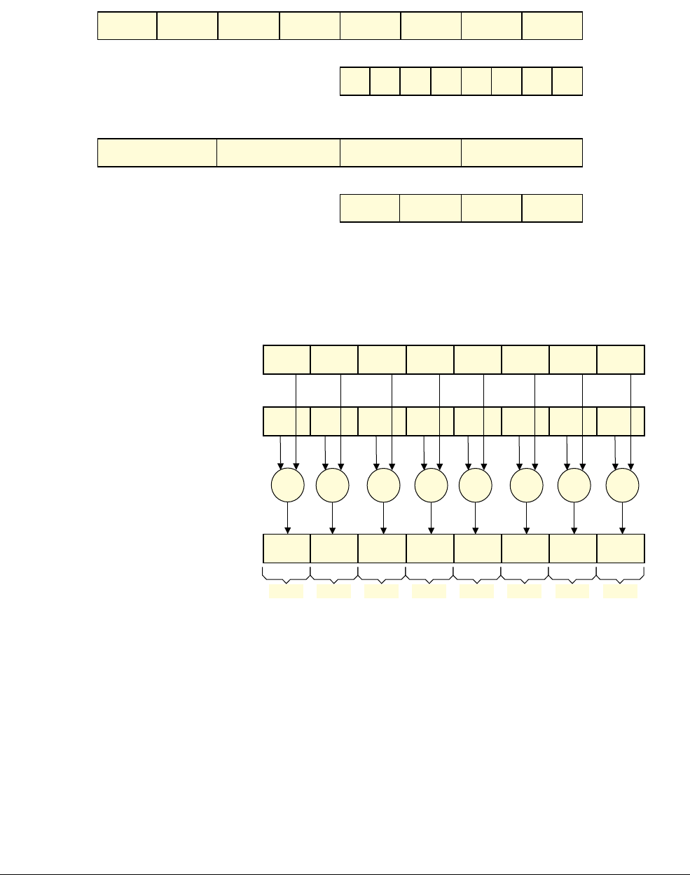
This operation performs a parallel addition of four 8-bit elements (called lanes) packed into
vectors in the 32-bit registers R1 and R2, and places the result into a vector in register R0.
The ARM1176™ applications processors, for example, implement the ARMv6 architecture.
ARM NEON technology builds on the concept of SIMD and supports 128-bit vector operations
instead of the 32-bit vector operations in the ARMv6 architecture.
The NEON unit is included by default in the Cortex-A7 and Cortex-A15 processors, but is
optional in other ARMv7 Cortex-A series processors.
31
31
31
24 23
24 23
24 23
16 15
16 15
16 15
8 7
8 7
8 7
0
0
0
+
Lane 2
R2
R1
R0
Vector
Lane 1 Lane 0Lane 3
+
++

Introduction
ARM DEN0018A Copyright © 2013 ARM. All rights reserved. 1-5
ID071613 Non-Confidential
Table 1-1 compares NEON technology with ARMv6 SIMD.
1.2.2 Comparison between NEON technology and other SIMD solutions
SIMD processing is not unique to ARM, and it is useful to consider other implementations and
compare them with NEON technology.
Table 1-1 Comparison of NEON extensions and ARMv6 SIMD instructions
Feature ARMv7 NEON extension ARMv6 SIMD instructions
Packed integers up to 8 x 8-bit, 4 x 16-bit, and 2 x 32 bit 4 x 8-bit
Data types Supports integer and, if the processor has a VFP unit,
single precision floating-point operations
Supports integer operations only
Simultaneous operations Maximum sixteen
(as 16 x 8-bit)
Maximum four
(as 4 x 8-bit)
Dedicated registers Operates on separate NEON register file that is shared
with the VFP unit
32 64-bit registers (or 16 128-bit registers)
Uses 32-bit general purpose ARM
registers
Pipeline Has dedicated pipeline that is optimized for NEON
execution
Uses the same pipeline as all other
instructions
Table 1-2 NEON technology compared with MMX and Altivec
NEON technology x86 MMX/SSE Altivec
Number of
registers
32 × 64-bit
(also visible as 16 × 128-bit)
SSE2: 8 × 128-bit XMM (in x86-32
mode)
Additional 8 registers in x86-64
mode
32 × 128-bit
Memory / register
operations
Register-based 3-operand
instructions
Mix of register and memory
operations
Register-based 3- and
4-operand instructions
Load/store support
for packed data
types
Yes as 2,3, or 4 element No No
Move between
scalar and vector
register
Yes Ye s No
Floating-point
support
Single-precision 32-bit Single-precision and
Double-precision
Single-precision

Introduction
ARM DEN0018A Copyright © 2013 ARM. All rights reserved. 1-6
ID071613 Non-Confidential
1.2.3 Comparison of NEON technology and Digital Signal Processors
Many ARM processors also incorporate a Digital Signal Processor (DSP) or custom signal
processing hardware, so they can include both a NEON unit and a DSP. There are some
differences between using NEON technology compared with using a DSP:
NEON technology features:
• Extends the ARM processor pipeline.
• Uses the ARM core registers for memory addressing.
• Single thread of control providing easier development and debug.
• OS multitasking supported (if the OS saves or restores the NEON and floating-point
register file).
• SMP capability. There is one NEON unit for each ARM core within an MPCore processor.
With multiple cores, this can provide many times standard performance using standard
pthreads.
• As part of the ARM processor architecture, the NEON unit will be available on future
faster processors and is supported by many ARM processor based SoCs.
• Broad NEON tools support is provided in both the open-source community and the ARM
ecosystem.
DSP features:
• Runs in parallel with ARM processors.
• Lack of OS and task switching overhead can provide guaranteed performance, but only if
DSP system design provides predictable performance.
• Generally more difficult to use by applications programmers: two toolsets, separate
debugger, potential synchronization issues.
• Less tightly integrated with the ARM processor. There can be some cache clean or flush
overhead with transferring data between DSP and the ARM processor which makes using
a DSP less efficient for processing very small blocks of data.

Introduction
ARM DEN0018A Copyright © 2013 ARM. All rights reserved. 1-7
ID071613 Non-Confidential
1.3 Architecture support for NEON technology
The NEON extension is implemented on some processors that implement the ARMv7-A or
ARMv7-R architecture profiles.
Note
• The ARMv8 architectural architecture extends the NEON support, and provides
backwards compatibility with ARMv7 implementations.
• This manual only covers cores that implement ARMv7-A and ARMv7-R.
• It is not guaranteed that the ARMv7-A or ARMv7-R processor that you are programming
contains either NEON or VFP technology. The possible combinations for cores that
conform to ARMv7 are:
— No NEON unit or VFP unit present.
— NEON unit present, but no VFP unit.
— No NEON unit present, but with a VFP unit.
— Both a NEON unit and a VFP unit are present.
• Processors that have a NEON unit, but no VPF unit, cannot execute floating-point
operations in hardware.
• Because NEON SIMD operations perform vector calculation more efficiently, vector
mode operation in the VFP unit was deprecated from the introduction of ARMv7. The
VFP unit is therefore sometimes referred to as the Floating Point Unit (FPU).
• Processors that do have a NEON or VFP unit, might not support the following extensions:
— Half precision.
— Fused Multiply-Add.
• If a VPF unit is present, there are versions that can access either 16 or 32 NEON
doubleword registers. See VFP views of the NEON and floating-point register file on
page 1-15.
1.3.1 Instruction timings
The NEON architecture does not specify instruction timings. An instruction might require a
different number of cycles to execute on different processors.
Even on the same processor, instruction timing can vary. One common cause of variation is
whether the instructions and data remain in the cache.

Introduction
ARM DEN0018A Copyright © 2013 ARM. All rights reserved. 1-8
ID071613 Non-Confidential
1.3.2 Support for VFP-only systems
Some instructions are common to the NEON and VFP extensions. These are called shared
instructions.
Note
Both VFP and the NEON unit are use instructions in the CP10 and CP11 coprocessor instruction
space and share the same register file, leading to some confusion between the two types of
operation:
• VFP can provide fully IEEE-754 compatible floating point operations that can, depending
on the implementation, operate on single-precision and double-precision floating point
values.
• The NEON unit is a parallel data processing unit for integer and single-precision floating
point data, and single precision operations in the ARMv7 NEON unit are not fully
IEEE-754 compliant.
• The NEON unit does not replace VFP. There are some specialized instructions that VFP
offers which have no equivalent implementations in the NEON instruction set.
If your processor does however have both a NEON unit and a VFP unit:
• All the NEON registers overlap with the VFP registers.
• All VFP data-processing instructions can execute on the VFP unit.
• The shared instructions can execute on the NEON Floating-Point pipeline.
1.3.3 Support for the Half-precision extension
The half-precision instructions are only available on NEON and VFP systems that include the
half-precision extension.
The Half-precision extension extends both the VFP and the NEON architectures. It provides
floating-point and NEON instructions that perform conversion between single-precision
(32-bit) and half-precision (16-bit) floating-point numbers.
1.3.4 Support for the Fused Multiply-Add instructions
The Fused Multiply-Add instructions is an optional extension to both the VFP and the NEON
extensions. It provides VFP and NEON instructions that perform multiply and accumulate
operations with a single rounding step, so suffers from less loss of accuracy than performing a
multiplication followed by an add.
The fused multiply-add instructions are only available on NEON or VFP systems that
implement the fused multiply-add extension. VFPv4 and Advanced SIMDv2 include support
for Fused Multiply-Add instructions.
1.3.5 Security and virtualization
The Cortex-A9 and Cortex-A15 processors include the ARM Security Extensions. The
Cortex-A15 processors include the ARM Security Extensions and the Virtualization Extensions.
These extensions can affect how you write code for the NEON and VFP units. These extensions
are outside the scope of this document, see the ARM Architecture Reference Manual ARMv7-A
and ARMv7-R for more information.

Introduction
ARM DEN0018A Copyright © 2013 ARM. All rights reserved. 1-9
ID071613 Non-Confidential
1.3.6 Undefined instructions
NEON instructions, including the half-precision half-precision and Fused Multiply-Add
instructions, are treated as Undefined Instructions on systems that do not support the necessary
architecture extension.
Even on systems that have the NEON unit and VFP unit, the instructions are undefined if they
are not enabled in the CP15 Coprocessor Access Control Register (CPACR). For more
information on enabling the NEON and VFP units, see the Technical Reference Manual for the
processor you are programming.
1.3.7 Support for ARMv6 SIMD instructions
ARMv6 architecture added a number of SIMD instructions for efficient software
implementation of multimedia algorithms. The ARM6 SIMD instructions were deprecated from
ARMv7. See Comparison between NEON technology and the ARMv6 SIMD instructions on
page 1-4.

Introduction
ARM DEN0018A Copyright © 2013 ARM. All rights reserved. 1-10
ID071613 Non-Confidential
1.4 Fundamentals of NEON technology
If you are familiar with the ARM v7-A architecture profile, you will have noticed that the
ARMv7 cores are a 32-bit architecture and use 32-bit registers, but the NEON unit uses 64-bit
or 128-bit registers for SIMD processing.
This is possible because the NEON unit and VFP are extensions to the ARMv7 instruction sets
that operate on a separate register file of 64-bit registers. The NEON and VFP units are fully
integrated into the processor and share the processor resources for integer operation, loop
control, and caching. This significantly reduces the area and power cost compared to a hardware
accelerator. It also uses a much simpler programming model, since the NEON unit uses the same
address space as the application.
The components of the NEON unit are:
• NEON register file
• NEON integer execute pipeline
• NEON single-precision floating-point execute pipeline
• NEON load/store and permute pipeline.
1.4.1 Registers, vectors, lanes and elements
NEON instructions and floating-point instructions use the same register file, called the NEON
and floating-point register file. This is distinct from the ARM core register file. The NEON and
floating-point register file is a collection of registers which can be accessed as 32-bit, 64-bit, or
128-bit registers. Which registers are available for an instruction depends on whether it is a
NEON instruction or VFP instruction. This document refers to the NEON and floating-point
registers as the NEON registers. Certain VFP and NEON instructions move data between the
general-purpose registers and the NEON registers or use the ARM general-purpose registers to
address memory.
The contents of the NEON registers are vectors of elements of the same data type. A vector is
divided into lanes and each lane contains a data value called an element.
Usually each NEON instruction results in
n
operations occurring in parallel, where
n
is the
number of lanes that the input vectors are divided into. Each operation is contained within the
lane. There cannot be a carry or overflow from one lane to another.
The number of lanes in a NEON vector depends on the size of the vector and the data elements
in the vector:
• 64-bit NEON vectors can contain:
— Eight 8-bit elements.
— Four 16-bit elements.
— Two 32-bit elements.
— One 64-bit element.
• 128-bit NEON vectors can contain:
— Sixteen 8-bit elements.
— Eight 16-bit elements.
— Four 32-bit elements.
— Two 64-bit elements.
Introduction
ARM DEN0018A Copyright © 2013 ARM. All rights reserved. 1-11
ID071613 Non-Confidential
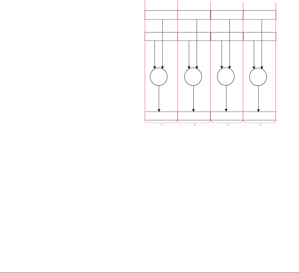
Element ordering
Figure 1-3 shows that the ordering of elements in the vector is from the least significant bit. This
means element 0 uses the least significant bits of the register.
Figure 1-3 Lanes and elements
Figure 1-4 shows how the
VADD.I16
Q0, Q1, Q2
instruction performs a parallel addition of eight
lanes of 16-bit (8 x 16 = 128) integer (
I
) elements from vectors in Q1 and Q2, storing the result
in Q0.
Figure 1-4 8 way 16-bit integer add operation
127 112 111 96 95 80 79 64 63 48 47 32 31 16 15 0
Q register with
eight 16-bit lanes
63 56 55 48 47 40 39 32 31 24 23 16 15 8 7 0
D register with
eight 8-bit lanes
127 96 95 64 63 32 31 0
Q register with
four 32-bit lanes
63 48 47 32 31 16 15 0
D register with
four 16-bit lanes
127 112 111 96 95 80 79 64 63 48 47 32 31 16 15 0
127 112 111 96 95 80 79 64 63 48 47 32 31 16 15 0
Q2
Q1
Q0
Vector
Lane 6 Lane 5 Lane 4 Lane 3 Lane 2 Lane 1 Lane 0Lane 7
++ + + + + + +
Introduction
ARM DEN0018A Copyright © 2013 ARM. All rights reserved. 1-12
ID071613 Non-Confidential
Register overlap
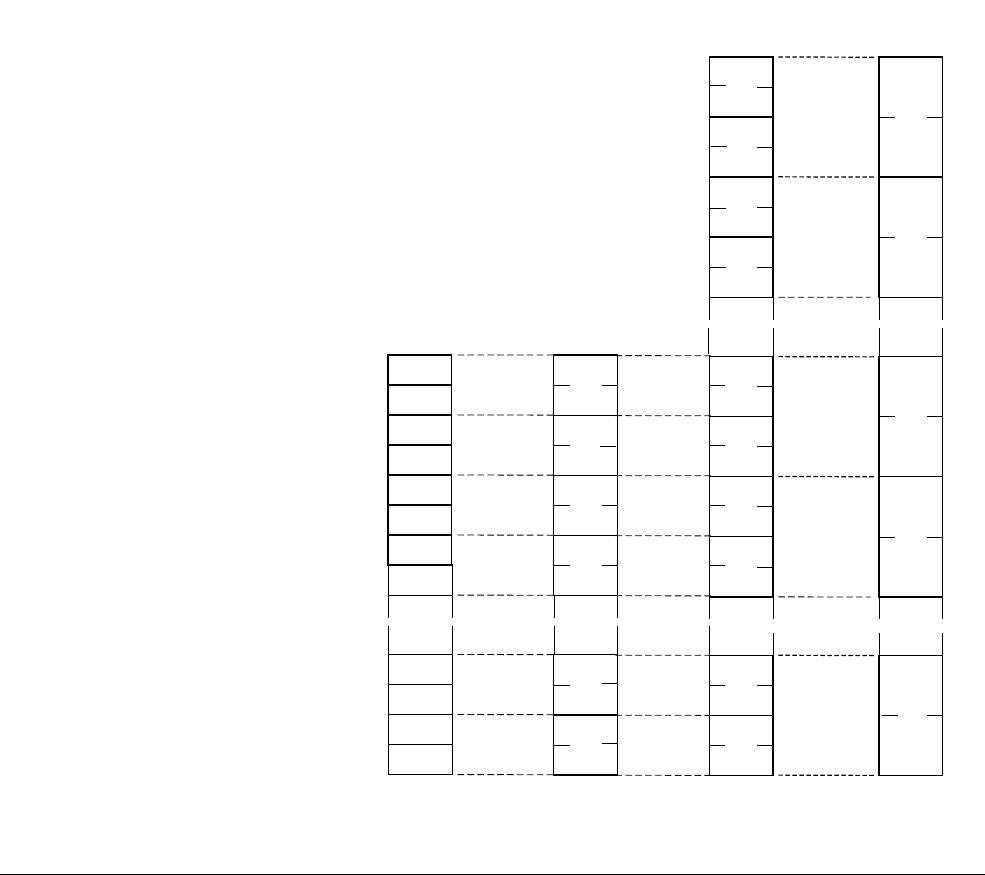
Figure 1-5 shows the NEON and floating-point register file and how the registers overlap.
The NEON unit views the register file as:
• Sixteen 128-bit Q, or quadword, registers,
Q0-Q15
.
• Thirty-two 64-bit D, or doubleword, registers,
D0-D31
. (Sixteen 64-bit D registers for
VFPv3-D16.)
The mapping for the D registers is:
—
D<2n>
maps to the least significant half of
Q<n>
—
D<2n+1>
maps to the most significant half of
Q<n>
.
• A combination of Q and D registers.
• The NEON unit cannot directly access the individual 32-bit VPF S registers. See VFP
views of the NEON and floating-point register file on page 1-15.
The mapping for the S registers is:
—
S<2n>
maps to the least significant half of
D<n>
—
S<2n+1>
maps to the most significant half of
D<n>.
Figure 1-5 NEON and floating-point register file
D0
D29
D31
D30
S3
S2
S24
S1
S0
...
D1
D28
D12
D13
D14
D15
...
Q0
Q6
Q7
Q15
...
...
...
~
~~
~~
~
~
~~
~~
~
~
~
~
~~
~~
~
S0-S31
VFP Only
D0
D1
D14
D15
...
~
~~
~
D0-D15
VFPv2 or
VFPv3-D16
D0-D31
VFPv3-D32
or NEON
Q0-Q15
NEON only
Q14
D13
D12
S25
S26
S27
S28
S29
S30
S31
Introduction
ARM DEN0018A Copyright © 2013 ARM. All rights reserved. 1-13
ID071613 Non-Confidential
All of these registers are accessible at any time. Software does not have to explicitly switch
between them because the instruction used determines the appropriate view.
In Figure 1-6 the S, D, and Q registers are different views of the same register Q0:
• The NEON unit can access Q0 as an 128-bit register.
• The NEON unit can access Q0 as two consecutive 64-bit registers D0 and D1.
• The NEON unit cannot access the 32-bit S registers in Q0 individually.
If a VPF unit is present, it can however access them as S0, S1, S2, and S3.
Figure 1-6 Register overlap
Scalar data
Scalar refers to a single value instead of a vector containing multiple values. Some NEON
instructions use a scalar operand. A scalar inside a register is accessed by index into the vector
of values. The array notation to access individual elements of a vector is Dm[x] or Qm[x] where
x is the index in the vector Dm or Qm.
The instruction
VMOV.8 D0[3], R3
moves the least significant byte of register R3 into the fourth
byte in register D0.
Figure 1-7 Moving a scalar to a lane
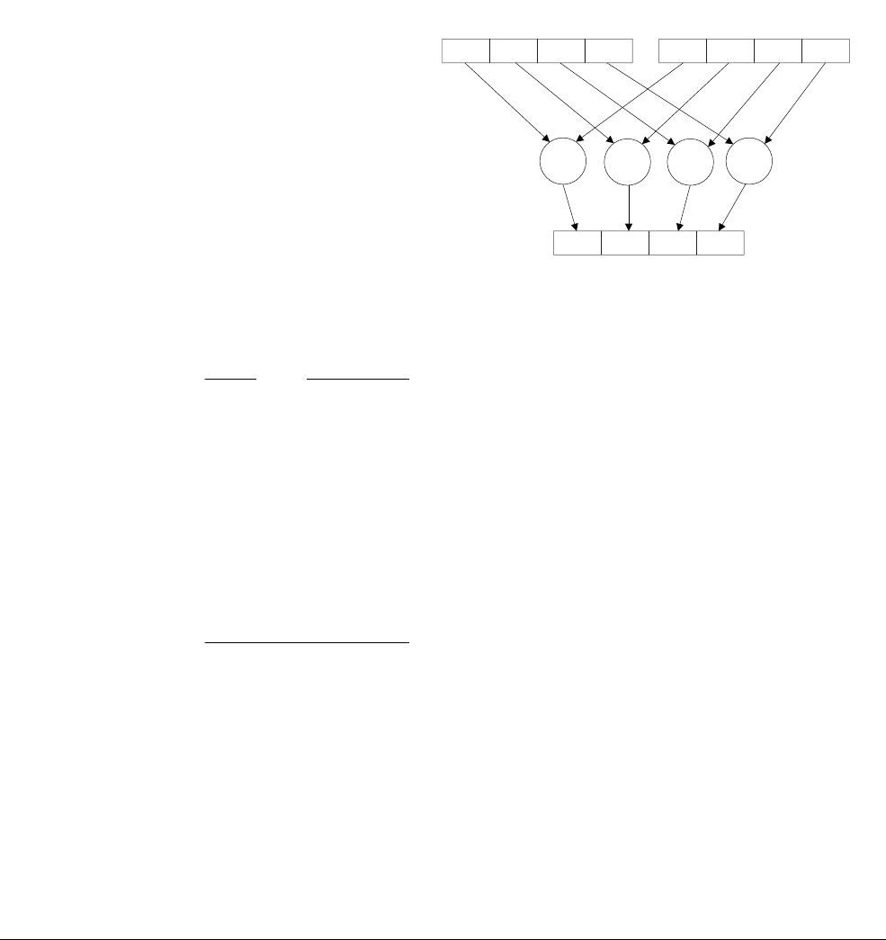
NEON scalars can be 8-bit, 16-bit, 32-bit, or 64-bit values. Other than multiply instructions,
instructions that access scalars can access any element in the register file.
Multiply instructions only allow 16-bit or 32-bit scalars, and can only access the first 32 scalars
in the register file:
• 16-bit scalars are restricted to registers D0[x]-D7[x], with x in the range 0 to 3
• 32-bit scalars are restricted to registers D0[x]-D15[x], with x either 0 or 1.
127 063 31
VFP only
VFP or NEON
NEON only
95 64 3296
S3 S2 S1 S0
D1 D0
Q0
L3
63 32 31 24 23 0
NEON register D0
31 8 7 0
ARM register R3

Introduction
ARM DEN0018A Copyright © 2013 ARM. All rights reserved. 1-14
ID071613 Non-Confidential
1.4.2 NEON data type specifiers
The form and construction of NEON instructions is covered in Chapter 3 NEON Instruction Set
Architecture.
Although the ARM architecture does not require a processor to implement both VFP and NEON
technology, the common features in the programming for these extensions mean an operating
system that supports VFP requires little or no modifications to also support NEON technology.
However because the NEON unit is optional in some Cortex-A series processors, you cannot
rely on NEON code working on all processors.
Before using NEON or VFP instructions and compiling the code on a given processor, you must
check that the NEON or VFP unit is there! This is covered in Chapter 2 Compiling NEON
Instructions.
Data type specifiers in NEON and VFP instructions consist of a letter indicating the type of data,
usually followed by a number indicating the width. They are separated from the instruction
mnemonic by a point, for example,
VMLAL.S8
.
Table 1-3 shows the available NEON data types.
Note
The polynomial type is for operations that use power-of-two finite fields or simple polynomials
over {0,1}. These are described in Polynomials on page 3-17.
Table 1-3 NEON data types
8-bit 16-bit 32-bit 64-bit
Unsigned integer U8 U16 U32 U64
Signed integer S8 S16 S32 S64
Integer of unspecified type I8 I16 I32 I64
Floating-point number not available F16 F32 or F not available
Polynomial over {0,1} P8 P16 not available not available

Introduction
ARM DEN0018A Copyright © 2013 ARM. All rights reserved. 1-15
ID071613 Non-Confidential
1.4.3 VFP views of the NEON and floating-point register file
Processors that implement the ARMv7A and ARMV-7R architecture can optionally include one
of the following VFP extensions:
In version VFPv3-D16 and VPFv3-D16-FP16, the VFP unit views the NEON register file as:
• Sixteen 64-bit D registers
D0-D15
. The D registers are called double-precision registers
and contain double-precision floating-point values.
• Thirty-two 32-bit S registers
S0-S31
. The S registers are called single-precision registers
and contain single-precision floating-point values or 32-bit integers.
For VPFv3-D16-F16, the S registers can contain a half-precision floating-point value.
• A combination of registers from the above views.
In versions VFPv3, VFPv3-D32, and VFPv3-D32-FP16, the VFP unit views the NEON register
file as:
• Thirty-two 64-bit D registers,
D0-D31
.
• Thirty-two 32-bit S registers,
S0-S31
. The registers D0-D15 overlap S registers S0-S31.
For VPFv3-D-32-F16, the S registers can contain a half-precision floating-point value.
• A combination of registers from the above views.
Note
• The different views means half-precision, single-precision, and double-precision values,
and NEON vectors to coexist in different non-overlapped registers at the same time.
• You can also use the same overlapped registers to store half-precision, single-precision,
and double-precision values, and NEON vectors at different times.
Table 1-5 shows the available data types for VFP instructions.
See VFP instructions on page C-67 for a description of the instructions specific to the VFP unit.
Table 1-4 VFPv3 variants
Number of 64-bit D registers With half-precision extension Without half-precision extension
Sixteen VFPv3-D16-FP16 VFPv3-D16
Thirty-two VFPv3-D32-FP16
(Also called VFPv4 if the fused
multiply-add extension is present)
VFPv3-D32
(Sometimes called just VFPv3 if there is
no possibility of confusion with other
extensions)
Table 1-5 VFP data types
16-bit 32-bit 64-bit
Unsigned integer U16 U32 not available
Signed integer S16 S32 not available
Floating point number F16 F32 (or F) F64 (or D)

ARM DEN0018A Copyright © 2013 ARM. All rights reserved. 2-1
ID071613 Non-Confidential
Chapter 2
Compiling NEON Instructions
This chapter describes how code targeted at NEON hardware can be written in C or assembly
language, and the range of tools and libraries are available to support this. It contains the
following topics:
•Vectorization on page 2-2
•Generating NEON code using the vectorizing compiler on page 2-9
•Vectorizing examples on page 2-11
•NEON assembler and ABI restrictions on page 2-17
•NEON libraries on page 2-19
•Intrinsics on page 2-20
•Detecting presence of a NEON unit on page 2-21
•Writing code to imply SIMD on page 2-22
•GCC command line options on page 2-24

Compiling NEON Instructions
ARM DEN0018A Copyright © 2013 ARM. All rights reserved. 2-2
ID071613 Non-Confidential
2.1 Vectorization
NEON was designed as an additional load/store architecture to provide good vectorizing
compiler support for languages such as C/C++. This enables a high level of parallelism. You can
hand-code NEON instructions for applications that need very high performance. It includes low
cost promotion and demotion of data sizes. It also includes structure loads capable of accessing
multiple data streams which are interleaved in memory.
NEON instructions can be written as part of the normal ARM code. This makes NEON
programming simpler and more efficient than with an external hardware accelerator. There are
NEON instructions available to read and write external memory, move data between NEON
registers and other ARM registers and to perform SIMD operations.
All compiled code and subroutines will conform to the EABI, which specifies which registers
can be corrupted and which registers must be preserved.
A vectorizing compiler can take your C or C++ source code and vectorize it in a way that
enables efficient usage of NEON hardware. This means you can write portable C code, while
still obtaining the levels of performance made possible by NEON instructions.
To assist vectorization, make the number of loop iterations a multiple of the vector length. Both
GCC and ARM Compiler toolchain have options for enabling automatic vectorization for
NEON technology, but because the C and C++ standards do not cover the concurrency aspects,
you might have to provide the compiler with additional information to get full benefit. The
required source code modifications are part of the standard language specifications, so they do
not affect code portability between different platforms and architectures.
The vectorizing compiler works best when it can determine the intention of the programmer.
Simple code that is easy for a human to understand is much easier to vectorize than code highly
tuned for a specific processor.
2.1.1 Enabling auto-vectorization in ARM Compiler toolchain
The ARM Compiler toolchain in DS-5™ Professional includes support for the vectorizing
compiler. To enable automatic vectorization you must target a processor that has a NEON unit.
The required command line options are:
--vectorize
Enable vectorization
--cpu 7-A
or
--cpu Cortex-A8
Specify a core or architecture with NEON support
-O2
or
–O3
Select high level or aggressive optimization
-Otime
Optimize for speed rather than for space.
Use the
armcc
command line parameter
--remarks
to provide more information about the
optimizations performed, or problems preventing the compiler from performing certain
optimizations.

Compiling NEON Instructions
ARM DEN0018A Copyright © 2013 ARM. All rights reserved. 2-3
ID071613 Non-Confidential
2.1.2 Enabling auto-vectorization in GCC compiler
To enable automatic vectorization in GCC, use the command line options:
•
-ftree-vectorize
•
–mfpu=neon
•
-mcpu
to specify the core or architecture.
Compiling at optimization level
-O3
implies
-ftree-vectorize
.
If you do not specify an
-mcpu
option, then GCC will use its built-in default core. The resulting
code might run slowly or not run at all.
The option
-ftree-vectoriz
e is available for many architectures that support SIMD operations.
2.1.3 C pointer aliasing
A major challenge in optimizing Standard C (ISO C90) is because you can de-reference pointers
which might (according to the standard) point to the same or overlapping datasets.
As the C standard evolved, this issue was addressed by adding the keyword
restrict
to C99 and
C++. Adding
restrict
to a pointer declaration is a promise that only this pointer will access the
address it is pointing to. This enables the compiler to do the work in setup and exit restrictions,
preload data with plenty of advance notice, and cache the intermediate results.
The ARM Compiler allows the use of the keyword
__restrict
in all modes. If you specify the
command line option
--restrict
, you can use the keyword
restrict
without the leading
underscores. GCC has similar options. See the GCC documentation for more information.
2.1.4 Natural types
Often algorithms are written to expect certain types for legacy, memory size or peripheral
reasons. It is common to cast these up to the natural type for the processor as mathematical
operations on natural sized data are usually faster, and truncation and overflow are only
calculated when data is passed or stored.
2.1.5 Array grouping
For processor designs that have few registers for storing memory pointers (such as x86), it is
common to group several arrays into one. This permits several different offsets from the same
pointer to access to different parts of the data. Grouping arrays in this way can confuse the
compiler into thinking that the offsets cause overlapping datasets. Avoid this unless you can
guarantee that there are no writes into the array. Split composite arrays into individual arrays to
simplify pointer use and remove this risk.
2.1.6 Inside knowledge
To turn an array with no size information into NEON code, the compiler must assume the size
might be anywhere between 0 and 4GB. Without additional information the compiler must
generate setup code which tests if the array is too small to consume a whole NEON register as
well as cleanup code which consumes the last few items in the array using the scalar pipeline.
In some cases array sizes are known at compile time and should be specified directly rather than
passed as arguments. In other cases, it is common for the engineer to know more about the array
layouts than the compiler. For example, arrays are often expressed as powers of 2. A
programmer might know that a loop iteration count will always be a multiple of 2, 4, 8, 16, 32
and so on. It is possible to write code to exploit this. See Optimizing for vectorization on
page 2-6 and Adding inside knowledge on page 8-24 for more information.

Compiling NEON Instructions
ARM DEN0018A Copyright © 2013 ARM. All rights reserved. 2-4
ID071613 Non-Confidential
2.1.7 Enabling the NEON unit in bare-metal applications
A bare-metal application is one that runs directly on the hardware without a kernel or operating
system support.
The NEON unit is disabled at reset by default, so you must enable it manually for a bare metal
application that requires NEON instructions. The
EnableNEON
code snippet shows how to enable
the NEON unit manually.
#include <stdio.h>
// Bare-minimum start-up code to run NEON code
__asm void EnableNEON(void)
{
MRC p15,0,r0,c1,c0,2 // Read CP Access register
ORR r0,r0,#0x00f00000 // Enable full access to NEON/VFP by enabling access to
// Coprocessors 10 and 11
MCR p15,0,r0,c1,c0,2 // Write CP Access register
ISB
MOV r0,#0x40000000 // Switch on the VFP and NEON hardware
MSR FPEXC,r0 // Set EN bit in FPEXC
}
When compiling a bare-metal application for a processor with a NEON unit, the compiler might
use NEON instructions. For example the ARM Compiler toolchain
armcc
uses
-O2
optimization
by default, which tries to vectorize code for a processor with a NEON unit if
-Otime
and
--vectorize
options are specified.
You can compile the bare metal application,
hello.c
, as:
armcc -c --cpu=Cortex-A8 --debug hello.c -o hello.o
armlink --entry=EnableNEON hello.o -o hello.axf
2.1.8 Enabling the NEON unit in a Linux stock kernel
A stock kernel is the kernel released by Linux at www.kernel.org, without modification. If you
use a Linux stock kernel to run your application, there is no need to manually enable the NEON
unit. The kernel automatically enables the NEON unit when it encounters the first NEON
instruction.
If the NEON unit is disabled and the application tries to execute a NEON instruction, it throws
an Undefined Instruction exception. The kernel uses this exception to enable the NEON unit and
then executes the NEON instruction. The NEON unit remains enabled until there is a context
switch. When a context switch is required, the kernel might disable the NEON unit to save time
and power.
Compiling NEON Instructions
ARM DEN0018A Copyright © 2013 ARM. All rights reserved. 2-5
ID071613 Non-Confidential
2.1.9 Enabling the NEON unit in a Linux custom kernel
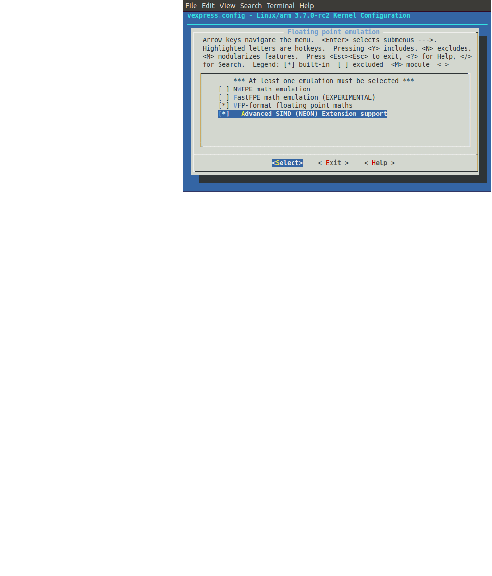
If you use a Linux custom kernel to run your application, you must enable the NEON unit. To
enable the NEON unit, you must use the kernel configuration settings to select:
•Floating point emulation → VFP-format floating point maths
•Floating point emulation → Advanced SIMD (NEON) Extension support.
Figure 2-1 shows the configuration settings for a Versatile Express board.
Figure 2-1 Configuration of a custom kernel
If
/proc/config.gz
is present, you can test for NEON support in the kernel using the command:
zcat /proc/config.gz | grep NEON
If the NEON unit is present, the command outputs:
CONFIG_NEON=y
To ensure that the processor supports the NEON extension, you can issue the command:
cat /proc/cpuinfo | grep neon
If it supports the NEON extension, the output shows
neon
, for example:
Features : swp half thumb fastmult vfp edsp neon vfpv3 tls vfpv4 idiva idivt
Compiling NEON Instructions
ARM DEN0018A Copyright © 2013 ARM. All rights reserved. 2-6
ID071613 Non-Confidential
2.1.10 Optimizing for vectorization
The C and C++ languages do not provide syntax that specifies concurrent behavior, so compilers
cannot safely generate parallel code. However, the developer can provide additional information
to let the compiler know where it is safe to vectorize.
Unlike intrinsics, these modifications are not architecture dependent, and are likely to improve
vectorization on any target platform. These modifications usually do not have negative impact
on performance on targets where vectorization is not possible.
The following describe the main rules:
• Short, simple loops work best (even if it means multiple loops in your code).
• Avoid using a break statement to exit a loop.
• Try to make the number of iterations a power of two.
• Try to make sure the number of iterations is known to the compiler.
• Functions called inside a loop should be inlined.
• Using arrays with indexing vectorizes better than using pointers.
• Indirect addressing (multiple indexing or dereferencing) does not vectorize.
•Use the
restrict
keyword to tell the compiler that pointers do not reference overlapping
areas of memory.
Indicate knowledge of number of loop iterations
If a loop has a fixed iteration count, or if you know that the iteration count is always a power of
2, making this obvious to the compiler enables the compiler to perform optimizations that would
otherwise be unsafe or difficult.
Example 2-1 shows a function accumulating a number (
len
) of
int
-sized elements. If you know
that the value passed as
len
is always a multiple of four, you can indicate this to the compiler by
masking off the bottom two bits when comparing the loop counter to
len
. This ensures that the
loop always executes a multiple of four times. Therefore the compiler can safely vectorize and:
• does not need to add code for runtime checks on
len
• does not need to add code to deal with over-hanging iterations.
Example 2-1 Specifying that the loop counter is a multiple of 4
int accumulate(int * c, int len)
{
int i, retval;
for(i = 0, retval = 0; i < (len & ~3) ; i++)
{
retval = retval + c[i]
}
return retval;
}

Compiling NEON Instructions
ARM DEN0018A Copyright © 2013 ARM. All rights reserved. 2-7
ID071613 Non-Confidential
Avoid loop-carried dependencies
If your code contains a loop where the result of one iteration is affected by the result of a
previous iteration, the compiler cannot vectorize it. If possible, restructure the code to remove
any loop-carried dependencies.
Use the
restrict
keyword
C99 introduced the
restrict
keyword, that you can use to inform the compiler that the location
accessed through a specific pointer is not accessed through any other pointer within the current
scope.
Example 2-2 shows a situation where using restrict on a pointer to a location being updated
makes vectorization safe when it otherwise would not be.
Example 2-2
int accumulate2(char * c, char * d, char * restrict e, int len)
{
int i;
for(i=0 ; i < (len & ~3) ; i++)
{
e[i] = d[i] + c[i];
}
return i;
}
Without the
restrict
keyword, the compiler must assume that
e[i]
can refer to the same
location as
d[i + 1]
, meaning that the possibility of a loop-carried dependency prevents it from
vectorizing this sequence. With
restrict
, the programmer informs the compiler that any
location accessed through
e i
s only accessed through pointer e in this function. This means the
compiler can ignore the possibility of aliasing and vectorize the sequence.
Using the
restrict
keyword does not enable the compiler to perform additional checks on the
function call. Hence, if the function is passed values for
c
or
d
that overlap with the value for
e
,
the vectorized code might not execute correctly.
Both GCC and ARM Compiler toolchain support the alternative forms
__restrict__
and
__restrict
when not compiling for C99. ARM Compiler toolchain also supports using the
restrict
keyword with C90 and C++ when
--restrict
is specified on the command line.
Avoid conditions inside loops
Normally, the compiler cannot vectorize loops containing conditional statements. In the best
case, it duplicates the loop, but in many cases it cannot vectorize it at all.

Compiling NEON Instructions
ARM DEN0018A Copyright © 2013 ARM. All rights reserved. 2-8
ID071613 Non-Confidential
Use suitable data types
When optimizing some algorithms operating on 16-bit or 8-bit data without SIMD, sometimes
you get better performance if you treat them as 32-bit variables. When producing software
targeting automatic vectorization, for best performance always use the smallest data type that
can hold the required values. This means a NEON register can hold more data elements and
execute more operations in parallel. In a given period, the NEON unit can process twice as many
8-bit values as 16-bit values.
Also, NEON technology does not support some data types, and some are only supported for
certain operations. For example, it does not support double-precision floating-point, so using a
double-precision double where a single-precision float is sufficient can prevent the compiler
from vectorizing code. NEON technology supports 64-bit integers only for certain operations,
so avoid using
long long
variables where possible.
Note
NEON technology includes a group of instructions that can perform structured load and store
operations. These instructions can only be used for vectorized access to data structures where
all members are of the same size.
Floating-point vectorization
Floating-point operations can result in loss of precision. The order of the operations or
floating-point inputs can be arranged to reduce the loss in precision. Changing the order of the
operations or inputs can result in further loss in precision. Hence some floating-point operations
are not vectorized by default because vectorizing can change the order of the operations. If the
algorithm does not require this level of precision, you can specify
--fpmode=fast
, for armcc, or
-ffast-math
, for GCC, on the command line to enable these optimizations.
Example 2-3 shows a sequence that can only be vectorized with one of these parameters
specified. In this case, it performs parallel accumulation, potentially reducing the precision of
the result.
Example 2-3
float g(float const *a)
{
float r = 0;
int i;
for (i = 0 ; i < 32 ; ++i)
r += a[i];
return r;
}
The NEON unit always operates in Flush-to-Zero mode (see Flush-to-zero mode on page 3-13),
making it non-compliant with IEEE 754. By default, armcc uses
--fpmode=std
, permitting the
deviations from the standard. However, if the command line parameters specify a mode option
requiring IEEE 754 compliance, for example
--fpmode=ieee_full
, most floating-point
operations cannot be vectorized.

Compiling NEON Instructions
ARM DEN0018A Copyright © 2013 ARM. All rights reserved. 2-9
ID071613 Non-Confidential
2.2 Generating NEON code using the vectorizing compiler
The vectorizing compiler evaluates vectorizable loops and potential NEON applications. If the
C or C++ code is written such that the compiler can determine the intent of the code, the
compiler optimizes it more efficiently. Although the compiler can generate some NEON code
without source modification, certain coding styles can promote more optimal output. Where the
vectorizer finds code with potential vectorizing opportunities but does not have enough
information, it can generate a remark to the user to prompt changes to the source code that can
provide more useful information. Although these modifications help the vectorizing compiler
they are all standard C notation and will allow re-compilation with any C99* compliant
compiler. C99 is required for parsing of the keyword
restrict
. In other compilation modes,
armcc also allows the use of the equivalent ARM-specific extension
__restrict
.
2.2.1 Compiler command line options
With the vectorizing licence option present, the compiler can be told to generate NEON code by
using the
O2
or
O3
,
Otime
,
vectorize
, and
cpu
options. The
cpu
option must specify a processor
that has NEON hardware.
SIMD code is sometimes bigger than the equivalent ARM code due to array cleanup and other
overheads.
To generate fast NEON code on a Cortex-A8 target, you should use the command line:
armcc --cpu=Cortex-A8 -O3 -Otime --vectorize ...
If you do not have a licence for the vectorizing compiler, this command will respond with an
error message.
Using the vectorizing compiler
We can now try using the vectorizing compiler on the addition example in Programming using
NEON intrinsics on page 4-14.
We can write the C code succinctly:
/* file.c */
unsigned int vector_add_of_n(unsigned int* ptr, unsigned int items)
{
unsigned int result=0;
unsigned int i;
for (i=0; i<(items*4); i+=1)
{
result+=ptr[i];
}
return result;
}
Note
• By using
(items*4)
we are telling the compiler that the size of the array is a multiple of
four. Although this is not required for the vectorizer to create NEON code, it provides the
compiler with extra information about the array. In this case it knows the array can be
consumed with vector arrays and does not require any extra scalar code to handle the
cleanup of any spare items.
• The value of
items
passed to the function must be a quarter of the actual number of items
in the array as
vector_add_of_n(p_list, item_count/4)
Compile:
armcc --cpu=Cortex-A8 -O3 –c -Otime –-vectorize file.c

Compiling NEON Instructions
ARM DEN0018A Copyright © 2013 ARM. All rights reserved. 2-10
ID071613 Non-Confidential
Viewing the generated code with:
fromelf –c file.o
vector_add_of_n PROC
LSLS r3,r1,#2
MOV r2,r0
MOV r0,#0
BEQ |L1.72|
LSL r3,r1,#2
VMOV.I8 q0,#0
LSRS r1,r3,#2
BEQ |L1.48| |L1.32|
VLD1.32 {d2,d3},[r2]!
VADD.I32 q0,q0,q1
SUBS r1,r1,#1
BNE |L1.32| |L1.48|
CMP r3,#4
BCC |L1.72|
VADD.I32 d0,d0,d1
VPADD.I32 d0,d0,d0
VMOV.32 r1,d0[0]
ADD r0,r0,r1 |L1.72|
BX lr
This disassembly is different from the intrinsic function example in Programming using NEON
intrinsics on page 4-14. The hand-coded example misses the important corner case where the
array is zero in length.
Although the code is longer than the handwritten example, the main parts of the routine (the
inner loop) are the same length and contain the same instructions. This means that the time
difference for execution is trivial if the dataset is reasonable in size. However, on Cortex-A8
processors, the code generated by the compiler is scheduled non-optimally compared to the
hand-written code. Thus the difference in performance on Cortex-A8 processors scales with the
dataset size.
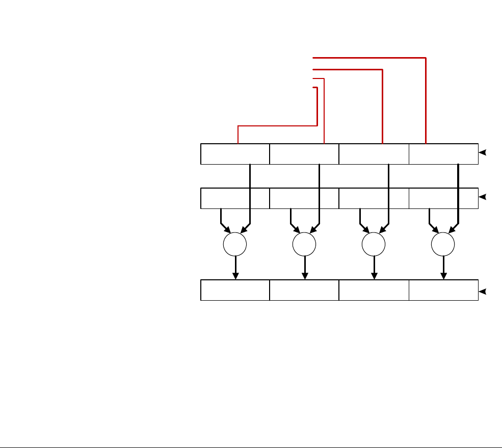
Compiling NEON Instructions
ARM DEN0018A Copyright © 2013 ARM. All rights reserved. 2-11
ID071613 Non-Confidential
2.3 Vectorizing examples
This section contains examples of vectorization:
2.3.1 Vectorization example on unrolling addition function
Consider the following code:
Void add_int (int * __restrict pa, int * __restrict pb, unsigned int n, int x)
{
unsigned int i;
for (i = 0; i < (n & ~3); i++)
pa[i] = pb [i] + x;
}
1. Analyze each loop
• Are pointer accesses safe for vectorization?
• What data types are being used, and how do they map onto NEON registers?
• How many loop iterations are there?
2. Unroll the loop to the appropriate number of iterations and perform other transformations
such as using pointer.
Figure 2-2 Vectorization example
3. Map each unrolled operation onto a NEON vector lane and generate a corresponding
NEON instruction.
127 0
++++
pb
x
pa
void add_int (int * __restrict pa, int* __restrict pb, unsigned n, int x )
{unsigned int i ;
for ( i = (( n & ~3 ) >>2 ) ; i ; i -- )
{
*( pa + 0 ) = *( pb +0 ) + x ;
*( pa + 1 ) = *( pb +1 ) + x ;
*( pa + 2 ) = *( pb +2 ) + x ;
*( pa + 3 ) = *( pb +3 ) + x ;
pa += 4 ; pb += 4;
}
}

Compiling NEON Instructions
ARM DEN0018A Copyright © 2013 ARM. All rights reserved. 2-12
ID071613 Non-Confidential
2.3.2 Vectorizing example with vectorizing compilation
Table 2-1 shows a comparison of code compiled with and without vectorizing compilation:
2.3.3 Vectorizing examples with different command line switches
This section contains very simple examples of compiler vectorization. The examples show the
effects of various command line switches and the effects of various source code changes.
Optimized for code space
In this example, the compiler option
-Ospace
results in smaller code size. The resulting code is
not optimized for speed.
Example 2-4 Optimized for code space
void add_int (int *pa, int * pb, unsigned int n, int x)
{
unsigned int i;
for(i = 0; i < n; i++)
pa[i] = pb[i] + x;
}
Compile the code with the following options:
armcc --cpu=Cortex-A8 -O3 -Ospace
Example 2-5 Resulting assembly language
add_int PROC
PUSH {r4, r5, 1r}
MOV r4, #0
|L0.8|
CMP r4,r2
Table 2-1 Result of using vectorize option
With vectorizing compilation Without vectorizing compilation
armcc --cpu=Cortex-A8 –O2 –Otime --vectorize armcc --cpu=Cortex-A8 –O2 -Otime
add_int PROC
BICS r12, r2, #3
BEQ |L1, 40 |
VDUP, 32 q1, r3
LSRS r2, r2, #2
BEQ |L1, 40 |
|L1.20|
VLD1.32 {d0,d1}, [r1]!
VADD.I32 q0, q0, q1
SUBS r2, r2, #1
VST1.32 {d0,d1}, [r0]!
BNE |L1.20|
|L1.40|
BX 1r
ENDP
add_int PROC
MOV r12, #0
PUSH {r4}
BICS r4, r2, #3
BEQ |L1.44|
|L1.20|
LDR r4, {r1, r12, LSL, #2]
ADD r4, r4, r3
STR r4, [r0,r12,LSL,#2]
ADD r12, r12, #1
CMP r2, r12
BHI |L1.20|
|L1.40|
POP {r4}
BX 1r
ENDP

Compiling NEON Instructions
ARM DEN0018A Copyright © 2013 ARM. All rights reserved. 2-13
ID071613 Non-Confidential
LDRCC r5, [r1, r4, LSL, #2]
ADCC r5, r5, r3
STRCC r5, [r0, r4, LSL, #2]
ADCC r4,r4, #1
BCC |L0.8|
POP {r4, r5, pc}
Optimized for time
In this example, the compiler option
-Otime
results in code faster and longer than the code in
Example 2-4 on page 2-12.
Example 2-6 Optimized for time
void add_int (int *pa, int * pb, unsigned int n, int x)
{
unsigned int i;
for(i = 0; i < n; i++)
pa[i] = pb[i] + x;
}
Compile the code with the following options:
armcc --cpu=Cortex-A8 -O3 -Otime
Example 2-7 Resulting assembly language
add_int PROC
CMP r2,#0
BXEQ lr
TST r2,#1
SUB r1,r1,#4
SUB r0,r0,#4
PUSH {r4}
BEQ |L0.48|
LDR r4,[r1,#4]!
ADD r12,r0,#4
ADD r4,r4,r3
STR r4,[r0,#4]
MOV r0,r12
|L0.48|
LSRS r2,r2,#1
BEQ |L0.96|
|L0.56|
LDR r12,[r1,#4]
SUBS r2,r2,#1
ADD r12,r12,r3
STR r12,[r0,#4]
ADD r12,r0,#8
LDR r4,[r1,#8]!
ADD r4,r4,r3
STR r4,[r0,#8]
MOV r0,r12
BNE |L0.56|

Compiling NEON Instructions
ARM DEN0018A Copyright © 2013 ARM. All rights reserved. 2-14
ID071613 Non-Confidential
|L0.96|
POP {r4}
BX lr
Optimized using knowledge of array size
In this example, the
for
loop iteration bound is set to
(n&~3)
. This tells the compiler that the size
of array
pa
is a multiple of
4
.
Example 2-8 Optimized using knowledge of array size
void add_int (int *pa, int * pb, unsigned int n, int x)
{
unsigned int i;
for(i = 0; i < (n&~3); i++)
pa[i] = pb[i] + x;
}
Compile the code with the following options:
armcc --cpu=Cortex-A8 -O3 -Otime
Example 2-9 Resulting assembly language
add_int
BICS r12,r12,#3
BXEQ lr
LSR r2,r2,#2
SUB r1,r1,#4
SUB r0,r0,#4
LSL r2,r2,#1
PUSH {r4}
|L0.28|
LDR r12,[r1,#4]
SUBS r2,r2,#1
ADD r12,r12,#3
STR r12,[r0,#4]
ADD r12,r0,#8
LDR r4,[r1,#8]!
ADD r4,r4,r3
STR r4,[r0,#8]
MOV r0,r12
BNE |L0.28|
POP {r4}
BX lr

Compiling NEON Instructions
ARM DEN0018A Copyright © 2013 ARM. All rights reserved. 2-15
ID071613 Non-Confidential
Optimized using auto-vectorize and knowledge of array size
In this example, the compiler option
--vectorize
causes the compiler to use the NEON
instructions
VLD1
,
VADD
, and
VST1
.
Example 2-10 Optimized using auto-vectorize and knowledge of array size
void add_int (int *pa, int * pb, unsigned int n, int x)
{
unsigned int i;
for(i = 0; i < (n&~3); i++)
pa[i] = pb[i] + x;
}
Compile the code with the following options:
armcc --cpu=Cortex-A8 -O3 -Otime --vectorize
Example 2-11 Resulting assembly language
add_int
PUSH r4,r5}
SUB r4,r0,r1
ASR r12,r4,#2
CMP r12,#0
BLE |L0.32|
BIC r12,r2,#3
CMP r12,r4,ASR #2
BHI |L0.76|
|L0.32|
BICS r12,r2,#3
BEQ |L0.68|
VDUP.32 q1,r3
LSR r2,r2,#2
|L0.48|
VLD1.32 {d0,d1},[r1]!
SUBS r2,r2,#1
VADD.I32 q0,q0,q1
VST1.32 {do,d1},[r0]!
BNE |L0.48|
|L0.68|
POP {r4,r5}
BX lr
|L0.76|
BIC r2,r2,#3
CMP r2,#0
BEQ |L0.68|
MOV r2,#0
BLS |L0.68|
|L0.96|
LDR r4,[r11,r2,LSL #2]
ADD r5,r0,r2,LSL #2
ADD r4,r4,r3
STR r4,[r0,r2,LSL #2]
ADD r4,r1,r2,LSL #2
ADD r2,r2,#2
LDR r4,[r4,#4]
CMP r12,r2

Compiling NEON Instructions
ARM DEN0018A Copyright © 2013 ARM. All rights reserved. 2-16
ID071613 Non-Confidential
ADD r4,r4,r3
STR r4,[r5,#4]
BHI |L0.96|
POP {r4,r5}
BX lr
Optimized using the restrict keyword
In this example, the array pointers
pa
and
pb
use the keyword restrict.
Example 2-12 Optimized using the restrict keyword
void add_int (int* restrict pa, int* restrict pb, unsigned int n, int x)
{
unsigned int i;
for(i = 0; i < (n&~3); i++)
pa[i] = pb[i] + x;
}
Compile the code with the following options:
armcc --cpu=Cortex-A8 -O3 -Otime --vectorize
Example 2-13 Resulting assembly language
add_int PROC
BICS r12,r2,#3
BEQ |L0.36|
VDUP.32 q1,r3
LSR r2,r3,#2
|L0.16|
VLD1.32 {d0, d1}, [r1]!
SUBS r2,r2,#1
VADD.I32 q0,q0,q1
VST1.32 {d0,d1},[r0]!
BNE |L0.16|
|L0.36|
BX lr

Compiling NEON Instructions
ARM DEN0018A Copyright © 2013 ARM. All rights reserved. 2-17
ID071613 Non-Confidential
2.4 NEON assembler and ABI restrictions
For very high performance, hand-coded NEON assembler is the best approach for experienced
programmers. Both GNU assembler (
gas
) and ARM Compiler toolchain assembler (
armasm
)
support assembly of NEON instructions.When writing assembler functions, you must be aware
of the ARM EABI which defines how registers can be used.The ARM Embedded Application
Binary Interface (EABI) specifies which registers are used to pass parameters, return results, or
must be preserved. This specifies the use of 32 D registers in addition to the ARM core registers
and is summarized in Table 2-2.
Typically, data values are not actually passed to a NEON code subroutine, so the best order to
use NEON registers is:
1. D0-D7
2. D16-D31
3. D8-D15 if they are saved.
Subroutines must preserve registers S16-S31 (D8-D15, Q4-Q7) before using them.
Registers S0-S15 (D0-D7, Q0-Q3) do not need to be preserved. They can be used for passing
arguments or returning results in standard procedure-call variants.
Registers D16-D31 (Q8-Q15), do not need to be preserved.
The Procedure Call Standard specifies two ways in which floating-point parameters can be
passed:
• For software floating point, they will be passed using ARM registers R0-R3 and on the
stack, if required.
• An alternative, where floating-point hardware exists in the processor, is to pass
parameters in the NEON registers.
2.4.1 Passing arguments in NEON and floating-point registers
This hardware floating point variant behaves in the following way:
Integer arguments are treated in exactly the same way as in softfp. So, if we consider the
function f below, we see that the 32-bit value a will be passed to the function in R0, and because
the value b must be passed in an even/odd register pair, it will go into R2/R3 and R1 is unused.
void f(uint32_t a, uint64_t b)
r0: a
r1: unused
r2: b[31:0]
r3: b[63:32]
FP arguments fill D0-D7 (or S0-S15), independently of any integer arguments. This means that
integer arguments can flow onto the stack and FP arguments will still be slotted into NEON
registers (if there are enough available).
Table 2-2 Use of D registers for parameters and results
D0-D7 Argument registers and return register. If the subroutine does not
have arguments or return values, then the value in these registers
might be uninitialized.
D8-D15 callee-saved registers.
D16-D31 caller-saved registers.

Compiling NEON Instructions
ARM DEN0018A Copyright © 2013 ARM. All rights reserved. 2-18
ID071613 Non-Confidential
FP arguments are able to back-fill, so it's less common to get the unused slots that we see in
integer arguments. Consider the following examples:
void f(float a, double b)
d0:
s0: a
s1: unused
d1: b
Here,
b
is aligned automatically by being assigned to
d1
(which occupies the same physical
registers as VFP
s2
/
s3
).
void f(float a, double b, float c)
d0:
s0: a
s1: c
d1: b
In this example, the compiler is able to place c into s1, so it does not need to be placed into s4.
In practice, this is implemented (and described) by using separate counters for s, d and q
arguments, and the counters always point at the next available slot for that size. In the second
FP example above, a is allocated first because it is first in the list, and it goes into first available
s register, which is s0. Next, b is allocated into the first available d register, which is d1 because
a is using part of d0. When c is allocated, the first available s register is s1. A subsequent double
or single argument would go in d2 or s4, respectively.
There is a further case when filling NEON registers for arguments: when an argument must be
spilled to the stack, no back-filling can occur, and stack slots are allocated in exactly the same
way for further parameters as they are for integer arguments.
void f(double a, double b, double c, double d, double e, double f, float g,
double h, double i, float j)
d0: a
d1: b
d2: c
d3: d
d4: e
d5: f
d6:
s12: g
s13: unused
d7: h
*sp: i
*sp+8: j
*sp+12: unused (4 bytes of padding for 8-byte sp alignment)
Arguments
a
-
f
are allocated to
d0
-
d5
as expected.
The single-precision
g
is allocated to
s12
, and
h
goes to d7.
The next argument, i, cannot fit in registers, so it is stored on the stack. (It would be interleaved
with stacked integer arguments if there were any.) However, while s13 is still unused, j must go
on the stack because we cannot back-fill to registers when FP arguments have hit the stack.
D and Q registers can also be used to hold vector data. This would not occur in typical C code.
No NEON registers are used for variadic procedures, that is, a procedure which does not have
a fixed number of arguments. They are instead treated as in softfp, in that they are passed in
ARM core registers (or the stack). Note that single-precision variadic arguments are converted
to doubles, as in softfp.

Compiling NEON Instructions
ARM DEN0018A Copyright © 2013 ARM. All rights reserved. 2-19
ID071613 Non-Confidential
2.5 NEON libraries
There is free open source software which makes use of NEON, for example:
• Ne10 library functions, the C interfaces to the functions provide assembler and NEON
implementations. See
http://projectne10.github.com/Ne10/
.
• OpenMAX, a set of APIs for processing audio, video, and still images. It is part of a
standard created by the Khronos group. There is a free ARM implementation of the
OpenMAX DL layer for NEON. See
http://www.khronos.org/openmax/
.
• ffmpeg, a collection of codecs for many different audio and video standards under LGPL
license at
http://ffmpeg.org/
.
• Eigen3, a linear algebra, matrix math C++ template library at
eigen.tuxfamily.org/
.
• Pixman, a 2D graphics library (part of Cairo graphics) at
http://pixman.org/
.
• x264, a rights-free GPL H.264 video encoder at
http://www.videolan.org/developers/x264.html
.
• Math-neon at
http://code.google.com/p/math-neon/
.

Compiling NEON Instructions
ARM DEN0018A Copyright © 2013 ARM. All rights reserved. 2-20
ID071613 Non-Confidential
2.6 Intrinsics
NEON C/C++ intrinsics are available in armcc, GCC/g++, and llvm. They use the same syntax,
so source code that uses intrinsics can be compiled by any of these compilers. They are
described in more detail in Chapter 4 NEON Intrinsics.
NEON intrinsics provide a way to write NEON code that is easier to maintain than assembler
code, while still enabling control of the generated NEON instructions.
The intrinsics use new data types that correspond to the D and Q NEON registers. The data types
enable creation of C variables that map directly onto NEON registers.
NEON intrinsics are written like a function call that uses these variables as arguments or return
values. However, the compiler directly converts the intrinsics to NEON instructions instead of
performing a subroutine call.
NEON intrinsics provide low-level access to NEON instructions. The compiler does some of
the hard work normally associated with writing assembly language, such as:
• Register allocation.
• Code scheduling, or re-ordering instructions to get highest performance. The C compilers
are aware of which processor is being targeted, and they can reorder code to ensure the
minimum number of stalls.
The main disadvantage with intrinsics is that it is not possible to get the compiler to output
exactly the code you want, so there is still some possibility of improvement when moving to
NEON assembler code. See Vector data types for NEON intrinsics on page 4-3 for more
information on vector data types.

Compiling NEON Instructions
ARM DEN0018A Copyright © 2013 ARM. All rights reserved. 2-21
ID071613 Non-Confidential
2.7 Detecting presence of a NEON unit
As the NEON unit can be omitted from a processor implementation, it might be necessary to
test for its presence.
2.7.1 Build-time NEON unit detection
This is the easiest way to detect presence of a NEON unit. In ARM Compiler toolchain (
armcc
)
v4.0 and later, or GCC, the predefined macro
__ARM_NEON__
is defined when a suitable set of
processor and FPU options is provided to the compiler. The armasm equivalent predefined
macro is
TARGET_FEATURE_NEON
.
This could be used for a C source file which has optimized code for systems with a NEON unit
and systems without a NEON unit.
2.7.2 Run-time NEON unit detection
To detect the NEON unit at run-time requires help from the operating system. This is because
the ARM architecture intentionally does not expose processor capabilities to user-mode
applications. See Enabling the NEON unit in a Linux custom kernel on page 2-5.
Under Linux,
/proc/cpuinfo
contains this information in human-readable form.
On Tegra2 (a dual-core Cortex-A9 processor with FPU),
cat /proc/cpuinfo
reports:
…
Features : swp half thumb fastmult vfp edsp thumbee vfpv3 vfpv3d16
…
An ARM quad-core Cortex-A9 processor with NEON unit gives a different result:
…
Features : swp half thumb fastmult vfp edsp thumbee neon vfpv3
…
As the
/proc/cpuinfo
output is text based, it is often preferred to look at the auxiliary vector
/proc/self/auxv
. This contains the kernel
hwcap
in a binary format. The
/proc/self/auxv
file can
be easily searched for the
AT_HWCAP
record, to check for the
HWCAP_NEON
bit (4096).
Some Linux distributions (for example, Ubuntu 09.10, or later) take advantage of the NEON
unit transparently. The
ld.so
linker script is modified to read the
hwcap
via
glibc
, and add an
additional search path for NEON-enabled shared libraries. In the case of Ubuntu, a new search
path
/lib/neon/vfp
contains NEON-optimized versions of libraries from
/lib
.
Note
See also Enabling the NEON unit in bare-metal applications on page 2-4.

Compiling NEON Instructions
ARM DEN0018A Copyright © 2013 ARM. All rights reserved. 2-22
ID071613 Non-Confidential
2.8 Writing code to imply SIMD
The following sections describes how to write code that helps the vectorizing compiler identify
where to make optimizations:
•Writing loops to imply SIMD.
•Tell the compiler where to unroll inner loops.
•Write structures to imply SIMD on page 2-23.
2.8.1 Writing loops to imply SIMD
When data is stored in structures, it is good practice to write loops to use all the contents of the
structure simultaneously. This exploits the cache better.
Splitting processing into three separate loops might have been done for a machine with very few
working registers:
for (...) { outbuffer[i].r = ....; }
for (...) { outbuffer[i].g = ....; }
for (...) { outbuffer[i].b = ....; }
A simple rewrite to combine the loops into a single loop gives better results on processors with
caches. This also allows the vectorizing compiler to access each part of the structure and
vectorize the loop:
for (...)
{
outbuffer[i].r = ....;
outbuffer[i].g = ....;
outbuffer[i].b = ....;
}
2.8.2 Tell the compiler where to unroll inner loops
For
armcc
, you can use the statement:
#pragma unroll (n)
before a
for
statement to ask the compiler to unroll loops a certain number of times. You can
use this to indicate to the compiler that the internal loops can be unrolled, which might enable
the compiler to vectorize an outer loop in more complex algorithms.
Other compilers might have different options to unroll inner loops.

Compiling NEON Instructions
ARM DEN0018A Copyright © 2013 ARM. All rights reserved. 2-23
ID071613 Non-Confidential
2.8.3 Write structures to imply SIMD
The compiler only tries to vectorize load operations that use all data items from the structure. In
some cases structures are padded to maintain alignment. Example 2-15 shows a pixel structure
with a padding of 1 byte to align each pixel to a 32-bit word. The compiler does not try to
vectorize loads of this structure because of the unused byte. The NEON load instructions can
load unaligned structures. Hence in this case, removing the padding is preferable so that the
compiler can vectorize the loads.
Example 2-14 Structure with padding
struct aligned_pixel
{
char r;
char g;
char b;
char not_used; /* Padding used to keep r aligned to a 32-bit word */
}screen[10];
NEON structure load instructions require that all items in the structure are the same length.
Therefore the compiler will not attempt to vectorize the code in Example 2-15.
Example 2-15 Structure with different size elements
struct pixel
{
char r;
short g; /* Green channel contains more information */
char b;
}screen[10];
If
g
must be held with higher precision, consider widening the other elements to allow
vectorizable loads.

Compiling NEON Instructions
ARM DEN0018A Copyright © 2013 ARM. All rights reserved. 2-24
ID071613 Non-Confidential
2.9 GCC command line options
GCC's command line options for ARM processors were originally designed many years ago
when the architecture was simpler than it is today. As the architecture has evolved, the options
that the compiler requires to generate the best code have also changed. Attempts have been
made to ensure that existing sets of options do not change their meaning. This means that the
compiler now requires a complex set of options to generate the best code for Cortex-A
processors. The main options to use to tell the compiler about the processor you are using are
-mcpu
,
-mfpu
, and
-mfloat-abi
.
2.9.1 Option to specify the CPU
When you compile a file, the compiler must know what processor you want the code to run on.
The primary option for doing this is
-mcpu=cpu-name
, where
cpu-name
is the name of the processor
in lower case. For example, for Cortex-A9 the option is
-mcpu=cortex-a9
. GCC supports the
Cortex-A processors in Table 2-3.
If your version of GCC does not recognize any of the cores in the table, then it might be too old
and you should consider upgrading. If you do not specify the processor to use, GCC will use its
built-in default. The default can vary depending on how the compiler was originally built and
the generated code might not execute or might execute slowly on the CPU that you have.
2.9.2 Option to specify the FPU
Almost all Cortex-A processors come with a floating-point unit and most also have a NEON
unit. However, the precise set of instructions available depends on the processor’s
Floating-Point Unit (FPU).
GCC requires a separate option,
-mfpu
, to specify this. It does not try to determine the FPU from
the
-mcpu
option. The
-mfpu
option controls what floating-point and SIMD instructions are
available.
The recommended choices for each CPU are given in Table 2-4.
Table 2-3 Cortex-A processors supported by GCC
CPU option
Cortex-A5 -mcpu=cortex-a5
Cortex-A7 -mcpu=cortex-a7
Cortex-A8 -mcpu=cortex-a8
Cortex-A9 -mcpu=cortex-a9
Cortex-A15 -mcpu=cortex-a15
Table 2-4 -mfpu options for Cortex-A processors
Processor FP only FP + SIMD
Cortex-A5 -mfpu=vfpv3-fp16
-mfpu=vfpv3-d16-fp16
-mfpu=neon-fp16
Cortex-A7 -mfpu=vfpv4
-mfpu=vfpv4-d16
-mfpu=neon-vfpv4

Compiling NEON Instructions
ARM DEN0018A Copyright © 2013 ARM. All rights reserved. 2-25
ID071613 Non-Confidential
VFPv3 and VFPv4 implementations provide 32 double-precision registers. However, when
NEON unit is not present, the top sixteen registers (D16-D31) become optional. This is shown
by the
-d16
in the option name, which means that the top sixteen D registers are not available,
see VFP views of the NEON and floating-point register file on page 2-6. The fp16 component
of the option name specifies the presence of half-precision (16-bit) floating-point load, store and
conversion instructions. This is an extension to VFPv3 but is also available in all VFPv4
implementations.
2.9.3 Option to enable use of NEON and floating-point instructions
GCC only uses floating-point and NEON instructions if it is explicitly told that it is safe to do
so. The option to control this is
-mfloat-abi
.
Note
-mfloat-abi
can also change the ABI that the compiler conforms to.
The option -mfloat-abi takes three possible options
-mfloat-abi=soft Does not use any FPU and NEON instructions. Uses only the core register
set. Emulates all floating-point operations using library calls.
-mfloat-abi=softfp Uses the same calling conventions as
-mfloat-abi=soft
, but uses
floating-point and NEON instructions as appropriate. Applications
compiled with this option can be linked with a soft float library. If the
relevant hardware instructions are available, then you can use this option
to improve the performance of code and still have the code conform to a
soft-float environment.
-mfloat-abi=hard Uses the floating-point and NEON instructions as appropriate and also
changes the ABI calling conventions in order to generate more efficient
function calls. Floating-point and vector types can be passed between
functions in the NEON registers which significantly reduces the amount
of copying. This also means that fewer calls are need to pass arguments on
the stack.
The correct option to use for
-mfloat-abi
depends on your target system. For a platform targeted
compiler, the default option is usually the correct and best option to use. Ubuntu 12.04 uses
-mfloat-abi=hard
by default. For more information on the ABI for the ARM Architecture, see
the Procedure Call Standard for the ARM Architecture,
http://infocenter.arm.com/help/topic/com.arm.doc.ihi0042e/index.html
Cortex-A8 -mfpu=vfpv3 -mfpu=neon
Cortex-A9 -mfpu=vfpv3-fp16
-mfpu=vfpv3-d16-fp16
-mfpu=neon-fp16
Cortex-A15 -mfpu=vfpv4 -mfpu=neon-vfpv4
Table 2-4 -mfpu options for Cortex-A processors (continued)
Processor FP only FP + SIMD

Compiling NEON Instructions
ARM DEN0018A Copyright © 2013 ARM. All rights reserved. 2-26
ID071613 Non-Confidential
2.9.4 Vectorizing floating-point operations
The NEON architecture contains operations that work on both integer and floating-point data
types.
GCC has a powerful auto-vectorizing unit to detect when it is appropriate to use the vector
engine to optimize the code and improve performance. However, the compiler might not
vectorize the code when you expect it to. There are various reasons for this:
•Optimization level for the vectorizer
•IEEE compliance.
Optimization level for the vectorizer
The vectorizer is only enabled by default at the optimization level of
-O3
. There are options to
enable the vectorizer for other levels of optimization. See the GCC documentation for these
options.
IEEE compliance
Floating-point operations in the NEON unit use the IEEE single-precision format for holding
normal operating range values. To minimize the amount of power needed by the NEON unit and
to maximize performance, the NEON unit does not fully comply to the IEEE standard if the
inputs or the results are denormal or NaN values, which are outside the normal operating range.
GCC's default configuration is to generate code that strictly conforms to the rules for IEEE
floating-point arithmetic. Hence even with the vectorizer enabled, GCC does not use NEON
instructions to vectorize floating-point code by default.
GCC provides a number of command-line options to precisely control which level of adherence
to the IEEE standard is required. In most cases, it is safe to use the option
-ffast-math
to relax
the rules and enable vectorization. Alternatively you can use the option
-Ofast
on GCC 4.6 or
later to achieve the same effect. It switches on
-O3
and a number of other optimizations to get
the best performance from your code. To understand all the effects of using the
-ffast-math
option, see the GCC documentation.
Note
• NEON unit only supports vector operations on single-precision data.
• If your code uses floating-point data that is not in single-precision format, then
vectorization might not work.
• You must also ensure that floating-point constants (literals) do not force the compiler to
perform a calculation in double-precision. In C and C++ write
1.0F
instead of
1.0
to
ensure that the compiler uses single-precision format.

Compiling NEON Instructions
ARM DEN0018A Copyright © 2013 ARM. All rights reserved. 2-27
ID071613 Non-Confidential
2.9.5 Example GCC command line usage for NEON code optimization
After you determine the target environment, you can use the GCC command line options for the
target.
Example 2-16 is for a Cortex-A15 processor with a NEON unit where the operating system
supports passing arguments in NEON registers. If there is floating-point code that manipulates
arrays of data with the
float
data type, then you can specify the
hard
floating-point processing
on the GCC command line:
Example 2-16 Cortex-A15 with a NEON unit
arm-gcc -O3 -mcpu=cortex-a15 -mfpu=neon-vfpv4 -mfloat-abi=hard -ffast-math -o
myprog.exe myprog.c
Example 2-17 is for a Cortex-A9 processor with a NEON unit, where the operating system
supports passing arguments in NEON registers. If there is floating-point code then you can
specify the
hard
floating-point processing on the GCC command line:
Example 2-17 Cortex-A9 with a NEON unit
arm-gcc -O3 -mcpu=cortex-a9 -mfpu=neon-vfpv3-fp16 -mfloat-abi=hard -ffast-math -o
myprog.exe myprog.c
Example 2-18 is for a Cortex-A7 processor without a NEON unit, where the operating system
only supports passing arguments in ARM core registers but can support the use of the
floating-point hardware for processing. If there is floating-point code, then you can specify the
softfp
floating-point processing on the GCC command line:
Example 2-18 Cortex-A7 without a NEON unit
arm-gcc -O3 -mcpu=cortex-a7 -mfpu=vfpv4-d16 -mfloat-abi=softfp -ffast-math -o
myprog2.exe myprog2.c
Example 2-19 is for a Cortex-A8 processor operating in an environment where the NEON
registers cannot be used. This might be because the code is in the middle of an interrupt handler
and the floating-point context is reserved for USER state. In this case, you can specify the
soft
floating-point processing on the GCC command line:
Example 2-19 Cortex-A8 without a NEON unit
arm-gcc -O3 -mcpu=cortex-a8 -mfloat-abi=soft -c -o myfile.o myfile.c

Compiling NEON Instructions
ARM DEN0018A Copyright © 2013 ARM. All rights reserved. 2-28
ID071613 Non-Confidential
2.9.6 GCC information dump
If you want more information about what GCC is doing, use the options
-fdump-tree-vect
and
-ftree-vectorizer-verbose=level
where
level
is a number in the range of 1 to 9. Lower values
output less information. These options control the amount of information that is generated.
While most of the information this generates is only of interest to compiler developers, you
might find hints in the output that explain why your code is not being vectorized as expected.

ARM DEN0018A Copyright © 2013 ARM. All rights reserved. 3-1
ID071613 Non-Confidential
Chapter 3
NEON Instruction Set Architecture
This chapter describes the NEON instruction set syntax. It contains the following topics:
•Introduction to the NEON instruction syntax on page 3-2.
•Instruction syntax on page 3-4.
•Specifying data types on page 3-8.
•Packing and unpacking data on page 3-9.
•Alignment on page 3-10.
•Saturation arithmetic on page 3-11.
•Floating-point operations on page 3-12.
•Flush-to-zero mode on page 3-13.
•Shift operations on page 3-14.
•Polynomials on page 3-17.
•Instructions to permute vectors on page 3-19.

NEON Instruction Set Architecture
ARM DEN0018A Copyright © 2013 ARM. All rights reserved. 3-2
ID071613 Non-Confidential
3.1 Introduction to the NEON instruction syntax
NEON instructions (and VFP instructions) all begin with the letter V.
Instructions are generally able to operate on different data types. The type is specified in the
instruction encoding. The size is indicated with a suffix to the instruction. The number of
elements is indicated by the specified register size.
For example, for the instruction
VADD.I8 D0, D1, D2
•
VADD
indicates a NEON ADD operation.
• The I8 suffix indicates that 8-bit integers are to be added.
• D0, D1 and D2 specify the 64-bit registers used (
D0
for the result destination,
D1
and
D2
for
the operands).
This instruction therefore performs eight additions in parallel as there are eight 8-bit lanes
in a 64-bit register.
There are operations which have different size registers for input and output.
VMULL.S16 Q2, D8, D9
This instruction performs four 16-bit multiplies of signed data packed in
D8
and
D9
and produces
four signed 32-bit results packed into
Q2
.
The
VCVT
instruction converts elements between single-precision floating-point and 32-bit
integer, fixed-point and half-precision floating-point (if implemented).
The NEON instruction set includes instructions to load or store individual or multiple values to
a register. In addition, there are instructions which can transfer blocks of data between multiple
registers and memory. It is also possible to interleave or de-interleave data during such multiple
transfers. See Figure 5-1 on page 5-3 for a de-interleave example.
The NEON instruction set includes:
• addition operations
• pairwise addition, which adds adjacent vector elements together
• multiply operations with doubling and saturating options
• multiply and accumulate operations
• multiply and subtract operations
• shift left, right, and insert operations
• common logical operations (AND, OR, EOR, AND NOT, OR NOT)
• operations to select minimum and maximum values
• operations to count leading zeros, count signed bits, and count set bits.
The NEON instruction set does not include:
• division operation (use
VRECPE
and
VRECPS
instead to perform Newton-Raphson iteration)
• square root operation (use
VRSQRTE
and
VRSQRTS
and multiply instead).
Because NEON instructions perform multiple operations, they cannot use the standard ALU
flags for comparison instructions. Instead two elements can be compared, with the result of the
comparison in the destination register. All bits of each lane in the destination register are set to
0 if the tested condition is false or 1if the tested condition is true. This bit mask can then be used
to control the data that subsequent instructions operate on. A number of different comparison
operations are supported. There are bitwise select instructions which can be used in conjunction
with these bit masks.

NEON Instruction Set Architecture
ARM DEN0018A Copyright © 2013 ARM. All rights reserved. 3-3
ID071613 Non-Confidential
Some NEON instructions act on scalars together with vectors. Like the vectors, the scalars can
be 8-bit, 16-bit, 32-bit, or 64-bit in size. Instructions which use scalars can access any element
in the register file, although there are differences for multiply instructions. The instruction uses
an index into a doubleword vector to specify the scalar value. Multiply instructions only support
16-bit or 32-bit scalars, and can only access the first 32 scalars in the register file (that is,
D0
-
D7
for 16-bit scalars or
D0
-
D15
for 32-bit scalars).
There are a number of different instructions to move data between registers, or between
elements. It is also possible for instructions to swap or duplicate registers, to perform reversal,
matrix transposition and extract individual vector elements.

NEON Instruction Set Architecture
ARM DEN0018A Copyright © 2013 ARM. All rights reserved. 3-4
ID071613 Non-Confidential
3.2 Instruction syntax
Instructions have the following general format:
V{<mod>}<op>{<shape>}{<cond>}{.<dt>} <dest1>{, <dest2>}, <src1>{, <src2>}
where:
<mod>
is a modifier:
•
Q
(Saturating)
•
H
(Halving)
•
D
(Doubling)
•
R
(Rounding).
See Instruction modifiers on page 3-5.
<shape>
is a modifier:
•
L
(Long)
•
W
(Wide)
•
N
(Narrow).
See Instruction shape on page 3-5.
<cond>
Condition, used with
IT
instruction.
<op>
Operation (for example,
ADD
,
SUB
,
MUL
).
<src1>, <src2>
Source registers.
Some instructions have an immediate value operand.
<dest1>, <dest2>
Destination registers.
The destination might be a list of registers.
<.dt>
Data type. See NEON data types on page 2-5.

NEON Instruction Set Architecture
ARM DEN0018A Copyright © 2013 ARM. All rights reserved. 3-5
ID071613 Non-Confidential
3.2.1 Instruction modifiers
For certain instructions, you can specify a modifier which alters the behavior of the operation.
3.2.2 Instruction shape
The result and operand vectors have the same number of elements. However, the datatypes of
the elements in the result can be different from the datatype of the elements in one or more
operands. Hence, the register size of the result might also be different from the register size of
one or more operands. This relationship in the register sizes is described by the shape. For
certain instructions, you can specify a shape.
NEON data processing instructions are typically available in Normal, Long, Wide, Narrow and
Saturating variants.
Table 3-1 Instruction modifiers
Modifier Action Example Description
None Basic operation
VADD.I16 Q0, Q1, Q2
The result is not modified
Q Saturation
VQADD.S16 D0, D2, D3
Each element in the result vector is set to either the
maximum or minimum if it exceeds the
representable range. The range depends on the type
(number of bits and sign) of the elements. The sticky
QC bit in the FPSCR is set if saturation occurs in any
lane.
H Halved
VHADD.S16 Q0, Q1, Q4
Each element shifted right by one place (effectively
a divide by two with truncation).
VHADD
can be used to
calculate the mean of two inputs.
D Doubled before
saturation
VQDMULL.S16 Q0, D1, D3
This is commonly required when multiplying
numbers in Q15 format, where an additional
doubling is needed to get the result into the correct
form.
R Rounded
VRSUBHN.I16 D0, Q1, Q3
The instruction rounds the result to correct for the
bias caused by truncation. This is equivalent to
adding 0.5 to the result before truncating.
Table 3-2 Instruction shape
None specified
Both operands and results are the same width
Example:
VADD.I16 Q0, Q1, Q2
Long – L
Operands are the same width. Number of bits in each result
element is double the number of bits in each operand element.
Example:
VADDL.S16 Q0, D2, D3
Narrow – N
Operands are the same width. Number of bits in
each result element is half the number of bits in each
operand element.
Example:
VADDHN.I16 D0, Q1, Q2
Wide –W
Result and operand are twice the width of the second operand.
Example:
VADDW.I16 Q0, Q1, D4
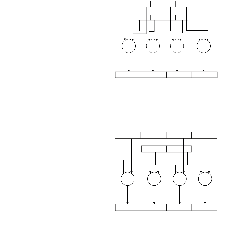
NEON Instruction Set Architecture
ARM DEN0018A Copyright © 2013 ARM. All rights reserved. 3-6
ID071613 Non-Confidential
•Normal instructions can operate on any vector types, and produce result vectors of the
same size, and usually the same type, as the operand vectors.
You can specify that the operands and result of a normal instruction must all be quadwords
by appending a
Q
to the instruction mnemonic. If you do this, the assembler produces an
error if the operands or result are not quadwords.
•Long instructions usually operate on doubleword vectors and produce a quadword vector.
The result elements are twice the width of the operand elements. Long instructions are
specified using an
L
appended to the instruction. Figure 3-1 shows an example long
instruction, with input operands being promoted to quadwords before the operation.
Figure 3-1 NEON long instructions
•Wide instructions operate on a doubleword vector operand and a quadword vector
operand, producing a quadword vector result. The result elements and the first operand
are twice the width of the second operand elements. Wide instructions have a
W
appended
to the instruction. Figure 3-2 shows this, with the input doubleword operands being
promoted to quadwords before the operation.
Figure 3-2 NEON wide instructions
Dn
Dm
Qd
Dn
Qd
Qn
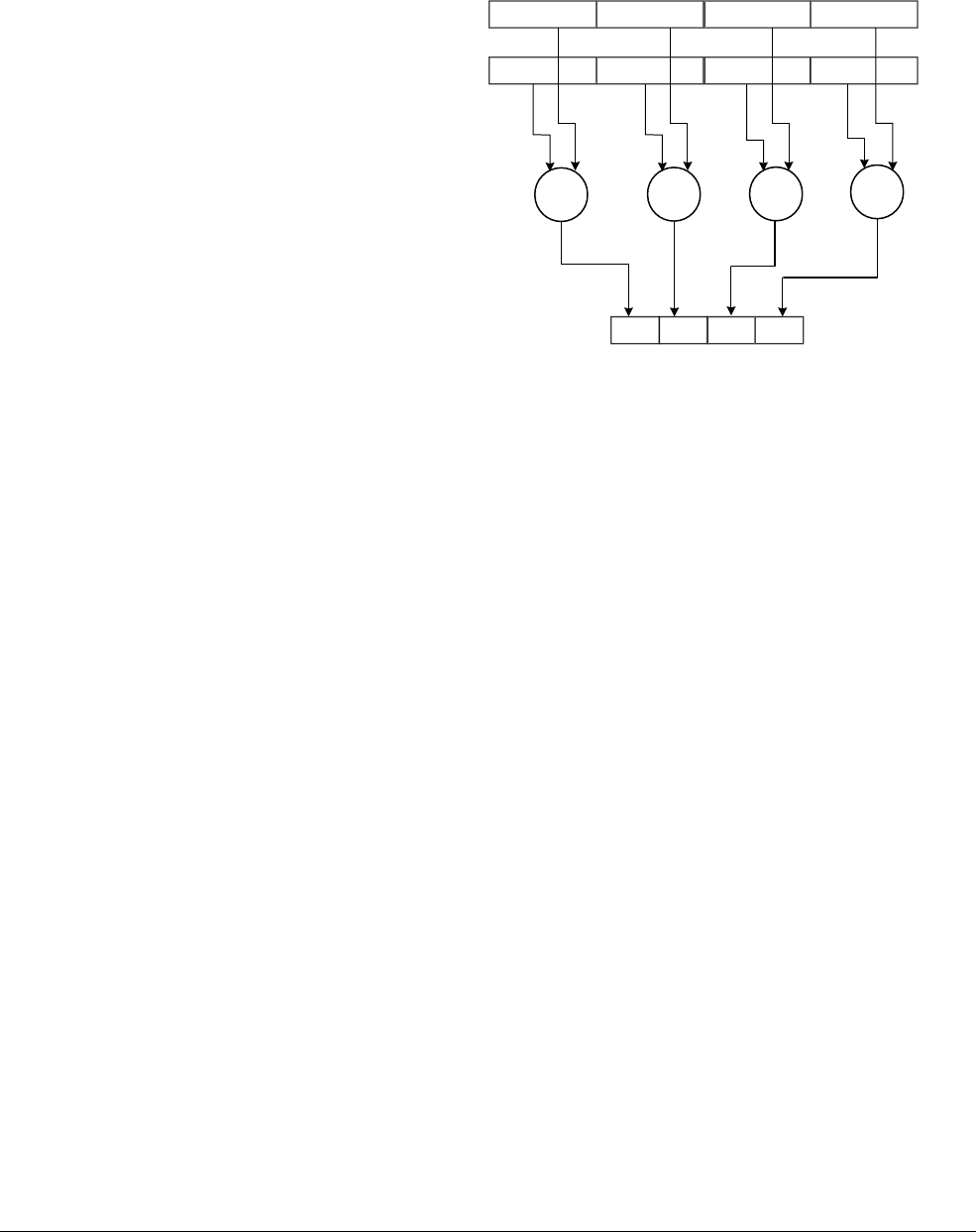
NEON Instruction Set Architecture
ARM DEN0018A Copyright © 2013 ARM. All rights reserved. 3-7
ID071613 Non-Confidential
•Narrow instructions operate on quadword vector operands, and produce a doubleword
vector. The result elements are half the width of the operand elements. Narrow
instructions are specified using an
N
appended to the instruction. Figure 3-3 shows this.
Figure 3-3 NEON narrow instructions
Qn
Qm
Dd

NEON Instruction Set Architecture
ARM DEN0018A Copyright © 2013 ARM. All rights reserved. 3-8
ID071613 Non-Confidential
3.3 Specifying data types
Some NEON instructions need to know more about the data type than others.
• Data movement/replication instructions
— Do not need to know how to interpret the data, only need to know the size.
— More specific data type can be specified if desired.
— Not encoded in Opcode, not shown in disassembly.
• Standard addition
— Must distinguish floating-point from integer but not signed/unsigned integer.
— Signed or Unsigned can be specified if desired.
• Saturating instructions
— Must distinguish sign/unsigned so the data type must be fully specified.
The datatype of the operand is specified in the instruction. Usually, only the data type of the
second operand must be specified
• Others are all inferred from the instruction shape, see Instruction shape on page 3-5.
• Though all the data types can be specified if desired.
Most instructions have a restricted range of permitted data types. However, the data type
description is flexible:
• If the description specifies
I
, you can also use
S
or
U
data types
• If only the data size is specified, you can specify a type (
I
,
S
,
U
,
P
or
F
)
• If no data type is specified, you can specify a data type.
The F16 data type is only available on systems that implement the half-precision architecture
extension and only applies to conversion.
NEON Instruction Set Architecture
ARM DEN0018A Copyright © 2013 ARM. All rights reserved. 3-9
ID071613 Non-Confidential
3.4 Packing and unpacking data
For NEON instructions, multiple data elements are packed into a single register to allow a single
instruction to operate on all the data elements in the register simultaneously.
Packed data is common but sometimes the required processing cannot be done on packed data
with NEON instructions. The data must therefore be unpacked into registers.
One way to do this is to load the packed data, mask the desired part by clearing the unwanted
bits, and shift the result left or right. This works, but is relatively inefficient.
There are NEON pack and unpack instructions which simplify conversion between packed and
unpacked data. This enables sequences of packed data in memory to be loaded efficiently using
word or doubleword loads, unpacked into separate register values, operated upon and then
packed back into registers for efficient writing out to memory. See Figure 3-4.
Figure 3-4 Packing and unpacking of 16-bit data in 32-bit registers
UXTH r1, r0, ROR #16 UXTH r2, r0
PKHBT r0, r2, r1, LSL #16
B1 R0A1
B1 R200...00A1R1 00...00
B2 R0A2
B2 R200...00A2R1 00...00
Processing continues
on each register
... ...
Unpack to two
registers
Pack back to
one register

NEON Instruction Set Architecture
ARM DEN0018A Copyright © 2013 ARM. All rights reserved. 3-10
ID071613 Non-Confidential
3.5 Alignment
The NEON architecture provides full unaligned support for NEON data access. However, the
instruction opcode contains an alignment hint which permits implementations to be faster when
the address is aligned and a hint is specified. However, if the alignment is specified but the
address is incorrectly aligned, a Data Abort occurs
The base address specified as [<Rn>:<align>]
Note
It is a programming error to specify an alignment hint, and then to use an incorrectly aligned
address.
An alignment hint can be one of :64, :128 or :256 bits depending on the number of D-registers.
VLD1.8 {D0}, [R1:64]
VLD1.8 {D0,D1}, [R4:128]!
VLD1.8 {D0,D1,D2,D3}, [R7:256], R2
Note
The ARM Architecture Reference Manual uses an “@” symbol to describe this, but this is not
recommended in source code.
The GNU gas compiler will still accept [Rn,:128] syntax (note the extra “,” before the colon)
but [Rn:128] syntax is preferred.
This applies to both the Cortex-A8 and Cortex-A9 processors. For the Cortex-A8 processor,
specifying 128-bit or greater alignment saves one cycle. For the Cortex-A9 processor,
specifying 64-bit or greater alignment saves one cycle.

NEON Instruction Set Architecture
ARM DEN0018A Copyright © 2013 ARM. All rights reserved. 3-11
ID071613 Non-Confidential
3.6 Saturation arithmetic
In Instruction modifiers on page 3-5 we came across the Q modifier to indicate that the
instruction carries out saturation arithmetic. This is a form of arithmetic in which the result of
mathematical operations are limited to a predetermined maximum and minimum value. if the
result of the function is greater than the maximum saturation value, it is set to the maximum
value. if it is less than the minimum value, it is set to the minimum value.
For example, if the range of values is -10 to +10, the following operations produce the following
values:
• 10 + 5 = 10
• 10 × 5 = 10
• 5 - 30 = -10
• 3 + 6 = 9
• 3 × 6 = 10
• 6 - (3 × 5) = -10
Saturated arithmetic is used in applications such as digital signal processing, to avoid situations
such as when audio signals exceed a maximum range.

NEON Instruction Set Architecture
ARM DEN0018A Copyright © 2013 ARM. All rights reserved. 3-12
ID071613 Non-Confidential
3.7 Floating-point operations
NEON floating-point is not fully compliant with IEEE-754
Denormals are flushed to zero
Rounding is fixed to round-to-nearest except for conversion operations
Single precision arithmetic (.F32) only
Separate (scalar) floating-point instructions.
3.7.1 Floating-point exceptions
In the description of instructions that can cause floating-point exceptions, there is a subsection
listing the exceptions. If there is no Floating-point exceptions subsection in an instruction
description, that instruction cannot cause any floating-point exception.

NEON Instruction Set Architecture
ARM DEN0018A Copyright © 2013 ARM. All rights reserved. 3-13
ID071613 Non-Confidential
3.8 Flush-to-zero mode
Flush-to-zero mode replaces denormalized numbers with 0. This does not comply with
IEEE-754 arithmetic, but in some circumstances it can considerably improve performance.
In the NEON unit and in VFPv3, flush-to-zero preserves the sign bit. In VFPv2, flush-to-zero
flushes to +0.
The NEON unit always uses flush-to-zero mode.
3.8.1 Denormals
The NEON unit is IEEE 754-1985 compliant, but only supports round-to-nearest rounding
mode. This is the rounding mode used by most high-level languages, such as C and Java.
Additionally, the NEON unit always treats denormals as zero.
In floating-point arithmetic, a denormal is a floating-point number which has a leading zero in
the significand. This means a number with a very small magnitude where the mantissa is in the
form
0.m
1
m
2
m
3
m
4
...m
p-1
m
p
and the exponent is the minimum possible exponent.
m
is a significant
digit 0 or 1, and
p
is the precision.
3.8.2 The effects of using flush-to-zero mode
With certain exceptions, flush-to-zero mode has the following effects on floating-point
operations:
• A denormalized number is treated as 0 when used as an input to a floating-point operation.
The source register is not altered.
• If the result of a single-precision floating-point operation, before rounding, is in the range
–2–126 to +2–126, it is replaced by 0.
• If the result of a double-precision floating-point operation, before rounding, is in the range
–2–1022 to +2–1022, it is replaced by 0.
An inexact exception occurs whenever a denormalized number is used as an operand, or a result
is flushed to zero. Underflow exceptions do not occur in flush-to-zero mode.
3.8.3 Operations not affected by flush-to-zero mode
The following NEON operations can be carried out on denormalized numbers even in
flush-to-zero mode, without flushing the results to zero:
• copy, absolute value, and negate (VMOV, VMVN, V{Q}ABS, and V{Q}NEG)
• duplicate (VDUP)
• swap (VSWP)
• load and store (VLDR and VSTR)
• load multiple and store multiple (VLDM and VSTM)
• transfer between NEON registers and ARM general-purpose registers (VMOV).
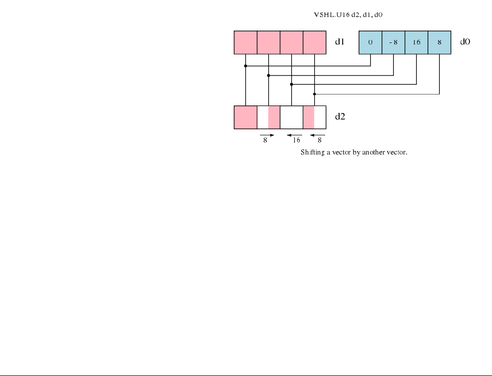
NEON Instruction Set Architecture
ARM DEN0018A Copyright © 2013 ARM. All rights reserved. 3-14
ID071613 Non-Confidential
3.9 Shift operations
This section introduces the NEON shift operations, and shows how they can be used to convert
image data between commonly used color depths.
The powerful range of shift instructions provided by the NEON instruction set enable:
• Quick division and multiplication of vectors by powers of two, with rounding and
saturation.
• Shift and copy of bits from one vector to another.
• Interim calculations at high precision and accumulation of results at a lower precision.
3.9.1 Shifting vectors
A NEON shift operation is very similar to shifts in scalar ARM code. The shift moves the bits
in each element of a vector left or right. Bits that fall of the left or right of each element are
discarded; they are not shifted to adjacent elements.
The amount to shift can be specified with a literal encoded in the instruction, or with an
additional shift vector. When using a shift vector, the shift applied to each element of the input
vector depends on the value of the corresponding element in the shift vector. The elements in
the shift vector are treated as signed values, so left, right and zero shifts are possible, on a
per-element basis.
Figure 3-5 Shifting vectors
A right shift operating on a vector of signed elements, indicated by the type attached to the
instruction, will sign extend each element. This is the equivalent of an arithmetic shift in ARM
code. Shifts applied to unsigned vectors do not sign extend.
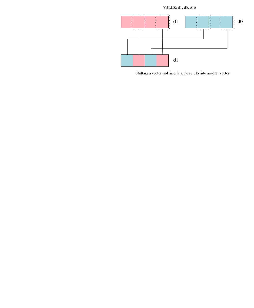
NEON Instruction Set Architecture
ARM DEN0018A Copyright © 2013 ARM. All rights reserved. 3-15
ID071613 Non-Confidential
3.9.2 Shifting and inserting
NEON shift with insertion operations provide a way to combine bits from two vectors. For
example, shift left and insert (
VSLI
) shifts each element of the source vector left. The new bits
inserted at the right of each element are the corresponding bits from the destination vector.
Figure 3-6 Shifting and inserting
3.9.3 Shifting and accumulating
There are NEON instructions to shift the elements of a vector right, and accumulate the results
into another vector. This is useful for situations in which interim calculations are made at a high
precision, before the result is combined with a lower precision accumulator.
3.9.4 Instruction modifiers
Each shift instruction can take one or more modifiers. These modifiers do not change the shift
operation itself, but the inputs or outputs are adjusted to remove bias or saturate to a range. There
are five modifiers for shift instructions:
• Rounding, denoted by R
• Narrow, denoted by N
• Long, denoted by L
• Saturating, denoted by Q
• Unsigned Saturating, denoted by a Q prefix and U suffix. This is similar to the saturation
modifier, but the result is saturated to an unsigned range when given signed or unsigned
inputs.
Some combinations of these modifiers do not describe useful operations, and so there is no
NEON instruction for them. For example, a saturating shift right (which would be called
VQSHR
)
is unnecessary, as right shifting makes results smaller, and so the value cannot exceed the
available range.

NEON Instruction Set Architecture
ARM DEN0018A Copyright © 2013 ARM. All rights reserved. 3-16
ID071613 Non-Confidential
3.9.5 Table of shifts available
All of the NEON shift instructions are shown in the table below. They are arranged according
to the modifiers mentioned earlier. If you are still unsure about what the modifier letters mean,
use Table 3-3, Table 3-4, and Table 3-5 to select the instruction you need. In the table, Imm is
shown for shifts by an immediate value. Reg is shown for shifts where a register specifies the
shift amount.
Table 3-3 NEON non-saturating shift operations
Not rounding Rounding
Default Long Narrow Default Long Narrow
Left (Imm)
VSHL VSHLL
Left (Reg)
VSHL VRSHL
Right (Imm)
VSHR VSHRN VRSHR VRSHRN
Left insert (Imm)
VSLI
Right insert (Imm)
VSRI
Right accumulate (imm)
VSRA VRSRA
Table 3-4 NEON saturating shift operations
Not rounding Rounding
Default Long Narrow Default Long Narrow
Left (Imm)
VQSHL
Left (Reg)
VQSHL VQRSHL
Right (Imm)
VQSHRN VQRSHRN
Table 3-5 NEON unsigned saturating shift operations
Not rounding Rounding
Default Long Narrow Default Long Narrow
Left (Imm)
VQSHLU
Left (Reg)
Right (Imm)
VQSHRUN VQRSHRUN

NEON Instruction Set Architecture
ARM DEN0018A Copyright © 2013 ARM. All rights reserved. 3-17
ID071613 Non-Confidential
3.10 Polynomials
A polynomial is an expression made from sum of powers in any variable, where each summand
has a coefficient. An example of a polynomial in the variable
x
is
a
2
x
2+
a
1
x
+
a
0.
You can use the datatypes P8 (8-bit polynomial) and P16 (16-bit polynomial) to represent a
polynomial if it is over a field {0,1}. A polynomial over field {0,1} is one where the coefficients
are either 0 or 1. You cannot use NEON polynomial arithmetic for polynomials whose
coefficients are not 0 or 1.
If
f
is one such polynomial, then using the 8 bits in the P8 datatype,
f
can represented as the
sequence of the coefficients {a7,a6,a5,a4,a3,a2,a1,a0}, where an is either 0 or 1. Alternatively, you
can use the P16 datatype to represent
f
as the sequence
{a15,a14,a13,a12,a11,a10,a9,a8,a7,a6,a5,a4,a3,a2,a1,a0}.
Each 8-bit or 16-bit lane in a
D
or
Q
NEON register thus contains a sequence of coefficients for
a polynomial like
f
.
Note
You can visualize the polynomial sequence of
1
s and
0
s as an 8-bit or 16-bit unsigned value.
However, polynomial arithmetic is different from conventional arithmetic and yields different
results.
3.10.1 Polynomial arithmetic over {0,1}
Polynomial arithmetic is useful when implementing certain cryptography or data integrity
algorithms.
The polynomial coefficients 0 and 1 are manipulated using the rules of Boolean arithmetic:
• 0 + 0 = 1 + 1 = 0
• 0 + 1 = 1 + 0 = 1
• 0 * 0 = 0 * 1 = 1 * 0 = 0
• 1 * 1 = 1
Adding two polynomials over {0,1} is the same as a bitwise exclusive OR. Polynomial
additional thus results in different values to a conventional addition.
Multiplying two polynomials over {0,1} involves first determining the partial products as done
in conventional multiply, then the partial products are exclusive ORed instead of being added
conventionally. Polynomial multiplication results in different values to conventional
multiplication because it requires polynomial addition of the partial products.
The polynomial type is to help with anything that must use power-of-two finite fields or simple
polynomials. Normal ARM integer code would typically use a lookup table for finite field
arithmetic, but large lookup tables cannot be vectorized. Polynomial operations are hard to
synthesize out of other operations, so it is useful having a basic multiply operation (add is EOR)
out of which larger multiplies or other operations can be synthesized.
Applications of polynomial arithmetic include:
• error correction such as Reed Solomon codes
•Cycle Redundancy Checking (CRC)
• elliptic curve cryptography.

NEON Instruction Set Architecture
ARM DEN0018A Copyright © 2013 ARM. All rights reserved. 3-18
ID071613 Non-Confidential
Field operations typically use a polynomial multiply + mod, but this can be reduced to just
multiplies using the Montgomery reduction method.
3.10.2 NEON instructions that can perform polynomial arithmetic
There are several NEON instructions that operate on the polynomial data types P8 and P16. The
multiply instruction is the only type of instruction where having a polynomial data type changes
the behavior from conventional multiply to polynomial multiply.
VMUL
and
VMULL
are the only two
multiply instructions that can perform the polynomial multiplication when a polynomial
datatype is used.
The
VADD
instruction performs conventional addition and cannot be used to perform polynomial
addition. Polynomial addition is exactly the same as a bitwise exclusive OR, so for polynomial
addition, you must use the
VEOR
instruction.
However, the VEOR intrinsic does not accept the polynomial data types P8 and P16.
Hence, when using intrinsics, you must reinterpret the data type from P8 or P16 to one of the
types that are accepted by the VEOR intrinsic. Use the NEON intrinsic
vreinterpret
for this,
see VREINTERPRET on page D-3.
3.10.3 Difference between polynomial multiply and conventional multiply
Polynomial add behaves as a bitwise exclusive OR (carry-less addition) rather than as a
conventional add (addition with carry). This results in differences in polynomial multiply, even
though polynomial multiply on individual bits is same as conventional multiply on individual
bits. The partial products have to be exclusive ORed rather than being added conventionally. In
some systems this is known as carry-less multiply.
The example shows a multiplication of
3
by
3
in conventional arithmetic. The multiply is shown
in binary to highlight the difference. The result of the multiplication is
b01001
, which is
9
, as
expected for the conventional multiply.
011
X 011
------
011 conventional multiply rules apply here on individual bits
+ 011
+000
------
01001 conventional addition of partial products,
which involves carry when adding 1+1
The next example shows a multiplication of
3
by
3
in polynomial arithmetic. The multiply is
shown in binary to highlight the difference. When operating on bit values, polynomial multiply
is same as conventional multiply, and polynomial addition of partial products is an exclusive
OR. The result of the polynomial multiplication is
b00101
, which is equal to
5
.
011
X 011
-----
011 conventional multiply rules apply here on individual bits
+ 011
+000
-----
00101 bitwise exclusive OR of partial products
results in carry-less addition of 1+1

NEON Instruction Set Architecture
ARM DEN0018A Copyright © 2013 ARM. All rights reserved. 3-19
ID071613 Non-Confidential
3.11 Instructions to permute vectors
Permutations, or changing the order of the elements in a vector, are sometimes required in vector
processing when the available arithmetic instructions do not match the format of the data in
registers. They select individual elements, from either one register, or across multiple registers,
to form a new vector that better matches the NEON instructions that the processor provides.
Permutation instructions are similar to move instructions, in that they are used to prepare or
rearrange data, rather than modify the data values. Good algorithm design might remove the
need to rearrange data. Hence consider whether the permutation instructions are necessary in
your code.
Reducing the need for move and permute instructions is often a good way to optimize code.
3.11.1 Alternatives
There are a number of ways to avoid unnecessary permutations:
• Rearrange your input data. It often costs nothing to store your data in a more appropriate
format, avoiding the need to permute on load and store. However, consider data locality,
and its effect on cache performance before changing your data structures.
• Redesign your algorithm. A different algorithm might be available that uses a similar
number of processing steps, but handled data in a different format.
• Modify the previous processing stage. A small change to an earlier processing stage,
adjusting the way in which data is stored to memory, can reduce or eliminate the need for
permutation operations.
• Use interleaving loads and stores. Load and store instructions have the ability to interleave
and de-interleave. If this does not completely eliminate the need to permute, it might
reduce the number of additional instructions you need.
• Combine approaches. Using more than one of these techniques can be still be more
efficient than additional permutation instructions.
If you have considered all of these, but none put your data in a more suitable format, you must
use the permutation instructions.
3.11.2 Instructions
There are a range of NEON permutation instructions from simple reversals to arbitrary vector
reconstruction. Simple permutations can be achieved using instructions that take a single cycle
to issue, whereas the more complex operations are multiple cycle, and might require additional
registers to be set up. As always, check your processor's Technical Reference Manual for
performance details.
VMOV and VSWP: Move and Swap
VMOV and VSWP are the simplest permute instructions, copying the contents of an entire
register to another, or swapping the values in a pair of registers.
Although you might not regard them as permute instructions, they can be used to change the
values in the two D registers that make up a Q register. For example, VSWP d0, d1 swaps the
most and least-significant 64-bits of q0.

NEON Instruction Set Architecture
ARM DEN0018A Copyright © 2013 ARM. All rights reserved. 3-20
ID071613 Non-Confidential
VREV: Reverse
VREV reverses the order of 8-bit, 16-bit or 32-bit elements within a vector. There are three
variants.
VREV16 reverses each pair of 8-bit sub-elements making up 16-bit elements within a vector.
VREV32 reverses the four 8-bit or two 16-bit sub-elements making up 32-bit elements within
a vector.
VREV64 reverses eight 8-bit, four 16-bit or two 32-bit elements in a vector.
Use VREV to reverse the endianness of data, rearrange color components or exchange channels
of audio samples.
VEXT: Extract
VEXT extracts a new vector of bytes from a pair of existing vectors. The bytes in the new vector
are from the top of the first operand, and the bottom of the second operand. This allows you to
produce a new vector containing elements that straddle a pair of existing vectors.
VEXT can be used to implement a moving window on data from two vectors, useful in FIR
filters. For permutation, it can also be used to simulate a byte-wise rotate operation, when using
the same vector for both input operands.
VTRN: Transpose
VTRN transposes 8-bit, 16-bit, or 32-bit elements between a pair of vectors. It treats the
elements of the vectors as 2x2 matrices, and transposes each matrix.
Use multiple VTRN instructions to transpose larger matrices. For example, a 4x4 matrix
consisting of 16-bit elements can be transposed using three VTRN instructions.
This is the same operation performed by VLD4 and VST4 after loading, or before storing,
vectors. As they require fewer instructions, try to use these structured memory access features
in preference to a sequence of VTRN instructions, where possible.
VZIP and VUZP: Zip and Unzip
VZIP interleaves the 8-bit, 16-bit, or 32-bit elements of a pair of vectors. The operation is the
same as that performed by VST2 before storing, so use VST2 rather than VZIP if you need to
zip data immediately before writing back to memory.
VUZP is the inverse of VZIP, de-interleaving the 8-bit, 16-bit, or 32-bit elements of a pair of
vectors. The operation is the same as that performed by VLD2 after loading from memory.
VTBL, VTBX: Table and Table Extend
VTBL constructs a new vector from a table of vectors and an index vector. It is a byte-wise table
lookup operation.
The table consists of one to four adjacent D registers. Each byte in the index vector is used to
index a byte in the table of vectors. The indexed value is inserted into the result vector at the
position corresponding to the location of the original index in the index vector.
VTBL and VTBX differ in the way that out-of-range indexes are handled. If an index exceeds
the length of the table, VTBL inserts zero at the corresponding position in the result vector, but
VTBX leaves the value in the result vector unchanged.

NEON Instruction Set Architecture
ARM DEN0018A Copyright © 2013 ARM. All rights reserved. 3-21
ID071613 Non-Confidential
If you use a single source vector as the table, VTBL allows you to implement an arbitrary
permutation of a vector, at the expense of setting up an index register. If the operation is used in
a loop, and the type of permutation doesn't change, you can initialize the index register outside
the loop, and remove the setup overhead.

ARM DEN0018A Copyright © 2013 ARM. All rights reserved. 4-1
ID071613 Non-Confidential
Chapter 4
NEON Intrinsics
This chapter describes how the ARM compiler toolchain provides intrinsics to generate NEON
code for all Cortex-A series processors in both ARM and Thumb state. It contains the following
topics:
•Introduction on page 4-2.
•Vector data types for NEON intrinsics on page 4-3.
•Prototype of NEON Intrinsics on page 4-5.
•Using NEON intrinsics on page 4-6.
•Variables and constants in NEON code on page 4-8.
•Accessing vector types from C on page 4-9.
•Loading data from memory into vectors on page 4-10.
•Constructing a vector from a literal bit pattern on page 4-11.
•Constructing multiple vectors from interleaved memory on page 4-12.
•Loading a single lane of a vector from memory on page 4-13.
•Programming using NEON intrinsics on page 4-14.
•Instructions without an equivalent intrinsic on page 4-16.

NEON Intrinsics
ARM DEN0018A Copyright © 2013 ARM. All rights reserved. 4-2
ID071613 Non-Confidential
4.1 Introduction
NEON intrinsics in the ARM compiler toolchain are a way to write NEON code that is more
easily maintained than assembler, while still keeping control of which NEON instructions are
generated.
NEON intrinsics are function calls that the compiler replaces with an appropriate NEON
instruction or sequence of NEON instructions. You must however optimize your code to take
full advantage of the speed increases offered by the NEON unit.
There are data types that correspond to NEON registers (both D-registers and Q-registers)
containing different sized elements. These allows you to create C variables that map directly
onto NEON registers. These variables are passed to NEON intrinsic functions. The compiler
will generate NEON instructions directly instead of performing an actual subroutine call.
Intrinsic functions and data types, or intrinsics in the shortened form, provide access to
low-level NEON functionality from C or C++ source code. Software can pass NEON vectors as
function arguments or return values, and declare them as normal variables.
Intrinsics provide almost as much control as writing assembly language, but leave the allocation
of registers to the compiler, so that you can focus on the algorithms. Also, the compiler can
optimize the intrinsics like normal C or C++ code, replacing them with more efficient sequences
if possible. It can also perform instruction scheduling to remove pipeline stalls for the specified
target processor. This leads to more maintainable source code than using assembly language.
The NEON intrinsics are defined in the header file
arm_neon.h
. The header file also defines a set
of vector types.
Note
There is no support for NEON instructions in architectures before ARMv7. When building for
earlier architectures, or for ARMv7 architecture profiles that do not include a NEON unit, the
compiler treats NEON intrinsics as ordinary function calls. This results in an error.

NEON Intrinsics
ARM DEN0018A Copyright © 2013 ARM. All rights reserved. 4-3
ID071613 Non-Confidential
4.2 Vector data types for NEON intrinsics
NEON vector data types are named according to the following pattern:
<type><size>x<number_of_lanes>_t
For example:
•
int16x4_t
is a vector describes a vector of four 16-bit short
int
values.
•
float32x4_t
describes a vector of four 32-bit
float
values.
Table 4-1 lists the vector data types.
You can specify the input and output of intrinsics using one of these vector data types. Some
intrinsics use an array of vector types. They combine two, three, or four of the same vector type:
<type><size>x<number_of_lanes>x<length_of_array>_t
These types are ordinary C structures containing a single element named
val
.
These types map the registers accessed by NEON load and store operations, which can
load/store up to four registers with a single instruction. An example structure definition is:
struct int16x4x2_t
{
int16x4_t val[2];
} <var_name>;
These types are only used by loads, stores, transpose, interleave and de-interleave instructions;
to perform operations on the actual data, select the element from the individual registers for
example,
<var_name>.val[0]
and
<var_name>.val[1]
.
There are array types defined for array lengths between 2 and 4, with any of the vector types
listed in Table 4-1.
Table 4-1 Vector data types
64-bit type (D-register) 128-bit type (Q-register)
int8x8_t int8x16_t
int16x4_t int16x8_t
int32x2_t int32x4_t
int64x1_t int64x2_t
uint8x8_t uint8x16_t
uint16x4_t uint16x8_t
uint32x2_t uint32x4_t
uint64x1_t uint64x2_t
float16x4_t float16x8_t
float32x2_t float32x4_t
poly8x8_t poly8x16_t
poly16x4_t poly16x8_t

NEON Intrinsics
ARM DEN0018A Copyright © 2013 ARM. All rights reserved. 4-4
ID071613 Non-Confidential
Note
The vector data types and arrays of the vector data types cannot be initialized by direct literal
assignment. You can initialize them using one of the load intrinsics or using the
vcreate
intrinsic, see VCREATE on page D-166.

NEON Intrinsics
ARM DEN0018A Copyright © 2013 ARM. All rights reserved. 4-5
ID071613 Non-Confidential
4.3 Prototype of NEON Intrinsics
The intrinsics use a naming scheme similar to the NEON unified assembler syntax:
<opname><flags>_<type>
An additional
q
flag is provided to specify that the intrinsic operates on 128-bit vectors.
For example:
•
vmul_s16
, multiplies two vectors of signed 16-bit values.
This compiles to
VMUL.I16 d2, d0, d1
.
•
vaddl_u8
, is a long add of two 64-bit vectors containing unsigned 8-bit values, resulting in
a 128-bit vector of unsigned 16-bit values.
This compiles to
VADDL.U8 q1, d0, d1
.
Registers other than those specified in these examples might be used. the compiler might also
perform optimization that in some way changes the instruction that the source code compiles to.
Note
The NEON intrinsic function prototypes that use
__fp16
are only available for targets that have
the NEON half-precision VFP extension.
To enable use of
__fp16,
use the
--fp16_format
command-line option. See
--fp16_format
in the
AR M Compiler toolchain Compiler Reference.
NEON Intrinsics
ARM DEN0018A Copyright © 2013 ARM. All rights reserved. 4-6
ID071613 Non-Confidential
4.4 Using NEON intrinsics
The ARM Compiler toolchain defines the NEON intrinsics in a special header file called
arm_neon.h
. This also defines a set of vector data types shown in Table 4-1 on page 4-3.
Intrinsics are part of the ARM ABI, and are therefore portable between the ARM Compiler
toolchain and GCC.
Intrinsics that use the ‘
q
’ suffix usually operate on Q registers. Intrinsics without the ‘
q
’ suffix
usually operate on D registers but some of these intrinsics might use Q registers.
The examples below show different variants of the same intrinsic.
uint8x8_t vadd_u8(uint8x8_t a, uint8x8_t b);
The intrinsic
vadd_u8
does not have the ‘
q
’ suffix. In this case, the input and output vectors are
64-bit vectors, which use D registers.
uint8x16_t vaddq_u8(uint8x16_t a, uint8x16_t b);
The intrinsic
vaddq_u8
has the ‘
q
’ suffix, so the input and output vectors are 128-bit vectors,
which use Q registers.
uint16x8_t vaddl_u8(uint8x8_t a, uint8x8_t b);
The intrinsic
vaddl_u8
does not have the ‘
q
’ suffix. In this case, the input vectors are 64-bit and
output vector is 128-bit.
Some NEON intrinsics use the 32-bit ARM general-purpose registers as input argument to hold
scalar values. For example intrinsics that extract a single value from a vector (
vget_lane_u8
), set
a single lane of a vector (
vset_lane_u8
), create a vector from a literal value (
vcreate_u8
), and
setting all lanes of a vector to the same literal value (
vdup_n_u8
).
The use of separate intrinsics for each type means that it is difficult to accidentally perform an
operation on incompatible types because the compiler will keep track of which types are held in
which registers.
The compiler can also reschedule program flow and use alternative faster instructions. There is
no guarantee that the instructions that are generated will match the instructions implied by the
intrinsic. This is especially useful when moving from one micro-architecture to another.
The code in Example 4-1 shows a short function that takes a four-lane vector of 32-bit unsigned
integers as input parameter, and returns a vector where the values in all lanes have been doubled.
Example 4-1 Add function using intrinsics
#include <arm_neon.h>
uint32x4_t double_elements(uint32x4_t input)
{
return(vaddq_u32(input, input));
}
Example 4-2 on page 4-7 shows the disassembled version of the code generated from
Example 4-1, which was compiled for hard float ABI. The
double_elements()
function
translates to a single NEON instruction and a return sequence.

NEON Intrinsics
ARM DEN0018A Copyright © 2013 ARM. All rights reserved. 4-7
ID071613 Non-Confidential
Example 4-2 Compiled with hard float ABI
double_elements PROC
VADD.I32 q0,q0,q0
BX lr
ENDP
Example 4-3 shows the disassembly of the same example compiled for software linkage. In this
situation, the code must copy the parameters from ARM general-purpose registers to a
NEON register before use. After the calculation, it must copy the return value back from NEON
registers to ARM general-purpose registers.
Example 4-3 Compiled with software linkage
double_elements PROC
VMOV d0,r0,r1
VMOV d1,r2,r3
VADD.I32 q0,q0,q0
VMOV r0,r1,d0
VMOV r2,r3,d1
BX lr
ENDP
GCC and armcc support the same intrinsics, so code written with NEON intrinsics is completely
portable between the toolchains. You must include the
arm_neon.h
header file in any source file
using intrinsics, and must specify command line options.
It can be useful to have a source module optimized using intrinsics, that can also be compiled
for processors that do not implement NEON technology. The macro __ARM_NEON__ is
defined by GCC when compiling for a target that implements NEON technology. RVCT 4.0
build 591 or later, and ARM Compiler toolchain also define this macro. Software can use this
macro to provide both optimized and plain C or C++ versions of the functions provided in the
file, selected by the command line parameters you pass to the compiler.
For information about the intrinsic functions and vector data types, see the ARM Compiler
toolchain Compiler Reference Guide, available from http://infocenter.arm.com. GCC
documentation is available from
http://gcc.gnu.org/onlinedocs/gcc/ARM-NEON-Intrinsics.html

NEON Intrinsics
ARM DEN0018A Copyright © 2013 ARM. All rights reserved. 4-8
ID071613 Non-Confidential
4.5 Variables and constants in NEON code
This section shows some example code that accesses variable data or constant data using NEON
code.
4.5.1 Declaring a variable
Declaring a new variable is as simple as declaring any variable in C:
uint32x2_t vec64a, vec64b; // create two D-register variables
4.5.2 Using constants
Using constants is straightforward. The following code will replicate a constant into each
element of a vector:
uint8x8 start_value = vdup_n_u8(0);
To load a general 64-bit constant into a vector, use:
uint8x8 start_value = vreinterpret_u8_u64(vcreate_u64(0x123456789ABCDEFULL));
4.5.3 Moving results back to normal C variables
To access a result from a NEON register, either store it to memory using VST, or move it back
to ARM using a “get lane” type operation:
result = vget_lane_u32(vec64a, 0); // extract lane 0
4.5.4 Accessing D registers from a Q register
Use
vget_low
and
vget_high
to access D registers from a Q register:
vec64a = vget_low_u32(vec128); // split 128-bit vector
vec64b = vget_high_u32(vec128); // into 2x 64-bit vectors
4.5.5 Casting NEON variables between different types
NEON intrinsics are strongly typed, so they must be explicitly cast between vectors of different
types. To cast vectors use
vreinterpret
for D registers or
vreinterpretq
for Q registers. These
intriniscs do not generate any code, but just enable you to cast the NEON types:
uint8x8_t byteval;
uint32x2_t wordval;
byteval = vreinterpret_u8_u32(wordval);
uint8x16_t byteval2;
uint32x4_t wordval2;
byteval2 = vreinterpretq_u8_u32(wordval2);
Note
The output type,
u8
, is listed after
vreinterpret
, before the input type,
u32
.

NEON Intrinsics
ARM DEN0018A Copyright © 2013 ARM. All rights reserved. 4-9
ID071613 Non-Confidential
4.6 Accessing vector types from C
The header file arm_neon.h is required to use the intrinsics and defines C style types for vector
operations. The C types are written in the form:
uint8x16_t This is a vector containing unsigned 8-bit integers. There are 16 elements in the
vector. Hence the vector must be in a 128-bit Q register.
int16x4_t This is a vector containing signed 16-bit integers. There are 4 elements in the
vector. Hence the vector must be in a 64-bit D register.
As there is incompatibility between the ARM scalar and NEON vector types it is impossible to
assign a scalar to a vector, even if they have the same bit length. Scalar values and pointers can
only be used with NEON instructions that use scalars directly.
For example, to extract an unsigned 32-bit integer from lane 0 of a NEON vector, use:
result = vget_lane_u32(vec64a, 0)
In armcc, vector types are not operable using standard C operators except for assignment. So the
appropriate
VADD
intrinsic should be used rather than the operator “+”. However, GCC allows
standard C operators to operate on NEON vector types and thus enables more readable code.
Where there are vector types which differ only in number of elements (uint32x2_t, uint32x4_t)
there are specific instructions to assign the top or bottom vector elements of a 128-bit value to
a 64-bit value and vice-versa. This operation does not use any code space if the registers can be
scheduled as aliases.
To use the bottom 64 bits of a 128-bit register, use:
vec64 = vget_low_u32(vec128);

NEON Intrinsics
ARM DEN0018A Copyright © 2013 ARM. All rights reserved. 4-10
ID071613 Non-Confidential
4.7 Loading data from memory into vectors
This section describes how to create a vector using a NEON intrinsic. Contiguous data from a
memory location can be loaded to a single vector or multiple vectors. The NEON intrinsic to do
this is
vld1_datatype
. For example to load a vector with four 16-bit unsigned data, use the
NEON intrinsic vld1_u16.
In the following example, array A contains eight 16-bit elements. The example shows how to
load this data from this array into a vector.
#include <stdio.h>
#include <arm_neon.h>
unsigned short int A[] = {1,2,3,4}; // array with 4 elements
int main(void)
{
uint16x4_t v; // declare a vector of four 16-bit lanes
v = vld1_u16(A); // load the array from memory into a vector
v = vadd_u16(v,v); // double each element in the vector
vst1_u16(A, v); // store the vector back to memory
return 0;
}
See the intrinsic descriptions for information on what vector types you can use with the
vld1_datatype
intrinsics, VLD1 on page D-120.

NEON Intrinsics
ARM DEN0018A Copyright © 2013 ARM. All rights reserved. 4-11
ID071613 Non-Confidential
4.8 Constructing a vector from a literal bit pattern
You can create a vector from a literal value. The NEON intrinsic to do this is
vcreate_datatype
.
For example if you want to load a vector with eight 8-bit unsigned data, you can use the NEON
intrinsic
vcreate_u8
.
The example shows how to create a vector from literal data.
#include <arm_neon.h>
int main (void)
{
uint8x8_t v; // define v as a vector with 8 lanes of 8-bit data
unsigned char A[8]; // allocate memory for eight 8-bit data
v = vcreate_u8(0x0102030405060708); // create a vector that contains the values
// 1,2,3,4,5,6,7,8
vst1_u8(A, v); // store the vector to memory, in this case, to array A
return 0;
}
See the intrinsic description for information on what vector types you can create with the
vcreate_datatype
intrinsics.

NEON Intrinsics
ARM DEN0018A Copyright © 2013 ARM. All rights reserved. 4-12
ID071613 Non-Confidential
4.9 Constructing multiple vectors from interleaved memory
Very often, the data in memory is interleaved. Neon intrinsics support 2-way, 3-way and 4-way
interleave patterns.
For example a region of memory might contain stereo data where the left channel data and right
channel data are interleaved. This is an example of a 2-way interleave pattern.
Another example is when memory contains a 24-bit RGB image. The 24-bit RGB image is a
3-way interleave of 8-bit data from the red, green, and blue channels. When memory contains
interleaved data, de-interleaving enables you to load a vector with all the red values, a separate
vector for all the green values, and a separate vector for all the blue values.
The NEON intrinsic to de-interleave is
vldn_datatype
where
n
represents the interleave pattern
and can be 2, 3, or 4. If you want to de-interleave the 24-bit RGB image into 3 different vectors,
you can use the NEON intrinsic
vld3_u8
.
The example shows how to de-interleave three vectors from a 24-bit RGB image in memory.
#include <arm_neon.h>
int main (void)
{
uint8x8x3_t v; // This represents 3 vectors.
// Each vector has eight lanes of 8-bit data.
unsigned char A[24]; // This array represents a 24-bit RGB image.
v = vld3_u8(A); // This de-interleaves the 24-bit image from array A
// and stores them in 3 separate vectors
// v.val[0] is the first vector in V. It is for the red channel
// v.val[1] is the second vector in V. It is for the green channel
// v.val[2] is the third vector in V. It is for the blue channel.
//Double the red channel
v.val[0] = vadd_u8(v.val[0],v.val[0]);
vst3_u8(A, v); // store the vector back into the array, with the red channel doubled.
return 0;
}
See the intrinsic descriptions in Load and store on page D-120 for information on the vector
types you can create with the
vldn_datatype
intrinsics.

NEON Intrinsics
ARM DEN0018A Copyright © 2013 ARM. All rights reserved. 4-13
ID071613 Non-Confidential
4.10 Loading a single lane of a vector from memory
If you want to construct a vector from data scattered in memory, you must use a separate
intrinsic to load each lane separately.
The NEON intrinsic to do this is
vld1_lane_datatype
. For example if you want to load one lane
of a vector with an 8-bit unsigned data, you can use the NEON intrinsic
vld1_lane_u8
.
The example shows how to load a single lane of a vector from memory.
#include <stdio.h>
#include <arm_neon.h>
....
See the intrinsic descriptions in Load and store on page D-120 for information on the vector
types you can create with the
vldn_lane_datatype
intrinsics.

NEON Intrinsics
ARM DEN0018A Copyright © 2013 ARM. All rights reserved. 4-14
ID071613 Non-Confidential
4.11 Programming using NEON intrinsics
Writing optimal NEON code directly in assembler, or by using the intrinsic function interface,
requires a thorough understanding of the data types used as well as the NEON instructions
available.
To know what NEON operations to use, it is useful to look at how an algorithm can be split into
parallel operations.
Commutative operations, for example
add
,
min
, and
max
are particularly easy from a SIMD point
of view.
To add eight numbers from an array:
unsigned int acc=0;
for (i=0; i<8;i+=1)
{
acc+=array[i]; // a + b + c + d + e + f + g + h
}
It is possible to exploit the associative property of addition to unroll the loop into several adds
((a + e) + (b + f)) + ((c + g) + (d + h)):
unsigned int acc2=0;
unsigned int acc3=0;
unsigned int acc4=0;
for (i=0; i<8;i+=4)
{
acc1+=array[i]; // (a, e)
acc2+=array[i+1]; // (b, f)
acc3+=array[i+2]; // (c, g)
acc4+=array[i+3]; // (d, h)
}
acc1+=acc2; // (a + e) + (b + f)
acc3+=acc4; // (c + g) + (d + h)
acc1+=acc3; // ((a + e) + (b + f))+((c + g) + (d + h))
The code above shows that it is possible to use a vector holding four 32-bit values for the
accumulator and temporary registers. This assumes that summing the elements of the array fits
in 32-bit lanes. It is then possible to do the operation using SIMD instructions. Extending the
code for any multiple of four:
#include <arm_neon.h>
uint32_t vector_add_of_n(uint32_t* ptr, uint32_t items)
{
uint32_t result,* i;
uint32x2_t vec64a, vec64b;
uint32x4_t vec128 = vdupq_n_u32(0); // clear accumulators
for (i=ptr; i<(ptr+(items/4));i+=4)
{
uint32x4_t temp128 = vld1q_u32(i); // load four 32-bit values
vec128=vaddq_u32(vec128, temp128); // add 128-bit vectors
}
vec64a = vget_low_u32(vec128); // split 128-bit vector
vec64b = vget_high_u32(vec128); // into two 64-bit vectors
vec64a = vadd_u32 (vec64a, vec64b); // add 64-bit vectors together
result = vget_lane_u32(vec64a, 0); // extract lanes and
result += vget_lane_u32(vec64a, 1); // add together scalars
return result;}

NEON Intrinsics
ARM DEN0018A Copyright © 2013 ARM. All rights reserved. 4-15
ID071613 Non-Confidential
The
vget_high_u32
and
vget_low_u32
are not analogous to any NEON instruction. These
intrinsics instruct the compiler to reference either the upper or the lower D register from the
input Q register. These operations therefore do not translate into actual code, but they affect
which registers are used to store
vec64a
and
vec64b
.
Depending on the version of the compiler, target processor and optimization options, the code
generated becomes:
vector_add_of_n PROC
VMOV.I8 q0,#0
BIC r1,r1,#3
ADD r1,r1,r0
CMP r1,r0
BLS |L1.36|
|L1.20|
VLD1.32 {d2,d3},[r0]!
VADD.I32 q0,q0,q1
CMP r1,r0
BHI |L1.20|
|L1.36|
VADD.I32 d0,d0,d1
VMOV.32 r1,d0[1]
VMOV.32 r0,d0[0]
ADD r0,r0,r1
BX lr
ENDP

NEON Intrinsics
ARM DEN0018A Copyright © 2013 ARM. All rights reserved. 4-16
ID071613 Non-Confidential
4.12 Instructions without an equivalent intrinsic
Most NEON instructions have an equivalent NEON intrinsic. The following NEON instructions
do not have an equivalent intrinsic:
•
VSWP
•
VLDM
•
VLDR
•
VMRS
•
VMSR
•
VPOP
•
VPUSH
•
VSTM
•
VSTR
•
VBIT
•
VBIF.
Note
VBIF
and
VBIT
cannot be generated explicitly. But the intrinsic
VBSL
can generate any of the
VBSL
,
VBIT
, or
VBIF
instructions.
VSWP
instruction does not have an intrinsic because the compiler can generate a
VSWP
instruction
when necessary, for example when swapping variables using simple C-style variable
assignments.
VLDM
,
VLDR
,
VSTM
, and
VSTR
are mainly used for context switching, and these instructions have
alignment constraints. When writing intrinsics, it is simpler to use
vldx
intrinsics.
vldx
intrinsics
do not require alignment unless explicitly specified.
VMRS
, and
VMSR
access the condition flags for NEON. These are not necessary for data processing
using NEON intrinsics.
VPOP
and
VPUSH
are used in argument passing to functions. Reducing variable reuse, or using
more NEON intrinsic variables, allows the register allocator to keep track of active registers.

ARM DEN0018A Copyright © 2013 ARM. All rights reserved. 5-1
ID071613 Non-Confidential
Chapter 5
Optimizing NEON Code
This chapter describes how when optimizing NEON code for a particular processor, you should
consider implementation-defined aspects of how that processor integrates the NEON
technology. It contains the following topics:
•Optimizing NEON assembler code on page 5-2.
•Scheduling on page 5-4.

Optimizing NEON Code
ARM DEN0018A Copyright © 2013 ARM. All rights reserved. 5-2
ID071613 Non-Confidential
5.1 Optimizing NEON assembler code
Consider implementation-defined aspects of how that processor integrates the NEON
technology because a sequence of instructions optimized for a specific processor might have
different timing characteristics on a different processor, even if the NEON instruction cycle
timings are identical.
To obtain best performance from hand-written NEON code, it is necessary to be aware of some
underlying hardware features. In particular, the programmer should be aware of pipelining and
scheduling issues, memory access behavior and scheduling hazards.
5.1.1 NEON pipeline differences between Cortex-A processors
The Cortex-A8 and Cortex-A9 processors share the same basic NEON pipelines, although there
are a few differences in how it is integrated into the processor pipeline. The Cortex-A5
processor contains a simplified NEON execution pipeline that is fully compatible, but it is
designed for the smallest and lowest-power implementation possible.
5.1.2 Memory access optimizations
It is likely that the NEON unit will be processing large amounts of data, such as digital images.
One important optimization is to make sure the algorithm is accessing the data in the most
cache-friendly way possible. This gets the maximum hit rate from the L1 and L2 caches. It is
also important to consider the number of active memory locations. Under Linux, each 4KB page
will require a separate TLB entry. The Cortex-A9 processor has 32 element micro-TLBs and a
128-element main TLB, after which it will start using the L1 cache to load page table entries. A
typical optimization is to arrange the algorithm to process image data in suitably sizes to
maximize the cache and TLB hit rate.
The instructions which support interleaving and de-interleaving can provide significant scope
for performance improvements. VLD1 loads registers from memory, with no de-interleaving.
However, the other VLDn operations enable us to load, store, and de-interleave structures
containing two, three or four equally sized 8, 16 or 32-bit elements. VLD2 loads two or four
registers, de-interleaving even and odd elements. This could be used, for example, to split left
and right channel stereo audio data as in Figure 5-1 on page 5-3. Similarly, VLD3 could be used
to split RGB pixels into separate channels and correspondingly, VLD4 might be used with
ARGB or CMYK images.
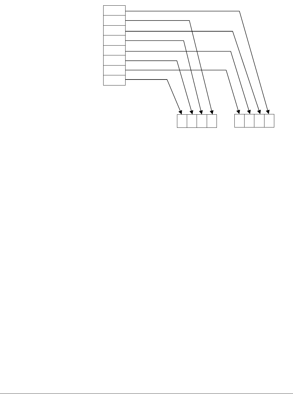
Optimizing NEON Code
ARM DEN0018A Copyright © 2013 ARM. All rights reserved. 5-3
ID071613 Non-Confidential
Figure 5-1 Labeled example of load de-interleaving
Figure 5-1 shows loading two NEON registers with VLD2.16, from memory pointed to by R1.
This produces four 16-bit elements in the first register, and four 16-bit elements in the second,
with adjacent paired left and right values separated to each register.
R3D1
R2R1R0L3D0L2L1L0
3
L0
0
R
L
R
1
2
1
R
L
L
R
2
3
NEON Registers
Memory
0
2
4
6
8
10
12
14
R1 offset
VLD2.16 {D0, D1}, [R1]

Optimizing NEON Code
ARM DEN0018A Copyright © 2013 ARM. All rights reserved. 5-4
ID071613 Non-Confidential
5.2 Scheduling
To get the very best performance from the NEON unit, you must be aware of how to schedule
code for the specific ARM processor you are using. Careful hand-scheduling is recommended
to get the best out of any NEON assembler code you write, especially for performance-critical
applications such as video codecs.
If writing C or NEON intrinsics, the compiler (GCC or armcc) will automatically schedule code
from NEON intrinsics or vectorizable C source code, but it can still help to make the source code
as friendly as possible for scheduling optimizations.
5.2.1 NEON instruction scheduling
NEON instructions flow through the ARM pipeline and then enter the NEON instruction queue
between the ARM and NEON pipelines. Although an instruction in the NEON instruction queue
is completed from the point of view of the ARM pipeline, the NEON unit must still decode and
schedule the instruction.
As long as these queues are not full, the processor can continue to run and execute both ARM
and NEON instructions. When the NEON instruction or data queue is full, the processor stalls
execution of the next NEON instruction until there is room for this instruction in the queues. In
this manner, the cycle timing of NEON instructions scheduled in the NEON unit can affect the
overall timing of the instruction sequence, but only if there are enough NEON instructions to
fill the instruction or data queue.
Note
When the processor is configured without a NEON unit, all attempted NEON and VFP
instructions result in an Undefined Instruction exception.
5.2.2 Mixed ARM and NEON instruction sequences
If the majority of instructions in a sequence are NEON instructions, then the NEON unit dictates
the time required for the sequence. Occasional ARM instructions in the sequence occur in
parallel with the NEON instructions. If most of the instructions in a sequence are ARM
instructions, they dominate the timing of the sequence, and a NEON data-processing instruction
typically takes one cycle. In hand calculations of cycle timing, you must consider whether it is
the ARM instruction or NEON instruction that dominates the sequence. Data hazards lengthen
the execution time of instructions, see Matrix multiplication on page 7-2.
5.2.3 Passing data between ARM general-purpose registers and NEON registers
Use the
VMOV
instruction to pass data from NEON registers to ARM registers. However, this is
slow especially on Cortex-A8. The data moves from the NEON register file at the back of the
NEON pipeline to the ARM general-purpose register file at the beginning of the ARM pipeline.
Multiple back-to-back transfers can hide some of this latency. The processor continues to issue
instructions following the
VMOV
instruction until it encounters an instruction that must read or
write the ARM general-purpose register file. At that point, instruction issue stalls until all
pending register transfers from NEON registers to ARM general-purpose registers are complete.
Use the
VMOV
instruction to also pass data from ARM general-purpose registers to NEON
registers. To the NEON unit, the transfers are similar to NEON load instructions.

Optimizing NEON Code
ARM DEN0018A Copyright © 2013 ARM. All rights reserved. 5-5
ID071613 Non-Confidential
5.2.4 Dual issue for NEON instructions
The NEON unit has limited dual issue capabilities, depending on the implementation. A
load/store, permute,
MCR
, or
MRC
-type instruction can be dual issued with a NEON
data-processing instruction. A load/store, permute,
MCR
, or
MRC
-type instruction executes in the
NEON load and store permute pipeline. A NEON data-processing instruction executes in the
NEON integer ALU, Shift, MAC, floating-point add or multiply pipelines. This is the only dual
issue pairing permitted.
The NEON unit can potentially dual issue on both the first cycle of a multi-cycle instruction
(with an older instruction), and on the last cycle of a multi-cycle instruction (with a newer
instruction). Intermediate cycles of a multi-cycle instruction cannot be paired and must be single
issue.
5.2.5 Example of how to read NEON instruction tables
This section provides examples of how to read NEON instruction tables. See the ARM
Architecture Reference Manual for assembly syntax of instructions.
In these NEON instruction tables, Q<n>Lo maps to D<2n> and Q<n>Hi maps to D<2n+1>.
NEON integer ALU instruction
VADDL.S16 Q2, D1, D2
This is an integer NEON vector and long instruction. Source1, in this case D1, and Source2, in
this case D2, are both required in N1. The result, stored in Q2 for this case, is available in N3
for the next subsequent instruction that requires this register as a source operand.
NEON floating-point multiply instruction
VMUL.F32 Q0, Q1, D4[0]
This is a floating-point NEON vector multiply by scalar instruction. It is a multi-cycle
instruction that has source operand requirements in both the first and second cycles. In the first
cycle, Source1, in this case Q1Lo or D2, is required in N2. Source2, in this case D4, is required
in N1. In the second cycle, Source1, in this case Q1Hi or D3, is required in N2. The result of the
multiply, stored in Q0 for this case, is available in N5 for the next instruction that requires this
register as a source operand. The low half of the result, Q0Lo or D0, is calculated in the first
cycle. The high half of the result, Q0Hi or D1, is calculated in the second cycle. Assuming no
data hazards, the instruction takes a minimum of two cycles to execute as indicated by the value
in the Cycles column.
Result-use scheduling
This is the main performance optimization when writing NEON code. NEON instructions
typically issue in one cycle, but the result is not always ready in the next cycle except for the
simplest NEON instructions, such as VADD and VMOV.
In some cases there can be a considerable latency, particularly VMLA multiply-accumulate
(five cycles for integer; seven cycles for a floating-point). Code using these instructions should
be optimized to avoid trying to use the result value before it is ready, otherwise a stall will occur.
Despite having a few cycles result latency, these instructions do fully pipeline so several
operations can be “in flight” at once.

Optimizing NEON Code
ARM DEN0018A Copyright © 2013 ARM. All rights reserved. 5-6
ID071613 Non-Confidential
The result latency is the same between the Cortex-A8 and Cortex-A9 processors for the majority
of instructions. The Cortex-A5 processor uses a simplified NEON architecture that is more
tailored to reduced power and area implementation, and most NEON instructions have a 3-cycle
result latency.
Dual-issue scheduling
On the Cortex-A8 processor, certain types of NEON instruction can be issued in parallel (in one
cycle). A load/store, permute or MCR/MRC type instruction can be dual issued with a NEON
data-processing instruction, such as a floating-point add or multiply, or a NEON integer ALU,
shift or multiply-accumulate. Programmers might be able to save cycles by ordering code to
take advantage of this.
5.2.6 Optimizations by variable spreading
There is often a temptation to reduce the number of variables used when writing a program.
When working with NEON intrinsics this is not necessarily beneficial.
This example demonstrates a function that multiplies two 4x4 floating-point matrices. Each
matrix is stored in column-major format. This means that the matrix is stored as a linear array
of sixteen floats, where the elements of each column are stored consecutively.
void altneonmult(const float *matrixA, const float *matrixB, float *matrixR)
{
float32x4_t a, b0, b1, b2, b3, r;
a0 = vld1q_f32(matrixA); /* col 0 of matrixA */
a1 = vld1q_f32(matrixA + 4); /* col 1 of matrixA */
a2 = vld1q_f32(matrixA + 8); /* col 2 of matrixA */
a3 = vld1q_f32(matrixA + 12); /* col 3 of matrixA */
b = vld1q_f32(matrixB); /* load col 0 of matrixB */
r = vmulq_lane_f32(a0, vget_low_f32(b), 0);
r = vmlaq_lane_f32(r, a1, vget_low_f32(b), 1);
r = vmlaq_lane_f32(r, a2, vget_high_f32(b), 0);
r = vmlaq_lane_f32(r, a3, vget_high_f32(b), 1);
vst1q_f32(matrixR, r); /* store col 0 of result */
b = vld1q_f32(matrixB + 4); /* load col 1 of matrixB */
r = vmulq_lane_f32(a0, vget_low_f32(b), 0);
r = vmlaq_lane_f32(r, a1, vget_low_f32(b), 1);
r = vmlaq_lane_f32(r, a2, vget_high_f32(b), 0);
r = vmlaq_lane_f32(r, a3, vget_high_f32(b), 1);
vst1q_f32(matrixR + 4, r); /* store col 1 of result */
b = vld1q_f32(matrixB + 8); /* load col 2 of matrixB */
r = vmulq_lane_f32(a0, vget_low_f32(b), 0);
r = vmlaq_lane_f32(r, a1, vget_low_f32(b), 1);
r = vmlaq_lane_f32(r, a2, vget_high_f32(b), 0);
r = vmlaq_lane_f32(r, a3, vget_high_f32(b), 1);
vst1q_f32(matrixR + 8, r); /* store col 2 of result */
b = vld1q_f32(matrixB + 12); /* load col 3 of matrixB */
r = vmulq_lane_f32(a0, vget_low_f32(b), 0);
r = vmlaq_lane_f32(r, a1, vget_low_f32(b), 1);
r = vmlaq_lane_f32(r, a2, vget_high_f32(b), 0);
r = vmlaq_lane_f32(r, a3, vget_high_f32(b), 1);
vst1q_f32(matrixR + 12, r); /* store col 3 of result */
}

Optimizing NEON Code
ARM DEN0018A Copyright © 2013 ARM. All rights reserved. 5-7
ID071613 Non-Confidential
This function computes
matrixR
=
matrixA
*
matrixB
, one column at a time. This is a variation
of the matrix multiply example given in Matrix multiplication on page 7-2.
The NEON code above, has scheduling constraints on the compiler due to the reuse of the vector
variable
r
. It must compute each column completely before moving on to the next one. As each
floating-point multiply (
vmulq
) or multiply and accumulate (
vmlaq
) depends on the result from
the previous instruction, the NEON unit cannot schedule more instructions into the pipeline.
This means that the NEON unit stalls, while waiting for the previous operation to complete.

Optimizing NEON Code
ARM DEN0018A Copyright © 2013 ARM. All rights reserved. 5-8
ID071613 Non-Confidential
Loading data into different variables
Another way of implementing the above is to load all the columns of both matrices, into
different variables, at the beginning of the function:
void neonmult(const float *matrixA, const float *matrixB, float *matrixR)
{
float32x4_t a0, a1, a2, a3, b0, b1, b2, b3, r0, r1, r2, r3;
a0 = vld1q_f32(matrixA); /* col 0 of matrixA */
a1 = vld1q_f32(matrixA + 4); /* col 1 of matrixA */
a2 = vld1q_f32(matrixA + 8); /* col 2 of matrixA */
a3 = vld1q_f32(matrixA + 12); /* col 3 of matrixA */
b0 = vld1q_f32(matrixB); /* col 0 of matrixB */
b1 = vld1q_f32(matrixB + 4); /* col 1 of matrixB */
b2 = vld1q_f32(matrixB + 8); /* col 2 of matrixB */
b3 = vld1q_f32(matrixB + 12); /* col 3 of matrixB */
/* compute all the cols in the order specified by compiler */
r0 = vmulq_lane_f32(a0, vget_low_f32(b0), 0);
r0 = vmlaq_lane_f32(r0, a1, vget_low_f32(b0), 1);
r0 = vmlaq_lane_f32(r0, a2, vget_high_f32(b0), 0);
r0 = vmlaq_lane_f32(r0, a3, vget_high_f32(b0), 1);
r1 = vmulq_lane_f32(a0, vget_low_f32(b1), 0);
r1 = vmlaq_lane_f32(r1, a1, vget_low_f32(b1), 1);
r1 = vmlaq_lane_f32(r1, a2, vget_high_f32(b1), 0);
r1 = vmlaq_lane_f32(r1, a3, vget_high_f32(b1), 1);
r2 = vmulq_lane_f32(a0, vget_low_f32(b2), 0);
r2 = vmlaq_lane_f32(r2, a1, vget_low_f32(b2), 1);
r2 = vmlaq_lane_f32(r2, a2, vget_high_f32(b2), 0);
r2 = vmlaq_lane_f32(r2, a3, vget_high_f32(b2), 1);
r3 = vmulq_lane_f32(a0, vget_low_f32(b3), 0);
r3 = vmlaq_lane_f32(r3, a1, vget_low_f32(b3), 1);
r3 = vmlaq_lane_f32(r3, a2, vget_high_f32(b3), 0);
r3 = vmlaq_lane_f32(r3, a3, vget_high_f32(b3), 1);
vst1q_f32(matrixR, r0);
vst1q_f32(matrixR + 4, r1);
vst1q_f32(matrixR + 8, r2);
vst1q_f32(matrixR + 12, r3);
}
The second implementation has the same number of loads, stores, and multiplies as the first
implementation. But now the compiler has a greater degree of freedom to schedule the code. It
could, for instance, perform all the loads at the beginning of the function such that they complete
before they are needed. Also, it can carry out multiply and accumulate instructions (
vmlaq
) on
alternate columns, such that there is no data-dependence between adjacent instructions. This
reduces stalling. For example, in the following four intrinsics, there is no data-dependence
because of the use of different variables
r0
,
r1
,
r2
, and
r3
, rather than the same variable
r
. Thus
the compiler can schedule the following four intrinsics together:
r0 = vmlaq_lane_f32(r0, a1, vget_low_f32(b0), 1);
r1 = vmlaq_lane_f32(r1, a1, vget_low_f32(b1), 1);
r2 = vmlaq_lane_f32(r2, a1, vget_low_f32(b2), 1);
r3 = vmlaq_lane_f32(r3, a1, vget_low_f32(b3), 1);

Optimizing NEON Code
ARM DEN0018A Copyright © 2013 ARM. All rights reserved. 5-9
ID071613 Non-Confidential
5.2.7 Optimizations when using lengthening instructions
You might be able to replace two NEON instructions with a single NEON instruction. For
example, the
vmovl
lengthening operation can be performed as part of other lengthening
instructions. This example shows separate
vmovl
and
vshl
instructions.
vmovl.u16 q7, d31
...
vshl.s32 q7, q7, #8
Note
The instruction
vshl
uses the register
q7
as input, which is the output from the instruction
vmovl
.
This creates data dependence on register
q7
. Hence it is a good idea to schedule other
instructions between them which do not use register
q7
.
The two instructions can be replaced with a
vshll
instruction.
vshll.s32 q7, d31, #8

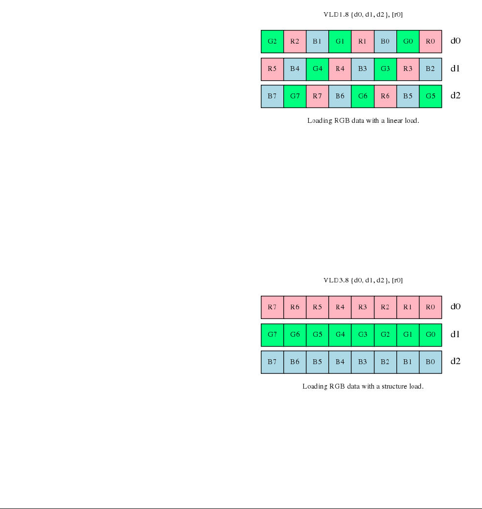
NEON Code Examples with Intrinsics
ARM DEN0018A Copyright © 2013 ARM. All rights reserved. 6-2
ID071613 Non-Confidential
6.1 Swapping color channels
This example involves a 24-bit RGB image. The red (R), green (G), and blue (B) pixels are
arranged in memory in the sequence R0,G0, B0, R1,G2, B2, and so on. R0 is the first red pixel.
R1 is the second red pixel, and so on.
This example shows how to swap the red and blue channels so that the sequence in memory
becomes B0, G0, R0, B1, G1, R1, and so on. This is a simple signal processing operation, which
NEON intrinsics can perform efficiently.
Figure 6-1 shows a normal load that pulls consecutive R, G, and B data from memory into
registers.
Figure 6-1 Loading RGB data with a linear load
Code to swap channels based on this input requires mask, shift and combine operations. It is not
elegant and is unlikely to be efficient.
The NEON instruction set provides structure load and store instructions to help in these
situations. They pull in data from memory and simultaneously separate values into different
registers. This is called de-interleaving. This example uses
VLD3
to split the red, green, and blue
channels as they are loaded into 3 different registers.
Figure 6-2 Loading RGB data with a structure load
Now swap the values in the red and blue registers using
VSWP
d0, d2
as Figure 6-3 on page 6-3
shows. And then write the data back to memory, with interleaving, using the similarly named
VST3
store instruction.
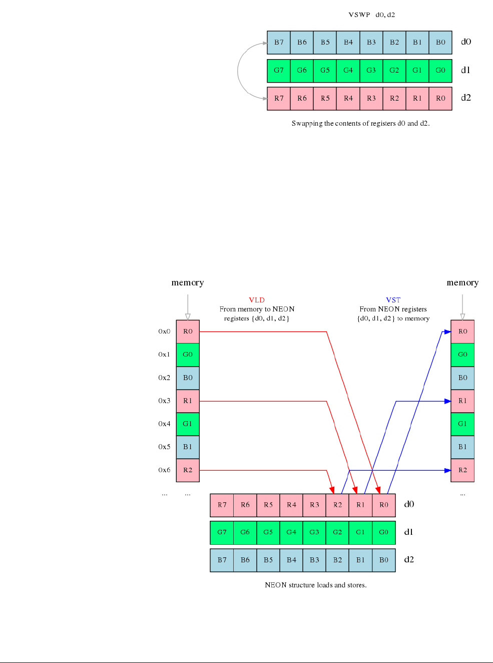
NEON Code Examples with Intrinsics
ARM DEN0018A Copyright © 2013 ARM. All rights reserved. 6-3
ID071613 Non-Confidential
Figure 6-3 Swapping the contents of registers d0 and d2
6.1.1 How de-interleave and interleave work
NEON structure loads read data from memory into 64-bit NEON registers, with optional
de-interleaving. Stores work similarly, interleaving data from registers before writing it to
memory as Figure 6-4 shows. For more information see VLDn and VSTn (multiple n-element
structures) on page C-63.
Figure 6-4 NEON structure loads and stores
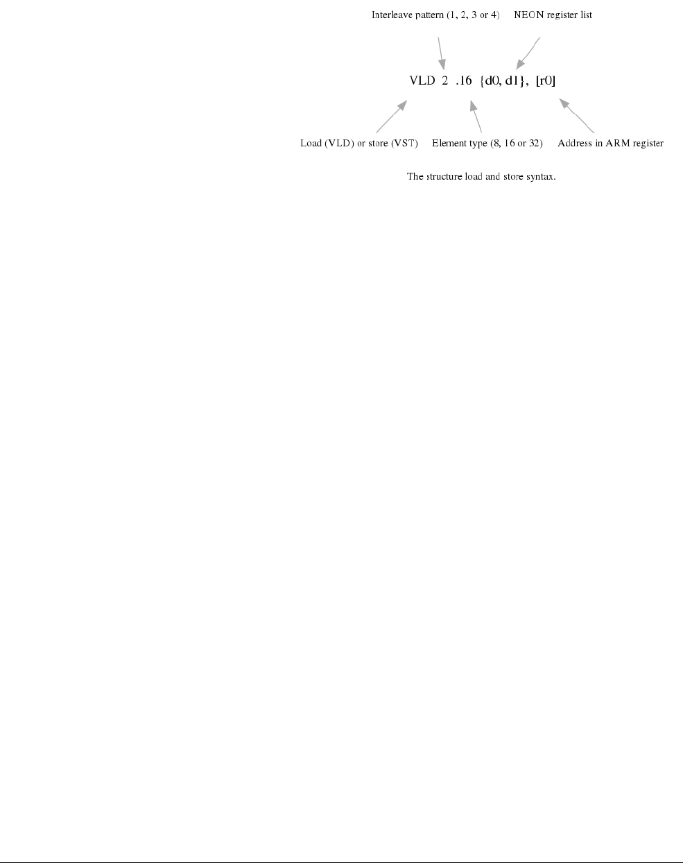
NEON Code Examples with Intrinsics
ARM DEN0018A Copyright © 2013 ARM. All rights reserved. 6-4
ID071613 Non-Confidential
Syntax
The structure load and store instructions have a syntax consisting of five parts.
Figure 6-5 The structure load and store syntax
•The instruction mnemonic is either
VLD
for loads or
VST
for stores.
•A numeric interleave pattern is the number of registers to interleave. This is also the gap
between corresponding elements in each structure.
•An element type specifies the number of bits in the accessed elements.
• A list of 64-bit NEON registers to load from memory or store to memory. The list can
contain up to four registers depending on the interleave pattern.
•An ARM address register contains the location to be accessed in memory to store or load
from. It is possible to update the address after the access.
Interleave pattern
NEON instructions are available to load, store, interleave, and de-interleave structures
containing from one to four equal sized elements. The element size can be 8-bit, 16-bit, or
32-bit.
•
VLD1
is the simplest form. It loads one to four registers of data from memory, with no
de-interleaving. Use this when processing an array of non-interleaved data.
•
VLD2
loads two or four registers of data. It de-interleaves even and odd elements into those
registers. Use this to separate stereo audio data into left and right channels.
•
VLD3
loads and de-interleaves into three registers. This is useful for splitting RGB color
pixels into the three channels.
•
VLD4
loads and de-interleaves into four registers. This is useful for processing ARGB
image data.
Element types
Loads and stores interleave elements based on the size specified in the instruction. For example,
loading two 64-bit NEON registers with
VLD2.16
results in four 16-bit elements in the first
register, and four 16-bit elements in the second registers as Figure 6-6 on page 6-5 shows. The
de-interleave separates the pairs of adjacent elements from memory into separate registers.
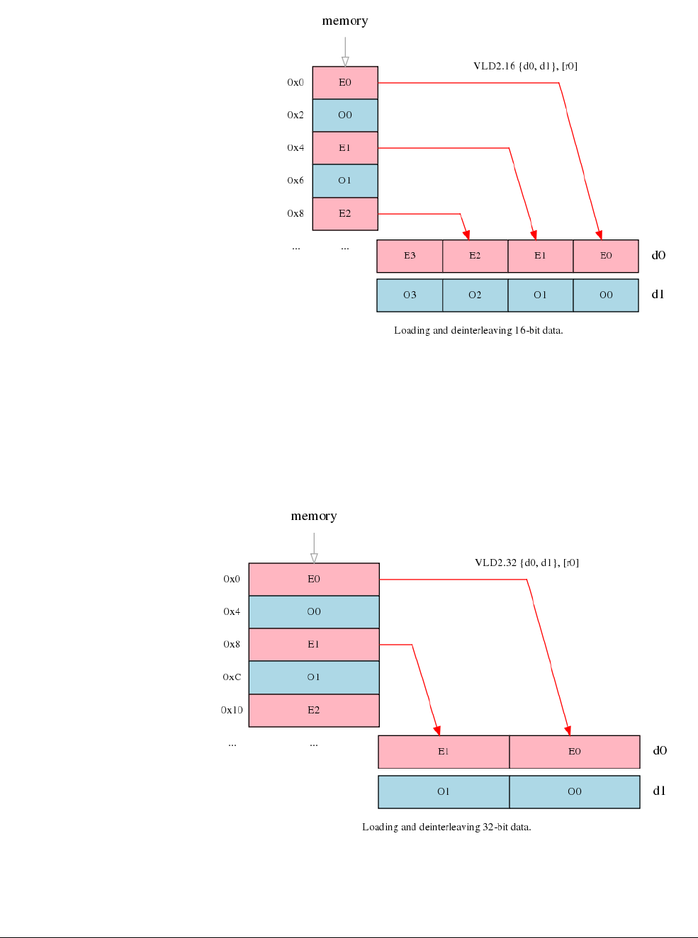
NEON Code Examples with Intrinsics
ARM DEN0018A Copyright © 2013 ARM. All rights reserved. 6-5
ID071613 Non-Confidential
Figure 6-6 Loading and de-interleaving 16-bit data
Changing the element size to 32-bit causes the same amount of data to be loaded. But now only
two elements make up each vector because each element is a 32-bit value rather than a 16-bit
value. This still separates the even and odd elements from memory into separate registers as
Figure 6-7 shows.
Figure 6-7 Loading and de-interleaving 32-bit data
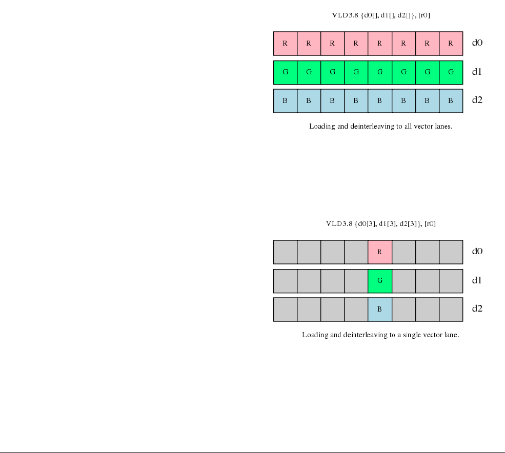
NEON Code Examples with Intrinsics
ARM DEN0018A Copyright © 2013 ARM. All rights reserved. 6-6
ID071613 Non-Confidential
Element size also affects endianness handling. In general, if you specify the correct element size
to the load and store instructions, bytes will be read from memory in the appropriate order, and
the same code will work on little-endian and big-endian systems.
Finally, element size has an impact on pointer alignment. Alignment to the element size will
generally give better performance, and it might be a requirement of your target operating
system. For example, when loading 32-bit elements, align the address of the first element to 32
bits.
6.1.2 Single or multiple elements
Structure loads de-interleave from memory and, in each NEON register, it can:
• load multiple lanes with different elements, as Figure 6-4 on page 6-3 shows
• load multiple lanes with the same element, as Figure 6-8 shows
• load a single lane with a single element and leave the other lanes unaffected, as Figure 6-9
shows.
Figure 6-8 Loading and de-interleaving to all vector lanes
The latter form is useful when you want to construct a vector from data scattered in memory.
Figure 6-9 Loading and de-interleaving to a single vector lane
Store instructions provide similar support for writing single or multiple elements with
interleaving.

NEON Code Examples with Intrinsics
ARM DEN0018A Copyright © 2013 ARM. All rights reserved. 6-7
ID071613 Non-Confidential
6.1.3 Addressing
Structure load and store instructions support a number of formats for specifying memory
addresses.
• Register: [Rn {,:align}]
This is the simplest form. The instruction loads or stores data at the specified address.
• Register with increment after: [Rn {,:align}]!
The instruction updates the pointer after loading or storing. Hence the pointer is ready for
the next instruction to load or store the next set of elements. The increment is equal to the
number of bytes read or written by the instruction.
• Register with post-index: [Rn {,:align}], Rm
After the memory access, the instruction increments the pointer by the value in register
Rm. This is useful when reading or writing groups of elements that are separated by fixed
widths. An example of this is when reading a vertical line of data from an image.
In all formats, it is possible to specify an alignment for the pointer passed in Rn, using the
optional :align parameter. Specifying an alignment often speeds up memory accesses.
6.1.4 Other loads and stores
The example on swapping color channels deals with NEON instructions for structure loads and
stores. These instructions only support 8-bit, 16-bit, and 32-bit data types. The NEON
instruction set also provides:
•
VLDR
and
VSTR
to load or store a single register as a 64-bit value.
•
VLDM
and
VSTM
to load multiple registers as 64-bit values. This is useful for storing and
retrieving registers from the stack.
For more details on supported load and store operations, see the ARM Architecture
Reference Manual.
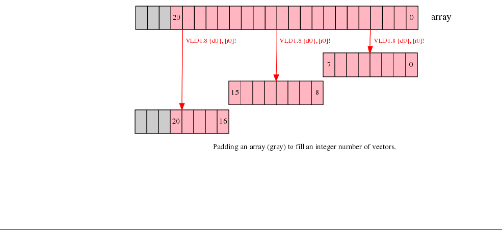
NEON Code Examples with Intrinsics
ARM DEN0018A Copyright © 2013 ARM. All rights reserved. 6-8
ID071613 Non-Confidential
6.2 Handling non-multiple array lengths
This section describes a common problem where the number of input elements to process is not
a multiple of the vector length. For example, to process 16-bit elements in a 64-bit register, the
vector length is four because it can hold four 16-bit elements. However, the array of input data
might contain twenty-six 16-bit elements. You must handle the leftover elements at the start or
end of the array.
6.2.1 Leftovers
NEON instructions typically involve operating on vectors that are four to sixteen elements in
length. Frequently, length of the input array is not a multiple of the vector length. The solution
is to process as many elements as possible using the full vector length. And then process the
leftover elements separately.
6.2.2 Example problem
This section looks at an example where the input array has 21 elements. And each iteration can
load, process, and store eight elements. The first two iterations process 8 elements each. But the
third iteration only has to process five elements.
There are three ways to handle these leftovers. The methods vary in requirements, performance,
and code size. In order of speed of handling leftovers, with the quickest method listed first, these
are:
•Larger arrays
•Overlapping on page 6-10
•Single element processing on page 6-12.
6.2.3 Larger arrays
If it is possible to change the size of the input arrays, then increase the length of the array to the
next multiple of the vector size using padding elements. This allows the NEON instruction to
read and write beyond the end of the input array without corrupting adjacent storage.
In the example described with 21 input elements, increasing the array size to 24 elements allows
the third iteration to complete without potential data corruption.
Figure 6-10 Lengthening an array with padding elements

NEON Code Examples with Intrinsics
ARM DEN0018A Copyright © 2013 ARM. All rights reserved. 6-9
ID071613 Non-Confidential
Note
The new padding elements created at the end of the array might need to be initialized to a value
that does not affect the result of the calculation. For example, if the operation is to sum an array,
the new elements must be initialized to zero for the result to be unaffected. If the operation is to
find the minimum of an array, set the new elements to the maximum value the element can take.
The disadvantages of the array lengthening method are:
• Allocating larger arrays consumes more memory. The increase might be significant if
there are many short arrays.
• In some cases, it might not be possible to initialize the padding elements to a value that
does not affect the result of a calculation. An example is when finding the range of a set
of numbers.
Code fragment
@ r0 = input array pointer
@ r1 = output array pointer
@ r2 = length of data in array
@ We can assume that the array length is greater than zero, is an integer
@ number of vectors, and is greater than or equal to the length of data
@ in the array.
add r2, r2, #7 @ add (vector length-1) to the data length
lsr r2, r2, #3 @ divide the length of the array by the length
@ of a vector, 8, to find the number of
@ vectors of data to be processed
loop:
subs r2, r2, #1 @ decrement the loop counter, and set flags
vld1.8 {d0}, [r0]! @ load eight elements from the array pointed to
@ by r0 into d0, and update r0 to point to the
@ next vector
...
... @ process the input in d0
vst1.8 {d0}, [r1]! @ write eight elements to the output array, and
@ update r1 to point to next vector
bne loop @ if r2 is not equal to 0, loop
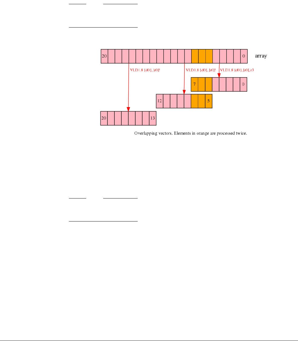
NEON Code Examples with Intrinsics
ARM DEN0018A Copyright © 2013 ARM. All rights reserved. 6-10
ID071613 Non-Confidential
6.2.4 Overlapping
The overlapping method involves processing some of the elements in the array twice. This
method might be suitable in some situations.
To process twenty-one elements using a vector length of 8:
• the first iteration processes elements 0 to 7.
• the second iteration processes elements 5 to 12.
• the third iteration processes elements 13 to 20.
Note
This method processes elements 5 to 7 twice because these elements are present in both the first
and second vectors iterations as Figure 6-11 shows.
Figure 6-11 Overlapping vectors
Overlapping can be used only when the operation is idempotent. This means that the value must
not change depending on how many times the operation is applied to the input data. For
example, it can be used to find the largest or smallest element in an array. The overlapping
method cannot be used to sum an array because the overlapped elements will be added twice.
Note
The overlapping method can be used only if the number of elements in the input array is more
than the vector length.
The overlapping method can be applied in any of the vector iterations.

NEON Code Examples with Intrinsics
ARM DEN0018A Copyright © 2013 ARM. All rights reserved. 6-11
ID071613 Non-Confidential
Code fragment
@ r0 = input array pointer
@ r1 = output array pointer
@ r2 = length of data in array
@ We can assume that the operation is idempotent, and the array is greater
@ than or equal to one vector long.
ands r3, r2, #7 @ calculate number of elements left over after
@ processing complete vectors using
@ data length & (vector length - 1)
beq loopsetup @ if the result of the ANDs is zero, the length
@ of the data is an integer number of vectors,
@ so there is no overlap, and processing can begin
@ at the loop
@ handle the first vector separately
vld1.8 {d0}, [r0], r3 @ load the first eight elements from the array,
@ and update the pointer by the number of elements
@ left over
...
... @ process the input in d0
...
vst1.8 {d0}, [r1], r3 @ write eight elements to the output array, and
@ update the pointer
@ now, set up the vector processing loop
loopsetup:
lsr r2, r2, #3 @ divide the length of the array by the length
@ of a vector, 8, to find the number of
@ vectors of data to be processed
@ the loop can now be executed as normal. the
@ first few elements of the first vector will
@ overlap with some of those processed above
loop:
subs r2, r2, #1 @ decrement the loop counter, and set flags
vld1.8 {d0}, [r0]! @ load eight elements from the array, and update
@ the pointer
...
... @ process the input in d0
...
vst1.8 {d0}, [r1]! @ write eight elements to the output array, and
@ update the pointer
bne loop @ if r2 is not equal to 0, loop
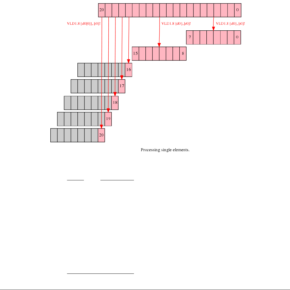
NEON Code Examples with Intrinsics
ARM DEN0018A Copyright © 2013 ARM. All rights reserved. 6-12
ID071613 Non-Confidential
6.2.5 Single element processing
The NEON instruction set provides load and store instructions that can operate on single
elements in a vector. Using these, it is possible to load a partial vector containing one element,
operate on it, and write the element back to memory.
To process twenty-one elements using a vector length of 8:
• the first iteration processes elements 0 to 7.
• the second iteration processes elements 8 to 15
• a separate loop processes elements 16 to 20 individually.
After the first two iterations, there are only five elements to process. A separate loop loads,
processes and stores these elements using NEON instructions that handle these elements
individually as Figure 6-12 shows.
Figure 6-12 Element processing
Note
• Single element processing is slower than the previous methods, as each element must be
loaded, processed and stored individually.
• Handling leftovers like this requires two loops:
— for vector iterations
— for single element operations.
This can double the amount of code in the function.
• A single element load instruction only changes the value of the destination element and
leaves the rest of the vector unchanged. If the operation requires instructions that work
across a vector, such as VPADD, the vector must be initialized with suitable values before
loading the first single element into it.

NEON Code Examples with Intrinsics
ARM DEN0018A Copyright © 2013 ARM. All rights reserved. 6-13
ID071613 Non-Confidential
The single elements method can be applied either at the start or at the end of processing the input
array.
Code fragment
@ r0 = input array pointer
@ r1 = output array pointer
@ r2 = length of data in array
lsrs r3, r2, #3 @ calculate the number of complete vectors to be
@ processed and set flags
beq singlesetup @ if there are zero complete vectors, branch to
@ the single element handling code
@ process vector loop
vectors:
subs r3, r3, #1 @ decrement the loop counter, and set flags
vld1.8 {d0}, [r0]! @ load eight elements from the array and update
@ the pointer
...
... @ process the input in d0
...
vst1.8 {d0}, [r1]! @ write eight elements to the output array, and
@ update the pointer
bne vectors @ if r3 is not equal to zero, loop
singlesetup:
ands r3, r2, #7 @ calculate the number of single elements to process
beq exit @ if the number of single elements is zero, branch
@ to exit
@ process single element loop
singles:
subs r3, r3, #1 @ decrement the loop counter, and set flags
vld1.8 {d0[0]}, [r0]! @ load single element into d0, and update the
@ pointer
...
... @ process the input in d0[0]
...
vst1.8 {d0[0]}, [r1]! @ write the single element to the output array,
@ and update the pointer
bne singles @ if r3 is not equal to zero, loop
exit:
6.2.6 Alignment
Load and store addresses must be aligned to cache lines to allow more efficient memory access.
This requires at least 16-word alignment on Cortex-A8. If it is not possible to align the start of
the input and output arrays, then it is better to process the unaligned elements as single elements.
This means some of the elements at the beginning of the array and some of the elements at the
end of the array can be processed as single elements. This allows the elements in the middle of
the array, where there is alignment, to be processed as vectors.
When aligning memory accesses remember to use
:64
or
:128
or
:256
address qualifiers with
load and store instructions for optimum performance. The Cortex-A8 Technical Reference
Manual lists the number of cycles required for load and store instructions for different
alignments.

NEON Code Examples with Intrinsics
ARM DEN0018A Copyright © 2013 ARM. All rights reserved. 6-14
ID071613 Non-Confidential
6.2.7 Using ARM instructions
In the single element processing method, it is possible to use ARM instructions to operate on
each element. However, storing to the same area of memory with both ARM and NEON
instructions can reduce performance. This is because writes from the ARM pipeline are delayed
until writes from the NEON pipeline have completed.
Avoid writing to the same area of memory, specifically the same cache line, from both ARM
and NEON code.

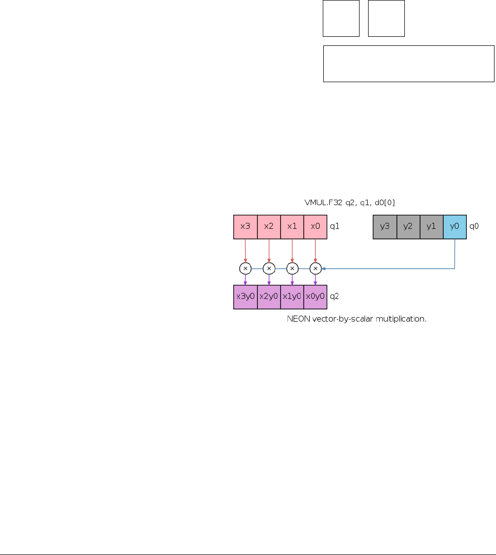
NEON Code Examples with Mixed Operations
ARM DEN0018A Copyright © 2013 ARM. All rights reserved. 7-2
ID071613 Non-Confidential
7.1 Matrix multiplication
This section describes an example of how to multiply four-by-four matrices efficiently. This
operation is frequently used in 3D graphics processing. This example assumes that the matrices
are stored in memory in column-major order. This is the format used by OpenGL-ES.
7.1.1 Algorithm
By expanding the matrix multiply operation in detail, it is possible to identify sub-operations
that can be implemented using NEON instructions.
Figure 7-1 Matrix multiplication showing first two columns of result
Notice that in Figure 7-1, each column of the first matrix (shown in red) is multiplied by a
corresponding single value in the second matrix (shown in blue). The individual products are
added as Figure 7-1 shows, and this gives a column of values for the result matrix. This
operation is repeated for the remaining columns in the result matrix.
Figure 7-2 Vector by scalar multiplication
If each column is a vector in a NEON register, the vector-by-scalar multiply instruction
efficiently calculates each column in the result matrix. The sub-operation highlighted in
tFigure 7-2 can be implemented using this instruction. Use the accumulating version of the
multiply instruction to accumulate the individual products from each column of the first matrix.
This example operates on the columns of the first matrix and produces a column of results.
Therefore, reading and writing elements to and from memory is a linear operation, and does not
require interleaving load and store instructions.
x0 x4 x8 xc
x1 x5 x9 xd
x2 x6 xa xe
x3 x7 xb xf
y0 y4 y8 yc
y1 y5 y9 yd
y2 y6 ya ye
y3 y7 yb yf
x0y0+x4y1+x8y2+xcy3
x1y0+x5y1+x9y2+xdy3
x2y0+x6y1+xay2+xey3
x3y0+x7y1+xby2+xfy3
x0y4+x4y5+x8y6+xcy7
x1y4+x5y5+x9y6+xdy7
x2y4+x6y5+xay6+xey7
x3y4+x7y5+xby6+xfy7
... ...
... ...
... ...
... ...
=
.

NEON Code Examples with Mixed Operations
ARM DEN0018A Copyright © 2013 ARM. All rights reserved. 7-3
ID071613 Non-Confidential
7.1.2 Code
The NEON unit has thirty-two 64-bit registers. Each D register can hold two 32-bit
floating-point elements. Hence it is possible to load all the elements from both input matrices
into NEON registers, and still have other registers for use as accumulators. The eight D registers
from d16 to d23 hold the 16 elements from the first matrix. The eight D registers from d0 to d7
hold the 16 elements from the second matrix.
The floating-point multiplication operations use Q registers because each matrix column has
four 32-bit floating-point numbers, which fit into a single 128-bit Q register.
Floating-point
This describes an implementation that multiplies single precision floating-point matrices. Each
matrix thus contains sixteen 32-bit floating-point values.
Begin by loading the matrices from memory into NEON registers. The matrices are stored in
column-major order, so columns of the matrix are stored linearly in memory. A column can be
loaded into NEON registers using
VLD1
, and written back to memory using
VST1
.
vld1.32 {d16-d19}, [r1]! @ load first eight elements of matrix 0
vld1.32 {d20-d23}, [r1]! @ load second eight elements of matrix 0
vld1.32 {d0-d3}, [r2]! @ load first eight elements of matrix 1
vld1.32 {d4-d7}, [r2]! @ load second eight elements of matrix 1
We can calculate a column of results using just four NEON multiply instructions:
vmul.f32 q12, q8, d0[0] @ multiply element 0 (y0) by matrix col 0 (x0-x3)
vmla.f32 q12, q9, d0[1] @ multiply-acc element 1 (y1) by matrix col 1 (x4-x7)
vmla.f32 q12, q10, d1[0] @ multiply-acc element 2 (y2) by matrix col 2 (x8-xb)
vmla.f32 q12, q11, d1[1] @ multiply-acc element 3 (y3) by matrix col 3 (xc-xf)
The first instruction,
vmul.f32
, implements the operation highlighted in Figure 7-2 on page 7-2.
x0, x1, x2, and x3 (in register q8) are each multiplied by y0 (element 0 in register d0) and then
stored in register q12.
Subsequent instructions operate on the other columns of the first matrix, and multiply by
corresponding elements of the first column of the second matrix. Results are accumulated into
q12 to give the first column of values for the result matrix.
Note
The scalar used in the multiply instructions refers to D registers. Although q0[3] is the same
value as d1[1], the GNU assembler might not accept the use of Q register to refer to a scalar.
Hence, specify a scalar using a D register.
The code above effectively performs a matrix-by-vector multiplication, which is a common
operation in 3D graphics. However, for a matrix-by-matrix multiplication, the code above
computes only the first column of the result matrix. To complete the matrix-by-matrix
multiplication, three more iterations are needed:
• second iteration uses values y4-y7 in register q1.
• third iteration uses values y8-yb in register q2.
• fourth iteration uses values yc-yf in register q3.
If we create a macro for the instructions above, we can simplify our code significantly.
.macro mul_col_f32 res_q, col0_d, col1_d
vmul.f32 \res_q, q8, \col0_d[0] @ multiply col element 0 by matrix col 0
vmla.f32 \res_q, q9, \col0_d[1] @ multiply-acc col element 1 by matrix col 1
vmla.f32 \res_q, q10, \col1_d[0] @ multiply-acc col element 2 by matrix col 2

NEON Code Examples with Mixed Operations
ARM DEN0018A Copyright © 2013 ARM. All rights reserved. 7-4
ID071613 Non-Confidential
vmla.f32 \res_q, q11, \col1_d[1] @ multiply-acc col element 3 by matrix col 3
.endm
The implementation of a four-by-four floating-point matrix multiply now looks like this.
vld1.32 {d16-d19}, [r1]! @ load first eight elements of matrix 0
vld1.32 {d20-d23}, [r1]! @ load second eight elements of matrix 0
vld1.32 {d0-d3}, [r2]! @ load first eight elements of matrix 1
vld1.32 {d4-d7}, [r2]! @ load second eight elements of matrix 1
mul_col_f32 q12, d0, d1 @ matrix 0 * matrix 1 col 0
mul_col_f32 q13, d2, d3 @ matrix 0 * matrix 1 col 1
mul_col_f32 q14, d4, d5 @ matrix 0 * matrix 1 col 2
mul_col_f32 q15, d6, d7 @ matrix 0 * matrix 1 col 3
vst1.32 {d24-d27}, [r0]! @ store first eight elements of result
vst1.32 {d28-d31}, [r0]! @ store second eight elements of result
Fixed point
Using fixed point arithmetic for calculations is often faster than floating-point. It requires less
memory bandwidth to read and write values that use fewer bits. Also, multiplication of integer
values is generally quicker than the same operations applied to floating-point numbers.
However, when using fixed point arithmetic, it is necessary to:
• choose the representation carefully to avoid overflow or saturation
• preserve the degree of precision in the results that the application requires.
Implementing a matrix multiply using fixed point values is very similar to floating-point. This
example uses the
Q1.14
fixed-point format. The operations required are similar for other formats
and might only require a change to the final shift applied to the accumulator. Here is the macro:
.macro mul_col_s16 res_d, col_d
vmull.s16 q12, d16, \col_d[0] @ multiply col element 0 by matrix col 0
vmlal.s16 q12, d17, \col_d[1] @ multiply-acc col element 1 by matrix col 1
vmlal.s16 q12, d18, \col_d[2] @ multiply-acc col element 2 by matrix col 2
vmlal.s16 q12, d19, \col_d[3] @ multiply-acc col element 3 by matrix col 3
vqrshrn.s32 \res_d, q12, #14 @ shift right and narrow accumulator into
@ Q1.14 fixed point format, with saturation
.endm
Comparing it to the macro used in the floating-point version, the major differences are:
• Values are now 16-bit rather than 32-bit, so D registers can hold four inputs.
• The result of multiplying two 16-bit numbers is a 32-bit number.
VMULL
and
VMLAL
can be
used because they store their results in Q registers. This preserves all of the bits of the
result using double-size elements.
• The final result must be 16 bits, but the accumulators have 32 bits. To obtain a 16-bit result
use the
VQRSHRN
instruction, see VQ{R}SHR{U}N on page C-28. This instruction:
— adds the correct rounding value to each element
— shifts it right
— saturates the result to the new, narrower element size.
The reduction from 32-bit to 16-bit element also has an effect on the memory accesses. The data
can be loaded and stored using fewer instructions. Here is the code for a fixed-point matrix
multiply:
vld1.16 {d16-d19}, [r1] @ load sixteen elements of matrix 0
vld1.16 {d0-d3}, [r2] @ load sixteen elements of matrix 1

NEON Code Examples with Mixed Operations
ARM DEN0018A Copyright © 2013 ARM. All rights reserved. 7-5
ID071613 Non-Confidential
mul_col_s16 d4, d0 @ matrix 0 * matrix 1 col 0
mul_col_s16 d5, d1 @ matrix 0 * matrix 1 col 1
mul_col_s16 d6, d2 @ matrix 0 * matrix 1 col 2
mul_col_s16 d7, d3 @ matrix 0 * matrix 1 col 3
vst1.16 {d4-d7}, [r0] @ store sixteen elements of result
Scheduling
It is possible to use instruction scheduling to improve the performance of the matrix-by-matrix
multiply. In the macro, adjacent multiply instructions write to the same register, so the NEON
pipeline must wait for each multiply to complete before it can start the next instruction.
It is possible to separate the instructions that are dependent on the same registers by scheduling
other instructions in between or by rearranging the instructions. These instructions can be issued
while the other instructions execute in the background. This example rearranges the code to
space out accesses to the accumulator registers.
vmul.f32 q12, q8, d0[0] @ rslt col0 = (mat0 col0) * (mat1 col0 elt0)
vmul.f32 q13, q8, d2[0] @ rslt col1 = (mat0 col0) * (mat1 col1 elt0)
vmul.f32 q14, q8, d4[0] @ rslt col2 = (mat0 col0) * (mat1 col2 elt0)
vmul.f32 q15, q8, d6[0] @ rslt col3 = (mat0 col0) * (mat1 col3 elt0)
vmla.f32 q12, q9, d0[1] @ rslt col0 += (mat0 col1) * (mat1 col0 elt1)
vmla.f32 q13, q9, d2[1] @ rslt col1 += (mat0 col1) * (mat1 col1 elt1)
...
...
Using this version, matrix-by-matrix multiply performance almost doubles on a Cortex-A8
based system.

NEON Code Examples with Mixed Operations
ARM DEN0018A Copyright © 2013 ARM. All rights reserved. 7-6
ID071613 Non-Confidential
7.2 Cross product
A cross product is an operation on two 3D vectors, where the result vector is perpendicular to
the plane formed by the input vectors. In 3D graphics, cross products are often used to find
normal vectors for lighting or reflection calculations.
Efficiently calculating a single cross product using the NEON unit is less efficient than
obtaining multiple products. This describes code for both.
7.2.1 Definition
If
i
,
j
, and
k
are mutually orthogonal unit vectors, then the 3D vectors
a
and
b
can be represented
as:
a = [a
i
, a
j
, a
k
]
b = [b
i
, b
j
, b
k
]
The cross product of the vectors
a
and
b
is defined as:
a x b = i(a
j
b
k
-a
k
b
j
) + j(a
k
b
i
-a
i
b
k
) + k (a
i
b
j
-a
j
b
i
)
The cross product result vector is therefore:
[a
j
b
k
-a
k
b
j
, a
k
b
i
-a
i
b
k
, a
i
b
j
-a
j
b
i
]
7.2.2 Single cross product
NEON instructions that operate across the elements of a single vector are limited to addition,
minimum and maximum. But to find a cross product efficiently, it must be calculated by
multiplication of permuted vectors.
Code
The code below uses 32-bit floating-point arithmetic. A fixed point version can be implemented
using the same method. The main feature of the algorithm is the efficient vector permutation
using
vld1_f32()
and
vextq_f32()
.
After this, a simple multiply and multiply-subtract is used to get the final result, which is stored
in two parts.
void cross_product_s(float32_t *r, float32_t* a, float32_t* b)
{
// Vector a is stored in memory such that a
i
is at the lower address and
// a
k
is at the higher address. Vector b is also stored in the same way.
// Registers are shown as vectors containing elements, for example:
// [element3, element2, element1, element0] where element3 uses the higher bits
// and element0 uses the lower bits of the register.
float32x2_t vec_a_1 = vld1_f32(a + 1); //D register = [a
k
, a
j
]
float32x2_t vec_a_2 = vld1_f32(a); //D register = [a
j
, a
i
]
float32x2_t vec_b_1 = vld1_f32(b + 1); //D register = [b
k
, b
j
]
float32x2_t vec_b_2 = vld1_f32(b); //D register = [b
j
, b
i
]
float32x4_t vec_a = vcombine_f32(vec_a_1, vec_a_2); //Q register = [a
j
, a
i
, a
k
, a
j
]
float32x4_t vec_b = vcombine_f32(vec_b_1, vec_b_2); //Q register = [b
j
, b
i
, b
k
, b
j
]
float32x4_t vec_a_rot = vextq_f32(vec_a, vec_a, 1);
float32x4_t vec_b_rot = vextq_f32(vec_b, vec_b, 1);
// vec_a = [ a
j
, a
i
, a
k
, a
j
]
// vec_b_rot = [ b
j
, b
j
, b
i
, b
k
]

NEON Code Examples with Mixed Operations
ARM DEN0018A Copyright © 2013 ARM. All rights reserved. 7-7
ID071613 Non-Confidential
// vec_a_rot = [ a
j
, a
j
, a
i
, a
k
]
// vec_b = [ b
j
, b
i
, b
k
, b
j
]
float32x4_t prod = vmulq_f32(vec_a, vec_b_rot);
// prod = [ a
j
b
j
, a
i
b
j
, a
k
b
i
, a
j
b
k
]
prod = vmlsq_f32(prod, vec_a_rot, vec_b);
// prod = [ a
j
b
j
-a
j
b
j
, a
i
b
j
-a
j
b
i
, a
k
b
i
-a
i
b
k
, a
j
b
k
-a
k
b
j
]
vst1_f32(r, vget_low_f32(prod)); // Store the lower two elements to address r
vst1_lane_f32(r + 2, vget_high_f32(prod), 0); // Store the 3rd element
}
Note
The result vector has 3 floating-point elements to store to memory. If an additional
floating-point value can be stored to memory without causing corruption, then it is possible to
replace the two store intrinsics with a single call to the
vst1q_f32
intrinsic.
7.2.3 Four cross products
Calculating multiple cross products for an array of 3D vectors is simpler and more efficient than
single cross products. Use this code for finding four cross products simultaneously.
Code
This is a straightforward translation of the scalar algorithm. Use
vld3q_f32()
to load and
de-interleave four input vectors into three components, one for each of
i
,
j
, and
k
dimensions.
Then
vmulq_f32()
and
vmlsq_f32()
are used to calculate each component of the result vector.
Finally
vst3q_f32()
interleaves the components into vectors, and stores them to memory.
void cross_product_q(float32_t* r, float32_t* a, float32_t* b)
{
float32x4x3_t vec_a = vld3q_f32(a);
float32x4x3_t vec_b = vld3q_f32(b);
float32x4x3_t result;
result.val[0] = vmulq_f32(vec_a.val[1], vec_b.val[2]);
result.val[0] = vmlsq_f32(result.val[0], vec_a.val[2], vec_b.val[1]);
result.val[1] = vmulq_f32(vec_a.val[2], vec_b.val[0]);
result.val[1] = vmlsq_f32(result.val[1], vec_a.val[0], vec_b.val[2]);
result.val[2] = vmulq_f32(vec_a.val[0], vec_b.val[1]);
result.val[2] = vmlsq_f32(result.val[2], vec_a.val[1], vec_b.val[0]);
vst3q_f32(r, result);
}
7.2.4 Arbitrary input length
Combine the code sequences above to produce a function that can efficiently calculate the cross
product of an arbitrary number of vectors. There is an extra function here,
cross_product_d()
,
which is the same as
cross_product_q()
, but modified to calculate two cross products per call,
using the
float32x2x3_t
type.
Code
Call
cross_product_q()
for the first groups of four vectors. Then process the remaining zero to
three vectors using
cross_product_d()
and
cross_product_s()
.

NEON Code Examples with Mixed Operations
ARM DEN0018A Copyright © 2013 ARM. All rights reserved. 7-8
ID071613 Non-Confidential
void cross_product(float32_t* r, float32_t* a, float32_t* b, int count)
{
int count4 = count / 4;
count &= 3;
while(count4 > 0)
{
cross_product_q(r, a, b);
r += 12; a += 12; b += 12; count4--;
}
if(count >= 2)
{
cross_product_d(r, a, b);
r += 6; a += 6; b += 6; count -= 2;
}
if(count == 1)
{
cross_product_s(r, a, b);
}
}

ARM DEN0018A Copyright © 2013 ARM. All rights reserved. 8-1
ID071613 Non-Confidential
Chapter 8
NEON Code Examples with Optimization
This chapter contains examples that use NEON instructions to perform several optimizations:
•Converting color depth on page 8-2
•Median filter on page 8-5
•FIR filter on page 8-21.
NEON Code Examples with Optimization
ARM DEN0018A Copyright © 2013 ARM. All rights reserved. 8-2
ID071613 Non-Confidential
8.1 Converting color depth
Converting between color depths is a frequent operation in graphics processing. Often, input or
output data is in an RGB565 16-bit color format. But data in RGB888 format is easier to work
with. This is particularly true when using the NEON unit, as there is no native support for data
types like RGB565.
Figure 8-1 RGB888 and RGB565 color formats
However, the NEON unit can still handle RGB565 data efficiently using the vector shift
operations.
8.1.1 Converting from RGB565 to RGB888
First thing to do is convert from RGB565 to RGB888 format. This example assumes that
register q0 has eight 16-bit pixels in the RGB565 format. The code separates the red, green, and
blue pixels into 8-bit elements across three registers d2 to d4.
vshr.u8 q1, q0, #3 @ shift red elements right by three bits,
@ discarding the green bits at the bottom of
@ the red 8-bit elements.
vshrn.i16 d2, q1, #5 @ shift red elements right and narrow,
@ discarding the blue and green bits.
vshrn.i16 d3, q0, #5 @ shift green elements right and narrow,
@ discarding the blue bits and some red bits
@ due to narrowing.
vshl.i8 d3, d3, #2 @ shift green elements left, discarding the
@ remaining red bits, and placing green bits
@ in the correct place.
vshl.i16 q0, q0, #3 @ shift blue elements left to most-significant
@ bits of 8-bit color channel.
vmovn.i16 d4, q0 @ remove remaining red and green bits by
@ narrowing to 8 bits.
The effects of each instruction are described in the comments above, but in summary, the
operation performed on each channel is:
• Remove color data for adjacent channels, using shift operations to push the bits off either
end of the element.
• Use a second shift operation to position the color data in the most significant bits of each
element.
• Use a narrow operation to reduce the element size from 16 bits to 8 bits.
Note
Element sizes are used in this sequence to address 8-bit and 16-bit elements, to achieve some of
the masking operations.

NEON Code Examples with Optimization
ARM DEN0018A Copyright © 2013 ARM. All rights reserved. 8-3
ID071613 Non-Confidential
Quality of the white color
After converting from RGB56 format to RGB888 format using the above code, the color white
is not white enough. This is because for each channel, the lowest two or three bits are zero, rather
than one. White represented in RGB565 format is
[0x1F
,
0x3F
,
0x1F
]. The above code converts
this to [
0xF8
,
0xFC
,
0xF8
] in RGB888 format. This can be fixed using shift with insert to place
some of the most significant bits into the lower bits.
Optimizing with intrinsics
You can optimize the RGB565 to RGB888 conversion using intrinsics. Here is a code snippet
using intrinsics:
uint16_t *src = image_src;
uint8_t *dst = image_dst;
int count = PIXEL_NUMBER;
while (count >= 8) {
uint16x8_t vsrc;
uint8x8x3_t vdst;
vsrc = vld1q_u16(src);
vdst.val[0] =
vshrn_n_u16(vreinterpretq_u16_u8(vshrq_n_u8(vreinterpretq_u8_u16(vsrc), 3)), 5);
vdst.val[1] = vshl_n_u8(vshrn_n_u16(vsrc, 5) ,2);
vdst.val[2] = vmovn_u16(vshlq_n_u16(vsrc, 3));
vst3_u8(dst, vdst);
dst += 8*3;
src += 8;
count -= 8;
}
GCC generates the following assembler code from these intrinsics:
vshr.u8 q1, q0, #3
vshrn.i16 d3, q0, #5
vshl.i16 q0, q0, #3
vshrn.i16 d2, q1, #5
vshl.i8 d3, d3, #2
vmovn.i16 d4, q0

NEON Code Examples with Optimization
ARM DEN0018A Copyright © 2013 ARM. All rights reserved. 8-4
ID071613 Non-Confidential
8.1.2 Converting from RGB888 to RGB565
This example code shows how to convert from RGB888 format to RGB565 format. This
example assumes that the RGB888 data is in the format produced by the code above. Hence the
red, green, and blue pixels are separated across three registers d0 to d2, with each register
containing eight elements. The result will be stored as eight 16-bit elements in RGB565 format
in register q2.
vshll.u8 q2, d0, #8 @ shift red elements left to most-significant
@ bits of wider 16-bit elements.
vshll.u8 q3, d1, #8 @ shift green elements left to most-significant
@ bits of wider 16-bit elements.
vsri.16 q2, q3, #5 @ shift green elements right and insert into
@ red elements.
vshll.u8 q3, d2, #8 @ shift blue elements left to most-significant
@ bits of wider 16-bit elements.
vsri.16 q2, q3, #11 @ shift blue elements right and insert into
@ red and green elements.
In summary, for each channel:
• Lengthen each element to 16 bits, and shift the color data into the most significant bits.
• Use shift right with insert operation to position each color channel in the result register.
Optimizing with intrinsics
You can optimize the RGB888 to RGB565 conversion using intrinsics. Here is a code snippet
using intrinsics:
uint8_t *src = image_src;
uint16_t *dst = image_dst;
int count = PIXEL_NUMBER;
while (count >= 8) {
uint8x8x3_t vsrc;
uint16x8_t vdst;
vsrc = vld3_u8(src);
vdst = vshll_n_u8(vsrc.val[0], 8);
vdst = vsriq_n_u16(vdst, vshll_n_u8(vsrc.val[1], 8), 5);
vdst = vsriq_n_u16(vdst, vshll_n_u8(vsrc.val[2], 8), 11);
vst1q_u16(dst, vdst);
dst += 8;
src += 8*3;
count -= 8;
}
GCC generates the following assembler code from these intrinsics:
vshll.u8 q2, d0, #8
vshll.u8 q3, d1, #8
vshll.u8 q8, d2, #8
vsri.16 q2, q3, #5
vsri.16 q2, q8, #11

NEON Code Examples with Optimization
ARM DEN0018A Copyright © 2013 ARM. All rights reserved. 8-5
ID071613 Non-Confidential
8.2 Median filter
Median filters are commonly used to remove noise that appears in the form of sparsely
distributed outliers, such as dead pixels in an image sensor.
For each pixel, a group of pixels near to the corresponding input pixel, typically from an NxN
square, are collected together and ordered by intensity. The middle pixel of the list is then
selected as the output. This generally has negligible impact on the output as most pixel values
are somewhere between their neighbors in each axis, and the selected pixel is usually the same
as or very close to the original pixel. However, pixels with extreme values fall outside of the
normal range of the surrounding pixels. Hence for input pixels with extreme values, the output
pixel will be one of the surrounding pixels in the normal range.
This example shows how to use NEON intrinsics for performing a median filter algorithm on
an RGB color image. In this example the filter window size is 7x7. This example performs
median filtering on 7 rows of data only. This example only performs the median filter on the
Red color plane. The same algorithm can be used to perform the filter on the other color planes
and the other rows of the image.
Note
Larger window sizes cause more blurring of the image while preserving the edges better.
8.2.1 Implementation
It is common to implement median filters using histograms that record the frequency of each
pixel intensity value, as it is a simple operation to pick the median from a histogram. This is
effective for large windows, as the work scales almost linearly with the window size. But there
is limited scope for vectorization, and all pixel values of the image do not fit within L1 cache.
For smaller windows it is reasonable to collect together all of the relevant inputs, order them,
and pick the midpoint from that list. The efficiency can be improved by only ordering the parts
of the list which are necessary for the median value, and by re-using partially-ordered lists from
previous pixel calculations.
8.2.2 Basic principles and bitonic sorting
Sorting network is a class of data ordering algorithm in which program flow is not affected by
the input data set. This is useful in the context of NEON operations, to ensure that all lanes in a
vector take the same code path.
Theoretical best case performance of these algorithms are lower than dynamic algorithms but
parallelism makes up for this. Bitonic sort networks are well suited to implementation in SIMD
architectures.
A 7x7 median filter uses an 8x8 bitonic sort algorithm. Figure 8-2 on page 8-6 shows the 7x7
bitonic sort which is based on an 8x8 bitonic sort. The algorithm consists of a series of
comparisons between two input values, for example
in1
and
in2
. After each comparison, the
lower value is placed in the lower of the two rows (row 1 in this case) and the higher value is
placed in the higher of the two rows (row 2 in this case). As this is a 7x7 median filter, the value
in the 8th row is set to the maximum possible value. This means that there is no need to perform
comparisons involving the 8th row. Hence comparisons with row 8 are shown with dotted lines
in Figure 8-2 on page 8-6. At the end of the algorithm, the values
out1
to
out8
are sorted with
out1
being the smallest value and
out8
being the largest value. Comparisons are performed by
using the
vmin
and
vmax
intrinsics to determine the minimum and maximum of two input values.
Each input row in this case is a vector of eight 16-bit unsigned integers. Each row corresponds
to a row of the image to apply the 7x7 median filter to.
NEON Code Examples with Optimization
ARM DEN0018A Copyright © 2013 ARM. All rights reserved. 8-6
ID071613 Non-Confidential
Note
This example assumes the image is in RGB565 format. Each input row in this case is a vector
of eight 16-bit unsigned integers.
Figure 8-2 7x7 bitonic sort
8.2.3 Bitonic merging
Bitonic merging is the merging of two pre-ordered lists. For example, given two separate vectors
of eight ordered elements, it is possible to convert this to a single ordered list of 16
elements. Figure 8-3 demonstrates this.
Figure 8-3 Merge two ordered vectors
The code for this is shown in Example 8-1. The code uses macros which are also shown in the
example.
Example 8-1 Bitonic merge
static VFP inline uint16x8x2_t bitonic_merge_16(uint16x8_t a, uint16x8_t b)
in7
in6
in5
in4
in3
in8
in2
in1
out7
out6
out5
out4
out3
out8
out2
out1
7x7 bitonic sort
Merging two ordered vectors
VREV cmp 4 12 24 46 29 18 14 2
99 60 51 59 62 69 82 99
4 12 24 59 62 69 82 99
2 14 18 29 46 51 60 99
99 60 51 46 29 18 14 2
VTRN.
64
4 12 24 46 99 60 51 59
29 18 14 2 62 69 82 99 cmp 4 12 14 2 62 60 51 59
29 18 24 46 99 69 82 99
There is no VTRN.64
instruction. Use VMOV or
VSWP instead.
4 12 14 2 62 60 51 59
29 18 24 46 99 69 82 99
VTRN.
32
4 12 29 18 62 60 99 69
14 2 24 46 51 59 82 99
cmp
4 2 24 18 51 59 82 69
14 12 29 46 62 60 99 99
4 2 24 18 51 59 82 69
14 12 29 46 62 60 99 99
VTRN.
16
4 14 24 29 51 62 82 99
2 12 18 46 59 60 69 99
cmp
2 12 18 29 51 60 69 99
4 14 24 46 59 62 82 99 VZIP 2 4 12 14 18 24 29 46
51 59 60 62 69 82 99 99
The two vectors are now
merged and ordered

NEON Code Examples with Optimization
ARM DEN0018A Copyright © 2013 ARM. All rights reserved. 8-7
ID071613 Non-Confidential
{
b = vrev128q_u16(b);
vminmaxq(a, b);
return bitonic_resort_16(a, b);
}
static VFP inline uint16x8x2_t bitonic_resort_16(uint16x8_t a, uint16x8_t b)
{
/* Start with two vectors:
* +---+---+---+---+---+---+---+---+
* | a | b | c | d | e | f | g | h |
* +---+---+---+---+---+---+---+---+
* +---+---+---+---+---+---+---+---+
* | i | j | k | l | m | n | o | p |
* +---+---+---+---+---+---+---+---+
* All the elements of the first are guaranteed to be less than or equal to
* all of the elements in the second, and both vectors are bitonic.
* We need to perform these operations to completely sort both lists:
* vminmax([abcd],[efgh]) vminmax([ijkl],[mnop])
* vminmax([abef],[cdgh]) vminmax([ijmn],[klop])
* vminmax([acef],[bdfh]) vminmax([ikmo],[jlmp])
* We can align the necessary pairs for mixing with transpose operations,
* like so:
*/
vtrn64q(a ,b);
/* We now have:
* +---+---+---+---+---+---+---+---+
* | a | b | c | d | i | j | k | l |
* +---+---+---+---+---+---+---+---+
* +---+---+---+---+---+---+---+---+
* | e | f | g | h | m | n | o | p |
* +---+---+---+---+---+---+---+---+
*/
vminmaxq(a, b);
vtrn32q(a, b);
/* We now have:
* +---+---+---+---+---+---+---+---+
* | a | b | e | f | i | j | m | n |
* +---+---+---+---+---+---+---+---+
* +---+---+---+---+---+---+---+---+
* | c | d | g | h | k | l | o | p |
* +---+---+---+---+---+---+---+---+
*/
vminmaxq(a, b);
vtrn16q(a, b);
/* We now have:
* +---+---+---+---+---+---+---+---+
* | a | c | e | g | i | k | m | o |
* +---+---+---+---+---+---+---+---+
* +---+---+---+---+---+---+---+---+
* | b | d | f | h | j | l | n | p |
* +---+---+---+---+---+---+---+---+
*/
vminmaxq(a, b);
/* Since we now have separate vectors of odd and even lanes, we can simply
* use vzip to stitch them back together producing our original
* positioning. Then we're done.
*/
return vzipq_u16(a, b);
}
/* Macros */

NEON Code Examples with Optimization
ARM DEN0018A Copyright © 2013 ARM. All rights reserved. 8-8
ID071613 Non-Confidential
/* In-place swap top 64 bits of “a” with bottom 64 bits of “b” -- one operation (vswp)
*/
#define vtrn64q(a, b) \
do { \
uint16x4_t vtrn64_tmp_a0 = vget_low_u16(a), vtrn64_tmp_a1 = vget_high_u16(a); \
uint16x4_t vtrn64_tmp_b0 = vget_low_u16(b), vtrn64_tmp_b1 = vget_high_u16(b); \
{ \
uint16x4_t vtrn64_tmp = vtrn64_tmp_a1; \
vtrn64_tmp_a1 = vtrn64_tmp_b0; \
vtrn64_tmp_b0 = vtrn64_tmp;\
} \
(a) = vcombine_u16(vtrn64_tmp_a0, vtrn64_tmp_a1); \
(b) = vcombine_u16(vtrn64_tmp_b0, vtrn64_tmp_b1); \
} while (0)
/* In-place exchange odd 32-bit words of “a” with even 32-bit words of “b” -- one
operation
*/
#define vtrn32q(a, b) \
do { \
uint32x4x2_t vtrn32_tmp = \
vtrnq_u32(vreinterpretq_u32_u16(a), vreinterpretq_u32_u16(b)); \
(a) = vreinterpretq_u16_u32(vtrn32_tmp.val[0]); \
(b) = vreinterpretq_u16_u32(vtrn32_tmp.val[1]); \
} while (0)
#define vtrn32(a, b)
do { \
uint32x2x2_t vtrn32_tmp = vtrn_u32(vreinterpret_u32_u16(a),vreinterpret_u32_u16(b));\
(a) = vreinterpret_u16_u32(vtrn32_tmp.val[0]); \
(b) = vreinterpret_u16_u32(vtrn32_tmp.val[1]); \
} while (0)
/* In-place exchange odd 16-bit words of “a” with even 16-bit words of “b” -- one
operation */
#define vtrn16q(a, b) \
do { \
uint16x8x2_t vtrn16_tmp = vtrnq_u16((a), (b)); \
(a) = vtrn16_tmp.val[0]; \
(b) = vtrn16_tmp.val[1]; \
} while (0)
#define vzipq(a, b) \
do { \
uint16x8x2_t vzip_tmp = vzipq_u16((a), (b)); \
(a) = vzip_tmp.val[0]; \
(b) = vzip_tmp.val[1]; \
} while (0)
#define vminmaxq(a, b) \
do { \
uint16x8_t minmax_tmp = (a); \
(a) = vminq_u16((a), (b)); \
(b) = vmaxq_u16(minmax_tmp, (b)); \
} while (0)
#define vrev128q_u16(a) \
vcombine_u16(vrev64_u16(vget_high_u16(a)), vrev64_u16(vget_low_u16(a)))
The
VTRN
and
VZIP
operations permute the positions of the lanes such that lines to be compared
appear in corresponding lanes in vector
a
or vector
b
, and the
VMIN
and
VMAX
operations
implement the compare-and-swap operations denoted by the vertical lines.
NEON Code Examples with Optimization
ARM DEN0018A Copyright © 2013 ARM. All rights reserved. 8-9
ID071613 Non-Confidential
This merging of two ordered vectors is represented by the
merge
operation box in Figure 8-8 on
page 8-13.
8.2.4 Partitioning
It is possible to re-use some of the operations performed on one pixel for its neighbors. The task
has to be partitioned in a way that allows us to produce re-usable chunks of the data. This
example progresses through the image in raster order horizontally. It then incrementally adds
and removes vertical columns of data to the region of interest. Basically, it collects together
vertical strips of data to be manipulated as a unit.
8.2.5 Color planes
Image data stored in packed pixel formats will have repeating cycles of RGB data in memory
which must not be mixed together. The usual implementation of median filters is to treat each
color plane separately. Having already committed to separating out columns, it is only a minor
extension to de-interleave these columns according to the color planes to which they belong.
Figure 8-4 shows an example RGB image that this example will apply the median filter to.
Values are only shown for the Red plane.
Figure 8-4 An example RGB image
8.2.6 Padding
To keep the data flow manageable, vectors containing only seven elements (seven rows of our
window) are padded with UINT16_MAX to make them a complete NEON register. These will
end up at the top of the list during merges and can be safely ignored, or pruned in cases where
eight pad words will pool together. In the example figures, 99 represents the UINT16_MAX.
8.2.7 Rolling window
A rolling window runs horizontally across the image, introducing new columns of pixels on the
right, and forgetting old columns on the left. New data is loaded in blocks of eight pixels across
by seven pixels deep. The width of eight pixels corresponds to the NEON register width as well
as the period of the sub-list reuse pattern introduced later. Each value is a 16-bit data. So a vector
in a 128-bit register can store 8 elements.
24
RGB image data
51 56
12 29 33
59 14 71
69 46 32
4 60 34
62 18 31
82 2 28
Row 1
Row 2
Row 3
Row 6
Row 4
Row 5
Row 7
3 80
26 53
58 85
1 20
16 15
63 50
42 27
30 10 11
93 86 52
5 43 83
90 75 17
40 78 79
98 87 49
74 95 8
72
13
97
37
44
89
39

NEON Code Examples with Optimization
ARM DEN0018A Copyright © 2013 ARM. All rights reserved. 8-10
ID071613 Non-Confidential
8.2.8 First pass sorting (bitonic sort)
The example loads each row of the image block into a vector. Seven rows need seven vectors.
Each vector is stored in a 128-bit Q register. The example implements a bitonic sort network
which sorts the elements in each lane separately. Hence all elements in lane 0 will be in order,
and all elements in lane 1 will be in order, and so on.
Example 8-2 and Example 8-3 on page 8-12 show the two parts of a function,
loadblock
. The
first part does the bitonic sort. The second part does the transpose.
Example 8-2 loadblock function
void loadblock(uint16_t dst[8][8], uint16_t const *src, int spitch)
{
uint16x8_t q0, q1, q2, q3, q4, q5, q6, q7;
spitch >>= 1;
q0 = vld1q_u16(src); src += spitch;
q1 = vld1q_u16(src); src += spitch;
q2 = vld1q_u16(src); src += spitch;
q3 = vld1q_u16(src); src += spitch;
q4 = vld1q_u16(src); src += spitch;
q5 = vld1q_u16(src); src += spitch;
q6 = vld1q_u16(src);
/* vminmaxq() performs a pair of vminq and vmaxq operations to put the two arguments in
order */
vminmaxq(q0, q1);
vminmaxq(q2, q3);
vminmaxq(q4, q5);
vminmaxq(q0, q2);
vminmaxq(q1, q3);
vminmaxq(q4, q6);
vminmaxq(q1, q2);
vminmaxq(q5, q6);
vminmaxq(q0, q4);
vminmaxq(q1, q5);
vminmaxq(q2, q6);
vminmaxq(q2, q4);
vminmaxq(q3, q5);
vminmaxq(q1, q2);
vminmaxq(q3, q4);
vminmaxq(q5, q6);
/* See Example 8-3 on page 8-12 for remainder of this function */
}
Because the lanes are independent, it is not important that different lanes come from different
color planes. This can be corrected later. However, the process will need to be repeated as many
times as there are color planes to get enough data for eight pixels. The comparison operation,
cmp
, in Figure 8-5 and Figure 8-6 is a combination of the instructions
VMIN
and
VMAX
. The series
of comparisons are performed as shown in the bitonic sort network in Figure 8-2 on page 8-6.
NEON Code Examples with Optimization
ARM DEN0018A Copyright © 2013 ARM. All rights reserved. 8-11
ID071613 Non-Confidential
Figure 8-5 Comparing corresponding elements of input vectors
Figure 8-6 Continuation of the bitonic sort network
8.2.9 Transpose
As the rolling window moves from left to right, it overlaps a new column of values for the red
plane, and then a column of values for the green plane, and then a column of values for the blue
plane, and so on. The algorithm works by treating each column of values as a vector. Initially,
each vector has values for red, green and blue planes. Hence these vectors must be transposed
into columns. Figure 8-7 on page 8-12 shows the transpose operation.
VZIP
merges corresponding 16-bit elements from the input vectors into the same output vector.
The two input vectors are merged into two output vectors. A vector of padding values can be
created and used for the transpose operations as it is simpler than adding the padding values after
the transpose operations.
VST4.32
treats two adjacent 16-bit elements as a 32-bit element and stores it in memory,
interleaved with the corresponding elements from its four input vectors. In this case, all values
from the same color plane are interleaved together. The memory contents are now in the
repeating order of:
1. seven values for the red color plane
2. a padding element
3. seven values for the green color plane
24
Bitonic sort on input vectors
51 56
12 29 33
59 14 71
69 46 32
4 60 34
62 18 31
82 2 28
Row 1
Row 2
Row 3
Row 6
Row 4
Row 5
Row 7
12 29 33
24 51 56
59 14 32
69 46 71
4 18 31
62 60 34
82 2 28
cmp
vmin
vmax
cmp
cmp
vmax
vmin
vmax
vmin
24
Bitonic sort on input vectors
51 56
12 29 33
59 14 71
69 46 32
4 60 34
62 18 31
82 2 28
Row 1
Row 2
Row 3
Row 6
Row 4
Row 5
Row 7
4 2 28
12 14 31
24 18 32
59 29 33
62 46 34
69 51 56
82 60 71
cmp
cmp
cmp
cmp
cmp
cmp
Each column is fully sorted
at the end of the bitonic
sort
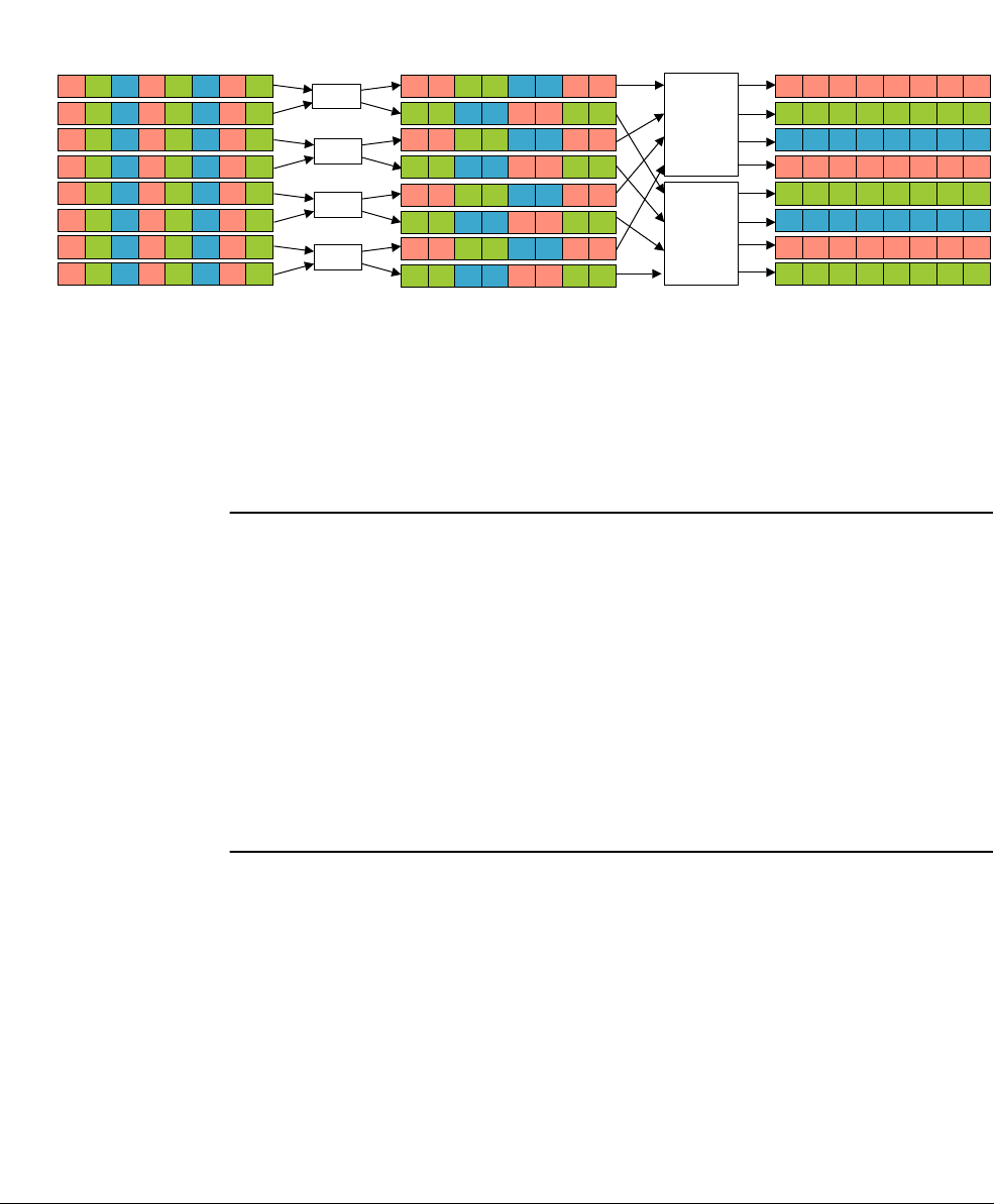
NEON Code Examples with Optimization
ARM DEN0018A Copyright © 2013 ARM. All rights reserved. 8-12
ID071613 Non-Confidential
4. a padding element
5. seven values for the blue color plane
6. a padding element.
VLD1.16
can then be used to load eight 16-bit values from memory to a vector for each color
plane.
Figure 8-7 Transpose
Example 8-3 loadblock function performing the transpose
q7 = vdupq_n_u16(UINT16_MAX);
vzipq(q0, q1);
vzipq(q2, q3);
vzipq(q4, q5);
vzipq(q6, q7);
uint32x4x4_t tmp;
tmp.val[0] = vreinterpretq_u32_u16(q0); tmp.val[1] = vreinterpretq_u32_u16(q2);
tmp.val[2] = vreinterpretq_u32_u16(q4); tmp.val[3] = vreinterpretq_u32_u16(q6);
vst4q_u32((uint32_t *)&dst[0], tmp);
tmp.val[0] = vreinterpretq_u32_u16(q1); tmp.val[1] = vreinterpretq_u32_u16(q3);
tmp.val[2] = vreinterpretq_u32_u16(q5); tmp.val[3] = vreinterpretq_u32_u16(q7);
vst4q_u32((uint32_t *)&dst[4], tmp);
8.2.10 Second pass sorting
The 7x7 median filter requires seven rows and seven columns of data for each color plane. As
the rolling window moves from left to right, a new median value can be found by using the new
column and ignoring the first column. Each column from the RGB image is stored in a vector.
This means every subsequent vector represents the next column of data in the image.
Once all the columns are ordered using the bitonic sort, the columns can then be merged using
bitonic merge as shown in Figure 8-8. The merge also ensures that the values are ordered.
Pairwise merging of the seven vectors creates a set of 49 values that are all ordered.
4
Transpose
2 28
12 14 31
24 18 32
59 29 33
62 46 34
69 51 56
82 60 71
VZIP
99 99 99 99 99 99 99 99
4 12 2 14
28 31 VST4.32
4 12 24 59 62 69 82 99
99
99
2 14 18 29 46 51 60 99
99
99
28 31 32 33 34 56 71 99
99
VST4.32
VZIP
VZIP
VZIP
99 represents the
maximum value
USHRT_MAX
82 99 99 99 60 99
99 99 71 99 99
24 59 18 29
32 33
62 69 46 51
34 56
VZIP merges
corresponding elements of
the vectors to be adjacent
VST4.32 interleaves and
stores 32-bit data to
memory. The values 4 and
12 are treated together as
a 32-bit value.
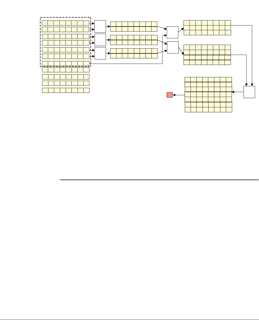
NEON Code Examples with Optimization
ARM DEN0018A Copyright © 2013 ARM. All rights reserved. 8-13
ID071613 Non-Confidential
Four of the seven vectors can be combined in the binary tree way, producing a sorted list of 32
pixels. Four of these are padding values. The remaining three vectors can be combined in the
same way by treating the last vector as if it had been paired with a vector of all padding values,
UINT16_MAX. When padding values are involved, the algorithm can avoid performing
operations with UINT16_MAX as this has predictable outcomes.
Figure 8-8 Merging seven vectors for median pixel 0
Example 8-4 shows the functions and macros involved in merging sorted lists to find the
median.
Example 8-4 Median finding
/* Take a set of sorted lists (32, 16, and 8 elements) and return the median.
*
* We arrange for the second and third lists to be combined in reverse order so
* that they merge directly with the first list without reversal.
*
* We return the first list unmodified because it means the caller can write it
* back to its origin and not worry about saving that data for subsequent
* calls.
*/
static VFP uint16x8x4_t bitonic_median_56(uint16_t *dst, uint16x8x4_t a,
uint16x8x2_t b0, uint16x8_t b1)
{
uint16x8x3_t b = bitonic_merge_24r(b0, b1); /* MUST inline */
b.val[0] = vminq_u16(a.val[1], b.val[0]);
b.val[1] = vminq_u16(a.val[2], b.val[1]);
b.val[2] = vminq_u16(a.val[3], b.val[2]);
b.val[1] = vmaxq_u16(a.val[0], b.val[1]);
b.val[2] = vmaxq_u16(b.val[0], b.val[2]);
b.val[2] = vmaxq_u16(b.val[1], b.val[2]);
Merge 0
4 12 24 59 62 69 82 99
2 14 18 29 46 51 60 99
merge
2 4 12 14 18 24 29 46
51 59 60 62 69 82 99 99
28 31 32 33 34 56 71 99
1 3 16 26 42 58 63 99
merge
1 3 16 26 28 31 32 33
34 42 56 58 63 71 99 99
15 20 27 50 53 80 85 99
5 30 40 74 90 93 95 99
merge
5 15 20 27 30 40 50 53
74 80 85 90 96 98 99 99
10 43 75 78 86 87 95 99
811 17 49 52 79 83 99
13 37 39 44 72 89 97 99
9 12 36 70 76 82 84 99
23 48 59 62 68 88 96 99
merge
merge
2 4 10 12 14 18 24 29
43 46 51 59 60 62 69 75
78 82 86 87 95 99 99 99
1 3 5 15 16 20 26 27
28 30 31 32 33 34 40 42
50 53 56 58 63 71 74 80
85 90 93 98 99 99 99 99
1 2 3 14 5 10 12 14
15 16 18 20 24 26 27 28
29 30 31 32 33 34 40 42
43 46 50 51 53 56 58 59
60 62 63 69 71 74 75 78
80 82 85 86 87 90 93 95
98 99 99 99 99 99 99 99
merge
43
The last 7 entries are just padding (99) so they are not counted in
finding the median. The first 49 values are the real values. Thus the 25
th
value is the median. This value is 43.

NEON Code Examples with Optimization
ARM DEN0018A Copyright © 2013 ARM. All rights reserved. 8-14
ID071613 Non-Confidential
{
uint16x4_t tmp;
tmp = vmin_u16(vget_low_u16(b.val[2]), vget_high_u16(b.val[2]));
tmp = vpmin_u16(tmp, tmp);
tmp = vpmin_u16(tmp, tmp);
vst1_lane_u16(dst, tmp, 0);
}
return a;
}
static VFP inline uint16x8x3_t bitonic_merge_24r(uint16x8x2_t a, uint16x8_t b)
{
uint16x8x3_t result;
b = vrev128q_u16(b);
vmaxminq(a.val[0], b);
vmaxminq(a.val[0], a.val[1]);
a = bitonic_resort_16r(a.val[0], a.val[1]);
vmaxmin_half(b);
b = bitonic_resort_8r(b);
result.val[0] = a.val[0];
result.val[1] = a.val[1];
result.val[2] = b;
return result;
}
static VFP inline uint16x8_t bitonic_resort_8r(uint16x8_t a)
{
uint16x4_t a0 = vget_low_u16(a), a1 = vget_high_u16(a);
vtrn32(a0, a1);
vmaxmin(a0, a1);
vtrn16(a0, a1);
vmaxmin(a0, a1);
vzip(a0, a1);
return vcombine_u16(a0, a1);
}
/* Macros */
#define vmaxminq(a, b) \
do { \
uint16x8_t maxmin_tmp = (a); \
(a) = vmaxq_u16((a), (b)); \
(b) = vminq_u16(maxmin_tmp, (b)); \
} while (0)
#define vmaxmin_half(a) \
do { \
uint16x4_t minmax_tmp_lo = vget_low_u16(a), minmax_tmp_hi = vget_high_u16(a); \
vmaxmin(minmax_tmp_lo, minmax_tmp_hi); \
(a) = vcombine_u16(minmax_tmp_lo, minmax_tmp_hi); \
} while (0)
#define vmaxmin(a, b) \
do { \
uint16x4_t maxmin_tmp = (a); \
(a) = vmax_u16((a), (b)); \
(b) = vmin_u16(maxmin_tmp, (b)); \
} while (0)
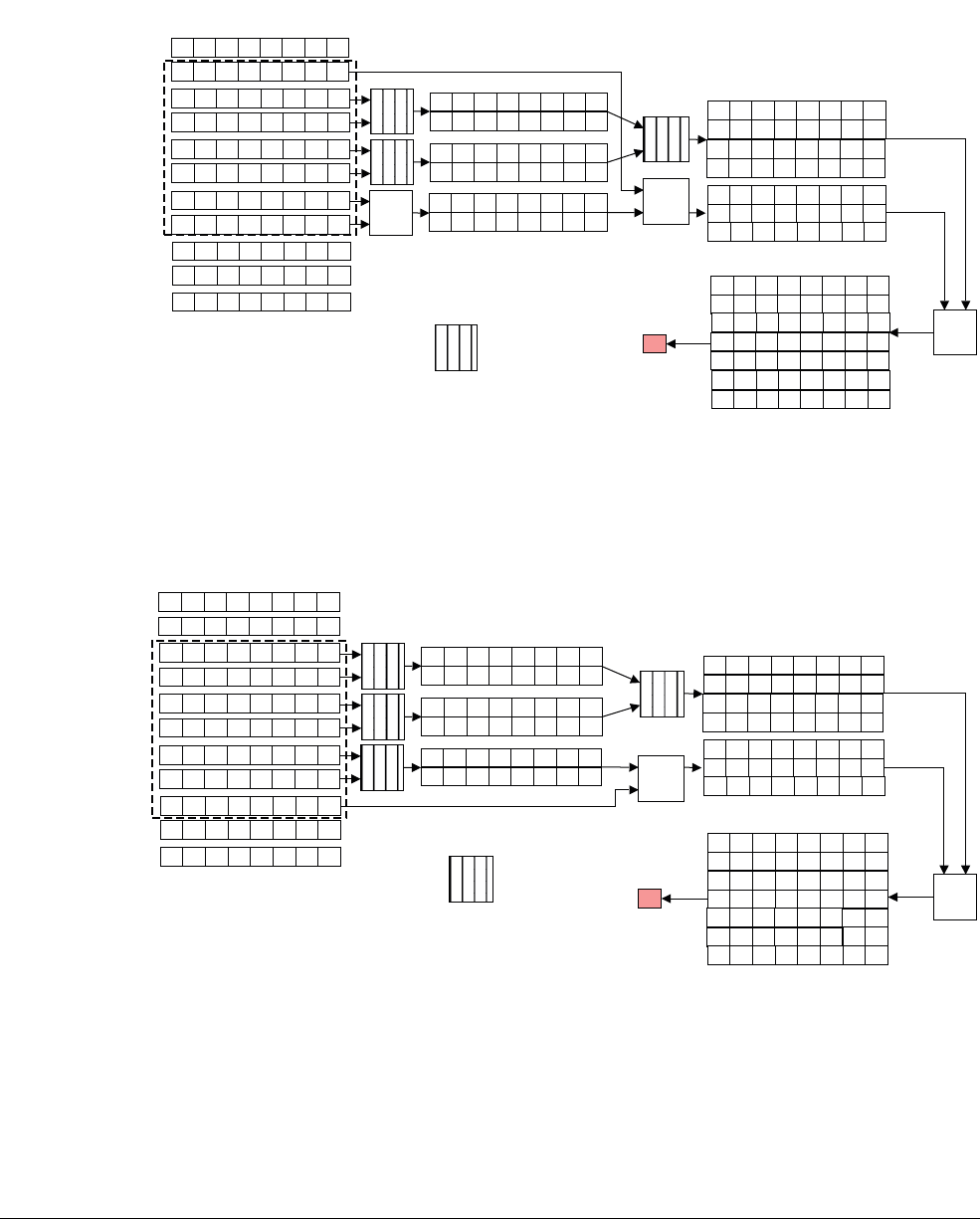
NEON Code Examples with Optimization
ARM DEN0018A Copyright © 2013 ARM. All rights reserved. 8-15
ID071613 Non-Confidential
8.2.11 Re-use
The merge process produces intermediate sorted lists or merged vectors. Some of these
intermediate merged vectors are useful for finding subsequent median values. Figure 8-9 to
Figure 8-12 on page 8-16 show that there is no need to recompute certain merge operations.
Figure 8-9 Merging 7 vectors for first median pixel
Figure 8-10 Merging 7 vectors for second median pixel
Merge 1
4 12 24 59 62 69 82 99
2 14 18 29 46 51 60 99
28 31 32 33 34 56 71 99
1 3 16 26 42 58 63 99
merge
1 3 16 26 28 31 32 33
34 42 56 58 63 71 99 99
15 20 27 50 53 80 85 99
5 30 40 74 90 93 95 99
merge
5 15 20 27 30 40 50 53
74 80 85 90 96 98 99 99
10 43 75 78 86 87 95 99
811 17 49 52 79 83 99
13 37 39 44 72 89 97 99
9 12 36 70 76 82 84 99
23 48 59 62 68 88 96 99
merge
2 8 10 11 14 17 18 29
43 46 49 51 52 60 75 78
79 83 86 87 95 99 99 99
1 3 5 15 16 20 26 27
28 30 31 32 33 34 40 42
50 53 56 58 63 71 74 80
85 90 93 98 99 99 99 99
1 2 3 5 8 10 11 14
15 16 17 18 20 26 27 28
29 30 31 32 33 34 40 42
43 46 49 50 51 52 53 56
58 60 63 71 74 75 78 79
80 83 85 86 87 90 93 95
98 99 99 99 99 99 99 99
merge
43
merge
2 4 12 14 18 24 29 46
51 59 60 62 69 82 99 99
merge
merge
The shaded merge operations
do not need to be performed
again because the outputs
have already been computed
during the previous merge
Merge 2
4 12 24 59 62 69 82 99
2 14 18 29 46 51 60 99
28 31 32 33 34 56 71 99
1 3 16 26 42 58 63 99
merge
1 3 16 26 28 31 32 33
34 42 56 58 63 71 99 99
15 20 27 50 53 80 85 99
5 30 40 74 90 93 95 99
merge
5 15 20 27 30 40 50 53
74 80 85 90 96 98 99 99
10 43 75 78 86 87 95 99
811 17 49 52 79 83 99
13 37 39 44 72 89 97 99
9 12 36 70 76 82 84 99
23 48 59 62 68 88 96 99
merge
8 10 11 13 17 37 39 43
44 49 52 72 75 78 79 83
86 87 89 95 97 99 99 99
1 3 5 15 16 20 26 27
28 30 31 32 33 34 40 42
50 53 56 58 63 71 74 80
85 90 93 98 99 99 99 99
9795
71 72 74 75 78 79 80 83
85 86 87 89 90 93
98 99 99 99 99 99 99 99
merge
44
merge
2 4 12 14 18 24 29 46
51 59 60 62 69 82 99 99
merge
1 3 5 8 10 11 13 15
16 17 20 26 27 28 30 31
32 33 34 37 39 40 42 43
44 49 50 52 53 56 58 63
merge
The shaded merge operations
do not need to be performed
again because the outputs
have already been computed
during the previous merge
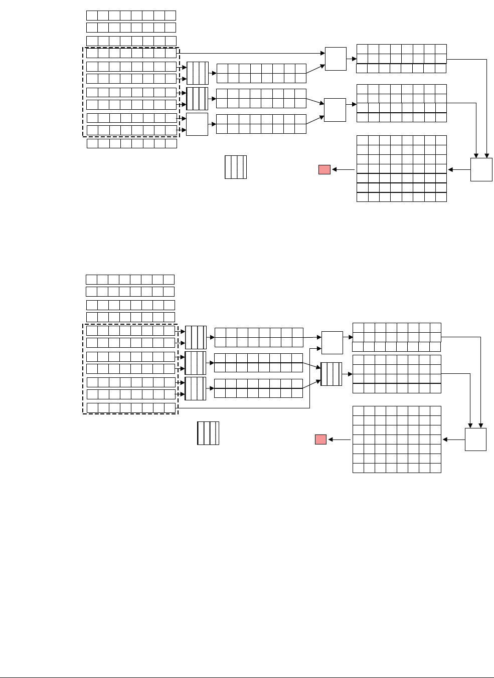
NEON Code Examples with Optimization
ARM DEN0018A Copyright © 2013 ARM. All rights reserved. 8-16
ID071613 Non-Confidential
Figure 8-11 Merging 7 vectors for third median pixel
Figure 8-12 Merging 7 vectors for fourth median pixel
Computing each median value involves:
• Merging two 8-lane vectors into a 16-lane vector. This is done for 3 pairs of vectors.
• Merging two 16-lane vectors into a 32-lane vector.
• Merging an 8-lane vector with a 16-lane vector into a 24-lane vector.
• Merging a 24-lane vector with a 32-lane vector into a 56-lane vector.
Merge 3
4 12 24 59 62 69 82 99
2 14 18 29 46 51 60 99
28 31 32 33 34 56 71 99
1 3 16 26 42 58 63 99
9 12 13 36 37 39 44 70
72 76 82 84 89 97 99 99
15 20 27 50 53 80 85 99
5 30 40 74 90 93 95 99
merge
5 15 20 27 30 40 50 53
74 80 85 90 96 98 99 99
10 43 75 78 86 87 95 99
811 17 49 52 79 83 99
13 37 39 44 72 89 97 99
9 12 36 70 76 82 84 99
23 48 59 62 68 88 96 99
merge
8 9 10 11 12 13 17 36
37 39 43 44 49 52 70 72
75 76 78 79 82 83 84 86
1 3 5 15 16 20 26 27
30 40 42 50 53 58 63 74
80 85 90 93 98 99 99 99
1 3 5 8 9 10 11 12
merge
50
merge
merge
merge
13 15 16 17 20 26 27 30
36 37 39 40 42 43 44 49
50 52 53 58 63 70 72 74
75 76 78 79 80 82 83 84
85 86 87 89 90 93 95 97
98 99 99 99 99 99 99 99
87 89 95 97 99 99 99 99
8 10 11 17 43 49 52 75
78 79 83 86 87 95 99 99
merge
The shaded merge operations
do not need to be performed
again because the outputs
have already been computed
during the previous merge
Merge 4
4 12 24 59 62 69 82 99
2 14 18 29 46 51 60 99
28 31 32 33 34 56 71 99
1 3 16 26 42 58 63 99
9 12 13 36 37 39 44 70
72 76 82 84 89 97 99 99
15 20 27 50 53 80 85 99
5 30 40 74 90 93 95 99 merge 5 15 20 27 30 40 50 53
74 80 85 90 96 98 99 99
10 43 75 78 86 87 95 99
811 17 49 52 79 83 99
13 37 39 44 72 89 97 99
9 12 36 70 76 82 84 99
23 48 59 62 68 88 96 99
merge
8 9 10 11 12 13 17 36
37 39 43 44 49 52 70 72
75 76 78 79 82 83 84 86
5 15 20 23 27 30 40 48
50 53 59 62 68 74 80 85
88 90 93 96 98 99 99 99
5 8 9 10 11 12 13 15
merge
59
merge 8 10 11 17 43 49 52 75
78 79 83 86 87 95 99 99 merge
merge
17 20 23 27 30 36 37 39
40 43 44 48 49 50 52 53
59 62 68 70 72 74 75 76
78 79 80 82 83 84 85 86
87 88 89 90 93 95 96 97
98 99 99 99 99 99 99 99
87 89 95 97 99 99 99 99
merge
The shaded merge operations
do not need to be performed
again because the outputs
have already been computed
during the previous merge
NEON Code Examples with Optimization
ARM DEN0018A Copyright © 2013 ARM. All rights reserved. 8-17
ID071613 Non-Confidential
The sliding window of 7 vectors can be seen as 3 separate windows:
• a window of one vector, containing 8 elements, for example [G] in Figure 8-13 on
page 8-17.
• a window of two merged vectors, containing the 16 merged elements, for example [AB]
in Figure 8-13 on page 8-17
• a window of four merged vectors, containing the 32 merged elements, for example
[CDEF] in Figure 8-13 on page 8-17.
Figure 8-13 on page 8-17 demonstrates this, where the vectors are represented by the letters A
to N. The Merge 4 in Figure 8-12 corresponds to first sliding window, [AB][CDEF][G], in
Figure 8-13 on page 8-17. As the sliding window moves from left to right, it overlaps a new
vector, for example [G] on the right and loses a vector on the left, for example [A]. However,
the merged values of [CDEF] are still used for calculating the next median value. Hence it
makes sense to store and reuse the merged values in [CDEF].
Figure 8-13 Sliding filter
In the sliding window example in Figure 8-13, it is possible to save and reuse:
• individual vectors, for example [B], [D], [F], [H], [I], and [M]
• merged vector pairs, for example [EF], [GH], [IJ], and [KL]
• merged quad vectors, for example [CDEF] and [GHIJ].
The paired vectors, like [CD], are only used to create the quad vector window [CDEF]. Merged
quad vectors are used continuously from creation until they are no longer needed.
As the sliding window moves from left to right, it calculates a new median value. After every 4
median values, the pattern of the windows repeats. This is the cycle of 4. For example in
Figure 8-13, the window pattern for the first and fifth median values is double vector, quad
vector, single vector.
The NEON register file has sixteen Q registers. It is possible to fit all of the saved vectors into
eight Q registers, plus four Q registers for the quad window. This leaves four working Q
registers. Fortunately most of the merge operations can be done with as few as one or two
temporary registers.
Example 8-5 shows the function to perform the median filter on a full row of pixels.
Example 8-5 Filter a row of pixels
void filter_row_bs(uint16_t *dst, uint16_t const *src, int spitch, int count)
{
uint16_t scratch[24][8];
struct
ADEFG
HBCDEFG
HCIDEFG
HJ
IDEFG
EFGH IJK
LFGHIJK
LGMHIJK
LN
MHIJK
BC

NEON Code Examples with Optimization
ARM DEN0018A Copyright © 2013 ARM. All rights reserved. 8-18
ID071613 Non-Confidential
{
uint16x8x2_t ab, ef;
uint16x8_t b, d, f, h;
} state[3];
int i;
loadblock(scratch + 0, src + 0, spitch);
loadblock(scratch + 8, src + 8, spitch);
loadblock(scratch + 16, src + 16, spitch);
for (i = 0; i < 3; i++)
{
uint16x8_t c, d, e, f;
c = vld1q_u16(scratch[i + 3]);
d = vld1q_u16(scratch[i + 6]);
e = vld1q_u16(scratch[i + 9]);
f = vld1q_u16(scratch[i + 12]);
state[i].ab = bitonic_merge_16(e, f);
state[i].ef = bitonic_merge_16(c, d);
state[i].d = d;
state[i].f = f;
state[i].b = vld1q_u16(scratch[i + 0]);
state[i].h = vld1q_u16(scratch[i + 15]);
}
src += 18;
/* We maintain three sets (components) of partially combined lists and we recombine
* these for a full bitonic sort in various permutations in an eight-phase rota.
*
* Register allocation collapses in a heap, here, and we spend a lot of our
* time marshalling things through the stack. We could probably do much
* better with hand-written assembly.
*/
while (count > 0)
{
int i;
uint16_t const *pft, *pft2;
for (i = 0; i < 3; i++)
{
loadblock(scratch + i * 8, src, spitch);
src += 8;
}
pft = src;
if (count < 8) pft -= 24;
pft2 = pft + 6 * spitch;
for (i = 0; i < 3; i++, dst++)
{
int cnt = count;
uint16x8x2_t ab, ef;
uint16x8_t h;
uint16x8_t x, y;
uint16x8x2_t xx;
uint16x8x4_t xxxx;
ef = state[i].ef;
ab = state[i].ab;
/* stage 0 */

NEON Code Examples with Optimization
ARM DEN0018A Copyright © 2013 ARM. All rights reserved. 8-19
ID071613 Non-Confidential
x = vld1q_u16(scratch[i + 0]);
__builtin_prefetch(pft + 0);
xx = bitonic_merge_16(state[i].h, x);
xxxx = bitonic_merge_32(ab, xx);
h = x;
ab = xx;
xxxx = bitonic_median_56(dst + 0, xxxx, ef, state[i].b);
if (--cnt <= 0)
continue;
/* stage 1 */
y = vld1q_u16(scratch[i + 3]);
__builtin_prefetch(pft + 16);
xxxx = bitonic_median_56(dst + 3, xxxx, ef, y);
if (--cnt <= 0)
continue;
/* stage 2 */
x = vld1q_u16(scratch[i + 6]);
__builtin_prefetch(pft + 23); pft += spitch;
xx = bitonic_merge_16(y, x);
state[i].b = x;
ef = xx;
xxxx = bitonic_median_56(dst + 6, xxxx, ef, state[i].d);
if (--cnt <= 0)
continue;
/* stage 3 */
y = vld1q_u16(scratch[i + 9]);
__builtin_prefetch(pft + 0);
(void)bitonic_median_56(dst + 9, xxxx, ef, y);
if (--cnt <= 0)
continue;
/* stage 4 */
x = vld1q_u16(scratch[i + 12]);
__builtin_prefetch(pft + 16);
xx = bitonic_merge_16(y, x);
xxxx = bitonic_merge_32(ef, xx);
state[i].d = x;
state[i].ef = xx;
xxxx = bitonic_median_56(dst + 12, xxxx, ab, state[i].f);
if (--cnt <= 0)
continue;
/* stage 5 */
y = vld1q_u16(scratch[i + 15]);
__builtin_prefetch(pft + 23); pft += spitch;
xxxx = bitonic_median_56(dst + 15, xxxx, ab, y);
if (--cnt <= 0)
continue;
/* stage 6 */
x = vld1q_u16(scratch[i + 18]);
__builtin_prefetch(pft2); pft2 += 8;
xx = bitonic_merge_16(y, x);
state[i].f = x;
ab = xx;
xxxx = bitonic_median_56(dst + 18, xxxx, ab, h);
if (--cnt <= 0)
continue;
/* stage 7 */

NEON Code Examples with Optimization
ARM DEN0018A Copyright © 2013 ARM. All rights reserved. 8-20
ID071613 Non-Confidential
y = vld1q_u16(scratch[i + 21]);
state[i].h = y;
state[i].ab = ab;
(void)bitonic_median_56(dst + 21, xxxx, ab, y);
}
dst += 24 - 3;
count -= 8;
}
}

NEON Code Examples with Optimization
ARM DEN0018A Copyright © 2013 ARM. All rights reserved. 8-21
ID071613 Non-Confidential
8.3 FIR filter
The Finite Impulse Response (FIR) filter is a common example of a vectorizable loop. This
example looks at different ways of generating NEON code:
•Using NEON intrinsics
•Using the vectorizing compiler on page 8-22.
Example 8-6 shows the C code for an FIR filter.
Example 8-6 FIR filter
/*fir.c*/
void fir(short * y, const short *x, const short *h, int n_out, int n_coefs)
{
int n;
for (n = 0; n < n_out; n++)
{
int k, sum = 0;
for(k = 0; k < n_coefs; k++)
{
sum += h[k] * x[n - n_coefs + 1 + k];
}
y[n] = ((sum>>15) + 1) >> 1;
}
}
8.3.1 Using NEON intrinsics
In the FIR filter code in Example 8-6, the central loop is vectorizable. It is a summation of the
product of two arrays, each of which have a stride of one. Also, the value of
n_coefs
is not
known at compile time.
To vectorize the inner
for
loop, divide the
n_coefs
by 4 and use 4 separate operations within the
loop. The accumulation operation is commutative, so it is possible to split the operations:
for(k = 0; k < n_coefs/4; k++)
{
sum0 += h[k*4] * x[n - n_coefs + 1 + k*4];
sum1 += h[k*4+1] * x[n - n_coefs + 1 + k*4 + 1];
sum2 += h[k*4+2] * x[n - n_coefs + 1 + k*4 + 2];
sum3 += h[k*4+3] * x[n - n_coefs + 1 + k*4 + 3];
}
sum = sum0 + sum1 + sum2 + sum3;
One side effect of this would be to reduce the loop overhead by a factor of 4. This works for the
majority of the array, but the number of array items might not be a multiple of four, so extra code
must be added to deal with this situation:
if (n_coefs % 4)
{
for(k = n_coefs - (n_coefs % 4); k < n_coefs; k++)
{
sum += h[k] * x[n - n_coefs + 1 + k];
}
}
Rewrite the main loop to use a vector operation instead of four scalar operations:

NEON Code Examples with Optimization
ARM DEN0018A Copyright © 2013 ARM. All rights reserved. 8-22
ID071613 Non-Confidential
sum = 0;
result_vec = vdupq_n_s32(0); /* Clear the sum vector */
for(k = 0; k < n_coefs / 4; k++)
{
h_vec = vld1_s16(&h[k*4]);
x_vec = vld1_s16(&x[n - n_coefs + 1 + k*4]);
result_vec = vmlal_s16(result_vec, h_vec, x_vec);
}
sum += vgetq_lane_s32(result_vec, 0) + vgetq_lane_s32(result_vec, 1) +
vgetq_lane_s32(result_vec, 2) + vgetq_lane_s32(result_vec, 3);
The final code looks like this:
#include <arm_neon.h>
void fir(short * y, const short *x, const short *h, int n_out, int n_coefs)
{
int n, k;
int sum;
int16x4_t h_vec;
int16x4_t x_vec;
int32x4_t result_vec;
for (n = 0; n < n_out; n++)
{ /* Clear the scalar and vector sums */
sum = 0;
result_vec = vdupq_n_s32(0);
for(k = 0; k < n_coefs / 4; k++)
{ /* Four vector multiply-accumulate operations in parallel */
h_vec = vld1_s16(&h[k*4]);
x_vec = vld1_s16(&x[n - n_coefs + 1 + k*4]);
result_vec = vmlal_s16(result_vec, h_vec, x_vec);
}
/* Reduction operation - add each vector lane result to the sum */
sum += vgetq_lane_s32(result_vec, 0);
sum += vgetq_lane_s32(result_vec, 1);
sum += vgetq_lane_s32(result_vec, 2);
sum += vgetq_lane_s32(result_vec, 3);
/* consume the last few data using scalar operations */
if(n_coefs % 4)
{
for(k = n_coefs - (n_coefs % 4); k < n_coefs; k++)
sum += h[k] * x[n - n_coefs + 1 + k];
}
/* Store the adjusted result */
y[n] = ((sum>>15) + 1) >> 1;
}
}
8.3.2 Using the vectorizing compiler
Compile the unmodified FIR code with:
armcc -O3 -Otime --vectorize --cpu=Cortex-A8 –c fir.c
No source code changes are required, so unintentional code changes are unlikely. The code
remains portable and readable.
Figure 8-14 on page 8-23 shows a comparison of the code generated from the hand-coded
NEON intrinsics and code generated from the vectorizing compiler.
NEON Code Examples with Optimization
ARM DEN0018A Copyright © 2013 ARM. All rights reserved. 8-23
ID071613 Non-Confidential
Figure 8-14 Comparison of NEON intrinsics and vectorizing compiler
||fir|| PROC
PUSH {r4-r9,lr}
MOV r6,#0
LDR r5,[sp,#0x1c]
ASR r4,r5,#31
ADD r12,r5,r4,LSR
#30
B |L1.200|
|L1.24|
MOV lr,#0
VMOV.I8 q0,#0
MOV r4,lr
SUB r7,r6,r5
B |L1.76|
|L1.44|
ADD r8,r2,r4,LSL #3
VLD1.16 {d2},[r8]
ADD r8,r7,r4,LSL #2
ADD r4,r4,#1
ADD r8,r1,r8,LSL #1
ADD r8,r8,#2
VLD1.16 {d3},[r8]
VMLAL.S16 q0,d2,d3
|L1.76|
CMP r4,r12,ASR #2
BLT |L1.44|
TST r5,#3
VMOV.32 r4,d0[0]
ADD r4,r4,lr
VMOV.32 lr,d0[1]
ADD r4,r4,lr
VMOV.32 lr,d1[0]
ADD r4,r4,lr
VMOV.32 lr,d1[1]
ADD lr,lr,r4
BEQ |L1.176|
BIC r4,r12,#3
SUB r4,r5,r4
SUB r4,r5,r4
|L1.136|
CMP r4,r5
BGE |L1.176|
ADD r9,r7,r4
ADD r8,r2,r4,LSL #1
ADD r4,r4,#1
ADD r9,r1,r9,LSL #1
LDRSH r8,[r8,#0]
LDRSH r9,[r9,#2]
MLA lr,r8,r9,lr
B |L1.136|
|L1.176|
MOV r4,#1
ADD r7,r0,r6,LSL #1
ADD r4,r4,lr,ASR #15
ADD r6,r6,#1
ASR r4,r4,#1
STRH r4,[r7,#0]
|L1.200|
CMP r6,r3
BLT |L1.24|
POP {r4-r9,pc}
ENDP
1
2
3
NEON Intrinsics
||fir|| PROC
PUSH {r4-r11,lr}
CMP r3,#0
MOV r9,#0
LDR r7,[sp,#0x24]
BLE |L1.208|
MOV lr,#1
ASR r12,r7,#31
ADD r11,r7,r12,LSR #30
|L1.32|
CMP r7,#0
MOV r5,#0
BLE |L1.180|
VMOV.I8 q0,#0
SUB r8,r9,r7
MOV r4,r2
ADD r12,r1,r8,LSL #1
ADD r6,r12,#2
ASRS r12,r11,#2
BEQ |L1.92|
|L1.72|
VLD1.16 {d3},[r4]!
SUBS r12,r12,#1
VLD1.16 {d2},[r6]!
VMLAL.S16 q0,d3,d2
BNE |L1.72|
|L1.92|
AND r12,r7,#3
CMP r12,#0
BLE |L1.152|
SUB r12,r7,r12
CMP r12,r7
BGE |L1.152|
|L1.116|
ADD r4,r2,r12,LSL #1
LDRH r6,[r4,#0]
ADD r4,r8,r12
ADD r12,r12,#1
ADD r4,r1,r4,LSL #1
CMP r12,r7
LDRH r4,[r4,#2]
SMLABB r5,r6,r4,r5
BLT |L1.116|
|L1.152|
ADD r12,r7,#3
CMP r12,#7
BCC |L1.180|
VADD.I32 d0,d0,d1
VPADD.I32 d0,d0,d0
VMOV.32 r12,d0[0]
ADD r5,r5,r12
|L1.180|
ADD r4,r0,r9,LSL #1
ADD r9,r9,#1
ADD r12,lr,r5,ASR #15
CMP r9,r3
ASR r12,r12,#1
STRH r12,[r4,#0]
BLT |L1.32|
|L1.208|
POP {r4-r11,pc}
ENDP
4
1
3
2
NEON vectorizing compiler

NEON Code Examples with Optimization
ARM DEN0018A Copyright © 2013 ARM. All rights reserved. 8-24
ID071613 Non-Confidential
Code shown in box [1] is the inner loop. The complex calculation for memory address has been
better optimized by the vectorizing compiler. The simple re-write using intrinsics is not
optimized.
The vectorizing compiler loop has five instructions, but the hand-coded loop has ten
instructions. As the instructions in the inner loop will be run the most, the vectorizing compiler
version will run significantly faster than the hand-coded version.
Code shown in box [3] is the cleanup code for the last results in the array. This code is effectively
the same from both the NEON intrinsics and vectorizing compiler.
Code shown in box [2] is the reduction code. This code shows a typical optimization
opportunity. The compiler knows which NEON instructions are available and picks the best
ones for the task. In the hand-coded NEON intrinsics case, the
vgetq_lane_s32
instruction is
used to get each lane and then scalar addition is performed. Although it is algorithmically
correct, it is better to use a vector addition and retrieve a single scalar value.
Code shown in box [4] is code for handling the corner case where the array is empty. The
hand-coded NEON intrinsics version does not handle this corner case.
8.3.3 Adding inside knowledge
If
n_coefs
is always divisible by four, there is no need for the cleanup code in the intrinsics
version. When using the vectorizing compiler, it is possible to inform the compiler by modifying
the expression of the loop count.
For example:
for (n = 0; n < n_coefs; n++)
can be changed to either one of:
• for (n = 0; n < ((n_coefs/4)*4); n++)
• for (n = 0; n < n_coefs_by_4*4; n++).
Both expressions inform the compiler that the loop count is a multiple of four.
The second expression uses a modified variable,
n_coefs_by_4
, which is equal to
n_coefs/4
. This
means that the caller function must pass this modified variable instead of
n_coefs
, as the input
argument. This makes it obvious at the function interface level and aids in correct reuse of the
function.
With this modification the function code now looks like:
void fir(short * y, const short *x, const short *h, int n_out, int n_coefs_by_4)
{
int n;
for (n = 0; n < n_out; n++)
{
int k, sum = 0;
for(k = 0; k < n_coefs_by_4*4; k++)
{
sum += h[k] * x[n - n_coefs_by_4*4 + 1 + k];
}
y[n] = ((sum>>15) + 1) >> 1;
}
}
The change is completely C portable and readable.Figure 8-15 on page 8-25 shows the
comparison of code generated by the NEON intrinsics method and code generated by the
vectorizing compiler when
n_coefs
is a multiple of 4.
NEON Code Examples with Optimization
ARM DEN0018A Copyright © 2013 ARM. All rights reserved. 8-25
ID071613 Non-Confidential
Figure 8-15 Comparison of NEON intrinsics and vectorizing compiler when
n_coefs
is a multiple of 4
||fir|| PROC
PUSH {r4-r9}
CMP r3,#0
MOV r6,#0
LDR r7,[sp,#0x18]
BLE |L1.144|
MOV r9,#1
ASR r12,r7,#31
ADD r5,r7,r12,LSR #30
|L1.32|
VMOV.I8 q0,#0
MOV r12,#0
SUB r4,r6,r7
B |L1.80|
|L1.48|
ADD r8,r2,r12,LSL #3
VLD1.16 {d2},[r8]
ADD r8,r4,r12,LSL #2
ADD r12,r12,#1
ADD r8,r1,r8,LSL #1
ADD r8,r8,#2
VLD1.16 {d3},[r8]
VMLAL.S16 q0,d2,d3
|L1.80|
CMP r12,r5,ASR #2
BLT |L1.48|
VMOV.32 r12,d0[0]
VMOV.32 r4,d0[1]
ADD r12,r12,r4
VMOV.32 r4,d1[0]
ADD r12,r12,r4
VMOV.32 r4,d1[1]
ADD r12,r12,r4
ADD r4,r0,r6,LSL #1
ADD r6,r6,#1
ADD r12,r9,r12,ASR
#15
CMP r6,r3
ASR r12,r12,#1
STRH r12,[r4,#0]
BLT |L1.32|
|L1.144|
POP {r4-r9}
BX lr
ENDP
2
NEON Intrinsics
1
2
NEON vectorizing compiler
1
||fir|| PROC
PUSH {r4-r11}
CMP r3,#0
MOV r6,#0
LDR r9,[sp,#0x20]
BLE |L1.148|
MOV r11,#1
RSB r10,r9,#0
LSL r8,r9,#2
|L1.32|
MOV r7,#0
CMP r8,#0
BLE |L1.120|
VMOV.I8 q0,#0
ADD r12,r6,r10,LSL #2
MOV r4,r2
ADD r12,r1,r12,LSL #1
ADD r5,r12,#2
MOVS r12,r9
BEQ |L1.92|
|L1.72|
VLD1.16 {d3},[r4]!
SUBS r12,r12,#1
VLD1.16 {d2},[r5]!
VMLAL.S16 q0,d3,d2
BNE |L1.72|
|L1.92|
ADD r12,r8,#3
CMP r12,#7
BCC |L1.120|
VADD.I32 d0,d0,d1
VPADD.I32 d0,d0,d0
VMOV.32 r12,d0[0]
ADD r7,r7,r12
|L1.120|
ADD r4,r0,r6,LSL #1
ADD r6,r6,#1
ADD r12,r11,r7,ASR #1
CMP r6,r3
ASR r12,r12,#1
STRH r12,[r4,#0]
BLT |L1.32|
|L1.148|
POP {r4-r11}
BX lr
ENDP

ARM DEN0018A Copyright © 2013 ARM. All rights reserved. A-1
ID071613 Non-Confidential
Appendix A
NEON Microarchitecture
This appendix lists some of the individual processors that implement the v7-A architecture
profile. It contains the following topics:
•The Cortex-A5 processor on page A-2
•The Cortex-A7 processor on page A-4
•The Cortex-A8 processor on page A-5
•The Cortex-A9 processor on page A-9
•The Cortex-A15 processor on page A-11.
NEON Microarchitecture
ARM DEN0018A Copyright © 2013 ARM. All rights reserved. A-2
ID071613 Non-Confidential
A.1 The Cortex-A5 processor
The Cortex-A5 processor supports all ARMv7-A architectural features, including the TrustZone
Security Extensions and the NEON Media Processing Engine. It is extremely area and power
efficient, but has lower maximum performance than other Cortex-A series processors. Both
single-core and multi-core versions of the Cortex-A5 processor are available.
Figure A-1 Block diagram of a single core Cortex-A5 processor
The Cortex-A5 processor shown in Figure A-1 has a single-issue, 8-stage pipeline. It can
dual-issue branches in some circumstances and contains sophisticated branch prediction logic
to reduce penalties associated with pipeline refills. Both NEON and floating-point hardware
support are optional. The Cortex-A5 processor VFP implements VFPv4, which adds both the
half-precision extensions and the Fused Multiply Accumulate instructions to the features of
VFPv3. It supports the ARM and Thumb instruction sets. The size of the level 1 instruction and
data caches is configurable (by the hardware implementer) from 4KB to 64KB.
A.1.1 The Cortex–A5 Media Processing Engine
The Cortex-A5 NEON unit extends the Cortex-A5 functionality to provide support for the ARM
v7 NEON and VFPv4 instruction sets. The Cortex-A5 NEON unit supports all addressing
modes and data-processing operations described in the ARM Architecture Reference Manual.
Data processing unit (DPU) Prefetch unit and branch predictor (PFU)
Debug
Data store
buffer (STB)
Data cache
unit (DCU) Main translation
lookaside buffer (TLB)
Instruction cache
unit (ICU)
Bus interface unit (BIU)
Cortex-A5
processor
Data micro-TLB Instruction micro-TLB
Embedded trace macrocell
(ETM) interface APB interface
AXI interface
CP15

NEON Microarchitecture
ARM DEN0018A Copyright © 2013 ARM. All rights reserved. A-3
ID071613 Non-Confidential
A.1.2 VFPv4 architecture hardware support
The Cortex-A5 NEON unit hardware supports single and double-precision add, subtract,
multiply, divide, multiply and accumulate, fused multiply accumulate, and square root
operations as described in the ARM VFPv4 architecture. It provides conversions between
16-bit, 32-bit, and 64-bit floating-point formats and ARM integer word formats, with special
operations to perform conversions in round-towards-zero mode for high-level language support.
All instructions are available in both the ARM and Thumb instruction sets supported by the
Cortex-A5 processor family.
ARMv7 deprecates the use of VFP vector mode so the Cortex-A5 hardware does not support
VFP vector mode. This means that the VFP instructions cannot operate across multiple registers
in the NEON register file. NEON instructions however can operate on vectors of data, where
the data type can be:
• integer
• polynomial
• single-precision data.
The Cortex-A5 NEON unit provides high speed VFP operation without support code. However,
if an application requires VFP vector operation, then it must use support code. See the ARM
Architecture Reference Manual for information on VFP vector operation support.
If the design includes the NEON unit, then FPU is included.
The Cortex-A5 NEON unit features are:
• SIMD and scalar single-precision floating-point computation
• Scalar double-precision floating-point computation
• SIMD and scalar half-precision floating-point conversion
• SIMD 8-bit, 16-bit, 32-bit, and 64-bit signed and unsigned integer computation
• 8-bit or 16-bit polynomial computation for single-bit coefficients
• Structured data load capabilities
• A large, shared register file, addressable as:
— thirty-two 32-bit S (single) registers
— thirty-two 64-bit D (double) registers
— sixteen 128-bit Q (quad) registers
See the ARM Architecture Reference manual for details of the NEON and floating-point
register file.
• Instructions for:
— addition and subtraction
— multiplication with optional accumulation
— maximum or minimum value driven lane selection operations
— inverse square-root approximation
— comprehensive data-structure load instructions, including register-bank-resident
table lookup.

NEON Microarchitecture
ARM DEN0018A Copyright © 2013 ARM. All rights reserved. A-4
ID071613 Non-Confidential
A.2 The Cortex-A7 processor
The Cortex-A7 MPCore processor is a high-performance, low-power processor which was
announced by ARM in October 2011. It has an in-order pipeline with direct and indirect branch
prediction and a number of improvements to floating point and NEON code performance. It is
application compatible with the other processors described in this book. The processor is fully
compatible with other Cortex-A series processor and incorporates all of the features of the
high-performance Cortex-A15 processor including virtualization, Large Physical Address
Extension (LPAE) NEON advanced SIMD, and AMBA 4 ACE coherency.
A.2.1 The Cortex-A7 NEON unit
The Cortex-A7 NEON unit includes the following features:
• SIMD and scalar single-precision floating-point computation
• Scalar double-precision floating-point computation
• SIMD and scalar half-precision floating-point conversion
• SIMD 8-bit, 16-bit, 32-bit, and 64-bit signed and unsigned integer computation
• 8-bit or 16-bit polynomial computation for single-bit coefficients
• Structured data load capabilities
• A large, shared register file, addressable as:
— thirty-two 32-bit S (single) registers
— thirty-two 64-bit D (double) registers
— sixteen 128-bit Q (quad) registers
See the ARM Architecture Reference manual for details of the NEON and floating-point
register file.
• Operations for:
— addition and subtraction
— multiplication with optional accumulation
— maximum or minimum value driven lane selection operations
— inverse square-root approximation
— comprehensive data-structure load instructions, including register-bank-resident
table lookup.
NEON Microarchitecture
ARM DEN0018A Copyright © 2013 ARM. All rights reserved. A-5
ID071613 Non-Confidential
A.3 The Cortex-A8 processor
The Cortex-A8 processor was the first to implement the ARMv7-A architecture profile. It is
available in a number of different devices, including the S5PC100 from Samsung, the
OMAP3530 from Texas Instruments and the i.MX515 from Freescale. A wide range of device
performances are available, with some giving clock speeds of more than 1GHz.
The Cortex-A8 processor has a considerably more complex micro-architecture compared with
previous ARM processors. Its integer processor has dual symmetric, 13-stage instruction
pipelines, with in-order issue of instructions. The NEON pipeline has an additional 10 pipeline
stages, supporting both integer and floating-point 64-bit or 128-bit SIMD. VFPv3 floating-point
is supported, as is Jazelle-RCT.
Figure A-2 is a block diagram showing the internal structure of the Cortex-A8 processor,
including the pipelines:
Figure A-2 Block diagram of Cortex-A8 processor
The separate instruction and data level 1 caches are 16KB or 32KB in size. They are
supplemented by an integrated, unified level 2 cache, which can be up to 1MB in size, with a
16-word line length. The level 1 data cache and level 2 cache both have a 128-bit wide data
interface to the processor. The level 1 data cache is virtually indexed, but physically tagged,
while level 2 uses physical addresses for both index and tags. Data used by the NEON unit is
not allocated to L1 by default (although the NEON unit can read and write data that is already
in the L1 data cache).
Instruction, data, NEON and preload engine buffers
L2 cache pipeline control
Fill and eviction queue
BIU Write
buffer
L2 cache data RAM L2 cache tag RAM
Cortex-A8
L1
RAM
Prefetch
and
branch
prediction
L1 cache
interface
TLB
Instruction fetch
L2
cache
DFT interface APB interface
AXI interface
Decode &
sequencer
Dependency
check and
issue
Instruction decode Instruction execute
Flags
RegBank
ALU1
ALU2
MAC
Control L1
RAM
L1
cache
interface
TLB
Load/store
NEON
Arbitration
ETM
ATB interface
Parity and
ECC RAM

NEON Microarchitecture
ARM DEN0018A Copyright © 2013 ARM. All rights reserved. A-6
ID071613 Non-Confidential
A.3.1 The Cortex-A8 Media Processing Engine
The Cortex-A8 processor’s NEON unit pipeline starts at the end of the main integer pipeline.
As a result, all exceptions and branch mispredictions are resolved before instructions reach it.
More importantly, there is a zero load-use penalty for data in the Level-1 cache. The ARM
integer unit generates the addresses for NEON load and store instructions as they pass through
the pipeline, thus allowing data to be fetched from the Level-1 cache before it is required by a
NEON data processing operation. Deep instruction and load-data buffering between the NEON
unit, the ARM integer unit and the memory system allow the latency of Level-2 accesses to be
hidden for streamed data. A store buffer prevents NEON store instructions from blocking the
pipeline and detects address collisions with the ARM integer unit accesses and NEON load
instructions.
The NEON unit is decoupled from the main ARM integer pipeline by the NEON Instruction
Queue (NIQ). The 10-stage NEON pipeline begins at the end the ARM integer pipeline.
The NEON unit has:
• 128-bit wide load and store paths to the Level-1 and Level-2 cache, and supports
streaming from both.
• Three SIMD integer pipelines.
— Integer multiply and accumulate pipeline (MAC)
— Integer Shift pipeline
— Integer ALU pipeline.
• A load-store/permute pipeline.
— Load and store of NEON data
— Data transfers to and from the integer unit
— Data permute operations such as interleave and de-interleave.
• Two SIMD single-precision floating-point pipelines.
— Multiply pipeline
— Add pipeline.
• A separate non-pipelined Vector Floating-Point unit (VFPLite) implementation of the
ARM VFPv3 Floating Point Specification targeted for medium performance IEEE 754
compliant floating point support.
VFPLite provides backwards compatibility with existing ARM floating point code and to
provide IEEE 754 compliant single and double precision arithmetic.
NEON instructions are issued and retired in-order. A data processing instruction is either a
NEON integer instruction or a NEON floating-point instruction.
The ARM Instruction Execute Unit can issue up to two valid instructions to the NEON unit each
clock cycle, but the Cortex-A8 NEON unit does not parallel issue two data-processing
instructions. This is to avoid the area overhead of duplicating the data-processing functional
blocks, and to avoid timing critical paths and complexity overhead associated with the muxing
of the read and write register ports.
Since all mispredicts and exceptions have been resolved in the ARM integer unit, an instruction
issued to the NEON unit must complete as it cannot generate exceptions.

NEON Microarchitecture
ARM DEN0018A Copyright © 2013 ARM. All rights reserved. A-7
ID071613 Non-Confidential
A.3.2 Cortex-A8 Data memory access
The Cortex-A8 processor has a 64-bit interface to the L1 cache. Normal memory allocates in
the L1 cache.
The NEON unit has a 128-bit interface to L1 cache and L2 cache.
• Allocates to L1 cache or L2 cache (controlled by L1NEON bit in CP15).
(Accesses can still hit L1 cache with L1NEON disabled)
• Hazards between NEON data and ARM data accesses are resolved on cache line
granularity.
ARM recommends that you maximize performance for NEON data accesses by:
• Avoid mixing ARM data and NEON data accesses to the same cache line.
• Consider using NEON code for memory copy routines. This results in higher bandwidth
and can prevent L1 cache pollution.
The separate instruction and data level 1 caches are 16KB or 32KB in size. They are
supplemented by an integrated, unified level 2 cache, which can be up to 1MB in size, with a
16-word line length. The level 1 data cache and level 2 cache both have a 128-bit wide data
interface to the processor. Data used by the NEON unit is not allocated to L1 by default.
Although the NEON unit can read and write data that is already in the L1 data cache.
The Cortex-A8 processor can dual issue NEON instructions in the following circumstances:
• No register or data dependencies
• One instruction is data processing, the other is one of the following
— a Load or Store instruction
VLD1.8 {D0}, [R1]!
VMLAL.S8 Q2, D3, D2
— an ARM – NEON data transfer (either direction)
VEXT.8 D0, D1, D2, #1
VSUB.16 D3, D4, D5
— a permute instruction
A.3.3 Cortex-A8 specific pipeline hazards
The Cortex-A8 NEON unit operates several pipeline stages after the ARM integer pipeline. It
receives instructions from the ARM pipeline through a FIFO. Transfer of data from ARM
register to NEON register is quick, but moving data from the NEON pipeline to ARM using an
MRC takes 20 cycles.
The NEON unit also has its own load and store unit separate from that of the ARM load and
store, with scope to bypass the level 1 cache. To avoid data hazards due to out-of-order memory
accesses, there is special hardware to detect such cases and to resolve them. If both NEON and
ARM units perform load or store instructions to addresses within the same cache line, a delay
of around 20 cycles is required to resolve ordering issues.
These delays can be avoided with careful coding. Firstly, we must try to minimize a combination
of ARM memory accesses and NEON memory accesses to the same region of memory. It can
still be sensible to store a NEON result to memory and then load the result into an ARM
general-purpose register from memory. If we do not need the result immediately, it should be

NEON Microarchitecture
ARM DEN0018A Copyright © 2013 ARM. All rights reserved. A-8
ID071613 Non-Confidential
possible to hide the 20 cycle latency by having the ARM do some other work before it attempts
the load. This is better than using direct NEON register to ARM register transfer, which always
incurs a penalty because the Cortex-A8 pipeline stalls.
Most compilers use a softfp calling convention to pass arguments and return values in ARM
general-purpose registers. To return a float value therefore requires passing a value from a
NEON register into ARM general-purpose registers, incurring the 20 cycle delay. A way to
avoid this problem is to try to inline such functions or use hard float linkage.
Conditional branches that depend upon floating point values can also incur this penalty.
Although the floating point unit has its own logic to evaluate comparisons and set flags, the
contents of this register must be transferred to the ARM to take a conditional branch and this
incurs a penalty.
NEON Microarchitecture
ARM DEN0018A Copyright © 2013 ARM. All rights reserved. A-9
ID071613 Non-Confidential
A.4 The Cortex-A9 processor
The Cortex-A9 MPCore processor and the Cortex-A9 uniprocessor provide higher performance
than the Cortex-A5 or Cortex-A8 processors, with clock speeds in excess of 1GHz and
performance of 2.5DMIPS/MHz. The ARM, Thumb, Thumb-2, TrustZone, Jazelle-RCT and
DBX technologies are all supported.
The level 1 cache system provides hardware support for cache coherency for between one and
four processors for multi-core software. A level 2 cache is optionally connected outside of the
processor. ARM supplies a level 2 cache controller (PL310/L2C-310) which supports caches of
up to 8MB in size.
The processor also contains an integrated interrupt controller, an implementation of the ARM
Generic Interrupt Controller (GIC) architecture specification. This can be configured to provide
support for up to 224 interrupt sources.
Figure A-3 Block diagram of single-core Cortex-A9 processor
A.4.1 The Cortex-A9 Media Processing Engine
The Cortex-A9 NEON unit features are:
• SIMD and scalar single-precision floating-point computation.
• Scalar double-precision floating-point computation.
• SIMD and scalar half-precision floating-point conversion.
• 8-bit, 16-bit, 32-bit, and 64-bit signed and unsigned integer SIMD computation.
• 8-bit or 16-bit polynomial computation for single-bit coefficients.
CoreSight
Debug Access
Port
Profiling
Monitor Block
Dual-instruction
Decode Stage
Fast Loop Mode
Instruction
Cache
Branch
Prediction
Virtual to
Physical
Register
pool
Register
Rename
stage
Branches
Out-of-Order
multi-issue with
speculation
Instruction queue
And
Dispatch
3+1 Dispatch Stage
Auto-prefetcher
Load-Store Unit
Data Cache
Memory System
uTLB
MMU
Program Trace Unit Out-of-orderWriteback Stage
ALU/MUL
ALU
FPU/NEON
Address
Instruction
queue
Prediction
queue

NEON Microarchitecture
ARM DEN0018A Copyright © 2013 ARM. All rights reserved. A-10
ID071613 Non-Confidential
• Structured data load capabilities.
• Dual issue with Cortex-A9 processor ARM or Thumb instructions.
• Independent pipelines for VFPv3 and Advanced SIMD instructions.
• Large, shared register file, addressable as:
— Thirty-two 32-bit S (single) registers.
— Thirty-two 64-bit D (double) registers.
— Sixteen 128-bit Q (quad) registers.
• High-performance SIMD vector operations for:
— Unsigned and signed integers
— Single bit coefficient polynomials
— Single-precision floating-point values.
The Cortex-A9 implemented the following new SIMD features over earlier Cortex processors:
Half-precision floating-point value conversion.
The half-precision floating-point value conversion adds support for both IEEE
and the common graphic representation, referred to as alternative-half-precision
representation, of 16-bit floating-point values. This provides a smaller memory
footprint for applications requiring large numbers of lower-precision
floating-point values to be stored, while avoiding the overhead of conversion in
software.
Additional VFP and Advanced SIMD instructions enable conversion of both
individual values and vectors of values to and from single-precision
floating-point representation. These values can then be processed using the rest
of the VFP and Advanced SIMD instructions.
Independent Advanced SIMD and VFP disable.
The independent Advanced SIMD disables permit Cortex-A9 implementations
with Cortex-A9 NEON unit to behave as though only the VFP extension were
present. This lets you enable optimal operating-system task scheduling between
Cortex-A9 multi-core clusters containing both Cortex-A9 NEON unit and
floating-point only units.
The Cortex-A9 processor provides support for preventing use of this feature
through Non-secure access.
Dynamically configurable NEON register file size.
The dynamically configurable NEON register file size provides additional
support for both VFPv3-D16 and VFPv3-D32 mixed multiprocessor clusters.
Cortex-A9 NEON unit implements thirty-two 64-bit double-precision registers.
VFP-only implementations are only required to support sixteen double-precision
registers. This register file disable control enables emulation of a 16-entry
double-precision register file, providing both enhanced compatibility and more
flexible task scheduling.
Additional control is provided in the Non-Secure Access Control Register.
NEON Microarchitecture
ARM DEN0018A Copyright © 2013 ARM. All rights reserved. A-11
ID071613 Non-Confidential
A.5 The Cortex-A15 processor
The Cortex-A15 MPCore processor has very high performance and improved floating-point
performance. It is application compatible with the other ARM processors described in this
document.
The Cortex-A15 MPCore processor introduces new capabilities, including support for full
hardware virtualization and Large Physical Address Extension (LPAE), that enable addressing
of up to 1TB of memory.
This section describes the LPAE extension and provide an introduction to virtualization.
Figure A-4 Block diagram of a single-core Cortex-A15 processor
The Cortex-A15 MPCore processor has the following features:
• An out-of-order superscalar pipeline.
• 32kB L1 Instruction and 32kB L1 Data caches.
• Tightly-coupled low-latency level-2 cache (up to 4MB in size).
• Improved floating-point and NEON code performance.
• Full hardware virtualization.
• Large Physical Address Extension (LPAE) addressing up to 1TB of memory.
• Error correction capability for fault-tolerance and soft-fault recovery.
• Multi-core 1-4X SMP within a single-core cluster.
• Multiple coherent multi-core clusters through AMBA4 technology.
• AMBA4 Cache Coherent Interconnect (CCI) allowing full cache coherency between
multiple Cortex-A15 MPCore processors.
LOAD
STORE
NEON
VFP
Dispatch stages
Rename
Virtual to
Physical
Register
Pool
Return
Stack
Instruction
Fetch
L2-TLB
Debug PTM
STLB
LTLB Data
Cache
Loop
Buffer
Decode Writeback
Processor arbitration (1
st
Level)
Instruction
Cache ITLB
CP14
CP15
Register
File
PMU
Ind Pred
Branch
prediction
Integer
Execute

NEON Microarchitecture
ARM DEN0018A Copyright © 2013 ARM. All rights reserved. A-12
ID071613 Non-Confidential
A.5.1 The Cortex-A15 Media Processing Engine
The Cortex-A15 can be configured at manufacture to support different levels of SIMD and VFP:
• NEON technology is the implementation of the Advanced SIMD extension to the
ARMv7-A architecture profile. It provides support for integer and floating-point vector
operations. The Cortex-A15 supports all addressing modes, data types, and operations in
the Advanced SIMDv2 instruction set.
• VFP is the vector floating-point extension to the ARMv7-A architecture profile. It
provides low-cost high performance floating-point computation. The processor supports
all addressing modes, data types, and operations in the VFPv4 extension with version 3 of
the Common VFP sub-architecture. The processor implements VFPv4-D32.
In the Cortex-A15 VFP implementation:
— All scalar operations are implemented entirely in hardware, with support for all
combinations of rounding modes, flush-to-zero, and default NaN modes.
— Vector operations are not supported. Any attempt to execute a vector operation
results in an Undefined Instruction exception. If an application requires VFP vector
operation, then it must use VFP support code. See the ARM Architecture Reference
Manual for information on VFP vector operation support.
— The Cortex-A15 VFP implementation does not generate asynchronous VFP
exceptions.
Note
• From reset, both the Advanced SIMD and VFP extensions are disabled.
• Any attempt to execute either an Advanced SIMD or VFP instruction results in an
Undefined Instruction exception being taken.
• Coprocessor registers CP10 and CP11 control software access to the Advanced SIMD and
VFP features.
• The Advanced SIMD and VFP can be configured to only be available in Secure state.

ARM DEN0018A Copyright © 2013 ARM. All rights reserved. B-1
ID071613 Non-Confidential
Appendix B
Operating System Support
This appendix describes the NEON and VFP system registers that are accessible in all
implementations of NEON architecture and VFP. It contains the following topics:
•FPSCR, the floating-point status and control register on page B-2.
•FPEXC, the floating-point exception register on page B-4.
•FPSID, the floating-point system ID register on page B-5.
•MVFR0/1 Media and VFP Feature Registers on page B-6.
Some NEON and VFP implementations might have additional registers.

Operating System Support
ARM DEN0018A Copyright © 2013 ARM. All rights reserved. B-2
ID071613 Non-Confidential
B.1 FPSCR, the floating-point status and control register
The FPSCR contains all the user-level NEON and VFP status and control bits. The NEON unit
only uses bits [31:27]. The bits are used as follows:
bits [31:28] Are the N, Z, C, and V flags. These are the NEON and VFP status flags. They
cannot be used to control conditional execution until they have been copied into
the status flags in the CPSR.
bit [27] Is the QC, cumulative saturation flag. This is set if saturation occurs in NEON
saturating instructions.
bit [25] Is the Default NaN (DN) mode control bit:
0 Disabled. NaN operands propagate through to the output of a
floating-point operation.
1 Enabled. Any operation involving one or more NaNs returns the
Default NaN.
Note
The NEON unit always uses the Default NaN enabled setting regardless of this
bit.
bit [24] Is the flush-to-zero mode control bit:
0 Flush-to-zero mode is disabled.
1 Flush-to-zero mode is enabled.
Flush-to-zero mode can provide greater performance, depending on your
hardware and software, at the expense of loss of range.
Note
The NEON unit always uses flush-to-zero mode regardless of this bit.
Flush-to-zero mode must not be used when IEEE 754 compatibility is a
requirement.
bit [23:22] Control rounding mode as follows:
0b00 Round to Nearest (RN) mode.
0b01 Round towards Plus infinity (RP) mode.
0b10 Round towards Minus infinity (RM) mode.
0b11 Round towards Zero (RZ) mode.
Note
The NEON unit always uses the Round to Nearest mode regardless of these bits.
bit [21:20] STRIDE is the distance between successive values in a vector. Stride is controlled
as follows:
0b00 STRIDE = 1.
0b11 STRIDE = 2.
Note
The use of vector mode is deprecated. Set STRIDE to 1.

Operating System Support
ARM DEN0018A Copyright © 2013 ARM. All rights reserved. B-3
ID071613 Non-Confidential
bit [18:16] LEN is the number of registers used by each vector. It is 1 + the value of
bits[18:16]:
0b000 LEN = 1.
... ...
0b111 LEN = 8.
Note
The use of vector mode is deprecated. Set LEN to 1.
bit [15, 12:8] Are the exception trap enable bits:
IDE input denormal exception enable.
IXE inexact exception enable.
UFE underflow exception enable
OFE overflow exception enable.
DZE division by zero exception enable
OFE invalid operation exception enable.
This document does not cover the use of floating-point exception trapping. For
information see the technical reference manual.
bit [7, 4:0] Are the cumulative exception bits:
IDC input denormal exception.
IXC inexact exception.
UFC underflow exception
OFC overflow exception
DZC division by zero exception
OFC invalid operation exception
all other bits Are unused in the basic NEON and VFP specification. They can be used in
particular implementations. Do not modify these bits except in accordance with
any use in a particular implementation.
To change some bits without affecting other bits, use a read-modify-write
procedure.

Operating System Support
ARM DEN0018A Copyright © 2013 ARM. All rights reserved. B-4
ID071613 Non-Confidential
B.2 FPEXC, the floating-point exception register
You can only access the FPEXC in privileged software execution. It contains the following bits:
bit [31] Is the EX bit. You can read it in all NEON or VFP implementations. In some
implementations you might also be able to write to it.
If the value is 0, the only significant state in the NEON or VFP system is the
contents of the NEON and floating-point registers, FPSCR, and FPEXC.
If the value is 1, you require implementation-specific information to save state.
bit [30] Is the EN bit. You can read and write it in all NEON or VFP implementations.
If the value is 1, the NEON unit (if present) and VFP (if present) are enabled and
operate normally.
If the value is 0, the NEON unit and VFP are disabled. When they are disabled,
you can read or write the FPSID or FPEXC registers, but other NEON or VFP
instructions are treated as Undefined Instructions.
bits [29:0] Might be used by particular implementations of VFP. You can use the VFP
instructions without accessing these bits.
You must not alter these bits except in accordance with their use in a particular
implementation.
To change some bits without affecting other bits, use a read-modify-write
procedure.

Operating System Support
ARM DEN0018A Copyright © 2013 ARM. All rights reserved. B-5
ID071613 Non-Confidential
B.3 FPSID, the floating-point system ID register
The FPSID is a read-only register. You can read it to find out which implementation of the
NEON architecture your program is running on.:
bits [31:24] Implementer code
bit [23] 0 for hardware coprocessor, 1 for software implementation
bits [22:16] Sub-architecture version number.
bits [15:8] Implementation defined part number
bits [7:4] Implementation defined variant number
bits [3:0] Implementation defined revision number.

Operating System Support
ARM DEN0018A Copyright © 2013 ARM. All rights reserved. B-6
ID071613 Non-Confidential
B.4 MVFR0/1 Media and VFP Feature Registers
The MVFR0/1 is a read-only register. It provides information about the VFP and SIMD
architecture on the processor. The register is available even on processors that do not have the
NEON unit or VFP.

ARM DEN0018A Copyright © 2013 ARM. All rights reserved. C-1
ID071613 Non-Confidential
Appendix C
NEON and VFP Instruction Summary
This appendix summarizes the NEON and VFP assembly language instructions.
The following topic lists all NEON and VFP assembly language instructions:
•List of all NEON and VFP instructions on page C-2
The following topics list instructions based on the instruction shape:
•List of doubling instructions on page C-7
•List of halving instructions on page C-8
•List of widening or long instructions on page C-9
•List of narrowing instructions on page C-10
•List of rounding instructions on page C-11
•List of saturating instructions on page C-12.
The following topics describe instructions based on the functional categories:
•NEON general data processing instructions on page C-14
•NEON shift instructions on page C-25
•NEON logical and compare operations on page C-31
•NEON arithmetic instructions on page C-41
•NEON multiply instructions on page C-55
•NEON load and store instructions on page C-60
•VFP instructions on page C-67
•NEON and VFP pseudo-instructions on page C-73.

NEON and VFP Instruction Summary
ARM DEN0018A Copyright © 2013 ARM. All rights reserved. C-2
ID071613 Non-Confidential
C.1 List of all NEON and VFP instructions
For each instruction, this appendix provides a description of the syntax, operands and behavior.
Not all usage restrictions are documented here, and the associated binary encoding is not shown.
If more detail about the precise operation of an instruction is required, see the ARM Architecture
Reference Manual, or to ARM Compiler Toolchain Assembler Reference and similar documents
which can be found at
http://infocenter.arm.com/help/index.jsp
.
Within each group, instructions are listed alphabetically.
Table C-1 shows an alphabetic listing of all NEON and VFP instructions, and shows which
section of this appendix describes them and which instruction sets support the instruction.
Table C-1 NEON (Advanced SIMD) and VFP instructions
Instruction Section Instruction
set
V{Q}{R}SHL
V{Q}{R}SHL on page C-26 NEON
V{Q}ABS
V{Q}ABS on page C-42 NEON
V{Q}ADD
V{Q}ADD, VADDL, VADDW on page C-43 NEON
V{Q}MOVN
VMOVL, V{Q}MOVN, VQMOVUN on page C-19 NEON
V{Q}SUB
V{Q}SUB, VSUBL and VSUBW on page C-53 NEON
V{R}ADDHN
V{R}ADDHN on page C-44 NEON
V{R}HADD
V{R}HADD on page C-46 NEON
V{R}SHR{N}
V{R}SHR{N}, V{R}SRA on page C-26 NEON
V{R}SRA
V{R}SHR{N}, V{R}SRA on page C-26 NEON
V{R}SUBHN
V{R}SUBHN on page C-54 NEON
VABA{L}
VABA{L} on page C-41 NEON
VABD{L}
VABD{L} on page C-41 NEON
VABS
V{Q}ABS on page C-42 VFP
VACGE
VACGE and VACGT on page C-31 NEON
VACGT
VACGE and VACGT on page C-31 NEON
VACLE
VACLE and VACLT on page C-73 NEON
VACLT
VACLE and VACLT on page C-73 NEON
VADD
V{Q}ADD, VADDL, VADDW on page C-43 VFP
VADDL
V{Q}ADD, VADDL, VADDW on page C-43 NEON
VADDW
V{Q}ADD, VADDL, VADDW on page C-43 NEON
VAND
VAND on page C-31 NEON
VAND (immediate) on page C-73 NEON
VBIC
VBIC (immediate) on page C-32 NEON
VBIF
VBIF on page C-33 NEON

NEON and VFP Instruction Summary
ARM DEN0018A Copyright © 2013 ARM. All rights reserved. C-3
ID071613 Non-Confidential
VBIT
VBIT on page C-34 NEON
VBSL
VBSL on page C-34 NEON
VCEQ
VCEQ, VCGE, VCGT, VCLE, and VCLT on page C-34 NEON
VCGE
VCEQ, VCGE, VCGT, VCLE, and VCLT on page C-34 NEON
VCGT
VCEQ, VCGE, VCGT, VCLE, and VCLT on page C-34 NEON
VCLE
VCEQ, VCGE, VCGT, VCLE, and VCLT on page C-34 NEON
VCLE and VCLT on page C-74 NEON
VCLS
VCLS on page C-45 NEON
VCLT
VCEQ, VCGE, VCGT, VCLE, and VCLT on page C-34 NEON
VCLE and VCLT on page C-74 NEON
VCLZ
VCLZ on page C-45 NEON
VCMP
VCMP (Floating-point compare) on page C-67 VFP
VCNT
VCNT on page C-46 NEON
VCVT
VCVT (fixed-point or integer to floating-point) on page C-14 NEON
VCVT
VCVT (between half-precision and single-precision
floating-point) on page C-15
NEON
VCVT
VCVT (between single-precision and double-precision) on
page C-68
VFP
VCVT
VCVT (between floating-point and integer) on page C-68 VFP
VCVT
VCVT (between floating-point and fixed-point) on
page C-68
VFP
VCVTB
VCVTB, VCVTT (half-precision extension) on page C-69 VFP
VCVTT
VCVTB, VCVTT (half-precision extension) on page C-69 VFP
VDIV
VDIV on page C-69 VFP
VDUP
VDUP on page C-15 NEON
VEOR
VEOR on page C-36 NEON
VEXT
VEXT on page C-16 NEON
VFMA
VFMA, VFMS on page C-55 NEON
VFMA, VFMS, VFNMA, VFNMS (Fused floating-point
multiply accumulate and fused floating-point multiply
subtract with optional negation) on page C-70
VFP
VFMS
VFMA, VFMS on page C-55 NEON
VFMA, VFMS, VFNMA, VFNMS (Fused floating-point
multiply accumulate and fused floating-point multiply
subtract with optional negation) on page C-70
VFP
Table C-1 NEON (Advanced SIMD) and VFP instructions (continued)
Instruction Section Instruction
set

NEON and VFP Instruction Summary
ARM DEN0018A Copyright © 2013 ARM. All rights reserved. C-4
ID071613 Non-Confidential
VFNMA
VFMA, VFMS, VFNMA, VFNMS (Fused floating-point
multiply accumulate and fused floating-point multiply
subtract with optional negation) on page C-70
VFP
VFNMS
VFMA, VFMS, VFNMA, VFNMS (Fused floating-point
multiply accumulate and fused floating-point multiply
subtract with optional negation) on page C-70
VFP
VHSUB
VHSUB on page C-47 NEON
VLD
VLDn and VSTn (single n-element structure to one lane) on
page C-61
NEON, VFP
VLD
VLDn (single n-element structure to all lanes) on page C-62 NEON, VFP
VLD
VLDn and VSTn (multiple n-element structures) on
page C-63
NEON, VFP
VLDM
VLDM, VSTM, VPOP, and VPUSH on page C-65 NEON, VFP
VLDR
VLDR and VSTR on page C-64 NEON, VFP
VMAX
VMAX and VMIN on page C-48 NEON
VMIN
VMAX and VMIN on page C-48 NEON
VMLA
VMUL, VMLA, VMLS, VNMUL, VNMLA, and VNMLS on
page C-71
VFP
VMLA{L}
VMUL{L}, VMLA{L}, and VMLS{L} (by scalar) on
page C-57
NEON
VMLS
VMUL, VMLA, VMLS, VNMUL, VNMLA, and VNMLS on
page C-71
VFP
VMLS{L}
VMUL{L}, VMLA{L}, and VMLS{L} (by scalar) on
page C-57
NEON
VMOV
VMOV (immediate) on page C-17 NEON
VMOV on page C-36 NEON
VMOV on page C-70 VFP
VMOV on page C-71 VFP
VMOV (between two ARM registers and a NEON register)
on page C-65
NEON, VFP
VMOV (between an ARM register and a NEON scalar) on
page C-66
NEON, VFP
VMOV2
VMOV2 on page C-75 NEON
VMOVL
VMOVL, V{Q}MOVN, VQMOVUN on page C-19 NEON
VMRS
,
VMSR
VMRS and VMSR (between an ARM register and a NEON or
VFP system register) on page C-66
NEON, VFP
VMUL
VMUL, VMLA, VMLS, VNMUL, VNMLA, and VNMLS on
page C-71
VFP
Table C-1 NEON (Advanced SIMD) and VFP instructions (continued)
Instruction Section Instruction
set

NEON and VFP Instruction Summary
ARM DEN0018A Copyright © 2013 ARM. All rights reserved. C-5
ID071613 Non-Confidential
VMUL{L}
VMUL{L}, VMLA{L}, and VMLS{L} on page C-56 NEON
VMUL{L}
VMUL{L}, VMLA{L}, and VMLS{L} (by scalar) on
page C-57
NEON
VMVN
VMVN on page C-18 NEON
VMVN on page C-37 NEON
VNEG
VNEG on page C-71 VFP
V{Q}NEG
V{Q}NEG on page C-48 NEON
VNMLA
VMUL, VMLA, VMLS, VNMUL, VNMLA, and VNMLS on
page C-71
VFP
VNMLS
VMUL, VMLA, VMLS, VNMUL, VNMLA, and VNMLS on
page C-71
VFP
VNMUL
VMUL, VMLA, VMLS, VNMUL, VNMLA, and VNMLS on
page C-71
VFP
VORN
VORN on page C-37 NEON
VORN (immediate) on page C-75 NEON
VORR
VORR (immediate) on page C-38 NEON
VORR
VORR (register) on page C-39 NEON
VPADAL
VPADD{L}, VPADAL on page C-48 NEON
VPADD{L}
VPADD{L}, VPADAL on page C-48 NEON
VPMAX
VPMAX and VPMIN on page C-50 NEON
VPMIN
VPMAX and VPMIN on page C-50 NEON
VPOP
VLDM, VSTM, VPOP, and VPUSH on page C-65 NEON, VFP
VPUSH
VLDM, VSTM, VPOP, and VPUSH on page C-65 NEON, VFP
VQ{R}DMULH
VQ{R}DMULH (by vector or by scalar) on page C-58 NEON
VQ{R}SHR{U}N
VQ{R}SHR{U}N on page C-28 NEON
VQDMLAL
VQDMULL, VQDMLAL, and VQDMLSL (by vector or by
scalar) on page C-59
NEON
VQDMLSL
VQDMULL, VQDMLAL, and VQDMLSL (by vector or by
scalar) on page C-59
NEON
VQDMULL
VQDMULL, VQDMLAL, and VQDMLSL (by vector or by
scalar) on page C-59
NEON
VQMOVUN
VMOVL, V{Q}MOVN, VQMOVUN on page C-19 NEON
VQSHL
VSHL, VQSHL, VQSHLU, and VSHLL (by immediate) on
page C-25
NEON
VQSHLU
VSHL, VQSHL, VQSHLU, and VSHLL (by immediate) on
page C-25
NEON
Table C-1 NEON (Advanced SIMD) and VFP instructions (continued)
Instruction Section Instruction
set

NEON and VFP Instruction Summary
ARM DEN0018A Copyright © 2013 ARM. All rights reserved. C-6
ID071613 Non-Confidential
For each instruction there is a diagram to represent how data is transferred to or between
registers. The diagrams usually show operations on D registers. If the instruction also operates
on Q registers, the same diagram applies.
VRECPE
VRECPE on page C-50 NEON
VRECPS
VRECPS on page C-51 NEON
VREV
VREV on page C-20 NEON
VRSQRTE
VRSQRTE on page C-51 NEON
VRSQRTS
VRSQRTS on page C-52 NEON
VSHL
V{Q}{R}SHL on page C-26 NEON
VSHLL
VSHL, VQSHL, VQSHLU, and VSHLL (by immediate) on
page C-25
NEON
VSLI
VSLI on page C-28 NEON
VSQRT
VSQRT on page C-72 VFP
VSRI
VSRI on page C-29 NEON
VST
VLDn and VSTn (single n-element structure to one lane) on
page C-61
NEON, VFP
VST
VLDn (single n-element structure to all lanes) on page C-62 NEON, VFP
VST
VLDn and VSTn (multiple n-element structures) on
page C-63
NEON, VFP
VSTM
VLDM, VSTM, VPOP, and VPUSH on page C-65 NEON, VFP
VSTR
VLDR and VSTR on page C-64 NEON, VFP
VSUB
VSUB on page C-72 VFP
VSUBL
V{Q}SUB, VSUBL and VSUBW on page C-53 NEON
VSUBW
V{Q}SUB, VSUBL and VSUBW on page C-53 NEON
VSWP
VSWP on page C-20 NEON
VTBL
VTBL on page C-21 NEON
VTBX
VTBX on page C-21 NEON
VTRN
VTRN on page C-22 NEON
VTST
VTST on page C-39 NEON
VUZP
VUZP on page C-23 NEON
VZIP
VZIP on page C-23 NEON
Table C-1 NEON (Advanced SIMD) and VFP instructions (continued)
Instruction Section Instruction
set

NEON and VFP Instruction Summary
ARM DEN0018A Copyright © 2013 ARM. All rights reserved. C-7
ID071613 Non-Confidential
C.2 List of doubling instructions
Table C-2 provides a list of doubling instructions
Table C-2 Doubling instructions
Instruction Section Instruction
set
VQDMULH VQ{R}DMULH (by vector or by scalar) on page C-58 NEON
VQRDMULH VQ{R}DMULH (by vector or by scalar) on page C-58 NEON
VQDMULL VQDMULL, VQDMLAL, and VQDMLSL (by vector or by
scalar) on page C-59
NEON
VQDMLAL VQDMULL, VQDMLAL, and VQDMLSL (by vector or by
scalar) on page C-59
NEON
VQDMLSL VQDMULL, VQDMLAL, and VQDMLSL (by vector or by
scalar) on page C-59
NEON

NEON and VFP Instruction Summary
ARM DEN0018A Copyright © 2013 ARM. All rights reserved. C-8
ID071613 Non-Confidential
C.3 List of halving instructions
Table C-3 provides a list of halving instructions
Table C-3 Halving instructions
Instruction Section Instruction
set
VHADD V{R}HADD on page C-46 NEON
VRHADD V{R}HADD on page C-46 NEON
VHSUB VHSUB on page C-47 NEON

NEON and VFP Instruction Summary
ARM DEN0018A Copyright © 2013 ARM. All rights reserved. C-9
ID071613 Non-Confidential
C.4 List of widening or long instructions
Table C-4 provides a list of widening or long instructions
Table C-4 Widening or Long instructions
Instruction Section Instruction
set
VADDW V{Q}ADD, VADDL, VADDW on page C-43 NEON
VSUBW V{Q}SUB, VSUBL and VSUBW on page C-53 NEON
VMOVL VMOVL, V{Q}MOVN, VQMOVUN on page C-19 NEON
VSHLL VSHL, VQSHL, VQSHLU, and VSHLL (by immediate) on
page C-25
NEON
VA B A L VABA{L} on page C-41 NEON
VA B D L VABD{L} on page C-41 NEON
VADDL V{Q}ADD, VADDL, VADDW on page C-43 NEON
VPADDL VPADD{L}, VPADAL on page C-48 NEON
VPADAL VPADD{L}, VPADAL on page C-48 NEON
VSUBL V{Q}SUB, VSUBL and VSUBW on page C-53 NEON
VMULL VMUL{L}, VMLA{L}, and VMLS{L} on page C-56 NEON
VMLAL VMUL{L}, VMLA{L}, and VMLS{L} on page C-56 NEON
VMLSL VMUL{L}, VMLA{L}, and VMLS{L} on page C-56 NEON
VMULL scalar VMUL{L}, VMLA{L}, and VMLS{L} (by scalar) on
page C-57
NEON
VMLAL scalar VMUL{L}, VMLA{L}, and VMLS{L} (by scalar) on
page C-57
NEON
VMLSL scalar VMUL{L}, VMLA{L}, and VMLS{L} (by scalar) on
page C-57
NEON
VQDMULL VQDMULL, VQDMLAL, and VQDMLSL (by vector or by
scalar) on page C-59
NEON
VQDMLAL VQDMULL, VQDMLAL, and VQDMLSL (by vector or by
scalar) on page C-59
NEON
VQDMLSL VQDMULL, VQDMLAL, and VQDMLSL (by vector or by
scalar) on page C-59
NEON

NEON and VFP Instruction Summary
ARM DEN0018A Copyright © 2013 ARM. All rights reserved. C-10
ID071613 Non-Confidential
C.5 List of narrowing instructions
Table C-5 provides a list of narrowing instructions
Table C-5 Narrowing instructions
Instruction Section Instruction
set
VMOVN VMOVL, V{Q}MOVN, VQMOVUN on page C-19 NEON
VQMOVN VMOVL, V{Q}MOVN, VQMOVUN on page C-19 NEON
VQMOVUN VMOVL, V{Q}MOVN, VQMOVUN on page C-19 NEON
VSHRN V{R}SHR{N}, V{R}SRA on page C-26 NEON
VRSHRN V{R}SHR{N}, V{R}SRA on page C-26 NEON
VQSHRN VQ{R}SHR{U}N on page C-28 NEON
VQSHRUN VQ{R}SHR{U}N on page C-28 NEON
VQRSHRN VQ{R}SHR{U}N on page C-28 NEON
VQRSHRUN VQ{R}SHR{U}N on page C-28 NEON
VADDHN V{R}ADDHN on page C-44 NEON
VRADDHN V{R}ADDHN on page C-44 NEON
VSUBHN V{R}SUBHN on page C-54 NEON
VRSUBHN V{R}SUBHN on page C-54 NEON

NEON and VFP Instruction Summary
ARM DEN0018A Copyright © 2013 ARM. All rights reserved. C-11
ID071613 Non-Confidential
C.6 List of rounding instructions
Table C-6 provides a list of rounding instructions
Table C-6 Rounding instructions
Instruction Section Instruction
set
VQRSHRN VQ{R}SHR{U}N on page C-28 NEON
VQRSHRUN VQ{R}SHR{U}N on page C-28 NEON
VCVTR VCVT (between floating-point and integer) on page C-68 VFP
VRADDHN V{R}ADDHN on page C-44 NEON
VRSHL V{Q}{R}SHL on page C-26 NEON
VQRSHL V{Q}{R}SHL on page C-26 NEON
VRHADD V{R}HADD on page C-46 NEON
VRSHR V{R}SHR{N}, V{R}SRA on page C-26 NEON
VRSHRN V{R}SHR{N}, V{R}SRA on page C-26 NEON
VRSRA V{R}SHR{N}, V{R}SRA on page C-26 NEON
VRSUBHN V{R}SUBHN on page C-54 NEON
VQRDMULH VQ{R}DMULH (by vector or by scalar) on page C-58 NEON

NEON and VFP Instruction Summary
ARM DEN0018A Copyright © 2013 ARM. All rights reserved. C-12
ID071613 Non-Confidential
C.7 List of saturating instructions
Table C-5 on page C-10 provides a list of saturating instructions. Saturating instructions set the
saturation flag in the FPSCR register if saturation occurs during its execution. Saturation flag is
set for any element in the vector, and during any stage of the operation. For example in
VQDMLAL
,
saturation can occur after either the multiplication or addition stages. Saturating instructions are
specified using a
Q
prefix between the
V
and the instruction mnemonic.
Table C-7 Saturating instructions
Instruction Section Instruction
set
VQSHL VSHL, VQSHL, VQSHLU, and VSHLL (by immediate) on
page C-25
NEON
VQRSHL V{Q}{R}SHL on page C-26 NEON
VQABS V{Q}ABS on page C-42 NEON
VQADD V{Q}ADD, VADDL, VADDW on page C-43 NEON
VQMOVN VMOVL, V{Q}MOVN, VQMOVUN on page C-19 NEON
VQMOVUN VMOVL, V{Q}MOVN, VQMOVUN on page C-19 NEON
VQSUB V{Q}SUB, VSUBL and VSUBW on page C-53 NEON
VQNEG V{Q}NEG on page C-48 NEON
VQDMULH VQ{R}DMULH (by vector or by scalar) on page C-58 NEON
VQRDMULH VQ{R}DMULH (by vector or by scalar) on page C-58 NEON
VQDMLAL VQDMULL, VQDMLAL, and VQDMLSL (by vector or by
scalar) on page C-59
NEON
VQDMLSL VQDMULL, VQDMLAL, and VQDMLSL (by vector or by
scalar) on page C-59
NEON
VQDMULL VQDMULL, VQDMLAL, and VQDMLSL (by vector or by
scalar) on page C-59
NEON
VQSHLU VSHL, VQSHL, VQSHLU, and VSHLL (by immediate) on
page C-25
NEON
VQSHRUN VQ{R}SHR{U}N on page C-28 NEON
VQRSHRUN VQ{R}SHR{U}N on page C-28 NEON
VQSHRN VQ{R}SHR{U}N on page C-28 NEON
VQRSHRN VQ{R}SHR{U}N on page C-28 NEON

NEON and VFP Instruction Summary
ARM DEN0018A Copyright © 2013 ARM. All rights reserved. C-13
ID071613 Non-Confidential
Saturating instructions saturate the result to the value of the upper limit or lower limit if the
result overflows or underflows. The saturation limits depend on the datatype of the instruction.
See Table C-8 for the ranges that NEON saturating instructions saturate to, where x is the result
of the operation.
Table C-8 NEON saturation ranges
Data type Saturation range of x
S8
–27 <= x < 27
S16
–215 <= x < 215
S32
–231 <= x < 231
S64
–263 <= x < 263
U8
0 <= x < 28
U16
0 <= x < 216
U32
0 <= x < 232
U64
0 <= x < 264
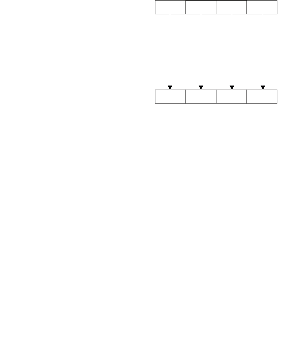
NEON and VFP Instruction Summary
ARM DEN0018A Copyright © 2013 ARM. All rights reserved. C-14
ID071613 Non-Confidential
C.8 NEON general data processing instructions
This section covers NEON data processing instructions, including those which extract or
manipulate values in registers, perform type conversion or other operations.
C.8.1 VCVT (fixed-point or integer to floating-point)
VCVT
(Vector Convert) converts each element in a vector and places the results in the destination
vector.
Figure C-1 VCVT
The possible conversions are:
• floating-point to integer
• integer to floating-point
• floating-point to fixed-point
• fixed-point to floating-point.
Integer or fixed-point to floating-point conversions use round to nearest.
Floating-point to integer or fixed-point conversions use round towards zero.
Syntax
VCVT{cond}.type Qd, Qm {, #fbits}
VCVT{cond}.type Dd, Dm {, #fbits}
where:
cond
is an optional conditional code.
type
specifies the data types for the elements of the vectors and can be:
•
S32.F32
floating-point to signed integer or fixed-point
•
U32.F32
floating-point to unsigned integer or fixed-point
•
F32.S32
signed integer or fixed-point to floating-point
•
F32.U32
unsigned integer or fixed-point to floating-point.
Qd
and
Qm
specify the destination and operand vectors for a quadword operation.
Dd
and
Dm
specify the destination and operand vectors for a doubleword operation.
Dn
=
=
=
=
Dd
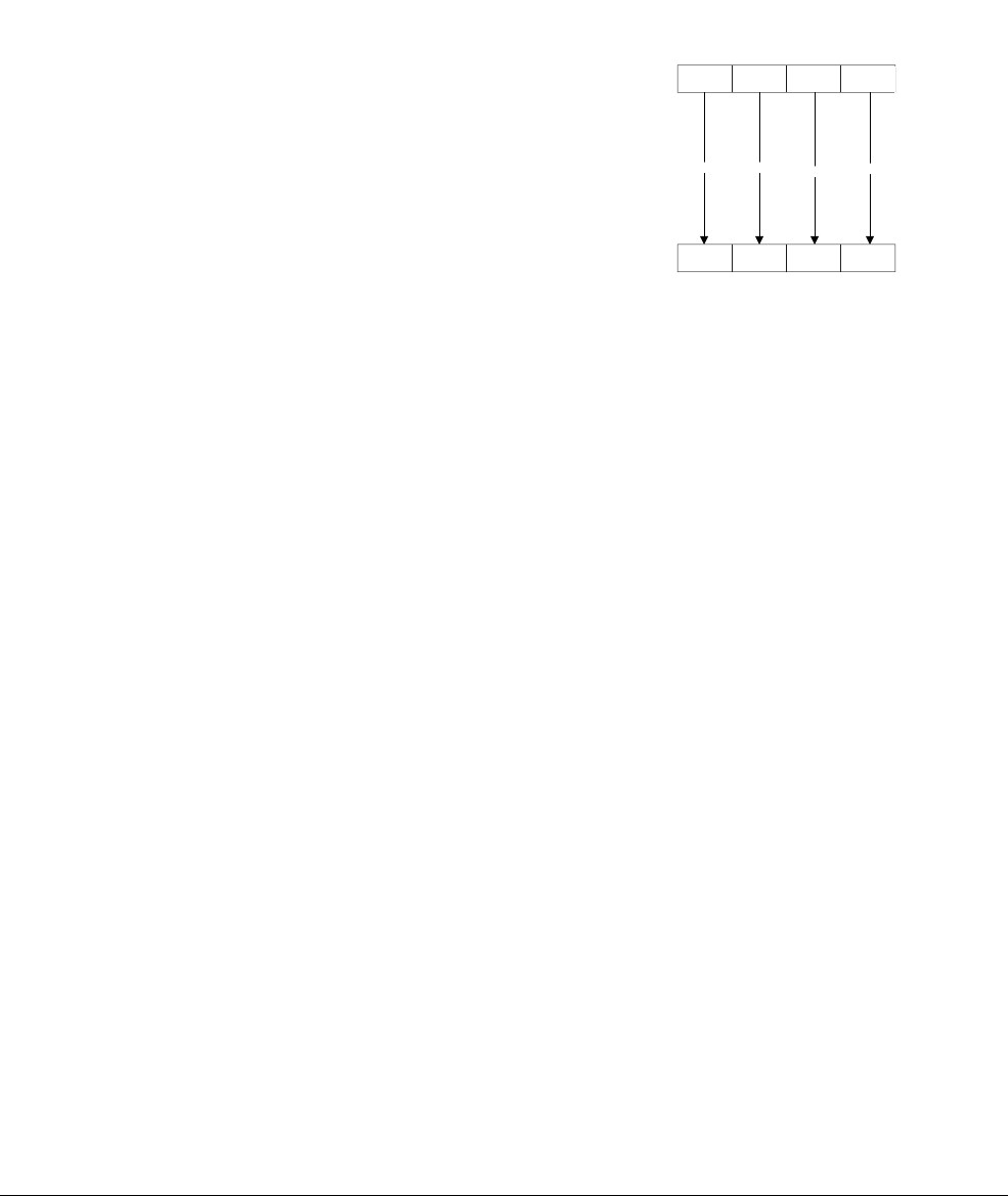
NEON and VFP Instruction Summary
ARM DEN0018A Copyright © 2013 ARM. All rights reserved. C-15
ID071613 Non-Confidential
fbits
specifies the number of fraction bits in the fixed point number, in the range 0-32. If
fbits
is not present, the conversion is between floating-point and integer.
C.8.2 VCVT (between half-precision and single-precision floating-point)
VCVT
(Vector Convert), with half-precision extension, converts each element in a vector and
places the results in the destination vector.
Figure C-2 VCVT.F32.F16
The conversion can be:
• from half-precision floating-point to single-precision floating-point (
F32.F16
)
• single-precision floating-point to half-precision floating-point (
F16.F32
).
This instruction is present only in NEON systems with the half-precision extension.
Syntax
VCVT{cond}.F32.F16 Qd, Dm
VCVT{cond}.F16.F32 Dd, Qm
where:
cond
is an optional conditional code.
Qd
and
Dm
specify the destination vector for the single-precision results and the half-precision
operand vector.
Dd
and
Qm
specify the destination vector for half-precision results and the single-precision
operand vector.
C.8.3 VDUP
VDUP
(Vector Duplicate) duplicates a scalar into every element of the destination vector. The
source can be either a NEON scalar or an ARM register.
Dn
=
=
=
=
Qd
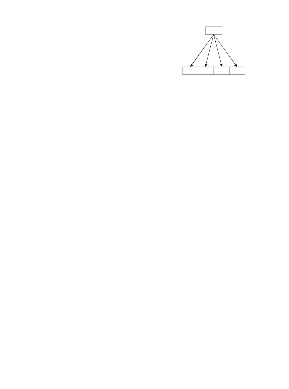
NEON and VFP Instruction Summary
ARM DEN0018A Copyright © 2013 ARM. All rights reserved. C-16
ID071613 Non-Confidential
Figure C-3 VDUP
Syntax
VDUP{cond}.size Qd, Dm[x]
VDUP{cond}.size Dd, Dm[x]
VDUP{cond}.size Qd, Rm
VDUP{cond}.size Dd, Rm
where:
cond
is an optional conditional code.
size
is 8, 16, or 32.
Qd
specifies the destination register for a quadword operation.
Dd
specifies the destination register for a doubleword operation.
Dm[x]
specifies the NEON scalar or
Rm
the ARM register.
C.8.4 VEXT
VEXT
(Vector Extract) extracts 8-bit elements from the bottom end of the second operand vector
and the top end of the first, concatenates them, and stores the result in the destination vector.
Dd
Dm[x]
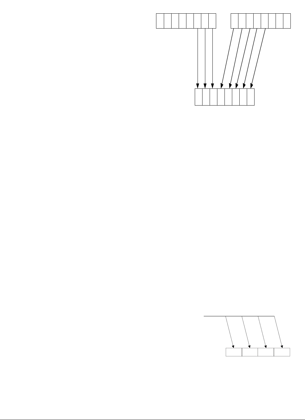
NEON and VFP Instruction Summary
ARM DEN0018A Copyright © 2013 ARM. All rights reserved. C-17
ID071613 Non-Confidential
Figure C-4 Operation of doubleword VEXT for imm = 3
Syntax
VEXT{cond}.8 {Qd,} Qn, Qm, #imm
VEXT{cond}.8 {Dd,} Dn, Dm, #imm
where:
cond
is an optional conditional code.
Qd
,
Qn
, and
Qm
specify the destination, first operand and second operand registers for a quadword
operation.
Dd
,
Dn
, and
Dm
specify the destination, first operand and second operand registers for a
doubleword operation.
imm
gives the number of 8-bit elements to extract from the bottom of the second operand vector,
between 0-7 for doubleword operations, or 0-15 for quadword operations.
VEXT
can also be written as a pseudo-instruction. In this case, a datatype of 16, 32, or 64 can be
used and
#imm
refers to halfwords, words, or doublewords, with a corresponding reduction in the
permitted range.
C.8.5 VMOV (immediate)
VMOV
(Vector Bitwise Move) (immediate), places an immediate value into every element of the
destination register.
Figure C-5 VMOV
Syntax
VMOV{cond}.datatype Qd, #imm
VMOV{cond}.datatype Dd, #imm
Dd
Dn
Dm
01234567
01234567
Dd
#imm

NEON and VFP Instruction Summary
ARM DEN0018A Copyright © 2013 ARM. All rights reserved. C-18
ID071613 Non-Confidential
where:
cond
is an optional conditional code.
datatype
is
I8
,
I16
,
I32
,
I64
, or
F32
.
Qd
or
Dd
specify the NEON register for the result.
imm
is an immediate value of the type specified by
datatype
, which is replicated to fill the
destination register.
C.8.6 VMVN
VMVN
(Vector Bitwise NOT) (immediate), places the bitwise inverse of an immediate integer
value into every element of the destination register.
Syntax
VMVN{cond}.datatype Qd, #imm
VMVN{cond}.datatype Dd, #imm
where:
cond
is an optional conditional code.
datatype
is one of
I8
,
I16
,
I32
,
I64
, or
F32
.
Qd
or
Dd
specify the NEON register for the result.
Table C-9 Available immediate values
datatype VMOV
I8 0xXY
I16 0x00XY
,
0xXY00
I32 0x000000XY
,
0x0000XY00
,
0x00XY0000
,
0xXY000000
0x0000XYFF
,
0x00XYFFFF
I64
byte masks,
0xGGHHJJKKLLMMNNPP
a
a. Each of
0xGG
,
0xHH
,
0xJJ
,
0xKK
,
0xLL
,
0xMM
,
0xNN
, and
0xPP
must be either
0x00
or
0xFF
.
F32
floating-point numbers b
b. Any number that can be expressed as +/–n * 2–r, where n
and r are integers, 16 <= n <= 31, 0 <= r <= 7.
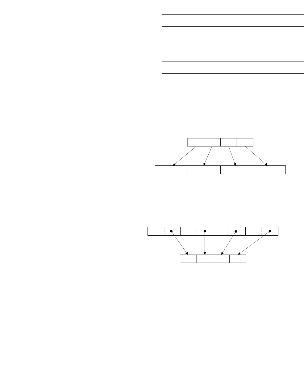
NEON and VFP Instruction Summary
ARM DEN0018A Copyright © 2013 ARM. All rights reserved. C-19
ID071613 Non-Confidential
imm
is an immediate value of the type specified by
datatype
, which is replicated to fill the
destination register.
C.8.7 VMOVL, V{Q}MOVN, VQMOVUN
VMOVL
(Vector Move Long) takes each element in a doubleword vector and sign or zero-extends
them to twice their original length. The results are stored in a quadword vector.
Figure C-6 Operation of doubleword VMOVL.16
VMOVN
(Vector Move and Narrow) copies the least significant half of each element of a quadword
vector into the corresponding element of a doubleword vector.
Figure C-7 Operation of quadword VMOVN.I32
VQMOVN
(Vector Saturating Move and Narrow) copies each element of the operand vector to the
corresponding element of the destination. The result element is half the width of the operand
element, and values are saturated to the result width.
VQMOVUN
(Vector Saturating Move and Narrow, signed operand with Unsigned result) copies each
element of the operand vector to the corresponding element of the destination. The result
element is half the width of the operand element and values are saturated to the result width.
Syntax
VMOVL{cond}.datatype Qd, Dm
V{Q}MOVN{cond}.datatype Dd, Qm
VQMOVUN{cond}.datatype Dd, Qm
Table C-10 Available immediate values
datatype VMVN
I8
-
I16 0xFFXY
,
0xXYFF
I32 0xFFFFFFXY
,
0xFFFFXYFF
,
0xFFXYFFFF
,
0xXYFFFFFF
0xFFFFXY00
,
0xFFXY0000
I64
-
F32
-
Dm
Qd
Dd
Qm
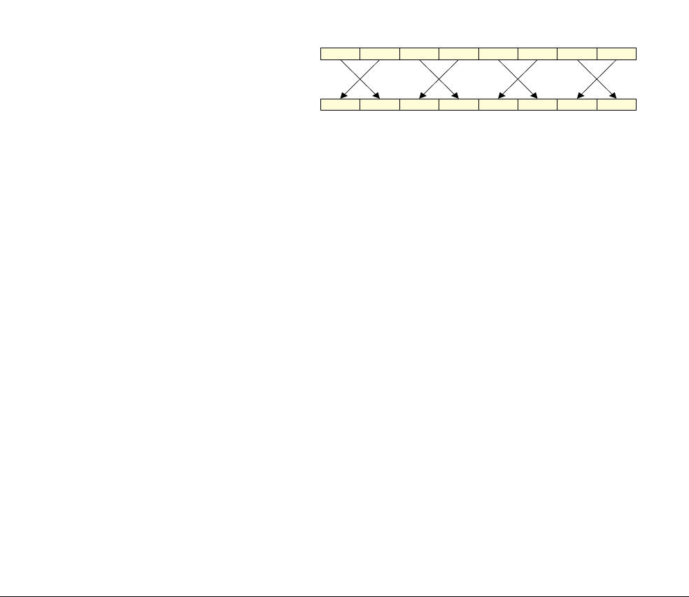
NEON and VFP Instruction Summary
ARM DEN0018A Copyright © 2013 ARM. All rights reserved. C-20
ID071613 Non-Confidential
where:
cond
is an optional conditional code.
Q specifies that the results are saturated.
datatype
is one of:
•
S8
,
S16
,
S32
for
VMOVL
•
U8
,
U16,
U32
for
VMOVL
•
I16
,
I32
,
I64
for
VMOVN
•
F32
.
U32
unsigned integer or fixed-point to floating-point
•
U16
,
U32
,
U64
for
VQMOVN
.
Qd
and
Dm
specify the destination vector and the operand vector for
VMOVL
.
Dd
and
Qm
specify the destination vector and the operand vector for
V{Q}MOV{U}N
.
C.8.8 VREV
VREV16
(Vector Reverse halfwords) reverses the order of 8-bit elements within each halfword of
the vector and stores the result in the corresponding destination vector.
Figure C-8 VREV16.8 instruction
VREV32
(Vector Reverse words) reverses the order of 8-bit or 16-bit elements within each word
of the vector, and stores the result in the corresponding destination vector.
VREV64
(Vector Reverse doublewords) reverses the order of 8-bit, 16-bit, or 32-bit elements
within each doubleword of the vector, and stores the result in the destination vector.
Syntax
VREVn{cond}.size Qd, Qm
VREVn{cond}.size Dd, Dm
where:
cond
is an optional conditional code.
n
is one of 16, 32, or 64.
size
is one of 8, 16, or 32, and must be less than
n
.
Qd
and
Qm
specify the destination and operand registers for a quadword operation.
Dd
and
Dm
specify the destination and operand registers for a doubleword operation.
C.8.9 VSWP
VSWP
(Vector Swap) exchanges the contents of two vectors, which can be either doubleword or
quadword.
Dn
Dd
01234
5
67
D registers with eight 8-bit elements
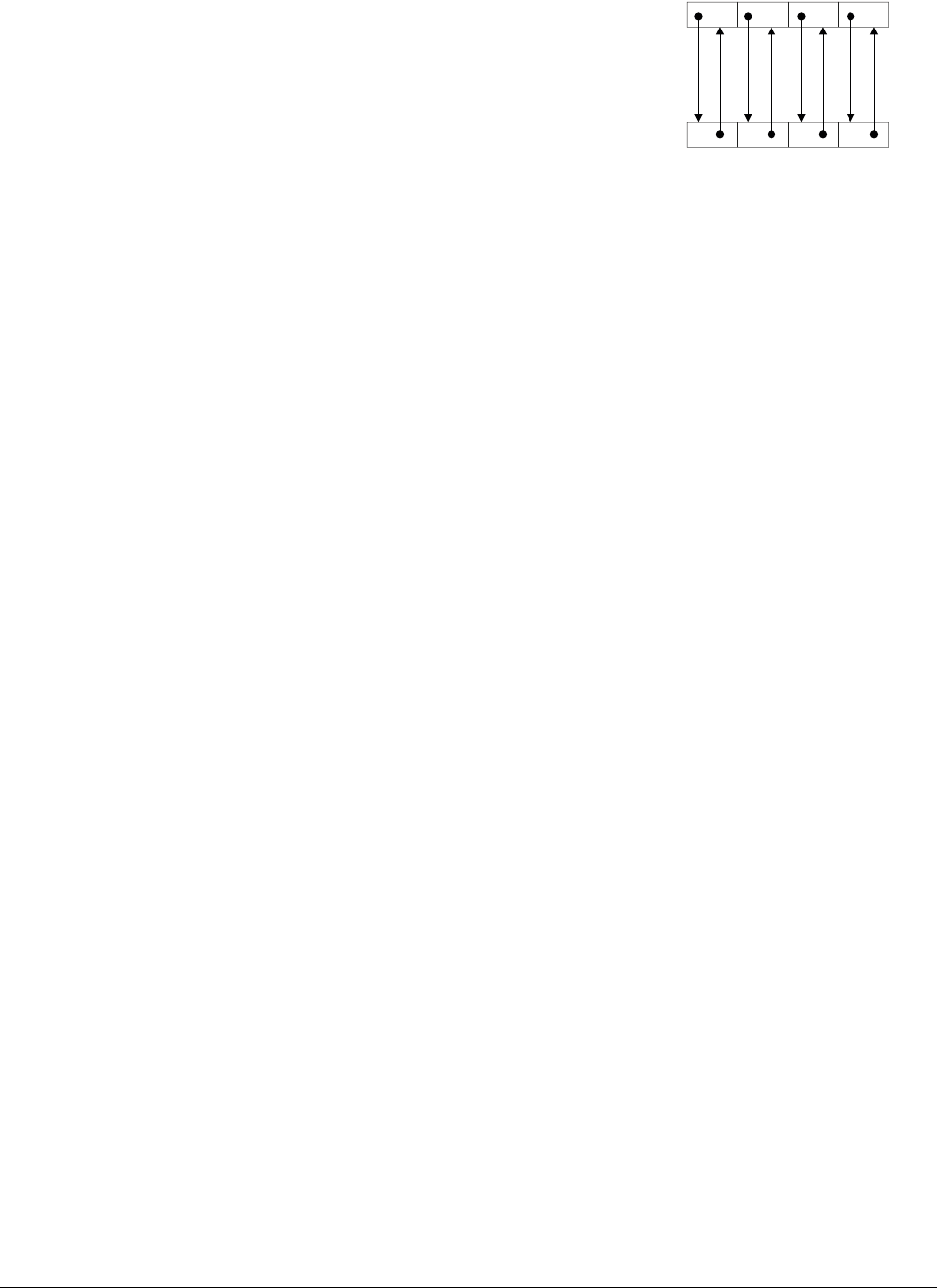
NEON and VFP Instruction Summary
ARM DEN0018A Copyright © 2013 ARM. All rights reserved. C-21
ID071613 Non-Confidential
Figure C-9 VSWP
Syntax
VSWP{cond}{.datatype} Qd, Qm
VSWP{cond}{.datatype} Dd, Dm
where:
cond
is an optional conditional code.
Qd
and
Qm
specify the vectors for a quadword operation.
Dd
and
Dm
specify the vectors for a doubleword operation.
C.8.10 VTBL
VTBL
(Vector Table Lookup) uses byte indexes in a control vector to look up byte values in a table
and generate a new vector. Indexes which are out of range return 0.
Syntax
VTBL{cond}.8 Dd, list, Dm
where:
cond
is an optional conditional code.
Dd
specifies the destination vector.
Dm
specifies the index vector.
list
specifies the vectors containing the table. It is one of:
•
{Dn}
•
{Dn,D(n+1)}
•
{Dn,D(n+1),D(n+2)}
•
{Dn,D(n+1),D(n+2),D(n+3)}
•
{Qn,Q(n+1)}
.
All of the registers in
list
must be in the range D0-D31 or Q0-Q15 and are not permitted to
wrap around the end of the register file.
C.8.11 VTBX
VTBX
(Vector Table Extension) uses byte indexes in a control vector to look up byte values in a
table and generate a new vector, but leaves the destination element unchanged when an out of
range index is used.
Dm
Dd
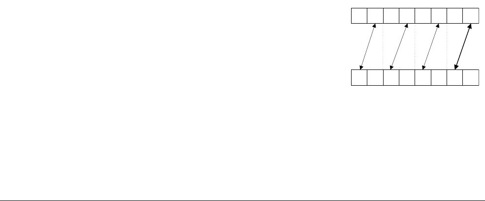
NEON and VFP Instruction Summary
ARM DEN0018A Copyright © 2013 ARM. All rights reserved. C-22
ID071613 Non-Confidential
Syntax
VTBX{cond}.8 Dd, list, Dm
where:
cond
is an optional conditional code.
Dd
specifies the destination vector.
Dm
specifies the index vector.
list
specifies the vectors containing the table. It is one of:
•
{Dn}
•
{Dn,D(n+1)}
•
{Dn,D(n+1),D(n+2)}
•
{Dn,D(n+1),D(n+2),D(n+3)}
•
{Qn,Q(n+1)}
.
All of the registers in
list
must be in the range D0-D31 or Q0-Q15 and are not permitted to
wrap around the end of the register file.
C.8.12 VTRN
VTRN
(Vector Transpose) treats the elements of its operand vectors as elements of 2 × 2 matrices,
and transposes them.
Syntax
VTRN{cond}.size Qd, Qm
VTRN{cond}.size Dd, Dm
where:
cond
is an optional conditional code.
size
is one of 8, 16, or 32.
Qd
and
Qm
specify the vectors for a quadword operation.
Dd
and
Dm
specify the vectors, for a doubleword operation.
Figure C-10 Operation of doubleword VTRN.8
Dd
Dm
01765432
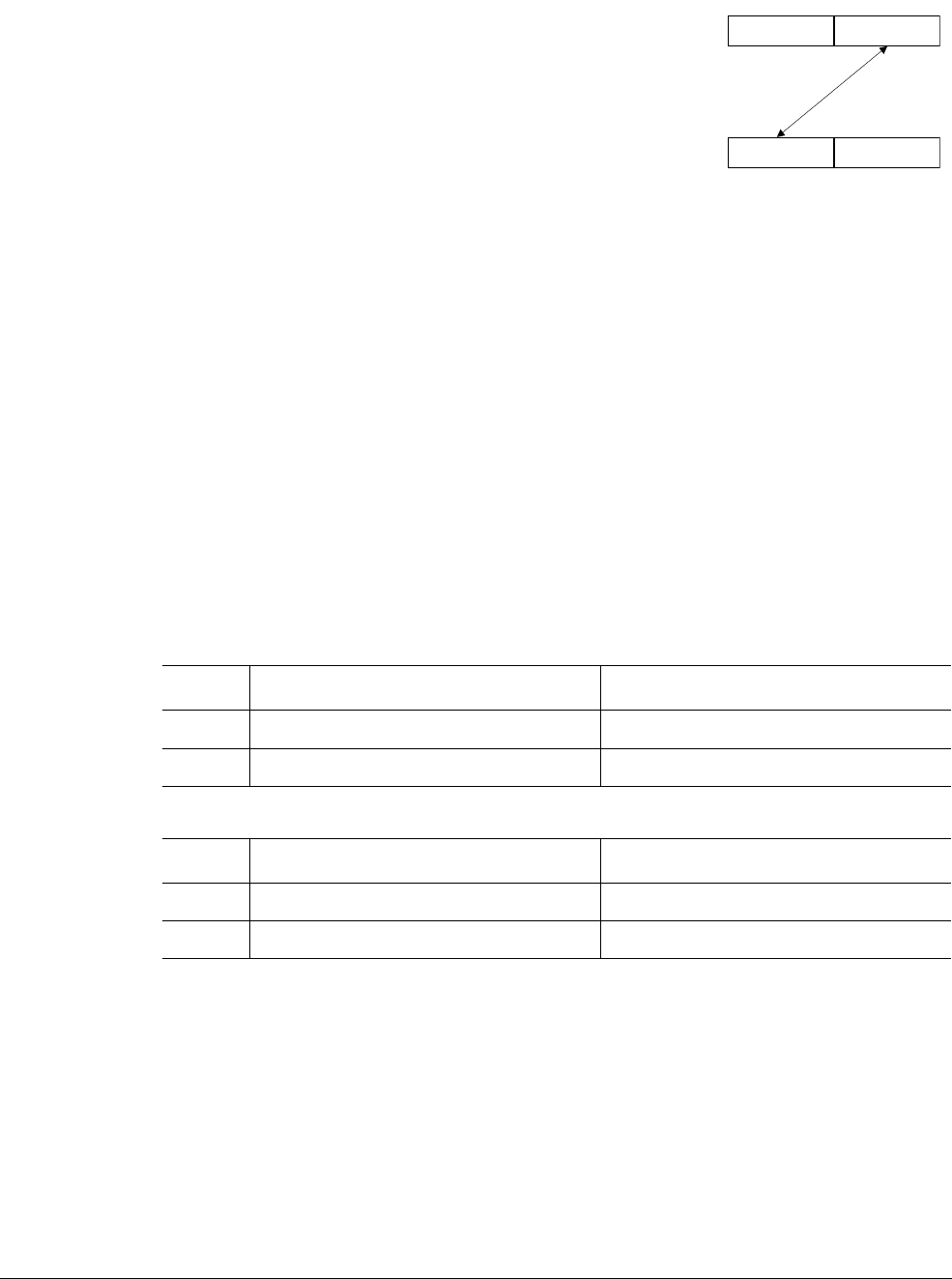
NEON and VFP Instruction Summary
ARM DEN0018A Copyright © 2013 ARM. All rights reserved. C-23
ID071613 Non-Confidential
Figure C-11 Operation of doubleword VTRN.32
C.8.13 VUZP
VUZP
(Vector Unzip) de-interleaves the elements of two vectors.
Syntax
VUZP{cond}.size Qd, Qm
VUZP{cond}.size Dd, Dm
where:
cond
is an optional conditional code.
size
is one of 8, 16, or 32.
Qd
and
Qm
specify the vectors for a quadword operation.
Dd
and
Dm
specify the vectors, for a doubleword operation.
C.8.14 VZIP
VZIP
(Vector Zip) interleaves the elements of two vectors.
Syntax
VZIP{cond}.size Qd, Qm
VZIP{cond}.size Dd, Dm
where:
cond
is an optional conditional code.
Dd
Dm
01
Table C-11 Operation of doubleword VUZP.8
Register state before operation Register state after operation
Dd A7A6A5A4A3A2A1A0B6B4B2B0A6A4A2A0
Dm B7B6B5B4B3B2B1B0B7B5B3B1A7A5A3A1
Table C-12 Operation of quadword VUZP.32
Register state before operation Register state after operation
Qd A3A2A1A0B2B0A2A0
Qm B3B2B1B0B3B1A3A1
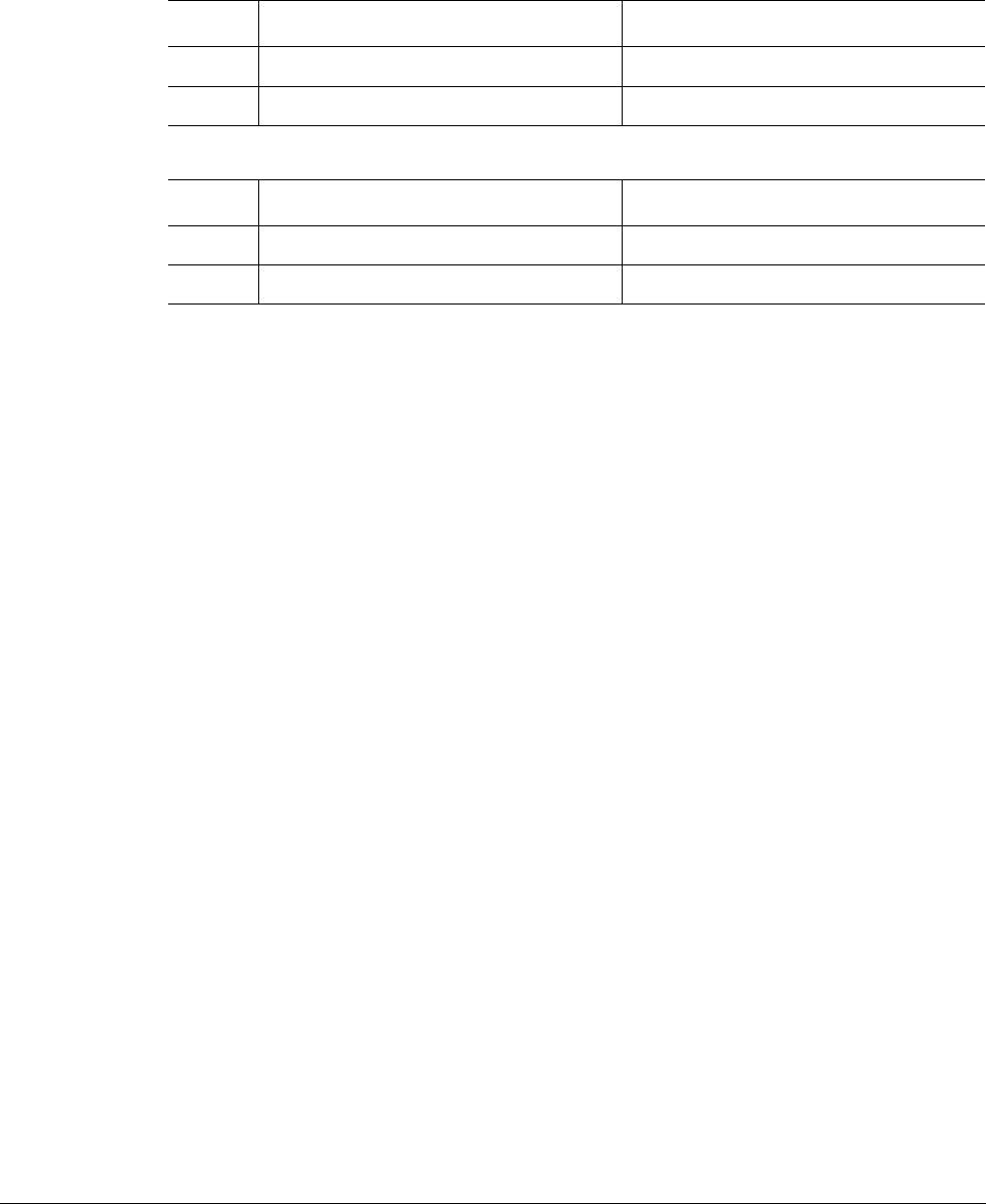
NEON and VFP Instruction Summary
ARM DEN0018A Copyright © 2013 ARM. All rights reserved. C-24
ID071613 Non-Confidential
size
is one of 8, 16, or 32.
Qd
and
Qm
specify the vectors for a quadword operation.
Dd
and
Dm
specify the vectors, for a doubleword operation.
Table C-13 Operation of doubleword VZIP.8
Register state before operation Register state after operation
Dd A7A6A5A4A3A2A1A0B3A3B2A2B1A1B0A0
Dm B7B6B5B4B3B2B1B0B7A7B6A6B5A5B4A4
Table C-14 Operation of quadword VZIP.32
Register state before operation Register state after operation
Qd A3A2A1A0B1A1B0A0
Qm B3B2B1B0B3A3B2A2
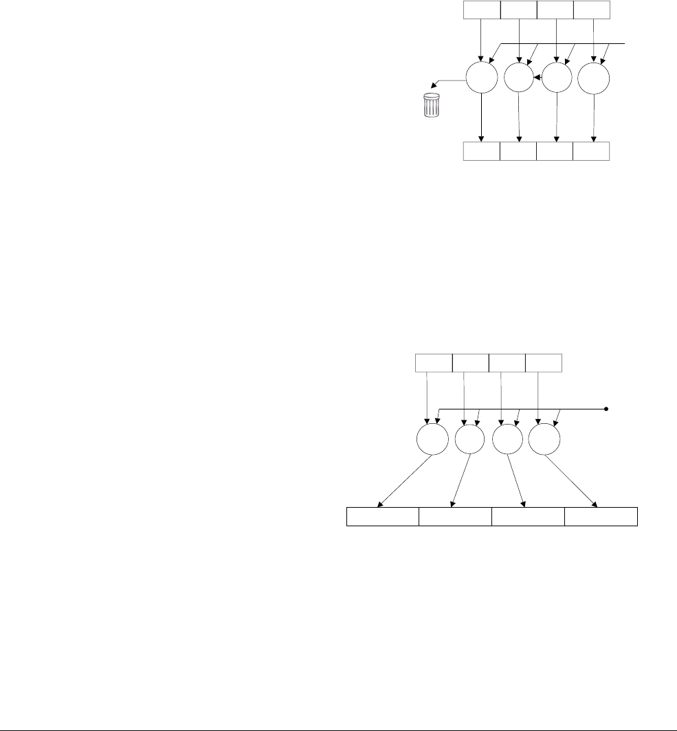
NEON and VFP Instruction Summary
ARM DEN0018A Copyright © 2013 ARM. All rights reserved. C-25
ID071613 Non-Confidential
C.9 NEON shift instructions
This section covers NEON instructions which perform logical shift or insert operations.
C.9.1 VSHL, VQSHL, VQSHLU, and VSHLL (by immediate)
Vector Shift Left (by immediate) instructions take each element in a vector of integers, left shifts
them by an immediate value, and write the result to the destination vector. The instruction
variants are:
•
VSHL
(Vector Shift Left) discards bits shifted out of the left of each element.
Figure C-12 VSHL
•
VQSHL
(Vector Saturating Shift Left) sets the sticky QC flag (FPSCR bit[27]) if saturation
occurs.
•
VQSHLU
(Vector Saturating Shift Left Unsigned) sets the sticky QC flag (FPSCR bit[27]) if
saturation occurs.
•
VSHLL
(Vector Shift Left Long) takes each element in a doubleword vector, left shifts them
by an immediate value, and places the results in a quadword vector.
Figure C-13 VSHLL
Syntax
V{Q}SHL{U}{cond}.datatype {Qd,} Qm, #imm
V{Q}SHL{U}{cond}.datatype {Dd,} Dm, #imm
VSHLL{cond}.datatype Qd, Dm, #imm
where:
cond
is an optional conditional code.
Dm
Dd
<< << << <<
#imm
Dm
Qd
<< << << <<
#imm

NEON and VFP Instruction Summary
ARM DEN0018A Copyright © 2013 ARM. All rights reserved. C-26
ID071613 Non-Confidential
Q
indicates that results are saturated if they overflow.
U
is only permitted if
Q
is also specified and indicates that the results are unsigned, even though
the operands are signed.
datatype
is one of:
•
I8
,
I16
,
I32
,
I64
for
VSHL
•
S8
,
S16
,
S32
for
VSHLL
,
VQSHL
, or
VQSHLU
•
U8
,
U16
,
U32
for
VSHLL
or
VQSHL
•
S64
for
VQSHL
or
VQSHLU
•
U64
for
VQSHL
.
Qd
and
Qm
are the destination and operand vectors for a quadword operation.
Dd
and
Dm
are the destination and operand vectors for a doubleword operation.
Qd
and
Dm
are the destination and operand vectors, for a long operation.
imm
is the immediate value that sets the size of the shift and must be in the range:
•1 to
size
(
datatype
) for
VSHLL
• 1 to (size(
datatype
) – 1) for
VSHL
,
VQSHL
, or
VQSHLU
.
A shift of 0 is permitted, but the code disassembles to
VMOV
or
VMOVL
.
C.9.2 V{Q}{R}SHL
VSHL
(Vector Shift Left) (by signed variable) shifts each element in a vector by a value from the
least significant byte of the corresponding element of a second vector, and stores the results in
the destination vector. If the shift value is positive, the operation is a left shift. Otherwise, it is
a right shift. The results can be optionally saturated, rounded, or both. The sticky QC flag is set
if saturation occurs.
Syntax
V{Q}{R}SHL{cond}.datatype {Qd,} Qm, Qn
V{Q}{R}SHL{cond}.datatype {Dd,} Dm, Dn
where:
cond
is an optional conditional code.
Q
indicates that results are saturated if they overflow.
R
indicates that each result is rounded. If
R
is not specified, each result is truncated.
datatype
is one of
S8
,
S16
,
S32
,
S64
,
U8
,
U16
,
U32
, or
U64
.
Qd
,
Qm
, and
Qn
specify the destination, first operand and second operand registers for a quadword
operation.
Dd
,
Dm
, and
Dn
specify the destination, first operand and second operand registers for a
doubleword operation.
C.9.3 V{R}SHR{N}, V{R}SRA
V{R}SHR{N}
(Vector Shift Right) (by immediate value) right shifts each element in a vector by an
immediate value and stores the results in the destination vector. The results can be optionally
rounded, or narrowed, or both.
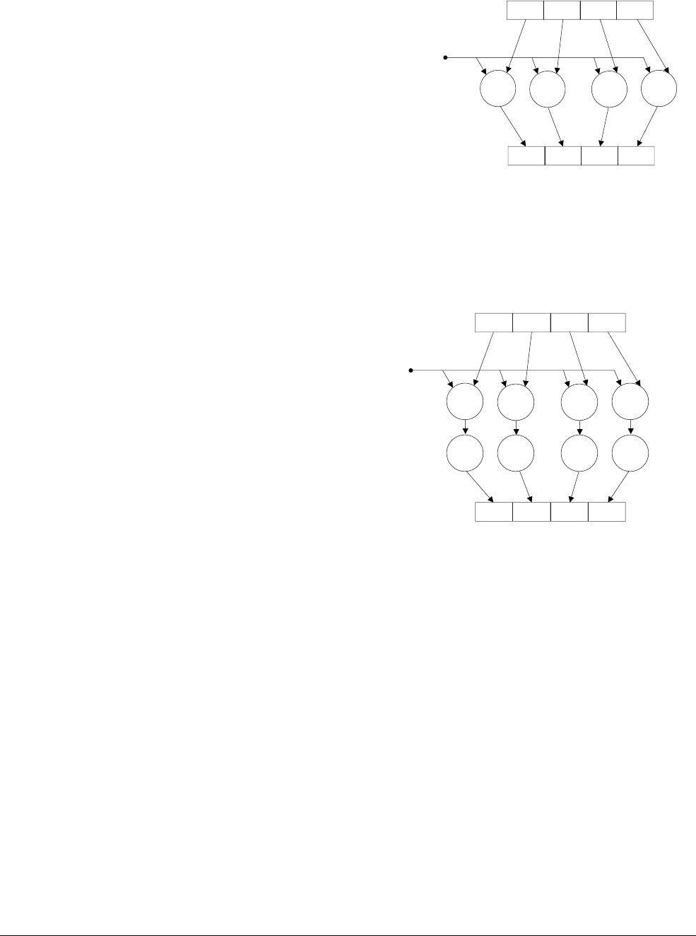
NEON and VFP Instruction Summary
ARM DEN0018A Copyright © 2013 ARM. All rights reserved. C-27
ID071613 Non-Confidential
Figure C-14 VSHR
V{R}SRA
(Vector Shift Right (by immediate value) and Accumulate) right shifts each element in
a vector by an immediate value, and accumulates the results into the destination vector. The
results can be optionally rounded.
Figure C-15 VSRA
Syntax
V{R}SHR{cond}.datatype {Qd,} Qm, #imm
V{R}SHR{cond}.datatype {Dd,} Dm, #imm
V{R}SRA{cond}.datatype {Qd,} Qm, #imm
V{R}SRA{cond}.datatype {Dd,} Dm, #imm
V{R}SHRN{cond}.datatype Dd, Qm, #imm
where:
cond
is an optional conditional code.
R
indicates that the results are rounded. If
R
is not present, the results are truncated.
datatype
is one of:
•
S8
,
S16
,
S32
,
S64
for
V{R}SHR
or
V{R}SRA
•
U8
,
U16
,
U32
,
U64
for
V{R}SHR
or
V{R}SRA
•
I16
,
I32
,
I64
for
V{R}SHRN
.
Qd
and
Qm
are the destination and operand vectors, for a quadword operation.
Dm
Dd
>> >> >> >>
#imm
Dm
Dd
>>
++ + +
>> >> >>
#imm
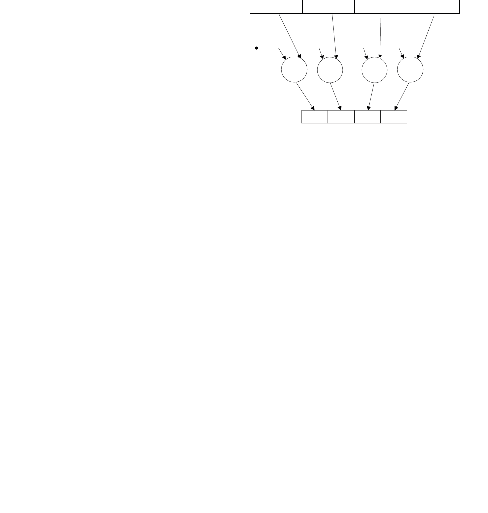
NEON and VFP Instruction Summary
ARM DEN0018A Copyright © 2013 ARM. All rights reserved. C-28
ID071613 Non-Confidential
Dd
and
Dm
are the destination and operand vectors for a doubleword operation.
Dd
and
Qm
are the destination vector and the operand vector, for a narrow operation.
imm
is the immediate value specifying the size of the shift, in the range 0 to (
size
(
datatype
) – 1).
C.9.4 VQ{R}SHR{U}N
VQ{R}SHR{U}N
(Vector Saturating Shift Right, Narrow) (by immediate value) with optional
Rounding) right shifts each element in a quadword vector of integers by an immediate value,
and stores the results in a doubleword vector. The sticky QC flag (FPSCR bit [27]) is set if
saturation occurs.
Figure C-16 VQSHRN
Syntax
VQ{R}SHR{U}N{cond}.datatype Dd, Qm, #imm
where:
cond
is an optional conditional code.
R
indicates that the results are rounded. If
R
is not present, the results are truncated.
U
indicates that the results are unsigned, although the operands are signed.
datatype
is one of:
•
S16
,
S32
,
S64
for
VQ{R}SHRN
or
VQ{R}SHRUN
•
U16
,
U32
,
U64
for
VQ{R}SHRN
only.
Dd
and
Qm
are the destination vector and the operand vector.
imm
is the immediate value specifying the size of the shift, in the range 0 to (size(datatype) – 1).
C.9.5 VSLI
VSLI
(Vector Shift Left and Insert) left shifts each element in a vector by an immediate value,
and inserts the results in the destination vector. Bits shifted out of the left of each element are
lost.
Dd
>> >> >> >>
#imm
Qd
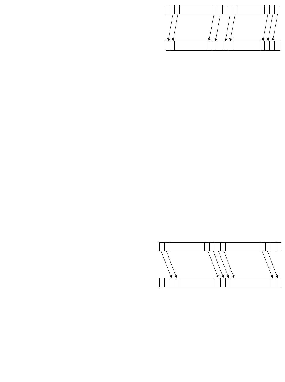
NEON and VFP Instruction Summary
ARM DEN0018A Copyright © 2013 ARM. All rights reserved. C-29
ID071613 Non-Confidential
Figure C-17 Operation of quadword VSLI.64 Qd, Qm, #1
Syntax
VSLI{cond}.size {Qd,} Qm, #imm
VSLI{cond}.size {Dd,} Dm, #imm
where:
cond
is an optional conditional code.
size
is one of 8, 16, 32, or 64.
Qd
and
Qm
are the destination and operand vectors for a quadword operation.
Dd
and
Dm
are the destination and operand vectors for a doubleword operation.
Dd
and
Qm
are the destination vector and the operand vector.
imm
is the immediate value that sets the size of the shift, in the range 0 to (
size
– 1).
C.9.6 VSRI
VSRI
(Vector Shift Right and Insert) right shifts each element in a vector by an immediate value,
and inserts the results in the destination vector. Bits shifted out of the right of each element are
lost.
Figure C-18 Operation of doubleword VSRI.64 Dd, Dm, #2
Syntax
VSRI{cond}.size {Qd,} Qm, #imm
VSRI{cond}.size {Dd,} Dm, #imm
where:
cond
is an optional conditional code.
size
is one of 8, 16, 32, or 64.
Qd
Qm
Element 0
0
Element 1
0
... ...
Dd
Dm
Element 0
0
... ...
0

NEON and VFP Instruction Summary
ARM DEN0018A Copyright © 2013 ARM. All rights reserved. C-30
ID071613 Non-Confidential
Qd
and
Qm
are the destination and operand vectors for a quadword operation.
Dd
and
Dm
are the destination and operand vectors for a doubleword operation.
imm
is the immediate value that sets the size of the shift, in the range 1 to
size
.
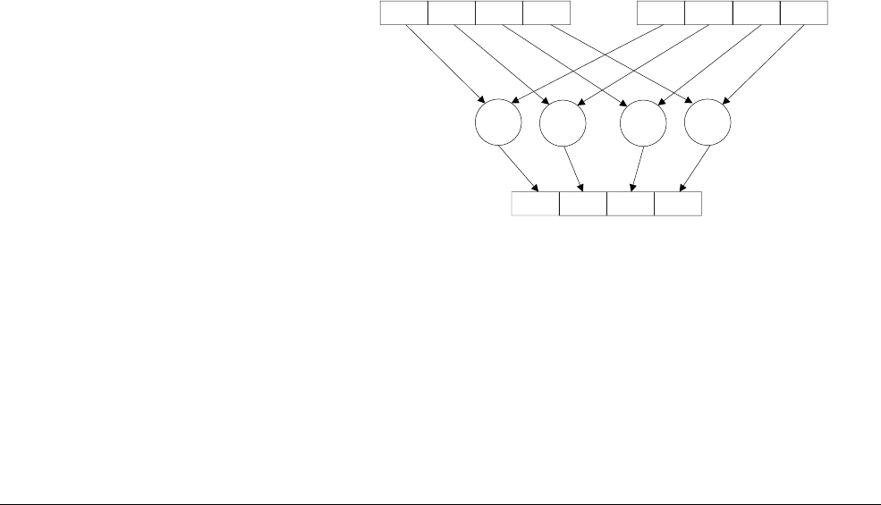
NEON and VFP Instruction Summary
ARM DEN0018A Copyright © 2013 ARM. All rights reserved. C-31
ID071613 Non-Confidential
C.10 NEON logical and compare operations
This section covers NEON instructions which perform bitwise boolean operations and
comparisons.
C.10.1 VACGE and VACGT
Vector Absolute Compare takes the absolute value of each element in a vector, and compares it
with the absolute value of the corresponding element in a second vector. If the condition is true,
the corresponding element in the destination vector is set to all ones. If the condition is not true,
it is set to all zeros.
Syntax
VACop{cond}.F32 {Qd,} Qn, Qm
VACop{cond}.F32 {Dd,} Dn, Dm
where:
cond
is an optional conditional code.
op
is either
GE
(Absolute Greater than or Equal) or
GT
(Absolute Greater Than).
Qd
,
Qn
, and
Qm
specify the destination, first operand and second operand registers for a quadword
operation.
Dd
,
Dn
, and
Dm
specify the destination, first operand and second operand registers for a
doubleword operation. The result datatype is
I32
.
C.10.2 VAND
VAND
performs a bitwise logical AND operation between values in two registers, and places the
results in the destination register.
Figure C-19 VAND
Syntax
VAND{cond}{.datatype} {Qd,} Qn, Qm
VAND{cond}{.datatype} {Dd,} Dn, Dm
where:
cond
is an optional conditional code.
datatype
is an optional data type, which is ignored by the assembler.
Dn Dm
Dd
&& & &
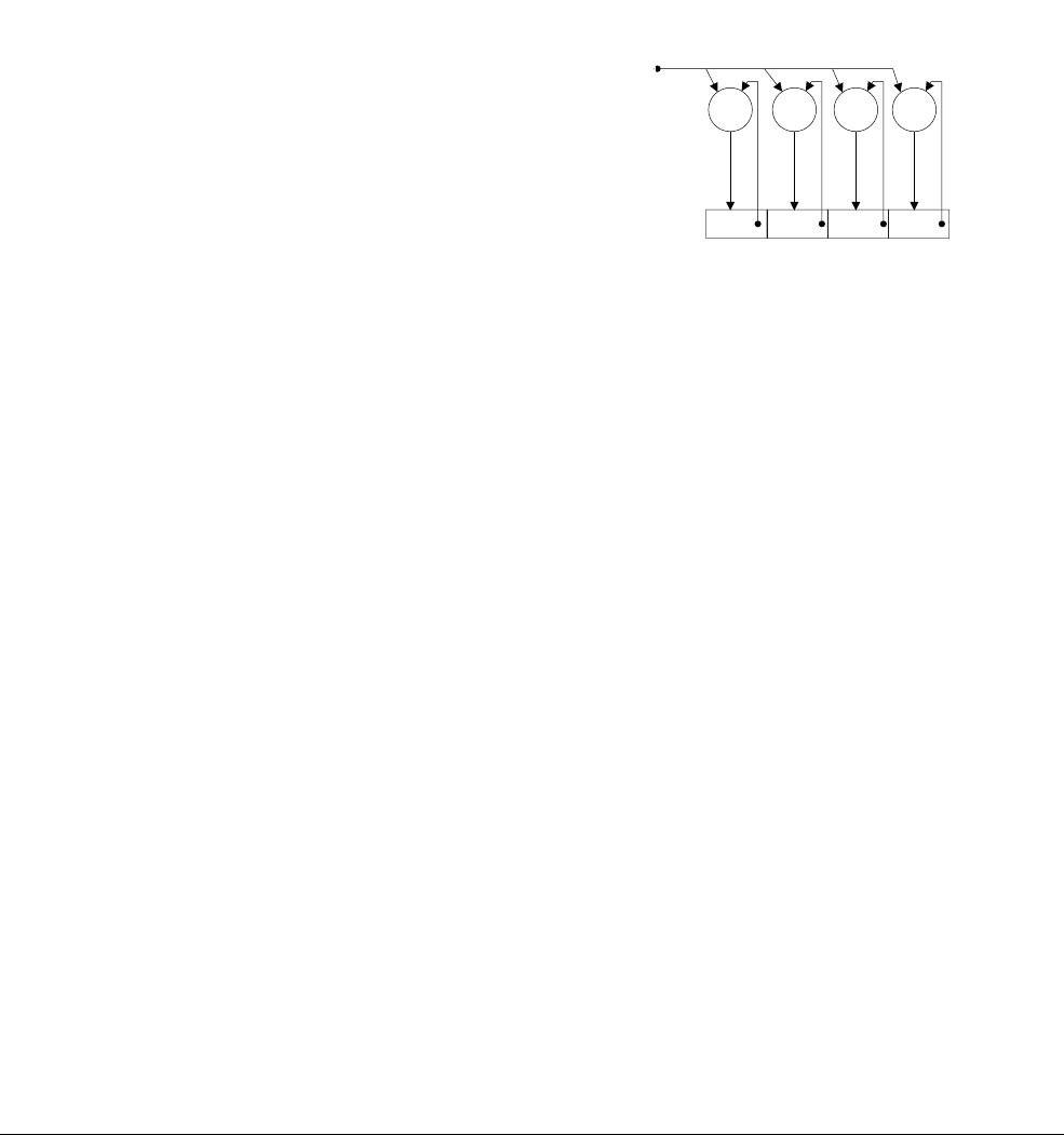
NEON and VFP Instruction Summary
ARM DEN0018A Copyright © 2013 ARM. All rights reserved. C-32
ID071613 Non-Confidential
Qd
,
Qn
, and
Qm
specify the destination, first operand and second operand registers for a quadword
operation.
Dd
,
Dn
, and
Dm
specify the destination, first operand and second operand registers for a
doubleword operation.
C.10.3 VBIC (immediate)
VBIC
(Vector Bitwise Clear) (immediate) takes each element of the destination vector, does a
bitwise AND Complement with an immediate value, and stores the result in the destination
vector.
Figure C-20 VBIC
Syntax
VBIC{cond}.datatype Qd, #imm
VBIC{cond}.datatype Dd, #imm
where:
cond
is an optional conditional code.
datatype
is one of
I8
,
I16
,
I32
, or
I64
.
Qd
or
Dd
is the NEON register for the source and result.
imm
is the immediate value.
Immediate values can be specified as a pattern which the assembler repeats to fill the destination
register. Alternatively, you can specify the entire value, provided it meets certain requirements.
The permitted patterns for immediate value are
0x00XY
or
0xXY00
for I16, or
0x000000XY
,
0x0000XY00
,
0x00XY0000
or
0xXY000000
for
I32
. If you choose
I8
or
I64
datatypes, the assembler
produces the
I16
or
I32
equivalent.
C.10.4 VBIC (register)
VBIC
(Vector Bitwise Clear) performs a bitwise logical AND complement operation between
values in two registers, and places the results in the destination register.
Dd
~ ~ ~ ~
#imm

NEON and VFP Instruction Summary
ARM DEN0018A Copyright © 2013 ARM. All rights reserved. C-33
ID071613 Non-Confidential
Figure C-21 VBIC (register)
Syntax
VBIC{cond}{.datatype} {Qd,} Qn, Qm
VBIC{cond}{.datatype} {Dd,} Dn, Dm
where:
cond
is an optional conditional code.
datatype
is an optional data type, which is ignored by the assembler.
Qd
,
Qn
, and
Qm
specify the destination, first operand and second operand registers for a quadword
operation.
Dd
,
Dn
, and
Dm
specify the destination, first operand and second operand registers for a
doubleword operation.
C.10.5 VBIF
VBIF
(Vector Bitwise Insert if False) inserts each bit from the first operand into the destination,
if the corresponding bit of the second operand is 0, otherwise it does not change the destination
bit.
Syntax
VBIF{cond}{.datatype} {Qd,} Qn, Qm
VBIF{cond}{.datatype} {Dd,} Dn, Dm
where:
cond
is an optional conditional code.
datatype
is an optional data type, which is ignored by the assembler.
Qd
,
Qn
, and
Qm
specify the destination, first operand and second operand registers for a quadword
operation.
Dd
,
Dn
, and
Dm
specify the destination, first operand and second operand registers for a
doubleword operation.
Dn Dm
Dd
~~ ~ ~

NEON and VFP Instruction Summary
ARM DEN0018A Copyright © 2013 ARM. All rights reserved. C-34
ID071613 Non-Confidential
C.10.6 VBIT
VBIT
(Vector Bitwise Insert if True) inserts each bit from the first operand into the destination if
the corresponding bit of the second operand is 1, otherwise it does not change the destination bit.
Syntax
VBIT{cond}{.datatype} {Qd,} Qn, Qm
VBIT{cond}{.datatype} {Dd,} Dn, Dm
where:
cond
is an optional conditional code.
datatype
is an optional data type, which is ignored by the assembler.
Qd
,
Qn
, and
Qm
specify the destination, first operand and second operand registers for a quadword
operation.
Dd
,
Dn
, and
Dm
specify the destination, first operand and second operand registers for a
doubleword operation.
C.10.7 VBSL
VBSL
(Vector Bitwise Select) selects each destination bit from the first operand if the
corresponding destination bit was 1 or from the second operand if the corresponding destination
bit was 0.
Syntax
VBSL{cond}{.datatype} {Qd,} Qn, Qm
VBSL{cond}{.datatype} {Dd,} Dn, Dm
where:
cond
is an optional conditional code.
datatype
is an optional data type, which is ignored by the assembler.
Qd
,
Qn
, and
Qm
specify the destination, first operand and second operand registers for a quadword
operation.
Dd
,
Dn
, and
Dm
specify the destination, first operand and second operand registers for a
doubleword operation.
C.10.8 VCEQ, VCGE, VCGT, VCLE, and VCLT
Vector Compare takes each element in a vector and compares it with the corresponding element
of a second vector (or zero). If the condition is true, the corresponding element in the destination
vector is set to all ones. Otherwise, it is set to all zeros.

NEON and VFP Instruction Summary
ARM DEN0018A Copyright © 2013 ARM. All rights reserved. C-35
ID071613 Non-Confidential
Figure C-22 VCEQ, VCGE, VCLT, VCGT
Syntax
VCop{cond}.datatype {Qd,} Qn, Qm
VCop{cond}.datatype {Dd,} Dn, Dm
VCop{cond}.datatype {Qd,} Qn, #0
VCop{cond}.datatype {Dd,} Dn, #0
where:
cond
is an optional conditional code.
op
is one of:
•
EQ
– Equal
•
GE
– Greater than or Equal
•
GT
– Greater Than
•
LE
– Less than or Equal (only if the second operand is #0)
•
LT
– Less Than (only if the second operand is #0).
datatype
is one of:
•
I8
,
I16
,
I32
, or
F32
for
VCEQ
•
S8
,
S16
,
S32
,
U8
,
U16
,
U32
, or
F32
for
VCGE
,
VCGT
,
VCLE
, or
VCLT
(except #0 form)
•
S8
,
S16
,
S32
, or
F32
for
VCGE
,
VCGT
,
VCLE
, or
VCLT
(#0 form).
The result datatype is:
•
I32
for operand datatypes
I32
,
S32
,
U32
, or
F32
•
I16
for operand datatypes
I16
,
S16
, or
U16
•
I8
for operand datatypes
I8
,
S8
, or
U8
.
Qd
,
Qn
, and
Qm
specify the destination, first operand and second operand registers for a quadword
operation.
Dd
,
Dn
, and
Dm
specify the destination, first operand and second operand registers for a
doubleword operation. #0 replaces
Qm
or
Dm
for comparisons with zero.
Dn Dm
Dd
op op op op
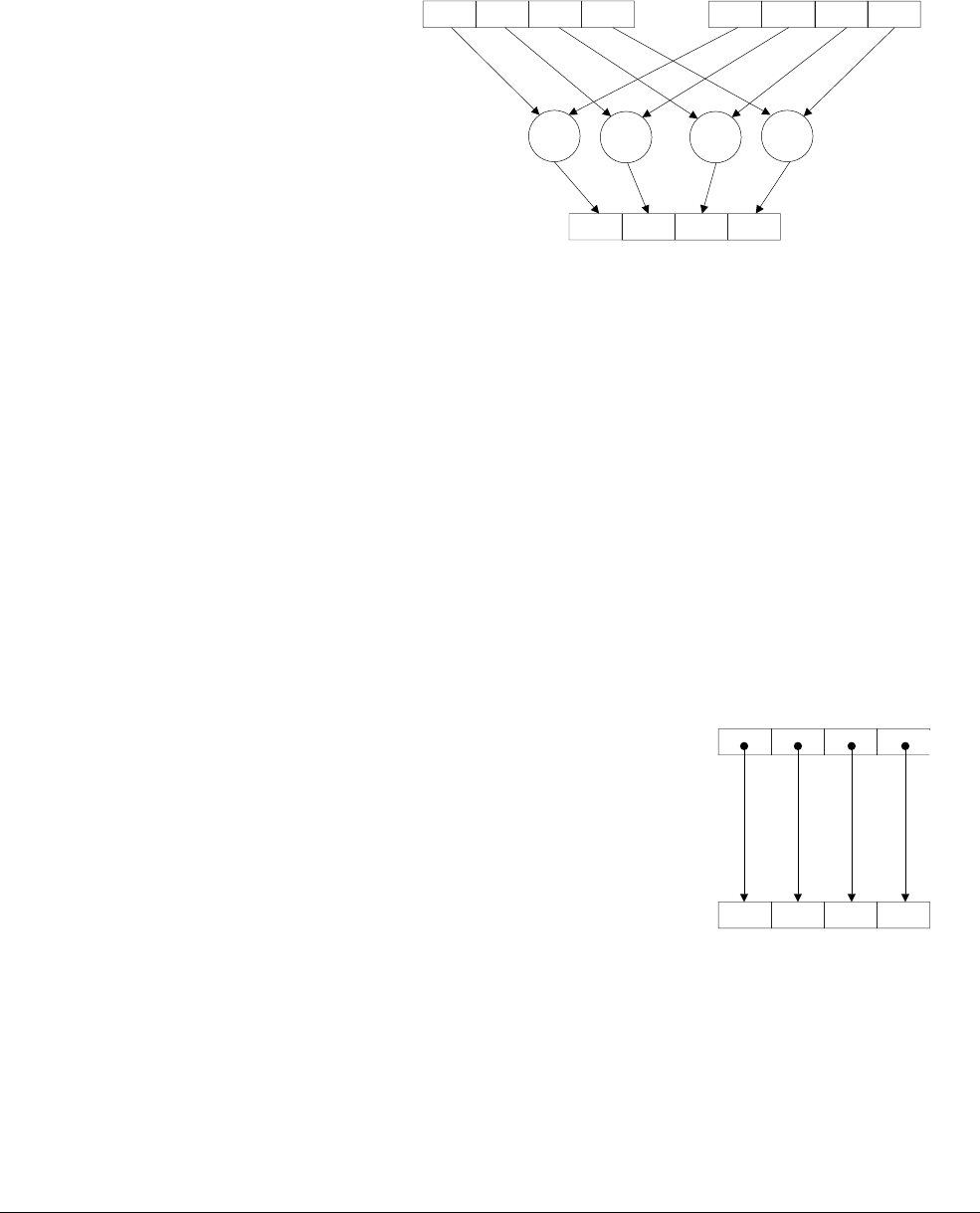
NEON and VFP Instruction Summary
ARM DEN0018A Copyright © 2013 ARM. All rights reserved. C-36
ID071613 Non-Confidential
C.10.9 VEOR
VEOR
performs a bitwise logical exclusive OR operation between values in two registers, and
places the results in the destination register.
Figure C-23 VEOR
Syntax
VEOR{cond}{.datatype} {Qd,} Qn, Qm
VEOR{cond}{.datatype} {Dd,} Dn, Dm
where:
cond
is an optional conditional code.
Qd
,
Qn
, and
Qm
specify the destination, first operand and second operand registers for a quadword
operation.
Dd
,
Dn
, and
Dm
specify the destination, first operand and second operand registers for a
doubleword operation.
C.10.10 VMOV
VMOV
(Vector Move) (register) copies a value from a source register to a destination register.
Figure C-24 VMOV (register)
Syntax
VMOV{cond}{.datatype} Qd, Qm
VMOV{cond}{.datatype} Dd, Dm
where:
cond
is an optional conditional code.
Dn Dm
Dd
xor xor xor xor
Dm
Dd
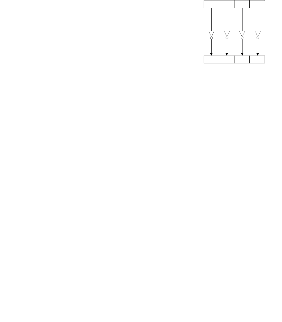
NEON and VFP Instruction Summary
ARM DEN0018A Copyright © 2013 ARM. All rights reserved. C-37
ID071613 Non-Confidential
Qd
and
Qm
specify the destination vector and the source vector, for a quadword operation.
Dd
and
Dm
specify the destination and source vector, for a doubleword operation.
C.10.11 VMVN
VMVN
, Vector Bitwise NOT (register) inverts the value of each bit from the source register and
stores the result to the destination register.
Figure C-25 VMVN
Syntax
VMVN{cond}{.datatype} Qd, Qm
VMVN{cond}{.datatype} Dd, Dm
where:
cond
is an optional conditional code.
Qd
and
Qm
specify the destination vector and the source vector, for a quadword operation.
Dd
and
Dm
specify the destination and source vector, for a doubleword operation.
C.10.12 VORN
VORN
performs a bitwise logical OR NOT operation between values in two registers, and places
the results in the destination register.
Dm
Dd
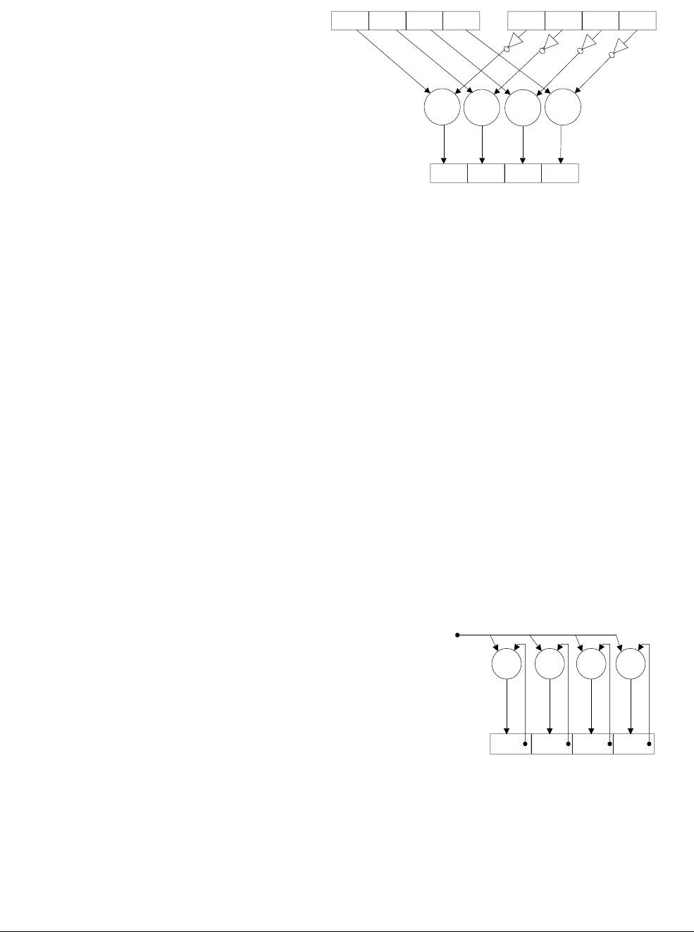
NEON and VFP Instruction Summary
ARM DEN0018A Copyright © 2013 ARM. All rights reserved. C-38
ID071613 Non-Confidential
Figure C-26 VORN
Syntax
VORN{cond}{.datatype} {Qd,} Qn, Qm
VORN{cond}{.datatype} {Dd,} Dn, Dm
where:
cond
is an optional conditional code.
Qd
,
Qn
, and
Qm
specify the destination, first operand and second operand registers for a quadword
operation.
Dd
,
Dn
, and
Dm
specify the destination, first operand and second operand registers for a
doubleword operation.
C.10.13 VORR (immediate)
VORR
(Bitwise OR immediate) takes each element of the destination vector, does a bitwise OR
with an immediate value, and stores the result into the destination vector.
Figure C-27 VORR (immediate)
Syntax
VORR{cond}.datatype Qd, #imm
VORR{cond}.datatype Dd, #imm
where:
Dn Dm
Dd
OR OR OR OR
Dd
OR OR OR OR
#imm
NEON and VFP Instruction Summary
ARM DEN0018A Copyright © 2013 ARM. All rights reserved. C-39
ID071613 Non-Confidential
cond
is an optional conditional code.
datatype
is one of
I8
,
I16
,
I32
, or
I64
.
Qd
or
Dd
is the NEON register for the source and result.
imm
is the immediate value.
Immediate values can be specified as a pattern which the assembler repeats to fill the destination
register. Alternatively, you can specify the entire value, provided it meets certain requirements.
The permitted patterns for immediate value are
0x00XY
or
0xXY00
for
I16
, or
0x000000XY
,
0x0000XY00
,
0x00XY0000
or
0xXY000000
for
I32
. If you choose
I8
or
I64
datatypes, the assembler
produces the
I16
or
I32
equivalent.
C.10.14 VORR (register)
VORR
performs a bitwise logical OR operation between values in two registers, and places the
results in the destination register.
Figure C-28 VORR (register)
Syntax
VORR{cond}{.datatype} {Qd,} Qn, Qm
VORR{cond}{.datatype} {Dd,} Dn, Dm
where:
cond
is an optional conditional code.
Qd
,
Qn
, and
Qm
specify the destination, first operand and second operand registers for a quadword
operation.
Dd
,
Dn
, and
Dm
specify the destination, first operand and second operand registers for a
doubleword operation.
C.10.15 VTST
VTST
(Vector Test Bits) takes each element in a vector and does a bitwise AND with the
corresponding element in a second vector. If the result is zero, the corresponding element in the
destination vector is set to all zeros. Otherwise, it is set to all ones.
Dn Dm
Dd
OR OR OR OR
NEON and VFP Instruction Summary
ARM DEN0018A Copyright © 2013 ARM. All rights reserved. C-40
ID071613 Non-Confidential
Figure C-29 VTST looks like VAND
Syntax
VTST{cond}.size {Qd,} Qn, Qm
VTST{cond}.size {Dd,} Dn, Dm
where:
cond
is an optional conditional code.
size
is one of 8, 16, or 32.
Qd
,
Qn
, and
Qm
specify the destination, first operand and second operand registers for a quadword
operation.
Dd
,
Dn
, and
Dm
specify the destination, first operand and second operand registers for a
doubleword operation.
Dn Dm
Dd
&& & &
NEON and VFP Instruction Summary
ARM DEN0018A Copyright © 2013 ARM. All rights reserved. C-41
ID071613 Non-Confidential
C.11 NEON arithmetic instructions
This section describe NEON instructions which perform arithmetic operations such as addition,
subtraction, reciprocal calculation etc
C.11.1 VABA{L}
VABA
(Vector Absolute Difference and Accumulate) subtracts the elements of one vector from
the corresponding elements of another and accumulates the absolute values of the results into
the elements of the destination vector. A long version of this instructions is available.
Figure C-30 VABA
Syntax
VABA{cond}.datatype {Qd,} Qn, Qm
VABA{cond}.datatype {Dd,} Dn, Dm
VABAL{cond}.datatype Qd, Dn, Dm
where:
cond
is an optional conditional code.
datatype
is one of
S8
,
S16
,
S32
,
U8
,
U16
, or
U32
.
Qd
,
Qn
, and
Qm
specify the destination, first operand and second operand registers for a quadword
operation.
Dd
,
Dn
, and
Dm
specify the destination, first operand and second operand registers for a
doubleword operation.
Qd
,
Dn
and
Dm
specify the destination, first operand and second operand vectors for a long
operation.
C.11.2 VABD{L}
VABD
(Vector Absolute Difference) subtracts the elements of one vector from the corresponding
elements of another and places the absolute values of the results into the elements of the
destination vector. A long version of the instruction is available.
Dn Dm
Dd
ABSDIFF ABSDIFF ABSDIFF ABSDIFF
++++
NEON and VFP Instruction Summary
ARM DEN0018A Copyright © 2013 ARM. All rights reserved. C-42
ID071613 Non-Confidential
Figure C-31 VABD
Syntax
VABD{cond}.datatype {Qd,} Qn, Qm
VABD{cond}.datatype {Dd,} Dn, Dm
VABDL{cond}.datatype Qd, Dn, Dm
where:
cond
is an optional conditional code.
datatype
is one of:
•
S8
,
S16
,
S32
,
U8
,
U16
,
U32
or
F32
for
VABD
•
S8
,
S16
,
S32
,
U8
,
U16
, or
U32
for
VABDL
.
Qd
,
Qn
, and
Qm
specify the destination, first operand and second operand registers for a quadword
operation.
Dd
,
Dn
, and
Dm
specify the destination, first operand and second operand registers for a
doubleword operation.
Qd
,
Dn
, and
Dm
specify the destination, first operand and second operand vectors for a long
operation.
C.11.3 V{Q}ABS
VABS
(Vector Absolute) takes the absolute value of each element in a vector, and stores the results
in the destination. The floating-point version only clears the sign bit. A saturating version of the
instructions is available. The sticky QC flag is set if saturation occurs.
Dn Dm
Dd
ABSDIFF ABSDIFF ABSDIFF ABSDIFF
NEON and VFP Instruction Summary
ARM DEN0018A Copyright © 2013 ARM. All rights reserved. C-43
ID071613 Non-Confidential
Figure C-32 VABS
Syntax
V{Q}ABS{cond}.datatype Qd, Qm
V{Q}ABS{cond}.datatype Dd, Dm
where:
cond
is an optional conditional code.
Q
indicates that saturation is performed if any of the results overflow.
datatype is one of:
•
S8
,
S16
,
S32
for
VABS
or
VQABS
•
F32
for
VABS
only.
Qd
and
Qm
specify the destination and operand vectors for a quadword operation.
Dd
and
Dm
specify the destination and operand vectors for a doubleword operation.
C.11.4 V{Q}ADD, VADDL, VADDW
VADD
(Vector Add) adds corresponding elements in two vectors, and stores the results in the
destination vector.
VADD
has long, wide and saturating variants.
Dn
Dd
ABS ABS ABS ABS
NEON and VFP Instruction Summary
ARM DEN0018A Copyright © 2013 ARM. All rights reserved. C-44
ID071613 Non-Confidential
Figure C-33 VADD
Syntax
V{Q}ADD{cond}.datatype {Qd,} Qn, Qm
V{Q}ADD{cond}.datatype {Dd,} Dn, Dm
VADDL{cond}.datatype Qd, Dn, Dm
VADDW{cond}.datatype {Qd,} Qn, Dm
where:
cond
is an optional conditional code.
Q
indicates that saturation is performed if any of the results overflow.
datatype
is one of:
•
I8
,
I16
,
I32
,
I64
,
F32
for
VADD
•
S8
,
S16
,
S32
for
VQADD
,
VADDL
or
VADDW
•
U8
,
U16
,
U32
for
VQADD
,
VADDL
or
VADDW
•
S64
,
U64
for
VQADD
.
Qd
,
Qn
, and
Qm
specify the destination, first operand and second operand registers for a quadword
operation.
Dd
,
Dn
, and
Dm
specify the destination, first operand and second operand registers for a
doubleword operation.
Qd
,
Dn
, and
Dm
specify the destination, first operand and second operand vectors for a long
operation.
Qd
,
Qn
and
Dm
specify the destination, first operand and second operand vectors for a wide
operation.
C.11.5 V{R}ADDHN
V{R}ADDHN
(Vector Add and Narrow, selecting High half) adds corresponding elements in two
vectors, selects the most significant halves of the results, and stores them in the destination
vector.
Dn Dm
Dd
+
+
+ + +
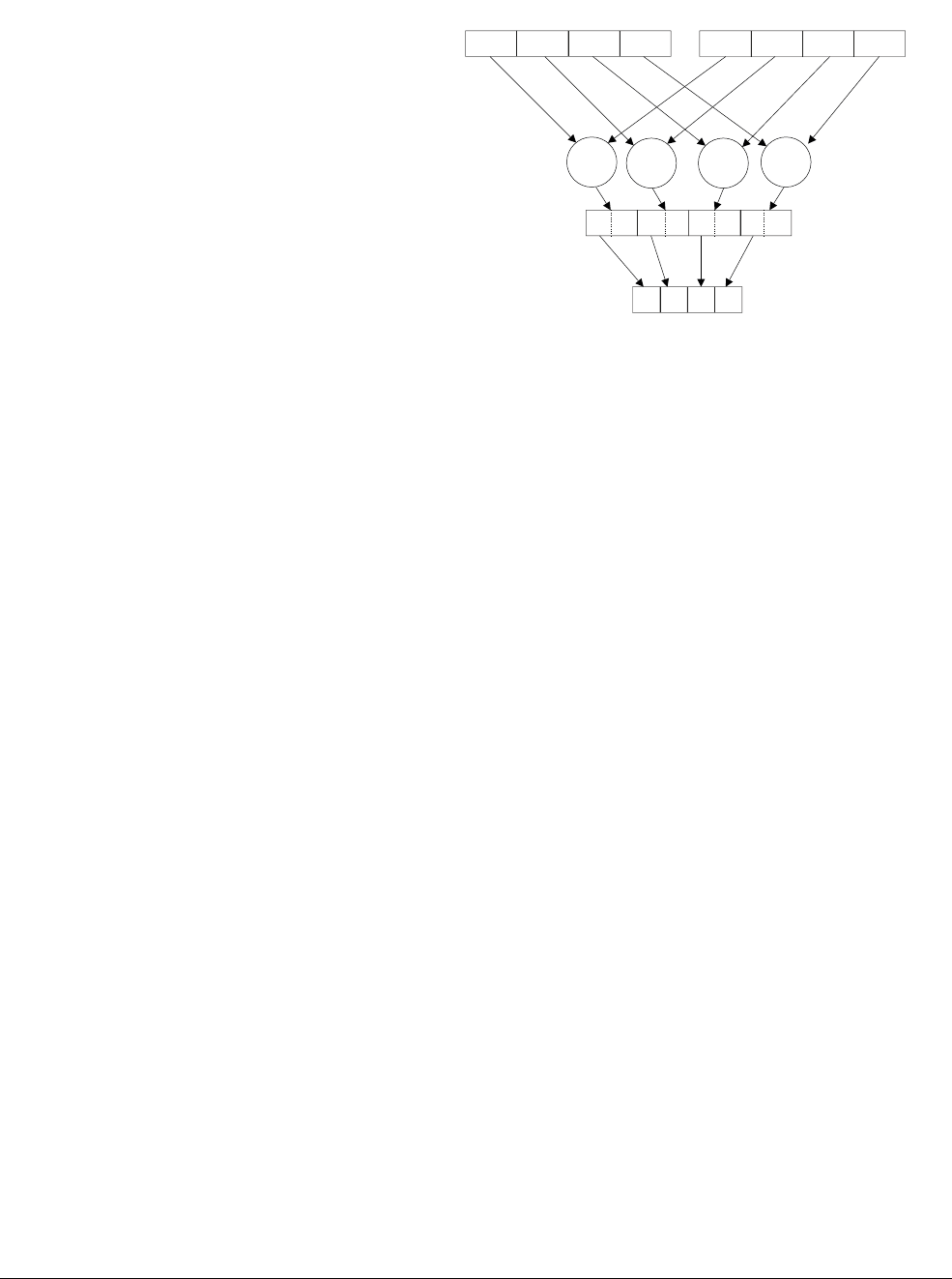
NEON and VFP Instruction Summary
ARM DEN0018A Copyright © 2013 ARM. All rights reserved. C-45
ID071613 Non-Confidential
Figure C-34 VADDHN
Syntax
V{R}ADDHN{cond}.datatype Dd, Qn, Qm
where:
cond
is an optional conditional code.
R
specifies that each result is rounded. If
R
is not specified, each result is truncated.
datatype
is one of
I16
,
I32
, or
I64
.
Dd
,
Qn
, and
Qm
are the destination vector, the first operand vector, and the second operand vector.
C.11.6 VCLS
VCLS
(Vector Count Leading Sign Bits) counts the number of consecutive bits following the
topmost bit that are the same as that bit, in each element in a vector, and stores the results in a
destination vector.
Syntax
VCLS{cond}.datatype Qd, Qm
VCLS{cond}.datatype Dd, Dm
where:
cond
is an optional conditional code.
datatype
is one of
S8
,
S16
, or
S32
.
Qd
and
Qm
specify the destination and operand vectors for a quadword operation.
Dd
and
Dm
specify the destination and operand vectors for a doubleword operation.
C.11.7 VCLZ
VCLZ
(Vector Count Leading Zeros) counts the number of consecutive zeros, starting from the
top bit, in each element in a vector, and stores the results in a destination vector.
Qn Qm
Dd
+
++ + +
NEON and VFP Instruction Summary
ARM DEN0018A Copyright © 2013 ARM. All rights reserved. C-46
ID071613 Non-Confidential
Syntax
VCLZ{cond}.datatype Qd, Qm
VCLZ{cond}.datatype Dd, Dm
where:
cond
is an optional conditional code.
datatype
is one of
S8
,
S16
, or
S32
.
Qd
and
Qm
specify the destination and operand vectors for a quadword operation.
Dd
and
Dm
specify the destination and operand vectors for a doubleword operation.
C.11.8 VCNT
VCNT
(Vector Count Set Bits) counts the number of bits that are one in each element in a vector,
and stores the results in a destination vector.
Syntax
VCNT{cond}.datatype Qd, Qm
VCNT{cond}.datatype Dd, Dm
where:
cond
is an optional conditional code.
datatype
must be
I8
.
Qd
and
Qm
specify the destination and operand vectors for a quadword operation.
Dd
and
Dm
specify the destination and operand vectors for a doubleword operation.
C.11.9 V{R}HADD
VHADD
(Vector Halving Add) adds corresponding elements in two vectors, shifts each result right
one bit and stores the results in the destination vector. Results can be either rounded or truncated.
Figure C-35 VHADD
Dm
Dd
+
<< << << <<
+++
Dn
NEON and VFP Instruction Summary
ARM DEN0018A Copyright © 2013 ARM. All rights reserved. C-47
ID071613 Non-Confidential
Syntax
V{R}HADD{cond}.datatype {Qd,} Qn, Qm
V{R}HADD{cond}.datatype {Dd,} Dn, Dm
where:
cond
is an optional conditional code.
R
specifies that each result is rounded. If
R
is not specified, each result is truncated.
datatype
is one of
S8
,
S16
,
S32
,
U8
,
U16
, or
U32
.
Qd
,
Qn
, and
Qm
specify the destination, first operand and second operand registers for a quadword
operation.
Dd
,
Dn
, and
Dm
specify the destination, first operand and second operand registers for a
doubleword operation.
C.11.10 VHSUB
VHSUB
(Vector Halving Subtract) subtracts the elements of one vector from the corresponding
elements of another vector, shifts each result right one bit, and stores the result in the destination
vector. Results are always truncated.
Figure C-36 VHSUB
Syntax
VHSUB{cond}.datatype {Qd,} Qn, Qm
VHSUB{cond}.datatype {Dd,} Dn, Dm
where:
cond
is an optional conditional code.
datatype
is one of
S8
,
S16
,
S32
,
U8
,
U16
, or
U32
.
Qd
,
Qn
, and
Qm
specify the destination, first operand and second operand registers for a quadword
operation.
Dd
,
Dn
, and
Dm
specify the destination, first operand and second operand registers for a
doubleword operation.
Dm
Dd
-
<< << << <<
---
Dn

NEON and VFP Instruction Summary
ARM DEN0018A Copyright © 2013 ARM. All rights reserved. C-48
ID071613 Non-Confidential
C.11.11 VMAX and VMIN
VMAX
(Vector Maximum) compares corresponding elements in two vectors, and writes the larger
of them into the corresponding element in the destination vector.
VMIN
(Vector Minimum) compares corresponding elements in two vectors, and writes the smaller
value into the corresponding element in the destination vector.
Syntax
VMAX{cond}.datatype Qd, Qn, Qm
VMAX{cond}.datatype Dd, Dn, Dm
VMIN{cond}.datatype Qd, Qn, Qm
VMIN{cond}.datatype Dd, Dn, Dm
where:
cond
is an optional conditional code.
datatype
is one of
S8
,
S16
,
S32
,
U8
,
U16
,
U32
, or
F32
.
Qd
,
Qn
, and
Qm
specify the destination, first operand and second operand registers for a quadword
operation.
Dd
,
Dn
, and
Dm
specify the destination, first operand and second operand registers for a
doubleword operation.
C.11.12 V{Q}NEG
VNEG
(Vector Negate) negates each element in a vector, and places the results in a second vector.
The floating-point version only inverts the sign bit. A saturating version of the instruction is
available. The sticky QC flag is set if saturation occurs.
Syntax
V{Q}NEG{cond}.datatype Qd, Qm
V{Q}NEG{cond}.datatype Dd, Dm
where:
cond
is an optional conditional code.
Q
indicates that saturation is performed if any of the results overflow.
datatype
is one of:
•
S8
,
S16
,
S32
for
VNEG
, or
VQNEG
•
F32
or F64 for
VNEG
.
Qd
and
Qm
specify the destination and operand vectors for a quadword operation.
Dd
and
Dm
specify the destination and operand vectors for a doubleword operation.
C.11.13 VPADD{L}, VPADAL
VPADD
(Vector Pairwise Add) adds adjacent pairs of elements of two vectors, and stores the
results in the destination vector.
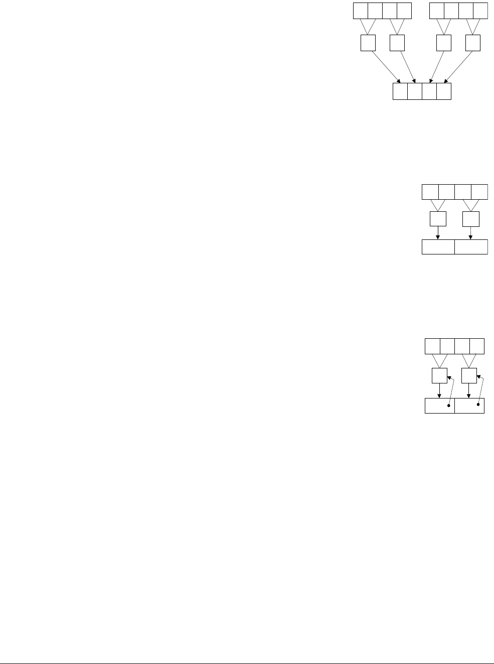
NEON and VFP Instruction Summary
ARM DEN0018A Copyright © 2013 ARM. All rights reserved. C-49
ID071613 Non-Confidential
Figure C-37 Example of operation of VPADD (in this case, for data type
I16
)
VPADDL
(Vector Pairwise Add Long) adds adjacent pairs of elements of a vector, sign or zero
extends the results to twice their original width and stores the results in the destination vector.
Figure C-38 Example of operation of doubleword VPADDL (in this case, for data type
S16
)
VPADAL
(Vector Pairwise Add and Accumulate Long) adds adjacent pairs of elements of a vector,
and accumulates the results into the elements of the destination vector.
Figure C-39 Example of operation of VPADAL (in this case for data type
S16
)
Syntax
VPADD{cond}.datatype {Dd,} Dn, Dm
VPopL{cond}.datatype Qd, Qm
VPopL{cond}.datatype Dd, Dm
where:
cond
is an optional conditional code.
op
is either
ADD
or
ADA
.
datatype
is one of:
•
I8
,
I16
,
I32
,
F32
for
VPADD
•
S8
,
S16
,
S32
for
VPADDL
or
VPADAL
•
U8
,
U16
,
U32
for
VPADDL
or
VPADAL
.
Dd
,
Dn
, and
Dm
specify the destination, first operand and second operand registers for a
VPADD
.
Dd
DnDm
+ + ++
Dd
Dm
++
Dd
Dm
+
+
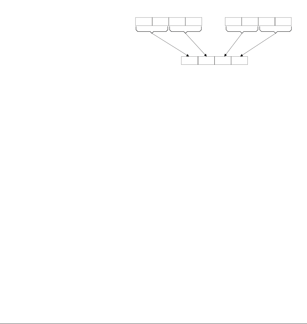
NEON and VFP Instruction Summary
ARM DEN0018A Copyright © 2013 ARM. All rights reserved. C-50
ID071613 Non-Confidential
Qd
and
Qm
specify the destination and operand vectors for a quadword operation.
Dd
and
Dm
specify the destination and operand vectors for a doubleword operation.
C.11.14 VPMAX and VPMIN
VPMAX
(Vector Pairwise Maximum) compares adjacent pairs of elements in two vectors and
writes the larger of each pair into the corresponding element in the destination vector.
Figure C-40 shows an example of the VPMAX operation.
VPMIN
(Vector Pairwise Minimum) compares adjacent pairs of elements in two vectors, and
writes the smaller of each pair into the corresponding element in the destination vector.
Operands and results must be doubleword vectors.
Figure C-40 VPMAX
Syntax
VPMAX{cond}.datatype Dd, Dn, Dm
VPMIN{cond}.datatype Dd, Dn, Dm
where:
cond
is an optional conditional code.
datatype
is one of
S8
,
S16
,
S32
,
U8
,
U16
,
U32
, or
F32
.
Dd
,
Dn
, and
Dm
specify the destination, first operand and second operand registers for a
doubleword operation.
C.11.15 VRECPE
VRECPE
(Vector Reciprocal Estimate) finds an approximate reciprocal of each element in a vector,
and stores the results in a destination vector.
Syntax
VRECPE{cond}.datatype Qd, Qm
VRECPE{cond}.datatype Dd, Dm
where:
cond
is an optional conditional code.
datatype
is either
U32
or
F32
.
Qd
and
Qm
specify the destination and operand vectors for a quadword operation.
Dm Dn
Dd
max max max max
VPMAX.S16 Dd, Dn, Dm

NEON and VFP Instruction Summary
ARM DEN0018A Copyright © 2013 ARM. All rights reserved. C-51
ID071613 Non-Confidential
Dd
and
Dm
specify the destination and operand vectors for a doubleword operation.
C.11.16 VRECPS
VRECPS
(Vector Reciprocal Step) multiplies the elements of one vector by the corresponding
elements of another, subtracts each of the results from 2.0, and stores the final results into the
elements of the destination. This instruction is used as part of the Newton-Raphson iteration
algorithm.
Syntax
VRECPS{cond}.F32 {Qd,} Qn, Qm
VRECPS{cond}.F32 {Dd,} Dn, Dm
where:
cond
is an optional conditional code.
datatype
is either
U32
or
F32
.
Qd
and
Qm
specify the destination and operand vectors for a quadword operation.
Dd
and
Dm
specify the destination and operand vectors for a doubleword operation.
C.11.17 VRSQRTE
VRSQRTE
(Vector Reciprocal Square Root Estimate) finds an approximate reciprocal square root
of each element in a vector and stores the results in a destination vector.
Syntax
VRSQRTE{cond}.datatype Qd, Qm
Table C-15 Results for out-of-range inputs
Operand element (
VRECPE
) Result element
Integer <=
0x7FFFFFFF 0xFFFFFFFF
Floating-point NaN Default NaN
Negative 0, Negative Denormal Negative Infinity a
a. The Division by Zero exception bit in the FPSCR (FPSCR[1]) is set
Positive 0, Positive Denormal Positive Infinity a
Positive infinity Positive 0
Negative infinity Negative 0
Table C-16 Results for out-of-range inputs
1st operand element 2nd operand element Result element (
VRECPS
)
NaN - Default NaN
- NaN Default NaN
+/– 0.0 or denormal +/– infinity 2.0
+/– infinity +/– 0.0 or denormal 2.0

NEON and VFP Instruction Summary
ARM DEN0018A Copyright © 2013 ARM. All rights reserved. C-52
ID071613 Non-Confidential
VRSQRTE{cond}.datatype Dd, Dm
where:
cond
is an optional conditional code.
datatype
is either
U32
or
F32
.
Qd
and
Qm
specify the destination and operand vectors for a quadword operation.
Dd
and
Dm
specify the destination and operand vectors for a doubleword operation.
C.11.18 VRSQRTS
VRSQRTS
(Vector Reciprocal Square Root Step) multiplies the elements of one vector by the
corresponding elements of another, subtracts each of the results from 3.0, divides these results
by 2.0, and places the final results into the elements of the destination. This instruction is used
as part of the Newton-Raphson iteration algorithm.
Syntax
VSQRTS{cond}.F32 {Qd,} Qn, Qm
VSQRTS{cond}.F32 {Dd,} Dn, Dm
where:
cond
is an optional conditional code.
Qd
and
Qm
specify the destination and operand vectors for a quadword operation.
Dd
and
Dm
specify the destination and operand vectors for a doubleword operation.
Table C-17 Results for out-of-range inputs
Operand element (
VRSQRTE
) Result element
Integer <=
0x3FFFFFFF 0xFFFFFFFF
Floating-point NaN, Negative Normal, Negative Infinity Default NaN
Negative 0, Negative Denormal Negative Infinity a
a. The Division by Zero exception bit in the FPSCR (FPSCR[1]) is set
Positive 0, Positive Denormal Positive Infinity a
Positive infinity Positive 0
Negative 0
Table C-18 Results for out-of-range inputs
1st operand element 2nd operand element Result element (
VRSQRTS
)
NaN - Default NaN
- NaN Default NaN
+/– 0.0 or denormal +/– infinity 1.5
+/– infinity +/– 0.0 or denormal 1.5

NEON and VFP Instruction Summary
ARM DEN0018A Copyright © 2013 ARM. All rights reserved. C-53
ID071613 Non-Confidential
C.11.19 V{Q}SUB, VSUBL and VSUBW
VSUB
(Vector Subtract) subtracts the elements of one vector from the corresponding elements of
another vector and stores the results in the destination vector.
VSUB
has Long, Wide and
Saturating variants.
Syntax
V{Q}SUB{cond}.datatype {Qd,} Qn, Qm
V{Q}SUB{cond}.datatype {Dd,} Dn, Dm
VSUBL{cond}.datatype Qd, Dn, Dm
VSUBW{cond}.datatype {Qd,} Qn, Dm
where:
cond
is an optional conditional code.
Q
specifies that saturation should be performed if any of the results overflow.
Figure C-41 VSUB operation
datatype
is one of:
•
I8
,
I16
,
I32
,
I64
,
F32
for
VSUB
•
S8
,
S16
,
S32
for
VQSUB
,
VSUBL
, or
VSUBW
•
U8
,
U16
,
U32
for
VQSUB
,
VSUBL
, or
VSUBW
•
S64
,
U64
for
VQSUB
.
Qd
,
Qn
, and
Qm
specify the destination, first operand and second operand registers for a quadword
operation.
Dd
,
Dn
, and
Dm
specify the destination, first operand and second operand registers for a
doubleword operation.
Qd
,
Dn
, and
Dm
specify the destination, first operand and second operand vectors for a long
operation.
Qd
,
Qn
and
Dm
specify the destination, first operand and second operand vectors for a wide
operation.
Dn Dm
Dd
__ _ _
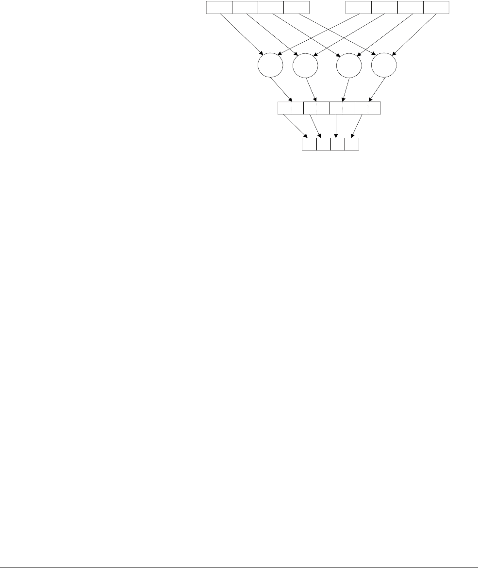
NEON and VFP Instruction Summary
ARM DEN0018A Copyright © 2013 ARM. All rights reserved. C-54
ID071613 Non-Confidential
C.11.20 V{R}SUBHN
V{R}SUBHN
(Vector Subtract and Narrow, selecting High Half) subtracts the elements of one
vector from the corresponding elements of another vector, selects the most significant halves of
the results and stores them in the destination vector. Results can be either rounded or truncated
for both operations.
Figure C-42 VSUBHN
Syntax
V{R}SUBHN{cond}.datatype Dd, Qn, Qm
where:
cond
is an optional conditional code.
R
specifies that each result is rounded. If
R
is not specified, each result is truncated.
datatype
is one of
I16
,
I32
, or
I64
.
Dd
,
Qn
, and
Qm
are the destination vector, the first operand vector, and the second operand vector.
Qn Qm
Dd
__ _ _
NEON and VFP Instruction Summary
ARM DEN0018A Copyright © 2013 ARM. All rights reserved. C-55
ID071613 Non-Confidential
C.12 NEON multiply instructions
This section describe NEON instructions which perform multiplication or multiply-accumulate.
C.12.1 VFMA, VFMS
VFMA
(Vector Fused Multiply Accumulate) multiplies corresponding elements in two vectors,
and accumulates the results into the destination vector.
Figure C-43 VFMA
VFMS
(Vector Fused Multiply Subtract) multiplies corresponding elements in two operand
vectors, subtracts the products from the corresponding elements of the destination vector, and
stores the final results in the destination vector. The result of the multiply is not rounded before
performing the accumulate or subtract operation.
Figure C-44 VFMS
Syntax
Vop{cond}.F32 {Qd,} Qn, Qm
Vop{cond}.F32 {Dd,} Dn, Dm
Vop{cond}.F64 {Dd,} Dn, Dm
Vop{cond}.F32 {Sd,} Sn, Sm
where:
Dn Dm
Dd
xx xx
++ + +
Dn Dm
new Dd
xx xx
--- -
Dd
NEON and VFP Instruction Summary
ARM DEN0018A Copyright © 2013 ARM. All rights reserved. C-56
ID071613 Non-Confidential
cond
is an optional conditional code.
op
is one of
FMA
or
FMS
.
Sd
,
Sn
, and
Sm
are the destination and operand vectors for word operation.
Dd
,
Dn
, and
Dm
are the destination and operand vectors for doubleword operation.
Qd
,
Qn
, and
Qm
are the destination and operand vectors for quadword operation.
C.12.2 VMUL{L}, VMLA{L}, and VMLS{L}
VMUL
(Vector Multiply) multiplies corresponding elements in two vectors and stores the results
in the destination vector.
Figure C-45 VMUL
VMLA
(Vector Multiply Accumulate) multiplies corresponding elements in two vectors and adds
the results to the corresponding element of the destination vector.
Figure C-46 VMLA
VMLS
(Vector Multiply Subtract) multiplies elements in two vectors, subtracts the results from
corresponding elements of the destination vector, and stores the results in the destination vector.
Dn Dm
Dd
xx xx
Dn Dm
Dd
xx xx
++ + +
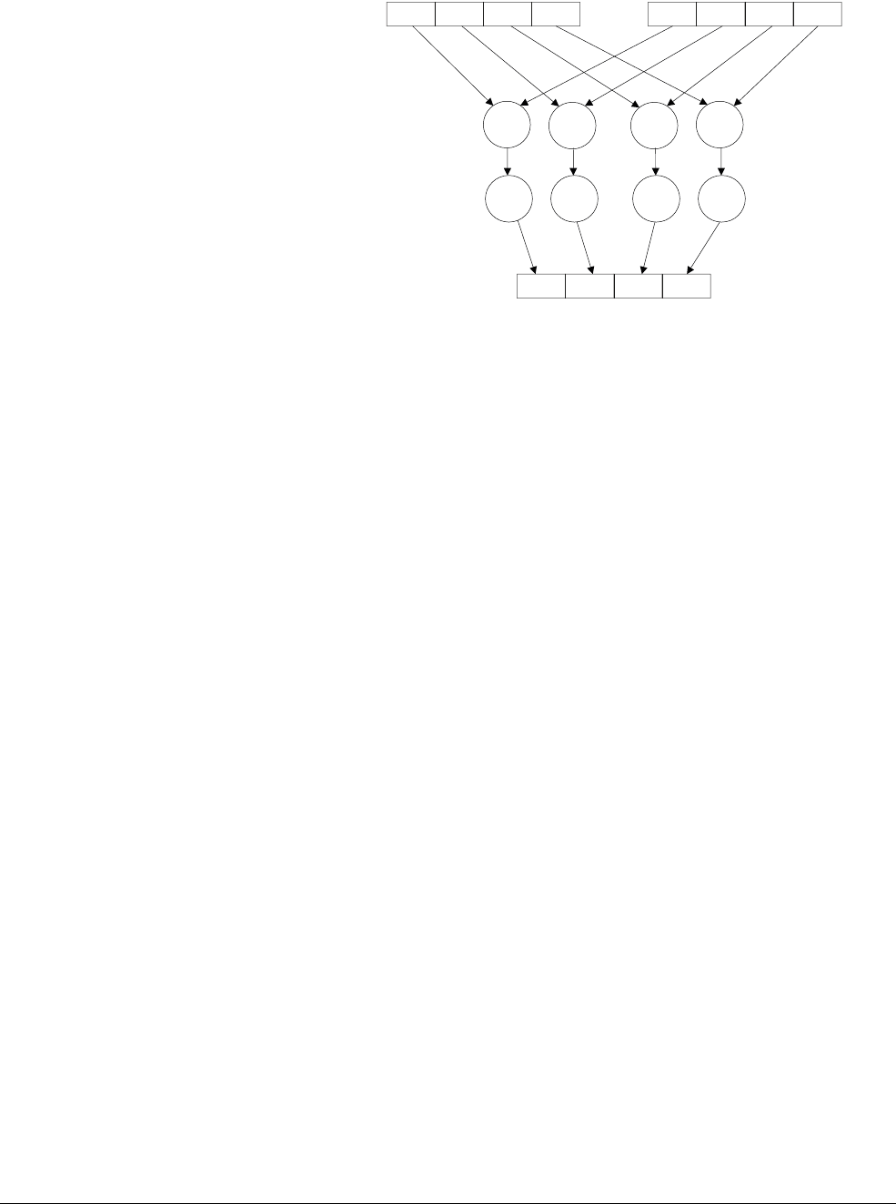
NEON and VFP Instruction Summary
ARM DEN0018A Copyright © 2013 ARM. All rights reserved. C-57
ID071613 Non-Confidential
Figure C-47 VMLS
Syntax
Vop{cond}.datatype {Qd,} Qn, Qm
Vop{cond}.datatype {Dd,} Dn, Dm
VopL{cond}.datatype Qd, Dn, Dm
where:
cond
is an optional conditional code.
op
is one of:
•
MUL
, Multiply
•
MLA
, Multiply Accumulate
•
MLS
, Multiply Subtract.
datatype
is one of:
•
I8
,
I16
,
I32
,
F32
for
VMUL
,
VMLA
, or
VMLS
•
S8
,
S16
,
S32
for
VMULL
,
VMLAL
, or
VMLSL
•
U8
,
U16
,
U32
for
VMULL
,
VMLAL
, or
VMLSL
•
P8
for
VMUL
or
VMULL
.
Qd
,
Qn
, and
Qm
specify the destination, first operand and second operand registers for a quadword
operation.
Dd
,
Dn
, and
Dm
specify the destination, first operand and second operand registers for a
doubleword operation.
Qd
,
Dn
, and
Dm
specify the destination, first operand and second operand vectors for a long
operation.
C.12.3 VMUL{L}, VMLA{L}, and VMLS{L} (by scalar)
VMUL
(Vector Multiply by scalar) multiplies each element in a vector by a scalar and stores the
results in the destination vector.
VMLA
(Vector Multiply Accumulate) multiplies each element in a vector by a scalar and
accumulates the results into the corresponding elements of the destination vector.
Dn Dm
Dd
xx xx
____

NEON and VFP Instruction Summary
ARM DEN0018A Copyright © 2013 ARM. All rights reserved. C-58
ID071613 Non-Confidential
VMLS
(Vector Multiply Subtract) multiplies each element in a vector by a scalar and subtracts the
results from the corresponding elements of the destination vector and stores the final results in
the destination vector.
Syntax
Vop{cond}.datatype {Qd,} Qn, Dm[x]
Vop{cond}.datatype {Dd,} Dn, Dm[x]
VopL{cond}.datatype Qd, Dn, Dm[x]
where:
cond
is an optional conditional code.
op
is one of:
•
MUL
– Multiply
•
MLA
– Multiply Accumulate
•
MLS
– Multiply Subtract.
datatype
is one of:
•
I16
,
I32
,
F32
for
VMUL
,
VMLA
, or
VMLS
•
S16
,
S32
for
VMULL
,
VMLAL
, or
VMLSL
•
U16
,
U32
for
VMULL
,
VMLAL
, or
VMLSL
Qd
,
Qn
, and
Qm
specify the destination, first operand and second operand registers for a quadword
operation.
Dd
,
Dn
, and
Dm
specify the destination, first operand and second operand registers for a
doubleword operation.
Qd
,
Dn
, and
Dm
specify the destination, first operand and second operand vectors for a long
operation.
Dm[x]
is the scalar holding the second operand.
C.12.4 VQ{R}DMULH (by vector or by scalar)
Vector Saturating Doubling Multiply Returning High Half instructions multiply their operands
and double the result. They return only the high half of the results. If any of the results overflow,
they are saturated and the sticky QC flag is set.
Syntax
VQ{R}DMULH{cond}.datatype {Qd,} Qn, Qm
VQ{R}DMULH{cond}.datatype {Dd,} Dn, Dm
VQ{R}DMULH{cond}.datatype {Qd,} Qn, Dm[x]
VQ{R}DMULH{cond}.datatype {Dd,} Dn, Dm[x]
where:
cond
is an optional conditional code.
R
specifies that each result is rounded. If
R
is not specified, each result is truncated.
datatype
is either
S16
or
S32
.
Qd
and
Qn
are the destination and first operand vector, for a quadword operation.
Dd
and
Dn
are the destination and first operand vector for a doubleword operation.

NEON and VFP Instruction Summary
ARM DEN0018A Copyright © 2013 ARM. All rights reserved. C-59
ID071613 Non-Confidential
Qm
or
Dm
specifies the vector holding the second operand, for a by vector operation.
Dm[x]
is the scalar holding the second operand for a by scalar operation.
C.12.5 VQDMULL, VQDMLAL, and VQDMLSL (by vector or by scalar)
Vector Saturating Doubling Multiply Long instructions multiply their operands and double the
results. The instruction variants are:
•
VQDMULL
stores the results in the destination register.
•
VQDMLAL
adds the results to the values in the destination register.
•
VQDMLSL
subtracts the results from the values in the destination register.
If any of the results overflow, they are saturated and the sticky QC flag is set.
Syntax
VQDopL{cond}.datatype Qd, Dn, Dm
VQDopL{cond}.datatype Qd, Dn, Dm[x]
where:
cond
is an optional conditional code.
op
is one of:
•
MUL
, Multiply
•
MLA
, Multiply Accumulate
•
MLS
, Multiply Subtract.
datatype
is either
S16
or
S32
.
Qd
and
Dn
are the destination vector and the first operand vector.
Dm
is the vector holding the second operand in the case of a by vector operation.
Dm[x]
is the scalar holding the second operand for a by scalar operation.
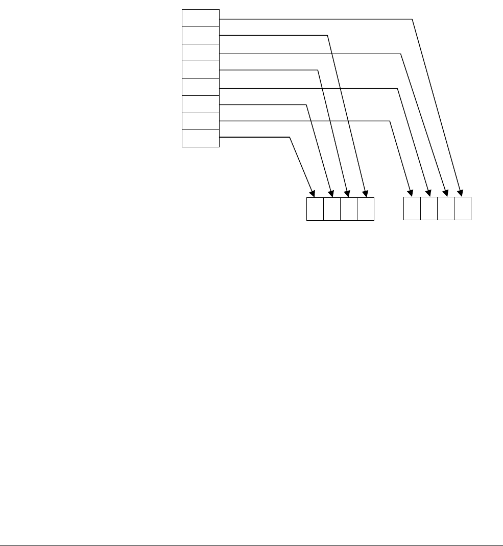
NEON and VFP Instruction Summary
ARM DEN0018A Copyright © 2013 ARM. All rights reserved. C-60
ID071613 Non-Confidential
C.13 NEON load and store instructions
This section describes NEON load and store instructions, which transfer data between memory
and the NEON registers. There are instructions to load single elements or a data structure.
C.13.1 Interleaving
Many instructions in this group provide interleaving when structures are stored to memory, and
de-interleaving when structures are loaded from memory. Figure C-48 shows an example of
de-interleaving. Interleaving is the inverse process.
Figure C-48 De-interleaving an array of 3-element structures
R3D1
R2R1R0L3D0L2L1L0
3
L0
0
R
L
R
1
2
1
R
L
L
R
2
3
NEON Registers
Memory
0
2
4
6
8
10
12
14
R1 offset
VLD2.16 {D0, D1}, [R1]

NEON and VFP Instruction Summary
ARM DEN0018A Copyright © 2013 ARM. All rights reserved. C-61
ID071613 Non-Confidential
C.13.2 Alignment restrictions in load and store, element and structure instructions
Many of these instructions allow memory alignment restrictions to be specified. When the
alignment is not specified in the instruction, the alignment restriction is controlled by the A bit
(CP15 register 1 bit[1]):
• if the A bit is 0, there are no alignment restrictions (except for strongly ordered or device
memory, where accesses must be element aligned or the result is unpredictable)
• if the A bit is 1, accesses must be element aligned.
If an address is not correctly aligned, an alignment fault occurs.
C.13.3 VLDn and VSTn (single n-element structure to one lane)
VLDn
(Vector Load single n-element structure to one lane) loads an n-element structure from
memory into one or more NEON registers. Elements of the register that are not loaded remain
unchanged.
VSTn
(Vector Store single n-element structure to one lane) stores an n-element structure to
memory from one or more NEON registers.
Syntax
Vopn{cond}.datatype list, [Rn{@align}]{!}
Vopn{cond}.datatype list, [Rn{@align}], Rm
where:
op
is either
LD
or
ST
.
n
is one of 1, 2, 3, or 4.
cond
is an optional conditional code.
datatype
is one of 8, 16 or 32.
The following table shows the permitted options.
Table C-19 Permitted combinations of parameters
n datatype list align alignment
1 8 {Dd[x]} - Standard only
16 {Dd[x]} @16 2-byte
32 {Dd[x]} @32 4-byte
2 8 {Dd[x], D(d+1)[x]} @16 2-byte
16 {Dd[x], D(d+1)[x]} @32 4-byte
{Dd[x], D(d+2)[x]} @32 4-byte
32 {Dd[x], D(d+1)[x]} @64 8-byte
{Dd[x], D(d+2)[x]} @64 8-byte
3 8 {Dd[x], D(d+1)[x], D(d+2)[x]} - Standard only
16 or 32 {Dd[x], D(d+1)[x], D(d+2)[x]} - Standard only
{Dd[x], D(d+2)[x], D(d+4)[x]} - Standard only

NEON and VFP Instruction Summary
ARM DEN0018A Copyright © 2013 ARM. All rights reserved. C-62
ID071613 Non-Confidential
list
is a list of NEON registers in the range D0-D31, subject to the limitations given in the table.
Rn
is the ARM register containing the base address (cannot be PC). If
!
is present,
Rn
is updated
to (
Rn
+ the number of bytes transferred by the instruction). The update occurs after all the loads
or stores have been performed.
Rm
is the ARM register containing an offset from the base address. If
Rm
is present, then
Rn
is
updated to (
Rn
+
Rm
) after the memory accesses have been performed.
Rm
cannot be SP or PC.
C.13.4 VLDn (single n-element structure to all lanes)
VLDn
(Vector Load single n-element structure to all lanes) loads multiple copies of an n-element
structure from memory into one or more NEON registers.
Syntax
VLDn{cond}.datatype list, [Rn{@align}]{!}
VLDn{cond}.datatype list, [Rn{@align}], Rm
where:
n
is one of 1, 2, 3, or 4.
cond
is an optional conditional code.
datatype
is one of 8, 16 or 32.
The following table shows the permitted options:
4 8 {Dd[x], D(d+1)[x], D(d+2)[x], D(d+3)[x]} @32 4-byte
16 {Dd[x], D(d+1)[x], D(d+2)[x], D(d+3)[x]} @64 8-byte
{Dd[x], D(d+2)[x], D(d+4)[x], D(d+6)[x]} @64 8-byte
32 {Dd[x], D(d+1)[x], D(d+2)[x], D(d+3)[x]} @64 or @128 8-byte or 16-byte
{Dd[x], D(d+2)[x], D(d+4)[x], D(d+6)[x]} @64 or @128 8-byte or 16-byte
Table C-19 Permitted combinations of parameters (continued)
n datatype list align alignment
Table C-20 Permitted combinations of parameters
n datatype list align Alignment
1 8 {Dd[]} - Standard only
{Dd[],D(d+1)[]} - Standard only
16 {Dd[]} @16 2-byte
{Dd[],D(d+1)[]} @16 2-byte
32 {Dd[]} @32 4-byte
{Dd[],D(d+1)[]} @32 4-byte
2 8 {Dd[], D(d+1)[]} @8 byte
{Dd[], D(d+2)[]} @8 byte

NEON and VFP Instruction Summary
ARM DEN0018A Copyright © 2013 ARM. All rights reserved. C-63
ID071613 Non-Confidential
list
is a list of NEON registers in the range D0-D31, subject to the limitations given in the table.
Rn
is the ARM register containing the base address.
Rn
cannot be PC. If
!
is specified,
Rn
is
updated to (
Rn
+ the number of bytes transferred by the instruction). The update occurs after the
memory accesses are performed.
Rm
is an ARM register containing an offset from the base address. If
Rm
is present,
Rn
is updated
to (
Rn
+
Rm
) after the address is used to access memory.
Rm
cannot be SP or PC.
C.13.5 VLDn and VSTn (multiple n-element structures)
VLDn
(Vector Load multiple n-element structures) loads multiple n-element structures from
memory into one or more NEON registers, with de-interleaving (unless
n
== 1). Every element
of each register is loaded.
VSTn
(Vector Store multiple n-element structures) writes multiple n-element structures to
memory from one or more NEON registers, with interleaving (unless
n
== 1). Every element of
each register is stored.
Syntax
Vopn{cond}.datatype list, [Rn{@align}]{!}
Vopn{cond}.datatype list, [Rn{@align}], Rm
where:
op
is either
LD
or
ST
.
n
is one of 1, 2, 3, or 4.
cond
is an optional conditional code.
datatype
is one of 8, 16 or 32.
16 {Dd[], D(d+1)[]} @16 2-byte
{Dd[], D(d+2)[]} @16 2-byte
32 {Dd[], D(d+1)[]} @32 4-byte
{Dd[], D(d+2)[]} @32 4-byte
3 8, 16, or 32 {Dd[], D(d+1)[], D(d+2)[]} - Standard only
{Dd[], D(d+2)[], D(d+4)[]} - Standard only
4 8 {Dd[], D(d+1)[], D(d+2)[], D(d+3)[]} @32 4-byte
{Dd[], D(d+2)[], D(d+4)[], D(d+6)[]} @32 4-byte
16 {Dd[], D(d+1)[], D(d+2)[], D(d+3)[]} @64 8-byte
{Dd[], D(d+2)[], D(d+4)[], D(d+6)[]} @64 8-byte
32 {Dd[], D(d+1)[], D(d+2)[], D(d+3)[]} @64 or @128 8-byte or 16-byte
{Dd[], D(d+2)[], D(d+4)[], D(d+6)[]} @64 or @128 8-byte or 16-byte
Table C-20 Permitted combinations of parameters (continued)
n datatype list align Alignment

NEON and VFP Instruction Summary
ARM DEN0018A Copyright © 2013 ARM. All rights reserved. C-64
ID071613 Non-Confidential
The following table shows the permitted options:
list
is a list of NEON registers in the range D0-D31, subject to the limitations given in the table.
Rn
is the ARM register containing the base address.
Rn
cannot be PC. If
!
is specified,
Rn
is
updated to (
Rn
+ the number of bytes transferred by the instruction). The update occurs after the
memory accesses are performed.
Rm
is an ARM register containing an offset from the base address. If
Rm
is present,
Rn
is updated
to (
Rn
+
Rm
) after the address is used to access memory.
Rm
cannot be SP or PC.
C.13.6 VLDR and VSTR
VLDR
loads a single NEON register from memory, using an address from an ARM core register,
with an optional offset.
VSTR
saves the contents of a NEON or VFP register to memory.
One word is transferred if
Fd
is a VFP single-precision register, otherwise two words are
transferred.
This instruction is present in both NEON and VFP instruction sets.
Syntax
VLDR{cond}{.size} Fd, [Rn{, #offset}]
VSTR{cond}{.size} Fd, [Rn{, #offset}]
VLDR{cond}{.size} Fd, label
VSTR{cond}{.size} Fd, label
where:
cond
is an optional conditional code.
size
is an optional data size specifier, which is 32 if
Fd
is an S register, or 64 otherwise.
Table C-21 Permitted combinations of parameters
n datatype list align alignment
1 8, 16, 32, or 64 {Dd} @64 8-byte
{Dd, D(d+1)} @64 or @128 8-byte or 16-byte
{Dd, D(d+1), D(d+2)} @64 8-byte
{Dd, D(d+1), D(d+2), D(d+3)} @64, @128, or @256 8-byte, 16-byte, or 32-byte
2 8, 16, or 32 {Dd, D(d+1)} @64, @128 8-byte or 16-byte
{Dd, D(d+2)} @64, @128 8-byte or 16-byte
{Dd, D(d+1), D(d+2), D(d+3)} @64, @128, or @256 8-byte, 16-byte, or 32-byte
3 8, 16, or 32 {Dd, D(d+1), D(d+2)} @64 8-byte
{Dd, D(d+2), D(d+4)} @64 8-byte
4 8, 16, or 32 {Dd, D(d+1), D(d+2), D(d+3)} @64, @128, or @256 8-byte, 16-byte, or 32-byte
{Dd, D(d+2), D(d+4), D(d+6)} @64, @128, or @256 8-byte, 16-byte, or 32-byte

NEON and VFP Instruction Summary
ARM DEN0018A Copyright © 2013 ARM. All rights reserved. C-65
ID071613 Non-Confidential
Fd
is the NEON register to be loaded or saved. For a NEON instruction, it must be a D register.
For a VFP instruction, it can be either a D or S register.
Rn
is the ARM register holding the base address for the transfer.
offset
is an optional numeric expression. It must be a multiple of 4, within the range –1020 to
+1020. The value is added to the base address to form the address used for the transfer. Label is
a PC-relative expression and must align to a word boundary within ±1KB of the current
instruction.
C.13.7 VLDM, VSTM, VPOP, and VPUSH
NEON and VFP register load multiple (
VLDM
), store multiple (
VSTM
), pop from stack (
VPOP
), push
onto stack (
VPUSH
).
These instructions are present in both NEON and VFP instruction sets.
Syntax
VLDMmode{cond} Rn{!}, Registers
VSTMmode{cond} Rn{!}, Registers
VPOP{cond} Registers
VPUSH{cond} Registers
where:
cond
is an optional conditional code.
mode
is one of:
•
IA
– Increment address after each transfer. This is the default, and can be omitted.
•
DB
– Decrement address before each transfer.
•
EA
– Empty Ascending stack operation. This is the same as
DB
for loads and
IA
for saves.
•
FD
– Full Descending stack operation. This is the same as
IA
for loads, and
DB
for saves.
Rn
is the ARM register holding the base address for the transfer. If
!
is specified, the updated
base address must be written back to
Rn
. If
!
is not specified, the mode must be
IA
.
Registers is a list of one or more consecutive NEON or VFP registers enclosed in braces, { }.
The list can be comma-separated, or in range format. S, D, or Q registers can be specified, but
they must not be mixed. The number of registers must not exceed 16 D registers, or 8 Q
registers.
VPOP
is equivalent to
VLDM
sp!
and
VPUSH
is equivalent to
VSTMDB
sp!
.
C.13.8 VMOV (between two ARM registers and a NEON register)
Transfer contents between two ARM registers and a 64-bit NEON register, or two consecutive
32-bit NEON registers.
This instruction is present in both NEON and VFP instruction sets.
Syntax
VMOV{cond} Dm, Rd, Rn
VMOV{cond} Rd, Rn, Dm
VMOV{cond} Sm, Sm1, Rd, Rn
VMOV{cond} Rd, Rn, Sm, Sm1
where:

NEON and VFP Instruction Summary
ARM DEN0018A Copyright © 2013 ARM. All rights reserved. C-66
ID071613 Non-Confidential
cond
is an optional conditional code.
Dm
is a 64-bit NEON register.
Sm
is a VFP 32-bit register and
Sm1
is the next consecutive VFP 32-bit register after
Sm
.
Rd
and
Rn
are the ARM registers.
C.13.9 VMOV (between an ARM register and a NEON scalar)
Transfer contents between an ARM register and a NEON scalar.
This instruction is present in both NEON and VFP instruction sets.
Syntax
VMOV{cond}{.size} Dn[x], Rd
VMOV{cond}{.datatype} Rd, Dn[x]
where:
cond
is an optional conditional code.
size
can be 8, 16, or 32(default) for NEON instructions, or 32 for VFP instructions.
datatype
can be
U8
,
S8
,
U16
,
S16
, or
32
(default). For VFP instructions,
datatype
must be
32
or
omitted.
Dn[x]
is the NEON scalar.
Rd
is the ARM register.
C.13.10 VMRS and VMSR (between an ARM register and a NEON or VFP system register)
VMRS
transfers the contents of NEON or VFP system register FPSCR into
Rd
.
VMSR
transfers the contents of
Rd
into a NEON or VFP system register, FPSCR.
These instructions are present in both NEON and VFP instruction sets.
Syntax
VMRS{cond} Rd, extsysreg
VMSR{cond} extsysreg, Rd
where:
cond
is an optional conditional code.
extsysreg
specifies a NEON and VFP system register, one of:
•FPSCR
•FPSID
•FPEXC.
Rd
is the ARM register.
Rd
can be APSR_nzcv, if
extsysreg
is FPSCR. Here, the floating-point
status flags are transferred into the corresponding flags in the ARM APSR.
These instructions stall the ARM until all current NEON or VFP operations complete.

NEON and VFP Instruction Summary
ARM DEN0018A Copyright © 2013 ARM. All rights reserved. C-67
ID071613 Non-Confidential
C.14 VFP instructions
This section describes VFP floating-point instructions.
C.14.1 VABS
Floating-point absolute value (
VABS
). This instruction can be scalar, vector, or mixed.
VABS
takes
the contents of the specified register, clears the sign bit and stores the result.
Syntax
VABS{cond}.F32 Sd, Sm
VABS{cond}.F64 Dd, Dm
where:
cond
is an optional conditional code.
Sd
and
Sm
are the single-precision registers for the result and operand.
Dd
and
Dm
are the double-precision registers for the result and operand.
C.14.2 VADD
VADD
adds the values in the operand registers and places the result in the destination register.
Syntax
VADD{cond}.F32 {Sd,} Sn, Sm
VADD{cond}.F64 {Dd,} Dn, Dm
where:
cond
is an optional conditional code.
Sd
,
Sn
, and
Sm
are the single-precision registers for the result and operands.
Dd
,
Dn
, and
Dm
are the double-precision registers for the result and operands.
C.14.3 VCMP (Floating-point compare)
VCMP
subtracts the value in the second operand register (or 0 if the second operand is #0) from
the value in the first operand register and sets the VFP condition flags depending on the result.
VCMP
is always scalar.
Syntax
VCMP{cond}.F32 Sd, Sm
VCMP{cond}.F32 Sd, #0
VCMP{cond}.F64 Dd, Dm
VCMP{cond}.F64 Dd, #0
where:
cond
is an optional conditional code.
Sd
and
Sm
are the single-precision registers holding the operands.
Dd
and
Dm
are the double-precision registers holding the operands.

NEON and VFP Instruction Summary
ARM DEN0018A Copyright © 2013 ARM. All rights reserved. C-68
ID071613 Non-Confidential
C.14.4 VCVT (between single-precision and double-precision)
VCVT
converts the single-precision value in Sm to double-precision and stores the result in
Dd
, or
converts the double-precision value in
Dm
to single-precision, storing the result in
Sd
.
VCVT
is
always scalar.
Syntax
VCVT{cond}.F64.F32 Dd, Sm
VCVT{cond}.F32.F64 Sd, Dm
where:
cond
is an optional conditional code.
Dd
is a double-precision register for the result, with
Sm
a single-precision register which holds
the operand.
Sd
is a single-precision register for the result with
Dm
a double-precision register holding the
operand.
C.14.5 VCVT (between floating-point and integer)
VCVT
forms which convert from floating-point to integer or from integer to floating-point.
VCVT
is always scalar.
Syntax
VCVT{R}{cond}.type.F64 Sd, Dm
VCVT{R}{cond}.type.F32 Sd, Sm
VCVT{cond}.F64.type Dd, Sm
VCVT{cond}.F32.type Sd, Sm
where:
cond
is an optional conditional code.
R
makes the operation use the rounding mode specified by the FPSCR. If
R
is not specified,
VCVT
rounds towards zero.
type
is either
U32
(unsigned 32-bit integer) or
S32
(signed 32-bit integer).
Sd
is a single-precision register for the result.
Dd
is a double-precision register for the result.
Sm
is a single-precision register holding the operand.
Dm
is a double-precision register holding the operand.
C.14.6 VCVT (between floating-point and fixed-point)
Convert between floating-point and fixed-point numbers. In all cases the fixed-point number is
contained in the least significant 16 or 32 bits of the register.
VCVT
is always scalar.
Syntax
VCVT{cond}.type.F64 Dd, Dd, #fbits
VCVT{cond}.type.F32 Sd, Sd, #fbits
VCVT{cond}.F64.type Dd, Dd, #fbits
VCVT{cond}.F32.type Sd, Sd, #fbits

NEON and VFP Instruction Summary
ARM DEN0018A Copyright © 2013 ARM. All rights reserved. C-69
ID071613 Non-Confidential
where:
cond
is an optional conditional code.
type
can be any one of:
•
S16
, 16-bit signed fixed-point number
•
U16
, 16-bit unsigned fixed-point number
•
S32
, 32-bit signed fixed-point number
•
U32
, 32-bit unsigned fixed-point number.
Sd
is a single-precision register for the operand and result.
Dd
is a double-precision register for the operand and result.
fbits
is the number of fraction bits in the fixed-point number, in the range 0-16 (if
type
is
S16
or
U16
), or 1-32 (if
type
is
S32
or
U32
).
C.14.7 VCVTB, VCVTT (half-precision extension)
These instructions convert between half-precision and single-precision floating-point numbers:
•
VCVTB
uses the lower half (bits[15:0]) of the single word register to obtain or store the
half-precision value.
•
VCVTT
uses the upper half (bits[31:16]) of the single word register to obtain or store the
half-precision value.
VCVTB
and
VCVTT
are always scalar.
Syntax
VCVTB{cond}.type Sd, Sm
VCVTT{cond}.type Sd, Sm
where:
cond
is an optional conditional code.
type
is either
F32.F16
(convert from half-precision to single-precision) or
F16.F32
(convert from
single-precision to half-precision).
Sd
is a single word register for the result.
Sm
is a single word register for the operand.
C.14.8 VDIV
VDIV
divides the value in the first operand register by the value in the second operand register,
and places the result in the destination register. The instructions can be scalar, vector, or mixed.
Syntax
VDIV{cond}.F32 {Sd,} Sn, Sm
VDIV{cond}.F64 {Dd,} Dn, Dm
where:
cond
is an optional conditional code.
Sd
,
Sn
, and
Sm
are the single-precision registers for the result and operands.

NEON and VFP Instruction Summary
ARM DEN0018A Copyright © 2013 ARM. All rights reserved. C-70
ID071613 Non-Confidential
Dd
,
Dn
, and
Dm
are the double-precision registers for the result and operands.
C.14.9 VFMA, VFMS, VFNMA, VFNMS (Fused floating-point multiply accumulate and fused
floating-point multiply subtract with optional negation)
VFMA
multiplies the operand registers, adds the value from the destination register and stores the
final result in the destination register. The result of the multiply is not rounded before the
accumulation.
VFMS
multiplies the values in the operand registers, subtracts the product from the destination
register value and places the final result in the destination register. The result of the multiply is
not rounded before the subtraction.
These instructions are always scalar.
Syntax
VF{N}op{cond}.F64 {Dd,} Dn, Dm
VF{N}op{cond}.F32 {Sd,} Sn, Sm
where:
cond
is an optional conditional code.
op
is either
MA
or
MS
.
N
negates the final result.
Sd
,
Sn
, and
Sm
are the single-precision registers for the result and operands.
Dd
,
Dn
, and
Dm
are the double-precision registers for the result and operands.
Qd
,
Qn
, and
Qm
are the double-precision registers for the result and operands.
C.14.10 VMOV
VMOV
puts a floating-point immediate value into a single-precision or double-precision register,
or copies one register into another register. This instruction is always scalar.
Syntax
VMOV{cond}.F32 Sd, #imm
VMOV{cond}.F64 Dd, #imm
VMOV{cond}.F32 Sd, Sm
VMOV{cond}.F64 Dd, Dm
where:
cond
is an optional conditional code.
Sd
is the single-precision destination register.
Dd
is the double-precision destination register.
imm
is the floating-point immediate value.
Sm
is the single-precision source register.
Dm
is the double-precision source register.

NEON and VFP Instruction Summary
ARM DEN0018A Copyright © 2013 ARM. All rights reserved. C-71
ID071613 Non-Confidential
C.14.11 VMOV
Transfer contents between a single-precision floating-point register and an ARM register.
Syntax
VMOV{cond} Rd, Sn
VMOV{cond} Sn, Rd
where:
cond
is an optional conditional code.
Sn
is the VFP single-precision register.
Rd
is the ARM register.
C.14.12 VMUL, VMLA, VMLS, VNMUL, VNMLA, and VNMLS
VMUL
(Floating-point Multiply (with optional negation)) multiplies the values in the operand
registers and stores the result in the destination register.
VMLA
(Floating-point Multiply Accumulate (with optional Negation)) multiplies the values in the
operand registers, adds the value from the destination register, and stores the final result in the
destination register.
VMLS
(Floating-point Multiply and Multiply Subtract (with optional Negation)) multiplies the
values in the operand registers, subtracts the result from the value in the destination register, and
stores the final result in the destination register.
The final result is negated if the
N
option is used.
These instructions can be scalar, vector, or mixed.
Syntax
V{N}MUL{cond}.F32 {Sd,} Sn, Sm
V{N}MUL{cond}.F64 {Dd,} Dn, Dm
V{N}MLA{cond}.F32 Sd, Sn, Sm
V{N}MLA{cond}.F64 Dd, Dn, Dm
V{N}MLS{cond}.F32 Sd, Sn, Sm
V{N}MLS{cond}.F64 Dd, Dn, Dm
where:
cond
is an optional conditional code.
N
negates the final result.
Sd
,
Sn
, and
Sm
are the single-precision registers for the result and operands.
Dd
,
Dn
, and
Dm
are the double-precision registers for the result and operands.
C.14.13 VNEG
VNEG (Floating-point negate). This instruction can be scalar, vector, or mixed.
VNEG
takes the
contents of the specified register, inverts the sign bit and stores the result.
Syntax
VNEG{cond}.F32 Sd, Sm

NEON and VFP Instruction Summary
ARM DEN0018A Copyright © 2013 ARM. All rights reserved. C-72
ID071613 Non-Confidential
VNEG{cond}.F64 Dd, Dm
where:
cond
is an optional conditional code.
Sd
and
Sm
are the single-precision registers for the result and operand.
Dd
and
Dm
are the double-precision registers for the result and operand.
C.14.14 VSQRT
VSQRT
(floating-point square root) takes the square root of the contents of
Sm
or
Dm
, and places the
result in
Sd
or
Dd
. It can be scalar, vector, or mixed.
Syntax
VSQRT{cond}.F32 Sd, Sm
VSQRT{cond}.F64 Dd, Dm
where:
cond
is an optional conditional code.
Sd
and
Sm
are the single-precision registers for the result and operand.
Dd
and
Dm
are the double-precision registers for the result and operand.
C.14.15 VSUB
VSUB
subtracts the value in the second operand register from the value in the first operand
register, and places the result in the destination register. The instructions can be scalar, vector,
or mixed.
Syntax
VSUB{cond}.F32 {Sd,} Sn, Sm
VSUB{cond}.F64 {Dd,} Dn, Dm
where:
cond
is an optional conditional code.
Sd
,
Sn
, and
Sm
are the single-precision registers for the result and operands.
Dd
,
Dn
, and
Dm
are the double-precision registers for the result and operands.

NEON and VFP Instruction Summary
ARM DEN0018A Copyright © 2013 ARM. All rights reserved. C-73
ID071613 Non-Confidential
C.15 NEON and VFP pseudo-instructions
This section describe pseudo-instructions which will be translated by the assembler to a real
machine instruction.
C.15.1 VACLE and VACLT
Vector Absolute Compare takes the absolute value of each element in a vector, and compares
with the absolute value of the corresponding element of a second vector. If the condition is true,
the corresponding element in the destination vector is set to all ones. If false, it is set to all zeros.
This produces the corresponding
VACGE
and
VACGT
instructions, with the operands reversed.
Syntax
VACop{cond}.datatype {Qd,} Qn, Qm
VACop{cond}.datatype {Dd,} Dn, Dm
where:
cond
is an optional conditional code.
op
is either
LE
(Absolute Less than or Equal) or
LT
(Absolute Less Than).
datatype
must be
F32
.
Qd
or
Dd
is the NEON register for the result. The result datatype is always I32.
Qn
or
Dn
is the NEON register holding the first operand,
Qm
or
Dm
is the NEON register which holds the second operand.
C.15.2 VAND (immediate)
VAND
(bitwise AND immediate) takes each element of the destination vector, does a bitwise AND
with an immediate value, and stores the result into the destination.
Syntax
VAND{cond}.datatype Qd, #imm
VAND{cond}.datatype Dd, #imm
where:
cond
is an optional conditional code.
datatype
is one of
I8
,
I16
,
I32
, or
I64
.
Qd
or
Dd
is the NEON register for the result.
imm
is the immediate value.
If
datatype
is
I16
, the immediate value must have one of the following forms:
•
0xFFXY
•
0xXYFF
.
If
datatype
is
I32
, the immediate value must have one of the following forms:
•
0xFFFFFFXY
•
0xFFFFXYFF
•
0xFFXYFFFF
•
0xXYFFFFFF
.

NEON and VFP Instruction Summary
ARM DEN0018A Copyright © 2013 ARM. All rights reserved. C-74
ID071613 Non-Confidential
C.15.3 VCLE and VCLT
Vector Compare takes the value of each element in a vector, and compares it with the value of
the corresponding element of a second vector. If the condition is true, the corresponding element
in the destination vector is set to all ones. If false, it is set to all zeros. These pseudo-instructions
produce the corresponding
VCGE
and
VCGT
instructions, with the operands reversed.
Syntax
VCop{cond}.datatype {Qd,} Qn, Qm
VCop{cond}.datatype {Dd,} Dn, Dm
where:
cond
is an optional conditional code.
op
is either
LE
(Less than or Equal) or
LT
(Less Than).
datatype
is one of
S8
,
S16
, S32,
U8
,
U16
,
U32
, or
F32
.
Qd
or
Dd
is the NEON register for the result. The result datatype is as follows:
•
I32
for operand datatypes
I32
,
S32
,
U32
, or
F32
•
I16
for operand datatypes
I16
,
S16
, or
U16
•
I8
for operand datatypes
I8
,
S8
, or
U8
•
U32
32-bit unsigned fixed-point number.
Qn
or
Dn
is the NEON register holding the first operand.
Qm
or
Dm
is the NEON register which holds the second operand.
C.15.4 VLDR pseudo-instruction
The
VLDR
pseudo-instruction loads a constant value into every element of a 64-bit NEON vector
(or a VFP single-precision or double-precision register).
Syntax
VLDR{cond}.datatype Dd,=constant
VLDR{cond}.datatype Sd,=constant
where:
cond
is an optional conditional code.
datatype
is one of
In
,
Sn
,
Un
(where n is one of 8, 16, 32, or 64) or
F32
for NEON instructions.
For VFP instructions, use either
F32
or
F64
.
Dd
or
Sd
is the register to be loaded.
constant
is an immediate value of the appropriate type for datatype. If an instruction is available
that can generate the constant directly, the assembler uses it. Otherwise, it generates a
doubleword literal pool entry containing the constant and use a
VLDR
instruction to load the
constant.
C.15.5 VLDR and VSTR (post-increment and pre-decrement)
The
VLDR
and
VSTR
pseudo-instructions load or store NEON registers with post-increment and
pre-decrement.

NEON and VFP Instruction Summary
ARM DEN0018A Copyright © 2013 ARM. All rights reserved. C-75
ID071613 Non-Confidential
Syntax
op{cond}{.size} Fd, [Rn], #offset ; post-increment
op{cond}{.size} Fd, [Rn, #-offset]! ; pre-decrement
where:
cond
is an optional conditional code.
op
is either
VLDR
or
VSTR
.
size
is 32 if
Fd
is an S register, or 64 if
Fd
is a D register. For a NEON instruction, it must be a
doubleword (Dd) register. For a VFP instruction, it can be a double precision (Dd) or single
precision (Sd) register.
Rn
is the ARM register that sets the base address for the transfer.
The post-increment instruction increments the base address in the register by the offset value,
after the transfer. The pre-decrement instruction decrements the base address in the register by
the offset value, and then does the transfer using the new address in the register. These
pseudo-instructions assemble to
VLDM
or
VSTM
instructions.
C.15.6 VMOV2
The
VMOV2
pseudo-instruction generates an immediate value and places it in every element of a
NEON vector, without a load from a literal pool. It always generates two instructions typically
a
VMOV
or
VMVN
followed by a
VBIC
or
VORR
.
VMOV2
can generate any 16-bit immediate value, and a
restricted range of 32-bit and 64-bit immediate values.
Syntax
VMOV2{cond}.datatype Qd, #constant
VMOV2{cond}.datatype Dd, #constant
where:
cond
is an optional conditional code.
datatype
is one of:
•
I8
,
I16
,
I32
, or
I64
•
S8
,
S16
,
S32
, or
S64
•
U8
,
U16
,
U32
, or
U64
•
F32
.
Qd
or
Dd
is the NEON register to be loaded.
constant
is an immediate value of the appropriate type for
datatype
.
C.15.7 VORN (immediate)
VORN
(Bitwise OR NOT) (immediate) takes each element of the destination vector, does a bitwise
OR Complement with an immediate value and stores the result into the destination vector.
Syntax
VORN{cond}.datatype Qd, #imm
VORN{cond}.datatype Dd, #imm
where:

NEON and VFP Instruction Summary
ARM DEN0018A Copyright © 2013 ARM. All rights reserved. C-76
ID071613 Non-Confidential
cond
is an optional conditional code.
datatype
is one of
I8
,
I16
,
I32
, or
I64
.
Qd
or
Dd
is the NEON register for the result.
imm
is the immediate value.
If
datatype
is I16, the immediate value must have one of the following forms:
•
0xFFXY
•
0xXYFF
.
If
datatype
is I32, the immediate value must have one of the following forms:
•
0xFFFFFFXY
•
0xFFFFXYFF
•
0xFFXYFFFF
•
0xXYFFFFFF
.

ARM DEN0018A Copyright © 2013 ARM. All rights reserved. D-1
ID071613 Non-Confidential
Appendix D
NEON Intrinsics Reference
This appendix describes NEON intrinsics support in the ARM Compiler toolchain. It contains:
•NEON intrinsics description on page D-2.
•Intrinsics type conversion on page D-3.
•Arithmetic on page D-8.
•Multiply on page D-24.
•Data processing on page D-50.
•Logical and compare on page D-74.
•Shift on page D-93.
•Floating-point on page D-114.
•Load and store on page D-120.
•Permutation on page D-151.
•Miscellaneous on page D-166.
The behavior of the NEON intrinsics is the same in the GNU toolchain.

NEON Intrinsics Reference
ARM DEN0018A Copyright © 2013 ARM. All rights reserved. D-2
ID071613 Non-Confidential
D.1 NEON intrinsics description
The intrinsics described in this section map closely to NEON instructions. The sections that
describe each intrinsic contain:
• what the intrinsic does
• function prototypes for the intrinsic
• related instructions that the compiler might generate for the intrinsic
• table showing the data size and vector size for the inputs and outputs.
The compiler selects an instruction that has the required semantics, but there is no guarantee that
the compiler produces the listed instruction.
Note
The intrinsic function prototypes in this section use the following type annotations:
__const(n)
the argument n must be a compile-time constant
__constrange(min, max)
the argument must be a compile-time constant in the range
min
to
max
__transfersize(n)
the intrinsic loads
n
lanes from this pointer.

NEON Intrinsics Reference
ARM DEN0018A Copyright © 2013 ARM. All rights reserved. D-3
ID071613 Non-Confidential
D.2 Intrinsics type conversion
These intrinsics convert between types.
D.2.1 VREINTERPRET
VREINTERPRET
treats a vector as having a different datatype, without changing its value.
VREINTERPRET
requires the input and output vectors to be 64-bit D registers.
VREINTERPRETQ
requires the input and output vectors to be 128-bit Q registers.
Intrinsic
Result_t vreinterpret_DSTtype_SRCtype(Vector1_t N);
Result_t vreinterpretq_DSTtype_SRCtype(Vector1_t N);
SRCtype is the type of data in the input vector. It can be any of the data types in Table D-1
or Table D-2 on page D-4. Vector1_t must be the corresponding vector type from
the same table.
DSTtype is the type that the data is to be reinterpreted as. It can be any of the data types in
Table D-1 or Table D-2 on page D-4. Vector1_t must be the corresponding vector
type from the same table.
Table D-1 vector types for
VREINTERPRET
intrinsic
SRCtype or
DSTtype
Vector1_t or
Result_t
s8 int8x8_t
s16 int16x4_t
s32 int32x2_t
s64 int64x1_t
u8 uint8x8_t
u16 uint16x4_t
u32 uint32x2_t
u64 uint64x1_t
f16 float16x4_t
f32 float32x2_t
p8 poly8x8_t
p16 poly16x4_t

NEON Intrinsics Reference
ARM DEN0018A Copyright © 2013 ARM. All rights reserved. D-4
ID071613 Non-Confidential
Examples
The following intrinsic reinterprets a vector of four signed 16-bit integers as a vector of four
unsigned 16-bit integers.
uint16x4_t vreinterpret_u16_s16(int16x4_t a);
The following intrinsic reinterprets a vector of four 32-bit floating-point values integers as a
vector of sixteen signed 8-bit integers.
int8x16_t vreinterpretq_s8_f32(float32x4_t a);
The following intrinsic reinterprets a vector of eight 16-bit polynomials as a vector of four 32-bit
unsigned integers.
uint32x4_t vreinterpretq_u32_p16(poly16x8_t a);
These conversions do not change the NEON register bit pattern represented by the vector.
Related Instruction
The intrinsic does not generate an instruction.
See also
NEON general data processing instructions on page C-14.
Assembler Reference:
•NEON instructions,
http://infocenter.arm.com/help/topic/com.arm.doc.dui0489g/CJAJIIGG.html.
Table D-2 vector types for
VREINTERPRETQ
intrinsic
SRCtype or
DSTtype
Vector1_t or
Result_t
s8 int8x16_t
s16 int16x8_t
s32 int32x4_t
s64 int64x2_t
u8 uint8x16_t
u16 uint16x8_t
u32 uint32x4_t
u64 uint64x2_t
f16 float16x8_t
f32 float32x4_t
p8 poly8x16_t
p16 poly16x8_t

NEON Intrinsics Reference
ARM DEN0018A Copyright © 2013 ARM. All rights reserved. D-5
ID071613 Non-Confidential
D.2.2 VCOMBINE
VCOMBINE
joins two 64-bit vectors into a single 128-bit vector. The output vector contains twice
the number of elements as each input vector. The lower half of the output vector contains the
elements of the first input vector.
Intrinsic
Result_t vcombine_type(Vector1_t N, Vector2_t M);
Related Instruction
The intrinsic does not generate an instruction.
Input and output vector types
Table D-3 shows the vector types for each type of the
VCOMBINE
intrinsic.
See also
NEON general data processing instructions on page C-14.
Assembler Reference:
•NEON instructions,
http://infocenter.arm.com/help/topic/com.arm.doc.dui0489g/CJAJIIGG.html.
D.2.3 VGET_HIGH
VGET_HIGH
returns the higher half of the 128-bit input vector. The output is a 64-bit vector that
has half the number of elements as the input vector.
Table D-3 vector types for
VCOMBINE
intrinsic
Result_t type Vector1_t Vector2_t
int8x16_t s8 int8x8_t int8x8_t
int16x8_t s16 int16x4_t int16x4_t
int32x4_t s32 int32x2_t int32x2_t
int64x2_t s64 int64x1_t int64x1_t
uint8x16_t u8 uint8x8_t uint8x8_t
uint16x8_t u16 uint16x4_t uint16x4_t
uint32x4_t u32 uint32x2_t uint32x2_t
uint64x2_t u64 uint64x1_t uint64x1_t
float16x8_t f16 float16x4_t float16x4_t
float32x4_t f32 float32x2_t float32x2_t
poly8x16_t p8 poly8x8_t poly8x8_t
poly16x8_t p16 poly16x4_t poly16x4_t

NEON Intrinsics Reference
ARM DEN0018A Copyright © 2013 ARM. All rights reserved. D-6
ID071613 Non-Confidential
Intrinsic
Result_t vget_high_type(Vector_t N);
Related Instruction
The intrinsic does not generate an instruction.
Input and output vector types
Table D-4 shows the vector types for each type of the
VGET_HIGH
intrinsic.
See also
NEON general data processing instructions on page C-14.
Assembler Reference:
•NEON instructions,
http://infocenter.arm.com/help/topic/com.arm.doc.dui0489g/CJAJIIGG.html.
D.2.4 VGET_LOW
VGET_LOW
returns the lower half of the 128-bit input vector. The output is a 64-bit vector that has
half the number of elements as the input vector.
Intrinsic
Result_t vget_low_type(Vector_t N);
Related Instruction
The intrinsic does not generate an instruction.
Table D-4 vector types for
VGET_HIGH
intrinsic
Result_t type Vector_t
int8x8_t s8 int8x16_t
int16x4_t s16 int16x8_t
int32x2_t s32 int32x4_t
int64x1_t s64 int64x2_t
uint8x8_t u8 uint8x16_t
uint16x4_t u16 uint16x8_t
uint32x2_t u32 uint32x4_t
uint64x1_t u64 uint64x2_t
float16x4_t f16 float16x8_t
float32x2_t f32 float32x4_t
poly8x8_t p8 poly8x16_t
poly16x4_t p16 poly16x8_t

NEON Intrinsics Reference
ARM DEN0018A Copyright © 2013 ARM. All rights reserved. D-7
ID071613 Non-Confidential
Input and output vector types
Table D-5 shows the vector types for each type of the
VGET_LOW
intrinsic.
See also
NEON general data processing instructions on page C-14.
Assembler Reference:
•NEON instructions,
http://infocenter.arm.com/help/topic/com.arm.doc.dui0489g/CJAJIIGG.html.
Table D-5 vector types for
VGET_LOW
intrinsic
Result_t type Vector_t
int8x8_t s8 int8x16_t
int16x4_t s16 int16x8_t
int32x2_t s32 int32x4_t
int64x1_t s64 int64x2_t
uint8x8_t u8 uint8x16_t
uint16x4_t u16 uint16x8_t
uint32x2_t u32 uint32x4_t
uint64x1_t u64 uint64x2_t
float16x4_t f16 float16x8_t
float32x2_t f32 float32x4_t
poly8x8_t p8 poly8x16_t
poly16x4_t p16 poly16x8_t

NEON Intrinsics Reference
ARM DEN0018A Copyright © 2013 ARM. All rights reserved. D-8
ID071613 Non-Confidential
D.3 Arithmetic
These intrinsics perform arithmetic operations such as addition or subtraction on two input
vectors. The operations are performed on corresponding elements of the input vectors. Input
vectors and result vector have the same number of elements.
D.3.1 VADD
VADD
adds corresponding elements of two vectors.
Intrinsic
Result_t vadd_type(Vector1_t N, Vector2_t M);
Result_t vaddq_type(Vector1_t N, Vector2_t M);
Related Instruction
VADD.dt Dd, Dn, Dm
VADD.dt Qd, Qn, Qm
Input and output vector types
Table D-6 shows the vector types for each type of the
VADD
intrinsic.
Table D-7 shows the vector types for each type of the
VADDQ
intrinsic.
Table D-6 vector types for
VADD
intrinsic
Result_t type Vector1_t Vector2_t
int8x8_t s8 int8x8_t int8x8_t
int16x4_t s16 int16x4_t int16x4_t
int32x2_t s32 int32x2_t int32x2_t
int64x1_t s64 int64x1_t int64x1_t
uint8x8_t u8 uint8x8_t uint8x8_t
uint16x4_t u16 uint16x4_t uint16x4_t
uint32x2_t u32 uint32x2_t uint32x2_t
uint64x1_t u64 uint64x1_t uint64x1_t
float32x2_t f32 float32x2_t float32x2_t
Table D-7 vector types for
VADDQ
intrinsic
Result_t type Vector1_t Vector2_t
int8x16_t s8 int8x16_t int8x16_t
int16x8_t s16 int16x8_t int16x8_t
int32x4_t s32 int32x4_t int32x4_t
int64x2_t s64 int64x2_t int64x2_t
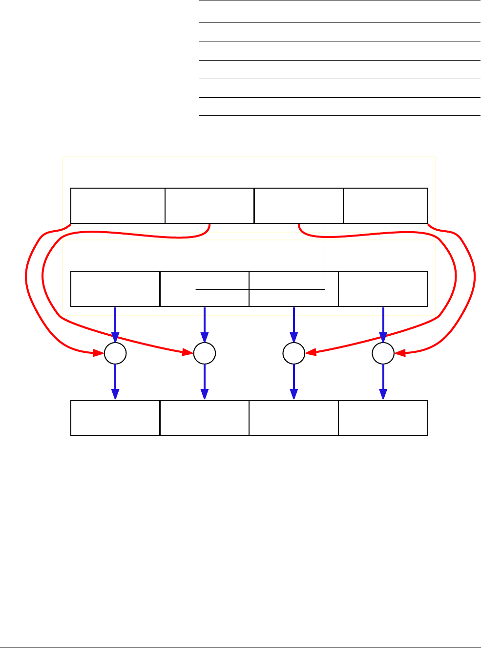
NEON Intrinsics Reference
ARM DEN0018A Copyright © 2013 ARM. All rights reserved. D-9
ID071613 Non-Confidential
Figure D-1 VADD.I32
See also
NEON arithmetic instructions on page C-41.
Assembler Reference:
•NEON instructions,
http://infocenter.arm.com/help/topic/com.arm.doc.dui0489g/CJAJIIGG.html.
D.3.2 VADDL
VADDL
adds corresponding elements of two vectors. The elements in the result vector are wider
than the elements in the input vectors.
uint8x16_t u8 uint8x16_t uint8x16_t
uint16x8_t u16 uint16x8_t uint16x8_t
uint32x4_t u32 uint32x4_t uint32x4_t
uint64x2_t u64 uint64x2_t uint64x2_t
float32x4_t f32 float32x4_t float32x4_t
Table D-7 vector types for
VADDQ
intrinsic (continued)
Result_t type Vector1_t Vector2_t
VADD.I32 Qd, Qn, Qm
Qn
Qm
Element 3
bits[96..127]
Element 2
bits[64..95]
Element 1
bits[32..63]
Element 0
bits[0..31]
Element 3 Element 2 Element 1 Element 0
++++
Element 3 Element 2 Element 1 Element 0
Qd

NEON Intrinsics Reference
ARM DEN0018A Copyright © 2013 ARM. All rights reserved. D-10
ID071613 Non-Confidential
Intrinsic
Result_t vaddl_type(Vector1_t N, Vector2_t M);
Related Instruction
VADDL.dt Qd, Dn, Dm
Input and output vector types
Table D-8 shows the vector types for each type of the
VADDL
intrinsic.
See also
NEON arithmetic instructions on page C-41.
Assembler Reference:
•NEON instructions,
http://infocenter.arm.com/help/topic/com.arm.doc.dui0489g/CJAJIIGG.html.
D.3.3 VADDW
VADDW
adds corresponding elements of two vectors. The elements in the first input vector are
wider than the elements in the second input vector.
Intrinsic
Result_t vaddw_type(Vector1_t N, Vector2_t M);
Related Instruction
VADDWL.dt Qd, Qn, Dm
Table D-8 vector types for
VADDL
intrinsic
Result_t type Vector1_t Vector2_t
int16x8_t s8 int8x8_t int8x8_t
int32x4_t s16 int16x4_t int16x4_t
int64x2_t s32 int32x2_t int32x2_t
uint16x8_t u8 uint8x8_t uint8x8_t
uint32x4_t u16 uint16x4_t uint16x4_t
uint64x2_t u32 uint32x2_t uint32x2_t

NEON Intrinsics Reference
ARM DEN0018A Copyright © 2013 ARM. All rights reserved. D-11
ID071613 Non-Confidential
Input and output vector types
Table D-9 shows the vector types for each type of the
VADDW
intrinsic.
See also
NEON arithmetic instructions on page C-41.
Assembler Reference:
•NEON instructions,
http://infocenter.arm.com/help/topic/com.arm.doc.dui0489g/CJAJIIGG.html.
D.3.4 VHADD
VHADD
adds corresponding elements in two vectors, then halves the sum. The results are
truncated.
Intrinsic
Result_t vhadd_type(Vector1_t N, Vector2_t M);
Result_t vhaddq_type(Vector1_t N, Vector2_t M);
Related Instruction
VHADD.dt Dd, Dn, Dm
VHADD.dt Qd, Qn, Qm
Input and output vector types
Table D-10 shows the vector types for each type of the
VHADD
intrinsic.
Table D-9 vector types for
VADDW
intrinsic
Result_t type Vector1_t Vector2_t
int16x8_t s8 int16x8_t int8x8_t
int32x4_t s16 int32x4_t int16x4_t
int64x2_t s32 int64x2_t int32x2_t
uint16x8_t u8 uint16x8_t uint8x8_t
uint32x4_t u16 uint32x4_t uint16x4_t
uint64x2_t u32 uint64x2_t uint32x2_t
Table D-10 vector types for
VHADD
intrinsic
Result_t type Vector1_t Vector2_t
int8x8_t s8 int8x8_t int8x8_t
int16x4_t s16 int16x4_t int16x4_t
int32x2_t s32 int32x2_t int32x2_t

NEON Intrinsics Reference
ARM DEN0018A Copyright © 2013 ARM. All rights reserved. D-12
ID071613 Non-Confidential
Table D-11 shows the vector types for each type of the
VHADDQ
intrinsic.
See also
NEON arithmetic instructions on page C-41.
Assembler Reference:
•NEON instructions,
http://infocenter.arm.com/help/topic/com.arm.doc.dui0489g/CJAJIIGG.html.
D.3.5 VRHADD
VRHADD
adds corresponding elements in two vectors, then halves the sum. The results are
rounded.
Intrinsic
Result_t vrhadd_type(Vector1_t N, Vector2_t M);
Result_t vrhaddq_type(Vector1_t N, Vector2_t M);
Related Instruction
VRHADD.dt Dd, Dn, Dm
VRHADD.dt Qd, Qn, Qm
uint8x8_t u8 uint8x8_t uint8x8_t
uint16x4_t u16 uint16x4_t uint16x4_t
uint32x2_t u32 uint32x2_t uint32x2_t
Table D-11 vector types for
VHADDQ
intrinsic
Result_t type Vector1_t Vector2_t
int8x16_t s8 int8x16_t int8x16_t
int16x8_t s16 int16x8_t int16x8_t
int32x4_t s32 int32x4_t int32x4_t
uint8x16_t u8 uint8x16_t uint8x16_t
uint16x8_t u16 uint16x8_t uint16x8_t
uint32x4_t u32 uint32x4_t uint32x4_t
Table D-10 vector types for
VHADD
intrinsic (continued)
Result_t type Vector1_t Vector2_t

NEON Intrinsics Reference
ARM DEN0018A Copyright © 2013 ARM. All rights reserved. D-13
ID071613 Non-Confidential
Input and output vector types
Table D-12 shows the vector types for each type of the
VRHADD
intrinsic.
Table D-13 shows the vector types for each type of the
VRHADDQ
intrinsic.
See also
NEON arithmetic instructions on page C-41.
Assembler Reference:
•NEON instructions,
http://infocenter.arm.com/help/topic/com.arm.doc.dui0489g/CJAJIIGG.html.
D.3.6 VQADD
VQADD
adds corresponding elements of two vectors and the results are saturated if they overflow.
Intrinsic
Result_t vqadd_type(Vector1_t N, Vector2_t M);
Result_t vqaddq_type(Vector1_t N, Vector2_t M);
Related Instruction
VQADD.dt Dd, Dn, Dm
VQADD.dt Qd, Qn, Qm
Table D-12 vector types for
VRHADD
intrinsic
Result_t type Vector1_t Vector2_t
int8x8_t s8 int8x8_t int8x8_t
int16x4_t s16 int16x4_t int16x4_t
int32x2_t s32 int32x2_t int32x2_t
uint8x8_t u8 uint8x8_t uint8x8_t
uint16x4_t u16 uint16x4_t uint16x4_t
uint32x2_t u32 uint32x2_t uint32x2_t
Table D-13 vector types for
VRHADDQ
intrinsic
Result_t type Vector1_t Vector2_t
int8x16_t s8 int8x16_t int8x16_t
int16x8_t s16 int16x8_t int16x8_t
int32x4_t s32 int32x4_t int32x4_t
uint8x16_t u8 uint8x16_t uint8x16_t
uint16x8_t u16 uint16x8_t uint16x8_t
uint32x4_t u32 uint32x4_t uint32x4_t

NEON Intrinsics Reference
ARM DEN0018A Copyright © 2013 ARM. All rights reserved. D-14
ID071613 Non-Confidential
Input and output vector types
Table D-14 shows the vector types for each type of the
VQADD
intrinsic.
Table D-15 shows the vector types for each type of the
VQADDQ
intrinsic.
See also
NEON arithmetic instructions on page C-41.
Assembler Reference:
•NEON instructions,
http://infocenter.arm.com/help/topic/com.arm.doc.dui0489g/CJAJIIGG.html.
D.3.7 VADDHN
VADDHN
adds corresponding elements of two vectors, and returns the most significant half of each
sum. The results are truncated.
Intrinsic
Result_t vaddhn_type(Vector1_t N, Vector2_t M);
Table D-14 vector types for
VQADD
intrinsic
Result_t type Vector1_t Vector2_t
int8x8_t s8 int8x8_t int8x8_t
int16x4_t s16 int16x4_t int16x4_t
int32x2_t s32 int32x2_t int32x2_t
int64x1_t s64 int64x1_t int64x1_t
uint8x8_t u8 uint8x8_t uint8x8_t
uint16x4_t u16 uint16x4_t uint16x4_t
uint32x2_t u32 uint32x2_t uint32x2_t
uint64x1_t u64 uint64x1_t uint64x1_t
Table D-15 vector types for
VQADDQ
intrinsic
Result_t type Vector1_t Vector2_t
int8x16_t s8 int8x16_t int8x16_t
int16x8_t s16 int16x8_t int16x8_t
int32x4_t s32 int32x4_t int32x4_t
int64x2_t s64 int64x2_t int64x2_t
uint8x16_t u8 uint8x16_t uint8x16_t
uint16x8_t u16 uint16x8_t uint16x8_t
uint32x4_t u32 uint32x4_t uint32x4_t
uint64x2_t u64 uint64x2_t uint64x2_t

NEON Intrinsics Reference
ARM DEN0018A Copyright © 2013 ARM. All rights reserved. D-15
ID071613 Non-Confidential
Related Instruction
VADDHN.dt Dd, Qn, Qm
Input and output vector types
Table D-16 shows the vector types for each type of the
VADDHN
intrinsic.
See also
NEON arithmetic instructions on page C-41.
Assembler Reference:
•NEON instructions,
http://infocenter.arm.com/help/topic/com.arm.doc.dui0489g/CJAJIIGG.html.
D.3.8 VRADDHN
VRADDHN
adds corresponding elements of two vectors, and returns the most significant half of
each sum. The results are rounded.
Intrinsic
Result_t vraddhn_type(Vector1_t N, Vector2_t M);
Related Instruction
VRADDHN.dt Dd, Qn, Qm
Input and output vector types
Table D-17 shows the vector types for each type of the
VRADDHN
intrinsic.
Table D-16 vector types for
VADDHN
intrinsic
Result_t type Vector1_t Vector2_t
int8x8_t s16 int16x8_t int16x8_t
int16x4_t s32 int32x4_t int32x4_t
int32x2_t s64 int64x2_t int64x2_t
uint8x8_t u16 uint16x8_t uint16x8_t
uint16x4_t u32 uint32x4_t uint32x4_t
uint32x2_t u64 uint64x2_t uint64x2_t
Table D-17 vector types for
VRADDHN
intrinsic
Result_t type Vector1_t Vector2_t
int8x8_t s16 int16x8_t int16x8_t
int16x4_t s32 int32x4_t int32x4_t
int32x2_t s64 int64x2_t int64x2_t

NEON Intrinsics Reference
ARM DEN0018A Copyright © 2013 ARM. All rights reserved. D-16
ID071613 Non-Confidential
See also
NEON arithmetic instructions on page C-41.
Assembler Reference:
•NEON instructions,
http://infocenter.arm.com/help/topic/com.arm.doc.dui0489g/CJAJIIGG.html.
D.3.9 VSUB
VSUB
subtracts the elements in the second vector from the corresponding elements in the first
vector.
Intrinsic
Result_t vsub_type(Vector1_t N, Vector2_t M);
Result_t vsubq_type(Vector1_t N, Vector2_t M);
Related Instruction
VSUB.dt Dd, Dn, Dm
VSUB.dt Qd, Qn, Qm
Input and output vector types
Table D-18 shows the vector types for each type of the
VSUB
intrinsic.
uint8x8_t u16 uint16x8_t uint16x8_t
uint16x4_t u32 uint32x4_t uint32x4_t
uint32x2_t u64 uint64x2_t uint64x2_t
Table D-17 vector types for
VRADDHN
intrinsic (continued)
Result_t type Vector1_t Vector2_t
Table D-18 vector types for
VSUB
intrinsic
Result_t type Vector1_t Vector2_t
int8x8_t s8 int8x8_t int8x8_t
int16x4_t s16 int16x4_t int16x4_t
int32x2_t s32 int32x2_t int32x2_t
int64x1_t s64 int64x1_t int64x1_t
uint8x8_t u8 uint8x8_t uint8x8_t
uint16x4_t u16 uint16x4_t uint16x4_t
uint32x2_t u32 uint32x2_t uint32x2_t
uint64x1_t u64 uint64x1_t uint64x1_t
float32x2_t f32 float32x2_t float32x2_t

NEON Intrinsics Reference
ARM DEN0018A Copyright © 2013 ARM. All rights reserved. D-17
ID071613 Non-Confidential
Table D-19 shows the vector types for each type of the
VSUBQ
intrinsic.
See also
NEON arithmetic instructions on page C-41.
Assembler Reference:
•NEON instructions,
http://infocenter.arm.com/help/topic/com.arm.doc.dui0489g/CJAJIIGG.html.
D.3.10 VSUBL
VSUBL
subtracts the elements in the second vector from the corresponding elements in the first
vector. The elements in the result vector are wider.
Intrinsic
Result_t vsubl_type(Vector1_t N, Vector2_t M);
Related Instruction
VSUBL.dt Qd, Dn, Dm
Input and output vector types
Table D-20 shows the vector types for each type of the
VSUBL
intrinsic.
Table D-19 vector types for
VSUBQ
intrinsic
Result_t type Vector1_t Vector2_t
int8x16_t s8 int8x16_t int8x16_t
int16x8_t s16 int16x8_t int16x8_t
int32x4_t s32 int32x4_t int32x4_t
int64x2_t s64 int64x2_t int64x2_t
uint8x16_t u8 uint8x16_t uint8x16_t
uint16x8_t u16 uint16x8_t uint16x8_t
uint32x4_t u32 uint32x4_t uint32x4_t
uint64x2_t u64 uint64x2_t uint64x2_t
float32x4_t f32 float32x4_t float32x4_t
Table D-20 vector types for
VSUBL
intrinsic
Result_t type Vector1_t Vector2_t
int16x8_t s8 int8x8_t int8x8_t
int32x4_t s16 int16x4_t int16x4_t
int64x2_t s32 int32x2_t int32x2_t

NEON Intrinsics Reference
ARM DEN0018A Copyright © 2013 ARM. All rights reserved. D-18
ID071613 Non-Confidential
See also
NEON arithmetic instructions on page C-41.
Assembler Reference:
•NEON instructions,
http://infocenter.arm.com/help/topic/com.arm.doc.dui0489g/CJAJIIGG.html.
D.3.11 VSUBW
VSUBW
subtracts the elements in the second vector from the corresponding elements in the first
vector. The elements in the first vector and result vector are wider.
Intrinsic
Result_t vsubw_type(Vector1_t N, Vector2_t M);
Related Instruction
VSUBW.dt Qd, Qn, Dm
Input and output vector types
Table D-21 shows the vector types for each type of the
VSUBW
intrinsic.
See also
NEON arithmetic instructions on page C-41.
Assembler Reference:
•NEON instructions,
http://infocenter.arm.com/help/topic/com.arm.doc.dui0489g/CJAJIIGG.html.
uint16x8_t u8 uint8x8_t uint8x8_t
uint32x4_t u16 uint16x4_t uint16x4_t
uint64x2_t u32 uint32x2_t uint32x2_t
Table D-20 vector types for
VSUBL
intrinsic (continued)
Result_t type Vector1_t Vector2_t
Table D-21 vector types for
VSUBW
intrinsic
Result_t type Vector1_t Vector2_t
int16x8_t s8 int16x8_t int8x8_t
int32x4_t s16 int32x4_t int16x4_t
int64x2_t s32 int64x2_t int32x2_t
uint16x8_t u8 uint16x8_t uint8x8_t
uint32x4_t u16 uint32x4_t uint16x4_t
uint64x2_t u32 uint64x2_t uint32x2_t

NEON Intrinsics Reference
ARM DEN0018A Copyright © 2013 ARM. All rights reserved. D-19
ID071613 Non-Confidential
D.3.12 VHSUB
VHSUB
subtracts the elements in the second vector from the corresponding elements in the first
vector, then halves each result. The results are truncated.
Intrinsic
Result_t vhsub_type(Vector1_t N, Vector2_t M);
Result_t vhsubq_type(Vector1_t N, Vector2_t M);
Related Instruction
VHSUB.dt Dd, Dn, Dm
VHSUB.dt Qd, Qn, Qm
Input and output vector types
Table D-22 shows the vector types for each type of the
VHSUB
intrinsic.
Table D-23 shows the vector types for each type of the
VHSUBQ
intrinsic.
See also
NEON arithmetic instructions on page C-41.
Table D-22 vector types for
VHSUB
intrinsic
Result_t type Vector1_t Vector2_t
int8x8_t s8 int8x8_t int8x8_t
int16x4_t s16 int16x4_t int16x4_t
int32x2_t s32 int32x2_t int32x2_t
uint8x8_t u8 uint8x8_t uint8x8_t
uint16x4_t u16 uint16x4_t uint16x4_t
uint32x2_t u32 uint32x2_t uint32x2_t
Table D-23 vector types for
VHSUBQ
intrinsic
Result_t type Vector1_t Vector2_t
int8x16_t s8 int8x16_t int8x16_t
int16x8_t s16 int16x8_t int16x8_t
int32x4_t s32 int32x4_t int32x4_t
uint8x16_t u8 uint8x16_t uint8x16_t
uint16x8_t u16 uint16x8_t uint16x8_t
uint32x4_t u32 uint32x4_t uint32x4_t

NEON Intrinsics Reference
ARM DEN0018A Copyright © 2013 ARM. All rights reserved. D-20
ID071613 Non-Confidential
Assembler Reference:
•NEON instructions,
http://infocenter.arm.com/help/topic/com.arm.doc.dui0489g/CJAJIIGG.html.
D.3.13 VRHSUB
VRHSUB
subtracts the elements in the second vector from the corresponding elements in the first
vector, then halves each result. The results are rounded.
Intrinsic
Result_t vrhsub_type(Vector1_t N, Vector2_t M);
Result_t vrhsubq_type(Vector1_t N, Vector2_t M);
Related Instruction
VRHSUB.dt Dd, Dn, Dm
VRHSUB.dt Qd, Qn, Qm
Input and output vector types
Table D-24 shows the vector types for each type of the
VRHSUB
intrinsic.
Table D-25 shows the vector types for each type of the
VRHSUBQ
intrinsic.
Table D-24 vector types for
VRHSUB
intrinsic
Result_t type Vector1_t Vector2_t
int8x8_t s8 int8x8_t int8x8_t
int16x4_t s16 int16x4_t int16x4_t
int32x2_t s32 int32x2_t int32x2_t
uint8x8_t u8 uint8x8_t uint8x8_t
uint16x4_t u16 uint16x4_t uint16x4_t
uint32x2_t u32 uint32x2_t uint32x2_t
Table D-25 vector types for
VRHSUBQ
intrinsic
Result_t type Vector1_t Vector2_t
int8x16_t s8 int8x16_t int8x16_t
int16x8_t s16 int16x8_t int16x8_t
int32x4_t s32 int32x4_t int32x4_t
uint8x16_t u8 uint8x16_t uint8x16_t
uint16x8_t u16 uint16x8_t uint16x8_t
uint32x4_t u32 uint32x4_t uint32x4_t

NEON Intrinsics Reference
ARM DEN0018A Copyright © 2013 ARM. All rights reserved. D-21
ID071613 Non-Confidential
See also
NEON arithmetic instructions on page C-41.
Assembler Reference:
•NEON instructions,
http://infocenter.arm.com/help/topic/com.arm.doc.dui0489g/CJAJIIGG.html.
D.3.14 VQSUB
VQSUB
subtracts the elements in the second vector from the corresponding elements in the first
vector. If any of the results overflow, they are saturated.
Intrinsic
Result_t vqsub_type(Vector1_t N, Vector2_t M);
Result_t vqsubq_type(Vector1_t N, Vector2_t M);
Related Instruction
VQSUB.dt Dd, Dn, Dm
VQSUB.dt Qd, Qn, Qm
Input and output vector types
Table D-26 shows the vector types for each type of the
VQSUB
intrinsic.
Table D-27 shows the vector types for each type of the
VQSUBQ
intrinsic.
Table D-26 vector types for
VQSUB
intrinsic
Result_t type Vector1_t Vector2_t
int8x8_t s8 int8x8_t int8x8_t
int16x4_t s16 int16x4_t int16x4_t
int32x2_t s32 int32x2_t int32x2_t
int64x1_t s64 int64x1_t int64x1_t
uint8x8_t u8 uint8x8_t uint8x8_t
uint16x4_t u16 uint16x4_t uint16x4_t
uint32x2_t u32 uint32x2_t uint32x2_t
uint64x1_t u64 uint64x1_t uint64x1_t
Table D-27 vector types for
VQSUBQ
intrinsic
Result_t type Vector1_t Vector2_t
int8x16_t s8 int8x16_t int8x16_t
int16x8_t s16 int16x8_t int16x8_t
int32x4_t s32 int32x4_t int32x4_t

NEON Intrinsics Reference
ARM DEN0018A Copyright © 2013 ARM. All rights reserved. D-22
ID071613 Non-Confidential
See also
NEON arithmetic instructions on page C-41.
Assembler Reference:
•NEON instructions,
http://infocenter.arm.com/help/topic/com.arm.doc.dui0489g/CJAJIIGG.html.
D.3.15 VSUBHN
VSUBHN
subtracts the elements in the second vector from the corresponding elements in the first
vector. It returns the most significant halves of the results. The results are truncated.
Intrinsic
Result_t vsubhn_type(Vector1_t N, Vector2_t M);
Related Instruction
VSUBHN.dt Dd, Qn, Qm
Input and output vector types
Table D-28 shows the vector types for each type of the
VSUBHN
intrinsic.
See also
NEON arithmetic instructions on page C-41.
int64x2_t s64 int64x2_t int64x2_t
uint8x16_t u8 uint8x16_t uint8x16_t
uint16x8_t u16 uint16x8_t uint16x8_t
uint32x4_t u32 uint32x4_t uint32x4_t
uint64x2_t u64 uint64x2_t uint64x2_t
Table D-27 vector types for
VQSUBQ
intrinsic (continued)
Result_t type Vector1_t Vector2_t
Table D-28 vector types for
VSUBHN
intrinsic
Result_t type Vector1_t Vector2_t
int8x8_t s16 int16x8_t int16x8_t
int16x4_t s32 int32x4_t int32x4_t
int32x2_t s64 int64x2_t int64x2_t
uint8x8_t u16 uint16x8_t uint16x8_t
uint16x4_t u32 uint32x4_t uint32x4_t
uint32x2_t u64 uint64x2_t uint64x2_t

NEON Intrinsics Reference
ARM DEN0018A Copyright © 2013 ARM. All rights reserved. D-23
ID071613 Non-Confidential
Assembler Reference:
•NEON instructions,
http://infocenter.arm.com/help/topic/com.arm.doc.dui0489g/CJAJIIGG.html.
D.3.16 VRSUBHN
VRSUBHN
subtracts the elements in the second vector from the corresponding elements in the first
vector. It returns the most significant halves of the results. The results are rounded.
Intrinsic
Result_t vrsubhn_type(Vector1_t N, Vector2_t M);
Related Instruction
VRSUBHN.dt Dd, Qn, Qm
Input and output vector types
Table D-29 shows the vector types for each type of the
VRSUBHN
intrinsic.
See also
NEON arithmetic instructions on page C-41.
Assembler Reference:
•NEON instructions,
http://infocenter.arm.com/help/topic/com.arm.doc.dui0489g/CJAJIIGG.html.
Table D-29 vector types for
VRSUBHN
intrinsic
Result_t type Vector1_t Vector2_t
int8x8_t s16 int16x8_t int16x8_t
int16x4_t s32 int32x4_t int32x4_t
int32x2_t s64 int64x2_t int64x2_t
uint8x8_t u16 uint16x8_t uint16x8_t
uint16x4_t u32 uint32x4_t uint32x4_t
uint32x2_t u64 uint64x2_t uint64x2_t

NEON Intrinsics Reference
ARM DEN0018A Copyright © 2013 ARM. All rights reserved. D-24
ID071613 Non-Confidential
D.4 Multiply
These intrinsics multiply vectors.
D.4.1 VMUL
VMUL
multiplies corresponding elements in two vectors. Elements in the result vector and input
vectors have the same width.
Intrinsic
Result_t vmul_type(Vector1_t N, Vector2_t M);
Result_t vmulq_type(Vector1_t N, Vector2_t M);
Related Instruction
VMUL.dt Dd, Dn, Dm
VMUL.dt Qd, Qn, Qm
Input and output vector types
Table D-30 shows the vector types for each type of the
VMUL
intrinsic.
Table D-31 shows the vector types for each type of the
VMULQ
intrinsic.
Table D-30 vector types for
VMUL
intrinsic
Result_t type Vector1_t Vector2_t
int8x8_t s8 int8x8_t int8x8_t
int16x4_t s16 int16x4_t int16x4_t
int32x2_t s32 int32x2_t int32x2_t
uint8x8_t u8 uint8x8_t uint8x8_t
uint16x4_t u16 uint16x4_t uint16x4_t
uint32x2_t u32 uint32x2_t uint32x2_t
float32x2_t f32 float32x2_t float32x2_t
poly8x8_t p8 poly8x8_t poly8x8_t
Table D-31 vector types for
VMULQ
intrinsic
Result_t type Vector1_t Vector2_t
int8x16_t s8 int8x16_t int8x16_t
int16x8_t s16 int16x8_t int16x8_t
int32x4_t s32 int32x4_t int32x4_t
uint8x16_t u8 uint8x16_t uint8x16_t
uint16x8_t u16 uint16x8_t uint16x8_t

NEON Intrinsics Reference
ARM DEN0018A Copyright © 2013 ARM. All rights reserved. D-25
ID071613 Non-Confidential
See also
NEON multiply instructions on page C-55.
Assembler Reference:
•NEON instructions,
http://infocenter.arm.com/help/topic/com.arm.doc.dui0489g/CJAJIIGG.html.
D.4.2 VMLA
VMLA
multiplies corresponding elements in the second and third input vectors, and then adds the
product to the corresponding elements in the first input vector.
Intrinsic
Result_t vmla_type(Vector1_t N, Vector2_t M, Vector3_t P);
Result_t vmlaq_type(Vector1_t N, Vector2_t M, Vector3_t P);
Related Instruction
VMLA.dt Dd, Dn, Dm
VMLA.dt Qd, Qn, Qm
Input and output vector types
Table D-32 shows the vector types for each type of the
VMLA
intrinsic.
uint32x4_t u32 uint32x4_t uint32x4_t
float32x4_t f32 float32x4_t float32x4_t
poly8x16_t p8 poly8x16_t poly8x16_t
Table D-31 vector types for
VMULQ
intrinsic (continued)
Result_t type Vector1_t Vector2_t
Table D-32 vector types for
VMLA
intrinsic
Result_t type Vector1_t Vector2_t Vector3_t
int8x8_t s8 int8x8_t int8x8_t int8x8_t
int16x4_t s16 int16x4_t int16x4_t int16x4_t
int32x2_t s32 int32x2_t int32x2_t int32x2_t
uint8x8_t u8 uint8x8_t uint8x8_t uint8x8_t
uint16x4_t u16 uint16x4_t uint16x4_t uint16x4_t
uint32x2_t u32 uint32x2_t uint32x2_t uint32x2_t
float32x2_t f32 float32x2_t float32x2_t float32x2_t

NEON Intrinsics Reference
ARM DEN0018A Copyright © 2013 ARM. All rights reserved. D-26
ID071613 Non-Confidential
Table D-33 shows the vector types for each type of the
VMLAQ
intrinsic.
See also
NEON multiply instructions on page C-55.
Assembler Reference:
•NEON instructions,
http://infocenter.arm.com/help/topic/com.arm.doc.dui0489g/CJAJIIGG.html.
D.4.3 VMLAL
VMLAL
multiplies corresponding elements in two vectors, and then adds the product to the
corresponding elements in the first input vector. This is a lengthening intrinsic. So the elements
in the result vector are wider than the elements being multiplied.
Intrinsic
Result_t vmlal_type(Vector1_t N, Vector2_t M, Vector3_t P);
Related Instruction
VMLAL.dt Qd, Dn, Dm
Input and output vector types
Table D-34 shows the vector types for each type of the
VMLAL
intrinsic.
Table D-33 vector types for
VMLAQ
intrinsic
Result_t type Vector1_t Vector2_t Vector3_t
int8x16_t s8 int8x16_t int8x16_t int8x16_t
int16x8_t s16 int16x8_t int16x8_t int16x8_t
int32x4_t s32 int32x4_t int32x4_t int32x4_t
uint8x16_t u8 uint8x16_t uint8x16_t uint8x16_t
uint16x8_t u16 uint16x8_t uint16x8_t uint16x8_t
uint32x4_t u32 uint32x4_t uint32x4_t uint32x4_t
float32x4_t f32 float32x4_t float32x4_t float32x4_t
Table D-34 vector types for
VMLAL
intrinsic
Result_t type Vector1_t Vector2_t Vector3_t
int16x8_t s8 int16x8_t int8x8_t int8x8_t
int32x4_t s16 int32x4_t int16x4_t int16x4_t
int64x2_t s32 int64x2_t int32x2_t int32x2_t

NEON Intrinsics Reference
ARM DEN0018A Copyright © 2013 ARM. All rights reserved. D-27
ID071613 Non-Confidential
See also
NEON multiply instructions on page C-55.
Assembler Reference:
•NEON instructions,
http://infocenter.arm.com/help/topic/com.arm.doc.dui0489g/CJAJIIGG.html.
D.4.4 VMLS
VMLS
multiplies corresponding elements in two vectors, subtracts the results from corresponding
elements of the destination vector.
Intrinsic
Result_t vmls_type(Vector1_t N, Vector2_t M, Vector3_t P);
Result_t vmlsq_type(Vector1_t N, Vector2_t M, Vector3_t P);
Related Instruction
VMLS.dt Dd, Dn, Dm
VMLS.dt Qd, Qn, Qm
Input and output vector types
Table D-35 shows the vector types for each type of the
VMLS
intrinsic.
uint16x8_t u8 uint16x8_t uint8x8_t uint8x8_t
uint32x4_t u16 uint32x4_t uint16x4_t uint16x4_t
uint64x2_t u32 uint64x2_t uint32x2_t uint32x2_t
Table D-34 vector types for
VMLAL
intrinsic (continued)
Result_t type Vector1_t Vector2_t Vector3_t
Table D-35 vector types for
VMLS
intrinsic
Result_t type Vector1_t Vector2_t Vector3_t
int8x8_t s8 int8x8_t int8x8_t int8x8_t
int16x4_t s16 int16x4_t int16x4_t int16x4_t
int32x2_t s32 int32x2_t int32x2_t int32x2_t
uint8x8_t u8 uint8x8_t uint8x8_t uint8x8_t
uint16x4_t u16 uint16x4_t uint16x4_t uint16x4_t
uint32x2_t u32 uint32x2_t uint32x2_t uint32x2_t
float32x2_t f32 float32x2_t float32x2_t float32x2_t

NEON Intrinsics Reference
ARM DEN0018A Copyright © 2013 ARM. All rights reserved. D-28
ID071613 Non-Confidential
Table D-36 shows the vector types for each type of the
VMLSQ
intrinsic.
See also
NEON multiply instructions on page C-55.
Assembler Reference:
•NEON instructions,
http://infocenter.arm.com/help/topic/com.arm.doc.dui0489g/CJAJIIGG.html.
D.4.5 VMLSL
VMLSL
multiplies corresponding elements in two vectors, subtracts the results from
corresponding elements of the destination vector.
Intrinsic
Result_t vmlsl_type(Vector1_t N, Vector2_t M, Vector3_t P);
Related Instruction
VMLSL.dt Qd, Dn, Dm
Input and output vector types
Table D-37 shows the vector types for each type of the
VMLSL
intrinsic.
Table D-36 vector types for
VMLSQ
intrinsic
Result_t type Vector1_t Vector2_t Vector3_t
int8x16_t s8 int8x16_t int8x16_t int8x16_t
int16x8_t s16 int16x8_t int16x8_t int16x8_t
int32x4_t s32 int32x4_t int32x4_t int32x4_t
uint8x16_t u8 uint8x16_t uint8x16_t uint8x16_t
uint16x8_t u16 uint16x8_t uint16x8_t uint16x8_t
uint32x4_t u32 uint32x4_t uint32x4_t uint32x4_t
float32x4_t f32 float32x4_t float32x4_t float32x4_t
Table D-37 vector types for
VMLSL
intrinsic
Result_t type Vector1_t Vector2_t Vector3_t
int16x8_t s8 int16x8_t int8x8_t int8x8_t
int32x4_t s16 int32x4_t int16x4_t int16x4_t
int64x2_t s32 int64x2_t int32x2_t int32x2_t
uint16x8_t u8 uint16x8_t uint8x8_t uint8x8_t
uint32x4_t u16 uint32x4_t uint16x4_t uint16x4_t
uint64x2_t u32 uint64x2_t uint32x2_t uint32x2_t

NEON Intrinsics Reference
ARM DEN0018A Copyright © 2013 ARM. All rights reserved. D-29
ID071613 Non-Confidential
See also
NEON multiply instructions on page C-55.
Assembler Reference:
•NEON instructions,
http://infocenter.arm.com/help/topic/com.arm.doc.dui0489g/CJAJIIGG.html.
D.4.6 VQDMULH
VQDMULH
multiplies the operands, doubles the results and returns only the high half of the
truncated results.
Intrinsic
Result_t vqdmulh_type(Vector1_t N, Vector2_t M);
Result_t vqdmulhq_type(Vector1_t N, Vector2_t M);
Related Instruction
VQDMULH.dt Dd, Dn, Dm
VQDMULH.dt Qd, Qn, Qm
Input and output vector types
Table D-38 shows the vector types for each type of the
VQDMULH
intrinsic.
Table D-39 shows the vector types for each type of the
VQDMULHQ
intrinsic.
See also
NEON multiply instructions on page C-55.
Assembler Reference:
•NEON instructions,
http://infocenter.arm.com/help/topic/com.arm.doc.dui0489g/CJAJIIGG.html.
Table D-38 vector types for
VQDMULH
intrinsic
Result_t type Vector1_t Vector2_t
int16x4_t s16 int16x4_t int16x4_t
int32x2_t s32 int32x2_t int32x2_t
Table D-39 vector types for
VQDMULHQ
intrinsic
Result_t type Vector1_t Vector2_t
int16x8_t s16 int16x8_t int16x8_t
int32x4_t s32 int32x4_t int32x4_t

NEON Intrinsics Reference
ARM DEN0018A Copyright © 2013 ARM. All rights reserved. D-30
ID071613 Non-Confidential
D.4.7 VQRDMULH
VQRDMULH
multiplies the operands, doubles the results and returns only the high half of the
rounded results. The results are saturated if they overflow.
Intrinsic
Result_t vqrdmulh_type(Vector1_t N, Vector2_t M);
Result_t vqrdmulhq_type(Vector1_t N, Vector2_t M);
Related Instruction
VQRDMULH.dt Dd, Dn, Dm
VQRDMULH.dt Qd, Qn, Qm
Input and output vector types
Table D-40 shows the vector types for each type of the
VQRDMULH
intrinsic.
Table D-41 shows the vector types for each type of the
VQRDMULHQ
intrinsic.
See also
NEON multiply instructions on page C-55.
Assembler Reference:
•NEON instructions,
http://infocenter.arm.com/help/topic/com.arm.doc.dui0489g/CJAJIIGG.html.
D.4.8 VQDMLAL
VQDMLAL
multiplies the elements in the second and third vectors, doubles the results and adds the
results to the values in the first vector. The results are saturated if they overflow.
Intrinsic
Result_t vqdmlal_type(Vector1_t N, Vector2_t M, Vector3_t P);
Table D-40 vector types for
VQRDMULH
intrinsic
Result_t type Vector1_t Vector2_t
int16x4_t s16 int16x4_t int16x4_t
int32x2_t s32 int32x2_t int32x2_t
Table D-41 vector types for
VQRDMULHQ
intrinsic
Result_t type Vector1_t Vector2_t
int16x8_t s16 int16x8_t int16x8_t
int32x4_t s32 int32x4_t int32x4_t

NEON Intrinsics Reference
ARM DEN0018A Copyright © 2013 ARM. All rights reserved. D-31
ID071613 Non-Confidential
Related Instruction
VQDMLAL.dt Qd, Dn, Dm
Input and output vector types
Table D-42 shows the vector types for each type of the
VQDMLAL
intrinsic.
See also
NEON multiply instructions on page C-55.
Assembler Reference:
•NEON instructions,
http://infocenter.arm.com/help/topic/com.arm.doc.dui0489g/CJAJIIGG.html.
D.4.9 VQDMLSL
VQDMLSL
multiplies the elements in the second and third vectors, doubles the results and subtracts
the results from the elements in the first vector. The results are saturated if they overflow.
Intrinsic
Result_t vqdmlsl_type(Vector1_t N, Vector2_t M, Vector3_t P);
Related Instruction
VQDMLSL.dt Qd, Dn, Dm
Input and output vector types
Table D-43 shows the vector types for each type of the
VQDMLSL
intrinsic.
See also
NEON multiply instructions on page C-55.
Assembler Reference:
•NEON instructions,
http://infocenter.arm.com/help/topic/com.arm.doc.dui0489g/CJAJIIGG.html.
Table D-42 vector types for
VQDMLAL
intrinsic
Result_t type Vector1_t Vector2_t Vector3_t
int32x4_t s16 int32x4_t int16x4_t int16x4_t
int64x2_t s32 int64x2_t int32x2_t int32x2_t
Table D-43 vector types for
VQDMLSL
intrinsic
Result_t type Vector1_t Vector2_t Vector3_t
int32x4_t s16 int32x4_t int16x4_t int16x4_t
int64x2_t s32 int64x2_t int32x2_t int32x2_t

NEON Intrinsics Reference
ARM DEN0018A Copyright © 2013 ARM. All rights reserved. D-32
ID071613 Non-Confidential
D.4.10 VMULL
VMULL
multiplies corresponding elements in two vectors. Elements in result are wider than
elements in input vectors.
Intrinsic
Result_t vmull_type(Vector1_t N, Vector2_t M);
Related Instruction
VMULL.dt Qd, Dn, Dm
Input and output vector types
Table D-44 shows the vector types for each type of the
VMULL
intrinsic.
See also
NEON multiply instructions on page C-55.
Assembler Reference:
•NEON instructions,
http://infocenter.arm.com/help/topic/com.arm.doc.dui0489g/CJAJIIGG.html.
D.4.11 VQDMULL
VQDMULL
multiplies the elements in the input vectors, doubles the results.
Intrinsic
Result_t vqdmull_type(Vector1_t N, Vector2_t M);
Related Instruction
VQDMULL.dt Qd, Dn, Dm
Table D-44 vector types for
VMULL
intrinsic
Result_t type Vector1_t Vector2_t
int16x8_t s8 int8x8_t int8x8_t
int32x4_t s16 int16x4_t int16x4_t
int64x2_t s32 int32x2_t int32x2_t
uint16x8_t u8 uint8x8_t uint8x8_t
uint32x4_t u16 uint16x4_t uint16x4_t
uint64x2_t u32 uint32x2_t uint32x2_t
poly16x8_t p8 poly8x8_t poly8x8_t

NEON Intrinsics Reference
ARM DEN0018A Copyright © 2013 ARM. All rights reserved. D-33
ID071613 Non-Confidential
Input and output vector types
Table D-45 shows the vector types for each type of the
VQDMULL
intrinsic.
See also
NEON multiply instructions on page C-55.
Assembler Reference:
•NEON instructions,
http://infocenter.arm.com/help/topic/com.arm.doc.dui0489g/CJAJIIGG.html.
D.4.12 VMLA_LANE
VMLA_LANE
multiplies each element in the second vector by a scalar, and adds the results to the
corresponding elements of the first vector. The scalar has index n in the third vector.
Intrinsic
Result_t vmla_lane_type(Vector1_t N, Vector2_t M, Vector3_t P, int n);
Result_t vmlaq_lane_type(Vector1_t N, Vector2_t M, Vector3_t P, int n);
Related Instruction
VMLA.dt Dd, Dn, Dm[x]
VMLA.dt Qd, Qn, Dm[x]
Input and output vector types
Table D-46 shows the vector types for each type of the
VMLA_LANE
intrinsic.
Table D-45 vector types for
VQDMULL
intrinsic
Result_t type Vector1_t Vector2_t
int32x4_t s16 int16x4_t int16x4_t
int64x2_t s32 int32x2_t int32x2_t
Table D-46 vector types for
VMLA_LANE
intrinsic
Result_t type Vector1_t Vector2_t Vector3_t int range
int16x4_t s16 int16x4_t int16x4_t int16x4_t 0-3
int32x2_t s32 int32x2_t int32x2_t int32x2_t 0-1
uint16x4_t u16 uint16x4_t uint16x4_t uint16x4_t 0-3
uint32x2_t u32 uint32x2_t uint32x2_t uint32x2_t 0-1
float32x2_t f32 float32x2_t float32x2_t float32x2_t 0-1

NEON Intrinsics Reference
ARM DEN0018A Copyright © 2013 ARM. All rights reserved. D-34
ID071613 Non-Confidential
Table D-47 shows the vector types for each type of the
VMLAQ_LANE
intrinsic.
See also
NEON multiply instructions on page C-55.
Assembler Reference:
•NEON instructions,
http://infocenter.arm.com/help/topic/com.arm.doc.dui0489g/CJAJIIGG.html.
D.4.13 VMLAL_LANE
VMLAL_LANE
multiplies each element in the second vector by a scalar, and adds the results to the
corresponding elements of the first vector. The scalar has index n in the third vector. The
elements in the result are wider.
Intrinsic
Result_t vmlal_lane_type(Vector1_t N, Vector2_t M, Vector3_t P, int n);
Related Instruction
VMLAL.dt Qd, Dn, Dm[x]
Input and output vector types
Table D-48 shows the vector types for each type of the
VMLAL_LANE
intrinsic.
See also
NEON multiply instructions on page C-55.
Table D-47 vector types for
VMLAQ_LANE
intrinsic
Result_t type Vector1_t Vector2_t Vector3_t int range
int16x8_t s16 int16x8_t int16x8_t int16x4_t 0-3
int32x4_t s32 int32x4_t int32x4_t int32x2_t 0-1
uint16x8_t u16 uint16x8_t uint16x8_t uint16x4_t 0-3
uint32x4_t u32 uint32x4_t uint32x4_t uint32x2_t 0-1
float32x4_t f32 float32x4_t float32x4_t float32x2_t 0-1
Table D-48 vector types for
VMLAL_LANE
intrinsic
Result_t type Vector1_t Vector2_t Vector3_t int range
int32x4_t s16 int32x4_t int16x4_t int16x4_t 0-3
int64x2_t s32 int64x2_t int32x2_t int32x2_t 0-1
uint32x4_t u16 uint32x4_t uint16x4_t uint16x4_t 0-3
uint64x2_t u32 uint64x2_t uint32x2_t uint32x2_t 0-1
NEON Intrinsics Reference
ARM DEN0018A Copyright © 2013 ARM. All rights reserved. D-35
ID071613 Non-Confidential
Assembler Reference:
•NEON instructions,
http://infocenter.arm.com/help/topic/com.arm.doc.dui0489g/CJAJIIGG.html.
D.4.14 VQDMLAL_LANE
VQDMLAL_LANE
multiplies each element in the second vector by a scalar, doubles the results and
adds them to the corresponding elements of the first vector. The scalar has index n in the third
vector. If any of the results overflow, they are saturated and the sticky QC flag (FPSCR bit[27])
is set.
Intrinsic
Result_t vqdmlal_lane_type(Vector1_t N, Vector2_t M, Vector3_t P, int n);
Related Instruction
VQDMLAL.dt Dd, Dn, Dm[x]
Input and output vector types
Table D-49 shows the vector types for each type of the
VQDMLAL_LANE
intrinsic.
See also
NEON multiply instructions on page C-55.
Assembler Reference:
•NEON instructions,
http://infocenter.arm.com/help/topic/com.arm.doc.dui0489g/CJAJIIGG.html.
D.4.15 VMLS_LANE
VMLS_LANE
multiplies each element in the second vector by a scalar, and subtracts them from the
corresponding elements of the first vector. The scalar has index n in the third vector.
Intrinsic
Result_t vmls_lane_type(Vector1_t N, Vector2_t M, Vector3_t P, int n);
Result_t vmlsq_lane_type(Vector1_t N, Vector2_t M, Vector3_t P, int n);
Related Instruction
VMLS.dt Dd, Dn, Dm[x]
VMLS.dt Qd, Qn, Dm[x]
Table D-49 vector types for
VQDMLAL_LANE
intrinsic
Result_t type Vector1_t Vector2_t Vector3_t int range
int32x4_t s16 int32x4_t int16x4_t int16x4_t 0-3
int64x2_t s32 int64x2_t int32x2_t int32x2_t 0-1

NEON Intrinsics Reference
ARM DEN0018A Copyright © 2013 ARM. All rights reserved. D-36
ID071613 Non-Confidential
Input and output vector types
Table D-50 shows the vector types for each type of the
VMLS_LANE
intrinsic.
Table D-51 shows the vector types for each type of the
VMLSQ_LANE
intrinsic.
See also
NEON multiply instructions on page C-55.
Assembler Reference:
•NEON instructions,
http://infocenter.arm.com/help/topic/com.arm.doc.dui0489g/CJAJIIGG.html.
D.4.16 VMLSL_LANE
VMLSL_LANE
multiplies each element in the second vector by a scalar, and subtracts them from the
corresponding elements of the first vector. The scalar has index n in the third vector. The
elements in the result are wider.
Intrinsic
Result_t vmlsl_lane_type(Vector1_t N, Vector2_t M, Vector3_t P, int n);
Related Instruction
VMLSL.dt Qd, Dn, Dm[x]
Table D-50 vector types for
VMLS_LANE
intrinsic
Result_t type Vector1_t Vector2_t Vector3_t int range
int16x4_t s16 int16x4_t int16x4_t int16x4_t 0-3
int32x2_t s32 int32x2_t int32x2_t int32x2_t 0-1
uint16x4_t u16 uint16x4_t uint16x4_t uint16x4_t 0-3
uint32x2_t u32 uint32x2_t uint32x2_t uint32x2_t 0-1
float32x2_t f32 float32x2_t float32x2_t float32x2_t 0-1
Table D-51 vector types for
VMLSQ_LANE
intrinsic
Result_t type Vector1_t Vector2_t Vector3_t int range
int16x8_t s16 int16x8_t int16x8_t int16x4_t 0-3
int32x4_t s32 int32x4_t int32x4_t int32x2_t 0-1
uint16x8_t u16 uint16x8_t uint16x8_t uint16x4_t 0-3
uint32x4_t u32 uint32x4_t uint32x4_t uint32x2_t 0-1
float32x4_t f32 float32x4_t float32x4_t float32x2_t 0-1

NEON Intrinsics Reference
ARM DEN0018A Copyright © 2013 ARM. All rights reserved. D-37
ID071613 Non-Confidential
Input and output vector types
Table D-52 shows the vector types for each type of the
VMLSL_LANE
intrinsic.
See also
NEON multiply instructions on page C-55.
Assembler Reference:
•NEON instructions,
http://infocenter.arm.com/help/topic/com.arm.doc.dui0489g/CJAJIIGG.html.
D.4.17 VQDMLSL_LANE
VQDMLSL_LANE
multiplies each element in the second vector by a scalar, doubles the results and
subtracts them from the corresponding elements of the first vector. The scalar has index n in the
third vector. If any of the results overflow, they are saturated and the sticky QC flag (FPSCR
bit[27]) is set.
Intrinsic
Result_t vqdmlsl_lane_type(Vector1_t N, Vector2_t M, Vector3_t P, int n);
Related Instruction
VQDMLSL.dt Dd, Dn, Dm[x]
Input and output vector types
Table D-53 shows the vector types for each type of the
VQDMLSL_LANE
intrinsic.
See also
NEON multiply instructions on page C-55.
Table D-52 vector types for
VMLSL_LANE
intrinsic
Result_t type Vector1_t Vector2_t Vector3_t int range
int32x4_t s16 int32x4_t int16x4_t int16x4_t 0-3
int64x2_t s32 int64x2_t int32x2_t int32x2_t 0-1
uint32x4_t u16 uint32x4_t uint16x4_t uint16x4_t 0-3
uint64x2_t u32 uint64x2_t uint32x2_t uint32x2_t 0-1
Table D-53 vector types for
VQDMLSL_LANE
intrinsic
Result_t type Vector1_t Vector2_t Vector3_t int range
int32x4_t s16 int32x4_t int16x4_t int16x4_t 0-3
int64x2_t s32 int64x2_t int32x2_t int32x2_t 0-1

NEON Intrinsics Reference
ARM DEN0018A Copyright © 2013 ARM. All rights reserved. D-38
ID071613 Non-Confidential
Assembler Reference:
•NEON instructions,
http://infocenter.arm.com/help/topic/com.arm.doc.dui0489g/CJAJIIGG.html.
D.4.18 VMUL_N
VMUL_N
multiplies a vector by a scalar.
Intrinsic
Result_t vmul_n_type(Vector_t N, Scalar_t M);
Result_t vmulq_n_type(Vector_t N, Scalar_t M);
Related Instruction
VMUL.dt Dd, Dn, Dm[x]
VMUL.dt Qd, Qn, Dm[x]
Input and output vector types
Table D-54 shows the vector types for each type of the
VMUL_N
intrinsic.
Table D-55 shows the vector types for each type of the
VMULQ_N
intrinsic.
See also
NEON multiply instructions on page C-55.
Table D-54 vector types for
VMUL_N
intrinsic
Result_t type Vector_t Scalar_t
int16x4_t s16 int16x4_t int16_t
int32x2_t s32 int32x2_t int32_t
uint16x4_t u16 uint16x4_t uint16_t
uint32x2_t u32 uint32x2_t uint32_t
float32x2_t f32 float32x2_t float32_t
Table D-55 vector types for
VMULQ_N
intrinsic
Result_t type Vector_t Scalar_t
int16x8_t s16 int16x8_t int16_t
int32x4_t s32 int32x4_t int32_t
uint16x8_t u16 uint16x8_t uint16_t
uint32x4_t u32 uint32x4_t uint32_t
float32x4_t f32 float32x4_t float32_t

NEON Intrinsics Reference
ARM DEN0018A Copyright © 2013 ARM. All rights reserved. D-39
ID071613 Non-Confidential
Assembler Reference:
•NEON instructions,
http://infocenter.arm.com/help/topic/com.arm.doc.dui0489g/CJAJIIGG.html.
D.4.19 VMULL_N
VMULL_N
multiplies a vector by a scalar. Elements in the result are wider than elements in input
vector.
Intrinsic
Result_t vmull_n_type(Vector_t N, Scalar_t M);
Related Instruction
VMULL.dt Qd, Dn, Dm[x]
Input and output vector types
Table D-56 shows the vector types for each type of the
VMULL_N
intrinsic.
See also
NEON multiply instructions on page C-55.
Assembler Reference:
•NEON instructions,
http://infocenter.arm.com/help/topic/com.arm.doc.dui0489g/CJAJIIGG.html.
D.4.20 VMULL_LANE
VMULL_LANE
multiplies the first vector by a scalar. The scalar is the element in the second vector
with index n. The elements in the result are wider than the elements in input vector.
Intrinsic
Result_t vmull_lane_type(Vector1_t N, Vector2_t M, int n);
Related Instruction
VMULL.dt Qd, Dn, Dm[x]
Table D-56 vector types for
VMULL_N
intrinsic
Result_t type Vector_t Scalar_t
int32x4_t s16 int16x4_t int16_t
int64x2_t s32 int32x2_t int32_t
uint32x4_t u16 uint16x4_t uint16_t
uint64x2_t u32 uint32x2_t uint32_t

NEON Intrinsics Reference
ARM DEN0018A Copyright © 2013 ARM. All rights reserved. D-40
ID071613 Non-Confidential
Input and output vector types
Table D-57 shows the vector types for each type of the
VMULL_LANE
intrinsic.
See also
NEON multiply instructions on page C-55.
Assembler Reference:
•NEON instructions,
http://infocenter.arm.com/help/topic/com.arm.doc.dui0489g/CJAJIIGG.html.
D.4.21 VQDMULL_N
VQDMULL_N
multiplies the elements in the vector by a scalar, and doubles the results. If any of the
results overflow, they are saturated and the sticky QC flag (FPSCR bit[27]) is set.
Intrinsic
Result_t vqdmull_n_type(Vector_t N, Scalar_t M);
Related Instruction
VQDMULL.dt Qd, Dn, Dm[x]
Input and output vector types
Table D-58 shows the vector types for each type of the
VQDMULL_N
intrinsic.
See also
NEON multiply instructions on page C-55.
Assembler Reference:
•NEON instructions,
http://infocenter.arm.com/help/topic/com.arm.doc.dui0489g/CJAJIIGG.html.
Table D-57 vector types for
VMULL_LANE
intrinsic
Result_t type Vector1_t Vector2_t int range
int32x4_t s16 int16x4_t int16x4_t 0-3
int64x2_t s32 int32x2_t int32x2_t 0-1
uint32x4_t u16 uint16x4_t uint16x4_t 0-3
uint64x2_t u32 uint32x2_t uint32x2_t 0-1
Table D-58 vector types for
VQDMULL_N
intrinsic
Result_t type Vector_t Scalar_t
int32x4_t s16 int16x4_t int16_t
int64x2_t s32 int32x2_t int32_t

NEON Intrinsics Reference
ARM DEN0018A Copyright © 2013 ARM. All rights reserved. D-41
ID071613 Non-Confidential
D.4.22 VQDMULL_LANE
VQDMULL_LANE
multiplies the elements in the first vector by a scalar, and doubles the results. The
scalar has index n in the second vector. If any of the results overflow, they are saturated and the
sticky QC flag (FPSCR bit[27]) is set.
Intrinsic
Result_t vqdmull_lane_type(Vector1_t N, Vector2_t M, int n);
Related Instruction
VQDMULL.dt Qd, Dn, Dm[x]
Input and output vector types
Table D-59 shows the vector types for each type of the
VQDMULL_LANE
intrinsic.
See also
NEON multiply instructions on page C-55.
Assembler Reference:
•NEON instructions,
http://infocenter.arm.com/help/topic/com.arm.doc.dui0489g/CJAJIIGG.html.
D.4.23 VQDMULH_N
VQDMULH_N
multiplies the elements of the vector by a scalar, and doubles the results. It then
returns only the high half of the results. If any of the results overflow, they are saturated and the
sticky QC flag (FPSCR bit[27]) is set.
Intrinsic
Result_t vqdmulh_n_type(Vector_t N, Scalar_t M);
Result_t vqdmulhq_n_type(Vector_t N, Scalar_t M);
Related Instruction
VQDMULH.dt Dd, Dn, Dm[x]
VQDMULH.dt Qd, Qn, Dm[x]
Table D-59 vector types for
VQDMULL_LANE
intrinsic
Result_t type Vector1_t Vector2_t int range
int32x4_t s16 int16x4_t int16x4_t 0-3
int64x2_t s32 int32x2_t int32x2_t 0-1

NEON Intrinsics Reference
ARM DEN0018A Copyright © 2013 ARM. All rights reserved. D-42
ID071613 Non-Confidential
Input and output vector types
Table D-60 shows the vector types for each type of the
VQDMULH_N
intrinsic.
Table D-61 shows the vector types for each type of the
VQDMULHQ_N
intrinsic.
See also
NEON multiply instructions on page C-55.
Assembler Reference:
•NEON instructions,
http://infocenter.arm.com/help/topic/com.arm.doc.dui0489g/CJAJIIGG.html.
D.4.24 VQDMULH_LANE
VQDMULH_LANE
multiplies the elements of the first vector by a scalar, and doubles the results. It
then returns only the high half of the results. The scalar has index n in the second vector. If any
of the results overflow, they are saturated and the sticky QC flag (FPSCR bit[27]) is set.
Intrinsic
Result_t vqdmulh_lane_type(Vector1_t N, Vector2_t M, int n);
Result_t vqdmulhq_lane_type(Vector1_t N, Vector2_t M, int n);
Related Instruction
VQDMULH.dt Dd, Dn, Dm[x]
VQDMULH.dt Qd, Qn, Dm[x]
Table D-60 vector types for
VQDMULH_N
intrinsic
Result_t type Vector_t Scalar_t
int16x4_t s16 int16x4_t int16_t
int32x2_t s32 int32x2_t int32_t
Table D-61 vector types for
VQDMULHQ_N
intrinsic
Result_t type Vector_t Scalar_t
int16x8_t s16 int16x8_t int16_t
int32x4_t s32 int32x4_t int32_t

NEON Intrinsics Reference
ARM DEN0018A Copyright © 2013 ARM. All rights reserved. D-43
ID071613 Non-Confidential
Input and output vector types
Table D-62 shows the vector types for each type of the
VQDMULH_LANE
intrinsic.
Table D-63 shows the vector types for each type of the
VQDMULHQ_LANE
intrinsic.
See also
NEON multiply instructions on page C-55.
Assembler Reference:
•NEON instructions,
http://infocenter.arm.com/help/topic/com.arm.doc.dui0489g/CJAJIIGG.html.
D.4.25 VQRDMULH_N
VQRDMULH_N
multiplies the elements of the vector by a scalar and doubles the results. It then
returns only the high half of the rounded results. If any of the results overflow, they are saturated
and the sticky QC flag (FPSCR bit[27]) is set.
Intrinsic
Result_t vqrdmulh_n_type(Vector_t N, Scalar_t M);
Result_t vqrdmulhq_n_type(Vector_t N, Scalar_t M);
Related Instruction
VQRDMULH.dt Dd, Dn, Dm[x]
VQRDMULH.dt Qd, Qn, Dm[x]
Table D-62 vector types for
VQDMULH_LANE
intrinsic
Result_t type Vector1_t Vector2_t int range
int16x4_t s16 int16x4_t int16x4_t 0-3
int32x2_t s32 int32x2_t int32x2_t 0-1
Table D-63 vector types for
VQDMULHQ_LANE
intrinsic
Result_t type Vector1_t Vector2_t int range
int16x8_t s16 int16x8_t int16x4_t 0-3
int32x4_t s32 int32x4_t int32x2_t 0-1

NEON Intrinsics Reference
ARM DEN0018A Copyright © 2013 ARM. All rights reserved. D-44
ID071613 Non-Confidential
Input and output vector types
Table D-64 shows the vector types for each type of the
VQRDMULH_N
intrinsic.
Table D-65 shows the vector types for each type of the
VQRDMULHQ_N
intrinsic.
See also
NEON multiply instructions on page C-55.
Assembler Reference:
•NEON instructions,
http://infocenter.arm.com/help/topic/com.arm.doc.dui0489g/CJAJIIGG.html.
D.4.26 VQRDMULH_LANE
VQRDMULH_LANE
multiplies the elements of the first vector by a scalar and doubles the results. It
then returns only the high half of the rounded results. The scalar has index n in the second vector.
If any of the results overflow, they are saturated and the sticky QC flag (FPSCR bit[27]) is set.
Intrinsic
Result_t vqrdmulh_lane_type(Vector1_t N, Vector2_t M, int n);
Result_t vqrdmulhq_lane_type(Vector1_t N, Vector2_t M, int n);
Related Instruction
VQRDMULH.dt Dd, Dn, Dm[x]
VQRDMULH.dt Qd, Qn, Dm[x]
Table D-64 vector types for
VQRDMULH_N
intrinsic
Result_t type Vector_t Scalar_t
int16x4_t s16 int16x4_t int16_t
int32x2_t s32 int32x2_t int32_t
Table D-65 vector types for
VQRDMULHQ_N
intrinsic
Result_t type Vector_t Scalar_t
int16x8_t s16 int16x8_t int16_t
int32x4_t s32 int32x4_t int32_t

NEON Intrinsics Reference
ARM DEN0018A Copyright © 2013 ARM. All rights reserved. D-45
ID071613 Non-Confidential
Input and output vector types
Table D-66 shows the vector types for each type of the
VQRDMULH_LANE
intrinsic.
Table D-67 shows the vector types for each type of the
VQRDMULHQ_LANE
intrinsic.
See also
NEON multiply instructions on page C-55.
Assembler Reference:
•NEON instructions,
http://infocenter.arm.com/help/topic/com.arm.doc.dui0489g/CJAJIIGG.html.
D.4.27 VMLA_LANE
VMLA_LANE
multiplies each element in the second vector by a scalar, and adds the results into the
corresponding elements of the first vector. The scalar has index n in the third vector.
Intrinsic
Result_t vmla_lane_type(Vector1_t N, Vector2_t M, Vector3_t P, int n);
Result_t vmlaq_lane_type(Vector1_t N, Vector2_t M, Vector3_t P, int n);
Related Instruction
VMLA.dt Dd, Dn, Dm[x]
VMLA.dt Qd, Qn, Dm[x]
Table D-66 vector types for
VQRDMULH_LANE
intrinsic
Result_t type Vector1_t Vector2_t int range
int16x4_t s16 int16x4_t int16x4_t 0-3
int32x2_t s32 int32x2_t int32x2_t 0-1
Table D-67 vector types for
VQRDMULHQ_LANE
intrinsic
Result_t type Vector1_t Vector2_t int range
int16x8_t s16 int16x8_t int16x4_t 0-3
int32x4_t s32 int32x4_t int32x2_t 0-1

NEON Intrinsics Reference
ARM DEN0018A Copyright © 2013 ARM. All rights reserved. D-46
ID071613 Non-Confidential
Input and output vector types
Table D-68 shows the vector types for each type of the
VMLA_LANE
intrinsic.
Table D-69 shows the vector types for each type of the
VMLAQ_LANE
intrinsic.
See also
NEON multiply instructions on page C-55.
Assembler Reference:
•NEON instructions,
http://infocenter.arm.com/help/topic/com.arm.doc.dui0489g/CJAJIIGG.html.
D.4.28 VMLAL_N
VMLAL_N
multiplies each element in the second vector by a scalar, and adds the results into the
corresponding elements of the first vector. The scalar has index n in the third vector. The
elements in the result are wider.
Intrinsic
Result_t vmlal_n_type(Vector1_t N, Vector2_t M, Scalar_t P);
Related Instruction
VMLAL.dt Qd, Dn, Dm[x]
Table D-68 vector types for
VMLA_LANE
intrinsic
Result_t type Vector1_t Vector2_t Vector3_t int range
int16x4_t s16 int16x4_t int16x4_t int16x4_t 0-3
int32x2_t s32 int32x2_t int32x2_t int32x2_t 0-1
uint16x4_t u16 uint16x4_t uint16x4_t uint16x4_t 0-3
uint32x2_t u32 uint32x2_t uint32x2_t uint32x2_t 0-1
float32x2_t f32 float32x2_t float32x2_t float32x2_t 0-1
Table D-69 vector types for
VMLAQ_LANE
intrinsic
Result_t type Vector1_t Vector2_t Vector3_t int range
int16x8_t s16 int16x8_t int16x8_t int16x4_t 0-3
int32x4_t s32 int32x4_t int32x4_t int32x2_t 0-1
uint16x8_t u16 uint16x8_t uint16x8_t uint16x4_t 0-3
uint32x4_t u32 uint32x4_t uint32x4_t uint32x2_t 0-1
float32x4_t f32 float32x4_t float32x4_t float32x2_t 0-1

NEON Intrinsics Reference
ARM DEN0018A Copyright © 2013 ARM. All rights reserved. D-47
ID071613 Non-Confidential
Input and output vector types
Table D-70 shows the vector types for each type of the
VMLAL_N
intrinsic.
See also
NEON multiply instructions on page C-55.
Assembler Reference:
•NEON instructions,
http://infocenter.arm.com/help/topic/com.arm.doc.dui0489g/CJAJIIGG.html.
D.4.29 VQDMLAL_N
VQDMLAL_N
multiplies the elements in the second vector by a scalar, and doubles the results. It
then adds the results to the elements in the first vector. If any of the results overflow, they are
saturated and the sticky QC flag (FPSCR bit[27]) is set.
Intrinsic
Result_t vqdmlal_n_type(Vector1_t N, Vector2_t M, Scalar_t P);
Related Instruction
VQDMLAL.dt Dd, Dn, Dm[x]
Input and output vector types
Table D-71 shows the vector types for each type of the
VQDMLAL_N
intrinsic.
See also
NEON multiply instructions on page C-55.
Assembler Reference:
•NEON instructions,
http://infocenter.arm.com/help/topic/com.arm.doc.dui0489g/CJAJIIGG.html.
Table D-70 vector types for
VMLAL_N
intrinsic
Result_t type Vector1_t Vector2_t Scalar_t
int32x4_t s16 int32x4_t int16x4_t int16_t
int64x2_t s32 int64x2_t int32x2_t int32_t
uint32x4_t u16 uint32x4_t uint16x4_t uint16_t
uint64x2_t u32 uint64x2_t uint32x2_t uint32_t
Table D-71 vector types for
VQDMLAL_N
intrinsic
Result_t type Vector1_t Vector2_t Scalar_t
int32x4_t s16 int32x4_t int16x4_t int16_t
int64x2_t s32 int64x2_t int32x2_t int32_t

NEON Intrinsics Reference
ARM DEN0018A Copyright © 2013 ARM. All rights reserved. D-48
ID071613 Non-Confidential
D.4.30 VMLSL_N
VMLSL_N
multiplies the elements in the second vector by a scalar, then subtracts the results from
the elements in the first vector. The elements of the result are wider.
Intrinsic
Result_t vmlsl_n_type(Vector1_t N, Vector2_t M, Scalar_t P);
Related Instruction
VMLSL.dt Qd, Dn, Dm[x]
Input and output vector types
Table D-72 shows the vector types for each type of the
VMLSL_N
intrinsic.
See also
NEON multiply instructions on page C-55.
Assembler Reference:
•NEON instructions,
http://infocenter.arm.com/help/topic/com.arm.doc.dui0489g/CJAJIIGG.html.
D.4.31 VQDMLSL_N
VQDMLSL_N
multiplies the elements of the second vector with a scalar and doubles the results. It
then subtracts the results from the elements in the first vector. If any of the results overflow, they
are saturated and the sticky QC flag (FPSCR bit[27]) is set.
Intrinsic
Result_t vqdmlsl_n_type(Vector1_t N, Vector2_t M, Scalar_t P);
Related Instruction
VQDMLSL.dt Dd, Dn, Dm[x]
Table D-72 vector types for
VMLSL_N
intrinsic
Result_t type Vector1_t Vector2_t Scalar_t
int32x4_t s16 int32x4_t int16x4_t int16_t
int64x2_t s32 int64x2_t int32x2_t int32_t
uint32x4_t u16 uint32x4_t uint16x4_t uint16_t
uint64x2_t u32 uint64x2_t uint32x2_t uint32_t

NEON Intrinsics Reference
ARM DEN0018A Copyright © 2013 ARM. All rights reserved. D-49
ID071613 Non-Confidential
Input and output vector types
Table D-73 shows the vector types for each type of the
VQDMLSL_N
intrinsic.
See also
NEON multiply instructions on page C-55.
Assembler Reference:
•NEON instructions,
http://infocenter.arm.com/help/topic/com.arm.doc.dui0489g/CJAJIIGG.html.
Table D-73 vector types for
VQDMLSL_N
intrinsic
Result_t type Vector1_t Vector2_t Scalar_t
int32x4_t s16 int32x4_t int16x4_t int16_t
int64x2_t s32 int64x2_t int32x2_t int32_t

NEON Intrinsics Reference
ARM DEN0018A Copyright © 2013 ARM. All rights reserved. D-50
ID071613 Non-Confidential
D.5 Data processing
These intrinsics perform general data processing operations.
D.5.1 VPADD
VPADD
adds adjacent pairs of elements of two vectors, and places the results in the destination
vector.
Intrinsic
Result_t vpadd_type(Vector1_t N, Vector2_t M);
Related Instruction
VPADD.dt Dd, Dn, Dm
Input and output vector types
Table D-74 shows the vector types for each type of the
VPADD
intrinsic.
See also
NEON general data processing instructions on page C-14.
Assembler Reference:
•NEON instructions,
http://infocenter.arm.com/help/topic/com.arm.doc.dui0489g/CJAJIIGG.html.
D.5.2 VPADDL
VPADDL
adds adjacent pairs of elements of a vector, sign extends or zero extends the results to
twice their original width, and places the final results in the destination vector.
Intrinsic
Result_t vpaddl_type(Vector_t N);
Result_t vpaddlq_type(Vector_t N);
Table D-74 vector types for
VPADD
intrinsic
Result_t type Vector1_t Vector2_t
int8x8_t s8 int8x8_t int8x8_t
int16x4_t s16 int16x4_t int16x4_t
int32x2_t s32 int32x2_t int32x2_t
uint8x8_t u8 uint8x8_t uint8x8_t
uint16x4_t u16 uint16x4_t uint16x4_t
uint32x2_t u32 uint32x2_t uint32x2_t
float32x2_t f32 float32x2_t float32x2_t

NEON Intrinsics Reference
ARM DEN0018A Copyright © 2013 ARM. All rights reserved. D-51
ID071613 Non-Confidential
Related Instruction
VPADDL.dt Dd, Dn
VPADDL.dt Qd, Qn
Input and output vector types
Table D-75 shows the vector types for each type of the
VPADDL
intrinsic.
Table D-76 shows the vector types for each type of the
VPADDLQ
intrinsic.
See also
NEON general data processing instructions on page C-14.
Assembler Reference:
•NEON instructions,
http://infocenter.arm.com/help/topic/com.arm.doc.dui0489g/CJAJIIGG.html.
D.5.3 VPADAL
VPADAL
adds adjacent pairs of elements in the second vector, sign extends or zero extends the
results to twice the original width. It then accumulates this with the corresponding element in
the first vector and places the final results in the destination vector.
Intrinsic
Result_t vpadal_type(Vector1_t N, Vector2_t M);
Table D-75 vector types for
VPADDL
intrinsic
Result_t type Vector_t
int16x4_t s8 int8x8_t
int32x2_t s16 int16x4_t
int64x1_t s32 int32x2_t
uint16x4_t u8 uint8x8_t
uint32x2_t u16 uint16x4_t
uint64x1_t u32 uint32x2_t
Table D-76 vector types for
VPADDLQ
intrinsic
Result_t type Vector_t
int16x8_t s8 int8x16_t
int32x4_t s16 int16x8_t
int64x2_t s32 int32x4_t
uint16x8_t u8 uint8x16_t
uint32x4_t u16 uint16x8_t
uint64x2_t u32 uint32x4_t

NEON Intrinsics Reference
ARM DEN0018A Copyright © 2013 ARM. All rights reserved. D-52
ID071613 Non-Confidential
Result_t vpadalq_type(Vector1_t N, Vector2_t M);
Related Instruction
VPADDL.dt Dd, Dn, Dm
VPADDL.dt Qd, Qn, Qm
Input and output vector types
Table D-77 shows the vector types for each type of the
VPADAL
intrinsic.
Table D-78 shows the vector types for each type of the
VPADALQ
intrinsic.
See also
NEON general data processing instructions on page C-14.
Assembler Reference:
•NEON instructions,
http://infocenter.arm.com/help/topic/com.arm.doc.dui0489g/CJAJIIGG.html.
D.5.4 VPMAX
VPMAX
compares adjacent pairs of elements, and copies the larger of each pair into the destination
vector. The maximums from each pair of the first input vector are stored in the lower half of the
destination vector. The maximums from each pair of the second input vector are stored in the
higher half of the destination vector.
Table D-77 vector types for
VPADAL
intrinsic
Result_t type Vector1_t Vector2_t
int16x4_t s8 int16x4_t int8x8_t
int32x2_t s16 int32x2_t int16x4_t
int64x1_t s32 int64x1_t int32x2_t
uint16x4_t u8 uint16x4_t uint8x8_t
uint32x2_t u16 uint32x2_t uint16x4_t
uint64x1_t u32 uint64x1_t uint32x2_t
Table D-78 vector types for
VPADALQ
intrinsic
Result_t type Vector1_t Vector2_t
int16x8_t s8 int16x8_t int8x16_t
int32x4_t s16 int32x4_t int16x8_t
int64x2_t s32 int64x2_t int32x4_t
uint16x8_t u8 uint16x8_t uint8x16_t
uint32x4_t u16 uint32x4_t uint16x8_t
uint64x2_t u32 uint64x2_t uint32x4_t

NEON Intrinsics Reference
ARM DEN0018A Copyright © 2013 ARM. All rights reserved. D-53
ID071613 Non-Confidential
Intrinsic
Result_t vpmax_type(Vector1_t N, Vector2_t M);
Related Instruction
VPMAX.dt Dd, Dn, Dm
Input and output vector types
Table D-79 shows the vector types for each type of the
VPMAX
intrinsic.
See also
NEON general data processing instructions on page C-14.
Assembler Reference:
•NEON instructions,
http://infocenter.arm.com/help/topic/com.arm.doc.dui0489g/CJAJIIGG.html.
D.5.5 VPMIN
VPMIN
compares adjacent pairs of elements, and copies the smaller of each pair into the
destination vector. The minimums from each pair of the first input vector are stored in the lower
half of the destination vector. The minimums from each pair of the second input vector are
stored in the higher half of the destination vector.
Intrinsic
Result_t vpmin_type(Vector1_t N, Vector2_t M);
Related Instruction
VPMIN.dt Dd, Dn, Dm
Table D-79 vector types for
VPMAX
intrinsic
Result_t type Vector1_t Vector2_t
int8x8_t s8 int8x8_t int8x8_t
int16x4_t s16 int16x4_t int16x4_t
int32x2_t s32 int32x2_t int32x2_t
uint8x8_t u8 uint8x8_t uint8x8_t
uint16x4_t u16 uint16x4_t uint16x4_t
uint32x2_t u32 uint32x2_t uint32x2_t
float32x2_t f32 float32x2_t float32x2_t

NEON Intrinsics Reference
ARM DEN0018A Copyright © 2013 ARM. All rights reserved. D-54
ID071613 Non-Confidential
Input and output vector types
Table D-80 shows the vector types for each type of the
VPMIN
intrinsic.
See also
NEON general data processing instructions on page C-14.
Assembler Reference:
•NEON instructions,
http://infocenter.arm.com/help/topic/com.arm.doc.dui0489g/CJAJIIGG.html.
D.5.6 VABD
VABD
subtracts the elements in the second vector from the corresponding elements in the first
vector, and returns the absolute values of the results.
Intrinsic
Result_t vabd_type(Vector1_t N, Vector2_t M);
Result_t vabdq_type(Vector1_t N, Vector2_t M);
Related Instruction
VABD.dt Dd, Dn, Dm
VABD.dt Qd, Qn, Qm
Input and output vector types
Table D-81 shows the vector types for each type of the
VABD
intrinsic.
Table D-80 vector types for
VPMIN
intrinsic
Result_t type Vector1_t Vector2_t
int8x8_t s8 int8x8_t int8x8_t
int16x4_t s16 int16x4_t int16x4_t
int32x2_t s32 int32x2_t int32x2_t
uint8x8_t u8 uint8x8_t uint8x8_t
uint16x4_t u16 uint16x4_t uint16x4_t
uint32x2_t u32 uint32x2_t uint32x2_t
float32x2_t f32 float32x2_t float32x2_t
Table D-81 vector types for
VABD
intrinsic
Result_t type Vector1_t Vector2_t
int8x8_t s8 int8x8_t int8x8_t
int16x4_t s16 int16x4_t int16x4_t
int32x2_t s32 int32x2_t int32x2_t

NEON Intrinsics Reference
ARM DEN0018A Copyright © 2013 ARM. All rights reserved. D-55
ID071613 Non-Confidential
Table D-82 shows the vector types for each type of the
VABDQ
intrinsic.
See also
NEON general data processing instructions on page C-14.
Assembler Reference:
•NEON instructions,
http://infocenter.arm.com/help/topic/com.arm.doc.dui0489g/CJAJIIGG.html.
D.5.7 VABDL
VABDL
subtracts the elements in the second vector from the corresponding elements in the first
vector, and returns the absolute values of the results. The elements in the result vector are wider.
Intrinsic
Result_t vabdl_type(Vector1_t N, Vector2_t M);
Related Instruction
VABDL.dt Qd, Dn, Dm
uint8x8_t u8 uint8x8_t uint8x8_t
uint16x4_t u16 uint16x4_t uint16x4_t
uint32x2_t u32 uint32x2_t uint32x2_t
float32x2_t f32 float32x2_t float32x2_t
Table D-82 vector types for
VABDQ
intrinsic
Result_t type Vector1_t Vector2_t
int8x16_t s8 int8x16_t int8x16_t
int16x8_t s16 int16x8_t int16x8_t
int32x4_t s32 int32x4_t int32x4_t
uint8x16_t u8 uint8x16_t uint8x16_t
uint16x8_t u16 uint16x8_t uint16x8_t
uint32x4_t u32 uint32x4_t uint32x4_t
float32x4_t f32 float32x4_t float32x4_t
Table D-81 vector types for
VABD
intrinsic (continued)
Result_t type Vector1_t Vector2_t

NEON Intrinsics Reference
ARM DEN0018A Copyright © 2013 ARM. All rights reserved. D-56
ID071613 Non-Confidential
Input and output vector types
Table D-83 shows the vector types for each type of the
VABDL
intrinsic.
See also
NEON general data processing instructions on page C-14.
Assembler Reference:
•NEON instructions,
http://infocenter.arm.com/help/topic/com.arm.doc.dui0489g/CJAJIIGG.html.
D.5.8 VABA
VABA
subtracts the elements in the third vector from the corresponding elements in the second
vector, and adds the absolute values of the results to the elements in the first vector.
Intrinsic
Result_t vaba_type(Vector1_t N, Vector2_t M, Vector3_t P);
Result_t vabaq_type(Vector1_t N, Vector2_t M, Vector3_t P);
Related Instruction
VABA.dt Dd, Dn, Dm
VABA.dt Qd, Qn, Qm
Input and output vector types
Table D-84 shows the vector types for each type of the
VABA
intrinsic.
Table D-83 vector types for
VABDL
intrinsic
Result_t type Vector1_t Vector2_t
int16x8_t s8 int8x8_t int8x8_t
int32x4_t s16 int16x4_t int16x4_t
int64x2_t s32 int32x2_t int32x2_t
uint16x8_t u8 uint8x8_t uint8x8_t
uint32x4_t u16 uint16x4_t uint16x4_t
uint64x2_t u32 uint32x2_t uint32x2_t
Table D-84 vector types for
VABA
intrinsic
Result_t type Vector1_t Vector2_t Vector3_t
int8x8_t s8 int8x8_t int8x8_t int8x8_t
int16x4_t s16 int16x4_t int16x4_t int16x4_t
int32x2_t s32 int32x2_t int32x2_t int32x2_t

NEON Intrinsics Reference
ARM DEN0018A Copyright © 2013 ARM. All rights reserved. D-57
ID071613 Non-Confidential
Table D-85 shows the vector types for each type of the
VABAQ
intrinsic.
See also
NEON general data processing instructions on page C-14.
Assembler Reference:
•NEON instructions,
http://infocenter.arm.com/help/topic/com.arm.doc.dui0489g/CJAJIIGG.html.
D.5.9 VABAL
VABAL
subtracts the elements in the third vector from the corresponding elements in the second
vector, and adds the absolute values of the results to the elements in the first vector. The
elements in the result are wider.
Intrinsic
Result_t vabal_type(Vector1_t N, Vector2_t M, Vector3_t P);
Related Instruction
VABAL.dt Qd, Dn, Dm
uint8x8_t u8 uint8x8_t uint8x8_t uint8x8_t
uint16x4_t u16 uint16x4_t uint16x4_t uint16x4_t
uint32x2_t u32 uint32x2_t uint32x2_t uint32x2_t
Table D-85 vector types for
VABAQ
intrinsic
Result_t type Vector1_t Vector2_t Vector3_t
int8x16_t s8 int8x16_t int8x16_t int8x16_t
int16x8_t s16 int16x8_t int16x8_t int16x8_t
int32x4_t s32 int32x4_t int32x4_t int32x4_t
uint8x16_t u8 uint8x16_t uint8x16_t uint8x16_t
uint16x8_t u16 uint16x8_t uint16x8_t uint16x8_t
uint32x4_t u32 uint32x4_t uint32x4_t uint32x4_t
Table D-84 vector types for
VABA
intrinsic (continued)
Result_t type Vector1_t Vector2_t Vector3_t

NEON Intrinsics Reference
ARM DEN0018A Copyright © 2013 ARM. All rights reserved. D-58
ID071613 Non-Confidential
Input and output vector types
Table D-86 shows the vector types for each type of the
VABAL
intrinsic.
See also
NEON general data processing instructions on page C-14.
Assembler Reference:
•NEON instructions,
http://infocenter.arm.com/help/topic/com.arm.doc.dui0489g/CJAJIIGG.html.
D.5.10 VMAX
VMAX
compares corresponding elements in two vectors, and returns the larger of each pair.
Intrinsic
Result_t vmax_type(Vector1_t N, Vector2_t M);
Result_t vmaxq_type(Vector1_t N, Vector2_t M);
Related Instruction
VMAX.dt Dd, Dn, Dm
VMAX.dt Qd, Qn, Qm
Input and output vector types
Table D-87 shows the vector types for each type of the
VMAX
intrinsic.
Table D-86 vector types for
VABAL
intrinsic
Result_t type Vector1_t Vector2_t Vector3_t
int16x8_t s8 int16x8_t int8x8_t int8x8_t
int32x4_t s16 int32x4_t int16x4_t int16x4_t
int64x2_t s32 int64x2_t int32x2_t int32x2_t
uint16x8_t u8 uint16x8_t uint8x8_t uint8x8_t
uint32x4_t u16 uint32x4_t uint16x4_t uint16x4_t
uint64x2_t u32 uint64x2_t uint32x2_t uint32x2_t
Table D-87 vector types for
VMAX
intrinsic
Result_t type Vector1_t Vector2_t
int8x8_t s8 int8x8_t int8x8_t
int16x4_t s16 int16x4_t int16x4_t
int32x2_t s32 int32x2_t int32x2_t
uint8x8_t u8 uint8x8_t uint8x8_t

NEON Intrinsics Reference
ARM DEN0018A Copyright © 2013 ARM. All rights reserved. D-59
ID071613 Non-Confidential
Table D-88 shows the vector types for each type of the
VMAXQ
intrinsic.
See also
NEON general data processing instructions on page C-14.
Assembler Reference:
•NEON instructions,
http://infocenter.arm.com/help/topic/com.arm.doc.dui0489g/CJAJIIGG.html.
D.5.11 VMIN
VMIN
compares corresponding elements in two vectors, and returns the smaller of each pair.
Intrinsic
Result_t vmin_type(Vector1_t N, Vector2_t M);
Result_t vminq_type(Vector1_t N, Vector2_t M);
Related Instruction
VMIN.dt Dd, Dn, Dm
VMIN.dt Qd, Qn, Qm
uint16x4_t u16 uint16x4_t uint16x4_t
uint32x2_t u32 uint32x2_t uint32x2_t
float32x2_t f32 float32x2_t float32x2_t
Table D-88 vector types for
VMAXQ
intrinsic
Result_t type Vector1_t Vector2_t
int8x16_t s8 int8x16_t int8x16_t
int16x8_t s16 int16x8_t int16x8_t
int32x4_t s32 int32x4_t int32x4_t
uint8x16_t u8 uint8x16_t uint8x16_t
uint16x8_t u16 uint16x8_t uint16x8_t
uint32x4_t u32 uint32x4_t uint32x4_t
float32x4_t f32 float32x4_t float32x4_t
Table D-87 vector types for
VMAX
intrinsic (continued)
Result_t type Vector1_t Vector2_t

NEON Intrinsics Reference
ARM DEN0018A Copyright © 2013 ARM. All rights reserved. D-60
ID071613 Non-Confidential
Input and output vector types
Table D-89 shows the vector types for each type of the
VMIN
intrinsic.
Table D-90 shows the vector types for each type of the
VMINQ
intrinsic.
See also
NEON general data processing instructions on page C-14.
Assembler Reference:
•NEON instructions,
http://infocenter.arm.com/help/topic/com.arm.doc.dui0489g/CJAJIIGG.html.
D.5.12 VABS
VABS
returns the absolute value of each element in a vector.
Intrinsic
Result_t vabs_type(Vector_t N);
Result_t vabsq_type(Vector_t N);
Table D-89 vector types for
VMIN
intrinsic
Result_t type Vector1_t Vector2_t
int8x8_t s8 int8x8_t int8x8_t
int16x4_t s16 int16x4_t int16x4_t
int32x2_t s32 int32x2_t int32x2_t
uint8x8_t u8 uint8x8_t uint8x8_t
uint16x4_t u16 uint16x4_t uint16x4_t
uint32x2_t u32 uint32x2_t uint32x2_t
float32x2_t f32 float32x2_t float32x2_t
Table D-90 vector types for
VMINQ
intrinsic
Result_t type Vector1_t Vector2_t
int8x16_t s8 int8x16_t int8x16_t
int16x8_t s16 int16x8_t int16x8_t
int32x4_t s32 int32x4_t int32x4_t
uint8x16_t u8 uint8x16_t uint8x16_t
uint16x8_t u16 uint16x8_t uint16x8_t
uint32x4_t u32 uint32x4_t uint32x4_t
float32x4_t f32 float32x4_t float32x4_t

NEON Intrinsics Reference
ARM DEN0018A Copyright © 2013 ARM. All rights reserved. D-61
ID071613 Non-Confidential
Related Instruction
VABS.dt Dd, Dn
VABS.dt Qd, Qn
Input and output vector types
Table D-91 shows the vector types for each type of the
VABS
intrinsic.
Table D-92 shows the vector types for each type of the
VABSQ
intrinsic.
See also
NEON general data processing instructions on page C-14.
Assembler Reference:
•NEON instructions,
http://infocenter.arm.com/help/topic/com.arm.doc.dui0489g/CJAJIIGG.html.
D.5.13 VQABS
VQABS
returns the absolute value of each element in a vector. If any of the results overflow, they
are saturated and the sticky QC flag (FPSCR bit[27]) is set.
Intrinsic
Result_t vqabs_type(Vector_t N);
Result_t vqabsq_type(Vector_t N);
Related Instruction
VQABS.dt Dd, Dn
VQABS.dt Qd, Qn
Table D-91 vector types for
VABS
intrinsic
Result_t type Vector_t
int8x8_t s8 int8x8_t
int16x4_t s16 int16x4_t
int32x2_t s32 int32x2_t
float32x2_t f32 float32x2_t
Table D-92 vector types for
VABSQ
intrinsic
Result_t type Vector_t
int8x16_t s8 int8x16_t
int16x8_t s16 int16x8_t
int32x4_t s32 int32x4_t
float32x4_t f32 float32x4_t

NEON Intrinsics Reference
ARM DEN0018A Copyright © 2013 ARM. All rights reserved. D-62
ID071613 Non-Confidential
Input and output vector types
Table D-93 shows the vector types for each type of the
VQABS
intrinsic.
Table D-94 shows the vector types for each type of the
VQABSQ
intrinsic.
See also
NEON general data processing instructions on page C-14.
Assembler Reference:
•NEON instructions,
http://infocenter.arm.com/help/topic/com.arm.doc.dui0489g/CJAJIIGG.html.
D.5.14 VNEG
VNEG
negates each element in a vector.
Intrinsic
Result_t vneg_type(Vector_t N);
Result_t vnegq_type(Vector_t N);
Related Instruction
VNEG.dt Dd, Dn
VNEG.dt Qd, Qn
Table D-93 vector types for
VQABS
intrinsic
Result_t type Vector_t
int8x8_t s8 int8x8_t
int16x4_t s16 int16x4_t
int32x2_t s32 int32x2_t
Table D-94 vector types for
VQABSQ
intrinsic
Result_t type Vector_t
int8x16_t s8 int8x16_t
int16x8_t s16 int16x8_t
int32x4_t s32 int32x4_t

NEON Intrinsics Reference
ARM DEN0018A Copyright © 2013 ARM. All rights reserved. D-63
ID071613 Non-Confidential
Input and output vector types
Table D-95 shows the vector types for each type of the
VNEG
intrinsic.
Table D-96 shows the vector types for each type of the
VNEGQ
intrinsic.
See also
NEON general data processing instructions on page C-14.
Assembler Reference:
•NEON instructions,
http://infocenter.arm.com/help/topic/com.arm.doc.dui0489g/CJAJIIGG.html.
D.5.15 VQNEG
VQNEG
negates each element in a vector. If any of the results overflow, they are saturated and the
sticky QC flag (FPSCR bit[27]) is set.
Intrinsic
Result_t vqneg_type(Vector_t N);
Result_t vqnegq_type(Vector_t N);
Related Instruction
VQNEG.dt Dd, Dn
VQNEG.dt Qd, Qn
Table D-95 vector types for
VNEG
intrinsic
Result_t type Vector_t
int8x8_t s8 int8x8_t
int16x4_t s16 int16x4_t
int32x2_t s32 int32x2_t
float32x2_t f32 float32x2_t
Table D-96 vector types for
VNEGQ
intrinsic
Result_t type Vector_t
int8x16_t s8 int8x16_t
int16x8_t s16 int16x8_t
int32x4_t s32 int32x4_t
float32x4_t f32 float32x4_t

NEON Intrinsics Reference
ARM DEN0018A Copyright © 2013 ARM. All rights reserved. D-64
ID071613 Non-Confidential
Input and output vector types
Table D-97 shows the vector types for each type of the
VQNEG
intrinsic.
Table D-98 shows the vector types for each type of the
VQNEGQ
intrinsic.
See also
NEON general data processing instructions on page C-14.
Assembler Reference:
•NEON instructions,
http://infocenter.arm.com/help/topic/com.arm.doc.dui0489g/CJAJIIGG.html.
D.5.16 VCLS
VCLS
counts the number of consecutive bits, starting from the most significant bit, that are the
same as the most significant bit, in each element in a vector, and places the count in the result
vector.
Intrinsic
Result_t vcls_type(Vector_t N);
Result_t vclsq_type(Vector_t N);
Related Instruction
VCLS.dt Dd, Dn
VCLS.dt Qd, Qn
Table D-97 vector types for
VQNEG
intrinsic
Result_t type Vector_t
int8x8_t s8 int8x8_t
int16x4_t s16 int16x4_t
int32x2_t s32 int32x2_t
Table D-98 vector types for
VQNEGQ
intrinsic
Result_t type Vector_t
int8x16_t s8 int8x16_t
int16x8_t s16 int16x8_t
int32x4_t s32 int32x4_t

NEON Intrinsics Reference
ARM DEN0018A Copyright © 2013 ARM. All rights reserved. D-65
ID071613 Non-Confidential
Input and output vector types
Table D-99 shows the vector types for each type of the
VCLS
intrinsic.
Table D-100 shows the vector types for each type of the
VCLSQ
intrinsic.
See also
NEON general data processing instructions on page C-14.
Assembler Reference:
•NEON instructions,
http://infocenter.arm.com/help/topic/com.arm.doc.dui0489g/CJAJIIGG.html.
D.5.17 VCLZ
VCLZ
counts the number of consecutive zeros, starting from the most significant bit, in each
element in a vector, and places the count in result vector.
Intrinsic
Result_t vclz_type(Vector_t N);
Result_t vclzq_type(Vector_t N);
Related Instruction
VCLZ.dt Dd, Dn
VCLZ.dt Qd, Qn
Table D-99 vector types for
VCLS
intrinsic
Result_t type Vector_t
int8x8_t s8 int8x8_t
int16x4_t s16 int16x4_t
int32x2_t s32 int32x2_t
Table D-100 vector types for
VCLSQ
intrinsic
Result_t type Vector_t
int8x16_t s8 int8x16_t
int16x8_t s16 int16x8_t
int32x4_t s32 int32x4_t

NEON Intrinsics Reference
ARM DEN0018A Copyright © 2013 ARM. All rights reserved. D-66
ID071613 Non-Confidential
Input and output vector types
Table D-101 shows the vector types for each type of the
VCLZ
intrinsic.
Table D-102 shows the vector types for each type of the
VCLZQ
intrinsic.
See also
NEON general data processing instructions on page C-14.
Assembler Reference:
•NEON instructions,
http://infocenter.arm.com/help/topic/com.arm.doc.dui0489g/CJAJIIGG.html.
D.5.18 VCNT
VCNT
counts the number of bits that are one in each element in a vector, and places the count in
the result vector.
Intrinsic
Result_t vcnt_type(Vector_t N);
Result_t vcntq_type(Vector_t N);
Related Instruction
VCNT.dt Dd, Dn
Table D-101 vector types for
VCLZ
intrinsic
Result_t type Vector_t
int8x8_t s8 int8x8_t
int16x4_t s16 int16x4_t
int32x2_t s32 int32x2_t
uint8x8_t u8 uint8x8_t
uint16x4_t u16 uint16x4_t
uint32x2_t u32 uint32x2_t
Table D-102 vector types for
VCLZQ
intrinsic
Result_t type Vector_t
int8x16_t s8 int8x16_t
int16x8_t s16 int16x8_t
int32x4_t s32 int32x4_t
uint8x16_t u8 uint8x16_t
uint16x8_t u16 uint16x8_t
uint32x4_t u32 uint32x4_t

NEON Intrinsics Reference
ARM DEN0018A Copyright © 2013 ARM. All rights reserved. D-67
ID071613 Non-Confidential
VCNT.dt Qd, Qn
Input and output vector types
Table D-103 shows the vector types for each type of the
VCNT
intrinsic.
Table D-104 shows the vector types for each type of the
VCNTQ
intrinsic.
See also
NEON general data processing instructions on page C-14.
Assembler Reference:
•NEON instructions,
http://infocenter.arm.com/help/topic/com.arm.doc.dui0489g/CJAJIIGG.html.
D.5.19 VRECPE
VRECPE
finds an approximate reciprocal of each element in a vector, and places it in the result
vector.
Intrinsic
Result_t vrecpe_type(Vector_t N);
Result_t vrecpeq_type(Vector_t N);
Related Instruction
VRECPE.dt Dd, Dn
VRECPE.dt Qd, Qn
Table D-103 vector types for
VCNT
intrinsic
Result_t type Vector_t
int8x8_t s8 int8x8_t
uint8x8_t u8 uint8x8_t
poly8x8_t p8 poly8x8_t
Table D-104 vector types for
VCNTQ
intrinsic
Result_t type Vector_t
int8x16_t s8 int8x16_t
uint8x16_t u8 uint8x16_t
poly8x16_t p8 poly8x16_t

NEON Intrinsics Reference
ARM DEN0018A Copyright © 2013 ARM. All rights reserved. D-68
ID071613 Non-Confidential
Input and output vector types
Table D-105 shows the vector types for each type of the
VRECPE
intrinsic.
Table D-106 shows the vector types for each type of the
VRECPEQ
intrinsic.
See also
NEON general data processing instructions on page C-14.
Assembler Reference:
•NEON instructions,
http://infocenter.arm.com/help/topic/com.arm.doc.dui0489g/CJAJIIGG.html.
D.5.20 VRECPS
VRECPS
performs a Newton-Raphson step for finding the reciprocal. It multiplies the elements of
one vector by the corresponding elements of another vector, subtracts each of the results from
2, and places the final results into the elements of the destination vector.
Intrinsic
Result_t vrecps_type(Vector1_t N, Vector2_t M);
Result_t vrecpsq_type(Vector1_t N, Vector2_t M);
Related Instruction
VRECPS.dt Dd, Dn, Dm
VRECPS.dt Qd, Qn, Qm
Input and output vector types
Table D-107 shows the vector types for each type of the
VRECPS
intrinsic.
Table D-105 vector types for
VRECPE
intrinsic
Result_t type Vector_t
uint32x2_t u32 uint32x2_t
float32x2_t f32 float32x2_t
Table D-106 vector types for
VRECPEQ
intrinsic
Result_t type Vector_t
uint32x4_t u32 uint32x4_t
float32x4_t f32 float32x4_t
Table D-107 vector types for
VRECPS
intrinsic
Result_t type Vector1_t Vector2_t
float32x2_t f32 float32x2_t float32x2_t

NEON Intrinsics Reference
ARM DEN0018A Copyright © 2013 ARM. All rights reserved. D-69
ID071613 Non-Confidential
Table D-108 shows the vector types for each type of the
VRECPSQ
intrinsic.
See also
NEON general data processing instructions on page C-14.
Assembler Reference:
•NEON instructions,
http://infocenter.arm.com/help/topic/com.arm.doc.dui0489g/CJAJIIGG.html.
D.5.21 VRSQRTE
VRSQRTE
finds an approximate reciprocal square root of each element in a vector, and places it in
the return vector.
Intrinsic
Result_t vrsqrte_type(Vector_t N);
Result_t vrsqrteq_type(Vector_t N);
Related Instruction
VRSQRTE.dt Dd, Dn
VRSQRTE.dt Qd, Qn
Input and output vector types
Table D-109 shows the vector types for each type of the
VRSQRTE
intrinsic.
Table D-110 shows the vector types for each type of the
VRSQRTEQ
intrinsic.
See also
NEON general data processing instructions on page C-14.
Table D-108 vector types for
VRECPSQ
intrinsic
Result_t type Vector1_t Vector2_t
float32x4_t f32 float32x4_t float32x4_t
Table D-109 vector types for
VRSQRTE
intrinsic
Result_t type Vector_t
uint32x2_t u32 uint32x2_t
float32x2_t f32 float32x2_t
Table D-110 vector types for
VRSQRTEQ
intrinsic
Result_t type Vector_t
uint32x4_t u32 uint32x4_t
float32x4_t f32 float32x4_t

NEON Intrinsics Reference
ARM DEN0018A Copyright © 2013 ARM. All rights reserved. D-70
ID071613 Non-Confidential
Assembler Reference:
•NEON instructions,
http://infocenter.arm.com/help/topic/com.arm.doc.dui0489g/CJAJIIGG.html.
D.5.22 VRSQRTS
VRSQRTS
performs a Newton-Raphson step for finding the reciprocal square root. It multiplies the
elements of one vector by the corresponding elements of another vector, subtracts each of the
results from 3, divides these results by two, and places the final results into the elements of the
destination vector.
Intrinsic
Result_t vrsqrts_type(Vector1_t N, Vector2_t M);
Result_t vrsqrtsq_type(Vector1_t N, Vector2_t M);
Related Instruction
VRSQRTS.dt Dd, Dn, Dm
VRSQRTS.dt Qd, Qn, Qm
Input and output vector types
Table D-111 shows the vector types for each type of the
VRSQRTS
intrinsic.
Table D-112 shows the vector types for each type of the
VRSQRTSQ
intrinsic.
See also
NEON general data processing instructions on page C-14.
Assembler Reference:
•NEON instructions,
http://infocenter.arm.com/help/topic/com.arm.doc.dui0489g/CJAJIIGG.html.
D.5.23 VMOVN
VMOVN
copies the least significant half of each element of a quadword vector into the
corresponding elements of a doubleword vector.
Table D-111 vector types for
VRSQRTS
intrinsic
Result_t type Vector1_t Vector2_t
float32x2_t f32 float32x2_t float32x2_t
Table D-112 vector types for
VRSQRTSQ
intrinsic
Result_t type Vector1_t Vector2_t
float32x4_t f32 float32x4_t float32x4_t

NEON Intrinsics Reference
ARM DEN0018A Copyright © 2013 ARM. All rights reserved. D-71
ID071613 Non-Confidential
Intrinsic
Result_t vmovn_type(Vector_t N);
Related Instruction
VMOVN.dt Dd, Qn
Input and output vector types
Table D-113 shows the vector types for each type of the
VMOVN
intrinsic.
See also
NEON general data processing instructions on page C-14.
Assembler Reference:
•NEON instructions,
http://infocenter.arm.com/help/topic/com.arm.doc.dui0489g/CJAJIIGG.html.
D.5.24 VMOVL
VMOVL
sign extends or zero extends each element in a doubleword vector to twice its original
length, and places the results in a quadword vector.
Intrinsic
Result_t vmovl_type(Vector_t N);
Related Instruction
VMOVL.dt Qd, Dn
Table D-113 vector types for
VMOVN
intrinsic
Result_t type Vector_t
int8x8_t s16 int16x8_t
int16x4_t s32 int32x4_t
int32x2_t s64 int64x2_t
uint8x8_t u16 uint16x8_t
uint16x4_t u32 uint32x4_t
uint32x2_t u64 uint64x2_t

NEON Intrinsics Reference
ARM DEN0018A Copyright © 2013 ARM. All rights reserved. D-72
ID071613 Non-Confidential
Input and output vector types
Table D-114 shows the vector types for each type of the
VMOVL
intrinsic.
See also
NEON general data processing instructions on page C-14.
Assembler Reference:
•NEON instructions,
http://infocenter.arm.com/help/topic/com.arm.doc.dui0489g/CJAJIIGG.html.
D.5.25 VQMOVN
VQMOVN
copies each element of the operand vector to the corresponding element of the
destination vector. The result element is half the width of the operand element, and values are
saturated to the result width.
Intrinsic
Result_t vqmovn_type(Vector_t N);
Related Instruction
VQMOVN.dt Dd, Qn
Input and output vector types
Table D-115 shows the vector types for each type of the
VQMOVN
intrinsic.
Table D-114 vector types for
VMOVL
intrinsic
Result_t type Vector_t
int16x8_t s8 int8x8_t
int32x4_t s16 int16x4_t
int64x2_t s32 int32x2_t
uint16x8_t u8 uint8x8_t
uint32x4_t u16 uint16x4_t
uint64x2_t u32 uint32x2_t
Table D-115 vector types for
VQMOVN
intrinsic
Result_t type Vector_t
int8x8_t s16 int16x8_t
int16x4_t s32 int32x4_t
int32x2_t s64 int64x2_t

NEON Intrinsics Reference
ARM DEN0018A Copyright © 2013 ARM. All rights reserved. D-73
ID071613 Non-Confidential
See also
NEON general data processing instructions on page C-14.
Assembler Reference:
•NEON instructions,
http://infocenter.arm.com/help/topic/com.arm.doc.dui0489g/CJAJIIGG.html.
D.5.26 VQMOVUN
VQMOVUN
copies each element of the operand vector to the corresponding element of the
destination vector. The result element is half the width of the operand element, and values are
saturated to the result width.
Intrinsic
Result_t vqmovun_type(Vector_t N);
Related Instruction
VQMOVUN.dt Dd, Qn
Input and output vector types
Table D-116 shows the vector types for each type of the
VQMOVUN
intrinsic.
See also
NEON general data processing instructions on page C-14.
Assembler Reference:
•NEON instructions,
http://infocenter.arm.com/help/topic/com.arm.doc.dui0489g/CJAJIIGG.html.
uint8x8_t u16 uint16x8_t
uint16x4_t u32 uint32x4_t
uint32x2_t u64 uint64x2_t
Table D-115 vector types for
VQMOVN
intrinsic (continued)
Result_t type Vector_t
Table D-116 vector types for
VQMOVUN
intrinsic
Result_t type Vector_t
uint8x8_t s16 int16x8_t
uint16x4_t s32 int32x4_t
uint32x2_t s64 int64x2_t

NEON Intrinsics Reference
ARM DEN0018A Copyright © 2013 ARM. All rights reserved. D-74
ID071613 Non-Confidential
D.6 Logical and compare
These intrinsics perform logical and compare operations.
D.6.1 VCEQ
VCEQ
compares the value of each element in a vector with the value of the corresponding element
of a second vector, or zero. If they are equal, the corresponding element in the destination vector
is set to all ones. Otherwise, it is set to all zeros.
Intrinsic
Result_t vceq_type(Vector1_t N, Vector2_t M);
Result_t vceqq_type(Vector1_t N, Vector2_t M);
Related Instruction
VCEQ.dt Dd, Dn, Dm
VCEQ.dt Qd, Qn, Qm
Input and output vector types
Table D-117 shows the vector types for each type of the
VCEQ
intrinsic.
Table D-118 shows the vector types for each type of the
VCEQQ
intrinsic.
Table D-117 vector types for
VCEQ
intrinsic
Result_t type Vector1_t Vector2_t
uint8x8_t s8 int8x8_t int8x8_t
uint16x4_t s16 int16x4_t int16x4_t
uint32x2_t s32 int32x2_t int32x2_t
uint8x8_t u8 uint8x8_t uint8x8_t
uint16x4_t u16 uint16x4_t uint16x4_t
uint32x2_t u32 uint32x2_t uint32x2_t
uint32x2_t f32 float32x2_t float32x2_t
uint8x8_t p8 poly8x8_t poly8x8_t
Table D-118 vector types for
VCEQQ
intrinsic
Result_t type Vector1_t Vector2_t
uint8x16_t s8 int8x16_t int8x16_t
uint16x8_t s16 int16x8_t int16x8_t
uint32x4_t s32 int32x4_t int32x4_t
uint8x16_t u8 uint8x16_t uint8x16_t
uint16x8_t u16 uint16x8_t uint16x8_t

NEON Intrinsics Reference
ARM DEN0018A Copyright © 2013 ARM. All rights reserved. D-75
ID071613 Non-Confidential
See also
NEON logical and compare operations on page C-31.
Assembler Reference:
•NEON instructions,
http://infocenter.arm.com/help/topic/com.arm.doc.dui0489g/CJAJIIGG.html.
D.6.2 VCGE
VCGE
compares the value of each element in a vector with the value of the corresponding element
of a second vector, or zero. If it is greater than or equal to it, the corresponding element in the
destination vector is set to all ones. Otherwise, it is set to all zeros.
Intrinsic
Result_t vcge_type(Vector1_t N, Vector2_t M);
Result_t vcgeq_type(Vector1_t N, Vector2_t M);
Related Instruction
VCGE.dt Dd, Dn, Dm
VCGE.dt Qd, Qn, Qm
Input and output vector types
Table D-119 shows the vector types for each type of the
VCGE
intrinsic.
uint32x4_t u32 uint32x4_t uint32x4_t
uint32x4_t f32 float32x4_t float32x4_t
uint8x16_t p8 poly8x16_t poly8x16_t
Table D-118 vector types for
VCEQQ
intrinsic (continued)
Result_t type Vector1_t Vector2_t
Table D-119 vector types for
VCGE
intrinsic
Result_t type Vector1_t Vector2_t
uint8x8_t s8 int8x8_t int8x8_t
uint16x4_t s16 int16x4_t int16x4_t
uint32x2_t s32 int32x2_t int32x2_t
uint8x8_t u8 uint8x8_t uint8x8_t
uint16x4_t u16 uint16x4_t uint16x4_t
uint32x2_t u32 uint32x2_t uint32x2_t
uint32x2_t f32 float32x2_t float32x2_t

NEON Intrinsics Reference
ARM DEN0018A Copyright © 2013 ARM. All rights reserved. D-76
ID071613 Non-Confidential
Table D-120 shows the vector types for each type of the
VCGEQ
intrinsic.
See also
NEON logical and compare operations on page C-31.
Assembler Reference:
•NEON instructions,
http://infocenter.arm.com/help/topic/com.arm.doc.dui0489g/CJAJIIGG.html.
D.6.3 VCLE
VCLE
compares the value of each element in a vector with the value of the corresponding element
of a second vector, or zero. If it is less than or equal to it, the corresponding element in the
destination vector is set to all ones. Otherwise, it is set to all zeros.
Intrinsic
Result_t vcle_type(Vector1_t N, Vector2_t M);
Result_t vcleq_type(Vector1_t N, Vector2_t M);
Related Instruction
VCGE.dt Dd, Dn, Dm
VCGE.dt Qd, Qn, Qm
Input and output vector types
Table D-121 shows the vector types for each type of the
VCLE
intrinsic.
Table D-120 vector types for
VCGEQ
intrinsic
Result_t type Vector1_t Vector2_t
uint8x16_t s8 int8x16_t int8x16_t
uint16x8_t s16 int16x8_t int16x8_t
uint32x4_t s32 int32x4_t int32x4_t
uint8x16_t u8 uint8x16_t uint8x16_t
uint16x8_t u16 uint16x8_t uint16x8_t
uint32x4_t u32 uint32x4_t uint32x4_t
uint32x4_t f32 float32x4_t float32x4_t
Table D-121 vector types for
VCLE
intrinsic
Result_t type Vector1_t Vector2_t
uint8x8_t s8 int8x8_t int8x8_t
uint16x4_t s16 int16x4_t int16x4_t
uint32x2_t s32 int32x2_t int32x2_t

NEON Intrinsics Reference
ARM DEN0018A Copyright © 2013 ARM. All rights reserved. D-77
ID071613 Non-Confidential
Table D-122 shows the vector types for each type of the
VCLEQ
intrinsic.
See also
NEON logical and compare operations on page C-31.
Assembler Reference:
•NEON instructions,
http://infocenter.arm.com/help/topic/com.arm.doc.dui0489g/CJAJIIGG.html.
D.6.4 VCGT
VCGT
compares the value of each element in a vector with the value of the corresponding element
of a second vector, or zero. If it is greater than it, the corresponding element in the destination
vector is set to all ones. Otherwise, it is set to all zeros.
Intrinsic
Result_t vcgt_type(Vector1_t N, Vector2_t M);
Result_t vcgtq_type(Vector1_t N, Vector2_t M);
Related Instruction
VCGT.dt Dd, Dn, Dm
VCGT.dt Qd, Qn, Qm
uint8x8_t u8 uint8x8_t uint8x8_t
uint16x4_t u16 uint16x4_t uint16x4_t
uint32x2_t u32 uint32x2_t uint32x2_t
uint32x2_t f32 float32x2_t float32x2_t
Table D-122 vector types for
VCLEQ
intrinsic
Result_t type Vector1_t Vector2_t
uint8x16_t s8 int8x16_t int8x16_t
uint16x8_t s16 int16x8_t int16x8_t
uint32x4_t s32 int32x4_t int32x4_t
uint8x16_t u8 uint8x16_t uint8x16_t
uint16x8_t u16 uint16x8_t uint16x8_t
uint32x4_t u32 uint32x4_t uint32x4_t
uint32x4_t f32 float32x4_t float32x4_t
Table D-121 vector types for
VCLE
intrinsic (continued)
Result_t type Vector1_t Vector2_t

NEON Intrinsics Reference
ARM DEN0018A Copyright © 2013 ARM. All rights reserved. D-78
ID071613 Non-Confidential
Input and output vector types
Table D-123 shows the vector types for each type of the
VCGT
intrinsic.
Table D-124 shows the vector types for each type of the
VCGTQ
intrinsic.
See also
NEON logical and compare operations on page C-31.
Assembler Reference:
•NEON instructions,
http://infocenter.arm.com/help/topic/com.arm.doc.dui0489g/CJAJIIGG.html.
D.6.5 VCLT
VCLT
compares the value of each element in a vector with the value of the corresponding element
of a second vector, or zero. If it is less than it, the corresponding element in the destination vector
is set to all ones. Otherwise, it is set to all zeros.
Intrinsic
Result_t vclt_type(Vector1_t N, Vector2_t M);
Result_t vcltq_type(Vector1_t N, Vector2_t M);
Table D-123 vector types for
VCGT
intrinsic
Result_t type Vector1_t Vector2_t
uint8x8_t s8 int8x8_t int8x8_t
uint16x4_t s16 int16x4_t int16x4_t
uint32x2_t s32 int32x2_t int32x2_t
uint8x8_t u8 uint8x8_t uint8x8_t
uint16x4_t u16 uint16x4_t uint16x4_t
uint32x2_t u32 uint32x2_t uint32x2_t
uint32x2_t f32 float32x2_t float32x2_t
Table D-124 vector types for
VCGTQ
intrinsic
Result_t type Vector1_t Vector2_t
uint8x16_t s8 int8x16_t int8x16_t
uint16x8_t s16 int16x8_t int16x8_t
uint32x4_t s32 int32x4_t int32x4_t
uint8x16_t u8 uint8x16_t uint8x16_t
uint16x8_t u16 uint16x8_t uint16x8_t
uint32x4_t u32 uint32x4_t uint32x4_t
uint32x4_t f32 float32x4_t float32x4_t

NEON Intrinsics Reference
ARM DEN0018A Copyright © 2013 ARM. All rights reserved. D-79
ID071613 Non-Confidential
Related Instruction
VCGT.dt Dd, Dn, Dm
VCGT.dt Qd, Qn, Qm
Input and output vector types
Table D-125 shows the vector types for each type of the
VCLT
intrinsic.
Table D-126 shows the vector types for each type of the
VCLTQ
intrinsic.
See also
NEON logical and compare operations on page C-31.
Assembler Reference:
•NEON instructions,
http://infocenter.arm.com/help/topic/com.arm.doc.dui0489g/CJAJIIGG.html.
D.6.6 VCAGE
VCAGE
compares the absolute value of each element in a vector with the absolute value of the
corresponding element of a second vector. If it is greater than or equal to it, the corresponding
element in the destination vector is set to all ones. Otherwise, it is set to all zeros.
Table D-125 vector types for
VCLT
intrinsic
Result_t type Vector1_t Vector2_t
uint8x8_t s8 int8x8_t int8x8_t
uint16x4_t s16 int16x4_t int16x4_t
uint32x2_t s32 int32x2_t int32x2_t
uint8x8_t u8 uint8x8_t uint8x8_t
uint16x4_t u16 uint16x4_t uint16x4_t
uint32x2_t u32 uint32x2_t uint32x2_t
uint32x2_t f32 float32x2_t float32x2_t
Table D-126 vector types for
VCLTQ
intrinsic
Result_t type Vector1_t Vector2_t
uint8x16_t s8 int8x16_t int8x16_t
uint16x8_t s16 int16x8_t int16x8_t
uint32x4_t s32 int32x4_t int32x4_t
uint8x16_t u8 uint8x16_t uint8x16_t
uint16x8_t u16 uint16x8_t uint16x8_t
uint32x4_t u32 uint32x4_t uint32x4_t
uint32x4_t f32 float32x4_t float32x4_t

NEON Intrinsics Reference
ARM DEN0018A Copyright © 2013 ARM. All rights reserved. D-80
ID071613 Non-Confidential
Intrinsic
Result_t vcage_type(Vector1_t N, Vector2_t M);
Result_t vcageq_type(Vector1_t N, Vector2_t M);
Related Instruction
VACGE.dt Dd, Dn, Dm
VACGE.dt Qd, Qn, Qm
Input and output vector types
Table D-127 shows the vector types for each type of the
VCAGE
intrinsic.
Table D-128 shows the vector types for each type of the
VCAGEQ
intrinsic.
See also
NEON logical and compare operations on page C-31.
Assembler Reference:
•NEON instructions,
http://infocenter.arm.com/help/topic/com.arm.doc.dui0489g/CJAJIIGG.html.
D.6.7 VCALE
VCALE
compares the absolute value of each element in a vector with the absolute value of the
corresponding element of a second vector. If it is less than or equal to it, the corresponding
element in the destination vector is set to all ones. Otherwise, it is set to all zeros.
Intrinsic
Result_t vcale_type(Vector1_t N, Vector2_t M);
Result_t vcaleq_type(Vector1_t N, Vector2_t M);
Related Instruction
VACGE.dt Dd, Dn, Dm
VACGE.dt Qd, Qn, Qm
Table D-127 vector types for
VCAGE
intrinsic
Result_t type Vector1_t Vector2_t
uint32x2_t f32 float32x2_t float32x2_t
Table D-128 vector types for
VCAGEQ
intrinsic
Result_t type Vector1_t Vector2_t
uint32x4_t f32 float32x4_t float32x4_t

NEON Intrinsics Reference
ARM DEN0018A Copyright © 2013 ARM. All rights reserved. D-81
ID071613 Non-Confidential
Input and output vector types
Table D-129 shows the vector types for each type of the
VCALE
intrinsic.
Table D-130 shows the vector types for each type of the
VCALEQ
intrinsic.
See also
NEON logical and compare operations on page C-31.
Assembler Reference:
•NEON instructions,
http://infocenter.arm.com/help/topic/com.arm.doc.dui0489g/CJAJIIGG.html.
D.6.8 VCAGT
VCAGT
compares the absolute value of each element in a vector with the absolute value of the
corresponding element of a second vector. If it is greater than it, the corresponding element in
the destination vector is set to all ones. Otherwise, it is set to all zeros.
Intrinsic
Result_t vcagt_type(Vector1_t N, Vector2_t M);
Result_t vcagtq_type(Vector1_t N, Vector2_t M);
Related Instruction
VACGT.dt Dd, Dn, Dm
VACGT.dt Qd, Qn, Qm
Input and output vector types
Table D-131 shows the vector types for each type of the
VCAGT
intrinsic.
Table D-129 vector types for
VCALE
intrinsic
Result_t type Vector1_t Vector2_t
uint32x2_t f32 float32x2_t float32x2_t
Table D-130 vector types for
VCALEQ
intrinsic
Result_t type Vector1_t Vector2_t
uint32x4_t f32 float32x4_t float32x4_t
Table D-131 vector types for
VCAGT
intrinsic
Result_t type Vector1_t Vector2_t
uint32x2_t f32 float32x2_t float32x2_t

NEON Intrinsics Reference
ARM DEN0018A Copyright © 2013 ARM. All rights reserved. D-82
ID071613 Non-Confidential
Table D-132 shows the vector types for each type of the
VCAGTQ
intrinsic.
See also
NEON logical and compare operations on page C-31.
Assembler Reference:
•NEON instructions,
http://infocenter.arm.com/help/topic/com.arm.doc.dui0489g/CJAJIIGG.html.
D.6.9 VCALT
VCALT
compares the absolute value of each element in a vector with the absolute value of the
corresponding element of a second vector. If it is less than it, the corresponding element in the
destination vector is set to all ones. Otherwise, it is set to all zeros.
Intrinsic
Result_t vcalt_type(Vector1_t N, Vector2_t M);
Result_t vcaltq_type(Vector1_t N, Vector2_t M);
Related Instruction
VACGT.dt Dd, Dn, Dm
VACGT.dt Qd, Qn, Qm
Input and output vector types
Table D-133 shows the vector types for each type of the
VCALT
intrinsic.
Table D-134 shows the vector types for each type of the
VCALTQ
intrinsic.
See also
NEON logical and compare operations on page C-31.
Table D-132 vector types for
VCAGTQ
intrinsic
Result_t type Vector1_t Vector2_t
uint32x4_t f32 float32x4_t float32x4_t
Table D-133 vector types for
VCALT
intrinsic
Result_t type Vector1_t Vector2_t
uint32x2_t f32 float32x2_t float32x2_t
Table D-134 vector types for
VCALTQ
intrinsic
Result_t type Vector1_t Vector2_t
uint32x4_t f32 float32x4_t float32x4_t

NEON Intrinsics Reference
ARM DEN0018A Copyright © 2013 ARM. All rights reserved. D-83
ID071613 Non-Confidential
Assembler Reference:
•NEON instructions,
http://infocenter.arm.com/help/topic/com.arm.doc.dui0489g/CJAJIIGG.html.
D.6.10 VTST
VTST
bitwise logical ANDs each element in a vector with the corresponding element of a second
vector. If the result is not zero, the corresponding element in the destination vector is set to all
ones. Otherwise, it is set to all zeros.
Intrinsic
Result_t vtst_type(Vector1_t N, Vector2_t M);
Result_t vtstq_type(Vector1_t N, Vector2_t M);
Related Instruction
VTST.dt Dd, Dn, Dm
VTST.dt Qd, Qn, Qm
Input and output vector types
Table D-135 shows the vector types for each type of the
VTST
intrinsic.
Table D-136 shows the vector types for each type of the
VTSTQ
intrinsic.
Table D-135 vector types for
VTST
intrinsic
Result_t type Vector1_t Vector2_t
uint8x8_t s8 int8x8_t int8x8_t
uint16x4_t s16 int16x4_t int16x4_t
uint32x2_t s32 int32x2_t int32x2_t
uint8x8_t u8 uint8x8_t uint8x8_t
uint16x4_t u16 uint16x4_t uint16x4_t
uint32x2_t u32 uint32x2_t uint32x2_t
uint8x8_t p8 poly8x8_t poly8x8_t
Table D-136 vector types for
VTSTQ
intrinsic
Result_t type Vector1_t Vector2_t
uint8x16_t s8 int8x16_t int8x16_t
uint16x8_t s16 int16x8_t int16x8_t
uint32x4_t s32 int32x4_t int32x4_t
uint8x16_t u8 uint8x16_t uint8x16_t

NEON Intrinsics Reference
ARM DEN0018A Copyright © 2013 ARM. All rights reserved. D-84
ID071613 Non-Confidential
See also
NEON logical and compare operations on page C-31.
Assembler Reference:
•NEON instructions,
http://infocenter.arm.com/help/topic/com.arm.doc.dui0489g/CJAJIIGG.html.
D.6.11 VMVN
VMVN
performs a bitwise inversion of each element from the input vector.
Intrinsic
Result_t vmvn_type(Vector_t N);
Result_t vmvnq_type(Vector_t N);
Related Instruction
VMVN.dt Dd, Dn
VMVN.dt Qd, Qn
Input and output vector types
Table D-137 shows the vector types for each type of the
VMVN
intrinsic.
uint16x8_t u16 uint16x8_t uint16x8_t
uint32x4_t u32 uint32x4_t uint32x4_t
uint8x16_t p8 poly8x16_t poly8x16_t
Table D-136 vector types for
VTSTQ
intrinsic (continued)
Result_t type Vector1_t Vector2_t
Table D-137 vector types for
VMVN
intrinsic
Result_t type Vector_t
int8x8_t s8 int8x8_t
int16x4_t s16 int16x4_t
int32x2_t s32 int32x2_t
uint8x8_t u8 uint8x8_t
uint16x4_t u16 uint16x4_t
uint32x2_t u32 uint32x2_t
poly8x8_t p8 poly8x8_t

NEON Intrinsics Reference
ARM DEN0018A Copyright © 2013 ARM. All rights reserved. D-85
ID071613 Non-Confidential
Table D-138 shows the vector types for each type of the
VMVNQ
intrinsic.
See also
NEON logical and compare operations on page C-31.
Assembler Reference:
•NEON instructions,
http://infocenter.arm.com/help/topic/com.arm.doc.dui0489g/CJAJIIGG.html.
D.6.12 VAND
VAND
performs a bitwise AND between corresponding elements of the input vectors.
Intrinsic
Result_t vand_type(Vector1_t N, Vector2_t M);
Result_t vandq_type(Vector1_t N, Vector2_t M);
Related Instruction
VAND.dt Dd, Dn, Dm
VAND.dt Qd, Qn, Qm
Input and output vector types
Table D-139 shows the vector types for each type of the
VAND
intrinsic.
Table D-138 vector types for
VMVNQ
intrinsic
Result_t type Vector_t
int8x16_t s8 int8x16_t
int16x8_t s16 int16x8_t
int32x4_t s32 int32x4_t
uint8x16_t u8 uint8x16_t
uint16x8_t u16 uint16x8_t
uint32x4_t u32 uint32x4_t
poly8x16_t p8 poly8x16_t
Table D-139 vector types for
VAND
intrinsic
Result_t type Vector1_t Vector2_t
int8x8_t s8 int8x8_t int8x8_t
int16x4_t s16 int16x4_t int16x4_t
int32x2_t s32 int32x2_t int32x2_t
int64x1_t s64 int64x1_t int64x1_t
uint8x8_t u8 uint8x8_t uint8x8_t

NEON Intrinsics Reference
ARM DEN0018A Copyright © 2013 ARM. All rights reserved. D-86
ID071613 Non-Confidential
Table D-140 shows the vector types for each type of the
VANDQ
intrinsic.
See also
NEON logical and compare operations on page C-31.
Assembler Reference:
•NEON instructions,
http://infocenter.arm.com/help/topic/com.arm.doc.dui0489g/CJAJIIGG.html.
D.6.13 VORR
VORR
performs a bitwise OR between corresponding elements of the input vectors.
Intrinsic
Result_t vorr_type(Vector1_t N, Vector2_t M);
Result_t vorrq_type(Vector1_t N, Vector2_t M);
Related Instruction
VORR.dt Dd, Dn, Dm
VORR.dt Qd, Qn, Qm
uint16x4_t u16 uint16x4_t uint16x4_t
uint32x2_t u32 uint32x2_t uint32x2_t
uint64x1_t u64 uint64x1_t uint64x1_t
Table D-140 vector types for
VANDQ
intrinsic
Result_t type Vector1_t Vector2_t
int8x16_t s8 int8x16_t int8x16_t
int16x8_t s16 int16x8_t int16x8_t
int32x4_t s32 int32x4_t int32x4_t
int64x2_t s64 int64x2_t int64x2_t
uint8x16_t u8 uint8x16_t uint8x16_t
uint16x8_t u16 uint16x8_t uint16x8_t
uint32x4_t u32 uint32x4_t uint32x4_t
uint64x2_t u64 uint64x2_t uint64x2_t
Table D-139 vector types for
VAND
intrinsic (continued)
Result_t type Vector1_t Vector2_t

NEON Intrinsics Reference
ARM DEN0018A Copyright © 2013 ARM. All rights reserved. D-87
ID071613 Non-Confidential
Input and output vector types
Table D-141 shows the vector types for each type of the
VORR
intrinsic.
Table D-142 shows the vector types for each type of the
VORRQ
intrinsic.
See also
NEON logical and compare operations on page C-31.
Assembler Reference:
•NEON instructions,
http://infocenter.arm.com/help/topic/com.arm.doc.dui0489g/CJAJIIGG.html.
D.6.14 VEOR
VEOR
performs a bitwise exclusive-OR between corresponding elements of the input vectors.
Intrinsic
Result_t veor_type(Vector1_t N, Vector2_t M);
Table D-141 vector types for
VORR
intrinsic
Result_t type Vector1_t Vector2_t
int8x8_t s8 int8x8_t int8x8_t
int16x4_t s16 int16x4_t int16x4_t
int32x2_t s32 int32x2_t int32x2_t
int64x1_t s64 int64x1_t int64x1_t
uint8x8_t u8 uint8x8_t uint8x8_t
uint16x4_t u16 uint16x4_t uint16x4_t
uint32x2_t u32 uint32x2_t uint32x2_t
uint64x1_t u64 uint64x1_t uint64x1_t
Table D-142 vector types for
VORRQ
intrinsic
Result_t type Vector1_t Vector2_t
int8x16_t s8 int8x16_t int8x16_t
int16x8_t s16 int16x8_t int16x8_t
int32x4_t s32 int32x4_t int32x4_t
int64x2_t s64 int64x2_t int64x2_t
uint8x16_t u8 uint8x16_t uint8x16_t
uint16x8_t u16 uint16x8_t uint16x8_t
uint32x4_t u32 uint32x4_t uint32x4_t
uint64x2_t u64 uint64x2_t uint64x2_t

NEON Intrinsics Reference
ARM DEN0018A Copyright © 2013 ARM. All rights reserved. D-88
ID071613 Non-Confidential
Result_t veorq_type(Vector1_t N, Vector2_t M);
Related Instruction
VEOR.dt Dd, Dn, Dm
VEOR.dt Qd, Qn, Qm
Input and output vector types
Table D-143 shows the vector types for each type of the
VEOR
intrinsic.
Table D-144 shows the vector types for each type of the
VEORQ
intrinsic.
See also
NEON logical and compare operations on page C-31.
Assembler Reference:
•NEON instructions,
http://infocenter.arm.com/help/topic/com.arm.doc.dui0489g/CJAJIIGG.html.
Table D-143 vector types for
VEOR
intrinsic
Result_t type Vector1_t Vector2_t
int8x8_t s8 int8x8_t int8x8_t
int16x4_t s16 int16x4_t int16x4_t
int32x2_t s32 int32x2_t int32x2_t
int64x1_t s64 int64x1_t int64x1_t
uint8x8_t u8 uint8x8_t uint8x8_t
uint16x4_t u16 uint16x4_t uint16x4_t
uint32x2_t u32 uint32x2_t uint32x2_t
uint64x1_t u64 uint64x1_t uint64x1_t
Table D-144 vector types for
VEORQ
intrinsic
Result_t type Vector1_t Vector2_t
int8x16_t s8 int8x16_t int8x16_t
int16x8_t s16 int16x8_t int16x8_t
int32x4_t s32 int32x4_t int32x4_t
int64x2_t s64 int64x2_t int64x2_t
uint8x16_t u8 uint8x16_t uint8x16_t
uint16x8_t u16 uint16x8_t uint16x8_t
uint32x4_t u32 uint32x4_t uint32x4_t
uint64x2_t u64 uint64x2_t uint64x2_t

NEON Intrinsics Reference
ARM DEN0018A Copyright © 2013 ARM. All rights reserved. D-89
ID071613 Non-Confidential
D.6.15 VBIC
VBIC
performs a bitwise clear of elements in the first vector. The bits to clear are bits set in the
elements of the second vector.
Intrinsic
Result_t vbic_type(Vector1_t N, Vector2_t M);
Result_t vbicq_type(Vector1_t N, Vector2_t M);
Related Instruction
VBIC.dt Dd, Dn, Dm
VBIC.dt Qd, Qn, Qm
Input and output vector types
Table D-145 shows the vector types for each type of the
VBIC
intrinsic.
Table D-146 shows the vector types for each type of the
VBICQ
intrinsic.
Table D-145 vector types for
VBIC
intrinsic
Result_t type Vector1_t Vector2_t
int8x8_t s8 int8x8_t int8x8_t
int16x4_t s16 int16x4_t int16x4_t
int32x2_t s32 int32x2_t int32x2_t
int64x1_t s64 int64x1_t int64x1_t
uint8x8_t u8 uint8x8_t uint8x8_t
uint16x4_t u16 uint16x4_t uint16x4_t
uint32x2_t u32 uint32x2_t uint32x2_t
uint64x1_t u64 uint64x1_t uint64x1_t
Table D-146 vector types for
VBICQ
intrinsic
Result_t type Vector1_t Vector2_t
int8x16_t s8 int8x16_t int8x16_t
int16x8_t s16 int16x8_t int16x8_t
int32x4_t s32 int32x4_t int32x4_t
int64x2_t s64 int64x2_t int64x2_t
uint8x16_t u8 uint8x16_t uint8x16_t
uint16x8_t u16 uint16x8_t uint16x8_t
uint32x4_t u32 uint32x4_t uint32x4_t
uint64x2_t u64 uint64x2_t uint64x2_t

NEON Intrinsics Reference
ARM DEN0018A Copyright © 2013 ARM. All rights reserved. D-90
ID071613 Non-Confidential
See also
NEON logical and compare operations on page C-31.
Assembler Reference:
•NEON instructions,
http://infocenter.arm.com/help/topic/com.arm.doc.dui0489g/CJAJIIGG.html.
D.6.16 VORN
VORN
performs a bitwise OR between elements of first vector and one's complement of elements
of second vector.
Intrinsic
Result_t vorn_type(Vector1_t N, Vector2_t M);
Result_t vornq_type(Vector1_t N, Vector2_t M);
Related Instruction
VORN.dt Dd, Dn, Dm
VORN.dt Qd, Qn, Qm
Input and output vector types
Table D-147 shows the vector types for each type of the
VORN
intrinsic.
Table D-148 shows the vector types for each type of the
VORNQ
intrinsic.
Table D-147 vector types for
VORN
intrinsic
Result_t type Vector1_t Vector2_t
int8x8_t s8 int8x8_t int8x8_t
int16x4_t s16 int16x4_t int16x4_t
int32x2_t s32 int32x2_t int32x2_t
int64x1_t s64 int64x1_t int64x1_t
uint8x8_t u8 uint8x8_t uint8x8_t
uint16x4_t u16 uint16x4_t uint16x4_t
uint32x2_t u32 uint32x2_t uint32x2_t
uint64x1_t u64 uint64x1_t uint64x1_t
Table D-148 vector types for
VORNQ
intrinsic
Result_t type Vector1_t Vector2_t
int8x16_t s8 int8x16_t int8x16_t
int16x8_t s16 int16x8_t int16x8_t
int32x4_t s32 int32x4_t int32x4_t

NEON Intrinsics Reference
ARM DEN0018A Copyright © 2013 ARM. All rights reserved. D-91
ID071613 Non-Confidential
See also
NEON logical and compare operations on page C-31.
Assembler Reference:
•NEON instructions,
http://infocenter.arm.com/help/topic/com.arm.doc.dui0489g/CJAJIIGG.html.
D.6.17 VBSL
VBSL
selects each bit for the destination from the first operand if the corresponding bit of the
destination is 1, or from the second operand if the corresponding bit of the destination is 0.
Intrinsic
Result_t vbsl_type(Vector1_t N, Vector2_t M, Vector3_t P);
Result_t vbslq_type(Vector1_t N, Vector2_t M, Vector3_t P);
Related Instruction
VBSL.dt Dd, Dn, Dm
VBSL.dt Qd, Qn, Qm
VBIT.dt Dd, Dn, Dm
VBIT.dt Qd, Qn, Qm
VBIF.dt Dd, Dn, Dm
VBIF.dt Qd, Qn, Qm
Input and output vector types
Table D-149 shows the vector types for each type of the
VBSL
intrinsic.
int64x2_t s64 int64x2_t int64x2_t
uint8x16_t u8 uint8x16_t uint8x16_t
uint16x8_t u16 uint16x8_t uint16x8_t
uint32x4_t u32 uint32x4_t uint32x4_t
uint64x2_t u64 uint64x2_t uint64x2_t
Table D-148 vector types for
VORNQ
intrinsic (continued)
Result_t type Vector1_t Vector2_t
Table D-149 vector types for
VBSL
intrinsic
Result_t type Vector1_t Vector2_t Vector3_t
int8x8_t s8 uint8x8_t int8x8_t int8x8_t
int16x4_t s16 uint16x4_t int16x4_t int16x4_t
int32x2_t s32 uint32x2_t int32x2_t int32x2_t

NEON Intrinsics Reference
ARM DEN0018A Copyright © 2013 ARM. All rights reserved. D-92
ID071613 Non-Confidential
Table D-150 shows the vector types for each type of the
VBSLQ
intrinsic.
See also
NEON logical and compare operations on page C-31.
Assembler Reference:
•NEON instructions,
http://infocenter.arm.com/help/topic/com.arm.doc.dui0489g/CJAJIIGG.html.
int64x1_t s64 uint64x1_t int64x1_t int64x1_t
uint8x8_t u8 uint8x8_t uint8x8_t uint8x8_t
uint16x4_t u16 uint16x4_t uint16x4_t uint16x4_t
uint32x2_t u32 uint32x2_t uint32x2_t uint32x2_t
uint64x1_t u64 uint64x1_t uint64x1_t uint64x1_t
float16x4_t f16 uint16x4_t float16x4_t float16x4_t
float32x2_t f32 uint32x2_t float32x2_t float32x2_t
poly8x8_t p8 uint8x8_t poly8x8_t poly8x8_t
poly16x4_t p16 uint16x4_t poly16x4_t poly16x4_t
Table D-150 vector types for
VBSLQ
intrinsic
Result_t type Vector1_t Vector2_t Vector3_t
int8x16_t s8 uint8x16_t int8x16_t int8x16_t
int16x8_t s16 uint16x8_t int16x8_t int16x8_t
int32x4_t s32 uint32x4_t int32x4_t int32x4_t
int64x2_t s64 uint64x2_t int64x2_t int64x2_t
uint8x16_t u8 uint8x16_t uint8x16_t uint8x16_t
uint16x8_t u16 uint16x8_t uint16x8_t uint16x8_t
uint32x4_t u32 uint32x4_t uint32x4_t uint32x4_t
uint64x2_t u64 uint64x2_t uint64x2_t uint64x2_t
float16x8_t f16 uint16x8_t float16x8_t float16x8_t
float32x4_t f32 uint32x4_t float32x4_t float32x4_t
poly8x16_t p8 uint8x16_t poly8x16_t poly8x16_t
poly16x8_t p16 uint16x8_t poly16x8_t poly16x8_t
Table D-149 vector types for
VBSL
intrinsic (continued)
Result_t type Vector1_t Vector2_t Vector3_t

NEON Intrinsics Reference
ARM DEN0018A Copyright © 2013 ARM. All rights reserved. D-93
ID071613 Non-Confidential
D.7 Shift
These intrinsics shift vectors.
D.7.1 VSHL
VSHL
left shifts each element in a vector by an amount specified in the corresponding element in
the second input vector. The shift amount is the signed integer value of the least significant byte
of the element in the second input vector. The bits shifted out of each element are lost. If the
signed integer value is negative, it results in a right shift.
Intrinsic
Result_t vshl_type(Vector1_t N, Vector2_t M);
Result_t vshlq_type(Vector1_t N, Vector2_t M);
Related Instruction
VSHL.dt Dd, Dn, Dm
VSHL.dt Qd, Qn, Qm
Input and output vector types
Table D-151 shows the vector types for each type of the
VSHL
intrinsic.
Table D-152 shows the vector types for each type of the
VSHLQ
intrinsic.
Table D-151 vector types for
VSHL
intrinsic
Result_t type Vector1_t Vector2_t
int8x8_t s8 int8x8_t int8x8_t
int16x4_t s16 int16x4_t int16x4_t
int32x2_t s32 int32x2_t int32x2_t
int64x1_t s64 int64x1_t int64x1_t
uint8x8_t u8 uint8x8_t uint8x8_t
uint16x4_t u16 uint16x4_t uint16x4_t
uint32x2_t u32 uint32x2_t uint32x2_t
uint64x1_t u64 uint64x1_t uint64x1_t
Table D-152 vector types for
VSHLQ
intrinsic
Result_t type Vector1_t Vector2_t
int8x16_t s8 int8x16_t int8x16_t
int16x8_t s16 int16x8_t int16x8_t
int32x4_t s32 int32x4_t int32x4_t
int64x2_t s64 int64x2_t int64x2_t
uint8x16_t u8 uint8x16_t uint8x16_t

NEON Intrinsics Reference
ARM DEN0018A Copyright © 2013 ARM. All rights reserved. D-94
ID071613 Non-Confidential
See also
NEON shift instructions on page C-25.
Assembler Reference:
•NEON instructions,
http://infocenter.arm.com/help/topic/com.arm.doc.dui0489g/CJAJIIGG.html.
D.7.2 VQSHL
VQSHL
left shifts each element in a vector of integers and places the results in the destination
vector. It is similar to VSHL. The difference is that the sticky QC flag (FPSCR bit[27]) is set if
saturation occurs.
Intrinsic
Result_t vqshl_type(Vector1_t N, Vector2_t M);
Result_t vqshlq_type(Vector1_t N, Vector2_t M);
Related Instruction
VQSHL.dt Dd, Dn, Dm
VQSHL.dt Qd, Qn, Qm
Input and output vector types
Table D-153 shows the vector types for each type of the
VQSHL
intrinsic.
uint16x8_t u16 uint16x8_t uint16x8_t
uint32x4_t u32 uint32x4_t uint32x4_t
uint64x2_t u64 uint64x2_t uint64x2_t
Table D-152 vector types for
VSHLQ
intrinsic (continued)
Result_t type Vector1_t Vector2_t
Table D-153 vector types for
VQSHL
intrinsic
Result_t type Vector1_t Vector2_t
int8x8_t s8 int8x8_t int8x8_t
int16x4_t s16 int16x4_t int16x4_t
int32x2_t s32 int32x2_t int32x2_t
int64x1_t s64 int64x1_t int64x1_t
uint8x8_t u8 uint8x8_t uint8x8_t
uint16x4_t u16 uint16x4_t uint16x4_t
uint32x2_t u32 uint32x2_t uint32x2_t
uint64x1_t u64 uint64x1_t uint64x1_t

NEON Intrinsics Reference
ARM DEN0018A Copyright © 2013 ARM. All rights reserved. D-95
ID071613 Non-Confidential
Table D-154 shows the vector types for each type of the
VQSHLQ
intrinsic.
See also
NEON shift instructions on page C-25.
Assembler Reference:
•NEON instructions,
http://infocenter.arm.com/help/topic/com.arm.doc.dui0489g/CJAJIIGG.html.
D.7.3 VRSHL
VRSHL
left shifts each element in a vector of integers and places the results in the destination
vector. It is similar to VSHL. The difference is that the shifted value is then rounded.
Intrinsic
Result_t vrshl_type(Vector1_t N, Vector2_t M);
Result_t vrshlq_type(Vector1_t N, Vector2_t M);
Related Instruction
VRSHL.dt Dd, Dn, Dm
VRSHL.dt Qd, Qn, Qm
Input and output vector types
Table D-155 shows the vector types for each type of the
VRSHL
intrinsic.
Table D-154 vector types for
VQSHLQ
intrinsic
Result_t type Vector1_t Vector2_t
int8x16_t s8 int8x16_t int8x16_t
int16x8_t s16 int16x8_t int16x8_t
int32x4_t s32 int32x4_t int32x4_t
int64x2_t s64 int64x2_t int64x2_t
uint8x16_t u8 uint8x16_t uint8x16_t
uint16x8_t u16 uint16x8_t uint16x8_t
uint32x4_t u32 uint32x4_t uint32x4_t
uint64x2_t u64 uint64x2_t uint64x2_t
Table D-155 vector types for
VRSHL
intrinsic
Result_t type Vector1_t Vector2_t
int8x8_t s8 int8x8_t int8x8_t
int16x4_t s16 int16x4_t int16x4_t
int32x2_t s32 int32x2_t int32x2_t

NEON Intrinsics Reference
ARM DEN0018A Copyright © 2013 ARM. All rights reserved. D-96
ID071613 Non-Confidential
Table D-156 shows the vector types for each type of the
VRSHLQ
intrinsic.
See also
NEON shift instructions on page C-25.
Assembler Reference:
•NEON instructions,
http://infocenter.arm.com/help/topic/com.arm.doc.dui0489g/CJAJIIGG.html.
D.7.4 VQRSHL
VQRSHL
left shifts each element in a vector of integers and places the results in the destination
vector. It is similar to VSHL. The difference is that the shifted value is rounded, and the sticky
QC flag (FPSCR bit[27]) is set if saturation occurs.
Intrinsic
Result_t vqrshl_type(Vector1_t N, Vector2_t M);
Result_t vqrshlq_type(Vector1_t N, Vector2_t M);
Related Instruction
VQRSHL.dt Dd, Dn, Dm
VQRSHL.dt Qd, Qn, Qm
int64x1_t s64 int64x1_t int64x1_t
uint8x8_t u8 uint8x8_t uint8x8_t
uint16x4_t u16 uint16x4_t uint16x4_t
uint32x2_t u32 uint32x2_t uint32x2_t
uint64x1_t u64 uint64x1_t uint64x1_t
Table D-156 vector types for
VRSHLQ
intrinsic
Result_t type Vector1_t Vector2_t
int8x16_t s8 int8x16_t int8x16_t
int16x8_t s16 int16x8_t int16x8_t
int32x4_t s32 int32x4_t int32x4_t
int64x2_t s64 int64x2_t int64x2_t
uint8x16_t u8 uint8x16_t uint8x16_t
uint16x8_t u16 uint16x8_t uint16x8_t
uint32x4_t u32 uint32x4_t uint32x4_t
uint64x2_t u64 uint64x2_t uint64x2_t
Table D-155 vector types for
VRSHL
intrinsic (continued)
Result_t type Vector1_t Vector2_t

NEON Intrinsics Reference
ARM DEN0018A Copyright © 2013 ARM. All rights reserved. D-97
ID071613 Non-Confidential
Input and output vector types
Table D-157 shows the vector types for each type of the
VQRSHL
intrinsic.
Table D-158 shows the vector types for each type of the
VQRSHLQ
intrinsic.
See also
NEON shift instructions on page C-25.
Assembler Reference:
•NEON instructions,
http://infocenter.arm.com/help/topic/com.arm.doc.dui0489g/CJAJIIGG.html.
D.7.5 VSHR_N
VSHR_N
right shifts each element in a vector by an immediate value, and places the results in the
destination vector.
Intrinsic
Result_t vshr_n_type(Vector_t N, int n);
Table D-157 vector types for
VQRSHL
intrinsic
Result_t type Vector1_t Vector2_t
int8x8_t s8 int8x8_t int8x8_t
int16x4_t s16 int16x4_t int16x4_t
int32x2_t s32 int32x2_t int32x2_t
int64x1_t s64 int64x1_t int64x1_t
uint8x8_t u8 uint8x8_t uint8x8_t
uint16x4_t u16 uint16x4_t uint16x4_t
uint32x2_t u32 uint32x2_t uint32x2_t
uint64x1_t u64 uint64x1_t uint64x1_t
Table D-158 vector types for
VQRSHLQ
intrinsic
Result_t type Vector1_t Vector2_t
int8x16_t s8 int8x16_t int8x16_t
int16x8_t s16 int16x8_t int16x8_t
int32x4_t s32 int32x4_t int32x4_t
int64x2_t s64 int64x2_t int64x2_t
uint8x16_t u8 uint8x16_t uint8x16_t
uint16x8_t u16 uint16x8_t uint16x8_t
uint32x4_t u32 uint32x4_t uint32x4_t
uint64x2_t u64 uint64x2_t uint64x2_t

NEON Intrinsics Reference
ARM DEN0018A Copyright © 2013 ARM. All rights reserved. D-98
ID071613 Non-Confidential
Result_t vshrq_n_type(Vector_t N, int n);
Related Instruction
VSHR.dt Dd, Dn, #imm
VSHR.dt Qd, Qn, #imm
Input and output vector types
Table D-159 shows the vector types for each type of the
VSHR_N
intrinsic.
Table D-160 shows the vector types for each type of the
VSHRQ_N
intrinsic.
See also
NEON shift instructions on page C-25.
Assembler Reference:
•NEON instructions,
http://infocenter.arm.com/help/topic/com.arm.doc.dui0489g/CJAJIIGG.html.
Table D-159 vector types for
VSHR_N
intrinsic
Result_t type Vector_t int range
int8x8_t s8 int8x8_t 1-8
int16x4_t s16 int16x4_t 1-16
int32x2_t s32 int32x2_t 1-32
int64x1_t s64 int64x1_t 1-64
uint8x8_t u8 uint8x8_t 1-8
uint16x4_t u16 uint16x4_t 1-16
uint32x2_t u32 uint32x2_t 1-32
uint64x1_t u64 uint64x1_t 1-64
Table D-160 vector types for
VSHRQ_N
intrinsic
Result_t type Vector_t int range
int8x16_t s8 int8x16_t 1-8
int16x8_t s16 int16x8_t 1-16
int32x4_t s32 int32x4_t 1-32
int64x2_t s64 int64x2_t 1-64
uint8x16_t u8 uint8x16_t 1-8
uint16x8_t u16 uint16x8_t 1-16
uint32x4_t u32 uint32x4_t 1-32
uint64x2_t u64 uint64x2_t 1-64

NEON Intrinsics Reference
ARM DEN0018A Copyright © 2013 ARM. All rights reserved. D-99
ID071613 Non-Confidential
D.7.6 VSHL_N
VSHL_N
left shifts each element in a vector by an immediate value, and places the results in the
destination vector. The bits shifted out of the left of each element are lost
Intrinsic
Result_t vshl_n_type(Vector_t N, int n);
Result_t vshlq_n_type(Vector_t N, int n);
Related Instruction
VSHL.dt Dd, Dn, #imm
VSHL.dt Qd, Qn, #imm
Input and output vector types
Table D-161 shows the vector types for each type of the
VSHL_N
intrinsic.
Table D-162 shows the vector types for each type of the
VSHLQ_N
intrinsic.
Table D-161 vector types for
VSHL_N
intrinsic
Result_t type Vector_t int range
int8x8_t s8 int8x8_t 0-7
int16x4_t s16 int16x4_t 0-15
int32x2_t s32 int32x2_t 0-31
int64x1_t s64 int64x1_t 0-63
uint8x8_t u8 uint8x8_t 0-7
uint16x4_t u16 uint16x4_t 0-15
uint32x2_t u32 uint32x2_t 0-31
uint64x1_t u64 uint64x1_t 0-63
Table D-162 vector types for
VSHLQ_N
intrinsic
Result_t type Vector_t int range
int8x16_t s8 int8x16_t 0-7
int16x8_t s16 int16x8_t 0-15
int32x4_t s32 int32x4_t 0-31
int64x2_t s64 int64x2_t 0-63
uint8x16_t u8 uint8x16_t 0-7
uint16x8_t u16 uint16x8_t 0-15
uint32x4_t u32 uint32x4_t 0-31
uint64x2_t u64 uint64x2_t 0-63

NEON Intrinsics Reference
ARM DEN0018A Copyright © 2013 ARM. All rights reserved. D-100
ID071613 Non-Confidential
See also
NEON shift instructions on page C-25.
Assembler Reference:
•NEON instructions,
http://infocenter.arm.com/help/topic/com.arm.doc.dui0489g/CJAJIIGG.html.
D.7.7 VRSHR_N
VRSHR_N
right shifts each element in a vector by an immediate value, and places the results in the
destination vector. The shifted values are rounded.
Intrinsic
Result_t vrshr_n_type(Vector_t N, int n);
Result_t vrshrq_n_type(Vector_t N, int n);
Related Instruction
VRSHR.dt Dd, Dn, #imm
VRSHR.dt Qd, Qn, #imm
Input and output vector types
Table D-163 shows the vector types for each type of the
VRSHR_N
intrinsic.
Table D-164 shows the vector types for each type of the
VRSHRQ_N
intrinsic.
Table D-163 vector types for
VRSHR_N
intrinsic
Result_t type Vector_t int range
int8x8_t s8 int8x8_t 1-8
int16x4_t s16 int16x4_t 1-16
int32x2_t s32 int32x2_t 1-32
int64x1_t s64 int64x1_t 1-64
uint8x8_t u8 uint8x8_t 1-8
uint16x4_t u16 uint16x4_t 1-16
uint32x2_t u32 uint32x2_t 1-32
uint64x1_t u64 uint64x1_t 1-64
Table D-164 vector types for
VRSHRQ_N
intrinsic
Result_t type Vector_t int range
int8x16_t s8 int8x16_t 1-8
int16x8_t s16 int16x8_t 1-16
int32x4_t s32 int32x4_t 1-32

NEON Intrinsics Reference
ARM DEN0018A Copyright © 2013 ARM. All rights reserved. D-101
ID071613 Non-Confidential
See also
NEON shift instructions on page C-25.
Assembler Reference:
•NEON instructions,
http://infocenter.arm.com/help/topic/com.arm.doc.dui0489g/CJAJIIGG.html.
D.7.8 VSRA_N
VSRA_N
right shifts each element in a vector by an immediate value, and accumulates the results
into the destination vector.
Intrinsic
Result_t vsra_n_type(Vector1_t N, Vector2_t M, int n);
Result_t vsraq_n_type(Vector1_t N, Vector2_t M, int n);
Related Instruction
VSRA.dt Dd, Dn, #imm
VSRA.dt Qd, Qn, #imm
Input and output vector types
Table D-165 shows the vector types for each type of the
VSRA_N
intrinsic.
int64x2_t s64 int64x2_t 1-64
uint8x16_t u8 uint8x16_t 1-8
uint16x8_t u16 uint16x8_t 1-16
uint32x4_t u32 uint32x4_t 1-32
uint64x2_t u64 uint64x2_t 1-64
Table D-164 vector types for
VRSHRQ_N
intrinsic (continued)
Result_t type Vector_t int range
Table D-165 vector types for
VSRA_N
intrinsic
Result_t type Vector1_t Vector2_t int range
int8x8_t s8 int8x8_t int8x8_t 1-8
int16x4_t s16 int16x4_t int16x4_t 1-16
int32x2_t s32 int32x2_t int32x2_t 1-32
int64x1_t s64 int64x1_t int64x1_t 1-64
uint8x8_t u8 uint8x8_t uint8x8_t 1-8

NEON Intrinsics Reference
ARM DEN0018A Copyright © 2013 ARM. All rights reserved. D-102
ID071613 Non-Confidential
Table D-166 shows the vector types for each type of the
VSRAQ_N
intrinsic.
See also
NEON shift instructions on page C-25.
Assembler Reference:
•NEON instructions,
http://infocenter.arm.com/help/topic/com.arm.doc.dui0489g/CJAJIIGG.html.
D.7.9 VRSRA_N
VRSRA_N
right shifts each element in a vector by an immediate value, and accumulates the
rounded results into the destination vector.
Intrinsic
Result_t vrsra_n_type(Vector1_t N, Vector2_t M, int n);
Result_t vrsraq_n_type(Vector1_t N, Vector2_t M, int n);
Related Instruction
VRSRA.dt Dd, Dn, #imm
VRSRA.dt Qd, Qn, #imm
uint16x4_t u16 uint16x4_t uint16x4_t 1-16
uint32x2_t u32 uint32x2_t uint32x2_t 1-32
uint64x1_t u64 uint64x1_t uint64x1_t 1-64
Table D-166 vector types for
VSRAQ_N
intrinsic
Result_t type Vector1_t Vector2_t int range
int8x16_t s8 int8x16_t int8x16_t 1-8
int16x8_t s16 int16x8_t int16x8_t 1-16
int32x4_t s32 int32x4_t int32x4_t 1-32
int64x2_t s64 int64x2_t int64x2_t 1-64
uint8x16_t u8 uint8x16_t uint8x16_t 1-8
uint16x8_t u16 uint16x8_t uint16x8_t 1-16
uint32x4_t u32 uint32x4_t uint32x4_t 1-32
uint64x2_t u64 uint64x2_t uint64x2_t 1-64
Table D-165 vector types for
VSRA_N
intrinsic (continued)
Result_t type Vector1_t Vector2_t int range

NEON Intrinsics Reference
ARM DEN0018A Copyright © 2013 ARM. All rights reserved. D-103
ID071613 Non-Confidential
Input and output vector types
Table D-167 shows the vector types for each type of the
VRSRA_N
intrinsic.
Table D-168 shows the vector types for each type of the
VRSRAQ_N
intrinsic.
See also
NEON shift instructions on page C-25.
Assembler Reference:
•NEON instructions,
http://infocenter.arm.com/help/topic/com.arm.doc.dui0489g/CJAJIIGG.html.
D.7.10 VQSHL_N
VQSHL_N
left shifts each element in a vector of integers by an immediate value, and places the
results in the destination vector, and the sticky QC flag (FPSCR bit[27]) is set if saturation
occurs.
Table D-167 vector types for
VRSRA_N
intrinsic
Result_t type Vector1_t Vector2_t int range
int8x8_t s8 int8x8_t int8x8_t 1-8
int16x4_t s16 int16x4_t int16x4_t 1-16
int32x2_t s32 int32x2_t int32x2_t 1-32
int64x1_t s64 int64x1_t int64x1_t 1-64
uint8x8_t u8 uint8x8_t uint8x8_t 1-8
uint16x4_t u16 uint16x4_t uint16x4_t 1-16
uint32x2_t u32 uint32x2_t uint32x2_t 1-32
uint64x1_t u64 uint64x1_t uint64x1_t 1-64
Table D-168 vector types for
VRSRAQ_N
intrinsic
Result_t type Vector1_t Vector2_t int range
int8x16_t s8 int8x16_t int8x16_t 1-8
int16x8_t s16 int16x8_t int16x8_t 1-16
int32x4_t s32 int32x4_t int32x4_t 1-32
int64x2_t s64 int64x2_t int64x2_t 1-64
uint8x16_t u8 uint8x16_t uint8x16_t 1-8
uint16x8_t u16 uint16x8_t uint16x8_t 1-16
uint32x4_t u32 uint32x4_t uint32x4_t 1-32
uint64x2_t u64 uint64x2_t uint64x2_t 1-64

NEON Intrinsics Reference
ARM DEN0018A Copyright © 2013 ARM. All rights reserved. D-104
ID071613 Non-Confidential
Intrinsic
Result_t vqshl_n_type(Vector_t N, int n);
Result_t vqshlq_n_type(Vector_t N, int n);
Related Instruction
VQSHL.dt Dd, Dn, #imm
VQSHL.dt Qd, Qn, #imm
Input and output vector types
Table D-169 shows the vector types for each type of the
VQSHL_N
intrinsic.
Table D-170 shows the vector types for each type of the
VQSHLQ_N
intrinsic.
See also
NEON shift instructions on page C-25.
Table D-169 vector types for
VQSHL_N
intrinsic
Result_t type Vector_t int range
int8x8_t s8 int8x8_t 0-7
int16x4_t s16 int16x4_t 0-15
int32x2_t s32 int32x2_t 0-31
int64x1_t s64 int64x1_t 0-63
uint8x8_t u8 uint8x8_t 0-7
uint16x4_t u16 uint16x4_t 0-15
uint32x2_t u32 uint32x2_t 0-31
uint64x1_t u64 uint64x1_t 0-63
Table D-170 vector types for
VQSHLQ_N
intrinsic
Result_t type Vector_t int range
int8x16_t s8 int8x16_t 0-7
int16x8_t s16 int16x8_t 0-15
int32x4_t s32 int32x4_t 0-31
int64x2_t s64 int64x2_t 0-63
uint8x16_t u8 uint8x16_t 0-7
uint16x8_t u16 uint16x8_t 0-15
uint32x4_t u32 uint32x4_t 0-31
uint64x2_t u64 uint64x2_t 0-63

NEON Intrinsics Reference
ARM DEN0018A Copyright © 2013 ARM. All rights reserved. D-105
ID071613 Non-Confidential
Assembler Reference:
•NEON instructions,
http://infocenter.arm.com/help/topic/com.arm.doc.dui0489g/CJAJIIGG.html.
D.7.11 VQSHLU_N
VQSHLU_N
left shifts each element in a vector of integers by an immediate value, places the results
in the destination vector, the sticky QC flag (FPSCR bit[27]) is set if saturation occurs, and
indicates that the results are unsigned even though the operands are signed.
Intrinsic
Result_t vqshlu_n_type(Vector_t N, int n);
Result_t vqshluq_n_type(Vector_t N, int n);
Related Instruction
VQSHLU.dt Dd, Dn, #imm
VQSHLU.dt Qd, Qn, #imm
Input and output vector types
Table D-171 shows the vector types for each type of the
VQSHLU_N
intrinsic.
Table D-172 shows the vector types for each type of the
VQSHLUQ_N
intrinsic.
See also
NEON shift instructions on page C-25.
Table D-171 vector types for
VQSHLU_N
intrinsic
Result_t type Vector_t int range
int8x8_t s8 int8x8_t 0-7
int16x4_t s16 int16x4_t 0-15
int32x2_t s32 int32x2_t 0-31
int64x1_t s64 int64x1_t 0-63
Table D-172 vector types for
VQSHLUQ_N
intrinsic
Result_t type Vector_t int range
int8x16_t s8 int8x16_t 0-7
int16x8_t s16 int16x8_t 0-15
int32x4_t s32 int32x4_t 0-31
int64x2_t s64 int64x2_t 0-63

NEON Intrinsics Reference
ARM DEN0018A Copyright © 2013 ARM. All rights reserved. D-106
ID071613 Non-Confidential
Assembler Reference:
•NEON instructions,
http://infocenter.arm.com/help/topic/com.arm.doc.dui0489g/CJAJIIGG.html.
D.7.12 VSHRN_N
VSHRN_N
right shifts each element in the input vector by an immediate value. It then narrows the
result by storing only the least significant half of each element into the destination vector.
Intrinsic
Result_t vshrn_n_type(Vector_t N, int n);
Related Instruction
VSHRN.dt Dd, Qn, #imm
Input and output vector types
Table D-173 shows the vector types for each type of the
VSHRN_N
intrinsic.
See also
NEON shift instructions on page C-25.
Assembler Reference:
•NEON instructions,
http://infocenter.arm.com/help/topic/com.arm.doc.dui0489g/CJAJIIGG.html.
D.7.13 VQSHRUN_N
VQSHRUN_N
right shifts each element in a quadword vector of integers by an immediate value, and
places the results in a doubleword vector. The results are unsigned, although the operands are
signed. The sticky QC flag (FPSCR bit[27]) is set if saturation occurs.
Intrinsic
Result_t vqshrun_n_type(Vector_t N, int n);
Table D-173 vector types for
VSHRN_N
intrinsic
Result_t type Vector_t int range
int8x8_t s16 int16x8_t 1-8
int16x4_t s32 int32x4_t 1-16
int32x2_t s64 int64x2_t 1-32
uint8x8_t u16 uint16x8_t 1-8
uint16x4_t u32 uint32x4_t 1-16
uint32x2_t u64 uint64x2_t 1-32

NEON Intrinsics Reference
ARM DEN0018A Copyright © 2013 ARM. All rights reserved. D-107
ID071613 Non-Confidential
Related Instruction
VQSHRUN.dt Dd, Qn, #imm
Input and output vector types
Table D-174 shows the vector types for each type of the
VQSHRUN_N
intrinsic.
See also
NEON shift instructions on page C-25.
Assembler Reference:
•NEON instructions,
http://infocenter.arm.com/help/topic/com.arm.doc.dui0489g/CJAJIIGG.html.
D.7.14 VQRSHRUN_N
VQRSHRUN_N
right shifts each element in a quadword vector of integers by an immediate value,
and places the rounded results in a doubleword vector. The results are unsigned, although the
operands are signed.
Intrinsic
Result_t vqrshrun_n_type(Vector_t N, int n);
Related Instruction
VQRSHRUN.dt Dd, Qn, #imm
Input and output vector types
Table D-175 shows the vector types for each type of the
VQRSHRUN_N
intrinsic.
See also
NEON shift instructions on page C-25.
Table D-174 vector types for
VQSHRUN_N
intrinsic
Result_t type Vector_t int range
uint8x8_t s16 int16x8_t 1-8
uint16x4_t s32 int32x4_t 1-16
uint32x2_t s64 int64x2_t 1-32
Table D-175 vector types for
VQRSHRUN_N
intrinsic
Result_t type Vector_t int range
uint8x8_t s16 int16x8_t 1-8
uint16x4_t s32 int32x4_t 1-16
uint32x2_t s64 int64x2_t 1-32

NEON Intrinsics Reference
ARM DEN0018A Copyright © 2013 ARM. All rights reserved. D-108
ID071613 Non-Confidential
Assembler Reference:
•NEON instructions,
http://infocenter.arm.com/help/topic/com.arm.doc.dui0489g/CJAJIIGG.html.
D.7.15 VQSHRN_N
VQSHRN_N
right shifts each element in a quadword vector of integers by an immediate value, and
places the results in a doubleword vector, and the sticky QC flag (FPSCR bit[27]) is set if
saturation occurs.
Intrinsic
Result_t vqshrn_n_type(Vector_t N, int n);
Related Instruction
VQSHRN.dt Dd, Qn, #imm
Input and output vector types
Table D-176 shows the vector types for each type of the
VQSHRN_N
intrinsic.
See also
NEON shift instructions on page C-25.
Assembler Reference:
•NEON instructions,
http://infocenter.arm.com/help/topic/com.arm.doc.dui0489g/CJAJIIGG.html.
D.7.16 VRSHRN_N
VRSHRN_N
right shifts each element in a vector by an immediate value, and places the rounded,
narrowed results in the destination vector.
Intrinsic
Result_t vrshrn_n_type(Vector_t N, int n);
Table D-176 vector types for
VQSHRN_N
intrinsic
Result_t type Vector_t int range
int8x8_t s16 int16x8_t 1-8
int16x4_t s32 int32x4_t 1-16
int32x2_t s64 int64x2_t 1-32
uint8x8_t u16 uint16x8_t 1-8
uint16x4_t u32 uint32x4_t 1-16
uint32x2_t u64 uint64x2_t 1-32

NEON Intrinsics Reference
ARM DEN0018A Copyright © 2013 ARM. All rights reserved. D-109
ID071613 Non-Confidential
Related Instruction
VRSHRN.dt Dd, Qn, #imm
Input and output vector types
Table D-177 shows the vector types for each type of the
VRSHRN_N
intrinsic.
See also
NEON shift instructions on page C-25.
Assembler Reference:
•NEON instructions,
http://infocenter.arm.com/help/topic/com.arm.doc.dui0489g/CJAJIIGG.html.
D.7.17 VQRSHRN_N
VQRSHRN_N
right shifts each element in a quadword vector of integers by an immediate value, and
places the rounded, narrowed results in a doubleword vector. The sticky QC flag (FPSCR
bit[27]) is set if saturation occurs.
Intrinsic
Result_t vqrshrn_n_type(Vector_t N, int n);
Related Instruction
VQRSHRN.dt Dd, Qn, #imm
Input and output vector types
Table D-178 shows the vector types for each type of the
VQRSHRN_N
intrinsic.
Table D-177 vector types for
VRSHRN_N
intrinsic
Result_t type Vector_t int range
int8x8_t s16 int16x8_t 1-8
int16x4_t s32 int32x4_t 1-16
int32x2_t s64 int64x2_t 1-32
uint8x8_t u16 uint16x8_t 1-8
uint16x4_t u32 uint32x4_t 1-16
uint32x2_t u64 uint64x2_t 1-32
Table D-178 vector types for
VQRSHRN_N
intrinsic
Result_t type Vector_t int range
int8x8_t s16 int16x8_t 1-8
int16x4_t s32 int32x4_t 1-16
int32x2_t s64 int64x2_t 1-32

NEON Intrinsics Reference
ARM DEN0018A Copyright © 2013 ARM. All rights reserved. D-110
ID071613 Non-Confidential
See also
NEON shift instructions on page C-25.
Assembler Reference:
•NEON instructions,
http://infocenter.arm.com/help/topic/com.arm.doc.dui0489g/CJAJIIGG.html.
D.7.18 VSHLL_N
VSHLL_N
left shifts each element in a vector of integers by an immediate value, and place the
results in the destination vector. Bits shifted out of the left of each element are lost and values
are sign extended or zero extended.
Intrinsic
Result_t vshll_n_type(Vector_t N, int n);
Related Instruction
VSHLL.dt Qd, Dn, #imm
Input and output vector types
Table D-179 shows the vector types for each type of the
VSHLL_N
intrinsic.
See also
NEON shift instructions on page C-25.
uint8x8_t u16 uint16x8_t 1-8
uint16x4_t u32 uint32x4_t 1-16
uint32x2_t u64 uint64x2_t 1-32
Table D-178 vector types for
VQRSHRN_N
intrinsic (continued)
Result_t type Vector_t int range
Table D-179 vector types for
VSHLL_N
intrinsic
Result_t type Vector_t int range
int16x8_t s8 int8x8_t 1-8
int32x4_t s16 int16x4_t 1-16
int64x2_t s32 int32x2_t 1-32
uint16x8_t u8 uint8x8_t 1-8
uint32x4_t u16 uint16x4_t 1-16
uint64x2_t u32 uint32x2_t 1-32

NEON Intrinsics Reference
ARM DEN0018A Copyright © 2013 ARM. All rights reserved. D-111
ID071613 Non-Confidential
Assembler Reference:
•NEON instructions,
http://infocenter.arm.com/help/topic/com.arm.doc.dui0489g/CJAJIIGG.html.
D.7.19 VSRI_N
VSRI_N
right shifts each element in the second input vector by an immediate value, and inserts
the results in the destination vector. It does not affect the highest
n
significant bits of the
elements in the destination register. Bits shifted out of the right of each element are lost. The
first input vector holds the elements of the destination vector before the operation is performed.
Intrinsic
Result_t vsri_n_type(Vector1_t N, Vector2_t M, int n);
Result_t vsriq_n_type(Vector1_t N, Vector2_t M, int n);
Related Instruction
VSRI.dt Dd, Dn, #imm
VSRI.dt Qd, Qn, #imm
Input and output vector types
Table D-180 shows the vector types for each type of the
VSRI_N
intrinsic.
Table D-180 vector types for
VSRI_N
intrinsic
Result_t type Vector1_t Vector2_t int range
int8x8_t s8 int8x8_t int8x8_t 1-8
int16x4_t s16 int16x4_t int16x4_t 1-16
int32x2_t s32 int32x2_t int32x2_t 1-32
int64x1_t s64 int64x1_t int64x1_t 1-64
uint8x8_t u8 uint8x8_t uint8x8_t 1-8
uint16x4_t u16 uint16x4_t uint16x4_t 1-16
uint32x2_t u32 uint32x2_t uint32x2_t 1-32
uint64x1_t u64 uint64x1_t uint64x1_t 1-64
poly8x8_t p8 poly8x8_t poly8x8_t 1-8
poly16x4_t p16 poly16x4_t poly16x4_t 1-16

NEON Intrinsics Reference
ARM DEN0018A Copyright © 2013 ARM. All rights reserved. D-112
ID071613 Non-Confidential
Table D-181 shows the vector types for each type of the
VSRIQ_N
intrinsic.
See also
NEON shift instructions on page C-25.
Assembler Reference:
•NEON instructions,
http://infocenter.arm.com/help/topic/com.arm.doc.dui0489g/CJAJIIGG.html.
D.7.20 VSLI_N
VSLI_N
left shifts each element in the second input vector by an immediate value, and inserts the
results in the destination vector. It does not affect the lowest
n
significant bits of the elements in
the destination register. Bits shifted out of the left of each element are lost. The first input vector
holds the elements of the destination vector before the operation is performed.
Intrinsic
Result_t vsli_n_type(Vector1_t N, Vector2_t M, int n);
Result_t vsliq_n_type(Vector1_t N, Vector2_t M, int n);
Related Instruction
VSLI.dt Dd, Dn, #imm
VSLI.dt Qd, Qn, #imm
Table D-181 vector types for
VSRIQ_N
intrinsic
Result_t type Vector1_t Vector2_t int range
int8x16_t s8 int8x16_t int8x16_t 1-8
int16x8_t s16 int16x8_t int16x8_t 1-16
int32x4_t s32 int32x4_t int32x4_t 1-32
int64x2_t s64 int64x2_t int64x2_t 1-64
uint8x16_t u8 uint8x16_t uint8x16_t 1-8
uint16x8_t u16 uint16x8_t uint16x8_t 1-16
uint32x4_t u32 uint32x4_t uint32x4_t 1-32
uint64x2_t u64 uint64x2_t uint64x2_t 1-64
poly8x16_t p8 poly8x16_t poly8x16_t 1-8
poly16x8_t p16 poly16x8_t poly16x8_t 1-16

NEON Intrinsics Reference
ARM DEN0018A Copyright © 2013 ARM. All rights reserved. D-113
ID071613 Non-Confidential
Input and output vector types
Table D-182 shows the vector types for each type of the
VSLI_N
intrinsic.
Table D-183 shows the vector types for each type of the
VSLIQ_N
intrinsic.
See also
NEON shift instructions on page C-25.
Assembler Reference:
•NEON instructions,
http://infocenter.arm.com/help/topic/com.arm.doc.dui0489g/CJAJIIGG.html.
Table D-182 vector types for
VSLI_N
intrinsic
Result_t type Vector1_t Vector2_t int range
int8x8_t s8 int8x8_t int8x8_t 0-7
int16x4_t s16 int16x4_t int16x4_t 0-15
int32x2_t s32 int32x2_t int32x2_t 0-31
int64x1_t s64 int64x1_t int64x1_t 0-63
uint8x8_t u8 uint8x8_t uint8x8_t 0-7
uint16x4_t u16 uint16x4_t uint16x4_t 0-15
uint32x2_t u32 uint32x2_t uint32x2_t 0-31
uint64x1_t u64 uint64x1_t uint64x1_t 0-63
poly8x8_t p8 poly8x8_t poly8x8_t 0-7
poly16x4_t p16 poly16x4_t poly16x4_t 0-15
Table D-183 vector types for
VSLIQ_N
intrinsic
Result_t type Vector1_t Vector2_t int range
int8x16_t s8 int8x16_t int8x16_t 0-7
int16x8_t s16 int16x8_t int16x8_t 0-15
int32x4_t s32 int32x4_t int32x4_t 0-31
int64x2_t s64 int64x2_t int64x2_t 0-63
uint8x16_t u8 uint8x16_t uint8x16_t 0-7
uint16x8_t u16 uint16x8_t uint16x8_t 0-15
uint32x4_t u32 uint32x4_t uint32x4_t 0-31
uint64x2_t u64 uint64x2_t uint64x2_t 0-63
poly8x16_t p8 poly8x16_t poly8x16_t 0-7
poly16x8_t p16 poly16x8_t poly16x8_t 0-15

NEON Intrinsics Reference
ARM DEN0018A Copyright © 2013 ARM. All rights reserved. D-114
ID071613 Non-Confidential
D.8 Floating-point
These intrinsics perform VFP related operations.
D.8.1 VCVT
VCVT
converts between single-precision and double-precision numbers.
Intrinsic
Result_t vcvt_type_f32(Vector_t N);
Result_t vcvtq_type_f32(Vector_t N);
Related Instruction
VCVT.dt Dd, Dn
VCVT.dt Qd, Qn
Input and output vector types
Table D-184 shows the vector types for each type of the
VCVT
intrinsic.
Table D-185 shows the vector types for each type of the
VCVTQ
intrinsic.
See also
VFP instructions on page C-67.
Assembler Reference:
•NEON instructions,
http://infocenter.arm.com/help/topic/com.arm.doc.dui0489g/CJAJIIGG.html.
D.8.2 VCVT_N
VCVT_N
converts between single-precision and double-precision numbers.
Intrinsic
Result_t vcvt_n_type_f32(Vector_t N, int n);
Table D-184 vector types for
VCVT
intrinsic
Result_t type Vector_t
int32x2_t s32 float32x2_t
uint32x2_t u32 float32x2_t
Table D-185 vector types for
VCVTQ
intrinsic
Result_t type Vector_t
int32x4_t s32 float32x4_t
uint32x4_t u32 float32x4_t

NEON Intrinsics Reference
ARM DEN0018A Copyright © 2013 ARM. All rights reserved. D-115
ID071613 Non-Confidential
Result_t vcvtq_n_type_f32(Vector_t N, int n);
Related Instruction
VCVT.dt Dd, Dn, #imm
VCVT.dt Qd, Qn, #imm
Input and output vector types
Table D-186 shows the vector types for each type of the
VCVT_N
intrinsic.
Table D-187 shows the vector types for each type of the
VCVTQ_N
intrinsic.
See also
VFP instructions on page C-67.
Assembler Reference:
•NEON instructions,
http://infocenter.arm.com/help/topic/com.arm.doc.dui0489g/CJAJIIGG.html.
D.8.3 VCVT_F32
VCVT_F32
converts between single-precision and double-precision numbers.
Intrinsic
Result_t vcvt_f32_type(Vector_t N);
Result_t vcvtq_f32_type(Vector_t N);
Related Instruction
VCVT.dt Dd, Dn
VCVT.dt Qd, Qn
Table D-186 vector types for
VCVT_N
intrinsic
Result_t type Vector_t int range
int32x2_t s32 float32x2_t 1-32
uint32x2_t u32 float32x2_t 1-32
Table D-187 vector types for
VCVTQ_N
intrinsic
Result_t type Vector_t int range
int32x4_t s32 float32x4_t 1-32
uint32x4_t u32 float32x4_t 1-32

NEON Intrinsics Reference
ARM DEN0018A Copyright © 2013 ARM. All rights reserved. D-116
ID071613 Non-Confidential
Input and output vector types
Table D-188 shows the vector types for each type of the
VCVT_F32
intrinsic.
Table D-189 shows the vector types for each type of the
VCVTQ_F32
intrinsic.
See also
VFP instructions on page C-67.
Assembler Reference:
•NEON instructions,
http://infocenter.arm.com/help/topic/com.arm.doc.dui0489g/CJAJIIGG.html.
D.8.4 VCVT_N_F32
VCVT_N_F32
converts between single-precision and double-precision numbers.
Intrinsic
Result_t vcvt_n_f32_type(Vector_t N, int n);
Result_t vcvtq_n_f32_type(Vector_t N, int n);
Related Instruction
VCVT.dt Dd, Dn, #imm
VCVT.dt Qd, Qn, #imm
Input and output vector types
Table D-190 shows the vector types for each type of the
VCVT_N_F32
intrinsic.
Table D-188 vector types for
VCVT_F32
intrinsic
Result_t type Vector_t
float32x2_t s32 int32x2_t
float32x2_t u32 uint32x2_t
Table D-189 vector types for
VCVTQ_F32
intrinsic
Result_t type Vector_t
float32x4_t s32 int32x4_t
float32x4_t u32 uint32x4_t
Table D-190 vector types for
VCVT_N_F32
intrinsic
Result_t type Vector_t int range
float32x2_t s32 int32x2_t 1-32
float32x2_t u32 uint32x2_t 1-32

NEON Intrinsics Reference
ARM DEN0018A Copyright © 2013 ARM. All rights reserved. D-117
ID071613 Non-Confidential
Table D-191 shows the vector types for each type of the
VCVTQ_N_F32
intrinsic.
See also
VFP instructions on page C-67.
Assembler Reference:
•NEON instructions,
http://infocenter.arm.com/help/topic/com.arm.doc.dui0489g/CJAJIIGG.html.
D.8.5 VCVT_F16_F32
VCVT_F16_F32
converts from single-precision to half-precision floating-point numbers.
Intrinsic
Result_t vcvt_f16_f32(Vector_t N);
Related Instruction
VCVT.F16.F32 Dd, Qn
Input and output vector types
Table D-192 shows the vector types for each type of the
VCVT_F16_F32
intrinsic.
See also
VFP instructions on page C-67.
Assembler Reference:
•NEON instructions,
http://infocenter.arm.com/help/topic/com.arm.doc.dui0489g/CJAJIIGG.html.
D.8.6 VCVT_F32_F16
VCVT_F32_F16
converts from half-precision to single-precision floating-point numbers.
Intrinsic
Result_t vcvt_f32_f16(Vector_t N);
Table D-191 vector types for
VCVTQ_N_F32
intrinsic
Result_t type Vector_t int range
float32x4_t s32 int32x4_t 1-32
float32x4_t u32 uint32x4_t 1-32
Table D-192 vector types for
VCVT_F16_F32
intrinsic
Result_t Vector_t
float16x4_t float32x4_t

NEON Intrinsics Reference
ARM DEN0018A Copyright © 2013 ARM. All rights reserved. D-118
ID071613 Non-Confidential
Related Instruction
VCVT.F32.F16 Qd, Dn
Input and output vector types
Table D-193 shows the vector types for each type of the
VCVT_F32_F16
intrinsic.
See also
VFP instructions on page C-67.
Assembler Reference:
•NEON instructions,
http://infocenter.arm.com/help/topic/com.arm.doc.dui0489g/CJAJIIGG.html.
D.8.7 VFMA
VFMA
multiplies corresponding elements in the two operand vectors, and accumulates the results
into the elements of the destination vector.
Intrinsic
Result_t vfma_type(Vector1_t N, Vector2_t M, Vector3_t P);
Result_t vfmaq_type(Vector1_t N, Vector2_t M, Vector3_t P);
Related Instruction
VFMA.dt Dd, Dn, Dm
VFMA.dt Qd, Qn, Qm
Input and output vector types
Table D-194 shows the vector types for each type of the
VFMA
intrinsic.
Table D-195 shows the vector types for each type of the
VFMAQ
intrinsic.
Table D-193 vector types for
VCVT_F32_F16
intrinsic
Result_t Vector_t
float32x4_t float16x4_t
Table D-194 vector types for
VFMA
intrinsic
Result_t type Vector1_t Vector2_t Vector3_t
float32x2_t f32 float32x2_t float32x2_t float32x2_t
Table D-195 vector types for
VFMAQ
intrinsic
Result_t type Vector1_t Vector2_t Vector3_t
float32x4_t f32 float32x4_t float32x4_t float32x4_t

NEON Intrinsics Reference
ARM DEN0018A Copyright © 2013 ARM. All rights reserved. D-119
ID071613 Non-Confidential
See also
VFP instructions on page C-67.
Assembler Reference:
•NEON instructions,
http://infocenter.arm.com/help/topic/com.arm.doc.dui0489g/CJAJIIGG.html.
D.8.8 VFMS
VFMS
multiplies corresponding elements in the two operand vectors, subtracts the products from
the corresponding elements of the destination vector, and places the final results in the
destination vector.
Intrinsic
Result_t vfms_type(Vector1_t N, Vector2_t M, Vector3_t P);
Result_t vfmsq_type(Vector1_t N, Vector2_t M, Vector3_t P);
Related Instruction
VFMS.dt Dd, Dn, Dm
VFMS.dt Qd, Qn, Qm
Input and output vector types
Table D-196 shows the vector types for each type of the
VFMS
intrinsic.
Table D-197 shows the vector types for each type of the
VFMSQ
intrinsic.
See also
VFP instructions on page C-67.
Assembler Reference:
•NEON instructions,
http://infocenter.arm.com/help/topic/com.arm.doc.dui0489g/CJAJIIGG.html.
Table D-196 vector types for
VFMS
intrinsic
Result_t type Vector1_t Vector2_t Vector3_t
float32x2_t f32 float32x2_t float32x2_t float32x2_t
Table D-197 vector types for
VFMSQ
intrinsic
Result_t type Vector1_t Vector2_t Vector3_t
float32x4_t f32 float32x4_t float32x4_t float32x4_t

NEON Intrinsics Reference
ARM DEN0018A Copyright © 2013 ARM. All rights reserved. D-120
ID071613 Non-Confidential
D.9 Load and store
These intrinsics load or store vectors.
D.9.1 VLD1
VLD1
loads a vector from memory.
Intrinsic
Result_t vld1_type(Scalar_t* N);
Result_t vld1q_type(Scalar_t* N);
Related Instruction
VLD1.dt {Dd},[Rn]
VLD1.dt {Dd, Dd+1},[Rn]
Input and output vector types
Table D-198 shows the vector types for each type of the
VLD1
intrinsic.
Table D-199 shows the vector types for each type of the
VLD1Q
intrinsic.
Table D-198 vector types for
VLD1
intrinsic
Result_t type Scalar_t
int8x8_t s8 int8_t
int16x4_t s16 int16_t
int32x2_t s32 int32_t
int64x1_t s64 int64_t
uint8x8_t u8 uint8_t
uint16x4_t u16 uint16_t
uint32x2_t u32 uint32_t
uint64x1_t u64 uint64_t
float16x4_t f16 float16_t
float32x2_t f32 float32_t
poly8x8_t p8 poly8_t
poly16x4_t p16 poly16_t
Table D-199 vector types for
VLD1Q
intrinsic
Result_t type Scalar_t
int8x16_t s8 int8_t
int16x8_t s16 int16_t
int32x4_t s32 int32_t

NEON Intrinsics Reference
ARM DEN0018A Copyright © 2013 ARM. All rights reserved. D-121
ID071613 Non-Confidential
See also
NEON load and store instructions on page C-60.
Assembler Reference:
•NEON instructions,
http://infocenter.arm.com/help/topic/com.arm.doc.dui0489g/CJAJIIGG.html.
D.9.2 VLD1_LANE
VLD1_LANE
loads one element of the input vector from memory and returns this in the result
vector. Elements of the vector that are not loaded are returned in the result vector unaltered. n is
the index of the element to load.
Intrinsic
Result_t vld1_lane_type(Scalar_t* N, Vector_t M, int n);
Result_t vld1q_lane_type(Scalar_t* N, Vector_t M, int n);
Related Instruction
VLD1.dt {Dd[x]},[Rn]
Input and output vector types
Table D-200 shows the vector types for each type of the
VLD1_LANE
intrinsic.
int64x2_t s64 int64_t
uint8x16_t u8 uint8_t
uint16x8_t u16 uint16_t
uint32x4_t u32 uint32_t
uint64x2_t u64 uint64_t
float16x8_t f16 float16_t
float32x4_t f32 float32_t
poly8x16_t p8 poly8_t
poly16x8_t p16 poly16_t
Table D-199 vector types for
VLD1Q
intrinsic (continued)
Result_t type Scalar_t
Table D-200 vector types for
VLD1_LANE
intrinsic
Result_t type Scalar_t Vector_t int range
int8x8_t s8 int8_t int8x8_t 0-7
int16x4_t s16 int16_t int16x4_t 0-3
int32x2_t s32 int32_t int32x2_t 0-1
int64x1_t s64 int64_t int64x1_t 0-0

NEON Intrinsics Reference
ARM DEN0018A Copyright © 2013 ARM. All rights reserved. D-122
ID071613 Non-Confidential
Table D-201 shows the vector types for each type of the
VLD1Q_LANE
intrinsic.
See also
NEON load and store instructions on page C-60.
Assembler Reference:
•NEON instructions,
http://infocenter.arm.com/help/topic/com.arm.doc.dui0489g/CJAJIIGG.html.
D.9.3 VLD1_DUP
VLD1_DUP
loads one element in a vector from memory. The loaded element is copied to all other
lanes of the vector.
uint8x8_t u8 uint8_t uint8x8_t 0-7
uint16x4_t u16 uint16_t uint16x4_t 0-3
uint32x2_t u32 uint32_t uint32x2_t 0-1
uint64x1_t u64 uint64_t uint64x1_t 0-0
float16x4_t f16 float16_t float16x4_t 0-3
float32x2_t f32 float32_t float32x2_t 0-1
poly8x8_t p8 poly8_t poly8x8_t 0-7
poly16x4_t p16 poly16_t poly16x4_t 0-3
Table D-201 vector types for
VLD1Q_LANE
intrinsic
Result_t type Scalar_t Vector_t int range
int8x16_t s8 int8_t int8x16_t 0-15
int16x8_t s16 int16_t int16x8_t 0-7
int32x4_t s32 int32_t int32x4_t 0-3
int64x2_t s64 int64_t int64x2_t 0-1
uint8x16_t u8 uint8_t uint8x16_t 0-15
uint16x8_t u16 uint16_t uint16x8_t 0-7
uint32x4_t u32 uint32_t uint32x4_t 0-3
uint64x2_t u64 uint64_t uint64x2_t 0-1
float16x8_t f16 float16_t float16x8_t 0-7
float32x4_t f32 float32_t float32x4_t 0-3
poly8x16_t p8 poly8_t poly8x16_t 0-15
poly16x8_t p16 poly16_t poly16x8_t 0-7
Table D-200 vector types for
VLD1_LANE
intrinsic (continued)
Result_t type Scalar_t Vector_t int range

NEON Intrinsics Reference
ARM DEN0018A Copyright © 2013 ARM. All rights reserved. D-123
ID071613 Non-Confidential
Intrinsic
Result_t vld1_dup_type(Scalar_t* N);
Result_t vld1q_dup_type(Scalar_t* N);
Related Instruction
VLD1.dt {Dd[]},[Rn]
VLD1.dt {Dd[],Dd+1[]},[Rn]
Input and output vector types
Table D-202 shows the vector types for each type of the
VLD1_DUP
intrinsic.
Table D-203 shows the vector types for each type of the
VLD1Q_DUP
intrinsic.
Table D-202 vector types for
VLD1_DUP
intrinsic
Result_t type Scalar_t
int8x8_t s8 int8_t
int16x4_t s16 int16_t
int32x2_t s32 int32_t
int64x1_t s64 int64_t
uint8x8_t u8 uint8_t
uint16x4_t u16 uint16_t
uint32x2_t u32 uint32_t
uint64x1_t u64 uint64_t
float16x4_t f16 float16_t
float32x2_t f32 float32_t
poly8x8_t p8 poly8_t
poly16x4_t p16 poly16_t
Table D-203 vector types for
VLD1Q_DUP
intrinsic
Result_t type Scalar_t
int8x16_t s8 int8_t
int16x8_t s16 int16_t
int32x4_t s32 int32_t
int64x2_t s64 int64_t
uint8x16_t u8 uint8_t
uint16x8_t u16 uint16_t
uint32x4_t u32 uint32_t
uint64x2_t u64 uint64_t

NEON Intrinsics Reference
ARM DEN0018A Copyright © 2013 ARM. All rights reserved. D-124
ID071613 Non-Confidential
See also
NEON load and store instructions on page C-60.
Assembler Reference:
•NEON instructions,
http://infocenter.arm.com/help/topic/com.arm.doc.dui0489g/CJAJIIGG.html.
D.9.4 VLD2
VLD2
loads 2 vectors from memory. It performs a 2-way de-interleave from memory to the
vectors.
Intrinsic
Result_t vld2_type(Scalar_t* N);
Result_t vld2q_type(Scalar_t* N);
Related Instruction
VLD2.dt {Dd, Dd+1},[Rn]
VLD2.dt {Dd, Dd+2},[Rn]
VLD1.64 {Dd, Dd+1},[Rn]
Input and output vector types
Table D-204 shows the vector types for each type of the
VLD2
intrinsic.
float16x8_t f16 float16_t
float32x4_t f32 float32_t
poly8x16_t p8 poly8_t
poly16x8_t p16 poly16_t
Table D-203 vector types for
VLD1Q_DUP
intrinsic (continued)
Result_t type Scalar_t
Table D-204 vector types for
VLD2
intrinsic
Result_t type Scalar_t
int8x8x2_t s8 int8_t
int16x4x2_t s16 int16_t
int32x2x2_t s32 int32_t
int64x1x2_t s64 int64_t
uint8x8x2_t u8 uint8_t
uint16x4x2_t u16 uint16_t
uint32x2x2_t u32 uint32_t

NEON Intrinsics Reference
ARM DEN0018A Copyright © 2013 ARM. All rights reserved. D-125
ID071613 Non-Confidential
Table D-205 shows the vector types for each type of the
VLD2Q
intrinsic.
See also
NEON load and store instructions on page C-60.
Assembler Reference:
•NEON instructions,
http://infocenter.arm.com/help/topic/com.arm.doc.dui0489g/CJAJIIGG.html.
D.9.5 VLD2_LANE
VLD2_LANE
loads two elements in a double-vector structure from memory and returns this in the
result. The loaded values are from consecutive memory addresses. Elements in the structure that
are not loaded are returned in the result unaltered. n is the index of the elements to load.
Intrinsic
Result_t vld2_lane_type(Scalar_t* N, Vector_t M, int n);
Result_t vld2q_lane_type(Scalar_t* N, Vector_t M, int n);
uint64x1x2_t u64 uint64_t
float16x4x2_t f16 float16_t
float32x2x2_t f32 float32_t
poly8x8x2_t p8 poly8_t
poly16x4x2_t p16 poly16_t
Table D-205 vector types for
VLD2Q
intrinsic
Result_t type Scalar_t
int8x16x2_t s8 int8_t
int16x8x2_t s16 int16_t
int32x4x2_t s32 int32_t
uint8x16x2_t u8 uint8_t
uint16x8x2_t u16 uint16_t
uint32x4x2_t u32 uint32_t
float16x8x2_t f16 float16_t
float32x4x2_t f32 float32_t
poly8x16x2_t p8 poly8_t
poly16x8x2_t p16 poly16_t
Table D-204 vector types for
VLD2
intrinsic (continued)
Result_t type Scalar_t

NEON Intrinsics Reference
ARM DEN0018A Copyright © 2013 ARM. All rights reserved. D-126
ID071613 Non-Confidential
Related Instruction
VLD2.dt {Dd[x], Dd+1[x]},[Rn]
VLD2.dt {Dd[x], Dd+2[x]},[Rn]
Input and output vector types
Table D-206 shows the vector types for each type of the
VLD2_LANE
intrinsic.
Table D-207 shows the vector types for each type of the
VLD2Q_LANE
intrinsic.
See also
NEON load and store instructions on page C-60.
Assembler Reference:
•NEON instructions,
http://infocenter.arm.com/help/topic/com.arm.doc.dui0489g/CJAJIIGG.html.
Table D-206 vector types for
VLD2_LANE
intrinsic
Result_t type Scalar_t Vector_t int range
int8x8x2_t s8 int8_t int8x8x2_t 0-7
int16x4x2_t s16 int16_t int16x4x2_t 0-3
int32x2x2_t s32 int32_t int32x2x2_t 0-1
uint8x8x2_t u8 uint8_t uint8x8x2_t 0-7
uint16x4x2_t u16 uint16_t uint16x4x2_t 0-3
uint32x2x2_t u32 uint32_t uint32x2x2_t 0-1
float16x4x2_t f16 float16_t float16x4x2_t 0-3
float32x2x2_t f32 float32_t float32x2x2_t 0-1
poly8x8x2_t p8 poly8_t poly8x8x2_t 0-7
poly16x4x2_t p16 poly16_t poly16x4x2_t 0-3
Table D-207 vector types for
VLD2Q_LANE
intrinsic
Result_t type Scalar_t Vector_t int range
int16x8x2_t s16 int16_t int16x8x2_t 0-7
int32x4x2_t s32 int32_t int32x4x2_t 0-3
uint16x8x2_t u16 uint16_t uint16x8x2_t 0-7
uint32x4x2_t u32 uint32_t uint32x4x2_t 0-3
float16x8x2_t f16 float16_t float16x8x2_t 0-7
float32x4x2_t f32 float32_t float32x4x2_t 0-3
poly16x8x2_t p16 poly16_t poly16x8x2_t 0-7

NEON Intrinsics Reference
ARM DEN0018A Copyright © 2013 ARM. All rights reserved. D-127
ID071613 Non-Confidential
D.9.6 VLD2_DUP
VLD2_DUP
loads 2 elements from memory and returns a double-vector structure. The first element
is copied to all lanes of the first vector. The second element is copied to all lanes of the second
vector.
Intrinsic
Result_t vld2_dup_type(Scalar_t* N);
Related Instruction
VLD2.dt {Dd[], Dd+1[]},[Rn]
VLD2.dt {Dd[], Dd+2[]},[Rn]
VLD1.64 {Dd, Dd+1},[Rn]
Input and output vector types
Table D-208 shows the vector types for each type of the
VLD2_DUP
intrinsic.
See also
NEON load and store instructions on page C-60.
Assembler Reference:
•NEON instructions,
http://infocenter.arm.com/help/topic/com.arm.doc.dui0489g/CJAJIIGG.html.
Table D-208 vector types for
VLD2_DUP
intrinsic
Result_t type Scalar_t
int8x8x2_t s8 int8_t
int16x4x2_t s16 int16_t
int32x2x2_t s32 int32_t
int64x1x2_t s64 int64_t
uint8x8x2_t u8 uint8_t
uint16x4x2_t u16 uint16_t
uint32x2x2_t u32 uint32_t
uint64x1x2_t u64 uint64_t
float16x4x2_t f16 float16_t
float32x2x2_t f32 float32_t
poly8x8x2_t p8 poly8_t
poly16x4x2_t p16 poly16_t

NEON Intrinsics Reference
ARM DEN0018A Copyright © 2013 ARM. All rights reserved. D-128
ID071613 Non-Confidential
D.9.7 VLD3
VLD3
loads 3 vectors from memory. It performs a 3-way de-interleave from memory to the
vectors.
Intrinsic
Result_t vld3_type(Scalar_t* N);
Result_t vld3q_type(Scalar_t* N);
Related Instruction
VLD3.dt {Dd, Dd+1, Dd+2},[Rn]
VLD3.dt {Dd, Dd+2, Dd+4},[Rn]
VLD1.64 {Dd, Dd+1, Dd+2},[Rn]
Input and output vector types
Table D-209 shows the vector types for each type of the
VLD3
intrinsic.
Table D-210 shows the vector types for each type of the
VLD3Q
intrinsic.
Table D-209 vector types for
VLD3
intrinsic
Result_t type Scalar_t
int8x8x3_t s8 int8_t
int16x4x3_t s16 int16_t
int32x2x3_t s32 int32_t
int64x1x3_t s64 int64_t
uint8x8x3_t u8 uint8_t
uint16x4x3_t u16 uint16_t
uint32x2x3_t u32 uint32_t
uint64x1x3_t u64 uint64_t
float16x4x3_t f16 float16_t
float32x2x3_t f32 float32_t
poly8x8x3_t p8 poly8_t
poly16x4x3_t p16 poly16_t
Table D-210 vector types for
VLD3Q
intrinsic
Result_t type Scalar_t
int8x16x3_t s8 int8_t
int16x8x3_t s16 int16_t
int32x4x3_t s32 int32_t
int64x2x3_t s64 int64_t

NEON Intrinsics Reference
ARM DEN0018A Copyright © 2013 ARM. All rights reserved. D-129
ID071613 Non-Confidential
See also
NEON load and store instructions on page C-60.
Assembler Reference:
•NEON instructions,
http://infocenter.arm.com/help/topic/com.arm.doc.dui0489g/CJAJIIGG.html.
D.9.8 VLD3_LANE
VLD3_LANE
loads three elements in a triple-vector structure from memory and returns this in the
result. The loaded values are from consecutive memory addresses. Elements in the structure that
are not loaded are returned in the result unaltered. n is the index of the element to load.
Intrinsic
Result_t vld3_lane_type(Scalar_t* N, Vector_t M, int n);
Result_t vld3q_lane_type(Scalar_t* N, Vector_t M, int n);
Related Instruction
VLD3.dt {Dd[x], Dd+1[x], Dd+2[x]},[Rn]
VLD3.dt {Dd[x], Dd+2[x], Dd+4[x]},[Rn]
Input and output vector types
Table D-211 shows the vector types for each type of the
VLD3_LANE
intrinsic.
uint8x16x3_t u8 uint8_t
uint16x8x3_t u16 uint16_t
uint32x4x3_t u32 uint32_t
uint64x2x3_t u64 uint64_t
float16x8x3_t f16 float16_t
float32x4x3_t f32 float32_t
poly8x16x3_t p8 poly8_t
poly16x8x3_t p16 poly16_t
Table D-210 vector types for
VLD3Q
intrinsic (continued)
Result_t type Scalar_t
Table D-211 vector types for
VLD3_LANE
intrinsic
Result_t type Scalar_t Vector_t int range
int8x8x3_t s8 int8_t int8x8x3_t 0-7
int16x4x3_t s16 int16_t int16x4x3_t 0-3
int32x2x3_t s32 int32_t int32x2x3_t 0-1
uint8x8x3_t u8 uint8_t uint8x8x3_t 0-7
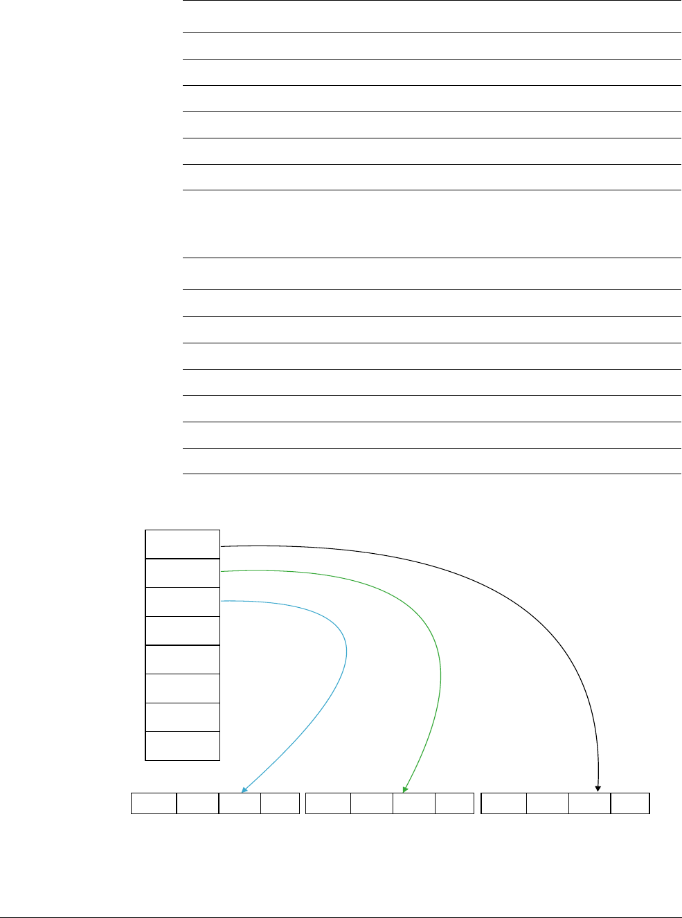
NEON Intrinsics Reference
ARM DEN0018A Copyright © 2013 ARM. All rights reserved. D-130
ID071613 Non-Confidential
Table D-212 shows the vector types for each type of the
VLD3Q_LANE
intrinsic.
Figure D-2 VLD3.32
uint16x4x3_t u16 uint16_t uint16x4x3_t 0-3
uint32x2x3_t u32 uint32_t uint32x2x3_t 0-1
float16x4x3_t f16 float16_t float16x4x3_t 0-3
float32x2x3_t f32 float32_t float32x2x3_t 0-1
poly8x8x3_t p8 poly8_t poly8x8x3_t 0-7
poly16x4x3_t p16 poly16_t poly16x4x3_t 0-3
Table D-212 vector types for
VLD3Q_LANE
intrinsic
Result_t type Scalar_t Vector_t int range
int16x8x3_t s16 int16_t int16x8x3_t 0-7
int32x4x3_t s32 int32_t int32x4x3_t 0-3
uint16x8x3_t u16 uint16_t uint16x8x3_t 0-7
uint32x4x3_t u32 uint32_t uint32x4x3_t 0-3
float16x8x3_t f16 float16_t float16x8x3_t 0-7
float32x4x3_t f32 float32_t float32x4x3_t 0-3
poly16x8x3_t p16 poly16_t poly16x8x3_t 0-7
Table D-211 vector types for
VLD3_LANE
intrinsic (continued)
Result_t type Scalar_t Vector_t int range
Address=R4
Address=R4+4
Address=R4+8
Address=R4+12
Address=R4+16
Address=R4+20
Address=R4+24
Address=R4+28
VLD3.32 {D0[2], D2[2], D4[2]}, [R4];
D5 and D4
= Q2 D3 and D2
= Q1 D1 and D0
= Q0
Element 3
bits[95..127]
Element 2
bits[64..95]
Element 1
bits[32..63]
Element 0
bits[0..31]
Element 3
bits[95..127]
Element 2
bits[64..95]
Element 1
bits[32..63]
Element 0
bits[0..31]
Element 3
bits[95..127]
Element 2
bits[64..95]
Element 1
bits[32..63]
Element 0
bits[0..31]

NEON Intrinsics Reference
ARM DEN0018A Copyright © 2013 ARM. All rights reserved. D-131
ID071613 Non-Confidential
See also
NEON load and store instructions on page C-60.
Assembler Reference:
•NEON instructions,
http://infocenter.arm.com/help/topic/com.arm.doc.dui0489g/CJAJIIGG.html.
D.9.9 VLD3_DUP
VLD3_DUP
loads 3 elements from memory and returns a triple-vector structure. The first element
is copied to all lanes of the first vector. And similarly the second and third elements are copied
to the second and third vectors respectively.
Intrinsic
Result_t vld3_dup_type(Scalar_t* N);
Related Instruction
VLD3.dt {Dd[], Dd+1[], Dd+2[]},[Rn]
VLD3.dt {Dd[], Dd+2[], Dd+4[]},[Rn]
VLD1.64 {Dd, Dd+1, Dd+2},[Rn]
Input and output vector types
Table D-213 shows the vector types for each type of the
VLD3_DUP
intrinsic.
See also
NEON load and store instructions on page C-60.
Table D-213 vector types for
VLD3_DUP
intrinsic
Result_t type Scalar_t
int8x8x3_t s8 int8_t
int16x4x3_t s16 int16_t
int32x2x3_t s32 int32_t
int64x1x3_t s64 int64_t
uint8x8x3_t u8 uint8_t
uint16x4x3_t u16 uint16_t
uint32x2x3_t u32 uint32_t
uint64x1x3_t u64 uint64_t
float16x4x3_t f16 float16_t
float32x2x3_t f32 float32_t
poly8x8x3_t p8 poly8_t
poly16x4x3_t p16 poly16_t

NEON Intrinsics Reference
ARM DEN0018A Copyright © 2013 ARM. All rights reserved. D-132
ID071613 Non-Confidential
Assembler Reference:
•NEON instructions,
http://infocenter.arm.com/help/topic/com.arm.doc.dui0489g/CJAJIIGG.html.
D.9.10 VLD4
VLD4
loads 4 vectors from memory. It performs a 4-way de-interleave from memory to the
vectors.
Intrinsic
Result_t vld4_type(Scalar_t* N);
Result_t vld4q_type(Scalar_t* N);
Related Instruction
VLD4.dt {Dd, Dd+1, Dd+2, Dd+3},[Rn]
VLD4.dt {Dd, Dd+2, Dd+4, Dd+6},[Rn]
VLD1.64 {Dd, Dd+1, Dd+2, Dd+3},[Rn]
Input and output vector types
Table D-214 shows the vector types for each type of the
VLD4
intrinsic.
Table D-214 vector types for
VLD4
intrinsic
Result_t type Scalar_t
int8x8x4_t s8 int8_t
int16x4x4_t s16 int16_t
int32x2x4_t s32 int32_t
int64x1x4_t s64 int64_t
uint8x8x4_t u8 uint8_t
uint16x4x4_t u16 uint16_t
uint32x2x4_t u32 uint32_t
uint64x1x4_t u64 uint64_t
float16x4x4_t f16 float16_t
float32x2x4_t f32 float32_t
poly8x8x4_t p8 poly8_t
poly16x4x4_t p16 poly16_t
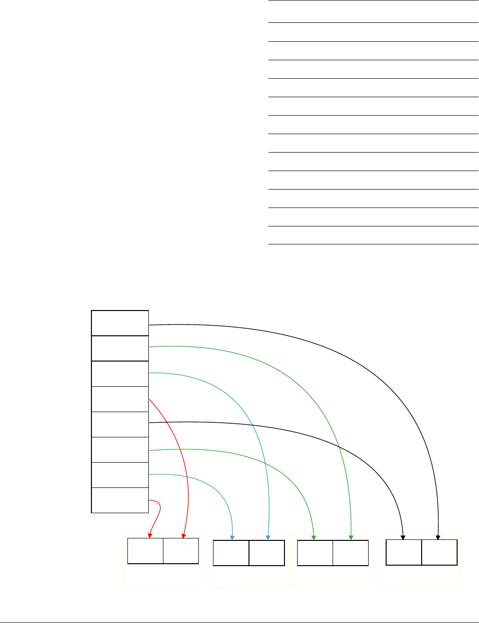
NEON Intrinsics Reference
ARM DEN0018A Copyright © 2013 ARM. All rights reserved. D-133
ID071613 Non-Confidential
Table D-215 shows the vector types for each type of the
VLD4Q
intrinsic.
Figure D-3 VLD4.32
Table D-215 vector types for
VLD4Q
intrinsic
Result_t type Scalar_t
int8x16x4_t s8 int8_t
int16x8x4_t s16 int16_t
int32x4x4_t s32 int32_t
int64x2x4_t s64 int64_t
uint8x16x4_t u8 uint8_t
uint16x8x4_t u16 uint16_t
uint32x4x4_t u32 uint32_t
uint64x2x4_t u64 uint64_t
float16x8x4_t f16 float16_t
float32x4x4_t f32 float32_t
poly8x16x4_t p8 poly8_t
poly16x8x4_t p16 poly16_t
VLD4.32 {D0, D1, D2, D3}, [R4], #0x10
Memory from address in R4,
containing 32-bit values
D3 D2 D1 D0
Address=R4
Address=R4+4
Address=R4+8
Address=R4+12
Address=R4+16
Address=R4+20
Address=R4+24
Address=R4+28
Element 1
bits[32..63]
Element 0
bits[0..31]
Element 1
bits[32..63]
Element 0
bits[0..31]
Element 1
bits[32..63]
Element 0
bits[0..31]
Element 1
bits[32..63]
Element 0
bits[0..31]

NEON Intrinsics Reference
ARM DEN0018A Copyright © 2013 ARM. All rights reserved. D-134
ID071613 Non-Confidential
See also
NEON load and store instructions on page C-60.
Assembler Reference:
•NEON instructions,
http://infocenter.arm.com/help/topic/com.arm.doc.dui0489g/CJAJIIGG.html.
D.9.11 VLD4_LANE
VLD4_LANE
loads four elements in a quad-vector structure from memory and returns this in the
result. The loaded values are from consecutive memory addresses. Elements in the structure that
are not loaded are returned in the result unaltered. n is the index of the element to load.
Intrinsic
Result_t vld4_lane_type(Scalar_t* N, Vector_t M, int n);
Result_t vld4q_lane_type(Scalar_t* N, Vector_t M, int n);
Related Instruction
VLD4.dt {Dd[x], Dd+1[x], Dd+2[x], Dd+3[x]},[Rn]
VLD4.dt {Dd[x], Dd+2[x], Dd+4[x], Dd+6[x]},[Rn]
VLD1.64 {Dd, Dd+1, Dd+2, Dd+3},[Rn]
Input and output vector types
Table D-216 shows the vector types for each type of the
VLD4_LANE
intrinsic.
Table D-216 vector types for
VLD4_LANE
intrinsic
Result_t type Scalar_t Vector_t int range
int8x8x4_t s8 int8_t int8x8x4_t 0-7
int16x4x4_t s16 int16_t int16x4x4_t 0-3
int32x2x4_t s32 int32_t int32x2x4_t 0-1
uint8x8x4_t u8 uint8_t uint8x8x4_t 0-7
uint16x4x4_t u16 uint16_t uint16x4x4_t 0-3
uint32x2x4_t u32 uint32_t uint32x2x4_t 0-1
float16x4x4_t f16 float16_t float16x4x4_t 0-3
float32x2x4_t f32 float32_t float32x2x4_t 0-1
poly8x8x4_t p8 poly8_t poly8x8x4_t 0-7
poly16x4x4_t p16 poly16_t poly16x4x4_t 0-3

NEON Intrinsics Reference
ARM DEN0018A Copyright © 2013 ARM. All rights reserved. D-135
ID071613 Non-Confidential
Table D-217 shows the vector types for each type of the
VLD4Q_LANE
intrinsic.
See also
NEON load and store instructions on page C-60.
Assembler Reference:
•NEON instructions,
http://infocenter.arm.com/help/topic/com.arm.doc.dui0489g/CJAJIIGG.html.
D.9.12 VLD4_DUP
VLD4_DUP
loads 4 elements from memory and returns a quad-vector structure. The first element
is copied to all lanes of the first vector. And similarly the second, third, and fourth elements are
copied to the second, third, and fourth vectors respectively.
Intrinsic
Result_t vld4_dup_type(Scalar_t* N);
Related Instruction
VLD4.dt {Dd[], Dd+1[], Dd+2[], Dd+3[]},[Rn]
VLD4.dt {Dd[], Dd+2[], Dd+4[], Dd+6[]},[Rn]
Input and output vector types
Table D-218 shows the vector types for each type of the
VLD4_DUP
intrinsic.
Table D-217 vector types for
VLD4Q_LANE
intrinsic
Result_t type Scalar_t Vector_t int range
int16x8x4_t s16 int16_t int16x8x4_t 0-7
int32x4x4_t s32 int32_t int32x4x4_t 0-3
uint16x8x4_t u16 uint16_t uint16x8x4_t 0-7
uint32x4x4_t u32 uint32_t uint32x4x4_t 0-3
float16x8x4_t f16 float16_t float16x8x4_t 0-7
float32x4x4_t f32 float32_t float32x4x4_t 0-3
poly16x8x4_t p16 poly16_t poly16x8x4_t 0-7
Table D-218 vector types for
VLD4_DUP
intrinsic
Result_t type Scalar_t
int8x8x4_t s8 int8_t
int16x4x4_t s16 int16_t
int32x2x4_t s32 int32_t
int64x1x4_t s64 int64_t
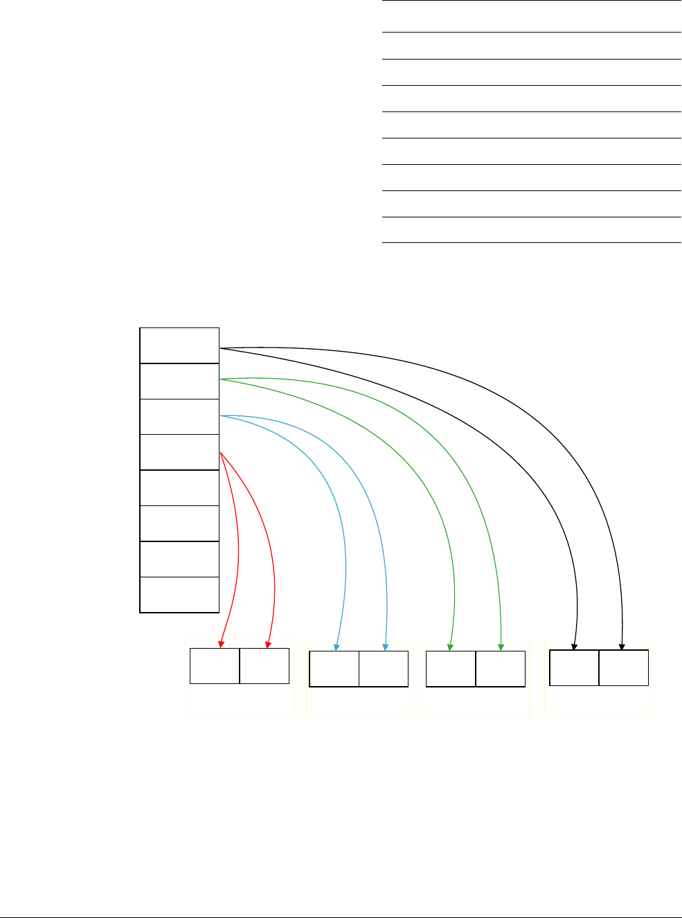
NEON Intrinsics Reference
ARM DEN0018A Copyright © 2013 ARM. All rights reserved. D-136
ID071613 Non-Confidential
Figure D-4 VLD4.32
See also
NEON load and store instructions on page C-60.
Assembler Reference:
•NEON instructions,
http://infocenter.arm.com/help/topic/com.arm.doc.dui0489g/CJAJIIGG.html.
uint8x8x4_t u8 uint8_t
uint16x4x4_t u16 uint16_t
uint32x2x4_t u32 uint32_t
uint64x1x4_t u64 uint64_t
float16x4x4_t f16 float16_t
float32x2x4_t f32 float32_t
poly8x8x4_t p8 poly8_t
poly16x4x4_t p16 poly16_t
Table D-218 vector types for
VLD4_DUP
intrinsic (continued)
Result_t type Scalar_t
Memory from address in R4,
32-bit value
D3 D2 D1 D0
Element 1
bits[32..63]
Element 0
bits[0..31]
Element 1
bits[32..63]
Element 0
bits[0..31]
Element 1
bits[32..63]
Element 0
bits[0..31]
Element 1
bits[32..63]
Element 0
bits[0..31]
VLD4.32 {D0[], D1[], D2[], D3[]}, [R4], #0x10

NEON Intrinsics Reference
ARM DEN0018A Copyright © 2013 ARM. All rights reserved. D-137
ID071613 Non-Confidential
D.9.13 VST1
VST1
stores a vector into memory.
Intrinsic
void vst1_type(Scalar_t* N, Vector_t M);
void vst1q_type(Scalar_t* N, Vector_t M);
Related Instruction
VST1.dt {Dd},[Rn]
VST1.dt {Dd, Dd+1},[Rn]
Input and output vector types
Table D-219 shows the vector types for each type of the
VST1
intrinsic.
Table D-220 shows the vector types for each type of the
VST1Q
intrinsic.
Table D-219 vector types for
VST1
intrinsic
type Scalar_t Vector_t
s8 int8_t int8x8_t
s16 int16_t int16x4_t
s32 int32_t int32x2_t
s64 int64_t int64x1_t
u8 uint8_t uint8x8_t
u16 uint16_t uint16x4_t
u32 uint32_t uint32x2_t
u64 uint64_t uint64x1_t
f16 float16_t float16x4_t
f32 float32_t float32x2_t
p8 poly8_t poly8x8_t
p16 poly16_t poly16x4_t
Table D-220 vector types for
VST1Q
intrinsic
type Scalar_t Vector_t
s8 int8_t int8x16_t
s16 int16_t int16x8_t
s32 int32_t int32x4_t
s64 int64_t int64x2_t
u8 uint8_t uint8x16_t

NEON Intrinsics Reference
ARM DEN0018A Copyright © 2013 ARM. All rights reserved. D-138
ID071613 Non-Confidential
See also
NEON load and store instructions on page C-60.
Assembler Reference:
•NEON instructions,
http://infocenter.arm.com/help/topic/com.arm.doc.dui0489g/CJAJIIGG.html.
D.9.14 VST1_LANE
VST1_LANE
stores one element of the vector into memory. n is the index in the vector to be stored.
Intrinsic
void vst1_lane_type(Scalar_t* N, Vector_t M, int n);
void vst1q_lane_type(Scalar_t* N, Vector_t M, int n);
Related Instruction
VST1.dt {Dd[x]},[Rn]
Input and output vector types
Table D-221 shows the vector types for each type of the
VST1_LANE
intrinsic.
u16 uint16_t uint16x8_t
u32 uint32_t uint32x4_t
u64 uint64_t uint64x2_t
f16 float16_t float16x8_t
f32 float32_t float32x4_t
p8 poly8_t poly8x16_t
p16 poly16_t poly16x8_t
Table D-220 vector types for
VST1Q
intrinsic (continued)
type Scalar_t Vector_t
Table D-221 vector types for
VST1_LANE
intrinsic
type Scalar_t Vector_t int range
s8 int8_t int8x8_t 0-7
s16 int16_t int16x4_t 0-3
s32 int32_t int32x2_t 0-1
s64 int64_t int64x1_t 0-0
u8 uint8_t uint8x8_t 0-7
u16 uint16_t uint16x4_t 0-3
u32 uint32_t uint32x2_t 0-1

NEON Intrinsics Reference
ARM DEN0018A Copyright © 2013 ARM. All rights reserved. D-139
ID071613 Non-Confidential
Table D-222 shows the vector types for each type of the
VST1Q_LANE
intrinsic.
See also
NEON load and store instructions on page C-60.
Assembler Reference:
•NEON instructions,
http://infocenter.arm.com/help/topic/com.arm.doc.dui0489g/CJAJIIGG.html.
D.9.15 VST2
VST2
stores 2 vectors into memory. It interleaves the 2 vectors into memory.
Intrinsic
void vst2_type(Scalar_t* N, Vector_t M);
void vst2q_type(Scalar_t* N, Vector_t M);
u64 uint64_t uint64x1_t 0-0
f16 float16_t float16x4_t 0-3
f32 float32_t float32x2_t 0-1
p8 poly8_t poly8x8_t 0-7
p16 poly16_t poly16x4_t 0-3
Table D-222 vector types for
VST1Q_LANE
intrinsic
type Scalar_t Vector_t int range
s8 int8_t int8x16_t 0-15
s16 int16_t int16x8_t 0-7
s32 int32_t int32x4_t 0-3
s64 int64_t int64x2_t 0-1
u8 uint8_t uint8x16_t 0-15
u16 uint16_t uint16x8_t 0-7
u32 uint32_t uint32x4_t 0-3
u64 uint64_t uint64x2_t 0-1
f16 float16_t float16x8_t 0-7
f32 float32_t float32x4_t 0-3
p8 poly8_t poly8x16_t 0-15
p16 poly16_t poly16x8_t 0-7
Table D-221 vector types for
VST1_LANE
intrinsic (continued)
type Scalar_t Vector_t int range

NEON Intrinsics Reference
ARM DEN0018A Copyright © 2013 ARM. All rights reserved. D-140
ID071613 Non-Confidential
Related Instruction
VST2.dt {Dd, Dd+1},[Rn]
VST2.dt {Dd, Dd+2},[Rn]
VST1.64 {Dd, Dd+1},[Rn]
Input and output vector types
Table D-223 shows the vector types for each type of the
VST2
intrinsic.
Table D-224 shows the vector types for each type of the
VST2Q
intrinsic.
Table D-223 vector types for
VST2
intrinsic
type Scalar_t Vector_t
s8 int8_t int8x8x2_t
s16 int16_t int16x4x2_t
s32 int32_t int32x2x2_t
s64 int64_t int64x1x2_t
u8 uint8_t uint8x8x2_t
u16 uint16_t uint16x4x2_t
u32 uint32_t uint32x2x2_t
u64 uint64_t uint64x1x2_t
f16 float16_t float16x4x2_t
f32 float32_t float32x2x2_t
p8 poly8_t poly8x8x2_t
p16 poly16_t poly16x4x2_t
Table D-224 vector types for
VST2Q
intrinsic
type Scalar_t Vector_t
s8 int8_t int8x16x2_t
s16 int16_t int16x8x2_t
s32 int32_t int32x4x2_t
u8 uint8_t uint8x16x2_t
u16 uint16_t uint16x8x2_t
u32 uint32_t uint32x4x2_t
f16 float16_t float16x8x2_t
f32 float32_t float32x4x2_t
p8 poly8_t poly8x16x2_t
p16 poly16_t poly16x8x2_t

NEON Intrinsics Reference
ARM DEN0018A Copyright © 2013 ARM. All rights reserved. D-141
ID071613 Non-Confidential
See also
NEON load and store instructions on page C-60.
Assembler Reference:
•NEON instructions,
http://infocenter.arm.com/help/topic/com.arm.doc.dui0489g/CJAJIIGG.html.
D.9.16 VST2_LANE
VST2_LANE
stores a lane of two elements from a double-vector structure into memory. The
elements to be stored are from the same lane in the vectors and their index is n.
Intrinsic
void vst2_lane_type(Scalar_t* N, Vector_t M, int n);
void vst2q_lane_type(Scalar_t* N, Vector_t M, int n);
Related Instruction
VST2.dt {Dd[x], Dd+1[x]},[Rn]
VST2.dt {Dd[x], Dd+2[x]},[Rn]
Input and output vector types
Table D-225 shows the vector types for each type of the
VST2_LANE
intrinsic.
Table D-225 vector types for
VST2_LANE
intrinsic
type Scalar_t Vector_t int range
s8 int8_t int8x8x2_t 0-7
s16 int16_t int16x4x2_t 0-3
s32 int32_t int32x2x2_t 0-1
u8 uint8_t uint8x8x2_t 0-7
u16 uint16_t uint16x4x2_t 0-3
u32 uint32_t uint32x2x2_t 0-1
f16 float16_t float16x4x2_t 0-3
f32 float32_t float32x2x2_t 0-1
p8 poly8_t poly8x8x2_t 0-7
p16 poly16_t poly16x4x2_t 0-3

NEON Intrinsics Reference
ARM DEN0018A Copyright © 2013 ARM. All rights reserved. D-142
ID071613 Non-Confidential
Table D-226 shows the vector types for each type of the
VST2Q_LANE
intrinsic.
See also
NEON load and store instructions on page C-60.
Assembler Reference:
•NEON instructions,
http://infocenter.arm.com/help/topic/com.arm.doc.dui0489g/CJAJIIGG.html.
D.9.17 VST3
VST3
stores 3 vectors into memory. It interleaves the 3 vectors into memory.
Intrinsic
void vst3_type(Scalar_t* N, Vector_t M);
void vst3q_type(Scalar_t* N, Vector_t M);
Related Instruction
VST3.dt {Dd, Dd+1, Dd+2},[Rn]
VST3.dt {Dd, Dd+2, Dd+4},[Rn]
VST1.64 {Dd, Dd+1, Dd+2},[Rn]
Input and output vector types
Table D-227 shows the vector types for each type of the
VST3
intrinsic.
Table D-226 vector types for
VST2Q_LANE
intrinsic
type Scalar_t Vector_t int range
s16 int16_t int16x8x2_t 0-7
s32 int32_t int32x4x2_t 0-3
u16 uint16_t uint16x8x2_t 0-7
u32 uint32_t uint32x4x2_t 0-3
f16 float16_t float16x8x2_t 0-7
f32 float32_t float32x4x2_t 0-3
p16 poly16_t poly16x8x2_t 0-7
Table D-227 vector types for
VST3
intrinsic
type Scalar_t Vector_t
s8 int8_t int8x8x3_t
s16 int16_t int16x4x3_t
s32 int32_t int32x2x3_t
s64 int64_t int64x1x3_t

NEON Intrinsics Reference
ARM DEN0018A Copyright © 2013 ARM. All rights reserved. D-143
ID071613 Non-Confidential
Table D-228 shows the vector types for each type of the
VST3Q
intrinsic.
See also
NEON load and store instructions on page C-60.
Assembler Reference:
•NEON instructions,
http://infocenter.arm.com/help/topic/com.arm.doc.dui0489g/CJAJIIGG.html.
D.9.18 VST3_LANE
VST3_LANE
stores a lane of three elements from a triple-vector structure into memory. The
elements to be stored are from the same lane in the vectors and their index is n.
Intrinsic
void vst3_lane_type(Scalar_t* N, Vector_t M, int n);
u8 uint8_t uint8x8x3_t
u16 uint16_t uint16x4x3_t
u32 uint32_t uint32x2x3_t
u64 uint64_t uint64x1x3_t
f16 float16_t float16x4x3_t
f32 float32_t float32x2x3_t
p8 poly8_t poly8x8x3_t
p16 poly16_t poly16x4x3_t
Table D-228 vector types for
VST3Q
intrinsic
type Scalar_t Vector_t
s8 int8_t int8x16x3_t
s16 int16_t int16x8x3_t
s32 int32_t int32x4x3_t
u8 uint8_t uint8x16x3_t
u16 uint16_t uint16x8x3_t
u32 uint32_t uint32x4x3_t
f16 float16_t float16x8x3_t
f32 float32_t float32x4x3_t
p8 poly8_t poly8x16x3_t
p16 poly16_t poly16x8x3_t
Table D-227 vector types for
VST3
intrinsic (continued)
type Scalar_t Vector_t

NEON Intrinsics Reference
ARM DEN0018A Copyright © 2013 ARM. All rights reserved. D-144
ID071613 Non-Confidential
void vst3q_lane_type(Scalar_t* N, Vector_t M, int n);
Related Instruction
VST3.dt {Dd[x], Dd+1[x], Dd+2[x]},[Rn]
VST3.dt {Dd[x], Dd+2[x], Dd+4[x]},[Rn]
Input and output vector types
Table D-229 shows the vector types for each type of the
VST3_LANE
intrinsic.
Table D-230 shows the vector types for each type of the
VST3Q_LANE
intrinsic.
See also
NEON load and store instructions on page C-60.
Table D-229 vector types for
VST3_LANE
intrinsic
type Scalar_t Vector_t int range
s8 int8_t int8x8x3_t 0-7
s16 int16_t int16x4x3_t 0-3
s32 int32_t int32x2x3_t 0-1
u8 uint8_t uint8x8x3_t 0-7
u16 uint16_t uint16x4x3_t 0-3
u32 uint32_t uint32x2x3_t 0-1
f16 float16_t float16x4x3_t 0-3
f32 float32_t float32x2x3_t 0-1
p8 poly8_t poly8x8x3_t 0-7
p16 poly16_t poly16x4x3_t 0-3
Table D-230 vector types for
VST3Q_LANE
intrinsic
type Scalar_t Vector_t int range
s16 int16_t int16x8x3_t 0-7
s32 int32_t int32x4x3_t 0-3
u16 uint16_t uint16x8x3_t 0-7
u32 uint32_t uint32x4x3_t 0-3
f16 float16_t float16x8x3_t 0-7
f32 float32_t float32x4x3_t 0-3
p16 poly16_t poly16x8x3_t 0-7

NEON Intrinsics Reference
ARM DEN0018A Copyright © 2013 ARM. All rights reserved. D-145
ID071613 Non-Confidential
Assembler Reference:
•NEON instructions,
http://infocenter.arm.com/help/topic/com.arm.doc.dui0489g/CJAJIIGG.html.
D.9.19 VST4
VST4
stores 4 vectors into memory. It interleaves the 4 vectors into memory.
Intrinsic
void vst4_type(Scalar_t* N, Vector_t M);
void vst4q_type(Scalar_t* N, Vector_t M);
Related Instruction
VST4.dt {Dd, Dd+1, Dd+2, Dd+3},[Rn]
VST4.dt {Dd, Dd+2, Dd+4, Dd+6},[Rn]
VST1.64 {Dd, Dd+1, Dd+2, Dd+3},[Rn]
Input and output vector types
Table D-231 shows the vector types for each type of the
VST4
intrinsic.
Table D-231 vector types for
VST4
intrinsic
type Scalar_t Vector_t
s8 int8_t int8x8x4_t
s16 int16_t int16x4x4_t
s32 int32_t int32x2x4_t
s64 int64_t int64x1x4_t
u8 uint8_t uint8x8x4_t
u16 uint16_t uint16x4x4_t
u32 uint32_t uint32x2x4_t
u64 uint64_t uint64x1x4_t
f16 float16_t float16x4x4_t
f32 float32_t float32x2x4_t
p8 poly8_t poly8x8x4_t
p16 poly16_t poly16x4x4_t

NEON Intrinsics Reference
ARM DEN0018A Copyright © 2013 ARM. All rights reserved. D-146
ID071613 Non-Confidential
Table D-232 shows the vector types for each type of the
VST4Q
intrinsic.
See also
NEON load and store instructions on page C-60.
Assembler Reference:
•NEON instructions,
http://infocenter.arm.com/help/topic/com.arm.doc.dui0489g/CJAJIIGG.html.
D.9.20 VST4_LANE
VST4_LANE
stores a lane of four elements from a quad-vector structure into memory. The elements
to be stored are from the same lane in the vectors and their index is n.
Intrinsic
void vst4_lane_type(Scalar_t* N, Vector_t M, int n);
void vst4q_lane_type(Scalar_t* N, Vector_t M, int n);
Related Instruction
VST4.dt {Dd[x], Dd+1[x], Dd+2[x], Dd+3[x]},[Rn]
VST4.dt {Dd[x], Dd+2[x], Dd+4[x], Dd+6[x]},[Rn]
Table D-232 vector types for
VST4Q
intrinsic
type Scalar_t Vector_t
s8 int8_t int8x16x4_t
s16 int16_t int16x8x4_t
s32 int32_t int32x4x4_t
u8 uint8_t uint8x16x4_t
u16 uint16_t uint16x8x4_t
u32 uint32_t uint32x4x4_t
f16 float16_t float16x8x4_t
f32 float32_t float32x4x4_t
p8 poly8_t poly8x16x4_t
p16 poly16_t poly16x8x4_t

NEON Intrinsics Reference
ARM DEN0018A Copyright © 2013 ARM. All rights reserved. D-147
ID071613 Non-Confidential
Input and output vector types
Table D-233 shows the vector types for each type of the
VST4_LANE
intrinsic.
Table D-234 shows the vector types for each type of the
VST4Q_LANE
intrinsic.
See also
NEON load and store instructions on page C-60.
Assembler Reference:
•NEON instructions,
http://infocenter.arm.com/help/topic/com.arm.doc.dui0489g/CJAJIIGG.html.
D.9.21 VGET_LANE
VGET_LANE
returns the value from the specified lane of a vector.
Table D-233 vector types for
VST4_LANE
intrinsic
type Scalar_t Vector_t int range
s8 int8_t int8x8x4_t 0-7
s16 int16_t int16x4x4_t 0-3
s32 int32_t int32x2x4_t 0-1
u8 uint8_t uint8x8x4_t 0-7
u16 uint16_t uint16x4x4_t 0-3
u32 uint32_t uint32x2x4_t 0-1
f16 float16_t float16x4x4_t 0-3
f32 float32_t float32x2x4_t 0-1
p8 poly8_t poly8x8x4_t 0-7
p16 poly16_t poly16x4x4_t 0-3
Table D-234 vector types for
VST4Q_LANE
intrinsic
type Scalar_t Vector_t int range
s16 int16_t int16x8x4_t 0-7
s32 int32_t int32x4x4_t 0-3
u16 uint16_t uint16x8x4_t 0-7
u32 uint32_t uint32x4x4_t 0-3
f16 float16_t float16x8x4_t 0-7
f32 float32_t float32x4x4_t 0-3
p16 poly16_t poly16x8x4_t 0-7

NEON Intrinsics Reference
ARM DEN0018A Copyright © 2013 ARM. All rights reserved. D-148
ID071613 Non-Confidential
Intrinsic
Result_t vget_lane_type(Vector_t N, int n);
Result_t vgetq_lane_type(Vector_t N, int n);
Related Instruction
VMOV.dt Rd, Dn[x]
VMOV.dt Rd, Rd+1, Dn
Input and output vector types
Table D-235 shows the vector types for each type of the
VGET_LANE
intrinsic.
Table D-236 shows the vector types for each type of the
VGETQ_LANE
intrinsic.
Table D-235 vector types for
VGET_LANE
intrinsic
Result_t type Vector_t int range
int8_t s8 int8x8_t 0-7
int16_t s16 int16x4_t 0-3
int32_t s32 int32x2_t 0-1
int64_t s64 int64x1_t 0-0
uint8_t u8 uint8x8_t 0-7
uint16_t u16 uint16x4_t 0-3
uint32_t u32 uint32x2_t 0-1
uint64_t u64 uint64x1_t 0-0
float32_t f32 float32x2_t 0-1
poly8_t p8 poly8x8_t 0-7
poly16_t p16 poly16x4_t 0-3
Table D-236 vector types for
VGETQ_LANE
intrinsic
Result_t type Vector_t int range
int8_t s8 int8x16_t 0-15
int16_t s16 int16x8_t 0-7
int32_t s32 int32x4_t 0-3
int64_t s64 int64x2_t 0-1
uint8_t u8 uint8x16_t 0-15
uint16_t u16 uint16x8_t 0-7
uint32_t u32 uint32x4_t 0-3
uint64_t u64 uint64x2_t 0-1

NEON Intrinsics Reference
ARM DEN0018A Copyright © 2013 ARM. All rights reserved. D-149
ID071613 Non-Confidential
See also
NEON load and store instructions on page C-60.
Assembler Reference:
•NEON instructions,
http://infocenter.arm.com/help/topic/com.arm.doc.dui0489g/CJAJIIGG.html.
D.9.22 VSET_LANE
VSET_LANE
sets the value of the specified lane of a vector. It returns the vector with the new value.
Intrinsic
Result_t vset_lane_type(Scalar_t N, Vector_t M, int n);
Result_t vsetq_lane_type(Scalar_t N, Vector_t M, int n);
Related Instruction
VMOV.dt Dd[x], Rn
VMOV.dt Dd, Rn, Rn+1
Input and output vector types
Table D-237 shows the vector types for each type of the
VSET_LANE
intrinsic.
float32_t f32 float32x4_t 0-3
poly8_t p8 poly8x16_t 0-15
poly16_t p16 poly16x8_t 0-7
Table D-236 vector types for
VGETQ_LANE
intrinsic (continued)
Result_t type Vector_t int range
Table D-237 vector types for
VSET_LANE
intrinsic
Result_t type Scalar_t Vector_t int range
int8x8_t s8 int8_t int8x8_t 0-7
int16x4_t s16 int16_t int16x4_t 0-3
int32x2_t s32 int32_t int32x2_t 0-1
int64x1_t s64 int64_t int64x1_t 0-0
uint8x8_t u8 uint8_t uint8x8_t 0-7
uint16x4_t u16 uint16_t uint16x4_t 0-3
uint32x2_t u32 uint32_t uint32x2_t 0-1
uint64x1_t u64 uint64_t uint64x1_t 0-0

NEON Intrinsics Reference
ARM DEN0018A Copyright © 2013 ARM. All rights reserved. D-150
ID071613 Non-Confidential
Table D-238 shows the vector types for each type of the
VSETQ_LANE
intrinsic.
See also
NEON load and store instructions on page C-60.
Assembler Reference:
•NEON instructions,
http://infocenter.arm.com/help/topic/com.arm.doc.dui0489g/CJAJIIGG.html.
float32x2_t f32 float32_t float32x2_t 0-1
poly8x8_t p8 poly8_t poly8x8_t 0-7
poly16x4_t p16 poly16_t poly16x4_t 0-3
Table D-238 vector types for
VSETQ_LANE
intrinsic
Result_t type Scalar_t Vector_t int range
int8x16_t s8 int8_t int8x16_t 0-15
int16x8_t s16 int16_t int16x8_t 0-7
int32x4_t s32 int32_t int32x4_t 0-3
int64x2_t s64 int64_t int64x2_t 0-1
uint8x16_t u8 uint8_t uint8x16_t 0-15
uint16x8_t u16 uint16_t uint16x8_t 0-7
uint32x4_t u32 uint32_t uint32x4_t 0-3
uint64x2_t u64 uint64_t uint64x2_t 0-1
float32x4_t f32 float32_t float32x4_t 0-3
poly8x16_t p8 poly8_t poly8x16_t 0-15
poly16x8_t p16 poly16_t poly16x8_t 0-7
Table D-237 vector types for
VSET_LANE
intrinsic (continued)
Result_t type Scalar_t Vector_t int range

NEON Intrinsics Reference
ARM DEN0018A Copyright © 2013 ARM. All rights reserved. D-151
ID071613 Non-Confidential
D.10 Permutation
These intrinsics load or store vectors.
D.10.1 VEXT
VEXT
extracts n elements from the lower end of the second operand vector and the remaining
elements from the higher end of the first, and combines them to form the result vector. The
elements from the second operand are placed in the most significant part of the result vector.
The elements from the first operand are placed in the least significant part of the result vector.
This intrinsic cycles the elements through the lanes if the two input vectors are the same.
Intrinsic
Result_t vext_type(Vector1_t N, Vector2_t M, int n);
Result_t vextq_type(Vector1_t N, Vector2_t M, int n);
Related Instruction
VEXT.dt Dd, Dn, Dm
VEXT.dt Qd, Qn, Qm
Input and output vector types
Table D-239 shows the vector types for each type of the
VEXT
intrinsic.
Table D-239 vector types for
VEXT
intrinsic
Result_t type Vector1_t Vector2_t int range
int8x8_t s8 int8x8_t int8x8_t 0-7
int16x4_t s16 int16x4_t int16x4_t 0-3
int32x2_t s32 int32x2_t int32x2_t 0-1
int64x1_t s64 int64x1_t int64x1_t 0-0
uint8x8_t u8 uint8x8_t uint8x8_t 0-7
uint16x4_t u16 uint16x4_t uint16x4_t 0-3
uint32x2_t u32 uint32x2_t uint32x2_t 0-1
uint64x1_t u64 uint64x1_t uint64x1_t 0-0
poly8x8_t p8 poly8x8_t poly8x8_t 0-7
poly16x4_t p16 poly16x4_t poly16x4_t 0-3
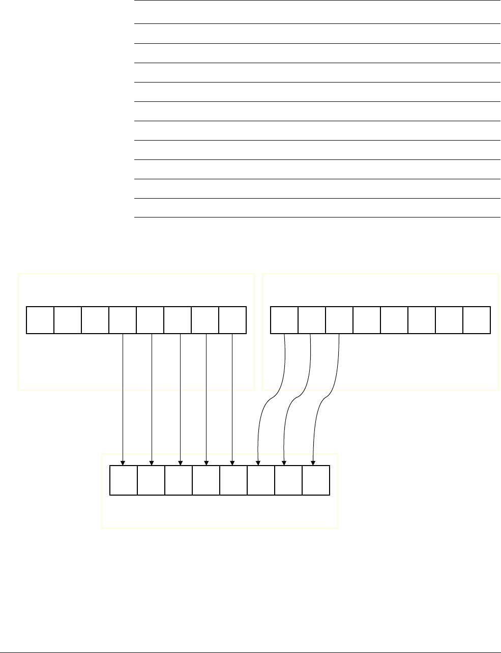
NEON Intrinsics Reference
ARM DEN0018A Copyright © 2013 ARM. All rights reserved. D-152
ID071613 Non-Confidential
Table D-240 shows the vector types for each type of the
VEXTQ
intrinsic.
Figure D-5 VEXT.8
See also
NEON general data processing instructions on page C-14.
Table D-240 vector types for
VEXTQ
intrinsic
Result_t type Vector1_t Vector2_t int range
int8x16_t s8 int8x16_t int8x16_t 0-15
int16x8_t s16 int16x8_t int16x8_t 0-7
int32x4_t s32 int32x4_t int32x4_t 0-3
int64x2_t s64 int64x2_t int64x2_t 0-1
uint8x16_t u8 uint8x16_t uint8x16_t 0-15
uint16x8_t u16 uint16x8_t uint16x8_t 0-7
uint32x4_t u32 uint32x4_t uint32x4_t 0-3
uint64x2_t u64 uint64x2_t uint64x2_t 0-1
poly8x16_t p8 poly8x16_t poly8x16_t 0-15
poly16x8_t p16 poly16x8_t poly16x8_t 0-7
VEXT.8 Dd, Dn, Dm, #5;
Dd
Dm Dn
b7 b6 b5 b4 b3 b2 b1 b0
b7 b6 b5 b4 b3 b2 b1 b0 b7 b6 b5 b4 b3 b2 b1 b0

NEON Intrinsics Reference
ARM DEN0018A Copyright © 2013 ARM. All rights reserved. D-153
ID071613 Non-Confidential
Assembler Reference:
•NEON instructions,
http://infocenter.arm.com/help/topic/com.arm.doc.dui0489g/CJAJIIGG.html.
D.10.2 VTBL1
VTBL1
uses byte indexes in a control vector to look up byte values in a table and generate a new
vector. Indexes out of range return 0. The table is in Vector1 and uses one D register.
Intrinsic
Result_t vtbl1_type(Vector1_t N, Vector2_t M);
Related Instruction
VTBL.dt Dd, {Dn}, Dm
Input and output vector types
Table D-241 shows the vector types for each type of the
VTBL1
intrinsic.
See also
NEON general data processing instructions on page C-14.
Assembler Reference:
•NEON instructions,
http://infocenter.arm.com/help/topic/com.arm.doc.dui0489g/CJAJIIGG.html.
D.10.3 VTBL2
VTBL2
uses byte indexes in a control vector to look up byte values in a table and generate a new
vector. Indexes out of range return 0. The table is in Vector1 and uses two D registers.
Intrinsic
Result_t vtbl2_type(Vector1_t N, Vector2_t M);
Related Instruction
VTBL.dt Dd, {Dn,Dn+1}, Dm
Table D-241 vector types for
VTBL1
intrinsic
Result_t type Vector1_t Vector2_t
int8x8_t s8 int8x8_t int8x8_t
uint8x8_t u8 uint8x8_t uint8x8_t
poly8x8_t p8 poly8x8_t poly8x8_t

NEON Intrinsics Reference
ARM DEN0018A Copyright © 2013 ARM. All rights reserved. D-154
ID071613 Non-Confidential
Input and output vector types
Table D-242 shows the vector types for each type of the
VTBL2
intrinsic.
See also
NEON general data processing instructions on page C-14.
Assembler Reference:
•NEON instructions,
http://infocenter.arm.com/help/topic/com.arm.doc.dui0489g/CJAJIIGG.html.
D.10.4 VTBL3
VTBL3
uses byte indexes in a control vector to look up byte values in a table and generate a new
vector. Indexes out of range return 0. The table is in Vector1 and uses three D registers.
Intrinsic
Result_t vtbl3_type(Vector1_t N, Vector2_t M);
Related Instruction
VTBL.dt Dd, {Dn,Dn+1, Dn+2}, Dm
Input and output vector types
Table D-243 shows the vector types for each type of the
VTBL3
intrinsic.
See also
NEON general data processing instructions on page C-14.
Assembler Reference:
•NEON instructions,
http://infocenter.arm.com/help/topic/com.arm.doc.dui0489g/CJAJIIGG.html.
Table D-242 vector types for
VTBL2
intrinsic
Result_t type Vector1_t Vector2_t
int8x8_t s8 int8x8x2_t int8x8_t
uint8x8_t u8 uint8x8x2_t uint8x8_t
poly8x8_t p8 poly8x8x2_t poly8x8_t
Table D-243 vector types for
VTBL3
intrinsic
Result_t type Vector1_t Vector2_t
int8x8_t s8 int8x8x3_t int8x8_t
uint8x8_t u8 uint8x8x3_t uint8x8_t
poly8x8_t p8 poly8x8x3_t poly8x8_t

NEON Intrinsics Reference
ARM DEN0018A Copyright © 2013 ARM. All rights reserved. D-155
ID071613 Non-Confidential
D.10.5 VTBL4
VTBL4
uses byte indexes in a control vector to look up byte values in a table and generate a new
vector. Indexes out of range return 0. The table is in Vector1 and uses four D registers.
Intrinsic
Result_t vtbl4_type(Vector1_t N, Vector2_t M);
Related Instruction
VTBL.dt Dd, {Dn,Dn+1, Dn+2, Dn+3}, Dm
Input and output vector types
Table D-244 shows the vector types for each type of the
VTBL4
intrinsic.
See also
NEON general data processing instructions on page C-14.
Assembler Reference:
•NEON instructions,
http://infocenter.arm.com/help/topic/com.arm.doc.dui0489g/CJAJIIGG.html.
D.10.6 VTBX1
VTBX1
uses byte indexes in a control vector to look up byte values in a table and generate a new
vector. Indexes out of range leave the destination element unchanged. The table is in Vector2
and uses one D register. Vector1 contains the elements of the destination vector.
Intrinsic
Result_t vtbx1_type(Vector1_t N, Vector2_t M, Vector3_t P);
Related Instruction
VTBX.dt Dd, {Dn}, Dm
Table D-244 vector types for
VTBL4
intrinsic
Result_t type Vector1_t Vector2_t
int8x8_t s8 int8x8x4_t int8x8_t
uint8x8_t u8 uint8x8x4_t uint8x8_t
poly8x8_t p8 poly8x8x4_t poly8x8_t

NEON Intrinsics Reference
ARM DEN0018A Copyright © 2013 ARM. All rights reserved. D-156
ID071613 Non-Confidential
Input and output vector types
Table D-245 shows the vector types for each type of the
VTBX1
intrinsic.
See also
NEON general data processing instructions on page C-14.
Assembler Reference:
•NEON instructions,
http://infocenter.arm.com/help/topic/com.arm.doc.dui0489g/CJAJIIGG.html.
D.10.7 VTBX2
VTBX2
uses byte indexes in a control vector to look up byte values in a table and generate a new
vector. Indexes out of range leave the destination element unchanged. The table is in Vector2
and uses two D registers. Vector1 contains the elements of the destination vector.
Intrinsic
Result_t vtbx2_type(Vector1_t N, Vector2_t M, Vector3_t P);
Related Instruction
VTBX.dt Dd, {Dn, Dn+1}, Dm
Input and output vector types
Table D-246 shows the vector types for each type of the
VTBX2
intrinsic.
See also
NEON general data processing instructions on page C-14.
Assembler Reference:
•NEON instructions,
http://infocenter.arm.com/help/topic/com.arm.doc.dui0489g/CJAJIIGG.html.
Table D-245 vector types for
VTBX1
intrinsic
Result_t type Vector1_t Vector2_t Vector3_t
int8x8_t s8 int8x8_t int8x8_t int8x8_t
uint8x8_t u8 uint8x8_t uint8x8_t uint8x8_t
poly8x8_t p8 poly8x8_t poly8x8_t poly8x8_t
Table D-246 vector types for
VTBX2
intrinsic
Result_t type Vector1_t Vector2_t Vector3_t
int8x8_t s8 int8x8_t int8x8x2_t int8x8_t
uint8x8_t u8 uint8x8_t uint8x8x2_t uint8x8_t
poly8x8_t p8 poly8x8_t poly8x8x2_t poly8x8_t

NEON Intrinsics Reference
ARM DEN0018A Copyright © 2013 ARM. All rights reserved. D-157
ID071613 Non-Confidential
D.10.8 VTBX3
VTBX3
uses byte indexes in a control vector to look up byte values in a table and generate a new
vector. Indexes out of range leave the destination element unchanged. The table is in Vector2
and uses three D registers. Vector1 contains the elements of the destination vector.
Intrinsic
Result_t vtbx3_type(Vector1_t N, Vector2_t M, Vector3_t P);
Related Instruction
VTBX.dt Dd, {Dn, Dn+1, Dn+2}, Dm
Input and output vector types
Table D-247 shows the vector types for each type of the
VTBX3
intrinsic.
See also
NEON general data processing instructions on page C-14.
Assembler Reference:
•NEON instructions,
http://infocenter.arm.com/help/topic/com.arm.doc.dui0489g/CJAJIIGG.html.
D.10.9 VTBX4
VTBX4
uses byte indexes in a control vector to look up byte values in a table and generate a new
vector. Indexes out of range leave the destination element unchanged. The table is in Vector2
and uses four D registers. Vector1 contains the elements of the destination vector.
Intrinsic
Result_t vtbx4_type(Vector1_t N, Vector2_t M, Vector3_t P);
Related Instruction
VTBX.dt Dd, {Dn, Dn+1, Dn+2, Dn+3}, Dm
Table D-247 vector types for
VTBX3
intrinsic
Result_t type Vector1_t Vector2_t Vector3_t
int8x8_t s8 int8x8_t int8x8x3_t int8x8_t
uint8x8_t u8 uint8x8_t uint8x8x3_t uint8x8_t
poly8x8_t p8 poly8x8_t poly8x8x3_t poly8x8_t

NEON Intrinsics Reference
ARM DEN0018A Copyright © 2013 ARM. All rights reserved. D-158
ID071613 Non-Confidential
Input and output vector types
Table D-248 shows the vector types for each type of the
VTBX4
intrinsic.
See also
NEON general data processing instructions on page C-14.
Assembler Reference:
•NEON instructions,
http://infocenter.arm.com/help/topic/com.arm.doc.dui0489g/CJAJIIGG.html.
D.10.10 VREV64
VREV64
reverses the order of 8-bit, 16-bit, or 32-bit elements within each doubleword of the
vector, and places the result in the corresponding destination vector.
Intrinsic
Result_t vrev64_type(Vector_t N);
Result_t vrev64q_type(Vector_t N);
Related Instruction
VREV64.dt Dd, Dn
VREV64.dt Qd, Qn
Input and output vector types
Table D-249 shows the vector types for each type of the
VREV64
intrinsic.
Table D-248 vector types for
VTBX4
intrinsic
Result_t type Vector1_t Vector2_t Vector3_t
int8x8_t s8 int8x8_t int8x8x4_t int8x8_t
uint8x8_t u8 uint8x8_t uint8x8x4_t uint8x8_t
poly8x8_t p8 poly8x8_t poly8x8x4_t poly8x8_t
Table D-249 vector types for
VREV64
intrinsic
Result_t type Vector_t
int8x8_t s8 int8x8_t
int16x4_t s16 int16x4_t
int32x2_t s32 int32x2_t
uint8x8_t u8 uint8x8_t
uint16x4_t u16 uint16x4_t
uint32x2_t u32 uint32x2_t

NEON Intrinsics Reference
ARM DEN0018A Copyright © 2013 ARM. All rights reserved. D-159
ID071613 Non-Confidential
Table D-250 shows the vector types for each type of the
VREV64Q
intrinsic.
See also
NEON general data processing instructions on page C-14.
Assembler Reference:
•NEON instructions,
http://infocenter.arm.com/help/topic/com.arm.doc.dui0489g/CJAJIIGG.html.
D.10.11 VREV32
VREV32
reverses the order of 8-bit or 16-bit elements within each word of the vector, and places
the result in the corresponding destination vector.
Intrinsic
Result_t vrev32_type(Vector_t N);
Result_t vrev32q_type(Vector_t N);
Related Instruction
VREV32.dt Dd, Dn
VREV32.dt Qd, Qn
poly8x8_t p8 poly8x8_t
poly16x4_t p16 poly16x4_t
float32x2_t f32 float32x2_t
Table D-250 vector types for
VREV64Q
intrinsic
Result_t type Vector_t
int8x16_t s8 int8x16_t
int16x8_t s16 int16x8_t
int32x4_t s32 int32x4_t
uint8x16_t u8 uint8x16_t
uint16x8_t u16 uint16x8_t
uint32x4_t u32 uint32x4_t
poly8x16_t p8 poly8x16_t
poly16x8_t p16 poly16x8_t
float32x4_t f32 float32x4_t
Table D-249 vector types for
VREV64
intrinsic (continued)
Result_t type Vector_t

NEON Intrinsics Reference
ARM DEN0018A Copyright © 2013 ARM. All rights reserved. D-160
ID071613 Non-Confidential
Input and output vector types
Table D-251 shows the vector types for each type of the
VREV32
intrinsic.
Table D-252 shows the vector types for each type of the
VREV32Q
intrinsic.
See also
NEON general data processing instructions on page C-14.
Assembler Reference:
•NEON instructions,
http://infocenter.arm.com/help/topic/com.arm.doc.dui0489g/CJAJIIGG.html.
D.10.12 VREV16
VREV16
reverses the order of 8-bit elements within each halfword of the vector, and places the
result in the corresponding destination vector.
Intrinsic
Result_t vrev16_type(Vector_t N);
Result_t vrev16q_type(Vector_t N);
Related Instruction
VREV16.dt Dd, Dn
VREV16.dt Qd, Qn
Table D-251 vector types for
VREV32
intrinsic
Result_t type Vector_t
int8x8_t s8 int8x8_t
int16x4_t s16 int16x4_t
uint8x8_t u8 uint8x8_t
uint16x4_t u16 uint16x4_t
poly8x8_t p8 poly8x8_t
Table D-252 vector types for
VREV32Q
intrinsic
Result_t type Vector_t
int8x16_t s8 int8x16_t
int16x8_t s16 int16x8_t
uint8x16_t u8 uint8x16_t
uint16x8_t u16 uint16x8_t
poly8x16_t p8 poly8x16_t

NEON Intrinsics Reference
ARM DEN0018A Copyright © 2013 ARM. All rights reserved. D-161
ID071613 Non-Confidential
Input and output vector types
Table D-253 shows the vector types for each type of the
VREV16
intrinsic.
Table D-254 shows the vector types for each type of the
VREV16Q
intrinsic.
See also
NEON general data processing instructions on page C-14.
Assembler Reference:
•NEON instructions,
http://infocenter.arm.com/help/topic/com.arm.doc.dui0489g/CJAJIIGG.html.
D.10.13 VTRN
VTRN
treats the elements of its input vectors as elements of 2 x 2 matrices, and transposes the
matrices. Essentially, it exchanges the elements with odd indices from Vector1 with the
elements with even indices from Vector2.
Intrinsic
Result_t vtrn_type(Vector1_t N, Vector2_t M);
Result_t vtrnq_type(Vector1_t N, Vector2_t M);
Related Instruction
VTRN.dt Dd, Dn, Dm
VTRN.dt Qd, Qn, Qm
Table D-253 vector types for
VREV16
intrinsic
Result_t type Vector_t
int8x8_t s8 int8x8_t
uint8x8_t u8 uint8x8_t
poly8x8_t p8 poly8x8_t
Table D-254 vector types for
VREV16Q
intrinsic
Result_t type Vector_t
int8x16_t s8 int8x16_t
uint8x16_t u8 uint8x16_t
poly8x16_t p8 poly8x16_t

NEON Intrinsics Reference
ARM DEN0018A Copyright © 2013 ARM. All rights reserved. D-162
ID071613 Non-Confidential
Input and output vector types
Table D-255 shows the vector types for each type of the
VTRN
intrinsic.
Table D-256 shows the vector types for each type of the
VTRNQ
intrinsic.
See also
NEON general data processing instructions on page C-14.
Assembler Reference:
•NEON instructions,
http://infocenter.arm.com/help/topic/com.arm.doc.dui0489g/CJAJIIGG.html.
D.10.14 VZIP
VZIP
interleaves the elements of two vectors.
Table D-255 vector types for
VTRN
intrinsic
Result_t type Vector1_t Vector2_t
int8x8x2_t s8 int8x8_t int8x8_t
int16x4x2_t s16 int16x4_t int16x4_t
int32x2x2_t s32 int32x2_t int32x2_t
uint8x8x2_t u8 uint8x8_t uint8x8_t
uint16x4x2_t u16 uint16x4_t uint16x4_t
uint32x2x2_t u32 uint32x2_t uint32x2_t
poly8x8x2_t p8 poly8x8_t poly8x8_t
poly16x4x2_t p16 poly16x4_t poly16x4_t
float32x2x2_t f32 float32x2_t float32x2_t
Table D-256 vector types for
VTRNQ
intrinsic
Result_t type Vector1_t Vector2_t
int8x16x2_t s8 int8x16_t int8x16_t
int16x8x2_t s16 int16x8_t int16x8_t
int32x4x2_t s32 int32x4_t int32x4_t
uint8x16x2_t u8 uint8x16_t uint8x16_t
uint16x8x2_t u16 uint16x8_t uint16x8_t
uint32x4x2_t u32 uint32x4_t uint32x4_t
poly8x16x2_t p8 poly8x16_t poly8x16_t
poly16x8x2_t p16 poly16x8_t poly16x8_t
float32x4x2_t f32 float32x4_t float32x4_t

NEON Intrinsics Reference
ARM DEN0018A Copyright © 2013 ARM. All rights reserved. D-163
ID071613 Non-Confidential
Intrinsic
Result_t vzip_type(Vector1_t N, Vector2_t M);
Result_t vzipq_type(Vector1_t N, Vector2_t M);
Related Instruction
VZIP.dt Dd, Dn, Dm
VZIP.dt Qd, Qn, Qm
Input and output vector types
Table D-257 shows the vector types for each type of the
VZIP
intrinsic.
Table D-258 shows the vector types for each type of the
VZIPQ
intrinsic.
Table D-257 vector types for
VZIP
intrinsic
Result_t type Vector1_t Vector2_t
int8x8x2_t s8 int8x8_t int8x8_t
int16x4x2_t s16 int16x4_t int16x4_t
int32x2x2_t s32 int32x2_t int32x2_t
uint8x8x2_t u8 uint8x8_t uint8x8_t
uint16x4x2_t u16 uint16x4_t uint16x4_t
uint32x2x2_t u32 uint32x2_t uint32x2_t
poly8x8x2_t p8 poly8x8_t poly8x8_t
poly16x4x2_t p16 poly16x4_t poly16x4_t
float32x2x2_t f32 float32x2_t float32x2_t
Table D-258 vector types for
VZIPQ
intrinsic
Result_t type Vector1_t Vector2_t
int8x16x2_t s8 int8x16_t int8x16_t
int16x8x2_t s16 int16x8_t int16x8_t
int32x4x2_t s32 int32x4_t int32x4_t
uint8x16x2_t u8 uint8x16_t uint8x16_t
uint16x8x2_t u16 uint16x8_t uint16x8_t
uint32x4x2_t u32 uint32x4_t uint32x4_t
poly8x16x2_t p8 poly8x16_t poly8x16_t
poly16x8x2_t p16 poly16x8_t poly16x8_t
float32x4x2_t f32 float32x4_t float32x4_t

NEON Intrinsics Reference
ARM DEN0018A Copyright © 2013 ARM. All rights reserved. D-164
ID071613 Non-Confidential
See also
NEON general data processing instructions on page C-14.
Assembler Reference:
•NEON instructions,
http://infocenter.arm.com/help/topic/com.arm.doc.dui0489g/CJAJIIGG.html.
D.10.15 VUZP
VUZP
de-interleaves the elements of two vectors.
Intrinsic
Result_t vuzp_type(Vector1_t N, Vector2_t M);
Result_t vuzpq_type(Vector1_t N, Vector2_t M);
Related Instruction
VUZP.dt Dd, Dn, Dm
VUZP.dt Qd, Qn, Qm
Input and output vector types
Table D-259 shows the vector types for each type of the
VUZP
intrinsic.
Table D-260 shows the vector types for each type of the
VUZPQ
intrinsic.
Table D-259 vector types for
VUZP
intrinsic
Result_t type Vector1_t Vector2_t
int8x8x2_t s8 int8x8_t int8x8_t
int16x4x2_t s16 int16x4_t int16x4_t
int32x2x2_t s32 int32x2_t int32x2_t
uint8x8x2_t u8 uint8x8_t uint8x8_t
uint16x4x2_t u16 uint16x4_t uint16x4_t
uint32x2x2_t u32 uint32x2_t uint32x2_t
poly8x8x2_t p8 poly8x8_t poly8x8_t
poly16x4x2_t p16 poly16x4_t poly16x4_t
float32x2x2_t f32 float32x2_t float32x2_t
Table D-260 vector types for
VUZPQ
intrinsic
Result_t type Vector1_t Vector2_t
int8x16x2_t s8 int8x16_t int8x16_t
int16x8x2_t s16 int16x8_t int16x8_t
int32x4x2_t s32 int32x4_t int32x4_t

NEON Intrinsics Reference
ARM DEN0018A Copyright © 2013 ARM. All rights reserved. D-165
ID071613 Non-Confidential
See also
NEON general data processing instructions on page C-14.
Assembler Reference:
•NEON instructions,
http://infocenter.arm.com/help/topic/com.arm.doc.dui0489g/CJAJIIGG.html.
uint8x16x2_t u8 uint8x16_t uint8x16_t
uint16x8x2_t u16 uint16x8_t uint16x8_t
uint32x4x2_t u32 uint32x4_t uint32x4_t
poly8x16x2_t p8 poly8x16_t poly8x16_t
poly16x8x2_t p16 poly16x8_t poly16x8_t
float32x4x2_t f32 float32x4_t float32x4_t
Table D-260 vector types for
VUZPQ
intrinsic (continued)
Result_t type Vector1_t Vector2_t

NEON Intrinsics Reference
ARM DEN0018A Copyright © 2013 ARM. All rights reserved. D-166
ID071613 Non-Confidential
D.11 Miscellaneous
These intrinsics perform various other operations on vectors.
D.11.1 VCREATE
VCREATE
creates a vector from a 64-bit pattern.
Intrinsic
Result_t vcreate_type(Scalar_t N);
Related Instruction
VMOV.dt Dd, Rn, Rm
Input and output vector types
Table D-261 shows the vector types for each type of the
VCREATE
intrinsic.
See also
NEON general data processing instructions on page C-14.
Assembler Reference:
•NEON instructions,
http://infocenter.arm.com/help/topic/com.arm.doc.dui0489g/CJAJIIGG.html.
D.11.2 VDUP_N
VDUP_N
duplicates a scalar into every element of the destination vector.
Table D-261 vector types for
VCREATE
intrinsic
Result_t type Scalar_t
int8x8_t s8 uint64_t
int16x4_t s16 uint64_t
int32x2_t s32 uint64_t
int64x1_t s64 uint64_t
uint8x8_t u8 uint64_t
uint16x4_t u16 uint64_t
uint32x2_t u32 uint64_t
uint64x1_t u64 uint64_t
float16x4_t f16 uint64_t
float32x2_t f32 uint64_t
poly8x8_t p8 uint64_t
poly16x4_t p16 uint64_t

NEON Intrinsics Reference
ARM DEN0018A Copyright © 2013 ARM. All rights reserved. D-167
ID071613 Non-Confidential
Intrinsic
Result_t vdup_n_type(Scalar_t N);
Result_t vdupq_n_type(Scalar_t N);
Related Instruction
VDUP.dt Dd, Rn
VDUP.dt Qd, Rn
VMOV Dd, Rn, Rm
VMOV.dt Dd, #imm
VMOV.dt Qd, #imm
Input and output vector types
Table D-262 shows the vector types for each type of the
VDUP_N
intrinsic.
Table D-263 shows the vector types for each type of the
VDUPQ_N
intrinsic.
Table D-262 vector types for
VDUP_N
intrinsic
Result_t type Scalar_t
int8x8_t s8 int8_t
int16x4_t s16 int16_t
int32x2_t s32 int32_t
int64x1_t s64 int64_t
uint8x8_t u8 uint8_t
uint16x4_t u16 uint16_t
uint32x2_t u32 uint32_t
uint64x1_t u64 uint64_t
float32x2_t f32 float32_t
poly8x8_t p8 poly8_t
poly16x4_t p16 poly16_t
Table D-263 vector types for
VDUPQ_N
intrinsic
Result_t type Scalar_t
int8x16_t s8 int8_t
int16x8_t s16 int16_t
int32x4_t s32 int32_t
int64x2_t s64 int64_t
uint8x16_t u8 uint8_t
uint16x8_t u16 uint16_t

NEON Intrinsics Reference
ARM DEN0018A Copyright © 2013 ARM. All rights reserved. D-168
ID071613 Non-Confidential
See also
NEON general data processing instructions on page C-14.
Assembler Reference:
•NEON instructions,
http://infocenter.arm.com/help/topic/com.arm.doc.dui0489g/CJAJIIGG.html.
D.11.3 VMOV_N
VMOV_N
duplicates a scalar into every element of the destination vector.
Intrinsic
Result_t vmov_n_type(Scalar_t N);
Result_t vmovq_n_type(Scalar_t N);
Related Instruction
VDUP.dt Dd, Rn
VDUP.dt Qd, Rn
VMOV Dd, Rn, Rm
Input and output vector types
Table D-264 shows the vector types for each type of the
VMOV_N
intrinsic.
uint32x4_t u32 uint32_t
uint64x2_t u64 uint64_t
float32x4_t f32 float32_t
poly8x16_t p8 poly8_t
poly16x8_t p16 poly16_t
Table D-263 vector types for
VDUPQ_N
intrinsic (continued)
Result_t type Scalar_t
Table D-264 vector types for
VMOV_N
intrinsic
Result_t type Scalar_t
int8x8_t s8 int8_t
int16x4_t s16 int16_t
int32x2_t s32 int32_t
int64x1_t s64 int64_t
uint8x8_t u8 uint8_t
uint16x4_t u16 uint16_t
uint32x2_t u32 uint32_t

NEON Intrinsics Reference
ARM DEN0018A Copyright © 2013 ARM. All rights reserved. D-169
ID071613 Non-Confidential
Table D-265 shows the vector types for each type of the
VMOVQ_N
intrinsic.
See also
NEON general data processing instructions on page C-14.
Assembler Reference:
•NEON instructions,
http://infocenter.arm.com/help/topic/com.arm.doc.dui0489g/CJAJIIGG.html.
D.11.4 VDUP_LANE
VDUP_LANE
duplicates a scalar into every element of the destination vector.
Intrinsic
Result_t vdup_lane_type(Vector_t N, int n);
Result_t vdupq_lane_type(Vector_t N, int n);
Related Instruction
VDUP.dt Dd, Dn[x]
uint64x1_t u64 uint64_t
float32x2_t f32 float32_t
poly8x8_t p8 poly8_t
poly16x4_t p16 poly16_t
Table D-265 vector types for
VMOVQ_N
intrinsic
Result_t type Scalar_t
int8x16_t s8 int8_t
int16x8_t s16 int16_t
int32x4_t s32 int32_t
int64x2_t s64 int64_t
uint8x16_t u8 uint8_t
uint16x8_t u16 uint16_t
uint32x4_t u32 uint32_t
uint64x2_t u64 uint64_t
float32x4_t f32 float32_t
poly8x16_t p8 poly8_t
poly16x8_t p16 poly16_t
Table D-264 vector types for
VMOV_N
intrinsic (continued)
Result_t type Scalar_t

NEON Intrinsics Reference
ARM DEN0018A Copyright © 2013 ARM. All rights reserved. D-170
ID071613 Non-Confidential
VDUP.dt Qd, Dn[x]
VMOV Dd, Dn
Input and output vector types
Table D-266 shows the vector types for each type of the
VDUP_LANE
intrinsic.
Table D-267 shows the vector types for each type of the
VDUPQ_LANE
intrinsic.
See also
NEON general data processing instructions on page C-14.
Table D-266 vector types for
VDUP_LANE
intrinsic
Result_t type Vector_t int range
int8x8_t s8 int8x8_t 0-7
int16x4_t s16 int16x4_t 0-3
int32x2_t s32 int32x2_t 0-1
int64x1_t s64 int64x1_t 0-0
uint8x8_t u8 uint8x8_t 0-7
uint16x4_t u16 uint16x4_t 0-3
uint32x2_t u32 uint32x2_t 0-1
uint64x1_t u64 uint64x1_t 0-0
float32x2_t f32 float32x2_t 0-1
poly8x8_t p8 poly8x8_t 0-7
poly16x4_t p16 poly16x4_t 0-3
Table D-267 vector types for
VDUPQ_LANE
intrinsic
Result_t type Vector_t int range
int8x16_t s8 int8x8_t 0-7
int16x8_t s16 int16x4_t 0-3
int32x4_t s32 int32x2_t 0-1
int64x2_t s64 int64x1_t 0-0
uint8x16_t u8 uint8x8_t 0-7
uint16x8_t u16 uint16x4_t 0-3
uint32x4_t u32 uint32x2_t 0-1
uint64x2_t u64 uint64x1_t 0-0
float32x4_t f32 float32x2_t 0-1
poly8x16_t p8 poly8x8_t 0-7
poly16x8_t p16 poly16x4_t 0-3

NEON Intrinsics Reference
ARM DEN0018A Copyright © 2013 ARM. All rights reserved. D-171
ID071613 Non-Confidential
Assembler Reference:
•NEON instructions,
http://infocenter.arm.com/help/topic/com.arm.doc.dui0489g/CJAJIIGG.html.
