DIV351006 Rev 2 Telium Troubleshooting Guide
DIV351006-Rev-2-Telium-Troubleshooting-Guide
User Manual:
Open the PDF directly: View PDF ![]() .
.
Page Count: 57
- Introduction to the Telium Troubleshooting Guide
- General Troubleshooting
- FUNCTIONS Overview
- Telium Manager Menu
- Telium System Application (TSA) Menu
- Telium Download Application (TDA) Menu
- PIN Pad Device Quick Reference Guides
- Revision History


Telium Troubleshooting Guide
Part Number DIV351006 Rev. 2
Non-Release June, 2014
Copyright © 2014, Ingenico Corp. All rights reserved.
Customer Service Centers:
Ingenico Inc.
3025 Windward Plaza, Suite 600
Alpharetta, GA 30005
Tel: 678.456.1200
Fax: 678.456.1201
www.ingenico-us.com
Ingenico Canada Ltd.
79 Torbarrie Road, Toronto, Ontario
Canada M3L 1G5
Tel: 416.245.6700
Fax: 416.245.6701
www.ingenico-us.com
North American Customer Support
Tel: 888.900.8221
Fax: 905.795.9343
Email: customersfirst.us@ingenico.com
Customer Service Centers:
In the U.S.A.
3025 Windward Plaza, Suite 600
Alpharetta, GA 30005
Canada
6520 Gottardo Court
Mississauga, Ontario, L5T 2A2
No part of this publication may be copied, distributed, stored in a retrieval system, translated into any
human or computer language, transmitted, in any form or by any means, without the prior written
consent of Ingenico. Ingenico and the Ingenico logo are registered trademarks of Ingenico Corp. All
other brand names and trademarks appearing in this guide are the property of their respective
holders.
Information in this document is subject to change without notice.
The information contained herein is considered an intellectual property of Ingenico and as such
should be treated as confidential information to be reviewed only by authorized employees covered
under the executed Mutual Non-Disclosure signed between our companies. Ingenico Corp © 2014.
All rights reserved.

Table of Contents
1_Introduction to the Telium Troubleshooting Guide . . . . . . . . . . . . . . . . . . . . . . . . . . . . . . . . 6
1_1 Conventions Used in this Manual . . . . . . . . . . . . . . . . . . . . . . . . . . . . . . . . . . . . . . . . . . . . . . . . . . . . . . . . . . . . . . . 6
1_2 Assumptions . . . . . . . . . . . . . . . . . . . . . . . . . . . . . . . . . . . . . . . . . . . . . . . . . . . . . . . . . . . . . . . . . . . . . . . . . . . . . . . 7
1_3 Reference Documents . . . . . . . . . . . . . . . . . . . . . . . . . . . . . . . . . . . . . . . . . . . . . . . . . . . . . . . . . . . . . . . . . . . . . . . 7
1_4 Support Procedures . . . . . . . . . . . . . . . . . . . . . . . . . . . . . . . . . . . . . . . . . . . . . . . . . . . . . . . . . . . . . . . . . . . . . . . . . 7
1_5 Devices Covered in this Manual . . . . . . . . . . . . . . . . . . . . . . . . . . . . . . . . . . . . . . . . . . . . . . . . . . . . . . . . . . . . . . . . 8
1_6 LCD Display Preservation for Telium Devices . . . . . . . . . . . . . . . . . . . . . . . . . . . . . . . . . . . . . . . . . . . . . . . . . . . . . 9
2_General Troubleshooting . . . . . . . . . . . . . . . . . . . . . . . . . . . . . . . . . . . . . . . . . . . . . . . . . . . . 10
2_1 Display Issues . . . . . . . . . . . . . . . . . . . . . . . . . . . . . . . . . . . . . . . . . . . . . . . . . . . . . . . . . . . . . . . . . . . . . . . . . . . . . 10
2_2 Security Issues . . . . . . . . . . . . . . . . . . . . . . . . . . . . . . . . . . . . . . . . . . . . . . . . . . . . . . . . . . . . . . . . . . . . . . . . . . . . 11
2_3 Pen/Finger Response Issues . . . . . . . . . . . . . . . . . . . . . . . . . . . . . . . . . . . . . . . . . . . . . . . . . . . . . . . . . . . . . . . . . 12
2_4 Card Response Issues . . . . . . . . . . . . . . . . . . . . . . . . . . . . . . . . . . . . . . . . . . . . . . . . . . . . . . . . . . . . . . . . . . . . . . 13
2_5 Communication Issues . . . . . . . . . . . . . . . . . . . . . . . . . . . . . . . . . . . . . . . . . . . . . . . . . . . . . . . . . . . . . . . . . . . . . . 14
2_6 Error Messages . . . . . . . . . . . . . . . . . . . . . . . . . . . . . . . . . . . . . . . . . . . . . . . . . . . . . . . . . . . . . . . . . . . . . . . . . . . 14
3_FUNCTIONS Overview . . . . . . . . . . . . . . . . . . . . . . . . . . . . . . . . . . . . . . . . . . . . . . . . . . . . . . . 16
3_1 Keyboard Shortcut to Access Menus . . . . . . . . . . . . . . . . . . . . . . . . . . . . . . . . . . . . . . . . . . . . . . . . . . . . . . . . . . . 16
3_2 Navigating Menus . . . . . . . . . . . . . . . . . . . . . . . . . . . . . . . . . . . . . . . . . . . . . . . . . . . . . . . . . . . . . . . . . . . . . . . . . . 17
3_3 FUNCTIONS Menu . . . . . . . . . . . . . . . . . . . . . . . . . . . . . . . . . . . . . . . . . . . . . . . . . . . . . . . . . . . . . . . . . . . . . . . . . 17
4_Telium Manager Menu . . . . . . . . . . . . . . . . . . . . . . . . . . . . . . . . . . . . . . . . . . . . . . . . . . . . . . . 18
4_1 Verify Contactless and Magnetic Stripe Reader (MSR) Formats . . . . . . . . . . . . . . . . . . . . . . . . . . . . . . . . . . . . . . 18
4_1_1 Contactless . . . . . . . . . . . . . . . . . . . . . . . . . . . . . . . . . . . . . . . . . . . . . . . . . . . . . . . . . . . . . . . . . . . . . . . . . . . . . . . . . . . . . . . 18
4_1_2 MSR Swipe (ISO) . . . . . . . . . . . . . . . . . . . . . . . . . . . . . . . . . . . . . . . . . . . . . . . . . . . . . . . . . . . . . . . . . . . . . . . . . . . . . . . . . . 19
5_Telium System Application (TSA) Menu . . . . . . . . . . . . . . . . . . . . . . . . . . . . . . . . . . . . . . . . 20
5_1 Terminal Serial Number . . . . . . . . . . . . . . . . . . . . . . . . . . . . . . . . . . . . . . . . . . . . . . . . . . . . . . . . . . . . . . . . . . . . . 20
5_1_1 Hardware Part Number . . . . . . . . . . . . . . . . . . . . . . . . . . . . . . . . . . . . . . . . . . . . . . . . . . . . . . . . . . . . . . . . . . . . . . . . . . . . . 20
5_1_2 Injected Serial Number . . . . . . . . . . . . . . . . . . . . . . . . . . . . . . . . . . . . . . . . . . . . . . . . . . . . . . . . . . . . . . . . . . . . . . . . . . . . . . 21
5_1_3 Terminal Serial Number as Displayed on the Screen . . . . . . . . . . . . . . . . . . . . . . . . . . . . . . . . . . . . . . . . . . . . . . . . . . . . . . 21
5_2 Encryption Validation . . . . . . . . . . . . . . . . . . . . . . . . . . . . . . . . . . . . . . . . . . . . . . . . . . . . . . . . . . . . . . . . . . . . . . . 21
5_2_1 Validating Special Keys . . . . . . . . . . . . . . . . . . . . . . . . . . . . . . . . . . . . . . . . . . . . . . . . . . . . . . . . . . . . . . . . . . . . . . . . . . . . . 22
5_2_2 Master Session . . . . . . . . . . . . . . . . . . . . . . . . . . . . . . . . . . . . . . . . . . . . . . . . . . . . . . . . . . . . . . . . . . . . . . . . . . . . . . . . . . . . 22
5_2_3 DUKPT KSN . . . . . . . . . . . . . . . . . . . . . . . . . . . . . . . . . . . . . . . . . . . . . . . . . . . . . . . . . . . . . . . . . . . . . . . . . . . . . . . . . . . . . . 22
6_Telium Download Application (TDA) Menu . . . . . . . . . . . . . . . . . . . . . . . . . . . . . . . . . . . . . . 24
6_1 Accessing the TDA Menu . . . . . . . . . . . . . . . . . . . . . . . . . . . . . . . . . . . . . . . . . . . . . . . . . . . . . . . . . . . . . . . . . . . . 24
6_1_1 RS-232 (Serial) Setting . . . . . . . . . . . . . . . . . . . . . . . . . . . . . . . . . . . . . . . . . . . . . . . . . . . . . . . . . . . . . . . . . . . . . . . . . . . . . 25

6_1_2 Ethernet Settings . . . . . . . . . . . . . . . . . . . . . . . . . . . . . . . . . . . . . . . . . . . . . . . . . . . . . . . . . . . . . . . . . . . . . . . . . . . . . . . . . . 26
6_1_2_1 Enabling SSL . . . . . . . . . . . . . . . . . . . . . . . . . . . . . . . . . . . . . . . . . . . . . . . . . . . . . . . . . . . . . . . . . . . . . . . . . . . . . . . . . . . 30
6_1_3 USB-HID Setting . . . . . . . . . . . . . . . . . . . . . . . . . . . . . . . . . . . . . . . . . . . . . . . . . . . . . . . . . . . . . . . . . . . . . . . . . . . . . . . . . . 31
6_1_4 USB-CDC Setting . . . . . . . . . . . . . . . . . . . . . . . . . . . . . . . . . . . . . . . . . . . . . . . . . . . . . . . . . . . . . . . . . . . . . . . . . . . . . . . . . . 31
6_1_5 Tailgate Settings . . . . . . . . . . . . . . . . . . . . . . . . . . . . . . . . . . . . . . . . . . . . . . . . . . . . . . . . . . . . . . . . . . . . . . . . . . . . . . . . . . . 31
6_1_6 Bluetooth Settings . . . . . . . . . . . . . . . . . . . . . . . . . . . . . . . . . . . . . . . . . . . . . . . . . . . . . . . . . . . . . . . . . . . . . . . . . . . . . . . . . 32
7_PIN Pad Device Quick Reference Guides . . . . . . . . . . . . . . . . . . . . . . . . . . . . . . . . . . . . . . . 34
7_1 iPP320 and iPP350 Quick Reference . . . . . . . . . . . . . . . . . . . . . . . . . . . . . . . . . . . . . . . . . . . . . . . . . . . . . . . . . . . 34
7_1_1 iPP320 and iPP350 Overview . . . . . . . . . . . . . . . . . . . . . . . . . . . . . . . . . . . . . . . . . . . . . . . . . . . . . . . . . . . . . . . . . . . . . . . . 34
7_1_2 iPP320 and iPP350 Power Requirements . . . . . . . . . . . . . . . . . . . . . . . . . . . . . . . . . . . . . . . . . . . . . . . . . . . . . . . . . . . . . . . 35
7_1_3 iPP320 and iPP350 Secure Access Modules . . . . . . . . . . . . . . . . . . . . . . . . . . . . . . . . . . . . . . . . . . . . . . . . . . . . . . . . . . . . . 35
7_1_4 iPP320 and iPP350 Host Interface Options . . . . . . . . . . . . . . . . . . . . . . . . . . . . . . . . . . . . . . . . . . . . . . . . . . . . . . . . . . . . . . 36
7_2 iSC250 Quick Reference . . . . . . . . . . . . . . . . . . . . . . . . . . . . . . . . . . . . . . . . . . . . . . . . . . . . . . . . . . . . . . . . . . . . 36
7_2_1 iSC250 Overview . . . . . . . . . . . . . . . . . . . . . . . . . . . . . . . . . . . . . . . . . . . . . . . . . . . . . . . . . . . . . . . . . . . . . . . . . . . . . . . . . . 37
7_2_2 iSC250 Power Requirements . . . . . . . . . . . . . . . . . . . . . . . . . . . . . . . . . . . . . . . . . . . . . . . . . . . . . . . . . . . . . . . . . . . . . . . . . 37
7_2_3 iSC250 SAM and Micro SD Card Slots . . . . . . . . . . . . . . . . . . . . . . . . . . . . . . . . . . . . . . . . . . . . . . . . . . . . . . . . . . . . . . . . . 38
7_2_4 iSC250 Contactless Module . . . . . . . . . . . . . . . . . . . . . . . . . . . . . . . . . . . . . . . . . . . . . . . . . . . . . . . . . . . . . . . . . . . . . . . . . . 39
7_2_5 iSC250 Peripheral Connectors and Host Interface Options . . . . . . . . . . . . . . . . . . . . . . . . . . . . . . . . . . . . . . . . . . . . . . . . . . 39
7_2_6 iSC250 Multipoint Connector . . . . . . . . . . . . . . . . . . . . . . . . . . . . . . . . . . . . . . . . . . . . . . . . . . . . . . . . . . . . . . . . . . . . . . . . . 40
7_3 iSC350 Quick Reference . . . . . . . . . . . . . . . . . . . . . . . . . . . . . . . . . . . . . . . . . . . . . . . . . . . . . . . . . . . . . . . . . . . . 41
7_3_1 iSC350 Overview . . . . . . . . . . . . . . . . . . . . . . . . . . . . . . . . . . . . . . . . . . . . . . . . . . . . . . . . . . . . . . . . . . . . . . . . . . . . . . . . . . 41
7_3_2 iSC350 Power Requirements . . . . . . . . . . . . . . . . . . . . . . . . . . . . . . . . . . . . . . . . . . . . . . . . . . . . . . . . . . . . . . . . . . . . . . . . . 42
7_3_3 iSC350 Secure Access Modules . . . . . . . . . . . . . . . . . . . . . . . . . . . . . . . . . . . . . . . . . . . . . . . . . . . . . . . . . . . . . . . . . . . . . . 42
7_3_4 iSC350 Peripheral Connectors and Host Interface Options . . . . . . . . . . . . . . . . . . . . . . . . . . . . . . . . . . . . . . . . . . . . . . . . . . 43
7_4 iSC480 Quick Reference . . . . . . . . . . . . . . . . . . . . . . . . . . . . . . . . . . . . . . . . . . . . . . . . . . . . . . . . . . . . . . . . . . . . 44
7_4_1 iSC480 Overview . . . . . . . . . . . . . . . . . . . . . . . . . . . . . . . . . . . . . . . . . . . . . . . . . . . . . . . . . . . . . . . . . . . . . . . . . . . . . . . . . . 45
7_4_2 iSC480 Power Requirements . . . . . . . . . . . . . . . . . . . . . . . . . . . . . . . . . . . . . . . . . . . . . . . . . . . . . . . . . . . . . . . . . . . . . . . . . 45
7_4_3 iSC480 SAM and Micro SD Card Slots . . . . . . . . . . . . . . . . . . . . . . . . . . . . . . . . . . . . . . . . . . . . . . . . . . . . . . . . . . . . . . . . . 46
7_4_4 iSC480 Peripheral Connectors and Host Interface Ports . . . . . . . . . . . . . . . . . . . . . . . . . . . . . . . . . . . . . . . . . . . . . . . . . . . . 46
7_5 iSMP Quick Reference . . . . . . . . . . . . . . . . . . . . . . . . . . . . . . . . . . . . . . . . . . . . . . . . . . . . . . . . . . . . . . . . . . . . . . 47
7_5_1 iSMP Overview . . . . . . . . . . . . . . . . . . . . . . . . . . . . . . . . . . . . . . . . . . . . . . . . . . . . . . . . . . . . . . . . . . . . . . . . . . . . . . . . . . . . 47
7_5_2 iSMP Power Requirements . . . . . . . . . . . . . . . . . . . . . . . . . . . . . . . . . . . . . . . . . . . . . . . . . . . . . . . . . . . . . . . . . . . . . . . . . . 48
7_5_3 iSMP SAM and Micro SD Card Slots . . . . . . . . . . . . . . . . . . . . . . . . . . . . . . . . . . . . . . . . . . . . . . . . . . . . . . . . . . . . . . . . . . . 48
7_5_4 iSMP Interface Options . . . . . . . . . . . . . . . . . . . . . . . . . . . . . . . . . . . . . . . . . . . . . . . . . . . . . . . . . . . . . . . . . . . . . . . . . . . . . 48
7_5_5 iSMP Barcode Reader . . . . . . . . . . . . . . . . . . . . . . . . . . . . . . . . . . . . . . . . . . . . . . . . . . . . . . . . . . . . . . . . . . . . . . . . . . . . . . 49
7_6 iSMP Companion Quick Reference . . . . . . . . . . . . . . . . . . . . . . . . . . . . . . . . . . . . . . . . . . . . . . . . . . . . . . . . . . . . 50
7_6_1 iSMP Companion Overview . . . . . . . . . . . . . . . . . . . . . . . . . . . . . . . . . . . . . . . . . . . . . . . . . . . . . . . . . . . . . . . . . . . . . . . . . . 50
7_6_2 iSMP Companion Power Requirements . . . . . . . . . . . . . . . . . . . . . . . . . . . . . . . . . . . . . . . . . . . . . . . . . . . . . . . . . . . . . . . . . 50
7_6_3 iSMP Companion Interface Options . . . . . . . . . . . . . . . . . . . . . . . . . . . . . . . . . . . . . . . . . . . . . . . . . . . . . . . . . . . . . . . . . . . . 50
7_6_4 iSMP Companion Barcode Reader . . . . . . . . . . . . . . . . . . . . . . . . . . . . . . . . . . . . . . . . . . . . . . . . . . . . . . . . . . . . . . . . . . . . 51
7_7 iWL250 Quick Reference . . . . . . . . . . . . . . . . . . . . . . . . . . . . . . . . . . . . . . . . . . . . . . . . . . . . . . . . . . . . . . . . . . . . 51

7_7_1 iWL250 Overview . . . . . . . . . . . . . . . . . . . . . . . . . . . . . . . . . . . . . . . . . . . . . . . . . . . . . . . . . . . . . . . . . . . . . . . . . . . . . . . . . . 51
7_7_2 iWL250 Power Requirements . . . . . . . . . . . . . . . . . . . . . . . . . . . . . . . . . . . . . . . . . . . . . . . . . . . . . . . . . . . . . . . . . . . . . . . . . 52
7_7_3 iWL250 SAM and Micro SD Card Slots . . . . . . . . . . . . . . . . . . . . . . . . . . . . . . . . . . . . . . . . . . . . . . . . . . . . . . . . . . . . . . . . . 52
7_7_4 iWL250 Interface with Host System . . . . . . . . . . . . . . . . . . . . . . . . . . . . . . . . . . . . . . . . . . . . . . . . . . . . . . . . . . . . . . . . . . . . 53
7_8 iSelf Series Quick Reference . . . . . . . . . . . . . . . . . . . . . . . . . . . . . . . . . . . . . . . . . . . . . . . . . . . . . . . . . . . . . . . . . 53
7_8_1 iUP250 Overview . . . . . . . . . . . . . . . . . . . . . . . . . . . . . . . . . . . . . . . . . . . . . . . . . . . . . . . . . . . . . . . . . . . . . . . . . . . . . . . . . . 54
7_8_2 iUP250 Power Requirements . . . . . . . . . . . . . . . . . . . . . . . . . . . . . . . . . . . . . . . . . . . . . . . . . . . . . . . . . . . . . . . . . . . . . . . . . 55
7_8_3 iUP250 SAM and SIM Options . . . . . . . . . . . . . . . . . . . . . . . . . . . . . . . . . . . . . . . . . . . . . . . . . . . . . . . . . . . . . . . . . . . . . . . . 55
7_8_4 iUP250 Interface Options . . . . . . . . . . . . . . . . . . . . . . . . . . . . . . . . . . . . . . . . . . . . . . . . . . . . . . . . . . . . . . . . . . . . . . . . . . . . 55
7_8_5 iUR250 Overview . . . . . . . . . . . . . . . . . . . . . . . . . . . . . . . . . . . . . . . . . . . . . . . . . . . . . . . . . . . . . . . . . . . . . . . . . . . . . . . . . . 55
7_8_6 iUC150 Overview . . . . . . . . . . . . . . . . . . . . . . . . . . . . . . . . . . . . . . . . . . . . . . . . . . . . . . . . . . . . . . . . . . . . . . . . . . . . . . . . . . 56
8_Revision History . . . . . . . . . . . . . . . . . . . . . . . . . . . . . . . . . . . . . . . . . . . . . . . . . . . . . . . . . . . 57
6/57 Telium Troubleshooting Guide / June 28, 2014
1_Introduction to the Telium Troubleshooting Guide
This document is intended for use by customers’ support personnel to assist in the troubleshooting of Ingenico Telium devices in
service. Along with helpful insights, the document provides step-by-step workflows for troubleshooting ease. Please refer to the
following sections for more information about this manual:
Conventions Used in this Manual
Assumptions
Reference Documents
Support Procedures
Devices Covered in this Manual
Menus pertaining to troubleshooting procedures are covered in this manual.
1_1 Conventions Used in this Manual
Refer to the below table for acronyms used in this manual.
Acronym Full Term
EBT Electronic Benefit Transfer
KCV Key Check Value
KSN Key Serial Number
MSR Magnetic Stripe Reader
POS Point Of Sale system, refers to cash register
RBA Retail Base Application
TDA Telium Download Application
TSA Telium System Application

7/57 Telium Troubleshooting Guide / June 28, 2014
1.
2.
3.
Acronym Full Term
UIA UnifiedPOS Interface Application
1_2 Assumptions
This manual assumes that the device is loaded with RBA (Retail Base Application) or UIA (UnifiedPOS Interface Application)
application. Instructions are based on the following software versions:
SDK: 9.12.3
TDA: 8.0.1
1_3 Reference Documents
The following documents shipped with the product should be referenced for setup, installation, and general user information:
DIV350783 Installation and Quick Reference Guide for iPP3xx
iPP3xx-900001663 R11 000 01 iPP3xx User Guide
DIV350824 iSC250 Installation and Quick Reference Guide
DIV350773 iSC350 Installation and Quick Reference Guide
ICO-ETU_11_1180 iPP3xx User Guide Addendum
The following document is provided to customers’ management level personnel and is included within each Software Integration Kit
(IK). The document explains all of the product’s available features, including how to install, operate, and configure the device.
Operations and Product Support Guide
1_4 Support Procedures
Before contacting Ingenico’s Technical Support or returning a device for repair, follow these procedures:
Contact your Help Desk or Support Department first.
Notate the issue, error code, and the process followed to troubleshoot the issue.
Record your device serial number.
This document does not cover repair and warranty policies. Refer to your repair contract for the correct procedures.

8/57 Telium Troubleshooting Guide / June 28, 2014
1_5 Devices Covered in this Manual
Refer to the below table which lists the devices covered in this manual. The below table also provides links to the Quick Reference
guides in this manual which include a general device description, power requirements, provisions for Secure Access Modules and
SIMs, micro SD cards, interface options and specifications.
Device Quick Reference
iPP320 iPP320 and iPP350 Quick Reference
iPP350 iPP320 and iPP350 Quick Reference
iSC250 iSC250 Quick Reference
iSC350 iSC350 Overview
iSC480 iSC480 Quick Reference
iSMP iSMP Quick Reference
iSMP Companion iSMP Companion Quick Reference
iUP250 iSelf Series Quick Reference
iWL250 iWL250 Quick Reference
Refer to the below gallery which shows images of the devices covered in this manual.

9/57 Telium Troubleshooting Guide / June 28, 2014
1_6 LCD Display Preservation for Telium Devices
Ingenico Telium PIN pad devices utilize backlit LCD displays to convey transaction and advertizing information. As with any LCD
display, preventative actions are recommended in order to minimize the occurrence of image persistence. Image persistence occurs
when an image is displayed for extended periods, leaving a temporary impression of the image on the screen which may be partially
visible when the screen changes to a new image. This can be minimized by taking the following preventative actions:
Do not allow a still image to be displayed for more than four hours.
Use a screensaver with black or medium-gray background when the device has been inactive for 10 minutes.
Power down the device for a period of time when not in use.

10/57 Telium Troubleshooting Guide / June 28, 2014
1.
2.
3.
4.
2_General Troubleshooting
This section provides troubleshooting procedures for issues which may be encountered in the field. Troubleshooting procedures are
organized and categorized as follows:
Display Issues
Security Issues
Pen/Finger Response Issues
Card Response Issues
Communication Issues
Error Messages
If unable to restore the device to proper working condition by following the troubleshooting procedures, return the device for repair.
Follow proper precautions for disconnecting and connecting cables to the terminal as provided in the Quick Reference
located in the Appendices section of this document. In order to prevent damage to the terminal, disconnect external power
supply when instructed to do so before removing or attaching any interface cables.
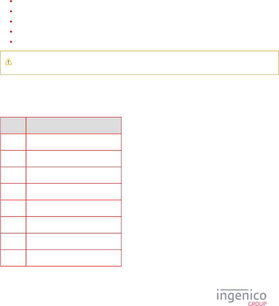
2_1 Display Issues
Refer to the below table for troubleshooting display related issues.
Issue Cause/Error Recommended Action
No Display Forms are not
loaded (UIA) or
hardware issue.
Reboot the device and reinitialize with the POS. Forms should load after
reconnection.
Connect the device to a different POS station.
Try replacing the cable to determine if it is defective.
Replace the power supply to determine if the power supply is defective, and retest.

11/57 Telium Troubleshooting Guide / June 28, 2014
1.
2.
3.
1.
2.
3.
4.
Issue Cause/Error Recommended Action
White Display or
Rainbow Display
(Multiple Colors)
Verify that the correct power supply is used per specifications for this product.
Refer to the product Quick Reference Guide for this device in the Appendices. If
the correct power supply is being used then proceed to step 2.
Reset power to the device and reinitialize the connection with the POS. If the issue
persists, proceed to step 3.
Replace the power supply to determine if the power supply is defective.
2_2 Security Issues
Refer to the below table for troubleshooting security related issues.
Issue Cause/Error Recommended Action
Alert Irruption
Error Message
Tamper Error. The terminal will lock up if the device detects any
tampering, which will result in the terminal secure memory areas
being cleared and rendering the terminal inoperable.
Replace the terminal.
Cannot Process
Debit Card
(Host message
error)
Error occurs, when transaction is sent for approval Notate the error from the
Host/Processor.
Proceed to Encryption Validation
and notate your key information.
Validate with the Host Processor to
ensure that the key is being
correctly processed.
If the key information is incorrect,
return the terminal to your specific
key injection facility for key
injection.

12/57 Telium Troubleshooting Guide / June 28, 2014
1.
2.
3.
4.
1.
2.
3.
4.
1.
2.
3.
4.
Issue Cause/Error Recommended Action
PIN Entry
Screen Does Not
Display
Keys not injected
Application goes offline (RBA)
Proceed to Encryption Validation
validate that a key is installed in
the device.
If key is present, validate the key
information and index are correct.
Check your applications and key
configuration index. These value
must match the key index.
If the key information is incorrect,
return the terminal to your specific
key injection facility for key
injection
2_3 Pen/Finger Response Issues
Refer to the below table for troubleshooting pen/finger response issues.
Issue Cause/Error Recommended Action
No Inking on Screen During
Signature Disconnect and then reconnect the stylus to the connector on the back of the
terminal, and retest.
Replace the stylus to determine if it is defective.
If stylus is defective, refer to your repair contract for next steps.
If the stylus has been replaced and the terminal is still not inking to screen
during signature, return for repair.
Signature is Distorted Disconnect and then reconnect the stylus to the connector on the back of the
terminal, and retest.
Replace the stylus to determine if it is defective.
If stylus is defective, refer to your repair contract for next steps.
If the stylus has been replaced and the terminal is still not inking to screen
during signature, return stylus and terminal for repair.

13/57 Telium Troubleshooting Guide / June 28, 2014
1.
2.
3.
1.
2.
3.
4.
5.
1.
2.
3.
Issue Cause/Error Recommended Action
Incorrect Selection of Menu
Option Using Finger
Calibration
may be off Reset device to allow for recalibration. Run a test transaction using your
finger to determine, if the issue is resolved.
If the issue persists, note if the issue is more prevalent on one particular
form/screen or if it affects all screens.
Return the terminal for repair if consistent in all menu selection or forms
requiring user finger input.
Stylus Visibly Damaged or
Defective
Replace stylus.
2_4 Card Response Issues
Refer to the below table for troubleshooting card response issues.
Issue Cause/Error Recommended Action
MSR Not Being Read Bad
MSR
stripe
Dirty
read
head
Inspect the card for damage or excessive wear.
Try swiping the card at normal swipe speed (0.5 seconds for the full swipe).
Use the other read head by flipping the card (iSCXXX devices only).
Swipe the card in a reverse direction. For example, if swiping top to bottom,
swipe from bottom to top.
If the device is experiencing frequent ‘Card Read Errors’, use an Ingenico
approved card cleaner to clean the MSR readers.
Contactless Light Not
Displaying
Contactless
is not
enabled
Refer to section and verify that contactless is enabled.Contactless
For the IPP3xx and ISC250, open the door at the bottom of the terminal and
verify that the contactless module is present and is seated properly.
Ensure that the application has configured contactless as enabled. Refer to the
RBA or UPOS Developer’s Guides.
Contactless Reader is Not
Reading Customer Card
or Data
Ensure you are tapping the card or phone near the location on the device where
the contactless antenna is located. Refer to the device Quick Reference for the
hardware configuration.

14/57 Telium Troubleshooting Guide / June 28, 2014
1.
2.
3.
4.
5.
1.
2.
1.
2.
3.
1.
2.
2_5 Communication Issues
Refer to the below table for troubleshooting communications issues.
Issue Cause/Error Recommended Action
Device Locks Up or
"Freezes Up" Reset power to the terminal. Wait until it completely initializes, then reset the POS
to determine if communication can be reestablished.
Access different screens to determine if the issue is consistent with a particular
transaction or form.
Check the store network.
Check the cable to ensure that no damage is present (bent pin, etc.). Replace the
cable, if necessary.
Swap the terminal with another POS system register to determine if the issue
follows the terminal.
Terminal Not
Communicating
with POS
Wrong
Communication
Setting
Reset device power and retry connection.
Ensure communication settings are correct. Refer to the Telium Download
section and follow the procedure for verifyingApplication (TDA) Menu
communication settings.
Device is
Unresponsive or
Consistently Resets
Ensure that the device is at least 12 inches away from any source of magnetic field
(security tag deactivation system, scanners, etc.).
For IPP3xx only, device may have been configured for contactless but the module
is not present or is not seated properly. Verify that the contactless module is
present and is properly seated.
Reset device to reestablish communication.
Bad Network Port Check Ethernet settings to ensure proper configuration
Change Ethernet settings to IP Static (if DHCP) to determine if communication is
established (or vice versa). If so, the issue is not with the terminal but with the
network configuration.
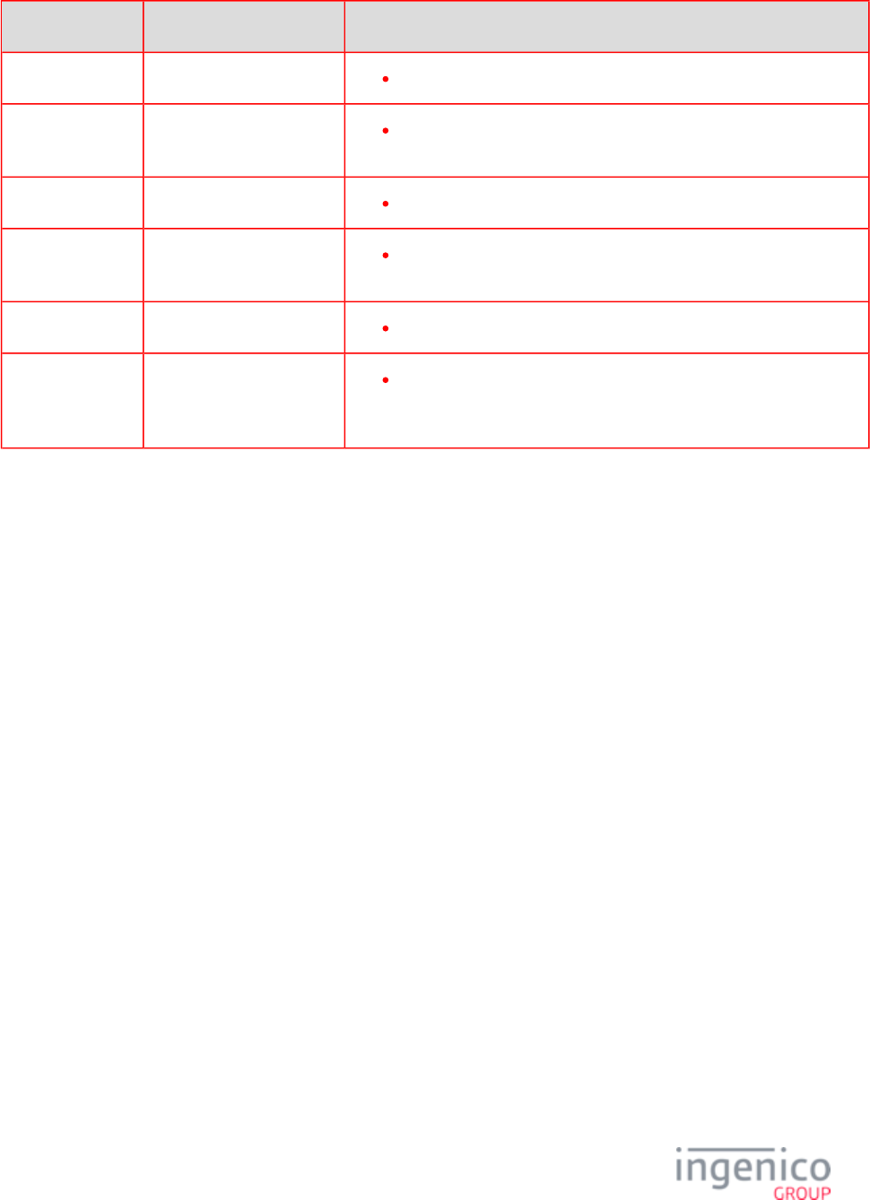
2_6 Error Messages
Refer to the below table for troubleshooting error messages.
15/57 Telium Troubleshooting Guide / June 28, 2014
Issue Cause/Error Recommended Action
ECC KO Replace the terminal.
WAITING FOR
DOWNLOAD
Missing data (.dat) files or
application
Reload the generic released application.
UNAUTHORIZED Replace the terminal.
BAD
SIGNATURE
Replace the terminal.
LLT Application is missing Reload the generic released application.
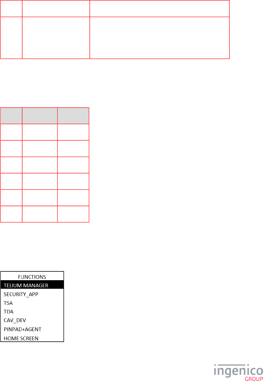
SYSTEM
PROBLEM CALL
HELP DESK
Incorrect parameter settings
or an incomplete software
load process
Some or all of the required software may be missing. Return the
terminal to the customization site to have software reloaded, or
download the software remotely if possible.

16/57 Telium Troubleshooting Guide / June 28, 2014
1.
2.
1.
2.
1.
2.
1.
2.
1.
2.
3_FUNCTIONS Overview
The Functions menu allows the user to access menus to verify software and hardware configuration settings. This manual will review
Telium Manager, Telium System Application (TSA), and Telium Download Application (TDA) menus to assist in the validation of
your configuration. Refer to the following sections for more detail:
Keyboard Shortcut to Access Menus
Navigating Menus
FUNCTIONS Menu
3_1 Keyboard Shortcut to Access Menus
The Functions menu is accessed using the device keypad as described in the below table. The splash screen is in reference to the
generic application (UIA, RBA) that is loaded in the device.
iSC480 Press [ # ] key and Yellow key When splash screen displays during power up (for 2 seconds):
Press [2], [6], [3], [4], and then press the green [Enter] key.
Wait until a second screen appears, and then press [ F ].
iSMPx Press [ # ] key and Yellow key When splash screen displays during power up (for 2 seconds):
Press [2], [6], [3], [4], and then press the green [Enter] key.
Wait until a second screen appears, and then press [ F2 ].
iWL250 Press [ # ] key and Yellow key When splash screen displays during power up (for 2 seconds):
Press [2], [6], [3], [4], and then press the green [Enter] key.
Wait until a second screen appears, and then press [ F2 ].
iSC250 Press [ - ] key and Yellow key When splash screen displays during power up (for 2 seconds):
Press [2], [6], [3], [4], and then press the green [Enter] key.
Wait until a second screen appears, and then press [ + ].
iSC350
Press [ - ] key and Yellow key
When splash screen displays during power up (for 2 seconds):
Press [2], [6], [3], [4], and then press the green [Enter] key.
17/57 Telium Troubleshooting Guide / June 28, 2014
2.
1.
2.
Wait until a second screen appears, and then press [ + ].
iPP3XX Press [ . ] key and Yellow key When splash screen displays during power up (for 2 seconds):
Press [2], [6], [3], [4], and then press the green [Enter] key.
Wait until a second screen appears, and then press [ + ].
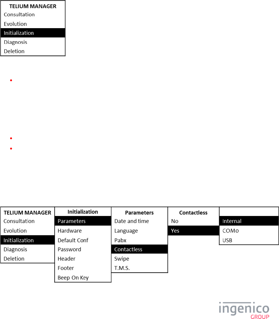
3_2 Navigating Menus
This section describes how to access the Functions menu. Scrolling through the menu options is specific to the device as shown in the
below table. Scrolling can be done by selecting a menu key or by selecting the corresponding menu number.
Device Scroll Up Scroll Down
iPP3XX [F3] key [F2] key
iSC250 [+] or [F3] key [F2] key
iSC350 [+] or [F3] key [F2] key
iSC480 [F] or [F3] key [F2] key
iSMPx [F3] key [F2] key
iWL250 [F4] key [F3] key
3_3 FUNCTIONS Menu
Access to the Telium Manager, Telium System Application (TSA), and Telium Download Application (TDA) is via the
menu which is illustrated in the following figure.FUNCTIONS
18/57 Telium Troubleshooting Guide / June 28, 2014
4_Telium Manager Menu
The Telium Manager menu is accessed via the FUNCTIONS main menu, and allows the user to verify hardware configuration
settings. Refer to the below figure which shows the Telium Manager main menu.
To verify contactless or MSR formats, refer to the following section:
Verify Contactless and Magnetic Stripe Reader (MSR) Formats
4_1 Verify Contactless and Magnetic Stripe Reader (MSR) Formats
The Telium Manager menu allows the user to verify that contactless is enabled and that the correct ISO format is selected for the
MSR. Please refer to the following sections:
Contactless
MSR Swipe (ISO)
4_1_1 Contactless
The contactless function used for reading contactless MSR cards, EMV cards, and some NFC enabled devices must be enabled in the
application and hardware. To verify that the contactless card reader is enabled for the hardware, choose the [Initialization] option
from the Telium Manager menu and follow the subsequent selections as illustrated in the below figure. In the below example, internal
contactless is selected.
19/57 Telium Troubleshooting Guide / June 28, 2014
When contactless is enabled, the first contactless LED will illuminate. This does not apply to the iSC480 with internal
contactless.
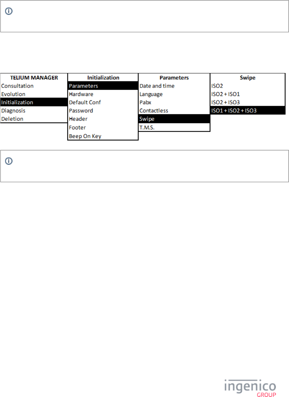
4_1_2 MSR Swipe (ISO)
ISO refers to the MSR tracks to be read. To verify that the correct ISO is selected, choose the [Initialization] option from the Telium
Manager menu and follow the subsequent selections as illustrated in the below figure.
MSR tracks to read can be determined in the application as well. Refer to the appropriate Developer's Guide for more
information.
20/57 Telium Troubleshooting Guide / June 28, 2014
5_Telium System Application (TSA) Menu
The Telium System Application (TSA) menu allows the user to verify the presence of encryption keys and serial numbers. The TSA
menu is accessed from the Functions main menu. Three menu options enable the user to verify that the encryption keys are present
(Key Check Value, Master Session, and DUKPT) and provide details on the keys which are loaded. Refer to the below figure for an
illustration of the TSA menu.
Please refer to the following sections for terminal serial number and encryption validation:
Terminal Serial Number
Encryption Validation
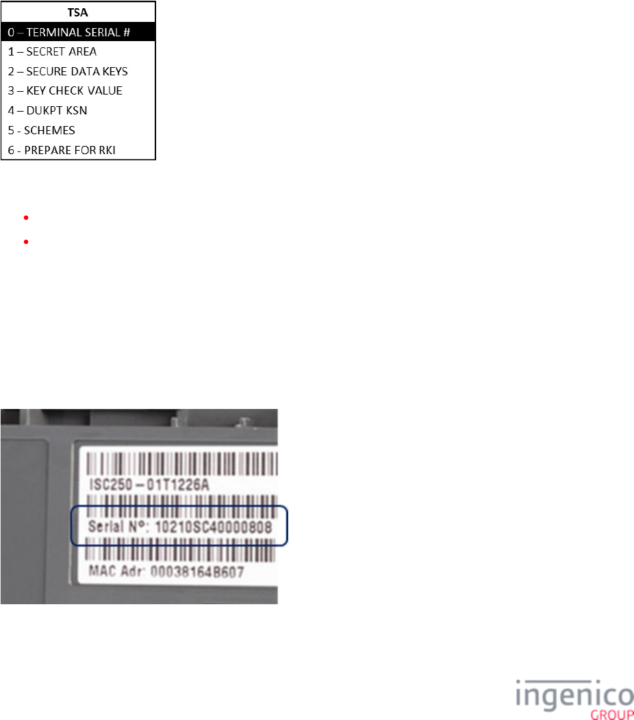
5_1 Terminal Serial Number
5_1_1 Hardware Part Number
The hardware part number is the device serial number. Only the last 8 characters of the hardware part number (40000808 for the
following example image) are displayed on the device screen when selecting the [Terminal Serial #] option.
21/57 Telium Troubleshooting Guide / June 28, 2014
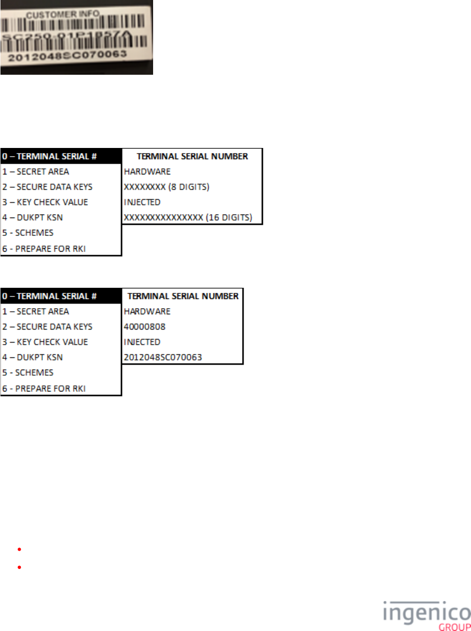
5_1_2 Injected Serial Number
The injected serial number matches the “Customer Info” label on the back of the device. Refer to the following image which shows a
"Customer Info" label. The injected serial number for this device would be "2012048SC070063".
5_1_3 Terminal Serial Number as Displayed on the Screen
When the [Terminal Serial #] option is selected, the TSA will display the last 8 digits of the hardware part number and the complete
injected serial number as illustrated in the below image.
For the above example images, the terminal serial number would be displayed as follows:
5_2 Encryption Validation
In order to perform a Debit, eWIC or EBT transaction, an encryption key must be injected into the device. During the loading process,
the encryption key and Key Serial Number (KSN) are injected. Only the KTK and KSN are visible for customer viewing.
An injected encryption key is also required for some MSR encryptions (e.g., Magtek, Monetra). MSR encryptions are enabled in the
application. Ingenico’s devices support Master Session and DUKPT key formats. Encryption key formats are determined by the
customer. Follow the validation instruction, per your format. Refer to the following sections for encryption validation:
Validating Special Keys
Master Session

22/57 Telium Troubleshooting Guide / June 28, 2014
DUKPT KSN
5_2_1 Validating Special Keys
To validate the Key Check Value (KTK), select the [KEY CHECK VALUE] option from the Telium System Application menu and
follow the subsequent selections as illustrated in the below figure. Only the KTK value needs to be checked to ensure KTK
encryption. If a generic default value of “KTK KCV (7AE462)” is displayed then this indicates that no keys are present.
5_2_2 Master Session
Using the Key Check Value menu, verify that keys are injected. Refer to the below figure for this process.
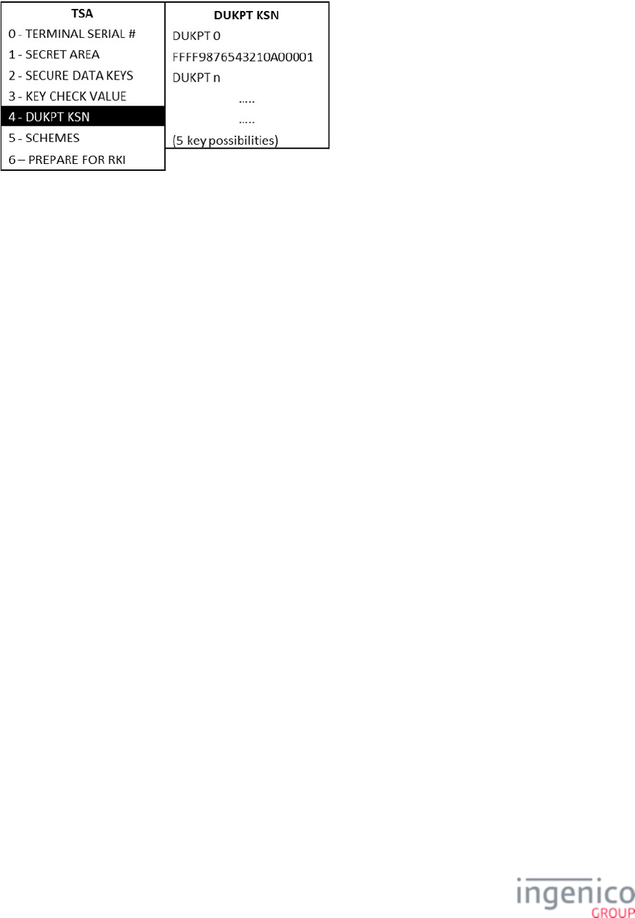
5_2_3 DUKPT KSN
The DUKPT KSN consists of 3 different values. The first 10 digits represent the KSI value assigned to a customer or region. The KSI
is used to verify the key information. The next 5 digits are the device ID, and the last 5 digits are the encryption counter. The counter
increases for each encryption. To validate that the DUKPT encryption key has been injected and is correct, select the [DUKPT KSN]
option from the TSA menu. Refer to the below figure.
23/57 Telium Troubleshooting Guide / June 28, 2014
24/57 Telium Troubleshooting Guide / June 28, 2014
6_Telium Download Application (TDA) Menu
The Telium Download Application (TDA) is an Ingenico application that can be used to perform the following functions:
Configure communication port settings.
Perform initial download and updates of software.
Refer to the section which will step you through the menu selection to verify or change settings forAccessing the TDA Menu
RS-232, Ethernet, Tailgate, and Bluetooth.
Communication port settings can also be observed on the main application splash screen.
TDA settings are configured within TDA.XML. Refer to the DIV350779 RBA Developer’s Guide and DIV350825 UPOS
Developer’s Guide for more info.
Refer to the DIV350827 Telium Download Guide for more information on TDA.
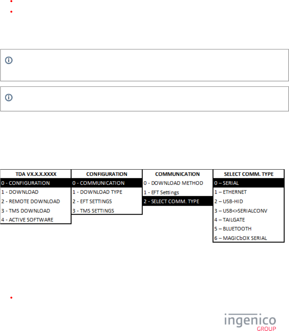
6_1 Accessing the TDA Menu
The TDA menu provides the user with options to verify and reconfigure communication settings. To view the communication port
settings, select the [CONFIGURATION] option from the TDA menu and follow the subsequent selections as illustrated in the below
figure.
By selecting the [SELECT COMM. TYPE] option you will be able to choose which communication port settings to view (i.e. serial,
Ethernet, Tailgate). Communication port settings can also be observed on the main application splash screen. If the communication
port settings are changed, press the [CANCEL] key several times in the Save and Reboot menu. Then select [YES] to save changes.
Refer to the following sections for verifying or changing Serial, Ethernet, USB-HID, USB-CDC, Tailgate, or Bluetooth
communication settings:
RS-232 (Serial) Setting

25/57 Telium Troubleshooting Guide / June 28, 2014
Ethernet Settings
USB-HID Setting
USB-CDC Setting
Tailgate Settings
Bluetooth Settings
To reverse the steps taken in any of the above menus, and go back to the Telium Manager main menu, press the red [X] keypad
button, then press the [+] or [F] keypad button.
If the communication port settings are changed, press the [CANCEL] key several times in the Save and Reboot menu. Then select
[YES] to save changes.
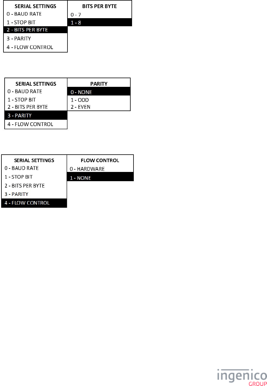
6_1_1 RS-232 (Serial) Setting
To view serial port settings, select the [CONFIGURATION] option from the Telium Download Application menu and follow the
subsequent selections as illustrated in the below figure. By selecting these options you will be able to view baud rate, stop bit, bits per
byte, parity, and flow control settings.
To change baud rate, follow the menu selection as illustrated below. In the below example, a baud rate of 115,200 (default) is
selected.
To change bits per byte, from the SERIAL SETTINGS menu proceed as follows:
26/57 Telium Troubleshooting Guide / June 28, 2014
To change parity, from the SERIAL SETTINGS menu proceed as follows:
To change flow control, from the SERIAL SETTINGS menu proceed as follows:
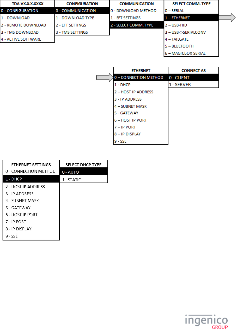
6_1_2 Ethernet Settings
To view or reconfigure Ethernet port settings, select the [CONFIGURATION] option from the Telium Download Application menu
and follow the subsequent selections as illustrated in the below figure. In the below example, the Ethernet connection method is
selected as “client.”
27/57 Telium Troubleshooting Guide / June 28, 2014
To set or change the DHCP setting, proceed as follows from the Ethernet Settings menu:
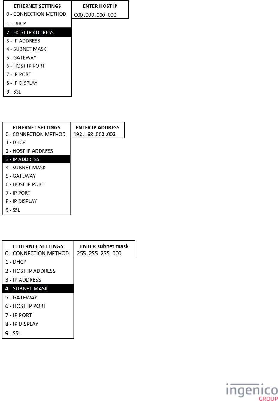
To set or change the Host IP address, proceed as follows from the Ethernet Settings menu:
28/57 Telium Troubleshooting Guide / June 28, 2014
Enter values with keypad and press "Enter". To set or change the IP address, proceed as follows from the Ethernet Settings menu:
To set or change the subnet mask, proceed as follows from the Ethernet Settings menu:
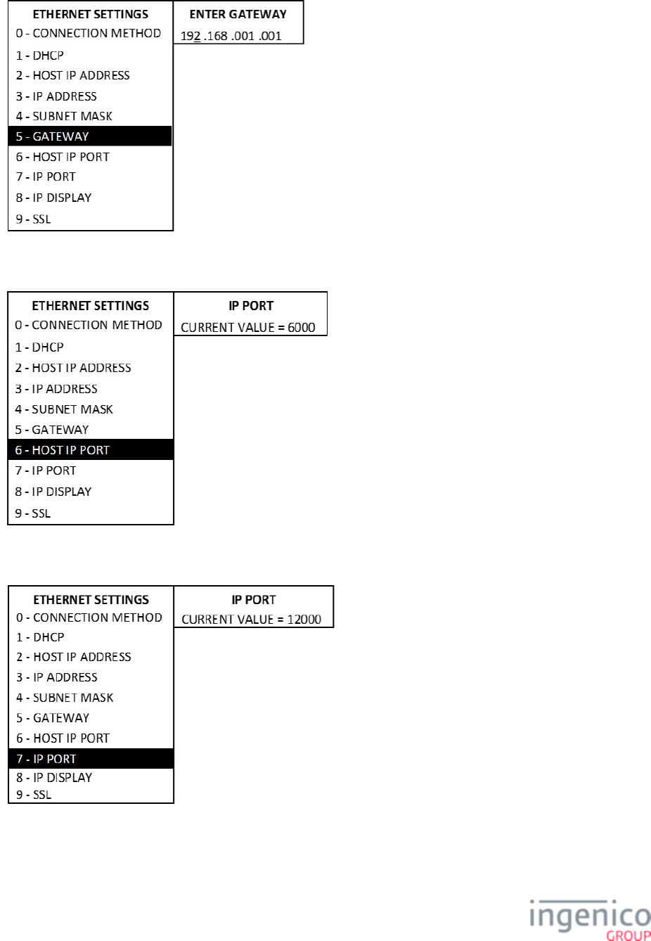
To set or change the Gateway, proceed as follows from the Ethernet Settings menu:
29/57 Telium Troubleshooting Guide / June 28, 2014
To set or change the Host IP port, proceed as follows from the Ethernet Settings menu:
To set or change the IP port, proceed as follows from the Ethernet Settings menu:
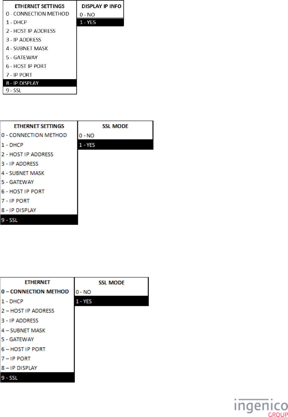
To set or change the IP display, proceed as follows from the Ethernet Settings menu:
30/57 Telium Troubleshooting Guide / June 28, 2014
To select SSL mode, proceed as follows from the Ethernet Settings menu:
Information will be displayed on the "splash" screen if "yes" is selected.
6_1_2_1 Enabling SSL
To set or change the SSL mode selection, proceed as follows from the Ethernet Settings menu:
31/57 Telium Troubleshooting Guide / June 28, 2014
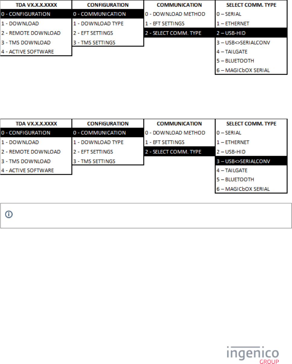
6_1_3 USB-HID Setting
To view or select USB port settings, select the [CONFIGURATION] option from the Telium Download Application menu and follow
the subsequent selections as illustrated in the below figure.
6_1_4 USB-CDC Setting
To view or select USB-CDC port settings, select the [CONFIGURATION] option from the Telium Download Application menu and
follow the subsequent selections as illustrated in the below figure.
The Jungo driver is recommended when using the USB-CDC communication setting.
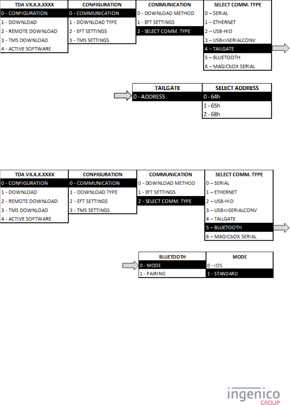
6_1_5 Tailgate Settings
To configure Tailgate settings, select [TAILGATE SETTINGS] from the menu. Select option ‘0’ forSELECT COMM. TYPE
address, and then select the address as illustrated in the below figure.
32/57 Telium Troubleshooting Guide / June 28, 2014
6_1_6 Bluetooth Settings
To configure Bluetooth settings, select [BLUETOOTH] from the SELECT COMM. TYPE menu. To select Bluetooth mode, select
the [MODE] option and choose the mode as illustrated in the below figure.
To select Bluetooth pairing, select the [PAIRING] option and choose the pairing as illustrated in the below figure.

33/57 Telium Troubleshooting Guide / June 28, 2014

34/57 Telium Troubleshooting Guide / June 28, 2014
7_PIN Pad Device Quick Reference Guides
The following sections provide quick references for the devices covered in this manual. This includes a general device overview,
power requirements, Secure Access Modules, contactless, interface connections, and interface cable specifications.
iPP320 and iPP350 Quick Reference
iSC250 Quick Reference
iSC350 Quick Reference
iSC480 Quick Reference
iSMP Quick Reference
iSMP Companion Quick Reference
iWL250 Quick Reference
iSelf Series Quick Reference
7_1 iPP320 and iPP350 Quick Reference
The iPP320 and iPP350 Quick Reference is organized into the following sections:
iPP320 and iPP350 Overview
iPP320 and iPP350 Power Requirements
iPP320 and iPP350 Secure Access Modules
iPP320 and iPP350 Host Interface Options
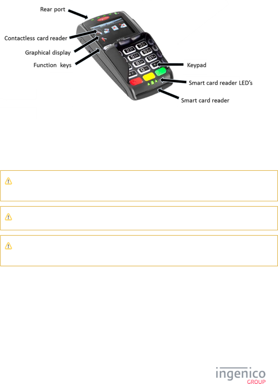
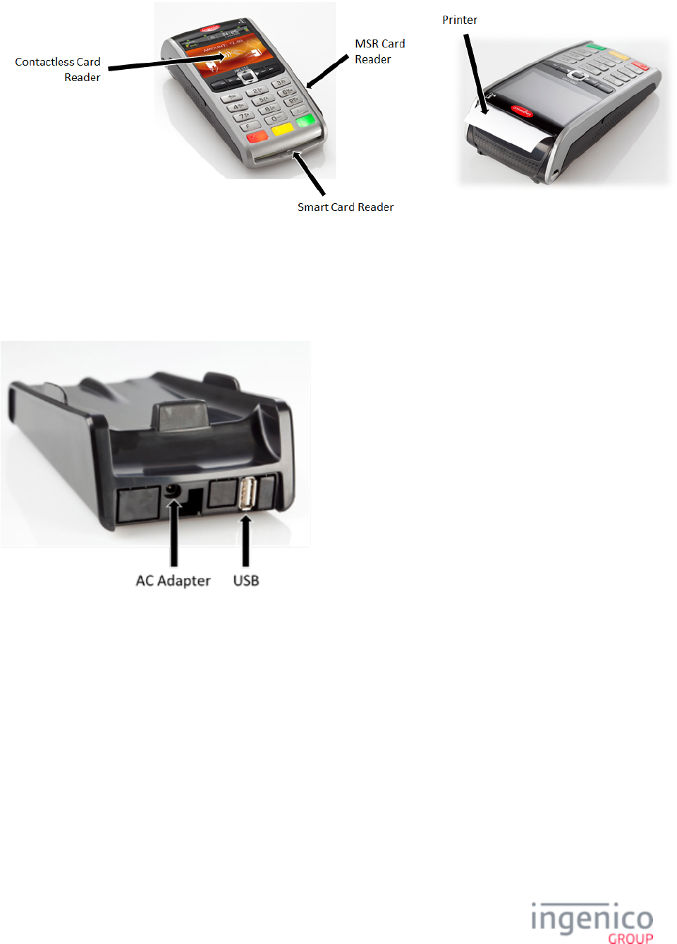
7_1_1 iPP320 and iPP350 Overview
This section provides a quick reference for the iPP320 and iPP350 terminals. These terminals are functionally identical with the
exception of the graphical display type. Both terminals feature a contactless card reader, smart card reader, and MSR as shown in the
below image.
35/57 Telium Troubleshooting Guide / June 28, 2014
7_1_2 iPP320 and iPP350 Power Requirements
An external power supply is required when connecting the iPP320 or iPP350 to the Host via Ethernet and 5m length RS-232 cables.
Ingenico specifies a DC power supply (model number 179901469) for this device. These terminals may also be powered from a POS
via the USB (5V, 500mA) interface.
Connect the cable to the Multipoint port before connecting power to the terminal. Only use the power supply which was
provided by Ingenico.
Do not disconnect power from the terminal until you have been instructed to do so.
Before you disconnect the terminal from the POS, you must first disconnect power in order to prevent damage to the
terminal.
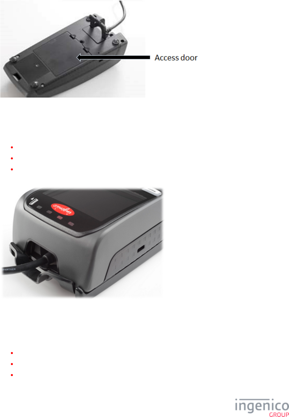
7_1_3 iPP320 and iPP350 Secure Access Modules
There are three Secure Access Module (SAM) slots designed to hold full-size SAM cards. These slots are accessible via an access
door on the bottom of the device as shown in the below image.
36/57 Telium Troubleshooting Guide / June 28, 2014
7_1_4 iPP320 and iPP350 Host Interface Options
A master port which is located on the back of the device enables the iPP320 and iPP350 PIN pad devices to connect to the Host via
the following interfaces:
USB
RS-232
Ethernet
Refer to the below image for the interface port location on these devices.
7_2 iSC250 Quick Reference
The iSC250 Quick Reference is organized into the following sections:
iSC250 Overview
iSC250 Power Requirements
iSC250 SAM and Micro SD Card Slots
37/57 Telium Troubleshooting Guide / June 28, 2014
iSC250 Contactless Module
iSC250 Peripheral Connectors and Host Interface Options
iSC250 Multipoint Connector
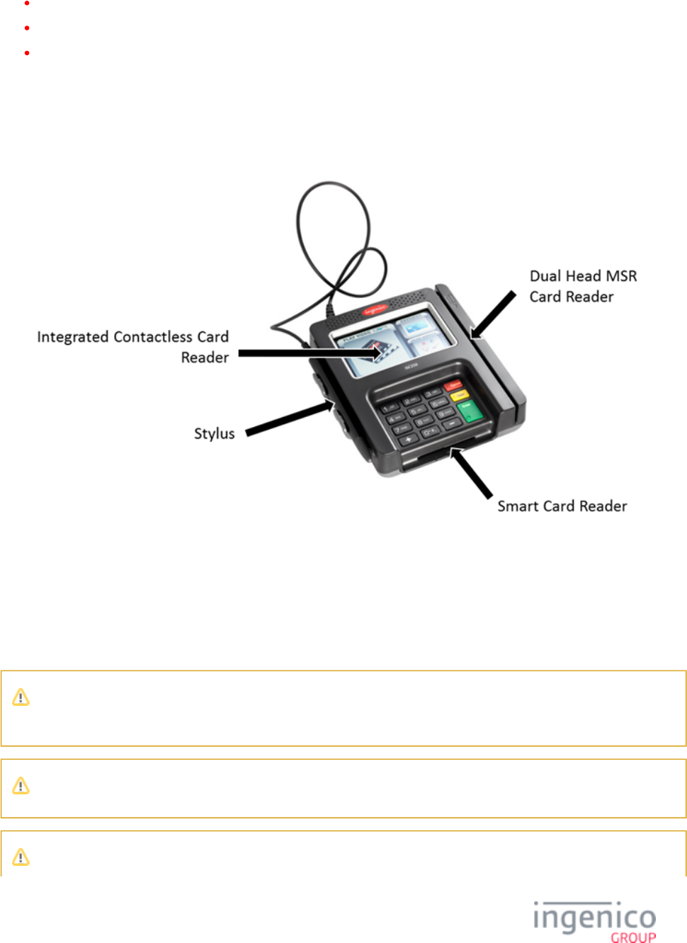
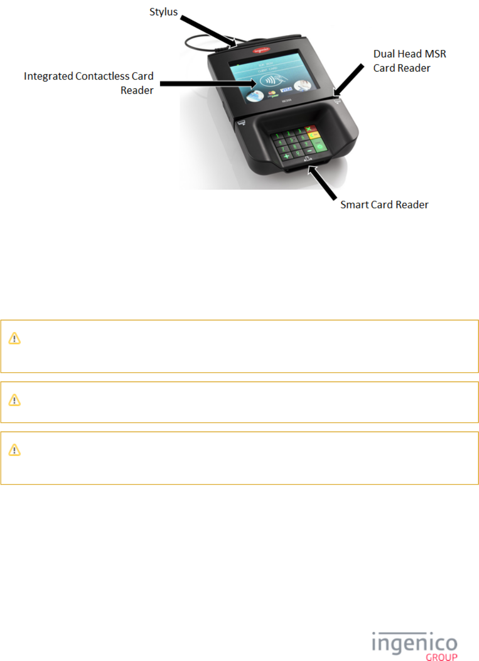
7_2_1 iSC250 Overview
The iSC250 terminal can communicate with a host device such as a Point of Sale (POS) system or PC via serial (RS-232), Tailgate
(RS-485), USB, VGA, or Ethernet interfaces. It features a stylus, smart card reader, MSR, and optional contactless card reader as
shown in the below figure.
7_2_2 iSC250 Power Requirements
When interfacing the iSC250 to the POS via RS-232, USB (5V), or Ethernet interfaces, an Ingenico power supply (192011597) is
required. Power may also be provided by the POS via USB (12V or 24V) or RS-485 (via Multipoint) connections. If an Ingenico
power supply was provided with the terminal, plug the power supply connector into the jack on the Multipoint cable.
Connect the cable to the Multipoint port before connecting power to the terminal. Only use the power supply which was
provided by Ingenico.
Do not disconnect power from the terminal until you have been instructed to do so.
38/57 Telium Troubleshooting Guide / June 28, 2014
Before you disconnect the terminal from the POS, you must first disconnect power in order to prevent damage to the
terminal.
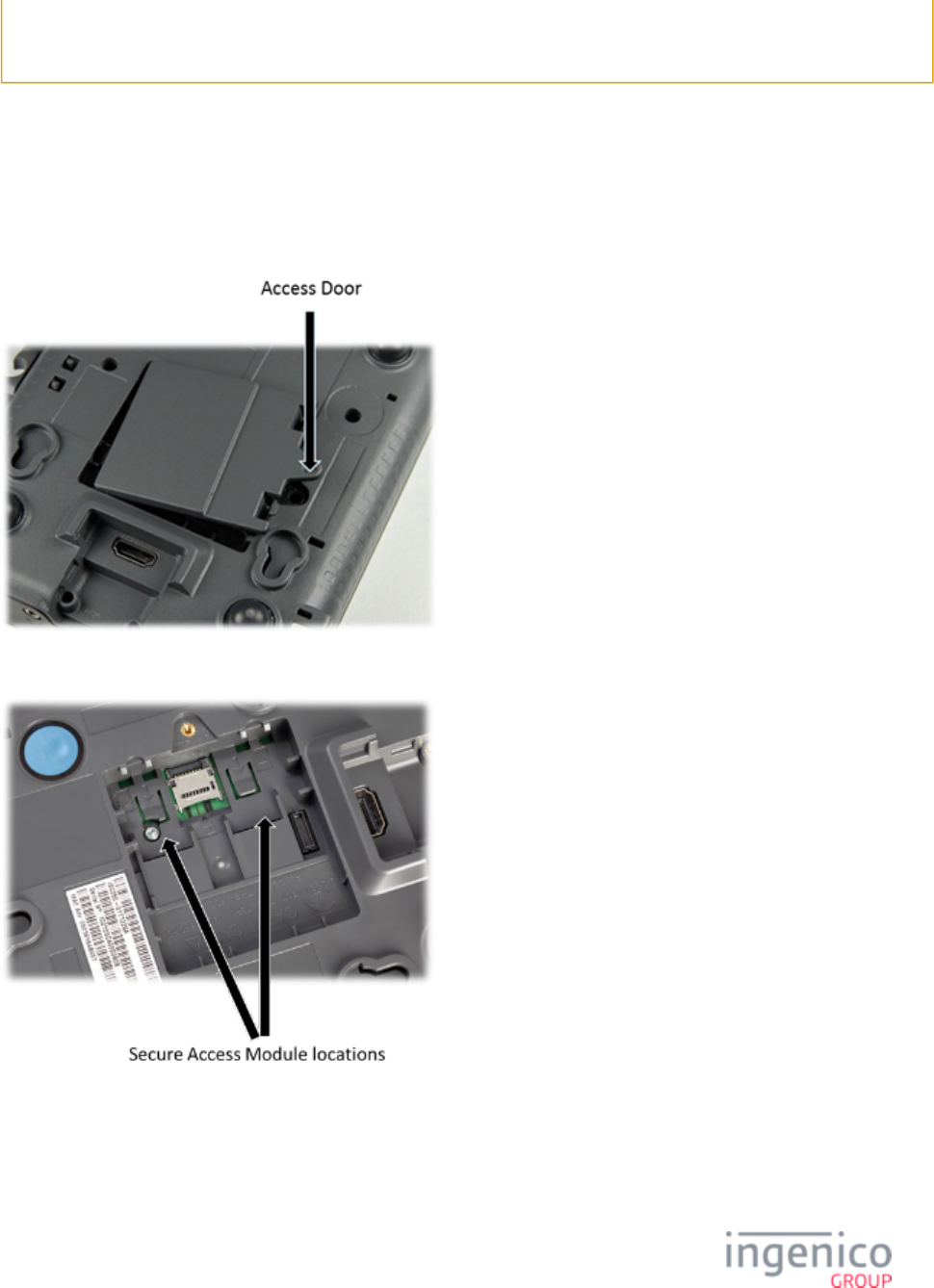
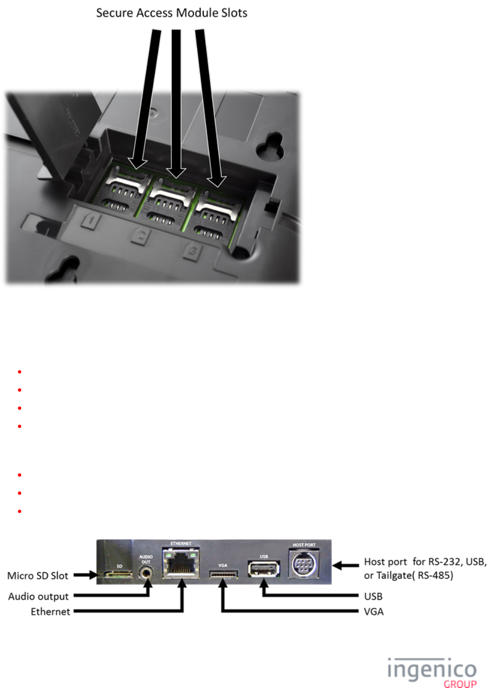
7_2_3 iSC250 SAM and Micro SD Card Slots
There are two Secure Access Module (SAM) slots and two Micro SD slots which are accessible via an access door which is located
on the bottom of the terminal. The access door may be opened by removing the screw which secures it as illustrated in the below
image.
With the access door removed, there are two slots where Secure Access Modules may be installed as shown in the below image.
The SAM cards, when installed, store proprietary information for use with smart card-based applications. The Micro SD cards
provide additional memory.
39/57 Telium Troubleshooting Guide / June 28, 2014
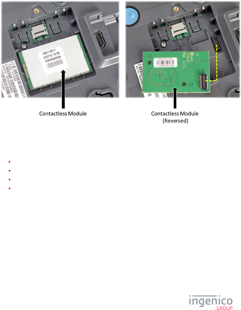
7_2_4 iSC250 Contactless Module
The contactless module is accessible via the access door on the bottom of the device. Refer to the below image which shows the
location and removal of the contactless module.
7_2_5 iSC250 Peripheral Connectors and Host Interface Options
The iSC250 may interface to a Host system using any of the following interface options:
RS-232
Tailgate (RS-485)
USB
Ethernet
Refer to the section for a description of the Multipoint port which facilitates RS-232, Tailgate, andiSC250 Multipoint Connector
Ethernet connections with the Host system.
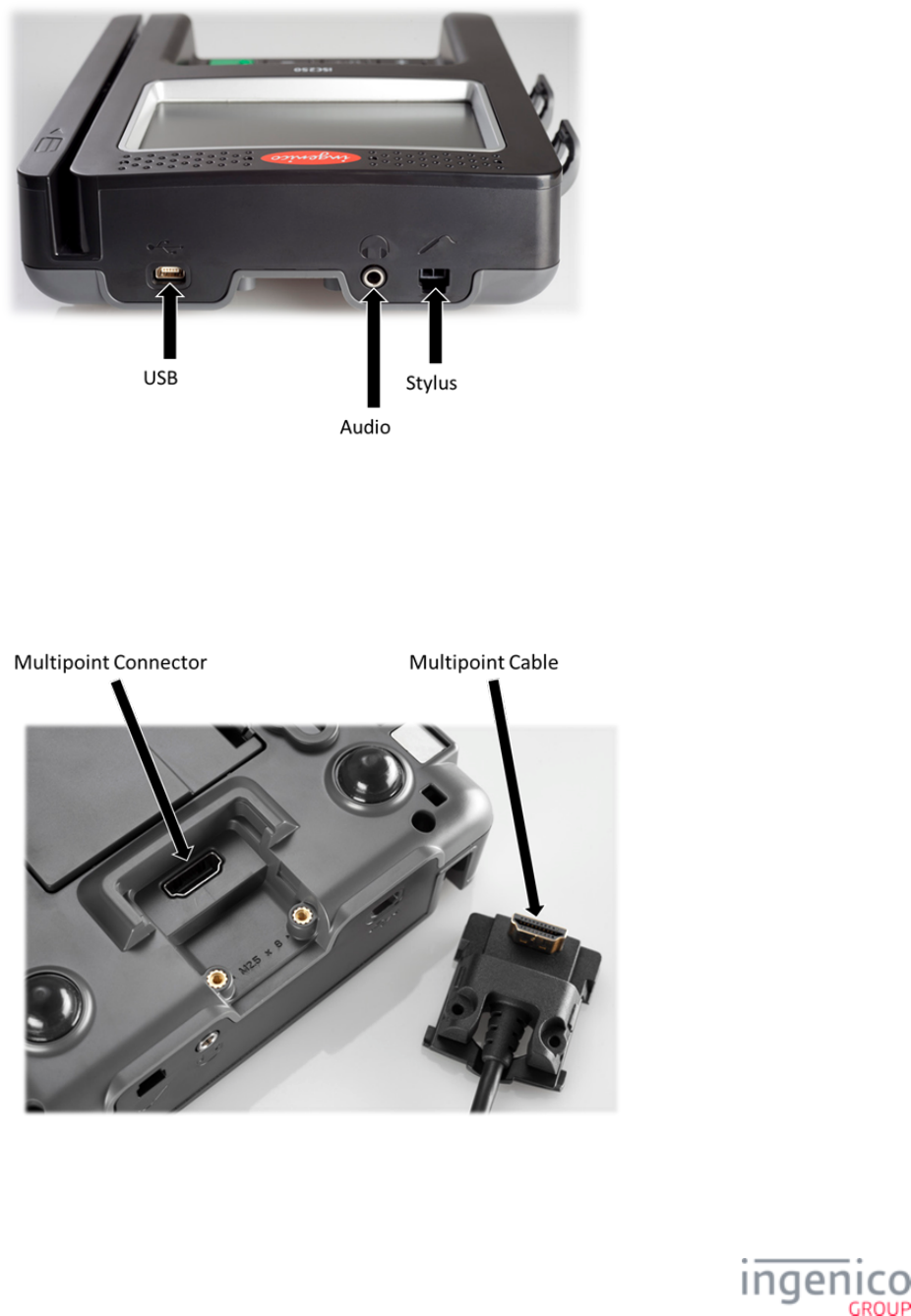
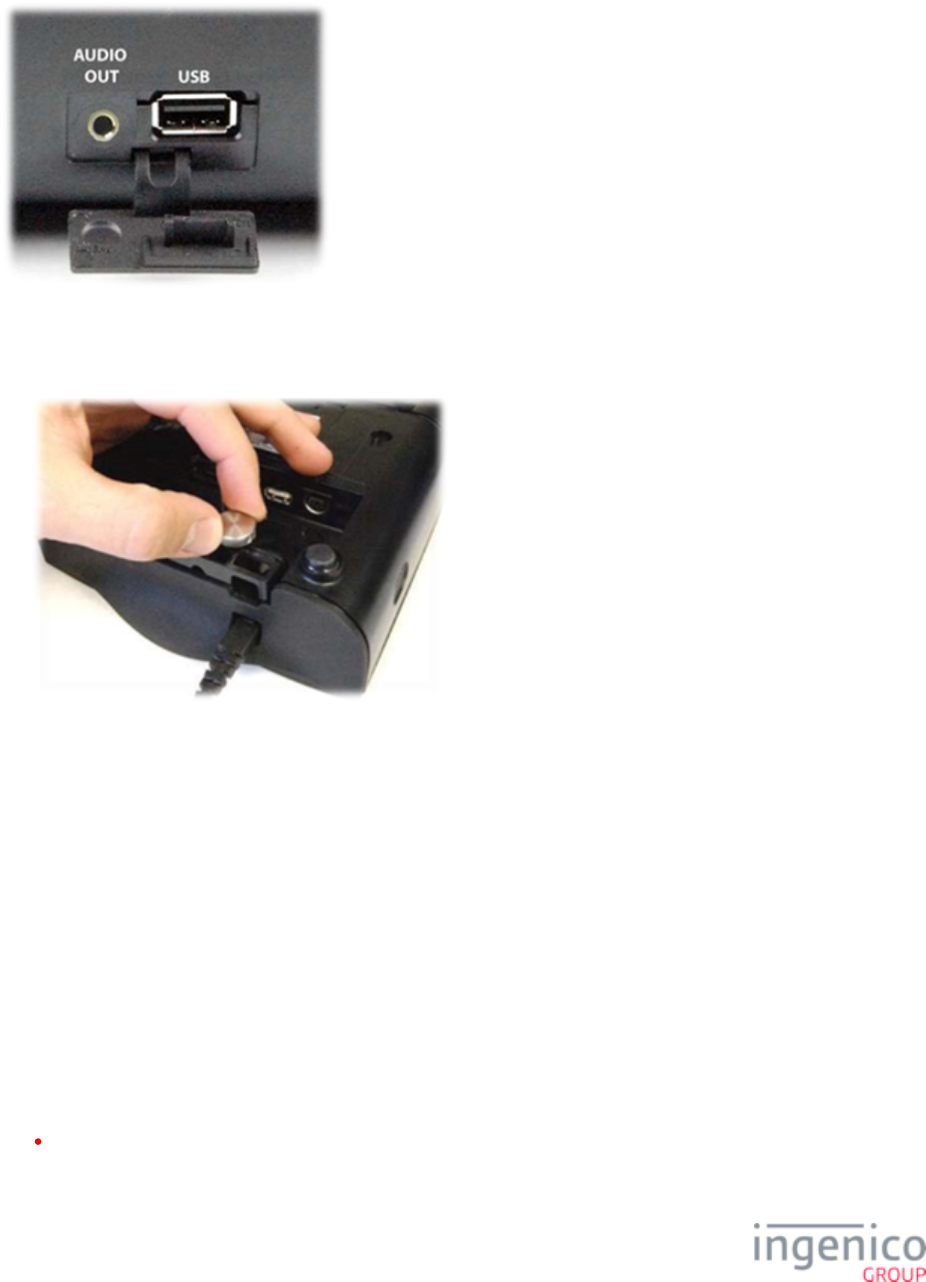
The USB port is located on the rear of the terminal as shown in the below image. Also located on this panel are the audio jack and
stylus connector.
40/57 Telium Troubleshooting Guide / June 28, 2014
1.
7_2_6 iSC250 Multipoint Connector
The Multipoint connector located on the bottom of the terminal may be attached with screws for additional security. This connector is
used to connect RS-232, Tailgate (RS-485), USB, Ethernet, Magic box or Universal cables. It is important that you are using the
correct cable for the required interface. Special care must be taken when connecting or disconnecting the cable which attaches to the
Multipoint. Refer to the below image which shows the Multipoint connector and cable.
To disconnect the cable from the Multipoint connector:
Disconnect power from the iSC250 to prevent damage to the device.

41/57 Telium Troubleshooting Guide / June 28, 2014
2.
3.
4.
Place the iSC250 in front of you with the bottom of the terminal facing up. Be careful not to place the device on a surface
where the display screen can be scratched or damaged.
If you have secured the cable with screws, carefully remove the two screws from either side of the Multipoint cable.
Carefully pull out the Multipoint cable using the loop as shown in the below image.
7_3 iSC350 Quick Reference
The iSC350 Quick Reference is organized into the following sections:
iSC350 Overview
iSC350 Power Requirements
iSC350 Secure Access Modules
iSC350 Peripheral Connectors and Host Interface Options
7_3_1 iSC350 Overview
The iSC350 device can communicate with a host device such as a POS or PC via RS-232, Tailgate (RS-485), USB or Ethernet
interfaces. This terminal features a stylus, optional integrated contactless card reader, smart card reader, and MSR as shown in the
below image.
42/57 Telium Troubleshooting Guide / June 28, 2014
7_3_2 iSC350 Power Requirements
The iSC350 can receive power from the POS system or via an external power supply provided by Ingenico. When interfacing to the
POS via RS-232, USB (5V), or Ethernet interfaces, a separate Ingenico power supply (192008227) is required. Power may also be
provided by the POS via USB (12V or 24V) or RS-485 (via Multipoint) connections. If an Ingenico power supply was provided with
the terminal, plug the power supply connector into the jack on the Multipoint cable.
Connect the cable to the Multipoint port before connecting power to the terminal. Only use the power supply which was
provided by Ingenico.
Do not disconnect power from the terminal until you have been instructed to do so.
Before you disconnect the terminal from the POS, you must first disconnect power in order to prevent damage to the
terminal.
7_3_3 iSC350 Secure Access Modules
There are three optional Secure Access Module (SAM) slots for the iSC350 which are accessible via an access door located on the
bottom of the terminal as shown in the below image.
43/57 Telium Troubleshooting Guide / June 28, 2014
7_3_4 iSC350 Peripheral Connectors and Host Interface Options
The iSC350 PIN pad device may interface with a Host system using any of the following options:
RS-232
Tailgate (RS-485)
USB
Ethernet
Interface ports and peripheral connections are located on a panel at the back of the device. Peripheral connectors on this panel
include:
VGA connection
Audio output
Micro SD slot
Refer to the below image which shows the location of the interface ports and peripheral connectors.
44/57 Telium Troubleshooting Guide / June 28, 2014
1.
2.
1.
2.
Depending on device configuration, a USB port and audio output connection are available on the side ports as shown in the below
image.
A cable retention bar secures cables to the terminal in order to prevent cables from becoming loose or damaged. When servicing
cables, this bar must be removed and then properly reinstalled when servicing is completed. Refer to the below image of the cable
retention bar.
To loosen the cable retention bar:
Turn the thumbscrew counterclockwise.
Lift the cable up and away from the terminal.
To reinstall the cable retention bar:
Position the cable retention bar on the terminal with cables aligned in their slots.
Turn the thumbscrew clockwise until tightened.
7_4 iSC480 Quick Reference
The iS480 Quick Reference is organized into the following sections:
iSC480 Overview
45/57 Telium Troubleshooting Guide / June 28, 2014
iSC480 Power Requirements
iSC480 SAM and Micro SD Card Slots
iSC480 Peripheral Connectors and Host Interface Ports
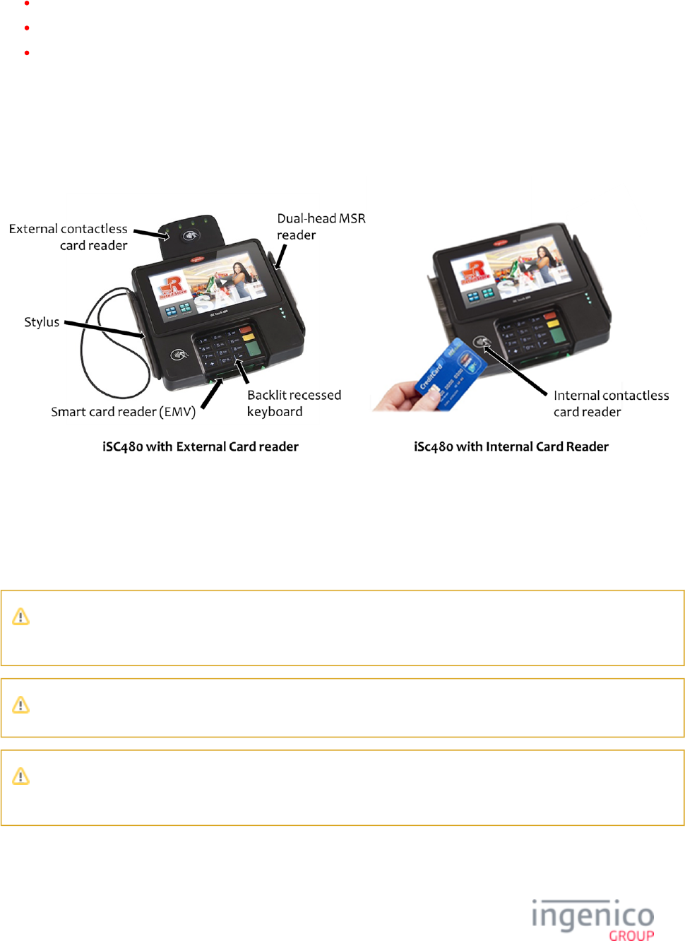
7_4_1 iSC480 Overview
This section provides a quick reference for the iSC480 PIN pad device. The iSC480 features a color touchscreen, MSR, smart card
reader, and contactless card reader. The contactless card reader is available as an integrated module or as an external module with
antenna. Refer to the below image for an overview of the iSC480 PIN pad device.
7_4_2 iSC480 Power Requirements
A separate Ingenico DC power supply (192006210 and power cord 188413214) is required when connecting the iSC480 device via
RS232, USB (5V), and Ethernet. When the device is powered from a POS, power may be provided via a USB (12V or 24V) or
RS485 cable.
Connect the cable to the Multipoint port before connecting power to the terminal. Only use the power supply which was
provided by Ingenico.
Do not disconnect power from the terminal until you have been instructed to do so.
Before you disconnect the terminal from the POS, you must first disconnect power in order to prevent damage to the
terminal.
46/57 Telium Troubleshooting Guide / June 28, 2014
7_4_3 iSC480 SAM and Micro SD Card Slots
The iSC480 features two Secure Access Module (SAM) slots to hold full size SAM cards. These cards store proprietary information
for use with smart cardbased applications. Refer to the below image for the location of the SAM access door.
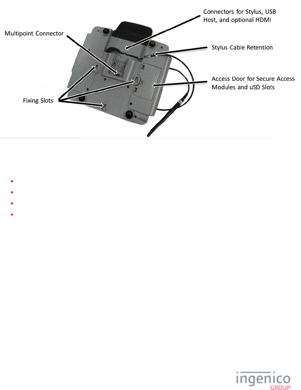
7_4_4 iSC480 Peripheral Connectors and Host Interface Ports
The iSC480 PIN pad device may interface with the Host system via the following interface options:
RS-232
Tailgate (RS-485)
USB
Ethernet
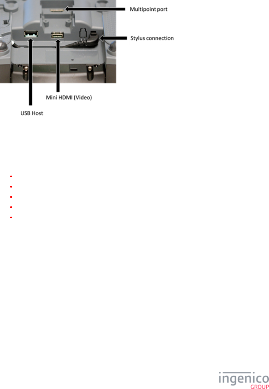
All interface options are via the Multipoint connector. Refer to the below image which shows the location of the USB port and
Multipoint connector. Also shown are the stylus connection and video port.
47/57 Telium Troubleshooting Guide / June 28, 2014
7_5 iSMP Quick Reference
The iSMP Quick Reference is organized into the following sections:
iSMP Overview
iSMP Power Requirements
iSMP SAM and Micro SD Card Slots
iSMP Interface Options
iSMP Barcode Reader
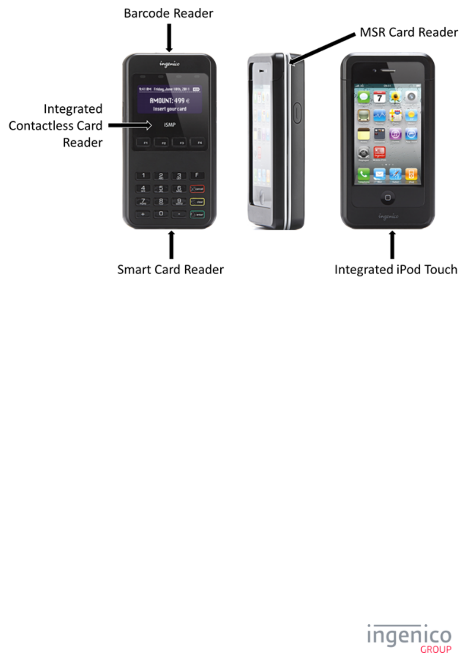
7_5_1 iSMP Overview
This section provides a quick reference for the iSMP PIN pad device. The iSMP processes MSR, contactless, and EMV cards, and is
Bluetooth compatible. It features an integrated barcode reader, and is designed to integrate with an iPod Touch for wireless operation.
Refer to the below image for an overview of the iSMP.
48/57 Telium Troubleshooting Guide / June 28, 2014
7_5_2 iSMP Power Requirements
The iSMP may be charged through the cradle accessory, or via the Multi-plug micro-USB cable. The device features a 1200mAh
battery which supports up to 800 card transactions and 66 hours in standby mode.
7_5_3 iSMP SAM and Micro SD Card Slots
There are no provisions for Secure Access Modules in the iSMP.
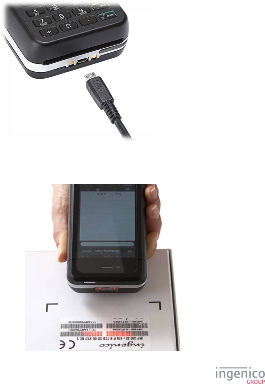
7_5_4 iSMP Interface Options
Interface options include Bluetooth class III and micro-USB AB slave for software upgrading or for charging for integration with
iPod Touch. Refer to the below image which shows the USB cable connection.
49/57 Telium Troubleshooting Guide / June 28, 2014
7_5_5 iSMP Barcode Reader
The iSMP features a factory option 1D/2D barcode reader which supports all major standards. The barcode reader is located in the
edge of the device as shown in the below image.
50/57 Telium Troubleshooting Guide / June 28, 2014
7_6 iSMP Companion Quick Reference
The iSMP Companion Quick Reference is organized into the following sections:
iSMP Companion Overview
iSMP Companion Power Requirements
iSMP Companion Interface Options
iSMP Companion Barcode Reader
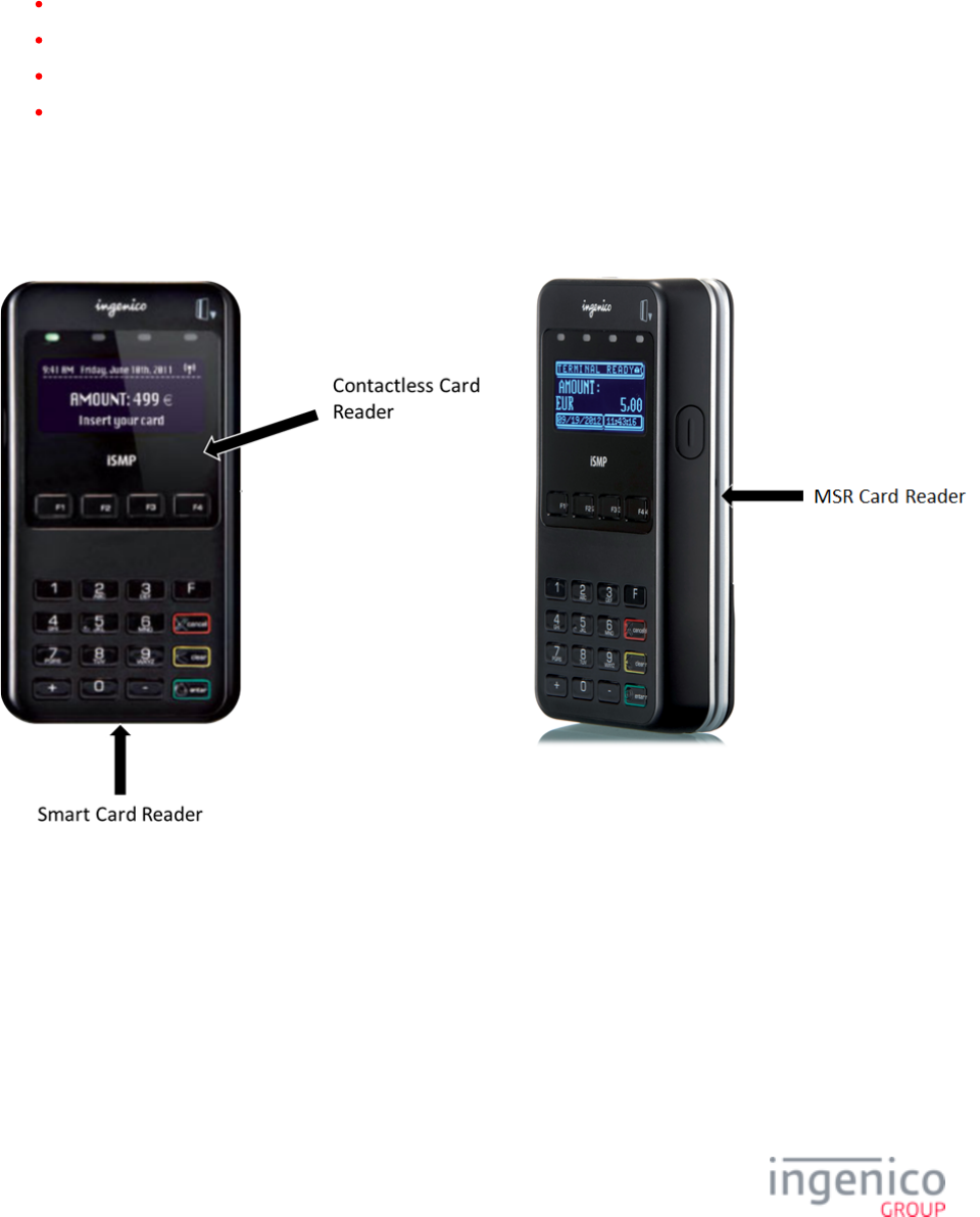
7_6_1 iSMP Companion Overview
This section provides a quick reference for the iSMP Companion (iSMPc) PIN pad device. The iSMP Companion processes MSR,
contactless, and EMV cards, and is Bluetooth compatible. Refer to the below image for an overview of this device.
7_6_2 iSMP Companion Power Requirements
The iSMP Companion may be charged through the cradle accessory, or via the Multi-plug micro-USB cable. The device features a
1200mAh battery for extended use independent of a power connection.
7_6_3 iSMP Companion Interface Options
Interface options include Bluetooth class II and micro-USB AB slave for software upgrading or for charging.
51/57 Telium Troubleshooting Guide / June 28, 2014
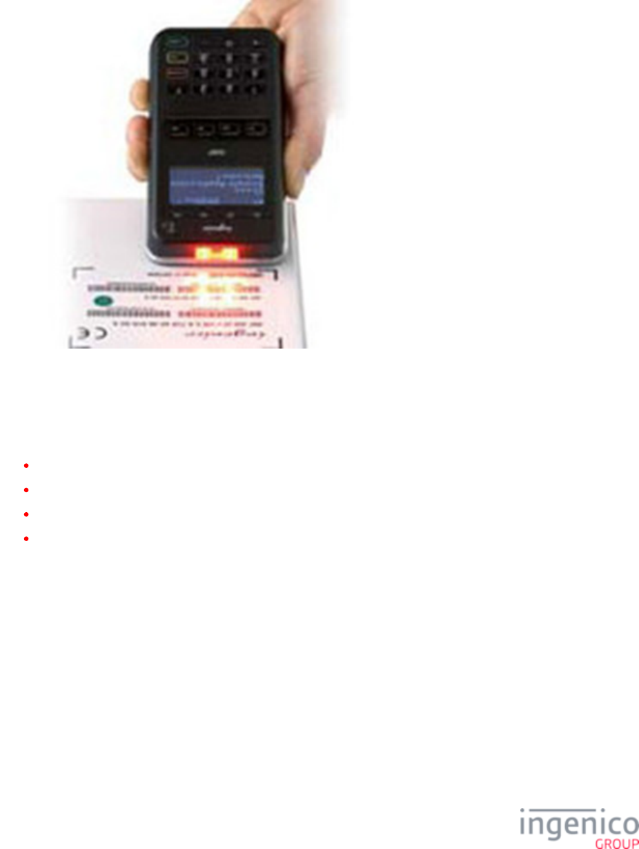
7_6_4 iSMP Companion Barcode Reader
The iSMP Companion features an optional 1D/2D integrated barcode reader which supports all major standards. The barcode reader
is located in the edge of the device as shown in the below image.
7_7 iWL250 Quick Reference
The iWL250 Quick Reference is organized into the following sections:
iWL250 Overview
iWL250 Power Requirements
iWL250 SAM and Micro SD Card Slots
iWL250 Interface with Host System
7_7_1 iWL250 Overview
This section provides a quick reference for the iWL250 PIN pad device. The iWL250 processes MSR cards and EMV cards, and
features an optional integrated contactless card reader. Refer to the below image for an overview of this device.
52/57 Telium Troubleshooting Guide / June 28, 2014
7_7_2 iWL250 Power Requirements
The iWL250 may be powered through the terminal base or through an optional terminal car charger. This device also features a
2050mAh batter for extended use independent of a power connection. Refer to the below image which shows the base and interface
connections.
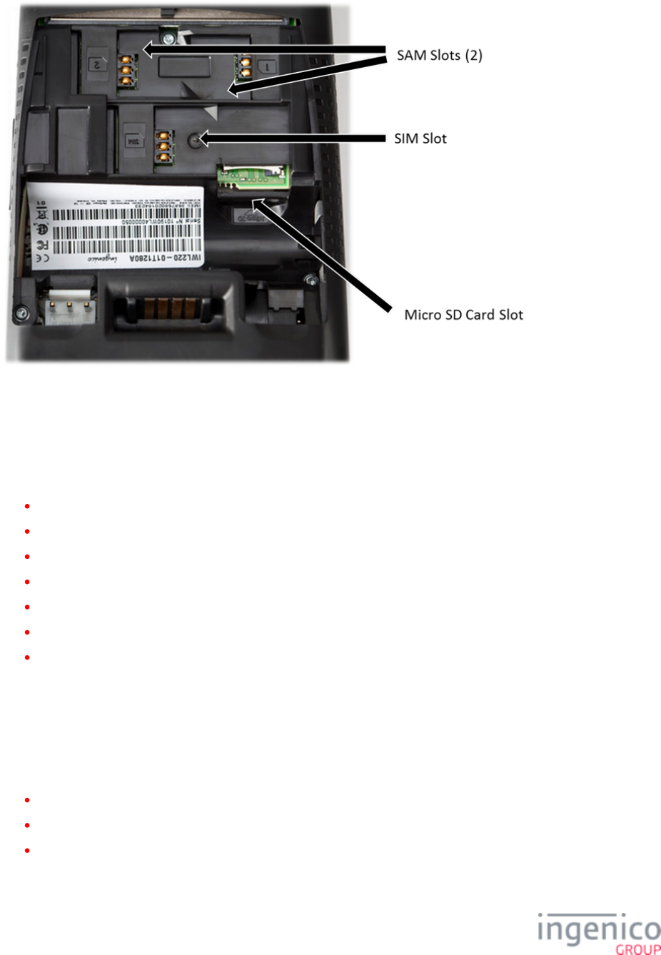
7_7_3 iWL250 SAM and Micro SD Card Slots
The iWL250 can hold 2 SAM cards, 1 SIM card, and 1 micro SD card. Access to these modules is attained by removing the back
cover of the device. Refer to the below image which shows the locations for these modules.
53/57 Telium Troubleshooting Guide / June 28, 2014
7_7_4 iWL250 Interface with Host System
In standalone mode the iWL250 may communicate to the Host system via a micro USB port, or via wireless (GPRS, 3G HSDPA, or
Bluetooth).
When connected with its base, communications options for the iWL250 include:
Dial-up modem (currently not used with RBA and UIA applications)
USB-A
RS-232
Ethernet modem
Ethernet 10/100 Base T
USB-B
Bluetooth Ethernet modem
7_8 iSelf Series Quick Reference
The iSelf Series of devices includes the iUP250, iUR250 smart card and MSR card reader, and the iUC150 contactless card reader as
shown in the following image. Configuration options include:
iUP250 integrated with iUR250 for MSR card and smart card transactions.
iUP250 integrated with iUC150 for contactless card transactions.
iUP250 integrated with iUR250 and iUC150 for MSR card, smart card and contactless card transactions.
Refer to the following image for this device family and its components.

54/57 Telium Troubleshooting Guide / June 28, 2014
This section is organized as follows:
iUP250 Overview
iUP250 Power Requirements
iUP250 SAM and SIM Options
iUP250 Interface Options
iUR250 Overview
iUC150 Overview
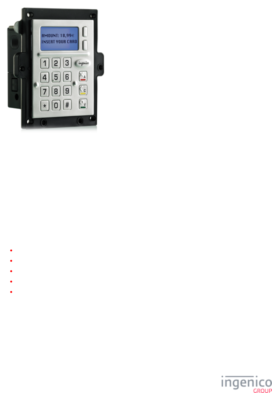
7_8_1 iUP250 Overview
The iUP250 is an iSelf series device which is integrated with external card readers to perform MSR, EMV, Hybrid, and contactless
card transactions. The iUP250 features a 128 x 64 pixel black & white graphical display, metallic keyboard, and multiple interface
options. Refer to the below image of the iUC250.
55/57 Telium Troubleshooting Guide / June 28, 2014
7_8_2 iUP250 Power Requirements
The iUP250 is powered by an external 12V-30V DC power supply. Both iUR250 and iUC150 card readers draw 5V power from the
iUP250 via the USB.
7_8_3 iUP250 SAM and SIM Options
The iUP250 features provisions for 2 Secure Access Modules and one optional SIM. There are also provisions for one micro SD card.
7_8_4 iUP250 Interface Options
Host interface options for the iUP250 include:
RS-232
USB Host
USB Slave
MDB Slave
MDB Master
Integration with the iUR250 is via the USB Slave port.
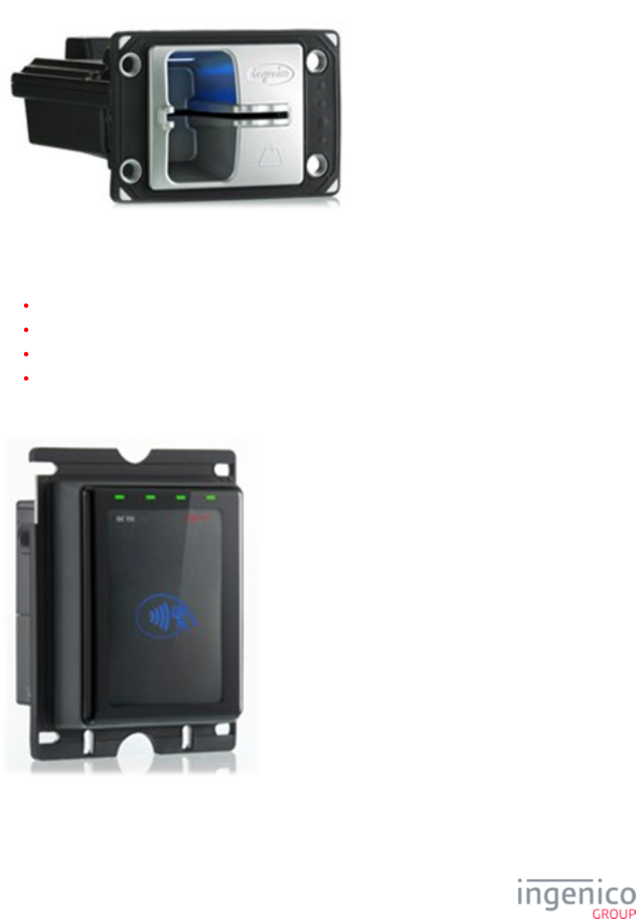
7_8_5 iUR250 Overview
The iUR250 integrates with the iUP250 as a MSR card and smart card reader (EMV chip and PIN). Communications with the iUP250
and power are provided through a USB interface. The iUR250 functions as a USB slave. Refer to the below image of the iUR250.
56/57 Telium Troubleshooting Guide / June 28, 2014
7_8_6 iUC150 Overview
The iUC150 integrates with the iUP250 as a contactless card reader. The iUC150 also complies with the following standards:
MasterCard PayPass
VISA PayWave
EMV contactless
e-wallet
Communications with the iUP250 and power are provided through a USB interface. The iUC150 also features an RS-232 interface.
Refer to the below image of the iUC150.

57/57 Telium Troubleshooting Guide / June 28, 2014
8_Revision History
Manual
Revision
Application
Revision
Changes
Rev 2 Reformatted Telium Manager, TDA, and TSA menu option illustrations.
Edited General Troubleshooting tables.
Removed flowcharts from document.
Incorporated new devices to document and added Quick references for:
iSc480
iSMP
iSMP Companion
iWL250
iUP250
iUR250
iUC150
Rev 1 Modified procedures to bring current.
Rev E Added flowcharts and Telium tips.
Rev D Updated syntax for the iSC480.
Rev C Updated document to be generic.
Added section which includes steps to verify contactless and MSR formats, including
images.
Rev B Changed heading in TDA section.
Rev A Initial document creation.
