DL 250 (DAS) Installation Manual
User Manual: DL-250 (DAS) Installation Manual AlarmHow.net Library
Open the PDF directly: View PDF ![]() .
.
Page Count: 50

DL-250
DOWNLOADABLE CONTROL COMMUNICATOR
INSTALLATION MANUAL
TABLE OF CONTENTS
1. GENERAL DESCRIPTION ...............................................P.2
2. STANDARD AND OPTIONAL PARTS LIST .................................P.2
3. FEATURE DEFINITIONS ...............................................P.3
4. TERMINAL DRAWING AND SPECIAL NOTES ...............................P.4
5. TERMINAL DESCRIPTION ..............................................P.5
6. PROGRAMMING PROCEDURES & EXAMPLES ........................... P.6-7
7. SPECIAL APPLICATION NOTES .........................................P.8
8. USERS 1-15 ARM/DISARM CODE ENABLING ...............................P.9
9. AVAILABLE ZONE TYPES ..............................................P.15
10. PROGRAMMING THE AUXILIARY OUTPUTS ..............................P.22
11. PROGRAMMING FOR PARTITIONS .....................................P.25
12. PROGRAMMING WORKSHEETS ..................................... P.38-45
13. APPENDIX 1, 2, & 3 ...................................................P.46
14. SPECIFICATIONS & WARRANTY .......................................P.50
DIRECT ALARM SUPPLIES CONDELL PARK NSW
SERVICE / TECHNICAL (02) 97092811 OR 1 800 252213
SALES
NSW VIC QLD SA WA
(02) 96472011
(02) 96989698 (03) 95627622
(03) 93832066 (07) 32525512 (08) 83711683 (08) 93453644
TAS DISTRIBUTOR - GHE
(03) 63316533 (03) 62342233
2
DL250
INSTALLATION MANUAL
General Description
The DAS DL250 is a versatile 8 expandable to 16 zone security control. Its microcomputer design gives some of the most
versatile, yet easy to use features available for most security applications today. Some of the features of the DL250
include; Partitionable up to three separate systems, dual reporting, Partial Arm (for at home monitoring), 15 user codes,
internal log, domestic dialling, dynamic battery test, plus many more. Each of the 8 zones can be programmed to be one
of nine different types including 24 Hour, Handover, Day Zone, and secondary entry. The system can be used with LCD
or LED Code Pads, key switches, or radio remote arming. Each zone is individually annunciated and can be isolated from
the Code Pad if so enabled. See page 11 for a description of all zone types. Read the OPERATORS MANUAL before
you begin the installation for the best overall description of how the DL250 functions. After installation of the security
system, complete the information on page 1 of the operators manual and explain the system operation to all security
system owners/operators.
Standard Parts List
The DL250 is shipped with the parts listed below.
QUANTITY PARTS DESCRIPTION PART #
1 MASTER CONTROL PANEL W/O CODE PAD FS4640
20 3K3 ½ WATT EOL RESISTORS EOL-33
1 TELECOM PHONE LEAD FS4596
1 INSTALLATION MANUAL IM-DL250
1 OPERATORS MANUAL OM-DL250
Optional Parts List
The following parts are available for use with the DL250.
OPTIONAL PARTS DESCRIPTION PART #
8 LED REMOTE CODE PAD FS4580
SMART 8 LED CODE PAD *(SMART BUSS COMPATIBLE) FS4672
SMART 12 LED / 4 ZONE EXPANDER REMOTE CODE PAD #(SMART BUSS ONLY) FS4673
LCD ALPHA NUMERIC DISPLAY CODE PAD *(SMART BUSS COMPATIBLE) FS4534
AC POWER SUPPLY 16.5V 1.5 AMP PLUG PACK FS4402
SMART PROGRAMMER WITH LCD DISPLAY FS4610
PROGRAMMER WITH DIGITAL NUMERIC DISPLAY FS4597
8 WAY RELAY OUTPUT MODULE #(SMART BUSS ONLY) FS4634
16 WAY VOLTAGE OUTPUT MODULE #(SMART BUSS ONLY) FS4614
16 WAY X10 VOLTAGE OUTPUT MODULE #(SMART BUSS ONLY) FS4804
12 VOLT 6.5 AMP HOUR BATTERY FS4312
* SMART BUSS COMPATIBLE - ARE PRODUCTS THAT CAN OPERATE IN EITHER BUSS PROTOCOLS. (Ref to buss
protocols in “FEATURE DEFINITIONS” on next page).
# SMART BUSS ONLY - ARE PRODUCTS THAT CAN ONLY OPERATE IN THE SMART BUSS PROTOCOLS. (Ref to
buss protocols in “FEATURE DEFINITIONS” on next page).

3
FEATURE DEFINITIONS
Smart Buss
The DL250 must be converted from the Standard Buss to a more advanced communication buss protocol called “Smart
Buss” when Partitioning and or Expansion devices are utilised. When the DL250 is set to Smart Buss, only Smart Buss
compatible code pads and accessories can be used. A parts list is available on the previous page.
Partitions
The DL250 can be partitioned into a maximum of three separate systems with distinct user codes per system. See page
25 for complete instructions.
Secondary Exit Delay
Used most often for garage doors, this zone type is a second entry/exit delay that has its own delay times, independent
of the standard entry/exit delay zone.
Group Isolate
Zones can be programmed to isolate as a group when the [U] button is pressed during the exit delay. This feature is
enabled in Locations 167-174: Assigning Special Characteristics For Zones beginning on page 15 of this manual.
Partial Arm (Entry Guard)
This unique home level arming allows you to remain inside your home and only arm areas that are not occupied. For
example, Night Arming.
Chime
This lowest level of security can be enabled by zone (see page 16, Locations 175-182: Assigning Audible
Characteristics For Zones) to create a time programmable tone through the Code Pad sounder when the system is
disarmed and a zone is violated. If so programmed, this feature can be turned on and off by a one digit keypress
programmed in Location 213: Assigning The Chime Code on page 20 of this manual.
Auto Isolate Enable
When enabled in location 196, the DL250 can be armed with zones violated, lacking a green "READY" light on the Code
Pad. Under this condition, all zones that are not secure at the end of the exit delay will become isolated. All zones that
become secured before the end of the exit delay will become active in the system.
Dynamic Battery Test
When enabled in locations 218, the DL250 can be programmed to perform a dynamic battery test for a selected duration,
at a selected time.
Internal Event Log
Up to 256 events can be stored in memory along with the date and time of the event. These events can be viewed through
the LCD Code Pad or the Dasload Download Software Package.
Twin Trip Zones
A twin trip zone requires two trips within the time programmed in location 191 or a continuous trip for more than ten
seconds for an alarm activation. If a single trip on a twin trip zone is initiated, an alarm would only occur if any other zone
has been in alarm, still is in alarm or any other zone is tripped with in the delay time set in location 191.
Radio Remote Arming
The Radio Remote Arming feature for the DL250 will cause the siren to pulse for a single burst, when the DL250 is
disarmed. The speaker output will also pulse two bursts when the DL250 is armed.
Zone Tamper
The DL250 can monitor any one of its zone for a short or open circuit. If any one of these conditions occur the DL250 can
report these events as Zone Tamper. With zone tamper enabled, zones only require one pair of wires to monitor both
alarms and tamper.
Pager Format
The DL250 can report any alarm via the Pager Format to a compatible pager.
4
12
COM
3
COM COM
56
4
COM
COM
ACAC
CLK DTA
YPADEK
POS ERTH
GND
8
7
N.C.
LOOP
N.O.
LOOP
LOOP
N.C.
3.3K
E.O.L.
RES
3.3K
E.O.L.
RES
N.C.
LOOP
N.O.
LOOP
3.3K
E.O.L.
RES RES
E.O.L.
3.3K
LOOP
N.O.
LOOP
N.C. N.C.
LOOP
N.O.
LOOP
3.3K
E.O.L.
RES RES
E.O.L.
3.3K
LOOP
N.O.
LOOP
N.C.
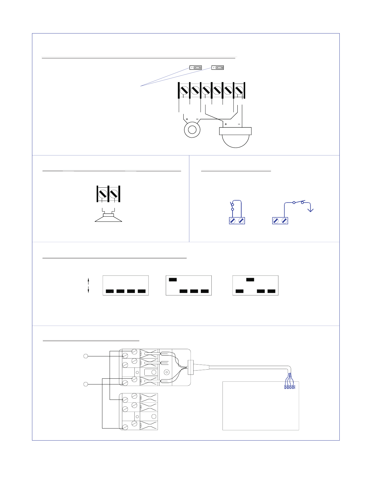
YELLOW GREEN BLACK RED
COLD WATER PIPE
GROUND
1 2 3 4 5 6 7 8 9 10 11 12 13 14 15 16 17 18 19 20 21 22 23 24 25 26 27 28 29
1) MAXIMUM
2) MAXIMUM WIRE RUN PER KEYPAD
a. 7/020 70 METERS
b. 14/020 120 METERS
3) DO NOT DAISY CHAIN KEYPADS.
EACH MUST HAVE AN INDIVIDUAL
KEYPAD
16/18 VDC
1.5 AMP
PLUG PACK
LIGHTNING PROTECTION
+
-
RED
BLACK
WIRE RUN.
THE CONTROL PANEL MUST BE
EARTH GROUNDED FOR LIGHTNING
PROTECTION TO WORK EFFECTIVELY.
THE GROUND CONNECTION SHOULD
BE TO A VERIFIED COLD WATER
GROUND PIPE OR A DEDICATED
DRIVEN METAL ROD 6' TO 10' LONG.
USE MINIMUM 14 GAUGE WIRE.
ZONE 1
ZONE 2
ZONE 3
ZONE 4
ZONE 5
ZONE 6
4) ADDITIONAL KEYPADS
16.5 V 20VA
DO NOT CONNECT TO
A RECEPTACLE THAT
IS CONTROLLED BY A
SWITCH
BUILT IN SIREN DRIVER
SMOKE DETECTOR
POWER
REGULATED
100 mA MAX
13.75 VDC
DO NOT CONNECT
240 VAC TO
TERMINAL STRIP
12 VOLT
6AH
SEALED
LEAD-
ACID OR
GELCELL
BATTERY
N.C.
LOOP
N.O.
LOOP
3.3K
E.O.L.
RES
RES
E.O.L.
3.3K
LOOP
N.O.
LOOP
N.C.
ZONE 7
ZONE 8
FOR HORN SPEAKER
STROBE
PROGRAMMER
DIRECT ALARM SUPPLIES PTY LTD
INSTALLATION ASSISTANCE NUMBER
008-252213
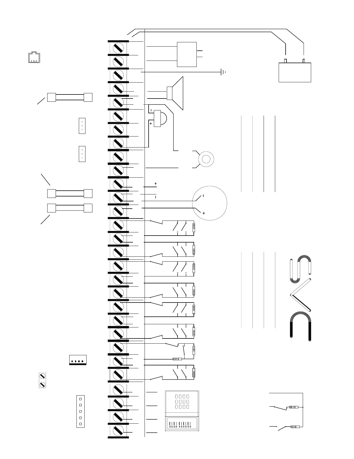
1. ALL UNUSED SECTORS MUST HAVE E.O.L RESISTOR ATTACHED
2. MAXIMUM LOOP RESISTANCE 300 OHMS
3. 3.3K RESISTOR COLOR CODE IS ORANGE,ORANGE,RED,GOLD
SMOKE
POWER
COM AUX
PWR NO C
AUX 1
NO CNC
AUX 2
NEG POS
SIREN
AUXILIARY
POWER
REGULATED
13.75 VOLTS
400 MA MAX
FOR 12 VOLT ALARM
OUTPUT PLACE AUX 1
JUMPER ON RIGHT SIDE
AUX 1 AUX 2
Volt
Volt
FOR 12 VOLT OUTPUT PLACE
JUMPER ON RIGHT SIDE. FOR
DRY CONTACT PLACE JUMPER
ON LEFT HAND SIDE
CONNECT 24 HOUR NORMALLY
CLOSED BOX TAMPER CIRCUIT
TAMPER
FUSE F1 RATED 1 AMP
PROTECTS KEYPAD, AUX
POWER, AND SMOKE
DETECTOR POWER
FUSE F3 RATED 3 AMPS
PROTECTS 12 VOLTS TO
AUX 1 AND AUX 2 RELAY
CONTACTS
FUSE F2 RATED 2 AMPS
PROTECTS SIREN DRIVER
OUTPUT
ZONE ZONE ZONE ZONE
1
2
3
4
PROGRAMMABLE
AUXILIARY OUTPUT
PINS 1-4
DL250
TAMPER
SWITCH
3.3K
E.O.L.
4. SECTOR 2 IS SHOWN WITH OPTIONAL DOUBLE END OF LINE RESISTOR CONFIGURATION
4 KEYPADS PER SYSTEM
60 - 120 mA DEPENDING
ON KEYPAD TYPE. CONSULT
MANUAL FOR ACTUAL AMOUNT
DRAW
WARNING - FOR CONTINUED PROTECTION
AGAINST THE RISK OF FIRE REPLACE
ONLY WITH THE SAME TYPE AND RATING
FUSE:
F1
F2 = 2 AMP
F3 = 3 AMP
WARNING - TO
PREVENT THE RISK
OF ELECTRIC SHOCK
ALWAYS DISCONNECT
THE TELEPHONE LINE
PRIOR TO SERVICING
NOTE: PINS 1 AND 2
IN PARALLEL WITH AUX1
AND AUX2 RELAYS
TO TAMPER TERMINALS
PIEZO SCREAMER
E.O.L.
3.3K
SWITCH
TAMPER
RES
E.O.L.
5.1K
POSITIVE
12 VOLTS
ZONE
INPUT
ZONE
COMMON
OPTIONAL DOUBLE EOL RESISTOR
NORMALLY OPEN CONFIGURATION
2 CENTER PINS - LINE IN
2 OUTER PINS LINE OUT
CONTROL PANEL
DRAWS 120 mA
STANDBY CURRENT.
MAXIMUM BATTERY
CHARGING CURRENT
375 mA.
0 TO 1.4K RESISTANCE
ZONE TAMPER.
1.4K TO 3.8K ZONE SECURE.
3.8K TO 7.2K ZONE ALARM.
GREATER THAN 7.2K
ZONE TAMPER.
= 1 AMP
1
#
0
*
987
654
32
TERMINAL DRAWING & SPECIAL NOTES
5
TERMINAL DESCRIPTION
TERMINAL # DESCRIPTION
1 - 4 Connect Code Pad wires as follows; Yellow to terminal 1, Green to terminal 2, Black to terminal 3,
and Red to terminal 4. Maximum run with 7/020 cable is 70 metres. Maximum run with 14/020
cable is 120 metres. A maximum of 4 code pads may be connected to the DL250. Each code pad
must be home run.
5 Connect one side of zone 1 loop. Connect other side of loop to common terminal 6. Open or short
causes alarm
7 Connect one side of zone 2 loop. Connect other side of loop to common terminal 6. Open or short
causes alarm.
8 - 16 See Terminal Drawing and repeat the above sequence for zones 3 through 8.
17 Resettable 12VDC 100mA Aux power.(Memory reset and/or Smoke detector power) this output
may be reset by the # on the code pad.
18 - 19 Auxiliary power, regulated 12VDC. Maximum 400 mA for all Auxiliary power outputs.
20 - 21 Form A programmable on board relay output. Tied to auxiliary output #1.
22 - 24 Form C programmable on board relay output. Tied to auxiliary output #2.
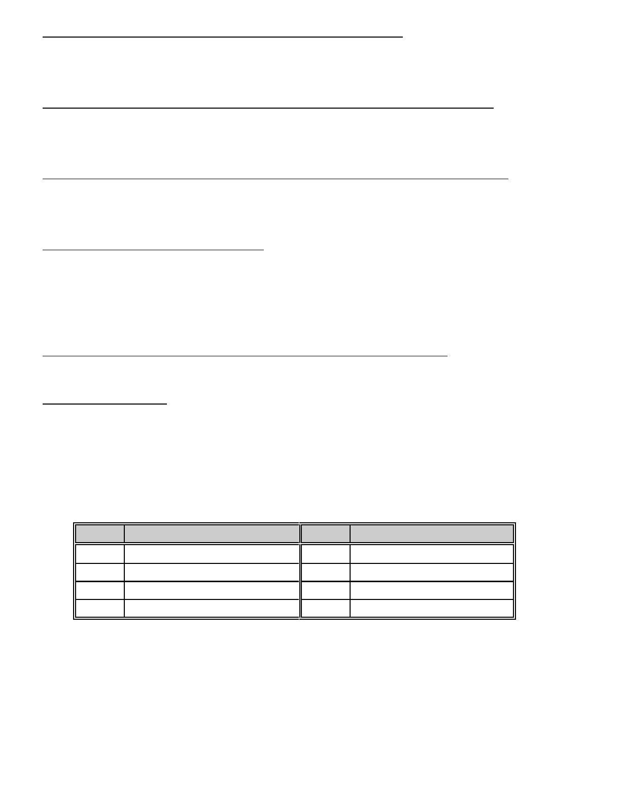
25 - 26 Siren driver output to speaker(s). Speaker rating 10 or 15 watt at 4, 8, or 16 ohms). See page 8
for connection diagram.
27 Earth Ground, connect to a cold water pipe, or 6 to 10 foot driven rod
28 - 29 AC input, connect 16.5V 1.5 AMP approved transformer.
Box Tamper The Box Tamper terminals are located at the top right side of the P.C.B. The tamper circuit is
Normally Closed. The left terminal is the Negative (-) point of the circuit.
Battery Leads Connect to 12VDC lead acid rechargeable battery: Black(-) & Red(+). Do not use a dry cell battery.
Buss Mode
Toggle To momentary toggle the DL250 code pad communication protocol I.E. Switch from Smart
Buss to Standard Buss or visa-versa. Short terminal (2) Data to terminal (5) zone one when
powering up the DL250. This is ONLY a temporary mode to permit Buss mode switching.
Refer to location 384 for more detail.
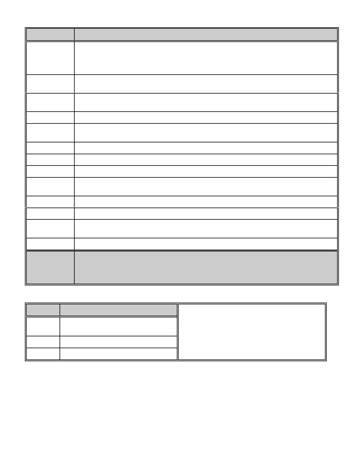
FUSE DESCRIPTION
FUSE # DESCRIPTION
F1 1 AMP / Code Pad & Smoke Detector
Power
F2 2 AMP / Siren Driver
F3 3 AMP / Relay Power

6
PROGRAMMING
The DL250 can be placed into the "Program" mode by use of the new FS4610 Smart Programmer, or the original FS4597
programmer, or for Code Pad programming, by utilising the FS4534 LCD Code Pad (the preferred method) or the FS4531
LED Code Pad. These methods are described below.
Using a Programmer
The FS4610 Smart Programmer has been designed to make programming of the DL250 simpler as well as more efficient
for users. The FS4610 programmer features up to 16 resident standard programs to allow for separate system
standardisation. Plug the optional model FS4610 programmer into the 4-pin male outlet marked "program" on the DL250
P.C. Board. We have also created a method that allows owners of the original FS4597 programmer to use this programmer
with the DL250. The FS4597 will program all locations of the DL250 but requires additional care for locations 400 and
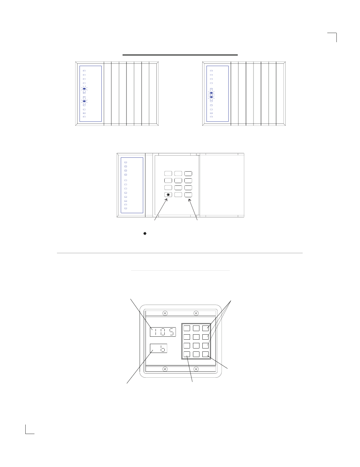
above. When the 400 location is reached, the two right 7 segment numeric displays will begin to flash on and off and the
left side numeric display will change to "0". The flashing is a signal to add a 4 to the left side number to determine which
location you are now programming. For example, if you are in location 435, the left (100's column) will be displaying a "0",
the middle (10's column) will be flashing and displaying a "3", and the right (one's column) will be flashing and displaying
a "5". By adding a 4 to the "0" displayed in left column, it is determined that the location number is 435.
Using The LCD Code Pad
The most straightforward method of Code Pad programming is to utilise the FS4534 LCD Code Pad in the programming
mode. To access the programming mode enter [C] [0] [0], followed by the four digit "Go To Program" access code which
is factory default [9] [0] [5] [0] (this code can be reprogrammed), and follow the Code Pad prompts.
Using The LED Code Pad
The DL250 can also be programmed by the standard binary method of Code Pad programming described below.
However, with over 400 locations, this method will be difficult except for the most experienced programmer. When the
FS4531 LED Code Pad is used for programming, enter the factory default four digit "Go To Program" access code of [9]
[7] [1] [3]. NOTE: The DL250 must be disarmed to gain access to programming with this code. After entry of this code, the
DL250 will be in the "Program" mode, and the yellow LED's will display the data in location 000. The data is displayed
using a Binary system. With this system the yellow zone 1 LED equals "1" when illuminated. The zone 2 LED equals "2"
when illuminated. The zone 3 LED equals "4" when illuminated. The zone 4 LED equals "8" when illuminated. Thus if the
data in location 000 is "9", the LED for zone 1 (=1) and zone 4 (=8) would be illuminated. By adding the two values
together, (1+8=9) you would determine that the data in location 000 is "9". If the data in location 000 is "6", the LEDs for
zone 2 (=2) and zone 3 (=4) would be added (2+4=6) indicating the data in that location to be "6". If no LED's are
illuminated, the location contains a "0". To advance from location 000 through 463, press the [#] key. To go to a specific
location, press the location number followed by the [#] key. The yellow LED's will then display the data in that location. Data
is changed by entering a number 0 to 15 followed by [U] (U = data enter). Review the examples in figure 1 on the following
page.
Important Function Codes
[9]-[5]-[0]-[#] When in the program mode, this function code can be used to write original factory default codes into the
DL250.
[9]-[3]-[0]-[#] This function code is used to exit the programming mode after it was accessed via the Code Pad.
! ! ! IMPORTANT ! ! !
Before programming the DL250 for the first time, enter the "Go To Program Code" [9][7][1][3] from the Code Pad,
followed by the factory default function code [9][5][0][#]. The panel defaults will now match this installation manual
and you may begin programming the control panel. When using an optional plug-in programmer which
automatically enters the programming mode, the only entry necessary is [9][5][0][#] to load factory defaults.
7
Armed
Ready
Instant
Power
Zone 1
Zone 2
Zone 3
Zone 4
Zone 5
Zone 7
Zone 7
Zone 5
Zone 4
Zone 3
Zone 2
Zone 1
Power
Instant
Ready
Armed
Zone 7
Zone 5
Zone 4
Zone 3
Zone 2
Zone 1
Power
Instant
Ready
Armed
}
ZONE 2
ZONE 3
LED = 2
LED = 4 DATA=6DATA=9
ZONE 1
ZONE 4
LED=1
LED=8 }
No LED's Illuminated = 0
To change or enter data in
location shown, enter data and
follow by the [ ] Key.
Pressing the [#] Key will advance
to next location, or specific loca-
tion can be reached by pressing
location number followed by the
[#] Key.
PROGRAMMING EXAMPLE - FIGURE 2
8950 PROGRAMMER - FIGURE 3
#
9
6
3
54
7
0
8
1 2
Data Enter/Change Key
#0
*
987
654
321
Current Data Indicator
Current Location Indicator
DATA
LOCATION
Advance
Key
Location
Data Keys
1 Thru 0
Zone 8
Zone 6
Zone 8
Zone 6
Zone 8
Zone 6
PROGRAMMING EXAMPLE - FIGURE 2
8
TAMPER TAMPER
Using Tamper
Terminal
Common
Using
Zone
Common
To
Zone
Common
1
2
3
4
5
6
1
2
3
4
5
6
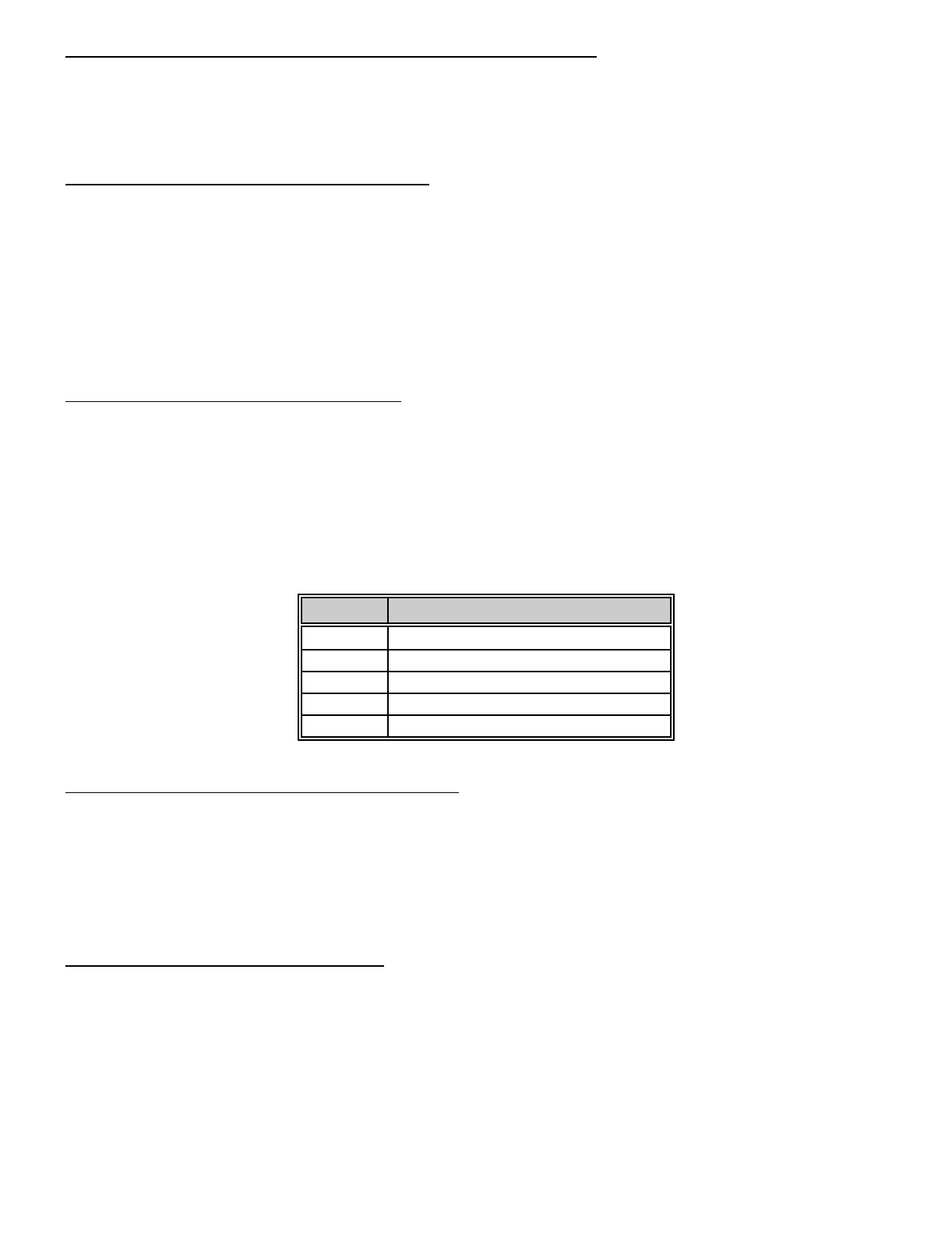
AC800
BOARD
DIALER CONNECTIONS
Telecom Mode 3 Connections
6
5
4
3
2
1
SITE
PHONE
SOCKET
TELECOM
LINE
IN
52 VOLTS MEASURED BETWEEN
TERMINALS 2 AND 6 ON
DIALER SOCKET.
Key Pad DIP Switch Settings For The DL250
1
2
34
1
234
1234
ON
OFF All switches off
PARTITION 1
1 On 2,3,4 Off
PARTITION 2
2 On 1,3,4 Off
PARTITION 3
Only switches1&2need to be changed. Switches3&4arealwaysoff.
25 26
Horn Speaker Connections For The DL250
8 Ohm
Horn Speaker
1 x 8 Ohm 30-40 Watt speaker is connected
directly across terminals 25 and 26.
NEG POS
20 21 22 23 24 25
NO NC NO C NC NEG
AUX 1 AUX 2
STROBE
PLACE JUMPER ON
RIGHT SIDE FOR 12
VOLT OUTPUT
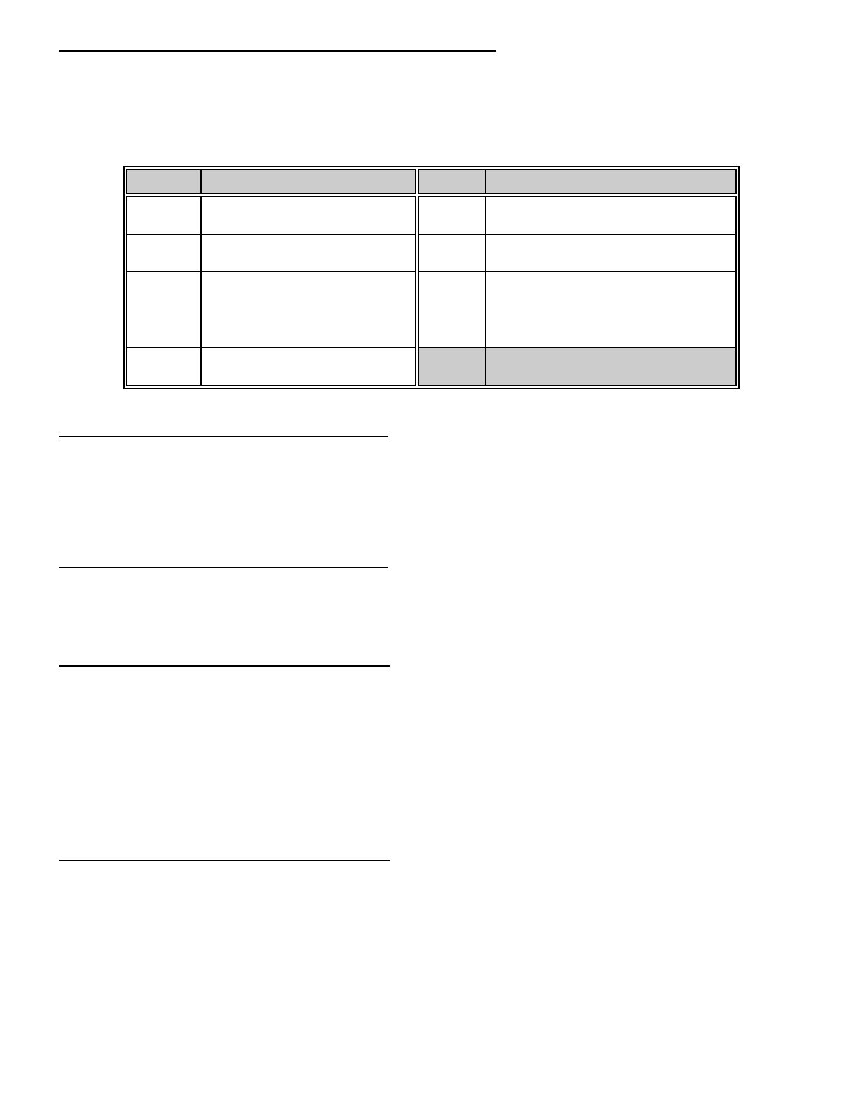
Box Tamper Diagram
12 Volt Siren/Piezo and Strobe Connections For The DL250
SPECIAL APPLICATION NOTES
9
LOCATIONS 000-003: PROGRAMMING THE MASTER ARM/DISARM CODE
Locations 000-003 contain the master arm/disarm code (user number 1). Location 000 contains the first digit of the code;
location 003 contains the fourth digit of the code. THE CODE MUST CONTAIN FOUR (4) DIGITS. The master code can
then be used in the RUN mode to enter arm/disarm codes 1 - 15. The factory default code is [1][2][3][4].
LOCATIONS 004-055: PROGRAMMING THE ARM/DISARM CODE FOR USERS 2 THROUGH 14
Locations 004-055 contain the arm/disarm codes for users 2 through 14. To program these codes, follow the instructions
in the paragraph above. To disable these codes, program a "15" (factory default) as the first digit of the code. These
codes can be changed in the RUN mode using the master code (refer to operator's manual).
LOCATIONS 056-059: PROGRAMMING THE ARM/DISARM CODE FOR USER 15 (DURESS CODE)
Locations 056-059 contain the arm/disarm code for user number 15 (Duress Code). To program this code, follow the
instructions in the paragraph above. This code can be used as a duress code if so programmed in locations 288 - 291.
Factory default for this code is "15", disabled.
LOCATION 060-063: GO TO PROGRAM CODE
Locations 060-063 contain the "Go To Program" access code. Location 060 contains the first digit of the code and location
063 contains the fourth digit of the code. THE CODE MUST CONTAIN FOUR (4) DIGITS. With the DL250 disarmed, the
"Go To Program" access code can be used to enter the program mode. To disable the "Go To Program" access code,
program a "15" in location 060. The factory default setting is [9][7][1][3]. NOTE: The first digit of this code should not match
the Quick-Arm digit. NOTE: If a "15" is programmed into location 60 to disable this code, programming can only be
accessed through the downloading software , a plug in programmer or using the program code on a LCD code pad.
LOCATIONS 064-079: PARTITION SELECT FOR CODES 1-15 AND PROGRAM CODE
PARTITIONED SYSTEMS:
If partitions are utilised, codes may be assigned to a specific partition by using locations 064-079. This is done by disabling
each individual code (code 1 is location 064, code 15 is location 079) for each of the four partitions that code should not
have access to. Codes are selected by adding the binary equivalents for each partition together and placing that number
in the proper location. Partition One = 1, Partition Two = 2, and Partition Three = 4. For example, if code 2 should only
be valid for Partition Three, program a "4" in location 065. If code 10 is valid for Partitions Two, and Three, a "6" would
be programmed in location 073. Factory default is "7", code valid for all partitions.
VALUE PARTITION SELECTION VALUE PARTITION SELECTION
0 NO PARTITIONS ENABLED 4 ENABLES PARTITION 3
1 ENABLES PARTITION 1 5 ENABLES PARTITION 1 & 3
2 ENABLES PARTITION 2 6 ENABLES PARTITION 2 & 3
3 ENABLES PARTITION 1 & 2 7 ENABLES PARTITION 1, 2 & 3
10
LOCATIONS 080-094: AUTHORISATION LEVEL FOR CODES 1-15
Locations 080-094 can be used to control the arming and disarming authority of the individual arm/disarm codes. A code
can be given limited authority by programming a number from 1 to 15 in the corresponding location for that code. Add the
values in the table below that correspond to the desired arm/disarm characteristics, and program the sum in the
appropriate locations. The opening communicator code (location 340), and the closing communicator code (location 341)
must be enabled for opening/closing reports.
VALUE AUTHORISATION LEVEL VALUE AUTHORISATION LEVEL
0 NO AUTHORISATION LEVEL
(USED FOR AUXILIARY OUTPUT) 9 REGULAR ARM/DISARM CODE
OPEN/CLOSE REPORTS BY USER
1 REGULAR ARM/DISARM CODE 10 ARM ONLY AFTER CLOSING TIME
OPEN/CLOSE REPORTS BY USER
2 ARM ONLY AFTER CLOSING TIME
NORMALLY REGULAR CODE,
CHANGE TO ARM ONLY CODE
AFTER THE CLOSING TIME,
RESET AT THE OPEN TIME
12 ARM ONLY CODE
OPEN/CLOSE REPORTS BY USER
4 ARM ONLY CODE
LOCATION 095: DIAL ATTEMPTS FOR PHONE #1
Location 095 is used to enter the number of dial attempts (1 to 15 attempts) the communicator will try for phone number
one before ending the notification process. Factory default is "6" and the communicator will make 2 attempts to the first
number, and then 2 attempts to the second number alternating until the “6" attempts in total are made. If no second number
is programmed all “6" attempts are made to the first number. If the factory default is modified in location 146, this dial
sequence can be altered, refer location 146.
LOCATION 096: DIAL ATTEMPTS FOR PHONE #2
Location 096 is used to enter the number of dial attempts (1 to 15 attempts) the communicator will try for phone number
two before ending the notification process. NOTE: Dial Attempts for Phone 2# will only be valid if SPLIT or DUAL
REPORTING is enabled in location 146.
LOCATIONS 097-112: PRIMARY PHONE NUMBER
Phone # 1 is programmed in successive locations beginning with location 097. Delays of four seconds can be programmed
at any point in the phone number by programming a "13" in the appropriate location. If tone dialling is desired, program
a "15" in the location where tone dialling should begin. If a "U" or "#" are required in your phone number then a "11" = "U"
and "12" = "#". If the entire number should be tone dialling, program a "15" in location 097. Factory default is "14" in each
location and the phone number is not enabled. When using split or dual reporting, phone #1 always takes priority over
phone #2. A "14" indicates the end of the phone number. Example: If phone number 02 is to be 7244211, and must be
touch tone dialling, phone number 02 would be programmed as
[15][U][#][0][U][#][2][U][#][7][U][#][2][U][#][4][U][#][4][U][#][2][U][#][1][U] [#][1][U] [#][14][U][#]. The "15" selects touch tone
dialling, and the "14" ends the phone number.
LOCATIONS 113-117: PRIMARY ACCOUNT CODE
The account code sent when phone #1 is dialled is programmed in locations 113-117. If the account code is three digits
long, use locations 113-114-115, and program a "0" in locations 116 and 117. If the account code is four digits long,
program a "0" in location 117. If a zero "0" is part of an account code, it should be programmed as a "10". Program a "0"
to indicate the end of the account code. To make this account code the account code for "Partition One", see location 146.
Example: Account number of 2090 would be entered as [2][U][#] [10][U][#] [9][U][#] [10][U][#] [0][U][#] (starting at location
113). Account code of 209 for low speed would be entered as [2][U][#] [10][U][#] [9][U][#] [0][U][#] (starting at location 113).

11
LOCATION 118: PRIMARY FORMAT
The primary format is transmitted when the primary phone number is dialled. Select a format from below, and program the
appropriate number in this location.
DATA FORMAT DESCRIPTION
0LOCAL ONLY COMMUNICATOR IS DISABLED
1ADEMCO CONTACT ID DTMF FORMAT
2ADEMCO 4/2 EXPRESS DTMF FORMAT
3PAGER FORMAT REPORTS IN 4 + 3 FORMAT AND/OR DOMESTIC DIALLING
4ADEMCO HIGH SPEED DTMF FORMAT
5RADIONICS EXTENDED SLOW 1800Hz TRANSMITTAL 2300Hz HANDSHAKE 20 PPS HEX
EXT DOUBLE ROUND
6CADDX MODEM PROPRIETARY
7RADIONICS EXTENDED FAST 1800Hz TRANSMITTAL 2300Hz HANDSHAKE 40 PPS HEX
EXT DOUBLE ROUND
8RADIONICS EXTENDED FAST 1800Hz TRANSMITTAL 1400Hz HANDSHAKE 40 PPS HEX
EXT DOUBLE ROUND
9RADIONICS EXT FAST
W/PARITY 1800Hz TRANSMITTAL 2300Hz HANDSHAKE 40 PPS HEX
EXTENDED
10 NOT USED
11 ADEMCO/SILENT KNIGHT
SLOW 1900Hz TRANSMITTAL 1400Hz HANDSHAKE 10 PPS
DOUBLE ROUND PARITY
12 SILENT KNIGHT 4+2 FAST 1900Hz TRANSMITTAL 1400Hz HANDSHAKE 20 PPS
DOUBLE ROUND PARITY
13 SESCOA/FRANKLIN FAST 1800Hz TRANSMITTAL 2300Hz HANDSHAKE 20 PPS HEX
DOUBLE ROUND
14 SIA FSK FORMAT
15 CUSTOM FORMAT SELECT YOUR OWN FORMAT FOR NON STANDARD BASE
STATIONS. REFER TO APPENDIX (3).
Location 118 contains the communicator format used to transmit to the receiver connected to the phone #1. Consult the
instructions for your central station receiver to determine which format is compatible. Select a format from the 14 listed
above. If you require a format other than those listed, review the override options described in locations 252-255, to build
the appropriate format. A "15" must be programmed in location 118 in addition to the entries into locations 252-255 in
order to create a special format. If this location contains a "0", the built-in communicator will be disabled, and the DL250
will function as a local only control. When using pager format for domestic dialling, program the primary account code to
"1717" and program a "1" in location 192 (all abort enable). Your telephone number will also require at least four (4) pauses
("13"s) added at the end of the phone number. Note The dial attempt counter must not be less than “4" attempts if the
second phone number is programmed.
LOCATIONS 119-134: SECONDARY PHONE NUMBER
Locations 119-134 contain phone #2. This number allows certain communicator reports to go to another number (split
reporting), or to cause the communicator to dial a second number if the primary number does not respond after the number
of attempts programmed into location 95 have been tried unsuccessfully, or for dual reporting. The same number of
attempts are made with the second phone number unless split or dual reporting is selected were the dial attempts in
location 96 are used. Tone dialling and delay instructions are the same as for the primary number. A "14" indicates the
end of the phone number.

12
LOCATIONS 135-139: SECONDARY ACCOUNT CODE
Locations 135-139 contain the account code for phone #2. The second account code can be programmed as per the
primary account code. This account code is reported when partition two is programmed or split or dual reporting is enabled.
If the account code is three digits long, use locations 135, 136, and 137. If a zero "0" is part of the account code it must
be programmed as a "10". Program a "0" to indicate the end of the account code. If these locations contain a "0", the
account code in locations 113-117 will be reported.
LOCATION 140: SECONDARY FORMAT
Location 140 contains the communicator format used to transmit to the receiver connected to phone #2. The second
format is used when split or dual reporting is required. Consult the instructions for your central station receiver to determine
which format is compatible. Select a format from the format chart. If you require a format other than those listed, review
the override options described in locations 252-255 to build the appropriate format. A "15" must be programmed in location
140 in addition to the entries into locations 252-255 in order to crate a special format. If this location contains a "0", the
format programmed into location 118 will be selected.
LOCATIONS 141-145: ACCOUNT CODE 3
Locations 141-145 are utilised to assign an account code for partition #3 if a unique code is desired. The third account
code can be programmed as per the primary account code . If these locations contain "0", the account code listed in
locations 113-117 will be used.
LOCATIONS 146: COMMUNICATOR DIALLING SEQUENCE OPTIONS
The number programmed into this location determines the sequence and method the communicator will utilise when
reporting an event code. Use the table below to build the appropriate number. Add the number(s) associated with the
desired features and program the sum in this location. Factory default is "3 programming the characteristics for data 1 and
data 2 (1 + 2 = "3")
DATA DESCRIPTION
"1" Alternates between phone number #1 and phone number #2 in increments of two (2)calls to each, until
the selected number of dial attempts has been made to each number.
"2" The communicator attempts the number of dial attempts programmed into the number of dial attempts
location to phone number #1 and if unsuccessful, it will delay 5 minutes and attempt the same number of
dial attempts programmed into number of dial attempts to phone number #2. (see locations 095 and 096
dial attempts to phone number 1 & 2)
"4" Force the communicator to tie the account code to the phone number. If this feature is not selected the
account code will correspond to the partition. Select for split or dual reporting.
"8" The communicator attempts the number of dial attempts programmed into the number of dial attempts
location to phone number #1 and if unsuccessful, tries the same number of dial attempts programmed into
number of dial attempts to phone number #2. (see locations 095 and 096 dial attempts to phone numbers
1 & 2)
"0" If a "0" is entered, the account code corresponds to the partition.
SPLIT REPORTING:
Split reporting is when one group of zone or system events report to a selected destination via the primary phone number,
primary account code and primary format. A second group of zone or system events report to a separate destination via
the second phone number, the second account code and the second format.
DUAL REPORTING:
Dual reporting is when all zone or system events report to a selected destination via the primary phone number, primary
account code and primary format. The same events report to a separate destination via the second phone number, the
second account code and the second format.
NOTE: For most installations, default data "3" is required. Program a "4" for split or dual reporting.
13
LOCATION 147: NUMBER OF RINGS TO ANSWER A DOWNLOAD CALL
Location 147 contains the number of rings a DL250 must detect before answering the telephone when initiating a download
session. If a number from "1" to "15" is entered in this location, the DL250 will answer after the number of rings entered
in this location times two (2) has been detected ("1" = two rings through "15" = thirty rings). If a "0" is programmed into
this location the DL250 will not answer the call and rings to answer is disabled. Default for this location is "0" disabled.
LOCATION 148: ANSWERING MACHINE DEFEAT
The number of rings (maximum 3) or less the control must see before it starts a 45 second defeat timer. To defeat an
answering machine, or fax two telephone calls must be made to the premises. On the first call, let the phone ring the
same number of times (or less) as the number programmed in this location (maximum 3). The control panel will detect
these rings and start a 45 second timer. If a call comes in during that 45 second time frame the control panel will answer
on the first ring. There must be at least five seconds delay between the first and second call to allow the DL250 to
determine that there are no more ring coming from the first call. To disable this feature program a "0" into this location.
Options for this location are "1" "2" or "3". (Default "0" disabled) Note: this feature must not be used when the control is
connected to a phone line which may experience call traffic such as described above, which may cause the control to
answer normal incoming calls .
LOCATION 149: TELEPHONE LINE MONITOR
Location 149 determines the action the DL250 will take when a phone line fault is detected. The options available are listed
in the table below. Program one or any combinations of these characteristics in location 149. Factory default is "0" and
the Phone line monitor is disabled. If Enable silent (Value = 1), is programmed then no code pad sounders or sirens are
activated but the auxiliary output option Category 3 and event 9 may be used. If Enable sirens (Value = 3) is
programmed, then the system siren will activate for the set siren time on a telephone line trouble condition. Note: A siren
can only be activated once per telephone line trouble condition, the telephone line trouble condition must restore be for
the siren can reactivate for a new telephone line trouble condition. If Enable sirens (Value = 5) is programmed, then the
system code pad sounder will activate until a valid code is entered, on a telephone line trouble condition. In the event of
a Phone line fault the "Ready LED" on the led code pad will flash to indicate Phone line fault. The LCD code pad will
display "PHONE TROUBLE".
VALUE TELEPHONE LINE MONITOR
0DISABLED
1ENABLES SILENT
3ENABLES SIREN (timed)
5ENABLES CODE PAD SOUNDER (latch)
7ENABLES CODE PAD SOUNDER & SIREN
LOCATION 150: TELEPHONE LINE MONITOR DELAY
Location 150 contains the number of 10 second increments in the Telephone line monitor delay before phone line fault
is activated. The Telephone line monitor delay is used to overcome unnecessary telephone line faults caused by the
momentary removal of the DL250 phone line socket. The Telephone line monitor delay can be programmed in 10 second
increments from 0 to 150 seconds ("0" = 0 seconds through "15" = 150 seconds). For example, programming a "2" in this
location will produce a Telephone line monitor delay of 20 seconds. Programming a "6" in this location will produce a
Telephone line monitor delay of 60 seconds. The phone line fault condition will not restore until the phone line is restored
for the same period of time as programmed in this location. Factory default is "1" for 10 seconds delay.
LOCATION 151: DIAL ATTEMPT COUNTER
The number programmed in location 151 (1 to 15) will represent the number of failed dial attempts made by the DL250
before the action programmed in location 149 is activated. Factory default is "0" and this feature is not enabled. This
feature can be used with a normally silent alarm activation that may require an audible action after a number of failed dial
attempts.

14
LOCATION 152: PRIMARY ENTRY TIME
Location 152 contains the number of 5 second increments in the entry delay. The entry delay can be programmed in 5
second increments from 5 to 75 seconds ("1" = 5 seconds through "15" = 75 seconds). For example, programming a "2"
in this location will produce an entry delay of 10 seconds. (Note: A "0" entry is treated as 0 seconds). Programming a "6"
in this location will produce a delay of 30 seconds. The initiation of the entry time will produce a steady code pad sounder
for the period of the entry delay. Factory default is 30 seconds.
LOCATION 153: PRIMARY EXIT TIME
Location 153 contains the number of 10 second increments in the exit delay. The exit delay can be programmed in 10
second increments from 10 to 150 seconds ("1" = 10 seconds through "15" = 150 seconds). For example, programming
a "2" in this location will produce an exit delay of 20 seconds. (Note: A "0" entry is treated as 0 seconds). Programming
a "6" in this location will produce an exit delay of 60 seconds. At the end of the exit delay a one (1) second beep will sound
at the code pad indicating the end of the primary exit delay. Factory default is 60 seconds.
LOCATION 154: SECONDARY ENTRY TIME
Location 154 contains the number of 10 second increments in the entry delay, when an entry delay is initiated by a zone
type 7. This entry delay can be programmed in 10 second increments for 10 to 150 seconds ("1" = 10 seconds through
"15" = 150 seconds. (Note: A "0" entry is treated as zero (0) seconds). Programming a "6" in this location will produce
an entry delay of 60 seconds. The initiation of the entry time will produce a steady code pad sounder for the period of the
entry delay. Factory default is 60 seconds.
LOCATION 155: SECONDARY EXIT TIME
Location 155 contains the number of 10 second increments after arming, before zone trips will be recognised on a zone
type 7. The exit delay can be programmed in 10 second increments from 10 to 150 seconds ("1" = 10 seconds through
"15" = 150 seconds). For example, programming a "2" in this location will produce an exit delay of 20 seconds. (Note:
A "0" entry is treated as zero (0) seconds). Programming a "6" in this location will produce an exit delay of 60 seconds.
At the end of the exit delay a one (1) second beep will sound at the code pad indicating the end of the secondary exit delay.
If the secondary exit delay time in this location is less than, or equal to that of the primary exit delay in location 153, then
the secondary exit delay time will follow the primary exit delay time. Factory default is 90 seconds. Note: To achieve a one
(1) second end of exit delay warning beep at the code pad, program this location with a value that is less than the primary
exit time by the warning time required. I.E. If a warning beep is required 10 seconds before the end of a 60 second primary
exit time, then program this location with a value of "5" for 50 seconds.
LOCATION 156: SIREN CUT-OFF TIME
Location 156 contains the number of 2 minute increments in the automatic cutoff time. The automatic cutoff time can be
programmed in 2 minute increments from 2 to 30 minutes ("1" = 2 minutes through "15" = 30 minutes). For example,
programming a "2" in this location will produce an automatic cutoff time of 4 minutes. (Note: A "0" entry is treated as the
factory default of 8 minutes). Programming a "5" in this location will produce an automatic cutoff time of 10 minutes.
NOTE: Please check your state regulations for the maximum siren time allowed by law, E.G. NSW EPA law currently
allows 10 minutes maximum.
LOCATION 157: TAMPER SOUNDER CONTROL
Location 157 controls the audible characteristic of the DL250 for any zone tamper, or box tamper activation. Zone tampers
can be individual enabled in locations 183-190. The box tamper is located at the top left side of the DL250 P.C.B, is a
normally closed circuit and must be open circuit for activation. To select one of the options available program one of these
characteristics listed in the table below in location 157. Factory default is "0" (silent characteristics). Note: the box tamper
circuit must be sealed if not used.
VALUE TAMPER SOUNDER CONTROL
0SILENT
1SIREN
2CODE PAD SOUNDER
3SIREN & CODE PAD SOUNDER
15
LOCATION 158: TWIN TRIP ZONE SOUNDER CONTROL
Location 158 controls the audible characteristic of the DL250 for the twin trip activation refer to location 183-190 for further
detail on a twin trip zone type, Twin trip zones are also individually enabled in locations 183-190. The audible characteristic
programmed will be activated when the first trip occurs on a twin trip zone. If a second trip occurs within the period
programmed in location 191 or a continuous trip for more than 10 seconds occurs, the normal audible characteristic
programmed for that zone type will over ride any options programmed in this location. Twin Trip zones can not be
programmed for entry\exit zones. The audible characteristic will sound for the duration of the siren cut-off time programmed
in location 156. Factory default is "0" (silent characteristics).
VALUE SOUNDER CONTROL
0SILENT
1SIREN
2CODE PAD SOUNDER
3CODE PAD SOUNDER & SIREN
LOCATIONS 159-166: PROGRAMMING THE ZONE TYPES FOR ZONES 1-8
Locations 159 through 166 contain a number identifying the characteristics of zones 1 through 8. Location 159 corresponds
to zone 1 and location 166 corresponds to zone 8. These zones have been factory defaulted to the zone type shown in
the below chart. Other zone characteristics can be found in the table on the this page.
ZONE # DEFAULT CHARACTERISTICS
1 "3" = ENTRY/EXIT DELAY ZONE
2 "5" = HANDOVER ZONE
3 "5" = HANDOVER ZONE
4 - 8 "6" = INSTANT
DATA AVAILABLE ZONE TYPES
"1" DAY ZONE - When armed, a trip produces an instant alarm. When disarmed, a trip activates
the code pad sounder.
"2" 24 HOUR - A trip on a 24 Hour zone produces an instant alarm when armed or disarmed.
"3" ENTRY/EXIT - A trip will start entry delay. The lack of a trip during exit delay will enable the
Auto Home mode if so programmed.
"4" INTERIOR DELAY - A trip on Interior Delay zone will initiate an entry delay. It will be ignored
during exit delay and when disarmed . This zone type is used with the "Auto home/Instant"
mode.
"5" HANDOVER - Interior zone that follows delay zones. It can be bypassed before arming, or
automatically bypassed in the "Auto home /Instant" mode if so programmed.
"6" INSTANT - Produces an instant alarm if tripped when armed. Ignored when disarmed.
"7" SECONDARY DELAY - Like an Entry/Exit zone but has its own independent delay time.
"8" FIRE - A short on a FIRE zone will create an alarm condition when the DL250 is armed or
disarmed. An open will create a Trouble condition. The code pad zone LED is steady for a fire
condition and flashing for a trouble condition. After a fire activation the # key must be pressed
on the keypad to clear the condition and reset the fire zone.
"9" KEY SWITCH - A zone attached to a momentary key switch will cause the DL250 to arm or
disarm when the zone is momentarily shorted from a sealed condition I.E. a 3.3K resister must
be used to seal the zone for the feature to work. NOTE: Check the corresponding "Special
Characteristics” for the selected Zone, If the zone programmed to operate as a key switch type
also has Partial Arm selected, I.E. a "4" in “Special Characteristics” then the key switch will then
arm/disarm Partial Mode.
16
LOCATIONS 167-174: ASSIGNING SPECIAL CHARACTERISTICS FOR ZONES 1-8
Locations 167 - 174 are used to assign zone characteristics for zones 1 through 8. Location 167 is for zone 1 and location
174 is for zone 8. Each zone can have any or all of the following characteristics regardless of the zone type selected in
locations 159-166 excluding Fire zones, which cannot be Isolated. Factory default is "12" for each of these locations,
meaning that Zone Isolate Capability & Partial Arm is enabled, and the other characteristics are not enabled. When
Partial Arm is enabled, that zone is active in Partial mode. Remove this option from the zone(s) which are to be isolated
in Partial mode. Note: zone will not isolate in partial mode or group isolate if (8) Zone Isolate Capability is not enabled.
VALUE CHARACTERISTIC VALUE CHARACTERISTIC
0NO FEATURE SELECTED 8 ZONE ISOLATE CAPABILITY
1 FAST LOOP RESPONSE (200ms) 9 FAST LOOP RESPONSE (200MS)
ZONE ISOLATE CAPABILITY
2 GROUP ISOLATE ZONE 10 GROUP ISOLATE ZONE
ZONE ISOLATE CAPABILITY
3FAST LOOP RESPONSE (200MS)
GROUP ISOLATE ZONE 11 FAST LOOP RESPONSE (200MS)
GROUP ISOLATE ZONE
ZONE ISOLATE CAPABILITY
4 PARTIAL ARM ZONE (Active) 12 PARTIAL ARM ZONE (Active)
ZONE ISOLATE CAPABILITY
5FAST LOOP RESPONSE (200MS)
PARTIAL ARM ZONE (Active) 13 FAST LOOP RESPONSE (200MS)
PARTIAL ARM ZONE (Active)
ZONE ISOLATE CAPABILITY
6GROUP ISOLATE ZONE
PARTIAL ARM ZONE (Active) 14 GROUP ISOLATE ZONE
PARTIAL ARM ZONE (Active)
ZONE ISOLATE CAPABILITY
7FAST LOOP RESPONSE (200MS)
GROUP ISOLATE ZONE
PARTIAL ARM ZONE (Active)
15 FAST LOOP RESPONSE (200MS)
GROUP ISOLATE ZONE
PARTIAL ARM ZONE (Active)
ZONE ISOLATE CAPABILITY
LOCATIONS 175-182: ASSIGNING AUDIBLE CHARACTERISTICS FOR Zones 1-8.
Locations 175-182 are used to assign the audible characteristics of zones 1 through 8. Location 175 is for zone 1 and
location 182 is for zone 8. Each zone can have one, or a combination of the following audible characteristics. To determine
the appropriate data for these locations, refer to the chart below and add the sum of the corresponding values to arrive
at the correct data for these locations. For all zones the factory default is "1". This means that all 8 zones will create a yelp
siren output when an alarm is created. NOTE: If a Fire zone type is selected in locations 159-166, standard fire zone
characteristics will override any selection made for a zone in this section I.E. a steady siren will be generated for a sort
circuit and a code pad sounder for an open circuit. Zones with a steady siren characteristic will over ride zones with a yelp
siren characteristic. If a chime zone is selected, then refer to locations 213 and 214 for more detail.
VALUE AUDIBLE CHARACTERISTICS VALUE AUDIBLE CHARACTERISTICS
0SILENT ZONE 8 CHIME FEATURE
1 YELP SIREN AUDIBLE 9 YELP SIREN AUDIBLE
CHIME FEATURE
2 STEADY SIREN AUDIBLE 10 STEADY SIREN AUDIBLE
CHIME FEATURE
4 CODE PAD SOUNDER AUDIBLE 12 CODE PAD SOUNDER AUDIBLE
CHIME FEATURE
5YELP SIREN AUDIBLE
CODE PAD SOUNDER AUDIBLE 13 YELP SIREN AUDIBLE
CODE PAD SOUNDER AUDIBLE
CHIME FEATURE
6STEADY SIREN AUDIBLE
CODE PAD SOUNDER AUDIBLE 14 STEADY SIREN AUDIBLE
CODE PAD SOUNDER AUDIBLE
CHIME FEATURE
17
LOCATIONS 183-190: REPORTING / SPECIAL CHARACTERISTICS FOR Zones 1-8
Locations 183-190 are used to assign communicator characteristics to individual zones 1 through 8. Location 183 is for
zone 1, and location 190 is for zone 8. Each zone can have one, or a combination of these characteristics. Factory default
for all zones is (1 + 2 = "3"). This means that each zone has Restore Reporting (Value = 1), Isolate Reporting (Value
= 2) enabled. It should be noted that these locations are used to enable individual zone report capability by zone. A
reporting code must be programmed in the appropriate location to enable overall reporting capability of Restore reports
(location 332) Isolate reports (location 334). Double EOL tamper and Twin trip zone 1 through 8 are also enabled in these
locations. Program Double EOL (Value + 4) and Twin trip (Value = 8) to enable these features. Double EOL Tamper
reports is selected in location 338.
VALUE REPORTING / SPECIAL CHARACTERISTICS VALUE REPORTING / SPECIAL CHARACTERISTICS
0NO FEATURE SELECTED 8TWIN TRIP
ENABLE
1 RESTORE REPORTING 9 RESTORE REPORTING
TWIN TRIP ENABLE
2 ISOLATE REPORTING 10 ISOLATE REPORTING
TWIN TRIP ENABLE
3RESTORE REPORTING
ISOLATE REPORTING 11 RESTORE REPORTING
ISOLATE REPORTING
TWIN TRIP ENABLE
4 DOUBLE EOL ENABLE 12 DOUBLE EOL REPORTING
TWIN TRIP ENABLE
5RESTORE REPORTING
DOUBLE EOL ENABLE 13 RESTORE REPORTING
DOUBLE EOL ENABLE
TWIN TRIP ENABLE
6ISOLATE REPORTING
DOUBLE EOL ENABLE 14 ISOLATE REPORTING
DOUBLE EOL ENABLE
TWIN TRIP ENABLE
7RESTORE REPORTING
ISOLATE REPORTING
DOUBLE EOL ENABLE
15 RESTORE REPORTING
ISOLATE REPORTING
DOUBLE EOL ENABLE
TWIN TRIP ENABLE
TWIN TRIP:
A twin trip zone requires two trips within the time programmed in location 191 or a continuous trip for more than ten
seconds for an alarm activation. If a single trip on a twin trip zone was initiated, an alarm would only occur if any other
zone has been in alarm, still is in alarm or any other zone is tripped with in the delay time set in location 191. The DL250
may have a combination of an audible alarm or code pad sounder after the first trip, but before the second trip, the twin
trip sounder control is programmed in location 158. Reporting can only occur after the full alarm activation. Default for
these locations will be "3" Restore + Isolate Reporting. Note: Entry/Exit zone types can NOT be set for twin trip zones.
LOCATION 191: TWIN TRIP TIME PERIOD
Location 191 contains the number of 1 minute increments in the Twin Trip Zone Time Period. The Twin Trip Zone Time
Period can be programmed in 1 minute increments from 1 to 15 minutes ("1" = 1 minute through "15" = 15 minutes). The
time programmed in this location will set the time period whereby two or more zones must trip before an alarm condition
will be registered or the one zone must trigger twice within this time period. Default is 5 minutes.
LOCATION 192: ALL ABORT ENABLE
Programming a "1" in location 192, will cause the communicator to abort its report at the end of an attempt in progress or
instantly if an attempt has not begun, if a valid code is entered. All 24 hour zones and code pad activated events will also
abort. This feature is recommended for pager dialling only. Default for this location is "0", all abort disabled.
LOCATION 193: RESERVED
LOCATION 194: RING DETECT ADJUST
Programming a (6 thru 12) in location 194 may assist, if difficulties are experienced with the DL250 answering the an
incoming call. This will make the ring detect window wider so that a grater number of exchange type and ring frequencies
can be catered for. Note: "6" is most sensitive and “12" is least sensitive. Caution must be taken when programming this
location that the DL250 dose not become to sensitive to incoming calls.
18
LOCATION 195: RESTORE / SIREN CONTROL
Location 195 is used to assign the restore/siren control characteristic for the DL250. If immediate restore (Value = 1) is
enabled the DL250 will report communicator event restores as they occur, if the restore communicator code in location
332 is selected and Report limited to once per arming (Value = 4) in this location is not enabled. If immediate restore
(Value = 1) is disabled the DL250 will report communicator event restores at the end of the siren time of the zone that
generated event. If Siren limited to once per arming (Value = 2) is enabled, the DL250 will only allow one siren activation
per zone, if this feature is disabled then each zone can activate unlimited siren attempts. If Report limited to once per
arming (Value = 4) is enabled, the DL250 will limit the communicator to reporting only one alarm event per zone, the
restore for that event (if enabled) will occur on a valid disarm. Note: Regardless to when restores have been programmed
to report the DL250 will only report restore if the alarmed condition physically restores. The DL250 can have one or a
combination of the characteristics listed in the restore/siren control table below. Factory default for the DL250 is "3" (1+2
= 3). This means that the DL250 has immediate restore (Value = 1) and siren limited to once per arming (Value = 2)
enabled. If restores where to report only at disarm and siren were to be limited to once per arming then a "6" (2+4=6)
would be programmed in this location.
VALUE RESTORE CONTROL VALUE RESTORE CONTROL
1 IMMEDIATE RESTORE ENABLED 4 REPORT LIMITED TO ONCE PER ARMING
2 SIREN LIMITED TO ONCE PER ARMING 5 IMMEDIATE RESTORE ENABLED
REPORT LIMITED TO ONCE PER ARMING
3IMMEDIATE RESTORE ENABLED
SIREN LIMITED TO ONCE PER ARMING 6SIREN LIMITED TO ONCE PER ARMING
REPORT LIMITED TO ONCE PER ARMING
LOCATION 196: AUTO-ISOLATE ENABLE
Location 196 is used to enable the Auto Isolate feature. If a "1" is programmed in this location, the DL250 will allow the
user to enter a valid code to arm, when one or more zones are not sealed. If these zones seal before the end of either
the primary or secondary exit delays, they will arm with the remainder of the zones when the exit delay time expires. All
zones which are not sealed at the end of the exit delay will be automatically isolated. If isolated reporting has been
enabled in location 334, all automatically isolated zones will be reported to the monitoring station. When partitioning is
enabled the above table would be referred to for the correct value required in this location. For example if a "7" (1+2+4=7)
was programmed in this location and partitions were selected. Then auto isolate for partition one (Value = 1), Auto isolate
for partition two (Value = 2) and Auto isolate for partition three (Value = 4) would be enabled. Default is an "0" which
disables this feature.
VALUE AUTO-ISOLATE VALUE AUTO-ISOLATE
0DISABLE AUTO-ISOLATE 4ENABLE FOR PARTITION 3
1ENABLE FOR PARTITION 1 5ENABLE FOR PARTITION 1 & 3
2ENABLE FOR PARTITION 2 6ENABLE FOR PARTITION 2 & 3
3ENABLE FOR PARTITION 1 & 2 7ENABLE FOR PARTITION 1, 2 & 3
LOCATION 197: SILENT CODE PAD PANIC ENABLE
Location 197 is used to silence the audible output for the Code Pad Panic/Hold-Up alarm. Programming a "1" in this
location will enable the Silent mode of Code Pad Panic operation. Factory default is "0" and operation of the Code Pad
Panic (double keypress [U] & [#]) will cause the yelp siren output to activate.
VALUE SILENT CODE PAD PANIC VALUE SILENT CODE PAD PANIC
0AUDIBLE CODE PAD PANIC 4ENABLE FOR PARTITION 3
1ENABLE FOR PARTITION 1 5ENABLE FOR PARTITION 1 & 3
2ENABLE FOR PARTITION 2 6ENABLE FOR PARTITION 2 & 3
3ENABLE FOR PARTITION 1 & 2 7ENABLE FOR PARTITION 1, 2 & 3
When partitioning is enabled the above table would be referred to for the correct value required in this location. For
example if a "7" (1+2+4=7) was programmed in this location and partitions were selected. Then silent Code pad Panic
for partition one (Value = 1), silent Code pad Panic for partition two (Value = 2) and silent Code pad Panic for partition three
(Value = 4) would be enabled.
19
LOCATION 198: BELL TEST CONTROL
Location 198 is used to assign the BELL TEST Control characteristics for the DL250. There are four options in this
location, each of which will cause a siren output on a different system condition. You are able to program one of these
options or any combination of. If Set for (1) + (7) Bell test (Value = 1) is enabled, then the simultaneous pressing of keys
[1] + [7] on the code pad will case an audible alarm activation for the period of the siren time. This feature should be used
to test your system sirens and/or strobes, an entry of a valid code will switch off this feature. A 500 ms siren output will
be generated when the following feature are enabled; Activate on arming (Value = 2) (whenever a valid code is entered
to arm the DL250 or a partition of), Activate on exit delay- expiration (Value = 4) (activates at the end of the primary exit
delay), Activate at closing kissoff (Value = 8) (activates upon a communication of a closing report).
VALUE BELL TEST CONTROL VALUE BELL TEST CONTROL
0NO FEATURE ENABLED 8 ACTIVATE AT CLOSING KISSOFF
1 SET FOR [1] & [7] BELL TEST 9 SET FOR [1] & [7] BELL TEST
ACTIVATE AT CLOSING KISSOFF
2 ACTIVATE ON ARMING 10 ACTIVATE ON ARMING
ACTIVATE AT CLOSING KISSOFF
3SET FOR [1] & [7] BELL TEST
ACTIVATE ON ARMING 11 SET FOR [1] & [7] BELL TEST
ACTIVATE ON ARMING
ACTIVATE AT CLOSING KISSOFF
4 ACTIVATE ON EXIT DELAY-
EXPIRATION 12 ACTIVATE ON EXIT DELAY EXPIRATION
ACTIVATE AT CLOSING KISSOFF
5SET FOR [1] & [7] BELL TEST
ACTIVATE ON EXIT DELAY-
EXPIRATION
13 SET FOR [1] & [7] BELL TEST
ACTIVATE ON EXIT DELAY EXPIRATION
ACTIVATE AT CLOSING KISSOFF
6ACTIVATE ON ARMING
ACTIVATE ON EXIT DELAY-
EXPIRATION
14 ACTIVATE ON ARMING
ACTIVATE ON EXIT DELAY EXPIRATION
ACTIVATE AT CLOSING KISSOFF
7SET FOR [1] & [7] BELL TEST
ACTIVATE ON ARMING
ACTIVATE ON EXIT DELAY-
EXPIRATION
15 SET FOR [1] & [7] BELL TEST
ACTIVATE ON ARMING
ACTIVATE ON EXIT DELAY EXPIRATION
ACTIVATE AT CLOSING KISSOFF
LOCATION 199: RESERVED
LOCATION 200: ISOLATED ZONE BEEP ENABLE
If a "1" is programmed in location 200, the Code Pad sounder will create a pulsed output if a valid code is utilised to arm
the DL250 when one or more zones are isolated. The code pad sounder can be silenced by re-entering a valid used code
or waiting until the end of the primary exit time. If a "0" is programmed in this location, the control can be armed with one
or more zones isolated with no Code Pad sounder output. Factory default is "1" and Code Pad sounder will sound when
arming occurs with a zone isolated.
LOCATION 201: AC OFF BEEP ENABLED
If a "1" is programmed in location 201 the Code Pad buzzer will create a pulsed output if a valid code is used to arm or
disarm the DL250 with the AC power removed. The code pad sounder can be silenced by re-entering a valid used code
or waiting until the end of the primary exit time. If a "0" is programmed in this location, the control can be armed with the
AC power removed with no Code Pad sounder output. Factory default is "1" and the Code Pad sounder will sound if the
control is armed with no AC power.
LOCATION 202: PARTIAL ARM SECURITY FEATURE
If a "1" is programmed in location 202, a valid user code must be entered to disarm the control from the Partial Arm mode.
Factory default is "0", Partial Arm mode can be disarmed with the one digit code programmed in location 215.
LOCATION 203: FIRST TO OPEN LAST TO CLOSE ENABLE
If a "1" is programmed in location 203 a closing report will only be reported when all partitions have closed and an opening
report will be reported only when the first partition has been opened . The opening and closing communicator codes must
have enabled in the appropriate locations if opening/closing reports are to be reported. Note: If a common area is enabled
in location 246 the common area will always be the last area to arm. Therefore the closing report will be generated with
user 28 and the primary account code to indicate a common area closing. Factory default is "0" and partitions will report
opening and closing individually.
20
LOCATION 204: SILENT ENTRY ENABLE
Programming a "1" in location 204 will disable the pre-alarm during entry delays. The silent entry time applies to all
entry/exit and Partial Arm zones. Factory default for this location is "0", making the entry delay pre-alarm audible.
LOCATION 205: PARTITION SIREN INHIBIT / CONTACT I.D GROUP DIGIT REPORTING
Factory default is "0" this feature is disabled, meaning a valid code entered from a Code Pad in any partition will silence
the siren regardless of what partition caused the alarm. If a "1" is programmed, only the Code Pad set for the partition
which the alarm was activated or an LCD code pad set for master mode can silence the siren. Programming a "2" in this
location will cause the DL250 to report the partition group information when reporting in Contact I.D. (When using the
Contact I.D group information, only one account code is required to be programmed for the individual reportion of partition
information). A "3" will enable partition siren inhibit and partition group information to be reported.
LOCATION 207: RADIO REMOTE ARMING
Location 207 enables the Radio Remote arming feature for the DL250. If a "1" is programmed in this location, the siren,
the 12 volt siren and the strobe outputs will pulse for a single 50 ms burst, when the DL250 is disarmed. The speaker
output will also pulse two, 50 ms bursts when the DL250 is armed. This output will not activate in the partial arming or
disarming. Factory default is a "0" and the Radio Remote Arming feature is disabled.
LOCATION 210: AUTO HOME ENABLE
Location 210 is used to enable the unique Auto Home feature. This feature can not be utilised when the Partial Arm
feature is enabled and must be left at its default of "0". If a "1" is programmed into this location, it will cause the DL250
to automatically enter the Auto Home mode and isolate handover zones (Zone Type 5). If a fault is not detected on an
entry/exit zone during the exit delay, I.E. entry/exit zone will be instant.
VALUE AUTO-HOME VALUE AUTO-HOME
0PARTIAL ARM OPTION 4SET FOR INSTANT TOGGLE ENABLE
1SET FOR AUTO HOME ENABLE 5SET FOR AUTO HOME ENABLE
SET FOR INSTANT TOGGLE ENABLE
2SET FOR AUTO ISOLATE ONLY 6SET FOR AUTO ISOLATE ONLY
SET FOR INSTANT TOGGLE ENABLE
Programming a "2" into this location will cause the DL250 to automatically enter the Auto Home mode and isolate handover
zones if a fault is not detected on an entry/exit zone during the exit delay, but will not change the status of the entry/exit
zone, I.E. entry/exit zone will still be delayed.
If a "4" was to be added to the value in this location, then pressing the [U] key when the system is armed will cause the
partial light to toggle. When the partial light is on, the entry/exit zones are instant; when off, the entry/exit zones are
delayed. This option can be used in conjunction with options 1 and 2 of this feature only.
LOCATION 211: SWINGER SHUTDOWN COUNT
Location 211 is used to enable the burglary zone swinger shutdown. The number programmed in this location will
determine the number of trips the DL250 will allow before isolating all burglary zones (1-16) which have tripped during the
arming cycle. The isolated zones will not report trips to a base station, and the local siren or bell will not sound for these
zones. A zone trip will not be added to the number count until the zone has tripped more than once. For this feature to
be valid, sirens and or the communicator must be set to unlimited in location 195. Factory default is "0" disabled.
LOCATION 212: QUICK ARM DIGIT
The DL250 can be programmed to Quick Arm with one digit by programming a digit (1-9) in location 212. This number
cannot be the first digit of the Go To Program code or the Chime enable digit. If enabled the Quick Arm digit will arm the
DL250. When reporting Closing, the Quick Arm digit will report user "13". Factory default is "0", no Quick Arm.
LOCATION 213: CHIME ENABLE DIGIT
Location 213 is used to program the Chime mode digit. The Chime digit can be any digit between 1 and 9. Factory default
is "1" and this feature is enabled. If you do not wish to enable the Chime feature at this installation, program a "15" in this
location. NOTE: The appropriate zones must be enabled for Chime mode in the Audible Characteristics Locations 175-
182. The Chime digit must not be the same as the Quick Arm digit or the Partial Arm digit.
21
LOCATION 214: CHIME TIME
Location 214 is used to program the Chime activation time. The number programmed in this location represents the
amount of time that the Chime sounder will remain activated. This duration time is selectable in 1 second increments from
1 to 14 seconds. For example, programming a "5" in this location will cause the Chime sound to last for 5 seconds (1 x
"5" = 5 seconds). Programming an "0" will cause the sounder to follow the condition. Programming a "15" will latch the
sounder until a valid code is entered. Programming selections for this location are the numbers "0" through "15". NOTE:
Zones that will activate the Chime Sounder are enabled in locations 175-182.
LOCATION 215: PARTIAL ARM DIGIT
Location 215 is used to program the Partial mode digit. This digit can be any digit between 1 and 9. Factory default is "2"
and this feature is enabled. NOTE: The first digit of the code must not match the Quick-Arm digit, or the Chime enable
digit. Location 210 must contain a "0" for Partial Arm to work.
LOCATION 216: PARTIAL ARM TIME
Location 216 contains the number of the 10 second increments in the Partial Arm entry delay time. The delay time can
be programmed in 10 second increments from 10 to 150 seconds ("1" = 10 seconds through "15" = 150 seconds). For
example, programming a 4 in this location will create a delay time of 40 seconds. Factory default is "2" (20 seconds).
An "0" equals zero seconds, or instant.
LOCATION 217: POWERUP DELAY
The number programmed in location 217 represents the number of 10 second increments the DL250 will delay before
accepting faulted zones. Factory default is "0", feature disabled. If a 6 is selected, the delay will be 60 seconds. This
delay period would also be initiated after a watchdog circuit reset condition or when exiting from the program mode.
LOCATION 218: DYNAMIC BATTERY TEST CONTROL
Location 218 is used to assign the Dynamic Battery Test Control for the DL250, which can be programmed for one of or
a combination of four options. If a "1" is programmed in this location the battery voltage will be tested every 6 seconds
for 50 ms for a missing or totally discharged battery, (This option does not perform a dynamic battery test). If a "2" is
programmed in this location, the battery will be dynamically tested at arming for the time programmed in location 219. If
a "4" is programmed in this location the DL250 will inhibit arming with a low or lost battery. Factory default is "0" and
Dynamic Battery Test will be performed at disarming for the period programmed in location 219. Note: Dynamic Battery
Test can only occur once every 24 hour period, the beginning and end of this period is “00:00" hours. If location 219
contains a “0" then no Dynamic Battery Test will be performed.
VALUE DYNAMIC BATTERY TEST CONTROL VALUE DYNAMIC BATTERY TEST CONTROL
0TEST AT DISARMING FOR THE TIME
PROGRAMMED IN LOCATION 219 4INHIBIT ARMING WITH A LOW BATTERY
1 TEST FOR 50 ms EVERY 6 SECONDS 5 TEST FOR 50 ms EVERY 6 SECONDS
INHIBIT ARMING WITH A LOW BATTERY
2 TEST AT ARMING FOR THE TIME
PROGRAMMED IN LOCATION 219 6 TEST AT ARMING FOR THE TIME
PROGRAMMED IN LOCATION 219
INHIBIT ARMING WITH A LOW BATTERY
3 TEST FOR 50 ms EVERY 6 SECONDS
TEST AT ARMING FOR THE TIME
PROGRAMMED IN LOCATION 219
7 TEST FOR 50 ms EVERY 6 SECONDS
TEST AT ARMING FOR THE TIME
PROGRAMMED IN LOCATION 219
INHIBIT ARMING WITH A LOW BATTERY
LOCATION 219: DYNAMIC BATTERY TEST TIME DURATION
The number programmed in location 219 will determine the number of minutes the DL250 will go into the dynamic battery
test mode during each 24 hour period. This test removes the AC power input and causes the control to function with the
system battery, thus verifying that the battery is capable of performing as designed during an actual power failure. This
location is programmed in 1 minute increments from 1 to 15 minutes ("1" = 1 minute through "15" = 15 minutes). For
example, if a "5" was programmed in this location the Dynamic Battery Test will occur for 5 minutes if enabled in location
218. Factory default is "0" and this feature is disabled.
22
LOCATIONS 220-235: PROGRAMMING THE AUXILIARY OUTPUT OPTIONS
Locations 220 through 235 control the output options for the four auxiliary outputs. Each of the four outputs have four
individual programming locations that will be referred to in this section as DATA 1, DATA 2, DATA 3, and DATA 4. There
are 60 events or conditions that can be programmed to activate these four auxiliary outputs. The following descriptions
of these data locations will help you to understand how to program each of these locations. Refer to the worksheet for a
full list of individual locations.
DATA 1 (Partition)- The number programmed in the Data 1 location is used to direct the control as to which partition(s)
will be the source to initiate the trigger output on each of the four auxiliary outputs. When partitioning is not being used,
program a "0" in this location (factory default = "0"). When partitions are being used, programming selections are as
follows: "0" for all Partitions, "1" for Partition ONE, "2" for Partition TWO, and "3" for Partition THREE. Programming
selections for this location are "0" through "3".
DATA 2 (Duration)- The number programmed in the Data 2 location represents the amount of time that a trigger output
will remain activated. This duration time is selectable in 2 second increments, from 2 to 28 seconds. For example,
programming a "5" in the data 2 location will create a voltage trigger that would last for 10 seconds (2 x "5" = 10 seconds).
Programming a "0" will cause the output to follow the condition. Programming a "15" will latch the trigger output and a valid
user code must be entered to reset this condition. Programming selections for this location are the numbers "0" through
"15". NOTE: If you want to change the increments from seconds to minutes, follow the programming instructions for
location 245 to do so, and the duration time will be selectable from 2 to 28 minutes.
DATA 3 (Category)- The number programmed in the Data 3 location will determine the category from which you will select
an activation event. Refer to the following event table to select which category number to program in this location.
Programming selections for this location are "0" through "15".
DATA 4 (Event)- The number programmed in the Data 4 location will determine the actual event in which you wish
to have the trigger activate upon. Refer to the event table to select which event number to program in this location.
Programming selections for this location are "0" through "15".
AUXILIARY OUTPUT DEFAULTS DATA 1 DATA 2 DATA 3 DATA 4
AUX OUTPUT #1 - ANY SIREN (Following) Locations 220-223 "0" "0" "1" "2"
AUX OUTPUT #2 - ANY SIREN (Latched) Locations 224-227 "0" "15" "1" "2"
AUX OUTPUT #3 - ARMED LED (Following) Locations 228-231 "0" "0" "1" "10"
AUX OUTPUT #4 - READY LED (Following) Locations 232-235 "0" "0" "1" "11"
DESCRIPTION OF EVENT DATA 3
CATEGORY DATA 4
EVENT
Any "FIRE ALARM". “0" “0"
Any "PANIC ALARM". “1"
Any "BURGLARY ALARM". “2"
Any "TROUBLE CONDITION". “3"
Any "BYPASS REPORT" “4"
Any "EARLY TO OPEN REPORT" “5"
Any "LATE TO CLOSE REPORT" “6"
"AC FAILURE" “7"
"DURESS" “8"
"AUXILIARY 1" [1] & [3] Double Keypress “9"
"AUXILIARY 2" [4] & [6] Double Keypress “10"
"CODE PAD PANIC" [U] & [#] Double Keypress “11"
"CODE PAD TAMPER" “12"
"AUTOTEST" “13"
Any "FAILURE TO COMMUNICATE REPORT" “14"
"CANCEL" “15"
DESCRIPTION OF EVENT DATA 3
CATEGORY DATA 4
EVENT
23
Activation of "PRIORITY (FIRE) SIREN" “1" “0"
Activation of "BURGLARY SIREN" “1"
"ANY SIREN" “2"
"ARMED WITH ISOLATED ZONE(S)" “3"
"ALARM MEMORY" “4"
"LOW BATTERY" “5"
"ENTRY DELAY TIME" “6"
"EXIT DELAY TIME" “7"
"ENTRY AND EXIT DELAY TIME" “8"
"PARTIAL LED" illumination. “9"
"ARMED LED" illumination. “10"
"SECURE LED" illumination. “11"
"AC LED" illumination. “12"
"CODE PAD SOUNDER" activation. (CHIME) “13"
"FIRE LED" illumination. “14"
"FIRE TROUBLE LED" illumination. “15"
"ENTRY OF ANY VALID CODE ENTRY" “2" “0"
"ENTRY OF CODE 1" “1"
"ENTRY OF CODE 2" “2"
"ENTRY OF CODE 3" “3"
"ENTRY OF CODE 4" “4"
"ENTRY OF CODE 5" “5"
"ENTRY OF CODE 6" “6"
"ENTRY OF CODE 7" “7"
"ENTRY OF CODE 8" “8"
"ENTRY OF CODE 9" “9"
"ENTRY OF CODE 10" “10"
"ENTRY OF CODE 11" “11"
"ENTRY OF CODE 12" “12"
"ENTRY OF CODE 13" “13"
"ENTRY OF CODE 14" “14"
"ENTRY OF CODE 15" “15"
"SMOKE DETECTOR POWER" “3" “0"
"DYNAMIC BATTERY TEST" “1"
"LINE SEIZURE" “2"
"ANY OPEN" “3"
"ANY SHORT" “4"
"ANY OPEN OR SHORT" “5"
"NOT USED" “6"
"OPEN TIME (AUX OPEN TIME)" “7"
"FAILURE TO COMMUNICATE" “8"
"PHONE LINE FAULT" “9"
"BOX TAMPER" activation. “10"
"TWIN TRIP ZONE" activation. "11"
“AUTO ARM WARNING TIMER” activation. "12"
LOCATION 236-239: AUXILIARY OUTPUT OPENING WINDOW
To enable the auxiliary output to activate on a pre-determined time a 24 hour (military) opening time must be programmed
into locations 236-239. For example, to enter a opening time of 8:15am (08:15) program a "0" into location 236, an "8"
in location 237, a "1" in location 238 and a "5" in location 239. Also see aux output option - category 3 event 7 (open time
aux open time).
24
LOCATION 240-243: AUXILIARY OUTPUT CLOSING WINDOW
To enable the auxiliary output to activate on a pre-determined time a 24 hour (military) closing time must be programmed
into locations 240-243. For example, to enter a closing time of 6:30pm (18:30) program a "1" into location 240, an "8"
in location 241, a "3" in location 242 and a "0" in location 243. Also see aux output option - category 3 event 7 (open time
aux open time)
LOCATION 244: AUXILIARY OUTPUT INVERSION
The auxiliary outputs of the DL250 are normally POSITIVE (+) going NEGATIVE (-). They can be changed to a normally
NEGATIVE (-) going POSITIVE (+) by programming the appropriate number in this location. Auxiliary output 1 has a
value of "1", Auxiliary output 2 has a value of "2", Auxiliary output 3 has a value of "4", and Auxiliary output 4 has a value
of "8". The values for the outputs that you wish to change to NEGATIVE going POSITIVE must be added together and
the total programmed in this location. For example, if you wished to make outputs 2 (=2) and 3 (=4) NEGATIVE going
POSITIVE, you would program "6" (2+4=6) in this location. The output for pin 1 is automatically tied to the on board form
A relay (Terminal locations 20 & 21), and pin 2 is tied to the form C relay (Terminal location 22, 23 & 24). You should
take this into consideration when planning auxiliary output operation. If you need a relay output on pins 3 or 4 you must
add a relay that can be tripped with the voltage and current available at these pins. NOTE: THE PINS ARE CURRENT
LIMITED TO 250 MICRO AMPS POSITIVE AND 20 mA NEGATIVE.
VALUE OUTPUT INVERSION VALUE OUTPUT INVERSION
0NO AUX INVERTED 8 INVERT AUX 4 OUTPUT
1 INVERT AUX 1 OUTPUT9INVERT AUX 1 & 4 OUTPUT
2 INVERT AUX 2 OUTPUT 10 INVERT AUX 2 & 4 OUTPUT
3INVERT AUX 1 & 2 OUTPUT 11 INVERT AUX 1, 2 & 4 OUTPUT
4 INVERT AUX 3 OUTPUT 12 INVERT AUX 3 & 4 OUTPUT
5INVERT AUX 1 & 3 OUTPUT 13 INVERT AUX 1, 3 & 4 OUTPUT
6INVERT AUX 2 & 3 OUTPUT 14 INVERT AUX 2, 3 & 4 OUTPUT
7INVERT AUX 1, 2 & 3 OUTPUT 15 INVERT AUX 1, 2, 3 & 4 OUTPUT
LOCATION 245: AUXILIARY OUTPUT MINUTES TIMING ENABLE
The number programmed into this location will determine if the 4 auxiliary output(s) described in the above locations will
create 2 to 28 seconds, or 2 to 28 minutes voltage trigger outputs. If this location contains a "0" (factory default = "0"),
the output duration time is computed in seconds. By adding the value that corresponds to each pin number in the table
below, and programming the sum in this location, the "second" increments will convert to "minute" increments for the
output(s) selected:
VALUE CONVERTING OUTPUT TIMING VALUE CONVERTING OUTPUT TIMING
0ALL AUXILIARIES ARE IN SECONDS 8 AUX 4 OUTPUT TIME TO MINUTES
1 AUX 1 OUTPUT TIME TO MINUTES 9 AUX 1&4 OUTPUT TIME TO MINUTES
2 AUX 2 OUTPUT TIME TO MINUTES 10 AUX 2&4 OUTPUT TIME TO MINUTES
3AUX 1&2 OUTPUT TIME TO MINUTES 11 AUX 1,2&4 OUTPUT TIME TO MINUTES
4 AUX 3 OUTPUT TIME TO MINUTES 12 AUX 3&4 OUTPUT TIME TO MINUTES
5AUX 1&3 OUTPUT TIME TO MINUTES 13 AUX 1,3&4 OUTPUT TIME TO MINUTES
6AUX 2&3 OUTPUT TIME TO MINUTES 14 AUX 2,3&4 OUTPUT TIME TO MINUTES
7AUX 1,2&3 OUTPUT TIME TO MINUTES 15 AUX 1,2,3&4 OUTPUT TIME TO MINUTES

25
PROGRAMMING FOR PARTITIONS
Locations 246, 247 and 248 are used to program and control the DL250 partition feature. The number of zones in
partitions 1 and 2, can be programmed in locations 247 and 248 with the remaining zones automatically assigned to the
next numerical partition, which would be 3 if both locations are programmed. If only the first location 247 has a number
programmed in it, all remaining zones will automatically go to partition 2. You can program any number of zones per
partition up to a maximum of 15. All zones must be in numerical sequence. For example, if you choose to have five
zones in partition 1 and 2 zones in partition 2, you would program a 5 in location 247 and zones 1-5 would be assigned
to partition 1, while zones 6 through 8 would be assigned to partition 2. You cannot assign zones out of sequence such
as placing zones 1-3-5-7 in partition 1 and 2-4-6-8 in partition two. Factory default is no partitions are enabled.
LOCATION 246: COMMON AREA ENABLE
If a "1" is programmed into location 246, partition 1 will become a common area for all selected partitions. When enabled,
partition 1 will automatically disarm when any other partition is disarmed, and will automatically arm when all partitions
have been armed. Care should be taken to allow sufficient entry delay time for partition 1 to allow the user to reach his
designated partition Code Pad and enter a code. Exit delay time is the combination of the delay for the last partition to
arm and the delay entered for partition 1. Factory default is '0" and this feature is disabled. In the factory default mode
the common area will not send open/close reports. To enable open/close reports for the common area, program a "3"
in this location. If “First To Open / Last TO close” is enabled in location 203 then open/close reports for the
common area must be enabled for closing reports to be reported. The Common area closing code is user code 28.
LOCATION 247: NUMBER OF ZONES IN PARTITION 1
Factory default is "0", and the control is not partitioned. Thus all 16 zones assigned to the one group. NOTE: When
no partitions are enabled, all features or characteristics associated with partitions are contained within one group. If only
two partitions are required then do not program location 248. Any leftover zones will automatically flow over to the next
partition.
LOCATION 248: NUMBER OF ZONES IN PARTITION 2
Factory default is "0", and Partition 2 is not enabled. If three partitions are required then any leftover zones after
programming location 248 will automatically flow over to the third partition.
LOCATION 249-251: RESERVED
LOCATION 252-255: FORMAT OVERRIDE
Format 15 allows you to set up your own format by using the format override locations 252-255. See appendix (3) for
complete description.

26
COMMUNICATOR CODES
Each of the following communication codes contain four (4) locations referred to as Data 1, Data 2, Data 3 and Data 4.
The first three locations are used for either enabling or disabling and or determining the reporting channel or event number
for the selected communication code. Data 4 is used to determine which phone number(s) is used when Dual or Split
reporting is enabled and or whether that communication event is recorded into the internal event log. Refer to the Data
1, 2, 3, and 4 listing below for more detail. Only Ademco High Speed and Contact I.D. are covered in this manual, for
detail on other formats please refer to the nearest sales branch.
DATA 1 - When Contact I.D is enabled, Data 1 is used to enable and or select the communicator code for the selected
communicator event. Program in Data 1 the required digit from appendix 1 (options 1 thru 15) to select the required
Contact I.D event report code. Not all communicator codes are programmable in this manner, and only require a “1" in Data
1 to enable the communicator event report. Refer to the individual communicator code location for further detail. When
Ademco High Speed is programmed, Data 1 is used to enable the communicator code for that event. Program a “1" to
enable the communicator event and a “0" to disable the communicator event. This process is valid for all the communicator
event other than Zones 1 thru 16 communicator event which are automatically enabled. The event report code is
predefined when Ademco High Speed is selected and can only be enabled or disabled. However, Zones 1 thru 16 can
have their Channel numbers changed in Data 3. Refer to the individual communicator code location for further detail.
DATA 2 - When Contact I.D is enabled, Data 2 is used to program the 10's digit of the point number. When Ademco High
Speed is programmed, Data 2 is not used.
DATA 3 - When Contact I.D is enabled, Data 3 is used to program the 1's digit of the point number. When Ademco High
Speed is programmed, Data 2 is used to program the channel number for Zones 1 thru 16. Note: only channel numbers
1 thru 8 are valid for Ademco High speed.
DATA 4 - Is used to select phone number (1 = “1"), phone number (2 = “2") , and the (internal log = “4") or any combination
of the three (3). When Dual or Split reporting is enabled in location 146 then the telephone number programmed in Data
4 for the selected communicator event is used to report that event. If Dual or Split reporting is not enabled then program
Data 4 to follow telephone number 1 for normal communicator event reporting. I.E. Report via telephone number 1 and
if unsuccessful try telephone number 2. If no Telephone is selected for a given communicator event that communicator
event will not be reported. If (internal log = “4") is enabled then each time that communicator event is reported it is also
recorded into the internal event log for future reference via a LCD Code pad in the smart buss mode or via the download
software. Note: The event log can only record communicator events when those communicator event s are enabled to
report. If the event log is required without communicator event reporting, enable the internal log by programming a “4"
in Data 4, and enable the communicator event in Data 1.
LOCATION 256-259: PROGRAMMING THE COMMUNICATOR CODE FOR ZONE 1
Locations 256-259 are used to control the communicator code for zone 1. Zone 1 is automatically enabled and when
contact I.D is selected the default report is event "130 - Burglary" with point “01" when in alarm. Refer to appendix 1 if a
different event type is required. When using Ademco High Speed, Zone 1 is defaulted to report, a "1555 5555 7" when
in alarm. Ademco High Speed is a predefined format and only the Channel number can be programmed in Data 3. The
defaults are “3:0:1:5" with telephone number 1 and the event log enabled.
LOCATION 260-263: PROGRAMMING THE COMMUNICATOR CODE FOR ZONE 2
Locations 260-263 are used to control the communicator code for zone 2. Zone 2 is automatically enabled and when
contact I.D is selected the default report is event "130 - Burglary" with point “02" when in alarm. Refer to appendix 1 if a
different event type is required. When using Ademco High Speed, Zone 2 is defaulted to report, a "5155 5555 7" when
in alarm. Ademco High Speed is a predefined format and only the Channel number can be programmed in Data 3. The
defaults are “3:0:2:5" with telephone number 1 and the event log enabled.
LOCATION 264-267: PROGRAMMING THE COMMUNICATOR CODE FOR ZONE 3
Locations 264-267 are used to control the communicator code for zone 3. Zone 3 is automatically enabled and when
contact I.D is selected the default report is event "130 - Burglary" with point “03" when in alarm. Refer to appendix 1 if a
different event type is required. When using Ademco High Speed, Zone 3 is defaulted to report, a "5515 5555 7" when
in alarm. Ademco High Speed is a predefined format and only the Channel number can be programmed in Data 3. The
defaults are “3:0:3:5" with telephone number 1 and the event log enabled.

27
LOCATION 268-271: PROGRAMMING THE COMMUNICATOR CODE FOR ZONE 4
Locations 268-271 are used to control the communicator code for zone 4. Zone 4 is automatically enabled and when
contact I.D is selected the default report is event "130 - Burglary" with point “04" when in alarm. Refer to appendix 1 if a
different event type is required. When using Ademco High Speed, Zone 4 is defaulted to report, a "5551 5555 7" when
in alarm. Ademco High Speed is a predefined format and only the Channel number can be programmed in Data 3. The
defaults are “3:0:4:5" with telephone number 1 and the event log enabled.
LOCATION 272-275: PROGRAMMING THE COMMUNICATOR CODE FOR ZONE 5
Locations 272-275 are used to control the communicator code for zone 5. Zone 5 is automatically enabled and when
contact I.D is selected the default report is event "130 - Burglary" with point “05" when in alarm. Refer to appendix 1 if a
different event type is required. When using Ademco High Speed, Zone 5 is defaulted to report, a "5555 1555 7" when
in alarm. Ademco High Speed is a predefined format and only the Channel number can be programmed in Data 3. The
defaults are “3:0:5:5" with telephone number 1 and the event log enabled.
LOCATION 276-279: PROGRAMMING THE COMMUNICATOR CODE FOR ZONE 6
Locations 276-279 are used to control the communicator code for zone 6. Zone 6 is automatically enabled and when
contact I.D is selected the default report is event "130 - Burglary" with point “06" when in alarm. Refer to appendix 1 if a
different event type is required. When using Ademco High Speed, Zone 6 is defaulted to report, a "5555 5155 7" when
in alarm. Ademco High Speed is a predefined format and only the Channel number can be programmed in Data 3. The
defaults are “3:0:6:5" with telephone number 1 and the event log enabled.
LOCATION 280-283: PROGRAMMING THE COMMUNICATOR CODE FOR ZONE 7
Locations 280-283 are used to control the communicator code for zone 7. Zone 7 is automatically enabled and when
contact I.D is selected the default report is event "130 - Burglary" with point “07" when in alarm. Refer to appendix 1 if a
different event type is required. When using Ademco High Speed, Zone 7 is defaulted to report, a "5555 5515 7" when
in alarm. Ademco High Speed is a predefined format and only the Channel number can be programmed in Data 3. The
defaults are “3:0:7:5" with telephone number 1 and the event log enabled.
LOCATION 284-287: PROGRAMMING THE COMMUNICATOR CODE FOR ZONE 8
Locations 284-287 are used to control the communicator code for zone 8. Zone 8 is automatically enabled and when
contact I.D is selected the default report is event "130 - Burglary" with point “08" when in alarm. Refer to appendix 1 if a
different event type is required. When using Ademco High Speed, Zone 8 is defaulted to report, a "5555 5551 7" when
in alarm. Ademco High Speed is a predefined format and only the Channel number can be programmed in Data 3. The
defaults are “3:0:8:5" with telephone number 1 and the event log enabled.
LOCATIONS 288-291: DURESS COMMUNICATOR CODES
The DL250 has the ability to report a duress code when the system is armed or disarmed with user code number 15 and
a duress communicator code is enabled in Data 1. When contact I.D is selected, program Data 1 with the required event
code from appendix 1 to enable this report event. Program a "10" in Data 1 to report event "121 - Duress". When using
Ademco High Speed, program a one (1) in Data 1 to enable this report, a "1555 5555 1" Duress is reported. The
Open/Close report will accompany the Duress report complete with the user number to indicate that an Open or Close was
preformed under Duress. No restore code is reported for this event. If Data 1 is a "0", the duress capability is disabled
and user code number 15 can only be used as a standard arm/disarm code. The defaults are “0:0:0:5" with telephone
number 1 and the event log enabled.
LOCATIONS 292-295: CODE PAD AUXILIARY 1 ([1] & [3]) COMMUNICATOR CODES
The DL250 has the ability to report an auxiliary 1 code and activate the priority (fire) siren each time the [1] and [3] keys
are pressed simultaneously on the Code Pad. The desired reporting code must be programmed into these locations. When
contact I.D is selected, program Data 1 with the required event code from appendix 1 to enable this report event. Program
a "1" in Data 1 to report event "110 - Fire". When using Ademco High Speed, program a one (1) in Data 1 to enable this
report, a "1555 5555 1" Duress is reported. If activated, the siren can be silenced by entering any arm/disarm code. No
restore code is reported for this event. If Data 1 is "0", the Auxiliary 1 double keypress is disabled. The defaults are
“1:0:0:5" with telephone number 1 and the event log enabled.

28
LOCATIONS 296-299: CODE PAD AUXILIARY 2 ([4] & [6]) COMMUNICATOR CODES
The DL250 has the ability to report an auxiliary 2 code and activate the pulsing buzzer each time the [4] and [6] keys are
pressed simultaneously on the Code Pad. The desired reporting code must be programmed into these locations. When
contact I.D is selected, program Data 1 with the required event code from appendix 1 to enable this report event. Program
a "11" in Data 1 to report event "100 - Medical". When using Ademco High Speed, program a one (1) in Data 1 to enable
this report, a "1555 5555 1" Duress is reported. If activated, the code pad sounder may be silenced by entering any valid
arm/disarm code. No restore code is reported for this event. If Data 1 is "0", the Auxiliary 2 double keypress is disabled.
The defaults are “1:0:0:5" with telephone number 1 and the event log enabled.
LOCATIONS 300-303: CODE PAD PANIC ([7] & [#]) COMMUNICATOR CODES
The DL250 has the ability to report a Code Pad panic code and activate the burglary siren (if not selected silent) each
time the [U] and [#] keys are pressed simultaneously on the Code Pad. The desired reporting code must be programmed
into these locations. When contact I.D is selected, program Data 1 with the required event code from appendix 1 to
enable this report event. Program a "2" in Data 1 to report event "120 - Code Pad Panic". When using Ademco High
Speed, program a one (1) in Data 1 to enable this report, a "1555 5555 1" Duress is reported. If activated, the code pad
sounder may be silenced by entering any valid arm/disarm code. No restore code is reported for this event. If Data 1 is
"0", the Code pad panic double keypress is disabled. The defaults are “2:0:0:5" with Code pad panic communicator code,
telephone number 1 and the event log enabled.
LOCATIONS 304-307: CODE PAD TAMPER COMMUNICATOR CODES
The DL250 has the ability to lock out the Code Pad for 1 minute if 30 or more key presses are made without producing
a valid code. The desired communicator code must be programmed into these locations to enable this feature. When
contact I.D is selected, program a "1" in Data 1 to report event "137 - Code Pad Tamper". When using Ademco High
Speed, program a one (1) in Data 1 to enable this report, a "5555 5551 7" Zone 8 alarm is reported. No restore code is
reported for this event. If Data 1 is "0", the Code Pad Tamper is disabled. The defaults are “1:0:0:5" with telephone number
1 and the event log enabled.
LOCATIONS 308-311: AUTOMATIC TEST COMMUNICATOR CODES
The DL250 has the ability to send autotest reports to the base station at weekly intervals or hourly intervals from 1 to 99
hours apart. The desired communicator code must be programmed into these locations. When contact I.D is selected,
program a "1" in Data 1 to report event "602 - Auto test". When using Ademco High Speed, program a one (1) in Data 1
to enable this report, a "5555 5555 9" Auto Test. No restore code is reported for this event. If Data 1 is "0", Auto Test is
disabled. The defaults are “0:0:0:5" with telephone number 1 and the event log enabled.
LOCATIONS 312-315: FAIL TO COMMUNICATE COMMUNICATOR CODES
The DL250 has the ability to report a failed to communicate code to the base station if a report fails to get through to the
base in its pre-determined number of dial attempts. After a report has failed to communicate to the base station the DL250
will store a failed to communicate code. When the very next report is communicated to the base the failed to communicate
report will be reported. When contact I.D is selected, program a "1" in Data 1 to report event "354 - Failed to
Communicate". When using Ademco High Speed, program a one (1) in Data 1 to enable this report, a "5555 5555 9" Auto
Test. No restore code is reported for this event. If Data 1 is "0", Failed to Communicate is disabled. The defaults are
“1:0:0:5" with telephone number 1 and the event log enabled.
LOCATIONS 316-319: BOX TAMPER COMMUNICATOR CODES
The DL250 has the ability to report a box tamper if the tamper input changes from a normally closed state to open circuit.
The desired communicator code must be programmed into these locations. When contact I.D is selected, program a "1"
in Data 1 to report event "137 - Box Tamper". When using Ademco High Speed, program a one (1) in Data 1 to enable
this report, a "5555 5555 9" Auto Test. If Data 1 is "0", Failed to Communicate is disabled. The defaults are “0:0:0:5" with
telephone number 1 and the event log enabled.
LOCATIONS 320-323: AC POWER FAIL COMMUNICATOR CODES
The DL250 has the ability to report an AC power loss code to the base station after the power has been off for a selected
number of minutes from 0 to 15 (see location 330). The desired communicator code must be programmed into these
locations. When contact I.D is selected, program a "1" in Data 1 will report event "301 - AC Power Fail". When using
Ademco High Speed, program a one (1) in Data 1 to enable this report, a "1555 5555 6" AC Power Fail. If Data 1 is "0",
AC Power Fail is disabled. The defaults are “1:0:0:5" with telephone number 1 and the event log enabled.

29
LOCATIONS 324-327: LOW BATTERY COMMUNICATOR CODES
The DL250 has the ability to report a low battery code to the base station when AC power has been lost and the battery
has discharged down to 10.3 Volts. Low battery will also report if the dynamic battery test fails. The desired communicator
code must be programmed into these locations. When contact I.D is selected, program a "1" in Data 1 to report event "302
-Low Battery" or “309- Fail Dynamic Battery Test”. When using Ademco High Speed, program a one (1) in Data 1 to
enable this report, a "5155 5555 6" Low Battery and Fail Dynamic Battery Test. Note: A restore code will not be report
for a “Dynamic Battery Fail” event, however, the “Dynamic Battery Fail” event code will be reported on every Dynamic
Battery Test time until the battery problem is corrected. If Data 1 is "0", Low Battery is disabled. The defaults are “1:0:0:5"
with telephone number 1 and the event log enabled.
SINGLE LOCATION COMMUNICATOR CODES
The following communicator code are programmed in one location only. When Contact I.D. or Ademco High Speed is
selected then programming a “1" in the selected location will enable the communicator event report and a “0" will disable
the communicator event report.
LOCATION 328: AC POWER RESTORE COMMUNICATOR CODE
The 250 has the ability to report to the base station when the AC power has been restored. Once the AC power has been
restored to the 250, there will be a delay time before the restore code will be sent to the base station. The time
programmed into location 330 for AC loss delay will also be the restore delay. Program a "1" into this location to enable
AC power loss restore reports. Program a "0" into this location to disable restore reports. Default for AC power restore code
is “1" enabled.
LOCATION 329: LOW BATTERY RESTORE COMMUNICATOR CODE
The 250 has the ability to send a restore code to the base station when the battery voltage is restored to normal operating
level (above 10.3 volts). Program a "1" into this location to enable low battery restore codes. Program a "0' into this location
to disable low battery restore codes. Default for low battery restore code is “1" enabled.
LOCATION 331: RESERVED
LOCATION 330: AC POWER FAIL REPORT DELAY
The number programmed into location 330 represents the number of 1 minute increments the AC power is lost before a
communication is initiated, from 1 to 15 minutes. Factory default is "5" which will delay AC power loss for 5 minutes. The
AC power restore if enabled in location 328, and will also delay reporting until after the number of minutes programmed
in this location has elapsed. If a "0" is selected (instant) the delay will be approximately 20 seconds. This is to allow for
transients and power surges.
LOCATION 332: RESTORE CODE FOR Zones 1-8
Location 332 is used to program the Restore code for zones (1 thru 16), when Contact I.D and Ademco High Speed is
selected. Note: Zone Restore codes can only be reported if Zones are enabled to report Restores in the “Zone Report /
Special Characteristics” locations per individual zone. Default for Zone restore code is “1" enabled.
LOCATION 333: RESTORE CODE FOR Zones 9-16
These locations should remain at factory default when Contact I.D and Ademco High Speed are selected.
LOCATION 334: ISOLATE CODE FOR Zones 1-8
Location 334 is used to program reporting of the Isolate code for zones (1 thru 16), when Contact I.D and Ademco High
Speed is selected. Note: Zone Isolate codes can only be reported if Zones are enabled to report Isolates in the “Zone
Report / Special Characteristics” locations per individual zone. When contact I.D is selected, program a one (1) in this
location to enable this report, an event "570 - Zone Isolate" will be reported. When using Ademco High Speed, program
a one (1) in this location to enable this report. A one (1) will be displayed for the channel corresponding to the zone that
is Isolated. EG, "5155 5555 3" will be reported for zone two (2). Default for Zone Isolate code is “1" enabled.

30
LOCATION 335: ISOLATE CODE FOR Zones 9-16
These locations should remain at factory default when Contact I.D and Ademco High Speed are selected.
LOCATION 336: TROUBLE CODE FOR Zones 1-8
Location 336 is used to program reporting of the Trouble code for zones (1 thru 16), when Contact I.D and Ademco High
Speed is selected. The Trouble communicator code can be reported when a Fire zone is in Trouble alarm (Refer to zone
types). When contact I.D is selected, program a one (1) in this location to enable this report, an event "380 - Zone Trouble"
will be reported. When using Ademco High Speed, program a one (1) in this location to enable this report. A one (1) will
be displayed for the channel corresponding to the zone that is in Trouble. EG, "5155 5555 5" will be reported for zone two
(2). Default for Trouble code is “1" enabled.
LOCATION 337: TROUBLE CODE FOR Zones 9-16
These locations should remain at factory default when Contact I.D and Ademco High Speed are selected.
LOCATION 338: ZONE TAMPER CODE FOR Zones 1-8
Location 338 is used to program reporting of the Zone Tamper code for zones (1 thru 16), when Contact I.D and Ademco
High Speed is selected. The Zone Tamper communicator code can be reported when a Double End Of Line Zone is in
an Open/Closed circuit condition (Refer to “zone reporting / special characteristics“). When contact I.D is selected, program
a one (1) in this location to enable this report, an event "137 - General Tamper" or program a two (2) in this location to
enable this report, an event "144 - Sensor Tamper". When using Ademco High Speed, program a one (1) in this location
to enable this report. A one (1) will be displayed for the channel corresponding to the zone that is in Tamper. EG, "5155
5555 5" will be reported for zone two (2). Default for Trouble code is “1" enabled.
LOCATION 339: TAMPER CODE FOR Zones 9-16
These locations should remain at factory default when Contact I.D and Ademco High Speed are selected.
LOCATION 340: OPENING COMMUNICATOR CODE
The DL250 has the ability to report an opening code each time the control is disarmed. The desired opening code is
programmed in location 340. To enable this communicator code report when Contact I.D or Ademco High Speed is
selected, program a one (1) in this location. Default for Opening code is “0" disabled.
LOCATION 341: CLOSING COMMUNICATOR CODE
The DL250 has the ability to report a closing code each time the control is armed. The desired closing code is programmed
in location 341. If this location contains a "0" closing will not be reported. When using Ademco high speed or contact I.D
formats a "1" is programmed into this location to enable closing reports. Default for Closing code is “0" disabled.
LOCATION 342: OPENING/CLOSING PHONE SELECTOR
If a phone number other than phone #1 is desired, I.E. for dual or split reporting. A binary number must be programmed
into this location. This is derived by adding a "1" for phone #1, a "2" for phone #2 and a "4" for the internal log. Factory
default is "5" which causes open/closing to report on phone #1 and internal log if the communicator event is enabled.
LOCATION 343: PROGRAMMING THE COMMUNICATOR CODE FOR CANCEL (EXCEPTION OPENING)
Location 343 contains the communicator code that will be sent for cancel. The cancel code programmed in this location
will be sent if an arm/disarm code is entered after an alarm on zones 1 through 16 has been reported (excluding 24 hour
zones). After a cancel has been reported, no zone restores will be transmitted on non-24 Hour zones. When contact I.D
is selected, program a one (1) in this location to enable this report, the event code “406" will be reported, followed by an
opening event with the user code number used. When using Ademco High Speed, program a one (1) in this location to
enable this report, the opening event will be reported with the user code number used. This feature can not be enable
when Open/Close reporting is also enabled. If this location contains a "0", cancel is disabled.

31
FOUR LOCATION COMMUNICATOR CODES
The following communicator codes are programmed in four locations. I.E. Data 1, 2, 3 and 4 (refer to page ?). When
Contact I.D. or Ademco High Speed is selected then programming a “1" in Data 1 for the selected location will enable the
communicator event report and a “0" will disable the communicator event report.
LOCATIONS 344-347: LATE TO CLOSE COMMUNICATOR CODE
The DL250 has the ability to report a 1-3 digit late closing code to the base station, when these locations are programmed
and a closing time has been programmed into locations 368-371. When contact I.D is selected, program a "1" in Data 1
to report event "404 - Late To Close". When using Ademco High Speed, program a one (1) in Data 1 to enable this report,
a "5555 5555 9" Auto Test. No restore code is reported for this event. If Data 1 is "0", Late To Close Communicate code
is disabled. The defaults are “0:0:0:5" with telephone number 1 and the event log enabled.
LOCATIONS 348-351: EARLY OPENING COMMUNICATOR CODE
The DL250 has the ability to report an early opening code to the base station, when these locations are programmed and
a opening time has been programmed into locations 364-367. When contact I.D is selected, program a "1" in Data 1 to
report event "400 - Early Open". When using Ademco High Speed, program a one (1) in Data 1 to enable this report, a
"5555 5555 9" Auto Test. No restore code is reported for this event. If Data 1 is "0", Early Open Communicate code is
disabled. The defaults are “0:0:0:5" with telephone number 1 and the event log enabled.
LOCATIONS 352-355: DOWNLOAD COMPLETE COMMUNICATOR CODES
Location 352-355 contains the communicator report sent each time a download session has been completed. The report
will come in after a disconnect has been made from a downloading session. When contact I.D is selected, program a "1"
in Data 1 to report event "412 - Download Complete Code". When using Ademco High Speed, program a one (1) in Data
1 to enable this report, a "5555 1555 6" Auto Test. No restore code is reported for this event. If Data 1 is "0", Download
Complete Code is disabled. The defaults are “0:0:0:5" with telephone number 1 and the event log enabled.
LOCATIONS 356-359: AUTOMATIC ARM COMMUNICATOR CODES
Location 356-359 contains the communicator report sent each time the DL250 is auto armed. When contact I.D is selected,
program a "1" in Data 1 to report event "403 - Auto Arm". When using Ademco High Speed, program a one (1) in Data
1 to enable this report, a "B444 4444 4" User 11 Closing. If Data 1 is "0", Failed to Communicate is disabled. The defaults
are “0:0:0:5" with telephone number 1 and the event log enabled. A time must also be entered into locations 368-371.
LOCATIONS 360-363: CODE PAD AUXILIARY 3 (7+9) COMMUNICATOR CODES
The DL250 will report an Aux 3 code and activate the steady buzzer output each time the [7] and [9] keys are pressed
simultaneously on the Code Pad. The desired code must be programmed in these locations. When contact I.D is selected,
program required event code from appendix 1 to enable this report event. Program a "14" in Data 1 to report event "602 -
Auto Test". When using Ademco High Speed, program a one (1) in Data 1 to enable this report, a "5555 5555 9" Auto Test
is reported. No restore code is reported for this event. If Data 1 is "0", the Auxiliary 3 double keypress is disabled. The
defaults are “0:0:0:5" with telephone number 1 and the event log enabled.
LOCATIONS 364-367: EARLY OPENING TIME
The Early Opening Time is used to determine the opening time, I.E. If a user disarms the DL250 before this time, the early
to open code will be reported if enabled. User code with authorisation restriction such as “Arm Only After Closing Time”
can not Disarm the DL250 before the Early Opening Time. The Early Opening Time also marks the time the Intelligent Auto
Arming feature stop attempting the auto arm the DL250.To enable the early opening report feature a 4 digit, 24 hour
(military) opening time must be entered in locations 364 -367. For example, to enter an opening time of 8:15 A.M (08:15),
program a "0" in location 364, a "8" in location 365, a "1" in location 366, and a "5" in location 367. Factory default is a "0-
6-0-0" which sets an opening time of 6:00 A.M..
32
LOCATIONS 368-371: LATE CLOSING/AUTO ARMING TIME
The Late Closing/Auto Arming Time is used to determine the Closing time, I.E. If a user Arms the DL250 after this time,
the Late to Close code will be reported is enabled. User code with authorisation restriction such as “Arm Only After Closing
Time” can not Disarm the DL250 After the Late Closing/Auto Arming Time. Late Closing/Auto Arming Time also marks the
time the Intelligent Auto Arming feature attempts to auto arm the DL250, if this feature is enabled in location 374.. To
enable the late closing report a 4 digit, 24 hour closing time must be entered in locations 368-371. For example, to enter
a closing time of 6:30 PM (1830), program a "1" in location 368, a "8" in location 369, a "3" in location 370 and an "0" in
location 371. Factory default is an "2-0-0-0" which sets a closing time of 8:00 P.M NOTE: A communicator code must
be entered in location(s) 348-351 if this feature is selected.
LOCATION 372: CLOSED SATURDAY ENABLE
A "1" should be programmed in location 372 if the DL250 will be closed on Saturdays and early opening or late to close
features have been enabled. A "1" will cause the early to open report to be communicated in the event an opening is made
on Saturday. User codes with authorisation restriction such as “Arm Only After Closing Time” can not Disarm the DL250
on a Saturday and auxiliary outputs following the open time will not activate if the feature is enabled. Factory default is "0"
and openings are allowed on Saturday within the assigned schedule without creating a report. Note: If auto-arm is enabled,
enabling closed Saturday will not allow the opening time to be valid all Saturday. This will result in the inability to disarm
the DL250 for more than 40 minutes at a time, as the auto-arm feature will attempt to arm the system during the closed
time.
LOCATION 373: CLOSED SUNDAY ENABLE
A "1" should be programmed in location 373 if the DL250 will be closed on Sundays and early opening or late to close
features have been enabled. A "1" will cause a report to be communicated in the event of a late closing after an opening.
User codes with authorisation restriction such as “Arm Only After Closing Time” can not Disarm the DL250 on a Sunday
and auxiliary outputs following the open time will not activate if the feature is enabled. Factory default is "0" and openings
are allow on Sunday with the assigned schedule without creating a report. Note: If auto-arm is enabled, enabling closed
Sunday will not allow the opening time to be valid all Sunday. This will result in the inability to disarm the DL250 for more
than 40 minutes at a time, as the auto-arm feature will attempt to arm the system during the closed time.
LOCATION 374: EARLY OPENING - LATE CLOSING / AUTO ARMING ENABLE
To enable the early opening/ late closing feature program a "1" into this location. A time must be programmed into locations
364-367 early open time and also locations 368-371 late close/autoarm time. To enable the auto arm feature program a
"2" into this location. A time must be programmed into locations 368-371. The automatic arming feature will be initiated
by the DL250 at the selected time. When all zones have been inactive for 5 minuted the buzzer will start beeping. One
minute later, if the buzzer is not silenced by the entry of a valid user code, the DL250 will autoarm. If the buzzer is silenced,
the DL250 will initiate a 40 minute delay. After the 40 minute delay, the DL250 will repeat the sequence of autoarming
after 5 minutes of zone inactivity. The DL250 will only stop attempting to auto arm at the opening time programmed in
locations 364-367. Default is “0" Early Opening - Late Closing / Auto Arming disabled.
VALUE EARLY OPENING \ AUTOARM ENABLE
0ALL FEATURES DISABLED
1 EARLY OPENING \ LATE TO CLOSE REPORTING
2 AUTOARMING ENABLED
3EARLY OPENING \ LATE TO CLOSE REPORTING
AUTOARMING ENABLED
LOCATION 375: AUTO CALLBACK ENABLE
This feature is used for the automatic download found in the “DASLOAD” download software. Programming a "1" in
location 375 will cause the control panel to automatically call the download computer callback number at every autotest
interval. This feature will not activate unless a callback phone number has been programmed in locations 008-015, and
a "2" is programmed in location 024 in the DL250 download section.
LOCATION 376: RESERVED

33
LOCATION 377: WEEKLY AUTO TEST ENABLE
Location 377 is used to select the day of the week, in which an autotest report will occur. Program a number from 1
(Sunday) to 7 (Saturday) for the day of the week to perform the autotest. The test will be performed at the hour specified
in locations 380-383. The default is "0" and Autotests will be performed on an hourly interval based on the settings of
locations 378 - 379. Note: The Autotest communicator code must be enabled in locations 308-311 for Autotest to report.
LOCATIONS 378-379: HOURLY AUTOTEST INTERVAL
Locations 378 - 379 are used to set the hourly autotest interval. Hourly Autotests are disabled if there are autotest day
intervals programmed in location 377. Programmed in these locations is the number hours 1 - 99 between autotest reports.
To determine when the first Auto Test will be reported, locations 452-453 “Number of elapsed hours since last autotest
“ must be set. The minutes setting for this Auto Test report can be programmed in locations 382-383. Factory default is
“2"-”4". Note: The Autotest communicator code must be enabled in locations 308-311 for Autotest to report.
LOCATION 380-383: TIME TO PERFORM AUTOTEST
In these locations you program the time that you want the autotest to report. The time must be entered in a 24 hour
(military) format. For example, if the autotest time will be 23:50 the location 380 contains a '2", location 381 contains a
"3" location 382 contains a "5" and location 383 contains a "0". If an autotest time of midnight is required then set these
locations to 00:00. The minutes locations (382-383) will be used to determine the minutes setting when Hourly Auto Test
is used in locations 378-379. Factory default is "02:00". Note: The Autotest communicator code must be enabled in
locations 308-311 for Autotest to report.
LOCATION 384: NUMBER OF EXPANSION DEVICES
Location 384 is programmed with the number of expansion devices that may be connected to the DL250. A total of seven
(7) expansion devices can be connected to the DL250, therefore, to connect 2 expansion device to the DL250 a “2" must
be programmed into this location. When expansion devises are used, the DL250 will automatically switch to the Smart
Buss mode. This means the standard 8 Zone LED code pad cannot be used with this system, and only Smart Buss
compatible code pads can be used. If a “8" is programmed in this location, the DL250 will switch to the Smart Buss mode
without requiring to see expansion devices. This feature is used when the features of the Smart buss are required ( such
as viewing the event log and change the panel clock via the LCD code pad and other Smart Buss related features) without
the programming of partitions or expansion devices. Note: expansion devices include; Wireless zone expander, 8 way
relay board, 16 way aux board, X10 interface, Printer interface, Telephone control interface (Release date: late 95), and
System event interface. Factory default is "0" no devices enabled.
LOCATION 385: EXPANDER TROUBLE COMMUNICATOR CODE
Location 385 is used to program reporting Trouble communicator code for expander devices (1 thru 7), when Contact I.D
and Ademco High Speed is selected. The Expander Trouble communicator code can be reported when an expansion
device dose not respond to the DL250 after a short period of time. When contact I.D is selected, program a one (1) in this
location to enable this report, an event "333 - Expander Trouble" will be reported. When using Ademco High Speed,
program a one (1) in Data 1 to enable this report, a "????5555 5555 9" Auto Test is reported. Default for Expander Trouble
code is “0" disabled.
LOCATION 386: EXPANDER TROUBLE PHONE SELECTOR
If a phone number other than phone #1 is desired, I.E. for dual or split reporting. A binary number must be programmed
into this location. This is derived by adding a "1" for phone #1, a "2" for phone #2 and a "4" for the internal log. Factory
default is "1" which causes Expander Trouble to report on phone #1 and internal log if the communicator event is enabled.
LOCATION 387: EXPANDER TROUBLE RESTORE COMMUNICATOR CODE
The 250 has the ability to report to the base station when the an expander device has been restored. Once the expander
device has been restored to the 250, there will be a short delay time before the restore code will be sent to the base
station. Program a "1" into this location to enable expander device restore reports. Program a "0" into this location to
disable restore reports. Default for expander device code is “0" disabled.

34
LOCATIONS 388-395: PROGRAMMING THE ZONE TYPES FOR ZONES 9-16
Locations 388 through 395 contain a number identifying the characteristics of zones 9 through 16. Location 388
corresponds to zone 9 and location 395 corresponds to zone 16. These zones have been factory defaulted to instant (6)
zone types. Other zone characteristics can be found in the table on page 15.
LOCATIONS 396-403: ASSIGNING SPECIAL CHARACTERISTICS FOR ZONES 9-16
Locations 396-403 are used to assign zone characteristics for zones 9 through 16. Location 396 is for zone 9 and location
403 is for zone 16. Each zone can have any or all of the following characteristics regardless of the zone type selected in
locations 388-395 excluding Fire zones, which cannot be Isolated. Factory default is "12" for each of these locations,
meaning that Zone Isolate Capability & Partial Arm is enabled, and the other characteristics are not enabled. When Partial
Arm is enabled, that zone is active in Partial mode. Remove this option from the zone(s) which are to be isolated in Partial
mode. Note: zone will not isolate in partial mode or group isolate if (8) Zone Isolate Capability is not enabled. Other special
characteristics can be found in the table on page 16.
LOCATIONS 404-411: ASSIGNING AUDIBLE CHARACTERISTICS FOR Zones 9-16.
Locations 404-411 are used to assign the audible characteristics of zones 9 through 16. Location 404 is for zone 9 and
location 411 is for zone 16. Each zone can have one, or a combination of the following audible characteristics. To
determine the appropriate data for these locations, refer to the chart below and add the sum of the corresponding values
to arrive at the correct data for these locations. For all zones the factory default is "1". This means that zones 9-16 will
create a yelp siren output when an alarm is created. NOTE: If a Fire zone type is selected in locations 388-395, standard
fire zone characteristics will override any selection made for a zone in this section I.E. a steady siren will be generated for
a short circuit and a code pad sounder for an open circuit. Zones with a steady siren characteristic will over ride zones with
a yelp siren characteristic. If a chime zone is selected, then refer to locations 213 and 214 for more detail. Other audible
characteristics can be found in the table on page 16.
LOCATIONS 412-419: REPORTING / SPECIAL CHARACTERISTICS FOR Zones 9-16
Locations 412-419 are used to assign communicator characteristics to individual zones 9 through 16. Location 412 is for
zone 9, and location 419 is for zone 16. Each zone can have one, or a combination of these characteristics. Factory
default for all zones is (1 + 2 = "3"). This means that each zone has Restore Reporting (Value = 1), Isolate Reporting
(Value = 2) enabled. It should be noted that these locations are used to enable individual zone report capability by zone.
A reporting code must be programmed in the appropriate location to enable overall reporting capability of Restore reports
(location 332) Isolate reports (location 334). Twin trip zone 9 through 16 are also enabled in these locations. Program
Twin trip (Value = 8) to enable this feature. Double EOL Tamper is not available on zones 9 to 16.
VALUE REPORTING/SPECIAL CHARACTERISTICS VALUE REPORTING/SPECIAL CHARACTERISTICS
0 NO FEATURE SELECTED 7 RESTORE REPORTING z ISOLATE REPORTING z
DOUBLE EOL ENABLE
1 RESTORE REPORTING 8 TWIN TRIP ENABLE
2 ISOLATE REPORTING 9 RESTORE REPORTING z TWIN TRIP ENABLE
3 RESTORE REPORTING z ISOLATE REPORTING 10 ISOLATE REPORTING z TWIN TRIP ENABLE
4 NOT USED 11 RESTORE REPORTING z ISOLATE REPORTING z
TWIN TRIP ENABLE
LOCATION 420-423: PROGRAMMING THE COMMUNICATOR CODE FOR ZONE 9
Locations 420-423 are used to control the communicator code for zone 9. Zone 9 is automatically enabled and When
contact I.D is selected, the default report is an event "130 - Burglary" with point “09" when in alarm. Refer to appendix 1
if a different event type is required. When using Ademco High Speed, Zone 9 is defaulted to report, a "1555 5555 7" when
in alarm. Ademco High Speed is a predefined format and only the Channel number can be programmed in Data 3. The
defaults are “3:0:9:5" with telephone number 1 and the event log enabled.

35
LOCATION 424-427: PROGRAMMING THE COMMUNICATOR CODE FOR ZONE 10
Locations 424-427 are used to control the communicator code for zone 10. Zone 10 is automatically enabled and When
contact I.D is selected, the default report is an event "130 - Burglary" with point “10" when in alarm. Refer to appendix 1
if a different event type is required. When using Ademco High Speed, Zone 10 is defaulted to report, a "5555 5551 7"
when in alarm. Ademco High Speed is a predefined format and only the Channel number can be programmed in Data
3. The defaults are “3:1:0:5" with telephone number 1 and the event log enabled.
LOCATION 428-431: PROGRAMMING THE COMMUNICATOR CODE FOR ZONE 11
Locations 428-431 are used to control the communicator code for zone 11. Zone 11 is automatically enabled and When
contact I.D is selected, the default report is an event "130 - Burglary" with point “11" when in alarm. Refer to appendix 1
if a different event type is required. When using Ademco High Speed, Zone 11 is defaulted to report, a "1555 5555 7"
when in alarm. Ademco High Speed is a predefined format and only the Channel number can be programmed in Data
3. The defaults are “3:1:1:5" with telephone number 1 and the event log enabled.
LOCATION 432-435: PROGRAMMING THE COMMUNICATOR CODE FOR ZONE 12
Locations 432-435 are used to control the communicator code for zone 12. Zone 12 is automatically enabled and When
contact I.D is selected, the default report is an event "130 - Burglary" with point “12" when in alarm. Refer to appendix 1
if a different event type is required. When using Ademco High Speed, Zone 12 is defaulted to report, a "5155 5555 7"
when in alarm. Ademco High Speed is a predefined format and only the Channel number can be programmed in Data
3. The defaults are “3:1:2:5" with telephone number 1 and the event log enabled.
LOCATION 436-439: PROGRAMMING THE COMMUNICATOR CODE FOR ZONE 13
Locations 436-439 are used to control the communicator code for zone 13. Zone 13 is automatically enabled and When
contact I.D is selected, the default report is an event "130 - Burglary" with point “13" when in alarm. Refer to appendix 1
if a different event type is required. When using Ademco High Speed, Zone 13 is defaulted to report, a "5515 5555 7"
when in alarm. Ademco High Speed is a predefined format and only the Channel number can be programmed in Data
3. The defaults are “3:1:3:5" with telephone number 1 and the event log enabled.
LOCATION 440-443: PROGRAMMING THE COMMUNICATOR CODE FOR ZONE 14
Locations 440-443 are used to control the communicator code for zone 14. Zone 14 is automatically enabled and When
contact I.D is selected, the default report is an event "130 - Burglary" with point “14" when in alarm. Refer to appendix 1
if a different event type is required. When using Ademco High Speed, Zone 14 is defaulted to report, a "5551 5555 7"
when in alarm. Ademco High Speed is a predefined format and only the Channel number can be programmed in Data
3. The defaults are “3:1:4:5" with telephone number 1 and the event log enabled.
LOCATION 444-447: PROGRAMMING THE COMMUNICATOR CODE FOR ZONE 15
Locations 444-447 are used to control the communicator code for zone 15. Zone 15 is automatically enabled and When
contact I.D is selected, the default report is an event "130 - Burglary" with point “15" when in alarm. Refer to appendix 1
if a different event type is required. When using Ademco High Speed, Zone 15 is defaulted to report, a "5555 1555 7"
when in alarm. Ademco High Speed is a predefined format and only the Channel number can be programmed in Data
3. The defaults are “3:1:5:5" with telephone number 1 and the event log enabled.
LOCATION 448-451: PROGRAMMING THE COMMUNICATOR CODE FOR ZONE 16
Locations 448-451 are used to control the communicator code for zone 16. Zone 16 is automatically enabled and When
contact I.D is selected, the default report is an event "130 - Burglary" with point “16" when in alarm. Refer to appendix 1
if a different event type is required. When using Ademco High Speed, Zone 16 is defaulted to report, a "5555 5155 7"
when in alarm. Ademco High Speed is a predefined format and only the Channel number can be programmed in Data
3. The defaults are “3:1:6:5" with telephone number 1 and the event log enabled. Note: The Autotest communicator code
must be enabled in locations 308-311 for Autotest to report.

36
LOCATIONS 452-453: NUMBER OF ELAPSED HOURS SINCE LAST AUTOTEST
Locations 452-453 sets the number of elapsed hours since the last auto test and is only used in conjunction with the
“Hourly autotest interval” feature in locations 378-379 . EG If you want the Autotest to be reported at 01:30 AM every 24
hours and the current time is 12:50 PM. First program the hourly intervals I.E. program locations 378-379 ( HOURLY
AUTOTEST INTERVAL) with a “2" in location 378 and a “4" in location 379 for 24 hour reporting. Secondly program the
minutes of the hour that the Autotest will report I.E. program locations 382-383 (TIME TO PERFORM AUTOTEST) with
a “3" in location 382 and a “0" in location 383 to report on the 30th minute of the selected hour. Then Lastly program these
location with the elapsed hours since the last Autotest, I.E. if the current time is 12:50PM and the Auto test time required
is 01:30AM then there has been 11 hours elapsed since 01:30AM. Therefore program a “1" in location 452 and a “1" in
location 453.
LOCATION 454: PROGRAMMING CURRENT DAY OF WEEK
A number from 1 to 7 is programmed in this location to indicate the current day of the week. If the day is Monday program
a "2" in this location. If the day is Friday, program a "6" in this location. Sunday = "1" and Saturday = "7".
LOCATION 455: PROGRAMMING THE CURRENT MONTH
Location 455 contains the current month. The month must be programmed using a number from "1" to "12".
LOCATION 456: PROGRAMMING THE CURRENT DAY OF MONTH TENS DIGIT
Location 456 should be programmed with the first digit of the current day of the month. If the current date is December
25th, program a "2" in location 456.
LOCATION 457: PROGRAMMING THE CURRENT DAY OF MONTH ONES DIGIT
Location 457 should be programmed with the second digit of the current day of the month. If the current date is December
25th, program a "5" in location 457.
LOCATION 458: PROGRAMMING THE CURRENT YEAR - TENS DIGIT
Location 458 contains the current year - tens digit. If the current year is 1997, this location should contain a 9, which is
the tens digit of the current year.
LOCATION 459: PROGRAMMING THE CURRENT YEAR - ONES DIGIT
Location 459 contains the current year - ones digit. If the current year is 1997, this location should contain a "7", which
is the ones digit of the current year.
LOCATION 460: PROGRAMMING THE CURRENT HOUR - TENS DIGIT
Location 460 contains the current hour - tens digit. The time is entered in 24 hour time. If the current time is 5:25 PM, the
24 hour time is 17:25, so this location should contain a "1", which is the current hour - tens digit. If the current time is 9:36
am, the 24 hour time is 09:36, so this location should contain a "0".
LOCATION 461: PROGRAMMING THE CURRENT HOUR - ONES DIGIT
Location 461 contains the current hour - ones digit. The time is entered in 24 hour time. If the current time is 5:25 pm,
the 24 hour time is 17:25, so location 461 should contain a "7", which is the current hours - tens digit. If the current time
is 9:36 am, the 24 hour time is 09:36, so this location should contain a "9".
LOCATION 462: PROGRAMMING THE CURRENT MINUTES - TENS DIGIT
Location 462 contains the current minutes - tens digit. The time is entered in 24 hour time. If the current time is 5:25 pm,
the 24 hour time is 17:25, so location 462 should contain a "2", which is the current minutes - tens digit. If the current time
is 9:36 am, the 24 hour time is 09:36, and this location should contain a "3".
37
LOCATION 463: PROGRAMMING THE CURRENT MINUTES - ONES DIGIT
Location 463 contains the current minutes - ones digit. The time is entered in 24 hour time. If the current time is 5:25 pm,
the 24 hour time is 17:25, so this location should contain a "5", which is the current minutes - ones digit. If the current time
is 9:36 am, the 24 hour time is 09:36 and this location should contain a "6".
LOCATIONS 464 - 475: PROGRAMMING WIRELESS ZONE EXPANDER
Locations 464-475 are referred to as “Shadow Location”. The DL250 wireless zone expander / receiver contains nonvolatile
memory for storing specific information about the receiver and each transmitter. Because of the amount of information and
the limited amount of programming locations available on the DL250, a set of Shadow Locations are employed to transfer
information from the DL250 to the wireless zone expander / receiver during programming. These shadow locations are
actual locations on the DL250, but are not used by the DL250. Instead, the DL250 wireless zone expander / receiver will
read these locations whenever a new set of programming parameter is ready to be set in the receiver. The DL250 wireless
zone expander / receiver manual must be referred to when these locations are used to program the wireless zone
expander / receiver.
THE FOLLOWING LOCATIONS ARE ACCESSIBLE ONLY THROUGH DOWNLOADING
LOCATIONS 000-007: CONTROL PANEL ACCESS CODE
Locations 000-007 contain the eight digit access code the DL250 must receive from the downloading software before the
panel will permit downloading to occur. The factory default code is listed in the instructions provided with the DAS
download software package.
LOCATIONS 008-023: CALL BACK TELEPHONE NUMBER
If a telephone number is programmed into these locations, and "callback" is enabled in location 024, the control panel will
hang up for approximately 36 seconds (insuring that the calling party has disconnected), and then call back. If tone dialling
is desired, program an "F" in location 008. Four second delays can be obtained anywhere in the sequence by programming
a "D" in the appropriate delay location. WARNING: THE CALLBACK PHONE NUMBER SHOULD ALWAYS BE
REVIEWED FOR ACCURACY BEFORE DISCONNECTING.
LOCATION 024: CALL BACK OPTIONAL FEATURES
The number programmed in location 024 will set the callback options for the control panel. Any or all of the features below
can be obtained by programming the appropriate data in this location. The correct data can be obtained by ADDING the
values of the corresponding characteristics from the table below (possible values are 0 to 7).
VALUE CHARACTERISTIC
1 Panel will automatically callback for download session.
2 Site initiated download call by entering [U][9][8][#] at Code Pad, and/or automatic
callback if a "1" is programmed in location 375.
4 Panel will automatically callback when the event log is full.
LOCATION 025: LOCAL PROGRAMMING LOCKOUT
Location 025 is used to disable local programming lockout. If a "5" is programmed in this location, all local programming is
locked out. Any other number in location 025 will allow all local programming.
LOCATION 026: CONTROL PANEL SHUTDOWN
Location 026 is used to shut down the control panel. Programming an "A" in this location will completely shutdown the control
panel. The Code Pad will appear "dead" and the siren and communicator will not operate. WARNING: EXTREME CARE
SHOULD BE TAKEN NOT TO INADVERTENTLY PROGRAM THIS LOCATION.
38
ARM/DISARM CODES 1 - 15
LOCATION PAGE DESCRIPTION DATA 1 DATA 2 DATA 3 DATA 4 "DEFAULT"
000-003 9 USER #1 ARM/DISARM CODE "1-2-3-4"
004-007 9 USER #2 ARM/DISARM CODE "15" DISABLED
008-011 9 USER #3 ARM/DISARM CODE "15" DISABLED
012-015 9 USER #4 ARM/DISARM CODE "15" DISABLED
016-019 9 USER #5 ARM/DISARM CODE "15" DISABLED
020-023 9 USER #6 ARM/DISARM CODE "15" DISABLED
024-027 9 USER #7 ARM/DISARM CODE "15" DISABLED
028-031 9 USER #8 ARM/DISARM CODE "15" DISABLED
032-035 9 USER #9 ARM/DISARM CODE "15" DISABLED
036-039 9 USER #10 ARM/DISARM CODE "15" DISABLED
040-043 9 USER #11 ARM/DISARM CODE "15" DISABLED
044-047 9 USER #12 ARM/DISARM CODE "15" DISABLED
048-051 9 USER #13 ARM/DISARM CODE "15" DISABLED
052-055 9 USER #14 ARM/DISARM CODE "15" DISABLED
056-059 9 USER #15 ARM/DISARM CODE "15" DISABLED
060-063 9 "GO TO PROGRAM" ACCESS CODE "9-7-1-3"
ENABLING ARM/DISARM CODES 1-15 BY PARTITION (OPTIONAL)
LOCATION PAGE DESCRIPTION DATA "DEFAULT"
64 9 PARTITION(S) FOR USER #1 "7" ALL
65 9 PARTITION(S) FOR USER #2 "7" ALL
66 9 PARTITION(S) FOR USER #3 "7" ALL
67 9 PARTITION(S) FOR USER #4 "7" ALL
68 9 PARTITION(S) FOR USER #5 "7" ALL
69 9 PARTITION(S) FOR USER #6 "7" ALL
70 9 PARTITION(S) FOR USER #7 "7" ALL
71 9 PARTITION(S) FOR USER #8 "7" ALL
72 9 PARTITION(S) FOR USER #9 "7" ALL
73 9 PARTITION(S) FOR USER #10 "7" ALL
74 9 PARTITION(S) FOR USER #11 "7" ALL
75 9 PARTITION(S) FOR USER #12 "7" ALL
76 9 PARTITION(S) FOR USER #13 "7" ALL
77 9 PARTITION(S) FOR USER #14 "7" ALL
78 9 PARTITION(S) FOR USER #15 "7" ALL
79 9 PARTITION(S) FOR "GO TO PROGRAM" ACCESS CODE "7" ALL
AUTHORISATION LEVEL FOR ARM/DISARM CODES 1-15 BY PARTITION (OPTIONAL)
LOCATION PAGE DESCRIPTION DATA "DEFAULT"
80 10 AUTHORISATION LEVEL FOR USER #1 "9"
81 10 AUTHORISATION LEVEL FOR USER #2 "9"
82 10 AUTHORISATION LEVEL FOR USER #3 "9"
83 10 AUTHORISATION LEVEL FOR USER #4 "9"
84 10 AUTHORISATION LEVEL FOR USER #5 "9"
85 10 AUTHORISATION LEVEL FOR USER #6 "9"
86 10 AUTHORISATION LEVEL FOR USER #7 "9"
87 10 AUTHORISATION LEVEL FOR USER #8 "9"
88 10 AUTHORISATION LEVEL FOR USER #9 "9"
89 10 AUTHORISATION LEVEL FOR USER #10 "9"
90 10 AUTHORISATION LEVEL FOR USER #11 "9"
91 10 AUTHORISATION LEVEL FOR USER #12 "9"
92 10 AUTHORISATION LEVEL FOR USER #13 "9"
93 10 AUTHORISATION LEVEL FOR USER #14 "9"
94 10 AUTHORISATION LEVEL FOR USER #15 "9"
39
DIAL ATTEMPTS
LOCATION PAGE DESCRIPTION DATA "DEFAULT"
95 10 DIAL ATTEMPTS FOR PHONE #1 OPT=("1" THRU "15") "6"
96 10 DIAL ATTEMPTS FOR PHONE #2 OPT=("1" THRU "15") "6"
PRIMARY PHONE NUMBER
LOCATION PAGE DESCRIPTION PHONE NUMBER "DEFAULT"
97-104 10 PRIMARY PHONE NUMBER, DIGITS 1 - 8 "14" DISABLED
105-112 10 PRIMARY PHONE NUMBER, DIGITS 9 - 16 "14" DISABLED
PRIMARY ACCOUNT NUMBER
LOCATION PAGE DESCRIPTION ACCOUNT CODE "DEFAULT"
113-117 10 PRIMARY ACCOUNT NUMBER "0" DISABLED
PRIMARY FORMAT
LOCATION PAGE DESCRIPTION FORMAT "DEFAULT"
118 11 PRIMARY FORMAT OPT=("1" THRU "15") "0" DISABLED
SECONDARY PHONE NUMBER
LOCATION PAGE DESCRIPTION PHONE NUMBER "DEFAULT"
119-126 11 SECONDARY PHONE NUMBER, DIGITS 1 - 8 "14" DISABLED
127-134 11 SECONDARY PHONE NUMBER, DIGITS 9 - 16 "14" DISABLED
SECONDARY ACCOUNT NUMBER
LOCATION PAGE DESCRIPTION ACCOUNT CODE "DEFAULT"
135-139 12 SECONDARY ACCOUNT NUMBER "0" DISABLED
SECONDARY FORMAT
LOCATION PAGE DESCRIPTION FORMAT "DEFAULT"
140 12 SECONDARY FORMAT OPT=("1" THRU "15") "0" DISABLED
PARTITION #3 ACCOUNT NUMBER (OPTIONAL)
LOCATION PAGE DESCRIPTION ACCOUNT CODE "DEFAULT"
141-145 12 PARTITION #3 ACCOUNT CODE "0" DISABLED
PROGRAMMING OPTIONS
LOCATION PAGE DESCRIPTION DATA "DEFAULT"
146 12 COMMUNICATOR DIALLING SEQUENCE OPT=("0" THRU "15") "3"
FORMAT SELECT TABLE
DATA FORMAT DESCRIPTION
0 LOCAL ONLY COMMUNICATOR IS DISABLED
1 ADEMCO CONTACT ID DTMF FORMAT
2 ADEMCO 4/2 EXPRESS DTMF FORMAT
3 PAGER FORMAT REPORTS IN 4 + 3 FORMAT OR DOMESTIC DIALLING
4 ADEMCO HIGH SPEED DTMF FORMAT
5 RADIONICS EXTENDED SLOW 1800Hz TRANSMITTAL 2300Hz HANDSHAKE 20 PPS HEX EXT DOUBLE ROUND
6 CADDX MODEM PROPRIETARY
7 RADIONICS EXTENDED FAST 1800Hz TRANSMITTAL 2300Hz HANDSHAKE 40 PPS HEX EXT DOUBLE ROUND
8 RADIONICS EXTENDED FAST 1800Hz TRANSMITTAL 1400Hz HANDSHAKE 40 PPS HEX EXT DOUBLE ROUND
9 RADIONICS EXT FAST W/PARITY 1800Hz TRANSMITTAL 2300Hz HANDSHAKE 40 PPS HEX EXTENDED
10 NOT USED
11 ADEMCO/SILENT KNIGHT SLOW 1900Hz TRANSMITTAL 1400Hz HANDSHAKE 10 PPS DOUBLE ROUND PARITY
12 SILENT KNIGHT 4+2 FAST 1900Hz TRANSMITTAL 1400Hz HANDSHAKE 20 PPS DOUBLE ROUND PARITY
13 SESCOA/FRANKLIN FAST 1800Hz TRANSMITTAL 2300Hz HANDSHAKE 20 PPS HEX DOUBLE ROUND
14 SIA FSK FORMAT
15 CUSTOM FORMAT SELECT YOU OWN FORMAT FOR PAGER,OR NON STANDARD BASE STATIONS. REF:-
TO APPENDIX (3).
40
PROGRAMMING OPTIONS
LOCATION PAGE DESCRIPTION DATA "DEFAULT"
147 13 NUMBER OF RINGS TO ANSWER DOWNLOAD CALL OPT=("0" THRU "15") "0" DISABLED
148 13 ANSWERING MACHINE DEFEAT OPT=("0" THRU "3") RINGS "0" DISABLED
149 13 TELEPHONE LINE MONITOR OPT=("0" THRU "7") "0" DISABLED
150 13 TELEPHONE LINE MONITOR DELAY OPT=("0" THRU "15") 10 SEC INC "0" DISABLED
151 13 DIAL ATTEMPT COUNTER OPT=("0" THRU "15") "0 DISABLED
152 14 PRIMARY ENTRY DELAY OPT=("0" THRU "15") 5 SEC INC "6" 30 SECONDS
153 14 PRIMARY EXIT DELAY OPT=("0" THRU "15") 10 SEC INC "6" 60 SECONDS
154 14 SECONDARY ENTRY DELAY OPT=("0" THRU "15") 10 SEC INC "6" 60 SECONDS
155 14 SECONDARY EXIT DELAY OPT=("0" THRU "15") 10 SEC INC "9" 90 SECONDS
156 14 SIREN CUTOFF TIME OPT=("0" THRU "15") 2 MIN INC "4" 8 MINUTES
157 14 TAMPER SOUNDER CONTROL OPT=("0" THRU "3") "0" SILENT
158 15 TWIN TRIP ZONE SOUNDER CONTROL OPT=("0" THRU "3") "0" SILENT
ZONE TYPES FOR ZONES 1 - 8
LOCATION PAGE DESCRIPTION DATA "DEFAULT"
159 15 ZONE #1 - ZONE TYPE "3" ENTRY/EXIT
160 15 ZONE #2 - ZONE TYPE "5" HANDOVER
161 15 ZONE #3 - ZONE TYPE "5" HANDOVER
162 15 ZONE #4 - ZONE TYPE "6" INSTANT
163 15 ZONE #5 - ZONE TYPE "6" INSTANT
164 15 ZONE #6 - ZONE TYPE "6" INSTANT
165 15 ZONE #7 - ZONE TYPE "6" INSTANT
166 15 ZONE #8 - ZONE TYPE "6" INSTANT
SPECIAL CHARACTERISTICS FOR ZONES 1 - 8
LOCATION PAGE DESCRIPTION DATA "DEFAULT"
167 16 ZONE #1 - SPECIAL CHARACTERISTICS "12"
168 16 ZONE #2 - SPECIAL CHARACTERISTICS "12"
169 16 ZONE #3 - SPECIAL CHARACTERISTICS "12"
170 16 ZONE #4 - SPECIAL CHARACTERISTICS "12"
171 16 ZONE #5 - SPECIAL CHARACTERISTICS "12"
172 16 ZONE #6 - SPECIAL CHARACTERISTICS "12"
173 16 ZONE #7 - SPECIAL CHARACTERISTICS "12"
174 16 ZONE #8 - SPECIAL CHARACTERISTICS "12"
AUDIBLE CHARACTERISTICS FOR ZONES 1 - 8
LOCATION PAGE DESCRIPTION DATA "DEFAULT"
175 16 ZONE #1 - AUDIBLE CHARACTERISTICS "1"
176 16 ZONE #2 - AUDIBLE CHARACTERISTICS "1"
177 16 ZONE #3 - AUDIBLE CHARACTERISTICS "1"
178 16 ZONE #4 - AUDIBLE CHARACTERISTICS "1"
179 16 ZONE #5 - AUDIBLE CHARACTERISTICS "1"
180 16 ZONE #6 - AUDIBLE CHARACTERISTICS "1"
181 16 ZONE #7 - AUDIBLE CHARACTERISTICS "1"
182 16 ZONE #8 - AUDIBLE CHARACTERISTICS "1"
41
REPORTING CHARACTERISTICS FOR ZONES 1-8
LOCATION PAGE DESCRIPTION DATA "DEFAULT"
183 17 ZONE #1 - REPORTING CHARACTERISTICS "3"
184 17 ZONE #2 - REPORTING CHARACTERISTICS "3"
185 17 ZONE #3 - REPORTING CHARACTERISTICS "3"
186 17 ZONE #4 - REPORTING CHARACTERISTICS "3"
187 17 ZONE #5 - REPORTING CHARACTERISTICS "3"
188 17 ZONE #6 - REPORTING CHARACTERISTICS "3"
189 17 ZONE #7 - REPORTING CHARACTERISTICS "3"
190 17 ZONE #8 - REPORTING CHARACTERISTICS "3"
PROGRAMMING OPTIONS
LOCATION PAGE DESCRIPTION DATA "DEFAULT"
191 17 TWIN TRIP TIME PERIOD OPT=("0" THRU "15") I MIN INC "5" MINUTES
192 17 ALL ABORT ENABLE "1" = ENABLED "0" DISABLED
193 17 RESERVED "0" RESERVED
194 17 RING DETECT ADJUSTMENT "0" DISABLED
195 18 ZONE RESTORE/SIREN CONTROL OPT=("0" THRU "7") "3"
196 18 AUTO ISOLATE OPT=("0" THRU "7") "0" DISABLED
197 18 SILENT CODE PAD PANIC OPT=("0" THRU "7") "0" DISABLED
198 19 BELL TEST CONTROL OPT=("0" THRU "15") "0" DISABLED
199 19 RESERVED "0"
200 19 ISOLATED ZONE BEEP "0" = DISABLED "1" ENABLED
201 19 AC POWER OFF BEEP "0" = DISABLED "1" ENABLED
202 19 ENTRY GUARD SECURITY FEATURE "1" = ENABLED "0" DISABLED
203 19 FIRST TO OPEN - LAST TO CLOSE "1" = ENABLED "0" DISABLED
204 20 SILENT ENTRY PREALARM "1" = SILENT "0" AUDIBLE
205 20 PARTITION SIREN INHIBIT "1" = ENABLED "0" DISABLED
206 20 RESERVED "1"
207 20 RADIO REMOTE ARMING "1" = ENABLED "0" DISABLED
208-209 20 RESERVED "15"-"0"
210 20 AUTO HOME OPT=("0" THTHRU6") "0" DISABLED
211 20 SWINGER SHUTDOWN COUNT OPT=("0" THTHRU15") "0" DISABLED
212 20 QUICK ARM DIGIT OPT=("1" THTHRU9") "0" DISABLED
213 20 CHIME DIGIT OPT=("0" THTHRU9") "0" DISABLED
214 21 CHIME TIME OPT=("1" THTHRU14") 2 SEC INC , 0 = FOLLOW , 15 = LATCH "2"
215 21 PARTIAL ARM DIGIT OPT=("0" THTHRU9") "2"
216 21 PARTIAL ARM ENTRY TIME OPT=("0" THTHRU15") 10 SEC INC "2" 20 SECONDS
217 21 POWER UP DELAY OPT=("0" THTHRU15") 10 SEC INC "0" DISABLED
218 21 DYNAMIC BATTERY TEST OPT=("0" THTHRU6") "0"
219 21 DYNAMIC BATTERY TEST TIME DURATION OPT=("0" THUR "15") 1 MIN INC "0" DISABLED
42
AUXILIARY OUTPUT OPTIONS
LOCATION PAGE DESCRIPTION DATA 1 DATA 2 DATA 3 DATA 4 "DEFAULT"
220-223 22 AUX PIN #1 "0 - 0 - 1 - 2"
224-227 22 AUX PIN #2 "0 - 15 - 1 - 2"
228-231 22 AUX PIN #3 "0 - 0 - 1 - 10"
232-235 22 AUX PIN #4 "0 - 0 - 1 - 11"
236-239 23 AUXILIARY OUTPUT OPENING WINDOW "0 - 6 - 0 - 0"
240-243 24 AUXILIARY OUTPUT CLOSING WINDOW "2 - 0 - 0 - 0"
244 24 AUXILIARY OUTPUT INVERSION OPT=("0" THRU "15") "0"
245 24 AUXILIARY OUTPUT MINUTES TIMING OPT=("0" THRU "15") "0"
PROGRAMMING PARTITIONS
LOCATION PAGE DESCRIPTION DATA "DEFAULT"
246 25 COMMON AREA "1" = ENABLED, "2" ENABLED WITH OPEN/CLOSE REPORTING "0"
247 25 NUMBER OF ZONES IN PARTITION #1 SELECT THE NUMBER OF ZONES "0"
248 25 NUMBER OF ZONES IN PARTITION #2 SELECT THE NUMBER OF ZONES "0"
249-251 25 RESERVED "0"
FORMAT OVERRIDE
LOCATION PAGE DESCRIPTION DATA 1 DATA 2 DATA 3 DATA 4 "DEFAULT"
252-255 25 FORMAT OVERRIDE TABLES "0 - 0 - 0 - 0"
COMMUNICATOR CODES
LOCATION PAGE DESCRIPTION DATA 1 DATA 2 DATA 3 DATA 4 "DEFAULT"
256-259 26 ZONE #1 COMMUNICATOR CODE "3 - 0 - 1 - 5"
260-263 26 ZONE #2 COMMUNICATOR CODE "3 - 0 - 2 - 5"
264-267 26 ZONE #3 COMMUNICATOR CODE "3 - 0 - 3 - 5"
268-271 27 ZONE #4 COMMUNICATOR CODE "3 - 0 - 4 - 5"
272-275 27 ZONE #5 COMMUNICATOR CODE "3 - 0 - 5 - 5"
276-279 27 ZONE #6 COMMUNICATOR CODE "3 - 0 - 6 - 5"
280-283 27 ZONE #7 COMMUNICATOR CODE "3 - 0 - 7 - 5"
284-287 27 ZONE #8 COMMUNICATOR CODE "3 - 0 - 8 - 5"
COMMUNICATOR CODES
LOCATION PAGE DESCRIPTION DATA 1 DATA 2 DATA 3 DATA 4 "DEFAULT"
288-291 27 DURESS USER CODE 15 COM CODE "0 - 0 - 0 - 5"
292-295 27 CODE PAD (1 + 3) AUX 1 COM CODE "1 - 0 - 0 - 5"
296-299 28 CODE PAD (4 + 6) AUX 2 COM CODE "1 - 0 - 0 - 5"
300-303 28 CODE PAD (U + #) PANIC COM CODE "2 - 0 - 0 - 5"
304-307 28 CODE PAD TAMPER COMMUNICATOR CODE "1 - 0 - 0 - 5"
308-311 28 AUTO TEST COMMUNICATOR CODES "0 - 0 - 0 - 5"
312-315 28 FAIL TO COMMUNICATE COM CODES "1 - 0 - 0 - 5"
316-319 28 BOX TAMPER COMMUNICATOR CODES "0 - 0 - 0 - 5"
320-323 28 AC POWER FAIL COMMUNICATOR CODES "1 - 0 - 0 - 5"
324-327 29 LOW BATTERY COMMUNICATOR CODES "1 - 0 - 0 - 5"
43
COMMUNICATOR CODES
LOCATION PAGE PAGE PAGE "DEFAULT"
328 29 AC POWER RESTORE COMMUNICATOR CODE "1"
329 29 LOW BATTERY RESTORE COMMUNICATOR CODE "1"
330 29 AC POWER FAIL REPORT DELAY "5"
331 29 RESERVED "0"
332 29 RESTORE CODE FOR ZONES 1-8 "1"
333 29 RESTORE CODE FOR ZONES 9-16 "0"
334 29 ISOLATE CODE FOR ZONES 1-8 "1"
335 30 ISOLATE CODE FOR ZONES 9-16 "0"
336 30 TROUBLE CODE FOR ZONES 1-8 "1"
337 30 TROUBLE CODE FOR ZONES 9-16 "0"
338 30 ZONE TAMPER CODE FOR ZONES 1-8 "1"
339 30 ZONE TAMPER CODE FOR ZONES 9-16 "0"
340 30 OPENING COMMUNICATOR CODE "0"
341 30 CLOSING COMMUNICATOR CODE "0"
342 30 OPENING/CLOSING PHONE SELECTOR "5"
343 30 CANCEL COMMUNICATOR CODE "0"
COMMUNICATOR CODES
LOCATION PAGE DESCRIPTION DATA 1 DATA 2 DATA 3 DATA 4 "DEFAULT"
344-347 31 LATE TO CLOSE COMMUNICATOR CODE "0 - 0 - 0 - 5"
348-351 31 EARLY OPENING COMMUNICATOR CODE "0 - 0 - 0 - 5"
352-355 31 DOWNLOAD COMPLETE COMMUNICATOR CODE "0 - 0 - 0 - 5"
356-359 31 AUTOMATIC ARM COMMUNICATOR CODE "0 - 0 - 0 - 5"
360-363 31 CODE PAD AUX #3 COMMUNICATOR CODE "0 - 0 - 0 - 5"
PROGRAMMING TIMER OPTIONS
LOCATION PAGE DESCRIPTION DATA 1 DATA 2 DATA 3 DATA 3 "DEFAULT"
364-367 31 EARLY OPENING TIME "0 - 6 - 0 - 0"
368-371 32 LATE CLOSING/AUTO ARMING TIME "2 - 0 - 0 - 0"
PROGRAMMING OPTIONS
LOCATION PAGE DESCRIPTION DATA "DEFAULT"
372 32 CLOSED SATURDAY ENABLE "0"
373 32 CLOSED SUNDAY ENABLE "0"
374 32 AUTO ARM ENABLE "0"
375 32 AUTO CALLBACK ENABLE "0"
376 33 RESERVED "RESERVED"
377 33 WEEKLY AUTOTEST ENABLE SUNDAY = "1" SATURDAY = "7" "0"
PROGRAMMING TIMER OPTIONS
LOCATION PAGE DESCRIPTION DATA "DEFAULT"
DATA 1 DATA 2
378-379 33 AUTOTEST INTERVALS (IN HOURS) "2 - 4"
DATA 1 DATA 2 DATA 3 DATA 4
380-383 33 TIME TO PERFORM AUTOTEST(24 HOUR TIME) "0 - 2 - 0 - 0"
44
PROGRAMMING EXPANSION DEVICES
LOCATION PAGE DESCRIPTION DATA "DEFAULT"
384 33 NUMBER OF EXPANSION DEVICES OPT=("1" THRU "7") "0" DISABLED
385 33 EXPANDER TROUBLE COMMUNICATOR CODE "0" DISABLED
386 33 EXPANDER TROUBLE PHONE SELECTOR "1"
387 33 EXPANDER TROUBLE RESTORE COMMUNICATOR CODE "0" DISABLED
ZONE TYPES FOR ZONES 9 -16
LOCATION PAGE DESCRIPTION DATA "DEFAULT"
388 34 ZONE # 9 - ZONE TYPE "6" INSTANT
389 34 ZONE #10 - ZONE TYPE "6" INSTANT
390 34 ZONE #11- ZONE TYPE "6" INSTANT
391 34 ZONE #12 - ZONE TYPE "6" INSTANT
392 34 ZONE #13 - ZONE TYPE "6" INSTANT
393 34 ZONE #14 - ZONE TYPE "6" INSTANT
394 34 ZONE #15 - ZONE TYPE "6" INSTANT
395 34 ZONE #16 - ZONE TYPE "6" INSTANT
SPECIAL CHARACTERISTICS FOR ZONES 9 -16
LOCATION PAGE DESCRIPTION DATA "DEFAULT"
396 34 ZONE # 9 - SPECIAL CHARACTERISTICS "12"
397 34 ZONE #10 - SPECIAL CHARACTERISTICS "12"
398 34 ZONE #11 - SPECIAL CHARACTERISTICS "12"
399 34 ZONE #12 - SPECIAL CHARACTERISTICS "12"
400 34 ZONE #13 - SPECIAL CHARACTERISTICS "12"
401 34 ZONE #14 - SPECIAL CHARACTERISTICS "12"
402 34 ZONE #15 - SPECIAL CHARACTERISTICS "12"
403 34 ZONE #16 - SPECIAL CHARACTERISTICS "12"
AUDIBLE CHARACTERISTICS FOR ZONES 9 -16
LOCATION PAGE DESCRIPTION DATA "DEFAULT"
404 34 ZONE # 9 - AUDIBLE CHARACTERISTICS "1"
405 34 ZONE #10 - AUDIBLE CHARACTERISTICS "1"
406 34 ZONE #11 - AUDIBLE CHARACTERISTICS "1"
407 34 ZONE #12 - AUDIBLE CHARACTERISTICS "1"
408 34 ZONE #13 - AUDIBLE CHARACTERISTICS "1"
409 34 ZONE #14 - AUDIBLE CHARACTERISTICS "1"
410 34 ZONE #15 - AUDIBLE CHARACTERISTICS "1"
411 34 ZONE #16 - AUDIBLE CHARACTERISTICS "1"
REPORTING CHARACTERISTICS FOR ZONES 9 -16
LOCATION PAGE DESCRIPTION DATA "DEFAULT"
412 34 ZONE # 9 - REPORTING CHARACTERISTICS "3"
413 34 ZONE #10 - REPORTING CHARACTERISTICS "3"
414 34 ZONE #11 - REPORTING CHARACTERISTICS "3"
415 34 ZONE #12 - REPORTING CHARACTERISTICS "3"
416 34 ZONE #13 - REPORTING CHARACTERISTICS "3"
417 34 ZONE #14 - REPORTING CHARACTERISTICS "3"
418 34 ZONE #15 - REPORTING CHARACTERISTICS "3"
419 34 ZONE #16 - REPORTING CHARACTERISTICS "3"
45
COMMUNICATOR CODES FOR ZONES 9 -16
LOCATION PAGE DESCRIPTION DATA 1 DATA 2 DATA 3 DATA 4 "DEFAULT"
420-423 34 ZONE # 9 COMMUNICATOR CODE "3 - 0 - 9 - 5"
424-427 35 ZONE #10 COMMUNICATOR CODE "3 - 1 - 0 - 5"
428-431 35 ZONE #13 COMMUNICATOR CODE "3 - 1 - 1 - 5"
432-435 35 ZONE #12 COMMUNICATOR CODE "3 - 1 - 2 - 5"
436-439 35 ZONE #13 COMMUNICATOR CODE "3 - 1 - 3 - 5"
440-443 35 ZONE #14 COMMUNICATOR CODE "3 - 1 - 4 - 5"
444-447 35 ZONE #15 COMMUNICATOR CODE "3 - 1 - 5 - 5"
448-451 35 ZONE #16 COMMUNICATOR CODE "3 - 1 - 6 - 5"
PROGRAMMING TIMER OPTIONS
LOCATION PAGE DESCRIPTION DATA 1 DATA 2 "DEFAULT"
452-453 36 NUMBER OF ELAPSED HOURS SINCE LAST AUTOTEST CODE "UNDEFINED"
DATA
454 36 DAY OF THE WEEK (SUNDAY = "1" SATURDAY= "7") "UNDEFINED"
455 36 MONTH OF THE YEAR (JANUARY = "1" DECEMBER = "12") "UNDEFINED"
456 36 DAY OF THE MONTH - TENS DIGIT (25TH = "2") "UNDEFINED"
457 36 DAY OF THE MONTH - ONES DIGIT (25TH = "5") "UNDEFINED"
458 36 CURRENT YEAR - TENS DIGIT (1994 = "9") "UNDEFINED"
459 36 CURRENT YEAR - ONES DIGIT (1994 = "4") "UNDEFINED"
460 36 CURRENT HOUR - TENS DIGIT "UNDEFINED"
461 36 CURRENT HOUR - ONES DIGIT "UNDEFINED"
462 36 CURRENT MINUTE - TENS DIGIT "UNDEFINED"
463 37 CURRENT MINUTE - ONES DIGIT "UNDEFINED"
PROGRAMMING SHADOW LOCATIONS FOR WIRELESS RECEIVER
LOCATION PAGE DESCRIPTION DATA "DEFAULT"
DATA 1 DATA 2 DATA 3 DATA 4
464-467 37 SYSTEM I.D. CODE "UNDEFINED"
DATA 1
468 37 TRANSMITTER TYPE "UNDEFINED"
469 37 TRANSMITTER TYPE CONTROL "UNDEFINED"
DATA 1 DATA 2
470-471 37 TRANSMITTER ZONE NUMBER "UNDEFINED"
472-473 37 TRANSMITTER POINT NUMBER "UNDEFINED"
DATA 1
474 37 TRANSMITTER PROGRAM "UNDEFINED"
475 37 PHONE SELECTOR / SUPERVISORY SIGNAL REPORT CONTROL "UNDEFINED"
THE FOLLOWING LOCATIONS ARE ACCESSIBLE ONLY THROUGH DOWNLOADING
LOCATION PAGE DESCRIPTION DATA "DEFAULT"
000-007 37 CONTROL PANEL ACCESS CODE "25000000"
008-015 37 CALLBACK PHONE NUMBER, DIGITS 1 - 8 "0" DISABLED
016-023 37 CALLBACK PHONE NUMBER, DIGITS 9 - 16 "0" DISABLED
024 37 CALLBACK ENABLE "0" DISABLED
025 37 LOCAL PROGRAMMING LOCKOUT "0" DISABLED
026 37 CONTROL PANEL SHUTDOWN "0" DISABLED

46
APPENDIX 1
This document lists the event reporting codes for Contact ID reporting in the DL-250. The event codes are programmed
by placing a number from 0-15 in the "100's" location of the communicator code for the event being reported. The 10's and
1's digit programmed are sent as the zone identifier. The following event codes will be sent for the digit programmed:
PROGRAMMED 100's DIGIT ADEMCO EVENT CODE DEFINITION
0 122 Silent panic
1 110 Fire
2 120 Panic
3 130 Burglary
4 131 Perimeter Burglary
5 132 Interior Burglary
6 133 24 hour Auxiliary
7 134 Entry/Exit Burglary
8 135 Day/Night Burglary
9 150 Non-burg 24 hour
10 121 Duress
11 100 Medical Alarm
12 123 Audible Panic
13 137 General Tamper
14 602 Autotest
15 354 Fail to Communicate
!!! IMPORTANT !!!
The following event codes are sent automatically but must be enabled by
programming a "1" in the communicator code location for that report:
REPORTING EVENT ADEMCO EVENT DIGIT LOCATIONS
Keypad Tamper 137 304
Autotest 602 308
Fail To Communicate 354 312
Box Tamper 137 316
A.C. Loss 301 320
Low Battery 302 324
Battery Test Fail 309 324
Restore Event code for alarm 332
Zone Isolate 570 334
Zone Trouble 380 336
Zone Tamper 137 / 144 339
Opening/Closing 401 340 / 341
Cancel 406 343
Late to Close 404 348
Early to Open 400 344
Download Complete 412 352
Expander Trouble 333 385
Wireless Sensor Tamper 137 / 144* 338
Wireless Tx Low Battery 384 Wireless zone Expander / Receiver
Wireless Tx Trouble / Inactive 381 Wireless zone Expander / Receiver
* If location 338 contains a "1", the event code will be 137. If location 338 contains a "2", the event code will be 144.

47
APPENDIX 2
This document describes the DL-250 reporting event codes when using the SIA format (format 14). The following codes
are programmable and are sent when the 100's digit is programmed as the event code. The 10's and 1's digit are then sent
as a zone identifier.
PROGRAMMED 100's DIGIT SIA CODE DEFINITION
0 PA PANIC ALARM
1 FA FIRE ALARM
2 PA PANIC ALARM
3 BA BURGLARY ALARM
4 GA GAS ALARM
5 KA HEAT ALARM
6 WA WATER ALARM
7 QA EMERGENCY ALARM
8 SA SPRINKLER ALARM
9 UA UNTYPED ALARM
10 HA HOLDUP ALARM
11 MA MEDICAL ALARM
12 ZA FREEZE ALARM
13 TA TAMPER ALARM
14 RP PERIODIC TEST
15 RESERVED
!!! IMPORTANT !!!
The following event codes are fixed but must be enabled by programming a 1 in the corresponding location.
REPORTING EVENT SIA CODE PROGRAMMING LOCATION
TAMPER TA 304
AUTOTEST RP 308
FAIL TO COMMUNICATE RT 312
AC LOSS AT 320
LOW BATTERY YT 324
AC RESTORE AR 328
BATTERY RESTORE YR 329
RESTORE CODE *R 332
BYPASS CODE *B 334
BYPASS RESTORE *U 334 / 332
TROUBLE CODE *T 336
TROUBLE RESTORE *R 336 / 332
OPENING OP 340
CLOSING CL 341
CANCEL OC 343
EARLY OPENING OK 344
FAIL TO CLOSE CI 348
DOWNLOAD COMPLETE RS 352
* The character transmitted in this location will be the first character in the SIA code from the top list for the event being
transmitted. If a "1" is programmed in location 332, and a Burglary Alarm (B A) restores, a B R will be transmitted. If a "1"
is programmed in location 336, and a Fire Alarm (F A) zone goes into Trouble, an (F T) will be transmitted.
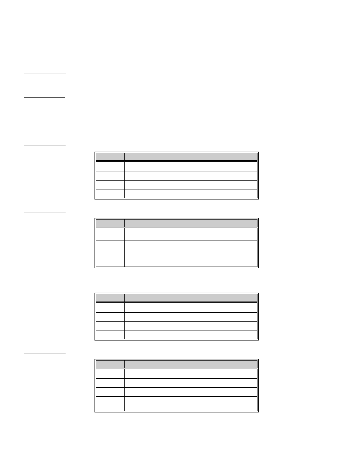
48
APPENDIX 3
Certain older and unusual receivers have formats other than those listed on page 11. Locations 250 thru 255 provide various
methods to duplicate these unusual formats. Included in these overrides is the ability to call and report to a personal pager.
The timer adjustment options allowed in locations 250 and 255 sometimes can compensate for substandard, or older
telephone exchanges. It is suggested that you call DAS technical assistance the first time you attempt to use these override
options.
LOCATION 250 - Inter-round time of a two round parity transmission. The inter-round time will be the number contained
in location 250 times 800 mSec. If location 250 is "0", the time is determined by the individual formats in locations 118 and
140.
LOCATION 251 - Inter-digit time of a pulse format. If the number programmed in location 251 is something other than "0",
The inter-digit time will be that number divided by the PPS. For example, if the number in location 251 is "10", and the format
is a 20PPS format, the inter-digit time will be 10/20 of 0.5 seconds. For locations 252 thru 255, you must add the listed
values for the desired characteristics and program the sum in the appropriate location. If the value is not added for locations
252 and 253, the converse mode will be enabled for those locations. If the value of 1 is not added to location 252, the
transmitted frequency will be 1900 Hz. If the value of 2 is not added to location 253, the communicator will not transmit hex
digits. If neither of values 4 or 8 are added to location 253, the communicator will send messages at 40 PPS.
LOCATION 252 - The number programmed in this location will determine the selected default as desired.
VALUE DESCRIPTION
1Set for 1800 Hz pulse transmit frequency
2Set for 2300 Hz handshake frequency
4Set for single round checksum frequency
8Set for 2 digit event code
LOCATION 253 - The number programmed in this location will determine the selected default as desired.
VALUE DESCRIPTION
1Set for extended reporting
2Set for hex digits
4Set for 20 PPS
8Set for 10 PPS
LOCATION 254 - The number programmed in this location will determine the selected default as desired.
VALUE DESCRIPTION
1Set for pager format
2Set for Ademco handshake
4Reserved
8Set for FBI Superfast
LOCATION 255 - The number programmed in this location will determine the selected default as desired.
VALUE DESCRIPTION
1Set for Contact ID and Ademco Highspeed
2Reserved
4Set for 4/3 and Contact ID
8Set for DTMF transmission format (4/2 Express,
Superfast, Ademco Highspeed & Contact ID

49
NOTES

SPECIFICATIONS
OPERATING POWER 16/18 VAC 1.5 AMP Plug Pack
AUXILIARY POWER 12 VDC Regulated 400 mA
LOOP RESISTANCE 300 Ohms Maximum
BUILT-IN SIREN DRIVER 4 Ohms Maximum
LOOP RESPONSE Selectable @ 200 or 500ms
OPERATING TEMPERATURE 32 to 120 degrees F
KEYPAD DIMENSIONS 5.50" Wide
4.25" High
.850" Deep
METAL ENCLOSURE DIMENSION 11.25" Wide
16.25" High
3.50" Deep
SHIPPING WEIGHT 9 lbs.
WARRANTY STATEMENT
DIRECT ALARM SUPPLIES GUARANTEES THIS PRODUCT AGAINST
DEFECTIVE PARTS AND WORKMANSHIP FOR TWENTY-FOUR (24) MONTHS
FROM DATE OF PURCHASE. IF ANY DEFECT APPEARS DURING THE
WARRANTY PERIOD RETURN IT TO DAS, POSTAGE PREPAID. THE UNIT
WILL BE REPAIRED AND RETURNED. DAS ASSUMES NO LIABILITY FOR
CONSEQUENTIAL OR INDIRECT DAMAGE AND ACCEPTS NO RESPONSIBILITY
FOR REPAIRING DAMAGE TO THE PRODUCT CAUSED BY MISUSE, CARELESS
HANDLING, OR WHERE REPAIRS HAVE BEEN MADE BY OTHERS.
NO OTHER GUARANTEE, WRITTEN OR VERBAL, IS AUTHORIZED BY OR
ON BEHALF OF DIRECT ALARM SUPPLIES, 9 NOWILL STREET
CONDELL PARK, NSW.
DIRECT ALARM SUPPLIES
9 NOWILL STREET, CONDELL PARK
NSW 2200 AUSTRALIA
PHONE (02) 9707 4311
FAX (02) 9790 3424
DL-250 INSTALLATION MANUAL
DL250ID98 REV D (01-08-98)
