DORNA EPS B2 (single M1) Servo User Manual
User Manual:
Open the PDF directly: View PDF ![]() .
.
Page Count: 179 [warning: Documents this large are best viewed by clicking the View PDF Link!]

AC SERVO SYSTEMS
EPS-B2 SERIES
USER MANUAL
DORNA
http://en.dorna.com.cn
(V1.05)
Contents
HOW TO READ THE PARAMETERS? ............................................................................................. 6
SAFETY NOTICE .................................................................................................................................. 7
CHAPTER 1 PRODUCT INTRODUCTION .................................................................................... 11
................................................................................................................
.............................................................................................
1.2.1 Description of nameplate ...................................................................................................... 12
1.2.2
Model identifications
........................................................................................................... 13
.................................................................................
.................................................................................................
................................................................................
CHAPTER 2 INSTALLATIONS
............................................................................................................ 17
................................................................................................
..............................................
......................................................
2.3.1 Installation of EMI filter ....................................................................................................... 19
2.3.2 Connection of AC/DC reactor for suppression of higher harmonic ...................................... 19
.....................................................................................
CHAPTER 3 WIRINGS ...................................................................................................................... 21
..................................................................................................
3.1.1 Servo system structure ........................................................................................................... 21
3.1.2 Servo drive connectors & terminals ...................................................................................... 22
3.1.3 Main circuit wirings .............................................................................................................. 22
.......................................................................
3.2.1 Configurations & definitions of quick plug terminals ........................................................... 24
3.2.2 Configurations and definitions of aviation plug terminals .................................................... 24
................................................................................
...................................................................................................
3.4.1 Pin arrangement of CN2 connector ...................................................................................... 25
3.4.2 CN2 signal descriptions ........................................................................................................ 27
3.4.3 Allocation of I/O signals ....................................................................................................... 29
3.4.4 Examples of connection with upper controllers .................................................................... 36
..................................................
3.5.1 Pin arrangement of CN3 connector ...................................................................................... 40
3.5.2 Examples of CN3 connections ............................................................................................... 41
......................................................................................................
3.6.1 Position control ..................................................................................................................... 42
3.6.2 Speed/torque control ............................................................................................................. 43
CHAPTER 4 PANEL OPERATIONS ................................................................................................. 44
..........................................................................................................................
.....................................................................................
...................................................................................................................
□□ .......................................................................................
4.4.1 Contents of monitoring display mode .................................................................................... 46
4.4.2 Example of operations at monitoring display mode (dP 00) ................................................. 46
□□□ ..................................................................................................
4.5.1 Remarks at parameter mode ................................................................................................. 47
4.5.2 Example of operations at parameter mode (PA100) ............................................................. 48
□□ .......................................................................................
4.6.1 Contents of auxiliary function mode ..................................................................................... 49
4.6.2 Example of operations at auxiliary function mode (AF 05) .................................................. 49
CHAPTER 5 MONITORING DISPLAY PARAMETERS ............................................................... 50
.................................................................................
..............................................................................................
5.2.1 Operations of entering dP 12 ................................................................................................ 52
5.2.2 Explanations of dP 12 LED displays ..................................................................................... 52
5.2.3 Examples of dP 12 LED displays .......................................................................................... 53
...........................................................................................
5.3.1 Operations of entering dP 13 ................................................................................................ 54
5.3.2 Explanations of dP 13 LED displays ..................................................................................... 54
5.3.3 Examples of dP 13 LED displays .......................................................................................... 55
.................................................................................
..................................................................................................
CHAPTER 6 AUXILIARY FUNCTIONS .......................................................................................... 56
..................................................................................
............................................................................................
.....................................................................................................
..........................................................................................................................
.....................................................................................................................
.....................................................................................
............................................................................................
................................................
........................................................
...................................................
..............................................................
.................................................
..................................................................................
..........................................................................
CHAPTER 7 JOG RUN ....................................................................................................................... 70
..................................................................................................
...................................................................................................
....................................................................
7.3.1 Wiring & status check of input signal circuit ........................................................................ 70
7.3.2 JOG run in position control mode ......................................................................................... 71
7.3.3 JOG run in speed control mode............................................................................................. 72
.................................................................................
.................................................................................................
CHAPTER 8 SERVO OPERATIONS ................................................................................................ 74
........................................................................................................
...........................................................................................................
8.2.1 S-ON settings ......................................................................................................................... 75
8.2.2 Switch of motor rotational directions .................................................................................... 76
8.2.3 Overtravel (OT) settings........................................................................................................ 77
8.2.4 Holding brake settings .......................................................................................................... 79
8.2.5 Selection of servo stop patterns at servo OFF ...................................................................... 83
8.2.6 Instantaneous power off settings ........................................................................................... 84
8.2.7 Analog voltage output ........................................................................................................... 85
.........................................................................................................
8.3.1 Absolute encoder selection .................................................................................................... 86
8.3.2 Using battery for absolute encoder ....................................................................................... 86
8.3.3 Battery replacement .............................................................................................................. 87
8.3.4 Setting up absolute encoders (AF 11) .................................................................................... 87
...................................................................................................
8.4.1 Parameter settings ................................................................................................................ 88
8.4.2 Electronic gear ...................................................................................................................... 89
8.4.3 Position instructions .............................................................................................................. 90
8.4.4 Smoothness ............................................................................................................................ 91
8.4.5 Positioning completed signal (COIN) ................................................................................... 92
8.4.6 Positioning near signal (NEAR) ............................................................................................ 93
8.4.7 Pulse input inhibited (INHIBIT) ............................................................................................ 93
........................................................................................................
8.5.1 Parameter settings ................................................................................................................ 94
8.5.2 Input signals .......................................................................................................................... 94
8.5.3 Instruction offset adjustment ................................................................................................. 96
8.5.4 Soft start ................................................................................................................................ 97
8.5.5 Speed instruction filter time constant .................................................................................... 97
8.5.6 Zero-speed clamp function .................................................................................................... 98
8.5.7 Encoder signal output ........................................................................................................... 99
8.5.8 Speed instruction reached (VCMP) ..................................................................................... 101
...................................................................................................
8.6.1 Parameter settings .............................................................................................................. 102
8.6.2 Input signals ........................................................................................................................ 103
8.6.3 Instruction offset adjustment ............................................................................................... 104
8.6.4 Speed limit in torque control mode ...................................................................................... 105
..........................................................................................................
8.7.1 Parameter settings .............................................................................................................. 107
8.7.2 Input signals ........................................................................................................................ 107
.....................................................................................................
8.8.1 Parameter settings .............................................................................................................. 109
8.8.2 Input signals ........................................................................................................................ 111
8.8.3 Output signals ..................................................................................................................... 114
.....................................................................................................................
.........................................................................
8.10.1 Parameter settings ............................................................................................................ 121
8.10.2 Input signal ....................................................................................................................... 121
CHAPTER 9 FAULT DIAGNOSIS .................................................................................................. 122
......................................................................................................................................
..................................................................................................................................
CHAPTER 10 COMMUNICATIONS .............................................................................................. 127
...................................................................................................
.................................................................................................
.....................................................................................................
10.3.1 Encoding definitions .......................................................................................................... 128
10.3.2 Byte structure .................................................................................................................... 129
10.3.3 Communication data structure .......................................................................................... 130
10.3.4 Communication troubleshooting ....................................................................................... 137
.......................................................................................................
CHAPTER 11 PRODUCT SPECIFICATIONS ............................................................................... 140
...................................................................................................
11.1.1 Basic specifications ........................................................................................................... 140
11.1.2 Position/speed/torque control specifications ..................................................................... 141
11.1.3 Servo drive dimensions ...................................................................................................... 142
.........................................................................
CHAPTER 12 APPENDIX ................................................................................................................ 146
................................................................................
..............................................................................
................................................................................................................
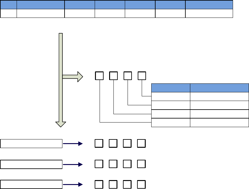
How to read the parameters?
High place/Low place explanation
Parameter 1/2/3/4 explanations
Parameter
PA200
Function
Position control switch
Range
d.0000~d.1232
Unit
-
Default
0000
Effective
Restart
Remarks
Writing
PA200.0 or d.×
Meaning
Place 0 of PA200
PA200.1 or d.×Place 1 of PA200
PA200.2 or d.× Place 2 of PA200
PA200.3 or d.× Place 3 of PA200
b.
3 2 1 0
d.
h.
Setting range of each digit is 0~1
Setting range of each digit is 0~9
Setting range of each digit is 0~F
d.
3 2 01
3 2 1 0
3 2 1 0

Safety Notice
DANGER
Input power
When installed to a machine, the servo motor shall be able to do emergency
stop at any moment.
Otherwise, there may be personnel injuries and mechanical failure.
When the power is on, the power supply terminals must be properly housed.
Otherwise, there may be electric shocks.
After power off or voltage withstand test, when the charge indication light
(CHARGE) is on, do not touch the power supply terminals.
Otherwise, there may be electric shocks caused by residual voltage.
Please do trial run (JOG) following the procedures and instructions of this
user manual.
Otherwise, there may be personnel injuries and mechanical failure.
Do not make any alterations to this product. Only qualified/designated
persons can configure, dismantle or repair this product.
Otherwise, there may be personnel injuries, mechanical failure or fire.
Please install stop mechanisms on the machine side to ensure safety.
The holding brake of the servo motor is not a device designed to ensure safety.
Otherwise, there may be injuries.
Please ensure to connect the earth terminal of servo drive with the earth
electrode (the earth resistance of servo drive for power input is below 100Ω).
ATTENTION: STORING & TRANSPORTING
The product shall not be stored or used in below environment:
(Otherwise, there may be fire, electric shocks or machinery breakdown.)
Please do not transport the product by grasping the cables, motor shafts or
encoders.

ATTENTION: INSTALLATIONS
Please do not block the air inlet and outlet, and prevent alien matters entering
the product.
Otherwise, the inner components may be aged and cause failure or fire.
Please install at correct directions.
Otherwise, there may be failure.
During installation, please ensure there is enough space between the servo
drive and internal surface of control cabinet and other electrical parts.
Otherwise, there may be fire or machine breakdown.
Please do not impose too big impacts.
ATTENTION: WIRING
Please connect wires correctly and reliably.
Otherwise, there may be out-of-control of motor, personnel injuries or machine
fault.
Please DO NOT connect commercial power supply to the UVW terminals of
the servo drive.
Otherwise, there may be personnel injuries or fire.
Please connect the UVW terminals with the servo motor firmly.
Otherwise, there may be a fire.
Please do not house the main circuit cables, input-output signal cables and
encoder cables with the same bushing, or tie them together. During wiring,
the main circuit cables shall be at least 30cm from the input-output signal
cable.
Cables for input-output signal and encoder shall be twin strands or multiple-
core twinning bulk shielding strands.
Maximum length of input-output signal cable: 3m;
Maximum length of encoder cable: 30m.
Even when the power is turned off, there may still be residual high voltage
inside the servo drive, so when the charge indication light (CHARGE) is on,
do not touch the power terminals.
Please connect or check wirings after the charge indication light (CHARGE) is
off.
Pleaseinstall circuit breakers to prevent external short-circuit.
Otherwise, there may be a fire.
When used in the following places, please take appropriate measures for
shielding:
Otherwise, there may be machinery breakdown.
When connecting to batteries, pay attention to the polarity.

ATTENTION: OPERATIONS
In order to prevent accidents, please conduct trial run (JOG) before
connecting to mechanical parts.
Otherwise, there may be injuries.
Before running, please set the appropriate parameters.
Otherwise, the machine may be out of control or have failure.
Please do not turn on/off the power supply frequently.
Because the power section of servo drive has capacitors, when the power is on,
heavy charging current may flow through them. Therefore, if the power is
frequently turned on/off, perseverance of the main circuit components inside the
servo drive may decline.
During JOG operation (AF 02) and manual load inertia detection (AF 15),
please note that the emergency stop will become ineffective at over-travel.
Otherwise, there may be machinery breakdown.
When the servo motor is used on the vertical axis, please set a safety device,
in case workpiece drops when there is alarm or over-travel. Besides, please
set up zero-position fixation when there is over-travel.
Otherwise, the workpiece may drop when there is over-travel.
Extreme or alternative parameter settings may cause the servo system to be
instable.
Otherwise, there may be personnel injuries and machinery breakdown.
When there are alarms, please reset the alarm after finding out the causes
and ensure operation safety, and then start operation again.
Otherwise, there may be machinery breakdown, fire or personnel injuries.
The holding brake (optional) of the servo motor is designed for maintaining
positions, NOT for servo motor braking at decelerations.
Otherwise, there may be machine fault.
The servo motor and servo drive shall be used in combinations as specified.

ATTENTION: MAINTENANCE
Please do not change the wiring when the power is on.
Otherwise, there may be electric shocks or personnel injuries.
When replacing the servo drive, please copy parameters to the new servo
drive, and then start operation again.
ATTENTION: OTHERS

Chapter 1 Product Introduction
1.1
Product inspections
Please check the items listed in the table below carefully, in case there is
negligence
during the purchase and transport of the product.
Items to inspect
Reference
Whether the product received is the
right one
you intend to buy?
Check the product model on the motor and driver
nameplate respectively. Please refer to the notes to
model in following sections.
Whether the motor shaft runs smoothly?
Rotate the rotor shaft of the motor. If it can rotate
smoothly, the rotor shaft is normal.
Note
that the motor with electro-magnetic brake
(holding brake) can
n
ot be rotated with hands!
Check whether there are any appearance
damages?
Check visually whether there are any appearance
damages.
Whether there are loosened screws?
Check whether the mounting screws of servo
drive is loosened with a screw driver.
Please contact your vendor if anything above occurs.
A complete set of servo components shall include the following:
No.
Reference
1
Servo drive and its matching servo motor.
2
Motor power line: supplies power from servo drive to servo motor.
3
Motor encoder line: transmits signals from motor encoder to servo drive.
4
RJ45 plug for CN1: RS485 communication (optional)
5
50-PIN plug for CN2 (3M simulation product) (optional)
6
20-PIN plug for CN3 (A, B type case only) (3M simulation product) (optional)
7
5-PIN plug for servo drive (A, B type case only) input power supply: L1. L2.
L3. L1C. L2C
8
5-PIN plug for external braking resistor and DC reactor (A, B type case only) :
(P, D, C, -1, -2)
9
Two metal pieces for short-circuiting (except E type case)
10
One copy of user manual
1.2
Product model identifications
1.2.1 Description of nameplate
Description of the nameplates of EPS-B2 series servo drives
AC SERVO DRIVE
MODEL:EPS-B2-0D75AA-0000
Servo drive model
22G0D 7500157000004
Input voltage
Manufacturing codeRated output current
INPUT
VOLTS 200~230V
PHASE 1 or 3 PH
HZ 50/60Hz
OUTPUT
DORNA TECHNOLOGY CO. LTD MADE IN CHINA
VOLTS 0~210V
PHASE 3 PH
AMPS 4.0A
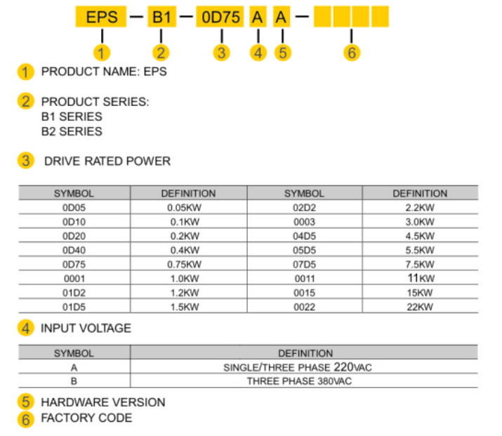
1.2.2
Model identifications
Description of the models of EPS-B2 servo drive
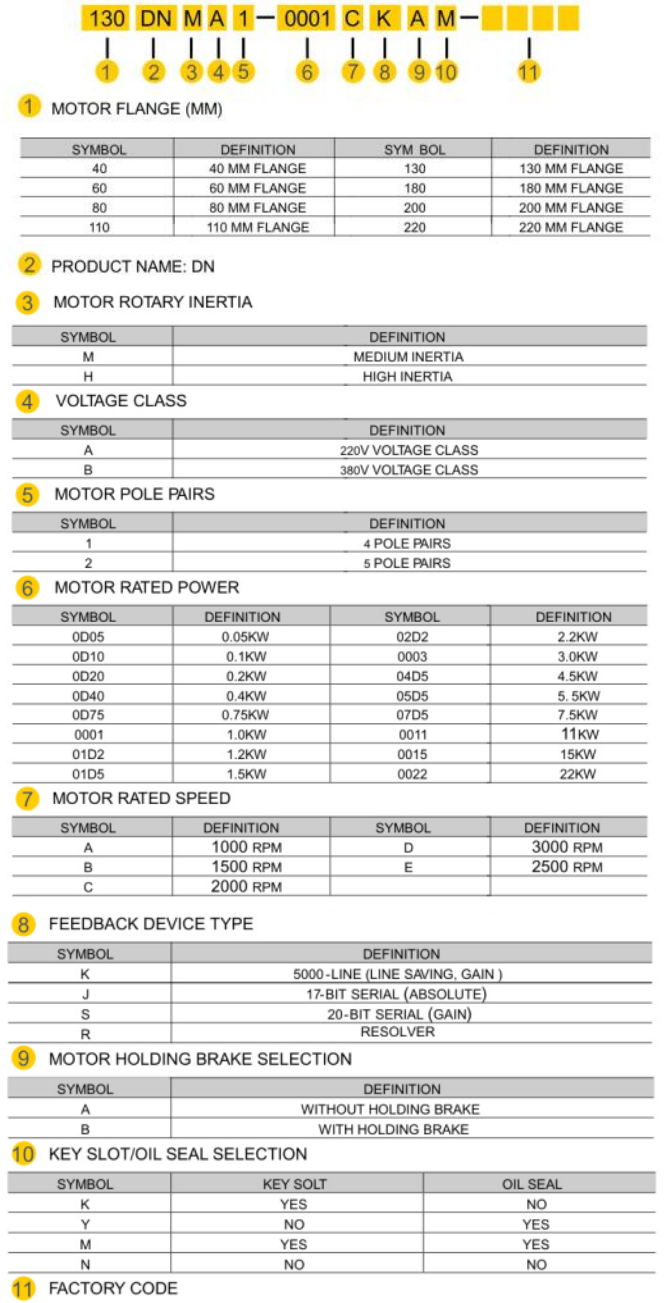
Description of the models of DORNA servo motors

1.3 Servo drive and motor matching table
Voltage
Class
Rated
power
Servo drive
Servo motor
Model
PA012
Value
Case
Type
Flange
(mm)
Model
Rated
speed
Rated
torque
220V
0.05KW
EPS-B2-
0D10AA
1
A
40
40DNMA2-
0D05D
3000rpm
0.16
N·M
0.1KW
EPS-B2-
0D10AA
1
A
40
40DNMA2-
0D10D
3000rpm
0.32
N·M
0.2KW
EPS-B2-
0D20AA
2
A
60
60DNMA2-
0D20D
3000rpm
0.64
N·M
0.4KW
EPS-B2-
0D40AA
3
A
80
60DNMA2-
0D40D
3000rpm
1.27
N·M
0.75KW
EPS-B2-
0D75AA
12
B
80
80DNMA2-
0D75D
3000rpm
2.37
N·M
1KW
EPS-B2-
0001AA
13
B
80
80DNMA2-
0001D
3000rpm
3.2
N·M
1KW
EPS-B2-
0001AA
33
B
130
130DNMA2-
0001C
2000rpm
5 N·M
1.2KW
EPS-B2-
01D5AA
25
B
110
110DNMA2-
01D2D
3000rpm
4 N·M
1.2KW
EPS-B2-
01D5AA
34
B
130
130DNMA2-
01D2C
2000rpm
6 N·M
1.5KW
EPS-B2-
01D5AA
35
B
130
130DNMA2-
01D5C
2000rpm
7.2
N·M
1.5KW
EPS-B2-
02D2AA
41
C
130
130DNMA2-
01D5C
2000rpm
7.2
N·M
1.8KW
EPS-B2-
01D5AA
29
B
110
110DNMA2-
01D8D
3000rpm
6 N·M
2.2KW
EPS-B2-
02D2AA
42
C
130
130DNMA2-
02D2C
2000rpm
10.5
N·M
3KW
EPS-B2-
0003AA
45
C
130
130DNMA2-
0003C
2000rpm
14.33
N·M
380V
2.2KW
EPS-B2-
02D2BA
42
C
130
130DNMB2-
02D2C
2000rpm
10.5
N·M
3KW
EPS-B2-
0003BA
45
C
130
130DNMB2-
0003C
2000rpm
14.33
N·M
3KW
EPS-B2-
0003BA
70
C
180
180DNMB2-
0003B
1500rpm
19.1
N·M
1.4 Maintenance and inspections
Type
Period
Items
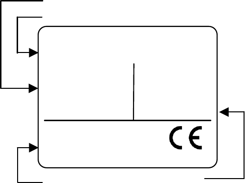
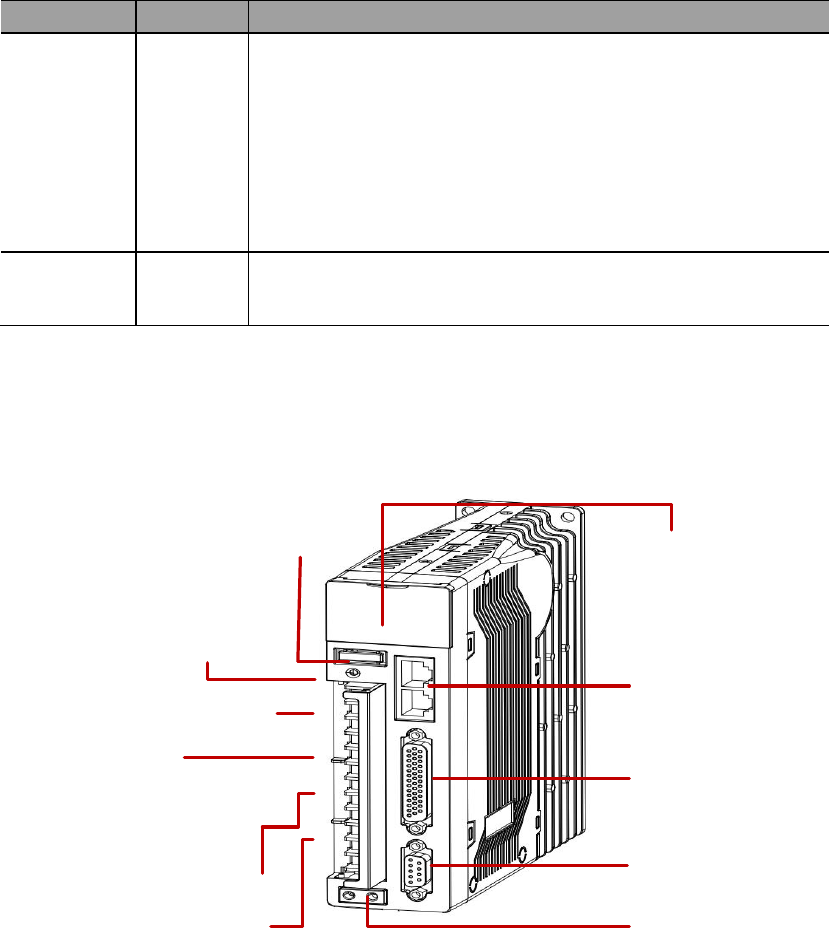
1.5 Name of each part of the servo driver
RS485 port
Display area
Power indication light
Main circuit input power terminals
PD: internal regenerative resistor
PC: external regenerative resistor
DC reactor terminals
UVW: motor power supply terminals
Grounding
I/O terminals
Motor encoder terminals
Control circuit input power terminals
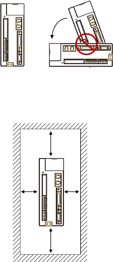
Chapter 2 Installations
2.1
Installation direction and space
Correct
>20mm>20mm
>50mm
>50mm

2.2 Recommended specifications of circuit-breaker and fuse
220V class
Servo drive case type
Circuit-breaker
Fuse (class T)
A
10A
20A
B
20A
40A
C
30A
80A
2.3 Countering noise interference and higher harmonics

2.3.1 Installation of EMI filter
Item
Reference
2.3.2 Connection of AC/DC reactor for suppression of higher
harmonic
AC Reactor
DC Reactor
Servo drive
L1
L2
L3
AC Reactor
Power
Servo drive
1
2
DC reactor

2.4 Selection of regenerative resistors
Servo drive
case type
Internal regenerative resistor specs
Minimum allowable
resistance value (Ohm)
Resistance (Ohm)
Capacity (Watt)
Item
Reference
℃
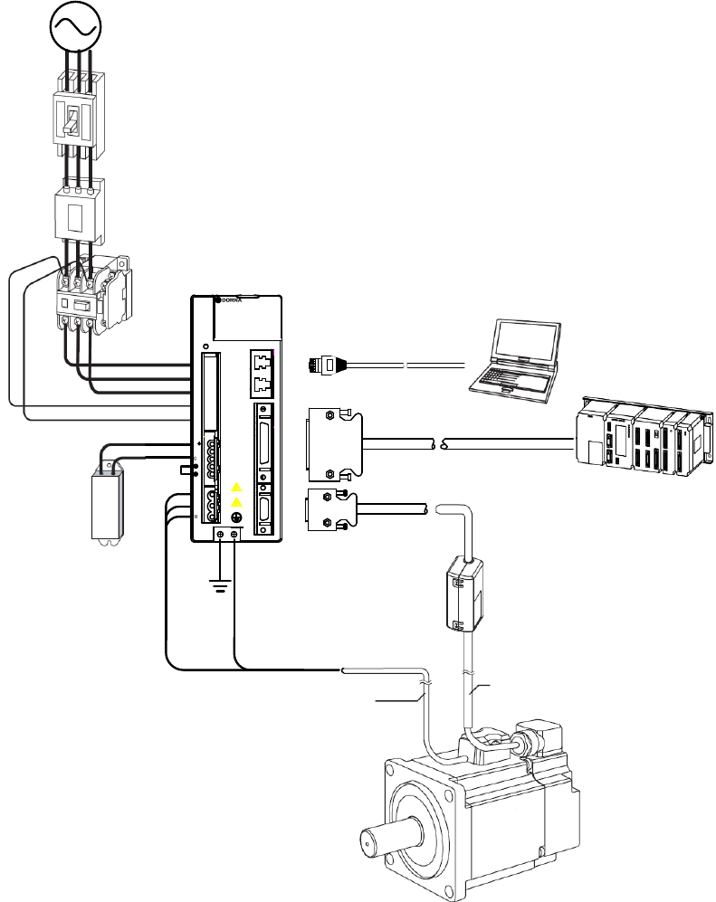
Chapter 3 Wirings
3.1 System structure and wiring
3.1.1 Servo system structure
U
V
P
D
L1
L2
L3
L1 C
L2 C
1
2
WORNI NG
CAUTION
CHARGE
C
N
1
C
N
2
C
N
3
Circuit-breaker
EMI filter
Electromagnetic
contactor
Input power
External
regenerative
resistor
RS485 cable
Computer
Control line: I/O signals
Upper controller
Encoder line
Power line
Battery box (for absolute encoders)
EPS-B1 servo drive
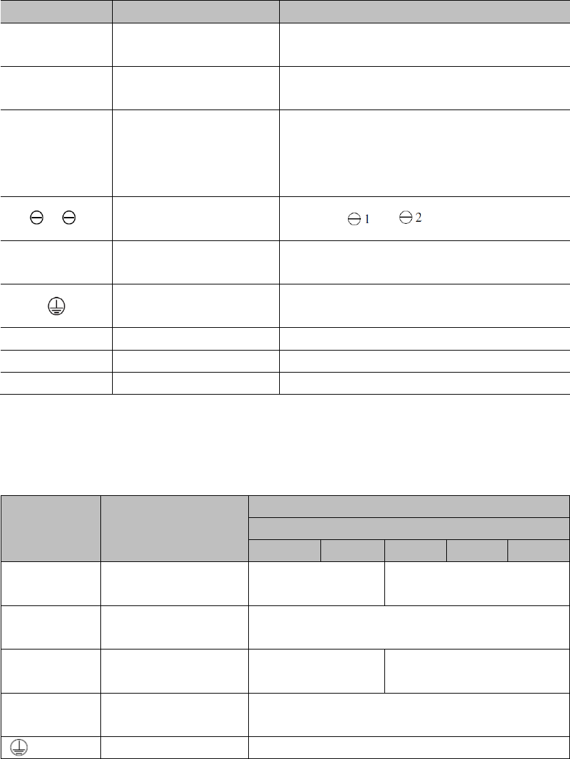
3.1.2 Servo drive connectors & terminals
Markings
Descriptions
Reference
L1, L2, L3
L1C, L2C
P, D, C
1, 2
U, V, W
CN1
CN2
CN3
3.1.3 Main circuit wirings
1) Cable diameter requirement
Mark
Name
Cable diameter: mm2 (AWG)
EPS-B1-
0D20A
0D40A
0D75A
0001A
01D5A
L1, L2, L3
L1C, L2C
U, V, W
P, D, C
2) Typical main circuit wiring example
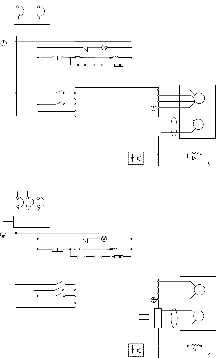
1PH 220VAC:
EMI Filter
M
P
G
Motor
Encoder
CN2
4
3
ALM
COM-
1 Ry +24V
0V
2
3
4
1
U
V
W
L1
L2
L3
L1C
L2C
1 MC
OFF ON
1 Ry
1 Ry PL
Peak voltage suppressor
1PH 200~230VAC
(50/60 Hz)
+10%
-15%
~
R T
1 MC
1 MC
1 MC
3PH 220VAC/380VAC:
EMI Filter
M
P
G
Motor
Encoder
CN2
4
3
ALM
COM-
1 Ry +24V
0V
2
3
4
1
U
V
W
L1
L2
L3
L1C
L2C
1 MC
OFF ON
1 Ry
1 Ry PL
Peak voltage suppressor
1PH 200~230VAC
(50/60 Hz)
+10%
-15%
~
R T
1 MC
1 MC
1 MC
S
1 MC
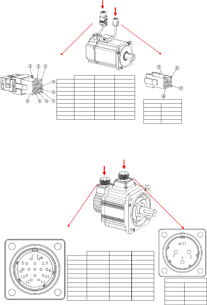
3.2 Wirings between servo drive & servo motor
3.2.1 Configurations & definitions of quick plug terminals
Encoder line Power line
CODE
1
2
DESCRIPTION
U
V
3
4
W
PE
Motor power(4P)
CABLE CODE
1
2
DESCRIPTION
+5V
0V
3
4
5
PA
/PA
PB
6 /PB
7
8
9
PZ
/PZ
FG
DESCRIPTION
+5V
0V
PD+
PD-
BAT+
BAT-
FG
Communicational
DESCRIPTION
SIN+
SIN-
COS+
COS-
REF+
REF-
FG
ResolverLine saving
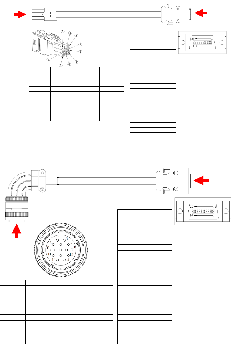
3.2.2 Configurations and definitions of aviation plug terminals
CODE
1
2
DESCRIPTION
PE
V
3
4
U
W
Motor power(4P)
CABLE CODE
1
2
DESCRIPTION
FG
+5V
3
4
5
0V
PA
PB
6 PZ
7
8
9
/PA
/PB
/PZ
Line saving
DESCRIPTION
FG
+5V
0V
PD+
BAT+
PD-
BAT-
Communicational
DESCRIPTION
FG
COS-
SIN-
SIN+
REF+
COS+
REF-
Resolver
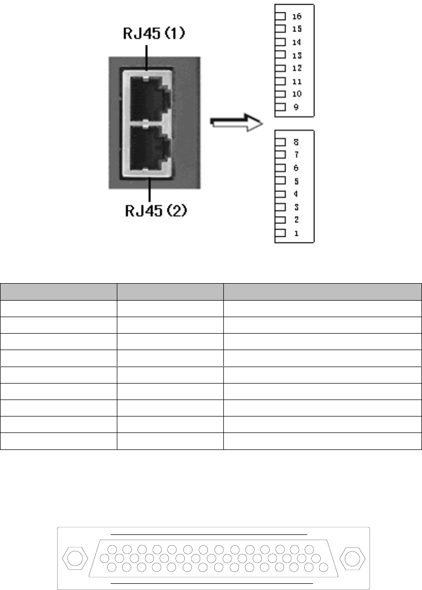
3.3 Wirings of CN1 (RS485 communication)
1) Terminal appearance
2) Signal definitions
Mark
Name
Function
3.4 Wirings of CN2 (I/O signals)
3.4.1 Pin arrangement of CN2 connector
31
115
44
16 30

1
31
2
-
16
32
3
17
+24V
24V Output
33
4
-
18
34
5
19
35
6
-
20
36
7
21
37
8
22
38
9
23
39
10
24
40
11
25
41
12
26
-
42
13
27
43
14
24V-GND
24V Output
28
44
MON
15
29
30
1)
2)
3)
4)

3.4.2 CN2 signal descriptions
Name and function of input signals (with default pin allocations)
Mode
Signal
Pin No.
Function
9
10
34
8
33
32
31
30
11
38
36
42
40
43
41
39
37
35
20
29
18
19

Name and function of output signals (with default pin allocations)
Mode
Signal
Pin
No.
Function
21
22
25
23
13
24
7
6
5
4
3
2
1
26
44
±8V.
16

3.4.3 Allocation of I/O signals
1) Allocation of input signals
PA
Description
Range
Unit
Default
Effective
PA500
DI 1 input signal selection

PA501
PA502
PA503
PA504
PA505
PA506
PA507
Parameter No.
Terminal name
CN2 pin
Default signal
9
10
34
8
33
32
31
30

PA
Description
Range
Unit
Default
Effective
PA508
Level selection of input signal 0
b.0001: DI 1 input signal level selection;
b.0010: DI 2 input signal level selection;
b.0100: DI 3 input signal level selection;
b. 1000: DI 4 input signal level selection;
PA509
Level selection of input signal 1
b.0001: DI 5 input signal level selection;
b.0010: DI 6 input signal level selection;
b.0100: DI 7 input signal level selection;
b. 1000: DI 8 input signal level selection;
Servo drive
3.3K Ω
+24VIN
/S-ONetc.
DC24 V
Above 50 mA
Servo drive
3.3K Ω
+24VIN
/S-ON etc.
DC24 V
Above 50 mA
PC PC

2) Allocation of output signals
PA
Description
Range
Unit
Default
Effective
PA510
Output signal selection
h.0001: DO 1 output signal selection
h.0010: DO 2 output signal selection
h.0100:DO 3 output signal selection
h.1000:DO 4 output signal selection
h.

PA511
Output signal level selection (negation)
b.0001: DO 1 (ALM) output signal level
selection
b.0010: DO 2 output signal level selection
b.0100: DO 3 output signal level selection
b.1000: DO 4 output signal level selection
Parameter No.
Terminal name
CN2 pin
Default signal
Servo drive
DC5V~ 24V
0V
Relay
Maximum allowable voltage: DC 30V
Opticalcoupler
S-RDY-
S-RDY+
Maximum allowable current: DC 50mA
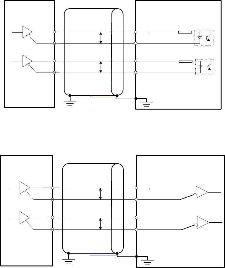
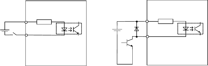
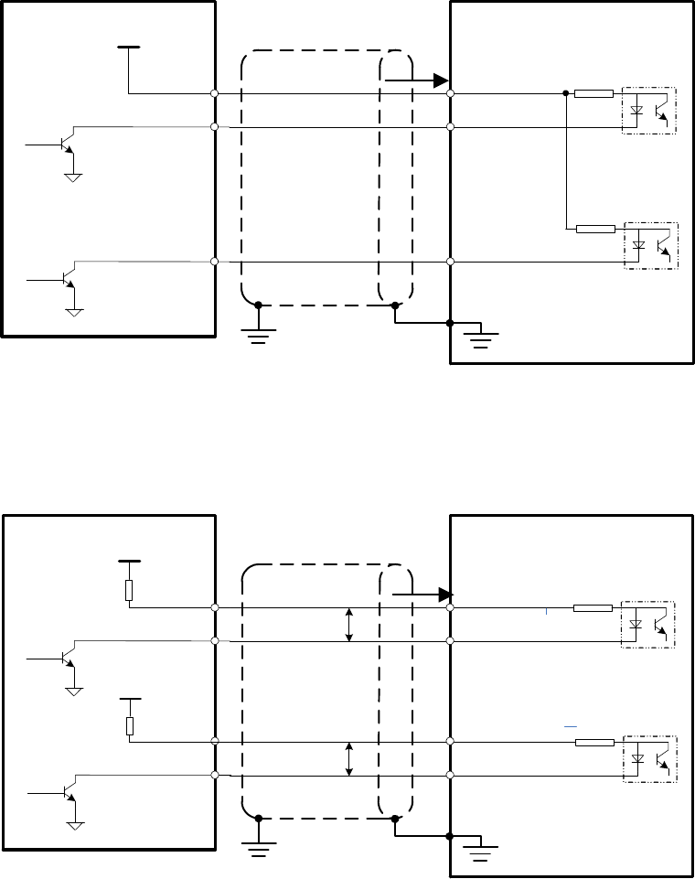
3.4.4 Examples of connection with upper controllers
1) Input signal connections
150
SIGN
/ SIGN
PULS
2CN-37
2CN-39
2CN-41
2CN-43
150
P
P
Servo drive
Optocoupler
/ PULS
Line driver
Upper controller
Both ends grounding
FG
HSIGN
/HSIGN
HPULS
2CN-40
2CN-42
2CN-36
2CN-38
P
P
Servo drive
Long line receiver
/HPULS
Line driver
Upper controller
Both ends grounding
FG
390
390
2K
/ SIGN
PL
2CN-37
2CN-41
2CN-35
2K
Servo Drive
/ PULS
Upper Controller
Vcc i
FG
150
SIGN
/ SIGN
PULS
1CN-37
1CN-39
2CN-41
2CN-43
150
P
P
Servo drive
Optocoupler
/ PULS
Upper controller
Vcc
R1
R1
i
Vcc
Both ends grounding
FG
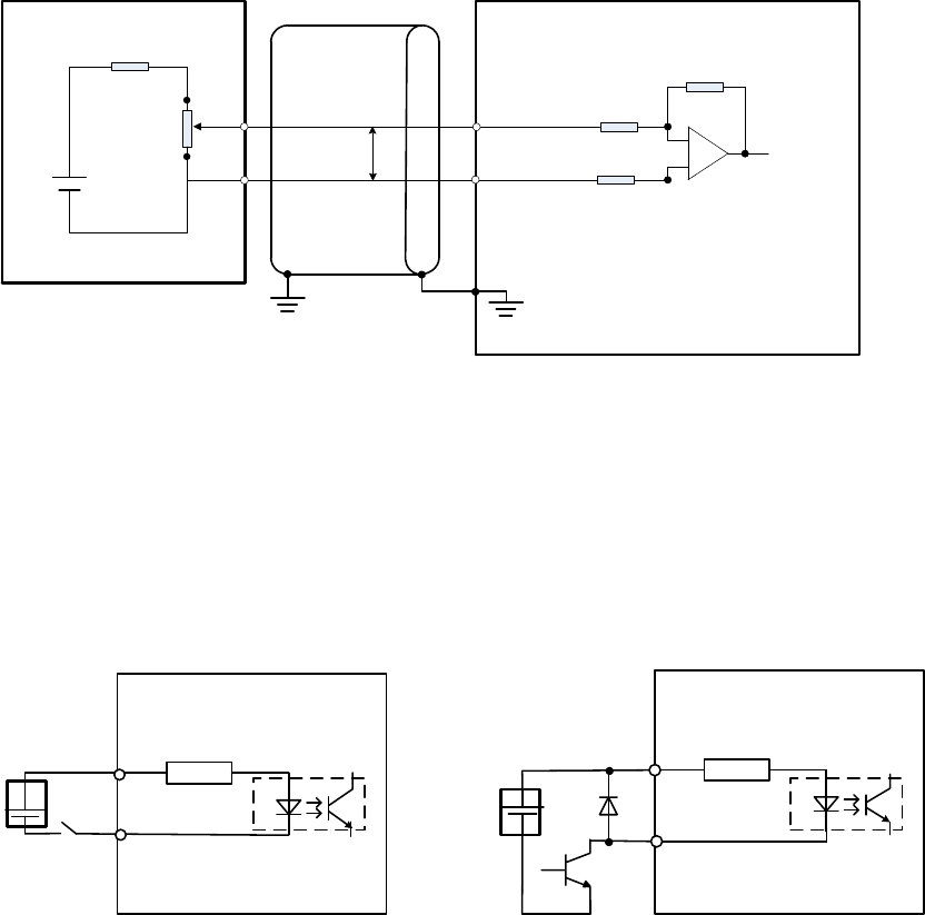
V-REF or
T-REF
2CN-20/29
2CN- 18/19
P
Servo drive
Upper controller
Above 1.8K (1/2W)
Both ends grounding
FG
AGND
12V Above 10K
Servo drive
3.3KΩ
+24VIN
/S-ON etc.
24VDC
Above 50mA
Servo drive
3.3KΩ
+24VIN
/S-ON etc.
Relay Open collector transistor
24VDC
Above 50mA
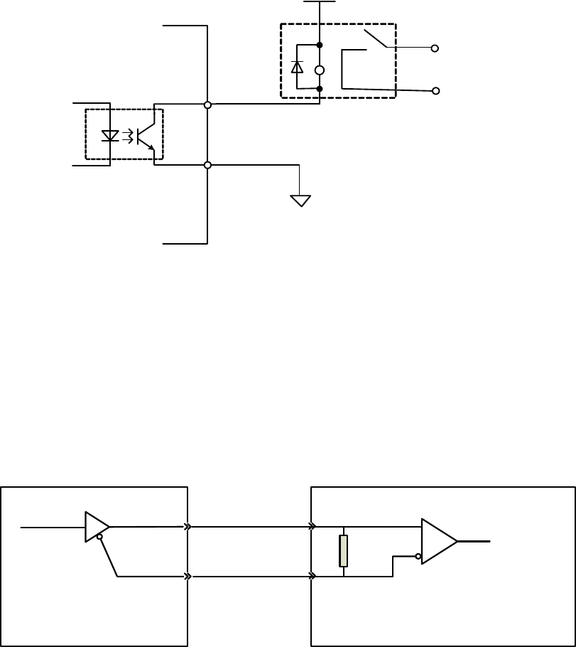
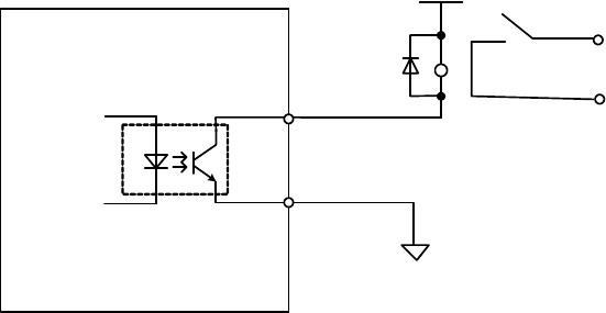
2) Output signal connections
ALM, S-RDY and other sequence of output signals are consisted of optocoupler.
Please connect with relays.
Servo drive
DC 5V~24V
0V
Relay
Maximum DC voltage: 30VDC
Maximum DC current: 50mA
Servo drive Controller
Compatible line receiver:
SN75175 or equivalent
220
~
470
3.5 Wirings of CN3 (feedback from encoder to servo drive)
3.5.1 Pin arrangement of CN3 connector
1) Quick plug
CABLE CODE
1
2
DESCRIPTION
+5V
0V
3
4
5
PA
/PA
PB
6 /PB
7
8
9
PZ
/PZ
FG
DESCRIPTION
+5V
0V
PD+
PD-
BAT+
BAT-
FG
Communicational
DESCRIPTION
SIN+
SIN-
COS+
COS-
REF+
REF-
FG
ResolverLine saving
20P CODE
1
2
DESCRIPTION
/PA
PA
3
4
5
/PB
PB
/PZ
6 /PZ
7
8
9
+5V
+5V
0V
CN3 plug
10 0V
11
12
13
SIN+
SIN-
COS-
14 COS+
15
16
17
REF+
REF-
PD-
18
19
20
PD+
Housing FG
2) Aviation plug
20P CODE
1
2
DESCRIPTION
/PA
PA
3
4
5
/PB
PB
/PZ
6 /PZ
7
8
9
+5V
+5V
0V
CN3 plug
10 0V
11
12
13
SIN+
SIN-
COS-
14 COS+
15
16
17
REF+
REF-
PD-
18
19
20
PD+
Housing FG
CABLE CODE
1
2
DESCRIPTION
FG
+5V
3
4
5
0V
PA
PB
6 PZ
7
8
9
/PA
/PB
/PZ
Line saving
DESCRIPTION
FG
+5V
0V
PD+
BAT+
PD-
BAT-
Communicational
DESCRIPTION
FG
COS-
SIN-
SIN+
REF+
COS+
REF-
Resolver
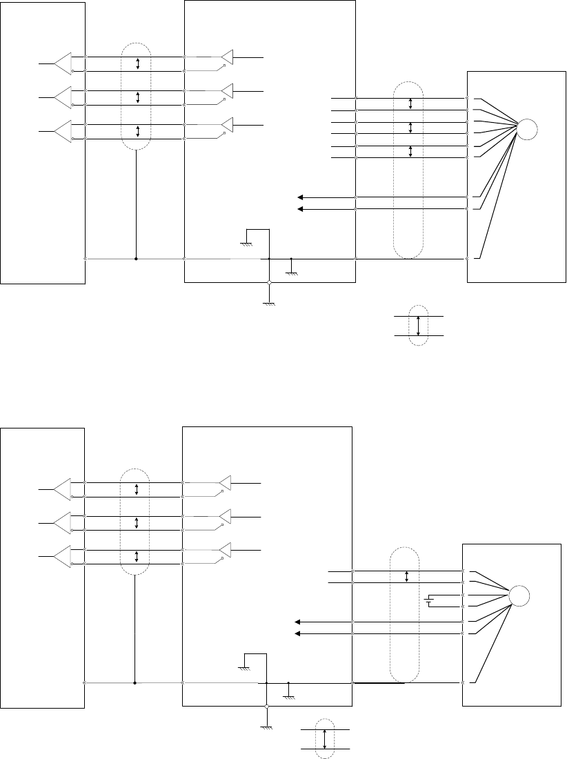
3.5.2 Examples of CN3 connections
Line-saving
incremental encoder
Servo driveClient
PG
PA+
PA-
PB+
PB-
PZ+
PZ-
PG5V
GND
PAO+
PAO-
21
22
P
P
P
P*
*
PG5V
PG0V
Shielding cable
PMulti-strand shielding cable*
A phase pulse
Line driver
AM26LS31 etc.
CN2
CN3
2
1
4
3
6
5
7
9
FG
Line receiver
SN75175 etc.
PBO+
PBO-
25
23
P
B phase pulse
PZO+
PZO-
13
24
P
Z phase pulse
17-bit serial encoder
Servo driveClient
PG
PD+
PD-
PG5V
GND
PAO+
PAO-
21
22
P
P
*
*
PG5V
PG0V
Shield cable
PMulti-strand shield
cable
*
A phase pulse
Line driver
AM26LS31 etc.
CN2
CN3
18
17
7
9
FG
Line receiver
SN75175 etc.
PBO+
PBO-
25
23
P
B phase pulse
PZO+
PZO-
13
24
P
Z phase pulse
BAT+
BAT-
BAT+, BAT- are used for absolute
encoders only.
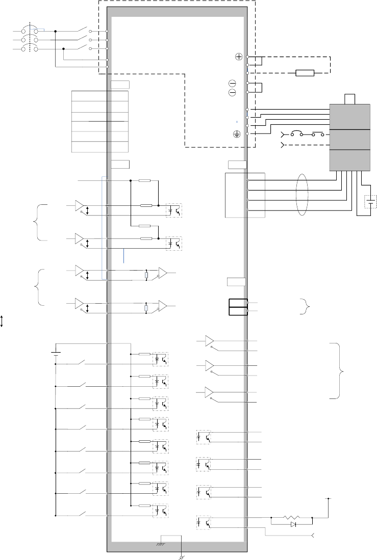
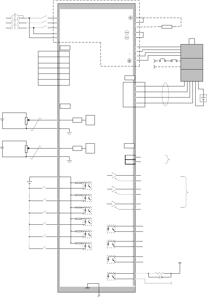
3.6 Standard wiring diagrams
3.6.1 Position control
150
P
P
PZO
/PZO
CN2
13
24
7
FG
34
10
9
11
S-ON
+24VIN
SIGN
PULS
SIGN+
SIGN-
PULS+
PULS-
PMulti-strand cables
Low speed
pulse inputs
Servo ON
0V
Housing
Connect shield cable with housing
Optocoupler output
Maximum voltage: 30VDC
Maximum current: 50mA
37
39
41
43
C-MOD
Alarm reset
POT
Position deviation
clearance
Feedback
signal output
6
ALM+
Z pulse output
150
PBO
/PBO
25
23
PAO
/PAO
21
22 A pulse output
B pulse output
33
8
NOT
CLR
Forward prohibited
Reverse prohibited
COM+
External 24VDC should use double
insulation
Servo drive
U
V
W
Handle shield cable ends properly
PD
C
Power
Brake
Encoder
BK
24V
7,8
9,10
18
17
External brake resistor
CN3
5V
0V
PD+
PD-
BAT+
BAT-
L1
L2
L3
L1C
L2C
MC
MC
MC
MCCB
AC220V/380V
50/60HZ
CN1
RS485+ 1,9
RS485- 2,10
GND 3,11
GND 6,14
7,15
8,16
32
A-RST
30
31
INHIBIT
ZEROSPD
CN2
5
+24V
4
ALM-
COIN+
COIN-
3
2
CZ+
CZ-
1
26
BK+
BK-
Mode switch
Input pulse prohibited
Zero speed clamp
P
P
HSIGN
HPULS
HSIGN+
HSIGN-
HPULS+
HPULS-
36
38
40
42
High speed
pulse inputs
EMGS
1
2
2K
2K
PL 35
44 MON
16 SG(GND)Analog output
3.6.2 Speed/torque control
PZO
/PZO
CN2
13
24
7
FG
34
10
9
11
S-ON
+24VIN
Servo ON
0V
Housing
Connect shield cable with housig
Optocoupler output:
Maximum voltage: 30VDC
Maximum current: 50mA
C-MOD
Alarm reset
POT
Feedback
signal output
6
ALM+
Z pulse output
PBO
/PBO
25
23
PAO
/PAO
21
22 A pulse output
B pulse output
32
8
NOT
Forward prohibited
Reverse prohibited
COM+
External 24VDC shall use double
insulation
Servo drive
U
V
W
Handle shield cable ends
properly
PD
C
Power
Brake
Encoder
BK
24V
7,8
9,10
18
17
External brake resistor
CN3
5V
0V
PD+
PD-
BAT+
BAT-
L1
L2
L3
L1C
L2C
MC
MC
MC
MCCB
AC220V/380V
50/60HZ
CN1
RS485+ 1,9
RS485- 2,10
GND 3,11
GND 6,14
7,15
8,16
30
A-RST
ZEROSPD
5
+24V
4
ALM-
COIN+
COIN-
3
2
CZ+
CZ-
1
26
BK+
BK-
Mode switch
Zero speed clamp
EMGS
±10V 2K18
T-REF
19
AGND
±10V 2K20
V-REF
29
AGND
LFC A/D
LFC A/D
1
2
CN2
44 MON
16 SG(GND)Analog output
Chapter 4 Panel operations
4.1 Panel operator
Hold & press ↑ & ← keys together can clear
servo drive alarms. BUT please find out the cause of alarms first.
SET
MOD
Key
Function description
←
↑
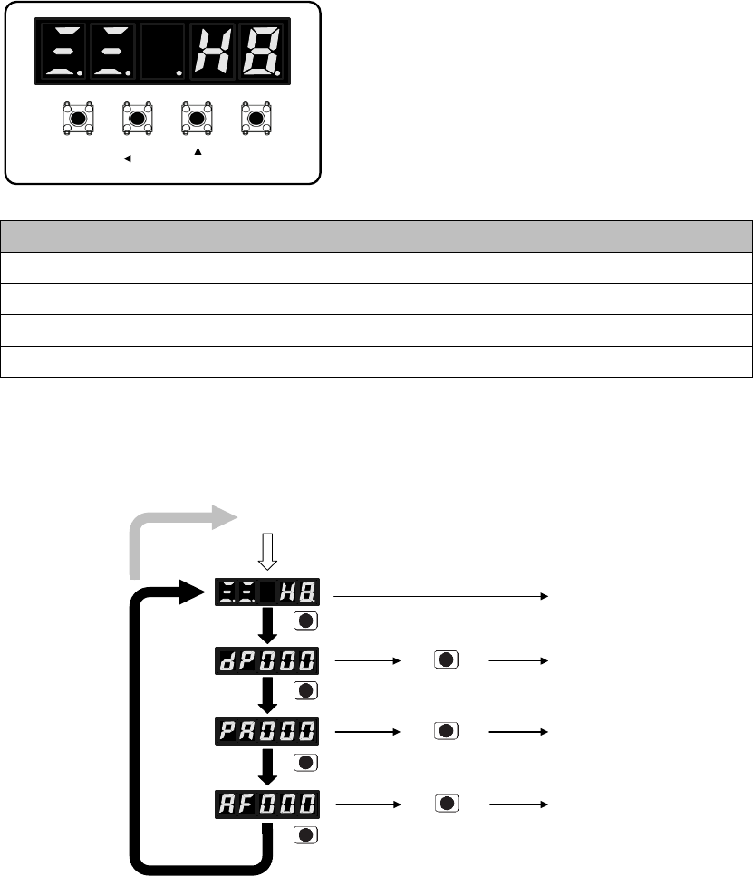
4.2 Switch between different functions
Power ON
Status display
mode
Monitor mode
Parameter
setting
Auxiliary
functions
MO
D
MO
D
MO
D
MO
D
按 键
SET
SET
SET
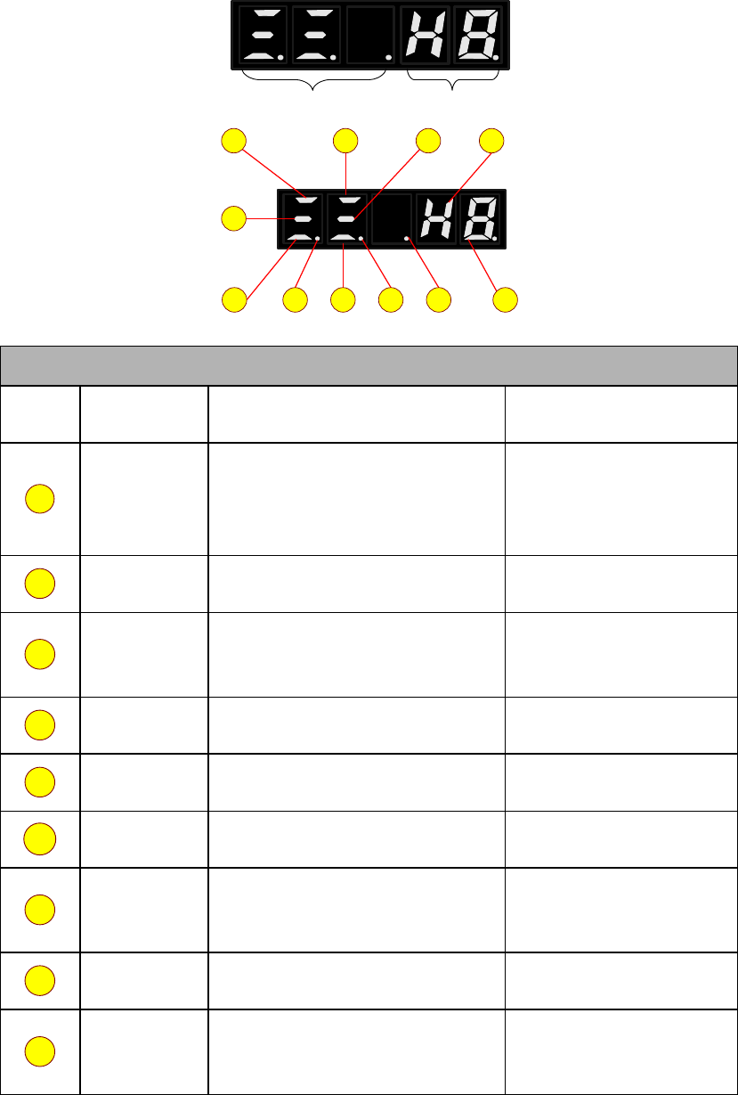
4.3 Status code display
Bit data Abbreviations
10
11987
6
43
2
1 5
Bit data
No.
Definition
Description in position control mode
Description in speed,
torque control mode
1
2
3
4
5
6
7
8
9
Abbreviations
10
11
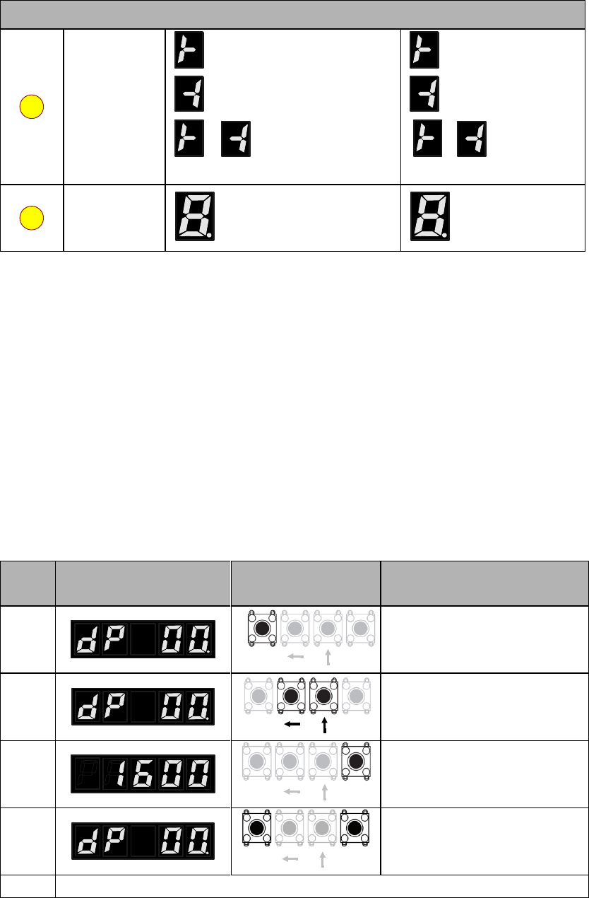
4.4 Monitoring display mode (dP □□)
4.4.1 Contents of monitoring display mode
4.4.2 Example of operations at monitoring display mode (dP 00)
Step
s
Panel display
Keys
Operations
SETMOD
SETMOD
SETMOD
SETMOD

4.5 Parameter mode (PA □□□)
4.5.1 Remarks at parameter mode
Panel display
Remarks
Panel display
Remarks
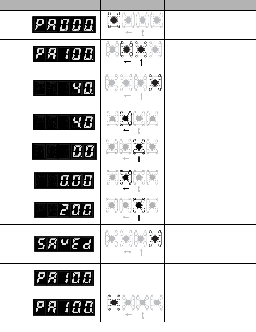
4.5.2 Example of operations at parameter mode (PA100)
Steps
Panel display
Keys
Operations
SETMOD
SETMOD
SETMOD
SETMOD
SETMOD
SETMOD
SETMOD
SETMOD
SETMOD
4.6 Auxiliary function mode (AF □□)
4.6.1 Contents of auxiliary function mode
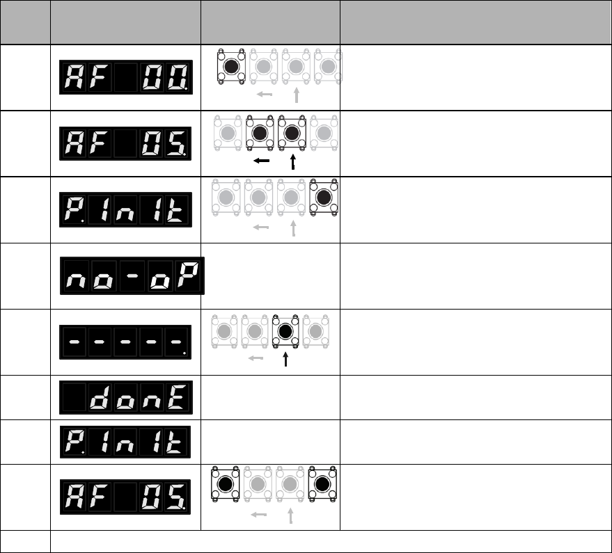
4.6.2 Example of operations at auxiliary function mode (AF 05)
Ste
ps
Panel display
Keys
Operations
SETMOD
SETMOD
SETMOD
SETMOD
SETMOD

Chapter 5 Monitoring display
parameters
5.1 List of monitoring display parameters
No.
Function
Unit
dP 00
Motor speed
dP 01
Motor feedback pulse number (encoder unit, lower 4 digits)
dP 02
Motor feedback pulse number (encoder unit, higher 5 digits)
dP 03
Input pulse number before electronic gear (user unit, lower 4
digits)
dP 04
Input pulse number before electronic gear (user unit, higher 5
digits)
dP 05
Deviation pulse number (encoder unit, lower 4 digits)
dP 06
Deviation pulse number (encoder unit, higher 5 digits)
dP 07
Speed instruction (analog voltage instruction)
dP 08
Internal speed instruction
dP 09
Torque instruction (analog voltage instruction)
dP 10
Internal torque instruction (value in relation to the rated torque)

dP 11
Torque feedback (value in relation to the rated torque)
dP 12
Input signal monitoring
dP 13
Output signal monitoring
dP 14
Instruction pulse frequency
dP 15
DC bus voltage
dP 16
Total operation time of the servo drive
dP 17
Rotation angle
dP 18
Exact position of absolute encoder (single-turn or multi-turn)
dP 19
Number of encoder turns (only for multi-turn absolute encoders)
dP 20
Cumulative load factor (take rated cumulative load as 100%)
dP 21
Regeneration load factor (take rated regeneration load as 100%)
dP 22
DB load factor (take rated DB load as 100%)
dP 23
Load inertial ratio
dP 24
Effective gain monitoring
dP 30
Subsidiary software version (refer to AF 10 for main software version)
dP 34
dP 35
dP 38
dP 39
dP 40
Voltage class (refer to PA000.3 for voltage class setting)
dP 46
IGBT temperature
℃
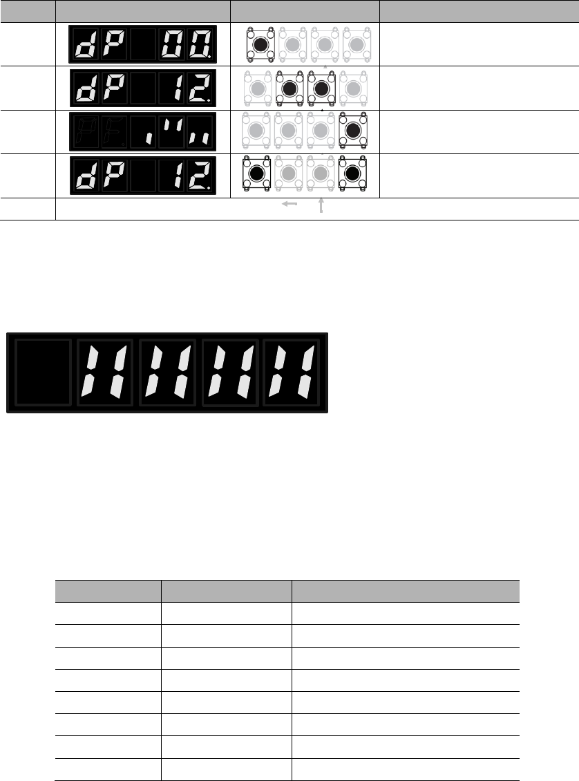
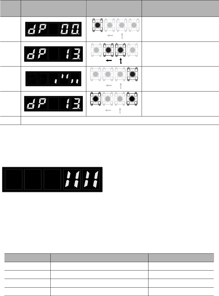
5.2 Input signal monitoring (dP 12)
5.2.1 Operations of entering dP 12
Steps
Panel display
Keys
Operations
SETMOD
SETMOD
SETMOD
SETMOD
5.2.2 Explanations of dP 12 LED displays
1248 7 6 5 3 DI number
Upper: corresponding signal
status
Lower: level of corresponding
signal
o
o
o
o
DI number
Pin (CN2)
Default signal
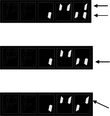
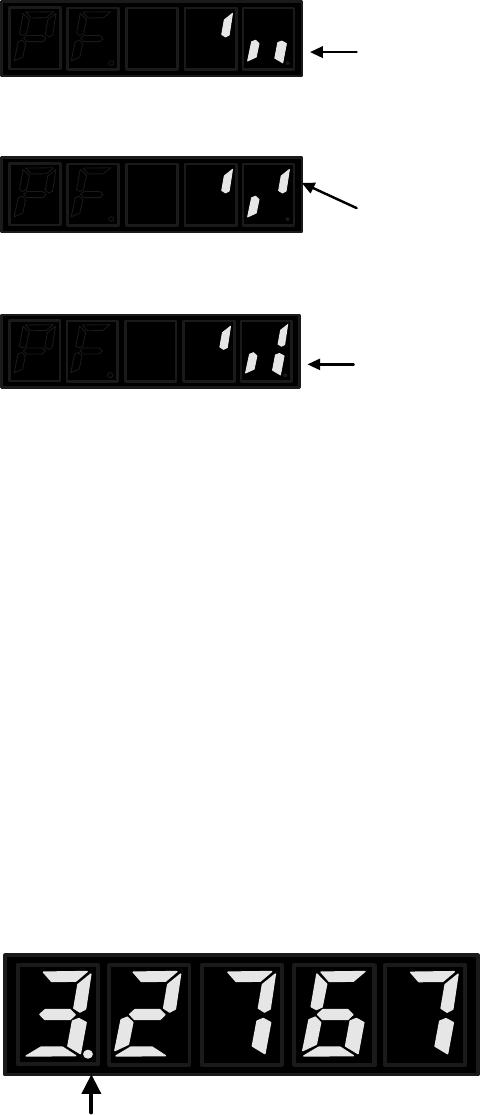
5.2.3 Examples of dP 12 LED displays
1248 7 6 5 3
1248 7 6 5 3
1248 7 6 5 3
5.3 Output signal monitoring (dP 13)
5.3.1 Operations of entering dP 13
Step
s
Panel display
Keys
Operations
SETMOD
SETMOD
SETMOD
SETMOD
5.3.2 Explanations of dP 13 LED displays
124 3 DO number
Upper: corresponding signal
status
Lower: level of corresponding
signal
o
o
o
o
DO number
Pin (CN2)
Default signal
5.3.3 Examples of dP 13 LED displays
124 3
124 3
124 3
5.4 Initial monitoring display at power on
5.5 Display range of dP 01~dP 06
Number is negative.

Chapter 6 Auxiliary functions
6.1 List of auxiliary function parameters
No.
Function
Reference
AF 00
AF 01
AF 02
AF 03
AF 04
AF 05
AF 06
AF 07
AF 08
AF 09
AF 10
AF 11
AF 12
AF 15
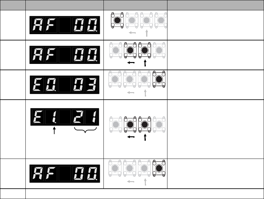
6.2 Display of error logging (AF 00)
Steps
Panel display
Keys
Operations
SETMOD
SETMOD
SETMOD
Alarm sequence Alarm code
SETMOD
SETMOD
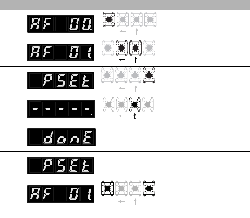
6.3 Position assignment (AF 01)
Steps
Panel display
Keys
Operations
SETMOD
SETMOD
SETMOD
SETMOD
SETMOD

6.4 JOG run (AF 02)
1) Preparing for JOG run
2) JOG run procedures
Steps
Panel display
Keys
Operations
SETMOD
SETMOD
SETMOD
4
This will show if the servo is
running or panel is locked (AF
03).
SETMOD
SETMOD
SETMOD
SETMOD
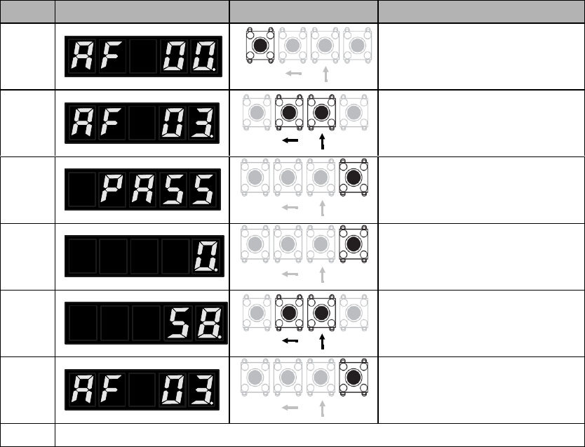
6.5 Panel lock (AF 03)
Steps
Panel display
Keys
Operations
SETMOD
SETMOD
SETMOD
SETMOD
SETMOD
SETMOD
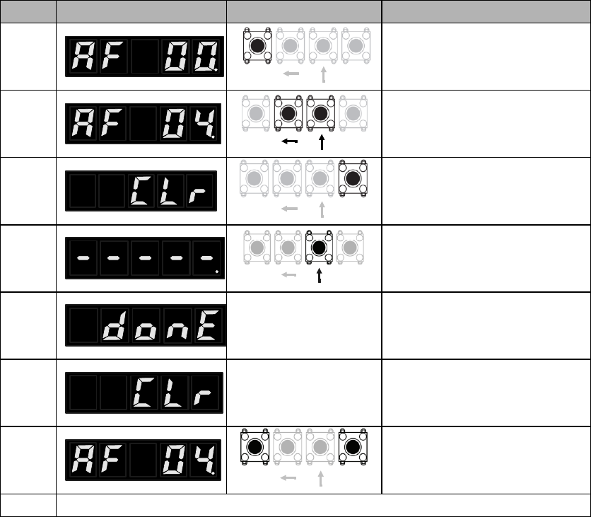
6.6 Clearance of alarm logging (AF 04)
Steps
Panel display
Keys
Operations
SETMOD
SETMOD
SETMOD
SETMOD
SETMOD
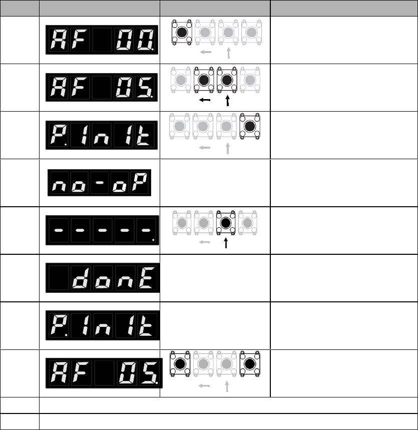
6.7 Parameter initialization (AF 05)
Steps
Panel display
Keys
Operations
SETMOD
SETMOD
SETMOD
4
This will show if the servo is
running or panel is locked (AF
03).
SETMOD
SETMOD
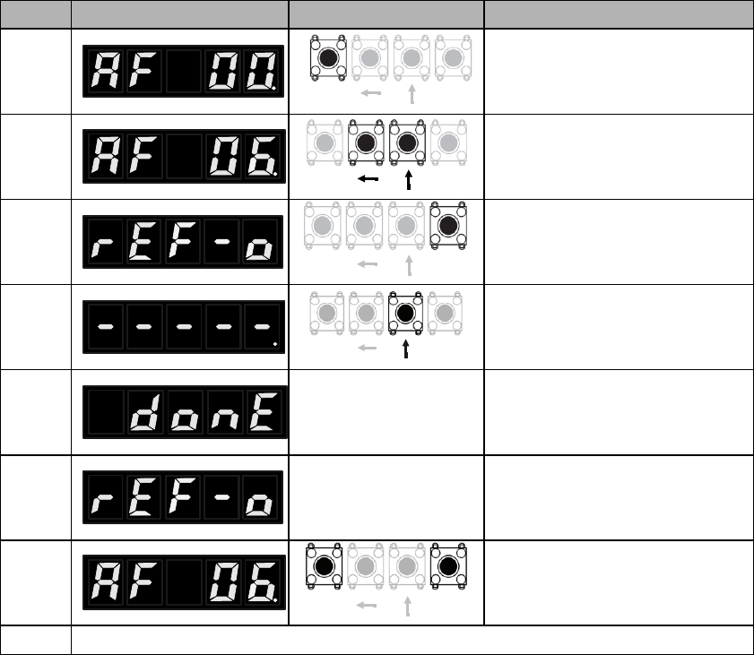
6.8 Analog instruction automatic offset adjustment (AF 06)
Steps
Panel display
Keys
Operations
SETMOD
SETMOD
SETMOD
SETMOD
SETMOD

6.9 Speed instruction manual offset adjustment (AF 07)
Steps
Panel display
Keys
Operations
SETMOD
SETMOD
SETMOD
SETMOD
SETMOD
SETMOD
SETMOD
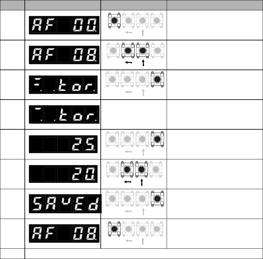
6.10 Torque instruction manual offset adjustment (AF 08)
Steps
Panel display
Keys
Operations
SETMOD
SETMOD
SETMOD
SETMOD
SETMOD
SETMOD
SETMOD
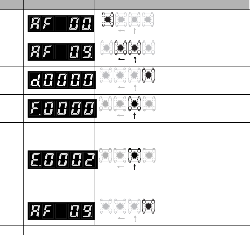
6.11 Overview of relevant motor parameters (AF 09)
Steps
Panel display
Keys
Operations
SETMOD
SETMOD
SETMOD
SETMOD
SETMOD
SETMOD
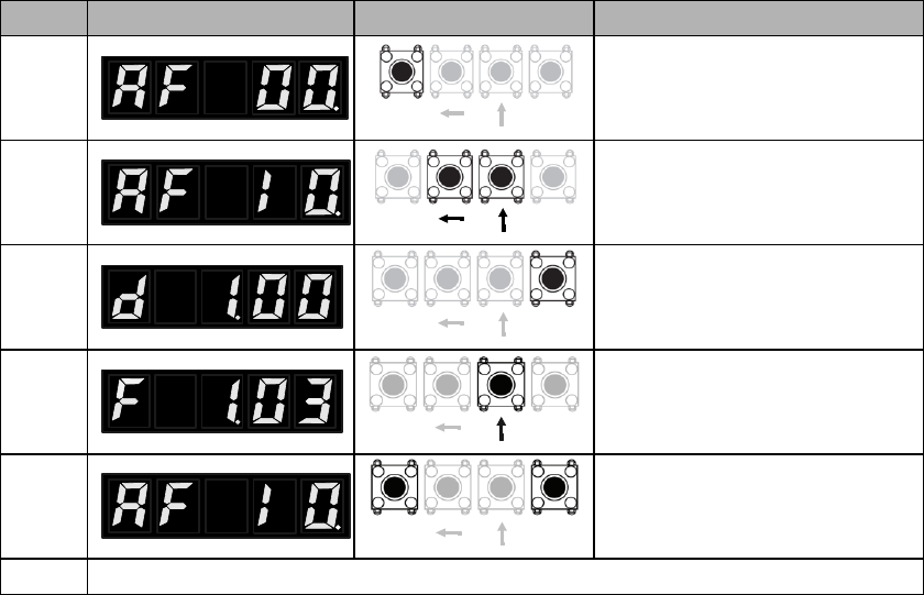
6.12 Display of main software version of servo drive (AF 10)
Steps
Panel display
Keys
Operations
SETMOD
SETMOD
SETMOD
SETMOD
SETMOD
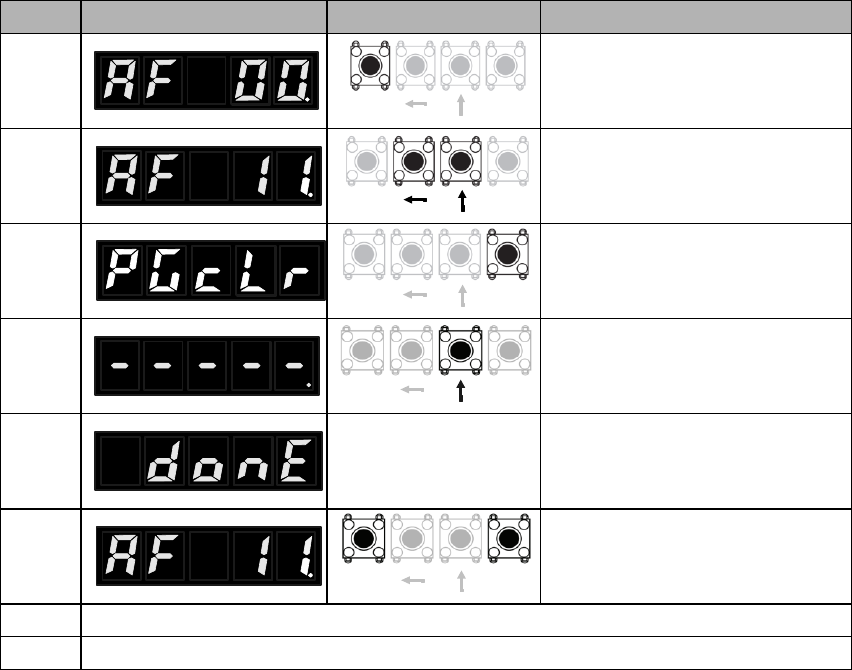
6.13 Setting up absolute encoders (AF 11)
Steps
Panel display
Keys
Operations
SETMOD
SETMOD
SETMOD
SETMOD
SETMOD
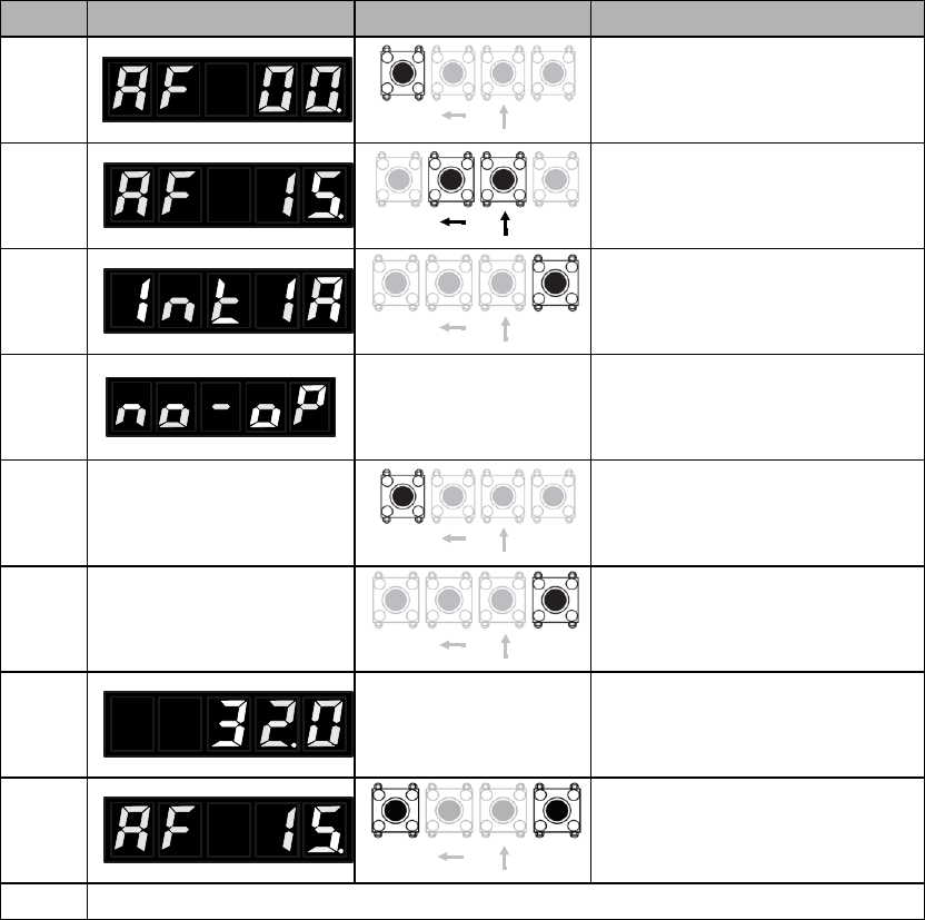
6.14 Manual detection of load inertia (AF 15)
Preparations before operation
Steps
Panel display
Keys
Operations
SETMOD
SETMOD
SETMOD
4
This will show if the servo is
running or panel is locked (AF
03).
SETMOD
SETMOD
SETMOD

Chapter 7 JOG run
7.1 Preparations before JOG run
Item
What to check
7.2 JOG run by panel operations
7.3 Stand-alone JOG run with upper controllers
Item
What to check
7.3.1 Wiring & status check of input signal circuit
Steps
Operations
Reference

7.3.2 JOG run in position control mode
Steps
Operations
Reference

7.3.3 JOG run in speed control mode
Steps
Operations
Reference

7.4 JOG run with mechanical connections
Steps
Items
Operations
Reference
chapter
7.5 JOG run with a holding brake
Item
Remarks

Chapter 8 Servo operations
8.1 Control mode selections
Parameter
Control mode
Refere
nce
PA000.1
h.□□0□
Position control (pulse train instruction)
h.□□1□
Speed control (analog voltage instruction)
h.□□2□
Torque control (analog voltage instruction)
h.□□3□
Internal speed control
h.□□4□
Internal speed control Position control
h.□□5□
Internal speed control Speed control
h.□□6□
Internal speed control Torque control
h.□□7□
Position control Speed control
h.□□8□
Position control Torque control
h.□□9□
Torque control Speed control
h.□□A□
Internal position control
h.□□B□
Internal position control Position control
h.□□C□
Reserved
h.□□D□
Fully closed loop control

8.2 Basic function settings
8.2.1 S-ON settings
Type
Signal
Status
Level
Remarks
Parameter
Remarks
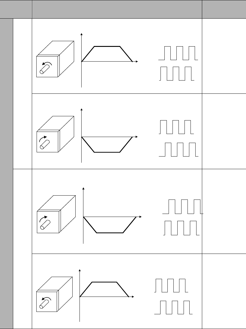
8.2.2 Switch of motor rotational directions
Parameter
Instructions & rotational directions
Overtravel (OT)
h.
Rotational direction at positive instruction
CCW
Time
Speed Encoder pulse output
PAO
PBO
POT
Rotational direction at negative instruction
CW
Time
Speed Encoder pulse output
PAO
PBO
NOT
h.
Rotational direction at positive instruction
CW
Time
Speed Encoder pulse output
PAO
PBO
NOT
Rotational direction at negative instruction
CCW
Time
Speed Encoder pulse output
PAO
PBO
POT
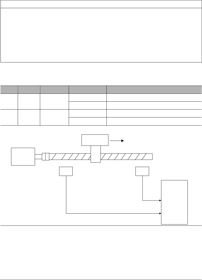
8.2.3 Overtravel (OT) settings
Attention
Installation of limit switches
Limit switches must be installed in applications such as linear motions. When the
to ensure the motor moves to the safer side.
Use of servo motors in vertical axis
Work piece might fall when overtravel. To prevent this, please set the servo into
zero-speed clamp when overtravel.
(1) Wiring for overtravel
Type
Signal
Pin
Setting
Meaning
Input
POT
CN2-34
(default)
ON=L level
Can forward run
OFF=H level
Forward run prohibited (positive overtravel)
Input
NOT
CN2-8
(default)
ON=L level
Can reverse run
OFF=H level
Reverse run prohibited (negative overtravel)
When in overtravel, servo can still move in the opposite direction.
Positive direction
Limit switch
Servo motor Servo drive
POT
NOT
CN1
42
43
Limit switch
Important
There might be position deviation pulse residual at overtravel in position
control. To clear the residual, use CLR signal.
POT, NOT can be allocated to other Pins.
To use POT, NOT, please set PA003.0 & PA003.1 to 0.

(2) Selection of servo stop patterns at overtravel
Parameter
During stop
After stop
Meaning
PA001
d.
d.
DB to stop
DB state
d.
d.
Free state
d.
d.
Coast to stop
d.
Decelerate to
stop
Zero-speed
clamp state
d.
Free state
Please restart the servo drive after modifying this parameter.
If the servo receives S-ON signal during coast to stop, the servo motor can only
be controlled after the speed has decelerated to 0.
Definitions:
o DB: dynamic brake (internal short-circuit of servo drive). This feature is
optional.
o Coast to stop: stop using natural frictions.
o Zero-speed clamp: the state when position instruction is 0 and position
deviation is cleared.
(3) Enable overtravel signal
Parameter
Description
(4) Stop torque setting during overtravel
Emergency Stop Torque
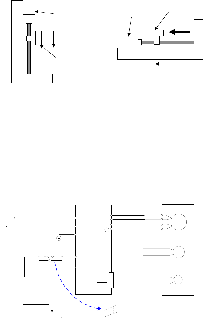
8.2.4 Holding brake settings
Vertical axis
Servo motor
Holding brake
Mechanical
moving part
To prevent
movement due to
gravity at power off
Horizontal axis
To prevent movement due to external
force at power off
Holding brake
Mechanical
moving part
External
force
(1) Example of connection
M
PG
电机
Encoder
L2C
L1C U
V
W
2CN
Servo drive
FG
BK
U
V
W
FG
Servo motor
with brake
BK-RY
+24V
BK-RY
AC DC
+24V
0V
+24V
0V
BK+
BK-
Switching
power supply
Notes:
1. BK-RY: the relay for brake control
2. The current provided by switching power supply shall be determined by the brake;
different brakes have different working currents. Normally, the DC24V of switching power
supply shall be provide the current >1A;
3. DC24V input of the brake is not restricted by direction
1
26
S-RDY
S-ON
BK
Holing brake status
OFF
ON
OFF
OFF OFF
OFF OFF
Holding
Brake release
Holding
ON
ON
*1 *2
*1. The time from BK signal active to brake release is different for different types of brakes.
*2. PA518 value
(2) BK signal output
Type
Signal name
Pin
Setting
Meaning
(3) Allocation of BK signal
Parameter
Pin
Meaning
+
-
PA510
h
CN2-4
CN2-5
BK signal output from CN2-4, CN2-5
h
CN2-3
CN2-2
BK signal output from CN2-3, CN2-2
h
CN2-1
CN2-26
BK signal output from CN2-1, CN2-26
Please refer to Chapter
(4) BK signal hysteresis time after Servo-OFF
PA518
BK signal hysteresis time after Servo-OFF
Range
Unit
Default
0~500
ms
100
S-ON
BK
Motor status
ON OFF
ON OFF
Power on
Power off
PA518
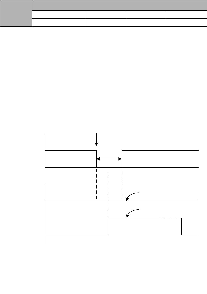
(5) Setting of BK signal timing during the rotation of servo motor
PA519
BK signal speed limit
Range
Unit
Default
0~1000
rpm
100
PA520
BK signal waiting time at Servo-OFF
Range
Unit
Default
100~1000
1ms
500
BK signal will be OFF (H level, nonconductive) in following situations:
• The motor speed is below PA519 after servo OFF
• The waiting time exceeds PA520 after servo OFF
S-ON
Brake status
OFF
ON
Motor speed PA519
PA520
BK
ON OFF
ON OFF

8.2.5 Selection of servo stop patterns at servo OFF
Parameter
During stop
After stop
Meaning
PA001
DB to stop
DB state
Free state
Coast to stop
Free state
Decelerate to
stop
DB state
Decelerate at rate of PA522, & stay in
DB state when speed is lower than
PA523.
Free state
Decelerate at rate of PA522, & coast to
stop when speed is lower than PA523.
This parameter is valid in following situations:
o When S-ON signal is OFF;
o When there is an alarm output;
o When main power (L1, L2, L3) is off.
In the above setting "DB state maintenance after DB stops" of "d.□□□0", if the
servo motor stops or rotates at a very low speed, no brake force will be generated.
Definitions:
o DB: dynamic brake (internal short-circuit of servo drive). This feature is
optional.
o Coast to stop: stop using natural frictions.
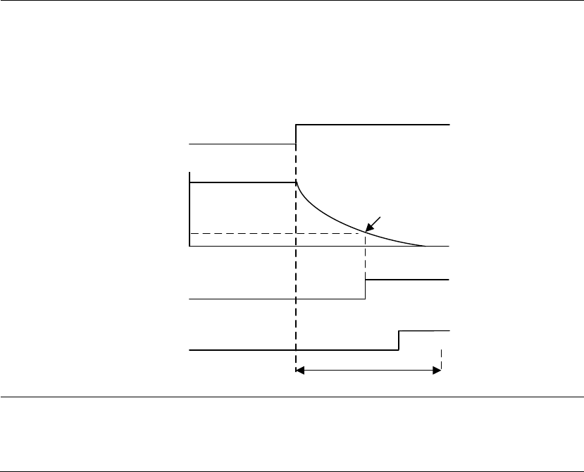
8.2.6 Instantaneous power off settings
PA521
Instantaneous power off holding time
Range
Unit
Default
40~800
1ms
60
Instantaneous
power off
Power off time: t
Main
power
PA521>t
PA521<t
S-ON
S-ON
Servo OFF
Keep on running
Stop running

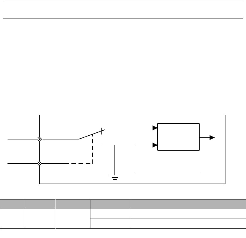
8.2.7 Analog voltage output
Parameter
Meaning
PA021
Analog output is motor speed feedback. (default)
Analog output is motor torque feedback.
Output voltage is not negated. (default)
Output voltage is negated.
PA023
Analog voltage output gain
Range
Unit
Default
=motor speed
PA023
=torque×1000
PA023
PA024
Analog voltage output zero calibration
Range
Unit
Default

8.3 Using absolute encoders
Encoder type
Resolution
Data
output
range
Action when exceed the limit
Absolute encoder
with multi-turn
memory
17-bit
-32768
~+32767
When multi-turn data overflows, E.58 will output. PA007.1 can disable this alarm
Parameter
Meaning
PA007
Multi-turn data overflows will output E.58 (default).
Multi-turn data overflows will not output E.58
8.3.1 Absolute encoder selection
Parameter
Meaning
PA002
Use absolute encoders as incremental encoders. (default)
Use absolute encoders as absolute encoders.
When use absolute encoders as incremental encoders, no battery is needed.
After modifying this parameter, restart the servo to take effect.
8.3.2 Using battery for absolute encoder
(1) Battery selection
(2) Battery installation
8.3.3 Battery replacement
Procedures to replace the battery
Important
8.3.4 Setting up absolute encoders (AF 11)
After AF 11 is done, please restart the servo drive.
8.4 Position control operations
8.4.1 Parameter settings
When using pulses for position control, please pay attention to following parameters.
1) Control mode selection
Parameter
Meaning
PA000
Position control (pulse train)
2) Pulse form selection
Type
Signal
CN2 Pin
Input
Low speed channel
(<500 Kbps)
PULS+
43
PULS-
41
SIGN+
39
SIGN-
37
High speed channel
(<4 Mbps)
HPULS+
38
HPULS-
36
HSIGN+
42
HSING-
40
Parameter
Pulse
form
Forward rotation
Reverse rotation
PA200
PULS+
SIGN
PULS
(CN2-7/8)
SIGN
(CN2-11/12)
PULS
(CN2-7/8)
SIGN
(CN2-11/12)
CW+
CCW
PULS
(CN2-7/8)
SIGN
(CN2-11/12)
PULS
(CN2-7/8)
SIGN
(CN2-11/12)
PULS
(CN2-7/8)
SIGN
(CN2-11/12)
PULS
(CN2-7/8)
SIGN
(CN2-11/12)
PULS
(CN2-7/8)
SIGN
(CN2-11/12)
/2
PULS
(CN1-7/8)
SIGN
(CN1-11/12)
/2

3) Position deviation clearance
Parameter
Meaning
PA200
Clear position deviation when S-ON is off, power is off or by CLR signal.
Clear position deviation only by CLR signal.
Clear position deviation only when servo has alarm or by CLR signal.
4) Input pulse channel selection
User can select input pulse channel by PA200.3.
Parameter
Meaning
PA200
PULS+SIGN input: low speed pulse channel
HPULS+HSIGN input: high speed pulse channel
8.4.2 Electronic gear
1) Encoder resolutions
Parameter
Encoder type
Pulses per revolution
Resolution
PA002
Absolute encoder
32768
131072 (17-bit)
Incremental encoder
32768
131072 (17-bit)
Incremental encoder
5000
20000
Resolver
4096
16384 (15-bit)
Incremental encoder
262144
1048576 (20-bit)
Remarks: encoder resolution is 4 times (quadruple frequency) of encoder pulses per revolution.
2) Electronic gear ratio
The function of electronic gear is for setting the work-piece moving distance by 1
pulse instruction (1 instruction unit).
Instruction processing
PA205
PA206
Pulse input Position
instruction
8.4.3 Position instructions
Upper controller's output forms include the following:
Field-bus output
+24V open-collector output
+12V open-collector output
+5V open-collector output
Open-collector output signals can only connect to servo drive's CN2-43, 41, 39, 37,
and the parameter should be set to low speed pulse channel, i.e. PA200.3=0 (factory
default).
In case of open-collector pulse input, the interference tolerance for input signal will
decrease. In case of deviation due to interference, changes should be made in the
following user parameters.
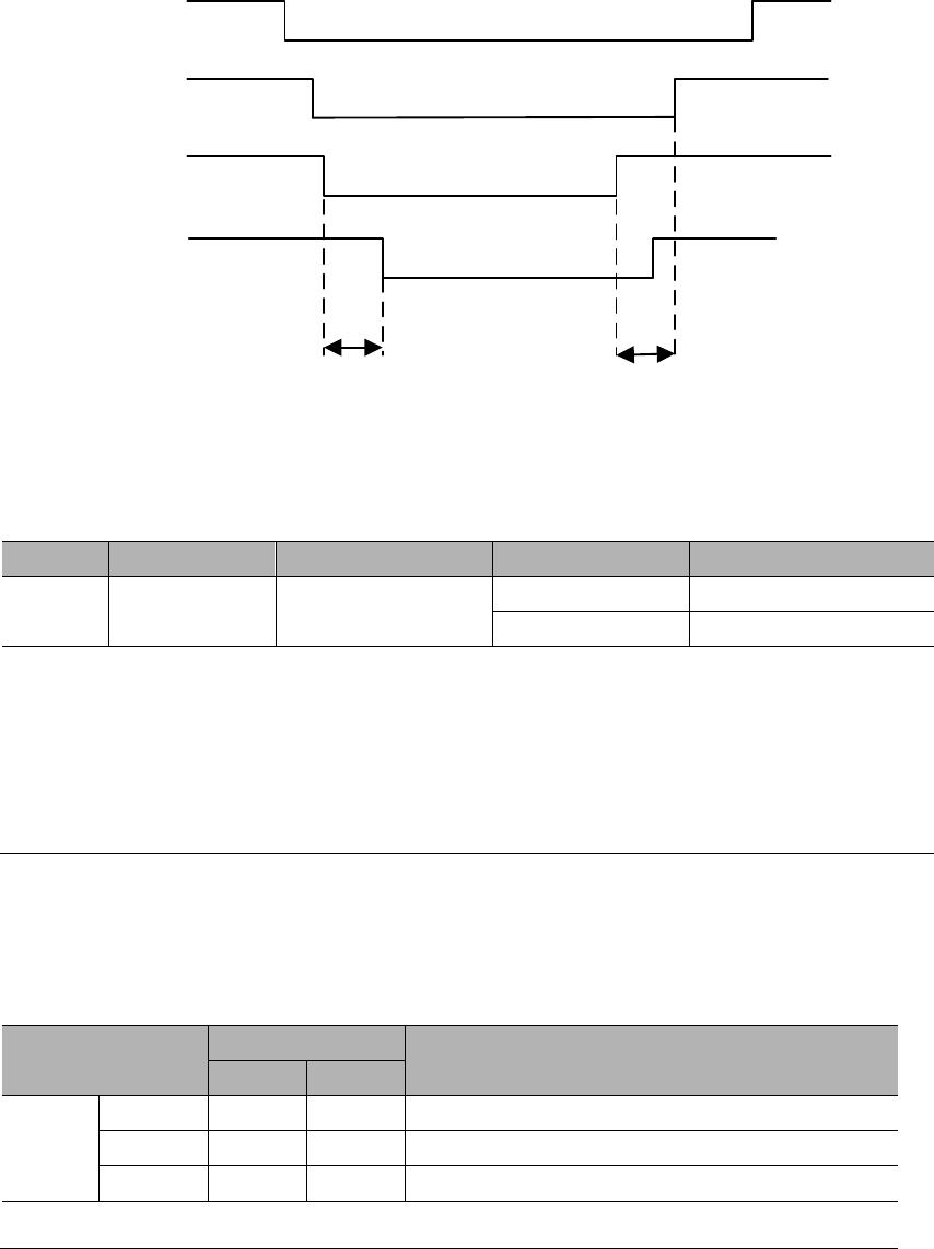
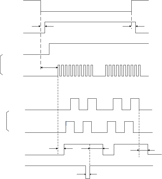
1) Example of I/O signal time sequence
S-ON
ON
Excited
t1 t2
H
H
L
t3
CN2-11,12
CN2-7,8
SIGN+PULS
t3 40ms
t1 30ms
t2 6ms
H
L
L
H
ON ON
t4 t5 t6
t7
Encoder
PAO
PBO
COIN
CLR
OFF
T4, t5, t62ms
t71ms
Motor excitation
The interval between S-ON signal and input pulse instructions should be above
40ms. If this interval is less than 40ms, servo drive may fail to receive the pulse
instructions.
Please set CLR signal to s.
.
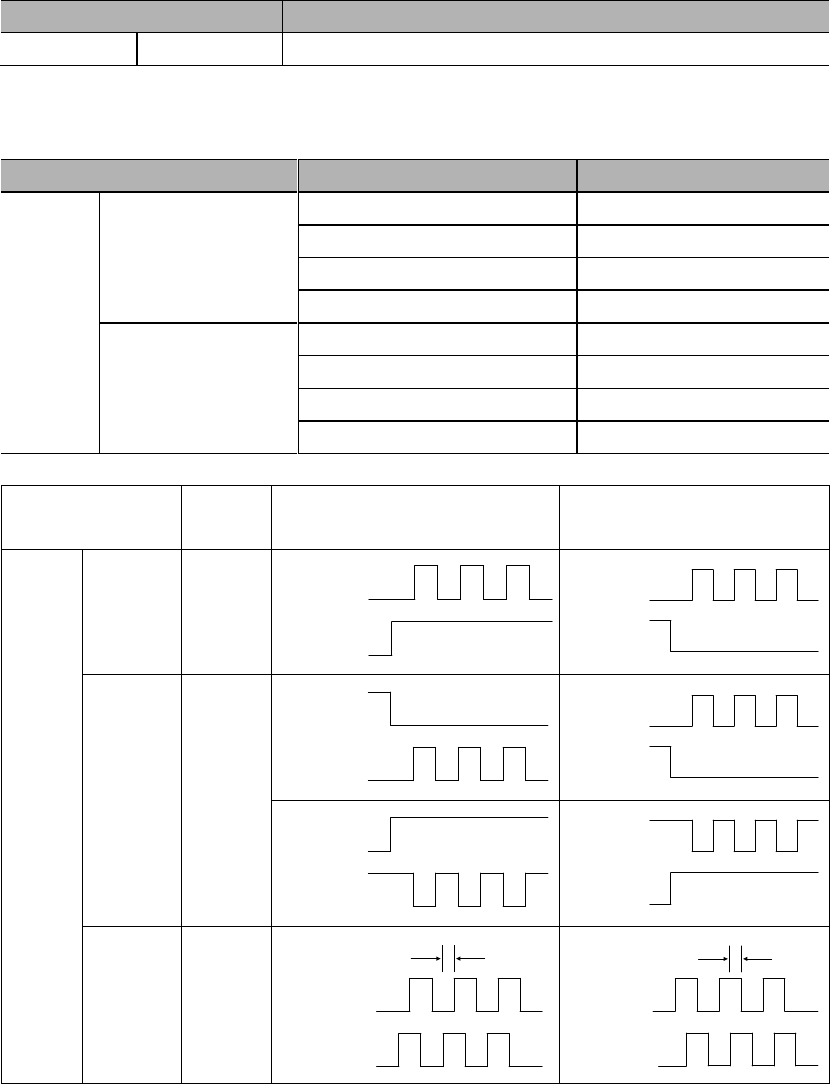
Pulse
forms
Maximum
frequency
Specifications
SIGN+
PULS
SIGN
PULS
t1 t2
t5 t6
t3 t7
t4
T
t1,t2 0.1us
t3,t7 0.1us
t4,t5,t6>3us
tt1.0us
Forward Reverse 50%<(t/T) 100%
CW+
CCW
t1 T
t2 t
t3
Forward Reverse
CCW
CW
t1,t2 0.1us
t3 >3us
t
1.0us
50%<(t/T) 100%
A phase+
B phase
t1 t2
t
T
Forward Reverse
A phase
B phase
t1,t2 0.1us
t1.0us
B phase ahead of A phase by π/2
50%<(t/T)100%
A phase ahead of B phase by π/2
2) Connection examples
8.4.4 Smoothness
PA214
Position instruction acceleration/deceleration time constant 1
Range
Unit
Default
0~1000
0
PA215
Position instruction acceleration/deceleration time constant 2
Range
Unit
Default
0~1000
0
PA216
Position instruction average-moving filter
Range
Unit
Default
0~500
0
If position instruction acceleration/deceleration time constants (PA214, PA215) are
simultaneous pulse input.
In order to truly reflect the set value, please input CLR signal to prohibit pulse
instructions.
Even in the following cases, motor can operate smoothly. Also this setting has no
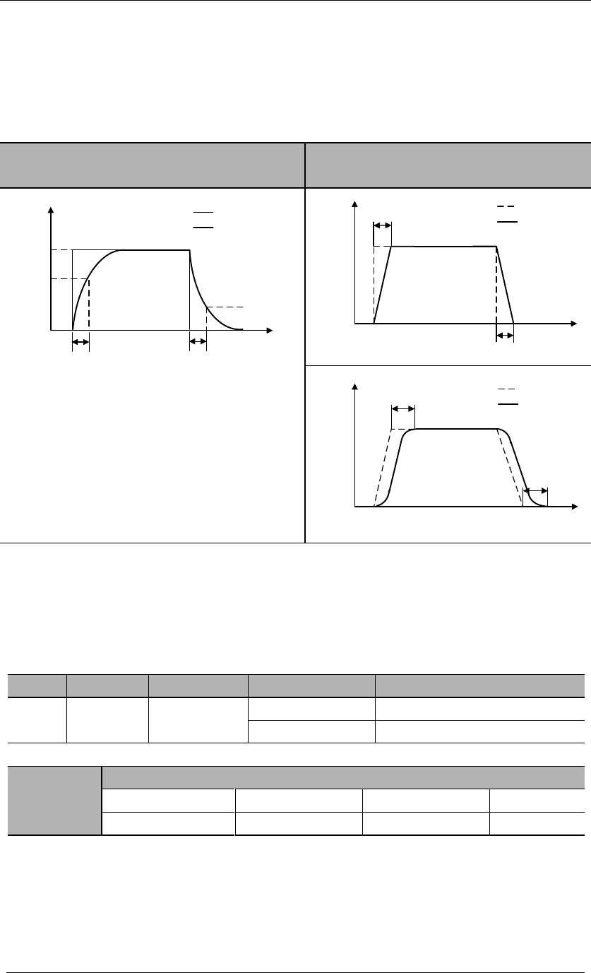
effect on movement amount (instruction pulse count).
The upper controller that sends the instructions
The frequency of instruction pulse is low
The electronic gear ratio is relatively high (more than 10 times)
Effects of PA214, PA215, PA216 are shown as below:
Position instruction acceleration/deceleration
time constants (PA214, PA215)
Position instruction average-moving filter
(PA216)
Before
After
100%
PA214/PA215
63.2%
36.8%
Before
After
100%
PA216
PA216
Before
After
100%
PA216
PA216
8.4.5 Positioning completed signal (COIN)
This signal means that servo motor positioning is completed at position control.
Type
Signal
Pin
Level
Name
Output
COIN
CN2-5, 4
(default)
ON= L level
Positioning completed
OFF=H level
Positioning not completed
PA525
COIN signal width
Range
Unit
Default
0~65535
10
If the
(deviation pulse) is lower than the set value
of this use parameter, then the COIN signal will output; this also depends on the
electronic gear setting.
If the set value of PA525 is too high and servo is running in low speed, COIN
signal may still output even though positioning is not completed. Please pay
close attention to this.
Setting of this user parameter does not affect the final positioning precision.
Please refer to 3.4.3 Allocation of I/O signals.
8.4.6 Positioning near signal (NEAR)
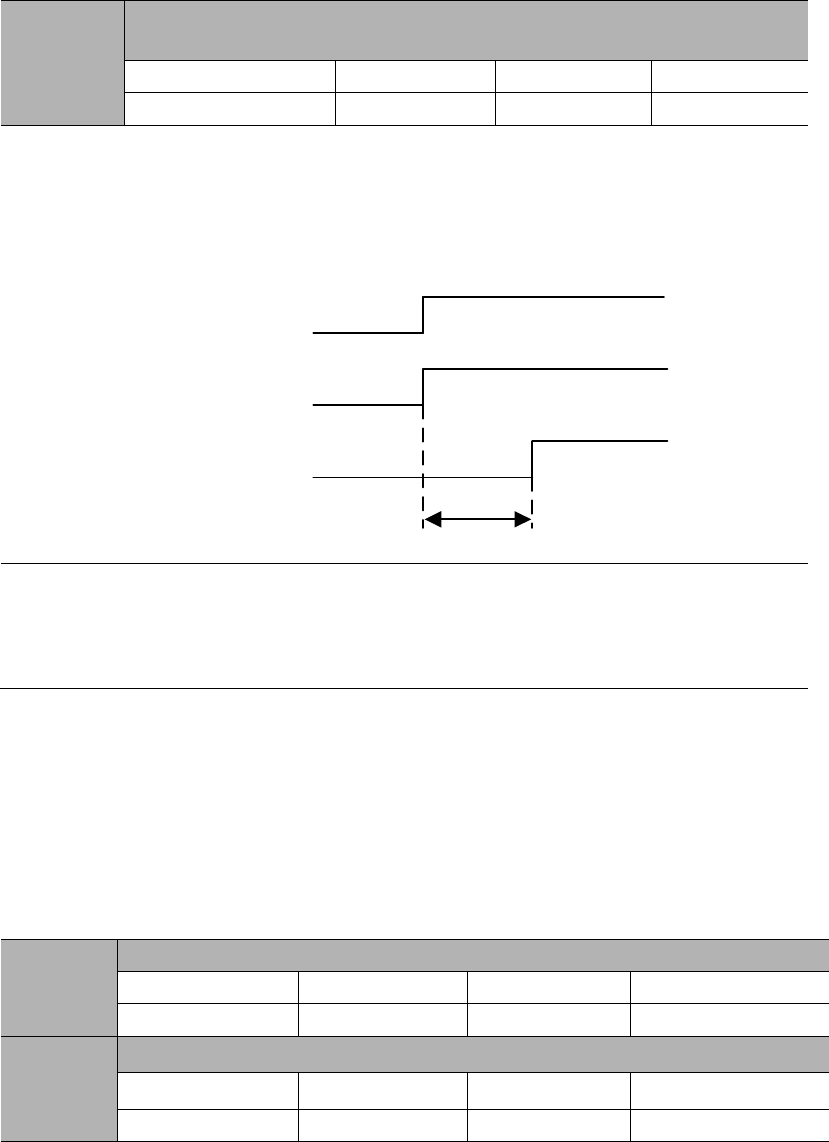
8.4.7 Pulse input inhibited (INHIBIT)
This is a function that stops (inhibits) instruction pulse input counting in case of
position control.
It is in servo locking (clamping) state when this function is used.
Pulse
instruction
INHIBIT
Deviation
counter
Pulse
feedback
OFF
ON
+
–
Type
Signal
Pin
Level
Name
Input
INHIBIT
CN2-31
(default)
ON=L level
INHIBIT is ON
OFF=H level
INHIBIT is OFF
INHIBIT is only valid in position control mode.
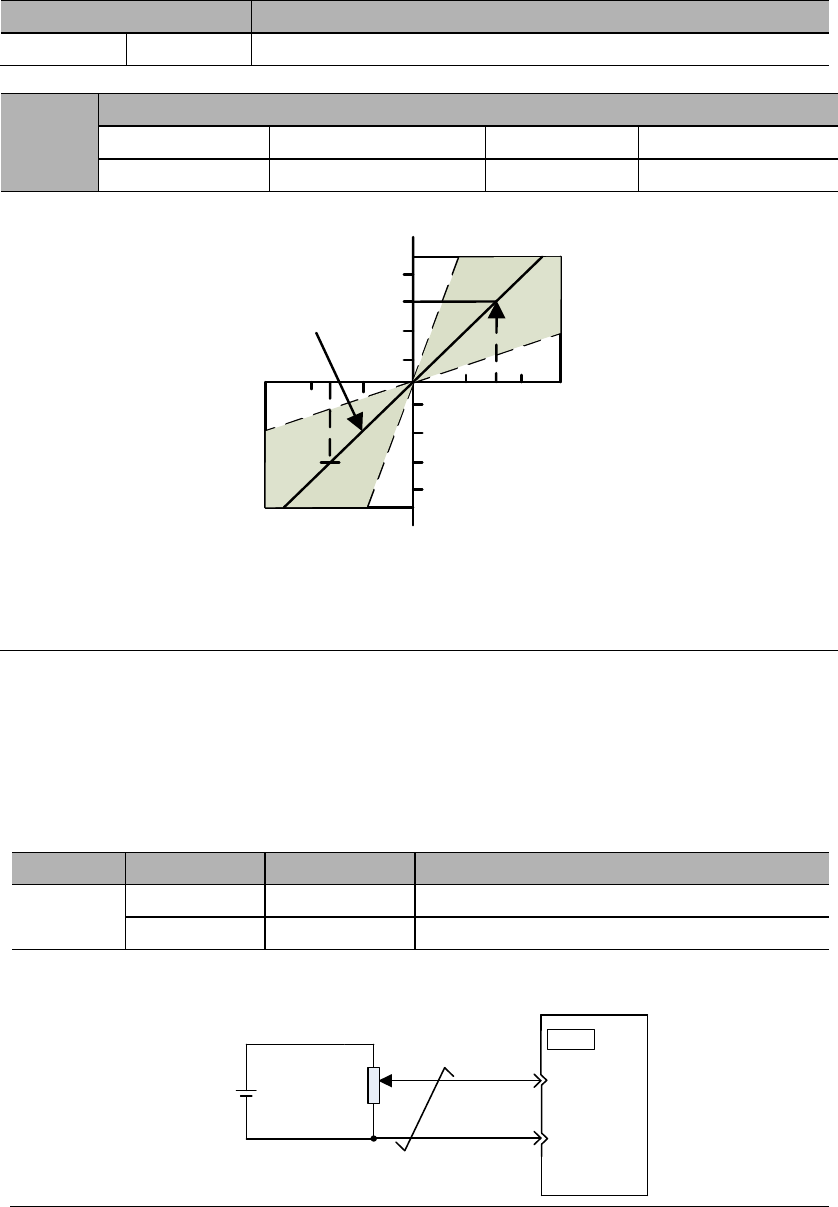
8.5 Speed control operations
8.5.1 Parameter settings
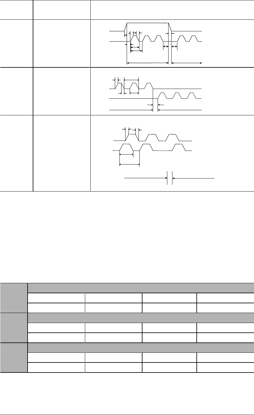
Parameter
Meaning
PA000
Control mode selection: speed control
When PA000.1 = 1, 5, 7, 9, speed control is being used.
PA301
Speed instruction gain
Range
Unit
Default
Effective
150~3000
0.01V/ rated speed
600
-
This parameter is for setting the instruction voltage (V-REF) at motor rated speed.
Rated speed
Default
4 8 12
-4-8-12
Rated speed
Input voltage (V)
The gradient is set
by PA301
Input voltage range: DC±2V ~ ±10V / rated speed
Examples:
PA301=600 means that with 6V input, the motor will at the rated speed (default) ;
PA301=1000 means that with 10V input, the motor will at the rated speed.
8.5.2 Input signals
1) Speed instruction input
If speed instruction is sent to the servo drive, servo motor will run at a speed
proportional to input voltage.
Type
Signal
Pin
Name
Input
V-REF
CN2-20
Speed instruction input
AGND
CN2-29
GND for speed instruction input
Please use multi-strand twisted wire to prevent interferences.
±10V 2K20
Servo drive
V-REF
29
CN2
AGND
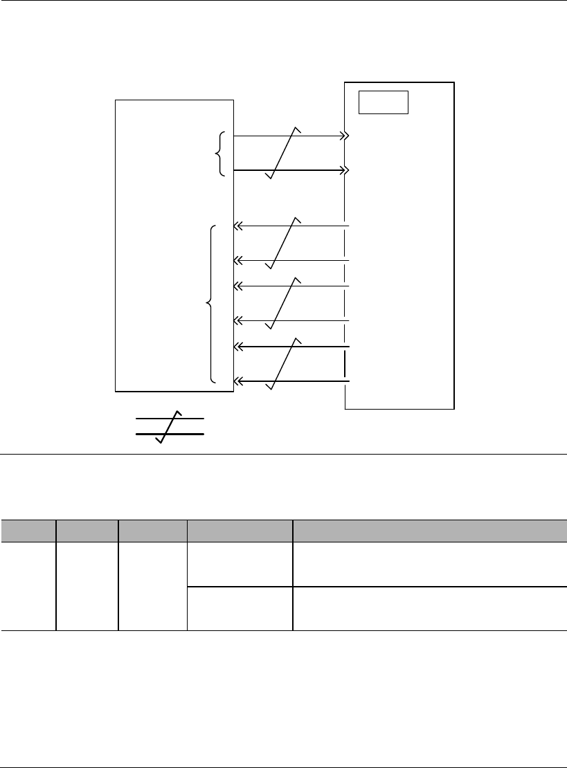
Programmable controller and so on are used for connection with the instruction
controller's speed instruction output terminal in case of position control by
5
Upper controller Servo drive
V-REF
6
CN2
Speed
instruction
input
Feedback
pulse output
34
35
36
33
PAO
PBO
/PBO
/PAO
multi-strand twisted wire
AGND
19
20
PZO
/PZO
2) Proportional action instruction signal (P-CON)
Type
Signal
Pin
Level
Name
Input
P-CON
To be
allocate
d
ON=L level
Operate the servo drive in proportional (P)
mode;
OFF=H level
Operate the servo drive in proportional &
integral (PI) mode
P-CON signal is a signal in respect of which speed control mode is selected
from PI (proportional and integral) or P (proportional) control.
If it’s set to P, then control can relieve motor rotation and slight vibration
caused by speed instruction input drifting.
Input instruction: It can progressively reduce servo motor rotation caused by
drifting at 0V, but servo rigidity (support strength) decreases at stop.
This signal is temporarily unavailable.
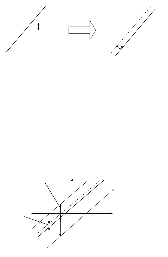
8.5.3 Instruction offset adjustment
When in speed control mode, even with 0V instruction, the motor may still rotate at a
slight speed. This happens when instruction voltage of upper controller or external
circuit has slight (mV unit) deviation (offset). In this case, instruction offset can be
adjusted automatically or manually by using the panel operator. Please use automatic
or manual offset adjust by referring to Chapter 6.8 & 6.9.
Automatic offset adjustment is the function of offset measuring and automatic voltage
adjustment. When the voltage instruction of upper controller and external circuit is
deviated, the servo drive will adjust the offset automatically as follows:
Deviation
Speed
instruction
Instruction
voltage
Internal adjustment
value inside servo drive
Automatic offset
adjustment
Deviation range:
±2046
Instruction
voltage
Speed
instruction
1) Analog instruction automatic offset adjustment (AF 06)
Please refer to Chapter 6.8.
2) Speed instruction manual offset adjustment (AF 07)
Use AF 07 in following situations (Please refer to Chapter 6.9) :
When user wants to set offset to a certain value;
When the offset value is confirmed by AF 06.
Instruction
voltage
Speed
instruction
Offset
adjustment
range
Offset
adjustment
unit
Offset adjustment range: ±2046
Speed instruction: ±750mV
Offset adjustment unit
Speed instruction: 1= 0.05mV
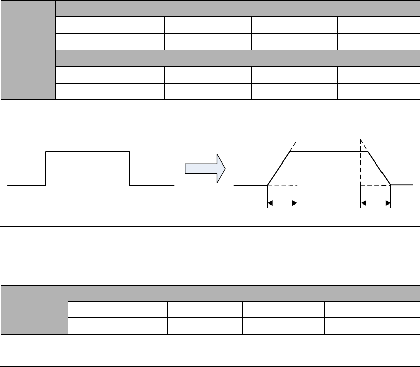
8.5.4 Soft start
Soft start is the function that phase step speed instruction input is transformed to
instruction with certain acceleration and deceleration curves inside servo drive, thus to
achieve smooth operations.
PA303
Soft start acceleration time
Range
Unit
Default
0~5000
1ms
0
PA304
Soft start deceleration time
Range
Unit
Default
0~5000
1ms
0
PA303: Acceleration time from 0rpm to 1000rpm;
PA304: Deceleration time from 1000rpm to 0rpm.
After soft start
PA303 PA304
8.5.5 Speed instruction filter time constant
PA302
Speed instruction filter time constant
Range
Unit
Default
Effective
0~1000
0.01ms
40
Immed
Analog speed instruction (V-REF) is input through 1-time relay filter to smooth
speed instruction. The responsiveness will be reduced if the set value is too large.
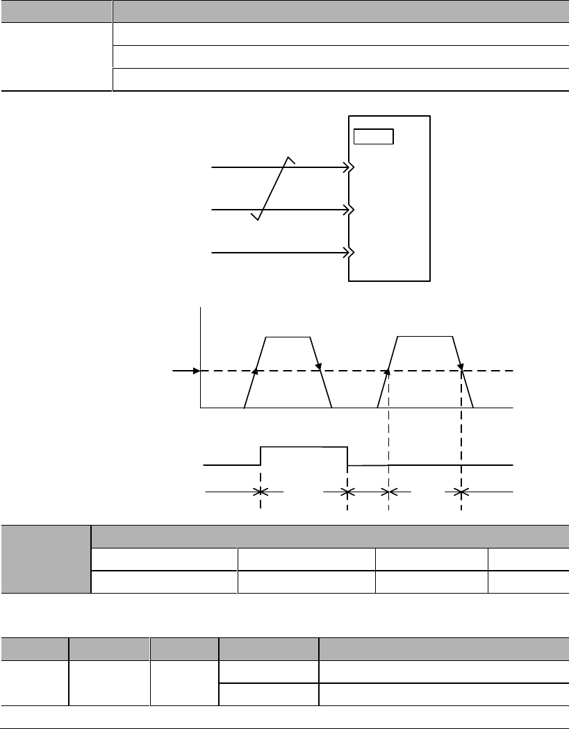
8.5.6 Zero-speed clamp function
This is a function used when upper controller is not configured with position loop in
case of speed control.
If zero-speed clamp (ZEROSPD) (PA300.3=0) signal is set to be ON, or input voltage
of speed instruction (V-REF) (PA300.3 = 1) is below PA316 (zero-speed clamp
grade), servo drive is configured with position loop inside, and speed instruction is
ignored and servo motor is stopped in the servo locking state. The servo motor is
clamped to within ± 1 pulse at the position where zero-speed clamp is effective, and it
will return to the zero-speed clamp position even if turned by external force.
Parameter
Meaning
PA300
Speed control switch 1: speed dead zone control
PA300.3=0: use input signal ZEROSPD
PA300.3=1: automatic, use PA316 setting
Servo drive
V-REF
CN2
ZEROSPD
5
6
AGND
Speed
Time
Zero-speed clamp
grade
V-REF
ZERPSPD signal input
Zero-speed clamp action ON OFF ON ON
OFF
ON OFF
PA316
PA316
Zero-speed clamp grade
Range
Unit
Default
1~2000
30
This is to set the motor into automatic zero-speed clamp state when speed is lower
than PA316 setting. PA316 should be lower than maximum motor speed.
Type
Signal
Pin
Level
Name
Input
ZERPSPD
To be
allocated
ON=L level
Zero-speed clamp function ON
OFF=H level
Zero-speed clamp function OFF
Please refer to 3.4.3 Allocation of I/O signals.
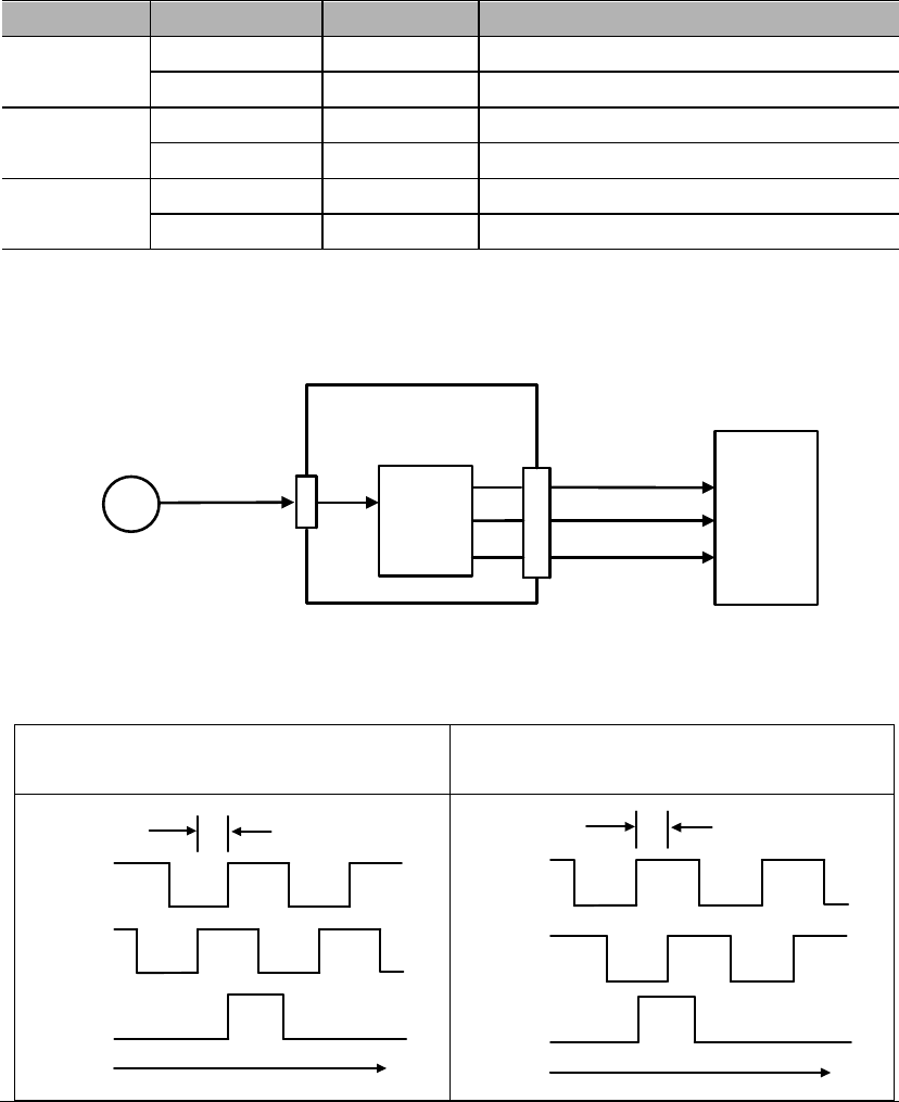
8.5.7 Encoder signal output
Pulse feedbacks from the encoder are processed inside the servo drive before
outputting to the upper controller.
Type
Signal
Pin
Name
Output
PAO
CN2-21
Encoder Output A Phase
/PAO
CN2-22
Encoder Output /A Phase
Output
PBO
CN2-25
Encoder Output B Phase
/PBO
CN2-23
Encoder Output /B Phase
Output
PZO
CN2-13
Encoder Output Z Phase (reference point)
/PZO
CN2-24
Encoder Output /Z Phase (reference point)
Frequency
division
Servo drive
A phase(PAO)
B phase(PBO)
Z phase(PZO)
Upper
controller
CN2
CN3
PG Data
Encoder
Output phase status
Positive rotation
()
Negative rotation
(A B phase)
t
A phase
B phase
90。
Z phase
t
A phase
B phase
90。
Z phase
Please phase pulse
output for mechanical reference point reset action. If this due to the
structure of the mechanical system, please implement reference point reset action at
speed below 600rpm ().
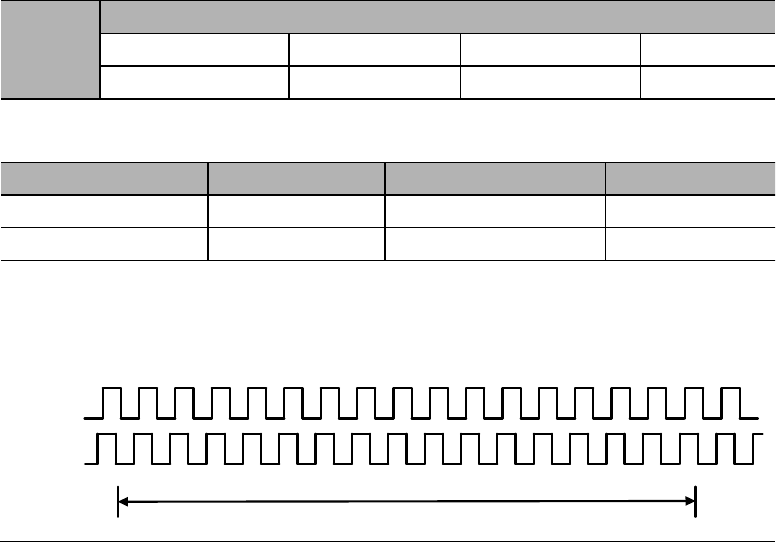
Frequency division
This is a transformation process of the encoder pulse feedbacks by changing the
density of pulses. The parameter is PA210.
Encoder resolution (frequency-division) setting
PA210
Encoder resolution (frequency-division) setting
Range
Unit
Default
16~16384
1Pulse/ rev
16384
The setting range is dependent on the encoder resolution.
Encoder specification
Resolution
Pulse per revolution
Range
Line-saving encoder
20000
5000ppr
16~5000
17-bit
131072
32768ppr
16~16384
Example: PA210=16
PAO
PBO
PA 210 Value: 16
1 revoluion
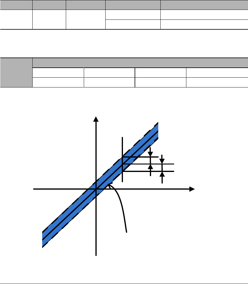
8.5.8 Speed instruction reached (VCMP)
When motor rotation speed is same as speed instruction, VCMP will output
Type
Signal
Pin
Level
Name
Output
VCMP
To be
allocated
ON=L level
Same speed
OFF=H level
Not same speed
VCMP needs to be allocated by PA510. Please refer to 3.4.3 Allocation of I/O
signals.
PA517
VCMP signal detection width
Range
Unit
Default
0~100
10
If the difference between motor speed and instruction speed is less than PA517
value, VCMP will output.
Motor speed
PA517
Speed
instruction
VCMP will output in
this range
For example,
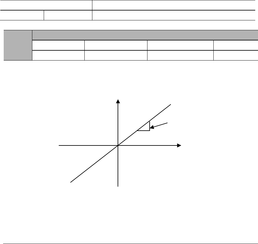
8.6 Torque control operations
8.6.1 Parameter settings
Parameter
Meaning
PA000
Control mode selection: torque control
PA400
Torque instruction gain
Range
Unit
Default
This parameter is for setting the instruction voltage (T-REF) at motor rated torque.
PA400
Instruction
voltage (V)
Torque
instruction
Examples
PA400=30: Input 3VDC will output rated torque (Default)
PA400=100: Input 10VDC will output rated torque
PA400= 20: Input 2VDC will output rated torque
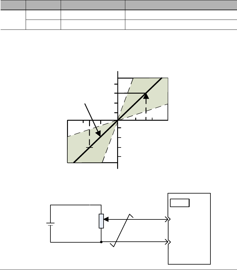
8.6.2 Input signals
Type
Signal
Pin
Name
Input
T-REF
CN2-18
Torque instruction input
AGND
CN2-19
GND for torque instruction input
When PA000.1 = 2, 6, 8, 9, torque control is being used.
Input voltage range: DC±2V ~ ±10V / rated torque
Torque
instruction (%)
Default
4 8 12
-4-8-12
Input voltage
(V)
100
200
300
-100
-200
-300
±10V2K9
Servo drive
T-REF
10
CN2
AGND
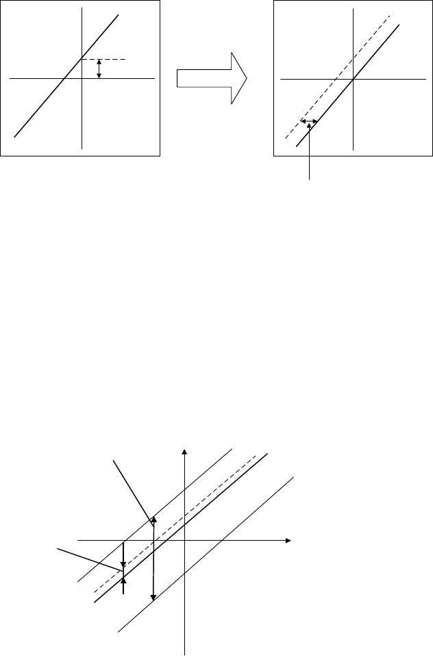
8.6.3 Instruction offset adjustment
When in torque control mode, even with 0V instruction, the motor may still output at
a slight torque. This happens when instruction voltage of upper controller or external
circuit has slight (mV unit) deviation (offset). In this case, instruction offset can be
adjusted automatically or manually by using the panel operator. Please use automatic
or manual offset adjust by referring to Chapter 6.8 & 6.10.
Automatic offset adjustment is the function of offset measuring and automatic voltage
adjustment. When the voltage instruction of upper controller and external circuit is
deviated, the servo drive will adjust the offset automatically as follows:
Deviation
Torque
instruction
Instruction
voltage
Internal adjustment
value inside servo drive
Automatic offset
adjustment
Deviation range:
±2046
Instruction
voltage
Torque
instruction
1) Analog instruction automatic offset adjustment (AF 06)
Please refer to Chapter 6.8.
2) Torque instruction manual offset adjustment (AF 08)
Use AF 08 in following situations (Please refer to Chapter 6.10) :
When user wants to set offset to a certain value;
When the offset value is confirmed by AF 06.
Instruction
voltage
Torque
instruction
Offset
adjustment
range
Offset
adjustment
unit
Offset adjustment range: ±2046
Torque instruction: ±750mV
Offset adjustment unit
Torque instruction: 1= 0.05mV

8.6.4 Speed limit in torque control mode
When servo motor needs to be output torque following torque instructions, motor's
rotating speed is not controlled. If instruction torque is too large due to the load torque
at mechanical side, motor's rotating speed may increase too much. As a protection
measure at mechanical side, servo motor's rotating speed needs to have limits in
torque control mode.
With no speed limit
With speed limit
Over mechanical speed
limit, may cause damage!
t
Motor speed
(rpm)
Maximum
speed
Wont be over
mechanical speed limit!
t
Motor speed
(rpm)
Speed limit
Speed limit in torque control mode selection
Parameter
Meaning
PA002
Use PA407 as speed limit (internal speed limit)
Use V-REF & PA301 setting as speed limit (external speed limit)
Speed limit in torque control mode
PA407
Speed limit in torque control mode
Range
Unit
Default
0~5000
1500
External speed limit
Type
Signal
Pin
Name
Input
V-REF
CN2-5
External speed limit
AGND
CN2-6
GND for external speed limit
PA301
Speed instruction gain
Range
Unit
Default
150~3000
0.01 V/rated speed
600
Output signal when speed is in limit
Type
Signal
Pin
Level
Name
Output
VLT+
To be allocated
ON=L level
In speed limit status
VLT
-
To be allocated
OFF=H level
Not in speed limit status
This signal is temporarily unavailable.
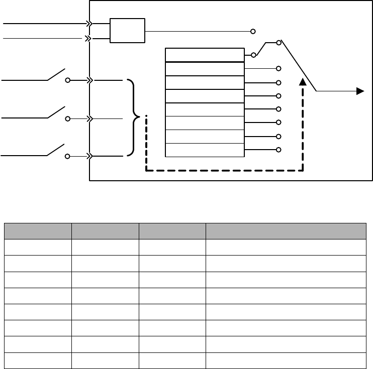
8.7 Internal speed control
Internal speed control is to set 8 speeds beforehand through parameters inside servo
drive and to select among them by using external input signals INSPD2, INSPD1 and
INSPD0.
Servo drive
INSPD0
INSPD1
INSPD2
SPEED0 PA307
Internal speed register
SPEED1 PA308
SPEED2 PA309
SPEED3 PA310
SPEED4 PA311
SPEED5 PA312
SPEED6 PA313
SPEED7 PA314
Speed
instruction
V-REF
AGND AD PA315.0
External analog
INSPD2
INSPD1
INSPD0
Internal speed selection
0 (Invalid)
0 (Invalid)
0 (Invalid)
Internal speed 0 (PA307)
0 (Invalid)
0 (Invalid)
1 (Valid)
Internal speed 1 (PA308)
0 (Invalid)
1 (Valid)
0 (Invalid)
Internal speed 2 (PA309)
0 (Invalid)
1 (Valid)
1 (Valid)
Internal speed 3 (PA310)
1 (Valid)
0 (Invalid)
0 (Invalid)
Internal speed 4 (PA311)
1 (Valid)
0 (Invalid)
1 (Valid)
Internal speed 5 (PA312)
1 (Valid)
1 (Valid)
0 (Invalid)
Internal speed 6 (PA313)
1 (Valid)
1 (Valid)
1 (Valid)
Internal speed 7 (PA314)

8.7.1 Parameter settings
Parameter
Meaning
PA000
Control mode selection: internal speed control
PA307
Internal speed 0
Range
Unit
Default
-5000~5000
100
PA308
Internal speed 1
Range
Unit
Default
-5000~5000
200
PA309
Internal speed 2
Range
Unit
Default
-5000~5000
300
PA310
Internal speed 3
Range
Unit
Default
-5000~5000
400
PA311
Internal speed 4
Range
Unit
Default
-5000~5000
500
PA312
Internal speed 5
Range
Unit
Default
-5000~5000
600
PA313
Internal speed 6
Range
Unit
Default
-5000~5000
700
PA314
Internal speed 7
Range
Unit
Default
-5000~5000
800
PA307~PA314 settings should not exceed maximum motor speed.
8.7.2 Input signals
Type
Signal
Pin
Definitions
Input
INSPD0
To be allocated
Internal speed register 0
INSPD1
To be allocated
Internal speed register 1
INSPD2
To be allocated
Internal speed register 2
Please refer to 3.4.3 Allocation of I/O signals.
8.8 Internal position control
PA000.1=A
Internal position control switches & selections (PA700, PA770)
1)
2)
3)
■ Internal position distance settings (PA701 to PA732)
1)
2)
3)
Internal position speeds (PA733 to PA748)
Internal position acceleration/deceleration time (PA749 to PA764)
Internal position stop (dead zone) time (PA765)
=

8.8.1 Parameter settings
Parameter
Meaning
PA000
Control mode selection: internal position control
Parameter
Meaning
PA700
INPOS selects internal position section.
PTRG triggers internal position run and in cycle.
Internal position runs in cycles at internal timing.
Incremental position
Absolute position
Cycle run starting position
Cycle run ending position
PA701
Internal position 0 distance low place
Range
Unit
Default
0x0000~0xFFFF
0x4E20
PA702
Internal position 0 distance high place
Range
Unit
Default
0x0000~0xFFFF
0x0000
PA731
Internal position 15 distance low place
Range
Unit
Default
0x0000~0xFFFF
0xE200
PA732
Internal position 15 distance high place
Range
Unit
Default
0x0000~0xFFFF
0x0004
PA733
Internal position 0 speed
Range
Unit
Default
0~5000
100
PA748
Internal position 15 speed
Range
Unit
Default
0~5000
100
PA749
Internal position 0 acceleration/deceleration time
Range
Unit
Default
0~500
0
PA764
Internal position 15 acceleration/deceleration time
Range
Unit
Default
0~500
0
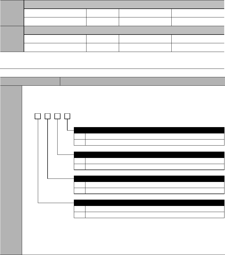
PA765
Internal position dead zone time
Range
Unit
Default
0~65335
100
PA768
JOG speed in internal position control mode
Range
Unit
Default
0~5000
100
Value of PA733~PA748 shall not exceed maximum motor speed.
Parameter
Meaning
PA770
Internal position control switch 2
b. 3 2 1 0
0
1
0
1
Stop.
Pause.
Trigger signal selection
Use PTRG
Use internal position selection signals: INPOS0、INPOS1、INPOS2、INPOS3
0
1
Trigger time sequence selection
Only receive new trigger signal when current position is completed (CMD-OK)
Can receive new trigger even though current position is not completed
PZERO function selection
0
1
Software position limit enabling
No enabling.
Can enable. PA756, PA757 are positive limits; PA758, PA759 are negative limits.

8.8.2 Input signals
Type
Signal
Pin
Level
Meaning
Input
ZPS
To be
allocated
ON=L level
External zero switch signal ON
OFF=H level
External zero switch signal OFF
PZERO
To be
allocated
ON=L level
Internal position control stops: valid
OFF=H level
Internal position control stops: invalid
INPOS0
To be
allocated
ON=L level
INPOS0 signal valid
OFF=H level
INPOS0 signal invalid
INPOS1
To be
allocated
ON=L level
INPOS1 signal valid
OFF=H level
INPOS1 signal invalid
INPOS2
To be
allocated
ON=L level
INPOS2 signal valid
OFF=H level
INPOS2 signal invalid
INPOS3
To be
allocated
ON=L level
INPOS3 signal valid
OFF=H level
INPOS3 signal invalid
PTRG
To be
allocated
OFF (H level)
to ON (L level)
PTRG signal valid
P-POS
To be
allocated
ON=L level
P-POS signal valid
OFF=H level
P-POS signal invalid
N-POS
To be
allocated
ON=L level
N-POS signal valid
OFF=H level
N-POS signal invalid
SHOME
To be
allocated
OFF (H level)
to ON (L level)
SHOME signal valid
Please refer to 3.4.3 Allocation of I/O signals.
External zero switch signal (ZPS)
Internal position control stops (PZERO)
When PZERO is valid in internal position control, the motor stops and stays in clamping
status. PA770.2 can select whether this is a stop or pause.
If PA770.2=0 (stop), homing process needs to restart after PZERO becomes invalid
again.
If PA770.2=1 (pause), homing process will continue after PZERO becomes invalid
again.
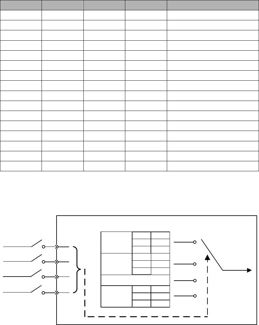
Internal position register (INPOS0、INPOS1、INPOS2、INPOS3)
INPOS0, INPOS1, INPOS2, INPOS3 combines to achieve 16-position control
INPOS3
INPOS2
INPOS1
INPOS0
Internal position selection
This is illustrated as below:
Servo drive
INPOS0
INPOS1
INPOS3
Parameters
related to
position 0
Internal position register
Position
instruction
PA701 PA702
PA733 PA749
PA765
Parameters
related to
position 1
PA703 PA704
PA734 PA750
PA765
Parameters
related to
position 15
PA731 PA732
PA748 PA764
PA765
INPOS2
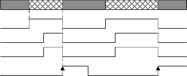
Internal position control trigger (PTRG)
When PA700.0=0 or 1, and PA770.1=0 in internal positon control mode, the rising edge
is valid.
Time sequence of PTRG is illustrated below:
Target position
CMD_OK
COIN
MC_OK
OFF
OFF
ON
Position X
Trigger signal:
(PTRG or INPOS)Rising edge
Null Position Y Null Position Z
OFF
ON
OFF ON
ON
ON
Rising edge
Internal position control Forward JOG (P-POS)
In internal position control mode, even during homing or internal position sections,
when P-POS signal becomes valid, position instruction will cut to forward JOG
immediately and all current running instructions will be canceled and the cycle run will
restart to starting point. PA768 is JOG speed in internal position control mode.
Internal position control Reverse JOG (N-POS)
Internal position control homing start (SHOME)
In internal position control mode, when SHOME signal becomes valid, all current
running instructions will be canceled

8.8.3 Output signals
Type
Signal
Pin
Status
Meaning
Output
To be
allocated
Valid
Internal position control homing completed
Invalid
Internal position control homing not completed
To be
allocated
Valid
Internal position control instruction completed
Invalid
Internal position control instruction not completed
To be
allocated
Valid
Internal position control positioning & command
completed
Invalid
Internal position control positioning & command
not completed
Please refer to 3.4.3 Allocation of I/O signals.
Internal position control homing completion signal (HOME)
When homing is completed, and position coordinates are valid, and position counter is
valid, this signal is ON.
This signal is OFF at power on;
When homing is completed, this signal is ON;
After running one position section, this signal is OFF;
When SHOME triggers, this signal is OFF;
When homing is completed again, this signal is ON;
When inputting PZERO to stop homing, this signal is OFF.
Internal position control instruction completion signal (CMD-OK)
This signal only means the completion of instructions, not necessarily actual motor
positioning.
Internal position control positioning & command completion (MC-OK)
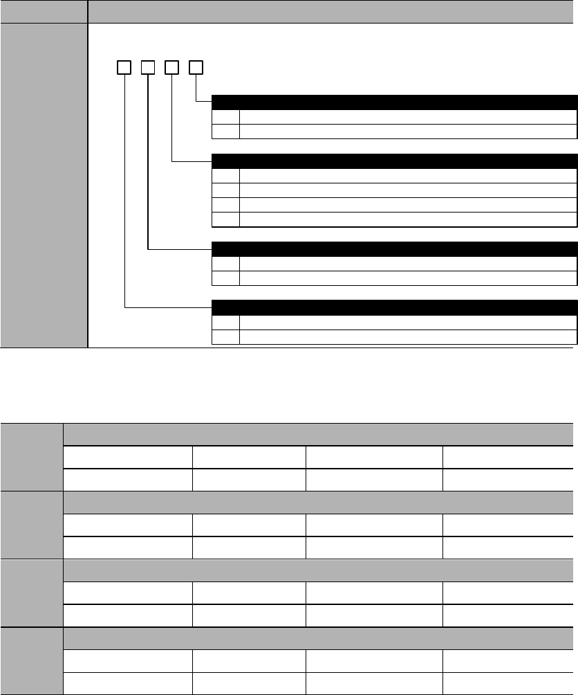
8.9 Homing function
■ Homing mode selections
Parameter
Meaning
PA771
d. 3 2 1 0
0
1
0
1
Forward rotation
Reverse rotation
Homing pattern selection
After contacting zero switch, look for Z pulse by rotating backward
After contacting zero switch, look for Z pulse by rotating forward
Homing rotational direction
0
1
Homing completion operation
Clear all position data
Not clear all position data
0
1
Homing signal selection
Use ZPS
Use Z pulse
2
3
After contacting zero switch, rotate backward, not look for Z pulse
After contacting zero point switch, rotate forward, not look for Z pulse
■ Other homing parameters
PA775
Homing speed before contacting zero signal
Range
Unit
Default
0~3000
500
PA776
Homing speed after contacting zero signal
Range
Unit
Default
0~500
30
PA777
Zero switch offset low place
Range
Unit
Default
0x0000~0xFFFF
0
PA778
Zero switch offset high place
Range
Unit
Default
0x0000~0x1FFF
0

Important
When PA775, PA776 settings exceed maximum speed of the servo motor,
maximum speed.
Zero position offset directions are determined by homing directions.
Homing functions are suitable for internal position control (junction instruction)
and position control (pulse instruction).
During homing, servo drive does not receive pulse commands.
■ Description of the homing process
-
-
-
-
-
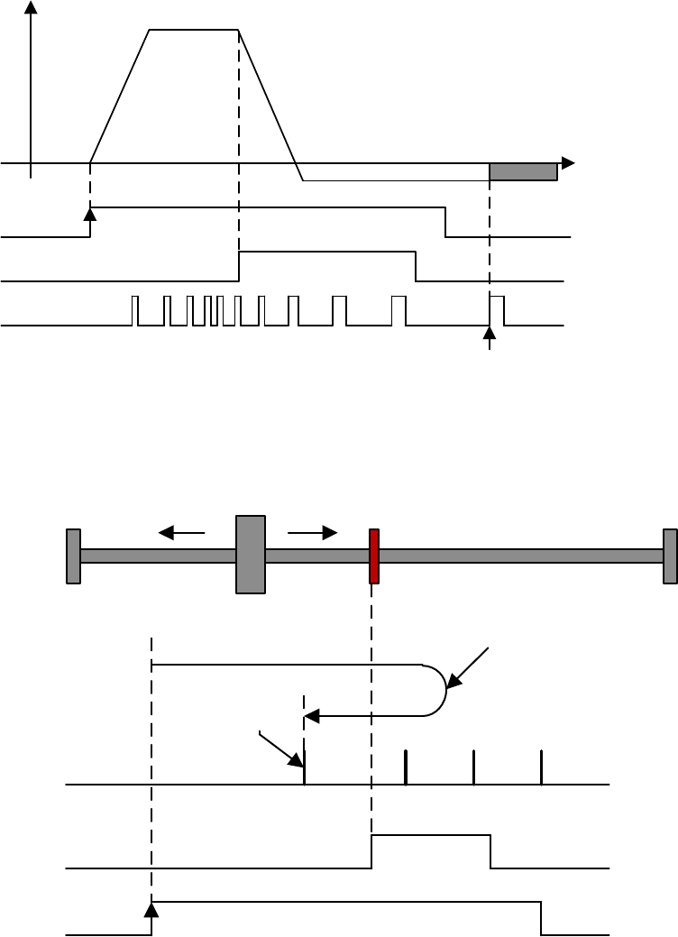
PA771.1=0: After contacting zero switch, look for Z pulse by rotating
backward.
Motor speed
(rpm)
0
PA775
PA776
Zero-switch offset
(PA777 & PA778)
SHOME
ZPS
Z pulse
After ZPS is invalid, the first Z
pulse to start calculating offset
Rising edge
Invalid Invalid
Valid
Zero switch
Z pulse
ZPS
SHOME
Motor decelerates and
moves backward
Rising edge
After ZPS is
invalid, the first
Z pulse to start
calculating
offset
Invalid Invalid
Valid
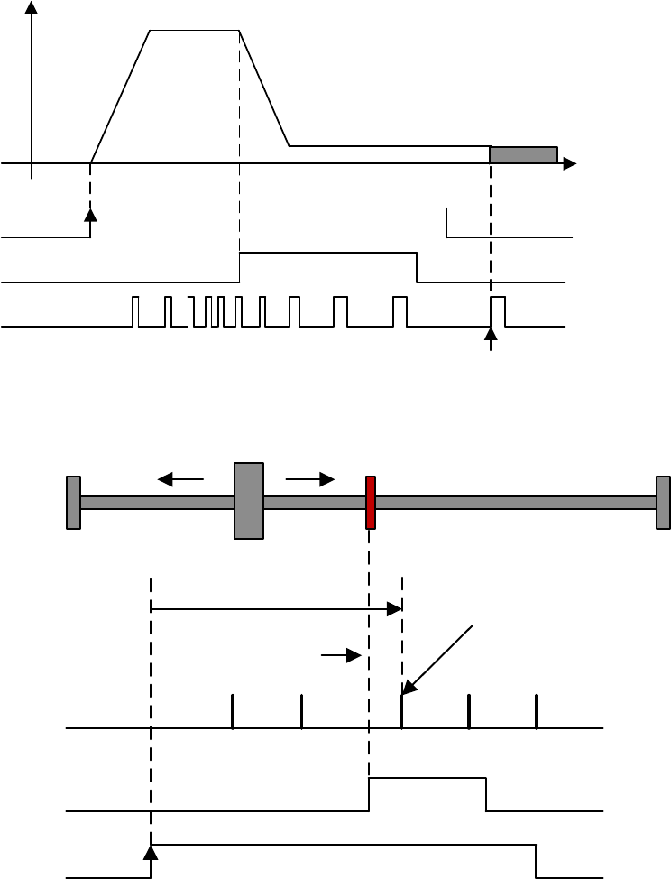
PA771.1=1: After contacting zero switch, look for Z pulse by rotating forward.
Motor speed
(rpm)
0
PA775
PA776
Zero-switch offset
(PA777 & PA778)
SHOME
ZPS
Z pulse
After ZPS is invalid, the first Z pulse
to start calculating offset
Rising edge
Invalid Invalid
Valid
Zero swtich
Z pulse
ZPS
SHOME
Motor
decelerates
Rising edge
Move forward to
look for Z pulse After ZPS is invalid,
the first Z pulse to start
calculating offset
Invalid Invalid
Valid
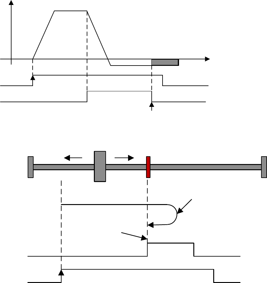
PA771.1=2: After contacting zero switch, rotate backward, not look for Z pulse.
Motor speed
(rpm)
0
PA775
PA776
Zero switch offset
(PA777 & PA778)
SHOME
ZPS
Rising edge
Invalid Valid
Valid
After ZPS is invalid,
start calculating offset.
Zero swtich
ZPS
SHOME
Motor decelerates and
moves backward
Rising edge
After ZPS is invalid,
start calculating offset.
Invalid Invalid
Valid
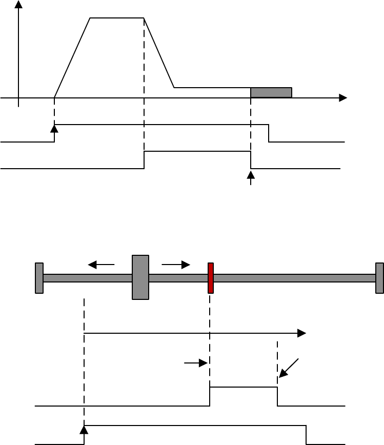
PA771.1=3: After contacting zero switch, rotate forward, not look for Z pulse.
Motor speed
(rpm)
0
PA775
PA776
Zero switch offset
(PA777 & PA778)
SHOME
ZPS
After ZPS is invalid, start
calculating offset.
Rising edge
Invalid Invalid
Valid
Zero switch
ZPS
SHOME
Motor decelerates and
moves forward
Rising edge
After ZPS is invalid,
start calculating offset.
Invalid Invalid
Valid
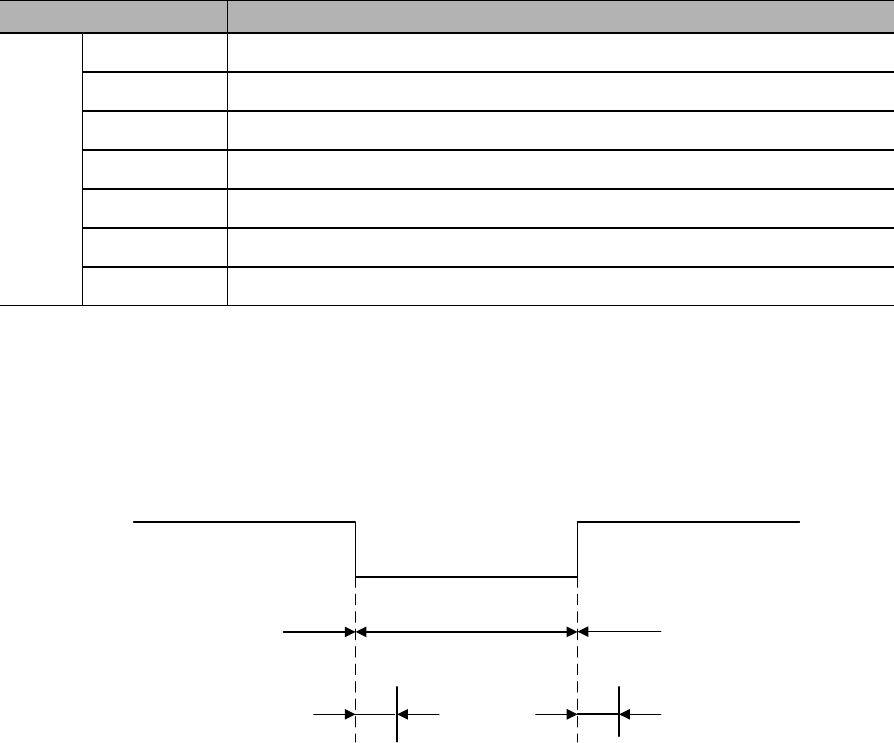
8.10 Combination of different control modes
8.10.1 Parameter settings
Parameter
Control mode combinations
PA000
Internal speed control Position control
Internal speed control Speed control
Internal speed control Torque control
Position control Speed control
Position control Torque control
Torque control Speed control
B
8.10.2 Input signal
C-MODE Invalid Valid Invalid
First control mode Second control mode First control mode
Above 10ms no instruction input

Chapter 9 Fault diagnosis
9.1 Alarms
Code
Symptom/Cause
Clear
Solutions
1)
2)
1)
2)
1)
2)
3)
4)
1)
2)
3)
1)
2)
1)
2)
3)
1)
2)
3)
1)

2)
3)
1)
2)
3)
1)
2)
3)
4)
1)
2)
3)
1)
2)
3)
4)
1)
2)
3)
4)
1)
2)
3)
1)
2)
3)
1)
2)
3)
4)
1)

2)
1)
2)
1)
2)
1)
2)
1)
2)
3)
1)
2)
3)
4)
1)
2)
3)
1)
2)
1)
2)
1)
2)
1)
2)

1)
2)
1)
2)
1)
2)
1)
2)
3)
1)
2)
3)
1)
2)

9.2 Warnings
Code
Symptom/Cause
Solutions
1)
2)
3)
1)
2)
3)
4)
5)
1)
2)
3)
4)
1)
2)
3)
4)
1)
2)
1)
2)
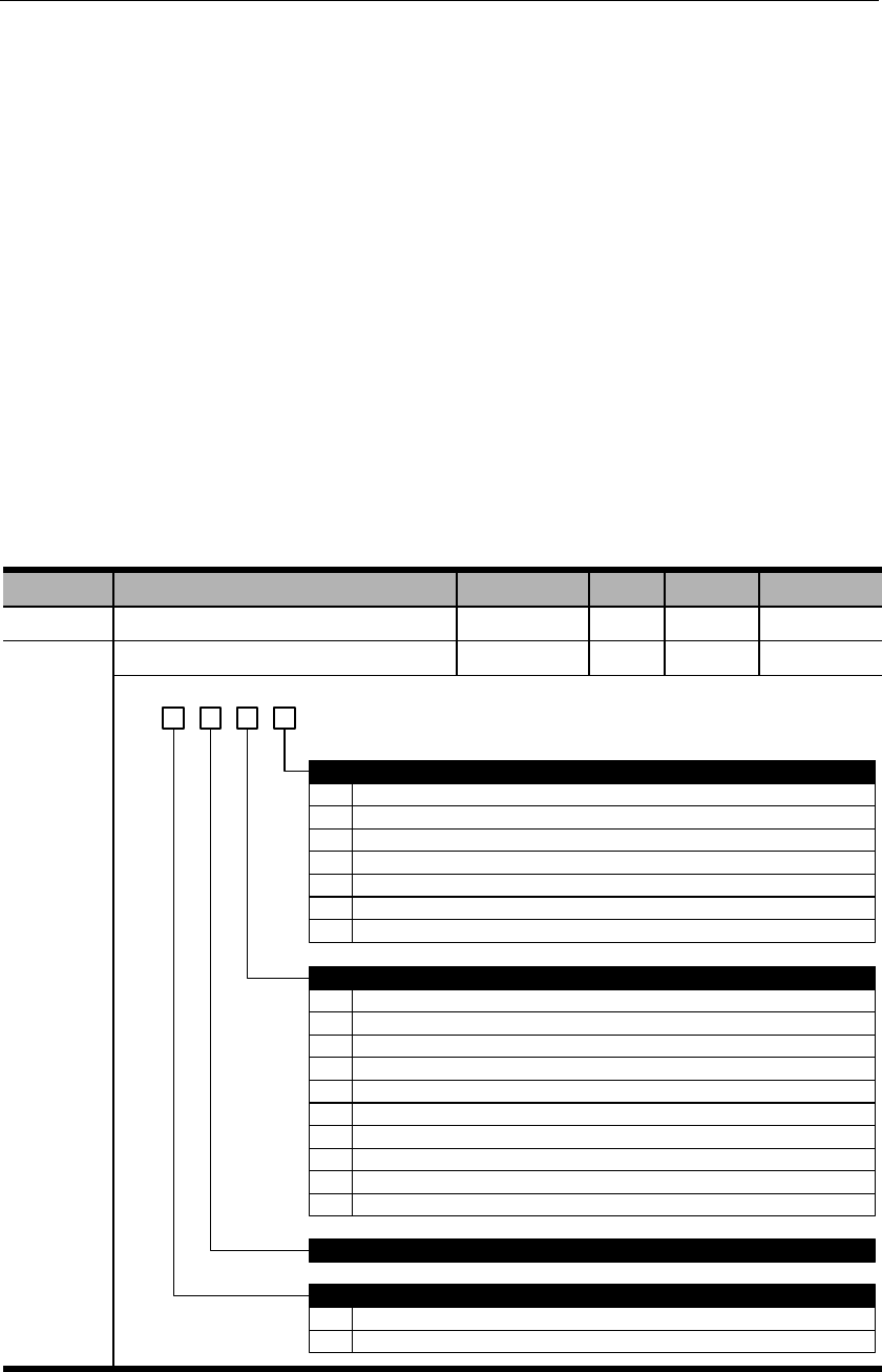
Chapter 10 Communications
10.1 Communication terminals
1)
2)
3)
10.2 Communication parameters
Parameter
Name
Range
Unit
Default
Effective
PA015
PA016
d. 3 2 01
0
1
2
3
4
5
0
2400bps
4800bps
9600bps
19200bps
38400bps
57600bps
Communicational protocal
8,N,1 (Modbus protocol, RTU mode)
1
2
3
4
5
6
7
8
8,N,2 (Modbus protocol, RTU mode)
8,E,1 (Modbus protocol, RTU mode)
8,O,1 (Modbus protocol, RTU mode)
7,N,2 (Modbus protocol, ASCII mode)
7,E,1 (Modbus protocol, ASCII mode)
7,O,1 (Modbus protocol, ASCII mode)
8,N,2 (Modbus protocol, ASCII mode)
8,E,1 (Modbus protocol, ASCII mode)
RS485 bit rate
9 8,O,1 (Modbus protocol, ASCII mode)
Reserved
Communicational data equivalent
0 Internal speed: 1rpm; internal torque: 1% rated torque.
1 Internal speed: 0.1rpm; internal torque: 0.1% rated torque.
6 115200bps

10.3 Communication protocol
10.3.1 Encoding definitions
ASCII mode:
Byte symbol
‘0’
‘1’
‘2’
‘3’
‘4’
‘5’
‘6’
‘7’
Byte symbol
RTU mode:
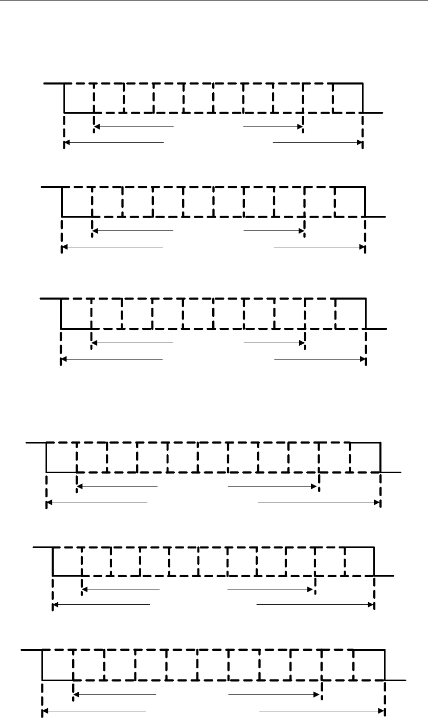
10.3.2 Byte structure
10-bits byte box (used for 7-bits data)
Start
bit 0 1 2 3 4 5 6 Stop
bit
Stop
bit
7-data bits
10- bits character frame
7,N,2(Modbus,ASCII)
Start
bit 0 1 2 3 4 5 6 Even
parity Stop
bit
7-data bits
10- bits character frame
7,E,1(Modbus,ASCII)
Start
bit 0 1 2 3 4 5 6 Odd
parity Stop
bit
7-data bits
10- bits character frame
7,O,1(Modbus,ASCII)
11-bits byte box (used for 8-bits data)
Start
bit 0 1 2 3 4 5 6 Stop
bit
8-data bits
11- bits character frame
8,N,2(Modbus,ASCII / RTU)
Stop
bit
7
Start
bit 0 1 2 3 4 5 6 Even
parity
8-data bits
11- bits character frame
8,E,1(Modbus,ASCII / RTU)
Stop
bit
7
Start
bit 0 1 2 3 4 5 6 Odd
parity
8-data bits
11- bits character frame
8,O,1(Modbus,ASCII / RTU)
Stop
bit
7

10.3.3 Communication data structure
ASCII mode:
STX
ADR
CMD
DATA (n-1)
…….
DATA (0)
LRC
End 1
End 0
RTU mode
STX
ADR
CMD
DATA (n-1)
…….
DATA (0)
CRC
End 1
STX (Communication starting)
:
ADR (communication address)
CMD (command code) & DATA (data content)
Command
Meaning
Remarks

1) CMD:03H (Read N words, N≤29)
ASCII mode:
Command
Response
STX
‘:’
STX
‘:’
ADR
‘0’
ADR
‘0’
‘1’
‘1’
CMD
‘0’
CMD
‘0’
‘3’
‘3’
Starting address (high
to low)
‘0’
Data quantity (bytes)
‘0’
‘2’
‘4'
‘0’
Starting address 0200H
(high to low)
‘0’
‘0’
‘0’
Data quantity (WORD)
‘0’
‘B’
‘0’
‘1’
‘0’
Second address 0200H
(high to low)
‘1’
‘2’
‘F’
LRC Check (high to
low)
‘F’
‘4’
‘8’
‘0’
End 1
(0DH)
(CR)
LRC Check (high to low)
‘E’
End 0
(0AH)
(LF)
‘8’
End 1
(0DH)
(CR)
End 0
(0AH)
(LF)
RTU mode:
Command
Response
ADR
01H
ADR
01H
CMD
03H
CMD
03H
Starting address (high to
low)
02H
Data quantity (bytes)
04H
00H
Starting address 0200H (high to
low)
00H
Data byte number (high to
low)
00H
B1H
02H
Second address 0200H (high to
low)
1FH
CRC check low
C5H
40H
CRC check high
B3H
CRC check low
A3H
CRC check high
D4H


2) CMD: 06H (write one word)
ASCII mode:
Command
Response
STX
‘:’
STX
‘:’
ADR
‘0’
ADR
‘0’
‘1’
‘1’
CMD
‘0’
CMD
‘0’
‘6’
‘6’
Starting address (high to
low)
‘0’
Starting address 0200H (high
to low)
‘0’
‘2’
‘2’
‘0’
‘0’
‘0’
‘0’
Data content (high to low)
‘0’
Data content (high to low)
‘0’
‘0’
‘0’
‘6’
‘6’
‘4’
‘4’
LRC Check (high to low)
‘9’
LRC Check (high to low)
‘9’
‘3’
‘3’
End 1
(0DH) (CR)
End 1
(0DH)
(CR)
End 0
(0AH) (LF)
End 0
(0AH) (LF)
RTU mode:
Command
Response
ADR
01H
ADR
01H
CMD
06H
CMD
06H
Starting address (high to
low)
02H
Starting address (high to
low)
02H
00H
00H
Data content (high to low)
00H
Data content (high to low)
00H
64H
64H
CRC check low
89H
CRC check low
89H
CRC check high
99H
CRC check high
99H

3) CMD: 10H (write N words, N≤29)
ASCII mode:
Command
Response
STX
‘:’
STX
‘:’
ADR
‘0’
ADR
‘0’
‘1’
‘1’
CMD
‘1’
CMD
‘1’
‘0’
‘0’
Starting address (high to
low)
‘0’
Starting address (high to
low)
‘0’
‘2’
‘2'
‘0’
‘0’
‘0’
‘0’
Data word number (high
place)
‘0’
Data word number (high to
low)
‘0’
‘0’
‘0’
Data word number (low
place)
‘0’
‘0’
‘2’
‘2’
Data byte number
‘0’
LRC Check (high to low)
‘9’
‘4’
‘3’
Data 1 content (high to
low)
‘0’
End 1
(0DH)
(CR)
‘0’
End 0
(0AH) (LF)
‘6’
‘4’
Data 2 content (high to
low)
‘0’
‘0’
‘6’
‘6’
LRC Check (high to low)
‘1’
‘D’
End 1
(0DH) (CR)
End 0
(0AH) (LF)

RTU mode:
Command
Response
ADR
01H
ADR
01H
CMD
10H
CMD
10H
Starting address (high to
low)
02H
Starting address (high to
low)
02H
00H
00H
Data word number (high to
low)
00H
Data word number (high to
low)
00H
02H
02H
Data byte number
04H
CRC check low
40H
Data 1 content
00H
CRC check high
70H
64H
Data 2 content
00H
66H
CRC check low
50H
CRC check high
11H

LRC (ASCII mode) & CRC (RTU mode) detected error value calculation
ASCII mode:
RTU mode:
Exclusive OR
;
Exclusive OR
3) End1、End0 (communication end)
ASCII mode:
RTU mode:

10.3.4 Communication troubleshooting
;
;
Upper controller data frame:
Start
Slave address
Command
Data address
Verification
Servo drive feedback error frame:
Start
Slave address
Response code
Error code
Verification
= ;
=
=
=
= ;
Upper controller data frame:
Start
Slave address
Command
Data address
Verification
Servo drive feedback error frame:
Start
Slave address
Response code
Error code
Verification
If slave address is 00H, this is broadcast data and the servo drive will send no
feedback.

10.4 Communication address
Notes: W/R: writable/readable (R: readable only; W: writable only)
Address
Meaning
Unit
Data type
W/R

Notes:

Chapter 11 Product specifications
11.1 Servo drive specifications
11.1.1 Basic specifications
℃
℃
:
℃

11.1.2 Position/speed/torque control specifications
:
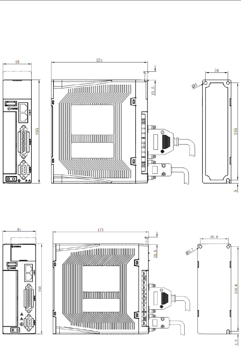
11.1.3 Servo drive dimensions
A type case:
B type case:
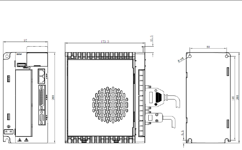
C type case:
11.2 Servo motor specifications & dimensions
General specifications
Working system: S1 continuous
Heat resistance class: B
Vibration: 5G
Insulation voltage class: AC1500V, 1 minute
Installation mode: Flange
Working temperature: 0~40℃ (no freezing)
Operating humidity: 20%~80% (no dewing)
Altitude: Below 1000m
Protections: Full-enclosed IP65 (except the
shaft-through part)
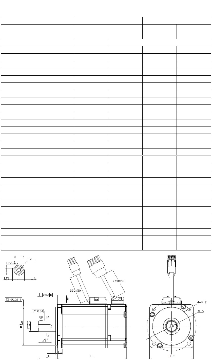
60/80 Series
Servo Motor series
60 series
80 Series
Servo Motor model
Input voltage
220VAC
220VAC
220VAC
220VAC
Inertia
Medium
Medium
Medium
Medium
Rated power (W)
Rated torque (N*m)
Rated current (A)
Maximum current (A)
Rated speed (rpm)
Maximum speed (rpm)
Torque constant (N*m/Amp)
Back EMF constant (V/Krpm)
Rotary inertia (with brake) (10-4Kg*m2)
Resistance (line-line) ()
Inductance (line-line) (mH)
Mass (with brake) (kg)
LL (with brake) (mm)
LR (mm)
LE (mm)
LG (mm)
S (mm)
LJ1 (mm)
LJ (mm)
J (mm)
LF1 (mm)
LF2 (mm)
LM (mm)
LA (mm)
LB (mm)
LC (mm)
LZ (mm)
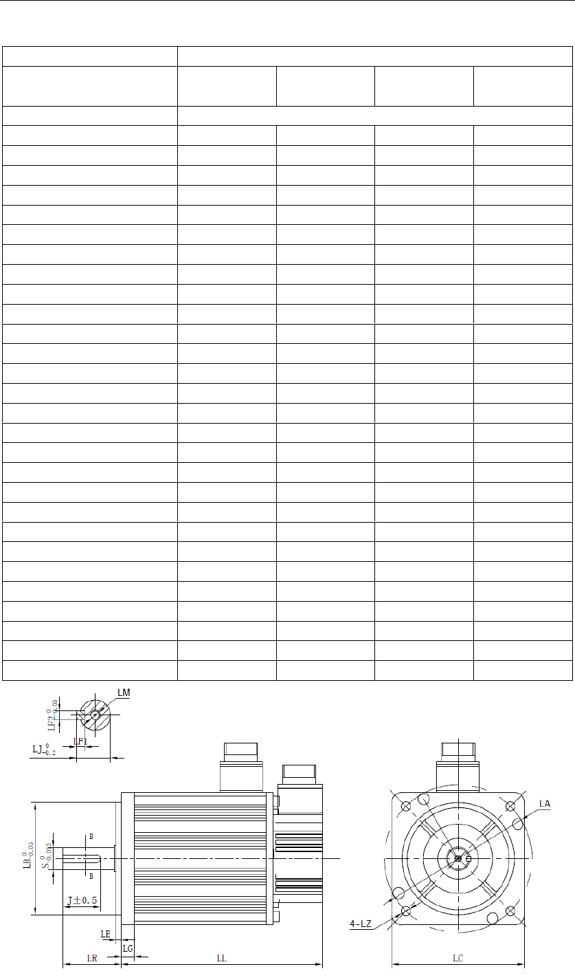
130 Series (220V class)
Servo Motor series
130 Series
Servo Motor model
Input voltage
220VAC
Rated power (KW)
1
1.5
2.2
3
Rated torque (N*m)
Maximum torque (N*m)
Rated current (A)
Maximum current (A)
Rated speed (rpm)
Maximum speed (rpm)
Torque constant (N*m/Amp)
Back EMF constant (V/Krpm)
Rotary inertia (w/brake) (10-4Kg*m2)
Resistance (line-line) ()
Inductance (line-line) (mH)
Mass (with brake) (kg)
LL (with brake) (mm)
LR (mm)
LE (mm)
LG (mm)
S (mm)
LJ1 (mm)
LJ (mm)
J (mm)
LF1 (mm)
LF2 (mm)
LM (mm)
LA (mm)
LB (mm)
LC (mm)
LZ (mm)

Chapter 12 Appendix
12.1 List of monitoring display functions
No.
Function
Unit
dP 00
Motor speed
dP 01
Motor feedback pulse number (encoder unit, lower 4 digits)
dP 02
Motor feedback pulse number (encoder unit, higher 5 digits)
dP 03
Input pulse number before electronic gear (user unit, lower 4
digits)
dP 04
Input pulse number before electronic gear (user unit, higher 5
digits)
dP 05
Deviation pulse number (encoder unit, lower 4 digits)
dP 06
Deviation pulse number (encoder unit, higher 5 digits)
dP 07
Speed instruction (analog voltage instruction)
dP 08
Internal speed instruction
dP 09
Torque instruction (analog voltage instruction)
dP 10
Internal torque instruction (value in relation to the rated torque)
dP 11
Torque feedback (value in relation to the rated torque)

dP 12
Input signal monitoring
dP 13
Output signal monitoring
dP 14
Instruction pulse frequency
dP 15
DC bus voltage
dP 16
Total operation time of the servo drive
dP 17
Rotation angle
dP 18
Exact position of absolute encoder (single-turn or multi-turn)
dP 19
Number of encoder turns (only for multi-turn absolute encoders)
dP 20
Cumulative load factor (take rated cumulative load as 100%)
dP 21
Regeneration load factor (take rated regeneration load as 100%)
dP 22
DB load factor (take rated DB load as 100%)
dP 23
Load inertial ratio
dP 24
Effective gain monitoring
dP 30
Subsidiary software version (refer to AF 10 for main software version)
dP 34
External linear encoder feedback pulse counts low place
dP 35
External linear encoder feedback pulse counts high place
dP 38
Hybrid deviation low place
dP 39
Hybrid deviation high place
dP 40
Voltage class (refer to PA000.3 for voltage class setting)
dP 46
IGBT temperature
℃

12.2 List of auxiliary function parameters
No.
Function
Reference
AF 00
AF 01
AF 02
AF 03
AF 04
AF 05
AF 06
AF 07
AF 08
AF 09
AF 10
AF 11
AF 12
AF 15
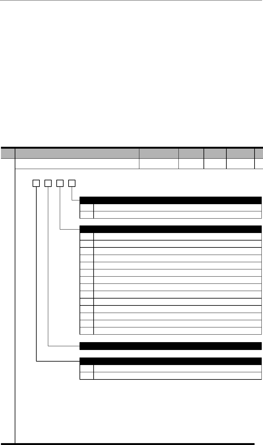
12.3 List of parameters
Legends:
PA000
Basic function selection 1
h. 3 2 0
0
1
0
1
2
3
4
Positive mode
Negative mode
Control mode selection
Position control (pulse train)
Speed control (analog instruction)
Torque control (analog instruction)
Internal speed control
Internal speed control Position control
5
6
7
8
9
A
Internal speed control Speed control
Internal speed control Torque control
Position control Speed control
Position control Torque control
Torque control Speed control
Internal position control
Reserved
Direction selection
Input voltage of servo drive
1
B Internal position control Position control
C Reserved
D Fully closed loop control
0
1
220V class
380V class
Notes:
220V class: PA000.3=0;
380V class: PA000.3=1;
Execute AF 05 (parameter initialization) after modifying PA000.3.
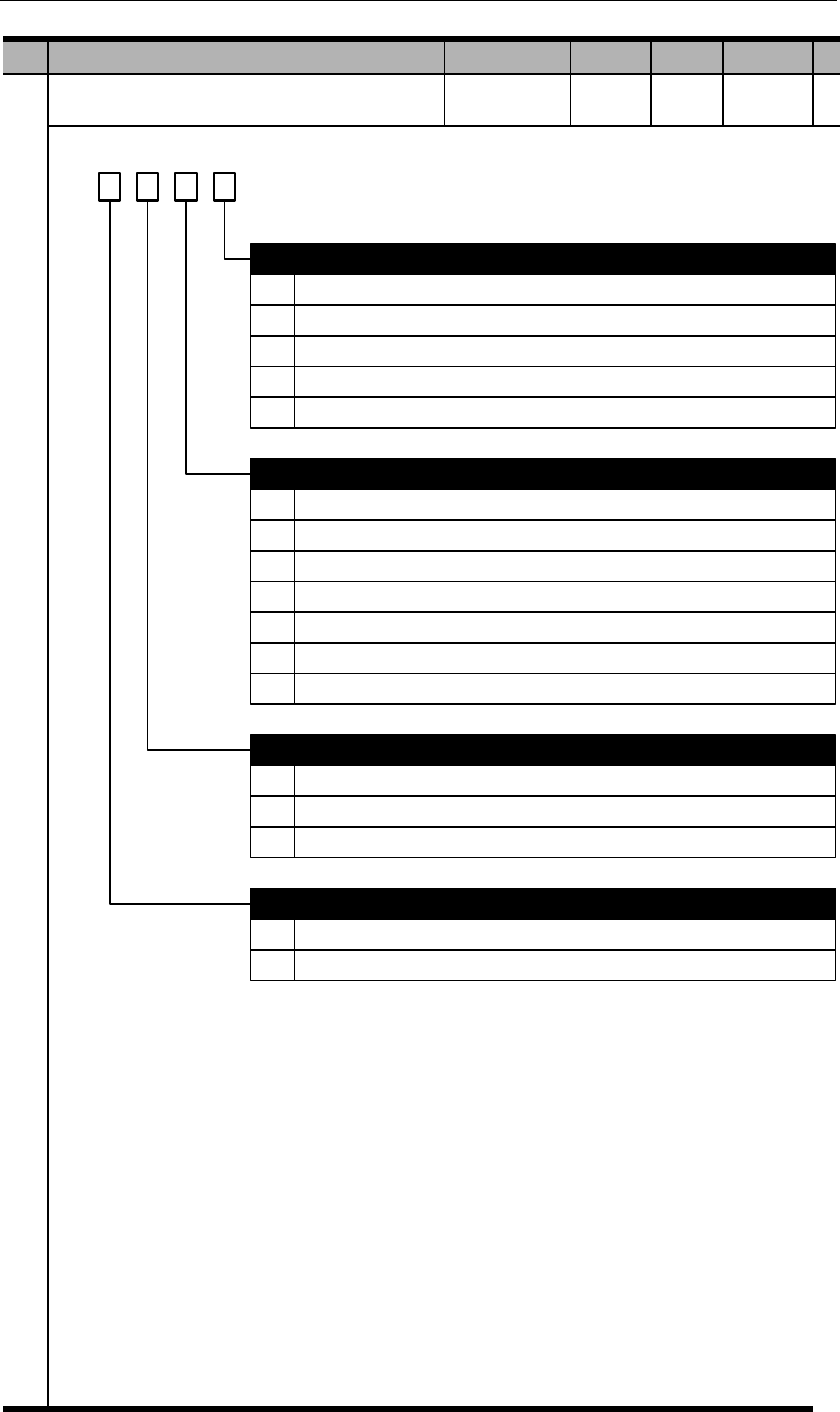
PA001
Basic function selection 2
d. 3 2 1 0
0
1
2
0
1
2
3
DB (dynamic brake) to stop
DB (dynamic brake) to stop, then release DB
Coast to stop, DB not used
Servo stop patterns at OT (Overtravel)
DB or coast to stop, same as PA001.0 (1~2)
Stop by torque set in PA406, then enter lock state
Stop by torque set in PA406, then coast to stop
Stop by torque set in PA406, after fully stopped, then enter DB state
0
1
2
AC/DC input power selection
AC input: Single phase 220VAC among L1, L2, L3
AC input: Three phase 220VAC among L1, L2, L3
DC input: 310VDC between P+, (-)
Enabling selection
Servo stop patterns at servo OFF or alarms
3
4
Decelerate at rate of PA522, & stay in DB state when speed is lower than PA523
Decelerate at rate of PA522, & coast to stop when speed is lower than PA523
4
5
6
Stop by torque set in PA406, decelerate at rate of PA522, then enter lock state
Stop by torque set in PA406, decelerate at rate of PA522, then coast to stop
Stop by torque set in PA406, decelerate at rate of PA522, then enter DB state
0
1
External enable from I/O or communication
Internal enable
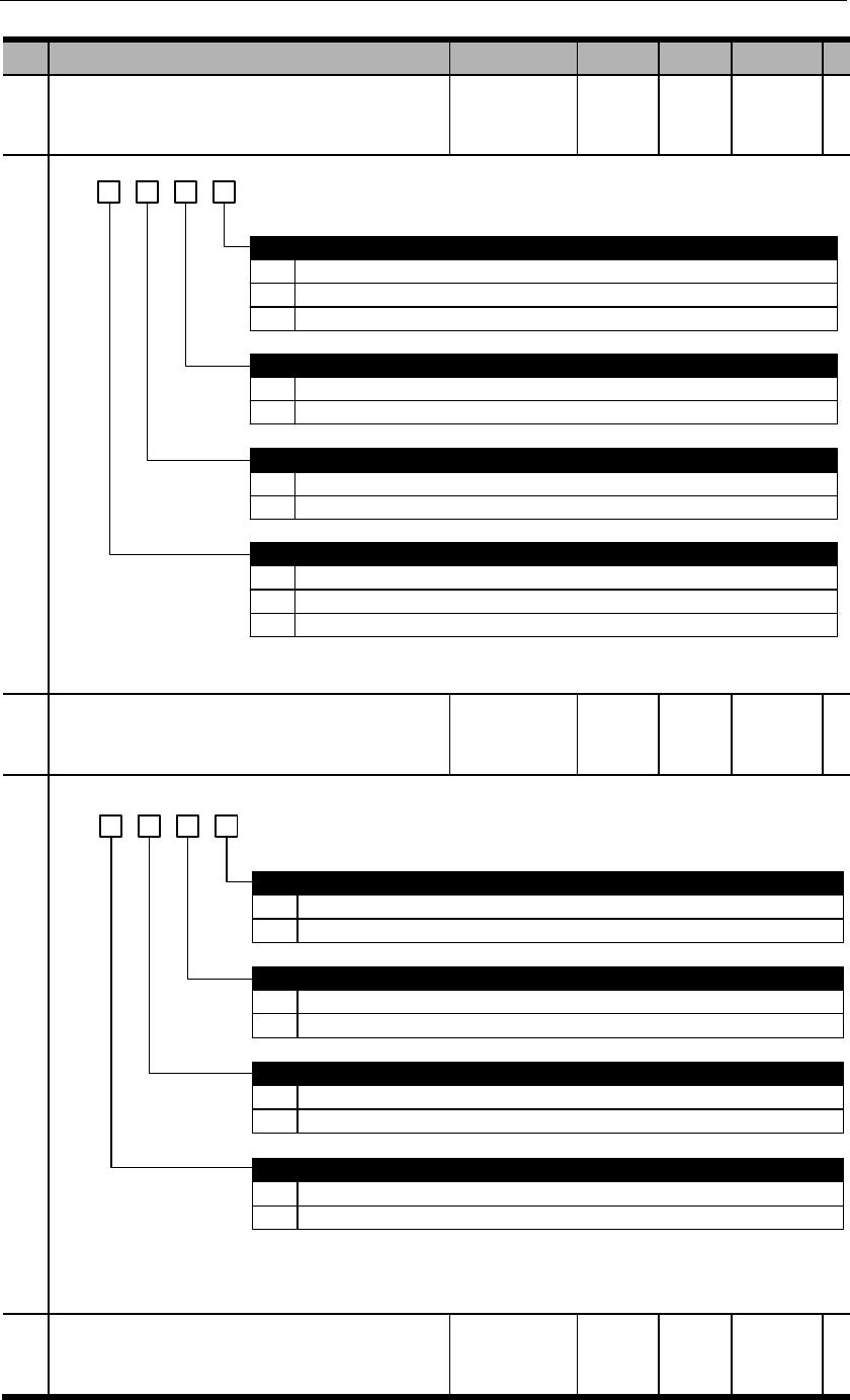
PA002
Basic function selection 3
b. 3 2 1 0
0
1
2
0
1
Invalid
Use T-REF as external analog torque limit input
Use PCL, NCL as external analog torque limit input
Speed limit in torque control mode selection
Use PA407 as speed limit (internal speed limit)
Use V-REF & PA301 setting as speed limit (external speed limit)
0
1
0
1
Use of absolute encoders
Use absolute encoders as incremental encoders
Use absolute encoders as absolute encoders
Encoder type selection
Absolute encoder (single-turn 17-bit, multi-turn 16-bit)
Single-turn absolute encoder (single-turn 17-bit, resolution 131072)
Torque limit in position control & speed control modes selection
2 Line-saving encoder (5000ppr, resolution 20000ppr)
PA003
Basic function selection 4
b. 3 2 1 0
0
1
0
1
Valid
Invalid
Reverse rotation prohibited (NOT) (OT)
Valid
Invalid
0
1
OT alarm selection
No alarm at POT/NOT input
E.35 alarm at POT/NOT input
Forward rotation prohibited (POT) (OT)
0
1
Z pulse signal negation
Not negated
Negated
PA004
Reserved
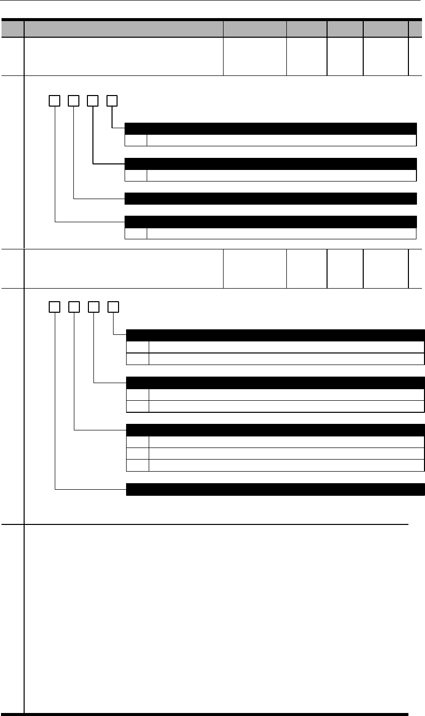
PA005
Basic function selection 6
d. 3 2 1 0
0~4
0~4
The higher this value, the less responsive to speed instructions
Speed feedback responsive grade
The higher this value, the less responsive to speed feedbacks
Reserved
E.29 alarm grade
Speed instruction responsive grade
0~5 The higher this value, the less sensitive to E.29. When the value is 5, E.29 is disabled.
PA007
Basic function selection 8
d. 3 2 1 0
0
1
Battery voltage alarm/warning selection
E.61 if battery voltage is less than 3.1V
A.97 if battery voltage is less than 3.1V
0
1
0
1
Warning detection selection
Warning can be detected but will not affect motor running until alarm is detected.
Warning cannot be detected.
Multi-turn data overflow alarm (E.58)
Multi-turn data overflows will output E.58 (default).
Multi-turn data overflows will not output E.58.
Reserved
2 Detected warning will stop the motor at enabled state and output warning signal (Position control mode only)
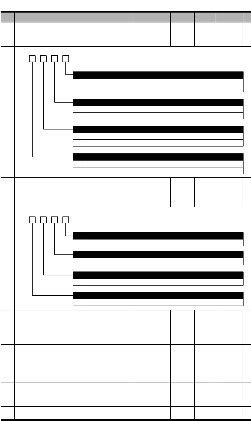
PA009
Basic function selection 10
b. 3 2 1 0
0
1
0
1
Detect. E.17 will output if there are problems.
Not detect.
Regenerative resistor selection
Use internal resistor
Use external resistor. Make sure to set PA537, PA538 correctly.
IGBT temperature detection
Motor temperature detection
Regenerative circuit detection
0
1
Not detect.
Detect (only valid for 380V class models).
0
1
Not detect.
Detect (only applicable to certain models).
PA010
Basic function selection 11
d. 3 2 01
0~5
0~9
Analog instruction input delay
The larger this va lue, the more delay of analog instruction sampling, but the more accurate the measurement is.
Regenerative resistor load ratio selection
The larger this value, the longer overload time.
0~9
Motor overload grade
The larger this value, the longer overload time.
Speed detection filter grade
0~3 The larger this va lue, the longer detection time. Sometimes this par ameter can increase gain and reduce vibrations.
PA011
Reserved
PA012
Motor model selection
Please refer to chapter 1.3 for correct matching
parameter.
PA013
Reserved
P
A
01
4
Status code display

Please refer to chapter 4.3 & 5.4 for details.
PA015
RS485 communication address
PA016
RS485 communication function selection
d. 3 2 01
0
1
2
3
4
5
0
2400bps
4800bps
9600bps
19200bps
38400bps
57600bps
Communicational protocal
8,N,1 (Modbus protocol, RTU mode)
1
2
3
4
5
6
7
8
8,N,2 (Modbus protocol, RTU mode)
8,E,1 (Modbus protocol, RTU mode)
8,O,1 (Modbus protocol, RTU mode)
7,N,2 (Modbus protocol, ASCII mode)
7,E,1 (Modbus protocol, ASCII mode)
7,O,1 (Modbus protocol, ASCII mode)
8,N,2 (Modbus protocol, ASCII mode)
8,E,1 (Modbus protocol, ASCII mode)
RS485 bit rate
9 8,O,1 (Modbus protocol, ASCII mode)
Reserved
Communicational data equivalent
0 Internal speed: 1rpm; internal torque: 1% rated torque.
1 Internal speed: 0.1rpm; internal torque: 0.1% rated torque.
6 115200bps
PA017
Reserved
PA018
Reserved
PA019
Reserved
PA020
Reserved

PA021
Analog output signal selection
d. 3 2 01
0
1
Output voltage negation
Not negated
Negated
Analog output signal selection
Reserved
Reserved
0
1
Motor speed feedback
Motor torque feedback
PA022
Reserved
PA023
Analog voltage output gain
=motor speed
PA023
=torque×1000
PA023
PA024
Analog voltage output zero calibration

PA025
Basic function selection 12
d. 3 2 01
0
1
2
If there is no high voltage (220VAC or 380VAC) input, no alarm will output, S-RDY invalid.
If there is no high voltage input within 1 second after power on, an alarm will output.
If there is high voltage input after power on, but power is lost with 1 second during operation , an
alarm will output.
Reserved
Reserved
Reserved
Main circuit input power alarm selection
PA100
First position loop proportional gain
This parameter determines the responsiveness of position control systems. The higher this value, the
shorter positioning time. But if this value is set too high, vibrations can be caused.
PA101
First speed loop proportional gain
This parameter determines the responsiveness of speed control loops. If PA100 is increased, PA101
also has to be increased accordingly. But if this value is set too high, vibrations can be caused.
PA102
First speed loop integral time constant
The lower this value, the stronger integral effects & counter-interference effects. But if this value is set
too high, vibrations can be caused.
PA103
First speed detection filter
This is the time constant of low pass filter. The higher this value, the higher time constant. This can
reduce motor noise but will also reduce system responsiveness.
PA104
First torque filter
This is to set the first grade hysteresis filter time constant of the torque instructions and can regulate
vibrations caused by distorted resonance. The higher this value, the higher time constant. This can
reduce motor noise but will also reduce system responsiveness.
PA105
Second position loop proportional gain
PA106
Second speed loop proportional gain
PA107
Second speed loop integral time constant
PA108
Second speed detection filter

PA109
Second torque filter
PA 110
Speed feedforward gain
The combination of the value of speed control instruction processed from position control, and the
value of speed control instruction processed from internal position control multiplying this parameter.
PA 111
Speed feedforward filter
This is to set the first grade hysteresis filter time constant of the speed feedforward.
PA 114
Friction compensation gain
PA 115
Friction compensation smoothness constant
PA 116
Friction compensation threshold speed
PA 118
Load inertia ratio
PA 119
Reserved
PA120
Gain switchover selection 1
d. 3 2 01
0
1
2
3
4
Use internal torque instructions PA121
Use speed instructions PA122
Use accelerations PA123
Use position deviations PA124
No mode switching.
Reserved
Reserved
Reserved
Mode switching condition selections

PA121
Mode switch (internal torque instructions)
PA122
Mode switch (speed instructions)
PA123
Mode switch (accelerations)
PA124
Mode switch (position deviations)
PA125
Gain switchover selection 2
d. 3 2 01
0
1
2
0
1
No gain switchover
Manual gain switchover
Automatic gain switchover:
When gain switch condition A is valid, switch from 1st gain to 2nd gain.
When gain switch condition A is invalid, switch from 2nd gain to 1st gain
Gain switchover condition A
COIN is ON
COIN is OFF
2
3
4
5
6
7
8
9
NEAR is ON
NEAR is OFF
Position instruction filter output is 0 and instruction pulse input OFF
Position instruction pulse input ON
Torque instruction value is greater than PA126
Speed instruction value is greater than PA127
Speed instruction variation value is greater than PA128
Position deviation value is greater than PA129
Gain switchover selections
Reserved
Reserved
PA126
Gain switchover grade (torque instruction)
PA127
Gain switchover grade (speed instruction)
PA128
Gain switchover grade (speed instruction
variation)
PA129
Gain switchover grade (position deviation)

PA130
Gain switchover time 1
PA131
Gain switchover time 2
PA132
Gain switchover waiting time 1
PA133
Gain switchover waiting time 2
PA134
Reserved
PA137
Reserved
PA138
Reserved
PA139
Reserved
PA140
Reserved
PA200
Position control switch 1
d. 3 2 01
0
1
2
0
1
2
3
PULS + SIGN
CW + CCW
A phase + B phase (quadruple frequency)
Pulse (PULS+SIGN) negations
Neither negates
PULS not negates, SIGN negates
PULS negates, SIGN not negates
Both negate
0
1
2
0
Position deviation clearance
Clear position deviation when S-ON is off, power is off or by CLR signal.
Clear position deviation only by CLR. CLR also clears OT lock.
Clear position deviation only when servo has alarm or by CLR signal.
Input pulse channel
Low speed channel (Pin 7/8, 11/12)
Input pulse form
1 High speed channel (Pin 16/17, 23/24)
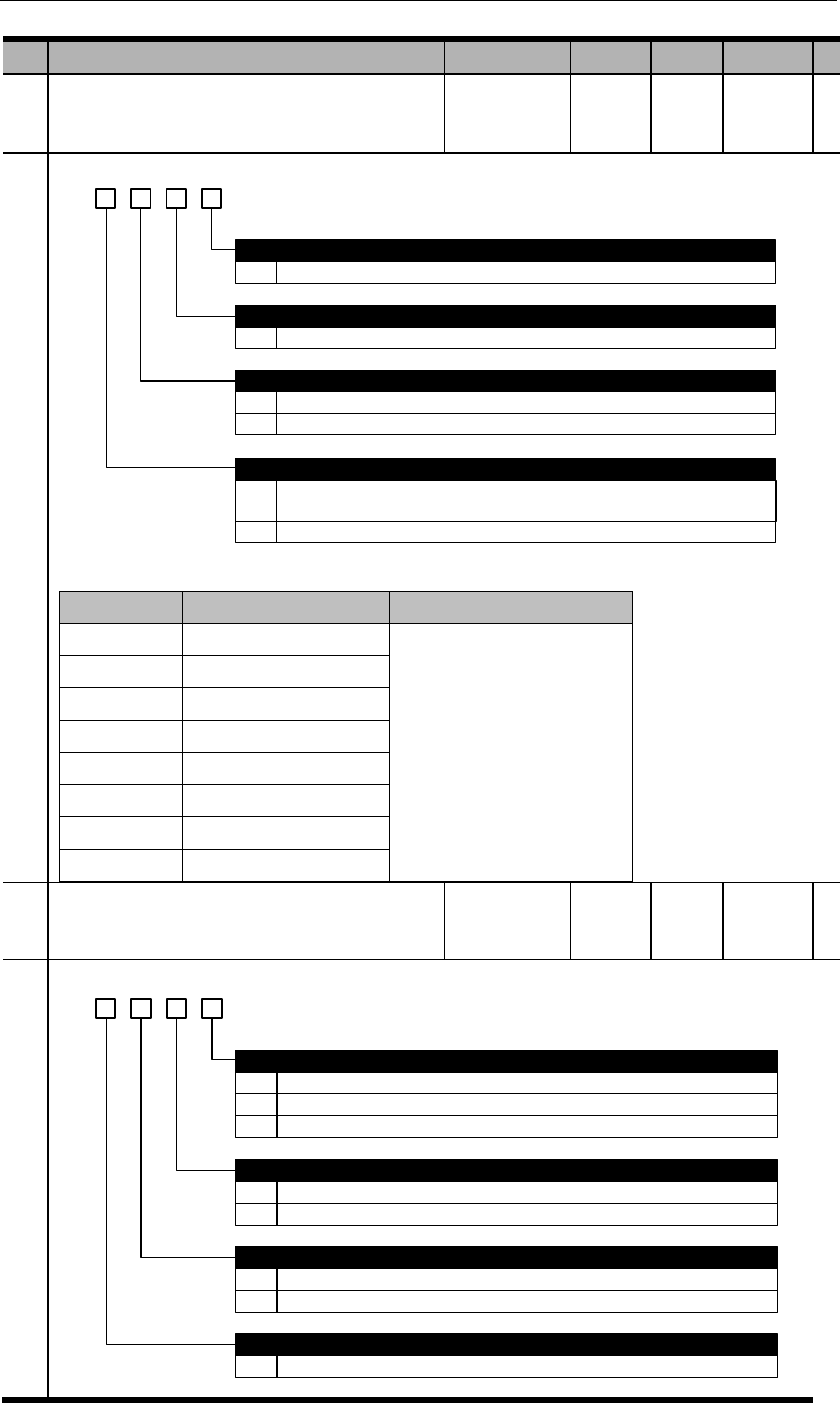
PA201
Position control switch 2
d. 3 2 01
0~7 The higher this value, the longer filter time, the lower chop frequency. 0 means no filter.
0
1
AB pulse output negation
Not negate.
Negate.
Low speed (pulse input) channel filter grade
0~7 The higher this value, the longer filter time, the lower chop frequency. 0 means no filter.
High speed (pulse input) channel filter grade
Z pulse output expansion
0
1
No expansion. (Communicational type) encoder Z pulse width is defined by one A pulse
width, i.e. the smaller the value of PA210, the wider Z pulse width.
Expand. (Non-communicational type) encoder Z pulse is A pulse width.
【】
PA202
Position control switch 3
d. 3 2 01
0
1
2
When position deviation is less than PA525.
When position deviation is less than PA525 AND position instruction is 0 after filtering.
When position deviation is less than PA525 and position instruction is 0.
Positioning completion (COIN) signal output condition
External linear encoder signal negation in fully closed loop mode
0
1
Not negate.
Negate.
Switchover between internal & external loops in fully closed loop mode
0
1
C-MOD (0: external; 1: internal)
When electronic gear switch.(1:external; others:internal)
Pulse residual in fully closed loop mode
0~9 When pulse residual is less than this value, fully closed loop control is finished.

PA203
Position control switch 4:Reserved
PA204
Reserved
PA205
First electronic gear ratio numerator
PA2
06
Electronic gear ratio denominator
PA207
Second electronic gear ratio numerator
PA208
Third electronic gear ratio numerator
PA209
Fourth electronic gear ratio numerator
PA210
Encoder resolution (frequency-division) setting
When value of PA210 exceeds number of encoder structural lines, this value becomes invalid and
the actual number of encoder structure lines will be used. For example, if a 5000-line incremental
encoder is used, and PA210 is set to 6000, the valid value is still 5000.
For communicational encoders, Z pulse width is set to be the width of one A pulse. Thus the
smaller PA210 value, the wider Z pulse given the same speed settings.
PA214
Position instruction acceleration/deceleration
time constant 1
PA215
Position instruction acceleration/deceleration
time constant 2
PA216
Position instruction average-moving filter

PA300
Speed control switch 1
PA300
d. 3 2 01
0
1
2
Linear filter
S-curve
First grade filter
Reserved
Manual load inertia detection operating distance
0
1
2
3
0
1
1 turn
2 turns
4 turns
8 turns
Speed dead zone control
Use input signal: ZEROSPD
Automatic: use PA316 setting
Speed instruction filter selection
PA301
Speed instruction gain
0.01
PA302
Speed instruction filter time constant
PA303
Soft start acceleration time
PA304
Soft start deceleration time
PA305
Speed instruction S-curve linear
acceleration/deceleration time
PA306
JOG speed
PA307
Internal speed 0
PA308
Internal speed 1
PA309
Internal speed 2
PA310
Internal speed 3
PA311
Internal speed 4
PA312
Internal speed 5
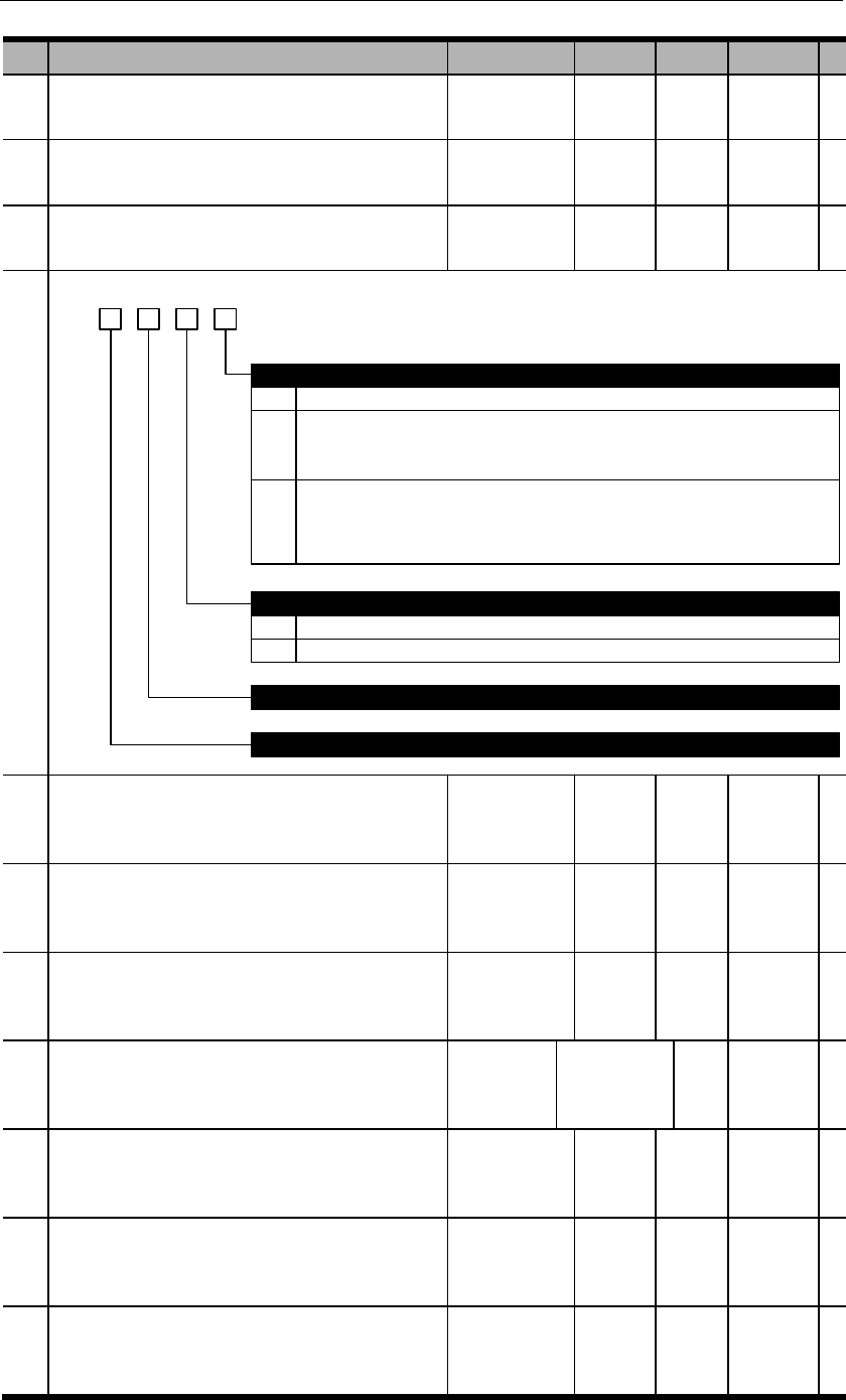
PA313
Internal speed 6
PA314
Internal speed 7
PA315
Speed control switch 2
d. 3 2 1 0
0
1
0
1
After the zero-speed clamp signal is active based on PA300.3, speed instruction is forced to be 0
After the zero-speed clamp signal is active based on PA300.3, speed instruction is forced to be 0
and when motor speed is below PA316, switch to position control mode and lock the servo in this
position. When ZEROSPD signal is inactive or control mode is switched, exit this zero-speed clamp
status.
Instruction source selection when INSPD2=INSPD1=INSPD0=0 in internal speed control
PA307 setting
External analog input
Reserved
Reserved
Zero-speed clamp selection
2 After the zero-speed clamp signal is active based on PA300.3, decelerate at rate of PA522 and when
motor speed is below PA316, switch to position control mode and lock the servo in this position.
When ZEROSPD signal is inactive or control mode is switched, exit this zero-speed clamp status.
This stop pattern is only suitable when PA300.0=0.
PA316
Zero-speed clamp grade
PA317
Reserved
PA318
Reserved
PA400
Torque instruction gain
PA401
Torque instruction filter time constant
PA402
Forward rotation torque limit
PA403
Reverse rotation torque limit

PA404
Forward rotation external torque limit
PA405
Reverse rotation external torque limit
PA406
Emergency stop torque
PA407
Speed limit in torque control mode
PA408
Reserved
PA409
Torque instruction reached (VCMP)
PA410
Grade 1 notch filter frequency
PA411
Grade 1 notch filter attenuation rate
PA412
Grade 2 notch filter frequency
PA413
Grade 2 notch filter attenuation rate
PA414
Internal torque register 0
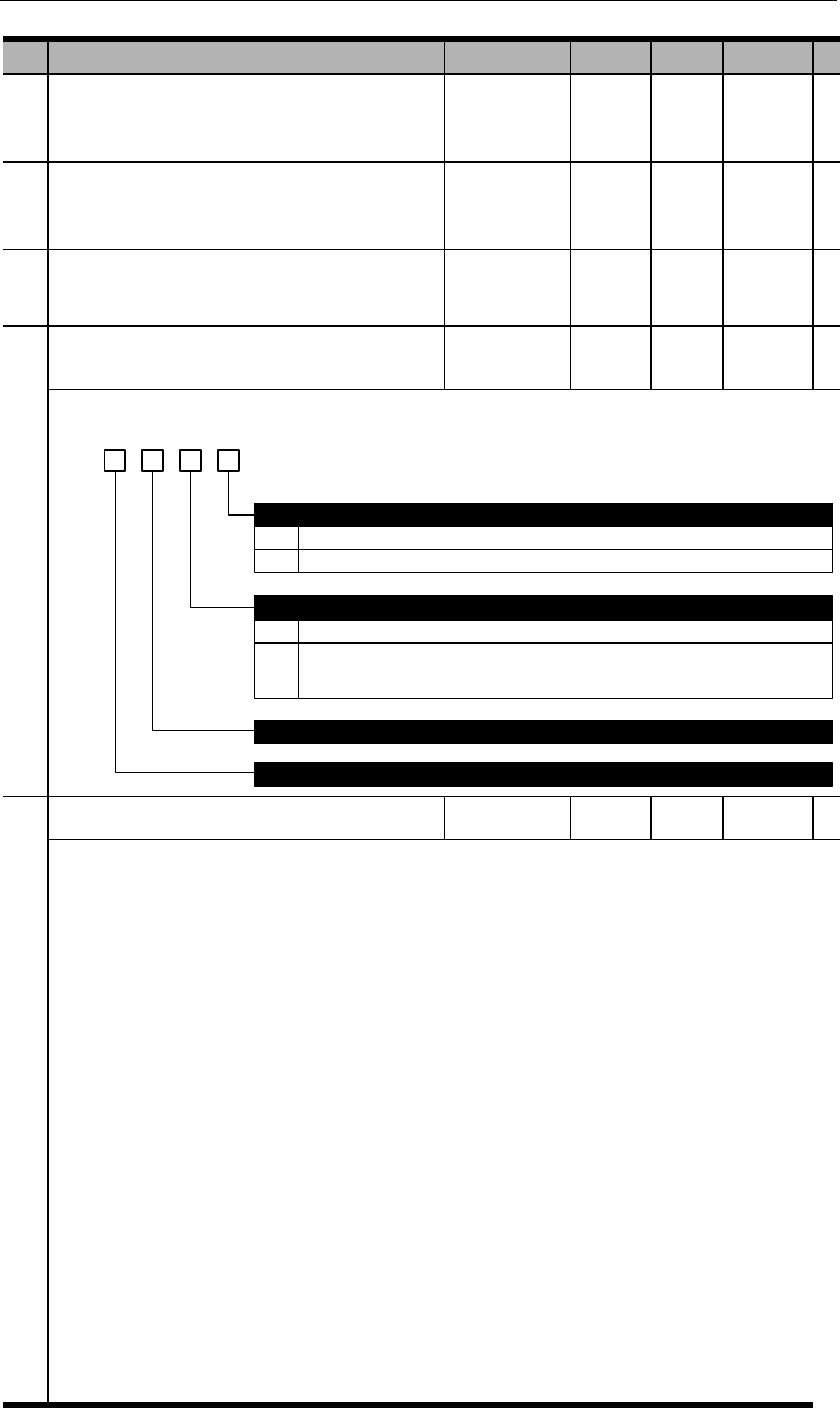
PA415
Internal torque register 1
PA416
Internal torque register 2
PA417
Reserved
PA418
Torque control switch 1
d. 3 2 0
0
1
No deceleration control
Use PA522 setting
Torque compensation
Reserved
Deceleration control of speed limit in torque control mode
Reserved
1
0
1
No torque compensation
Torque compensation in position or speed control mode. Compensation value is in
accordance with torque instruction. (Analog input or internal torque registers)
PA500
DI 1 input signal selection

PA501
DI 2 input signal selection (same as PA500)
PA502
DI 3 input signal selection (same as PA500)
PA503
DI 4 input signal selection (same as PA500)
PA504
DI 5 input signal selection (same as PA500)
PA505
DI 6 input signal selection (same as PA500)
PA506
DI 7 input signal selection (same as PA500)
PA507
DI 8 input signal selection (same as PA500)
PA508
Input signal level selection 1

b. 3 2 01
0
1
0
1
0
L level active (optocoupler conductive)
H level active (optocoupler not conductive)
DI 2 input signal level selection
L level active (optocoupler conductive)
H level active (optocoupler not conductive)
DI 3 input signal level selection
L level active (optocoupler conductive)
1
0
1
H level active (optocoupler not conductive)
DI 4 input signal level selection
L level active (optocoupler conductive)
H level active (optocoupler not conductive)
DI 1 input signal level selection
PA509
Input signal level selection 2
b. 3 2 01
0
1
0
1
0
L level active (optocoupler conductive)
H level active (optocoupler not conductive)
DI 6 input signal level selection
L level active (optocoupler conductive)
H level active (optocoupler not conductive)
DI 7 input signal level selection
L level active (optocoupler conductive)
1
0
1
H level active (optocoupler not conductive)
DI 8 input signal level selection
L level active (optocoupler conductive)
H level active (optocoupler not conductive)
DI 5 input signal level selection
PA510
Output signal selection
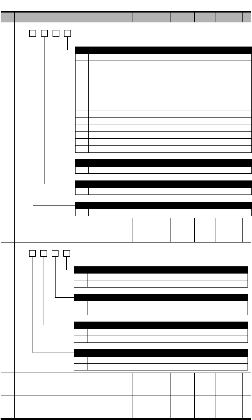
h. 3 2 0
1
2
3
4
5
6
DO 1 output signal selection
Positioning completed (COIN): position deviation is less than PA525.
Z pulse open-collector signal (CZ)
Brake release signal (BK): can be adjusted by PA518.
Servo ready signal (S-RDY): active when servo is in proper status.
Speed instruction reached (VCMP): speed deviation is less than PA517.
Motor rotation detection (TGON): active when rotational speed exceeds PA516.
7
8
0~D
0~D
Torque limited signal (TLC): active when load torque reaches PA402/PA403.
Zero-speed detection signal (ZSP): active when rotational speed is less than PA515.
DO 2 output signal selection
same allocation method as DO 1
DO 3 output signal selection
same allocation method as DO 1
0 Alarm signal output (ALM)
9 Warning output (WARN)
A
B
Internal position control homing completion signal (HOME)
Internal position control position instruction completion signal (CMD-OK)
C Internal position control positioning & command completion signal (MC-OK)
D Torque reached (TREACH): load torque exceeds PA404 or PA405.
1
0~D
DO 4 output signal selection
same allocation method as DO 1
PA511
Output signal level selection
b. 3 2 01
0
1
0
1
0
H level active (optocoupler not conductive)
L level active (optocoupler conductive)
DO 2 output signal level selection
L level active (optocoupler conductive)
H level active (optocoupler not conductive)
DO 3 output signal level selection
L level active (optocoupler conductive)
1
0
1
H level active (optocoupler not conductive)
DO 4 output signal level selection
L level active (optocoupler conductive)
H level active (optocoupler not conductive)
DO 1 output signal level selection
PA512
Input signal filter time
(DC bus voltage compensation)
PA513
Serial encoder communicational alarm time

PA514
Reserved
PA515
Zero position fixed value
PA516
Rotation detection value
PA517
VCMP signal detection width
PA518
BK signal hysteresis time after Servo-OFF
PA519
BK signal speed limit
PA520
BK signal waiting time at Servo-OFF
PA521
Instantaneous power off holding time
PA522
Deceleration at Servo OFF
PA523
Servo OFF stop threshold
PA525
COIN signal width
PA526
NEAR signal width
PA527
Position over-deviation WARN threshold at S-
ON
PA528
Position over-deviation ERR threshold at S-ON
PA529
Speed deviation ERR detection time
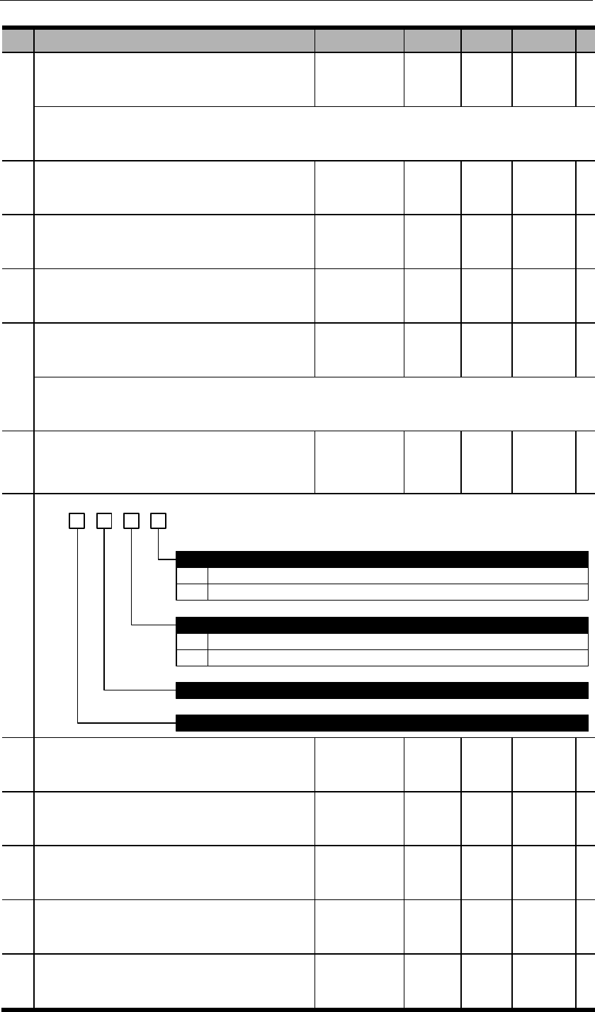
PA530
Speed deviation ERR threshold grade
PA531
Overload WARN threshold
PA532
Speed increment threshold
PA533
ALM clearance input setting
PA534
Main power off detection time
PA535
Special switch 1
b. 3 2 1 0
0
1
ADC detection at power on
Detect.
Not detect.
0
1
Torque limit at stop
Invalid.
Torque limit at stop is PA404 & PA405.
Reserved
Reserved
PA536
High voltage compensation of pumping process
PA537
Resistance of external regenerative resistor
PA538
Capacity of external regenerative resistor
PA542
Low voltage compensation of pumping process
PA543
IGBT temperature adjustment amplitude
℃
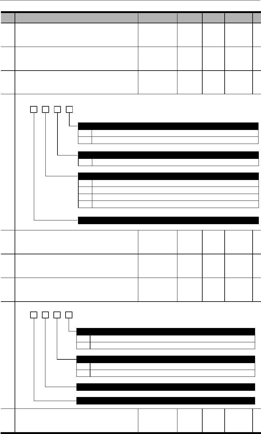
PA544
Dynamic brake (DB) start time
PA545
S-RDY time
PA600
Adjustment switch 1
d. 3 2 01
0
Auto-tuning selection
Invalid
1 Valid
0~F
Load inertia estimation pace at auto-tuning
The larger this value, the faster auto-tuning pace but the less accurate.
0
Load inertia estimation pattern selection
Invalid.
1
2
3
Minor change. When load inertia changes, respond with minute instructions.
Small change. When load inertia changes, respond with second instructions.
Drastic change. When load inertia changes, respond with the fastest instructions.
Reserved
PA601
Reserved
PA602
Reserved
PA603
Adjustment switch 4
b. 3 2 01
0
1
PA118 (load inertia ratio) adjustment after load inertia detection
Automatic adjustment
Manual adjustment
0
1
Load inertia value at auto-tuning
Use estimated value
Use PA118 value
Reserved
Reserved
PA604
Reserved

PA605
Reserved
PA606
Inertia stabilization criteria
PA608
Reserved
PA609
Reserved
PA610
Bandwidth setting at auto-tuning
PA612
Reserved
PA613
Reserved
PA700
Internal position control switch 1
h. 3 2 01
0
1
2
0
1
INPOS selects internal position section; PTRG trigger.
Internal position runs in cycles but each position needs PTRG signal. (Step by step)
Internal position runs in cycles at internal timing automatically.
Incremental or absolute position selection
Incremental position
Absolute position
0~F
0~F
Cycle run starting position
To select the starting position
Cycle run ending position
To select the ending position
Internal position running pattern
2 PAbs selects incremental or absolute position.
PA701
Internal position 0 distance low place

PA702
Internal position 0 distance high place
PA703
Internal position 1 distance low place
PA704
Internal position 1 distance high place
PA705
Internal position 2 distance low place
PA706
Internal position 2 distance high place
PA707
Internal position 3 distance low place
PA708
Internal position 3 distance high place
PA709
Internal position 4 distance low place
PA710
Internal position 4 distance high place
PA711
Internal position 5 distance low place
PA712
Internal position 5 distance high place
PA713
Internal position 6 distance low place
PA714
Internal position 6 distance high place
PA715
Internal position 7 distance low place
PA716
Internal position 7 distance high place
PA717
Internal position 8 distance low place
PA718
Internal position 8 distance high place

PA719
Internal position 9 distance low place
PA720
Internal position 9 distance high place
PA721
Internal position 10 distance low place
PA722
Internal position 10 distance high place
PA723
Internal position 11 distance low place
PA724
Internal position 11 distance high place
PA725
Internal position 12 distance low place
PA726
Internal position 12 distance high place
PA727
Internal position 13 distance low place
PA728
Internal position 13 distance high place
PA729
Internal position 14 distance low place
PA730
Internal position 14 distance high place
PA731
Internal position 15 distance low place
PA732
Internal position 15 distance high place
PA733
Internal position 0 speed
PA734
Internal position 1 speed
PA735
Internal position 2 speed

PA736
Internal position 3 speed
PA737
Internal position 4 speed
PA738
Internal position 5 speed
PA739
Internal position 6 speed
PA740
Internal position 7 speed
PA741
Internal position 8 speed
PA742
Internal position 9 speed
PA743
Internal position 10 speed
PA744
Internal position 11 speed
PA745
Internal position 12 speed
PA746
Internal position 13 speed
PA747
Internal position 14 speed
PA748
Internal position 15 speed
PA749
Internal position 0 acceleration/deceleration
time
PA750
Internal position 1 acceleration/deceleration
time
PA751
Internal position 2 acceleration/deceleration
time
PA752
Internal position 3 acceleration/deceleration
time

PA753
Internal position 4 acceleration/deceleration
time
PA754
Internal position 5 acceleration/deceleration
time
PA755
Internal position 6 acceleration/deceleration
time
PA756
Internal position 7 acceleration/deceleration
time
PA757
Internal position 8 acceleration/deceleration
time
PA758
Internal position 9 acceleration/deceleration
time
PA759
Internal position 10 acceleration/deceleration
time
PA760
Internal position 11 acceleration/deceleration
time
PA761
Internal position 12 acceleration/deceleration
time
PA762
Internal position 13 acceleration/deceleration
time
PA763
Internal position 14 acceleration/deceleration
time
PA764
Internal position 15 acceleration/deceleration
time
PA765
Internal position dead zone time
PA766
Position demonstration low place
PA767
Position demonstration high place
PA768
JOG speed in internal position control mode
PA769
Switch of incremental/absolute position in
internal position control mode
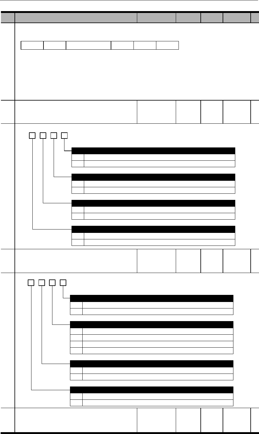
BIT15
Position 15
BIT14
Position 14
BIT2
Position 2
BIT1
Position 1
BIT0
Position 0
PA770
Internal position control switch 2
b. 3 2 1 0
0
1
0
1
Stop.
Pause.
Trigger signal selection
Use PTRG
Use internal position selection signals: INPOS0、INPOS1、INPOS2、INPOS3
0
1
Trigger time sequence selection
Only receive new trigger signal when current position is completed (CMD-OK)
Can receive new trigger even though current position is not completed
PZERO function selection
0
1
Software limit switch selection
Invalid. No software limit switch.
Valid. PA756, PA757 are positive limits; PA758, PA759 are negative limits.
PA771
Internal position control switch 3
d. 3 2 1 0
0
1
0
1
Forward rotation
Reverse rotation
Homing pattern selection
After contacting zero switch, look for Z pulse by rotating backward
After contacting zero switch, look for Z pulse by rotating forward
Homing rotational direction
0
1
Homing completion operation
Clear all position data
Not clear all position data
0
1
Homing signal selection
Use ZPS
Use Z pulse
2
3
After contacting zero switch, rotate backward, not look for Z pulse
After contacting zero point switch, rotate forward, not look for Z pulse
PA772
Internal position control switch 4
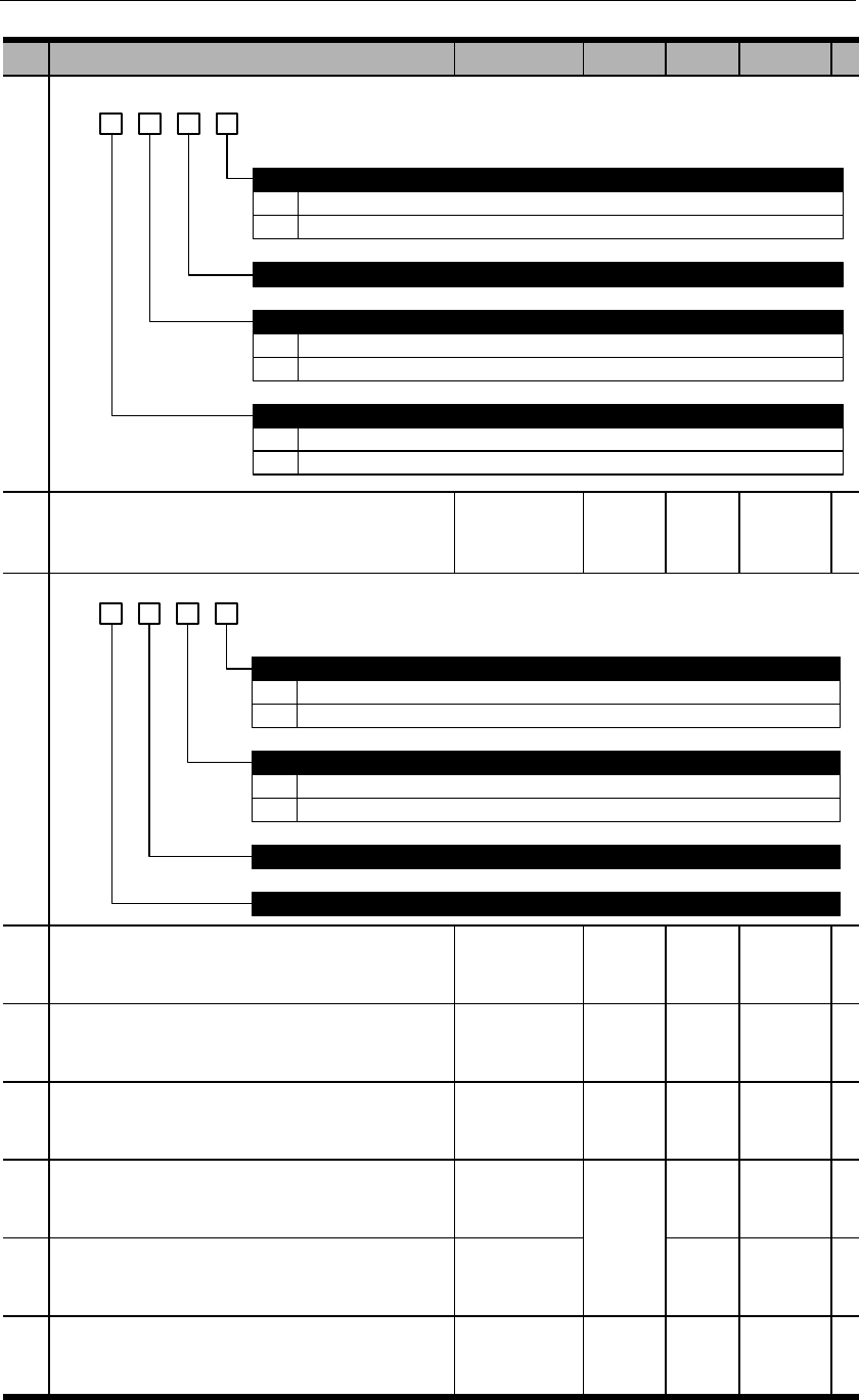
b. 3 2 1 0
0
1
Use feedback position
Use reference position
Reserved
Calculating absolute positions
0
1
Use of electronic gear for communication position feedback
Feedback data 0x0783, 0x0784 as data after electronic gear.
Feedback data 0x0783, 0x0784 as motor feedback data to be used with dP 00 and dP 01.
0
1
High/low switchover
Same as user manual, 32-bit data not negate
Contrary to user manual, 32-bit data negate
PA773
Internal position control switch 5
b. 3 2 1 0
0
1
CLR signal function
Only clear position deviation.
Clear all position data
Reserved
Reserved
0
1
Homing position limit
Valid
Invalid. Only valid when homing completed after run backwards and find zero point.
PA774
Reserved
PA775
Homing speed before contacting zero signal
PA776
Homing speed after contacting zero signal
PA777
Zero switch offset low place
PA778
Zero switch offset high place
PA779
Positive software limit switch low place

PA780
Positive software limit switch high place
PA781
Negative software limit switch low place
PA782
Negative software limit switch high place
