DP 340x MOTOTRBO Portable Basic Service Manual DP3400 3401 3600 3601 6866574D29 E
User Manual: DP3400 3401 3600 3601 Basic service manual 6866574D29-E
Open the PDF directly: View PDF ![]() .
.
Page Count: 85
- 6866574D29-E DP BSM EN.pdf
- Foreword
- Document History
- Table of Contents
- Foreword ii
- Chapter 1 Introduction 1-1
- Chapter 2 Test Equipment and Service Aids 2-1
- Chapter 3 Transceiver Performance Testing 3-1
- Chapter 4 Radio Programming and Tuning 4-1
- Chapter 5 Disassembly/Reassembly Procedures 5-1
- Chapter 6 Basic Troubleshooting 6-1
- Appendix A EMEA Regional Warranty, Service and Technical Support A-1
- Glossary Glossary-1
- List of Figures
- List of Tables
- Chapter 1 Introduction
- Chapter 2 Test Equipment and Service Aids
- Chapter 3 Transceiver Performance Testing
- Chapter 4 Radio Programming and Tuning
- Chapter 5 Disassembly/Reassembly Procedures
- 5.1 Introduction
- 5.2 Preventive Maintenance
- 5.3 Safe Handling of CMOS and LDMOS Devices
- 5.4 Repair Procedures and Techniques - General
- 5.5 Disassembling and Reassembling the Radio - General
- 5.6 Radio Disassembly - Detailed
- 5.7 Radio Reassembly - Detailed
- 5.8 Ensuring Radio Immersibility
- 5.9 Radio Exploded Mechanical Views and Parts Lists
- Chapter 6 Basic Troubleshooting
- Appendix A EMEA Regional Warranty, Service and Technical Support
- Glossary

Foreword
This manual covers all models of the DP series Portable Radios, unless otherwise specified. It includes all the information
necessary to maintain peak product performance and maximum working time, using levels 1 and 2 maintenance
procedures. This level of service goes down to the board replacement level and is typical of some local service centers,
self-maintained customers, and distributors.
Product Safety and RF Exposure Compliance
ATTENTION!
This radio is restricted to occupational use only to satisfy FCC RF energy exposure requirements.
Before using this product, read the RF energy awareness information and operating instructions in the
Product Safety and RF Exposure booklet enclosed with your radio (Motorola Publication part number
6864117B25 ) to ensure compliance with RF energy exposure limits.
For a list of Motorola-approved antennas, batteries, and other accessories, visit the following web site:
http://www.motorola.com/governmentandenterprise
Computer Software Copyrights
The Motorola products described in this manual may include copyrighted Motorola computer programs stored in
semiconductor memories or other media. Laws in the United States and other countries preserve for Motorola certain
exclusive rights for copyrighted computer programs, including, but not limited to, the exclusive right to copy or reproduce in
any form the copyrighted computer program. Accordingly, any copyrighted Motorola computer programs contained in the
Motorola products described in this manual may not be copied, reproduced, modified, reverse-engineered, or distributed in
any manner without the express written permission of Motorola. Furthermore, the purchase of Motorola products shall not
be deemed to grant either directly or by implication, estoppel, or otherwise, any license under the copyrights, patents or
patent applications of Motorola, except for the normal non-exclusive license to use that arises by operation of law in the
sale of a product.
Document Copyrights
No duplication or distribution of this document or any portion thereof shall take place without the express written permission
of Motorola. No part of this manual may be reproduced, distributed, or transmitted in any form or by any means, electronic
or mechanical, for any purpose without the express written permission of Motorola.
Disclaimer
The information in this document is carefully examined, and is believed to be entirely reliable. However, no responsibility is
assumed for inaccuracies. Furthermore, Motorola reserves the right to make changes to any products herein to improve
readability, function, or design. Motorola does not assume any liability arising out of the applications or use of any product
or circuit described herein; nor does it cover any license under its patent rights nor the rights of others.
Trademarks
MOTOROLA and the Stylized M logo are registered in the U.S. Patent and Trademark Office. All other product or service
names are the property of their respective owners.
© 2007 and 2008 Motorola, Inc.
All rights reserved.
Before using this product, read the operating instructions
for safe usage contained in the Product Safety and RF
Exposure booklet enclosed with your radio.
!
C a u t i o n

iii
Document History
The following major changes have been implemented in this manual since the previous edition:
Edition Description Date
6866574D29-A Initial Release Feb. 2007
6866574D29-B Added VHF band information.
Updated UHF1 Model Chart.
Added leak test procedures.
June 2007
6866574D29-C Added pin layout diagram in Test Equipment and
Service Aids chapter.
Updated Troubleshooting Charts in Disassembly/
Reassembly chapter.
Added warning note in Transceiver Performance
Testing chapter.
Updated front cover and diagrams of knobs.
Updated knob removal tool part number.
Updated Technical Support contact information in
Appendix A.
Oct. 2007
6866574D29-D Updated model charts and added 20kHz
specifications information in Introduction chapter. Jan. 2008
6866574D29-E Added UHF2 band information.
Updated Radio Exploded Mechanical Views and
Parts Lists.
June 2008

iv
Notes

Table of Contents v
Table of Contents
Foreword.........................................................................................................ii
Product Safety and RF Exposure Compliance............................................................................................ii
Computer Software Copyrights ...................................................................................................................ii
Document Copyrights..................................................................................................................................ii
Disclaimer....................................................................................................................................................ii
Trademarks .................................................................................................................................................ii
Document History ........................................................................................ iii
Chapter 1 Introduction ......................................................................... 1-1
1.1 Notations Used in This Manual.................................................................................................... 1-1
1.2 Radio Description ........................................................................................................................ 1-1
1.2.1 Display Model.................................................................................................................. 1-2
1.2.2 Non-Display Model ..........................................................................................................1-3
1.3 Portable Radio Model Numbering Scheme ................................................................................. 1-4
1.4 Model Charts ............................................................................................................................... 1-5
1.4.1 VHF Model Chart............................................................................................................. 1-5
1.4.2 UHF1 Model Chart...........................................................................................................1-6
1.4.3 UHF2 Model Chart...........................................................................................................1-7
1.5 Specifications............................................................................................................................... 1-8
Chapter 2 Test Equipment and Service Aids ..................................... 2-1
2.1 Recommended Test Equipment .................................................................................................. 2-1
2.2 Service Aids................................................................................................................................. 2-2
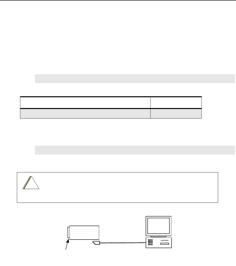
2.3 Programming, Testing and Alignment Cable ............................................................................... 2-3
Chapter 3 Transceiver Performance Testing ..................................... 3-1
3.1 General ........................................................................................................................................ 3-1
3.2 Setup ........................................................................................................................................... 3-1
3.3 Display Model Test Mode ............................................................................................................ 3-3
3.3.1 Entering Display Radio Test Mode.................................................................................. 3-3
3.3.2 RF Test Mode.................................................................................................................. 3-3
3.3.3 Display Test Mode........................................................................................................... 3-7
3.3.4 LED Test Mode................................................................................................................ 3-7
3.3.5 Backlight Test Mode........................................................................................................3-7
3.3.6 Speaker Tone Test Mode................................................................................................ 3-7
3.3.7 Earpiece Tone Test Mode ............................................................................................... 3-7
3.3.8 Audio Loopback Earpiece Test Mode.............................................................................. 3-7
3.3.9 Battery Check Test Mode................................................................................................ 3-8
3.3.10 Button/Knob/PTT Test Mode........................................................................................... 3-8
3.4 Non–Display Model Test Mode..................................................................................................3-10
3.4.1 Entering Non–Display Radio Test Mode ....................................................................... 3-10

vi Table of Contents
3.4.2 RF Test Mode................................................................................................................3-10
3.4.3 LED Test Mode..............................................................................................................3-10
3.4.4 Speaker Tone Test Mode ..............................................................................................3-10
3.4.5 Earpiece Tone Test Mode ............................................................................................. 3-11
3.4.6 Audio Loopback Earpiece Test Mode............................................................................3-11
3.4.7 Battery Check Test Mode .............................................................................................. 3-11
3.4.8 Button/Knob/PTT Test Mode .........................................................................................3-11
Chapter 4 Radio Programming and Tuning ....................................... 4-1
4.1 Introduction ..................................................................................................................................4-1
4.2 Customer Programming Software Setup ..................................................................................... 4-1
4.3 AirTracer Application Tool............................................................................................................4-1
4.4 Radio Tuning Setup ..................................................................................................................... 4-2
Chapter 5 Disassembly/Reassembly Procedures ............................. 5-1
5.1 Introduction ..................................................................................................................................5-1
5.2 Preventive Maintenance ..............................................................................................................5-1
5.2.1 Inspection ........................................................................................................................5-1
5.2.2 Cleaning Procedures .......................................................................................................5-1
5.3 Safe Handling of CMOS and LDMOS Devices ............................................................................5-2
5.4 Repair Procedures and Techniques – General............................................................................5-4
5.5 Disassembling and Reassembling the Radio — General ............................................................ 5-4
5.6 Radio Disassembly – Detailed ..................................................................................................... 5-5
5.6.1 Front Cover from Chassis Disassembly .......................................................................... 5-5
5.6.2 Chassis Disassembly.......................................................................................................5-8
5.6.3 Speaker Disassembly....................................................................................................5-11
5.7 Radio Reassembly – Detailed....................................................................................................5-12
5.7.1 Speaker Reassembly.....................................................................................................5-12
5.7.2 Chassis Reassembly .....................................................................................................5-14
5.7.3 Chassis and Front Cover Reassembly .......................................................................... 5-17
5.8 Ensuring Radio Immersibility .....................................................................................................5-18
5.8.1 Servicing........................................................................................................................5-18
5.8.2 Accidental Immersion ....................................................................................................5-18
5.8.3 Specialized Test Equipment ..........................................................................................5-19
5.8.4 Vacuum Pump Kit NLN9839..........................................................................................5-19
5.8.5 Pressure Pump Kit NTN4265 ........................................................................................5-19
5.8.6 Miscellaneous Hardware ...............................................................................................5-19
5.8.7 Vacuum Test..................................................................................................................5-19
5.8.8 Pressure Test ................................................................................................................5-20
5.8.9 Troubleshooting Leak Areas..........................................................................................5-21
5.8.9.1 Front Housing .................................................................................................5-21
5.8.9.2 Chassis (Main Seal O-ring)............................................................................. 5-22
5.8.9.3 Battery Contact Seal.......................................................................................5-22
5.8.9.4 Breathing Vent Membrane and Breathing Vent Label ....................................5-23
5.8.10 Troubleshooting Charts .................................................................................................5-24
5.9 Radio Exploded Mechanical Views and Parts Lists ...................................................................5-27
5.9.1 Display Model Exploded View and Parts List ................................................................5-27
5.9.2 Non-Display Model Exploded View and Parts List.........................................................5-30
5.9.3 Torque Chart..................................................................................................................5-32

Table of Contents vii
Chapter 6 Basic Troubleshooting ....................................................... 6-1
6.1 Introduction .................................................................................................................................. 6-1
6.2 Replacement Back Cover Kit Procedures ................................................................................... 6-1
6.3 Power-Up Error Codes (Display Model only)............................................................................... 6-2
6.4 Operational Error Codes.............................................................................................................. 6-4
Appendix A EMEA Regional Warranty, Service and Technical Support ..
A-1
A.1 Warranty and Service Support.....................................................................................................A-1
A.1.1 Warranty Period and Return Instructions ........................................................................A-1
A.1.2 After Warranty Period......................................................................................................A-1
A.2 European Radio Support Centre (ERSC) ....................................................................................A-2
A.3 Piece Parts ..................................................................................................................................A-2
A.4 Technical Support........................................................................................................................A-3
A.5 Further Assistance From Motorola ..............................................................................................A-3
Glossary.........................................................................................Glossary-1

viii List of Figures
List of Figures
Figure 1-1. Display Model.......................................................................................................................1-2
Figure 1-2. Non-Display Model............................................................................................................... 1-3
Figure 1-3. Portable Radio Model Numbering Scheme..........................................................................1-4
Figure 2-1. Programming, Testing and Alignment Cable........................................................................2-3
Figure 2-2. Pin Layout of Side Connector .............................................................................................. 2-4
Figure 3-1. Battery Check Test Mode Display ........................................................................................3-8
Figure 4-1. CPS Programming Setup.....................................................................................................4-1
Figure 4-2. Radio Tuning Equipment Setup ...........................................................................................4-2
Figure 5-1. Dust Cover removal. ............................................................................................................5-5
Figure 5-2. Battery and Antenna removal...............................................................................................5-6
Figure 5-3. Knob removal. ......................................................................................................................5-6
Figure 5-4. Chassis removal................................................................................................................... 5-7
Figure 5-5. LCD Module removal. ..........................................................................................................5-8
Figure 5-6. LCD Retainer removal.......................................................................................................... 5-8
Figure 5-7. Transmission and Interface Board removal..........................................................................5-9
Figure 5-8. Shield Clip removal. ............................................................................................................. 5-9
Figure 5-9. O-ring and Battery Contact Seal removal...........................................................................5-10
Figure 5-10. Speaker removal. ............................................................................................................... 5-11
Figure 5-11. Speaker reassembly (Display Model).................................................................................5-12
Figure 5-12. Speaker reassembly (Non-Display Model).........................................................................5-13
Figure 5-13. O-ring and Battery Contact Seal reassembly. .................................................................... 5-14
Figure 5-14. Shield Clip reassembly.......................................................................................................5-15
Figure 5-15. Secondary O-ring reassembly............................................................................................5-15
Figure 5-16. Transmission and Interface Board reassembly. ................................................................. 5-16
Figure 5-17. LCD Retainer and LCD Module reassembly. ..................................................................... 5-16
Figure 5-18. Back Cover Kit reassembly. ...............................................................................................5-17
Figure 5-19. Chassis to Front Cover reassembly. ..................................................................................5-18
Figure 5-20. Connector Fitting - Fitting Seal Pump Connector...............................................................5-19
Figure 5-21. Display Model Exploded View............................................................................................5-27
Figure 5-22. Non-Display Model Exploded View .................................................................................... 5-30

List of Tables ix
List of Tables
Table 1-1. Radio Frequency Ranges and Power Levels....................................................................... 1-1
Table 2-1. Recommended Test Equipment........................................................................................... 2-1
Table 2-2. Service Aids ......................................................................................................................... 2-2
Table 2-3. Pin Configuration of Side Connector.................................................................................... 2-4
Table 3-1. Initial Equipment Control Settings........................................................................................ 3-1
Table 3-2. Front Panel Access Test Mode Displays.............................................................................. 3-3
Table 3-3. Test Environments................................................................................................................ 3-4
Table 3-4. Test Frequencies.................................................................................................................. 3-4
Table 3-5. Transmitter Performance Checks ........................................................................................3-5
Table 3-6. Receiver Performance Checks ............................................................................................ 3-6
Table 4-1. Software Installation Kits Radio Tuning Setup ..................................................................... 4-1
Table 5-1. Lead Free Solder Wire Part Number List............................................................................. 5-4
Table 5-2. Lead Free Solder Paste Part Number List ........................................................................... 5-4
Table 5-3. Display Model Exploded View Parts List............................................................................ 5-28
Table 5-4. Non-Display Model Exploded View Parts List.................................................................... 5-31
Table 5-5. Torque Specifications for Screws ....................................................................................... 5-32
Table 6-1. Power-Up Error Codes......................................................................................................... 6-2
Table 6-2. Operational Error Codes ...................................................................................................... 6-4

xRelated Publications
Related Publications
IMPRES Adaptive Single-Unit Charger User Manual ..................................................................6816787H01
IMPRES Adaptive Multi-Unit Charger User Manual.....................................................................6816789H01
IMPRES Adaptive Multi-Unit Charger Service Manual ................................................................ 6871357L01
Remote Speaker Microphone User Manual................................................................................. 6871003L01
IMPRES Remote Speaker Microphone User Manual .................................................................. 6871004L01
Factory Mutual Approval Manual ................................................................................................. 6871532L01
Chapter 1 Introduction
1.1 Notations Used in This Manual
Throughout the text in this publication, you will notice the use of note and caution notations. These
notations are used to emphasize that safety hazards exist, and due care must be taken and
observed.
NOTE: An operational procedure, practice, or condition that is essential to emphasize.
1.2 Radio Description
The DP series portable radios are available in the following frequency ranges and power levels.
These digital radios are among the most sophisticated two-way radios available. They have a robust
design for radio users who need high performance, quality, and reliability in their daily
communications. This architecture provides the capability of supporting a multitude of legacy and
advanced features resulting in a more cost-effective two-way radio communications solution.
CAUTION indicates a potentially hazardous situation which, if
not avoided, might result in equipment damage.
Table 1-1. Radio Frequency Ranges and Power Levels
Frequency Band Bandwidth Power Level
VHF 136–174 MHz 1 Watt or 5 Watt
UHF R1 403–470 MHz 1 Watt or 4 Watt
UHF R2 450–512 MHz 1 Watt or 4 Watt
!
C a u t i o n
1-2 Introduction: Radio Description
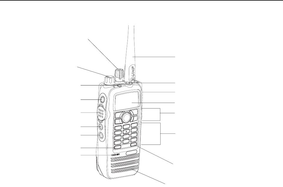
1.2.1 Display Model
Figure 1-1. Display Model
• ON/OFF/VOLUME KNOB – Rotate clockwise until click is heard to turn on radio; rotate counter-
clockwise until click is heard to turn off radio. Rotate clockwise to increase volume level; rotate
counter-clockwise to decrease volume level.
• LED INDICATORS – Red, green and orange light-emitting diodes indicate operating status.
• LCD (Liquid Crystal Display) – 132x34 full dot matrix display provides visual information about
many radio features.
• MENU NAVIGATION KEYS – Five keys to provide menu navigation and selection interface.
• KEYPAD – Twelve keys that allows the user to input characters for various text based
operations.
• FRONT BUTTONS and SIDE BUTTONS – These five buttons are field programmable using the
CPS.
• CHANNEL SELECTOR KNOB – Rotate clockwise to increment and counter clockwise to
decrement the channel.
• PUSH - to - TALK (PTT) – Press to execute voice operations (e.g. Group call and Private Call).
• ANTENNA – Provides the needed RF amplification when transmitting or receiving.
• MICROPHONE – Allows the voice to be sent when PTT or voice operations are activated.
• UNIVERSAL CONNECTOR FOR ACCESSORIES – Interface point for all accessories to be
used with the radio. It has twelve points to which specific accessories will connect and be
activated.
Front Button P2
Antenna
Emergency Button
Universal Connector for Accessories
Display
Menu Navigation Keys
Keypad
Speaker
Channel Selector Knob
On/Off/Volume Control Knob
LED Indicator
Side Button 1
Push-to-Talk (PTT) Button
Side Button 3
Side Button 2
Front Button P1
Microphone
Introduction: Radio Description 1-3
• EMERGENCY BUTTON – Turns on and off the Emergency Operations.
• SPEAKER – Outputs all tones and audio that are generated by the radio (e.g. features like
keypad tones and voice audio).
1.2.2 Non-Display Model
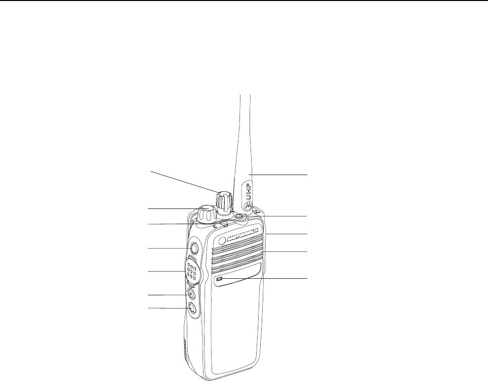
Figure 1-2. Non-Display Model
• ON/OFF/VOLUME KNOB – Rotate clockwise until click is heard to turn on radio; rotate counter-
clockwise until click is heard to turn off radio. Rotate clockwise to increase volume level; rotate
counter-clockwise to decrease volume level.
• LED INDICATORS – Red, green and orange light-emitting diodes indicate operating status.
• SIDE BUTTONS – These 3 buttons are field programmable using the CPS.
• CHANNEL SELECTOR KNOB – Rotate clockwise to increment and counter clockwise to
decrement the channel.
• PUSH - to - TALK (PTT) – Press to execute voice operations (e.g. Group call and Private Call).
• ANTENNA – Provides the needed RF amplification when transmitting or receiving.
• MICROPHONE – Allows the voice to be sent when PTT or voice operations are activated.
• UNIVERSAL CONNECTOR FOR ACCESSORIES – Interface point for all accessories to be
used with the radio. It has twelve points to which specific accessories will connect to and be
activated.
• EMERGENCY BUTTON – Turns on and off the Emergency Operations.
• SPEAKER – Outputs all tones and audio that are generated by the radio (e.g. features like
keypad tones and voice audio).
Channel Selector Knob
On/Off/Volume Control Knob
LED Indicator
Side Button 1
Side Button 3
Side Button 2
Push-to-Talk (PTT) Button
Antenna
Emergency Button
Universal Connector for Accessories
Speaker
Microphone

1-4 Introduction: Portable Radio Model Numbering Scheme
1.3 Portable Radio Model Numbering Scheme
Figure 1-3. Portable Radio Model Numbering Scheme
Model No.Example : AZ H 5 5 Q D H 9 L A 1 A N
Position : 1 2 3 4 5 6 7 8 9 10 11 12
N: Standard Package
Version Letter
Feature Level
1: Standard
Primary System Type
A: Conventional
Primary Operation
J: w/o GPS
L: w/ GPS
Channel Spacing
9: Variable/Programmable
Power Level
D: 1.0-5.0 W
55: MOTOTRBO Portable
Model Series
Band
Q: 403-470MHz
T: 450-527 MHz
J: 136-174MHz
Physical Packages
C: Non-Display Model
H: Display Model
H: Portable
A
Z: Asia/Australia
LA: Latin America
A
A: North America (except Mexico)
MD: Europe/Middle East/Africa
Introduction: Model Charts 1-5
1.4 Model Charts
1.4.1 VHF Model Chart
DP Series, VHF, 136–174 MHz
Model Description
MDH55JDH9LA1AN 136–174 MHz 5W, MOTOTRBO Display Portable with GPS
MDH55JDH9JA1AN 136–174 MHz 5W, MOTOTRBO Display Portable without GPS
MDH55JDC9LA1AN 136–174 MHz 5W, MOTOTRBO Non-Display Portable with GPS
MDH55JDC9JA1AN 136–174 MHz 5W, MOTOTRBO Non-Display Portable without
GPS
Item Description
X PMLD4308_ Back Cover Kit, MOTOTRBO Display Portable with GPS
XPMLD4309_ Back Cover Kit, MOTOTRBO Display Portable without GPS
X PMLD4326_ Back Cover Kit, MOTOTRBO Non-Display Portable with GPS
XPMLD4327_ Back Cover Kit, MOTOTRBO Non-Display Portable without GPS
X X PMLN4646_ Front Cover Kit with Display and Keypad
XXPMLN4922_ Front Cover Kit without Display and Keypad
XXXXPMAD4067_ VHF GPS Helical Antenna (136–147MHz)
XXXXPMAD4068_ VHF GPS Helical Antenna (147–160MHz)
XXXXPMAD4069_ VHF GPS Helical Antenna (160–174MHz)
XX6866574D01 Quick Reference Guide
X X 6866574D02 Quick Reference Guide
1-6 Introduction: Model Charts
1.4.2 UHF1 Model Chart
DP Series, UHF1, 403–470 MHz
Model Description
MDH55QDH9LA1AN 403–470 MHz 4W, MOTOTRBO Display Portable with GPS
MDH55QDH9JA1AN 403–470 MHz 4W, MOTOTRBO Display Portable without GPS
MDH55QDC9LA1AN 403–470 MHz 4W, MOTOTRBO Non-Display Portable with GPS
MDH55QDC9JA1AN 403–470 MHz 4W, MOTOTRBO Non-Display Portable without
GPS
Item Description
X PMLE4371_ Back Cover Kit, MOTOTRBO Display Portable with GPS
XPMLE4372_ Back Cover Kit, MOTOTRBO Display Portable without GPS
X PMLE4428_ Back Cover Kit, MOTOTRBO Non-Display Portable with GPS
XPMLE4429_ Back Cover Kit, MOTOTRBO Non-Display Portable without GPS
X X PMLN4646_ Front Cover Kit with Display and Keypad
XXPMLN4922_ Front Cover Kit without Display and Keypad
X X PMLN4018_ UHF GPS Folded Monopole(403–433 MHz)
XXPMLN4024_ UHF GPS Folded Monopole(433–470 MHz)
X X PMAE4021_ UHF GPS Stubby Antenna(403–433 MHz)
XXPMAE4023_ UHF GPS Stubby Antenna(430–470 MHz)
X X PMAE4022_ UHF Whip Antenna(430–470 MHz)
XX6866574D01 Quick Reference Guide
X X 6866574D02 Quick Reference Guide

Introduction: Model Charts 1-7
1.4.3 UHF2 Model Chart
DP Series, UHF2, 450–512 MHz
Model Description
MDH55TDH9LA1AN 450–512 MHz 4W, MOTOTRBO Display Portable with GPS
MDH55TDH9JA1AN 450–512 MHz 4W, MOTOTRBO Display Portable without GPS
MDH55TDC9LA1AN 450–512 MHz 4W, MOTOTRBO Non-Display Portable with GPS
MDH55TDC9JA1AN 450–512 MHz 4W, MOTOTRBO Non-Display Portable without
GPS
Item Description
X PMUE3088_ Back Cover Kit, MOTOTRBO Display Portable with GPS
XPMUE3087_ Back Cover Kit, MOTOTRBO Display Portable without GPS
X PMUE3089_ Back Cover Kit, MOTOTRBO Non-Display Portable with GPS
XPMUE3090_ Back Cover Kit, MOTOTRBO Non-Display Portable without GPS
X X PMLN4646_ Front Cover Kit with Display and Keypad
XXPMLN4922_ Front Cover Kit without Display and Keypad
X X PMAE4050_ UHF2 GPS Folded Monopole(450–495 MHz)
XXPMAE4051_ UHF2 GPS Folded Monopole(495–527 MHz)
X X PMAE4052_ UHF2 GPS Stubby Antenna(450–495 MHz)
XXPMAE4048_ UHF2 GPS Stubby Antenna(495–527 MHz)
X X PMAE4049_ UHF2 Whip Antenna(450–527 MHz)
XX6866574D01 Quick Reference Guide
X X 6866574D02 Quick Reference Guide
1-8 Introduction: Specifications
1.5 Specifications
General Display
DP 3600/ DP 3601 Non-Display
DP 3400/ DP 3401
Channel Capacity 160 32
Frequency VHF: 136 – 174 MHz
UHF1: 403 – 470 MHz
UHF2: 450 – 512 MHz
Dimensions (HxWxT) w/ NiMH battery 5.18 x 2.40 x 1.38 in (131.5 x 61 x 35 mm)
Weight (with NiMH battery)
(with LiIon FM battery)
(with LiIon non-FM battery)
(with LiIon 2200 battery)
15.2 oz (430 g)
13 oz (370 g)
12.7 oz (360 g)
12.7 oz (360 g)
13.2 oz (375 g)
11.1 oz (315 g)
10.75 oz (305 g)
10.75 oz (305 g)
Power Supply 7.5V nominal
Average battery life at 5/5/90 duty cycle with battery saver enabled in carrier squelch and transmitter in high
power.
NiMH core battery Analog: 8 hrs
Digital: 11.2 hrs
IMPRES LiIon Slim Battery (Standard) Analog: 9.3 hrs
Digital: 13 hrs
IMPRES FM LiIon Analog: 8.7 hrs
Digital: 12.1 hrs
IMPRES LiIon 2200 Analog: 13.5 hrs
Digital: 19 hrs
Introduction: Specifications 1-9
* 20 kHz channel spacing is not applicable for UHF2.
Receiver Display
DP 3600/ DP 3601 Non-Display
DP 3400/ DP 3401
Frequencies VHF: 136 – 174 MHz
UHF1: 403 – 470 MHz
UHF2: 450 – 512 MHz
Channel Spacing 12.5 kHz/ *20 kHz/ 25 kHz
Frequency Stability (-30°C to +60°C) +/-1.5 ppm (DP 3600)
+/-0.5 ppm (DP 3601) +/-1.5 ppm (DP 3400)
+/-0.5 ppm (DP 3401)
Analog Sensitivity 0.35 µV (12dB SINAD)
0.22 µV (typical) (12dB SINAD)
0.4 µV (typical) (20dB SINAD)
Digital Sensitivity 5% BER: 0.3µV
Intermodulation (ETS) 65 dB
Adjacent Channel Selectivity 60 dB @ 12.5 kHz, 70 dB @ *20 kHz/ 25 kHz
Spurious Rejection 70 dB
Rated Audio 500 mW
Audio Distortion @ Rated Audio 3% (typical)
Hum and Noise -40 dB @ 12.5 kHz
-45 dB @ *20 kHz/ 25 kHz
Audio Response +1, -3 dBm
Conducted Spurious Emission -57 dBm
1-10 Introduction: Specifications
* 20 kHz channel spacing is not applicable for UHF2.
Transmitter Display
DP 3600/ DP 3601 Non-Display
DP 3400/ DP 3401
Frequencies VHF: 136 – 174 MHz
UHF1: 403 – 470 MHz
UHF2: 450 – 512 MHz
Channel Spacing 12.5 kHz/ *20kHz/ 25 kHz
Frequency Stability (-30°C to +60°C) +/-1.5 ppm (DP 3600)
+/-0.5 ppm (DP 3601) +/-1.5 ppm (DP 3400)
+/-0.5 ppm (DP 3401)
Power Output (Low Power) 1 W
Power Output (High Power) VHF: 5 W
UHF1/UHF2: 4 W
Modulation Limiting +/-2.5 kHz @ 12.5 kHz
+/-4.0 kHz @ *20 kHz
+/-5.0 kHz @ 25 kHz
FM Hum and Noise -40 dB @ 12.5 kHz
-45 dB @ *20 kHz/ 25 kHz
Conducted / Radiated Emission -36 dBm < 1 GHz
-30 dBm > 1 GHz
Adjacent Channel Power 60 dB @ 12.5 kHz
70 dB @ *20 kHz/ 25 kHz
Audio Response +1, -3 dBm
Audio Distortion 3% (typical)
FM Modulation 12.5 kHz: 11K0F3E
*20 kHz: 14K0F3E
25 kHz: 16K0F3E
4FSK Digital Modulation 12.5 kHz Data Only: 7K60FXD
12.5 kHz Data & Voice: 7K60FXE
Digital Vocoder Type AMBE+2
Digital Protocol ETSI-TS102361-1
ETSI-TS102361-2
ETSI-TS102361-3
Introduction: Specifications 1-11
UHF1 Self-Quieter Frequencies
GPS Non-GPS
403.20 MHz ± 5k
409.23 MHz ± 5k –
414.00 MHz
417.79 MHz ± 10k
420.00 MHz ± 5k
425.60 MHz ± 5k –
431.10 MHz ± 5k
432.00 MHz ± 5k
436.80 MHz ± 5k
441.97 MHz ± 5k –
442.36 MHz ± 10k
444.00 MHz ± 5k
450.00 MHz
453.60 MHz ± 5k
458.34 MHz ± 5k –
466.93 MHz ± 10k
468.00 MHz ± 5k
VHF Self-Quieter Frequencies
GPS Non-GPS
144.000 MHz ± 100k
147.320 MHz ± 5k –
147.455 MHz ± 10k
151.200 MHz ± 5k
156.000 MHz ± 10k
162.000 MHz ± 10k
163.690 MHz ± 5k –
166.675 MHz ± 5k
168.000 MHz ± 5k
172.030 MHz ± 10k
1-12 Introduction: Specifications
UHF2 Self-Quieter Frequencies
GPS Non-GPS
450.000 MHz
453.600 MHz ± 5k
458.340 MHz ± 5k –
466.930 MHz ± 10k
468.000 MHz ± 5k
470.400 MHz ± 5k
474.701 MHz ± 10k –
480.000 MHz ± 5k
486.000 MHz ± 15k
487.200 MHz ± 5k
491.070 MHz ± 10k –
491.520 MHz ± 10k
502.200 MHz ± 5k
504.000 MHz ± 15k
506.695 MHz ± 5k
507.439 MHz ± 15k –
Introduction: Specifications 1-13
GPS Display
DP 3600/ DP 3601 Non-Display
DP 3400/ DP 3401
TTFF (Time To First Fix) Cold Start < 1 minute
TTFF (Time To First Fix) Hot Start < 10 seconds
Horizontal Accuracy < 10 meters
Accuracy specs are for long-term tracking (95th percentile values > 5 satellites visible at a nominal
-130 dBm signal strength)
Military Standards
Applicable MIL–STD 810E 810F
Methods Procedures Methods Procedures
Low Pressure 500.3 II 500.4 II
High Temperature 501.3 I/A, II/A1 501.4 I/Hot, II/Hot
Low Temperature 502.3 I/C3, II/C1 502.4 I/C3, II/C1
Temperature Shock 503.3 I/A, 1C3 503.4 I
Solar Radiation 505.3 I 505.4 I
Rain 506.3 I,II 506.4 I, III
Humidity 507.3 II 507.4 –
Salt fog 509.3 I 509.4 I
Dust 510.3 I 510.4 I
Vibration 514.4 I/10,II/3 514.5 I/24
Shock 516.4 I, IV 516.5 I, IV
1-14 Introduction: Specifications
* -Operating temperature specification with LiIon battery is -10°C to +60°C.
-Operating temperature specification with NiMH battery is -20°C to +60°C.
Conforms to:
MOTOTRBO Portable series radios meet FM (Factory Mutual) standards for intrinsic safety used in
Class I, II, III, Division 1, Groups C, D, E, F, and G when properly equipped with a Motorola FM
approved battery option. They are also approved for nonincendive use in Class I, Division 2, Groups
A, B, C, and D. For more details, please refer to the Factory Mutual Approval Manual (6871532L01).
ETSI TS 102 361 (Parts 1, 2 & 3) – ETSI DMR Standard
1999/5/EC (R&TTE – Radio and Telecommunications Terminal Equipment)
2002/95/EC (RohS – Banned Substances)
2002/96/EC (WEEE – Waste Electrical and Electronic Equipment)
94/62/EC (Packaging and Packaging Waste)
Radio meets applicable regulatory requirements.
Specifications subject to change without notice. All specfications shown are typical.
Environmental Specifications
*Operating Temperature -30°C to +60°C
Storage Temperature -40°C to +85°C
Thermal Shock Per MIL-STD
Humidity Per MIL-STD
ESD IEC-801-2KV
Water Intrusion IEC 60529 -IP57
Packaging Test MIL-STD 810D and E

Chapter 2 Test Equipment and Service Aids
2.1 Recommended Test Equipment
The list of equipment contained in Table 2-1 includes most of the standard test equipment required
for servicing Motorola portable radios.
Table 2-1. Recommended Test Equipment
Equipment Characteristics Example Application
Service
Monitor Can be used as a substi-
tute for items marked with
an asterisk (*)
Aeroflex 2975
(www.aeroflex.com),
Motorola R2670, or equivalent
Frequency/deviation meter and
signal generator for wide-range
troubleshooting and alignment
Digital RMS
Multimeter * 100 µV to 300 V
5 Hz to 1 MHz
10 Mega Ohm Impedance
Fluke 179 or equivalent
(www.fluke.com) AC/DC voltage and
current measurements. Audio
voltage measurements
RF Signal
Generator * 100 MHz to 1 GHz
-130 dBm to +10 dBm
FM Modulation 0 kHz to
10 kHz
Audio Frequency 100 Hz
to 10 kHz
Agilent N5181A
(www.agilent.com),
Ramsey RSG1000B
(www.ramseyelectronics.com), or
equivalent
Receiver measurements
Oscilloscope * 2 Channel
50 MHz Bandwidth
5 mV/div to 20 V/div
Leader LS8050
(www.leaderusa.com),
Tektronix TDS1001b
(www.tektronix.com),
or equivalent
Waveform measurements
Power Meter
and Sensor * 5% Accuracy
100 MHz to 500 MHz
50 Watts
Bird 43 Thruline Watt Meter
(www.bird-electronic.com) or
equivalent
Transmitter power output
measurements
RF Millivolt
Meter 100 mV to 3 V RF
10 kHz to 1 GHz Boonton 92EA
(www.boonton.com) or equivalent RF level measurements
Power Supply 0 V to 32 V
0 A to 20 A B&K Precision 1790
(www.bkprecision.com)
or equivalent
Voltage supply
2-2 Test Equipment and Service Aids: Service Aids
2.2 Service Aids
Table 2-2 lists the service aids recommended for working on the radio. While all of these items are
available from Motorola, most are standard workshop equipment items, and any equivalent item
capable of the same performance may be substituted for the item listed.
Table 2-2. Service Aids
Motorola
Part No. Description Application
RLN4460_ Portable Test Set Enables connection to the audio/accessory jack.
Allows switching for radio testing.
GMVN5141_ Customer Programming
Software on CD-ROM Allows servicer to program radio parameters, tune
and troubleshoot radios.
PMKN4012_ Portable Programming Cable This cable connects the radio to a USB port for radio
programming and data applications.
PMKN4013_ Portable Programming, Testing &
Alignment Cable This cable connects the radio to a USB port for radio
programming, testing and alignment.
PMNN4076_ 7.5V Universal Battery Eliminator Connects to radio via battery eliminator cable.
5880348B33 DMR SMA to BNC RF Adaptor Adapts radio’s antenna port to BNC cabling of test
equipment.
PMHN4085_ Bench Test Housing Eliminator Interconnects radio to power supply. Provides for
troubleshooting of the radio when the housing is
removed.
NLN9839_ Vacuum Pump Kit Allows servicer to test for leakages.
NTN4265_ Pressure Pump Kit Allows servicer to locate leakages.
5871134M01 Connector Fitting This connector allows the vacuum hose to be con-
nected to the radio chassis.
3271133M01 Fitting Seal This seal secures the connector fitting to the radio
chassis.
Test Equipment and Service Aids: Programming, Testing and Alignment Cable 2-3
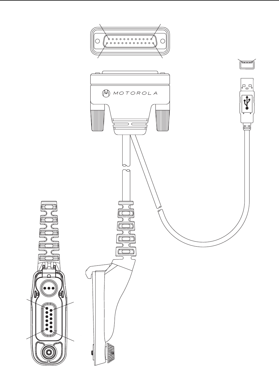
2.3 Programming, Testing and Alignment Cable
Figure 2-1. Programming, Testing and Alignment Cable
#1
#14
#25
#13
#4
#1
#2
#12
#11
#1
P1
P2
P3
2-4 Test Equipment and Service Aids: Programming, Testing and Alignment Cable
Figure 2-2. Pin Layout of Side Connector
Table 2-3. Pin Configuration of Side Connector
CONNECTION
P1 P2 P3
Pin Pin Pin Function
1 3 VCC (5V)
34DATA +
25DATA -
16 6 GROUND
78 SPEAKER -
17 10 EXTERNAL MIC +
16 11 EXTERNAL MIC -
20 9 EXTERNAL PTT
17 SPEAKER +
41
(Coax
Connector)
GROUND
slot for accessory
connector hook
Coaxial RF
Connector
1
23
45
67
89
10 11
12
GPIO_0
Spkr +
Spkr -
Mic +
Mic -
GPIO_3
GPIO_4
1-Wire
Vbus
D+
D-
GND
Chapter 3 Transceiver Performance Testing
3.1 General
These radios meet published specifications through their manufacturing process by utilizing high-
accuracy laboratory-quality test equipment. The recommended field service equipment approaches
the accuracy of the manufacturing equipment with few exceptions. This accuracy must be
maintained in compliance with the manufacturer’s recommended calibration schedule.
Although these radios function in digital and analog modes, all testing is done in analog mode.
3.2 Setup
Supply voltage is provided using a 7.5 VDC power supply. The equipment required for alignment
procedures is connected as shown in the Radio Tuning Equipment Setup Diagram, Figure 4-2.
Initial equipment control settings should be as indicated in Table 3-1. The remaining tables in this
chapter contain the following related technical data:
Do NOT use any form of connector, e.g. wires, crocodile
clips, and probes, to supply voltage to the radio, other
than the Motorola approved battery eliminator.
Table Number Title
3-2 Front Panel Access Test Mode Displays
3-3 Test Environments
3-4 Test Frequencies
3-5 Transmitter Performance Checks
3-6 Receiver Performance Checks
Table 3-1. Initial Equipment Control Settings
Service Monitor Power Supply Test Set
Monitor Mode: Power Monitor Voltage: 7.5Vdc Speaker set: A
RF Attn: -70 DC on/standby:
Standby Speaker/load:
Speaker
AM, CW, FM: FM Volt Range: 10V PTT: OFF

3-2 Transceiver Performance Testing Setup
Oscilloscope Source: Mod
Oscilloscope Horizontal: 10mSec/Div
Oscilloscope Vertical: 2.5kHz/Div
Oscilloscope Trigger: Auto
Monitor Image: Hi
Monitor Bandwidth: Narrow
Monitor Squelch: Middle setting
Monitor Vol: 1/4 setting
Current: 2.5A
Table 3-1. Initial Equipment Control Settings
Service Monitor Power Supply Test Set
Transceiver Performance Testing Display Model Test Mode 3-3
3.3 Display Model Test Mode
3.3.1 Entering Display Radio Test Mode
1. Turn the radio on.
2. Within 10 seconds after Self Test is complete, press Side Button 2 five times in succession
3. The radio beeps and will show a series of displays that will give information regarding various
version numbers and subscriber specific information. The displays are described in Table 3-2.
NOTE: The radio stops at each display for 2 seconds before moving to the next information display.
If the information cannot fit into 1 line, the radio display scrolls automatically character by
character after 1 second to view the whole information. If the Left Navigation Key (W) is
pressed before the last information display, the radio shall suspend the information display
until the user presses Right Navigation Key (X) to resume the information display. The radio
beeps for each button press. After the last display, RF Test Mode will be displayed.
3.3.2 RF Test Mode
When the radio is operating in its normal environment, the radio's microcontroller controls the RF
channel selection, transmitter key-up, and receiver muting, according to the customer codeplug
configuration. However, when the unit is on the bench for testing, alignment, or repair, it must be
removed from its normal environment via a special routine, called TEST MODE or air test.
In RF Test Mode, the display upon the first line is “RF Test”, together with the power level icon at the
right end of the first line. The display upon the second line is the test environment, the channel
number and channel spacing. The default test environment is CSQ.
1. Each short press of Side Button 2 changes the test environment (CSQ->TPL->DIG->USQ
->CSQ). The radio beeps once when radio toggles to CSQ, beeps twice for TPL, beeps three
times for DIG and beeps four times for USQ.
NOTE: DIG is digital mode and other test environments are analog mode as described in Table 3-3.
Table 3-2. Front Panel Access Test Mode Displays
Name of Display Description Appears
Service Mode The literal string indicates the radio has entered test mode. Always
Host Version The version of host firmware. Always
DSP Version The version of DSP firmware. Always
Model Number The radio’s model number as programmed in the codeplug. Always
MSN The radio’s serial number as programmed in the codeplug. Always
FLASHCODE The FLASH codes as programmed in the codeplug. Always
RF Band The radio’s band. Always
3-4 Transceiver Performance Testing Display Model Test Mode
2. Each short press of Side Button 1 toggles the channel spacing between 25 kHz, 12.5 kHz
and 20 kHz as. The radio beeps once when radio toggles to 20kHz, beeps twice for 25 kHz
and beeps three times for 12.5 kHz.
3. Turning of the Channel Knob changes the test channel from 1 to 14 as described in
Table 3-4. The radio beeps in each position.
Table 3-3. Test Environments
No. of
Beeps Description Function
1Carrier Squelch
(CSQ) RX: if carrier detected
TX: mic audio
2 Tone Private-Line
(TPL) RX: unsquelch if carrier and tone detected
TX: mic audio + tone
3Digital Mode
(DIG) RX: if carrier detected
TX: mic audio
4 Unsquelch
(USQ) RX: constant unsquelch
TX: mic audio
Table 3-4. Test Frequencies
Channel
Selector
Switch
Position
Test
Channel UHF1 UHF2 VHF
1 Low Power
8 High Power TX#1 or #8
RX#1 or #8 403.000
403.000 450.075
450.075 136.075
136.075
2 Low Power
9 High Power TX#2 or #9
RX#2 or #9 414.150
414.150 464.075
464.075 142.575
142.575
3 Low Power
10 High Power TX#3 or #10
RX#3 or #10 425.350
425.350 475.075
475.075 146.575
146.575
4 Low Power
11 High Power TX#4 or #11
RX#4 or #11 436.500
436.500 486.525
486.525 155.575
155.575
5 Low Power
12 High Power TX#5 or #12
RX#5 or #12 447.675
447.675 496.875
496.875 161.575
161.575
6 Low Power
13 High Power TX#6 or #13
RX#6 or #13 458.850
458.850 504.875
504.875 167.575
167.575
7 Low Power
14 High Power TX#7 or #14
RX#7 or #14 470.000
470.000 511.875
511.875 173.975
173.975

Transceiver Performance Testing Display Model Test Mode 3-5
Table 3-5. Transmitter Performance Checks
Test Name Communications
Analyzer Radio Test Set Comments
Reference
Frequency Mode: PWR MON
4th channel test
frequency*
Monitor: Frequency
error
Input at RF In/Out
TEST MODE,
Test Channel 4
carrier squelch
PTT to
continuously
transmit
(during the
performance
check)
Frequency error to be
±654 Hz for
non-GPS models
(UHF1)
±218 Hz for GPS
models (UHF1)
±729 Hz for
non-GPS models
(UHF2)
±243 Hz for GPS
models (UHF2)
±233 Hz for
non-GPS models
(VHF)
±77 Hz for GPS
models (VHF)
Power RF As above As above As above Low Power:
1.0 – 1.6W (VHF/
UHF1/UHF2)
High Power:
4.0 – 4.8W (UHF1/
UHF2)
5.0 – 6.0W (VHF)
Voice
Modulation Mode: PWR MON
4th channel test
frequency*
atten to -70, input to RF
In/Out
Monitor: DVM: AC Volts
Set 1kHz Mod Out level
for 0.025Vrms at test
set,
80mVrms at AC/DC
test set jack
As above As above, meter
selector to mic Deviation:
≥ 4.0 kHz but ≤ 5.0
kHz (25 kHz Ch Sp).
Voice
Modulation
(internal)
Mode: PWR MON
4th channel test
frequency*
atten to -70, input to RF
In/Out
TEST MODE,
Test Channel 4
carrier squelch
output at
antenna
Remove
modulation input Press PTT switch on
radio. Say “four”
loudly into the radio
mic. Measure
deviation:
≥ 4.0 kHz but ≤ 5.0
kHz (25 kHz Ch Sp)
TPL
Modulation As above
4th channel test
frequency*
BW to narrow
TEST MODE,
Test Channel 4
TPL
As above Deviation:
≥500Hz but ≤1000Hz
(25 kHz Ch Sp).

3-6 Transceiver Performance Testing Display Model Test Mode
* See Table 3-4
* See Table 3-4
Table 3-6. Receiver Performance Checks
Test Name Communications
Analyzer Radio Test Set Comments
Reference
Frequency Mode: PWR MON
4th channel test
frequency*
Monitor: Frequency error
Input at RF In/Out
TEST MODE,
Test Channel 4
carrier squelch
output at
antenna
PTT to
continuously
transmit
(during the
performance
check)
Frequency error to be
±654 Hz for
non-GPS models
(UHF1)
±218 Hz for GPS
models (UHF1)
±729 Hz for
non-GPS models
(UHF2)
±243 Hz for GPS
models (UHF2)
±233 Hz for
non-GPS models
(VHF)
±77 Hz for GPS
models (VHF)
Rated Audio Mode: GEN
Output level: 1.0mV RF
4th channel test
frequency*
Mod: 1kHz tone at
3kHz deviation
Monitor: DVM: AC Volts
TEST MODE
Test Channel 4
carrier squelch
PTT to OFF
(center), meter
selector to Audio
PA
Set volume
control to 2.83Vrms
Distortion As above, except to
distortion As above As above Distortion <3.0%
Sensitivity
(SINAD) As above, except SINAD,
lower the RF level for
12dB SINAD.
As above PTT to OFF
(center) RF input to be
<0.35μV
Noise
Squelch
Threshold
(only radios
with
conventional
system need
to be tested)
RF level set to 1mV RF As above PTT to OFF
(center), meter
selection to
Audio PA,
speaker/load to
speaker
Set volume
control to 2.83Vrms
As above, except change
frequency to a
conventional system.
Raise RF level from zero
until radio unsquelches.
Out of TEST
MODE; select
a conventional
system
As above Unsquelch to occur at
<0.25μV.
Preferred SINAD = 9
– 10dB

Transceiver Performance Testing Display Model Test Mode 3-7
3.3.3 Display Test Mode
1. Press and hold Side Button 1 in RF Test Mode. The radio beeps once and momentarily
displays “Display Test Mode”.
2. Upon entering Display Test Mode, the radio displays a horizontal line on row 8 (center row).
3. With each button/key press, the radio fills the screen up with 2 horizontal lines from the center
row (1 line each above and below the center row) until the top and bottom of the screen (row
7-0 and row 9-16) is completely full.
4. When the screen is filled up with the horizontal lines, any button/key press clears the screen
and displays vertical lines at column 0, 6, 12, 18, 24, 30, 36, 42, 48, 54, 60. Any button/key
press fills the screen with vertical lines, (1 line to the right of any existing line) until the display
is full.
5. When the screen is filled up with the vertical lines, any button/key press clears the screen and
displays the first 10 available icons on the screen. Successive button/key press displays the
remaining 4 icons.
3.3.4 LED Test Mode
1. Press and hold Side Button 1 after Display Test Mode. The radio beeps once and displays
“LED Test Mode”.
2. Upon any button/key press, the radio lights the red LED and displays “Red LED On”.
3. Consequently, upon any button/key press, the red LED is turned off and the radio lights the
green LED and displays “Green LED On”.
4. Upon any successive button/key press, the green LED is turned off, and the radio shall light
both LEDs up while displaying “Both LEDs On”. Since there is only one LED on the portable,
the LED color will be orange when the radio lights both LEDs.
3.3.5 Backlight Test Mode
1. Press and hold Side Button 1 after LED Test Mode. The radio beeps once and displays
“Backlight Test Mode”.
2. The radio turns on both LCD and keypad backlight together.
3.3.6 Speaker Tone Test Mode
1. Press and hold Side Button 1 after Backlight Test Mode. The radio beeps once and displays
“Speaker Tone Test Mode”.
2. The radio generates a 1 KHz tone with the internal speaker.
3.3.7 Earpiece Tone Test Mode
1. Press and hold Side Button 1 after Speaker Tone Test Mode. The radio beeps once and
displays “Earpiece Tone Test Mode”.
2. The radio generates a 1 KHz tone with the earpiece.
3.3.8 Audio Loopback Earpiece Test Mode
1. Press and hold Side Button 1 after Earpiece Tone Test Mode. The radio beeps once and
displays “Audio Loopback Earpiece Test Mode”.
2. The radio shall route any audio on the external mic to the earpiece.
3-8 Transceiver Performance Testing Display Model Test Mode
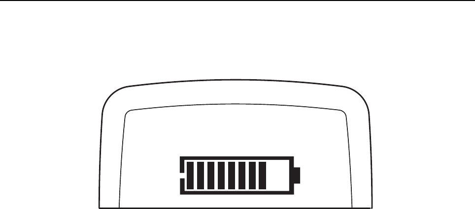
3.3.9 Battery Check Test Mode
1. Press and hold Side Button 1 after Audio Loopback Earpiece Test Mode. The radio beeps
once and momentarily displays “Battery Check Test Mode”.
2. The radio will display the following:
Figure 3-1. Battery Check Test Mode Display
3.3.10 Button/Knob/PTT Test Mode
1. Press and hold Side Button 1 after Battery Check Test Mode. The radio beeps once and
displays “Button Test”(line 1).
2. The radio also displays the button/knob/PTT button command opcode (BCO) and state
(BCO/state) on the screen (line 2) upon any button state changes.
3. Rotate the Volume Knob; “2/0” through “2/255” appears. The radio beeps at each position.
4. Rotate the Channel Knob; “4/0” through “4/15” appears. The radio beeps at each position.
5. Press Side Button 1; “96/1” appears & radio beeps; release, “96/0” appears & radio beeps.
6. Press Side Button 2; “97/1”appears & radio beeps; release, “97/0” appears & radio beeps.
7. Press Side Button 3; “98/1”appears & radio beeps; release, “98/0” appears & radio beeps.
8. Press the PTT Switch; “1/1” appears & radio beeps; release, “1/0” appears & radio beeps.
9. Press Top Button; “148/1” appears & radio beeps; release, “148/0” appears & radio beeps.
10. Keypad Checks:
-Press 0, “48/1” appears & radio beeps; release, “48/0” appears & radio beeps.
-Press 1, “49/1” appears & radio beeps; release, “49/0” appears & radio beeps.
-Press 2, “50/1” appears & radio beeps; release, “50/0” appears & radio beeps.
-Press 3, “51/1” appears & radio beeps; release, “51/0” appears & radio beeps.
-Press 4, “52/1” appears & radio beeps; release, “52/0” appears & radio beeps.
-Press 5, “53/1” appears & radio beeps; release, “53/0” appears & radio beeps.
-Press 6, “54/1” appears & radio beeps; release, “54/0” appears & radio beeps.
-Press 7, “55/1” appears & radio beeps; release, “55/0” appears & radio beeps.
-Press 8, “56/1” appears & radio beeps; release, “56/0” appears & radio beeps.
-Press 9, “57/1” appears & radio beeps; release, “57/0” appears & radio beeps.
-Press *, “58/1” appears & radio beeps; release, “58/0” appears & radio beeps.
- Press #, “59/1” appears & radio beeps; release, “59/0” appears & radio beeps.
-Press P1, “160/1” appears & radio beeps; release, “160/0” appears & radio beeps.
-Press P2, “161/1” appears & radio beeps; release, “161/0” appears & radio beeps.
Capacity: 88%

Transceiver Performance Testing Display Model Test Mode 3-9
- Press OK, “85/1” appears & radio beeps; release, “85/0” appears & radio beeps.
- Press MENU, “139/1” appears & radio beeps; release, “139/0” appears & radio beeps.
- Press BACK, “129/1” appears & radio beeps; release, “129/0” appears & radio beeps.
- Press W, “128/1” appears & radio beeps; release, “128/0” appears & radio beeps.
- Press X, “130/1” appears & radio beeps; release, “130/0” appears & radio beeps.

3-10 Transceiver Performance Testing Non–Display Model Test Mode
3.4 Non–Display Model Test Mode
3.4.1 Entering Non–Display Radio Test Mode
1. Turn the radio on.
2. Within 10 seconds after “Self Test” is complete, press Side Button 2 five times in succession.
3. The radio beeps.
3.4.2 RF Test Mode
When the radio is operating in its normal environment, the radio's microcontroller controls the RF
channel selection, transmitter key-up, and receiver muting, according to the customer codeplug
configuration. However, when the unit is on the bench for testing, alignment, or repair, it must be
removed from its normal environment via a special routine, called TEST MODE or “air test”.
1. Each short press of Side Button 2 changes the test environment (CSQ->TPL->DIG->USQ
->CSQ). The radio beeps once when radio toggles to CSQ, beeps twice for TPL, beeps three
times for DIG and beeps four times for USQ.
NOTE: DIG is digital mode and other test environments are analog mode as described in Table 3-3.
2. Each short press of Side Button 1 toggles the channel spacing between 25 KHz, 12.5 KHz
and 20 KHz as. The radio beeps once when radio toggles to 20KHz, beeps twice for 25KHz
and beeps three times for 12.5KHz.
3. Turning of the Channel Knob changes the test channel from 1 to 14 as described in
Table 3-4. The radio beeps in each position.
3.4.3 LED Test Mode
1. Press and hold Side Button 1 in RF Test Mode. The radio beeps once.
2. Upon any button/key press, the radio lights up the red LED.
3. Consequently, upon any button/key press, the red LED is turned off and the radio turns on the
green LED.
4. Consequently, upon any button/key press, the green LED is turned off the radio shall turn on
both LEDs.
3.4.4 Speaker Tone Test Mode
1. Press and hold Side Button 1 after LED Test Mode. The radio beeps once.
2. The radio generates a 1 KHz tone with the internal speaker.

Transceiver Performance Testing Non–Display Model Test Mode 3-11
3.4.5 Earpiece Tone Test Mode
1. Press and hold Side Button 1 after Speaker Tone Test Mode. The radio beeps once.
2. The radio generates a 1 KHz tone with the earpiece.
3.4.6 Audio Loopback Earpiece Test Mode
1. Press and hold Side Button 1 after Earpiece Tone Test Mode. The radio beeps once.
2. The radio shall route any audio on the external mic to the earpiece.
3.4.7 Battery Check Test Mode
1. Press and hold Side Button 1 after Audio Loopback Earpiece Test Mode. The radio beeps
once.
2. The radio LED lights up accordingly; green LED for High Battery Level, orange LED for Mid
Battery Level and blinking red LED for Low Battery Level.
3.4.8 Button/Knob/PTT Test Mode
1. Press and hold Side Button 1 after Battery Check Test Mode. The radio beeps once.
2. Rotate the Volume Knob; the radio beeps at each position.
3. Rotate the Channel Knob; the radio beeps at each position.
4. Press Side Button 1; the radio beeps; release, the radio beeps.
5. Press Side Button 2; the radio beeps; release, the radio beeps.
6. Press Side Button 3; the radio beeps; release, the radio beeps.
7. Press the PTT Switch; the radio beeps; release, the radio beeps.
8. Press Top Button; the radio beeps; release, the radio beeps.

Notes
3-12 Transceiver Performance Testing Non–Display Model Test Mode
Chapter 4 Radio Programming and Tuning
4.1 Introduction
This chapter provides an overview of the MOTOTRBO Customer Programming Software (CPS), as
well as the Tuner and AirTracer applications, which are all designed for use in a Windows 2000/XP
environment. These programs are available in one kit as listed in Table 4-1. An Installation Guide is
also included with the kit.
4.2 Customer Programming Software Setup
The CPS programming setup, shown in Figure 4-1 is used to program the radio.
Figure 4-1. CPS Programming Setup
4.3 AirTracer Application Tool
The MOTOTRBO AirTracer application tool has the ability to capture over-the-air digital radio traffic
and save the captured data into a file. The AirTracer application tool can also retrieve and save
NOTE Refer to the appropriate program on-line help files for the programming procedures.
Table 4-1. Software Installation Kits Radio Tuning Setup
Description Kit Number
MOTOTRBO CPS, Tuner and AirTracer Applications CD GMVN5141_
NOTE Refer to appropriate program on-line help files for the programming procedures.
Computer USB ports can be sensitive to Electrostatic Discharge. Do not touch
exposed contacts on cable when connected to a computer.
!
C a u t i o n
Radio
Battery Programming, Testing
& Alignment Cable
PMKN4012_
PMKN4013_
4-2 Radio Programming and Tuning: Radio Tuning Setup
internal error logs from MOTOTRBO radios. The saved files can be analyzed by trained Motorola
personnel to suggest improvements in system configurations or to help isolate problems.
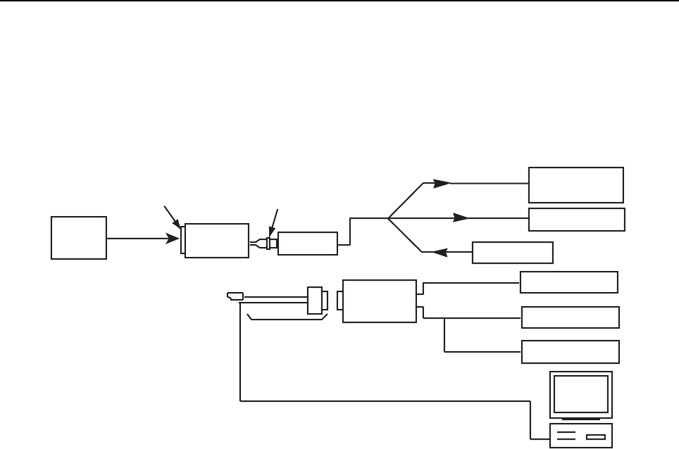
4.4 Radio Tuning Setup
A personal computer (PC), Windows 2000/XP and a tuner program are required to tune the radio.
To perform the tuning procedures, the radio must be connected to the PC, radio interface box (RIB),
and test equipment setup as shown in Figure 4-2.
Figure 4-2. Radio Tuning Equipment Setup
Wattmeter
Audio Generator
Sinad Meter
AC Voltmeter
10 dB Pad
Power
Supply
Audio InTx
Rx
Receive
Transmit
RF Generator
RF Adaptor
RLN4460_
Test Box
Radio
Programming, Testing &
Alignment Cable
PMKN4013
Service Monitor
or Counter
SMA to BNC
PMNN4076
+12VDC
Battery
Eliminator
7.5V Reg.

Chapter 5 Disassembly/Reassembly Procedures
5.1 Introduction
This chapter provides details about the following:
• Preventive maintenance (inspection and cleaning).
• Safe handling of CMOS and LDMOS devices.
• Disassembly and reassembly of the radio.
• Repair procedures and techniques.
5.2 Preventive Maintenance
Periodic visual inspection and cleaning is recommended.
5.2.1 Inspection
Check that the external surfaces of the radio are clean, and that all external controls and switches
are functional. It is not recommended to inspect the interior electronic circuitry.
5.2.2 Cleaning Procedures
The following procedures describe the recommended cleaning agents and the methods to be used
when cleaning the external and internal surfaces of the radio. External surfaces include the front
cover, housing assembly and battery case. These surfaces should be cleaned whenever a periodic
visual inspection reveals the presence of smudges, grease, and/or grime.
The only recommended agent for cleaning the external radio surfaces is a 0.5% solution of a mild
dishwashing detergent in water. The only factory recommended liquid for cleaning the printed circuit
boards and their components is isopropyl alcohol (100% by volume).
NOTE Internal surfaces should be cleaned only when the radio is disassembled for service or
repair.
The effects of certain chemicals and their vapors can have harmful results on
certain plastics. Avoid using aerosol sprays, tuner cleaners and other
chemicals.
!
C a u t i o n

5-2 Disassembly/Reassembly Procedures: Safe Handling of CMOS and LDMOS Devices
Cleaning External Plastic Surfaces
Apply the 0.5% detergent-water solution sparingly with a stiff, non-metallic, short-bristled brush to
work all loose dirt away from the radio. Use a soft, absorbent, lintless cloth or tissue to remove the
solution and dry the radio. Make sure that no water remains entrapped near the connectors, cracks,
or crevices.
Cleaning Internal Circuit Boards and Components
Isopropyl alcohol (100%) may be applied with a stiff, non-metallic, short-bristled brush to dislodge
embedded or caked materials located in hard-to-reach areas. The brush stroke should direct the
dislodged material out and away from the inside of the radio. Make sure that controls or tunable
components are not soaked with alcohol. Do not use high-pressure air to hasten the drying process
since this could cause the liquid to collect in unwanted places. After completing of the cleaning
process, use a soft, absorbent, lintless cloth to dry the area. Do not brush or apply any isopropyl
alcohol to the frame, front cover or back cover.
5.3 Safe Handling of CMOS and LDMOS Devices
Complementary metal-oxide semiconductor (CMOS) devices are used in this family of radios, and
are susceptible to damage by electrostatic or high voltage charges. Damage can be latent, resulting
in failures occurring weeks or months later. Therefore, special precautions must be taken to prevent
device damage during disassembly, troubleshooting, and repair.
Handling precautions are mandatory for CMOS circuits and are especially important in low humidity
conditions. DO NOT attempt to disassemble the radio without first referring to the CMOS CAUTION
paragraph in the Disassembly and Reassembly section of the manual.
NOTE Always use a fresh supply of alcohol and a clean container to prevent contamination by
dissolved material (from previous usage).

Disassembly/Reassembly Procedures: Safe Handling of CMOS and LDMOS Devices 5-3
DO NOT attempt to disassemble the radio without first referring to the following CAUTION
statement.
This radio contains static-sensitive devices. Do not open the radio unless you are
properly grounded. Take the following precautions when working on this unit:
• Store and transport all CMOS devices in conductive material so that
all exposed leads are shorted together. Do not insert CMOS devices
into conventional plastic “snow” trays used for storage and
transportation of other semiconductor devices.
• Ground the working surface of the service bench to protect the
CMOS device. We recommend using the Motorola Static Protection
Assembly (part number 0180386A82), which includes a wrist strap,
two ground cords, a table mat, and a floor mat.
• Wear a conductive wrist strap in series with a 100k resistor to
ground.
(Replacement wrist straps that connect to the bench top covering
are Motorola part number 4280385A59).
• Do not wear nylon clothing while handling CMOS devices.
• Do not insert or remove CMOS devices with power applied. Check
all power supplies used for testing CMOS devices to be certain that
there are no voltage transients present.
• When straightening CMOS pins, provide ground straps for the
apparatus used.
• When soldering, use a grounded soldering iron.
• If at all possible, handle CMOS devices by the package and not by
the leads. Prior to touching the unit, touch an electrical ground to
remove any static charge that you may have accumulated. The
package and substrate may be electrically common. If so, the
reaction of a discharge to the case would cause the same damage
as touching the leads.
!
C a u t i o n
5-4 Disassembly/Reassembly Procedures: Repair Procedures and Techniques – General
5.4 Repair Procedures and Techniques – General
Any rework or repair on Environmentally Preferred Products must be done using the appropriate
lead-free solder wire and lead-free solder paste as stated in the following table:
Parts Replacement and Substitution
When damaged parts are replaced, identical parts should be used. If the identical replacement part
is not locally available, check the parts list for the proper Motorola part number and order the part
Rigid Circuit Boards
This family of radios uses bonded, multi-layer, printed circuit boards. Since the inner layers are not
accessible, some special considerations are required when soldering and unsoldering components.
The printed-through holes may interconnect multiple layers of the printed circuit. Therefore, exercise
care to avoid pulling the plated circuit out of the hole.
When soldering near a connector:
• Avoid accidentally getting solder in the connector.
• Be careful not to form solder bridges between the connector pins.
• Examine your work closely for shorts due to solder bridges.
5.5 Disassembling and Reassembling the Radio — General
When disassembling and reassembling the radio, it is important to pay particular attention to the
snaps and tabs, and how parts align with each other.
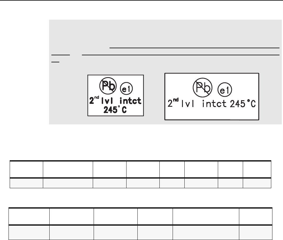
NOTE Environmentally Preferred Products (EPP) (refer to the marking on the printed circuit
boards — examples shown below) were developed and assembled using
environmentally preferred components and solder assembly techniques to comply with
the European Union’s Restriction of Hazardous Substances (ROHS) Directive 2002/
95/EC and Waste Electrical and Electronic Equipment (WEEE) Directive 2002/96/
EC. To maintain product compliance and reliability, use only the Motorola specified parts
in this manual.
Table 5-1. Lead Free Solder Wire Part Number List
Motorola
Part Number Alloy Flux Type Flux Content
by Weight Melting
Point Supplier Part
number Diameter Weight
1088929Y01 95.5Sn/3.8Ag/0.7Cu RMA Version 2.7-3.2% 217C 52171 0.015” 1lb spool
Table 5-2. Lead Free Solder Paste Part Number List
Motorola Part
Number Manufacturer Part
Number Viscosity Type Composition & Percent Metal Liquid
Temperature
1085674C03 NC-SMQ230 900-1000KCPs
Brookfield (5rpm) Type 3
(-325/+500) (95.5%Sn-3.8%Ag-0.7%Cu)
89.3% 217°C
Disassembly/Reassembly Procedures: Radio Disassembly – Detailed 5-5
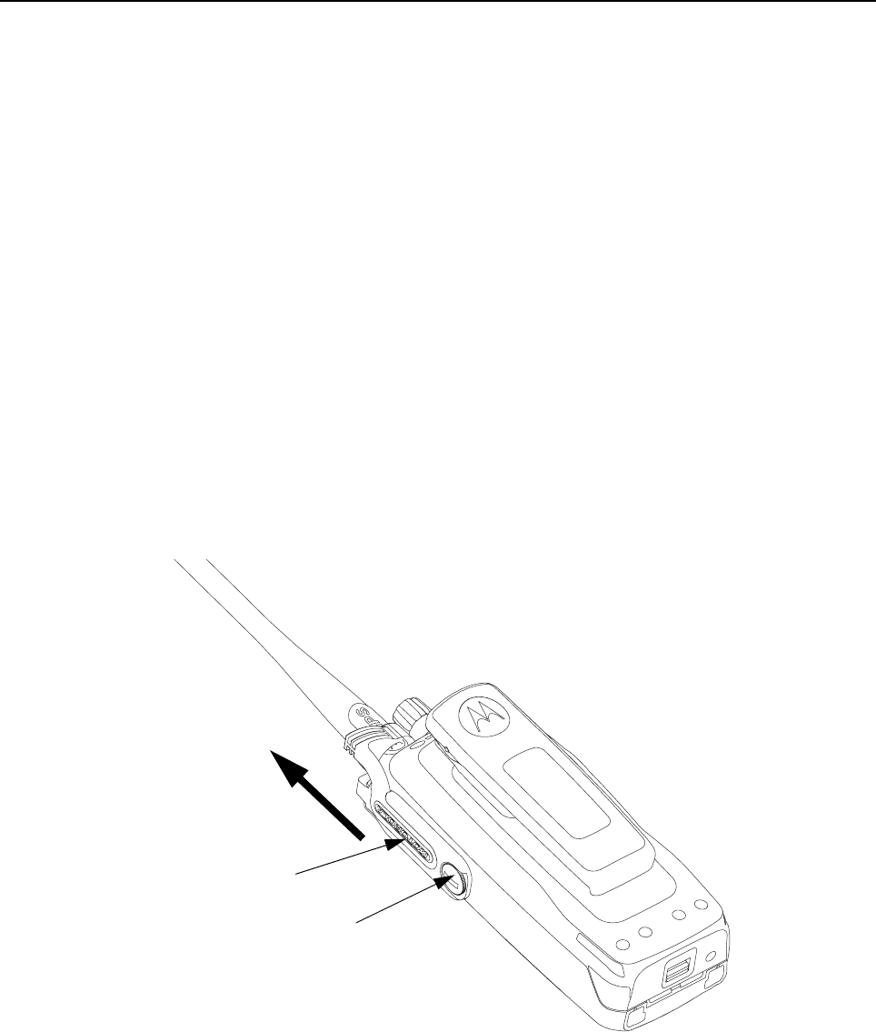
The following tools are required for disassembling the radio:
• TORX™ T6 screwdriver
• Knob Removal Tool (6671789L02)
The following item and tools are required for reassembling the radio:
• Grease (1185937A01)
• TORX™ T6 screwdriver
• Vacuum Pump Kit (NLN9839) - Radio Immersibility Test
• Pressure Pump Kit (NTN4265) - Radio Immersibility Test
• Connector Fitting (5871134M01) - Radio Immersibility Test
• Fitting Seal (3271133M01) - Radio Immersibility Test
If a unit requires further testing or service than is customarily performed at the basic level, please
send the radio to a Motorola Service Center.
5.6 Radio Disassembly – Detailed
5.6.1 Front Cover from Chassis Disassembly
1. Turn off the radio.
2. Unscrew the fastener screw.
3. Pull the dust cover upward to remove it.
Figure 5-1. Dust Cover removal.
Dust Cover
Screw
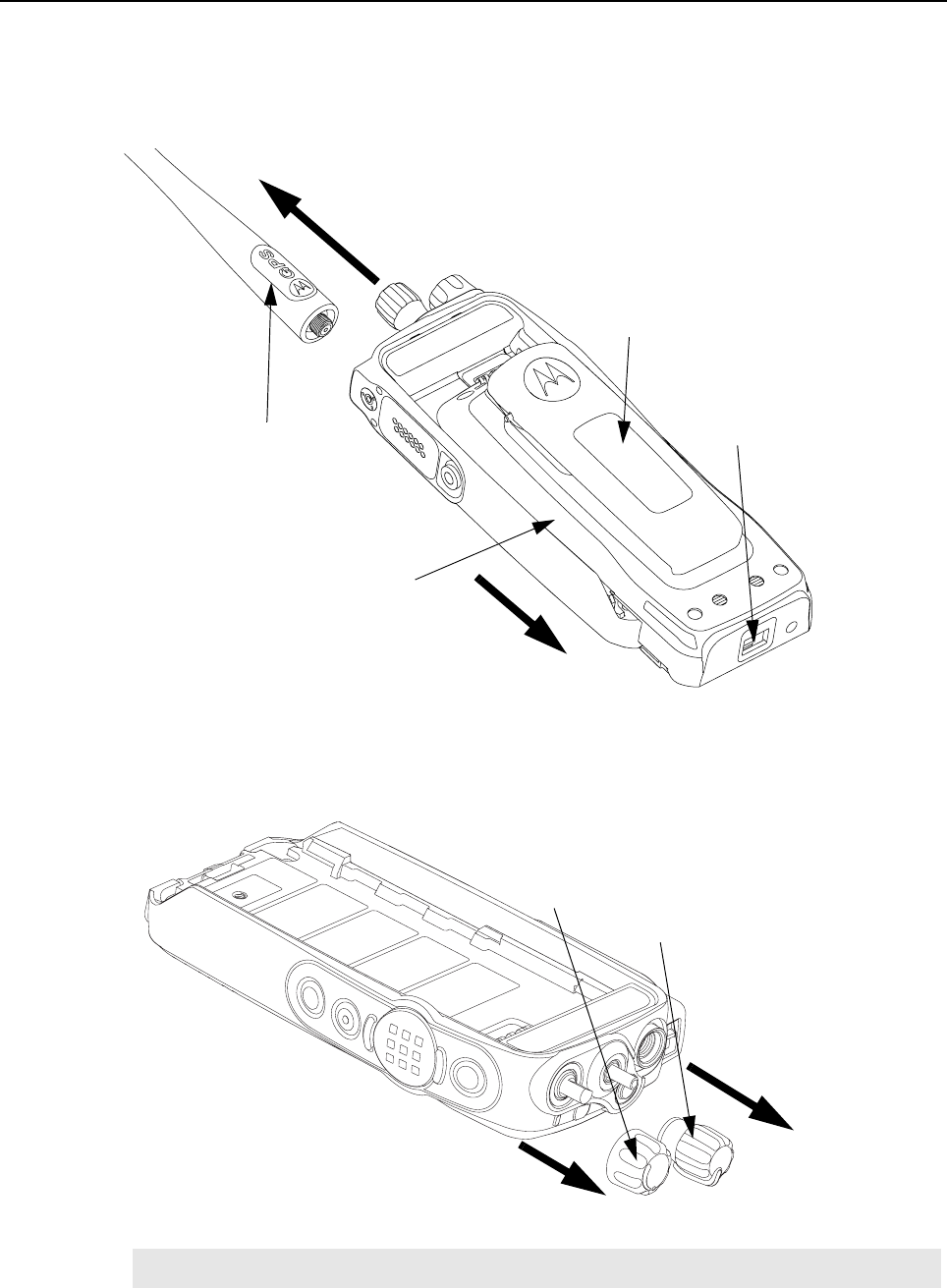
5-6 Disassembly/Reassembly Procedures: Radio Disassembly – Detailed
4. Remove the battery:
a. Release the battery latch by moving it into the unlock position.
b. With the latch released, slide the battery downwards.
c. Remove the battery from the radio.
Figure 5-2. Battery and Antenna removal.
5. Remove the antenna by turning it counterclockwise.
6. Remove the volume and channel selector knobs off from their shafts using the knob removal
tool.
Figure 5-3. Knob removal.
NOTE Both knobs slide on and off. However, they are supposed to fit very tightly on their shafts.
Antenna
Belt Clip
Battery
Battery Latch
Volume Knob
Channel Knob
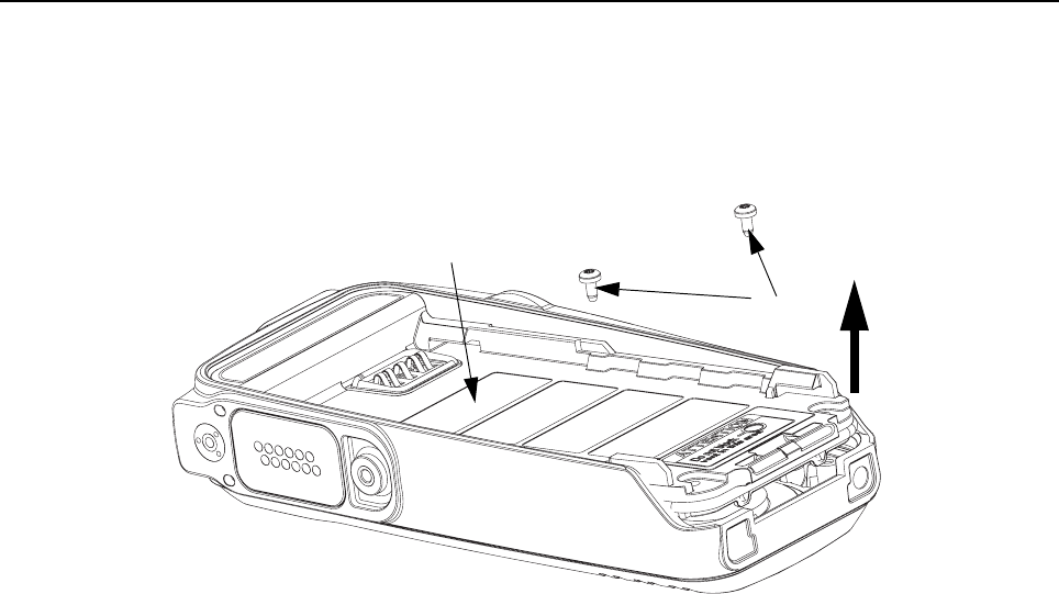
Disassembly/Reassembly Procedures: Radio Disassembly – Detailed 5-7
7. Separate the chassis from the internal electronics front cover assembly as follows:
a. Unscrew the screws using the TORX™ T6 screwdriver.
b. Release the chassis slightly upward and disconnect the board-to-board connector
between the option board and the keypad flex.
c. Remove the chassis from the front cover.
Figure 5-4. Chassis removal.
Chassis
Screws
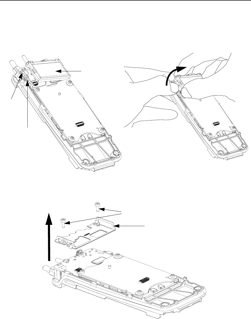
5-8 Disassembly/Reassembly Procedures: Radio Disassembly – Detailed
5.6.2 Chassis Disassembly
1. Display Module Disassembly
a. Release the display retainer catch and disconnect the board-to-board connector
between the display flex and the transmission board, subsequently remove the display
module.
Figure 5-5. LCD Module removal.
b. Remove the two screws using the TORX™ T6 screwdriver.
c. Remove the display retainer.
Figure 5-6. LCD Retainer removal.
Display
Retainer
Display Retainer
Catch
Display Module
Screws
Display Retainer
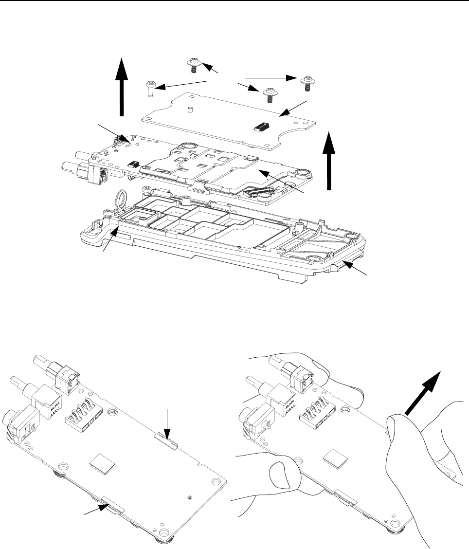
Disassembly/Reassembly Procedures: Radio Disassembly – Detailed 5-9
2. Use the TORX™ T6 screwdriver to remove the four screws holding the transmission board
and interface board.
3. Lift up the interface and transmission board to remove.
Figure 5-7. Transmission and Interface Board removal.
4. Release the catch from the reflow post by pushing away the shield clips.
5. Remove the shield clip by releasing the hook from the slot at the top shield.
Figure 5-8. Shield Clip removal.
Screws
Transmission
Board
Interface Board
Top Shield
O-ring
Chassis
Shield Clip
Reflow Post
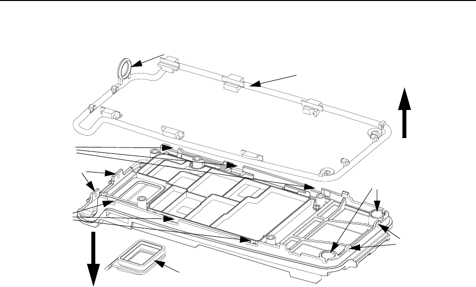
5-10 Disassembly/Reassembly Procedures: Radio Disassembly – Detailed
6. Release all the tabs from the catches.
7. Remove O-ring and battery contact seal.
Figure 5-9. O-ring and Battery Contact Seal removal.
Main O-ring
Catches
Catches
Battery Contact Seal
Secondary O-ring
Chassis Well
Notches
Notches
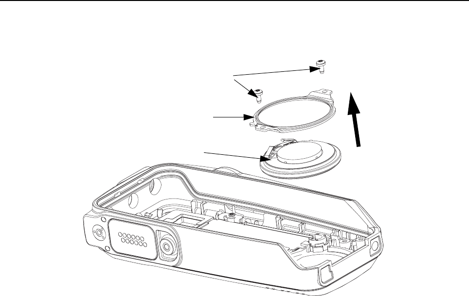
Disassembly/Reassembly Procedures: Radio Disassembly – Detailed 5-11
5.6.3 Speaker Disassembly
1. Remove the screws using the TORX™ T6 screwdriver.
2. Remove the speaker retainer and subsequently the speaker.
Figure 5-10. Speaker removal.
Screws
Speaker Retainer
Speaker
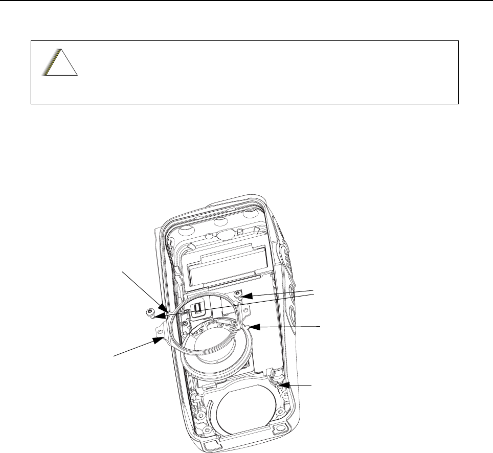
5-12 Disassembly/Reassembly Procedures: Radio Reassembly – Detailed
5.7 Radio Reassembly – Detailed
5.7.1 Speaker Reassembly
1. Place the speaker onto the front cover with the orientation tab aligned with the orientation slot
on the front cover.
2. Place speaker retainer in the correct orientation.
3. Fasten the screws using TORX™ T6 screwdriver.
Figure 5-11. Speaker reassembly (Display Model).
Adhere strictly to ALL reassembly procedures to ensure radio immersibility.
!
C a u t i o n
Screws
Speaker Retainer
Orientation Tab
Speaker Retainer
Speaker Orientation Tab
Speaker Orientation Slot
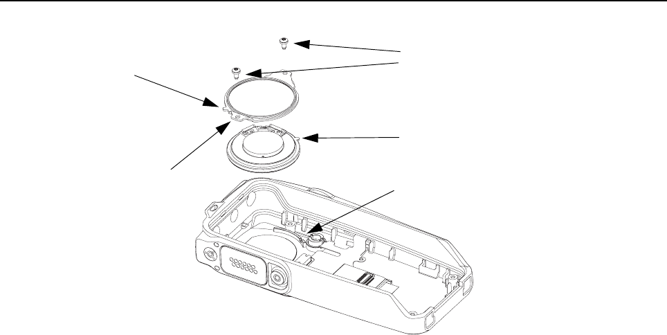
Disassembly/Reassembly Procedures: Radio Reassembly – Detailed 5-13
Figure 5-12. Speaker reassembly (Non-Display Model).
Screws
Speaker Retainer
Speaker Orientation Tab
Speaker Orientation Slot
Speaker Retainer
Orientation Tab
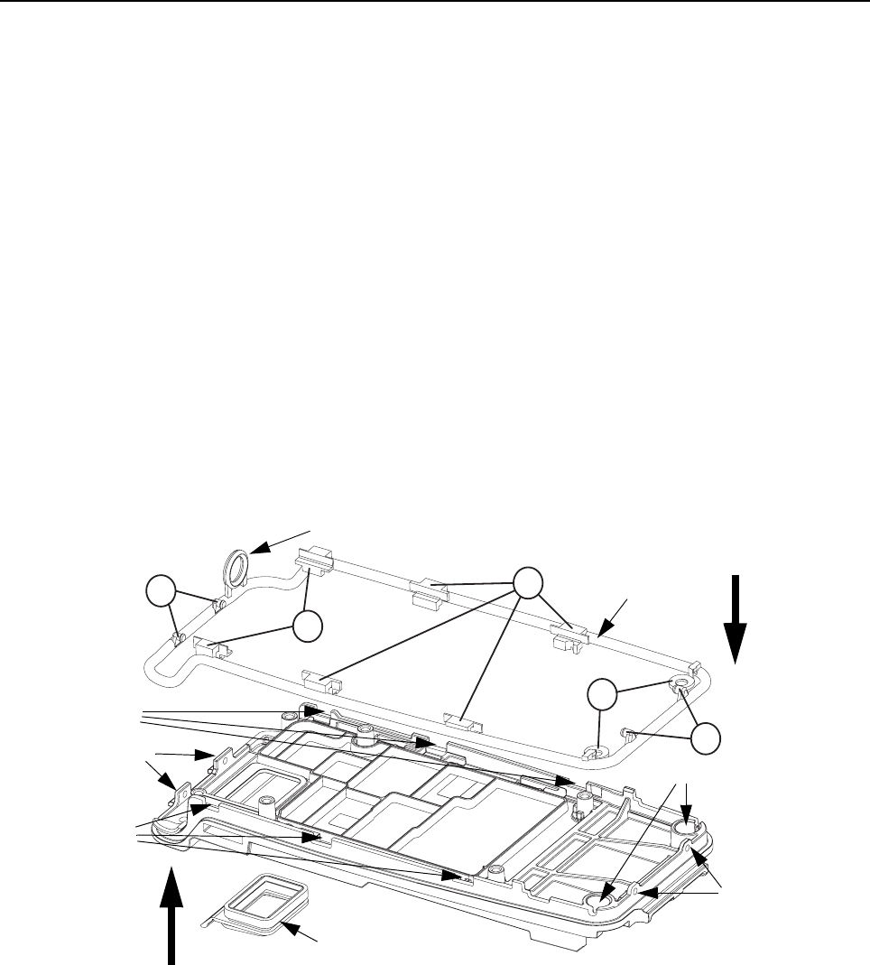
5-14 Disassembly/Reassembly Procedures: Radio Reassembly – Detailed
5.7.2 Chassis Reassembly
1. Fit the battery contact seal onto the battery contact slot.
2. Refer to Figure 5-13 to fit the main O-ring onto the chassis in the following sequence:
i. Ensure that the main O-ring is not twisted and untangle it to its actual form if needed
before performing reassembly.
ii. Secure A1 into the top two notches on the chassis.
iii. Fit the top section of the main O-ring by inserting it into the grooves at the top two cor-
ners formed by the black retainers.
iv. Insert B1 into the top two catches on the chassis.
v. Fit the bottom section of the main O-ring around the bottom two corners of the chassis.
vi. Secure A2 into the remaining four notches on the chassis.
vii. Insert C into the chassis well and push to the bottom of the well to secure it.
viii. Insert B2 into the bottom two catches on the chassis.
NOTE:To maintain radio immersibility, it is recommended that the main O-ring be replaced although
the existing one may appear undamaged. Be sure to replace the battery contact seal also if
necessary.
Figure 5-13. O-ring and Battery Contact Seal reassembly.
A1
A2
C
B1
B2
Catches
Main O-ring
Catches
Battery Contact Seal
Secondary O-ring
Chassis Well
Notches
Notches
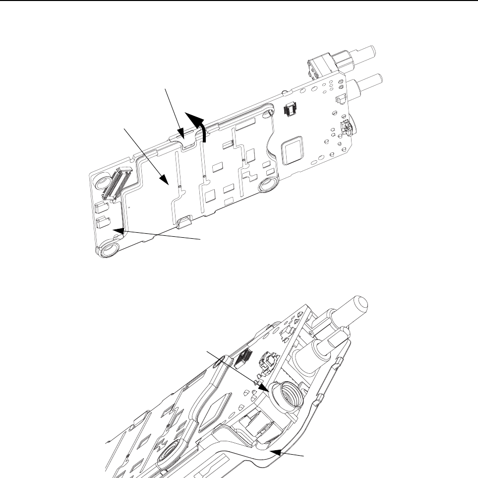
Disassembly/Reassembly Procedures: Radio Reassembly – Detailed 5-15
3. Hook the shield clip on the top shield slot.
4. Push against the clip towards the board until catch is securely in place.
Figure 5-14. Shield Clip reassembly.
5. Fit the secondary O-ring onto the antenna nut securely.
Figure 5-15. Secondary O-ring reassembly.
Top Shield
Shield Clip
Transmission Board
Secondary O-ring
Main O-ring
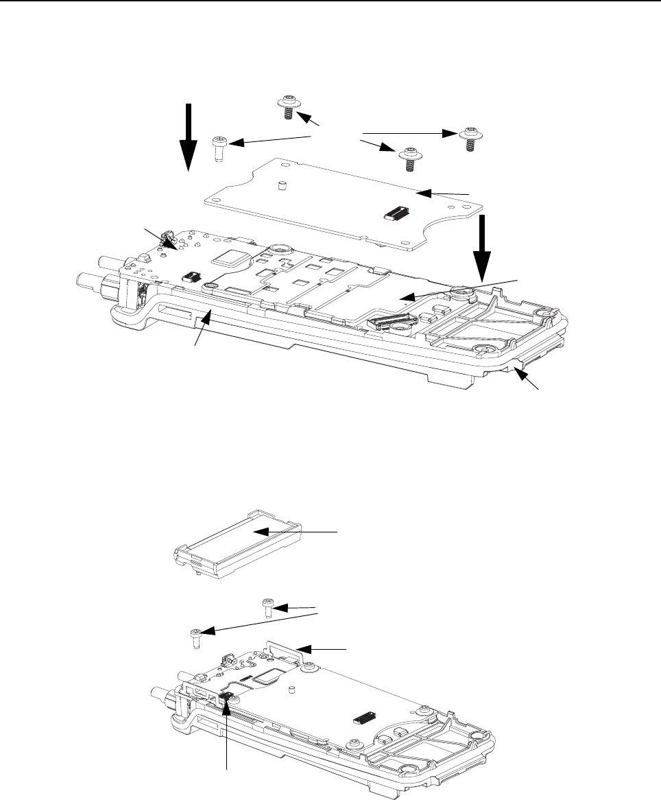
5-16 Disassembly/Reassembly Procedures: Radio Reassembly – Detailed
6. Place the transmission board onto the chassis.
7. Put on the interface board by connecting the board-to-board connectors between the inter-
face and transmission board.
8. Fasten the screws using the TORX™ T6 screwdriver.
Figure 5-16. Transmission and Interface Board reassembly.
9. Place the display retainer.
10. Fasten the screws using the TORX™ T6 screwdriver.
11. Snap the display module onto the display retainer catch.
Figure 5-17. LCD Retainer and LCD Module reassembly.
Screws
Transmission Board
Interface Board
Main O-ring
Top Shield
Chassis
Display Module
Screws
Display Retainer
Board-to-Board Connector
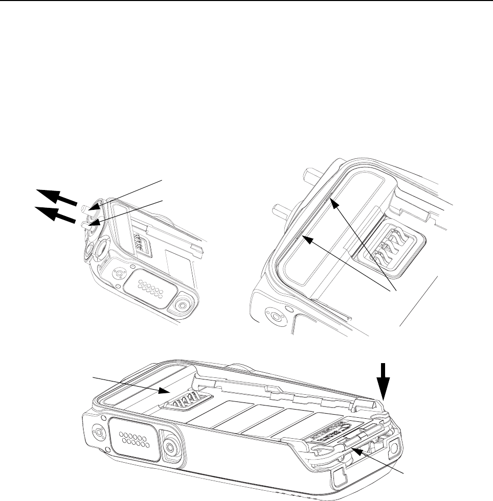
Disassembly/Reassembly Procedures: Radio Reassembly – Detailed 5-17
5.7.3 Chassis and Front Cover Reassembly
1. Slide in the volume and channel shafts into the top slot.
2. Connect the board-to-board connector between the keypad flex and the transmission board.
3. Insert top chassis tabs into recesses on front cover and apply some force until tabs are fully
inserted.
4. Apply some grease at the bottom portion of the main O-ring.
5. Gently push the chassis onto the front cover.
NOTE:Take necessary precautions while performing step 5 of See Section 5.7.3: Chassis and Front
Cover Reassembly to prevent visible outward pinches of the main O-ring.
Figure 5-18. Back Cover Kit reassembly.
Volume Shaft
Channel Shaft
Chassis
Apply grease
at the bottom
portion of the
O-ring
Tabs
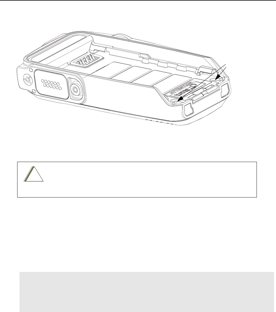
5-18 Disassembly/Reassembly Procedures: Ensuring Radio Immersibility
6. A visual inspection into the two screw holes will reveal blockage by a pinched O-ring in that
area which requires the chassis to be re-inserted into the front cover. See “Chassis and Front
Cover Reassembly” on page 5-17.
Figure 5-19. Chassis to Front Cover reassembly.
7. Fasten the screws using TORX™ T6 screwdriver.
8. Reassemble knobs.
5.8 Ensuring Radio Immersibility
This section discusses radio immersibility concerns, tests, and disassembly and reassembly of the
series radios.
5.8.1 Servicing
The series radios shipped from the Motorola factory have passed vacuum testing and should be
capable of restoring the watertight integrity of the radio.
5.8.2 Accidental Immersion
If the radio is accidentally dropped in water, shake the radio to remove the excess water from the
speaker grille and microphone port area before operating; otherwise, the sound may be distorted
until the water has evaporated, or is dislodged from these areas.
If the antenna needs to be replaced, ensure that only MOTOTRBO antennas are
used. Neglecting this would damage your radio. Refer to separate Accessory
List Leaflet 6866574D04 for a list of available antennas.
CAUTION: It is strongly recommended that the maintenance of the radio be deferred to qualified ser-
vice personnel and service shops. This is of paramount importance as irreparable damage to the radio
can result from service by unauthorized persons. If disassembly is necessary, unauthorized attempts
to repair the radio may void any existing warranties or extended performance agreements with
Motorola. It is also recommended that immersibility be checked annually by qualified service person-
nel/workshop that is authorized by Motorola.
Screw Holes
!
C a u t i o n
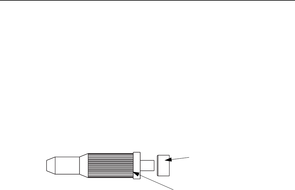
Disassembly/Reassembly Procedures: Ensuring Radio Immersibility 5-19
5.8.3 Specialized Test Equipment
This section summarizes the specialized test equipment necessary for testing the integrity of the
series radios.
To ensure that the radio is truly a watertight unit, special testing, test procedures, and specialized
test equipment are required. The special testing involves a vacuum check of the radio and pressure
testing (troubleshooting) for water leaks if the vacuum check fails. The specialized test equipment/
instrument (Table 2-2 on page 2-2) is authorized by Motorola and needed to perform the vacuum
check and pressure testing, if required. Any equipment/tools/instruments not mentioned in the table
must not be used to perform these test.
5.8.4 Vacuum Pump Kit NLN9839
The vacuum pump kit includes a vacuum pump with gauge, and a vacuum hose. A connector fitting
(part number 5871134M01) and fitting seal (part number 3271133M01) pump connector, which must
be ordered separately, connects the vacuum hose to the radio’s chassis.
Figure 5-20. Connector Fitting - Fitting Seal Pump Connector
5.8.5 Pressure Pump Kit NTN4265
The pressure pump kit includes a pressure pump with gauge, and a pressure hose. As with the
vacuum pump kit above, the connector fitting - fitting seal pair connects the pressure hose to the
radio’s chassis.
5.8.6 Miscellaneous Hardware
Other items needed for testing the immersibility radio include:
• Large water container
• Deionized (DI) water
• A supply of replacement parts: Main seal O-ring, Battery Contact Seal, Breathing Vent Label
and Breathing Vent Membrane. (Refer to Section 5.9.1 "Display Model Exploded View and
Parts List" on page 5-27 or Section 5.9.2 "Non-Display Model Exploded View and Parts List"
on page 5-30.)
5.8.7 Vacuum Test
The vacuum test uses a vacuum pump and gauge. The pump creates a vacuum condition inside the
radio, and the gauge monitors the radio for a stable vacuum reading; that is, checking for a properly
sealed, watertight unit. Before starting the vacuum test:
• Remove the battery.
Fitting Seal
(part number
3271133M01)
Connector Fitting
(part number
5871134M01)

5-20 Disassembly/Reassembly Procedures: Ensuring Radio Immersibility
• Remove the universal connector dustcover to expose the universal connector.
• Remove the breathing vent label and breathing vent membrane.
To conduct the vacuum test:
1. Attach antenna firmly to the radio.
2. Attach the vacuum hose to the vacuum pump. Check the pump and hose for leaks by block-
ing off the open end of the hose and operating the pump a few times. The actual reading of
the gauge at this point is not important; it is important that the gauge pointer remained steady,
indicating no vacuum leaks in the pump.
3. Ensure that the fitting seal is attached to the hose-to-chassis pump connector. Screw the
pump connector into the tapped hole in the chassis.
4. Attach the open end of the hose to the pointed end of the pump connector.
5. Place the radio on a flat surface with the chassis facing upward.
6. Operate the pump until the gauge indicates 6 in. Hg of vacuum on the radio.Observe the
gauge for approximately 1 minute.
• If the needle falls 0.5 in. Hg or less (one scale interval, for example, from 6 in. Hg to 5.5 in.
Hg), then the radio has passed the vacuum test and is approved for immersibility. No
additional testing will be required.
• If the needle falls more than 0.5 in. Hg (one scale interval, for example, from 6 in. Hg to less
than 5.5 in. Hg), then the radio has failed the vacuum test and the radio might leak if
immersed. Additional troubleshooting of the radio will be required; complete this procedure,
then go to Section 5.8.8 "Pressure Test".
7. Remove the vacuum hose and pump connector from the radio.
5.8.8 Pressure Test
Pressure testing the radio is necessary only if the radio has failed the vacuum test. Do not perform
the pressure test until the vacuum test has been completed. Pressure testing involves creating a
positive pressure condition inside the radio, immersing the radio in water, and observing the radio
for a stream of bubbles (leak). Since all areas of the radio are being checked, observe the entire unit
carefully for the possibility of multiple leaks before completing this test.
To conduct the pressure test:
1. Screw the pump connector (with fitting seal) into the tapped hole in the chassis.
2. Attach one end of the pressure hose to the pump connector and the other end to the pressure
pump.
3. Attach antenna firmly to the radio.
4. Operate the pump until the gauge reads approximately 1 psig.
5. Maintain the pressure at 1 psig and immerse the radio into a water-filled container.
6. Watch for any continuous series of bubbles. A stream of bubbles indicates a sign of leakage.
CAUTION: Pressure any greater than 1 psig might push air around the main seal.
NOTE Some air entrapment may cause the accumulation of bubbles, especially in the grille area,
but the bubbles should not be continuous.

Disassembly/Reassembly Procedures: Ensuring Radio Immersibility 5-21
7. Note all of the seal areas that show signs of leakage. Pinpoint the problem(s) to one (or more)
of the following areas:
• Front Housing
• Chassis (Main Seal O-ring)
• Battery Contact Seal
8. Remove the radio from the water container, and dry the radio thoroughly. Be especially care-
ful to dry the area around the main seal to prevent contamination of the internal electronics
while the unit is open.
9. Remove the pump connector from the chassis.
10. Radio after performing Pressure Test must undergo baking process in a temperature chamber
for constant temperature soaking at 60°C for 1 hour. This is to ensure no moisture is trapped
inside the radio and prevent contamination of the internal electronics after reassembling the
radio.
5.8.9 Troubleshooting Leak Areas
Before repairing any leak, first read all of the steps within the applicable section. This will help to
eliminate unnecessary disassembly and reassembly of a radio with multiple leaks. Troubleshoot
only the faulty seal areas listed in Section 5.8.8 "Pressure Test" on page 5-20, and when multiple
leaks exist, in the order listed.
5.8.9.1 Front Housing
Do one or both of the following:
1. If a leak occurs at the Lens (Display Models only), Universal Connector, chassis/Housing
interface, PTT button area of the housing, replace the housing. Refer to Section 5.6 "Radio
Disassembly – Detailed" on page 5-5.
a. Remove the housing assembly from the radio.
b. Discard the housing assembly and main seal O-ring.
c. Install a new main seal O-ring around the chassis assembly according to Section 5.7.2
"Chassis Reassembly" on page 5-14.
d. Install a new housing assembly to the radio.
e. Inspect the main seal for proper seating.
f. Observe carefully to ensure that the main seal O-ring is not pinched between the
housing and the chassis interface.
2. If the leak occurs at the control top area, remove the knobs in order to determine the leak
location:
a. Conduct the Pressure Test.
b. Identify the leak location.
CAUTION: Keep the area around the chassis’s vacuum port dry by ensuring that there is no water
around it.
NOTE Before reassembling the radio, always install a new Main seal O-ring, Battery Contact Seal
in the defective area.

5-22 Disassembly/Reassembly Procedures: Ensuring Radio Immersibility
5.8.9.2 Chassis (Main Seal O-ring)
To replace the main seal O-ring:
1. Refer to Section 5.6.1 "Front Cover from Chassis Disassembly" on page 5-5, remove the
chassis assembly from the radio.
2. Refer to Section 5.6.2 "Chassis Disassembly" on page 5-8, remove the Main Board from
chassis.
3. Remove the main seal O-ring.
4. Inspect the seal area around the chassis for foreign material that might prevent the main seal
O-ring from sealing properly.
5. Assemble a new O-ring; discard the old O-ring.
6. For detailed O-ring assembly sequence, refer to clause 2, step i. to step viii. of Section 5.7.2
"Chassis Reassembly" on page 5-14.
7. Reassemble the chassis assembly followed by installing into Front Cover. (Refer to Section
5.7 "Radio Reassembly – Detailed" on page 5-12).
8. Inspect the main seal O-ring for proper seating. Observe carefully to ensure that the main
seal O-ring is not pinched between the housing and the chassis.
5.8.9.3 Battery Contact Seal
To replace the Battery Contact Seal:
1. Refer to Section 5.6 "Radio Disassembly – Detailed" on page 5-5 to remove the Battery Con-
tact Seal.
2. Remove the Battery Contact Seal from the Chassis.
3. Inspect the Battery Contact Seal, Chassis and surrounding areas for foreign material that
might prevent the Battery Contact Seal from sealing properly.
4. Install a new Battery Contact Seal; discard the old Seal.
5. Replace a new main seal O-ring; discard the old O-ring.
6. Reassemble the chassis assembly followed by installing into Front Cover. (Refer to Section
5.7 "Radio Reassembly – Detailed" on page 5-12).
7. Inspect the main seal O-ring for proper seating. Observe carefully to ensure that the main
seal O-ring is not pinched between the housing and the chassis.
IMPORTANT: Both Breathing Vent Label (3371478L01) and Breathing Vent Membrane
(3271570L01) need to be replaced after vacuum test, pressure test or
water leakage troubleshooting.
NOTE When installing the assembled chassis to the Front Cover, ensure the O-ring at the top two
corners are not dislodged from the chassis groove.

Disassembly/Reassembly Procedures: Ensuring Radio Immersibility 5-23
5.8.9.4 Breathing Vent Membrane and Breathing Vent Label
To replace the Breathing Vent Membrane and Breathing Vent Label:
1. Remove the Breathing Vent Label that covers the Breathing Vent Membrane from the chas-
sis.
2. Remove the Breathing Vent Membrane.
3. Ensure that the chassis’s surface (at the Breathing Vent Label & Breathing Vent Membrane
recessed) is clean, no/minimum scratches and free from any adhesive or other foreign mate-
rials.
4. Install a new Breathing Vent Membrane, covering the vent port hole, in the small recessed
area in the chassis. Ensure that no oily substance come in contact with the seal.
5. Install a new Breathing Vent Label over the Breathing Vent Membrane in the larger recessed
area in the chassis. Press down evenly over the label’s surface to ensure good adhesion.
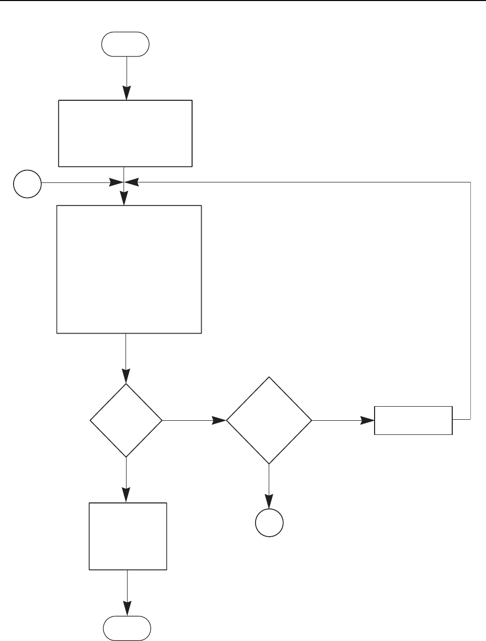
5-24 Disassembly/Reassembly Procedures: Ensuring Radio Immersibility
5.8.10 Troubleshooting Charts
Troubleshooting Flow Chart for Vacuum Test (Sheet 1 of 2)
Start
1. Remove Battery
2. Remove Universal
Connector Dustcover
3. Remove breathing vent label
and membrane
1. Attach antenna firmly to the radio.
2. Attach vacuum hose to vacuum
pump
3. Ensure fitting seal is attached to
hose-to-chassis pump connector
4. Screw pump connector into chas-
sis’s tapped hole
5. Attach vacuum hose to pump
connector
6. Place radio on flat surface
7. Operate pump (gauge = 6 in. Hg)
Gauge
does not fall
below
0.5 in. Hg
NO
YES
Run Pressure Test
1.Replace Breath-
ing Vent label and
Breathing Vent
Membrane
2. Radio approved
for immersibility
Full
equipment for
pressure test
procedure
available
YES
NO
B
End
A
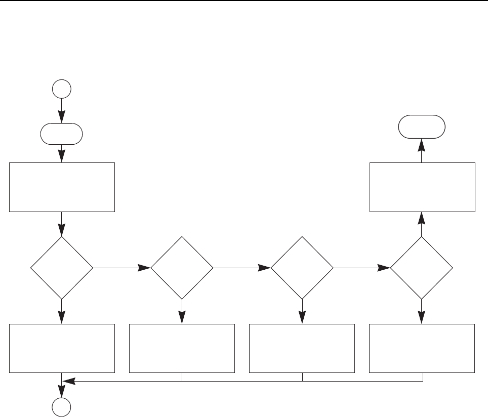
Disassembly/Reassembly Procedures: Ensuring Radio Immersibility 5-25
Troubleshooting Flow Chart for Vacuum Test (Sheet 2 of 2)
Start
B
1Remove pump and
connectors from radio
2. Remove antenna
3. Separate front housing kit
Examine and
reassemble
main O-ring
Replace front
housing kit with
new unit
Replace main
O-ring with
new unit
Replace new
chassis kit
without PCBs
YES
NO NO NO NO
Changed
front housing
kit
YES Changed
back chassis
kit
YES Changed
main O-ring
Examined
main O-ring
fitting
YES
Send radio to
Motorola Depot
or
Motorola Service Center
End
A
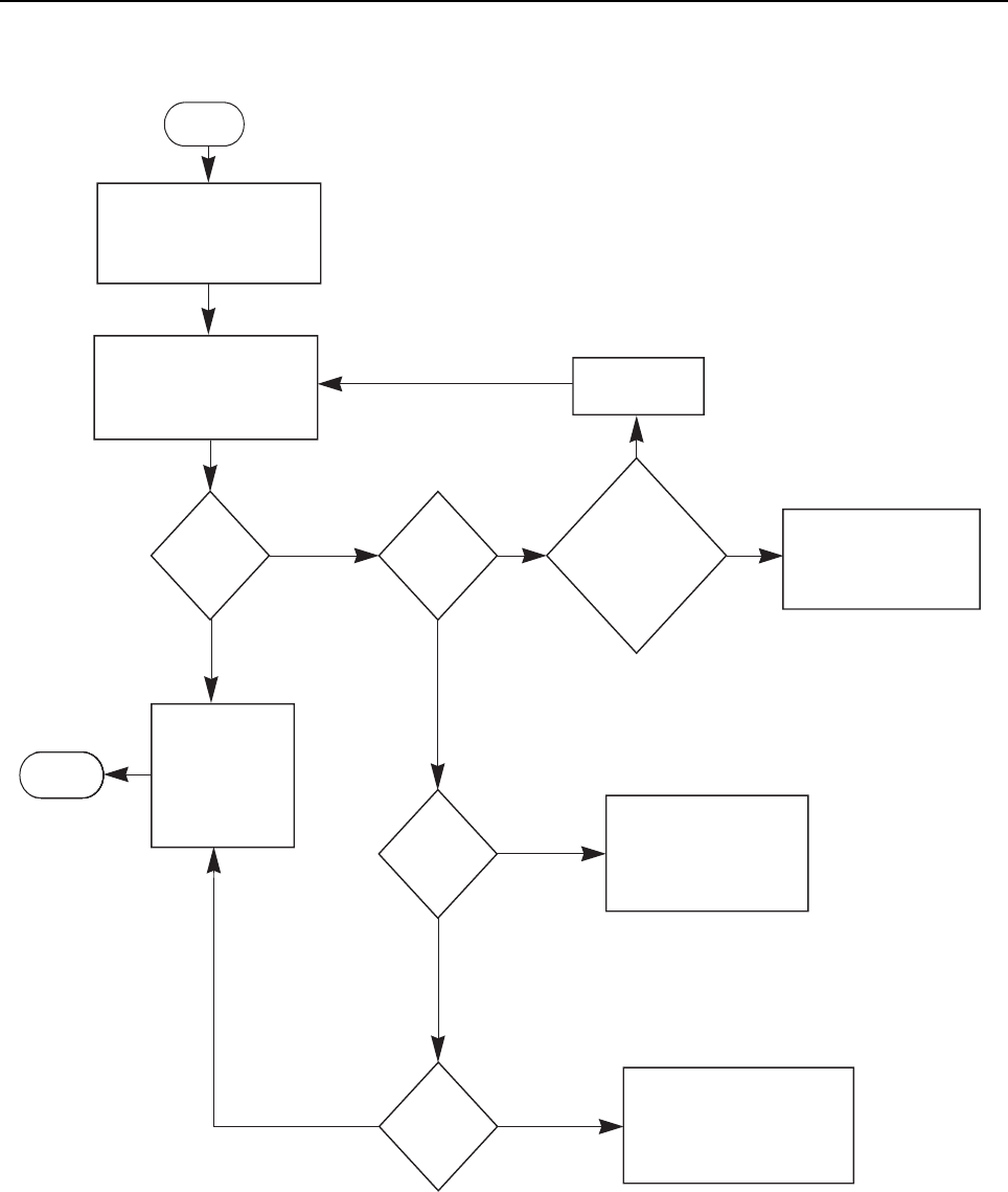
5-26 Disassembly/Reassembly Procedures: Ensuring Radio Immersibility
Troubleshooting Flow Chart for Pressure Test & Leakage Areas
Start
1. Remove vacuum hose from
pump connector
2. Attach pressure hose to
pump connector
1. Operate pressure pump
(pressure = 1 psig)
2. Immerse radio into a water-
filled container
Continuous
Series of
bubbles
YES
NO
Bubbles from
Front
Housing
YES
NO
Bubbles from
Chassis
YES
NO
Bubbles from
Battery Con-
tact Seal
YES
NO
Bubbles from
Lens*/Univer-
sal Connector/
chassis/
Housing Inter-
face/ PTT
1. Dry the radio
2. Replace Housing, Main
Seal O-Ring, and repeat
steps in Troubleshooting
Flow Chart for Vacuum Test.
YES
1. Remove Knobs
NO
1. Dry the radio
2. Replace Battery Contact Seal,
Main Seal O-Ring, and repeat
steps in Troubleshooting Flow
Chart for Vacuum Test.
1. Dry the radio
2. Replace Main Seal O-ring,
and repeat steps in
Troubleshooting Flow Chart
for Vacuum Test.
1. Dry the radio
2.Replace Breathing
Vent label and
Breathing Vent
Membrane
3. Radio approved
for immersibility
* Only for Display Model
EndEndEndEndEnd
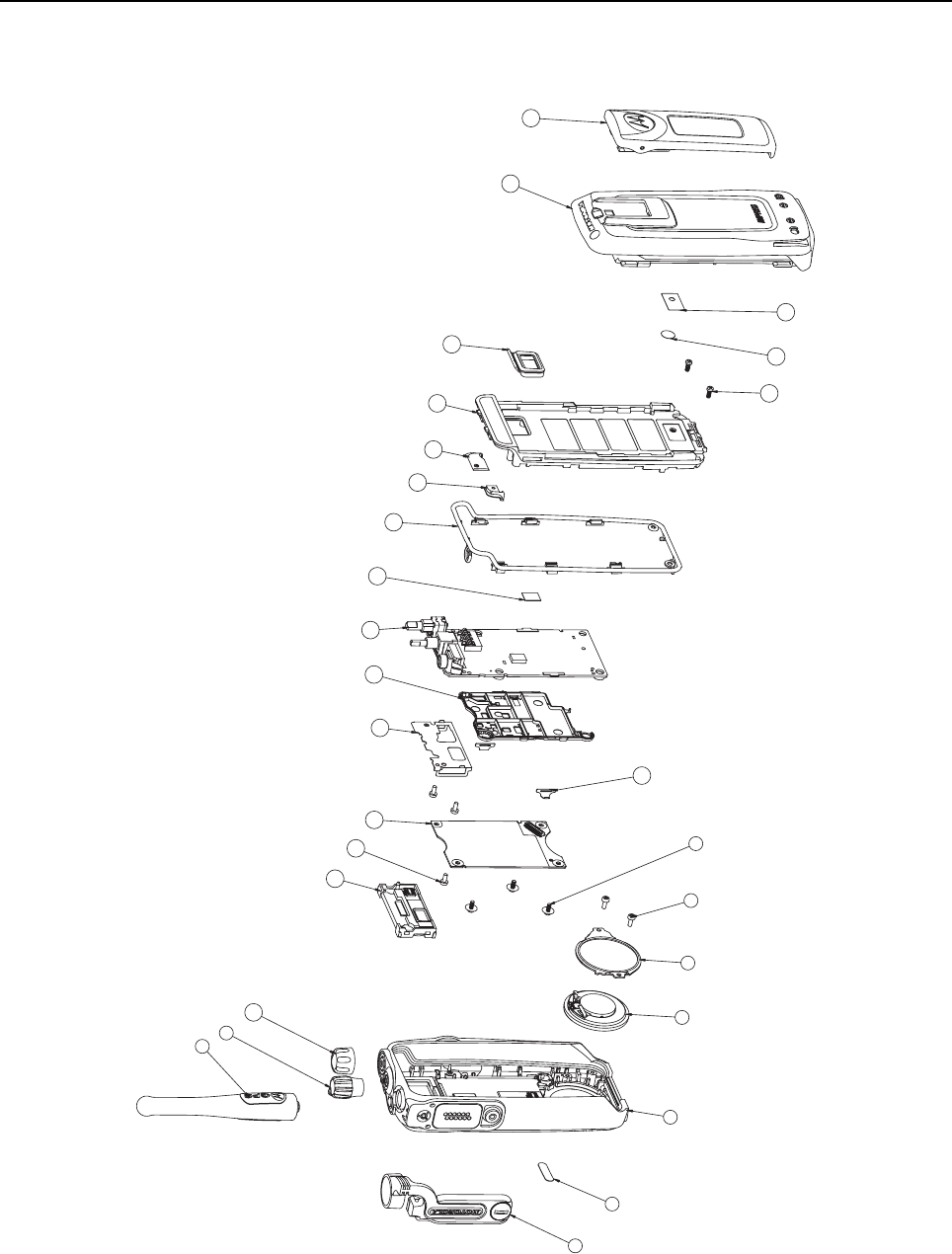
Disassembly/Reassembly Procedures: Radio Exploded Mechanical Views and Parts Lists 5-27
5.9 Radio Exploded Mechanical Views and Parts Lists
5.9.1 Display Model Exploded View and Parts List
Figure 5-21. Display Model Exploded View
1
2
3
4
5
6
7
8
9
10
11
12
13 14 16 17 18
19
20
21 22
23
24 25 26
27
28
15
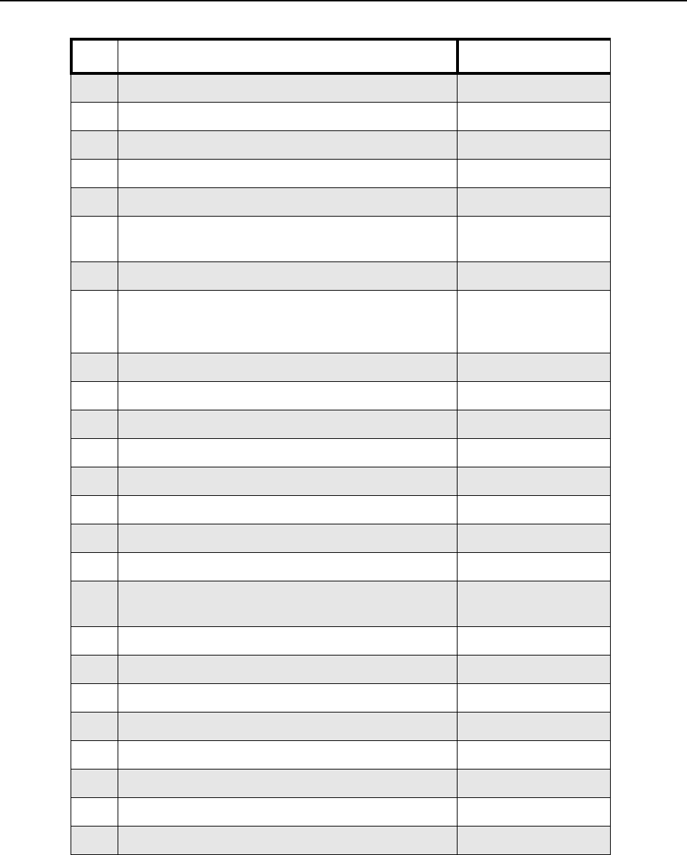
5-28 Disassembly/Reassembly Procedures: Radio Exploded Mechanical Views and Parts Lists
Table 5-3. Display Model Exploded View Parts List
Item Description Part Number
1Screw with Washer 0371981L01
2 Screw, Speaker Retainer 0386434Z02
3Retainer, Speaker 4271352L02
4 Speaker 5085798F09
5Assembly, Front Housing PMLN4646_
6 Nameplate for DP 3601
Nameplate for DP 3600 3371390L03
3371390L04
7Cover, Dust 1571477L01
8 Antenna Refer to separate
Accessory List Leaf-
let 6866574D04
9Knob, Frequency 3615204H01
10 Knob, Volume 3615205H01
11 Module, Display 7215182H01
12 Screw 0386104Z04
13 Board, Interface 0104022J35
14 Retainer, Display 4215189H01
15 Clip, Shield 4271320L01
16 Shield, Can 2615156H01
17 Back Cover Kit See Section 1.4:
Model Charts
18 Pad, Thermal 7515526H01
19 O-ring, Chassis 3215181H01
20 Retainer, O-ring 4216293H01
21 Retainer, O-ring 4216292H01
22 Assembly, Chassis Molded w/ MIP Shield 0104023J31
23 Seal, Battery Contact 3215177H02
24 Screw 0316281H01
25 Seal, Pot 3271570L01
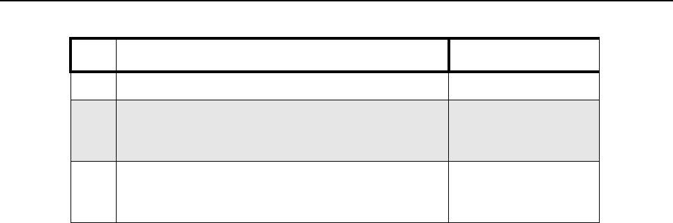
Disassembly/Reassembly Procedures: Radio Exploded Mechanical Views and Parts Lists 5-29
26 Label, Pot Seal 3371478L01
27 Battery Refer to separate
Accessory List Leaf-
let 6866574D04
28 Belt Clip Refer to separate
Accessory List Leaf-
let 6866574D04
Table 5-3. Display Model Exploded View Parts List
Item Description Part Number
5-30 Disassembly/Reassembly Procedures: Radio Exploded Mechanical Views and Parts Lists
5.9.2 Non-Display Model Exploded View and Parts List
Figure 5-22. Non-Display Model Exploded View
26
25
24
20
19
18
17
16
15
14
13
12
10
11
8
9
5
6
7
4
3
2
1
21 22 23
Disassembly/Reassembly Procedures: Radio Exploded Mechanical Views and Parts Lists 5-31
Table 5-4. Non-Display Model Exploded View Parts List
Item Description Part Number
1Screw with Washer 0371981L01
2 Assembly, Front Housing PMLN4922_
3Cover, Dust 1571477L01
4 Nameplate for DP 3401
Nameplate for DP 3400 3371391L03
3371391L04
5Antenna Refer to separate
Accessory List Leaf-
let 6866574D04
6 Knob, Frequency 3615204H01
7Knob, Volume 3615205H01
8 Speaker 5085798F09
9Retainer, Speaker 4271352L02
10 Screw, Speaker Retainer 0386434Z02
11 Screw 0386104Z04
12 Board, Interface 0104022J35
13 Clip, Shield 4271320L01
14 Shield, Can 2615156H01
15 Back Cover Kit See Section 1.4:
Model Charts
16 Pad, Thermal 7515526H01
17 O-Ring 3215181H01
18 Retainer, O-Ring 4216293H01
19 Retainer, O-Ring 4216292H01
20 Assembly, Chassis Molded w/ MIP Shield 0104023J31
21 Screw 0316281H01
22 Seal, Pot 3271570L01
5-32 Disassembly/Reassembly Procedures: Radio Exploded Mechanical Views and Parts Lists
5.9.3 Torque Chart
Table 5-5 lists the various screws by part number and description, followed by the torque values in
different units of measure. Torque all screws to the recommended value when assembling the radio.
23 Label, Pot Seal 3371478L01
24 Seal, Battery Contact 3215177H02
25 Battery Refer to separate
Accessory List Leaf-
let 6866574D04
26 Belt Clip Refer to separate
Accessory List Leaf-
let 6866574D04
Table 5-5. Torque Specifications for Screws
Part
Number Description Driver/ Socket Torque
N-m lbs-in kgf-cm
0386434Z02 Screw, M1.91 x 0.79 x 5.8 mm T6 Torx 0.25 2.2 2.54
0316281H01 Screw, M2 x 0.8 x 6.3 mm T6 Torx 0.25 2.2 2.54
0386104Z04 Screw, M2 x 0.4 x 4.5 mm T6 Torx 0.25 2.2 2.54
0371981L01 Screw, M2 x 0.4 x 5.0 mm T6 Torx 0.25 2.2 2.54
Table 5-4. Non-Display Model Exploded View Parts List
Item Description Part Number

Chapter 6 Basic Troubleshooting
6.1 Introduction
This chapter contains error codes and board replacement procedures. If the board does not pass all
the performance checks in Chapter 3 or exhibits an error code listed below, then the circuit board
should be replaced. If repair requires knowledge of details of component level troubleshooting,
please send radio to a Motorola Service Center listed in Appendix A.
NOTE: To access the various connector pins, use the housing eliminator/test fixture along with the
diagrams found in this section of the manual. (See the section, "Service Aids" on page 2-2,
for the appropriate Motorola service aids and tools parts numbers.)
6.2 Replacement Back Cover Kit Procedures
Once a problem has been isolated to a specific board, install the appropriate service kit (See Model
Charts from page 1-5 to page 1-6), which is orderable.
• If a board is replaced, it does not necessarily need to be retuned if it has been factory tuned. It
should however be checked for performance before being placed into service. Of particular
concern is the Bias DAC, which will need to be set for the appropriate final device bias current
prior to keying up the radio. If the bias is not properly set it may be possible to cause damage to
the transmitter.
CAUTION: The Tuner Tool only allows the serial number of the blank board to be entered once.
Be very attentive during this procedure.

6-2 Basic Troubleshooting: Power-Up Error Codes (Display Model only)
6.3 Power-Up Error Codes (Display Model only)
Upon powering up, the radio performs certain tests to determine if its basic electronics and software
are in working order. Any error detected has an associated error code that is presented on the radio
display. These error codes are intended to be used by a service technician when the radio
generates the Self Test Fail Tone. If these tests are successfully completed, the radio will generate
the Self Test Tone.
There are two classes of detectable errors, fatal and non-fatal. If it is considered as a fatal error, then
the normal radio operation will be inhibited. Fatal errors include hardware errors detected by the
microprocessor and certain memory errors. These memory errors include incorrect ROM checksum,
incorrect RAM checksum, and incorrect checksums of codeplug (Persistent Storage) blocks that
contain operating parameters. If the codeplug block operating parameters are corrupted, operation
of the unit on the proper frequency, system, and group are in question. Attempts to use this
information could provide the user with a false sense of security that others are receiving his
messages. Corrupted codeplug blocks of call IDs, or their associated aliases are considered non-
fatal errors. While the user may be inconvenienced, normal communication is still possible.
Table 6-1. Power-Up Error Codes
Error Code Description Error Type Corrective Action
ERROR 01/02 Call ID or associated
aliases codeplug block
checksum is wrong.
Non-Fatal Normal communication is still possible, but the
user may be inconvenienced.
Reprogram codeplug.
ERROR 01/22 Tuning Codeplug block
checksum is wrong. Non-Fatal Normal communication is still possible.
FAIL 01/82 External Codeplug block
checksum is wrong. Fatal Reprogram codeplug.
FAIL 01/92 Secure Codeplug check-
sum error Fatal Reprogram codeplug.
FAIL 01/A2 Tuning Codeplug block
checksum is wrong. Fatal Reprogram codeplug.
FAIL 01/81 ROM Checksum is
wrong. Fatal Reprogram FLASH Memory, then retest. If
message reoccurs, replace main board or
send radio to nearest Motorola Depot.
FAIL 01/88 Radio RAM Test Failure. Fatal Retest radio by turning it off and turning it on
again. If message reoccurs, replace main
board or send radio to nearest Motorola
Depot.
FAIL 01/90
or
FAIL 02/90
General hardware test
failure. Fatal Retest radio by turning it off and turning it on
again. If message reoccurs, replace main
board or send radio to nearest Motorola
Depot.
FAIL 02/81 DSP ROM Checksum is
wrong. Fatal Reprogram FLASH Memory, then retest. If
message reoccurs, replace main board or
send radio to nearest Motorola Depot.
FAIL 02/82 DSP RAM1 test failure. Fatal Retest radio by turning it off and turning it on
again. If message reoccurs, replace main
board or send radio to nearest Motorola
Depot.

Basic Troubleshooting: Power-Up Error Codes (Display Model only) 6-3
FAIL 02/84 DSP RAM2 test failure. Fatal Retest radio by turning it off and turning it on
again. If message reoccurs, replace main
board or send radio to nearest Motorola
Depot.
FAIL 02/88 DSP RAM test failure. Fatal Retest radio by turning it off and turning it on
again. If message reoccurs, replace main
board or send radio to nearest Motorola
Depot.
FAIL 02/C0 DSP ROM Checksum is
wrong. Fatal Retest radio by turning it off and turning it on
again. If message reoccurs, replace main
board or send radio to nearest Motorola
Depot.
No Display Display module is not
connected properly.
Display module is dam-
aged.
Fatal Check connection between main board and
display module.
Replace with new display module.
NOTE A non-display radio emits only the Self Test Fail Tone if it fails the self-test.
Table 6-1. Power-Up Error Codes (Continued)
Error Code Description Error Type Corrective Action

6-4 Basic Troubleshooting: Operational Error Codes
6.4 Operational Error Codes
During radio operation, the radio performs dynamic tests to determine if the radio is working properly.
Problems detected during these tests are presented as error codes on the radio’s display. The
presence of an error code should prompt a user that a problem exists and that a Motorola Authorized
MOTOTRBO dealer should be contacted. Use Table 6-2 to aid in understanding particular
operational error codes.
Table 6-2. Operational Error Codes
Error Code Description Error Type Corrective Action
FAIL 001 Synthesizer Out-of-Lock NON-FATAL 1. Reprogram the codeplug.
2. Refer to Detailed Service
Manual.
FAIL 002 Personality checksum or
system block error NON-FATAL Reprogram the codeplug.

Appendix A EMEA Regional Warranty, Service and
Technical Support
A.1 Warranty and Service Support
Motorola offers long term support for its products. This support includes full exchange and/or repair
of the product during the warranty period, and service/ repair or spare parts support out of warranty.
Any "return for exchange" or "return for repair" by an authorized Motorola Dealer must be
accompanied by a Warranty Claim Form. Warranty Claim Forms are obtained by contacting an
Authorized Motorola Dealer.
A.1.1 Warranty Period and Return Instructions
The terms and conditions of warranty are defined fully in the Motorola Dealer or Distributor or
Reseller contract. These conditions may change from time to time and the following notes are for
guidance purposes only.
In instances where the product is covered under a "return for replacement" or "return for repair"
warranty, a check of the product should be performed prior to shipping the unit back to Motorola.
This is to ensure that the product has been correctly programmed or has not been subjected to
damage outside the terms of the warranty.
Prior to shipping any radio back to the appropriate Motorola warranty depot, please contact
Customer Resources (Please see page A-3). All returns must be accompanied by a Warranty Claim
Form, available from your Customer Services representative. Products should be shipped back in
the original packaging, or correctly packaged to ensure no damage occurs in transit.
A.1.2 After Warranty Period
After the Warranty period, Motorola continues to support its products in two ways.
1. Motorola's Managed Technical Services (MTS) offers a repair service to both end users and
dealers at competitive prices.
2. MTS supplies individual parts and modules that can be purchased by dealers who are techni-
cally capable of performing fault analysis and repair.

A-2 EMEA Regional Warranty, Service and Technical Support: European Radio Support Centre (ERSC)
A.2 European Radio Support Centre (ERSC)
The ERSC Customer Information Desk is available through the following service numbers:
Austria: 08 00 29 75 41 Italy: 80 08 77 387
Belgium: 08 00 72 471 Luxemburg: 08 00 23 27
Denmark: 80 88 05 72 Netherlands: 08 00 22 45 13
Finland: 08 00 11 49 910 Norway: 80 01 11 15
France: 08 00 90 30 90 Portugal: 08 00 84 95 70
Germany: 08 00 18 75 240 Spain: 90 09 84 902
Greece: 00 80 04 91 29 020 Sweden: 02 07 94 307
UK : 08 00 96 90 95 Switzerland: 08 00 55 30 82
Ireland: 18 00 55 50 21 Iceland: 80 08 147
Or dial the European Repair and Service Centre:
Tel: +49 30 6686 1555
Please use these numbers for repair enquiries only.
A.3 Piece Parts
Some replacement parts, spare parts, and/or product information can be ordered directly.
If a complete Motorola part number is assigned to the part, it is available from Motorola Radio
Products and Solutions Organization (RPSO). If no part number is assigned, the part is not normally
available from Motorola. If the part number is appended with an asterisk, the part is serviceable by
Motorola Depot only. If a parts list is not included, this generally means that no user-serviceable parts
are available for that kit or assembly.
Orders for replacement parts, kits and assemblies should be placed directly on Motorola's local
distribution/dealer organisation or via Motorola Online at: http://emeaonline.motorola.com
* The Radio Products and Solutions Organization (RPSO) was formerly known as the Radio
Products Services Division (RPSD) and/or the Accessories and Aftermarket Division (AAD).

EMEA Regional Warranty, Service and Technical Support: Technical Support A-3
A.4 Technical Support
Motorola Product Services is available to assist the dealer/distributors in resolving any malfunctions
which may be encountered.
North Europe – Stephen Woodrow Central and East Europe – Siggy Punzenberger
Telephone: +44 (0) 1256 488 082 Telephone: +49 (0) 6128 70 2342
Fax: +44 01256 488 080 Fax: +49 (0) 6128 95 1096
Email: CSW066@motorola.comEmail: TFG003@email.mot.com
Russia and Belarus – Oleg Machnev Germany – Customer Connect Team
Telephone: +7 495 785 0150 Telephone: +49 (0) 30 6686 1539
Fax: +7 495 785 0185 Fax: +49 (0) 30 6686 1916
Email: CSA002@email.mot.com Email: cgiss.emea@europe.mot.com
Middle East and Africa – Wayne Holmes Italy – Ugo Gentile
Telephone: +27 11 800 7922 Telephone: +39 0 2822 0325
Fax: +27 11 800 7923 Fax: +39 0 2822 0334
Email: radiosupport.za@motorola.com Email: C13864@email.mot.com
France – Armand Roy France – Laurent Irrmann
Telephone: +33 1 6935 7868 Telephone: +33 1 6935 7866
Fax: +33 1 6935 7808 Fax: +33 1 6935 7808
Email: armand.roy@motorola.com Email: laurent.irrmann@motorola.com
A.5 Further Assistance From Motorola
You can also contact the Customer Help Desk through the following web address.
http://www.motorola.com/governmentandenterprise/contactus

Notes
A-4 EMEA Regional Warranty, Service and Technical Support: Further Assistance From Motorola

Glossary Glossary
This glossary contains an alphabetical listing of terms and their definitions that are applicable to
portable and mobile subscriber radio products. All terms do not necessarily apply to all radios, and
some terms are merely generic in nature.
Term Definition
Analog Refers to a continuously variable signal or a circuit or device designed
to handle such signals.
Band Frequencies allowed for a specific purpose.
CPS Customer Programming Software: Software with a graphical user
interface containing the feature set of a radio.
Default A pre-defined set of parameters.
DP Refers to Digital Professional Radio model names in the MOTOTRBO
Professional Digital Two-Way Radio System.
Digital Refers to data that is stored or transmitted as a sequence of discrete
symbols from a finite set; most commonly this means binary data
represented using electronic or electromagnetic signals.
DPL Digital Private-Line: A type of digital communications that utilizes
privacy call, as well as memory channel and busy channel lock out to
enhance communication efficiency.
FCC Federal Communications Commission.
Frequency Number of times a complete electromagnetic-wave cycle occurs in a
fixed unit of time (usually one second).
GPIO General-Purpose Input/Output: Pins whose function is programmable.
GPS Global Positioning System.
IC Integrated Circuit: An assembly of interconnected components on a
small semiconductor chip, usually made of silicon. One chip can contain
millions of microscopic components and perform many functions.
IF Intermediate Frequency.
kHz kilohertz: One thousand cycles per second. Used especially as a radio-
frequency unit.
LCD Liquid-Crystal Display: An LCD uses two sheets of polarizing material
with a liquid-crystal solution between them. An electric current passed
through the liquid causes the crystals to align so that light cannot pass
through them.
LED Light Emitting Diode: An electronic device that lights up when electricity
is passed through it.

Glossary-2
MDC Motorola Digital Communications.
MHz Megahertz: One million cycles per second. Used especially as a radio-
frequency unit.
Paging One-way communication that alerts the receiver to retrieve a message.
PC Board Printed Circuit Board. Also referred to as a PCB.
PL Private-Line Tone Squelch: A continuous sub-audible tone that is
transmitted along with the carrier.
Programming Cable A cable that allows the CPS to communicate directly with the radio
using USB.
Receiver Electronic device that amplifies RF signals. A receiver separates the
audio signal from the RF carrier, amplifies it, and converts it back to the
original sound waves.
Repeater Remote transmit/receive facility that re-transmits received signals in
order to improve communications range and coverage (conventional
operation).
RF Radio Frequency: The portion of the electromagnetic spectrum between
audio sound and infrared light (approximately 10 kHz to 10 GHz).
RX Receive.
Signal An electrically transmitted electromagnetic wave.
Spectrum Frequency range within which radiation has specific characteristics.
Squelch Muting of audio circuits when received signal levels fall below a pre-
determined value. With carrier squelch, all channel activity that exceeds
the radio’s preset squelch level can be heard.
TOT Time-out Timer: A timer that limits the length of a transmission.
TPL Tone Private Line.
Transceiver Transmitter-receiver. A device that both transmits and receives analog
or digital signals. Also abbreviated as XCVR.
Transmitter Electronic equipment that generates and amplifies an RF carrier signal,
modulates the signal, and then radiates it into space.
TX Transmit.
UHF Ultra-High Frequency.
USB Universal Serial Bus: An external bus standard that supports data
transfer rates of 12 Mbps.
VIP Vehicle Interface Port.
Term Definition

MOTOROLA and the Stylized M Logo are
registered in the U.S. Patent and Trademark Office.
All other product or service names are the property
of their respective owners.
© 2007-2008 Motorola, Inc.
All rights reserved. August 2008.
www.motorola.com/mototrbo
@6866574D29@
6866574D29-E
EN DE FR ES
IT PL RU
