Digital Performer 6 Power! DP6Power Ebook
DP6PowerEbook DP6PowerEbook
User Manual: DP6PowerEbook
Open the PDF directly: View PDF ![]() .
.
Page Count: 553 [warning: Documents this large are best viewed by clicking the View PDF Link!]
- Contents
- Introduction
- Chapter 1 About Digital Performer and Your Mac
- Chapter 2 Setting Up Digital Performer 6
- Chapter 3 Navigating Digital Performer 6
- Chapter 4 Setting Up a New Project
- Chapter 5 Project Management: Part 1
- Chapter 6 Project Management: Part 2
- The Undo History
- Managing Audio Files and Soundbites
- Changing the Location of Audio Files and Soundbites
- Organizing Audio Files and Soundbites into Folders
- Renaming Existing Audio Files or Soundbites
- Deleting Audio Files and Soundbites
- “Removing” Audio Files and Soundbites
- Compacting an Audio File
- Compacting a Project
- Locating Missing Audio Files or Soundbites
- Backup and Project Archival
- Summary
- Chapter 7 Recording Audio
- Chapter 8 Recording MIDI
- Chapter 9 MIDI: The Region Menu, Plug-Ins, and Virtual Instruments
- Chapter 10 Editing
- Chapter 11 Arranging
- Chapter 12 Mixing
- Chapter 13 Processing and Mastering
- Chapter 14 Music Notation
- Chapter 15 Scoring to Picture
- Index

Digital Performer
TM
6
Power!: The
Comprehensive
Guide
Don Barrett
Course Technology PTR
A part of Cengage Learning
Australia .Brazil .Japan .Korea .Mexico .Singapore .Spain .United Kingdom .United States
Printed in Canada
1234567111009
Digital Performer 6 Power!: The
Comprehensive Guide
Don Barrett
Publisher and General Manager, Course
Technology PTR: Stacy L. Hiquet
Associate Director of Marketing: Sarah
Panella
Manager of Editorial Services: Heather
Talbot
Marketing Manager: Mark Hughes
Acquisitions Editor: Orren Merton
Project Editor/Copy Editor: Cathleen
D. Small
Technical Reviewer: David Das
Editorial Services Coordinator: Jen Blaney
Interior Layout Tech: Macmillan Publishing
Solutions
Cover Designer: Mike Tanamachi
Indexer: Kelly Henthorne
Proofreader: Gene Redding
C2009 Course Technology, a part of Cengage Learning.
ALL RIGHTS RESERVED. No part of this work covered by the copyright herein
may be reproduced, transmitted, stored, or used in any form or by any means
graphic, electronic, or mechanical, including but not limited to photocopying,
recording, scanning, digitizing, taping, Web distribution, information
networks, or information storage and retrieval systems, except as permitted
under Section 107 or 108 of the 1976 United States Copyright Act, without
the prior written permission of the publisher.
For product information and technology assistance, contact us at
Cengage Learning Customer & Sales Support, 1-800-354-9706
For permission to use material from this text or product, submit all
requests online at cengage.com/permissions
Further permissions questions can be emailed to
permissionrequest@cengage.com
Digital Performer is a trademark of Mark of the Unicorn, Inc.
All other trademarks are the property of their respective owners.
Library of Congress Control Number: 2008941419
ISBN-13: 978-1-59863-907-0
ISBN-10: 1-59863-907-2
Course Technology, a part of Cengage Learning
20 Channel Center Street
Boston, MA 02210
USA
Cengage Learning is a leading provider of customized learning solutions with
office locations around the globe, including Singapore, the United Kingdom,
Australia, Mexico, Brazil, and Japan. Locate your local office at:
international.cengage.com/region
Cengage Learning products are represented in Canada by Nelson
Education, Ltd.
For your lifelong learning solutions, visit courseptr.com
Visit our corporate website at cengage.com
eISBN-10: 1-43545-451-0
I would like to dedicate this book to every current and
future user of Digital Performer; to my wonderful Nina
(the brightest light of my life); to all my family and
friends, whose unwavering support has helped me in
countless ways; and to my Grandmother Frances
(you are still with me every day).

Acknowledgments
I initially thought that Digital Performer 6 Power! would be a breeze after working on
Digital Performer 5 Power!. Let’s just say that I was in for a monumental reality check. As
before, it has been quite the educational and enlightening experience, to say the least. Incredibly,
each day with DP brings many new (and fortuitous) revelations.
First, I would like to recognize fellow author Steve Thomas for his significant and substantial
contribution. I would like to thank composer and friend Ron Jones, who originally guided me
into the land of DP and whose relentless drive to be the master of his craft is the ultimate stan-
dard to which I will continue to strive.
In addition, many colleagues have provided incredible insight and assistance over the years that
has helped make this book a possibility for me. I am exceedingly grateful to Scott Marcussen,
Lee Sanders, Josh Hetrick, Matt LaPoint, Gregg Manfredi, Armin Steiner at Fox, John Rodd,
Mass Giorginni and Fergus Daly at Sonic Iguana, Steve Hallmark, Ryan at Warner Brothers,
Charlie Largent, Ricardo Wilson, MOTU, everyone at the Fox Newman Stage, Jeff Cardoni,
Dallas Taylor, Laurence Sheldon at E!, Robert Drasnin, Hal Stephens at West L.A. Music,
Karen Takata at CBS, Steve Cooper at IRC Audio, Smart Post Sound, MOTUNATION,
Roger Hunt, Bryan Arata, the RJ Production team, and Mike Hooser (who gave me my first
break in this town).
Further, I would like to extend my appreciation to Dianne Hill, for creating this opportunity,
and to fellow composer Donald Hill, for being my sounding board during the writing process.
I must also recognize Wayne Downey, who inspired me to integrate all of my handwritten DP
cheat sheets into formal training lessons, all of which laid the groundwork for this project. Many
thanks to David Das for his technical expertise, to Orren Merton, and to the wonderfully
talented Cathleen Small (who provided invaluable guidance from the beginning).
Finally, for their dedicated support and encouragement, I wish to give special thanks to Nina,
my mom and dad, Nanette, my grandfather Dale, Tyler, Carole Roth, Matthew Ruth, Franziska
Thon, Uncle Syd, and, of course, Brenda Kay.
iv

About the Author
Don Barrett has been a musician since the age of 10. Upon graduating from Purdue University, his
training, performances, compositions, and recordings have included projects ranging from pro-
gressive rock (with veteran producers Mass Giorginni and Fergus Daly) to studying film scoring at
UCLA under the instruction of acclaimed composers Robert Drasnin (Mission Impossible) and
Lee Sanders (The Amazing Race). Don composed the original score for the popular series
Touched by an Angel in its final season on CBS and is currently assisting Emmy-nominated
and BMI award-winning composer Ron Jones (Fox’s Family Guy), where he serves as orchestra-
tor, composer assistant, and technical adviser. He recently completed original music for several
short films, numerous Smart Post Sound projects, and the award-winning television pilot “The
Real Life” by creator Krystal Jalene Thomas. Don has also composed nationally recognized con-
cert works and continues to compose and arrange for competitive marching bands and concert
percussion ensembles around the country.
Don resides in Los Angeles and continues to serve as a panelist at various technical seminars and
provides guest lectures at the Art Institute of L.A. Currently, Don can be found hard at work in
his private studio, promoting Don Barrett Music (www.donbarrettmusic.com) and Patio 7 Pro-
ductions (www.patio7productions.com).
v

Contents
Introduction . . ................................................. xv
Chapter 1
About Digital Performer and Your Mac 1
What Is a DAW? . . . . . . ........................................... 1
Nonlinear Editing ...............................................2
Host- and Non-Host-Based Systems . . . . . .............................2
Expansion Cards ...............................................2
MIDI Interfaces . ...............................................3
Audio Interfaces . ...............................................3
Digital Performer 6 Requirements . .................................... 4
The Mac and Your DP System. . . . .................................... 4
Hard Drives . . . . ...............................................4
Disk Maintenance...............................................6
SuperDrives . . . . ...............................................7
Summary . . . . . .................................................. 8
Chapter 2
Setting Up Digital Performer 6 9
Installing Digital Performer 6. . . . . .................................... 9
Installing Audio Hardware Drivers . . . . . . .............................9
Installing Core MIDI Drivers . . . ...................................11
Loading Digital Performer 6 on Your System . . . . . .....................11
Installing Third-Party Plug-Ins . . ...................................13
Launching Digital Performer for the First Time . . . .........................15
Audio Configuration . . . . ...........................................17
Audio System: Choosing MAS, DAE, or MIDI Only .....................17
The Configure Hardware Driver Window . ............................18
The Configure Studio Settings Window. . . ............................22
vi

The Input Monitoring Mode Window. . . . . ...........................23
The Bundles Window . . .........................................24
MIDI Configuration . . .............................................28
The Audio MIDI Setup Utility (AMS) . . . . . ...........................28
Synchronization . .................................................32
Syncing DP . . . . . .............................................32
Summary . . . . . . .................................................35
Chapter 3
Navigating Digital Performer 6 37
The Consolidated Window . . . . ......................................37
Control Panel. . . .................................................39
Transport . . . . . . .............................................40
Counter . ....................................................42
Status Strip with Tempo Control . ..................................43
Tracks Window . .................................................47
Information Bar . . .............................................48
Tracks List. . . . . . .............................................52
The Tracks Overview Section. . . . ..................................56
The Sequence Editor . . .............................................57
Sequence Editor Mini-Menu . . . . ..................................58
Track Settings Panel . . . .........................................60
Graphic Editing . . .............................................62
Grids, Time Rulers, and Zooming ..................................62
The Mixing Board . . . .............................................64
Window Target Menu and Mini-Menu . . . . ...........................64
Track Strips . . . . . .............................................67
Soundbites Window . . .............................................70
The Soundbites Mini-Menu . . . . . ..................................70
List . . . . ....................................................72
The Sound File Information Window . . . . . ...........................74
Summary . . . . . . .................................................77
Chapter 4
Setting Up a New Project 79
Project Basics . . . .................................................79
The Default Workspace.............................................81
Setting the Sample Rate.............................................83
Tracks in Digital Performer . . . . ......................................84
Contents vii

Deleting Tracks . ..............................................84
Adding Tracks . . ..............................................85
Renaming Tracks ..............................................86
Moving Tracks. . ..............................................87
Track Folders. . ..................................................89
Audio Tracks and Internal Busses. . ....................................91
Input and Output Assignments for Audio and Aux Tracks . . ..................92
Audio and Aux Track I/O . .......................................92
MIDI Track I/O . ..............................................95
Monitoring External MIDI Devices . . . . . ............................99
Monitoring MAS/AU Instruments..................................100
Monitoring ReWire Instruments. ..................................102
Tempo and Meter. . . . . . ..........................................104
Setting the Tempo . . . . . . ......................................104
Setting the Meter .............................................106
Setting Up a Click . . . . . ..........................................108
Creating a Click Default . ..........................................110
Pattern Clicks (the Ultimate in Clicks) . . . ...........................112
Defining the Countoff . . . ..........................................115
Summary . . . . . .................................................116
Chapter 5
Project Management: Part 1 117
The Digital Performer Project . . . . ...................................118
Opening an Existing Project......................................118
Opening Other File Types . ......................................119
Saving Your Project . . . . ..........................................121
The Save Command . . . . . ......................................121
The Save As Command . . . ......................................121
Save As Template .............................................125
Standard MIDI Files . . . . . ......................................129
OMF Interchange and AAF Interchange Files . . . . . ....................132
Final Cut Pro XML Interchange. ..................................132
Customizing Your Workspace . . . . ...................................134
The Consolidated Window ......................................135
The Preferences and Settings Command . . ...........................143
Window Sets . . . .............................................162
Track Colors . . . .............................................166
The Commands Window. . ......................................173
Summary . . . . . .................................................178
viii Digital Performer 6 Power!: The Comprehensive Guide

Chapter 6
Project Management: Part 2 179
The Undo History................................................179
The Project Undo History . . . . . . .................................179
Branching . . . . . . ............................................181
Managing the Undo History Windows . . . . ..........................187
Audio File Undo History Windows.................................190
Polar Undo History Window . . . . .................................192
Managing Audio Files and Soundbites . . . ..............................193
Changing the Location of Audio Files and Soundbites ...................193
Organizing Audio Files and Soundbites into Folders . . ...................195
Renaming Existing Audio Files or Soundbites . . . . . . ...................196
Deleting Audio Files and Soundbites. . . . . . ..........................196
“Removing” Audio Files and Soundbites. . . ..........................198
Compacting an Audio File . . . . . . .................................198
Compacting a Project . . ........................................200
Locating Missing Audio Files or Soundbites ..........................201
Backup and Project Archival . . . .....................................203
Backups. ...................................................203
Archiving...................................................205
External Hard Drives . . ........................................205
CD-R versus DVD-R. . . ........................................205
Rewritable Media . ............................................206
USB Flash Drives . ............................................206
Software Solutions ............................................206
Summary . . . . . . ................................................209
Chapter 7
Recording Audio 211
Input Assignments and the Audio Assignments Window . . ...................212
Monitoring Input Signals. . . . . . .....................................214
Audio Patch Thru . ............................................214
Monitoring with External Mixers. .................................215
Direct Hardware Playthrough . . . .................................216
Setting Input Levels . . ............................................216
Arming a Track . . ............................................216
Audio Monitor Window ........................................218
The Meter Bridge Window . . . . . .................................220
DP’s Trim Plug-In. ............................................223
Contents ix

Recording Audio . . . . . . ..........................................224
Recording and Managing Takes . ..................................226
Punching In and Out. . . . . ......................................231
Overdub Record Mode . . . ......................................233
Cycle Record Mode . . . . . ......................................233
Recording with Effects . . . ......................................235
Importing Audio.................................................238
Sound File Locations. . . . . ......................................238
Automatic Conversions Preferences. . . . . . ...........................239
The Import Audio Command versus Drag and Drop ....................240
Summary . . . . . .................................................242
Chapter 8
Recording MIDI 243
MIDI-Related Windows and Commands . ...............................243
The MIDI Monitor Window . . . ..................................243
The Set Input Filter Command. . ..................................244
The Input Quantize Command. . ..................................246
MIDI Device Groups . . . . ......................................247
MIDI Patch Lists .............................................251
Recording MIDI .................................................254
Summary . . . . . .................................................263
Chapter 9
MIDI: The Region Menu, Plug-Ins, and Virtual Instruments 265
Region Menu Commands ..........................................265
Region Commands Preferences and Settings . . . . . . ....................266
The Transpose Command . ......................................268
The Quantize Command . . ......................................272
The Change Velocity Command. ..................................275
The Split Notes Command ......................................278
MIDI Effects Plug-Ins . . . ..........................................280
Processing with the Region Menu’s MIDI Effects Plug-Ins. . . . .............280
Inserting Real-Time MIDI Plug-Ins . . . . . ...........................281
Virtual Instrument Plug-Ins . . . . . . ...................................282
Pre-Rendered Instrument Tracks (MOTU’s Pre-Gen) ....................282
Assigned Instrument Track ......................................284
xDigital Performer 6 Power!: The Comprehensive Guide

Unassigned Instrument Tracks . . . .................................285
Instrument Inserts and the Mixing Board . . ..........................286
The Freeze Selected Tracks Command . . . ..............................289
Summary . . . . . . ................................................291
Chapter 10
Editing 293
The Tool Palette. ................................................294
The Time Formats Window, Time Ruler, and Edit Grid . . ...................295
The Time Formats Window . . . . . .................................295
The Time Ruler . . ............................................298
The Edit Grid. . . . ............................................300
The View Filters . ................................................303
Zooming . . . . . . ................................................304
Selecting and Moving . ............................................305
Selecting and Moving Audio . . . . .................................306
Selecting and Moving MIDI Notes .................................309
Basic Edit Commands . ............................................312
The Erase Command. . . ........................................312
The Copy, Cut, Paste, Repeat, and Merge Commands ...................312
Editing Audio in the Sequence Editor . . . . ..............................315
Edge Editing Soundbites ........................................315
Soundbite Editing Shortcuts . . . . . .................................317
Fades and Crossfades . . ........................................318
MIDI Editing in the Graphic Editor . . . . . ..............................321
Inserting, Removing, and Modifying Notes in the Note Grid...............323
The Median Strip and Continuous Data Grid . . . . . . ...................324
The Event List . . ................................................332
Event List Basics. . ............................................332
Editing the Parameter of an Event .................................333
Summary . . . . . . ................................................333
Chapter 11
Arranging 335
The Conductor Track . ............................................335
Modify Conductor Track Menu . . .................................336
Editing Conductor Track Data. . . .................................338
Contents xi
Tempo........................................................343
Tempo Sources and the Tempo Control Menu. . . . . ....................343
Adjusting Tempo .............................................344
Audio Menu Tempo Commands ..................................353
Meter ........................................................357
The Change Meter Command . . ..................................357
Applying and Editing Meter Changes . . . . ...........................358
Partial Measures. .............................................359
Key..........................................................359
The Change Key Command ......................................360
Transposing Audio and MIDI Data . . . . . ...........................362
Chunks . . . . . . .................................................363
Sequences . . . . . .............................................363
The Chunks Window . . . . ......................................367
Controlling Chunks . . . . . ......................................370
Songs . ....................................................372
Looping. . . . . . .................................................377
Inserting a Loop Using the Region Menu . ...........................378
Inserting a Loop in the Event List . . . . . . ...........................379
The Loop Tool. . .............................................379
Clipping Windows . . . . . ..........................................381
Clipping Data Icons . . . . . ......................................382
Creating, Opening, and Managing Clippings . . . . . . ....................382
Where Clippings Are Stored......................................383
Adding Audio and MIDI Data . . ..................................384
Saving Plug-In Settings . . . ......................................384
Documents, Folders, and URLs . ..................................384
Markers. . . . . . .................................................385
Marker Basics . . .............................................385
Creating Markers on the Fly . . . ..................................386
Quantizing Markers . . . . . ......................................388
Recalling Markers . . . . . . ......................................388
Snapping and Shifting Data to a Marker Location . . ....................389
Selecting with Markers . . . ......................................390
Markers in Post-Production Work . . . . . . ...........................390
Summary . . . . . .................................................390
xii Digital Performer 6 Power!: The Comprehensive Guide

Chapter 12
Mixing 391
Mixing Board Setup . . ............................................391
Showing and Hiding Track Strip Sections . . ..........................391
The Board Layout Feature . . . . . . .................................393
Track Groups. . . . ............................................395
Alternate Mixes with Mix Mode . .................................400
Inserts and Plug-Ins. . . ............................................400
Signal Flow . . . . . ............................................401
Pre-/Post-Fader Divider . ........................................402
Dynamic versus Time-Based Effects . . . . . . ..........................402
Aux Tracks and Sends. ............................................403
Send and Returns . ............................................404
Submixing . . . . . . ............................................409
Automation . . . . . ............................................410
Summary . . . . . . ................................................424
Chapter 13
Processing and Mastering 427
Audio Processing ................................................428
Automatic Delay Compensation . . .................................428
Real-Time Effects . ............................................429
File-Based Processing. . . ........................................431
The Background Processing Window . . . . . ..........................436
The Audio Performance Window . .................................440
Plug-In Formats . . ............................................441
The Effects Window . . . ........................................443
Saving and Recalling Effect Presets .................................445
Pitch-Shifting Audio . . . ........................................447
Time-Stretching Audio . ........................................453
Mastering . . . . . ................................................456
The Master Fader . ............................................457
Mastering in DP . . ............................................458
Processing Your Final Mix . . . . . .................................459
Bouncing to Disk . ............................................465
Exporting Audio. . ............................................471
Exporting and Bouncing to the MP3 Format ..........................472
Summary . . . . . . ................................................472
Contents xiii

Chapter 14
Music Notation 473
The QuickScribe Editor. . ..........................................473
Customizing the Appearance of a Score . . ...........................475
Customizing the Appearance of an Individual Track. ....................482
Working with Measures . . ......................................485
Inserting Key, Meter, and Tempo Changes ...........................490
Inserting Dynamic Symbols ......................................492
Printing ....................................................493
Summary . . . . . .................................................494
Chapter 15
Scoring to Picture 497
Music Scoring . .................................................498
Movie Window . .............................................498
Cue Sheets . . . . . .............................................507
Viewing Film Cues . . . . . . ......................................508
Hit Points . . . . . .............................................510
Using Hit Points to Find Tempos ..................................510
Film Scoring Events . . . . . ......................................513
Summary . . . . . .................................................519
Index ......................................... 521
xiv Digital Performer 6 Power!: The Comprehensive Guide

Introduction
Mark of the Unicorn’s Digital Performer began as a MIDI-only application (Performer) back in
the mid-1980s. It was a great program that gave the Mac user an intuitive way to record, edit,
and play back MIDI performances. During the mid-1990s, MOTU added digital audio capabi-
lities to this already successful MIDI software application and took the music software industry
by storm. Since then, DP has undergone incredible upgrades and enhancements, allowing the
end user to manipulate MIDI and digital audio to a degree never before imagined.
This book offers a comprehensive overview of DP6’s features, system setup, and configurations
within the OS X environment, while also supplying useful engineering tips and shortcuts to help
you get the most out of Digital Performer.
How to Use This Book
In this book, I have tried to address the many different proficiency levels of the Digital Performer
user; I’ve attempted to jumpstart the newbie, take the intermediate user to the next level, and
show the power user an interesting trick or two.
I’ve organized the chapters and sections as they would appear within the context of the music
production process. Reading straight through from start to finish will provide the user who is
new to the program or unfamiliar with the audio production process with a solid grasp of how
Digital Performer integrates within the studio environment. Users with an understanding of
audio recording and mixing concepts may want to just skip to specific chapters.
For those who are already familiar with Digital Performer, Chapter 1 provides useful informa-
tion on setting up and optimizing your Mac, while Chapter 2 walks you step by step through the
DP6 setup and configuration process. If you’re new to the world of digital audio and MIDI or
multitrack recording in general, I suggest starting with Chapter 1.
How This Book Is Organized
Digital Performer 6 Power! is divided into 15 chapters.
nChapter 1, “About Digital Performer and Your Mac,” provides an overview of the basic
concepts of linear and nonlinear editing, digital audio workstations, hardware requirements
and recommendations for Digital Performer, and Mac OS X configuration and optimization.
xv
nChapter 2, “Setting Up Digital Performer 6,” covers software installation, audio and MIDI
configurations, and synchronization.
nChapter 3, “Navigating Digital Performer 6,” covers Digital Performer’s main windows: the
Consolidated Window, the Control Panel, the Tracks window, the Sequence Editor, the
Mixing Board, and the Soundbites window.
nChapter 4, “Setting Up a New Project,” provides a detailed step-by-step guide to creating
and preparing a project for recording.
nChapter 5, “Project Management: Part 1,” and Chapter 6, “Project Management: Part 2,”
cover the management of your project and media assets in order to help you streamline your
production workflow.
nChapter 7, “Recording Audio,” focuses on getting the most out of your audio recordings,
from proper gain staging and monitoring to working with alternate takes during the over-
dubbing process.
nChapter 8, “Recording MIDI,” focuses on the procedures involved with the recording and
monitoring of your MIDI tracks.
nChapter 9, “MIDI: The Region Menu, Plug-Ins, and Virtual Instruments,” provides an
overview of the Region menu commands, MIDI plug-ins, and virtual instrument tracks.
nChapter 10, “Editing,” provides an overview of the tools and procedures involved with
editing digital audio, MIDI, and automation data within DP6.
nChapter 11, “Arranging,” covers the use of Chunks and songs, as well as the detailed use of
markers and clippings within the recording and mixing process.
nChapter 12, “Mixing,” discusses the fundamentals of mixing within Digital Performer, from
setting up inserts and sends to creating submixes and using mix automation.
nChapter 13, “Processing and Mastering,” covers the use of audio effects processing, the
concepts of file-based and real-time processing, destructive Waveform Editor processing, as
well as the basics of the mastering process. Procedures for bouncing to disk and exporting
your mixes are also explained.
This chapter also familiarizes you with the basic concepts and technical procedures involved
with mastering music within the DP environment.
nChapter 14, “Music Notation,” shows you how to convert MIDI notes into printable music,
from individual parts to full-blown orchestral scores. You can take an existing MIDI track or
use the QuickScribe tools to prepare and manipulate printable scores and parts. This chapter
will take you through the process of transferring your music from computer screen to paper.
nChapter 15, “Scoring to Picture.” Because of its flexible architecture, Digital Performer is
also a popular scoring tool for many film composers and sound designers. This chapter takes
you through the basic setup process for scoring to picture within DP.
xvi Digital Performer 6 Power!: The Comprehensive Guide
What’s Not in This Book
This book covers a lot of ground, but it doesn’t cover everything—I have assumed some basic
knowledge on your part, and I have had to leave out certain topics due to space constraints.
nComputer basics. In this book, I assume that you already know how to get around on your
Mac: how to make a new folder, empty the trash, install a program, or change the monitor
resolution. If you’re uncertain about some of these common procedures, seek out one of the
numerous learning resources for the Mac, available in both print and online forms. Keep in
mind that the Mac is the heart of your Digital Performer system, and being able to properly
navigate and maintain it is essential to the health of your studio environment.
nOlder versions of DP. It is assumed that most users have moved out of OS 9. However,
many DP features have remained unchanged in the transition to OS X, so users of previous
DP versions can still find Digital Performer 6 Power! a very useful resource.
nOther programs. If you’re like me, you probably have a number of other software appli-
cations that you incorporate into the production process. There isn’t enough space in this
book to include detailed explanations of all these other programs, but I will discuss some key
applications that I feel are important to the DP user, such as CD burning software and virtual
instruments.
Keeping It Current
The DAW-related software and hardware industry is in a constant state of change, ever evolving
with the addition of faster computers, improved operating systems, and enhanced feature sets.
Production cycles tend to run on a six-month schedule, so keeping the content of a book like this
current is a challenge in itself. Everyone involved with the creation of Digital Performer 6
Power! has made a concerted effort to include the most up-to-date information concerning Dig-
ital Performer, OS X, and the other applications mentioned within this book.
Introduction xvii
This page intentionally left blank

1About Digital Performer
and Your Mac
What is Digital Performer? It is essentially a music studio in a box. Its comprehensive
tools allow you to record, edit, mix, and master music. Of course, this is a simplifi-
cation of a very deep program, but if you can keep yourself grounded in these basic
processes, it will keep you from getting overwhelmed by DP’s many complex feature sets.
This chapter will discuss:
nThe basics of digital audio workstations
nThe requirements for DP
nSuggestions for working with Mac OS X
What Is a DAW?
In case you’re wondering, DAW stands for digital audio workstation, which is usually made up
of compositional and recording tools centered on a computer configured specifically for music
production. The benefits of having all the necessary recording and mixing tools integrated in one
place and right at your fingertips are great, but I would argue that the most incredible feature of
any DAW—which many users often take for granted—is its nonlinearity.
Before the advent of programs such as MOTU’s Digital Performer and Digidesign’s Pro Tools,
modern audio was recorded in a linear fashion directly to tape. I won’t get into the age-old
argument of digital versus analog here, but suffice it to say that tape has many disadvantages
when it comes to the world of editing. With tape, audio (and video) is recorded in a linear fash-
ion, meaning from start to finish. When tape travels across the head stack of a multitrack
recorder, the audio is magnetically transferred in a continuous fashion until recording is stopped.
If you want to fix a part within the recording, you have to physically rewind the tape machine
and punch in, permanently erasing the previous material. If you blow the punch, or the musi-
cian’s performance isn’t ideal, there is no way to get back (or undo) the lost audio. Also, if you
want to rearrange the order of the recorded material (maybe you need the chorus to happen two
times instead of one, for example), you have to cut and splice the different sections together,
which involves making two physical copies of the tape in real time (one for each chorus), then
manually splicing it together with a razorblade!
1
Nonlinear Editing
What NLEs (or nonlinear editors) offer is the ability to change the order of recorded data in a
nondestructive way. The recorded audio is stored on the hard drive of the workstation’s com-
puter and can be instantaneously accessed (or read) from the hard drive in any specified order. It
is a simple matter of building a playlist within the particular music program. Going back to my
earlier example of creating two choruses for a song, if you’re working in a nonlinear editor, such
as Digital Performer, you can just tell it to play the chorus twice instead of once—it’s as easy
as that.
That sounds simple if you are thinking in terms of one audio file. However, multitrack sessions
normally consist of many tracks with multiple audio files—sometimes as many as 100-plus
tracks (a definite mixing challenge!). Audio recording and mixing can be a very taxing job for
your Mac.
Host- and Non-Host-Based Systems
Digital Performer is a host-based application, meaning that it relies on the CPU of the computer
for all of its audio needs. On top of crunching all those numbers for DP, the CPU also has to run
the Mac OS at the same time. This is why the quality and speed of your DAW components are so
important. Faster hard drives, for example, can access audio faster, resulting in higher track
counts and the ability to handle sessions that contain heavy edits. The amount of RAM available
to Digital Performer impacts the number of tracks you can record and play back simultaneously.
A high-performance video card will provide faster screen redraws, taking strain off the host
processor. (It takes a lot of power to display all of those bouncing level meters and various
windows in Digital Performer.) Audio cards with DSP (digital signal processing) can absorb
many of the CPU stresses of recording audio. Finally, the processor speed and amount of
RAM in your computer also directly impact the performance of virtual instruments and other
processor-intensive tasks, such as real-time effects plug-ins. Although modern computers typi-
cally contain more than one processor (or processing “cores”) and are packed with plenty of
power to handle the comprehensive duties of working with audio, it is always worth the time
and effort to investigate your system to see what lies under the hood!
Expansion Cards
In time, you may find that your audio production setup has evolved beyond your computer’s
“native” processing power. This can be a result of advanced processing plug-ins, extended vir-
tual instrument libraries, or advanced monitoring needs (a combination of which can push even
the latest Mac Pro’s limits!). Hardware peripherals dedicated to running plug-ins or software-
based synthesizers can also be integrated into a host-based system for additional horsepower,
and some DAWs come preconfigured with these devices. Digidesign’s top-of-the-line Pro Tools
systems fall into the latter category. Instead of relying on the host processor to do all the work,
PCI cards that contain dedicated processor chips are installed in your computer and supply the
muscle for any audio processing. The computer’s CPU only has to worry about running the
program and the Mac OS—the dedicated PCI card handles all of the audio tasks.
2Digital Performer 6 Power!: The Comprehensive Guide

Multiple cards can be used simultaneously, allowing you to create a very powerful and stable
workstation. The drawback for many is the high cost and proprietary nature of Pro Tools
and similar systems. Luckily, there are a few companies out there that offer expansion cards
or units that work with host-based audio applications, such as Digital Performer. TC Electronic
(www.tcelectronic.com), Universal Audio (www.uaudio.com), and Apogee Electronics (www
.apogeedigital.com) are three such companies. These expansion peripherals are fairly inexpen-
sive when compared to other integrated workstations, which can run into the tens or hundreds
of thousands of dollars.
MIDI Interfaces
MIDI stands for Musical Instrument Digital Interface. MIDI is a language (or protocol) that allows
electronic devices to communicate with each other. A means for MIDI communication is necessary
to record MIDI data, whether it be an outboard unit (a MIDI interface) or a simple USB connec-
tion. The type of interface you choose usually depends on the number of external MIDI devices you
need to control. The most basic setup will have a keyboard MIDI controller and a MIDI interface
to get the data into your Mac. If you have just one MIDI keyboard, some models only require a USB
connection. Otherwise, a 11or22 MIDI interface, such as MOTU’s FastLane, would be appro-
priate. More elaborate setups requiring multiple MIDI I/O and sophisticated synchronization
capabilities will benefit from MOTU’s more advanced MIDI Timepiece AV.
MIDI without an Interface? If you have multiple computers and work mainly with virtual
instruments, the advent of MIDI Over LAN (Local Area Network), Network MIDI (avail-
able in later versions of the Mac OS), and MIDI Over IP (built into Apple’s Leopard OS)
allows you to use network connections to exchange MIDI data between your computers.
This is a relatively simple process that requires no extra hardware, and better yet, does not
limit you to a specific number of MIDI channels. For example, if you have two Macs, you
could create a main Mac and slave Mac setup where the main Mac drives the slave Mac
that serves as a virtual instrument host (much like a multi-timbral synth or hardware
sampler).
Audio Interfaces
One of the most important aspects of a DAW is the audio interface. Though you can rely on the
Mac’s audio interface (see System Preferences 4Sound to access the built-in audio options of
your computer), you’ll need a more “professional” device if you want to get the most out of your
recording and mixing. You should use a dedicated audio interface that can handle multiple
inputs of balanced audio. The audio interface is in charge of getting audio into and out of
your Mac. This process is done with analog-to-digital (A/D) and digital-to-analog (D/A) con-
verters. The analog signal is converted to digital on the way in, then converted back to analog on
the way out to your studio monitors. This is the most crucial point in the concept of digital
Chapter 1 About Digital Performer and Your Mac 3

audio, and the quality of the converter has a direct impact on the sound of your digital audio, as
well as on the price of the interface.
PCI-based systems are available to relieve the Mac’s processor of some of the stresses of record-
ing and converting audio. These systems include DSP microprocessors that can “do the math”
for the computer regarding audio signal conversion. MOTU offers its own version of a PCI-
based unit called the 2408mk3. This less-expensive unit integrates seamlessly into the DP
work environment and is a viable option for a mid-level interface.
Other popular options include FireWire (also know as IEEE 1394) and USB interfaces. Many of
these audio interfaces include DSP chips but rely on the respective FireWire or USB busses (con-
nections) for the recording and mixing duties. With ease of connectivity and expansion, inter-
faces such as MOTU’s Traveler and M-Audio’s ProFire series have become widely popular.
Digital Performer 6 Requirements
To run MOTU’s Digital Performer 6, a Power Mac (G4 or G5) with a 1-GHz processor and
1 GB of RAM running Mac OS X 10.4.7 or higher is required. These are just the minimum
requirements, however, and real-world experiences from DP users suggest a more powerful sys-
tem is needed. If you plan on working with a lot of tracks, numerous effect plug-ins, and an
array of virtual instruments, you’ll want at least 2 GB of RAM—4þGB will definitely provide
you with better and more responsive system performance. Also, DP 6 is compatible with Intel-
based Macs and takes full advantage of multi-core/multi-processor systems.
Is 1 GB of RAM Enough for My System? Even though some Macs ship with only 1 to 2 GB
of RAM, this may not be sufficient for extensively running media-based applications, such
as Digital Performer. In reality, having more RAM will help to provide you with a more
responsive overall system.
The Mac and Your DP System
The Mac, the OS, and its connected peripherals form the foundation for your Digital Performer
studio. Proper care and feeding of your Mac is critical to maintaining a healthy Digital Per-
former system. The ins and outs of Mac maintenance are beyond the scope of the book, so
investing in a Mac OS X–specific book is highly recommended. You can find out more about
the Mac on the web by visiting the support section of Apple’s website (www.apple.com). In
addition to the official Apple website, there are also various third-party sites that serve up a
wealth of information on all things Mac-related.
Hard Drives
The hard drive is the container for your OS, applications, and associated media files. When you
play back or record audio in Digital Performer, the OS must physically access the drive to
4Digital Performer 6 Power!: The Comprehensive Guide

retrieve or write the file. The faster the drive, the faster it will read or write a file. If DP were only
reading or writing one file at a time, drive speed would not be a factor. But in actual use, the
drive is very busy simultaneously playing back and recording multiple tracks, accessing OS-
related files, streaming your large audio sample library, checking your e-mail, and so on.
To maximize your DP system’s resources, you may want to consider using two hard drives: one
drive for the Mac OS and another for your DP projects. Keep in mind that your DP system must
constantly access your hard drive when playing back and recording audio—the faster your hard
drive, the more tracks you will be able to play back and record. If your project resides on the
same drive as the Mac OS, the drive will have to split up its time between accessing OS-related
data and playing back/recording audio.
Most desktop Macs today come with multiple hard-drive bays, making it quite simple to install
and configure a separate internal “audio” drive. Another option, considering the growing size of
system hard drives (large-capacity single drives are typically included at purchase time), is to
partition the single hard drive. This is like creating two hard drives from one. Think of it like
organizing your garage—one side is for tools, one side is for your car. This can be done quickly
with Apple’s Disk Utility program or any other hard-drive maintenance software. In addition to
the performance boost, keeping the Mac OS drive separate from your audio drive(s) makes rou-
tine maintenance tasks much easier.
Can I Start Working in DP with only One Hard Drive? Of course you can run your projects
off your internal (or “boot”) drive, and it’s fine to get started that way. As your projects
begin to increase in size and complexity, you’ll start realizing the benefits of using addi-
tional drives.
If the idea of installing multiple internal hard drives is overwhelming, you might want to
consider connecting an external FireWire or eSATA drive instead. USB can be used for
smaller projects, though its performance is not as good as FireWire or eSATA for audio.
Before you begin installing DP on your Mac, you should think about how you plan to use Digital
Performer in your music production workflow. Will you be running virtual instruments that
contain large sample libraries? Will you be working on large projects that contain a lot of
audio tracks with effects processing? Or will your DP sessions be fairly small and consist of a
few tracks of audio and MIDI?
If you plan to use large audio sample libraries within Digital Performer, you should also consider
installing a separate hard drive dedicated to this purpose. Installing your audio sample libraries
on a separate drive will help alleviate the bottlenecks that can occur when DP is simultaneously
playing back (or recording) multiple tracks of audio, triggering audio sample libraries, and
so on.
Chapter 1 About Digital Performer and Your Mac 5

Multiple Hard Drives An ideal system might contain four separate hard drives: one for the
Mac OS, one for your Digital Performer audio files, another for backing up your DP proj-
ects, and a fourth that contains your audio sample libraries (virtual instruments). Of
course, you can take this setup even further by having multiple hard drives for your DP
audio files and sample libraries.
You could even install the Mac OS on another drive and use it specifically for your music
applications. (This means no web surfing, word processing, or game playing on your DP-
related system drive.) Having a duplicate “boot” drive is also a lifesaver for when disaster
strikes.
Back Up Your Data! Keep in mind that you may also need to reinstall the Mac OS when
reconfiguring or installing hard drives in your DP system. Make sure you fine-tune your
cloning strategy (using Leopard’s Time Machine, for example) or manually back up any
important data to another hard drive or optical media (such as CD-R and DVD-R) before
beginning any system reconstruction.
Disk Maintenance
Disk maintenance is another critical piece of the Mac OS maintenance puzzle. The two main
maintenance procedures you need to worry about for Mac OS X are repairing disk permissions
and the disk directory, if needed.
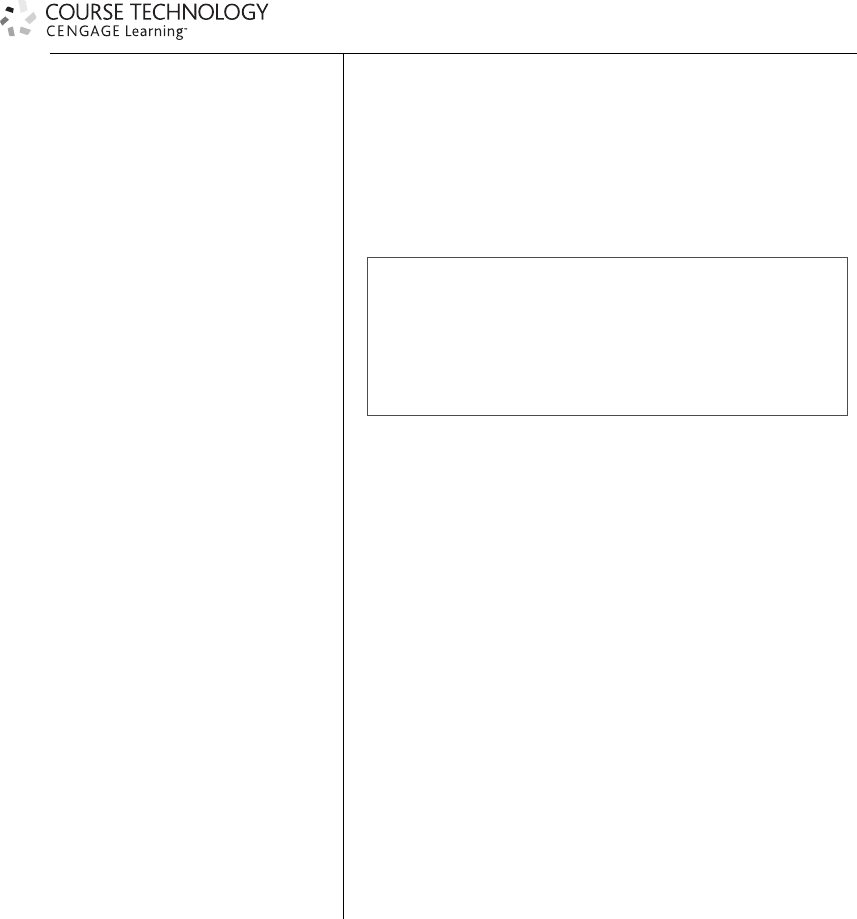
Repair Disk
The Repair Disk option, shown in Figure 1.1, in the Disk Utility window (OS Hard Drive 4
Applications 4Utilities 4Disk Utility) repairs (or corrects) the directory of any disks or disk
partitions within your system when needed. A disk directory is like the table of contents for a
book—it tells the OS where data is located on your hard drive(s). System crashes, hard restarts,
or loss of power can lead to the corruption of a disk directory. Use the Repair Disk option to
correct this kind of problem.
Repair Disk Permissions
The Repair Disk Permissions option (OS Hard Drive 4Applications 4Utilities 4Disk Utility)
repairs the permissions for a system-related folder or file. When a file or folder is installed on the
system, a file called a receipt is installed in the Receipts folder (OS Hard Drive 4Library 4
Receipts). When the current permissions for a file/folder do not match the permissions described
in its associated OS X receipt file, the Repair Disk Permissions option will reset (or correct) the
disk permissions for that file or folder. Problems with disk permissions generally occur after
the installation of new applications on your Mac, so be sure to repair disk permissions after
the installation of any software.
6Digital Performer 6 Power!: The Comprehensive Guide
SuperDrives
With the continuous fall in the price of DVD burners, adding a DVD burner to your Mac is a
small investment (if you don’t have one already—SuperDrives are included in most Macs cur-
rently shipping). These multifunction optical drives are capable of reading and writing both CDs
and DVDs. Your DP projects can increase in size very quickly, so you’ll need a convenient and
inexpensive solution for your larger archiving needs; the DVD (although not as convenient and
cost effective as a secondary external hard drive) is an option that fills this function nicely. Stan-
dard DVDRs will hold approximately 4 GB worth of data, while dual-layer discs can hold
double that amount (though they are more expensive). In addition, most DVD burners will
also burn CDs, so you’ll be able to put your mixes on CD, also.
Many users underestimate the importance of backing up their material. Having a DVD burner
connected to your system can help to ensure that you don’t lose any important work. Refer to
Chapter 5, “Project Management: Part 1,” for a discussion of the backup and archival processes.
Figure 1.1 The Disk Utility window allows you to repair a disk and its permissions.
Chapter 1 About Digital Performer and Your Mac 7
Summary
Configuring your Mac to work with DP can be as comprehensive as you want it to be. Some
users will want to jump right in, install the program, and begin working in DP. Other users may
want to take a more planned approach to the configuration process. Exactly how you confront
the installation and configuration process is up to you; just remember to perform the basic main-
tenance procedures, such as repairing disk permissions.
If you do decide, however, to reconfigure your Mac with additional hard drives, more RAM,
and so on, be sure to back up any important files and follow the proper procedures for installing
each new device. I strongly recommend performing installations or upgrades only if you are not
in a deadline crunch with a project. If your DAW is running flawlessly and time is on your side,
however, there is a common two-part question worth asking yourself before adding anything to
your system: “Do I really need this right now, and how much will the added technology actually
help me?”
8Digital Performer 6 Power!: The Comprehensive Guide

2Setting Up Digital
Performer 6
This chapter will focus on the setup procedures involved with Digital Performer, starting
with the installation process and moving to the audio and MIDI configuration processes.
I’ll also discuss how you can use DP’s Receive Sync and Transmit Sync commands to
synchronize DP with other devices and applications.
This chapter will cover the following topics:
nThe installation process
nHow to configure your audio hardware to work with DP
nHow to enable audio tracks and I/O routing assignments within a project
nHow to use the Audio MIDI Setup window to configure your MIDI devices
nHow to work with DP’s synchronization features
Installing Digital Performer 6
Once you have your Mac configured for your DP workflow (discussed in the previous chapter),
you’re ready to begin the installation process.
Installing Audio Hardware Drivers
Before installing the Digital Performer application, you should proceed with installing the nec-
essary hardware drivers for your audio interfaces. These Core Audio drivers (explained in “The
Configure Hardware Driver Window” section of this chapter) allow your audio interface to
communicate with Digital Performer and other Mac OS X Core Audio–compatible applications.
If you’re working with MOTU audio interfaces, you can visit the Download section of MOTU’s
website (www.motu.com). If you plan to use the Mac’s built-in audio, you can skip this process.
Updating Your Hardware Drivers Be aware that some manufacturers will update their
hardware drivers on a regular basis—some more often than others. You should take a
trip to the manufacturer’s website and check to make sure you have the most current
9
drivers available. Also, be sure to verify that the updated driver is compatible with your
current Mac OS!
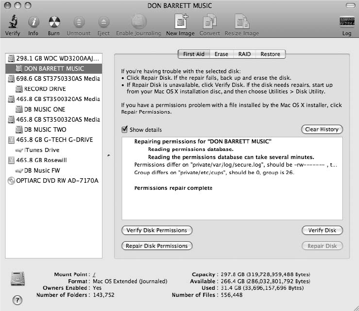
Testing Your Audio Interface Once you have installed the necessary Core Audio driver for
your specific audio interface, you should test to make sure it is working properly.
Because you haven’t installed DP yet, you can use Mac OS X’s iTunes music player
instead. First, you’ll need to open the Audio MIDI Setup utility from the System Hard
Drive 4Application 4Utilities folder. Select the Audio Devices tab and choose your
audio interface from the Default Output pop-up menu, as shown in Figure 2.1. Your
Figure 2.1 The audio section of the Audio MIDI Setup window.
10 Digital Performer 6 Power!: The Comprehensive Guide
audio interface will appear in the list as long as its Core Audio driver is successfully
installed. Make sure your audio interface is connected to a set of speakers (or head-
phones) so that you can verify playback. Open iTunes, play a song from your iTunes
library, and you should hear the song play through your audio interface.
Installing Core MIDI Drivers
If you plan to connect any MIDI devices to your DP system, you may need to install the Core
MIDI drivers (or additional software) for your particular MIDI interface. Although many drivers
are built into the Mac’s OS, be sure to follow the manufacturer’s installation guidelines to ensure
that you install your MIDI drivers properly.
Use the Audio MIDI Setup utility (System Hard Drive 4Application 4Utilities folder) to con-
nect any additional MIDI devices to your MIDI controller; these will automatically appear in
Digital Performer when they are configured. Refer to the “MIDI Configuration” section of this
chapter for an explanation of the MIDI device setup process.
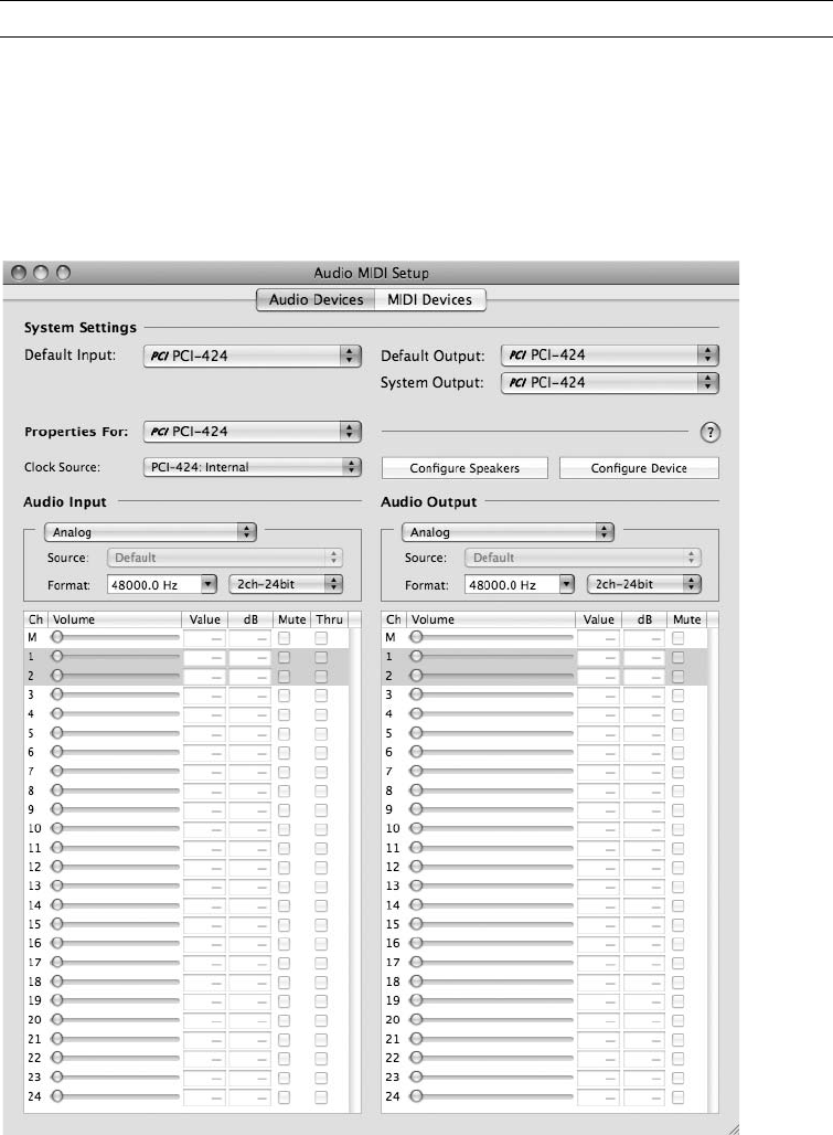
Loading Digital Performer 6 on Your System
When you have confirmed that your audio interface is working properly, begin installing DP
onto your system’s hard drive. Simply open up the installer disc and double-click the Install
Digital Performer icon, as shown in Figure 2.2, and then follow the installation process as
Figure 2.2 Click the DP installer icon to install Digital Performer on your Mac.
Chapter 2 Setting Up Digital Performer 6 11
directed. After the DP items have been installed, the installer will need to run an optimization;
click OK to proceed with the process. When the OS X optimization process is complete, click the
Quit button to exit the installer.
Registering Digital Performer 6 Be sure to promptly register your new copy of Digital Per-
former 6 at MOTU’s website. MOTU will ask you to create a free motu.com account,
which will provide you with members-only features, such as free updates, downloads,
and information regarding your registered MOTU products. This is a great time to see
whether there has been an update since you purchased your copy! If you are upgrading
a previous version of DP, no action is necessary (you are already registered).
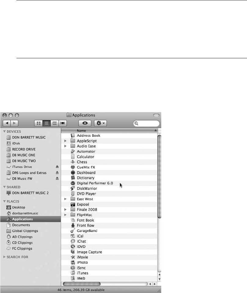
When you have successfully completed the installation process, the MOTU DP 6 application
icon will be located in your Applications folder on your hard drive (see Figure 2.3). In addition,
a folder called Clicks and Grooves (containing DP’s audio click and preset Groove Quantize
files) will be placed in User 4Library 4Application Support 4Digital Performer.
Figure 2.3 The MOTU DP6 icon located in the Applications folder on the Mac’s main hard drive.
12 Digital Performer 6 Power!: The Comprehensive Guide
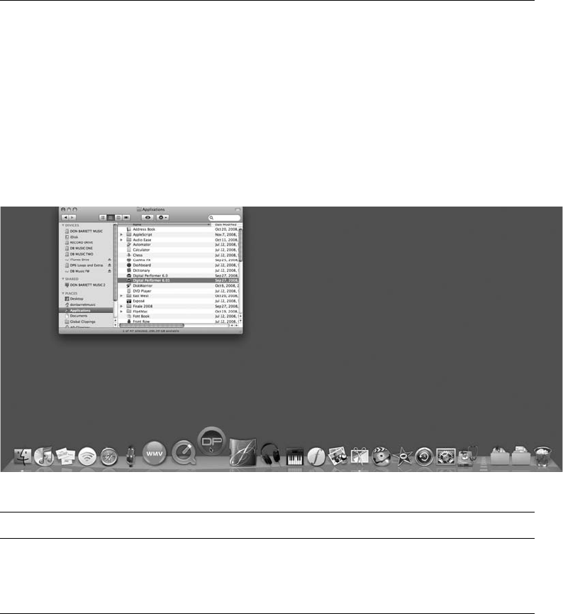
Adding DP to the Dock For quick and easy access, try placing the DP application icon on
the Dock (if it doesn’t appear there automatically). The Dock is the small strip usually
located at the bottom of the screen. Think of the Dock as a container for your shortcuts;
it allows you to click on an application icon to launch the program without using the Mac’s
Finder.
Simply drag the icon onto the Dock and release the mouse button (see Figure 2.4). Once
the icon is placed on the Dock, you can launch Digital Performer by clicking on the DP
Dock icon. You may also consider placing other icons on the Dock to streamline your
access to specific DAW-related applications, such as the Audio MIDI Setup utility.
Digital Performer Extras Disc Don’t forget to take a look at the Digital Performer Extras
disc that comes bundled with DP; it is packed with more than 500 MB of royalty-free
audio loops and REX files.
Installing Third-Party Plug-Ins
In addition to audio hardware drivers, you may also have third-party plug-ins or virtual instru-
ments to install for use with DP. Before installing them, however, you may want to launch DP to
make sure the installation process was successful and that DP is functioning properly. When
you’re satisfied that DP is working correctly, quit the application and proceed with the instal-
lation of your third-party applications.
Figure 2.4 Drag the Digital Performer application icon onto the Dock for easy access to DP.
Chapter 2 Setting Up Digital Performer 6 13
Audio plug-ins should be placed in the Library 4Audio 4Plug-Ins folder. You can install them
in either the System Hard Drive 4Library folder, which will give all users on your Mac access
to these plug-ins, or the User 4Library folder, which will provide plug-in access only to a
specific user. If you’re the only person working on your system, it doesn’t really matter which
location you choose. Most third-party plug-in installers will automatically place the plug-ins in
the necessary folders, so you don’t have to worry about manually placing them in the correct
locations. MAS plug-ins (DP’s native audio plug-ins), for example, are automatically placed
in the Hard Drive 4Library 4Audio 4Plug-Ins 4MAS folder when DP6 is first installed.
There will be times, however, when you will need to manually place plug-ins in their correct
location.
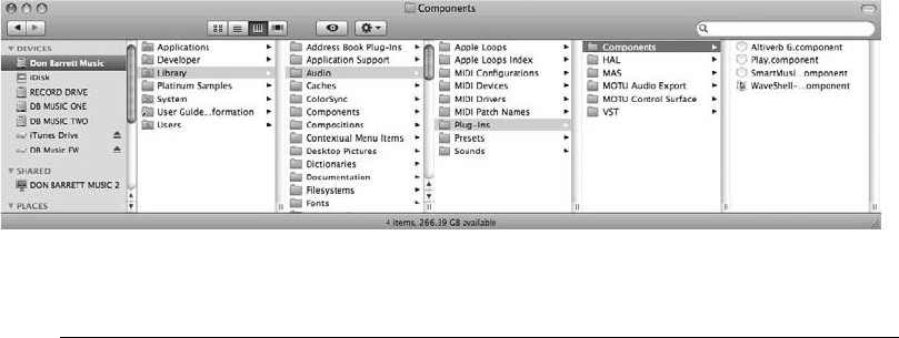
If you take a look at the Plug-Ins folder, shown in Figure 2.5, you can see that there are sub-
folders for each different plug-in type supported by Mac OS X (such as MAS, VST, and Audio
Units). You’ll also notice that there is no Audio Units plug-in folder. This is because AU plug-ins
are actually stored in the Components folder. (Don’t ask me why.) If you run into a situation in
which a plug-in isn’t showing up in your Digital Performer project, check to make sure that it’s
in the proper plug-in folder.
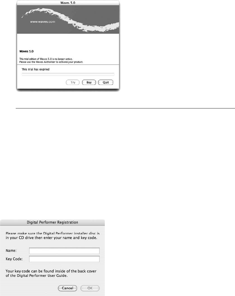
Trial Versions If you install trial versions of plug-ins, be aware that most will expire after a
set period of time (typically 7 to 14 days). Once a plug-in has expired, DP will present you
with an Expired Plug-In dialog box, as shown in Figure 2.6. If you want to continue using
the plug-in, you can purchase it using the Buy button in the dialog box. If you don’t want
to purchase the plug-in, simply click the Quit button, and DP will not load it.
Keep in mind that this window will open every time you launch Digital Performer, which
can get very annoying. To stop this window from appearing, simply remove the plug-in
from the appropriate plug-in folder.
Figure 2.5 Audio plug-ins are located in the Library 4Audio 4Plug-Ins folder. Audio Unit plug-ins
can be found in the Components folder.
14 Digital Performer 6 Power!: The Comprehensive Guide
Launching Digital Performer for the First Time
The first time you launch DP after installation, you will most likely be asked to keep the instal-
lation disk in your CD-ROM drive, and you will be presented with a Key Code dialog box, as
shown in Figure 2.7. Enter your name and the key code located on the inside cover of the DP
user’s guide (typically the back cover). Click OK to continue loading the DP application; you
should see DP loading available plug-ins, as shown in Figure 2.8. In addition, the first time DP is
opened, it will examine the Audio Plug-In 4Components folder for any Audio Unit plug-ins.
Each AU plug-in is examined once. If DP finds a problem with an AU plug-in, the plug-in will
not be loaded and will not be available in any of DP’s plug-in menus. The results of the AU
examination process are saved in a text file and placed on your hard drive.
Figure 2.6 In this example, the trial version of the Waves 5.0 plug-in has expired.
Figure 2.7 Your key code for DP is located inside the back cover of the user manual.
Chapter 2 Setting Up Digital Performer 6 15
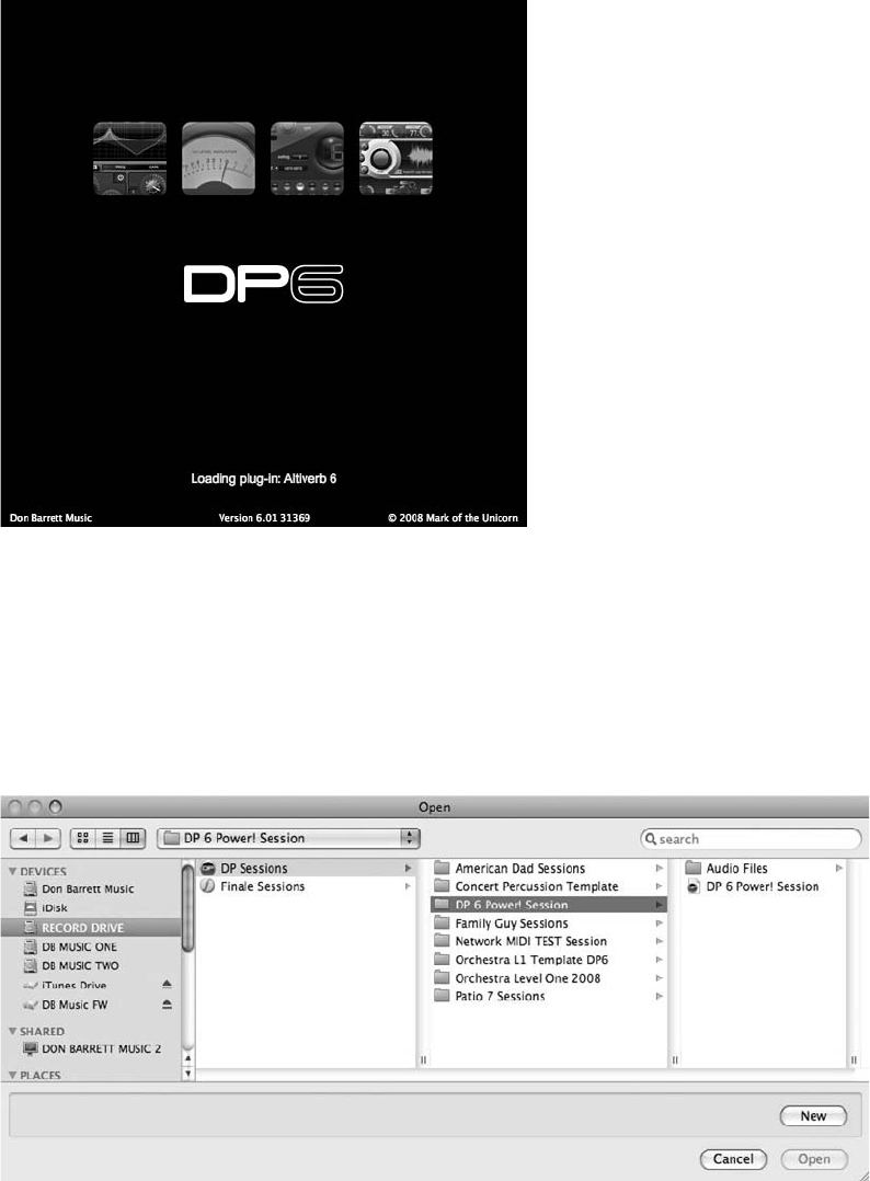
DP will launch the Open dialog box by default, allowing you to open an existing project or
create a new one, as shown in Figure 2.9. If you do not want to create or open a project, simply
click the Cancel button. Keep in mind that you do not have to have a project open in order to
configure DP’s audio and MIDI settings. As long as Digital Performer is open, you will have
Figure 2.8 When Digital Performer is launched, it will load available plug-ins for use in your DP
projects.
Figure 2.9 By default, the Open dialog box will automatically open when you launch DP.
16 Digital Performer 6 Power!: The Comprehensive Guide
access to the necessary audio configuration windows and menus (explained in the next section).
MIDI device configurations are handled directly by OS X, so you don’t need DP to be open at all
when setting up your MIDI connections.
Creating and Opening a Project Procedures for creating, opening, and setting up a Digital
Performer project are discussed in Chapter 4, “Setting Up a New Project.” Be sure to
configure your audio and MIDI devices (explained in the next section) before proceeding
with the audio and MIDI recording processes.
Audio Configuration
Before you jump into the audio playback and recording side of Digital Performer, you will need
to configure any connected audio devices and their settings for your DP project. In addition, you
must determine the specific audio system (MAS, DAE, or MIDI Only), tracks and internal bus-
ses, available inputs and outputs, input recording mode, and sample rates for your project.
Audio System: Choosing MAS, DAE, or MIDI Only
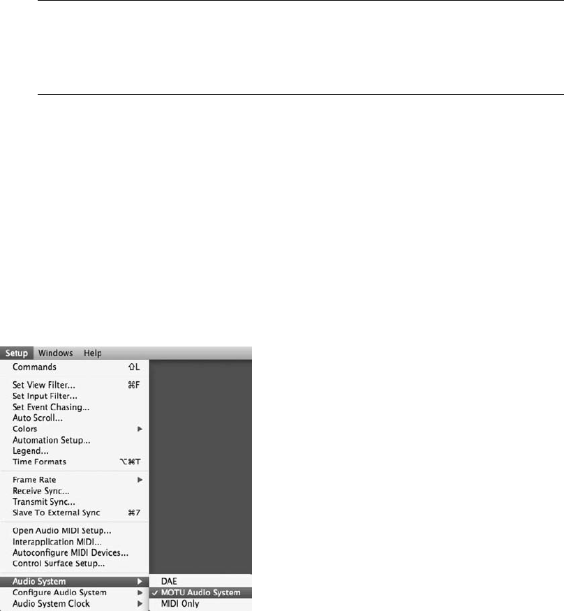
The Audio System submenu (Setup 4Audio System), as shown in Figure 2.10, provides three
audio system options: DAE, MOTU Audio System, and MIDI Only. These options determine
how audio operations, if any, are handled within Digital Performer—or which audio engine will
perform DP’s audio-related tacks.
An audio engine basically provides or handles all of the audio-related processes (such as audio
playback, recording, internal bussing, effects processing, and so on) for an application. For
Figure 2.10 The Audio System submenu.
Chapter 2 Setting Up Digital Performer 6 17

example, Mac OS X’s built-in applications (such as iTunes) rely on Mac OS X’s Core Audio
engine to play back audio. Digital Performer has its own built-in audio engine called the MOTU
Audio System, or MAS. In addition to MAS, DP can also run under the Digidesign Audio
Engine, or DAE. Selecting DAE will allow you to use Digital Performer as a front end for Pro
Tools MIX and TDM systems. MIDI Only, however, will turn off DP’s audio playback and
recording capabilities all together—tremendously reducing the CPU consumption of your DP
project.
nDAE. Choose this option if you want to run DP under Digidesign’s audio engine, providing a
front end for your Pro Tools TDM or MIX system. Keep in mind that, even though you will
have access to TDM/HTDM and RTAS/AudioSuite plug-ins, you will not be able to use any
of DP’s native (built-in) plug-ins or any AU (Audio Unit) plug-ins when operating under
DAE.
nMOTU Audio System. Enabled by default, the MOTU Audio System (or MAS) is DP’s built-
in audio engine. When MAS is selected, you will have access to all of DP’s native effects,
along with any other third-party AU and MAS plug-ins installed within your system.
nMIDI Only. This option will turn off DP’s audio playback and recording capabilities all
together.
The rest of this section will assume that you are running DP under the MOTU Audio System. For
more information on DAE and using DP as a front end for Pro Tools TDM and MIX systems,
consult the “Using Digital Performer with Pro Tools” chapter of the Digital Performer user manual.
The Configure Hardware Driver Window
As discussed earlier, you will need to install the necessary Core Audio driver for your audio
hardware interface before DP will be able to start communicating with it. Consult the manual
(or installer disc) of your particular audio interface if you’re not sure how to complete this
process.
Core Audio Core Audio is a built-in technology that provides OS X with its comprehensive
audio capabilities. Mac OS X’s Audio MIDI Setup utility (System Hard Drive 4Applica-
tions 4Utilities 4Audio MIDI Setup) provides controls for managing Core Audio
(and Core MIDI) devices. For an audio interface to work with DP, it must be Core
Audio–compatible and have its Core Audio driver installed within your Mac.
The Configure Hardware Driver window (Setup 4Audio System 4Configure Hardware
Driver) allows you to control any Core Audio–compatible audio interfaces that are connected
to your computer, including the Mac’s built-in audio, as shown in Figure 2.11. Options for
controlling the master device clock, sample rate, and audio clock mode for a selected hardware
18 Digital Performer 6 Power!: The Comprehensive Guide
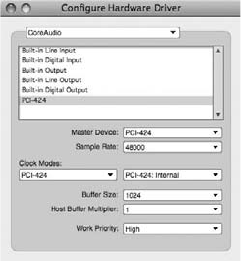
device are provided. In addition, global project settings for the buffer size, host buffer multiplier,
and work priority are also displayed.
The Hardware Driver List
The Configure Hardware Driver window allows you to control any Core Audio–compatible
audio interfaces that are connected to your computer, including the Mac’s built-in audio.
Installed hardware drivers will appear in the hardware driver list.
To enable an audio device for use with DP:
1. Open the Configure Hardware Driver by choosing Setup 4Audio System 4Configure
Hardware Driver.
2. Click on a hardware driver within the list to enable it. Once enabled, it will be high-
lighted in blue.
3. DP allows you to simultaneously use multiple audio devices. Simply Control-Command-
click on another driver to enable multiple audio devices in DP. Be aware that you will need
to resolve the audio clocks of each device when working with multiple drivers (explained
in the “Clock Modes” section later in this chapter).
Master Device
The Master Device setting only comes into play when you have multiple hardware drivers
enabled (explained in the previous section). Enabled digital devices will operate at the sample
rate that is designated in the Sample Rate drop-down menu (explained in the next section). To
keep their digital signals locked together, you must designate one of the devices as the master
clock source. Once a master clock is specified, the other digital devices in your system should be
set to listen to it (commonly referred to as being a slave to the master).
For the other devices to listen to the master clock, you must physically output the audio clock of
the master device to the other digital devices via a word clock, AES/EBU, or ADAT (9-pin) cable.
Figure 2.11 The Configure Hardware Driver window.
Chapter 2 Setting Up Digital Performer 6 19
The type of sync you choose will be determined by the specific devices with which you’re work-
ing. Resolving the audio clocks of multiple digital sources is essential when you are working with
multiple digital devices. Audio clocks that are not resolved can cause digital distortion, as well as
introduce digital pops and clicks in your audio signal.
Sample Rate
Choose the sample rate for the project from the Sample Rate drop-down menu. Only sample
rates supported by the selected hardware driver will appear in the list. Keep in mind that the
chosen setting will apply to all audio devices that are enabled in the hardware driver list.
Clock Modes
The Clock Modes section of the Configure Hardware Driver window contains two drop-down
menus—the device list (left) and the clock source (right). Only audio devices enabled in the
hardware list will appear in the device list. Once a device is selected, its clock source will appear
in the Clock Source menu. By default, the clock source for a device is set to Internal, which
means the selected device will listen to its own internal audio clock. Digital Performer will
also use this clock as its master clock source when playing back and recording audio. If you
have only one device enabled in the list, be sure to set its clock source to Internal—once it’s
set, you’ll never have to worry about it again.
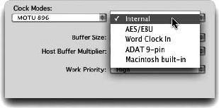
When using multiple devices, however, you will need to resolve the audio clocks of each device.
Set the master device to Internal, and then choose the appropriate audio clock for the slaved
devices, as shown in Figure 2.12. As discussed earlier, the type of clock source you choose will be
determined by how each device is physically synced (or slaved) to the master device.
Buffer Size
Abuffer is basically a small chunk of memory. When you are working with digital audio, the buffer
temporarily holds onto the audio that is traveling between your Mac and your audio device. The
longer the buffer holds the audio, the more monitoring latency, or audible delay of the live signal,
that is introduced. Lower buffer settings reduce monitoring latency but put additional strain on
your Mac. The lower the buffer setting, the harder your computer must work to play back and
record audio; this forces your Mac to allocate more CPU processing power for playback and record-
ing functions, essentially reducing the number of effects plug-ins and processing that can be used in
Figure 2.12 The Clock Source menu.
20 Digital Performer 6 Power!: The Comprehensive Guide
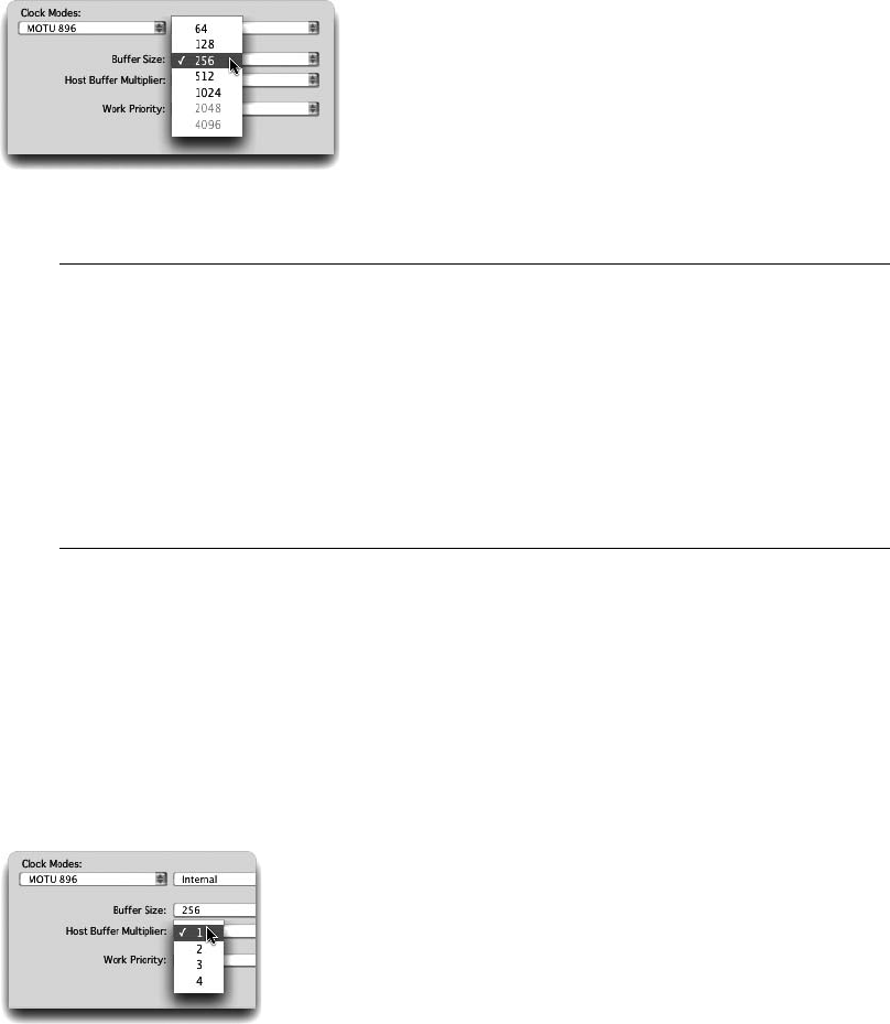
a project. Higher buffer settings have the opposite effect—monitoring latency is increased, freeing
up your Mac’s CPU for other tasks, such as effects processing.
Buffer sizes are measured in samples and can be changed by clicking on the Buffer Size menu, as
shown in Figure 2.13.
When to Change the Buffer Size The general rule when working with buffer settings is
lower settings for recording (256 samples or lower) and higher settings for mixing (512
or 1,024þsamples). If you’re triggering virtual instruments within a project, however,
you’ll need to find a middle ground—lowering the buffer enough to reduce monitoring
latency, but not lowering it so much that you run out of CPU power for effects.
Keep in mind that the buffer setting can be changed at any point in your project and will
be dictated by the specific task at hand. Be sure to use the Audio Performance window
(explained in Chapter 13, “Processing and Mastering”) to monitor buffer activity.
Host Buffer Multiplier
The Host Buffer Multiplier menu, shown in Figure 2.14, helps to improve the performance of
Digital Performer. MOTU recommends the following Host Buffer Multiplier settings:
n1. Use this setting if you only have one audio device enabled in the hardware driver list.
n2. Choose 2 if you have two or more devices enabled.
n3–4. Choose 3 or 4 if you are experiencing audio performance problems.
Figure 2.13 The Buffer Size menu. The actual settings listed will be dictated by the selected hardware
device.
Figure 2.14 The Host Buffer Multiplier setting.
Chapter 2 Setting Up Digital Performer 6 21
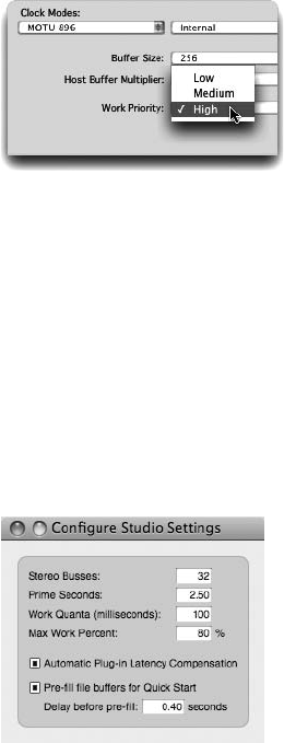
Work Priority
The Work Priority setting, shown in Figure 2.15, determines the priority the MAS engine
receives from Mac OS X, so try to keep this setting as high as possible. MOTU audio devices
can be set to High, while other devices may require Medium or Low settings. If you are working
with third-party audio devices, you may need to experiment with this setting if you are experi-
encing performance problems.
Once you have enabled the necessary audio devices and properly configured their settings, click
OK to confirm the audio settings. Remember that you can change these settings at any time
during the music production process, allowing you to tailor the responsiveness of Digital Per-
former to work with your specific project needs.
The Configure Studio Settings Window
The Configure Studio Settings window, shown in Figure 2.16, allows you to adjust certain
parameters of Digital Performer’s audio engine. Here you can decide how many stereo busses
you need, as well as fine-tune settings that can make DP more responsive during playback.
Stereo Busses
The Stereo Busses setting determines how many internal audio busses will be provided by MAS
and will be seen within your Digital Performer work environment. The number of busses you
can create is limited to a total of 99. MOTU states that this number is arbitrary and will not
affect system performance. However, the actual number of busses simultaneously used in a proj-
ect could, and most likely will, have an impact on your system resources.
Figure 2.15 The Work Priority setting.
Figure 2.16 The Configure Studio Settings window.
22 Digital Performer 6 Power!: The Comprehensive Guide
Prime Seconds
The Prime Seconds setting determines how far in advance Digital Performer pre-cues audio or pre-
renders any plug-in effects before playback begins. In other words, DP prepares (renders) audio in
advance before attempting to play it, and this setting defines how much time DP is given to do this.
If issues occur immediately after playback begins, try increasing this number. On the other hand, if
DP is not responding as quickly as you would like when you hit Play, try decreasing this number.
Work Quanta
The Work Quanta number controls the intervals at which the MAS audio engine makes its
calculations. Increasing this number can free up some processing power, allowing for more
real-time effects. A lower number will help smooth the graphic elements of Digital Performer,
such as the Playback Wiper.
Max Work Percent
Depending on the nature and size of your DP project, you can control the amount of processing
power or CPU that is allocated to the MAS engine as it pre-renders or cues audio tracks for
playback. Higher values in the Max Work Percent field benefit the audio engine, but at the
expense of graphics display and other tasks. Lower values reduce CPU for audio but increase
graphics performance (screen redraws and so on).
Automatic Plug-In Latency Compensation
The Automatic Plug-In Latency Compensation option will compensate for any delay that is
introduced to an audio track when you’re using real-time audio plug-ins. This option will
also compensate for virtual instruments being triggered by prerecorded MIDI tracks. Refer to
Chapter 13 for an explanation of the Automatic Plug-In Latency Compensation feature.
Pre-Fill File Buffers for Quick Start
The Pre-Fill File Buffers for Quick Start setting tells DP to pre-fill the play buffers before play-
back is initiated—essentially speeding up the responsiveness of DP when you hit the Play button.
DP fills this buffer anytime you move the Playback Wiper or perform any action that is playback
related.
The Input Monitoring Mode Window
The Input Monitoring Mode window, shown in Figure 2.17, determines how live audio signals
are monitored in Digital Performer. The settings you choose here will affect overall monitoring
latency and your ability to perform successful audio punches.
Monitoring Thru Effects versus Direct Hardware Playthrough
When the Monitor Record-Enabled Tracks Through Effects option is selected in the Input Mon-
itoring Mode window, live audio signals are routed through Digital Performer before going out
to your audio interface. This allows you to listen to the live signal through any effects plug-ins
Chapter 2 Setting Up Digital Performer 6 23
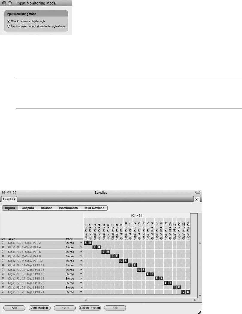
inserted in DP. The tradeoff is increased monitoring latency, because the audio signal must travel
through Digital Performer and any plug-ins before you hear it.
Recording in Sync Regardless of which input monitoring mode setting you choose, live
audio will always be recorded in the proper location, without any latency and in perfect
sync with other tracks.
The Direct Hardware Playthrough option, however, introduces little (if any) delay to the live
signal because it bypasses Digital Performer all together. The disadvantage to this method is the
inability to process the input signal with DP’s cool effects plug-ins.
The Bundles Window
The Bundles window, shown in Figure 2.18, is a one-stop location for enabling (or disabling) the
routing assignments of the audio and MIDI gear that is connected to your system. Unlike the
Figure 2.17 The Input Monitoring Mode window.
Figure 2.18 The Bundles window.
24 Digital Performer 6 Power!: The Comprehensive Guide
other configuration windows I have discussed so far, settings for the Bundles window are project
specific, so you’ll need to have a DP project open before this window will be available.
The Bundles window is divided into five tabbed sections, labeled Inputs, Outputs, Busses, Instru-
ments, and MIDI Devices. Each section displays the name, channel format (or model), and rout-
ing assignments for each bundle. Buttons for adding, deleting, and editing bundles are located at
the bottom of the window. Changes made in the Bundles window will be reflected in the I/O
assignment menus and in the Meter Bridge (discussed in more detail in Chapter 7, “Recording
Audio”).
The five available tabbed sections are:
1. Inputs. This tab is where you can define and route all of the necessary audio inputs you
will be using for your project.
2. Outputs. Here you can specify the audio outputs for the project.
3. Busses. The Busses tab allows for the creation of multiple internal audio busses.
Remember, the number of busses you can add is limited to the number designated in the
Configure Studio Settings window (mentioned previously). Anything beyond this will
create a duplicate “shared” bus.
4. Instruments. In many Audio Unit (AU) plug-ins and ReWire-compatible applications,
multiple audio outputs are available. The Instruments tab is where you can route these
outputs to anywhere in the Digital Performer environment. Once the virtual instrument
is instantiated, simply click the Add button to create as many bundles as needed.
5. MIDI Devices. The MIDI Devices tab in the Bundles window provides access to the
same information regarding your MIDI setup as in the Audio MIDI Setup window
(discussed in “The Audio MIDI Setup Utility (AMS)” section of this chapter). The
presentation looks different, but all of your MIDI connections are represented, and any
changes made here will appear in the AMS Utility window as well. You can add a device
by simply clicking the Add button and define its properties by highlighting the new
device and clicking the Edit button.
What Are Bundles?
A bundle is basically a set of inputs, outputs, and internal busses for audio, routing paths for
virtual instruments, and I/O assignments for MIDI gear. Think of the Bundles window as a vir-
tual patch bay. Although you are not changing the physical connections of your equipment (as
most bundles are simply the physical inputs and outputs of your audio and MIDI interfaces),
there is much freedom in assigning DP’s internal busses. While it’s possible to create audio bun-
dles on the fly from DP’s I/O assignment menus, the Bundles window provides you with a
graphic interface allowing for the creation, removal, renaming, and rerouting of I/O assignments
Chapter 2 Setting Up Digital Performer 6 25
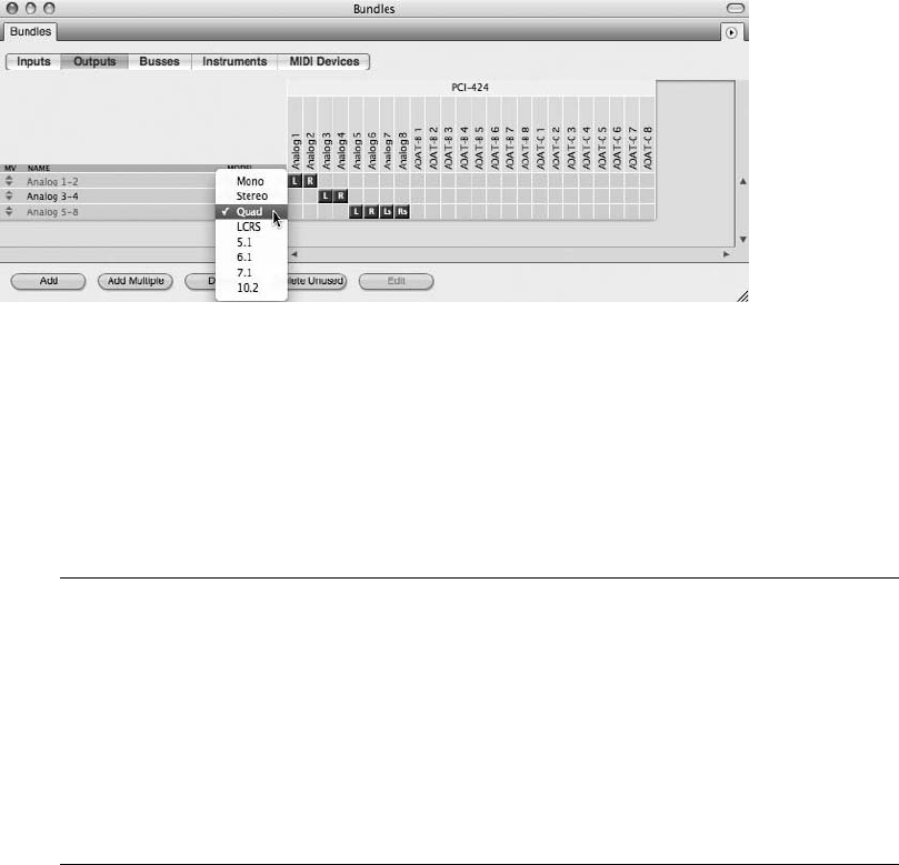
between Digital Performer and your connected audio and MIDI interfaces (and third-party vir-
tual instruments, such as Stormdrum or Ableton Live).
First, I want to focus on creating audio bundles, and then we will look into MIDI connections
and virtual instrument paths.
To create an audio bundle in the Bundles window:
1. Select the desired Inputs, Outputs, or Busses tab and click the Add button.
2. Specify the channel format for the audio bundle by clicking on the Model menu, shown
in Figure 2.19.
To remove or delete an audio bundle:
1. Click on the name of an audio bundle to select it. Drag to select multiple audio bundles.
2. Click the Delete button. You can also press the Delete key on your computer keyboard.
Renaming Bundles Another benefit to using the Bundles window versus DP’s I/O assign-
ment menus is the ability to rename a specific input, output, or bus. You could, for exam-
ple, call Bus 1-2 “Reverb” if you were using it as an effects send, or you could customize
the input/output bundle names to correspond to any studio gear that’s physically con-
nected to your audio interface. Customizing your audio bundle names can help you per-
sonalize and possibly speed up your Digital Performer workflow.
To rename an audio bundle, Option-click the name of the bundle. Enter the new name
and press the Return key on your Mac’s keyboard to confirm the change.
Figure 2.19 Set an audio bundle’s channel format from the Model menu. Notice that you can also
choose surround configurations.
26 Digital Performer 6 Power!: The Comprehensive Guide
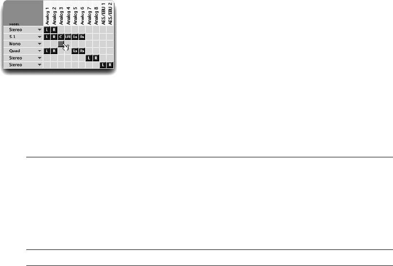
Rerouting Input, Output, and Bussing Assignments for Audio and Virtual Instrument
Bundles
The Tile Grid of the Bundles window is where you can change the routing assignment for a
specific audio bundle. The selected audio hardware driver and third-party virtual instruments
you have installed determine the audio devices and virtual instrument I/O that appear above the
assignment grid in each tabbed section. The location of each tile determines the routing assign-
ment of an audio bundle. Each bundle tile basically opens the connection between a specific DP
input, output, or bus and a specific input, output, or bus on your connected audio device or
virtual instrument. For example, suppose you have an audio interface with four analog outputs
(two stereo pairs), and you have four speakers connected to these outputs (two for each pair).
The hardware driver for the interface would allow you to create an audio bundle with two sep-
arate stereo outputs—say, Analog 1-2 and Analog 3-4. Now, in the Tile Grid, you are free to
define the routing of audio (in DP) through these outputs.
nTo make a new I/O routing assignment, click and drag a bundle tile to a new assignment, as
shown in Figure 2.20.
nTo swap the left and right channels of a stereo bundle, drag the left or right bundle to the
opposite channel.
Sharing I/O Assignments DP allows you to create bundles that share the same assign-
ments as other bundles. This is especially handy when you are working with surround
bundles, because you can create dedicated bundles for panning to specific speakers in a
surround setup. This would allow you, for example, to pan specific “stems” to specific
combinations of speakers (such as dialogue in the center, the music score in the front
left/right and rear left/right channels, FX stems in 5.1, and so on).
Exchanging Bundles Between DP Projects You can exchange bundles between DP projects
simply by choosing the Export or Import Bundles option available in the Bundles window
mini-menu. Just click the mini-menu button (located in the upper-right corner of the
Figure 2.20 Click and drag a bundle tile to change the routing assignment for an audio bundle.
Chapter 2 Setting Up Digital Performer 6 27
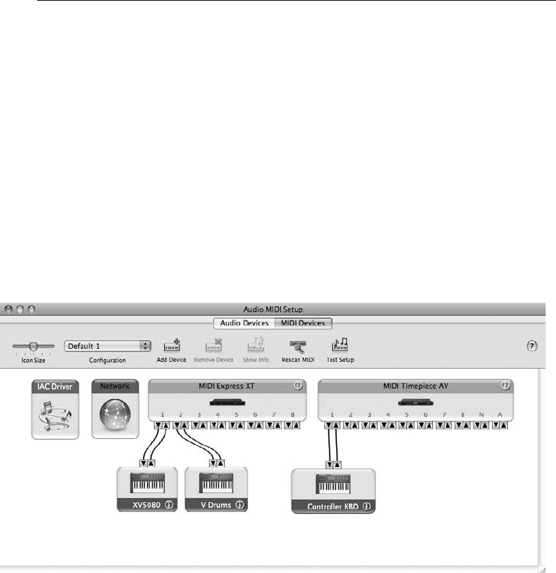
Bundles window) and exp ort your bundles for use in another DP proje ct, or impo rt a saved
bundle into you r curren t proje ct.
MIDI Configuration
MIDI device configuration has been greatly simplified in Mac OS X—you no longer have to rely
on third-party applications (such as FreeMIDI or OMS) to connect Digital Performer with your
studio’s MIDI devices. Similar to how OS X handles audio (with Core Audio), Apple’s Core
MIDI technology connects your MIDI studio together at the system level, offering improved
speed and performance. In addition, once your MIDI devices have been configured, other
Core MIDI–compatible applications you may have installed on your Mac (such as Pro Tools,
Finale, GarageBand, and so on) will also have access to this global MIDI setup.
The Audio MIDI Setup window, shown in Figure 2.21, provides a virtual representation of your
MIDI studio’s physical setup. Use this window to connect your MIDI interface and MIDI devices
to DP (and other Core MIDI applications). As discussed earlier in this chapter, the MIDI Devices
tab in the Bundles window is also a place for you to configure your MIDI connections to DP via
a Tile Grid. I will focus on the Audio MIDI Setup window, although the results are the same.
The Audio MIDI Setup Utility (AMS)
The Audio MIDI Setup (AMS) window allows you to configure the routing assignments for all of
your connected MIDI devices. Once you install the Core MIDI drivers for your particular MIDI
interface, the drivers will automatically appear in the AMS window, as shown in Figure 2.22.
Figure 2.21 The MIDI Devices tab of the Audio MIDI Setup window shows your system’s MIDI routing
assignments.
28 Digital Performer 6 Power!: The Comprehensive Guide
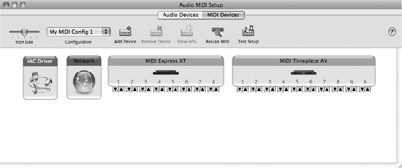
You can access this window directly in Digital Performer by choosing Setup 4Open Audio
MIDI Setup or by using Mac OS X’s Finder.
Configuring Your MIDI Devices
Once your MIDI interface is visible in the MIDI Devices tab of the AMS window, it’s very easy
to add, configure, and connect your MIDI devices.
To add a new MIDI device:
1. Open the AMS window by choosing System Hard Drive 4Applications 4Utilities 4
AMS. You can also open the window from DP by choosing Setup 4Open Audio
MIDI Setup.
2. Once AMS is opened, click the MIDI Devices tab to display your MIDI configuration.
3. Click the Add Device button to add a new external MIDI device. You can also use the
default keyboard shortcut CommandþD. When you’ve created the new device, a device
called New External Device will appear in the AMS window, as shown in Figure 2.23.
The new external device that is created will be a generic MIDI device. You can specify the man-
ufacturer, model, and MIDI properties of the device from the Properties window. This allows
DP to recognize a particular device’s patch lists and so on.
To configure the new MIDI device:
1. Double-click the new external device you created in the previous section. The Properties
window will open, allowing you to change the generic device’s MIDI properties.
2. Specify the manufacturer and model name from the appropriate menus, as shown in
Figure 2.24.
Figure 2.22 Once you have installed the Core MIDI driver for your particular MIDI interface, it will
automatically appear in the AMS window.
Chapter 2 Setting Up Digital Performer 6 29
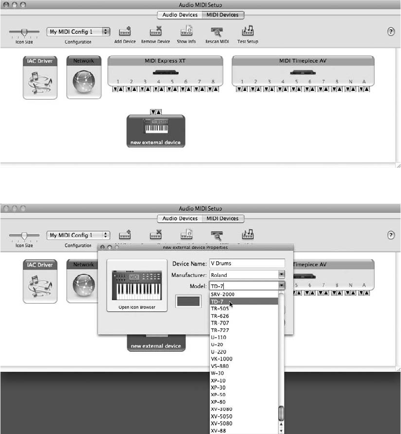
3. Once defined, the device’s properties will automatically be configured for the specific
device. To view the actual properties for the MIDI device, click the More Information
button (see Figure 2.25).
4. Make any necessary changes and then click the Apply button to confirm them.
5. Close the Properties window by clicking on the window’s red Close button (located at
the top-left corner of the window).
Figure 2.23 Click the Add Device button to add a new external MIDI device.
Figure 2.24 Double-click the device to define its properties.
30 Digital Performer 6 Power!: The Comprehensive Guide
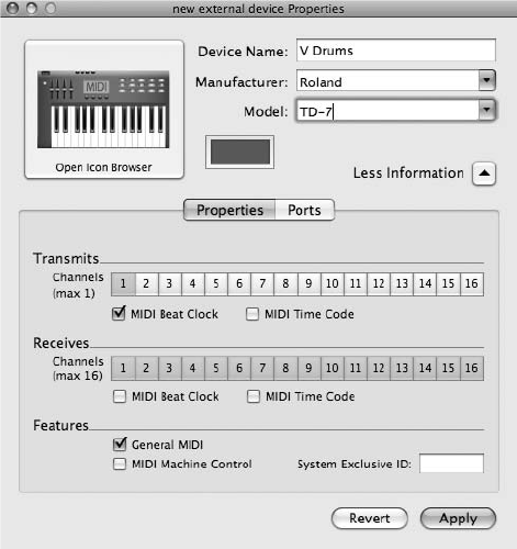
Once you have configured the properties for your new MIDI device, it will appear with the
model name you specified in the previous section (such as V Drums).
Next, you need to connect the device to your MIDI interface. Make sure the virtual connections
you are making in the AMS window match the physical connections of your MIDI studio.
To connect your MIDI device:
nClick and drag the device’s output/input arrows to the MIDI interface’s input/output arrows,
as shown in Figure 2.26.
Once you have configured your MIDI devices, made the appropriate connections, and so on, you
can use the Configuration drop-down menu to edit the configuration. Here, you can duplicate,
rename, or delete the current configuration, or you can create a new configuration. It is a good
idea to duplicate your main configuration for backup purposes.
To quit the Audio MIDI Setup utility, simply choose Quit from the Audio MIDI Setup
menu. You can also use the default keyboard shortcut CommandþQ. Devices configured in
AMS will automatically appear in Digital Performer and any other Core MIDI–compatible
application.
Figure 2.25 The Properties tab of the AMS window.
Chapter 2 Setting Up Digital Performer 6 31
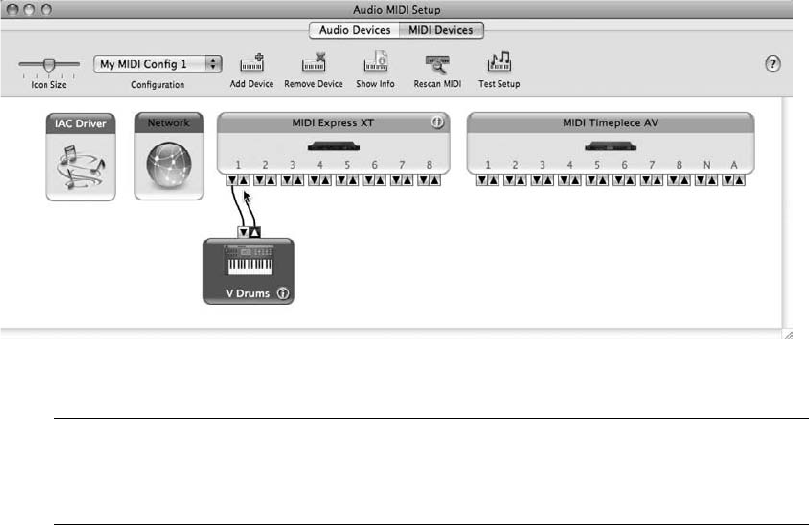
AMS in the Dock For quick access to the Audio MIDI Setup utility when you are not in
Digital Performer, I suggest dragging the application icon onto your Dock. This eliminates
just a few screen clicks, but every second counts when you are in a crunch!
Synchronization
You can synchronize Digital Performer with other devices and applications. Digital Performer
supports all standard synchronization modes, including SMPTE, standard MIDI beat clocks,
and tap tempo sync. When receiving SMPTE time code, you can choose MIDI Time Code,
Direct Time Lock, or Indirect Time Lock for the SMPTE-to-MIDI conversion that is required
for SMPTE. Refer to the “Synchronization” chapter of the Digital Performer user manual for an
explanation of DP’s different sync modes.
Syncing DP
You can synchronize DP with other devices (and applications) using the Receive Sync and Trans-
mit Sync commands. Even though Digital Performer can receive sync from a wide variety of
synchronization modes, it can only transmit sync as MIDI beat clocks (a.k.a. standard beat
clocks) or MIDI time code.
To slave DP to another device or application:
1. Open the Receive Sync command by choosing Setup 4Receive Sync (or Receive Sync in
the Preferences and Settings window).
2. Click the Sync to Port menu and choose the sync source, as shown in Figure 2.27.
Selecting Any will enable DP to sync to any time code it receives.
Figure 2.26 Drag the input/output arrows to connect devices in the AMS window.
32 Digital Performer 6 Power!: The Comprehensive Guide
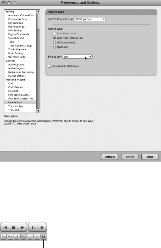
3. Choose the desired sync mode from the Type of Sync section.
4. Once you’ve specified the sync settings, click the Done button.
5. Next, select Slave to External Sync from the Setup menu. You can also use the default
keyboard shortcut Commandþ7. Once enabled, the Control Panel’s Slave to External
Sync button will become highlighted, as shown in Figure 2.28.
Figure 2.27 The Sync to Port menu allows you to set the sync source.
The Slave to External S
y
nc button
Figure 2.28 The Slave to External Sync button. In addition to the methods provided in Step 5, you can
also click on the Slave to External Sync button to toggle the Slave to External Sync feature on and off.
Chapter 2 Setting Up Digital Performer 6 33
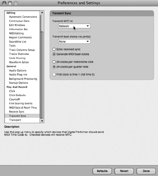
6. Press the Control Panel’s Play or Record button. The Play button will flash, indicating
that DP is waiting to receive sync from the device specified in Step 2.
To slave another device or application to Digital Performer:
1. Open the Transmit Sync command by choosing Setup 4Transmit Sync (or Transmit
Sync in the Preferences and Settings window).
2. Decide which type of sync you wish to transmit (either MIDI beat clocks or MIDI time
code [MTC]) and then specify the sync destination from the appropriate Transmit
menu, as shown in Figure 2.29. Keep in mind that you can transmit both types of sync
simultaneously to multiple destinations, simply by making the desired assignments.
3. Once you have chosen the desired settings, click the Done button.
Figure 2.29 Use the Transmit MTC or Transmit Beat Clocks via Port(s) menus to send MIDI time code or
MIDI beat clock sync to another device or application.
34 Digital Performer 6 Power!: The Comprehensive Guide
Keep in mind that the device (or application) to which you’re transmitting sync must be set to
receive sync in order for DP to control the device. See the specific device’s user manual for
instructions on how to slave the device or application to Digital Performer.
Summary
Once you have successfully installed DP and configured your audio and MIDI devices, you will
be ready to start working in Digital Performer. See Chapter 3, “Navigating Digital Performer 6,”
for an overview of the major windows in Digital Performer. If you want to go ahead and dive
into DP, refer to Chapter 4, “Setting Up a New Project,” for an explanation of how to set up a
project for recording.
Chapter 2 Setting Up Digital Performer 6 35
This page intentionally left blank

3Navigating Digital
Performer 6
Digital Performer’s interface is composed of various information windows that allow you
to access its numerous tools and features sets. This chapter will provide an overview of
the most important windows, which serve as the backbone for Digital Performer (see
Figure 3.1). For information on DP’s other windows and important features, check the Table of
Contents of this book to find related chapters or appendixes.
A Modern User Interface? Yes, it’s true. Digital Performer 6 has a cleaner, more modern
(and manageable) look and feel. Historically referred to as having far too many windows,
menus, and so on, DP 6 is neater and more compact in its presentation of data. The nav-
igation controls have been unified throughout so you are less likely to miss “hidden” infor-
mation or be forced to tick through several windows just to make a simple adjustment.
Keep in mind that although many aesthetic changes have been made, DP maintains its
technical depth and magnitude of features. It’s just more efficient and easier to use!
Following is a list of the windows and features discussed in this chapter:
nConsolidated Window
nControl Panel
nTracks window
nSequence Editor
nMixing Board
nSoundbites window
The Consolidated Window
The Consolidated Window feature allows you to view and configure DP’s various windows in a
single consolidated window, as shown in Figure 3.2. The Consolidated Window is broken up
37
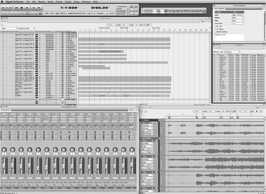
into different sections that can be added, subtracted, or resized to fit your specific production
needs. If you want to jump right into using this feature, you can access the provided default
Consolidated Window sets from the Window Sets menu (Window 4Window Sets).
The Consolidated Window preferences (Digital Performer 4Preferences 4Display 4Consoli-
dated Window) control the functionality of the Consolidated Window, as shown in Figure 3.3.
From here, you can decide which windows will automatically open in the Consolidated Win-
dow, how many rows will initially appear, how projects created in older versions of DP are
affected, and how the Mixing Board behaves when the Consolidated Window is turned on.
You can also select options for enabling or disabling the Consolidated Window altogether.
See the “Customizing Your Workspace” section of Chapter 5, “Project Management: Part 1,”
for an explanation of the Consolidated Window and the Consolidated Window preference
settings.
Figure 3.1 Digital Performer’s main windows: Control Panel, Tracks, Sequence Editor, Mixing Board,
Soundbites, and the new Track Inspector.
38 Digital Performer 6 Power!: The Comprehensive Guide
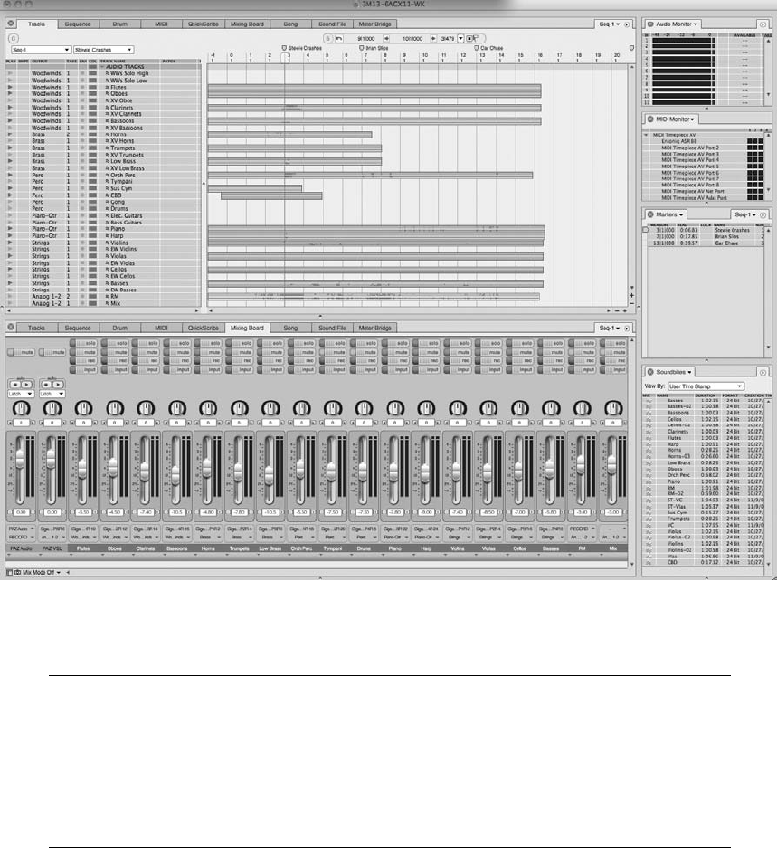
Tabs in the Consolidated Window Digital Performer 6 offers a new approach for accessing
different windows within the Consolidated Window. Across the top of the main body
(center) section is a row of tabs, each representing a different editor or primary window.
For example, to access the Mixer window, simply click on its corresponding tab, and it will
appear in the main body of the Consolidated Window. Tabbed browsing is also available
in sidebars and cells (discussed in Chapter 5).
Control Panel
The Control Panel in Digital Performer 6 is divided into three main sections (see Figure 3.4).
This window is the central location from which you can access playback controls in the Trans-
port, view and adjust the Counter, and enable enhanced selection and tempo features in the
Figure 3.2 The Consolidated Window feature allows you to display DP’s various windows in a single
consolidated window. In this example, the default Tracking window set is displayed.
Chapter 3 Navigating Digital Performer 6 39
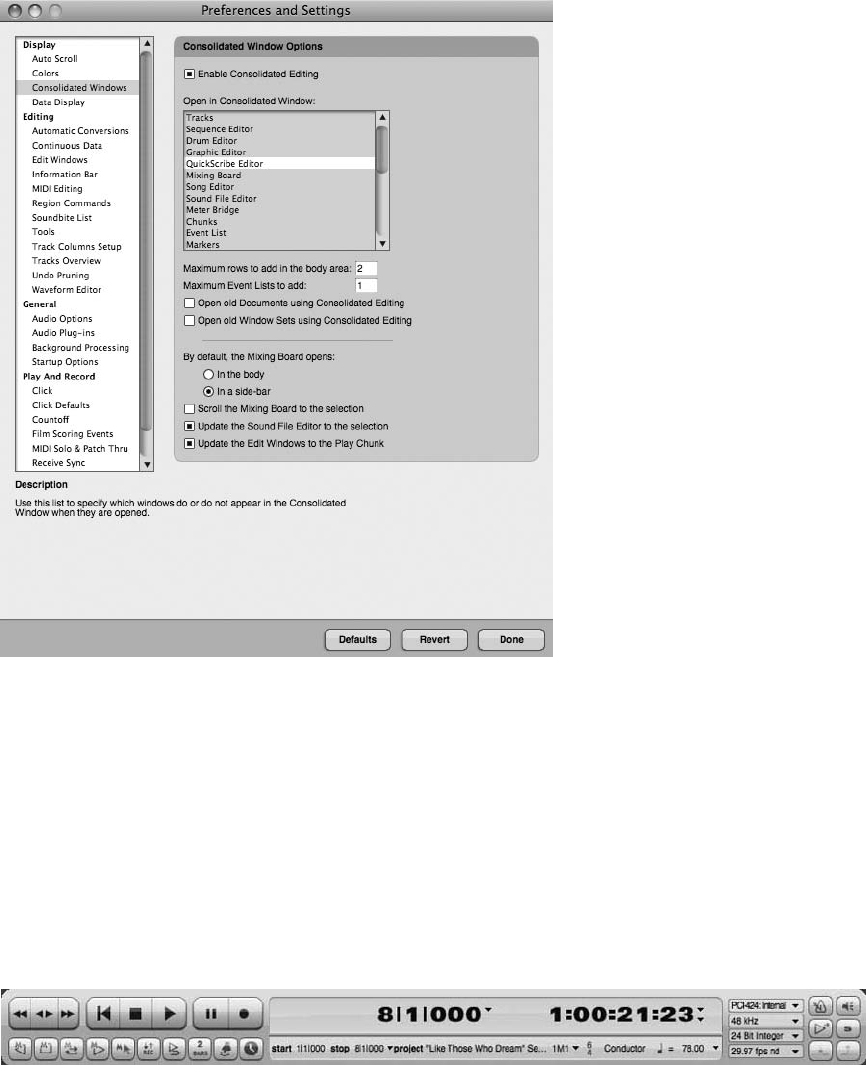
Status Strip. You can also quickly adjust audio settings for your project or toggle the various
Transport buttons to access modes such as Overdub, Wait, and Solo. Unlike other DP windows,
the Control Panel cannot be closed and will automatically open anytime a new session is created
or opened.
Transport
The Control Panel’s Transport controls operate like those on any standard multitrack recorder.
The main transport, or “go,” functions (see Figure 3.5) are (from left to right):
Figure 3.3 The Consolidated Window preferences control the functionality of the Consolidated
Window.
Figure 3.4 The Control Panel consists of three main sections that make DP “go.”
40 Digital Performer 6 Power!: The Comprehensive Guide
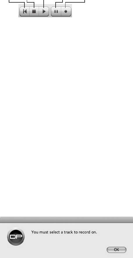
nFast Rewind. This button rewinds the sequence in fast motion.
nSlow Rewind/Forward. This combination button allows you to rewind or move forward in
slow motion.
nFast Forward. This button moves the sequence forward in fast motion.
nRewind. This button takes you to the beginning of the current sequence. If you have the
Memory Bar options enabled, the Transport will rewind to the Memory Start location. If
pressed during playback, there will be a momentary pause before DP resumes playback at
the proper location. Pressing this button during the record process will stop the recording
and begin the rewind normally. You can also press the number 1 key on the numeric keypad
to instantly locate to the beginning of your project or Memory Start location.
nStop. This button will halt playback and recording and will also turn off the Pause button, if
it is engaged. If the Memory Bar’s Auto-Rewind button is turned on, DP will automatically
rewind to the Memory Start location. You can also use the spacebar to stop or start
playback.
nPlay. This button begins playback. Use the spacebar to start or stop playback.
nPause.This button suspends playback and puts the Transport in standby. If this is pressed
during playback, DP will suspend playback without turning off any sounding MIDI notes. If
it is pressed while the Transport is stopped, playback will be suspended until the Transport is
“unpaused.”
nRecord. This button engages playback and begins recording from the playback cursor’s
current location. A track must be record-enabled for recording to begin. If you attempt to
start recording when no tracks are armed, you will be presented with a warning dialog box
(see Figure 3.6).
Rewind Stop Play Pause Record
Figure 3.5 The main “go” functions of the Control Panel.
Figure 3.6 A track must be record-enabled before you can begin recording.
Chapter 3 Navigating Digital Performer 6 41
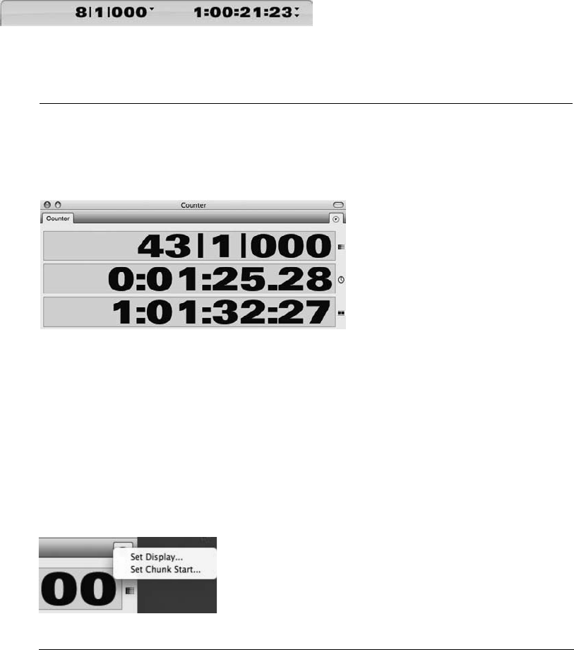
Counter
The Counter section of the Control Panel displays the current playback location for the enabled
sequence. The Main and Auxiliary Counters can display four different formats: measures, real-
time, SMPTE frames, and samples. Click on the time disclosure triangles located to the right of
each Counter to change the display. Be aware that you cannot display the same time format in
both Counters (see Figure 3.7).
The Large Counter Window In addition to the Control Panel’s Counter window, DP also
has a “large” Counter window (see Figure 3.8) that you can access from the Studio menu.
(The default keyboard shortcut is Shift+J.)
The large Counter consists of a Main Counter and one to three Auxiliary Counters,
depending on whether you enable all four time formats from the Set Display command
located in the mini-menu. This command also lets you specify the time format that will be
displayed in the Main Counter.
The mini-menu (see Figure 3.9) also provides a command for setting the Chunk Start
Time. (See Chapter 11, “Arranging.”)
Figure 3.7 The Control Panel’s Counter. In this example, the Main Counter is configured to display
measures/beats/ticks, while the Auxiliary Counter displays SMPTE frame time.
Figure 3.8 The large Counter window.
Figure 3.9 The Counter window mini-menu.
42 Digital Performer 6 Power!: The Comprehensive Guide
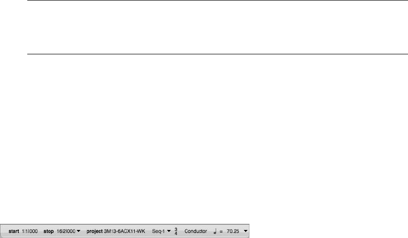
Chunks Digital Performer refers to sequences as Chunks. DP projects can contain an
unlimited number of Chunks and are managed from the Chunks window (Projects 4
Chunks). See Chapter 11 for a full explanation of Chunks.
Status Strip with Tempo Control
The Status Strip is located at the very bottom of the Control Panel’s Counter (see Figure 3.10)
and presents a great deal of sequence information. On the left, the strip has fields to enter Mem-
ory Start and End times, access to the Set To drop-down menu (discussed later in this chapter),
the name of the project, and the sequence (Chunk) that is currently selected in the Sequence
drop-down menu. (See the “Sequence and Marker Menus” section later in this chapter.)
When Auto-Record mode is enabled, the project name and current Chunk fields will disappear
and be replaced by the Punch-In and Punch-Out fields, wherein you can specify the exact loca-
tions for punch-in and -out recording. (For more information, see the “Punching In and Out”
section of Chapter 7, “Recording Audio.”)
Located to the right of the Sequence menu (see Figure 3.11) are the current Meter, Tempo Con-
trol, Beat Value, and Tempo displays (from left to right). Last is a disclosure triangle that pro-
vides access to the Tempo Control drop-down menu.
nCurrent Meter. This displays the current time signature of the enabled sequence. This value
can only be changed by selecting Project 4Modify Conductor Track 4Change Meter. You
could also insert a meter event directly into the Conductor track. (See Chapter 4, “Setting Up
a New Project,” and Chapter 11 for details on working with meters within DP.)
nTempo Control. This displays the current tempo mode of the sequence.
nCurrent Beat Value. This value determines which note gets the “beat,” or subdivision, for
the current tempo, displayed in beats per minute (BPM). See Chapters 4 and 11 for details on
working with tempo within DP.
nCurrent Tempo. This displays the current tempo, or BPM, of the enabled sequence. You can
click and drag directly into the BPM window to change the tempo (even during playback), as
long as the tempo is not set to be controlled by the Conductor track (explained in the
“Conductor Track” section of Chapter 11).
nTempo Control menu. This menu allows you to select a specific tempo mode to control the
current sequence. You can choose Tempo Slider, Conductor Track, Tap Pad, or Remote
Control.
Figure 3.10 The Control Panel’s Status Strip.
Chapter 3 Navigating Digital Performer 6 43
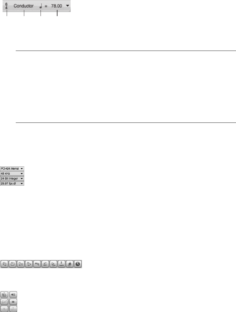
The Conductor Track The Conductor track (discussed further in Chapter 11) is a special
track that contains data related to tempo, meter, key signatures, and markers. Think of
this track as a roadmap for the sequence. Unlike other tracks, it cannot be deleted. How-
ever, its data can be viewed and edited in the Graphic Editor or Event List window. When
the tempo of a sequence is set to Conductor Track mode (discussed earlier), the data
entered or recorded into this track will control the tempo(s) for the current sequence.
You can even have separate takes for the Conductor track! (See Chapter 7 for information
regarding takes.)
Audio Settings
The Audio Settings section (see Figure 3.12) allows you to specify audio clock sources, the sam-
pling rate, bit depth, and the SMPTE frame rate without having to open their related windows.
Routine Transport Buttons
Located directly below the Transport controls and to the right of the Audio Settings section are
various routine buttons that can help significantly streamline your workflow and allow you to
concentrate more on the creative process (see Figures 3.13 and 3.14). For example, the Memory
buttons can help you automate routine Transport procedures by allowing you to program the
Transport controls to activate at specified times during playback or recording.
Meter Tempo
Control
Beat Value
Figure 3.11 The Control Panel’s current Meter, Tempo Control, Beat, and Value (from left to right).
Figure 3.12 The Audio Settings section of the Control Panel.
Figure 3.13 The routine Transport buttons can help you significantly streamline your workflow.
Figure 3.14 More routine Transport buttons are located to the far-right of the Control Panel.
44 Digital Performer 6 Power!: The Comprehensive Guide
nAuto-Rewind. Use this feature to immediately rewind to the Memory Start Time when
playback is stopped.
nAuto Stop. This option causes playback and recording to stop at the Memory Stop Time.
nMemory Cycle. This button will force playback and recording to loop infinitely between the
designated Memory Start and Stop Times. Multiple consecutive playbacks will occur until
the Stop button is selected.
nLink Playback to Memory. This buttons functions just like the Memory Cycle button but
will stop at the specified Memory Stop Time rather than repeat over and over. Once enabled,
the Pre/Post Roll buttons become active (discussed later in this section).
nLink Selection to Memory. When this button is enabled, the Memory Start and Memory
Stop Times will always match (update to) the current selection.
nAuto-Record. Use this button to automate punches within DP. Once enabled, the Punch
Start and End times will become visible in the Status Strip. (See Chapter 7 for more
information.)
nOverdub Record. When engaged, this option will merge recorded MIDI data with any data
that already exists within a MIDI track. When Overdub mode is turned off, previously
recorded MIDI data will be replaced when recording starts.
However, audio tracks operate differently. With Overdub mode enabled, newly recorded
material will not be merged, but will be layered over existing soundbites. When Overdub
mode is off, previously recorded soundbites in that track are erased.
nCountoff. This button enables the countoff for the MIDI metronome. The number of
countoff measures can be set in the Countoff preferences, which you can quickly access by
double-clicking the Countoff button.
nWait. Click this button to place the Transport in standby mode. When playback or recording
is initiated, DP will “wait” for a MIDI message before beginning playback or recording. (See
Chapter 8, “Recording MIDI,” for more information.)
nSlave to External Sync. This button will turn on external sync. Double-clicking will open the
Receive Sync window, where you can set specific sync options. Use this option when you
wish to synchronize your Digital Performer system with another playback or recording
device/application. Review Chapter 2 for an explanation of synchronization.
nMetronome Click. This option will turn on DP’s Metronome. Double-clicking on this button
will open the Click preferences. See the “Setting Up a Click” section of Chapter 4 for an
explanation of Digital Performer’s click.
nAudible Mode. Click on the speaker icon to enable Audible mode so you can listen to MIDI
or audio data simply by clicking on notes or phrases in a track and holding down the mouse
Chapter 3 Navigating Digital Performer 6 45

button. Dragging the Playback Wiper with Audible mode turned on will also allow you to
“scrub” existing MIDI data.
nAuto Scroll. This enables auto scrolling for the Tracks window. Option-click to open the
Scroll preferences (explained in Chapter 5).
nSolo. Click on the S icon to turn on Solo mode. By default, the Tracks window’s Solo mode
button will mute all tracks when enabled. See the note entitled “The Control Panel’s Solo
Button” for a further explanation of the Tracks window’s Solo mode button.
nPre/Post Roll. When you select the Link Playback to Memory button (discussed earlier in
this chapter), these two buttons become active, allowing you to add “lead-in” or “lead-out”
preparation time to the cycle. Consult the Digital Performer User Guide for more detail
about Memory Cycle management.
The Control Panel’s Solo Button When enabled, the Solo button will temporarily mute all
tracks. This is a very handy way to mute multiple tracks and listen to others. However, this
can be confusing to users new to DP, because clicking on the Solo button does not nec-
essarily solo a specific track. If you click the Solo button on the Control Panel, you will need
to click on an individual track’s Play-Enable button to actually “solo” it. Think of it like this:
When you traditionally solo a track with a single click, say, in the Mixer window, all tracks
become muted apart from the soloed track. The Control Panel’s Solo button works in the
same manner except you must play-enable the track or tracks you want to listen to
(because a dedicated solo option is not available for each track in the Tracks window).
Remember, in order to solo an audio track, it must be “online” as well as play-enabled.
(Placing audio tracks online or offline is discussed later in Chapter 7.)
The Solo mode button is global and affects all windows in a DP project. A track’s Play-
Enable button changes color, depending on its current playback state. Orange indicates
that the track is muted when in Solo mode, but it will play back (and become blue) when
Solo mode is turned off. Blue means that the track will always play back, regardless of
whether it is soloed. When the Play-Enable button is gray, the track is muted and will not
play back even if it is soloed.
Tracks can, of course, be soloed or muted at any time during playback, and Digital
Performer will remember a track’s soloed and un-soloed play-enabled state.
Preferences for further controlling how soloing functions in DP operate can be found in
the MIDI Solo Setup and MIDI Patch Thru sections of the Preferences and Settings
window. See Chapter 5 for an explanation of the MIDI Solo Setup preferences.
46 Digital Performer 6 Power!: The Comprehensive Guide
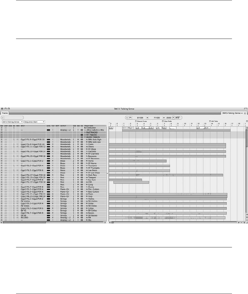
Control Panel Preferences Digital Performer 6 adds two new Control Panel settings. You
can specify the Control Panel as a floating window (meaning it will always “float” on top
of other windows), and you can calibrate the Control Panel’s transparency. Simply use
Digital Performer 4Preferences 4Control Panel to make these adjustments.
Tracks Window
The Tracks window is the central window in Digital Performer (see Figure 3.15). It provides an
overview of a project’s tracks, track data, and available sequences. This window is really divided
into three main sections: the Information Bar, the Tracks List, and the Tracks Overview. Choose
Project 4Tracks or use the default keyboard shortcut ShiftþT.
Is Your Tracks Window Too Small? New to Digital Performer 6 is the ability to vertically
resize the Tracks window. I am not sure why it took so long, but this new feature brings
much relief to users who have long been straining their eyes to view their track data in this
window. Look for the þand signs below the vertical scroll bar (at the right side of the
window) and use them to expand or shrink the graphic overview of the Tracks window.
Figure 3.15 The Tracks window is the central window in Digital Performer.
Chapter 3 Navigating Digital Performer 6 47
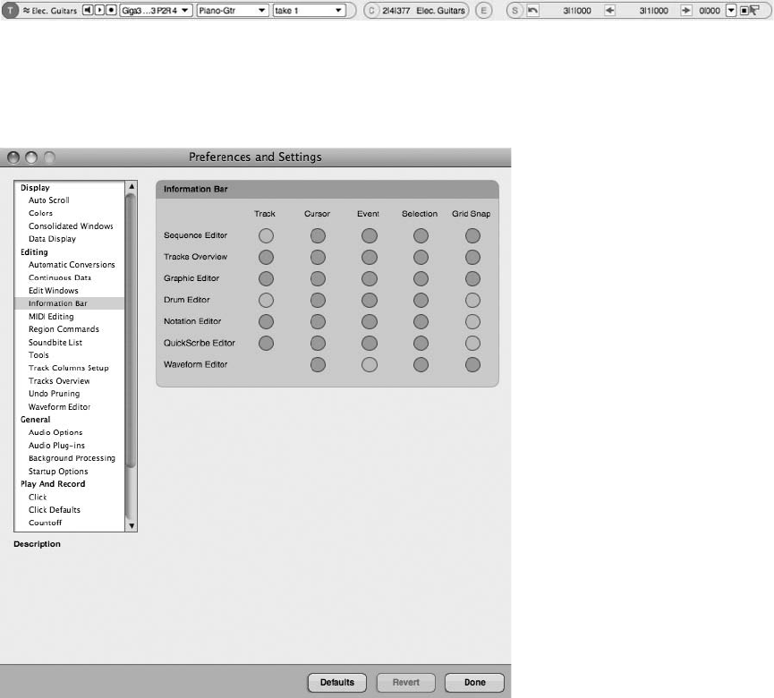
Information Bar
Located in the Tracks window (just above the Tracks List and Tracks Overview sections) and in
each of the edit windows is the Information Bar (see Figure 3.16). This bar—or “strip”—
contains data fields representing some or all of the information provided in each of the Infor-
mation windows (discussed in the “Floating Information Windows” section later in this
chapter). You can select the data fields you want to make visible in the strip by selecting Digital
Performer 4Preferences 4Information Bar (see Figure 3.17).
Figure 3.16 The Information Bar contains a wealth of information regarding your sequence.
Figure 3.17 The Information Bar preferences allow you to select the data fields you want to see in the
“strip” of each window.
48 Digital Performer 6 Power!: The Comprehensive Guide
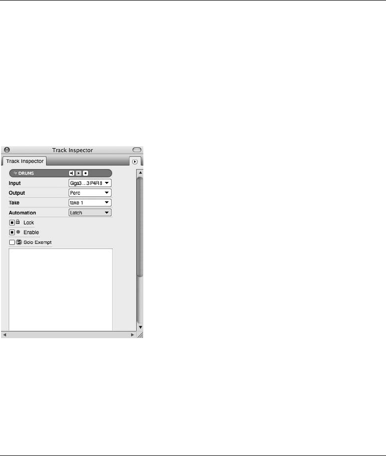
“Floating” Information Windows The information located in the Information Bar is also
available in separate “floating” windows. You can keep these windows open, and they
will continually update while you work. Each set of data fields is represented by a corre-
sponding letter in parentheses, such as (T) for Track Inspector (see Figure 3.18). Just
double-click on any letter in the strip, and the data will appear in its own floating window.
(You can also Option-click to open the window in configuration mode or Command-click
a letter for quick access to the Information Bar preferences.) Additionally, each separate
window is accessible in the Studio menu, such as Studio 4Track Inspector.
There is yet another window available in the Studio menu that does not appear in the
Information Bar. The Sound File Information window (discussed in the “Sound File
Information Window” section later in this chapter) provides details about currently
selected soundbites. (See Chapter 6, “Project Management: Part 2,” for more information
about soundbites and audio files.)
You can choose from the following options. (By default, the Tracks window only displays
Cursor and Selection information.)
nTrack Inspector (T). When a track (or a portion of a track) is highlighted, these data fields
show information regarding the selected track’s color, icon, name, play-enable status,
record-enable status, input monitor, input, output, take, automation, default patch/patch
(for MIDI tracks), lock, and solo exempt status.
Figure 3.18 The Track Inspector information in a separate floating window.
Chapter 3 Navigating Digital Performer 6 49
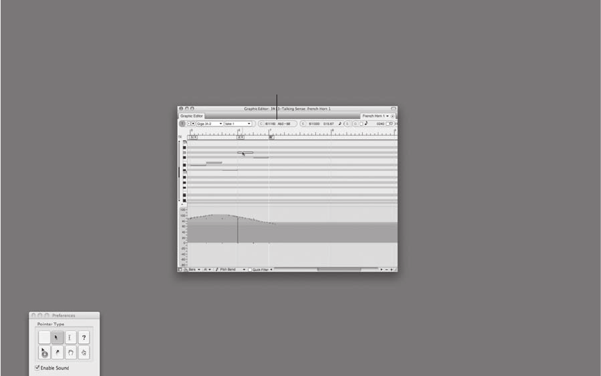
nCursor Information (C). This field displays time and track name information relating to
the current location of the mouse cursor (pointer). It continually updates as you move the
mouse horizontally and/or vertically around the screen. In the Graphic Editor (discussed in
Chapter 10, “Editing”), the Cursor Information data field will also display MIDI pitch
information (see Figure 3.19).
nEvent Information (E). This field displays details about a single event that has been selected
(much like the Event List discussed later in Chapter 10). For example, if you highlight a
MIDI note, that note’s pitch, on velocity, off velocity, and duration data are presented in the
appropriate fields.
nSelection Information (S). These fields show the Selection Start and End times for a selected
(highlighted) region of a track or tracks. These times are used to define the in and out points
of the segment that you wish to edit. When clicked, the Selection Start and Selection End
arrows will place the current Counter location (position of the Playback Wiper) into the
corresponding start or end field. The “curved” arrow (located to the far left) is used to recall
a Remembered Time (discussed in the “Set to Remembered Times and New Saved Time
The Cursor Information Field
Figure 3.19 Cursor information is displayed in the Cursor Information data field of the Graphic Editor.
In this example, data represents a MIDI note’s measure and beat position, pitch value, and MIDI note
number.
50 Digital Performer 6 Power!: The Comprehensive Guide
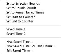
Commands” section later in this chapter), and the Smart Selections button (located to the
far right) is used to toggle the Smart Selections command on or off. Consult the Digital
Performer User Guide for more details about Smart Selections.
You can also use the Set To drop-down menu (discussed later in this chapter) to access
shortcuts for setting or loading times, as shown in Figure 3.20. New to version 6, the New
Saved Time and Set to Remembered Times options give you even quicker access to time
selections (discussed in the “Set to Remembered Times and New Saved Time Commands”
section of this chapter).
nGrid Snap Information (G). This data field contains “snapping” and “nudging” information
according to the Edit Grid settings (discussed in the “Grids, Time Rulers, and Zooming”
section later in this chapter and in Chapter 10).
The Set To Menu Shortcuts
The Set To menu provides the following options for quickly making time-range selections.
nSet to Selection Bounds. This shortcut will automatically set the Selection Start and End times
to the current time-range selection in the Time Ruler (located directly above the Tracks
Overview window). You can make a time-range selection by simply clicking and dragging in the
sequence timeline or anywhere in the Tracks Overview window. You will notice the Start and
End times will automatically update as you click and drag to make your time-range selection.
nSet to Chunk Bounds. This option will set the Start and End times to the entire range of the
current sequence.
nSet to Remembered Times. This option will set the Start and End times to any “remem-
bered” time-range selections made using the CommandþR shortcut (discussed in the “Set to
Remembered Times and New Saved Time Commands” section of this chapter).
nSet Start to Counter. This will set the Selection Start point to the time displayed within the
Control Panel’s Main Counter. You can also accomplish this by clicking the Sequence Start
button.
Figure 3.20 The Set To menu provides shortcuts for setting or loading time-range selections. Notice the
saved times listed in the center of the window.
Chapter 3 Navigating Digital Performer 6 51
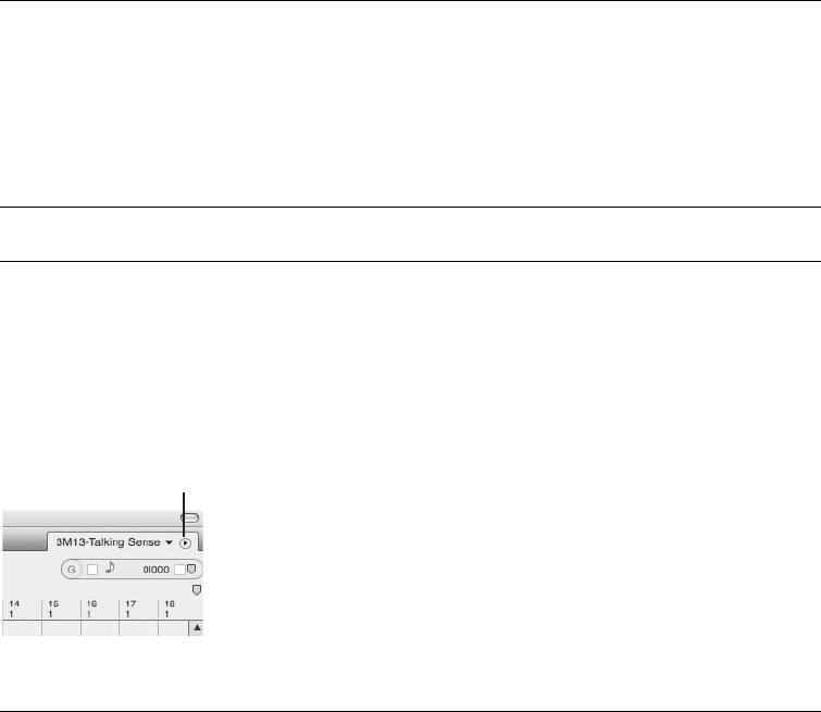
nSet End to Counter. This will set the Selection End time to the time displayed within the
Control Panel’s Main Counter. Clicking the Sequence End button will give the same results.
nNew Saved Time. This option will allow you to name and save a time-range selection for
Memory Cycle or Auto Record purposes.
nNew Saved Time for This Chunk. This option will allow you to name and save a time-range
selection that will only appear in this menu for the Chunk in which it was created.
nEdit Saved Times. Use this option to rename and delete saved time-range selections.
Remember Saved Times and New Saved Time Commands Digital Performer 6 adds a new
set of features that allow you to create “remembered” or “saved” times. These features
enable speedier recall of time-range selections and can significantly accelerate the editing
process. They both perform similar functions but are configured and recalled in different
ways. Consult the Digital Performer User Guide for more details regarding these new
features.
Mini-Menus Mini-menus appear in most of DP’s windows. In previous versions of DP,
these menus were located in the upper-left corner, but in version 6, they are located in
the upper-right corner and are represented by a small disclosure triangle, as shown in
Figure 3.21. Each one contains different options pertaining to the respective window.
Many of these menus also provide access to the Preferences and Settings window.
Tracks List
The Tracks List section, shown in Figure 3.22, displays various features that allow you to man-
age tracks within the Tracks window. The following subsections describe the features that you
will find in the Tracks List section.
The Mini-Menu Disclosure Triangle
Figure 3.21 Mini-menus appear in most of DP’s windows and are represented by a small
disclosure triangle.
52 Digital Performer 6 Power!: The Comprehensive Guide
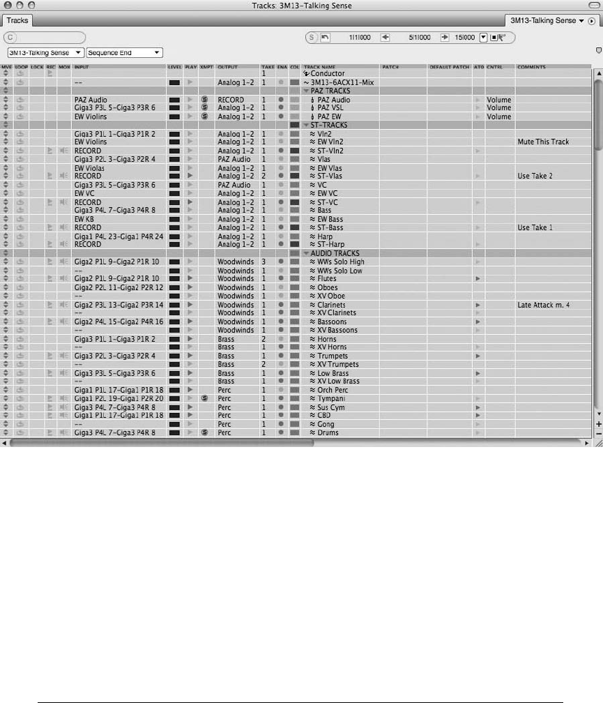
Sequence and Marker Menus
Located above the Track Columns (discussed in the “Track Columns” section of this chapter),
you will find two drop-down menus. In the Sequence menu, you can switch between sequences
(provided you have more than one sequence in your project), create a new sequence, rename or
delete the current sequence, or copy a selection to a new sequence.
In the Marker menu, you can quickly proceed to specific marker locations in the current
sequence. The Marker menu also provides other important timeline locations, such as the
Sequence Start and End times. See Chapter 11 for more information about the Sequence and
Marker menus.
Window Target Menus Be on the lookout for Window Target menus (new to version 6).
These menus are located in the upper-right corner (and to the immediate left of the mini-
menu’s disclosure triangle button) in the Tracks window and all editor windows. Basically,
Figure 3.22 The Tracks List.
Chapter 3 Navigating Digital Performer 6 53
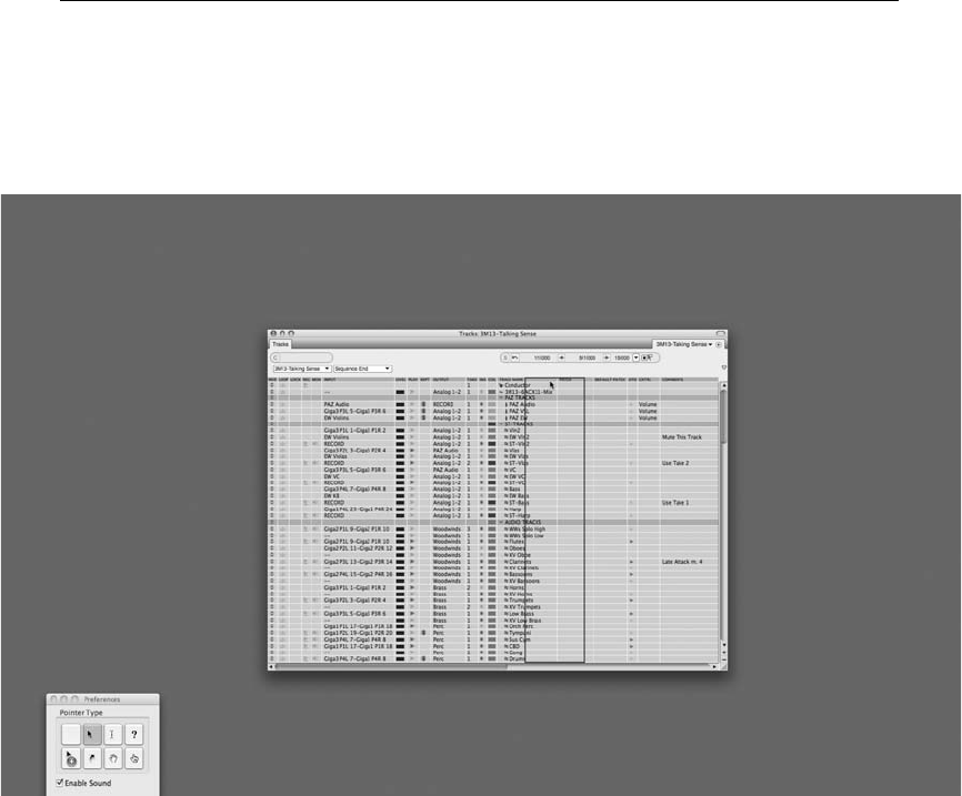
these menus provide efficient access to a list of “target” destinations, such as a different
track or sequence. For example, if you are editing a section of audio in the Waveform
Editor (discussed in Chapter 13, “Processing and Mastering”), and you want to make a
brief edit to a different audio track (using the current editor), simply use the Window Tar-
get menu to select the new “target” track, and the waveform of the new audio track will
promptly appear. This new feature saves only a few clicks, but it can be very beneficial in a
deadline crunch!
Beware, switching sequences using the Window Target menu in the Tracks window or
the Sequence Editor does not work like the conventional Sequence menu. It switches the
display to the new sequence but does not play-enable it.
Track Columns
Track Columns (see Figure 3.23) allow you to manage track I/O assignments, MIDI patches,
takes, track order, comments, and so on. Choose Track Columns Setup from the mini-menu to
show and hide specific columns within this list. You can even double-click on a column heading
Figure 3.23 Track Columns display the settings for each track within a sequence. Click and drag the
column heading to change the column order within the Tracks List.
54 Digital Performer 6 Power!: The Comprehensive Guide
to open the Track Columns Setup window without using the mini-menu. To change the order of
the columns within the list, click and drag on a column name. The various columns and their
associated controls are as follows (from the default left to right placement):
nMove. Click on the Move handle of a track and drag up or down to change the position of a
track within the Tracks List.
nLoop. A track’s Loop icon will be highlighted when a track contains a loop. Keep in mind
that you can’t click directly on a track’s Loop icon to insert a loop. Use the Region menu’s
Set Loop command or the Loop tool to loop a track. See Chapter 11 for an explanation of
looping in Digital Performer.
nLock. Click the Lock button to “lock” a track. Once a track is locked, all data within the
track will be locked to its current SMPTE frame location. Be aware that this feature does not
prevent or “lock” data from being edited within a track.
nRecord. Click the Record button to record-enable a track. Record-enabled tracks are des-
ignated with a red Record icon. An input and output assignment must be made before a
track can be armed for recording.
nMonitor. Once this is enabled, you can monitor an incoming signal of an audio track’s input.
nInput. This column provides the input assignment menu for each track.
nLevel. These activity meters display the output level of a track.
nPlay. Click the Play-Enable button to enable track playback. When the Play icon is blue,
tracks will play back. When it is dimmed, tracks will be muted. When in Solo mode, an
orange state indicates that the track is muted.
nXmpt. This is the Solo Exemption column. Enabling this feature will prevent a track from
being muted when other tracks are soloed. This is especially handy for tracks that are usually
never muted, such as aux and master tracks.
nOutput. This column provides the output assignment menu for each track.
nTake. Click on this column to access the Take menu for a track. See Chapter 7 for infor-
mation on recording and managing alternate takes.
nEnable. This button places an audio track online or offline in order to manage CPU
resources.
nCol. Click on a track’s Color column to change the color of a specific track. See Chapter 5
for an explanation of track colors.
nTrack Name. This column displays the name of a track. Option-click the track name to
rename a track.
Chapter 3 Navigating Digital Performer 6 55
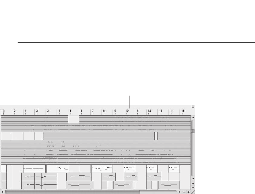
nPatch. This is the “current” patch setting for the selected MIDI track. If a patch is not
selected, the setting will be blank. (Think of patches as available sounds in your selected
MIDI device.)
nDefault Patch. This feature determines what MIDI patch the track will always start with.
This setting is saved with the project, allowing you to reopen a project and return to the
correct sound or patch for a track.
nAto. This is the automation menu for each track. See Chapter 12, “Mixing,” for an expla-
nation of DP’s track-automation features.
nCntrl. This feature lets you choose controller data to overlay on top of existing data within a
track.
nComments. This column displays comments that have been entered within a track. To enter
or change comments, simply click on a track’s Comments column.
The Disappearing Tracks List Perhaps you might like to gain more screen space. Digital
Performer 6 presents a new and nifty little feature that allows you to make the Tracks
List quickly disappear. Simply double-click on the divider (located between the Tracks
List and the Tracks Overview section) to hide or reveal the Tracks List.
The Tracks Overview Section
The Tracks Overview section displays the audio and MIDI data for all available tracks, as shown
in Figure 3.24. This is a global look at all the tracks within a sequence, including Conductor
The Tracks Overview section
Figure 3.24 The Tracks Overview section provides a global look at all audio and MIDI data within a
sequence’s tracks. Phrases of MIDI data are intuitively grouped into blocks. You must first select data
before you can edit it.
56 Digital Performer 6 Power!: The Comprehensive Guide
track data, such as meter, tempo, and marker events. Within the Tracks Overview section of the
Tracks window, you can view tracks, select tracks, make edits over entire sections of a sequence,
or add and delete tracks from a project. Unlike other tracks, however, the Conductor track can-
not be deleted from a sequence. See Chapter 11 for an explanation of the Conductor track
within Digital Performer.
MIDI and Audio Data
The Tracks Overview section displays MIDI and audio data in blocks. Phrases of MIDI data are
intuitively grouped into blocks by Digital Performer’s Dynamic Phrase Parsing feature. This fea-
ture looks at the amount of empty time between blocks, as well as density of the MIDI data.
Within a MIDI block, notes are displayed as purple bars, while controller data appears as green
bars. You can customize how MIDI data is phrased from the Tracks Overview section of the
Preferences and Settings window (Digital Performer 4Preferences and Settings) or by selecting
the Tracks Overview Preferences in the Tracks window’s mini-menu. See Chapter 5 for an expla-
nation of the Tracks Overview preferences.
Audio soundbites appear as entire blocks that contain the waveform display of the audio data
and are selected and edited as single objects. Although you can perform standard edits on audio
tracks within the Tracks window, the edges of soundbites cannot be trimmed in the Tracks
Overview. Use the Sequence or Waveform Editor to trim the edges of soundbites in DP (dis-
cussed in Chapter 10).
Time Rulers and Grids
The Time Ruler, located directly above the Tracks Overview section, is broken up into columns,
or grids. By default, one grid column is equal to one measure of music. You can use the hori-
zontal Zoom buttons (þand ), located at the bottom-right corner of the Tracks window, to
change the resolution of the grid. If you wish to display other time formats within the Time
Ruler, select Setup 4Time Format and choose the appropriate options (see Figure 3.25). Unlike
other editors within DP, the Snap to Grid feature within the Tracks window cannot be disabled.
However, it can be temporarily overridden by pressing the Command key while making an edit
selection.
The Sequence Editor
The Sequence Editor is very similar to the Tracks window in that it displays audio and MIDI
data, as well as Conductor track events (see Figure 3.26). Where it differs, however, is in its
ability to display a project’s QuickTime movie, show and hide specific tracks, reveal automation
data, display audio waveforms, and perform edits that are not constrained to a grid. In addition,
you can zoom horizontally and vertically in order to perform detailed edits, even down to the
sample level! This is a powerful, one-stop editing window for working with tracks in DP.
Choose Project 4Sequence Editor or use the default keyboard shortcut ShiftþS to open the
Sequence Editor window.
Chapter 3 Navigating Digital Performer 6 57
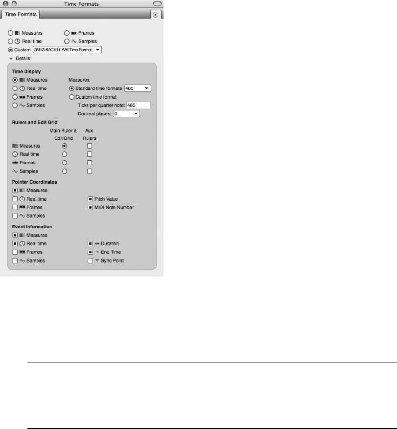
The Sequence Editor Information Bar As discussed earlier in this chapter, the Information
Bar in the Sequence Editor (and all other editing windows) contains the same data as the
Information Bar in the Tracks window. Remember, you can use Digital Performer 4Pref-
erences 4Information Bar to customize this “strip” for each window.
Sequence Editor Mini-Menu
The mini-menu provides various items and commands for controlling the Sequence Editor and
accessing other important windows (see Figure 3.27). Some of these options were already cov-
ered in the “Tracks Window” section earlier in this chapter or are straightforward enough that
they don’t require an explanation. MIDI-related commands, such as the Continuous Data pref-
erences, can be found in the “MIDI Editing in the Graphic Editor” section of Chapter 10.
Figure 3.25 The Time Formats window provides options for controlling the display of time formats
within DP’s various windows. Choose the Custom option to simultaneously show different time formats
within a Time Ruler.
58 Digital Performer 6 Power!: The Comprehensive Guide
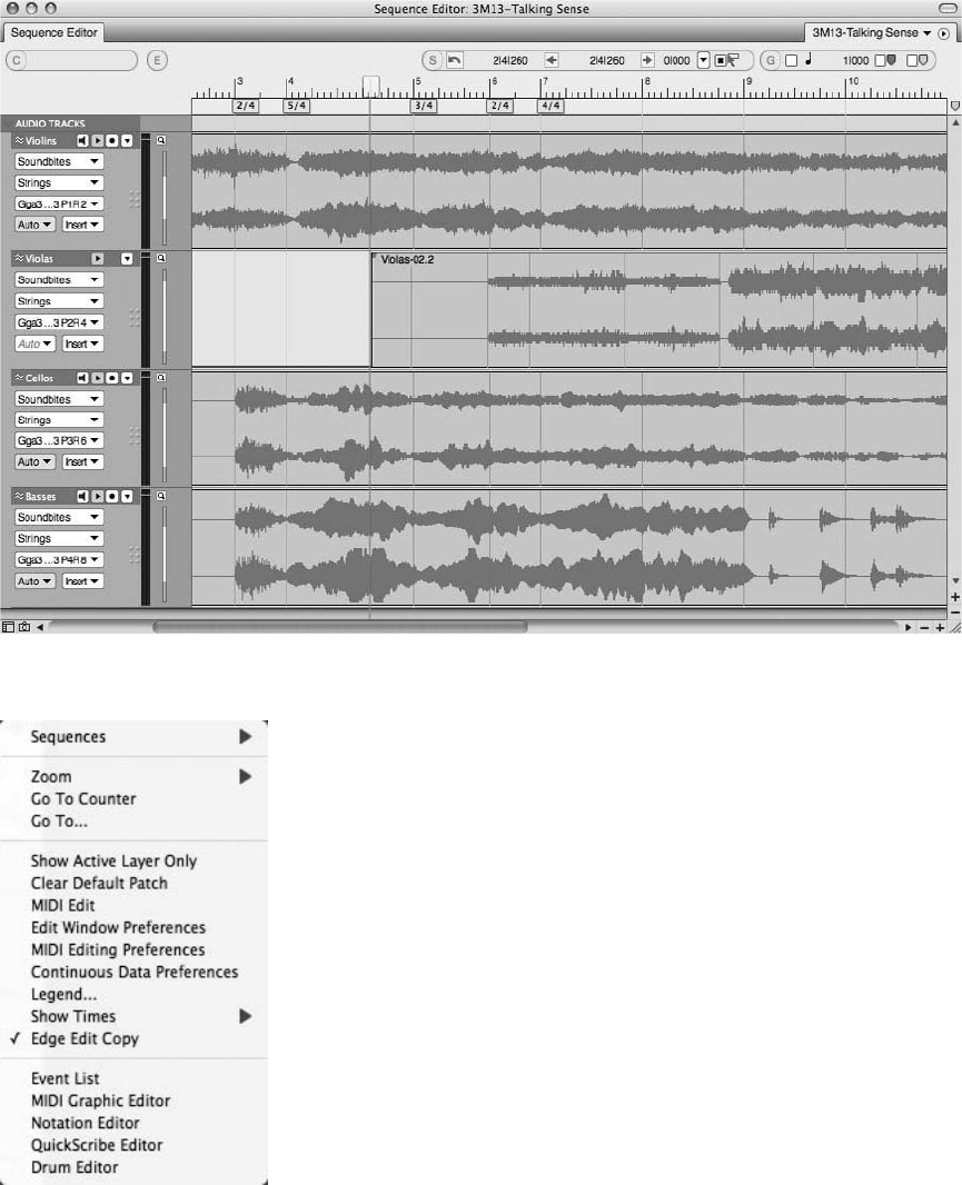
Figure 3.26 The Sequence Editor is a one-stop window for your track editing needs.
Figure 3.27 The Sequence Editor’s mini-menu.
Chapter 3 Navigating Digital Performer 6 59
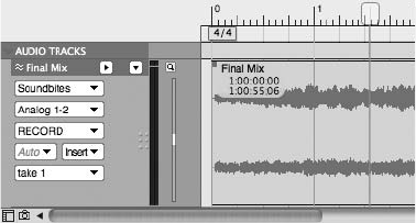
The items that are important or unique to the Sequence Editor are as follows:
nSequences. This menu is a duplicate of the Sequence menu located in the Control Panel and
Tracks window.
nShow Active Layer Only. This option hides all data that is not chosen as the active layer for
each track (discussed in the “Track Settings Panel” section of this chapter).
nShow Times. This option will display the time stamp for soundbites within the Sequence
Editor. Choose the appropriate format from the Show Times submenu.
nEdge Edit Copy. When enabled (checked), this feature will create a new soundbite when the
edge of a soundbite is trimmed. This prevents the original soundbite from being modified,
which is handy when you have multiple instances of the same soundbite within a track, but
you only want to affect a single instance of that soundbite. Turning this feature off (leaving it
unchecked) will cause the original soundbite (plus any instances of that soundbite) to be
affected when trimmed. You can, however, Option-drag the edge of a soundbite to override
the current Edge Edit Copy setting.
Track Settings Panel
The Track Settings panel displays important information about a track, making it possible to
complete the majority of your track management without having to return to the Tracks win-
dow. This panel varies slightly, depending on whether you are working with an audio or a MIDI
track. The Settings panel for an audio track is shown in Figure 3.28.
Many of these features—such as the Play/Mute and Record Enable buttons, the Take menu,
automation settings, Lock, Solo Exempt, and Comments—are universal to other editors and
are covered in their respective chapters. The Track Settings panel’s important and unique fea-
tures are as follows (from top to bottom):
nTrack Type icon/Color Selector. This feature is located to the left of the track name. The
Track Type icon allows you to visually differentiate between track types. Clicking on this
icon will also allow you to change the track color.
Figure 3.28 The Sequence Editor’s Track Settings panel for an audio track.
60 Digital Performer 6 Power!: The Comprehensive Guide
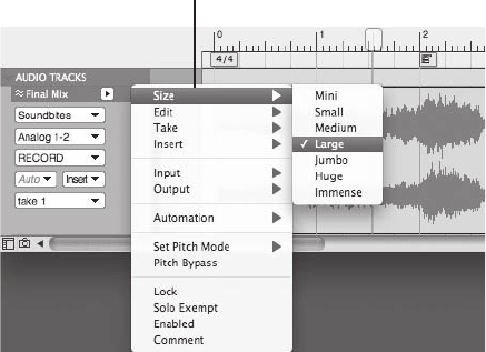
nTrack name. Click the name of a track to select it. Option-click to rename a track.
Commandþdouble-click to open the Mixing Board.
nTrack Settings menu. This menu provides a list of all of a track’s settings (see Figure 3.29).
This is useful because a track’s size can be minimized to conceal all of the track settings
contained within the Track Settings panel or increased to make it easier to edit a track’s
visible audio or MIDI data. You can access this menu by clicking on the small black triangle
located to the right of the track name.
nWaveform Vertical Zoom. Located to the right of the Track Settings menu, this button (the
magnifying glass icon) controls the vertical height of an audio track’s waveform display or a
MIDI track’s note data.
nActive Layer. This option allows you to choose the type of information or data that is dis-
played in the top layer of a track, such as automation data or loop information. Choosing
Volume for an audio track, for example, will overlay volume automation data over the
track’s waveform display (which will be dimmed).
nInsert menu. This menu allows you to insert certain types of data into a track. See the
“Inserting Automation Data” section of Chapter 12 for an explanation on inserting data
within a track.
nHorizontally Resize. Use the Resize handles (gray dots) to drag and resize the Track Settings
panel into a horizontal position.
The Track Settings panel for a MIDI track appears in Figure 3.30. Unique to a MIDI track’s
Settings panel are the following features:
The Track Settings menu
Figure 3.29 The Track Settings menu displays the track’s various settings as a list.
Chapter 3 Navigating Digital Performer 6 61
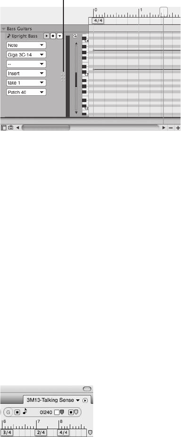
nDefault Patch. This button determines the MIDI patch that the track will always start with.
You can clear this setting from the Tracks window’s mini-menu.
nNote Grid (piano roll) scroll bar. Use this slider to scroll the note grid up and down. The size
of the slider is determined by the overall height of the MIDI track.
Graphic Editing
You can perform comprehensive graphic editing of audio and MIDI tracks in the area located to
the right of each track’s Settings panel. See Chapter 10 for a detailed look into the editing
process.
Grids, Time Rulers, and Zooming
Like the Tracks window, you can configure the Sequence Editor to conform to a specific grid
value (see Figure 3.31). These values are displayed in the Grid Snap Information data fields
(usually located in the far-right corner of the Information Bar). Any edits and selections made
with the grid enabled will constrain the action(s) to the user-defined grid resolution.
Edit Grid, Beat Grid, and Snap to Markers
Grid Snap Information consists of three main sections; Edit Grit, Beat Grid, and Snap to
Markers.
The Horizontal Resize button
Figure 3.30 A MIDI track’s Settings panel with the Horizontal Resize button.
Figure 3.31 You can confine your edits to a specific grid setting. In this example, all edits will “snap” to
eighth-note values.
62 Digital Performer 6 Power!: The Comprehensive Guide

nEdit Grid. The current grid resolution (a.k.a. measurement units you want to use while
editing) is determined by the Unit indicator icon, which by default is represented by a note
value. (Other values appear according to selections made in the Time Formats window
(Setup 4Time Formats). Click on the Note icon to change the resolution grid. (Matching
numeric values will update in the aligned data fields.) To turn the grid on or off, click the
Edit Grid button (to the left of the Unit indicator).
nBeat Grid. The Beat Grid toggle button (located to the left of the Beat Grid icon, a purple
chevron) determines whether specific editing actions will “snap” to beats within the actual
audio waveform (even if they don’t match up with “units” in the Edit Grid). Consult the
Digital Performer User Guide for more information about this advanced feature.
nSnap to Markers. The Snap to Markers section does exactly what the name implies. When its
toggle button is selected (located to the left of the Marker icon, a yellow chevron), editing
actions “snap” to marker locations in the current sequence. Using Snap to Markers and Edit
Grid features together providers an even greater editing flexibility, especially when marker
locations don’t “line up” perfectly with units in the edit grid.
Time Ruler
Below the Information Bar is the Time Ruler, which consists of a “main” ruler that measures the
time of a sequence horizontally. The time formats displayed are determined by the options set in
the Time Formats window (select Setup 4Time Formats). Making selections within the Time
Ruler allows you to make time-range selections that will include all visible tracks.
Zoom Buttons
Like the Tracks window, the Sequence Editor has zoom controls built directly into the window.
Located at the bottom-right corner are zoom control buttons that control the vertical and hor-
izontal zooming (see Figure 3.32). Click the horizontal plus and minus buttons on the left to
zoom horizontally. Click the vertical plus and minus buttons on the right to zoom vertically.
Option-click on a zoom button to instantly zoom to the minimum or maximum zoom resolu-
tion. These buttons are global controls and will affect all visible tracks. To affect the zoom res-
olution for a particular track, choose the Size option from the Track Settings menu discussed
earlier in this chapter.
Figure 3.32 The Sequence Editor’s horizontal and vertical zoom buttons.
Chapter 3 Navigating Digital Performer 6 63

Track Selector
This button (located in the bottom-left corner of all editor windows) will reveal or hide the
Track Selector List as shown in Figure 3.33, from which you can choose to show or hide specific
tracks in the editor’s window. Tracks that are showing will be highlighted in blue (or your cus-
tom Mac OS highlight color). You can click on a specific track or drag over multiple tracks to
show or hide them. Option-clicking on the name of a track will hide all other tracks, while
Command-clicking will reveal all tracks except the one you click on.
Universal Track Selector Since many of DP’s windows contain a Track Selector List, it can
be fairly inconvenient to manage each one as you switch between windows. New to ver-
sion 6 is the Universal Track Selector (Studio 4Track Selector). Because it updates to the
current active window, this separate “floating” window makes it possible to use one Track
selector for all edit windows.
The Mixing Board
The Mixing Board provides a comprehensive environment for mixing audio, MIDI, and virtual
instrument tracks within Digital Performer. Modeled on traditional mixing consoles, the Mixing
Board, shown in Figure 3.34, also offers access to real-time plug-in inserts, sends, automation
modes, and helpful features for managing your mixes.
Window Target Menu and Mini-Menu
The Mixing Board’s Window Target menu is similar to other Window Target menus within DP.
(See the “Window Target Menus” note earlier in this chapter.) However, in addition to being
able to switch sequences, you can use this menu to create new V-Racks or switch between exist-
ing V-Racks. A V-Rack is a “virtual” rack used as a central location for effects processing or
virtual instruments. For more details regarding V-Racks, see the “V-Racks” note in Chapter 11.
The Mixing Board’s important mini-menu features, shown in Figure 3.35, are as follows (from
top to bottom):
nMixer Settings Show/Hide. The first section of the mini-menu (starting with Inserts and
ending with the Input/Output settings) provides a list of mixer settings that can be shown
(checked) or hidden from display (unchecked) within the Mixing Board. To show only one
item while hiding all other items, Option-click with the mouse. Command-clicking an item
Figure 3.33 The Track Selector button will reveal or hide the Track Selector List.
64 Digital Performer 6 Power!: The Comprehensive Guide
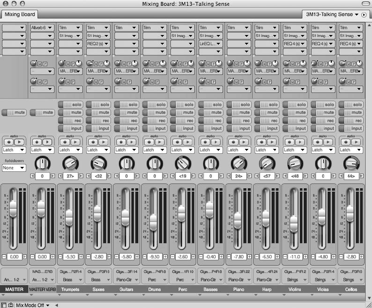
will have the opposite effect, hiding one track and showing all the others. In order for this
shortcut to work, be sure to press the Option or Command key before you access the mini-
menu items.
nAuto Resize. When this option is checked, the Mixing Board will automatically resize itself
when mix settings or tracks are shown or hidden.
nUse Narrow View. Turn this feature on to shrink tracks horizontally within the Mixing
Board. This will allow you to display more tracks within the same amount of space.
nV-Rack Edit. This item is used to toggle the Mixing Board to the last viewed V-Rack.
nSet Number of Effects Inserts. Choose this option to set the number of inserts that will be
displayed within the Mixing Board. The default number of effect inserts is five. A maximum
number of 20 effect inserts per audio/aux track can be made available for mixing!
Figure 3.34 Digital Performer’s Mixing Board offers a familiar environment for mixing audio and MIDI
tracks.
Chapter 3 Navigating Digital Performer 6 65
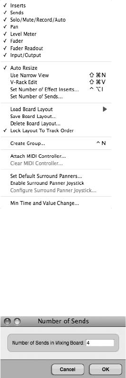
nSet Number of Sends. Choose this option to set the number of sends that will be displayed
within the Mixing Board (see Figure 3.36). The default number of effect inserts is four. A
maximum number of 20 sends per audio/aux track is available in mono, stereo, and sur-
round formats.
nLoad/Save/Delete Board Layout. These options are used to manage board layouts within the
Mixing Board. See Chapter 12 for an explanation of these options.
nLock Layout to Track Order. Checking this option will force the horizontal track order
within the Mixing Board to adhere to the vertical track order within the Sequence Editor and
Tracks windows. Uncheck this option to make the track layout independent of these other
windows.
nCreate Group. This option will allow you to create track groups. See Chapter 12 for an
explanation of track groups.
Figure 3.35 The Mixing Board’s mini-menu provides options for managing track layouts, the number
of effect inserts and sends, mix groups, and surround features within DP’s Mix window.
Figure 3.36 Use the Mixing Board mini-menu’s Set Number of Sends option to specify the number of
sends that will be available in a project.
66 Digital Performer 6 Power!: The Comprehensive Guide
nAttach/Clear MIDI Controller. The Attach feature lets you connect a fader or knob within
the Mixing Board to a MIDI controller. Use the Clear option to remove the connection.
nSet Default Surround Panners. This option lets you set the surround panner plug-in that will
be used when a surround track is first created.
nEnable/Configure Sound Panner Joystick. Use these features to enable and configure a
standard USB joystick to control surround panner plug-ins within DP.
nMin Time and Value Change. This control sets the minimum amount of time between a
volume or pan move that DP records when making changes with the Volume faders and
panners. You can use this to control the amount of data that is recorded when making
automation moves, for example. Using higher settings can reduce the amount of data but
may also introduce unwanted noise and artifacts.
Track Strips
The track strips (or channel strips) within the Mixing Board, shown in Figure 3.37, are broken into
sections that contain standard mixing options for inserting real-time plug-ins, controlling volume
and panning, enabling automation, and so on. Audio and MIDI tracks differ in that MIDI tracks do
not contain Sends sections. The various sections are as follows (from top to bottom):
nInserts. You can insert real-time audio and MIDI effects by clicking on the Insert menus
(located at the top of each track strip; they appear with small gray triangles). You can also
insert virtual instrument plug-ins into unassigned instrument tracks. See Chapters 9 and 13
for explanations of this feature.
nSends. Sends are used to send, or route, signals from audio and aux tracks to additional
sources within your system. See Chapter 12 for an explanation of this standard mixing
feature.
nSolo/Mute/Record/Input. Use these buttons to solo, mute, record-enable, or monitor the
input of a track. Only instrument, aux, and master tracks contain Mute buttons.
nAutomation. The Automation section provides buttons for turning on and record-enabling
automation on a track. You can access the different automation modes from the Automation
menu. See Chapter 12 for an explanation of Digital Performer’s automation features.
nPan knob and Pan Readout field. Click and drag a track’s Pan knob to pan a track. You can
also type a pan value directly into the Pan Readout field or use the left and right arrow
buttons, which will change the pan value by increments of 1 (see Chapter 12).
nVolume and Metering. The Volume fader controls the output (post–hard disk) level of a
signal, while the Level meters display the audio output levels or MIDI velocities of a track.
As with the Pan Readout controls, you can use the Volume Readout section to make level
adjustments to a track.
Chapter 3 Navigating Digital Performer 6 67
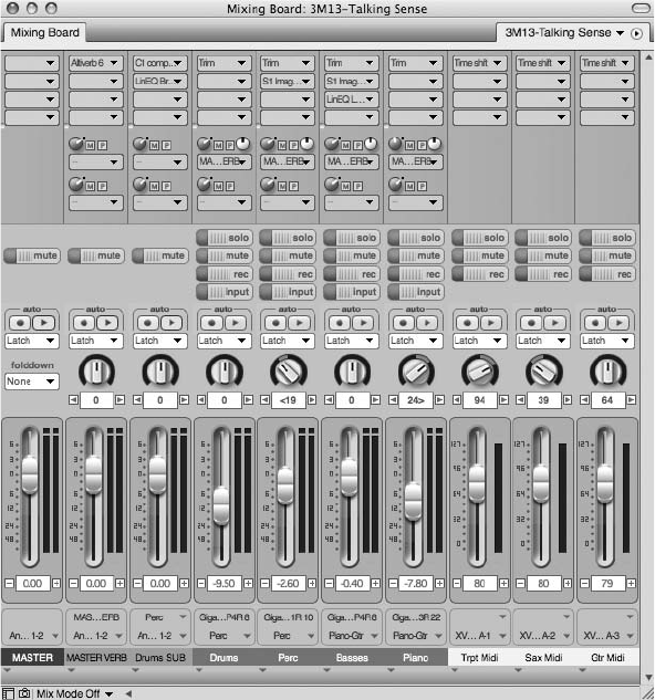
Keep in mind that the level numbers to the left of the audio track faders appear to be rep-
resenting traditional analog values (or average volume levels of a track expressed), but this is
not actually the case. In DP, audio volume is expressed in decibels, where zero is unity gain.
These audio faders include an extra þ6 dB of boost (headroom). This is the case throughout
the program wherever audio volume values are displayed.
nInput/Output menus. These two menus display the current input and output assignments of
a track. Click on each menu to access track I/O assignments without returning to the Tracks
window or the Sequence Editor. You can hide the I/O menu from a channel strip all together
by unchecking it in the mini-menu.
nTrack Name. Option-click to rename a track. You can change the track order within the
Mix window by clicking and dragging on the name of a track. Double-clicking on a track
Figure 3.37 The track strips within the Mixing Board resemble traditional mixing console channel
strips. MIDI and master tracks do not contain Sends sections.
68 Digital Performer 6 Power!: The Comprehensive Guide
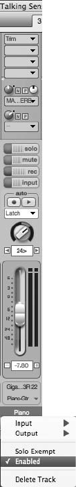
name will launch an editor window for the track. This setting can be specified in DP’s
Preferences window. (See the “Edit Windows” section of Chapter 5.)
nInput/Output Assignment menu. Located directly below the track name, you can access this
menu by clicking on the down arrow. Similar to the Input/Output menu, this menu lets you
configure input and output assignments without leaving the Mixing Board. Unlike the pre-
vious Input/Output menu, this menu cannot be hidden from the mini-menu, and it offers
additional options for solo exempting, deleting, or placing a track online or offline (see
Figure 3.38).
Figure 3.38 Hidden below the track name, the Input/Output Assignment menu lets you configure I/O
and voicing assignments without leaving the Mixing Board.
Chapter 3 Navigating Digital Performer 6 69
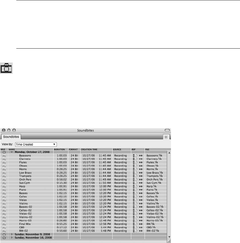
Snapshot Camera Buttons You may have noticed the small camera icon (see Figure 3.39)
located in the bottom-left corner of the Mixing Board window (to the right of Track Selec-
tor button). This button is used to take an automation “snapshot” that subsequently
inserts automation data into a track (at a specified location and time). See the “Snapshot
Automation” section of Chapter 12 for more information.
Soundbites Window
The Soundbites window allows you to view and manage soundbites within Digital Performer.
This window is divided into three sections—List, Info, and Edit—as shown in Figure 3.40.
The Soundbites Mini-Menu
The Soundbites window mini-menu’s important options are explained in the following list (from
top to bottom). The mini-menu is shown in Figure 3.41.
nNew Sound File. This option creates a new empty audio file. Choose the file format (mono,
stereo, and so on) from the New Sound File submenu. Once created, the file will be a half-
second long and will only contain silence. You can use this file for anything you like, from
pasting audio data (of any length) into it, to using it like a “video slug.”
Figure 3.39 The Snapshot button (camera icon) is used to insert automation data into a track.
Figure 3.40 The Soundbites window.
70 Digital Performer 6 Power!: The Comprehensive Guide
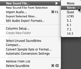
nNew Sound File from Selection. This option creates a new sound file based on the audio
selection within the Soundbites window Waveform Editor. Simply highlight a selection
within the Waveform Editor and choose this command to create a new soundbite from the
existing selection. You can also use this command to simply duplicate an entire sound file
that is highlighted in the Soundbite List.
nImport Audio. This option will open the Import Audio window. See Chapter 7 for a detailed
explanation of this feature.
nExport Selected Bites. Use this command to export a selected soundbite. See Chapter 13 for
an explanation of the Export command.
nEdit Audio Export Formats. Use this option to make changes to any saved export formats.
nColumns Setup. Choose this option to open the Soundbite List preferences in the Preferences
and Settings window, which allows you to configure the columns that are actually displayed
within the List section of the Soundbites window (see Figure 3.42).
nCreate New Folder. This option remains dimmed until Folders view is selected from the
View By menu. See Chapter 6 for an explanation of this feature.
nSelect Unused Soundbites. Use this command to select all the soundbites that are not being
used in any tracks in any sequences within a project.
nCompact. This command will compact a selected audio file. See Chapter 6 for an explana-
tion of the compacting process.
nConvert Sample Rate or Sample Format. Use these commands to convert a selected sound-
bite’s sampling rate or bit depth. See Chapter 13 for more information on sample rate and
sample format conversion. These options will remain dimmed until a soundbite is selected.
nAutomatic Conversions Settings. Select this option to open the Automatic Conversions
window. See Chapter 7 for an explanation of the automatic conversions process.
Figure 3.41 The Soundbites window mini-menu.
Chapter 3 Navigating Digital Performer 6 71
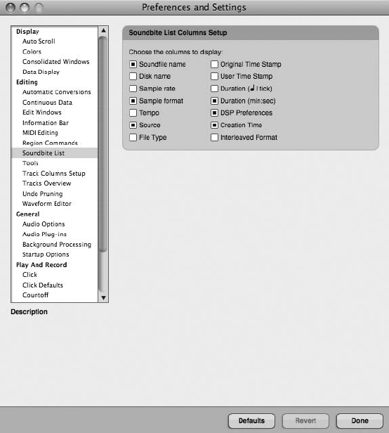
nRemove from List. Use this option to remove selected soundbites from a project while
leaving any corresponding regions intact. (See the “Managing Audio Files and Soundbites”
section of Chapter 6.)
nDelete. This option removes selected soundbites from the Soundbite List and deletes any
reference to their parent audio files. Parent audio files will not actually be deleted until the
last referencing region is deleted. (See the “Managing Audio Files and Soundbites” section of
Chapter 6.)
List
The Soundbite List displays a complete list of all soundbites that are in a project (see Fig-
ure 3.43). The List columns provide detailed information on each soundbite and can be managed
from the Soundbites window mini-menu (explained earlier), while the View By menu lets you
sort the Soundbite List for easy viewing.
Figure 3.42 The Soundbite List preferences allow you to specify which columns to display in the List
section of the Soundbites window.
72 Digital Performer 6 Power!: The Comprehensive Guide

List Columns
The list columns are as follows (from left to right):
nMove. Click and drag on a soundbite to change its position in the list.
nName. This column displays the name of the soundbite. Option-click to rename a soundbite.
If Audible mode is engaged (the speaker icon is turned on), then clicking on the name of
soundbite will allow you to audition it. Double-clicking the name will open the soundbite in
a separate Waveform Editor or third-party software editor.
nOriginal Time. This is the time the soundbite was originally created, often referred to as the
original time stamp.
nUser Time. This is the user-defined time stamp. Choose Audio 4Time Stamps to apply a
user time stamp to a selected soundbite.
nDuration. This column displays the length of the soundbite in minutes, seconds, and
milliseconds.
nTicks. This column displays the length of a soundbite in quarter notes/ticks. The soundbite
must have a defined tempo map, or this column will be blank.
nTempo. This shows the soundbite’s tempo map. If the soundbite does not have a tempo map,
then this column will be blank. If the tempo varies, DP will display an average tempo. To
manually define the tempo map, choose Audio 4Set Soundbite Tempo.
nSampling Rate. This displays the soundbite’s sampling rate.
nFormat. This displays the sample format or bit depth of the soundbite.
nCreation Time. This column shows the date/time when the soundbite was created or
imported into DP.
nSource. This offers a description of how the soundbite was created.
Figure 3.43 The Soundbite List displays detailed information for every soundbite contained within a
project.
Chapter 3 Navigating Digital Performer 6 73
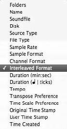
nDSP. This column shows how a soundbite’s time scaling and transposing preferences are set.
(See Chapter 13 for an explanation of PureDSP and transposition in Digital Performer.)
nFile. This is the audio file that the soundbite is referencing. Option-click to rename the audio
file. Double-click on the filename to replace or relocate the soundbite.
nDisk. This displays the disk location of the soundbite.
nFile Type. This displays the type of soundfile.
nInterleaved Format. This shows whether the file is an interleaved (combined left and right
mono files) or non-interleaved file (separate left and right mono files—a.k.a. split stereo).
The View By Menu
The View By menu contains a list of sorting criteria (see Figure 3.44). Choose a specific criterion
by which to sort the Soundbite List. Once sorted, the soundbites will be displayed with disclo-
sure triangles that group soundbites into a specific hierarchy. Use this sorting feature to quickly
find specific soundbites.
The Sound File Information Window
The Sound File Information Window (Studio 4Sound File Information), shown in Figure 3.45,
displays important information about a selected soundbite. This window is divided into three
sections: the Sound File, Soundbite, and Audio Loop panes.
The Sound File Information Pane
The first pane displays information about the soundbite’s parent audio file. Click on the menu
located at the top of this section to choose another parent audio file. You can use the Comments
section to enter specific comments on the sound file. Comments are global and will be imported
with the file when it is used in other Digital Performer projects.
Figure 3.44 The View By menu allows you to sort the Soundbite List by specific criteria.
74 Digital Performer 6 Power!: The Comprehensive Guide
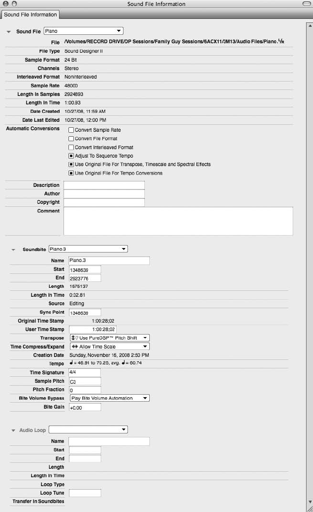
Figure 3.45 The Information window is divided into three sections that display important information
about a selected soundbite.
Chapter 3 Navigating Digital Performer 6 75
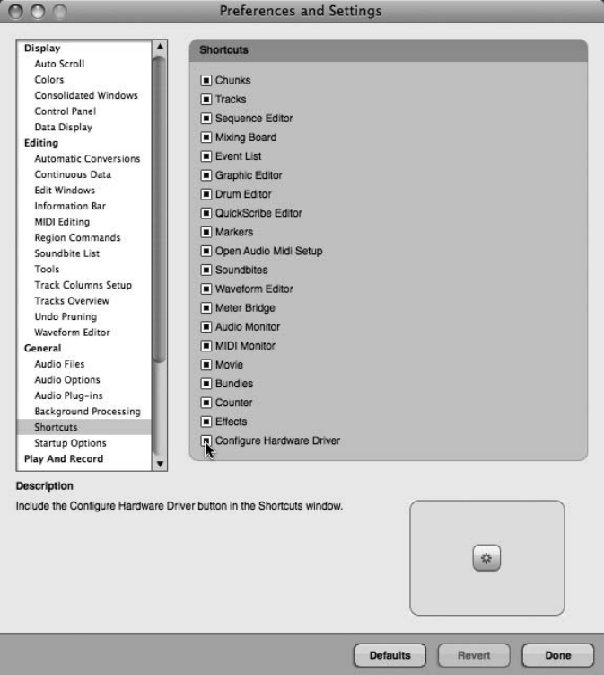
The Soundbite Information Pane
This pane displays information about the currently selected soundbite. Like the Sound File infor-
mation pane, there is a menu located at the top of this section that will allow you to select other
soundbites that exist within a project. The Transpose and Time Compression/Expansion menus
allow you to set the preferences for their respective process. (See Chapter 13 for information on
PureDSP and transposing a soundbite in DP.) You can also bypass any Bite Volume settings or
change the Bite Gain value of any selected soundbites from within this pane. (See Chapter 12 for
information regarding Bite Volume and Bite Gain settings.)
Figure 3.46 Use DP’s Shortcuts preferences to choose which buttons you would like to appear in the
Shortcuts window.
76 Digital Performer 6 Power!: The Comprehensive Guide

The Audio Loop Information Pane
The Audio Loop information pane allows you to view any loop points and settings that have
been created by a sampler. If no settings exist, this section will be blank. These loop settings have
no effect on the behavior of the file within DP.
DP’s Shortcuts I’d like to mention one more navigation feature in version 6 (included in the
6.02 update that was made available at the time of the writing of this book). DP’s Short-
cuts window (Studio 4Shortcuts) is a host for buttons that give you quick access to fre-
quently used windows and dialogs. You can choose which buttons you would like to
appear in the Shortcuts window by choosing Digital Performer 4Preferences 4Shortcuts
to toggle your selections (see Figure 3.46). This feature comes as a relief to many DP users
who yearned to have their “buttons” back (available in the form of Quick Access Drawers
in earlier versions).
Summary
This chapter has, I hope, provided you with a basic understanding of the way Digital Performer’s
main windows appear and function in version 6. It is important to take plenty of time to practice
navigating DP in order to establish an efficient strategy for your sessions. More detailed explan-
ations of these and other DP features are covered throughout the various chapters of this book.
Chapter 3 Navigating Digital Performer 6 77
This page intentionally left blank

4Setting Up a New Project
Now that we’ve discussed the optimization process for your Mac, installed Digital Per-
former, connected and configured our audio and MIDI devices, and learned how to
navigate DP, we’re ready to create a new project. Digital Performer offers a number of
different ways to access its many comprehensive features: through the main application menus,
through various floating windows or a Consolidated Window, and by using extensive keyboard
shortcuts. Though this versatility allows you to really customize, it can be very overwhelming for
the novice (and even for the experienced) DP user. Instead of bombarding you with every option
and detailed function, this chapter will focus on helping you quickly and efficiently set up a
project for recording.
This chapter will cover the following topics:
nHow to create a new Digital Performer project
nHow to configure the project’s sample rate via the Control Panel
nHow to create Track Folders
nHow to manage busses with the Configure Studio Settings window
nHow to add, delete, rename, and move audio and MIDI tracks
nHow to configure input and output routing assignments for audio and MIDI tracks
nHow to set up the tempo and meter for a project
nHow to set up a click with internal and/or external MIDI sources
Project Basics
Unlike some applications, Digital Performer only allows one project to be open at a given time.
A project must be closed before you can open or create another one.
To create a new Digital Performer project:
1. Launch Digital Performer.
79
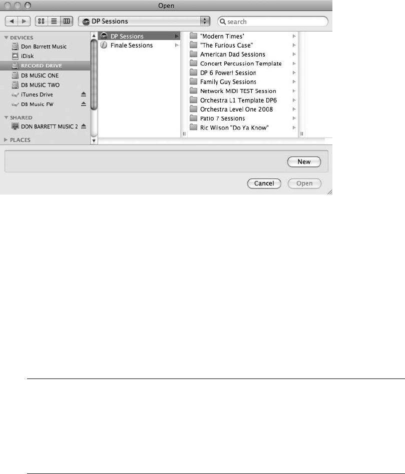
2. From the File menu, choose New. If you are prompted to open an existing project, click
on the New button instead (see Figure 4.1). You can change the Startup options from
the Preferences and Settings window (Digital Performer 4Preferences). See Chapter 5,
“Project Management: Part 1,” for an explanation of DP’s Startup preferences.
3. In the Save As field, name your new project (see Figure 4.2).
4. Select the destination hard drive and folder for the new project file. If you want to create
a new folder for the project, click on the New Folder button. Name the folder and click
OK.
5. Click on the Save button to save the new Digital Performer project.
Once the new project is saved, a new Digital Performer project folder will be created in the
designated folder and hard drive. This project folder will contain your new project document
and a folder called Audio Files (see Figure 4.3).
Periodically Saving Your Project Remember to periodically save your project (File 4Save).
How often you save really depends on your personal workflow habits. Keep in mind, how-
ever, that when you experience a crash (the endless spinning beach ball), any changes
made to the project since your last save will be lost forever. If speed is a priority, try incor-
porating the default keyboard shortcut Command+S to save your project without using
the mouse.
Figure 4.1 The Open dialog box prompts you to open an existing project file or create a new one.
80 Digital Performer 6 Power!: The Comprehensive Guide
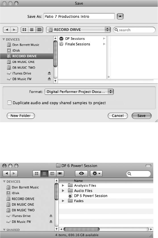
The Default Workspace
The default workspace within Digital Performer consists of two windows: the Control Panel and
the Tracks window. The Control Panel (see Figure 4.4) operates much like the standard trans-
port of a multitrack recorder, with basic controls for playback, recording, and locating to spe-
cific points within your project. Buttons for customizing the project tempo and Metronome,
Figure 4.2 The Save As dialog. This window prompts you to create a name and destination for your
new project file.
Figure 4.3 The Digital Performer project folder. This is where you will find all files related to the newly
created project. (Analysis, Fades, and Undo folders only appear once the project contains these types of
files.)
Chapter4 SettingUpaNewProject 81
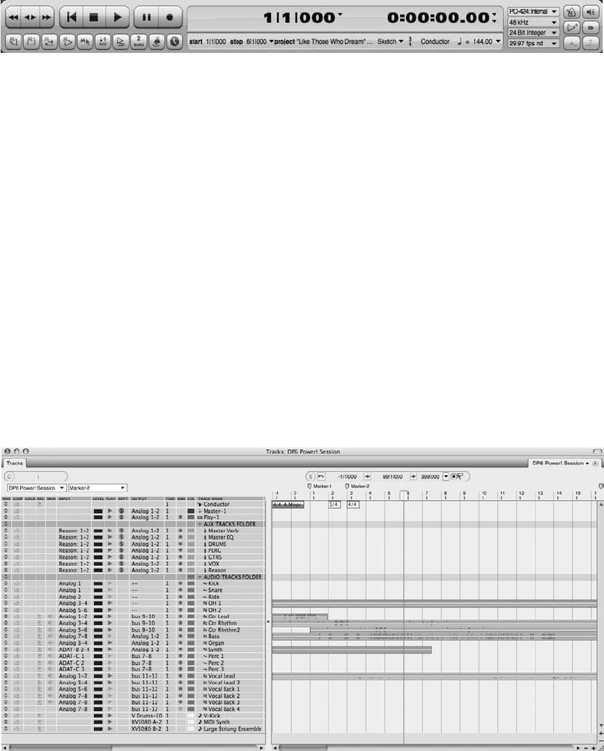
setting memory locate points, auto recording, and controlling sequences can also be found here.
Positioned to the right of the Main Counter are additional buttons for quick access to audio
settings, tempo control, solo mode, and pre/post roll settings. Review Chapter 3 for a detailed
look at Digital Performer’s Control Panel.
Considered to be the “central” window by many DP users, the Tracks window (see Figure 4.5) is
basically a container for viewing and editing all tracks within your project. Corresponding infor-
mation, such as track name, I/O and voice assignments, playback level metering, play and record
enable buttons, as well as MIDI patch assignments, is located to the left of the window. Audio
and MIDI data are stored to the right within the actual track. Any selections or edits made to
audio or MIDI data in a track are conformed to a grid by default. The grid size is determined by
the current viewing resolution of the Tracks window. Click on the plus or minus icon located at
the bottom-right corner of the Tracks window to expand the grid horizontally or vertically.
Review Chapter 3 for a detailed look at the Tracks window.
Figure 4.4 The Control Panel.
Figure 4.5 The Tracks window provides an overview of all tracks within a Digital Performer project.
82 Digital Performer 6 Power!: The Comprehensive Guide

Customizing Your DP Workspace By default, Digital Performer adds blank MIDI and audio
tracks to your new project. You can change this basic track configuration, along with any
other default parameter, by creating and configuring a project to your liking, then saving
the project as a template. You can create multiple templates for different project scenarios,
which greatly reduces project setup time. Digital Performer templates are discussed in
detail in Chapter 5.
Setting the Sample Rate
Asample rate is simply the number of times per second a signal is being “sampled” or recorded.
For example, a sample rate of 44.1 kHz results in a signal being sampled 44,100 times per sec-
ond during recording. Generally, the higher the sample rate, the better the sound quality. Bit
depth,orsample format, refers to the theoretical dynamic range of a recorded signal. The higher
the bit depth, the more accurately a signal’s dynamic range can be captured, especially the qui-
eter levels. However, higher sample rates and bit depths also result in larger audio files that take
up more disk space.
Even though you configured the sample rate in Chapter 2, every new project you create will have
its own specific setup needs and requirements. Just because you can record at 192 kHz doesn’t
mean you should. Intended playback medium, the artist’s budget, available hard drive space for
the project, DAW performance issues—these are just some of the things you will need to take
into consideration before your project begins. Careful planning in the early stages of a project
will save you many headaches later in the production process.
Bit Depth Historically, all audio files within a DP project had to match the designated set-
ting (16 bit or 24 bit) for proper playback. Now you can freely mix and match files of either
bit depth within the same project or sequence. You can still, however, change an audio
file’s bit depth in the Convert Sample Rate or Format command in the Soundbites window
mini-menu.
To quickly change the sample rate and bit depth of a project from the Control Panel,
simply select the desired rate and bit depth from the available drop-down menus (as shown in
Figure 4.6).
The Sample Rate and Bit Depth menus
Figure 4.6 The Control Panel’s Sample Rate and Bit Depth drop-down menus.
Chapter4 SettingUpaNewProject 83

Changing the Sample Rate or Bit Depth When Audio Data Already Exists within a Project
You can change the sample rate and bit depth at any time during a project, but be
aware that audio files not matching the project’s current sample rate will need to be con-
verted before becoming available for playback. You can perform this procedure manually
or configure DP to carry out the conversion automatically. Conversion options are located
within the Soundbites mini-menu and the Preferences and Settings windows. See Chapter
7, “Recording Audio,” for a detailed look into this process.
Tracks in Digital Performer
Tracks within Digital Performer (or any multitrack recorder or sequencer) are basically contain-
ers for storing audio and/or MIDI data. Different information is stored within different track
types, and you can employ several methods to add audio and MIDI data to a DP project, includ-
ing the following:
nAudio and MIDI data can be recorded directly to an audio or MIDI track, respectively.
nAudio and MIDI data can be loaded from another Digital Performer sequence.
nAudio and MIDI data can be “dragged” into a corresponding audio or MIDI track directly
from the desktop or other folder.
nAudio can be imported from another source, such as a CD or hard drive.
nMIDI sequences can be opened from a standard MIDI file.
nMIDI data/events can be manually inserted within a track.
Because tracks form the basic foundation of any multitrack recorder (digital or analog), famil-
iarity with them will greatly enhance your music production workflow, allowing you to move
between various music applications and/or platforms with greater ease.
Deleting Tracks
As noted earlier, Digital Performer defaults to adding basic MIDI and audio tracks to newly
created projects. If you would like to begin your project with a blank canvas, simply delete
the existing tracks.
To delete an existing track or tracks:
1. Select the track you want to delete by clicking on the name of the track within the
Tracks window’s Track Name column. To select multiple adjacent tracks, click and
drag with the mouse. Command-Shift-click to select multiple tracks that are not located
next to each other.
2. Once your tracks are selected, choose Delete Tracks from the Project menu.
84 Digital Performer 6 Power!: The Comprehensive Guide
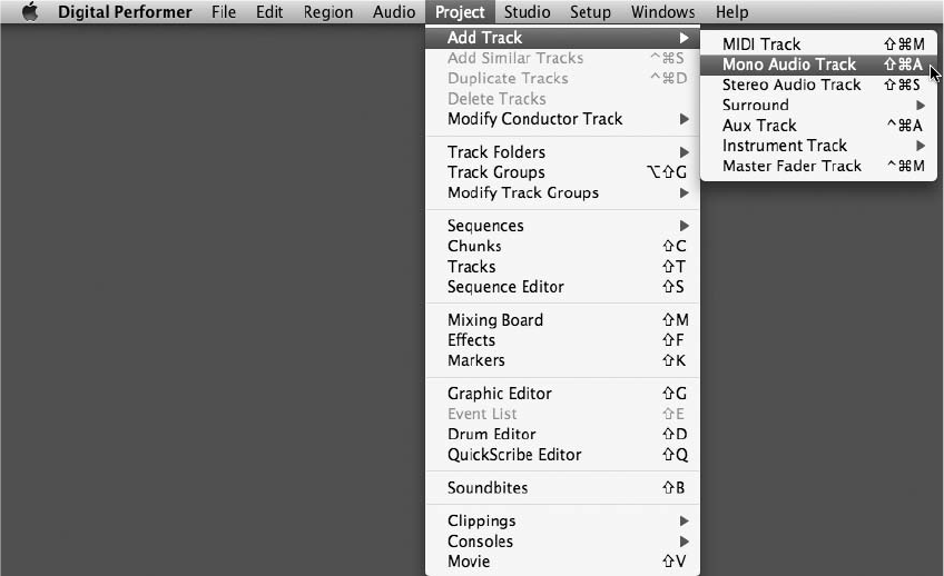
Adding Tracks
There are basically six types of tracks that can be created in Digital Performer (see Figure 4.7).
nMIDI tracks. See Chapter 8, “Recording MIDI,” for more information.
nInstrument tracks (for use with virtual instrument plug-ins). See Chapter 9, “MIDI: The
Region Menu, Plug-Ins, and Virtual Instruments,” for more information.
nAudio tracks (mono or stereo). See Chapter 7 for more information.
nSurround (multichannel audio tracks).
nAux tracks (stereo-only auxiliary tracks). See Chapter 12, “Mixing.”
nMaster fader tracks (can be used to control a subgroup or an entire mix). See Chapter 13,
“Processing and Mastering.”
To add a track or tracks:
1. Select Project 4Add Track and choose the type of track you want to create.
Figure 4.7 Tracks can be added from the Add Track submenu.
Chapter4 SettingUpaNewProject 85
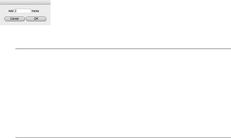
2. To add multiple tracks at once, press and hold the Option key before selecting Add
Track from the Project menu. You’ll notice the Add MIDI and Audio Tracks commands
now appear with the word multiple preceding them (such as Add Track 4Multiple
MIDI Tracks). Once an Add Multiple Track command is selected, the Multiple Tracks
options window will open.
3. Enter the number of tracks you want to create in the pop-up window and click the OK
button (see Figure 4.8).
Adding Multiple Tracks and Default Positions Only multiple audio and MIDI tracks can be
created with the Option key method. Surround, aux, instrument, and master fader tracks
must be added individually.
Also, DP will add tracks to default positions in the Tracks List (usually below any
previously existing tracks). This can become problematic if you are adding tracks to a
project already containing a large number of tracks, or if you have groupings of similar
tracks in designated areas. (Scrolling to the bottom of a large project every time you add
tracks can be awkward and inefficient.) Simply highlight a track in the desired area of the
Tracks List before adding a track, and DP will place the new track just below the
highlighted track.
Renaming Tracks
It’s always a good idea to rename your tracks for easy identification. Audio files, in particular,
benefit from this because, by default, their filenames are based on their track names. Renaming
your audio tracks before you begin recording can save you headaches and prevent your Sound-
bites window from filling up with files generically named Audio-1, Audio-2, Audio-3, and so on.
To rename a track:
1. Hold the Option key and click on the name of the track. The name will appear
highlighted.
2. Type the desired name and press the down arrow key to proceed to the next track.
3. Once all of your tracks are renamed, press the Return key to confirm the last change.
Figure 4.8 The Multiple Tracks options window.
86 Digital Performer 6 Power!: The Comprehensive Guide
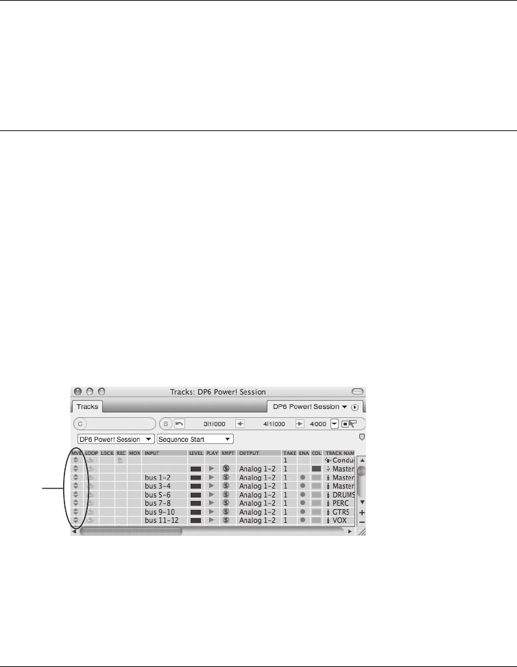
Did You Forget to Name Your Audio Tracks Before Recording? If you forget to name your
audio tracks before you begin recording (as mentioned earlier), have no fear. Digital Per-
former offers several locations where you can rename the recorded soundbites. When you
change a soundbite’s name, all instances of that soundbite will reflect the change. See
“Renaming Existing Audio Files or Soundbites” in Chapter 6, “Project Management:
Part 2.”
Moving Tracks
Once you have renamed your tracks, you may want to change their order. Many engineers and
producers like to categorize their tracks by specific groups or instruments. This is a matter of
personal taste, of course, but keeping your tracks organized is another way to speed up your
production workflow. You can reorder tracks in several different locations, each of which causes
DP to update all relevant windows.
To move a track in the Tracks window:
nBy default, track Move handles are located to the far left of the Tracks columns. They
are represented by the up and down arrow icons within the MVE (Move) column (see
Figure 4.9).
nClick on the Move handle icon and drag the track to a new location. A solid outline will
allow you to preview the new location for the track.
Tracks Window Columns You can show or hide Tracks window columns from the Tracks
List preferences (see Figure 4.10) by selecting Tracks List Preferences from the mini-menu
in the Tracks window or by double-clicking directly on a column heading. Unchecked
items will not appear within the Tracks window.
Move Handles
Figure 4.9 Use the track Move handles to change the track order.
Chapter4 SettingUpaNewProject 87
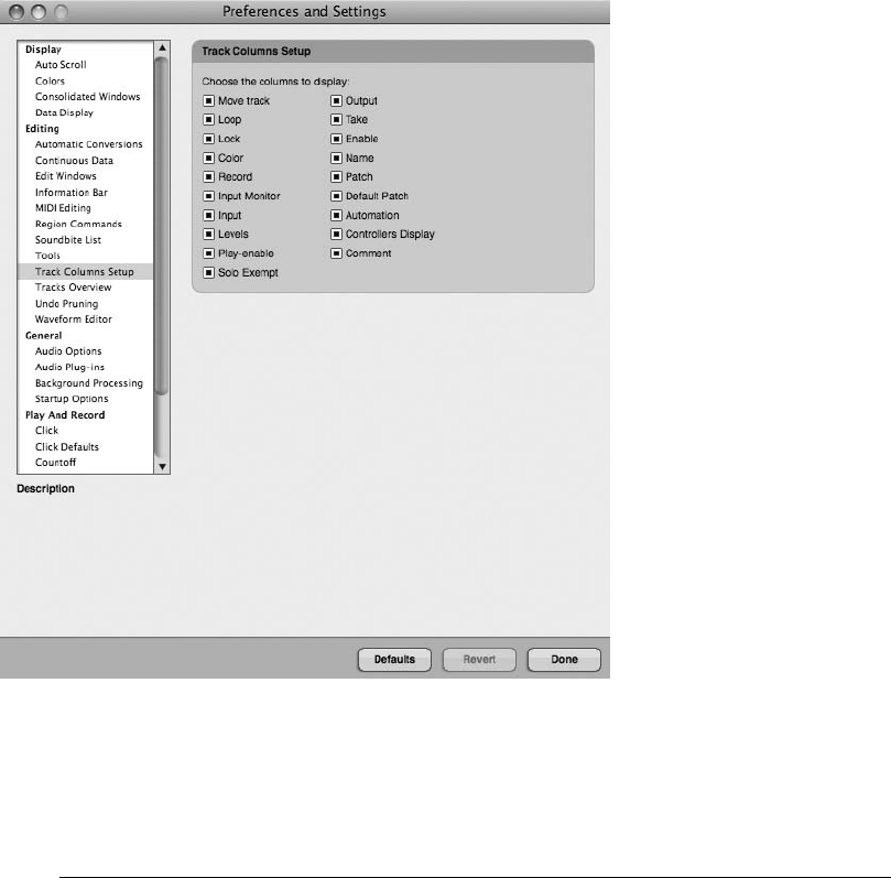
To rearrange their order of appearance, click and drag the corresponding column
headings to a new location. A dotted outline will allow you to preview the new location
for the column.
To move a track in the Mixing Board:
1. In the Mixing Board, make sure the desired tracks appear by using the Track Selector
List (discussed earlier in Chapter 3).
2. In the track strip, click and hold in the blank gray area just below the track name so the
entire strip becomes highlighted.
3. Drag left or right to the new location.
Figure 4.10 Use the Tracks List preferences to show or hide specific columns in the Tracks window.
88 Digital Performer 6 Power!: The Comprehensive Guide
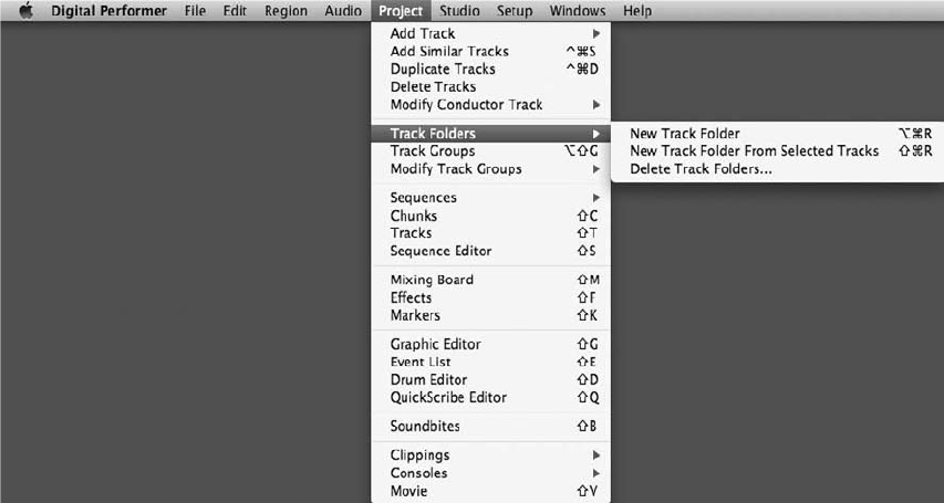
To move a track in the Sequence Editor:
1. In the Sequence Editor, make sure the desired tracks appear by using the Track Selector
List.
2. Click and hold in the blank gray area of the track’s Information panel (discussed in
Chapter 3), and the pointer arrow will become vertical arrows.
3. Drag up or down to the new location.
Track Folders
Track Folders are a great way to keep tracks organized and to save space or reduce clutter. Track
Folders will also appear in the Track Selector List, making it easier to navigate large multitrack
projects.
You can create a Track Folder and move tracks into it or create a Track Folder from selected
tracks (see Figure 4.11).
To create a Track Folder and move tracks into it:
1. In the Tracks Overview window, go to the Project menu, select Track Folders, and
select New Track Folder from the submenu. A new Track Folder will appear in the
Tracks List.
Figure 4.11 The Track Folders option from the Project menu.
Chapter4 SettingUpaNewProject 89
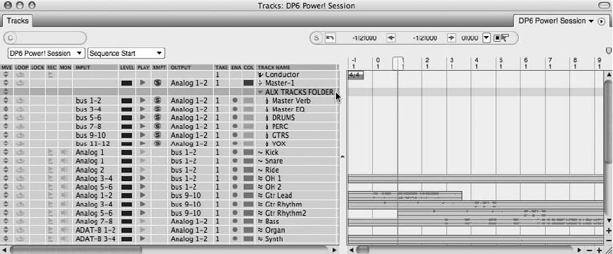
2. Option-click the untitled folder to name it (just as you would name other tracks).
3. Simply use the Move handles to drag tracks into the Track Folder.
To create a Track Folder from selected tracks:
1. In the Tracks Overview window, highlight a track or Shift-highlight several tracks.
Tracks do not have to be adjacent.
2. Go to the Project menu and select Track Folders 4New Track Folder from Selected
Tracks. A new Track Folder will appear in the Tracks List containing the selected tracks
(see Figure 4.12).
You can show or hide tracks within Track Folders by clicking on the disclosure triangle to the
left of each Track Folder name. Deleting Track Folders is simple. However, it is important to
distinguish between deleting and removing Track Folders. Deleting will delete a Track Folder
and all of its contents (tracks and track data). Removing will simply remove the Track Folder
and place all of its contents back in the Tracks List.
To delete or remove a Track Folder:
1. Go to the Project menu and select Track Folders 4Delete Track Folders.
2. A dialog will appear, asking you to choose the Track Folders from the list provided (see
Figure 4.13). You can highlight one Track Folder or Shift-click to highlight several
Track Folders at once.
Figure 4.12 A Track Folder for all of this project’s aux tracks was created using the New Track Folder
from Selected Tracks option.
90 Digital Performer 6 Power!: The Comprehensive Guide
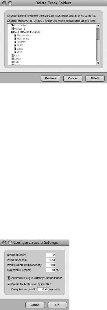
3. Choose Delete or Remove. Track Folders will be deleted or removed as specified. If a
Track Folder is removed, all of its contents will be moved up one level in the Tracks
List.
Audio Tracks and Internal Busses
In Chapter 2, I explained how DP’s built-in audio engine, the MOTU Audio System (MAS),
works to provide the digital audio capabilities (such as playback, recording, internal bussing,
effects plug-ins, and so on) for Digital Performer. The number of available audio tracks is deter-
mined by the speed of your computer, your hard drive, and the amount of available RAM.
If you create aux tracks for your project, you must also make available the necessary number of
internal busses. The Stereo Busses setting controls the total number of internal busses that are
available within a project. Busses are internal signal paths where audio is routed from one place
to another or combined with other audio to create a submix (see Chaper 12). Digital Performer’s
virtual bussing system is much like the conventional mixing board. And with the MOTU Audio
System, you can create as many busses as you need (up to 99 total), as shown in Figure 4.14.
Figure 4.13 The Delete Track Folders dialog box.
Figure 4.14 The Configure Studio Settings dialog box.
Chapter4 SettingUpaNewProject 91
To define the number of internal stereo busses:
1. Go to Setup 4Configure Audio System 4Configure Studio Settings.
2. Within the Configure Studio Settings box, type in the desired number of stereo busses.
3. Once you have enabled the necessary stereo busses, click the OK button.
Input and Output Assignments for Audio and Aux Tracks
Tracks must be assigned or routed to the necessary inputs and outputs in order to record or play
back audio and MIDI data.
Audio tracks are assigned to either the Mac’s built-in audio or the inputs and outputs of a con-
nected audio hardware interface. MIDI tracks are assigned to MIDI devices, such as MIDI con-
trollers, external sound modules, or virtual instrument plug-ins.
Audio and Aux Track I/O
Following are a few things to keep in mind when working with audio and aux tracks within
Digital Performer:
nAudio and aux tracks cannot be assigned to multiple inputs or outputs.
nAudio cannot be recorded to or placed into an aux track.
To configure the I/O assignments for an audio or aux track:
1. Click on the track’s Input or Output menu, located within the Input or Output column
of the Tracks window. Unassigned tracks are designated by a dotted line, as shown in
Figure 4.15.
2. Currently enabled inputs and outputs (also called audio bundles) are listed below the
None assignment. If the necessary audio bundles are not enabled, you will need to create
a new bundle assignment from the New Mono or New Stereo Bundle drop-down menu.
Here you will find a list of available hardware I/O and internal busses. (The default
names for hardware I/O assignments are Analog 1, Analog 2, AES/EBU 1, AES/EBU 2,
and so on.)
3. Make the necessary routing assignment by selecting the I/O destination with the mouse.
Clicking again on the drop-down menu will reveal a check mark next to the track’s
current I/O assignment.
4. If you want to change the current routing assignment of a track, simply click on the
Input or Output menu and make a new selection.
92 Digital Performer 6 Power!: The Comprehensive Guide
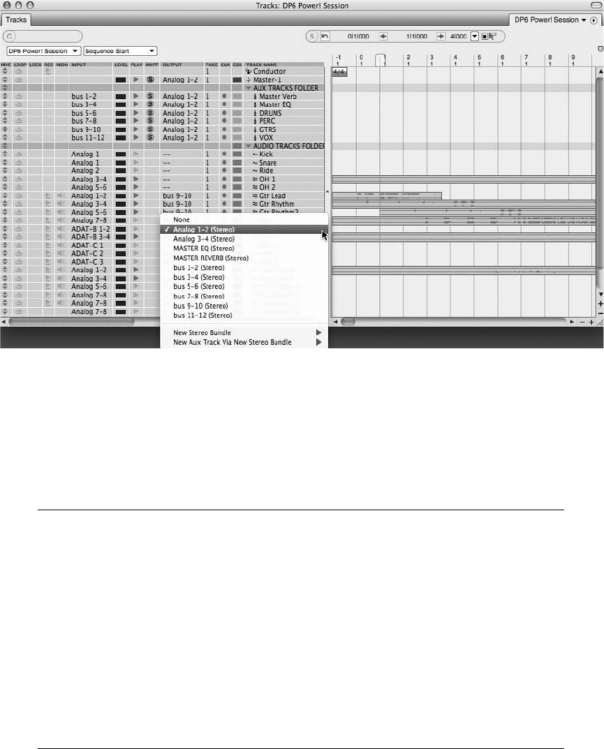
5. Routing assignments can also be made or changed in the Mixing Board and Sequence
Editor windows. (Review Chapter 3 for more information regarding routing assign-
ments in these windows.)
Audio Bundles A bundle basically groups a set of inputs, outputs, internal busses, virtual
instrument routings, or MIDI connections. Bundles for audio can be mono, stereo, or mul-
tichannel I/O configurations. Although you can create a bundle on the fly from within any
assignment menu, the Bundles window (Studio 4Bundles, or Shift+U) provides you with
a graphical interface that allows for the creation, removal, and rerouting of I/O assign-
ments between DP and any connected audio hardware, MIDI interfaces, or installed vir-
tual instruments (see Figure 4.16).
When you’re working with internal busses, only busses that have been made available
from the Configure Studio Settings window (Setup 4Configure Audio System 4
Configure Studio Settings) will appear within the Audio Bundles window or in DP’s
various assignment menus. Review Chapter 2 for a detailed look at the Bundles window.
Figure 4.15 Tracks that are unassigned or set to None are designated by a dotted line. Enabled audio
bundles are listed directly below the None assignment in an Input or Output assignment’s pop-up
menu.
Chapter4 SettingUpaNewProject 93
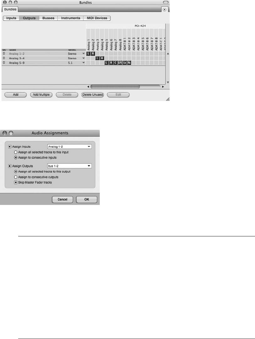
Making Multiple I/O Assignments with the Audio Assignments Window The Audio Assign-
ments window (Studio 4Audio Assignments) offers a convenient way to reassign the
inputs and/or outputs for multiple tracks (see Figure 4.17).
Begin by selecting the tracks you want to affect by clicking on the name of the track.
(Shift-click to make multiple selections.) Then open the Audio Assignments window.
(The default keyboard shortcut is Option+A.) Make the appropriate reassignments and
choose OK.
Be aware that audio bundles must be enabled before they will become available within
the appropriate Audio Assignment drop-down menus. See Chapter 7 for an in-depth look
at the Audio Assignments window.
Figure 4.16 The Bundles window with various audio bundle configurations.
Figure 4.17 The Audio Assignments window lets you change the routing assignments of multiple
tracks.
94 Digital Performer 6 Power!: The Comprehensive Guide
MIDI Track I/O
Following are a few things to keep in mind when working with MIDI tracks in Digital
Performer:
nMIDI tracks can be assigned to either an external MIDI device or a virtual MIDI instrument.
nMulti Record mode is used to record from several MIDI devices at once. When you’re
working with MIDI tracks, only the output assignment needs to be configured if Multi
Record mode is turned off (the default setting in DP). Turn Multi Record mode on from the
Studio menu in order to specify input from a specific MIDI device.
nMIDI tracks can be assigned to multiple outputs through the use of MIDI device groups.
nYou must create an audio or aux track to monitor (hear) external MIDI devices or ReWire
synths within Digital Performer. However, if you are using an audio interface equipped with
DSP (Digital Signal Processor) hardware-based monitoring (such as MOTU’s CueMIX
DSP), this step is not necessary. Consult your interface manual for more information.
nA virtual AU or MAS instrument (or RTAS if you are working DAE mode) must be inserted
into an instrument track before the virtual instrument plug-in’s outputs will become avail-
able in the output menu of a MIDI track.
nAux/audio tracks are not needed to monitor AU/MAS virtual instruments, because the audio
output of the virtual instrument goes directly to the output of the associated instrument
track.
nBy default (when Multi Record mode is turned off), DP will not allow you to change the
input source of a MIDI track. When a MIDI track is record enabled, it will receive MIDI
data from any connected MIDI device and transmitting MIDI channel. If you do not need to
record MIDI data from a specific source, you can skip this process.
To set the input source for a MIDI track:
1. To record MIDI data from a specific MIDI device/channel, turn on Multi Record mode
from the Studio menu. Once enabled, it will appear with a check mark, as shown in
Figure 4.18.
2. Select the input source for the MIDI track. Only one MIDI device and MIDI channel
can be specified for a track (see Figure 4.19).
To output MIDI data to an external MIDI device:
1. Click on the Output menu for the MIDI track in the Output column of the Tracks
window. The default output for a MIDI track is MIDI channel 1 of your MIDI interface
(see Figure 4.20).
Chapter4 SettingUpaNewProject 95
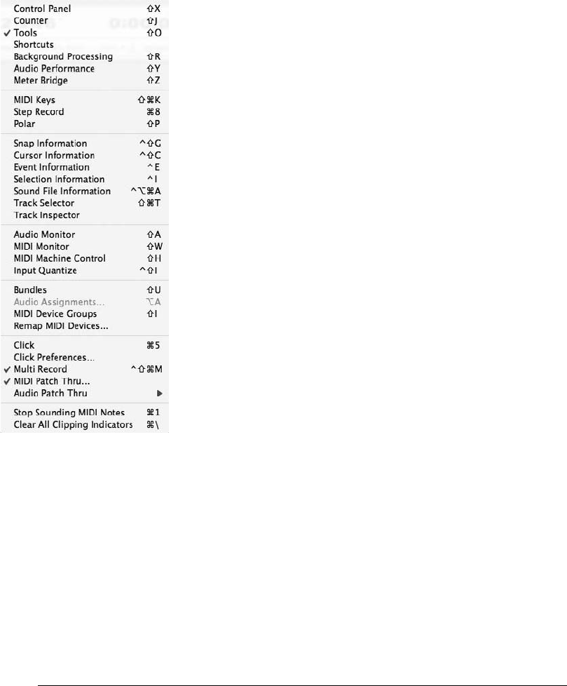
2. Connected external MIDI devices will be listed below the None assignment. Choose the
appropriate device and MIDI channel. If the MIDI channel for a specific device is not
listed, you will need to configure it from the Audio/MIDI Setup utility (Setup 4Open
Audio MIDI Setup). Review Chapter 2 for a detailed look into this procedure.
3. If you want to output your MIDI track to multiple MIDI devices, you will need to create
a MIDI device group.
Device Groups MIDI device groups allow you to assign the output of a MIDI track to mul-
tiple MIDI channels and/or devices. A maximum of 10 MIDI channels from any combi-
nation of devices can be used within a device group (see Figure 4.21).
Figure 4.18 Multi Record mode is enabled from the Studio menu and will appear with a check mark
when enabled.
96 Digital Performer 6 Power!: The Comprehensive Guide
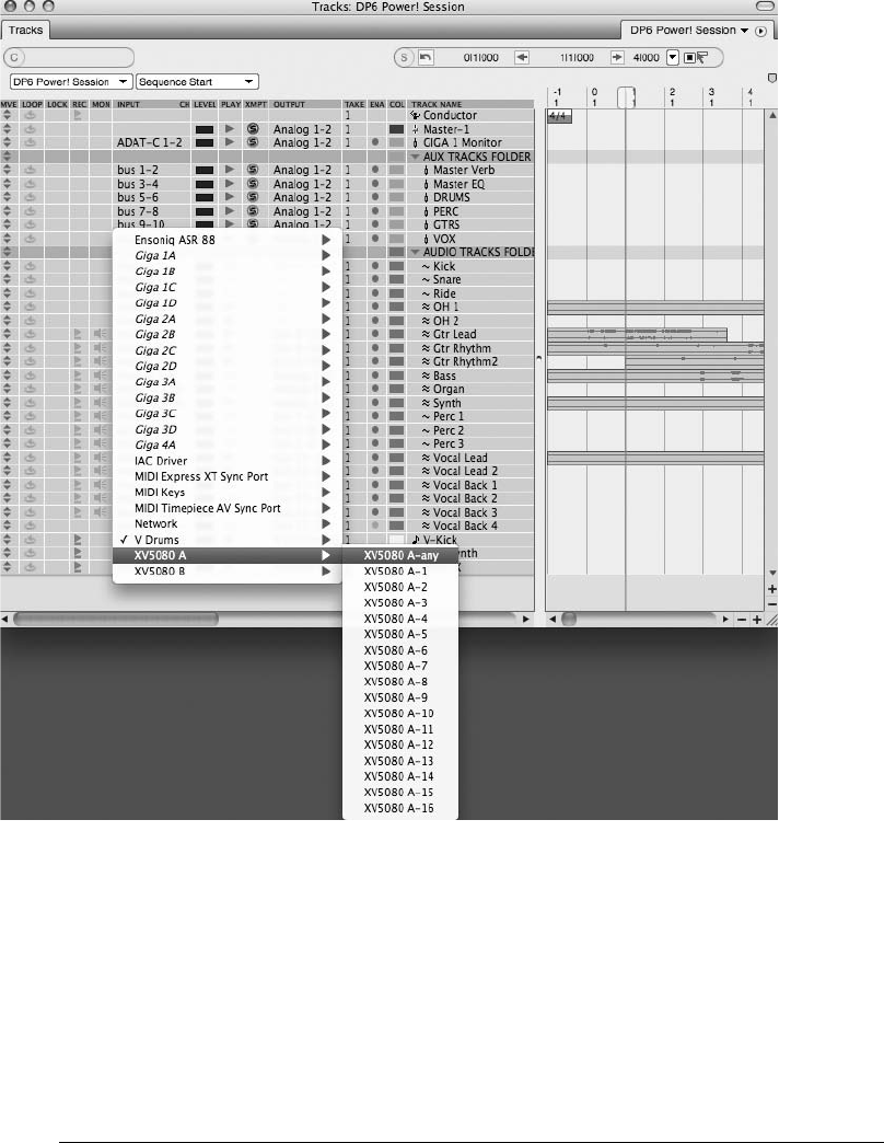
To output to a device group, select the device group from the MIDI track’s Output menu.
If you need to create a new device group, choose New Device Group and add the
appropriate MIDI devices and/or MIDI channels. The newly added device groups will
appear near the bottom of the output assignments list. See Chapter 8 for a detailed look
at the process of creating and editing MIDI device groups in Digital Performer.
Figure 4.19 With Multi Record mode enabled, specific MIDI input sources can be assigned to a MIDI
track.
Chapter4 SettingUpaNewProject 97
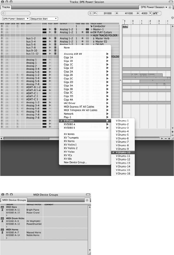
Figure 4.20 Configuring the output assignment for a MIDI track from the Output menu.
Figure 4.21 The MIDI Device Groups window lets you assign the output of a MIDI track to multiple
MIDI channels/devices.
98 Digital Performer 6 Power!: The Comprehensive Guide

Monitoring External MIDI Devices
If you have the audio output of your MIDI instrument connected to an audio input of your
audio hardware interface and you want to monitor the MIDI instrument in Digital Performer,
you’ll need to use an aux or audio track. The simplest setup, however, is through the use of aux
tracks.
DSP Monitoring As mentioned earlier in this chapter, if you are using an audio interface
equipped with DSP (Digital Signal Processor) hardware-based monitoring (such as
MOTU’s CueMIX DSP), creating aux tracks for monitoring MIDI devices is not necessary.
DSP monitoring is set up independently of Digital Performer and allows signals to be
routed directly to the main outputs (without having to internally pass through DP first).
Consult your audio interface manual for more information.
To monitor the audio output of an external MIDI device with an aux track:
1. Add an aux track. (The default keyboard shortcut is Control+Command+A.)
2. Assign the input of the aux track to the appropriate inputs of your connected audio
hardware interface.
3. Confirm the output routing assignment of the track. The output should be assigned to
the main outputs of your audio hardware interface in order for you to hear the audio
through your studio monitors.
4. Consider naming the aux track appropriately, such as MIDI Piano Monitor.
Connecting and Monitoring External MIDI Devices In my studio the physical outputs of my
MIDI piano are connected directly to analog inputs 3 and 4 of my MOTU 2408mk3 PCI-
424 audio interface. If I didn’t have CueMix DSP, in order to monitor (hear) my piano, I
would need to assign the input of an aux track to analog inputs 3 and 4.
Review Chapter 3 for additional info on the procedures for connecting external MIDI
devices to your Digital Performer system.
Monitoring MIDI Devices with an Audio Track The setup procedures for monitoring an
external MIDI device or virtual instrument with an audio track are similar to the procedures
for monitoring with an aux track, but with a few exceptions.
Chapter4 SettingUpaNewProject 99
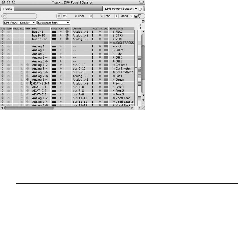
nAudio tracks must have the Input button selected (Mixing Board), an Input Monitor icon
selected (Tracks or Sequence Editor window), as shown in Figure 4.22, or be record-enabled
when monitoring.
nRecord-enabling a track enables input monitoring automatically, even if the track’s Input
Monitor button or icon is not engaged.
nRemember, audio tracks must also be online when monitoring. (Refer to Chapter 3 for more
information regarding placing an audio track online or offline.)
The Pros and Cons of Monitoring MIDI Devices and Instruments with Audio Tracks The
advantage: When you are ready to record the output of the MIDI device or virtual instru-
ment as audio, you simply start recording on the configured audio track.
The disadvantage: A project with multiple audio tracks used for monitoring multiple MIDI
tracks or groups of MIDI tracks can rapidly deplete your CPU resources.
See Chapter 8 for a deeper look into this process.
Monitoring MAS/AU Instruments
When working with AU or MAS virtual instruments (or RTAS instruments if you are in DAE
mode), the new instrument track replaces the aux/audio track during the monitoring process.
Figure 4.22 The Input Monitor icon is enabled in the MON column of the Tracks List in order to mon-
itor a MIDI organ through an audio track.
100 Digital Performer 6 Power!: The Comprehensive Guide
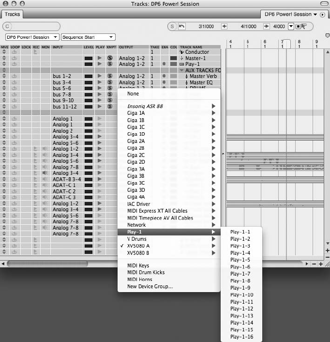
Keep in mind that you must first create an instrument track before the virtual instrument will
become available within the output menu of a MIDI track.
See Chapters 8 and 9 for an in-depth look at the process of working with virtual instruments
and instrument tracks in Digital Performer.
To set up an AU or MAS virtual instrument track:
1. Begin by creating a new instrument track for the specific instrument (Project 4Add
Track 4Instrument Track 4Virtual Instrument). Select Unassigned if you want to
create a blank instrument track.
2. Once the track is added, the virtual instrument will become available within the output
menu of any MIDI track (see Figure 4.23).
Figure 4.23 A MIDI track’s output menu.
Chapter4 SettingUpaNewProject 101
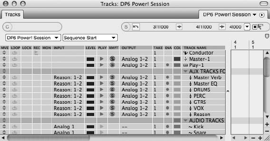
3. Assign the virtual instrument and its corresponding MIDI channel to the output of a
MIDI track.
Monitoring ReWire Instruments
When working with ReWire virtual instruments, Digital Performer must be opened before you
launch the ReWire synth. Then you must create the necessary virtual instruments in the ReWire
application before they will become published in the output menu of DP’s MIDI tracks. Once
published, they will appear as available busses.
To set up a ReWire instrument within DP:
1. Start by launching Digital Performer.
2. Create an aux or audio track to monitor the ReWire instrument and assign the audio
input to any available ReWire output, as shown in Figure 4.24. This is a crucial step
because you must have at least one DP input assigned to a ReWire instrument output in
order for the ReWire application to recognize DP as a valid audio output destination.
3. Launch the ReWire application and create the desired ReWire virtual instruments.
4. In Digital Performer, create a MIDI track and assign the MIDI output to the newly
created ReWire instrument, as shown in Figure 4.25. Once assigned, the MIDI track
will send MIDI data from DP to the ReWire synth. Then the ReWire instrument
will output its audio to the Digital Performer aux track you created and configured in
Step 2.
Figure 4.24 Digital Performer aux tracks that have been configured to monitor individual ReWire
instruments.
102 Digital Performer 6 Power!: The Comprehensive Guide
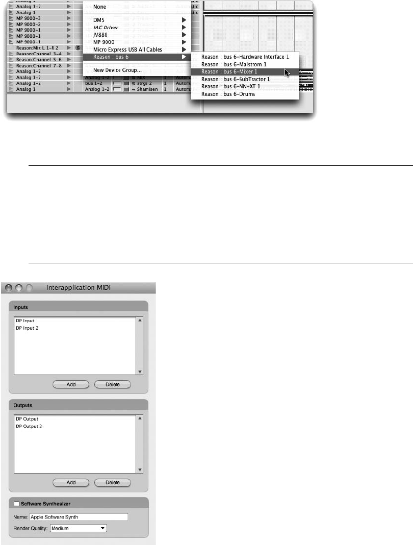
Interapplication MIDI Many applications, such as Propellerhead’s Reason, publish their
own MIDI inputs and outputs that automatically appear within Digital Performer’s assign-
ment menus. There may be times, however, when you are working with programs (or
older versions of programs) that do not have this capability. You can use Digital Perform-
er’s Interapplication MIDI feature to publish DP’s MIDI inputs and outputs to these appli-
cations (see Figure 4.26). Think of Interapplication MIDI as “virtual” MIDI cables.
Figure 4.25 ReWire virtual instruments will appear as busses within a MIDI track’s output menu.
Figure 4.26 Digital Performer’s Interapplication MIDI window.
Chapter4 SettingUpaNewProject 103
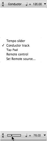
Tempo and Meter
Another integral part of any session is the proper setup of a project’s tempo and meter. You can,
of course, begin recording MIDI and audio data without worrying about this process. But you
won’t be able to take full of advantage of DP’s nonlinear editing capabilities, utilize the built-in
Metronome, make use of MIDI processes such as quantization, or properly output MIDI data
within the QuickScribe Editor.
There are numerous ways to control tempo and meter within DP, but because this chapter is
aimed at quickly getting your project up and running, we will focus only on the most basic setup
procedures. See Chapter 11, “Arranging,” for additional information on tempo and meter in
Digital Performer.
Setting the Tempo
Digital Performer displays the currently enabled sequence’s (Chunk’s) meter, tempo beat value,
and tempo within the metronome section of the Control Panel, shown in Figure 4.27. The
Tempo Control menu, shown in Figure 4.28, determines how tempo will be controlled, provid-
ing you with five different ways of controlling tempo.
nTempo Slider. Use the Tempo slider when you want to change tempo simply by dragging the
slider with the mouse (see Figure 4.29). Dragging the slider to the left will decrease the
tempo, while dragging it to the right will increase the tempo. When Tempo slider is selected
as the tempo source, you can also quickly type new tempo values in the Tempo box.
nConductor Track. Use the Conductor track when you want your sequence to reflect tempo
information (also known as a tempo map) contained in the Conductor track.
Figure 4.27 The Control Panel displays the tempo, tempo beat value, and meter for the currently
enabled sequence.
Figure 4.28 The Control Panel’s Tempo Control menu determines the tempo source.
Figure 4.29 When the Tempo Control source is set to the Tempo slider, you can use the slider as well as
the Control Panel’s Tempo box to control tempo.
104 Digital Performer 6 Power!: The Comprehensive Guide
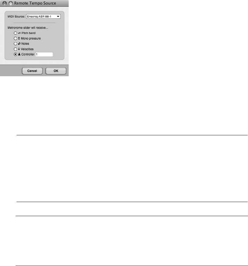
nTap Pad. Use the Tap Pad when you want to manually “tap” in the desired tempo by
clicking repeatedly on the available Tap Pad. This feature is best used when your sequence is
stopped, as DP will not reflect your tempo tapping while the sequence is playing.
nRemote Control. Use the Remote Control feature when you want to control tempo from an
external MIDI source, such as a modulation wheel or a programmable dial on a MIDI
keyboard. The MIDI source can be defined using the Set Remote Source option (see
Figure 4.30).
nBackslash Key. Much like the Tap Pad button, press repeatedly on the backslash key of your
QWERTY keyboard to set your tempo, and the Tempo box will update accordingly. This
nifty shortcut works in all modes except Conductor Track mode.
Projects with a Constant Tempo The Tempo slider can be used for sequences that have a
constant tempo. Because you are not working with a set tempo map, you are free to make
changes to the tempo at any time, even on the fly, without affecting playback of MIDI
tracks. If your project requires tempo changes, however, you will need to program the
change and use another tempo source, such as the Conductor track. I recommend defin-
ing all tempo settings prior to recording audio, because any adjustments made later will
cause audio tracks to be shifted or moved in the timeline of your sequence.
Figure 4.30 The Remote Tempo Source window allows you to define a MIDI source to control tempo.
The Conductor Track The Conductor track in Digital Performer, shown in Figure 4.31, is a
container for tempo, meter, key change data, and markers. This information can be
inserted directly into the Conductor track and automated over time. (This is how you
can achieve variable clicks, such as tempo ritardandos and accelerandos, within DP.) See
Chapter 11 for more information on the Conductor track.
Chapter4 SettingUpaNewProject 105
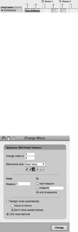
Setting the Meter
Digital Performer sequences default to a meter of 4/4 (unless you are working with a Digital
Performer template whose meter has been set to a different value). Like tempo, meter has a
direct impact on event editing, click and countoff options, and the display of information within
the QuickScribe Editor. Unlike the Tempo slider, however, any meter changes made to a
sequence must be programmed with the Change Meter command.
To set the meter of a sequence:
1. Open the Change Meter window by choosing Project 4Modify Conductor Track 4
Change Meter.
2. Enter the new meter by clicking and typing directly in the Change Meter To field (see
Figure 4.32). You can also change the values by clicking and dragging up or down with
the mouse.
3. Next, you will need to specify the measure start and end locations for the change. If you
would like to change the meter for the entire project, enter a value of 1in the From
Measure location box. In the To location section, click on the End of Sequence button.
Figure 4.31 The Conductor track contains tempo, meter, markers, and key change information.
Figure 4.32 The Change Meter window.
106 Digital Performer 6 Power!: The Comprehensive Guide
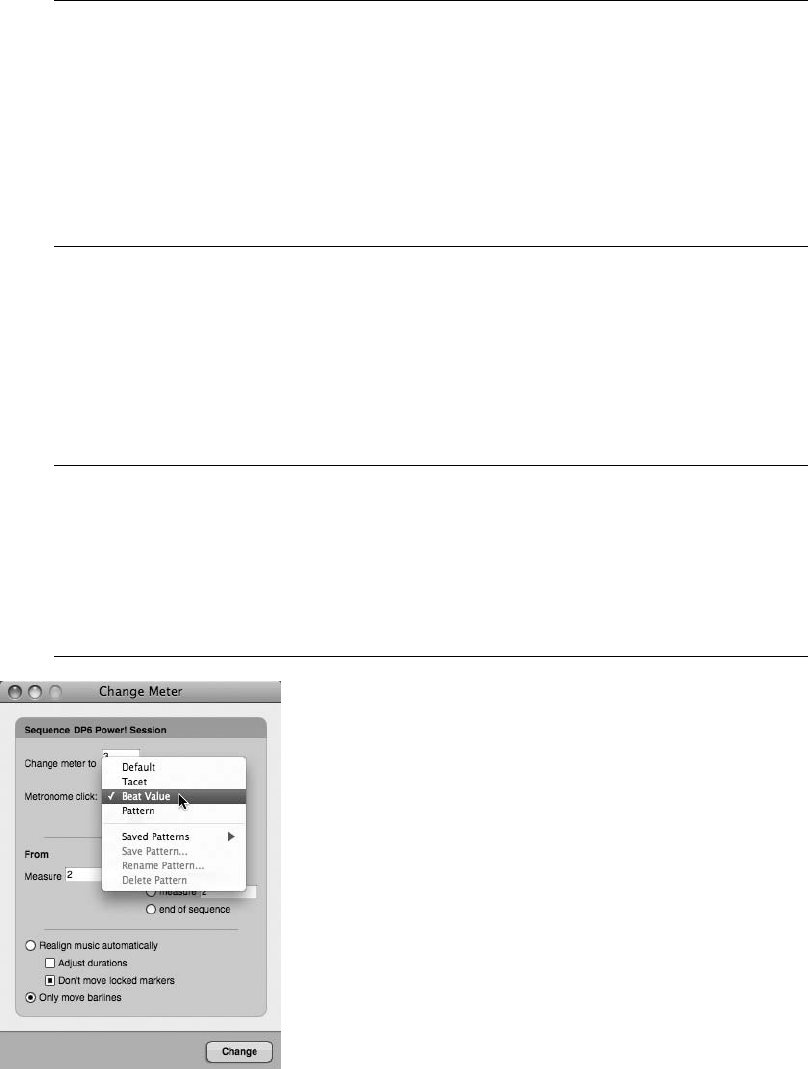
Multiple Meter Changes If you have many meter changes within a project that contain the
same beat value (the bottom number, or denominator), DP makes it very simple to quickly
create the different meters. As in Step 2, once you have entered the number of beats per
measure (the top number, or numerator) for Measure 1, select Next Measure from the To
column. You will notice the beats per measure value becomes highlighted automatically,
allowing you to simply use the number pad to change the value of each measure and hit
Enter consecutively until the meter map is completed. With this method, the From value
updates automatically as well.
4. In the Options section of the window, choose Only Move Barlines, which will leave any
existing data within the sequence unaffected.
5. Once the meter parameters have been adjusted, click on the Change button to set the
new meter for the sequence.
6. Close the window by clicking on the title bar’s Close button.
Metronome Click in the Change Meter Window Also appearing in the Change Meter win-
dow is a Metronome Click area (as shown in Figure 4.33). Here you can designate the type
of click you want for a specified time range. You can select and define the basic beat value
or even remove clicks for a measure or a range of measures. Default clicks and click pat-
terns can be accessed and created here as well. (See the section on “Creating a Click
Default” later in this chapter.)
Figure 4.33 The Metronome Click menu allows you to designate a click type for a specified time range.
Chapter4 SettingUpaNewProject 107

Setting Up a Click
Recording audio and MIDI data to a click has many benefits. Besides giving the performer a
stable timing reference, it also provides an easier recording and mixing environment for the
audio engineer, which allows him, for example, to take advantage of bar/beat editing, to quickly
create time-based effects that are synced to a project’s tempo, or to achieve better results when
working with Digital Performer’s Beat Detection Engine.
Before you can successfully begin using a click within Digital Performer, you will need to con-
figure it from the Click preferences in the Preferences and Settings window.
To set up the click from the Click preferences in the Preferences and Settings window:
1. Open the Click preferences by double-clicking on the Metronome button in the Control
Panel, as shown in Figure 4.34. You can also access the window by choosing Digital
Performer 4Preferences.
2. Select the Audition Click option to audition (hear) the current click settings. Once
enabled, parameter changes made in this window will be updated in real time.
3. Choose the source of the click (see Figure 4.35):
nThe Audio option will generate a click from a variety of preset click sounds that can
be assigned to any available audio outputs in your system.
nThe MIDI option will transmit a MIDI note (to a designated MIDI device/channel)
for each click sound.
nSelecting both options will produce click sounds from both the Audio and MIDI
designations.
nVisual Punches are flashes that appear onscreen with each click. The flashes become
visible once a movie has been imported into Digital Performer. They are closely
related to Streamers and Flutters and are commonly used as conducting tools when
scoring to picture. Visual Punches are triggered by tempo beats and can be used
without engaging an audible click. There are also options to output the punches to
other hardware devices so the punches can be visible on another screen. (Read more
about Visual Punches in Chapter 15, “Scoring to Picture.”)
The Metronome button
Figure 4.34 Double-click on the Control Panel’s Metronome button to quickly open the Click prefer-
ences located in the Preferences and Settings window.
108 Digital Performer 6 Power!: The Comprehensive Guide
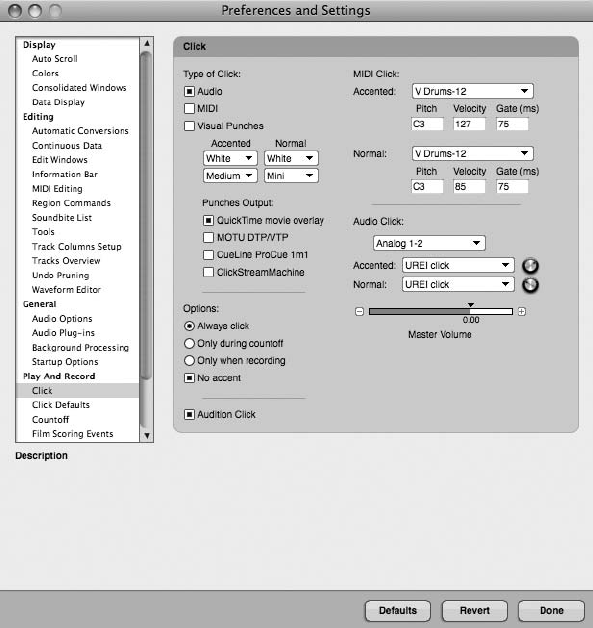
4. If you selected MIDI as the click source, you will need to specify the MIDI instrument
that will be used to produce the accented and normal click sounds from the MIDI
Click section of the Click preferences. If you selected an audio click, you can proceed to
Step 7.
nThe accented click will be played on Beat 1 of a measure.
nThe normal click will be played on all other beats of a measure.
5. Choose the MIDI device and channel from the Accented and Normal pop-up menus.
Devices within this list are determined by the Mac’s Audio MIDI Setup utility (AMS).
Refer to Chapter 2 for information on configuring MIDI devices with AMS.
6. Specify the Pitch, Velocity, and Gate values for the accented and normal click sounds.
nPitch. This determines the MIDI note that will be played when the click sounds. The
letter represents the actual note within a scale, while the number represents the
Figure 4.35 Use the Click preferences located in the Preferences and Settings window to configure
Digital Performer’s click.
Chapter4 SettingUpaNewProject 109
octave of the note. A pitch of C3, for example, represents middle C. Use the number
sign (#) to designate a sharp and the letter b to designate a flat.
nVelocity. This sets the volume of the click sound. Values range from 0 to 127.
nGate. This determines the length of the note in milliseconds.
7. If you chose an audio click, you can set the overall volume of the click with the Master
Volume slider (located below the Audio Click section). Keep in mind, if you are using Built-
in Audio as your click output, that the Mac’s Sound Preference settings (Applications 4
System Preferences 4Sound) will also affect the overall volume of Digital Performer’s
click.
8. Next, specify when the click will sound with the Click options.
nAlways Click. This forces the click to sound during countoff, recording, and
playback.
nOnly during Countoff. This forces the click to sound only during countoff measures.
The click will stop once playback or recording actually begins.
nOnly When Recording. This forces the click to sound only during recording.
nNo Accent. This eliminates the accent on Beat 1 of a measure. This setting affects
both the internal and MIDI clicks.
9. Save your project (File 4Save)!
10. If you plan to reuse this specific project configuration or you want to base your future
Digital Performer projects on the one you just created, then choose File 4Save As
Template. Name the project and click OK. (See Chapter 5 for details on creating Digital
Performer templates.)
Creating a Click Default
This feature allows you to choose and/or create a specific click scheme for any meter or
tempo range (see Figure 4.36). You can choose between preset beat values or patterns, or
you can customize your own. DP will automatically use these default clicks when the Click
button is enabled and the sequence Conductor track matches the tempo range and meter of
the default click. It is important to keep in mind that in order to use a click default, you must
select Default in the Metronome Click drop-down menu in the Change Meter menu discussed
previously.
To set up a default click from the Click Defaults preferences in the Preferences and Settings
window:
1. Choose Digital Performer 4Preferences.
2. Select the Click Defaults option.
110 Digital Performer 6 Power!: The Comprehensive Guide
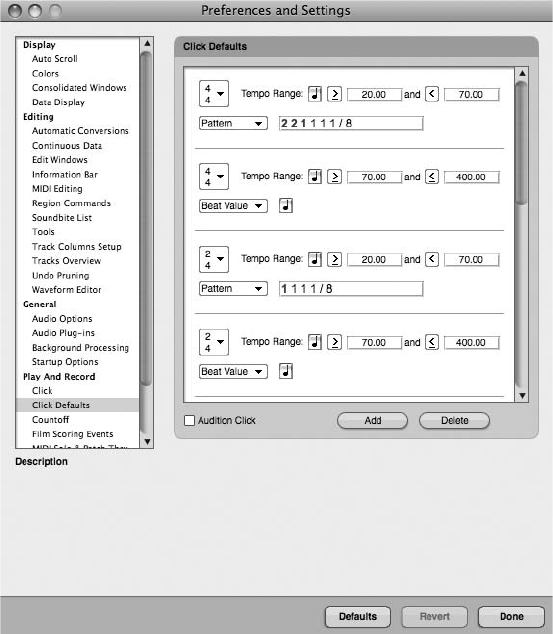
3. Choose a preset by clicking in the white space of the appropriate click, and the chosen
click default will become highlighted in blue. (You can audition the click at any time by
selecting Audition Click, located just below the Click Defaults list.)
4. In the Meter drop-down menu, select the desired meter.
5. In the Tempo Range section, choose the tempo’s beat value by clicking on the quarter-
note icon. Most tempos are based on the quarter note, but DP allows you to choose
among sixteenth notes, eighth notes, quarter notes, half notes, whole notes, and dotted
versions of all of these.
6. Next, choose a tempo range that will apply to the designated click default. When the
tempo of your sequence falls within this designated range, the current click default will
“activate.” Use the greater-than or less-than arrow to customize these parameters.
7. Just below is the Beat Value or Pattern drop-down-menu (for the sounding click). If you
select Beat Value, the click will be based on the meter (designated in Step 4). However,
Figure 4.36 The Click Defaults Preferences window.
Chapter4 SettingUpaNewProject 111
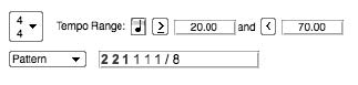
you can change the beat value of the sounding click (it can be different than the tempo’s
beat value) by, again, clicking on the quarter-note icon located to the right of the Beat
Value drop-down menu. (DP defaults to quarter notes.) Skip to Step 9 if you will only be
using Beat Value default clicks.
8. Selecting Pattern in the drop-down menu allows you to choose between several preset
saved patterns, or you can create your own. (Unfortunately, DP’s preset saved patterns
only include 4/4 and 12/8.) If you want to create your own pattern, see “Pattern Clicks
(the Ultimate in Clicks)” in the next section.
9. Once you have selected the desired beat value or pattern, close the window by clicking
Done.
Pattern Clicks (the Ultimate in Clicks)
Sometimes projects require a sequence with many different meters and tempos. In the past, you
were limited to one or two types of clicks for the entire sequence, and if you needed a different
click for just one measure (or a subdivision of the click), you were out of luck. Not anymore!
DP’s pattern clicks involve exactly what the name implies—patterns (see Figure 4.37). For exam-
ple, suppose you have a sequence that involves a long, slow ritard at the end. A quarter-note
click can be very difficult for performers to follow, especially at very slow tempos. With a pat-
tern click, you can create a click that changes once the ritard begins. Depending on rhythms in
the music, the click could change on any part of the measure to, say, eighth notes or triplets, and
can even contain accents on beats other than count one. This is quite an effective tool for
recording.
Patterns in DP are created using an editable text code. This syntax can be somewhat confusing at
first and requires some practice. However, it is quite simple once you grasp the general idea.
Beware, though: A bit of math is involved!
Each pattern is based on a string of numbers and text (the letter dfor “dotted”). Just as in
normal rhythms, each type of note is given a numerical value, and the numerical values of the
pattern are determined by the last two numbers of the string (separated by the slash sign [/]). The
final number (to the right of the slash) is referred to as the indicator. Table 4.1 shows the indi-
cator values in DP.
The number after the slash (the indicator value) indicates the numeric value of the number
before the slash. Remember, indicator values from Table 4.1 refer only to the number after
the slash.
Figure 4.37 DP’s new pattern clicks are an effective tool for recording.
112 Digital Performer 6 Power!: The Comprehensive Guide

For example, a string ending with 2/8 means the pattern will be based on eighth notes (according
to Table 4.1, because 8 is an eighth note), and all 2s appearing in the string must be interpreted as
eighth notes (the 8 makes the 2 an eighth note). In this case (and here is where simple math comes
in), if 2 means an eighth note, then 4 (twice as large as 2) means a quarter note, and 1 (half the
value of 2) means a sixteenth note. So, a pattern of 442222/8will result in a sounding click of
two quarter notes (4 is twice as large as 2), followed by four eighth notes (the 8 makes the 2s
eighth notes). A pattern of 2 2 1111/4will result in a sounding click of two half notes (2 is
twice as large as 1), followed by four quarter notes (the 4 makes the 1 a quarter note).
To set up a custom click pattern:
1. Choose Digital Performer 4Preferences.
2. Select the Click Defaults option in the Preferences and Settings list.
3. Select the Add button in the bottom-right corner under the Click Defaults list. (I suggest
creating a new pattern rather than changing 1 of DP’s preset patterns.)
4. Scroll to the bottom of the Click Defaults list; DP will place a new generic click default
here.
5. In the Meter drop-down menu, select the desired meter.
6. In the Tempo Range section, choose the tempo’s beat value by clicking on the quarter-
note icon. Refer to the tempo beat values discussed in the previous section.
Table 4.1 Indicator Values in Digital Performer
Indicator Value
1 Whole note
2 Half note
2d Dotted half note
4 Quarter note
4d Dotted quarter note
8 Eighth note
8d Dotted eighth note
16 Sixteenth note
16d Dotted sixteenth note
Chapter4 SettingUpaNewProject 113
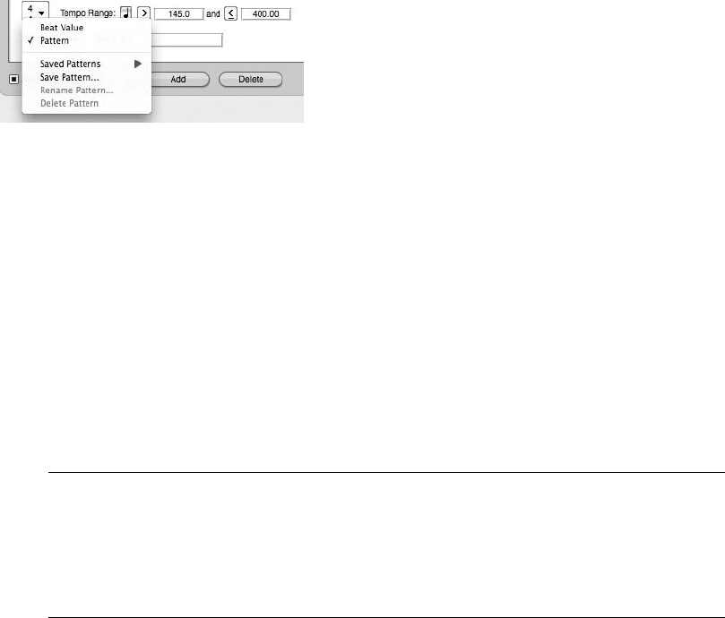
7. Next, choose a tempo range that will apply to the designated click default. Again, use
the greater-than or less-than arrow to further adjust these parameters.
8. In the Beat Value drop-down menu, select Pattern.
9. In the Pattern (or string) window, enter your custom numerical pattern. Make sure to
leave a space between each entry.
10. To accent a click in the pattern, highlight the number you want to accent and enter
Command+B. This makes the number bold and red. Make sure No Accent is not
selected in the Click preferences window discussed earlier in this chapter.
11. Save the new custom pattern by selecting Save Pattern from the Pattern drop-down
menu (see Figure 4.38).
12. In the Save Click Pattern window, enter a name for the pattern and click OK. The newly
created pattern will appear in the Saved Patterns list.
13. You can also rename or delete patterns in the Pattern drop-down menu. These actions
apply to whatever pattern is present in the Pattern window.
14. To delete the entire click default, simply make sure it is highlighted in red and then
choose the Delete button located below the Click Defaults window.
Again, creating your own click patterns will take some practice, but with a little trial and error,
you can design what seems like limitless click opportunities.
The Indicator Value When creating a custom click pattern, I suggest starting with the indi-
cator value and working your way backward. Remember, the indicator value will be the
basis for the click pattern. In other words, if you know you want a click pattern that
includes sixteenth notes, use 16 as your indicator value. Once you establish this, it’s
much easier to do the math to create the remaining beats of the pattern.
Figure 4.38 The Save Pattern option.
114 Digital Performer 6 Power!: The Comprehensive Guide
Defining the Countoff
Often a preparatory period is necessary before recording or playback begins. This allows per-
formers or engineers the opportunity to get ready or to become set for action. This is called the
countoff. The countoff is typically two bars of click based on the first measure of the sequence,
so if Measure 1 is a 4/4 bar, then the countoff is usually 8 counts long (two bars of 4/4).
However, Digital Performer provides an extensive array of customizable countoff features. In
the same manner as click defaults, you can construct your own countoff scheme, including its
beat value, pattern, number of measures, total number of beats, and whether you want to enable
it for recording purposes only. You can also assign various visual aspects of the countoff feature.
(See Chapter 15 for more information regarding these new countoff features.)
To specify the countoff preferences:
1. Choose Digital Performer 4Preferences (or double-click the Countoff or 2-Bars button
located to the right of the Metronome button in the Control Panel).
2. Select the Countoff option in the Preferences and Settings list. The Countoff window
will appear (see Figure 4.39).
3. Select the Click button to enable a sounding click for countoff. Leaving this button
unselected will result in a silent countoff.
4. In the drop-down menu located just below the Click button, select the type of countoff
click you want to use for your project. You can choose a default click, a beat value, or a
click pattern (all discussed at length earlier in this chapter). If you select Pattern, you
have another opportunity to design, save, delete, or rename a custom click pattern.
However, the pattern chosen or created here affects the countoff click only, not the
main sequence metronome click.
5. In the Options section of the Countoff window, enter the number of measures to deter-
mine the length of the countoff. You can also specify extra beats, which is especially
useful when the sequence starts with a pickup note or an odd meter. Any changes here
will automatically be updated in the Control Panel’s Countoff button.
6. Now select the Countoff Only When Recording option if you want the countoff to acti-
vate only for actual recording purposes.
7. Click the D1 button to exit the Countoff preferences.
Now that you have set up your countoff click, it is important to enable it by making sure the
Countoff button in the Control Panel is activated (darkened). You can easily toggle this button
on and off while you are working in your project. Also, it is not necessary to be at the beginning
of your sequence (Measure 1) for the countoff to work. You can be located anywhere in the
Chapter4 SettingUpaNewProject 115
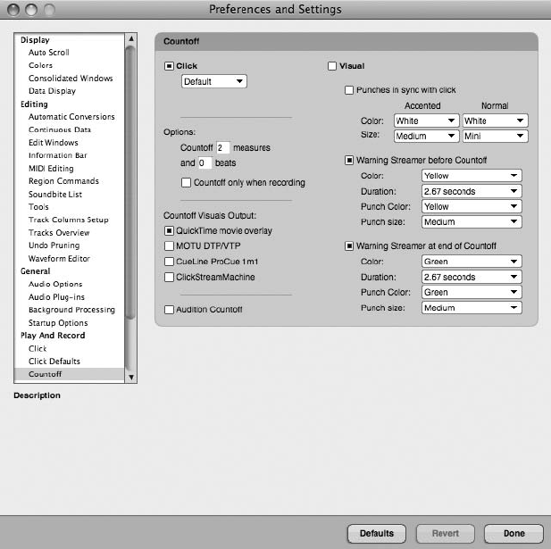
timeline, and if activated, DP will provide the defined countoff before recording or playback
begins.
Summary
Obviously, there likely will be other parameters or features specific to your project that you’ll
need to set up before recording or mixing. The steps and procedures provided in this chapter are
meant to get you up and running quickly with Digital Performer 6. We’ll dive into the details of
DP’s tools and enhanced features in the upcoming chapters of this book.
Figure 4.39 The Countoff Preferences window.
116 Digital Performer 6 Power!: The Comprehensive Guide

5Project Management: Part 1
Project management is an extremely important, though often overlooked, part of the music
production process. Keeping audio files, multiple versions of a project, and your Digital
Performer workspace organized requires careful planning and consideration, but it
doesn’t have to be an overwhelming task.
One of the common misconceptions about project management is that only serious professionals
working on large projects need to worry about it. On the contrary, even the smallest of projects
and studio setups can benefit from some organization. Proper audio file management, for exam-
ple, can provide a more stable operating environment for Digital Performer by preventing
unneeded files from consuming precious disk space, which can negatively affect the performance
of the Mac OS.
Digital Performer contains a number of features to help you manage the various aspects of your
sessions, from customization of the DP workspace to the compacting and archiving of your
projects. I’ve chosen to break up this complex topic into two chapters. Part 1 will discuss
basic project management concepts, such as creating, saving, and opening projects and custom-
izing your DP workspace. Part 2 (Chapter 6) will discuss the project Undo History window,
audio file management, and backup solutions.
Here is a summary of topics discussed in this chapter:
nHow to open and save existing Digital Performer projects
nThe differences between Save and Save As
nHow to create and manage project templates
nHow to open and save standard MIDI and OMFI files
nHow to customize the Digital Performer workspace
nThe Consolidated Window
117

The Digital Performer Project
When you create a new Digital Performer project, a project file (document) is created and placed
in the new project’s folder. Within this document is all the information associated with the project,
from track layout and window placement to mix settings and recorded MIDI data. Everything that
is needed to re-create the project is saved in this document, with the exception of audio files, audio
file undo history information, fades, and analysis files. Remember, soundbites (audio files/regions)
in a DP project are only pointers that reference the actual audio files, which exist on a hard drive
within your system. This is why the project file is relatively small—the much larger audio files are
not actually contained in the Digital Performer document but in separate distinctive folders. DP
automatically links these separate folders to your main project file.
As noted in Chapter 4, Digital Performer will allow only one project to be open at a given time
(though an unlimited number of sequences, or Chunks, can exist within a given project). You
must close a project before you can open or create a new one. See Chapter 11, “Arranging,” for
a detailed look at Chunks within Digital Performer.
Opening an Existing Project
To open an existing Digital Performer project from the File menu:
1. Launch Digital Performer.
2. Choose File 4Open. The default keyboard shortcut is CommandþO.
3. Choose the project file from the appropriate folder or hard drive and click OK. If you
have an unsaved project currently open, you will be prompted to save the file before DP
closes it and opens the newly chosen one (see Figure 5.1). Choosing Don’t Save will
close the currently open project, discarding any changes made since your last save.
Other Methods for Opening a Project In addition to File 4Open, there are two other
methods for opening a Digital Performer project.
nDrag and drop. Drag the Digital Performer project you want to open directly onto the
DP application icon. This method will also work when the application icon resides in
the Dock.
Figure 5.1 The Save Changes before Closing dialog.
118 Digital Performer 6 Power!: The Comprehensive Guide

nDouble-click. Double-click the Digital Performer document icon you want to open.
If DP is not currently running, this method will launch the program before opening
the project file.
Working with Multiple Versions of DP If you have multiple versions of Digital Performer
installed on your system, you may have experienced instances in which DP opened a proj-
ect in the “wrong” version of the application when you used the double-click method.
You can remedy this problem and force a file to open within a specific version of DP using
the Finder’s Get Info command (see Figure 5.2).
To force a project to open in a specific version of Digital Performer:
1. Select the Digital Performer project icon by clicking on it. Don’t double-click, or you
will accidentally launch the program and open the selected project.
2. From the Finder’s File menu, choose Get Info. The default keyboard shortcut is
CommandþI.
3. Click to display the Open With section pane of the Get Info window.
4. Click the disclosure triangle to access the Open With pop-up menu.
5. In the pull-down menu, select the specific version of the Digital Performer application in
which you would like the file to open.
6. If you would like all similar DP projects to open with the application version you just
selected, then click on the Change All button. An “Are You Sure” dialog will open,
asking you to cancel or continue with the change. Select Continue.
7. Close the Get Info window.
8. Now, when you double-click on the project file, it will open in the designated version of
DP.
Opening Other File Types
Digital Performer can also open the following types of files created in earlier versions of DP,
Performer, or other supported applications:
nProjects created in earlier versions of Digital Performer and Performer
nProjects created in AudioDesk
nStandard MIDI files
Chapter 5 Project Management: Part 1 119
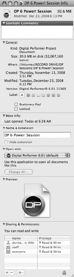
nOMF Interchange files (for transfer with other applications)
nAAF Interchange files (for transfer with other applications involving video)
nFinal Cut Pro XML files (for transfer with editing projects involving Apple’s Final Cut Pro)
Figure 5.2 The Finder’s Get Info command.
120 Digital Performer 6 Power!: The Comprehensive Guide
Once opened, the file will be converted to a Digital Performer file. Choose the Save As command
to export a file back into its original format. Standard MIDI and OMF Interchange files are
discussed in further detail in the “Standard MIDI Files” and “OMF Interchange and AAF Inter-
change Files” sections later in this chapter.
Saving Your Project
Save! Save! Save! Why do we need to save? And why do we lose precious changes that haven’t
been saved, for example, when a program crashes? The answer is simple. When a project file is
opened, it is loaded into RAM. So you are actually working on a copy of the project and not the
original file, which is stored on your hard drive. Until you save, any modifications or changes
you make to a file exist only in RAM and are not updated in the original document.
Redundancy can rescue us many times over, so if you would like to save a different version of
your project for backup purposes or export it into a different file format, you’ll need to choose
the Save As command.
The Save Command
To save a Digital Performer project:
1. From Digital Performer’s File menu, choose Save. The universal keyboard shortcut for
saving on a Mac is CommandþS.
2. If you are saving a project for the first time, you will be prompted to name the file before
saving.
The Save As Command
The Save As command (File 4Save As) has multiple uses, including the following:
nCreating an alternate version of a project with a different file name
nExporting a project in a different file format
nSaving to create a backup or duplicate copy of a project
To save an alternate version of a project:
1. Choose Save As from Digital Performer’s File menu.
2. Name the project. Try to choose a descriptive name or devise a specific naming scheme
to keep your alternate project files organized.
3. If you need to make duplicate copies of your project audio files to include with this
alternate version, click the Duplicate Audio and Copy Shared Samples to Project option,
as shown in Figure 5.3.
Chapter 5 Project Management: Part 1 121
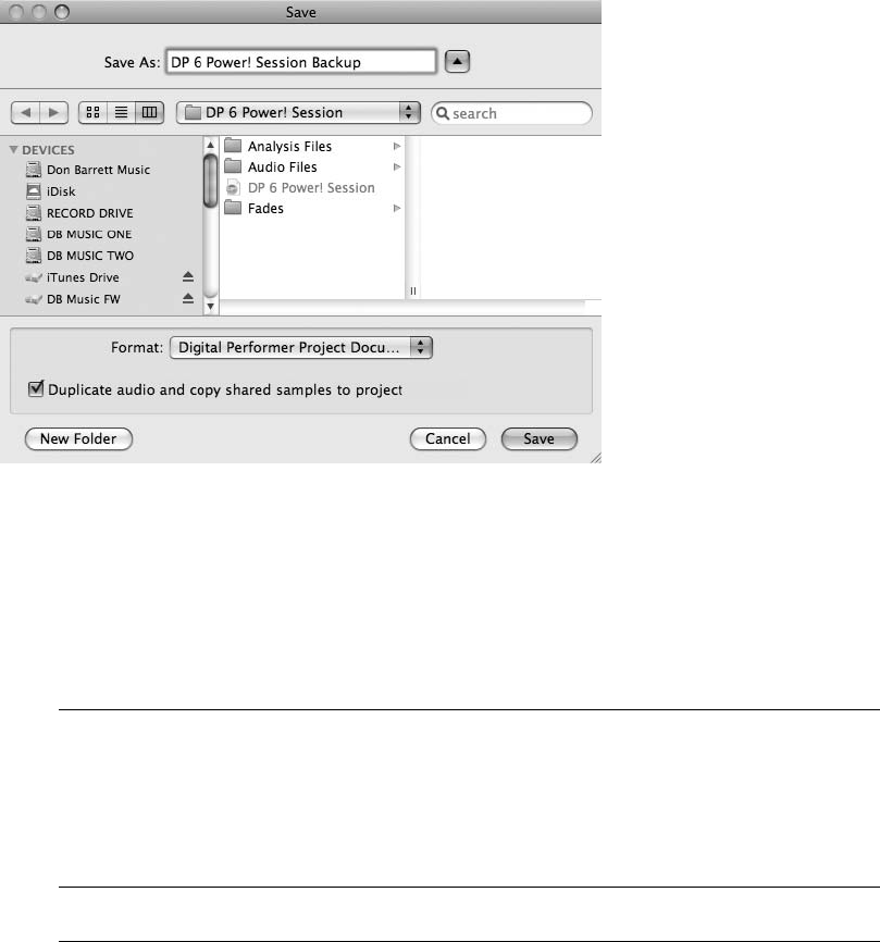
4. Select the destination for the new version and click OK.
5. Once saved, DP will automatically save and close the original file, and you will be
working on the new (alternate or backup) version of the project.
Saving a Copy As If you would like to save an alternate version of a project but continue
working on the current version, use the Save a Copy As command (File 4Save a Copy
As). Be aware that unlike the normal Save As command, Save a Copy As will not auto-
matically save the project you’re currently working with. You will need to manually save to
preserve any changes you have made since your last save.
Beware When Using the Save As Command Many users find out the hard way: A new and
separate Audio Files folder is not created when using the Save As command, unless you
enable the Duplicate Audio and Copy Shared Samples to Project option. When this option
is left unchecked, any alternate versions of a project you create will still refer to the original
Audio Files, Fades, Analysis, and Undo folders. If you delete an audio file in one version of
a project, for example, it will disappear from any and all alternate versions that may have
been created with the standard Save As command.
Figure 5.3 The Save As dialog with the Duplicate Audio and Copy Shared Samples to Project option
selected.
122 Digital Performer 6 Power!: The Comprehensive Guide
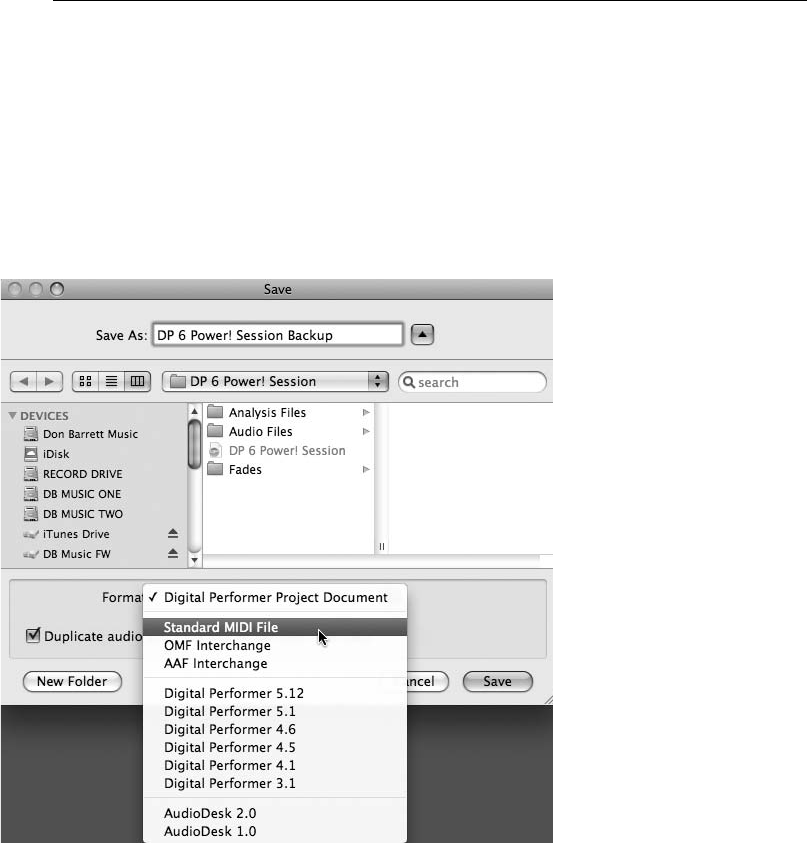
If you like to keep the alternate versions of a project organized by removing unused audio
files from the Soundbites window, be sure to use the Remove from List command.
(Choose Remove from List from the mini-menu in the Soundbites window.) This will
remove the audio from the specific document’s Soundbites window without actually
deleting the regions (soundbites) associated with the original audio files.
To export your project in a different file format:
1. Choose Save As from Digital Performer’s File menu.
2. Name the project.
3. Choose the destination folder and/or hard drive for the file.
4. Select the new format from the Format pop-up menu, as shown in Figure 5.4.
5. Click OK to save.
Figure 5.4 The Save dialog with supported file format options.
Chapter 5 Project Management: Part 1 123

See the “OMF Interchange and AAF Interchange Files” and “Final Cut Pro XML Interchange”
sections of this chapter for detailed information on exporting to these file formats.
Working with Previous Versions of DP Digital Performer projects are not backwards
compatible with earlier versions. You cannot, for example, open a project created in
DP 6.02 in version 5.13. If you need to open a project in an earlier version of Digital
Performer (perhaps you are collaborating with another musician who has an older version
of DP), then use the Save As command and simply select the desired version of DP in the
Format drop-down menu.
Ensuring Compatibility Be aware that certain features, such as virtual instrument tracks,
may not be successfully exported to previous versions. For example, exporting a DP 6.02
project containing an instrument track to an older version will result in the instrument track
appearing as an empty aux track.
Here are a few suggestions for ensuring compatibility with older versions of Digital
Performer and/or differently configured systems:
nPrint (record) any existing instrument tracks as audio files. The method you choose
(Freeze Tracks, Bounce to Disk, Real-Time Audio Bounce, and so on) will depend
on your particular setup and workflow. Each feature is discussed in detail in upcoming
chapters of this book.
nIf you are supplying a project for another musician to perform overdubs (and not
mix), for example, you may be able to get away with bouncing the entire project
to disk as a stereo file.
nFind out what audio interface the other DP user is working with. Can his system
handle your project’s sample rate, track, and plug-in count? If the answer is no,
you may be forced to bounce to disk, remove effects plug-ins, or convert the
project’s sample rate and/or bit depth.
nRemember, it’s a smart practice to supply the other user with only what he needs.
Don’t rely on him to figure it out when he receives your project! Besides being
courteous, you’ll be able to retain more control over how the project will return to
you when the user’s work is completed.
124 Digital Performer 6 Power!: The Comprehensive Guide
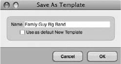
Save As Template
A much-overlooked project management feature in Digital Performer is the project template. If
you constantly find yourself reinventing the wheel, so to speak, by devoting a lot of time to
setting up projects, creating new tracks, renaming those tracks, making specific I/O assignments,
arranging the workspace, and so on, you may want to incorporate templates into your produc-
tion workflow. In DP 6, you have the ability to save multiple project templates with the Save as
Template command (File 4Save as Template).
Saving a Template
You can create templates tailored to accommodate your specific recording, mixing, and/or com-
position needs. Prepare them ahead of time or save them as your projects are created.
To create a project template using the Save As Template command:
1. Begin by setting up your Digital Performer project. This may entail adding and
renaming specific tracks, configuring specific audio bundles, setting up the Mixing
Board with effects plug-ins inserted on your tracks, and so on.
2. Once you have configured your project, choose Save As Template (File 4Save As
Template).
3. Name the template (see Figure 5.5). Try to choose a descriptive name to help you easily
identify the nature of the template.
4. If you would like the template to become the default template, select the Use as Default
New Template option.
5. Click OK to save the template.
6. Once saved, the template will appear in the File 4New submenu, as shown in
Figure 5.6.
Figure 5.5 The Save As Template window.
Chapter 5 Project Management: Part 1 125
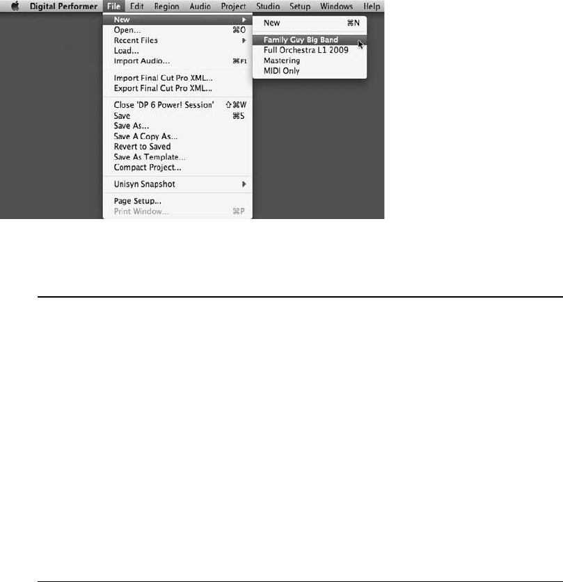
Preventing a Template in Previous Versions from Being Overwritten The greatest benefit to
DP’s New Template submenu is that you cannot accidentally overwrite a project template.
When you choose a template as the basis for a new project, you are not actually using the
original project used to create the template; you are simply creating a new project based
on the selected template.
When working with versions prior to DP 4.1, you are limited to the creation of one
template with the Save as New Template command. To work around this restriction, you
can use a normal DP project and choose Save As to create a pseudo template on which to
build other projects. In this scenario, however, it is very easy to accidentally overwrite
your makeshift template, or even worse, create “new” projects that share the same
Audio Files folder!
Thankfully, there is an easy way to prevent a project from being overwritten, and believe
it or not, it is a standard feature of the Mac OS—see the next set of steps.
To prevent a Digital Performer project from being overwritten:
1. Select the project’s document icon by clicking on it. Be careful not to double-click on the
document, or you will accidentally open the project.
2. From the Finder’s File menu, choose the Get Info command. The default keyboard
shortcut is CommandþI.
3. Click to show the General section pane of the Get Info window, shown in Figure 5.7.
Figure 5.6 The New submenu. Descriptive naming schemes allow for easy identification of project
templates.
126 Digital Performer 6 Power!: The Comprehensive Guide
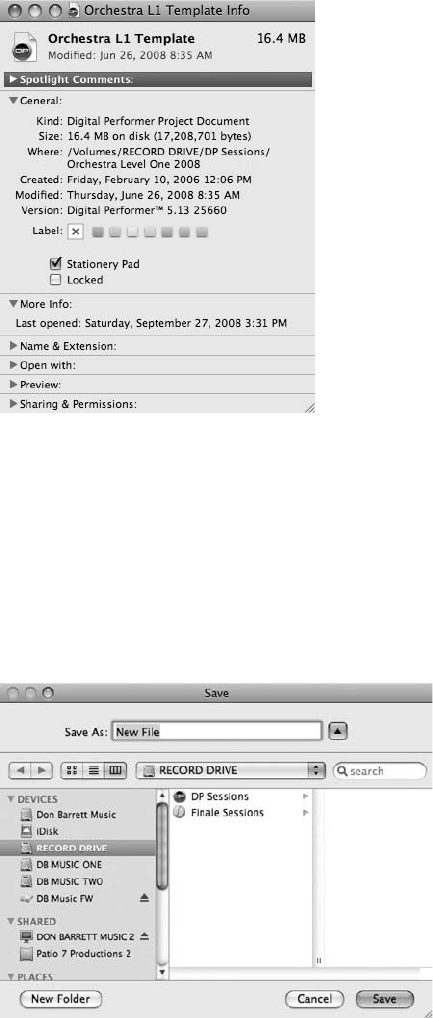
4. Select the Stationery Pad option.
5. Close the Get Info window.
6. Now when you open this project (or template), you will be forced to Save As, creating a
new project (with its own Audio Files folder) that is entirely independent from the
original “template” (see Figure 5.8).
Figure 5.7 The General section pane of the Get Info window with the Stationery Pad option selected.
Figure 5.8 When attempting to open a project with the Stationery Pad feature enabled, you will be
forced to Save As, ensuring that the file is not overwritten. Choosing Cancel will automatically close the
file.
Chapter 5 Project Management: Part 1 127
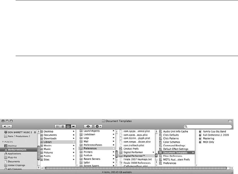
Don’t Double-Click to Open a Project Template Be sure to use Digital Performer’s Open
command (File 4Open) when opening a project (or pseudo template) protected with the
Finder’s Stationery Pad feature. If you use the double-click method, only a copy of the
original file will be created and opened. This “copy” will be created in the project folder of
the protected document and, more importantly, will share the same Audio Files folder as
the original project!
Deleting, Moving, and Renaming Templates
Digital Performer templates are stored in the User 4Library 4Preferences 4Digital Performer 4
Document Templates folder (see Figure 5.9). Once a template is created in DP, it can be managed
only from the Finder menu. DP will automatically update to reflect any changes made to the Doc-
ument Templates folder.
To delete a project template:
1. Navigate to the User 4Library 4Preferences 4Digital Performer 4Document
Templates folder.
2. Drag the template document to the Trash, or use the keyboard shortcut
CommandþDelete.
To remove the project template without deleting it:
1. Create a new folder (File 4New Folder) outside the Document Templates folder in a
location of your choosing.
2. Navigate to the User 4Library 4Preferences 4Digital Performer 4Document
Templates folder.
3. Drag the template document to the folder you created in Step 1.
Figure 5.9 DP templates are stored in the Document Templates folder.
128 Digital Performer 6 Power!: The Comprehensive Guide

To rename a project template:
1. Navigate to the User 4Library 4Preferences 4Digital Performer 4Document
Templates folder.
2. Select the document template by clicking on it.
3. Click again, and the name will become highlighted.
4. Type the new name.
5. Press the Return key to confirm the change.
Opening Documents and Folders from Within DP Digital Performer’s Clippings feature
allows you to create shortcuts to documents, folders, and website links (almost anything
that resides outside of DP). This saves you the hassle of leaving the application and nav-
igating with the Mac OS Finder. See Chapter 11 for details on using Clippings.
Standard MIDI Files
The standard MIDI file format (SMF) was created to facilitate the transfer of MIDI data across
different applications and, most importantly, different computer platforms (see Figure 5.10).
Almost every music software sequencer can open and save MIDI data in the SMF format.
This allows a musician working in Digital Performer, for example, to save a MIDI sequence
as an SMF and exchange it with a PC user without the loss of any data.
There are basically two types of standard MIDI files that DP can work with, Type 1 and Type 0.
Digital Performer replaces the term type with format.
nFormat 1. This setting preserves the layout of individual MIDI tracks and includes
tempo and meter information.
nFormat 0. This setting includes tempo and meter information but merges all MIDI
tracks into a single multichannel track. DP also has the ability to save a format 0 SMF
that only includes tempo and meter map information.
In addition to this information, track names and other descriptive data will be stored when
opening and exporting standard MIDI files from Digital Performer.
Figure 5.10 The Standard MIDI File icon created in Digital Performer.
Chapter 5 Project Management: Part 1 129
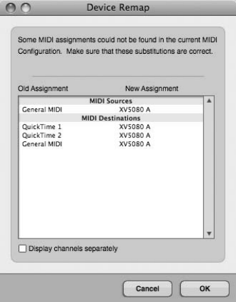
Opening Standard MIDI Files
To open a SMF via the File menu:
1. In Digital Performer, choose File 4Open. The default keyboard shortcut is CommandþO.
2. Select the standard MIDI file and click the Open button.
3. If the MIDI assignments in the SMF do not match the MIDI configuration of Digital
Performer, then the Device Remap window will appear and attempt to make the
appropriate substitution (see Figure 5.11).
4. Click OK to confirm the recommended substitution. Choosing Cancel will ignore the
substitutions and assign the MIDI inputs or outputs to NONE.
To import a SMF into an existing project via the drag-and-drop method:
1. In Digital Performer, open the Chunks window (Project 4Chunks). The default key-
board shortcut is ShiftþC.
2. Within the Mac OS Finder, select the standard MIDI file and drag the SMF into DP’s
Chunks window. Once imported via drag and drop, the SMF will appear as a sequence
in Digital Performer’s Chunks window. MIDI assignments will not be substituted but
will default to an assignment of NONE. There is no need to Save As, because the SMF
will be copied directly into the existing project.
Figure 5.11 The Device Remap window.
130 Digital Performer 6 Power!: The Comprehensive Guide
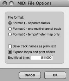
Exporting Standard MIDI Files
To export a standard MIDI file using the Save As command:
1. In Digital Performer choose File 4Save As.
2. Name the project and choose the destination folder and hard drive. Be aware that DP
doesn’t automatically add the standard .mid extension to the end of the file name. Be
sure to include this extension (.mid) when naming the standard MIDI file to ensure that
the destination program is able to read it correctly.
3. Select Standard MIDI File from the Format pop-up menu.
4. Click on the Save button.
5. Specify the SMF options in the MIDI File Options window, shown in Figure 5.12.
6. Select the options for the standard MIDI file. Keep in mind that MIDI effects and MIDI
loops cannot be exported with your SMF, so you will need to enable the Expand Loops
and Print Effects option, then use the End File at Time option to specify the end time of
the printed loop.
nFormat 1 - Separate Tracks. This setting will maintain the separation of MIDI tracks
and include the tempo and meter data as the first track. This standard exporting
option is enabled by default. It’s a good idea to use the Format 1 option if you’re
unsure of the standard MIDI file format you should be using.
nFormat 0 - One Multi-Channel Track. This option will create a multichannel MIDI
track with tempo and meter at the beginning.
nFormat 0 - Tempo/Meter Map Only. This option will export only the Conductor
track with tempo and meter data.
nSave Track Names as Plain Text. This option will only save plain text events, such as
track names, with the SMF. Track comments and other special text events will not be
Figure 5.12 The MIDI File Options window.
Chapter 5 Project Management: Part 1 131
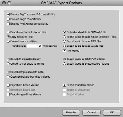
saved with the file. Use this option to ensure compatibility with programs that do not
support special text.
nExpand Loops and Print Effects. Loops and real-time MIDI effects cannot be
included in standard MIDI files. This option will print any real-time MIDI effects
and convert any loops into a region of repeated MIDI data. Use the End File at Time
option to specify the end time of the printed loop.
7. Once you have specified the MIDI file options, choose OK to export the standard MIDI
file.
OMF Interchange and AAF Interchange Files
OMFI (Open Media Framework Interchange) and AAFI (Advanced Authoring Format Inter-
change) are industry-standard formats for exchanging digital files between applications, such
as Digidesign’s Pro Tools and Apple’s Final Cut Pro. These formats speed up the production
workflow by allowing media files and metadata created in one program to be made available
in another.
Digital Performer supports OMFI 1.0 and 2.0 formats, as well as AAFI 1.0 and 1.1, and can also
export OMFI files that are compatible with Digidesign’s DigiTranslator 2.0 (see Figure 5.13).
Final Cut Pro XML Interchange
There is nothing more frustrating when scoring to picture than being notified that new visual
edits have been made after the music track has been written and recorded. New to Digital
Figure 5.13 The OMF/AAF Export Options window.
132 Digital Performer 6 Power!: The Comprehensive Guide

Performer 6 is the support of advanced session interchange features via the Final Cut Pro XML
Interchange protocol. This new method adds an entire new dimension of communication
between DP and Final Cut Pro. Gone are the days of a composer or songwriter having to
painstakingly scan through a newly edited piece of film or video to locate recent changes
that have been made by the Final Cut Pro editor. Basically, when an editor makes edits to a
project, he can then export an XML file that accounts for and itemizes the changes.
This XML file can be imported into DP, and all the new editorial changes will appear in
DP’s Import Final Cut Pro XML window. This window will provide a detailed list of the
changes where the composer or songwriter can simply double-click any edit to view a color-
coded comparison in DP’s Sequence Editor timeline. A blue border will represent the old
position, and a red border reveals the new position of the edit. This timesaving new feature
makes the process of adjusting music to new picture edits much more efficient and less
complicated.
Although the extent of the XML Interchange procedure is beyond the scope of this book, let’s
briefly discuss the simple process of importing and exporting Final Cut Pro XML files. The
importing and exporting options are located in a different place than the traditional Save As
location for OMF and AAF Interchange files (discussed earlier in this chapter).
XML Alerts When media files cannot be imported into DP, a warning dialog box will
appear. There are three reasons why this may occur: The file path for the media may
be incorrect on the host machine (DP can’t find the media), the media file is in an unsup-
ported format (a format that DP can’t play or convert), or the media is in a format that DP
understands but cannot play natively.
To import a Final Cut Pro XML Interchange file:
1. In Digital Performer, choose File 4Import Final Cut Pro XML Interchange (as shown
in Figure 5.14).
2. The Import Final Cut Pro XML window will appear. Simply double-click any edit in the
list, and DP will scroll to and highlight the location of the edit in the Sequence Editor
timeline.
To export a Final Cut Pro XML Interchange file:
1. In Digital Performer, choose File 4Export Final Cut Pro XML Interchange.
2. The Export Final Cut Pro XML window will appear (as shown in Figure 5.15). Choose
the desired options and click Export.
Chapter 5 Project Management: Part 1 133
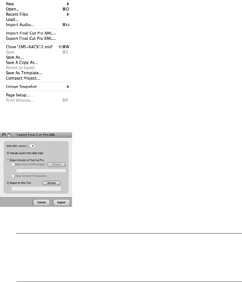
DP and Final Cut Pro on the Same Machine? To further streamline the XML Interchange
process, in DP 6 you can import or export XML files directly to or from the Final Cut Pro
application using the Import Direct from Final Cut Pro or Export Directly to Final Cut Pro
command. For these features to work, however, Final Cut Pro must be running on the
same computer as DP 6. Consult the Digital Performer User Guide for more information.
Customizing Your Workspace
Organizing your Digital Performer workspace is much like organizing the desk in your office.
When working in a physical space, it is important to keep files, documents, pens and pencils, and
so on in logical locations that allow for easy access, storage, and management. These rules are
Figure 5.15 The Export Final Cut Pro XML window provides several options for creating an XML file
from all sequences in the currently open DP project.
Figure 5.14 The Import and Export Final Cut Pro XML options located in the File menu of Digital Per-
former 6.
134 Digital Performer 6 Power!: The Comprehensive Guide
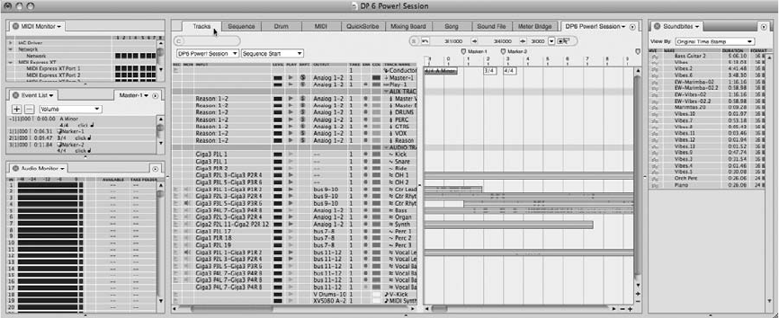
just as applicable within the desktop environment. Digital Performer has many different win-
dows that you will need to access within the course of the music production process. Like phys-
ical office space, screen real estate is limited—unless you are lucky enough to have a 30-inch
Cinema display!
Digital Performer has a number of features that allow you to customize your DP workspace,
from project-specific window configurations and track colors for easy track identification, to
the customization of keyboard shortcut commands and preferences. Digital Performer’s
Consolidated Window feature provides additional control for managing the numerous
windows in DP.
The Consolidated Window
When enabled, the Consolidated Window feature allows you to view multiple windows in a
single, consolidated environment. The Consolidated Window, shown in Figure 5.16, displays
various tabs across the top of the window. These tabs provide quick access to many of DP’s
main windows—when clicked, the desired window will open in the main body or center of
the Consolidated Window. Sidebars are available for displaying other windows, such as the
Audio Monitor, Chunks, Markers, Event List, and Undo History windows.
The Title Bar
The Consolidated Window’s title bar closely resembles the title bars found in DP’s editors, but it
adds one extra feature: You can Command-click the name of the project file to reveal the path of
the file on your hard disk (as shown in Figure 5.17).
Figure 5.16 Click on a tab to open the desired window in the main body of the Consolidated Window.
In this example, the Tracks Overview window is revealed in the center section of the Consolidated
Window.
Chapter 5 Project Management: Part 1 135
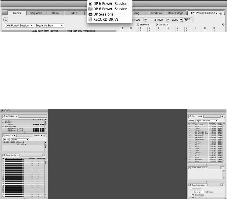
Sidebars and Cells
Sidebars are additional sections that allow you to display other selected windows (cells) to the
left or right of the main body (center section) of the Consolidated Window (see Figure 5.18).
You can open and close several cells in each sidebar, and each contains the appropriate mini-
menu options associated with the selected cell. To open a sidebar simply double-click the
divider, as shown in Figure 5.19, or choose Windows 4Open/Close Left (or Right) Sidebar.
Once a sidebar is open, you can change what is displayed in each sidebar cell using the window
selector menu that becomes available when you click on the cell’s title (as shown in Figure 5.20).
Keep in mind that editor windows do not appear in this list and cannot be displayed in a sidebar.
In addition, a sidebar cell can be “popped” out of the sidebar and into its own separate window.
To “pop” a cell out of the sidebar and into its own separate window, simply double-click the
empty space in the Tab bar of the cell (see Figure 5.21). The cell will “pop” out in a separate
window. Double-click the empty space in the Tab bar again, and the window will return to the
sidebar of the Consolidated Window. To close a sidebar cell, just click the X next to its title (or
use the traditional Apple shortcut CommandþW).
Figure 5.17 Command-click the project name in the title bar of the Consolidated Window to reveal its
path on your hard disk.
Figure 5.18 Sidebars include additional windows (or cells) to the left and right of the Consolidated
Window’s main body section.
136 Digital Performer 6 Power!: The Comprehensive Guide
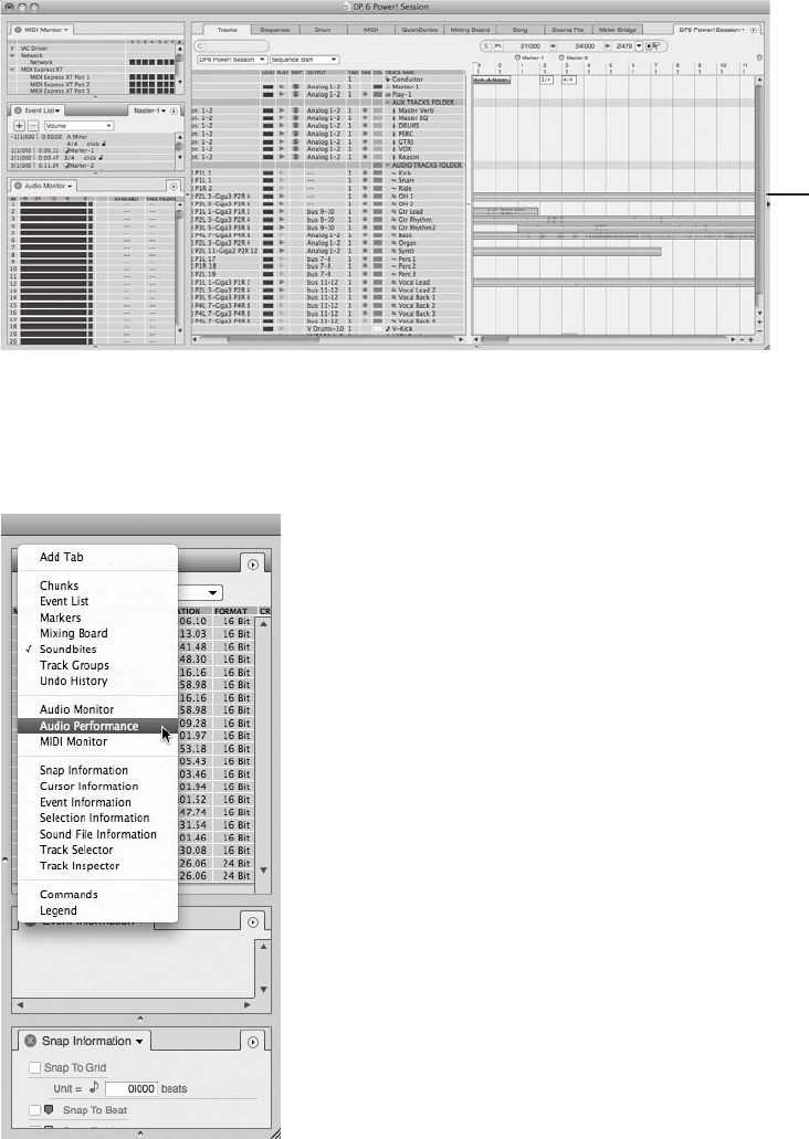
Figure 5.20 You can change what is displayed in each sidebar cell by using the window selector menu.
Sidebar Divide
r
Figure 5.19 To open a sidebar, simply double-click the body/sidebar divider.
Chapter 5 Project Management: Part 1 137
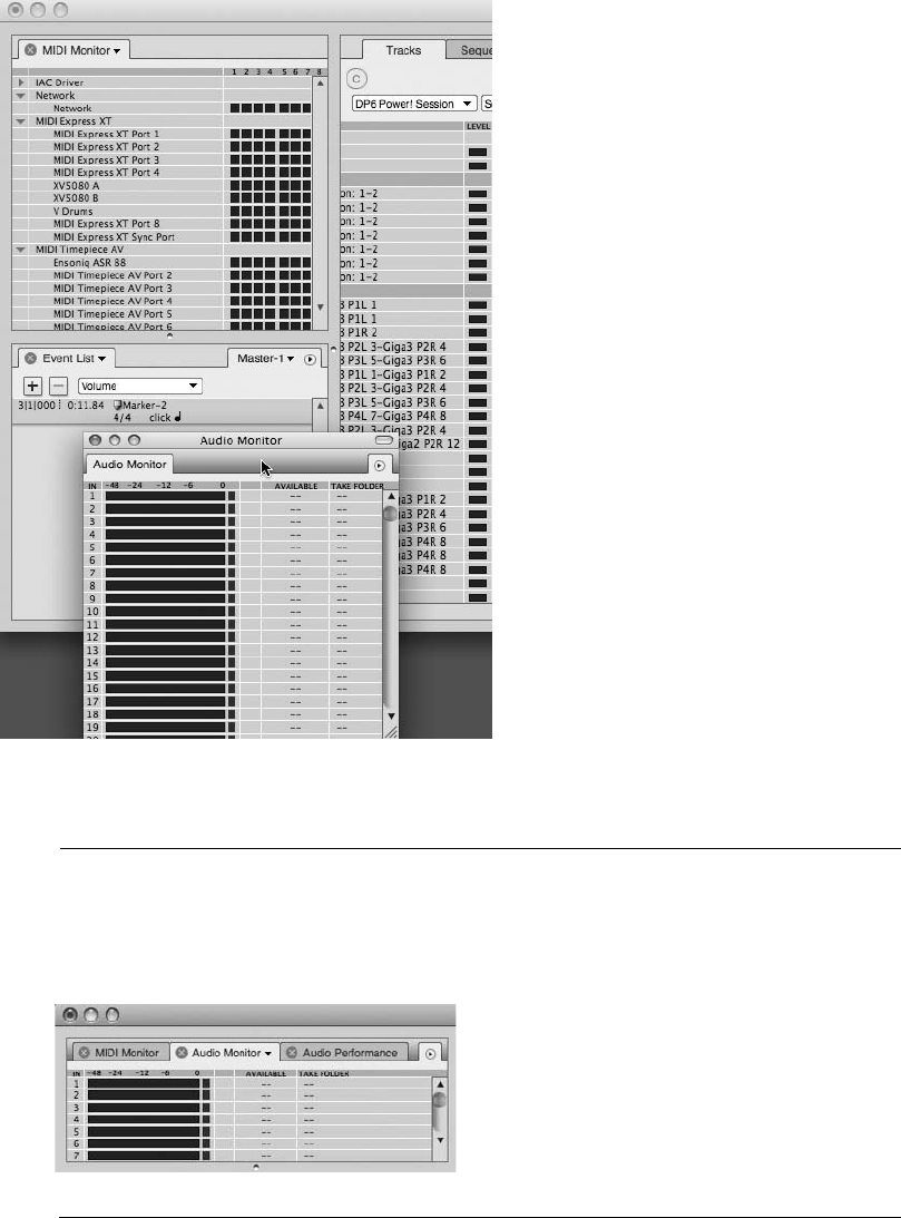
Multiple Tabs in Sidebar Cells By default, each sidebar cell contains only one window
(cell). However, you can add multiple windows within a single cell (see Figure 5.22).
These windows will appear as tabs and are manipulated in the same manner as single
cells. To add a tab, choose the Add Tab option located in the window selector menu.
Figure 5.21 Sidebar cells can be “popped” out of the sidebar and into their own separate window by
double-clicking the empty space of the cell’s Tab bar.
Figure 5.22 A sidebar cell can have multiple windows as “tabs.”
138 Digital Performer 6 Power!: The Comprehensive Guide
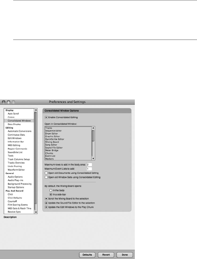
Cell Focus Cell focus is similar to the front-most window when working with multiple win-
dows. In DP, when a cell is currently selected, it has focus. And when a cell is in focus, its Tab
bar (title bar) has a slightly darker shade. Because certain operations in DP only pertain to a
cell that currently has the focus, it is important to become familiar with the “focus” concept
and how to direct it. To apply focus to a specific cell, simply click its Tab (title) bar.
Setting Up the Consolidated Window
The Consolidated Window feature can be enabled or disabled entirely from the Consolidated
Window preferences, as shown in Figure 5.23. The preferences listed are global and will affect
all of your Digital Performer projects. However, changes made to these preferences will not
affect previous projects. In other words, if you disable Consolidated Windows but open an
older project that used Consolidated Windows, Consolidated Windows will be active in the
project until you close and reopen the individual windows.
Figure 5.23 The Consolidated Window preferences allow you to enable or disable the Consolidated
Window all together.
Chapter 5 Project Management: Part 1 139
The Consolidated Window preferences are as follows:
nEnable Consolidated Editing. This button toggles the Consolidated Window on and off.
nOpen in Consolidated Window. This section contains a list of Digital Performer
windows that can be included in the Consolidated Window. Windows highlighted in
blue are included, while unhighlighted windows will open as separate windows.
nMaximum Rows to Add in the Body Area. This setting determines how many rows (or
windows from the tabbed selections) will be automatically added to the main body or
center section of the Consolidated Window when opened. To add or remove rows
manually, simply drag on the Consolidated Window’s horizontal divider.
nMaximum Event Lists to Add. This setting determines the maximum number of Event
Lists you can open in the Consolidated Window. If you attempt to exceed the specified
maximum number, DP will simply replace one of the Event Lists you have currently
open with the new Event List. Keep in mind that this setting does not prevent you from
manually opening an Event List from the sidebar cell menus.
nOpen Old Documents Using Consolidated Editing. Enable this option if you want to
have older DP projects (created in versions prior to 4.5) automatically open in the
Consolidated Window layout. Turn off this option if you wish to work with these older
documents in their original window layout. Keep in mind that you can always migrate
these older documents into the Consolidated Window layout at your own pace.
nOpen Old Window Sets Using Consolidated Editing. Enable this feature if you want
window sets created in older versions of DP (prior to DP 4.5) to open in a Consoli-
dated Window layout. Disable this option if you want to preserve the original layout of
the older window set. Refer to the “Window Sets” section of this chapter for an
explanation of window sets.
nBy Default, the Mixing Board Opens. Use this option to determine where the Mixing
Board will automatically open in the Consolidated Window if you have the Mixing
Board highlighted in the Open in Consolidated Window section.
nScroll the Mixing Board to the Selection. Turn on this option if you want the Mixing
Board to automatically scroll and display the channel strip for a selected track. This
option only applies when the Mixing Board appears in the Consolidated Window and is
especially handy when viewing the Mixing Board in a sidebar. This option is the same as
the Consolidated Window mini-menu’s Scroll Mixing Board to Selection option.
nUpdate the Sound File Editor to the Selection. Similar to the Scroll the Mixing Board to
the Selection option, this option causes a soundbite selected in a DP editor, such as the
Sequence Editor or the Tracks window, to always display in the Waveform Editor
140 Digital Performer 6 Power!: The Comprehensive Guide
(when the Waveform Editor is visible in the Consolidated Window). You can also
enable this setting from the Consolidated Window mini-menu.
nUpdate the Edit Windows to the Play Chunk. Use this option if you want DP’s various
editor windows to always display tracks from the currently play-enabled Chunk. You
can also enable this setting from the Consolidated Window mini-menu.
To enable or disable the Consolidated Window feature:
1. Open the Consolidated Window preferences by choosing Digital Performer 4
Preferences 4Consolidated Window Preferences.
2. Click the Enable Consolidated Editing button to toggle the Consolidated Window
feature on or off.
Once you have decided to work in the Consolidated Window, and you have enabled it from the
Preferences and Settings window, you will need to decide which particular windows will open in
the Consolidated Window. The Open in Consolidated Window section of the Consolidated Win-
dow preferences provides a list of windows that are to be included or excluded from the Consoli-
dated Window. Windows highlighted in blue will be included, whereas unhighlighted windows will
open independently. Keep in mind that you can “pop” windows in or out (explained earlier) to
manually separate a window or force it back into the Consolidated Window.
To determine which windows will open in the Consolidated Window:
1. Open the Consolidated Window preferences by choosing Digital Performer 4
Preferences 4Consolidated Window preferences.
2. In the Open in Consolidated Window section, click to highlight the window or windows
you want to have included. All the windows in the list should be highlighted (in blue) by
default. Windows that are not highlighted will automatically open in a separate
window.
The Main Body and Rows. The main body section is the center section of the Consolidated Win-
dow and is used to display the main windows in DP. Use the tabs located above the main body to
display a particular window. Drag the main body section’s horizontal divider to manually show or
hide additional sections (or rows), as shown in Figure 5.24. New rows will appear with their own
sets of tabs, allowing you to display multiple windows in this center section of the Consolidated
Window. Keep in mind that you can set the number of rows that are automatically opened in the
main body section from the Consolidated Window preferences (explained earlier).
The Sidebars and Cells. As discussed earlier in this chapter, the left and right sidebars of the
Consolidated Window are used to display DP’s secondary windows, such as the list windows,
and monitor windows (with the exception of the Mixing Board, which can be displayed in a
Chapter 5 Project Management: Part 1 141
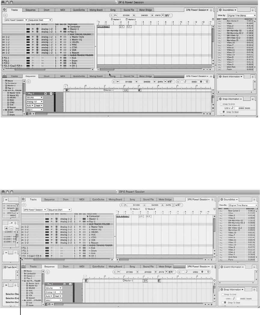
sidebar or main body section). If a sidebar is hidden, drag on its vertical sidebar divider (shown
in Figure 5.25). Similar to the main body section, which contains rows, the sidebars are divided
into individual cells. Drag on a sidebar’s horizontal divider to create additional cells or to hor-
izontally resize a cell or reveal more cells.
Figure 5.24 Drag on the main body section’s horizontal divider to add or remove rows from the Con-
solidated Window.
Vertical Divider
Figure 5.25 Drag on a sidebar’s vertical divider to reveal the sidebar.
142 Digital Performer 6 Power!: The Comprehensive Guide
Working with Rows and Cells. Digital Performer provides various ways to control the Consoli-
dated Window’s rows and cells. Remember, rows or cells that are currently selected (also called
the focus) will appear with the title bar slightly darker.
nTo open a new row or cell: Drag upward on the main body section’s or the main side-
bar’s horizontal divider to create a new row or cell. As you locate your pointer on the
divider, an up and down arrow icon will appear, indicating a new row or cell is being
added. Keep in mind that to create a third row or cell (provided your preferences are set
to three or more), you must drag on the lowermost main body section’s or lowermost
sidebar’s horizontal divider to create the newest row or cell. Rows and cells, when
added by the dragging method, appear according to the order of the Tabbed Section
(from left to right) and the Window Selector List (from top to bottom).
nTo close an existing row or cell: Click on the desired window’s Close button, located at
the leftmost part of the title bar. If the particular row/cell is in focus, you can also use
the Close Cell command (choose Close Cell from the Windows menu) or the default
keyboard shortcut CommandþW. You can also simply drag the horizontal dividers of
any row or cell (except the uppermost row or cell) to the bottom of the main Con-
solidated Window or sidebar to delete.
nTo open/close the left or right sidebar: Double-click the sidebar’s vertical divider, drag
the divider away from the main body section, or choose Open/Close Left (or Right)
Sidebar from the Windows menu.
nTo vertically resize a sidebar: Vertically drag on the sidebar’s divider.
nTo focus a row or cell: Simply click on the title bar or any area within a particular row
or cell. A window that is in focus will appear with its title bar shaded darker.
nTo resize a row or cell: To horizontally resize a row or cell, drag on its horizontal
divider. To resize vertically, click and drag on the sidebar dividers.
nTo pop out a row or cell from the Consolidated Window: Double-click the empty space
in the Tab (title) bar of the cell or row. The cell or row will “pop” out in a separate
window. You can also use the default keyboard shortcut Controlþ1 to pop out a
focused row or cell.
nTo force a separate window back into the Consolidated Window: Double-click the
empty space in the Tab (title) bar, and the window will return to the sidebar or row
of the Consolidated Window.
The Preferences and Settings Command
Digital Performer’s Preferences and Settings window, shown in Figure 5.26, provides options for
customizing DP. Choose Digital Performer 4Preferences to open the Preferences and Settings
window. The settings found here are global and affect all DP files.
Chapter 5 Project Management: Part 1 143
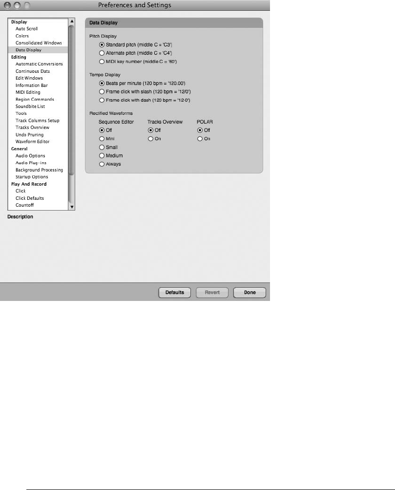
Preferences are listed on the left side of the window. Once a preference option is selected (high-
lighted), its various settings will appear to the right (in the main section of the window). In this
section, you can position the cursor over a setting to see its description listed below, in the
Description area.
If you have made changes to the current preferences and you need to return to the previous
settings, click the Revert button. Keep in mind that once you click the Done button and close
the Preferences and Settings window, the Revert button will no longer remember the previous
settings and will not be able to undo or revert to the last changes made before the window was
closed. Use the Defaults button to restore the preferences to their factory default settings. Be
aware that this change is instantaneous and cannot be undone.
Preferences in Older Versions of DP DP has consolidated most of the preferences and set-
tings into the Preferences and Settings window, though many of these settings can still be
accessed via DP’s various menus. Users working with older versions of DP may find that
Figure 5.26 Digital Performer’s Preferences and Settings window.
144 Digital Performer 6 Power!: The Comprehensive Guide
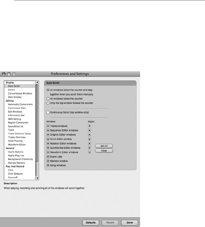
many of the preferences discussed in this chapter do not apply to them, since they are new
additions introduced in version 6.
Display Preferences
The Display preferences provide options for controlling auto scrolling, colors, Consolidated
Windows, and data display settings.
Auto Scroll. The Auto Scroll preferences, shown in Figure 5.27, provide a centralized location
for controlling how and if DP’s various windows will scroll, whether a particular window’s
Playback Wiper will be visible, and what type of auto scrolling is used—paging or continuous
scrolling. Be aware that auto scrolling will only affect the windows that relate to the currently
play-enabled sequence or Chunk.
nAll Windows Follow the Counter and Stay Together When You Scroll Them Manually.
This option basically forces all windows to scroll together during playback and
recording, stopping, rewinding, fast-forwarding, or when performing any type of cueing
Figure 5.27 Digital Performer’s Auto Scroll preferences.
Chapter 5 Project Management: Part 1 145
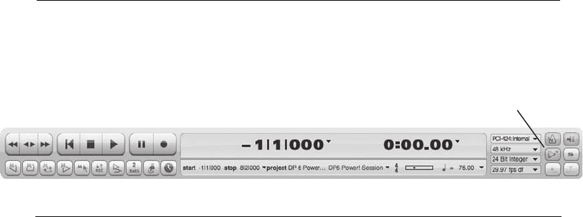
function. Windows will also scroll together when dragging the Playback Wiper or
horizontal scroll bar to manually scroll a window.
nAll Windows Follow the Counter. This is the same as the first option, with the exception
that the windows will not scroll together when you are scrolling a window manually.
nOnly the Top Window Follows the Counter. This option will only scroll the topmost
window within a sequence, providing the extra benefit of reducing the amount of
processor load put on Digital Performer when scrolling. Depending on the speed of your
computer, you may find this option improves the responsiveness of DP when scrolling is
enabled.
nContinuous Scroll (Top Window Only). With this option turned off, DP will scroll win-
dows one “page” at a time. This feature is referred to as page scrolling or paging. When
the Playback Wiper reaches the last measure or event in a window, DP will automati-
cally jump to the next measure or data event and update the window display, sort of like
turning a page in a book.
When the Continuous Scroll option is enabled, DP will continuously scroll the topmost
window smoothly from left to right, with the Playback Wiper centered in the window. If
you want to move the Playback Wiper away from the center of the window when scrolling,
you can press the Option key while dragging the Playback Wiper to the left or right.
nWindow. Use the Window section to enable or disable auto scrolling for a specific win-
dow type.
nWiper. This option determines whether the Playback Wiper is visible in a particular window.
nSet All. Click this button to enable all the options in both the Window and Wiper
sections of the Preferences and Settings window.
nClear. Click this button to quickly disable auto scrolling and Playback Wiper
visibility for all windows.
Using a Window Title Bar’s Auto Scroll Button You can also click on the Auto Scroll button
located on the Control Panel within a window’s title bar, shown in Figure 5.28, to manually
turn off/on auto scrolling. This saves you the hassle of calling up the Preferences and Settings
window if you need to temporarily enable or disable auto scrolling.
Auto Scroll Button
Figure 5.28 Click on the Control Panel’s Auto Scroll button to quickly enable or disable auto scrolling.
146 Digital Performer 6 Power!: The Comprehensive Guide
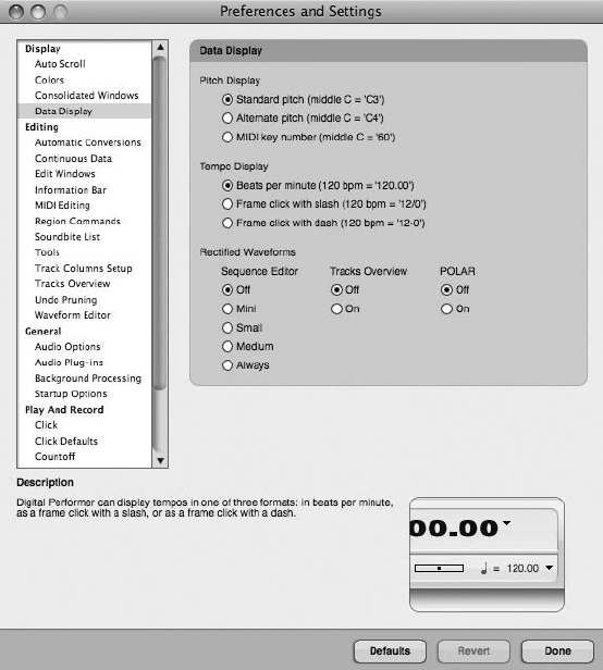
Colors. The Colors preferences are explained later, in the “Track Colors” section of this chapter.
Consolidated Windows. The Consolidated Windows preferences were explained earlier, in
“The Consolidated Window” section of this chapter.
Data Display. The Data Display preferences, shown in Figure 5.29, control how certain types of
data are displayed within Digital Performer.
nPitch Display. This option allows you to determine how octaves are numbered and
displayed in a project.
nTempo Display. This option determines whether tempo is displayed as beats per minute
(BPM) or as frame clicks.
nRectified Waveforms. This option will force DP to display only the positive arc of an
audio waveform, allowing the information to be shown in half of the vertical space
(see Figure 5.30). The Mini, Small, or Medium option will display waveforms rectified
Figure 5.29 The Data Display preferences.
Chapter 5 Project Management: Part 1 147
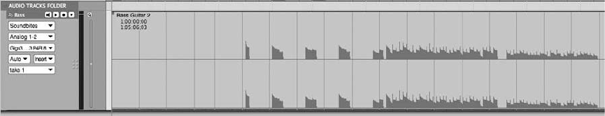
when a specific size of track is selected. Checking the Medium option, for example,
will display a track’s waveforms rectified when a vertical track size of medium or
smaller is selected. Separate options for displaying rectified waveforms within the
Tracks and Polar windows are also provided.
Editing Preferences
The Editing preferences provide options for controlling how the Automatic Conversions option
behaves, how information is displayed in DP’s various editor windows, how the Tool palette
functions, how to work with Undo Pruning settings, and so on.
Automatic Conversions. The Automatic Conversions preferences provide options for control-
ling how and if audio is automatically converted when the material in question does not conform
to the project’s current tempo or sample rate. See Chapter 7, “Recording Audio,” for an expla-
nation of the Automatic Conversions preferences in DP.
Continuous Data. The Continuous Data preferences control the display of continuous data
within DP’s various MIDI Graphic Editors. See the “MIDI Editing in the Graphic Editor” sec-
tion of Chapter 10, “Editing,” for an explanation of continuous MIDI data and the Continuous
Data preferences.
Edit Windows. The Edit Windows preferences, shown in Figure 5.31, control how DP handles
partial measures, the display of grid lines within an edit window, and which specific editor will
open by default when you are working with specific types of data.
nFix Partial Measures Automatically. Partial measures are bars that contain an incom-
plete number of beats. A partial measure is created when a meter change is inserted in
the middle of a bar. This happens because meter changes will always create a new
measure, essentially truncating the measure in the process.
When the Fix Partial Measures Automatically option is checked, DP will automatically
remove any partial measures by moving meter events as needed when a project is
opened. You may need to check any MIDI data to make sure it aligns with the read-
justed meters the way you want it to. Be sure to uncheck this option if you want to have
partial measures remain within a project.
Figure 5.30 Rectified waveform display.
148 Digital Performer 6 Power!: The Comprehensive Guide
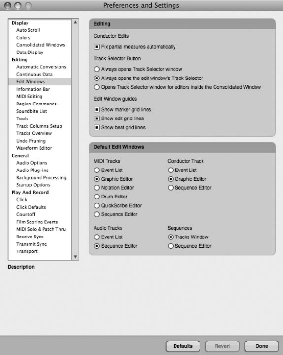
nTrack Selector Button. This setting determines how each edit window’s Track Selector
button will behave. For example, you can choose to have a separate Track Selector
window open rather than the traditional manner of being attached to the left side of the
edit window.
nEdit Window Guides. Enable these options to turn on marker and edit grid lines within
an edit window, or beat grid lines within an audio track that has been analyzed with
DP’s Beat Detection Engine (BDE). Grid lines can be useful for making precise edits or
moving around data that needs to conform to a specified grid. See Chapter 10 for an
explanation of grid lines within DP.
nDefault Edit Windows. This option determines which editor window opens when you
double-click on a track.
Figure 5.31 Digital Performer’s Edit Windows preferences.
Chapter 5 Project Management: Part 1 149
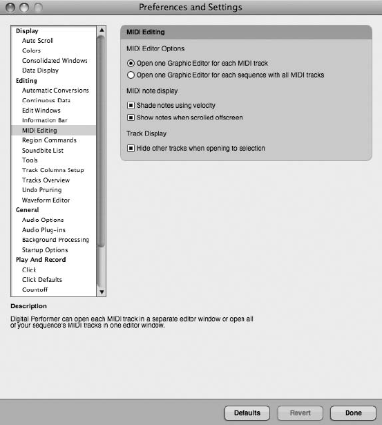
Information Bar. Discussed in Chapter 3, this preference window allows you to designate how
(or if) Cursor, Event, Selection, and Grid Snap information will appear in the information
“strip” of each edit window.
MIDI Editing. The MIDI Editing preferences determine what happens when you double-click on a
MIDI track for editing and how MIDI notes are displayed in a track, as shown in Figure 5.32.
nOpen One Graphic Editor for Each MIDI Track. This option will force a separate editor
window to open for each MIDI track that only displays the data for that track.
nOpen One Graphic Editor for Each Sequence with All MIDI Tracks. This option will
open a global editor window capable of displaying multiple MIDI tracks.
nShade Notes Using Velocity. Enable this option if you want MIDI notes to be shaded
according to their velocity. The higher the velocity, the darker the color will be, and vice
versa.
Figure 5.32 Digital Performer’s MIDI Editing preferences.
150 Digital Performer 6 Power!: The Comprehensive Guide
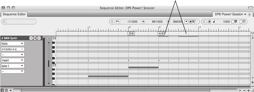
nShow Notes When Scrolled Offscreen. When a MIDI note appears outside the currently
displayed pitch range of a MIDI track, DP will show a small bar at the top or bottom
border of a track, as shown in Figure 5.33.
Region Commands. This setting affects the behavior of Region menu command windows, such
as Quantize or Change Velocity. DP allows only one Region menu command window to be open
at a time, but you can decide how you want the windows to be presented. For example, if you
need to change the MIDI velocities of several different tracks, you can elect to have the Velocity
command window stay open. This eliminates the need to reopen the window as you change
velocities of each track.
nApply Closes Window. Choose this option if you want command windows to close
when you click the Apply button or press Enter.
nApply Sends Window to Back. Choose this option if you want to keep command win-
dows open when you click Apply or press Enter, but you would like to send them to the
back (of other windows).
nApply with Enter Key Sends Window to Back. Choose this option if you want command
windows to stay open when you click Apply or go to the back when you press Enter.
Soundbite List. The Soundbite List Columns Setup preferences determine which specific col-
umns will appear in the Soundbites window. Refer to Chapter 3 for an explanation of Digital
Performer’s Soundbites window.
Offscreen MIDI Notes
Figure 5.33 MIDI notes that appear outside the currently displayed pitch range of a MIDI track will
appear as a small bar when the Show Notes When Scrolled Offscreen option is enabled in the MIDI
Editing section of the Preferences and Settings window.
Chapter 5 Project Management: Part 1 151
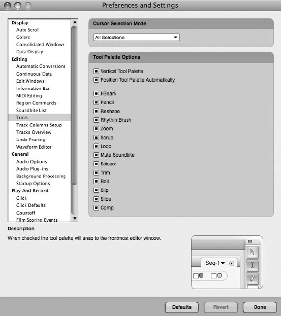
Tools. The Tools preferences, shown in Figure 5.34, determine how Pointer tool selections are
executed and how the Tool palette functions in DP.
nCursor Selection Mode. This menu allows you to specify how Pointer tool selections
function within the Tracks Overview or the Sequence Editor. See Chapter 10 for an
explanation of the Pointer tool and Pointer tool selections in Digital Performer.
nVertical Tool Palette. Click this option to force the Tool palette into a vertical position
when opened. You can use the keyboard shortcut OptionþShiftþ’ to toggle between
vertical and horizontal positions. Once this shortcut is activated, the Tool palette will
automatically dock to the edge of the frontmost edit window.
nPosition Tool Palette Automatically. This option will force the Tool palette to automat-
ically dock with the frontmost edit window. When horizontal, it will snap to the bottom
or top edge of the window. A vertical position will force it to the left or right edge of the
window.
Figure 5.34 Digital Performer’s Tools preferences.
152 Digital Performer 6 Power!: The Comprehensive Guide
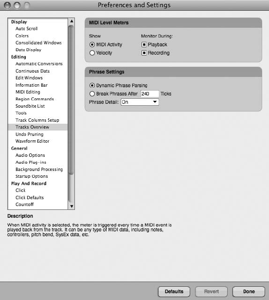
nTool Palette List. This option lets you choose which tools are displayed in the Tool
palette. Keep in mind that the keyboard shortcuts used to select a specific tool will
continue to function even when they are hidden from the Tool palette.
Track Columns Setup. The Tracks List preferences are used to show or hide specific columns in
the Tracks window. Refer to Chapter 3 for an explanation of the Tracks window.
Tracks Overview. The Tracks Overview preferences (shown in Figure 5.35) provide options for
controlling MIDI level meters and the phrasing of MIDI data that appears in the Tracks Over-
view window. Refer to Chapter 3 for an explanation of MIDI phrasing in the Tracks Overview
section of the Tracks window.
nShow MIDI Activity or Velocity. MIDI level meters can display either MIDI data or
note-on velocity. Choose MIDI Activity to trigger the MIDI level meter every time a
MIDI event occurs. Choosing Velocity will trigger the MIDI level meter and display the
note-on velocity of each MIDI note that is played back.
Figure 5.35 Digital Performer’s Tracks Overview preferences.
Chapter 5 Project Management: Part 1 153
nMonitor during Playback or Recording. Use these two options to enable or disable
MIDI level metering during the playback and/or recording process. If you are work-
ing on a slower Mac, you may find that disabling the MIDI level meters will make your
DP system more responsive during playback and recording.
nDynamic Phrase Parsing. Click this option to turn on DP’s Dynamic Phrase Parsing
feature, which will automatically control how MIDI data is phrased and placed into
blocks in the Tracks window. Review Chapter 3 for an explanation of MIDI phrasing
and MIDI blocks.
nBreak Phrases After ____ Ticks. This option provides a simpler approach to MIDI
phrasing by allowing you to specify the amount of empty space (specified in MIDI ticks)
that must be present before a MIDI block ends and a new one begins.
nPhrase Detail. This option determines how much detail and priority is given to the data
that is displayed in a MIDI block. Operations such as scrolling and zooming, which
cause DP to redraw data in the Tracks Overview, are directly impacted by the Phrase
Detail setting, and vice versa. The Phrase Detail options are as follows:
nOn. This setting will give phrase detailing a high priority and will always be com-
puted before any screen redrawing occurs. This option produces the best visual
results but also results in the slowest screen redraws.
nOn Demand. This setting will cause DP to only display the outline of blocks when
screen redraws are occurring. Once they are completed, DP will fill in the detail of
the blocks. Though not as visually impressive, this option strikes a nice balance
between high detail and responsiveness.
nOff. Select this option to completely turn off phrase detailing. Blocks are instead
filled with a generic pattern. This setting provides the most responsiveness, though
it sacrifices all the detail within a block.
Undo Pruning. The Undo Pruning preferences provide controls for determining how Digital
Performer’s Undo History windows manage overall disk space and RAM consumption, as
well as the number of undoable actions that are remembered within a project. See Chapter 6,
“Project Management: Part 2,” for an explanation of the Undo History windows and their Undo
Pruning preferences.
Waveform Editor. The Waveform Editor preferences allow you to control how stereo audio
waveforms are displayed, whether edits will be automatically crossfaded, and whether
Stereo/Mono Conversion settings will be applied when mono material is pasted into a stereo
file and vice versa. See Chapter 13, “Processing and Mastering,” for an explanation of the Wave-
form Editor and the Waveform Editor preferences.
154 Digital Performer 6 Power!: The Comprehensive Guide
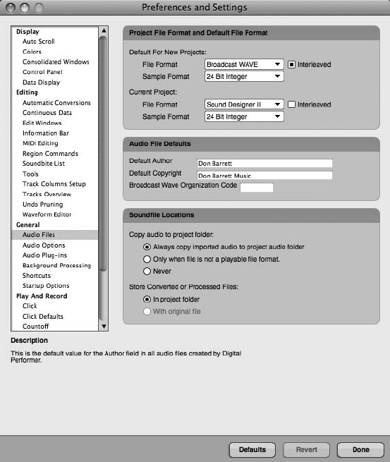
General Preferences
The General preferences contain options for controlling audio recording, the locations of
imported or processed audio files, background processing, and basic startup options.
Audio Files. These settings, as shown in Figure 5.36, affect how audio files are recorded and
managed and whether DP presents a warning when the processor overloads and playback is
interrupted.
nProject File Format and Default File Format. These determine a default sample format
(discussed later in this chapter) for new audio files created in Digital Performer projects
or a different sample format for the current project. Currently, DP works with 16-bit,
24-bit, and 32-bit floating-point sample formats.
Figure 5.36 Digital Performer’s Audio Files preferences.
Chapter 5 Project Management: Part 1 155

Bit-Depth Basics Let’s get slightly technical for a moment. Just as the frequency range of
recorded audio is determined by the sample rate (such as 44.1k), the dynamic range
(potential loudness or softness) of recorded audio is determined by the sample format,
otherwise known as bit depth. If you choose to record your audio at a higher sample
format, such as 24-bit, you are, in essence, increasing the dynamic range of the recorded
audio by a theoretically determined number of decibels (dBs) per sample. Unlike 16-bit
and 24-bit, however, 32-bit floating-point is not “fixed” to a theoretical maximum
dynamic range. Think of it as 24-bit plus a scaling factor that allows a much larger
range of values, from very small to very large. Many who work with digital audio prefer
higher bit depths because they can hear a larger dynamic spectrum of their recorded
tracks. Keep in mind that using higher bit depths (and sample rates) requires more hard
disk space for audio files!
nAudio File Defaults. Here is where you can define the default author, default copyright,
and Broadcast Wave Organization Code (if applicable) of all audio files created in your
projects.
nSoundfile Locations. These settings determine where imported, processed, and converted
audio will be stored in a project. See the “Importing Audio” section of Chapter 7 for an
explanation of the Soundfile Locations preferences.
Audio Options.
nShow Alert When Playback Overloads the Processor(s). Enabling this option will cause
a warning dialog box to appear when a lack of system resources interrupts playback.
nShow Alert When Disk(s) Can’t Keep Up with Record. Choosing this option will cause a
warning dialog to appear when a lack of system resources interrupts recording.
nMultiRecord Is Always On for Audio Tracks. When this option is checked, you can
simultaneously record-enable two or more audio tracks. Disabling this option, how-
ever, will allow only one track to be armed for recording at a time.
Audio Plug-Ins. This section of DP’s Preferences and Settings is where you can manage all of the
plug-ins installed in your system (see Figure 5.37). Remember, audio plug-ins are software units
that are installed separately and then “plugged in” to DP, such as processing effects or virtual
instruments (discussed in Chapter 9, “MIDI: The Region Menu, Plug-Ins, and Virtual Instru-
ments,” and Chapter 13). The settings in this window allow you to enable, disable, or reexamine
any or all of your plug-ins. You can create custom sets that include your favorite or most-used
plug-ins. This can be very helpful on projects where you want to save processing power or if you
have a lot of plug-ins and you don’t want to wait for all of the plug-ins to load. This window is
also the place to choose whether your plug-ins will run in real time or will be generated ahead of
156 Digital Performer 6 Power!: The Comprehensive Guide
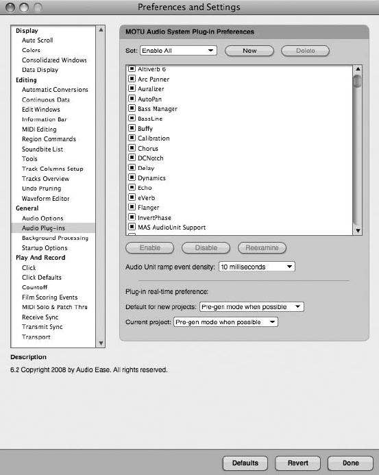
time with DP’s Pre-Gen feature. Consult the Digital Performer User’s Guide for more details
regarding the Audio Plug-Ins preferences.
Background Processing. These settings affect how background processing occurs in Digital
Performer. See Chapter 13 for an explanation of DP’s Background Processing feature and the
Background Processing preferences.
Startup Options. The Startup Options preferences control what happens after Digital Performer
is launched, as shown in Figure 5.38.
nNone. Once Digital Performer is launched, no window or dialog box will appear and
prompt you to open or create a new project. Only DP’s menu bar will be visible at the
Figure 5.37 DP’s new Audio Plug-Ins preferences allow you to manage all of your audio plug-ins.
Chapter 5 Project Management: Part 1 157
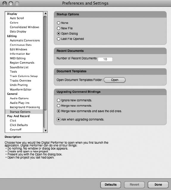
top of the screen. Choose Open or New from the File menu to begin working on a
project.
nNew File. The New Project dialog will automatically open when DP is launched,
allowing you to create a new project.
nOpen Dialog. This setting will launch the Open dialog, allowing you to choose a DP
project to open.
nLast File Opened. This will automatically open the last DP project you had open.
nRecent Documents. For quicker access, this is the number of previous projects DP will
list in the Recent Files option in the File menu.
nDocument Templates. This option provides simpler access to your Document Templates
folder, stored in User 4Library 4Preferences 4Digital Performer 4Document
Templates, discussed earlier in this chapter.
Figure 5.38 Digital Performer’s Startup Options preferences.
158 Digital Performer 6 Power!: The Comprehensive Guide
nUpgrading Command Bindings. This setting determines what happens to DP’s com-
mand key bindings (keyboard shortcuts) when you upgrade to a newer version of
Digital Performer.
Play and Record Preferences
The Play and Record preferences provide settings for controlling DP’s Click, Countoff, and Film
Scoring Events options, how MIDI Patch Thru and track soloing behaves, how DP’s synchro-
nization features operate, and how the Transport will respond in Wait mode.
Click. Click preferences allow you to configure Digital Performer’s click. Review the
“Setting Up a Click” section of Chapter 4 for an explanation of DP’s click options.
Click Defaults. This feature allows you to choose and/or create a specific click pattern for any
meter or tempo range. You can choose between beat values and beat patterns. In addition, you
can create your own customized beat patterns. DP will automatically use these default clicks
when the Click button is enabled and the sequence Conductor track matches the tempo range
and meter of the default click. Refer to the “Creating a Click Default” section of Chapter 4 for
more information regarding click default options.
Countoff. The Countoff preferences provide customizable settings for the countoff click, including
newly added visual aspects of the countoff. See the “Defining the Countoff” section of Chapter 4 or
see Chapter 15, “Scoring to Picture,” for more information regarding countoff options.
Film Scoring Events. Yet another new set of features (introduced in Digital Performer 5) is the
Film Scoring Events preferences (see Figure 5.39). Composers, conductors, and anyone working
with pictures generate streamers, punches, and flutters. These visual cues are superimposed on a
specified video screen and act as a reference to visual material. See Chapter 15 for more details
regarding Film Scoring Events.
MIDI Solo and Patch Thru. MIDI Patch Thru allows Digital Performer to “patch” or route
incoming MIDI data “thru” to any connected MIDI devices and/or virtual instruments. This
feature basically lets you hear your MIDI devices or instrument plug-ins when you play a
note on your MIDI controller. MIDI data will only be patched through to MIDI tracks that
have been record-enabled. The MIDI Solo preferences shown in Figure 5.40 determine how
soloed MIDI tracks function in DP.
nMIDI Patch Thru Mode - Off. This setting turns off MIDI Patch Thru all together.
nMIDI Patch Thru Mode - Direct Echo. Use this setting to echo incoming MIDI data on
the same channel it was received. So if DP is receiving MIDI data from Channel 16 of
your MIDI controller, for example, Digital Performer will echo or send that MIDI data
out on MIDI Channel 16. Data that is direct-echoed bypasses most of DP’s MIDI
processing and is unaffected by the Setup menu’s Input Filter settings. See Chapter 8,
“Recording MIDI,” for an explanation of the Input Filter window.
Chapter 5 Project Management: Part 1 159
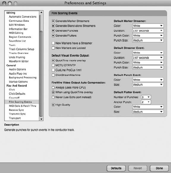
nMIDI Patch Thru Mode - Auto Channelize. This option is enabled by default and will
route MIDI data from your MIDI controller to the currently record-enabled track,
regardless of the MIDI device or virtual instrument to which the MIDI track is assigned.
Simply arm a track and play a note on your MIDI controller, and the data will be routed
to the MIDI device assigned to the output of the record-enabled MIDI track. If the MIDI
output of a track is assigned to a device group, all devices in the group will sound.
Unlike the Direct Echo setting, auto channelizing is directly affected by the Setup menu’s
Input Filter settings. Any MIDI data options that are disabled in the Input Filter window will
not be passed through to connected MIDI devices, device groups, or virtual instruments.
nPatch Thru in Background. Turn this option on if you need to continue to patch
through MIDI data even when DP is in the background and is not the currently
active application. When working with ReWire synths—such as Propellerhead’s Rea-
son, for example—this option allows you to play a note on your MIDI controller and
trigger a Reason instrument—even when DP is operating in the background.
nSync Recorded MIDI to Patch Thru. This option compensates for the small millisecond
delay that occurs when you are recording MIDI tracks via DP’s MIDI Patch Thru
Figure 5.39 The Film Scoring Events preferences window.
160 Digital Performer 6 Power!: The Comprehensive Guide
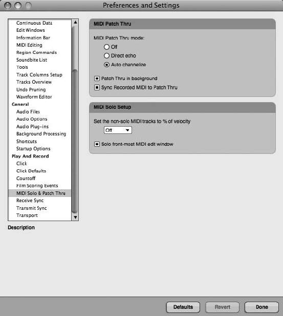
option, ensuring what you hear when recording your MIDI tracks will be what is heard
during playback. This option is unavailable if you have the Use CoreMIDI Patch Thru
option turned on.
nSet the Non-Solo MIDI Tracks to % of Velocity. Also called Partial Solo, this option
lets muted MIDI tracks actually be heard at a reduced volume when other tracks are
soloed. Click the Partial Solo pop-up menu to set the reduced percentage value or to
turn off partial soloing all together.
nSolo Front-Most MIDI Edit Window. This option determines what is soloed when solo-
ing a track in an editor window, such as the Sequence or Graphic Editor. When this
option is enabled, the track you are soloing is soloed by itself. When this option is
turned off, the soloed tracks will be determined by what is soloed in the Mixing Board
and how Solo mode is configured in the Tracks Overview section of the Tracks window.
Refer to Chapter 3 for an explanation of the Tracks window’s Solo Mode feature.
Figure 5.40 Digital Performer’s MIDI Patch Thru and MIDI Solo preferences.
Chapter 5 Project Management: Part 1 161
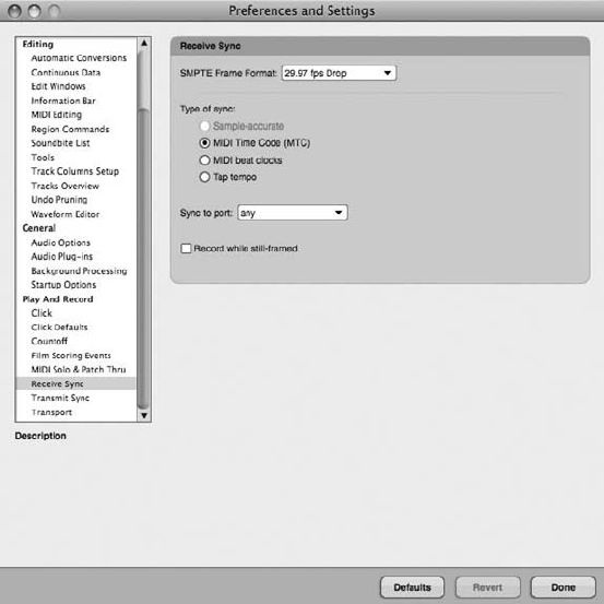
Receive and Transmit Sync. The Receive Sync and Transmit Sync preferences, shown in
Figure 5.41, control how DP’s synchronization features operate—whether DP will be transmit-
ting or receiving sync, and what type of source clock will be used in the synchronization process.
Refer to Chapter 2 for an explanation of DP’s Receive Sync and Transmit Sync commands.
Transport. This setting determines how the Control Panel (or Transport bar) will respond when
the Wait button is activated. When in Wait mode, the Transport can wait for a MIDI note to be
played or a controller message to be received, or it can wait upon any MIDI activity before it
starts recording or playback.
Window Sets
An often-overlooked feature of Digital Performer is the ability to create window sets. One of the
most daunting and overwhelming obstacles for even the advanced DP user is managing the var-
ious windows. This becomes even more apparent if you are short on screen real estate. Window
sets enable you to name, capture, and save window layouts, allowing you to instantly reconfig-
ure your Digital Performer workspace to suit your specific music-production needs. Even though
the default window sets provided with Digital Performer are all based on a Consolidated Win-
dow layout, you can use the Window Sets feature regardless of whether the Consolidated Win-
dow feature is turned on or off.
Figure 5.41 Digital Performer’s Receive Sync and Transmit Sync preferences.
162 Digital Performer 6 Power!: The Comprehensive Guide
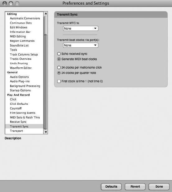
To recall an existing window set:
nChoose the desired preset from the Window Sets submenu (Windows 4Window Sets).
If you are working in the Consolidated Window, you can also access window sets from
the Consolidated Window mini-menu.
To save a window configuration layout:
1. Begin by arranging DP’s windows to your liking. Position them in the location that you
want them to appear when a window set is recalled.
2. Choose Windows 4Window Sets 4Capture Window Set.
3. Name the window set, as shown in Figure 5.42.
4. If you would like to assign your new window set to a desired hot key or custom key
binding (keyboard shortcut), click in the Key Binding input field and press a key on your
computer keyboard.
Figure 5.41 (Continued)
Chapter 5 Project Management: Part 1 163
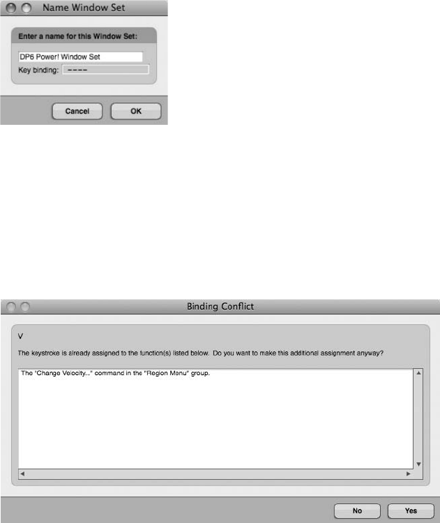
5. If the hot key is assigned to another command, a warning dialog will open, asking
whether you want to continue with the additional assignment (see Figure 5.43). Cus-
tom key bindings are explained later, in “The Commands Window” section of this
chapter.
6. Once named, click the OK button, and your window set will appear within the Window
Sets submenu, as shown in Figure 5.44.
To modify an existing window set:
1. Repeat the steps for creating a new window set.
2. When naming the set, however, choose the exact name of the window set you want to
modify.
Figure 5.43 When attempting to assign a key binding that is already in use by another command, DP
will present you with a warning dialog.
Figure 5.42 The Name Window Set window.
164 Digital Performer 6 Power!: The Comprehensive Guide
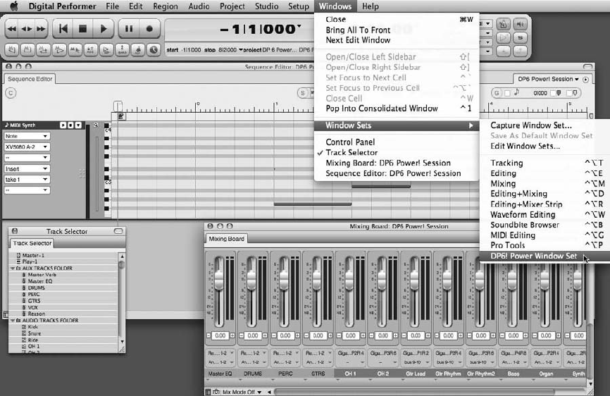
To delete or rename an existing window set:
1. Choose Windows 4Window Sets 4Edit Window Sets.
2. Select the window set you want to modify.
3. To rename the window set, click the Rename button and type the new name. Click OK
to confirm the change.
4. To delete the window set, click the Delete button. A warning dialog will open, asking
you to confirm the action. Click OK to delete the window set.
To change the order of window sets within the Window Sets menu:
1. Choose Windows 4Window Sets 4Edit Window Sets.
2. Click on the icon located to the left of the window set name and drag it up or down
within the menu.
Figure 5.44 The Window Sets submenu.
Chapter 5 Project Management: Part 1 165

To assign a keyboard shortcut (key binding) to an existing window set:
1. Choose Windows 4Window Sets 4Edit Window Sets.
2. Associated key bindings are listed to the right of each window set.
3. Click on the existing key binding or empty slot and enter the desired hot key (key
combination).
4. If the hot key is assigned to another command, a warning dialog will open, asking
whether you want to continue with the additional assignment. Click Yes to assign the
key binding.
Streamline the Window Sets Menu If the default window sets that appear in the Window
Sets menu don’t fit your production needs, you may want to think about deleting them all
together and starting from scratch. Having a menu that contains only window sets you
actually use will certainly be more helpful than a list full of window sets you never look at.
Of course, you don’t have to create your window sets in one sitting; simply create them
during the normal course of production, and you’ll have a menu full of useful window sets
in no time at all.
Track Colors
Another customization feature in DP is the ability to assign track colors. You can assign any
color you want to a single track, selected tracks, or tracks of the same type. This feature is just
another way to quickly distinguish between different tracks or track types within the various
editor windows. Colors within DP are grouped into color schemes (preset color groups), which
you can edit to suit your specific needs. You can also create your own color schemes by dupli-
cating and modifying existing ones.
Color Schemes
A color scheme is a set of colors that is displayed within Digital Performer’s Color palette pop-
up window. Stock color scheme presets are listed in the Colors submenu (in the Setup menu).
Simply choose a preset to change the color scheme for a project. You can also edit schemes by
choosing Setup 4Colors 4Edit Color Schemes. The Edit Color Schemes window provides you
with several options for customizing these presets (see Figure 5.45).
nEdit. Double-click on a color scheme, or select it and click the Edit button to modify
an existing preset. This will open the Color palette for the selected color scheme (see
Figure 5.46). Click to modify the color of a tile. This action will cause the Mac OS Color
Picker to open, allowing you to choose a specific color for the tile (see Figure 5.47). Only
the left- and right-most color tiles within the palette can be modified, however. You can
166 Digital Performer 6 Power!: The Comprehensive Guide
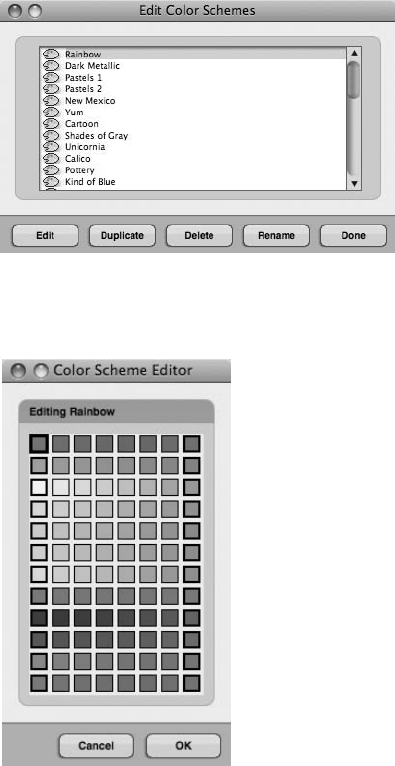
also change the position of these “heavy bordered” tiles by dragging with the mouse. DP
will automatically fill in the in-between tiles with a variable shade of the two colors.
nDuplicate. This option will duplicate the currently selected (highlighted) color scheme.
Once you choose a color scheme, you will be prompted to enter a new name for the
duplicated scheme (see Figure 5.48). Use this option when you want to create your own
preset. Once you have duplicated the scheme and given it a new name, select OK and
then click the Edit button to customize the preset.
Figure 5.46 Click the Edit Color Schemes dialog’s Edit button to modify the selected color scheme. Only
the left- and right-most color tiles (designated with a heavy border) can be modified.
Figure 5.45 The Edit Color Schemes window provides several options for modifying color schemes. The
currently selected scheme will be highlighted.
Chapter 5 Project Management: Part 1 167
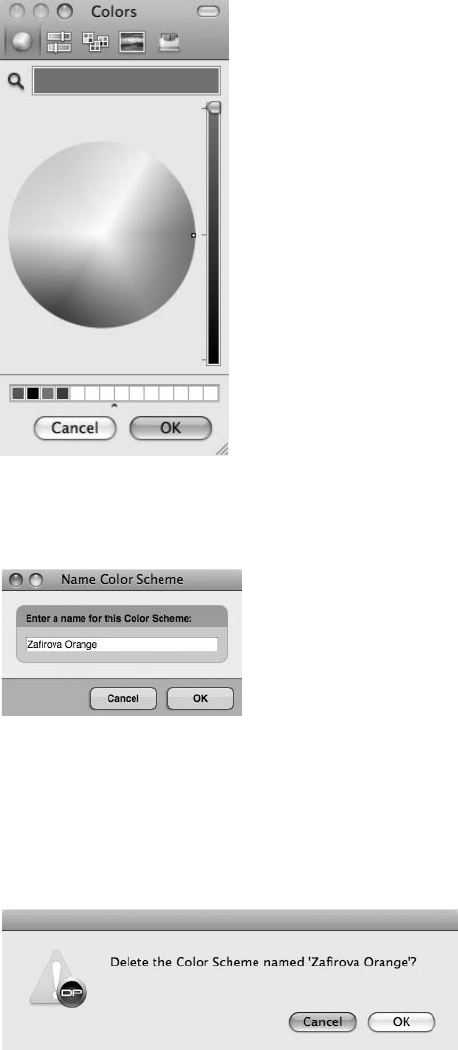
nDelete. Click this button to delete a color scheme. A warning dialog will open, asking
you to confirm the action (see Figure 5.49).
Figure 5.49 The Delete Color Scheme warning dialog.
Figure 5.47 Double-clicking on the left or right (heavy bordered) color tiles within a color scheme will
launch the Mac OS Color Picker.
Figure 5.48 The Name Color Scheme window.
168 Digital Performer 6 Power!: The Comprehensive Guide
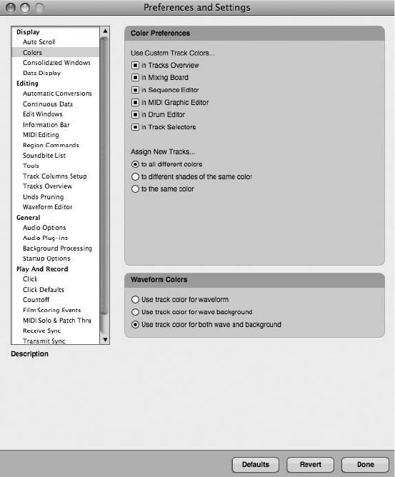
nRename. Click this button to rename a color scheme.
nDone. Click this button to close the Edit Color Schemes window.
Color Preferences
The Color preferences (Setup 4Colors 4Color Preferences or Digital Performer 4Preferences and
Settings) will affect how colors are used throughout DP’s various edit windows (see Figure 5.50).
nUse Custom Track Colors. These options allow you to specify whether custom colors
are used within Digital Performer’s various edit windows.
nAssign New Tracks. These options determine how custom colors are assigned to new
tracks. If you choose the To Different Shades of the Same Color or the To the Same
Figure 5.50 The Color preferences are located in the Preferences and Settings window.
Chapter 5 Project Management: Part 1 169
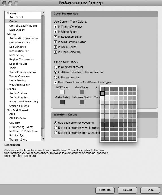
Color option, the Color preferences will update and display the Use Different Colors for
Different Track Types option.
nUse Different Colors for Different Track Types. When this option is unchecked, you
can change the specific color that will be assigned to a track by clicking on the Pick a
Color option. When this option is checked, however, DP will display multiple color
swatches, allowing you to choose a different color for each track type (see Figure 5.51).
Available colors will be determined by the currently selected color scheme.
nWaveform Colors. In Digital Performer 6, you can use these new options to designate
colors for audio waveforms, waveform backgrounds, or both. These color choices are
based on the colors you have chosen for each individual track.
Figure 5.51 The Use Different Colors for Different Track Types option. Once enabled, color swatches
for each track type will become available.
170 Digital Performer 6 Power!: The Comprehensive Guide
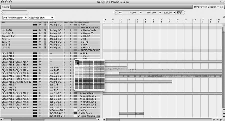
Changing the Colors of Tracks in the Tracks Window
To set the color for a track:
1. In the Tracks window, click on the color swatch of the desired track within the Color
column. A Color palette pop-up window will appear, as shown in Figure 5.52.
2. Click on a tile within the Color palette to assign the new color to the track.
3. If the Color column isn’t visible, choose Digital Performer 4Preferences and Settings 4
Track Columns Setup List and enable the Color column (see Figure 5.53).
To set the color for multiple tracks:
1. Select the tracks you want to affect. Remember to Shift-click to make multiple selections
if the tracks are adjacent (or simply click and drag up or down). Command-Shift-click
to select nonadjacent tracks.
2. Choose Setup 4Colors 4Assign Colors to access the Assign Colors window, as shown
in Figure 5.54 (or simply hold down the T key while changing the color for one of the
tracks, and the others will automatically change to the newly chosen color).
Figure 5.52 Click on a color swatch within the Tracks window’s Color column to assign a color to a
specific track.
Chapter 5 Project Management: Part 1 171
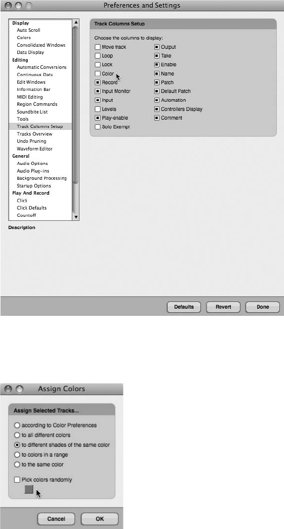
Figure 5.54 The Assign Colors command determines how colors are assigned to multiple tracks.
Figure 5.53 Click the Color option to make the Color column visible within the Tracks window.
172 Digital Performer 6 Power!: The Comprehensive Guide
3. As you select an option, a color button will appear, providing access to the color
swatch. Choose the option you want from the following:
nAccording to Color Preferences. This option allows you to make color assignments
according to the settings within the Colors preferences.
nTo All Different Colors. This option automatically assigns a color to the selected
tracks. Colors are determined by the current color scheme, starting with the begin-
ning color of the palette. Enabling the Pick Colors Randomly option will force colors
to be assigned in a random order.
nTo Different Shades of the Same Color. This option allows you to designate a specific
color from the Color palette. Once more, a Color palette will appear when this
option is selected. When a color is chosen for the first track, only colors from the
same palette row will be used for the other tracks within the selection.
nTo Colors in a Range. This option lets you select a start and end color from the
current Color palette. Once start and end colors are chosen, DP will cycle through
the in-between colors when making color assignments to the selected tracks.
nTo the Same Color. This option assigns all selected tracks to the same color.
nPick Colors Randomly. Enabling this option makes many of the above color assign-
ments happen in a random order.
The Commands Window
The Commands window, shown in Figure 5.55, provides a central location for accessing and
customizing Digital Performer’s extensive keyboard shortcut commands. You can even assign
specific MIDI events to functions within DP, which allows you to trigger commands from your
MIDI controller in place of the computer keyboard. Keyboard shortcuts within DP are called
key bindings.
Navigating the Commands Window
All commands within the Commands window are organized into logical groups. Click on the
disclosure triangle located to the left of the group name to view the commands within that
group. Option-click on a triangle icon to show or hide all command groups.
To search for a specific command:
1. Choose Setup 4Commands or use the default keyboard shortcut ShiftþL.
2. In the search field located at the top of the window, type in the command (or text string)
you want to find.
3. Click the Search button or press the Return key to begin searching.
4. DP will return the results by highlighting the appropriate command (see Figure 5.56).
Chapter 5 Project Management: Part 1 173
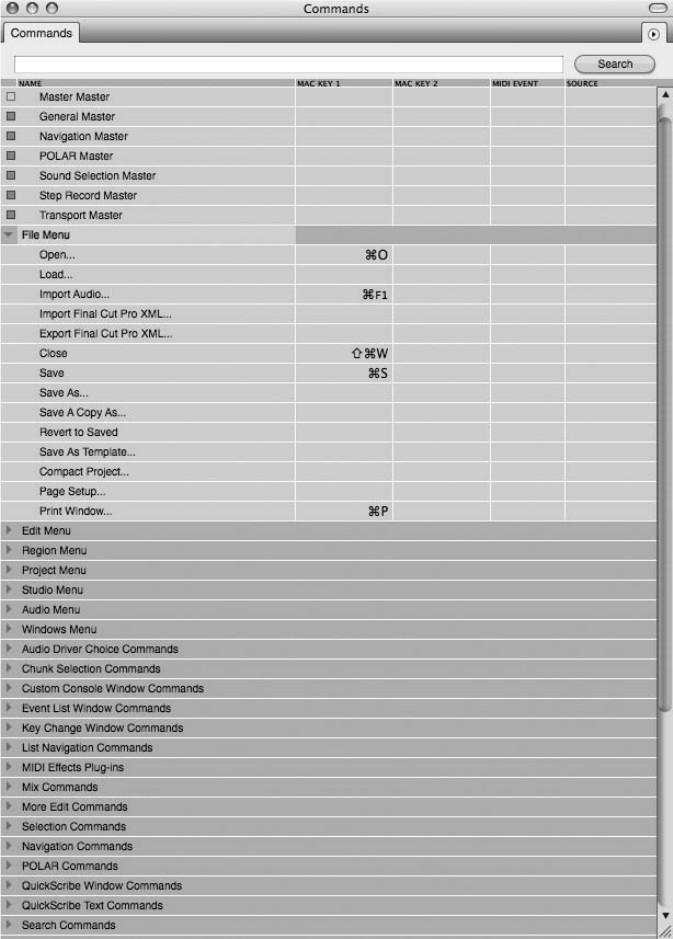
Figure 5.55 The Commands window provides a central location for accessing and customizing key
bindings in Digital Performer.
174 Digital Performer 6 Power!: The Comprehensive Guide
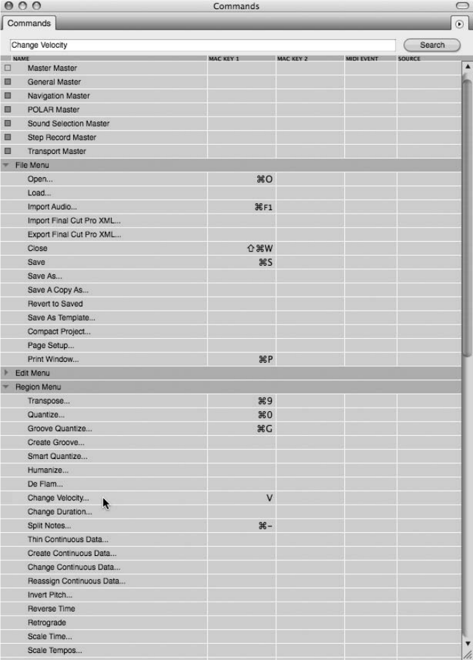
Figure 5.56 DP will return search results by highlighting the appropriate command within the
Commands list. In this example, the Change Velocity command has been searched for and found.
Chapter 5 Project Management: Part 1 175
To assign a keyboard shortcut (key binding) to a specific command:
1. Find the command you want to modify.
2. Click in the Mac Key column.
3. Press the desired key combination. It will be entered into the Mac Key column.
4. If the key binding you entered is already assigned to another command, a warning dia-
log will open, asking whether you want to proceed with the assignment.
5. You can assign two key bindings to a command by using both the Mac Key 1 and Mac
Key 2 columns.
To assign a MIDI event to a specific command:
1. Find the command you want to modify.
2. Click with the mouse in the MIDI Event column (located to the right of the Mac Key
columns).
3. Enter the MIDI event by pressing the appropriate key on your MIDI controller.
4. For even further customization, specify the MIDI source by clicking in the Source col-
umn and choosing the specific MIDI device.
Numeric Base Note
When entering numeric values for certain commands (recalling markers, for example), DP will
allow you to use your MIDI controller in place of the numeric keypad on your keyboard. To
properly take advantage of this feature, you must set the numeric MIDI base note by choosing
Set Numeric MIDI Base Note from the Commands window’s mini-menu. This option sets the
value for the base MIDI note or basically tells DP which MIDI note will correspond to the
number 1 key on your computer keyboard. If you choose C4, for example, a value of 1 will
be the C4 key on your MIDI controller. A value of 2 will be C#4, a value of 3 will be the
pitch D4, and so on.
To set the numeric base note value:
1. Choose Set Numeric MIDI Base Note from the mini-menu in the Commands window
(see Figure 5.57).
2. Specify the base pitch by pressing the appropriate note on your MIDI controller.
3. Click OK to confirm the change.
176 Digital Performer 6 Power!: The Comprehensive Guide
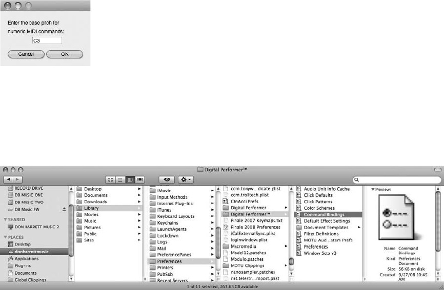
Key Bindings
Key commands in DP are called key bindings. A key binding can be a single key command or a
set of commands that are contained in a project. Project key bindings are saved in the Command
Bindings file located in the Digital Performer Preferences folder, as shown in Figure 5.58.
Key bindings can be exported out of or imported into a Digital Performer project, allowing you
to further customize the DP workspace. This allows you to create personalized key bindings that
you can save and open in another Digital Performer system, back up your key bindings, or save
them before importing a different set of commands.
To export a set of key bindings:
1. Choose Export Key Bindings from the mini-menu in the Commands window.
2. A standard Save dialog will open. Choose the destination for the new key bindings file.
3. Click the Save button to export the key binding.
To import a set of key bindings:
1. Choose Import Key Bindings from the mini-menu in the Commands window.
2. Choose the key bindings file you want to open.
Figure 5.58 Project key bindings are stored within the User 4Library 4Preferences 4Digital Per-
former 4Command Bindings file.
Figure 5.57 The Set Numeric MIDI Base Note command.
Chapter 5 Project Management: Part 1 177
3. Click Open.
4. Next, DP will open a dialog asking you either to merge any new custom bindings that
differ from the current set or to simply import the entire file and replace the current key
bindings.
5. Click on the desired button to import or merge the new key bindings.
Summary
Digital Performer has a number of feature sets that allow you to organize and customize your DP
projects. Each feature by itself may have only a limited impact on your workflow, but used in
combination, these features offer a powerful solution for managing the music production pro-
cess. The next chapter, “Project Management: Part 2,” will focus on the more complex Undo
History, audio management, and backup processes.
178 Digital Performer 6 Power!: The Comprehensive Guide

6Project Management: Part 2
In this chapter, we will dive deeper into the topic of project management within Digital
Performer 6. Here is a summary of topics discussed within this chapter:
nUsing DP’s Undo History windows
nEfficiently managing audio files and hard drive space
nUnderstanding your options and solutions for backup and archival of your DP projects,
including third-party software
The Undo History
Digital Performer supports unlimited undos and redos, which you can manage from the Undo
History windows. The are basically three Undo History windows in DP—the main project Undo
History, the Polar Undo History, and the audio files Undo History windows. The audio files
Undo History windows are unique in that each individual audio file in DP has its own indepen-
dent Undo History window. Each Undo History window provides you with a complete list of
actions, a timeline, and preferences for controlling undo behaviors. DP even supports unlimited
branching, which I’ll discuss later in this section. Every edit you make when working on a project
is remembered, unless you configure the Undo History preferences (called the Pruning preferences)
to do otherwise.
Though the main project Undo History window is found in the Edit menu, I’ve chosen to discuss
this feature within the “Project Management: Part 2” chapter of this book because of its direct
impact on the project management process. Many of the features that I will discuss in this chapter
require an understanding of the Undo History, the Pruning preferences, and their related terms.
I will cover undo commands contained within the Edit menu in detail in Chapter 10, “Editing.”
The Project Undo History
The project Undo History window (Edit 4Undo History) displays a complete list of edits made
within the project (see Figure 6.1). Besides the name of the action, other information, such as the
time, the date, and the amount of memory and disk space required to remember the action, is
listed. Although every action remembered will require a small amount of RAM, disk space is
179
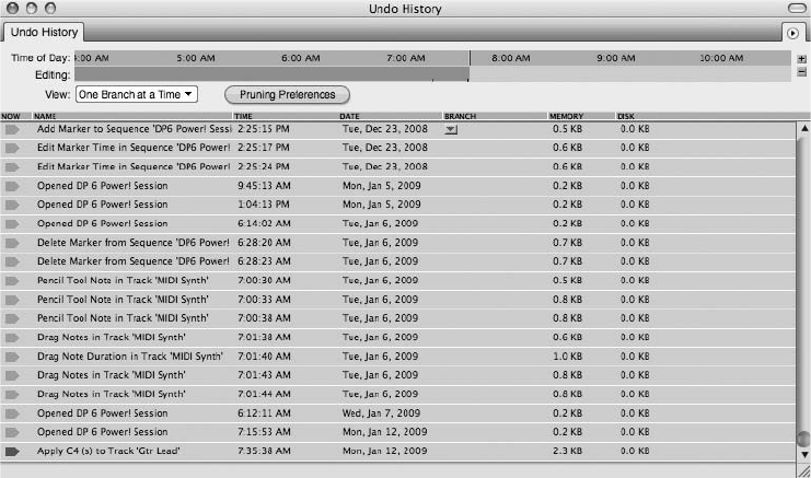
only needed for actions that require it in the first place, such as recording or disk-based
processing.
The Undo History Timeline
At the top of the Undo History window is the timeline. The Time of Day strip provides a linear
timeline that you can drag to the left or right to move backward or forward in time. Zoom
buttons (+/) located to the right of the strip let you magnify or shrink the timeline. The
green line or current action marker indicates the timeline position of the current action.
Directly below the Time of Day strip is the Editing strip. The white area represents the life of the
project, from the beginning to the most recent action. Actions are displayed as vertical lines. You
can click and drag vertically in this white area to quickly zoom within the timeline. Clicking
directly on a vertical action line will highlight it in blue and automatically locate the action
within the Undo History List for easy identification.
The Undo History List
The Undo History List is located below the timeline, in the main body of the Undo History
window. There are seven columns that provide important information about the listed actions.
nNow. A shaded arrow in this column represents the current action. Double-click in this
column next to an action to jump to that point in your project’s history. Actions that have
been undone are shaded in blue. This shaded arrow corresponds to the Time of Day strip’s
current action marker (the vertical green line).
Figure 6.1 The Undo History window.
180 Digital Performer 6 Power!: The Comprehensive Guide

nName. This column offers a brief description of the action. Customizing your project
beforehand by renaming your tracks, sequences, and sound files can help you quickly
identify an action.
nTime. This column shows the time the action occurred.
nDate. This column shows the day, month, and year the action occurred.
nBranch. This column indicates whether a branch has occurred within the Undo History
timeline. (I’ll explain branches shortly.) Branches are separated from other actions by heavy
lines. A branch menu, which is indicated by an inverted triangle, is displayed if One Branch
at a Time is chosen in the View pop-up menu.
nMemory. This column displays the amount of RAM needed to remember the action.
nDisk. This column displays the amount of hard drive space required to remember the action.
Only certain actions (such as recording and processing) will consume disk space.
Taking Advantage of the Name Column To speed up your navigation of the Undo History
List, be sure to rename your tracks, audio files, soundbites, and sequences with appropri-
ate, descriptive names. DP will add a brief description of the action within the Name col-
umn of the Undo History window, based on the name of the file in question.
For example, if your tracks are called Audio 1, Audio 2, Audio 3, and so on, then you may
wind up with an action called “recorded on track Audio 4,” or “edit fade in track Audio
5.” If you are working on a larger project, you may not remember offhand what track
Audio 4 is. Renaming your tracks something specific, such as Bass, may spare you the
task of searching by trial and error.
Branching
What sets Digital Performer’s Undo History apart from that of other applications is its support
for unlimited branching. You can think of branches as separate but dependent undo timelines, or
sets of actions. Here’s how branching works: Because Digital Performer remembers all of your
actions within a project, you can jump backward within the timeline (undoing the current
action) and begin a new set of actions (branch off), and DP will remember both sets of actions,
or branches. The new actions are basically “branching off” in a new direction, so to speak,
creating two branches in the process. The first branch is the set of undone actions and will be
represented in the Branch menu by heavy lines and a disclosure triangle, and it will be named
after the first undone action of the branch. The second branch is simply the new set of actions.
This branch point will be created where your new actions start.
When working with branches, the current active set of actions (the “not undone” actions) is
always considered the main branch. Any branches you are not working with will be undone.
Chapter 6 Project Management: Part 2 181
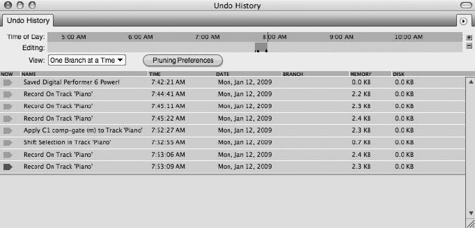
Keep in mind, “undone” really means removed from your set of actions (main branch) and not
“erased.”
Once you’ve created a branch, you can choose it by clicking on the Branch pop-up menu. When
you select another branch, its actions will be displayed in a shade of blue, indicating that the
branch is in an undone state. Double-click in the Now column next to the name of an undone
action to make the branch active. This branch will become the main branch again, and all other
branches will immediately disappear from the list and be marked as undone.
The Undo History in Action
The concept of branching can be difficult to grasp when you are just reading about it, so to
demonstrate better how it works, I’ll walk you through a hypothetical session, complete with
screenshots. It begins with the recording of a piano track.
1. First, I create a session called Digital Performer 6 Power! I record a few passes on the
piano track. I process the track with a Waves C1 comp-gate (m) plug-in compressor,
then record a few more passes. At this point in time, the Undo History looks like that in
Figure 6.2.
2. I decide to undo the processing from the piano track, so I double-click in the Now
column next to the Record on Track ‘Piano’ action—the one that immediately precedes
the Apply C1 comp-gate (m) to Track ‘Piano’ action (see Figure 6.3). I have now undone
all the actions needed to get back to the uncompressed piano track.
3. Next, I record a bass guitar track. This new action automatically creates a new branch
(or a new set of actions). The undone C1 comp-gate processing actions are preserved in
the first branch (see Figure 6.4).
Figure 6.2 The Undo History window for the example. The shaded arrow next to the most current
action in the Now column indicates that no actions have been undone.
182 Digital Performer 6 Power!: The Comprehensive Guide
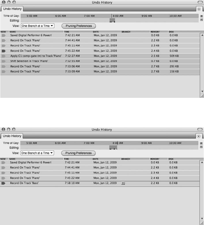
4. I record two more bass guitar passes, as shown in Figure 6.5.
5. Clicking on the Branch pop-up menu reveals the original undone C1 comp-gate proc-
essing, as shown in Figure 6.6. Selecting the C1 comp-gate branch displays the undone
actions, as shown in Figure 6.7.
6. In Figure 6.8, the C1 comp-gate branch has been made active again by double-clicking
in the Now column next to the last action of the C1 comp-gate branch. (The Bass
branch automatically becomes undone.) If you were to view the undone Bass branch, it
would look like that in Figure 6.9.
Figure 6.4 I record a bass guitar track, automatically creating a new branch. Branch points are indi-
cated by heavy lines and a disclosure triangle.
Figure 6.3 The Waves C-1 processing has been undone. Undone actions are shaded in blue.
Chapter 6 Project Management: Part 2 183
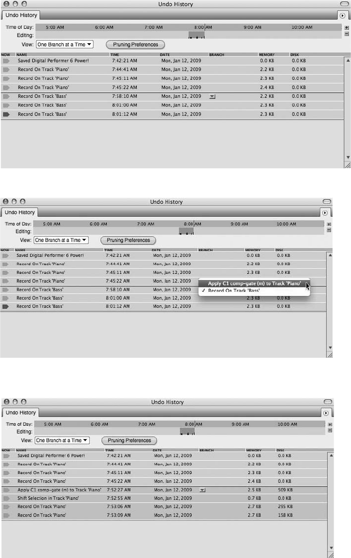
Figure 6.5 Two more bass guitar passes are recorded.
Figure 6.6 Clicking on the Branch menu reveals a check mark next to the currently selected main
branch, as well as the C1 comp-gate processing branch that has been undone.
Figure 6.7 Selecting the C1 comp-gate branch in the Branch menu displays the undone actions.
184 Digital Performer 6 Power!: The Comprehensive Guide
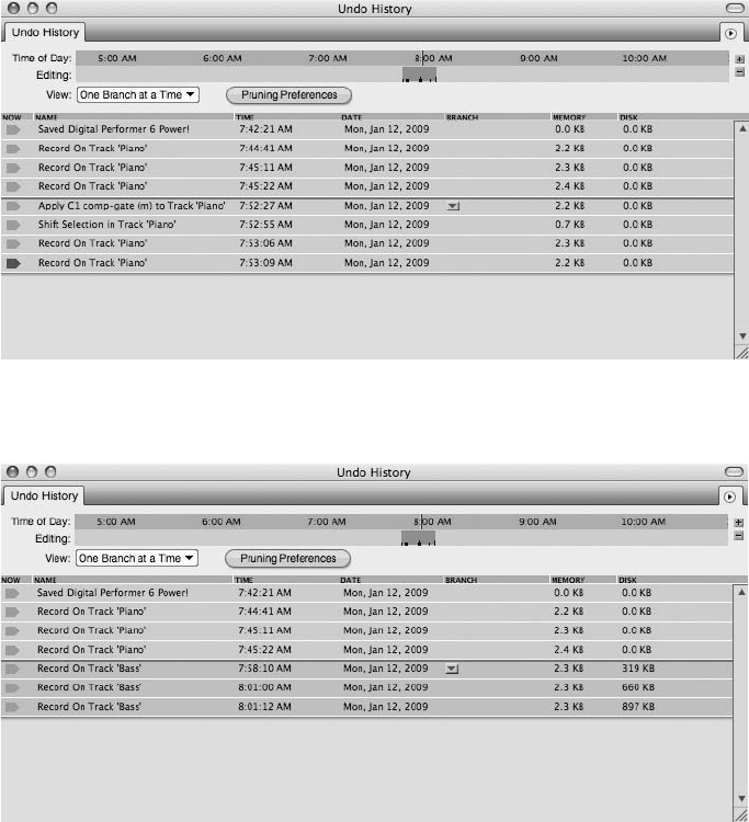
7. Next, I decide to undo both sets of actions, the original C1 comp-gate branch and the
newly created bass guitar recordings. To do this, I must double-click the Now column to
select the action just prior to the first Record on Track ‘Bass’ action (see Figure 6.10).
I now decide to record a vocal take (see Figure 6.11).
8. If you click on the Branch pop-up menu, you can see all three branches, as shown in
Figure 6.12. The check mark next to the Vox branch tells you that it is the main branch
and is currently active.
9. In Figure 6.13, you can see that I’ve recorded another vocal take. In the View drop-
down menu, however, I’ve selected All Branches at Once. Notice that the Branch menus
Figure 6.9 Selecting the Bass branch reveals that it has been undone.
Figure 6.8 The C1 comp-gate branch that was previously undone is made active again. Notice the
shaded arrow next to the most current action in the list. This branch has now become the main branch.
Chapter 6 Project Management: Part 2 185
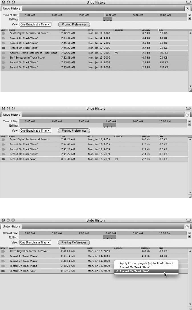
Figure 6.10 I have undone both branches by selecting the action just prior to the branch point.
Figure 6.11 I have recorded a new vocal (Vox) track, creating a third branch within the Undo History
timeline.
Figure 6.12 The Branch menu displays all three branches. The main, or active, branch is designated by a
check mark.
186 Digital Performer 6 Power!: The Comprehensive Guide
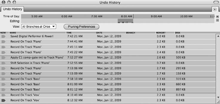
are no longer visible, and the non-active branches (which have been undone) are dis-
played shaded in blue and separated by heavy lines.
Managing the Undo History Windows
As a project progresses and DP begins to keep track of undone actions, branches, and so on, the
remembered actions will begin to consume precious RAM and disk space. Digital Performer
provides a number of features to customize the undo process. You can set up DP’s Undo History
windows to automatically manage themselves through the Pruning preferences. For example, if
you find that as you work, you never go back in your project timeline to undo an action that is,
say, two hours old, DP can discard or “prune” all actions that were made before the current
two-hour work period. You can also “prune” manually using the options provided within the
Undo History window’s mini-menu.
Pruning Preferences
Each Undo History window has its own independent preferences, located in the Undo Pruning
section of the Preferences and Settings window. These preferences allow you to establish a set of
criteria to automatically manage the amount of memory and disk space that the Undo History
windows can consume. You can access the Undo Pruning preferences from any one of DP’s
Undo History windows by clicking on the Pruning Preferences button (see Figure 6.14). You
can also choose Digital Performer 4Preferences.
Unlike the three Undo History windows, the Undo Pruning preferences are centralized in the
Preferences and Settings window. From the Undo Pruning section, use the Undo Pruning tabs,
shown in Figure 6.15, to set the Undo Pruning preferences for a specific Undo History window.
This Undo Pruning drop-down menu offers three options.
Figure 6.13 Selecting All Branches at Once in the View drop-down menu will display all actions within
all branches. Actions within a branch will appear grouped in chronological order.
Chapter 6 Project Management: Part 2 187
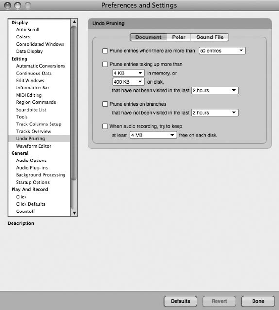
nDocument Undo Pruning Setup. Preferences for a project’s main Undo History window.
nPolar Undo Pruning Setup. Preferences for the Polar Undo History window.
nSound File Undo Pruning Setup. Preferences for audio file Undo History windows.
Within the Undo Pruning preferences, you have the following four options for controlling each
Undo History window:
nPrune Entries When There Are More Than. This setting limits the total number of entries
that will be remembered in an Undo History list.
nPrune Entries Taking Up More Than. This option is used to automatically discard (or prune)
any action that consumes a specific amount of memory and disk space and hasn’t been
visited within a set time. This option will affect actions within all branches.
Figure 6.14 Click the Pruning Preferences button in any of DP’s Undo History windows to open the
Undo Pruning preferences, located in the Preferences and Settings window.
188 Digital Performer 6 Power!: The Comprehensive Guide
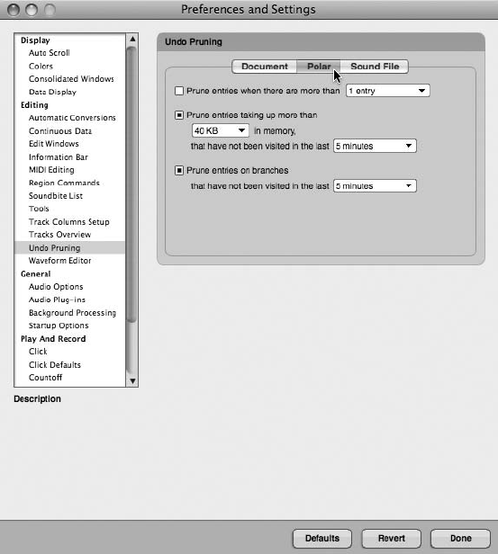
nPrune Entries on Branches. This option only affects actions that are on branches (that is,
actions that have been undone). This option will discard actions within branches that have
not been visited within a set amount of time. Actions on the main branch, or current actions,
will not be affected.
nWhen Audio Recording, Try to Keep. This option will discard actions when available hard
drive space falls below a specified value during the recording process. Actions that are fur-
thest back within the Undo History List will be pruned first.
Manually Pruning the Undo History from the Mini-Menu
Even though the Undo Pruning preferences can be set independently for each Undo History List
to automatically discard, or flush, actions, these settings are global and not project specific. For
even greater control, DP provides extra options for manually flushing each Undo History List.
These options are contained within the mini-menus of each Undo History window, as shown in
Figure 6.16, and can also be accessed from the Commands window.
Figure 6.15 Click on the Undo Pruning tabs to set the pruning preferences for a specific Undo History
window.
Chapter 6 Project Management: Part 2 189
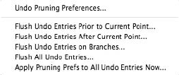
nFlush Undo Entries Prior to Current Point. This command will discard any entries, or
actions, that occur before the current action (the action designated with a shaded arrow in
the Now column).
nFlush Undo Entries after Current Point. This command will discard any entries that occur
after the current action.
nFlush Undo Entries on Branches. This command will discard entries on all branches that are
not part of the main branch. These are basically actions that have been undone.
nFlush All Undo Entries. This command will flush the entire Undo History List, so use it with
caution!
nApply Pruning Prefs to All Undo Entries Now. This command will immediately apply any
settings you have within the Undo Pruning preferences (minus any time settings) to all
actions within the Undo History window.
Following are a few points to keep in mind when working with DP’s manual flush commands:
nFlush commands always apply to the front-most Undo History window. If no window is
open, the commands will be applied to the project’s main Undo History window.
nIf the Polar Undo History window is in the foreground, then pruning commands will be
applied to the open Polar session.
nIf the Soundbites window is in the foreground, then pruning commands will be applied to
any selected parent audio files. Only the Flush All Undo Entries and Apply Pruning Prefer-
ences to All Undo Entries commands can be applied in this manner, however. To use the
other commands, open the Undo History window for the specific audio file.
Audio File Undo History Windows
Each audio file in DP has its own independent Undo History window, which can be accessed from
an audio file’s Waveform Editor (see Figure 6.17). This is one of the most overlooked components
of the Undo History because many users have yet to discover its versatility. What sets this Undo
History window apart from the main project and Polar Undo History windows is your ability to
modify or remove an action without affecting the actions that come after it. Modifications can be
made to plug-ins or to DSP processing that has been applied to an audio file.
Figure 6.16 Contained in each Undo History window’s mini-menu are controls for manually flushing
the undo entries and branches.
190 Digital Performer 6 Power!: The Comprehensive Guide
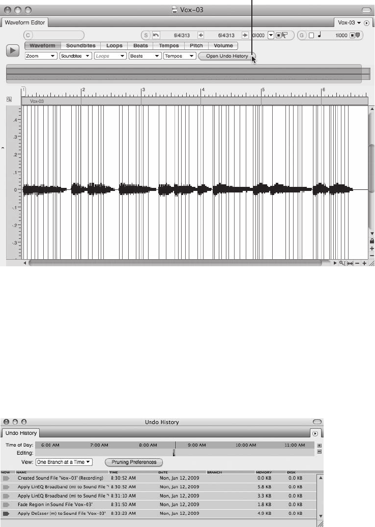
In the following example, a Waves LinEQ, fade, and DeEsser have been applied to a soundbite
called Vox-03. Because the file has been processed in the Waveform Editor, the actions are
stored within the audio file’s independent Undo History window, shown in Figure 6.18. To
modify the LinEQ action, simply double-click on the name of the action. This will reopen the
EQ plug-in window with the original settings used to EQ the Vox-03 soundbite. Make the nec-
essary changes to the EQ setting and reapply the effect.
The Waveform Editor’s Open Undo History Button
Figure 6.17 The Waveform Editor. Click on the Open Undo History button to open an audio file’s Undo
History window.
Figure 6.18 An audio file’s Undo History window.
Chapter 6 Project Management: Part 2 191
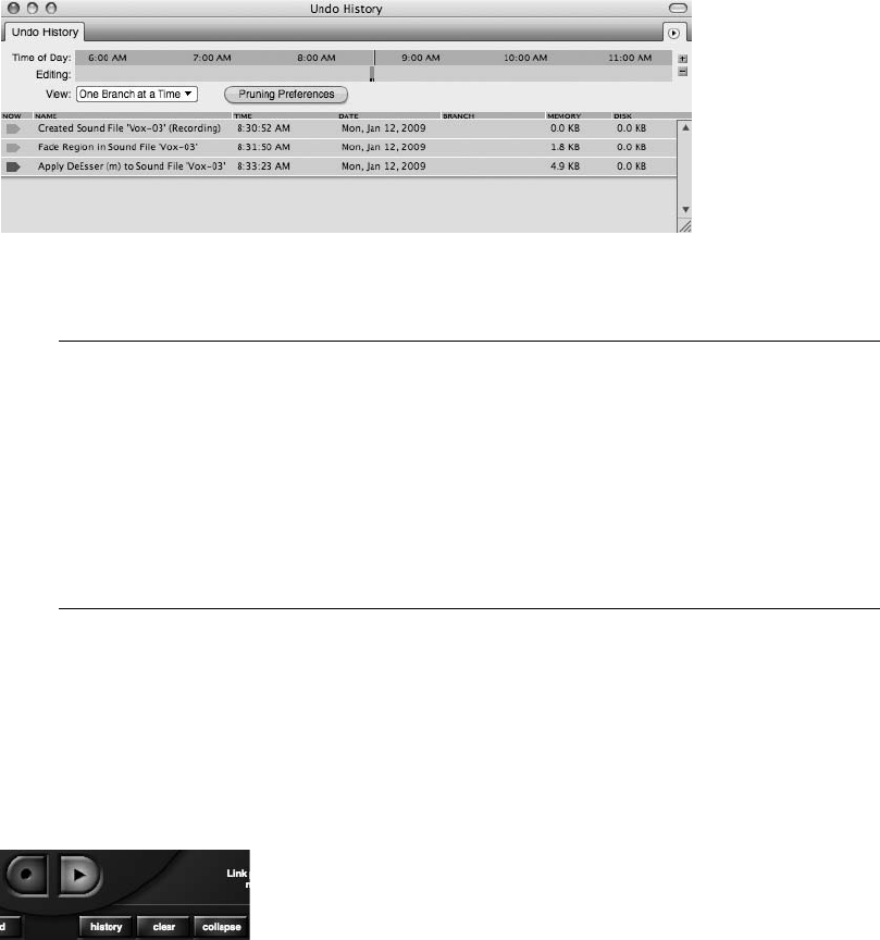
Keep in mind that modifications made to actions within an audio file’s Undo History List are not
undoable. To return to your original setting, you will need to reapply the effect. If you would
like to remove the action, click the name of the action and choose Edit 4Erase or press the
Delete key. Deleting an action will not affect actions that occur after it, as shown in Figure 6.19.
Once an action is removed, DP will essentially “fix” the audio file in order to reflect the change
that has been made.
Sequence Editor versus Waveform Editor It is important to understand that the indepen-
dent Undo History window for audio files applies only to those processing actions taken
from within an audio file’s Waveform Editor. Applying an effect to an audio file in the
Sequence Editor will redefine the sound file as “Created Sound File” in its Undo History,
and the effect cannot be modified or undone from this window. (You can, however, still
undo the action from the main Undo History window in the Edit menu.) In addition, any
processing performed on an audio file in the Sequence Editor will flush the file’s indepen-
dent Undo History in the Waveform Editor.
Polar Undo History Window
The Polar window also has its own independent Undo History window, as shown Figure 6.20.
The Polar Undo History works much like the project’s main Undo History. The Undo List
applies to the currently open Polar session. Unlike the other Undo History windows, however,
Polar Undo Histories are discarded when the Polar session is closed.
Figure 6.19 Deleted actions will not affect actions that come after it. Notice the Fade and DeEsser
actions have been left intact even though the preceding LinEQ actions have been removed.
Figure 6.20 Click the History button to open Polar’s Undo History window.
192 Digital Performer 6 Power!: The Comprehensive Guide
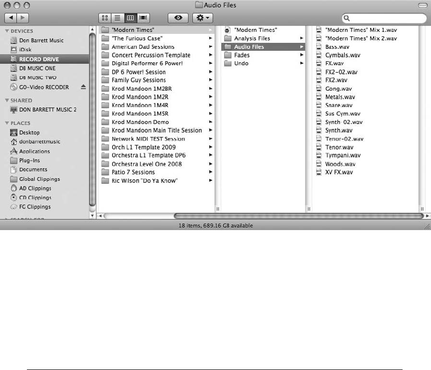
Managing Audio Files and Soundbites
By default, audio files in a new DP project are stored within the project’s Audio Files folder,
shown in Figure 6.21. This allows you to take a hands-off approach, relying on DP to automat-
ically place newly created take files in the proper location.
Changing the Location of Audio Files and Soundbites
Audio files do not have to be placed in this folder, however. They can be located within different
folders or even across multiple hard drives. You can change the location of your audio files
before the actual recording process or after audio has been placed within the Audio Files folder.
Digital Performer will automatically keep track of the audio files regardless of which folder or
hard drive they are moved to.
Understanding Soundbites and Regions It is important to know that soundbite is a term
synonymous with region. However, DP often uses the region term in an entirely different
context with regard to its Region menu. So, for the purposes of this discussion, regions and
soundbites are one and the same. And yes, DP’s mention of sound files simply refers to
audio files.
So, a soundbite is only a reference (or link) to a specific portion (or region) of a parent audio
file that exists on your hard drive. This region information (length of the soundbite—in
Figure 6.21 The project folder’s Audio Files folder. Here we see audio files with the .wav extension new
to version 6.
Chapter 6 Project Management: Part 2 193
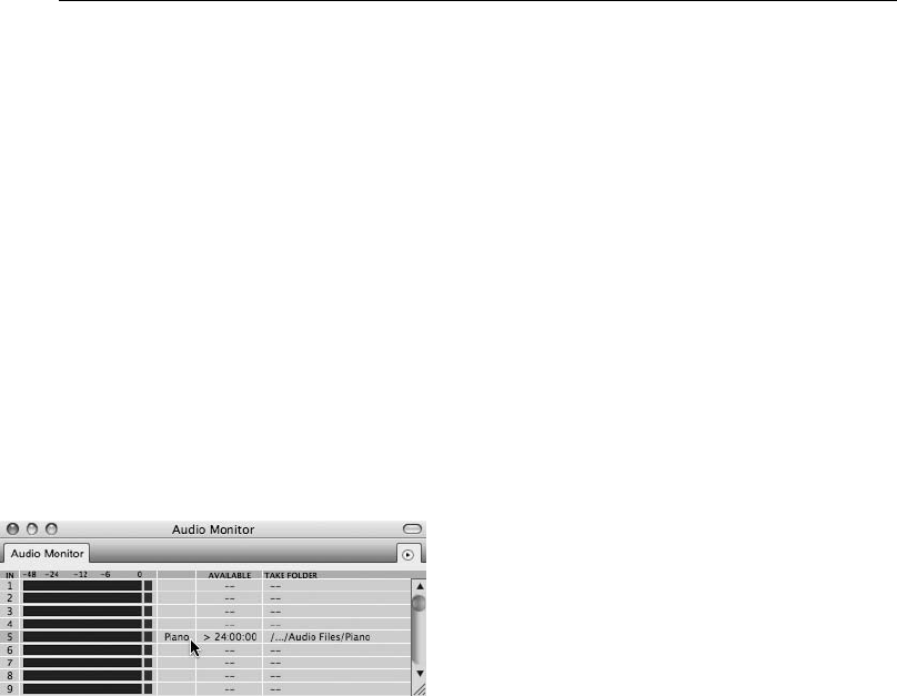
other words, start and end times) is stored within (and cannot be separated from) its parent
audio file.
This is how nonlinear, nondestructive editing is able to work. Suppose you have imported
an audio file into your project. You can make multiple copies of this file or cut the file into
multiple sections (soundbites) and move them around or even delete some of them.
Because these multiple soundbites are only referencing the same parent audio file and not
duplicating it each time, they are not using up more space on your hard drive. On
playback, your drive links to the soundbite reference pointers (region information) and
plays just that portion of the original audio file (as many times as the soundbite appears in
your project).
To change the destination folder or hard drive for your audio files before recording:
1. In Digital Performer, arm an audio track by clicking the Record-Enable button in the
Tracks or Mixing Board window (discussed in Chapter 7, “Recording Audio”).
2. Choose Studio 4Audio Monitor. The Audio Monitor window provides information
concerning the inputs of record-enabled tracks, including input level meters, location,
and available hard drive space for that location.
3. Double-click on the location of the take file in the Take Folder column to display the
full path name for a file. Click on the abbreviated locations to expand the full path.
4. The destination for each armed audio input can be set independently or globally for all
take files. To change the location for a specific take file, double-click on the name of the
take file. (This is usually the track name located to the right of the input level meters, as
shown in Figure 6.22.) The Choose a Folder dialog window will open, asking you to
choose the location for the specific audio input.
5. Navigate to the desired folder or hard drive. If you would like to create a new folder,
click on the New Folder button. Rename the folder and click Open. To choose an
existing folder, select the folder and click Choose.
Figure 6.22 Double-clicking on the name of a take file within the Audio Monitor window will allow
you to specify the destination folder of audio files for an armed input before recording.
194 Digital Performer 6 Power!: The Comprehensive Guide
6. If you would like to simultaneously change the destination folder for multiple/all take
files, select the take files by clicking on the first take file name, then Shift-clicking the
rest. To quickly select adjacent take files, drag over them with the mouse. To select all
the files in the list, use the default keyboard shortcut Command+A.
7. From the Audio Monitor’s mini-menu, choose Set Take Folder. A dialog asking you to
select the destination folder or hard drive for the selected take files will open.
8. If you need to set the take file locations for other take files, repeats Steps 4 through 6 as
needed.
To change the location of existing audio files:
1. Within the Finder, simply move the audio files to a new location by dragging with the
mouse. DP will automatically keep track of the audio files’ new location.
2. If for some reason DP loses track of a file, it will ask you to manually locate the file.
To find the location of an existing audio file:
nSelect the audio file or soundbite within the Soundbites window and then click on the Info
Pane button. The File column of the parent file will display the full path.
nYou can also select the audio file or soundbite and use the keyboard shortcut Option+R. This
method will launch the Finder and open up the actual folder in which the selected audio file
is located. Keep in mind that you can use this method to determine the location of an audio
file or soundbite without opening the Soundbites window.
Organizing Audio Files and Soundbites into Folders
Within the Soundbites window, audio files and soundbites can be organized into folders. This
often-overlooked feature allows you to clean up and organize the Soundbites window List sec-
tion. Placing soundbites into folders will also keep any regions created by the editing process
with their parent soundbites.
To create a folder within the Soundbites window:
1. Open the Soundbites window by choosing Project 4Soundbites. You can also use the
default keyboard shortcut Shift+B or use the Open Soundbites button in the Quick
Access drawer of the Control Panel.
2. With the List section visible, click on the View By menu and choose Folders.
3. Choose Create New Folder from the Soundbites window mini-menu. Folders are indi-
cated by a dark-gray band.
Chapter 6 Project Management: Part 2 195
4. To rename the new folder, Option-click on the folder name.
5. Drag the desired soundbite or soundbite icons from the far-left Move column into the
folder.
Renaming Existing Audio Files or Soundbites
Audio file and soundbite names can be changed from any location in which they appear within
DP, including the Mac OS Finder. Regardless of where you change the name, Digital Performer
will automatically update the name wherever the file appears.
To change the name of an existing audio file or soundbite:
nTo rename an audio file or soundbite within the Soundbites window (or any other editor in
which the file appears), Option-click the name with the mouse.
nTo rename an audio file from within the Finder, click on the name of the file and type the
new name.
Deleting Audio Files and Soundbites
One of the most frightening processes of project management is deleting media files. This is why
you should make a backup copy of your project (including its Audio Files folder) before con-
tinuing with this process. Accidents do happen—seemingly unimportant files that you delete
turn out to be the lead vocal tracks, or the band decides that they really did want that alternate
track you just deleted to regain disk space. Chances are, you have been in some situation where
you deleted something, only to discover that you shouldn’t have. Making backups of your
important files can prevent, or at least minimize, the damage of losing precious data.
You can delete a project’s audio files from within the Finder by dragging them directly to the
trash, but if you do so, DP will not know what happened to them. Their references will remain in
the project’s Soundbites window but will appear as lost sound files. More importantly, however,
you won’t be able to verify whether the audio file in question contains regions that are actually
being used within a project.
The Delete command in the Soundbites window will delete an audio file and/or its associated
soundbites from the current project. This command will also delete a soundbite’s reference
points to its parent audio file. Keep in mind that this command will only delete the audio file
from the project, not from your hard disk. The actual parent audio file will remain on your disk
until the last soundbite referring to the parent audio file is also deleted. In other words, before an
audio file is deleted from disk, DP makes sure there are no remaining references to the audio file
existing somewhere in the project (or another project sharing the audio file).
For example, you have soundbites A, B, C, and D. Each of these soundbites references Audio
File 1. If you use the Delete command in the Soundbites window to delete A, B, and C, Audio
File 1 remains on your hard disk until soundbite D has been deleted.
196 Digital Performer 6 Power!: The Comprehensive Guide
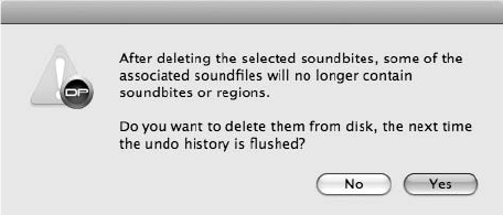
To permanently delete an audio file from disk, again, all soundbites referencing the parent audio
file must have been deleted using the Delete command, or you can use DP’s Compact commands
to delete unused portions of a parent audio file (discussed in the “Compacting an Audio File”
section later in this chapter).
To delete an audio file and/or region from a project:
1. In the Soundbites window, select Soundfile from the View By menu. This will ensure
that any soundbites will be listed with their parent audio files. If you need to audition
the soundbite, make sure Audible mode (the title bar’s speaker icon) is turned on.
2. Select the soundbite you want to delete. Shift-click to make multiple selections.
3. Choose Delete from the mini-menu to delete the audio. The keyboard shortcut is
Command+Delete.
4. If the soundbite currently exists within a track, DP will display a warning dialog asking
whether you really want to delete the selection. Click OK to continue.
5. If the soundbite is the last remaining reference to a parent audio file, a dialog will open,
asking whether you want to delete the audio selection the next time the Undo History is
flushed (see Figure 6.23).
nChoose No to delete the audio file or region without flushing the Undo History. This
allows the action to still reside within the Undo History List, and you can use the
keyboard shortcut Command+Z to undo the process.
nChoose Yes to delete the audio file/soundbite.
6. Another dialog will open, asking whether you want to immediately flush the Undo
History (see Figure 6.24).
nChoose Don’t Flush to preserve the audio file or soundbite within the Undo History
until it is manually flushed.
nChoose Flush to immediately flush the Undo History, permanently deleting the
selected audio files and/or regions from the project and from your hard disk.
Figure 6.23 You can undo the deletion process as long as the Undo History has not been flushed! To
bypass this warning dialog, hold down the Option key before selecting Delete from the mini-menu.
Chapter 6 Project Management: Part 2 197
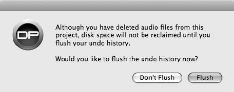
“Removing” Audio Files and Soundbites
There will be times when you want to simply remove an audio file or soundbite from a project
without actually deleting the region information from its parent file—perhaps the soundbite is
being used in another project, or you simply wish to preserve the sound file’s region data or
playlist information for future use. This can be accomplished using the Remove from List com-
mand, located in the Soundbites window’s mini-menu.
To remove a file or soundbite from a project:
1. In the Soundbites window, select Soundfile from the View By menu. This will ensure
that any individual soundbites will be listed with their parent audio files.
2. Click with the mouse to select the soundbite you want to remove. Shift-click to make
multiple selections.
3. Choose Remove from List from the mini-menu. This will remove the soundbite from the
project without deleting the region information from its parent audio file.
4. If the soundbite currently exists in a track, DP will display a warning asking whether
you really want to delete the selection. Click OK to continue. This action will remain in
the Undo History List until it is manually flushed.
Compacting an Audio File
Even though the Delete and Remove from List commands will delete sound files and regions
from a project, often audio files will still reside on your hard drive and consume valuable disk
space. DP’s compact commands, however, will permanently delete portions of unused audio files
from disk. In this process, unused audio data that is not referenced by a soundbite is erased, and
the remaining portions are placed end to end. This is a destructive procedure and should be used
with caution.
Think of the imported audio file example from earlier in this chapter. When you made multiple
edits (cuts, copies, and so on), numerous soundbites were created that referenced the audio file.
Figure 6.24 Immediately flushing the Undo History will permanently delete the selected audio files
and/or regions from the project and the hard disk. Choosing Don’t Flush will preserve the data within
the Undo History until it is manually flushed.
198 Digital Performer 6 Power!: The Comprehensive Guide
Even though, in the process of working, you decide to delete some of these soundbites from your
project, their references to the audio file are still using disk space. Compacting permanently
deletes these portions of the audio file and then closes the gaps between the leftover regions
(or soundbites still being used in your project). The result can be significant amounts of
reclaimed free space on your hard disk!
Here are a few points to keep in mind when using the Compact commands:
nOnly audio data that is not referenced by an existing soundbite is deleted.
nSoundbites that are not deleted with the Delete command or have simply been “removed”
with the Remove from List command will not be compacted.
nIf you want to compact a soundbite that has been removed, import the soundbite again and
use the Delete command to delete the region.
nThe amount of time it takes to compact a file depends on the amount of data that is being
removed.
nOnce a file or project is compacted and the Undo History flushed, any deleted audio files will
be permanently discarded from your hard drive.
To compact an audio file or files:
1. In the Soundbites window, begin by selecting the soundbites or regions you want to
discard from the project.
2. You can quickly select all of the unused soundbites in a project by choosing Select
Unused Soundbites from the mini-menu. This will highlight all of the soundbites that
are not in use within the current project.
3. Choose Delete from the mini-menu. This will remove the soundbites from the project
while deleting the region data from the parent audio file.
4. Now, select a soundbite from the audio file you want to compact. Shift-click to make
multiple soundbite selections.
5. Choose Select All from the mini-menu if you want to compact all of the audio
files within the Soundbites window. The default keyboard shortcut is
Command+A.
6. Choose Compact from the mini-menu.
7. Within the Compact Soundfiles window, specify the amount of extra audio at the
beginning and end of each soundbite that you want to preserve. This is necessary if you
have crossfades, you wish to use crossfades, or you want to make any edits to the edges
of the soundbites (see Figure 6.25).
Chapter 6 Project Management: Part 2 199
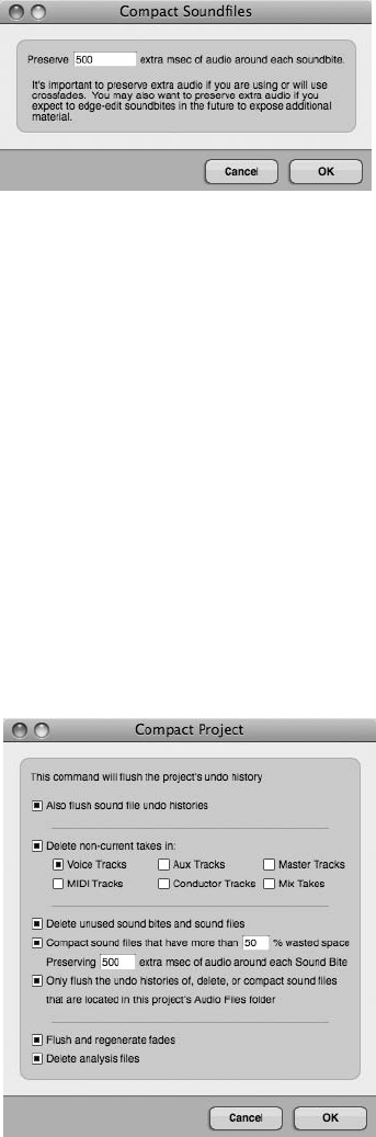
8. Another dialog box will open, asking whether you want to immediately flush the Undo
History. Click the Flush button to flush the Undo History and permanently discard the
removed audio data.
Compacting a Project
The File menu’s Compact Project command allows you to discard the unwanted portions of a
project, from flushing the main Undo History and audio Undo Histories to deleting unused
soundbites and sound files. The Compact Project window provides you with various options
for managing the compact process (see Figure 6.26) and has the benefit of regaining significant
portions of unused disk space. You can apply this command at any time during a project. Be
aware, however, that this procedure is permanent and will flush the project’s main Undo His-
tory! I suggest using the Compact feature at the end of the production process when you are
ready to back up your finished project.
Figure 6.25 The Compact Soundfiles window.
Figure 6.26 The Compact Project window.
200 Digital Performer 6 Power!: The Comprehensive Guide
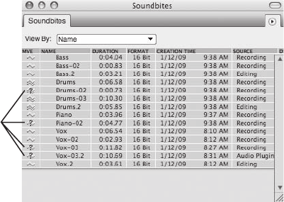
To compact an entire project:
1. Choose File 4Compact Project.
2. In the Compact Project window, select the items you want to discard.
3. Click OK. A warning dialog will launch, informing you that the procedure is not
undoable.
4. Click OK to proceed. The data you selected will be discarded immediately.
Locating Missing Audio Files or Soundbites
Occasionally, DP may lose track of or misplace a soundbite—perhaps you moved it to another
location or deleted it with the Finder. When this happens, you can correct the situation by simply
pointing DP to the new location. Lost soundbites will be indicated by a question-mark icon over
the Move handle of a soundbite within the Soundbites window, as shown in Figure 6.27.
If you are opening a project that contains missing soundbites or sound files, DP will first launch
the Missing Sound Files window, shown in Figure 6.28, which will allow you to locate the files
before opening the project.
To locate a missing file in an open project:
1. In the Soundbites window, select the soundbite you want to find. Missing soundbites
are indicated by a question mark.
2. Choose Audio 4Replace Soundbite.
3. Navigate to the missing soundbite and click Open (see Figure 6.29).
Missing
Soundbites
Figure 6.27 The question-mark icon indicates that the soundbite’s location is unknown to Digital
Performer.
Chapter 6 Project Management: Part 2 201
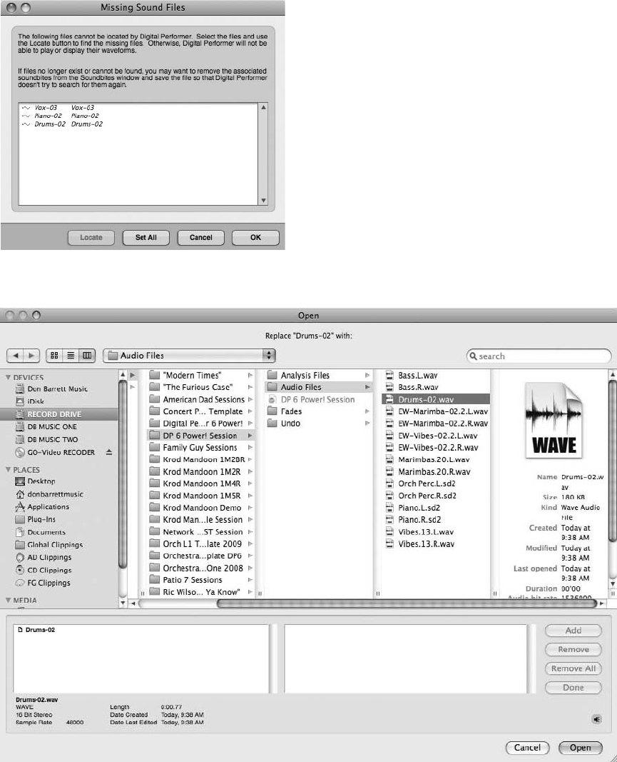
Figure 6.28 The Missing Sound Files window will appear when you attempt to open a project with
missing soundbites.
Figure 6.29 The Replace Soundbites command can be used to locate and replace missing soundbites.
202 Digital Performer 6 Power!: The Comprehensive Guide
To locate a missing file when you first open a project:
1. Open a project that contains missing soundbites. DP will launch the Missing Sound Files
window, prompting you to locate the files. Missing files will be displayed in italics.
Once the window is opened, you will be presented with three choices.
nCancel. Click this button to cancel the process and close the selected project.
nOK. Click this button to skip the location process and open the project. Lost files will
appear as missing soundbites within the Soundbites window. You can use the
Replace Soundbite command to find the missing files.
nSet All. Click this button to select all the missing files within this window. Once a file
is selected, the Locate button will become available. You can also skip the Set All
button and simply click on a file to begin the location process.
2. To locate a missing file, click the file and choose Locate. Click the Set All button to
select all of the missing sound files.
3. In the Open dialog, navigate to the location of the missing file.
4. Select the file and click Open.
5. If you have chosen the location for more than one sound file, repeats Steps 3 and 4.
6. Once found, the missing file will no longer appear in italics, indicating that DP is aware
of its location in your system.
7. Once you have found the selected files, click OK. The Soundbites window will auto-
matically update to reflect the changes.
Backup and Project Archival
Though seemingly similar, backing up a project and archiving it are very different procedures. A
backup is more of a temporary procedure, while archiving is more long term or permanent. Both
are extremely important within the music production process (or any production process, for
that matter) and can help prevent loss of valuable work or can safeguard data that you may want
to access even after a project has been completed. This section will discuss different approaches
and solutions for backing up and archiving your Digital Performer projects.
Backups
As stated earlier, backups can be thought of as temporary solutions or precautions for protecting
work in progress. It is imperative that you back up regularly to prevent the accidental loss of data.
Even the most stable of systems can fail; having a current backup copy of your project can spare
you the time and hassle (and even embarrassment) of re-creating hours or days of lost work.
It’s best to save your backups to a separate hard drive. It won’t do you any good to back up to
the same drive as your original copy if the drive fails or is damaged. Although it might seem like
Chapter 6 Project Management: Part 2 203
an unnecessary additional expense, having an extra hard drive is really the most convenient and
cost-effective solution for backing up your data. If a separate drive isn’t available, then go ahead
and back up to your main drive. Though not ideal, doing so is better than not backing up at all.
As an extra precaution, or if you do not need a lot of storage space, you might also consider
backing up to CD (CD-R or CD-RW) for projects less than 700 MB in size or DVD (DVD-R or
DVD-RW) for projects less than 4.4 GB in size (or 8 GB for dual-layer DVDs).
How often you should back up your projects depends on your personal workflow and setup.
You might consider performing quick backups every 10 to 15 minutes, then performing a more
substantial backup procedure later, wherein you actually make duplicate copies of the project’s
audio files. This more substantial backup could be performed at the end of the day or perhaps
every six hours. As a general rule, back up as often as you can.
To perform a quick backup of a project (without duplicating audio files):
1. Choose File 4Save a Copy As.
2. Rename the project. You might try devising a naming system for these temporary backup
copies—something as simple as adding a number after the project name might do. This
will help you easily recognize which version is which when you’re saving every 15 minutes.
3. Choose the destination for the backup copy. Consider creating a new folder called
Temporary Backups or something similar for quick recognition. You might place this
new folder within the main project folder, but if you really want to be safe, save the
folder to a separate drive.
4. Click Save. Remember that the Save a Copy As command will not save the current
version you are working on. It only creates a backup copy (alternate version) of the
current project.
To back up a project and its audio files:
1. First, choose File 4Save to save the project.
2. Choose File 4Save a Copy As. If you choose Save As, DP will close the original project,
and you will be working on the new backup copy when you hit the Save button. To keep
working on the original copy after creating your backup copy, choose the Save a Copy
As command.
3. Rename the project. You might also try devising a naming system for your more serious
backup copies or creating a backup folder.
4. Choose the destination. This copy should be placed on a separate drive (if possible).
Creating a new folder called Backups, for example, can help you easily locate the
project when disaster strikes.
204 Digital Performer 6 Power!: The Comprehensive Guide
5. Click the Duplicate Audio Data option. This option will make a duplicate copy of every
audio file contained within the current project, even if the audio is scattered across
multiple hard drives. Analysis and fade files will also be duplicated.
6. Click Save to create your backup copy.
Archiving
The archival process can be thought of as a more permanent backup solution. Finished projects
and files that are rarely used should be archived and stored in a safe location. This process will
usually involve archiving to a separate storage medium in order to regain precious disk space
within your system. DP’s Compact Project command can be a handy feature for reducing the
overall file size of a project by eliminating unused audio files that can take up huge amounts of
disk space. Besides archiving to a separate drive or removable storage medium, you should also
try to store your archived projects in a separate room or building. Investing in a fireproof safe for
storage of important projects, software disks, serial numbers, and so on is just another way of
protecting your studio assets against catastrophe.
There are many storage possibilities for your archived projects, from external FireWire/USB 2
drives to various forms of removal media. The solution you choose will really depend on your
personal workflow, budget, and overall size of your projects.
External Hard Drives
External drives are basically IDE or SATA drives (5400 RPM or 7200 or 10,000 RPM) housed
in an external enclosure with USB, FireWire, and/or eSATA ports. Some allow you to install
your own IDE drive, and some are preconfigured, while others allow you to hot-swap drives
for easy removal and installation. Generally speaking, external kits do not provide a real price
advantage over normal external drives, but they do allow you to take an internal drive from your
computer, for example, and instantly turn it into an external unit. Hot-swappable drives are
typically more expensive but can provide you with greater flexibility.
FireWire, USB, and eSATA external drives are very common, as the overall price of hard drives
has fallen over recent years. The greatest benefits, however, come from the inherent nature of the
storage medium. Large projects can be quickly backed up and easily moved between different
systems. Some engineers are even using these external drives as their main recording drives.
CD-R versus DVD-R
CD-Rs are not the greatest backup or archival solution because of their limited storage capacity.
Six- to seven-hundred megabytes of data may seem like a lot of storage, but where audio (or
video) files are concerned, it is not much. A four-minute/16-track project recorded at 24-bit/
48-kHz would consume about 550 MB of disk space. Start editing and processing the tracks,
and the project will quickly grow larger than the 700-MB capacity of the CD-R. You can, of
course, spread the project files over multiple disks, but this can be an inconvenient as well as
time-consuming endeavor.
Chapter 6 Project Management: Part 2 205

4.7-GB DVD can actually hold about 4.2 GB of data, which should be enough space to contain a
typical DP project. DVD-R technology is steadily progressing, with read/write speeds becoming
faster and faster. Double-sided DVD-R (dual-layer) media sporting capacities of 8.54 GB are
also available.
Running a Session from a CD-R or DVD-R Ke ep in mind that even though you can archiv e
your proje cts to both CD-R and DVD -R form ats, you can’t actual ly run a proje ct off of
these media due to their slow read speeds. They are really only suit able for archivi ng,
contraste d with external hard driv es, from which you can run a session.
All of these recent advances in the technology can be confusing for the end user. If you already
have a DVD burner (perhaps a built-in Apple SuperDrive), be aware of its maximum burning
speed (1x, 2x, 4x, 8x, 16x) when purchasing DVD-R media. Pricing is based on write speeds, so
there is no need to purchase 16x DVDs if your burner only has 4x write capabilities.
Rewritable Media
Rewritable media are typically much more expensive than write-once disks. For archival pur-
poses, they are not very practical because you probably won’t be rewriting data onto the disk on
a regular basis, which defeats the purpose of using rewritable media. On top of this, many con-
sumer CD players will not play audio that is burned to a CD-RW.
On the DVD-rewritable side of things, there are different formats to choose from, such as DVD-
RAM and DVD+RW. These formats function like CD-rewritable media but have a larger stor-
age capacity.
USB Flash Drives
I don’t recommend backing up or archiving your data to these convenient little drives, but they
are great for the quick transfer or temporary storage of project sessions, audio files, or any other
data with which you are working. They are typically about the size of your thumb and connect
easily to any of your computer’s USB ports. Considering that some are available in sizes larger
than most desktop hard drives from a few years ago, you can squeeze a lot of data on one. They
have relatively fast transfer speeds and are fairly durable. (My little Memorex drive survived a
Maytag wash cycle!) Like a lot of media technology, prices have dropped considerably, with
2- or 4-GB drives selling for around $10 to $20 (as of the writing of this book). Not a bad
deal when you think about having your band’s entire demo session and mixes on your keychain!
Software Solutions
These days there are many available software applications that concentrate specifically on the
backup and archival process. These powerful applications make it much easier for the user to
store data in efficient and systematic ways without becoming too inundated in storage routines.
206 Digital Performer 6 Power!: The Comprehensive Guide
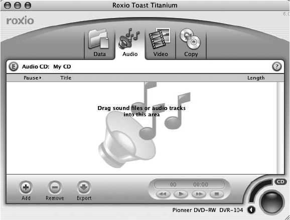
CD/DVD-Burning Software
Roxio’s Toast Titanium software, shown in Figure 6.30, is probably the most widely used CD/
DVD-burning software for the Mac. Its simple yet intuitive interface makes burning disks a no-
brainer. (Of course, you cannot schedule a backup with a burning program like this; archival
and backup must be performed manually.) As of this writing, supported formats include CD-R,
CD-RW, DVD-R, DVD+RW, and DVD-RAM. Be aware that the “lite” version bundled with
many CD burners doesn’t support DVD burning. You will need to upgrade to a Titanium ver-
sion in order to burn DVDs and take advantage of the program’s more advanced features. Don’t
forget, if your budget doesn’t allow for the added software expense, you can also burn discs
directly from the Mac OS X Finder if your computer has a Combo Drive or a SuperDrive.
Browse the Mac Help menu for more information.
Dedicated Backup Software
A more sophisticated approach is to utilize dedicated backup software, such as Retrospect by
EMC Insignia. This application is highly respected and widely used within the Mac and PC
worlds. Various disk types and tape-drive formats are supported. You can back up data existing
on multiple drives or networked computers according to a user-specified schedule. You can also
perform full or incremental backups. Keep in mind that programs like this are not tailored to
understand the specific requirements of media applications such as Digital Performer. If you
have files that are scattered over multiple drives, you will need to tell the program exactly
which files need to be backed up.
Figure 6.30 Roxio’s Toast Titanium.
Chapter 6 Project Management: Part 2 207
Mezzo by Mezzo Technologies is a dedicated backup/archival program built specifically for
media applications such as DP, Pro Tools, and Final Cut Pro. It supports disk mirroring (simul-
taneous backups to multiple hard drives), CD, DVD, and various tape devices. You can perform
full and incremental backups manually or automatically at specific times and intervals, even in
the background. So far, this program sounds much like Retrospect. Where this program shines,
however, is in its understanding of Digital Performer projects. Once you tell Mezzo that it is
working with a DP project, you can simply drag the project document into Mezzo, and it will
search for and back up all related project files! Restoring a project is just as easy, placing the files
back to their original, multiple disk locations. Mezzo also tracks changes in your DP projects,
allowing you to back up only the data that has been changed.
Beyond just backing up data from your Digital Performer projects, what if your entire hard drive
containing your operating system starts to fail? SuperDuper! by Shirt Pocket is an inexpensive
Mac-based program that can simplify the process of creating a fully bootable backup system. In
a few simple steps, you can completely duplicate your boot drive to another drive or partition,
say an external FireWire drive. So, if your system drive does fail you (if it makes that unwanted
clicking noise or refuses to boot), you can simply boot from your most recent backup drive and
be up and running again in minutes. And to save more time, once you have copied the entire
boot drive to the backup drive, selecting the Smart Update option the next time you use the
program will only copy any changes that have been made to your boot drive since the last
backup process (eliminating the need to duplicate the entire drive each time you use the pro-
gram). And like Mezzo, SuperDuper! can be put on a schedule so backups are done
automatically.
Offsite Storage
The future of data backup and archival just may lie in the ever-growing trend of secure offsite
storage facilities. Big companies having been doing this for years, and now so can you. Think of
this concept as simply involving very large hard drives (called servers) that are located—you
guessed it—at a place different from your home or studio. Basically, just as you subscribe to
an Internet service for access to the World Wide Web, you pay a fee to gain access to server
space, such as Amazon S3. The cost is typically based on the amount of storage you need (mea-
sured in gigabytes) and is accessed via a personal account. There are many advanced offsite
systems available, but Apple’s iDisk (shown in Figure 6.31) is very straightforward and provides
a standard 20 GB of storage for Mac and PC users via their MobileMe personal or family
accounts. This relatively easy storage solution allows you to create separate folders and simply
drag and drop files just as you would with traditional hard drives. Keep in mind that broadband
high-speed Internet connections, such as cable or DSL, are typically required for offsite storage
services, and although the true beauty of this process is that all of your backed-up data is located
at a different “secure” place, I suggest using offsite storage in conjunction with traditional
backup and archival methods, just in case!
208 Digital Performer 6 Power!: The Comprehensive Guide
Summary
Project management is an integral part of the music production process. In addition to speeding
up routine functions, such as project setup, backup and archival procedures can prevent the loss
of important data when disaster strikes.
Figure 6.31 Apple’s iDisk is a good option for offsite storage.
Chapter 6 Project Management: Part 2 209
This page intentionally left blank

7Recording Audio
Digital Performer offers a number of powerful tools and feature sets for recording audio.
This chapter will focus on the steps necessary for getting audio into DP and for properly
recording it. Besides audio recording basics, I will discuss recording features, such as
the Audio Assignments and Meter Bridge windows, alternate takes, cycle recording, and record-
ing with effects.
Following is a list of topics covered in this chapter:
nHow to use the Audio Assignments window to configure multiple track I/O assignments
nHow to monitor incoming audio
nHow to set input levels
nHow to designate a specific location for recorded audio files
nHow to use the Meter Bridge
nHow to record, overdub, and cycle record
nHow to work with alternate takes
nHow to create Comp Takes
nHow to record audio with effects
nHow to import audio files into a DP project
Online or Offline in Digital Performer The Track Enable option in the Tracks window (as
shown in Figure 7.1) is similar to the Mute Frees System Resources option in previous
versions of DP. It places tracks online or offline, allowing for better CPU management
during a project. Tracks must be online for playback, recording, and monitoring. Tracks
that are offline no longer use any CPU resources, and their Record-Enable and Input Mon-
itor buttons cannot be selected. By default, DP automatically places new tracks online.
Keep in mind, the process of muting a track is instantaneous, while placing a track online
or offline may take a couple of seconds.
211
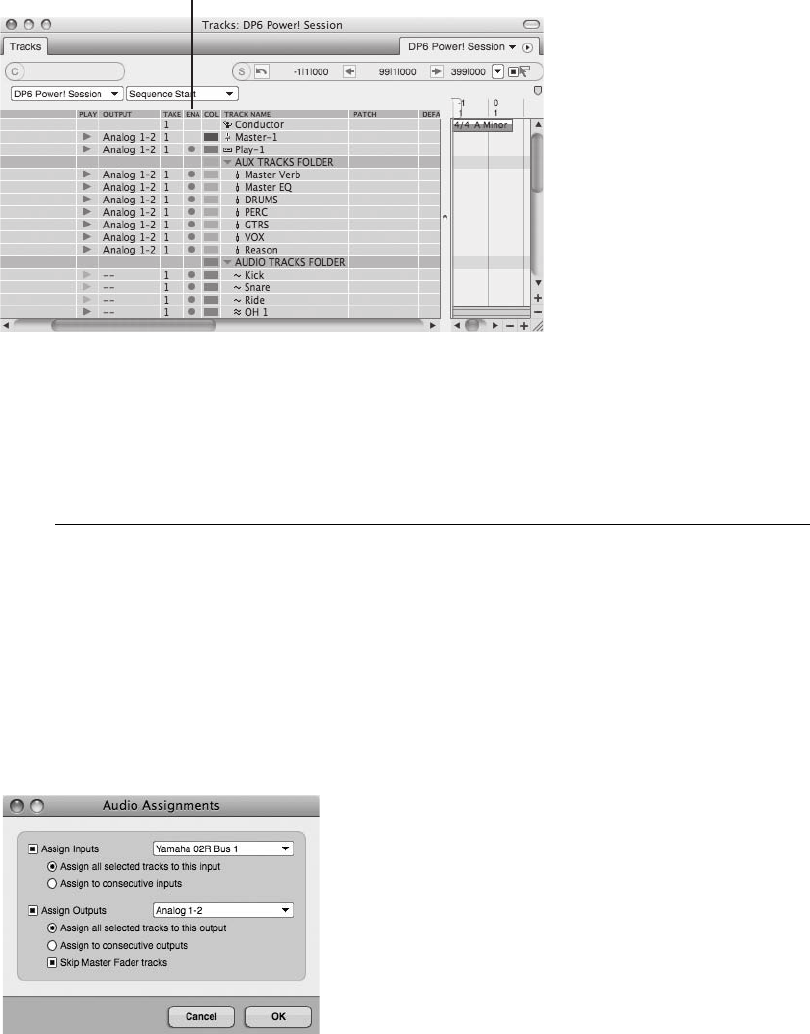
If you do not see the Enable column in the Tracks window (represented by blue dots for
online tracks and gray dots for offline tracks), go to the mini-menu in the Tracks window
and select Track Columns Setup, and then select Enable as a column to be included in the
Tracks window. Also, make sure to keep all tracks online for the purposes of this chapter.
Input Assignments and the Audio Assignments Window
Before you can begin setting audio levels for recording, you will need to arm the necessary audio
tracks. Before you can record-enable a track, however, you must assign the input to either the
Mac’s built-in audio or a connected hardware audio interface (such as a MOTU 2408mk3). The
specific steps for configuring the input assignment of a single audio track, as well as those
for making multiple audio assignments with the Audio Assignments window, were covered in
Chapter 4. Here, I’ll cover the Audio Assignments window in greater detail (see Figure 7.2).
The Track Enable Column
Figure 7.1 DP’s Track Enable option places tracks online or offline for better CPU management.
Figure 7.2 The Audio Assignments window allows you to make I/O and voice assignments for multiple
tracks.
212 Digital Performer 6 Power!: The Comprehensive Guide
At least one audio track must be selected before the Audio Assignments window will become
available. Simply click on the name of a track to select it, and then Shift-click to make multiple
track selections. Once you have selected the necessary tracks, open the Audio Assignments win-
dow from the Studio menu. The default keyboard shortcut is OptionþA. Be aware that inputs
and outputs must be enabled from the Audio Bundles window before they will appear in the
Audio Assignments window.
To configure the input assignment for multiple tracks:
1. Make the necessary track selections.
2. Open the Audio Assignments window (OptionþA).
3. Enable the Assign Inputs option.
4. Choose the desired input from the Input pop-up menu. Be aware that only inputs (audio
bundles) that are already enabled will appear in this menu. If the input assignment you
want to use isn’t listed, close the window and enable the desired inputs from the Audio
Bundles window. (Refer to Chapter 2.)
5. Next, choose the appropriate option from the Assign Input section.
nAssign All Selected Tracks to This Input. This option will assign the selected tracks
to the input that is selected within the Input menu.
nAssign to Consecutive Inputs.Enabling this option will assign the tracks to consec-
utive inputs starting with the input that is selected within the Input menu.
6. Click OK to confirm the input assignments. If you want to continue with output assign-
ments, proceed to Step 1 of the next section before clicking the OK button.
To configure the output assignment for multiple tracks:
1. Enable the Assign Outputs option.
2. Choose the desired output from the Output menu. Again, be aware that only outputs
(audio bundles) that are already enabled will appear in this menu. If the output
assignment you want to use isn’t listed, close the window and enable the desired outputs
from the Audio Bundles window. (Refer to Chapter 2.)
3. Choose the appropriate option from the Assign Output section.
nAssign All Selected Tracks to This Output. This option will assign the selected
tracks to the output that is selected within the Output menu.
nAssign to Consecutive Outputs. Enabling this option will assign the tracks to con-
secutive outputs, starting with the output that is selected within the Output menu.
Chapter 7 Recording Audio 213

nSkip Master Fader Tracks. This option will ignore master fader tracks when making
output assignments.
4. Once you have chosen the desired settings, click OK to confirm the input or output
assignments.
Monitoring Input Signals
An essential part of recording is monitoring your live input signal. You basically have three
choices when working with Digital Performer (or any other DAW, for that matter).
nMonitor through Digital Performer with Audio Patch Thru (using the MOTU Audio System).
nMonitor through your hardware interface with Direct Hardware Playthrough (bypassing the
MOTU Audio System).
nConnect your DP system to an external mixer.
Refer to Chapter 2 for an in-depth look into the different monitoring configurations within Dig-
ital Performer.
Audio Patch Thru
To monitor a live signal through Digital Performer (MAS), Audio Patch Thru must be turned on
from the Studio menu. For example, imagine you are recording a live singer. You will want to be
able to hear the singer through your Digital Performer system as you set input levels or begin to
record. The signal needs a pathway to get from the singer, to Digital Performer, to your com-
puter’s processor, and back out to you in order to begin proper recording. Once enabled, Audio
Patch Thru does exactly what its name implies. It passes the incoming signal from a track’s
designated input to its specified output assignment. Choose an output destination (such as the
outputs of your hardware interface) that is connected to a set of speakers or a pair of head-
phones, and you’ll be able to listen to the signal.
When using an audio track (as the pathway) for monitoring a signal, the audio track must be
record-enabled or the Input Monitor button must be selected before you will be able to hear the
incoming audio. You can also use an aux track to monitor audio signals. The setup procedure is
the same as for audio tracks, except that the aux track is always active (instead of being active
only when the Input Monitor button is selected or the track is record-enabled).
New Audio Patch Thru Options in Version 6 Since version 5, DP has replaced the Monitor
the Inputs of Record-Enabled Tracks option in the Input Monitoring Mode window with
four Audio Patch Thru options in the Studio menu. To get started, simply select Studio 4
Audio Patch Thru 4Auto.
214 Digital Performer 6 Power!: The Comprehensive Guide
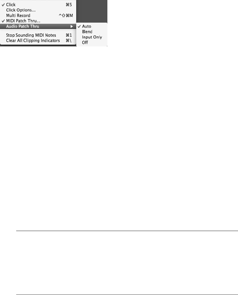
The four different Audio Patch Thru options located at Studio 4Audio Patch Thru (as shown in
Figure 7.3) are:
nOff. The incoming signal is never audible, even if the track is record-enabled or the Input
Monitor button is selected.
nInput Only. You will hear the incoming signal only when the track is record-enabled or the
Input Monitor button is selected. If there is existing audio material on the track (refer to the
“Monitoring during the Overdub Process” note later in this chapter), the existing audio will
not be heard during playback.
nAuto. This is the same as Input Only except that, when you are using Auto Record, you will
hear any existing audio material on the track until punch-in occurs. During punch-in, you
will only hear the incoming “live” signal.
nBlend. When the track is record-enabled or the Input Monitor button is selected, you will
hear both the existing audio material and the incoming “live” signal.
Monitoring with External Mixers
If your system is connected to an external mixer, then it is possible for you to monitor live signals
directly through your console instead of through Digital Performer. Be sure to turn off Audio
Patch Thru to avoid hearing the live signal twice. With this configuration, you will be listening
to the audio signal before it actually reaches Digital Performer, or pre-multitrack. The advantage
to this setup, of course, is the elimination of any monitoring latency.
What Is Monitoring Latency? Monitoring latency is the slight delay of a live input signal.
When monitoring through Digital Performer, for example, the signal must travel through
your audio interface, through DP, back to the audio interface, and out to your speakers or
headphones. This monitoring setup introduces an audible delay in the live signal. The
amount of delay introduced is determined by the buffer settings of your audio interface
and Digital Performer. With monitoring latency, even though you will be hearing the sig-
nal “late,” the audio will actually be recorded in time, precisely as it’s being input into DP.
Figure 7.3 The four Audio Patch Thru options located in the Studio menu.
Chapter 7 Recording Audio 215
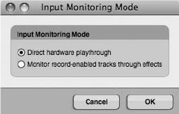
Direct Hardware Playthrough
As noted earlier, the best way to deal with monitoring latency is to use an external mixer with
your DP system. You can, of course, monitor without external equipment and get excellent
results. Another option is to use your soundcard or connected audio interface to directly monitor
the live signal (as long as your audio hardware device has this monitoring capability). When
using the MOTU hardware, you can monitor the signal with DP’s Direct Hardware Playthrough
option, located in the Input Monitoring Mode window. With this configuration, monitoring
latency is eliminated or dramatically reduced, the tradeoff being the inability to listen to the
signal through any plug-in effects (see Figure 7.4).
MOTU also offers CueMix DSP with its audio hardware interfaces. With this additional pro-
gram, the monitoring tasks take place on the PCI card (for PCI-based interfaces) or a DSP chip
(for FireWire interfaces). This eliminates the need for the signal to make the roundtrip through
Digital Performer and your computer’s processor to your speakers. Many other manufacturers
include their own version of the direct hardware playthrough feature, so be sure to consult the
manual for your specific interface.
Setting Input Levels
Before you begin recording, you’ll need to set the level of any incoming audio. This is a crucial
step in the recording process. Setting levels too low may result in a noisier track, and setting the
levels too high may result in digital distortion. Before you can “see” the input levels within
Digital Performer, however, you must first arm, or record-enable, a track.
Arming a Track
Remember that tracks are like containers for audio and MIDI data. Before you can bring an
audio signal into Digital Performer, its input must be assigned to a track, and the track must
be armed (and placed “online”). For information about making basic track I/O assignments,
refer to Chapter 4.
Figure 7.4 The Input Monitoring Mode window.
216 Digital Performer 6 Power!: The Comprehensive Guide
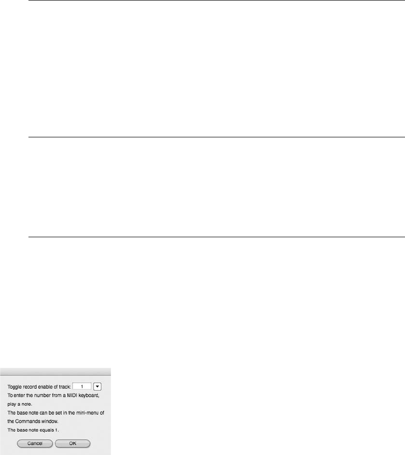
To record-enable an audio track:
1. First, make sure the audio track’s input and output assignments have been properly
configured. If the output is not assigned, for example, the Record-Enable buttons for
the track will not be available.
The Record Column of the Tracks Window If the I/O and voice assignments have been
properly made but the Record-Enable buttons are still not visible, check to see whether
the Record column within the Tracks window is showing. If the Record column is hidden,
choose the Track Columns Setup option from the mini-menu in the Tracks window. When
the window is open, select the Record option to make the Record-Enable buttons within
the Tracks window visible. Be aware that when working in the Sequence Editor or Mixer
window, however, the Columns Setup options will have no effect on the visibility of the
Record-Enable buttons. In these windows, they will become available as soon as the
proper track I/O assignments are made.
2. Click on the track’s Record-Enable icon to arm the track.
3. To arm adjacent audio tracks, click and drag with the mouse. Remember that you
must enable the Audio Options preferences Multi Record Is Always On feature
(located in the Preferences and Settings window) in order to simultaneously arm
multiple audio tracks.
Shortcuts for Arming Tracks
nShiftþControlþR. This key command will open the Track Record Enable window (see
Figure 7.5). Enter the track you want to record-enable and click OK. You can also
choose tracks from your connected MIDI keyboard.
nUp/down arrow keys. If a track is record-enabled, you can use the keyboard’s up and
down arrow keys to proceed to the next or previous record track.
Figure 7.5 You can access the Track Record Enable window with the keyboard shortcut ShiftþControlþR.
Chapter 7 Recording Audio 217
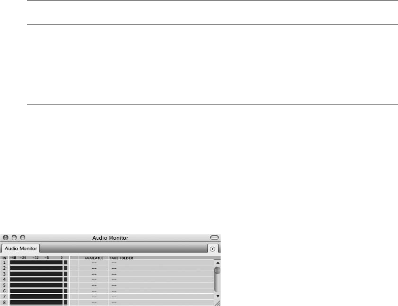
nCommand-click the Record-Enable button. This will arm all other tracks within a
sequence that can be record-enabled, while ignoring the track in question. If the
selected track was already record-enabled, it will be unarmed in the process.
nOption-click the Record-Enable button. This shortcut will arm the track in question
while simultaneously unarming all other tracks.
Arming Tracks on the Fly Tracks can be armed or unarmed (or placed online or offline) on
the fly during playback, but not during the actual recording process (when the Record
button is red or flashing red). The ability to arm tracks on the fly may sound like a really
useful feature, but doing so isn’t actually such a smooth process—actual playback tends to
be momentarily interrupted.
Audio Monitor Window
Once a track or a set of tracks has been record-enabled and placed online, you will be able
to view the incoming signals in Digital Performer. Input signals can be viewed in the Audio
Monitor window (see Figure 7.6) or the Meter Bridge window (discussed in “The Meter Bridge
Window” section later in this chapter). Besides displaying incoming signal levels in the Audio
Monitor window, DP allows you to change the location of take files and control how these files
are named. (Refer to Chapter 6 for details on naming take files.)
To set input levels with the Audio Monitor window:
1. When a track or a set of tracks has been armed, its corresponding input row will be
highlighted (see Figure 7.7). If you have the Scroll to Record Enabled Inputs option
enabled from the mini-menu (which is turned on by default), the Audio Monitor win-
dow will automatically scroll to display the record-enabled track.
2. You can click on the Input Monitor button for the record-enabled track in order to hear
the incoming signal (although record-enabling a track will automatically allow you to
Figure 7.6 The Audio Monitor window.
218 Digital Performer 6 Power!: The Comprehensive Guide
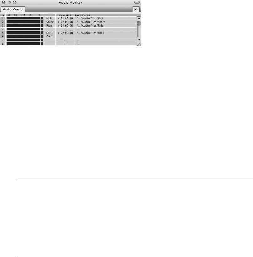
hear the signal even without the Input Monitor button selected). You can do this in the
track strip of the Mixer window or in the Monitor column of the Tracks window.
3. Check your audio input level. You should see the incoming signal (represented in green)
in the input level window.
4. You can change the meter resolution in the Audio Monitor window by choosing Level
Range from the mini-menu. Remember that signals recorded at low levels may result in
increased noise levels, while signals that are too hot can clip, causing unwanted digital
distortion. When operating in the MOTU Audio System (MAS), the Retain Clip option
(in the Audio Monitor window’s mini-menu) is enabled by default to help you see
whether a signal actually clips. If you notice that clips are not being retained, check to
see whether this option is actually turned on.
Tips on Setting Input Levels Even after your input levels are set, you’ll probably want to
keep the Audio Monitor or Meter Bridge open throughout the recording process. Input
levels tend to change over the course of a recording session, so it’s good to have constant
visual feedback warning you when adjustments are necessary. Also keep in mind that
performers tend to play louder and with more energy when you actually press the red
button, so you should set your levels accordingly. If the incoming audio gets too high
and overloads (most likely resulting in distortion), you may want to rerecord it. Remember
that digital distortion can instantly render a great performance useless.
In addition to highlighting a track’s corresponding row in red in the Audio Monitor window, DP
will also display take-file names in standard text, along with the available hard disk space, but
only when a track is armed. Checking these settings is an important part of the DP recording
process.
To check the take-file location and amount of available hard disk space:
1. When a track is armed, the take-file location name appears. The default take-file loca-
tion is the project’s Audio Files folder. The abbreviated take-file location will appear in
the Take Folder column. Double-click on the folder name to display the full path. You
Figure 7.7 In this example, three stereo audio tracks have been armed. Besides being highlighted, the
take-file names appear in the take-file columns.
Chapter 7 Recording Audio 219
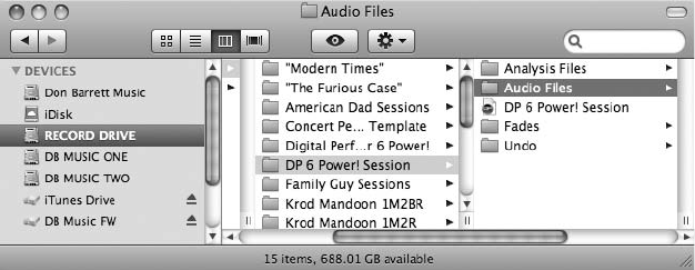
can also change this location by double-clicking on the take-file name in the Take File
column.
2. This will open a dialog box, asking you to choose a new take folder for the specific
audio input (see Figure 7.8).
3. Choose the location for the take file. Keep in mind that you can even designate separate
hard drives for individual take files.
4. After confirming the take-file location, be sure to check on the amount of free hard disk
space. Click to toggle the display between minutes and megabytes. It’s always best to
have extra disk space when recording audio, so you should plan accordingly.
Besides setting levels in DP, you must take care that the signal chain going into DP has been set
properly in order to get the most out of your audio signal. Check the integrity of the audio at
each point in the input chain to maximize levels and keep noise at a minimum.
The Meter Bridge Window
Analyzing levels in your DP project can get a little frustrating if you find yourself switching
among the various windows in order to view specific levels. In addition, trying to balance
more precise input levels via the Audio Monitor’s level range can be quite the strain on the
eyes.
The Meter Bridge window (see Figure 7.9) displays level meters for all inputs, outputs, busses,
audio tracks, and instrument tracks. You can choose to view them independently or simultane-
ously by clicking on their buttons in the left portion of the window. All of the routing informa-
tion displayed in the Meter Bridge window reflects your studio configurations in the Bundles
window. Any changes made in the Bundles window will immediately appear in the Meter
Bridge. (Refer to Chapter 4 for more information about routing assignments and bundles.)
Figure 7.8 Double-clicking on the name of a take file within the Take File column will open the Finder
and allow you to change the location of the take file.
220 Digital Performer 6 Power!: The Comprehensive Guide
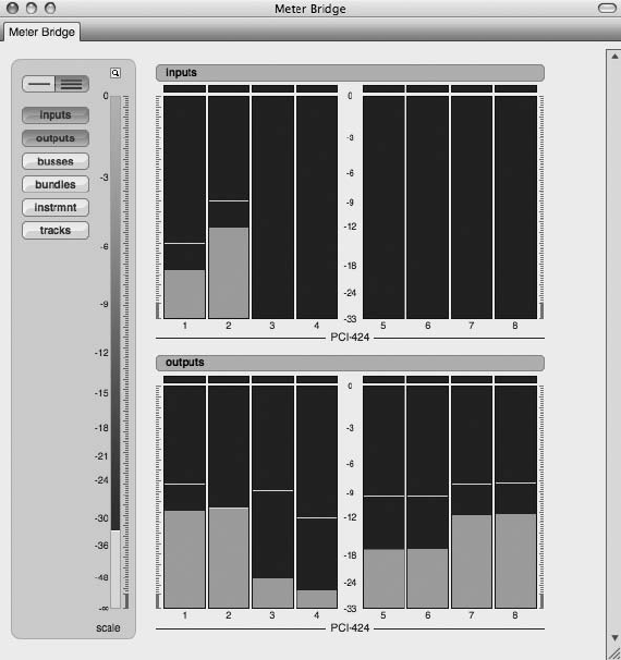
The Meter Bridge window provides a more detailed look at the audio levels in your DP project.
As in the Audio Monitor window, you can specify the level range in decibels as well as magnify
the width of the meters. You can also customize the layout by choosing the Linear View option
(which puts the meters in a horizontal row) or the Wrap View option (which creates a bird’s-eye
view of all selected meters). Let’s take a look at the various options of Meter Bridge window.
To customize the Meter Bridge window:
1. Open the Meter Bridge by choosing Studio 4Meter Bridge or by using the keyboard
shortcut ShiftþZ. The Meter Bridge will appear.
2. Use the Meter buttons on the far left to select the sets of meters you want to view. For
example, if you are getting ready to record, it might be beneficial to view the input
meters during the recording process.
Figure 7.9 DP’s Meter Bridge window can display level meters for all inputs, outputs, busses, audio
tracks, and instrument tracks. In this example, you see a Wrap view (a bird’s-eye view) of inputs and
outputs.
Chapter 7 Recording Audio 221
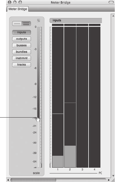
3. Directly above the meter buttons are the View buttons. Here you can choose Linear
view or Wrap view. Keep in mind that if you have multiple meter buttons selected,
horizontal scroll bars are provided if you run out of screen space in Linear view.
4. Adjust the level range using the Scale control, as shown in Figure 7.10. Simply move
your cursor over the scale strip, and it will change to a hand. Use the hand to move the
range up and down. You will notice the bottom number changing to the left of the
meters as you move the Scale control.
5. Next, adjust the width of the meters by clicking on the small magnifying glass located
above the Scale control strip.
6. Finally, as with other DP windows, you can leave the Meter Bridge open as you work,
pop it into or out of a Consolidated Window set, or simply close it.
The Scale
Control Strip
Figure 7.10 Adjust the level range of the Meter Bridge (seen here in Linear view) by dragging in the
Scale control strip.
222 Digital Performer 6 Power!: The Comprehensive Guide
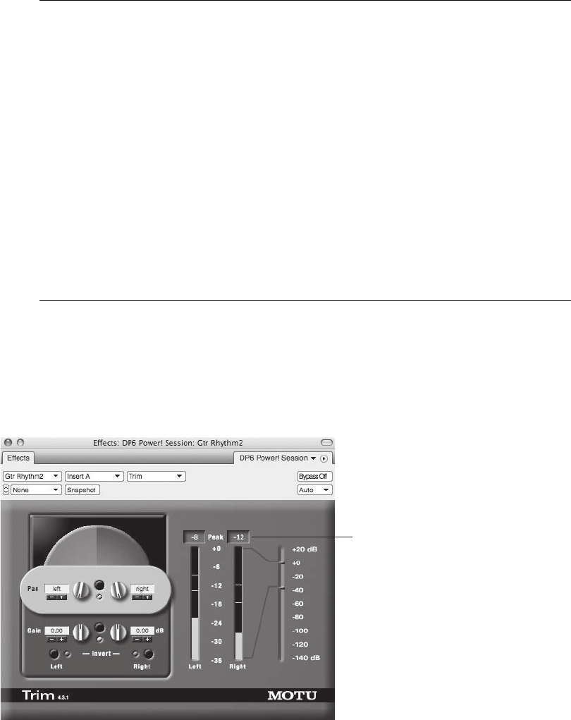
Level Ranges and Clipping Depending on the nature of the music being recorded, adjust-
ing the Scale control strip in the Meter Bridge can be very helpful for viewing levels in a
more precise manner. For example, if you know you will be recording audio that will most
likely involve hotter signals—say, rock guitar tracks—consider adjusting the Scale control
to a lower number. This will provide a smaller spectrum of level ranges, making it easier to
be more accurate while monitoring. In other words, your incoming signal could be repre-
sented in the meters between 20 dB and 0 dB, rather than 51 dB and 0 dB.
Level meters in the Meter Bridge will turn red for a few seconds after clipping occurs to
let you know that a signal has clipped. If the meters remain red for a longer period of
time, this signifies continuous clipping, and some level adjustments may need to be
made. Also, meters have a peak level indicator. This is the last part of level reading (in
green) that has a delayed dissolve from the screen. Unfortunately, you have to be pretty
quick to catch it, and, as of the current version of DP, there is no peak-hold setting
(where peak values stay onscreen until cleared).
DP’s Trim Plug-In
If you need to utilize a peak-hold feature, you can use DP’s Trim plug-in (see Figure 7.11). This
handy little plug-in is another great way to monitor levels in your project. Like the Meter Bridge
and the Audio Monitor windows, you can adjust the level range to the needs of your session. The
Peak Value
Indicators
Figure 7.11 DP’s Trim plug-in is another great way to monitor levels within your project. Notice the
peak value indicators.
Chapter 7 Recording Audio 223

Trim plug-in utilizes peak hold in two different ways—visually in the meters and by numbers in
the Peak Value windows. To clear the peak value indicators, just click in each window to reset
them. This is not the only feature of the Trim plug-in, but it is one if its most powerful with
regard to monitoring levels while recording.
To use the Trim plug-in to view levels and peak-hold values:
1. First create an aux track. The default keyboard shortcut is ControlþCommandþA.
2. Rename the track Input Trim or something appropriate and make sure it is online.
3. Assign the aux track’s input as if you were recording on an audio track. Make sure you
choose the input for the signal you want to record.
4. Assign the aux track’s output to whatever output you’re using to monitor with
(Analog 1-2, for example). These are typically the outputs connected to your speakers.
5. Insert DP’s Trim plug-in on the aux track (in the Inserts menu of the aux track’s strip in
the Mixer window).
6. Once the Trim plug-in is inserted, double-click on its name in the track strip to open the
Trim plug-in window.
7. Test your signal levels and peak indicators in the Trim plug-in window.
8. You can now create an audio track with the same inputs and outputs and begin record-
ing. The signal levels you see in the Trim plug-in window should be the same signal
levels that will be recorded.
The Trim Plug-In as a Gain Stage In the aforementioned example, you set up DP’s Trim
plug-in as a way to monitor levels and peak indicators in your project. You can put the
plug-in to further use by using it as a tool for changing the volume levels of your incoming
signal. In Step 4, simply assign the aux track’s output to an available bus. In Step 8, simply
assign the audio track’s input to the bus used for the aux track’s output. Now record-
enable the audio track, and any adjustments made in Gain value windows of the Trim
plug-in will affect the recorded signal. Keep in mind that you must be in Monitor
Record-Enabled Tracks through Effects mode in the Input Monitoring Mode window.
(See the “Recording with Effects” section later in this chapter.)
Recording Audio
In previous chapters, I discussed the proper optimization and setup procedures for your Mac,
connected audio hardware, and the Digital Performer project. Now your Digital Performer sys-
tem should be configured for recording audio, also. If you are still hesitant or unclear on the
224 Digital Performer 6 Power!: The Comprehensive Guide
steps leading up to this point in the music production process, you might want to refer to Chap-
ters 2 and 4 before proceeding.
Once you have armed your tracks and checked the levels of the incoming audio signal with the
Meter Bridge or the Audio Monitor, you will be ready to begin recording.
To record audio into DP:
1. Start by moving the Counter location to the point where you want to begin recording.
You can type a location directly into the Control Panel’s Counter window, or you can
click and drag the Playback Wiper to the desired location.
2. If you need to, turn on the built-in click. Though not strictly necessary, it’s always a
good idea to record your audio and MIDI data to a click, preferably the click within
Digital Performer. Doing so will ensure that your recorded tracks will be properly
aligned with DP’s grid, allowing you to take full advantage of the program’s editing
features. (Refer to the “Setting Up a Click” section of Chapter 4 for a detailed look at
the setup procedures for DP’s built-in metronome.)
3. To start recording, click on the Control Panel’s Record button. (You can also begin
recording by pressing the number 3 key on your computer keyboard’s numeric key-
pad. If you have a MIDI keyboard controller attached to your system, you can also send
a MIDI message to begin recording. For specific information on assigning a MIDI event
to a specific command, see the “Navigating the Commands Window” section in
Chapter 5.) Once recording begins, DP will display the audio as a red bar scrolling from
left to right on your screen.
4. When you are finished, click the Control Panel’s Stop button. (You can also use the
keyboard’s spacebar or the 0 key.)
Once recording had stopped, Digital Performer will take a moment to process the
audio data and convert the red bar to a normal waveform display. Only when recording
has stopped and the waveform display has been fully updated will you be able to
edit the soundbite. Newly recorded audio will appear in the Soundbites window.
Remember to name your tracks before recording in order to easily recognize the new
sound files in the Soundbites window!
To undo recorded audio:
1. To undo a record pass, choose Edit 4Undo. You must immediately choose this option
before beginning another action. Once undone, the take file will be placed in the trash.
Only when another undoable action is performed will the discarded take file be deleted
from disk.
Chapter 7 Recording Audio 225
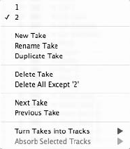
2. If you decide to undo a recording after you have taken other actions, you will need to
use the Undo History List. Keep in mind that any actions that were taken after the
undone action will also be undone in the process. Refer to Chapter 6 for details on the
Undo History window.
Recording and Managing Takes
Takes are basically alternative versions of any data that’s stored within a Digital Performer
track. By default, DP records data into Take 1 of a track (see Figure 7.12). A track can contain
an unlimited number of takes.
Takes are managed through DP’s Take menu, found in the Tracks List or the Sequence Editor
Information panel. The options are as follows:
nNew Take. This option creates a new, blank take.
nRename Take. This option allows you to rename the currently selected take. Current takes
are indicated with a check mark.
nDuplicate Take. Choose this option to create a duplicate of the current take.
nDelete Take. The option deletes the currently selected take.
nDelete All Except. This option discards all of the takes except the current take.
nNext Take. This option selects and displays the next available take.
nPrevious Take. This option selects and displays the previous available take.
nTurn Takes into Tracks. Use this option to remove takes from a track and “explode” them
into separate tracks. The Current Take submenu option will appear only when there is more
than one take and allows you to select the current take or all takes.
nAbsorb Selected Tracks. This option collects takes from other tracks and places them into
the current track from which you are using the Absorb Selected Tracks command. The
Figure 7.12 The Take Column menu allows you to manage takes for individual tracks.
226 Digital Performer 6 Power!: The Comprehensive Guide

Current Takes and All Takes submenu options allow you to absorb the current take or all
takes from the selected tracks.
To create a new take for recording:
1. Arm the appropriate audio tracks.
2. Click on the track’s Take menu and choose New Take. This will create a new blank take
while preserving the track’s original data in the previous (original) take.
3. To rename the new take, simply Option-click on the name of the take within the track’s
Take column. You can also use the Take menu’s Rename Take option.
4. To return to the original take, click on the track’s Take menu column and select it with
the mouse.
Keyboard Shorcuts for Managing Takes You must arm and select the appropriate tracks
before you can use keyboard shortcuts to manage takes. Remember that you can select
a track by clicking on its name. Shift-click to make multiple track selections. Also, if there
are no record-enabled tracks, all take commands (such as New Take, Delete Take, and so
on) will apply to the selected track.
nTo create a new take, press ControlþOptionþN.
nTo delete the current take, press ShiftþControlþDelete.
nTo erase the contents of the current take, press OptionþControlþDelete.
nTo proceed to the next available take, press OptionþControlþup arrow.
nTo proceed to the previous available take, press OptionþControlþdown arrow.
Comp Takes (or Track Comping)
Let’s talk more take talk (in this case, easier done than said!). The phrase Comp Take is short for
“composite take” or simpler yet, “comping.” Basically, comping involves the process of select-
ing pieces of regular takes and combining them into one unified take. For example, let’s say
you’ve recorded four separate piano takes. You can use the Comp Takes feature to pick the
best parts of each take and seamlessly play through the chosen pieces as if they all reside on
the same track. This powerful feature is new to Digital Performer 6 and can undoubtedly
Chapter 7 Recording Audio 227
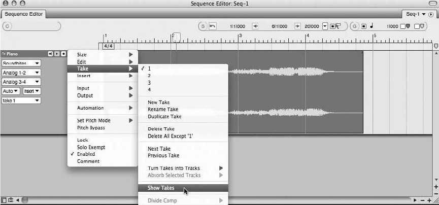
help make recording audio a much more efficient and orderly exercise. The scope of DP’s new
comping power is fairly substantial, so for the sake of this book, let’s explore the basics.
Assuming you have already recorded an audio track with numerous takes, to create a Comp
Take for the track:
1. In the Sequence Editor, choose Track Information panel 4Track Settings 4Take 4
Show Takes (see Figure 7.13).
2. A full editable Comp Take track is created along with a scrolling, resizable Take Grid.
(By default, DP will use Comp 1 as the Comp Take name.) Use the scroll controls to
reveal all takes in the Take Grid, as shown in Figure 7.14. Each take will also appear in
the Sequence Editor’s Track selector.
3. The Comp Take contains a copy of the contents of the current take at the time the Show
Takes command was selected, as indicated by the current take’s shading in the Take
Grid.
4. Now, use ShiftþO (or Windows 4Tools) to open the Tool palette and select the Comp
tool, as shown in Figure 7.15.
5. Simply drag over the desired portion (region) of a take to add it to the Comp Take track.
The selected regions of each take will be shaded and outlined by red dividers (as shown
in Figure 7.16).
Figure 7.13 A Comp Take is created by using the Show Takes option in the Take menu of the Track
Information panel.
228 Digital Performer 6 Power!: The Comprehensive Guide
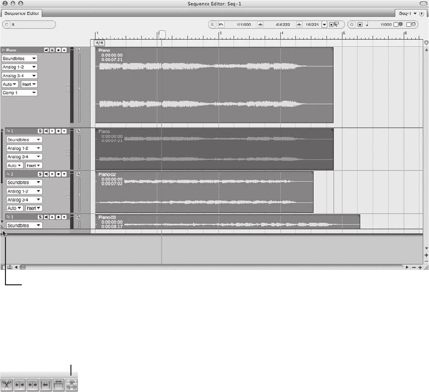
6. Use the finger pointer to move each divider line as desired by placing the cursor over a
divider line. Notice the Comp Take track updating as you select regions and/or move
the divider lines.
7. To hide the Take Grid, go to Comp Take 4Track Information panel 4Take 4Hide
Takes.
8. Press Play on the Control Panel to play back your newly created Comp Take.
The Comp Tool
Figure 7.15 The Comp tool in DP’s Tool palette. Consult the DP6 User Guide for information regarding
advanced Comp tool operations.
The Scroll Grid Resize Handle
Figure 7.14 Once a Comp Take is created, all takes can be revealed using the Resize handle of the Take
Grid. In this example, Take 1 is the current take and is shaded in the Take Grid.
Chapter 7 Recording Audio 229
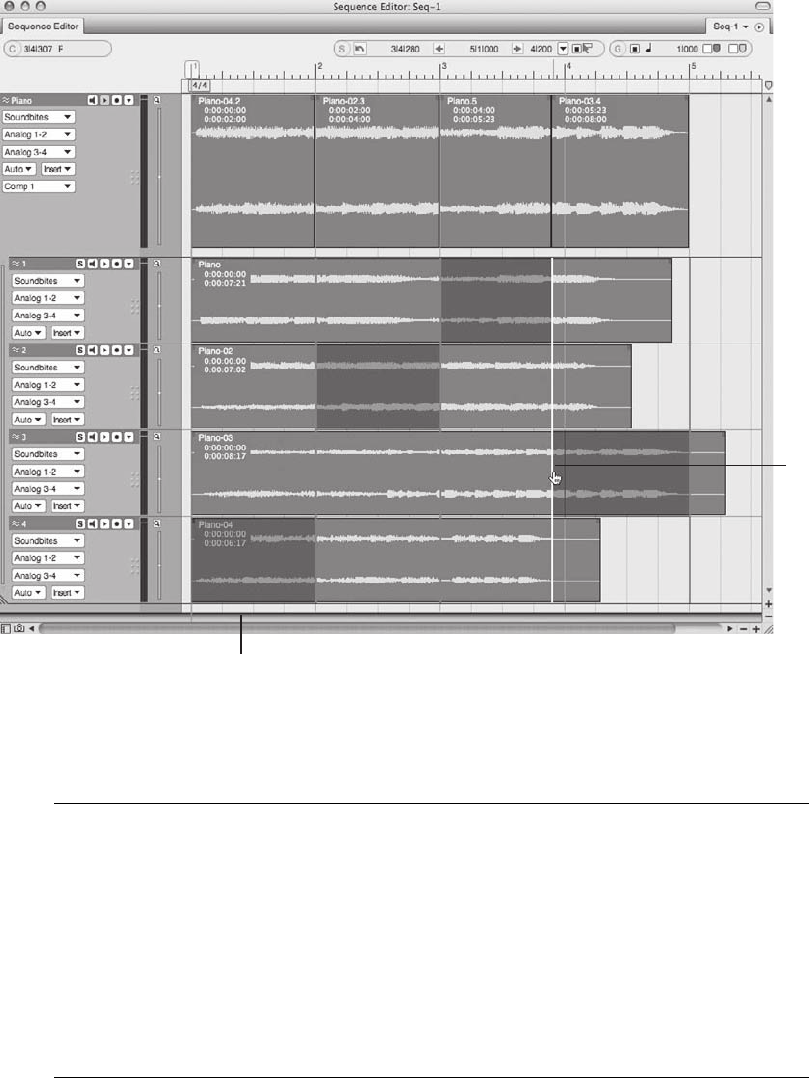
Manipulating Comp Takes When a Comp Take is created and the Take Grid is revealed,
you will notice that each take will have its own Track Information panel with many of the
same controls as a standard audio track. You can resize, reorder, show/hide, rename,
automate, and edit each take. However, if you make an edit (such as a fade) to a
take’s region currently being used in the Comp Take track, you will need to click in the
edited region of the take with the Comp tool so the Comp Take track can inherit the
changes. On the contrary, if you make a change to the Comp Take track itself, the cor-
responding regions of each take will not be affected (and clicking on said regions with the
Comp tool will reset the Comp Take accordingly).
Divide
r
Line
Selected Re
g
ion (Shaded)
Figure 7.16 Desired portions of each take have been selected, and the finger pointer is used to move
divider lines.
230 Digital Performer 6 Power!: The Comprehensive Guide

Punching In and Out
The terms punching in and punching out refer to the process of starting and stopping recording in the
middle of a track. Instead of recording from the very beginning of your project, you can start and
stop recording at any point in a track during playback, regardless of how many tracks are armed.
Digital Performer allows you to perform both manual, on-the-fly punches (punching in and out dur-
ing playback) and automated punches. Automating a punch saves you the hassle of pressing the
Record button on the Transport and allows you to perform very precise punches. This a great feature
for when you are recording yourself, and you need your hands free to play an instrument.
Punching can occur within an empty track or in the middle of recorded material. Punching in the
middle of existing audio to replace what is currently there is called overdubbing.
Monitoring During the Overdub Process To properly overdub audio data, you need to be
able to hear (monitor) what already exists on a track. Auto mode allows you to do this.
Auto mode automatically switches between the “live” input signal and playback (preex-
isting audio), depending on the state of the Transport. When playing back and not record-
ing, you will hear playback of any existing audio material. As soon as recording is initiated
(you’ve punched in), Digital Performer automatically switches to the “live” signal, allow-
ing you to hear what you are actually recording. Once you punch out, you will immedi-
ately hear playback of the material that already existed within the track.
To punch in manually on the fly:
1. Arm the appropriate audio tracks.
2. Press the spacebar to begin playback.
3. Press the number 3 key on your computer keyboard’s numeric keypad to punch in
(begin recording). Or, press the Control Panel’s Record button to begin recording.
4. Press the number 3 key again to punch out (stop recording).
5. Repeat Steps 3 and 4 as needed.
6. When you are finished recording, press the spacebar to halt playback.
To automate a punch:
1. Arm the appropriate audio tracks.
2. Enable the Control Panel’s Auto Record button (see Figure 7.17). Punch In and
Out fields will appear within the Status Strip, and the Auto Record button will be
highlighted.
Chapter 7 Recording Audio 231
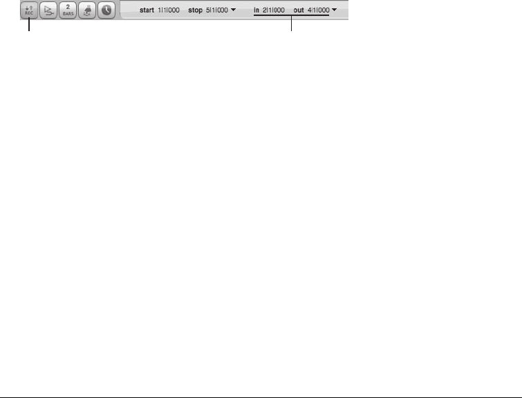
3. Enter the location for when recording is to start and stop. The punch-in point is where
recording will begin, and the punch-out point is where recording will stop. These
positions are represented by red arrows in the timeline of the Tracks or Sequence Editor
window. (They can be moved manually for quicker adjustments.)
4. Position the playback cursor at a point before the punch-in location. Remember to give
yourself or the artist enough pre-roll so that you can properly prepare for the punch.
5. Press the number 3 key on your computer keyboard’s numeric keypad to begin record-
ing. Once recording is engaged, playback will begin with the Record button flashing.
Actual recording will begin at the specified punch-in point, and the Record button will
be continuously highlighted. When the punch-out location is reached, Digital Performer
will go out of Record mode, and the Record button will begin flashing again. Playback
will continue until it is stopped.
6. Press the spacebar to stop playback.
Tips on Performing Seamless Punches Here are a few tips for getting the most out of your
punches:
nWhen possible, punch in and out on a downbeat and avoid punching in the middle
of a line or continuous note. Of course, you can always go back and “fix” your
edit point if the punch is audible, but it’s good practice to make your initial punches
as seamless as possible, for when you are working on that “old school” analog
recorder.
nWhen recording other performers, remember to give them sufficient pre-roll. If
you’re trying to overdub on an existing track, ask the performers to start playing or
singing along as soon as they know where they are at in the recording. This will
help ensure that they are breathing properly and will give them time to match their
own tones and nuances from their previous performance. Continuity is a key factor in
executing seamless punches.
nWhen recording vocalists, be conscious of their breathing and don’t cut off the breaths.
nSet up markers before beginning an overdub session. Being able to quickly jump to
any important locations within a track will keep your session running smoothly and,
The Auto Record Button The Punch In and Out Fields
Figure 7.17 The Control Panel’s Auto Record button allows you to perform punches at precise loca-
tions within a track.
232 Digital Performer 6 Power!: The Comprehensive Guide
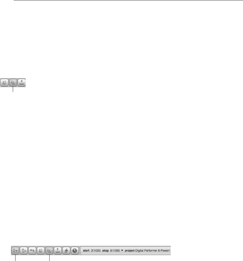
most importantly, will keep your artists happy. There is nothing that will frustrate
your performers more than having to wait while you try to locate that third chorus. See
Chapter 11, “Arranging,” for information on using markers within your projects.
Overdub Record Mode
Overdub Record mode is a handy feature that allows further control over the overdubbing pro-
cess. Under normal recording circumstances (with Overdub Record mode off), existing audio
(and/or MIDI data) is removed and replaced by new data when you punch in on a track. When
the Overdub Record feature is enabled, however (see Figure 7.18), new data is placed on top of
any existing soundbites. Deleting the new recording will reveal the original audio data, allowing
you to quickly return to the previous performance.
Overdub Record mode can be combined with cycle recording to achieve a looping-style record-
ing mode that automatically creates new takes during each record pass.
Cycle Record Mode
Cycle, or loop-style, recording can be achieved by enabling both the Memory Cycle and the
Overdub Record features (see Figure 7.19). This is handy for when you want to record multiple
passes of audio or MIDI data over a specific section of a project. When cycle recording audio
data, DP will automatically create a new take for each record pass, preventing the previous
passes from being recorded over. You can also incorporate DP’s Auto Punch feature to initiate
recording in a designated section within the Memory Cycle in and out points, essentially pro-
viding you with pre-roll and post-roll roll when cycle recording. However, with the Auto button
selected, new takes will not automatically be created. You will simply be replacing the punch
selection in each record pass.
The Overdub
Button
Figure 7.18 The Overdub Record Mode button.
Overdub
Button
Memory Cycle
Button
Figure 7.19 Enable the Memory Cycle and Overdub Record Mode buttons to cycle record within Digital
Performer. The Status Strip’s Start and End times determine the length of the section that will be
looped.
Chapter 7 Recording Audio 233
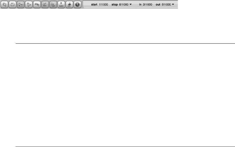
For even greater control over the cycle-recording process, utilize Digital Performer’s comprehen-
sive Polar window, discussed in “The Polar Window” note later in this chapter.
To enable cycle recording:
1. Engage the Memory Cycle and Overdub Record buttons within the Control Panel.
2. In the Memory Bar, specify the start and end points for the section to loop. The end time
should be the beginning (or Count 1) of the measure where you want the loop to end.
For example, when setting an 8-bar loop that starts on measure 1/1/000, the end time
would be Measure 9/1/000.
3. Begin the recording process as discussed earlier in this chapter. Keep in mind that
recording will be continuous and will create a new record take for each record pass.
4. To allow yourself some pre-roll and post-roll time during the cycle-record process,
incorporate DP’s Auto Punch In and Out feature (Auto Record). Turn on Auto Rec-
ord and set the punch-in and punch-out times. (See the previous section on punching in
and out for more information on this feature.)
5. Readjust your original Memory Cycle start and end times to reflect the changes. Now
when you begin recording, DP will cycle though the specified section but will only
record between the punch-in and punch-out points (see Figure 7.20).
The Polar Window Another great tool for performing loop-style or cycle recording is DP’s
Polar feature. (Polar stands for Performance Oriented Loop Audio Recording.) Polar is
ideal if you are working alone and you need to record multiple passes of material. With
Polar, you can record each pass either individually or in layers, and each pass is automat-
ically stored as a new take that gets muted as you begin a new take. Polar can also be set
up to start recording as soon as it receives an incoming signal or the incoming signal
reaches a certain volume threshold. What makes Polar different from normal recording
is that Polar records your material entirely into RAM rather than writing it to hard disk
(ROM). This allows DP to instantaneously respond to newly recorded or overdubbed
material. When you are finished, you simply record your RAM-based audio to hard disk
using the normal recording process in DP! See the “Polar” chapter of your Digital Per-
former User Manual for more information.
Figure 7.20 In this example, the Auto Punch In and Out feature is being used together with Cycle
Record mode. The Transport is set to loop between Measures 1 and 6 but will only record audio
between Measures 3 and 5. Incorporate the Auto Record feature to provide pre-roll and post-roll during
the cycle-recording process.
234 Digital Performer 6 Power!: The Comprehensive Guide

Recording with Effects
When it comes to recording a signal with processing effects to disk (or tape), opinions vary
widely. Some people will argue that you shouldn’t risk screwing up your audio and that you
can always add any processing in the mix, and others say that if you know what you want, then
recording with effects will save you time from having to process later. Then there is the middle
path, where engineers use effects such as mild compression to get a hotter signal to disk (tape) or
brick-wall limiters to prevent digital distortion. Regardless of your philosophy, just keep in mind
that there aren’t any rules. Better safe than sorry, though, so if you are not confident about using
effects during recording, save the processing for later. Once a signal is recorded with an effect,
you can’t remove it.
When you insert a plug-in or effect on a record-enabled audio track in Digital Performer, you
won’t actually be recording the effected signal to your hard drive. You will only be listening to
(monitoring) the effected signal post–hard disk. This is like placing an effect in the “monitor
section” of traditional signal flow. In other words, you hear the effect, but you are not recording
it. To record a signal that has a plug-in inserted in it, you need to send the effected signal to the
hard disk to be recorded. How do you do this? By creating an “input” fader, then bussing (send-
ing) the effected signal to an audio track (see Figure 7.21).
The Monitor Record-Enabled Tracks Through Effects Setting Don’t forget to select Monitor
Record-Enabled Tracks through Effects in the Input Monitoring Mode window (Setup 4
Configure Audio System 4Input Monitoring Mode). If this option is not selected, you can
still record the signal with the applied effect plug-in; however, you will not be able to hear
the effect until recording is finished and you begin playback.
To record an effected signal to disk:
1. First create an aux track. The default keyboard shortcut is ControlþCommandþA.
2. Rename this track Input Fader or something related to the inserted plug-in (such as
Compressor or Reverb). It’s always good practice to name your tracks as you create
them. This will keep you organized and will save you many headaches later.
3. Assign the aux track’s input as if you were recording on an audio track. Be sure to
choose the input for the signal you want to record.
4. Assign the aux track’s output to an available bus. If no busses appear in the track’s
output options window, select a bus from the New Stereo Bundle (or mono) drop-
down menu. (Refer to Chapter 2 for more information regarding busses.)
5. Now create an audio track. Assign its input to the same bus as the output of the aux
track. The signal coming into the aux track is now routed through the audio track.
Chapter 7 Recording Audio 235
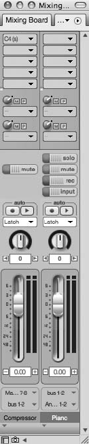
6. The output assignment for the audio track should be whatever output you use to mon-
itor with (Analog 1-2, for example). These are typically the outputs connected to your
speakers.
7. Arm the track and check your levels with the Audio Monitor window or the Meter
Bridge.
8. Now insert the desired effect on the aux track or input fader you created in Step 1.
9. Adjust the effects parameters to your liking.
Figure 7.21 A basic example of recording an effected audio signal to disk. In this setup, the aux track
(named Compressor) receives the incoming signal and processes it with a Waves C4 stereo compressor
plug-in. The effected signal is then routed from the aux track, via Bus 1-2, to the Piano audio track,
where it is recorded to disk.
236 Digital Performer 6 Power!: The Comprehensive Guide
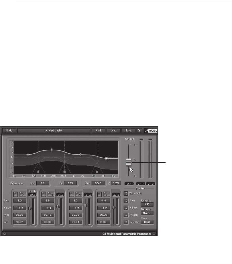
Audio Levels and Proper Gain Structure Once you have set your plug-in parameters, you
may notice that there is a rise or drop in input level because of the processing that is
occurring. Be careful that you don’t re-adjust the input level going into DP (your preamp,
for example) to compensate! If you do, you will be increasing the signal level going into
your audio interface, possibly distorting the audio and throwing off all your plug-in param-
eter settings in the process.
Here is where proper gain structure is important. You need to adjust audio levels at the
output stage of the plug-in. If you are inserting a compressor, for example, adjust the
output level to boost or cut the signal level being sent from the plug-in to the audio track
(as shown in Figure 7.22). If there is no available output level adjustment on the effect,
then insert DP’s Trim plug-in and use the gain settings to adjust the output of the aux
track there (as discussed earlier in this chapter).
Be sure to keep an eye on the Audio Monitor or Meter Bridge window!
10. If necessary, adjust the output level of the plug-in to compensate for the processing.
Check the levels of the audio track in the Audio Monitor window or the Meter
Bridge while making any changes.
11. Begin recording, and the effected signal will be recorded to disk.
Plug-in Output
Level
Figure 7.22 The Waves C4 (s) compressor provides an additional gain stage to control the level of the
signal being sent to the audio track.
Chapter 7 Recording Audio 237

Simultaneously Recording the Dry and Effected Signals If you would rather be safe than
sorry, you can simultaneously record the dry and effected signals by creating another
audio track and assigning its input to the same input as the aux track (input fader). The
incoming signal is sent to two separate tracks for recording, resulting in one with the effect
and one without the effect.
Importing Audio
In addition to recording audio directly to a track, you can import existing audio into Digital
Performer. This audio can reside in DP’s native Sound Designer II format or can exist in other
formats, such as AIFF, MP3, WAV, Broadcast WAV, REX, and even as AVI and QuickTime
movie soundtracks. Imported compatible audio files will remain unchanged, while all other for-
mats will be converted to the project’s audio file format.
Before you begin importing audio, there are a few settings that you should take a look at.
Sound File Locations
Located in Preferences and Settings is the Audio Options window. This global preference win-
dow determines where imported, converted, and processed audio is stored. The Soundfile Loca-
tions preferences are described in the following sections.
Copy Audio to Project Folder
The settings contained in this section of the Audio Options preferences determine where
imported audio will be stored within a project. By default, imported files will always be copied
to the project folder.
nAlways Copy Imported Audio to Project Audio Folder. This option tells DP to always copy
any imported audio files to the project’s Audio Files folder. This option is enabled by default
and is convenient if you want to consolidate all of your project audio files into one central
location.
nOnly When Format Is Not a Playable File Format. This option will convert and import any
non-native formatted audio files into the project’s Audio Files folder.
nNever. This option will place any imported files—even if they need to be converted—in a
specified location.
To Import Means to Duplicate Keep in mind that files imported with the Import Audio
command are never removed from their original locations. Instead, duplicate files are
made and imported into DP.
238 Digital Performer 6 Power!: The Comprehensive Guide

Store Converted or Processed Files
This setting specifies where converted and processed audio will be stored. By default, all pro-
cessed and converted files are saved to the project’s Audio Files folder. Keep in mind that the last
two options become available when the Always Copy Imported Audio to Project Audio Folder
or the Only When Format Is Not a Playable Format option is selected.
nIn Project Folder. This option will place converted and processed files in the project’s Audio
Files folder.
nWith Original File. This option will keep converted and processed files with the originals.
Automatic Conversions Preferences
Located in the mini-menu of the Soundbites window are the Automatic Conversions preferences.
When audio that does not conform to a project’s sampling rate, bit depth, or tempo is imported
into Digital Performer, these preferences will govern the conversion of those files and force them
to adhere to the project’s current settings. Processing is done in the background and can also be
used to convert the files of an existing project to a new sampling rate, bit depth, and/or tempo.
To turn on Automatic Conversions, simply go to Digital Performer 4Preferences 4Automatic
Conversions and select Enable Automatic Conversions for this project. You can also toggle the
automatic conversions setting by using the default keyboard shortcut Optionþ (minus).
The Convert Sample Rate, Convert File Format, Convert Interleaved Format, and Convert to
Sequence Tempo options provide you with the setting choices explained here.
nOn Import. This option will force files that do not match the project to be converted on
import. Files that do not match the project tempo will be converted when they are placed on
a track.
nWhenever File Doesn’t Match. This option does the same thing as the On Import option but
will also convert audio anytime there is a circumstance in which a file’s settings differ from
the project. For example, if you change the sample format in the middle of a project, DP will
automatically convert existing soundbites to the new setting.
nWhen Bite Is Added to a Track. Unique to the Convert to Sequence Tempo option, this
setting will force a soundbite that contains embedded tempo data to conform to the sequence
tempo when added to a track.
nNever. Choosing this option will turn off Automatic Conversions for the specific file setting.
Remember that you can use the Enable Automatic Conversions for This Project option to
globally enable or disable Automatic Conversions for a project.
Convert to Sequence Tempo Files that contain embedded tempo data—such as REX files
and Apple Loops, for example—will automatically adjust to the sequence tempo if you
Chapter 7 Recording Audio 239

have the Convert to Sequence Tempo preference set to either the When Bite Is Added to a
Track or Whenever File Doesn’t Match setting.
The Import Audio Command versus Drag and Drop
There are several ways to import audio into Digital Performer, including using the Import Audio
Command and dragging and dropping files directly into DP. The benefit of using the Import
Audio command is that you can import specific regions that are associated with an audio file.
With the drag-and-drop method (though it is more convenient at times), you are limited to the
importation of entire files. The two methods of importing audio are further described here.
To import audio without leaving Digital Performer, first choose one of the following methods
for importing:
nChoose File 4Import Audio.
nPress the CommandþF1 default keyboard shortcut.
nFrom the Soundbites window, choose Import Audio from the mini-menu.
1. When you use one of the methods for importing audio, the Import Audio dialog box
will open, allowing you to audition audio files before they are imported into DP. This
window also lets you import soundbites, or individual regions. Regions associated with
a sound file automatically appear underneath the parent file in the Add list.
2. Navigate to the desired folder/hard disk.
3. Select the file you want to import. The file will appear in the bottom-left pane of the
Import Audio window. The audio file will be indicated in bold type, with any individual
regions listed below the parent audio file.
4. If you want to audition the file or regions before importing, click on the speaker icon,
located below the Done button, to enable the Audition feature (see Figure 7.23).
5. Highlight the name of the file in the left pane and click the Add button to place the file
or region in the To Be Imported column (right pane).
6. If you decide that you do not want to import a file that has been placed in this column,
select it and click the Remove button. Use the Remove All button to clear the list of any
files or regions.
7. Once you have added your selections to the To Be Imported column, click OK. The files
and/or regions will be imported into DP.
240 Digital Performer 6 Power!: The Comprehensive Guide
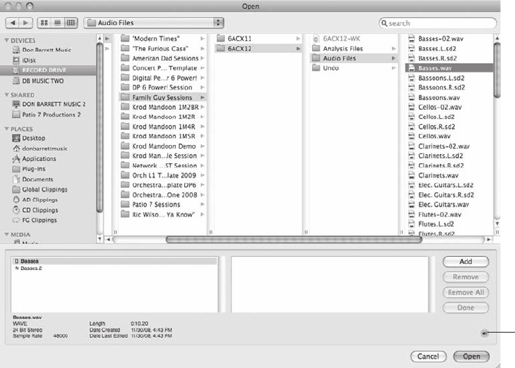
To import audio using the drag-and-drop method:
1. Before you import any files, decide whether you want DP to automatically convert the
files to the project’s current settings. (See the “Automatic Conversions Preferences” and
“Sound File Locations” sections of this chapter.)
2. Locate the file you want to import from the Mac’s Finder window. You can hold down
the Command key and press the Tab key to quickly navigate to the Finder (or any open
application) within Mac OS X. Tab to the Finder application in the list and release the
Command key.
3. With both the selected file and the target Digital Performer window visible, click and
drag the file into DP.
4. If the Automatic Conversions feature is turned on, DP will automatically convert the file
to the project’s current settings and allow for immediate playback of the file. If you have
Automatic Conversions disabled, the file will appear with an X icon next to the file name
in the Move column of the Soundbites window, as shown in Figure 7.24. In addition, if
the soundbite resides on a track, it will appear dimmed within the Sequence Editor.
Speaker Icon
Figure 7.23 Click the speaker icon to enable the Audition feature and audition a selected soundbite or
region.
Chapter 7 Recording Audio 241
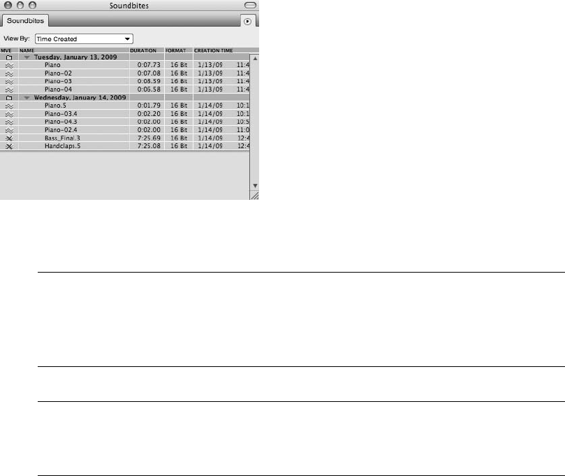
Dragging Files into DP You can drag files to any windows that hold audio. You can drag
them directly into an audio track as long as the channel format is the same. For example,
you cannot drop a mono file onto a stereo track, and vice versa. If you need to drag files of
mixed channel formats, drag them into the Soundbites window instead.
Exporting Audio Files via Drag and Drop You can also export audio files by dragging them
from DP and dropping them into a Finder window or on the desktop. Exported files will be
in the format of the current project.
Summary
Digital Performer offers a powerful approach to digital audio, with sophisticated audio record-
ing and importing capabilities. Extensive features, such as Comp Takes, allow you to further
modify your recording operations, while the dedicated Audio Monitor and Meter Bridge win-
dows provide visual feedback during the audio recording process. In addition to its standard
recording capabilities, Digital Performer’s Polar window provides a self-contained RAM-
based loop-recording module.
Figure 7.24 Files that cannot be played (say, the sample rate does not match) will appear in the Sound-
bites window with an X icon in the Move column.
242 Digital Performer 6 Power!: The Comprehensive Guide

8Recording MIDI
Digital Performer provides a number of powerful features for managing how MIDI is
handled within a project. In this chapter I will discuss the basic process of recording
data on your MIDI tracks, as well as how to overdub MIDI data, cycle record, step
record, and record with MIDI quantizing. In addition to these MIDI recording-related opera-
tions, I’ll discuss other MIDI features, such as the Input Filter, MIDI Patch Thru, interapplica-
tion MIDI, and device groups.
Following is a list of topics covered in this chapter:
nHow to use the MIDI Monitor window to verify incoming MIDI signals
nHow to alter recorded MIDI data using the Input Filter and Input Quantize commands
nHow to create multiple MIDI output destinations with MIDI device groups
nHow to select MIDI patches for specific MIDI channels
nHow to set up MIDI tracks for recording
nHow to output MIDI data to external MIDI devices and virtual instruments
nHow to record MIDI data
nHow to overdub, punch in, cycle record, and step record MIDI data
MIDI-Related Windows and Commands
In this section—before you dive into the actual MIDI recording process—I’ll discuss a few of
Digital Performer’s MIDI-related windows and commands that can be used to affect how MIDI
data is recorded within a project.
The MIDI Monitor Window
The MIDI Monitor window, shown in Figure 8.1, provides a visual display of any MIDI data,
system controller information, or MIDI sync data (such as MIDI beat clocks, DTL, DTLe, and
system reset commands) that is being received by Digital Performer. Use this window to verify
that DP is actually receiving MIDI signals from a connected MIDI device. To open the MIDI
243
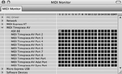
Monitor window, choose Studio 4MIDI Monitor or use the default keyboard shortcut
ShiftþW.
Each MIDI interface that is connected to DP in the current Audio MIDI Setup (AMS) configu-
ration (explained in Chapter 2) will appear in the MIDI Monitor window. Click the MIDI inter-
face’s disclosure triangle to reveal MIDI devices that are connected to the interface. Each device
row displays a blue indicator box that will light up when a MIDI signal is being received on a
specific MIDI channel (numbered from 1 to 16). The Co (System Common) indicators display
MIDI data that is non-channel-specific, such as system exclusive data. The RT (System Real-
Time) indicators display real-time sync data, such as MIDI beat clocks.
Keep in mind that the Input Filter (explained in the next section) has no effect on the MIDI
Monitor window.
The Set Input Filter Command
The Input Filter, shown in Figure 8.2, “filters” incoming MIDI data—it basically determines
what type of MIDI data can be recorded (or not recorded) in a MIDI track. For example,
you can use the Input Filter to allow on-velocities to be recorded in a MIDI track, but any
mod-wheel messages will be ignored (“filtered” out). Choose Setup 4Set Input Filter to
open this window. Be aware that these settings are global and will affect all MIDI data that
is recorded.
To prevent a specific type of MIDI data from being recorded on a track:
1. Open the Input Filter window by choosing Setup 4Set Input Filter.
2. Uncheck the box located left of the data type, as shown in Figure 8.3.
To determine the type of MIDI controller data that is recorded:
1. Enable the Controllers section of the Input Filter window by clicking on its check box.
Figure 8.1 The MIDI Monitor window.
244 Digital Performer 6 Power!: The Comprehensive Guide
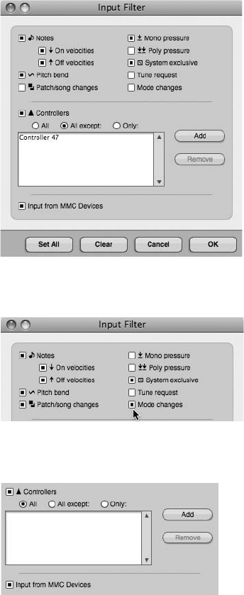
2. Use the buttons located below the Controllers check box to quickly determine the type
of data that will be affected, as shown in Figure 8.4.
nAll. Click this option to record all types of MIDI controller data.
nAll Except. Click this option to record all types of controller data except the specific
controller numbers added to the Controllers list (explained in the next section).
Figure 8.3 Simply uncheck an item to prevent it from being recorded.
Figure 8.4 Use the buttons located below the Controllers check box to determine the types of control-
ler data that are recorded.
Figure 8.2 The Input Filter allows you to filter out MIDI data that you do not want to record.
Chapter 8 Recording MIDI 245
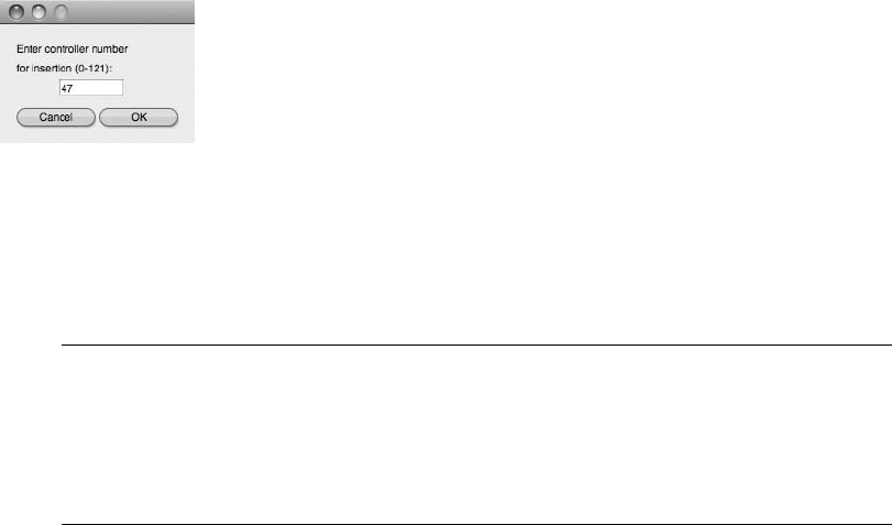
nOnly. Click this option to record only the controller numbers added to the Control-
lers list.
To add or remove a controller number from the Controllers list:
nTo add a controller number, click the Add button and type the controller number in the pop-
up window, as shown in Figure 8.5. Click OK to enter the controller number into the
Controllers list.
nTo remove a controller number, click on the specific number (which will become highlighted
in blue) and click the Remove button. To quickly select more than one controller number in
the list, drag with your mouse.
The Set View Filter Command Similar to the Input Filter I just discussed, the View Filters
window determines the type of MIDI data (already contained in a project) that is displayed
within a project or Event List. Soundbites, audio volume, and panning, as well as automa-
tion data, can also be affected. See Chapter 10, “Editing,” for more information on the
View Filters window.
The Input Quantize Command
Use the Input Quantize command, shown in Figure 8.6, to quantize incoming MIDI data that is
being recorded to a track. This is a destructive process, meaning that your MIDI data is auto-
matically quantized and then recorded to the specified MIDI track. This feature is very useful
when you want to automatically “fix” the timing of your performance and you do not wish to
make manual adjustments after your MIDI track is recorded. For nondestructive quantizing
options, see the “MIDI Effects Plug-Ins” section of Chapter 9, “MIDI: The Region Menu,
Plug-Ins, and Virtual Instruments.” Choose Studio 4Input Quantize to open the Input Quan-
tize window.
If you’re already familiar with the standard Quantize command (explained in Chapter 9), you’ll
find this command very straightforward.
Figure 8.5 The Controllers section pop-up window.
246 Digital Performer 6 Power!: The Comprehensive Guide
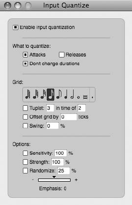
To quantize MIDI data during the recording process:
1. Open the Input Quantize window by choosing Studio 4Input Quantize. You can
also use the default keyboard shortcut ShiftþControlþI.
2. Click the Enable Input Quantize option to turn on Input Quantize, and then choose
the desired quantize settings. Once Input Quantize is enabled, MIDI data being
recorded to a track will automatically be quantized.
The quantize settings listed in the Input Quantize window are identical to the settings found in
the Note section of the standard Quantize command. Refer to Chapter 9 for an explanation of
the Region menu’s Quantize command.
MIDI Device Groups
Digital Performer’s MIDI Device Groups command, shown in Figure 8.7, allows you to send
MIDI data to multiple MIDI output destinations. Choose Studio 4MIDI Device Groups to
open this window.
MIDI device groups are especially useful when you are stacking multiple MIDI sound modules
(or virtual instruments) to create a layered “patch” or sound. For example, you might have three
external MIDI devices in your studio that you use to create a “layered” bass sound. Instead of
creating separate MIDI tracks for each sound, you can create a MIDI device group containing
the three devices you’re using. Once created, the group will appear in the output assignment
menus of all MIDI tracks, as shown in Figure 8.8.
Figure 8.6 The Input Quantize command quantizes MIDI data as it is being recorded to a track.
Chapter 8 Recording MIDI 247
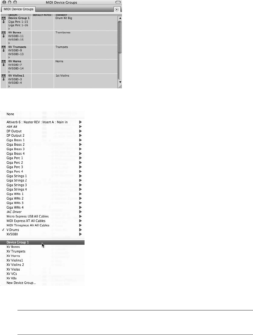
The Maximum Number of MIDI Channels in a Device Group The maximum number of MIDI
devices/channels that can be added to a MIDI device group is 10.
Figure 8.8 Once created, device groups will appear in the output assignment menus of MIDI tracks.
Figure 8.7 The MIDI Device Groups window.
248 Digital Performer 6 Power!: The Comprehensive Guide
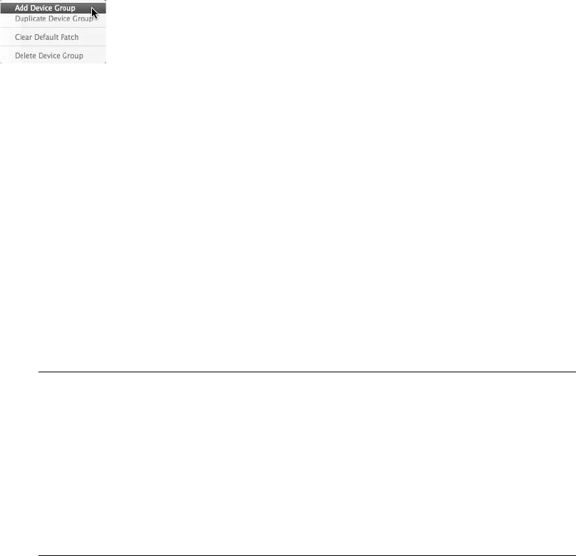
To create a new MIDI device group:
1. Open the MIDI Device Groups window by choosing Studio 4MIDI Device Groups or
by using the default keyboard shortcut ShiftþI. If you want to create a new device group
without going to the Studio menu, simply choose New Device Group from a MIDI
track’s output assignment menu. If you use this method, proceed to Step 3.
2. From the MIDI Device Group window’s mini-menu, choose the Add Device Group
option, as shown in Figure 8.9. An empty device group called Device Group 1 will
appear in the window. Hold the Option key while creating a new device group to
quickly add multiple device groups.
3. You’ll probably want to customize the new device group’s name so that you can easily
recognize it. To rename the device group, Option-click the device group name.
To add a specific MIDI device/channel to your new device group or remove one from it:
1. Click the disclosure triangle located below the device group name. A list of connected
MIDI devices and channels will open. Select the specific MIDI device and channel from
the list, as shown in Figure 8.10. Once chosen, the MIDI device/channel will be added to
the MIDI device group.
2. To add additional devices to the group, repeat Step 1 (or see the following note entitled
“The Expand/Compress Icon”).
3. To remove a device from the group, select it and choose Delete from the mini-menu.
The Expand/Compress Icon The Expand/Compress icon, shown in Figure 8.11, toggles the
display of all MIDI devices that are connected to your MIDI interface. As in the MIDI
Monitor window, each MIDI device channel is displayed as a box. Clicking a channel
box will add that MIDI channel to the selected device group. MIDI channels assigned
to the device group will appear highlighted in black.
Use the expanded view to quickly add (or remove) MIDI channels to a device group
without using the MIDI device list discussed in Step 3 of the previous section, which only
allows you to add one MIDI channel at a time.
Figure 8.9 Choose Add Device Group to create a new device group.
Chapter 8 Recording MIDI 249
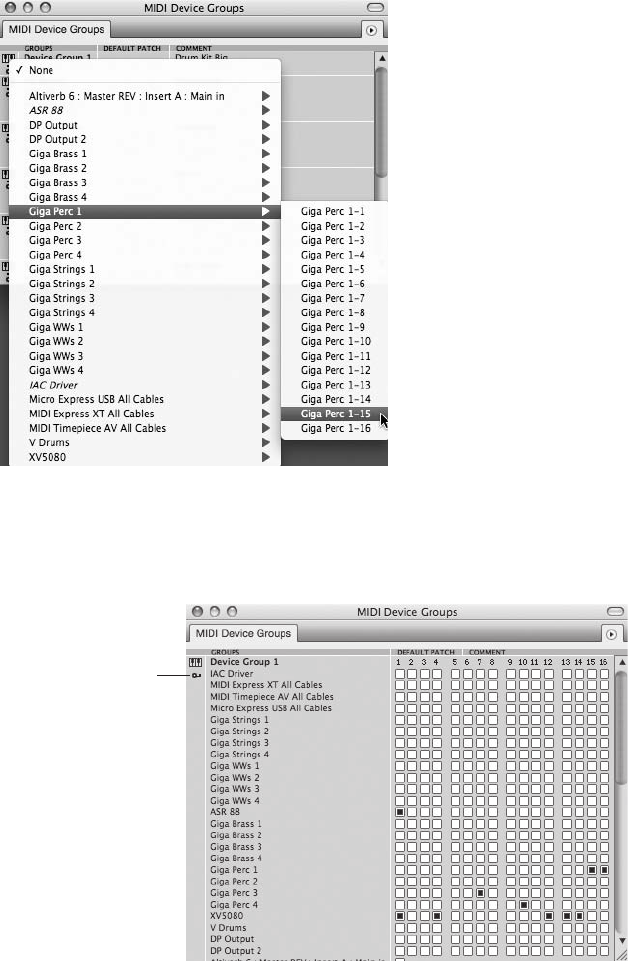
Expand/Compress
Icon
Figure 8.11 Click the Expand/Compress icon to view all connected MIDI devices/channels within the
MIDI Device Groups window. MIDI channel boxes that are highlighted in green indicate that they are
part of the device group.
Figure 8.10 Add a MIDI device to the group from the MIDI device list.
250 Digital Performer 6 Power!: The Comprehensive Guide

Undoing Actions Taken in the MIDI Device Groups Window Be aware that any actions
taken in the MIDI Device Groups window (such as creating and deleting device groups)
cannot be undone.
To set or clear the default patch for a specific MIDI channel contained in your device group:
nTo set the default patch, click in the Default Patch column directly to the right of the
particular channel and choose the desired patch from the list.
nTo clear the default patch for a specific MIDI channel, click the MIDI channel name and
choose Clear Default Patch from the mini-menu.
nTo clear the default patch lists for an entire device group, click the device group name
and choose Clear Default Patch from the mini-menu.
The Default Patch A MIDI channel’s default patch is basically the first patch (or sound)
from your synthesizer or sound module that DP uses when you play a MIDI track. This
patch is remembered and saved with the project, so the next time you open the session,
DP will know what patch to select and play back. Be aware that when a MIDI channel is
using a default patch, it will automatically override any manual patch changes you make
on the specific MIDI device. To have a different patch play back, you will need to change
the default patch, remove the default patch, or program a patch change.
Be sure not to confuse the standard Patch (or Current Patch) column with the Default
Patch column. MIDI patches selected in the Patch column won’t be remembered with a
project, so be sure to use the Default Patch column if you want DP to recall the patch the
next time you open your project. DP’s MIDI patch lists are explained in the next section.
MIDI Patch Lists
A patch list contains the names of a MIDI device’s (or a virtual instrument’s) sounds or patches,
as shown in Figure 8.12.
Digital Performer relies on Mac OS X to supply the default factory patch names of connected
MIDI devices. The patch names for most of the popular MIDI devices and instruments (includ-
ing their expansion boards) in use today are recognized by OS X. Patch names that aren’t rec-
ognized, however, are listed with generic patch names, such as Patch-1, Patch-2, Patch-3, and so
on (see Figure 8.13).
Chapter 8 Recording MIDI 251
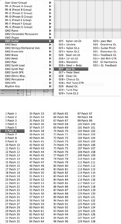
To edit the patch list for a specific MIDI device:
1. Open the Bundles window by choosing Studio 4Bundles (or by using the keyboard
shortcut ShiftþU).
Figure 8.12 Patch names recognized by OS X will be displayed with their factory default names.
Figure 8.13 A patch list containing generic patch names.
252 Digital Performer 6 Power!: The Comprehensive Guide
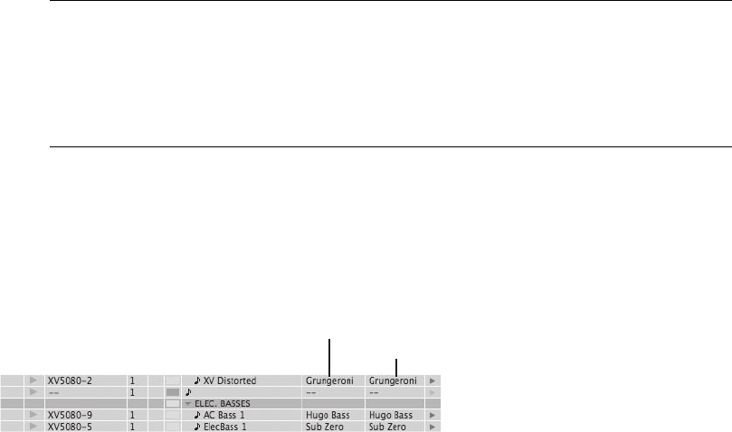
2. Select the MIDI Devices tab.
3. Highlight the MIDI device from the MIDI device list.
4. Choose the Edit button.
5. The MIDI Device Properties window will appear. Select the Patches tab.
6. Make the appropriate selection from the available patch list. Keep in mind that the
Name, Manufacturer, and Model data fields must be completed before any compatible
patch lists will appear in the list. Use this window or the Audio MIDI Setup utility to
identify these data fields.
Patch List Editors/Librarians If you’re tired of seeing generic patch names in your patch
lists, you can use a dedicated MIDI patch list editor/librarian application, such as MOTU’s
Unisyn, to supply DP with the correct patch names. These programs contain expanded
lists of different MIDI devices and their patch names. MOTU’s Unisyn will even allow you
to edit a device’s sounds and rename them.
The Current Patch versus the Default Patch
Digital Performer basically contains two different patch features (both reference the same patch
list)—the current patch column and the default patch column, as shown in Figure 8.14. The
patches contained in each list are identical. Where they differ is in their functions.
As explained earlier, the default patch list tells DP which MIDI patch should always be played
first on a specific MIDI track. As long as the patch change doesn’t exist with a MIDI track (via
Controller Data Automation), the selected default patch will always play when playback is
engaged—even if you manually change the patch on the MIDI device or virtual instrument.
Use the default patch list if you want Digital Performer to remember the MIDI patches you
are using even after you close your DP project.
The current patch list (or Patch column) always displays the currently selected MIDI patch and
will even update on the fly when you have patch changes inserted on a MIDI track. As with the
Patch Default
Patch
Figure 8.14 The (current) Patch and Default Patch columns allow you set the current or default patch
assignment for a specific MIDI channel in the Tracks window.
Chapter 8 Recording MIDI 253

default patch list, you can assign MIDI channels to a specific patch by choosing the desired patch
from the list. If you don’t want DP to automatically play certain patches (or the default patch),
use the current patch list when you assign a MIDI channel to a specific patch.
Clear Default Patch I have always found it a little strange that once a default patch is
selected for a MIDI track, there is no option in the Default Patch column to clear the
default patch or select “None.” To clear a default patch, you must highlight the MIDI
track in the Tracks List and then go to Tracks Window 4Mini-Menu 4Clear Default
Patch.
Recording MIDI
Now that you’ve seen some of the various MIDI-related features that can affect the MIDI
recording process, you’re ready to begin recording. This section will cover the various ways
to record MIDI data on your MIDI tracks.
Setting Up Your MIDI Tracks Chapter 4 demonstrated the proper setup procedures for
creating MIDI and instrument tracks, setting the MIDI input and output assignments,
and monitoring your MIDI devices and/or virtual instruments. If you’re shaky on the ins
and outs of this process, refer to Chapter 4 for an in-depth look at how to set up your MIDI
tracks for recording.
Setting Up to Record a MIDI Track
Because I have already explained the MIDI track setup process in detail in Chapter 4, I’ll assume
that you understand MIDI track configuration, and I’ll only provide a review of the track and
I/O setup process here.
To set up a MIDI track for recording:
1. Create a MIDI track using the default keyboard shortcut ShiftþCommandþM. To
create multiple MIDI tracks, press ShiftþOptionþCommandþM. By default, the track
will automatically be record-enabled.
2. Assign the MIDI track to the desired MIDI device (and channel) from the track’s output
menu. If you want to assign the track to a virtual instrument instead, you’ll need to
create the instrument before it will show up in the output menu.
3. Next, set up an aux track to monitor your MIDI device. Press ControlþCommandþA
to add an aux track. If you are monitoring through a DSP program, such as MOTU’s
CueMix, skip Steps 3 and 4.
254 Digital Performer 6 Power!: The Comprehensive Guide

4. In the aux track’s input menu, choose the audio hardware inputs that correspond to your
MIDI device. For example, if the physical outputs of your MIDI device are connected to
Analog 1-2 of your audio interface, choose Analog 1-2 for the aux track inputs.
5. If necessary, select the specific sound you want to use for your MIDI track from the
current or default patch list (explained a moment ago).
6. Since the track is already record-enabled, press some notes on your MIDI controller to
make sure you “have signal.” If you aren’t hearing anything, open up the MIDI Monitor
window (explained earlier in this chapter) and verify that DP is receiving MIDI data
from the specific MIDI device.
MIDI Patch Thru MIDI Patch Thru allows you to hear your MIDI devices or instrument
plug-ins when you play a note on your MIDI controller. Be sure to enable MIDI Patch
Thru, or you won’t hear anything when you press a note on your MIDI controller, regard-
less of whether DP is receiving MIDI data from your connected MIDI devices. Refer to
“The Preferences and Settings Command” section of Chapter 5 for an explanation of the
MIDI Patch Thru feature.
Setting Up an Instrument Track
When working with virtual instruments (VIs), you need to create the desired instrument track
before it will become available in a MIDI track’s output menu. There are a couple of different
ways to create your Digital Performer instrument tracks. Once way is to add a specific type of
instrument track. The other way is to create an empty (or unassigned) instrument track and
assign its instrument at a later time. Unassigned instrument tracks are especially useful when
you are creating project templates.
Working with Virtual Instruments That Exist in Another Application If you want to assign a
MIDI track to a virtual instrument that exists in another application (outside DP), you need to
create the VI before it will show up in DP. Some third-party applications have specific setup
requirements that you must follow in order to publish their VI in a Digital Performer MIDI
track (such as Fable Sounds’ Broadway Big Band instruments). Consult the specific program’s
user manual for the proper setup instructions.
To add a Digital Performer instrument track that’s assigned to a specific virtual instrument:
nChoose Project 4Add Track 4Instrument Track and select the specific virtual instrument
from the instrument track list.
Chapter 8 Recording MIDI 255
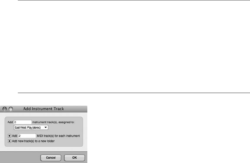
To add an unassigned (empty) instrument track:
nChoose Project 4Add Track 4Instrument Track 4Unassigned or press
ShiftþCommandþI.
nTo create multiple assigned tracks, choose Project 4Add Track 4Instrument Track 4Add
Instruments. You can also use the default keyboard shortcut ShiftþOptionþCommandþI.
Adding Multiple Virtual Instruments When using the Add Instruments option to add several
instances of a virtual instrument, the Add Instrument Track window (shown in Figure 8.15)
offers a few extra shortcuts. In this window, you can choose the virtual instrument and the
desired number of instances of the instrument. You may need new MIDI tracks to trigger the
instruments, so you can also specify a number of new MIDI tracks to create, and DP will
automatically map each new MIDI track to a separate channel of the virtual instrument
(as long as the virtual instrument includes multiple MIDI destinations). Finally, you can
also create a new Track Folder for the tracks. DP will automatically place the virtual instru-
ment tracks and the accompanying MIDI tracks in a Track Folder named after the virtual
instrument, such as Stormdrum Folder.
Basic MIDI Recording
Once you have configured your MIDI and/or instrument tracks, and you have confirmed that
you have signal, you’re ready to begin recording.
To record on a MIDI track:
1. Record-enable (or arm) the MIDI track by simply clicking in the REC column of the
MIDI track in the Tracks window.
2. Test the signal by playing a few notes on your MIDI controller.
Figure 8.15 The Add Instrument Track window offers a few extra shortcuts when adding multiple
instances of a virtual instrument.
256 Digital Performer 6 Power!: The Comprehensive Guide
3. Click the Control Panel’s Record button to begin recording. You can also press the
number 3 key on the numeric keypad to start recording.
4. Press the number 3 key again to stop recording but continue playback (or punch out of
record), or hit the spacebar to stop recording and playback at the same time.
5. If you don’t like the recording and you want to try it again, press CommandþZto
undo the record pass. You can also use the Undo History window to undo the
performance (as explained in Chapter 6). Press the number 1 key on the numeric keypad
to rewind to the beginning of the sequence.
6. Repeat Steps 3 through 5 as needed.
Punch Recording
Punch recording (or punching in on a track) is the process of replacing existing material by
recording over a specific portion of a track. For example, suppose you record a 16-bar MIDI
performance and, upon listening to playback of the track, you decide you’re very happy with the
first half of the track but you’re not satisfied with the second half (Bars 8 to 16). Instead of
rerecording the entire track and losing your great performance during Bars 1 to 8, you could
just rerecord Bars 8 to 16; this is called punching in on a track. There are basically two ways to
execute a punch within DP: manually and automatically.
To manually punch in on a MIDI track:
1. Arm the MIDI track on which you want to punch in.
2. Move the Playback Wiper close to where you want to start recording—anywhere from 5
to 20 seconds (or 4 to 16 bars) before the punch-in point. Exactly how much pre-roll
you use is really up to you.
3. Press the spacebar to begin playback.
4. To make the punch-in as seamless as possible, make sure you (or the artist you’re
recording) start playing along with the track as soon as you know where you are within
the song.
5. At the desired location, press the number 3 key on the numeric keypad to start recording
and “punch in” on the track.
6. Press the number 3 key again to punch out of record.
7. Repeat Steps 4 through 6 as needed. When you’ve completed your punches, press the
spacebar to stop recording and playback.
8. Hit the number 1 key to return to the beginning of the sequence.
Chapter 8 Recording MIDI 257
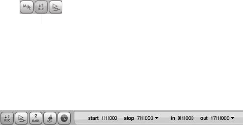
To automatically punch in on a MIDI track:
1. Arm the MIDI track on which you want to record.
2. Engage the Control Panel’s Auto Record button, as shown in Figure 8.16.
3. With the Auto Record button enabled, set the punch-in and punch-out times, as shown
in Figure 8.17.
4. Move the Playback Wiper close to where you want to start recording—anywhere from 5
to 20 seconds (or 4 to16 bars) before the punch-in point. How much pre-roll you use is
really up to you.
5. Press the number 3 key to begin recording. The Record button on the Control Panel will
flash (red) repeatedly until playback reaches the specified punch points, where it will
become solid during the punch record.
6. To make the punch-in as seamless as possible, make sure you (or the artist you’re
recording) start playing along with the track as soon as you know where you are in the
song.
7. When playback reaches the designated punch-in start time, DP will punch in on the
track. At the specified punch-out time, DP will punch out of record.
8. Press the spacebar to stop playback.
9. Press the number 1 key on the numeric keypad to locate to the beginning of the
sequence.
Overdub Recording
After you get a satisfactory first MIDI record pass, you might want to add (or layer) on addi-
tional passes of the same sound or MIDI channel. (You might want to add another chord on top
of the previous record pass, for example.) This is called overdub recording,oroverdubbing.
When you’re working with audio tracks, you must use a new track to perform overdub record-
ing, or overdubs. If you overdub in the same audio track, you will actually be erasing the existing
Auto Record Button
Figure 8.16 Use the Control Panel’s Auto Record button to perform an “auto punch.”
Figure 8.17 Use the Auto Record button’s punch-in and -out times to set the duration of the punch-in.
258 Digital Performer 6 Power!: The Comprehensive Guide
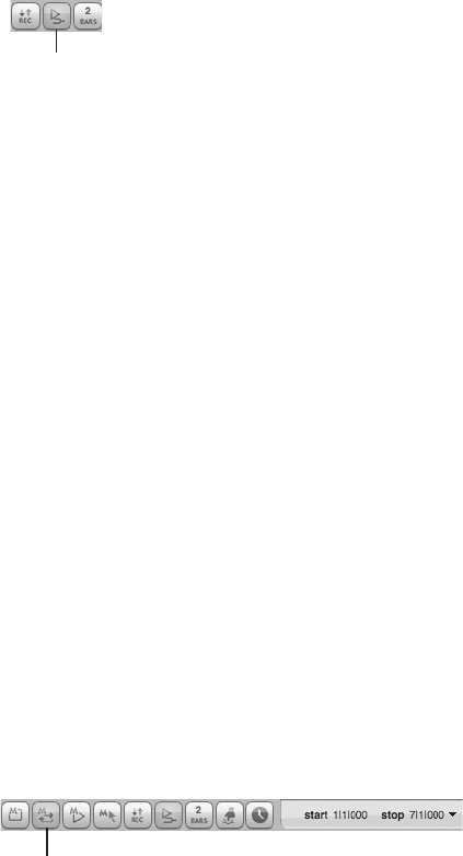
material when you press the Record button. Digital Performer MIDI tracks, however, allow you
the option of layering new MIDI record passes onto existing material without actually deleting
the existing MIDI data—essentially, you’re merging the new data with the existing data.
To overdub record on a MIDI track:
1. Arm the track on which you want to overdub.
2. Click the Overdub button on the Control Panel, as shown in Figure 8.18.
3. Press the number 3 key on the numeric keypad to start playback and recording.
4. Begin playing your MIDI controller to layer your new performance onto the existing
MIDI data.
5. When you are ready, press the number 3 key to punch out of record.
6. Press the spacebar to stop recording and playback all together.
7. Press the number 1 key on the numeric keypad to return to the beginning of the
sequence.
Cycle Recording
When the Overdub record feature is combined with the Control Panel’s Memory Cycle feature,
DP allows you to cycle record (or loop record) audio and MIDI data. Set the Transport to loop
continuously, engage the Overdub record feature, and you can overdub continuously over a
specific time range.
To engage cycle-record mode:
1. Click the Control Panel’s Memory Cycle and set the Memory Start and Stop Times, as
shown in Figure 8.19. The Start and Stop Times will basically define the loop beginning
and end.
Overdub Button
Figure 8.18 The Overdub button, when engaged, will allow you to layer, or overdub, new MIDI data
onto existing data within a MIDI track.
Memory Cycle
Button
Figure 8.19 Use the Control Panel’s Memory Start and Stop Times to specify the loop points for the
cycle-record process.
Chapter 8 Recording MIDI 259
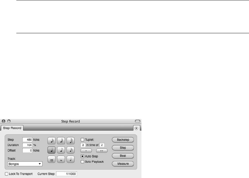
2. Engage the Overdub button.
3. Press the number 3 key on the numeric keypad to start playback and recording.
4. Begin playing your MIDI controller to layer your new performance onto the existing
MIDI data.
5. When DP reaches the specified Stop Time for the loop, it will jump back to the Memory
Start Time and continue overdub recording, merging the new material with the existing
MIDI data.
6. When you are finished recording, press the number 3 key to punch out of record.
7. Press the spacebar to stop recording and playback all together.
8. Press the number 1 key on the numeric keypad to return to the beginning of the
sequence.
Recording Alternate Takes The process of using takes with MIDI tracks is identical to that
of using audio tracks. Refer to the “Recording and Managing Takes” section of Chapter 7
for an explanation of takes within Digital Performer.
Step Recording
When you’re step recording, MIDI data is not recorded in real time, but is inserted one note at a
time into a MIDI track. Digital Performer’s Step Record command, shown in Figure 8.20, allows
you to step record MIDI notes of a specific duration that are automatically quantized. This fea-
ture can be useful for entering especially difficult rhythmic passages that you cannot perform or
for creating a lead sheet for use in DP’s QuickScribe Editor or other notation software applica-
tions, such as Finale.
The basic process of inserting a MIDI note with the Step Record command is very simple. Refer
to Chapter 22 of the DP6 User Guide for an in-depth discussion of the Step Record command.
Figure 8.20 The Step Record window.
260 Digital Performer 6 Power!: The Comprehensive Guide
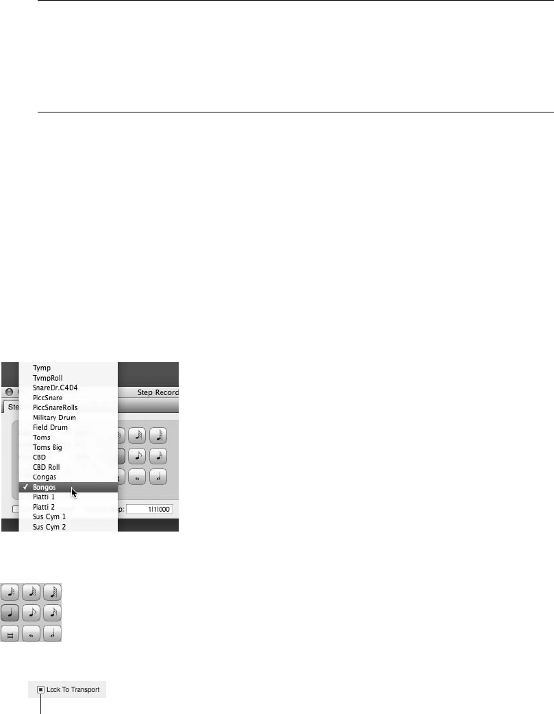
Step Recording and the MIDI Graphic Editor Using the MIDI Graphic Editor window while
step recording can provide a more detailed look at the MIDI data you are entering. Simply
open a MIDI Graphic Editor window for a desired MIDI track, use the zoom buttons and
magnifying tool to resize (if necessary), and open the Step Record window. During the
step-recording process, you can view each step as it is recorded.
To step record MIDI notes:
1. Open the Step Record window by pressing Commandþ8 or by choosing Studio 4
Step Record.
2. Select the MIDI track you want to step record on from the Current Record Track
pop-up menu, as shown in Figure 8.21.
3. Choose the desired note duration with the Step Duration buttons, as shown in Figure 8.22.
4. If you want to have the Step Record window linked to DP’s main Transport
controls, click the title bar’s Transport Lock button, shown in Figure 8.23. Use this
button to toggle the locked or unlocked state of the Step Record window.
Figure 8.21 The Current Record Track menu determines the track into which you will step record.
Figure 8.22 Use the Step Duration buttons to specify the note value to be entered.
Transport Lock
Button
Figure 8.23 The Transport Lock button.
Chapter 8 Recording MIDI 261
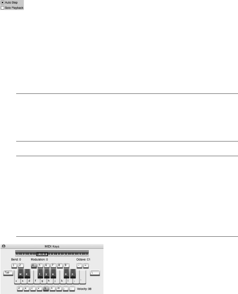
5. If you want DP to automatically advance to the next step once you have inserted a MIDI
note, make sure the Auto Step button (shown in Figure 8.24) is engaged.
6. To insert a note (or chord), press and hold the desired notes on your MIDI controller. Be
sure to press the notes together—and cleanly—to ensure that the notes are inserted in
the same location (or step).
7. Release the notes, and they will be automatically inserted in the selected MIDI track.
8. If you step record an incorrect note, use the Backstep button.
9. Repeat Steps 3, 5, 6, and 7 to continue step recording.
Step Recording versus the Pencil Tool Don’t confuse step recording with the basic process
of inserting notes with the Pencil tool. Although they are technically similar in function, the
Pencil tool provides more versatility when inserting notes directly into a MIDI track within
the Graphic or Sequence Editor. The process of inserting notes with the Pencil tool is dis-
cussed in the “MIDI Editing in the Graphic Editor” section of Chapter 10.
Entering MIDI Data with MIDI Keys If you need to enter MIDI data and you do not have a
MIDI controller keyboard available, Digital Performer offers a convenient alternative. The
MIDI Keys window (Studio 4MIDI Keys) turns your computer keyboard into a basic MIDI
controller. In this window, you can use your qwerty keyboard to enter notes, adjust
octaves, change velocities, and apply modulation, pitch bend, and MIDI sustain. Simply
record-enable a MIDI track and open the MIDI Keys window to begin entering MIDI data
(see Figure 8.25). This may not be the most efficient way to get MIDI data into your proj-
ect, but when the creative mood strikes and you are sitting on a plane with your laptop,
MIDI Keys can come to the rescue!
Figure 8.24 The Auto Step button.
Figure 8.25 The MIDI Keys window turns your qwerty keyboard into a basic MIDI controller.
262 Digital Performer 6 Power!: The Comprehensive Guide
This page intentionally left blank

9MIDI: The Region Menu,
Plug-Ins, and Virtual
Instruments
Now that you’ve seen the MIDI recording process in Chapter 8, I’ll discuss DP’s related
MIDI commands, plug-ins, and virtual instruments tracks.
Following is a list of topics covered in this chapter:
nThe Region menu commands
nHow to use MIDI plug-ins
nHow DP handles virtual instruments and instrument tracks
nHow to use the Freeze Selected Tracks command
Region Menu Commands
The majority of Digital Performer’s MIDI commands are located in the Region menu, shown in
Figure 9.1. Region menu commands allow you to apply changes to selected MIDI data and
tracks—similar to the way Audio menu plug-ins can be applied to audio tracks for file-based
processing. Region menu commands will alter the original MIDI data you’re working with, so
you may want to create a copy of the tracks you’re modifying by duplicating the track take or by
duplicating the track all together.
Many of the Region menu commands (including the MIDI effects plug-ins) can be used non-
destructively, and in real-time, by inserting the desired effect within the Mixing Board. Real-
time effects have the benefit of not altering your MIDI track’s original data. In addition, you
can change the plug-in settings at any time if you aren’t satisfied with the plug-in’s current
settings.
This section will highlight some of the more frequently used Region menu commands and pro-
vide a basic overview of their processes. We’ll also discuss how the Region command windows
function compared to DP’s other edit commands. Refer to the “Region Menu” chapter of the
Digital Performer User Manual for a comprehensive look at the Region menu commands.
265
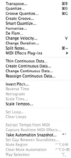
Region Commands Preferences and Settings
Unlike DP’s standard edit command windows, which won’t allow you to perform other oper-
ations until you apply or cancel the command, Region command windows can stay open while
you perform other actions within a project—though you can only have one Region command
open at a given time. Choosing another Region menu command will replace the current window
with the new one.
The Region Commands window in DP’s Preferences, shown in Figure 9.2, controls what hap-
pens to a Region command window after a setting is applied. Keep in mind that the options
listed are global and will affect all Region command windows.
nApply Closes Window. This option will close the window when you hit the Apply button or
press the Return key on your Mac’s keyboard.
nApply Sends Window to Back. This option will force the window into the background when
you hit the Apply button or press the Return key on your Mac’s keyboard.
nApply with Enter Key Sends Window to Back. This option will force the window into the
background when you press the Return key on your Mac’s keyboard. Hitting the Apply
button will apply the command but keep the window in the foreground.
Figure 9.1 The Region menu.
266 Digital Performer 6 Power!: The Comprehensive Guide
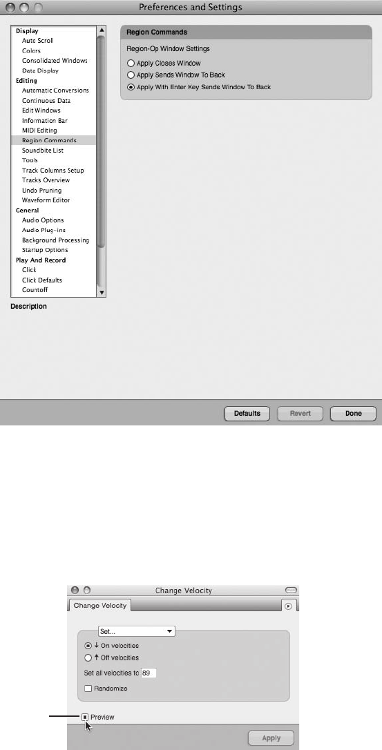
Some of the Region menu commands allow you to audition or preview settings before applying
them. Click the window’s Preview button to turn on previewing, as shown in Figure 9.3.
If the window supports previewing, the mini-menu will also containa previewing option that controls
how the preview feature behaves when a window is not in the foreground, as shown in Figure 9.4.
Preview
Button
Figure 9.3 The Preview button.
Figure 9.2 These Region Commands preferences control what happens to a window when a setting is
applied.
Chapter 9 MIDI: The Region Menu, Plug-Ins, and Virtual Instruments 267
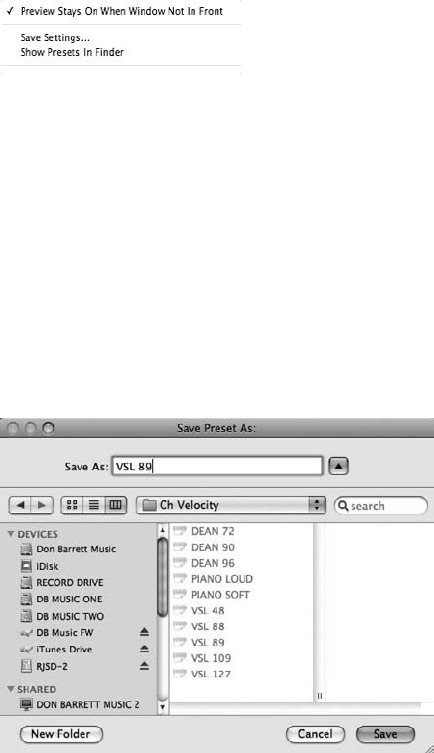
Check the Preview Stays On When Window Not in Front option if you want to the window to
continue auditioning a Region command’s settings, even when the window is forced to the
background.
Similar to audio plug-in presets, some of the Region commands allow you to save the window’s
current settings for future use. Once the Save Settings command is selected, the Finder will open,
allowing you to name the preset and save it in the appropriate folder, as shown in Figure 9.5. If
you have a particular setting that you want to use again, use the Save Settings command in the
window’s mini-menu. To edit a preset, choose Show Presets in Finder from the mini-menu.
nTo save a preset, choose Save Settings from the mini-menu. Enter the name for your new
preset in the Save Preset As window. Click OK to name the new preset.
nIf you want to rename, delete, or duplicate a preset, choose Show Presets in Finder from the
mini-menu. A Finder window containing all of the presets for the current Region command
will appear, allowing you to make the necessary adjustments.
The Transpose Command
Use the Region menu’s Transpose command, shown in Figure 9.6, to change the pitch of selected
MIDI notes (and audio files). Choose Region 4Transpose or use the default keyboard shortcut
Figure 9.4 Use the mini-menu’s Preview option to keep previewing turned on when a window is in the
background.
Figure 9.5 In this example, I have chosen the Save Settings command from the Change Velocity mini-
menu to save a custom velocity preset that will automatically be placed in DP’s Ch Velocity folder.
268 Digital Performer 6 Power!: The Comprehensive Guide
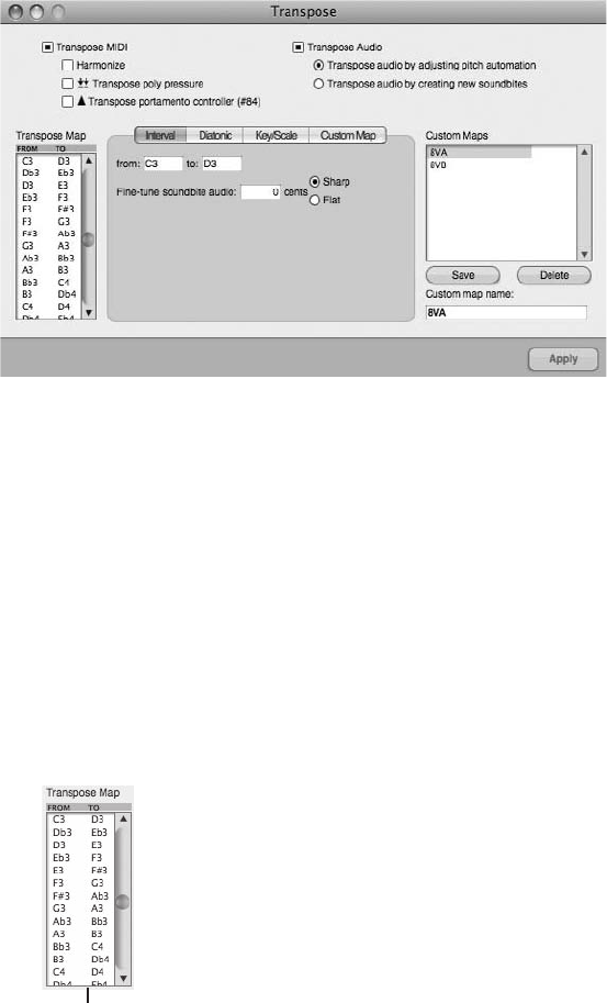
Commandþ9 to open the Transpose command. Once it is open, you can choose to transpose
selected notes, modifying the original data in the process, or you can harmonize the selected
notes, which will create a new harmonized version and merge it with the original material.
Use the Transpose and Harmonize options to set the window to either transpose or harmonize.
The Transpose Map
The Transpose Map, shown in Figure 9.7, contains two columns: From and To. The From and
To columns include a list of all 128 MIDI pitches that determine the interval of the transposi-
tion. For example, if you would like to transpose a selected region of MIDI notes up a major
third, simply choose the appropriate interval from the list, such as C3 to E3 (four semitones).
The Interval, Diatonic, Key/Scale, and Custom Map Options
The Interval, Diatonic, Key/Scale, and Custom Map options (shown in Figure 9.8) determine which
notes will actually be displayed in the To and From columns of the Transpose Map. Use these dif-
ferent options to transpose pitches to a certain type of scale (chromatically, diatonically, and so on).
Figure 9.6 The Region menu’s Transpose command.
The Transpose Map
Figure 9.7 The Transpose Map.
Chapter 9 MIDI: The Region Menu, Plug-Ins, and Virtual Instruments 269
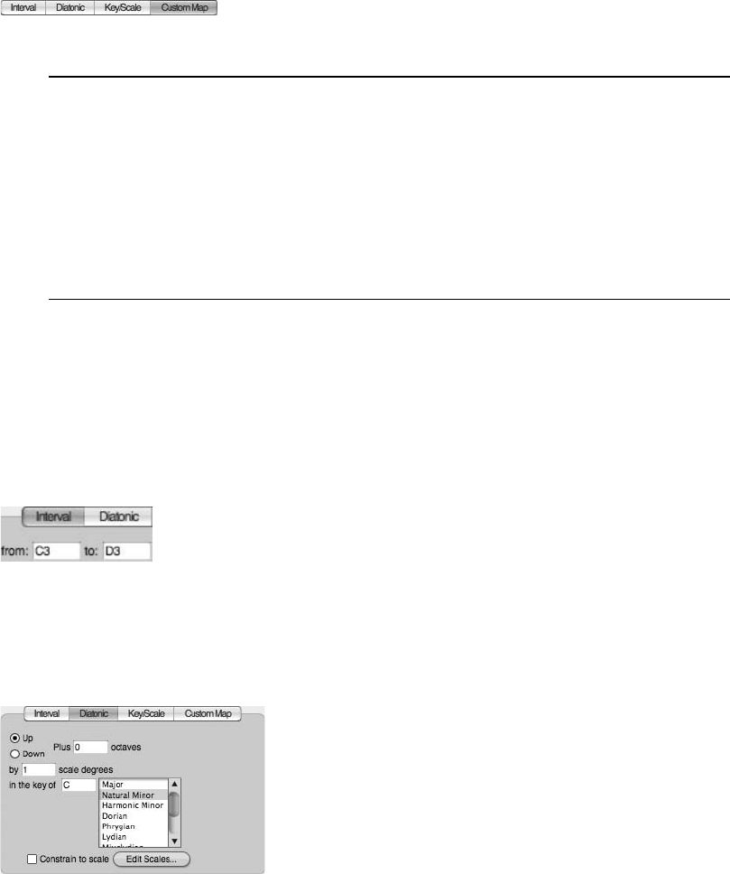
Diatonic or Key/Scale Mode When you choose Diatonic or Key/Scale mode, the scale
steps in the source key (the key you define in the In the Key Of data field) become
bold-faced in the From column. This can be helpful if those pesky scale lessons from
music theory class have escaped you. However, at the time of the writing of this book,
DP’s new user interface and the small size of the font make it somewhat difficult to dis-
tinguish the scale steps in bold type. Hopefully, a future version will remedy this issue.
Until then, keep staring at the list like it’s one of those 3D stereogram images, and the
bold scale steps may eventually appear!
nInterval. Select this option when you want to transpose or harmonize notes chromatically.
All selected notes will be pitched up or down according to the interval that you set in the
From and To input fields, as shown in Figure 9.9. The actual notes you enter do not matter—
only the interval will be used when changing the notes. You can also use the Interval option
to transpose audio data. Refer to Chapter 13, “Processing and Mastering,” for an expla-
nation of pitch-shifting audio. Click Apply to transpose the selected data.
nDiatonic. The Diatonic option, shown in Figure 9.10, allows you to change the pitch of a
note (up or down) by a specific number of scale steps within a designated key (or scale
mode).
Start by choosing the proper key and scale mode for the selected data. Type in the number of
scale steps by which the selected data is to be transposed in the By _____ Scale Degrees input
Figure 9.8 The Transpose command’s different scale options.
Figure 9.9 Use the To and From input fields to set the interval for the pitch change.
Figure 9.10 The Diatonic option and related settings. In this example, all MIDI notes will be transposed
up one scale degree in the key of C Natural Minor.
270 Digital Performer 6 Power!: The Comprehensive Guide
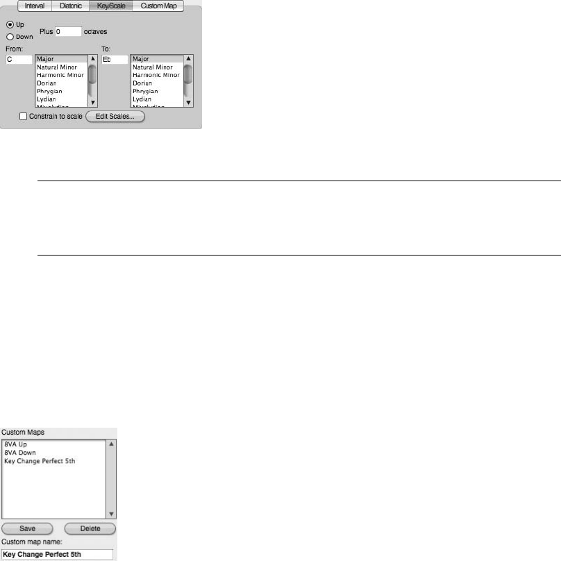
field. Set the direction for the pitch change using the Up and Down options. Use the Plus
_____ Octaves setting to pitch-shift notes by more than one octave. Click the Apply button
to diatonically transpose the selected data.
nKey/Scale. Use the Key/Scale option, shown in Figure 9.11, to change a selection from one
scale to another (or one key to another). Set the selection’s current key in the From input
field and set the scale mode from the list. Use the To input field and list to specify the
destination key and scale mode. Set the direction of the pitch change using the Up or Down
and Plus _____ Octaves options. Click Apply to pitch-shift the selection.
The Constrain to Scale Option The Constrain to Scale option forces all notes that are not
contained in the set scale to be shifted to the closest note within the destination scale. This
option will only appear when the Diatonic or Key/Scale option is selected.
nCustom Map. Use the Custom Map option to create a custom scale of notes. Choose the
Transpose option (Interval, Diatonic, or Key/Scale) on which you wish to base your custom
Transpose Map. Enter your transposition data in the available windows. Once the settings
are changed, the Transposition Map window will automatically adjust to the custom map.
(Continue modifying the new scale as needed.)
To save the custom scale for later use, name the custom map and click the Save button,
shown in Figure 9.12. If your new custom map does not appear in the Custom Maps
Figure 9.11 The Key/Scale option and related settings. In this example, all MIDI notes will be trans-
posed up from the key of C Major to the key of Eb Major.
Figure 9.12 Saved custom map presets will appear in the Custom Maps list.
Chapter 9 MIDI: The Region Menu, Plug-Ins, and Virtual Instruments 271
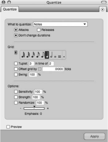
window, simply click anywhere in the white space of the window, and the name should
appear. Click the Apply button to apply your customized scale to the current MIDI selection.
The Quantize Command
The Quantize command, shown in Figure 9.13, is probably the most popular and widely used
Region menu command. Choose Region 4Quantize or use the default keyboard shortcut
Commandþ0 to open the Quantize command. Use this option to constrain the locations of
selected data to a set rhythmic grid.
Quantizing MIDI Notes
The most basic use of the Quantize command is to correct the rhythmic timing of a recorded
MIDI performance. To quantize selected MIDI notes, select the notes you want to quantize,
open the Quantize window, and then choose the Notes option from the What to Quantize
menu. Set the Grid and Options settings as needed, and then click the Apply button. Remember
that you can preview the selection before applying the Quantize settings by enabling the Preview
option, located at the bottom of the window.
The What to Quantize Menu. The Quantize command can alter the attack/release times of
MIDI data, change the start locations of soundbites and markers, and even change the locations
of beats within a soundbite. The What to Quantize menu, shown in Figure 9.14, allows you to
specify the type (or types) of data that will be quantized when you hit the window’s Apply
Figure 9.13 The Region menu’s Quantize command.
272 Digital Performer 6 Power!: The Comprehensive Guide
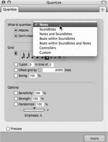
button. The Quantize options that appear in the window are dependent on the data type selected
in the What to Quantize menu. Choose Notes to quantize a selection of MIDI notes.
Quantizing the Attacks, Releases, and/or Durations of Notes. Once you specify the type of data
to be quantized in the What to Quantize menu, you’ll need to decide whether the attacks,
releases, and/or durations will be quantized.
nAttacks. Enabling this option will cause the attack (or start) of the note to be moved to the
closest grid location.
nReleases. This option causes the release times of notes to be moved to the closest grid
location, while preserving the attack times (or start times) of the selected MIDI notes.
nEnabling Both Attacks and Releases. Choosing both options will cause both the attacks and
releases of selected notes to be moved to their closest grid locations; this can change note
durations in the process. When both the Attacks and Releases options are enabled, the Don’t
Change Durations option will be disabled, as note durations will be automatically changed
when quantizing both the attacks and releases of a selection.
nDon’t Change Durations. Enable this option to preserve the durations of quantized MIDI
notes. If this option is turned off, notes (or other types of data) may be truncated or lengthened
when quantized, and this can significantly affect the performance of a selection. Be aware that
this option is disabled when both the Attacks and Releases options are turned on.
Figure 9.14 Use the What to Quantize menu to select the type of data that will be quantized.
Chapter 9 MIDI: The Region Menu, Plug-Ins, and Virtual Instruments 273
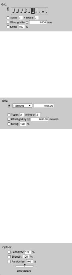
Setting the Resolution for the Quantize Grid. The Grid section of the Quantize window deter-
mines the resolution of the Quantize Grid, or basically divides the Quantize Grid into the speci-
fied duration. By default, the Measures time format will be displayed in the grid section. This
allows you align your MIDI data to specific note values, as shown in Figure 9.15.
To change the time format that’s displayed in the Grid section, click the Time Format button, as
shown in Figure 9.16. Continue clicking to cycle through the available time formats. Keep in
mind that MIDI notes can be quantized to any time format grid and are not limited to just the
Measures time format.
Use the Grid section to choose the value for the Quantize Grid. You can specify the tuplet and
swing settings and even offset the Quantize Grid by a certain number of ticks. Generally speak-
ing, choosing the smallest note value that appears in your MIDI selection will allow you to
“clean up” your performance without totally altering the performance (assuming that your orig-
inal performance isn’t too rhythmically inaccurate).
The Quantize Options. Of course, there will be many times when you do not want to quantize
(or realign) your MIDI selection to the Quantize Grid, because doing so can cause your
performance to feel robotic and emotionless. You can use the Options section, shown in
Figure 9.17, to help maintain the rhythmic “feel” of a performance. When these options are
Figure 9.15 The Measures time format allows you to set the Quantize Grid to a specific note value.
Figure 9.16 The Quantize window’s Time Format button changes the time format of the Quantize
Grid. In this example, the Minutes and Seconds time format has been selected.
Figure 9.17 The Quantize Options section.
274 Digital Performer 6 Power!: The Comprehensive Guide
disabled, however, the data set to be quantized will be moved and aligned precisely to the
chosen Grid value.
nSensitivity. Use positive Sensitivity values to only affect the downbeats of a selection and
negative values to only affect notes that are rhythmically inaccurate. The lower the Sensi-
tivity value, the less the MIDI selection will be precisely aligned to the Quantize Grid. A
setting of 100% is the same as not having the option turned on.
nStrength. Use settings lower than 100% to quantize a selection but still retain the overall
“feel” of the performance. A setting of 50%, for example, only moves a selection halfway
toward the specified grid when quantized.
nRandomize. Randomize basically has the opposite effect of quantizing. A setting of 100%
allows the attacks, releases, and/or durations to be placed in totally random locations within
the specified grid.
nEmphasis. Use this setting to determine whether randomly placed notes will appear earlier or
later within the designated randomize range. Positive values place notes ahead of the beat,
while negative values place notes behind the beat, resulting in a more laidback performance.
The Change Velocity Command
The Change Velocity command, shown in Figure 9.18, is used to alter the velocities (or change
the volume) of a selection of MIDI notes. You can choose to modify a note’s on or off velocities
with the On Velocities or Off Velocities option. Be aware that this command has no effect on
audio data.
The Change Velocity command allows you to change the velocity of notes in different ways, as
shown in Figure 9.19.
nSet. Use this option to change (or set) selected notes to a specific velocity (see Figure 9.20).
For example, entering a value of 64 in the Set All Velocities to _____ input field will change
all selected notes to a velocity of 64.
nAdd. This option, shown in Figure 9.21, allows you to add a set number of velocity values to
a MIDI note selection. Use the Add _____ to All Velocities input field to set the velocity value
that will be added.
nScale. This option scales a MIDI note selection by a percentage value. Use the Change to
_____% of Current Value input field to specify the percentage value, as shown in Figure 9.22.
nLimit. This option limits the velocity values of a MIDI selection to a set velocity range, as
shown in Figure 9.23.
nCompress/Expand. This option, shown in Figure 9.24, is similar to an audio compressor/
expander plug-in. The Threshold knob determines when velocity compression/expansion
Chapter 9 MIDI: The Region Menu, Plug-Ins, and Virtual Instruments 275
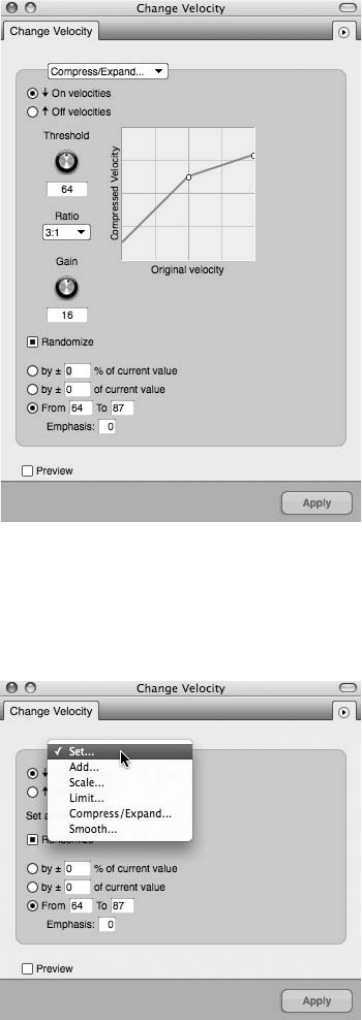
Figure 9.19 Select an option from this list to determine how velocities will be changed with the
Change Velocity command.
Figure 9.18 The Region menu’s Change Velocity command. In this example, the Compress/Expand
option has been selected.
276 Digital Performer 6 Power!: The Comprehensive Guide
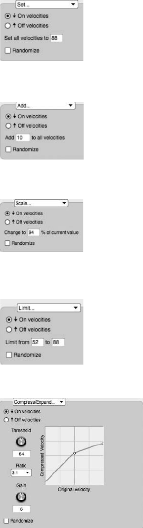
Figure 9.20 The Set velocity option.
Figure 9.21 The Add velocity option.
Figure 9.22 The Scale velocity option.
Figure 9.23 The Limit velocity option.
Figure 9.24 The Compress/Expand velocity option.
Chapter 9 MIDI: The Region Menu, Plug-Ins, and Virtual Instruments 277
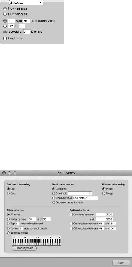
will start and stop. The Ratio setting determines the amount of compression/expansion
applied. Use the Gain knob to make up any gain that’s lost in the process.
nSmooth. The Smooth option, shown in Figure 9.25, basically automates a smooth velocity
change along a set curve. The _____% to _____% of Current Value option is similar to
the previously discussed Scale command, except that the MIDI selection will be scaled
between the first and second percentage values that you specify.
The _____ to _____ option sets the velocity of the first MIDI note within your selection to the
first value and the last note velocity in your MIDI selection to the last value. Once set, the in-
between values are automatically calculated to create a smooth velocity transition between
the first and last notes in your selection.
The With Curvature setting determines the type of curve that will be used. A setting of zero
creates a linear curve. Positive values apply the majority of the velocity changes toward the
end of the curve, while negative values have the opposite effect.
The Split Notes Command
The Split Notes command, shown in Figure 9.26, is used to copy or cut specific notes from a MIDI
track. Use this command to “explode” selected MIDI notes onto their own individual tracks.
Figure 9.25 The Smooth velocity option.
Figure 9.26 The Split Notes command.
278 Digital Performer 6 Power!: The Comprehensive Guide
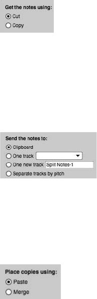
At first glance, the Split Notes window may seem confusing, but actually it’s fairly straight-
forward. Once you’ve selected a MIDI region to work with (or an entire MIDI track), simply
proceed to each section within the window and make the desired settings.
nGet the Notes Using. Select how DP will retrieve the specified notes from the MIDI selection
by copying the notes (leaving the original MIDI data intact) or by cutting the notes (which
will remove the selected notes all together), as shown in Figure 9.27. If you are using the
Cut option, you may want to duplicate the track or take before beginning this process in
order to have a backup of your MIDI data.
nSend the Notes To. This section, shown in Figure 9.28, determines where the copied or cut
material will be placed once you hit the Apply button. Notes can be placed on the Mac’s
clipboard, on an existing track, or on a new track. Choosing the Separate Tracks by Pitch
option allows you to explode each different pitch onto its own new track.
nPlace Copies Using. This section, shown in Figure 9.29, determines whether copied or cut
notes will be pasted in the destination track (overwriting the existing material) or merged
with any existing data.
nPitch Criterion. The Pitch Criterion section, shown in Figure 9.30, allows you to specify
exactly which notes will be copied or cut with the Split Notes command. Choose the
appropriate setting from the list. To choose specific notes, simply click on the note in the
keyboard.
nOptional Criteria. The Optional Criteria section, shown in Figure 9.31, allows you to further
specify the exact notes that will be split from the MIDI selection.
Figure 9.27 The Get the Notes Using section.
Figure 9.28 The Send the Notes To section.
Figure 9.29 The Place Copies Using section.
Chapter 9 MIDI: The Region Menu, Plug-Ins, and Virtual Instruments 279
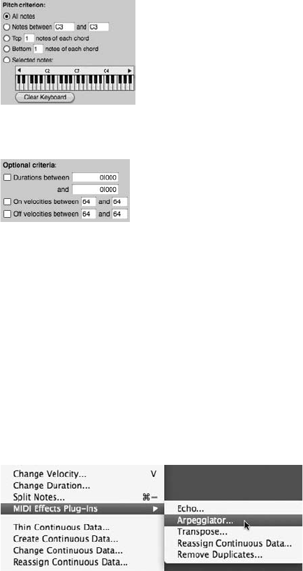
When you have specified how and where the specified notes will be split, click the Apply button
to execute the Split Notes command.
MIDI Effects Plug-Ins
Similar to audio plug-ins, MIDI effects plug-ins can be applied in real time or as a file-based
process. MIDI plug-ins located in the Region menu, shown in Figure 9.32, will permanently alter
MIDI data that they process; real-time MIDI plug-ins inserted in the Mixing Board, shown in
Figure 9.33, will only affect the real-time playback of a MIDI track.
Processing with the Region Menu’s MIDI Effects Plug-Ins
The procedures for processing selected MIDI data with the Region menu’s MIDI effects plug-ins
are identical to those of the Region menu commands. Simply select the MIDI data you want to
modify and choose the desired plug-in from the Region menu’s MIDI Effects Plug-Ins submenu.
When you have configured the plug-in and hit the Apply button, the selected data will be
destructively processed with the specified settings, permanently altering the selected MIDI data.
Figure 9.30 The Pitch Criterion section.
Figure 9.31 The Optional Criteria section.
Figure 9.32 The Region menu’s MIDI effects plug-ins are destructive processes that permanently alter
the original MIDI data in a track.
280 Digital Performer 6 Power!: The Comprehensive Guide
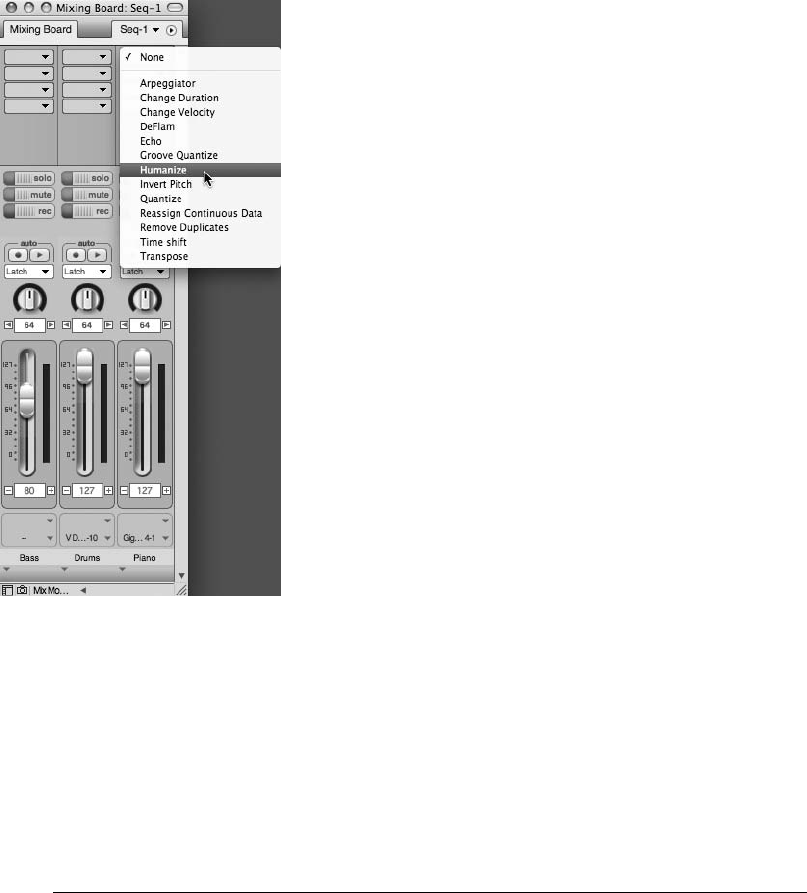
Inserting Real-Time MIDI Plug-Ins
To insert a real-time MIDI plug-in, open the Mixing Board by pressing ShiftþM. Navigate to the
desired MIDI track, click on an available Insert slot, and then choose the MIDI plug-in from the
list. Start playback to hear the inserted MIDI effect in real time. Refer to Chapter 12, “Mixing,”
for an explanation of Insert slots and the Mixing Board.
Recording MIDI Tracks into Audio Tracks: The Basics Although the current trend is concen-
trated on virtual instruments and soft synths, you may be using MIDI tracks to activate
hardware (outboard) MIDI sound modules, such as a Roland DM5 Drum Module or a
Korg Wavestation synth. If so, you might want to include these tracks in the final mix
of audio tracks (as well as apply any desired audio processing plug-ins). When you
have made all of the necessary adjustments to your MIDI tracks, such as velocities, tim-
ings, or transpositions, the next step is to record your MIDI tracks into audio tracks.
Figure 9.33 Real-time MIDI plug-ins affect the playback of MIDI tracks while keeping the original MIDI
data intact. Notice that the Mixing Board’s MIDI plug-ins menu even contains real-time versions of the
Region menu’s various commands.
Chapter 9 MIDI: The Region Menu, Plug-Ins, and Virtual Instruments 281

This recording process involves all of the steps discussed in Chapter 7. The only
difference is that the incoming signal consists of the sounds coming out of your MIDI
hardware (such as a synthesizer, sampler, or sound module). Think of it like this: The
data in your MIDI tracks is triggering chosen instruments from the device (via MIDI
connections), and depending on your studio configuration, the triggered audio is sent
from the device’s audio outputs to specific inputs of your audio interface (via audio
connections).
When recording from a MIDI track into an audio track, simply choose the input for the
audio track that corresponds to the MIDI device. Once you have armed the track and
checked the levels of the incoming signal, you are ready to begin recording. If you are
still unclear about the signal flow of your MIDI devices, you might want to refer to
Chapters 2 and 4 before recording.
Virtual Instrument Plug-Ins
Much like hardware MIDI devices, such as synthesizers, samplers, and sound modules, virtual
instruments (plug-in instruments or soft synths) are triggered by data in corresponding MIDI
tracks. However, virtual instruments reside within DP and are accessed via the inserts of an
instrument track (in other words, “plugged in”). For a virtual instrument plug-in to show up
in Digital Performer, it must be in the MAS (MOTU Audio System)orAU(Audio Units) format
(explained in Chapter 2). DP also supports VI plug-ins that reside in other applications (such as
Propellerhead’s Reason and Ableton Live).
Pre-Rendered Instrument Tracks (MOTU’s Pre-Gen)
With third-party VI plug-ins, such as Spectrasonics’ Trilian Bass or VSL’s Vienna Instrument,
there are two very important things to always consider: your computer’s processor and available
RAM. Today, feature-rich third-party VIs are quite amazing when it comes to their sound qual-
ity, flexibility, on-board effects, and so on. However, just a few instances of the coolest new
plug-in can drain the resources of even the most robust computer system (not to mention the
need to play nice in the same sequence with numerous audio tracks, accompanying effects pro-
cessors, and an imported movie file—the combination can be treacherous!).
To the rescue (and new to version 6) is the ability to create and run more VIs without having to
cross your fingers that the revolving beach ball doesn’t pay repeated visits! In DP6, once you
close a plug-in’s window, a VI’s output (from the created instrument track, discussed later in this
chapter) is busily being prerendered (or assembled). MOTU refers to this process as pre-gen.
This means your computer’s CPU is allowed to ration out its available processing power before
playback actually begins, resulting in real-time playback being less taxing on the system. Of
course, you can always run a VI in conventional real-time mode by selecting Run This Instance
in Real-Time in each plug-in’s mini-menu (see Figure 9.34).
282 Digital Performer 6 Power!: The Comprehensive Guide
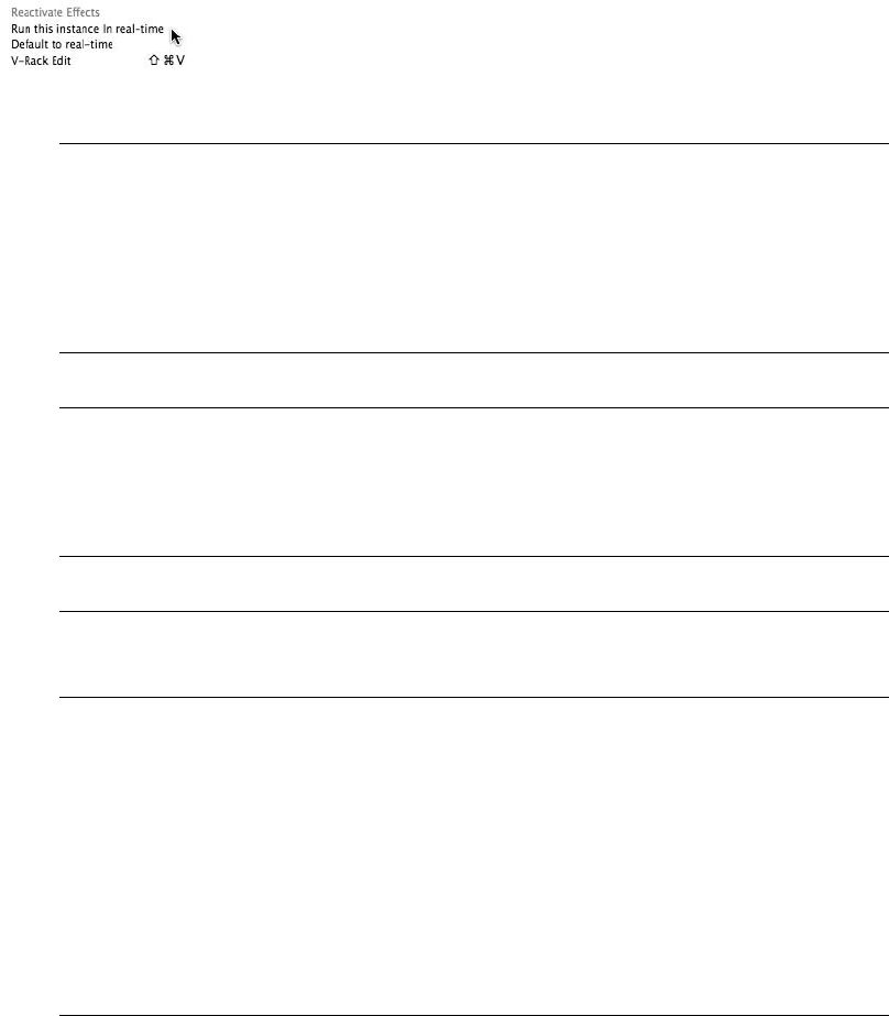
Digital Performer Includes Six Virtual Instrument Plug-Ins In DP, six virtual instrument plug-
ins are included with your Digital Performer software. BassLine, Model 12, Modulo,
Nanosampler, PolySynth, and Proton provide a nice variety of instrument sounds, such
as analog-modeled bass guitars, various drum kits, and retro-style synthesizers. For a
detailed look at these instruments and their various settings, consult the “Virtual Instru-
ment Plug-Ins” chapter of your DP User Manual.
Virtual Instruments and DAE Keep in mind that when running Digital Performer under DAE
(Digidesign Audio Engine) and not MAS, AU/MAS/VST plug-ins will not be available. You
will, however, be able to open up plug-ins and virtual instruments that are in the TDM,
RTAS, and AudioSuite formats.
Working with ReWire Virtual Instruments Refer to Chapter 4 for an explanation of the
setup process involved with ReWire virtual instruments.
Once a supported virtual instrument plug-in has been installed, it will appear in the Instrument
Track submenu, as shown in Figure 9.35.
As explained in Chapter 8, virtual instrument plug-ins must first be opened within an instrument
track before they will appear in the output assignment menu of a MIDI track. Basically, you will
not be able to send MIDI data to a virtual instrument plug-in until its instrument track has been
created. Once a VI is created and opened (also referred to as instantiated), it will present (pub-
lish) its MIDI input channels (as shown in Figure 9.36), which also become immediately avail-
able in the output assignment menu of all MIDI tracks (as shown in Figure 9.37).
Can’t See or Hear Your Virtual Instrument? Don’t worry; it happens to the best of us!
Remember, an available output (or bus routed to an available output) must be used
when creating a virtual instrument track in order to open and ultimately hear the instru-
ment. Sometimes a VI is created but no output assignment is defined for the track, result-
ing in an incomplete loading of the VI’s window (which is usually the case with third-party
plug-ins). As with an audio track, make sure to use the output assignment menu of the
Figure 9.34 In DP6, virtual instruments are pre-rendered unless Run This Instance in Real-Time is selected.
Chapter 9 MIDI: The Region Menu, Plug-Ins, and Virtual Instruments 283
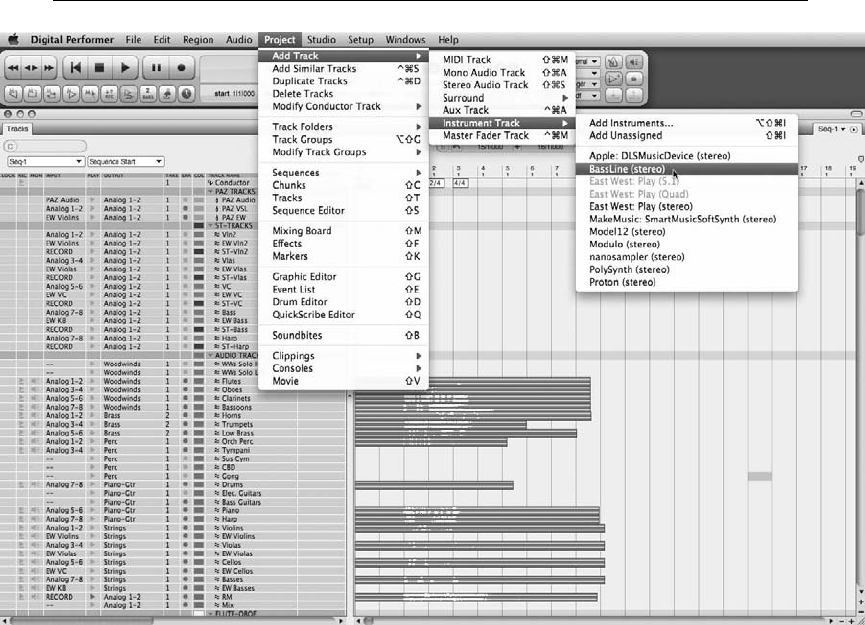
instrument track to select an available output or bus (such as Analog 1-2). As is to be
expected, if no output is selected, the VI title header will appear but will not fully load,
and its MIDI inputs will not be available in the output assignment menu of your MIDI
tracks (as discussed earlier in this chapter).
Assigned Instrument Track
Digital Performer allows you to create two basic types of instrument tracks: assigned and unas-
signed. Assigned instrument tracks are created with a virtual instrument already assigned to
them—simply choose the desired virtual instrument plug-in from the Instrument Track submenu.
For example, to create an instrument track with MOTU’s Bassline virtual instrument assigned to
it, just choose Bassline from the Instrument Track submenu, as shown in Figure 9.38.
To create an assigned instrument track, choose Project 4Add Track 4Instrument Track and
select the virtual instrument from the list. To add multiple assigned instrument tracks (and mul-
tiple corresponding MIDI tracks), choose Project 4Add Track 4Add Instruments.
Figure 9.35 The Instrument Track submenu provides a list of installed MAS and AU virtual instrument
plug-ins.
284 Digital Performer 6 Power!: The Comprehensive Guide
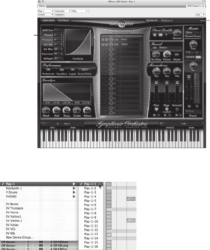
Unassigned Instrument Tracks
Unassigned instrument tracks, shown in Figure 9.39, are basically “empty” tracks that do not
currently have a virtual instrument plug-in assigned or inserted. Unassigned instrument tracks
are handy for creating project templates—they allow you to make a virtual instrument plug-in
assignment at a later time.
A Loaded
VI Instrument
in East
West/Quantum
Leap’s Play
Engine
A VI Plug-In’s
MIDI Channel
Figure 9.36 Once a VI is opened (instantiated), it will publish its available MIDI input channels. In this
example, there is a contrabass “Big Sus” in MIDI channel 1 of EastWest/Quantum Leap’s Play virtual
instrument.
Figure 9.37 Once instantiated, the Play VI’s available MIDI input channels become available in the out-
put assignment menu of a MIDI track.
Chapter 9 MIDI: The Region Menu, Plug-Ins, and Virtual Instruments 285
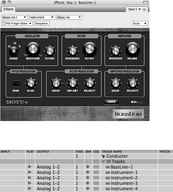
To create an unassigned instrument track, choose Add Track 4Instrument Track 4Unas-
signed. You can also use the default keyboard shortcut ShiftþCommandþI.
Instrument Inserts and the Mixing Board
Within the Mixing Board, an instrument track functions almost identically to an audio track.
You are free to insert effects, utilize sends, and so on. The difference, however, is that instrument
tracks contain a special type of insert called an instrument insert that appears shaded yellow
within the track’s Insert section. Clicking on the insert will reveal a list of available virtual
instrument plug-ins. Use the instrument insert to assign an instrument to an unassigned track
or to change the existing instrument to a new one.
To assign a virtual instrument to an unassigned instrument track:
1. Open the Mixing Board by pressing ShiftþM.
2. Navigate to the unassigned instrument track. At the top of the channel strip is the first
Insert menu, as shown in Figure 9.40. This is called the instrument insert.
Figure 9.38 A Bassline virtual instrument is created by choosing Bassline from the Instrument Track
submenu (shown earlier in Figure 9.35).
Figure 9.39 Unassigned instrument tracks are created with the default name “Instrument.” Notice that
the assigned Bassline instrument tracks appear with the name Bassline-1.
286 Digital Performer 6 Power!: The Comprehensive Guide
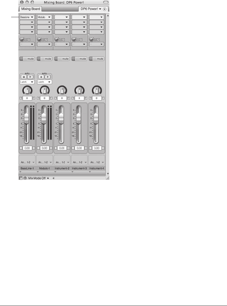
3. Click on the instrument insert and choose the desired instrument plug-in from the list, as
shown in Figure 9.41.
To insert a different virtual instrument in an assigned instrument track:
1. Open the Mixing Board by pressing ShiftþM.
2. Navigate to the assigned instrument track. The name of the existing virtual instrument
plug-in will be displayed in the instrument insert that’s shaded red.
3. Click on the instrument insert and choose another instrument from the list.
Virtual Instrument or Virtual Sampler? We have already discussed virtual instruments, but
what is a virtual sampler? Although these terms are often used interchangeably, let’s take
a deeper look. Without going too far into their extensive list of features, think of virtual
Instrument
Insert
Figure 9.40 Within the Mixing Board, virtual instrument plug-ins have their own instrument inserts.
Unassigned instrument inserts will appear blank.
Chapter 9 MIDI: The Region Menu, Plug-Ins, and Virtual Instruments 287
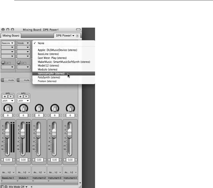
samplers as yet another container for your virtual instruments. Virtual samplers are also
“plugged in” to DP via an instrument track and can be a host for a multitude of instru-
ments and sounds. When you load your VI in a compatible sampler (rather than its own
instrument track), you often have much more flexibility in manipulating the sound of the
instrument (or, to use the latest term, “tweakability”). Within the virtual sampler, you
can import, edit, synthesize, and process instruments, looped patterns, synths, and
sounds, or like samplers of old, you can “sample” your own sounds to use as instru-
ments, FX, and so on. MOTU’s MachFive and Native Instruments’ Kontakt are powerful
examples of virtual samplers and are compatible with (or can import and convert) many
of the virtual instrument libraries on the market. In addition, many virtual samplers
include a large set of instruments and sounds, allowing you to start creating right out
of the box.
Figure 9.41 Click the instrument insert to choose an instrument plug-in.
288 Digital Performer 6 Power!: The Comprehensive Guide
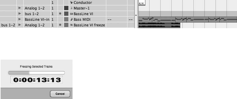
The Freeze Selected Tracks Command
The Audio menu’s Freeze Selected Tracks command enables you to automatically “print” or
temporarily bounce selected tracks in real time, allowing you to free up your system’s resources
for other CPU-intensive tasks. When you freeze a track, DP will automatically assign tracks that
are to be frozen to a new bus, create a new audio track with its input assigned to the new bus,
and begin recording the outputs of the frozen tracks to the new audio track (with all real-time
effects printed to the track). Not only is this a great way to lessen the strain on your CPU, it can
also be very handy for creating a quick stereo mix of your project.
To freeze an audio, aux, or instrument track:
1. Click the name of the instrument track in the Tracks Overview section of the Tracks
window.
2. Select the data you want to freeze.
3. If you’re freezing an instrument track or an aux/audio track being used to monitor a
MIDI device (as discussed in Chapter 4), be sure to include the associated MIDI track in
the selection. Remember that you can Shift-click the names of tracks within the Tracks
window to select multiple tracks. This is an important step—if you don’t include the
corresponding MIDI track, DP will create a frozen track that contains silence.
4. Choose Audio 4Freeze Selected Tracks. DP will start the freeze process. In this
example, DP automatically creates a new audio track with an input assignment on
Bus 1-2 and assigns the tracks selected in Steps 1 and 2 to the new bus, as shown in
Figure 9.42. The progress bar that appears is identical to the Bounce to Disk command’s
progress bar, as shown in Figure 9.43.
Figure 9.43 The Freeze Selected Tracks progress bar.
Figure 9.42 Tracks are automatically created and assigned during the freeze process.
Chapter 9 MIDI: The Region Menu, Plug-Ins, and Virtual Instruments 289
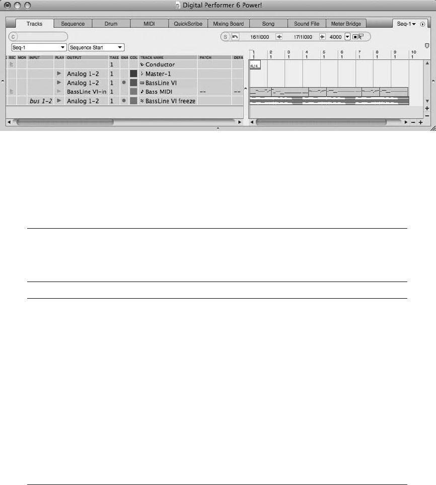
5. When the Freeze Selected Tracks process is completed, you’ll need to mute the original
MIDI track (shown in Figure 9.44) or assign the instrument track’s voice to None so
that you don’t hear playback from the original tracks along with the newly created
frozen track.
nTo unfreeze a frozen track, press and hold the Shift key and choose Audio 4Unfreeze
Selected Tracks. Use the Shift key to toggle between the Freeze and Unfreeze Selected Tracks
commands.
Freezing Tracks with Processing Effects When using the Freeze Selected Tracks command,
be aware that effects plug-ins must be run in real time in order for them to be “printed” on
the frozen track. Use a plug-in’s mini-menu to toggle its real-time settings.
Bouncing Virtual Instrument Tracks to Disk In previous versions of DP, you were required
to either “freeze” VI tracks with the Freeze Selected Tracks command or record the
audio output of the instrument tracks to separate audio tracks in real time (discussed
below) before using the Bounce to Disk command (“bouncing” multiple audio tracks
down to a single sound file). On account of MOTU’s new pre-gen feature, mentioned
earlier in this chapter, Digital Performer 6 now has the ability to include VI tracks in a
bounce-to-disk operation. For more information on the Bounce to Disk command, refer
to Chapter 13.
To record the audio output of an instrument track in real time, create a new audio track
and assign its input to an available bus, such as Bus 1-2. Change the instrument track’s
output assignment to Bus 1-2. Arm the audio track and hit Record, and the audio from
the instrument track will be recorded into the audio track in real time.
Figure 9.44 In this example, the Freeze Selected Tracks process has been completed, and the MIDI track
has been muted to prevent simultaneous playback of the original and frozen tracks.
290 Digital Performer 6 Power!: The Comprehensive Guide
Summary
DP’s Region menu contains many powerful commands for altering MIDI data. In addition to
these destructive MIDI operations, you can also use the Mixing Board’s MIDI effects plug-ins to
process MIDI tracks in real time, allowing you to audition different settings or change plug-ins
all together without altering the original MIDI data within a track. Support for virtual instru-
ment plug-ins and samplers, along with DP’s instrument tracks, allows you to expand your
library of sounds, while the Freeze Selected Tracks command helps to reallocate precious
CPU resources when you are working with complex projects.
Chapter 9 MIDI: The Region Menu, Plug-Ins, and Virtual Instruments 291
This page intentionally left blank

10 Editing
Arguably the greatest advantage of nonlinear editors (such as Digital Performer, Pro
Tools, Final Cut Pro, Photoshop, and so on) is their powerful features and tools for
editing data. Every aspect of a track or project can be refined—wrong notes can be
fixed, timing inaccuracies can be corrected, and so on. Nonlinear editors provide you with
powerful ways to enhance and improve—or unknowingly destroy—your media projects. Just
because you can tune the vocal to harmonic perfection doesn’t mean you should. The Quantize
command, for example, is a great tool for correcting rhythmic imperfections within a perfor-
mance. When used (or abused) too aggressively, however, it can render a grooving track lifeless
and robotic.
Digital Performer packs a powerful set of editing tools and feature sets. Various tools, editor
windows, and keyboard shortcuts provide you with an arsenal of editing capabilities. In this
section, I’ll provide an overview of the basic (and most widely used) ways of editing audio
and MIDI data. For a full explanation of the DP’s selection capabilities, refer to the Digital
Performer User Manual.
Following is a list of topics covered in this chapter:
nThe Tool palette
nHow to work with time formats, Time Rulers, and edit grids
nHow to use the View Filters
nHow to zoom
nHow to select and move audio and MIDI data
nHow to use DP’s standard Edit menu commands
nHow to edit audio in the Sequence Editor
nHow to create fades and crossfades
nHow to edit MIDI notes and controller events in the Graphic Editor
nHow to use the Event List
293
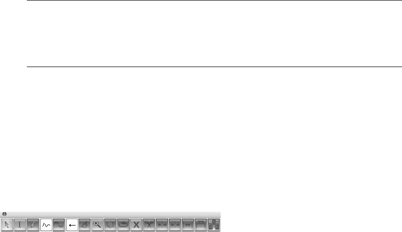
The Tool Palette
The Tool palette is like a toolbox for Digital Performer’s various editing tools. You can call up,
or open, the Tool palette by pressing ShiftþO. You can also choose Studio 4Tools.
Positioning the Tool Palette You can position the Tool palette vertically or horizontally by
using ShiftþOptionþ‘. You can even force it to automatically stay docked with the active
edit window by selecting Digital Performer 4Preferences 4Tools 4Position Tool
Palette Automatically.
Each tool within the Tool palette allows you to perform a certain function. Simply click on a
tool to select it. You can also use DP’s many default keyboard shortcuts to quickly select a
particular tool. To toggle (or temporarily select) a particular tool, press and hold its correspond-
ing letter key. Double-tap the letter key to make the tool selection stick.
Following is a description of the various tools contained in the Tool palette, which is shown in
Figure 10.1. The letter that comes after the tool name (in parentheses) is the tool’s default key-
board shortcut. Keep in mind that Insert/Reshape Curve and Reshape Mode cannot be accessed
from the Mac’s keyboard.
nThe Pointer tool (A). Use the Pointer tool (also called the Arrow tool) to select and move
audio and MIDI data.
nThe I-Beam tool (I). Use the I-Beam tool (also called the Selector tool) to make time-range
selections within an editor window, regardless of the type data you’re working with.
nThe Pencil tool (P). Use the Pencil tool to insert note and automation data. The Insert/
Reshape Curve determines the shape or type of waveform that is drawn with the Pencil tool.
nThe Insert/Reshape Curve. Use this drop-down menu to set the shape/curve of the Pencil
tool.
nThe Reshape tool (R). Use the Reshape tool to change the shape or curve of existing auto-
mation and controller data.
nThe Reshape Action (Mode). Use the Reshape Mode to determine how data is affected by
the Reshape tool.
nThe Pattern tool (E). The Pattern tool (also called the Rhythm Brush) allows you to “paint”
or draw notes within the Drum Editor.
Figure 10.1 The Tool palette.
294 Digital Performer 6 Power!: The Comprehensive Guide
nThe Zoom tool (Z). Use the Zoom tool (or Zoomer tool) to zoom in or out on a selection.
nThe Scrub tool (S). Use the Scrub tool to “scrub” or audition the playback of data within an
audio and MIDI track.
nThe Insert Loop tool. Use this tool to insert a loop in a track by clicking and dragging
horizontally in the marker strip.
nThe Mute Soundbites tool (M). Use this tool to quickly mute or un-mute a soundbite. Once
muted, the soundbite will appear dimmed. Keep in mind that the Automation Setup window’s
Mute Frees System Resources setting has no effect on soundbites muted with the Mute tool.
nThe Scissors tool (C). Use the Scissors tool to split a soundbite or MIDI note. You can
repeatedly split a soundbite or note into sections that are constrained to a specific grid value
by dragging with this tool (with the edit grid turned on).
nThe Trim tool. This tool allows you to relocate the right or left edge of a soundbite with a
simple click in the desired location.
nThe Roll tool. When two soundbites are adjacent, this tool allows you to edge edit the end of
one soundbite and the beginning of another at the point where the two soundbites come
together.
nThe Slip tool. This tool allows you to edge edit the start and end of a soundbite without
changing the position of the soundbite in the track. In other words, you can move (slip) the
audio back and forth within the edge-edited soundbite location.
nThe Slide tool. Use this tool to move the position of a soundbite while leaving the soundbite’s
audio at the same playback time.
nThe Comp tool. Use this tool to create a composite (or Comp) Take from multiple takes
in an audio track. See the “Comp Takes (or Track Comping)” section of Chapter 7 for
more information.
The Time Formats Window, Time Ruler, and Edit Grid
There are a few specific features that you should be familiar with in order to efficiently edit data
within Digital Performer. Time formats and the Time Ruler directly affect how audio and MIDI
data is selected, while the edit grid constrains edits and selections to a specified grid value.
The Time Formats Window
Digital Performer provides four different time formats that can be displayed within a project—
Measures, Real-Time (minutes and seconds), Frames (SMPTE), and Samples (audio samples).
Each time format can be displayed individually or simultaneously. The Time Formats window,
shown in Figure 10.2, allows you to set the time formats that will appear throughout a project—
including the various Counters, rulers, Event Lists, and so on.
Chapter 10 Editing 295
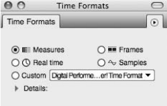
To set the time format for a project:
1. Choose Setup 4Time Formats. The Time Formats window will open.
2. Select the time format to be displayed. Changes are instantaneous and will be reflected
anywhere time can be shown.
Multiple time formats can also be displayed. You can even specify different time formats for the
Time Ruler, edit grid, pointer coordinates, and event information from the Details section of the
Time Formats window, as shown in Figure 10.3. The Rulers and Edit Grid section uses aux
rulers to display multiple time formats, because only one time format can be designated as
the main ruler.
The Pointer Coordinates and Event Information sections, however, allow you to enable multiple
time formats by simply clicking on each time format check box. Additional parameter setting
information, such as pitch value, MIDI note number, duration, end time, and sync point, can
also be displayed.
To enable multiple time formats for a project:
1. Open the Time Formats window by pressing OptionþCommandþT.
2. Click the Details disclosure triangle to display the Custom options.
3. In the Time Display section, select the main Time Ruler that will be displayed
throughout your project. If you select Measures, you can further customize the
Measures time format from the Measures section of the window, as shown in
Figure 10.4.
4. Next, choose the desired time format settings for the Rulers and Edit Grid section, the
Pointer Coordinates section, and the Event Information section. Notice that the Rulers
and Edit Grid section allows you to display multiple time formats with the use of aux
rulers, as shown in Figure 10.5. Once an aux ruler (or secondary time format) is
enabled, the particular time format will appear above a Time Ruler’s main ruler, as
shown in Figure 10.6.
Figure 10.2 The Time Formats window.
296 Digital Performer 6 Power!: The Comprehensive Guide
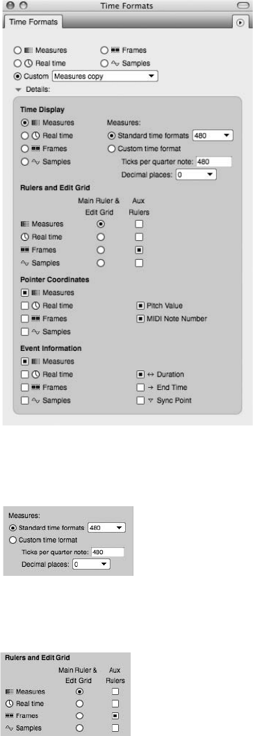
Figure 10.4 Use the Measures section to further customize how the Measures time format will be dis-
played in DP.
Figure 10.5 Enable an aux ruler to display multiple time formats within a Time Ruler.
Figure 10.3 The Details section of the Time Formats window is displayed by clicking the Details disclo-
sure triangle, located below the Custom option.
Chapter 10 Editing 297
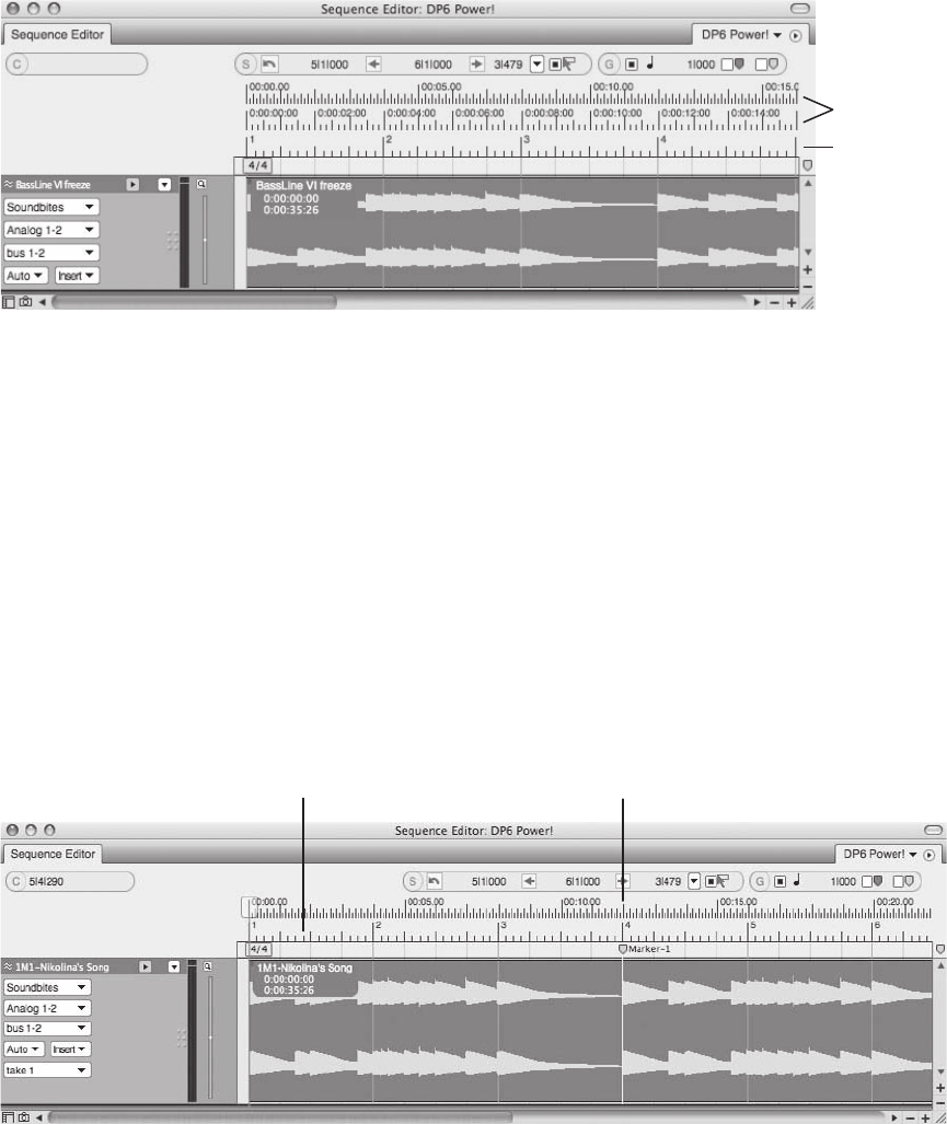
5. Custom settings will be saved automatically and listed in the Custom drop-down menu
located to the right of the Details disclosure triangle.
6. Close the Time Formats window. There is no need to apply the new settings—any
changes made to the Time Formats window will be instantaneous.
The Time Ruler
Each editor window in DP (except the QuickScribe Editor) contains a Time Ruler that is located
below the window’s title bar and/or Information Bar, as shown in Figures 10.7 and 10.8. A Time
Ruler consists of a main ruler and/or secondary aux rulers. To designate a specific time format
for the main and aux rulers, refer to the previous section.
Aux Rulers
Main Ruler
Figure 10.6 In this example, the Time Ruler’s main ruler is set to Measures.
Measures Real Time
Figure 10.7 In this example, the Sequence Editor’s main Time Ruler is shown as Measures. Notice that a
secondary (aux) ruler displaying Real Time has been enabled. Vertical lines divide the window into sec-
tions or subdivisions.
298 Digital Performer 6 Power!: The Comprehensive Guide
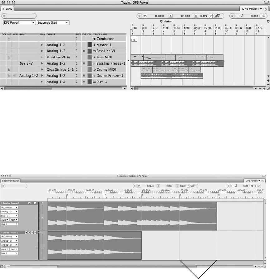
The Time Ruler basically displays a linear measurement of time throughout an editor window,
with vertical lines that extend and divide a window into equal segments (or subdivisions). The size
of each subdivided section depends on the current horizontal zoom resolution and time format
that are displayed in the main ruler. For example, if I horizontally zoom in far enough in the
Sequence Editor, I can view each measure within a track, as shown in Figure 10.9. Notice that
the Time Ruler’s vertical lines extend from Beat 1 of each measure through each visible track.
If I horizontally zoom out, the main Time Ruler’s subdivisions will become larger, allowing
me to view more of the track’s data within the same amount of physical space, as shown in
Figure 10.10. Notice that the Time Ruler vertical lines no longer appear at the beginning of
Figure 10.8 The Tracks window’s Time Ruler appearance is simple compared to the other editor
windows.
Vertical Lines Extend
Through the Window
Figure 10.9 The Time Ruler displays vertical lines that extend through an editor’s window. These lines
divide a track (or window) into equal subdivisions.
Chapter 10 Editing 299
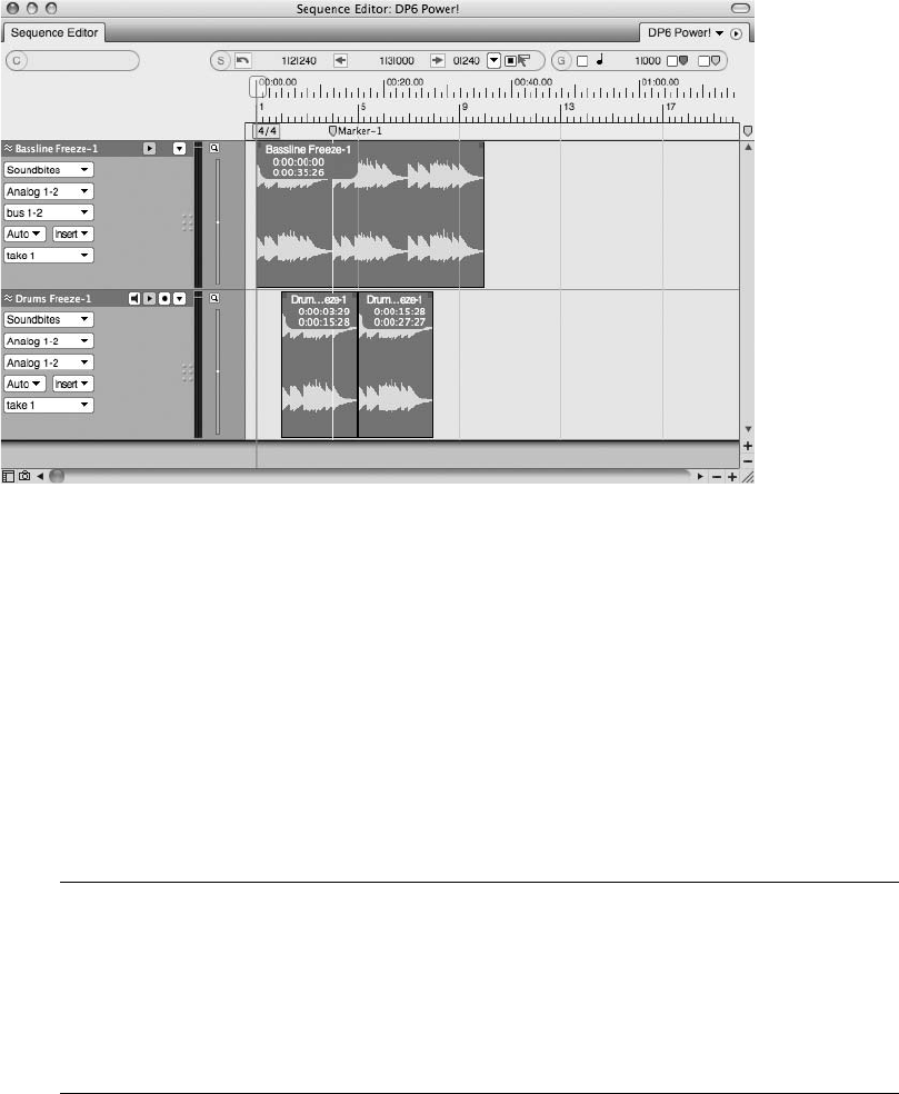
each measure; now they appear every four measures—basically subdividing the tracks into four-
bar segments.
The Time Ruler is a critical part of DP’s editor windows that allows you to visually navigate to
specific times or points within a sequence and view the relationship between a sequence’s time-
line and data within a track. You can even make time-range selections directly in the Time Ruler
by simply clicking and dragging. In addition to the Time Ruler’s vertical lines that subdivide an
editor window, edit grid lines can be enabled to constrain edits to a specified grid. The edit grid
is explained in the following section.
Which Time Formats Should You Display in the Time Ruler? Remember that the type of
time measurement that is displayed in the Time Ruler’s main and aux rulers is determined
by the specific time formats selected in the Time Formats window. Exactly which formats
you choose to work with and display is entirely up to you and will be dictated by the type
of project and the specific type of editing tasks you need to accomplish. Feel free to
change the displayed time formats at any time within a project.
The Edit Grid
An edit grid is a staple of nonlinear editing applications. Edit grids basically subdivide a window
or track into equal segments (or a grid). An edit grid’s resolution setting (or value) determines
Figure 10.10 In this example, I have horizontally zoomed out on the tracks. Notice that the main Time
Ruler now displays four-bar subdivisions.
300 Digital Performer 6 Power!: The Comprehensive Guide
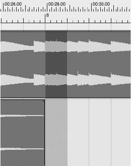
the amount of time between each grid line. For example, if you enable the edit grid and set its
resolution to a quarter-note value, any edits that are made will be automatically constrained to
quarter-note divisions, as shown in Figure 10.11.
With the edit grid set to a quarter-note resolution, you could make a quarter-note time-range
selection, a half-note selection (two quarter notes), a whole-note selection (four quarter notes),
and so on. Any time range that can be divided by a quarter note is possible. An eighth-note
selection, however, would not be possible, because it is smaller than the specified quarter-
note grid. Refer to the “Grids, Time Rulers, and Zooming” section of Chapter 3 for a review
of grid resolution settings.
Working with DP’s Edit Grids
Some of DP’s editor windows (such as the Tracks window, the Notation Editor, and the Drum
Editor) automatically constrain edits and selections to an edit grid and will not allow you to
disable this grid. Other windows, such as the QuickScribe Editor and the Event List, do not
contain edit grids. The Sequence, Graphic, and Waveform Editors, however, give you an option
for enabling and disabling the edit grid and setting its resolution—providing you increased
flexibility when editing audio and MIDI data (see Figure 10.12).
The Tracks Window
The Tracks window, by its nature, automatically constrains edits and selections to a grid. The
Time Ruler’s main time format, along with the current zoom setting, determines the actual size
of the grid. Zooming in within the Tracks window, for example, will reduce the size of the grid,
allowing you to make smaller edits and selections, as shown in Figure 10.12.
Figure 10.11 In this example, the Sequence Editor’s edit grid has been enabled and set to a quarter-
note value. Notice that the visible grid lines, divided into quarter-note subdivisions, constrain the selec-
tion at Measure 8.
Chapter 10 Editing 301
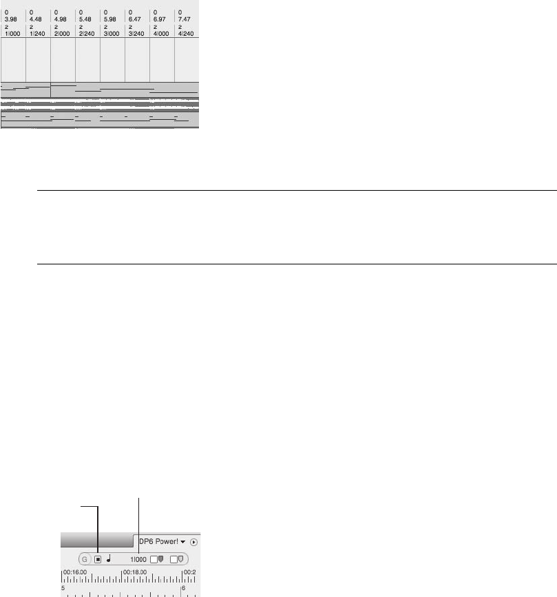
Overriding the Grid in the Tracks Window Digital Performer won’t allow you to perma-
nently turn off the Tracks window’s grid, but you can temporarily override the feature.
Simply press and hold the Command key to temporarily toggle the grid off.
The Sequence, Graphic, and Waveform Editors
The Sequence, Graphic, and Waveform Editors allow you enable or disable the window’s edit
grid. This gives you more flexibility in the editing process because it allows you to make edits
and selections freely (without being constrained to a set grid value). The Grid Snap Information
settings can be found at the far-right corner of the Information Bar, as shown in Figure 10.13.
Keep in mind that, as we discussed in Chapter 3, you must have Grid Snap selected in Digital
Performer 4Preferences 4Information Bar for Grid Snap Information (G) to appear in speci-
fied windows.
To enable/disable the edit grid:
nClick on the Edit Grid box to turn the edit grid on or off. The box will be highlighted
blue when the grid is on.
nPress the Command key to temporarily toggle the edit grid on or off. Keep in mind that this
will not work in the Waveform Editor.
Figure 10.12 In this example, I’ve zoomed in enough within the Tracks window to allow eighth-note
edits.
Edit Grid
Toggle Button
Edit Grid Resolution
Settings
Figure 10.13 The Edit Grid toggle button and Edit Grid Resolution settings.
302 Digital Performer 6 Power!: The Comprehensive Guide
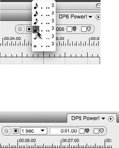
When you’re working in the Measures time format, the Edit Resolution pop-up menu, shown in
Figure 10.14, will display note values, along with dotted, double dotted, and triplet markings.
When the main ruler is set to Real-Time, Frames, or Samples, the Edit Grid Resolution pop-up
menu will change to display the corresponding values, as shown in Figure 10.15. An input field
allows you to type in the exact value if you need to.
To set the resolution for the edit grid:
1. Click the Edit Grid Resolution pop-up menu. If you’re working with measures, note
values will be displayed in the pop-up menu.
2. Choose the desired grid value from the pop-up menu. Changes to the edit grid are
instantaneous.
The View Filters
In Chapter 8, I discussed the use and function of the Input Filter window and how it’s used to
determine what type of MIDI data will be recorded—as well as how the window basically filters
out selected data during the MIDI input stage. View Filters, shown in Figure 10.16, operate in a
similar fashion, except that this setting determines what types of data will be visible in a track
after it has been recorded or inserted. This allows you to decide what types of data can be edited
within DP by filtering out the data you don’t want to work with. Keep in mind that this only
affects the global appearance of data within a project—it doesn’t actually remove or alter it.
You can open the View Filters window by choosing Setup 4Set View Filter or by using the
default keyboard shortcut CommandþF. Once the window is open, click to enable or disable the
particular type or types of data you want to view within your project. Data that is unchecked
will not be visible. You can set the View Filters separately for the Event Lists by clicking on the
Event List tab, as shown in Figure 10.17.
Figure 10.14 Note values will be displayed in the Edit Grid Resolution pop-up menu when the main
ruler is set to Measures.
Figure 10.15 In this example, the Edit Grid Resolution is set to Real-Time.
Chapter 10 Editing 303
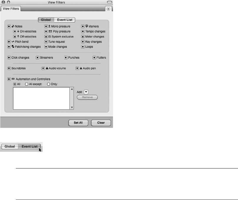
The Invisible Project Clicking the Clear button in the View Filters window will cause the
data in your project to disappear but will not affect playback! If your project becomes
“invisible,” simply use the View Filters window to re-enable desired data.
Zooming
Digital Performer provides a number of different methods for zooming in and out within a win-
dow or data selection. In addition to an editor window’s dedicated zoom buttons, the Zoomer
tool allows you to zoom in and out and also provides more control for zooming in on specific
data or parts of a track.
To zoom with the Zoomer tool:
1. Call up the Zoomer tool by double-tapping the Z key. You can temporarily invoke the
tool by pressing and holding the Z key.
2. Click at the desired location to zoom.
3. To control exactly what you’re zooming in on, click and drag over a selection of data
instead. Release the mouse, and DP will zoom into the section.
4. To zoom out, press and hold the Option key while zooming.
Figure 10.16 The View Filters.
Figure 10.17 Select the Event List tab to configure the view settings for all Event Lists within a project.
304 Digital Performer 6 Power!: The Comprehensive Guide

You can also zoom from the keyboard, even when the Zoomer tool is not enabled. Keep in mind,
however, that this method will simply enlarge/shrink the current view of the window—you’ll
need to use the Zoomer tool to zoom in on specific selections.
To zoom from the keyboard:
nTo zoom horizontally, press and hold the Command key while hitting the left and right
arrow keys to zoom in and out.
nTo zoom vertically in the Sequence or Graphic Editor, press and hold the Command key
while hitting the up and down arrow keys to zoom vertically. This basically increases or
decreases the height of visible tracks. Although you can use the zoom buttons to vertically
resize the Tracks window in Digital Performer 6, these keyboard shortcuts do not apply in
the Tracks window.
Leopard’s Spaces The new Spaces feature in Mac’s latest operating system (Leopard)
allows you to configure the same keys for swapping desktop spaces as DP’s keyboard
shortcuts for zooming. In this case, Spaces will override Digital Performer.
Selecting and Moving
Within Digital Performer, you can use the Pointer and I-Beam tools to select and move audio,
MIDI, and breakpoint automation data—you can even change the duration of MIDI notes. This
section will discuss the procedures for selecting and moving audio data and MIDI notes.
Selecting is the most basic part of the editing process—data must be selected before it can be
edited. There are basically two ways to select data within DP—by clicking on it or by dragging
with a selected tool. Once data is selected, it will become highlighted.
To select the Pointer tool:
nClick on the Pointer tool in the Tool palette.
nDouble-tap the letter A key.
nPress and hold the letter A key to temporarily invoke the Pointer tool.
To select the I-Beam tool:
nClick on the I-Beam tool in the Tool palette.
nDouble-tap the letter I key.
nPress and hold the letter I key to temporarily invoke the I-Beam tool.
Chapter 10 Editing 305
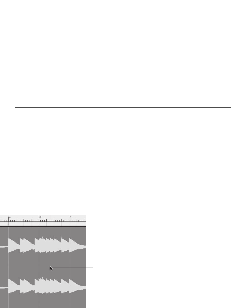
Selecting with the Edit Grid Turned On When enabled, the edit grid will constrain any
selections and confine them to the current grid resolution. If you want to select freely,
be sure to turn the edit grid off. To temporarily disable the edit grid, press and hold the
Command key.
The Select All/Deselect All Commands If you want to select all of the contents of a win-
dow, such as audio and MIDI data on all tracks within the Tracks window or an entire
soundbite within the Waveform Editor, use the Edit menu’s Select All command. (The
default keyboard shortcut is CommandþA.) Keep in mind that this command only
works on visible data and affects the active window (the window in the foreground).
To deselect everything, choose Edit 4Deselect All or press CommandþD.
Selecting and Moving Audio
Audio data can be edited in the Tracks window, the Sequence Editor, the Event List, or the Wave-
form Editor. When audio data is selected with the I-Beam tool or crosshair cursor, it will appear
highlighted blue. When an entire soundbite is selected, however, it will be highlighted yellow in
the Tracks window and yellow with a blue band in the Sequence Editor.
The Pointer Tool
The Pointer tool is unique in that it will change states, depending on where it’s positioned. Posi-
tion the Pointer over a soundbite, about a third of the way up the soundbite, and you will see the
normal Pointer (or Arrow) tool, as shown in Figure 10.18. Move the Pointer below this area,
and it will change to the crosshair cursor, as shown in Figure 10.19.
Pointer Tool
Figure 10.18 The Pointer tool.
306 Digital Performer 6 Power!: The Comprehensive Guide
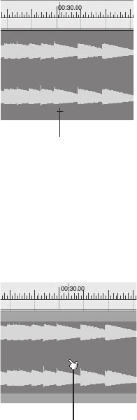
If you place the Pointer tool over a selected soundbite, however, it will change to the finger
cursor. The finger cursor, shown in Figure 10.20, is identical to the normal Pointer tool and
is used by DP to indicate that you have positioned the Pointer over a selected soundbite.
Use the Pointer tool to do the following:
nSelect a single soundbite. Click on a soundbite to select it.
nMove a soundbite. Click and drag a soundbite to move it. The soundbite will be placed
where you release the mouse. This allows you to drag audio between different tracks and
even different windows.
Use the crosshair cursor to do the following:
nSelect a single soundbite. Click and drag across the entire soundbite.
nSelect a portion of a soundbite. Click and drag over the portion of audio you want to select.
nShorten/extend/add to an existing selection. After you have made an initial selection, press
and hold the Shift key while making a new selection or adjusting the existing one, as
shown in Figure 10.21. You can even make selections that aren’t adjacent to one another.
Crosshair Cursor
Figure 10.19 The crosshair cursor.
Finger Cursor
Figure 10.20 The finger cursor.
Chapter 10 Editing 307
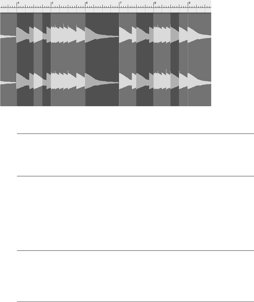
Edge Editing with the Pointer Tool For quick edge-editing tasks, you can place the pointer,
the finger, or the crosshair cursor at either edge of a soundbite, and it will automatically
change to the Trim tool. Simply click and drag to create an edge edit at either end of a
soundbite.
The I-Beam Tool
The I-Beam tool is used to make time-range selections. Selections can contain audio data, or they
can be made in an empty part of a track. When you’re selecting audio with the I-Beam tool, the
top soundbite will be selected, along with any underlying automation data. Incorporate the Shift
key to shorten or extend a selection. Unlike the crosshair cursor, the I-Beam tool cannot be used
to make noncontiguous selections.
The I-Beam Tool versus the Crosshair Cursor The I-Beam tool and the crosshair cursor are
nearly identical to one another in behavior and function. Both will make time-range selec-
tions and can select both audio and MIDI data. Unlike the I-Beam tool, however, the
crosshair cursor will not allow you to create insertion points or anchor points for selections
(discussed in the upcoming section).
Use the I-Beam to do the following:
nMake an empty time-range selection. Click and drag across an empty portion of a track.
Press the Shift key while dragging to extend or shorten a selection.
Figure 10.21 You can Shift and drag with the crosshair cursor to make noncontiguous selections.
308 Digital Performer 6 Power!: The Comprehensive Guide

nMake a time-range selection of audio data. Click and drag across a soundbite.
nSelect data across all tracks. Click and drag in the Time Ruler.
nSelect an entire soundbite. Double-click on a soundbite.
nCreate an insertion point (anchor point) for edit commands, such as Paste. Simply click
at any location to insert the I-Beam cursor, which will appear as a flashing vertical black
line.
The Flashing I-Beam Cursor Once placed into a track, the I-Beam cursor becomes an
anchor point for selections and edit commands, such as Paste, Merge, Split, Splice, and
Trim End.
Selecting Only the Visible Portion of a Soundbite with the I-Beam Tool When a portion of a
soundbite is covered by another soundbite and you double-click on it with the I-Beam
tool, you will be selecting the entire soundbite, not just the visible portion. To work around
this, press and hold the Option key before double-clicking the soundbite with the I-Beam
tool.
Selecting and Moving MIDI Notes
Digital Performer can edit MIDI data in every editor window except the Waveform Editor. Each
editor window provides a different way of displaying MIDI data. The Tracks window shows
MIDI data as phrases and blocks, the Notation and QuickScribe Editors show MIDI notes as
standard notation, the Event List displays MIDI notes (and MIDI data) as event information
within a list, and the Graphic and Sequence Editors show MIDI notes as horizontal bars within
a “scrolling piano”–style note grid.
MIDI note selection with the Pointer tool and crosshair cursor is similar to audio data selection.
Position the Pointer tool directly over a MIDI note to see the normal Pointer, as shown in
Figure 10.22. Move the Pointer outside a note to see the crosshair cursor, as shown in
Figure 10.23. If you place the Pointer over a MIDI note that has been selected, you will see
the finger cursor, as shown in Figure 10.24. Selected notes will be shaded lighter (or brighter)
than non-selected notes.
The finger cursor is identical to the normal Pointer tool and is only used by DP to indicate that
you have positioned the Pointer over a selected note. The finger and crosshair cursors will not be
available when working in the Event List and QuickScribe Editor. Use the normal Pointer tool
when working in these windows.
Chapter 10 Editing 309
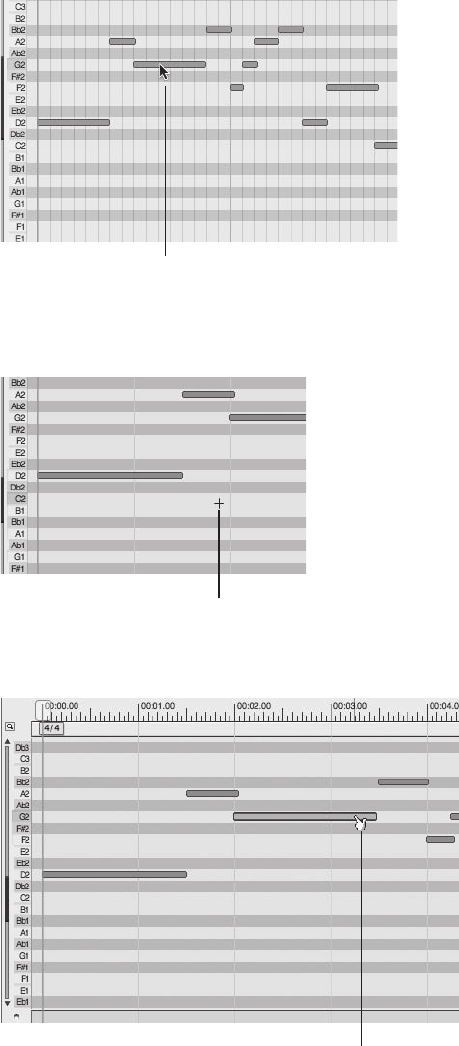
Crosshair Cursor
Figure 10.23 Place the Pointer in an empty area of a MIDI track to invoke the crosshair cursor.
Pointer Tool
Figure 10.22 In this example, the Pointer tool is positioned over a MIDI note.
Finger Cursor
Figure 10.24 The finger cursor will appear when you place the Pointer tool over a selected MIDI note.
310 Digital Performer 6 Power!: The Comprehensive Guide

Use the Pointer tool to do the following:
nSelect a single note. Click on a note to select it.
nMove a note. Click and drag a note to move it. The note will be placed where you release the
mouse. This allows you to drag notes between different tracks. Move the note horizontally
to change its location within the track. If the edit grid is turned on, the note will “snap” to
the next Grid Resolution value. If the edit grid is turned off, you can position notes freely.
nChange the pitch of a note in the Graphic Editor. Click and drag the note vertically. Drag the
note up to raise the pitch. Drag the note down to lower the pitch.
Finger Pointer Extras In the MIDI Graphic Editor, you may notice that once a MIDI note is
selected, the finger pointer changes shape when placed at the beginning or end of a MIDI
note. It becomes a “pinching” form and allows you to stretch or shrink (lengthen or
shorten) a MIDI note’s duration either from the beginning or from the end of the note.
This action will be constrained to the edit grid when the grid is activated.
In addition, the finger pointer becomes a two-finger pointer when used in conjunction
with the Option-click combination, allowing you to quickly copy MIDI notes and drag
them to a new location. This efficient feature can be used for both MIDI and audio data
in the Sequence Editor and Tracks window!
Use the crosshair cursor to do the following:
nSelect a single note. Click and drag over the note.
nSelect multiple notes. Click and drag over the notes.
nAdd notes to an existing MIDI note selection. After you have made an initial selection of
notes as described a moment ago, press and hold the Shift key while dragging to include (or
exclude) notes from the current note selection.
Nudging Audio and MIDI Data Data that exists within a track can be moved, or nudged, in
small increments. Simply press the keyboard’s left or right arrow key to nudge data for-
ward or backward in time. This feature is especially useful in post-production work, where
you need to nudge a sound by single-frame increments to match it to a specific cue or
action onscreen.
You can set the nudge amount by double-clicking on the Grid Snap Information icon (G) in
the Information Bar. Use the Nudge drop-down menu to make nudge amount selections.
Chapter 10 Editing 311
Basic Edit Commands
In this section, I’ll discuss some of the more common and useful edit commands contained in DP.
Keep in mind that these commands can be used to affect audio and/or MIDI data. In addition,
each command that’s discussed here is undoable. Simply press CommandþZ to undo an action.
If you need more control over the undo operations in DP, refer to “The Undo History” section of
Chapter 6 for an in-depth look into the Undo History windows.
The Erase Command
The Erase command (Edit 4Erase) will basically delete or remove a selection from a track or
window. The default keyboard shortcut is CommandþB, though most users will simply use the
Mac keyboard’s Delete key instead. Be aware that some windows will not allow the use of
the Erase command. When the Erase command is unavailable, it will appear dimmed within
the Edit menu.
The Copy, Cut, Paste, Repeat, and Merge Commands
Probably the most fundamental parts of the editing process (next to the selection process) in
any software program—including non-music applications—are the basic Copy, Cut, and
Paste commands. Like most applications on the Mac, these commands are located in DP’s
Edit menu.
The Copy and Cut Commands
The Copy command will copy a selection and place the contents on the Mac’s virtual clipboard,
leaving the original data in the selection intact. The copied data will remain stored in the clip-
board until other data is copied with the Copy or Cut command. The Cut command is similar
to Copy, except that it erases (or removes) the original data once it has been copied to the
clipboard.
To copy or cut a selection:
1. Start by selecting the data you want to affect.
2. Choose the Copy or the Cut command from the Edit menu. You can also use the default
keyboard shortcuts CommandþC to copy a selection and CommandþX to cut a
selection.
The Paste Command
Once a selection has been copied or cut and stored on the clipboard, it can be placed or pasted
into another track or window. Choose Edit 4Paste or use the default keyboard shortcut
CommandþV.
To use the Paste command, you have to tell Digital Performer where the copied or cut material
needs to be placed. There are a couple of different ways to do this.
312 Digital Performer 6 Power!: The Comprehensive Guide
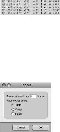
To paste a copied or cut selection into a track:
nEnable the I-Beam tool with the letter I key and click at the desired location. The flashing
I-Beam cursor will appear. Press CommandþV to paste the copied/cut selection at the
I-Beam cursor location.
nMake a time-range selection with the crosshair cursor or I-Beam tool. Press CommandþV,
and DP will paste the copied/cut material at the start of the time-range selection.
nDeselect everything and do not use the I-Beam cursor. This will tell DP to paste the copied/
cut material at the current location of the Playback Wiper within the original track. Press
CommandþV to paste the data that’s residing in the clipboard.
To paste a selection into the Event List:
nEnable the I-Beam tool with the letter I key and click on the white line that separates
two events. The flashing I-Beam cursor will appear, as shown in Figure 10.25. Press
CommandþV to paste the copied/cut selection at the I-Beam cursor location.
The Repeat Command
The Repeat command (Edit 4Repeat) basically takes a selection of data and repeats it a specified
number of times. The repeated material can be pasted, merged, or spliced into the destination
track. Once you have made a selection and selected Repeat from the Edit menu, the Repeat win-
dow (shown in Figure 10.26) will open, presenting you with the following options:
nRepeat selected data _______ time(s). Use this option to set the number of times the selection
will be repeated.
I-Beam Cursor
Figure 10.25 Click between two event rows to insert the I-Beam cursor in the Event List.
Figure 10.26 The Repeat window.
Chapter 10 Editing 313
nPaste. Paste will copy and repeat the selection while overwriting any data that exists on the
track.
nMerge. Merge will merge (or combine) the repeated material with the existing data on the
track.
nSplice. Splice will move any existing data forward in time to make room for the repeated
material.
To repeat a selection:
1. Start by making a data selection.
2. Press CommandþR or choose Edit 4Repeat.
3. The Repeat window will open. Set the number of times the selection is to be repeated.
4. Next, choose what happens to the repeated data from the Place Copies Using section of
the window.
5. Click OK to repeat the selected material.
The Paste Repeat Command
The Paste Repeat command combines the standard Paste and Repeat commands. Use this command
to fill a time-range selection with the copied or cut material that resides on the clipboard. DP will
automatically paste and repeat the clipboard contents as needed to fill the time-range selection.
To paste repeat into a track:
1. Start by copying or cutting a selection of data.
2. Make a time-range selection.
3. Press ControlþCommandþV or choose Edit 4Paste Repeat.
The Paste Multiple and Paste Multiple Repeat Commands
Two other variations to the standard Paste command are the Paste Multiple and Paste Multiple
Repeat commands. The Paste Multiple command allows you to copy or cut a selection from one
track and paste into multiple target tracks. The Paste Multiple command is only visible when
you press and hold the Option key.
To paste into multiple tracks:
1. Start by copying or cutting a selection of data from a single track.
2. Select the target tracks by following the selection procedures for the standard Paste
command. If you’re using the I-Beam cursor, use the Shift key to place the cursor in
multiple tracks.
314 Digital Performer 6 Power!: The Comprehensive Guide
3. Press OptionþCommandþV to paste the clipboard contents into multiple tracks. You
can also press and hold the Option key and then choose Edit 4Paste Multiple.
The Paste Multiple Repeat command takes the Paste command a step further by combining the
Paste Multiple and Paste Repeat commands. Like the Paste Multiple command, you must press
and hold the Option key in order for this command to appear within the Edit menu.
To paste repeat into multiple tracks:
1. Start by copying or cutting a selection of data from a single track.
2. Make a time-range selection across the target tracks. Remember to Shift-click to include
multiple tracks.
3. Press ControlþOptionþCommandþV to paste repeat the clipboard contents into
multiple tracks. You can also press and hold the Option key and then choose
Edit 4Paste Multiple Repeat.
The Merge Command
The Merge command (Edit 4Merge) allows you to combine selected track data with the con-
tents of the clipboard. New data is mixed (or merged) with the existing data on the track. When
you’re working with soundbites, however, data isn’t merged together, but is placed on top of any
existing soundbite data instead. If you drag the new soundbite or remove it, you’ll find that the
old soundbite still exists in its original location.
To merge selected data:
1. Start by copying or cutting a selection of data from a single track.
2. Select the data in the track with which you want to have the clipboard contents merged.
3. Press CommandþM or choose Edit 4Merge to merge the data.
Editing Audio in the Sequence Editor
The Sequence Editor is by far the most versatile and comprehensive editor window for editing
audio data. The Sequence Editor’s graphic environment allows for standard editing commands,
such as Copy, Paste, and Repeat, and it also provides unique operational features that allow you
to quickly trim (edge edit), fade, cross-fade, mute, and even time-stretch audio data.
Edge Editing Soundbites
A soundbite, as you know, is a region of audio. Soundbites are not, however, audio files. They
are only references, or pointers, to the parent audio file that resides on your hard drive. Sound-
bites can represent an entire audio file or only a portion of it.
Chapter 10 Editing 315
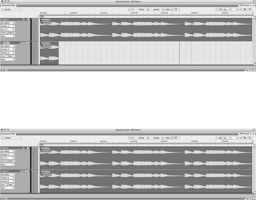
Edge edits allow you to shorten or extend the duration of a soundbite—for example, if you have
a three-second soundbite that references a much longer soundbite that’s 35 seconds long (see
Figure 10.27).
If you trimmed the edge of the soundbite to the right, you could drag to extend its duration until
the entire five-minute soundbite was displayed, as shown in Figure 10.28. Keep in mind, how-
ever, that you cannot extend a soundbite beyond its original boundaries.
The Trim Cursor. The trim cursor, shown in Figure 10.29, allows you to edge edit or trim
soundbites within the Sequence Editor. Like many other tools within DP, the trim cursor
must be positioned in the correct place in order for it to be visible. Place the Pointer tool at
the very edge of a soundbite and below the colored title bar to invoke the trim cursor.
The Edge-Edit Copy Option. When the Edge-Edit Copy feature is turned on, a new soundbite (or
an alternate version of the soundbite) will be created when you edge edit a soundbite with the trim
cursor. This can be a helpful feature when you have multiple instances of the same soundbite
Figure 10.27 A three-second-long soundbite (Soundbite.2) and its related 35-second soundbite
(Soundbite.1).
Figure 10.28 The shorter soundbite (Soundbite.2) has been edge edited, displaying the entire length
of the soundbite. Even though Soundbite.1 and Soundbite.2 are individual soundbites, they both ref-
erence the same parent audio file.
316 Digital Performer 6 Power!: The Comprehensive Guide
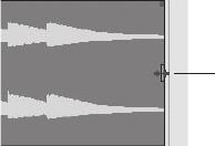
within a project and you want to trim a single instance of that soundbite. Instead of affecting each
instance of the soundbite, DP just creates a new, trimmed version of the soundbite.
If Edge-Edit Copy is turned off, however, when you edit an instance of a soundbite, each and
every other instance of that soundbite will also be edited. Sometimes this is just how you need
the edge-edit feature to operate—it really depends on the type of editing you need to do and
whether you want to affect all instances or just a single instance of a soundbite.
To temporarily disable the Edge-Edit Copy option, press and hold the Option key while edge
editing a soundbite. To turn off this option all together, choose Edge-Edit Copy from the
Sequence Editor’s mini-menu and then uncheck the option.
Soundbite Editing Shortcuts
In addition to the standard Edit menu commands discussed earlier, Digital Performer provides a
number of keyboard shortcuts that affect how audio is handled (or edited) in the Sequence Edi-
tor. This section will provide a list of various keyboard shortcuts and a brief description of how
they are used.
nTo constrain vertical and horizontal movements, press the Shift key while dragging.
nTo quickly copy a soundbite, Option-drag it. (The one-finger cursor becomes a two-finger
cursor.)
nTo force a soundbite to snap to another soundbite when dragging, select the soundbite
and then Control-drag in the desired direction.
nTo copy a soundbite and “throw” it end to end with an adjacent soundbite, press
ControlþOption and then drag (or throw) the soundbite in the desired direction. (The finger
pointer becomes a throwing hand.)
nTo nudge a soundbite, press the Mac keyboard’s left and/or right arrow keys. Remember
that you can set the nudge value by double-clicking on the Grid Snap icon (G) in the
Information Bar, shown in Figure 10.30.
nTo trim (or edge edit) the edge of a soundbite, position the cursor at the beginning or end of
a soundbite. The cursor will change to the trim cursor. Click and drag to trim (or change the
boundary of) the soundbite.
Trim Curso
r
Figure 10.29 Use the trim cursor to edge edit soundbites.
Chapter 10 Editing 317
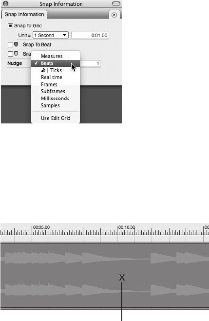
nTo quickly mute a soundbite, invoke the Mute Soundbites tool by pressing and holding the
letter M key and clicking on a soundbite (or a portion of a soundbite) to mute it, as shown in
Figure 10.31. Drag with the Mute Soundbites tool to mute multiple adjacent soundbites.
Muted soundbites become dimmed.
nTo quickly split a soundbite, invoke the Scissors tool by pressing and holding the letter C
key, and then click on a soundbite to split it. Drag the Scissors tool across a soundbite (with
the edit grid turned on) to split soundbites into sections that conform to the current grid
resolution.
nTo graphically time-stretch audio, position the Pointer over the left or right edge of a
soundbite’s colored title bar (as shown in Figure 10.32) to display the hand cursor. Click and
drag to time-stretch the soundbite. See Chapter 13, “Processing and Mastering,” for an
explanation of time-stretching in DP.
Fades and Crossfades
Fades and crossfades are continuous gain or volume changes that are computed by Digital Per-
former. Fades can occur at the beginning (a fade-in) or end (a fade-out) of a soundbite, while
crossfades can only be placed at the boundary points (or splice points) of two adjacent soundbites.
Figure 10.30 The Snap Information window.
Mute Soundbites Tool
Figure 10.31 The Mute Soundbites tool can be used to mute a soundbite (or a portion of a soundbite).
318 Digital Performer 6 Power!: The Comprehensive Guide
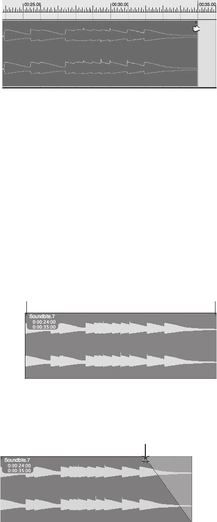
There are two ways to insert fades within Digital Performer—with the Sequence Editor’s Fade
Handles and with the Audio menu’s Fade command. Fades and crossfades within DP are non-
destructive (unless they are created with the destructive Fade command). When a fade is created,
DP calculates the volume change and then places this new audio over the original soundbite.
Calculated fade files are stored in the Fades folder within the main project folder.
Fade Handles
A soundbite’s Fade handles, shown in Figure 10.33, are located at the left and right edges of
the soundbite, directly below the colored title bar. When you position the Pointer tool over a
Fade handle, the fade/crossfade cursor will appear. Click and drag to insert a fade, as shown in
Figure 10.34.
Figure 10.32 Dragging to graphically time-stretch a soundbite.
Fade/Crossfade
Cursor
Figure 10.34 Drag the Fade handles to insert a fade. Notice that the fade/crossfade cursor appears
when you’re creating or adjusting fades.
Fade Handle
Fade Handle
Figure 10.33 The Fade handles.
Chapter 10 Editing 319
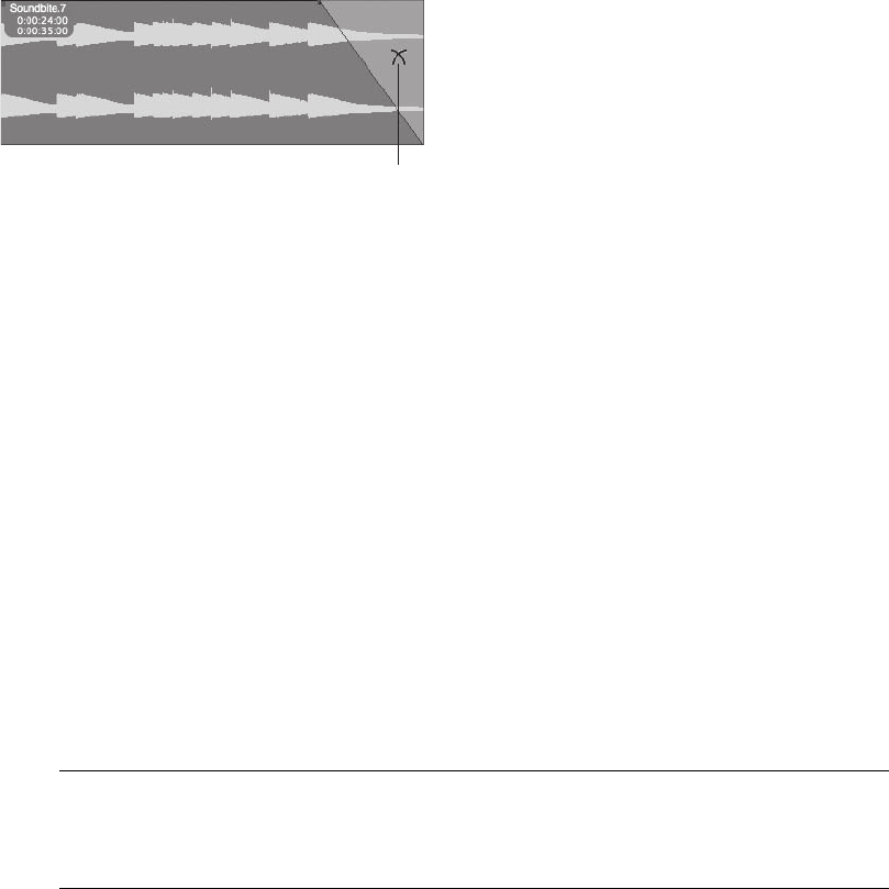
When the edges of two soundbites are touching (adjacent), you can drag on either soundbite’s
Fade handle to cross-fade them together. Once a fade or crossfade is created, you can double-
click on it to open the Create Fades window (explained in the next section), allowing you to edit
the curve of the fade or change the fade type all together.
You can remove a fade or crossfade by dragging the Fade handle again—until the fade is no
longer visible—or you can select it and choose the Delete Fade command (explained in the next
section). When you position the Pointer over an existing fade, the select/edit fade/crossfade cur-
sor will appear, as shown in Figure 10.35.
The Fade and Delete Fade Commands
In addition to the Fade handles, you can also use the Audio menu’s Fade command. Start by
making a time-range selection at the beginning (to fade in) or end (to fade out) of a soundbite.
The length of the selection will determine the length of the fade-in or fade-out. Next, choose
Audio 4Fade to open the Create Fades window. You can also use the default keyboard shortcut
ControlþF.
When the Create Fades window (shown in Figure 10.36) opens, DP will automatically select the
fade type it thinks is most appropriate for your time-range selection. If you’re satisfied with
the type DP has chosen, simply click the OK button. If you want to edit or change the selected
fade type, choose the fade you want from the various options before clicking OK.
The Delete Fades command allows you to permanently remove or delete a fade or crossfade.
Click the fade or crossfade you want to remove and press ShiftþControlþF, or choose Audio 4
Delete Fades to delete the selected fade. To remove multiple fades, simply drag to select the fades
before choosing the Delete Fades command.
Destructive Fades Fades can be applied destructively from within the Waveform Editor by
using the Audio menu’s Fade command. See the “Processing” section of Chapter 13 for
an explanation of destructive fades.
Select/Edit/Fade/
Crossfade Curso
r
Figure 10.35 The select/edit fade/crossfade cursor.
320 Digital Performer 6 Power!: The Comprehensive Guide
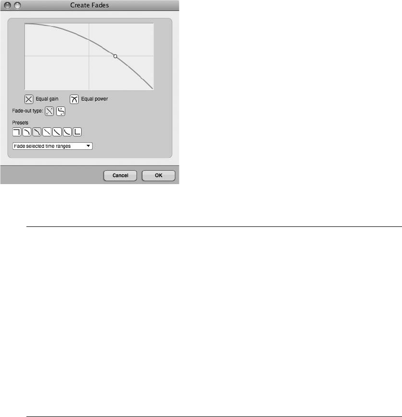
Editing Audio in the Waveform Editor You can also edit audio in DP’s Waveform Editor.
The Waveform Editor allows you to apply all of Digital Performer’s editing capabilities
within this window. Unlike other editing windows, however, edits made to a soundbite
in the Waveform Editor are destructive. In other words, any alteration made to a sound-
bite is permanent, and subsequently, the parent audio file is also modified.
The Waveform Editor’s Transport Lock button allows you to use all of DP’s Transport
controls to control playback of a selected soundbite within the Waveform Editor window,
such as skip forward/backward, pause, rewind, Memory Cycle mode, or Link Selection to
Memory.
To edit a soundbite in the Waveform Editor, simply choose a soundbite and select
Audio 4Edit in Waveform Editor. Consult the “Waveform Editor” chapter of DP’s User
Manual for a detailed look at the Waveform Editor’s features.
MIDI Editing in the Graphic Editor
Just as the Sequence Editor is the choice editor for soundbite editing, the Graphic Editor provides
tremendous control over the MIDI editing process. Even though the Graphic Editor, shown in
Figure 10.37, is a MIDI-only editing window, it is nearly identical to the Sequence Editor in that
it allows for standard editing commands, such as Copy, Paste, and Repeat. Unlike the Sequence
Editor, where MIDI controller data is layered below the notes of a MIDI track, the Graphic Edi-
tor provides two sections of the window that are dedicated to the editing of MIDI controller
events. These sections are called the Continuous Data Grid and the Median Strip. In addition,
Figure 10.36 The Create Fades window.
Chapter 10 Editing 321
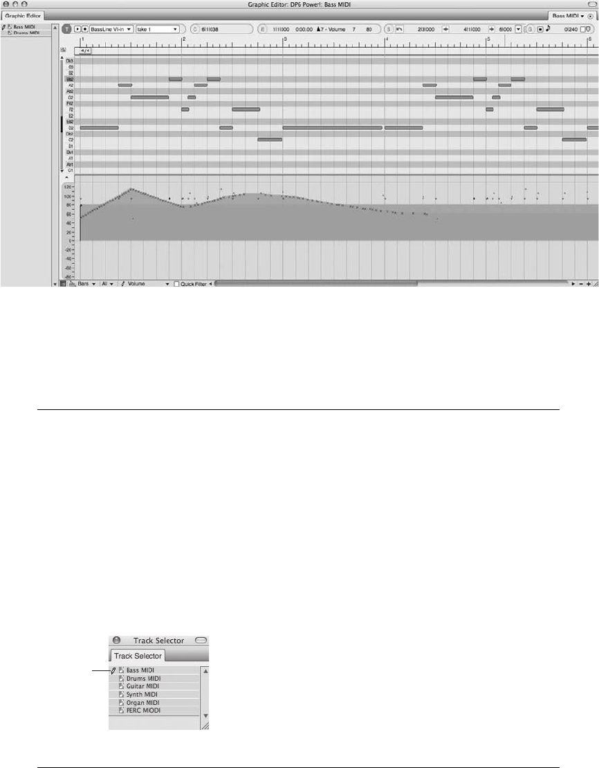
the Graphic Editor will not display MIDI data in separate tracks; it will overlay MIDI notes into
the same note grid when multiple tracks are being shown with the window’s Track selector.
Unlike the Sequence Editor, multiple Graphic Editors can be opened at the same time.
The Track Selector In Digital Performer, multiple tracks can be displayed simultaneously in
a single Graphic Editor window. Use the Track selector (discussed in Chapter 3) and simply
click on as many MIDI track names as desired. (Shift-clicking is not necessary in this case.)
This feature is very handy for making note edits to several tracks at once or simply com-
paring one track to another. However, to edit controller data for a specific track (while
multiple tracks are being displayed), use the Master Track selector (located in the Track
Selector List as a Pencil icon), shown in Figure 10.38. This determines which track’s Con-
troller Data and Median Strip will be displayed and affected. Simply click next to the
desired track name to activate it as the master track. Keep in mind, only one track can
be selected as the master track at a time.
Figure 10.37 The Graphic Editor.
Master
Track
Selector
Figure 10.38 The Master Track selector is indicated with the Pencil icon.
322 Digital Performer 6 Power!: The Comprehensive Guide
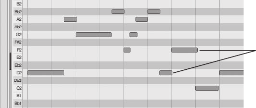
Inserting, Removing, and Modifying Notes in the Note Grid
The note grid allows you to insert, remove, or modify MIDI notes within a MIDI track.
MIDI notes are displayed as solid lines or bars, as shown in Figure 10.39. As with all tracks
within DP, horizontal positioning determines where in the sequence a MIDI note will appear,
while the length of a note sets the duration for that note. Vertical positioning determines the
pitch.
To the left of the note grid is the Pitch Ruler (the piano keys) and the Pitch Ruler scroll bar (the
vertical slider). Each line or row that extends out from a piano key determines a note’s pitch
within the note grid. Click and drag the Pitch Ruler scroll bar to scroll the note grid up or down;
doing so will reveal hidden pitches. To display more pitches within the note grid, zoom vertically
in the Graphic Editor.
To insert a note within the note grid of the Graphic Editor (or Sequence Editor):
1. Select the Pencil tool with the letter P key. Make sure you double-tap the P key to make
the selection stick.
2. Specify the master track if you’re working with multiple tracks.
3. If you need to, scroll the vertical Pitch Ruler (located to the left of the piano roll) to
display the appropriate pitches.
4. Click with the Pencil tool at the location where you want the note to start.
5. Drag horizontally to set the duration and vertically to set the pitch, as shown in
Figure 10.40.
6. If you need to change the position or pitch of the note once it’s been inserted, invoke the
Pointer tool by pressing and holding the letter A key. Click and drag the note to the new
location and pitch. Release the letter A key to revert back to the Pencil tool.
7. Repeat Steps 3 through 5 as needed.
MIDI Notes
Figure 10.39 MIDI notes within the note grid.
Chapter 10 Editing 323
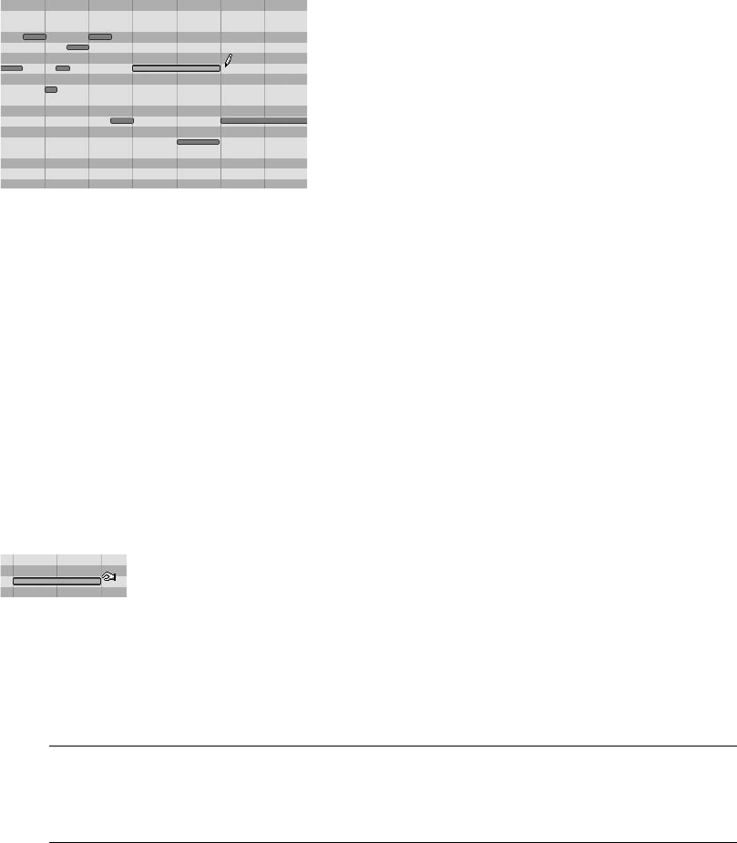
To change the duration of a note within the note grid of the Graphic Editor (or Sequence Editor):
1. Select the Pointer tool with the letter A key. Make sure you double-tap the A key to
make the selection stick.
2. Specify the master track if you’re working with multiple tracks.
3. If you need to, scroll the vertical Pitch Ruler (located to the left of the piano roll) to
display the appropriate note.
4. Position the Pointer at the beginning or end of a note, as shown in Figure 10.41. Notice
that the tool changes to allow you to grasp the edge of the note (as discussed in the
“Finger Pointer Extras” note earlier in this chapter).
5. Drag to the left or right to shorten or extend the duration of the note.
6. Repeat Steps 4 and 5 as needed.
The Edit Grid The edit grid, when enabled, will constrain any edits and movements to the
set grid resolution. If you want to work freely within the note grid, make sure you turn the
edit grid off or press and hold the Command key to temporarily disable it.
The Median Strip and Continuous Data Grid
There are basically two types of MIDI controller data: events that are discrete (or do not have
durations) and continuous controller data (events that occur over a period of time). Discrete
events are displayed in the Graphic Editor’s Median Strip, while continuous controller data
appears in the Continuous Data Grid (see Figure 10.42).
Figure 10.41 Changing the duration of a MIDI note with the Pointer tool.
Figure 10.40 Inserting a MIDI note with the Pencil tool.
324 Digital Performer 6 Power!: The Comprehensive Guide
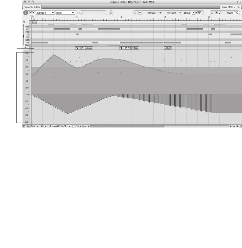
Each type of MIDI controller data within Digital Performer will be displayed with its own icon,
indicating what type of MIDI event it is. To see a list of these icons and their MIDI event names,
open the Legend window from the Graphic Editor, Sequence Editor, or Event List mini-menu. If
you’re working in the Consolidated Window, you can also open the Legend window from a
sidebar’s Window selector.
The Legend Window Use the Legend window, shown in Figure 10.43, to see the names of
MIDI events and their associated icons. Learning these icons can help you speed up your
MIDI controller editing tasks by allowing you to quickly determine what type of event
you’re working with.
The Median Strip
The Median Strip divides the Graphic Editor’s note grid from the Continuous Data Grid. Grab
the Median Strip Move handle, shown in Figure 10.44, to move the Median Strip up or down.
Doing so will change the overall size of the note grid and Continuous Data Grid. Double-click
on the Median Strip Move handle to toggle the view of the Continuous Data Grid.
The Median Strip displays discrete MIDI events, such as patch changes, sustain events, and mute
events. Each event will be displayed as a small block with its MIDI controller number, event
name, and corresponding icon.
Median Strip
Continuous
Date Grid
Figure 10.42 The Graphic Editor’s Median Strip and Continuous Data Grid.
Chapter 10 Editing 325
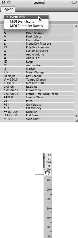
The Continuous Data Grid
The Continuous Data Grid, shown in Figure 10.45, displays continuous controller data, such
as volume and pan changes, modulation changes, and so on. If you’re new to MIDI and find
this topic confusing, just think of continuous controller data as automation for your MIDI tracks
that can be created via a MIDI controller, with DP’s various MIDI features (such as the Tracks
window’s Patch and Default Patch columns), or by directly inserting a controller event into a
MIDI track.
Median Strip
Move Handle
Figure 10.44 Use the Median Strip Move handle to change the size of the note grid and Continuous
Data Grid.
Figure 10.43 The Legend window.
326 Digital Performer 6 Power!: The Comprehensive Guide
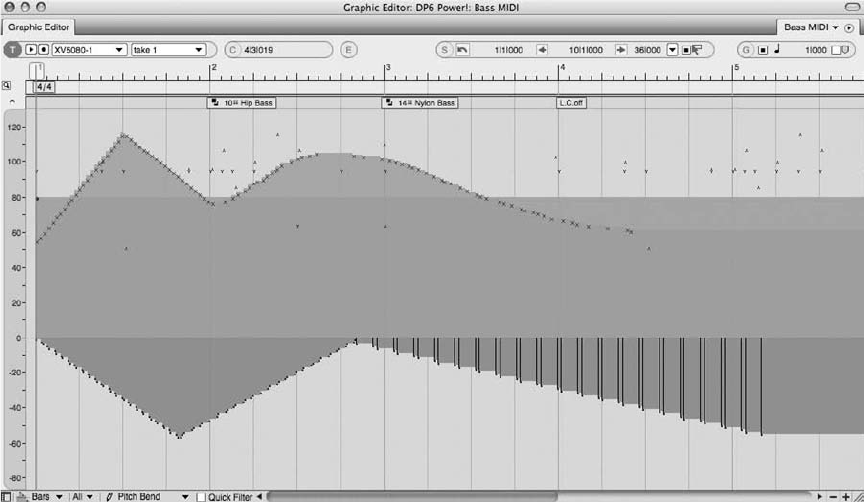
The Continuous Data Ruler. On the left side of the Continuous Data Grid is the Continuous
Data Grid Ruler, which displays a controller scale (from 0 to 127), a pitch-bend scale (from
8192 to 8191) that starts at the middle of the Continuous Data Grid, and a third scale that
displays a combination of the controller and pitch-bend scales. Click on the Continuous Data
Grid Ruler to toggle between the three different scales.
The Grid Display Mode. The Continuous Data Grid will display continuous MIDI data in three
different ways: as points, bars, or lines. Use the Grid Display Mode pop-up menu to choose
between the different view types. Points mode, shown in Figure 10.46, will display controller
data as small points or dots within the grid. Controller data that’s selected will appear with a
small vertical line extending from the bottom of the window to the controller point.
Bars mode will display continuous controller data with small points that are connected by a
colored bar, as shown in Figure 10.47. Use this view when you want to easily see the relationship
between the current value of the event and its duration.
Lines mode, shown in Figure 10.48, will display continuous controller data as points connected
by lines. These lines attempt to approximate the shape of the curve of the controller points. This
view is similar to how breakpoint automation is displayed in non-MIDI tracks. Users more com-
fortable with breakpoint automation may find it easier to work in Lines mode than in Points
and Bars grid display modes.
Figure 10.45 The Graphic Editor’s Continuous Data Grid.
Chapter 10 Editing 327
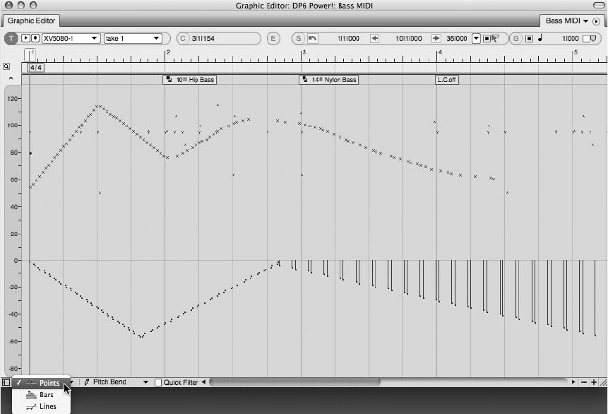
Moving MIDI Controller Events
Moving MIDI controller events (both continuous and non-continuous) is identical to moving
MIDI notes. Simply click and drag with the Pointer tool to move the event. To select multiple
events, drag over the MIDI data with the crosshair cursor. Keep in mind that the edit grid, if
enabled, will constrain any movements you attempt to make.
Inserting MIDI Controller Events
MIDI controller events can be inserted directly into the Median Strip and Continuous Data Grid.
Remember that, as with any editing operation, the edit grid directly affects how data can be
inserted, moved, and so on. If you want to constrain your edits to a specific grid resolution,
be sure to turn on the edit grid and select the desired grid value.
To insert an event directly into the Median Strip or Continuous Data Grid:
1. Select the type of event you want to create from the Pencil Tool Data selector, shown in
Figure 10.49. Keep in mind that the types of controller data that will be available are
determined by the View Filter. Data that has been turned off in the View Filter will
appear dimmed in the Pencil Tool Data Selector List, as shown in Figure 10.50.
Figure 10.46 Points mode will display continuous controller data as small points. Selected data will also
appear with small vertical lines.
328 Digital Performer 6 Power!: The Comprehensive Guide
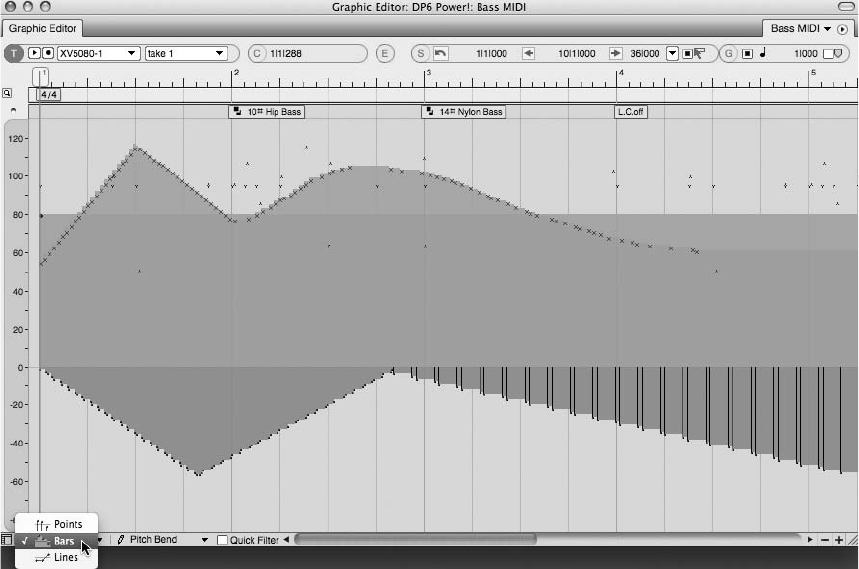
2. Enable the Pencil tool by double-tapping the letter P key.
3. If you’re going to be inserting continuous data, choose the shape of the curve to be inserted
from the Tool palette’s Insert/Reshape Flavor (Curve) menu, shown in Figure 10.51.
4. Click in the Median Strip or Continuous Data Grid to create a single MIDI controller
event.
5. If the MIDI event has a duration, click and drag to create a continuous stream of con-
troller events.
Editing Existing MIDI Controller Events
MIDI events in the Median Strip and Continuous Data Grid can be modified or changed all
together.
To edit a MIDI event within the Median Strip:
nTo delete an event, select the event and press the Delete key.
nTo change or modify the properties of the MIDI event, select the event and press ShiftþEto
open it in an Event List. Once the Event List opens, the selected MIDI event will become
Figure 10.47 Bars mode connects each controller point with a colored bar.
Chapter 10 Editing 329
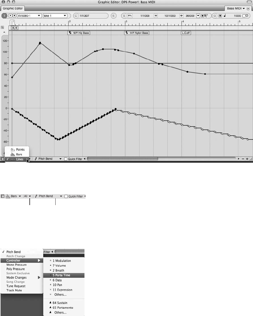
Figure 10.48 Lines mode connects each controller point with a line.
Figure 10.50 Controller data that appears dimmed has been disabled in the View Filter.
Data View
Menu
Data
Selector
Figure 10.49 The Pencil Tool Data selector.
330 Digital Performer 6 Power!: The Comprehensive Guide
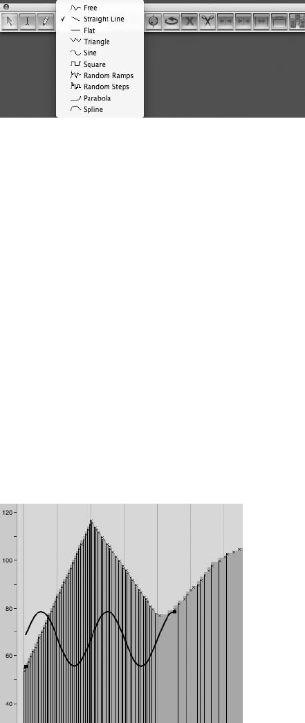
highlighted blue. Click on the desired property to pop-edit its value. The Event List is
explained in the next section.
nTo move the event within the Median Strip, click and drag with the Pointer tool.
To edit continuous controller data within the Continuous Data Grid:
nTo delete MIDI controller data, select the MIDI event and press the Delete key. To delete a
stream of continuous MIDI data, click and drag over the events with the crosshair cursor and
then press the Delete key (or simply double-click one event to select the entire stream).
nTo change the value of MIDI controller data, vertically drag the data within the grid.
nTo move the data to a different location in the track, horizontally drag the data.
nTo change the existing curve of a stream of continuous controller data, select the Reshape
tool by double-tapping the letter R key. Select the shape for the new curve from the Insert/
Reshape Flavor menu. Click where you want to start changing the curve and then drag to
reshape the existing stream of data, as shown in Figure 10.52.
Figure 10.52 In this example, the Insert/Reshape Flavor menu’s sine curve is being used to reshape the
existing stream of continuous MIDI controller data.
Figure 10.51 The Insert/Reshape Flavor (Curve) menu.
Chapter 10 Editing 331
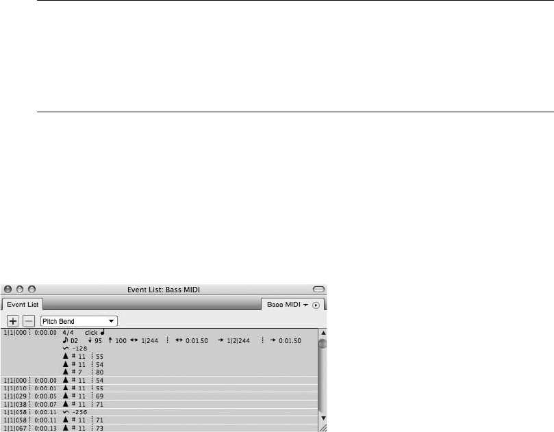
MIDI Controller Data within the Sequence Editor When you’re working in the Sequence
Editor, MIDI tracks do not have separate Continuous Data Grids and Median Strips.
Instead, MIDI controller data will appear stacked within a MIDI track. Use the track’s
Active View layer to bring notes and controller data into the foreground of the track.
Only active layers can be edited.
The Event List
The Event List, shown in Figure 10.53, displays selected audio and MIDI data in rows that are
chronologically organized from top to bottom. Multiple Event Lists can be opened for each
track within a project. Simply select the track or any data contained in the track and press
ShiftþE. You can also choose Project 4Event List.
The Event List may seem intimidating at first glance because the data listed is displayed only as
text. Understanding all the symbols and positioning of the data takes time, but with a little
patience and help from the Legend window (if you’re working with MIDI controller data),
you’ll be editing away in the Event List like a seasoned pro.
Event List Basics
The Event List displays event information in rows. If multiple events occur at the same time
location, they will appear as a block of information. The location (or start time) of an event
will be displayed to the right of an event row. Thetimeformatdisplayedisdeterminedbythe
Time Formats window settings. The event properties will appear after the start location;
which properties appear depends on the type of data you are viewing. Refer to the Digital
Performer User Manual for a detailed explanation of how data and its associated properties
are shown.
Figure 10.53 The Event List.
332 Digital Performer 6 Power!: The Comprehensive Guide
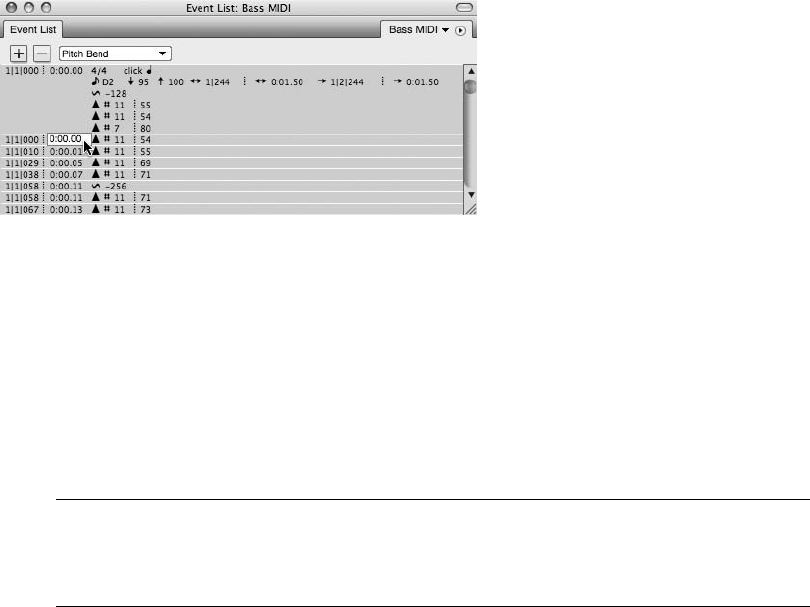
Editing the Parameter of an Event
It’s very easy to edit existing events within the Event List. You can even insert MIDI controller
data directly into the list and apply standard Edit menu commands.
nTo edit an event property, double-click on its parameter field, as shown in Figure 10.54. A
pop-up text box will allow you to change the current parameter setting.
nTo apply standard Edit menu commands, select the event and choose the desired command.
To paste material that exists on the clipboard, insert the I-Beam cursor at the desired
location before pressing CommandþV.
nTo insert MIDI controller data, click on the Event List title tab’s Insert button (þ) and
choose the type of data you want to insert. A new event row will appear. Set the controller
data’s properties from the pop-up text boxes. Press the Return key to confirm the property
settings.
Displaying Duration, End Time, and Sync Point Parameters If you want to display the Dura-
tion, End Time, and Sync Point parameters within the Event List, make sure you enable
these options in the Event Information section of the Time Formats window.
Summary
The audio and MIDI editing capabilities of Digital Performer are truly amazing. Every param-
eter of a soundbite, MIDI note, and automation/controller point can be manipulated to your
heart’s desire—from trimming unwanted silence within a soundbite to tweaking individual
MIDI notes and associated controller data.
As I discussed earlier in this chapter, however, it’s a fine line between fixing and improving a
performance and editing the life out of one. Take time to frequently step back and “listen” to the
big picture (meaning the song itself, not necessarily the individual tracks or notes), and you’ll be
able to edit your projects with positive, satisfying results.
Figure 10.54 Double-click on an event property to modify its current parameter setting.
Chapter 10 Editing 333
This page intentionally left blank

11 Arranging
A
rranging
, as a musical term, sometimes refers to the act of creating the structure of a
song or composition (for example, verse-chorus-bridge-chorus). It can also describe the
selection of the instrumentation used within a composition (for example, piano-bass-
drums). Digital Performer’s arrangement tools allow you to manage the overall structure of a
project, provide location points for easy navigation, or control compositional aspects, such as
meter and tempo.
Some of the features discussed in this chapter have been mentioned or briefly explained in other
parts of this book, and I could have discussed them in those chapters, but to maintain a degree of
familiarity, I decided to follow MOTU’s structuring scheme (as described in the official DP User
Guide) and discuss certain features here in the “Arranging” chapter.
Following is a list of topics covered in this chapter:
nHow to work with tempo, meter, key, and the Conductor track
nHow to manage sequences within Digital Performer
nHow to set up a V-Rack
nHow to use Chunks and songs
nHow to set up loops within a track
nHow to make your projects more efficient through the use of Clippings
nHow to use markers
The Conductor Track
The job of a musical conductor is to literally “conduct” a musical piece or ensemble. The con-
ductor controls the tempo of a composition, indicates meter, gives cues for musical entrances
and dynamics, and so on. Digital Performer’s Conductor track takes on the role of conductor
and provides a “track” in which tempo, meter, key change, and marker information is stored.
The Conductor track is similar to other tracks in that basic edit commands—such as copying,
pasting, and deleting—can be executed, and alternate takes can be created. The Conductor track
335
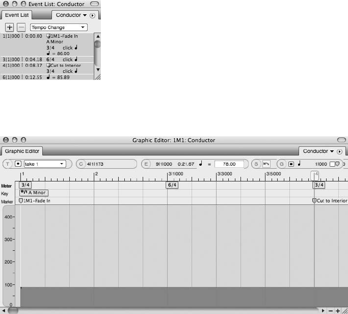
can also be record-enabled to input tap tempo event information. Unlike other tracks, however,
the Conductor track cannot be moved, deleted, looped, or renamed. The Conductor track can be
edited in the Event List and other editor windows where it is visible. Here, we are going to
discuss two windows specifically: the Event List (shown in Figure 11.1) and the Graphic Editor
(shown in Figure 11.2). You can edit Conductor events in both windows, though the method for
viewing and modifying event data in each window is very different.
Modify Conductor Track Menu
The Modify Conductor Track menu, located in the Project menu, contains separate commands
for inserting key, meter, and tempo data, as shown in Figure 11.3. You’ll also find here addi-
tional commands for inserting measures (explained in a moment), as well as for adjusting and
recording beats.
Figure 11.1 The Event List displays Conductor track data as a list. Tempo, meter, and key information is
shown separately from marker information.
Figure 11.2 The Graphic Editor displays Conductor track data in a linear fashion. Meter, key, and
marker information appears below the Time Ruler at a fixed viewing resolution, while tempo data is
shown as continuous controller data, represented by a colored bar.
336 Digital Performer 6 Power!: The Comprehensive Guide
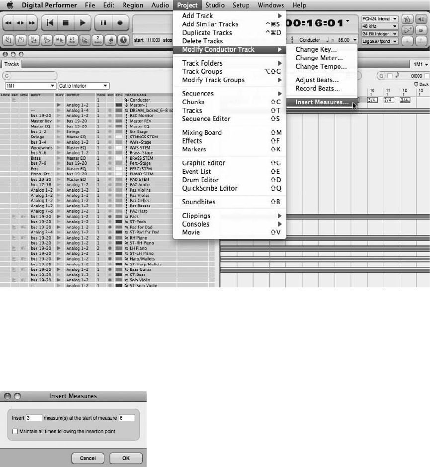
To insert a measure using the Insert Measures command:
1. Open the Insert Measures command by choosing Project 4Modify Conductor Track 4
Insert Measures (see Figure 11.4).
2. Specify the number of measures you want to insert in the Insert field.
3. In the Start of Measure field, enter the location (measure number) at which you want to
insert the measures.
Figure 11.4 The Insert Measures command allows you to insert a blank measure at any location within
a sequence.
Figure 11.3 The Modify Conductor Track menu provides commands for inserting measures and chang-
ing the key, meter, and tempo of a sequence. Advanced options for adjusting and recording beats are
also provided.
Chapter 11 Arranging 337

4. If you want to preserve the SMPTE times of all events that occur after the insertion
point, select the Maintain All Times Following the Insertion Point option.
5. Click OK to insert the measures.
Inserting Measures Be aware that audio data that resides at the insertion point will be split,
while MIDI notes will not. If you would like MIDI to be split, use the Edit menu’s Split
command (CommandþY) before inserting any measures.
Editing Conductor Track Data
You can edit Conductor track events directly in the Conductor track of DP’s various editors and
in the Event List. The windows you choose will determine how and what type of editing can be
executed. Standard edit commands, such as Cut, Copy, and Paste, however, can be used regard-
less of the window in which you are editing.
When working with markers, be aware that they behave differently, depending on the window
in which you are working. For example, markers within the Event List will react to standard edit
commands, such as Cut, Copy, Paste, and Delete, but their properties cannot be modified within
the Event List window. The Graphic Editor, however, will allow you to rename a marker and
also change its location.
The Event List
In the Event List, Conductor track data will appear as a list, similar to the way in which MIDI
data is presented and viewed (refer to Figure 11.1). You can open the Event List for the Con-
ductor track by selecting the Conductor track within the Tracks window or the Sequence Editor
and pressing ShiftþE on your keyboard. Remember that markers will only accept standard edit
commands, such as Cut, Copy, Paste, and Delete. Marker properties, such as location and name,
must be edited in another window, such as the Markers window or the Graphic Editor.
To modify existing Conductor track events in the Event List:
1. Double-click on a Conductor track event within the Event List. The specific event will
become active, allowing you to modify the existing data.
2. Make the necessary modifications, then press the Return key to confirm the change.
To insert new Conductor track data within the Event List:
1. Click on the Event List’s Insert button. This is the þbutton located directly below the
Event List title tab.
2. Choose the type of event you want to insert from the Insert drop-down menu.
338 Digital Performer 6 Power!: The Comprehensive Guide

3. Enter the location (in measures) and press the Return key. Use the Tab key to quickly
move to the next input field.
4. Double-click on the new event to make any changes and then hit the Return key to
confirm the modification.
The Graphic Editor
When editing the Conductor track in the Graphic Editor, events such as key, meter, and markers
are displayed within the window’s Median Strip. Once an event is selected, its settings are dis-
played in the Graphic Editor’s Information Bar. Located below the Median Strip are any tempo
events that exist; these are displayed as continuous controller data and are represented by a
colored bar (refer to Figure 11.2).
The Conductor Track Median Strip Unlike Median Strips in normal MIDI tracks, the Con-
ductor track’s Median Strip is larger, with a fixed width, and is positioned directly below
the Time Ruler. In addition, there is no note grid because the Conductor track does not
contain any notes.
To insert a key or meter event within the Conductor track’s Graphic Editor:
1. Enable the Pencil tool by double-tapping the letter P key on the Mac keyboard.
2. If you need to, enable the edit grid to constrain the event location to the current grid
value.
3. Click on the Median Strip to insert a key or meter event. The vertical position will
determine which type of event (key or meter) is inserted. The horizontal position will
determine the location in time. You cannot insert marker events using this method.
To edit existing key or meter events in the Conductor track’s Graphic Editor:
1. Begin by clicking on a key or meter event. Once selected, the event will become visible in
the Information Bar, which is located directly below the title bar.
2. In the Information Bar, click on the event data. It will immediately become active,
allowing you to make any modifications (see Figure 11.5).
3. When you’re finished, press the Return key to confirm the changes.
Dragging in the Median Strip In addition to the procedures just described, you can also
click and drag an event within the Median Strip to change its location.
Chapter 11 Arranging 339
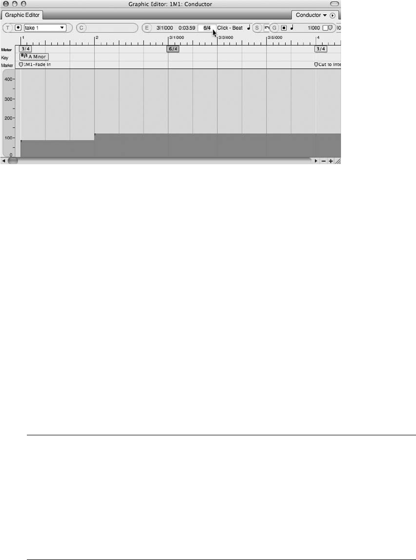
Unlike in the Event List, marker properties such as location and name can be modified in the
Graphic Editor:
nTo change the position of a marker, click on it below the Median Strip and drag with the mouse.
nTo rename a marker, double-click on it. Hit the Return key to confirm the change.
The Tempo Change Grid. Located below the Graphic Editor’s Median Strip is the tempo
change grid, which shows tempo events as continuous controller data. The Tempo Ruler on
the left side of the grid vertically displays tempo, with slower values appearing at the bottom
and increasing toward the top. Placing the mouse over the Tempo Ruler changes the cursor to a
magnifying glass icon that allows you to zoom in for greater accuracy when inserting and editing
tempo events (see Figure 11.6). Clicking on the Ruler allows you to toggle between the normal
zoom and magnified resolutions.
Keep in mind that the tempo source must be set to Conductor track (Control Panel 4Tempo Control
Drawer) in order for Digital Performer to follow any tempo changes that reside in the Conductor track.
Figure 11.5 Click on an event in the Graphic Editor’s Information Bar to make changes to the selected
key or meter event.
Inserting Tempo Change Events You can insert tempo events directly into the tempo change
grid by enabling the Pencil tool and clicking with the mouse. Though this sounds like a simple
procedure, getting your events exactly where you want them with one mouse click can be
challenging because DP does not constrain your mouse movements to the edit grid, even
when it is enabled! The Information Bar will prove helpful in this situation because it will
display the vertical (tempo) and horizontal (Time Ruler location) of the mouse. Once you
insert the tempo event and discover that it isn’t exactly where you want it, simply select it
with the Arrow tool and edit it in the Information Bar or the Event List.
340 Digital Performer 6 Power!: The Comprehensive Guide
To insert a single tempo event in the Conductor track’s Graphic Editor:
1. Double-tap the letter P key on your computer keyboard to quickly enable the Pencil tool.
2. Click in the tempo change grid to insert a tempo event. The vertical position determines
the tempo, while the horizontal position determines its location within the Time Ruler.
Once the event is inserted, a colored bar will appear with a small icon located at the top-
left corner. This small icon is the actual tempo event, while the bar represents the
duration of the tempo change.
3. If the actual tempo or location isn’t exactly where you want it, enable the Arrow tool
and select the event by clicking on the small tempo event icon. Once the event is
selected, its settings will appear in the Graphic Editor’s Information Bar.
4. Click on the setting you want to change (either the location or the actual tempo) and
change it as needed. Hit the Return key to confirm the change.
In addition to single events, tempo events that change over time (such as accelerandos and
ritards) can also be inserted in the Graphic Editor. The Change Tempo command also provides
options for creating tempo changes that need to occur over a specific period of time.
To insert a tempo event that changes over time:
1. Enable the Pencil tool by double-tapping the letter P key on the Mac keyboard.
2. Choose the shape of the curve you want to insert from the Tool palette’s Insert/Reshape
Curve button, shown in Figure 11.7. Choosing a straight line, for example, will allow
you to insert a continuous and even tempo change.
Figure 11.6 Click on the Tempo Ruler (indicated with the magnifying glass icon) to change the viewing
resolution.
Chapter 11 Arranging 341
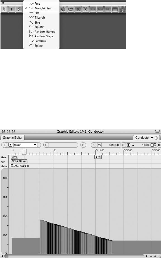
3. Click in the tempo grid where you want the tempo change to begin and drag the mouse
to the position where you want the change to end. Dragging up or down will change the
tempo, and dragging to the left or right will set the length of the tempo change.
4. Release the mouse to insert the tempo change (see Figure 11.8). Once the tempo change
is inserted, multiple tempo events will be created between the start and end points of the
tempo change.
To edit existing tempo events:
nTo change the actual tempo or location of an event, enable the Arrow tool and drag the
event with the mouse. Drag vertically to change the tempo or horizontally to change the
event’s location within the Time Ruler.
Figure 11.8 Tempo change events created with the Straight Line tool. In this example, the newly cre-
ated events are selected (indicated by vertical black lines).
Figure 11.7 The Tool palette’s Insert/Reshape Curve button lets you choose the type of curve that will
be used when creating tempo events that change over time.
342 Digital Performer 6 Power!: The Comprehensive Guide
nYou can also select the event and edit its properties within the Graphic Editor’s Information
Bar. Click on an Information Bar setting to activate it, and then enter the change and hit
the Return key.
nTo cut, copy, and/or delete, select the events with the Arrow tool and apply the appropriate
command from the Edit menu or keyboard.
nTo paste a cut/copied event, place the cursor at the position where you want the
event to be pasted and choose Edit 4Paste, or use the default keyboard shortcut
CommandþP.
Tempo
Now that you know how to create and edit tempo events within the Graphic Editor, I’ll discuss
setting tempo sources within Digital Performer, the use of the more standard Change Tempo
command window, and advanced Tap Tempo features. I’ll also explain the various Audio menu
tempo commands.
Tempo Sources and the Tempo Control Menu
Tempo sources basically tell Digital Performer what is dictating the tempo of the sequence.
There are four tempo sources to choose from, though only one tempo source can be chosen
at a time. The Control Panel’s Tempo Control menu allows you to set the tempo source for a
project. (Refer to Chapter 3 for a look at the Tempo Control menu.) Simply click on a source
within the Tempo Control menu to set DP’s source tempo.
nTempo slider. The Tempo slider allows you to change the tempo of a sequence at
any time by simply dragging on the slider control. This is like a manual setting and will
ignore any tempo events that may exist within the Conductor track. The Tempo slider
is the simplest way to set a project’s tempo—just set the tempo with the slider and start
recording.
nConductor track. Setting the control to Conductor track will tell DP to follow the sequence’s
tempo map or tempo events that exist within the Conductor track. (This was explained
earlier in the chapter.)
nTap Pad. Use this setting to force DP to listen to a “tap” from any designated MIDI source.
Click on the Tap Pad button repeatedly to establish a tap tempo. The Tap Pad feature,
however, does not function while playback is engaged, so you’ll need to tap in your tempo
while the Transport is stopped. To have DP track your tapping during playback, you need to
use the Receive Sync command’s Tap Tempo feature.
nRemote Control. This setting allows you to control DP’s Tempo slider from a MIDI
controller’s modulation wheel or any other source that can output continuous controller
data.
Chapter 11 Arranging 343
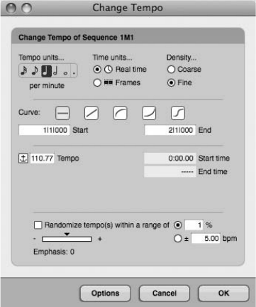
Adjusting Tempo
There are several ways to set the tempo of a sequence in Digital Performer. I’ve already discussed
the use of the Conductor track’s Graphic Editor. This section will cover the creation of tempo
events with the following methods:
nThe Change Tempo command
nThe Tap Tempo feature
nThe Adjust and Record Beats commands
Change Tempo Command
The Change Tempo command is located within the Project menu’s Modify Conductor Track
submenu (Project 4Modify Conductor Track 4Change Tempo). The Change Tempo window
provides options for creating and inserting tempo events within a sequence’s Conductor track
(see Figure 11.9). Its various settings and options (from top to bottom) are explained in the
following list.
nTempo Units. This is the beat value of the tempo or the note value on which the tempo will
be based.
nTime Units. Click on this setting to set the tempo parameter display to real time or frames.
Figure 11.9 The Change Tempo window.
344 Digital Performer 6 Power!: The Comprehensive Guide
nDensity. This option determines the number of tempo events that are created for every beat.
The Fine setting will create 12 tempo events for every beat, while the Coarse setting will
create fewer events. Use the Fine setting when you need more accuracy and control over
tempo events.
nCurve. Use this setting to set the type of tempo change that will be created. Each setting
has its own options that will be displayed directly below the Curve section of the window.
(This will be explained in the “Tempo Curves” sidebar later in this chapter.)
nRandomize Tempo(s). You can use this setting to randomize the tempo changes by a
percentage or a bpm value. Use the Emphasis slider to force the randomization to occur
at higher or lower tempo values. Positive settings will randomize higher tempos, while
negative values will randomize lower ones.
nOptions button. The Options button (located next to the OK button) allows you to
toggle between the different methods of setting curve parameters. The parameter settings
that are displayed are dependent on the type of curve selected. You can use the End
Time setting to have DP calculate the tempo for a specific duration, which is handy
when you’re working with film or video and you need tempo changes to occur at specific
points in time.
nAnchoring. Located next to the Start and End tempos is an anchor icon, which enables
the Anchoring feature. Anchoring allows you to use the current tempo that is at the
sequence’s current location. Use this feature to ensure that the tempos before and
after the region match; doing so will prevent any sudden changes or jumps between tempo
changes.
To insert a static tempo change:
1. Open the Change Tempo window by choosing Project 4Modify Conductor Track 4
Change Tempo.
2. Set the tempo unit. For a standard tempo of 120bpm, for example, choose a
quarter-note value. This basically tells DP that a single beat is equal to one quarter
note.
3. Set the tempo curve to constant. This is the first button within the Curve section of the
window and is represented by a straight-line icon.
4. Set the Start and End measures for the tempo change. The Start Time is where the tempo
change will begin, and the End Time is where the change will stop.
5. Type a value in the Tempo field. This value is in beats per minute, or bpm.
6. If needed, set the Randomize Tempo options, then click OK.
Chapter 11 Arranging 345
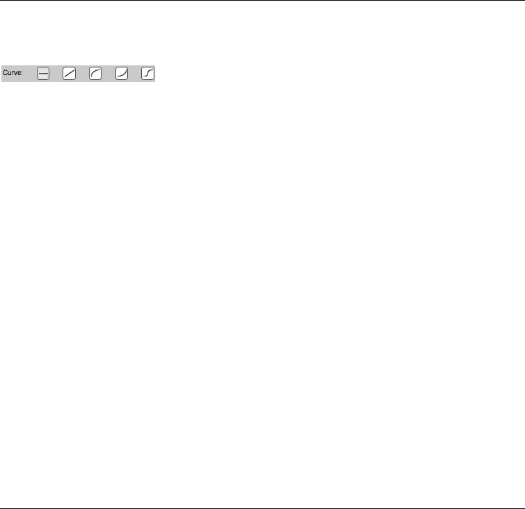
Tempo Curves DP provides five different tempo curves that allow for greater control over
tempo changes (see Figure 11.10).
Instead of manually inserting multiple tempo changes, you can use the provided curves to
automate much of the process. The various curves determine how a change will be
implemented over a specified period of time. The first curve (Straight-Line) will insert one
tempo at the beginning of a region, while the remaining curves (Linear, Logarithmic,
Exponential, and Polynomial) will create multiple tempo events to simulate the shape of
the chosen curve.
When working with the last three curves, you have an additional curve setting called
Curvature. This setting controls the amount of tempo change that will occur at the
“changing” point of the curve, allowing you to smooth out or over-exaggerate the shape
of a chosen curve. Lower values will smooth out the tempo change and force it to more
closely resemble the Linear curve setting. Higher values will force any tempo changes to
happen closer to the beginning or end of a curve, depending on which one is selected.
For example, when you’re using the Logarithmic curve (the middle curve button), higher
curvature values will cause the majority of the tempo change events to happen toward
the beginning of the curve.
When working with the Polynomial curve (the leftmost curve button), you can also
specify the Mid-Beat parameter. This setting tells DP where the most rapid tempo
changes will occur.
To insert a smooth tempo change that starts with one tempo and ends with another:
1. Open the Change Tempo window by choosing Project 4Modify Conductor Track 4
Change Tempo.
2. Set the tempo unit. For a standard tempo of 120bpm, for example, choose a quarter-
note value. This basically tells DP that a single beat is equal to one quarter note.
3. Choose the curve you want (any curve except the Straight-Line curve). Notice that the
settings update to provide additional options for setting the End tempo, Curvature, and/
or Mid-Beat settings.
4. Set the Start and End measures.
Figure 11.10 The Change Tempo command’s five tempo curves are, from left to right:
Straight-Line, Linear, Logarithmic, Exponential, and Polynomial.
346 Digital Performer 6 Power!: The Comprehensive Guide
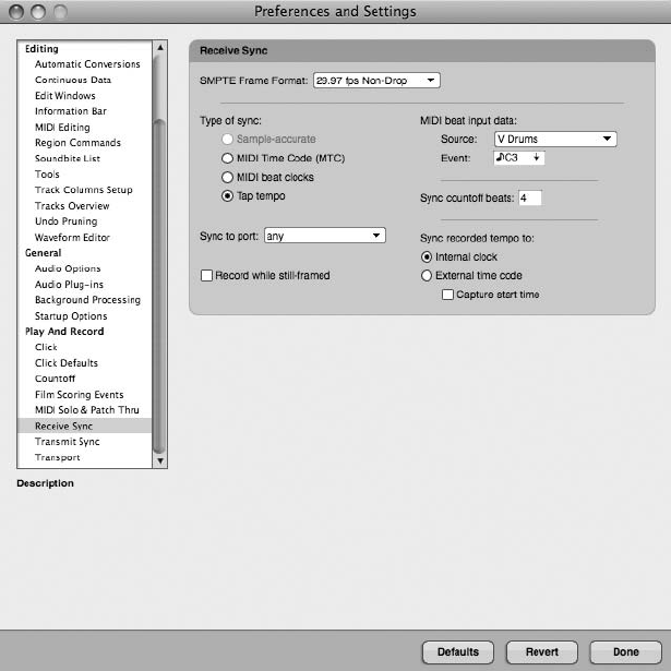
5. Enter the Start and End tempos for the change. Remember that you can toggle the
Option button to activate the End Time setting, which will let DP automatically
calculate the Start or End tempo for you.
6. Set the Randomize, Curvature, and/or Mid-Beat settings as needed and click OK.
Tap Tempo and the Receive Sync Command
The simplest form of DP’s Tap Tempo command is the Control Panel’s Tap Pad feature. Simply
click on the Tap Pad button to “tap” in a tempo. Unfortunately, you cannot use the Tap Pad
function while playback is engaged. To have DP track a tempo during playback, or to record a
tapped tempo into the Conductor track, you’ll need to use the Receive Sync command’s Tap
Tempo option (see Figure 11.11). Setting DP to receive sync from a tap tempo source will basi-
cally slave Digital Performer to an incoming tap tempo MIDI source; this can be used during any
part of the music production process. Keep in mind that this setting will override any Conductor
track tempo settings!
Figure 11.11 The Receive Sync command’s Tap Tempo feature allows you to slave DP to an external tap
tempo source.
Chapter 11 Arranging 347
Once the Tap Tempo command is chosen, DP’s Tap Tempo options become available. They are
as follows:
nMIDI Beat Input Data. This section controls the MIDI source and event number (note).
Use the Source section to set the MIDI device you will be using to tap tempos. Once the
device is chosen, press a note on your MIDI controller to set the MIDI event or note that will
be used to tap the tempo.
nSync Countoff Beats. This setting is the number of taps that will be used as a countoff. You
can set the number from 1 to 127.
nSync Recorded Tempo To. The External setting will let you slave DP to an external
clock source while in Tap Tempo mode. Enabling the Capture Start Time option will tell DP
to remember the exact SMPTE frame of the first tap after the countoff. This will ensure that
the sequence will always start at the correct time.
To record tap tempo events into the Conductor track:
1. Begin by ensuring that DP is set to the correct meter with the Change Meter command
(Project 4Modify Conductor Track 4Change Meter).
2. Choose Receive Sync (Setup 4Receive Sync). Set the MIDI source and event. If you are
planning to simultaneously record a MIDI performance into MIDI tracks, make sure
you choose a MIDI event that will not be in use for this “performance.” Also remember
to have the Multi Record option enabled from the Studio menu.
3. Set the number of countoff taps in the Sync Countoff Beats section (as explained
earlier).
4. Set the Sync Recorded Tempo To option to either Internal or External and then
click OK.
5. Enable the Slave the External Sync option from the Setup menu. The default keyboard
shortcut for this is Commandþ7, or you can simply enable the Slave to External Sync
button in the Control Panel.
6. Record-enable the Conductor track (and any other tracks, if needed). Be aware that
Overdub mode will not function on the Conductor track during this process. Any
tempo events that exist within the track will be erased, regardless of which recording
mode is selected. To get around this, create an alternate take before beginning the
recording process.
7. Press Record; the default keyboard shortcut is the number 3 key on the numeric keypad.
The Record button will begin flashing in the Control Panel, and DP will be ready for
you to begin tapping your tempo.
348 Digital Performer 6 Power!: The Comprehensive Guide
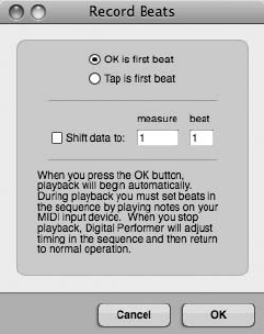
8. Disable the Metronome button on the Control Panel.
9. Start tapping the MIDI note or event on the specified MIDI controller. Digital
Performer will wait to “hear” the specific number of countoff beats (specified in Step 3)
before playback and recording begin.
10. Enter (tap) the tempo into DP. You can be as expressive as you wish.
11. Hit the spacebar when you are finished tapping, and DP will calculate the new
tempo.
12. Unarm any record-enabled tracks, place the Control Panel’s Tempo Source into Con-
ductor Track mode, and disable the Slave to External Sync button.
13. Hit Play to check your results. (Make sure you re-enable the Metronome button.)
Adjust Beats and Record Beats Commands
Digital Performer contains more advanced commands that allow you to adjust the tempo for a
sequence: the Adjust Beats and Record Beats commands (Project 4Modify Conductor Track 4
Adjust Beats or Record Beats). These commands allow you to realign DP’s bar lines to match the
tempo of existing music. Both commands are extremely useful for situations in which you have
an existing piece of music that was not recorded to a metronome click, and you would like to
align DP’s bar and beat lines to the music without changing the original performance.
The Record Beats Command. The Record Beats command lets you tap a new tempo while
listening to playback of existing material. Once you have finished, DP will calculate the new
tempo and automatically readjust bar lines and beat markers to match the tempo you entered,
while leaving the existing musical material intact. This feature is very similar to the Tap Tempo
feature, but it offers dedicated options for greater control in this specific type of situation (see
Figure 11.12).
Figure 11.12 The Record Beats command window.
Chapter 11 Arranging 349
nOK Is First Beat. This option will make the first beat or tempo event occur at the counter’s
current location.
nTap Is First Beat. Use this option to make your first tap the first beat of the realignment
procedure. This is like a manual setting, allowing you begin playback and wait before you
begin tapping the new tempo.
nShift Data To. Use this setting to compensate for any pickup notes (notes that may
occur before the actual beginning of a measure). For example, if you have material that
starts on Beat 1 of Measure 3 but contains two quarter-note pickups, set the values to
Measure 2 Beat 3.
To use the Record Beats feature:
1. First record new material (without concern for the click) or import an existing piece of
music.
2. Place the playback cursor at the precise location at which the material starts. If the
material is an audio region, you can zoom in and manually place the playback cursor
at the proper location. If it is a MIDI track, open the Event List (ShiftþE) and make note
of the location of the first MIDI event.
3. Disable the Metronome button on the Control Panel.
4. Open the Record Beats command by choosing Project 4Modify Conductor Track 4
Record Beats.
5. Choose the OK Is First Beat option. This will automatically place the first beat at the
current location that you set in Step 2.
6. If the material contains pickup notes, use the Shift Data To option to compensate.
7. Now you should get ready to start tapping any note on your MIDI controller. Once you
hit the OK button, DP will automatically tap the first beat, and you will need to begin
tapping on the second beat.
8. Click OK and start tapping on the second beat.
9. When the song is finished, press the spacebar to stop playback. DP will automatically
calculate the new tempo for the song and realign the bar/beat lines.
10. Unarm any record-enabled tracks, place the Control Panel’s Tempo Source into Con-
ductor Track mode, and hit Play to check your results.
11. If you want to use the Tap Is First Beat option to manually place the first beat, start by
placing the playback cursor at a location prior to where you want the first tap to occur.
In other words, give yourself some pre-roll.
350 Digital Performer 6 Power!: The Comprehensive Guide
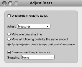
12. Open the Record Beats command and select the Tap Is First Beat option.
13. Click OK to begin playback.
14. Start tapping at the desired location. DP will not begin recording beats until your first
tap.
15. Repeat Steps 8 through 10 as needed.
The Adjust Beats Command. The Adjust Beats command (see Figure 11.13) allows you to man-
ually realign DP’s Time Ruler to match the tempo of existing material. Instead of tapping in a
tempo as you listen back to an existing audio or MIDI track (as with the Record Beats com-
mand), you manually drag the bar and beat lines of the Time Ruler. As you might have guessed,
this can be a time-consuming process, depending on the length of the material you are working
with; this option is really aimed at tempo-mapping rubato passages or other material that the
built-in Beat Detection Engine has trouble analyzing.
For simpler situations in which you need to realign a sequence to an existing soundbite with a
constant tempo or clearly defined transients, use the Beat Detection Engine to analyze the sound-
bite and then use the Adjust Sequence to Soundbites Tempo command to align the sequence to
the soundbite in question.
The Adjust Beats command window provides options for controlling the adjustment process.
They are, from top to bottom:
nDrag Beats in Graphic Editor. Click this option to turn on the Adjust Beats feature.
nAdjust pop-up menu. The Adjust option’s pop-up menu, shown in Figure 11.13, allows you
to adjust beats by entire measures, individual beats, or a fixed-note duration. When the
Fixed Duration option is selected, a note value pop-up menu will appear and allow you to
choose the specific note duration you want to work with.
nMove One Beat at a Time. Choose this setting when you need to make individual beat
adjustments in the Time Ruler.
Figure 11.13 The Adjust Beats command window.
Chapter 11 Arranging 351
nMove All Following Beats by the Same Amount. Select this option when you want to move
one beat and have all the beats that appear after it move by the same amount.
nApply Adjusted Beat’s Tempo until End of Sequence. When this option is selected, the tempo
change generated by moving a beat will be applied until the end of the sequence.
nPreserve Realtime Performance. This option tells DP to only adjust the Time Ruler and not
the original audio or MIDI data.
nSnapping. This option forces realigned beats to snap to MIDI notes and audio beats
(if they exist within the track you are dragging in) or markers. Choose None to turn off
snapping all together.
To use the Adjust Beats feature:
1. First record new material or import an existing piece of music.
2. Open the Adjust Beats command by choosing Project 4Modify Conductor Track 4
Adjust Beats.
3. Click the Drag Beats in Graphic Editor option to enable the Adjust Beats command.
Keep in mind that the Adjust Beats window must be open in order for the Adjust
Beats feature to work.
4. Start by adjusting the downbeats of the first measure. Choose Measures from the Adjust
pop-up menu.
5. Open the Sequence Editor for the track, zooming as needed so that you can see the
individual measures within the Time Ruler. It also helps if the track you are working
on is at the very top of the window, so use the Track Selector List to hide all the other
tracks, including the Conductor track.
6. Position the cursor over the downbeat of the first measure within the Time Ruler. The
actual data that you want to align may start later within your sequence—say, at
Measure 8. If this is the case, simply start with that measure. You could also trim the
soundbite or MIDI region so that it begins precisely on Beat 1 of Measure 1.
7. Drag the downbeat of the measure within the Time Ruler to the actual beginning of
Beat 1 in the track. As you drag, you should see a red bar line appear, indicating the
new bar/beat position.
8. Release the mouse, and DP will realign the Time Ruler.
9. Proceed with adjusting the individual beats. Change the Adjust pop-up menu to Beats.
10. Click and drag the Time Ruler’s individual bar/beat markers and align them with the
individual beats of the music.
352 Digital Performer 6 Power!: The Comprehensive Guide
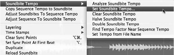
11. If you are working with a rubato passage, make sure you enable the Move One Beat at a
Time option, which will let you adjust each beat independently.
12. Repeat Steps 5 through 11 as needed.
Audio Menu Tempo Commands
Soundbites within DP may or may not contain a tempo map. Audio that is recorded within DP
will take on the tempo of the sequence at the time of recording, while audio that is imported will
contain a tempo map only if it is present in the original file (for example, an audio file from a
“loop” sound library, an Apple Loop, or an ACID WAV file).
Digital Performer’s Audio menu contains a number of tempo commands, shown in Figure 11.14,
that allow you to set or change the tempo map for an existing soundbite, force a soundbite to
match the sequence tempo (time compressing or expanding it in the process), or change the
sequence tempo to match a soundbite’s tempo. These commands give you tremendous control
over how audio and your sequences interact with each other, providing you with the flexibility
to work with many different audio sources without worrying about their original tempo maps.
Soundbite Tempos
If a soundbite contains a tempo map, then the tempo map will be displayed throughout DP’s
various windows. The List section of the Soundbites window displays this information in the
Tempo and Quarter Note columns. If these columns are blank, then the soundbite does not
contain a tempo map. (Refer to Chapter 3 for information on the columns within the Soundbites
window.) Within the Sequence Editor, soundbites with tempo maps are displayed with red grid
lines, as shown in Figure 11.15. If the tempo map matches the sequence’s tempo, these grid lines
will line up with the Sequence Editor’s Time Ruler. If the tempo map is different, however, these
lines will not line up with the sequence’s Time Ruler (see Figure 11.16).
Tempo maps can be applied to a soundbite by using the Set Soundbite Tempo or Copy Sequence
Tempo to Soundbite command. These commands will not change the actual audio of the sound-
bite; they only change the tempo maps associated with the files. Soundbites must contain a
tempo map in order for you to take advantage of DP’s more advanced time-stretching and
Figure 11.14 The Audio menu’s various tempo commands.
Chapter 11 Arranging 353
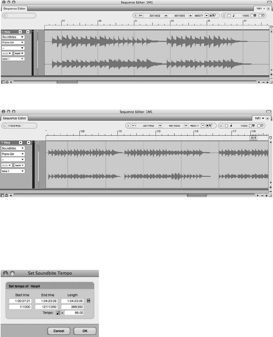
compression features, such as the Adjust Soundbites to Sequence and Adjust Sequence to Sound-
bite Tempo commands.
Set Soundbite Tempo. Use the Set Soundbite Tempo command to define a constant tempo map
for a soundbite or a selected portion of a soundbite (see Figure 11.17). You must know the
Figure 11.15 If a soundbite contains a tempo map that matches the sequence’s tempo, it will be dis-
played with red grid lines that line up with the Time Ruler.
Figure 11.16 Soundbites that contain tempo maps that do not match the sequence tempo are dis-
played with grid lines that do not line up with the Time Ruler.
Figure 11.17 The Set Soundbite Tempo window.
354 Digital Performer 6 Power!: The Comprehensive Guide
duration of the soundbite for this command to work properly. The options provided in the Set
Soundbite Tempo command window are as follows:
nStart Time. Displays the start time of the selection. This value cannot be edited.
nEnd Time. Shows the end time of the selection. Only the bar/beat input fields can be modified.
nLength. The duration of the selection is displayed here. Like the End Time values, only the
bar/beat input fields can be modified.
nTempo. The calculated tempo is displayed here. Once a value is entered in the End Time or
Length section, the tempo is automatically calculated for the soundbite. You can also enter a
tempo directly into the Tempo field if you want.
To apply a tempo map to a soundbite using the Set Soundbite Tempo command:
1. Begin by selecting a soundbite. You can also select a portion of a soundbite. Be aware
that this command will only work on one soundbite at a time.
2. Open the Set Soundbite Tempo command by choosing Audio 4Set Soundbite Tempo.
3. Enter the value for the length of the selected soundbite in quarter notes.
4. Once the information is entered, DP will automatically calculate the tempo for the selection.
5. Click OK.
To remove a tempo map from a soundbite using the Clear Soundbite Tempo command:
1. Begin by selecting a soundbite. You can also select a portion of a soundbite. Be aware
that this command will only work on one soundbite at a time.
2. Choose the Clear Soundbite Tempo command, and the tempo map will be immediately
removed from the soundbite.
Copy Sequence Tempo to Soundbite. Use this option to copy the tempo of a sequence to
selected soundbites. In other words, this command will imprint the tempo map of the sequence
to the soundbite. This is handy when you want the soundbite to automatically conform to any
(sequence) tempo changes made at a later time. This command will affect multiple soundbites
but will not function on portions of a soundbite. The entire soundbite must be selected before
this command will function.
To copy the sequence tempo to a soundbite:
1. Begin by selecting a soundbite or soundbites. You must select an entire soundbite—this
command will not work on portions of a soundbite.
Chapter 11 Arranging 355

2. Choose the proper tempo control from the Control Panel. For example, if you
have the Conductor track selected, any tempo events or custom tempo maps will be
copied.
3. Choose Audio 4Copy Sequence Tempo to Soundbite to copy the sequence tempo to a
soundbite.
Adjust Soundbites to Sequence Tempo
Once a soundbite contains a tempo map, you can take advantage of DP’s more advanced tempo
features. Unlike the previous Audio menu tempo commands, the Adjust Soundbites to Sequence
Tempo command will automatically time stretch or compress a selected soundbite to match the
sequence tempo. Keep in mind that this will only work on soundbites that contain a tempo map.
If a soundbite doesn’t have a tempo map, then use the Set Soundbite Tempo command to apply
one. Also, set the Time Compressing and Expanding option in the Soundbites window’s Info
Pane to Allow Time Scale. (Refer to Chapter 3.)
Tempo Map Tangle Recently, I was in quite a jam regarding an audio file that did not
match my DP session tempo (for a cue in a short film that was to be delivered later that
day!). I had previously contracted a small group of live players to record a track that would
eventually be combined with a mix of several electronic stems (several audio tracks
merged together, such as drums, strings, brass, and so on). However, as one should
expect in this business, a new cut of the film arrived with a last-minute edit that required
a slightly faster tempo for the cue. For my MIDI tracks, it was no problem. (I simply rere-
corded the tracks at the new tempo.) However, the live mix from the players was defi-
nitely not going to line up with my new tempo—and worse yet (and for unknown
reasons), the track was not embedded with a tempo map from the live session! So,
after my heart rate became normal again, I quickly used the Control Panel’s Tap Pad fea-
ture to get an “average” of the live track’s tempo (although I more or less knew the
“click” to which it should have been recorded). Next, I used Set Soundbite Tempo and
defined the tempo for the track as my Tap Pad average. Finally, knowing that my tapping
was relatively accurate and the new tempo was not much faster than the original tempo, I
proceeded to use Adjust Soundbites to Sequence Tempo and voila
`, I was back in business.
A few minutes late on delivery, but back in business!
Adjust Sequence to Soundbite Tempo
This command has the opposite effect from the previous Adjust Soundbites to Sequence Tempo
command. It copies the tempo map from a soundbite into the sequence. The new tempo will be
copied into the current tempo source (for example, a Tempo slider or Conductor track).
356 Digital Performer 6 Power!: The Comprehensive Guide
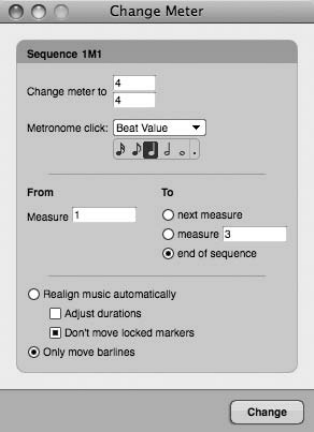
Meter
Meter, along with tempo and key, serves as the foundation for modern music (modern being a
relative term) and recording, determining how music is divided and counted within a song.
Meter, displayed as a fraction (for example, 4/4 or 6/8), is made up of two parts, a numerator
and a denominator. The first (or top) number is the numerator, which tells the musician or
writer how many beats will be contained in a measure of music. The second (or bottom) number
is the denominator, which represents the beat value. A denominator of 4 is a quarter note, a
value of 8 is an eighth note, a value of 2 is a half note, and so on. So a standard meter of 4/4 tells
us that there are four quarter notes within one measure of music, 6/8 would be six eighth notes
to a measure, 5/4 would be five quarter notes to a measure, and so on.
The intricacies of meter and its complex role within music and music theory are beyond the
scope of this book, and this section will focus on the functionality of meter as it applies to
your Digital Performer projects. Basic use of DP’s Change Meter command was discussed
briefly at the end of Chapter 4; this section will offer further explanations on the options
available in this window, while also discussing more advanced concepts, such as partial
measures.
The Change Meter Command
Choose Project 4Modify Conductor Track 4Change Meter to open the Change Meter com-
mand window, shown in Figure 11.18. This window provides a number of options for modify-
ing the meter of a sequence; they are as follows:
Figure 11.18 The Change Meter command window.
Chapter 11 Arranging 357
nChange Meter To. Click on the numerator and denominator values to change the meter.
nMetronome Click. This is the number of clicks within a measure; it also determines how
often the Transport’s Counter will be updated. For example, when Beat Value is selected
and a meter of 4/4 is chosen, a value of one quarter note will tell DP to click four times
within a measure. Selecting an eighth note would force the Metronome to click eight times,
and so on.
Also appearing in the Metronome Click drop-down menu are options such as Tacet (removes
clicks for a measure or a range of measures), Default (applies any Click Defaults for the
specified meter), and Patterns (allows you to create or use a saved click pattern). Refer to
Chapter 4 for more information on Click Default settings and pattern clicks.
nFrom. This is the start location for the meter change, indicated in measures.
nTo. This is the end location for the meter change. The Next Measure option will tell DP to
affect one measure at a time.
The To Measure option will force a meter change up to the measure number entered in
this field. Keep in mind that this ending measure will not be included in the change. For
example, a meter change starting at Measure 1 and ending at Measure 9 would change
Measures 1 through 8, leaving Measure 9 unaffected.
The To End of Sequence option will tell DP to apply the meter change from the start measure
until the end of the sequence.
nRealign Music Automatically. When this option is enabled (and the Adjust Durations option
is turned off), DP will automatically delete notes or add rests as needed to force a sequence to
adhere to applied meter changes.
nAdjust Durations. This option can only be enabled when the Realign Music Automatically
option is selected. Adjust Durations will shorten or lengthen notes to force existing notes to
conform to the new meter change. Only notes that fall on the beats affected by the meter
change will be modified.
nDon’t Move Locked Markers. This option leaves all locked markers in their locked position
in the timeline of your sequence.
nOnly Move Barlines. This option keeps existing music intact and only moves the Time
Ruler’s bar lines when a meter change is applied.
Applying and Editing Meter Changes
Applying meter changes with the Change Meter command is a fairly straightforward process.
Simply open the Change Meter window by choosing Project 4Modify Conductor Track 4
Change Meter. Set the new meter, enter the start and end locations, enable any extra options
as needed, then choose OK.
358 Digital Performer 6 Power!: The Comprehensive Guide
Once applied, meter events can be edited within the Conductor track. See the previous “The
Conductor Track” section of this chapter for an explanation of the process of editing Conductor
track events.
Partial Measures
Partial measures can occur when meter changes are applied within the middle of an existing
measure. How does this happen? Well, meter events within DP will always start a new measure.
This is the rule, so if you insert a meter change on Beat 4 of a 4/4 measure (in the Conductor
track’s Event List or Graphic Editor), DP will insert the meter event and create a new measure at
that location. Now you have a situation in which the previous measure only contains three beats,
but still retains a meter marking of 4/4.
Even though partial measures do not have an effect on the actual playback of music, they can be
annoying when you’re trying to make edits, or they can be totally unacceptable when you’re
working with notation in the QuickScribe Editor. DP provides a few options for correcting par-
tial measures or for preventing them from occurring in the first place.
The most basic ways to fix a partial measure is to open up the Conductor track’s Event List and
erase the change you previously applied and start over, or to insert a new meter change to “cor-
rect” the partial measure. The other way is to have DP automatically correct partial measures for
you. Simply enable the Fix Partial Measures Automatically option within the Preferences win-
dow (Preferences 4Edit Windows). When this option is turned on, DP will automatically move
meter changes as needed to prevent partial measures from being created.
Key
Within music, the key represents the musical scale that is used in a composition and is named
after the dominant pitch of the scale, called the tonic (for example, the key of C). So if you are
working in the key of C (major or minor), all of the notes within this scale will relate to and
gravitate toward the pitch of C. In music of the Western Hemisphere, key signatures are the
combination of flat (b) and sharp (#) symbols that are used to represent a certain key. Musicians
and writers who read music can look at a key signature and automatically know which pitches
within a scale should be flat or sharp. Of course, this explanation is a simplification of this
part of music theory; knowing the available scales and their various forms takes training and
practice. Simply put, music notation, along with its key and time signatures, is a visual language
that represents music.
Luckily, key signatures within DP only affect the visual representation of notes, so you don’t
need to know about key signatures and key unless you are working with notation or you are
preparing to transpose (pitch-shift) MIDI and/or audio data.
Within Digital Performer, only one key change event can exist in a single location and will affect
all tracks within a sequence (though you can have as many key changes as needed). If a sequence
does not contain key change events, then a default key of C will be used. Key changes can only
Chapter 11 Arranging 359
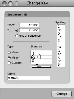
be edited in the Conductor track (in the Event List, Graphic Editor, or Sequence Editor) and in
the QuickScribe Editor.
The Change Key Command
Digital Performer’s Change Key command window (see Figure 11.19) provides options for
inserting key change events within a sequence. These options are as follows:
nFrom. This is the start location for the key change, indicated in bars and beats.
nTo. This is the end location for the key change. The End of Sequence option will tell DP to
change the key from the start location to the end of the sequence.
nType. Here you can specify whether the scale is major or minor or whether you would like to
use a custom (modal) scale.
nSignature. Use the slider to choose a key signature. The Spellings list will automatically
update to reflect the selection.
nName. This field displays the default name for the selected key signature. You can type in a
new name if you want; this can be useful when creating custom key signatures (for example,
modal keys such as Phrygian, Mixolydian, Dorian, and so on). Names are only used for your
reference and will not appear in the key event display in the Conductor track or Editor
window.
nSpellings. The Spellings list provides a table with the existing notes of a selected scale. Use
this column to change how notes are “spelled” within a standard key signature (for example,
spelling a C as B# or Dbb) or when you are creating custom key signatures.
Figure 11.19 The Change Key command window.
360 Digital Performer 6 Power!: The Comprehensive Guide

To apply a key change using the Change Key command:
1. Start by choosing Project 4Modify Conductor Track 4Change Key to open the
Change Key window.
2. Set the start and end locations for the key change.
3. Set the key type (Major, Minor, or Custom) and move the slider to select the appropri-
ate key.
4. If necessary, modify the note spellings in the Spellings list and the name of the key.
5. Click the Change button, and the new key event will be inserted.
Where Key Changes Are Inserted… Be aware that key changes are inserted into the active
sequence window/editor or highlighted Chunk window. If a Chunk isn’t selected, the key
event will be placed in the play-enabled Chunk. Digital Performer helpfully displays the
sequence you will be modifying in the top portion of the Change Key command window.
To edit the key signature of an existing key change event:
1. Navigate to the Conductor track within the Tracks window and double-click on the key
change event. This will open the Event List for the Conductor track (as long as Event
List is selected in Preferences 4Edit Windows 4Default Edit Windows 4Conductor
Track). If you are working in the Graphic Editor, clicking on the Conductor track’s key
change event will display the event within the Information Bar.
2. Within the Event List, double-click on the key change event. If you are in the Graphic
Editor, click on the key signature that appears in the Information Bar.
3. The Key Change dialog window will open. This window is identical to the Change Key
window, minus the start and end location section (see Figure 11.20).
4. Choose a new key signature and click the OK button.
To edit the location of an existing key change event:
1. In the Conductor track’s Event List, double-click on the location of the key change
event. The location will become active, allowing you to type in a new value.
2. If you are working in the Conductor track’s Graphic Editor, select the event to display it
in the Information Bar. Click on the location and enter a new value. You could also
horizontally drag the event within the Conductor track and drop it in a new location.
The drag-and-drop method also works in the Tracks window and the Sequence Editor.
Chapter 11 Arranging 361
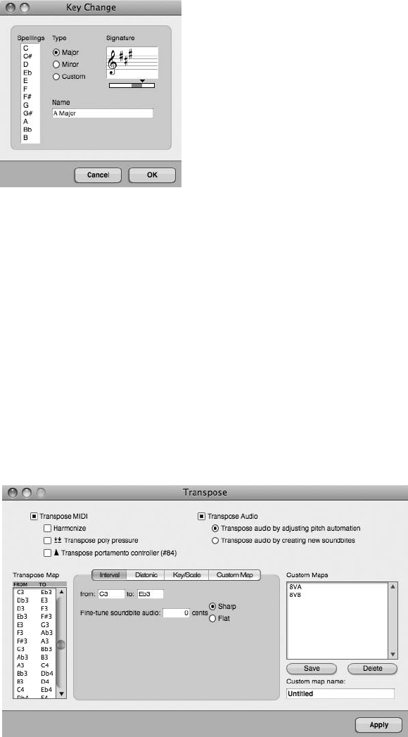
You can also use standard editing commands, such as Copy, Cut, and Paste, with key change
events. See the earlier “The Conductor Track” section of this chapter for related information.
Transposing Audio and MIDI Data
The difference between inserting a key change and transposing audio or MIDI data is huge.
Key changes only affect the visual display of notes, while transposing data changes the actual
pitch of MIDI and audio data. The Region menu’s Transpose command window, shown in
Figure 11.21, provides powerful options for controlling how selected MIDI data and soundbites
are transposed. Refer to Chapters 9 and 13 for an exploration into the use of the Transpose
command.
Figure 11.20 The Key Change dialog window is identical to the Change Key command window, minus
the start and end location section.
Figure 11.21 The Region menu’s Transpose command allows you to change the pitch of selected MIDI
and audio data.
362 Digital Performer 6 Power!: The Comprehensive Guide
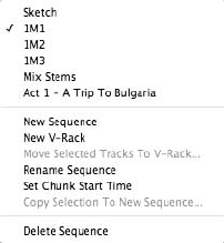
Chunks
Many DP users find the term Chunk confusing. What is a Chunk? I’m glad you asked. A Chunk
can be either a sequence (which is made up of multiple tracks) or a song (which is made up of
multiple sequences or other songs). That’s it. Sounds too simple, doesn’t it? Well it is, really, once
you understand how sequences, Chunks, and songs interact with each other. Even though sequen-
ces and Chunks are the same thing, you may have noticed throughout the book that I tend to favor
one word or the other, depending on the situation and topic I’m discussing. Usually, when I’m
referring to a single sequence, I use the word sequence, and when I’m referring to multiple sequen-
ces, I use the word Chunk. This is more of a nuance than anything, and some of you power users
out there may have a different take on the subject. Regardless, a sequence is a Chunk, and a
Chunk is a sequence. I’ll leave it up to you to decide whether it’s a “tomayto” or a “tomahto.”
This section will explain the procedures for managing individual sequences within the Tracks
window and will also discuss the Chunks window, which provides a dedicated location for
managing multiple sequences (Chunks) and songs.
Sequences
Asequence is basically a container for your audio and MIDI tracks. By default, a new sequence
is automatically created when you create a new project. This sequence is called Seq-1 and is
displayed in the Control Panel’s Sequence menu, shown in Figure 11.22.
The Sequence Menu
You can click on the Sequence pop-up menu to rename the sequence or create a new one. If
multiple sequences already exist, they will be listed within this menu. Simply select a sequence to
play-enable it (that is, to make it the active sequence).
An unlimited number of sequences can exist within a project; the number is only limited by the
amount of RAM you have installed within your system. Now, read that last sentence again—the
Figure 11.22 The Control Panel’s Sequence menu provides options for creating, renaming, and play-
enabling sequences.
Chapter 11 Arranging 363

amount of RAM dictates the number of sequences you can efficiently have within a project. If
you are going to be using multiple sequences (or Chunks) in a project, then make sure you have
plenty of memory available to DP.
Incorporating Sequences into Your Workflow
If you look beyond the clear-cut definition of a sequence, you may begin to imagine the various
ways you can incorporate the strength of sequences into your production workflow.
A really handy, though sometimes overlooked, feature is the Sequence menu’s Copy Selection to
New Sequence option. This command will take any track selection (including all its current set-
tings) and place it into a new sequence. Simple enough, so what’s the big deal? Well, this powerful
feature can really help you streamline your entire workflow. The following subsections present a
few examples of how you can incorporate this command into the music production process.
Copy Selection to New Sequence The music-production process is a very dynamic and fluid
combination of events. In a perfect world, we would move from one stage to another (for
example, recording, then editing, then mixing, then mastering). In the real world, how-
ever, we find that many of these processes overlap. For example, you may be mixing a
tune while you are still performing those last-minute overdubs and edits at 2 AM! Or, if
you are involved in the film-scoring process, you can create separate sequences for each
cue—1M1, 1M2, and so on. These separate “cues” would simply duplicate the “virtual”
orchestration setup as well as share the same movie file. When it comes to your studio
workflow, flexibility is the key, and the Copy Selection to New Sequence command is just
one of the many helpful features that DP provides to help you accomplish this goal. It
allows you to easily move (arrange) tracks or portions of tracks into separate sequences.
Recording. If you are working on a project that contains multiple songs, such as an album proj-
ect, you could record each song into a separate sequence instead of recording them into separate
projects. This, of course, has its advantages and disadvantages.
One advantage is that you have each song within this single project under one roof, so to speak.
If you would like to use a soundbite from one song and place it in another, you can easily do so.
You can quickly switch between sequences when you need to, and project management is sim-
plified because all your work is consolidated into a single project.
The disadvantage is that there is a danger in keeping all of your eggs (sequences) in one basket—
if the project is corrupted for some reason, you run the risk of losing every sequence contained in
the project. However, if you are executing proper backups, this shouldn’t be a concern.
Overdubbing. When you’re overdubbing, preparing your project to be as responsive and effi-
cient as possible—for example, using low buffer settings, freeing up RAM and CPU—should be
a prime concern. Providing a streamlined recording environment for your performer should be
364 Digital Performer 6 Power!: The Comprehensive Guide

your main focus and priority. This can be a problem if you are also in the middle of mixing the
material to which you will be overdubbing (with many plug-ins), or if you have a ton of tracks
eating up precious CPU and RAM. The Copy Selection to New Sequence feature can be the
solution to this problem; read on to find out how.
To use the Copy Selection to New Sequence command during the overdub process:
1. Create a stereo version of your mix by bouncing your tracks to disk or by recording the
summed output to a stereo track (make sure you name the track before recording) in
real time.
Bouncing Subgroups or “Stems” For greater flexibility, you could bounce your tracks in
subgroups (or stems)—for example, drums, bass, keys, guitars, and so on. This adds a
little more work to the procedure, but it offers more control over the “mix” being pro-
vided to the artist.
2. If you’re using the Bounce to Disk command, make sure to tell DP to import the
bounced file into the current sequence. Name it something appropriate, such as 2Mix
or Stereo Mix. At this point, you should have a new stereo track (or multiple tracks)
that contains a stereo mix of your song.
3. Select the new stereo files along with the Conductor track (this is important),
and choose Copy Selection to New Sequence from the Sequence menu. The Create
Chunk window will open, allowing you to name the new Chunk. Name it something
appropriate, such as Piano Overdubs or Vocal Overdubs. Set the end time to Auto and
click OK.
Don’t Forget the Conductor Track! You need the Conductor track so that your new
sequence will retain the same meter, tempo, and any other Conductor track events.
If you’re really organized, you have already created markers at important song struc-
ture locations (for example, the intro, verse, chorus, bridge, outro, and so on). These
location points will be copied over with the Conductor track into the new sequence.
Markers are discussed in detail later, in the “Markers” section of this chapter.
4. Now, from the same menu, select the new Overdub sequence, and it will become the
active sequence in the Tracks window. At this point, you should be viewing a stream-
lined sequence (with freed-up RAM and CPU) that only contains the Conductor track
and the bounced stereo mix of your song.
5. Next, lower your buffer settings if you need to reduce any monitoring latency. Create
your headphone mix, and you’re ready to begin recording.
Chapter 11 Arranging 365

Once you have overdubbed any necessary parts, you’re ready to combine your new
tracks with the main sequence. To combine your tracks using the “copy” method,
continue on with these steps.
6. Start by selecting all of the new tracks you overdubbed by choosing Edit 4Select All.
The default keyboard shortcut is CommandþA. Make a note of the number and type of
tracks you are selecting. This is important because you will need to duplicate the track
layout in the main sequence in order for the material to be copied over correctly. If you
have a combination of different tracks (for example, mono, stereo, and MIDI), you
might want to group them together by type by changing the track order. This might
make it easier for you when you are creating the new tracks within the original
sequence.
7. Next, press the Shift key and click on the name of the Conductor track to exclude it
from this procedure.
8. Once your tracks are selected, choose Edit 4Copy (or press CommandþC).
9. Next, choose the main sequence from the Sequence menu.
10. Create the same number of tracks (with the same format—for example, mono or stereo)
within this main sequence. Make sure the order of the tracks is exactly like the order
within the Overdub sequence.
11. Make sure your new tracks are selected by clicking on their track names.
12. Cue the Main Counter to the beginning of your sequence and choose Edit 4Paste (or
press CommandþV) to paste the material into the main sequence.
13. Mute the bounced file you created in Step 1, then hit the spacebar to check your work.
Overdubbed Tracks and the Soundbites Window Because multiple Chunks (or sequen-
ces) within a project share the same Audio Files folder, another option regarding the
placement of overdubbed tracks back into a main sequence is to use the Soundbites
window. Once you have returned to the main sequence and created the same number
of tracks (as in Step 4 in the previous section), simply drag each soundbite to its corre-
sponding track. Remember our discussion of naming your tracks before recording? This
is where track naming becomes very useful!
Chunks Window Another method for combining tracks from one sequence into another
is by using the Chunks window’s Song feature. See “The Chunks Window” section of
this chapter for an explanation of this procedure.
366 Digital Performer 6 Power!: The Comprehensive Guide
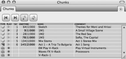
Arranging. You could also use the steps outlined in the preceding “How To” section to split the
different sections of your song (the verse, chorus, and so on) into separate parts. Once they are
separated into individual sequences, you could use the Chunks window to place them into a song
to experiment with different versions or arrangements.
Mastering. This is always a very touchy and controversial subject, so I’ll start by adding my
disclaimer: Mastering should be left up to professional mastering engineers! They are called
“mastering” engineers for a reason. It takes many years of training, practice, and the right
gear and studio environment to properly master a recording. (See Chapter 13 for a continuation
of this discussion.)
Okay, with that said, the reality is that we DP users sometimes need to use Digital Performer for
our mastering needs. Because the application was built to function more like a multitrack
recorder than a dedicated two-track recorder, mastering can be a confusing task. How do
you set up a DP project for mastering a collection of songs (such as for an album)? One way
is through the use of Chunks. Start by placing each song in its own sequence (with its own plug-
in chain) and open a separate Tracks window for each song. Then use the Chunks window
(explained next) to quickly switch between each song. This setup lets you instantly jump
between each song, allowing you to easily check the sonic and dynamic relationships between
them.
The Chunks Window
Now that I’ve covered a few different situations where you might use Chunks within a project,
let’s take a look at the Chunks window, shown in Figure 11.23.
You can access the Chunks window by choosing Project 4Chunks or by using the default key-
board shortcut ShiftþC. The main area of the Chunks window lets you specify the order of
existing Chunks or songs, play-enable a specific Chunk/song, enter comments, and set song
select numbers for cueing Chunks from a MIDI controller.
Figure 11.23 The Chunks window. In this example, there are five sequences, one song, and two
V-Racks. Notice the different icons that are used to represent them. Only one song or chunk can be
play-enabled at a time (and V-Racks incorporate the online/offline icon).
Chapter 11 Arranging 367
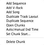
The options included in the Chunks window are as follows:
nType. This column displays the Chunk or song icon. Chunk icons are yellow, and song icons
are purple.
nPlay. This column indicates which Chunk or song is currently play-enabled. Only one item
can be play-enabled at a time.
nS#. This is the Song Select Number column, which is the number from 1 to 127 that can
be assigned to a song or Chunk so that it can be cued from your MIDI controller. If the
column contains a dash, then there is no song select number assignment. Playback order is
also based on its placement within the list, so if a Chunk or song contains the same number,
DP will play back the topmost item in the list first. Be aware that your MIDI controller must
be able to send a song select message in order to take advantage of this feature.
nEnd Time. This is the end time of the Chunk. When this is set to Auto End Time, the measure
after the last full measure of the Chunk is used and cannot be edited from this column. If it’s
set to Manual (which can be done by selecting the Chunk and choosing the mini-menu’s
Auto/Manual End Time option), the end time will be displayed in bold and can be edited
directly in this column.
nName. This column shows the name of the Chunk. Option-click to rename a Chunk.
nComment. Click on the Comment column to enter comments for a specific Chunk.
The Chunk window’s mini-menu options, shown in Figure 11.24, are as follows:
nAdd Sequence. This option creates a new sequence. Holding down the Option key before
opening up the mini-menu allows you to create multiple sequences at once.
nAdd V-Rack. This option adds a V-Rack to the Chunks list (discussed later in this section).
nAdd Song. This option creates a new song. Holding down the Option key before opening up
the mini-menu allows you to create multiple songs at once.
nDuplicate Track Layout. Once a Chunk is selected, this command will become available.
This option creates a blank sequence with the exact track layout as the selected Chunk.
Figure 11.24 The Chunk window’s mini-menu.
368 Digital Performer 6 Power!: The Comprehensive Guide
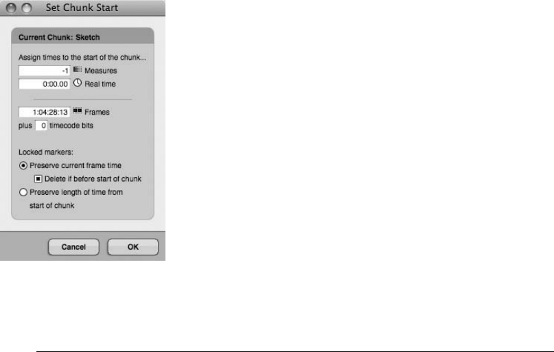
nDuplicate Sequence. This option creates an exact duplicate of the selected sequence.
nOpen Chunks. This option opens separate Tracks windows for selected Chunks and separate
Song windows for selected songs.
nAuto/Manual End Time. Use this option to toggle a Chunk’s end time to be either auto or
manual. Only manual end times can be pop-edited in the main Chunk window.
nSet Chunk Start. This option opens the Set Chunk Start window, shown in Figure 11.25, in
which you can change the actual start time for the selected Chunk. This is the same window you
see when clicking on the Start Times button in the Control Panel’s Tempo Control drawer.
nDelete Chunk. This option deletes selected Chunks.
V-Racks V-Racks are virtual racks that can be created in the Chunks window, the
Sequence drop-down menu of the Control Panel, or Project 4Sequences. V-Racks are
simply a collection of aux tracks, virtual instruments, or master faders that is shared by all
sequences (Chunks) in a project. These virtual racks are active regardless of what sequence
is play-enabled, meaning their inputs and outputs are always available to the different
sequences. For example, imagine you have four separate sequences within a project
and you want to use the same set of virtual instruments for all sequences. By creating a
V-Rack of the virtual instruments, you will not have to load them separately into each
sequence, nor will you have to wait for the virtual instruments to reload each time you
switch to a different sequence within a project. V-Racks are a great way to save memory
and CPU resources—and, more importantly, time!
Figure 11.25 The Set Chunk Start window allows you to change the start time for a Chunk. This win-
dow even allows you to set negative start times, such as Measure 1.
Chapter 11 Arranging 369
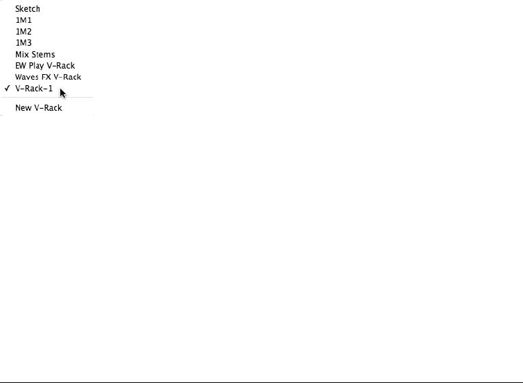
To create a V-Rack:
1. Choose New V-Rack from the Sequence drop-down menu in the Control Panel.
2. The Mixing Board will open automatically, revealing the newly created V-Rack. If not,
simply open the Mixing Board (ShiftþM) and select the new V-Rack from the Mixing
Board’s Sequence drop-down menu (see Figure 11.26).
3. To add an aux track, virtual instrument, or master fader, use the standard techniques for
adding tracks (Project 4Add Track).
4. If you would like to move tracks from a sequence to the V-Rack, make sure the desired
sequence is play-enabled, highlight the tracks you want to move, and choose Move
Selected Tracks to V-Rack from the Sequence drop-down menu in the Control Panel.
5. To delete a track from the V-Rack, select the Delete Track option from the drop-down
menu at the bottom of its mixer strip in the Mixing Board (see Figure 11.27).
Once a V-Rack is created, you can take it online or offline by enabling/disabling the
V-Rack in the Chunks window. Also, V-Racks are only visible in the Mixing Board window.
Controlling Chunks
The Chunks window contains a number of features that control the playback of Chunks within a
DP project. (Refer to Chapter 3 for a detailed look at the Control Panel.) Keep in mind that all of
these features cannot provide smooth playback transitions between each Chunk, but you can use
DP’s Song feature to accomplish this.
Skipping, Cueing, and Chaining Chunks
The Chunk Control buttons are used to manage the playback of Chunks within DP (see Figure 11.28).
Use the Next and Previous Chunk buttons (the first two buttons from the left) to quickly move (skip)
to the previous and next Chunks within the Chunks window. Once clicked, playback of the current
Chunk will be interrupted, and the next or previous Chunk will automatically begin playback.
Figure 11.26 The Mixing Board’s Sequence drop-down menu with a new V-Rack.
370 Digital Performer 6 Power!: The Comprehensive Guide
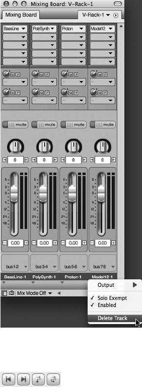
The Cue Chunks button—the third button from the left—will automatically cue (bring up) the
next Chunk within the Chunks window for playback. This is why the order of the Chunks
within the Chunks list is so important. If you would like to use this feature, then make sure
you have your Chunks in the correct playback order. You can rearrange the Chunks by simply
grabbing the Chunks icon and dragging it to the desired location.
The fourth button from the left, Chain Chunks, will cause the next Chunk to automatically play
back when the end of the current Chunk is reached. If you require a pause between the playback
of one Chunk and another, simply change the end time of the first Chunk by the amount you
want. Remember, you will need to set the end time to Manual to accomplish this.
Figure 11.27 The Delete Track option at the bottom of a track’s mixer strip.
Figure 11.28 The Chunk Control buttons control the playback of Chunks within DP.
Chapter 11 Arranging 371
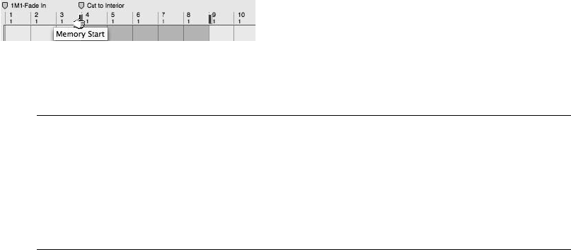
When using the Cue Chunks or Chain Chunks feature, the Memory Bar’s Start and Stop Time
settings will update to show the start and end times for the current Chunk. In addition, the Time
Rulers will display the Start and Stop bar-line markers (see Figure 11.29), which offer a visual rep-
resentation of where and when the Chunk will start and end playback. You can drag these bar lines
to new locations to quickly change when playback of the current Chunk will begin and end.
Switching Chunks and Updating Edit Windows Many times, you will use the Chunks win-
dow to switch to another Chunk while an Edit window is still open. This can be confusing,
for example, if you play-enable a new Chunk and hit the Control Panel’s Play button. This
action will trigger the new Chunk, but you just may be looking at the previous Chunk’s
Tracks window! So keep in mind, Edit windows do not update to the selected Chunk. You
must close and re-open Edit windows once a new Chunk has been play-enabled.
Songs
The Song window provides an environment for combining Chunks together. They can be daisy-
chained for seamless playback, stacked for simultaneous playback, or a combination of both.
Why would you need to do any of this? Let’s go back to our previous “arranging” scenario. You
could take an existing sequence and break the major sections (the intro, verse, chorus, and so on)
into separate Chunks, then use the Song window to arrange them in different orders to audition
multiple versions of your song. Maybe you find that verse-verse-chorus works better than verse-
chorus-verse. You could also create smaller Chunks (say, a four-bar pattern) of various instru-
ments (drums, bass, keyboard riffs, and so on) and use the Song window to construct a song.
Once your arrangement has been created, you can even merge your song (with its multiple
Chunks) into a single Chunk. The possibilities are endless.
The Song Window
The Song window provides a flexible grid for arranging Chunks. Remember that a Chunk can also
be a song, so it’s entirely possible to have a song nested within another song (see Figure 11.30).
A Chunk appears as a gray bar with the yellow Chunk icon located in the top-middle portion of
the Chunk. Songs also appear as gray bars, but with the purple song icon as an identifier. Selected
Chunks and songs will always be highlighted yellow.
The Chunk and grid is fairly easy to comprehend. The grid is divided into columns, or placement
guides, that are represented by blue lines. When a song is created (choose Add Song from the
Figure 11.29 Drag the Start and Stop bar lines within the Time Ruler to quickly change when playback
will begin and end for the current Chunk.
372 Digital Performer 6 Power!: The Comprehensive Guide
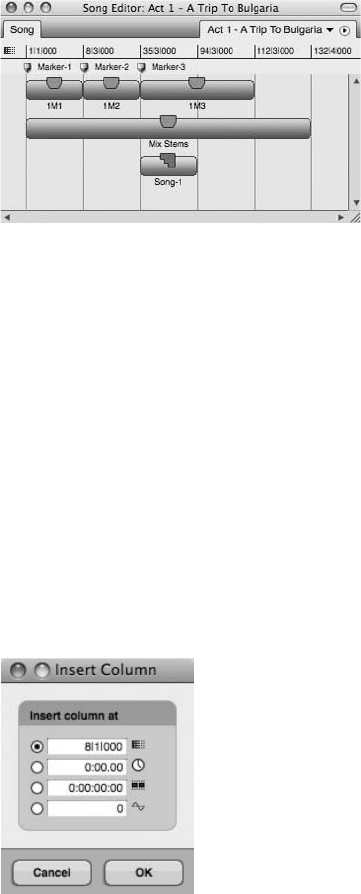
Chunks window’s mini-menu), a column is automatically placed at the beginning of the Song
window. Columns must exist in order for a Chunk to be placed at a specific location. For exam-
ple, if you want to place your first Chunk at Measure 8, you will need to manually insert a
column at Measure 8 because the only column will exist at Measure 1/1/000. Be aware that
DP will automatically delete manually inserted columns if a Chunk does not exist in that loca-
tion. Be sure to place a Chunk in that location before DP redraws the Chunk grid.
To insert a column:
1. Open the Song window by double-clicking on the name of the song in the Chunks win-
dow. (Make sure you have created a new song, as mentioned a moment ago.)
2. Click Insert Column in the Song window’s mini-menu. The Insert Column window,
shown in Figure 11.31, will open.
3. Enter a value of 8in the measure section. Click OK. Your new column will appear at
Measure 8.
4. Now you can drag and drop a Chunk at that location. Once placed on the grid, DP will
automatically insert another column at the end of the new Chunk.
Figure 11.31 The Insert Column window. Four different time formats allow you to insert columns at
precise locations.
Figure 11.30 The Song window can contain sequence Chunks and song Chunks.
Chapter 11 Arranging 373
To place a Chunk within the Chunk grid:
1. Start by creating a grid column at the location where you want to place the Chunk.
If you need to place the Chunk at the beginning, don’t worry about this step. DP
automatically places a grid column at the start of the Song window (Measure 1/1/000).
2. Drag and drop a Chunk from the Chunks window into the Song window’s Chunk grid.
Again, if there aren’t any columns available, then the Chunk will be placed at the
start of the song. Besides vertical grid columns, the Song window is also divided into
Chunk rows. These rows are invisible, but they allow you to horizontally stack Chunks
so they can play back simultaneously, depending on their vertical locations.
3. To change the location of this Chunk, simply drag it to a new location. (Remember to
insert a column if one isn’t present already.)
Markers in the Song Window. Just like a normal sequence, songs can contain markers. Song
markers appear beneath the Song window’s Time Ruler. Markers not only provide organiza-
tional benefits, but they also automatically create grid columns at their locations. You can
use markers when you need to create multiple grid columns without the fear of them being
removed by DP. For an explanation of Digital Performer’s markers feature, see the “Markers”
section of this chapter.
To place a marker in the Song window:
1. With the Song window active and in the foreground, open the Markers window (ShiftþK).
2. Click on the marker’s mini-menu and choose Add.
3. Once you’ve created the marker, type in the desired location in the marker’s Measure
column. Your marker will be placed in the correct location along with a blue grid
column.
4. To delete these markers, select the marker within the Markers window and choose
Delete.
When working with song and Chunk markers in DP, you can delete any markers that are dupli-
cated between your song and a selected Chunk.
To delete duplicate markers:
1. Start by selecting a Chunk.
2. Open the Song window’s mini-menu and choose Delete Markers. Any song markers
that are identical to the selected Chunk’s markers will be removed.
Markers can also be merged between selected Chunks and placed in the Song window.
374 Digital Performer 6 Power!: The Comprehensive Guide
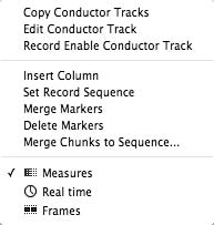
To merge Chunk markers:
1. Start by selecting the Chunks that contain the markers you want to merge.
2. Open the Song window’s mini-menu and choose Merge Markers. The merged markers
will be copied into the Song window.
Mini-Menu. I’ve already covered some of the mini-menu’s features, but the mini-menu includes
some additional controls (see Figure 11.32) that can allow you to dive deeper into the Song
window.
nCopy Conductor Tracks. This option copies the Conductor track from a selected Chunk into
the Song window. If multiple Chunks are selected, DP will use the topmost Chunk when
copying.
nEdit Conductor Track. This option opens the Event List or Graphic Editor for the song’s
Conductor track.
nRecord Enable Conductor Track. This option record-enables the Song window’s Conductor
track so you can record tap tempo data. See the “Tempo” section of this chapter for an
explanation of tap tempo.
nInsert Column. This option opens the Insert Column window. It is identical to the title bar’s
Insert button (I).
nSet Record Sequence. This option toggles the Record-Enable button for a selected Chunk.
This feature allows you to record into a selected sequence while hearing playback of the
entire song.
nMerge Markers. This option merges the markers of selected Chunks and places them into the
Song window.
nDelete Markers. This option deletes markers that are duplicated between a song and selected
Chunks.
Figure 11.32 The Song window’s mini-menu provides options for controlling songs and their related
Chunks.
Chapter 11 Arranging 375
nMerge Chunks to Sequence. Use this command to combine selected Chunks into a single
Chunk. When you choose this option, the Merge Chunks window will open and present you
with two options. The Copy All Tracks option will copy all of the tracks of the selected
Chunks and place them into a new sequence. The Merge Tracks with Identical Names
option is identical to the previous Merge Chunks to Sequence option except that it merges
tracks that have the same names. Both options will place the new sequence in the Chunks
window.
nTime Ruler settings. Here you can enable the listed time formats, and they will appear in the
Song window’s Time Ruler.
Controlling Songs. Just as with a “normal” sequence or Chunk, DP allows you to play back,
record into, and edit songs.
To play back a song:
1. Click on the song’s Play-Enable button in the Chunks window.
2. Press the spacebar.
3. You can also select the song within the Control Panel’s Sequence menu.
To record audio or MIDI data into a song:
1. Double-click on the song in the Chunks window to open the Song window.
2. Double-click to select the Chunk into which you want to record. It will open in the
Tracks window. Notice that there aren’t any record-enable buttons.
3. Choose Set Record Sequence from the Song window’s mini-menu to record-enable the
selected Chunk. You should see the Chunk icon display a red dot, indicating that the
Chunk is record-enabled. The Record-Enable buttons for each track within the Chunk
will also become visible.
4. Arm the necessary tracks and proceed with the normal recording procedure.
5. When you are finished recording and you have stopped the Transport, return to the
Song window’s mini-menu and choose Set Record Sequence to toggle off or disable
the Chunk’s recording capabilities.
To record tap tempo data into a song’s Conductor track:
1. Double-click on the song in the Chunks window to open the Song window.
2. From the mini-menu, choose Record Enable Conductor Track. This will arm the song’s
Conductor track and will be indicated by a check mark next to this option.
376 Digital Performer 6 Power!: The Comprehensive Guide
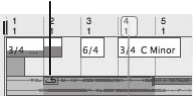
3. Double-click the Control Panel’s Slave to External Sync button. The Slave to External
Sync option will be enabled, and the Receive Sync window will open.
4. In the Receive Sync window, select the Tap Tempo option. Choose the tap tempo
options you want and click OK.
5. Click the Record button and start tapping. (See the “Tap Tempo and the Receive Sync
Command” section of this chapter for a detailed look at the procedure.)
6. Click the Stop button when you are finished.
7. Return to the Song window’s mini-menu and click the Record Enable Conductor Track
option to toggle off this feature.
To edit Chunks in the Song window:
1. Double-click on the song in the Chunks window to open the Song window.
2. Select the Chunk you want to modify and apply the necessary command from the Edit
menu (Cut, Copy, Paste, Erase, Select All, or Undo). The results of each command are
identical to those in DP’s standard Editor windows.
3. When using the Paste command, you will need to click with the mouse to tell Digital
Performer where you would like to paste the selected Chunk.
Looping
Digital Performer’s looping feature allows you to loop or repeat selected regions in a track. Each
track has its own independent loop capabilities, allowing you to set different loops for different
tracks. Loops can even be nested within another loop. DP’s looping capabilities provide a more
efficient use of your Mac’s resources than the more standard approach of copying and pasting
the same region multiple times. In addition, you can quickly execute modifications to a loop,
because you only have to change the loop points of the region. If you used the copy-paste
method, you would have to edit multiple regions to make any changes.
There are three components that define a loop: the start point, the end point, and the number of
repetitions. Loops within a track are indicated with a Loop icon, as shown in Figure 11.33. The
Loop Icon
Figure 11.33 Regions within a track will appear with a Loop icon. These icons are only visual markers to
indicate that a loop is present and cannot be edited directly within a track.
Chapter 11 Arranging 377
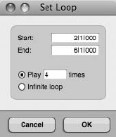
length of the loop indicator (either a gray bar or a gray bar with solid lines) identifies the dura-
tion of the loop and points to where the region will begin repeating. Audio or MIDI data that
appears below the loop indicator bar will not play back and will be ignored by DP.
Inserting a Loop Using the Region Menu
There are numerous ways to insert a loop. You can use the Region menu’s Set Loop command,
the Event List’s Insert Button (þ), or the Loop tool. The Set Loop command differs from the
other methods in that it is global and allows you insert a loop regardless of the window in which
you are working.
To insert a loop using the Set Loop command:
1. Begin by selecting the region or regions you want to loop. Keep in mind that the length
of your selection will also define the amount of data that will be looped. For example, if
a region is two bars long but you make a time-range selection of four bars (which
includes the two-bar region), DP will loop the entire four-bar selection. So you will
essentially be looping the two bars of music along with two bars of silence. In addition,
you can make selections across multiple tracks to set multiple track loops with one
command.
2. Choose Region 4Set Loop. The Set Loop window, shown in Figure 11.34, will
open.
3. Set the Start and End points for the loop. The initial values that appear will be based
on the time-range selection you made in Step 1, so depending on your needs, you
may not have to change these values.
4. Set the number of repeats for the loop. The Play ___Times option lets you enter a
specific value. The Infinite Loop option forces the selection to loop indefinitely.
5. Click OK. The selection will update and appear with the Loop icon indicating that the
region is looping.
Figure 11.34 The Set Loop window.
378 Digital Performer 6 Power!: The Comprehensive Guide
To remove a loop using the Clear Loop command:
1. Select the region that contains the loop.
2. Choose Region 4Clear Loop. The loop will be removed.
Inserting a Loop in the Event List
You can also manage loops from the Event List. Unlike the Region menu commands, which only
allow you to create and delete loops, the Event List also lets you edit existing loop parameters
and will display nested loops if any are present.
To insert or delete a loop in the Event List:
1. Select the region or regions you want to loop.
2. Press ShiftþE to open the Event List.
3. Click on the title bar’s Insert button (the þicon) and choose Loop from the Insert menu.
4. The Start Point setting will appear, allowing you to enter a start value.
5. Tab to the End Point pop-up field and enter the loop’s end point.
6. Tab to the Repeat pop-up field and enter the number of repetitions for the loop.
7. Press Return to confirm the settings. The Event List will display the location of the loop and
the loop settings. The notes or soundbites being looped will be listed below the loop event.
8. To remove the loop, select the loop event within the Event List and press the Delete key.
To edit a loop in the Event List:
1. With the looped region selected and the Event List open, click on the parameter you
want to modify. The setting will appear, allowing you to make the necessary changes.
2. Once modified, press the Return key to confirm the change.
The Loop Tool
Using the Loop tool, you can insert a loop directly into the Sequence, Graphic, and Drum Editors.
The loop settings will appear in the editor’s Information Bar, and you can simply click on a
setting to edit the values.
To insert or edit a loop in the Sequence Editor:
1. Activate the Loop tool by double-tapping the L key.
2. Click at the beginning of the desired region and drag to the right, stopping at the end of
the region. Notice that a gray bar appears at the end of the selection (see Figure 11.35).
Chapter 11 Arranging 379
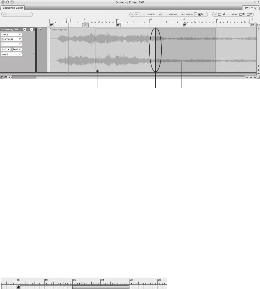
This represents the duration of the loop—where the region will begin to repeat and
where it will end.
3. The loop settings will also appear in the editor’s Information Bar when the loop is
selected. To change a value, simply click on the setting to edit it.
4. You can also change the loop Start and End points directly in the track by dragging on
the beginning loop icon or the ending loop bracket. However, you can only change the
loop duration in the Information Bar.
To insert or edit a loop in the Graphic Editor:
1. Activate the Loop tool by double-tapping the L key.
2. In the marker strip (located below the Time Ruler), click at the desired location and
drag to the right, stopping where you want the end loop point to be. Notice that a
gray bar (with solid lines) appears at the end of the selection (see Figure 11.36). This bar
represents the duration of the loop—where the region will begin to repeat and where it
will end.
3. The loop settings will also appear in the editor’s Information Bar when the loop is
selected. To change a value, simply click on the setting to edit it.
Loop Bracket
(Black Line)
Loop Icon
Loop Duration
(Gray Bar)
Figure 11.35 The Loop icon indicates the beginning of a loop, while a loop bracket designates the loop
End point. The gray bar that appears after the loop bracket shows the duration of the loop.
Figure 11.36 A loop within the Graphic Editor’s marker strip.
380 Digital Performer 6 Power!: The Comprehensive Guide
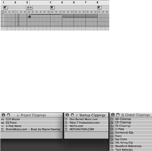
4. You can also change the loop Start and End points directly in the marker strip by
dragging on the beginning loop icon or the ending loop bracket. However, you can only
change the loop duration in the Information Bar.
To insert or edit a loop in the Drum Editor:
1. Open the Drum Editor (ShiftþD) and activate the Loop tool by double-tapping the
L key.
2. Drag with the Loop tool in the note grid row that appears with the track name (see
Figure 11.37). All other edit procedures are identical to those concerning the Graphic
Editor, described previously.
Clipping Windows
Clipping windows in Digital Performer (see Figure 11.38) are like containers for holding any-
thing to which you would like to have quick access. A Clipping can be an audio or MIDI file; an
FX chain consisting of your favorite plug-ins, sequences, and even text documents; web links; or
entire folders located on your Mac’s hard drives.
There are three types of Clipping windows in Digital Performer:
nDigital Performer. This Clipping window is global and can be accessed within any DP
project.
nProject. This Clipping window is project-specific and can only be opened in the project in
which it was created.
Figure 11.37 To insert a loop in the Drum Editor, drag with the Loop tool in the grid row that contains
the track name.
Figure 11.38 The Digital Performer Clipping windows (from left to right): a Project Clipping window, a
Startup Clipping window, and a Digital Performer Clipping window.
Chapter 11 Arranging 381
nStartup. This Clipping window is used to hold aliases of other documents that will auto-
matically launch when a project is opened. Startup Clipping windows are project-specific,
allowing you launch different documents or applications with specific DP projects. Keep in
mind that Startup Clipping windows, like the other Clipping windows, can also contain
normal MIDI and audio data.
How can you use Clippings in your everyday workflow? Suppose you’re working on a film
score, and you have created a recurring theme that consists of four tracks of strings. You
want to be able to get to this element of the composition quickly, without having to import
audio or load a sequence every time you need it, so all you do is copy your string tracks into
the Digital Performer Clipping window, and the clipping instantly becomes available in any DP
project on your computer. You could also save the lyrics to a song as a text file or an MS Word
document so every time the song project is opened, DP opens the lyrics for you!
Clipping Data Icons
Items that are placed in a Clipping window are given their own icons, allowing you to quickly
determine the type of data that is held in the window:
nAudio. Soundbites appear with a single- or double-waveform icon, depending on their
format (mono or stereo). If the audio is grouped as a sequence, however, it appears with a
note icon.
nTrack data. Track data is represented by an eighth-note icon and consists of MIDI data,
Conductor track information, and/or entire sequences (containing track data).
nPlug-ins. Individual plug-ins and plug-in chains are indicated by a small bar with dotted
lines.
nDocuments. Page icons represent documents.
nFolders. Folders appear with folder icons.
Creating, Opening, and Managing Clippings
The Project menu’s Clippings submenu (Project 4Clippings) allows you to create new Clipping
windows or access existing ones. Once a Clipping window is open, commands for deleting and
changing the viewing options for the active Clipping window become available (see Figure 11.39).
To create a new Clipping window:
1. Choose Project 4Clippings and select the type of Clipping you want to create (Project,
Digital Performer, or Startup).
2. Name the Clipping and press the Return key to confirm the change.
382 Digital Performer 6 Power!: The Comprehensive Guide
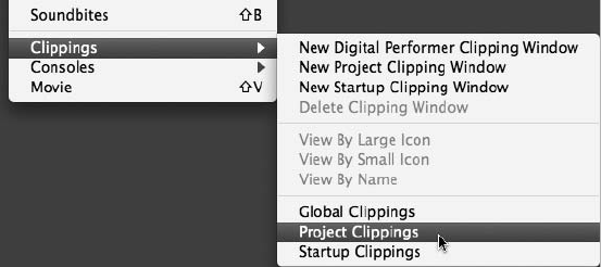
To open or delete an existing Clipping window:
1. To open an existing Clipping window, choose Project 4Clippings and select the
Clipping window you want to open from the list.
2. To delete that Clipping window, click the Clipping window to make it active.
3. Then, to continue with the deletion, choose Project 4Clippings 4Delete Clipping
Window.
To change the order of Clippings within a Clipping window:
1. Open the desired Clipping window.
2. Place the cursor over a Clipping, and a hand icon will appear. Click and drag the
Clipping to the desired position.
To delete a Clipping:
1. Open the desired Clipping window.
2. Click on the desired Clipping and press the Delete key.
Where Clippings Are Stored
Clipping windows are actually folders and are stored in the project’s Clippings folder (Project
folder 4Clippings folder) or, in the case of Digital Performer Clippings, in the User Library
Preferences folder (User 4Library 4Preferences 4MOTU Clippings). Once you realize that
Clipping windows are actually folders on your hard drive, you can manage them directly within
these locations. Creating a folder within the actual Clippings folder will create a new Clipping
window that is accessible in Digital Performer. In addition, Clippings folders are dynamic and
will automatically update in DP if they are changed at the Project or Preference folder level.
Figure 11.39 The Project menu’s Clippings submenu provides options for creating, deleting, opening,
and managing the viewing options of Clippings.
Chapter 11 Arranging 383

Adding Folders to the Project Clippings Folder Adding a folder directly to the Project Clip-
pings folder will result in a standard Project Clipping window being created in that project.
Startup Clipping windows can only be created by using the New Startup Clipping Window
command (Project 4Clippings 4New Startup Clipping Window).
Adding Audio and MIDI Data
You can add a soundbite and any data that is contained within a track (for example, audio, MIDI,
and Conductor track data) to a Clipping window by dragging it from a track or Soundbites win-
dow into the Clipping window. An item that is dragged individually into the Clipping window
will appear as its own Clipping. If you make a selection of multiple track items and drag them into
the Clipping window, however, they will appear grouped as a single sequence or Clipping.
You can also select data and choose Edit 4Copy to Clipping Window or use the keyboard
shortcut CommandþOptionþC, which will copy the selected data to the last Clipping window
to which you copied data.
Saving Plug-In Settings
Plug-ins can also be placed within a Clipping window. This is an incredibly useful feature
because it allows you to take an FX chain, for example, copy it into a global Digital Performer
Clipping window, and access it within other projects. Imagine—once you have created the per-
fect set of processing plug-ins for, say, a great drum kit sound, you can simply drag the Clippings
into a project the next time you want to quickly re-create the sound.
To save a plug-in chain as a Clipping:
1. Start by creating or opening a Digital Performer Clipping window.
2. Open the Mixing Board and select the plug-in from the Inserts section. Shift-click to
select multiple plug-ins.
3. Drag the plug-in chain into the Clipping window. DP will automatically name the new
Clipping according to the plug-ins that you add.
4. You can rename the Clipping by Option-clicking.
Documents, Folders, and URLs
You can also add documents, folders, and URLs to a Clipping window for quick access. Think
of these Clippings as shortcuts to your favorite items or websites. To add a document or folder,
simply drag the item into the Clipping window or add an alias of the item directly into the
Project Clippings folder or MOTU Clippings folder. Remember that you can place these
items in any type of Clipping window. If you need certain documents or applications to auto-
matically launch when you open a project, use the Startup Clippings feature.
384 Digital Performer 6 Power!: The Comprehensive Guide
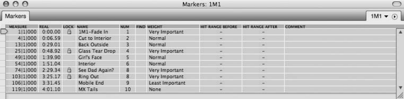
However, you cannot add URLs by dragging them directly into a Clipping window. You will
need to drag the address from your web browser into the project’s Clippings folder or the
MOTU Clippings folder instead.
Markers
The Markers window offers you a quick way to navigate to specific points within your Digital
Performer projects. Markers are also referred to as memory location points or simply locate points.
Users working with standard multitrack recorders—whether they are digital or analog—are prob-
ably already familiar with this very common, yet indispensable, feature. In addition to offering
navigational benefits, markers can be given custom names in order to help identify various sections
or a project. They can be used to quickly make time-range selections, and they can be recorded in
real time, making the process of setting up cues for film and video scores a simpler process.
Marker Basics
Before we dive into the actual use of markers, let’s take a look at the interface (see Figure 11.40).
You can access the Markers window in several ways.
1. Choose Project 4Markers.
2. Use the default keyboard shortcut ShiftþK.
Located in the Markers window title bar are standard controls for collapsing, resizing, and auto-
scrolling. Markers that have been created are listed in the main body of the window, with basic
columns describing the marker’s name and location as well as any comments about the marker.
The interface also includes advanced features that allow you to configure markers to be included
within the mini-menu’s powerful Find Tempo command. (See Chapter 15, “Scoring to Picture.”)
To create or add a marker:
1. Open the Markers window by pressing ShiftþK.
2. Click on the mini-menu and choose Add. A marker will be created at the current
Counter position with a default name of Marker-1.
Figure 11.40 The Markers window.
Chapter 11 Arranging 385
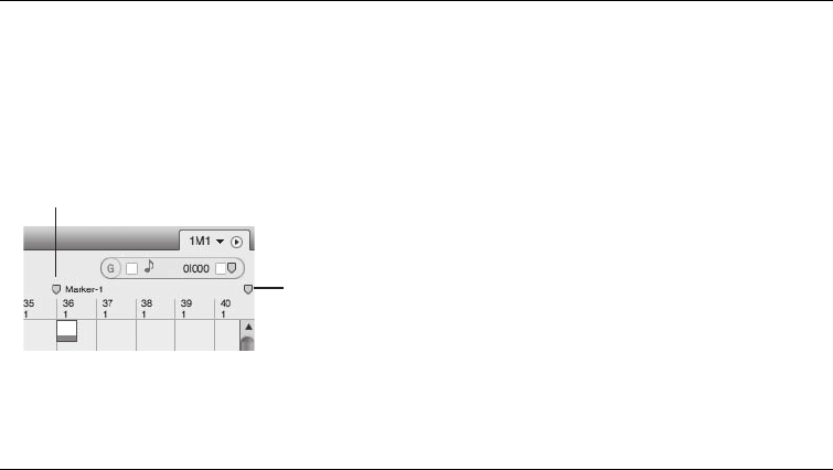
3. Click on the yellow position indicator (located to the left of the Measure column) to
instantly locate to that marker position.
The Marker Bin When working in the Tracks window, you can click and drag a marker
from the Marker Bin to quickly add a marker to the Time Ruler (see Figure 11.41). Use the
horizontal zoom buttons to expand the Time Ruler grid for more detailed marker place-
ments, and be sure to drag directly between the Time Ruler and the title bar.
Once a marker has been created, it will appear throughout DP’s Track Event and Editor windows.
A marker is displayed with a yellow chevron icon along with its name (refer to Figure 11.41).
To change the name of an existing marker:
1. Option-click the name of a marker within the Tracks or Markers window to change its
name.
2. Press the Return key to confirm the change.
To change the location of an existing marker:
nOpen the Markers window and click a value in the Measure column to edit the location.
nWithin an Editor window, simply click and drag the marker to a new location.
Creating Markers on the Fly
Digital Performer also allows you to create markers while you listen to a track by pressing the
default keyboard shortcut ControlþM during playback or by using the mini-menu’s Record Hits
feature. To take advantage of this latter feature, however, you must have a MIDI controller
attached to your DP system.
Marker Icon
(Chevron)
Marker Bin
Figure 11.41 Markers are indicated by a yellow chevron icon and will appear globally through-
out DP’s various Event and Editor windows. The Tracks window’s Marker Bin (the chevron icon in
the top-right corner) allows you to drag markers into the Time Ruler.
386 Digital Performer 6 Power!: The Comprehensive Guide
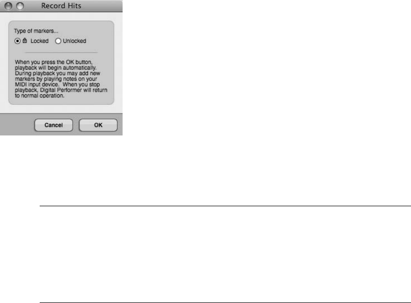
To add markers on the fly from your computer keyboard:
1. Begin playback.
2. At the desired time location, press ControlþM on your computer keyboard to insert a
marker on the fly.
To add markers on the fly using the Record Hits feature:
1. Begin by cueing up the playback cursor to the location at which you want to begin
playback.
2. Open the Markers window and choose Record Hits from the mini-menu. The Record
Hits window will open (see Figure 11.42).
3. Choose whether the markers will be locked or unlocked.
Locked versus Unlocked Markers Markers that are locked will be anchored to a SMPTE
frame location. This will force the marker to retain that SMPTE frame location even if
the tempo is changed. This is handy for post-production work, where you may want
markers to remain locked to a specific scene within a movie. An unlocked marker will be
anchored to its bar/beat location. Click on a marker’s Lock column in the Markers win-
dow to toggle its locked state.
4. Click OK, and playback will automatically begin.
5. Press any note on your MIDI controller to add a marker at that location.
6. Press the spacebar to halt playback.
Figure 11.42 The Record Hits window.
Chapter 11 Arranging 387
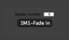
Quantizing Markers
When you use the Record Hits feature, your marker location may be a little off—some markers
may be early, while others may be late. You could manually move each marker by dragging it
with the mouse or by typing in a new value in the Markers window, but there is an easier way.
The Quantize window isn’t just for quantizing MIDI data or soundbites. Hidden within the
Quantize window’s Custom menu is an option to also quantize markers, allowing you to pre-
cisely align markers to a specified bar/beat grid or absolute time location. Of course, this isn’t a
solution to all your marker-location problems—it may be only appropriate for situations in
which you want selected markers to snap to specific beats, such as the downbeats of measures.
See the “MIDI Editing in the Graphic Editor” section in Chapter 10 for a detailed look at the
Quantize window.
To quantize selected markers:
1. Click and drag in the Markers window to select the markers you want to quantize.
2. Open the Quantize window by pressing Commandþ0.
3. Click on the What to Quantize button and choose Custom.
4. Make sure the Markers option is enabled.
5. Select the Grid value, specify any options, and click Apply. The selected markers will
instantly snap to the specified Grid value.
Recalling Markers
Besides clicking on a marker’s position indicator in the Markers window, there are different
ways to navigate to a specific marker location.
nYou can click on the Marker menu in the Tracks window (located to the right of the
Sequence menu) and choose a marker.
nYou can use the Control Panel’s Marker menu (located below the auxiliary time format
menu).
nYou can use the Go-To-Marker window, as shown in Figure 11.43.
Figure 11.43 The Go-To-Marker window.
388 Digital Performer 6 Power!: The Comprehensive Guide
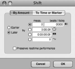
To navigate to a marker using the Go-To-Marker window:
1. Use the default keyboard shortcut ShiftþControlþM to open the Go-To-Marker
window.
2. Use the number pad to enter a marker number and then press Return. You can also
use your MIDI controller to specify the marker number by simply pressing the
corresponding note.
You may need to confirm the Numeric Base Note value from the Commands window’s
mini-menu. See “The Commands Window” section in Chapter 5. If the Numeric Base
Note value were set to C3, then pressing C3 on your MIDI controller would recall
Marker 1. Pressing C#3 would recall Marker 2, and so on.
Snapping and Shifting Data to a Marker Location
The Shift to Marker feature and Snap to Marker command allow you to move specific data to a
marker or use markers as a form of edit grid.
To shift selected data to a marker location:
1. Select the data you want to shift.
2. Open the Shift command window by pressing CommandþL (see Figure 11.44).
3. Choose Shift to Time or Marker from the pop-up menu.
4. Select the marker you want to shift to from the Marker pop-up menu.
5. Click OK. The selected material will be moved to the specified marker location.
To snap data to a marker location:
1. Turn on the Snap to Markers feature by toggling the box next to the Marker
chevron in the Snap Information section of the Information Bar (see Figure 11.45).
Figure 11.44 The Shift command window.
Chapter 11 Arranging 389
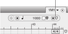
You can also double-click the (G) icon to enable this feature in the Snap Information
window.
2. Now any notes or soundbites that are dragged near a marker will “snap” to the marker
location.
Selecting with Markers
You can also use markers to make time-range selections for editing and recording by simply
clicking on a marker within a non–Conductor track. Shift-click to select multiple markers and
extend the time-range selection. Once you define a selection, you can use the Memory Bar’s Set
to Selection Bounds feature (refer to Chapter 3) to set the Memory locate points and to define in
and out points for an automated punch (refer to Chapter 7).
Markers in Post-Production Work
You can also use markers in more advanced post-production settings when you are working
with film and video scores. For example, you can attach streamers and punches to markers
related to specific film-scoring events. See Chapter 15 for a discussion of these advanced
features.
Summary
Digital Performer provides many powerful tools and feature sets for controlling how your proj-
ect’s sequences, Chunks, and songs behave. Some of these features (such as tempo and meter)
form the foundation of your DP projects, while others are there to help streamline your produc-
tion workflow.
Snap to Markers
Toggle
Figure 11.45 In this example, the Snap to Markers feature is toggled on in the Sequence Editor.
390 Digital Performer 6 Power!: The Comprehensive Guide

12 Mixing
Mixing in Digital Performer is mainly accomplished from the Mixing Board (see
Figure 12.1). Similar to a traditional mixing console, the Mixing Board provides
standard mixing features, such as volume and panning, inserts and sends, solos
and mutes, automation modes, alternate mixes, access to I/O assignments and mix groups,
along with mini-menu features for controlling how the Mixing Board reacts to user commands.
Here is a summary of what you’ll learn in this chapter:
nHow to customize the Mixing Board interface with board layouts
nHow to create and manage mix groups
nHow to create and manage alternate mixes
nHow to use inserts and real-time plug-ins
nHow to use aux tracks for send/returns and submixing
nHow to use DP’s mix automation features
Mixing Board Setup
Digital Performer provides various features for controlling the look and feel of the Mixing
Board, allowing you to show or hide the different sections (for example, inserts, sends, faders,
meters, and so on) in the track strips. This allows you to get certain features out of the way when
you’re not using them. I discussed the actual Mixing Board interface (the mini-menu and track
strip) in “The Mixing Board” section of Chapter 3, so let’s dive straight into the actual mixing
processes. If you need a refresher on the mini-menu options or sections within the track strips,
refer to Chapter 3 before reading further.
Showing and Hiding Track Strip Sections
A track strip’s various sections can be shown or hidden from view. Showing or hiding sections
affects the Mixing Board globally, meaning it affects all tracks within the Mixing Board.
391
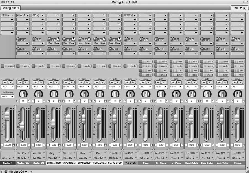
To show or hide a section within a track strip:
1. Open the Mixing Board by choosing Project 4Mixing Board. You can also use the
default keyboard shortcut ShiftþM.
2. Each track strip section is listed at the top of the Mixing Board’s mini-menu
(see Figure 12.2). Click on a section to toggle its visibility on and off. A check mark will
indicate whether the section is showing.
3. To show all sections except the one you click on, press and hold the Command
key before opening the mini-menu and clicking on the section you want
to hide.
4. To hide all sections except the one you click on, press and hold the Option key before
opening the mini-menu and clicking on the section you want to show.
Figure 12.1 Digital Performer’s Mixing Board resembles a traditional mixing console and can be cus-
tomized for specific mixing needs.
392 Digital Performer 6 Power!: The Comprehensive Guide
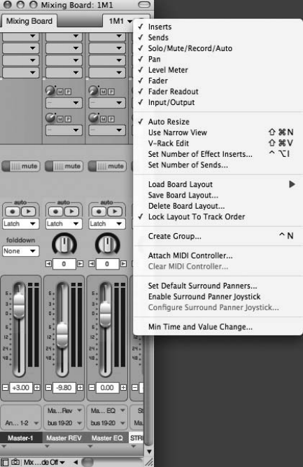
The Board Layout Feature
The Board Layout feature is an often-overlooked feature of the Mixing Board; it gives you the
ability to save and load different Mixing Board configurations. If you use the Board Layout
feature in conjunction with the previously discussed Show/Hide feature, you can really simplify
the viewing process and tailor the Mixing Board to your specific needs. You could, for example,
create a board layout that only shows your rhythm tracks or a layout for using headphone mixes
that only contains the sends section for all of your tracks. The possible combinations are endless.
To save a board layout:
1. Start by configuring the Mixing Board to your liking. Show or hide specific sections
from the mini-menu, and show or hide specific tracks within your mix.
2. Once your layout is set, choose Save Board Layout from the Mixing Board’s mini-menu.
Figure 12.2 The track strip sections appear at the top of the Mixing Board’s mini-menu. Sections that
are showing will appear with check marks.
Chapter 12 Mixing 393
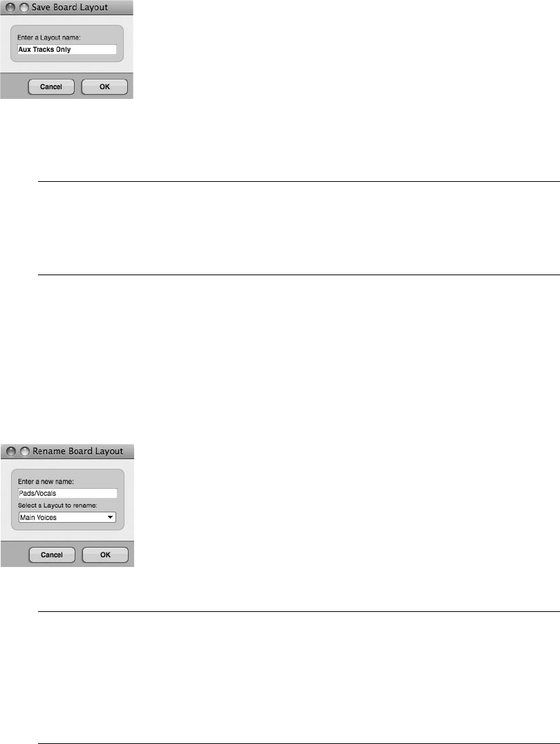
3. Name the layout and click OK (see Figure 12.3).
What’s in a Name? No need to get fancy with your naming schemes. The idea here is to
have instant access to different mix configurations so that you can speed up your work-
flow. Choose something that’s direct and to the point (for example, “Headphones” or
“Drum Tracks”) so you know at a glance what items the layout contains.
To load or rename a board layout:
1. Choose the Load Board Layout submenu from the Mixing Board’s mini-menu. You’ll be
presented with a list that contains your custom board layouts, as well as standard layout
presets, such as Showing All Tracks, Showing All Sections, and Showing Everything.
2. To rename an existing custom layout, choose the Rename Board Layout option. Select
the layout you want to modify, enter the new name, and click OK (see Figure 12.4).
Load Board Layout Shortcut Many users tend to overlook the Board Layout feature
because they think they must return to the mini-menu every time they need to recall a
layout, which can be a tedious affair. I myself ignored the Board Layout feature until I
discovered a shortcut: Simply Option-click the Sequence menu (to the immediate left of
the mini-menu), and you’ll get a drop-down menu of your board layouts that is identical
to the mini-menu’s Load Board Layout command (see Figure 12.5).
Figure 12.3 The Save Board Layout window.
Figure 12.4 The Rename Board Layout window. Choose from the list and rename the configuration.
394 Digital Performer 6 Power!: The Comprehensive Guide
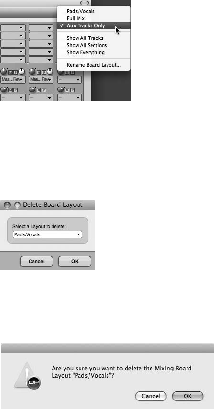
To delete a board layout:
1. Choose Delete Board Layout from the Mixing Board’s mini-menu. The Delete Board
Layout window (see Figure 12.6) will open.
2. Select the layout you want to delete and click OK.
3. A warning dialog will open, asking you to confirm the change (see Figure 12.7). Click OK.
Track Groups
Track groups (commonly referred to as groups) are a standard feature of the music production
process that lets you link, or “group,” together selected tracks so they act as one. You can spec-
ify exactly which type of track parameters will be linked together (for example, volume and
panning, solos and mutes, and so on). In DP, you can create an unlimited number of track
groups that can be designated as mix groups, edit groups, or a combination of the two (the
Edit & Mix option). You can also create specialized custom track groups.
Figure 12.5 Option-click the Mixing Board’s title bar to load a board layout.
Figure 12.6 The Delete Board Layout window.
Figure 12.7 The Delete Board Layout warning dialog.
Chapter 12 Mixing 395
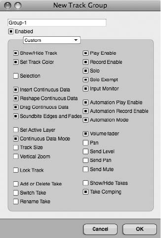
Even though track grouping is also used in the editing and arranging processes, I’ll discuss Dig-
ital Performer’s Track Group feature here because it’s especially used during the mixing process.
To create a track group from the Mixing Board:
1. Choose Create Group from the Mixing Board’s mini-menu. You can also use the
keyboard shortcut ControlþN.
2. The cursor will change into a large plus (þ) icon. Click on the faders or pan knobs of the
tracks you want to group together. Selected tracks will be highlighted with a flashing
green box.
3. To remove a track from the group selection, Shift-click the track.
4. Once you have selected the tracks you wish to group, press the Return or Enter key.
5. The New Track Group window will open (see Figure 12.8).
6. From the drop-down menu, choose the group type:
nEdit. Edit groups will link time-range selections; the inserting, reshaping, and
dragging of continuous data; and Sequence Editor active layer, continuous data
mode, track resize, and vertical zoom characteristics.
Figure 12.8 The Custom group setting in the New Track Group window lets you pick and choose the
specific parameters to link.
396 Digital Performer 6 Power!: The Comprehensive Guide

nMix. Mix groups will link volume, solos and mutes, solo exempt status (Solo
Isolate), and automation controls (Automation Play Enable, Record Enable, and
Automation modes).
nEdit & Mix. This option will link both the Mix and Edit group functions explained
above.
nCustom. The Custom option will allow you to choose specific parameters for
grouping.
7. Name the group and click OK.
8. Once a parameter is linked, adjusting it on one track will affect the same parameter on
all tracks within the group.
Show and Hide Tracks When tracks are grouped together as edit, mix, or edit/mix groups,
their Show/Hide settings will become linked. Clicking on a track in the Track selector of a
window will show or hide all the tracks within its associated group. To override this fea-
ture, create a custom group and disable the Show/Hide Track option.
Temporarily Overriding a Group When working with tracks that are grouped, you will
sometimes need to adjust a setting on only one track. You could delete the group entirely,
but that’s not a very productive solution to the problem. Instead, temporarily override the
group by pressing the Option key before making a parameter adjustment.
Modify Track Groups Submenu The Project menu’s Modify Track Groups submenu also
allows you to group and ungroup tracks. This is handy for when you’re not working in
the Mixing Board. You can even temporarily suspend a group with the Suspend Track
Grouping option.
The Track Groups Window
Once you create a track group, you can manage it from the Track Groups window (Project 4
Track Groups), as shown in Figure 12.9. You can open this window using the default keyboard
shortcut ShiftþOptionþG.
The main body of the Track Groups window displays the group name, group type, Move han-
dles (for changing the list order), and a button for turning the group on or off. The disclosure
triangle, located to the left of the group name, will show the tracks that are contained within the
group. At the very top of the group list is a group called All Tracks—turned off by default
Chapter 12 Mixing 397
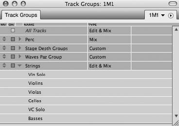
(indicated by italics)—which lets you quickly group all tracks within a sequence. The mini-menu
provides options for further managing your groups.
To add a track to an existing track group:
1. Select the desired track (or a part of the track) you want to add to the track group. Keep
in mind that you can make this track selection from the Tracks window or another
editor window by clicking on the name of the track.
2. Select the group to which you want to add the selected tracks in the Track Groups
window.
3. Choose Add Selection to Group from the Track Groups window’s mini-menu.
To remove or delete a track from an existing track group:
1. Click the track group’s disclosure triangle and select the tracks.
2. Choose Remove/Delete Tracks from Group from the Track Groups window’s mini-menu.
To temporarily suspend an existing track group:
1. Click the track group’s On/Off check box in the Track Groups window. Disabled
groups will appear in italics. You can also press CommandþOptionþG and enter the
number for the group you want to disable (see Figure 12.10). The group number is listed
in the order (from top to bottom) in which the group appears within the Track Groups
window. Clicking 0 will choose the All Tracks group.
2. To globally suspend all track groups, choose Project 4Modify Track Groups 4Sus-
pend All Track Grouping. You can also press and hold down the G key to temporarily
disable all groups. Releasing the key will instantly re-enable all groups.
Figure 12.9 You can manage a track group from the Project menu’s Track Groups window.
398 Digital Performer 6 Power!: The Comprehensive Guide
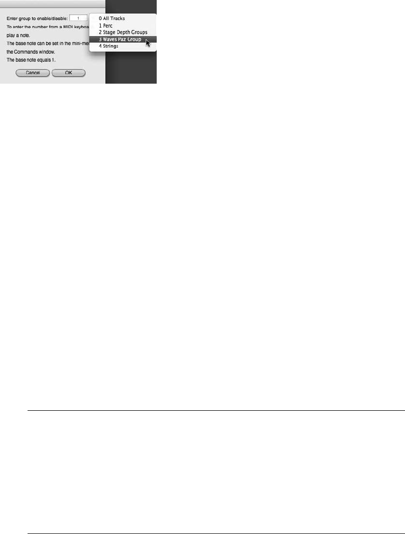
To change the type of an existing track group:
1. Open the Track Groups window (ShiftþOptionþG).
2. Click on the Type column of the desired group and select a new group type.
Temporary Track Groups
You can create a temporary track group of selected tracks that aren’t already in a track group.
To create a temporary group:
1. Select the desired tracks in the Tracks window or the Sequence Editor.
2. Hold down the letter T key on your computer keyboard (or double-tap the letter T key
to make the temporary group “stick”). The tracks will remain grouped until you tap the
letter T key again. Keep in mind that temporary groups are created “behind the
scenes”—DP will not provide any visual or aural confirmation of the temporary
grouping action.
3. If you are working in the Sequence Editor or the Mixing Board, you can temporarily
group all visible tracks by pressing the letter W key. Tap the W key again to remove
the group.
Groups versus Subgroups? In Digital Performer, groups and subgroups are two completely
different concepts. To place your tracks into a subgroup or submix, you basically bus
desired tracks to the same aux track (or master fader). This configuration is tremendously
flexible; because the selected tracks are not “track grouped,” you still have independent
control of each track’s parameters. The greatest benefit, however, is the ability to insert
effects across your entire subgroup, which is a popular and effective mixing technique.
This allows you, for example, to compress an entire drum kit or group of background
vocals.
Figure 12.10 The Suspend Track Groups window.
Chapter 12 Mixing 399
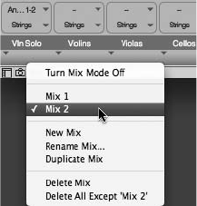
Alternate Mixes with Mix Mode
Another handy feature of the Mixing Board is the Mix Mode menu, shown in Figure 12.11,
which allows you to create and manage new or alternate versions of a mix. By default, projects
will start with Mix mode turned off, so you can think of this setting as your default mix. Keep in
mind that Mix Mode Off does not mean you cannot create a mix. It simply indicates that if you
switch to an alternate take of a track, its mix settings and automation data will switch along
with the take. (See “Recording and Managing Takes” in Chapter 7 for more information on
alternate takes.)
The New Mix command will create a new “empty” mix that contains the same volume, pan,
and send positions that are currently visible in the Mixing Board, but it will not include any
automation data or effect inserts. Duplicate Mix will create a copy of your current mix with all
the previously mentioned data, including any automation and effect inserts. To delete an alter-
nate mix, select it from the Mix Mode menu and choose Delete Mix. To return to your original
(default) mix, choose Turn Mix Mode Off.
Inserts and Plug-Ins
The Inserts section of the Mixing Board allows you to place, or “insert,” real-time processing on
an audio or MIDI track. You can also insert virtual instrument plug-ins (such as MOTU’s MX4)
on an instrument track. Real-time effects are nondestructive, meaning they will not change or
modify the original audio or MIDI data that exists within a track, allowing you to audition
different parameter settings or even change the inserted plug-in entirely. The disadvantage is that
real-time effects consume CPU resources—some more than others. Time-based effects, such as
reverb in particular, can be hungry when it comes to CPU usage. If Digital Performer starts to
act sluggish, try increasing the Buffer Size setting located in the Configure Hardware Driver win-
dow (Setup 4Configure Audio System 4Configure Hardware Setting). For more information on
buffer size and audio configuration settings in general, refer to Chapter 2. Refer to Chapter 13,
“Processing and Mastering,” for a more in-depth look at effects plug-ins within Digital Performer.
Figure 12.11 The Mixing Board’s Mix Mode menu provides options for creating and managing alter-
native versions of a mix.
400 Digital Performer 6 Power!: The Comprehensive Guide
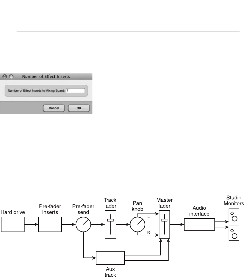
Monitoring CPU Usage You can monitor DP’s CPU consumption from the Audio Perfor-
mance window (Studio 4Audio Performance). Refer to Chapters 2 and 13 for an expla-
nation of the Audio Performance window.
By default, Digital Performer creates five blank insert menus on every track. To change the num-
ber of inserts, choose Set Number of Effect Inserts from the Mixing Board’s mini-menu (see
Figure 12.12). You can have up to an incredible 20 inserts available on each track!
Signal Flow
Inserts are labeled A, B, C, D, and so on from top to bottom and are set to pre-fader by default.
This means that an audio signal, for example, will play back from your Mac’s hard drive, travel
through the Insert section (from top to bottom), continue through the Send section, and then go
though the fader (see Figure 12.13). Any adjustment you make to the level of the track will have
no effect on the signal going into the Insert section.
Because the signal is traveling through the inserts (or plug-ins) from top to bottom, the order in
which you apply your effects is extremely important. A will have an effect on B, which will have
an effect on C, and so forth. To change the order of inserted plug-ins, simply click and drag them
to a new location.
Figure 12.12 The Number of Effect Inserts window allows you to set a maximum number of 20 effect
inserts!
Figure 12.13 Pre-fader inserts are independent of the track fader.
Chapter 12 Mixing 401
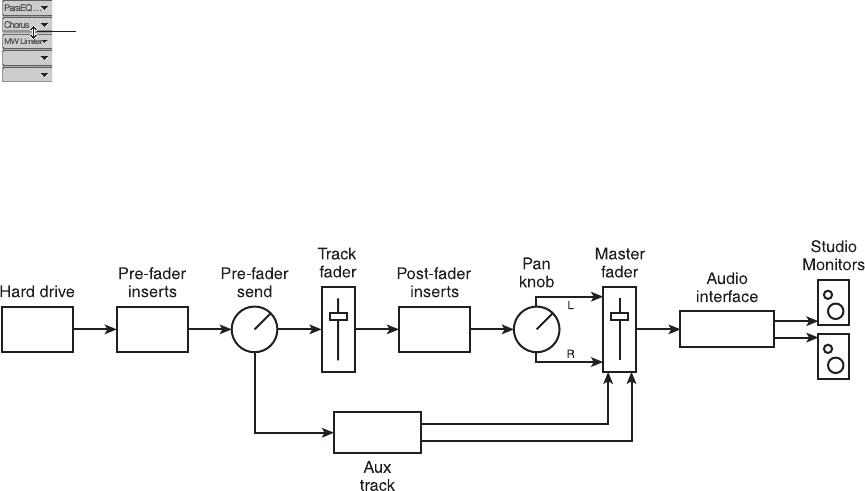
Pre-/Post-Fader Divider
If you would like to set the Insert section to post-fader (where an inserted plug-in will appear
after the fader in the signal flow), you will need to move the pre-/post-fader divider. By default,
the divider is located at the bottom of the Insert section. Place the cursor at this location, and it
will change to an up/down arrow icon (see Figure 12.14). Click and drag the divider up to the
location where you want the post-fader section to begin.
Once an insert is designated as post-fader, the signal flow of the Mixing Board will change. Post-
fader inserts have a dependent relationship on the track fader (see Figure 12.15).
Dynamic versus Time-Based Effects
Generally speaking, dynamic effects are used to control gain. Compressors, limiters, expanders,
gates, and EQ are all considered dynamic effects. Digital Performer’s Trim plug-in also falls into
this category. Examples of time-based effects are reverb, delay, and echo.
Knowing when and where to place dynamic and time-based plug-ins within your tracks is very
important. For example, will you use an insert or a send?
Insert or Send?
The general rule is this: Direct inserts are used for dynamic effects, and sends are used for time-
based effects. Why? The thinking is that dynamic effects, such as compression, are usually meant
to work on one signal. The vocal is loud, so you strap a compressor across it. The voice is thin,
Pre-/Post-Fader
Divider
Figure 12.14 The cursor will change when placed over the pre-/post-fader divider.
Figure 12.15 Post-fader insert are dependent on the level of the track fader. Any changes made to the
fader will affect the input level of the post-fader inserts.
402 Digital Performer 6 Power!: The Comprehensive Guide
so you insert an EQ and boost 200 Hz. In these scenarios, you want the entire signal to be
affected. When the signal leaves the plug-ins, you want it to be 100-percent wet. In other
words, you only want to hear the compressed and EQ’d signal. If you used a send for this,
you would have both a dry vocal and a compressed/EQ’d vocal being mixed together (though
I know this is sometimes exactly what you want).
When working with time-based effects, you usually want to control the ratio between the dry
(unaffected) and wet (affected) signals, so a send is just what the doctor ordered. You insert your
reverb plug-in (such as Audio Ease’s Altiverb plug-in) on an aux track (100-percent wet), send to
the aux track from your audio track, and blend the two together. The fader level on your aux
track determines how much reverb is heard on the track.
There’s also another benefit to using sends: If you decide you want that reverb on another track,
you simply turn up the send level for that track, and it also goes to the Altiverb plug-in. If you
inserted your Altiverb plug-in directly on an audio track, however, you could only use it for that
specific track. To have reverb on another track, you would be forced to insert a new instance of the
plug-in. Conceptually, this scenario works, but it is hardly efficient. Besides having to open up the
plug-in every time you need to adjust the wet/dry ratios, you would also be wasting valuable CPU
resources. If you transplant this situation to the analog world, you would need a separate reverb
unit for every track in which you wanted to include reverb—a very costly and wasteful endeavor!
Special FX
Special effects, such as flange, chorus, tremolo, and phasers, can be inserted or sent, depending
on your needs. If you would like to use the same effect across multiple tracks (with the same
parameters), you can employ a send. If you need the effect to be unique to a specific track, you
could use an insert. Just realize that you must control the wet/dry ratio from the plug-in when
using a direct insert.
Aux Tracks and Sends
Aux tracks are similar to audio tracks, except they cannot contain audio data. Digital Performer
aux tracks are similar to empty channels on a traditional analog console—like a miscellaneous
track or channel used as a routing mechanism. Aux tracks can be used as effects returns, to sum
together a set of tracks (submix), or to shuffle audio from one place to another. Inserts and
sends, as well as solo, mute, volume, panning, and automation controls, are identical in nature
to those for audio tracks. The channel format of an aux track is determined by its input assign-
ment. For example, a mono input assignment will force the aux track to be mono.
Sends allow you to “split” off a signal and send it to another destination. This destination can be
a virtual bus or a physical hardware out, which could, for example, be connected to a headphone
amp or an external reverb device. A send has no effect on the original signal from which it
branches off, but it has a direct relationship to the original track, depending on its pre- or
post-fader setting.
Chapter 12 Mixing 403
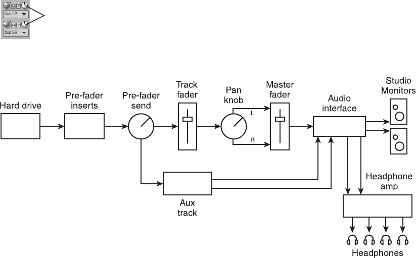
Send and Returns
There are several ways to utilize aux tracks within the music production process. The main use for
an aux track would be as a container for time-based effects, such as reverb. I have already dis-
cussed the benefits of using sends in the mixing process, and aux tracks are an integral part of the
send “equation.” Once you create an aux track, you insert a reverb plug-in; next, you assign the
track’s input to a bus, then you send from a track to that corresponding bus. The “sent” signal
travels through the reverb plug-in, and the 100-percent wet reverb signal continues to the master
fader, where it is mixed in (or returned) with the original dry signal. To change the amount of
reverb on the original track, you simply adjust the aux track’s fader. The term send and return
originates from the process of sending a signal to another destination—which could be a plug-in or
external FX unit—and returning it through an auxiliary track (or master fader) back into the mix.
Pre- versus Post-Fader Sends
You designate a send to be either pre- or post-fader with the Pre-/Post-Fader switch (as shown in
Figure 12.16). This button (switch) is located to the right of the Send Level knob (it’s the letter P
button), adjacent to the Send Mute button (the letter M button). As I discussed earlier, in the
“Inserts and Plug-Ins” section of this chapter, a pre-fader setting allows a send (or an insert) to
be independent of the track fader. Because of its location, turning up or down the track fader
will have no effect on the level of the signal sent to the headphone amplifier (see Figure 12.17).
Pre-/Post-Fader
Switch
Figure 12.16 The Pre-/Post-Fader switch toggles the send’s pre-/post-fader settings. When the Mixing
Board is set to Narrow view, the pre-/post-fader settings will be listed in the Send menu.
Figure 12.17 Headphone mixes are set to pre-fader to maintain independence from the track’s fader,
Solo, and Mute buttons. When the Pre-/Post-Fader switch is dimmed, the send is set to pre-fader.
404 Digital Performer 6 Power!: The Comprehensive Guide
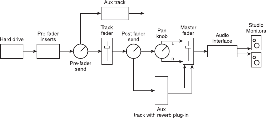
Soloing or muting the track will have no effect on the send. A post-fader reverb send, however, is
located after the track fader in signal flow (see Figure 12.18).
So when should you use a pre-fader send and when should you use a post-fader send? Here is the
general rule: Pre- is for headphone mixes, and post- is for effects. Why are headphone mixes pre-
fader? You need a headphone send to be pre-fader so that it’s independent of your mix. When
you adjust a fader in the studio or when you solo a track, you don’t want the artist to hear your
adjustments. If the artist’s headphone mix was dependent on yours, you wouldn’t be able to
multitask (for example, mix while you record or solo a track for troubleshooting purposes).
Effects, however, are typically post-fader because you usually want the relationship between the
dry and wet signals to stay the same. So if you turn the level down on your original track, the
reverb gets turned down with it. In this scenario, your reverb would be dependent on your orig-
inal track fader. Of course, there will be times when you may want your effects to be pre-fader,
allowing you to turn down the original track and have the reverb signal remain in the mix. Pre-
fader effects are not an uncommon part of the mixing process.
The Send Level Knobs
DP provides a total of 20 sends per audio track. Each send can be assigned to a mono, stereo, or
multichannel output destination. Each Send Level knob allows you to adjust the level of the send
and by default is set to Infinity (turned off). The small dot next to the knob (located at the two
o’clock position) is called the unity gain dot and designates the unity gain or zero position of the
Send Level knob. Double-click (or Control-click) the knob to force it to unity gain. When a Send
Figure 12.18 Reverb sends are usually set to post-fader so they will remain dependent on the track
fader. With this configuration, any adjustments to the track fader, solo, or mutes will have a direct
effect on the post-fader send. It is now considered to be dependent on the track fader.
Chapter 12 Mixing 405
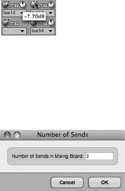
Level knob is adjusted, the dB value is displayed in a pop-up box, as shown in Figure 12.19. The
M buttons designate mutes; simply click on a button to mute a send.
To set the number of available sends:
1. Choose Set Number of Sends from the Mixing Board’s mini-menu to open the Number
of Sends window, as shown in Figure 12.20.
2. Enter the desired number of sends (up to a total of 20).
3. Click OK to confirm the change.
The Send Menu
The Send menu allows you to choose the desired routing assignment for a send and determine
the channel source (L, R, or stereo) for the specific send. When the Mixing Board is set to Nar-
row view, the pre-/post-fader options will also be listed here. In addition to any currently
enabled audio bundles, the send assignment submenus located at the bottom of the list
(shown in Figure 12.21) allow you to create new audio bundles and aux tracks directly from
the Send menu. The assignment submenus are described below.
nNew Mono/Stereo Bundle. Choose an output assignment from the desired submenu to
create a new audio bundle. The number of busses appearing in the list is determined by the
Stereo Bus setting in the Configure Studio Settings window (Setup 4Configure Audio
System 4Configure Studio Settings).
nNew Aux Track via New Mono/Stereo Bundle. These two submenu options allow you to
create a new aux track when you create a new mono or stereo audio bundle. The new audio
bundle will then feed the newly created aux track. Think of these two options as shortcuts
that allow you to quickly create an aux track while you’re configuring a send assignment.
Figure 12.19 When adjusting a Send Level knob, the dB value of the send is displayed in a pop-up box.
Figure 12.20 Use the Number of Sends window to set the number of sends that are available in the
Mixing Board.
406 Digital Performer 6 Power!: The Comprehensive Guide

To set up a send and return (aux track):
1. Click the Send menu (located below the Send Level knob) on the desired audio track.
2. Choose the New Aux Track via New Mono/Stereo Bundle option and select a bus
from the drop-down list. Once selected, DP will assign the send to the chosen bus and
create a new aux track. The input of the new aux track will be assigned to the send
output in the process.
If you already have an aux track (effects return) configured, you can simply assign the send to a
new or existing audio bundle.
Figure 12.21 Use the Send menu to route the send to an existing audio or bus output destination. New
audio bundles, as well as new aux tracks, can be created directly in the Send menu.
Chapter 12 Mixing 407
To set up a send (without setting up a new aux track):
1. Click the Send menu (located below the Send Level knob) on the desired audio track.
2. Assign the send to an available bus or audio hardware output. If you need to create a
new audio bundle, choose the New Mono Bundle or New Stereo Bundle option and the
appropriate audio bundle from the drop-down list.
Effects Returns
As I discussed earlier, effects returns (or returns) are used for returning a signal that has been
sent from a track back into your mix. Within Digital Performer, aux tracks are used as returns.
Aux tracks can be automatically created via the aux track shortcuts (described in Step 2 of the
previous How To section), or you can configure them manually as needed. The following How
To section describes the procedures for setting up a reverb return. If you want to create a dif-
ferent type of effects return, such as an effects return for a delay plug-in, simply substitute the
example reverb plug-in with a different plug-in.
To manually configure an aux track as a reverb return:
1. Create an aux track by choosing Project 4Add Track 4Aux Track. You can also use
the default keyboard shortcut ControlþCommandþA.
2. Assign the input of the track to an available stereo bus (for example, Bus 1-2). Keep in
mind that the channel format of the aux track is determined by the input assignment.
3. Assign the aux track’s output to your main outs (for example, Analog 1-2).
4. Insert a plug-in on the aux track, making sure to set the plug-in’s Mix parameter to
100%.
5. Now you can send a signal to Bus 1, and it will be bussed to the reverb plug-in and
returned to your main mix (Analog 1-2) via the configured aux track.
6. Your aux track’s fader level sets the amount of reverb being mixed with the audio
track’s dry signal, so adjust it accordingly. (For example, for less reverb in the mix,
simply turn down the aux fader.)
Setting Up a Headphone Mix
Headphones mixes are different from typical reverb configurations in that they don’t require an
effects return. Once the signal is sent off to a headphone amp (and to each pair of your artist’s
headphones), the journey ends. The setup process is almost identical to that of the reverb send
and return configuration. The aux track, however, is utilized as a group fader and not a return.
Of course, you don’t have to employ an aux fader in a headphone mix; you could send directly
to the outputs of your audio interface (which is connected to your headphone amp). This setup
configuration doesn’t allow you much flexibility, but using an aux fader as a headphone-group
408 Digital Performer 6 Power!: The Comprehensive Guide

master between your individual track sends and your headphone amp will let you control the
overall level going to the amplifier with relative ease. In addition, you’ll have the ability to insert
plug-ins if needed, allowing you, for example, to EQ or compress your entire headphone mix.
To set up a headphone mix (with a headphone-group master):
1. Make sure your headphone amp is directly connected to the outputs of your audio
hardware interface (such as Analog 7-8).
2. Follow the procedures for setting up a send and assign the send to an available stereo
bus, such as Bus 3-4. Be sure to use the Send menu’s New Aux Track via Stereo Bundle
option to create a new aux track in the process.
3. Set the output of the new aux track to Analog 7-8.
4. Rename the aux track to something appropriate, such as Phones Mix.
5. Turn up the Send Level fader you configured in Step 2 to send the track’s audio signal to
the headphone amp via the Phones Mix aux track.
6. To send from another track, assign a send on the desired track to Bus 3-4 and turn up
the Send Level knob.
7. To adjust the overall output level of the headphone mix, simply turn up or down the
Phones Mix aux track fader.
Pre-Fader Headphone Sends Sends are set to pre-fader by default, so you do not have to
worry about manually configuring each headphone level send to pre-.
Submixing
Submixing is the act of combining multiple signals and sending them through either an internal
or an external bus. Submixing allows you to work around I/O limitations, efficiently apply
effects across multiple tracks, and establish sends and returns. Also, it can greatly simplify com-
plex mixes. Submixing is an especially common practice in the film and video post-production
processes, where multiple submixes (or stems) are used to group common elements, such as
dialogue, music, and sound effects. Submixing works especially well with instruments that are
normally treated as one unit, such as string sections, or for instruments that are recorded with
multiple microphones, such as drums and piano.
Submixing differs from track grouping in that it allows individual tracks within a subgroup to
remain independent. For example, you can still make track-specific volume adjustments and
insert individual plug-ins while controlling the overall volume of the entire group from the
group master fader.
Chapter 12 Mixing 409
Within Digital Performer, subgroups are very easy to set up.
To set up a subgroup:
1. Create an aux track by choosing Project 4Add Track 4Aux Track. You can also use
the default keyboard shortcut ControlþCommandþA.
2. Assign the input of the track to an available stereo bus (for example, Bus 5-6).
3. Assign the aux track’s output to your main outs (for example, Analog 1-2).
4. Remember, it’s always a good idea to rename your tracks for easy identification. To
rename the new aux track, Option-click on the name of the track.
5. Change the output for the audio tracks you want to put in this subgroup to Bus 5-6.
Remember that you can use the Assignments window to quickly assign multiple tracks
to the same output channel (refer to Chapter 7). Now the desired audio tracks will be
bussed through your aux track (group master fader), allowing you to easily control the
overall volume or insert effects across the entire group.
Automation
Automation is the process of automating various aspects of the mixing process, from simple
fader moves (or volume changes) to more complex actions, such as manipulating the pitch of
a soundbite (discussed in Chapter 13). Automation allows the mix engineer to fine-tune his
mixes and perform real-time changes to multiple audio and MIDI events. Such changes would
be nearly impossible without the automation process.
Automation events can be inserted with DP’s various tools or recorded in real time by adjusting
track/plug-in parameters with the mouse. Automation modes determine how real-time automa-
tion is handled within a track, allowing you to write new data or update existing events. The
Automation Setup window allows you to set track-specific and global automation parameters
that affect how this data is recorded.
Automation Setup Window
Digital Performer’s automation features are so easy use that you may never need to pay a visit to
the Automation Setup window. (I’m sure there are plenty of users out there who never have.)
You owe it to yourself to get familiar with this window, however. Besides providing a complete
list of parameters that can be automated within DP, the Automation Setup window also allows
you to turn off specific automation settings, control how automation modes react within a track,
and free up system resources. You can access the Automation Setup window by choosing Setup
4Automation Setup (see Figure 12.22).
Global Automation Enable. This section determines the type of data that can be automated
within DP. Note that only the Volume, Pan, and Track Mute settings can be automated within
a MIDI track; audio tracks provide more extensive automation capabilities. Click on a specific
410 Digital Performer 6 Power!: The Comprehensive Guide
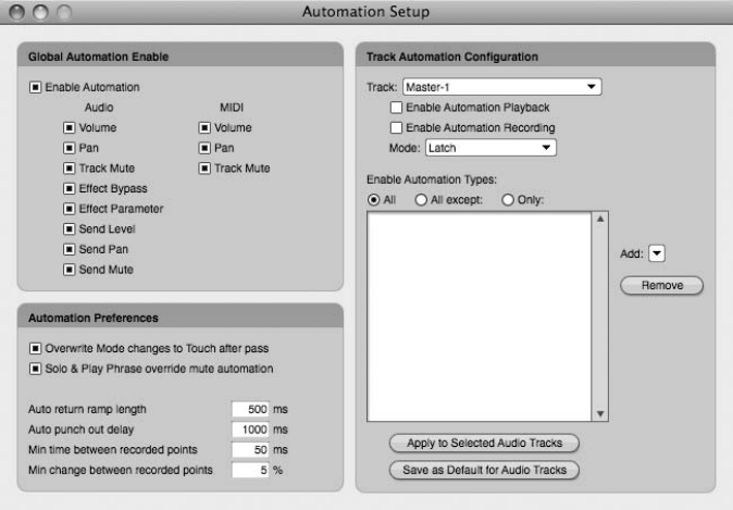
parameter button to globally enable/disable an automation parameter. (Buttons will appear blue
when enabled.) Click the Enable Automation button to globally turn on or off automation
within a project.
Track Automation Configuration. This section lets you control automation for a specific track.
The Tracks List is a drop-down menu of all tracks within the current sequence. Choose a track
to set its automation preferences. (Keep in mind that an audio track must be online in order to
change its automation preferences.) Below this list are buttons for enabling/disabling automation
playback or recording for the track. The Mode menu sets the automation mode for the selected
track. These settings are identical to the automation play-enable and mode buttons in the Mix-
ing Board’s individual Tracks Lists (explained earlier in this chapter).
The Enable Automation Types section is where you can decide which parameters will be turned
on or off.
To enable/disable specific automation parameters:
1. Select the desired track from the Tracks List.
2. Click the Add drop-down menu to select a setting and place it in the Tracks List.
3. Next, use the radio buttons below the Tracks List to decide whether the listed parameters
will be turned on or off. All Except will exclude the parameters in the list, while Only
Figure 12.22 The Automation Setup window provides global and track-specific automation
preferences.
Chapter 12 Mixing 411
will turn on automation only for the listed parameters. All, of course, will enable all
parameters for automation, regardless of the items that appear in the list.
4. To remove a parameter from the list, select it and click the Remove button.
5. If you would like to use the same settings on other tracks, select the tracks you want to
affect and click the Apply to Selected Audio Tracks button.
6. To make the current list parameters the default settings for all audio tracks, click the
Save as Default for Audio Tracks button.
Automation Preferences. The Automation Preferences section provides several different
preferences:
nOverwrite Mode Changes to Touch After Pass. This option will force a track’s automation
mode to Touch mode when an overwrite pass has been completed.
nSolo & Play Phrase Override Mute Automation. When this option is enabled, mute auto-
mation will be ignored when a track is either soloed or auditioned by pressing
Commandþspacebar.
nAuto Return Ramp Length. When automation recording is stopped, DP automatically inserts
areturn ramp, which creates a smooth transition between the new automation and the
previous parameter setting. This option determines the length of the transition.
nAuto Punch Out Delay. This is the amount of time that DP waits before stopping the
recording of automation after it receives the last automation event from an external controller.
nMin Time/Change between Recorded Points. The last two options set the number of control
points that are recorded when making any automation moves. Higher numbers and lower
percentages provide finer tracking of automation moves.
Automation Modes
Digital Performer’s five automation modes determine how automation data is recorded within a
track. You can set the mode for a specific track either from the Automation Setup window or
directly with a track’s Automation Mode menu (see Figure 12.23).
nOverwrite. This mode writes new automation from when playback starts until it is stopped.
Any existing automation data will be overwritten in the process. This mode will automat-
ically switch to Touch if the Overwrite Mode Changes to Touch After Pass option is turned
on from the Automation Setup window. When you begin your first automation pass or you
want to erase any existing automation, use this mode.
nTouch. Touch mode will begin to write new automation data as soon as a fader or knob is
touched and will continue to write data until it is released. The Automation Setup window’s
412 Digital Performer 6 Power!: The Comprehensive Guide
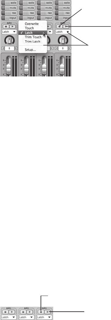
Auto Ramp Length option determines how long it takes for DP to return to the original
automation data once recording is stopped. Use this mode when you need to update only a
portion of existing automation, and you want DP to return to the existing automation when
you release the fader or knob.
nLatch. When Latch mode is engaged, automation will begin as soon as you grab a fader or
knob, but unlike in Touch mode, automation data will continue to be written until recording
is stopped.
nTrim Touch/Latch. This setting is identical to both normal Touch and Latch modes, except
that the fader will change to display 0 (unity gain) as the current volume in the track. These
two modes can only be used to update volume and pan data. All other automation events
will be overwritten. This mode is handy when you need to raise or lower the overall auto-
mation values, while preserving the existing automation curves.
Enabling and Disabling Automation
You can enable or disable automation in DP from several locations—globally in the Automation
Setup window (explained earlier), in the ATO column of the Tracks window, in the Automation
menu of each track strip in the Mixing Board, or in the Automation drop-down menu or Track
Settings menu in the Sequence Editor (see Figure 12.24).
Automation
Record-Enable
Button Automation
Play-Enable
Button
Automation
Mode Menu
Figure 12.23 A track’s Automation Mode menu provides a list of automation modes and access to the
Automation Setup window (Setup option). Located above the Automation Mode menu are the Auto-
mation Play-Enable and Record-Enable buttons.
Automation
Record-Enable
Button Automation
Play-Enable
Button
Figure 12.24 You can enable or disable a track’s automation by clicking on the Automation Play-Enable
or Record-Enable button.
Chapter 12 Mixing 413
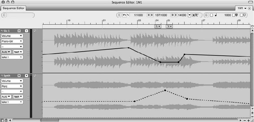
To enable the playback of recorded track automation, click the Automation Play-Enable button;
it will be highlighted green. Click again to disable automation playback for the track; the button
will return to a normal state. To record automation, click on the Automation Record-Enable
button, and it will be highlighted red. Click again to turn off this feature.
Automation that is enabled will appear in bold (———), while disabled automation will appear
as a dashed line (- - - - -) within the Sequence Editor (see Figure 12.25).
Recording Real-Time Automation
Automation data can be recorded in real time from the Mixing Board.
To record new automation data in real time:
1. Start by opening the Mixing Board (ShiftþM) and choosing Overwrite mode from the
desired track’s Automation Mode menu.
2. Turn on both the Automation Play and Record-Enable buttons. (They both should be
highlighted, red for Record and green for Play.)
3. Begin playback at the desired position. Automation will immediately begin being
recorded.
4. Make the desired automation moves (real-time parameter adjustments).
5. Press the spacebar when you are finished making your moves to stop recording.
Figure 12.25 Within the Sequence Editor, automation that is enabled will appear in bold, while dis-
abled automation will appear as a dashed line.
414 Digital Performer 6 Power!: The Comprehensive Guide
6. Click the Automation Record-Enable button to turn off recording; doing so will prevent
you from accidentally overwriting your recorded moves.
7. Return to the desired location and begin playback to hear (and see) your automation
moves play back exactly as you executed them in Step 4.
To update existing automation data in real time:
1. Start by choosing Touch or Latch mode (or Trim Touch/Latch) from the desired track’s
Automation Mode menu. Both modes will only begin recording when you grab a fader
or knob. Touch mode, however, will punch out of automation recording as soon as you
stop making fader or knob adjustments, while Latch mode continues to write new data
until playback is stopped.
2. Turn on both the Automation Play and Record-Enable buttons. (They should both be
highlighted.)
3. Begin playback at the desired position.
4. Grab a fader or knob; automation recording will begin.
5. Press the spacebar to stop playback (and recording if in Latch mode).
6. Click the Automation Record-Enable button to turn off recording; doing so will prevent
you from accidentally overwriting your recorded moves.
7. Return to the desired location and begin playback to hear (and see) your automation
moves play back exactly as you executed them in Step 4.
Inserting Automation Data
Automation data (which is represented by control points) can be inserted directly into a track
from DP’s various editor windows. A single control point can be drawn directly in a track by
clicking once with the Arrow or the Pencil tool and is used to anchor a parameter to a specific
value. To insert a parameter change over a period of time, you need at least two control points.
The first point anchors the parameter and tells DP where you want the change to begin. The
second point is where you want the parameter change to end. What happens in between these
two points (how you draw the automation data) can determine whether the transition is smooth
(for example, a 30-second fade-out) or instantaneous (for example, a volume mute).
For an explanation of inserting control points within the Graphic Editor, refer to the “Inserting
MIDI Controller Events” section in Chapter 10.
To insert automation data in the Sequence Editor:
1. Open the Sequence Editor (ShiftþS).
Chapter 12 Mixing 415
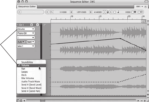
2. Click on the desired track’s active layer and choose the parameter you want to automate
(see Figure 12.26). Keep in mind that the options listed will vary, depending on the
type of track you are working with (and Send options only become available when a
send is being used).
3. Enable the Pencil tool by double-tapping the P key on your computer
keyboard.
4. Set the shape of the Pencil tool from the Insert/Reshape Curve menu. (Refer to
Chapter 10.) This setting determines the shape of the inserted automation.
5. Click where you want the parameter change to start and drag the cursor to where you
want the parameter change to stop, then release the mouse. You can use the Information
Bar to view the location of the cursor and its related parameter value. The horizontal
position of the mouse release sets the duration of the automation move. The vertical
position determines the amount of change for the parameter.
If you were inserting a volume fade-out, for example, the first control point would set
the beginning of the fade. Once you click with the Pencil tool and insert the first
automation point, you would drag the mouse vertically to the bottom of the edit
window to turn down the track. How far you drag the cursor to the right before
releasing the mouse would determine the duration (for example, minutes and seconds)
Active Layer
Menu
Figure 12.26 Within the Sequence Editor, automation that is enabled will appear in bold, while dis-
abled automation will appear as a dashed line. In this example, Send options are available because I am
using the first send insert (A).
416 Digital Performer 6 Power!: The Comprehensive Guide
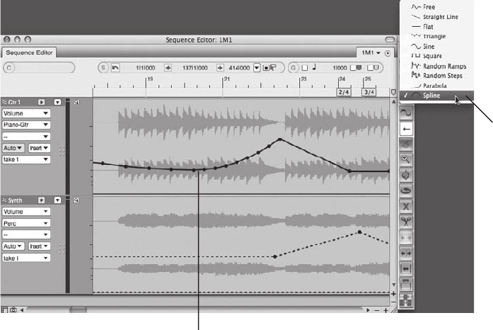
of the fade-out. The type of curve you choose from the Insert/Reshape Curve button
would determine how the fade was drawn in. If you wanted a fade with a rounded
curve, you could use the spline curve (see Figure 12.27).
6. If you want a simple straight line, you could also use the Arrow tool. Click to insert a
single automation point. Then insert another controller point and drag up or down with
the mouse.
To select automation data in the Sequence or Graphic Editor:
1. Enable the Arrow tool by double-tapping the A key on your computer keyboard.
2. To select a single controller point, click with the mouse. Selected controller points will
be highlighted yellow.
3. To make multiple controller-point selections, Shift-click with the Arrow tool. You can
also click and drag within the Time Ruler or any open area within the track that doesn’t
contain automation data.
Spline Curve
Tool Selection
Rounded Fade
Created with the
Spline Curve
Figure 12.27 In this example, a custom volume fade has been drawn in with the Pencil tool set to a
spline curve.
Chapter 12 Mixing 417
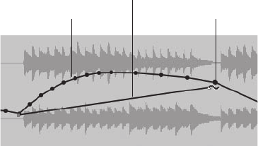
To edit automation data in the Sequence or Graphic Editor:
1. Enable the Arrow tool by double-tapping the A key on your computer keyboard.
2. Select the automation data you want to modify.
3. To change the location of the data, click on any selected controller point and drag with
the mouse.
4. To change the shape of existing automation data, enable the Reshape tool by double-
tapping the R key. Select a new curve from the Tool palette’s Insert/Reshape Curve
button. Click at the location where the move should start and drag to where you want
the move to end (see Figure 12.28).
5. Release the mouse, and the automation data will update to reflect the change, inserting
new controller points if needed.
6. To delete selected events, simply press the Delete key.
You can use DP’s standard edit commands, such as Cut, Copy, and Paste, to edit automation
data. When pasting automation data in an audio track, however, you will need to use the Merge
command in place of the Paste command to avoid affecting the actual audio data.
To cut, copy, and paste automation data in the Sequence Editor:
1. Begin by selecting the automation data you want to cut or copy.
2. Choose the Cut (CommandþX) or Copy (CommandþC) command from the Edit menu.
3. Insert a single automation point by clicking with either the Arrow tool or the Pencil tool
at the location where you want to paste the data.
4. Now choose Edit 4Merge to paste the selected data. Keep in mind that you can use the
Paste command (CommandþV) when working with MIDI tracks.
Original Fade Reshape Tool
New Curve
Figure 12.28 In this example, the Reshape tool is used to change the shape of an existing automation
curve. The top automation curve is the original automation fade, while the bottom fade shows the new
curve.
418 Digital Performer 6 Power!: The Comprehensive Guide
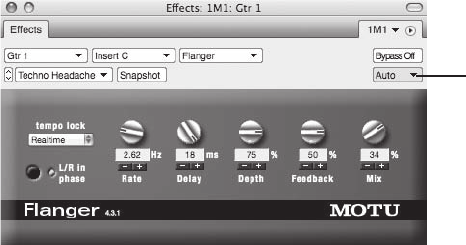
In addition to inserting data with the Arrow or Pencil tool, you can also use a track’s Event List to
insert automation data. This can sometimes prove to be time consuming, however, because the “list
view” will force you to enter in each parameter setting as its own event. Inserting and editing auto-
mation events is identical to inserting or editing other data types. (Refer to Chapter 10.) To delete an
automation event from the Event List, simply click on the event name and press the Delete key.
To insert automation data in a track’s Event List:
1. Start by selecting the desired track and opening its Event List (ShiftþE).
2. Click on the Insert button (þ).
3. Select the parameter from the drop-down menu.
4. Pop-edit the location of the automation event, then set the parameter values.
5. Press the Return key to confirm the changes.
Plug-In Automation
Besides standard track parameters, such as volume and panning, plug-in parameters can also be
automated. Each Effects window contains an Automation menu (located below the mini-menu)
identical to a track’s Automation menu (see Figure 12.29).
Procedures for automating plug-in parameters are the same as for standard track automation.
Simply engage the Automation Play and Record-Enable buttons for the track, select an automa-
tion mode, begin playback, and adjust the desired plug-in settings. You can also insert and edit
automation data directly in a track (explained earlier) or incorporate DP’s snapshot automation
features (explained in the next section).
All of Digital Performer’s bundled plug-ins can be fully automated, but you should keep in mind
that some third-party plug-ins may not have this capability. Consult the specific plug-in’s user
manual for information on its automation features.
Automation
Menu
Figure 12.29 The Effects window’s Automation button contains an Automation menu that provides
access to DP’s automation features.
Chapter 12 Mixing 419
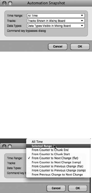
Snapshot Automation
Snapshot automation is used to insert multiple automation points in a single step. This can be
useful when you have many parameters that need to change simultaneously or that must remain
static for a certain duration within a mix. This form of automation is especially useful in video
and film post-production work, where mixes must sometimes change suddenly and dramatically
in order to accommodate abrupt scene changes. Of course, there are many uses within the music
production process as well, such as automating mutes across all tracks before the beginning of
a song.
Within Digital Performer, you can apply snapshot automation to a single point in time or across
a specified time range. Click on the Snapshot icon in the Mixing Board or Editor window’s title
bar to open the Automation Snapshot window, shown in Figure 12.30. Once you have specified
a selection for each of the three drop-down menus, click the OK button to apply the snapshot.
Time Range or Location. The first thing you need to do when inserting snapshot automation is
to specify the location or time range of the inserted automation data. If you want to have the
snapshot occur at a specific location, simply move the playback cursor to that location. The
options you choose from the Time Range menu set the end point or duration for the snapshot,
as shown in Figure 12.31. You can also make a time-range selection and choose Selected Range
from the Time Range menu. To apply the snapshot to the entire sequence, thereby overwriting
any existing automation data, choose All Time.
Figure 12.30 The Automation Snapshot window.
Figure 12.31 The Time Range menu allows you to specify a time range for the automation snapshot.
420 Digital Performer 6 Power!: The Comprehensive Guide
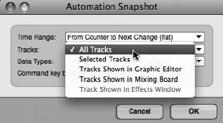
The Time Range menu’s various options are as follows:
nAll Time. This option will apply the snapshot to an entire sequence, regardless of the
playback cursor location, while overwriting any existing automation data.
nSelected Range. This option will apply a snapshot across the current time-range selection.
Keep in mind that this setting will also overwrite any existing automation data within the
selection.
nFrom Counter to Chunk End/Start. Use this setting to apply the snapshot from the Counter
location until the Chunk end or start time.
nFrom Counter to Next/Previous Change (Flat/Ramp). This option will apply the snapshot
from the Counter location until the next or previous automation or MIDI controller
point. The flat setting will create a constant value (flat line) for each automation parameter,
while the ramp setting will create a normal automation ramp (continuous and smooth
change) from the Counter location until the next or previous controller point.
nFrom Previous Change to Next Change. You can use this setting to create a snapshot
between two automation points. Place the cursor between two controller points and choose
this option.
Tracks. After the location, you will need to specify the tracks that will be included in the auto-
mation snapshot (see Figure 12.32). The Tracks menu allows you to specify the tracks that will
be included in the automation snapshot.
nAll Tracks. Use this setting to include all tracks within a snapshot.
nSelected Tracks. This option will apply a snapshot only to selected tracks.
nTracks Shown in Graphic Editor. Use this setting to apply the snapshot only to tracks that
are visible (highlighted in the Show/Hide column) in the Graphic/Sequence Editor.
Figure 12.32 The Tracks menu allows you to specify the tracks that will be included in the automation
snapshot.
Chapter 12 Mixing 421
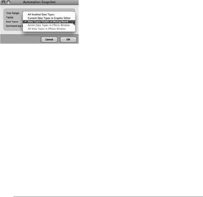
nTracks Shown in Mixing Board. Use this setting to apply the snapshot only to tracks that are
visible (highlighted in the Show/Hide column) in the Mixing Board.
nTrack Shown in Effects Window. This option is available when you click on a plug-in’s
Snapshot Automation button.
Data Types. The last snapshot setting to specify is the type of automation data that is to be
included (see Figure 12.33). The Data Types menu allows you to specify the type of automation
data to be included in the automation snapshot.
nAll Enabled Data Types. Use this setting to include all automation parameters that are
enabled within the Automation Setup window.
nCurrent Data Types in Graphic Editor. This option will only include automation data that is
currently visible within a track or is active within an audio track’s active layer. This setting
prevents you from writing automation data that doesn’t already exist.
nData Types Visible in Mixing Board. This setting only includes automation data that is
visible within the Mix window. For example, if the Sends section is hidden, send volume and
panning automation will not be written with the snapshot.
nActive Data Types in Effects Window. This setting will only include automation parameters
for the plug-in currently showing in the Effects window.
nAll Data Types in Effects Window. This setting will include all automation parameters for
the plug-in currently showing in the Effects window.
Using the Previous Snapshot Setting
DP remembers the automation snapshot setting that was last used within a specific window. So, if you
would like to override the Automation Snapshot window and simply take a snapshot with the win-
dow’s previous setting, simply press the Command key and click the window’s Snapshot button (the
camera icon). You can also use the default keyboard shortcut CommandþControlþ’ (single quote).
Snapshot of Initial Values Possibly the most fundamental use of DP’s Snapshot feature is
to set initial values for various mix parameters that you will be automating. For example,
suppose your mix involves several tracks. Rather than using the Pencil tool to manually
Figure 12.33 The Data Types menu lets you specify the type of automation data to be included in the
snapshot.
422 Digital Performer 6 Power!: The Comprehensive Guide
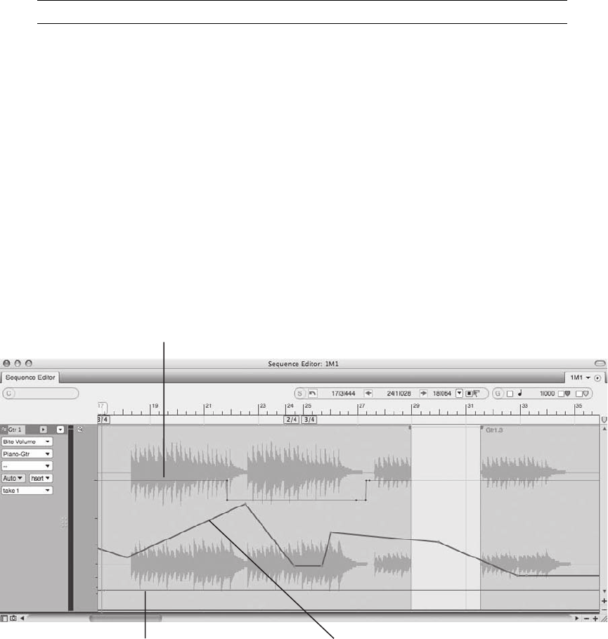
insert, say, the initial volume or pan settings, you can simply take a snapshot of these
settings and then enable automation for each track. Now each track’s data will have a
starting point from which you can base all of your future automation moves.
Soundbite Volume Automation Digital Performer provides yet another level of volume auto-
mation by allowing you to nondestructively apply volume changes directly to a soundbite.
This automation data exists independently of any track automation data and becomes part
of the soundbite. In other words, the data stays with the soundbite if the soundbite is moved
or copied. Further, soundbite automation data can be edited or deleted at any time.
Creating soundbite volume automation is just like inserting volume automation for a track
(discussed earlier in this chapter). In the Active Layer drop-down menu of an audio track
(in the Sequence Editor), simply choose Bite Volume and insert the desired volume changes
for the soundbite. The soundbite volume automation curves will be superimposed over
existing automation layers (see Figure 12.34). All soundbite volume automation data will
also be visible in the Waveform Editor by selecting the Volume tab. In addition,
adjustments to any soundbite volume automation data can be made in the Bite Volume
and Gain submenu (Audio 4Bite Volume and Gain), as shown in Figure 12.35. (Bite Gain
settings will be discussed in Chapter 13.)
Bite Automation Data
Pan Automation Data Track Automation Data (Volume)
Figure 12.34 Bite volume automation data is superimposed over any existing track automation data.
Notice how the track volume and pan data continue, and the bite volume stays with the soundbite.
Chapter 12 Mixing 423
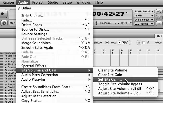
Summary
Even though Digital Performer provides many comprehensive mix features, such as snapshot
automation and plug-in effects, don’t neglect the most basic, yet powerful tools at your
disposal—the Volume fader and Pan knob. A good mix begins with proper levels and panning.
Before you even reach for an effect, you should start with these two fundamental controls.
Think about what the important elements are in your mix. Is it the vocals? Is it the rhythm
section? Start by getting a basic blend of the most important tracks with only the track faders.
If you are working on a larger project and feeling overwhelmed, simply turn down all the tracks
and start building your mix track by track—this is always a good idea. Besides actually listening
to what’s on each track (you’d be surprised how many engineers don’t listen to an individual
track from start to finish), you’ll be able to hear how one track affects another, both from a
technical-engineering standpoint and from an emotional-performance standpoint.
As you’re adjusting levels, listen for tracks that are competing with one another. Instead of
immediately reaching for an EQ, think about panning and how you can use the stereo field
to give each track its own space within your mix. If the heavy guitar track is fighting with
the lead vocal, for example, try panning it left or right to add separation and clarity. You’ll
also need to take into consideration the balance of your instruments (for example, complemen-
tary frequency and volume distribution across the stereo field). In addition to the technical
aspects, “headphone candy” should also play a role in your panning decisions—it can serve
to keep the listener engaged while adding variety to your mix.
Figure 12.35 Adjustments to bite volume automation data can also be made in the Bite Volume and
Gain submenu.
424 Digital Performer 6 Power!: The Comprehensive Guide
Believe it or not, I’ve heard some engineers refer to panning as the most difficult and delicate
part of the mixing process, and they say how the simple act of changing the panning position of
one instrument totally sent their mix back to the drawing board.
Once you’ve satisfied with your basic blend, you should start considering effects plug-ins. We’ve
already discussed how to insert plug-ins, so the next chapter will continue with an explanation
of real-time versus disk-based processing and highlight some of the plug-ins that come bundled
with Digital Performer.
Chapter 12 Mixing 425
This page intentionally left blank

13 Processing and Mastering
Processing is the act of modifying audio or MIDI data with software- or hardware-based
effects. This processing can occur in real time through the use of software plug-ins
and hardware effects units, or it can occur as a file-based process that actually modifies
and replaces the audio or MIDI data within a track. Even though this chapter appears after the
“Mixing” chapter, audio and MIDI processing can happen anytime during the music production
process—from the initial stage of recording and throughout the mixing and mastering stages.
The processing section of this chapter, however, will focus specifically on audio soundbite pro-
cessing. For information on MIDI plug-ins and processing, refer to Chapter 9.
Mastering is the last stage of the music production process (assuming the replication process is a
separate entity outside the music studio environment). Mastering is your final chance to improve
on the sound quality of an audio project before it is mass produced and shipped off to the public.
Ideally, mixers should consider having their mixes mastered by an experienced mastering engi-
neer (budget permitting, of course). Mastering engineers work in a fine-tuned studio environ-
ment that allows them to quickly pinpoint problems and shape a track (or a set of tracks) so that
it will translate well across different types of playback systems. They also use their mastering
tools to match the sonic quality of several audio tracks, so sequential playback of the tracks
sounds more cohesive. There will be times, however, when you will want to or need to master
mixes within Digital Performer.
Though by no means a comprehensive guide to the mastering process, the mastering section of
this chapter will provide an overview of the basic procedures involved with mastering—showing
you how you might incorporate DP’s various tools and feature sets to “master” your mixes in
Digital Performer.
Here is a summary of topics covered within this chapter:
nThe difference between real-time and file-based processing
nHow Automatic Delay Compensation works
nHow to use real-time effect inserts and file-based Audio menu plug-ins
nHow to apply destructive processing in the Waveform Editor
427

nThe Effects window
nHow to transpose soundbites
nHow to bounce to disk or perform a real-time bounce
nHow to export soundbites in different file formats, including MP3
nAn overview of the mastering process within DP
nHow to use dither and noise shaping
nHow to perform sample format and sample rate conversion
Audio Processing
There are basically two ways to process audio data with effects in DP: through the use of effect
inserts or with DP’s file-based Audio menu plug-ins. Effect inserts (in the Mixing Board) are
applied in real time and do not change the actual audio in a track. Audio menu plug-ins, how-
ever, are file based, meaning that a new sound file (mixed with the applied effect) will be created
after a soundbite has been processed. There are, of course, advantages and disadvantages to both
of these methods.
Real-Time versus File-Based Processing Real-time effects are like when you plug a guitar
into a series of effects pedals before sending it to an amp or recorder. File-based process-
ing, however, is like taking an audio track that’s already recorded and “printing” an effect
on top of it (permanently merging the original audio and the effect together).
Automatic Delay Compensation
Regardless of which method you choose (real-time or file-based processing), be aware that plug-
in processing may introduce a delay, called latency, to the processed signal. How much latency is
introduced depends on the particular plug-in you’re working with. To get around this limitation,
enable DP’s Automatic Delay Compensation (ADC) feature, which automatically adjusts the
playback of the audio signal to compensate for any added latency—with sample accuracy
(Setup 4Configure Audio System 4Configure Studio Settings).
When ADC Doesn’t Work Keep in mind that this feature only works on real-time audio
processing and virtual instruments triggered by prerecorded MIDI data. ADC has no effect
on live audio or MIDI data that is triggered in real time or file-based processing applied
with the Audio menu plug-ins.
428 Digital Performer 6 Power!: The Comprehensive Guide

Real-Time Effects
Real-time plug-ins are the most versatile form of processing because they do not alter the audio track
data. You are free to audition different settings or even bypass or remove plug-ins entirely—all in
real time. The disadvantage is that inserted plug-ins consume your system’s CPU resources. Some
plug-ins are only a light drain on your CPU resources, while others (such as Audio Ease’s Altiverb,
Waves Mastering Bundle plug-ins, and so on) can slow down even the fastest Macs when you’re
working with larger projects. You may want to work with higher buffer sizes when mixing with real-
time effects. Higher buffer sizes have the benefit of freeing up your computer’s CPU resources. The
tradeoff, however, is the unfortunate increase in monitoring latency, which can make recording
extremely difficult. You can monitor DP’s resource consumption from the Audio Performance win-
dow (explained in “The Audio Performance Window” section of this chapter).
To insert a real-time effect plug-in:
1. Open the Mixing Board by choosing Project 4Mixing Board. You can also use
the default keyboard shortcut ShiftþM.
2. Click on an effect insert and choose the desired plug-in from the drop-down menu
(see Figure 13.1).
3. The plug-in will open in a separate Effects window (see Figure 13.2). If you close
the Effects window, you can reopen it by double-clicking on the name of the plug-in in
the Inserts section of the Mixing Board.
4. Adjust the plug-in parameters as needed.
To remove or switch to a new plug-in:
1. In the Mixing Board, click on the desired effect insert and choose None to remove
the plug-in.
2. When working in the Effects window, click on the plug-in’s Effect menu and choose
None.
3. To switch to a new plug-in, repeat Step 1 or 2, but instead of choosing None, choose
the new plug-in from the drop-down menu.
Plug-In Compatibility As I discussed in Chapter 2, Digital Performer supports the use of
MAS, AU, and VST plug-ins. (VST plug-ins require a VST wrapper.). As long as they are
installed within the correct plug-ins folder, they will appear in DP.
DAE users will have access to TDM, RTAS, and AudioSuite plug-ins—but not AU or
native MAS plug-ins. DAE users wanting to use VST plug-ins can choose to use
FXpansion’s VST/RTAS adapter.
Chapter 13 Processing and Mastering 429
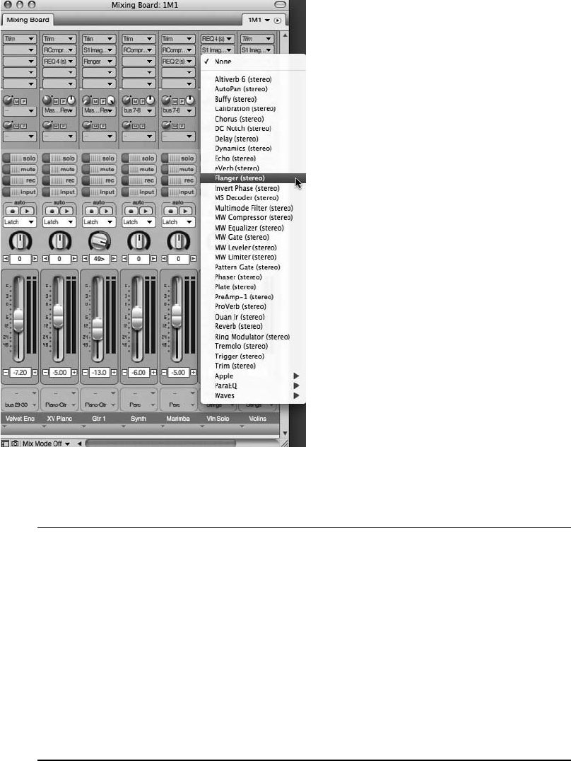
Real-Time versus Pre-Gen Effects Much like our discussion of pre-rendered virtual instru-
ment tracks, by default a processing effect in DP is also pre-rendered ahead of time
(meaning DP goes to work once the effect window is closed). This “pre-gen” feature,
as MOTU calls it, lightens the load on your computer’s processor during real-time play-
back. You can use the Digital Performer 4Preferences 4Audio Plug-Ins 4Plug-In Real
Time preference to adjust default pre-gen settings for projects. For example, you can
select Pre-Gen Mode When Possible as the default setting for new projects or choose
All Plug-Ins in Real Time for the current project. Keep in mind that no matter what you
choose as a default setting, you still have the option to change the real-time setting of
each effect plug-in in its mini-menu. (See “The Effects Window” section later in this
chapter.)
Figure 13.1 The Inserts drop-down menu provides a complete list of compatible plug-ins that are
installed within your system.
430 Digital Performer 6 Power!: The Comprehensive Guide
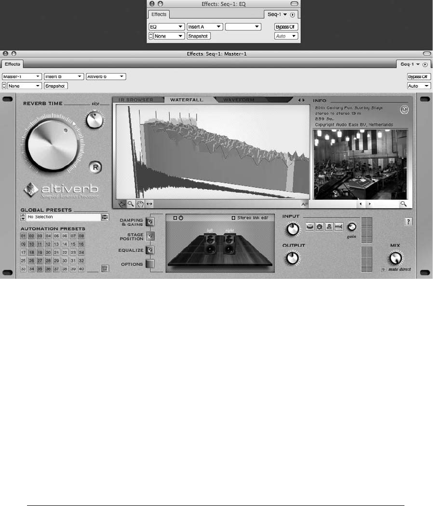
File-Based Processing
File-based processing has the benefit of not consuming real-time system resources. You basically
apply an effect from the Audio menu to a soundbite, which creates a new sound file of the
processed audio. The disadvantage is that you must reapply the effect if you want to change
it. This is a constructive process, meaning a new soundbite is created, so you can always return
to the original file—at any time—simply by dragging the original soundbite into a track from the
Soundbites window. You can apply file-based processing to a soundbite directly in an audio
track or in the Waveform Editor (Soundbites 4Edit). Keep in mind that, unlike track process-
ing, Waveform Editor processing is a destructive process that permanently alters the soundbite.
You can use the sound file’s independent Undo History List to undo (or remove) any applied
processing if you have the Sound File Undo History configured to remember your actions. Refer
to Chapter 6 for an explanation of the Undo History window.
The Normalize and Fade Commands In addition to Audio menu plug-ins and other audio
commands (such as the Region menu’s Transpose command), the Waveform Editor will
also allow you to apply destructive fades and normalization (explained in the “Normalizing
Figure 13.2 Plug-ins will open up in their own Effects window. The first Effects window (top) is dis-
playing an empty insert, while the second Effects window (bottom) displays an Altiverb plug-in that’s
been inserted in Slot A of the Main Reverb Aux track.
Chapter 13 Processing and Mastering 431

Soundbites” section later in this chapter). These Audio menu commands are only available
when you are working in the Waveform Editor and will appear dimmed (or unavailable)
when you are processing audio directly in a track.
Background Processing Keep in mind that file-based effects processing occurs in the back-
ground, so you will be free to perform other actions while any processing is taking place.
The Background Processing window controls how background processing functions in
Digital Performer; it is explained later, in “The Background Processing Window” section
of this chapter.
Processing Audio within a Track
You can process entire soundbites or only portions of soundbites within an audio track. Simply
make the appropriate time-range selection, choose the desired plug-in from the Audio menu, and
then apply the effect. Because this is a constructive process, a new audio file with the applied
effect will be created in the Soundbites window and will replace the original soundbite within
the track.
To process a soundbite within the Tracks window or Sequence Editor:
1. Begin by selecting the audio data you want to affect. You can select an entire soundbite
or just a portion of it (explained in the “Selecting and Moving Audio” section of
Chapter 10).
2. Select the desired plug-in by choosing Audio 4Audio Plug-Ins. The plug-ins
listed here are identical to the plug-ins found in the Inserts section of the Mixing
Board.
3. Adjust the plug-in parameters and click the Preview button to audition the settings (see
Figure 13.3).
4. Once you are satisfied with the plug-in settings, click the Apply button. The time it
takes to process the soundbite depends on the type of process and the speed of your
computer. Files that are being processed will appear as an outlined waveform, as shown
in Figure 13.4.
Once a soundbite is processed, a new sound file will be created with the applied effect. This new
file will replace the original file within the track. Keep in mind that the original file will remain
intact within the Soundbites window, allowing you to return to the original version when you
need to.
432 Digital Performer 6 Power!: The Comprehensive Guide
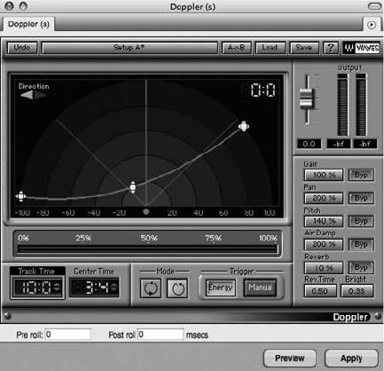
Processing Audio in the Waveform Editor
The procedure for processing audio with effects within the Waveform Editor, shown in
Figure 13.5, is similar to the way in which you process soundbites directly within a track.
Simply select the soundbite in the Soundbites window, make a time-range selection in the Edit
pane (Waveform Editor), and then apply the desired plug-in from the Audio menu. You can also
use the Audio menu’s Normalize and Reverse commands when working in the Waveform
Editor. As mentioned earlier, processing done in the Waveform Editor is destructive and will
permanently alter the original file, so it’s always a good idea to make sure you have a backup
copy of the soundbite before applying any destructive processing/edits.
To make a copy of a soundbite in the Waveform Editor:
1. Open the Soundbites window and double-click the desired soundbite from the Sound-
bite List. A separate Waveform Editor window will automatically open.
2. Use the default keyboard shortcut CommandþA to quickly select the entire soundbite.
3. Once the soundbite is selected, choose New Sound File from Selection from the Sound-
bites window’s mini-menu. A copy of the soundbite will be created with the same
name as the original soundbite. A numerical suffix will be added to differentiate the two
files (such as Audio-1.1, Audio-1.2, Audio-1.3, and so on).
4. You may want to rename this new backup copy something more easily recognizable.
If so, Option-click the soundbite name in the Name column and rename the soundbite.
Figure 13.3 Plug-ins that are accessed from the Audio menu contain additional controls for preview-
ing, applying, and setting pre- or post-roll times.
Chapter 13 Processing and Mastering 433
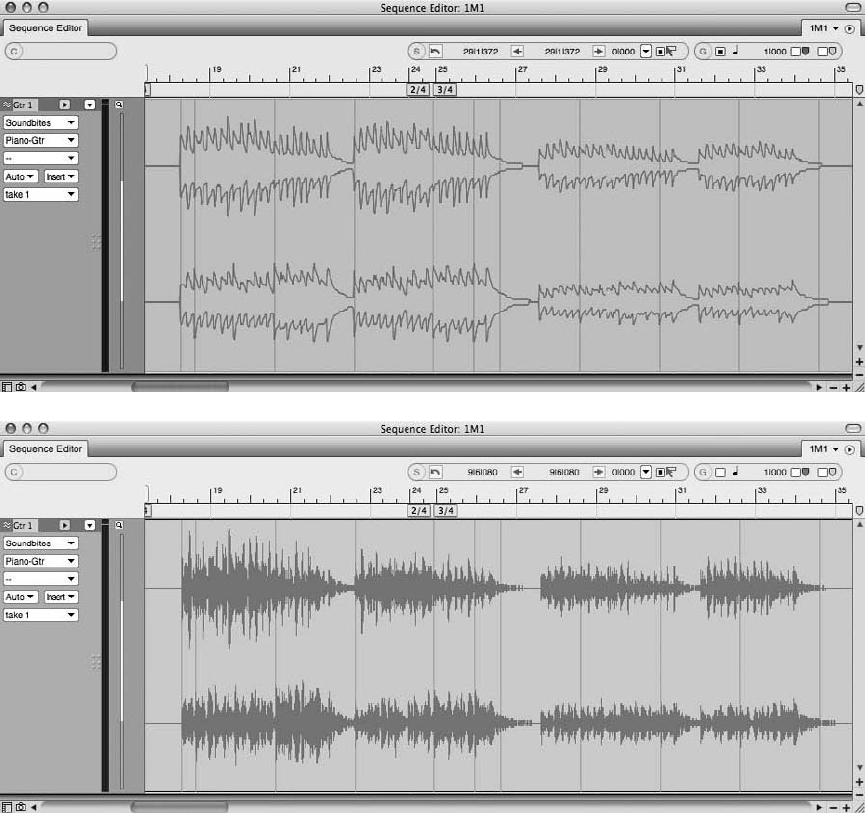
To process a soundbite in the Waveform Editor:
1. Open the Soundbites window and double-click the desired soundbite from the Sound-
bite List. A separate Waveform Editor window will automatically open.
2. Select the audio data you want to affect. You can select an entire soundbite or just a
portion of it. Use the default keyboard shortcut CommandþA to quickly select the
entire soundbite.
Figure 13.4 Soundbites that are being processed will appear as an outlined waveform (top). Once an
effect has been applied, it will change to a solid waveform (bottom).
434 Digital Performer 6 Power!: The Comprehensive Guide
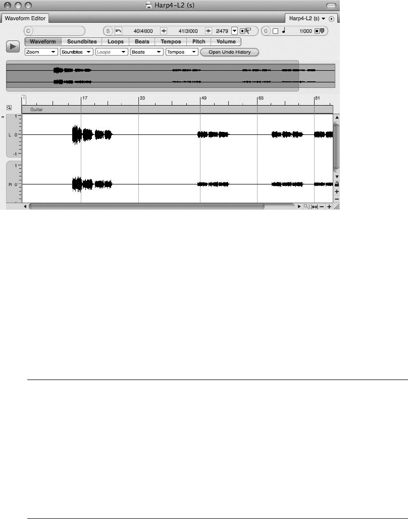
3. Select the desired audio plug-in by choosing Audio 4Audio Plug-Ins. As discussed
earlier, the plug-ins listed here are identical to the plug-ins found in the Inserts section of
the Mixing Board.
4. Adjust the plug-in parameters and click the Preview button to audition the settings.
If needed, set the pre- and post-roll times.
5. Click Apply to process the soundbite with the effect. The amount of time it takes
to process the file depends on the plug-in being applied, the length of the selection to be
processed, and the speed of your computer.
Sound File Undo History Keep in mind that processing (and editing) applied in the Wave-
form Editor is a destructive process—meaning that it will permanently alter the original file.
Use a soundbite’s independent Sound File Undo History to undo/redo destructive actions
that have been applied. Simply click on the Undo History button in the Waveform Editor to
open a soundbite’s independent Undo History window. In the window, you should see a
list of actions that have been performed on the particular file. Be sure to configure the
Sound File Undo Pruning preferences to remember the necessary actions, or you may
be surprised when you open the Undo History and find the list of actions discarded.
Click on the Pruning Preferences button to access the Sound File Undo Pruning Setup.
Normalizing Soundbites. Normalization is the destructive process of raising a soundbite’s loud-
est peak to full-scale digital zero (or 0 dB). Because this command basically takes a soundbite
Figure 13.5 The Waveform Editor allows you to perform destructive processing to a selected soundbite.
Chapter 13 Processing and Mastering 435

and makes it sound louder, it is commonly confused with the more sophisticated process of
brickwall limiting (explained in the “Mastering” section of this chapter). When applied, the
Normalize command will first scan an audio selection for its loudest peak. Once the peak is
determined, DP will calculate how much overall gain needs to be applied to the soundbite to
make the loudest peak reach 0 dB. Keep in mind that normalization affects an entire selection of
audio—not just its loudest peak—and will also raise the audio file’s noise floor in the process;
this can have the side effect of making the noise floor more noticeable.
The process for normalizing soundbites can only be applied to audio selections within the Wave-
form Editor and is the same as for effects processing (discussed in the previous section, “Proc-
essing Audio in the Waveform Editor”).
Soundbite Gain Digital Performer allows you to nondestructively boost or attenuate
(reduce) a soundbite’s gain by a specific number of decibels. For example, rather than
normalizing a soundbite to make it sound louder (discussed in the previous section),
you could add just a few decibels to slightly raise its volume. You can also quickly bypass
any bite volume automation (discussed in the “Soundbite Volume Automation” sidebar in
Chapter 12) that may be attached to the soundbite. To change a soundbite’s gain setting
or to bypass any bite volume automation, simply use the Audio 4Bite Volume and Gain
submenu or the Bite Gain and Bite Volume Bypass options in the Information Pane of the
Soundbites window.
Applying Destructive Fades. Fades can be applied destructively to a soundbite within the Wave-
form Editor. Simply make a soundbite selection within the Waveform Editor and choose Audio
4Fade In/Out to apply a destructive fade-in or fade-out. Keep in mind that these fades are
linear, and their fade curves cannot be changed.
If you need more versatility with the fade process, consider using the standard Fade command
(Audio 4Fades), which can be used in any other editor window (except the Waveform Editor)
and is nondestructive.
The Background Processing Window
Unlike some audio commands (such as the Audio menu’s Bounce to Disk command) that
monopolize Digital Performer’s system resources, many of the tasks (such as DSP processing
and beat detection analysis) that DP performs occur in the background. The Background Proc-
essing window automatically prioritizes background tasks, placing more important processes at
the top of the list (see Figure 13.6). DP will even interrupt low-priority analysis tasks to work on
high-priority ones first. You can control how Background Processing functions in the Back-
ground Processing preferences (explained in the “Background Processing Preferences” section
later in this chapter).
436 Digital Performer 6 Power!: The Comprehensive Guide
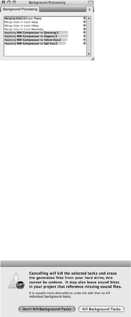
Background Processing Tasks
Actions that must be processed are called tasks and are listed in the Task List of the Background
Processing window. Tasks that are currently being processed will appear at the top of the list—
DP will always work on higher-priority tasks first—with the task name displayed in black text.
In addition, tasks that are being processed have a progress bar (located behind the task name)
that progresses from left to right. Once a task is processed, it will disappear from the Task List.
Tasks that are waiting to be processed appear in the list without a progress bar.
Here are a few tips for managing background processing tasks:
nTo view the current tasks in the Task List: Open the Background Processing window by
choosing Studio 4Background Processing. You can also use the default keyboard shortcut
ShiftþR. When first opened, the Background Processing window may appear with only a
few tasks visible. You can expand the window by clicking on the title bar’s Zoom button or
by dragging the bottom-right portion of the window downward.
nTo stop a task: Click on the task’s Cancel button, indicated by a small x. You will be pre-
sented with a warning dialog, shown in Figure 13.7, asking whether you really want to
continue with the cancellation process. Click the Kill Background Tasks button to stop the
background processing for the specific task. Choose the Don’t Kill Background Tasks button
to continue with the task’s background processing.
Figure 13.7 Clicking on a task’s Cancel button will launch the Kill Background Tasks warning dialog.
Figure 13.6 The Background Processing window shows a list of tasks that are waiting to be processed.
Chapter 13 Processing and Mastering 437
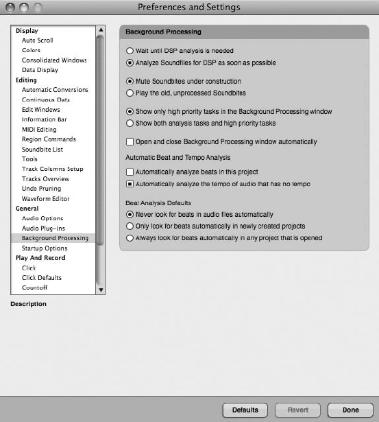
nTo begin running a task that has been stopped: If Digital Performer encounters a problem
and stops processing a task, you can run the process again by choosing the Run Stopped
Task Again command from the Background Processing mini-menu.
nTo further customize how the Background Processing window functions in DP: Open the
Background Processing preferences and choose the desired settings (explained in the next
section).
Background Processing Preferences
The Background Processing preferences, shown in Figure 13.8, determine how background
processing is handled in DP. The provided options are divided into three different sections:
the Background Processing section, the Automatic Beat and Tempo Analysis section, and the
Beat Analysis Defaults section.
Figure 13.8 The Background Processing preferences provide options for controlling the functionality
of DP’s background processing.
438 Digital Performer 6 Power!: The Comprehensive Guide
Background Processing Section. The Background Processing section controls the overall func-
tionality of DP’s Background Processing feature; its options are as follows:
nWait Until DSP Analysis Is Needed. Use this option if you do not want DP to automatically
analyze soundbites listed in the Soundbites window. Soundbite analysis will occur only
when you perform an audio process that requires it.
nAnalyze Soundfiles for DSP as Soon as Possible. Select this option if you want DP to auto-
matically analyze soundbites for future processing. This can come in handy if you are
performing a lot of audio processing. DP will not have to perform this analysis for each
audio process because it will have already been completed in the background. This option is
enabled by default.
nMute Soundbites under Construction. This option is enabled by default and will prevent
a soundbite from being heard while it is still being processed. Once background processing
has been completed, the soundbite will become available for playback.
nPlay the Old, Unprocessed Soundbites. Choose this option to hear the unprocessed soundbite
while background processing is occurring.
nShow Only High Priority Tasks in the Background Processing Window. Enabled by default,
this option will hide any lower-priority preemptive analysis tasks from the Background
Processing window’s Task List. Since these tasks are always processed after higher-priority
tasks, it really isn’t as necessary to see them.
nShow Both Analysis Tasks and High Priority Tasks. Use this option to view all background
processing tasks within the Task List.
nOpen and Close Background Processing Window Automatically. Enabled by default, this
option will automatically open and close the Background Processing window when back-
ground processing begins and ends. Disable this option if you want to manually control the
visibility of this window.
Automatic Beat and Tempo Analysis Section. The Beat Detection Engine is able to detect the
transients in an audio file, allowing DP to analyze where the locations of beats are in a sound-
bite. Once a soundbite is analyzed and its beats are detected, soundbites can be intuitively quantized
and time-stretched or compressed to conform to a project’s tempo. Preemptive beat analysis helps to
automate the beat detection process by automatically analyzing soundbites contained in a project so
that they are ready to go when you wish to apply any beat- or tempo-related commands.
The Automatic Beat and Tempo Analysis section of the Background Processing preferences deter-
mines how preemptive beat and tempo analysis functions in DP; its options are explained below.
nAutomatically Analyze Beats in This Project. This option turns on preemptive beat analysis,
which causes soundbites contained in the current project to be automatically analyzed.
Chapter 13 Processing and Mastering 439
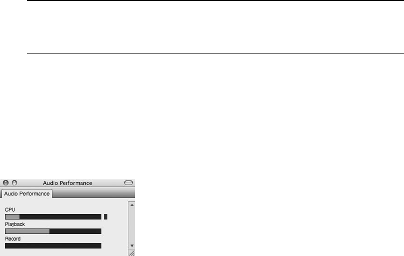
Keep in mind that when turned on, this feature will override the Beat Analysis Default
settings, explained in the next section.
nAutomatically Analyze the Tempo of Audio That Has No Tempo. As with the previous
option, enable this option if you want DP to automatically analyze a soundbite that doesn’t
contain tempo data.
Beat Analysis Defaults Section. The Beat Analysis Defaults options allow you to further control
the functionality of DP’s Beat Detection Engine. These options basically affect how the Auto-
matically Analyze Beats in This Project option (explained in the previous section) functions
when enabled. They are as follows:
nNever Look for Beats in Audio Files Automatically. Turn on this feature if you do not
want DP to preemptively analyze beats. Keep in mind that the previously discussed
Automatically Analyze Beats in This Project option will override this setting.
nOnly Look for Beats Automatically in Newly Created Projects. Enable this option if you
only want DP to look for beats in new projects that you create in the current version
of Digital Performer—and to leave older, existing projects alone.
nAlways Look for Beats Automatically in Any Project That Is Opened. Enable this option if
you want DP to automatically look for beats when you open a project—regardless of the
version of DP in which it was created.
Disabling Preemptive Beat Analysis Keep in mind that if you turn off DP’s beat detection
feature, you will need to perform soundbite beat analysis manually when you use any of
Digital Performer’s tempo- or beat-related commands.
The Audio Performance Window
Real-time audio plug-ins consume CPU power—some more than others, depending on the plug-
in you are working with. DP’s Audio Performance window provides visual feedback on the amount
of CPU usage, along with Playback and Record buffer activity, as shown in Figure 13.9. Remem-
ber that your system’s audio performance may suffer if you run out of CPU resources during
playback. If this happens, you may need to scale down the number of real-time effects plug-ins
you have inserted. You can also try increasing the hardware buffer size; this will free up your
Figure 13.9 The Audio Performance window provides visual feedback on DP’s resource consumption.
440 Digital Performer 6 Power!: The Comprehensive Guide
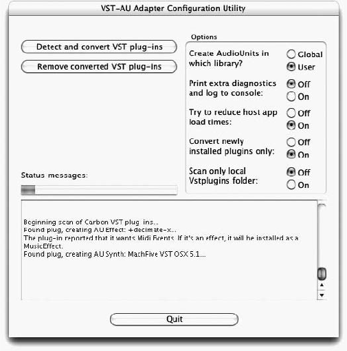
system resources for more real-time effects. The tradeoff with higher buffer sizes is increased
monitoring latency—this shouldn’t be a problem, however, during the mixing process.
Plug-In Formats
DP comes bundled with audio effect plug-ins that are in its native MAS (MOTU Audio System)
format, and it also provides direct support for Apple’s AU (Audio Units) format. You will need
to install a third-party application—called a wrapper— if you want to incorporate VST effect
and instrument plug-ins into your DP system (see Figure 13.10). Once installed and configured,
these wrappers will automatically convert a VST-formatted instrument or effect plug-in into
either the AU or MAS format (depending on the application) and make it available throughout
Digital Performer.
Figure 13.10 FXpansion VST to Audio Unit Adapter allows access to installed VST effect and instrument
plug-ins.
Plug-In Locations
Audio plug-ins are stored in the System (User) 4Library 4Audio 4Plug-Ins folder and are sep-
arated into different subfolders by plug-in type (such as MAS, VST, and Digidesign folders). AU plug-
ins, however, are located in the Components folder. When installing plug-ins, keep in mind that you
can store them in either the System or User Library folder. The only difference is that plug-ins installed
in the User Library folder will only be available to that particular user. If you are working on a system
that doesn’t contain multiple user accounts, there really isn’t anything to worry about—you’ll have
access to installed plug-ins, regardless of their System or User locations.
Chapter 13 Processing and Mastering 441
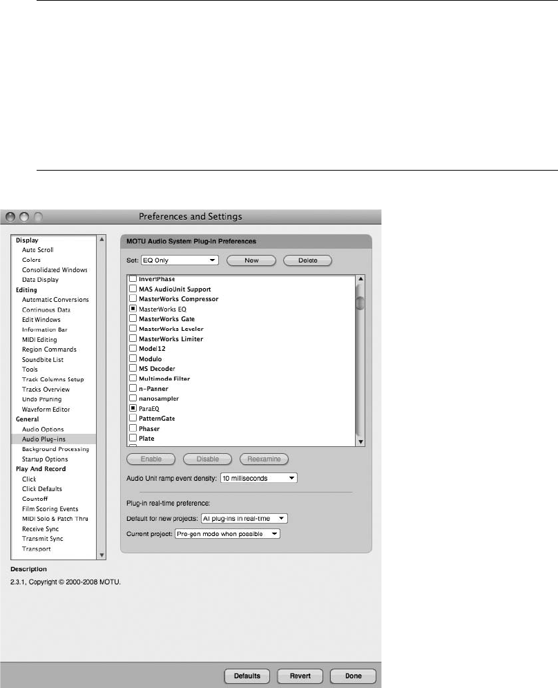
Plug-In Management As discussed in Chapter 5, Digital Performer 6 now offers extensive
plug-in management options. You can freely enable and disable any native or third-party
plug-ins, create customized plug-in sets, and force plug-ins to load even if they don’t pass
startup validation. Plug-in sets are a great way to manage plug-ins in DP. In other words, if
you know your current project will only require a handful of plug-ins (such as a project
where you will only be recording MIDI), simply create a set that includes only the neces-
sary plug-ins! Go to Digital Performer 4Preferences 4Audio Plug-Ins to access the audio
plug-ins preferences within DP (see Figure 13.11).
Figure 13.11 The Audio Plug-ins Preferences in DP allow you to manage all native and third-party
audio plug-ins. In this example, I have created a plug-in set labeled EQ Only for a mixing session.
442 Digital Performer 6 Power!: The Comprehensive Guide

Installing AU Plug-Ins
Typically, plug-ins will automatically be placed in the proper folder by the installer program.
However, it is important that when installing AU plug-ins manually, you make sure to place
them in the Library 4Audio 4Plug-Ins 4Components folder. Remember that you can
place them in either the System or the User Library folder. The first time you launch DP after
successful installation, DP will analyze each AU plug-in for problems during the loading process.
At the end of the loading process, DP will display a dialog box showing you the results of the
analysis. AU examination happens only once per plug-in and can take up to a few minutes,
depending on the number of plug-ins to be analyzed. If an AU plug-in fails to load because of
a problem, the plug-in will not be available for the project.
AU/MAS-Compatible Plug-Ins When installed plug-ins are in both MAS and AU formats,
DP will ignore the AU version and only load the MAS version for use in Digital Performer.
Dynamic CPU Management DP has a unique method for handling the demands placed on
your computer’s processor by audio plug-ins. Dynamic CPU management means that
when an effect plug-in—say, DP’s Masterworks Limiter—is not receiving an audio signal,
it is automatically and temporarily disabled until it receives more audio from its corre-
sponding track. Once it receives audio again, it will automatically reactivate so it can per-
form its task. (No preferences or settings are involved!) Although all of the plug-ins
included in DP support this feature, third-party plug-ins may or may not. Consult the
company’s resources to determine whether your third-party plug-ins can take advantage
of dynamic CPU management.
The Effects Window
Digital Performer’s Effects windows display real-time audio and MIDI plug-ins that are inserted
in the Mixing Board, as shown in Figure 13.12. Multiple Effects windows can be open at the
same time.
To open an Effects window for a specific audio track:
1. Highlight an audio track in the Tracks window.
2a. Choose Project 4Effects (or use the shortcut ShiftþF).
OR
2b. Simply double-click on an existing plug-in insert in the Mixing Board.
Chapter 13 Processing and Mastering 443
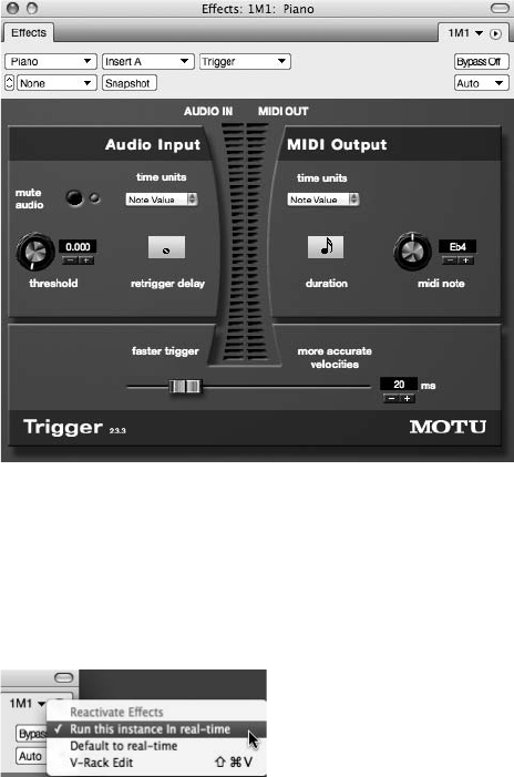
The Mini-Menu
The Effects window’s mini-menu (as shown in Figure 13.13) contains options such as:
nReactivate Effects (DAE Only). This option makes TDM plug-ins active again (under the
DAE audio system).
nRun This Instance in Real-Time. When selected, an effect plug-in will no longer take
advantage of DP’s pre-rendering feature (producing a plug-in’s output in advance as soon as
its window is closed). When a plug-in is run in real time, its “effect” will only be produced
during playback (which, depending on the number of plug-ins running in real time, results in
a greater demand on the CPU).
nDefault to Real-Time. When this is selected for a plug-in, each time you activate the same
plug-in, it will default to Run in Real-Time.
nV-Rack Edit. This option toggles between the current plug-in’s Effects window and the last
viewed V-Rack.
Figure 13.13 The Effects window’s mini-menu includes options for utilizing plug-in effects in real time.
Figure 13.12 Digital Performer’s Effects window displays real-time plug-ins that are inserted in the
Mixing Board. In this example, DP’s Trigger plug-in is shown.
444 Digital Performer 6 Power!: The Comprehensive Guide
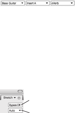
Track, Insert, Effect, and Preset Menus
Located below the Effects window’s title tab are four menus that allow you to access another
track, access another effect insert (A, B, C, and so on), choose a different effect plug-in, or man-
age an effect’s presets. (See the upcoming “Saving and Recalling Effect Presets” section for a
detailed explanation of this process.) In addition to providing automation controls, the menus
allow you to access inserted plug-ins—even if they are located on different tracks—with only one
Effects window open (see Figure 13.14).
Bypassing or Automating an Effect
You can bypass or temporarily disable inserted plug-ins by clicking on an effect’s Bypass button
(see Figure 13.15). If the plug-in window is closed, you can Option-click directly on an insert in
the Mixing Board window to bypass it. In addition, you can access DP’s automation options in
the available Automation drop-down menu. You can even take an automation snapshot with the
handy Snapshot button!
Saving and Recalling Effect Presets
Many of DP’s audio plug-ins (as well as third-party plug-ins) contain factory presets, which you
can access from the plug-in’s Preset menu. Presets are listed below the Save Settings and Show
Presets in Finder commands, shown in Figure 13.16, and are available regardless of whether the
plug-in is a real-time effect insert or a file-based Audio menu plug-in.
To choose a plug-in preset:
1. Open the desired plug-in from the Audio menu or the Mixing Board inserts.
2. Click on the plug-in window’s Preset menu.
3. Select the desired preset to load it. Active presets are indicated by a check mark and will
appear as the Preset menu’s title. If you have modified any of the preset’s settings, the
name will become italicized. Use the available Compare menu item to compare a
modified preset to the original, unmodified preset.
Plug-in Bypass Button
Plug-in Automation Button
Figure 13.15 The Effects window’s Bypass button is used to temporarily disable a plug-in, while the
Automation drop-down menu provides DP’s options for automating an effect.
Figure 13.14 Use the Track, Insert, and Effect menus to navigate between different plug-ins, even if
they are located on different tracks.
Chapter 13 Processing and Mastering 445
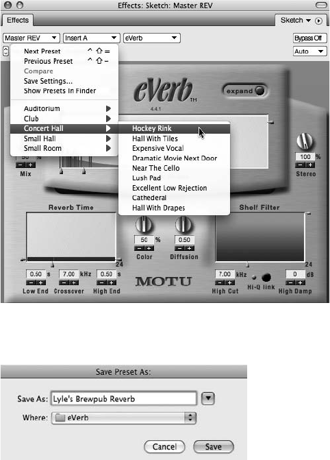
To save a plug-in preset:
1. Start by configuring the specific plug-in’s parameter settings to your liking.
2. Once you are satisfied, click on the plug-in window’s Preset menu and choose Save Settings.
3. Name the custom preset in the Save Preset As window (see Figure 13.17).
4. Click OK, and the new preset will appear in the User Presets section of the plug-in’s
Preset menu.
To modify the parameter settings of an existing preset:
1. Select the desired preset from the plug-in’s Preset menu and then adjust the parameter
settings as needed.
Figure 13.17 The Save Preset As window.
Figure 13.16 Effect presets are listed in the specific plug-in’s mini-menu.
446 Digital Performer 6 Power!: The Comprehensive Guide

2. Once you’re satisfied with the new changes, choose Save Settings from the plug-in’s
Preset menu.
3. Type in the same name of the effect preset in the Name Effect Preset window.
4. An alert will allow you to replace the preset.
Pitch-Shifting Audio
When you are pitch-shifting audio, DP can transpose soundbites in two different ways: with
standard pitch-shifting or with MOTU’s proprietary PureDSP pitch-shifting algorithm. Standard
pitch-shifting alters the frequencies of an audio file without affecting its length. With this
method, the further you transpose a file away from its original pitch, the higher or lower the
timbre of the pitch will be. This processing artifact leads to the well-known “chipmunk” sound.
PureDSP processing, however, attempts to preserve the resonant frequencies of the sound with-
out affecting the actual timbre or character of the audio file. By default, all audio files are set to
use MOTU’s PureDSP pitch-shifting algorithm. You can change a specific audio file’s Transpose
setting in the sound file’s Information window (Studio 4Sound File Information 4Sound File
drop-down menu), as shown in Figure 13.18.
Dry Monophonic Audio Material Pitch processing in Digital Performer produces much bet-
ter results with dry monophonic audio material. In other words, make sure the audio you
want to pitch-shift is a single voice (or instrument) and contains no effect processing, such
as reverb or delay. Pitch-shifting a soundbite that contains chords, stacked vocals, effects,
or a full mix will not produce tangible results. The success of pitch-shifting in Digital Per-
former (or any other audio program) is highly dependent on the nature and quality of the
original recorded audio material.
To change the Transpose setting of a soundbite:
1. Open the Sound File Information window by choosing Studio 4Sound File
Information.
2. Select the desired sound file from the Sound File menu. Once the sound file is selected,
the Sound File Information window will update accordingly.
3. From the Soundbite section (the center section), click on the Transpose pop-up
menu and choose the desired pitch-shifting algorithm, as shown in Figure 13.19. If
you do not see the Soundbite section’s details, be sure to click the disclosure triangle
located to the left of the word Soundbite.
4. If you want to prevent a soundbite from being pitch-shifted all together, choose the
Don’t Pitch Shift option.
Chapter 13 Processing and Mastering 447
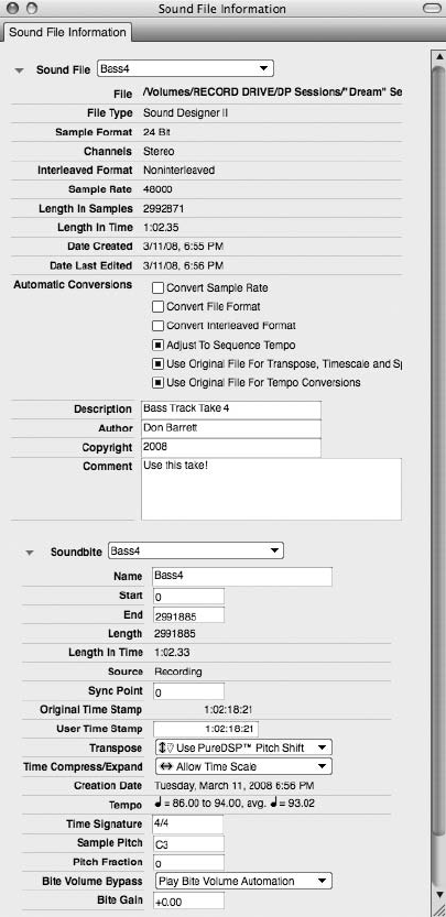
The Transpose Command
The Transpose command, shown in Figure 13.20, allows you to transpose or pitch-shift selected
MIDI data and soundbites (or portions of MIDI data and soundbites).
You can even simultaneously transpose MIDI and audio data selections together—allowing you,
for example, to transpose an entire project that contains both MIDI and audio data. Keep in
Figure 13.18 You can configure an individual soundbite’s Transpose setting in the Info Pane of the
Soundbites window.
448 Digital Performer 6 Power!: The Comprehensive Guide
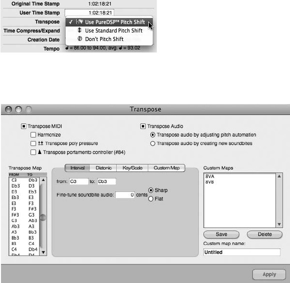
mind that the specific pitch-shifting algorithm used by the Transpose command to transpose
audio will be determined by an individual soundbite’s Transpose setting.
To transpose the pitch of an audio file using the Transpose command:
1. Select the soundbite you want to transpose. Remember that portions of a soundbite
can also be transposed. (Simply use the I-Beam tool to select a portion of the soundbite,
as discussed in the “Selecting and Moving Audio” section of Chapter 10.)
2. Open the Transpose command by choosing Region 4Transpose. You can also use
the default keyboard shortcut Commandþ9.
3. Enable the Transpose Audio button and choose between the options Transpose Audio
by Adjusting Pitch Automation (transposition will be based on any existing pitch
automation for the soundbite—discussed in the “Pitch-Shifting Audio with Pitch
Automation” tip a bit later in this chapter) and Transpose Audio by Creating New
Soundbites (transposition will result in a new soundbite).
Figure 13.19 Set the Transpose settings for a soundbite from the Info Pane’s Transpose pop-up menu.
The Use PureDSP Pitch Shift option is enabled by default.
Figure 13.20 The Region menu’s Transpose command can be used to transpose both audio and MIDI
data.
Chapter 13 Processing and Mastering 449

4. Select the Interval option. Keep in mind that soundbites can only be transposed when
the Interval option is selected. Once the Interval option is chosen, the Transpose Audio
options will become available.
5. In the From and To interval input fields (located in the center of the Transpose win-
dow), set the transpose interval. This interval will determine how much a soundbite is
pitch-shifted. The actual notes you choose to enter do not matter; only the interval
between the two pitches will be used to transpose the selection. For example, if you
want to transpose a soundbite up a whole step, you could enter a value of C3 in the
From input field and a value of D3 in the To input field. You could also enter the pitches
of G4 and A4, respectively.
6. If necessary, use the Fine-Tune Audio options to adjust the transposition up or
down by a number of cents. Keep in mind that there are 100 cents per half step (or
semitone).
7. Once you have entered the necessary values, click the Apply button to confirm the
change.
Pitch-Shifting Audio with Pitch Automation Like volume, pan, and bite volume (discussed
in Chapter 12), the pitch of audio material can also be automated in Digital Performer
(see Figure 13.21). Pitch automation is nondestructive and is output in real time during
playback. In addition to providing a Pitch Ruler for reference, DP superimposes a pitch
curve (a blue line) and a pitch segment (average root pitch of each note) over the audio
waveform. You can perform a number of pitch-related actions, such as drawing in
pitch corrections with the Pencil tool or slightly scaling the pitch curve of an entire
section. As with bite volume, all pitch automation edits are linked to the soundbite
and will travel with it if the soundbite is movedorcopied.PitchautomationinDigital
Performer is relatively simple but can be a very tedious and time-consuming process.
For more detailed information, consult the Transposing Audio section of your DP User
Manual.
The Spectral Effects Command
Compared to the standard Transpose command, the Spectral Effects command, shown in
Figure 13.22, offers a different approach to pitch-shifting audio. Besides being able to transpose
an audio selection, the Spectral Effects command also lets you manipulate the formants and/or
tempo of a sound—independent of the actual pitch of the audio file.
Keep in mind that the Spectral Effects command will ignore a soundbite’s PureDSP settings
(located in its Sound File Information window). A soundbite selected with the Spectral Effects
command can always be processed, regardless of its PureDSP Settings.
450 Digital Performer 6 Power!: The Comprehensive Guide
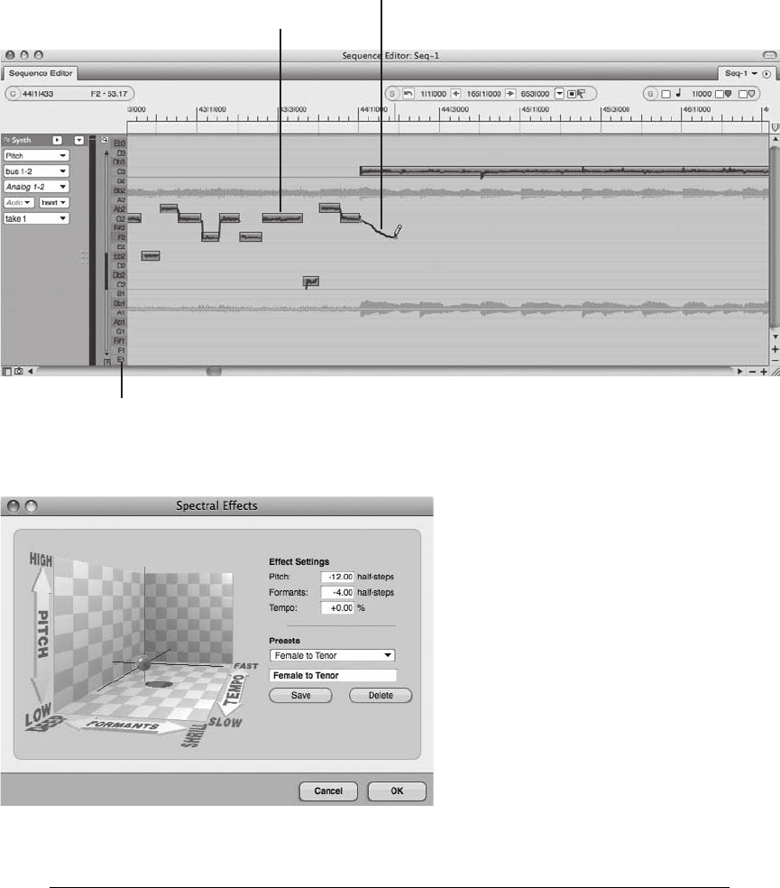
What Are Formants? Formants are the resonant frequencies present within a sound. These
frequencies have fixed peaks that exist independently of the sound’s fundamental pitch or
note. This is what gives a sound its particular timbre and character. Think of two
Figure 13.22 The Spectral Effects command provides a 3D space for controlling the pitch, formants,
and tempo of a sound source.
Pitch Segment
Pitch Curve
Pitch Ruler
Figure 13.21 Pitch automation in DP is as simple as using the Pencil tool to draw in a pitch change or a
pitch correction!
Chapter 13 Processing and Mastering 451
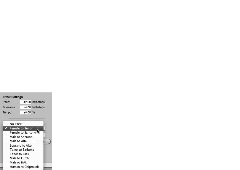
instruments—say, an oboe and a trumpet—playing the exact same note of middle C. Even
though both instruments are playing the same pitch, you can distinguish between the two
instruments because of their unique timbres or formants. When working with the human
voice, formants also determine the character of a voice and whether a voice sounds either
male or female. Generally speaking, male voices have lower formants than female voices,
vibrating at almost half the speed of their female counterparts. This is what makes the
male voice sound lower than the female voice.
The Effect Settings Section. The Spectral Effects command allows you to alter the pitch of a
sound source independently of its formants and tempo. Mono sound sources work best when
using this command. You can enter the desired values for the pitch, formants, and tempo directly
in the Effect Settings input fields—or you can use the red globe within the 3D space. Located at
the left of the Spectral Effects window, the 3D space shows the relationships between the pitch,
formant, and tempo. Drag the red globe vertically to affect the pitch or horizontally to change
the formant. Dragging the globe forward or backward in the space will change the tempo.
Presets. Digital Performer provides a number of gender-bending presets that you can access by
clicking the Presets menu, as shown in Figure 13.23.
Presets such as Female to Tenor, Male to Soprano, Male to Lurch, and Human to Chipmunk are
included. These presets automatically adjust the pitch, formants, and tempo values according to
the preset you have selected. You can save your own custom preset by setting the necessary
values, typing in the name of the new preset, and then clicking the Save button. To delete a
preset, select it and click the Delete button.
Applying the Spectral Effects Command. Once you get used to the concept of formants, you’ll
find that the Spectral Effects command window is fairly straightforward.
Figure 13.23 Spectral Effects presets.
452 Digital Performer 6 Power!: The Comprehensive Guide

To use the Spectral Effects command:
1. Select the soundbites you want to affect. Keep in mind that the Spectral Effects com-
mand works best with mono sound sources.
2. Choose Audio 4Spectral Effects.
3. Once the Spectral Effects window is open, enter the desired pitch, formants, and tempo
values in the Effects Settings input fields. Remember that you can also drag the 3D
space’s red globe to set these values.
4. If you would like to start with an existing preset, select it from the Presets menu.
5. Click OK to apply the changes.
Start with a Preset If you’re new to the Spectral Effects window, try starting with one of
the provided presets. Experiment to see how certain combinations of settings will change a
sound. The 3D space can be especially useful in this situation because it allows you to
actually “see” the settings and compare them to the altered sound.
Time-Stretching Audio
Time-stretching allows you to change the duration of a soundbite without affecting its pitch.
Digital Performer provides two different ways to time-stretch audio: graphically time-stretching
soundbites by dragging with the hand cursor or applying the Region menu’s Scale Time com-
mand to an audio selection.
Time-Stretching and Tempo Commands Digital Performer’s various tempo-related com-
mands (such as Set Soundbite Tempo) also time-stretch audio, but they will change the
tempo of the soundbite in the process. Similarly, the Automatic Conversion option will also
time-stretch audio files to force them to conform to a project’s tempo, sample rate, and/or
sample format—all without affecting the pitch of the audio. Refer to Chapter 12 for an
explanation of tempo within DP and Chapter 7 for an explanation of the Automatic Con-
version preferences.
Graphically Time-Stretching Audio
Time-stretching audio graphically within Digital Performer is a very simple process and can be
accomplished within the Sequence Editor.
Chapter 13 Processing and Mastering 453
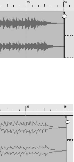
To graphically time-stretch audio in the Sequence Editor:
1. Open the Sequence Editor from the Project menu by choosing Project 4Sequence.
You can also use the default keyboard shortcut ShiftþS.
2. Locate the soundbite you want to time-stretch and place the cursor at the left or right
edge of the soundbite (just below the Fade handles). Once in position, you should
see the cursor change to the Hand tool, as shown in Figure 13.24.
3. Once the cursor switches to the Hand tool, click and drag the soundbite to time-stretch
or time-compress it, as shown in Figure 13.25. How far you drag with the Hand
tool will determine the duration of the time-stretched audio.
4. Release the mouse, and DP will begin time-stretching the audio.
Soundbites currently being processed will appear with their waveforms displayed as outlines.
Once the time-stretching is completed, the soundbite will update and appear as a solid waveform
display. Keep in mind that this is a constructive process, so DP will create a new time-stretched
version of the soundbite to replace the original audio. DP will add a number to the end of the
soundbite name (such as audio.1, audio.2, audio.3, and so on) to designate it as an alternative
version.
Figure 13.24 Position the cursor over a soundbite’s title bar to switch to the Hand tool.
Figure 13.25 Drag with the Hand tool to time-stretch a soundbite. Soundbites being time-stretched
will appear with an outlined waveform display.
454 Digital Performer 6 Power!: The Comprehensive Guide
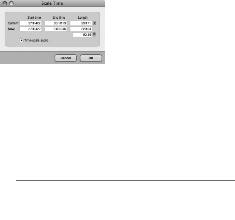
The Scale Time Command
The Scale Time command, shown in Figure 13.26, allows you to time-stretch (or time-scale)
selected audio and/or MIDI data—even at the same time.
The Scale Time command is divided into three separate columns that show the start, end, and
length of the current selection (which is the first row showing the current time-range selection)
and the new time-stretched selection (which is what the selection will be time-scaled to after you
hit the OK button). Be aware that you cannot change the current selection values from within
the Scale Time window. (These values will appear dimmed.) You must make a new time-range
selection within an editor window in order to change the current selection values.
There are two settings that will impact whether audio can be time-stretched with the Scale Time
command: the Scale Time command’s Time-Scale Audio option and the soundbite’s Time Com-
press/Expand setting (explained earlier). Both settings/options must be enabled in order for DP
to time-stretch a soundbite. If the Time-Scale Audio option is turned off, DP will only change the
start time of the selection, leaving the soundbite’s current duration intact.
Time Compress/Expand Is Enabled by Default Keep in mind that the Time Compress/
Expand setting (located in the Info Pane of the Soundbites window) is enabled on all
soundbites by default, so you shouldn’t have to worry about this PureDSP attribute
under normal circumstances.
To time-stretch audio using the Scale Time command:
1. Start by selecting the soundbite you want to time-stretch.
2. Enter the desired value in the New Start Time, End Time, or Length column. If you only
want to change the actual duration of the soundbite while preserving its start time,
change the End Time or Length value. You’ll notice that the End Time and Length input
fields are linked together for greater flexibility.
Figure 13.26 The Scale Time command window.
Chapter 13 Processing and Mastering 455

3. You can also click the Percentage button, located below the New Length field, to
change the input field from a percentage value to a scale factor (or ratio), as shown
in Figure 13.27.
4. Set the ratio for the time-stretching in the Scale by a Factor Of input fields.
5. Enable the Time-Scale Audio option and click OK.
Mastering
As explained earlier in this chapter, the mastering process requires skill and experience to per-
form it correctly. An ideal situation would allow for your final mixes to be sent to a professional
mastering engineer (of course, depending on your budget). There will be times, however, when
you will need to master in Digital Performer. Many of DP’s standard mixing and editing features
(such as the master fader track, plug-in processing, the Waveform and Sequence Editors, and so
on) can be used in the DP mastering process. Keep in mind that there really isn’t a special way to
configure a DP project for mastering. DP mastering methods and setups vary from user to user
and project to project.
If you’re new to the concept of mastering, you probably have a million questions, such as,
“When should I EQ?” “Should I compress or limit my mix?” “How loud should I make my
mastered mixes?” and “What is brickwall limiting?” Unfortunately, standard answers or step-
by-step processes do not really exist. Every mix will be different, and experience will tell you
what needs to be accomplished and what specific tools you can use to achieve the best results
with the least amount of compromise.
A detailed tutorial of processing scenarios during the mastering stage is far beyond the scope of
this book. This section will attempt to provide a very basic understanding of the procedures
involved with music mastering and provide a few suggestions for mastering audio within DP.
In addition, and if your budget allows, I highly recommend picking up a copy of the Bob Katz
book Mastering Audio: The Art and the Science (Focal Press, 2007). This text—albeit advanced
and sometimes perplexing—serves as a great guide for learning about all of the “mysterious”
aspects of mastering. I keep my battered copy right next to my mixing console!
Before you dive into these concepts, I’ll discuss some technical aspects of mastering in Digital
Performer.
Figure 13.27 Click the percentage button to toggle the values displayed in the Scale by a Factor Of
input fields. This allows you to time-stretch audio by a specific ratio or scale factor.
456 Digital Performer 6 Power!: The Comprehensive Guide
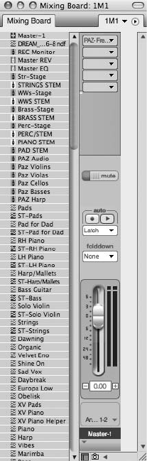
The Master Fader
DP’s master fader track, shown in Figure 13.28, is used to control the overall level of a specific
bus or output assignment. Unlike audio and aux tracks, master faders do not have sends, record,
or solo buttons.
You can use DP’s master fader to apply processing or control the levels of an overall mix, either
during the actual mixing process or during the mastering stage. The procedures for using a mas-
ter fader are the same regardless of the type of situation you are working with.
To insert a master fader:
1. Create a master fader by choosing Project 4Add Tracks 4Master Fader Track.
You can also use the default keyboard shortcut ShiftþControlþM.
Figure 13.28 DP’s master fader track.
Chapter 13 Processing and Mastering 457

2. Assign the output of the master fader to the output of the other tracks in your project.
For example, if the audio track you are working with is assigned to Analog 1-2,
assign the master fader to Analog 1-2 as well.
Setting Up the Master Fader I suggest that the master fader be one of the first tracks you
create in your Digital Performer project. When assigned to the mix output, this fader will
allow you to control the overall volume of your entire mix. Because it also contains an
Insert and Automation section, you can apply effects processing across your entire mix
and even automate a fade-out of the song. In addition, you can use the master fader level
meters to monitor the overall levels of your mix—ensuring that you do not overload the
mix outputs, which can result in degraded audio integrity and unwanted digital distortion.
Once the master fader is created, you can usually set it to unity gain and then forget about
it. Usually, you must start working with this fader only when the mixing process begins.
Mastering in DP
There is no set way to configure a project for mastering. Circumstances will dictate your specific
setup and processing configurations. Following are just a few scenarios illustrating how you
might set up your project for mastering in Digital Performer:
nYou want to perform a quick “mastering” job on a demo you’ve been working on, so
you insert a compressor (such as a UAD Fairchild or a Waves Renaissance Compressor)
and a brickwall limiter (such as the MasterWorks Limiter or the Waves L3) on the master
fader. You add some light mix bus compression (1.5.1:1 ratio with 1 to 3 dB of gain
reduction) and turn the threshold down on the limiter to make your mix louder (3 to 6 dB of
limiting). You bounce to disk and then burn a disc at 52 speed.
nYou need to master a number of songs for an album, so you import each song into DP
at 24-bit/48-kHz, which will allow you to process the tracks at a high resolution. You
work within the Waveform Editor and tweak the balance of each song by applying subtle
amounts of EQ and/or compression, using Audio 4Audio Plug-Ins, starting with the
most important song. With the first track as your guide, you make any necessary adjusts
to the remaining tracks. Next, you add brickwall limiting (and 16-bit dithering) to the
track you started with. Using this track as a reference, you jump between the other songs as
you limit them, adjusting the perceived loudness of each track in relation to one another.
You also make any necessary head/tail edits and add quick fades to the beginning and end of
each soundbite. You make sure to apply any fades at the last stage of the processing.
You then perform real-time recordings of each edited and processed song or you bounce
them all to disk. At last, you convert the sample rate of each 16-bit file to 44.1 kHz
(explained in the “Sample Rate or Format Conversion” section of this chapter), export
each processed track, and import the tracks into a CD burning program, such as Toast or
458 Digital Performer 6 Power!: The Comprehensive Guide

Jam. You set the track gaps as you listen back to each track, and then you burn a disk at
4speed.
nThis scenario is similar to the previous one, except that you place all your import songs onto
their own separate audio tracks within separate Chunks instead of working in the Waveform
Editor. Each Chunk contains an audio track (which contains a song) and a master fader.
You set up your workspace so that you can view all your Chunks at once, allowing you to
quickly jump between and play back each song in your album. When you start processing
your songs, you use the real-time inserts on each master fader instead of destructively
processing in the Waveform Editor. This setup allows you greater flexibility because you
can tweak the processing for each track in real time while jumping between the various
songs. The processing is intensive because you have multiple Chunks with the same effects
plug-ins duplicated multiple times across different tracks, but you have the RAM and
processing speed to handle it.
Processing Your Final Mix
When you think of the goal of music mastering, the first thing that may come to mind is making
your mix louder. Anyone who has ever A/B’d (compared) one of his or her finished mixes with a
professionally mastered mix knows exactly what I’m talking about. Other goals that may come to
mind are balance, clarity, and punch. You can use processing in the mastering stage of music
production to achieve these goals. Equalization, compression, volume automation, and brickwall
limiting are some of the tools used by mastering engineers to shape a track or set of tracks. Regard-
less of the types of processing you choose to incorporate, here are a few tips to keep in mind:
nStart subtly. Even the subtlest of changes can be perceived when working on a two-channel
mix (or a multichannel mix). Start with gentle processor settings and go from there.
nA/B. The best way to check whether you’re making positive changes is to bypass the plug-in
you’re working with and compare the processed sound to the original mix.
nKeep a reference track. Keep a professionally mastered track nearby of the style of music
you are working with so you can quickly reference it (or use it as a standard) as you master
your own mix.
The A/B Process Even if you’re not familiar with the term A/B, chances are that you’ve
been using this process for a long time without knowing it. When you compare one file (or
track, mix, setting, and so on) against another file, you are A/Bing the file. This applies
even to situations in which you’re comparing more than two things.
In addition to effects processing and editing, you’ll also have to consider dither and sample rate
conversion, which are necessary to get your high-resolution mix (for example, 24-bit/96-kHz)
Chapter 13 Processing and Mastering 459
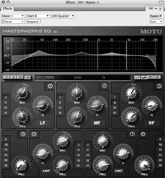
into the 16-bit/44.1-kHz CD standard if you’re going to be burning CDs. Dithering and sample
rate conversion are discussed in the “Dither and Noise Shaping” and “Sample Rate or Format
Conversion” sections of this chapter.
Equalization
Tonal balance is one of the important components of a good mix. Too much bass and too many
low-mid frequencies can make a song sound muffled or muddy. Too much energy in the high
frequencies can have the opposite effect, making a mix sound thin and overly bright, while too
much of the high-mid frequencies can make a mix shrill and bitey or even painful to listen to. In
the ideal world, any obvious balance problems would be taken care of during the mix, or the
track would be sent back for a re-mix if the mastering engineer requested it. There will be many
times, however, when you will have to fix it in the mastering.
You can use equalization, or EQ, to subtly change the tone of a track or to surgically “fix”
frequencies that stand out in a mix. Keep in mind that some EQ plug-ins will do a better job
at certain tasks than others will. The MasterWorks EQ, shown in Figure 13.29, is an example of
an EQ that can be used for both subtle and surgical corrections.
Figure 13.29 The MasterWorks EQ.
460 Digital Performer 6 Power!: The Comprehensive Guide
Here are a few thoughts and suggestions for using EQ in the mastering process, regardless of
which type of EQ plug-ins you decide to use.
nLow frequencies. Extremely low frequencies contain a lot of energy, as you must turn them
up louder compared to other frequencies in order to hear them. This can cause the low
end to consume the precious headroom of a mix. Try inserting a low-cut filter at 40 Hz or
below to control the low end of your mix. Because this type of low-frequency roll-off will
affect other elements in your mix (not just the kick and bass), you may want to start the
EQ shelf at 20 Hz and slowly raise the frequency, stopping when you hear the filter starting
to adversely affect the mix.
nEQ—surgery versus subtlety. If you have specific frequencies that need to be tamed without
affecting other surrounding frequencies, you can use an EQ band set to a narrow Q.
Remember that the Q (or bandwidth) determines how many frequencies surrounding the
center frequency will be affected—the higher the Q, the narrower the bandwidth, and
vice versa. If you need to gently shape the sound, try using an EQ set to a wide band, or
smaller Q.
nCause and effect. Be aware that EQing not only affects the specific frequencies you’re
working with, but it also changes how other related frequencies (or instruments) are per-
ceived in a mix. EQing the bass, for example, can cause the cymbals to sound less bright or
can cause the vocal to lose presence. Always be aware of the EQ relationships of a mix
before you start twisting those knobs.
Compression versus Limiting
When should you compress? When should you limit? Generally speaking, compressors are used
to reduce the overall dynamic range of a signal by making the louder sounds quieter in relation
to the softer sounds. Compressors can be used to also change the character of a signal’s sound by
strengthening the low- or mid-level passages. Limiters are basically compressors that are set to a
harder ratio (the amount of output level change that results from a given input level change),
such as 10:1 or 20:1. Limiters are typically used when you want to make a signal louder while
maintaining transparency and without significantly changing the overall sound of a signal.
Brickwall limiters are a special form of limiter that increases the apparent loudness of a
sound in proportion to the amount of limiting that is applied. The lower the threshold (the
level at which the limiter starts working), the louder the sound will be. The brickwall limiter
is typically found at the very end of a mastering signal chain.
As you may already know, compressors and limiters come in many different flavors. Some com-
pressor plug-ins are designed to handle broadband material with great results. Universal Audio’s
Fairchild and Waves’ C4 Compressor (shown in Figure 13.30) are two such plug-ins.
Multiband Compression. DP’s MasterWorks Compressor is also effective when working with
mixed material, but it operates differently than a standard compressor. The MasterWorks
Chapter 13 Processing and Mastering 461
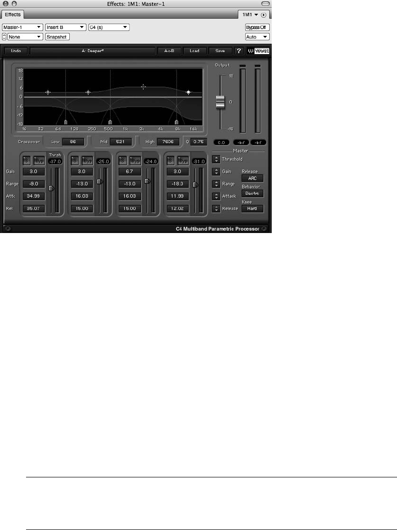
compressor, shown in Figure 13.31, is a multiband compressor. Multiband compression basi-
cally splits a signal into multiple frequency bands (typically three to four bands) and compresses
them independently of one another, allowing you, for example, to compress only the low fre-
quencies of a mix while leaving the high frequencies intact.
Brickwall Limiting. As discussed earlier, a brickwall limiter is a special type of limiter that
makes a sound louder by limiting its transient peaks and raising the gain of the sound. Lower
the limiter’s threshold by 3 dB, and the gain of the signal will be raised proportionally by 3 dB.
The limiter’s threshold sets a ceiling for the sound that acts as a “brick wall,” completely stop-
ping any part of the signal from going over the specified threshold. Waves L3 Ultramaximizer,
shown in Figure 13.32, is an example of a brickwall limiter.
Many brickwall limiting plug-ins also provide controls for dithering and noise shaping your
high-resolution files from 24 bits to the 16-bit CD audio standard (explained in the next sec-
tion). Use the dithering options only when the plug-in is the last step in your processing chain.
Dither should always be applied at the very final stage of the mastering process.
Over-Limiting Your Mix! As with any useful tool, applying too much limiting to a sound
can have very negative effects on the audio quality. Besides the introduced harmonic dis-
tortion, excessively loud musical material can be fatiguing to the ear.
Figure 13.30 Waves’ C4 Compressor.
462 Digital Performer 6 Power!: The Comprehensive Guide
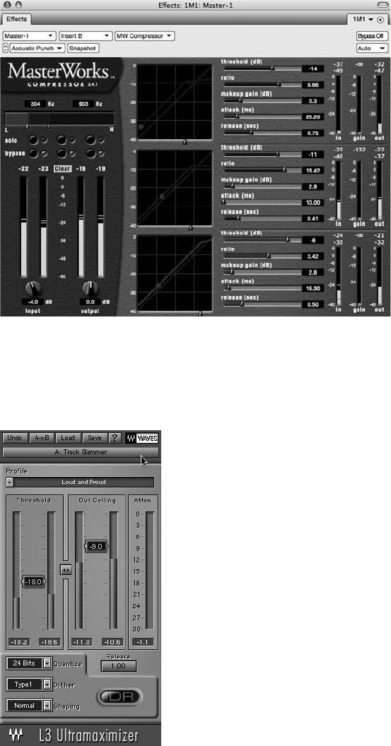
Figure 13.31 Digital Performer’s MasterWorks Compressor plug-in.
Figure 13.32 Waves L3 Ultramaximizer is an example of a brickwall limiter.
Chapter 13 Processing and Mastering 463

Compressing the Mix Bus with 2-Mix Compression The 2-mix is another name for your
overall stereo mix. The mix bus refers to the bus or output that is used to sum the indi-
vidual tracks in your mix down to two channels (or more) of audio. So when you hear the
phrase 2-mix compression or mix-bus compression, what people are referring to is the
compression that is applied to your entire mix.
As with many audio engineering practices, there are many different schools of thought
on mix-bus compression. Some feel that this type of compression should be saved for the
mastering engineers, while others like the effect it has on their mixes.
If you’re mixing and mastering your own tunes, however, you may find yourself using
mix-bus compression along with other effects plug-ins—almost mastering your tunes
during the mix process. As I mentioned earlier in this chapter, when and how you decide
to approach mastering your mixes in DP is entirely up to you and will be determined by
an indeterminate number of always varying factors.
Dither and Noise Shaping
A digital audio signal is described as a string of ones and zeros. In digital terms, the dynamic
range of an audio signal is called bit depth (alsoreferredtoasthesample format or resolu-
tion). CDs use a 16-bit format, while DP internally operates at a resolution of 32-bit floating
point. (See the “Bit-Depth Basics” note of Chapter 5 for more details.) Any time you reduce
the bit depth of an audio file (such as when you are bouncing your mix to 16-bit/44.1-kHz to
use in an audio CD), quantization distortion is introduced during the conversion process.
Dither is the small amount of noise that is applied to a signal when its sample format is
changed in order to reduce the amount of this quantization distortion. Since dithering actu-
ally adds noise (and raises the noise floor in the process), noise-shaping algorithms are usu-
ally employed to make this added noise less obvious (and more pleasant-sounding) to the
listener.
DP’s MasterWorks Limiter (along with many other brickwall limiters) contains options for dith-
ering and noise shaping your high-resolution signal to lower bit depths. You should always try to
mix/master at the highest resolution possible to maintain the integrity of the sound, dithering
and noise shaping at the final stage of the production process to bring your high-resolution audio
files back into the 16-bit/44.1-kHz world of CDs.
If you plan to send your mixes off to be mastered by someone else, don’t apply any dither or
noise shaping to your audio! Simply keep your mix at the highest resolution possible and let the
mastering engineer deal with this process. In addition, leave at least 2 to 3 dB of headroom on
your master fader, and make sure it doesn’t overload (go over digital 0) at any point in the
mixdown process!
464 Digital Performer 6 Power!: The Comprehensive Guide
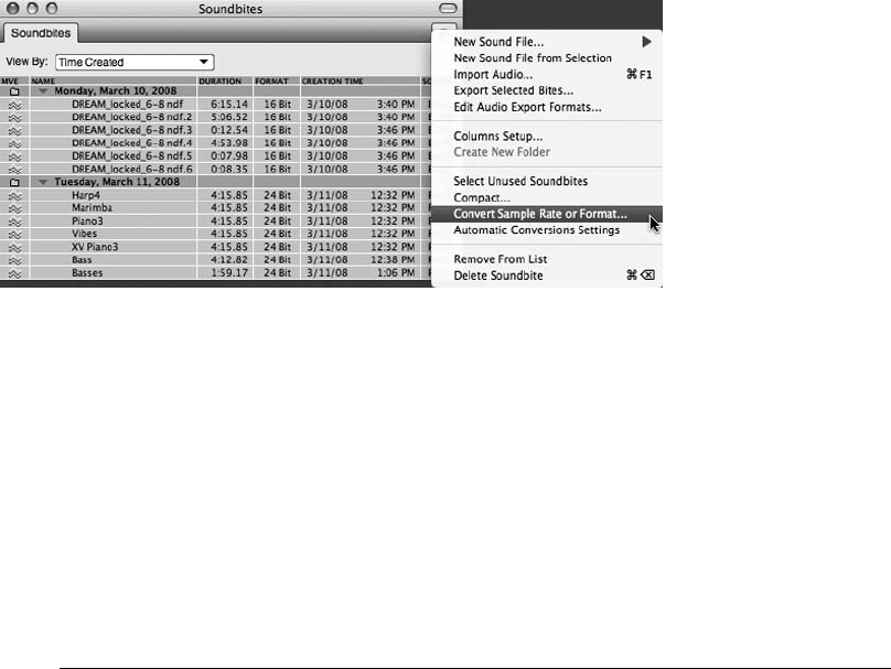
Sample Rate or Format Conversion
In Digital Performer, you can change the sample rate or format (bit depth) of an audio file with
DP’s Convert Sample Rate or Format command, located in the mini-menu of the Soundbites win-
dow. Remember that standard CD audio operates at 44.1 kHz, so if your project is running at a
higher rate (such as 48, 88.2, or 96 kHz), you’ll need to “down-sample” your mixes when attempt-
ing to burn a CD. If convenience is a factor (suppose you just want to burn a quick demo of a song),
you may be able to rely on your CD burning program to convert the sample rate for you. The
results will vary, of course, depending on the sophistication of the program you are using.
To use DP’s Convert Sample Rate or Format command, simply select the soundbite you want to
convert from the Soundbite List and choose the Convert Sample Rate or Format command from
the Soundbites window’s mini-menu, shown in Figure 13.33. In the Audio File Conversion win-
dow, enter the new sample rate for the soundbite, choose the conversion quality, and then spec-
ify what happens to the soundbite after it is converted (shown in Figure 13.34).
Bouncing to Disk
Once you have mixed/mastered your project, you’ll need to bounce your tracks to disk. The
bounce-to-disk process basically takes multiple selected tracks and merges them together into
a single track on your hard drive. Think of this as a mixdown process. Bouncing to disk is a
constructive process, creating a new audio file while keeping your original tracks intact. There
are two methods for bouncing to disk—using the Bounce to Disk command or using a real-time
recording. Before you can use the Bounce to Disk command, you must first select the audio you
want to bounce.
Bouncing MIDI Tracks? If you want to include your MIDI tracks in your final mix, there are
times when you must convert them to audio first. If you’re using MIDI tracks that are
assigned to outboard MIDI sound modules or ReWire instruments, follow the procedures
Figure 13.33 Use the Convert Sample Rate or Format command in the Soundbites window’s mini-menu
to change the sample rate or bit depth of an existing soundbite.
Chapter 13 Processing and Mastering 465
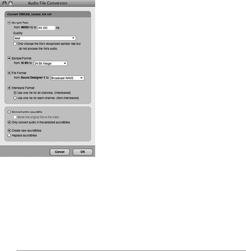
for recording MIDI tracks into audio tracks (explained in the “Recording MIDI Tracks into
Audio Tracks: The Basics” tip in Chapter 9). If you’re running virtual instruments in real
time, use the Audio menu’s Freeze Selected Tracks command to convert them to audio
tracks before attempting a bounce. However, if you are taking advantage of DP’s new
pre-gen feature (as discussed in Chapter 9’s “Pre-Rendered Instrument Tracks (MOTU’s
Pre-Gen)” section), there is no need to convert them to audio first—go ahead and include
them in your bounce! Although most MAS and AU plug-ins are compatible, be sure to
verify that your MAS and AU plug-ins support this feature.
The Bounce to Disk Command
The Audio menu’s Bounce to Disk command, shown in Figure 13.35, provides several options
for specifying the final format of your bounced audio file.
nFormat. This menu, shown in Figure 13.36, allows you to specify the format for the bounce
file. You can choose from a variety of formats or select Project Format if you want to use the
current project’s settings as a basis for your bounce. You can also bounce files to a variety of
different stereo-interleaved Core Audio formats supplied by Mac OS X.
Figure 13.34 The Audio File Conversion window.
466 Digital Performer 6 Power!: The Comprehensive Guide
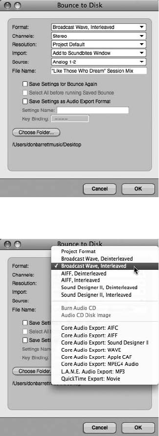
nChannels. This menu, shown in Figure 13.37, determines the channel format for the Stan-
dard Format (SD II) format option. Its options are:
nMono (No Attenuation). This option will create a mono sound file on your hard drive by
summing together the left and right channels. This audio summing will result in an
increased signal level of the file.
Figure 13.35 The Bounce to Disk command.
Figure 13.36 The Bounce to Disk command’s Format menu.
Chapter 13 Processing and Mastering 467
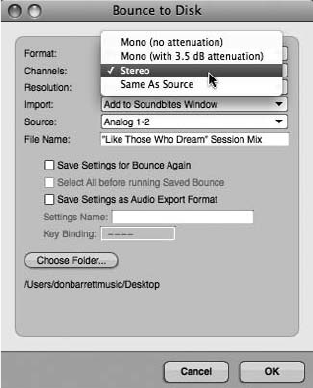
nMono (with 3.5 dB Attenuation). This option creates a summed mono audio file,
but compensates for the 3.5-dB increase that is a result of the mono-summing
process.
nStereo. Use this option to create a stereo file. If Interleaved is selected in the Format
menu, an interleaved stereo file will be created. If Deinterleaved is selected in the
Format menu, two separate mono files labeled with .L and .R extensions will be
created.
nSame as Source. This option creates a file that has the same channelization as the output
(or bundle) selected in the Source menu.
nResolution. The Resolution menu allows you to set the sample format (or bit depth) of the
bounced file. Choices are 8-, 16-, 24-, and 32-bit floating point. Under normal circum-
stances, you’ll probably want to choose the sample format that your project is already in
(Project Default).
nImport. The Import menu determines what happens to the new file that is created as a result
of the bounce-to-disk process. Choose Do Not Import if you only want to create the file
on your hard drive. Use the Add to Soundbites Window option to add the bounced file
to the current project’s Soundbite List. Select Add to Sequence to create a new audio track
in the current sequence that contains your bounced file.
nSource. Select the source for the audio bounce from this menu. For example, if you have your
tracks all assigned to output Analog 1-2, choose Analog 1-2 from the drop-down menu.
Figure 13.37 The Channels menu provides options for specifying the channel format for DP’s native
non-interleaved SD II format.
468 Digital Performer 6 Power!: The Comprehensive Guide
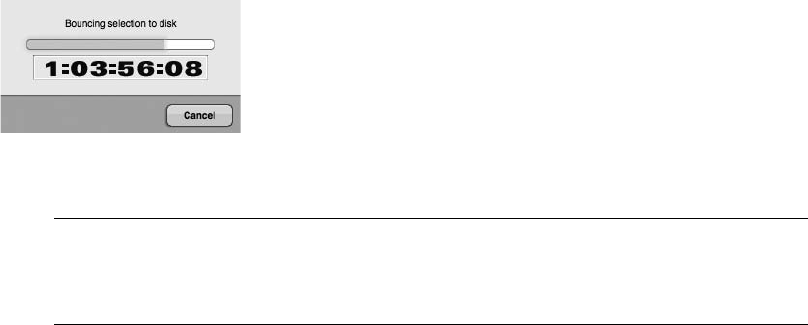
nFile Name. This is the name for the final bounce file. If needed, the appropriate extensions
(such as .aiff and so on) will be automatically added to the newly created audio files.
nChoose Folder. This is the location for the new files that will be created during the audio
bounce. By default, the current project’s Audio Files folder will be selected. Click the Choose
button to manually set a location for the bounced files.
To bounce an audio selection to disk:
1. Start by assigning all of the tracks you want to include in your bounce to the same
output or bus pair.
2. Next, make a time-range selection in your sequence.
3. Select the soundbites you want to include in your bounce by Shift-clicking on the appro-
priate track names in the Tracks List.
4. Once the soundbites are selected, choose Audio 4Bounce to Disk.
5. Make the desired Bounce to Disk settings (discussed earlier) and click OK.
Once you click OK, DP will begin bouncing the audio selection to disk. The Bouncing Selection
to Disk progress window will appear and display the progress of the bounce (see Figure 13.38).
In most situations, DP will bounce audio faster than real time. This really depends on the speed
of your computer, the number of tracks, and the number of plug-ins that DP must process during
the bounce.
Bounce to Disk Is Not a Background Process The bounce-to-disk process occurs in the fore-
ground, so you will not be able to perform any other operations while DP is bouncing
tracks to disk.
Bouncing Directly to an Audio CD or Disk Image
You may have noticed two additional options in the Bounce to Disk window. Burn Audio CD
and Audio CD Disk Image are new features that allow you to bounce selections directly to an
Figure 13.38 The Bouncing Selection to Disk progress window.
Chapter 13 Processing and Mastering 469
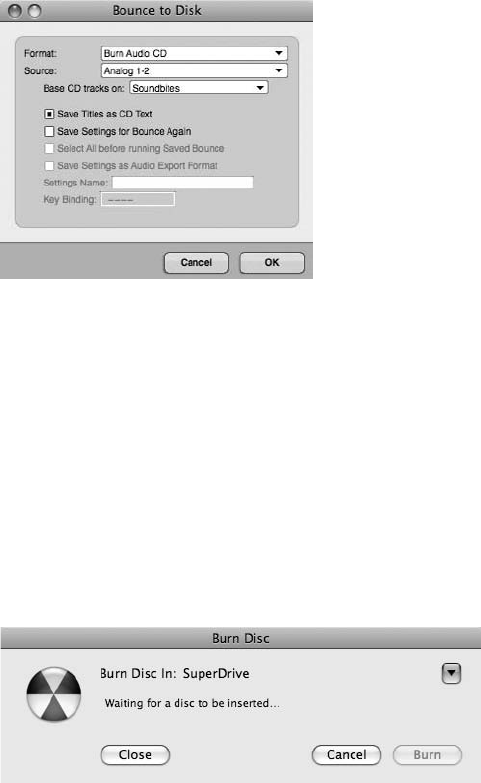
audio CD or disk image (see Figure 13.39). You can create a quick reference CD containing one
track, or you can create a CD with multiple tracks (including track titles). In addition, you can
define the pre-gap amounts (blank time between tracks) in the Set Gap Between Soundbites
command in the Region menu.
The Base CD Tracks On menu allows you to specify the start of each track. Here you can choose
Soundbites, Markers, or Soundbites and Markers. Once you have made your selection and
pressed OK, the Bouncing Selection to Disk progress window will appear and display the prog-
ress of the bounce. When it is finished, a Burn Disc window will appear, asking you to insert a
blank disc so the burning process can be completed (as shown in Figure 13.40). Naturally, this
feature utilizes your built-in or installed disk burner, such as Apple’s Superdrive. If you would
like to bounce a selection to disk but burn your CD at a later time (or in a different CD burning
program), simply choose Audio CD Disk Image (rather than Burn Audio CD) in the Format
menu. This will create a disk image on your hard drive that you can burn at your convenience.
Real-Time Recording (Printing Your Mix)
Real-time recording is very similar to our recording audio discussion in Chapter 7. Instead of
using the Bounce to Disk command to create a mixdown, selected tracks are routed to a new
audio track within DP and recorded in real time. If you have virtual instrument tracks in your
session and you don’t want to freeze each track, then use the real-time recording process, which
Figure 13.40 A Burn Disc window appears after the Bounce Selection to Disk progress window has
finished.
Figure 13.39 The Burn Audio CD option in the Bounce to Disk window allows you to bounce a selec-
tion directly to an audio CD!
470 Digital Performer 6 Power!: The Comprehensive Guide
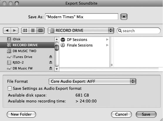
will create a new track of your entire mix that also includes the audio outputs of your virtual
instruments.
To perform a real-time recording of your entire mix:
1. Start by changing the output assignments of the tracks you want to include in the
real-time recording to a new bus (for example, Bus 1-2). Don’t forget to include any aux
tracks that are being used to monitor MIDI tracks!
2. Create a new stereo audio track and assign its input to Bus 1-2. (Remember to name
it accordingly, such as Rough Mix or Final Mix 1.)
3. Arm the track and begin recording. Use the Audio Monitor or Meter Bridge to verify the
signal and its levels (as discussed in the “Audio Monitor Window” and “The Meter
Bridge Window” sections in Chapter 7).
4. Look for the new audio file in the Soundbites window when the recording process
is finished.
Exporting Audio
DP’s Export Selected Bites command, located in the Soundbites window mini-menu, allows you
to export existing soundbites to a variety of different file formats. This command is different
than the Audio menu’s Bounce to Disk command, which creates new soundbites from selected
tracks. Use the Export Selected Bites command to open the Export Soundbite window, shown in
Figure 13.41, to export soundbites selected within the Soundbites window to a different file
format or hard drive location.
Figure 13.41 The Export Selected Bites command is used to open the Export Soundbite window in
order to export selected soundbites to different file formats.
Chapter 13 Processing and Mastering 471
Exporting and Bouncing to the MP3 Format
Digital Performer can export or bounce to disk in the MP3 format—simply choose the MP3
option when bouncing or exporting audio files to disk. Before you can begin using this feature,
however, you must install the LAME MP3 codec, which you can find on the web. This
open-source MP3 encoder does not come bundled with DP and will not be installed during
the Digital Performer installation process.
LAME Framework
There are many different sites from which you can download this codec. Simply perform a web
search for the Mac OS X–compatible version of the LAME codec (or the LAME framework) and
download it to your computer. Once it’s downloaded, place the LAME framework file in the
System 4Library 4Frameworks folder.
When the LAME framework is installed and your computer is restarted, the LAME MP3 option
will become available in both the Bounce to Disk and the Export Selected Bites commands.
Converting to AAC with iTunes
If you don’t want to use Digital Performer to export to MP3, or you would rather convert your
mix to the AAC format instead, you can use Apple’s free iTunes music player. Keep in mind that
the audio file must be in a supported iTunes format: MPEG-4, AIFF, WAV, MP3, or AAC.
To convert an audio file to the AAC format with iTunes:
1. First, drop your bounced mix into the iTunes window to import your song into iTunes.
2. Once it is imported, highlight the track in the list of your iTunes tracks.
3. Select Create AAC Version from the Advanced menu.
4. iTunes will create a new audio file in the AAC format. Once created, the audio file will
appear in the list and in the iTunes Library.
Summary
Processing and mastering are especially intricate and complex music production processes. Digital
Performer contains many specialized tools to help you with these types of work—from the
MasterWorks Limiter to the comprehensive Bounce to Disk and Export features. It takes a
lot of time and training to obtain the proper skills and experience necessary to perform these
jobs well. If you’re new to the processes discussed in this chapter, fear not—practice makes
perfect. For those users who are already working in these fields, you’ll find that DP contains
a wealth of valuable tools and feature sets that will allow you to perform many of these complex
tasks with relative ease.
472 Digital Performer 6 Power!: The Comprehensive Guide

14 Music Notation
Music notation is a visual language and, like any language, it takes time to develop a
full understanding of how to read and write it. To create a notated score or part, you
do not need to be an expert in music theory; however, familiarizing yourself with
notation methods and associated terms (for example, staves and brackets, margins, clefs, ledgers,
codas, alternate endings and repeats, accidentals, and so on) will definitely accelerate your mas-
tery of this comprehensive process.
Although you won’t find Digital Performer’s notation features to be as sophisticated or extensive
as state-of-the-art notation programs, such as Sibelius or MakeMusic’s Finale, you can still cre-
ate competent and effective-looking scores and parts. In DP, MIDI tracks can be viewed as stan-
dard music notation within the Notation and QuickScribe Editor windows. The Notation Editor
displays a single MIDI track as a scrolling grand staff, while the more accommodating Quick-
Scribe Editor displays single MIDI tracks as notation or multiple MIDI tracks as full scores. In
this chapter, I will introduce you to the basic notation options provided within the QuickScribe
Editor. For a look at Digital Performer’s more advanced notation features, such as score arrang-
ing, transcription, markers, and time-anchored text, consult the “Notation Editor” and “Quick-
Scribe Editor” chapters of your DP User Manual.
Here are some of the topics covered in this chapter:
nHow to customize a score or an individual track
nHow to use the QuickScribe Editor’s Tool and Dynamics palettes
nHow to insert key, meter, and tempo changes
nHow to insert dynamic symbols
nHow to print a score
The QuickScribe Editor
The QuickScribe Editor, shown in Figure 14.1, is similar to the standard Notation Editor, but it
offers more advanced features for greater control over the way notes are displayed within a part
(a single track) or a score (multiple tracks).
473
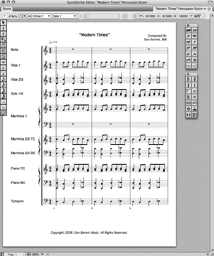
Unlike the Notation Editor, the QuickScribe Editor provides a Tool palette from which you can
choose specific note values when inserting notes and arrangement tools for controlling brackets
and braces. It also offers tools for changing the spelling of accidentals, as well as inserting text,
page numbers, and the current date. In addition, the QuickScribe Editor provides mini-menu
options for customizing the look of individual parts and entire scores (see Figure 14.2), along
Figure 14.1 The QuickScribe Editor’s various tool palettes and advanced features offer greater control
over the notation of individual parts and scores than the standard Notation Editor does.
474 Digital Performer 6 Power!: The Comprehensive Guide
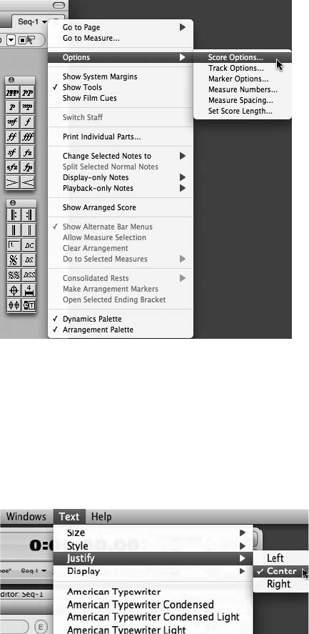
with the ability to display film cues to assist film composers in the film-scoring process. Once the
QuickScribe Editor is open, a specialized Text menu will appear between Digital Performer’s
Windows and Help menus, as shown in Figure 14.3.
Customizing the Appearance of a Score
The Score Options window, shown in Figure 14.4, contains various choices for controlling how
a score’s different elements are displayed. Instead of simply providing a list of the various
options contained in the Score Options window, I’ve decided to explain many of the important
options in the context of the score creation process.
Figure 14.2 The Options submenu in the QuickScribe’s mini-menu provides various options for control-
ling the look of individual parts and scores, how the transcription engine handles MIDI data, and the
overall length of a score.
Figure 14.3 The Text menu in DP’s title bar is only visible when the QuickScribe Editor is open.
Chapter 14 Music Notation 475
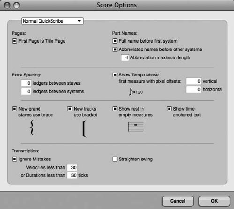
The Different QuickScribe Views
Digital Performer allows you to view your QuickScribe scores in three different ways: the
Normal QuickScribe view, the QuickScribe þFilm Cues view, and the Film Cues Only view.
Each view maintains its own set of independent QuickScribe options. Some windows in parti-
cular (such as the Score Options, Marker Options, Measure Numbers, and Measure Spacing
Options windows) provide a QuickScribe View pop-up menu so you can specify the particular
QuickScribe view.
The Title Page
A score’s title page is typically different than its normal body pages. In addition to the title
(which may or may not appear within the body pages), other text elements, such as subtitles,
composer credits, lyrics, and copyright notices, may appear on this page. Digital Performer pro-
vides tools for adding text, as well as the ability to adjust the system margins of the page to make
room for these extra elements.
To customize the title page of a score:
1. Open the Score Options window by choosing Options 4Score Options from the
QuickScribe Editor’s mini-menu.
2. Click the First Page Is Title Page option. This will allow you to format the first page
of the score differently from the other score pages. You can even adjust the system
margins on the title page separately from the body pages.
Figure 14.4 The Score Options window.
476 Digital Performer 6 Power!: The Comprehensive Guide
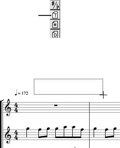
3. Click the Full Name before First System option to display the full name of an instrument
at the beginning of the score. Instrument names are based on individual track names,
so you may need to go back and rename your tracks accordingly.
4. If you would like all other instances of the instrument’s name to be abbreviated, click
the Abbreviated Names before Other Systems option. Next, specify the number of
letters to be used in the abbreviations by typing a number in the Abbreviation
Maximum Length field.
5. If you would like the tempo displayed at the beginning of the score, enable the
Show Tempo above First Measure option.
6. Click OK to confirm the changes.
7. Now enter the title of the page by choosing the Text tool from the QuickScribe
Tool palette (see Figure 14.5).
8. With the Text tool enabled, draw a text box at the top of the title page, as shown
in Figure 14.6.
9. Set the text attributes (for example, the font, size, and justification) from the Text menu.
10. From the Display submenu, choose Both Title & Body Pages (see Figure 14.7). This will
place the title of the score throughout each page of the score. If you only want the
title to appear on the title page, however, choose Title Page Only.
11. Once you have specified the text attributes, type the desired text.
12. Click outside the text box to confirm the entry.
When you are working with text at the top of the title page, you may find that you do not have
enough room to enter other text elements, such as the subtitle, composer, orchestrator, and so
Text Tool
Figure 14.5 The QuickScribe Tool palette’s Text tool.
Figure 14.6 Click and drag with the Text tool to draw a text box.
Chapter 14 Music Notation 477
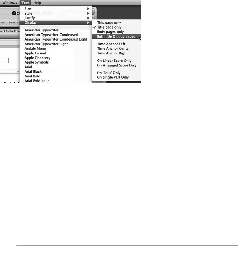
on. Some modern scores may even contain the lyrics for a song on the title page, before the
actual score begins. To get around the space limitations, DP allows you to move the system
margins to make as much room at the top and bottom of your title page as you need to accom-
modate all your text elements.
To adjust the title page’s system margins to accommodate additional text elements:
1. With the title page showing, choose Show System Margins from the QuickScribe
Editor’s mini-menu. The title page will update to display the system margins for the
page (see Figure 14.8). Make sure the First Page Is Title Page option is still enabled in
the Score Options window (explained earlier). If it is turned off, you will affect all pages
within the score!
2. Drag the top horizontal margin toward the middle of the page. The actual music
staves will move toward the bottom of the title page. How far you drag the margin
depends on how much space above the first staves you need for text.
Adjusting Title Page Margins The staves within the title page (as well as in body pages) will
automatically adjust their locations to accommodate the new margin locations, moving to
Page 2 of the score if necessary.
3. If you want to include text elements—such as copyright notices and so on—at the
bottom of the title page, simply drag the lower horizontal margin toward the top of the
title page.
Figure 14.7 The Text menu’s Display submenu provides options for how and where selected text will
appear within a score.
478 Digital Performer 6 Power!: The Comprehensive Guide
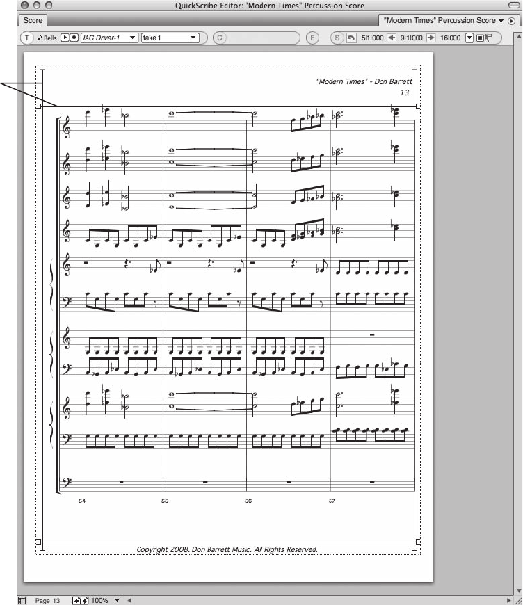
4. When you are finished adjusting the margins, click the Show System Margins
option again to hide them.
5. Enable the Text tool and add any additional text elements as needed. Keep in mind that
the QuickScribe Tool palette will not be available when the mini-menu’s Show System
Margins option is turned on.
System
Margins
Figure 14.8 Enable the mini-menu’s Show System Margins option to display a page’s system margins.
Chapter 14 Music Notation 479
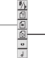
Body Pages
You can also customize body pages to include common text elements that appear on every page.
If the title appears within the body pages, for example, it is sometimes displayed with a smaller
font and in a different location than on the title page. You can also adjust system margins for the
body pages to accommodate any additional text elements.
To add common text elements that appear on all body pages:
1. Begin by adjusting the system margins on the first body page (Page 2 of the score)
to make room for the new text you will be adding. You can choose any body page to
work with, because changes will be global—that is, they will affect all body pages in
the score.
2. Once you have adjusted the system margins, enable the Text tool from the QuickScribe
Tool palette.
3. Click and drag at the desired location to create a text box.
4. Set the text attributes (such as font, size, and justification) from the Text menu, then
enter the text.
5. In the Text menu’s Display submenu, be sure to choose Body Pages Only if you want the
text to appear on every body page in the score.
Inserting Page Numbers and the Current Date
You can insert page numbers and the current date into a score using the Page Number tool and
the Current Date tool, as shown in Figure 14.9.
To add page numbers throughout an entire score:
1. Select the Page Number tool from the QuickScribe Tool palette.
2. Click at the desired location to insert a page number. Once a page number is inserted,
the Page Number tool will revert to the QuickScribe Arrow tool. In addition, DP
will automatically place the correct number on the page and set its Display property to
show the page numbers on both the title and body pages.
3. With the page number still selected, set its other text attributes (such as size, font,
and justification) from the Text menu.
Page
Number
Tool
Current
Date
Tool
Figure 14.9 The QuickScribe Tool palette’s Page Number tool and Current Date tool.
480 Digital Performer 6 Power!: The Comprehensive Guide
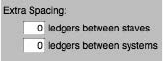
4. When you are satisfied with the text formatting, click anywhere outside the page num-
ber box to deselect it.
To insert the current date:
1. Select the Current Date tool from the QuickScribe Tool palette.
2. Click at the desired location to insert the current date, which is set by the Mac OS. Like
the Page Number tool, the Current Date tool will automatically revert to the Quick-
Scribe Arrow tool once the current date is inserted.
3. With the current date still selected, set the other text attributes (such as size, font, and
justification) from the Text menu. The Display property will automatically be set to
Title Page Only.
4. When you are satisfied with the text formatting, click anywhere outside the current date
box to deselect it.
Ledger Spacing between Staves and Staff Systems
Within the QuickScribe Editor, single tracks are displayed as individual staves, while multiple
tracks are displayed as a grouped-staff system. The Score Options command’s Extra Spacing
section allows you to adjust the spacing between a score’s staves and staff systems, as shown
in Figure 14.10. This will allow you, for example, to make room for dynamic markings, lyrics,
or a track’s extended ledger lines, which will help you create a less cluttered, easily legible score.
These settings are global and will affect all staves and staff systems within a score.
In addition to affecting the global spacing of staves and staff systems, you can also change the
ledger line spacing for individual tracks from the Track Options window (explained later in the
“Inter-Staff Spacing” section of this chapter).
Staff Bracket/Brace Options and Tools
Digital Performer provides different options for controlling how staff brackets and braces are
displayed within a score. The Score Options command lets you choose whether a bracket or a
brace will be used when a new track is created, as shown in Figure 14.11. You can change the
type of staff that a specific track is using—for example, set a MIDI piano track to a grand staff—
from the Track Options window, or you can manually change a track’s bracket or brace setting
Figure 14.10 You can adjust the spacing between a score’s staves and staff system from the Score
Options command’s Extra Spacing section.
Chapter 14 Music Notation 481
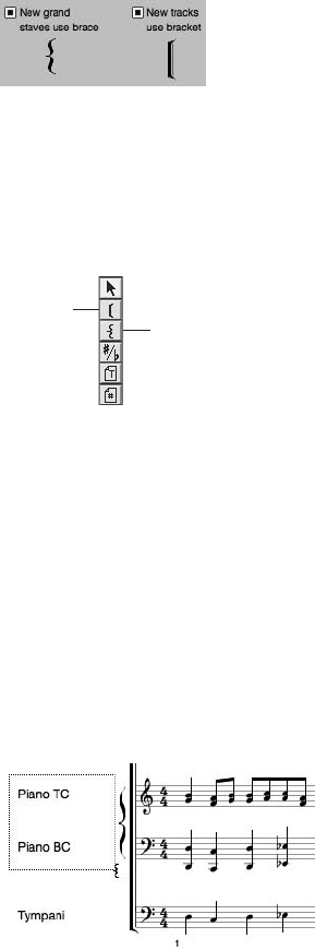
with the QuickScribe Tool palette’s Insert Staff Bracket or Insert Staff Brace tools, shown in
Figure 14.12.
To manually insert, delete, or change the bracket setting for a track:
1. Select the Insert Staff Bracket or Insert Staff Brace tool from the QuickScribe
Tool palette.
2. Once the tool is enabled, draw a box around the name of a track or tracks within
the QuickScribe Editor that you want to affect, as shown in Figure 14.13.
3. The staff bracket or staff brace will be inserted or removed when you release the mouse.
Customizing the Appearance of an Individual Track
The mini-menu’s Track Options window, shown in Figure 14.14, allows you to set the appear-
ance of a score on a track-by-track basis. Options for setting the staff type and clef (treble, bass,
grand, alto, or tenor), part and score transposition settings, as well as inter-staff ledger settings,
can be adjusted for individual tracks.
Figure 14.11 The Score Options command’s staff brackets and staff systems options are used to deter-
mine whether a bracket or a brace will be used when a new track is created.
Insert
Staff
Bracket
Insert
Staff
Brace
Figure 14.12 The QuickScribe Tool palette’s Insert Staff Bracket tool (top) and Insert Staff Brace tool
(bottom).
Figure 14.13 In this example, the Insert Staff Brace tool is used to remove the piano track’s staff
bracket so that it can be replaced with a staff brace.
482 Digital Performer 6 Power!: The Comprehensive Guide
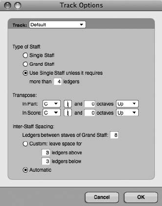
Staff Types and Clefs
The Track Options window’s Type of Staff menu, shown in Figure 14.15, provides a list of
available staves and clefs that can be used within a DP score. This menu is only visible when
an individual track is selected from the Track menu and the Use Default option for the selected
track is disabled.
To set the staff type for an individual track:
1. Choose Options 4Track Options from the QuickScribe Editor’s mini-menu.
2. Select the desired track from the Track drop-down menu.
3. If needed, click the Use Default button to turn off the default settings. Once the default
settings are disabled, individual track options will become available.
4. Next, click the Type of Staff drop-down menu and choose the desired staff or clef
from the list.
5. If you would like to change the staff settings for other tracks, repeat Steps 2 through 4.
6. When you are satisfied, click OK to confirm the changes.
The process of configuring QuickScribe Editor track settings is further simplified by the Use
Default option. When an individual track is set to the Use Default option, its staff and clef settings
are determined by the default track options. You can view and configure the default track options
Figure 14.14 The mini-menu’s Track Options window provides options for controlling the appearance
of individual tracks.
Chapter 14 Music Notation 483
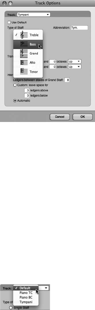
by choosing Default from the Track Options window’s Track menu, as shown in Figure 14.16.
Use this option to automatically assign the following specific Type of Staff settings to tracks in the
QuickScribe Editor:
nSingle Staff. Tracks set to the Use Default option will be displayed with a single staff. DP will
automatically choose the type of clef (treble or bass) that uses the fewest ledger lines,
depending on the MIDI data in the track.
nGrand Staff. Tracks set to the Use Default option will be displayed with a grand staff.
DP automatically splits notes between the treble and bass staves, depending on the MIDI
data in the track.
nUse Single Staff Unless It Requires More Than ___ Ledgers. This option will let DP
automatically use a grand staff when tracks contain notes that exist above the specified
number of ledger lines.
Figure 14.15 The Track Options window’s Type of Staff menu lets you choose a specific staff or clef for
individual tracks.
Figure 14.16 The default track settings can be accessed by choosing Default from the Track Options
window’s Track menu.
484 Digital Performer 6 Power!: The Comprehensive Guide

Transpose Settings
The Track Options Transpose options allow you to set a track’s transposition settings differently
when viewed as individual parts or as part of a score. This is extremely handy when you are creat-
ing full orchestral scores in which the conductor’s score is written in concert pitch and individual
instruments are written in their transposed keys (for example, clarinets scored in the key of Bb).
Transposition settings are only visual and will not affect the actual MIDI data within a track.
Inter-Staff Spacing
The Inter-Staff Spacing options determine how much space (that is, the number of ledger lines) is
created above and below the staves for a specific track. A setting of Automatic lets DP automat-
ically scale the space, depending on the data within a track.
Where Is the Rest Tool? While inserting notes into the QuickScribe Editor, you may have
noticed that there is not a dedicated Rest tool. This is because DP automatically calculates
any rests according to the type of notes that are inserted. However, if a measure is empty
—it does not contain any MIDI data—you will need to choose whether to display these
measures as blank measures or with whole rests. You can do this from the Score Options
window of the mini-menu. Measures that do not contain any MIDI data can be left empty
or set to automatically display a whole rest by enabling or disabling the Show Rests in
Empty Measures option.
Working with Measures
The QuickScribe Editor provides powerful tools for controlling the appearance and visibility of
measures within a score.
Measure Numbers
The Measure Numbers command tells DP how to number measures within a score. Choose
Options 4Measure Numbers from the QuickScribe Editor’s mini-menu to open the Measure
Numbers window, shown in Figure 14.17.
Figure 14.17 The QuickScribe Editor’s Measure Numbers window.
Chapter 14 Music Notation 485
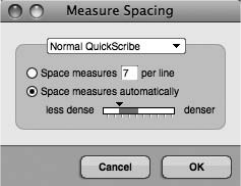
nShow Measure Numbers. Click this option to make measure numbers visible within a score.
n___ Ledgers. These settings determine how many ledger lines above or below the staff
the measure numbers will appear.
nEvery System. Click this option to place measure numbers above or below the first measure
of a staff system.
nEvery Measure. Use this option to number every measure within a score.
nEvery ___ Measures. Use this option to specify how often a measure number is placed in
a score.
Measure Spacing
Use the Measure Spacing command to determine how many measures will appear per staff line.
You can set a specific number or let DP automatically adjust the size of measures according to
the number of notes contained within a measure. Choose Options 4Measure Spacing from the
QuickScribe Editor’s mini-menu to open the Measure Spacing window, shown in Figure 14.18.
nSpace Measures ___ per Line. This option allows you to specify the exact number of
measures that will appear within a staff line.
nSpace Measures Automatically. This option allows DP to automatically control the number
of measures that appear in a staff line, based on the value of the slider. Drag the slider to
the left to create more space between notes in a measure. Drag the slider to the right to
condense notes into a smaller space.
The QuickScribe Tool Palette
The QuickScribe Editor’s specialized notation tools are located in the QuickScribe Tool palette,
shown in Figure 14.19. This palette is permanently docked to the top-left portion of the Quick-
Scribe Editor. Its tools are, from top to bottom, as follows:
nPointer. The Pointer tool is identical to the standard Tool palette’s Arrow tool. Use this
tool to make general selections within the QuickScribe Editor.
Figure 14.18 The QuickScribe Editor’s Measure Spacing window.
486 Digital Performer 6 Power!: The Comprehensive Guide

nInsert Staff Bracket. This tool allows you to insert or remove a staff bracket at the beginning
of a single staff or a system staff (explained earlier).
nInsert Staff Brace. This tool allows you to insert or remove a staff brace at the beginning of a
single staff or a system staff (explained earlier).
nChange Enharmonic Spelling. This tool allows you to change the spelling of accidentals.
Keep in mind that you will need to insert the proper key changes within your score for
notes to be spelled with their proper accidentals as they relate to their respective key
signatures.
nText. Use this tool to draw text boxes and insert text (explained earlier).
nPage Number. Use this tool to insert page numbers in a score. By default, inserting a page
number on one page will automatically place page numbers on all pages of a score. DP
handles the actual page-numbering process, so you don’t have to worry about specifying the
correct page number for a certain page. This tool will revert to the Pointer (Arrow) tool
when a page number is inserted.
nCurrent Date. Use this tool to insert the current date in a score. This tool will revert to the
Pointer (Arrow) tool when the current date is inserted. The current date is set by the Mac
OS.
nNote Durations. The remaining tools allow you to choose specific note values when inserting
notes directly into a score or part. Dot, double dot, and triplet tools are also provided
for further accuracy.
Figure 14.19 The QuickScribe Tool palette provides specialized notation tools for inserting notes,
arrangement brackets, and braces, as well as text and accidentals.
Chapter 14 Music Notation 487
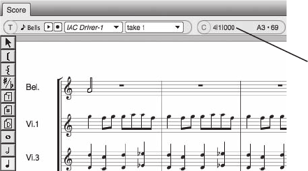
Inserting Notes
The process of inserting notes with the mouse is similar to that when using the Notation Editor.
Standard edit commands, such as Cut, Copy, and Paste, also work in the QuickScribe Editor. To
paste notes that have been cut or copied, click on the desired location with the Pointer tool and
press CommandþV. Region commands, such as Transpose, Quantize, and so on, can also be
applied to selected notes.
To insert a note using the QuickScribe Tool palette:
1. Select the desired note value from the QuickScribe Tool palette.
2. Click with the mouse at the desired pitch location within the staff of a track. If you have
Cursor Information enabled in Digital Performer 4Preferences 4Information Bar,
you can use the Cursor Information fields of the Information Bar to help guide you to
the exact beat location (see Figure 14.20). Drag up and down to change the pitch of a
note.
3. If you want to add a dot, double dot, or triplet marking to the note, select the desired
marking before choosing a note value from the QuickScribe Tool palette.
To change the value of an existing note:
1. Select the new duration from the QuickScribe Tool palette and click the desired note
to change its value.
2. To change the duration of multiple notes to the same value, select the notes with the Pointer
tool by Shift-clicking with the mouse or by dragging a selection box over them.
3. Once multiple notes have been selected, Command-click the new note duration in
the QuickScribe Tool palette.
Cursor
Information
Figure 14.20 The QuickScribe Editor’s Cursor Information fields can help guide you as you enter notes
in a staff. In this example, I am entering a quarter note with a pitch of A3 on Count 1 of Measure 4.
488 Digital Performer 6 Power!: The Comprehensive Guide

Temporarily Enabling the Pointer Tool To temporarily enable the Pointer tool when work-
ing with other tools in the QuickScribe Tool palette, simply press and hold down the
Option key. When you release the Option key, the Pointer will revert back to the tool
that was previously selected.
To delete an existing note from a part or score:
1. Select the note you want to affect by clicking with the Pointer tool. To select multiple
notes, Shift-click or drag a selection box around the desired notes.
2. Press the Delete key.
Working with Accidentals
Accidentals are flat or sharp notes that fall outside the notes of a specific scale or key signature.
For example, the key of C does not contain any flat or sharp pitches, so if a flat or sharp note
occurs within this natural scale, it is noted with an accidental (# or b). Digital Performer’s tran-
scription engine automatically controls the spelling of accidentals within a score, but there may
be times when you need to change the way a particular note is spelled. By default, the note
spellings are set to Auto. You can manually change a note spelling with the QuickScribe Tool
palette’s Change Enharmonic Spelling tool (the sharp/flat icon button).
To change the spelling of accidentals within a score:
1. Start by choosing the Change Enharmonic Spelling tool from the QuickScribe Tool
palette (see Figure 14.21).
2. Click on a desired accidental and continue holding the mouse button down. A pop-up
menu will appear with alternate spelling options.
3. Select the desired spelling from the list. Setting the spelling to Auto will allow
DP’s transcription engine to automatically choose a spelling for you.
Change Enharmonic
Spelling Tool
Figure 14.21 Use the QuickScribe Tool palette’s Change Enharmonic Spelling tool to change the
spelling of accidentals within a score.
Chapter 14 Music Notation 489
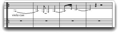
Small Note Heads
Certain musical elements, such as performance cues and grace notes, usually do not carry the
same weight as normal notes within a score. To show the difference between normal notes, these
musical elements are notated with smaller note heads, as shown in Figure 14.22.
To change the size of note heads:
1. Select the note or notes you want to affect.
2. Choose Change Selected Notes To 4Small/Normal Noteheads from the QuickScribe
Editor’s mini-menu.
Inserting Key, Meter, and Tempo Changes
Digital Performer allows you to insert key, meter, and tempo changes by clicking on a Quick-
Scribe Editor bar line. Keep in mind that users of previous versions (prior to DP 4.5) will need to
use the Modify Conductor Track command when inserting key, meter, and tempo changes in the
QuickScribe Editor.
Inserting Key Changes
You can make key changes directly in the QuickScribe Editor via a Key pop-up menu (shown in
Figure 14.23), even if a key change doesn’t exist. The procedures for inserting key changes are
explained here.
nTo modify an existing key signature: Place the Pointer tool over the key signature. The
pointer will change to the #/b cursor. Click on the key signature to display the Key Change
pop-up menu and select a new key from the list.
nTo insert a key change where meter and key changes do not exist: Press the Option key
while place the Pointer tool over a bar line. Click to open the Key pop-up menu and insert
a key change.
nTo insert a key change where a meter change already exists: Place the Pointer tool to the
left of the meter marking, a third of the way up from the bottom of the staff. Once in the correct
position, the cursor will change to the #/b symbol. Click to open the Key pop-up menu.
Figure 14.22 You can use small note heads to represent certain musical elements, such as performance
cues and grace notes.
490 Digital Performer 6 Power!: The Comprehensive Guide
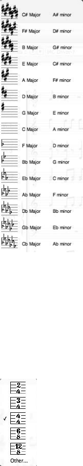
Inserting Meter Changes
You can make meter changes in the QuickScribe Editor via a Meter pop-up menu (shown in
Figure 14.24) by clicking directly on an existing meter marking or bar line. The QuickScribe
Editor’s Meter pop-up menu is explained here.
nTo change the existing meter: Place the Pointer tool over the existing meter marking. The
cursor will change to the 4/4 cursor. Click on the existing meter marking to open the Meter
pop-up menu and change the meter.
Figure 14.23 The QuickScribe Editor’s Key pop-up menu.
Figure 14.24 The QuickScribe Editor’s Meter pop-up menu.
Chapter 14 Music Notation 491
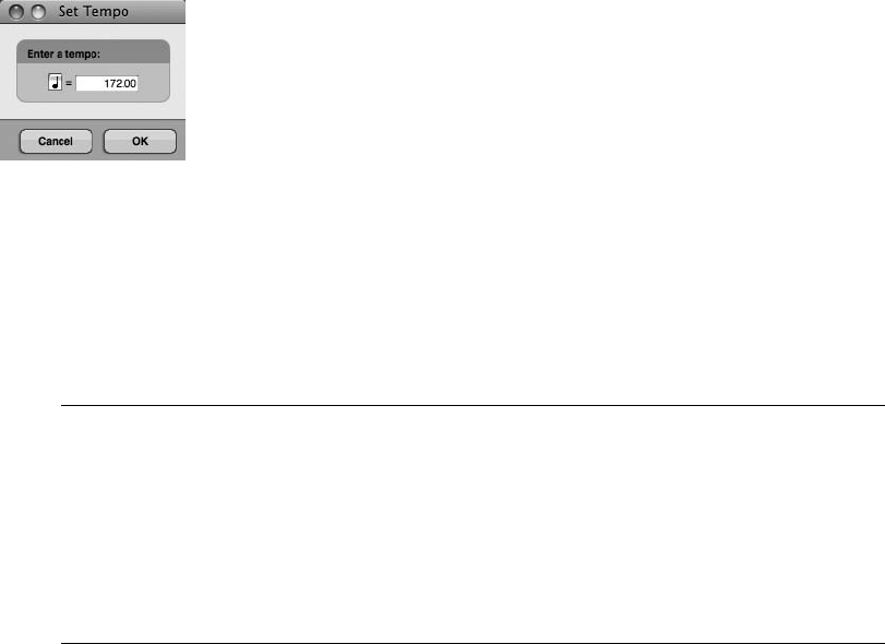
nTo add a new meter change after an existing key change: Position the Pointer tool over
the right edge of the key signature. The cursor will change to the 4/4 cursor. Click to open
the Meter pop-up menu. Select a time signature from the list to change the meter.
nTo add a new meter change where key and meter changes do not exist: Position the Pointer
tool directly over a bar line to change the cursor to the 4/4 cursor. Click directly on the
bar line to insert a new meter change.
Inserting Tempo Changes
You can make tempo changes in the QuickScribe Editor via the Set Tempo dialog box (shown in
Figure 14.25) by clicking directly on a bar line. Be aware that tempo changes made in the
QuickScribe Editor are placed in the Conductor track. The tempo source must be set to the
Conductor track in order to be displayed in the QuickScribe Editor.
To insert a tempo change, while pressing the Control key, position the Pointer tool over a bar
line to change the cursor to the bpm cursor. Click directly on the bar line to open the Set Tempo
dialog box. Enter the new tempo and set the beat value if needed. Click OK to enter the new
tempo change.
Setting and Displaying Tempo in the QuickScribe Editor Tempo changes that are inserted
with the Set Tempo dialog box will continue on until the next tempo change. In addition,
when the tempo source is set to the Conductor track and the tempo is displayed in the
QuickTime Editor, only the initial tempo change located at the first measure will be visible. To
display all tempo changes, you need to enable the Show Film Cues option from the Quick-
Scribe Editor’s mini-menu (discussed in the “Viewing Film Cues” section of Chapter 15,
“Scoring to Picture.”
Inserting Dynamic Symbols
The QuickScribe Editor’s Dynamics palette, shown in Figure 14.26, lets you insert standard
dynamic symbols into a score, including sforzandos and hairpin crescendos/decrescendos.
Figure 14.25 The QuickScribe Editor’s Set Tempo dialog box.
492 Digital Performer 6 Power!: The Comprehensive Guide
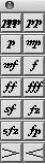
To insert a dynamic symbol into a score:
1. Open the Dynamics palette by choosing Dynamics Palette from the QuickScribe
Editor’s mini-menu.
2. Choose the appropriate symbol from the palette.
3. Click at the desired score location to insert the symbol.
To move an existing dynamic symbol:
1. Enable the Pointer tool.
2. Click and drag the desired symbol to the new location.
3. To move dynamic symbols together with notes, select both with the Pointer tool and
drag them to the desired location.
To insert hairpin crescendos and decrescendos:
1. Select the hairpin crescendo or decrescendo from the Dynamics palette.
2. Click at the desired score location to insert the symbol.
3. Drag the handles vertically or horizontally to adjust the angle or length of the symbol.
Printing
Once you have formatted your individual parts and your overall score, you are ready to print
them out. If you still need to work on the appearance of your manuscript pages, see the “Cus-
tomizing the Appearance of a Score” and “Customizing the Appearance of an Individual Track”
sections of this chapter.
To print individual parts:
1. Select the tracks you want to print by enabling them in the Track Selector List. Once the
tracks are highlighted, they should all be visible within the QuickScribe Editor.
Figure 14.26 The QuickScribe Editor’s Dynamics palette allows you to insert standard dynamic symbols
into a score. This palette is floating and can be positioned anywhere within your DP workspace.
Chapter 14 Music Notation 493
2. Choose Print Individual Parts from the QuickScribe Editor’s mini-menu. All of the
visible tracks will be printed as separate parts.
To save a part as a PDF document:
1. Select the track you want to turn into a PDF by enabling only that track in the Track
Selector List. Only the part you want to work with should be visible within the
QuickScribe Editor.
2. Press CommandþP to open the Mac’s Print window.
3. Click the Save as PDF button.
4. Give the part a name in the Save As column.
5. Choose the destination for the PDF document and click Save.
To print a score:
1. Select the tracks you want to include in the score by enabling them in the Track
Selector List. Once the tracks are highlighted, they should all be visible within the
QuickScribe Editor.
2. Press CommandþP to open the Mac’s Print window.
3. Set the print options as necessary and click the Print button.
To save a score as a PDF document:
1. Select the tracks you want to include in the score by enabling them in the Track
Selector List. Once the tracks are highlighted, they should all be visible within the
QuickScribe Editor.
2. Press CommandþP to open the Mac’s Print window.
3. Click the Save as PDF button.
4. Give the score a name in the Save As column.
5. Choose the destination for the PDF document and click Save.
Summary
Digital Performer contains many features for working with musical notation, and many are
beyond the scope of our discussion in this chapter. However, as with other editing windows
in DP, it takes just a little practice to become comfortable with the capabilities of the
494 Digital Performer 6 Power!: The Comprehensive Guide
QuickScribe Editor. Though it is not entirely necessary, it is helpful to have some knowledge of
music theory or music notation methods when you are creating a printed score or individual
part. The basic steps covered in this chapter for generating a full score and individual parts
from the MIDI tracks in your DP project provide a solid foundation on which you can further
develop your knowledge and experience involving music notation.
Chapter 14 Music Notation 495
This page intentionally left blank

15 Scoring to Picture
The music-scoring process is the act of writing music for motion pictures—film, television,
video games, Internet content, and other multimedia. In the past several years, Digital
Performer has proven to be a dominant force in the music production of many block-
buster films and hit television series produced in Hollywood and around the world. In an indus-
try full of erratic deadlines and constant revisions, film composers have long since determined
that DP’s versatile, intuitive, and straightforward nature helps make their scoring experiences
more efficient, organized, and on target. In Digital Performer, you can import QuickTime mov-
ies directly into a project, providing movie playback that is perfectly synchronized to your audio
and MIDI tracks (without the hassle of syncing an external video deck to your DP system). This
approach provides a random-access digital picture, meaning you can easily locate any spot in the
movie, advance or “scrub” forward or backward by frames, and create and display streamers,
punches, and flutters that are superimposed on the movie image. Other sophisticated scoring
features, such as the Find Tempo command and the Film Cues view, help with composing
music cues within your Digital Performer project.
This chapter, however, will only make a small dent in the actual scoring process; it is a complex
topic that is beyond the scope of this book. Like the previous chapter on music notation, famil-
iarizing yourself with film-scoring methods and associated terms (such as SMPTE time code,
frame rates, frame offsets, spotting notes, and full DV format) will help you to take full advan-
tage of DP’s powerful scoring features. I will be focusing on the technical aspects of how some of
these features can be integrated into your music-scoring process.
Here is what you will learn in this chapter:
nHow to import a QuickTime movie into a project
nHow to output QuickTime video to an external monitor via FireWire
nHow to work with DP’s Film Cues feature
nHow to set up a scoring project with markers and hits
nHow to search for tempos that accommodate designated hit points
497

nHow to insert DP’s Film Scoring Events, such as streamers, punches, and flutters
nHow to export a QuickTime movie that includes your soundtrack
Music Scoring
Digital Performer provides a powerful environment for scoring music, giving you the ability to
create hit points (or markers), calculate tempos, or even transmit synchronization signals to
other systems. But before you can begin creating or setting your composition to picture, you
must first have a movie to score. DP’s Movie window supports the synchronized playback of
QuickTime-formatted movies with your sequence’s audio and MIDI tracks. You can, of course,
sync Digital Performer to an external video deck or other playback medium, but in this section,
I’ll focus on the process of scoring to an imported QuickTime movie.
Movie Window
Before you begin importing a QuickTime movie, make sure you have the latest version of Quick-
Time installed on your Mac. The QuickTime application is free and comes bundled and prein-
stalled on Mac OS X. If you are working with an older version of QuickTime, you can update it
through OS X’s Software Update or by visiting www.apple.com/quicktime/download.
To open and close QuickTime movies in Digital Performer:
1. Choose Project 4Movie or use the default keyboard shortcut ShiftþV.
2. Select the movie you want to import and click the Open button.
3. Once a movie window is open, you can use the Open command in its mini-menu to
switch to a different movie. You can only have one movie open at a time.
4. To close the movie but still keep it linked to your project, click the Movie window’s red
Close button. Digital Performer will remember movies that are closed in this fashion.
Repeat Step 1 to reopen the previous movie.
5. To permanently close a movie, choose the mini-menu’s Close command.
Blank Movies? When importing a movie, DP offers an option to create a blank movie for
your project. This can be very useful when you need to create Film Scoring Events (dis-
cussed later, in the “Film Scoring Events” section of this chapter) or markers, but you have
not received the actual movie. For example, suppose you are scoring a short commercial,
and the music editor has provided all of the spotting notes and SMPTE time-code refer-
ences for the picture regarding where the music begins and ends, where special FX will
occur, and so on. Although you haven’t received the actual picture from the production
company (maybe the film editor is still making changes or adjustments), you can use the
blank movie to get started.
498 Digital Performer 6 Power!: The Comprehensive Guide
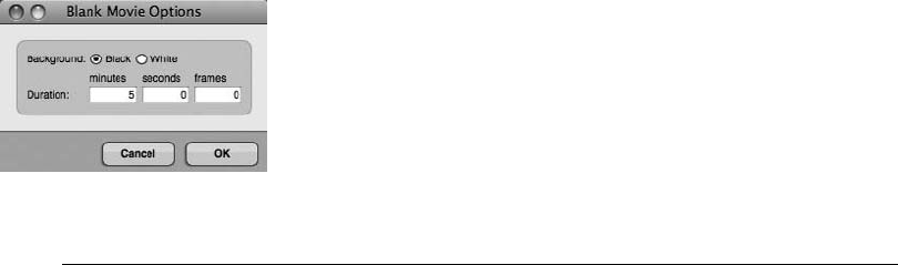
When the picture finally arrives, your project is ready to seamlessly incorporate all of the
Film Scoring Events into the finished or “picture-locked” movie. To create a blank movie,
simply select Project 4Movie and choose Use Blank Movie. The Blank Movie Options
window will appear (as shown in Figure 15.1), allowing you to select a background and
set the blank movie’s duration.
The Movie’s Mini-Menu
Once you have chosen a movie and opened the Movie window, you will have access to its var-
ious mini-menu commands and options (explained here).
nOpen Movie. This option allows you to open a different movie. Use this option to close
the existing movie and open a new one.
nOpen Blank Movie. This option allows you to open a blank movie (discussed in the
previous section).
nUse Same Movie for All Sequences. With this option enabled, all sequences in your
project will use the same movie.
nUse Black Background before/after Movie. This option allows you to set a black back-
ground for your movie during the time periods before the picture starts and after the picture
ends. This is useful if the tail of your score slightly overruns the last frame of the movie,
or if you need to compose before the start of the movie.
nLock to Transport. When selected, this option “locks” the movie to DP’s Transport (and
vice versa). As you play, stop, or locate, the movie will slave to your actions. You can
also use the controls at the bottom of the Movie window to control DP.
nClose Movie. This option permanently closes the Movie window (and “unlinks” it from
your project).
nSet Movie Start Time. This command will open the Set Movie Start window, allowing you
to set the SMPTE start time for the open movie.
Figure 15.1 The Blank Movie Options window allows you to choose a background and set the duration
for a blank movie.
Chapter 15 Scoring to Picture 499
nUse Movie’s Color Table. If your movie contains a predetermined color table, enabling this
option allows DP to use the color table in order to present truer colors.
nChase Graphical Edits. This option will force the Movie window to follow any edits that you
make in any of DP’s editing windows, such as moving and trimming, allowing you to
instantly see how your edits correspond to the picture you’re working with.
nChase Numeric Edits. This option will force the Movie window to follow numeric edits,
such as clicking an event’s numeric bar/beat location in the Information Bar of an editor
window’s title bar. When the event’s parameter is highlighted for editing, you will see the
movie jump to that location. Edit the event’s location number, and the movie jumps to the
new location, showing where the event will be placed in relation to the movie when you
confirm the edit. Press the Return key, and the movie will jump back to the Counter
location.
nHalf/Normal/Double Size. Use these three options to quickly change the size of the window.
The current size is indicated by a check mark.
nMovie Floats on Top. For those who do not have access to a second display monitor, select
this option if you want your movie to always be visible (or to “float” on top of other
windows).
nVideo Output. This option allows you to send an opened DV-formatted movie out to a
connected FireWire DV camera or FireWire video converter.
nVideo Output Playback Offset. This command becomes visible when you enable FireWire
video output. Choosing this command will open the Set Playback Offset window, allowing
you to compensate for the inherent playback delay in FireWire video devices.
nCopy Movie Audio to Sequence. Choosing this command will copy the open movie’s
soundtrack to an audio track in the current sequence. This command will only be visible
when a movie contains an audio track.
Setup
Once you have opened your movie in DP, you’ll need to configure your sequence’s frame rate
and start times to match that of your imported movie. You can even output the DV-formatted
movie to a FireWire camera or FireWire converter in order to view the movie as a full-screen
image on a standard television or video monitor.
Frame Rate. Digital Performer supports frame rates of 23.976, 24, 25, 29.97 Drop, 29.97 Non-
Drop, and 30 frames per second. New to version 6, you can also select the Use Non-Standard
Frame Rate option to designate non-standard frame rates such as 30 Drop, Legacy 29.97 Drop,
and Legacy 29.97 Non-Drop. If you don’t know the frame rate of your QuickTime movie, you
can check its settings by opening it up in your Mac’s QuickTime Player application.
500 Digital Performer 6 Power!: The Comprehensive Guide
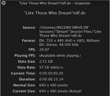
To determine a movie’s frame rate:
1. Open the movie in the QuickTime Player application.
2. Choose Window 4Show Movie Inspector. You can also use the default keyboard
shortcut CommandþI. The frame rate, along with the movie’s other attributes, will
be displayed in the Movie Inspector window, as shown in Figure 15.2.
Start Times. Next, you’ll need to set your QuickTime movie’s start time and your sequence (or
Chunk) start time so that the cues you are composing will be created in the proper locations.
Doing so will ensure that you (the composer) and the post-production staff for the film are on
the same page. Most likely your movie will have a visual superimposed SMPTE time code (called
awindow burn). If not, try a start time of 0:00:00:00. This may vary from project to project—
and, remember, you can freely experiment with start times at any time while working in your
session. When setting the start time of a sequence, however, you must determine whether your
music will begin at the very beginning or at a later time of the movie.
To set the movie start time:
1. If your movie has a SMPTE time-code window burn, makes sure the movie’s Play slider
is positioned to the far left (the very beginning of the movie) and make note of the
time code at this position (see Figure 15.3).
2. Choose the Set Movie Start Time command from the Movie window’s mini-menu.
3. Next, enter the correct start time from Step 1 (or 0:00:00:00 if there is no window burn)
in the Set Movie Start window (shown in Figure 15.4).
Figure 15.2 QuickTime Pro’s Movie Inspector window.
Chapter 15 Scoring to Picture 501
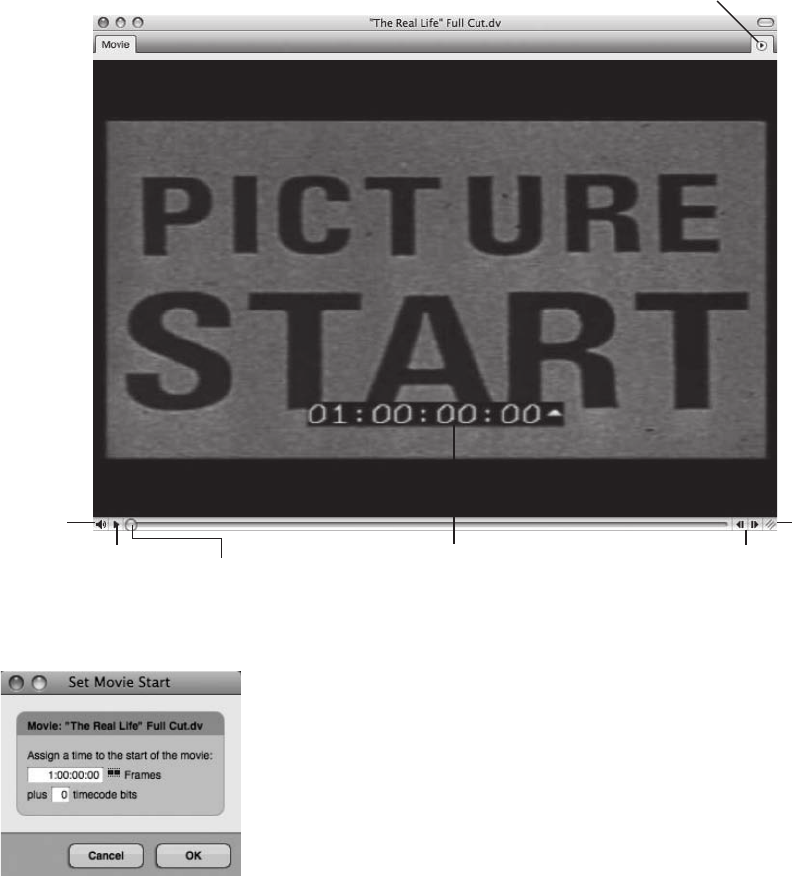
4. The Plus ___ Timecode Bits input field is used to offset the movie by a desired amount
if the frame numbers in the window burn don’t precisely line up with the frame
numbers in the Counter of DP’s Control Panel. It’s helpful to know that there are
80 time-code bits in a single frame!
Mini-menu
Movie
Audio
Volume Play/Stop Play Slider Frame Steps
Grow
Box
SMPTE Timecode
Window Burn
Figure 15.3 The various controls in the QuickTime Movie window.
Figure 15.4 The Set Movie Start window.
502 Digital Performer 6 Power!: The Comprehensive Guide
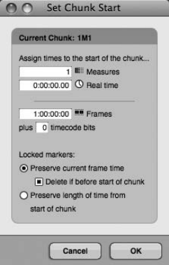
To set the sequence (or Chunk) start time when your music begins at the very beginning of the movie:
1. Use the Control Panel’s Sequence menu to open the Set Chunk Start window, as shown
in Figure 15.5.
2. In the Frames field, enter the start time for the sequence. (This should be the same
number as the movie start time from Step 3 in the previous How-To section.)
3. If you have previously created locked markers within the sequence, use the Locked Markers
options to specify what will happen to them when the Chunk start time is applied.
To set the sequence (or Chunk) start time when your music begins later in the movie:
1. Use the Play slider in the Movie window to scroll to the point where the music will
start, and make note of the SMPTE time code at this position (or refer to any of your
spotting notes or cue information that may include music start times).
2. Use the Control Panel’s Sequence menu to open the Set Chunk Start window.
3. In the Frames section of the Set Chunk Start window, enter the start time from Step 1.
(See Figure 15.6.)
4. Again, if you have previously created locked markers within the sequence, you also need
to specify what will happen to them when the Chunk start time is applied.
5. Once applied, the Play slider in the Movie window will automatically relocate to
the sequence start time. For this sequence, DP’s Transport controls will only take you
back to this point in the movie. To return to the very beginning of the movie, simply use
the Play slider in the Movie window to scroll back to the beginning.
Figure 15.5 The Set Chunk Start window.
Chapter 15 Scoring to Picture 503
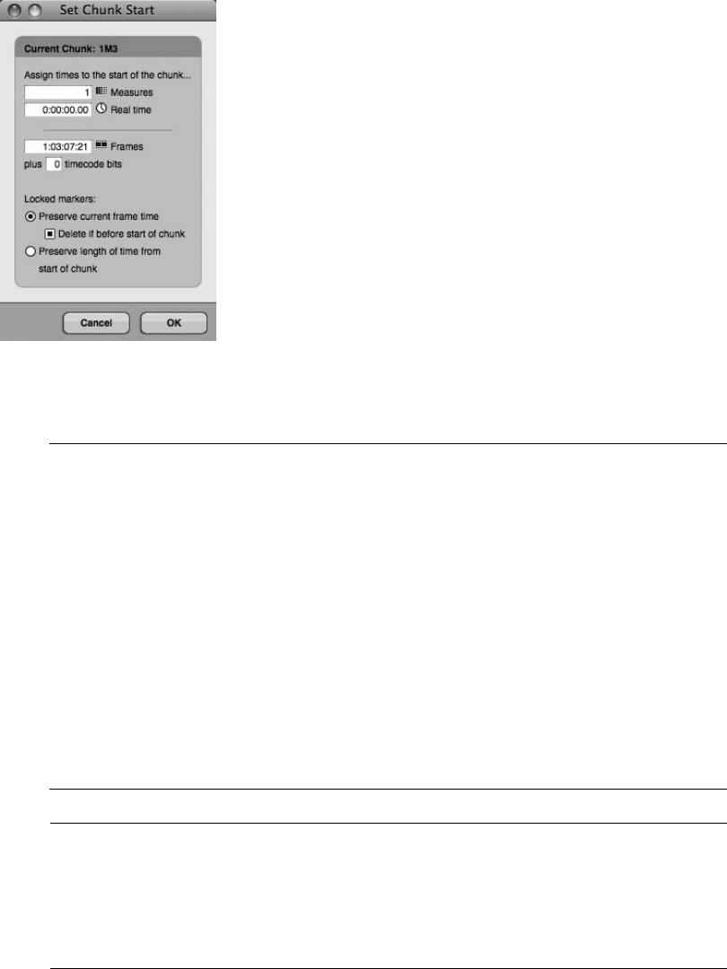
Using the Same Movie for All Sequences The Movie window’s Use Same Movie for All
Sequences option in its mini-menu is great for streamlining the film-scoring process.
With this feature enabled, you could simply create a separate sequence (Chunk) for
each piece of music (or cue) in your project, enter their respective start times (as discussed
earlier), and then use the Sequence menu in the Tracks window or the Control Panel to
quickly navigate between the different cues. This eliminates the need to create separate
Digital Performer project files for each cue or having to repeatedly import the same movie
file. Don’t forget, the Copy Selection to New Sequence command is a great way to create
separate sequences within a project by duplicating your “virtual” orchestration setup or
making use of a fine-tuned template for each cue! Just make a selection in the timeline of
the Tracks window and choose Copy Selection to New Sequence from the Sequence
menu. The Create Chunk window will appear, allowing you to specify the parameters
of the duplicated Chunk, such as sequence name and start time.
Figure 15.6 In this example, a different start time is entered for a sequence in which the music starts at
a later time in the movie.
Pre-Roll Sometimes you may want to have some pre-roll (a preparatory period) before
your sequence begins playback. To create pre-roll, simply enable the Countoff button on
the Control Panel. Use the Countoff section of the Preferences and Settings window to
determine the duration of the countoff. See the section in Chapter 4 entitled “Defining the
Countoff” for more information.
504 Digital Performer 6 Power!: The Comprehensive Guide
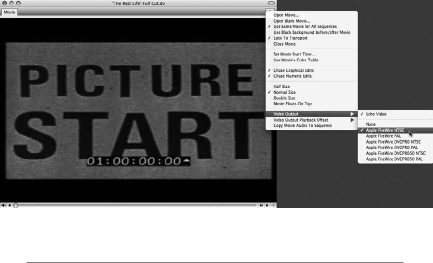
FireWire Video Output. Digital Performer’s Movie window allows you to output your DV-
formatted QuickTime movie to a FireWire DV camera or a FireWire converter (such as a
Canopus ADVC110) in order to view your QuickTime movie as a full-screen image on a stan-
dard television or video monitor. Audio output via FireWire, however, is not supported. In other
words, if the movie contains audio (such as a production dialog track), the audio cannot be
output to the television or video monitor. However, DP does allow you to import a movie’s
audio track directly into your sequence. See the upcoming tip “Importing a Movie’s Audio
Track into Your Sequence” for more information.
To enable FireWire video output:
1. Choose Video Output from the Movie window’s mini-menu. A list of FireWire DV
formats (for example, Apple FireWire NTSC, Apple FireWire PAL, DVCPRO NTSC,
and so on) that are supported by your system will appear, as shown in Figure 15.7.
2. To turn off FireWire video output, choose Video Output 4None from the Movie win-
dow’s mini-menu.
Real-Time Video Compression Digital Performer 6 now offers the ability to convert non-
DV formatted movies in real time so you can view them (along with any film-scoring
events that you create) on an external monitor. If your movie is not in the DV format
(and you don’t want to convert it manually with QuickTime), use the FireWire Video
Figure 15.7 The Movie window mini-menu’s Video Output submenu provides a list of DV formats
supported by your system.
Chapter 15 Scoring to Picture 505
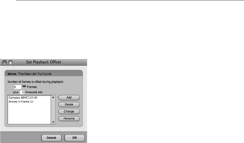
Output Auto Compression options available in the Film Scoring Events preferences (dis-
cussed later in the “Film Scoring Events” section of this chapter). Keep in mind that this
adds yet another hefty task to your computer’s processor!
FireWire Playback Delay Compensation. When outputting DV video over FireWire, you may
notice that the picture is delayed from the audio in Digital Performer. The amount of playback
delay varies by device, but it is anywhere from three to nine frames. You can compensate for this
delay in the Set Playback Offset window, shown in Figure 15.8.
To set the playback offset for the Movie window:
1. Open the Set Playback Offset window by choosing Video Output Playback Offset from
the Movie window’s mini-menu.
2. By default, the None option will be checked. Select the Other option to open the Set
Playback Offset window.
3. Enter the appropriate number of frames in the Number of Frames to Offset during
Playback input field, keeping in mind that you may have to experiment with different
values.
4. For finer adjustments, use the Plus __ Timecode Bits input field. This field allows
you to offset the movie by a specific number of time-code bits. (There are 80 time-code
bits to a single frame.)
5. Click OK to confirm the offset. If you want to save this setting as an offset preset, select
the Add button and simply type in a name for the preset, then click OK.
Figure 15.8 The Set Playback Offset window allows you to compensate for delays in video playback
over FireWire, as well as create and manage offset presets.
506 Digital Performer 6 Power!: The Comprehensive Guide
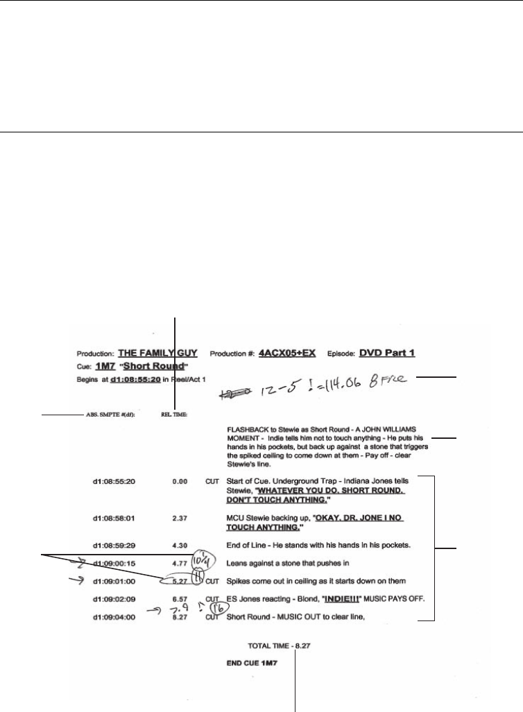
Importing a Movie’s Audio Track into Your Sequence If your movie has an audio track, you
can import the audio directly into your sequence by selecting Copy Movie Audio to
Sequence from the Movie window’s mini-menu. Choosing this option will create a new
audio track in your sequence and automatically place the movie’s audio into it. Remember
to pull down the Movie window’s Volume slider to avoid doubling up the audio during
playback!
Cue Sheets
Cue sheets are timing notes that describe in great detail the composition of every shot within a
movie or scene. The music editor typically prepares these sheets and supplies them to the com-
poser so that he or she can use the information to decide where cues should start and be
synchronized, and also to find appropriate tempos for a cue (see Figure 15.9). In simpler
terms, composers use cue sheets to view the relationship between the events onscreen and the
music in the score.
Real-time
SMPTE Time
Composer’s
Timing Notes
Total Length of Scene/Cue
Important
Scene Events
Scene Synopsis
Click/Tempo
Information
Figure 15.9 A traditional cue sheet prepared by a music editor. In this example, composer Ron Jones
made timing notes for a short cue in an episode of Fox’s Family Guy.
Chapter 15 Scoring to Picture 507
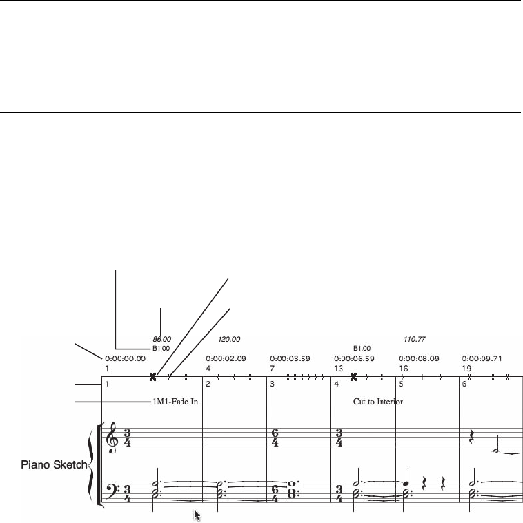
If you find yourself having to take on some of the music editor’s roles, don’t worry: Digital Per-
former lets you create your own hit points with markers. These hit points can then be used to
calculate tempos for a specific cue and can be viewed in the QuickScribe Editor as Film Cues.
Cue Sheets and Licensing Royalties Cue sheets are also used to provide specific informa-
tion to performing rights organizations, such as BMI, ASCAP, and SESAC, in order for
them to collect licensing royalties for composers. So, if you are your own music editor,
be sure to keep track of cue information even if it means creating your own customized
cue sheets. To find out more, visit www.bmi.com, www.ascap.com, or www.sesac.com.
Viewing Film Cues
Though not as intricate and detailed as traditional cue sheets, Digital Performer’s Show Film
Cues feature displays film cue information in a logical and composer-friendly format. To turn on
Film Cues, choose Show Film Cues from the QuickScribe Editor’s mini-menu. Once enabled, it
will display Film Cue information within the QuickScribe Editor, as shown in Figure 15.10.
Film Cue Information
When the Film Cues option is turned on from the QuickScribe Editor’s mini-menu, Digital Per-
former will display Film Cue information at the top of every staff system. This information
includes tempo changes, beat location, measure start times, beat/measure numbers, beat
marks, as well as cue points or markers—and it is described in more detail in the following list.
Measure Start Time
Beat Number
Tempo
Marker Beat Location Beat Mark for a Marker
Regular Beat Mark
Measure Number
Marker Name
Figure 15.10 Film Cue information is displayed at the top of every staff system when the Film Cues
option is enabled.
508 Digital Performer 6 Power!: The Comprehensive Guide
nTempo changes. The topmost line displayed in italics is the tempo, simply expressed as a
bpm value or number.
nBeat location. The second row of information is the beat location of any cue points or
markers. Plus and minus symbols appearing before () or after (þ) the beat location indicate
that the cue point occurs before or after the closest beat or half-beat. A marker’s hit
ranges and skew settings (explained in the “Markers” section of Chapter 11) have a direct
effect on whether a marker is considered early or late in relationship to the closest beat.
nMeasure start time. The next line is a measure’s start time, displayed in minutes:seconds:
milliseconds. The measure start time appears above every measure that is showing.
nBeat number. The beat number consists of two values. The number above the film cue’s
horizontal line is the beat number (starting from the beginning of the sequence). The second
number, located below the horizontal line, is the measure number (also starting from the
beginning of the sequence).
nBeat marks. Beat marks indicate the location of beats within a measure and appear as X
marks located directly on the Film Cue’s horizontal line. If a cue point or marker exists in a
measure, the nearest beat will be indicated by a bold Xmark.
nCue points. Cue points are markers (explained in the “Markers” section of Chapter 11).
You can choose whether to display markers or cue points all together, or you can set exactly
how they will appear in the QuickScribe Editor from the mini-menu’s Marker Options
window (explained in the “Marker Basics” section of Chapter 11). Keep in mind that a
marker’s Hit Point and Skew setting (explained later, in the “Using Hit Points to Find
Tempos” section of this chapter) also affects how markers (or cue points) are displayed in
the Film Cue view. Also, markers whose weight is set to None will not appear in the
Film Cue view.
The Different Film Cue Views
Digital Performer basically has three views when you are working with the QuickScribe Editor—
Normal QuickScribe, QuickScribe þFilm Cues, and Film Cues Only. You can select these view-
ing options in QuickScribe Editor by choosing Score Options from the mini-menu (explained in
Chapter 14, in the section entitled “Customizing the Appearance of a Score”). The options are as
follows:
nNormal QuickScribe. This view is displayed when the mini-menu’s Show Film Cues
option is turned off (unchecked).
nQuickScribe þFilm Cues. This view is displayed when the mini-menu’s Show Film Cues
option is enabled and a single staff or set of staves (a track or multiple tracks) is visible in
the QuickScribe Editor. If only the Film Cues are showing, click on a track in the Track
selector to display its staff.
Chapter 15 Scoring to Picture 509
nFilm Cues Only. This view is displayed when only the Film Cues are visible and tracks or
staves are hidden from the QuickScribe Editor. If you want to work in Film Cues Only
view, simply enable the mini-menu’s Show Film Cues option and hide any tracks or staves
with the QuickScribe Editor’s Track selector. When working in Film Cues Only view, you
cannot use the pop-up key signature menu, since key signatures are not displayed in this
view.
Hit Points
Hit points within a score are basically markers that indicate important points in a movie, such as
a specific scene change, or certain actions in the film, such as an explosion or a car crash. You
may already have these hit points mapped out from spotting sessions with the film’s director and
music editor—it will really depend on the project. Regardless of the pre-planning process, hit
points are extremely easy to create in DP.
To create hit points in a sequence:
1. With the Movie window open, begin playback of the sequence.
2. When a significant point in the movie occurs, create a marker by pressing ControlþM.
Be sure to also place a marker at the beginning of each important cue, ensuring that the
Find Tempo feature (explained in the next section) works properly.
3. Once you have created the necessary hit points, you may need to manually move
the markers to place them in the exact SMPTE frame locations. See the “Markers”
section of Chapter 11 for a detailed look at the Markers feature in DP.
Using Hit Points to Find Tempos
There is nothing more time-consuming than manually experimenting with tempos in order to
find one that is most suitable for a movie scene with many hit points. In fact, it’s nearly impos-
sible! Though I still believe in the traditional method of calculating tempos using frame-clicks
and a Knudsen or Rose click book (a printed set of timing tables covering an extensive range of
tempos), the Find Tempo command in DP is a very powerful and effective feature. Once you
have created the necessary hit points in a score, you can use them to quickly calculate the most
appropriate tempo for the cue. Like other features in DP, however, some practice and trial and
error with the Find Tempo command will allow you to become much more comfortable with
this process.
To calculate the tempo for specific hit points:
1. Open the Markers window by choosing Project 4Markers. You can also use the
default keyboard shortcut ShiftþK.
2. Lock the markers that you want to include in the tempo search by clicking in the Lock
column of each marker. (This will anchor the markers to their SMPTE frame locations.)
510 Digital Performer 6 Power!: The Comprehensive Guide
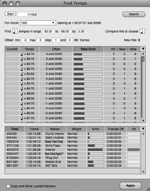
3. Click the Find column of the hit points you want to include, making sure to include
the marker that is located at the beginning of the cue. Included hit points are indicated
by a check mark icon.
4. Click the Weight column of a marker to set its weight (or importance).
5. Set the hit range in the Hit Range column. In this column, you can designate a number
of frames before and after the marker that constitute the specific hit point. In other
words, you can define a small margin of error for the hit points rather than forcing them
to be exact. You can use this feature when certain hit points occur over a range of
frames. To assign a range to several markers at once, simply Shift-click the names of the
markers and choose Set Hit Range from the Markers window’s mini-menu. Remember,
when scoring musical hits to picture, it is much better to be early than to be late.
6. Once you have your search parameters set, choose Find Tempos for Locked
Markers from the Markers window’s mini-menu. The Find Tempo window, shown in
Figure 15.11, will open.
Figure 15.11 The Markers window’s Find Tempo window.
Chapter 15 Scoring to Picture 511
7. In the Start field, enter the measure where you want to start the tempo search.
Clicking the Start button will automatically enter the current Counter time (where
the Playback Wiper is currently located).
8. Use the Chunk Selector drop-down menu to choose the sequence for which you
are searching.
9. Choose a metric division in the Beat Value drop-down menu and a range of tempos in
the Tempos in Range field. For example, you may want to view quarter-note tempos
from 60 to 80 beats per minute (bpm).
10. In the By field, enter the frequency of tempos you want to view in the search results. The
default frequency is 0.25. This means that if you are searching quarter-note tempos,
every tempo—in quarter-bpm increments—will be searched within the specified
tempo range. Smaller frequencies produce more tempos and increase the potential to
find the most hit points. Larger frequencies produce fewer tempos but take less time for
DP to calculate.
11. In the Compare Hits to Closest drop-down menu, set the beat resolution grid for
hit points (markers) being searched. This is independent from the beat value of the
tempo range. In other words, you can search for quarter-note tempos but examine hits
that fall to the nearest sixteenth note.
12. In the Offset fields, enter an amount of offset in frames you want to consider from your
sequence’s current SMPTE start time. The Step fields allow you to determine how many
of the specified offsets will be checked between the minimum and maximum frame
numbers. For example, you could check the results of every tempo with offsets ranging
from 3 to 3 frames with a Step setting of 1 and 0/80 frames. The results would include
tempos with offsets of 3, 2, 1, 0, 1, 2, and 3. So, if you select a resulting tempo
with an offset of 3 frames, the SMPTE start time will be changed to three frames
earlier.
13. The Max Hits indicator includes the number of locked markers included in your search.
14. As you may have noticed, every time you enter a search parameter, DP begins searching
and automatically updates the results. However, you can initiate your tempo search by
clicking the Search button in the upper-right corner of the Find Tempo window.
15. In the Results section, click on any of the column headings to sort the tempo list by
specific criteria. Use the bar graph in the Total Error column to quickly navigate to
the more favorable tempos.
16. Click on a tempo row in the list to look at a detailed view of the selected tempo. In the Hit
column, a colored bar displays how close a hit point falls on the beat (designated in
Step 11). Green is a direct hit, yellow is a near miss, and red indicates a complete miss.
512 Digital Performer 6 Power!: The Comprehensive Guide
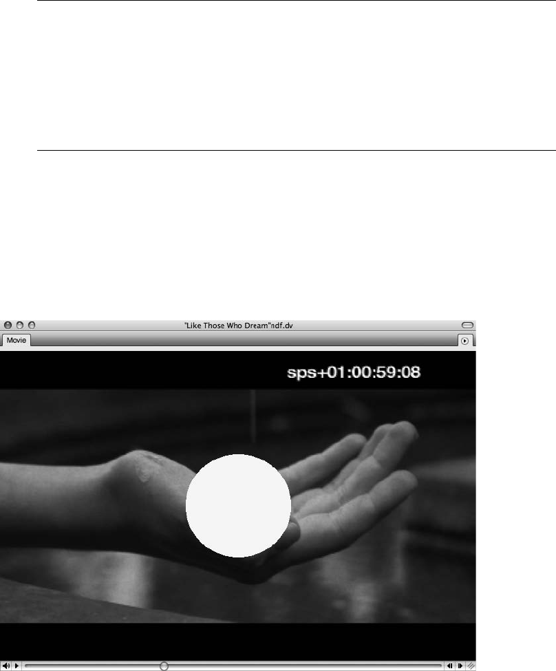
17. Once you have decided on a tempo, click the Apply button, and the new tempo will be
written from the start time assigned in Step 7.
Copy and Move Locked Markers If you have already composed your music score prior to
searching for an appropriate tempo, you can select the Copy and Move Locked Markers
option (located in the lower-left corner of the Find Tempo window) to create an unlocked
copy of each existing marker that will move when the new tempo is applied. You can then
view these moved markers to see how the tempo change has affected your composition. If
you have data that you want to preserve (not move), simply lock the track before applying
the tempo change by clicking in the track’s Lock column in the Tracks window.
Film Scoring Events
Film Scoring Events, such as streamers, punches, and flutters, are visual cues that are superim-
posed on a movie or video screen and are used to assist composers, conductors, and post-
production staff during the writing and recording processes. For example, a green streamer (a
colored vertical bar that travels across the screen from left to right) can signal the start of a
cue or the location of a hit point, and a punch (a circle that flashes onscreen) can be used to
emphasize the hit point (see Figure 15.12). A flutter is a flickering set of punches typically
Figure 15.12 In this example, a punch has been superimposed over a QuickTime movie in order to
emphasize a hit point.
Chapter 15 Scoring to Picture 513
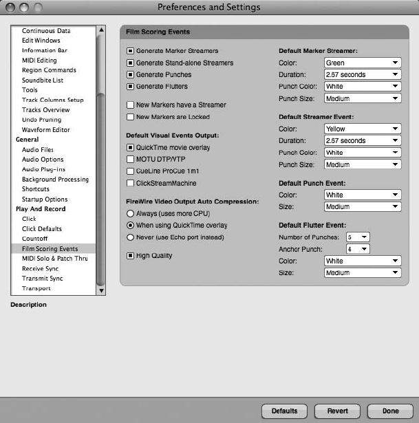
designated to mark the downbeats of measures. These events can be displayed as a QuickTime
movie overlay (when viewed on your computer’s monitor or an external video monitor con-
nected to the FireWire video output from DP), on an external video monitor (when connected
to a supported device than can generate streamers, punches, and flutters, such as a Video Time-
piece or ClickStreamMachine), or on an exported QuickTime movie (discussed in the “Export-
ing a QuickTime Movie” section later in this chapter). In this section, we will focus on creating a
streamer and a punch that are triggered by a specific marker (hit point) and viewing them as a
QuickTime overlay. For more detail on Film Scoring Events, consult the Streamers, Punches, and
Flutters chapter of your DP User Manual.
To create a streamer and punch for a specific marker:
1. Open the Film Scoring Events preferences to globally set your Film Scoring
Events (Digital Performer 4Preferences 4Film Scoring Events), as shown in
Figure 15.13.
Figure 15.13 The Film Scoring Events preferences allow you to superimpose visual cues, such as streamers,
punches, and flutters, on your QuickTime movie.
514 Digital Performer 6 Power!: The Comprehensive Guide
2. Enable the Generate Marker Streamers and Generate Punches options. Enable
all options if you eventually would like to create independent events (not associated
with markers—discussed in the “Film Scoring Events That Are Not Associated with a
Marker” tip later in this chapter).
3. Enable the QuickTime Movie Overlay option in the Default Visual Events Output
section.
4. To view your Film Scoring Events on an external monitor, select Always (Uses More
CPU) or When Using QuickTime Overlay from the FireWire Video Output Auto
Compression section.
5. Assign default settings to your Film Scoring Events using the drop-down menus
located at the right side of the window. However, you can override most of these
settings in other windows of DP.
6. Click Done.
7. Set the video output of your QuickTime movie accordingly (as discussed earlier in this
chapter).
8. Open the Markers window for your sequence (ShiftþK). Refer to the “Hit Points”
section earlier in this chapter or the “Markers” section of Chapter 11 for more
information regarding the creation of hit points and markers.
9. Select Show Streamers from the Markers window’s mini-menu to enable the
Streamer column within the Markers window.
10. Highlight the name of a specific marker (hit point) in the Name column of the Markers
window (or Shift-click to highlight multiple markers).
11. Open the Marker/Streamer Options window, as shown in Figure 15.14. (Choose
Set Marker/Streamer Options from the mini-menu in the Markers window.)
12. Name the marker in the Marker Name field. If a marker has been previously named,
the name will automatically appear in this window. If you are creating streamers for
multiple markers at once, the Name column will not appear.
13. Enable the Marker Is Locked option if you want to include this marker in the
Find Tempo process discussed earlier in this chapter.
14. Enable the Show Streamer On option and select QuickTime Movie Overlay.
15. To override default marker streamer settings (from Step 5 earlier), choose the attributes
of your marker streamer in the Streamer Color, Streamer Duration, Punch Color,
and Punch Size drop-down menus. (The Streamer Duration value indicates how long it
will take for the vertical bar to pass from left to right on your Movie window screen.)
Chapter 15 Scoring to Picture 515
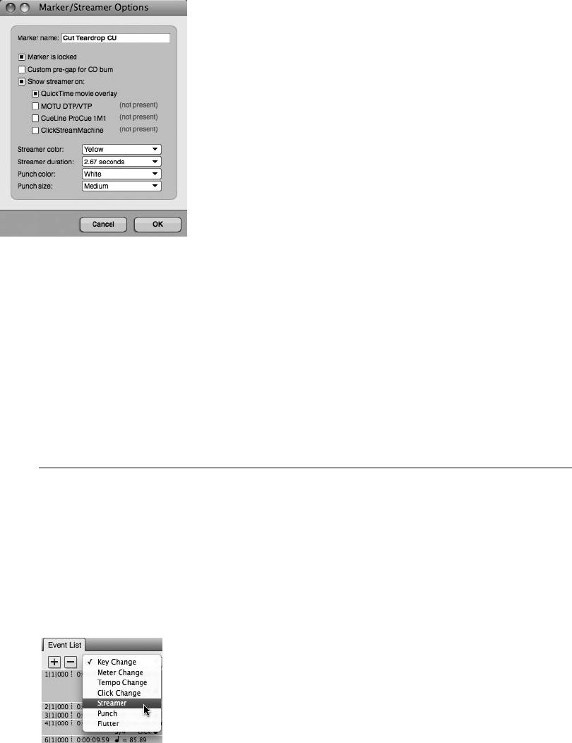
16. Click OK.
17. In the Tracks window, use the Playback Wiper to scroll back in your sequence prior to
the location of the marker and start playback. (Or you can use the shortcut Controlþ
ShiftþM, select the marker, enable the Countoff button in the Control Panel for
pre-roll, and then press Play.)
18. Use the Movie window in your computer monitor or your connected external video
monitor to view the superimposed streamer and punch.
Film Scoring Events That Are Not Associated with a Marker You can easily create a Film
Scoring Event that is not attached to a marker by using the Event List of the Conductor
track. Simply move the Playback Wiper to the desired position in the timeline, highlight the
Conductor track, and select Project 4Event List (or use the default shortcut ShiftþE). Use
the Insert button under the Event List title tab (the þicon) to insert a Film Scoring
Event and press Return (see Figure 15.15). The event will be placed at the location of
the Playback Wiper. As with other events in the Event List, you can edit a Film Scoring
Figure 15.14 Use the Marker/Streamer Options window to quickly create a streamer or punch that is
associated with a hit point in your sequence.
Figure 15.15 You can easily insert Film Scoring Events in the Event List window of the
Conductor track.
516 Digital Performer 6 Power!: The Comprehensive Guide

Event simply by double-clicking on its location parameters or single-clicking its Color,
Duration, and Output parameters. (Refer to the section in Chapter 10 entitled “The
Event List” for more information regarding editing events in the Event List.)
Missing Film Scoring Events? For unknown reasons, punches and streamers may not
always appear in your Movie window or external video monitor (even when the available
output options have been assigned properly). This may be due to the demanding nature of
video transfer via FireWire or the taxing process of real-time video compression. If this
happens to you, stop playback and scroll the Playback Wiper farther back in the sequence,
prior to the start of the events. Sometimes this allows DP to “reset” itself to allow events to
materialize.
Exporting a QuickTime Movie
With Digital Performer, you can use the Bounce to Disk command to export a QuickTime movie
that contains your composed soundtrack and any Film Scoring Events that you have created. For
those scoring to picture, this can be an extremely efficient way of “dubbing” music (syncing
sound to picture) and creating visual demos during the production process. For example, a com-
poser could export a sketch or draft (often called a mockup) of each cue and supply the director
or producer of the project with a QuickTime movie in order to gather feedback (before he or she
begins the actual scoring process). Not only does this save time in the long run, but if recording
sessions and live players are involved, it can save a lot of money!
To export a QuickTime movie:
1. In your sequence that contains a QuickTime movie, assign all of the audio tracks you
want to include in the bounce to the same output bundle, such as Analog 1-2.
Remember, audio tracks must be “online” and unmuted to be included in the
Bounce to Disk process.
2. In the Film Scoring Events section of DP’s Preferences and Settings window, make
sure you have enabled any streamers, punches, or flutters you want to include in the
movie.
3. In the Tracks window, select the audio tracks over the range you want to bounce.
Refer to the section in Chapter 13 entitled “Bouncing to Disk” for a review of this
procedure.
4. Select Audio 4Bounce to Disk (or use the default shortcut ControlþJ).
5. In the Bounce to Disk window, select QuickTime Export: Movie from the Format
drop-down menu.
Chapter 15 Scoring to Picture 517
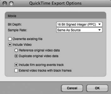
6. In the Source drop-down menu, select your output bundle (the same bundle designated
in Step 1).
7. Name the movie in the File Name field and enable any Save Settings commands.
8. Choose a destination for the bounced file using the Choose Folder button.
9. Click OK.
10. The QuickTime Export Options window will appear, as shown in Figure 15.16.
11. Choose a bit depth and a sample rate for the file from the corresponding drop-down
menus.
12. Enable Overwrite Existing File if you want to replace the existing movie; otherwise,
the current movie (the source video) will not be affected during the bounce.
13. Enable the Include Video option.
14. Enable the Reference Original Video Data or Duplicate Original Video Data
option. Referencing video data saves disk space, and duplicating video data creates a
complete, self-contained movie file.
15. Enable the Include Film Scoring Events Track option if you want to include any
streamers, punches, or flutters that you have created in your sequence.
16. Choose the Extend Video Tracks with Black Frames option if your audio is longer than
the length of the video.
17. Click OK. Once the Bouncing Selection to Disk and Saving Self-Contained Movie
progress windows are finished, the QuickTime movie will appear in your designated
folder.
Figure 15.16 The QuickTime Export Options window.
518 Digital Performer 6 Power!: The Comprehensive Guide

Bouncing Movie Audio If your QuickTime movie contains audio, such as production dialog
or an FX track, and you want to include this in your QuickTime movie bounce, make sure
you import the movie’s audio using the Copy Movie Audio to Sequence command (dis-
cussed earlier in this chapter). Once the movie’s audio has been imported into your
sequence, simply include this track in the assignment of audio tracks in Step 1 of the pre-
vious How-To section.
Summary
Digital Performer contains many powerful tools for scoring a film, television, video game, or
multimedia soundtrack. Though not required, it is helpful to have some insight into the film-
making and scoring processes when writing music for picture. This chapter only scratches the
surface of DP’s film-scoring capabilities, but it does provide a solid introduction that can jump-
start your process. Considering DP’s intuitive and straightforward nature, you can quickly
develop a great deal of technical expertise regarding the production responsibilities of the
composer.
Chapter 15 Scoring to Picture 519
This page intentionally left blank

Index
A
AAF Interchange files, 120, 132
archives, 205–208
hardware, 205–206
offsite, 208
software, 206–208
arranging, 335–390
Chunks, 363–377
Chunks window, 367–369
controlling, 370–372
sequences, 363–367
Song window, 372–377
V-Racks, 369–370
Clipping windows, 381–385
Conductor track, 335–343
Event List, 338–339
Graphic Editor, 339–343
Modify Conductor Track menu, 336–338
key, 359–362
Change Key command, 360–362
Transpose command, 362
looping, 377–381
Event List, 379
Loop tool, 379–381
Region menu, 378–379
markers, 385–390
meter, 357–359
Change Meter command, 357–358
partial measures, 358–359
tempo, 343–356
Adjust Beats command, 349–353
Audio menu commands, 353–356
Change Tempo command, 344–347
curves, 346
Receive Sync command, 347–349
Record Beats command, 349–353
sources, 343
Tap Tempo feature, 347–349
Tempo Control menu, 343
Audio Assignments window, 94, 212–214
audio configuration, 17–28
Audio System options, 17–18
Bundles window, 24–28
Configure Hardware Driver window, 18–22
Buffer Size menu, 20–21
Clock Modes section, 20
Clock Source menu, 20
hardware driver list, 19
Host Buffer Multiplier menu, 21
Master Device setting, 19–20
Sample Rate drop-down menu, 20
Work Priority setting, 22
Configure Studio Settings window, 22–24
Automatic Plug-In Latency Compensation
option, 23
Max Work Percent field, 23
Pre-Fill File Buffers for Quick Start
setting, 23
Prime Seconds setting, 22
Stereo Busses setting, 22
Work Quanta number, 23
Core Audio driver, 18
Input Monitoring Mode window, 23–24
Direct Hardware Playthrough option, 24
Monitor Record-Enabled Tracks through
Effects option, 23–24
AudioDesk files, 119
audio files
Compact Project window, 200
Compact Soundfiles window, 200
compacting, 198–201
deleting, 196–198
finding, 201–203
folders, organization, 195–196
importing, 238–242
location, changing, 193–195
managing, 193–203
missing, 201–203
recording, 211–238
removing, 198
renaming, 196
521
audio files (continued)
selecting, 306–309
Undo History, 190–192
audio hardware drivers, installation, 9–11
testing, 10–11
updating, 9–10
audio interfaces, 3–4
Audio Loop Information pane, Soundbites
window, 77
Audio MIDI Setup window, 10, 28–32
Audio Path Thru, recording, 214–215
Audio Performance window, 440–441
Audio Settings, Control Panel, 44
Audio System options, 17–18
audio tracks, 91–92
importing, 507
Auto Scroll button, 146
Automatic Conversions preferences, 239–240
Automatic Delay Compensation feature, 428
automation, 410–424
data, 415–419
modes, 412–413
plug-in, 419
real-time, 414–415
Snapshot, 420–424
Automation Setup window, 410–412
aux tracks, 403–424
automation, 410–424
automation data, 415–419
automation modes, 412–413
plug-in automation, 419
real-time automation, 414–415
returns, 404, 408–409
sends, 404–408
Snapshot automation, 420–424
submixing, 409–410
B
background processing, 432, 436–440
backups, 203–208
hardware, 205–206
offsite, 208
software, 206–208
beat detection feature, 440
bit depth, 83–84
Bite Gain option, 436
blank movies, 498–499
bouncing, 465–470
movie audio, 519
Branch menu, 181–187
branching, Undo History, 181–187
buffers, 20–21
bundles, 24–28
bussing assignments, 27–28
defined, 25–26
exchanging, 27–28
I/O, 93
renaming, 26
window, 24–25
Bundles window, 24–28, 94
busses, internal, 91–92
C
CD-Rs, 205–206
Change Velocity command, Region menu,
275–278
Chunks, 43, 363–377
Chunks window, 367–369
controlling, 370–372
sequences, 363–367
Song window, 372–377
V-Racks, 369–370
clicks, 108–114
Click preferences, 108–110
defaults, 110–112
pattern, 112–114
set up, 108–110
Click preferences, 108–110
Clippings feature, 129
Clipping windows, 381–385
colors, tracks, 166–173
changing, 171–173
color preferences 169–170
color schemes, 166–169
Commands window, 173–178
key bindings, 177–178
navigation, 173–176
numeric base note values, 176–177
Compact Project window, 200
Compact Soundfiles window, 200
compacting, audio files, 198–201
compression, mastering, 461–464
Comp Takes feature, 227–230
Conductor track, 44, 335–343
Event List, 338–339
Graphic Editor, 339–343
Modify Conductor Track menu, 336–338
configuration, audio, 17–28
Audio System options, 17–18
Bundles window, 24–28
Configure Hardware Driver window, 18–22
Buffer Size menu, 20–21
Clock Modes section, 20
Clock Source menu, 20
hardware driver list, 19
Host Buffer Multiplier menu, 21
Master Device setting, 19–20
Sample Rate drop-down menu, 20
Work Priority setting, 22
Configure Studio Settings window, 22–24
522 Digital Performer 6 Power!: The Comprehensive Guide
Automatic Plug-In Latency Compensation
option, 23
Max Work Percent field, 23
Pre-Fill File Buffers for Quick Start
setting, 23
Prime Seconds setting, 22
Stereo Busses setting, 22
Work Quanta number, 23
Core Audio driver, 18
Input Monitoring Mode window, 23–24
Direct Hardware Playthrough option, 24
Monitor Record-Enabled Tracks through
Effects option, 23–24
Configure Hardware Driver window, 18–22
Buffer Size menu, 20–21
Clock Modes section, 20
Clock Source menu, 20
hardware driver list, 19
Host Buffer Multiplier menu, 21
Master Device setting, 19–20
Sample Rate drop-down menu, 20
Work Priority setting, 22
Configure Studio Settings window, 22–24
Automatic Plug-In Latency Compensation option,
23
Max Work Percent field, 23
Pre-Fill File Buffers for Quick Start setting, 23
Prime Seconds setting, 22
Stereo Busses setting, 22
Work Quanta number, 23
Configure Studio Settings dialog box, 91
Consolidated Window feature, 37–40, 135–143
preferences, 139–143
sidebar cells, 136–139
title bar, 135–136
Control Panel, 39–47, 81–82
Audio Settings section, 44
Conductor track, 44
Counter section, 42–43
Counter window, larger, 42
preferences, 47
Routine Transport buttons, 44–46
Solo button, 46
Status Strip, 43–44
Tempo Control, 43
Transport controls, 40–41
Copy command, 312
Core Audio driver, 18
Counter section, Control Panel, 42–43
Counter window, larger, 42
countoffs, 115–116
cue sheets, 507–508
Cut command, 312
cycle recording
audio, 233–234
MIDI, 259–260
D
DAE, Audio System option, 17–18
DAW, see digital audio workstation
default patches, MIDI, 251, 253–254
Delete Track Folders dialog box, 91
deleting, audio files, 196–198
destructive fades, processing, 436
device groups, MIDI, 96–97
digital audio workstation, 1–4
audio interfaces, 3–4
digital signal processing, 2
expansion cards, 2–3
host-based systems, 2
MIDI interfaces, 3
non-host-based systems, 2
nonlinear editors, 2
Digital Performer
defined, 1
installation, 11–13
previous versions, 124, 144–145
digital signal processing, 2
monitoring, 99
Digital Signal Processor, 95
Direct Hardware Playthrough option, 216
disk maintenance, 6–7
Repair Disk option, 6
Repair Disk Permissions option, 6
Disk Utility window, 7
Display preferences, 145–148
dither, 464
Dock, 13
drag and drop, 118
DVD-Rs, 205–206
dynamic CPU management, 443
dynamic effects, mixing, 402–403
dynamic symbols, QuickScribe Editor, 492–493
E
edit grids, 300–303
Graphic Editor, 302–303
Sequence Editor, 302–303
Tracks window, 301–302
Waveform Editor, 302–303
editing, 293–333
Copy command, 312
Cut command, 312
edit grids, 300–303
Graphic Editor, 302–303
Sequence Editor, 302–303
Tracks window, 301–302
Waveform Editor, 302–303
Erase command, 312
Event List, 332–333
Graphic Editor, 321–332
Continuous Data Grid, 324, 326–328
Index 523
editing (continued)
controller events, MIDI, 328–332
Median Strip, 324–326
note grid, 323–324
Track Selector, 322
Merge command, 315
Paste command, 312–313
Paste Multiple command, 314–315
Paste Multiple Repeat command,
314–315
Paste Repeat command, 314
Repeat command, 313–314
selecting, 305–311
audio, 306–309
edit grid on, 306
I-Beam tool, 308–309
MIDI notes, 309–311
Pointer tool, 306–308
Select All/Deselect All commands, 306
Sequence Editor, 315–321
crossfades, 318–320
Delete Fade command, 320–321
fades, 318–320
Fade command, 320–321
soundbites, edges, 315–317
soundbites, shortcuts, 317–318
Time Formats window, 295–298
Time Ruler, 298–300
Tool palette, 294–295
View Filters window, 303–304
Waveform Editor, 321
zoom buttons, 301–302
Editing preferences, 148–154
Editing strip, Undo History, 181
effects
presets, 445–447
recording, 235–238
returns, 408
Effects window, 443–445
equalization, 460–461
Erase command, 312
Event List, 332–333
Expand/Compress icon, MIDI, 249
expansion cards, 2–3
exporting audio, 471
Extras disc, 13
F
Fade command, 431–432
files, dragging and dropping, 240–242
file-based processing, 431–436
film cues, 508–510
Film Scoring Events, 513–518
Final Cut Pro XML files, 120, 132–134
final mix, 459–465
Flash drives, USB, 206
folders, organization, 195–196
formants, 451–452
format conversion, 465
Freeze Selected Tracks command,
289–290
G
General preferences, 155–159
graphic editing, Sequence Editor, 62
Graphic Editor, 321–332
Continuous Data Grid, 324, 326–328
controller events, MIDI, 328–332
edit grids, 302–303
Median Strip, 324–326
note grid, 323–324
Track Selector, 322
grids, Sequence Editor, 62–63
H
hard drives, 4–6
external, 205
headphone mixes, 408–409
hit points, 510–513
host-based systems, 2
I–J
I-Beam tool, 308–309
importing, audio, 238–242
Automatic Conversions preferences,
239–240
files, dragging and dropping, 240–242
Import Audio command, 240–241
Soundfile Locations preferences,
238–239
Import Audio command, 240–241
Information Bar, Sequence Editor, 58
Information Bar, Tracks window, 48–51
Cursor Information (C), 50
Event Information (E), 50
Grid Snap Information (G), 51
Selection Information (S), 50–51
Track Inspector (T), 49
Information windows, floating, 49
input assignments, 212–214
input levels, setting, 216–224
Audio Monitor window, 218–220
clipping, 223
Input Monitoring Mode window, 224
Meter Bridge window, 220–223
tracks, arming, 216–218
Trim plug-in, 223–224
524 Digital Performer 6 Power!: The Comprehensive Guide
Input Monitoring Mode window, 23–24
Direct Hardware Playthrough option, 24
Monitor Record-Enabled Tracks through Effects
option, 23–24
input/output assignments, 92–103
MAS/AU instruments, 100–102
MIDI devices, external, 99–100
MIDI tracks, 95–98
multiple, 94
ReWire instruments, 102–103
Input Quantize command, MIDI, 246–247
input signals, monitoring, 214–216
inserts, mixing, 400–403
installation, 9–15
audio hardware drivers, 9–11
testing, 10–11
updating, 9–10
Digital Performer 6, 11–13
Dock, 13
Extras disc, 13
MIDI devices, 11
plug-ins, third-party, 13–15
trial versions, 14–15
registration, 12
instrument track, MIDI, 255–256
iTunes, 472
K
key, 359–362
Change Key command, 360–362
QuickScribe Editor, 490–491
Transpose command, 362
key code, 15
L
LAME framework, 472
latency, 428
launching, 15–17
limiting, 461–464
List columns, Soundbites window, 73–74
location, audio files, 193–195
looping, 377–381
Event List, 379
Loop tool, 379–381
Region menu, 378–379
loop-style recording, 233–234
M
Macintosh systems, 4–7
disk maintenance, 6–7
hard drives, 4–6
SuperDrives, 7
markers, 385–390
moving, 513
MAS/AU instruments, I/O, 100–102
master fader, 457–458
mastering, 427, 456–472
bouncing, 465–470
compression, 461–464
dither, 464
equalization, 460–461
exporting audio, 471
final mix, 459–465
format conversion, 465
iTunes, 472
LAME framework, 472
limiting, 461–464
master fader, 457–458
MP3 format, 472
noise shaping, 464
real-time recording, 470–471
sample rate, 465
measures, QuickScribe Editor, 485–490
accidentals, 489
Measure Numbers command, 485–486
Measure Spacing command, 486
note heads, 490
notes, inserting, 488–489
QuickScribe Tool palette, 486–487
Merge command, 315
meter, 106–107, 357–359
Change Meter command, 357–358
partial measures, 358–359
QuickScribe Editor, 491–492
MIDI, recording, 243–263
cycle recording, 259–260
default patch, 251, 253–254
Expand/Compress icon, 249
Input Quantize command, 246–247
instrument track, set up, 255–256
MIDI Device Groups command, 247–251
MIDI Monitor window, 243–244
MIDI Path Thru, 255
MIDI tracks, set up, 254–255
overdubbing, 258–259
patch lists, 251–254
punching recording, 257–258
Set Input Filter command, 244–246
Step Record command, 260–262
virtual instruments, 255–256
MIDI configuration, 28–32
MIDI devices
external, I/O, 99–100
groups, 96–97
installation, 11
MIDI Device Groups command, 247–251
MIDI Effects Plug-Ins options, Region menu, 280–282
MIDI interfaces, 3
MIDI Monitor window, 243–244
Index 525
MIDI notes, selecting, 309–311
MIDI Only, Audio System option, 17–18
MIDI Path Thru, 255
MIDI tracks
I/O, 95–98
set up, 254–255
Mini-menus, 52
missing, audio files, 201–203
mixers, external, 215
mixing, 391–425
Automation Setup window, 410–412
aux tracks, 403–424
automation, 410–424
automation data, 415–419
automation modes, 412–413
plug-in automation, 419
real-time automation, 414–415
returns, 404, 408–409
sends, 404–408
Snapshot automation, 420–424
submixing, 409–410
dynamic effects, 402–103
effects returns, 408
headphone mixes, 408–409
inserts, 400–403
Mixing Board, setup, 391–400
Board Layout feature, 393–395
Mix Mode menu, 400
track groups, 395–399
track strips, hiding, 391–393
plug-ins, 400–403
pre-/post-fader divider, 402
returns, 404, 408–409
sends, 402–408
Send Level knobs, 405–406
Send menu, 406–408
signal flow, 401
special effects, 403
time-based effects, 402–403
Mixing Board, 64–70
setup, 391–400
Board Layout feature, 393–395
Mix Mode menu, 400
track groups, 395–399
track strips, hiding, 391–393
track strips, 67–70
tracks, moving, 88
Window Target menu, 64–67
monitoring latency, 20, 215
MOTU, 9, 12
MOTU Audio System option, 17–18
Movie window, 498–507
FireWire delay compensation, 506
FireWire output, 505–506
frame rates, 500–501
menu options, 499–500
pre-roll, 504
setup, 500–504
start times, 501–504
Use Same Movie for All Sequences option, 504
MP3 format, 472
Multi Record mode, Studio menu, 96
music notation, 473–495
dynamic symbols, 492–493
key, 490–491
measures, 485–490
accidentals, 489
Measure Numbers command, 485–486
Measure Spacing command, 486
notes, inserting, 488–489
note heads, 490
QuickScribe Tool palette, 486–487
meter, 491–492
printing, 493–494
score, customizing, 475–482
body pages, 480–481
bracket/brace options, 481–482
ledger spacing, 481
QuickScribe views, 476
staffs, spacing, 481
staves, spacing, 481
title page, 476–479
tempo, 492
tracks, customizing, 482–485
clefs, 483–484
Inter-Staff Spacing options, 485
staff types, 483–484
Transpose options, 485
music scoring, see scoring
N
Name column, Undo History, 181
noise shaping, 464
non-host-based systems, 2
nonlinear editors, 2
normalization, 431–432, 435–436
O
OMF Interchange files, 120, 132
online versus offline, 211–212
Open dialog box, 16, 80
overdubbing
audio, 231, 233
MIDI, 258–259
P
Paste command, 312–313
Paste Multiple command, 314–315
526 Digital Performer 6 Power!: The Comprehensive Guide
Paste Multiple Repeat command, 314–315
Paste Repeat command, 314
patch lists, MIDI, 251–254
pattern clicks, 112–114
pitch-shifting audio, 447–450
Play and Record preferences, 159–162
plug-ins, mixing, 400–403
plug-ins, third-party, 13–15
processing, 441–443
trial versions, 14–15
Pointer tool, 306–308
Polar window
recording, 234
Undo History, 192
Preferences and Settings window, 52, 143–162
Display preferences, 145–148
Editing preferences, 148–154
General preferences, 155–159
Play and Record preferences, 159–162
pre-/post-fader divider, 402
Preview button, Region menu, 267
printing, QuickScribe Editor, 493–494
processing, audio, 427–440
Audio Performance window, 440–441
Automatic Delay Compensation feature, 428
background, 432
background processing, 436–440
beat detection feature, 440
Bite Gain option, 436
destructive fades, 436
effect presets, 445–447
Effects window, 443–445
Fade command, 431–432
file-based, 431–436
formants, 451–452
latency, 428
normalization, 431–432, 435–436
pitch-shifting audio, 447–450
plug-ins, 441–443
real-time effects, 429–431
Scale Time command, 455–456
Spectral Effects command, 450–453
time-stretching, 453–454
Tracks window, 432
Waveform Editor, 433–436
projects
compatibility, 124
creating, 79–81
opening, 118–121
saving, 80–81, 121–124
templates, 125–129
Undo History, 179–181
Pruning preferences, 179, 187–189
punch recording, MIDI, 257–258
punching in/out, 231–233
Q
Quantize command, Region menu, 272–275
QuickScribe Editor, 473–495
dynamic symbols, 492–493
key, 490–491
measures, 485–490
accidentals, 489
Measure Numbers command, 485–486
Measure Spacing command, 486
note heads, 490
notes, inserting, 488–489
QuickScribe Tool palette, 486–487
meter, 491–492
printing, 493–494
score, customizing, 475–482
body pages, 480–481
bracket/brace options, 481–482
ledger spacing, 481
QuickScribe views, 476
staffs, spacing, 481
staves, spacing, 481
title page, 476–479
tempo, 492
tracks, customizing, 482–485
clefs, 483–484
Inter-Staff Spacing options, 485
staff types, 483–484
Transpose options, 485
QuickTime, 498, 517–519
R
RAM requirements, 4
real-time effects, 429–431
real-time recording, 470–471
Reason, Propellerhead, 103
receipt files, 6
recording audio, 211–238
Audio Assignments window, 212–214
Audio Path Thru, 214–215
Comp Takes feature, 227–230
cycle recording, 233–234
Direct Hardware Playthrough option, 216
effects, 235–238
input assignments, 212–214
input levels, setting, 216–224
Audio Monitor window, 218–220
clipping, 223
Input Monitoring Mode window, 224
Meter Bridge window, 220–223
tracks, arming, 216–218
Trim plug-in, 223–224
input signals, monitoring, 214–216
loop-style, 233–234
mixers, external, 215
Index 527
recording audio (continued)
overdubbing, 231, 233
Polar window, 234
punching in/out, 231–223
takes, 226–227
undo, 225–226
regions, 193–194
Region menu, 265–280
Change Velocity command, 275–278
MIDI Effects Plug-Ins options, 280–282
preferences, 266–268
Preview button, 267
Quantize command, 272–275
settings, 266–268
Split Notes command, 278–280
Transpose command, 268–272
Custom Map option, 269–272
Diatonic option, 269–270
Interval option, 269–270
Key/Scale option, 269–271
Transpose Map, 269
registration, 12
removing, audio files, 198
renaming, audio files, 196
Repair Disk option, 6
Repair Disk Permissions option, 6
Repeat command, 313–314
resizing, Tracks window, 47
returns, mixing, 404, 408–409
ReWire instruments, I/O, 102–103
rewritable media, backups, 206
Routine Transport buttons, Control Panel, 44–46
S
sample format, 83
sample rate, 83–84, 465
Save command, 121
Save a Copy As command, 122
Save As command, 121–123
Save As Template command, 125–128
Scale Time command, 455–456
score, QuickScribe Editor, 475–482
body pages, 480–481
bracket/brace options, 481–482
ledger spacing, 481
QuickScribe views, 476
staffs, spacing, 481
staves, spacing, 481
title page, 476–479
scoring, 497–519
audio tracks, importing, 507
blank movies, 498–499
bouncing, movie audio, 519
cue sheets, 507–508
film cues, 508–510
Film Scoring Events, 513–518
hit points, 510–513
markers, moving, 513
Movie window, 498–507
FireWire delay compensation, 506
FireWire output, 505–506
frame rates, 500–501
menu options, 499–500
pre-roll, 504
setup, 500–504
start times, 501–504
Use Same Movie for All Sequences option,
504
QuickTime, 498, 517–519
Show Film Cues feature, 508
tempo, 510–513
selecting, 305–311
audio, 306–309
edit grid on, 306
I-Beam tool, 308–309
MIDI notes, 309–311
Pointer tool, 306–308
Select All/Deselect All commands, 306
sends, mixing, 402–408
Send Level knobs, 405–406
Send menu, 406–408
Sequence Editor, 57–64, 192, 315–321
crossfades, 318–320
Delete Fade command, 320–321
edit grids, 302–303
Fade command, 320–321
fades, 318–320
graphic editing, 62
grids, 62–63
Information Bar, 58
mini-menu, 58–59
soundbites, edges, 315–317
soundbites, shortcuts, 317–318
Time Ruler, 62–63
Track Selector button, 64
Track Settings panel, 60–62
tracks, moving, 89
zoom control buttons, 63
Set Input Filter command, MIDI, 244–246
Set To menu, 51–52
Show Film Cues feature, 508
sidebar cells, 136–139
signal flow, mixing, 401
Slave to External Sync button, 33
Solo button, 46
soundbites, 193–194
Compact Project window, 200
Compact Soundfiles window, 200
compacting, 198–201
528 Digital Performer 6 Power!: The Comprehensive Guide
deleting, 196–198
finding, 201–203
folders, organization, 195–196
location, changing, 193–195
managing, 193–203
missing, 201–203
removing, 198
renaming, 196
Soundbite Information pane, 76
Soundbites List, 72–73
Soundbites mini-menu, 70–72
Soundbites window, 70–77
Audio Loop Information pane, 77
List columns, 73–74
Soundbite Information pane, 76
Soundbites List, 72–73
Soundbites mini-menu, 70–72
Sound File Information window, 74–75
View By menu, 74
Sound File Information window, 74–75
Soundfile Locations preferences, 238–239
special effects, mixing, 403
Spectral Effects command, 450–453
Split Notes command, Region menu, 278–280
standard MIDI files, 129–132
Status Strip, Control Panel, 43–44
Step Record command, MIDI, 260–262
Stereo Busses setting, 91
SuperDrives, 7
synchronization, 24, 32–35
Sync to Port menu, 33
system requirements, 4
T
takes, recording, 226–227
tempo, 104–106, 343–356
Adjust Beats command, 349–353
Audio menu commands, 353–356
Change Tempo command, 344–347
curves, 346
QuickScribe Editor, 492
Receive Sync command, 347–349
Record Beats command, 349–353
scoring movies, 510–513
sources, 343
Tap Tempo feature, 347–349
Tempo Control menu, 343
Tempo Control, Control Panel, 43
time-based effects, mixing, 402–403
Time of Day strip, Undo History, 180
Time Formats window, 295–298
timeline, Undo History, 180
Time Ruler, 57, 62–63, 298–300
times, saved, 52
time-stretching, 453–454
Tool palette, 294–295
Track Folders, 89–91
tracks, 84–89
adding, 85–86
deleting, 84
moving, 87–89
multiple, 86
QuickScribe Editor, 482–485
clefs, 483–484
Inter-Staff Spacing options, 485
staff types, 483–484
Transpose options, 485
renaming, 86–87
Track Enable option, 211–212
Tracks List section, Tracks window, 52–56, 87–88
hiding, 56
Marker menu, 53
Sequence menu, 53
Track Columns, 54–56
Window Target menus, 53–54
Track Selector button, Sequence Editor, 64
Track Settings panel, Sequence Editor, 60–62
Tracks Overview section, Tracks window, 56–57
track strips, Mixing Board, 67–70
Tracks window, 47–57, 81–82
edit grids, 301–302
Information Bar, 48–51
Cursor Information (C), 50
Event Information (E), 50
Grid Snap Information (G), 51
Selection Information (S), 50–51
Track Inspector (T), 49
Information windows, floating, 49
processing, 432
resizing, 47
Set To menu, 51–52
Tracks List section, 52–56
hiding, 56
Marker menu, 53
Sequence menu, 53
Track Columns, 54–56
Window Target menus, 53–54
Tracks Overview section, 56–57
Time Ruler, 57
Transmit Sync command, 34
Transport controls, Control Panel, 40–41
Transpose command, Region menu, 268–272
Custom Map option, 269–272
Diatonic option, 269–270
Interval option, 269–270
Key/Scale option, 269–271
Transpose Map, 269
Index 529
U
Undo History List, 180–181
Undo History window, 179–192
audio files, 190–192
branching, 181–187
Editing strip, 181
Name column, 181
Polar window, 192
projects, 179–181
Pruning preferences, 179, 187–189
Time of Day strip, 180
timeline, 180
Undo History List, 180–181
Undo Pruning preferences, 189–190
Undo Pruning preferences, 189–190
undo, recording 225–226
Universal Track Selector, 64
USB Flash drives, 206
user interface, 37
V
View By menu, Soundbites window, 74
View Filters window, 303–304
virtual instruments, MIDI, 255–256, 282–288
assigned tracks, 284–285
Mixing Board, 286–288
pre-rendered tracks, 282–284
unassigned tracks, 285–286
virtual samplers, 287–288
W–X
Waveform Editor, 192, 321
edit grids, 302–303
processing, 433–436
window sets, 162–166
Window Target menu, Mixing Board, 64–67
workspace, 81–83, 134–135
Y–Z
zoom buttons, 301–302
zoom control buttons, Sequence Editor, 63
530 Digital Performer 6 Power!: The Comprehensive Guide