DR 2580C
User Manual: DR-2580C
Open the PDF directly: View PDF ![]() .
.
Page Count: 254 [warning: Documents this large are best viewed by clicking the View PDF Link!]
- dr2580c-sm.pdf
- dr2580c-pc.pdf
- DR-2580C_eng.pdf
- DR-2580C_eng_toc.pdf

COPYRIGHT © 2005 CANON ELECTRONICS INC. CANON DR-2580C FIRST EDITION APR. 2005
FIRST EDITION
APR. 2005 MY8-13A5-000

COPYRIGHT © 2005 CANON ELECTRONICS INC.
Use of this manual should be
strictly supervised to avoid
disclosure of confidential
information.

COPYRIGHT © 2005 CANON ELECTRONICS INC. CANON DR-2580C FIRST EDITION APR. 2005
PREFACE
Quality Assurance Cente
r
Canon Electronics Inc.
This Service Manual describes necessary basic information for field service and maintenance for
maintaining the product quality and functions of the DR-2580C.
Contents
Chapter 1: General description
Features, specifications, name of parts, operation method
Chapter 2: Functions and operation
Description of operation of machine system and electrical system by function
Chapter 3: Disassembly and reassembly
Disassembly method, reassembly method
Chapter 4: Installation and maintenance
Installation method, maintenance method
Chapter 5: Troubleshooting
Service modes and troubleshooting
Appendix: General circuit diagrams, etc.
Information in this manual is subject to change. Notification of such changes will be given in Service
Information Bulletins.
Thoroughly read the information contained in this Service Manual and the Service Information Bulletins
to gain a correct and deeper understanding of the machine. This is one way of fostering response for
ensuring prolonged quality and function, and for investigating the cause of trouble during troubleshooting.

CONTENTS
COPYRIGHT © 2005 CANON ELECTRONICS INC. CANON DR-2580C FIRST EDITION APR. 2005
CHAPTER 1 GENERAL DESCRIPTION
I. FEATURES ..............................................1-1
II. SPECIFICATIONS....................................1-2
III. PRECAUTIONS .......................................1-6
IV. NAME OF PARTS.................................... 1-7
V. USER OPERATION............................... 1-10
VI. USER MAINTENANCE ......................... 1-12
CHAPTER 2 FUNCTIONS & OPERATION
I. OUTLINE..................................................2-1
II. READING SYSTEM .................................2-5
III. FEED SYSTEM ........................................2-8
IV. CONTROL SYSTEM .............................. 2-11
V. IMAGE PROCESSING...........................2-14
VI. POWER SUPPLY ...................................2-30
VII. FLATBED UNIT ......................................2-31
VIII
. ELECTRICAL PARTS LAYOUT .............2-35
IX. PARTS LAYOUT OF EACH PCB ...........2-37
CHAPTER 3 DISASSEMBLY & REASSEMBLY
I. EXTERNAL COVERS ..............................3-1
II. UPPER UNIT............................................3-4
III. LOWER UNIT.........................................3-10
IV. FLATBED................................................3-21

COPYRIGHT © 2005 CANON ELECTRONICS INC. CANON DR-2580C FIRST EDITION APR. 2005
CHAPTER 4 INSTALLATION & MAINTENANCE
I. INSTALLATION........................................ 4-1
II. PERIODICALLY REPLACED PARTS...... 4-5
III. CONSUMABLE PARTS........................... 4-6
IV. LIST OF PERIODIC MAINTENANCE
ITEMS ...................................................... 4-7
CHAPTER 5 TROUBLESHOOTING
I. ERROR DISPLAY .................................... 5-1
II. SERVICE MODE ..................................... 5-2
III. IMAGE TROUBLESHOOTING .............. 5-13
IV. OPERATION TROUBLESHOOTING..... 5-16
V. AFTER REPLACING PARTS ................ 5-19
APPENDIX
I. GENERAL DIAGRAM.............................. A-1

CHAPTER 1
GENERAL DESCRIPTION
COPYRIGHT © 2005 CANON ELECTRONICS INC. CANON DR-2580C FIRST EDITION APR. 2005
I. FEATURES ..............................................1-1
II. SPECIFICATIONS....................................1-2
III. PRECAUTIONS .......................................1-6
IV. NAME OF PARTS ....................................1-7
V. USER OPERATION ...............................1-10
VI. USER MAINTENANCE ..........................1-12
COPYRIGHT © 2005 CANON ELECTRONICS INC. CANON DR-2580C FIRST EDITION APR. 2005
1-1
CHAPTER 1 GENERAL DESCRIPTION
I. FEATURES
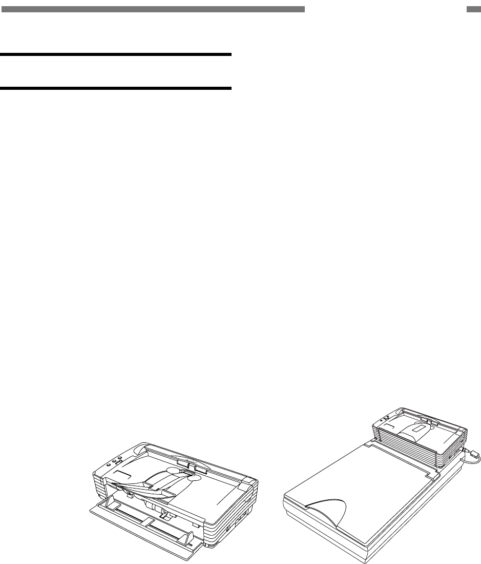
1. Compact design (small, light)
Dimensions (Tray closed): 304 (W) × 169 (D) × 81.5 (H) mm
Wight: 1.9 Kg
2. High-speed scanning
Black & White, Grayscale: Simplex 25 ppm, Duplex 50 ipm (200 dpi, A4 size)
Color: Simplex 13 ppm, Duplex 26 ipm (200 dpi, A4 size)
3. Dual-path mechanism (U-turn/Straight path)
Straight path is provided for thicker documents and cards.
4. Flatbed scanner for option
It can be attached and detached by users.
5. Installation and replacing of consumable parts by users
with flatbed
Figure 1-101
“Windows” is a trademark of Microsoft Corporation in the U.S. and other countries.
Other company names and product names mentioned in this document are registered trademarks or
trademarks of the respective companies.

1-2
COPYRIGHT © 2005 CANON ELECTRONICS INC. CANON DR-2580C FIRST EDITION APR. 2005
CHAPTER 1 GENERAL DESCRIPTION
II. SPECIFICATIONS
1. Appearance / Installation
No. Item Specifications
1 Type Desktop type sheet-fed scanner
2 Product models 1) 100 V model: 100 VAC, 50/60 Hz
2) 120 V model: 120 VAC, 60 Hz
3) 220-240 V model: 220-240 VAC, 50/60 Hz
3 Rating power 1) Main body
All mode: 16VDC, 1.4A
*Packaged AC adapter must be used
*Energy Star conformity
2) Packaged AC adapter
Input: 100-240 VAC, 50/60 Hz,
0.65-0.34 A (65-82 VA)
Output: 16 VDC, 1.8 A
4 Operating
environment
10 to 32.5°C (50 to 90.5°F)
20 to 80%RH
*No condensation allowed.
5 Noise 1) Sound power level
In standby mode: 40 dB or less
In operating mode: 66 dB or less
2) Sound pressure level: Bystanders (reference)
In operating mode: 57 dB or less
6 Dimensions Tray closed: 302 (W) × 171 (D) × 81 (H) mm
7 Weight Approx. 1.9 kg
8 Output interface 1) USB2.0 (Hi-speed)
2) Flatbed’s interface
9 Expected product life
(in-house
information)
One of the following two items, whichever comes first.
1) 5 years
2) Sheets fed: 500,000 sheets (A4 size)
*There are parts needed to replace.
10 Estimated duty cycle 750 sheets/day
11 Installation By users
12 Bundle software ISIS/TWAIN driver, CapturePerfect 3.0, Acrobat 7.0
13 Option 1) Flatbed unit
2) Barcode module
14 Consumable parts
(commercial goods)
Exchange roller kit (roller unit, retard roller)
Table 1-201

COPYRIGHT © 2005 CANON ELECTRONICS INC. CANON DR-2580C FIRST EDITION APR. 2005
1-3
CHAPTER 1 GENERAL DESCRIPTION
2. Documents Feed
No. Item Specifications
U-turn path Straight path
1) Width 53 to 216 mm
1 Document size
2) Length 70 to 297 mm
* Up to 355.5 mm for single sheet feed
only include LGL size.
1) Separation-feed 52 to 128 g/m2
(0.06 to 0.15 mm)
42 to 157 g/m2
(0.05 to 0.20 mm)
2 Document weight
(converted thickness)
2) Non-Separation 42 to 157 g/m2 (0.05 to 0.20 mm)
* No guarantee for 0.20 mm if feeding can
be done at straight path.
3 International
standard card
Available at straight path with non-separation feed only.
Width: 53.9 mm, Length: 85.5 mm, Thickness: 0.76 mm
*No embossment is permitted.
4 Document
requirements
1) Pressure-sensitive paper: Can be fed with limitation of direc-
tion.
2) Carbon-backed paper: Cannot be fed.
3) Perforated paper for binder: Can be fed with limitation of
holes.
4) Curled paper: Can be fed only if curl is 5 mm or less.
5) Creased paper: Can be fed, but crease must be straightened
before being fed.
U-turn path Straight path
1) Pickup 5 mm or less including curls, or 50 sheets
with 80 g/m2 at max.
*Special sheets whose pickup perform-
ance is poor are 10 sheets or less
2) Ejection Same as pickup 1 sheet
5 Document storage
3) Ejection face
direction
Face down Face up
Resolution Binary Grayscale Color
100 dpi 156 mm/sec
200 dpi 78 mm/sec
300 dpi
156 mm/sec
52 mm/sec
400 dpi 58 mm/sec 19 mm/sec
600 dpi 39 mm/sec 13 mm/sec
6 Feeding speed
*For big size of image data like A4/600dpi/color mode, docu-
ment is fed with intermittence.
Table 1-202

1-4
COPYRIGHT © 2005 CANON ELECTRONICS INC. CANON DR-2580C FIRST EDITION APR. 2005
CHAPTER 1 GENERAL DESCRIPTION
3. Document Reading *using bundle software CapturePerfect 3.0
No. Item Specifications
1 Type of sensor Contact Image Sensor (CIS)
2 Picture element Density of element: 600 dpi, Effective elements: 5104 (216 mm)
3 Light source 3-color (RGB) LEDs
R: 620 nm, G: 530 nm, B: 467 nm
4 Color dropout Available: R/G/B, front/back each side
*Color emphasize modes are available also.
5 Reading side Simplex/Duplex/Blank skip/Folio/Auto/Flatbed
*“Auto, flatbed” are good for connected flatbed unit only.
6 Reading size 1) Typical: A4/A5/A5-R/A6/A6-R, B5/B6/B6-R, LGL/LTR
2) Auto size detection
3) Maximum size (216 × 355 mm)
4) User setting
7 Output mode 1) Binary (Black & White/Error diffusion/Advanced text en-
hancement)
2) Grayscale (8 bit)
3) Color (24 bit)
8 Output resolution 100 × 100 dpi, 150 × 150 dpi, 200 × 200 dpi, 240 × 240 dpi,
300 × 300 dpi, 400 × 400 dpi, 600 × 600 dpi,
A4 size documents
Mode Resolution Single Double
200 dpi 25 ppm 50 ipm
300 dpi 25 ppm 50 ipm
Black & White
/Grayscale
600 dpi 6 ppm 12 ipm
200 dpi 13 ppm 26 ipm
300 dpi 8 ppm 16 ipm
Color
600 dpi 2 ppm 4 ipm
9 Reading speed
*Settings of reading are default. The numbers above may differ
depending on the computer, the function settings and other con-
ditions.
For big size of image data, document is fed with intermittence.
Table 1-203

COPYRIGHT © 2005 CANON ELECTRONICS INC. CANON DR-2580C FIRST EDITION APR. 2005
1-5
CHAPTER 1 GENERAL DESCRIPTION
4. Image Processing/Other Functions *using bundle software CapturePerfect 3.0
No. Item Specifications
1 Brightness adjustment 255 steps, back side individual setting
2 Contrast adjustment 7 steps, back side individual setting
3 Gamma correction Grayscale/R/B/G individual color, each side setting
4 Edge emphasize 5 steps
5 Shading correction Automatic operation at each batch
6 Skew correction
(deskew)
Performed by image processing
7 Double feed detection Length detection sensor
8 Other image processing Black border removal, Binder hole removal, Image rotation,
Text orientation
9 Counter Total fed counts (memorize in scanner)
10 Operation buttons
(job buttons)
3 buttons (available registering the functions)
Table 1-204
5 Flatbed Unit (option)
No. Item Specifications
1 Type Desktop type flatbed scanner
*No operation without main body DR-2580C
2 Dimensions
(tray closed)
Flatbed itself: 315 (W) × 545 (D) × 82.5 (H) mm
With DR-2580C: 315 (W) × 557 (D) × 155 (H) mm
3 Weight Approx. 3.8 kg (with DR-2580C: Approx. 5.7 kg)
4 Type of sensor CCD: 600 dpi, 5104 pixels (216 mm), Grayscale/RGB output
5 Light source Xenon lamp (white)
6 Reading size 216 × 297 mm maximum
7 Expected product life
(in-honse information)
One of the following two items, whichever comes first.
1) 5 years
2) Sheets scanned: 20,000 sheets (A4 size)
8 Installation By users
*Include detach/attachment with main body DR-2580C
Table 1-205
The specifications above are subject to change for improvement of the product.

1-6
COPYRIGHT © 2005 CANON ELECTRONICS INC. CANON DR-2580C FIRST EDITION APR. 2005
CHAPTER 1 GENERAL DESCRIPTION
III. PRECAUTIONS
This section describes items that require
particular care, for example, regarding human
safety. These precautions must be observed.
Explain to the user items that relate to user
safety, and instruct the user to take appropri-
ate actions.
1. Power OFF in Emergency
When such abnormalities as abnormal
noise, smoke, heat and odor occur, turn the
power switch OFF and unplug the power cord
immediately.
As it may cause injury, be careful not to
get clothing (ties, long hair, etc.) caught in the
machine. If this happens, unplug the power
cord immediately. Also, do not insert your
fingers in the feed section while feeding
documents.
2. Prohibition of Modify
Do not change nor modify this machine. If
this has been carried out, its use may be
forcibly discontinued on site.
If this machine’s specifications shall be
changed, or the machine shall be disassem-
bled and reassembled, follow the instructions
described in this manual or in service Infor-
mation.
3. Electromagnetic Wave Interference
Countermeasures
This machine complies with the electro-
magnetic wave interference standards (VCCI,
FCC, etc.). However, the user might have to
carry out countermeasures if the machine
causes electromagnetic wave interference.
4. User Manual
Read the user manual thoroughly before
using this machine.
5. Disposal
Following local regulations when dispos-
ing of the product and parts.
COPYRIGHT © 2005 CANON ELECTRONICS INC. CANON DR-2580C FIRST EDITION APR. 2005
1-7
CHAPTER 1 GENERAL DESCRIPTION
IV. NAME OF PARTS
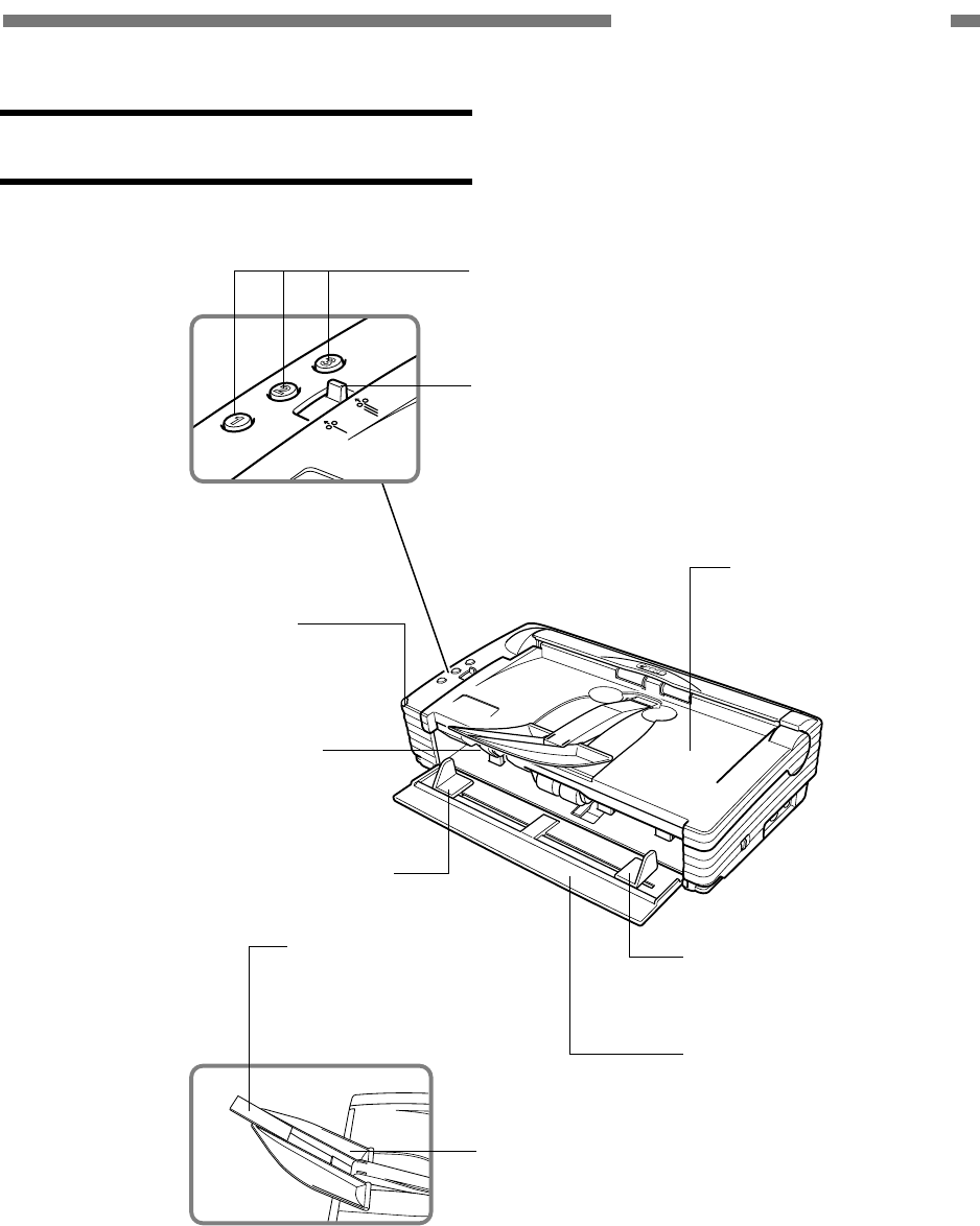
1. Front
Pickup selection lever
Job buttons
Eject tray/
upper unit
Eject tray extension 2
Pickup tray
Document guide
Eject tray extension
Power indicator
OPEN knob
Document guide
Figure 1-401
1-8
COPYRIGHT © 2005 CANON ELECTRONICS INC. CANON DR-2580C FIRST EDITION APR. 2005
CHAPTER 1 GENERAL DESCRIPTION
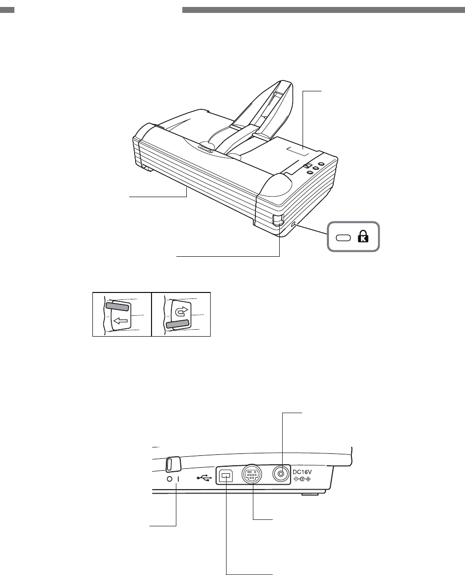
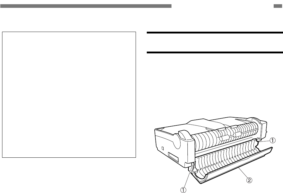
2. Rear
Kensington slot
Eject selection lever
Up : Straight path
Down : U-turn path
Job label location
Eject opening
Figure 1-402
3. Side (interface)
USB connector
Power switch Option connector
Power connector
Figure 1-403
COPYRIGHT © 2005 CANON ELECTRONICS INC. CANON DR-2580C FIRST EDITION APR. 2005
1-9
CHAPTER 1 GENERAL DESCRIPTION
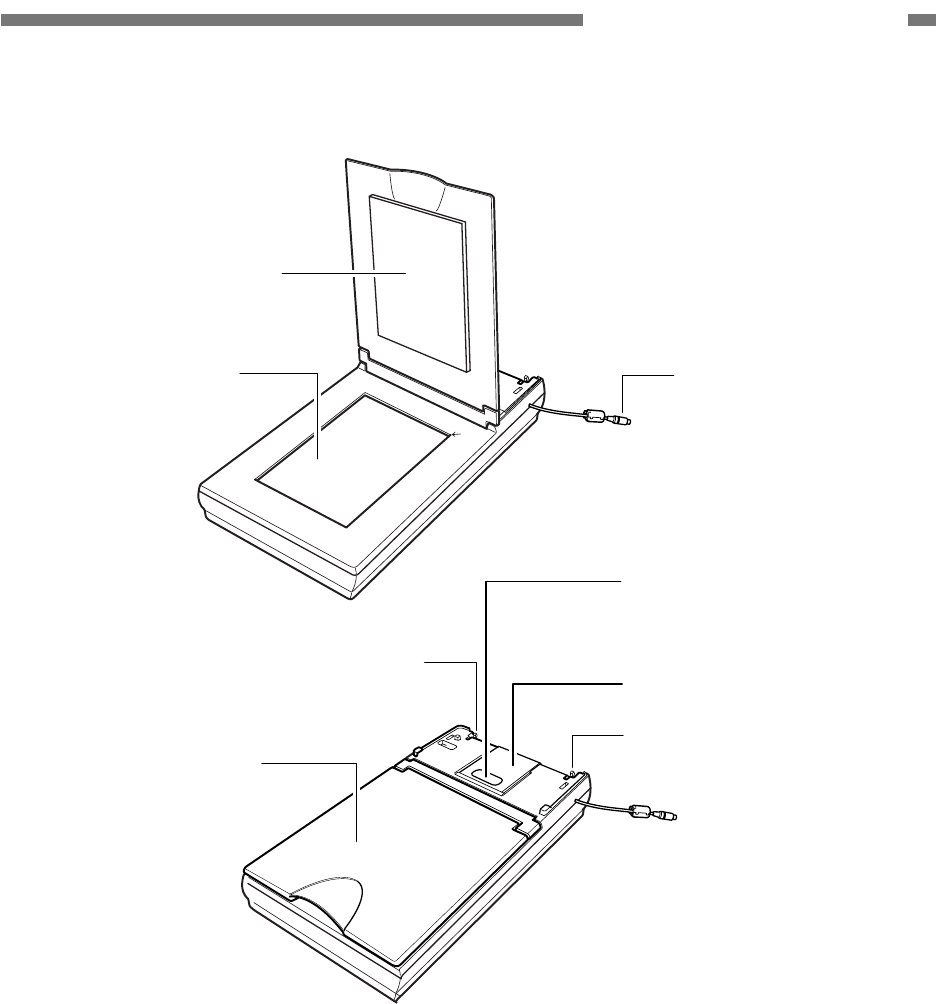
4. Flatbed unit (option)
Pressure board
(black)
Flatbed (platen glass) Interface cable
Auxiliary paper support plate
Scanning unit slide lock
Flatbed cover
DR-2580C locking hook
DR-2580C locking hook
Figure 1-404
1-10
COPYRIGHT © 2005 CANON ELECTRONICS INC. CANON DR-2580C FIRST EDITION APR. 2005
CHAPTER 1 GENERAL DESCRIPTION
V. USER OPERATION
Refer to the user manuals for this machine
and software to be used for details.
1. Installation
This machine is installed by the user.
Unpacking and installation are performed by
the user. If they are performed by a service
technician, refer to the user manual.
“CHAPTER 4 INSTALLATION & MAINTENANCE,”
in this manual provides an overview. However,
the next section “USER MAINTENACE”
shows how to install the roller unit and retard
roller.
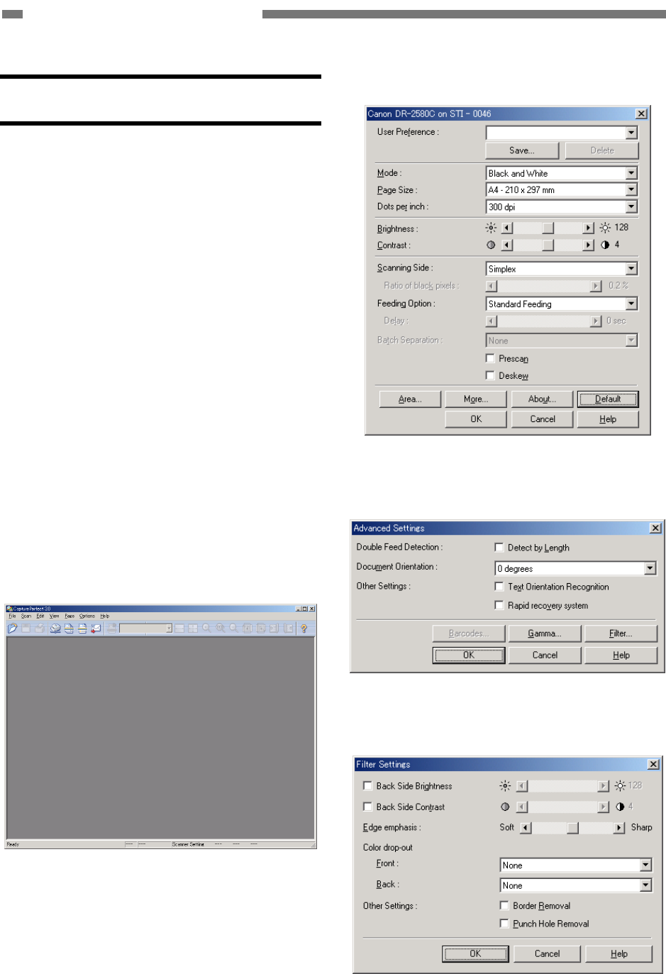
2. Operation Screen
Basic operation screens if CapturePerfect
3.0 is used are shown for reference. Cap-
turePerfect 3.0 uses an ISIS driver.
1) Main screen
Figure 1-501
2) Basic settings
Figure 1-502
3) Detailed settings
Figure 1-503
4) Filter
Figure 1-504
COPYRIGHT © 2005 CANON ELECTRONICS INC. CANON DR-2580C FIRST EDITION APR. 2005
1-11
CHAPTER 1 GENERAL DESCRIPTION
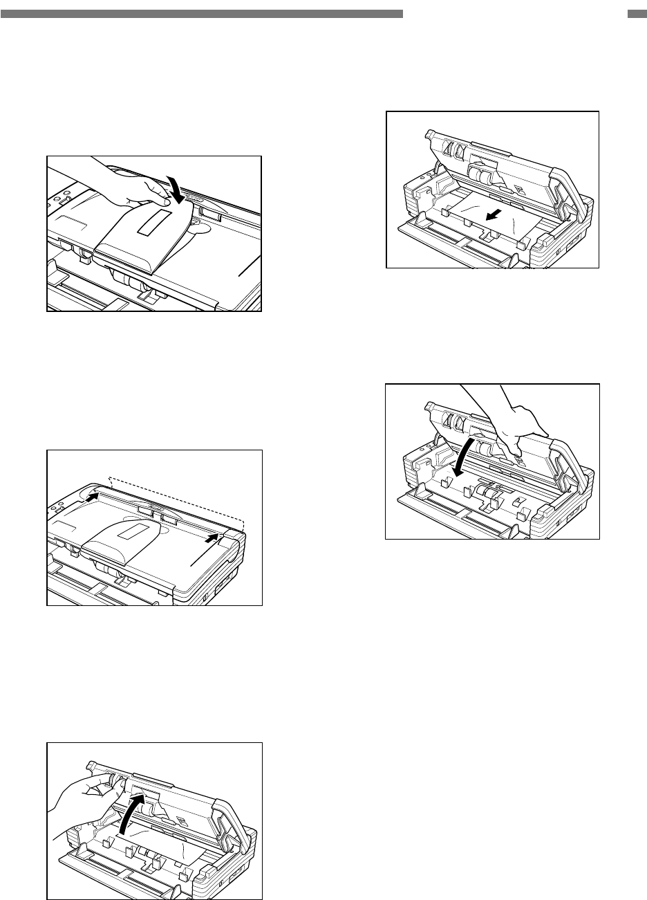
3. Clearing Jams
1) Remove documents left on the eject tray
and then close the eject tray extension.
Figure 1-505
2) Open the rear cover by pressing the both
sides.
Figure 1-506
3) Push the OPEN knob from both sides and
open the upper unit slowly.
Figure 1-507
4) Remove the jammed document carefully.
Figure 1-508
5) Close the upper unit slowly.
Figure 1-509
6) Close the rear cover by pressing the both
sides.
1-12
COPYRIGHT © 2005 CANON ELECTRONICS INC. CANON DR-2580C FIRST EDITION APR. 2005
CHAPTER 1 GENERAL DESCRIPTION
VI. USER MAINTENANCE
Refer to the user manual for this machine
for details.
1. Cleaning
Daily cleaning items are shown below.
1) Main unit exterior
2) Main unit interior (feed path)
3) Rollers
4) Reading glass
5) Shading plates
2. Roller Replacement
The roller unit and retard rollers are con-
sumables. They should be replaced when
100,000 sheets are fed as a guide. They are
replaced by the user.
The roller unit has the pickup roller and
retard roller.
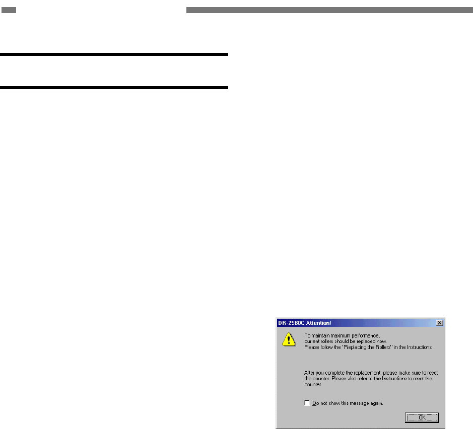
a. Replacement message
When the number of sheets fed exceeds
100,000, a “roller replacement message”
is displayed on the display when the
computer is started.
Note: The message is not displayed when the
operating system is Windows NT.
Figure 1-601
COPYRIGHT © 2005 CANON ELECTRONICS INC. CANON DR-2580C FIRST EDITION APR. 2005
1-13
CHAPTER 1 GENERAL DESCRIPTION
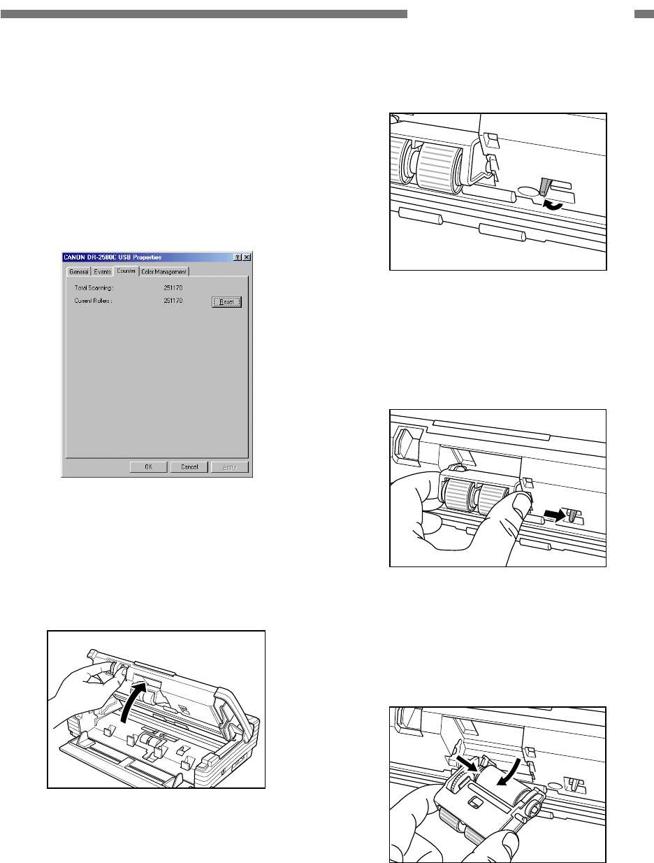
When the rollers are replaced, the counter
must be reset.
To reset the counter, select “Start → Set-
tings → Control Panel → Scanner and
Camera” to display the “Properties”
screen for this machine, and click the
“Reset” button for the counter.
Figure 1-602
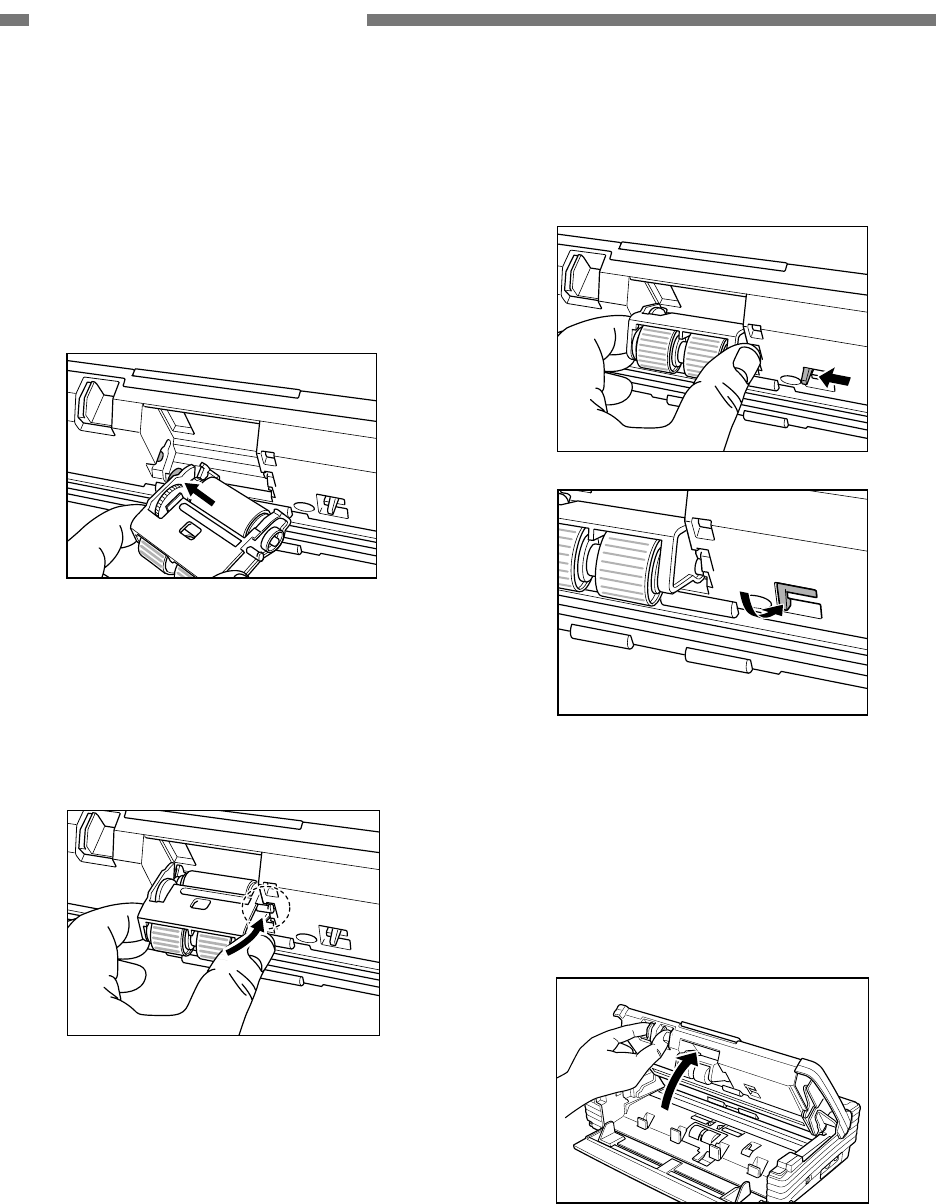
b. Roller unit
• Removal
1) Push the OPEN knob from both sides and
open the upper unit slowly.
Figure 1-603
2) Raise the roller locking lever.
Figure 1-604
3) Hold the roller unit with your fingers and
slide the locking lever to the right.
Figure 1-605
4) Detach the right side of the roller unit first
and remove the roller unit.
Figure 1-606
1-14
COPYRIGHT © 2005 CANON ELECTRONICS INC. CANON DR-2580C FIRST EDITION APR. 2005
CHAPTER 1 GENERAL DESCRIPTION
• Reinstallation
1) Push the OPEN knob from both sides and
open the upper unit slowly.
2) Raise the roller locking lever and slide it to
the right.
3) Set the roller unit on the shaft of the main
body.
Figure 1-607
4) Insert the projection on the roller unit into
the groove in the main body and lift the
roller unit.
Figure 1-608
5) Slide the roller locking lever to the left and
then push it backward to secure the roller
unit.
Figure 1-609
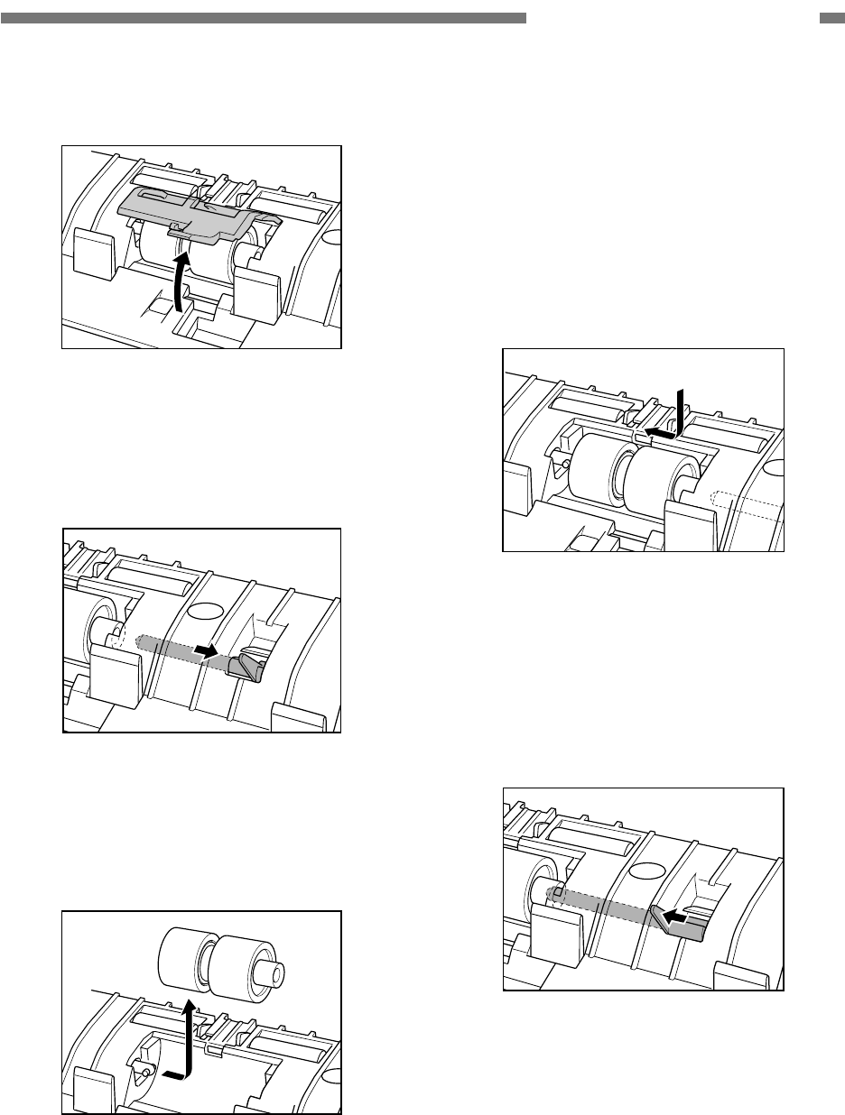
c. Retard roller
• Removal
1) Push the OPEN knob from both sides and
open the upper unit slowly.
Figure 1-610
COPYRIGHT © 2005 CANON ELECTRONICS INC. CANON DR-2580C FIRST EDITION APR. 2005
1-15
CHAPTER 1 GENERAL DESCRIPTION
2) Remove the roller cover.
Figure 1-611
3) Raise the roller locking lever and slide it to
the right.
Figure 1-612
4) Move the retard roller to the right and
remove it.
Figure 1-613
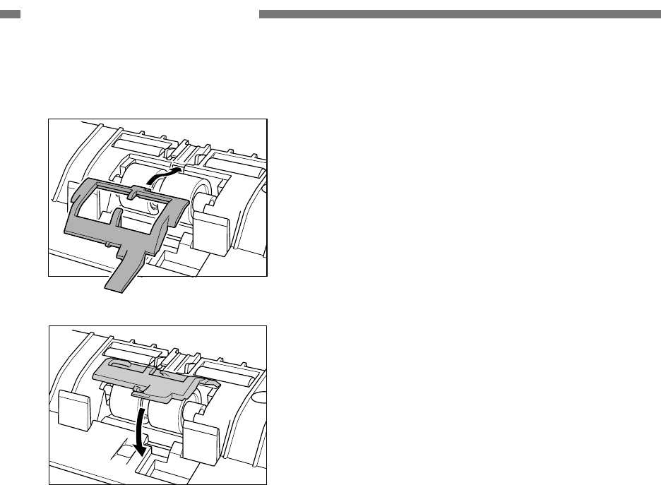
• Reinstallation
1) Push the OPEN knob from both sides and
open the upper unit.
2) Remove the roller cover.
3) Raise the roller locking lever and slide it to
the right.
4) Align the notch in the retard roller with the
shaft of the main body and set it.
Figure 1-614
5) Slide the roller locking lever to the left, fit it
into the hole in the retard roller and push
the lever backward to secure the retard
roller.
Figure 1-615
1-16
COPYRIGHT © 2005 CANON ELECTRONICS INC. CANON DR-2580C FIRST EDITION APR. 2005
CHAPTER 1 GENERAL DESCRIPTION
6) Install the roller cover.
Figure 1-616

CHAPTER 2
FUNCTIONS & OPERATION
COPYRIGHT © 2005 CANON ELECTRONICS INC. CANON DR-2580C FIRST EDITION APR. 2005
I. OUTLINE..................................................2-1
II. READING SYSTEM .................................2-5
III. FEED SYSTEM ........................................2-8
IV. CONTROL SYSTEM .............................. 2-11
V. IMAGE PROCESSING...........................2-14
VI. POWER SUPPLY ...................................2-30
VII. FLATBED UNIT ......................................2-31
VIII
. ELECTRICAL PARTS LAYOUT .............2-35
IX. PARTS LAYOUT OF EACH PCB ...........2-37
COPYRIGHT © 2005 CANON ELECTRONICS INC. CANON DR-2580C FIRST EDITION APR. 2005
2-1
CHAPTER 2 FUNCTION & OPERATION
I. OUTLINE
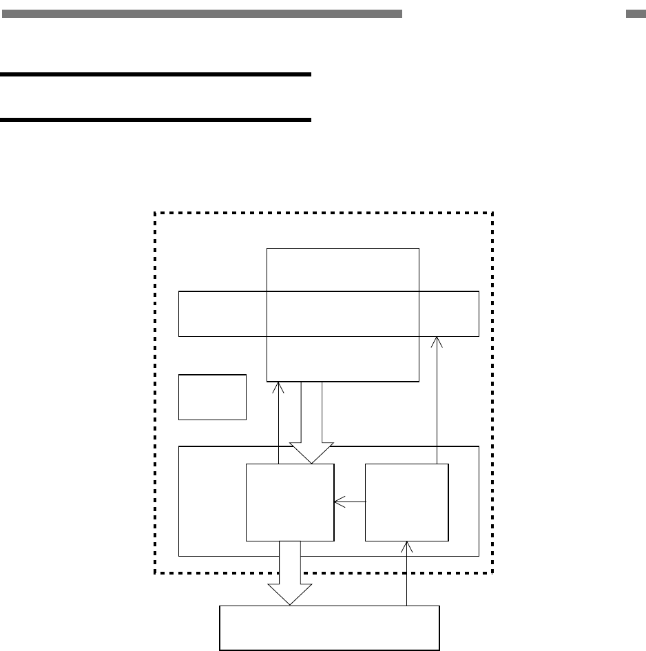
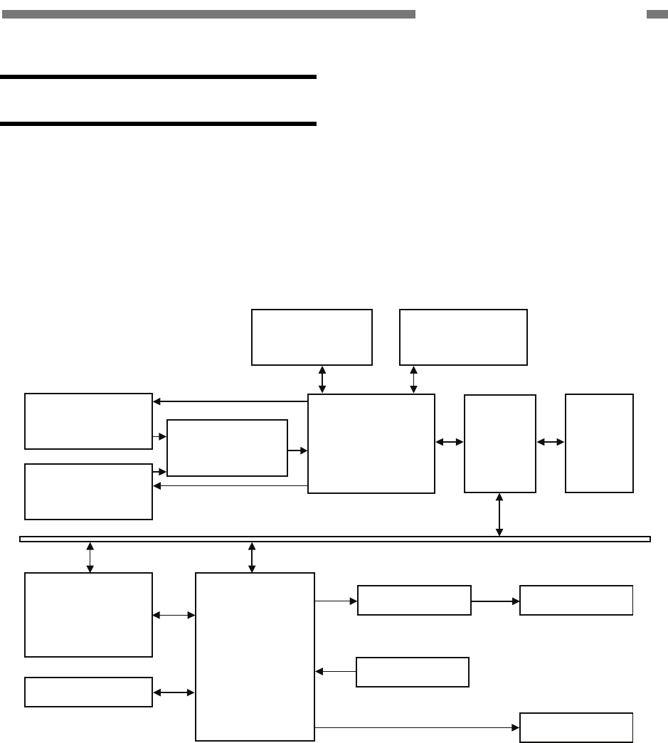
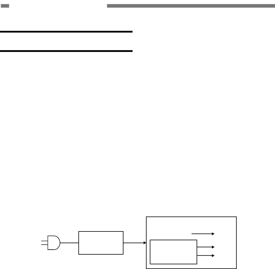
1. Basic Configuration
Figure 2-101 shows the configuration of
this machine.
This machine
Reading system
Feed system
Control
system
Image
processing
section
Feed
control
section
Computer
Power
supply
section
Figure 2-101
1) Reading System
This system reads image data from image
sensors.
2) Feed System
This system performs from document
pickup to document ejection.
3) Control System
This system is comprised of an image
processing section and a feed control
section.
The image processing section controls the
reading system, processes the read im-
age data, and outputs it to the computer.
However, the image data processing is
also performed by the computer.
The feed control section controls the feed
system.
4) Power Supply Section
This section converts the AC power into
the DC power by a supplied AC adapter
and supplies it to the control PCB in the
main body.
2-2
COPYRIGHT © 2005 CANON ELECTRONICS INC. CANON DR-2580C FIRST EDITION APR. 2005
CHAPTER 2 FUNCTION & OPERATION
2. Motor Drive
This machine has a pickup motor (M1)
and a carry motor (M2) for feeding the docu-
ment.
These motors drive the stopper and the
reading unit.
Retard roller
Eject roller 1
Carry roller
Eject roller 2
Carry motor
Pickup motor
Control PCB
Switch PCB
Registration
roller
Pickup roller
Feed roller
Torque limiter
M1
M2
Figure 2-102
COPYRIGHT © 2005 CANON ELECTRONICS INC. CANON DR-2580C FIRST EDITION APR. 2005
2-3
CHAPTER 2 FUNCTION & OPERATION
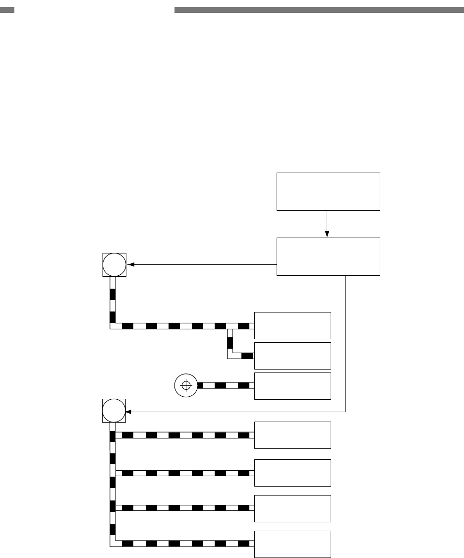
3. Electrical Circuits
Figure 2-103 shows an overview of the
electrical circuits block diagram of this ma-
chine.
Control PCB
Document board
sensor PCB
I/F Connector
Motor
Sensor
Switch PCB
Reading unit
(back)
Flatbed unit
Option
AC adapter
Sensor,
Power
LED
Switch
CIS PCB
CIS PCB
Reading unit
(front)
Figure 2-103
2-4
COPYRIGHT © 2005 CANON ELECTRONICS INC. CANON DR-2580C FIRST EDITION APR. 2005
CHAPTER 2 FUNCTION & OPERATION
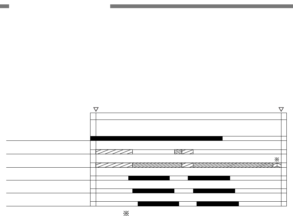
4. Timing Chart
Figure 2-104 describes the timing chart
when you separately feed two sheets of
document without temporarily suspending the
machine.
Document board sensor
Carry motor
Pickup motor
Pre-registrarion sensor
Registration sensor
Document reading
Start End
Reading speedReading speed
* 2nd document* 1st document
Reversal→stopper; Closed, reading unit (lower); to fornt
Figure 2-104
COPYRIGHT © 2005 CANON ELECTRONICS INC. CANON DR-2580C FIRST EDITION APR. 2005
2-5
CHAPTER 2 FUNCTION & OPERATION
II. READING SYSTEM
1. Outline
Figure 2-201 shows the configuration of
the reading system.
The reading unit (upper) reads the front
side of the documents and the reading unit
(lower) reads the back side of the documents.
This configuration enables the unit to read
both the front and back sides of a document
using a single scan.
The image data read are sent to the image
processing section of the control PCB.
Reading unit (upper)
Reading unit (lower)
Document
Figure 2-201
2-6
COPYRIGHT © 2005 CANON ELECTRONICS INC. CANON DR-2580C FIRST EDITION APR. 2005
CHAPTER 2 FUNCTION & OPERATION
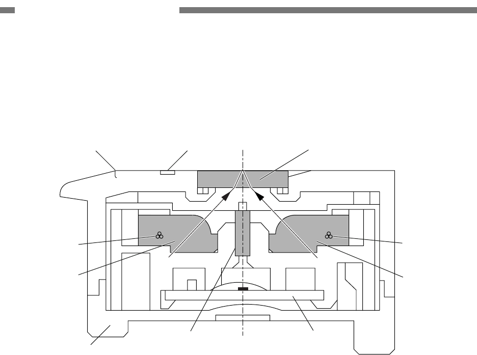
2. Reading Unit
Figure 2-202 shows the sectional diagram
of the reading unit.
Shading plate
LED(R/G/B)
Lens array
Case
Light guide
Holder
CIS PCB
Reading glass
LED(R/G/B)
Light guide
Figure 2-202
The reading unit consists of CIS unit,
holder, and lid. The CIS unit consists of CIS
PCB, lens array, LED (R/G/B), light guide, and
case. The reading glass and 2-mm width
shading plate are mounted on the holder.
Photosensitive pixels are mounted on the
CIS PCB with a density of 600 dpi. Effective
reading width is 216 mm, and the number of
effective picture elements is 5104.
Two sets of three basic color LEDs, red,
green, and blue (RGB), are mounted in the
CIS unit. In the binary or grayscale modes,
image data are read with composite light
generated by lighting the RGB LEDs simul-
taneously. In the color mode, the LED is suc-
cessively lit, and reads image data with each
color. As documents are being fed at regular
speed while image data are read, the reading
positions of RGB are shifted slightly.
In the color dropout mode, only the LED of
a designated color lights. In the color empha-
sis mode, the LED of a color other than a
designated color lights.
The LED light illuminates the document
through the light guide.
The reflected light from the document
enters photosensitive pixels through the lens
array, and converted into analog signals cor-
responding to the density of each picture
element.
COPYRIGHT © 2005 CANON ELECTRONICS INC. CANON DR-2580C FIRST EDITION APR. 2005
2-7
CHAPTER 2 FUNCTION & OPERATION
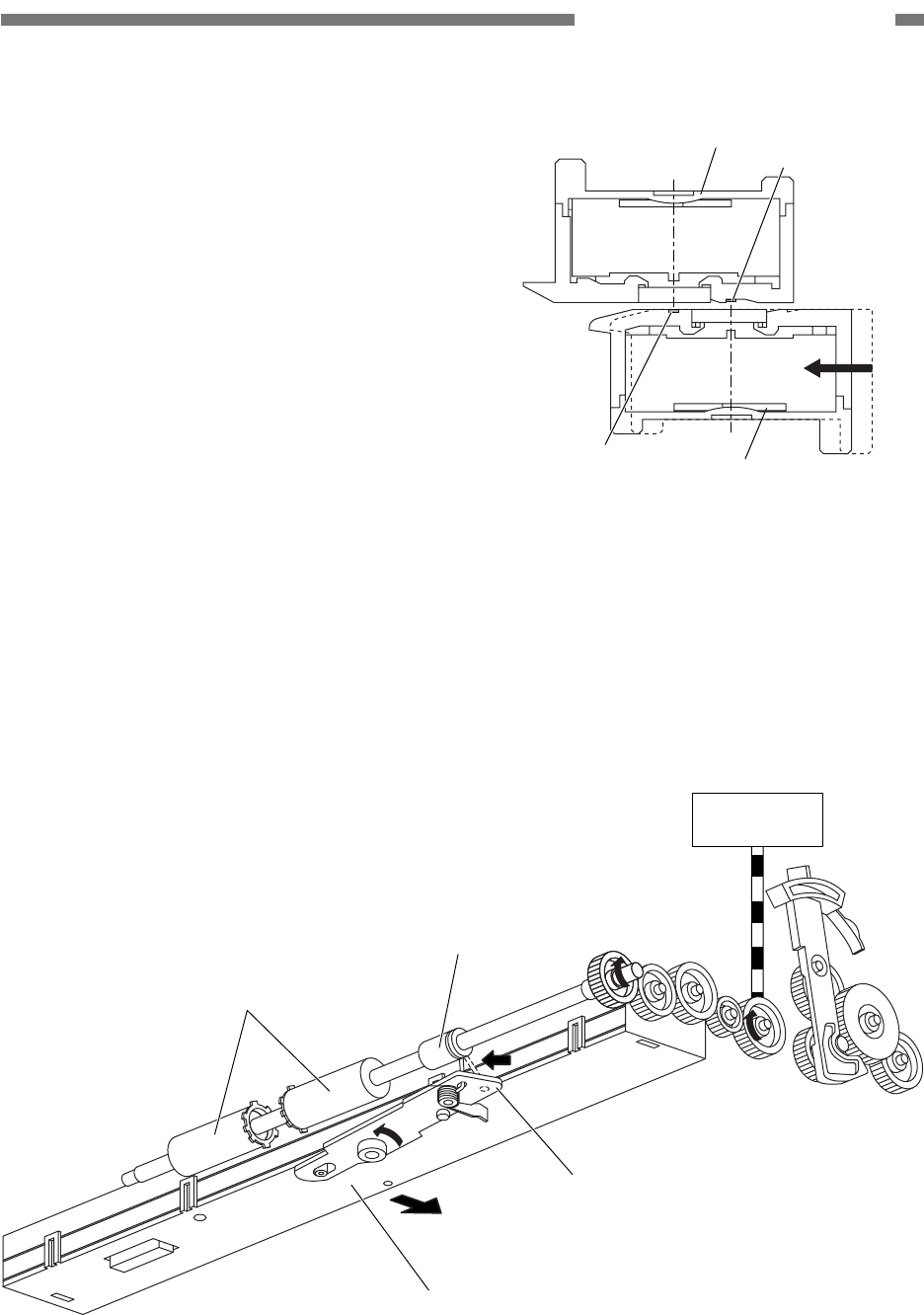
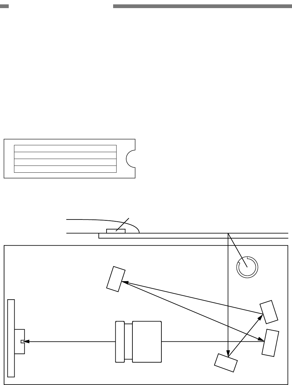
3. Shading
This section describes how the reading
unit (lower) mechanically works when a
shading correction value is determined.
The reading unit is usually set up so that
the background color becomes black. When a
shading correction value is determined, the
data on a shading plate need to be read. Thus,
the reading unit (lower) is moved about 2 mm
to the document pickup side.
Figure 2-204 describes the structural
drawing of that part. If the carry motor is ro-
tated opposite to the feed direction, the me-
chanical clutch which is installed on the shaft
of the eject roller 1 rotates. At this point in time,
the coupling plate starts rotating by the head of
the coil spring and the reading unit moves
horizontally.
When such motor normally rotates, the
reading unit returns again to its original posi-
tion.
Reading unit (upper)
Reading unit (lower)
Shading plate
Shading plate
Figure 2-203
Carry motor
Mechanical clutch
Reading unit (lower)
Coupling plate
Pickup side
Eject roller 1
Figure 2-204
2-8
COPYRIGHT © 2005 CANON ELECTRONICS INC. CANON DR-2580C FIRST EDITION APR. 2005
CHAPTER 2 FUNCTION & OPERATION
III. FEED SYSTEM
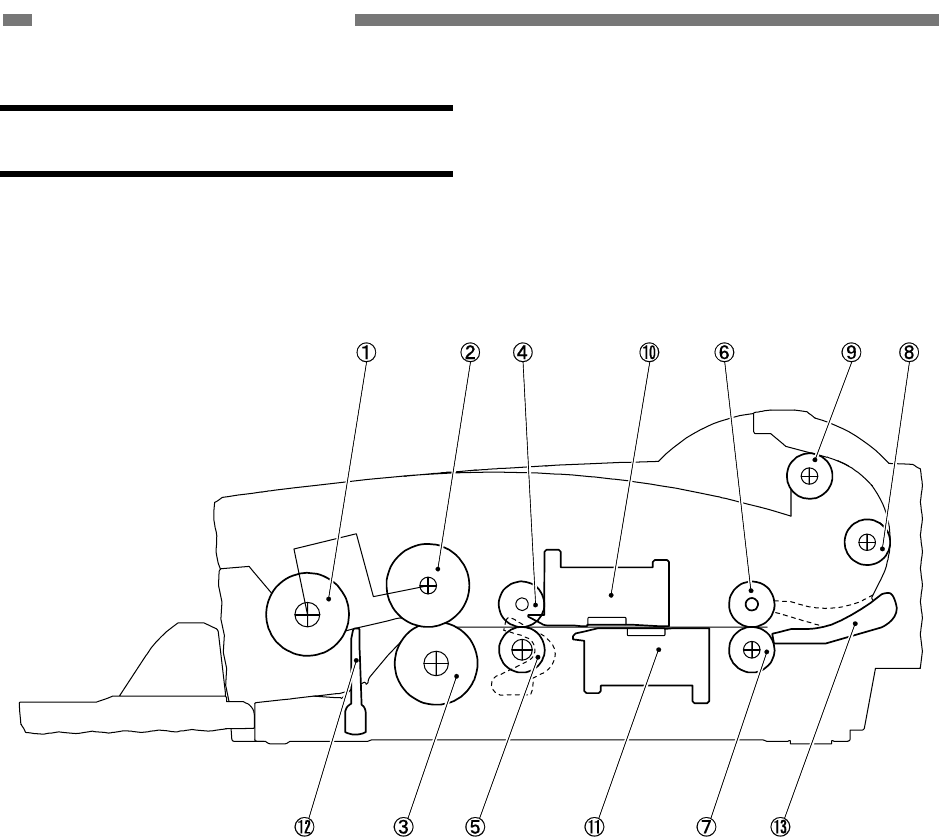
1. Outline
Figure 2-301 is a sectional diagram of the
feed system.
{
1 Pickup roller*
{
2 Feed roller*
{
3 Retard roller
{
4 Follower roller
{
5 Registration roller
{
6 Follower roller
{
7 Eject roller 1
{
8 Carry roller
{
9 Eject roller 2
{
10
Reading unit (upper)
{
11
Reading unit (lower)
{
12
Stopper
{
13
Flapper
Figure 2-301
Note: The pickup roller and the feed roller
make up a single unit called a roller unit.
COPYRIGHT © 2005 CANON ELECTRONICS INC. CANON DR-2580C FIRST EDITION APR. 2005
2-9
CHAPTER 2 FUNCTION & OPERATION
2. Feed Mechanism
1) Document pickup
The pickup section has a document
stopper. (Figure 2-301)
The stopper opens and starts picking up a
document when a scan start instruction is
given. The carry motor opens and closes
the stopper.
This machine picks up a document by
lowering the pickup roller not by lifting and
lowering the document board.
The lifting and lowering of the pickup roller
synchronizes with the opening and closing
of the stopper.
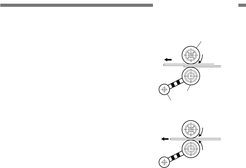
2) Document separation
Separation of this machine is performed
by the retard roller.
The torque limiter is built in the retard
roller. When the outside pressure on the
roller exceeds the specified value into the
feed direction, the roller begins to rotate in
the same direction.
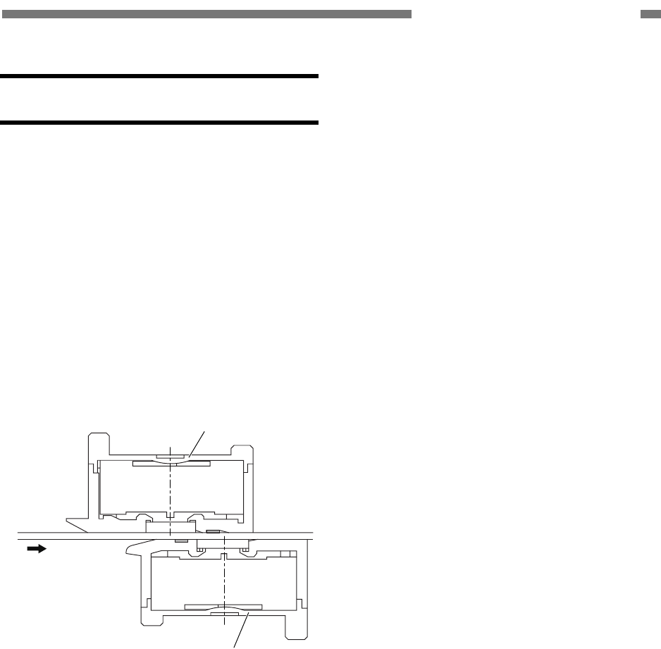
As shown in Figure 2-302-a, when over-
lapped documents enter into the clear-
ance between the feed roller and the re-
tard roller, the document in contact with
the feed roller is fed in the feed direction,
and the retard roller does not rotate so
that the document in contact with the re-
tard roller is not pushed in.
As shown in Figure 2-302-b, once a single
document remains, the retard roller ro-
tates in conjunction with the feed roller
and the document to feed the document.
If non-separation is selected, the retard
roller rotation becomes free and the
separation function becomes invalid.
Feed roller
Retard roller
Torque limiter
a.
b.
Figure 2-302
3) Document ejection
The U-turn path or the straight path can be
selected for the document ejection. The
lever makes the flapper change the feed
path. The flapper is behind the eject roller
1. (Figure 2-301)
The straight path is very useful when the
thicker documents or cards are scanned.

2-10
COPYRIGHT © 2005 CANON ELECTRONICS INC. CANON DR-2580C FIRST EDITION APR. 2005
CHAPTER 2 FUNCTION & OPERATION
3. Feed Error Detection
There are three types of document sen-
sors in this machine: a document board
sensor and two registration sensors.
The document board sensor detects
whether or not a document is present in the
document pickup opening, and the
pre-registration and registration sensors de-
tect it in the registration roller section.
The pre-registration and registration
sensors detect a document feed error.
1) Delay jam (document pickup error)
When the registration sensors do not
detect the leading edge of the document,
even after the motor drives the specified
length.
2) Residual jam
When the registration sensors do not
detect the trailing edge of the document
after the leading edge of the document is
detected, although the motor drives the
specified length (about 365 mm).
3) Early start jam
When the registration sensors detect the
trailing edge of the document after the
leading edge of the document is detected
before the motor drives the specified
length (about 40 mm).
4) Non-removable jam
When the registration sensors detect the
presence of the document when the
power is ON or after the upper unit opens
and closes.
5) Double feed detection
This machine checks the double feed by
detecting the document length by the
registration sensors. The detection
process is the same as the above the
residual jam. The specified length is
determined by the user set document
size.
4. Mechanical Feed Mode
Feed status can be checked without the
computer in this mode. This mode should not
be open to users.
The mechanical feed mode can be acti-
vated by pressing the job buttons on the op-
eration panel, as follows:
i) Turn ON the power switch with the job
button No.1 pressed.
ii) Keep pressing the job button No.1. For
about one second later, the power in-
dicator blinks. Then, press the job
button No.2 immediately.
iii) Press off the both buttons. When it is
in the mechanical feed mode, the
power indicator keeps blinking.
Set the document and push the job but-
ton No.1. The document will begin feeding.
The feeding speed is the same as for the
black and white setting of 200 dpi. To cancel,
turn the power switch OFF.
COPYRIGHT © 2005 CANON ELECTRONICS INC. CANON DR-2580C FIRST EDITION APR. 2005
2-11
CHAPTER 2 FUNCTION & OPERATION
IV. CONTROL SYSTEM
1. Control PCB
Control of this machine is performed by
the control PCB.
Figure 2-401 shows the block diagram of
the control PCB.
I/F for FB
Image memory section
·SDRAM
8MB
I/F for front sensor Data controller
(Regain)
USB
control
section
USB I/F
Analog processor
I/F for back sensor
CPU BUS
CPU memory section
· CPU
Main body control
section
Motor control section
· FLASH_ROM
· SRAM
· EEPROM
FB motor I/F
Detection sensor section
Key switch section
Power control section
Figure 2-401
2-12
COPYRIGHT © 2005 CANON ELECTRONICS INC. CANON DR-2580C FIRST EDITION APR. 2005
CHAPTER 2 FUNCTION & OPERATION
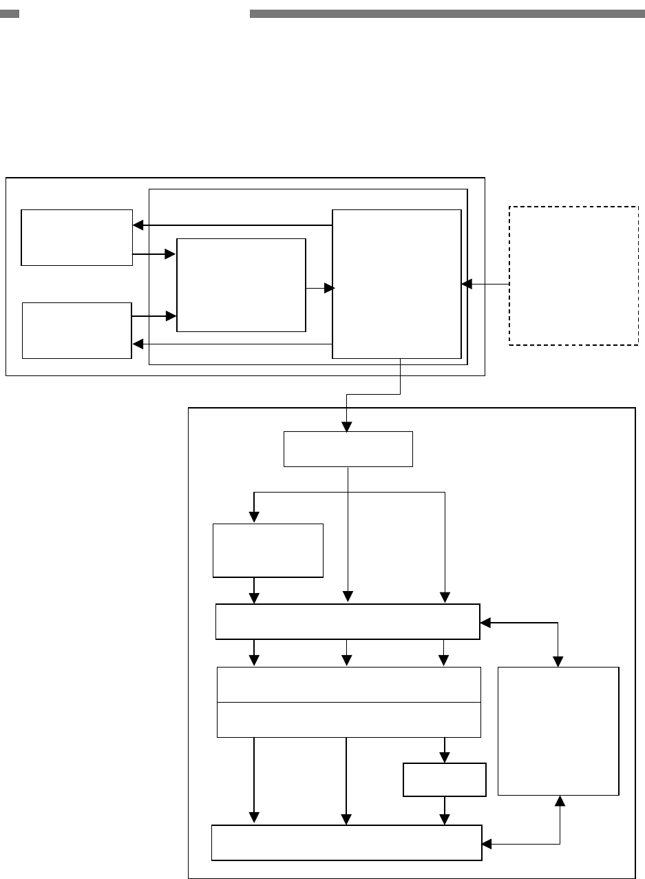
2. Image Processing Control
Figure 2-402 shows the block diagram of
the image processing in the main body.
CIS PCB
front
"This machine"
CIS PCB
back
Analog processor
· Offset adjustment
· Gain adjustment
· A/D conversion
Data controller
· LED light control
·
Resolution
conversion
· 12bit→8bit
"Computer"
"Flatbed"
Option
Shading correction
1-dimensional gamma correction
BinaryColor
Edge emphasis
Binarizing
Grayscale
Data after shading correction
USB interface
Data after image processing
Other processing
·
Size detection
·
Black border
removal
·
Binder hole
removal
· Others
Control PCB
Color
correction
(3-dimensions)
Figure 2-402

COPYRIGHT © 2005 CANON ELECTRONICS INC. CANON DR-2580C FIRST EDITION APR. 2005
2-13
CHAPTER 2 FUNCTION & OPERATION
Analog signals proportionate to the den-
sity of each picture element are output to the
analog processor on the control PCB from the
CIS PCB.
The analog processor carries out offset
adjustment, gain adjustment, and A/D con-
version. Analog signals are converted into
12bit digital signals in the analog processor.
Then the image data is transferred to the data
controller and the resolution is converted from
12 bits to 8 bits.
After that, the image data is output to the
computer through an USB interface.
All the image processing carried out in this
machine are described above. Other image
processing are carried out inside the com-
puter.
The computer performs the image proc-
essing according to the user settings after the
shading correction.

2-14
COPYRIGHT © 2005 CANON ELECTRONICS INC. CANON DR-2580C FIRST EDITION APR. 2005
CHAPTER 2 FUNCTION & OPERATION
V. IMAGE PROCESSING
Note: The principle of the image processing is
described simply in this section so that
you can easily understand it. In actual
cases, the procedure may be somewhat
complicated.
1. Image Processing in Main Body
1) Offset adjustment
Offset adjustment is carried out on analog
signals for the whole image sensor. Black
correction is adjusted so that the minimum
output value of the overall black level
matches the specified value.
2) Gain adjustment
Gain adjustment is carried out on analog
signals for the whole image sensor. White
correction is adjusted so that the maxi-
mum output value of the overall white
level matches the specified value.
Note: Offset and gain adjustment are used to
perform A/D conversion properly.
3) A/D conversion
This processing converts analog signals
into digital signals. The analog processor
unique to this machine converts analog
signals into 12bit digital signals. However,
12bit data is converted to 8bit data during
the resolution conversion described later.
Note: Shading correction for digital signals is
carried out in a computer, however,
correction values are stored in the flash
memory of the control PCB. The correc-
tion values are output to the computer.

COPYRIGHT © 2005 CANON ELECTRONICS INC. CANON DR-2580C FIRST EDITION APR. 2005
2-15
CHAPTER 2 FUNCTION & OPERATION
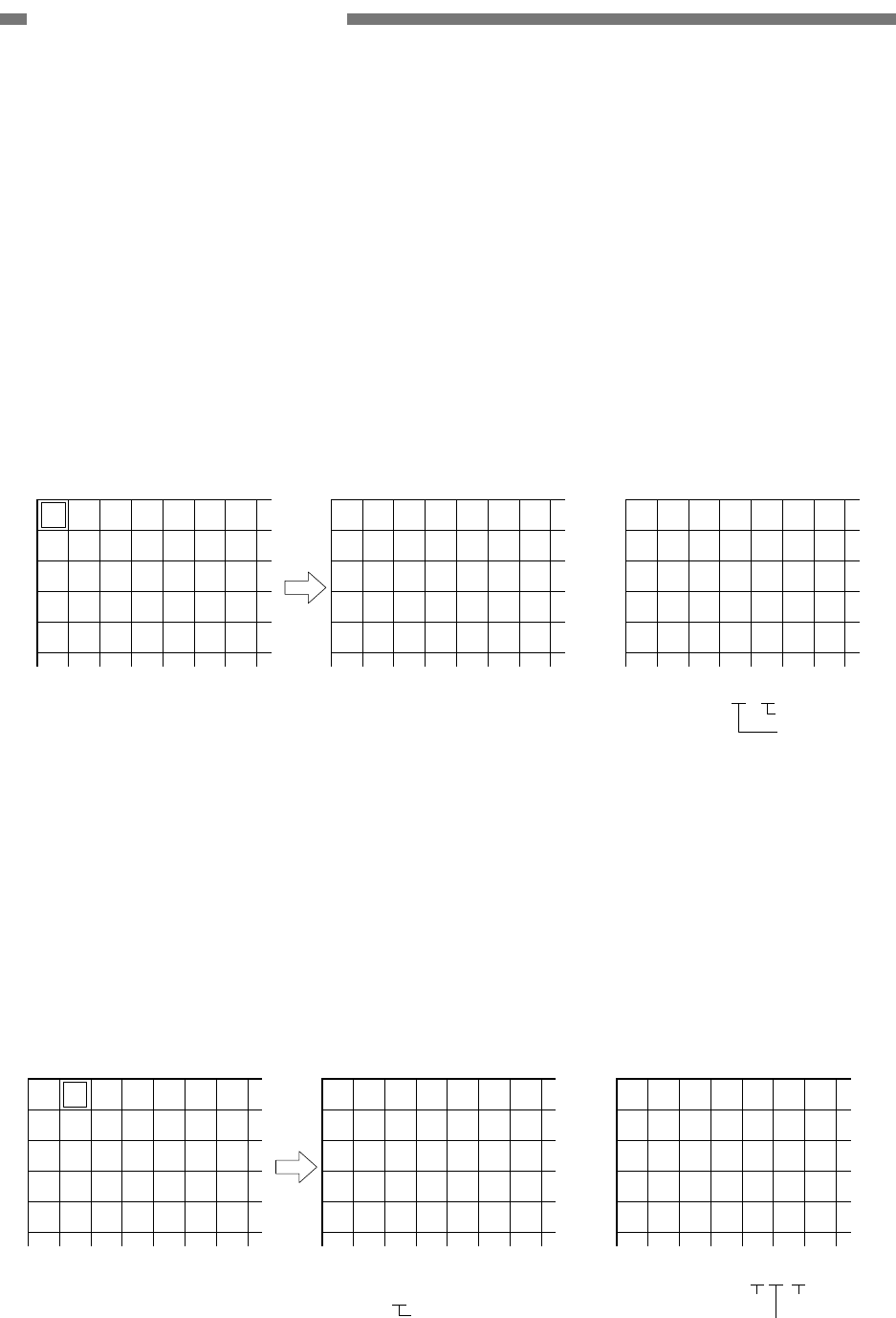
4) Image Resolution Conversion
a) Main-Scanning Direction
This machine enables outputs from the
CIS PCB to be converted into 600dpi or
300dpi data. In case that the resolution
selected is the 600/400dpi mode, it
produces 600dpi outputs. On the other
hand, in case that the resolution is set
at 300dpi or less, 300dpi outputs are
produced.
When 600 or 300dpi data are produced,
this machine can convert the resolu-
tions of those data by averaging them.
The image resolution conversion by
averaging is sometimes called
“smoothing.”
Averaging method conversion enables
the data to be smoothly transformed
much better than that by thinning-out
method, resulting in reducing the oc-
currence of Moire patterns.
Averaging is especially useful for
low-resolution photographs.
The data are averaged according to
the resolution applied when the basic
data of each picture element are con-
verted.
Figure 2-501 shows the aspects of
300dpi image data and the image data
averaged to 150dpi data.
A
A
A
A
A
A
1st line
2nd line
3rd line
1st line
2nd line
3rd line
(A+B)/2
(A+B)/2
(A+B)/2
(C+D)/2
(C+D)/2
(C+D)/2
(E+F)/2
(E+F)/2
(E+F)/2
(G+H)/2
(G+H)/2
(G+H)/2
4th line
5th line
6th line
B
B
B
B
B
B
C
C
C
C
C
C
D
D
D
D
D
D
E
E
E
E
E
E
F
F
F
F
F
F
G
G
G
G
G
G
H
H
H
H
H
H
•
300 dpi
•
150 dpi
Figure 2-501
2-16
COPYRIGHT © 2005 CANON ELECTRONICS INC. CANON DR-2580C FIRST EDITION APR. 2005
CHAPTER 2 FUNCTION & OPERATION
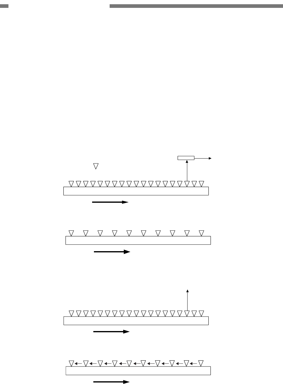
b) Sub-Scanning Direction
The document is scanned in the
sub-scanning direction basically by
changing the feeding speed.
In the case of 200 dpi, feeding speed is
1.5 times as fast as 300 dpi. In the case
of 150 dpi, it is twice the speed, and in
the case of 100 dpi, three times the
speed used for 300 dpi.
If the timing for reading the data from
the image sensor is the same, the
resolution in the sub-scanning direction
can be converted by changing the
feeding speed. (Figure 2-502)
However, the feeding speed is limited
depending on the specifications of
carry motor. If the feeding speed can-
not be increased, the read timing in-
terval is widened. (Figure 2-503)
Feeding speed (2 times as fast as 300 dpi)
Feeding speed
Image sensor
• 150 dpi
• 300 dpi : Reading point
Figure 2-502
Feeding speed (same as 300 dpi)
Feeding speed
•
150 dpi
•
300 dpi
Figure 2-503
COPYRIGHT © 2005 CANON ELECTRONICS INC. CANON DR-2580C FIRST EDITION APR. 2005
2-17
CHAPTER 2 FUNCTION & OPERATION
2. Image Processing in the Computer
1) Shading Correction
Even if the image brightness is consistent,
the values output from the image sensor
are not necessarily consistent because
the sensitivities of each element of the
image sensor and the performance of
each reading system would vary. In the
shading correction, the variations of each
element are compensated. This process-
ing is done for the digital signals after A/D
conversion.
The correction values of each element are
calculated in advance and stored in a
memory.
There are two types of correction values:
black and white correction values. For
black correction value, readout indicated
when an LED does not illuminate, in other
words, when a black image is read (in-
tense black) is set as a target value. For
white correction value, readout of stan-
dard shading plate is set as a target value
(pure white).
The data of each element which have
been converted into digital signals are
compensated in accordance with the
corresponding values.
After A/D
conversion
LEDS turned off
Black
correction
value
Figure 2-504
White
document
Same brightness
After A/D
conversion
After shading correction
Figure 2-505
This machine prepares a thin long shad-
ing plate near the reading glass instead of
a standard shading plate in order to
calculate correction values. Thus,
correction values can be automatically
calculated during normal operation.
2) Color Correction
To improve the reproducibility of color
images, the 3-dimensional gamma con-
version is performed on the color data
after the shading correction. A
3-dimensional conversion table that suits
the characteristics of this machine is pro-
vided to convert RGB values.
2-18
COPYRIGHT © 2005 CANON ELECTRONICS INC. CANON DR-2580C FIRST EDITION APR. 2005
CHAPTER 2 FUNCTION & OPERATION
3) Gamma Correction (1-dimension)
To improve the reproducibility of docu-
ments or modify the acquired image as
required by the user, it is possible to
convert the document image data using
conversion tables.
This machine provides various conversion
tables adjusted for image mode and set-
ting value.
However, there are several adjustment
items not available for image mode and
other conditions. For details, refer to the
driver software “Help” function.
The conversion tables below are for fun-
damental items and may be different from
actual items.
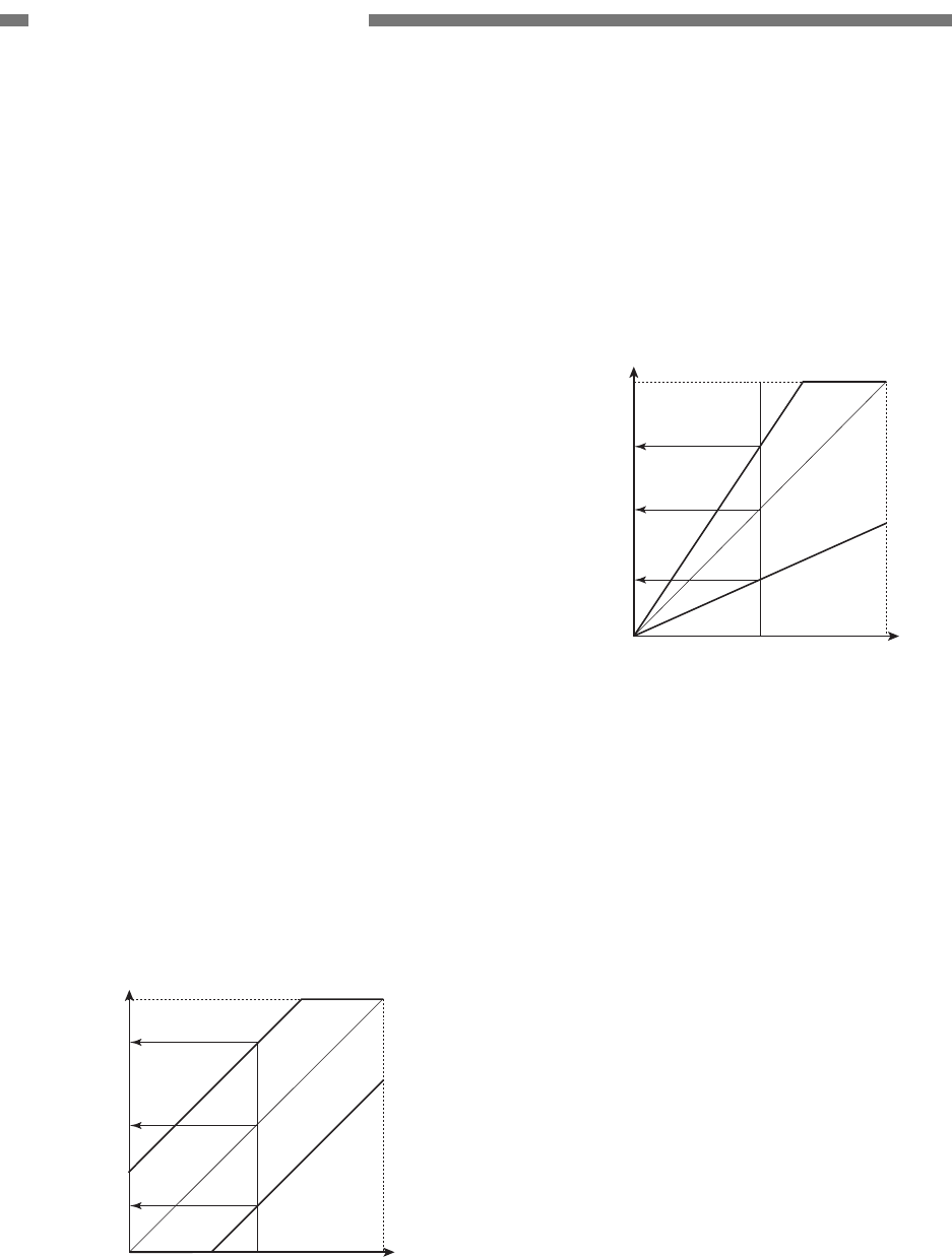
a) Brightness Adjustment
This adjusts the overall brightness of
the scanned image. The image
brightness increases as the setting
value becomes larger, and decreases
as the value becomes smaller.
For brightness adjustment in black and
white mode, refer to the “Binarizing”
section.
Y0
YH
White
(255)
After conversion
Before conversion
White
(255)
Black
(0)
(+)
(-)
YL
X0
Figure 2-506
b) Contrast Adjustment
This adjusts the contrast of the
scanned image. The image contrast
increases as the setting value be-
comes larger, and decreases as the
value becomes smaller.
Y0
White
(255)
White
(255)
Black
(0)
YH
X0
(+)
(-)
After conversion
Before conversion
YL
Figure 2-507
COPYRIGHT © 2005 CANON ELECTRONICS INC. CANON DR-2580C FIRST EDITION APR. 2005
2-19
CHAPTER 2 FUNCTION & OPERATION
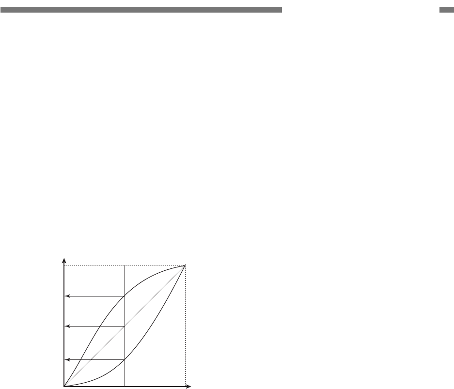
c) Custom Adjustment
This is used when data conversion
other than brightness and contrast
adjustments is required.
It is possible for the user to use a
custom conversion table for converting
the gamma curve to the document
image data. In this case, the bright-
ness and contrast adjustments be-
come invalid, and the unique gamma
curve is given priority.
YH
White
(255)
White
(255)
Black
(0)
Y0
YL
X0
(+)
(-)
After conversion
Before conversion
Figure 2-508
2-20
COPYRIGHT © 2005 CANON ELECTRONICS INC. CANON DR-2580C FIRST EDITION APR. 2005
CHAPTER 2 FUNCTION & OPERATION
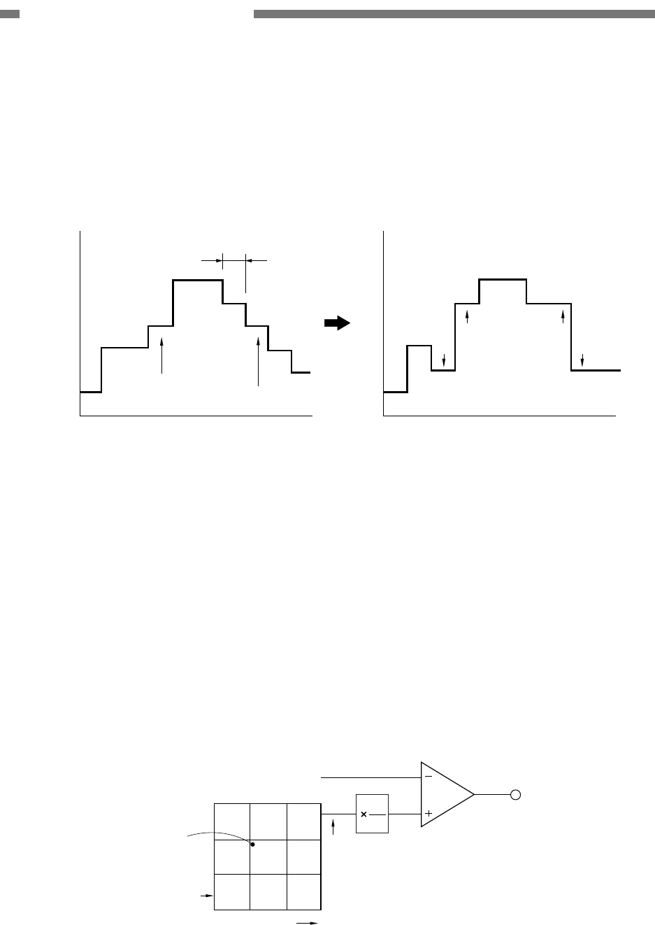
4) Edge Emphasis
Edge emphasis is a kind of processing
which emphasizes the brightness change
in order to make the image appear sharp.
(Figure 2-509)
Output
White
Black
White
Black
1 picture element
Edge portion Edge portion
Before edge emphasis After edge emphasis
Figure 2-509
The processing is performed by compar-
ing the data in the conversion table pro-
vided for performing edge emphasis, with
the target picture element data (a). (Figure
2-510)
The stages in edge emphasis can be
changed by changing the conversion table
and reproduction ratio (B) of the conver-
sion table.
For example, if the target picture element
data is increased fourfold and the other
four points multiplied by-1, the overall
brightness will remain unchanged.
Target picture
element
Conversion table
Output
Target picture
element (a)
Sub-scanning
direction
Main-scanning
direction
-a 00
4a -a-a
-a 00
: 1~64
32
B
B
Figure 2-510
COPYRIGHT © 2005 CANON ELECTRONICS INC. CANON DR-2580C FIRST EDITION APR. 2005
2-21
CHAPTER 2 FUNCTION & OPERATION
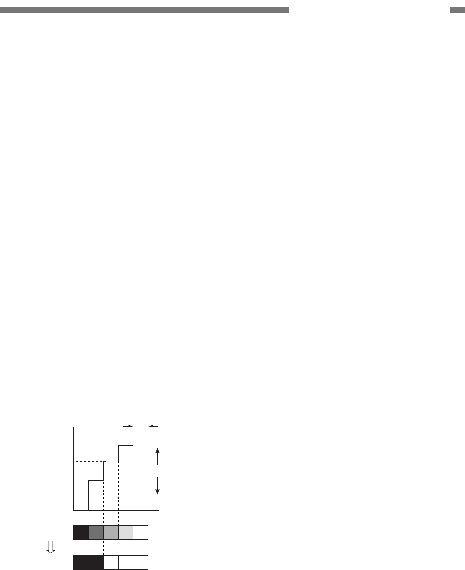
5) Binarizing
a) Simple Binarizing
Binary image data can only express
picture elements as either “black” or
“white.”
In order to separate the picture ele-
ments into black and white, signals
corresponding to the image brightness
must be cut off at a certain level, so that
anything above that level is judged as
“white” and anything below as “black.”
This is called simple binarizing. This is
useful for text documents. Simple bi-
narizing for this machine is called
“Black and White” mode.
The level at which picture elements are
to be divided into white or black is
called the “slice level.” The image
brightness is adjusted by changing this
slice level.
Black
1 picture element
White
Slice level
Document
Output
White 255
Black 0
160
128
96
Figure 2-511
2-22
COPYRIGHT © 2005 CANON ELECTRONICS INC. CANON DR-2580C FIRST EDITION APR. 2005
CHAPTER 2 FUNCTION & OPERATION
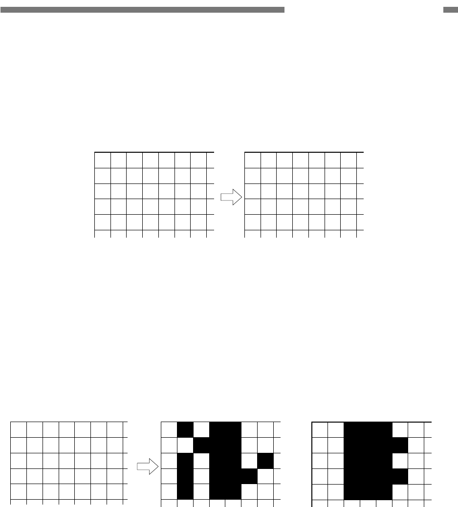
b) Error Diffusion
Error diffusion processing is used to
binarize documents containing gray
levels, such as pictures and photos.
A sample case is shown below, where
the output is set to four bits and the
slice level is set to “8.”
The value of 1 picture element of input
image data is compared with the slice
level. When it is smaller than the slice
level, it is output as “0” and when it is
bigger then the slice level, it is output
as “15.” The difference between the
values of the input and output picture
elements is then added to the next
picture element to be processed.
First, when processing the first low of
Line 1, since the data “12” is larger than
the slice level “8,” the output data be-
comes “15,” and the resultant error
becomes -3 (=12-15). (Figure 2-512)
12 9 6 3 1 9 13
Input data
15
Output data
12>8 → "15"
-3
Error -3=(12-15)
Output
Input
First row of line 1
Figure 2-512
Next, when processing the second row
of Line 1, since the error is diffused to
the right, the data of the picture ele-
ment of the second row of Line 1 be-
comes “6” (=9-3).
As this value is smaller than the slice
level, the output data is “0” and the
error becomes “+6” [=(9-3)-0]. (Figure
2-513)
The third row of Line 1 and later are
processed similarly.
12 9 6 3 1 9 13
Input data
15
(9-3)=6<8 → "0"
+6
Error +6=(9-3)-0
Error of first row of Line 1
Input
Second row of line 1
0
Error of first row of Line 1 Output
Output data
Figure 2-513
COPYRIGHT © 2005 CANON ELECTRONICS INC. CANON DR-2580C FIRST EDITION APR. 2005
2-23
CHAPTER 2 FUNCTION & OPERATION
Line 2 is processed using the first row
of Line 2 as a reference. If the rest is
processed similarly, the data becomes
as shown in Figure 2-514.
12
10
9
11
12
9
13
12
8
9
6
5
6
5
2
3
4
3
0
7
1
2
1
3
6
9
7
10
5
9
13
13
9
10
11
15
15
15
15
15
0
15
0
0
0
15
0
15
15
15
0
0
0
0
0
15
15
15
0
15
15
15
0
15
15
0
0
0
0
0
Input data Output data
Figure 2-514
Figure 2-515 shows a comparison of
binarizing with error diffusion proc-
essing, and binarizing without error
diffusion processing (simple binariz-
ing).
The brightness adjustment for error
diffusion is done by using the data
conversion table. The slice level is al-
ways set at median.
12
10
9
11
12
9
13
12
8
9
6
5
6
5
2
3
4
3
0
7
1
2
1
3
6
9
7
10
5
9
13
13
9
10
11
With error diffusion processing Without error diffusion processingDigital signal output
Figure 2-515
2-24
COPYRIGHT © 2005 CANON ELECTRONICS INC. CANON DR-2580C FIRST EDITION APR. 2005
CHAPTER 2 FUNCTION & OPERATION
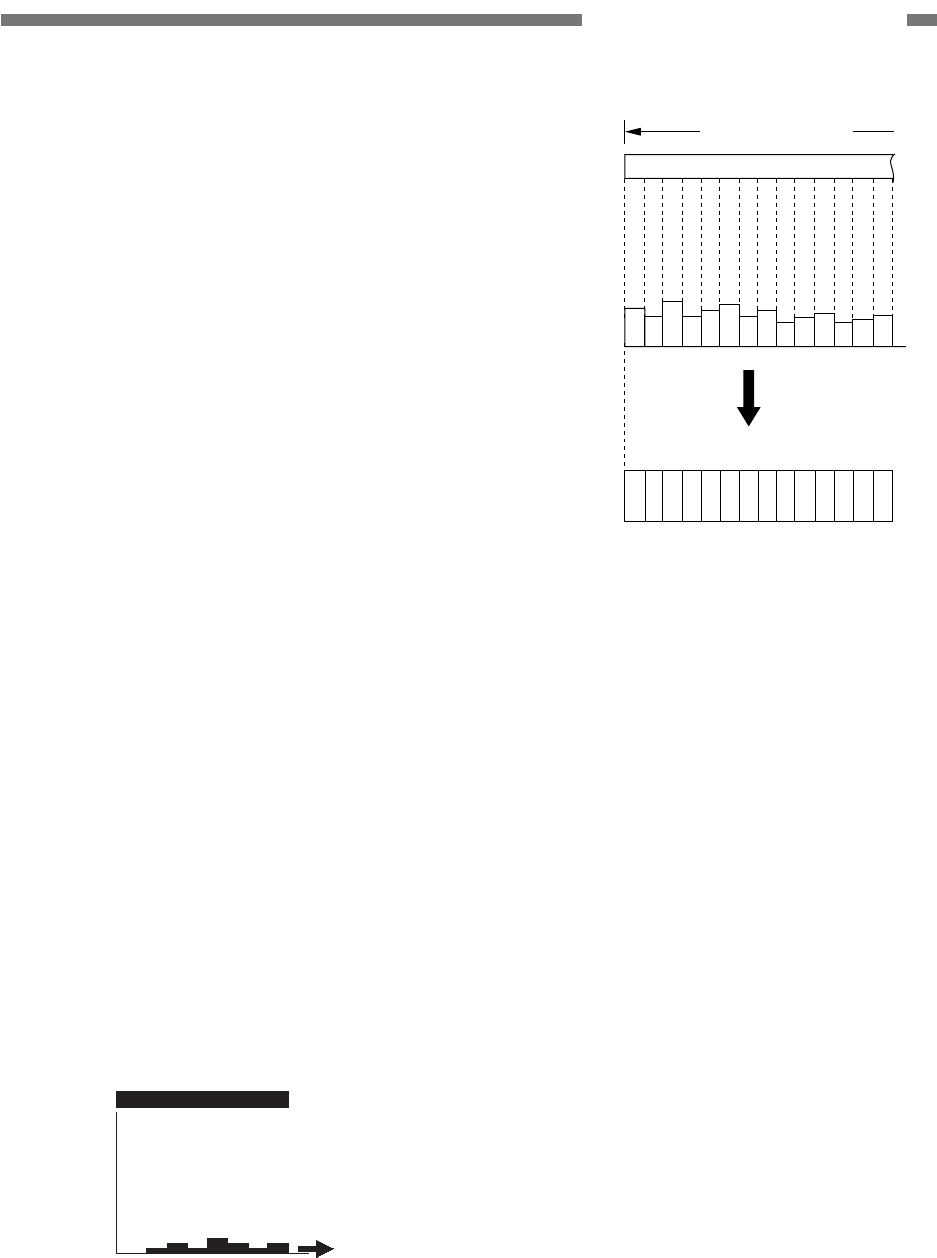
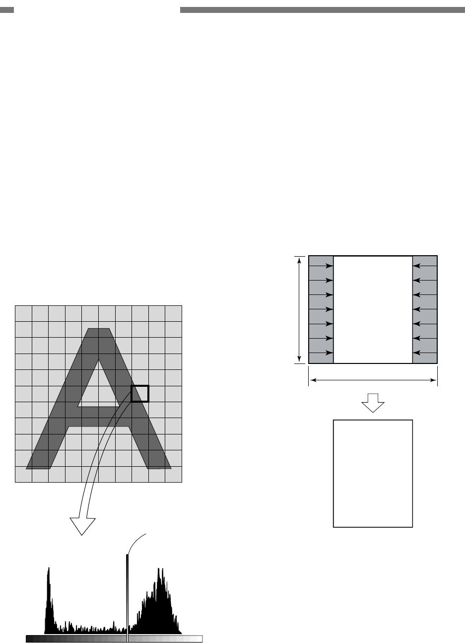
c) Advanced Text Enhancement
In this mode, a histogram of brightness
level for each block within the scanned
data is calculated, and an optimum slice
level is determined to binarize the picture
elements.
Binarizing in this way removes the back-
ground, for example, from behind text
printed on a background.
For example, as shown in the image in
Figure 2-516, a histogram for each block
is calculated, and the optimum slice level
is determined to binarize the picture ele-
ments.
Slice level
Brightness level
Black White
Frequency of appearance
Figure 2-516
6) Automatic Size Detection
In case that the automatic size detection
mode is selected, an image data with the
maximum width and the length detected
by the registration sensors in the feed di-
rection is read.
The maximum outside frame is detected
from the image data which has been read.
The inside of the data is defined as the
document size and the margins are re-
moved.
ABC
ABC
Registration
sensors
Maximum size
Figure 2-517
COPYRIGHT © 2005 CANON ELECTRONICS INC. CANON DR-2580C FIRST EDITION APR. 2005
2-25
CHAPTER 2 FUNCTION & OPERATION
If a document skews when you select auto-
matic size detection, but do not select skew
correction, parts of leading and trailing edges
of the image will be missing.
ABC
Figure 2-518
Note: In case that part of circumference of
document is dark or brightness level is
not appropriately set, this function may
not successfully work. This may also
happen when the skew correction or
black frame removal described later is
performed.
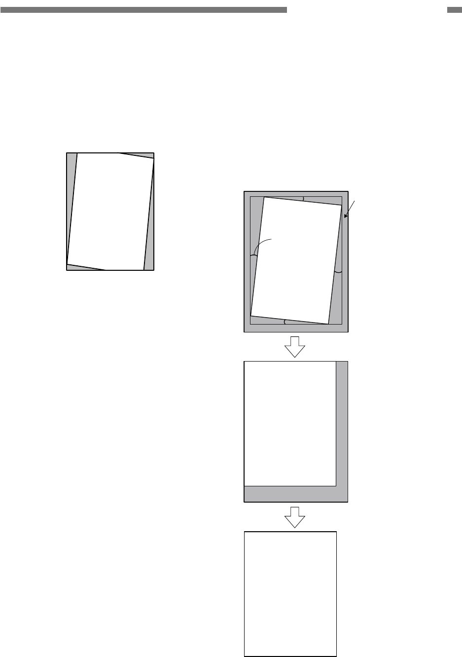
7) Skew Correction (Deskew)
If the skew correction is selected, the size
of document read is broadened by 10 mm
compared with the user-specified size.
The skew is detected based on the data
read to compensate the skew.
The image data is then restored to the
user-specified image size.
ABC
ABC
ABC
Maximum outside frame
Angle
Figure 2-519
2-26
COPYRIGHT © 2005 CANON ELECTRONICS INC. CANON DR-2580C FIRST EDITION APR. 2005
CHAPTER 2 FUNCTION & OPERATION
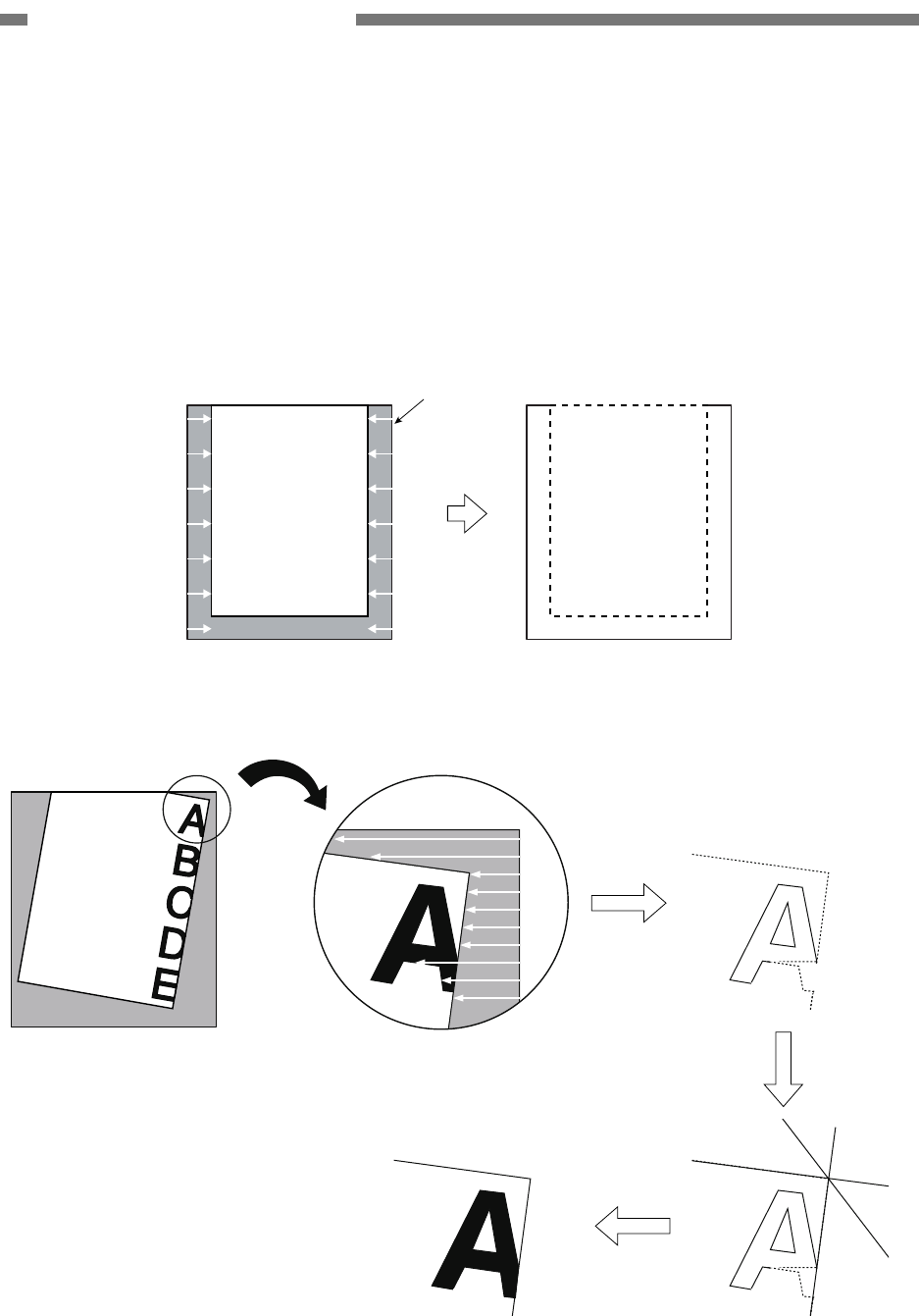
8) Black Border Removal
When the black border removal is se-
lected, the image data is read with the
specified read size.
The frame of document is detected based
on this image data and the outside of the
frame is converted into the white data.
(Figure 2-520)
The conventional black border removal
may vanish the letters if there are some
letters on the edge of document and the
document is skewed to much. This ma-
chine extracts the outer shape of docu-
ment without dent after extracting the
frame. Thus, no letters vanish. (Figure
2-521)
ABC ABC
Specifed size
Figure 2-520
Outer shape
is extracted
Tangent line
is processed
Outside
turns white
Figure 2-521
COPYRIGHT © 2005 CANON ELECTRONICS INC. CANON DR-2580C FIRST EDITION APR. 2005
2-27
CHAPTER 2 FUNCTION & OPERATION
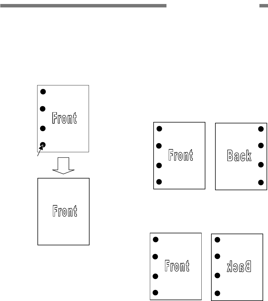
9) Binder Hole Removal
When a document in which holes are
punched is scanned, this function re-
moves those holes by using the front and
back sides of an image.
Figure 2-522
The procedures and principle are de-
scribed below.
Note: If the scan area is specified and the
optional flatbed unit is attached to this
machine, the processing is different from
this processing to perform the only sim-
plex scanning.
i) The front and back sides of document
are read.
Figure 2-523
ii) The image of the back side is reversed.
Figure 2-524
Binder hole
2-28
COPYRIGHT © 2005 CANON ELECTRONICS INC. CANON DR-2580C FIRST EDITION APR. 2005
CHAPTER 2 FUNCTION & OPERATION
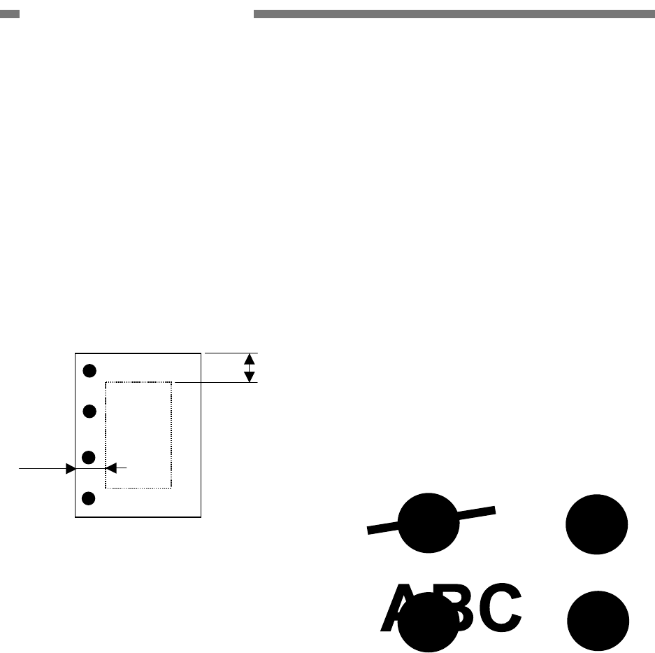
iii) The front side of a document is overlaid
on the back. And the part of the over-
lapping images, in which the black
points of the front and back sides
overlap one another, is extracted from
the target image area (margins with the
width of 20 mm). And then, an image
data is created. This image is called
hole pattern image.
If there are some binder holes, a hole
pattern image is created.
Figure 2-525
iv) In case that both the front and back
side images have some black objects
(which are not binder holes) on the
same spots in the previous step, those
should be determined as holes and a
hole pattern image should be created.
Thus, some black objects other than
those binder holes will be deleted as
well. In this case, the low-pass filter
processing should be done to handle
and delete small objects.
v) The shapes (such as area, circumfer-
ence, and center of balance) of the
binder holes of the hole pattern, front
and back side images are compared. If
they are the same, those black objects
are determined as binder holes. And
then, they are removed from the front
image.
vi) In case that both sides of document are
scanned, after the binder holes on the
front image are removed, those on the
back side image are removed as well.
The binder hole removal function does not
successfully work under the following
conditions.
• In case that a binder hole and figure or
character overlap one another, the binder
hole is not removed because the shape
of the hole on the front should be different
from that on the back. However, if the
object which overlaps a binder hole is a
thin line which can be deleted by the
low-pass filter processing, the hole is
successfully removed.
(Front) (Back)
Figure 2-526
20mm
20mm
COPYRIGHT © 2005 CANON ELECTRONICS INC. CANON DR-2580C FIRST EDITION APR. 2005
2-29
CHAPTER 2 FUNCTION & OPERATION
• Processing only by single image data
In case of scan area specification, the
front area is different from the back area.
In case of the flatbed, only one side exists.
Thus, binder holes are removed as fol-
lows.
This machine determines the objects as
binder holes and deletes those if the de-
grees of circularity* of such objects which
exist in a target image area (20 mm
around) exceed 0.8.
However, the objects whose area is 10
mm2 or less are excluded.
* Degree of circularity = (area × 4π)
/(circumference)2
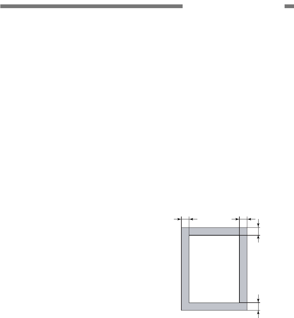
10) Blank Skip
Judgment as to whether or not to record a
document is determined by comparing the
actual number of picture elements of the
document with the user-preset percent-
age (0% to 20%) of number of black pic-
ture elements.
However, the margin of an image data
(10% of lengths of each side edge) is ex-
cluded. Thus, the number of black picture
elements in the central area is compared
with the user-defined number of black
picture elements. If the number of black
picture elements in this target area ex-
ceeds the predefined number, the data
are recorded. If not, the data are not re-
corded.
Target area
10%
10%
10% 10%
Figure 2-527
2-30
COPYRIGHT © 2005 CANON ELECTRONICS INC. CANON DR-2580C FIRST EDITION APR. 2005
CHAPTER 2 FUNCTION & OPERATION
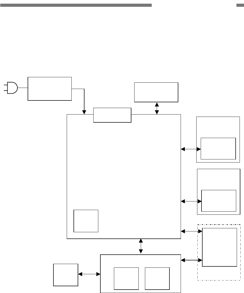
VI. POWER SUPPLY
1. Power Supply
The AC adapter is used for the power
supply of this machine. The values of AC input
and output power are 100-240V 50/60Hz and
+16VDC, respectively.
Use the AC adapter which is enclosed
with this machine.
The output power is input to the control
PCB. And then, +3.3V and +5V are generated
there.
+3.3V, +5V and +16V are supplied for
each IC including the CPU, for CIS LED and
ICs including the analog processor, and for
driving the motors, respectively.
The power for the optional flatbed unit is
supplied by this machine.
The AC adapter has the overload protection
function to automatically block the power
output in the event of a failure such as short
circuit on the load side of the AC adapter.
This machine will shift into the power
saving mode if such states as no document
feeding and no USB interface communication
continue. In the power saving mode, the
electrical circuits enter the sleep state. The
CPU, however, does not shift into the sleep
state.
The machine returns to the standby mode
from the power saving mode when any
communication is carried out on the computer
side or when any job button is pressed.
100-240V
50/60Hz
AC adapter +3.3V
+16V
+5V
DC/DC
converter
Control PCB
+16V
Figure 2-601

COPYRIGHT © 2005 CANON ELECTRONICS INC. CANON DR-2580C FIRST EDITION APR. 2005
2-31
CHAPTER 2 FUNCTION & OPERATION
VII. FLATBED UNIT
1. Outline
The flatbed unit is prepared for DR-2580C
as an option. In case that a document which
cannot be fed, for example, a book, needs to
be scanned, this unit should be used. The
power and driving signals are supplied for the
unit from the main body of DR-2580C.
Therefore, it does not work independently.
The CCD is used as an image reading
sensor. The optical unit including the CCD is
moved by the motor and timing belt to read
images.
Table 2-701 includes the key specifica-
tions of the flatbed unit.
No. Item Specifications
1 Type Desktop type flatbed scanner
*No operation without main body DR-2580C
2 Dimensions
(tray closed)
Flatbed itself: 315 (W) × 545 (D) × 82.5 (H) mm
With DR-2580C: 315 (W) × 557 (D) × 155 (H) mm
3 Weight Approx. 3.8 kg (with DR-2580C: Approx. 5.7 kg)
4 Type of sensor CCD: 5340 picture elements × 4 lines (RGB/Grayscale)
5 Effective picture element 600 dpi, 5104 picture elements (216 mm)
6 Light source Xenon lamp (white)
7 Reading size 216 × 297 mm maximum
8 Expected product life
(in-honse information)
One of the following two items, whichever comes first.
1) 5 years
2) Sheets scanned: 20,000 sheets (A4 size)
9 Installation By users
*Include detach/attachment with main body DR-2580C
Table 2-701
2-32
COPYRIGHT © 2005 CANON ELECTRONICS INC. CANON DR-2580C FIRST EDITION APR. 2005
CHAPTER 2 FUNCTION & OPERATION
2. Configuration
1) Reading System
The color CCD sensor with 5340 picture
elements × 4 lines is used as an image
sensor. The size of a picture element is
7µm × 7µm. And the picture elements are
arranged with 7µm pitches. The length of
a line is about 37.4 mm.
* CCD censor
RED
GREEN
BLUE
GRAY
Figure 2-701
The unit, which consists of the CCD PCB
with the CCD sensor, 4 mirrors, lens, and
xenon lamp as a light source, is called
“optical unit.” Since this unit is adjusted
before the shipment from a plant, do not
disassemble the unit except for the lamp
in the field.
The images of a document are reduced by
the optical unit. And then, the 600dpi im-
age data with 5104 effective picture ele-
ments (length: 210 mm) are output from
the CCD sensor.
The shading plate for shading correction
is slipped between the document board
glass and cover.
Document board glass
Mirror 3
Mirror 2
Mirror 1
Mirror 4
Optical unit
CCD
Lens
Lamp
Shading plate
Figure 2-702
COPYRIGHT © 2005 CANON ELECTRONICS INC. CANON DR-2580C FIRST EDITION APR. 2005
2-33
CHAPTER 2 FUNCTION & OPERATION
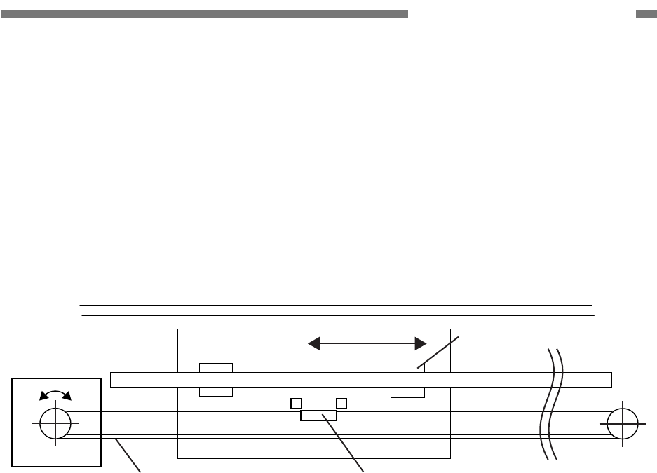
2) Drive System
Image data can be read in the
sub-scanning direction by moving the op-
tical unit horizontally.
A timing belt is fixed to the optical unit. The
rotations of the stepping motors run the
timing belt to move the optical unit. A shaft
is installed as a guide for the unit move-
ment.
Motor
Timing belt
Optical unit
Document board glass
Guide
Shaft
Stopper
Shaft
Figure 2-703
2-34
COPYRIGHT © 2005 CANON ELECTRONICS INC. CANON DR-2580C FIRST EDITION APR. 2005
CHAPTER 2 FUNCTION & OPERATION
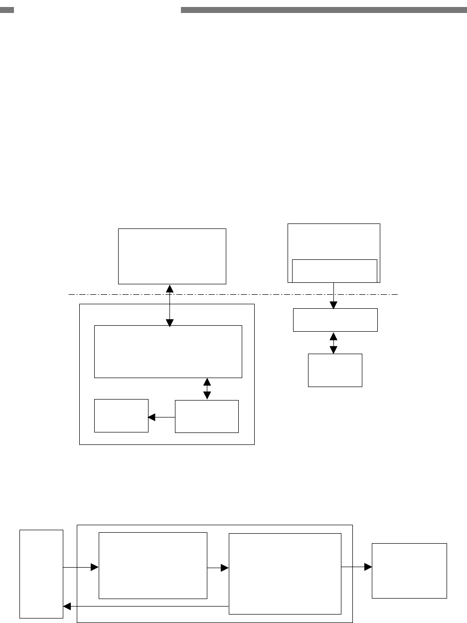
3) Control System
Driving signals for the CCD and motors
are supplied from the main body of
DR-2580C. After analog image data are
converted into digital data in the optical
CCD PCB, those data are output to the
main body of DR-2580C.
Figures 2-704 and 2-705 describe the
electric circuit block diagram and image
processing block diagram, respectively.
DR-2580C
Control PCB
CCD PCB
Optical unit
Lamp Inverter
DR-2580C
Switch PCB
Connector PCB
Connector PCB
Motor
Figure 2-704
CCD Analog processor
· Offset adjustment
· Gain adjustment
· A/D conversion
(12bit)
Data controller
· Lamp light control
· Data rearrangement DR-2580C
Control PCB
CCD PCB
Figure 2-705
COPYRIGHT © 2005 CANON ELECTRONICS INC. CANON DR-2580C FIRST EDITION APR. 2005
2-35
CHAPTER 2 FUNCTION & OPERATION
VIII
. ELECTRICAL PARTS
LAYOUT
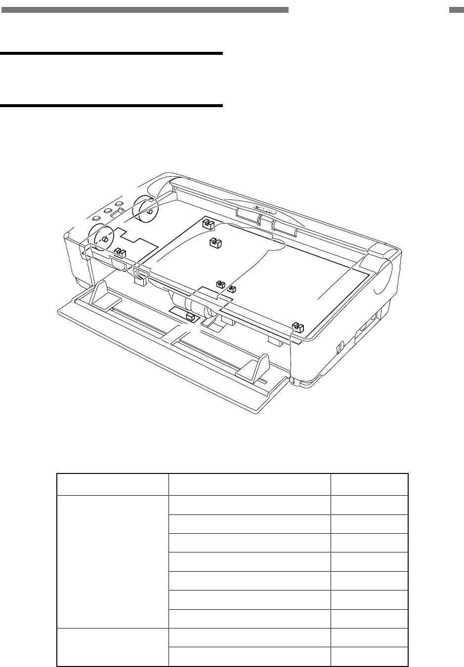
1. Main Body
M2
M1 PS2
PS5
M2
M1
PS3
PS4
PS1
PS7
PS6
Figure 2-801
Category Name Symbol
Power supply sensor PS1
Rear cover sensor PS2
Upper opening sensor PS3
Document board sensor PS4
Shading sensor PS5
Pre-registration sensor PS6
Sensor
Registration sensor PS7
Pickup motor M1 Motor
Carry motor M2
Table 2-801
2-36
COPYRIGHT © 2005 CANON ELECTRONICS INC. CANON DR-2580C FIRST EDITION APR. 2005
CHAPTER 2 FUNCTION & OPERATION
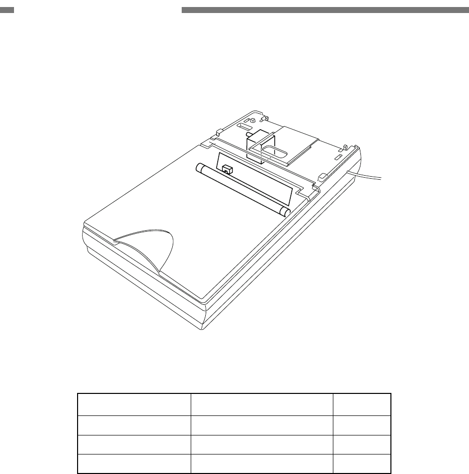
2. Flatbed
M3
PS8
FL1
Figure 2-802
Category Name Symbol
Sensor Optical unit sensor PS8
Motor Optical motor M3
Lamp Light source lamp FL1
Table 2-802
COPYRIGHT © 2005 CANON ELECTRONICS INC. CANON DR-2580C FIRST EDITION APR. 2005
2-37
CHAPTER 2 FUNCTION & OPERATION
IX. PARTS LAYOUT OF
EACH PCB
Items that are not listed in the lists and
items that are specified as usage prohibited
must not be procured in the field.
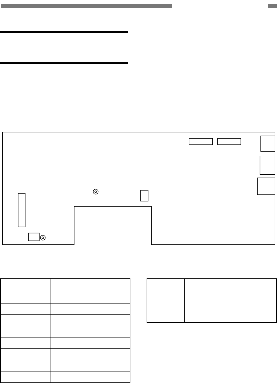
1. Controller PCB
J102
J4
J701
J501J502
J2000
LED101
LED501
J1001
J1000
Figure 2-901
Connector Description
J4 9P Flatbed
J102 2P AC adapter (16 VDC)
J501 16P CIS PCB (front)
J502 16P CIS PCB (back)
J701 5P USB I/F
J1000 19P Switch PCB
J1001 4P Document board PCB
J2000 7P Ultrasonic sensor PCB
Table 2-901
LED Description
LED101 Blinking: CPU normal opera-
tion
LED501 Lighting: Normal power supply
Table 2-902
2-38
COPYRIGHT © 2005 CANON ELECTRONICS INC. CANON DR-2580C FIRST EDITION APR. 2005
CHAPTER 2 FUNCTION & OPERATION
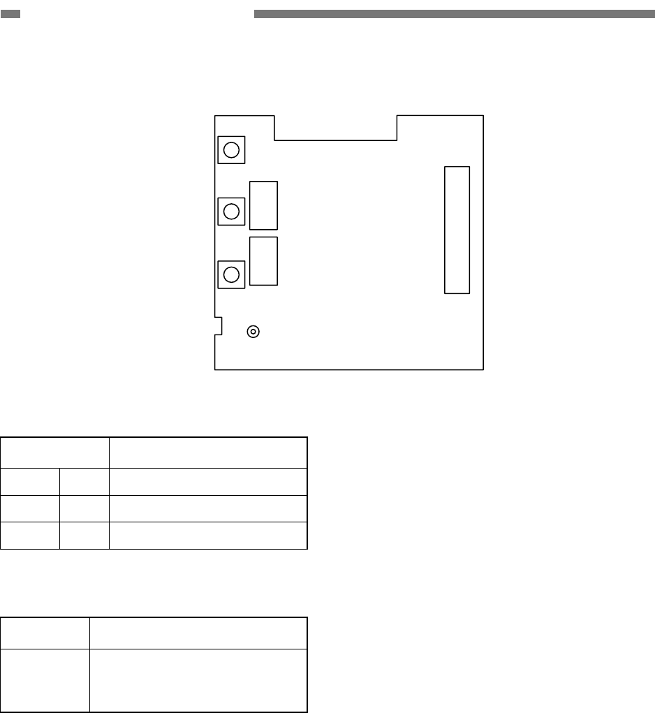
2. DC Control PCB
SW202
SW201
SW200
J200
J202
J201
LED200
Figure 2-902
Connector Description
J200 19P Control PCB
J201 4P Pickup motor
J202 4P Carry motor
Table 2-903
LED Description
LED200
Lighting: Normal
Blinking: Scanner abnormal
(jams and so on)
Table 2-904

CHAPTER 3
DISASSEMBLY & REASSEMBLY
COPYRIGHT © 2005 CANON ELECTRONICS INC. CANON DR2580C FIRST EDITION APR. 2005
I. EXTERNAL COVERS ..............................3-1
II. UPPER UNIT............................................3-4
III. LOWER UNIT .........................................3-10
IV. FLATBED................................................3-21
COPYRIGHT © 2005 CANON ELECTRONICS INC. CANON DR-2580C FIRST EDITION APR. 2005
3-1
CHAPTER 3 DISASSEMBLY/ASSEMBLY
* Notes on disassembly and assembly
1) The upper unit sometimes closes while
working. Thus, be careful not to get
your fingers caught in the unit.
2) Many of parts are fixed with the fitting
parts instead of screws or E rings. Do
not deform such parts too much while
working because they would be dam-
aged. However, do not leave a gap
between the parts when installing them.
3) Prepare a thin and flat head tool such
as precision driver because it is nec-
essary to unhook some fitting parts.
I. EXTERNAL COVERS
1. Rear Cover
1) Fully open the rear cover.
2) Bend the left or right arm
{
1, unhook the
fitting parts, and remove the rear cover
{
2.
Figure 3-101
* Notes on assembly
Do not deform the grounding plate which
is put on one of the fitting parts.
3-2
COPYRIGHT © 2005 CANON ELECTRONICS INC. CANON DR-2580C FIRST EDITION APR. 2005
CHAPTER 3 DISASSEMBLY/ASSEMBLY
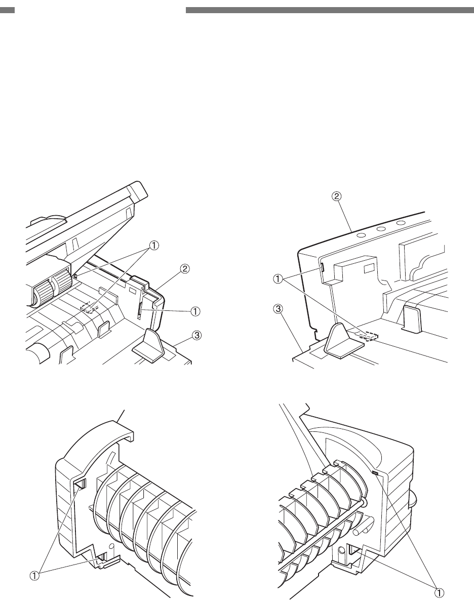
2. Right Cover
1) Remove the rear cover and fully open the
pickup tray and upper unit.
2) Unhook the 5 fitting parts
{
1 (one of them
on the back side) and remove the right
cover
{
2. At this time, the pickup tray
{
3
also comes off.
Figure 3-102
* Notes on assembly
Do not pinch the cable. In case that the
power switching lever comes off, be sure
to put it back.
3. Left Cover
1) Remove the rear cover and fully open the
pickup tray and upper unit.
2) Unhook the 4 fitting parts
{
1 (one of them
on the back side) and remove the left
cover
{
2. At this time, the pickup tray
{
3
also comes off.
Figure 3-103
* Notes on assembly
Set the rear fitting parts and the edge of
the eject selection lever in the mounting
positions indicated on the main frame.
COPYRIGHT © 2005 CANON ELECTRONICS INC. CANON DR-2580C FIRST EDITION APR. 2005
3-3
CHAPTER 3 DISASSEMBLY/ASSEMBLY
4. Pickup Tray
1) When the right cover or the left cover is
removed, the pickup tray comes off.
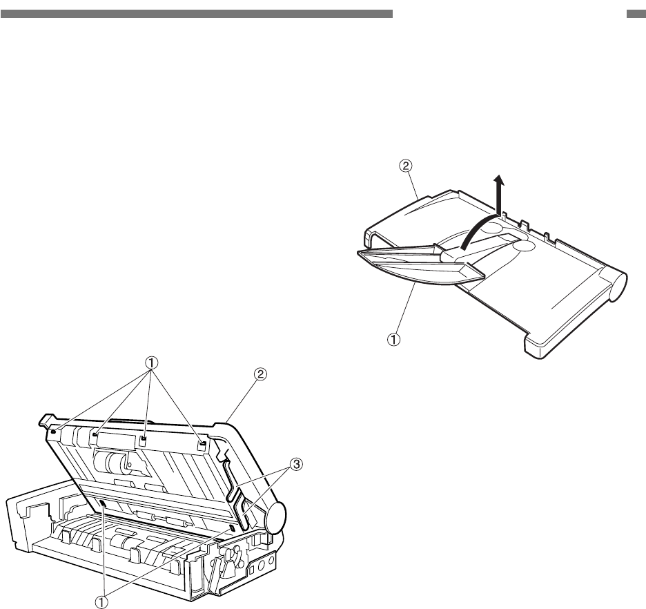
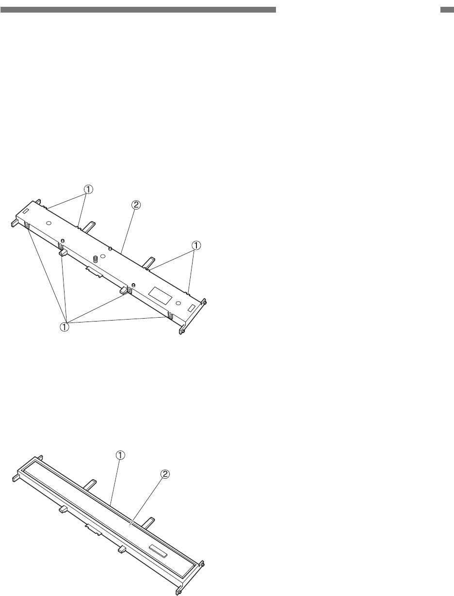
5. Upper Cover
1) Remove the right cover.
2) After unhooking the 6 fitting parts
{
1,
close the upper unit and remove the upper
cover assembly
{
2.
Note: The arm
{
3 of the left and right reading
units would come off after removing the
upper cover assembly.
Figure 3-104
3) After opening the eject tray extension
assembly
{
1, rotate it and remove the
upper cover
{
2.
Figure 3-105
* Notes on assembly
Do not pinch the cable.
3-4
COPYRIGHT © 2005 CANON ELECTRONICS INC. CANON DR-2580C FIRST EDITION APR. 2005
CHAPTER 3 DISASSEMBLY/ASSEMBLY
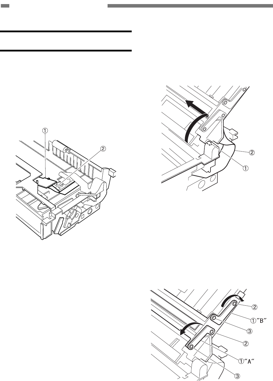
II. UPPER UNIT
1. Upper Unit
1) Remove the right cover, left cover and
upper cover assembly.
2) Disconnect the cable
{
2 which is con-
nected to the PCB
{
1.
Note: After removing the reading unit, dis-
connect the cable for the reading unit.
Figure 3-201
3) After further opening the upper unit, slide
it to the left, unhook the right fitting parts
{
1, and remove the upper unit.
Note: Do not pull the upper unit too hard be-
cause the cable
{
2 is connected to it.
Figure 3-202
4) After unhooking the fitting parts
{
2 which
are put on the base of the reading unit
arms
{
1, rotate the arms and unhook the
fitting parts
{
3 which are put on the
reading unit. Remove the arm “A” first.
There are 4 arms installed in the right and
left sides.
Figure 3-203
COPYRIGHT © 2005 CANON ELECTRONICS INC. CANON DR-2580C FIRST EDITION APR. 2005
3-5
CHAPTER 3 DISASSEMBLY/ASSEMBLY
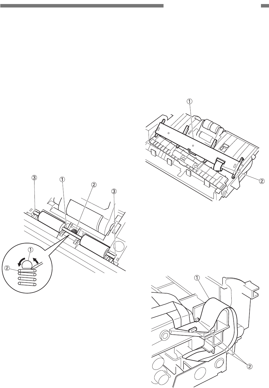
5) Rotate the follower roller shaft (ahead)
{
1
to bring the flat part which contacts the coil
spring
{
2 to the front. Apply a flat head
tool to a flat part of the roller shaft and
rotate it.
Push the roller shaft downwards to slide it,
unhook the right or left fitting parts
{
3, and
remove the roller and roller shaft.
Note: The roller, roller shaft and coil spring
would jump out when removing them.
Do not mix up the coil spring for the
follower roller (ahead) with the one for
the follower roller (behind) because they
are different. The coil spring for the fol-
lower roller (behind) is white.
Figure 3-204
6) Remove the reading unit
{
1 and discon-
nect the cable
{
2 which is connected to its
back side.
Note: In case that the cable which is con-
nected to the lower unit are discon-
nected, it is not necessary to disconnect
the cable.
Figure 3-205
* Notes on assembly 1
When installing the upper cover, put the
cable
{
1 in the 2 cable holders
{
2 to
prevent them from being caught in the
upper cover.
Figure 3-206
3-6
COPYRIGHT © 2005 CANON ELECTRONICS INC. CANON DR-2580C FIRST EDITION APR. 2005
CHAPTER 3 DISASSEMBLY/ASSEMBLY
* Notes on assembly 2
Install the reading unit so that the coil
spring on its back side can contact the
grounding plate.
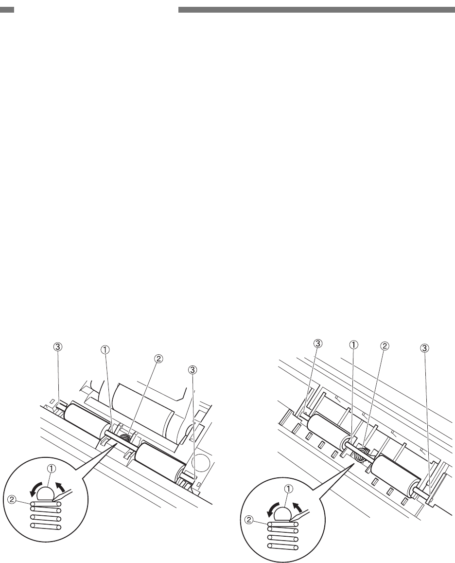
2. Follower Roller (Ahead)
1) Fully open the upper unit.
2) Rotate the roller shaft
{
1 to bring the flat
part which contacts the coil spring
{
2 to
the front. Apply a flat head tool to a flat
part of the roller shaft and rotate it.
Push the roller shaft downwards to slide it,
unhook the right or left fitting parts
{
3, and
remove the roller and roller shaft.
Note: The roller, roller shaft and coil spring
would jump out when removing them.
The coil spring for the follower roller
(ahead) is metallic color.
Figure 3-207
3. Follower Roller (Behind)
1) Fully open the upper unit.
Note: In case that there is not enough room to
disassemble the follower roller (behind),
remove the right cover, left cover and
upper cover assembly to further open
the upper unit.
2) Rotate the roller shaft
{
1 to bring the flat
part which contacts the coil spring
{
2 to
the front. Apply a flat head tool to a flat
part of the roller shaft and rotate it.
Push the roller shaft downwards to slide it,
unhook the right or left fitting parts
{
3, and
remove the roller and roller shaft.
Note: The roller, roller shaft and coil spring
would jump out when removing them.
The coil spring for the follower roller
(behind) is white.
Figure 3-208
COPYRIGHT © 2005 CANON ELECTRONICS INC. CANON DR-2580C FIRST EDITION APR. 2005
3-7
CHAPTER 3 DISASSEMBLY/ASSEMBLY
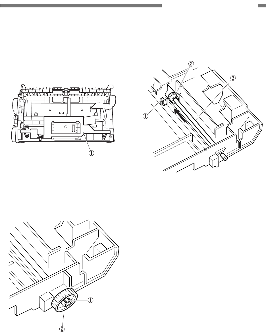
4. Roller Drive Shaft
1) Remove the roller unit.
2) Remove the right cover and upper cover
assembly.
3) Remove the open/close knob
{
1.
Figure 3-209
4) Unhook the fitting parts
{
1 with a thin and
flat head tool and remove the drive gear
{
2.
Figure 3-210
5) Unhook the fitting parts
{
1 and rotate the
bearing
{
2 90 degrees. After that, slide
the roller drive shaft
{
3 to remove it.
Figure 3-211
3-8
COPYRIGHT © 2005 CANON ELECTRONICS INC. CANON DR-2580C FIRST EDITION APR. 2005
CHAPTER 3 DISASSEMBLY/ASSEMBLY
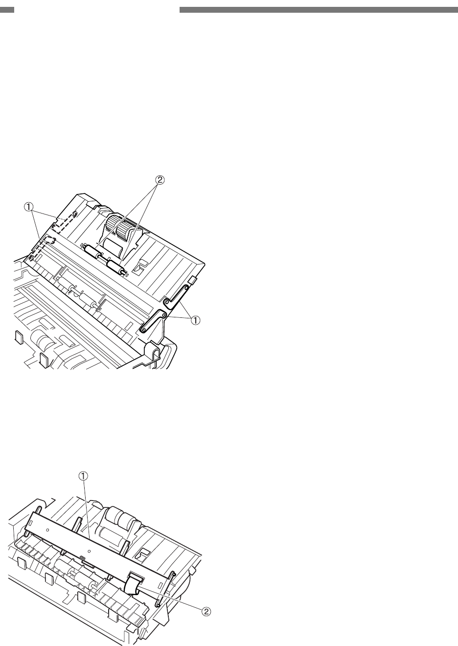
5. Reading Unit
1) Remove the right cover, left cover and
upper cover assembly, and fully open the
upper unit.
2) Refer to the procedure for “Upper Unit” to
remove the 4 arms
{
1 of the reading unit
and follower roller (ahead)
{
2.
Figure 3-212
3) Remove the reading unit
{
1 and discon-
nect the cable
{
2 which is connected to its
back side.
Figure 3-213
* Notes on assembly
Install the reading unit so that the coil
spring on its back side can contact the
grounding plate.
COPYRIGHT © 2005 CANON ELECTRONICS INC. CANON DR-2580C FIRST EDITION APR. 2005
3-9
CHAPTER 3 DISASSEMBLY/ASSEMBLY
6. Reading Holder (with Glass)
1) Remove the reading unit.
2) Unhook the 8 fitting parts
{
1 with a thin
and flat head tool and remove the cover
{
2.
Note: Since the fitting part is bent easily, un-
hook it carefully.
Figure 3-214
3) Draw the CIS unit
{
2 out of the reading
holder
{
1.
Note: Prevent scraps of paper or other foreign
particles from getting into the CIS unit.
Figure 3-215
* Notes on assembly 1
Remove scraps of paper or other foreign
particles out of the CIS unit with a tool
such as blower. Install it after cleaning its
inside including the glass which is put on
the reading holder. And make sure that
the coil spring is put in the cover.
* Notes on assembly 2
Do not stain or damage the shading plate
installed on the reading holder. If it is
stained, clean it and if it is damaged, re-
place the reading holder.
* Notes on assembly 3
The reading unit cover and CIS unit are
the same as those for the upper unit. On
the other hand, their reading holders are
different in shape.
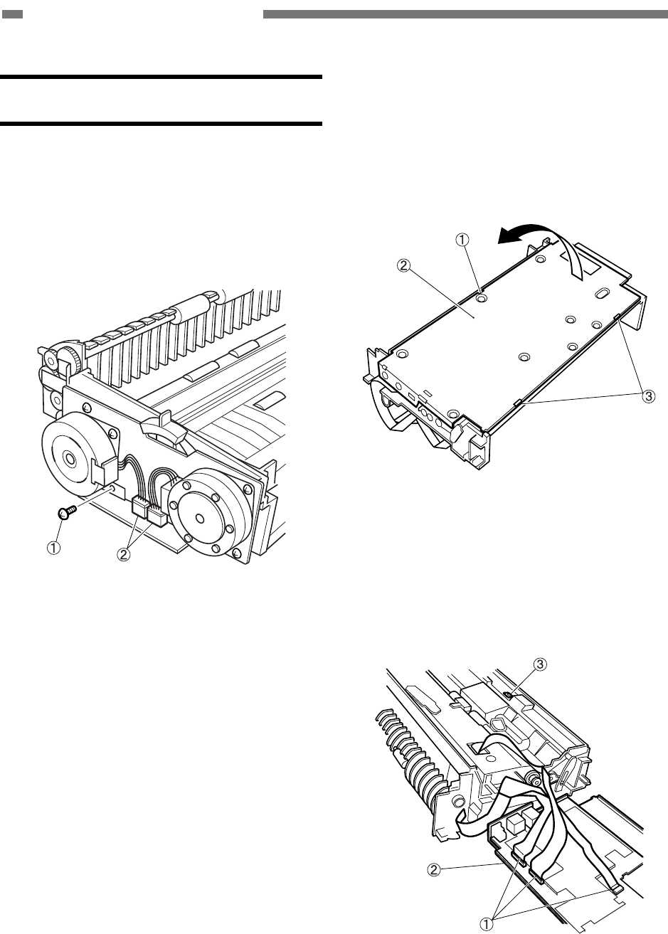
3-10
COPYRIGHT © 2005 CANON ELECTRONICS INC. CANON DR-2580C FIRST EDITION APR. 2005
CHAPTER 3 DISASSEMBLY/ASSEMBLY
III. LOWER UNIT
A. Common
1. PCB Unit
1) Remove the right cover and left cover.
2) Remove the screw
{
1 on the left and the 2
connectors
{
2.
Figure 3-301
3) Insert a thin and flat head tool into the hole
{
1 on the back side to remove the plate
{
2. Then, unhook the 2 fitting parts
{
3
and open the plate to the direction of the
arrow. Be aware that the cable is con-
nected to the inside of the unit.
Figure 3-302
4) Disconnect the 3 cables
{
1 which are
connected to the PCB unit and remove the
PCB unit
{
2.
Note: Be careful not to lose the sensor cover
{
3 because it comes off.
Figure 3-303
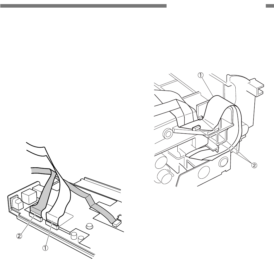
COPYRIGHT © 2005 CANON ELECTRONICS INC. CANON DR-2580C FIRST EDITION APR. 2005
3-11
CHAPTER 3 DISASSEMBLY/ASSEMBLY
* Notes on assembly 1
Make sure that the cables for the upper
and lower reading units are appropriately
connected. The reinforcing plate for the
contacts of the cable
{
1 which is con-
nected to the lower unit is blue, and this
cable should be connected to the con-
nector J502. The cable
{
2 which is con-
nected to the upper unit is aluminum
shielded, and it should be connected to
the connector J501.
Figure 3-304
* Notes on assembly 2
Do not pinch the cables. Put the 2 cables
{
1, which are connected to the upper unit,
in the 2 cable holders
{
2.
Figure 3-305
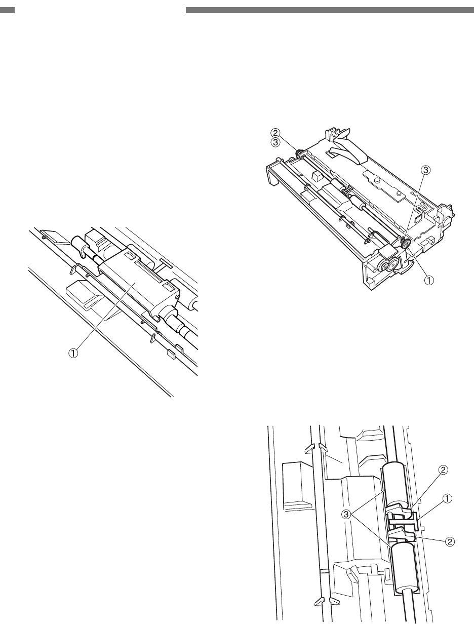
3-12
COPYRIGHT © 2005 CANON ELECTRONICS INC. CANON DR-2580C FIRST EDITION APR. 2005
CHAPTER 3 DISASSEMBLY/ASSEMBLY
B. Feed System (Roller and
Others)
1. Registration Roller
1) Remove the retard roller.
2) Remove the right cover, left cover and
PCB unit.
3) Remove the retard roller shaft unit
{
1. For
more details, refer to the section “Retard
Roller Shaft Unit.”
Figure 3-306
4) Remove the motor drive unit. For more
details, refer to the section “Drive Unit.”
5) Remove the gear
{
1, clutch gear
{
2 and
2 ball bearings
{
3.
Note: Unhook the fitting parts mounted on the
edge of the gear to pull the gear out.
Figure 3-307
6) Pull the leaf spring
{
1 out of the fitting
parts. And then, pull the sensor lever
{
2
out of the fitting parts. Finally, remove the
registration roller
{
3.
Figure 3-308
* Notes on assembly
Make sure if the registration roller
smoothly rotates after the completion of
assembly.
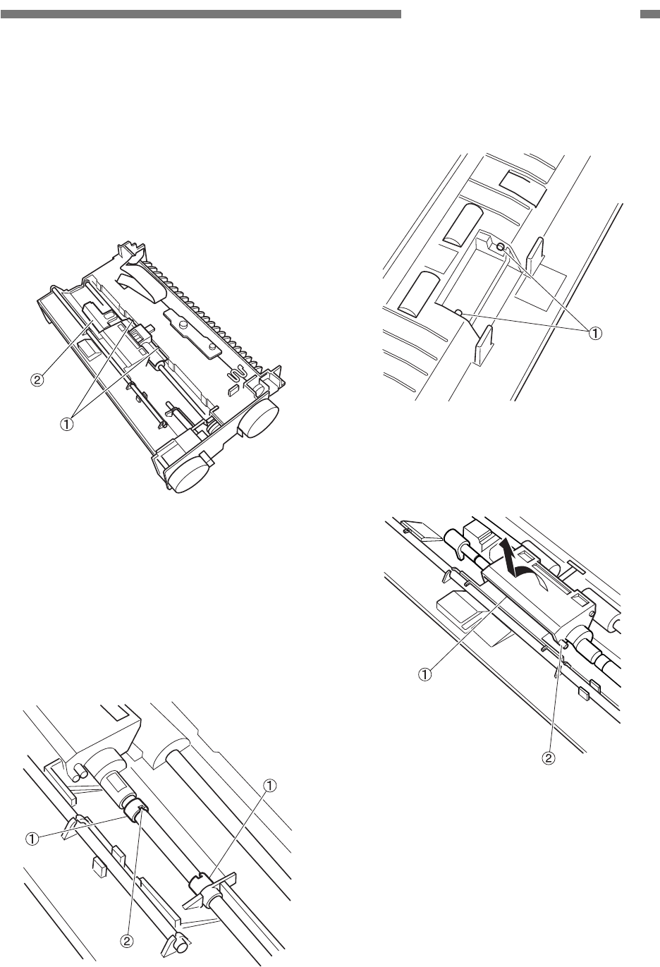
COPYRIGHT © 2005 CANON ELECTRONICS INC. CANON DR-2580C FIRST EDITION APR. 2005
3-13
CHAPTER 3 DISASSEMBLY/ASSEMBLY
2. Retard Roller Shaft Unit
1) Remove the retard roller.
2) Remove the right cover, left cover and
PCB unit.
3) Insert thin and flat head tools into the 2
fitting parts
{
1 and remove the roller
cover
{
2.
Figure 3-309
4) Insert thin and flat head tools into the
small hole
{
2 of the 2 C shaped collars
{
1
and pull then out.
Note: Slightly press the C shaped collars when
pulling it out to prevent it from being
blown away.
Figure 3-310
5) Push and rotate the right and left shafts
{
1
to insert their edges into the inside of the
frame.
Figure 3-311
6) Rotate the retard roller shaft unit
{
1 and
unhook the left and right fitting parts
{
2.
Figure 3-312
* Notes on assembly
Make sure if the retard roller smoothly
rotates after the completion of assembly.
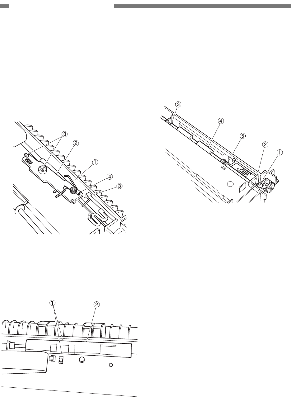
3-14
COPYRIGHT © 2005 CANON ELECTRONICS INC. CANON DR-2580C FIRST EDITION APR. 2005
CHAPTER 3 DISASSEMBLY/ASSEMBLY
3. Eject Roller 1
1) Remove the right cover, left cover and
PCB unit.
2) Remove the torsion spring
{
1. And bend
the moving arm
{
2 to unhook the 3 fitting
parts
{
3 and remove the moving arm. And
also, remove the edge
{
4 of the spring
clutch.
Figure 3-313
3) Insert thin and flat head tools into the 2
fitting parts
{
1 and remove the roller
cover
{
2.
Figure 3-314
4) Remove the gear
{
1, right and left bearing
stoppers
{
2 and
{
3. Remove the eject
roller 1
{
4. And then, remove the me-
chanical clutch
{
5 out of the eject roller.
Note: Unhook the fitting parts mounted on the
edge of the gear to pull the gear out.
Figure 3-315
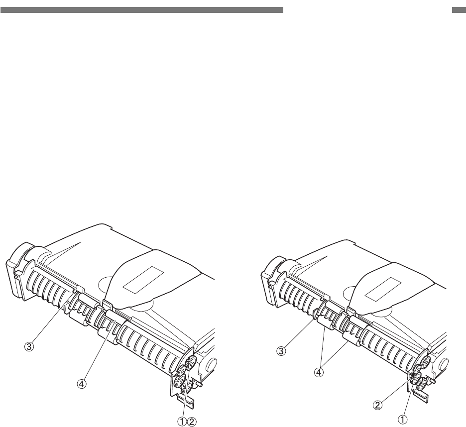
COPYRIGHT © 2005 CANON ELECTRONICS INC. CANON DR-2580C FIRST EDITION APR. 2005
3-15
CHAPTER 3 DISASSEMBLY/ASSEMBLY
4. Eject Roller 2
1) Remove the left cover. Fully open the
upper unit and rear cover.
2) Remove the gear
{
1, right and left bearing
stoppers
{
2 and
{
3. And remove the
eject roller 2
{
4.
Note: Unhook the fitting parts mounted on the
edge of the gear to pull the gear out.
Unhook the fitting parts to remove the
bearing stopper
{
3.
Figure 3-316
5. Carry Roller
1) Remove the left cover. Fully open the rear
cover.
2) Remove the gear
{
1, right and left bearing
stoppers
{
2 and
{
3. And remove the
carry roller
{
4.
Note: Unhook the fitting parts mounted on the
edge of the gear to pull the gear out. Pull
the bearing stopper
{
3 out and unhook
the fitting parts mounted on the back
side.
Figure 3-317
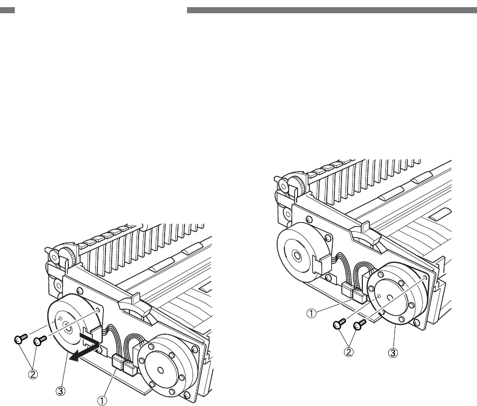
3-16
COPYRIGHT © 2005 CANON ELECTRONICS INC. CANON DR-2580C FIRST EDITION APR. 2005
CHAPTER 3 DISASSEMBLY/ASSEMBLY
C. Drive System (Motor and
Others)
1. Carry Motor
1) Remove the left cover.
2) Remove the connector
{
1 and 2 screws
{
2. And slide the carry motor
{
3 to the
right to remove it.
Note: The left side connector in the figure is for
the carry motor.
Figure 3-318
* Notes on assembly
Reeve the timing belt on the gear of the
carry motor. If it is hard to do it, remove the
motor mounting plate. For more details,
refer to the section “Drive Unit.”
2. Pickup Motor
1) Remove the left cover.
2) Remove the connector
{
1 and 2 screws
{
2. And remove the carry motor
{
3.
Note: The right side connector in the figure is
for the pickup motor.
Figure 3-319
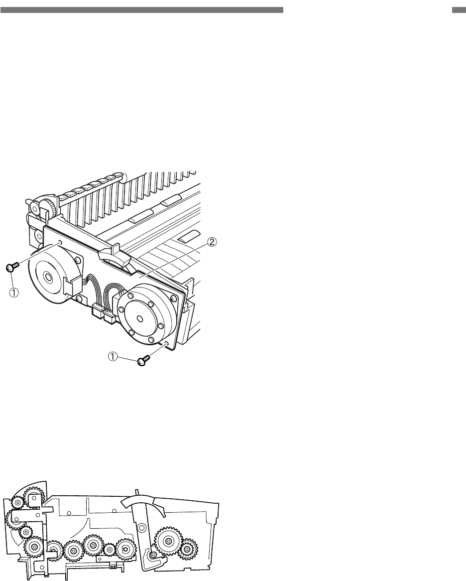
COPYRIGHT © 2005 CANON ELECTRONICS INC. CANON DR-2580C FIRST EDITION APR. 2005
3-17
CHAPTER 3 DISASSEMBLY/ASSEMBLY
3. Drive Unit
1) Remove the right cover, left cover and
PCB unit.
2) Remove the 2 screws
{
1. And remove the
drive unit
{
2.
Note: The gear or something would drop when
removing the drive unit.
Figure 3-320
* Notes on assembly
Before installing the drive unit, install the
gear, grounding plate and lever in the
appropriate positions.
Figure 3-321
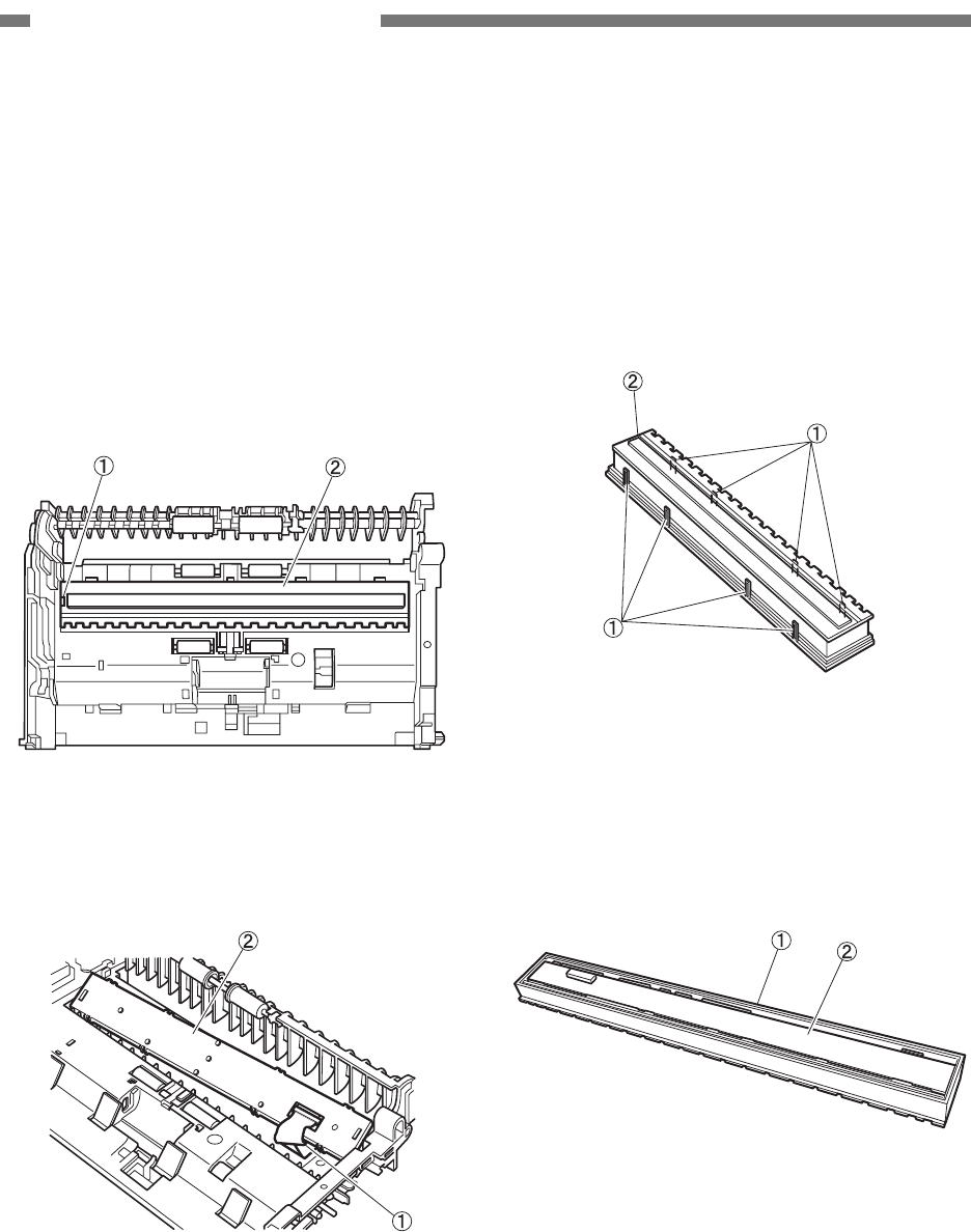
3-18
COPYRIGHT © 2005 CANON ELECTRONICS INC. CANON DR-2580C FIRST EDITION APR. 2005
CHAPTER 3 DISASSEMBLY/ASSEMBLY
D. Reading System
1. Reading Unit
1) Remove the upper unit. For more details,
refer to the section “Upper Unit.”
2) Insert a flat head tool into the slit
{
1 on the
left and slightly lift the reading unit
{
2 to
remove it.
Note: The cable is connected to the right back
side.
Figure 3-322
3) Disconnect the cable
{
1 and remove the
reading unit
{
2.
Figure 3-323
2. Reading Holder (with Glass)
1) Remove the reading unit.
2) Unhook the 8 fitting parts
{
1 with a thin
and flat head tool and remove the cover
{
2.
Note: Since the fitting part is bent easily, un-
hook it carefully.
Figure 3-324
3) Draw the CIS unit
{
2 out of the reading
holder
{
1.
Note: Prevent scraps of paper or other foreign
particles from getting into the CIS unit.
Figure 3-325

COPYRIGHT © 2005 CANON ELECTRONICS INC. CANON DR-2580C FIRST EDITION APR. 2005
3-19
CHAPTER 3 DISASSEMBLY/ASSEMBLY
* Notes on assembly 1
Remove scraps of paper or other foreign
particles out of the CIS unit with a tool
such as blower. Install it after cleaning its
inside including the glass which is put on
the reading holder.
* Notes on assembly 2
Do not stain or damage the shading plate
installed on the reading holder. If it is
stained, clean it and if it is damaged, re-
place the reading holder.
* Notes on assembly 3
The reading unit cover and CIS unit are
the same as those for the upper unit. On
the other hand, their reading holders are
different in shape. And no coil spring is
included in the cover of the lower unit.
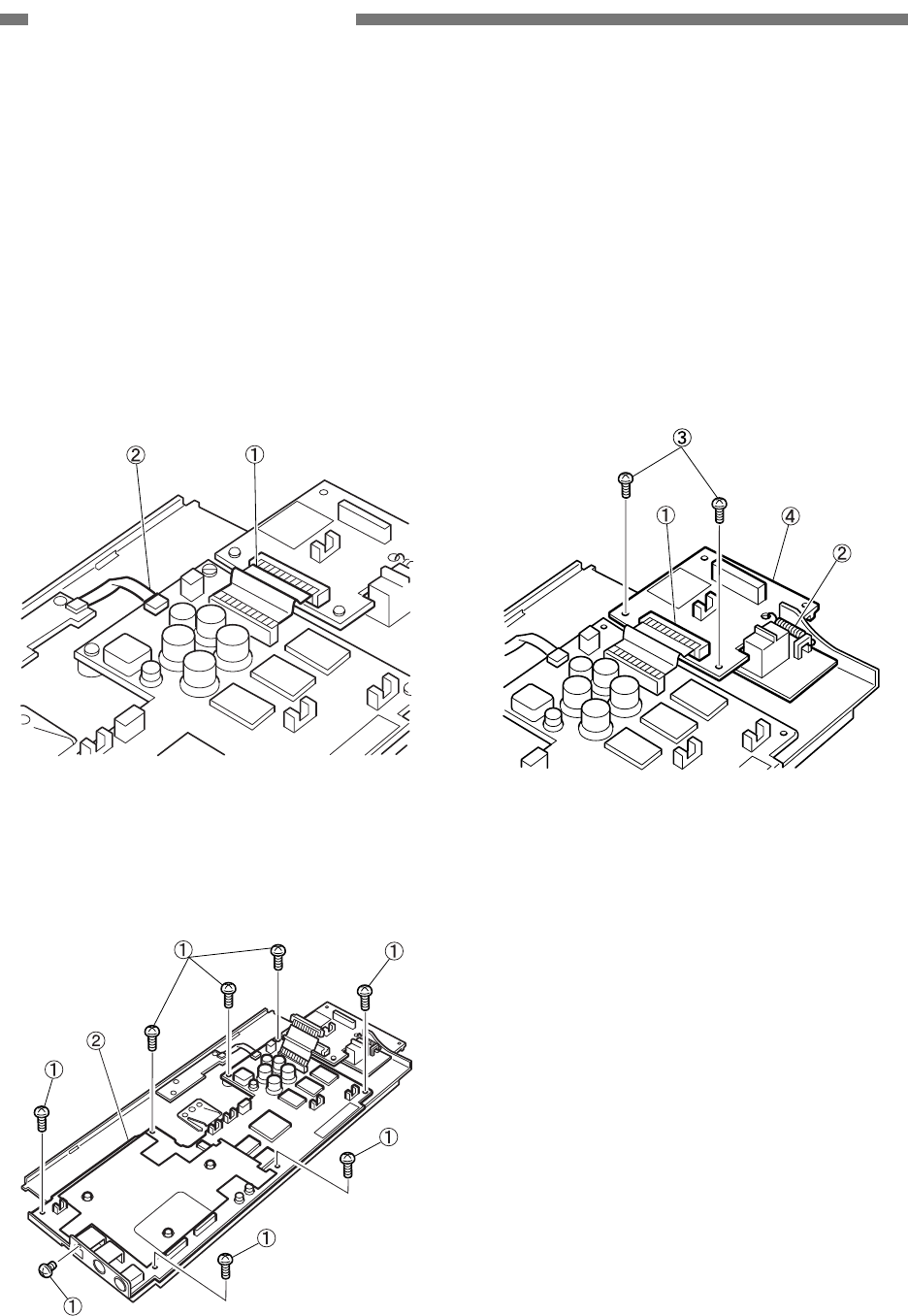
3-20
COPYRIGHT © 2005 CANON ELECTRONICS INC. CANON DR-2580C FIRST EDITION APR. 2005
CHAPTER 3 DISASSEMBLY/ASSEMBLY
E. Electrical System (PCB and
Others)
1. Control PCB
1) Remove the PCB unit.
2) Remove the connectors A
{
1 and B
{
2.
Note: The connector A which should be re-
moved is mounted on the switch PCB as
indicated in the figure. The connector
mounted on the other side (on the con-
trol PCB) cannot be removed.
Figure 3-326
3) Remove the 8 screws
{
1 and remove the
control PCB
{
2.
Note: The screws on the USB connector are
M3 and the others are M2.5.
Figure 3-327
2. Switch PCB
1) Remove the PCB unit.
2) Remove the connector
{
1 and spring
{
2.
And remove the 2 screws
{
3 and remove
the switch PCB
{
4.
Note: The connector which should be re-
moved is mounted on the switch PCB as
indicated in the figure. The connector
mounted on the other side (on the con-
trol PCB) cannot be removed.
Figure 3-328
* Notes on assembly
Before installing the switch PCB, install
the contact cover.
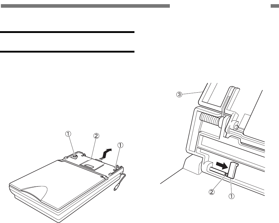
COPYRIGHT © 2005 CANON ELECTRONICS INC. CANON DR-2580C FIRST EDITION APR. 2005
3-21
CHAPTER 3 DISASSEMBLY/ASSEMBLY
IV. FLATBED
A. Upper Unit
1. Upper Unit
1) Unlock the optical unit (reading unit).
2) Unhook the 2 fitting parts
{
1 and slightly
slide the upper unit
{
2 backwards to re-
move it.
Figure 3-401
* Notes on assembly
Before installing the upper unit, clean the
inner surface of the glass. And remove the
dust if there is inside the unit.
2. Flatbed Cover Assembly
1) Fully open the flatbed cover.
2) Bend the stopper
{
1, insert a tool into the
gap of the shaft
{
2, and slide the flatbed
cover assembly
{
3 until it is removed.
Figure 3-402
* Notes on part replacement
A black pressure board needs to be put on
the position on which the document board
glass is actually mounted. Thus, when
replacing a part, prepare a flatbed cover
without black pressure board and a black
pressure board, and install them accord-
ing to the following procedure.
1) Install the flatbed cover without black
pressure board.
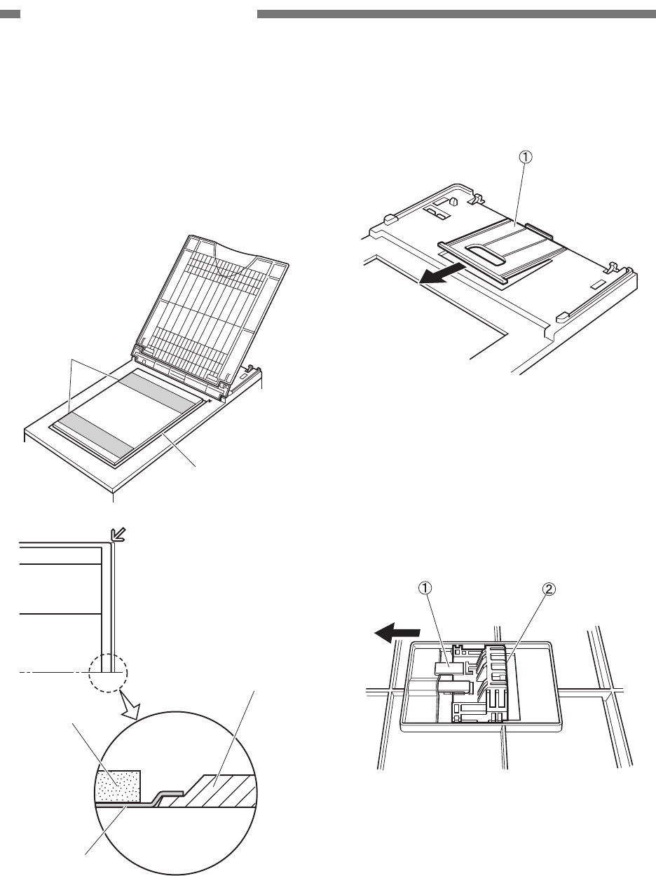
3-22
COPYRIGHT © 2005 CANON ELECTRONICS INC. CANON DR-2580C FIRST EDITION APR. 2005
CHAPTER 3 DISASSEMBLY/ASSEMBLY
2) Remove the release papers of the adhe-
sive tapes which are stuck on the back
side of the black pressure board. Put it
along the origin point mark indicated in the
figure of the document board glass. It is
included to prevent light from pouring from
a gap.
A
dhesive tape
Black pressure boar
d
Upper cover
Sponge
Black sheet
Origin point
Figure 3-403
3) Slowly close the flatbed cover so that the
black pressure board does not shift. And
gently press the cover to stick the black
pressure board to it.
3. Eject Tray
1) Slightly lift the edge of the eject tray
{
1,
put it on the outer frame to remove it.
Figure 3-404
4. Lock Board (for Optical Unit)
1) Remove the upper unit. And fully open or
remove the eject tray.
2) Bend the stopper
{
1 mounted on the back
side of the upper unit, and slide the lock
plate
{
2 until it is removed.
Figure 3-405
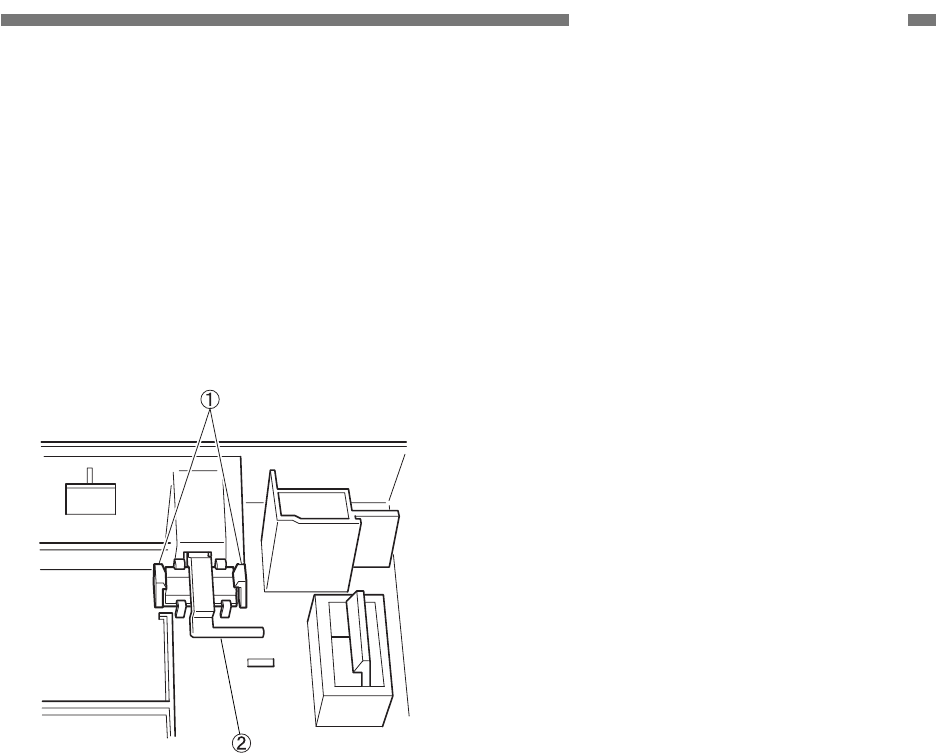
COPYRIGHT © 2005 CANON ELECTRONICS INC. CANON DR-2580C FIRST EDITION APR. 2005
3-23
CHAPTER 3 DISASSEMBLY/ASSEMBLY
5. Hook (for Main Body)
1) Remove the upper unit.
2) Bend the 2 stoppers
{
1 mounted on the
back side of the upper unit and remove
the hook
{
2.
Note: The same procedure applies to the
disassemblies of both right and left
hooks.
Figure 3-406
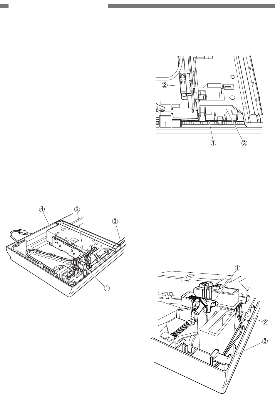
3-24
COPYRIGHT © 2005 CANON ELECTRONICS INC. CANON DR-2580C FIRST EDITION APR. 2005
CHAPTER 3 DISASSEMBLY/ASSEMBLY
B. Lower Unit
Note: When moving the optical unit, move the
timing belt by hand. Power cannot be
evenly transmitted if using the rail
mounted on the other side to move the
optical unit.
1. Optical Unit
1) Remove the upper unit.
2) Lift the contact assembly
{
1 to remove it.
And disconnect the cable
{
2 from the
PCB and pull the main shaft
{
3 out of the
optical unit
{
4.
Note: When disconnecting the cable from the
connectors, press those connectors by
hand to prevent the PCB from being
damaged.
Figure 3-407
3) Remove the timing belt
{
1 and cable
guide
{
2 out of the optical unit
{
3.
Figure 3-408
Note: Do not remove the cover of the optical
unit. Do not touch the glass tube of the
lamp.
* Notes on assembly
When assembling the contact assembly,
hook the end of the lever
{
1 on the pro-
jection
{
2 of the contact assembly. Hold
the cable with the 2 cable holders
{
3.
Figure 3-409
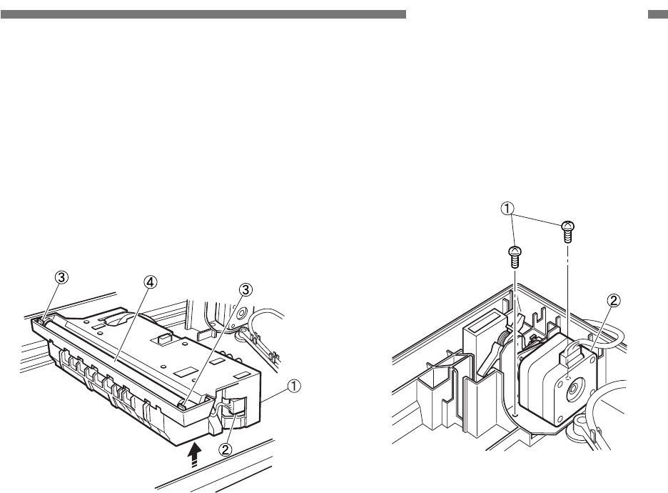
COPYRIGHT © 2005 CANON ELECTRONICS INC. CANON DR-2580C FIRST EDITION APR. 2005
3-25
CHAPTER 3 DISASSEMBLY/ASSEMBLY
2. Lamp
1) Remove the upper unit.
2) Slightly tilt the optical unit
{
1 and remove
the connector
{
2 (with lock). Unhook the
2 fitting parts
{
3 and remove the lamp
{
4.
Note: Do not touch the glass tube of the lamp.
Be sure to turn the power OFF since the
high voltage is applied to the lamp.
Figure 3-410
3. Motor Unit
1) Remove the upper unit.
2) Remove the contact assembly.
3) Remove the 2 screws
{
1 and remove the
motor unit
{
2.
Figure 3-411
* Notes on assembly
Reeve the belt for the optical unit on the
pulley.
* Tension adjustment for belt
If the tension of the belt for the optical unit
needs to be adjusted, use the tension
adjustment plate which is mounted on the
other side of the motor.
Adjust the belt tension so that teeth are
not skipped. If it is too tight, vibration be-
comes excessive and it is not good.

CHAPTER 4
INSTALLATION & MAINTENANCE
COPYRIGHT © 2005 CANON ELECTRONICS INC. CANON DR-2580C FIRST EDITION APR. 2005
I. INSTALLATION ........................................4-1
II. PERIODICALLY REPLACED PARTS ......4-5
III. CONSUMABLE PARTS ...........................4-6
IV. LIST OF PERIODIC MAINTENANCE
ITEMS.......................................................4-7
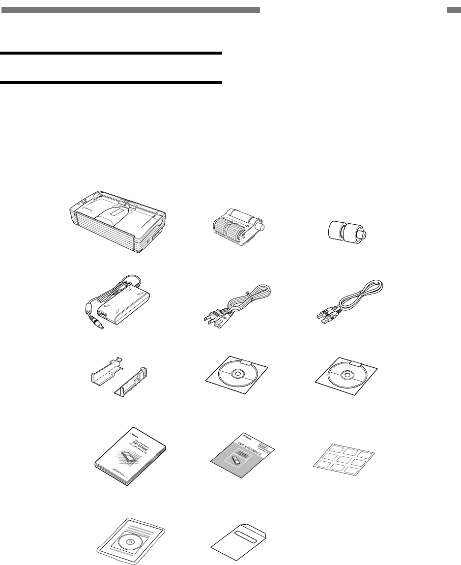
COPYRIGHT © 2005 CANON ELECTRONICS INC. CANON DR-2580C FIRST EDITION APR. 2005
4-1
CHAPTER 4 INSTALLATION & MAINTENANCE
I. INSTALLATION
1. Unpacking
Open the outer packaging box and take
out the main body and other items packed with
it. Check that there are no missing items. The
unpacking procedure is indicated on the box.
Quick reference
guide
Power cord
Startup manual
AC adapter
DR-2580C
setup disc
USB interface cable
Adobe Acrobat
setup disc
DR-2580C main body
Document guide
adapter
Warranty card
(only for 100 V and
120 V models)
Job labels
Roller unit Retard roller
Application kit
(only for 100 V
model)
Figure 4-101
• The DR-2580C setup disk is inserted in the
startup manual.
• Retain the outer packaging box and packing
materials because they are required to store
and transport this machine.
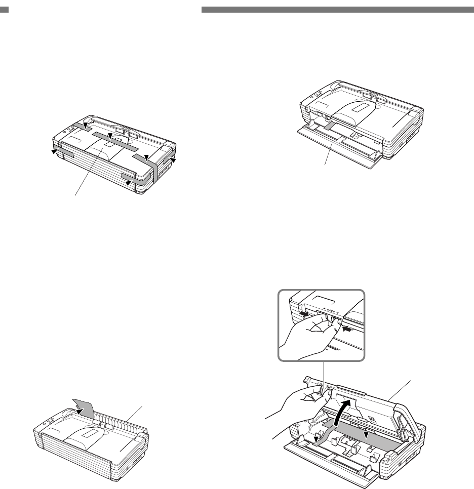
4-2
COPYRIGHT © 2005 CANON ELECTRONICS INC. CANON DR-2580C FIRST EDITION APR. 2005
CHAPTER 4 INSTALLATION & MAINTENANCE
2. Protection Material Removal
1) Remove the protection tape from the main
body.
Eject tray extension
Figure 4-102
Note: When removing the protection tape
holding the eject tray extension, remove
it while holding the eject tray extension
by hand.
2) Push both sides of the rear cover, open it
backward, and remove the protection
sheet.
Rear cover
Figure 4-103
3) Push both sides of the rear cover and
close it.
4) Open the pickup tray forward.
Pickup tray
Figure 4-104
5) Push the OPEN knob from both sides,
open the upper unit slowly, and remove
the protection tape and protection sheet.
Upper Unit
Figure 4-105
6) Close the upper unit slowly. Then push both
sides of the upper unit with both hands and
close it.
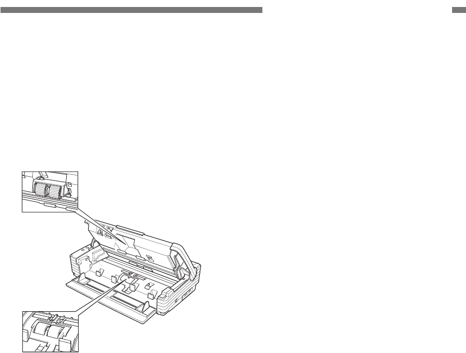
COPYRIGHT © 2005 CANON ELECTRONICS INC. CANON DR-2580C FIRST EDITION APR. 2005
4-3
CHAPTER 4 INSTALLATION & MAINTENANCE
3. Roller Installation
Install the supplied “roller unit” and “retard
roller” on the main body. For the installation
method, refer to the user manual or
“CHAPTER 1 INTRODUCTION, VI. User
Maintenance” of this manual.
Roller unit
Retard roller
Figure 4-106
4. Connection to the computer
1) Check whether the computer has an I/F
card and install one if necessary.
2) Connect an USB interface cable.
3) Connect the supplied AC adapter and
power cord. Be sure to use the supplied
power cord.
4) Switch this machine ON and then turn the
computer ON.
5) Let the computer to recognize this ma-
chine (scanner).
6) Install software (drivers and applications)
necessary for the computer.
7) Restart the computer as required.
5. Operation Check
1) Install the supplied document guide
adapters as required.
2) Set documents.
3) Run the application software according to
the operation procedure.
4) Check operation results.
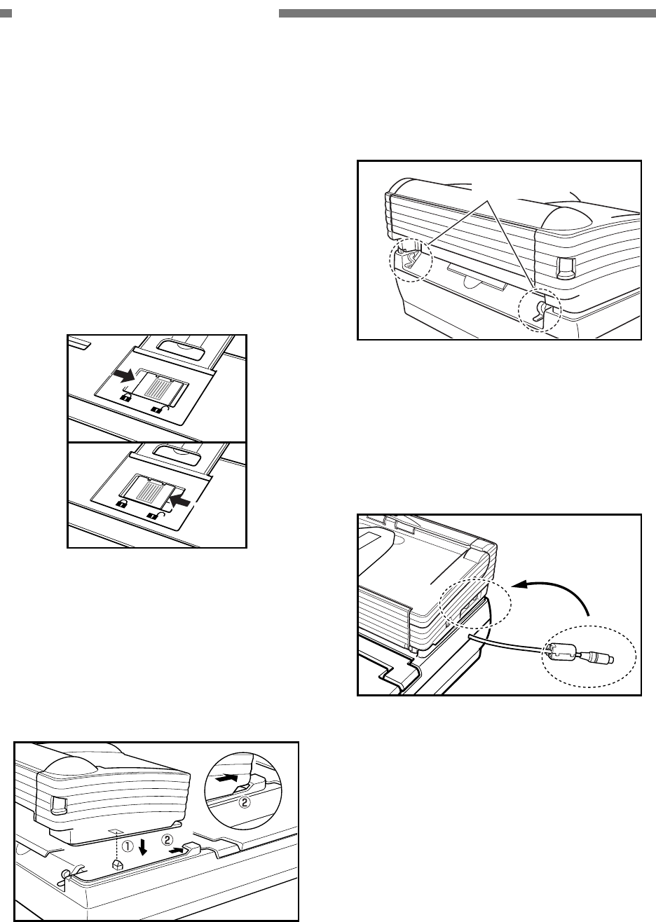
4-4
COPYRIGHT © 2005 CANON ELECTRONICS INC. CANON DR-2580C FIRST EDITION APR. 2005
CHAPTER 4 INSTALLATION & MAINTENANCE
6. Flatbed Unit Installation
This unit is installed by the user. For de-
tails, refer to the user manual supplied with the
unit.
Switch the DR-2580C OFF when installing
the unit.
1) Unlocking
Move the locking plate located under the
eject tray extension and unlock the read-
ing unit (optical unit).
Unlock
Lock
Figure 4-107
2) DR-2580C installation
Set the DR-2580C so that the projection
on this unit is inserted into the hole in the
bottom of the DR-2580C (
{
1) and slide it
forward (
{
2).
Figure 4-108
3) Scanner fixing
Hang the locking hooks on this unit on the
scanner and fix them.
Locking hooks
Figure 4-109
4) Connection
Connect the interface cord so that the
arrow on the plug of the interface cord
faces up.
Figure 4-110

COPYRIGHT © 2005 CANON ELECTRONICS INC. CANON DR-2580C FIRST EDITION APR. 2005
4-5
CHAPTER 4 INSTALLATION & MAINTENANCE
II. PERIODICALLY
REPLACED PARTS
This machine has no periodically replaced
parts, but it has consumable parts.
Reference: Differences periodically replaced parts and consumable parts
1. Periodically replaced parts shall be replaced when becoming at appointed time, and which
are usually replaced by service technicians and assigned as service parts. However, if the
storage period is limited, parts are assigned as commercially available products.
2. Consumable parts shall be replaced when becoming no good by users or service techni-
cians, and which are assigned as service parts and/or commercially available products.

4-6
COPYRIGHT © 2005 CANON ELECTRONICS INC. CANON DR-2580C FIRST EDITION APR. 2005
CHAPTER 4 INSTALLATION & MAINTENANCE
III. CONSUMABLE PARTS
No. Part name Part number Expected life Remarks
1 Roller unit MG1-3720-000
2 Retard roller MA2-7326-000
100,000 sheets It should be replaced when a
roller is worn and the pickup
failures or document jams are
occurred after roller cleaning.
Replacement is done by users.
Table 4-301
Note: Each roller is assigned as service parts
and also assigned as commercially
available products for a set named an
exchange roller kit.

COPYRIGHT © 2005 CANON ELECTRONICS INC. CANON DR-2580C FIRST EDITION APR. 2005
4-7
CHAPTER 4 INSTALLATION & MAINTENANCE
IV. LIST OF PERIODIC
MAINTENANCE ITEMS
This machine has no items for the periodic
maintenance by service technicians.
If service technicians visit users, check
the rollers and reading glass and direct “User’s
Maintenance” if they are very dirty.
Reference:
List of User’s Maintenance Items
[ : Cleaning, ●: Replace, : Lubricate, : Adjust, : Check]
Intervals (sheets)
Unit
name Location/Parts As
necessary 100,000
Remarks
Roller unit ●
Retard roller ●
Feed sec-
tion
Registration roller
Reading glass
Reading
section Shading plate
Wipe with cloth slightly
moistened with water,
then wipe dry.
Table 4-401
Remove the paper dust and other dust on
the feed section including document detection
sensors as required.

CHAPTER 5
TROUBLESHOOTING
COPYRIGHT © 2005 CANON ELECTRONICS INC. CANON DR-2580C FIRST EDITION APR. 2005
I. ERROR DISPLAY ....................................5-1
II. SERVICE MODE......................................5-2
III. IMAGE TROUBLESHOOTING ..............5-13
IV. OPERATION TROUBLESHOOTING .....5-16
V. AFTER REPLACING PARTS .................5-19
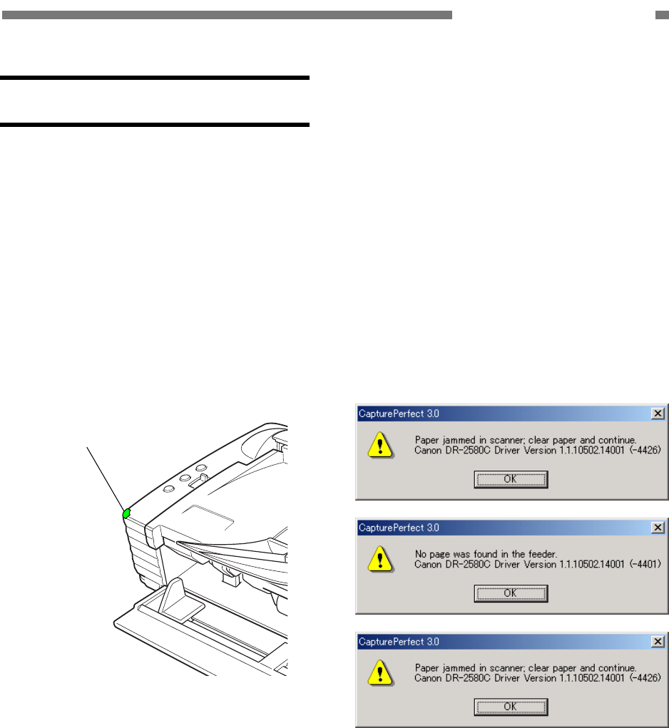
COPYRIGHT © 2005 CANON ELECTRONICS INC. CANON DR-2580C FIRST EDITION APR. 2005
5-1
CHAPTER 5 TROUBLESHOOTING
I. ERROR DISPLAY
1. Power Indicator
The DR-2580C does not have an error
display area, but some errors are indicated
by the power indicator on the operation
panel of the main body.
If the DR-2580C operates normally, the
power indicator lights. The power indicator
blinks if it can not scan the document in case
that the upper unit opens or the document
jam occurs, etc.
Power Indicator
Figure 5-101
2. Error Messages
Error messages are displayed on the
display connected to the computer.
The contents of the error message differ
depending on the software that is used.
Most error messages are related to im-
proper user operation and document jams.
The user shall perform the remedy accord-
ing to the error message. If the “motor ab-
normality,” etc. occur, the matter must be
referred to a service technician.
The followings show the main error
messages displayed when the “Cap-
turePerfect 3.0” is used.
Figure 5-102
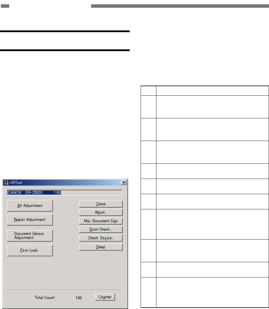
5-2
COPYRIGHT © 2005 CANON ELECTRONICS INC. CANON DR-2580C FIRST EDITION APR. 2005
CHAPTER 5 TROUBLESHOOTING
II. SERVICE MODE
1. Outline
The service mode of the DR-2580C can
be executed by installing on the computer for
servicing the service mode software located in
the setup disk provided with the DR-2580C.
The system conditions for the computer to
be used are the same as those described in
the user manual. If the CPU performance or
memory capacity is lower, the processing time
might be longer, but the service mode can still
be used.
Figure 5-201 shows the service screen.
Figure 5-201
The service screen displays the buttons
for selecting the various modes. Each service
mode is performed from this screen.
Table 5-201 shows the list of the service
modes.
No. Button name/Functions
1 All Adjustment
Perform all adjustments related to
image reading.
2 Regist Adjustment
Perform the registration adjust-
ments.
3 Document Sensor Adjustment
Perform the document board sensor
adjustments.
4 Firm Load
Change the firmware.
5 About
Display this service mode version.
6 Max. Document Size
Set the long document mode.
7 Dcon Check
Check the operation of the hard-
ware such as operation buttons,
sensors, motors, etc.
8 Check Device
Display the version of the internal
devices of the DR-2580C.
9 Sleep
Set the sleep mode.
10 Counter
Display and change the total count
(cumulative number of sheets fed)
and the number of document jam.
Table 5-201
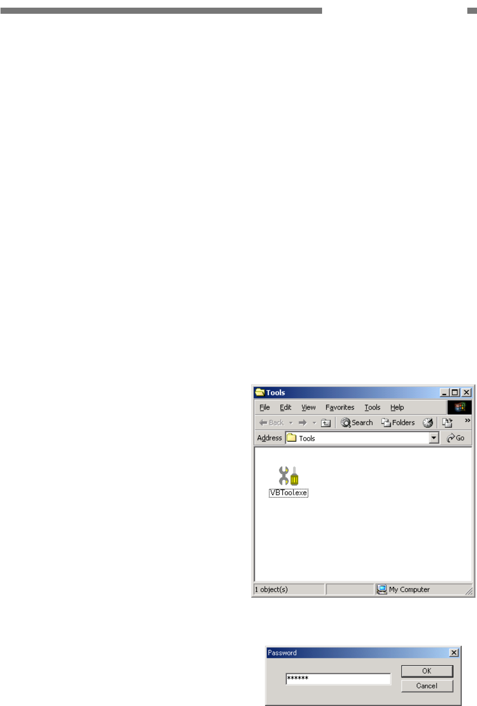
COPYRIGHT © 2005 CANON ELECTRONICS INC. CANON DR-2580C FIRST EDITION APR. 2005
5-3
CHAPTER 5 TROUBLESHOOTING
2. Installation Procedure
The service mode software installation
procedure is described below. Do not install it
on the user's computer.
1) Power ON the computer for servicing and
start up the OS (Windows).
2) Set the DR-2580C setup disk supplied
with this machine.
3) Copy the “\Driver\Tools” folder in the
setup disk to one of the drives of the
computer for servicing.
Note: For how to install the software provided
with the DR-2580C, refer to the user
manual.
However, for the specifications, such as
the maximum number of documents that
can be scanned at one time, see the
computer system conditions described
in the user manual.
3. Starting Up and Exiting Service
Mode
The procedure for starting up the service
mode is described below.
1) Connect the computer for servicing with
the DR-2580C using a USB interface ca-
ble.
2) After powering ON the DR-2580C, power
ON the computer.
3) Open the installed “Tools” folder and start
up the “VBTool.exe” file. (See Figure
5-202.)
4) The password screen is displayed, so
after inputting the six characters “market,”
select [OK]. (See Figure 5-203.)
5) The service screen is displayed.
To exit the service mode, select [Close] in
the service screen.
.
Figure 5-202
Figure 5-203
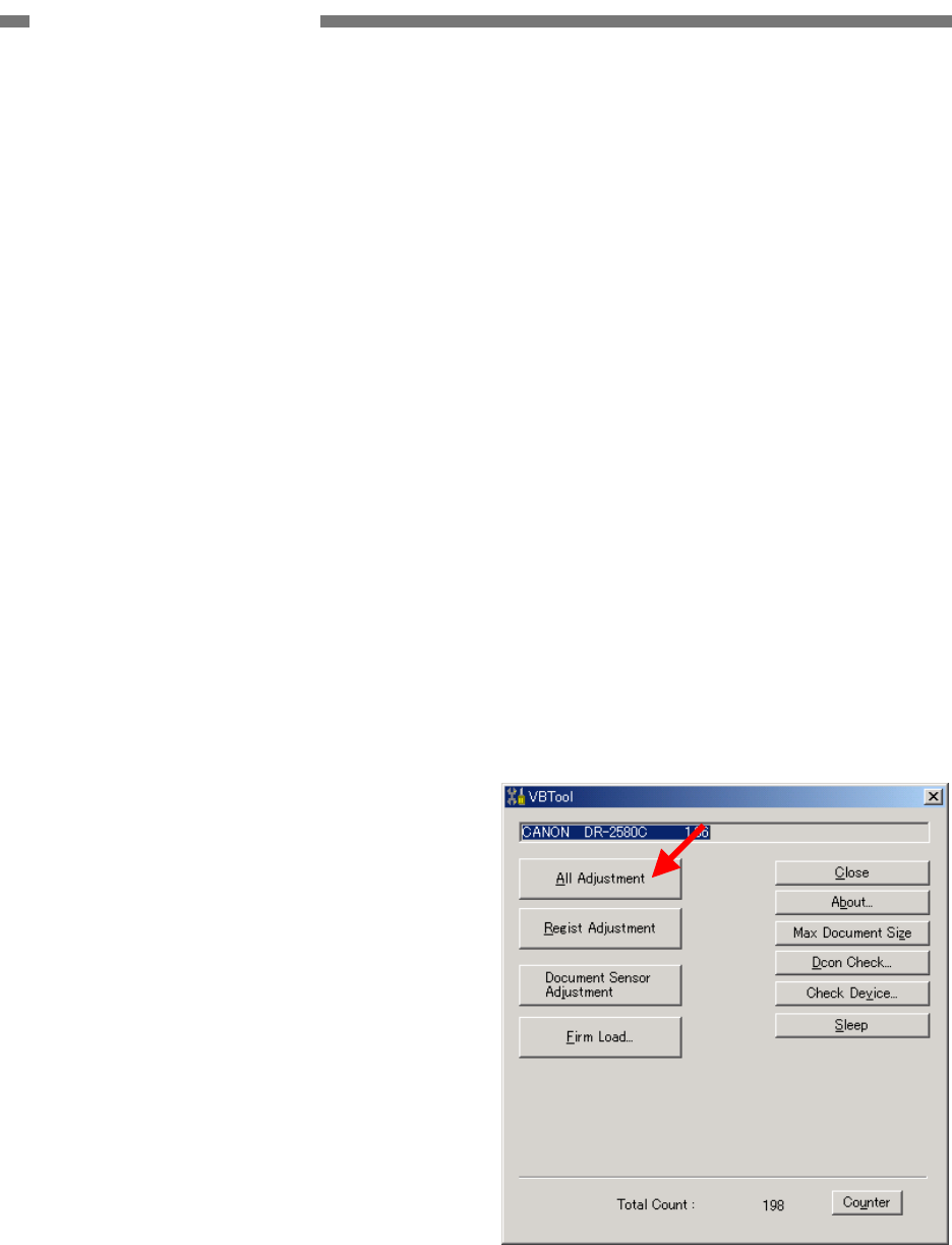
5-4
COPYRIGHT © 2005 CANON ELECTRONICS INC. CANON DR-2580C FIRST EDITION APR. 2005
CHAPTER 5 TROUBLESHOOTING
Note: After the DR-2580C is connected to the
computer and the computer is powered
ON for the first time, a screen requesting
installation of “New Hardware” or a
“Device Driver” is displayed. In this case,
perform the “Scanner Recognition” ac-
cording to the user manual.
Note: To execute the service mode with the
user's computer, start up “VBTool.exe”
on the setup disk supplied with the
DR-2580C. Do not copy this program to
the user's computer. Do not let the user
know the folder name and password to
be used.
4. All Adjustment
This mode is used to adjust all image
reading adjustments at the same time. Since
the adjustment value is saved on the control
PCB, be sure to execute this mode after the
control PCB have been replaced.
This mode consists of two individual ad-
justment items: “Regist Adjustment” and
“Document Sensor Adjustment.”
• Operating Procedure
1) Clean the document board sensor window,
the shading plate and the reading glass.
2) Set a piece of regular white copy paper
(A4/LTR). The paper can be set both ver-
tically and horizontally. Set the document
guide position to the paper. This paper is
used to perform “Regist Adjustment.”
3) Select [All Adjustment] on the service
screen.
Figure 5-204
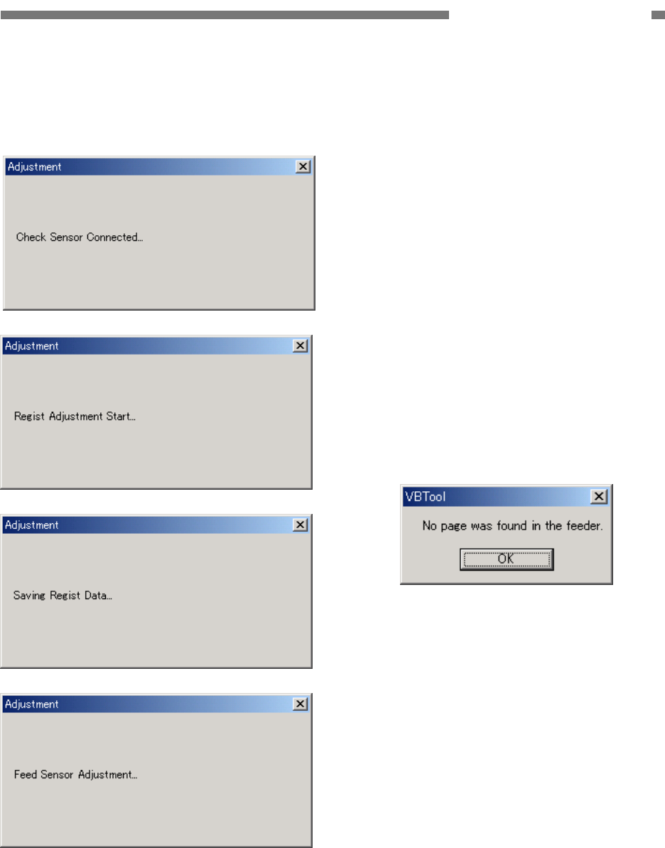
COPYRIGHT © 2005 CANON ELECTRONICS INC. CANON DR-2580C FIRST EDITION APR. 2005
5-5
CHAPTER 5 TROUBLESHOOTING
4) The adjustment starts automatically. The
progress screen appears on the display.
An example of display is shown below.
Figure 5-205
5) When the adjustment is finished, the
progress screen disappears and the ser-
vice screen appears.
It takes approx. 10 seconds to finish.
• Errors
If an adjustment value failure occurs in the
while executing this mode, an error screen
is displayed, and adjustment is interrupted.
If an error screen is displayed, select [OK]
in the screen to stop adjustment. Then
after checking the operating procedure,
perform adjustment again. If adjustment is
interrupted, the adjustment value remains
the value prior to adjustment.
Sample error screens are shown below.
Figure 5-206
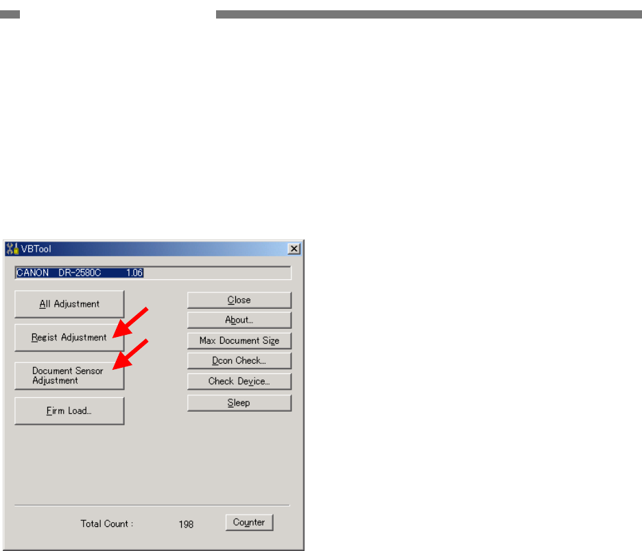
5-6
COPYRIGHT © 2005 CANON ELECTRONICS INC. CANON DR-2580C FIRST EDITION APR. 2005
CHAPTER 5 TROUBLESHOOTING
5. Individual Adjustments
This section describes the following indi-
vidual adjustment items. If all the two adjust-
ments are performed, use [All Adjustment].
• [Regist Adjustment]
• [Document Sensor Adjustment]
Figure 5-207
a. Regist Adjustment
The reading position is adjusted in this
mode. Execute this mode if the leading
edge and trailing edge of a read image are
faulty.
• Operating Procedure
1) Set a piece of regular white copy paper
(A4/LTR). Set the document guide posi-
tion to the paper.
2) Select [Regist Adjustment] on the service
screen.
3) The adjustment starts automatically. The
progress screen appears on the display.
4) When the adjustment is finished, the pro-
gress screen disappears and the service
screen appears.
b. Document Sensor Adjustment
The detection level of the document board
sensor is adjusted in this mode. Execute
this mode if there is a problem with
document detection when a document is
set.
Since this sensor is affected by stain on
the sensor window and the external light,
the sensor window should be cleaned and
external light should be adjusted to the
using state when executing this mode.
• Operating Procedure
1) Clean the document board sensor win-
dow.
2) Select [Document Sensor Adjustment] on
the service screen.
3) The adjustment starts automatically. The
progress screen appears on the display.
4) When the adjustment is finished, the pro-
gress screen disappears and the service
screen appears.
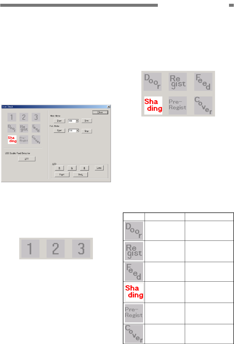
COPYRIGHT © 2005 CANON ELECTRONICS INC. CANON DR-2580C FIRST EDITION APR. 2005
5-7
CHAPTER 5 TROUBLESHOOTING
6. Dcon Check
This mode is used when checking the
operation of the hardware controlled with the
control PCB.
• Operation screen
When [Dcon Check] is selected on the
service screen, the operation screen is
displayed.
Figure 5-208
a. Job buttons
When the job button is pressed, the cor-
responding mark lights.
Figure 5-209
b. Sensors
When sensors enter the detection state,
the corresponding mark lights. The case
where the shading sensor enters the de-
tection state is shown below.
Figure 5-210
Note 1: If the upper unit or the rear cover is
open, the registration sensor function
is invalid and its display is not correct.
Note 2: “USS Double Feed Detection” at the
lower left side of the screen does not
need to be used until the ultrasonic
sensor is installed.
The contents of marks are shown below.
Mark Sensor name Lighting state
Upper opening
sensor
The upper unit is
open.
Registration
sensor
The registration
sensor detects a
document.
Document
board sensor
A document is set.
Shading sensor The reading unit
(lower) is at the
shading position.
Pre-registration
sensor
The pre-registration
sensor detects a
document.
Rear cover
sensor
The rear cover is
open.
Table 5-202
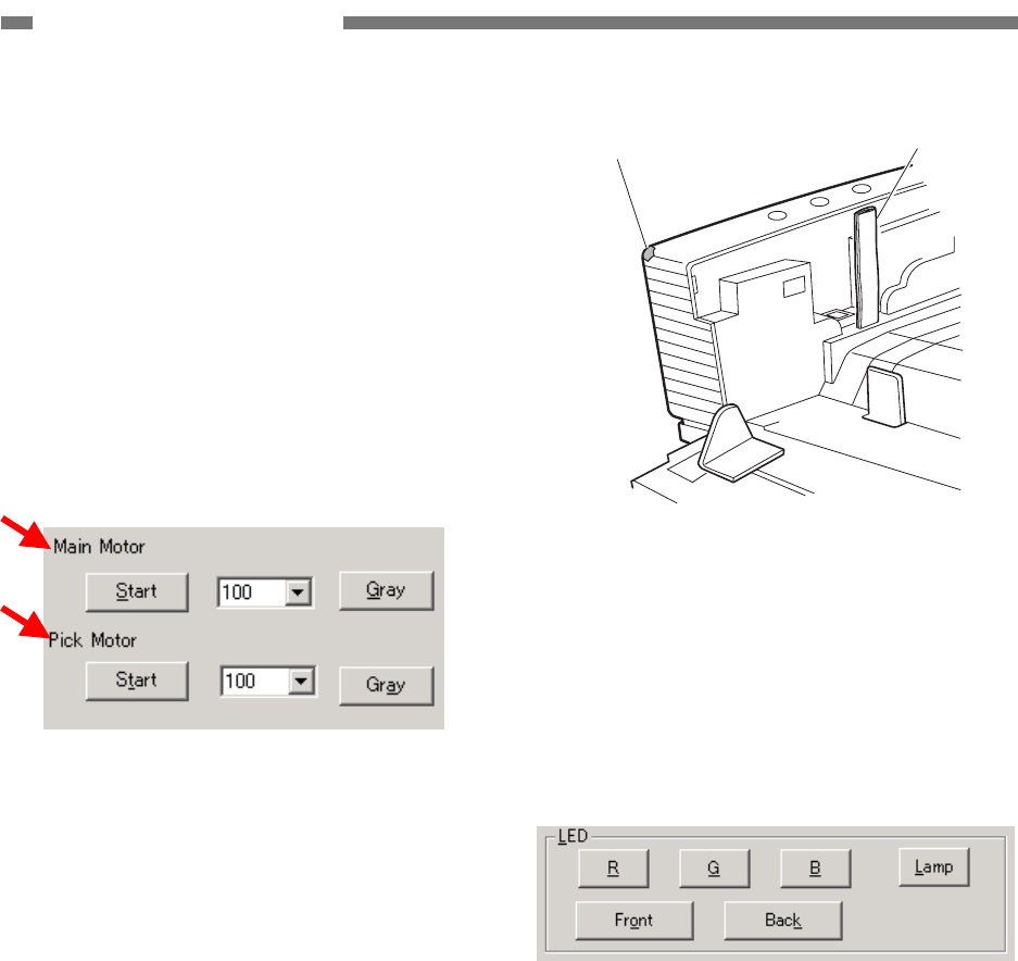
5-8
COPYRIGHT © 2005 CANON ELECTRONICS INC. CANON DR-2580C FIRST EDITION APR. 2005
CHAPTER 5 TROUBLESHOOTING
c. Motor
This section describes the operation
check of the carry motor (main motor) and
the eject motor (pick motor).
When the reading mode and resolution
corresponding to each motor are selected
and the [Start] button is selected, the
motor runs at the speed that meets the
conditions. When the button is selected
again, the motor stops.
The operation screen is shown below.
Figure 5-211
d. LED and lamp
The confirmation of the lighting of the
lamp of the CIS unit LED and optional
flatbed unit is shown.
When the corresponding button is se-
lected, the lamp lights.
However, in case of the CIS unit LED, the
lamp does not light unless the upper
opening sensor is turned “ON.” Open the
upper unit, insert a piece of paper like
folded thick paper into an opening of the
upper opening sensor and hold it. Refer to
Figure 5-212. When the sensor is “ON,”
the power indicator lights.
Power indicator Insert
Figure 5-212
Select a reading surface (front, back) in
addition to a color (R, G, B). In case of the
flatbed unit lamp, select the [Lamp] button.
When the button is selected again, it turns
“OFF.”
Figure 5-213
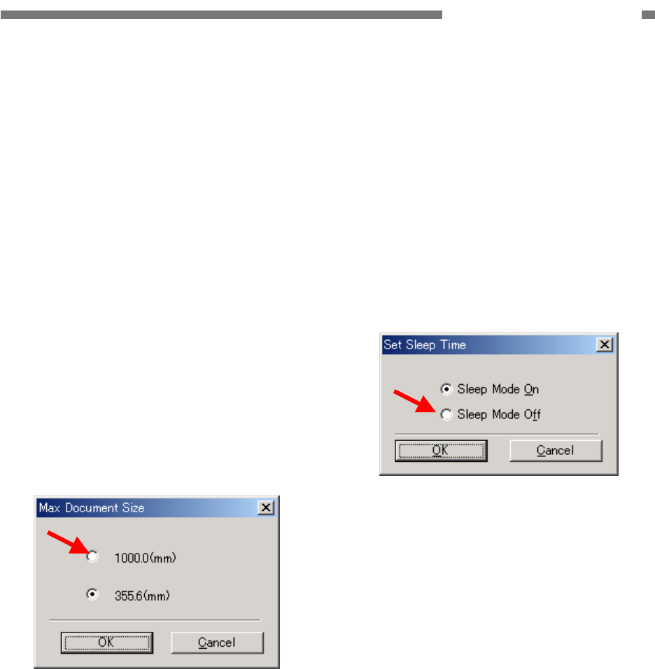
COPYRIGHT © 2005 CANON ELECTRONICS INC. CANON DR-2580C FIRST EDITION APR. 2005
5-9
CHAPTER 5 TROUBLESHOOTING
7. Max Document Size
This mode is used to set the long docu-
ment mode. However, the long document
mode is not standard specification, so it is
used for special users only. Do not use it for
general users.
When the long document mode is set, the
document length is 1000 mm at the maximum,
but there are restrictions shown below:
• Document size: “Automatic detection” only
• Feed: Feed a sheet of paper. Performance
of paper pickup/eject is not guaranteed.
When [Max Document Size] is selected on
the service screen, the setting screen is dis-
played. To set the long document mode,
change the setting to [1000.0(mm)] and press
the [OK] button.
Figure 5-214
8. Sleep
This mode is used to set so that the sleep
mode is not effective. However, the sleep
mode OFF is not the standard specification, so
it is used for special users only. Do not use it
for general users.
When [Sleep] is selected on the service
screen, the setting screen is displayed. To set
the sleep mode OFF, change the setting to
[Sleep Mode Off] and press the [OK] button.
Figure 5-215
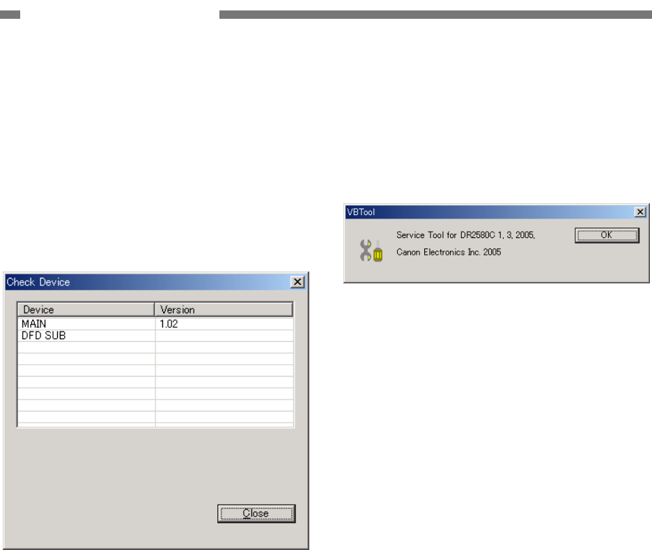
5-10
COPYRIGHT © 2005 CANON ELECTRONICS INC. CANON DR-2580C FIRST EDITION APR. 2005
CHAPTER 5 TROUBLESHOOTING
9. Check Device
This mode is used to check the versions of
the internal devices of the DR-2580C.
When [Check Device] is selected on the
service screen, the version screen is dis-
played.
[MAIN] indicates the version number of
the firmware of the control PCB.
Figure 5-216
10. About
This mode is used to check the version of
the software for this service mode.
When [About] is selected on the service
screen, the version screen is displayed.
Figure 5-217
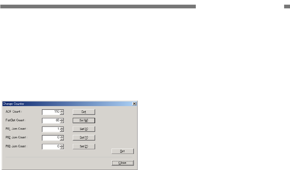
COPYRIGHT © 2005 CANON ELECTRONICS INC. CANON DR-2580C FIRST EDITION APR. 2005
5-11
CHAPTER 5 TROUBLESHOOTING
11. Counter
This mode is used to display/change total
count (cumulative number of feed sheet) and
display/change the number of document jams.
When [Counter] is selected on the service
screen, the counter screen is displayed.
Figure 5-218
The contents of display are as follows:
• ADF Count
Indicates total count of the main unit.
• FlatBed Count
Indicates the number of scan of the flatbed
unit.
• P01_Jam Count
Indicates the number of early reach jams.
• P02_Jam Count
Indicates the number of residual jams.
• P03_Jam Count
Indicates the number of fast feed jams.
The “Total Count” shown at the bottom of
the service screen is the total of “ADF Count”
and “FlatBed Count”.
When the [Set] button on the right or the
[Set] on the lower right of the screen is se-
lected after the value is changed, the changed
value is determined.
To close the screen, press the [Close]
button.
These values might be changed if the
control PCB is replaced. Therefore, inputting
the values again is required after the re-
placement. If the values before the replace-
ment are not clear, it is better to input the
recommended values.

5-12
COPYRIGHT © 2005 CANON ELECTRONICS INC. CANON DR-2580C FIRST EDITION APR. 2005
CHAPTER 5 TROUBLESHOOTING
12. Firm Load
This mode is used to change the firmware
of the DR-2580C. For details, refer to the
service information issued during firmware
changes. Be careful not to execute this mode
by mistake.
• Operation procedure outline
1) Select [Firm Load] in the service screen.
2) The screen for selecting the file in which
the firmware is saved is displayed.
3) Select and open the file.
4) The firmware is loaded to the DR-2580C.
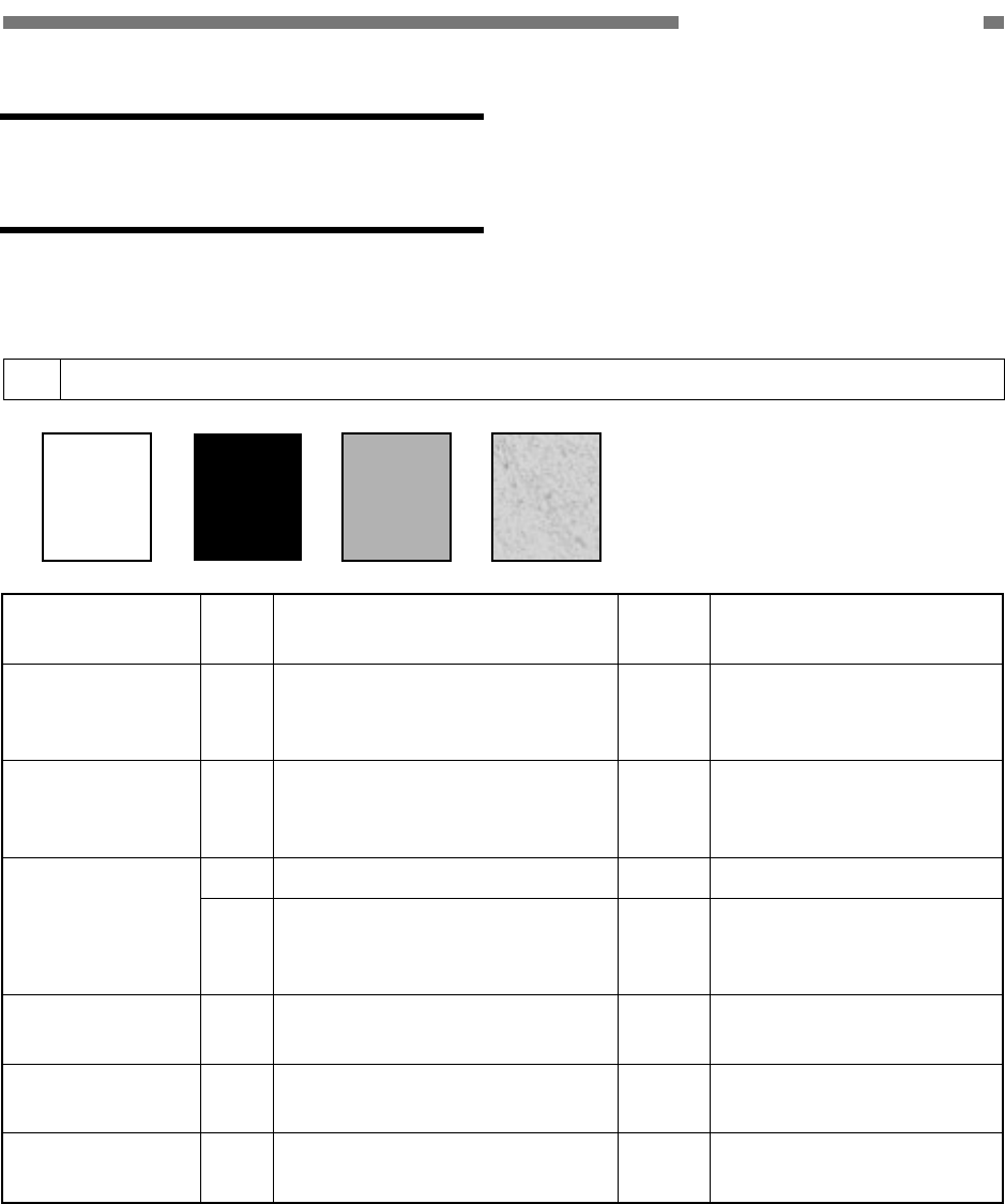
COPYRIGHT © 2005 CANON ELECTRONICS INC. CANON DR-2580C FIRST EDITION APR. 2005
5-13
CHAPTER 5 TROUBLESHOOTING
III. IMAGE
TROUBLESHOOTING
There are times when, depending on the type of image and settings, document reproducibility
becomes poor. In such case, the image may be improved by changing the settings.
1 No image is output (completely white, completely black, completely gray, mottled)
Cause/Faulty
location Step Check Item Result Action
“Brightness”
setting
1 Is the “Brightness” setting ap-
propriate?
NO Change the setting.
Also change “Contrast” if
necessary.
Reading glass 2 Is the reading glass clean? NO Clean it.
If necessary, clean the
roller too.
3 Is the shading plate clean? NO Clean it. Shading plate
4 Does the reading unit (lower)
move when the power is turned
ON?
NO Check the mechanism
related to the movement
of the reading unit (lower).
Connection of
reading unit
5 Are the reading related cables
connected properly?
NO Connect them properly.
Reading unit 6 Is the problem solved when the
reading unit is replaced?
YES End.
Control PCB 7 Is the problem solved when the
control PCB is replaced?
YES End.
Table 5-301

5-14
COPYRIGHT © 2005 CANON ELECTRONICS INC. CANON DR-2580C FIRST EDITION APR. 2005
CHAPTER 5 TROUBLESHOOTING
2 Uneven density, streaks (main-scanning direction)
Cause/Faulty
location Step Check Item Result Action
1 Are the roller unit and retard
roller properly installed?
NO Install them properly. Roller
2 Are they dirty or deformed? NO Clean or replace them.
Gear, belt 3 Does it turn smoothly? NO Adjust assembling or re-
place parts.
Motor (M1, M2) 4 Is the problem solved when the
motor is replaced?
YES End.
Reading unit 5 Is the problem solved when the
reading unit is replaced?
YES End.
Control PCB 6 Is the problem solved when the
control PCB is replaced?
YES End.
Table 5-302
3 Uneven density, streaks (sub-scanning direction)
Cause/Faulty
location Step Check Item Result Action
Reading glass 1 Is the reading glass clean? NO Clean it.
If necessary, clean the
roller too.
2 Is the shading plate clean? NO Clean it. Shading plate
3 Does the reading unit (lower)
move when the power is turned
ON?
NO Check the mechanism
related to the movement
of the reading unit (lower).
Reading unit 4 Is the problem solved when the
reading unit is replaced?
YES End.
Control PCB 5 Is the problem solved when the
control PCB is replaced?
YES End.
Table 5-303

COPYRIGHT © 2005 CANON ELECTRONICS INC. CANON DR-2580C FIRST EDITION APR. 2005
5-15
CHAPTER 5 TROUBLESHOOTING
4 Faulty images of flatbed unit
Cause/Faulty
location Step Check Item Result Action
Document
board glass
1 Is the document board glass
clean?
NO Clean it.
Clean the inside glass
surface if necessary.
Gear, belt, guide
shaft
2 Does the optical unit move
smoothly?
NO Adjust assembling. (It
includes the belt tension
adjustment.)
Replace parts.
Motor (M3) 3 Is the problem solved when the
optical motor is replaced?
YES End.
Optical unit 4 Is the problem solved when the
optical unit is replaced?
YES End.
Table 5-303

5-16
COPYRIGHT © 2005 CANON ELECTRONICS INC. CANON DR-2580C FIRST EDITION APR. 2005
CHAPTER 5 TROUBLESHOOTING
IV. OPERATION
TROUBLESHOOTING
When an operation problem occurs, first check for an “Error Messages” on the display con-
nected to the computer. In addition, check the operation of the various sensors, motors using the
“Service Modes.”
1 No power
Note: The machine power indicator does not light.
Cause/Faulty lo-
cation Step Check Item Result Action
Connection of
power cord
1 Are the power cord and AC
adapter connected?
NO Connect it properly.
AC power supply
voltage
2 Is the specified voltage sup-
plied at the outlet?
NO Explain to the user that
the trouble is not with the
machine.
Power switch 3 Is the power switch turned
ON?
NO Turn the power switch
ON.
4 Is the control PCB connected
to the switch PCB connect?
NO Connect it properly.
5 Connect the power code and
turn the power lever sensor
ON.
Does the LED of the control
PCB light or blink properly?
YES The power is supplied
properly.
Find out the other causes
such as sensors, motors,
etc.
PCB unit (connec-
tion)
6 Is the problem solved when the
switch PCB or control PCB is
replaced?
YES End.
Table 5-401

COPYRIGHT © 2005 CANON ELECTRONICS INC. CANON DR-2580C FIRST EDITION APR. 2005
5-17
CHAPTER 5 TROUBLESHOOTING
2 Computer does not recognize the machine
Cause/Faulty
location Step Check Item Result Action
Power supply 1 Is the power supplied to the
machine?
NO Perform the actions in
section 1: “No power.”
Connection of
USB interface
cable
2 Is the USB interface cable
properly connected?
NO Connect it properly.
Computer, I/F card 5 Are the computer and I/F card
set properly?
NO Use them properly.
Table 5-402
3 Motors do not operate
Cause/Faulty
location Step Check Item Result Action
Power supply 1 Is the power supplied to the
machine?
NO Perform the actions in
section 1: “No power.”
Connectors 2 Are the connectors for the mo-
tor connected properly?
NO Connect them properly.
Transmission
system load
3 Is the transmission system
driven by the motor normal?
Are such parts as gears and
belts normal?
NO Remove the abnormal
load.
Replace needed parts.
4 Is the operation normal when
checking the sensor detection
display in the service mode?
NO Replace the sensor. Sensor
5 Is the problem solved when per-
forming “Document Sensor Ad-
justment” in the service mode?
YES End.
Motor 6 Is the operation normal when
checking the operation in the
service mode?
NO Replace the motor.
Control PCB 7 Is the problem solved when the
control PCB is replaced?
YES End.
Table 5-403

5-18
COPYRIGHT © 2005 CANON ELECTRONICS INC. CANON DR-2580C FIRST EDITION APR. 2005
CHAPTER 5 TROUBLESHOOTING
4 Faulty document feeding (jam/double feed/wrinkles)
Cause/Faulty lo-
cation Step Check Item Result Action
Document 1 Is the document within the
specifications (thickness, di-
mensions, fold, curl, etc.)?
NO Ask the user to use
documents within the
specifications.
2 Are the roller unit and retard
roller properly installed?
NO Install them properly. Roller
3 Are they dirty or deformed? NO Clean or replace them.
4 Are all parts that the docu-
ments contact properly in-
stalled (not loose or tilted)?
NO Install them properly. Parts in feed path
5 Is the surface in contact with
the document smooth (not
scratched, no burrs)?
NO Replace faulty parts.
Drive transmission
system
6 Is any abnormal noise emitted
when feeding documents?
Are any gears broken or is the
belt tension failed?
YES Replace faulty parts. Ad-
just the belt tension.
Table 5-404
5 Flatbed unit does not operate
Cause/Faulty
location Step Check Item Result Action
Installation 1 Are the I/F cable connection,
unlocking, and fixing to the
main body correct?
NO Set it properly.
“Reading side”
setting
2 Is the “Reading side” set to
“Flatbed”?
NO Change the settings.
Motor (M3) 3 Is the problem solved if the
optical motor is replaced?
YES End.
Table 5-405

COPYRIGHT © 2005 CANON ELECTRONICS INC. CANON DR-2580C FIRST EDITION APR. 2005
5-19
CHAPTER 5 TROUBLESHOOTING
V. AFTER REPLACING
PARTS
Some of the parts used in this machine
require adjustments and settings after being
replaced or disassembled/reassembled.
Check document feed and images after
the replacement or disassembly/reassembly
of the parts.
1. Control PCB
1) Perform “All Adjustment” and “Counter” in
the service mode.
2) Perform the following service mode set-
tings if required.
• “Max Document Size”
• “Sleep”
2. Registration Adjustment
Perform “Regist Adjustment” in the ser-
vice mode when failures occur on the leading
edge or trailing edge of scanned images after
replacing or reassembling parts related to
registration such as a registration sensor
lever.
3. Document Board Sensor, Docu-
ment Board Window, etc.
Perform “Document Sensor Adjustment”
in the service mode when the document de-
tection failures occur after replacing or reas-
sembling parts related to the document board
sensor.

APPENDIX
COPYRIGHT © 2005 CANON ELECTRONICS INC. CANON DR-2580C FIRST EDITION APR. 2005
I. GENERAL DIAGRAM ............................. A-1
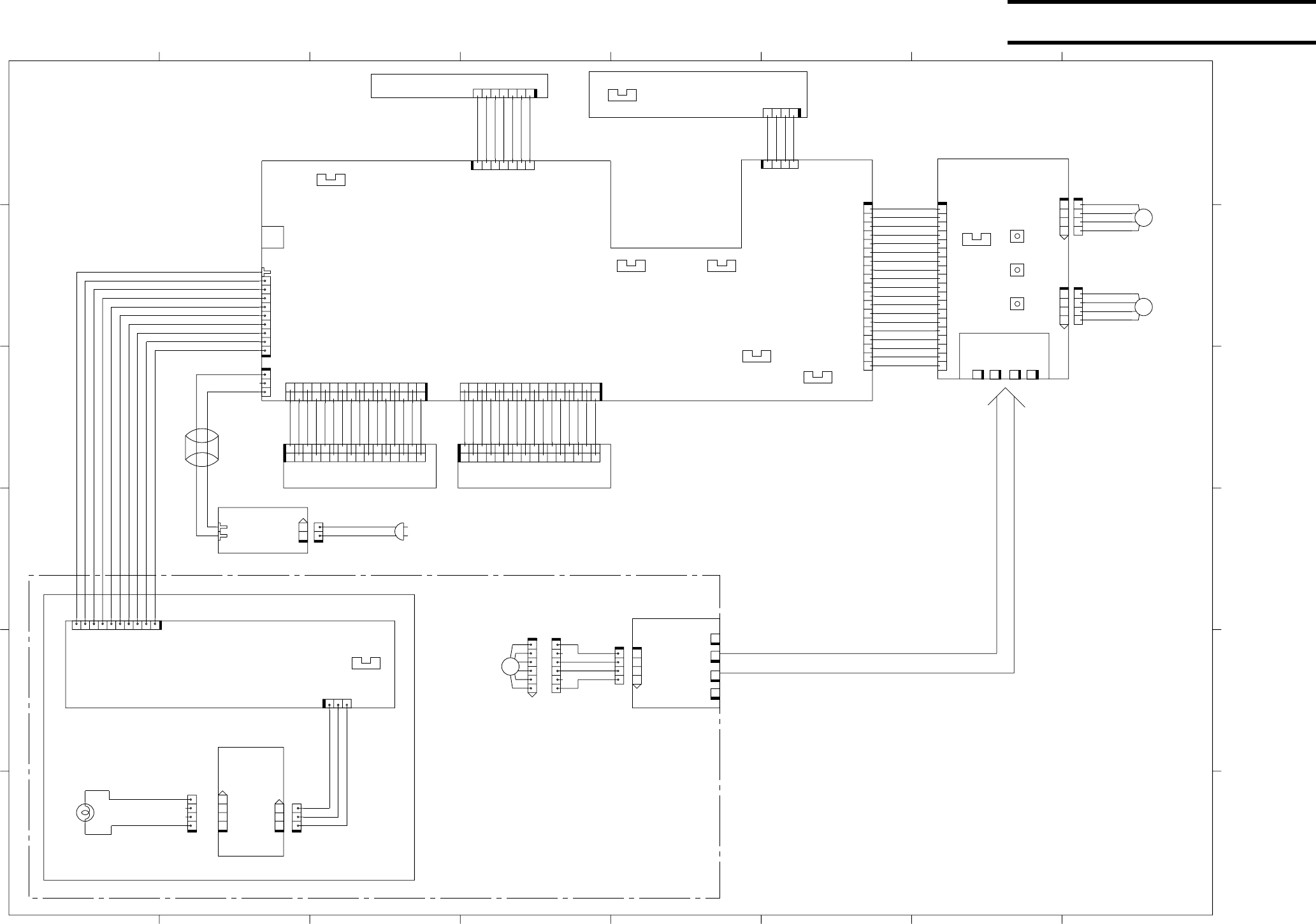
COPYRIGHT © 2005 CANON ELECTRONICS INC. CANON DR-2580C FIRST EDITION APR. 2005
A-1
I. GENERAL DIAGRAM
A
432
C
B
D
E
F
765 1
PICK_A*
PICK_A
PICK_B
FEED_B*
FEED_B
FEED_A
FLAT_B
FLAT_A*
FLAT_A
PICK_B*
FLAT_B*
2431
Vref
+3.3V
MODE_300
Vout
GND_A
F_GND
+5V
LED_R
CLK
SP
LED_G
LED_B
LED_B
LED_G
LED_R
LED_R
LED_G
LED_B
HIGH VOLTAGE
(BLUE CABLE)
(WHITE CABLE)
LOW VOLTAGE
GND
CCD RXDO LVDS N
CCD RXDO LVDS P
CCD RXDE LVDS N
CCD TXD OUT
+16V
CCD RXDE LVDS P
GND
GUARD GND
CCD CLK LVDS N
CCD CLK LVDS P
J701
USB
5P
GND
LED_B
LED_G
SP
CLK
LED_R
+5V
F_GND
GND_A
Vout
MODE_300
+5V
+3.3V
Vref
+5V
SENS ON
DETECT
+5V
PICK_A
PICK_B
PICK_B*
FEED_B
FEED_B*
1342
J202
J72 J73 J74J71
LAMP_ON
+16V
+16V
CN1
PICK_A*
LED_P*
FEED_A*
FEED_A
FLAT_B*
FLAT_B
FLAT_A*
FLAT_A
GND
+3.3V
SEL_CH1
CH1
CH2
GND
FEED_A*
THERMISTA
Sonic Pulse
SONIC RXD
+5V
GND
SONIC TXD
GND
GND
7654321
J50
1234567
J2000
1234
J1001
4321
J100
16
1
2
3
4
5
6
7
8
9
10
111315
1214
J501
14 12
15 13 11
10
9
8
7
6
5
4
3
2
1
16
J502
2341
J70
345612
181716151413121110982345617 19
J1000
231
J103
81234567910
J102
123456789
J4
1234 4321
4321
J201
19 7 16543289101112131415161718
J200
1412
151311
10
9
8
7
6
5
4
3
2
1
16
J1
231
J101
1
2
P1
132
J102
234561
J80
543216
2341
CN2
12
21
J5
16
1
2
3
4
5
6
7
8
9
10
11 13 15
12 14
J2
1234
J203
SW3
SW2
SW1
M2
M1
PS3
PS4
PS1
PS6
PS2
PS5
PS7
PS8
M3
Picup motor
Job switch
Swtich PCB
Carry motor
Open detect
sensor
Document board sensor
Power lever sensor
Pre-registration
sensor
Rear cover sensor
Shading sensor
Registration
sensor
Optical unit
sensor
Flatbed scanner unit (option)
Optical motor
Optical unit
Control PCB
CIS PCB (back)CIS PCB (front)
CCD PCB
Inverter
PCB
Lamp
FL1
AC adapter
U-sonic sensor PCB
Document board sensor PCB
Contact PCB A
Contact
PCB B
Prepared by
Quality Assurance Center
Canon Electronics Inc.
3-17-7 Shibaura, Minato-ku
Tokyo 108-0023, Japan
FIRST EDITION (APR. 2005) [63999]

0305TG
COPYRIGHT
©
2005 CANON ELECTRONICS INC. CANON DR-2580C FIRST EDTION APR. 2005
i
PARTS
CATALOG
APR. 2005 MY8-31A4-000
FIRST EDTION
DR-2580C
100V
120V
220-240V
220-240V CA
220-240V KR
220-240V CN
M11-0521
M11-0523
M11-0524
M11-0525
M11-0526
M11-0529
F/B UNIT
100V
120V/220-240V
M18-0831
M18-083
A

COPYRIGHT
©
2005 CANON ELECTRONICS INC. CANON DR-2580C FIRST EDTION APR. 2005
序
このパーツ・カタログは,DR-2580Cに対するサービス部品調達の手引として発行します。
サービス部品の要求は、キヤノン販売営業所にお願い致します。
製品に大きな変更がある場合は,改訂版のパーツ・カタログを発行しますが,その他の場合は随時新し
い情報をお届けします。
このパーツ・カタログは当社品質保証部品質推進課が発行管理を行っています。
PREFACE
This Parts Catalog contains listings of parts used in the DR-2580C.
Diagrams are provided with the listings to aid the service technician in identifying clearly, the item to be
ordered.
Whenever ordering parts, consult this Parts Catalog for all of the information pertaining to each item. Be
sure to include in the Parts Request, the full item description, the item part number and the quantity.
Quality Assurance Center
Canon Electronics Inc.
版権所有,無断転載,引用を禁ず。
Copyright 2005 Canon Electronics Inc
本マニュアルについては,機密保持等その取扱には十分注意して下さい。
万一取扱を誤まりますと法律で処罰されることがあります。
Use of this manual should be strictly supervised to avoid disclosure of confidential
information.
ii
キヤノン電子株式会社
品質保証部 品質推進課

COPYRIGHT
©
2005 CANON ELECTRONICS INC. CANON DR-2580C FIRST EDTION APR. 2005
目 次
CONTENTS
A 主要部品配置図-1,2 A ASSEMBLY LOCATION DIAGRAM-1, 2
B イラスト索引 B ILLUSTRATION INDEX
100 外装カバー部 100 EXTERNAL COVERS
200 上部ユニット 200 UPPER UNIT
300 上下読取部 300 READING UNIT, UPPER/LOWER
400 下部ユニット-1 400 LOWER UNIT-1
410 下部ユニット-2 410 LOWER UNIT-2
420 下部ユニット-3 420 LOWER UNIT-3
500 電装部 500 ELECTRICAL COMPONENTS ASSEMBLY
600 フラットベッド・スキャナ・
ユニット(オプション)
600 FLATBED SCANNER UNIT (OPTION)
部品索引表 NUMERICAL INDEX
iii

COPYRIGHT
©
2005 CANON ELECTRONICS INC. CANON DR-2580C FIRST EDTION APR. 2005
主要部品配置図について
部品図番号 (Figure No.) および各アセンブリの位置を捜
すとき,主要部品配置図を用います。
図中 内は部品図名称, 内は部品図番号を
示しています。
また,「イラスト索引」からも検索できます。
部品番号の捜し方
どのアセンブリに使用されている部品かを,主要部品配置
図またはイラスト索引で調べその部品図番号 (Figure
No.) のページをめくります。
部品図の中からその部品をみつけ,そのキーNo.を部品
番号リストの中から捜し出せば,部品番号・部品名称を知
ることができます。
注: 電源電圧・周波数等の仕様が異なる場合は,同一の
キーNo.に複数の部品番号が記されているので
“REMARKS”欄を注意して見るようにしてください。
部品番号リストについて
部品番号リストの内容項目は次のとおりです。
(1) 部品図番号およびキーNo. (FIGURE & KEY No.)
部品図番号は,各部品番号リスト欄の左上に示してあ
り,各部品図に対応しています。
また,キーNo. は,部品図中に示してある個々の部品
に対応します。
(2) 部品番号 (PART NUMBER)
リストの2番目の欄には,部品番号が示してあります。
部品を発注する際は,必ずこの番号を明示してくださ
い。NPNと記載されている部品はサービスパーツに設
定されていません。
注: 部品番号の末尾3桁を訂番といいます。部品改良等
の目的で部品の一部が変更になった場合,訂番が
変わることがあります。これらの変更については,技
術情報 (Service Information) で随時連絡されます
ので,常にこれらの情報も注意深く読むよう心がけて
ください。
(3) ラ ン ク (RANK)
Nと記載されている部品はサービスパーツに設定され
ていますが,在庫はされていません。注文を受けてか
らの受注生産になります。
(4) 使用個数 (Q’TY)
4番目の使用個数欄に示してある数字は,各部品図
中における各部品の使用数量を示しています。
使用個数欄には数字の他に以下のアルファベット文
字も表示されています。
AR 数量を限定せず,組立時に必要に応じた数
量を使用するもの,および個数の明記できな
いもの
(5) 部品名称 (DESCRIPTION)
個々の部品の名称が英文と和文で記されています。
部品発注の際,部品名称も必ず明示してください。
電気部品等の主な仕様・型番は,英文の末尾に記し
ているものもあります。
(6) 備考 (REMARKS)
電源電圧・周波数等の仕様の違いがある場合に,表
示しています。
これらの表示のないものについてはすべての機械に
適用できます。
部品索引表 (NUMERICAL INDEX)
部品番号の索引が巻末にあります。
部品番号がわかっていて,使用場所を調べる場合に活用
できます。
索引表の左の欄が部品番号 (PART No.) ,中央の欄が
部品図番号 (FIGURE No.) とキーNo. (KEY No.) ,右の
欄が使用個数 (Q’TY) を示しています。
パーツカタログの見方
iv

COPYRIGHT
©
2005 CANON ELECTRONICS INC. CANON DR-2580C FIRST EDTION APR. 2005
Assembly Location Diagrams
These diagrams show Figure Number and the
locations of major assemblies of the machine.
Figure names are identified in rectangular
boxes , and Figure numbers are identified in
elliptic boxes . Also, it is possible to be
found out by “Illustration Index”.
Finding a Parts Number
Refer to the Assembly Location Diagrams or
Illustration Index, and find out the Figure Number.
Turn to the page (s), and find its Key Number.
Refer to the Parts List, and find the Key Number,
Part Number and Description.
Note : While looking for a Part Number, pay
particular attention to the voltage listed in the
“REMARKS” column to ensure that the Part
Number selected is for your type of machine.
Part List pages
The Parts List pages contain the following columns
and information.
(1) Figure and Key Number.
The first column shows the Figure Number of the
illustration corresponding to the Parts List, and
the Key Number that identifies the part on the
illustration.
(2) Part Number.
The second column shows the Part Number for
the part. This Number must be used when ordering
replacement parts or assemblies. Parts marked
“NPN” are not service parts.
Note : The last three digits (suffix) of the Parts Number
are called the Revision Number. The Revision
Number is changed of the part is modified.
Information regarding such changes will be
provided by Service Information Bulletins.
These Bulletins should be read carefully.
(3) Rank.
Parts marked “N” are service parts, but are not
stock items. They are produced on a special-order
basis.
(4) Quantity (Q’ty).
The quantity shown in this column is the number
of parts used in the figure.
This column indicates the following alphabets as
well as numeric characters.
AR This indicates that the quantity of a part is
not specified, allowing the use of the
number of parts needed for assembly and
that the quantity cannot be mentioned
clearly.
(5) Description.
The Description column lists the description in
Japanese and in English. When ordering the part,
such description should be use as well as the part
number. Some major specifications and type
numbers are described at the end of the
description in English.
(6) Remarks.
When there are differences in the specifications of
power supply voltage or others, the differences
are described in this column.
If there are not such differences, the part is
available for all machines.
Numerical Index
There is a Numerical Index at the end of this catalog.
It can be used when looking for the location where
the part is used, if you know the part number.
The first column shows the Part Number, the second
column lists the Figure and Key Number and the
third column shows the used quantities.
HOW TO USE PARTS CATALOG
v
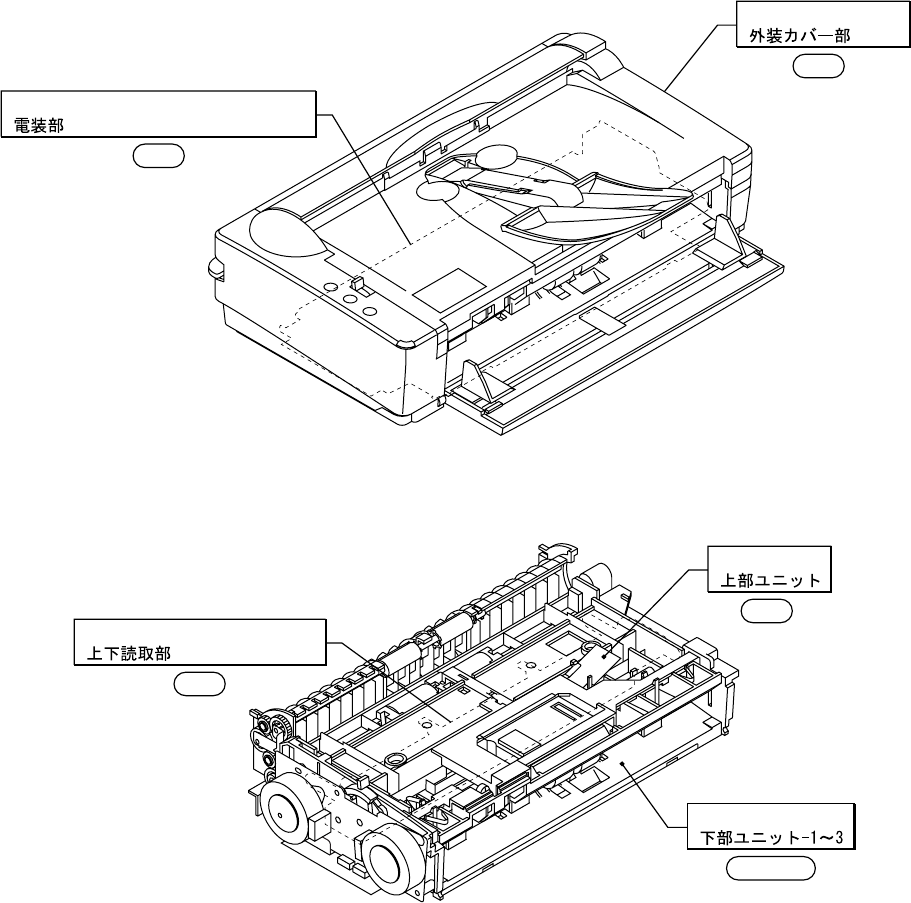
COPYRIGHT
©
2005 CANON ELECTRONICS INC. CANON DR-2580C FIRST EDTION APR. 2005
FIGURE
A
-1 ASSEMBLY LOCATION DIAGRAM-1
主要部品配置図-1
A-1
100
READING UNIT, UPPER/LOWER
300
ELECTRICAL COMPONENTS ASSEMBLY
500
LOWER UNIT-1~3
400~420
UPPER UNIT
200
EXTERNAL COVERS
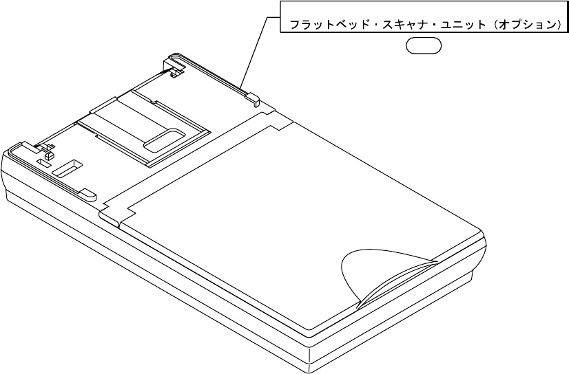
COPYRIGHT
©
2005 CANON ELECTRONICS INC. CANON DR-2580C FIRST EDTION APR. 2005
FIGURE
A
-2 ASSEMBLY LOCATION DIAGRAM-2
主要部品配置図-2
A-2
600
FLATBED SCANNER UNIT (OPTION)
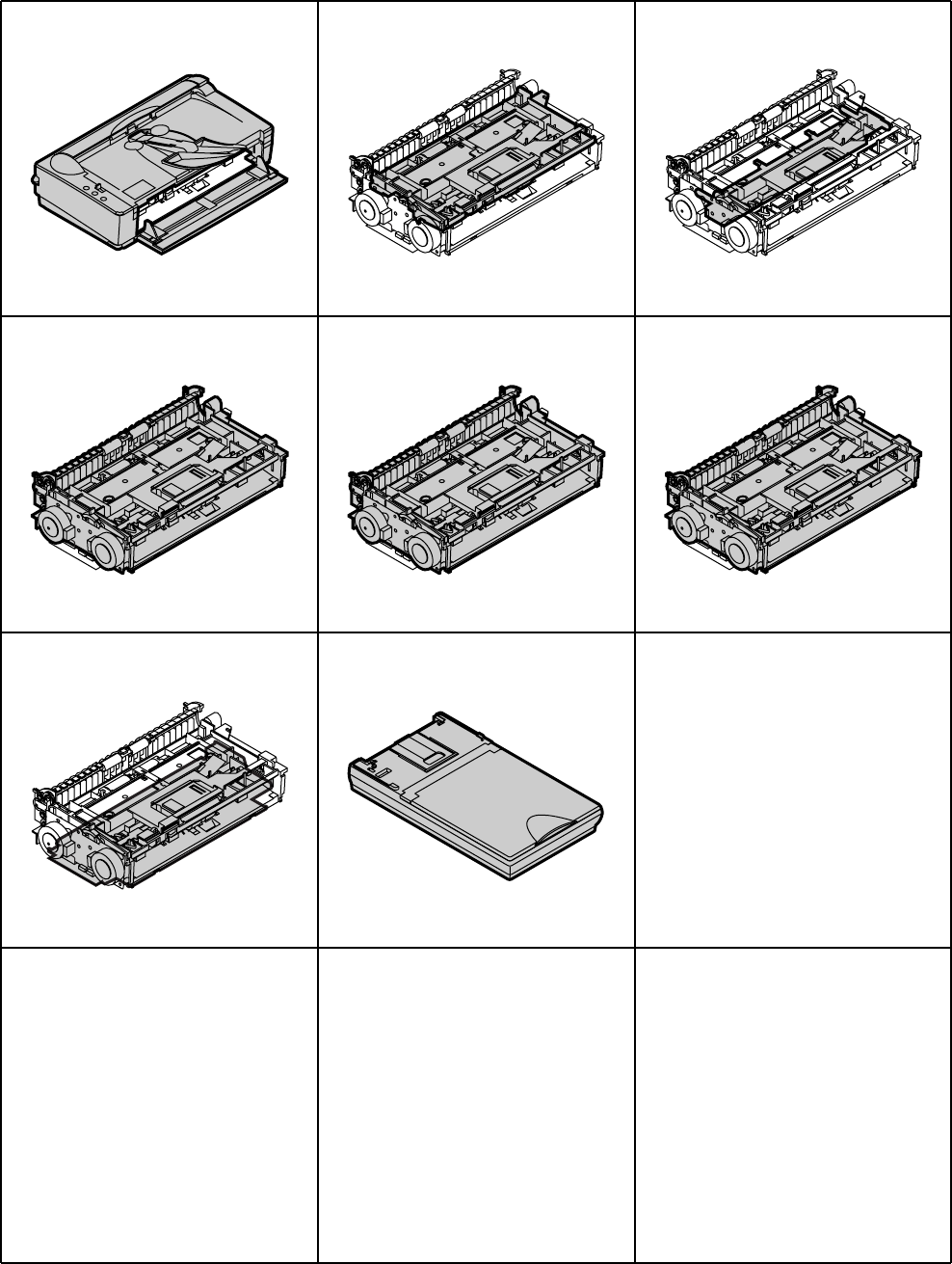
COPYRIGHT
©
2005 CANON ELECTRONICS INC. CANON DR-2580C FIRST EDTION APR. 2005
FIGURE B ILLUSTRATION INDEX
イラスト索引
B
FIGURE 100 FIGURE 200 FIGURE 300
FIGURE 410 FIGURE 420
FIGURE 600
FIGURE 400
FIGURE 500

COPYRIGHT
©
2005 CANON ELECTRONICS INC. CANON DR-2580C FIRST EDTION APR. 2005
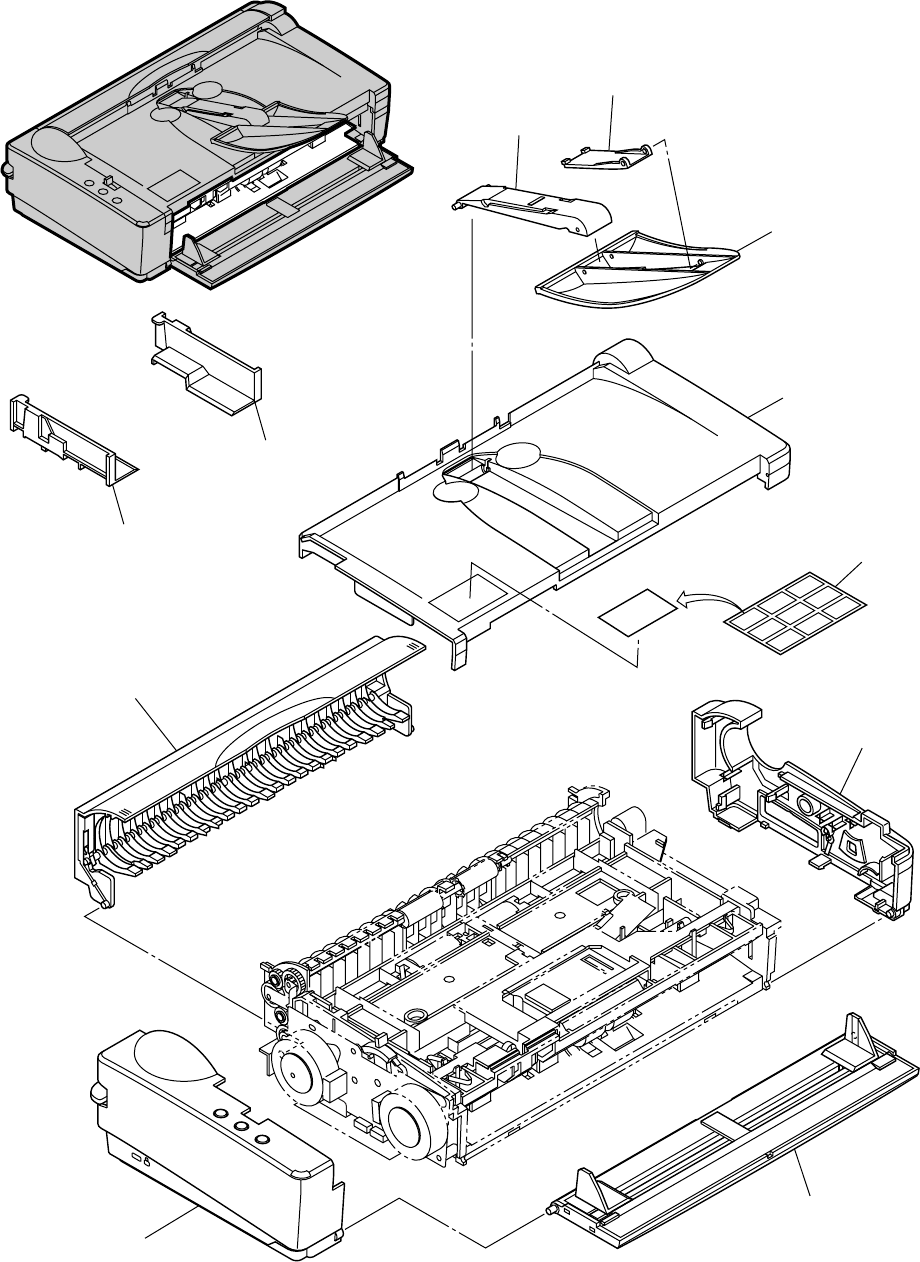
COPYRIGHT
©
2005 CANON ELECTRONICS INC. CANON DR-2580C FIRST EDTION APR. 2005
FIGURE 100 EXTERNAL COVERS
外装カバー部
100-1
1
2
3
4
5
6
7
8
9
11
10

COPYRIGHT
©
2005 CANON ELECTRONICS INC. CANON DR-2580C FIRST EDTION APR. 2005
FIGURE
&
KEY NO.
PART NUMBER
R
A
N
K
Q’
T
Y
DESCRIPTION REMARKS
100-2
100 - 1 MA2-7243-000 N 1 CONNECTOR, EJECT TRAY
(
MECH
)
ハイシ レンケツ ブザイ
2 MA2-7315-000 N 1 TRAY, EJECT 2
ハイシ トレイ 2
3 MA2-7242-000 1 TRAY, EJECT 1
ハイシ トレイ 1
4 MA2-7239-000 1 COVER, UPPER
ウエ カバー
5 MA2-7390-000 N 1 LABEL, JOB
JOB ボタン シール
6 MF1-4321-000 1 COVER, RIGHT
ミギ カバー
7 MG1-3703-000 1 COVER, U-TURN
Uターン カバー クミタテ
8 MG1-3704-000 1 COVER, LEFT
ヒダリ カバー クミタテ
9 MG1-3705-000 1 TRAY, PICKUP
キュウシ トレイ クミタテ
10 MA2-7391-000 N 1 GUIDE, DOCUMENT, EXTENSION R
エンチョウ ガイド R
11 MA2-7392-000 N 1 GUIDE, DOCUMENT, EXTENSION L
エンチョウ ガイド L
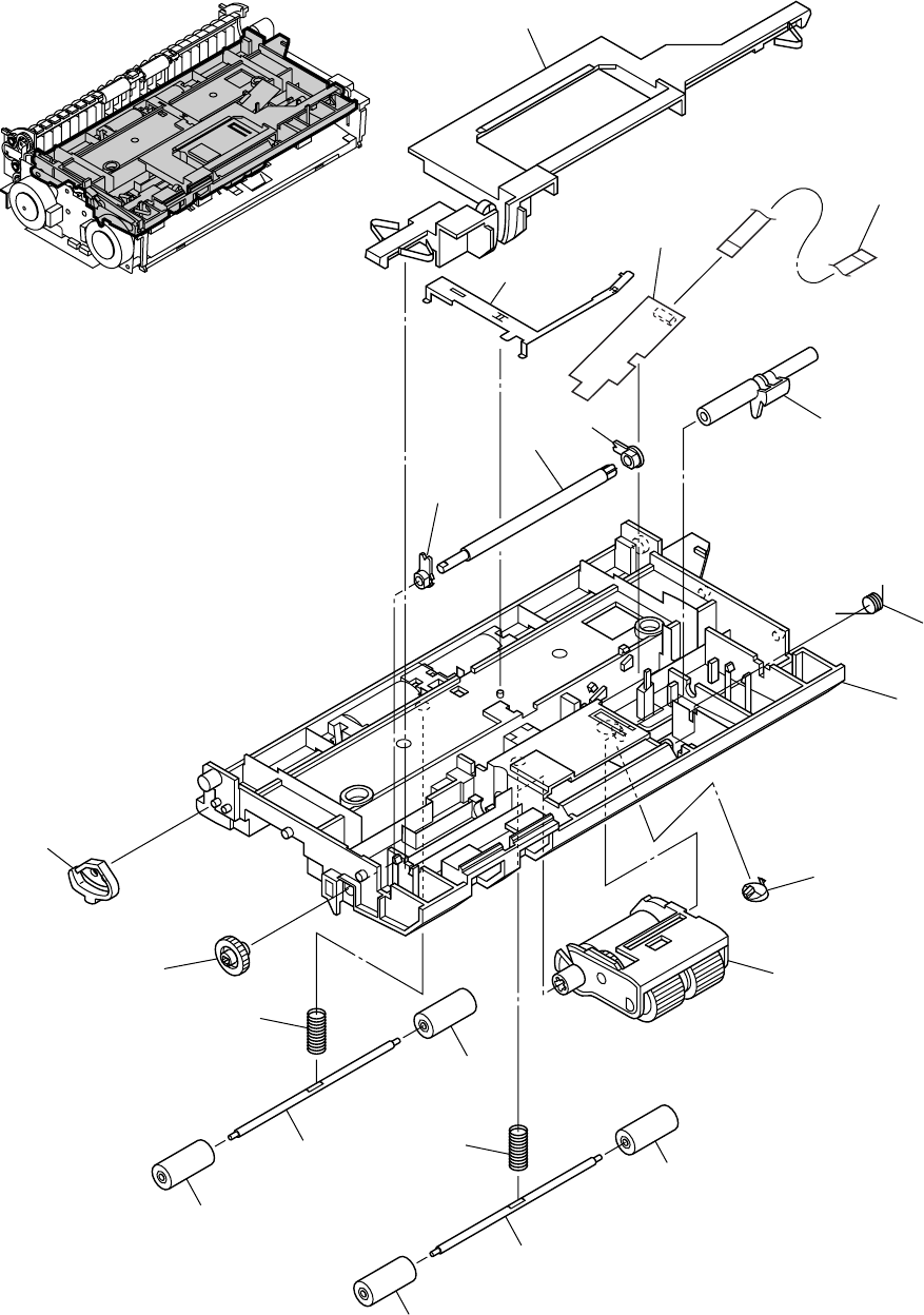
COPYRIGHT
©
2005 CANON ELECTRONICS INC. CANON DR-2580C FIRST EDTION APR. 2005
200-1
FIGURE 200 UPPER UNIT
上部ユニット
1
2
3
4
5
6
7
8
9
10
11
12
13
14
15
18
16
16
16
16
17
17

COPYRIGHT
©
2005 CANON ELECTRONICS INC. CANON DR-2580C FIRST EDTION APR. 2005
FIGURE
&
KEY NO.
PART NUMBER
R
A
N
K
Q’
T
Y
DESCRIPTION REMARKS
200-2
200 - 1 MA2-7246-000 N 1 KNOB, OPEN/CLOSE
カイヘイ ロック
2 MH2-5331-020 1 CABLE, FFC, U-SONIC SENSOR
チョウオンパ センサ FFC
3 MG1-3829-000 1 PCB ASSEMBLY, U-SONIC SENSOR
チョウオンパ センサ ユニット
4 MA2-7299-000 N 1 PLATE, GROUNDING, UPPER
ジョウブ ユニット アース バン
5 MA2-7250-000 N 1 SHAFT, FEED SUPPORT
フィード シジ ジク
6 MA2-7297-000 N 1 SUPPORT, SHAFT 5
ジクウケ
7 MA2-7249-000 N 1 SHAFT, FEED DRIVE
フィード クドウ ジク
8 MA2-7277-000 N 1 SUPPORT, SHAFT 4
ジクウケ
9 MA2-7306-000 1 SPRING, TORSION
キュウシ オウアツ バネ
10 MA2-7236-000 N 1 FRAME, UPPER
ウエ フレーム
11 MA2-7301-000 N 1 COVER, DFD UPPER
DFD フタ ウエ
12 MG1-3720-000 1 UPPER ROLLER UNIT
ジョウブ キュウシ ローラ
13 MA2-7304-000 N 1 STOPPER, ROTATION
カイテン ロック ブザイ
14 MS2-0128-000 1 GEAR, G25
ギア
15 MS1-2500-000 1 SPRING, COMPRESSION
ジュウドウ コロ バネ レジスト
16 MA2-6476-000 4 ROLLER, FOLLOWER
ジュウドウ ローラ
17 MA2-7248-000 N 2 SHAFT, FOLLOWER
ジュウドウ コロジク
18 MS1-2502-000 1 SPRING, COMPRESSION
ジュウドウ コロ バネ ハイシ 1
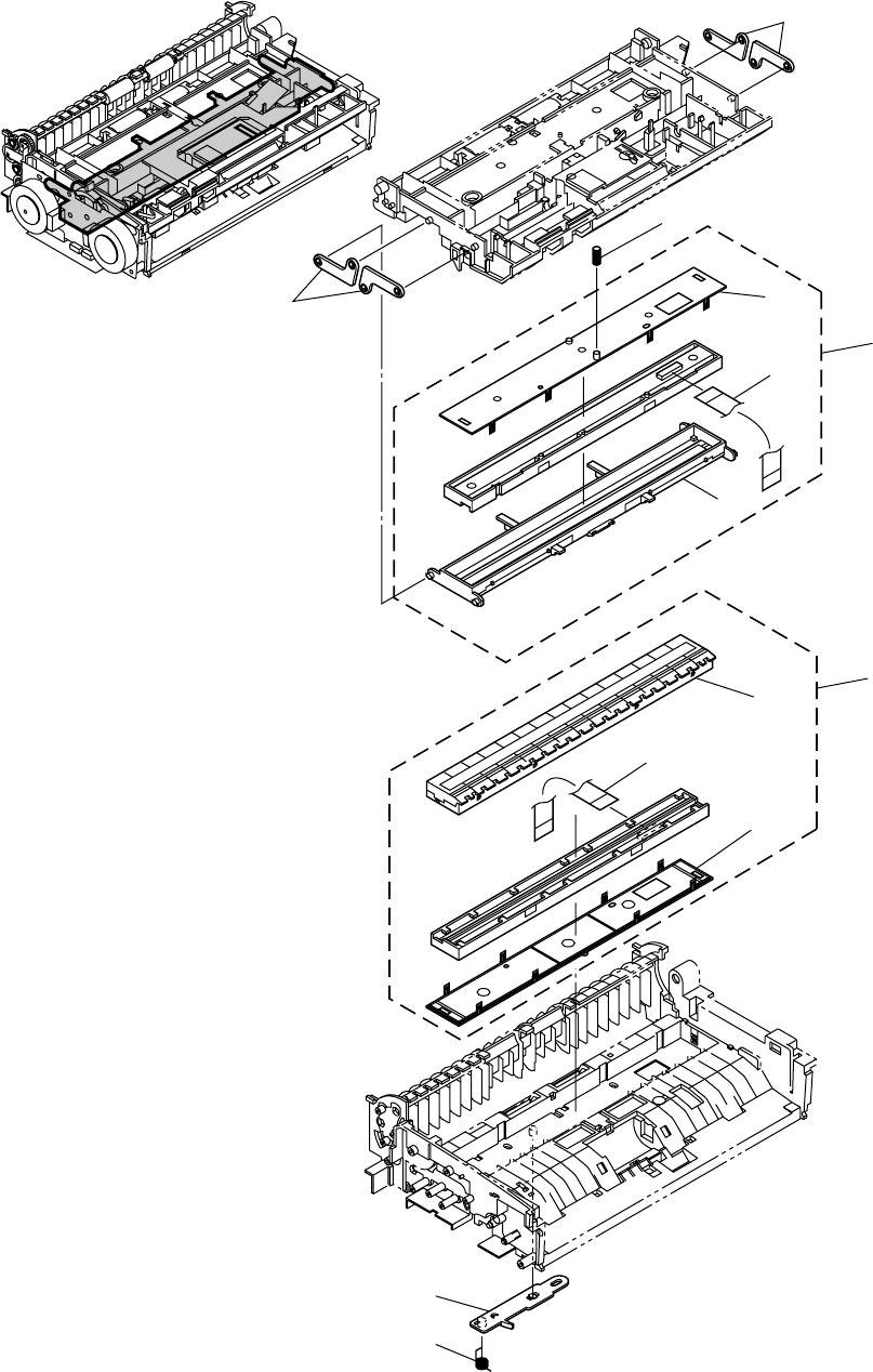
COPYRIGHT
©
2005 CANON ELECTRONICS INC. CANON DR-2580C FIRST EDTION APR. 2005
FIGURE 300 READING UNIT, UPPER/LOWER
上下読取部
300-1
1
2
1
3
4
5
6
7
4
8
9
10
11

COPYRIGHT
©
2005 CANON ELECTRONICS INC. CANON DR-2580C FIRST EDTION APR. 2005
FIGURE
&
KEY NO.
PART NUMBER
R
A
N
K
Q’
T
Y
DESCRIPTION REMARKS
300 - 1 MA2-7247-000 N 4 ARM, READING
ヨミトリ ヨウドウ アーム
2 MS1-2501-000 1 SPRING, COMPRESSION
アッシュク バネ ヨミトリウエ
3 MG1-8265-000 1 READING UNIT, UPPER
ヨミトリ ユニット ウエ
4 MA2-7295-000 N 2 COVER, READING UNIT
ヨミトリ ユニット フタ
5 MH2-5323-020 1 CABLE, FFC, CIS FRONT
CIS オモテメン FFC
6 MF1-4327-000 N 1 HOLDER, READING UPPER
ヨミトリ ホルダー ウエ
7 MG1-8264-000 1 READING UNIT, LOWER
ヨミトリ ユニット シタ
8 MF1-4326-000 N 1 HOLDER, READING LOWER
ヨミトリ ホルダー シタ
9 MH2-5324-000 1 CABLE, FFC, CIS BACK
CIS ウラメン FFC
10 MA2-7263-000 N 1 ARM, READING LOWER
ヨミトリ シタ イドウ アーム
11 MA2-7264-000 1 SPRING, TORSION
トーション バネ ヨミトリ シタ
300-2
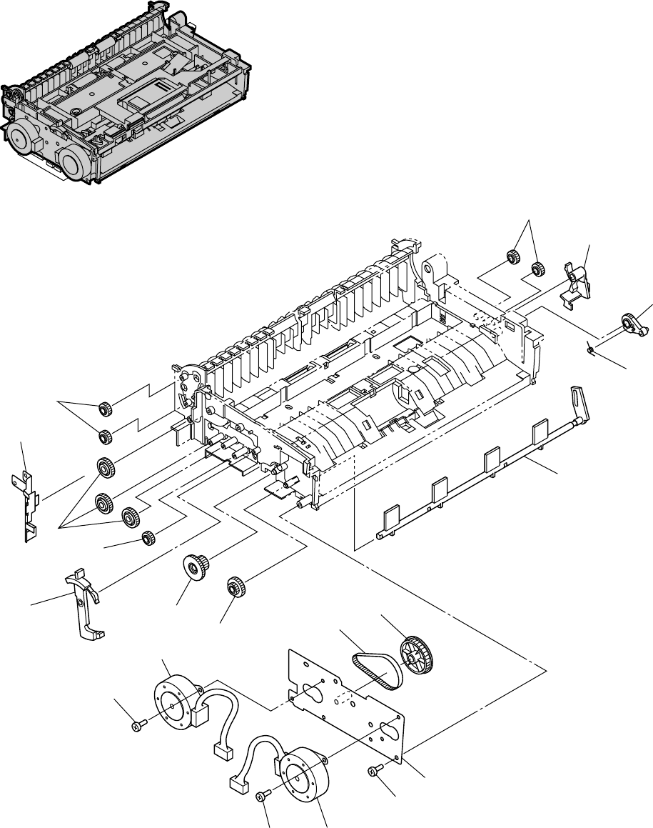
COPYRIGHT
©
2005 CANON ELECTRONICS INC. CANON DR-2580C FIRST EDTION APR. 2005
FIGURE 400 LOWER UNIT-1
下部ユニット-1
400-1
1
1
1
2
3
4
5
6
7
89
10
11
12
50
13
14
15
51
50

COPYRIGHT
©
2005 CANON ELECTRONICS INC. CANON DR-2580C FIRST EDTION APR. 2005
FIGURE
&
KEY NO.
PART NUMBER
R
A
N
K
Q’
T
Y
DESCRIPTION REMARKS
400-2
400 - 1 MS2-0126-000 5 GEAR, G20
ギア
2 MA2-7280-000 N 1 LEVER, POWER
デンゲン レバー
3 MA2-7283-000 1 GEAR, ARM
アーム ギア
4 MA2-7317-000 1 SPRING, TORSION
セキサイ リターン スプリング
5 MA2-7282-000 N 1 STOPPER, PICKUP
キュウシ セキサイ ストッパー
6 MA2-7298-000 N 1 PLATE, GROUNDING, LOWER
カブ ユニット アース バン
7 MS2-0127-000 3 GEAR, G31
ギア
8 MA2-7259-000 N 1 LEVER, SEPARATION
ブンリ レバー
9 MS2-0130-000 1 GEAR, G41-18
ギア
10 MS2-0129-000 1 GEAR, G31-18
ギア
11 MS1-3198-000 1 PULLY, P47 G18
プーリー
12 XF2-1606-740 1 BELT, TIMING 67T
タイミング ベルト
13 MF1-4324-000 1 MOTOR, STEPPING, PICKUP
キュウシ モータ
14 MF1-4323-000 1 MOTOR, STEPPING, CARRY
ハンソウ モータ
15 MF1-4322-000 N 1 PLATE, MOTOR
モータ プレート
50 XB1-2300-405 4 SCREW, BH M3x4
バインド ネジ M3 L4
51 XB4-7300-605 2 SCREW, TAP, BH M3x6
B タイト ネジ M3 L6
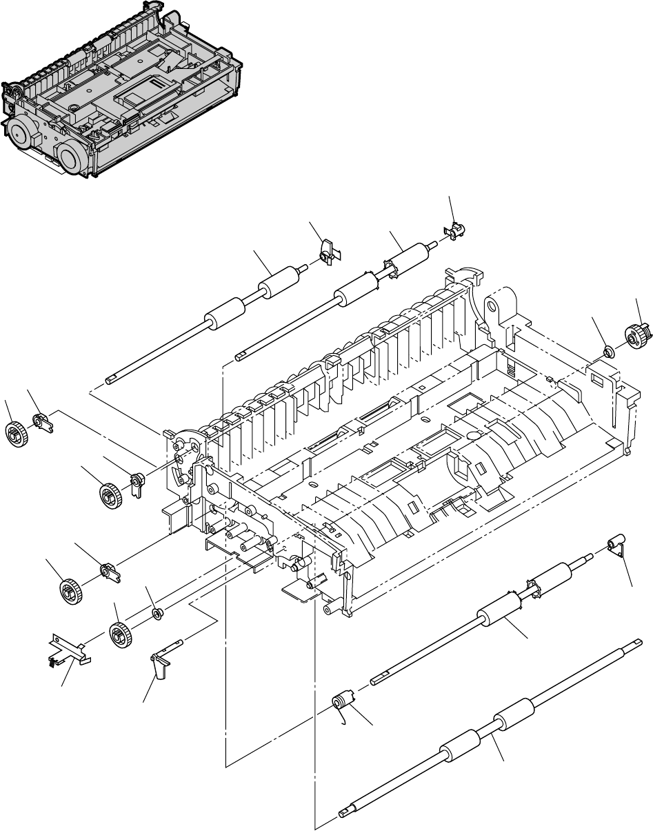
COPYRIGHT
©
2005 CANON ELECTRONICS INC. CANON DR-2580C FIRST EDTION APR. 2005
FIGURE 410 LOWER UNIT-2
下部ユニット-2
410-1
1
23
4
56
7
8
7
8
7
8
5
8
10
9
11
12
13
14

COPYRIGHT
©
2005 CANON ELECTRONICS INC. CANON DR-2580C FIRST EDTION APR. 2005
FIGURE
&
KEY NO.
PART NUMBER
R
A
N
K
Q’
T
Y
DESCRIPTION REMARKS
410-2
410 - 1 MA2-7322-000 1 ROLLER, CARRY
ハンソウ ローラ
2 MA2-7308-000 N 1 SUPPORT, CARRY ROLLER
ハンソウ ローラ ジクウケ
3 MA2-7323-000 1 ROLLER, EJECT 2
ハイシ ローラ 2
4 MA2-7309-000 N 1 SUPPORT, EJECT ROLLER 2
ハイシ ローラ 2 ジクウケ
5 XG9-0568-000 2 BALL BEARING
ベアリング
6 MG1-3711-000 N 1 CLUTCH, STOPPER
セキサイ ストッパ クラッチ
7 MA2-7277-000 N 3 SUPPORT, SHAFT 4
ジクウケ
8 MS2-0125-000 4 GEAR, G30
ギア
9 MA2-7540-000 1 PLATE, GROUNDING
レジスト アース バン 2
10 MA2-7310-000 N 1 LEVER, OPEN/CLOSE
カイヘイ ケンチ レバー
11 MG1-3710-000 N 1 CLUTCH, READING
ヨミトリ イドウ クラッチ
12 MA2-7321-000 1 ROLLER, EJECT 1
ハイシ ローラ 1
13 MA2-7307-000 N 1 SUPPORT, EJECT ROLLER 1
ハイシ ローラ 1 ジクウケ
14 MA2-7320-000 1 ROLLER, REGISTRATION
レジスト ローラ
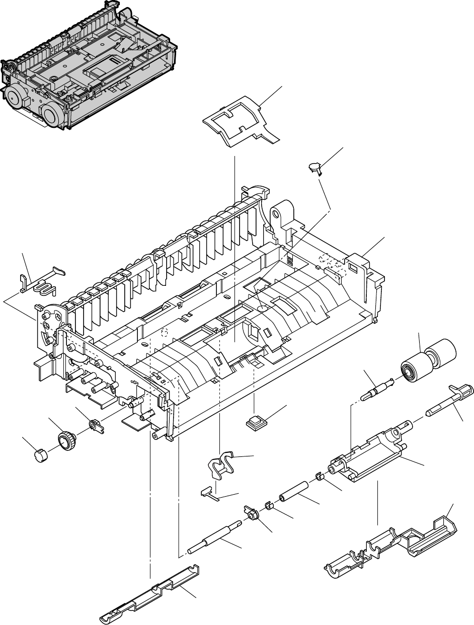
COPYRIGHT
©
2005 CANON ELECTRONICS INC. CANON DR-2580C FIRST EDTION APR. 2005
420-1
FIGURE 420 LOWER UNIT-3
下部ユニット-3
1
2
3
4
5
6
7
8
9
10
11
12
14
15
15
16
13
5
17
18
19

COPYRIGHT
©
2005 CANON ELECTRONICS INC. CANON DR-2580C FIRST EDTION APR. 2005
FIGURE
&
KEY NO.
PART NUMBER
R
A
N
K
Q’
T
Y
DESCRIPTION REMARKS
420 - 1 MA2-7261-000 N 1 COVER, RETARD ROLLER
キュウシグチ ガイド
2 MA2-7302-000 N 1 COVER, DFD LOWER
DFD フタ シタ
3 MA2-7235-000 N 1 FRAME, LOWER
シタ フレーム
4 MA2-7267-000 N 1 LEVER, U-TURN COVER
ユーターン パス カイヘイ ケンチ レバー
5 MA2-7277-000 N 2 SUPPORT, SHAFT 4
ジクウケ
6 MS2-0131-000 1 GEAR, G31
ブンリ ギア
7 XG9-0567-000 1 CLUTCH, ONE-WAY
ワンウェイ クラッチ
8 MA2-7262-000 N 1 COVER, SENSOR
ゲンコウ ケンチ マド
9 MA2-7272-000 N 1 SHAFT, RETARD, CONNECTION
リタード ローラ レンケツ ジク
10 MA2-7326-000 1 RETARD ROLLER
リタード ローラ
11 MA2-7271-000 N 1 SHAFT, RETARD, SUPPORT
リタード ローラ シジ ジク
12 MA2-7268-000 N 1 CASE, RETARD SWING
リタード ローラ ヨウドウ ケース
13 MA2-7278-000 N 1 COVER, DUST 1
ボウジン カバー 1
14 MA2-7270-000 N 1 SHAFT, RETARD, DRIVE 2
リタード ローラ クドウ ジク 2
15 MA2-7314-000 N 2 STOPPER, C
C クリップ
16 MA2-7269-000 N 1 SHAFT, RETARD, DRIVE 1
リタード ローラ クドウ ジク 1
17 MA2-7265-000 N 1 LEVER, REGISTRATION
レジスト ケンチ レバー
18 MA2-7266-000 N 1 PLATE, REGISTRATION
レジスト ケンチ レバー バネ
19 MA2-7279-000 N 1 COVER, DUST 2
ボウジン カバー 2
420-2
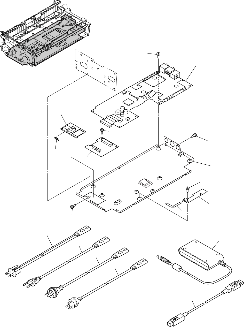
COPYRIGHT
©
2005 CANON ELECTRONICS INC. CANON DR-2580C FIRST EDTION APR. 2005
500-1
FIGURE 500 ELECTRICAL COMPONENTS ASSEMBLY
電装部
1
50
50
51
51
2
34
5
50
6
7
9
10
11
8
13
12

COPYRIGHT
©
2005 CANON ELECTRONICS INC. CANON DR-2580C FIRST EDTION APR. 2005
FIGURE
&
KEY NO.
PART NUMBER
R
A
N
K
Q’
T
Y
DESCRIPTION REMARKS
500-2
500 - 1 MG1-3732-000 1 PCB ASSEMBLY, CONTROL
DCON カイロ キバン
2 MA2-7281-000 N 1 COVER, CONTACT
セッテン カバー
3 MS1-2498-000 1 SPRING, TENSION
ヒッパリ バネ セッテン カバー
4 MG1-3733-000 1 PCB ASSEMBLY, SWITCH
スイッチ カイロ キバン
5 MF1-4330-000 N 1 PLATE, DCON
DCON プレート クミタテ
6 MG1-3734-000 1 PCB ASSEMBLY, DOCUMENT SENSOR
ゲンコウ センサ カイロ キバン
7 MH2-5327-000 1 CABLE, FFC, DOCUMENT SENSOR
ゲンコウ センサ FFC
8 WT3-5118-000 1 CORD, POWER, 100/120 100V, 120V
デンゲン コード (100/120V)
9 MH2-5309-000 1 CORD, POWER, 200 220-240V
デンゲン コード (220-240V)
10 MH2-5310-000 1 CORD, POWER, AUSTRALIA 220-240V CA
デンゲン コード (220-240V CA)
11 WT3-5085-000 1 CORD, POWER, CHINA 220-240V CN
デンゲン コード (220-240V CN)
12 MG1-3607-040 1 ADAPTOR, AC, 100-240V
AC アダプタ
13 MH2-5313-000 1 CABLE, USB
USB ケーブル
50 XB1-2250-405 11 SCREW, BH M2.5x4
バインド ネジ M2.5 L4
51 XB1-2300-405 2 SCREW, BH M3x4
バインド ネジ M3 L4
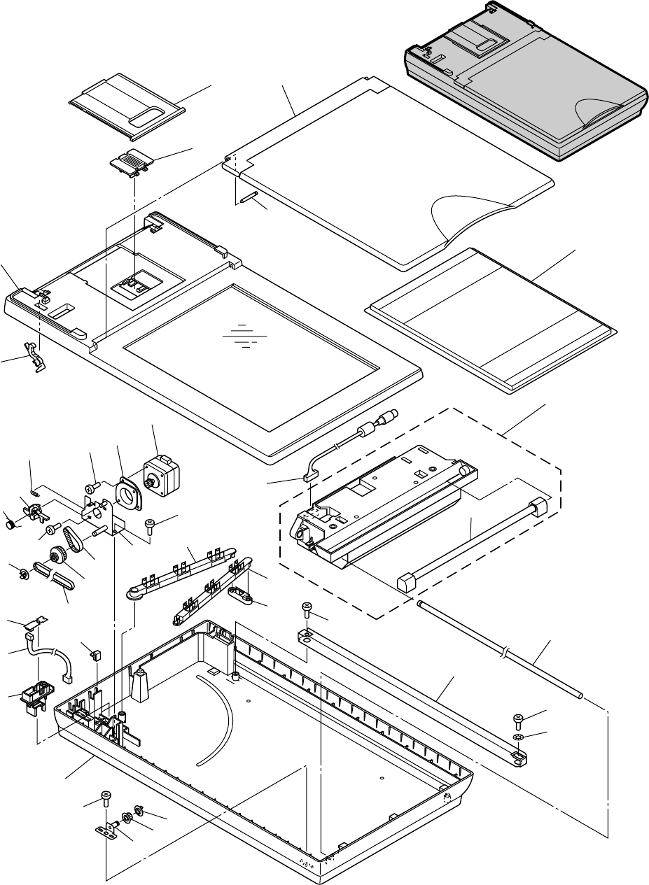
COPYRIGHT
©
2005 CANON ELECTRONICS INC. CANON DR-2580C FIRST EDTION APR. 2005
FIGURE 600 FLATBED SCANNER UNIT (OPTION)
フラットベッド・スキャナ・ユニット(オプション)
600-1
1
2
3
4
5
6
8
9
10
11
12
13
14
15
16
50
50
51
51 16
17
18
19 20 21
22
23
24
28
29
30
31 32
26
27
51
33
51
25
7

COPYRIGHT
©
2005 CANON ELECTRONICS INC. CANON DR-2580C FIRST EDTION APR. 2005
FIGURE
&
KEY NO.
PART NUMBER
R
A
N
K
Q’
T
Y
DESCRIPTION REMARKS
600-2
600 - 1 MG1-3743-000 1 LID ASSEMBLY
フタ ユニット
2 MA2-7357-000 N 1 TRAY, EJECT
ハイシ トレイ
3 MA2-7354-000 N 1 STOPPER, OPTICAL UNIT
ユソウ ストッパー
4 MF1-4335-000 1 COVER, UPPER
ウエ カバー クミタテ
5 MA2-7355-000 N 2 HOOK
フック
6 MA2-7367-000 N 1 SHAFT, ASSEMBLE
ジク
7 MA2-7348-000 N 1 PLATE, PRESSURE, BLACK
クロ アッパン
8 MG1-3745-020 1 OPTICAL UNIT
コウガク ユニット
9 MH7-3048-000 1 LAMP, XENON
ランプ
10 MH2-5325-000 1 CABLE ASSEMBLY, LVDS
LVDS ケーブル
11 MF1-4334-000 1 MOTOR, STEPPING
モータ ユニット
12 FB3-2195-000 N 1 MOUNT, RUBBER, MOTOR
モータ ボウシン マウント
13 MS1-2503-000 1 SPRING, TENSION
ヒッパリ バネ
14 MA2-7339-000 N 1 LEVER
レバー
15 MA2-7340-000 1 SPRING, TORSION
ネジリ バネ 1
16 MA2-7335-000 N 2 FLANGE
フランジ
17 XF2-1145-540 1 BELT, TIMING 455T
タイミング ベルト
18 MS1-3200-000 1 PULLY, 20-35
プーリー
19 XF2-1105-040 1 BELT, TIMING 50T
タイミング ベルト
20 MF1-4333-000 N 1 PLATE, MOTOR
モータ プレート
21 MA2-7342-000 N 1 ARM, 1
アーム 1
22 MA2-7343-000 N 1 ARM, 2
アーム 2
23 MA2-7344-000 N 1 ARM, 3
アーム 3
24 MA2-7333-000 N 1 SHAFT, MAIN
メイン シャフト
25 MA2-7537-000 N 1 PLATE, RAIL
レール
26 MA2-7334-000 N 1 ROLLER, IDLER
アイドラ
27 MF1-4331-000 N 1 PLATE, IDLER SHAFT
アイドラ ジク クミタテ
28 MF1-4332-000 1 COVER, LOWER
シタ カバー クミタテ
29 MA2-7332-000 N 1 HOLDER, CONNECT PCB
セッテン ブザイ
30 MG1-3739-000 1 CABLE ASSEMBLY, MOTOR
モータ ケーブル
31 MG1-3738-000 1 PCB ASSEMBLY, FB CONNECT
セツゾク カイロ キバン
32 MA2-6761-000 N 2 STOPPER, CABLE
タバセン ドメ
33 X71-9773-000 1 WASHER, WAVE
ナミ ワッシャ
50 XB1-2300-609 4 SCREW, BH M3x6
バインド ネジ M3 L6
51 XB4-7400-809 5 SCREW, TAP, BH M4x8
B タイト ネジ M4 L8

PART NO.
FIGURE
&
KEY NUMBER
Q’TY PART NO.
FIGURE
&
KEY NUMBER
Q’TY PART NO.
FIGURE
&
KEY NUMBER
Q’TY
COPYRIGHT
©
2005 CANON ELECTRONICS INC. CANON DR-2580C FIRST EDTION APR. 2005
NUMERICAL INDEX-1
部品索引表-1
FB3-2195-000 600-12 1
MA2-6476-000 200-16 4
MA2-6761-000 600-32 2
MA2-7235-000 420-03 1
MA2-7236-000 200-10 1
MA2-7239-000 100-04 1
MA2-7242-000 100-03 1
MA2-7243-000 100-01 1
MA2-7246-000 200-01 1
MA2-7247-000 300-01 4
MA2-7248-000 200-17 2
MA2-7249-000 200-07 1
MA2-7250-000 200-05 1
MA2-7259-000 400-08 1
MA2-7261-000 420-01 1
MA2-7262-000 420-08 1
MA2-7263-000 300-10 1
MA2-7264-000 300-11 1
MA2-7265-000 420-17 1
MA2-7266-000 420-18 1
MA2-7267-000 420-04 1
MA2-7268-000 420-12 1
MA2-7269-000 420-16 1
MA2-7270-000 420-14 1
MA2-7271-000 420-11 1
MA2-7272-000 420-09 1
MA2-7277-000 200-08 1
↓
410-07 3
↓
420-05 2
MA2-7278-000 420-13 1
MA2-7279-000 420-19 1
MA2-7280-000 400-02 1
MA2-7281-000 500-02 1
MA2-7282-000 400-05 1
MA2-7283-000 400-03 1
MA2-7295-000 300-04 2
MA2-7297-000 200-06 1
MA2-7298-000 400-06 1
MA2-7299-000 200-04 1
MA2-7301-000 200-11 1
MA2-7302-000 420-02 1
MA2-7304-000 200-13 1
MA2-7306-000 200-09 1
MA2-7307-000 410-13 1
MA2-7308-000 410-02 1
MA2-7309-000 410-04 1
MA2-7310-000 410-10 1
MA2-7314-000 420-15 2
MA2-7315-000 100-02 1
MA2-7317-000 400-04 1
MA2-7320-000 410-14 1
MA2-7321-000 410-12 1
MA2-7322-000 410-01 1
MA2-7323-000 410-03 1
MA2-7326-000 420-10 1
MA2-7332-000 600-29 1
MA2-7333-000 600-24 1
MA2-7334-000 600-26 1
MA2-7335-000 600-16 2
MA2-7339-000 600-14 1
MA2-7340-000 600-15 1
MA2-7342-000 600-21 1
MA2-7343-000 600-22 1
MA2-7344-000 600-23 1
MA2-7348-000 600-07 1
MA2-7354-000 600-03 1
MA2-7355-000 600-05 2
MA2-7357-000 600-02 1
MA2-7367-000 600-06 1
MA2-7390-000 100-05 1
MA2-7391-000 100-10 1
MA2-7392-000 100-11 1
MA2-7537-000 600-25 1
MA2-7540-000 410-09 1
MF1-4321-000 100-06 1
MF1-4322-000 400-15 1
MF1-4323-000 400-14 1
MF1-4324-000 400-13 1
MF1-4326-000 300-08 1
MF1-4327-000 300-06 1
MF1-4330-000 500-05 1
MF1-4331-000 600-27 1
MF1-4332-000 600-28 1
MF1-4333-000 600-20 1
MF1-4334-000 600-11 1
MF1-4335-000 600-04 1
MG1-3607-040 500-12 1
MG1-3703-000 100-07 1
MG1-3704-000 100-08 1
MG1-3705-000 100-09 1
MG1-3710-000 410-11 1
MG1-3711-000 410-06 1
MG1-3720-000 200-12 1
MG1-3732-000 500-01 1
MG1-3733-000 500-04 1
MG1-3734-000 500-06 1
MG1-3738-000 600-31 1
MG1-3739-000 600-30 1
MG1-3743-000 600-01 1
MG1-3745-020 600-08 1
MG1-3829-000 200-03 1
MG1-8264-000 300-07 1
MG1-8265-000 300-03 1
MH2-5309-000 500-09 1
MH2-5310-000 500-10 1
MH2-5313-000 500-13 1
MH2-5323-020 300-05 1
MH2-5324-000 300-09 1
MH2-5325-000 600-10 1
MH2-5327-000 500-07 1
MH2-5331-020 200-02 1
MH7-3048-000 600-09 1
MS1-2498-000 500-03 1
MS1-2500-000 200-15 1
MS1-2501-000 300-02 1
MS1-2502-000 200-18 1
MS1-2503-000 600-13 1
MS1-3198-000 400-11 1
MS1-3200-000 600-18 1
C-1

PART NO.
FIGURE
&
KEY NUMBER
Q’TY PART NO.
FIGURE
&
KEY NUMBER
Q’TY PART NO.
FIGURE
&
KEY NUMBER
Q’TY
COPYRIGHT
©
2005 CANON ELECTRONICS INC. CANON DR-2580C FIRST EDTION APR. 2005
MS2-0125-000 410-08 4
MS2-0126-000 400-01 5
MS2-0127-000 400-07 3
MS2-0128-000 200-14 1
MS2-0129-000 400-10 1
MS2-0130-000 400-09 1
MS2-0131-000 420-06 1
WT3-5085-000 500-11 1
WT3-5118-000 500-08 1
X71-9773-000 600-33 1
XB1-2250-405 500-50 11
XB1-2300-405 400-50 4
↓
500-51 2
XB1-2300-609 600-50 4
XB4-7300-605 400-51 2
XB4-7400-809 600-51 5
XF2-1105-040 600-19 1
XF2-1145-540 600-17 1
XF2-1606-740 400-12 1
XG9-0567-000 420-07 1
XG9-0568-000 410-05 2
C-2
NUMERICAL INDEX-2
部品索引表-2

COPYRIGHT
©
2005 CANON ELECTRONICS INC. CANON DR-2580C FIRST EDTION APR. 2005
COPYRIGHT
©
2005 CANON ELECTRONICS INC. CANON DR-2580C FIRST EDTION APR. 2005
〒108-0023
2005年 4月 第1版発行
東京都港区芝浦3-17-7
キヤノン電子株式会社
品質保証部 品質推進課
Prepared by
QUALITY ASSURANCE CENTER
CANON ELECTRONICS INC.
3-17-7 Shibaura, Minato-ku, Tokyo 108-0023, Japan
FIRST EDITION (APR. 2005)
vi

vii 0405TG

1
Chinese
日本語
Nederland
Italiano Español Deutsch Français English
Flatbed Scanner Unit for DR-2580C
Instructions
Thank you for purchasing the Flatbed Scanner Unit for DR-2580C (hereafter referred to as “the
scanner unit”).
This scanner unit was developed exclusively for use with the Canon DR-2580C Document
Scanner. To ensure that you get the most out of the scanner unit, be sure to read these instruc-
tions before attempting to use it for the first time, and keep them with the DR-2580C Startup
Manual in a safe place for future reference.
Contents
Handling ........................................................................................... 2
Specifications ................................................................................... 3
Part Names ...................................................................................... 3
Installing the DR-2580C ................................................................... 4
Removing the DR-2580C ................................................................. 6
Using the Flatbed ............................................................................. 7
Cleaning ........................................................................................... 8

2
Safe Operation
WARNING
Note the following precautions whenever using the scanner unit. Failure to do so creates the
risk of fire or electrical shock.
•Never try to take the scanner unit apart or modify it in any way.
•Do not use flammable aerosol products near the scanner unit.
•Moisten a cloth with plain water, wring out the excess water, and then wipe the exterior
of the scanner unit to clean it. Never use alcohol, benzene, thinner, or any other
flammable substances.
•In the case of a scanner unit malfunction, such as mechanical failure when it is powered
up, immediately turn OFF the DR-2580C and contact the Canon dealer or service
representative.
• Do not drop the scanner unit, or subject it to impact or strong shock. Should the
scanner unit ever become damaged, immediately turn OFF the DR-2580C and contact
the Canon dealer or service representative.
CAUTION
• Do not locate the scanner unit on a surface that is unstable or tilted, or in an area
subjected to strong vibration. Such conditions might cause the scanner unit to fall and
create the risk of personal injury.
•Never store the the scanner unit by hanging it on a wall in an upright configuration.
Doing so might cause the scanner unit to fall and become damaged.
•Never touch the connector pins or contacts of the scanner unit with your fingers. Doing
so might result in malfunction.
•Never press down on the flatbed cover with excessive force while scanning a book or
other thick object on the flatbed. Doing so might damage the glass and create the risk
of malfunction or personal injury.
•Never place any object other than documents to be scanned onto the scanner unit’s
flatbed glass. Doing so might result in malfunction.
•Never place anything on top of the scanner unit. Such objects may tip or fall over and
create the risk of personal injury.
•Be sure to grip the plugs when connecting the cord. Holding the cord might break the
core leads.
• Before moving the DR-2580C with the scanner unit attached, always disconnect the
interface cable connected to the DR-2580C and the AC adaptor first. Moving the DR-
2580C with cables attached might cause damage to the plugs and connectors due to
excessive force applied to them during movement.
•Hang the scanner never upright standing to the wall. The scanner could fall down to
cause the damage.
• The ferrite core attached to the scanner unit is required to comply with electromagnetic
interference regulations. Do not remove the ferrite core.
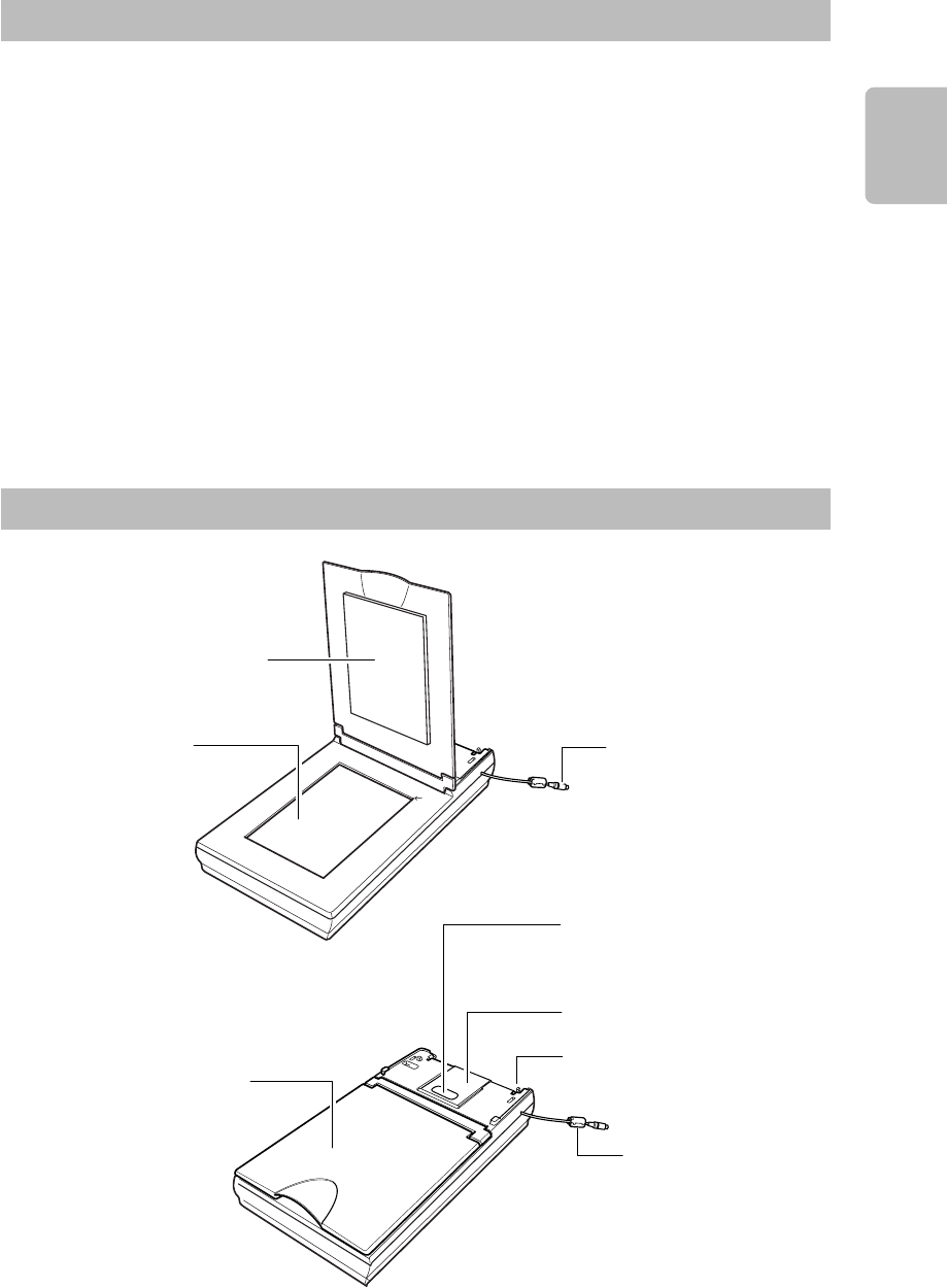
3
Chinese
日本語
Nederland
Italiano Español Deutsch Français English
Specifications
Type Flatbed scanner
Maximum Document Size 216 mm x 297 mm (W x L)
Scanning sensor CCD(*)
Light Source External gas fluorescence lamp(*)
Scanning Resolution 600 dpi
Dimensions 12.4” x 3.2” x 21.5” (W x H x D)
315 mm x 82.5 mm x 545 mm (W x H x D)
Dimensions (with DR-2580C) 12.4” x 6.1” x 21.5” (W x H x D)
315 mm x 155 mm x 545 mm (W x H x D)
Weight 8.4 lb (3.8 kg)
Weight (with DR-2580C) 12.6 lb (5.7 kg)
Power Requirement Supplied from DR-2580C
(*) Because the scanning sensor and light source differ from the scanning sensor (CIS) and light source
(LED) of the DR-2580C main unit, tones of scanned images may differ slightly.
Specifications are subject to change without notice.
Part Names
Pressure Board
Flatbed (Platen Glass)
(See p. 6.) Interface Cable
(See p. 5.)
Auxiliary Paper Support Plate
(See p. 8.)
Scanning Unit Slide Lock
(See p. 4.)
Flatbed Cover
DR-2580C Locking Hook
(See p. 4.)
Ferrite Core
(See p. 2.)
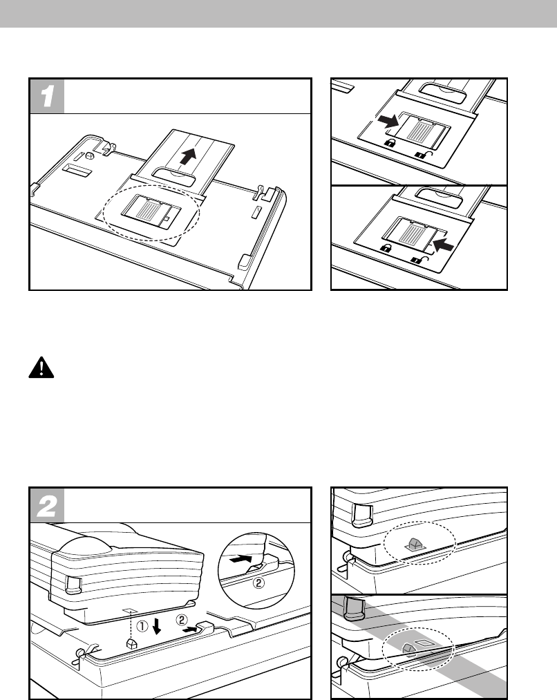
4
Installing the DR-2580C
Use the procedure below to install the DR-2580C on the scanner unit.
Déverrouillage du verrou coulissant
de l’unité de scanner Unlock
Lock
The scanner mechanism inside the scanner unit is locked to avoid movement during transport.
Before setting the DR-2580C on the scanner unit, be sure to unlock the scanning unit slide lock.
CAUTION
•Turning the power ON without unlocking the scanning unit slide lock might result in
malfunction of the scanner unit.
•Never touch the connector pins or contacts of the scanner unit with your fingers. Doing
so might result in malfunction.
•When relocking the scanning unit slide lock, make sure it is in the home position (the
position it reaches at the end of a scan) before locking it.
Installing the DR-2580C
Positioning the DR-2580C on its protrusions to enter the holes in the bottom of the DR-2580C
q, and then slide the scanner unit forward into place w.
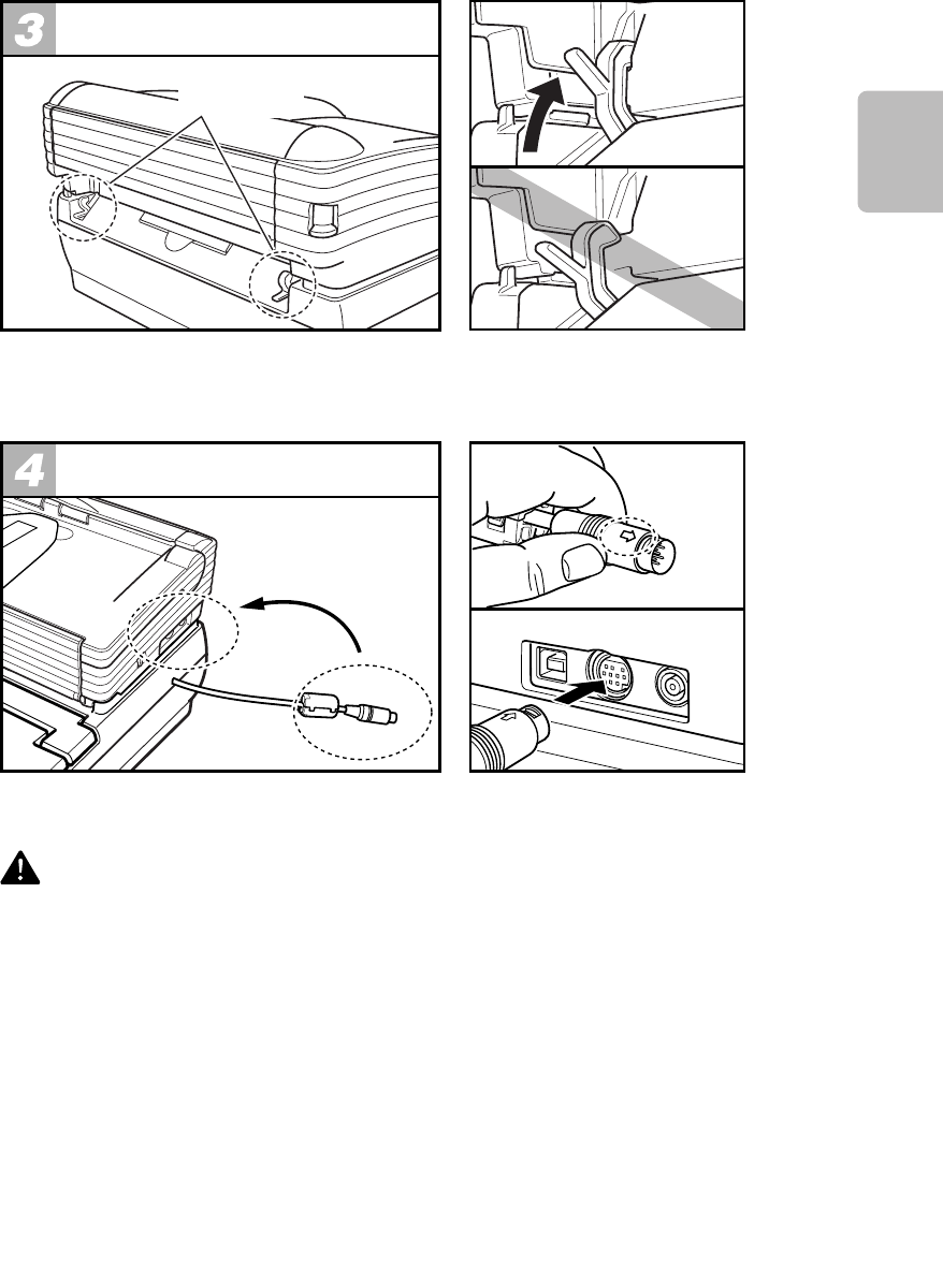
5
Chinese
日本語
Nederland
Italiano Español Deutsch Français English
Locking the Scanner
Locking Hooks
Check to make sure that the DR-2580C is not loose, and that the hooks on the left and right of
the scanner unit secure the DR-2580C in place. Check to make sure that the hooks are fully
engaged.
Connections
Making sure the arrow on the plug is on top, insert the plug into the connector as far as it will go.
CAUTION
•Be sure to grip the plugs when connecting the cord. Holding the cord might break the
core leads.
•Incorrect DR-2580C installation will cause scanning errors and make scanning with the
scanner unit and DR-2580C impossible.
• Do not disconnect the plug or operate the locking hooks while the DR-2580C power is
turned ON. Doing so might cause malfunction of the scanner unit and the DR-2580C.
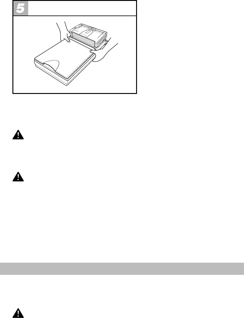
6
Configuring Flatbed Settings
Whenever moving the scanner unit, grip it with both hands to keep it from falling. The scanner
unit weighs approximately 8.4Ib (3.8 kg) alone, while the DR-2580C and scanner unit together
weigh approximately 12.6 Ib (5.7 kg).
WARNING
Do not drop the scanner unit, or subject it to impact or strong shock. Should the scanner
unit ever become damaged, immediately turn OFF the DR-2580C and contact your local
authorized Canon dealer or service representative.
CAUTION
•Before moving the DR-2580C while it is installed on the scanner unit, first make sure
that the scanner unit is secured by the hooks. Moving the unit while the hooks are
released might cause the scanner unit to drop and become damaged.
•Before moving the DR-2580C while it is installed on the scanner unit, always disconnect
the interface cable connected to the DR-2580C and the AC adaptor first. Moving the DR-
2580C with cables attached might cause damage to the plugs and connectors due to
excessive force applied to them during movement.
• Do not locate the scanner unit on a surface that is unstable or tilted, or in an area
subjected to strong vibration. Such conditions might cause the scanner unit to fall and
create the risk of personal injury.
Removing the DR-2580C
To remove the DR-2580C, first release the locking hooks, and then lift up on the back of the DR-
2580C to remove it.
CAUTION
Never store the scanner unit by hanging it on a wall in an upright configuration. Doing so
might cause the scanner unit to fall and become damaged.
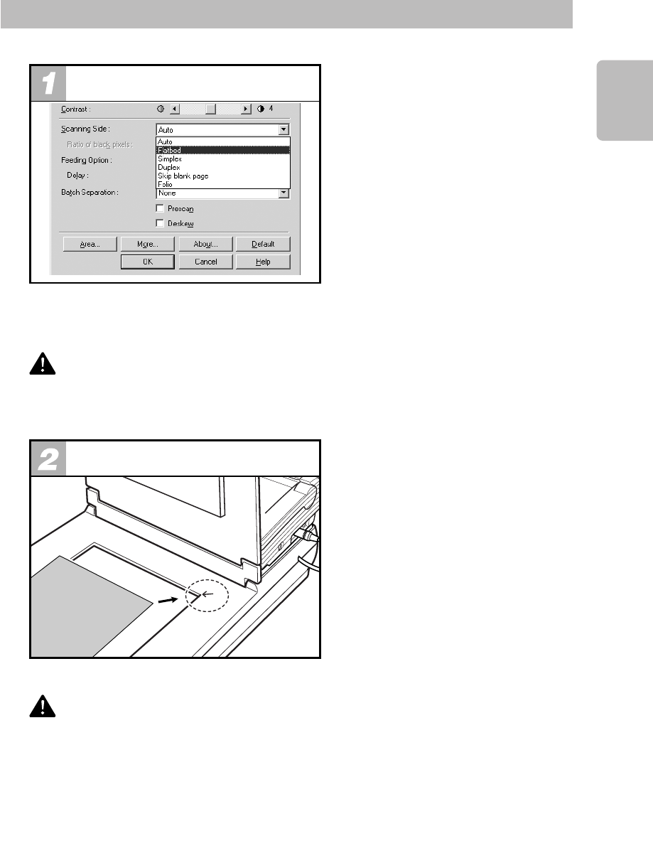
7
Chinese
日本語
Nederland
Italiano Español Deutsch Français English
Using the Flatbed
Use the flatbed as described below.
Moving the Scanner
When using the flatbed scanner, select either [Flatbet] or [Auto] for the ISIS/TWAIN driver
[Scanning side] setting. Refer to Help for the ISIS/TWAIN driver for information about the ISIS/
TWAIN driver settings.
CAUTION
Unless the DR-2580C is correctly installed, scan errors will be generated when attempt-
ing to scan, and scanning from the Flatbed scanner and the DR-2580C will not be
possible. Make sure the DR-2580C is correctly installed before starting to scan.
Placing Documents onto
the Flatbed (X, Y Origin)
The upper right corner of the flatbed (platen glass) is the origin (0, 0) of the X, Y coordinates.
CAUTION
•Never place any object other than documents to be scanned onto the scanner unit’s
flatbed glass. Doing so might result in malfunction.
• Do not allow the scanner unit to be subjected to vibration while it is operating. Vibration
might cause scanning errors.
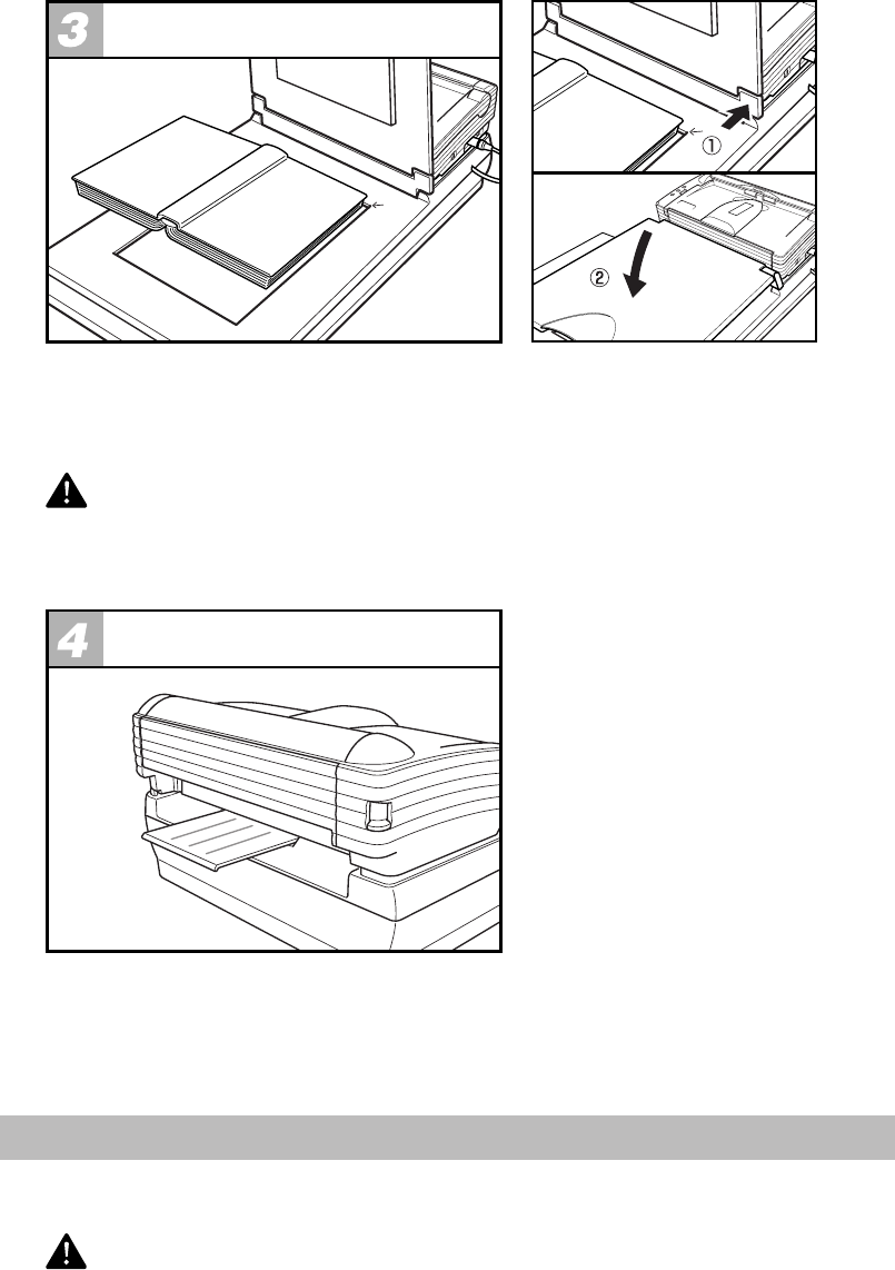
8
Scanning Thick Documents
When scanning a book or other thick document, open the flatbed cover. Align the book or other
thinck document with the upper right corner of the platenglass by the arrow q, and then close
the flatbed cover w.
CAUTION
Never press down on the flatbed cover with excessive force while scanning a book or
other thick object on the flatbed. Doing so might damage the flatbed glass and create the
risk of malfunction or personal injury.
Using the auxiliary paper
support plate
Extend the auxiliary paper support plate on the back of the scanner unit when performing Straight
Path scanning with the DR-2580C. Pulling out the auxiliary paper support plate when cards and
other originals are output during Straight Path scanning will keep the output documents from
falling from the scanner unit.
Cleaning
Moisten a cloth with plain water, wring out the excess water, and then wipe the exterior of the
scanner unit to clean it.
CAUTION
Do not apply excessive force when wiping the flatbed (platen glass). Doing so might
damage the glass and create the risk of malfunction or personal injury.
Startup Manual
Please read this manual before operating this unit. After you finish
reading this manual, store it in a safe place for future reference.
Document Scanner
ENGLISH

International ENERGY STAR® Office Equipment Program
As an ENERGY STAR® Partner, Canon Electronics Inc., has determined that this machine
meets the ENERGY STAR® Program guidelines for energy efficiency.
The International ENERGY STAR® Office Equipment Program is an international program
that promotes energy saving through the use of computers and other office equipment.
The program backs the development and dissemination of products with functions that
effectively reduce energy consumption. It is an open system in which business
proprietors can participate voluntarily. The targeted products are office equipment, such
as computers, monitors, printers, fax, machine, copiers, and scanners. The standards and
logos are uniform among participating nations.
Trademarks
•Canon and the Canon logo are trademark of Canon Inc.
•Microsoft and Windows are registered trademarks of Microsoft Corporation in the United States and other countries.
•ISIS is a trademark of Pixel Translations, a division of Captiva Software Corporation, in the United States.
•Intel and Pentium are registered trademarks of Intel Corporation.
•E
NERGY STAR® is a U.S. registered mark.
•Adobe is the registered trademark of Adobe Systems Incorporated in the United States and/or other countries.
•Adaptec is registered trademark of Adaptec Inc.
•Other product and company names here in may be the trademarks of their respective owners.
Copyright
Copyright 2005 by CANON ELECTRONICS INC. All rights reserved. No part of this publication may be
reproduced or transmitted, in any form or by any means, electronic or mechanical, including photocopying
and recording, or by any information storage or retrieval system without the prior written permission of
CANON ELECTRONICS INC.
Disclaimers
The information in this document is subject to change without notice.
CANON ELECTRONICS INC. MAKES NO WARRANTY OF ANY KIND WITH REGARD TO THIS
MATERIAL, EITHER EXPRESS OR IMPLIED, EXPECT AS PROVIDED HERE IN, INCLUDING WITHOUT
LIMITATION, THERE OF, WARRANTIES AS TO MARKETABILITY, MERCHANTABILITY, FITNESS FOR
A PARTICULAR PURPOSE OF USE OR AGAINST INFRINGEMENT OF ANY PATENT. CANON
ELECTRONICS INC. SHALL NOT BE LIABLE FOR ANY DIRECT, INCIDENTAL, OR CONSEQUENTIAL
DAMAGES OF ANY NATURE, OR LOSSES OR EXPENSES RESULTING FROM THE USE OF THIS
MATERIAL.
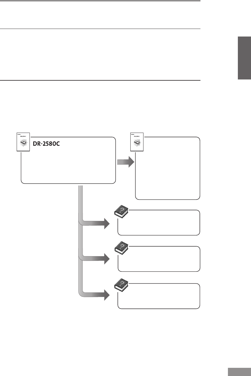
INTRODUCTION 1
ENGLISH
Startup Manual
Read this manual thoroughly before using this scanner.
Keep this manual in a safe place for future reference.
Document Scanner
Startup Manual
Read this manual thoroughly before using this scanner.
Keep this manual in a safe place for future reference.
Document Scanner
Explains how to set up the scanner,
make connections, install software, and
other procedures.
Startup Manual
Installing the
Scanner (See p. 17.)
Installation Procedure
(See p. 19.)
Installing the ISIS/TWAIN
Driver (See p. 28.)
Installing
CapturePerfect
(See p. 31.)
ISIS/TWAIN Driver Help
Explains how to use the
ISIS/TWAIN driver.
CapturePerfect Help
Explains how to use
CapturePerfect.
Job Registration Tool Help
Explains how to use Job
Registration Tool.
Be sure to read it before using the
scanner.
INTRODUCTION
Thank you for purchasing the Canon DR-2580C scanner. Please read this
manual thoroughly before using the machine to familiarize yourself with its
capabilities, and to make the most of its many functions. After reading this
manual, store it in a safe place for future reference.
Manuals for the Scanner
The DR-2580C scanner has a Startup Manual (this manual) and online help.
Please refer to the Startup Manual regarding the handling of the scanner, such as
installation of software and setting up the scanner. The online help explains how
to use the ISIS/TWAIN driver and the enclosed software, CapturePerfect.

2INTRODUCTION
Conventions
This manual uses the following symbols and indications.
Before you start reading this manual, read the following and familiarize
yourself with their meanings.
WARNING
Indicates a warning concerning operations that may lead to death
or injury to persons if not performed correctly. In order to use the
machine safely, always pay attention to these warnings.
CAUTION
Indicates a caution concerning operations that may lead to injury
to persons, or damage to property if not performed correctly. In
order to use the machine safely, always pay attention to these
cautions.
IMPORTANT
Indicates operational requirements and restrictions. Be sure to read these items
carefully in order to operate the machine correctly, and to avoid damage to the
machine.
Note
Indicates a clarification of an operation, or contains additional explanations
for a procedure. Reading these notes is highly recommended.

Contents 3
ENGLISH
Contents
INTRODUCTION .......................................................................................................... 1
Manuals for the Scanner .................................................................................................. 1
Conventions ................................................................................................................... 2
Before Using the Scanner ......................................................................................... 4
Safe Operation ............................................................................................................... 4
Installation Location ......................................................................................................... 4
Power ............................................................................................................................... 5
Moving the Scanner ......................................................................................................... 5
Normal Handling .............................................................................................................. 6
Disposal ........................................................................................................................... 7
Features of the DR-2580C ............................................................................................. 8
Checking the Packing List ........................................................................................... 10
Removing the Protective Packing Materials .................................................................. 12
Names and Functions of Parts .................................................................................... 15
Installing the Scanner .............................................................................................. 17
Installation Requirements ............................................................................................ 17
Installation Procedure .................................................................................................. 19
Interface Cards ............................................................................................................ 20
Connecting the Power Cord ........................................................................................ 21
Connecting the Scanner to Your PC ............................................................................ 22
Tur ning the Power ON/OFF ......................................................................................... 23
Turning the Power ON .................................................................................................... 23
Recognizing the Scanner ............................................................................................... 24
Turning the Power OFF .................................................................................................. 26
Installing the Software ............................................................................................. 27
Installing the ISIS/TWAIN Driver .................................................................................. 28
Installing CapturePerfect ............................................................................................. 31
Uninstalling Software ................................................................................................... 34
Using the Software................................................................................................... 37
Using the ISIS/TWAIN Driver ....................................................................................... 37
Using Job Tools ........................................................................................................... 38
Starting Job Registration Tool ........................................................................................ 38
Using CapturePerfect .................................................................................................. 40
Starting CapturePerfect ................................................................................................. 40
Using the Scanner.................................................................................................... 43
Documents ................................................................................................................... 43
Preparing the Trays ...................................................................................................... 45
Setting Up the Document Feed Tray ............................................................................... 45
Document Eject Tray ...................................................................................................... 47
Placing a Document for Scanning ............................................................................... 50
How to Feed with the Page Separation Mode ............................................................... 50
How to Feed with the Bypass Mode .............................................................................. 53
Clearing a Paper Jam .................................................................................................. 55
Other Functions ........................................................................................................... 58
Regular Maintenance ............................................................................................... 60
Cleaning the Scanner ..................................................................................................... 60
Cleaning Inside the Scanner .......................................................................................... 60
Cleaning the Sensor Glass, Shading Boards, and the Rollers ....................................... 61
Removing and Attaching the Rollers ........................................................................... 64
Roller Replacement Cycle .............................................................................................. 64
Resetting the Counter .................................................................................................... 65
Removing and Attaching the Roller Unit ........................................................................ 67
Removing and Attaching the Retard Roller .................................................................... 71
Troubleshooting ....................................................................................................... 75
Specifications ........................................................................................................... 80
Index .............................................................................................................84

4Before Using the Scanner
Before Using the Scanner
Safe Operation
In order to ensure safe operation, be certain to read the cautions described
below.
Installation Location
The performance of this scanner is affected by the environment in which it is
installed. Make sure that the location where the scanner is installed meets the
following environmental requirements:
• Provide adequate space around the scanner for operation and maintenance.
•
Provide adequate space behind the scanner in order to eject scanned
documents to the back of the scanner. (See “Document Eject Tray,” on p. 47.)
• Avoid locations exposed to direct sunlight. If the scanner must be placed in
such a spot, hang a heavy curtain, or similar object to shade the scanner.
• Avoid dusty locations. Dust can get inside of the scanner and cause
problems.
• Avoid warm or humid locations, such as in the vicinity of a water faucet,
water heater, or humidifier, and avoid locations where the fumes from
ammonia, paint thinner, or other volatile chemicals may be present.
• Avoid unstable surfaces and locations subject to vibration.
• Avoid locations that are subject to rapid temperature changes.
Condensation inside of the scanner can result in inferior image quality. Use
this scanner under the following environmental conditions:
Temperature: 10˚C to 32.5˚C
Humidity: 20% to 80% RH
• Avoid locating the scanner near equipment that generates electromagnetic
fields, including speakers, televisions, and radios.
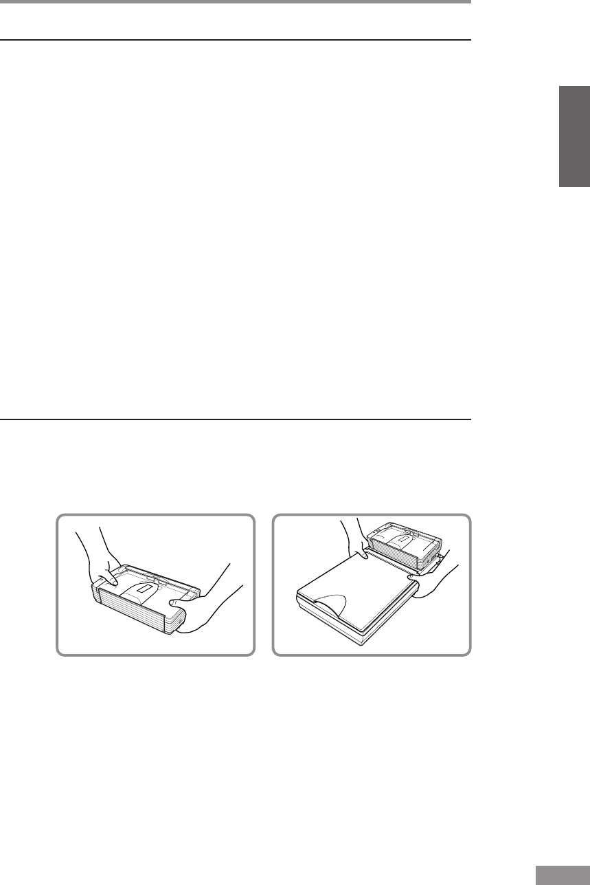
Before Using the Scanner 5
ENGLISH
Power
• Connect only to a power outlet of the rated voltage and power supply
frequency. (220-240 V, 50/60 Hz).
• Do not connect to power outlets with other electrical devices. Also, when
using an extension cord, make sure that the extension cord is rated for the
current requirements of the scanner.
• Disassembling and/or reassembling the AC adapter is extremely dangerous
and should not be attempted under any circumstances.
• Do not place heavy objects on the AC adapter or Power Cord. Do not place
the adapter or cords in an area where they are likely to be stepped on.
• Do not use the Power Cord while it is bundled.
• Never pull directly on the Power Cord. To remove the plug from the outlet,
grasp the plug directly and remove it from the outlet.
• Keep the area around the power plug clear of articles so that the power plug
can be disconnected in an emergency.
•
Use only the AC adapter provided with the product. Do not use the scanner’s
AC adapter with any other product.
Model: MG1-3607
•If you have any questions about the AC adapter, contact your local
authorized Canon dealer or service representative for futher information.
Moving the Scanner
•
When moving the scanner, always hold it with both hands to avoid dropping
it. The scanner weighs approximately 1.9 kg alone, and approximately 5.7 kg
with the optional flatbed scanner unit installed.
•Make sure that the flatbed scanner unit is correctly attached to the
DR-2580C scanner before moving the scanner.
• Make sure to disconnect the interface cable and Power Cord. If the scanner
is transported with these items plugged in, the plugs and connectors may be
damaged due to physical shock.
With Optional Flatbed Scanner
Unit Installed

6Before Using the Scanner
Normal Handling
WARNING
To avoid fire and electric shock, always observe the following
warnings when using this scanner.
• Do not place flammable chemicals, such as alcohol or paint thinner, near
the scanner.
• Do not cut, damage, or modify the Power Cord. Do not place heavy objects
on the Power Cord, do not pull on the Power Cord, and do not bend the
Power Cord sharply.
• Do not plug in or unplug the Power Cord with wet hands.
• Do not use multioutlet adapters to connect multiple devices to one outlet.
• Do not tie up or bundle the Power Cord. Push the plug in as far as it will go
when plugging in the Power Cord.
• Only use the Power Cord that was provided with this scanner.
• Do not attempt to disassemble or modify this scanner.
• Do not use flammable sprays near this scanner.
• Always turn the scanner OFF and unplug the Power Cord before cleaning
this scanner.
• To clean this scanner, dampen a cloth in a mild detergent solution and then
wring the cloth out thoroughly. Do not use flammable liquids to clean the
scanner, including alcohol, benzene, or paint thinner.
• If the scanner ever makes a strange noise, emits smoke or a strange odor,
becomes hot, or if the scanner does not operate at all even though the
power is ON, immediately turn the scanner OFF and unplug the Power
Cord. Contact your local authorized Canon dealer or service representative
to have the scanner serviced.
• Do not drop, kick, or otherwise strike the scanner. If the scanner does
somehow become damaged, immediately turn the scanner OFF and unplug
the Power Cord. Contact your local authorized Canon dealer or service
representative to have the scanner serviced.
• Always turn the scanner OFF and unplug the Power Cord before moving
the scanner.
CAUTION
• Do not set the scanner up on a wobbly platform, a sloped surface, or any
other type of unstable location. Do not set up the scanner in a location that
is subject to vibration. The scanner could injure someone if it falls or tips
over.
• Do not block the ventilation openings. Doing so could cause the scanner to
overheat, creating a risk of fire.

Before Using the Scanner 7
ENGLISH
• Do not place paper clips, staples, necklaces, or any other metallic objects
on top of the scanner. Liquids or small metallic objects that get inside of
the scanner create a risk of fire or electrical shock. If such foreign matter
does get inside of the scanner, unplug the Power Cord immediately, and
then contact your local authorized Canon dealer or service representative
for assistance.
• Do not set up the scanner in a dusty or humid location. Doing so creates a
risk of fire or electrical shock.
• Do not place objects on top of the scanner. The object could injure
someone if it falls or tips over.
• To prevent any risk of fire or electrical shock, be sure that the power source
meets the power requirements of the scanner.
• When unplugging the Power Cord, always grasp the plug. Pulling on the
cord itself could expose or break the wires in the Power Cord, damaging
the cord and creating a risk of fire or electrical shock.
• To allow you to easily unplug the Power Cord at any time, do not place
other objects around the power outlet. Such obstacles could prevent you
from unplugging the Power Cord quickly in an emergency.
• Do not spill liquids or flammable chemicals (such as alcohol, paint thinner,
or benzene) on the scanner. Doing so creates a risk of fire or electrical
shock.
• If the scanner will not be used for an extended period of time, unplug the
Power Cord for safety’s sake.
• When operating this scanner, avoid wearing loose fitting clothing, dangling
jewelry, or other material that could get pulled into the scanner. Injury
could result. Be especially careful if you are wearing a necktie or have long
hair. In the event that some article or clothing does get caught in the
scanner, turn the power OFF immediately.
• Be careful when placing paper in the scanner and when removing jammed
paper. It is possible to cut your hand on the edge of a sheet of paper.
Disposal
• When disposing of this scanner, be sure to follow all local ordinances and
laws or consult with the retailer who sold you the scanner.

8Before Using the Scanner
Features of the DR-2580C
The main features of the DR-2580C scanner are listed below.
■Fast Document Feeding
The scanner can scan a maximum of 25 documents per minute in a range of
sizes from business cards to A4 size. (Scanning conditions: Black and
white, A4 size portrait, two sided, 200 dpi.)
■USB 2.0 Interface
Connecting to a computer is done with Hi-Speed USB 2.0 protocol.
■Waiting Time Is “0”
The DR-2580C is ready to scan after the power is turned ON without a
waiting time.
■Color/Grayscale Support
Documents can be scanned in 24-bit color or 256-level grayscale.
■Supports a Variety of Scanning Modes
The scanner supports the following scanning modes, depending on the
document type:
• Single-sided/double-sided mode
• Single sheet/dual feeding path
■U-Turn Path
Documents are fed and ejected from the front of the scanner. (See p. 47.)
■Straight Path
Documents are ejected to the back of the scanner. Note, the ejected
documents are stacked in reverse order to how they were fed. (See p. 47.)
■Paper Size Detection
The scanner automatically detects the size of a scanned document and
eliminates any unnecessary space around the edges of the image when
storing it, even when storing a document of irregular size.
■Card Scan
It is possible to scan business card. (See p. 43.)
■Folio Scan
A folio (folded in half) document can be set for scanning as it is, and the
scanned images of both sides are combined as a single image. (See p. 59.)
■Deskew
The Deskew function automatically straightens an image if the document
was loaded askew.
■Character Orientation Detector
Identifies the orientation of characters in a document, and rotates the image
so the orientation of the scanned characters is straight.
■Advanced Text Enhancement
The scanner is equipped with an Advanced Text Enhancement mode that
allows you to clearly scan text printed on a dark background, and text that
is written in faint pencil.

Before Using the Scanner 9
ENGLISH
■Dropout Color
The scanner is equipped with a Dropout Color function that allows you to
specify a color for the scanner to omit from scanned images.
■Skip Blank Page Function
The scanner is equipped with a Skip Blank Page function that allows it to
scan a document regardless of whether every document is two-sided or one-
sided.
■Prescan Function
The scanner is equipped with a Prescan function that allows you to adjust
the contrast and brightness of a prescanned image and then send the
adjusted image to the application software, without needing to scan the
document again.
■Remove Binder Holes
Deletes black spots left when scanning documents that have had holes
punched in them to be stored in a binder.
■Auto Start
The scanner is equipped with an Auto Start function that automatically
initiates scanning when a document is placed in the document feed tray.
■Compatible with Carbonless Duplicating Paper
The scanner is able to scan carbonless duplicating paper.
■Job Function
Executing a scan with one of the scanner's job buttons automatically
performs the specified process (save, print, mail attachment). (See p. 58.)
■Flatbed Scanner Unit (Option)
The Flatbed Scanner Unit can be attached to and used with the DR-2580C
scanner. Contact your local authorized Canon dealer for more detailed
information. (See p. 59.)
■Power Saving Feature
The scanner has a power saving feature that puts the scanner in low power
mode after it has been idle for a certain period of time.
Note
Some functions may not be available depending on the software you are
using.
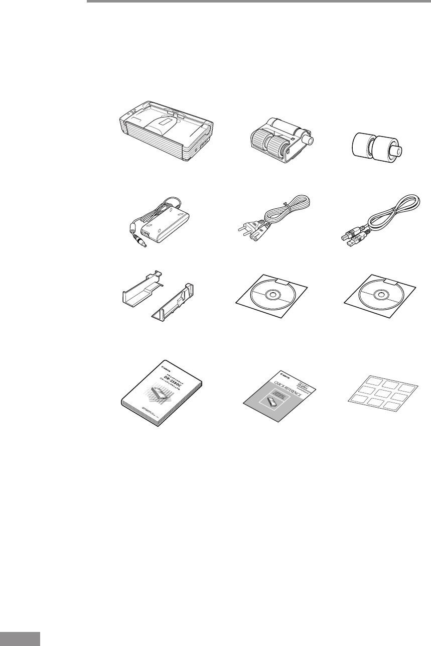
10 Before Using the Scanner
Quick Reference
Guide
Power Cord
Startup Manual
(This Manual)
AC Adapter
DR-2580C
Setup Disc
(CD-ROM)
USB Interface Cable
Adobe Acrobat
Setup Disc
(CD-ROM)
DR-2580C
Scanner
Document Guide
Adapter
Job Labels
Roller Unit Retard Roller
Checking the Packing List
The contents of the carton in which this scanner is shipped are described
below. If anything is missing or damaged, contact your local authorized
Canon dealer or service representative.
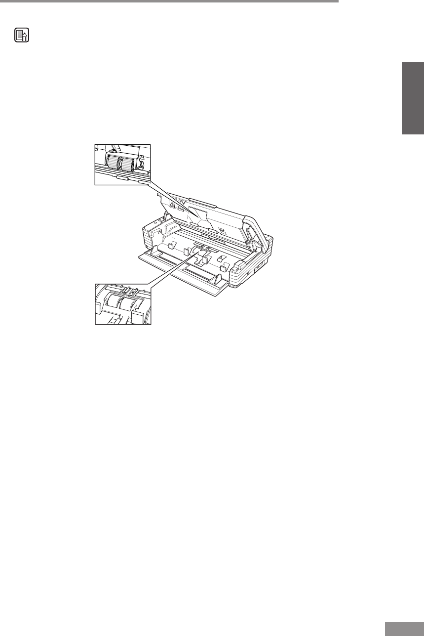
Before Using the Scanner 11
ENGLISH
Note
•
Remove all of the protective tape and protective sheets from the DR-2580C.
(Refer to “Removing the Protective Packing Materials” page 12.)
•
To use the
“
roller unit
”
and the
“
retard roller
”
install them to the DR-2580C.
Refer to “Removing and Attaching the Roller Unit” (see p. 67.) and
“Removing and Attaching the Retard Roller” (see p. 71.) for information
about installing the rollers.
• The DR-2580C Setup Disc is in the Startup Manual (this manual).
• Items included in this package may change without notice.
• You need to keep the machine's packaging and packing materials for
storing or transporting the machine.
• The power cord varies according to country of purchase.
Roller Unit
Retard Roller
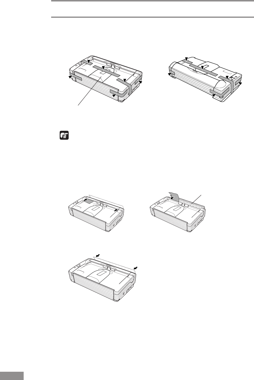
12 Before Using the Scanner
Document Eject Tray Extension
Removing the Protective Packing Materials
Remove all of the protective packing materials before using the scanner.
1
Remove the protective tape (indicated by the ▼) from the scanner.
IMPORTANT
When peeling off the protective tape fastening the Document Eject Tray
Extension, hold the Document Eject Tray Extension firmly in place with your
hand.
2
Press on both sides of the rear cover to open it towards the rear, and remove
the protective sheet.
3
Press on both sides of the rear cover to close.
Rear Cover
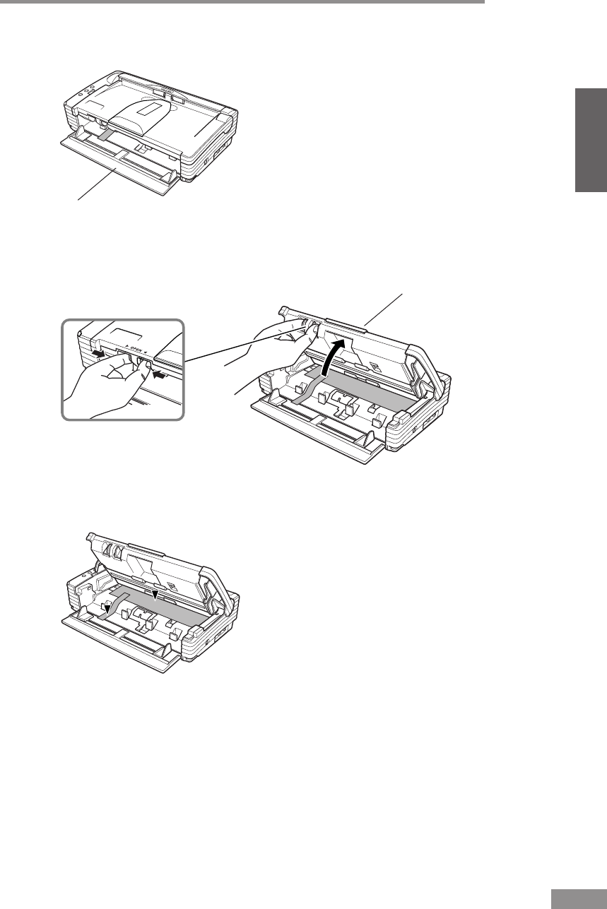
Before Using the Scanner 13
ENGLISH
4
Open the Document Feed Tray towards you.
5
Pressing the OPEN knob from both sides, raise the Upper Unit.
6
Remove the protective tape (indicated by ▼) and protective sheet.
Document Feed Tray
Upper Unit
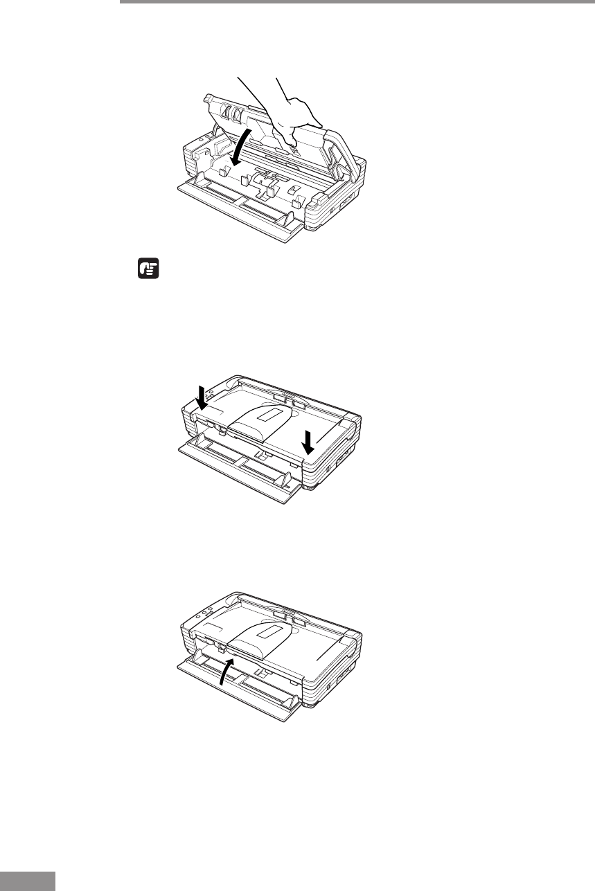
14 Before Using the Scanner
7
Close the Upper Unit slowly.
IMPORTANT
Do not force the Upper Unit to close. Doing so can damage the scanner.
8
Be sure that the Upper Unit is completely closed by pushing on both edges
with both hands until you hear a click.
9
Close the Document Feed Tray.
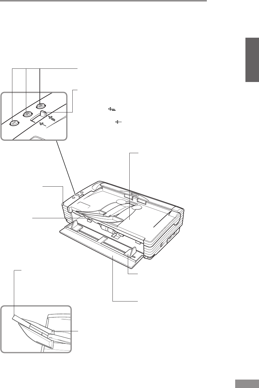
Before Using the Scanner 15
ENGLISH
Feed Selection Lever
Use it to change the way the
documents are fed.
Move it up ( ) to continuously feed documents
(Page Separation mode). (See p. 50.)
Move it down ( ) to feed documents one at a time
or to feed documents that are
fastened together, such as invoices, without
separating them (Bypass mode). (See p. 53.)
Job Buttons
These buttons can be assigned functions using the
Job Registration Tool. (See p. 38.)
Document Eject Tray/
Upper Unit
Scanned documents are
ejected here. (See p. 47.)
Open to clear paper jams
and for cleaning.
Document Eject Tray
Extension 2
Keeps documents from falling
and becoming jammed in the
scanner. (See p. 48.)
Document Feed Tray
Place the document to be
scanned here. (See p. 45.)
Document Guides
Adjust them to align with
the width of the document.
(See p. 51.)
Document Eject Tray
Extension
Open when reading a
document. (See p. 48.)
Power Indicator
This indicator lights
when the scanner is
turned ON. (See p. 23.)
OPEN Knob
Opens the upper unit.
(See p. 56 and p. 61.)
Names and Functions of Parts
This section explains the name and function of each part. Familiarize yourself
with the parts before connecting the scanner.
■Front
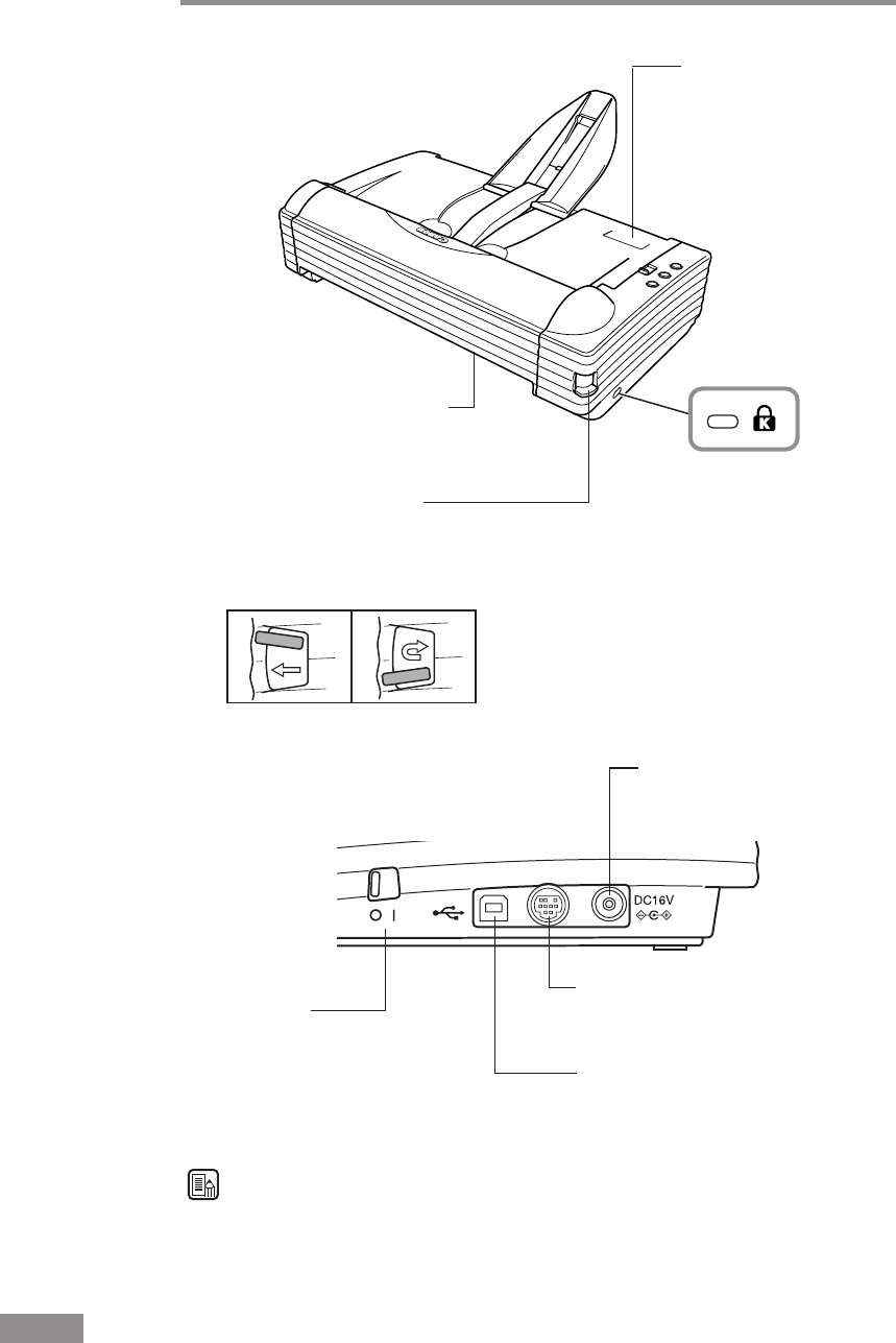
16 Before Using the Scanner
■Rear
Kensington Slot
Used for anti-theft
measures.
Theft can be prevented
by attaching a chain,
etc.
Eject Selection Lever
Raise or lower this lever to switch the
document eject direction. (See p. 47.)
Up : Straight Path
Down : U-Turn Path
Job Label Location
Location for affixing job
labels that describe
what is assigned to the
Job buttons.
(See p. 39.)
Document Eject Opening
Document ejected from here when
the straight path is being used.
(See p. 49.)
USB Connector
Connect the USB cable provided or
one that supports Hi-Speed USB
2.0. (See p. 22.)
Power Switch
This switch is used to
turn the scanner ON.
(See p. 23 and p. 26.)
■Side (Interfaces)
Option Connector
Interface connector for the optional
flatbed scanner unit.
Power Connector
Connect the bundled AC
adaptor. (See p. 21.)
Note
Do not touch the connector's pins or contacts. Doing so may damage the scanner.

Installing the Scanner 17
ENGLISH
Installing the Scanner
Installation Requirements
In order to use the DR-2580C, your computer must satisfy the following
system requirements:
• A computer that meets the following specifications:
•CPU: Pentium 4 (1.5 GHz or higher)
•Memory: 512 MB or more (1 GB or more recommended)
•Hard disk: 1 GB or more available space
•CD-ROM drive
•Hi-Speed USB 2.0 interface
•Extension slot: PCI or CardBus (for interface cards)
•Monitor: Resolution of 1024 x 768 (XGA) or better recommended
• The Hi-Speed USB 2.0 interface is standard equipment on some computers
and is supported on the scanner with the Hi-Speed USB 2.0 interface card
(See “Interface Cards” on p. 20.)
• One of the following operating systems:
•Microsoft Windows 98SE
•Microsoft Windows Me
•Microsoft Windows 2000 Professional SP3 or later
•Microsoft Windows XP Professional SP1 or later
•Microsoft Windows XP Home Edition SP1 or later
• ISIS compatible or TWAIN compatible application software that runs on
your operating system
IMPORTANT
• Use the most recently available USB 2.0 driver when using the DR-2580C.
Contact your local authorized Canon dealer or service representative for
more detailed information.
• If the Hi-Speed USB 2.0 interface is standard equipment on your computer,
then all computer operations are not guaranteed. If the standard Hi-Speed
USB 2.0 interface does not operate normally sometimes, then use the
recommended Hi-Speed USB 2.0 interface card. Contact your local
authorized Canon dealer or service representative for more detailed
information.
• If the CPU, memory, interface card, and other specifications do not satisfy
those recommended, the scanning speed may be greatly reduced and
transmission may take a long time.
• Even if the computer satisfies the recommended specifications, the
scanning speed may be slow depending on the scan settings.

18 Installing the Scanner
Note
• Make sure that enough virtual memory is set on your Windows system.
Virtual memory settings vary according to the Windows system. For more
information, refer to the Windows manual or the online help.
• The USB cable you are using should be the one originally bundled with the
scanner or a Hi-Speed USB 2.0 compatible cable.
• Depending on the application software that you are using, the device driver
provided may not operate, or you may not be able to use the functions
described in this guide.
• Make sure that the device driver and application software that you will be
using are compatible with your PC, the system configuration, and the type
of interface card that you are using.
• The ISIS/TWAIN driver provided with the scanner is not necessarily
compatible with all ISIS compatible or TWAIN compatible application
software. For details, contact your local authorized Canon dealer or service
representative.

Installing the Scanner 19
ENGLISH
Installation Procedure
The procedure for installing the scanner is outlined below. (For a detailed
outline of this procedure, see “Connecting the Scanner to Your PC,” on p. 22.)
1. Check the interface card in your computer.
(See “Interface Cards,” on p. 20.)
2. Connect the Power Cord to the scanner.
(See “Connecting the Power Cord,” on p. 21.)
3. Connect the scanner to the PC.
(See “Connecting the Scanner to Your PC,” on p. 22.)
4. Turn ON the scanner.
(See “Turning the Power ON,” on p. 23.)
5. Let the PC recognize the Scanner.
(See “Recognizing the Scanner,” on p. 24.)
6. Turn the scanner OFF.
(See “Turning the Power OFF,” on p. 26.)

20 Installing the Scanner
Interface Cards
The recommended USB 2.0 interface card for this machine is noted below.
Recommended USB 2.0 Interface Cards
(for PCI Bus)
Manufacturer: Adaptec
Models: USB 2 connect 2000LP (AUA-2000)
USB 2 connect 3100 (AUA-3100LP)
USB 2 connect 5100 (AUA-5100)
(for Card Bus)
Manufacturer: Adaptec
Models: USB 2 connect for Notebooks (AUA-1420)
IMPORTANT
• Follow the instructions in your computer's and the USB 2.0 interface card's
manuals to install the USB 2.0 interface card into your computer.
• Use the most recent version of the USB 2.0 driver provided by Microsoft.
Note
If the USB 2.0 interface is not compatible with Hi-Speed USB 2.0, scanning
speed is reduced.
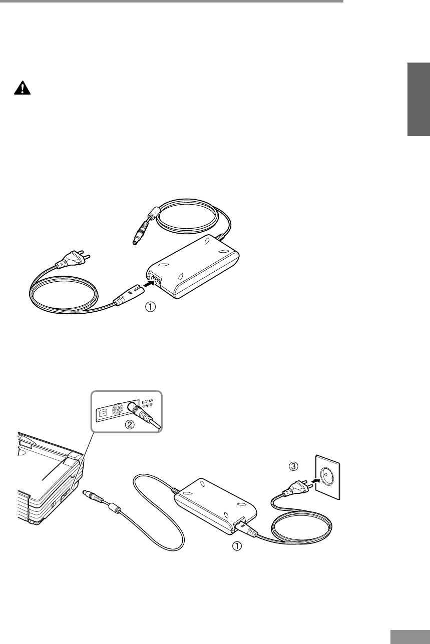
Installing the Scanner 21
ENGLISH
Connecting the Power Cord
Perform the following steps to connect the Power Cord.
WARNING
• Be sure to use the Power Cord and AC adaptor provided with
the scanner.
• Be sure the scanner is turned OFF when performing this
operation.
1
Connect the bundled Power Cord q to the AC adaptor.
2
Plug the AC adaptor Power Cord into the power connector w on the right side
of the scanner, and plug the power plug into a power outlet e.
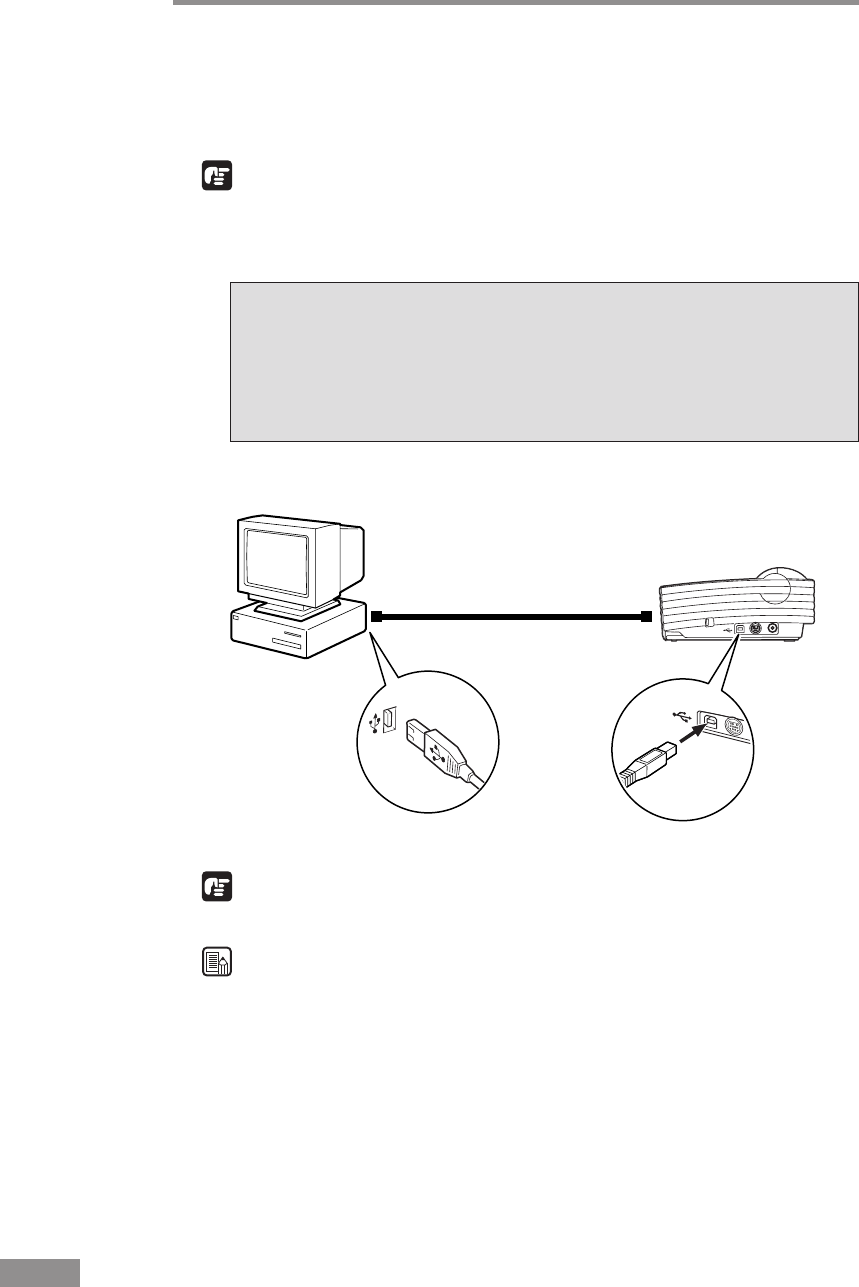
22 Installing the Scanner
Computer
DR-2580C
USB Cable
Connecting the Scanner to Your PC
Connecting the scanner to a computer using a USB connection.
IMPORTANT
• When the application is running, do not turn the scanner OFF or unplug the
interface cable.
• Do not connect multiple DR-2580C scanners to one (1) computer.
USB Interface Connection
•Be sure to use the USB cable bundled with the scanner or a Hi-Speed
USB 2.0 compatible cable.
•When using a USB extension card that supports Hi-Speed USB 2.0, be
sure to choose one verified for use with the scanner. (See p. 20.)
IMPORTANT
When using a USB hub, be sure to use one compatible with USB 2.0.
Note
• The DR-2580C passed the Hi-Speed USB 2.0 certification test. However,
when you use the scanner with a personal computer equipped with USB 2.0
as standard, the scanner may not always operate normally.
• If the interface is not Hi-Speed USB 2.0 compatible, the scanning speed
will slow down.
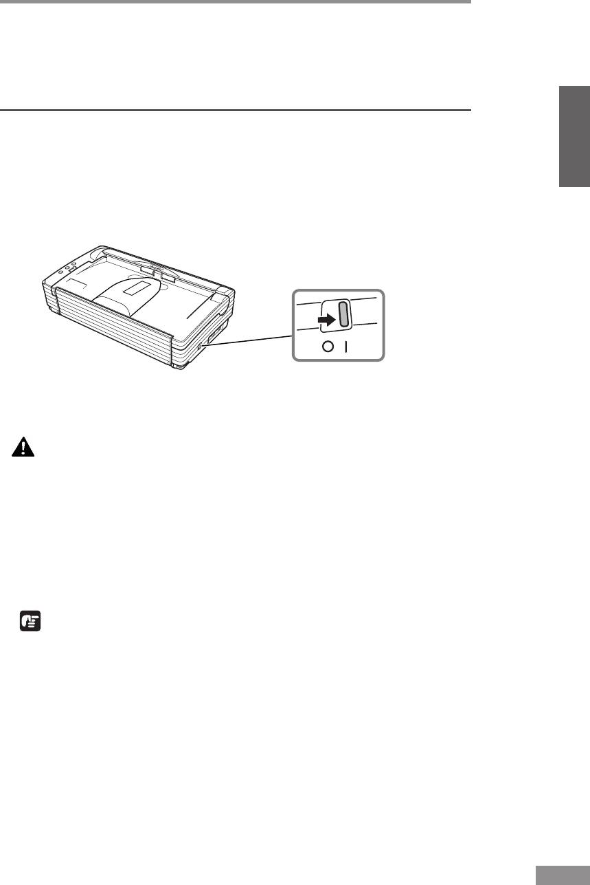
Installing the Scanner 23
ENGLISH
Turning the Power ON/OFF
Follow the procedures described below when turning the power ON or OFF.
Turning the Power ON
1
Turn ON the scanner.
The power switch is on the right side of the scanner.
Push the power switch to turn ON the scanner. The power lamp lights green
when the power is ON.
2
Turn ON the PC.
WARNING
If the scanner ever makes a strange noise, emits smoke or a
strange odor, becomes hot, or if the scanner does not operate at
all even though the power is ON, immediately turn the scanner
OFF and unplug the Power Cord. Contact your local authorized
Canon dealer or service representative to have the scanner
serviced.
3
Log on to Windows.
IMPORTANT
If you are using Windows 2000 Professional or Windows XP, be sure to log
on as a user with administrator privileges.

24 Installing the Scanner
Recognizing the Scanner
When the computer recognizes the scanner, Windows Plug And Play displays
the scanner driver's installation screen. Follow the instructions that appear on
the screen to install the driver.
• If you are using Windows 98SE, the [Add New Hardware Wizard] dialog
box appears.
1. Click the [Next] button.
2. Select [Search for the best driver for your device. (Recommended)], and
then click the [Next] button.
3. Insert the setup disc into the computer’s CD-ROM drive.
4.
Select [Specify a location], enter “D:\INF” (assuming that “D” is the
letter assigned to your CD-ROM drive), and then click the [Next] button.
5. Click the [Next] button.
6. Click the [Finish] button.
• If you are using Windows Me, the [Add New Hardware Wizard] dialog
box appears.
1. Select [Specify the location of the driver (Advanced)], and then click the
[Next] button.
2. Insert the setup disc into the computer’s CD-ROM drive.
3. Select [Search for the best driver for your device. (Recommended)], and
then select [Specify a location]. Enter “D:\INF” (assuming that “D” is
the letter assigned to your CD-ROM drive), and then click the [Next]
button.
4. Click the [Next] button.
5. Click the [Finish] button.
• If you are using Windows 2000 Professional, the [Found New Hardware
Wizard] dialog box appears.
1. Click the [Next] button to proceed to the Install Hardware Device
Drivers screen.
2. Select [Search for a suitable driver for my device (Recommended)], and
then click the [Next] button to proceed to the Locate Driver Files screen.
3. Select [Specify a location], and then click the [Next] button.
4. Insert the setup disc into the computer’s CD-ROM drive.
5. Enter “D:\INF” (assuming that “D” is the letter assigned to your
CD-ROM drive), and then click the [OK] button.
6. On the Driver Files Search Results screen, click the [Next] button.
7. If the message “Digital Signature Not Found” appears, click [Yes] to
continue installation.
8. On the Completing the Found New Hardware Wizard screen, click the
[Finish] button.

Installing the Scanner 25
ENGLISH
• If you are using Windows XP, the [Found New Hardware Wizard] dialog
box appears.
1. Insert the setup disc into the computer’s CD-ROM drive.
2. On the Welcome to the Found New Hardware Wizard screen, select
[Install from a list or specific location (Advanced)], and then click the
[Next] button.
3. Select [Search for the best driver in these locations], and then clear the
[Search removable media (floppy, CD-ROM...)] check box. Select
[Include this location in the search], enter “D:\INF” (assuming that “D”
is the letter assigned to your CD-ROM drive), and then click the [Next]
button.
4. Although a message appears indicating that the driver “has not passed
Windows logo testing”, click the [Continue Anyway] button in the
[Hardware Installation] dialog box.
5. Click the [Finish] button on the Completing the Found New Hardware
Wizard screen.
Note
The DR-2580C is registered as “CANON DR-2580C USB” in the Imaging
Device directory.
IMPORTANT
The job function will no longer be available if scanner recognition is
cancelled part way through (see “Job Function,” on p. 58.). Be sure to perform
the scanner recognition procedure all the way to the end.
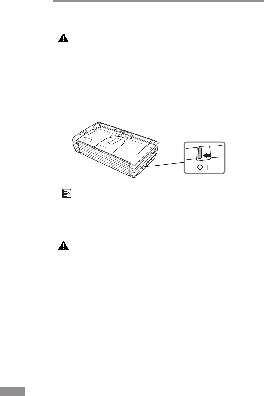
26 Installing the Scanner
Turning the Power OFF
CAUTION
If the scanner will not be used for an extended period of time,
unplug the Power Cord for safety’s sake.
1
Exit the application.
2
Turn OFF the scanner.
The power switch is located on the lower right front corner of the scanner. To
turn the scanner OFF, press the power switch. When the power indicator turns
OFF, the scanner is OFF.
Note
• Make sure you exit the application before turning OFF the scanner.
Turning OFF the scanner before exiting the application can cause unstable
operation of the computer.
• Wait at least 10 seconds before turning the scanner back ON after it has
been turned OFF.
WARNING
If the scanner ever makes a strange noise, emits smoke or a
strange odor, becomes hot, or if the scanner does not operate at
all even though the power is ON, immediately turn the scanner
OFF and unplug the Power Cord. Contact your local authorized
Canon dealer or service representative to have the scanner
serviced.

Installing the Software 27
ENGLISH
Installing the Software
IMPORTANT
The DR-2580C setup disc contains the software listed below. Be sure to read
the contents of the Readme.txt file before installing the software.
• ISIS/TWAIN Driver
This driver allows this scanner to be used with ISIS compatible application
software or TWAIN compatible application software. The driver must be
installed to be able to use the scanner.
• Job Tool
The job tool TWAIN-compatible application software is installed together
with the ISIS/TWAIN driver.
The job tool comprises a “Job Registration Tool” and a “Job Execution
Tool.” The Job Registration Tool is for assigning the job button functions
on the scanner, and the Job Execution Tool is for executing scanning from
job buttons. (See “Using Job Tools” on p. 38.)
• CapturePerfect
CapturePerfect is software for scanning images that is ISIS compatible.
You need to install the ISIS/TWAIN driver before installing
CapturePerfect.
For information about installing the bundled Adobe Acrobat, see the “How To
Install” file on the Adobe Acrobat setup disc.
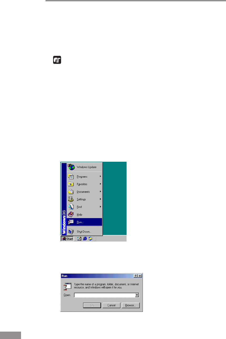
28 Installing the Software
Installing the ISIS/TWAIN Driver
The ISIS/TWAIN driver setup program installs the ISIS/TWAIN driver and
the job tool. Follow the procedure below to install the ISIS/TWAIN driver.
1
Turn ON your PC. Windows starts.
IMPORTANT
• If you are using Windows 2000 Professional or Windows XP, be sure to
log on as a user with administrator privileges.
• If another ISIS compatible driver is already installed in your PC, you must
back up the files listed below. These files may be overwritten when you
install this ISIS/TWAIN driver.
C:\Windows\System\pix*.dll
C:\Windows\PixTran\*.*
• The name of the “\Windows” and “\Windows\System” folder varies,
depending on which version of Windows you are using. Substitute the
above folder names with the relevant folder names for Windows used in
your system.
2
Insert the setup disc in the PC’s CD-ROM drive.
3
Click the [Start] button, and then select [Run].
The [Run] dialog box appears.
4
In the Open box, enter “D:\Driver\Setup.exe” (assuming that “D” is the letter
assigned to your CD-ROM drive), and then click the [OK] button.
The installer starts.
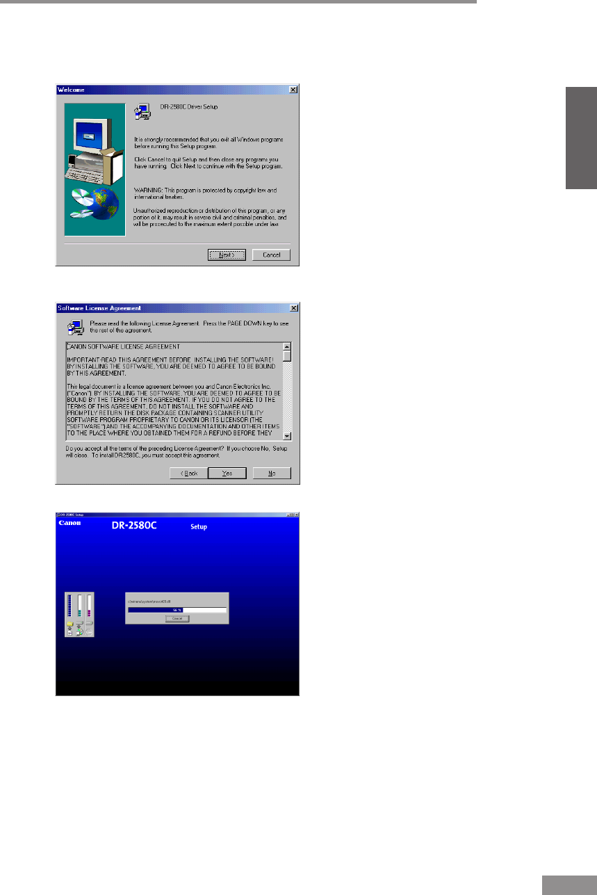
Installing the Software 29
ENGLISH
5
Follow the instructions that appear on the screen to install the software.
1. Read the Welcome text, and then click [Next].
2. Read the License Agreement text, and then click [Yes].
3. Start installation of the ISIS/TWAIN driver.
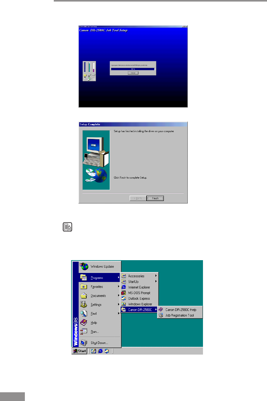
30 Installing the Software
4. After installing the ISIS/TWAIN driver, start installation of the job tool.
5. This completes the installation.
6
After installation is complete, click the [Finish] button to exit the installer.
Note
When the ISIS/TWAIN driver is installed, Canon DR-2580C Help (see
“Using the ISIS/TWAIN Driver” on p. 37.) and the Job Registration Tool
(see “Using Job Tools” on p. 38.) icons are registered to the Start menu.
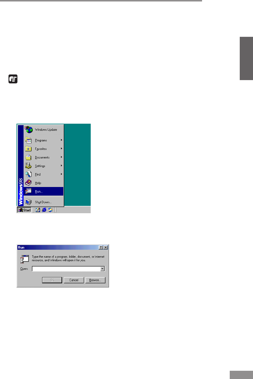
Installing the Software 31
ENGLISH
Installing CapturePerfect
CapturePerfect is ISIS compatible application software. You need to install the
ISIS/TWAIN driver before installing CapturePerfect. Follow the procedure
below to install CompturePerfect.
1
Turn ON your PC. Windows starts.
IMPORTANT
If you are using Windows 2000 Professional or Windows XP, be sure to log
on as a user with administrator privileges.
2
Insert the setup disc in the PC’s CD-ROM drive.
3
Click the [Start] button, and then select [Run].
The [Run] dialog box appears.
4
In the Open box, enter “D:\CapturePerfect\Setup.exe” (assuming that “D” is
the letter assigned to your CD-ROM drive), and then click the [OK] button.
The installer starts.
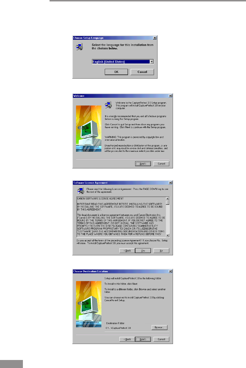
32 Installing the Software
5
Follow the instructions that appear on the screen to install the software.
1. Select the installation language.
2. Read the Welcome text, and then click [Next].
3. Read the License Agreement text, and then click [Yes].
4. Read the Choose Destination Location text, and then click [Next].
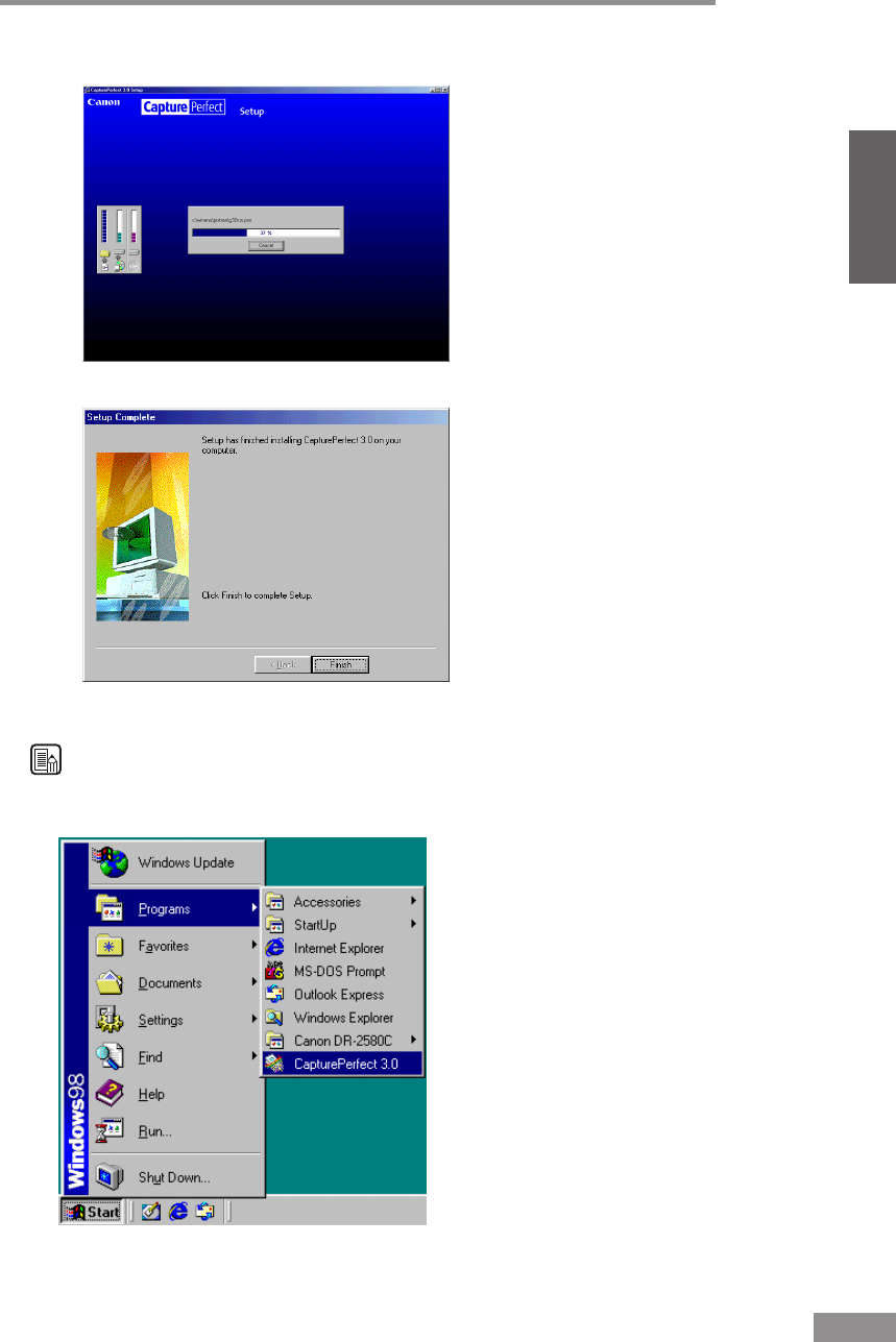
Installing the Software 33
ENGLISH
5. This starts the installer.
6. This completes the installation.
6
After installation is complete, click the [Finish] button to exit the installer.
Note
Installing CapturePerfect will put a CapturePerfect icon on your Windows
Start Menu. (See “Using CapturePerfect,” on p. 40.)
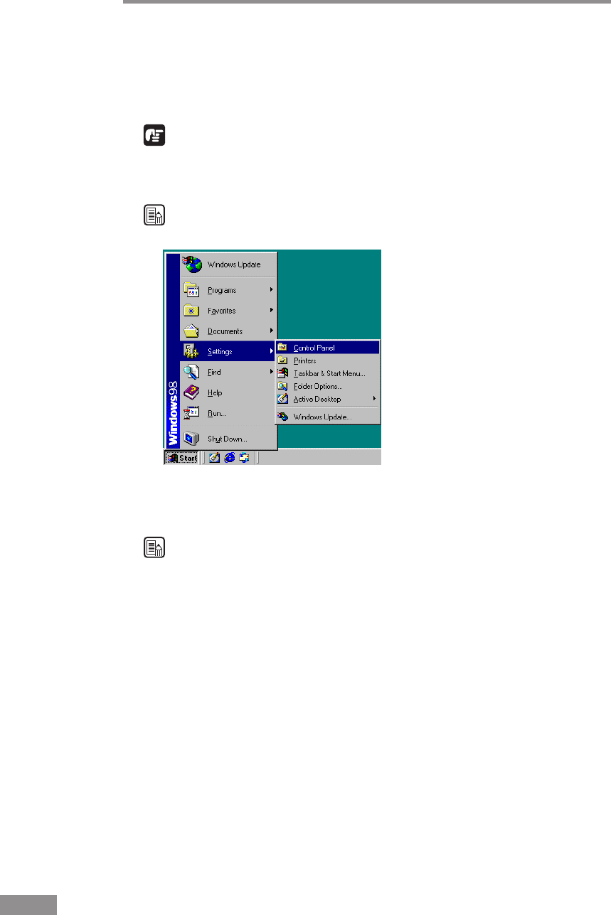
34 Installing the Software
Uninstalling Software
Follow the procedure described below to uninstall the ISIS/TWAIN driver,
Job Tools, and CapturePerfect.
IMPORTANT
Uninstall the ISIS/TWAIN driver and job tool separately.
1
Click the [Start] button, point to [Settings], and then click [Control Panel].
Note
If you are using Windows XP, on the Start menu, click [Control Panel].
The [Control Panel] window is displayed.
2
Double-click the [Add/Remove Programs] icon.
Note
If you are using Windows XP, double-click the [Add or Remove Programs]
icon.
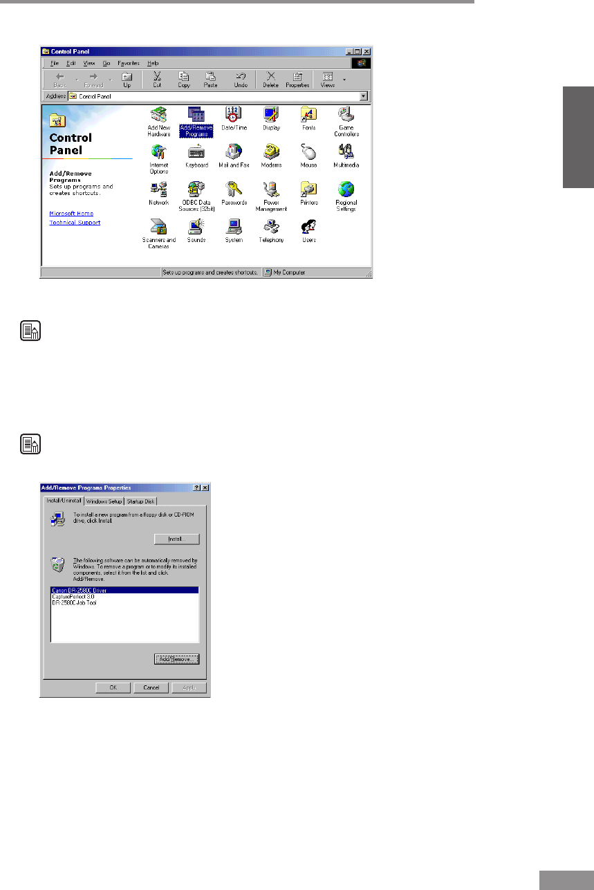
Installing the Software 35
ENGLISH
The [Add/Remove Programs Properties] dialog box is displayed.
Note
If you are using Windows XP, the [Add or Remove Programs] dialog box is
displayed.
3
On the list in the dialog box, select the application you want to delete, and
then click [Add/Remove].
Note
If you are using Windows XP, click the [Change/Remove] button.
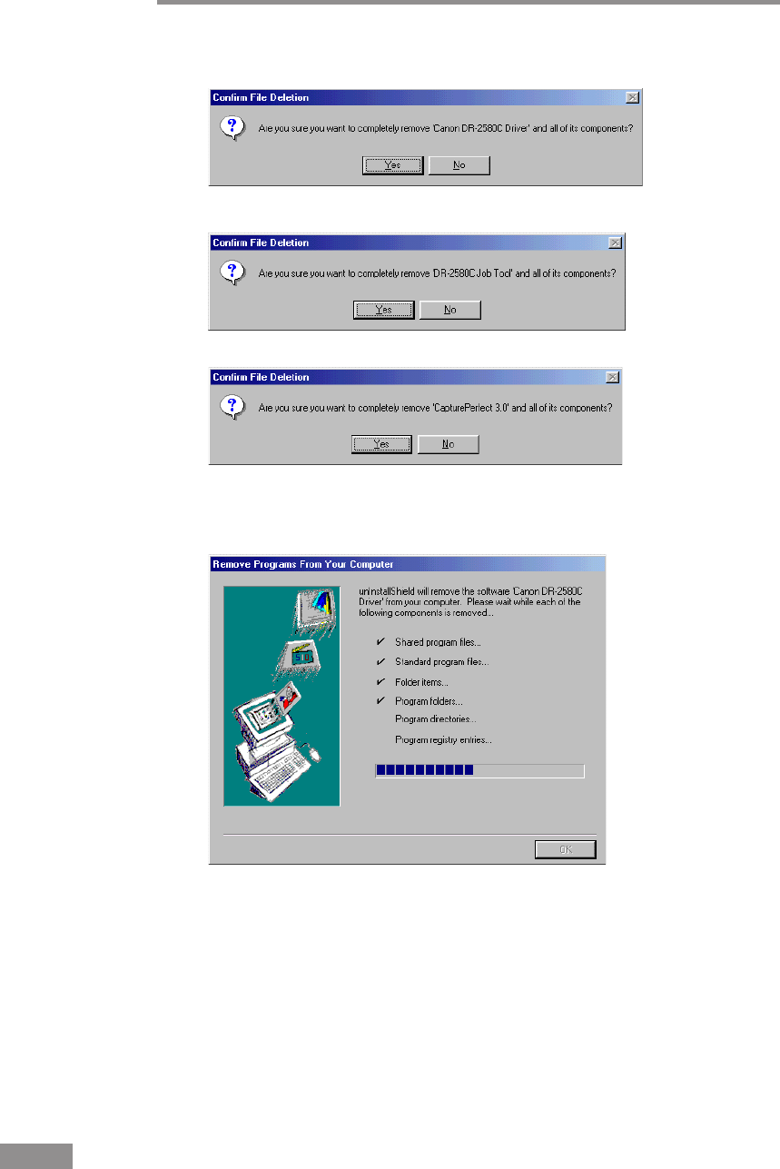
36 Installing the Software
4
The [Confirm File Deletion] dialog box appears.
When [Canon DR-2580C Driver] is selected.
When [DR-2580C Job Tool] is selected.
When [CapturePerfect] is selected.
5
Click the [Yes] button to start the uninstaller.
6
After uninstall is complete, click the [OK] button to exit the uninstaller.
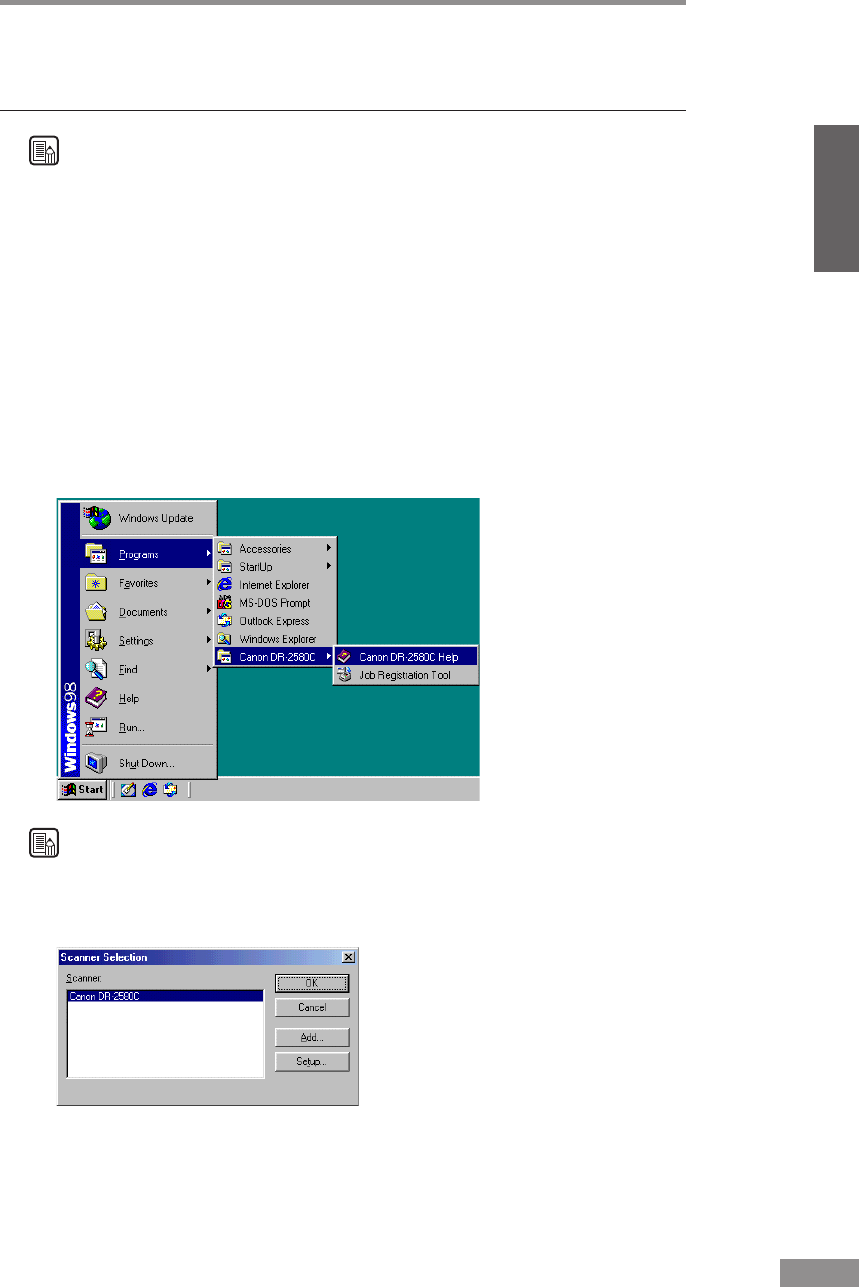
Using the Software 37
ENGLISH
Using the Software
Note
• This section provides only the basic procedures for using installed
software. Software applications also have their own help. See the
applicable help for details about using each software application.
• For information about the bundled Adobe Acrobat, see Adobe Acrobat
help.
Using the ISIS/TWAIN Driver
The ISIS/TWAIN driver help describes how to use the ISIS/TWAIN driver.
To access ISIS/TWAIN driver help, click the [Start] button, point to
[Programs] (when using Windows XP, point to [All Programs]) -
[Canon DR-2580C], and then click [Canon DR-2580C Help], or click the
[Help] button displayed in the dialog box.
Note
Before using the ISIS/TWAIN Driver, select the scanner [Canon DR-2580C]
with the software. For more information, refer to [Canon DR-2580C Help]
and the manual for the software you are using.
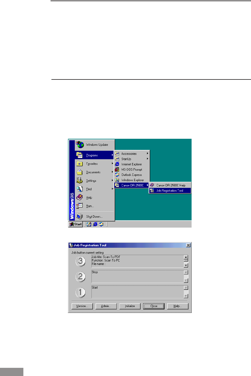
38 Using the Software
Using Job Tools
This section explains how to start up Job Registration Tool. Details about
configuring Job Registration Tool settings can be found in Job Registration
Tool help.
To view information about settings, click the [Help] button on the Job
Registration Tool main screen.
Starting Job Registration Tool
1
Turn ON the scanner.
2
Turn ON your computer. Windows starts.
3
Click the [Start] button, point to [Programs] (when using Windows XP, point
to [All Programs]) - [Canon DR-2580C
]
, and then click [Job Registration
Tool].
Job Registration Tool starts.
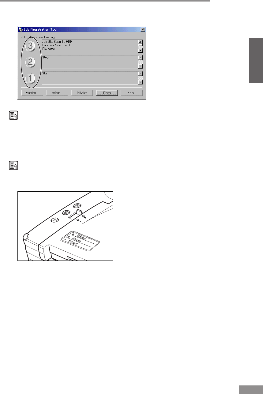
Using the Software 39
ENGLISH
4
Press a Job button, and then configure the Job Registration Tool settings.
Note
For details about configuring Job Registration Tool settings, click the [Help]
button.
5
After configuring the settings, click the [Close] button to exit Job Registration
Tool.
Note
Fill in the Job Registration Tool settings on the included job label, and affix
the job label to the scanner.
Job Label
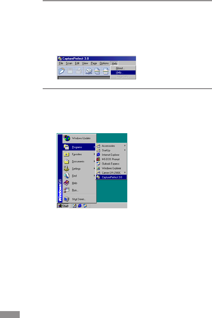
40 Using the Software
Using CapturePerfect
This section explains the basic procedures to start and exit CapturePerfect.
Details about actually using CapturePerfect can be found in CapturePerfect
help. To view information about using CapturePerfect, click [Help] on the
CapturePerfect menu bar.
Starting CapturePerfect
1
Turn ON the scanner.
2
Turn ON your computer. Windows starts.
3
Click the [Start] button, point to [Programs] (when using Windows XP, point
to All Programs), and then click [CapturePerfect].
CapturePerfect starts.
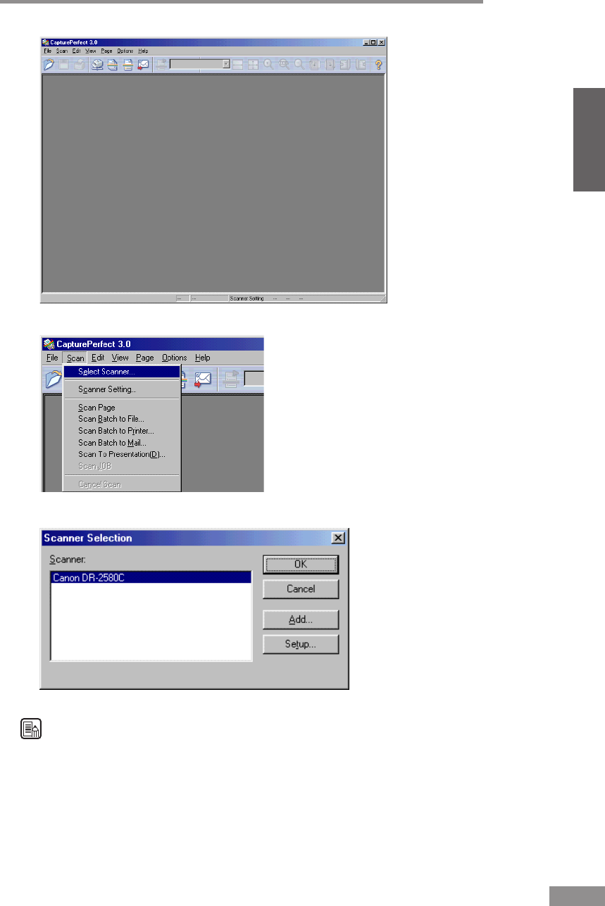
Using the Software 41
ENGLISH
4
On the [Scan] menu, click [Select Scanner].
5
Select [Canon DR-2580C], and then click the [OK] button.
Note
If [Canon DR-2580C] is not displayed in the list of scanners, reinstall the
ISIS/TWAIN driver. (See “Installing the ISIS/TWAIN Driver,” on p. 28.)
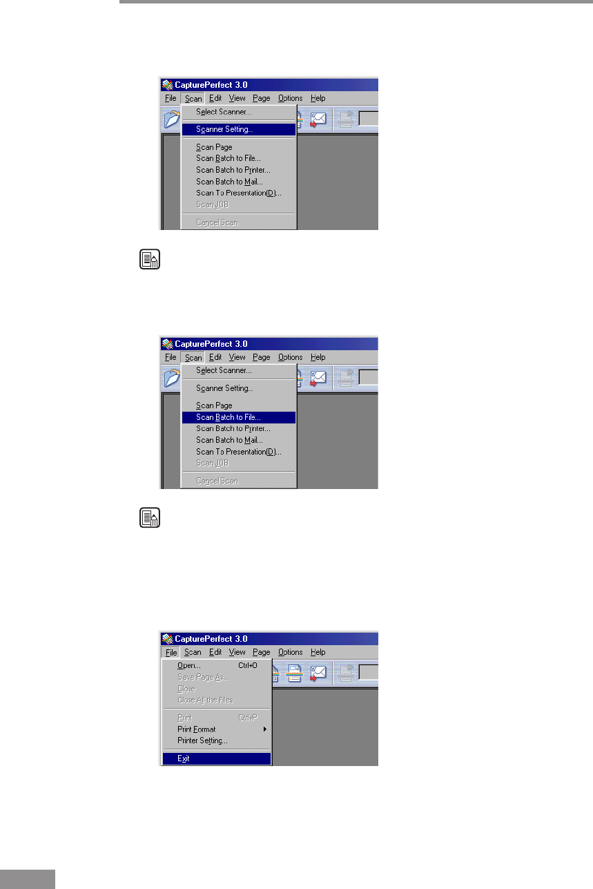
42 Using the Software
6
On the [Scan] menu, click [Scanner Setting], and then configure the scanning
parameters.
Note
For details about how to configure scanning parameters, see ISIS/TWAIN
driver help. (See p. 37.)
7
Execute the scan operation from the [Scan] menu.
Note
Details about actually using CapturePerfect can be found in CapturePerfect
help. To view information about using CapturePerfect, click [Help] on the
menu bar.
8
After scanning is complete, select [Exit] on the [File] menu to quit
CapturePerfect.
CapturePerfect closes.

Using the Scanner 43
ENGLISH
Using the Scanner
Documents
This scanner can scan documents ranging in size from business cards and
checks to A4 size documents. The size of documents that can be scanned is
shown below.
Eject Direction (*1) U-Turn Path Straight Path
Width 53 mm to 216 mm 53 mm to 216 mm
Length 70 mm to 355.5 mm (*2) 70 mm to 355.5 mm
Weight (*3)
Feeding documents 52 to 128g/m
2
42 to 157g/m
2
are separated 0.06 mm to 0.15 mm 0.05 mm to 0.20 mm
Feeding documents 42 to 157g/m
2
42 to 157g/m
2
are not separated 0.05 mm to 0.20 mm 0.05 mm to 0.20 mm
Business Cards Cannot be scanned Can be scanned
(not separated)
Size: 53.9 mm x 85.5 mm
Thickness:
0.76 ± 0.08 mm
without embossing
(*1) For information about the output directions, see “Document Eject Tray,”
on p. 47.
(*2) If the document is longer than 297 mm, use the Bypass mode with Feed
Selection Lever for document scanning (See p. 53.).
(*3) For information about feeding a document, see “Placing a Document for
Scanning,” on p. 50.
IMPORTANT
A document must meet the following criteria to be scannable:
• When scanning a multipage document, pages must be grouped together so
that they have the same size, thickness, and weight. Scanning different
types of paper at one time can cause the scanner to jam.
• When using the U-turn path to scan a document that is longer than 297
mm, use the Bypass mode and feed pages one at a time. Attempting to use
the U-turn path for continuous feed scanning of a document that is longer
than 297 mm can cause the document pages to fall onto the feed tray and
become jammed in the scanner.
•Scanning documents before the ink is dry can cause problems with the
scanner. Always make sure that the ink on a document is dry before
scanning it.
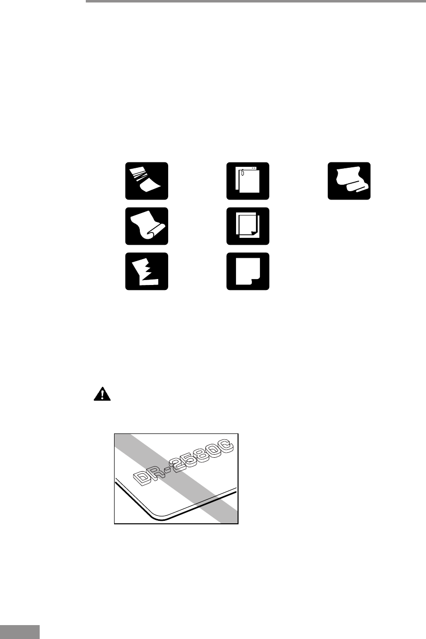
44 Using the Scanner
•Scanning documents that are written in pencil or similar material can make
the rollers dirty, which can then transfer the dirt to subsequent documents.
Always clean the rollers after scanning a document written in pencil.
• When scanning a two-sided document that is printed on thin paper, the
image on the opposite side of each page may show through. Adjust the
scanning intensity in the application software before scanning the
document.
• Scanning the following types of documents can cause a paper jam or
malfunction. To scan such a document, make a photocopy of the document
and then scan the photocopy.
•Note that glossy originals or card originals sometimes cannot be scanned
correctly, or functions such as Paper Size Detection and Deskew do not
function properly due to reflected light.
•When scanning business cards, make sure to select the nonseparation feed
and straight path.
Wrinkled or
creased
documents
Curled
documents
Torn
documents
Documents
with paper
clips or
staples
Carbon
paper
Coated
paper
Extremely
thin,
translucent
paper
Embossed Card
CAUTION
The results of scanning embossed cards are not guaranteed. Note
that scanning embossed cards may scratch the sensor glass.
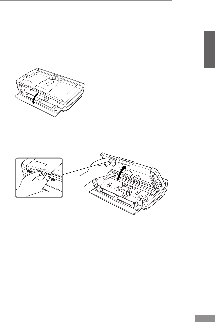
Using the Scanner 45
ENGLISH
Preparing the Trays
Prepare the Document Feed Tray and Document Eject Tray according to the
paper size and feed/eject method.
Setting Up the Document Feed Tray
Pull the Document Feed Tray towards you to open it.
When Documents Are Skewed
If fed documents are skewed, follow the procedure described below to install
the Document Guide Adapters.
1
Pressing the OPEN Knob from both sides, raise the Upper Unit.
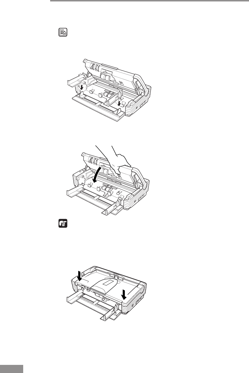
46 Using the Scanner
2
Set the Document Guide Adapters onto the Document Guides.
Note
Cover the Document Guides from above with the Document Guide Adapters,
and insert them as far as they will go, until they click into place.
3
Carefully close the Upper Unit.
IMPORTANT
Do not force the Upper Unit to close. Doing so can damage the scanner.
4
Be sure that the Upper Unit is completely closed by pushing on both edges
with both hands until you hear a click.
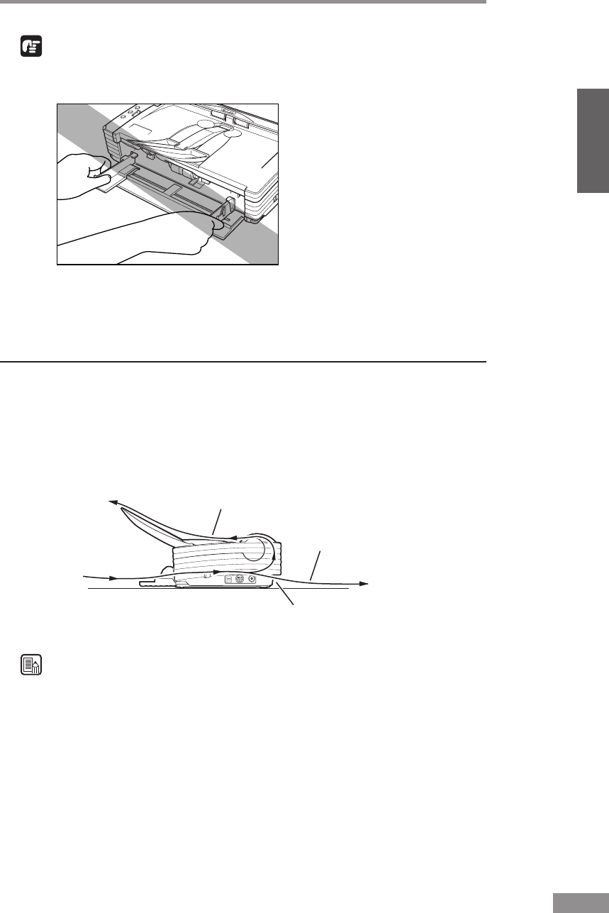
Using the Scanner 47
ENGLISH
IMPORTANT
• Do not hold the tips of the Document Guide Adaptors when moving them.
Doing so can damage the document tray.
• Before removing the Document Guide Adapters, be sure to open the upper
unit first. Using undue force when removing the Document Guide Adaptors
can damage the document tray.
Document Eject Tray
The scanner has two eject methods: documents can be ejected to the front of
the scanner in a U-Turn Path, or to the back of the scanner in a Straight Path.
The eject method can be switched by moving the Eject Selection Lever up and
down. Select the eject method according to what you need to do.
Straight Path
U-Turn Path
Document Feed Openig
Document Eject Opening
Note
The Straight Path can be used to scan thick paper, thin paper, and business
cards.
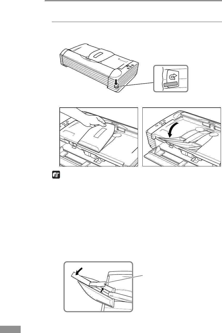
48 Using the Scanner
Document Eject
Tray Extension 2
Using the U-Turn Path
1
Lower the Eject Selection Lever.
Scanned documents will be ejected to the Document Eject Tray.
2
Pull the Document Eject Tray Extension towards you to open it.
IMPORTANT
• Be careful when opening the Document Eject Tray Extension. Forcing it
open can damage it.
• Never try to raise the Document Eject Tray Extension more than necessary.
Doing so can damage it.
• Do not place anything other than documents on the Document Eject Tray
Extension. Doing so can damage it.
• Make sure the Document Eject Tray Extension is open when using the
scanner. If the Document Eject Tray Extension is not opened, ejected
documents can fall from the tray and become jammed in the scanner.
• If it appears that the document may fall from the Document Eject Tray
Extension and become jammed in the scanner, open the Document Eject
Tray Extension 2.
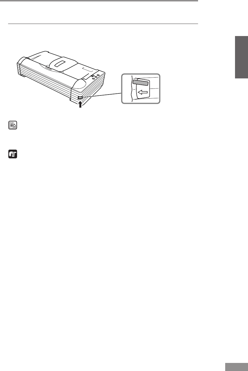
Using the Scanner 49
ENGLISH
Using the Straight Path
1
Raise the Eject Selection Lever.
Scanned documents will be ejected to the back of the scanner.
Note
When using the Straight Path, the ejected documents are stacked in reverse
order to how they were fed.
IMPORTANT
• Be sure there is enough space for documents that are ejected behind the
scanner when using the Straight Path. If there is not enough space for
ejected documents, the documents may be damaged or a paper jam may
occur.
• Switch the position of the Eject Selection Lever before you start scanning.
Changing the lever position while scanning is being performed can cause
jamming.
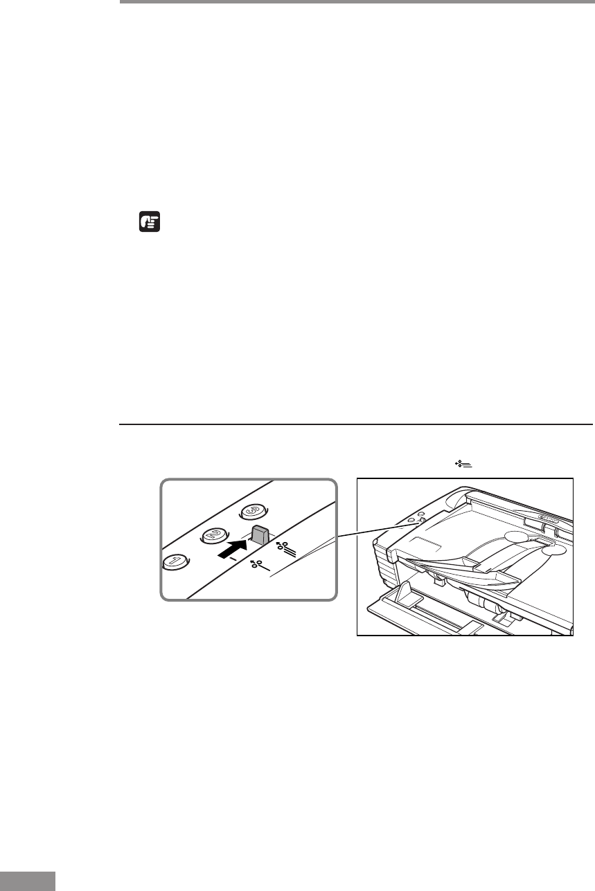
50 Using the Scanner
Placing a Document for Scanning
There are two methods for paper separation, called the Page Separation mode
and Bypass mode for feeding documents. Feeding documents continuously
from a stack of documents placed in the feed tray is called the Page
Separation mode. Feeding documents one sheet at a time by hand or feeding
multiple sheet documents, such as invoices that are attached at one end, is
called the Bypass mode. The document feed method can be switched by
moving the Feed Selection Lever.
IMPORTANT
• When placing a document for scanning, be careful to remove all paper
clips, staples, etc., from the document. During the scanning process, such
objects can tear the document, cause a paper jam, and damage the scanner.
• Do not wear loose clothing or jewelry that may get caught in the scanner
while you are operating it. If they get caught in the scanner it may cause an
injury. Be extra careful of neckties and long hair. If anything gets caught in
the scanner, quickly unplug the scanner to stop it.
• If the leading edge of the documents are curled, they may cause a paper
jam. If the curls are large, straighten them out before scanning.
How to Feed with the Page Separation Mode
1
Move the feed selection lever to the page separation ( ) side.
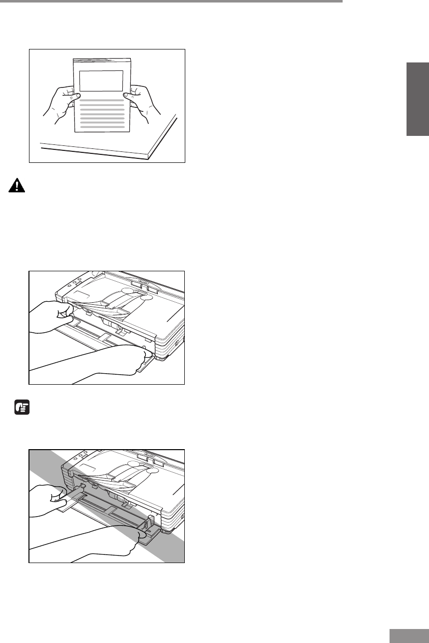
Using the Scanner 51
ENGLISH
2
Straighten the edges of the stack of documents to be scanned.
CAUTION
• Do not place the documents on top of the scanner to align
them. Doing so may cause a malfunction.
• Be careful when placing a document in the scanner. It is
possible to cut your hand on the edge of a sheet of paper.
3
Set the Document Guides so they are wider than the document to be scanned.
IMPORTANT
Do not hold the tips of the Document Guide Adaptors when moving them.
Doing so can damage the Document Tray.
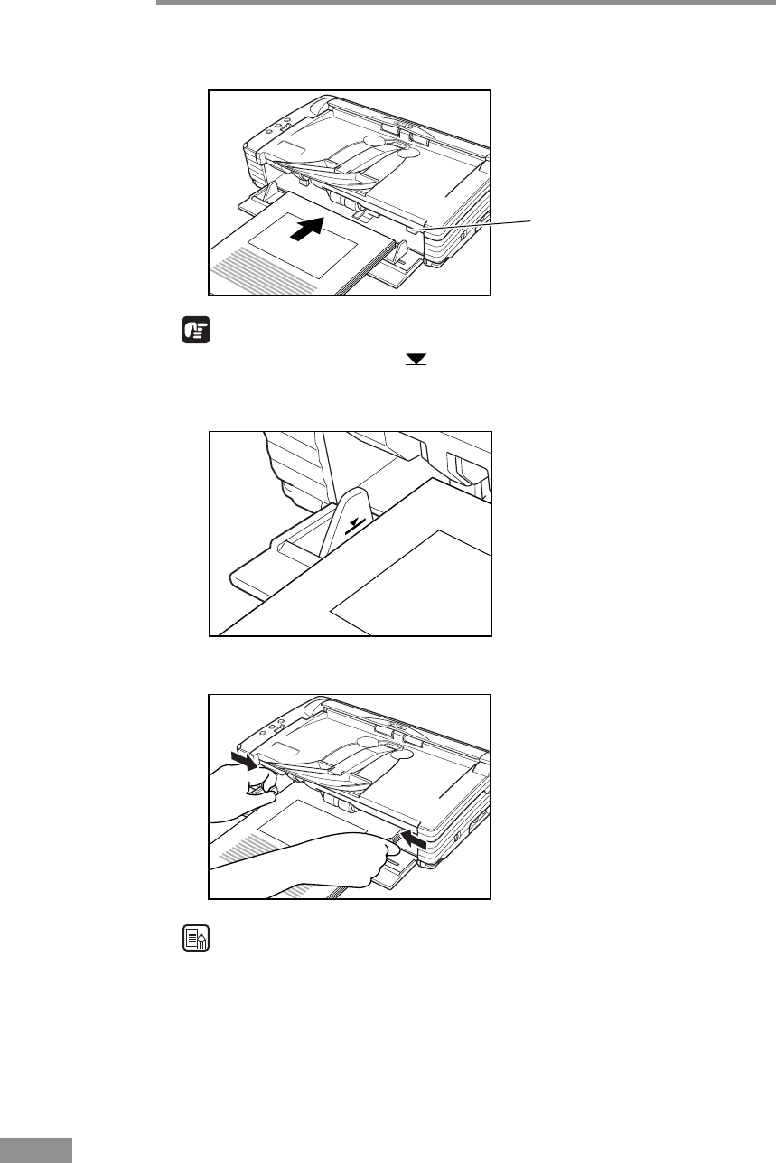
52 Using the Scanner
Stopper
4
Place the documents face up into the feed tray, so that they touch the stoppers.
IMPORTANT
There is a load limit mark ( ) on the Document Guides. Do not stack
documents higher than this mark (approximately 50 sheets of 80g/m2 paper.
Doing so may cause a paper jam.
5
Adjust the Document Guides so they match the width of the document.
Note
Before starting a scan, make sure that the document is loaded in the scanner
correctly. Scanning a curled document or a creased document can damage the
document.
6
Start scanning from the application.
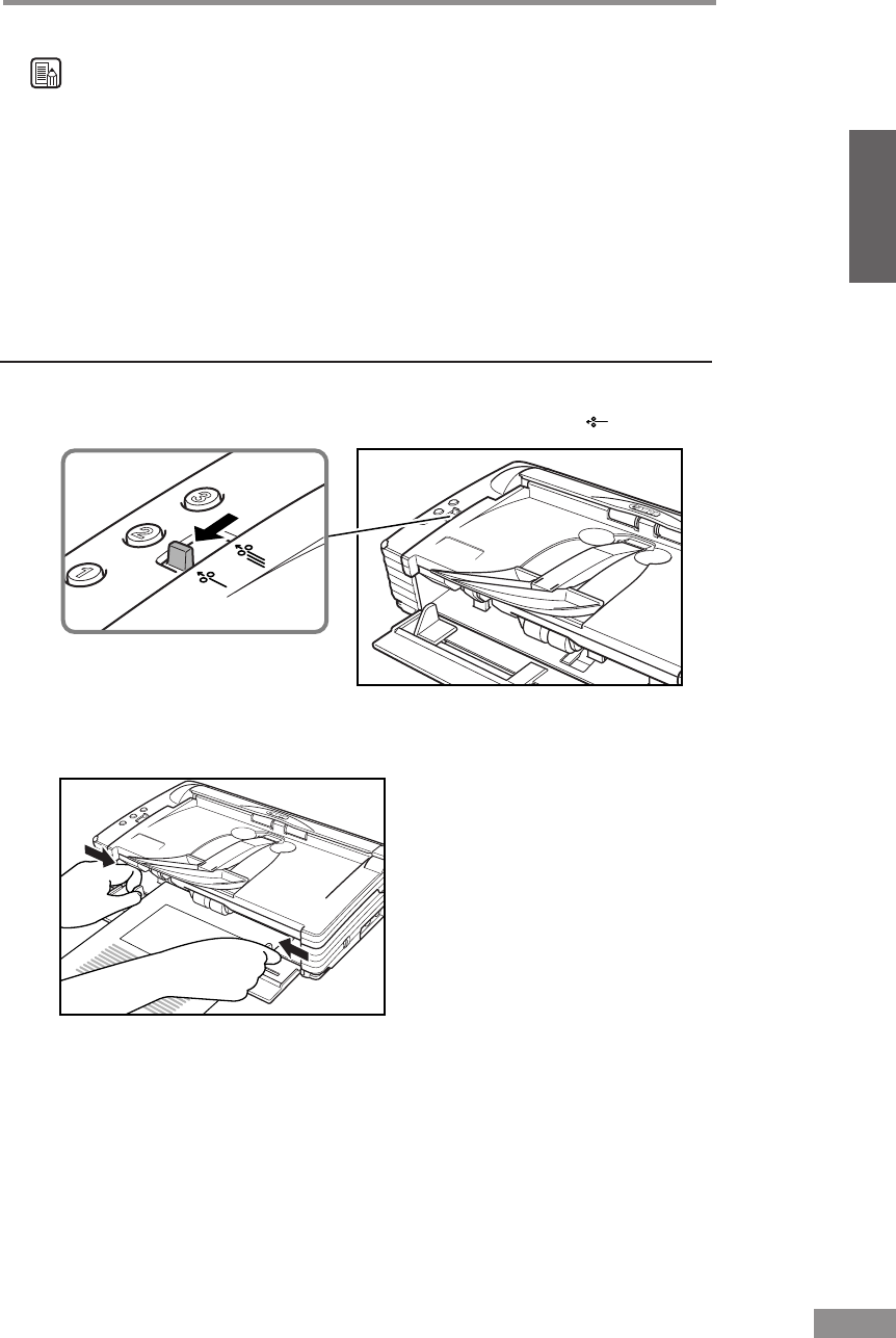
Using the Scanner 53
ENGLISH
Note
• If the paper feed operation stops due to a system error or a paper jam while
the scanner is scanning, resolve the problem, make sure that the scanned
image of the last page that was fed has been stored, and then resume the
scanning operation.
• Note that documents that are printed on thin paper may fall out of the
Document Eject Tray.
• After you finish scanning, close the Document Feed Tray and the
Document Eject Tray Extension to prevent damage to the scanner while it
is not being used.
How to Feed with the Bypass Mode
1
Move the Feed Selection Lever to the nonseparated document ( ) side.
2
Place the document into the Document Feed Tray one sheet at a time, so that
it touches the stoppers, and adjust the position of the Document Guides.
3
Start scanning from the application.
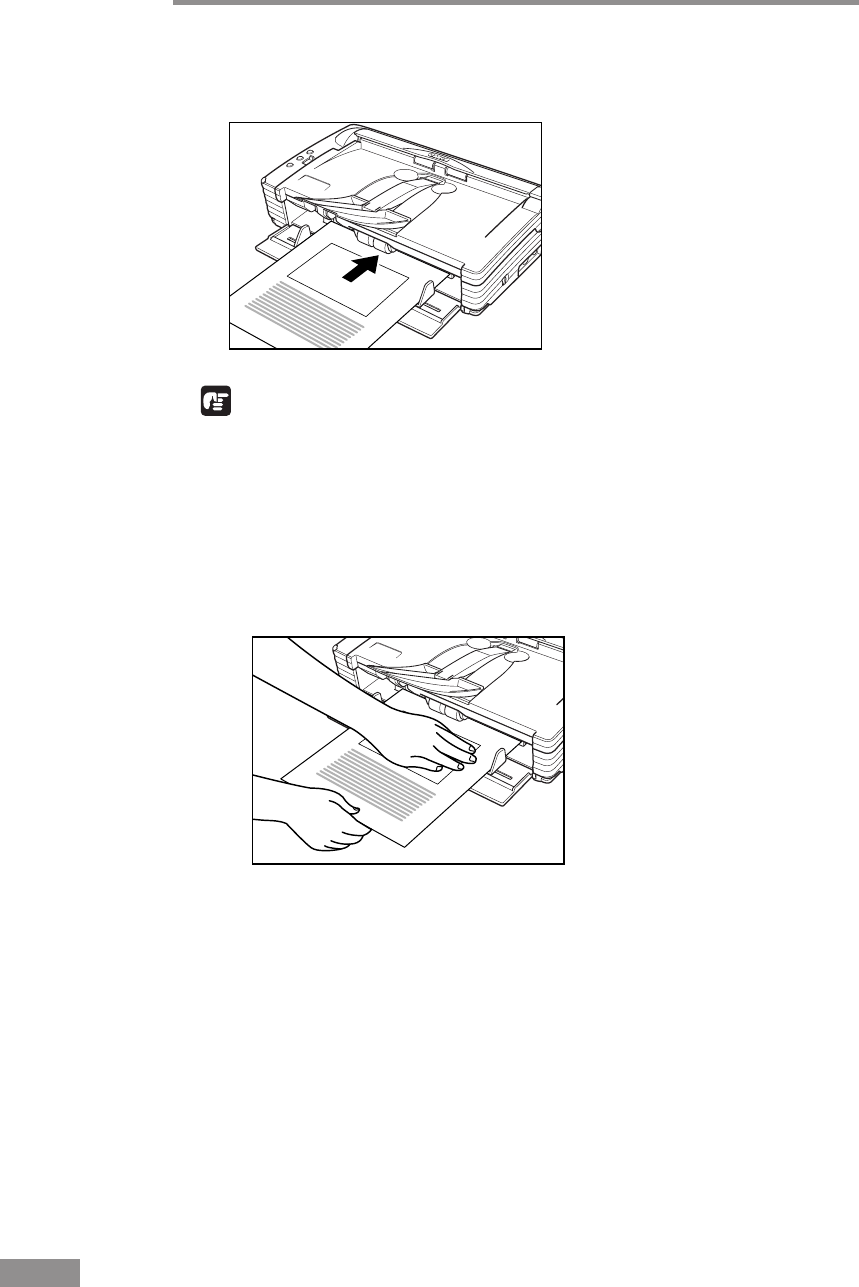
54 Using the Scanner
4
The document is pushed against the document feed slot and is fed into the
scanner.
IMPORTANT
• When scanning documents that are fastened together, such as invoices, set
the edge that is fastened together as the leading edge.
• Note that when scanning with nonseparated feed, if you place several
documents that are not fastened together on the feed tray at one time, they
will be fed together.
• In particular, very thin or curled documents will not be fed very well. In
this case, lightly press on the leading edge of the documents as you feed
them.
•
After you finish scanning, close the Document Feed Tray and the Document
Eject Tray Extension to prevent damage to the scanner while it is not being
used.
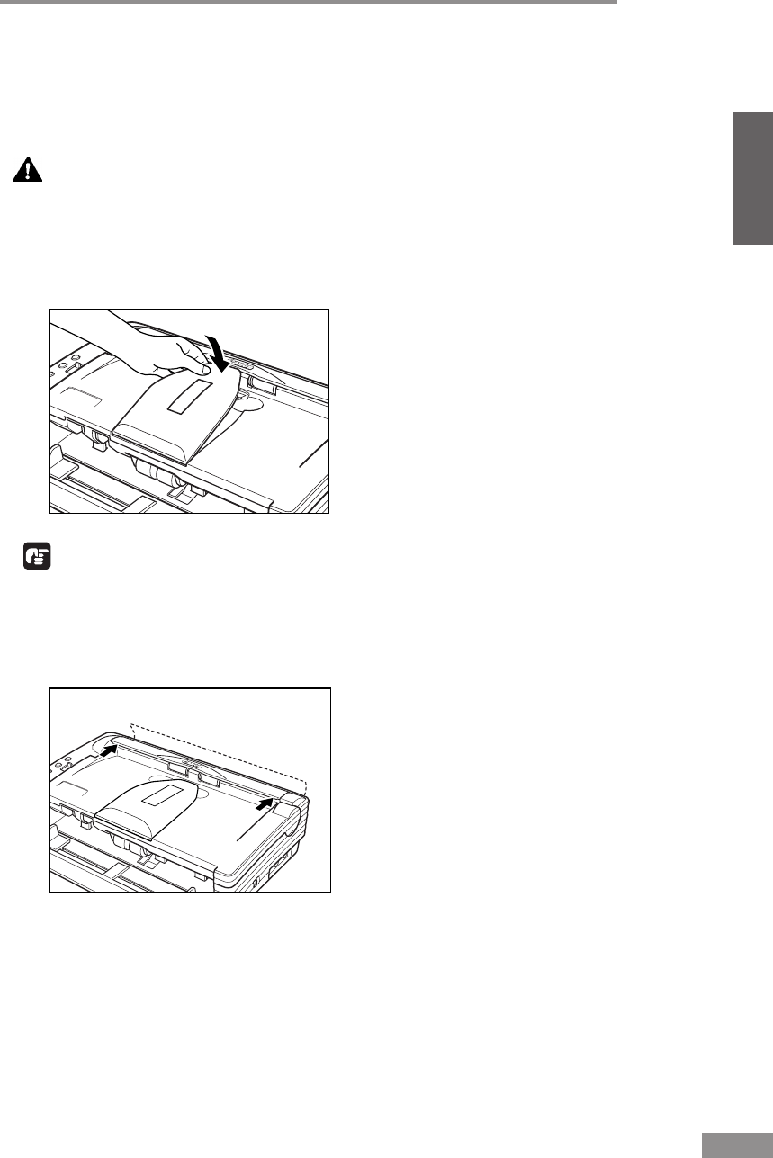
Using the Scanner 55
ENGLISH
Clearing a Paper Jam
When paper jams occur during scanning, use the following procedure to clear
them.
CAUTION
Be careful when removing jammed paper. It is possible to cut
your hand on the edge of a sheet of paper.
1
Remove any documents that have been left in the eject tray.
2
Close the Document Eject Tray Extension.
IMPORTANT
If document ejection is stopped part way, perform this operation with the
Document Eject Tray Extention open. Attempting to force the Document
Eject Tray Extension closed can crease the document.
3
Press on both sides of the back cover to open it.
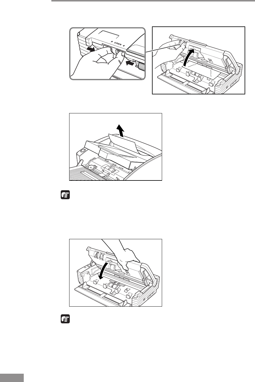
56 Using the Scanner
4
Pressing the OPEN Knob from both sides, raise the Upper Unit.
5
Remove the jammed document.
IMPORTANT
Be sure to pull the document out carefully, without applying too much force.
Should the document tear, be sure to remove any part remaining in the
scanner.
6
Close the Upper Unit slowly.
IMPORTANT
Do not force the Upper Unit to close. Doing so may damage the scanner.
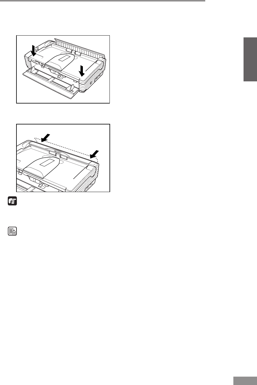
Using the Scanner 57
ENGLISH
7
Be sure that the upper unit is completely closed by pushing on both edges with
both hands until you hear a click.
8
Press on both sides of the back cover to close it.
IMPORTANT
Be sure to press on both sides of the upper unit and back cover to ensure that
they are securely closed. Feeding errors will occur if only one side is closed.
Note
After removing the jammed paper, check to see if the last page was scanned,
and then continue scanning.
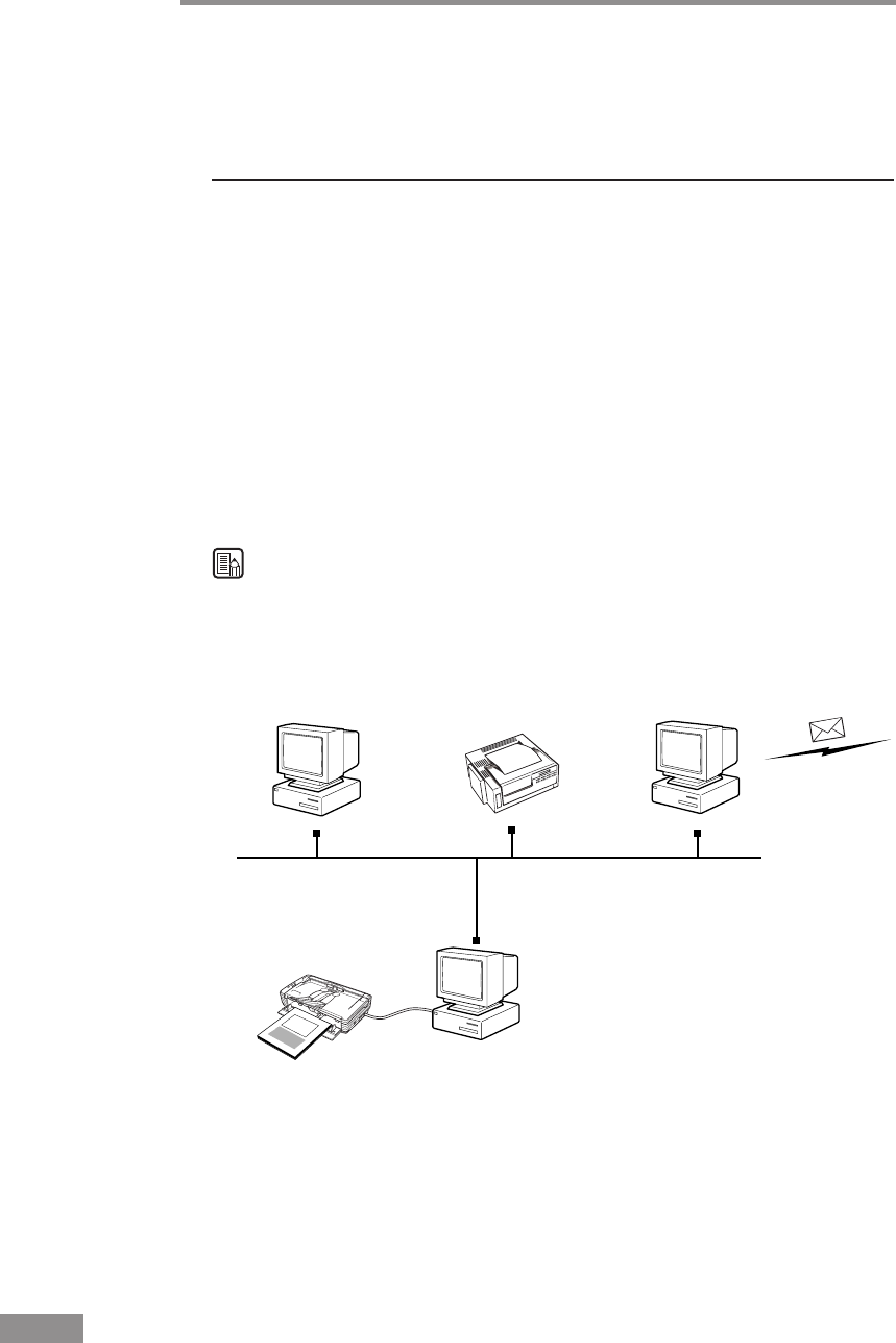
58 Using the Scanner
Other Functions
This scanner also supports the scanning functions described below.
Job Function
Job Registration Tool can be used to assign a scan function to one of the
scanner's Job buttons.
Placing a document on the scanner and pressing the applicable Job button will
perform scanning in accordance with the parameters configured using Job
Registration Tool.
The following functions can be assigned using Job Registration Tool for
automatic processing of scanned images:
•Scan to Save: Saves the scanned image to a shared folder or other folder.
•Scan to Print: Sends the scanned image to a specific printer.
•Scan to E-Mail:Attaches the scanned image to an e-mail massage.
Note
See Job Registration Tool help for details about how to use it. (See “Using
Job Tools,” on p. 38.)
Scan to Save
Saves to a specific folder.
DR-2580C
Scan to Print
Sends to a printer.
Scan to E-Mail
Attaches to an e-mail message.
(Mail Server)
(Network)
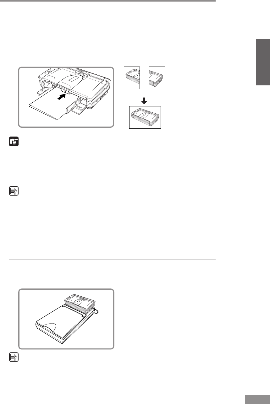
Using the Scanner 59
ENGLISH
Scanning Folio (Folded Document)
The scanner uses a folio scanning method to scan documents that are bigger
than A4 size (maximum A3 size). To do folio scanning, fold the document in
half and place it on the scanner. Both sides of the folded document are
scanned and combined into a single image.
(Front) (Back)
(Combined Image)
IMPORTANT
• Attach the Document Guide Adaptors to prevent documents from skewing
when doing folio scan. (See p. 46.)
• Use nonseparated document scanning when doing folio scan.
• Firmly set the fold in the document. The fold in the document may cause
paper jams or misaligned images.
Note
• Folio scanning is set in the ISIS/TWAIN driver.
• The image on the front of the folded document appears as the left side of
the image.
• Combined images can be a maximum of A3 size.
• A seam may appear where the images are combined if the document or the
fold in the document is crooked.
Flatbed Scanner Unit (Option)
An optional flatbed scanner unit is available for the DR-2580C as an option.
The flatbed scanner unit can be used to scan thick documents, books, and
other originals that cannot pass through the feeder.
Note
The flatbed scanner unit cannot operate in a stand-alone configuration.
Contact your local authrized Canon dealer or service representative for more
detailed information.
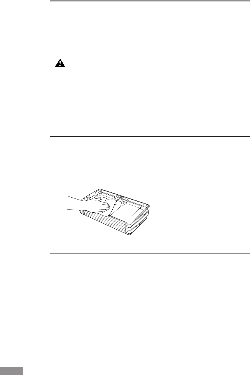
60 Regular Maintenance
Regular Maintenance
Clean the scanner on a regular basis as described below to maintain peak
scanning quality.
CAUTION
• When cleaning the scanner or inside of the scanner, turn OFF
the power switch and unplug the Power Cord from the outlet.
• Do not use excessive force when removing or attaching the
rollers. Doing so may damage them.
• Never use paint thinner, alcohol, or other organic solvents to
clean the scanner. Such solvents can damage or discolor the
exterior of the scanner. They also create a risk of fire or
electrical shock.
Cleaning the Scanner
To clean the exterior of the scanner, dampen a cloth with water or a mild
detergent, wring the cloth out thoroughly, and then wipe the dirt away. Then
use a dry, soft cloth to wipe away any moisture.
Cleaning Inside the Scanner
Dust or paper particles inside the scanner can cause lines in scanned images.
Use a blower for regular cleaning of dust and paper particles from inside the
scanner. After finishing a large scanning job, you should turn OFF the scanner
and then clean any paper particles that are remaining.
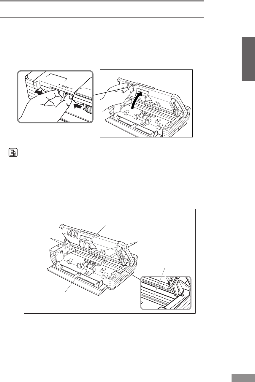
Regular Maintenance 61
ENGLISH
Cleaning the Sensor Glass, Shading Boards, and the Rollers
If scanned images have extraneous marks, or if the scanned documents are
dirty, then the sensor glass or rollers inside the scanner may be dirty. Clean
them periodically.
1
Pressing the OPEN Knob from both sides, raise the Upper Unit.
Note
• The location of the sensor glass and various rollers are shown below.
• The scanner has white, 2mm wide shading boards located at the front and
back of the upper and lower sensor glasses. The scanner uses the shading
boards to determine white standards during scanning. Dirty shading boards
can cause stripes in scanned images. Periodically clean them to ensure
good scanning results.
Retard Roller
Roller Unit
Roller
Sensor
Glass
Shading Boards
(White Standard Boards)
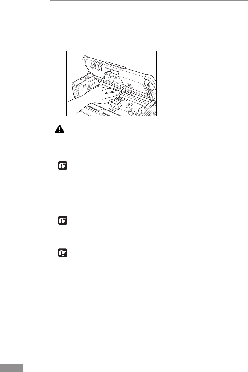
62 Regular Maintenance
2
Use a blower to keep the interior of the scanner free of dust and paper
particles.
3
Use a clean dry cloth to wipe dirt off the sensor glass.
Wipe both the top and bottom sensor glasses.
CAUTION
Do not use spray type cleaners to clean the scanner. Precision
mechanisms, such as the light source, may get wet which will
cause a malfunction.
IMPORTANT
Scratches on the sensor glass may cause marks on the images and could cause
feeding errors. If there are scratches on the sensor glass, contact your local
authorized Canon dealer or service representative.
4
Use a commercially available cotton swab to clean off any dirt from the
shading boards at the front and back of the sensor glasses.
IMPORTANT
Wipe both the top and bottom shading boards.
5
Wipe the rollers with a firmly wrung cloth moistened with water.
IMPORTANT
• Do not use detergent to clean the rollers, since any detergent on the rollers
could cause a feeding error.
• If you cannot freely rotate the rollers, do not force them to rotate. Just clean
the part that you can see. Forcing the rollers to rotate may cause a feeding
error.
6
Remove the roller unit and retard roller. (See “Removing and Attaching the
Roller Unit,” on p. 67.)
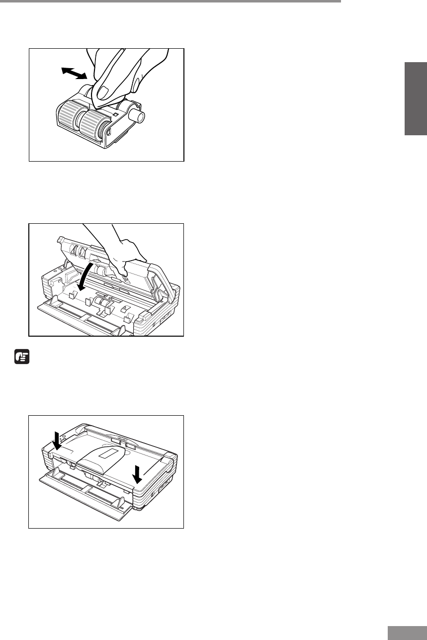
Regular Maintenance 63
ENGLISH
7
Wipe the removed rollers with a firmly wrung cloth moistened with water.
8
Attach the rollers that were removed. (See “Removing and Attaching the
Roller Unit,” on p. 67.)
9
Close the Upper Unit slowly.
IMPORTANT
Do not force the Upper Unit to close. Doing so may damage the scanner.
10
Be sure that the Upper Unit is completely closed by pushing on both edges
with both hands until you hear a click.
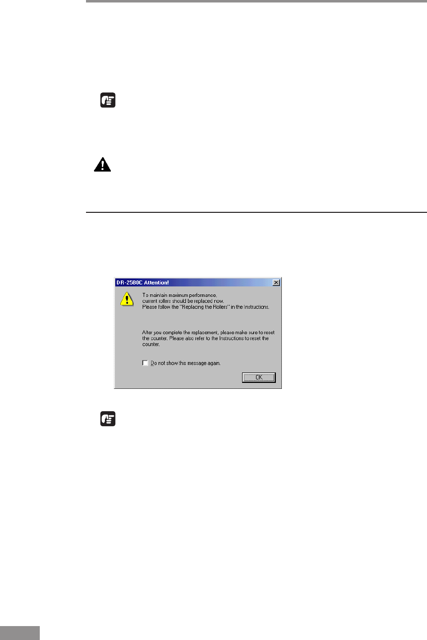
64 Regular Maintenance
Removing and Attaching the Rollers
Follow the relevant procedure to remove and attach the roller unit and retard
roller when you clean or replace them.
IMPORTANT
Feed rollers are consumable parts. When the rollers start to wear out, paper
jams and misfeeds may occur more often. When this happens, buy a exchange
roller kit, and replace the roller unit and the retard roller.
CAUTION
Do not use excessive force when removing or attaching the
rollers. Doing so may damage them.
Roller Replacement Cycle
When the number of pages scanned exceeds 100,000, a roller replacement
message will appear when the computer is started. Buy a exchange roller kit,
and replace the roller unit and the retard roller.
IMPORTANT
• If misfeeds happen often, check the rollers for wear, and replace them if
necessary before the message is displayed.
• Be sure to reset the counter after replacing the rollers. (See “Resetting the
Counter,” on p. 65.)
• Contact your local authrized Canon dealer or service representative for
information about the exchange roller kit (roller unit and retard roller).
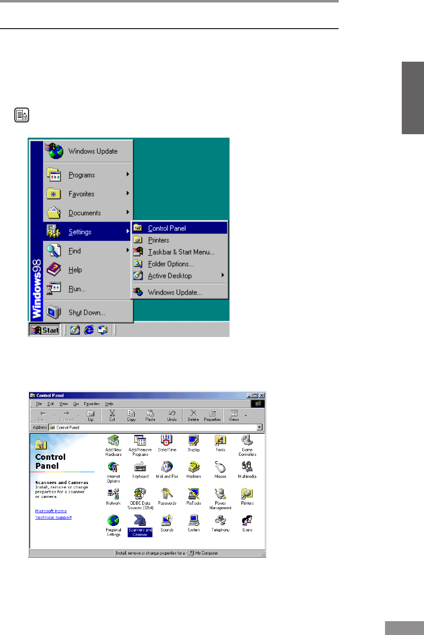
Regular Maintenance 65
ENGLISH
Resetting the Counter
After replacing the feed rollers, reset the counter according to the following
procedure.
1
Click the [Start] button, point to [Settings], and then click [Control Panel].
Note
If you are using Windows XP, on the Start menu, click [Control Panel].
The [Control Panel] window is displayed.
2
Double-click the [Scanners and Cameras] icon.
The [Scanners and Cameras Properties] dialog box is displayed.
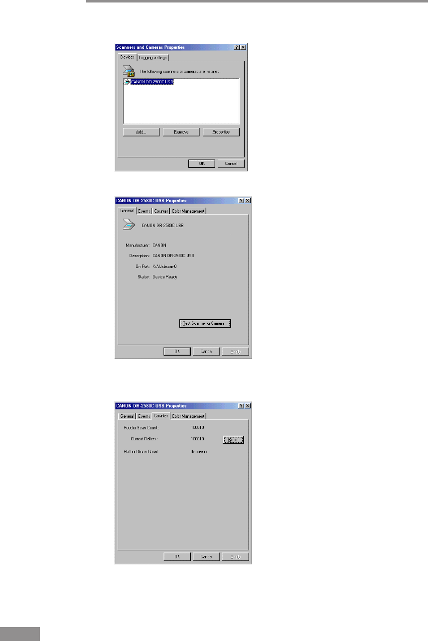
66 Regular Maintenance
3
Click on [Properties] for the scanner you are using.
4
Click the [Counter] tab.
5
Press the [Reset] button, and then make sure that the counter for the roller
being used is set to 0.
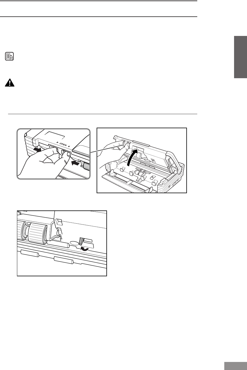
Regular Maintenance 67
ENGLISH
Removing and Attaching the Roller Unit
Follow the procedure below to remove and attach the roller unit for cleaning
or replacement.
Note
When attaching the Roller Unit during installation, operate the roller fastening
lever according to the removal procedure and then attach the Roller Unit.
CAUTION
Do not use excessive force when removing or attaching the
rollers. Doing so may damage them.
Removing the Roller Unit
1
Pressing the OPEN Knob from both sides, raise the Upper Unit.
2
Move the roller lock lever towards you.
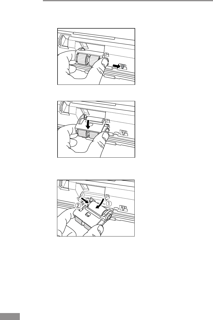
68 Regular Maintenance
3
Supporting the roller unit with your hand, slide the roller lock lever to the
right.
4
Lower the roller unit.
5
First detach the right side of the roller unit (q), and then remove the roller
unit (w).
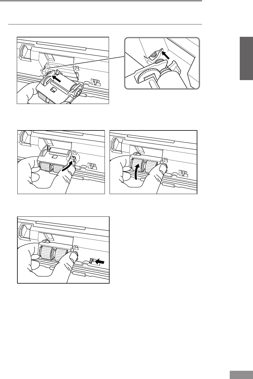
Regular Maintenance 69
ENGLISH
Attaching the Roller Unit
1
Set the roller unit onto the scanner's shaft.
2
Insert the protrusion of the roller unit into the groove in the scanner, and then
lift the roller unit.
3
Slide the roller lock lever to the left.
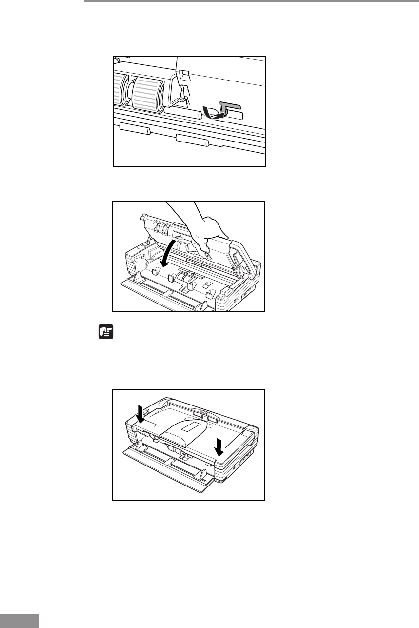
70 Regular Maintenance
4
Push the roller lock lever towards the back of the scanner to lock the roller
unit in place.
5
Close the Upper Unit slowly.
IMPORTANT
Do not force the Upper Unit to close. Doing so may damage the scanner.
6
Be sure that the Upper Unit is completely closed by pushing on both edges
with both hands until you hear a click.
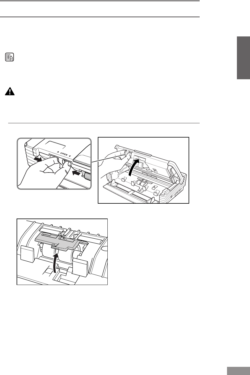
Regular Maintenance 71
ENGLISH
Removing and Attaching the Retard Roller
Follow the procedure below to remove and attach the retard roller for cleaning
or replacement.
Note
When attaching the Retard Roller during installation, operate the roller
fastening lever according to the removal procedure and then attach the Roller
Unit.
CAUTION
Do not use excessive force when removing or attaching the
rollers. Doing so may damage them.
Removing the Retard Roller
1
Pressing the OPEN Knob from both sides, raise the Upper Unit.
2
Remove the roller cover.
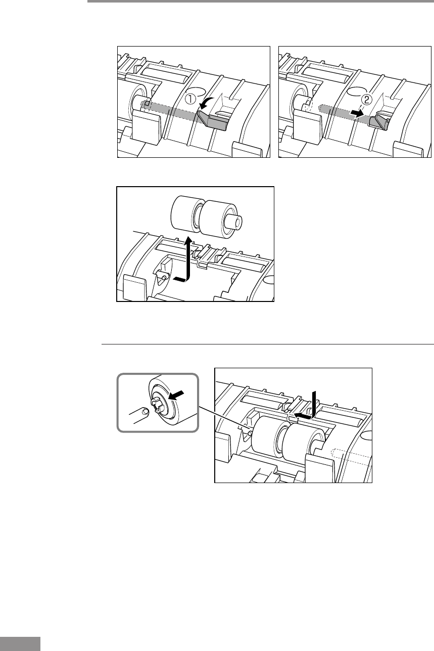
72 Regular Maintenance
3
Move the roller lock lever upward (q), and then slide it to the right (w).
4
Shift the retard roller to the right to remove it.
Attaching the Retard Roller
1
Position the retard roller so the notch in the roller is facing the scanner's shaft.
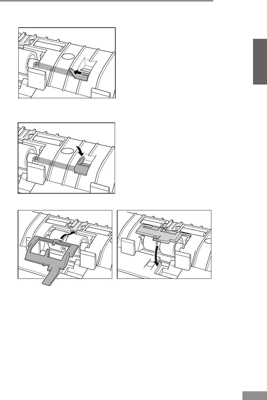
Regular Maintenance 73
ENGLISH
2
Slide the roller lock lever to the left, and insert it into the retard roller hole.
3
Push the roller lock lever towards the back of the scanner to lock the retard
roller in place.
4
Attach the roller cover.
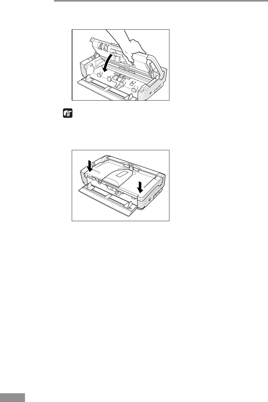
74 Regular Maintenance
5
Close the Upper Unit slowly.
IMPORTANT
Do not force the Upper Unit to close. Doing so may damage the scanner.
6
Be sure that the Upper Unit is completely closed by pushing on both edges
with both hands until you hear a click.

Troubleshooting 75
ENGLISH
Troubleshooting
This section describes common problems that may occur while you are using
the scanner, and how to resolve them.
Refer to the troubleshooting section related to the problem that you have
encountered.
The Scanner Does Not Turn ON ................................................. p. 75
The PC Does Not Recognize the Scanner ................................. p. 76
Scanning Is Slow ......................................................................... p. 76
Images Are Not Scanned............................................................. p. 77
Documents Do Not Feed Properly.............................................. p. 77
Resulting Scanned Images Are Not Correct ............................. p. 78
The Flatbed Scanner (Option) Does Not Work .......................... p. 79
If after consulting the above section you still cannot resolve the problem,
contact your local authorized Canon dealer or your service representative.
The Scanner Does Not Turn ON
Check the following:
• Is the power switch in the ON position? (See p. 23.)
• Is the Power Cord plugged into an outlet? (See p. 21.)

76 Troubleshooting
The PC Does Not Recognize the Scanner
The following are possible causes of the PC failing to recognize the scanner.
Check each possible cause.
Cause The scanner is not connected correctly.
Remedy Check the USB cable connections between the scanner and the
PC. (See p. 22.)
Cause The USB 2.0 interface card is not inserted in the PC
correctly.
Remedy Reseat the USB 2.0 interface card in the PC correctly, referring to
the instruction manual for the USB 2.0 interface card. Also,
confirm whether the USB interface card is recognized by the
operating system you are using.
Cause The scanner is not ON.
Remedy Refer to “The Scanner Does Not Turn On,” on p. 75 and make
sure that the scanner is turned ON. If the scanner is not turned
ON, turn it ON. (See p. 23.)
Cause The USB 2.0 interface card does not support the scanner.
Remedy Use the recommended USB 2.0 interface card. (See p. 20.)
Cause The scanner does not support the USB cable.
Remedy Use the USB cable provided with the scanner. (See p. 22.)
Cause The scanner does not support the USB HUB.
Remedy Remove the USB HUB to use the scanner. (See p. 22.)
Scanning Is Slow
The following problems might cause the scanner to be slow. Try the solutions
according to the problem.
Cause The USB 2.0 interface card does not support Hi-Speed 2.0.
Remedy Use the recommended USB 2.0 interface card. (See p. 20.)
Cause The USB 2.0 interface cable does not support Hi-Speed 2.0.
Remedy Use the USB cable provided with the scanner. (See p. 22.)
Cause The USB HUB does not support Hi-Speed 2.0.
Remedy Remove the HUB or replace it with one that supports
HI-Speed 2.0. (See p. 22.)

Troubleshooting 77
ENGLISH
Images Are Not Scanned
Check the following if the scanner does not scan an image even though the
scanning operation is being performed:
• Is the scanner correctly connected to the PC?
• Has the scanner driver been installed?
• Has the application software been installed correctly? Has the application
software been set up correctly?
• Is there a problem in the PC system?
• Is the flatbed scanner unit (option) correctly attached?
Note
• When system errors result in the scanner not functioning at all, turn OFF
the scanner and wait at least ten seconds before turning it back ON.
• Make sure that the last document scanned was scanned correctly when
scanning continues.
• When using the flatbed scanner unit (option), make sure that the flatbed
scanner unit is correctly attached to the DR-2580C before scanning.
Scanning cannot be done if the flatbed scanner unit is not correctly attached
to the DR-2580C.
Documents Do Not Feed Properly
The following are possible causes of a document failing to feed properly.
Check each possible cause.
Cause Attempting to scan a document of a size, thickness, or
weight that the scanner cannot scan.
Remedy Check the size, thickness, and weight of the document. For
precautions concerning documents, see “Documents,” on p. 43.
Cause The rollers inside the scanner are dirty or worn.
Remedy Refer to page 61 and clean the rollers. If the rollers are worn,
then they need to be replaced. Contact your local authorized
Canon dealer or service representative to purchase a roller
replacement kit.
For details on how to clear jammed paper, see “Clearing a Paper Jam,” on
p. 55.

78 Troubleshooting
Resulting Scanned Images Are Not Correct
If the resulting scanned images are not crisp, if there are lines or spots on the
images, or if there is some other problem with scanned images, likely causes
are listed below. Check each item and take the appropriate action.
Cause The sensor glass or the rollers inside the scanner are dirty.
Remedy Clean the sensor glass and rollers as described on p. 61.
Cause The scanner’s internal platen glass is scratched.
Remedy Contact your local authorized Canon dealer or service
representative.
Cause The application software is not set up properly for
scanning.
Remedy Check the scanning related settings, such as brightness in the
application software.
For example, if the document cannot be scanned at all, it is
possible that the brightness setting is too high. If the resulting
scanned images are too dark, it is possible that the brightness
setting is too low.
Cause The scanner driver or application software is not running
normally.
Remedy If the software is set properly for scanning and scanning is still
not possible, it is possible that the scanner driver or the
application software is not running normally. Reinstall the
scanning driver or the application software. For details on how to
install the scanner driver, see “Installing the ISIS/TWAIN
Driver,” on p. 28. For details on how to install the application
software, refer to the application software instruction manual.
Cause Attempting to use a function of the DR-2580C that is not
supported by the application software.
Remedy Some application software may not support certain functions,
such as automatically detecting the paper size or changing the
scanning mode/resolution through the scan panel. Using such
application software for scanning may yield abnormal scanning
results. Try scanning without using functions such as automatic
paper size detection or margins settings.
If problems with the scanned images persist even after trying these solutions,
then contact your local authorized Canon dealer or service representative.

Troubleshooting 79
ENGLISH
The Flatbed Scanner (Option) Does Not Work
Operational failure of the optional flatbed scanner unit can be caused by any
of the reasons described below. Try the solution according to the problem.
Cause The ISIS/TWAIN scanner is set to something other than
Flatbed.
Remedy Set the ISIS/TWAIN driver to Flatbed. Refer to Help for the
ISIS/TWAIN Driver for information about the ISIS/TWAIN
Driver settings.
Cause The interface connector is not connected.
Remedy Check the connections between the DR-2580C and the flatbed
scanner unit.
Cause The DR-2580C is not installed correctly.
Remedy Check the document size, thickness, and paper type. Remove the
DR-2580C scanner and then reinstall it correctly.
Cause The hook is not correctly attached to the DR-2580C.
Remedy Remove the DR-2580C scanner and then reinstall it correctly.
Cause The DR-2580C scanner was installed without removing the
transport locks.
Remedy Remove the DR-2580C scanner and remove the transport locks.
For information about removing the flatbed scanner unit, see the manual that
comes with it.

80 Specifications
Specifications
Type Desktop sheetfed scanner
Scanning Document Specifications
Width: 53 mm to 216 mm
Length: 70 mm to 355.5 mm
Weight: Using the U-Turn Path
(separated documents) 52 to 128 g/m2(0.06 mm to 0.15 mm)
(nonseparated documents) 42 to 157 g/m2(0.05 mm to 0.2 mm)
Weight: Using the Straight Path
(separated documents) 42 to 157 g/m2(0.05 mm to 0.2 mm)
(nonseparated documents) 42 to 157 g/m2(0.05 mm to 0.2 mm)
Business cards are supported (excluding embossed cards).
Size: 53.9 mm x 85.5 mm
Thickness: 0.76 ± 0.08 mm
Document Feeding Method Automatic/Manual
Scanning Method Contact image sensor
Light Source LED
Scanning Side Simplex/Duplex/flatbed (option)
Scanning Modes Black and white, Advanced text enhancement,
Error diffusion, 256-level grayscale, 24 bit color
Scanning Resolution 100 x 100 dpi, 150 x 150 dpi, 200 x 200 dpi
(Primary Scan Lines x Secondary Scan Lines)
240 x 240 dpi, 300 x 300 dpi, 400 x 400 dpi
600 x 600 dpi
Scanning Speed A4
Black and White Simplex
200 x 200 dpi 25 pages/minute
300 x300 dpi 25 pages/minute
600 x 600 dpi 6 pages/minute
Duplex
200 x 200 dpi 50 images/minute
300 x 300 dpi 50 images/minute
600 x 600 dpi 12 images/minute
256-level Gray Simplex
200 x 200 dpi 25 pages/minute
300 x 300 dpi 25 pages/minute
600 x 600 dpi 6 pages/minute
Duplex
200 x 200 dpi 50 images/minute
300 x 300 dpi 50 images/minute
600 x 600 dpi 12 images/minute

Specifications 81
ENGLISH
Amount of paper that can be 5 mm stack, maximum
stacked in automatic feeder (50 sheets of 80 g/m2)
Interface Hi-Speed USB 2.0
Other Functions Blank page skip, job function, folio scan
Dimensions (with trays close) 81 mm x 302mm x 171 mm (W x D x H)
Dimensions (with trays open) 136 mm x 302 mm x 267 mm (W x D x H)
Weight Approximately 1.9 kg
5.7 kg with flatbed scanner unit
Power Supply DC 16 V 1.4 A
Power Consumption Scanning: 19 W maximum
27 W maximum
(with Flatbed Scanner Unit)
Standby: 6 W
Power SW OFF: 0.5 W
Noise Not more than 66 dB
Operating Environment Temperature: 10˚ C to 32.5˚ C
Humidity: 20 % to 80 % RH
AC Adaptor (100 - 240V)
Model MG1-3607
Input AC 100-240 V 50/60 Hz 0.65-0.34 A
Output DC 16 V 1.8 A
Power Supply 0.5 W max. (separate AC adaptor)
Weight Approximately 0.3 kg (including Power Cord)
24-bit Color Simplex
200 x 200 dpi 13 pages/minute
300 x 300 dpi 8 pages/minute
600 x 600 dpi 2 pages/minute
Duplex
200 x 200 dpi 26 images/minute
300 x 300 dpi 16 images/minute
600 x 600 dpi 4 images/minute

82 Specifications
Options
Flatbed Scanner Unit (Model: 0106B001)
Flatbed Scanner Unit for the DR-2580C scanner.
Bar code module (product code: 0434B003)
Additional software to allow the ISIS/TWAIN driver to recognize bar codes.
• Contact your local authorizde Canon dealer or service representative for detailed
information about the options.
Replacement Parts
Roller replacement kit (product code: 0106B002)
Kit to replace the feed rollers (roller unit and retard roller).
• Refer to “Removing and Attaching the Rollers,” on p. 65 for information about replacing
the rollers.
• Contact your local authorized Canon dealer or service representative for detailed
information about the replacement parts.
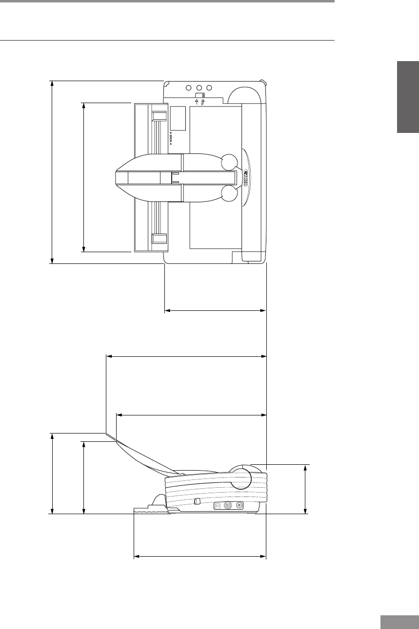
Specifications 83
ENGLISH
External Dimensions
Units: millimeters
267
243
171
125
136
217
81
249
302 (Excluding protrusions)
(Document Eject Tray Extension2 is open)
(Document Eject Tray Extension is open)

84 Index
Index
A
AC adapter .................................................. 5
C
CaptuerPerfect
Install .................................................... 31
Uninstall ............................................... 34
Using .................................................... 40
Checking the Packing List ........................ 10
Cleaning
Glass ..................................................... 61
Inside .................................................... 60
Scanner ................................................. 60
D
Document Eject Opening ......................... 16
Document Eject Tray .......................... 15, 47
Document Eject Tray Extension ......... 15, 48
Document Eject Tray Extension2 ....... 15, 48
Document Feed Tray .......................... 15, 45
Document Guide Adapter ......................... 46
Document Guides ..................................... 15
Documents ................................................ 43
E
Eject Selection Lever .......................... 16, 48
F
Features ...................................................... 8
Feed Selection Lever ................................ 15
Feed with the Bypass mode ...................... 53
Feed with the Page Separation mode........ 50
Flatbed Scanner Unit ................................ 59
I
Installation Requirements ......................... 17
Interface Cards.......................................... 20
ISIS/TWAIN Driver
Install .................................................... 28
Uninstall ............................................... 34
Using .................................................... 37
J
Job Buttons ............................................... 15
Job Function ............................................. 58
Job Label ............................................ 16, 39
Job Tool
Using .................................................... 38
K
Kensington Slot ........................................ 16
N
Names of Parts .......................................... 15
Notes Concerning Disposal ........................ 7
Notes on Normal Handling ......................... 6
O
OPEN Knob .............................................. 15
Option Connector ..................................... 16
P
Paper Jam ................................................. 55
Placing a Document for Scanning ............ 50
Power connector ....................................... 16
Power Indicator ........................................ 15
Power Switch ............................................ 16
R
Regular Maintenance ................................ 60
Retard Roller ............................................ 71
Roller
Replacement Cycle .............................. 64
Resetting the Counter ........................... 65
Roller Unit ................................................ 67
S
Scanner
Preparation ........................................... 45
Installation Procedure .......................... 19
Recognizing ......................................... 24
Straight Path ............................................. 49
Scanning Folio .......................................... 59
Specifications ........................................... 80
AC Adaptor .......................................... 81
External Dimensions ............................ 83
Options ................................................. 82
Replacement Parts ................................ 82
Scanner ................................................. 80
T
Troubleshooting ........................................ 75
U
Upper Unit ................................................ 15
USB Connector ......................................... 16
U-Turn Path .............................................. 48
