DS_USB2 F 5001_ES_000017_ D 5001 ES DS USB2 5001(ES 000017)
User Manual: D 5001 ES
Open the PDF directly: View PDF ![]() .
.
Page Count: 27

EasySync Ltd
Unit 1, 2 Seaward Place, Centurion Business Park, Glasgow, G41 1HH, United Kingdom
Tel.: +44 (0) 141 418 0181 Fax: + 44 (0) 141 418 0110
E-Mail (Support): support@easysync.co.uk Web: http://www.easysync.co.uk
Neither the whole nor any part of the information contained in, or the product described in this manual, may be adapted or reproduced
in any material or electronic form without the prior written consent of the copyright holder. This product and its documentation are
supplied on an as-is basis and no warranty as to their suitability for any particular purpose is either made or implied. EasySync Ltd will
not accept any claim for damages howsoever arising as a result of use or failure of this product. Your statutory rights are not affected.
This product or any variant of it is not intended for use in any medical appliance, device or system in which the failure of the product
might reasonably be expected to result in personal injury. This document provides preliminary information that may be subject to
change without notice. No freedom to use patents or other intellectual property rights is implied by the publication of this document.
EasySync Ltd, Unit 1, 2 Seaward Place, Centurion Business Park, Glasgow, G41 1HH, United Kingdom. Scotland Registered Number:
SC224924
Copyright © 2009 EasySync Limited
The USB-COM-Plus adaptors are a family of communication devices from EasySync Ltd. This model,
USB2-F-5001, provides a simple method of adapting legacy serial devices with RS485 interfaces to
modern USB ports by incorporating the FTDI FT232R bridge chip.
A power supply output of +5VDC @ up to 250mA is available on the 9-pin D-sub connector.
Indicator LEDs provide functional status.
had
EasySync Ltd
USB2-F-5001 Full-Speed USB to 1-Port
RS485 Adapter
Data Sheet
Document Reference No.: ES_0000177
Version 1.02
Issue Date: 2009-08-24

Document Reference No.: ES_000017
USB2-F-5001 Full-Speed USB to 1-Port RS485 Adapter Data Sheet Version 1.02
Clearance No.: ES
#08
©2009 EasySync Ltd.
2
1 Introduction ................................................................................... 4
1.1
Functional Description .................................................................................. 4
1.2
LED Description ............................................................................................. 5
1.3
Block Diagram ............................................................................................... 5
1.3.1
Block description ....................................................................................... 5
1.4
Features ........................................................................................................ 6
1.5
Performance Figures ..................................................................................... 6
1.6
Ordering Information .................................................................................... 7
2 Installation ..................................................................................... 8
2.1
Example Applications and Configurations ..................................................... 8
2.2
Hardware Installation ................................................................................... 8
2.2.1
Mounting .................................................................................................. 8
2.2.2
Wiring ...................................................................................................... 8
2.3
Device Driver Installation ........................................................................... 10
2.3.1
Microsoft Windows ....................................................................................10
2.3.2
Mac OS X, Linux, Windows CE ....................................................................13
2.4
Local Echo ................................................................................................... 13
3 Connections .................................................................................. 14
3.1
External Connectors .................................................................................... 14
3.1.1
USB ........................................................................................................14
3.1.2
RS485 .....................................................................................................15
4 Electrical details ........................................................................... 16
4.1
USB ............................................................................................................. 16
4.2
RS485 ......................................................................................................... 17
4.3
Power Output .............................................................................................. 17
5 Mechanical Details ........................................................................ 18
5.1
Module Mechanical Dimensions ................................................................... 18
5.2
UniClip™ Mechanical Dimensions ................................................................ 19
6 Physical Environment Details ....................................................... 20
6.1
Storage ....................................................................................................... 20
6.2
Operating .................................................................................................... 20
7 Environmental Approvals & Declarations ...................................... 21
7.1
EMI Compatibility ........................................................................................ 21
7.2
Safety ......................................................................................................... 21
7.3
Environmental ............................................................................................. 21

Document Reference No.: ES_000017
USB2-F-5001 Full-Speed USB to 1-Port RS485 Adapter Data Sheet Version 1.02
Clearance No.: ES
#08
©2009 EasySync Ltd.
3
7.4
Reliability .................................................................................................... 21
7.4.1
MTTF ......................................................................................................21
7.5
Import / Export Information ....................................................................... 22
8 Troubleshooting ........................................................................... 23
8.1
Hardware .................................................................................................... 23
8.2
Device Driver .............................................................................................. 23
8.3
Technical Support ....................................................................................... 23
9 Contact Information ..................................................................... 25
Appendix A - List of Figures and Tables ............................................. 26
Appendix B - Revision History ............................................................ 27
Document Reference No.: ES_000017
USB2-F-5001 Full-Speed USB to 1-Port RS485 Adapter Data Sheet Version 1.02
Clearance No.: ES
#08
©2009 EasySync Ltd.
4
1 Introduction
1.1 Functional Description
The USB-COM-Plus adaptors are a family of communication devices. This model, USB2-F-5001, provides
a simple method of adapting legacy serial devices with RS485 interfaces to modern USB ports. This is
accomplished by incorporating the industry standard FTDI FT232R USB-Serial bridge chip.
Each USB2-F-5001 adapter contains a small internal electronic circuit board which utilises the FTDI
FT232R, mounted inside a rugged plastic enclosure capable of withstanding industrial temperature
ranges. The integrated electronics also include RS485 level shifters and TXD/RXD LEDs to provide a
visual indication of data traffic through the adapter.
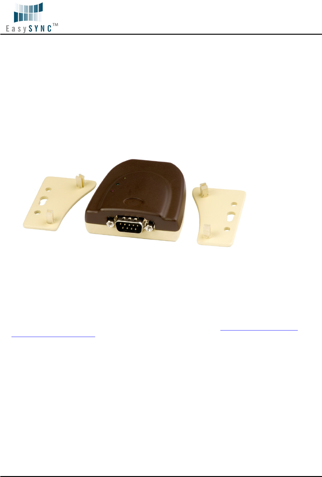
Figure 1.1 USB-COM-Plus USB2-F-5001
Flexible mounting allows the USB2-F-5001 to be used in a variety of applications, from a portable adapter
to accompany a laptop to permanent installations in industrial, commercial and retail locations.
The enclosure incorporates a standard USB-B client connector for connection to an upstream host or hub
port. RS485-level signals, are available on an industry-standard DE-9P connector. The maximum
RS485-level data rate is 1Mbps.
The USB2-F-5001 adapter require USB device drivers, available free from http://www.easysync.co.uk or
http://www.easysync-ltd.com, which are used to make the USB2-F-5001 appear as a Virtual COM Port
(VCP). This allows existing serial communications software, such as HyperTerminal, to exchange data
through the USB2-F-5001 to a legacy RS485 peripheral device.
Pin 9 of the D-sub connector can provide +5V power output with maximum 450mA.
Document Reference No.: ES_000017
USB2-F-5001 Full-Speed USB to 1-Port RS485 Adapter Data Sheet Version 1.02
Clearance No.: ES
#08
©2009 EasySync Ltd.
5
1.2 LED Description
The USB2-F-5001 uses three LEDs to indicate a valid link as well as data traffic according to the following
table:
LED Color Function Description
Yellow Enumerated ON when USB2-F-5001 is configured and ready
Green TxD Activity Flashes when data is transmitted from the USB2-F-5001
to the attached
RS485 device
Red RxD Activity Flashes when data is transmitted from the attached RS485 device to the
USB2-F-5001
Table 1.1 – LED Description
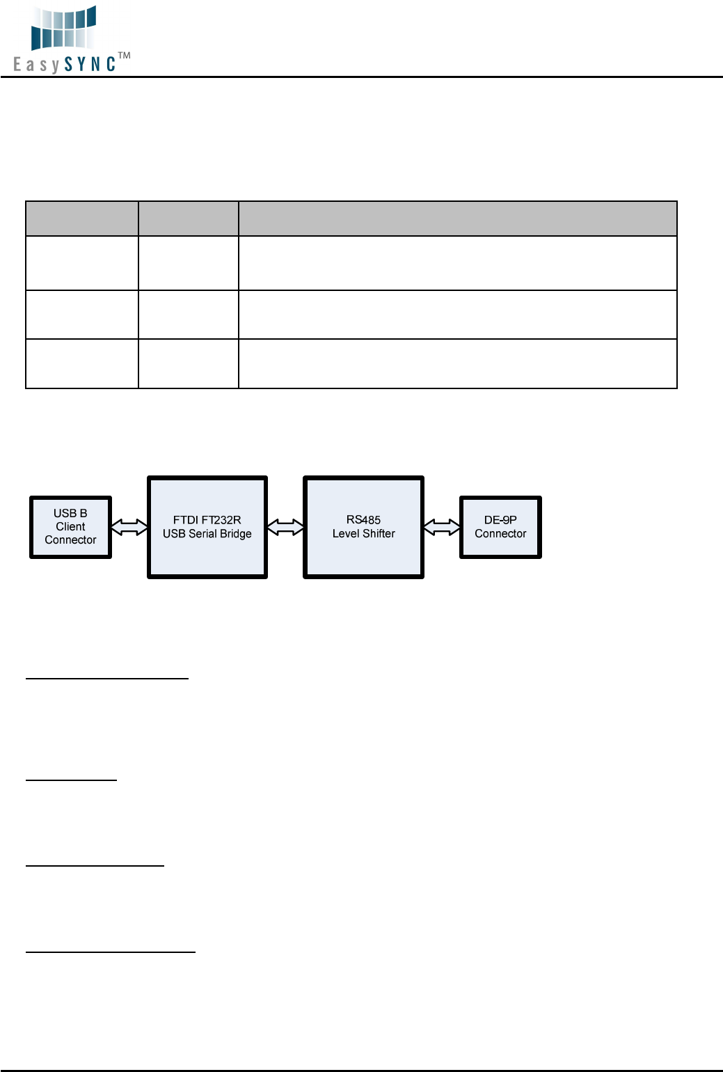
1.3 Block Diagram
Figure 1.2 USB2-F-5001 Block Diagram
1.3.1 Block description
USB B Client Connector
This connector provides the interface for connection to a USB Host or Hub port. A standard “A to B”
cable is provided, though one of a different length may also be used. The maximum cable length is 5
meters, according to the USB 2.0 specification.
FTDI FT232R
The FTDI FT232R provides the USB-to-Serial conversion. Operating system device drivers are required in
order to work with the FT232R to provide the Virtual COM Port serial functionality.
RS485 Level Shifter
The RS485 level shifter converts the signals provided by the FT232R into the voltage levels required by
RS485 devices.
DE-9P Connector (Male)
The DE-9P connector is configured in an industry standard (TIA/EIA-485) pin-out to provide connection
to RS485 peripherals through standard cables. See section 3.1.2

Document Reference No.: ES_000017
USB2-F-5001 Full-Speed USB to 1-Port RS485 Adapter Data Sheet Version 1.02
Clearance No.: ES
#08
©2009 EasySync Ltd.
6
1.4 Features
• Adds one RS-485 serial port by connecting to USB
• Easy plug & play installation and RS-485 device connection
• Works with USB 1.1 & 2.0 Host and Hub ports
• Industry Standard FTDI chip set & device drivers for maximum compatibility
• Microsoft Windows
®
WHQL-certified, Mac OS X, Linux and Windows CE device drivers
• Installs as a standard Windows COM port
• COM port number can be changed to any available COM port number, to support HyperTerminal,
or any other serial communications software application running in Windows
• Supports Windows Server 2008, 2003, Vista, XP, 2000, Linux, Mac OS X
• FIFO: 128 byte transmit buffer, 256 byte receive buffer
• RS-485 data signals: Data+, Data-, GND
• Powered by USB port. No external power adapter required.
• Pin 9 of DE-9P can provide +5VDC output at 450mA
• Serial port speed up to 3Mbps
• Serial Communication Parameters
o Parity: None, Even, Odd
o Data bits: 7, 8
o Flow control: None
• One DE-9P male connector
• LEDs indicate USB Enumeration, RxD, TxD for monitoring port status & easy diagnostics
• High-temperature plastic enclosure
• Operating temperature of -40°C to +85°C
• USB cable of 0.9 meter included
1.5 Performance Figures
Parameter Performance
USB Interface 12Mbps USB 2.0 Full-Speed
RS485 Interface
Standard Windows baud rates (300bps to 921.6Kbps)
Custom baud rates (300bps to 3Mbps) through baud rate aliasing. See
FTDI Application Note: Configuring FT232R, FT2232 and FT232BM Baud
Rates
Table 1.2 - Performance Figures

Document Reference No.: ES_000017
USB2-F-5001 Full-Speed USB to 1-Port RS485 Adapter Data Sheet Version 1.02
Clearance No.: ES
#08
©2009 EasySync Ltd.
7
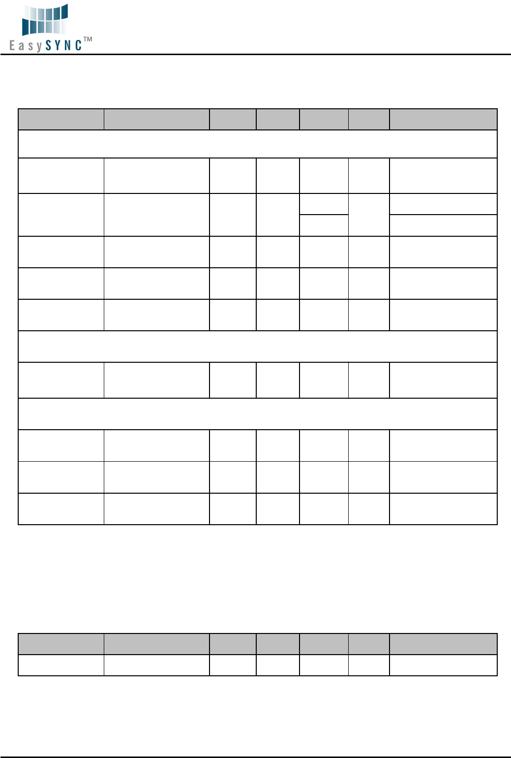
1.6 Ordering Information
Part Number Description
USB2-F-5001 USB-COM-Plus Full-Speed USB to 1-Port RS485 Adapter
Table 1.3 - Ordering Information
Document Reference No.: ES_000017
USB2-F-5001 Full-Speed USB to 1-Port RS485 Adapter Data Sheet Version 1.02
Clearance No.: ES
#08
©2009 EasySync Ltd.
8
2 Installation
2.1 Example Applications and Configurations
2.2 Hardware Installation
There are no switches or jumpers to configure on the USB-COM-Plus USB2-F-5001.
2.2.1 Mounting
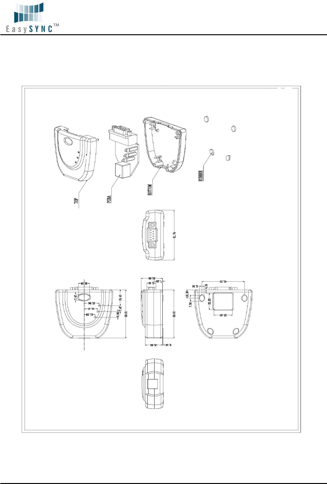
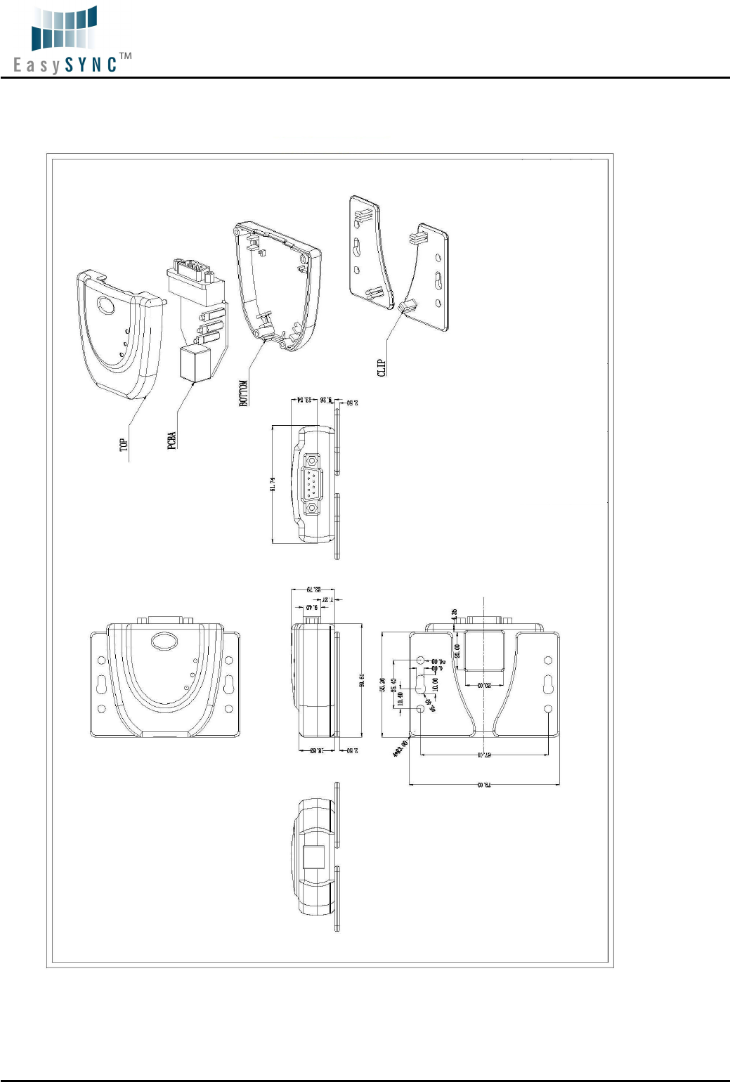
The USB2-F-5001 is provided with two mounting options: UniClip™ Wall/DIN rail mount and rubber feet.
The UniClip Wall/DIN rail mount allows the USB2-F-5001 to be permanently mounted to a wall or
attached to a DIN rail. The rubber feet can be used when mobility or desktop use is desired. NOTE: The
UniClip provides a permanent mounting style. The USB2-F-5001 case may be damaged if the UniClip is
removed.
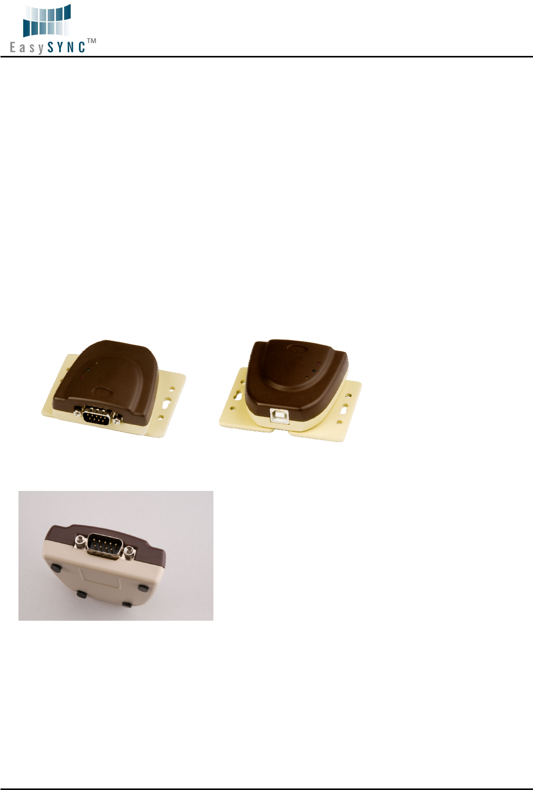
The following figures indicate various mounting styles.
Figure 2.1 - USB2-F-5001 with UniClip Brackets
Figure 2.2 - USB2-F-5001 with Rubber Feet
2.2.2 Wiring
A standard 0.9m USB “A” to “B” cable is provided.
Insert the A-plug into an available USB Host or Hub port. Insert the B-plug into the B-receptacle on the
USB2-F-5001.
Document Reference No.: ES_000017
USB2-F-5001 Full-Speed USB to 1-Port RS485 Adapter Data Sheet Version 1.02
Clearance No.: ES
#08
©2009 EasySync Ltd.
9
DTE Pin Number Signal Name
Expected Connect Signal
1 DATA- = Transmit/Receive
Data, negative polarity
Also Terminator 2
DATA-
Pin 2 of 120R Terminating Resistor. Only Required if the
USB-COM485-PLUS1 is the first or last device in a multi-drop
RS485 System, to meet RS485 Termination Requirements.
2 DATA+ = Transmit/Receive
Data, positive polarity
DATA+
3 Terminator 1 Pin 1 of 120R Terminating Resistor. Only Required if the
USB-COM485-PLUS1 is the first or last device in a multi-drop
RS485 System, to meet RS485 Termination Requirements.
4 N/A N/A
5 GND = RS485 signal ground 5
6 N/A N/A
7 N/A N/A
8 N/A N/A
9 PWR = +5V DC output PWR
Table 2.1 – RS485 DTE to DCE connection with straight-through cable
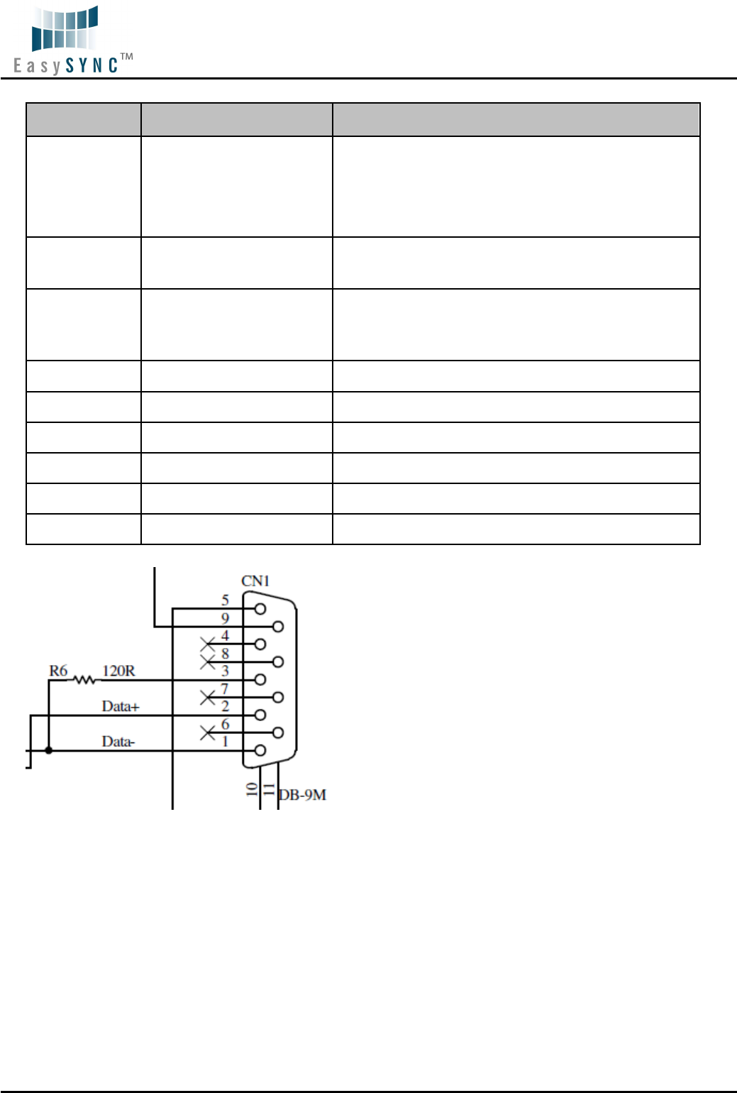
Figure 2.3 USB-COM485-PLUS1 Termination resistor
Document Reference No.: ES_000017
USB2-F-5001 Full-Speed USB to 1-Port RS485 Adapter Data Sheet Version 1.02
Clearance No.: ES
#08
©2009 EasySync Ltd.
10
2.3 Device Driver Installation
The USB2-F-5001 adaptor drivers are available for download from:
http://www.easysync.co.uk – United Kingdom site
http://www.easysync-ltd.com – USA site
2.3.1 Microsoft Windows
With the device drivers being Windows Hardware Quality Labs (WHQL) certified, they are also available
through download directly from the Microsoft
®
Windows
®
Update service. This is the best choice when
connecting the USB2-F-5001 to a computer running Windows Vista. Additional installation options are
noted below:
Installation Executable on Windows XP
1) Login to your system as Administrator, or a user with Administrator rights.
2) Prior to connecting the USB2-F-5001 to the USB Host or Hub port, download the latest device
driver version from the EasySync web site.
3) Run this executable to install the device drivers.
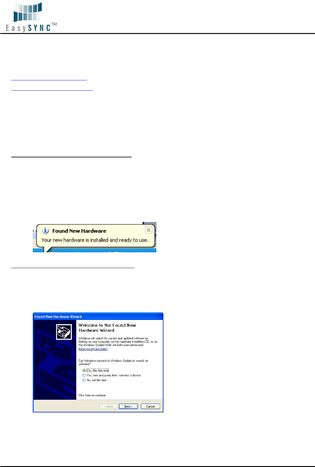
4) Connect the USB2-F-5001 to your computer. A notification will appear near the task bar
indicating that new hardware has been installed and is ready for use. It is normal if this notice
appears twice.
Figure 2.4 - Hardware Ready
Windows Update shown on Windows XP
You must have an active Internet connection and the Windows Update Service enabled.
1) Connect the USB2-F-5001 to your USB Host or Hub.
2) The “Found New Hardware” Wizard will appear. The first dialog should ask whether it is
acceptable to use the Windows Update Service to find the device driver.
Figure 2.5 – Found New Hardware Wizard
3) Select one of the “Yes” choices and click “Next”.
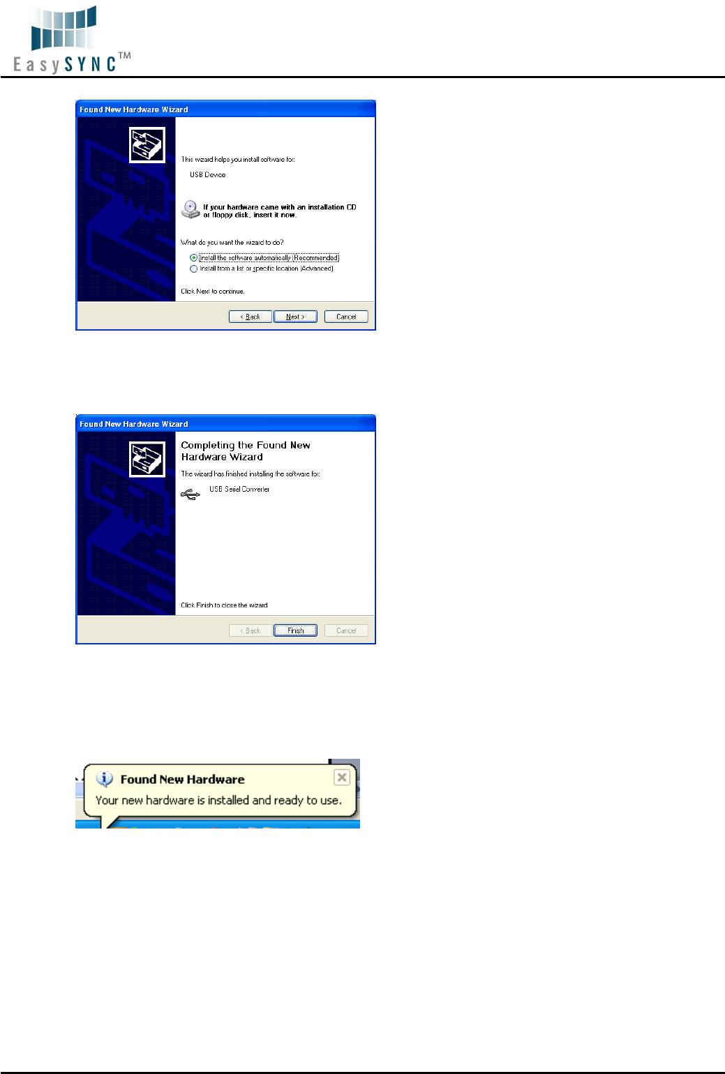
4) The following screen appears:
Document Reference No.: ES_000017
USB2-F-5001 Full-Speed USB to 1-Port RS485 Adapter Data Sheet Version 1.02
Clearance No.: ES
#08
©2009 EasySync Ltd.
11
Figure 2.6 – Automatic Install
5) Wait while the driver is found, downloaded, and installed. This step may take a couple minutes
depending on the Internet speed.
6) After the files are found and installed, click “Finish” to complete the installation.
Figure 2.7 - Complete Hardware Installation
7) Steps 2 through 6 will repeat. The first time installs the basic USB Serial Converter in the USB
device tree. The second time installs the Virtual COM Port layer in the Ports tree and assigns the
COM port number.
8) When both portions of the device driver have been installed successfully, the following message
will appear, indicating that the device is ready.
Figure 2.8 - Hardware Ready
Document Reference No.: ES_000017
USB2-F-5001 Full-Speed USB to 1-Port RS485 Adapter Data Sheet Version 1.02
Clearance No.: ES
#08
©2009 EasySync Ltd.
12
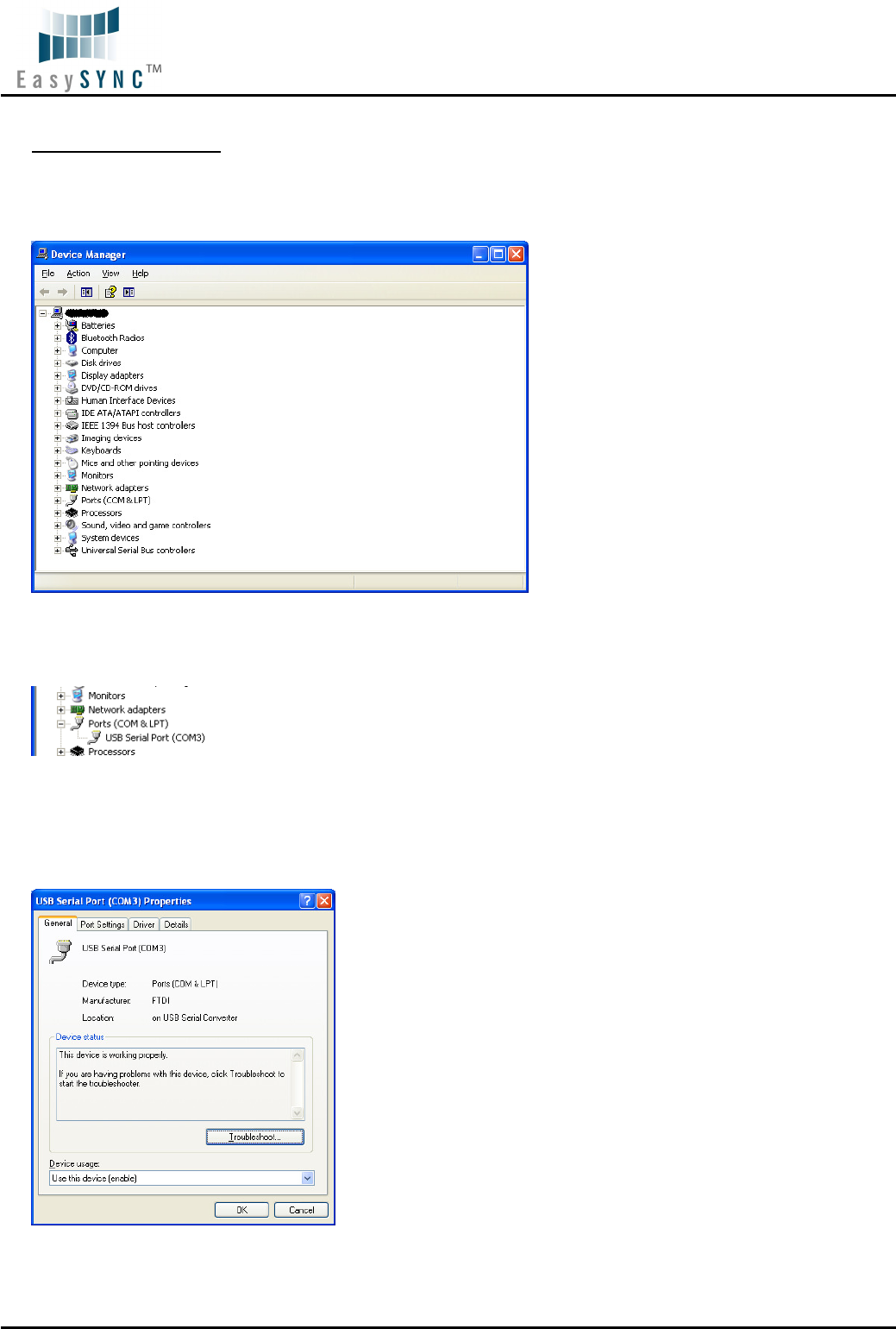
COM Port Assignment
Next, to determine which COM port has been assigned, open the Windows Device Manager from the
System Control Panel.
Figure 2.9 - Device Manager
Click on the Plus “+” sign next to the Ports tree to list the available COM port. You will see “EasySync
USB COM Port”, followed by a COMn assignment. In the figure below, the USB2-F-5001 is assigned to
COM3.
Figure 2.10 - COM Port Assignment
Use this COM port number with your application software in order to access the USB2-F-5001.
If an application requires use of a different COM port number, the assignment may be changed through
the Advanced Driver Options settings.
From the Device Manager listing above, right-click on the EasySync USB COM Port and select Properties.
Figure 2.11 – Access COM Port Properties
Next, click on the “Port Settings” tab.
Document Reference No.: ES_000017
USB2-F-5001 Full-Speed USB to 1-Port RS485 Adapter Data Sheet Version 1.02
Clearance No.: ES
#08
©2009 EasySync Ltd.
13
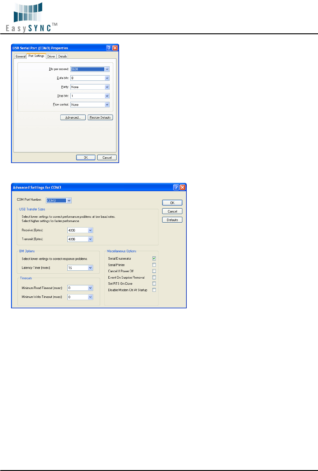
Figure 2.12 - Settings Tab
Then click on the “Advanced…” button.
Figure 2.13 - Advanced Options
This will display the various advanced settings. Note the COM port assignment in the upper left. Clicking
on the drop-down list will display the available port numbers. Select one that is not in use and click OK
on each dialog box to activate the selection. Windows will remember this COM port number.
2.3.2 Mac OS X, Linux, Windows CE
Device drivers and FTDI installation guides for Mac OS X, Linux and Windows CE are available for
download on the EasySync web sites. Follow the respective FTDI installation guides for the chosen
operating system.
2.4 Local Echo
The ability to enable or disable local echo on the RS485 data is controlled by the setting in the FT232R
EEPROM. A free utility is provided to change the configuration. The default is for local echo to be disabled.
Document Reference No.: ES_000017
USB2-F-5001 Full-Speed USB to 1-Port RS485 Adapter Data Sheet Version 1.02
Clearance No.: ES
#08
©2009 EasySync Ltd.
14
3 Connections
3.1 External Connectors
3.1.1 USB
The USB-F-5001 is a downstream USB 2.0 Device. A standard USB Series “B” receptacle is mounted
inside the USB-F-5001 to facilitate connection to an upstream USB Host or Hub.
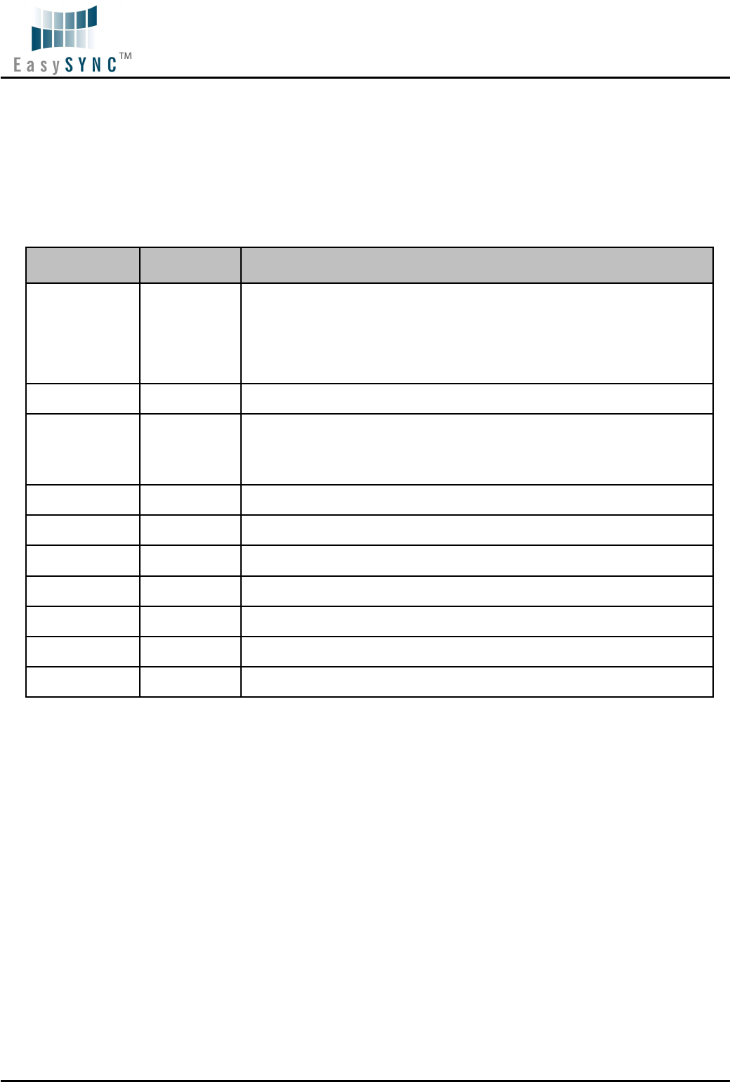
Pin Number
Pin Type Description
1 Power VBUS – USB Power provided from upstream USB Host or Hub
2 Bidirectional D– = USB data signal, negative polarity
3 Bidirectional D+ = USB data signal, positive polarity
4 Ground GND = USB signal ground
Shield Case Ground Drain = typically connected to the host PC case
Table 3.1 – USB "B" Receptacle Pin-Out
Document Reference No.: ES_000017
USB2-F-5001 Full-Speed USB to 1-Port RS485 Adapter Data Sheet Version 1.02
Clearance No.: ES
#08
©2009 EasySync Ltd.
15
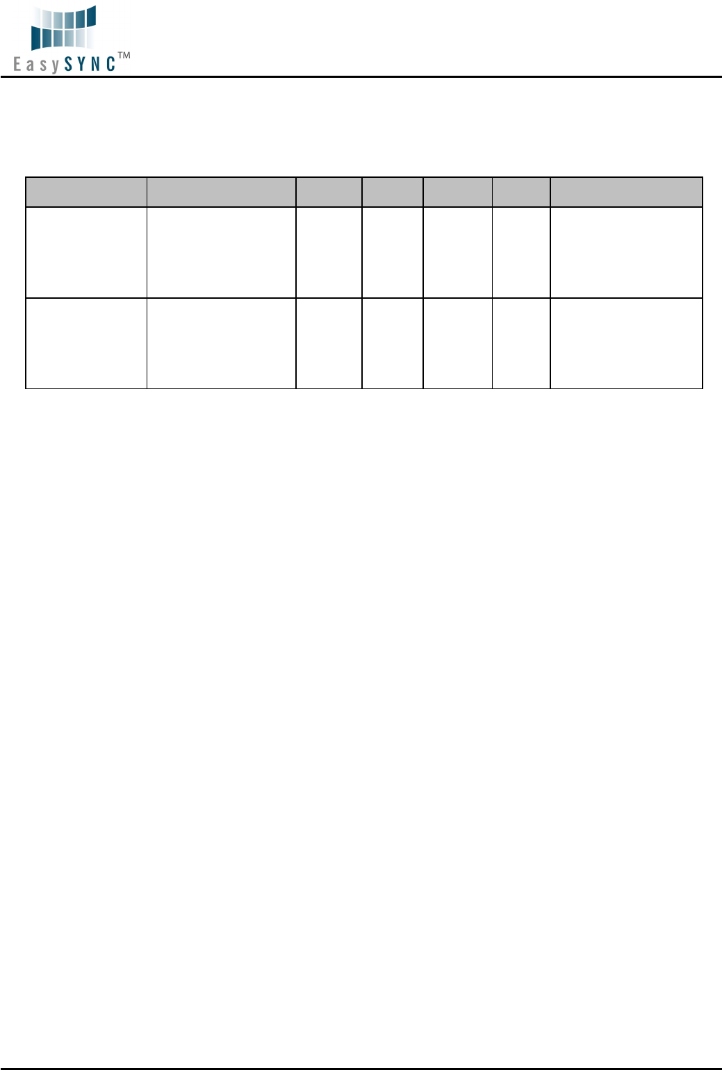
3.1.2 RS485
The RS485 port is configured as Data Terminal Equipment (DTE), with a 9-contact D-Sub Pin connector.
Pin assignments are according to TIA/EIA-485. In addition, Pin9 of this connector can provide +5VDC to
an external device with a maximum current draw of 450mA once the USB2-F-5001 has been enumerated
by the system.
Pin Number
Pin Type Description
1 Input/Output
DATA- = Transmit/Receive Data, negative polarity
Pin 2 of 120R Terminating Resistor. Only Required if the USB2-F-5001 is the
first or last device in a multi-drop RS485 System, to meet RS485 Termination
Requirements.
2 Input/Output DATA+ = Transmit/Receive Data, positive polarity
3 Input/Output
Pin 1 of 120R Terminating Resistor. Only Required if the USB2-F-5001 is the
first or last device in a multi-drop RS485 System, to meet RS485 Termination
Requirements.
4 N/A N/A
5 Ground GND = signal ground
6 N/A N/A
7 N/A N/A
8 N/A N/A
9 Power +5VDC @ 450mA max
Shield Case Ground Drain = typically connected to the host PC case
Table 3.2 – DE-9P RS485 Pin-Out
A 120R Resistor is connected internally between pin 1 and pin 3 of the 9 way D-type connector – see
Figure 2.3
Document Reference No.: ES_000017
USB2-F-5001 Full-Speed USB to 1-Port RS485 Adapter Data Sheet Version 1.02
Clearance No.: ES
#08
©2009 EasySync Ltd.
16
4 Electrical details
4.1 USB
Parameter Description Minimum
Typical Maximum
Units Conditions
USB_VCC Input Power Voltage* 4.25 5.0* 5.25 V
*Present when USB
cable is attached and
USB Host or Hub
powered.
I
cc
USB current*** 30 50 mA
***Does not include
power supplied to
external device
connected to pin 9
Table 4.1 - USB Electrical Details
Document Reference No.: ES_000017
USB2-F-5001 Full-Speed USB to 1-Port RS485 Adapter Data Sheet Version 1.02
Clearance No.: ES
#08
©2009 EasySync Ltd.
17
4.2 RS485
Parameter Description Minimum
Typical Maximum
Units Conditions
Receiver Input
VCM Common-mode input
voltage range
-7 +12 V
IN Input Current
1.0
mA
VIN = +12V
-0.8 VIN = -7V
VTH
Differential Threshold
Voltage,VTH -0.2 +0.2 V
VIHYST Input Hysteresis 20 mV
RIN Input Resistance, RIN 12 15 kΩ
Transmitter Output
VOD
Differential Output
Voltage,
dVOD 1.5 5 V With RL = 54Ω.
CL = 50pF *
ESD Tolerance
ESD HBM
RS485 Inputs and
Outputs
±15
kV
EN61000-4-
2ContactDischarge
RS-485 Inputs and
Outputs
±8
kV
EN61000-4-
2AirGapDischarge
RS-485 Inputs and
Outputs
±15
kV
Table 4.2 – RS485 Electrical Details
4.3 Power Output
The USB2-F-5001 assigns pin9 of DE-9P to provide +5V DC for an external device that requires power.
The maximum allowable current that can be supplied from the USB bus is 500mA, including the circuitry
of the USB2-F-5001 itself. Up to 450mA may be used by the external device.
Parameter Description Minimum
Typical Maximum
Units Conditions
I
O
Output Power Current 0 450 mA USB2-F-5001
Table 4.3 - Power Output Option
Document Reference No.: ES_000017
USB2-F-5001 Full-Speed USB to 1-Port RS485 Adapter Data Sheet Version 1.02
Clearance No.: ES
#08
©2009 EasySync Ltd.
18
5 Mechanical Details
5.1 Module Mechanical Dimensions
Table 5.1 - USB2-F-5001 Case Dimensions
Document Reference No.: ES_000017
USB2-F-5001 Full-Speed USB to 1-Port RS485 Adapter Data Sheet Version 1.02
Clearance No.: ES
#08
©2009 EasySync Ltd.
19
5.2 UniClip™ Mechanical Dimensions
Table 5.2 - USB2-F-5001 Case Dimensions with UniClip
Document Reference No.: ES_000017
USB2-F-5001 Full-Speed USB to 1-Port RS485 Adapter Data Sheet Version 1.02
Clearance No.: ES
#08
©2009 EasySync Ltd.
20
6 Physical Environment Details
6.1 Storage
Parameter
Description Minimum
Typical Maximum
Units Conditions
T Storage Temperature
Range -65 +150
o
C
Table 6.1 - Storage Temperature
6.2 Operating
Parameter
Description Minimum
Typical Maximum
Units Conditions
T Operating Temperature
Range –40 +85
o
C 5% to 95% RH,
non condensing
Table 6.2 - Operating Temperature

Document Reference No.: ES_000017
USB2-F-5001 Full-Speed USB to 1-Port RS485 Adapter Data Sheet Version 1.02
Clearance No.: ES
#08
©2009 EasySync Ltd.
21
7 Environmental Approvals & Declarations
7.1 EMI Compatibility
FCC and CE
The USB2-F-5001 has been tested to be compliant with both FCC Part 15 Subpart B and European EMC
Directive.
NOTE: This is a Class B product. In a domestic environment, this product may cause radio interference,
in which case the user may be required to take adequate measures.
NOTE: This equipment has been tested and found to comply with the limits for a Class B digital device,
pursuant to Part 15 of the FCC Rules. These limits are designed to provide reasonable protection against
harmful interference in a residential installation. This equipment generates, uses and can radiate radio
frequency energy and, if not installed and used in accordance with the instructions, may cause harmful
interference to radio communications. However, there is no guarantee that interference will not occur in a
particular installation. If this equipment does cause harmful interference to radio or television reception,
which can be determined by turning the equipment off and on, the user is encouraged to try to correct
the interference by one or more of the following measures:
• Reorient or relocate the receiving antenna.
• Increase the separation between the equipment and receiver.
• Connect the equipment into an outlet on a circuit different from that to which the receiver is
connected.
• Consult the dealer or an experienced radio/TV technician for help.
7.2 Safety
The USB2-F-5001 is defined as Limited Power Supply (LPS) device, with operating voltages under 60VDC.
7.3 Environmental
The USB2-F-5001 is a lead-free device that complies with the following environmental directives: RoHS,
WEEE, REACH, PFOS and DecaBDE.
7.4 Reliability
The USB2-F-5001 is designed as a robust USB-Serial adapter for use in many environments. There are
no user-serviceable parts. Any failure will require a replacement of the unit.
7.4.1 MTTF
The Mean Time To Failure is calculated at TBD hours.

Document Reference No.: ES_000017
USB2-F-5001 Full-Speed USB to 1-Port RS485 Adapter Data Sheet Version 1.02
Clearance No.: ES
#08
©2009 EasySync Ltd.
22
7.5 Import / Export Information
Import / Export Information
Country of Origin China
Harmonized Code TBD
Product Description USB to RS485 Computer Adapter, Single Port
USA ECCN EAR99 – No License Required
Table 7.1 - Import / Export Information

Document Reference No.: ES_000017
USB2-F-5001 Full-Speed USB to 1-Port RS485 Adapter Data Sheet Version 1.02
Clearance No.: ES
#08
©2009 EasySync Ltd.
23
8 Troubleshooting
8.1 Hardware
Cables are the most common sources of trouble with external devices.
Check the following:
- USB cable is properly inserted at both ends
- Computer power is ON
- Computer is not in Sleep or Standby
- If a USB Hub is used, be sure it is set for “Self-Powered” operation
- If a USB Hub is used, be sure all cables are properly inserted
- If all the above are OK, the Yellow LED should be lit, indicating the device has been recognized by the
USB subsystem.
RS485 cables – check the following:
- Check for specific handshake requirements of your RS485 peripheral.
- Because there is no handshake signals, ensure the application is set to “No Hardware Handshake”, or
equivalent.
8.2 Device Driver
Ensure the latest device driver is in use. See http://www.easysync.co.uk or http://www.easysync-
ltd.com.
If other devices with FTDI chips are installed in the system, check with all manufacturers of these devices
for the latest device drivers.
See the FTDI installation guides for additional details: http://ftdichip.com/Documents/InstallGuides.htm
Common Windows Device Driver Troubles:
• DEVICE TIMES OUT: The default settings of the device driver assume typical data transfers of
hundred to thousands or more bytes at a given time. Some applications, such as a GPS device,
only send data in short packets, often only a few bytes. If this is the case, it may be necessary
to adjust the drivers buffer size and/or latency timer to smaller values. These values can be
adjusted through the Advanced driver options as noted in Figure 2.13. The buffer size can be
reduced to 64 bytes. The latency timer can be set as low as 2ms. A setting of 1ms will cause
unnecessary USB traffic and could adversely affect data transmission.
• ERRATIC MOUSE POINTER: The device driver defaults to query an attached device to find out
whether it is a mouse or modem, consistent with native COM port operation. Some RS485
peripherals constantly send short packets of data, causing the host system to “think” a mouse or
modem has been attached. These short packets will interfere with normal mouse operation
causing the pointer to jump around the screen. If this happens, disconnect the RS485 device and
uncheck the Serial Enumerator option, also found on the Advanced driver options screen in Figure
2.13.
• COM PORT IN USE: Windows keeps track of all COM port assignments. If multiple EasySync
products have been connected to a single system, the COM port number will increase, even if the
other devices are not attached. If the higher COM port assignments are not acceptable for the
application, known unused COM port numbers should be uninstalled according to the FTDI
installation guide: http://ftdichip.com/Documents/InstallGuides.htm.
8.3 Technical Support

Document Reference No.: ES_000017
USB2-F-5001 Full-Speed USB to 1-Port RS485 Adapter Data Sheet Version 1.02
Clearance No.: ES
#08
©2009 EasySync Ltd.
24
Technical support may be obtained from your nearest EasySync office:
United Kingdom: support@easysync.co.uk
United States: support@easysync-ltd.com

Document Reference No.: ES_000017
USB2-F-5001 Full-Speed USB to 1-Port RS485 Adapter Data Sheet Version 1.02
Clearance No.: ES
#08
©2009 EasySync Ltd.
25
9 Contact Information
Head Office – Glasgow, UK
EasySync Limited
Unit 1, 2 Seaward Place,
Centurion Business Park
Glasgow, G41 1HH
United Kingdom
Tel: +44 (0) 141 418 0181
Fax: +44 (0) 141 418 0110
E-mail (Sales) sales@easysync.co.uk
E-mail (Support) support@easysync.co.uk
E-mail (General Enquiries) admin@easysync.co.uk
Web Site URL http://easysync.co.uk
Web Shop URL http://easysync.co.uk
Branch Office – Hillsboro, Oregon, USA
EasySync Limited (USA)
7235 NW Evergreen Parkway, Suite 600
Hillsboro, OR 97123-5803
USA
Tel: +1 (503) 547 0909
Fax: +1 (503) 547 0990
E-Mail (Sales) sales@easysync-ltd.com
E-Mail (Support) support@easysync-ltd.com
E-Mail (General Inquiries) admin@easysync-ltd.com
Web Site URL http://easysync-ltd.com
Web Shop URL http://easysync-ltd.com

Document Reference No.: ES_000017
USB2-F-5001 Full-Speed USB to 1-Port RS485 Adapter Data Sheet Version 1.02
Clearance No.: ES
#08
©2009 EasySync Ltd.
26
Appendix A - List of Figures and Tables
List of Figures
Figure 1.1 USB-COM-Plus USB2-F-5001 ........................................................................................................ 4
Figure 1.2 USB2-F-5001 Block Diagram ......................................................................................................... 5
Figure 2.1 - USB2-F-5001 with UniClip Brackets ........................................................................................... 8
Figure 2.2 - USB2-F-5001 with Rubber Feet ................................................................................................... 8
Figure 2.3 USB-COM485-PLUS1 Termination resistor.................................................................................. 9
Figure 2.4 - Hardware Ready .........................................................................................................................10
Figure 2.5 – Found New Hardware Wizard ...................................................................................................10
Figure 2.6 – Automatic Install ........................................................................................................................11
Figure 2.7 - Complete Hardware Installation ...............................................................................................11
Figure 2.8 - Hardware Ready .........................................................................................................................11
Figure 2.9 - Device Manager ..........................................................................................................................12
Figure 2.10 - COM Port Assignment .............................................................................................................12
Figure 2.11 – Access COM Port Properties .................................................................................................12
Figure 2.12 - Settings Tab ..............................................................................................................................13
Figure 2.13 - Advanced Options ....................................................................................................................13
List of Tables
Table 1.1 – LED Description ............................................................................................................................ 5
Table 1.2 - Performance Figures ..................................................................................................................... 6
Table 1.3 - Ordering Information ..................................................................................................................... 7
Table 2.1 – RS485 DTE to DCE connection with straight-through cable .................................................... 9
Table 3.1 – USB "B" Receptacle Pin-Out .....................................................................................................14
Table 3.2 – DE-9P RS485 Pin-Out..................................................................................................................15
Table 4.1 - USB Electrical Details ..................................................................................................................16
Table 4.2 – RS485 Electrical Details .............................................................................................................17
Table 4.3 - Power Output Option ...................................................................................................................17
Table 5.1 - USB2-F-5001 Case Dimensions ..................................................................................................18
Table 5.2 - USB2-F-5001 Case Dimensions with UniClip ............................................................................19
Table 6.1 - Storage Temperature ...................................................................................................................20
Table 6.2 - Operating Temperature ...............................................................................................................20
Table 7.1 - Import / Export Information.........................................................................................................22

Document Reference No.: ES_000017
USB2-F-5001 Full-Speed USB to 1-Port RS485 Adapter Data Sheet Version 1.02
Clearance No.: ES
#08
©2009 EasySync Ltd.
27
Appendix B - Revision History
Version 1.0 Initial Release 2009-05-22
Version 1.01
Added detail of 120R termination resistor
2009-06-11
Version 1.02
Removed debug suggestion to fit a loopback connector.
Corrected max power available from 450mA to 250mA
Added section 2.4 for local echo
2009-08-24
