DSX9_supplemental_manual DSX9 Supplemental Manual
User Manual: DSX9_supplemental_manual
Open the PDF directly: View PDF ![]() .
.
Page Count: 8
9 Channel 2.4 GHz Computer Radio System
MacGregor Industries
Supplemental Instruction Manual
Binding
It is necessary to programme the receiver to the
transmitter so that the receiver will only recognise
that specific transmitter, ignoring signal from any
other sources. If the receiver is not bound to the
transmitter, the system will not operate. During
binding, the servo's fail-safe positions are stored.
The following sequence describes the binding
procedure for the JR RD921, however, all JR DSM
aircraft receivers are bound in the same way.
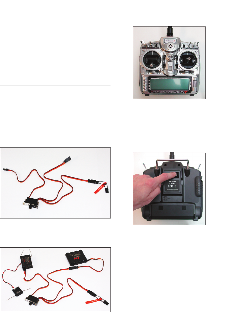
How to Bind
1. With the system hooked up as shown, insert the
bind plug in the charge plug receptable. The
switch must be a 3-wire type switch to enter the
bind mode through the switch. If a
3-wire switch is not available, install the male bind
plug into the charge plug receptable and then
power the receiver through any other open port to
enter bind mode.
2. Turn on the receiver switch. Note that the LED's
on all receivers should be flashing, indicating that
the receiver is ready to bind.
3. Establish the desired fail-safe stick positions:
normally low throttle and flight controls neutral.
4. Press and hold the bind button on the back of
the transmitter while turning on the power switch.
The bind button should flash and within a few
seconds the system should connect. The LED's on
the receivers should go solid, indicating the system
has connected.
5. Remove the bind plug from the receiver or
switch harness and store it in a convient place.
6. After you've programmed your model, it's most
important to rebind the system so the true low
throttle and neutral control surface positions are
programmed.
NOTE: To bind an aircraft with an electronic speed
controller that powers the receiver through the
throttle channel (BEC), insert the bind plug into the
battery port and proceed to Step 2.
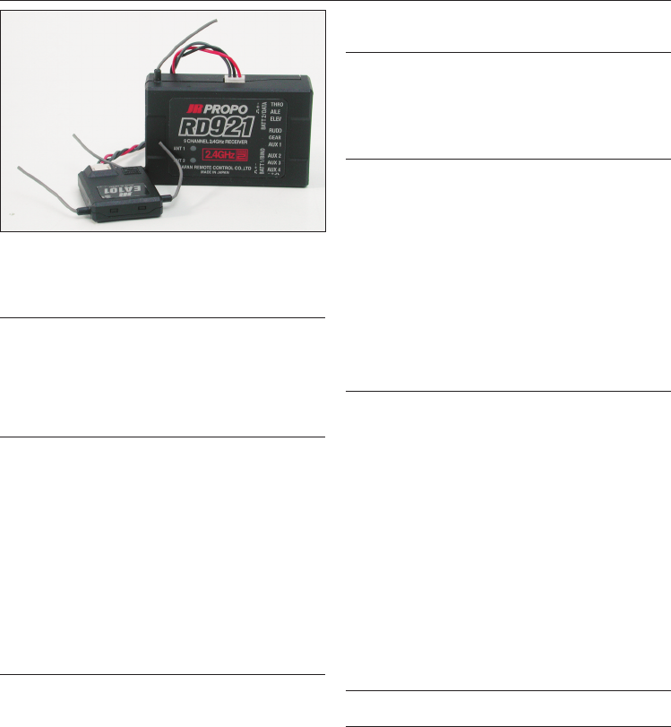
Fail-Safe Functions
The JR RD921 receiver features two types of
fail-safe: SmartSafe and Preset Fail-Safe.
SmartSafe
This type of fail-safe is ideal for most types of
electric aircraft and is also recommended for most
types of petrol- and glow- powered airplanes and
helicopters. Here's how SmartSafe works.
Receiver Power Only
When the receiver only is turned on (no
transmitter signal is present), all servos except for
the throttle are driven to their preset fail-safe
positions, normally control surfaces at neutral and
the landing gear down. These fail-safe positions
are stored in the receiver during binding. At this
time the throttle channel has no output, to avoid
operating or arming the electronic speed control.
In glow-powered models, the throttle servo has no
input so it remains in its current position.
After Connection
When the transmitter is turned on and after the
receiver connects to the transmitter, normal
control of all channels occurs. After the system
makes a connection, if loss of signal occurs,
SmartSafe drives the throttle servo only to its
preset fail-safe position (low throttle) that was set
during binding. All other channels hold their last
position. When the signal is regained, the system
immediately (less than 4ms) regains control.
Preset Fail-Safe
Preset Fail-Safe is ideal for sail planes and is
preferred by some modellers for their glow-and
petrol-powered aircraft.
Receiver Power Only
When the receiver only is turned on (no
transmitter signal is present), all servos except for
the throttle are driven to their preset fail-safe
positions, normally control surfaces at neutral and
the landing gear down. These fail-safe positions
are stored in the receiver during binding. At this
time the throttle channel has no output, to avoid
operating or arming the electronic speed control.
In glow-powered models, the throttle servo has no
input so it remains in its current position.
After Connection
When the transmitter is turned on and after the
receiver connects to the transmitter, normal
control of all channels occurs. After the system
makes a connection, if loss of signal occurs preset
Fail-Safe drives all servos to their preset Fail-Safe
positions. For sailplanes, it's recommended that
the spoilers/flaps deploy to de-thermalise the
aircraft, preventing a flyaway. Some powered
modellers prefer to use this Fail-Safe system to
programme a slight turn and low throttle to
prevent their aircraft from flying away. When the
signal is regained, the system immediately (in less
than 4 ms) regains control.
Programming SmartSafe
(All DSM Aircraft Receivers)
During the binding process the bind plug is left in
throughout the process and is removed only after
the receiver connects to the transmitter. After the
connection is made, confirmed by operating the
servos, the bind plug can be removed. The receiver
is now programmed for SmartSafe.
Programming Preset Fail-Safe
(JR RD921 Receivers Only)
During the binding process, the bind plug is
inserted in the bind port or in the charge jack, then
the receiver is powered up. The LED's in each
receiver should blink, indicating that the receiver is
in bind mode, remove the bind plug. The LED's will
still be blinking.With the control sticks and
switches in the desired Fail-Safe positions, bind the
transmitter to the receiver by pressing and holding
the bind buttons on the back of the
transmitter/module and turning on the
transmitter. The system should connect in less
than 15 seconds. The receiver is now programmed
for preset Fail-Safe.
NOTE: Fail-Safe position are stored via the stick and
switch positions on the transmitter during binding.
Standard Range Testing
Before each flying session, and especially with a
new model, it's important to perform a range
check. The DSX9 incorporates a range testing
system which, when the bind button on the
transmitter is pressed and held, reduces the output
power, allowing a range check.
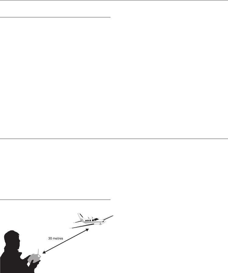
Range Testing the DSX9
1. With the model resting on the ground, stand 30
paces (approx. 90 feet) away from the model.
2. Face the model with the transmitter in your
normal flying position and depress and hold the
bind button on the back of the transmitter. This
causes reduced power output from the
transmitter.
3. You should have total control of the model with
the button depressed at 30 paces (25-30 metres).
4. If control issues exist, contact your Authorised JR
Dealer for further assistance.
Press and hold the bind button

Receiver Power System Requirements
With all radio installations, it is vital that the
onboard power system provides adequate power
without interruption to the receiver even when the
system is fully loaded (servos at maximum flight
loads). This becomes especially critical with giant-
scale models that utilise multiple high torque/high
current servos. Inadequate power systems that are
unable to provide the necessary minimum voltage
to the receiver during flight loads have become
the number one cause of in-flight failures. Some of
the power system components that affect the
ability to properly deliver adequate power include:
the selected reciever battery pack (number of cells,
capacity, cell type, state of charge), switch harness,
battery leads, regulator (if used), power bus (if
used).
While the RD921 receiver’s minimum operational
voltage is 3.5-volts, it is highly recommended the
system be tested per the guidelines below to a
minimum acceptable voltage of 4.8-volts during
ground testing. This will provide head room to
compensate for battery discharging or if the actual
flights loads are greater than the ground test loads.
Recommended Power System Guidelines
1. When setting up large or complex aircraft with
multiple high torque servos, it's highly
recommended a current and voltmeter in an open
channel port in the receiver and with the system
on, load the control surfaces (apply pressure with
your hand) while monitoring the voltage at the
receiver. The voltage should remain above 4.8-
volts even when all servos are heavily loaded.
2. With the current meter inline with the receiver
battery lead, load the control surfaces (apply
pressure with your hand) while monitoring the
current. The maximum continuous recommended
current for a single heavy-duty servo/battery lead
is three amps while short duration current spikes of
up to five amps are acceptable. Consequently, if
your system draws more than three amps
continuous or five amps for short durations, a
single battery pack with a single switch harness
plugged into the receiver for power will be
inadequate. It will be necessary to use multiple
packs of the same capacity with multiple switches
and multiple leads plugged into the receiver.
3. If using a regulator, it’s important that the above
tests are done for an extended period of 5 minutes.
When current passes through a regulator, heat is
generated and this heat causes the regulator to
increase resistance, which in turn causes even
more heat to build up (thermal runway). While a
regulator may provide adequate power for a short
duration, its important to test its ability over time
as the regulator may not be able to maintain
voltage at significant power levels.
4. For really large aircraft or complex models (for
example 35% and larger or jets), multiple battery
packs with multiple switch harnesses are necessary
or, in many cases one of the commercially
available power boxes/buses is recommended. No
matter what power systems you choose, always
carry out test #1 above making sure that the
receiver is constantly provided with 4.8 volts or
more under all conditions.
5. The latest generation of Nickel Metal Hydride
batteries incorporate a new chemistry mandated
to be more environmentally friendly. These
batteries , when charged with peak detection fast
chargers, have tendencies to false peak (not fully
charge) repeatedly. This includes all brands of Ni-
MH batteries. If using Ni-MH packs, be especially
cautious when charging making absolutely sure
that the battery is fully charged. It is recommended
to use a charger that can display total charge
capacity. Note the number of mAh put into a
discharged pack to verify it has been charged to
full capacity.

Tips on Using 2.4GHz Systems
While your DSM equipped 2.4GHz system is intuitive
to operate, functioning nearly identically to 35MHz
systems, following are a few common questions from
customers:
Q1: Which do I turn on first, the transmitter or the
receiver?
A1: If the receiver is turned on first, all servos except
for the throttle will be driven to their preset fail-safe
positions set during binding. At this time, the throttle
channel doesn’t put out a pulse position preventing
the arming of electronic speed controllers or, in the
case of an engine-powered aircraft, the throttle servo
remains in its current position. When the transmitter is
then turned on, the transmitter scans the 2.4GHz band
and acquires two open channels. Then the receiver
that was previously bound to the transmitter scans
the band and finds the GUID (Globally Unique
Identifier Code) stored during binding. The system
then connects and operates normally.
If the transmitter is turned on first, the transmitter
scans the 2.4GHz band and acquires two open
channels. When the receiver is then turned on for a
short period (the time it takes to connect), all servos
except for the throttle are driven to their preset fail-
safe positions while the throttle has no output pulse;
the receiver scans the 2.4GHz band looking for the
previously stored GUID; and when it locates the
specific GUID code and confirms uncorrupted
repeatable packet information the system connects
and normal operation takes place. Typically this takes
2 to 6 seconds.
Q2: Sometimes the system takes longer to connect
and sometimes it doesn’t connect at all?
A2: In order for the system to connect (after the
receiver is bound) the receiver must receive a large
number of continuous (one after the other)
uninterrupted perfect packets from the transmitter in
order to connect. This process is purposely critical of
the environmental, ensuring that it’s safe to fly when
the system does connect. If the transmitter is too close
to the receiver (less than 3/4 metre) or if the
transmitter is located near metal objects (metal
transmitter case, the bed of a truck, the top of a metal
work bench, etc) connection will take longer, and in
some cases, connection will not occur as the system is
receiving reflected 2.4GHz energy from itself and is
interpreting this as unfriendly noise. Moving the
system away from metal objects or moving the
transmitter away from the receiver and powering the
system up again will cause a connection to occur. This
only happens during the initial connection. Once
connected, the system is locked-in and, should a loss
of signal occur (fail-safe), the system connects
immediately (4ms) when signal is regained.
Q3: I’ve heard that the DSM system is less tolerant of
low voltage. Is that correct?
A3: All DSM receivers have an operational voltage
range of 3.5 to 9 volts. With most systems, this is not a
problem as most servos cease to operate at around
3.8 volts. When using multiple high current draw
servos with a single or inadequate battery/power
source, heavy momentary loads can cause the voltage
to dip below this 3.5 volt threshold, causing the entire
system (servos and receiver) to brown out. When the
voltage drops below the low voltage threshold (3.5
volts), the DSM receiver must reboot (go through the
start-up process of scanning the band and finding the
transmitter) and this can take several seconds. Please
read the receiver power requirement on page G-24 as
this explains how to test for and prevent this
occurrence.
Q4: Sometimes my receiver loses its bind and won’t
connect, requiring rebinding. What happens if the
bind is lost in flight?
A4: The receiver will never lose it bind unless it’s
instructed to. It’s important to understand that during
the binding process the receiver not only learns the
GUID (code) of the transmitter but the transmitter
learns and stores the type of receiver that it’s bound
to. If the bind button on the transmitter is pressed at
any time and the transmitter is turned on, the
transmitter looks for the binding protocol signal from
a receiver. If no signal is present, the transmitter no
longer has the correct information to connect to a
specific receiver and in essence the transmitter has
been “unbound” from the receiver. We’ve had several
customers that use transmitter stands or trays that
unknowingly depress the bind button and the system
is then turned on, losing the necessary information to
allow the connection to take place. We’ve also had
customers that didn’t fully understand the range test
process and pushed the bind button before turning
on the transmitter, also causing the system to “lose its
bind”. If, when turning on, the system fails to connect,
one of the following has occurred:

Tips on Using 2.4GHz Systems (Continued)
•The wrong model has been selected in the model
memory (Model Match)
•The transmitter is near conductive material
(transmitter case, truck bed, etc) and the reflected
2.4GHz energy is preventing the system from
connecting (See Q2)
•The bind button was unknowingly (or knowingly)
depressed and the transmitter was turned on
previously, causing the transmitter to no longer
recognise the receiver.
Q5: Can I use a 3-cell Li-Po pack in my transmitter?
A5: No. All current JR transmitters are designed to
operate using a 9.6 volt transmitter pack. A fully
charged 3-cell Li-Po pack puts out 12.6 volts. This
higher voltage can over load the power-regulating
transistor causing damage and or failure, possibly in
flight. Many of our customers have experienced
failures using 3-cell Li-Po packs and their use in JR
transmitters is highly advised against. The DSX9 2.4
system will operate for over 8 hours using a 1500mAh
Ni-MH battery.
JR DSX9 Frequently Asked Questions
Does the transmitter aerial orientation really
matter?
No, the transmitter will function normally with the
aerial pointing in any direction.
How do I mount the main & remote receivers?
With the small aerials leaving the receiver it makes it
much more difficult to mount the receiver in foam. If
you do still want to mount it in foam please make sure
that the aerials are not damaged. Most pilots will
mount both the main & remote receivers with double
sided foam tape or hook & loop tape. Both of these
systems work fine and will absorb normal amounts of
vibration. To help the tape stick to wooden surfaces,
coat the wood with a thin smear of epoxy. Allow this
to dry and then apply the tape.
Where do I mount the remote receiver?
As with any receiver system it is important to mount it
as far from interference as possible, i.e Ignition
systems & servo leads. The orientation of the receiver
aerials is also important. Try to mount the remote
receiver so that the aerials are pointing in a different
orientation, ie. X, Y & Z axis, so if the main receiver
aerials are horizontal, mount the remote receiver so its
aerials are vertical.
Is there an advantage to adding more remote
receivers?
Yes there is, the more you add the less likely it is for a
loss of signal. Again try to mount the additional
receivers in different orientations to aid reception.
Battery systems:
Please make sure that you use a high quality battery
and switch harness. Try to avoid high capacity Ni-Mh
cells of a small case diameter (2400mAh +) as there is
a lot of internal resistance in the cells, sub C type cells
are better. This is true of all radio setups.
Please use high quality extention leads as poor
examples will have high resistance and can cause low
power situations.
Ni-Mh cells are susceptible to temperature. For those
of you flying in the winter or storing models in the
shed/ garage please make sure that you check your
battery power on a regular basis. Topping up the
battery the day of flying is advisable using a peak
detect charger.
If using the second power port on the receiver please
make sure that you use an independent battery
supply and not just 'Y' lead from one power source.
Overcharging batteries:
JR's DSM2 system will use less power to transmit than
a normal 35mHz system. Please be aware of this when
using the supplied wall charger.
DSC (Direct Servo Control):
JR have confirmed that this function is not available
with DSM2 receivers. Owners of JR DSX transmitters
should not therefore use this function.
For set-up purposes the set should be used in the
conventional manner. Due to the multitude of
frequencies available, this will not endanger other
models, either in the air or on the ground.

The Specifications and the Manual are subject to change without prior notice.
16/09/2008
MacGregor Industries Ltd
Cordwallis Street,
Maidenhead,
Berkshire,
SL6 7GF
Tel: 01628 760430 Fax: 01628 760435
www.macgregor.co.uk
